LIGHT WEIGHT PORTABLE CONTROL TELEPHONE
21
LIGHT WEIGHT PORTABLE CONTROL TELEPHONE 1. Introduction The conventional mode of communication between driver / guard and section controller is by means of emergency control Telephone (ECP set). This emergency communication is initiated from the site of emergency by drivers / guards of the affected train. For this purpose driver/guard have to carry their ECP set to the nearest emergency post which may be about 500 meters far. Considering the difficulties in carrying the conventional emergency portable control telephone, RDSO laid the specification for light weight portable control telephone lighter and handheld for ease of carrying and using. This handbook covers brief description, various components, circuit working and installation of the equipment according to the RDSO specification no. IRS:TC:78-2000.
-
Upload
khangminh22 -
Category
Documents
-
view
0 -
download
0
Transcript of LIGHT WEIGHT PORTABLE CONTROL TELEPHONE

LIGHT WEIGHT PORTABLE CONTROL TELEPHONE
1. Introduction
The conventional mode of communication between driver / guard and section controller is by means of emergency control Telephone (ECP set). This emergency communication is initiated from the site of emergency by drivers / guards of the affected train. For this purpose driver/guard have to carry their ECP set to the nearest emergency post which may be about 500 meters far. Considering the difficulties in carrying the conventional emergency portable control telephone, RDSO laid the specification for light weight portable control telephone lighter and handheld for ease of carrying and using. This handbook covers brief description, various components, circuit working and installation of the equipment according to the RDSO specification no. IRS:TC:78-2000.

CAMTECH/S/2005/LWPCT/1.0
Lightweight portable control telephone November’2005
2
2. Brief Description
The train control is an arbitrary supervision of the actual movement of the trains between section in order that section capacity may utilized to the greatest advantage. This control is exercised by Section Controller at control office. Railway control circuits are omnibus telephone circuits, which provides communication with each train working point thus facilitating efficient train operation. They provides satisfactory and reliable communication between the controller and the various way side stations, signalling cabins, loco sheds, yard offices and tapping provided in entire section. When control circuits are through under ground cables, it is difficult to connect a portable telephones to the control wires to establish communication between control office and any point on section. To get over this difficulty taps are provided from under ground cables at regular intervals on entire section and these taps are terminated on sockets. The control office can be connected by plugging a telephone in to any of the sockets. These taps are provided from separate circuit instead of section control circuit so that the section control circuit is not un-necessarily disturbed. This speech circuit is called the emergency control circuit.

CAMTECH/S/2005/LWPCT/1.0
Lightweight portable control telephone November’2005
3
The lightweight 4 wire/2 wire control telephone provides communication between any way side point along the track to section controller in the control office. This telephone works with two pencil cells and has facility to communicate both on RE area and non-RE area selectable through a sliding switch. Lightweight portable telephones are provided with Drivers, Guards and other maintenance staff to communicate with section controller as and when required. For communication on 4-wire they inserts 6 pin plug of his instrument in emergency socket and establish communication with controller. Similarly for communication on 2-wire, both lines of over head control circuit will be terminated to the terminals provided on the bottom of the telephone instrument.

CAMTECH/S/2005/LWPCT/1.0
Lightweight portable control telephone November’2005
4
3. COMPONENTS
Lightweight portable control telephone is consist of the following components.
Body of telephone instrument Transmitter Receiver Transformer / induction coil Battery compartment Battery indication Cord Internal wiring Terminals and PCB DC Blocking Capacitor Changeover Switch Six-pin Plug Battery ON-OFF switch Press to talk (PTT) switch Terminal for 2 wire
i) Body of telephone instrument
The body of the Lightweight portable control telephone instrument is made of mild steel or ABS plastic. The shape of the body is rectangular box. The weight of this instrument with all components except cord and connector is 400 grams in case of mild steel body and 350 grams in case of ABS plastic body. The simple sketch of the instrument is shown below:

CAMTECH/S/2005/LWPCT/1.0
Lightweight portable control telephone November’2005
5
Battery Compartment
Hole for Coiled Cord For 2 wire Line
ii) Transmitter
Electrodynamic transducers /condenser` microphone/ ceramic microphone is provided as transmitter. The transmitter is work on 3 volt DC with associated amplifier for its operation.

CAMTECH/S/2005/LWPCT/1.0
Lightweight portable control telephone November’2005
6
iii) Receiver
Electrodynamic transducer is provided as receiver. For the protection against acoustic shock, two rectifiers in parallel and with opposite polarity are provided across the receiver.
iv) Transformer / induction coil
Two sets of transformers are provided to match the transmitter and receiver’s impedance with the line. Transformers are vaccume impregnated and the complete windings are protected by proper insulation to avoid ingress of moisture.
v) Battery compartment
Battery compartment is provided on the instrument. The cover of this compartment is press & fit type or screwed flush telephone body. The Lightweight portable control telephone instrument is work on 3 volt DC for that purpose two numbers dry pencil batteries of 1.5 volt are used. These are housed in a plastic holder fitted with springs to give proper contact pressure to batteries. The maximum working current of Light weight portable control telephone instrument during talk condition is not more than 15 milli amperes.
CAMTECH/S/2005/LWPCT/1.0
Lightweight portable control telephone November’2005
7
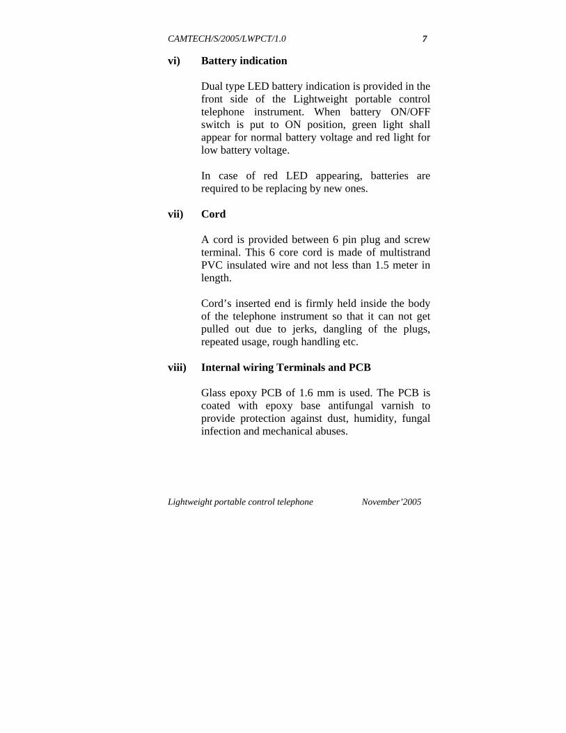
vi) Battery indication
Dual type LED battery indication is provided in the front side of the Lightweight portable control telephone instrument. When battery ON/OFF switch is put to ON position, green light shall appear for normal battery voltage and red light for low battery voltage. In case of red LED appearing, batteries are required to be replacing by new ones.
vii) Cord
A cord is provided between 6 pin plug and screw terminal. This 6 core cord is made of multistrand PVC insulated wire and not less than 1.5 meter in length. Cord’s inserted end is firmly held inside the body of the telephone instrument so that it can not get pulled out due to jerks, dangling of the plugs, repeated usage, rough handling etc.
viii) Internal wiring Terminals and PCB
Glass epoxy PCB of 1.6 mm is used. The PCB is coated with epoxy base antifungal varnish to provide protection against dust, humidity, fungal infection and mechanical abuses.

CAMTECH/S/2005/LWPCT/1.0
Lightweight portable control telephone November’2005
8
ix) DC Blocking Capacitor
Capacitor made of mettallised polyster is provided. 1.5 to 2.2 micro farad capacitor of operating voltage minimum 400 volt is used to avoid tripping of the circuit breaker of the control circuit.
x) Changeover switch
Sliding type switch is provided on the side of the instrument. It works on one side with 2-wire control line and opposite side with 4-wire control line. “2 Wire” and “4 Wire” is printed on the body to signify the exact position of the switch.
xi) Six pin plug
6-Pin plug is connected with the cord and provided for inserting in emergency socket. Connections of six-pin plug’s are such that two outer most pins are connected on receive, next two on trans and central two pins are connected to terminals for 2-wire working.

CAMTECH/S/2005/LWPCT/1.0
Lightweight portable control telephone November’2005
9
L2
L1
Tx
Rx
Tx
Rx
PLUG CONNECTION DIAGRAM
xii) Battery ON-OFF switch
A sliding type switch is provided on the body of the Lightweight portable control telephone instrument for battery make ON or OFF. This switch is provided in the series with batteries and extend power to receive amplifier of the circuit when pressed to ON position. It also extend power to LED when in the ON position which will glow to indicate that the telephone instrument is ready for use.

CAMTECH/S/2005/LWPCT/1.0
Lightweight portable control telephone November’2005
10
xiii) Press to talk (PTT) switch
Press to talk switch is provided on the body of lightweight portable control telephone. When this PTT switch is pressed, it will extend power to trans amplifier & when released, it will disconnect supply to this amplifier.
xiv) Terminals for 2 wire
Separate optional terminals at the bottom of the telephone body are provided for 2-wire connection. In case if on our requirement these separate terminals are provided, central two pins of six-pin plug will be with out any connection. These separate terminals are banana type terminals.

CAMTECH/S/2005/LWPCT/1.0
Lightweight portable control telephone November’2005
11
4. Working
Block diagram of lightweight portable control telephone instrument is given below:
The circuit consisting of electrodynamic inset and a condenser microphone. In the transpath the speech output signal from condenser microphone is low, hence the signal is amplified through an inbuilt IC amplifier. Another feature in this telephone is that it has a multi colour LED to indicate status of battery. A green light indicate normal condition of battery, red indicates low battery status. The wiring diagram and a typical Circuit Diagram of the instrument manufactured by Epsilon Electronic Equipment & Components Pvt.Ltd is shown on next pages.

CAMTECH/S/2005/LWPCT/1.0
Lightweight portable control telephone November’2005
12
A low voltage IC amplifier U1 is used for trans and transistor amplifier is used for receive. The trans amplifier receives the voice from the condenser microphone and the gain of the amplifier is adjusted to get 0-dB output across Tx / (L1-L2).

CAMTECH/S/2005/LWPCT/1.0
Lightweight portable control telephone November’2005
13

CAMTECH/S/2005/LWPCT/1.0
Lightweight portable control telephone November’2005
14
COMPONENTS – LIST
Part No.
Description
Type
Make
Qty /Pcs
RESISTORS R1,R4,R5,R17 1K/ .25W MFR Philips/Keltron 4 R2 680R/.25W MFR Philips/Keltron 1 R3 100K/.25W MFR Philips/Keltron 1 R6 43K/.25W MFR Philips/Keltron 1 R7,R12 1M/.25W MFR Philips/Keltron 2 R8 68R/.25W MFR Philips/Keltron 1 R9 33K/.25W MFR Philips/Keltron 1 R10 470R/.25W MFR Philips/Keltron 1 R11 56K MFR Philips/Keltron 1 R13 39R/.25W MFR Philips/Keltron 1 R14 1R/.25W MFR Philips/Keltron 1 R15,R16 560R/.25W MFR Philips/Keltron 2 R18 330R/.25W MFR Philips/Keltron 1 CPACITORS C1, C9 .22MFD/100V PPC Philips/Keltron 2 C2 1MFD/63V Electrolytic Philips/Keltron 1 C3, C10 .1MFD/100V PPC Philips/CTR/FEC 2 C4,C6,C8,C12, C13
10MFD/25V Electrolytic Philips/Keltron 5
C5 100MFD/40D Electrolytic Philips/Keltron 1 C7 .33MFD/100V PPC Philips/CTR/FEC 1 C11 1.5MFD/400V PPC Philips/Advance 1 DIODES D1, D2 1N4148 Switching CDIL/ECIL 2 D3 1N4007 Rectifier CDIL/ECIL 1 ZD1, ZD2 4.7V/1WATT Zener CDIL/ECIL 2

CAMTECH/S/2005/LWPCT/1.0
Lightweight portable control telephone November’2005
15
TRANSISTORS Q1 TO Q4 2N2222A NPN BEL/CDIL 4 POTENTIOMETERS P1 20K Multi Turn 3296 Bourns/Spectrol 1 P2 500R Multi Turn 3296 Bourns/Spectrol 1 INTEGRATED CIRCUITS U1 MC34119 OP-AMP National/Signetics 1 MISCELLANEOUS RECEIVER RX RT160 RAJAMANI 1 CONDENSER MIC TX CZN-15E SIEMNS 1 SW1 SLIDE SWITCHES GILARD/IEC 1 PTT MICRO SWITCH OEN/IEC 1 PTT BUTTON ----- EPSILON 1 6CORE CORD ------ ASWANI 1 6PIN FLAT PIN ------ EPSILON 1 BI-COLOR LED COMMON CATHOD Fairchild/Quality 1 PC 8 EEE 9935/4 EPSILON 1 EE25 BOBBIN 5 PIN VERTICAL BHAGYA LAXMI 1 EE20 BOBBIN 10PIN VERTICAL BHAGYA LAXMI 1 MOULDED CABINET ABS PLASTIC EPSILON 1 CONNECTORS 6PIN RELAMETE UNICON 1 CONNECTORS 4PIN RELAMETE UNICON 1 CONNECTORS 2PIN RELAMETE UNICON 1

CAMTECH/S/2005/LWPCT/1.0
Lightweight portable control telephone November’2005
16
5. Specifications 1. Maximum working current
during talk condition. < 15 mA
2. Insulation resistance at 500 VDC, between all terminals of 6 pin plug connected together and the main body.
> 100 Mega Ohms
3. High voltage at 2 KV, 50 HZ AC sinusoidal r.m.s. when applied between the body and all the pins of the 6 pin plug connect together for one minute.
No breakdown
2 wire side Send Efficiency 4. Send level –44dBm, 1000 Hz
across MIC with 160 ohms impedance
> 0dBm (across line terminals with 600 ohms impedance)
5. Side tone across receiver < - 18 dBm 6. Total harmonic distortion < 3% 7. Frequency response 300 Hz to
3400 Hz ±0.5 dB
Receive efficiency 8. Receive level –12dBm, 1000 Hz
across MIC with 600ohms impedance
> -18dBm (across receiver with 160 ohms impedance)
9. Total harmonic distortion < 3%
10. Frequency response 300 Hz to 3400 Hz
±0.5 dB
11. Insertion loss < 0.2 dB listen condition <0.8 dB talk condition

CAMTECH/S/2005/LWPCT/1.0
Lightweight portable control telephone November’2005
17
4 Wire side Trans efficiency 12. Send level –44dBm, 1000 Hz
across MIC with 160 ohms impedance
> +3.8dB (across Tx terminals with 1120 ohms impedance)
13. Side tone across receiver ±0.5 dB 14. Total harmonic distortion < 3% Receive Efficiency 15. Receive level at input of –20
dB, 1000 Hz across mic terminals with 1120 ohms impedance
>-26 dBm (across receiver terminals with 160 ohms impedance)
16. Frequency response 300 to 3400 Hz
±0.5 dB
17. Insertion loss < 0.5 dB listen condition < 1 dB talk condition
Dimensions 18. Long 175 mm 19. Wide 50 mm 20. Deep 40 mm 21. Weight 400 gram (max)

CAMTECH/S/2005/LWPCT/1.0
Lightweight portable control telephone November’2005
18
6. Installation
The lightweight portable control telephone is supplied duly packed in a waterproof pouch and is provided with 6 pin plug. Pin configuration is as given below: L1 & L2 are available in the centre pins of the plug as well in the binding terminals provided in the telephone body. Normally as per the existing wiring the 2 wire lines are not terminated in the middle pins of the emergency socket. Remove the telephone from the pouch and ensure that 2 numbers of dry cells are inserted in the battery compartment properly and close the lid. Switch ON the power by sliding the switch to ON position. The green LED shall glow. Keep the second slide switch to 4 wire. The lightweight portable telephone is ready to use. To talk to the controller, press the PTT switch. After the use, power OFF to avoid battery drain and keep the telephone inside the pouch.
Rx Tx L1 L2 Tx Rx

CAMTECH/S/2005/LWPCT/1.0
Lightweight portable control telephone November’2005
19
7. Operating Instructions
Keep 2-wire/ 4-wire switch towards 2-wire side for 2 wire operation and 4 wire side for 4 wire operation.
Insert 6 pin plug in emergency socket for 4
wire operation or connect L1 & L2 to over head line for 2 wire operation.
Now switch ON the power of the instrument.
Press PTT (Press to Talk switch) to talk.
After conversation switch OFF the power.
If battery indication is RED, replace the
batteries with new one.

CAMTECH/S/2005/LWPCT/1.0
Lightweight portable control telephone November’2005
20
8. Maintenance
The lightweight portable control telephone equipment is a solid state, very handy, easy to operate and maintenance free instrument. However, following checks may be done for trouble free operation. If the power ON LED shows red, the battery
has fallen below 2.7 volt DC. The battery has to be replaced.
Cleaning of instruments from dust and
moisture. Continuity of cord.
Since the circuitry works on 3 volts DC and the operating power is as low as 1mili watt. No components shall fail. However, while using the telephone heavy induction due to lightning may effect the telephone, even though adequate protection is provided in the line with MOVR and GD tube.

CAMTECH/S/2005/LWPCT/1.0
Lightweight portable control telephone November’2005
21
9. Testing
Lightweight portable control telephone instrument can be tested for insulation and insertion loss tests. Insulation Test The insulation resistance between all terminals of six-pin plug connected together and body of lightweight portable control telephone instruments shall not be less than 100 mega ohms when tested with 500-volt DC meggar at ambient temperature. Insertion loss tests 2-Wire Listen Condition
It shall not be greater than 0.2 dB.
2-Wire Talk Condition
It shall not be greater than 0.8 dB.
4-Wire Listen Condition
It shall not be greater than 0.5 dB.
4-Wire Talk Condition
It shall not be greater than 1.0 dB.