STANDARD DRAFTING PRACTICES BELL TELEPHONE ...
90
X-62725 ISSUE 6 STANDARD DRAFTING PRACTICES FOR THE PREPARATION OF WIRING DIAGRAMS BELL TELEPHONE LABORATORIES INCORPORATED SYSTEMS DEVELOPMENT DEPARTMENT 463 WEST STREET NEW YORK PRINTED IN U. 9. A.
-
Upload
khangminh22 -
Category
Documents
-
view
4 -
download
0
Transcript of STANDARD DRAFTING PRACTICES BELL TELEPHONE ...
X-62725 ISSUE 6
STANDARD DRAFTING PRACTICES
FOR THE PREPARATION OF
WIRING DIAGRAMS
BELL TELEPHONE LABORATORIES INCORPORATED
SYSTEMS DEVELOPMENT DEPARTMENT
463 WEST STREET
NEW YORK
PRINTED I N U. 9. A.
BEI;L TELEPHONE UBCRATOBIES , I NC . SYSTECS DEYELOWENT DEPARTMENT
2-62725, L'JCUST
Xi'GC INC LU'3IL
STANDhaD DRAFTING PRACTICES
FOB THE PREPMTION OF
WIRING DIhGRAUS
1.01 This s p e c i f i ~ a t i o n ~ t o g e t h e r wi th t h e sup- plementary informat ion herein r e f e r r e d t o ,
cove r s t h e s t anda rd d r a f t i n g p r a c t i c e s f o r t n e p repa ra t ion of wir ing diagram drawings. I t a l s o c o n t a i n s u s e f u l t abu la t ed informat ion f o r the draf tsman i n making up t h e s e drawings.
Engineer ' s R e s ~ o n s i b i l i t p
1.02 The engineer w i l l be r e spons ib l e f o r f u r - n i s h i n g new and r ev i sed drawing information
t o the draftsman. This informat ion should be o r i g i n a t e d i n t h e form of a s tandard drawing o rde r , p rope r ly approved. The drawing order may inc lude complete informat ion with o r without r e f e r e n c e t o o t h e r drawings such a s schematic, equipment, l o c a l cab le , and connect ing drawings, and any o t h e r informat ion which may be of a s s i s - tanoe in p repa r ing t h e drawing. The informat ion , however, should be s u f f i c i e n t l y comprehensive s o t h a t t h e draftsman may proceed without unnec- e s s a r y l o r s of time.
1 .0s A f t e r a drawing order has oeen o r i g i n a t e d , a l l subsequent changes made by the engineer
rhould be covered bgsupplenentary o rde r s . Where such changes a r e made v e r b a l l y , they should be conf i r aed by supplementary drawing o rde r s .
1.04 The engineer w i l l a l s o be r e spons ib l e f o r t h e following:
( a ) That informat ion is furnished r e l a t i v e t o t h e gauge of wire, source of r i n g i n g
c u r r e n t , and s tandard and other.exp1anatory n o t e s cover ing the u s e of f i g u r e s and con- d i t i o n a l wiring.
(b ) That t he a r r angesen t of appa ra tus , cab- l i n g , and wi r ing ag ree with t h e r e q u i r e -
ments s p e c i f i e d b y t h e customer and s t anda rd o r s p e c i a l p r e c t i c e s .
Draftsman' s R e s ~ o n s i b i l i t y
1.05 The draftsman s h a l l be r e spons ib l e f o r t h e fo l lowing:
( a ) That the s i z e , form, and gene ra l a r r anee - ment of t h e drawing is i n accordance
wi th 'the requi rements oovered he re in u n l e s s o therwise speoi f ied .
(b ) That t he drawing conforms with the sche- matic and s tandard p r a c t i c e s such a s ap-
p a r a t u s and cab le conventions, c o l o r s of w i re s , n a n u f a c t u r i n ~ no te s (when the opera- t i o n of t he c i r c u i t i s not a f f e c t e d ) .
( c ) That d e s i g n a t i o n s of l e a d s t o connecting o r a s s o c i a t e d c i r c u i t s a r e i n agreement
and t h a t des ienated wires on t h e c i r cu i t a r e i n agreement wi th a s s o c i a t e d manufacturing and engineer ing notes .
( d ) That. drawing numbers are l i s t e d of sche- mat ics and Telephone Company's drawings
f r o n which t h e wi r ing d i ag ron was made a s well a s t he drawing numbers of connecting and a s soc ia t ed drawings.
1.06 Af te r completion of a drawing the d r a f t s - man s h a l l send t h e drawing toge the r w i th
t h e drawing o r d e r , and supplements i f any, and a l l a t tachments t h e r e t o t o the d r a f t i n g checker.
1.07 Checking a l l w i r ing diagrams c a r e f u l l y w i l l o f t e n e l imina te a l a r g e number of
i n s t a l l e r ' s compla in ts and unnecessary add i t ion - a l expense. Supplementary I n f o r n a t i o n
Drawings
ES-223291 - Grounding - Tol l Switchboards 38-378383 - Groundins - Lead Covered Cables SD-66197-01 - Grounding - PBX SD-80426-01 - Grounding - Tol l T-622406 - Grounding - T o l l
S p e c i f i c a t i o n s
11-32463 - Manufacturing Information fcr Shie lded U :+e
X-62604 - Draf t ing P r a c t i c e s f o r t he Prepara- t i o n of Assembly, Equipment, and Cabling Drawings
1-62724 - Draf t ing Informat ion f o r C i r c u i t Schemat i c Drawings
BSP M610.003 - Gauge and I n s u l a t i o n of Wire BSP AA612.601 - Wiring Symbols, Wiring Abbre-
v i a t i o n s , and D e f i n i t i o n s BSP lY.612.002 - A i r l i n e System of D e ~ i c t i n a
Wiring ~ i a g r a m s -
BSP AA612.005 - W i r i n ~ and Cabl inc . Formina. ~ a n n i n g , Sewing, and ~ k i n n i n i
BSP AA612.013 - St rapp ing BSP AA612.015 - Color Combinations and Uses,
Wiring and Cabl ing BSP AXG12.019 - Wiring and Cabl ing , Crosbbar
Type Equipment BSP AA613.001 - Abbrevia t ions and Symbols Used
i n Designat ing Central Off ice , PBX, and Power Equipment
BSP AA618.201 - Assembly and I n s t a l l a t i o n of Power P l a n t Bus Bar and Wiring
KS-5482 - Manufacturing Informat ion f o r Flame Retarding Power Wire and Cable
KS-7133 - LIanufacturing In fo rma t ion fo rRubber . Insu la t ed Cordage
P r i n t e d i n U. S. A.
2.01 Drawings s h a l l be s o planned that they may be accommodated by the atandard t r a c i n g
forms provided f o r t h i s purpose.
2.02 A l l wiring diagrans to be used f o r a t r i a l i n s t a l l a t i o n s h a l l be drawn on penci l
t racings .
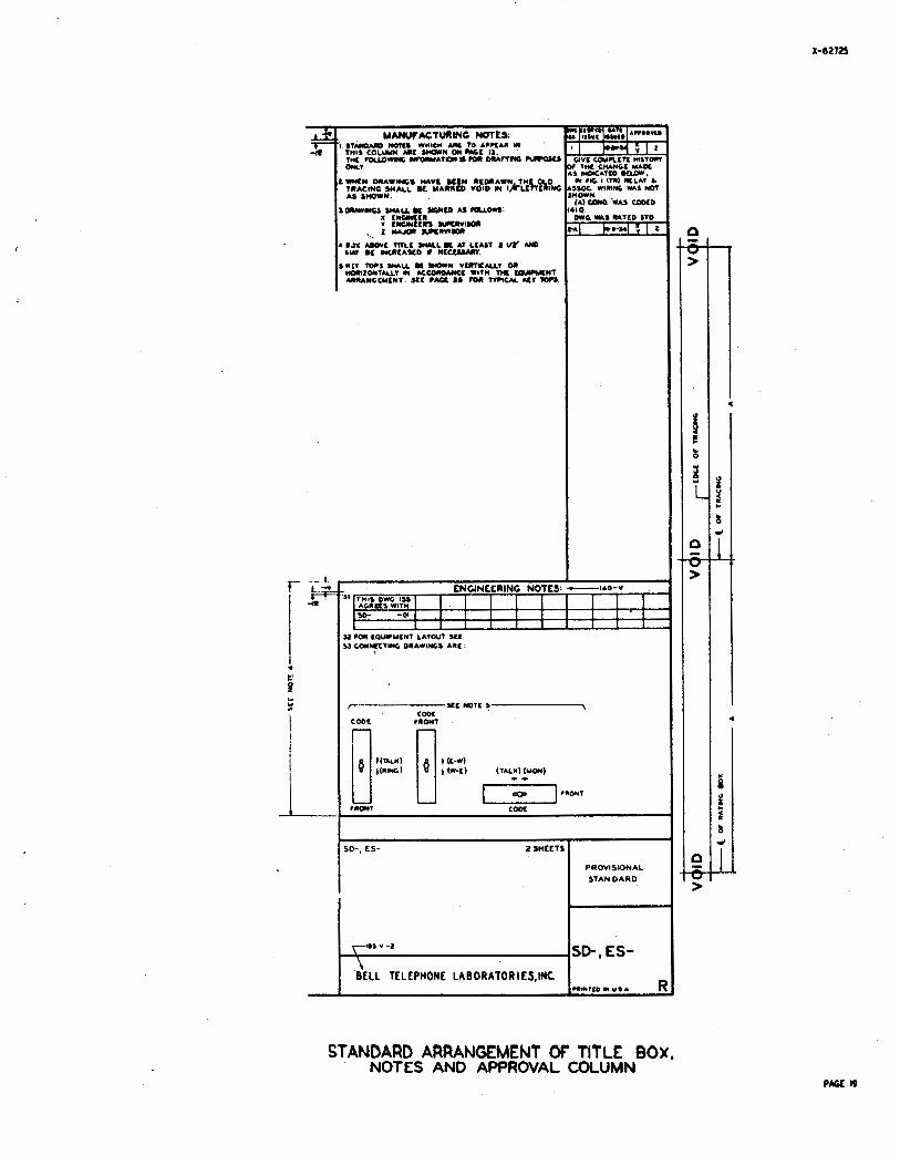
2.03 T i t l e box, notea, and approval column s h a l l be arranged a s shown on page 19.
2.04' The i s sue column s h a l l cover a b r i e f but complete record of all changes nade on the
t r a c i n . I n no case s h a l l the i s sue columns show Shanged per engineer* s marked p r i n t u or 'redrawn due t o extensive changes". When it is necessary t o pontinue t h e i s sue column on a drawing the words "continued a t A" or B, e t c . r h a l l be shown a t the bottom of the i s sue column.
Layout Planning
2.05 The draftsman s h a l l f a m i l i a r i z e himself with the c i r c u i t . The sohematics s h a l l
be analyzed, cross-connections checked, and a l l notes ca re fu l ly read. Any question t h a t may a r i s e such a s source of ground, r ing ing supply, number of f i g u r e s required,e tc . , s h a l l be taken up with the engineer before proceeding. The layout of equipment s h a l l be ohecked against the achematic t o see t h a t a l l equipment is accounted f o r .
Apparatus Layout
2.06 The f i g u r e s l i s t e d herein a r e s p e c i f i c and s h a l l be arranged on drawings i n ac-
oordance with the equipment layout. No space s h a l l be reserved on a t r a c i n g ( spec i f i ca t ion shee t s included) f o r add i t iona l f i g u r e s un less i t is c e r t a i n t h a t the add i t ions w i l l be made before the drawing is issued. Any request f o r dev ia t ions t o . t h i s r u l e o r from the information and p rac t i ces s e t f o r t h i n t h i s s p e c i f i c a t i o n s h a l l be re fe r red t o t h e d r a f t i n g supervisor.
2.07 The apparatus s h a l l be arranged i n the sane general o rder a s t h a t shown on the
equipment drawings, looking a t the terminal or so lde r ing s ide of the equipnent. The equipment on tb individual mounting p l a t e s s h a l l be shown a t d i f f e r e n t l eve le .
2.08 X ~ ~ o r a t u s wired from t h e f r o n t of a an el f r a n e s h a l l be shown above or t o one
s ide of apparatus wired from the rear,and s h a l l be designated by a bracket reading: "Apparatus wired from f r o n t of panel or framew.
2.09 ,Where t h e apparatus mounts i n P v e r t i c a l on a Croup of mounting p l a t e s with a
v e r t i c a l cable arm, i t may be shbnn i n a v e r t i c a l row i n the a c t u a l order i n nhich i t i s mounted, provided the s i z e of the drawing w i l l permit; otherwise, the apparatus may be shown i n two or more v e r t i c a l rows. THE TOP SECTION TO BE SHOWN AT THE LEFT.
2.10 Where the apparatus mounts i n a horizon- a 1 row a s on a mounting p la te i t nay be
shown i n a hor izontal row i n the a c t u a l order i n which it is mounted. ~ r o v i d e d the size of the draw'ng w i l l permit ; otherwise, t h e apparatus may be shown i n two rows from l e f t t o r i g h t a s thou@ the mounting p l a t e was oade i n two sec- t ionb, THE LETT SECTION SHOW ABOVE THE FtiGIiT SECTION.
2.11 The above requirements may be disregarded on miscellaneous c i r c % i t s , aux i l i a ry s ig-
na l , supervisor* s telephone, and miscellaneous alarm c i r c u i t s where it would not be feasible t o follbw the arrangements specif ied.
2.12 Where it i s necessary to connect or double up a lead i n a handmade cab le wi th a lead
i n a switchboard cab le , o r t o terminate one end of a lead i n a t r i p l e or p a i r , an "insulated terminal" a h a l l be shown located a t a posi t ion adjacent t o the apparatus a t which the cables meet or where the t r i p l e o r p a i r terminates.
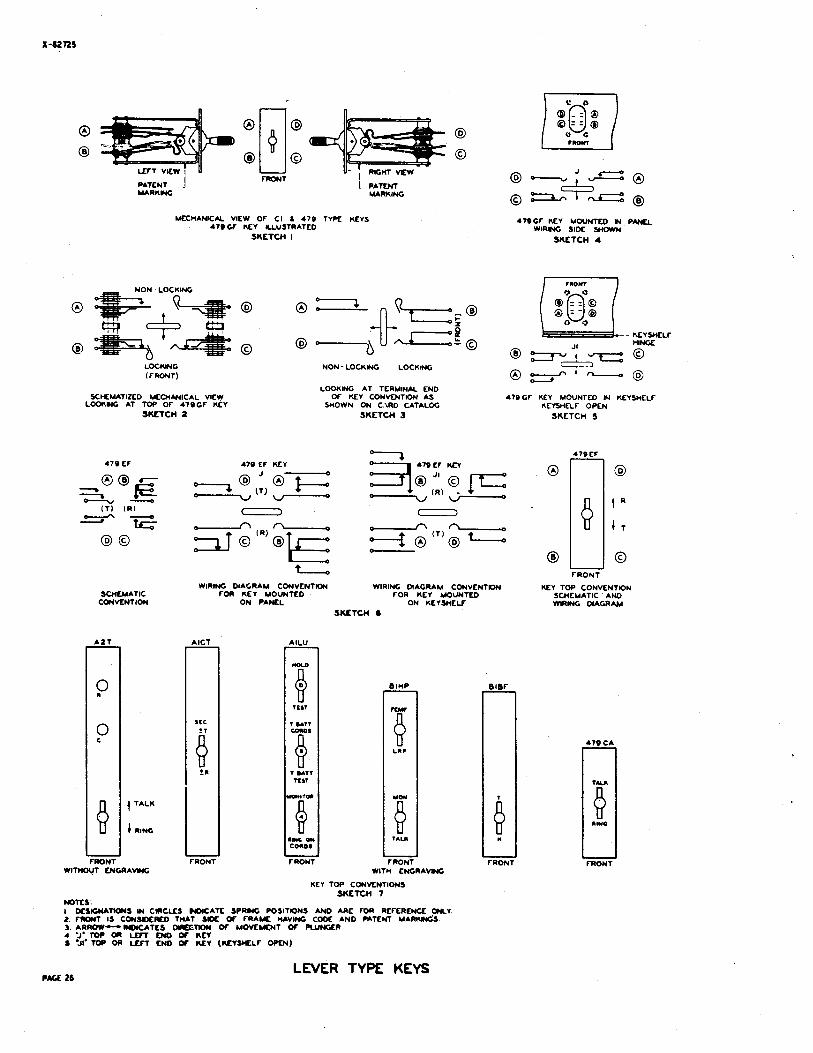
2.13 I n order t o proper ly assoc ia te the mount- ing of keys with t h e i r arrangement on the
equipment drsrring, one end of the key s h a l l be indicated by the l e t t e r "Jw on the wiring d i a - gram. The purpose o f t h e l e t t e r "J" is explained i n a manufacturing note nhich is shown on the drawing. Where keys a r e shown i n var ious nays on t~he aame drawin'g, a number s h a l l be added t o the l e t t e r such aa "JlW, "J2", e t c . Lach bf the designat ions s h a l l be properly explained i n a manulfacturing note. (See page 43
2.14 The operat ion of key l e v e r s i s indicated on the key top diagram shown on the sche-
matic drawing. I n the case of " s p l i t t i n g keys" wher~e the operat ion of t h e key l ever i s not in - dicalted, the key lever s h a l l operate away from the operator t o t a l k on the "A" cord and toward the operator t o t a l k ' on the "CR cord, unless otherwise specif ied. (See page 26.)
2.15 Key top diagrams f o r a l l keys except E l and individual push buttonskeys, s h a l l be
shown cm wirin diagrams undb engineer ine notes. (Sea page 19.7
F i m r e s 2.16 Wiring diagrams msy be arranged i n f igures
i n order t o provide f l e x i b i l i t y i n eover- ing va r iab le conditions.
2.17 On a l l wiring drawings, except c i r c u i t l a b e l s , s u b t i t l e s f o r f i g u r e s s h a l l be a s
shown i n Sketch A.
2.10 Lettered f if iures s h a l l include opt ional or va r iab le wiring and apparatus which
fo rq d par t of a numbered f igure .
2-14 The opt ional o r va r iab le f e a t u r e s covered by l e t t e r e d f i g u r e s on wiring diagrams
s h a l l be properly explained under engineering notes such a s "Specify Fig. A f o r Flashing Re- c a l l "
2.20 Numbered f i g u r e s s h a l l ' include a complete I a i v i s i o n of the c i r c u i t . The main f i g u r e
shal$ be designated "Fie. 1" i n a11 cases . The
Page 2
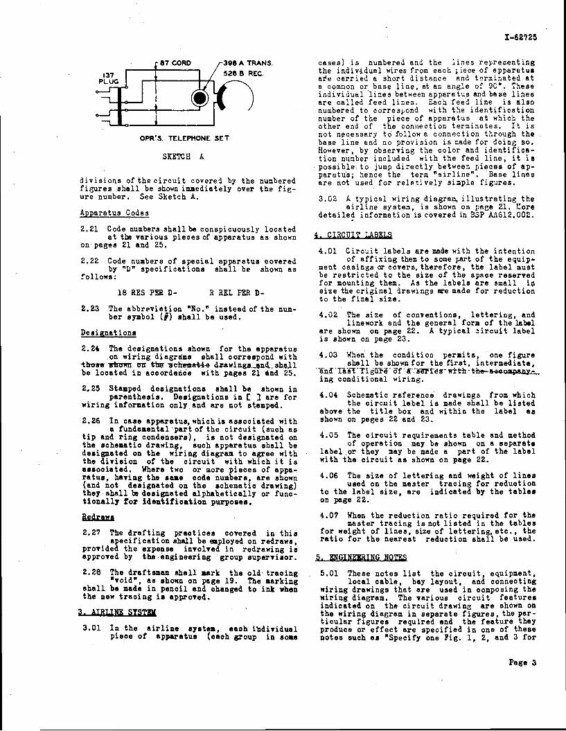
396 A 1 RANS. 528 B REC.
OPR'S. TELEPHONE SET
SKETCH A
d i v i s i o n s o f t h e c i r c u i t covered by the numbered f i g u r e s s h a l l be shown immediately over t h e f i e - u r e number. See Sketch A.
Apparatus Codes
2.21 Code numbers s h a l l be conspicuously loca ted a t the v a r i o u s p i eces of appara tus a s shonn
on pages 21 and 25.
2.22 Code numbers of s p e c i a l appara tus covered by "Dn s p e c i f i c a t i o n s s h a l l be shonn a s
fo l lows :
18 RES PER D- R ilEL M D-
2.23 The abbrev ia t ion "No." in s t ead of t h e num- be r symbol (#) s h a l l be used.
Designat i o n s
2.24 The des igna t ions shown f o r t he appera tus on wir ing diagrams s h a l l correspond wi th
those atmmr mr +Am ae3ymtri-e drawings.,r)nb. s h a l l be l o c a t e d i n aooordance wi th pages 21 and 25.
2.25 Stamped des igna t ions s h a l l be shown i n pa ren thes i s . Des ignat ions i n C I a r e f o r
w i r ing informat ion only and a r e not stamped.
2.26 I n case apparatus, which is a s soc ia t ed with a fundamental p a r t of t h e c i r c u i t (such a s
t i p and r i n g condensers) , i s no t des ignated on t h e schematio drawing, such appa ra tus s h a l l be des ignated on t h e wir ing diagram t o agree with t h e d i v i s i o n of t h e c i r c u i t wi th which i t i s a s soc ia t ed . Where two o r more p i e c e s of appa- r a t u s , having t h e same code numbers, a r e shown (and not des ignated on t h e schematic drawing) they s h a l l be des ignated a l p h a b e t i c a l l y o r func- t i o n a l l y for i d e n t i f i o a t i o n purposes.
2.27 The d r a f t i n g p r a o t i c e s covered i n t h i s s p e c i f i c a t i o n shal l be enployed on redraws,
provided t h e expense involved i n redrawing is approved by the engineer ing group supe rv i so r .
2.28 The draftsman & a l l mark t h e o l d t r a o i n g "void", a s shown on page 19. The marking
s h a l l be made i n p e n c i l and changed t o ink when t h e new t r a c i n g is approved.
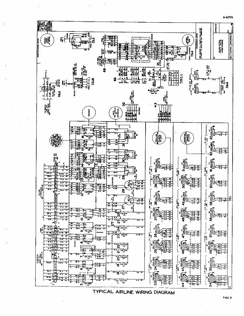
3.01 I n t h e a i r l i n e system, eaoh ihd iv idua l p i ece o f appara tus (eaoh group i n some
cases ) i s numbered and the l i n e s r e p r e s e n t i n g the i n d i v i d u a l wires from each ~ i e c e of apparatus a r e c a r r i e d a sho r t d i s t a n c e and t c r s i n a t e d a t a comnon or base l i n e , at an angle of 9G0. These indiv idut l l l i n e s between appara tus and base l i n e s a r e c a l l e d feed l i n e s . Each feed l i n e i s a l s o numbered t o co r re s t cnd with the i d e n t i f i c a t i o n number of t h e p iece of appa ra tus a t which t h e o the r end of t he connection terminates . I t i s not necessary t o follow a connection through the base l i n e and no provis ion i s nade f o r doing so. However, by observing the co lo r and i d e n t i f i c a - t i o n nunber included wi th t h e feed l i n e , i t i s poss ib l e t o jump d i r e c t l y between p i eces of ap- pa ra tus ; hence the t e r n " a i r l i n e " . Base l i n e s a r e not used f o r r e l ~ t i v e l y simple f i g u r e s .
3.02 k t y p i c a l wir ing diagram, i l l u s t r a t i n g t h e a i r l i n e system, i s shown on pnge 21. Core
d e t a i l e d information i s covered in BSP M~G12.002.
3. CIRCUIT LABELS
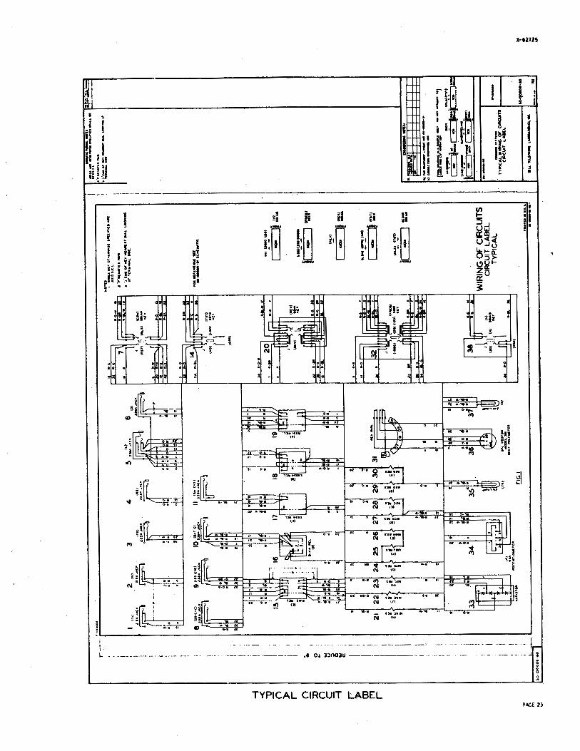
4.01 C i r c u i t l a b e l s a r e made with t h e i n t e n t i o n of a f f i x i n g them t o some part of t h e equip-
ment cas ings or c o v e r s , t h e r e f o r e , t he l a b e l must be r e s t r i c t e d t o the s i z e of t h e space r e se rved f o r mounting them. ha the l a b e l s a r e smal l i p s i z e the o r i g i n a l drawings me made f o r r educ t ion t o t h e f i n a l s i z e .
4.02 The s i z e of convent ions , l e t t e r i n g , and l inenork and t h e gene ra l form of t h e label
a r e shown on page 22. k t y p i c a l c i r c u i t l a b e l i s shown on page 23.
4.03 When t h e cond i t ion pe rmi t s , one f i g u r e s h a l l be shown f o r t h e f i r s t , i n t e rmed ia t e ,
~ h d ' T l i i i - f igiiTG- 6f .h ~amres- with- the-e+aapany--- i ng cond i t iona l wiring.
4.04 Schematic r e fe rence drawings from which t h e c i r c u i t l a b e l i s made s h a l l be l i s t e d
above t h e t i t l e box and wi th in the l a b e l a s shown on pages 22 and 23.
4.05 The c i r c u i t requirements t a b l e and method of ope ra t ion may be shonn on a s e p a r a t e
l a b e l or they nay be made a p a r t of t h e l a b e l with t h e c i r c u i t a s shown on page 22.
4.06 The s i z e of l e t t e r i n g and weight of l i n e s used on t h e master t r a c i n g f o r r educ t ion
t o the l a b e l s i z e , a r e i n d i c a t e d by t h e t a b l e s on page 22.
4.07 When t h e r educ t ion r a t i o r equ i r ed f o r the master t r a c i n g i s n o t l i s t e d i n t h e t a b l e s
f o r weight of l i n e s , size of l e t t e r i n g , e t c . , t h e r a t i o f o r t h e nea res t r educ t ion s h a l l be used.
5.01 These no te s l i s t the c i r c u i t , equipment, l o c a l c a b l e , bay l ayou t , and connecting
wi r ing drawings t h a t a r e used i n composing t h e n i r i n g diagram. The var ious c i r c u i t f e a t u r e s i n d i c a t e d on t h e c i r c u i t drawing a r e shown on t h e wi r ing diagram i n s e p a r a t e f i g u r e s , t h e par- t i c u l a r f i e u r e a r equ i r ed and t h e f e a t u r e they produoe or e f f e c t a r e s p e c i f i e d i n one of t hese no te s such a s "Specify one Fig. 1, 2, and 3 f o r
Page 3
each stationn. mesa notes are ahown on the drawingsin t h e space reserved f o r them a s shown on page 19.
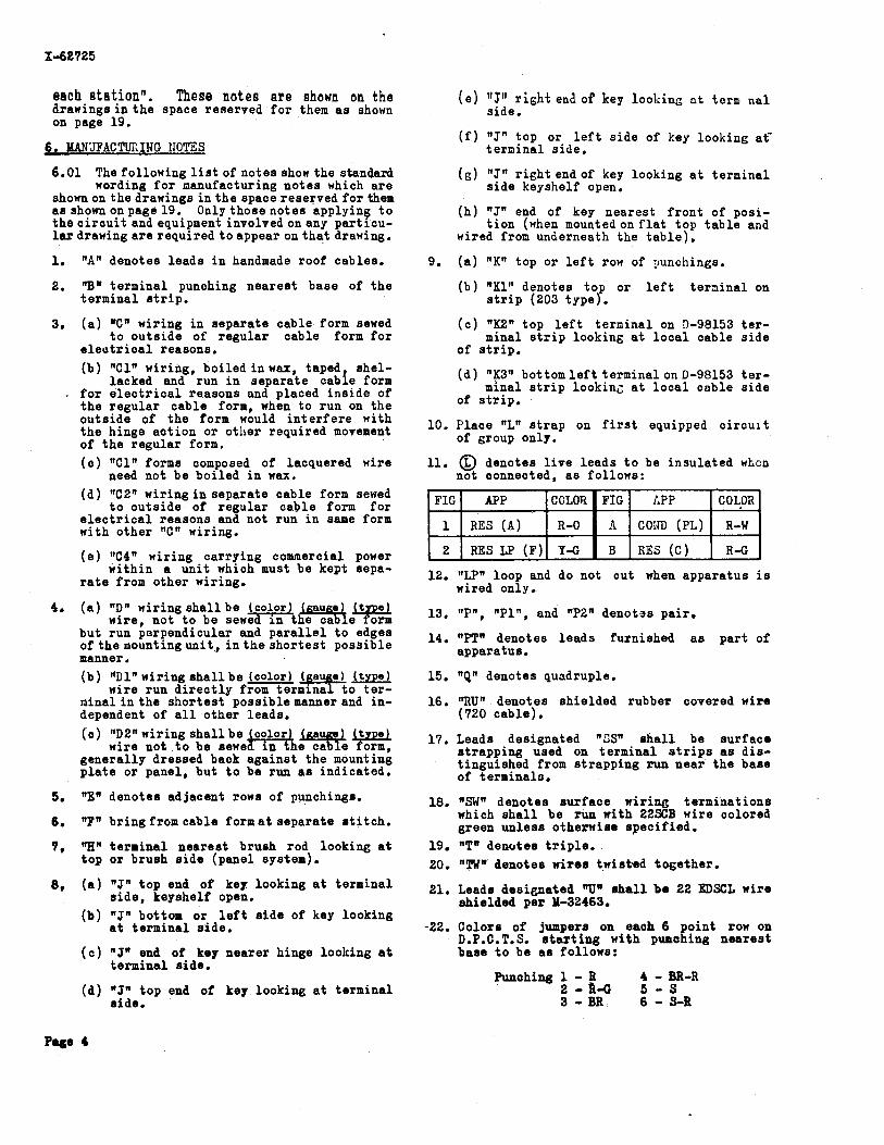
6. MANUFACTURING IIOTES
6.01 Thefollowinglistofnotesshowthe standard wording f o r nanufacturing no tes which a r e
shownonthedrawings i n t h e space reserved f o r them a s shonnonpage 19. Only thoseno tes applying t o t h e c i r c u i t and equipmentinvolvedonany par t i cu- l a r d r a w i n g a r e requ i red toappear o n t h a t drawing.
1. "An denotes l eads i n handmade roof cables.
2. "Bw terminal punching neares t base of t h e terminal s t r i p .
3. ( a ) "Cw wiring i n separa te cable form sewed t o ou t s ide of r egu la r cable form f o r
e l e u t r i c a l reasons. (b) " C I R wiring, boi led i n wax, taped, shel-
lacked and run i n separa te cable form - f o r e l e c t r i c a l reasons and placed ins ide of
t h e regu la r cable form, when t o run on the ou t s ide of t h e form would i n t e r f e r e with t h e hinge a c t i o n or otiler required movement of t h e regu la r form. ( c ) " C l n forms composed of lacquered wire
need not be boi led i n wax.
(d) "C2" wir ing i n separate cable form sewed t o ou t s ide of regular cable form f o r
e l e c t r i c a l reasons and not run i n same form with other "Cn wiring.
( e ) 11C4n wir ing carrying commercial power wi thin a u n i t which must be kept sepa-
r a t e from other wiring.
4. ( a ) "On wiring s h a l l be J r ? o r ) baug;! [tg;: wire. not t o be sewe I n the ca e
but run perpendicular and p a r a l l e l t o edges o f t h e m o u n t i n g u n i t , i n t h e s h o r t e s t poss ib le nanner . (b) "Dl" wiring s h a l l be jco lor ) (gauge) ( type)
wire run d i r e c t l y from terminal t o t e r - n i n a l i n t h e shor tes t -poss ib le manner and in- dependent of a l l o the r leads.
( c ) IfD2" wir ing s h a l l be wire not t o be sewe
genera l ly dressed back aga ins t the mounting p l a t e o r panel, but t o be run a s indicated.
5. "EW denotes adjacent rows of punchings.
6. "FW br ingf romcable fo rmat separa te s t i t c h .
7, "Hn t e r n i n a l nea res t brush rod looking a t top o r brush s i d e (panel system).
8, ( a ) "Jn top end of key looking a t terminal s i d e , keyshelf open.
(b) "JW bot toa o r l e f t s i d e of key looking a t terminal s ide .
( c ) "JW end of key neare r hinge 1ool:ing a t terminal s ide .
(d) "JW top end of key looking a t terminal side.
( e ) "Jtl r i g h t end of key lool;inc a t term n a l side.
( f ) "J" top or l e f t s i d e of key looking at- t e r n i n a l s ide .
(6 ) "J" r i g h t endof key looking a t t e r n i n a l s i d e keyshelf open.
(h) "J" end of key neares t f r o n t of posi- t i o n (when n o u n t e d o n f l a t top t a b l e and
wired f ron underneath the t a b l e ) .
9. ( a ) "KIf top or l e f t row of gunchings.
(b) "K1" denotes t o or l e f t t e r a i n a l on s t r i p (203 typef.
( c ) "K2" top l e f t t e r n i n a l on D-98153 t e r - minal s t r i p looking at l o c a l cable s i d e
of s t r i p .
(d ) nK3tt bottomleftterminalonU-98153 t e r - minal s t r i p looking a t l o c a l cable s i d e
of s t r i p ,
10. Place "LW s t r a p on f i r s t equipped c i r c u i t of group only.
11. @ denotes l i v e l eads t o be insu la ted wlicn not connected, a s follows:
12. "LPW loop and do not cut when apparatus i s wired only.
13. I1Pn, "P1If, and "P2" denotos pair .
14. "PTR denotes l e a d s furnished a s p a r t of apparatus.
15. "QW denotes quadruple.
16. "RUN denotes shie lded rubber covered wire (720 cable) .
17. Leads designated "CSw s h a l l be su r face s t rapp ing used on terminal s t r i p s a s d i s - t inguished from s t rapp ing run near t h e base of t erminalo.
18. "SWW denotes su r face wir ing terminat ions which s h a l l be run with 22SCB wire colored green un less otherwise spec i f i ed .
19. "TW denotes t r i p l e . 20. "TWN denotes wires twis ted together .
21. Leads designated "Uw s h a l l be 22 EDSCL wire shie lded per 142463 .
-22. Colors of jumpera on each 6 po in t row on D.P.C.T.S. s t a r t i n g with punahing neares t base t o be a s follows:
Punohing 1 - B 4 - BR-R 2 - R - C 5 - S 3 - BR 6 - S-R

83. For method of ope ra t ion see CD-
24. Furnish ( ) and ( ) n i r i n g when s p e c i f i e d .
25. Furnish ( ) and ( ) w i r i n e and appare tus when s f p c i f i e d .
26. Fu rn i sh ( ) n i r i n g and appa ra tus and ( ) n i r i n g when s p e c i f i e d .
27. iiairyin loops shall be run by in s t a l l e r o r shop.
28. Leave t h e s e l e a d s long enough t o connect t o any t e rmina l on condenser, transformer, e t c .
29". O m i t on f i r s t c i r c u i t of group.
30. The knur led s i d e of t h e p lug s h a l l be con- s i d e r e d a s t h e t i p .
31. Wires not o therwise s p e c i f i e d s h a l l be (Spec i fy gauge and i n s u l a t i o n ) .
32. ( a ) 1 W One conductor jumper n i r e .
( b ) 2~ Two conductor jumper wire.
( c ) 3W Three conductor jumper wire. (d ) 4W Four conductor jumper wire. ( S p i r a l )
( a ) 4W(P) Four conductor jumper n i r e . Gul- t i p l e Twin)
Denotes cab le .
-+ Denotes s p l i c e .
4fi End of n i r e s h i e l d . (Treatment to be a s i n - ++ d i c a t e d by t h e connect ing l e a d ) . L L - a i a e r t o l e v e l of appa ra tus .
,-,, Standard s t r a p p i n g hrrnished n i t h apparatus.
7.01 T h i s t ype of drawing is a combination n i r - i n g dineram and schematic. The engineer
s h a l l de termine whether a manufacturing schematic o r a wi r ing diagram s h a l l be i s sued . 7.02 When a manufacturing schematic is t o be
i s s u e d , a r ep roduc t ion o f t h e schematic drawing ( o r p o r t i o n s thereof r equ i r ed f o r manu- f a c t u r i n g purposes) s h a l l be ordered , o r when t o o many chances a r e r equ i r ed a new drawing may be made except that numbers, l e t t e r s , and doubl ing up p o i n t s s h a l l be added t o t h e r e l a y conven- t i o n s . The key convent ions s h a l l be arranged i n accordance wi th wi r ing diagram p r a c t i c e s . B a t t e r y and ground connect ions s h a l l be shown i n schematic fo rn . 7.03 The fo l lowing n o t e s and ske tches s h a l l be
shonn a s aanufnc tu r ing no te s : 1. S t a r t i n g a t any t e rmina l t r a c e l ead cons i s -
t e n t l y n i t h arrows, o r a g a i n s t arrows t o end of l ead .
2. Do no t make a r e v e r s e t u r n (switchback). 3. Doubling up p o i n t s a r e shown i n Skdtches B
and C.
SKZTCH B
I n t h i s example, l ead runs from terminal 1 t o t e rmina l 2 t o t e rmina l 3.
I n t h i s example, lead r u n s from t e rmina l 1 t o t e rmina l 2 t o te rminal 3 t o t e rmina l 4 .
8 '
8.01 Th i s type of drawing i s issued t o modify e x i s t i n g n i r i n g and equipment.
8.02 C o d i f i c a t i o n drawings, which show undee i r - a b l e p r a c t i c e s such a s s p l i c i n g o f l e a d s ,
e t c . , s h a l l not be s p e c i f i e d on new equipment. Wben a mod i f i ca t ion drawing i s s a t i s f a c t o r y f o r use on new eqpipment i t shal l be s o ind ica t ed by means o f a n eng inee r ing note on t h e drawing. The p r a c t i c e of spec i fy ing mod i f i ca t ion drawingq on new equipment s h a l l be r e s t r i c t e d a s f a r a8 p r a c t i c a b l e , s i n c e n i r i n g record drawings and i n s p e c t i o n o r t e s t methods a r e n o t prepared f o r such drawings.
8.03 The n o t a t i o n nMODn s h a l l be added fol-low- ing r e f e r e n c e t o the "ES Dwg." be ing modi-
f i e d i . e . "Kade from B.T.Labs'. ES-12345-01, Iss. 1 (MOD)'.
8.04 Modif ica t ion no te s s h a l l be shown on wir- i n g diagrams whenever t h e c i r c u i t doer not
ag ree wi th t h e schematic from which t h e wir ing diagram o r i g i n a t e d . The mod i f i ca t ion notes s h a l l d e s c r i b e t h e f e a t u r e omi t t ed , added, o r changed r a t h e r than t h e d e t a i l e d t i f f e r e n c e s . Example: nModif ica t ion of B.T.Labs . ES-12345-01, Iss.1, c o n e i s t s of adding 90A cond. i n each of t h e Tip and Ring Leadsn.
8.05 A s e p a r a t e nire l ist shal l be shown i n t a b l e f o r n s i m i l a r t o Tables A , B , C , and 3.
X INDICATES NMBEn OF FT. OF WIRE REQ.
TABLE A
TITLE BOX
BELL TELEPHONE A
LIST OF APPARATUS, CABLE, AND WIRE BEClUIRED FOR
EODI FIC AT1 ON
X
CU
c i
ti
1 1 , 4
C i
IZ
16 ESLB 6062 CABLE ~ 6 1 2 3 REL
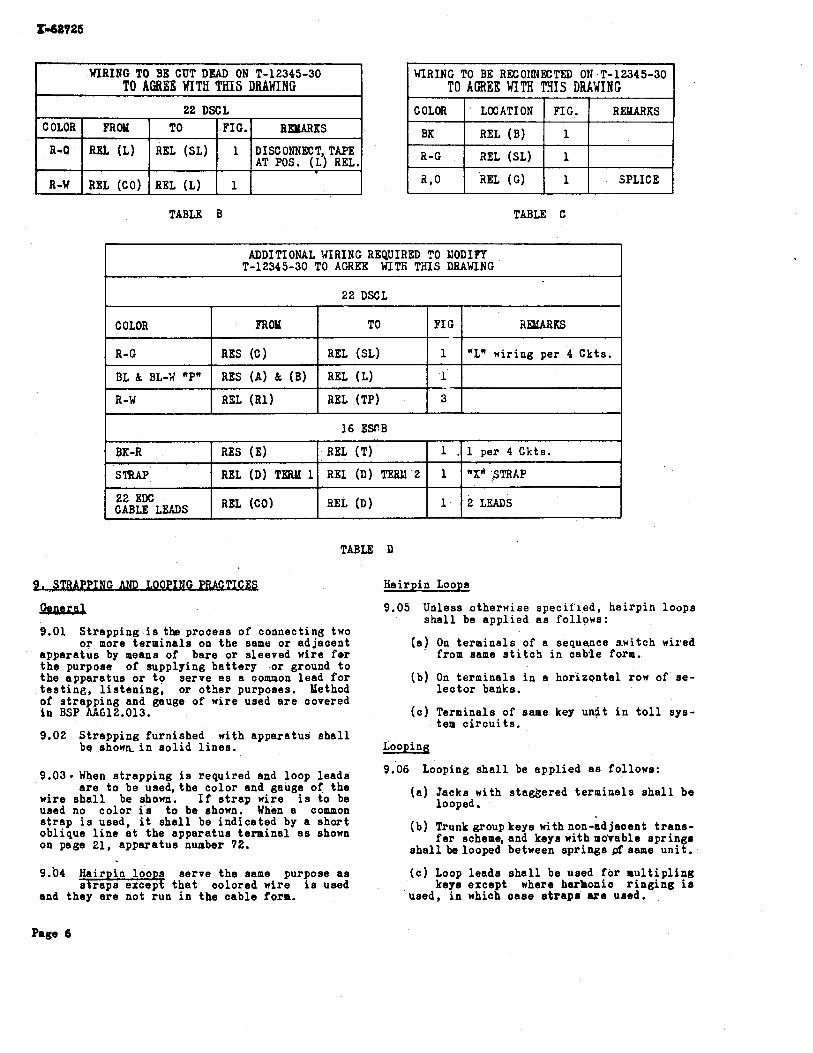
TABLE B TABLE C
WIRING TO BE RECOtR4ECTED ON T-12345-30 TO AFREE xIm TYIS DUVINC
COLOR
BK
R-G
a 0 0
TABLE D
.
I N G AND Hairpin Loops
LOCATION
REL (B)
EL (SL)
2EL (G)
9.01 S t r app ing i s tb process of connecting two o r more t e rmina l s on t h e same o r adjacent
apgara tue by means of bare o r sleeved n i r e f o r t h e purpose of supplying b a t t e r y o r ground t o t h e appara tus o r t o se rve a s a common l ead f o r t e s t i n g , l i s t e n i n g , o r o the r purposes. Method of s t r a p p i n g and gauge of n i r e used a r e covered in BSP hk612.013.
f ADDITIONAL WIRING REQUIRED TO LIODIFY
T-12345-30 TO AGREE WITH T i S DRAWING
22 DSCL
9.02 S t r app ing furnished n i t h appa ra tus s h a l l be s h o n a i n s o l i d l i n e s .
FIG.
1
1
1
9.03. When s t r app ing is requi red and loop l e a d s a r e t o be used, t h e co lo r and gauge of t he
wire s h a l l be shonn. I f s t r a p n i r e i s t o be used no c o l o r i s t o be shonn. When a common s t r a p i s used, it s h a l l be ind ica t ed by a s h o r t obl ique l i n e a t the appara tus te rminal a s shonn on page 21, appara tus number 72.
REMARKS
SPLICE
BELURKS
"L" wir ing per 4 Ckts.
9.b4 Hair i n l o o s serve t h e same purpose a s t h a t colored wire i s used
and they a r e not run i n t h e cab le form.
COLOR
R-G
BL & BL-W "P"
R-W
9.05 Unless o therwise s p e c i f i e d , h a i r p i n loops s h a l l be app l i ed a s fo l lows:
TO
REL (SL)
REL (L)
REL (TP)
FROM
RES (C)
RES ( A ) & ( B )
RXL (Rl)
1 6 ESCB
( a ) On t e rmina l s of a sequence s.witch wired from same s t i t c h i n cab le form.
FIG
1
L
3
(b ) On t e r n i n a l s i n a ho r i zon ta l row of se- l e c t o r badks.
( c ) Terminals of same key u n i t i n t o l l sys- tem c i r c u i t s .
1 .
1
1
REL (T)
REI (D) TERM 2
9EL (D)
BK-R
STRAP
82 EDC CABLE LEADS
Iiooping
9.06 Looping s h a l l be app l i ed a s follows:
1 per 4 Ckts.
m~~~~~~~
2LpUDS
RES (E)
REL (D) TW 1
REL (CO)
( a ) Jacks n i t h s tagkered t e rmina l s s h a l l be looped.
(b ) Trunk group keys n i th non-ad jacent t r a n s - f e r scheme, and keys n i t h mo'vable s p r i n g s
s h a l l be looped between s p r i n g s p f s a m e u n i t .
( 0 ) Loop leada s h a l l be used f o r m u l t i p l i n g keys except where harlnonic r i n g i n g is
used, i n which c a s e s t r a p s are used.
Page 6
St rapp ing
9.07 S t r app ing s h a l l be app l i ed t o t e rmina l s of appa ra tus a s fo l lows:
( a ) I n g e n e r a l , t e r n i n a l s of same p iece of appa ra tus , s t rapped from l e f t t o r i g h t
and from bottom up.
( b ) Adjacent t e r a i n a l s of a v e r t i c a l r o q o r e r c , of a s e l e c t o r bank.
( c ) Adjacent jacks of same s t r i p .
( d ) Sp r ings of same key u n i t . ( e ) Adjacent kzy u n i t s of same key.
( f ) Adjacent r i n g i n g keys.
(C) Adjacent switchboard lamps of same s t r i p .
( h ) B a t t e r y o r ground l e a d s s e r v i n g both " c a l l " and "ans." lamps s h a l l be run
from l e f t t e rmina l of r i g h t lamp t o r i g h t t e rmina l of l e f t lamp. S t r a p comnon l e a d s f o r a l l " c a l l n lamps i n same p o s i t i o n to - ge ther , and a l L comnon l e a d s for "ans. " lamps toge the r . Run an "L" s t r a p between t h e two groups on f i r s t equipped c i r c u i t .
t i ) Res i s t ances and condensers i n ad jacen t equipment p o s i t i o n s .
( j ) Corresponding t e r m i n a l s of r e l a y s i n ad- jacent equipment p o s i t i o n s when a l l r e -
l a y s a r e of same code on mounting p l a t e .
(k) Two r e l a y s mounted ad jacen t and served by one v e r t i c a l c a b l e a r m s h a l l be con-
s i d e r e d a s o n e r e l a y f o r s t r app ing and loop- i n g purposes.
10.01 Un ive r sa l w i r in is a term app l i ed to t h e process of p r o f i d i n g proper wi r ing and
s t i t c h e s on a l o c a l cable f o r u s e on an immediate i n s t a l l a t i o n and where appa ra tus may be added a t some f u t u r e t ime without a l t e r i n g t h e l o c a l c a b l e i n any way.
10.02 Yhere wi r ing is ar ranged f o r a c i r c u i t - cond i t ion f o r which appa ra tus w i l l be
fu rn i shed a t some f u t u r e t ime, wires a r e looped o r l e f t dead a t t h e p o s i t i o n a t which t h e appa- r a t u q nay be added.
10.03 When wi r ing diagrams a r e t o be arranged f o r u n i v e r s a l w i r ing , t h e fo l lowing pro-
cedure s h a l l be followed:
( a ) Where minor wir ing and appa ra tus changes a r e r equ i r ed , t h e complete informat ion
e h a l l be shown on one c i r c u i t drawing by means of o p t i o n a l f i g u r e s .
( b ) Where minor wi r ing and major appa ra tus changes r e q u i r e more than one drawing
t h e c o i o r e and a r r angeaen t of l e a d s oommon t o a l l drawings s h a l l correspond.
( c ) Where major w i r ing o h n g e s are r e q u i r e d t h e prooedure p re rc r ibed i n item (b )
s h a l l be fol lowed, except t h a t a n a d d i t i o n a l drawing knownas a un ive r sa l w i r ing diagram s h a l l .be prepared which s h a l l show the w i r - i ng ( i n diagram form) f o r a l l c i r c u i t s . I n eene ra l , t h e ind iv idua l c i r cu i t drawing a s - soc ia t ed wi th a un ive r sa l wir ing diagram s h a l l not be used un le s s t he corresponding un ive r sa l wir ing d iagran i s s p e c i f i e d .
11. WIRE COLOQ
11.01 The c o l o r s , a s used f o r l e a d s , s h a l l be abbrevia ted a s follow^:
BK - Black S - S l a t e R - Red BL - Blue G - Green W - White BR - Brown Y - Yellow N - Novelty
0 - Orange
11.02 Colors, i n t he following' l i s t s . ind ica t ed wi th an a s t e r i s k ( * ) a r e t o be used i n
p re fe rence t o those not marked.
11.03 Color schemes a r e provided f o r s p e c i f i c l e a d s appear ing on the more common c i r -
c u i t s . The c o l o r s ass igned t o b a t t e r y , ground, and o t h e r l e a d s f o r power sources should not be used f o r other. purposes.
11.04 A genera l c o l o r scheme which should be used whenever p o s s i b l e is a s fo l lows:
( a ) S igna l c i r c ; i t s s h a l l be wired wi th r e d ' o r some combination of t he same co lo r .
(b ) When two o r more w i r e s a r e connected t o t h e same t e rmina l they s h a l l be t h e
same color . ( c ) A s i n g l e or s o l i d co lo r i s used on t i p ,
ground, o r p o s i t i v e s i d e of c i r c u i t ; and mul t ip l e c o l o r s a r e used on r i n g , ba t - t e r y o r nega t ive s i d e of c i r c u i t .
11.05 Golor Scheme : The s e l e c t i o n of c o l o r s , ass igned t o l e a d s t h a t a r e
common t o any number of s i m i l a r c i r c u i t s , con- s t i t u t e a c o l o r scheme. Where t h e s e c o l o r s a r e ass igned they should be used e x p l i c i t l y . Color schemes f o r s eve ra l gauges o f wire a r e shown.
General S i n g l e s o r P a i r s
BK ground Y ground extended BK-A b a t t e r y Y-C b a t t e r y extended
20 Gauge Wire Color Scheme
General S i n g l e s o r P a i r s
BK ground Y ground extended BK-R b a t t e r y Y-C b a t t e r y extended
S i n g l e s
BK-R P.U. bus ba r t o res. l a a p , coamon ba t . l ead
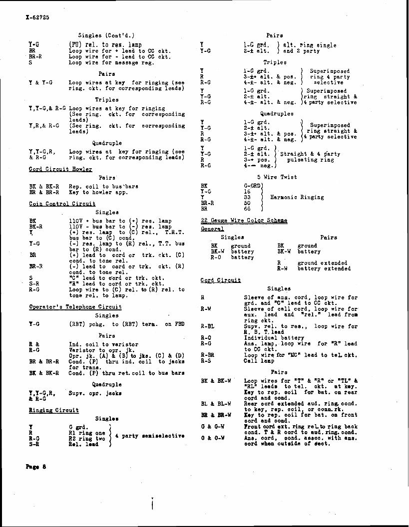
S i n g l e s (Cont'd.)
Y-G (PU) r e l . t o reg. lamp BR Loop wire f o r + l ead t o CC c k t . BR -R Loop wire f o r - lead t o CC c k t . S Loop wire f o r message reg .
P a i r s
Y & Y-C Loop wires a t key f o r r i n g i n g ( s e e r i n g . c k t . f o r corresponding l e a d s )
T r i p l e s
Y,Y-G,k R-G Loop wires a t key f o r r i n g i c g (See r i n g . c k t . f o r corresponding l e a d s )
Y,R,& R-G (See r i n g . ck t . f o r corresponding l e a d s )
Quadruple Y,Y-C,R, Loop wires a t key f o r r i n g i n g ( see k R-G r i n g . c k t . f o r corresponding l e a d s )
Ford C i r c u i t Howler P a i r s
9K & BK-R Rep. c o i l t o bus 'bars BR k BR-R Key t o howler app.
Coin Contro l C i r c u i t S i n g l e s
BK l l O V + bus bar t o 1:I r e s . lamp BK-R 1 l O V - bus b a r t o r e s . lamp n: (+) r e s . lamp t o C r e l . , T.R.T.
bus bar t o (C) cond. Y-G (-) r e s . lamp t o (R) r e l . , T.T. bus
bar t o (R) cond. BR ( * ) l ead t o cord o r t r k . c k t . (C)
cond. t o tone r e l . 9R -8 (-) l ead t o cord o r t r k . ck t . (R)
cond. t o tone r e l . S "C" lead t o c'ord o r t r k . ck t . S -R "R" lead t o cord o r t r k . c k t . R-G Loop wire t o (C) rel. to (R) r e l . t o
tone r e l . t o lamp.
Opera tor ' s Telephone C i r c u i t
S i n g l e s Y-G (3BT) pchg. t o (RBT) term. on FBD
P a i r s
R & Ind. c o i l t o v a r i s t o r R-G Var i s to r t o opr. 'k.
Opr. jk. (A) k ( ~ j to jks. (C) & (D) BR & BR-R Cond. (P) t h r u ind. c o i l t o jaoks
f o r t r a n s . BK & BK-R Cond. (P) t h r u r e t . c o i l t o bus b a r s
Quadruple
I,Y-G,R, Supv. opr. jaoks k R-C
Ringing C i r c u i t S i n g l e r
Y R 8-0 4 p a r t y s e n i a e l e o t i v e R2 r i n g two S-R Rel. l e a d
P a i r s
Y 1-G grd. j s l t . ring s i n g l e Y-C 2-f a l t . and 2 p a r t y
T r i p l e s Y 1 - G grd. I Superimposed R 3-f+ a l t . & pos. r i n g 4 pa r ty R-C 4-f- a l t . k neg. s e l e c t i v e Y 1 - G grd. I Superimposed Y-G 2-f a l t . r i n g s t r a i g h t k R-G 4-f- a l t . k neg. 4pa r ty s e l e c t i v e
Quadruples Y 1 - G grd. Y-G 2-f a l t . Superimposed
R r i n g s t r a i g h t k 3-f* a l t . & POS. 4 my selective R-G 4-f- a l t . k neg.
Y P-G S t r a i g h t k 4 $arty R 3-• pos. p u l s a t i n g r i n g R-G 4-- neg.
5 Wire T w i s t BK G-FRD Y-G Y 33 l6 1 Harmonic Rinaina
22 Gauae Wire Color Schema
General S i n g l e s P a i r s
BK ground BK ground BK-W b a t t e r y 9K-W b a t t e r y R-0 b a t t e r y
R ground extended R-W b a t t e r y extended
Ford C i r c u S i n g l e s
R S leeve of ans . cord , loop wire f o r grd. and "C" l e a d t o CC c k t .
R -W Sleeve of c a l l cord , l oop wire f o r aux. l e a d and "re l . " l e a d from r i n g c k t .
B-BL SUDV. r e l . t o r e s . . loo^ wire f o r R. -B. T . lead
R-0 I n d i v i d u a l b a t t e r y R-G Ans. lamp, loop wire f o r "aw l ead
t o CC c k t . R-BR Loop wire for "UCn l ead t o t e L c k t . R-S C a l l lamp
P a i r s
BKkBK-W L o o p w i r e s f o r "T" k w R w o r "TLm& "RLW l e a d s t o t e l . ok t . a t key. Key t o r ep . c o i l f o r b a t . on r e a r oord and cond.
BL & BL-W Rear oord extended aud. r i n 6 cond. t o key, rep . c o i l , o r conn.rk.
BB k BOI-W Key t o rep . o o i l f o r ba t . on f r o n t oord and cond.
0 k GW Front oord ex t . r ing r e L t o r i n g back oond. T & R oord t o aud.ring. oond.
0 & 0-W Anr. oord , oond. asaoo. w i th ens . oord when o u t r i d e of dea t .
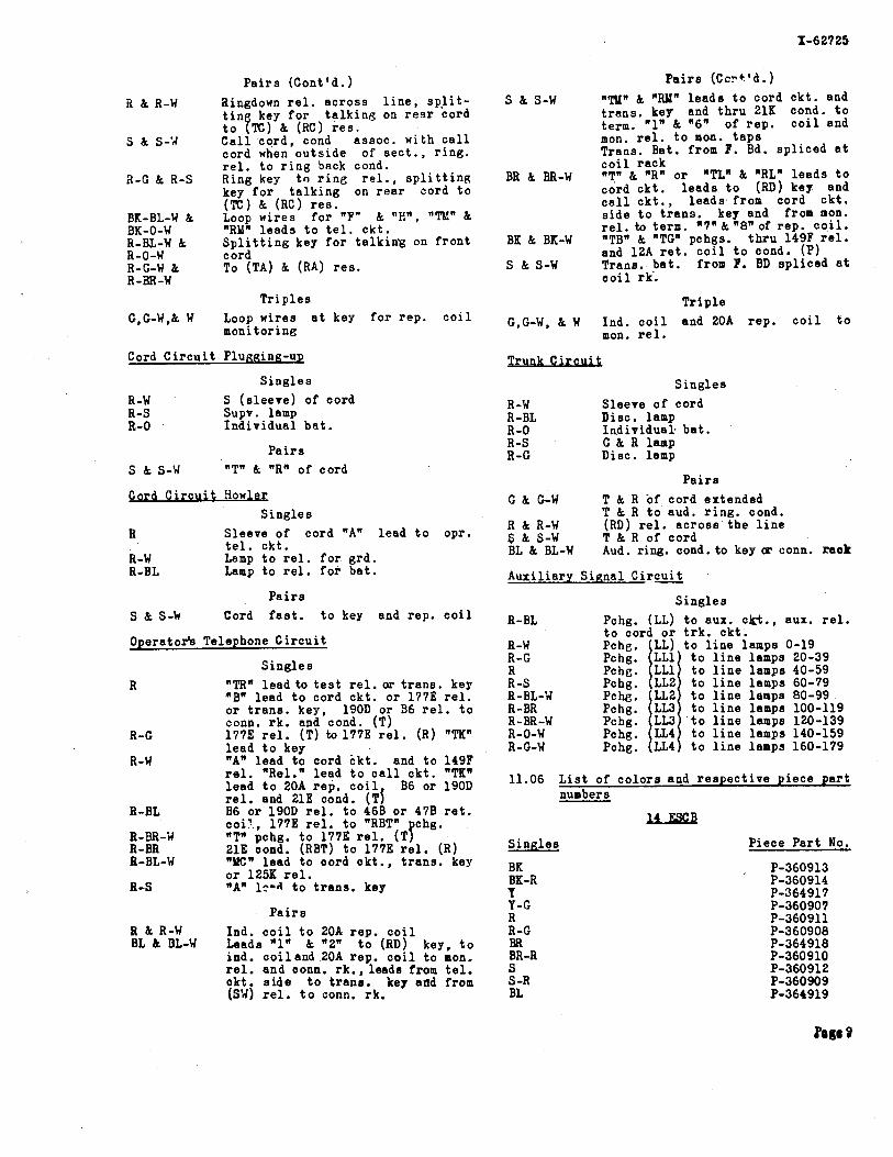
R k R-W
S k S-'d
2-G & A-S
BK-BL-W k BK-0-W R-BL-W & R-0-W R-C-W & R-3R-W
P a i r s (Cont'd. )
Ringdown r e l . a c r o s s l i n e , s p l i t - t i n key f o r t a l k i n g on r e a r cord t o 7x1 (RC) r e s . C a l l co rd , cond assoc . wi th c a l l cord when o u t s i d e of s e c t . , r i n g . r e l . to r i n g back cond. Ring key t o r i n e r e l . , s p l i t t i n g key f o r t a l k i n g on r e a r cord t o (TC) k (RC) r e s . Loop wi re s f o r "F" k "H", 'TE" & "RY" l e a d s t o t e l . c k t . S p l i t t i n g key f o r t a l k i n g on f r o n t cord To (TA) k (RA) r e s .
T r i p l e s
G,G-W,& W Loop wi re s a t key f o r r ep . c o i l moni tor ing
Cord C i r c u i t Plugging-up
S i n g l e s
R-W S ( s l e e v e ) of cord R-S Supv. lamp R.-0 I n d i v i d u a l b a t .
P a i r s
S k S-W "Tn C "Rn of cord
Ford C i r c u i t Howler S i n g l e s
R Sleeve of cord "An l e ad t o opr. t e l . c k t .
R-W Lamp t o r e l . f o r g rd . R-BL Lamp t o r e l . f o r b a t .
P a i r s
S & S-k Cord f a s t . t o key and rep . c o i l
Operator's Telephone C i r c u i t
S i n g l e s
R "TRn l e a d to t e s t r e l . or t r a n s . keg "Bn l ead t o cord c k t . o r 177E r e l . o r t r a n s . key, 190D o r 96 r e l . t o conn. r k . and cond. (T)
R-G 177E r e l . ( T ) to 177E r e l . (R) "TI[" l e ad t o key
R-W "A" l e a d t o cord c k t . and t o 149F r e l . "Rel." l ead t o c a l l c k t . "TK" l e ad t o 20A reD. c o i l . B6 or 190D r e l . and 21E c h i . (TI
R-BL B6 o r 190D r e l . t o 468 o r 47B r e t . c o i ? , 177E r e l . t o "RBT" chg.
R-BR-'rl "TW pchg. t o 17711 r e l . (TP R-BR 21E cond. (RBT) t o 177E r e l . (R) R-BL-W "UCn l e a d t o oord ckt . . t r a n s . key
o r 125K r e l . R-S "An 1t4 t o t r a n s . key
P a i r s R & R-W Ind. c o i l t o 20A rep . c o i l BL & BL-W Leads "1" & "2" t o (RD) key, t o
ind . c o i l a n d 20A rep . c o i l t o mon. r e l . and conn. r k . , l e a d s from t e l . c k t s i d e t o t ran8 . key and from ( S V ~ r e l . t o conn. rk.
P a i r s ( C c ~ + ' d . )
S & S-W nm" k "Rlln l e a d s t o cord c k t . and t r a n s . key and t h r u 21K cond. t o term. "1' k "6" of r e p . c o i l and rnon. r e l . t o mon. t a p s Trans. Bat. from F. Ed. s p l i c e d a t c o i l rack
BR & BR-w *Tn & "Rn o r "TL" k "RL" l e a d s t o cord c k t . l e a d s t o (RD) key and Eiii c k t . , l e a d s from cord c k t . s i d e t o t r a n s . key and from non. r e l . to term. "7"& "8" of r ep . c o i l .
BK & BK-W "TBn k "TG" pchgs. t h r u 149F r e l . and 12A r e t . c o i l t o cond. (P)
S & S-W Trana. b a t . from F. BD s p l i c e d a t c o i l r k .
T r i p l e
G , E W , & W Ind . c o i l and 20A rep . c o i l t o mon. r e l .
S i n g l e s
R-W Sleeve of cord R-BL Disc. lamp R-0 Indiv idual . b a t . R-S C k R lanp R-G Disc. lamp
P a i r s
G k G-W T & R of cord extended T k R t o aud. r i n g . cond.
R k R-W (RD) r e l . a c r o s s t h e l i n e S k S-W T & R of cord BL k BL-W Aud. ring. cond. t o key tx conn. raok
Aux i l i a ry S i g n a l Circuit
S i n g l e s
R-BL Pchg. (LL) t o aux. ck t . , aux. r e l . t o cord o r t r k . c k t .
R-W t o l i n e lamps 0-19 R-C t o l i n e lamps 20-39 R t o l i n e lamps 40-59 R-S t o l i n e lamps 60-79 R-BL-V t o l i n e lamps 80-99 R-BR t o l i n e lamps 100-119 R-BR-W t o l i n e lamps 120-139 R-0-W t o l i n e lamps 140-159 R-C-W t o l i n e lamps 160-179
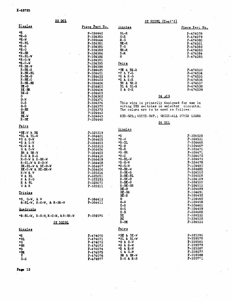
11.06 L i s t of c o l o r s and r e s p e c t i v e p i e c e p a r t numbers
lLJiim2
S i n g l e s
BK BK-R Y Y-G R a-G BR BR-R S S -R BL
P iece P a r t No.
P-360913 P-360914 P-364917 P-360907 P-360911 P-360908 P-364918 P-360910 P-360912 P-360909 P-364919
Pogo 9
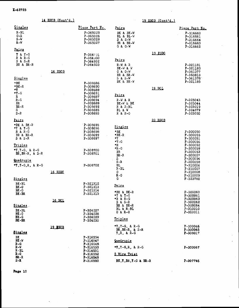
14 ESCB (Cont 'd.1 19 ESCB (Cont 'd.)
P i e c e P a r t No, P-316660 P-316661 P-316664 P-316663 P-316662
S i n n l e s R-BL 0-S S -U R-W
Piece P a r t No.
P-365029 P-365026 P-365028 P-365027
P a i r s BK k 9K-W BL k BL-'A S & S-W BR & BR-W G & G-W
P a i r s Y & Y-G R & R-G S & S-R BR k BR-R
P a i r s R-w dc a BK-;J k i( 0 k 0-5( BR & BR-W S & S-w BK & BK-Y
S i n g l e s * BK
BK -R *Y *Y-G
R 8 - G
P a i r s 2-il & R BK-W 8: BK
a ac a-o P a i r s *BK dc 9K-R *Y & Y-G
R k R-G BR & BR-R S & S-R
20 ESCB
S i n g l e s 9K
'BK-R *Y *Y-G *R *R-G
BR BR -R S S -R BL R-BL 0 R-0 G
T r i p l e s *Y ,Y-G, k R-G BR,BR-R, & S-R
Quadruple *Y,Y-G,R, & R--G
S i n g l e s BK-BL BK-0 BK-G BK-BR +BK & BK-R
*Y & Y-G *R 6t R-G S & S-R BR & BR-R BL k R-BL 0 & R-0
J,uG.L S i n n l e s .
BK-BL BK-0 BK-G m-BR T r i p l e s
*Y,Y-G, & R-G BR,BR-R, & S-R Y , R , & R-G
lusU S i n g l e s
BK BK-w R-C R-W R-EL R-0 BR -R S -R
g u a d r u ~ l e
*Y,Y-G,R, & R-G
5 Wire Twis t
BK,Y,BR,Y-G & BR-R
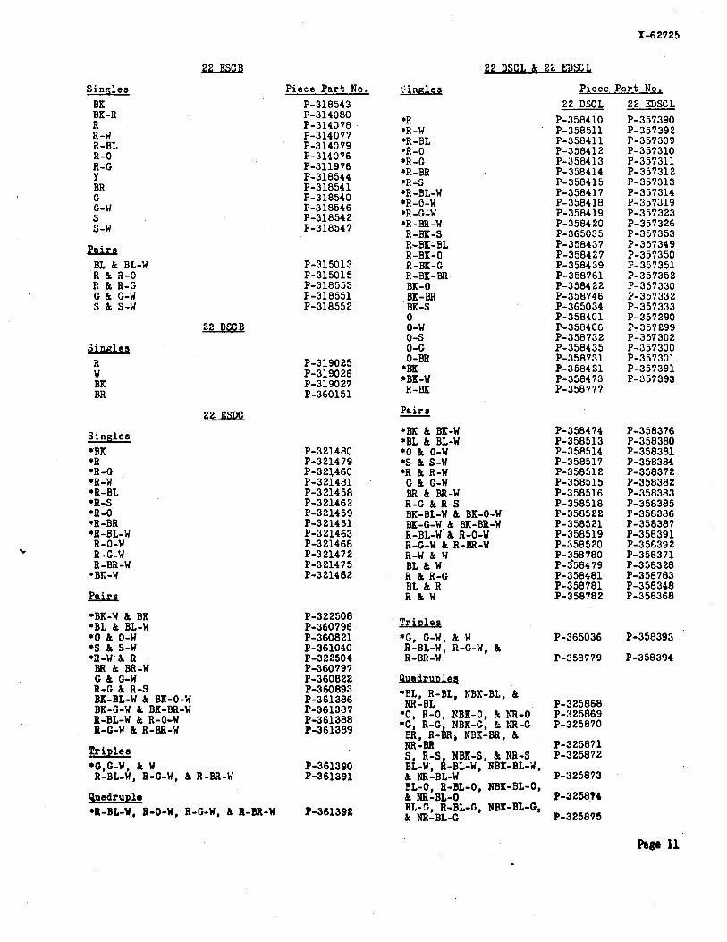
GL&U! S i n ~ l e s P i e c e Pa r t No .
2 2 DSCL & 2 2 EDSCL
S i n n l e s Piece P a r t No, 2 2 D S C L 2 2 E D S C L
*R P - 3 5 8 4 1 0 P - 3 5 7 3 9 0 *R -W P - 3 5 8 5 1 1 P - 3 5 7 3 9 2 R
R-W a - B L R - 0 R-C Y BR
*R-BL *R-0 *R-C *R-BR *R-S *R-BL-W *R-0-W *R-C-W *R-BR-W
R-BK-S R-BK-BL R-BK-0 R-BK-C R-BK-BR BK-0 BK-BR BK-S 0 0-W 0-S 0-G 0-BR *BK *BK-W
R-BK
Pa i r s - *BK & BK-W *BL & BL-W *o & 0-W *S & S-W *R & R-W
C & G-W BR & BR-W R-G & R-S BK-BL-W & BK-0-W BK-G-W & BK-BR-W R-BL-W & R-0-W R-G-W & R-BR-W R-W & W BL & W R & R-C BL & R R & W
G G-W S S-W
Psire BL & BL-W R & 2-0 R & R-G C & C-W S & S-W
S i n g l e s *BK *R *R-C *R-W
*R-0 *R-BR *R-BL-W a-o-w R-C-W R-Bii-W
*BK-W
,Psira
*BK-W & BK *BL & BL-W *O & 0-w *S & S-W *a-W h R
BR & BR-W C & C-W R-G & R-S BK-BL-W & BK-0-W BK-C-W & BK-BR-W R-BL-W & R-0-W R-G-W & R-BR-W
T r i ~ l e s *G,G-W, & W
R-BL-W, B-C-W, & R-BR-W
T r i u l e s *G, G-W, & W P-365036 P-358393
R-BL-W, R-G-W, & R-BR-W P - 3 5 8 7 7 9 P-358394
*BL, R-BL, NBK-BL, & NR-BL P - 3 2 5 8 6 8
*O, R - 0 , XBK-0, & NR-0 P - 3 2 5 8 6 9 *C. R-G. NBK-C. tc IIR-G P - 3 2 5 8 7 0
BR, R-BR, I B K ~ B R , & NR-BR S, R-S NBK-S, & NR-S BL-W, R-BL-V, IBK-BL-W, & NR-BL-W BL-0, a-BL-0, IBK-BL-0, & NR-BL-0 BL-5 , R-BL-0, NBK-BL-G, & NR-BL-C
9uadruple *R-BL-W, R-0-W, R-C-W, & 8-BR-W P-361398
Singles
*R *R-C *R -W *R - BL *R -S *R-0 *R-BR *R-BL-W *R-0-W *R-C-W *R-BR-W R-BK-S R-BK-BL R-BK-0 R-BK-G R-BK-BR BK-0 BK-BA BK-S
BK-W R-BK
2iLw P i e c e P a r t No.
P-324442 P-324383 P-324444 P-324381 P-324385 P-324382 P-324384 P-324386 P-324391 P-324395 P-324398 P-324425 P-324421 P-324422 P-324423 P-324424 P-324402 P-324404 P-324405
P a i r s - *BK-W & BK +BL & BL-W * O & 0-W *S & S-W *R-W & R
C & C-W BR & BR-W R - 0 & R-S R-C-W & R-BR-W R-BL-W & R-0-W BK-BL-W & BK-0-W BK-C-W & BK-BR-W R-W & W W k BL R & R-c R k BL W & R
T r i ~ l e e
*c , C-W, & W R-BL-W, R-C-W, & R-BR-W
*R-BL-W, R-0-W, R-C-W, &R-BR-W
S i n n l e s
22 DSSEL (Cont 'd)
5 in r . l e s
BL-R 0-R R-C BK-R Y-G BR -R S -R 0
P a i r s - *BK & BK-R *Y h Y-C *R & R-C *S k S-R
BR & 9R-R BL & SL-R 0 & 0-R
? i e c e F a r i KO.
F-474078 P-474079 P-474080 P-474081 P-474082 P-474083 P-474084 P-474085
T h i s w i r e i s p r i n a r i l y de s igned f o r u s e i n w i r i n g SXS s w i t c h e s i n s e l e c t o r c i r c u i t s . The c o l o r s a r e t o be used c s f o l l o w s :
R E D - W . ; WIIITE-SAT. ; CRE%I:-ALL O?!= LSADS
24 DCL
S i n g l e s
*R *H -il *R -9L *a-0 *R -C *a-J3R. *R -S *R-BL-W *R-0-W *R-C-W *R-BR-W R-BK-S R-BK-BL R-BK-0 R-BK-C R-BK-J3R BK-0 BK-BR BK-S 0 0-W 0-S 0-C
BK R-BK
P a i r s - *BK & 9K-W *BL & BL-W *o & 0-W *S k s-W *R & R-W c & C-w BR & BR-W A-C & R-S
P-324529 P-324531 P-324468 P-324469 P-32447C P-324471 P-324472 P-324473 P-324478 P-324482 P-324485 P-324512 P-3245C8 P-324309 P-324510 P-324511 P-324489 P-Y 24491 P-324492 P-324449 P-324458 P-324461 P-324459 P-324460 3-324530 P-324532 P-324533
Page 12

24 DCL (Cont'd.1
P a i r s - Piece P a r t No. Paire ce P a r t No,
R-BL-w L a-o-u R-C-W & R-BR-W BK-BL-W & 9K-0-3 BK-0-W & BK-BR-W R-W & 'A BL & W R & R-C BL & R R & W
S & S-R R & R-C BR & BR-R BL & BL-R 0 & 0-R Y & Y-G
12. WIRING PRACTICES
Battery and C r w d and Tio and A ~ ~ a r a t u T r i p l e s
+C, G-W, & W P-359761 R-BL-W, R-C%W, & R-BR-W P-359762.
12.01 Unless otherwise spec i f i ed connect bat- ter? and ground l e a d s t o terminals of
apparatus a s shown i n Table B on page 14.
R-BL-W, R-0-W, R-C-W, & R-BR-W P-359763 12.02 The l i m i t of l eads s h a l l be ind ica ted on
a l l wir ing diagrams, f o r example: 22 ZDSCL Wire Shielded Per 1-32463
1 lead per 5 c i r c u i t s . 1 lead per s i d e of frame. 1 lead per position..
Shielded and S inn les Shielded O u Bre5ded
R BK S R -S R-C
12.03 Limit on loop wires s h a l l be shown when other than s t r a i g h t l o o p i n e i s shown, f o r
example :
1 lead per 5 odd c i r c b i t s 1, 3, e to . 1 lead per 5 even c i r c u i t s 2, 4, e to .
P a i r s - S k S-R R & a-c BR & BR-R BK & BK-R Y & Y-G 0 & 0-R BL & BL-R
12.04 Vhen two or more wire8 of the sane color a r e t o be connected to di f ferent terminals
of the same piece of apparatus,or when one wire of a p a i r i s t o be cut and the ends connected t o d i f f e r e n t t e r n i n a l s of the same p ieceof appara- t u s , one of the wires s h a l l be brought out a t the regu la r s t i t c h and each of the o the r wires a t a separa te s t i t c h .
12.05 Where the re a r e dup l ica t ions of co lo rs , coming out a t the same s t i t c h , pne of
each color s h a l l be brought out a t succeeding "F" s t i t c h e s .
BR, 9R-R, & S-R Y, Y-C, & R-C
Shielded 'dire Per Lf-19069
ui.JE2 S i n d e s
P a i r s - BK & 'BK-R Y & Y-C
IP1 s S-R
Page 13
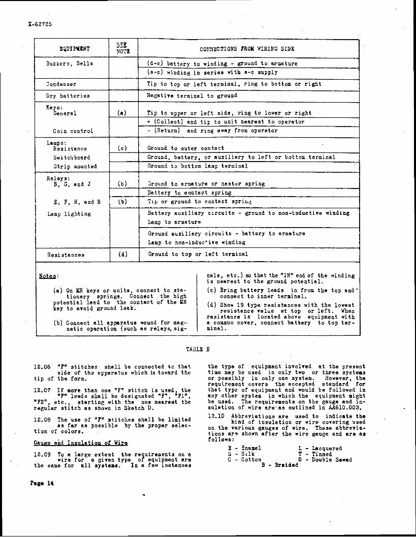
COtTNECTIONS FROM WIRING SIDE I Buzzers , 9 e k l s
Dry b a t t e r i e s
(d -C) b a t t e r y t o n i n d i n g - ground t o a rc la tu re
(a -C) winding i n s e r i e s w i t h a-c supply
Tip t o t o p o r lef t , t e r m i n a l , r i n g t o bottom o r r i g h t 1 Negat ive t e r m i n a l t o ground 1
Keys: Genera l
Coin c o n t r o l
I Lamps : R e s i s t a n c e
Relays : I B, G, and J 1 ( b ) I 2raund t o a r m a t u r e o r n a s t e r s p r i n g
( a )
( c ) Grourid t o o u t e r c o n t a c t 1 Switchboard S t r i p mounted
{
T i p t o upper o r l e f t s i d e , r i n g t o l o n e r o r r i g h t + ( C o l l e c t ) and t i p t o u n i t n e a r e s t t o o p e r a t o r
- (Re turn) and r i n g away from o p e r a t o r
Ground, b a t t e r y , o r a u x i l i a r y t o l e f t o r bot tom t e r n i n a l
Ground t o bot tom lamp t e r n i n a l
Lamp t o a r a a t u r e
Ground a u x i l i a r y c i r c u i t s - b a t t e r y t o a r m a t u r e
E , F , H , and R
Lamp l i g h t i n g 1
I I Lamp t o non-induc'ive winding I
B a t t e r y t o c o n t a c t s p r i n g Tip o r ground t o c o n t a c t spriu.5
B a t t e r y a u x i l i a r y c i r c u i t s - ground t o n o n - i n d u c t i v e winding
-
R e s i s t a n c e s ( d l Ground t o t o p o r l e f t t e r m i n a l
n a l s , e t c . ) so t h a t the "IN" end of t h e n i n d i n g I i s n e a r e s t t o t h e ground p o t e n t i a l .
( a ) On LIR keys o r u n i t s , connec t t o s t a - I ( c ) B r i n g b a t t e r y l e a d s i n from t h e t o p a n d ' t i o n a r y s p r i n g s . Connect t h e h i e h c o n n e c t t o i n n e r t e r m i n a l .
p o t e n t i a l l e a d - t o - t h e c o n t a c t of t h e UR key t o avo id ground l e a k . I ( d ) Show 1 9 t y p e r e s i s t a n c e s w i t h t h e l o w e s t
r e s i s t a n c e v a l u e a t t o p o r l e f t . When
I r e s i s t a n c e i s l o c a t e d above equipment n i t h (b) Connect a l l a p p a r a t u s wound f o r mag- a comm'on c o v e r , connec t b a t b e r y t o t o p t e r -
n e t i c o p e r a t i o n ( s u c h a s r e l a y s , s i g - mina l . -
12.06 "F" s t i t c h e s s h a l l be connected t c t h a t t h e t y p e of equipment involved a t t h e p r e s e n t s i d e of t h e a p p a r a t u s which is toward t h e t ime may be used i n on ly two o r t h r e e sys tems
t i p o f t h e form. o r p o s s i b l y i n o n l y one system. However, t h e requ i rement c o v e r s t h e a c c e p t e d s t a n d a r d f o r
12.07 I f more t h a n one "Fw s t i t c h i s used , t h e t h a t t y p ~ of equipment and would be fo l lowed i n "Fw l e a d s s h a l l be d e s i g n a t e d "F", " F l W , any o t h e r sys tem i n which t h e equipment might
"F2", e t c . , s t a r t i n g w i t h t h e one n e a r e s t t h e be used. The r e q u i r e m e n t s on t h e gauge and i n - r e g u l a r s t i t c h a s shown i n S k e t c h D. s u l a t i o n of w i r e a r e a s o u t l i n e d i n kA610.003.
12.10 A b b r e v i a t i o n s a r e used t o i n d i c a t e t h e 12.08 The u s e o f "Fw s t i t c h e s s h a l l be l i m i t e d k ind of i n s u l a t i o n o r w i r e c o v e r i n g used as far as possible by the proper selec- on t h e v a r i o u s gauges of wire . These a b b r e v i a -
t i o n of c o l o r s . t i o n s a r s shown a f t e r t h e w i r e gauge and a r e a s
B u a e and I n s u l a t i o n of Wira f o l l o w s : E - h a m e l L - Lacquered
12.09 To a l a r g e e x t e n t t h e r e u i r e m e n t s on a S - S i l k T - Tinned w i r e f o r a g i v e n t y p e o f equipment a r e C - C o t t o n D - Double Sewed
t h e same f o r a l l systems. I n a few i n s t a n c e s B - Bra ided
Page 14
J u m ~ e r Wires
12.11 The number of conductors i n each s e t of jumpers s h a l l be ind ica t ed by l U , 2W,
3W, e t c . An explanatory note s h a l l be placed on t h e drawing a s a manufacturing note. (See manufacturine no te 32 on page 5.)
12.12 The gauge and type of jumper wires s h a l l n o t be shown on wir ing diagrams a s they
g e n e r a l l y a r e furnished by t h e Telephone Company a s covered by the s tandard i n s t a l l i n g s p e c i f i c a - t i o n and t h e A.T.&T.Co.*s f i e l d information.
42.13 Live l e a d s s h a l l be cons idered those upon which vo l t age i s e i t h e r d i r e c t l y armomen-
t a r i l y inp res sed such a s t a l k i n g b a t t e r y , s i g n a l b a t t e r y , c o i n c o n t r o l , a u d i b l e r i n g i n g s i g n a l , a-c o r d-c r inging, harmonic r inging, howler busy back, f l a s h i n e r e c a l l , busy t e s t , t r o u b l e t e s t , i n t e r r u p t e r s , t one , g r i d , f i l amen t , e t c . , and unequipped ground l e a d s t e rmina t ing a t she lves which a r e . i n s u l a t e d from t h e frame.
12.14 By "momentarily impressedw i s meant t h e i n p r e s s i n g of v o l t a g e on l e a d s b.y t h e op-
e r a t i o n of a r e l a y , key, o r s i m i l a r appa ra tus i n the same o r connect ing c i r c u i t s .
12.15 A l l l i v e l e a d s t e rmina t ing a t unequipped appa ra tus p o s i t i o n s should be s leeved o r
.taped.
12.16 Designate l i r e l e a d s wi th t h e symbol @ a t t h e unequipped appara u s p o s i t i o n s .
Yhen more than one l i k e colored l e a d s appear a t any one unequipped appa ra tus p o s i t i o n t h e number o f t h e s e l e a d s s h a l l precede t h e c o l o r i n t h e t a b l e t h a t is shown i n t h e manufacturing note. See manufacturing note 11 and table t h e r e i n on page 4.
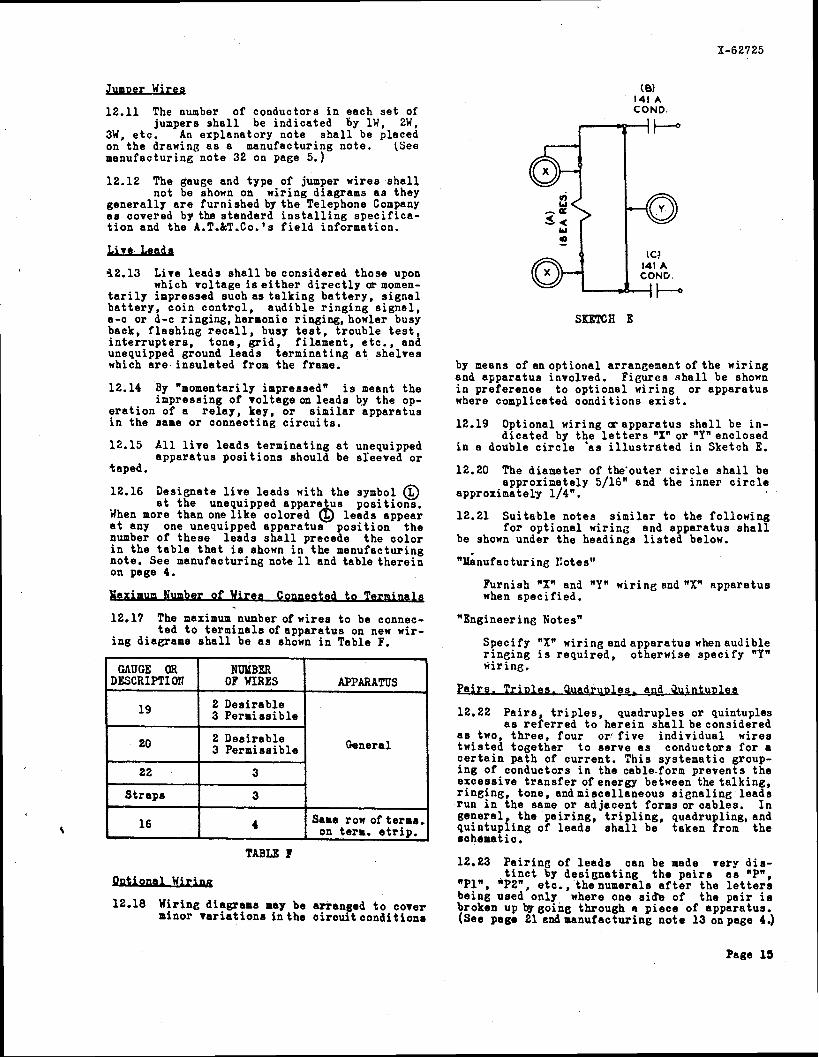
Iumber of Wires C ~ p p e c t e d t o Tar-
12.17 The naximum nunber o f w i r e s t o be connec- t e d t o t e rmina l s o f a p p a r a t u s on new wir-
i n g diaplrams s h a l l be a s shown i n Table F.
TABLE I
GAUGE OR DESCRIPTI 011
1 9
20
22
S t r a p s
1 6 r
12.18 Wir ine diagrams may be ar ranged t o cover minor v a r i a t i o n s i n t h e c i r o u i t c o n d i t i o n s
( 8) 141 A COND.
3 I +
hl % --Q t IC!
@- 141 A COND.
4l-J
NUlIBER OF WIRES
2 Des i r ab le 3 Pe rmis s ib l e
2 Des i r ab le 3 Pe rmis s ib l e
3
3
4
SKETCH E
APPARATUS
General
Same row of terns, on term. s t r i p .
by means of an op t iona l arrangement o f t h e wi r ing and appa ra tus involved. F igures s h a l l be shown i n p re fe rence t o op t iona l wir ing o r appa ra tus where complicated cond i t ions e x i s t .
12.19 Optional & r i n g c~ appa ra tus s h a l l be i n - d i c a t e d by t h e l e t t e r s "Xnor "Ynenclosed
i n a double c i r c l e 'as i l l u s t r a t e d i n Sketch E.
12.20 The diameter of the 'outer c i r c l e s h a l l be approx ina te ly 5/16" and t h e inne r c i r c l e
approx ina te ly 1/4".
12.21 S u i t a b l e no te s s i m i l a r t o the fo l lowing f o r op t iona l w i r ing and appa ra tus s h a l l
be shown under t h e headings l i s t e d below.
" i n u f a c t u r i n g notes"
Furnish "Xu and "YR w i r i n e andnX" appa ra tus when s p e c i f i e d .
"Engineering Botesw
Spec i fy "Xu wir ing and appa ra tus whenaudible r i n g i n g is requ i r ed , o therwise s p e c i f y "Y" wir ine .
P a i r s . T r i o l e s . W u ~ l e s . and Q u i n t u D l e ~
12.22 P a i r s , t r i p l e s , quadruples o r quintuples a s r e f e r r e d t o h e r e i n s h a l l beconsidered
a s two, t h r e e , f o u r or1 f i v e i n d i v i d u a l wires tw i s t ed toge the r t o s e r v e a s conductors f o r a c e r t a i n pa th of c u r r e n t . T h i s sys t ema t i c group- i n g of conductors i n the cable.form p reven t s t h e excess ive t r a n s f e r of energy between the t a l k i n g , r i n g i n g , t one , andmiscel laneous s i e n a l i n e l e a d s run i n t h e same o r a d j a c e n t f o r m s o r c a b l e s . I n gene ra l t h e p a i r i n g , t r i p l i n g , quadrupling, and pu in tup i ing of l e a d s s h a l l be taken from t h e schdmatic.
12.23 P a i r i n g o f l e a d s can be made very d i s - t i n c t by d e s i g n a t i n g t h e p a i r s a s "Pn,
"Pl", "P2", e tc . , t henumera l s a f t e r t h e l e t t e r s be ing used only where one s i b of t h e p a i r i s broken up bggoihg through a p i e c e of appara tus . (See page 21 end manufac t w i n s n o t e 13 on page 4.)
Page 15

12.24 Pa i r ed l e a d s s h a l l f o r m a s e t of continu- ous ly pa i r ed conductors of t h e same l e n g t h
when they a r e connected a t t h e terminating po in t s . The same g e n e r a l p r i n c i p l e s apply t o t r i p l e s and quads.
13.01 These p r a c t i c e s have been e s t a b l i s h e d t o govern p r e p a r a t i o n o f wi r ing drawings f o r
t e l e t y p e w r i t e r s t a t i o n equipment. These drawings a r e in tended f o r r educ t ion t o i n s t a l l a t i o n and maintenance handbooks.
13.02 The drawings s h a l l bearranged f o r reduc- t i o n t o 5-1/2" x 3-1/2", from t h e master
which i s shown on page 20. The l e t t e r i n g s i z e s r equ i r ed a r e a l a o shown on t h i s page.
13.03 The v e r t i c a l p o s i t i o n of a page s h a l l be cons idered normal. When i t is necessary
t o view a p l an in a h o r i z o n t a l p o s i t i o n t h e page s h a l l be turned counter-clockwise.
k t t e r b . , Paces. P l ans . and T i t l e s
13.04 Page t i t les s h a l l be a s b r i e f a s possible, u s i n g s t anda rd abbrev ia t ions and dashes
i n p l a c e of con junc t ions o r p repos i t i ons . Re- g a r d l e s s of t h e p o s i t i o n of t h e p l an t h e page t i . t l e s h a l l be a t t h e top of t h e normal page, r e e page 20.
13.05 A l l l e t t e r i n g , except page t i t l e s , s h a l l be shorn s o t h a t it i s read from t h e same
p o s i t i o n t h a t t h a p l an i s viewed.
13.06 P lan numbers should beshown below and a t t h e l e f t s i d e of t h e p l a n , fol lowed by t h e
p lan t i t l e extending a s f a r a c r o s s the width of t h e page a s r e q u i r e d , provided t h e p l n n s a r e not shown side by s i d e . I n such a case the t i t l e may occupy the width of the a r e a a l l o t t e d t o t h e plan.
13.07 I n p l an t i t l e s , t e l e t y p e w r i t e r subsc r ibe r s e t s , a n d t e l e t y p e w r i t e r t a b l e s , when r e -
f e r r e d t o by code number, should be l i s t e d a s s e t s and t a b l e s only , such a s , 120A1 set or 15A t a b l e .
13.08 Symbols, such a s , TTY, TWX, TLT, o r CLX a r e shown a s c a p i t a l l e t t e r s and a r e not
a b b r e v i a t i o n s , therefore no periods s h a l l be used.
13.09 Explanat ion of convent ions s h a l l be a s e p a r a t e page and r e f e r e n c e , by a note ,
made t o i t oneach of thedrawings showing plans .
13.10 Notes s h a l l cover any o t h e r informat ion r equ i r ed f o r t h e complete i n s t a l l a t i o n
t h a t is not apparent frpm the p lans . Those n o t e s s h a l l not be shown on t h e handbook pages nor s h a l l any r e f e r e n c e be made t o them.
Wirina P r a c t i c e s
13.11 Dotted wir ing on appa ra tus s h a l i be used t o i n d i c a t e wi r ing o r appa ra tus shown on
another drawine.
13.12 Terminnls s h a l l not be shown d o t t e d , but i f i t i s d e s i r a b l e t o i n d i c a t e t h a t t e r -
minals on a p i ece of appa ra tus a r e shown on another drawing t h e convention of t h e appa ra tus s h a l l be d o t t e d around t h e t e rmina l s .
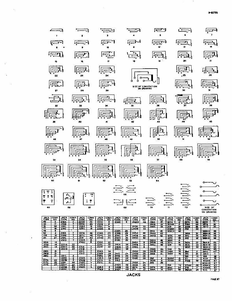
13.13 P lugs and jacks s h a l l be ar ranged t o i n - d i c a t e those t h a t connect t o e e t h e r and
s h a l l be a l igned h o r i z o n t a l l y .

Pap 17

Y L NOTC s-,
PROVISIONAL STANDARD
STANDARD ARRANGEMENT W TITLE BOX, NOTES AND APPROVAL COLUMN

I,.
TRIM LINES WUEN USED - -- -- IN fULL SIZC F0LD.R
I
0 LI
ITSV-z 1nlRO AND ~OURTH LINES or TITLE
1 rOUTLINC OF WORNING SPACE -------
I I
NOTE I WALL RCAO-TOR CXCLUIATION W CONVCUIIONS SEE CD-700s-Dl?
NOTE 51 %ALL READ .MADC ~ R O M 8 T LABS SO----:
IN SRCTCMCS,MMENSKM GIVEN ARC f0R 3:l RCDUCTWW.
1
ARRANGEMENT OF FORMS FOR TELETYPEWRITER HANDBOOK
17%-2 40V-2
LFTTLRINC IN R A N SHALL (1E I IOCV-I
JL sv-1 *
-IN -c"
z
d
PAGE 21

NOTES I ALL LETTERING ON CIRCUIT LABEL TO BE VERTICAL.
LINEWORK AND LETTERING INFORMATION FOR CIRCUIT LABEL REDUCTIONS PACt 22
TYPICAL CIRCUIT LABEL P S E 23
I LEAD PER STRIP
SIGNAL
-0 LOOPED IN CABLE
L-l--- * ---I \ 0 ,
FIG IB
TO r IG. I
1 07 CORD
TO AUX. SIGNAL
C
OPERATORS TELECHONC CIRCUIT FIG. I
YCTHOD OF SHOWING SWITCHDOARD MULTIPLE FIG.2
r- CORD FASTENERS 7 CALL (FRONT) ANS (REAR) I ! . ...Scif ;' -
a a 0 6 s
STANDARD COLORING FOR LEADS TO CORD FASTCNER5 SEE NOTE I
FlG.3
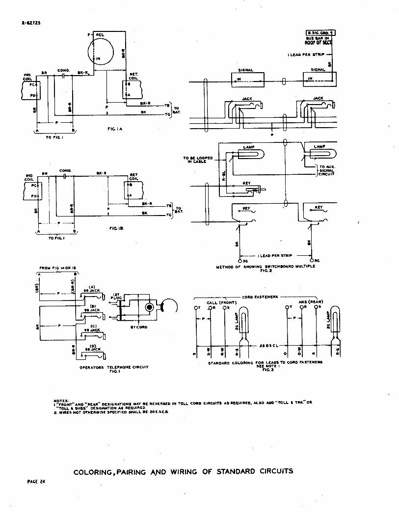
NOTES: I "TRONT"ANO Y ~ ~ ~ ~ " DESIGNATIONS MAY BE REVERSED IN TOLL CORD CIRCUITS AS REQUIRED, ALSO TOLL L TRK"OR
"TOLL L wBS" DCSIGWTION A5 REQUIRED 2 WIRCI NOT OTHERWISC SPECITILD SHALL BC 20C.5.C.Cd
COLORING, PAIRING A-ND WIRING OF STANDARD CIRCUITS PAGE 24
ADJACENT ROWS : (Or PUNCHINGS )
- - - - ERMNAL P U K H N G NfARfST CORD FUTENERS 8
((I ITOP OR LEFT TERMINAL O N STRPl
203 A TERMINAL STRIP
METHOD OF SMOWING TERMINAL STRIP ROWS ON DRAWING
(V ) 130A OR 131A V T SOCKET 7 WITH 231 0 V. T
(RCC)
(R) 8 0 RES LMP
K S - 8 1 4 0
CONN RASK K M G O(I UKY 0 .SW& TERM STRIP PC*.
0 POWER CCMG. OR SWOD. TERM. STRIP Kffi.
@ 8INOING W I T
(0) CODE ROUND T I P L
OUS OARS ON FUSE OD.
( B )
z{ 5i] rl ii$~c-l mTJ:i - = a 0 - *
0
CODE MESSAGE REGISTERS AND SIGNALS
(M)
METMOD OF DCSKNATING APPARATUS
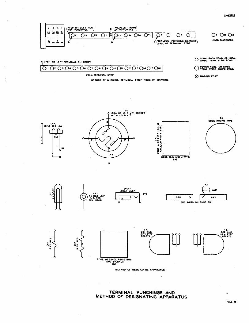
TERMINAL PUNCHINGS AND METHOD OF DESIGNATING APPARATUS
0 @ rnon
8 0 0 "0" FRONT 0 w L P A E N l
0 MARKING
UECHANICM VlEW OF CI b 479 TYPE KEYS 470 GF KEY ILLUSTRATED
SKETCH I
479GF KEY MOUNTED IN P M L WIRING S I X S*HmN
SKETCH 4
LOCKING
4
NON - LOCKING LOCKING
SCHEMATIZED YEWANICAL VlEW LWKW AT TOP OF 479GF M Y
S M K M 2
LOOKING AT TERMINAL END OF KEY CONVENTION AS
SHOWN ON C.\RD CATALOG 479CF KEY MOUNTED IN KEYWELf
KEYS~ELF OPEN SKETCH S SKETCH 3
479 EF KEY 470CF
. 0 @I FRONT
7 @@,c = - ( T I (R)
WIRING DIAGRAM CONVCNTK>N WIRING DIAGRAM CONVENTION KEY TOP CONVENTION FOR KEY MOUNTED FOR KEY MOUNTED XHEMATIC AND
ON PANEL ON KEYSHELF WIRING DIAGRAM SKETCH 6
s CnWATlC CONVENTION
?n rn F RONT
AILU
1 U T l
W * I T O l
n m orr COWS
FRONT
1 l A L l
r RONT
479 CA W F RONT
1 TALK
1 RING
WITHOUT ENCRAVING WITH CNGRAVING
KLV TOP CONVLNTIONS SKCtCCI 7 - - -
Nom I D C S M l W N S IN CIRCUS NMCAtE S P R W POSITOMS AND ARE COR REFERENCE ONLY 2 F K I l l IS CONSIDCREO THAT SIOC Of FRAME HAVING COM AND PATENT MAR&S 3. ARROW-IWOICATES D*TCTIOW Of MWEUENT Of PLUNGER 4 5 ' r O P 011 LEn rN0 Of KEY S 31' TOP OR LCrT END OF KEY (KEYSHELF OPEN)
LEVER TYPE KEYS

COUN *L061 om DILL HEAD SET
WAND SET MOUNTING
HANO SLT
M L L DROP
C W N f D JACK AN0 SIGNAL
WCSTOH METER ALARM FUSE PROTCCTOA M A T COIL CLIP (AU;GALV. MAM. VM)
WO SPfAKCR POTENT IOUTfR
OR RHEOSTAT GCNCIIA'IOR
CLECTRK CLOCK SUD SET TELtCRAPll RELAY
VOLTME W S S M L RfGlSTER TELEGRAPH
KEY
Low mcs *CAT C O I U
mm .LOLLS
Lz{*: FOR M 'N D TYPE f GRD. FRWC THERMOCOUPLE ISA AN0 10E COW. VACUUM TUBE SOCKET AN0 SOCKET BLOCKS USED w t r n
206 OR 209 RELS. 26D CONN.
BLOCK USED WITH
210 RCL.
I. f C O W BLOCK USED w l r n 228
RCLS
I010ub*ch0*1 2LD CONN MOW
PART Of OWL MTG. 188 CONN BLOCK USED WITH 215
RELS.
(CONVENTONS - nALf SIZE)
MISCELLANEOUS APPARATUS

P K E 20 A, A8 AND 8 TYPE RELAY CODES
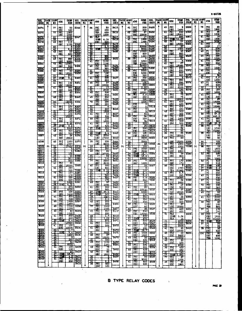
B TYPE RELAY CODES Wa)
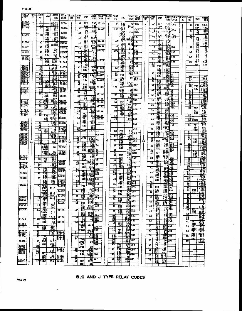
- S O 8 ,G AND J TYPE RELAY CODES
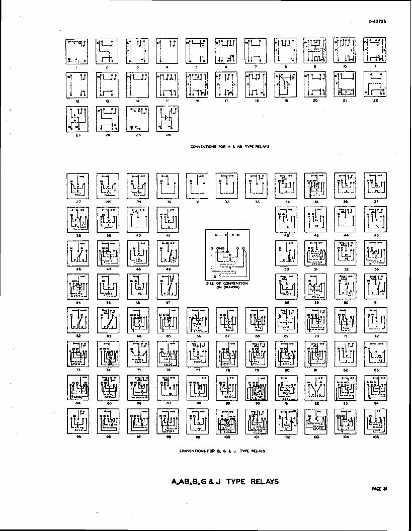
W V C N T O N S FOR A b AB TYPE R L A Y S
SIZE OF CONVENTION ON DRAW*(G
A,AB,B,G & J TYPE RELAYS
SIZE OF CONVENTIONS 4 O N DRAWING
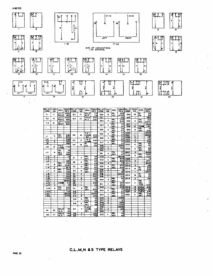
PAGE 32 C,L,M,N & S TYPE RELAYS
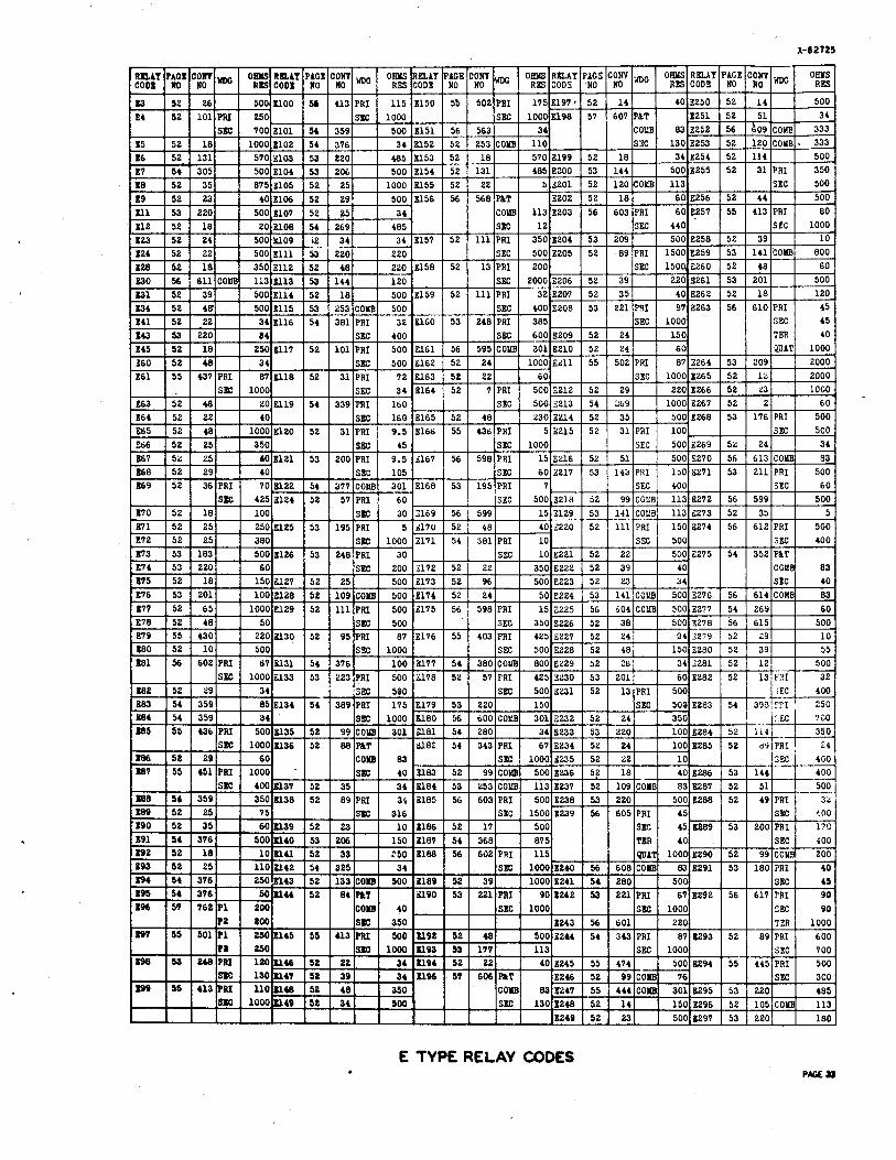
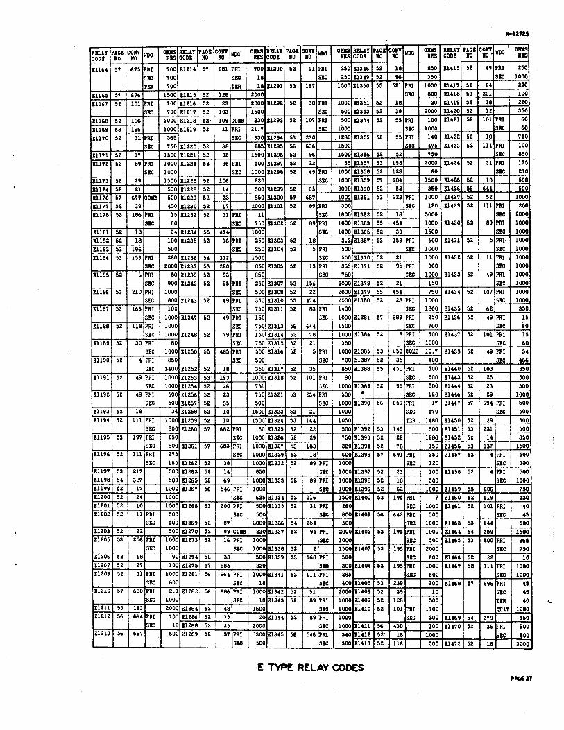
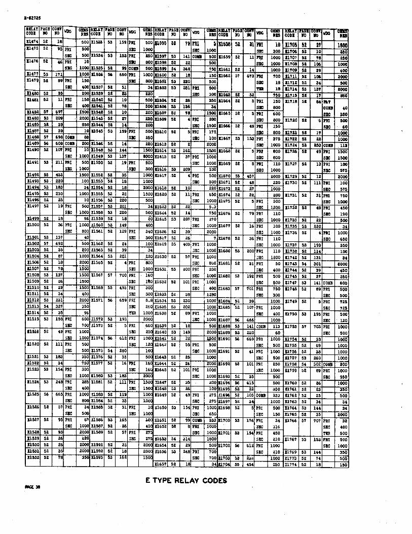
E TYPE RELAY CODES
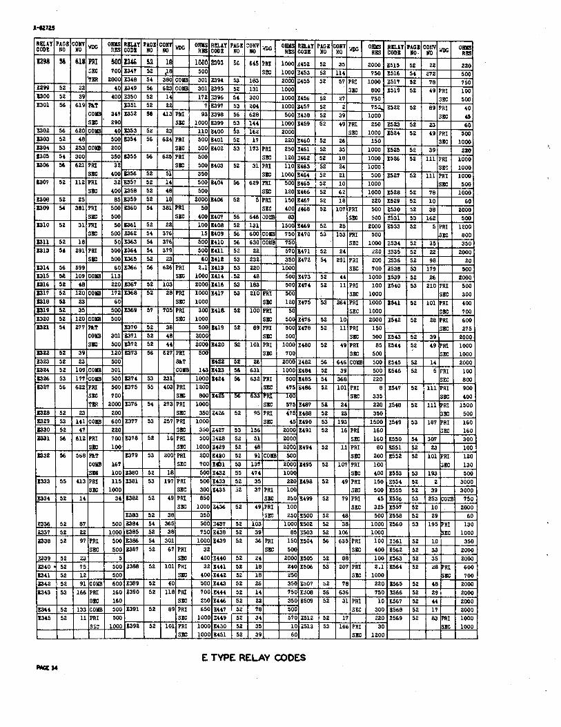
E TYPE RELAY mDES -34
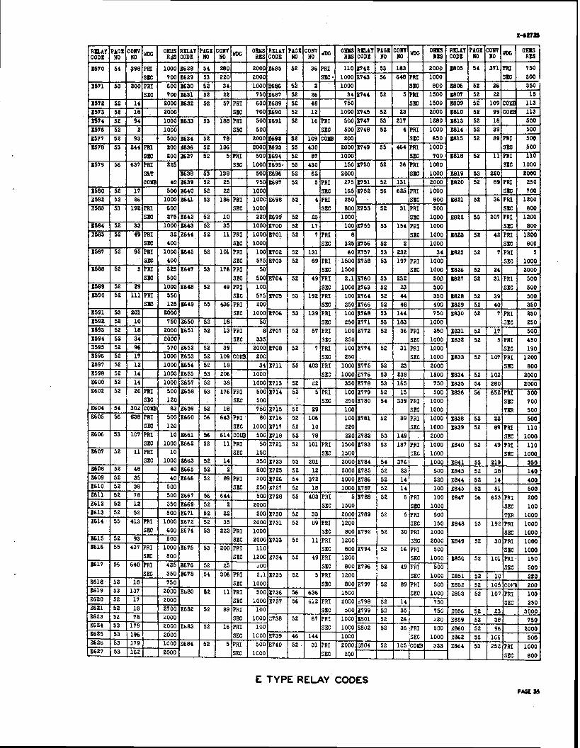
E TYPE RELAY CODES PAGE 3s

E TYPE RELAY COOES
SBC 1000 SBC 18 31343 52 89 PRI 1000 31409 52 128 500 TKR 40 11211 53 183 2000 21284 52 48 '500 SllC 1000 11410 52 101 PRI 1700 WAT lo00
--- 20 31344 52 89 FPi 1000 S E 200 21469 54 379 350
2000 3SC 1000 11411 56 430 100 11410 52 36 TRI 600 ----- 31213 56 661
------ -- 500 31289 52 37 PRI 300 31345 56 546
SaC 1 5001
E TYPE RELAY CODES ?M ST
E TYPE RELAY CODES mrx*
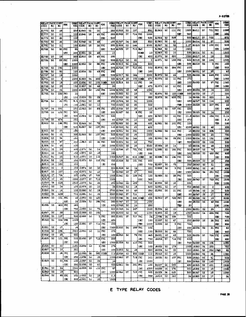
E TYPE RELAY CODES PACE w
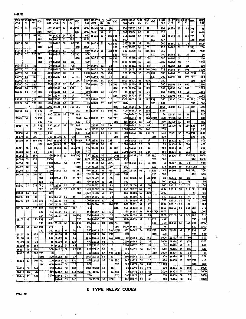
E TYPE RELAY CODES PACL 40
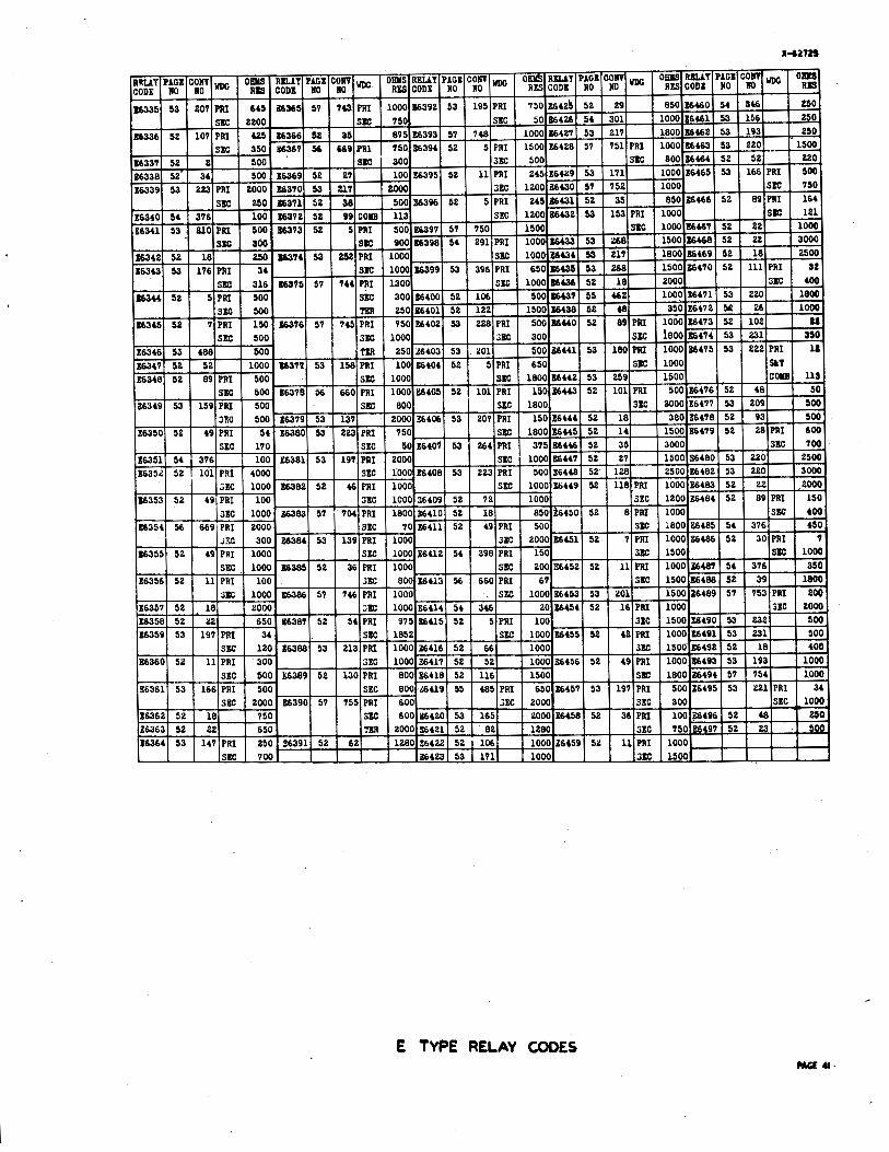
E TYPE RELAY CODES

A TYPE RELAY CODES -12
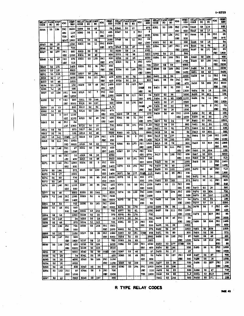
R TYPE R E U Y CODES M U

R TYPE RELAY COOES
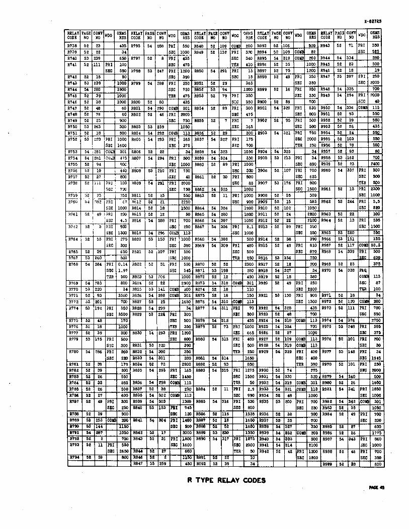
R TYPE RELAY CODES WE4

R TYPE RELAY CODES - 4 0
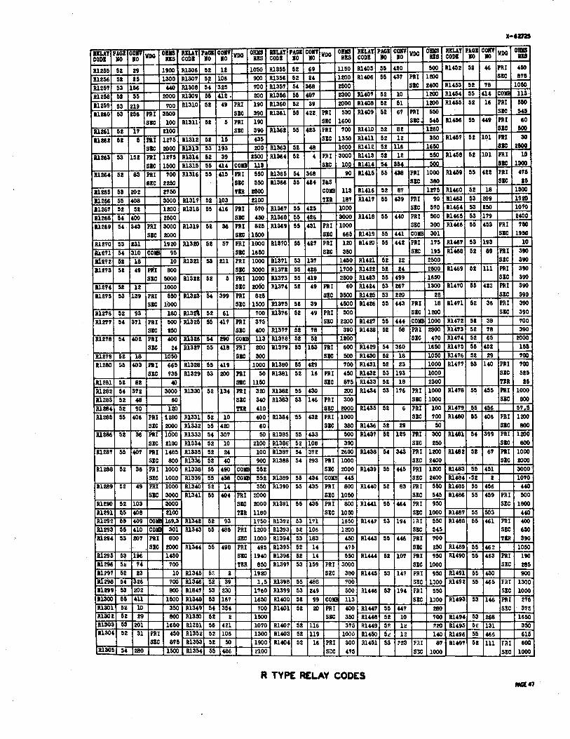
R TYPE RELAY CODES

R TYPE RELAY CODES MGta

R TYPE RELAY CODES WQm
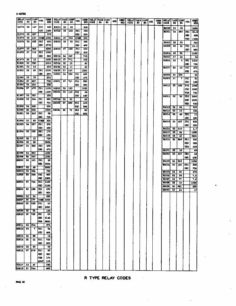
R TYPE RELAY COWS ma50
RELAY CODE
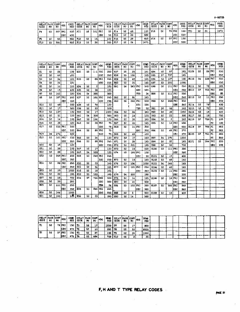
F, H AND T TYPE RELAY COWS
T1
T2
I r l l
PACE NO
52
52
COW NO
79
57
WDD ORls RELAY PACE COW WDC
PRI SIC PRI
150
415 150
T3 1 52 ?4 1 52 T5 1 52
17
10 27
1250
350 183
T7
T8 ~9
52
52 59
17 1 221 AS^
800 2000 i t s n
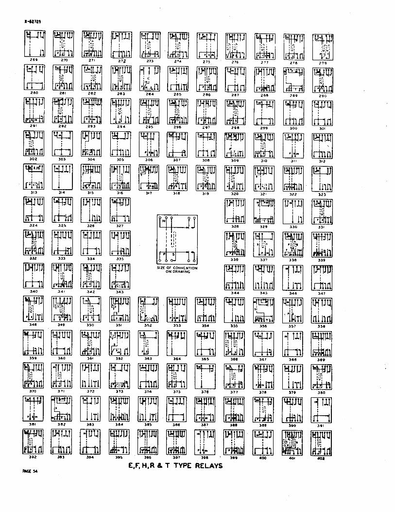
SIZE OT CONVENTDN ON W I N G
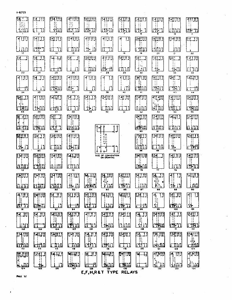
E ,F,H,R LT TYPE RELAYS MCt 52
I - - 1 SIZE OF CONVENTION
O N ORAWING
2 0 6 2 0 7 2 0 8 2 0 9 2 10 211 212 213
XdZlZ5
403 404 405 406 407 4 0 8 4 0 9 410 411 412 413
414 415 416 417 418 419 420 4 2 1 422 423 424
425 426 427 428 429 430 431 432 433 434 435
436 437 438 439 4 4 0 441 442 4 4 3 4 4 4 445
447 4 4 8 4 4 9 450 451 452 453 454 455 456 457
I I
468 469 470 471 472 4 73
SIZE OF CONVENTION ON OHAWING
4 7 8 4 7 9
487
496
504 505 506 507
516 517 518

S l r f OF CONVENTION O N DRAWING
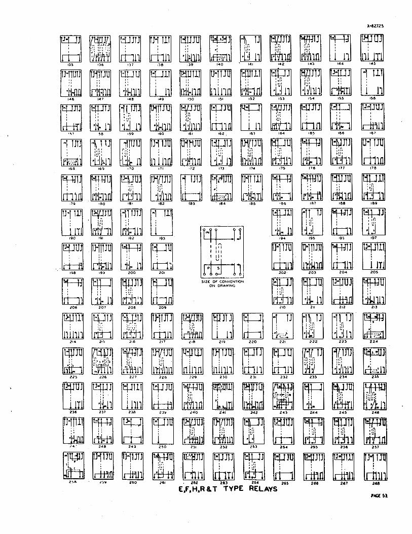
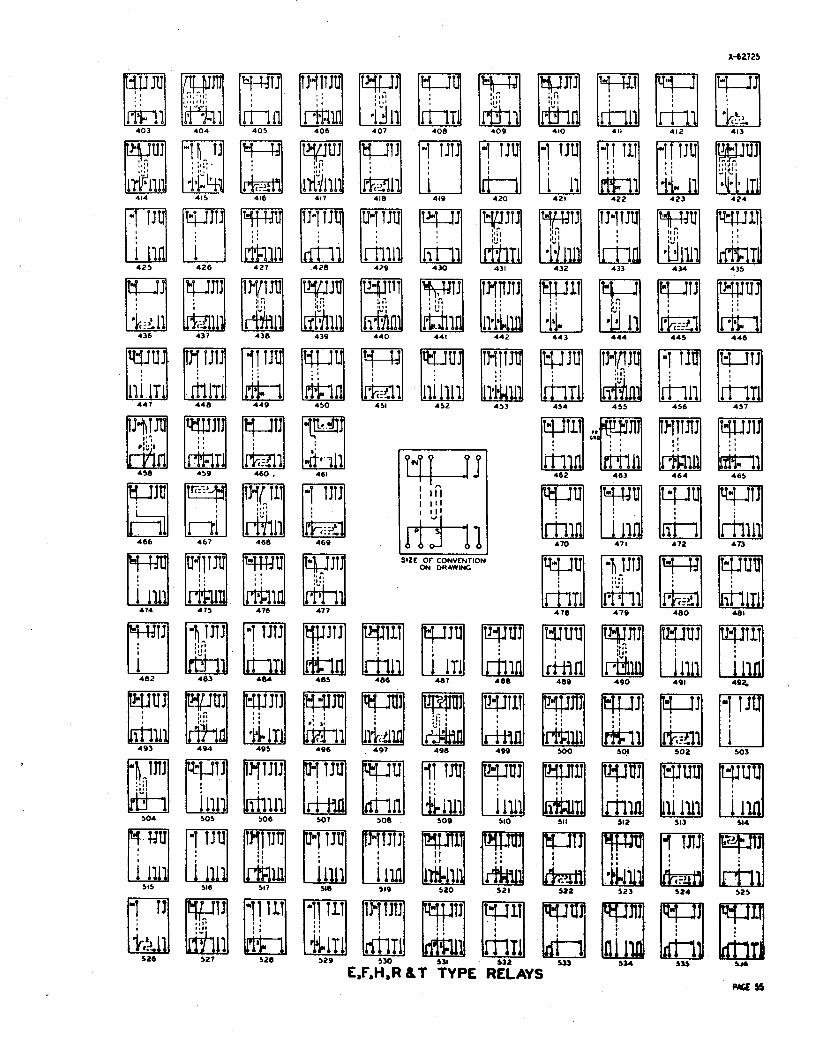
E,F, H, R 8, T TYPE RELAYS PM;E 5s'

SIZE OF COI)VEHTION ON DRAWlYt
'El6
E,F, H,P 6 T TYPE RELAYS
23 2 4 2 5 2 6 2 7 2 0 29 3 0 31 3 2 1
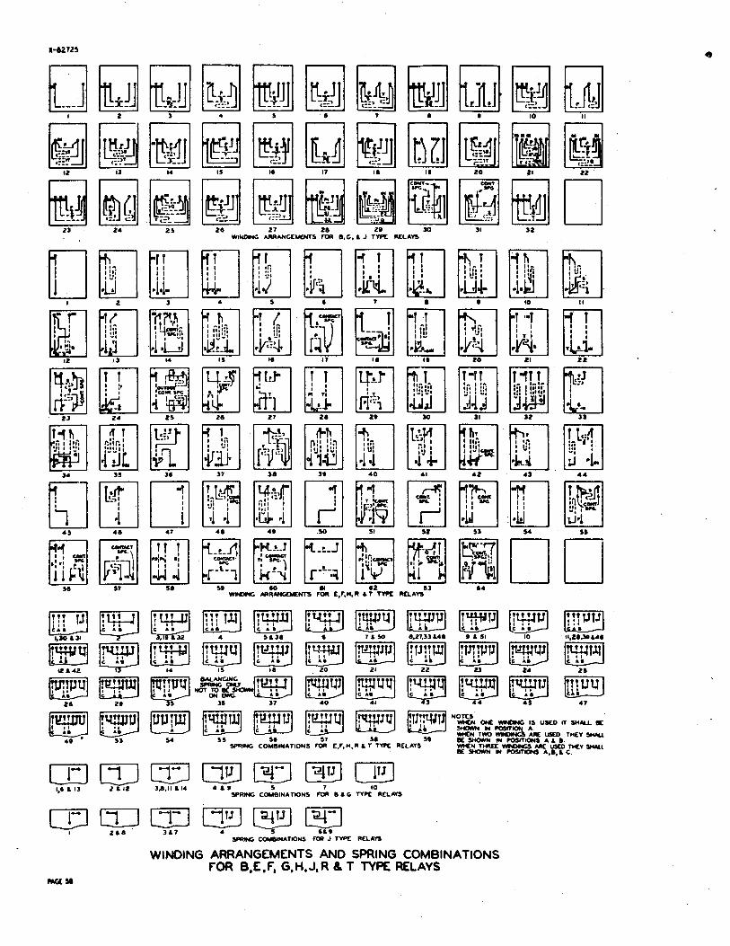
WINDING ARRANCLUCNTS FOR B.G. A J TYPE WLAVS
im :yu ONC WNUNC IS usco IT w u nc C A. C A C A
5 4 55 56 51 56 :(C: UKD THEY WI
49 5 3 59 E SHOWN IN POSITIONS A L B SPRING COU~INATIONS FOR E.F,M.R A r T W RtLAVS W*EN TMEC YlMCIGS UK USu) THfV WILL
Bc OOWN N COSAI(M *,a, A C ~~~~~~~ $6 A 13 2 A I 2 36.11 A14 4 A 9 5 1 10
SPRING COMBINATIONS FOR 0 A C W P C RELAYS
WINDING ARRANGEMENTS AND SPRING COMBINATIONS FOR B,E,f, G,H,J,R h T TYPE RELAYS

qm RES CODE
PACE M) Om RKLAT NO I N f l 1 RES 1 CODE [
2 INNER 155 1248 OW?KR 10000 124?
36 ? - P 500 1245 ? - S 240 RKAR 500 124E
32 PRI 500 149813 m 1 ISKC! 5 0 0 f l 34 UCE 95 149BR 32 PRI 100 1498s -..-- I I SIC I 1 o o f i 32 PRI 500 14980
RMR
12 320 178DA 12 320 178D3 14 320 178DK 23 PRI 200 l78DL
1 1:: 350 1 8 PRI 13.5 149%
350 149CH
28 PRI *
1% 26 PRI
26 PRI
27 Cot9 134
SEC 170 26 PRI 110
SIC 170
SEC 170 PRI &10
NUMBER TYPE RELAY CODES PAGE W
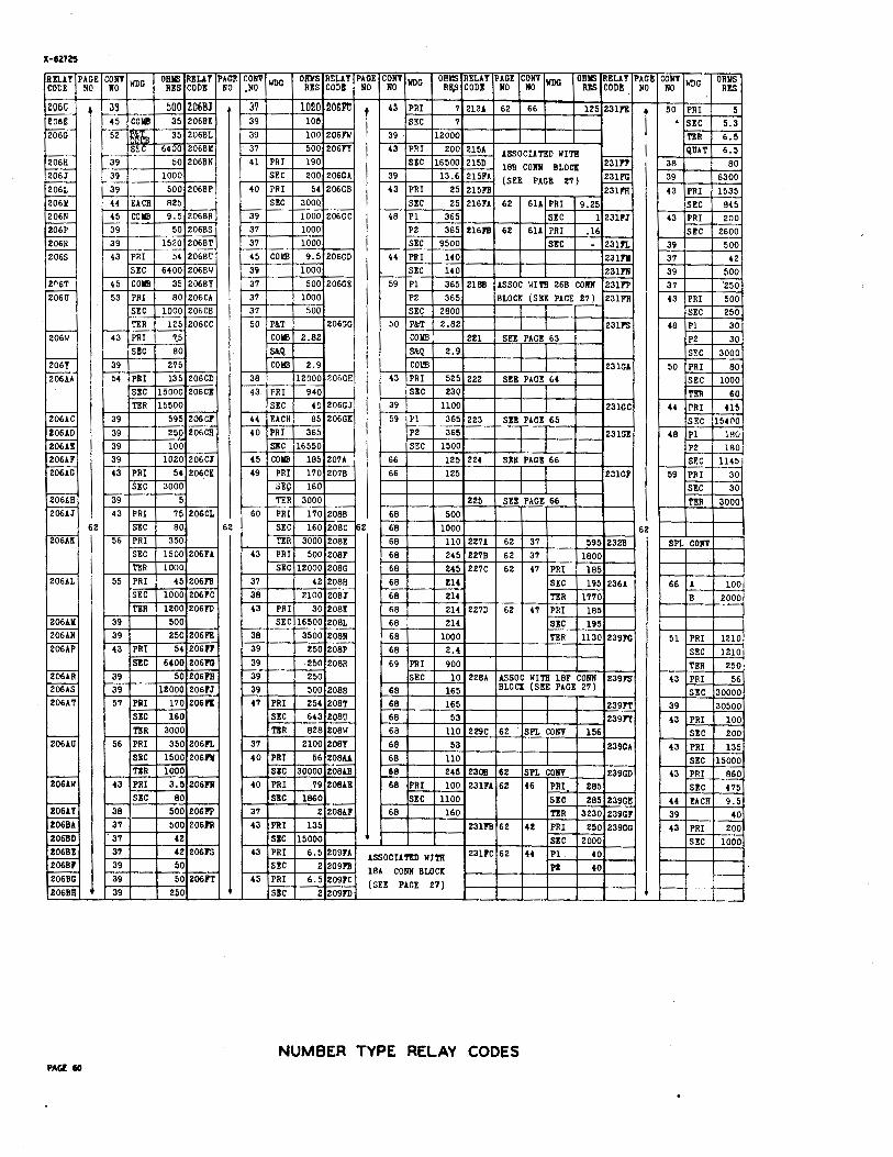
NUMBER TYPE RELAY CODES PAGE 60
REPEATING COILS
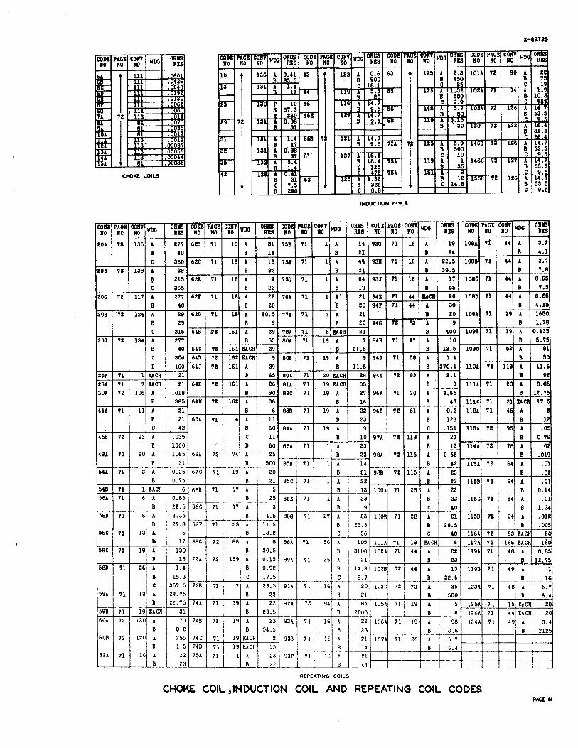
CHOKE COIL ,INDUCTION COlL AND REPEATING COlL CODES PAGE dl
SIZE OF CONVENTION ON DRAWING
ml ----- pi ---- ---x ,-- - --' I ----- 4 5 ---- 4 6 ---- ;""I .
4 7 ---
pi ---- 51 5 2 p!!fj --.. 53 7
---
---- .-.-. SIZE OF CONVENTION
ON DRAWING
5 4 5 5 5 6
2 3 2 B REL (HALF SIZE
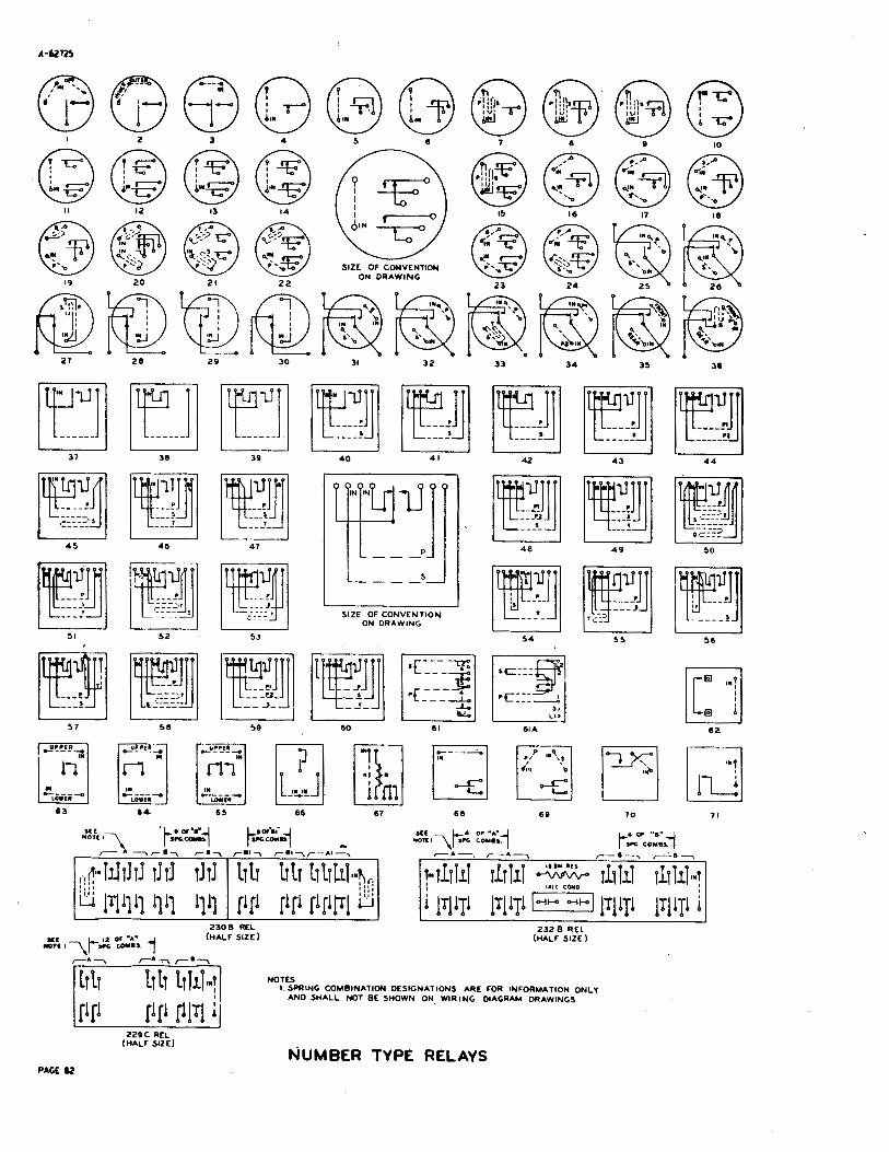
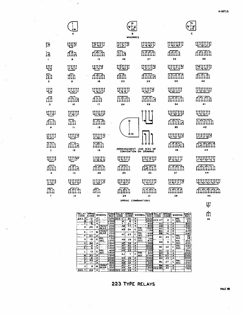
NOTES I. SPRING COMBINATION DESIGNATIONS ARE FOR INFORMATION ONLY
AND SHALL NOT BE SHOWN ON WIRING DIAGRAM DRAWINGS.
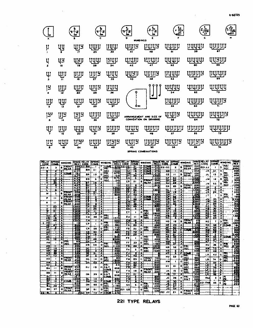
0 t WINDINGS
ARRANGEMENT AN0 SIZE OF COmLNTKm ON DRAWING
SPRING COMBINATIONS
221 TYPE RELAYS PACE 63
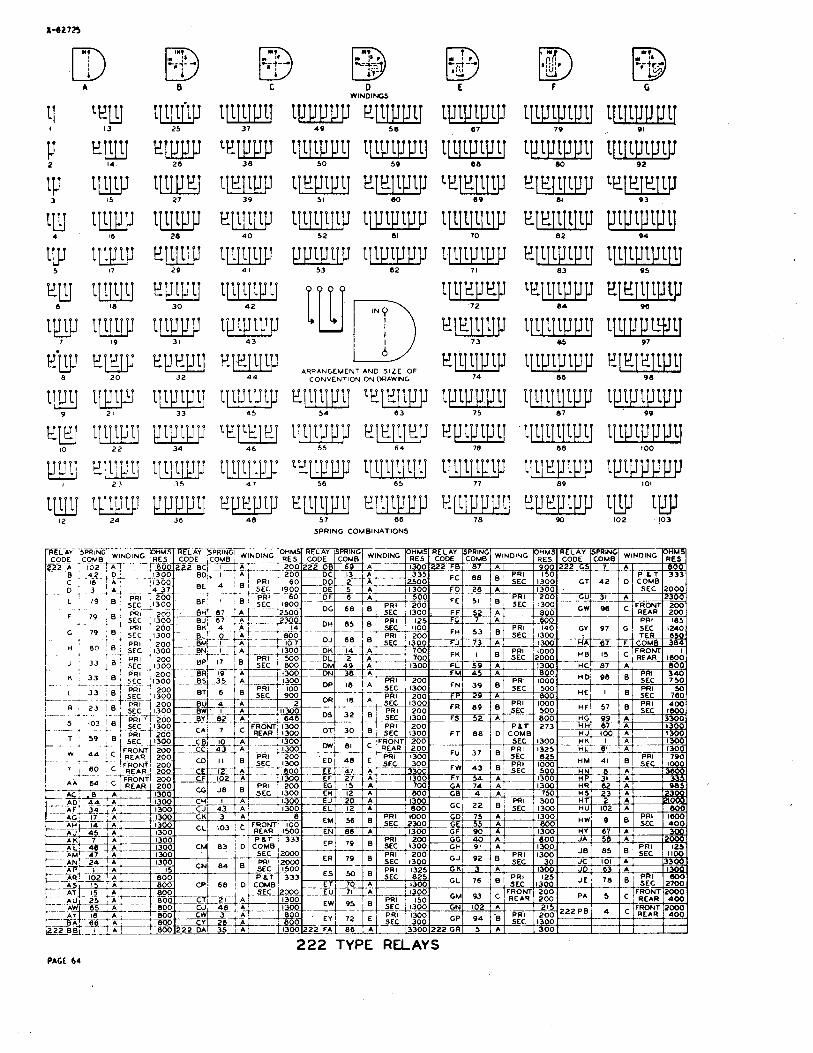
0 WINDINGS
ARRANGEMENT AND SIZE OF CONVENTION ON DRAWING
ep111p11 teiiqepp 54 0 3
57 66
SPRING COMBINATIONS
222 TYPE RELAYS PAGE 64
B WINDINGS
ARRANGEMENT' AND SIZE 'OF CONVENTION ON DRAWING
SPRING COMBINATIONS
223 TYPE RELAYS

*RIAMEWENT AND SIZE Of 2 2 4 TYPE CONVENTIW ON DRAWING
rm rFfifZl sfiXEl rW sKfZEl r1-h 14 2 1 26 3 1 38
224 TYPE SPRING COMBINATONS 45
H 225 TYPE WINDINGS
.I
+--o
225 TYPE SPRING
224 8 225 TYPE RELAYS mix
SIZE OF CONVENTION ON DRAWING
SIZE or CONVCWTION ON DRAWING
JACKS PMX 67

RETARDATION COIL CODES
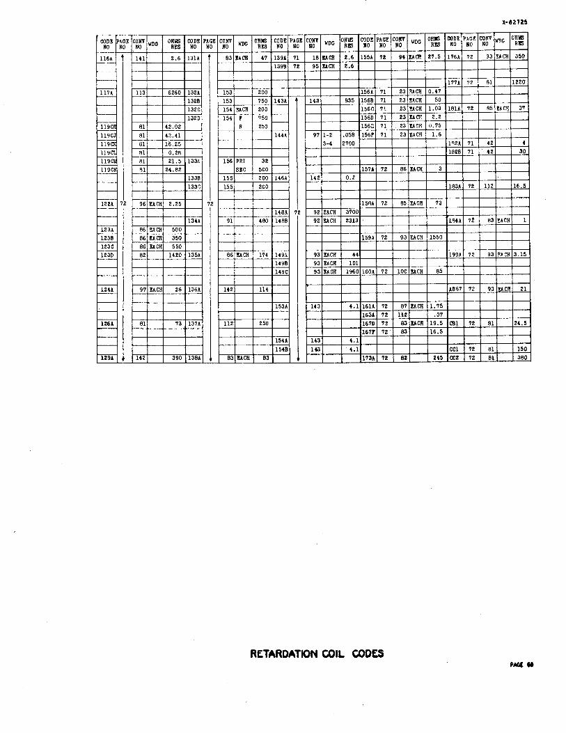
RETARDATION COIL CODES
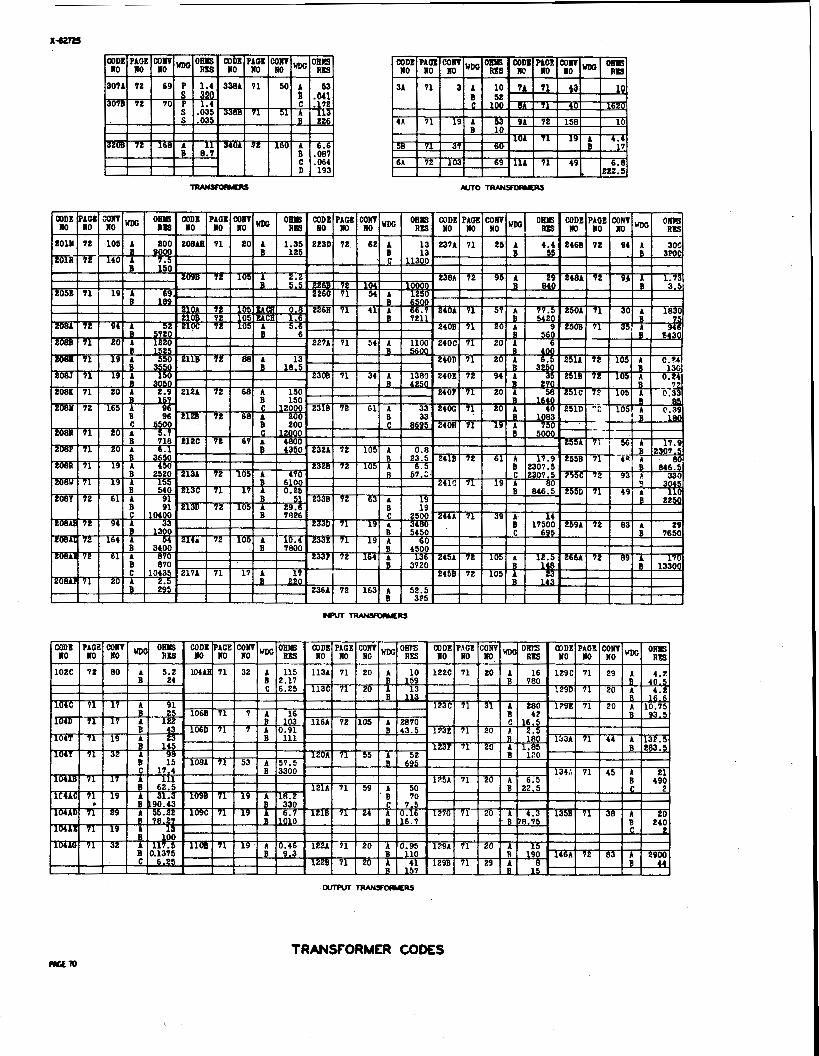
TRANSFORMER COMS
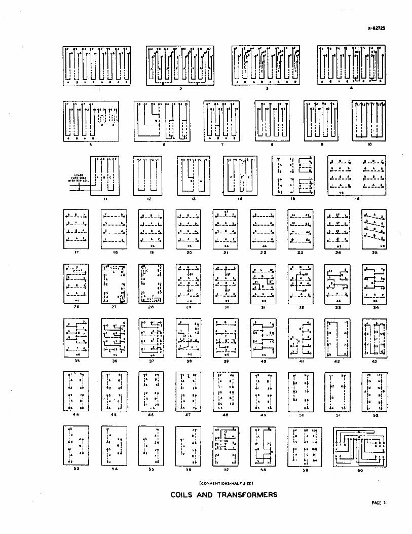
(CONVENTIONS-HALF SIZE)
COILS AND TRANSFORMERS PAGE 71
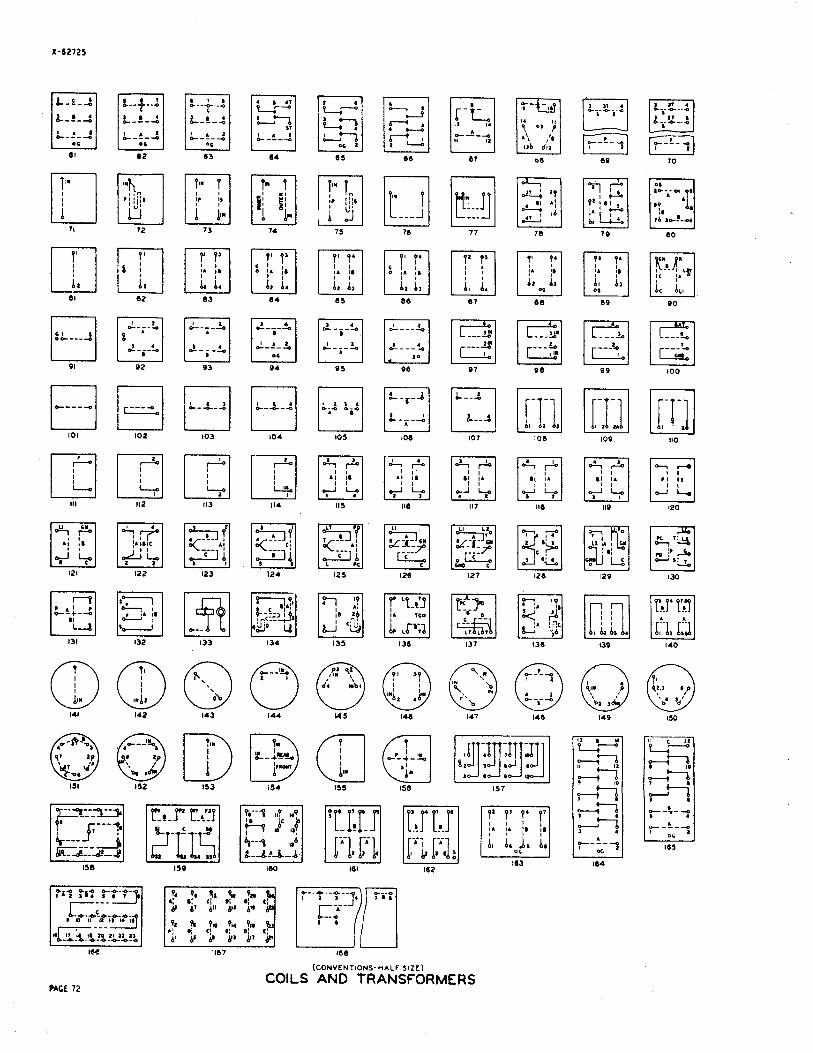
(CONVENTIONS-HALF SIZE)
COILS AND TRANSFORMERS

CABLES

X -62725
TRIPLES
500 TYPE CABLES AND CABLE COLOR COMBINATIONS PACE 74
- I
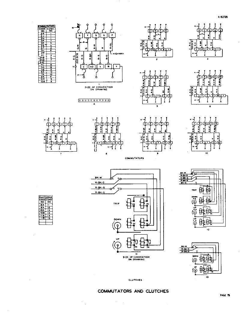
SIZE OF CONVENTION ON DRAWING
COMMUTATORS
(id, 1 - SIZE OF CONVENTION
ON DRAWING
CLUTCHES
COMMUTATORS AND CLUTCHES
L E A D S N R N I S M D WITH A P P
I 2 3
I 6
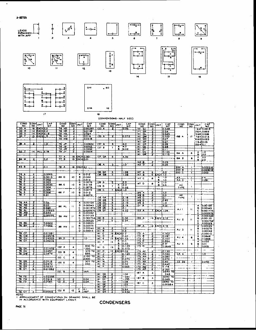
CCONVENTIONS - HALF SIZE)
I ARRANGEMENT OF CONVENTIONS ON ORAWING SHALL BE I N ACCORDANCE WITH EQUIPMENT LAYOUT.
CONDENSERS
SlZL Of CONVENTION ON DRAWING SIZE OF SIZL of S l Z f of SIZE of
CONVENTION CCWVENTIW CONVENlKm CONVENTDN ON DRAWING ON D R A M ON DRAWING ON DRAWING
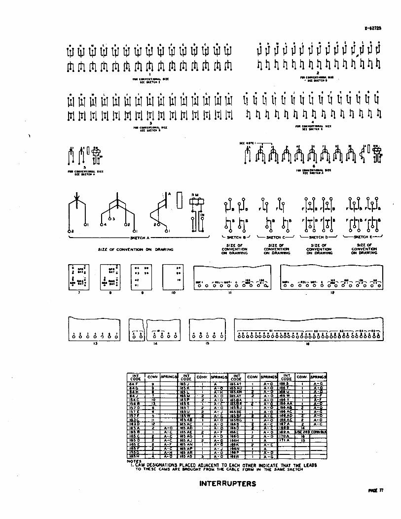
.-" . -- I. CAM DESIGNATIONS PLACED ADJACENl TO EACH OTHER INDICATE TMAT TML LEADS
TO TnEsf CAMS *RE OROUWT FROM THE CABLE FORM IN THC SAML smrTcn
INTERRUPTERS
4
SIZE OF CONVE\TION ON DRAWING
SIZE OF CONVENTION ON DRAWING
I SWITCHBOARD LAMPS I
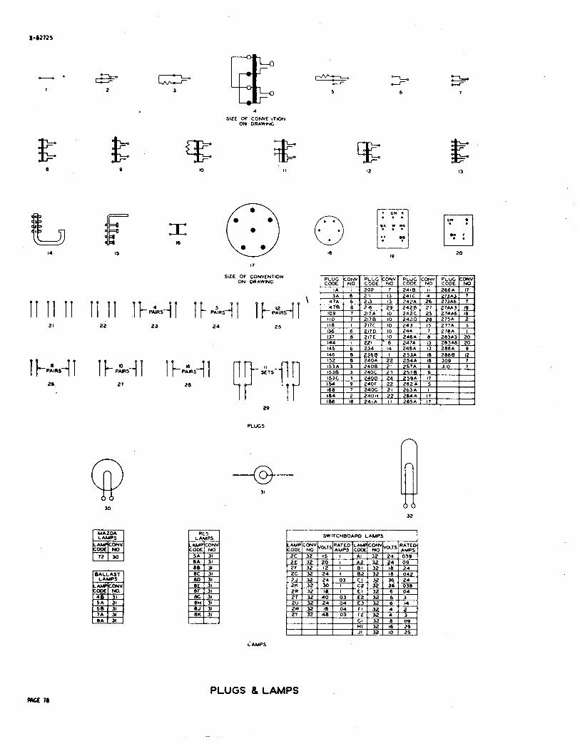
LAMPS
PLUGS 8 LAMPS
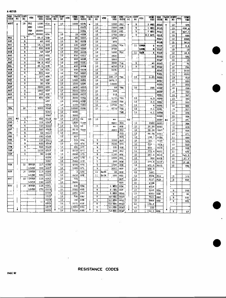
I COW 1 Olns 1 RBS I NO S CODE NO
; COW 0816 R B PAGE NO RE9 CODE NO
COW Om5 RlB PAGE 1 rro I RXS coda NO
I LOWER 1 89 11 l Urn 1 89
UPPER 5143
19AD
EACH PE.CH
11 UPPFR 40
Zj CH U P P t R 60 LO" 260
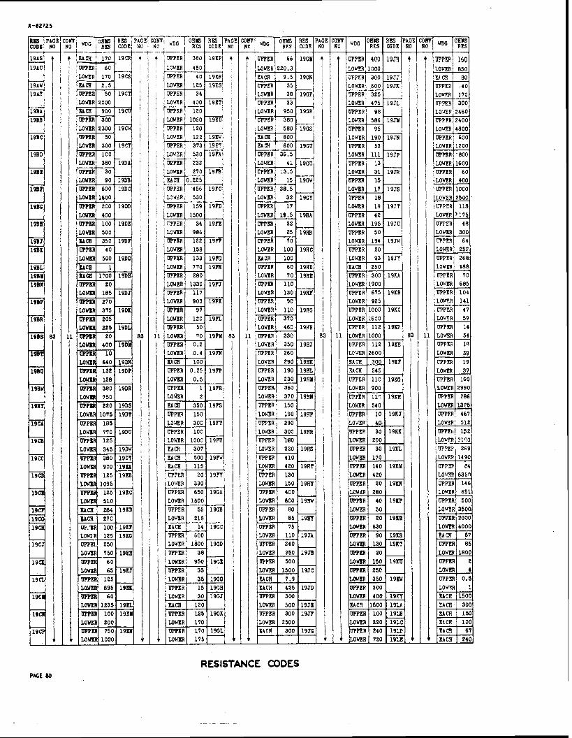
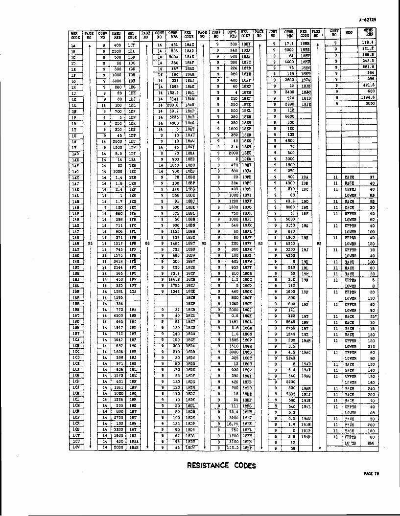
RESISTANCE CODES PACE 80

RESISTANCE CODES PAtt *
RESISTANCE CODES PAGE P
I , - 1 3 5 I
: ; I s-, L
SIZC OF CONVENTION i-' ON DRAWING O N DRAWING
2 4 6
a:: G:.: :
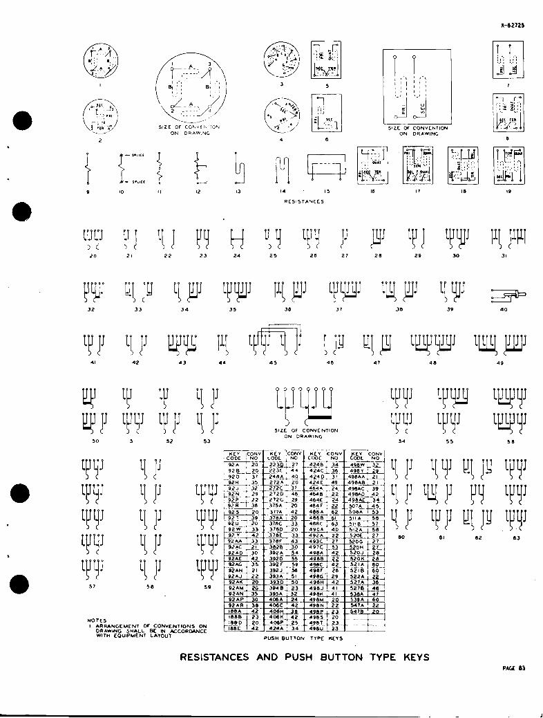
e e e s s t e e s s s Y IY VY 1'1 V!P-lJJ !IY Y uw
NOTES I ARRANGEMENT OF CONVENTIONS ON
DRAWING SHALL BE IN KCORDANCE w l T n EQUIPMENT LAYOUT
SIZE OF CONVENTION ON DRAWING
RESISTANCES AND PUSH BUTTON TYPE KEYS PAGE 83

1 0 s m 1 6 5 . ) 2 # 0 0 0 0 0 0 0 0 e 0
0 0 0 0 0 0 0 0 0 0
A 8 C
OFF NOOMAL S P R M C0MtNATW)NS U A L F SIZE
\- 2 0 4 TYPE SELECTOR . . , H A L F SIZE
BRUSHES
2 7 ea MAGNCTS
(5) (4) (3) (2) (I)
0 SIZE OF CONVENTION
ON DRAWING eANHS
--
206,207 1208 TYPE SELECTORS
NOTCS I ARRANGEMENT OF CONVENTIONS ON ORAWING SHALL BE
IN ACCORDANCE WITH EQUIPMENT LAYOUT
SELECTORS PACE 84
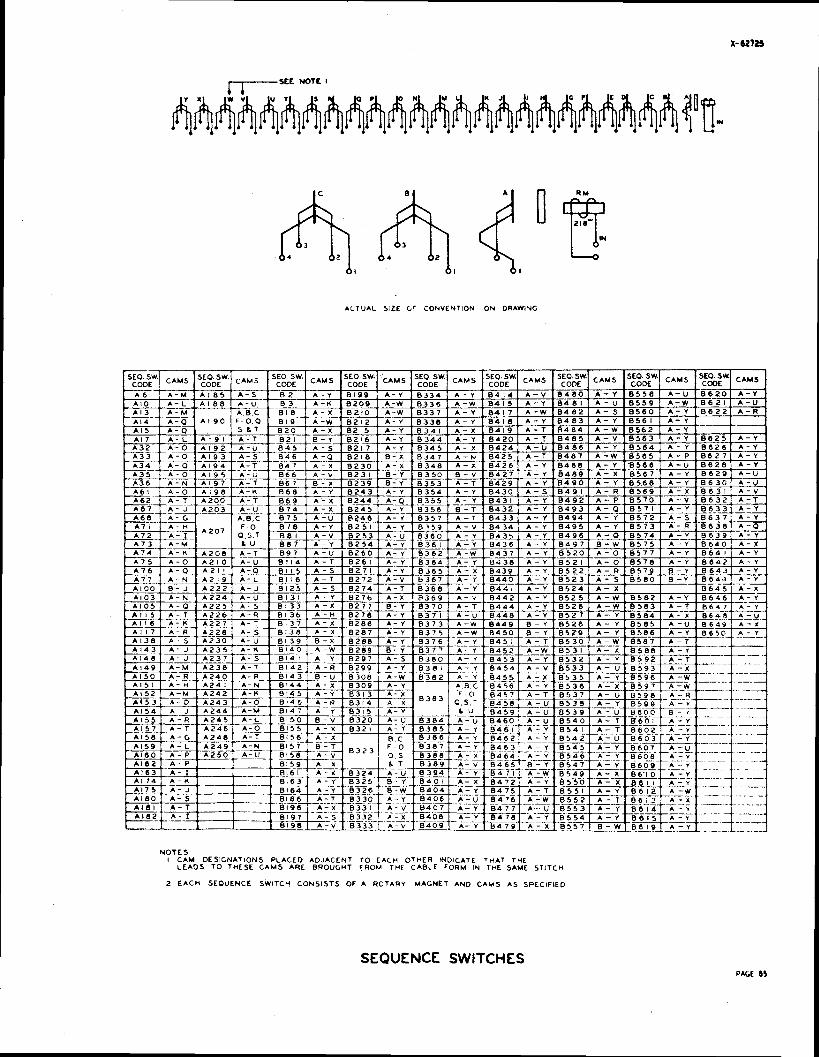
ALTUAL SIZE (rr CONVENTION ON DRAWING
N O T E S I CAM DESIGNATIONS PLACED ADJACENT TO EACH OTHER INDICATE THAT THE
LEADS T O THESE CAMS ARE BROUGHT FROM THE CABLE FORM IN THE SAME STITCH
2 E A C H SEQUENCE SWITCH CONSISTS OF A RCTARY MAGNET AND CAMS A s SPECIFIED
SEQUENCE: SWITCHES PAGE 85
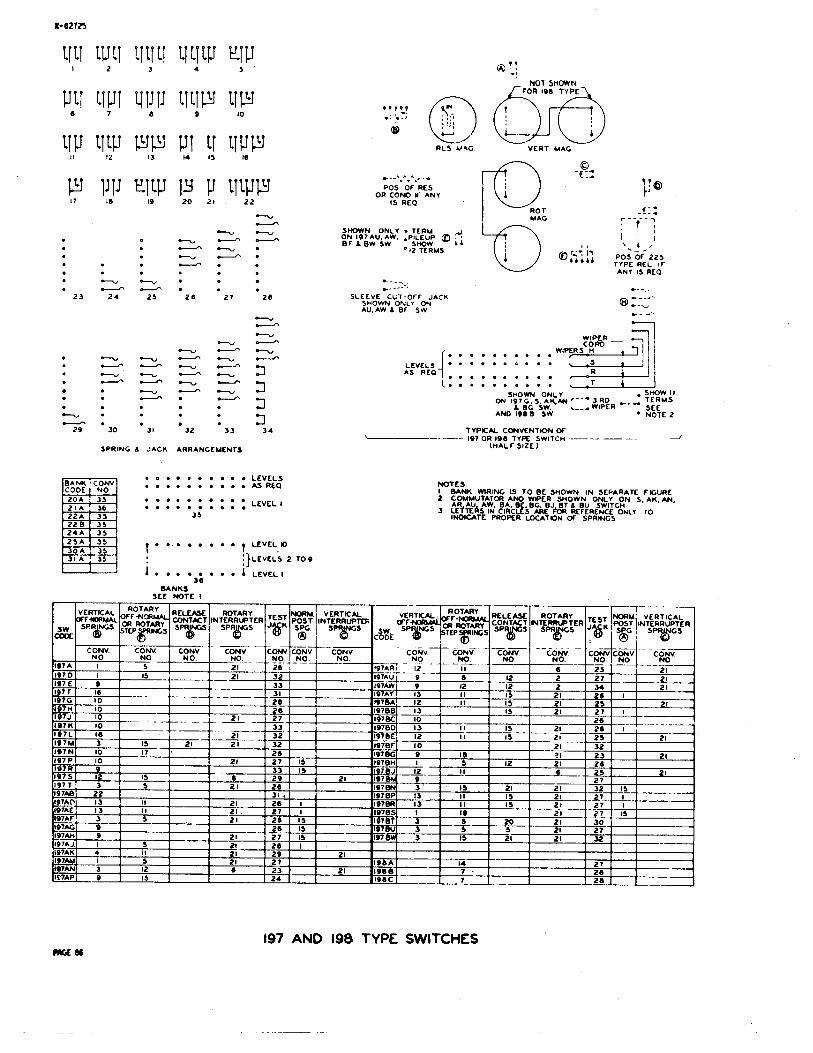
SPRING & JACK ARRANGEMENTS
LEVELS .......... o . . . . . . . . A S R L Q
b e ....... A L E V E L 1 36
B A N K S SEE NOTE I
@ ! S '-:
R L S U 4 G VERT MAG
SLEEVE-CLT-OFF JACK SHOWN ONLY ON AU, AW A BF SW
- ANY IS REQ
L.. . . . . . . . . . . -1 1 I SHOWN ONLY . S W W I I
ON 197G.S.AK.AN 3 RD ,-, TERMS L BG SW. \--a WIPER SEE
AN0 1 0 8 8 SW * NOTE 2
TYPICAL CONVENTION OF I 9 7 oR loo TYPE s w l T c n -- -- - -J
(HALF SIZE)
NOTES I BANK WRING IS TO BE SHOWN I N SEPARATE FIGURE 2 COMMUTATOA AND WIPER SHOWN ONLY O N S. AK. AN.
3 2t W d l ca:Rc8:iehEBJtE &?Y RE'$lCo"NLy T o INMCATE PROPER LOCATON OF SPRINGS
197 AND 198 TYPE SWITCHES

S u b j e c t page S u b j e c t
A and AB TyperRelays (See Relay) A i r l i n e System 3
k ' i r i n g Diagram, Ty 2 1 Alarm Fuse (See FusePical Ammeter (See Meter ) Appara t u s
Codes 3 D e s i g n a t i o n s 3 Layout 2
Approval Column, Arrangement of 1 9 Arrangement of T e l e t y p e w r i t e r
Handbook Form 20 Auto T r a n s f o r m e r s 70
B Type Relay (See Relay) B a l l a s t Lamps 7 8 Banks (See S e l e c t o r s and 197 and 1 9 8
Type Swi tch) B a t t e r y and round Connec t ions 13 B e l l 2 7 Bind ing P o s t 2 5 B r e a s t Type T r a n s m i t t e r (See T r a n s m i t t e r ) B r u s h e s , S e l e c t o r (See S e l e c t o r s ) Bus Bars 24 Buzzer 27
C Type Relay (See Relay) C a b l e s 7 3 Choke C o i l s 60 C i r c u i t L a b e l s 3
Linework and L e t t e r i n g Requirements 22
look (See E l e c t r i c Clock) C l u t c h e s 75 C o i l s
Choke (See Choke C o i l s ) Heat (See Heat C o i l ) I n d u c t i o n See I n d u c t i o n C o i l ) R e p e a t i n g I See R e p e a t i n g C o i l s ) R e t a r d a t i o n (See R e t a r d a t i o n C o i l s )
C o l o r c o m b i n a t i o n s of C a b l e s 7 4 C o l o r Schemes 7 C o l o r s , L i s t o f U i r e 9 C o l o r i n g , P a i r i n g , and Wiring of
S t a n d a r d C i r c u i t s 24 Combined Jack and S i g n a l 2 7 Common Leads 1 3 Commutators 7 5 Condensers 7 6 Connec t ing Blocks 27 Connec t ing Rack Punching 2 5 C o n n e c t i o n s , Batte'ry, Ground, T i p , a n d R i n g 1 3 Cord F a s t e n e r s 25
Wir ing of 24
D e r i v a t i o n o f Conventions f o r Lever Type Keys
D e s i g n a t i o n s Desk S t a n d D i a l
~ o u n t i n g Draf tsmun's R e s ~ o n s i b i l i t ~ Drawings
Form Layout P l a n n i n g M o d i f i c a t i o n Ref e r e n o e R e s p o n s i b i l i t y f o r
Drop Dynamic Loud Speaker
E Type Relay (See Relay) E l e c t r i c Clock E n g i n e e r i n g Notes E n g i n e e r ' s Respons ib iYi ty
F Type Relay (See a e l a y ) "F" S t i t c h i n g F i g u r e s
L e t t e r e d Numbered
Form, Drawing Form f o r T e l e t y p e w r i t e r Handbook Fuses
Page
26 3 and 25
2 7
2 7 3 and 1 9
1
C Type a e l a y
h u g e and I n s u l a t i o n o f Wire Genera l Requirements Genera tor Ground C o n n e c t i o n s , B a t t e r y and
H Type Relay (See i i e l a y ) H a i r p i n Loops Handbook, T e l e t y p e w r i t e r
T e l e t y p e w r i t e r Form Handset
Count ing Headset Heat C o i l Howler
Page 87
Sub jec t Page Subject Page
Induc t ion C o i l s Inpu t Transformers I n s u l a t i o n of 'dire I n t e r r u p t e r s
Optional Wiring Output Transf orrners
P a i r s P lugs Potent iometers Power Punchings P ro tec to r
J Notes J Type Belay (See Relay) Jack and S igna l Combined
(See Combined Jack and S igna l ) Jacks Jumper Wires
Punchings Push Button Type Key (See Keys)
auadruples Qu in tup le s Key
Lever Type (Typical Conventions) Push Button Type Telegraph (See Telegraph) Tops (Typica l ) Wiring Informat ion - Table E
2 and 26 14
R Type Relay (See Relay) Receiver Receptac le (See Lamp) Redraws Reference (See Drawings and
S p e c i f i c a t i o n s ) R e g i s t e r (See Message R e g i s t e r ) Relay
A Type AB Type B Type C Type
L L Type i3elay (See Relay) Lamp
B a l l a s t (See B a l l a s t Lamp) Mazda (See Uazda Lamp) Receptac le o r Socket i i e s i s t ance (See Res i s t ance Lamp) Switchboard
Layout Planning Le t t e red F igu res L i s t of Wire Co lo r s Live Leads Looping
P r a c t i c e s Loud Speaker
M ~umi)er Type
8 1 t o 218, 227 t o 239 221 222 2 23 224 and 225
Telegraph (See Telegraph) Voltage (See Voltage)
Relay Spr ing Combinations and Winding Arrangements
Repeating C o i l s Res i s t ances Res i s t ance Lamps Respons ib i l i t y (See Draftsman,
Drawing, and Engineer) Re ta rda t ion C o i l s Rheostat H i nger
L Type Relay (See a e l a y ) Kagnets (See S e l e c t o r and 137 end
198 Type Switches) Manufacturing Notes Manufacturing Schematics Maximum 1:umber of ; l i res Connected
t o Terminals Hazda Lamp HDF P r o t e c t o r Yessaee i l e e i s t e r Meter Method of Designat ing A pe ra tus Y i l l i a u e t e r (See ~ e t e r f Modif ica t ion Drawings Mounting (See D i a l and Handset)
N Type Relay (See Helay) Notes, Engineering
Uanufactur ing Number Type Relay (See Relay)
S Type Relay (See i ielay) S e l e o t o r s
Subject
Sequence Switches Signal Socket
Lamp (See amp) Vacuum Tube
Sounder Specifications for Reference Spring Combinations for B, B, F, G, H, J, R, and T Type Belays
Standard Arrangement of Title Box, Notes, and Approval Column Strapping and Looping Practices
General Hairpin Loops Looping Strapping
Subset Supplementary Information Switch .
197 and 198 Type Switchboard
Cables (See Cables) Cable Color Combinations (See Color) Lamps (See Lamps)
T Type Relay (See Relay) Telegraph
Key ~ e i a y
Teletypewriter Handbook Drawings Form. Drawing ~ettering - Wiring Practices
Terminal Strip
Page Sub ject
Terminals Thenooouple and Socket Tip and Ring Connections Transformers
Auto (See Auto) Input (See Input ) Output (See Output)
Transmitter (See Sketch A) Triples
Universal Wiring
Vaouum Tube and Socket Voltage Relay Voltmeter (See Ueter)
Winding Arrangements for B, E, F, C, H, J, R, and T Type Relays
Wire Colors Wire, Gauge, and Insulaticn Wires, Maximum Number Connected to Terminals
\firing Optional Practices Universal
Wiring Diagram, Typical Airline
Bell Telephone Laboratories, Inc,