NO. DE PROJET : Date: 17-22096 U-90/U-91
277
2323 Administrative Services and Property Management DEVIS NO. DE SOLICITATION: Edifice: PROJET: NO. DE PROJET : Date: 17-22096 U-90/U-91 2320 Lester Road, campus d’Uplands Ottawa, Ontario U-90/U-91, Nouvelle alimentation électrique 5452 novembre 2017
-
Upload
khangminh22 -
Category
Documents
-
view
1 -
download
0
Transcript of NO. DE PROJET : Date: 17-22096 U-90/U-91

2323
Administrative Services and Property Management
DEVIS
NO. DE SOLICITATION:
Edifice:
PROJET:
NO. DE PROJET :
Date:
17-22096
U-90/U-91
2320 Lester Road, campus d’Uplands
Ottawa, Ontario
U-90/U-91, Nouvelle alimentation électrique
5452
novembre 2017

DEVIS
TABLE DES MATIERES
Formulaire de soumission
Annonce Achatsetventes
Instructions aux soumissionnaires
Taxes de ventes Ontario
Compagnies de cautionnements
Articles de convention
Plans et devis A
Modalités de paiement B
Conditions générales C

Conditions de travail et échelle des D
justes salaires N/A
Conditions d'assurance E
Condition de garantie du contrat F
Liste de vérification des exigences
relatives à la sécurité LVERS G

Directions to the Ottawa Research Facilities — Uplands
NRC Institute for Aerospace Research (NRC-IAR)Research RoadOttawa, Ontario, Canada
Tel: 613-991-5738
NRC Centre for Surface Transportation Technology (NRC-CSTT)2320 Lester RoadOttawa, Ontario, Canada
Tel: 613-998-9639
NRC Institutes/Branch/Program Buildings
NRC Administrative Services and Property Management (NRC-ASPM) U-62
NRC Institute For Aerospace Research (NRC-IAR) U-61, U-66, U-67, U-69, U-70
NRC Centre for Surface Transportation Technology (NRC-CSTT) U-84, U-86, U-87, U-88, U89, U-90, U-91
By Road, from the MONTREAL RD FACILITIES to NRC-CSTT, 2320 Lester Road
1. Drive EAST on MONTREAL RD
2. Turn RIGHT on BLAIR RD, cross OGILVIE RD
3. Take the ramp and follow Highway 174 WEST
4. Keep RIGHT and take first exit on ramp Highway 417 EAST towards Cornwall/Montreal
5. Exit at WALKLEY RD, merge RIGHT on WALKLEY
6. Turn LEFT at CONROY RD
7. Turn RIGHT at DAVIDSON RD, cross BANK ST – name changes to LESTER RD
8. Continue on LESTER RD and watch for NRC Research Facilities signs

By Road, from the MONTREAL RD FACILITIES to NRC-IAR, Research Road
1. Drive EAST on MONTREAL RD
2. Turn RIGHT on BLAIR RD, cross OGILVIE RD
3. Take the ramp and follow Highway 174 WEST
4. Keep RIGHT and take first exit on ramp Highway 417 EAST towards Cornwall/Montreal
5. Exit at WALKLEY RD, merge RIGHT on WALKLEY
6. Turn LEFT at HAWTHORNE RD
7. Turn RIGHT at HUNT CLUB RD, cross CONROY RD, ALBION RD, BANK ST
8. Turn LEFT at UPLANDS DR. Continue and watch for NRC Research Facilities signs
Directions to the Ottawa Research Facilities — Uplands PAGE 2 of 4

Directions to the Ottawa Research Facilities — Uplands PAGE 3 of 4
NRC Institute
Trans Canada HWY
Major HWY
Secondary HWY
Airport
Train Station
Ferry Metro
Bus Station
map-legend-eng.pdf 1 03/11/09 11:47 AM
2
1
0 1 2 km
N
Montréal
Rock cliffe
Aviation
Blair
Bank
Woodroffe
Greenbank
Merivale
Island
Park
Fisher
Prince of W
alesP
rinceof W
ales
Riversid
e Uplands
Airp
ort
Albion
Conroy
VanierSuss
exCarlin
g
Aylmer
Taché
Outaouais
Outaouais
Carling
Otta
wa
River
ON
TARI
O
QU
ÉBEC
Baseline
Heron
Hunt Club (W)
Fallowfield
Leitrim
Hunt Club
Walkley
Walkley
417
417
417
148
148
38
38
73
31
31
34
19
19
19
5
50
416
174
Bronson
Bank
Haw
thorne
3 4
Wellington
3
4
1
2
OTTAWA
GATINEAU
Sussex Facilities
Montreal Road Facilities
Uplands Facilities
NRC-CSTT
LesterDavidson

NRC Institute
Trans Canada HWY
Major HWY
Secondary HWY
Airport
Train Station
Ferry Metro
Bus Station
map-legend-eng.pdf 1 03/11/09 11:47 AMDirections to the Ottawa Research Facilities — Uplands PAGE 4 of 4
Hunt Club
Hunt Club
Lester
McCarthy
Bank
Bank
Uplands
Airport
Airport
Airport
Alert
AlertLevy
Research
Albion
Riversid
e
Riversid
e
3 4
0 500 1000 km
N

Richardma
Callout
Door #1

National Research Council Conseil national de recherches
Canada Canada
Administrative Services Direction des services
& Property management administratifs et de la gestion
Branch (ASPM) de l’immobilier (SAGI)
Formulaire de proposition – Marché de construction
Titre du projet U-90/U91- Nouvelle alimentation électrique
No. de Proposition: 17-22096
1.2 Nom d’entreprise et adresse du soumissionnaire
Nom __________________________________________________________________________
Adresse _______________________________________________________________________
_______________________________________________________________________________
Personne-ressource (nom en lettres moulées) ________________________________________
Téléphone (______) ______________ Téléc. (_______) ____________________
1.3 Offre de prix
Le soumissionnaire soussigné offre par les présentes à Sa Majesté du chef du Canada
(ci-après appelée « Sa Majesté »), représentée par le Conseil national de recherches du
Canada, d’exécuter et d’achever les travaux se rapportant au projet désigné ci-haut,
conformément aux plans et devis et aux autres documents d’appel d’offres, à l’endroit et
de la manière énoncés aux présentes, pour un montant total de _____________,______ $
(montant numéraire uniquement) dans la monnaie ayant cours légal au Canada
(TPS/TVH en sus).
Le montant de l’offre comprend toutes les taxes fédérales, provinciales et municipales
applicables(*)
. Cependant, si l’une des taxes imposées en vertu de la Loi sur l’accise, de la
Loi sur la taxe d’accise, de la Loi sur la sécurité de la vieillesse, de la Loi sur les
douanes, du tarif des douanes ou de toute autre loi provinciale imposant une taxe de vente
au détail sur les achats de biens meubles incorporés à un bien immobilier est modifiée et
que cette modification survient :
.1 après que la présente proposition ait été mise à la poste ou livrée; ou
.2 si la présente proposition est révisée, après la dernière révision;
le montant de l’offre de prix devra être diminué ou augmenté de la manière prévue à
l’article CG22 des Conditions générales du contrat.

National Research Council Conseil national de recherches
Canada Canada
Administrative Services Direction des services
& Property management administratifs et de la gestion
Branch (ASPM) de l’immobilier (SAGI)
1.3.1 Offre de prix (suite)
(*)
Dans le cadre de la présente proposition, la taxe sur les produits et services (TPS) n’est
pas une taxe applicable.
Dans la province de Québec, la taxe de vente du Québec (TVQ) ne doit pas être ajoutée
au montant de l’offre, le gouvernement fédéral étant exempté de la TVQ. Les
soumissionnaires doivent s’adresser directement au ministère du Revenu provincial pour
récupérer toute taxe qu’ils sont appelés à verser sur des biens et services acquis dans le
cadre de l’exécution du présent marché. Les soumissionnaires devraient cependant
inclure dans le montant de leur offre de prix tout montant de TVQ pour lequel ils ne
peuvent exiger un remboursement de taxe sur les intrants.
1.4 Acceptation et conclusion du marché
Le soumissionnaire soussigné s’engage, dans les quatorze (14) jours suivant l’avis
confirmant l’acceptation de la présente proposition, à signer un contrat portant sur
l’exécution des travaux, à condition que l’avis d’acceptation du Ministère parvienne au
soumissionnaire dans un délai de trente (30) jours suivant la date de clôture de l’appel
d’offres.
1.5 Délai d’exécution des travaux
Le soumissionnaire soussigné s’engage à achever les travaux dans le délai stipulé au
devis, lequel commence à courir à compter de l’avis d’acceptation de la présente
proposition.
1.6 Garantie de soumission
Le soumissionnaire soussigné joint à la présente proposition une garantie de soumission,
conformément à l’article 5 des Instructions générales à l’intention des soumissionnaires.
Le soumissionnaire soussigné convient que dans l’éventualité où il refuse de conclure un
contrat qu’il est tenu de conclure en vertu des présentes, tout dépôt de garantie fourni à
titre de garantie de soumission sera retenu pour débit. Cependant, le Ministre peut, au
nom de l’intérêt public, renoncer au droit de Sa Majesté de retenir pour débit le dépôt de
garantie.
Le soumissionnaire soussigné convient que si la garantie de soumission n’est pas
conforme aux modalités de l’article 5 des Instructions générales à l’intention des
soumissionnaires, sa proposition peut être jugée irrecevable.

National Research Council Conseil national de recherches
Canada Canada
Administrative Services Direction des services
& Property management administratifs et de la gestion
Branch (ASPM) de l’immobilier (SAGI)
1.7 Garantie d’exécution
Dans les quatorze (14) jours suivant l’avis d’acceptation de sa proposition, le
soumissionnaire soussigné doit fournir une garantie d’exécution contractuelle,
conformément à la section F, Conditions contractuelles, du contrat.
Le soumissionnaire soussigné convient que la garantie d’exécution visée par les
présentes, si elle est fournie sous forme de lettre de change, sera versée au Trésor public
du Canada.
1.8 Annexes
L’annexe n° ______n/a____________ fait partie intégrante de la présente proposition.
1.9 Addenda
Le montant total de l’offre de prix porte sur l’exécution des travaux définis dans les
addenda suivants :
N° DATE N° DATE
(Les soumissionnaires doivent indiquer le numéro et la date des addenda.)

National Research Council Conseil national de recherches
Canada Canada
Administrative Services Direction des services
& Property management administratifs et de la gestion
Branch (ASPM) de l’immobilier (SAGI)
1.10 Signature de la proposition
Les soumissionnaires doivent consulter l’article 2 des Instructions générales à l’intention
des soumissionnaires.
SIGNÉ, AUTHENTIFIÉ ET REMIS le ____________________ e jour du mois de
________________ au nom de
________________________________________________________________________
(Inscrire le nom d’entreprise du soumissionnaire)
SIGNATAIRE(S) AUTORISÉ(S)
______________________________________
(Signature du signataire autorisé)
______________________________________
(Inscrire le nom et le titre du signataire en lettres moulées)
_____________________________________
(Signature du signataire autorisé)
______________________________________
(Inscrire le nom et le titre du signataire en lettres moulées)
SCEAU

ANNONCE ACHATSETVENTES
U-90/U-91, Nouvelle alimentation électrique
Le Conseil national de recherches du Canada, 2320 chemin Lester, Campus d’Uplands, Ottawa, ON, a une demande pour un projet qui comprend : Fournir une alimentation électrique normale et de secours à l’édifice U-90 et U-91.
1. GENERAL : Adresser à le représentant ministériel (ou à son représentant) ou à l’Agent des contrats toute question portant sur tout aspect du projet. Ils sont les seuls autorisés à fournir des réponses. On ne tiendra nullement compte des informations obtenues d'une personne autre que le représentant ministériel (ou son représentant) ou l’Agent des contrats et ce, autant à l'octroi du contrat qu'au cours des travaux. Les entreprises souhaitant présenter des soumissions pour ce projet devraient obtenir les documents relatifs aux appels d’offres en s’adressant au fournisseur de service Achatsetventes.gc.ca AGAO. Si des addenda sont ajoutés, ils seront distribués par Achasetventes.gc.ca AGAO. Les entreprises qui choisissent de préparer leurs soumissions en se fondant sur des documents d’appel d’offres provenant d’autres sources le font à leurs propres risques et seront tenues d’informer le responsable de l’appel d’offres de leur intention de soumissionner. Les trousses d'appel d'offres ne pourront être diffusées le jour même de la clôture des soumissions.
2. . VISITE DU SITE OBLIGATOIRE
Les soumissionnaires ont l'obligation de participer à une des visites du site à la date et à l'heure prévues. Les soumissionnaires qui ont l'intention de présenter une soumission doivent envoyer au moins un représentant à cette visite. Les visites de chantier se tiendront le 14 novembre et le 17 novembre, 2017 à 9 :00. Rencontrer Maurice Richard à l’édifice U-89, 2320 chemin Lester, Campus d’Uplands, Ottawa, ON. Les soumissionnaires qui, pour une raison quelconque, ne peuvent pas participer à la visite à la date et à l'heure prévues ne pourront obtenir un deuxième rendez-vous; leur soumission sera donc considérée comme non conforme. AUCUNE EXCEPTION NE SERA FAITE.
Pour prouver qu'ils ont participé à la visite du site, les soumissionnaires ou leurs représentants DOIVENT signer, lors de la visite, le formulaire de participation élaboré par l'autorité contractante. Les soumissionnaires ou leurs représentants ont la responsabilité de vérifier s'ils ont bien signé ce formulaire avant de quitter le site. Les soumissions présentées par des soumissionnaires qui n'ont pas participé à la visite du site ou qui ont oublié de signer le formulaire de participation seront considérées comme non conformes. 3. DATE DE FERMÊTURE : La date de fermeture est le 7 décembre, 2017 14 :00 4. RÉSULTATS DE L’APPEL D’OFFRES : À la fermeture de l’appel d’offres, les résultats de l’appel d’offre seront envoyés par télécopieur à tous les entrepreneurs qui auront soumis un appel d’offre.

5. CRITÈRES DE SÉCURITÉ OBLIGATOIRES POUR LES ENTREPRENEURS 5.1 EXIGENCES OBLIGATOIRES RELATIVES A LA SECURITE
.1 L'entrepreneur doit détenir en permanence, pendant l'exécution du contrat à commandes, une attestation de vérification d'organisation désignée (VOD) en vigueur, délivrée par la Direction de la sécurité industrielle canadienne (DSIC) de Travaux publics et Services gouvernementaux Canada (TPSGC).
.2 Les membres du personnel de l'entrepreneur devant avoir accès à des
établissements de travail dont l'accès est réglementé doivent TOUS détenir une cote de FIABILITÉ en vigueur, délivrée ou approuvée par la DSIC de TPSGC.
.3 L'entrepreneur doit respecter les dispositions:
a) de la Liste de vérification des exigences relatives à la sécurité et directive de sécurité (s'il y a lieu), reproduite à l'Annexe D;
b) du Manuel de la sécurité industrielle (dernière édition)@ http://ssi-iss.tpsgc-
pwgsc.gc.ca/msi-ism/msi-ism-fra.html 5.2 VÉRIFICATION DE L’ATTESTATION DE SÉCURITÉ À LA CLÔTURE DES SOUMISSIONS
.1 Le soumissionnaire doit détenir une attestation de vérification d'organisation désignée (VOD) en vigueur, délivrée par la Direction de la sécurité industrielle canadienne (DSIC) de Travaux publics et Services gouvernementaux Canada (TPSGC) ET DOIT L’INCLURE AVEC LEUR SOUMISSION OU FAIRE SUIVRE DANS LES 48 HEURES SUIVANT LA DATE ET L’HEURE DE CLÔTURE DE L’APPEL D’OFFRE. Des vérifications seront effectuées par l’intermédiaire de la DSIC pour confirmer l’attestation de sécurité du soumissionnaire. L’omission de se conformer à cette exigence rendra la soumission non conforme et celle-ci sera rejetée.
.2 L’entrepreneur général doit nommer tous ses sous-traitants dans un délai de 72
heures suivant la clôture des soumissions, et ceux-ci doivent aussi détenir une attestation VOD valide et soumettre les noms, dates de naissance ou numéros de certificats de sécurité de toutes les personnes qui seront affectées au projet.
.3 Il faut noter que les sous-traitants qui doivent exécuter des tâches pendant
l’exécution du contrat subséquent doivent aussi satisfaire aux exigences obligatoires du contrat en matière de sécurité. De plus, aucune personne ne possédant pas le niveau de sécurité exigé ne sera admise sur le site. Le soumissionnaire retenu devra s’assurer que les exigences liées à la sécurité sont satisfaites pendant toute l’exécution du contrat. La Couronne ne sera tenue responsable d’aucun retard ni d’éventuels coûts supplémentaires liés à l’inobservation par l’entrepreneur des exigences en matière de sécurité. L’omission de satisfaire à ces exigences sera suffisante pour résilier le contrat pour cause d’inexécution.
.4 Pour toute question concernant les exigences liées à la sécurité pendant la période
de soumission, les soumissionnaires doivent communiquer avec l’agente de sécurité @ 613-993-8956.

6.0 CSPAAT (COMMISSION DE LA SECURITE PROFESSIONNELLE ET DE L’ASSURANCE CONTRE LES ACCIDENTS DU TRAVAIL
.1 Tous les soumissionnaires doivent fournir une attestation de la CSPAAT valide avec
leur offre ou avant l’attribution du contrat. 7.0 L’OMBUDSMAN DE L’APPROVISIONNEMENT
.1 Services de règlement des différends Les parties reconnaissent que l’ombudsman de l’approvisionnement nommé en vertu du paragraphe 22.1(1) de la Loi sur le ministère des Travaux publics et des Services gouvernementaux veillera à proposer aux parties concernées un processus de règlement de leur différend, sur demande ou consentement des parties à participer à un tel processus de règlement extrajudiciaire en vue de résoudre un différend entre elles au sujet de l’interprétation ou de l’application d’une modalité du présent contrat, et obtiendra leur consentement à en assumer les coûts. Le Bureau de l’ombudsman de l’approvisionnement peut être joint par téléphone, au 1-866-734-5169 ou par courriel, à l’adresse [email protected].
.2 Administration du contrat
Les parties reconnaissent que l’ombudsman de l’approvisionnement nommé en vertu du paragraphe 22.1(1) de la Loi sur le ministère des Travaux publics et des Services gouvernementaux examinera une plainte déposée par [le fournisseur ou l’entrepreneur ou le nom de l’entité à qui ce contrat a été attribué] concernant l’administration du contrat si les exigences du paragraphe 22.2(1) de la Loi sur le ministère des Travaux publics et des Services gouvernementaux et les articles 15 et 16 du Règlement concernant l’ombudsman de l’approvisionnement ont été respectées, et si l’interprétation et l’application des modalités ainsi que de la portée du contrat ne sont pas contestées. Le Bureau de l’ombudsman de l’approvisionnement peut être joint par téléphone, au 1-866-734-5169 ou par courriel, à l’adresse [email protected].
.3 Le Bureau de l’ombudsman de l’approvisionnement (BOA) a été mis sur pied
par le gouvernement du Canada de manière à offrir aux fournisseurs un moyen
indépendant de déposer des plaintes liées à l’attribution de contrats de moins
de 25 000 $ pour des biens et de moins de 100 000 $ pour des services. Vous
pouvez soulever des questions ou des préoccupations concernant une demande
de soumissions ou l’attribution du contrat subséquent auprès du BOA par
téléphone, au 1-866-734-5169 ou par courriel, à l’adresse boa.opo@boa-
opo.gc.ca. Vous pouvez également obtenir de plus amples informations sur les
services qu’offre le BOA, en consultant son site Web, à l’adresse www.opo-
boa.gc.ca.
Le représentant ministériel responsable ou son représentant: Maurice Richard
Téléphone: 613 993-9299
L’autorité contractante : Alain Leroux [email protected]
Téléphone : 613 993-2274

INSTRUCTIONS AUX SOUMISSIONNAIRES
Article 1 - Réception des soumissions 1a) Aucune soumission reçue après le moment fixé pour la clôture des soumissions ne sera
acceptée. LES SOUMISSIONS RECUES APRES LE MOMENT FIXÉ NE SONT PAS VALIDES et ne peuvent être prises en considération, peu importe la raison de leur retard.
1b) Une lettre ou une télécommunication imprimée envoyée par un soumissionnaire pour signifier un
prix ne peut être considérée comme étant une soumission valide à moins qu’une soumission officielle n’ait été reçue sur la formule prescrite à cette fin.
1c) Il est loisible aux soumissionnaires de modifier leurs soumissions par lettre ou télécommunication
imprimée mais à condition que de telles modifications ne soient pas reçues plus tard qu’au moment prévu pour la clôture des soumissions.
1d) Les modifications à la soumission qui sont transmises par télécopieur doivent être signées et
doivent permettre d’identifier sans équivoque le soumissionnaire. Toutes les modifications de ce genre doivent être envoyées à : Conseil national de recherches Canada Services d’approvisionnement Alain Leroux, agent supérieur de contrats Édifice M-22 Chemin Montréal, Ottawa (Ontario) K1A OR6 Télécopieur: (613) 991-3297
Article 2 - Formule de soumission et qualifications 1) Toutes les soumissions doivent être présentées sur la formule de soumission - construction et
être signées en conformité avec les exigences suivantes:
a) Société à responsabilité limitée : le nom complet de la société ainsi que le nom et le titre des fondés de signature autorisés doivent être imprimés dans l’espace prévu à cette fin. La signature des fondés de signature et le sceau de la société doivent être apposés.
b) Société de personne : le nom de l’entreprise ainsi que le(s) noms du (des) signataire(s)
doivent être imprimés dans l’espace prévu. L’un ou plusieurs des associés doivent signer en présence d’un témoin qui, lui aussi, doit apposer sa signature. Un sceau de couleur adhésif doit être apposé en regard de chaque signature.
c) Entreprise à propriétaire unique : le nom de l’entreprise et le nom du propriétaire unique
doivent être imprimés dans l’espace prévu. Le propriétaire est tenu de signer en présence d’un témoin qui doit lui aussi apposer sa signature. Un sceau de couleur adhésif doit être apposé en regard de chaque signature.

2) Toute modification à la partie imprimée de la formule de soumission - construction ou tout défaut de fournir l’information qui y est demandée peut invalider la soumission.
3) Toutes les rubriques de la formule de soumission - construction doivent être remplies et les
corrections manuscrites ou dactylographiées apportées aux parties ainsi remplies doivent être paraphées par la ou les personnes qui signe(nt) la soumission au nom du soumissionnaire.
4) Les soumissions doivent être basées sur les plans, devis et documents de soumission fournis. Article 3 - Contrat 1) L’entrepreneur devra signer un contrat semblable à la formule standard pour contrats de
construction à prix fixe dont un exemplaire en blanc est annexé dos à la présente brochure pour information.
Article 4 - Destinataire de la soumission 1a) Les soumissions doivent être envoyées sous enveloppe cachetée adressée à l’Agent de contrats,
Conseil national de recherches, Services administratifs et gestion de l’immobilier, édifice M-22, 1200 chemin Montréal, Ottawa, ON. K1A 0R6 Canada, et la mention “Soumission relative à (inscrire le titre de travail apparaissant sur les dessins et le cahier des charges)” ainsi que le nom et l’adresse du soumissionnaire doivent apparaître sur l’enveloppe.
1b) Sauf dispositions contraires, les seuls documents à soumettre pour la soumission sont la formule
de soumission et la garantie de soumission. Article 5 - Garantie 1a) La garantie de soumission est requise. La garantie doit alors être soumise sous l’une ou l’autre
des formes suivantes :
i) un chèque certifié payable au Receveur général du Canada et tiré sur un établissement membre de l’Association canadienne des paiements ou un établissement de crédit coopératif local membre d’une société centrale de crédit coopératif elle-même membre de l’Association canadienne des paiements OU
ii) des obligations du gouvernement du Canada, ou des obligations avec garantie
inconditionnelle par le gouvernement du Canada quant au capital et aux intérêts, OU iii) un cautionnement de soumission.
1b) Peu importe la forme de la garantie de soumission, elle ne devrait jamais dépasser la somme de 250 000 $ calculée à 10% de la première tranche de 250 000 $ du prix soumissionné, plus 5% de tout montant dépassant 250 000 $.
2a) Une garantie de soumission doit être fournie avec chaque soumission. Elle peut aussi être
envoyée séparément à condition qu’elle ne soit pas reçue plus tard qu’au moment prévu pour la clôture des soumissions. On doit fournir l’ORIGINAL de la garantie de soumission. Des garanties transmises par télécopieur ou des photocopies NE SONT PAS acceptées. DEFAUT DE FOURNIR LA GARANTIE REQUISE RENDRA LA SOUMISSION INVALIDE.
2b) Dans le cas où la soumission n’est pas acceptée, la garantie de soumission fournie en conformité
avec l’article 8 sera retournée au soumissionnaire.

3a) L’adjudicataire doit fournir une garantie au plus tard 14 jours après réception d’un avis lui signifiant l’acceptation de sa soumission. Il doit fournir L’UN OU L’AUTRE des documents suivants :
i) Un dépôt de garantie tel que décrit à l’alinéa 1b) ci-dessus ainsi qu’un cautionnement du
paiement de la main d’oeuvre et des matériaux s’élevant à 50%, au moins, de la somme payable en vertu du contrat, OU
ii) Une garantie d’exécution et un cautionnement du paiement de la main d’ oeuvre et des matériaux, chacun s’élevant à 50% du montant payable en vertu du contrat.
3b) Au cas où il ne serait pas possible d’obtenir un cautionnement du paiement de la main d’oeuvre
et des matériaux, tel que requis aux termes de l’alinéa 3a) ci-dessus, en s’adressant par conséquent à au moins deux compagnies de garantie acceptables, un dépôt de garantie supplémentaire s’élevant à 10% exactement du montant payable en vertu du contrat doit être fourni.
3c) Lorsqu’une soumission a été accompagnée d’un dépôt de garantie tel que décrit à l’alinéa 1b) ci-
dessus, le montant du dépôt de garantie requis en vertu de l’alinéa 3a) ci-dessus peut être réduit du montant du dépôt de garantie qui accompagnait la soumission.
3d) Les obligations doivent être de la forme approuvée et doivent être émises par des compagnies
dont les obligations sont acceptées par le gouvernement du Canada. Des modèles de la forme approuvée des garanties à déposer par les soumissionnaires, des garanties d’exécution et des cautionnements du paiement de la main-d’oeuvre et des matériaux ainsi qu’une liste des compagnies de garantie acceptables peuvent être obtenus en s’adressant au Services d’approvisionnement, Conseil national de recherches du Canada, édifice M-22, chemin Montréal, Ottawa (Ontario) K1A OR6, Canada.
Article 6 - Intérêt payé sur les dépôts de garantie 1) Les soumissionnaires sont avertis qu’ils doivent se mettre d’accord personnellement avec leurs
banquiers relativement à l’intérêt, le cas échéant, payé sur le montant du chèque certifié accompagnant leur soumission. Le Conseil ne paiera pas d’intérêt sur ledit chèque en attendant l’adjudication du contrat et ne sera pas non plus responsable du paiement des intérêts en vertu de toute disposition prise par les soumissionnaires.
Article 7 - Taxe sur les ventes 1) Le montant de la soumission doit comprendre toutes les taxes prélevées en vertu de la Loi sur
l’accise, de la Loi sur la taxe d’accise, de la Loi sur la sécurité de la vieillesse, de la Loi sur les douanes ou du Tarif des douanes en vigueur ou applicables à ce moment.
2) Au Québec, la taxe provinciale ne doit pas être incluse au montant
soumissionné, car le Gouvernement Fédéral en est exclu. Les soumissionnaires devront faire les démarches nécessaires auprès du Ministère du Revenu provincial pour recouvrir toute taxe payée sur les biens et services dans le cadre de ce contrat.
Cependant , les soumissionnaires devraient inclure dans leur prix, les taxes provinciales pour lesquelles les remboursements ne s’appliquent pas.
Article 8 - Examen de l’emplacement

1) Tous les soumissionnaires examineront l’emplacement des travaux proposés avant d’envoyer leur soumission, étudieront minutieusement ledit emplacement et obtiendront tous les renseignements nécessaires à la bonne exécution du contrat. Aucune réclamation postérieure ne sera permise ou admise relativement à tout travail ou matériaux pouvant être requis et nécessaires à la bonne exécution du présent contrat à l’exception des dispositions de l’article CG 35 des Conditions générales du cahier des charges général.
Article 9 - Erreurs, omissions, etc. 1a) Les soumissionnaires relevant des erreurs ou des omissions dans les dessins, le cahier des
charges ou d’autres documents, ou ayant des doutes quant au sens ou à l’intention de n’importe quelle partie de ces derniers, devront en avertir immédiatement l’ingénieur qui fera parvenir des directives ou des explications écrites à tous les soumissionnaires.
1b) Ni l’ingénieur, ni le Conseil ne seront responsables des directives orales. 1c) Les additions ou les corrections effectuées au cours de la présentation des soumissions seront
incluses dans la soumission. Cependant, le contrat remplace toutes les communications, négociations et tous les accords, sous forme verbale ou écrite, se rapportant aux travaux et effectués avant la date du contrat.
Article 10 - Nul paiement supplémentaire pour accroissement des frais 1) Les seules autres modifications pouvant être apportées au prix forfaitaire sont celles précisées
dans les Conditions générales du Cahier des charges général. Le prix forfaitaire ne sera pas modifié à la suite de changements dans les tarifs de transport, les cotes des changes, les échelles de salaire, le coût des matériaux, de l’outillage ou des services.
Article 11 - Adjudication 1a) Le Conseil se réserve le pouvoir et le droit de rejeter les soumissions provenant de parties ne
possédant pas les connaissances et la préparation requises à la bonne exécution de la catégorie de travaux mentionnés dans les présentes et précisés dans les plans. Les soumissionnaires doivent fournir la preuve de leur compétence lorsque cela est exigée.
1b) Un soumissionnaire peut être tenu de faire parvenir au Services d’approvisionnement, Conseil
national de recherches Canada, édifice M-22, chemin Montréal, Ottawa (Ontario) K1A OR6, Canada, des copies non signées des polices d’assurance auxquelles il envisage de souscrire pour satisfaire aux exigences relatives aux assurances comprises dans les Conditions d’assurance du Cahier des charges général.
1c) Le Conseil ne s’engage pas à accepter la soumission la plus basse ni une soumission
quelconque. Article 12 - Taxe TPS 1) La TPS qui est maintenant en vigueur est applicable à cette proposition; cependant,
l’entrepreneur devra proposer un prix NE COMPRENNANT PAS la TPS. La TPS détaillée séparément dans toutes les factures et demandes de paiement partiel présentées pour des produits fournis ou un travail accompli et sera payée par le Canada. Le montant de la TPS sera inclus dans le prix total du contrat. L’Entrepreneur convient de verser à Revenu Canada tout montant payé ou dû au titre de la TPS.

Entrepreneurs non résidents
Guide de la TVD 804F
Date de publication : août 2006
Dernière mise à jour : août 2010
ISBN: 1-4249-2010-8 (Imprimé), 1-4249-2012-4 (PDF), 1-4249-2011-6 (HTML)
P u b l i c a t i o n a r c h i v é e s
Avis aux lecteurs : Concernant la taxe de vente au détail (TVD) – Le 1er
juillet 2010, la taxe
de vente harmonisée (TVH) de 13 % est entrée en vigueur en Ontario pour remplacer la TVD
provinciale en la combinant avec la taxe fédérale sur les produits et services (TPS).
Conséquemment, les dispositions de la TVD décrites dans cette page et dans d'autres
publications ont expiré le 30 juin 2010.
A compter du 1er
juillet 2010, cette publication fait partie des archives pour la TVD seulement.
Puisque ce document reflète la loi de la TVD qui était en vigueur au moment où il fut publié et
peut ne plus être valide, veuillez l'utiliser avec prudence.
Les renseignements contenus dans le présent Guide décrivent les responsabilités d'un entrepreneur non
résident qui obtient un contrat en vue d'effectuer des travaux de construction en Ontario, ainsi que celles de
ses clients ontariens. Veuillez prendre note que le présent Guide remplace la version précédente publiée en
mars 2001.
D é f i n i t i o n d ' u n e n t r e p r e n e u r n o n r é s i d e n t
Un entrepreneur non résident est un entrepreneur en construction dont le siège social est situé à
l'extérieur de l'Ontario et qui a obtenu un contrat de construction pour effectuer des travaux en
Ontario, mais qui n'a pas tenu de façon continue un établissement stable en Ontario au cours des
douze mois qui ont précédé la signature du contrat, ou qui n'est pas une société constituée en
Ontario. Un contrat de construction est un contrat pour ériger, remodeler ou réparer un bâtiment
ou autre structure situé sur un terrain.
Un entrepreneur est une personne qui se livre à la construction, la modification, la réparation ou
la rénovation de biens immobiliers et s'entend, sans s'y limiter,
1. d'un entrepreneur général et d'un sous-traitant,
2. d'un charpentier, d'un maçon, d'un tailleur de pierres, d'un électricien, d'un plâtrier, d'un plombier, d'un
peintre, d'un décorateur, d'un paveur et d'un constructeur de ponts,
3. d'un entrepreneur en tôle, en carreaux et en terrazzo, en chauffage, en climatisation, en isolation, en
ventilation, en pose de papier peint, en construction de routes, en revêtement de toiture et en ciment,
qui installe ou qui incorpore des articles dans un bien immobilier. (Consultez le Guide de la taxe
de vente au détail no 206F - Biens immobiliers et accessoires fixes).

I n s c r i p t i o n e t c a u t i o n n e m e n t
Tout entrepreneur non résident à qui l'on accorde un contrat de construction pour des travaux en
Ontario doit s'inscrire auprès du ministère des Finances (ministère), Unité des programmes
centralisés, et verser un cautionnement équivalant à 4 p. 100 du total de la valeur de chaque
contrat. Ce cautionnement peut être acquitté en espèces, par chèque certifié (libellé à l'ordre du
Ministre des Finances), par lettre de crédit ou par certificat de cautionnement.
Afin de s'inscrire auprès du ministère et pour obtenir plus de précisions sur le dépôt d'un
cautionnement, les entrepreneurs peuvent communiquer avec l'Unité des programmes centralisés
du ministère, 33, rue King Ouest, CP 623, Oshawa, Ontario, L1H 8H7, sans frais 1 866 ONT-
TAXS (1 866 668-8297) ou télécopieur 905) 435-3617.
Tout entrepreneur non résident qui vend et qui fournit seulement des biens taxables à des clients
de l'Ontario, ou qui fournit des services taxables en Ontario, peut obtenir un permis de vendeur
régulier lui permettant de percevoir et remettre la TVD sur ses ventes. Tout entrepreneur non
résident à qui un permis de vendeur régulier a été émis doit tout de même s'inscrire séparément
auprès du ministère et verser un cautionnement s'il se voit accorder un contrat de construction en
Ontario.
L e t t r e d e c o n f o r m i t é
Après avoir reçu le cautionnement, le ministère envoie à l'entrepreneur non résident une lettre de
conformité en deux exemplaires attestant que les exigences relatives à la TVD ont bien été
respectées. L'entrepreneur doit alors remettre un exemplaire de cette lettre à son client.
S'il omet de le faire, le client doit retenir 4 p. 100 de chaque paiement dû à l'entrepreneur non
résident et remettre les sommes retenues au Ministre des Finances (le ministre). Les paiements
doivent être envoyés à l'Unité des programmes centralisés en prenant soin d'y joindre les détails
du contrat visé. Au lieu d'effectuer ces paiements de 4 p. 100, le client peut remettre au ministre
un certificat de cautionnement équivalant à 4 p. 100 du prix contractuel total.
Remarque : Tout client qui néglige d'observer ces règles pourrait être tenu de verser une somme
égale à 4 % de tous les montants payables à l'entrepreneur non résident ou tout autre montant
qui, de l'avis du ministère, devrait être assujetti à la TVD à la suite de l'exécution du contrat.
C a l c u l d e l a T V D
J u s t e v a l e u r
La TVD doit être versée sur la « juste valeur » des matériaux achetés ou importés en Ontario et
utilisés pour l'exécution du contrat en Ontario. Par « juste valeur », on entend :

le prix d'achat en devises canadiennes;
tous les frais de manutention et de livraison facturés par le fournisseur; et
tous les droits de douane ainsi que les taxes de vente et d'accise fédérales (mais non la taxe fédérale sur les
produits et services [TPS]).
L'entrepreneur est aussi tenu de payer la TVD aux fournisseurs de l'Ontario au moment de l'achat
ou de la location (avec ou sans bail) de services, matériaux, machines ou d'équipement taxables.
M a c h i n e s e t é q u i p m e n t - l o u é s à b a i l
Lorsque des machines ou un équipement loués auprès d'un fournisseur de l'extérieur de l'Ontario
sont apportés dans la province, la TVD est exigible sur les paiements de location pendant toute la
période de séjour des machines et de l'équipement en Ontario.
M a c h i n e s e t é q u i p m e n t - a p p a r t e n a n t à l ' e n t r e p r e n e u r
1. Si un entrepreneur apporte des machines et de l'équipement en Ontario pour une durée
inférieure à douze mois, la TVD applicable doit être calculée selon la formule suivante :
1/36 × valeur comptable nette à la date d'importation × nombre de mois en Ontario × taux
de taxe.
Aux fins de cette formule, la TVD est exigible pour chaque mois ou partie de mois
pendant lesquels les biens se trouvent en Ontario. En outre, on considère qu'un mois
constitue une période de 31 jours consécutifs, et qu'une partie de mois représente plus de
12 jours. La TVD exigible est fondée sur le nombre de jours où les machines et
l'équipement se trouvent en Ontario et non sur le nombre de jours d'utilisation effective
des machines ou de l'équipement.
Exemple: De l'équipement est apporté en Ontario le 28 mars et sorti de la province le 8 mai.
L'équipement a donc séjourné pendant 41 jours dans la province. La TVD est alors payable sur
les 31 premiers jours de séjour temporaire en Ontario vs l'usage de l'équipement. Étant donné
que la période restante (10 jours) n'est pas considérée comme une partie d'un mois, aucune TVD
n'est exigible sur cette période.
1. Si l'on prévoit que les machines ou l'équipement apportés en Ontario resteront dans cette
province pendant plus de 12 mois, l'entrepreneur doit payer la TVD selon la formule
suivante :
valeur comptable nette à la date d'importation × taux de taxe
Si, au moment de l'importation des machines et de l'équipement, la durée du séjour n'est
pas connue, le vendeur peut appliquer la formule (a). Si, par la suite, il s'avère nécessaire
de garder les machines et l'équipement en Ontario pendant une durée dépassant 12 mois,
la TVD versée selon (a) pourra être déduite du montant de la TVD payable selon (b).

À l'aide de la formule (a) ou (b) ci-dessus, les entrepreneurs calculeront et remettront la TVD
exigible sur la déclaration à produire une fois le contrat dûment exécuté.
F a b r i c a t i o n d e m a t é r i e l à d e s f i n s p e r s o n n e l l e s
Il arrive qu'un entrepreneur doive fabriquer divers éléments, tels que des portes et fenêtres, pour
exécuter son contrat de construction. Par fabrication, il faut entendre tout travail effectué dans
une usine à l'extérieur d'un chantier de construction, une unité mobile ou un atelier sur un
chantier de construction ou à proximité de ce dernier. La fabrication a lieu lors de la
transformation de matières brutes en produits fabriqués qui seront utilisés dans l'exécution de
contrats immobiliers.
Un entrepreneur est considéré comme un entrepreneur fabricant si :
1. les produits fabriqués sont destinés à un usage personnel dans l'exécution de contrats immobiliers; et que
2. le coût de fabrication des produits dépasse 50 000 $ par an.
(Consultez le Guide de la taxe de vente au détail no 401F - Entrepreneurs- fabricants).
C o n t r a t a v e c l e g o u v e r n e m e n t f é d é r a l
Lorsqu'un entrepreneur non résident conclut un contrat de construction avec le gouvernement
fédéral, pour la construction d'un bâtiment et(ou) l'installation d'équipement, c'est la nature de
l'équipement qui détermine si le contrat doit être soumissionné sur une base taxe comprise ou
taxe non comprise.
Les contrats pour la construction d'un bâtiment et l'installation d'équipement qui dessert
directement ce bâtiment (par ex. les ascenseurs, escaliers roulants, luminaires, systèmes de
chauffage central, air climatisé, etc.) doivent être soumissionnés sur une base taxe comprise.
L'entrepreneur est considéré comme le consommateur des articles utilisés dans l'exécution de ces
contrats et doit payer ou rendre compte de la TVD sur les articles utilisés aux fins de ces
contrats. Le simple fait qu'un contrat soit conclu avec le gouvernement fédéral ne donne pas
droit, en soi, à une exemption.
Les contrats pour l'installation d'équipement qui devient un accessoire fixe et qui ne dessert pas
directement un bâtiment (par ex. le matériel de manutention, l'outillage de production,
l'équipement de télécommunication et le matériel de formation) peuvent être soumissionnés sur
une base taxe non comprise. Les entrepreneurs qui entreprennent des contrats de ce genre sont
permis d'acheter un tel équipement en exemption de la TVD en remettant un Certificat
d'exemption de taxe valide aux fournisseurs. Seul un entrepreneur non résident inscrit auprès du
ministère et ayant versé un cautionnement peut remettre un Certificat d'exemption de taxe.

E x o n é r a t i o n s
Il arrive que des entrepreneurs fournissent et installent de l'équipement ou du matériel pour
certains clients ayant droit à une exemption de la TVD (par ex. fabricants, conseils de bandes
indiennes, agriculteurs et organismes diplomatiques). Une fois installés, l'équipement ou les
matériaux deviennent des biens immobiliers s'ils sont fixés en permanence au sol, ou des
accessoires fixes s'ils sont fixés de façon permanente à un bâtiment ou une structure immobilière.
Étant donné que la responsabilité de la TVD incombe à l'entrepreneur, ce dernier doit
communiquer avec le ministère pour déterminer si le client est admissible à l'exonération, avant
d'offrir un contrat taxe non comprise.
I n d i e n s i n s c r i t s , b a n d e s i n d i e n n e s e t
c o n s e i l s d e b a n d e s i n d i e n n e s
L'entrepreneur non résident peut acheter des matériaux de construction en exemption de la TVD
pour certains bâtiments et certaines structures situés dans des réserves. Le coût de ces projets doit
être défrayé par un conseil de bande, et les bâtiments doivent servir à des fins communautaires,
au bénéfice de la réserve. Dans le cas de contrats pour des projets de construction
communautaires exonérés de taxe, le contrat doit être offert sur une base taxe non comprise.
L'entrepreneur non résident peut acheter les matériaux sans payer la TVD s'il remet aux
fournisseurs un Certificat d'exemption de taxe valide. Comme précisé ci-dessus, seul un
entrepreneur non résident inscrit auprès du ministère et ayant versé un cautionnement peut
remettre un Certificat d'exemption de taxe. (Consultez le Guide de la taxe de vente au détail no
204F - Certificats d'exemption de taxe).
Les entrepreneurs non résidents doivent payer eux-mêmes la TVD sur les articles achetés à des
fins d'incorporation à un bâtiment ou une structure, érigé à l'intention d'un Indien inscrit
particulier dans une réserve. (Consultez le Guide de la taxe de vente au détail no 808F - Indiens
inscrits, bandes indiennes et conseils de bandes indiennes).
E x é c u t i o n d u c o n t r a t
Une fois le contrat dûment exécuté, l'entrepreneur qui a dû déposer un cautionnement doit
remplir une « Déclaration de la taxe de vente au détail - Entrepreneurs non résidents [PDF -
93 KO] » qui est fournie par le ministère.
Lorsque le cautionnement a été acquitté en espèces ou par chèque certifié, le montant déposé
peut être déduit de la TVD que l'entrepreneur doit payer. Si le montant de cette taxe est supérieur
au montant déposé, l'entrepreneur doit verser la différence. Dans le cas contraire, si le montant
déposé est supérieur au montant de la taxe exigible, la différence lui sera remboursée.

Si, au lieu d'un acquittement en espèces, un certificat de cautionnement a été déposé, ce dernier
fera l'objet d'une main-levée une fois que le paiement de la taxe aura été intégralement acquitté.
Toutes les déclarations peuvent faire l'objet d'une vérification.
R é f é r e n c e s l é g i s l a t i v e s
Loi sur la taxe de vente au détail, parpagraphes 19 (2) et 39 (3) 4 et 5
Règlement 1012 pris en application de la Loi, paragraphes 15.3 (1) (2) (5) (6) et (7)
Règlement 1013 pris en application de la Loi, articles 1 et 3
P o u r p l u s d e r e n s e i g n e m e n t s
Les informations contenues dans cette publication ne sont données qu'à titre d'indication. Pour
plus de renseignements, adressez-vous au ministère des Finances de l'Ontario en composant le
1 866 ONT-TAXS (1 866 668-8297) ou visitez notre site Web à ontario.ca/finances.

C o m p a g n i e s d e c a u t i o n n e m e n t r e c o n n u e s
Publiée septembre 2010
Voici une liste des compagnies d'assurance dont les cautionnements peuvent être acceptés par le gouvernement à
titre de garantie.
1 . C o m p a g n i e c a n a d i e n n e s
Assurance ACE INA
Allstate du Canada, Compagnie d'assurances
Ascentus Ltée, Les Assurances (cautionnement seulement)
Aviva, Compagnie d'Assurance du Canada
AXA Assurances (Canada)
AXA Pacific Compagnie d'assurance
Le Bouclier du Nord Canadien, Compagnie d'Assurance
Certas direct, compagnie d'assurances (cautionnement seulement)
Chubb, Compagnie d'assurances du Canada
Commonwealth, Compagnie d'assurances du Canada
Compagnie d'assurance Chartis du Canada (anciennement La Cie d'assurance commerciale AIG du Canada)
Co-operators General, Compagnie d'assurance
CUMIS, Compagnie d'assurances générales
La Dominion du Canada, Compagnie d'assurances générales
Échelon, Compagnie D'Assurances Générale (cautionnement seulement)
Economical, Compagnie Mutuelle d'Assurance
Elite, Compagnie d'assurances
La Compagnie d'Assurance Everest du Canada
Federated, Compagnie d'assurances du Canada
Federation, Compagnie d'assurances du Canada
La Compagnie d'assurance et de Garantie Grain
Gore Mutual Insurance Company
The Guarantee, Compagnie d'Amérique du Nord
Industrielle Alliance Pacifique, Compagnie d'Assurances Générales
Intact Compagnie d'assurance
Jevco, Compagnie d'assurances (cautionnement seulement)
Compagnie canadienne d'assurances générales Lombard
Compagnie d'assurance Lombard
Markel, Compagnie d'assurances du Canada
Missisquoi, Compagnie d'assurances
La Nordique compagnie d'assurance du Canada
The North Waterloo Farmers Mutual Insurance Company (fidélité du personnel seulement)
Novex Compagnie d'assurance (fidélité du personnel seulement)
La Personnelle, compagnie d'assurances
La Compagnie d'Assurance Pilot
Compagnie d'Assurance du Québec
Royal & Sun Alliance du Canada, société d'assurances
Saskatchewan Mutual Insurance Company
Compagnie d'Assurance Scottish & York Limitée
La Souveraine, Compagnie d'Assurance Générale
TD, Compagnie d'assurances générales
Temple, La compagnie d'assurance
Traders, Compagnie d'assurances générales
La Compagnie Travelers Garantie du Canada
Compagnie d'Assurance Trisura Garantie

Waterloo, Compagnie d'assurance
La Compagnie Mutuelle d'Assurance Wawanesa
Western, Compagnie d'assurances
Western, Compagnie de garantie
2 . C o m p a g n i e p r o v i n c i a l e s
Les cautionnements de garantie des compagnies suivantes peuvent être acceptés à condition que le contrat de
garantie soit conclu dans une province où la compagnie est autorisée à faire affaires, comme il est indiquée entre
parenthèses.
AXA Boréal Assurances Inc. (I.-P.-É., N.-B., Qué., Ont., Man., C.-B.)
ALPHA, Compagnie d'assurances Inc. (Québec)
Canada West Insurance Company (Ont., Man., Sask., Alb., C.-B., T.-N.-0.) (cautionnement seulement)
La Capitale assurances générales inc. (T.-N.-L., N.-É, I.-P.-É, Qué. (cautionnement seulement), Man., Sask., Alb.
C.-B., Nun., T.-N.-O., Yuk.)
Coachman Insurance Company (Ont.)
La Compagnie d'Assurance Continental Casualty (T.-N.-L., N.-É, I.-P.-É, N.-B., Qué., Ont., Man., Sask., Alb. C.-B.,
Nun., T.-N.-O., Yuk.)
GCAN Compagnie d'assurances (T.-N.-L., N.-É, I.-P.-É, N.-B., Qué., Ont., Man., Sask., Alb. C.-B., Nun., T.-N.-O.,
Yuk.)
The Insurance Company of Prince Edward Island (N.-É, I.-P.-É, N.-B.)
Kingsway Compagnie d'assurances générales (N.-E., N.-B., Qué., Ont., Man., Sask., Alb., et C.-B.)
La Compagnie d'Assurance Liberté Mutuelle (T.-N.-L., N.-É, I.-P.-É, N.-B., Qué., Ont., Man., Sask., Alb. C.-B.,
Nun., T.-N.-O., Yuk.)
Norgroupe Assurances Générales Inc.
Orléans, compagnie d'assurance générale (N.-B., Qué., Ont.)
Saskatchewan Government Insurance Office (Sask.)
SGI CANADA Insurance Services Ltd. (Ont., Man., Sask., Alb.)
Société d'assurance publique du Manitoba (Man.)
Union Canadienne, Compagnie d'assurances (Québec)
L'Unique assurances générales inc. (T.-N.-L., N.-É, I.-P.-É, N.-B., Qué. (cautionnement seulement), Ont.
(cautionnement seulement), Man., Sask., Alb. C.-B. (cautionnement seulement), Nun., T.-N.-O., Yuk.)
3 . C o m p a g n i e é t r a n g è r e s
Aspen Insurance UK Limited
Compagnie Française d'Assurance pour le Commerce Extérieur (fidélité du personnel seulement)
Eagle Star Insurance Company Limited
Société des Assurances Ecclésiastiques (fidélité du personnel seulement)
Lloyd's, Les Souscripteurs du
Mitsui Sumitomo Insurance Company, Limited
NIPPONKOA Insurance Company, Limited
Assurances Sompo du Japan
Tokio Maritime & Nichido Incendie Compagnie d'Assurances Ltée
XL Insurance Company Limited (cautionnement seulement)
Zurich Compagnie d'Assurances SA

A r t i c l e s d e c o n v e n t i o n
Contrat de construction – Articles de convention
(23/01/2002)
A1 Contrat
A2 Description des travaux et date d’achèvement
A3 Prix du contrat
A4 Adresse de l’entrepreneur
A5 Tableau des prix unitaires

A r t i c l e s d e c o n v e n t i o n
Les présents Articles de convention faits en double le 8ième
jour de janvier, 2015
Entre
Sa Majesté la Reine, du chef du Canada (ci-àprès appelé “ Sa Majesté”) représentée par le Conseil National
recherches du Canada. (ci-àprès appelé “ le Conseil”)
Et Les installations électriques Pichette Inc.
( ci-àprès appelé “l’Entrepreneur”)
Font foi que sa Majesté et l’Entrepreneur ont établi entre eux les conventions suivantes:
A1 Contrats
(23/01/2002)
1.1 Sous réserve des paragraphes A1.4 and A1.5, les documents constituant le contrat passé entre Sa Majesté et
l’Entrepreneur (ci-après appelé le Contrat) sont:
1.1.1 les présents Articles de convention;
1.1.2 les documents intitulés “Plans et devis” et annexés aux présentes sous la cote “A”;
1.1.3 le document intitulé “Modalités de paiement” et annexé aux présentes sous la cote “B”;
1.1.4 le document intitulé, “Conditions générales” et annexé aux présentes sous la cote “C”;
1.1.5 le document intitulé, “Conditions de travail” et annexé aux présentes sous la cote “D”;
1.1.6 le document intitulé, “Conditions d’assurance” et annexé aux présentes sous la cote “E”;
1.1.7 le document intitulé, “Conditions de garantie du contract” et annexé aux présentes sous la cote
“F”; et
1.1.8 toute modification au Contract en accord avec le Conditions génerales.
1.1.9 le document intitulé “Échelles de juste salaire pour les contrats fédéraux de construction”, désigné
dans le présent document par l’appellation “Échelles de justes salaires”.

A r t i c l e s d e C o n v e n t i o n
1.2 Le Conseil désigne de SAGI
du CNRC, du gouvernement du Canada, Ingénieur aux fins du Contrat et à toute fin, y compris aux fins
accessoires, l’adresse de l’Ingénieur est réputée être:
1.3 Dans le Contrat
1.3.1 “ Entente à prix fixe” désigne la partie du Contrat où il est stipulé qu’un paiement global sera fait
en contrepartie de l’exécution des travaux auxquels elle se rapporte; et
1.3.2 “ Entente à prix unitaire” désigne la partie du Contrat où il est stipulé que le produit d’un prix
multiplié par un nombre d’unité de mesurage d’une catégorie sera versé à titre de paiement pour
l’exécution des travaux visés par cette entente.
1.4 Toute dispositions du Contrat qui s’applique expressément et seulement à une Entente à prix unitaire ne
s’applique à aucune partie des travaux qui relève de l’ Entente à prix fixe.
1.5 Toute dispositions du Contrat qui s’applique expressément et seulement à une Entente à prix fixe ne
s’applique à aucune partie des travaux qui relève de l’ Entente à prix Unitaire.
A2 Description des travaux et date d’achèvement
(23/01/2002)
2.1 Entre la date des présentes Articles de convention et le
jour de , l’Entrepreneur exécute, avec
soin et selon le règles de l’art, à l’endroit et de la manière indiquée, les travaux suivants :
plus particulièrement décrits dans les Plans et devis, incluant les addenda no.

A r t i c l e s d e C o n v e n t i o n
A3 Prix du marché
(23/01/2002)
3.1 Sous réserve de toute addition, soustraction, déduction, réduction ou compensation prévue en vertu du
Contrat, Sa Majesté, aux dates et de la manière énoncées ou mentionnées dans les Modalités de paiement,
paie à l’Entrepreneur:
3.1.1 la somme de $ (TPS/TVH en sus), en considération et l’exécution des travaux ou des
parties de travaux à laquelle s’applique l’Entente à prix fixe, et
3.1.2 une somme égale à l’ensemble des produits du nombre d’unités de mesurage de chaque catégorie
de travail, d’outillage ou de matériaux indiqué dans le Certificat définitif de mesurage mentionné
ou paragraphe CG44.8, ce nombre d’unités étant multiplié selon le cas par le prix de chaque unité
indiquée dans le Tableau des prix unitaires relativement à l’exécution des travaux ou des parties de
travaux qui ont fait l’objet d’une Entente à prix unitaire.
3.2 Pour le gouverne de l’ Entrepreneur et des personnes chargées de l’exécution du Contrat au nom de sa
Majesté, mais sans toutefois comporter une garantie ou un engagement de quelque nature de la part de
l’une ou l’autre partie, il est estimé que la somme totale payable par Sa Majesté à l’Entrepreneur pour la
partie des travaux qui a fait l’objet d’une Entente à prix unitaire, sera d’environ N/A $
3.3 L’alinéa A3.1.1 ne s’applique qu’à une Entente à prix fixe.
3.4 L’alinéa A3.1.2 et le paragraphe A3.2 ne s’appliquent qu’à une Entente à prix unitaire.
A4 Adresse de L’Entrepreneur
(23/01/2002)
4.1 Aux fins du Contrat, y compris les fins accessoires, l’adresse de l’Entrepreneur est réputé être:

A r t i c l e s d e C o n v e n t i o n
A5 Tableau des prix unitaires
(23/01/2002)
5.1 Il est convenu entre Sa Majesté et l’Entrepreneur que le tableau ci-après est le Tableau des prix unitaires
pour le Contrat:
Colonne 1
Postes
Colonne 2
Catégorie de
travail
outillage ou de
matériaux
Colonne 3
Unité de
mesurage
Colonne 4
Quantité totale
estimative
Colonne 5
Prix unitaire Colonne 6
Prix total
estimatif
N/A
5.2 Le Tableau des prix unitaires présenté au paragraphe A5.1 décrit la partie des travaux visée par l’Entente à
prix unitaire.
5.3 La partie des travaux qui n’est pas décrite dans le Tableau des prix unitaires mentionné au paragraphe A5.2
est la partie des travaux visée par l’Entente à prix fixe.

A r t i c l e s d e C o n v e n t i o n
Signé au nom de Sa Majesté par
___________________________________________________
en tant que agent supérieur de contrats
et_________________________________________________
en tant que__________________________________________
du Conseil national de recherches Canada
le__________________________________________________
jour de___________________________________________
Signé, scellé et signifié par
___________________________________________________
en tant que_________________________________________et
emploi
par_________________________________________________
en tant que___________________________________________
emploi Sceau
de ________________________________________________.
entrepreneur
le__________________________________________________
jour de_________________________________________

National Research Council of Canada - Project #5452 Section 00 01 10 Building U-90/91 Service Entrance and Generator Design TABLE OF CONTENTS Issued for Tender Page 1 of 1
DIVISION SECTION NO. OF PAGES
DIVISION 01 00 10 00 DIRECTIVES GÉNÉRALES 13 00 15 45 EXIGENCES GÉNÉRALES DE SÉCURITÉ 6 01 33 00 SUBMITTAL PROCEDURES 4 01 35 29.06 HEALTH AND SAFETY REQUIREMENTS 4 01 77 00 CLOSEOUT PROCEDURES 2 01 78 00 CLOSEOUT SUBMITTALS 7 01 79 00 DEMONSTRATION AND TRAINING 2 01 91 00 COMMISSIONING 4
DIVISION 03 03 10 00 CONCRETE FORMING AND ACCESSORIES 3
03 20 00 CONCRETE REINFORCING 4 03 30 00 CAST-IN-PLACE CONCRETE 7
DIVISION 26 26 05 00 COMMON WORK RESULTS FOR ELECTRICAL 9 26 05 08 FIRE STOPPING FOR ELECTRICAL SYSTEMS 3 26 05 10 ELECTRICAL TESTING 18 26 05 14 POWER CABLE AND OVERHEAD CONDUCTORS (1001 V) 2 26 05 20 WIRE AND BOX CONNECTORS (0-1000 V) 2 26 05 21 WIRES AND CABLES (0-1000V) 3 26 05 22 CONNECTORS AND TERMINATIONS 2 26 05 27 GROUNDING – PRIMARY 4 26 05 28 GROUNDING – SECONDARY 3 26 05 29 HANGERS AND SUPPORTS FOR ELECTRICAL SYSTEMS 2 26 05 32 OUTLET BOXES, CONDUIT BOXES AND FITTINGS 2 26 05 34 CONDUITS, CONDUIT FASTENINGS, AND FITTINGS 3 26 05 36 CABLE TRAYS FOR ELECTRICAL SYSTEMS 2 26 05 43.01 INSTALLATION OF CABLES IN TRENCHES AND IN DUCTS 4 26 09 23.01 METERING AND SWITCHBOARD INSTRUMENTS 4 26 11 00.01 OUTDOOR SUBSTATION TO 27.6 KV 4 26 12 19 PAD MOUNTED, LIQUID FILLED, MEDIUM VOLTAGE TRANSFORMERS 7 26 22 19 CONTROL AND SIGNAL TRANSFORMERS 2 26 23 00 SECONDARY SWITCHBOARD 5 26 24 13 OUTDOOR SWITCHBOARDS 3 26 24 16.01 PANELBOARDS BREAKER TYPE 3 26 27 26 WIRING DEVICES 3 26 28 18 FUSED CUTOUTS AND LINKS 2 26 28 16.02 MOULDED CASE CIRCUIT BREAKERS 3 26 36 23 AUTOMATIC TRANSFER SWITCHES 5 26 41 00.01 PRIMARY LIGHTNING ARRESTERS 2 26 43 00 SURGE PROTECTIVE DEVICES TO 600 V 3 DIVISION 31 31 05 16 AGGREGATES: GENERAL 3 31 23 10 EXCAVATING, TRENCHING AND BACKFILLING 7 DIVISION 33 33 65 73 CONCRETE ENCASED DUCT BANKS AND MANHOLES 4 33 71 20 POLE LINES AND HARDWARE 3
END OF SECTION


NRC Section 00 10 00 Projet No. DIRECTIVES GÉNÉRALES 5452 Page 1 of 13
1. DESCRIPTION DES TRAVAUX
.1 Les travaux visés par le présent contrat comprennent nouvelle alimentation électrique dans l'édifice U90 et U91 du Conseil national de recherches.
2. DESSINS
Les dessins suivants illustrent les travaux exécutés et font partie du présent contrat.
E101 Building U90/U91 layout - demolition
E102 Building U90/U91 layout – new construction
E501 Electrical Details
E502 Electrical Details
E601 Building U90/U91 single line diagram – demolition
E602 Building U90/U91 single line diagram – new construction
3. ACHÈVEMENT DES TRAVAUX
.1 Terminer tous les travaux dans les 14 semaine(s) qui suivent la réception de l'avis d'acceptation de la soumission.
4. GÉNÉRALITÉS
.1 Sans objet en français.
.2 Fournir les items mentionnés dans les dessins ou dans les spécifications
5. MATÉRIEL ET PRODUITS SPÉCIFIÉS, DÉSIGNÉS ACCEPTABLES OU SUBSTITUTS
.1 Les produits et le matériel spécifiés dans les dessins ou les devis ont été sélectionnés dans le but d'établir des normes de rendement et de qualité. Dans la plupart des cas, lorsque l’on précise la marque de commerce et le numéro de modèle de tout produit ou matériel, on indique aussi les noms d'autres fabricants qui seraient acceptables. Les entrepreneurs peuvent calculer le montant de leur soumission en se fondant sur les prix des produits et du matériel fournis par n'importe quel des fabricants désignés comme étant des fournisseurs acceptables de produits ou de matériel particuliers.
.2 En plus des fabricants spécifiés ou désignés comme étant acceptables, vous pouvez demander au représentant ministériel d'approuver d'autres fabricants, produits ou matériel. Pour faire approuver un produit en tant que substitut, vous devez remettre une demande par écrit au représentant ministériel au cours de la période fixée pour soumissionner, au plus tard dix (10) jours ouvrables avant la clôture de l'appel d'offres.
.3 Vous devez attester par écrit que le substitut répond à toutes les exigences relatives aux dimensions, à la capacité, au rendement et à la qualité du matériel ou des produits spécifiés. En outre, il est entendu que l'entrepreneur assume tous les coûts qui sont reliés à l'acceptation des substituts proposés, ou qui en résultent.
.4 L'approbation des substituts sera communiquée sous forme d'un Addendum aux documents de soumission.

NRC Section 00 10 00 Projet No. DIRECTIVES GÉNÉRALES 5452 Page 2 of 13
.5 Nous n'examinerons pas les demandes d'approbation d'autres fabricants, produits ou matériel qui sont incomplets et impossibles à évaluer ou qui sont soumises moins de dix (10) jours avant la clôture de l'appel d'offres.
6. NORMES MINIMALES
.1 Se conformer aux exigences des normes minimales acceptables des divers codes fédéraux, provinciaux et municipaux pertinents tels le Code national du bâtiment, le Code national de prévention des incendies, le Code canadien de la plomberie, le Code canadien de l'électricité, le Code canadien de la sécurité sur les chantiers de construction et la Loi provinciale sur la sécurité dans la construction, ou les dépasser.
.2 Effectuer les travaux conformément aux normes et codes dont il est fait mention, en vigueur ou révisés à la date de publication du présent devis.
7. SYSTÈME D'INFORMATION SUR LES MATIÈRES DANGEREUSES UTILISÉES AU TRAVAIL (SIMDUT)
.1 L'entrepreneur doit se conformer aux lois fédérales et provinciales portant sur le SIMDUT. Les responsabilités de l'entrepreneur comprennent les tâches suivantes, sans s'y limiter :
.1 S'assurer de l'étiquetage acceptable de tout produit contrôlé introduit sur les lieux des travaux par l'entrepreneur lui-même ou un sous-traitant, ou l'un de leurs fournisseurs;
.2 Mettre à la disposition des travailleurs et du représentant ministériel des fiches techniques « santé - sécurité » (FTSS) portant sur ces produits contrôlés;
.3 Former ses propres ouvriers pour le SIMDUT et les produits contrôlés présents au chantier;
.4 Informer les autres entrepreneurs, les sous-traitants, le représentant ministériel, les visiteurs autorisés, ainsi que les représentants des organismes externes d'inspection, de la présence et de l'utilisation de ces produits sur les lieux des travaux.
.5 Le contremaître ou le surveillant des travaux doit pouvoir démontrer au représentant ministériel qu'il a reçu une formation portant sur le SIMDUT et qu'il est au courant des exigences de ce système. Le représentant ministériel peut exiger le remplacement de cette personne, si celle-ci ne satisfait pas à l'exigence susmentionnée ou si le SIMDUT n'est pas mis en œuvre de façon acceptable.
8. PRESCRIPTIONS DU RÈGLEMENT 208, SECTION 18(A)
.1 Tel que prescrit par le Règlement 208 de la Loi sur la santé et la sécurité au travail du Ministère du Travail de l'Ontario, nous vous avisons de la présence possible sur les lieux de travail visés par le présent contrat des matières désignées suivantes:,
.1 Acrylonitrile, Arsenique, Amiante, Benzène, Résidus de cokéfaction, Oxyde d'éthylène, Isocyanotes, Plomb, Mercure , Silice, Chlorure de vinyle
.1 L'entrepreneur général a la responsabilité de s'assurer que tous les éventuels sous-traitants ont reçu une copie de liste des matières désignées qui peuvent être présentes sur le chantier

NRC Section 00 10 00 Projet No. DIRECTIVES GÉNÉRALES 5452 Page 3 of 13 9. VENTILATION DES COÛTS
.1 Avant de demander le premier paiement d'acompte, soumettre à l'approbation du représentant ministériel une ventilation des coûts.
.2 Une fois approuvée, utiliser la ventilation des coûts comme base pour la soumission de toute autre demande.
.3 Avant de rédiger et de soumettre une demande sous sa forme définitive, obtenir le consentement verbal du représentant ministériel quant au montant de cette demande.
10. SOUS-TRAITANTS
.1 Dans les 72 heures qui suivent l'acceptation de la soumission, soumettre à l'étude du représentant ministériel une liste complète des sous-traitants.
11. INSIGNES D’IDENTIFICATION ET ENQUETES DE SÉCURITÉ DU PERSONNEL
.1 Toute personne employée par l’Entrepreneur ou par un de ses sous-traitants et présents sur le chantier doit rencontrer les exigences d’une enquête de sécurité en accord avec la section intitulée Instructions Spéciales aux Soumissionnaires.
.2 Toutes ces personnes doivent porter et garder visible une insigne d'identification émise par le Bureau de la sécurité du CNRC
12. HEURES DE TRAVAIL ET EXIGENCES D’ESCORTE
.1 Les heures normales de travail au CNRC sont de 8h00 à 16h30, du lundi au vendredi inclusivement, sauf les congés fériés.
.2 En tout autre temps, des laissez-passer spéciaux sont nécessaires pour avoir accès au chantier.
.3 Obtenir la permission du représentant ministériel d'exécuter des tâches particulières avant de planifier tout travail après les heures normales de travail.
.4 Après les heures normales de travail, il se peut qu'une escorte soit nécessaire. Défrayer les coûts de cette escorte si le représentant ministériel le demande.
13. CALENDRIER DES TRAVAUX
.1 L'Entrepreneur doit soumettre un calendrier détaillé des travaux, indiquant les dates du début et de la fin des diverses étapes des travaux et le mettre à jour. Il doit remettre ce calendrier au représentant ministériel au plus tard deux semaines après l'adjudication du contrat et avant d'entreprendre tout travail au chantier.
.2 Informer le représentant ministériel par écrit de toute modification apportée au calendrier,
.3 20 jour (s) avant la date d'achèvement prévue, planifier de faire une inspection provisoire avec le représentant ministériel.
14. RÉUNIONS
.1 Tenir régulièrement des réunions aux heures et aux endroits approuvés par le représentant ministériel.

NRC Section 00 10 00 Projet No. DIRECTIVES GÉNÉRALES 5452 Page 4 of 13
.2 Aviser toutes les parties intéressées des réunions pour assurer une bonne coordination des travaux.
.3 Le représentant ministériel déterminera les heures de réunions et assume la responsabilité d'enregistrer et distribuer le procès verbal.
15. DESSINS D'ATELIER
.1 Soumettre au représentant ministériel, aux fins de vérification, les dessins d'atelier, la documentation et les échantillons selon la section 01 33 00.
.2 Soumettre au représentant ministériel aux fins de vérification, une liste complète de tous les dessins d'atelier, la documentation et les échantillons prescrits et une confirmation écrite des dates de livraison correspondantes dans l'intérieur d'une (1) semaine, suite à la date d'approbation des dessins d'atelier, de la documentation et des échantillons. Cette liste devra être mise à jour sur une base de deux(2) semaine(s) et n'importe quels changements à la liste devront être immédiatement notifiés par écrit au représentant ministériel.
.3 Examiner les dessins d'atelier, la documentation et les échantillons avant de les soumettre.
.4 Sauf avis contraire, soumettre 5 copies de tous les dessins d'atelier, de la documentation, ainsi que des échantillons pour vérification.
.5 Demeurer responsable des erreurs et des omissions apparaissant dans les dessins d'atelier et la documentation et s'assurer qu'ils sont conformes aux documents contractuels même s'ils sont revus par le représentant ministériel.
16. ÉCHANTILLONS ET MAQUETTES
.1 Soumettre des échantillons aux dimensions et quantités prescrites.
.2 Si la couleur, le motif ou la texture sont des facteurs spécifiés, soumettre tout un éventail d'échantillons.
.3 Monter des modèles et des maquettes au chantier, aux endroits qui conviennent le représentant ministériel.
.4 Tout travail terminé est vérifié sur place d'après les modèles ou maquettes approuvés qui servent de normes pour la façon et les matériaux.
17. MATÉRIAUX ET MISE EN ŒUVRE
.1 Pour le présent projet, n'utiliser que des matériaux neufs, sauf si noté autrement.
.2 Seuls les travaux de première classe seront acceptés, non seulement en ce qui a trait à la sécurité, l'efficacité et la durabilité, mais aussi à l'exactitude du détail et au bon rendement.
18. OUVRAGES ET MATÉRIAUX FOURNIS PAR LE PROPRIÉTAIRE
.1 Les ouvrages et matériaux non inclus dans ce contrat sont décrits sur les dessins et dans le devis.

NRC Section 00 10 00 Projet No. DIRECTIVES GÉNÉRALES 5452 Page 5 of 13
.2 Tous les matériaux retournés au Propriétaire doivent être transportés à un lieu d'entreposage désigné par le représentant ministériel.
.3 Sauf indication contraire, prendre possession des matériaux fournis par le Propriétaire à leur lieu d'entreposage et assurer leur transport.
.4 Responsabilités de l'Entrepreneur :
.1 les décharger à pied d'œuvre;
.2 en faire aussitôt l'inspection et signaler tout article endommagé ou défectueux;
.3 par écrit, informer le représentant ministériel des articles qui sont reçus en bon état;
.4 les manutentionner à pied d'œuvre, ce qui comprend leur déballage et leur entreposage;
.5 Réparer ou remplacer les articles endommagés au chantier.
.6 Installer et raccorder les produits finis conformément aux prescriptions.
19. VOIES D'ACCÈS
.1 Prendre les dispositions nécessaires avec le représentant ministériel avant de commencer les travaux ou avant de transporter des matériaux et du matériel au chantier.
.2 Obtenir l'approbation du représentant ministériel quant aux moyens d'accès normaux au chantier pendant la période de construction.
.3 Obtenir l'approbation du représentant ministériel avant de suspendre temporairement les travaux sur le chantier; avant de retourner au chantier et avant de quitter le chantier à la fin des travaux.
.4 Obtenir l'approbation du représentant ministériel avant de suspendre temporairement les travaux sur le chantier; avant de retourner au chantier et avant de quitter le chantier à la fin des travaux.
.5 Aménager et entretenir des routes provisoires pendant les travaux.
.6 Fournir le déneigement et l'enlèvement de la neige au besoin pendant la durée du contrat
.7 L'Entrepreneur doit réparer et nettoyer les routes qu'il a dû utiliser au cours des travaux.
20. UTILISATION DU CHANTIER
.1 Limiter les travaux sur le chantier aux secteurs approuvés par le représentant ministériel au moment de la soumission.
.2 Tous matériel, structures, abris, etc. provisoires doivent se trouver dans les secteurs désignés.
.3 Limiter le stationnement aux secteurs désignés.
21. ACCEPTATION DU CHANTIER
.1 Avant d'entreprendre les travaux, l'Entre- preneur doit visiter le chantier et, en compagnie du représentant ministériel, revoir toutes les conditions qui pourraient toucher ses travaux.
.2 Le début des travaux signifiera l'acceptation des conditions existantes.

NRC Section 00 10 00 Projet No. DIRECTIVES GÉNÉRALES 5452 Page 6 of 13 22. BUREAU ET TÉLÉPHONE AU CHANTIER
.1 L'Entrepreneur devra ériger, à ses frais, un bureau temporaire au chantier.
.2 Au besoin, installer un téléphone et en assurer l'entretien.
.3 Il est interdit d'utiliser les téléphones du CNRC, sauf en cas d'urgence.
23. INSTALLATIONS SANITAIRES
.1 Fournir ses propres installations, et en assumer tous les frais
24. SERVICES PROVISOIRES
.1 L'Entrepreneur pourra bénéficier d'une source provisoire d'électricité à pied d'œuvre. Il devra fournir, sans frais, tous les raccords et matériaux nécessaires pour assurer ledit service au chantier.
.2 Fournir et installer tous les centres de distributions, disjoncteurs, conduits, câblage, commutateur de déconnexion, transformateurs nécessaires à partir de la source d'électricité.
.3 Il n'est permis d'utiliser le courant que pour les outils électriques, l'éclairage, les commandes, les moteurs, et non pas pour chauffer.
.4 Sur demande, il sera possible de se raccorder provisoirement au réseau de distribution d'eau.
.5 Assumer tous les frais pour amener l'eau aux endroits nécessaires.
.6 Se conformer aux exigences du CNRC lors du raccordement aux réseaux existants, conformément aux articles "Coopération" et "Interruptions des services" de cette section".
25. DEVIS DESCRIPTIF, BULLETINS, DESSINS D'ARCHIVES
.1 L'Entrepreneur doit conserver à pied d'œuvre une (1) copie à jour et en bon état de tous les devis, dessins et bulletins relatifs aux travaux; le représentant ministériel ou ses représentants doivent pouvoir les consulter en tout temps.
.2 L'Entrepreneur doit annoter au moins une (1) copie du devis et des dessins pour y indiquer tous les travaux tels qu'ils ont été exécutés. Il doit la remettre au représentant ministériel avec la Demande de paiement pour le Certificat définitif d'achèvement des travaux.
26. COOPÉRATION
.1 Coopérer avec le personnel du CNRC pour que les travaux de recherche courants soient interrompus le moins possible.
.2 Faire, à l'avance, un calendrier de tous les travaux qui pourraient interrompre le travail normal exécuté dans l'édifice.
.3 Faire approuver le calendrier par le représentant ministériel.
.4 Donner un préavis écrit de 72 heures au représentant ministériel avant toute interruption projetée des installations, des secteurs, des corridors, des services mécaniques ou électriques, et attendre son autorisation.

NRC Section 00 10 00 Projet No. DIRECTIVES GÉNÉRALES 5452 Page 7 of 13 27. MESURES DE PROTECTION ET ÉCRITEAUX AVERTISSEMENT
.1 Fournir et installer tous les matériaux nécessaires pour protéger le matériel existant.
.2 Ériger des écrans anti-poussière pour éviter que la poussière et les débris ne se répandent en dehors des limites des travaux.
.3 Protéger contre la poussière le matériel et le mobilier avec des bâches et coller ces dernières au plancher, au moyen de ruban adhésif, pour que la poussière ne s'infiltre pas.
.4 Réparer ou remplacer, gratuitement et à la satisfaction du représentant ministériel, tout bien du Propriétaire endommagé pendant les travaux.
.5 Protéger les édifices, les routes, les pelouses, les services, etc. contre tout dommage qui pourrait survenir suite à l'exécution des présents travaux.
.6 Planifier et coordonner les travaux pour que l'eau, la poussière, etc. ne s'infiltre pas dans les édifices.
.7 Fermer toutes les portes, fenêtres, etc. qui pourraient permettre le passage de la poussière, de vapeurs, etc. dans les autres secteurs de l'édifice.
.8 Fermer le secteur des travaux à la fin de chaque journée de travail et être responsable des lieux.
.9 Fournir et installer en permanence des barrières de sécurité appropriées autour du chantier pour éviter que le public et le personnel du CNRC soient blessé pendant l'exécution des travaux.
.10 Poser des écriteaux d'avertissement pour toutes les situations où il pourrait se produire des blessures (ex : Casque protecteurs obligatoires, danger, travaux, etc.) ou lorsque le représentant ministériel le demande.
.11 Fournir et installer des abris provisoires au-dessus des entrées et des sorties de l'édifice pour assurer la protection des piétons. Tous ces abris doivent pouvoir résister aux intempéries et à la chute de débris
28. BILINGUISME
.1 Tous les écriteaux, avis, etc. doivent être bilingues.
.2 Toute identification de services exigée aux termes du présent contrat.
29. DISPOSITION DES OUVRAGES
.1 Les localisations des équipements, appareils, raccords et ouvertures tel que spécifiées ou indiquées aux dessins doivent être considérées comme approximatives.
.2 Situer les équipements, appareils et systèmes de distributions de façon à minimiser les interférences et maximiser l’espace utilisable et en accord avec les instructions du manufacturier pour un accès et entretien sécuritaire
.3 Engager une personne compétente pour agencer les travaux selon les documents contractuels

NRC Section 00 10 00 Projet No. DIRECTIVES GÉNÉRALES 5452 Page 8 of 13 30. ÉCARTS ET INTERFÉRENCES
.1 Avant de débuter les travaux , examiner les dessins et le devis. Signaler aussitôt au représentant ministériel tout écart, défaut, omission ou interférence qui touchent les travaux.
.2 Si, au cours des travaux, l'Entrepreneur trouve que les plans ne reflètent pas la réalité, il lui incombe de le signaler immédiatement par écrit au représentant ministériel, lequel doit rapidement vérifier les allégations.
.3 Tout travail exécuté après cette découverte, jusqu'à ce qu'il soit autorisé, doit être fait aux risques de l'Entrepreneur.
.4 Si des obstacles ou interférences mineures sont décelés en cours d'exécution et qu'ils n'avaient pas été signalés sur la soumission originale ou sur les plans et le devis, fournir et installer des doubles coudes ou des coudes ou modifier le tracé des services pour qu'il soit appropriés aux conditions du chantier, et ce sans frais supplémentaire.
.5 Prendre les dispositions pour que tous les travaux ne gênent d'aucune façon l'exécution des autres travaux.
31. INSTRUCTIONS DU FABRICANT
.1 Sauf indications contraires, se conformer aux plus récentes instructions écrites du fabricant concernant les matériaux et le matériel à utiliser et les méthodes de mise en place.
.2 Aviser le représentant ministériel par écrit de toute divergence entre le présent devis et les instructions du fabricant; le représentant ministériel déterminera alors quel document a priorité.
32. CHAUFFAGE PROVISOIRE ET VENTILATION
.1 Assumer les frais de la ventilation et du chauffage provisoire utilisés pendant la construction, y compris les frais d'installation, de combustible, d'exploitation, d'entretien et d'enlèvement du matériel.
.2 Sauf si le représentant ministériel l'a autorisé, il est interdit d'utiliser des appareils de chauffage autonomes répandant des émanations dans les zones de travail.
.3 Fournir et installer le matériel provisoire de chauffage et de ventilation requis dans les endroits fermés afin de:
.1 faciliter l'exécution des travaux.
.2 protéger les ouvrages et les matériaux contre l'humidité et le froid.
.3 réduire la condensation de l'humidité sur les surfaces à un niveau acceptable.
.4 assurer les niveaux de température ambiante et d'humidité indispensables pour l'entreposage, l'installation et la période de séchage requis des matériaux.
.5 assurer une ventilation adéquate afin de répondre aux exigences de santé publique concernant la sécurité dans les zones de travail.
.4 Maintenir une température d'au moins 10o C (50oF) aux endroits spécifiés, partir du début des travaux de finition jusqu'au moment de l'acceptation du bâtiment par le représentant ministériel.

NRC Section 00 10 00 Projet No. DIRECTIVES GÉNÉRALES 5452 Page 9 of 13
.1 Maintenir la température ambiante et l'humidité aux niveaux nécessaires pour assurer le bien être du personnel du CNRC.
.5 Prendre les mesures nécessaires pour empêcher les accumulations dangereuses de poussières, fumées, buées, vapeurs et émanations, dans les zones occupées pendant les travaux de construction, y compris aussi les aires d'entreposage et les installations sanitaires.
.1 Évacuer les substances dangereuses de sorte que la santé des occupants ne soit pas mise en danger.
.6 Assurer une surveillance constante et rigoureuse du fonctionnement du matériel de chauffage et de ventilation.
.1 Faire respecter les normes et les codes pertinents.
.2 Se conformer aux instructions de l'Agent de prévention des incendies du CNRC, ce qui comprend la désignation, sur demande, de gardiens de sécurité- incendie à temps complet.
.3 Faire respecter les normes de sécurité.
.4 Doter les appareils de combustion autonomes de mises à l'air libre vers l'extérieur.
.7 Rédiger les soumissions en supposant que les installations et le matériel neufs ou existants ne pourront être utilisés pour le chauffage et la ventilation provisoire.
.8 Une fois le contrat adjugé, le représentant ministériel peut autoriser l'utilisation de l'installation permanente s'il peut y avoir entente sur ce qui suit:
.1 conditions d'utilisation, matériel spécial, protection et entretien, remplacement des filtres, etc.;
.2 méthodes pour s'assurer que le caloporteur ne sera pas perdu et, dans le cas de la vapeur, entente sur ce qu'il adviendra du condensateur;
.3 réduction du prix du contrat (s'il doit être débit);
.4 prescriptions pertinentes aux garanties du matériel.
33. INTERRUPTIONS DES SERVICES
.1 Lorsque les travaux impliquent le raccord a des services existants, exécuter les travaux en temps et manière pré-agrées avec le représentant ministériel et autres autorités ayant juridiction avec le minimum de perturbations au personnel du CNRC, a la circulation véhiculaire et de temps d’interruption du service. L’entrepreneur ne doit en aucun cas opérer les équipements du CNRC.
.2 Avant de commencer les travaux, établir la localisation et l’étendue des lignes de services dans l’espace de travail et ou affectés par les travaux et aviser le représentant ministériel des constatations.
.3 Fournir une cédule et obtenir l’approbation du représentant ministériel pour toute interruption ou fermeture de services actif et allouer un préavis de 72 heures.
.4 Aviser le représentant ministériel immédiatement suivant la rencontre de services inconnus et confirmer la découverte par écrit
.5 Afin de minimiser les interruptions, prévoir des déviations, des ponts, des sources d'alimentation de rechange, etc., au besoin

NRC Section 00 10 00 Projet No. DIRECTIVES GÉNÉRALES 5452 Page 10 of 13
.6 Protéger les services existants comme il se doit et effectuer aussitôt toutes les réparations nécessaires si des dommages surviennent.
.7 Enlever tous les lignes de services abandonnés tel qu’indiqués dans les documents contractuels et tel qu’approuvé par le représentant ministériel, boucher et ou autrement sceller aux points de coupure. Noter et fournir une copie au représentant ministériel de la localisation de toutes les lignes de services maintenues, déroutées et ou abandonnées
34. DÉCOUPAGE ET RAPIÉÇAGE
.1 Découper les surfaces existantes de façon à ce que les ouvrages s'agencent correctement entre eux.
.2 Supprimer tous les articles indiqués ou prescrits.
.3 Rapiécer et réparer, à la satisfaction du représentant ministériel, les surfaces qui ont été modifiées, découpées ou endommagées, avec des matériaux identiques.
.4 Là où des nouveaux tuyaux passent à travers des travaux existants, percer une ouverture. La dimension de l'ouverture doit laisser un jeu de 12mm (1/2") autour des tuyaux ou de l'isolation de la tuyauterie. Ne pas percer, ni couper aucune surface sans l'approbation de le représentant ministériel.
.5 Obtenir l'approbation écrite du représentant ministériel avant de percer des ouvertures dans les pièces de charpente neuves ou existantes.
.6 Calfeutrer toutes les ouvertes où des câbles, conduits ou tuyaux passent à travers les murs avec un calfeutrant acoustique conforme à CAN/CGSB 19.21-M87.
.7 Là où des câbles, conduits ou tuyaux passent à travers des murs ou des planchers coupe-feu, emplir l'espace avec des fibres de verre comprimées et calfeutrer avec un calfeutrant en accord avec CAN/CGSB-19.13 et NBC 3.1.7.
35. DISPOSITIFS DE FIXATION
.1 Sauf autorisation expresse du représentant ministériel, il est interdit d'utiliser des pistolets à charge explosive.
.2 Se conformer aux exigences de la norme ACNOR A-166, Pistolets d'ancrage à charge explosive.
.3 Obtenir la permission du représentant ministériel avant d'utiliser tout genre d'outils percussion.
36. SURCHARGE
.1 S'assurer qu'aucune partie de l'ouvrage ou de l'édifice ne supporte une charge susceptible de compromettre sa sécurité ou de causer une déformation permanente ou un dommage de structure.
37. DRAINAGE
.1 Assurer le drainage et le pompage temporaires, selon les besoins, afin de garder les excavations et le chantier propres.

NRC Section 00 10 00 Projet No. DIRECTIVES GÉNÉRALES 5452 Page 11 of 13 38. ENCEINTES ET FERMETURES DE LA CHARPENTE
.1 Ériger et entretenir toutes les enceintes temporaires nécessaires pour protéger les fondations, le sous-sol, le béton, la maçonnerie, etc. contre le gel ou les dommages.
.2 Ne pas les enlever tant que tout danger de dommage n'est pas écarté et tant que la cure n'est pas terminée.
.3 Munir les ouvertures extérieures de fermetures protectrices provisoires à l'épreuve des intempéries, jusqu'à ce que les châssis, les vitres et les portes extérieures soient installés en permanence.
.4 Fournir et installer des fermetures avec verrou, afin d'assurer la sécurité des installations du CNRC, et en être responsable.
.5 Sur demande, remettre des clés au personnel de sécurité du CNRC.
.6 Disposer les ouvrages avec soin et avec précision. Vérifier toutes les dimensions et en être responsable. Situer les points de repère généraux et prendre les mesures nécessaires pour empêcher leur déplacement.
.7 Pendant toute la durée des travaux, voir à toujours être au courant des conditions du chantier et des travaux exécutés par tous les autres gens de métier, engagés dans le présent projet.
.8 Sauf indication contraire, dissimuler tous les services, tuyauterie, câblage, conduits, etc. dans les planchers, les murs ou les plafonds.
39. ENTREPOSAGE
.1 Pour ne pas que les outils, matériaux, etc. soient endommagés ou volés, prévoir un entrepôt et en être responsable.
.2 Il est interdit d'entreposer des produits inflammables ou explosifs sur le chantier à moins que l'Agent de prévention des incendies du CNRC l'autorise.
40. EXAMEN GÉNÉRAL
.1 Même si le représentant ministériel revoit périodiquement les travaux de l'Entrepreneur, ceci ne dégage pas l'Entrepreneur de sa responsabilité d'exécuter les travaux conformément aux documents contractuels. L'Entrepreneur doit effectuer son propre contrôle de la qualité pour vérifier si ses travaux sont conformes aux documents contractuels.
.2 Informer le représentant ministériel de tout obstacles à la bonne conduite des travaux et obtenir son approbation pour la relocalisation
41. INSPECTION DES SERVICES ENFOUIS OU DISSIMULÉS
.1 Avant de dissimuler tout service installé, s'assurer que tous les organismes d'inspection intéressés, y compris le CNRC, ont inspecté les ouvrages et ont assisté à tous les essais. Dans le cas contraire, l'Entrepreneur peut avoir à les découvrir à ses propres frais.

NRC Section 00 10 00 Projet No. DIRECTIVES GÉNÉRALES 5452 Page 12 of 13 42. ESSAIS
.1 A l'achèvement des travaux, ou sur demande du représentant ministériel et (ou) des inspecteurs des organismes locaux en cours d'exécution, et avant que tout service soit couverts et que le rinçage soit terminé, faire l'essai de toutes les installations en présence du représentant ministériel.
.2 Obtenir tous les certificats d'acceptation ou tous les résultats d'essais des organismes compétents et les remettre le représentant ministériel. Dans le cas contraire, le projet ne sera pas complet.
43. OCCUPATION PARTIELLE
.1 Le CNRC peut demander une occupation partielle de l'installation si les travaux se poursuivent au-delà de la date d'achèvement prévue.
.2 Ne pas limiter l'accès à l'édifice, routes et services.
.3 Ne pas encombrer inutilement le chantier de matériaux ou de matériel.
44. ÉVACUATION DES DÉCHETS
.1 Évacuer, en toute sécurité hors des terrains du CNRC, tous les déchets, y compris les produits volatils; voir article "Sécurité-incendie et "Sécurité générale", section 01000.
45. NETTOYAGE PENDANT LA CONSTRUCTION
.1 Sur une base quotidienne, garder les lieux et le secteur adjacent au campus, y compris les toits, exempts de débris et de déchets.
.2 Apporter sur les lieux des conteneurs destinés à la cueillette des déchets et des débris.
46. NETTOYAGE FINAL
.1 A la fin des travaux, effectuer le nettoyage final à la satisfaction du représentant ministériel.
.2 Nettoyer toutes les nouvelles surfaces, les luminaires et les surfaces existantes touchés par les présents travaux, remplacer les filtres, etc.
.3 Nettoyer tous les couvre-planchers souples et les préparer à recevoir le fini protecteur qui sera appliqué par le personnel du CNRC.
47. GARANTIE
.1 Voir les conditions générales C, section GC32.
.2 Veiller à ce que toutes les garanties soient adressées au nom de l'entrepreneur et du Conseil national de recherches du Canada.
48. MANUELS D'ENTRETIEN
.1 À la fin des travaux et avant la décharge de garantie, soumettre deux (2) exemplaires bilingues des manuels d'entretien ou deux exemplaires de chacune des versions anglaises et françaises ainsi qu’une copie électronique de la même information.
.2 Bien relier les données dans des cahiers à couverture rigide pour feuilles volantes.

NRC Section 00 10 00 Projet No. DIRECTIVES GÉNÉRALES 5452 Page 13 of 13
.3 Les manuels doivent renfermer les instructions d'exploitation et d'entretien, les garanties, les dessins d'atelier, la documentation technique, etc. touchant les matériaux et les appareils fournis aux termes du présent contrat.
FIN DE SECTION

NRC Section 00 15 45 Projet No. EXIGENCES GÉNÉRALES DE SÉCURITÉ 5452 Page 1 of 6
1. EXIGENCES GÉNÉRALES DE SÉCURITÉ EN CONSTRUCTION
.1 L’Entrepreneur doit prendre toutes les mesures nécessaires lors de l’exécution du contrat pour protéger le personnel (travailleurs, les visiteurs, le public général, etc…) et la propriété immobilière.
.2 L’Entrepreneur est le seul responsable pour la sécurité de ses employés, des employés de
ses sous-traitants et pour l’initiation, le maintien et la supervision des précautions, programmes et procédures de sécurité en rapport avec l’exécution des travaux.
.3 L’Entrepreneur doit se conformer à la règlementation et les codes de sécurité Fédéraux,
Provinciaux et municipaux et ainsi que la Loi sur la santé et la sécurité au travail (Ontario) à la Commission de la sécurité professionnelle et de l'assurance contre les accidents du travail (CSPAAT). Advenant des conflits entre les dispositions de la législation ou des codes, les dispositions les plus sévères s’appliqueront.
.4 La révision périodique du travail de l’Entrepreneur par le représentant ministériel en utilisant les critères des documents contractuels ne relève pas l’Entrepreneur de ses responsabilités vis-à-vis la sécurité lors de l’accomplissement des travaux selon les documents contractuels. L’Entrepreneur doit consulter avec le représentant ministériel pour s’assurer que cette responsabilité est acquitte
.5 L’Entrepreneur doit s’assurer que seulement des personnes compétentes puissent avoir accès et travailler sur le chantier. Tout au cours du contrat toute personne qui n’observe pas ou n’applique pas les règlements de sécurité pourra être renvoyée du chantier.
.6 Tous les équipements doivent être sécuritaires en bon état de fonctionnement et appropriés pour la tâche.
.7 Suivant une évaluation du projet et des risques spécifiques au site des travaux, L’Entrepreneur doit développer un Plan de sécurité spécifique au Site
.1 Fournir une affiche montée dans un endroit visible du site du projet contenant les informations suivantes :
.1 Avis de Projet
.2 Politique de Sécurité Spécifique au site
.3 Une copie de Loi sur la santé et la sécurité au travail (Ontario)
.4 Un schéma du bâtiment indiquant toutes les sorties d’urgence
.5 Les procédures en cas d’urgence spécifiques au bâtiment.
.6 Une liste de contacts pour le CNRC, l’Entrepreneur et tous les sous-traitants impliqués
.7 Toutes fiches signalétiques SIMDUT pertinentes
.8 Les numéros téléphoniques d’urgence du CNRC
.8 L’Entrepreneur doit fournir du personnel compétent pour appliquer son programme de sécurité ainsi que tout article applicable de la Loi sur la santé et la sécurité au travail et pour s’assurer que ces directives sont suivies

NRC Section 00 15 45 Projet No. EXIGENCES GÉNÉRALES DE SÉCURITÉ 5452 Page 2 of 6
.9 L’Entrepreneur doit orienter tous ces employés ainsi que ceux des sous-traitants sous sa juridiction
.10 Le représentant ministériel exercera une surveillance pour s’assurer que les exigences de
sécurité sont rencontrées, que les documents pertinents sont bien remplis et conservés. Le contrat pourra être cancellé et l’Entrepreneur ou ses sous-traitants pourront être renvoyés du chantier advenant le non-respect répétitif des standards de sécurités
.11 L’Entrepreneur devra rapporter tout accident ou incident qui résulte de l’exécution des
travaux par l’Entrepreneur et impliquant l’Entrepreneur, le personnel du CNRC ou le public au représentant ministériel et aux autorités ayant juridiction.
.12 Si pour effectuer ses travaux, l’entrée dans une laboratoire est requise, l’Entrepreneur devra être fournir une session d’orientation concernant la sécurité et les procédures spécifiques a ce laboratoire a ses employés ainsi qu’à ceux de ses sous-traitants suivant les instructions fournies par le responsable du laboratoire ou le représentant ministériel.
2. EXIGENCES DE SÉCURITÉ INCENDIE
.1 Autorité
1. Le Commissaire des incendies du Canada (CIC) est l'autorité en matière de sécurité incendie au CNRC.
2. Aux fins du présent document, le représentant ministériel est le représentant de la CNRC en charge du projet.
3. Respectez les normes suivantes publiées par le Bureau du commissaire des incendies du Canada:
a. Norme 301 'Norme Travaux de construction', juin 1982;
b. Norme 302 'Norme Travaux de soudage et de coupage au chalumeau', juin 1982.
.2 Usage du Tabac
1. Il est interdit de fumer dans les immeubles du CNRC, ainsi que sur les toits.
2. Respectez les écriteaux "DÉFENSE DE FUMER".
.3 Travail à chaud
.1 Vous devez obtenir un permis de 'Travail à chaud' du représentant ministériel avant d'entreprendre des travaux de soudage, de brasage, de brûlage ou d'utilisation de chalumeaux et de salamandres ou d'une flamme nue.
.2 Avant le début du travail à chaud, réexaminez l'aire de travaux avec le représentant ministériel pour déterminer le niveau de sécurité incendie nécessaire.

NRC Section 00 15 45 Projet No. EXIGENCES GÉNÉRALES DE SÉCURITÉ 5452 Page 3 of 6
.4 Signalisation des Incendies
.1 Soyez au courant de l'emplacement exact du téléphone et de l'alarme manuelle d'incendie les plus près, ainsi que le numéro de téléphone d'urgence.
.2 SIGNALER immédiatement tout incident comportant un feu en procédant comme suit :
.1 Déclenchez l'alarme manuelle d'incendie le plus près;
.2 Téléphonez au numéro de téléphone d'urgence suivant:
D’UN TÉLÉPHONE DU CNRC 333
D’UN AUTRE TÉLÉPHONE (613) 993-2411
.3 Lorsque vous signalez un incendie par téléphone, indiquez l'endroit exact du feu, le nom et le numéro du bâtiment, et soyez prêts à vérifier le lieu
.4 La personne qui déclenche l'alarme manuelle d'incendie doit demeurer sur la scène d'incendie pour fournir les renseignements et les indications nécessaires au personnel du service d'incendie.
.5 Réseaux Détecteurs et Alarmes d'Incendie à l'Intérieur et à l'Extérieur
.1 N'OBSTRUEZ PAS ET NE FERMEZ PAS LES RÉSEAUX DÉTECTEURS ET ALARMES D'INCENDIE SANS L'AUTORISATION DU REPRÉSENTANT MINISTÉRIEL..
.2 LORS D'UNE INTERRUPTION D'UN RÉSEAU AVERTISSEUR, DES MESURES SPÉCIALES DÉFINIES PAR LE REPRÉSENTANT MINISTÉRIEL DOIVENT ÊTRE PRISES POUR S'ASSURER QUE LA PROTECTION INCENDIE SOIT MAINTENUE.
.3 NE LAISSEZ PAS LES RÉSEAUX DÉTECTEURS ET AVERTISSEURS D'INCENDIE INACTIFS A LA FIN D'UNE JOURNÉE DE TRAVAIL SANS AVOIR AVISÉ LE REPRÉSENTANT MINISTÉRIEL ET OBTENU SON AUTORISATION. LE REPRÉSENTANT MINISTÉRIEL DOIT INFORMER L'API DES DÉTAILS À CHAQUE OCCASION.
.4 N'UTILISEZ PAS LES BORNES D'INCENDIE NI LES RÉSEAUX DE COLONNES MONTANTES ET ROBINETS ARMÉS À D'AUTRES FINS QUE LA LUTTE CONTRE L'INCENDIE SANS L'AUTORISATION DU REPRÉSENTANT MINISTÉRIEL.
.6 Extincteurs d'Incendies
.1 Fournissez au moins un extincteur à poudre ABC (20 lb) pour chaque site de travail à chaud.
.2 Fournissez les extincteurs suivants pour les travaux d'asphalte chaud et de toiture:
.1 Près du pot de goudron - 1 extincteur à poudre ABC (20 lb);
.2 Toiture - 2 extincteurs à poudre ABC (20 lb)..

NRC Section 00 15 45 Projet No. EXIGENCES GÉNÉRALES DE SÉCURITÉ 5452 Page 4 of 6
.3 Prévoir des extincteurs munis:
.1 d'une goupille et d'un sceau;
.2 d'un manomètre;
.3 d'une étiquette portant la signature d'un préposé d'une compagnie d'entretien d'extincteurs d'incendie.
.4 d'une étiquette portant la signature d'un préposé d'une compagnie d'entretien d'extincteurs d'incendie.
.4 Les extincteurs à l'anhydride carbonique (CO) ne sont pas considérés comme des substituts des extincteurs ci-dessus.
.7 Travaux de Toiture
.1 Chaudières:
.1 Prévoyez l'emplacement des chaudières d’asphalte et le lieu d'entreposage avec le représentant ministériel avant la livraison au chantier. N'installez pas les chaudières sur une toiture ou sur un échafaudage et placez-les à une distance d'au moins 10 m (30 pi) de tout bâtiment..
.2 Les chaudières doivent être équipées de thermomètres ou de jauges en bon état de fonctionnement.
.3 N'utilisez pas les chaudières à des températures excédant 232C (450F).
.4 Assurez une surveillance permanente pendant l'usage des chaudières et fournissez des couvercles de métal pour étouffer les flammes en cas de feu dans les chaudières. Fournissez les extincteurs d'incendie exigés à l'article 2.6.
.5 Expliquez les capacités des récipients au représentant ministériel avant le début des travaux
.6 Ranger les bouteilles de gaz comprimé debout à une distance d'au moins 6M (20 pieds) de la chaudière.
.2 Balais à franges ('vadrouilles'):
.1 N'utilisez que des balais à franges en fibres de verre pour toitures.
.2 Enlevez les balais à franges usagés du lieu de travail à la fin de chaque journée de travail.
.3 Application au chalumeau::
.1 N'UTILISEZ PAS DE CHALUMEAUX À PROXIMITÉ DES MURS.
.2 N'UTILISEZ PAS DE CHALUMEAUX POUR APPLIQUER DES MEMBRANES SUR DU BOIS EXPOSÉS OU DANS DES CAVITÉS
.3 Assurez une surveillance incendie conformément à l'article 2.9 de la présente section.
.4 Rangez tous les matériaux combustibles utilisés pour les toitures à une distance d'au moins 3 m (10 pi) de toute structure.

NRC Section 00 15 45 Projet No. EXIGENCES GÉNÉRALES DE SÉCURITÉ 5452 Page 5 of 6
.5 Les bouteilles de gaz doivent être protégées des dommages mécaniques et maintenues en position verticale et a au moins d'au moins 6m (20 pieds) de la chaudière.
.8 Operations de soudure et de meulage
.1 L’Entrepreneur doit fournir des couvertures ignifuges, des dispositifs d’extraction de fumée, de écrans et autre équipements similaires pour prévenir l’exposition aux éclairs d’arc de soudure ou étincelles de meulage
.9 Surveillance Incendie
.1 Assurez une surveillance incendie pendant au moins une heure après la fin d'une journée de travail à chaud.
.2 Chauffage provisoire : voir la Section 01000, Instructions générales.
.3 Dotez les équipes de repérage des incendies des extincteurs prévus à l'article 2.6.
.10 Obstruction des voies d'évacuation des chaussées, des couloirs, des portes et des ascenseurs
.1 Avisez le représentant ministériel avant d'entreprendre tout travail qui entraverait le libre passage du personnel du service d'incendie et de son équipement. Cela englobe toute dérogation à la hauteur libre minimale, à l'édification de barricades et au creusage de tranchées.
.2 Les parcours d'issue du bâtiment ne doivent nullement être obstrués sans la permission expresse du représentant ministériel, qui s'assurera que des parcours de remplacement seront maintenus.
.3 Le représentant ministériel avisera l'API de tout obstacle pouvant justifier une planification et des dispositifs de communication plus poussés pour assurer la sécurité des occupants et l'efficacité des interventions de lutte contre l'incendie.
.11 Débris et Déchets
.1 Limitez autant que possible les détritus et les déchets et les ranger à une distance d'au moins 20 pieds des chaudières ou des torches.
.2 Il est interdit de faire brûler des détritus sur le chantier.
.3 Bennes à déchets
.1 En consultation avec le représentant ministériel, déterminez un emplacement sûr et acceptable avant de livrer la benne au chantier ou installer des chutes.
.2 Ne pas excéder la capacité de remplissage des bennes et garder le périmètre libre de tous débris
.4 Stockage:

NRC Section 00 15 45 Projet No. EXIGENCES GÉNÉRALES DE SÉCURITÉ 5452 Page 6 of 6
.1 Soyez extrêmement prudents lorsque vous devez stocker des déchets combustibles sur les lieux de travail. Maintenez les lieux le plus propre possible et bien ventilés et respectez les normes de sécurité.
.2 Déposez les torchons et autres matériaux graisseux ou huileux sujets à la combustion spontanée dans des contenants approuvés et évacuez-les comme exigé au paragraphe 3.1.
.12 Liquides Inflammables
.1 La manutention, le stockage et l'utilisation de liquides inflammables sont régis par le Code national de prévention des incendies du Canada en vigueur.
.2 Les liquides inflammables comme l'essence, le kérosène et le naphta, peuvent être gardés sur les lieux pour fins d'usage à brève échéance en quantités ne dépassant pas 45 litres (10 Gal Imp.) , à condition d'être stockés dans les bidons de sûreté portant le sceau d'approbation des LAC (ULC). Le stockage de plus grandes quantités de liquides inflammables aux fins de l'exécution des travaux qui nécessite l'autorisation du représentant ministériel.
.3 Il est interdit de laisser des liquides inflammable sur les toits après les heures normales de travail
.4 Il est interdit de transvaser des liquides inflammables à l'intérieur des bâtiments..
.5 Il est interdit de transvaser des liquides inflammables à proximité de dispositifs à flamme nue ou de tout autre type de dispositif dégageant de la chaleur.
.6 Il est interdit d'utiliser des liquides inflammables ayant un point d'éclair inférieur à 38C (100F, tels que le naphta ou l'essence, comme solvants ou agents de nettoyage.
.7 Stockez les liquides résiduels inflammables dans des récipients approuvés situés dans un endroit sûr bien ventilé. Les déchets constitués de liquides inflammables doivent être régulièrement évacués du chantier.
.8 Lorsque des liquides inflammables, tels que des laques ou des uréthanes, sont utilisés, veillez à ce que la ventilation soit adéquate et éliminer toute source d'inflammation. Prévenez le représentant ministériel avant le début de tels travaux et une fois les travaux achevés.
3. Questions et/ou demandes d’explications
.1 Adressez vos questions ou demandes d'explications concernant la sécurité incendie au représentant ministériel.
END OF SECTION

National Research Council of Canada - Project #5452 Section 01 33 00 Building U-90/91 Service Entrance and Generator Design SUBMITTAL PROCEDURES Issued for Tender Page 1 of 4
Part 1 General
1.1 RELATED REQUIREMENTS
.1 Section 01 78 00 – Closeout Submittal
1.2 REFERENCE STANDARDS
.1 Canadian Construction Documents Committee (CCDC)
.1 CCDC 2-2008, Stipulated Price Contract.
1.3 ADMINISTRATIVE
.1 Submit to Departmental Representative submittals listed for review. Submit promptly and in orderly sequence to not cause delay in Work. Failure to submit in ample time is not considered sufficient reason for extension of Contract Time and no claim for extension by reason of such default will be allowed.
.2 Do not proceed with Work affected by submittal until review is complete.
.3 Present shop drawings, product data, samples and mock-ups in SI Metric units.
.4 Where items or information is not produced in SI Metric units converted values are acceptable.
.5 Review submittals prior to submission to Departmental Representative. This review represents that necessary requirements have been determined and verified, or will be, and that each submittal has been checked and co-ordinated with requirements of Work and Contract Documents. Submittals not stamped, signed, dated and identified as to specific project will be returned without being examined and considered rejected.
.6 Notify Departmental Representative, in writing at time of submission, identifying deviations from requirements of Contract Documents stating reasons for deviations.
.7 Verify field measurements and affected adjacent Work are co-ordinated.
.8 Contractor's responsibility for errors and omissions in submission is not relieved by Departmental Representative's review of submittals.
.9 Contractor's responsibility for deviations in submission from requirements of Contract Documents is not relieved by Departmental Representative review.
.10 Keep one reviewed copy of each submission on site.
1.4 SHOP DRAWINGS AND PRODUCT DATA
.1 Refer to CCDC 2 GC 3.11.
.2 The term "shop drawings" means drawings, diagrams, illustrations, schedules, performance charts, brochures and other data which are to be provided by Contractor to illustrate details of a portion of Work.
.3 Indicate materials, methods of construction and attachment or anchorage, erection diagrams, connections, explanatory notes and other information necessary for completion of Work. Where articles or equipment attach or connect to other articles or equipment,

National Research Council of Canada - Project #5452 Section 01 33 00 Building U-90/91 Service Entrance and Generator Design SUBMITTAL PROCEDURES Issued for Tender Page 2 of 4
indicate that such items have been co-ordinated, regardless of Section under which adjacent items will be supplied and installed. Indicate cross references to design drawings and specifications.
.4 Adjustments made on shop drawings by Departmental Representative are not intended to change Contract Price. If adjustments affect value of Work, state such in writing Departmental Representative prior to proceeding with Work.
.5 Make changes in shop drawings as Departmental Representative may require, consistent with Contract Documents. When resubmitting, notify Departmental Representative in writing of revisions other than those requested.
.6 Accompany submissions with transmittal letter, containing:
.1 Date.
.2 Project title and number.
.3 Contractor's name and address.
.4 Identification and quantity of each shop drawing, product data and sample.
.5 Other pertinent data.
.7 Submissions include:
.1 Date and revision dates.
.2 Project title and number.
.3 Name and address of:
.1 Subcontractor.
.2 Supplier.
.3 Manufacturer.
.4 Contractor's stamp, signed by Contractor's authorized representative certifying approval of submissions, verification of field measurements and compliance with Contract Documents.
.5 Details of appropriate portions of Work as applicable:
.1 Fabrication.
.2 Layout, showing dimensions, including identified field dimensions, and clearances.
.3 Setting or erection details.
.4 Capacities.
.5 Performance characteristics.
.6 Standards.
.7 Operating weight.
.8 Wiring diagrams.
.9 Single line and schematic diagrams.
.10 Relationship to adjacent work.
.8 After Departmental Representative's review, distribute copies.
.9 Submit electronic copy of shop drawings for each requirement requested in specification Sections and as Departmental Representative may reasonably request.

National Research Council of Canada - Project #5452 Section 01 33 00 Building U-90/91 Service Entrance and Generator Design SUBMITTAL PROCEDURES Issued for Tender Page 3 of 4
.10 Submit electronic copies of product data sheets or brochures for requirements requested in specification Sections and as requested by Departmental Representative where shop drawings will not be prepared due to standardized manufacture of product.
.11 Submit electronic copies of test reports for requirements requested in specification Sections and as requested by Departmental Representative.
.1 Report signed by authorized official of testing laboratory that material, product or system identical to material, product or system to be provided has been tested in accord with specified requirements.
.2 Field Testing must occur after all equipment is installed.
.12 Submit electronic copies of certificates for requirements requested in specification Sections and as requested by Departmental Representative.
.1 Statements printed on manufacturer's letterhead and signed by responsible officials of manufacturer of product, system or material attesting that product, system or material meets specification requirements.
.2 Certificates must be dated after award of project contract complete with project name.
.13 Submit electronic copies of manufacturers instructions for requirements requested in specification Sections and as requested by Departmental Representative.
.1 Pre-printed material describing installation of product, system or material, including special notices and Material Safety Data Sheets concerning impedances, hazards and safety precautions.
.14 Submit electronic copies of Manufacturer's Field Reports for requirements requested in specification Sections and as requested by Departmental Representative.
.15 Documentation of the testing and verification actions taken by manufacturer's representative to confirm compliance with manufacturer's standards or instructions.
.16 Submit electronic copies of Operation and Maintenance Data for requirements requested in specification Sections and as requested by Departmental Representative.
.17 Delete information not applicable to project.
.18 Supplement standard information to provide details applicable to project.
.19 If upon review by Departmental Representative, no errors or omissions are discovered or if only minor corrections are made, copies will be returned and fabrication and installation of Work may proceed. If shop drawings are rejected, noted copy will be returned and resubmission of corrected shop drawings, through same procedure indicated above, must be performed before fabrication and installation of Work may proceed.
.20 The review of shop drawings by the Departmental Representative is for sole purpose of ascertaining conformance with general concept.
.1 This review shall not mean that the Departmental Representative approves detail design inherent in shop drawings, responsibility for which shall remain with Contractor submitting same, and such review shall not relieve Contractor of responsibility for errors or omissions in shop drawings or of responsibility for meeting requirements of construction and Contract Documents.

National Research Council of Canada - Project #5452 Section 01 33 00 Building U-90/91 Service Entrance and Generator Design SUBMITTAL PROCEDURES Issued for Tender Page 4 of 4
.2 Without restricting generality of foregoing, Contractor is responsible for dimensions to be confirmed and correlated at job site, for information that pertains solely to fabrication processes or to techniques of construction and installation and for co-ordination of Work of sub-trades.
1.5 SAMPLES
.1 Submit for review samples in duplicate as requested in respective specification Sections. Label samples with origin and intended use.
.2 Deliver samples prepaid to Departmental Representative's business address.
.3 Notify Departmental Representative in writing, at time of submission of deviations in samples from requirements of Contract Documents.
.4 Where colour, pattern or texture is criterion, submit full range of samples.
.5 Adjustments made on samples by Departmental Representative are not intended to change Contract Price. If adjustments affect value of Work, state such in writing to Departmental Representative prior to proceeding with Work.
.6 Make changes in samples which Departmental Representative may require, consistent with Contract Documents.
.7 Reviewed and accepted samples will become standard of workmanship and material against which installed Work will be verified.
Part 2 Products
2.1 NOT USED
.1 Not Used.
Part 3 Execution
3.1 NOT USED
.1 Not Used.
END OF SECTION

National Research Council of Canada - Project #5452 Section 01 35 29.06 Building U-90/91 Service Entrance and Generator Design HEALTH AND SAFETY REQUIREMENTS Issued for Tender Page 1 of 4
Part 1 General
1.1 RELATED REQUIREMENTS
.1 Section 01 33 00 – Submittal Procedures
1.2 REFERENCE STANDARDS
.1 Canada Labour Code, Part 2, Canada Occupational Safety and Health Regulations
.2 Province of Ontario
.1 Occupational Health and Safety Act and Regulations for Construction Projects, R.S.O. 1990, c.0.1, as amended and O. Reg. 213/91 as amended- Updated 2011.
1.3 ACTION AND INFORMATIONAL SUBMITTALS
.1 Submit in accordance with Section 01 33 00- Submittal Procedures.
.2 Submit site-specific Health and Safety Plan: Within 7 days after date of Notice to Proceed and prior to commencement of Work. Health and Safety Plan must include:
.1 Results of site specific safety hazard assessment.
.2 Results of safety and health risk or hazard analysis for site tasks and operation found in work plan.
.3 Submit weekly updates to Departmental Representative.
.4 Submit copies of reports or directions issued by Federal, Provincial and Territorial health and safety inspectors.
.5 Submit copies of incident and accident reports.
.6 Departmental Representative will review Contractor's site-specific Health and Safety Plan and provide comments to Contractor within 7 business days.
.7 Departmental Representative's review of Contractor's final Health and Safety plan should not be construed as approval and does not reduce the Contractor's overall responsibility for construction Health and Safety.
.8 Medical Surveillance: where prescribed by legislation, regulation or safety program, submit certification of medical surveillance for site personnel prior to commencement of Work, and submit additional certifications for any new site personnel to Departmental Representative.
.9 On-site Contingency and Emergency Response Plan: address standard operating procedures to be implemented during emergency situations.
1.4 FILING OF NOTICE
.1 File Notice of Project with Provincial authorities prior to beginning of Work.
.2 Contractor shall be responsible and assume the Principal Contractor role for each work zone location and not the entire complex. Contractor shall provide a written acknowledgement of this responsibility with 3 weeks of contract award. Work zone locations include:

National Research Council of Canada - Project #5452 Section 01 35 29.06 Building U-90/91 Service Entrance and Generator Design HEALTH AND SAFETY REQUIREMENTS Issued for Tender Page 2 of 4
.1 Building U-90;
.2 Building U-91; and
.3 Surrounding exterior building areas.
.3 Contractor shall agree to install proper site separation and identification in order to maintain time and space at all times throughout life of project.
1.5 SAFETY ASSESSMENT
.1 Perform site specific safety hazard assessment related to project.
1.6 MEETINGS
.1 Schedule and administer Health and Safety meeting with Departmental Representative prior to commencement of Work.
1.7 REGULATORY REQUIREMENTS
.1 Do Work in accordance with Local Regulatory Requirements.
1.8 PROJECT/SITE CONDITIONS
.1 Work at site will involve contact with:
.1 Electrical energy.
1.9 GENERAL REQUIREMENTS
.1 Develop written site-specific Health and Safety Plan based on hazard assessment prior to beginning site Work and continue to implement, maintain, and enforce plan until final demobilization from site. Health and Safety Plan must address project specifications.
.2 Departmental Representative may respond in writing, where deficiencies or concerns are noted and may request re-submission with correction of deficiencies or concerns.
1.10 RESPONSIBILITY
.1 Be responsible for health and safety of persons on site, safety of property on site and for protection of persons adjacent to site and environment to extent that they may be affected by conduct of Work.
.2 Contractor will be responsible and assume the role Constructor as described in the Ontario Occupational Health and Safety Act and Regulations for Construction Projects.
.3 Comply with and enforce compliance by employees with safety requirements of Contract Documents, applicable federal, provincial, territorial and local statutes, regulations, and ordinances, and with site-specific Health and Safety Plan.
1.11 COMPLIANCE REQUIREMENTS
.1 Comply with Ontario Occupational Health and Safety Act, R.S.O. 1990, c. 0.1 and Ontario Regulations for Construction Projects, O. Reg. 213/91.
.2 Comply with Canada Labour Code, Canada Occupational Safety and Health Regulations.

National Research Council of Canada - Project #5452 Section 01 35 29.06 Building U-90/91 Service Entrance and Generator Design HEALTH AND SAFETY REQUIREMENTS Issued for Tender Page 3 of 4
1.12 UNFORSEEN HAZARDS
.1 When unforeseen or peculiar safety-related factor, hazard, or condition occur during performance of Work, follow procedures in place for Employee's Right to Refuse Work in accordance with Acts and Regulations of Province having jurisdiction and advise Departmental Representative verbally and in writing.
.2 When unforeseen or peculiar safety-related factor, hazard, or condition occur during performance of Work, advise Safety Officer and follow procedures in accordance with Acts and Regulations of Province having jurisdiction and advise Departmental Representative verbally and in writing.
1.13 HEALTH AND SAFETY CO-ORDINATOR
.1 Employ and assign to Work, competent and authorized representative as Health and Safety Co-ordinator. Health and Safety Co-ordinator must:
.1 Have site-related working experience specific to activities associated with Electrical work.
.2 Have working knowledge of occupational safety and health regulations.
.3 Be responsible for completing Contractor's Health and Safety Training Sessions and ensuring that personnel not successfully completing required training are not permitted to enter site to perform Work.
.4 Be responsible for implementing, enforcing daily and monitoring site-specific Contractor's Health and Safety Plan.
.5 Be on site during execution of Work and report directly to and be under direction of site supervisor.
1.14 POSTING OF DOCUMENTS
.1 Ensure applicable items, articles, notices and orders are posted in conspicuous location on site in accordance with Acts and Regulations of Province having jurisdiction, and in consultation with Departmental Representative.
1.15 CORRECTION OF NON-COMPLIANCE
.1 Immediately address health and safety non-compliance issues identified by authority having jurisdiction or by Departmental Representative.
.2 Provide Departmental Representative with written report of action taken to correct non-compliance of health and safety issues identified.
.3 Departmental Representative may stop Work if non-compliance of health and safety regulations is not corrected.
1.16 BLASTING
.1 Blasting or other use of explosives is not permitted without prior receipt of written instruction by Departmental Representative.
1.17 POWDER ACTUATED DEVICES
.1 Use powder actuated devices only after receipt of written permission from Departmental Representative.

National Research Council of Canada - Project #5452 Section 01 35 29.06 Building U-90/91 Service Entrance and Generator Design HEALTH AND SAFETY REQUIREMENTS Issued for Tender Page 4 of 4
1.18 WORK STOPPAGE
.1 Give precedence to safety and health of public and site personnel and protection of environment over cost and schedule considerations for Work.
Part 2 Products
2.1 NOT USED
.1 Not used.
Part 3 Execution
3.1 NOT USED
.1 Not used.
END OF SECTION

National Research Council of Canada - Project #5452 Section 01 77 00 Building U-90/91 Service Entrance and Generator Design CLOSEOUT PROCEDURES Issued for Tender Page 1 of 2
Part 1 General
1.1 RELATED REQUIREMENTS
.1 Section 01 33 00 Submittal Procedures
1.2 REFERENCE STANDARDS
.1 Canadian Construction Documents Committee (CCDC)
.1 CCDC 2-2008, Stipulated Price Contract.
1.3 ADMINISTRATIVE REQUIREMENTS
.1 Acceptance of Work Procedures:
.1 Contractor's Inspection: Contractor: conduct inspection of Work, identify deficiencies and defects, and repair as required to conform to Contract Documents.
.1 Notify Departmental Representative in writing of satisfactory completion of Contractor's inspection and submit verification that corrections have been made.
.2 Request Departmental Representative inspection.
.2 Departmental Representative Inspection:
.1 Departmental Representative and Contractor to inspect Work and identify defects and deficiencies.
.2 Contractor to correct Work as directed.
.3 Completion Tasks: submit written certificates in English that tasks have been performed as follows:
.1 Work: completed and inspected for compliance with Contract Documents.
.2 Defects: corrected and deficiencies completed.
.3 Equipment and systems: tested, balanced, adjusted and fully operational.
.4 Certificates required by Utility companies: submitted.
.5 Operation of systems: demonstrated to Owner's personnel.
.6 Commissioning of electrical systems: completed in accordance with 01 91 00 - Commissioning and Departmental Representative
.7 Work: complete and ready for final inspection.
.4 Final Inspection:
.1 When completion tasks are done, request final inspection of Work by Departmental Representative and Contractor.
.2 When Work incomplete according to Departmental Representative, complete outstanding items and request re-inspection.
.5 Declaration of Substantial Performance: when Departmental Representative considers deficiencies and defects corrected and requirements of Contract

National Research Council of Canada - Project #5452 Section 01 77 00 Building U-90/91 Service Entrance and Generator Design CLOSEOUT PROCEDURES Issued for Tender Page 2 of 2
substantially performed, make application for Certificate of Substantial Performance.
.6 Commencement of Lien and Warranty Periods: date of Owner's acceptance of submitted declaration of Substantial Performance to be date for commencement for warranty period and commencement of lien period unless required otherwise by lien statute of Place of Work.
.7 Final Payment:
.1 When Departmental Representative considers final deficiencies and defects corrected and requirements of Contract met, make application for final payment.
.2 Refer to CCDC 2: when Work deemed incomplete by Departmental Representative, complete outstanding items and request re-inspection.
.8 Payment of Holdback: after issuance of Certificate of Substantial Performance of Work, submit application for payment of holdback amount in accordance with contractual agreement.
1.4 FINAL CLEANING
.1 Remove surplus materials, excess materials, rubbish, tools and equipment.
.2 Waste Management: separate waste materials for recycling and reuse.
Part 2 Products
2.1 NOT USED
.1 Not Used.
Part 3 Execution
3.1 NOT USED
.1 Not Used.
END OF SECTION

National Research Council of Canada - Project #5452 Section 01 78 00 Building U-90/91 Service Entrance and Generator Design CLOSEOUT SUBMITTALS Issued for Tender Page 1 of 7
Part 1 General
1.1 RELATED REQUIREMENTS
.1 Section 01 77 00 – Closeout Procedures
.2 Section 01 91 00 - Commissioning
.3 Section 01 79 00 – Demonstration and Training
.4 Section 26 05 00 – Common Work Results for Electrical
.5 Section 26 05 10 – Electrical Testing
1.2 REFERENCE STANDARDS
.1 Canadian Environmental Protection Act (CEPA)
.1 SOR/2008-197, Storage Tank Systems for Petroleum Products and Allied Petroleum Products Regulations.
1.3 ADMINISTRATIVE REQUIREMENTS
.1 Pre-warranty Meeting:
.1 Convene meeting one week prior to contract completion with Departmental Representative to:
.1 Verify Project requirements.
.2 Review warranty requirements and manufacturer's installation instructions.
.2 Departmental Representative to establish communication procedures for:
.1 Notifying construction warranty defects.
.2 Determine priorities for type of defects.
.3 Determine reasonable response time.
.3 Contact information for bonded and licensed company for warranty work action: provide name, telephone number and address of company authorized for construction warranty work action.
.4 Ensure contact is located within local service area of warranted construction, is continuously available, and is responsive to inquiries for warranty work action.
1.4 ACTION AND INFORMATIONAL SUBMITTALS
.1 Provide submittals in accordance with Section 01 33 00- Submittal Procedures.
.2 Two weeks prior to Substantial Performance of the Work, submit to the Departmental Representative, four final copies of operating and maintenance manuals in English.
.3 Provide spare parts, maintenance materials and special tools of same quality and manufacture as products provided in Work.
.4 Provide evidence, if requested, for type, source and quality of products supplied.

National Research Council of Canada - Project #5452 Section 01 78 00 Building U-90/91 Service Entrance and Generator Design CLOSEOUT SUBMITTALS Issued for Tender Page 2 of 7
1.5 FORMAT
.1 Organize data as instructional manual.
.2 Binders: vinyl, hard covered, 3 'D' ring, loose leaf 219 x 279mm with spine and face pockets.
.3 When multiple binders are used correlate data into related consistent groupings.
.1 Identify contents of each binder on spine.
.4 Cover: identify each binder with type or printed title 'Project Record Documents'; list title of project and identify subject matter of contents.
.5 Arrange content by systems under Section numbers and sequence of Table of Contents.
.6 Provide tabbed fly leaf for each separate product and system, with typed description of product and major component parts of equipment.
.7 Text: manufacturer's printed data, or typewritten data.
.8 Drawings: provide with reinforced punched binder tab.
.1 Bind in with text; fold larger drawings to size of text pages.
.9 Provide 1:1 scaled CAD files in dwg format on CD.
.10 Provide one complete Adobe Acrobat .pdf format file of the complete Operations and Maintenance Manual on CD.
1.6 CONTENTS - PROJECT RECORD DOCUMENTS
.1 Table of Contents for Each Volume: provide title of project;
.1 Date of submission; names.
.2 Addresses, and telephone numbers of Consultant and with name of responsible parties.
.3 Schedule of products and systems, indexed to content of volume.
.2 For each product or system:
.1 List names, addresses and telephone numbers of subcontractors and suppliers, including local source of supplies and replacement parts.
.3 Product Data: mark each sheet to identify specific products and component parts, and data applicable to installation; delete inapplicable information.
.4 Drawings: supplement product data to illustrate relations of component parts of equipment and systems, to show control and flow diagrams.
.5 Typewritten Text: as required to supplement product data.
.1 Provide logical sequence of instructions for each procedure, incorporating manufacturer's instructions.
.6 Training: refer to Section 01 79 00 - Demonstration and Training.

National Research Council of Canada - Project #5452 Section 01 78 00 Building U-90/91 Service Entrance and Generator Design CLOSEOUT SUBMITTALS Issued for Tender Page 3 of 7
1.7 AS -BUILT DOCUMENTS AND SAMPLES
.1 Maintain, in addition to requirements in General Conditions, at site for Departmental Representative one record copy of:
.1 Contract Drawings.
.2 Specifications.
.3 Addenda.
.4 Change Orders and other modifications to Contract.
.5 Reviewed shop drawings, product data, and samples.
.6 Field test records.
.7 Inspection certificates.
.8 Manufacturer's certificates.
.2 Store record documents and samples in field office apart from documents used for construction.
.1 Provide files, racks, and secure storage.
.3 Label record documents and file in accordance with Section number listings in List of Contents of this Project Manual.
.1 Label each document "PROJECT RECORD" in neat, large, printed letters.
.4 Maintain record documents in clean, dry and legible condition.
.1 Do not use record documents for construction purposes.
.5 Keep record documents and samples available for inspection by Departmental Representative.
1.8 RECORDING INFORMATION ON PROJECT RECORD DOCUMENTS
.1 Record information on set of black line opaque drawings provided by Departmental Representative.
.2 Use felt tip marking pens, maintaining separate colours for each major system, for recording information.
.3 Record information concurrently with construction progress.
.1 Do not conceal Work until required information is recorded.
.4 Contract Drawings and shop drawings: mark each item to record actual construction, including:
.1 Measured depths of elements of foundation in relation to finish first floor datum.
.2 Measured horizontal and vertical locations of underground utilities and appurtenances, referenced to permanent surface improvements.
.3 Measured locations of internal utilities and appurtenances, referenced to visible and accessible features of construction.
.4 Field changes of dimension and detail.
.5 Changes made by change orders.
.6 Details not on original Contract Drawings.

National Research Council of Canada - Project #5452 Section 01 78 00 Building U-90/91 Service Entrance and Generator Design CLOSEOUT SUBMITTALS Issued for Tender Page 4 of 7
.7 Referenced Standards to related shop drawings and modifications.
.5 Specifications: mark each item to record actual construction, including:
.1 Manufacturer, trade name, and catalogue number of each product actually installed, particularly optional items and substitute items.
.2 Changes made by Addenda and change orders.
.6 Other Documents: maintain manufacturer's certifications, inspection certifications, field test records required by individual specifications sections.
.7 Provide digital photos, if requested, for site records.
1.9 FINAL SURVEY
.1 Submit final site survey certificate certifying that elevations and locations of completed Work are in conformance, or non-conformance with Contract Documents.
1.10 EQUIPMENT AND SYSTEMS
.1 For each item of equipment and each system include description of unit or system, and component parts.
.1 Give function, normal operation characteristics and limiting conditions.
.2 Include performance curves, with engineering data and tests, and complete nomenclature and commercial number of replaceable parts.
.2 Panel board circuit directories: provide electrical service characteristics, controls, and communications.
.3 Include installed colour coded wiring diagrams.
.4 Operating Procedures: include start-up, break-in, and routine normal operating instructions and sequences.
.1 Include regulation, control, stopping, shut-down, and emergency instructions.
.2 Include summer, winter, and any special operating instructions.
.5 Maintenance Requirements: include routine procedures and guide for trouble-shooting; disassembly, repair, and reassembly instructions; and alignment, adjusting, balancing, and checking instructions.
.6 Provide servicing and lubrication schedule, and list of lubricants required.
.7 Include manufacturer's printed operation and maintenance instructions.
.8 Include sequence of operation by controls manufacturer.
.9 Provide original manufacturer's parts list, illustrations, assembly drawings, and diagrams required for maintenance.
.10 Provide installed control diagrams by controls manufacturer.
.11 Provide Contractor's co-ordination drawings, with installed colour coded piping diagrams.
.12 Provide charts of valve tag numbers, with location and function of each valve, keyed to flow and control diagrams.

National Research Council of Canada - Project #5452 Section 01 78 00 Building U-90/91 Service Entrance and Generator Design CLOSEOUT SUBMITTALS Issued for Tender Page 5 of 7
.13 Provide list of original manufacturer's spare parts, current prices, and recommended quantities to be maintained in storage.
.14 Additional requirements: as specified in individual specification sections.
1.11 MATERIALS AND FINISHES
.1 Building products, applied materials, and finishes: include product data, with catalogue number, size, composition, and colour and texture designations.
.1 Provide information for re-ordering custom manufactured products.
.2 Instructions for cleaning agents and methods, precautions against detrimental agents and methods, and recommended schedule for cleaning and maintenance.
.3 Moisture-protection and weather-exposed products: include manufacturer's recommendations for cleaning agents and methods, precautions against detrimental agents and methods, and recommended schedule for cleaning and maintenance.
.4 Additional requirements: as specified in individual specifications sections.
1.12 MAINTENANCE MATERIALS
.1 Spare Parts:
.1 Provide spare parts, in quantities specified in individual specification sections.
.2 Provide items of same manufacture and quality as items in Work.
.3 Deliver to location as directed; place and store.
.4 Receive and catalogue items.
.1 Submit inventory listing to Departmental Representative.
.2 Include approved listings in Maintenance Manual.
.5 Obtain receipt for delivered products and submit prior to final payment.
.2 Extra Stock Materials:
.1 Provide maintenance and extra materials, in quantities specified in individual specification sections.
.2 Provide items of same manufacture and quality as items in Work.
.3 Deliver to location as directed; place and store.
.4 Receive and catalogue items.
.1 Submit inventory listing to Departmental Representative.
.2 Include approved listings in Maintenance Manual.
.5 Obtain receipt for delivered products and submit prior to final payment.
.3 Special Tools:
.1 Provide special tools, in quantities specified in individual specification section.
.2 Provide items with tags identifying their associated function and equipment.
.3 Deliver to location as directed; place and store.
.4 Receive and catalogue items.
.1 Submit inventory listing to Departmental Representative.

National Research Council of Canada - Project #5452 Section 01 78 00 Building U-90/91 Service Entrance and Generator Design CLOSEOUT SUBMITTALS Issued for Tender Page 6 of 7
.2 Include approved listings in Maintenance Manual.
1.13 DELIVERY, STORAGE AND HANDLING
.1 Store spare parts, maintenance materials, and special tools in manner to prevent damage or deterioration.
.2 Store in original and undamaged condition with manufacturer's seal and labels intact.
.3 Store components subject to damage from weather in weatherproof enclosures.
.4 Store paints and freezable materials in a heated and ventilated room.
.5 Remove and replace damaged products at own expense and for review by Departmental Representative.
1.14 WARRANTIES AND BONDS
.1 Develop warranty management plan to contain information relevant to Warranties.
.2 Submit warranty management plan, 30 days before planned pre-warranty conference, to Departmental Representative approval.
.3 Warranty management plan to include required actions and documents to assure that Departmental Representative receives warranties to which it is entitled.
.4 Provide plan in narrative form and contain sufficient detail to make it suitable for use by future maintenance and repair personnel.
.5 Submit, warranty information made available during construction phase, to Departmental Representative for approval prior to each monthly pay estimate.
.6 Assemble approved information in binder, submit upon acceptance of work and organize binder as follows:
.1 Separate each warranty or bond with index tab sheets keyed to Table of Contents listing.
.2 List subcontractor, supplier, and manufacturer, with name, address, and telephone number of responsible principal.
.3 Obtain warranties and bonds, executed in duplicate by subcontractors, suppliers, and manufacturers, within ten days after completion of applicable item of work.
.4 Verify that documents are in proper form, contain full information, and are notarized.
.5 Co-execute submittals when required.
.6 Retain warranties and bonds until time specified for submittal.
.7 Except for items put into use with Owner's permission, leave date of beginning of time of warranty until Date of Substantial Performance is determined.
.8 Include information contained in warranty management plan as follows:
.1 Roles and responsibilities of personnel associated with warranty process, including points of contact and telephone numbers within the organizations of Contractors, subcontractors, manufacturers or suppliers involved.
.2 Listing and status of delivery of Certificates of Warranty for extended warranty items, to include switchgear, ATS and transformers.

National Research Council of Canada - Project #5452 Section 01 78 00 Building U-90/91 Service Entrance and Generator Design CLOSEOUT SUBMITTALS Issued for Tender Page 7 of 7
.3 Provide list for each warranted equipment, item, feature of construction or system indicating:
.1 Name of item.
.2 Model and serial numbers.
.3 Location where installed.
.4 Name and phone numbers of manufacturers or suppliers.
.5 Names, addresses and telephone numbers of sources of spare parts.
.6 Warranties and terms of warranty: include one-year overall warranty of construction. Indicate items that have extended warranties and show separate warranty expiration dates.
.7 Cross-reference to warranty certificates as applicable.
.8 Starting point and duration of warranty period.
.9 Summary of maintenance procedures required to continue warranty in force.
.10 Cross-Reference to specific pertinent Operation and Maintenance manuals.
.11 Organization, names and phone numbers of persons to call for warranty service.
.12 Typical response time and repair time expected for various warranted equipment.
.4 Contractor's plans for attendance at 9 month post-construction warranty inspections.
.5 Procedure and status of tagging of equipment covered by extended warranties.
.6 Post copies of instructions near selected pieces of equipment where operation is critical for warranty and/or safety reasons.
.9 Respond in timely manner to oral or written notification of required construction warranty repair work.
.10 Written verification to follow oral instructions.
.1 Failure to respond will be cause for the Departmental Representative to proceed with action against Contractor.
Part 2 Products
2.1 NOT USED
.1 Not Used.
Part 3 Execution
3.1 NOT USED
.1 Not Used.
END OF SECTION


National Research Council of Canada - Project #5452 Section 01 79 00 Building U-90/91 Service Entrance and Generator Design DEMONSTRATION AND TRAINING Issued for Tender Page 1 of 2
Part 1 General
1.1 RELATED REQUIREMENTS
.1 Section 01 78 00 - Closeout Submittals.
.2 Section 01 91 00 - Commissioning
1.2 ADMINISTRATIVE REQUIREMENTS
.1 Demonstrate scheduled operation and maintenance of equipment and systems to Owner's personnel two weeks prior to date of substantial performance.
.2 Owner: provide list of personnel to receive instructions, and co-ordinate their attendance at agreed-upon times.
.3 Preparation:
.1 Verify conditions for demonstration and instructions comply with requirements.
.2 Verify designated personnel are present.
.3 Ensure equipment has been inspected and put into operation.
.4 Ensure testing, adjusting, and balancing has been performed and equipment and systems are fully operational.
.4 Demonstration and Instructions:
.1 Demonstrate start-up, operation, control, adjustment, trouble-shooting at the agreed upon location.
.2 Instruct personnel in phases of operation and maintenance using operation and maintenance manuals as basis of instruction.
.3 Review contents of manual in detail to explain aspects of operation and maintenance.
.4 Prepare and insert additional data in operations and maintenance manuals when needed during instructions.
.5 Time Allocated for Instructions: ensure amount of time required for instruction of each item of equipment or system as follows:
.1 Low Voltage Switchboard – 4 hours
.2 Automatic Transfer Switch – 4 hours
1.3 ACTION AND INFORMATIONAL SUBMITTALS
.1 Provide submittals in accordance with Section 01 33 00 - Submittal Procedures.
.2 Submit schedule of time and date for demonstration of each item of equipment and each system two weeks prior to designated dates, for Departmental Representative's approval.
.3 Submit reports within one week after completion of demonstration, that demonstration and instructions have been satisfactorily completed.
.4 Give time and date of each demonstration, with list of persons present.

National Research Council of Canada - Project #5452 Section 01 79 00 Building U-90/91 Service Entrance and Generator Design DEMONSTRATION AND TRAINING Issued for Tender Page 2 of 2
.5 Provide copies of completed operation and maintenance manuals for use in demonstrations and instructions.
1.4 QUALITY ASSURANCE
.1 When specified in individual Sections requiring manufacturer to provide authorized representative to demonstrate operation of equipment and systems:
.1 Instruct Owner's personnel.
.2 Provide written report that demonstration and instructions have been completed.
Part 2 Products
2.1 NOT USED
.1 Not Used.
Part 3 Execution
3.1 NOT USED
.1 Not Used.
END OF SECTION

National Research Council of Canada - Project #5452 Section 01 91 00 Building U-90/91 Service Entrance and Generator Design COMMISSIONING Issued for Tender Page 1 of 4
Part 1 General
1.1 SECTION INCLUDES
.1 Includes general requirements for commissioning facilities and facility systems.
.2 The scope consists of:
.1 Testing of the ‘new’ components installed as defined in the tender document.
.2 Testing of system(s) including existing system(s) which has been modified or extended as part of the work as defined in the tender document.
.3 Integrated System Performance Testing and fine tuning as defined in the tender document.
1.2 PRECEDENCE
.1 For Federal Government projects, Division 1 Sections take precedence over technical specification sections in other Divisions of this Project Manual.
1.3 RELATED SECTIONS
.1 Section 26 05 10 – Electrical Testing.
1.4 COMMISSIONING SCHEDULE
.1 Within 20 business days of contract award, the contractor will be responsible for providing an estimated schedule for showing all construction activities. The schedule to include the following milestones as a minimum; switchgear delivery, installation, testing, start-up, training, delivery of O&M Manual, sequencing of commissioning, acceptance, and occupancy.
.2 At least 40 business days before shipment of switchgear, the contractor will be responsible for providing a detailed schedule for showing all construction and commissioning activities. The schedule to include the following milestones as a minimum; testing, start-up, training, delivery of O&M Manual, sequencing of commissioning, acceptance, and occupancy.
.3 Contractor to provide schedule using Bar (Gantt) Charts.
.4 Unless otherwise specified in writing by the Engineer, all testing and related requirements specified herein will be successfully performed prior to the issuance of the Substantial Completion Letter.
1.5 PROCEDURES - GENERAL
.1 Provide testing organization services under provisions specified in Section 26 05 10 – Electrical Testing.

National Research Council of Canada - Project #5452 Section 01 91 00 Building U-90/91 Service Entrance and Generator Design COMMISSIONING Issued for Tender Page 2 of 4
1.6 FINAL REPORTS
.1 Organization having managerial responsibility shall make reports, or assemble and compile reports completed by specialist subcontractors.
.2 Ensure each form bears signature of recorder, and that of supervisor of reporting organization.
1.7 CONTRACTOR RESPONSIBILITIES
.1 Prepare each system for testing and balancing.
.2 Cooperate with testing organization and provide access to equipment and systems.
.3 Provide personnel and operate systems at designated times, and under conditions required for proper testing, adjusting, and balancing.
.4 Notify testing organization 10 business days prior to time project will be ready for testing, adjusting, and balancing.
1.8 MANUFACTURERS INVOLVEMENT
.1 Arrange for Manufacturer to submit copies of all production test records for production test required by these specifications prior to shipping.
.2 Prior to start-up of equipment or systems, obtain manufacturer’s installation, start-up and operation instructions and review with Departmental Representative.
.3 Use manufacturer’s trained start-up personnel to maintain integrity of warranty.
.4 Verify with manufacturer that testing as specified will not void any warranties.
.5 Manufacturer’s personnel to be experienced in design, installation and operation of equipment and systems and be able to interpret test results in clear, concise, logical manner.
.6 Report in writing to Departmental Representative any deficiencies or defects noted during performance of services.
1.9 WITNESSING OF STARTING AND TESTING
.1 Provide sufficient notice not less than ten (10) business days prior to commencement.
.2 Departmental Representative may witness all or any portion of start-up and testing at their discretion.
.3 General Contractor to be present at all tests performed by sub-trades, suppliers, and equipment manufacturers.
1.10 AUTHORITIES HAVING JURISDICTION
.1 The contractor will complete initial start-up successfully prior to performance verifications and certification by presiding authorities having jurisdiction.

National Research Council of Canada - Project #5452 Section 01 91 00 Building U-90/91 Service Entrance and Generator Design COMMISSIONING Issued for Tender Page 3 of 4
.2 To facilitate the turnover of the project, call and arrange for authorities to witness procedures in a manner that avoids unnecessary duplication of tests. It shall be the responsibility of the Contractor to confirm which tests the presiding authorities having jurisdiction are required to attend. Confirm that the presiding authorities will be present for each test, as required.
.3 Any cost associated with presiding authorities attending testing during the daytime and during off-hours shall be the responsibility of the Contractor. Include all such cost in your tender.
.4 Obtain Certificates of Approval, acceptance and compliance with the rules and regulations of authority having jurisdiction. Provide copies to the Departmental Representative within five (5) days of tests with the commissioning report.
.5 Submit reports generated by special testing agencies to the Departmental Representative prior to the issuance of the Interim Certificate of Completion.
.6 Special Testing agencies shall be approved by the Departmental Representative with acceptable facilities and qualifications.
1.11 DEFICIENCIES, FAULTS, DEFECTS, REPETITION
.1 Correct all deficiencies found during start-up and commissioning to satisfaction of the Departmental Representative.
.2 Report faults, defects affecting commissioning to Departmental Representative in writing as they become apparent. Unless instructed otherwise, halt commissioning until same is rectified.
.3 Where verification of reported results fail to receive Departmental Representative approval, and where repetition of verification again fails to receive approval, and where Departmental Representative deems Contractor’s request for 2nd verification was premature, then all costs incurred by Departmental Representative for 3rd and subsequent verifications to be borne by the contractor.
1.12 ACTIVITIES UPON COMPLETION OF COMMISSIONING
.1 After commissioning is completed to satisfaction of Departmental Representative, replace drive guards, close access doors, lock devices in set positions, ensure sensors are at required settings, and otherwise return devices back to normal operation conditions.
Part 2 Products
2.1 NOT USED
.1 Not Used.

National Research Council of Canada - Project #5452 Section 01 91 00 Building U-90/91 Service Entrance and Generator Design COMMISSIONING Issued for Tender Page 4 of 4
Part 3 Execution
3.1 NOT USED
.1 Not Used.
END OF SECTION

National Research Council of Canada - Project #5452 Section 03 10 00 Building U-90/91 Service Entrance and Generator Design CONCRETE FORMING AND ACCESSORIES Issued for Tender Page 1 of 3
Part 1 General
1.1 RELATED REQUIREMENTS
.1 Section 03 30 00 – Cast-in-Place Concrete
1.2 REFERENCE STANDARDS
.1 Canadian Standards Association (CSA International)
.1 CSA-A23.1-14, Concrete Materials and Methods of Concrete Construction
.2 CSA-O86S1-14, Supplement No. 1 to CAN/CSA-O86-01, Engineering Design in Wood.
.3 CSA O121-M1978(R2013), Douglas Fir Plywood.
.4 CSA O151-09(R2014), Canadian Softwood Plywood.
.5 CSA O153-13, Poplar Plywood.
.6 CAN3-O188.0-M78, Standard Test Methods for Mat-Formed Wood Particleboards and Waferboard.
.7 CSA O437 Series-93(R2011), Standards for OSB and Waferboard.
.8 CSA S269.1-1975(R2003), Falsework for Construction Purposes.
.9 CAN/CSA-S269.3-M92(R2013), Concrete Formwork.
.10 CAN/CSA-O325.0-92(R2003), Construction Sheathing.
.2 Underwriters' Laboratories of Canada (ULC)
.1 CAN/ULC-S701-05, Standard for Thermal Insulation, Polystyrene, Boards and Pipe Covering.
1.3 ACTION AND INFORMATIONAL SUBMITTALS
.1 Submittals in accordance with Section 01 33 00 - Submittal Procedures.
.2 Submit shop drawings for formwork and falsework.
.1 Submit drawings stamped and signed by professional engineer registered or licensed in Province of Ontario, Canada.
.3 Indicate method and schedule of construction, shoring, stripping and re-shoring procedures, materials, arrangement of joints, special architectural exposed finishes, ties, liners, and locations of temporary embedded parts. Comply with CAN/CSA-S269.3 for formwork drawings.
.4 Indicate formwork design data: permissible rate of concrete placement, and temperature of concrete, in forms.
.5 Indicate sequence of erection and removal of formwork/falsework as directed by Departmental Representative.
.6 When slip forming or flying forms are used, submit details of equipment and procedures for review by Departmental Representative.

National Research Council of Canada - Project #5452 Section 03 10 00 Building U-90/91 Service Entrance and Generator Design CONCRETE FORMING AND ACCESSORIES Issued for Tender Page 2 of 3
1.4 DELIVERY, STORAGE AND HANDLING
.1 Store and manage hazardous materials.
.2 Waste Management and Disposal:
.1 Separate waste materials for reuse and recycling
.2 Place materials defined as hazardous or toxic in designated containers.
.3 Divert wood materials from landfill to a recycling facility as approved by Departmental Representative.
.4 Divert plastic materials from landfill to a recycling facility as approved by Departmental Representative.
.5 Divert unused form release material from landfill to an official hazardous material collections site as approved by the Departmental Representative.
Part 2 Products
2.1 MATERIALS
.1 Formwork materials:
.1 For concrete without special architectural features, use wood and wood product formwork materials to CSA-O121, CAN/CSA-O86, CSA O437 Series and CSA-O153.
.2 Pan forms: removable as indicated.
.3 Use 19mm plywood for all framing.
.4 Form release agent: biodegradable, non-toxic, and low VOC.
.5 Form stripping agent: colourless mineral oil, low VOC, biodegradable,non-toxic, free of kerosene, with viscosity between 70 and 110s Saybolt Universal at 40 degrees C, flashpoint minimum 150 degrees C, open cup.
.6 Falsework materials: to CSA-S269.1.
Part 3 Execution
3.1 FABRICATION AND ERECTION
.1 Verify lines, levels and centres before proceeding with formwork/falsework and ensure dimensions agree with drawings.
.2 Obtain Departmental Representative's approval for use of earth forms framing openings not indicated on drawings.
.3 Hand trim sides and bottoms and remove loose earth from earth forms before placing concrete.
.4 Fabricate and erect falsework in accordance with CSA S269.1 and COFI Exterior Plywood for Concrete Formwork.

National Research Council of Canada - Project #5452 Section 03 10 00 Building U-90/91 Service Entrance and Generator Design CONCRETE FORMING AND ACCESSORIES Issued for Tender Page 3 of 3
.5 Refer to architectural drawings for concrete members requiring architectural exposed finishes.
.6 Do not place shores and mud sills on frozen ground.
.7 Provide site drainage to prevent washout of soil supporting mud sills and shores.
.8 Fabricate and erect formwork in accordance with CAN/CSA-S269.3 to produce finished concrete conforming to shape, dimensions, locations and levels indicated within tolerances required by CSA-A23.1/A23.2.
.9 Align form joints and make watertight.
.1 Keep form joints to minimum.
.10 Form chases, slots, openings, drips, recesses, expansion and control joints as indicated.
.11 Build in anchors, sleeves, and other inserts required to accommodate Work specified in other sections.
.1 Ensure that anchors and inserts will not protrude beyond surfaces designated to receive applied finishes, including painting.
.12 Clean formwork in accordance with CSA-A23.1/A23.2, before placing concrete.
3.2 REMOVAL AND RESHORING
.1 Remove formwork as soon as possible after concrete has attained adequate strength to support its own weight and superimposed loads, without cracking or deflecting excessively in order to facilitate effective finishing, but not earlier than 30 hours after placement.
.2 Remove formwork when concrete has reached 75% of its design strength or minimum period noted above, whichever comes later, and replace immediately with adequate reshoring.
END OF SECTION


National Research Council of Canada - Project #5452 Section 03 20 00 Building U-90/91 Service Entrance and Generator Design CONCRETE REINFORCING Issued for Tender Page 1 of 4
Part 1 General
1.1 RELATED REQUIREMENTS
.1 Section 03 30 00 – Cast-in-Place Concrete
1.2 REFERENCE STANDARDS
.1 American Concrete Institute (ACI)
.1 ACI 315R-80, Manual of Engineering and Placing Drawings for Reinforced Concrete Structure.
.2 American National Standards Institute/American Concrete Institute (ANSI/ACI)
.1 ANSI/ACI 315-80, Details and Detailing of Concrete Reinforcement.
.3 ASTM International
.1 ASTM A775/A775M-91c, Standard Specification for Epoxy-Coated Reinforcing Steel Bars.
.4 CSA International
.1 CAN/CSA-A23.1-14, Concrete Materials and Methods of Concrete Construction.
.2 CAN3-A23.3-94, Design of Concrete Structures for Buildings.
.3 CSA G30.3-M1983(R1998), Cold Drawn Steel Wire for Concrete Reinforcement.
.4 CSA G30.5-M1983(R1998), Welded Steel Wire Fabric for Concrete Reinforcement.
.5 CSA G30.14-M1983(R1991), Deformed Steel Wire for Concrete Reinforcement.
.6 CSA G30.15-M1983(R1998), Welded Deformed Steel Wire Fabric for Concrete Reinforcement.
.7 CAN/CSA-G30.18-09(R2014), Billet-Steel Bars for Concrete Reinforcement.
.8 CAN/CSA-G40.21-13, Structural Quality Steels.
.9 CAN/CSA-G164-M92 (R2003), Hot Dip Galvanizing of Irregularly Shaped Articles.
.10 CSA W186-M1990(R2012), Welding of Reinforcing Bars in Reinforced Concrete Construction.
.5 Reinforcing Steel Institute of Canada RSIC
.1 RSIC-2004, Reinforcing Steel Manual of Standard Practice.
1.3 ACTION AND INFORMATIONAL SUBMITTALS
.1 Submit in accordance with Section 01 33 00 - Submittal Procedures.
.2 Prepare reinforcement drawings in accordance with RSIC Manual of Standard Practice.
.3 Shop Drawings:

National Research Council of Canada - Project #5452 Section 03 20 00 Building U-90/91 Service Entrance and Generator Design CONCRETE REINFORCING Issued for Tender Page 2 of 4
.1 Submit drawings stamped and signed by professional engineer registered or licensed in the Province of Ontario, Canada.
.1 Indicate placing of reinforcement and:
.1 Bar bending details.
.2 Lists.
.3 Quantities of reinforcement.
.4 Sizes, spacings, locations of reinforcement and mechanical splices if approved by Departmental Representative, with identifying code marks to permit correct placement without reference to structural drawings.
.5 Indicate sizes, spacings and locations of chairs, spacers and hangers.
.2 Detail lap lengths and bar development lengths to CAN/CSA-A23.3,
.4 When Chromate solution is used as replacement for galvanizing non-prestressed reinforcement, provide product description for review Departmental Representative prior to its use.
1.4 QUALITY ASSURANCE
.1 Submit the following
.1 Mill Test Report: provide Departmental Representative with certified copy of mill test report of reinforcing steel, minimum 4 weeks prior to beginning reinforcing work.
.2 Upon request, submit in writing to Departmental Representative proposed source of reinforcement material to be supplied.
1.5 DELIVERY, STORAGE AND HANDLING
.1 Deliver, store and handle materials.
.2 Delivery and Acceptance Requirements: deliver materials to site in original factory packaging, labelled with manufacturer's name and address.
.3 Storage and Handling Requirements:
.1 Store materials off ground, in dry location, indoors and in accordance with manufacturer's recommendations in clean, dry, well-ventilated area.
.2 Replace defective or damaged materials with new.
Part 2 Products
2.1 MATERIALS
.1 Substitute different size bars only if permitted in writing by Departmental Representative.
.2 Reinforcing steel: billet steel, grade 300, deformed bars to CSA-G30.18, unless indicated otherwise.
.3 Reinforcing steel: weldable low alloy steel deformed bars to CSA-G30.18.

National Research Council of Canada - Project #5452 Section 03 20 00 Building U-90/91 Service Entrance and Generator Design CONCRETE REINFORCING Issued for Tender Page 3 of 4
.4 Cold-drawn annealed steel wire ties: to CSA G30.3.
.5 Deformed steel wire for concrete reinforcement: to CSA G30.14.
.6 Welded steel wire fabric: to CSA G30.5. Provide in flat sheets only. Provide in flat sheets only.
.7 Welded deformed steel wire fabric: to CSA G30.15. Provide in flat sheets only. Provide in flat sheets only.
.8 Epoxy Coating of non-prestressed reinforcement: to ASTM A775/A775M.
.9 Chairs, bolsters, bar supports, spacers: to CSA-A23.1/A23.2.
.10 Mechanical splices: subject to approval of Departmental Representative.
.11 Plain round bars: to CSA-G40.20/G40.21.
2.2 FABRICATION
.1 Fabricate reinforcing steel in accordance with CSA-A23.1/A23.2, Reinforcing Steel Manual of Standard Practice by the Reinforcing Steel Institute of Canada.
.2 Obtain Departmental Representative's written approval for locations of reinforcement splices other than those shown on placing drawings.
.3 Upon approval of Departmental Representative, weld reinforcement in accordance with CSA W186.
.4 Ship bundles of bar reinforcement, clearly identified in accordance with bar bending details and lists.
2.3 SOURCE QUALITY CONTROL
.1 Upon request, provide Departmental Representative with certified copy of mill test report of reinforcing steel, showing physical and chemical analysis, minimum 4 weeks prior to beginning reinforcing work.
Part 3 Execution
3.1 FIELD BENDING
.1 Do not field bend or field weld reinforcement except where indicated or authorized by Departmental Representative.
.2 When field bending is authorized, bend without heat, applying slow and steady pressure.
.3 Replace bars, which develop cracks or splits.
3.2 PLACING REINFORCEMENT
.1 Place reinforcing steel as indicated on approved placing drawings in accordance with CSA-A23.1/A23.2.
.2 Use plain round bars as slip dowels in concrete.
.1 Paint portion of dowel intended to move within hardened concrete with one coat of asphalt paint.

National Research Council of Canada - Project #5452 Section 03 20 00 Building U-90/91 Service Entrance and Generator Design CONCRETE REINFORCING Issued for Tender Page 4 of 4
.2 When paint is dry, apply thick even film of mineral lubricating grease.
.3 Prior to placing concrete, obtain Departmental Representative's approval of reinforcing material and placement.
.4 Ensure cover to reinforcement is maintained during concrete pour.
.5 Protect epoxy and paint coated portions of bars with covering during transportation and handling.
3.3 FIELD TOUCH-UP
.1 Touch up damaged and cut ends of epoxy coated or galvanized reinforcing steel with compatible finish to provide continuous coating.
3.4 CLEANING
.1 Leave Work area clean at end of each day.
.2 Final Cleaning: upon completion remove surplus materials, rubbish, tools and equipment.
END OF SECTION

National Research Council of Canada - Project #5452 Section 03 30 00 Building U-90/91 Service Entrance and Generator Design CAST-IN-PLACE CONCRETE Issued for Tender Page 1 of 7
Part 1 General
1.1 RELATED REQUIREMENTS
.1 Section 03 10 00 - Concrete Forms and Accessories.
.2 Section 03 20 00 - Concrete Reinforcement
1.2 PRICE AND PAYMENT PROCEDURES
.1 Measurement and Payment:
.1 Cast-in-place concrete will not be measured but will be paid for as fixed price item.
.2 Supply and installation of anchor bolts, nuts and washers and bolt grouting will not be measured but considered incidental to work.
1.3 REFERENCE STANDARDS
.1 ASTM International
.1 ASTM C260/C260M, Standard Specification for Air-Entraining Admixtures for Concrete.
.2 ASTM C309, Standard Specification for Liquid Membrane-Forming Compounds for Curing Concrete.
.3 ASTM C494/C494M, Standard Specification for Chemical Admixtures for Concrete.
.4 ASTM C1017/C1017M, Standard Specification for Chemical Admixtures for Use in Producing Flowing Concrete.
.5 ASTM D412, Standard Test Methods for Vulcanized Rubber and Thermoplastic Elastomers-Tension.
.6 ASTM D624, Standard Test Method for Tear Strength of Conventional Vulcanized Rubber and Thermoplastic Elastomer.
.7 ASTM D1751, Standard Specification for Preformed Expansion Joint Filler for Concrete Paving and Structural Construction (Non-extruding and Resilient Bituminous Types).
.8 ASTM D1752, Standard Specification for Preformed Sponge Rubber Cork and Recycled PVC Expansion Joint Fillers for Concrete Paving and Structural Construction.
.2 Canadian General Standards Board (CGSB)
.1 CAN/CGSB-37.2, Emulsified Asphalt, Mineral Colloid-Type, Unfilled, for Dampproofing and Waterproofing and for Roof Coatings.
.2 CAN/CGSB-51.34, Vapour Barrier, Polyethylene Sheet for Use in Building Construction.

National Research Council of Canada - Project #5452 Section 03 30 00 Building U-90/91 Service Entrance and Generator Design CAST-IN-PLACE CONCRETE Issued for Tender Page 2 of 7
.3 CSA International
.1 CSA A23.1/A23.2, Concrete Materials and Methods of Concrete Construction/Methods of Test and Standard Practices for Concrete.
.2 CSA A283, Qualification Code for Concrete Testing Laboratories.
.3 CSA A3000, Cementitious Materials Compendium (Consists of A3001, A3002, A3003, A3004 and A3005).
1.4 ABBREVIATIONS AND ACRONYMS
.1 Limestone Cement: hydraulic cement, blended hydraulic cement (XXb - b denotes blended) and Portland-limestone cement.
.1 Type GU, GUb and GUL - General use cement.
.2 Type MS and MSb - Moderate sulphate-resistant cement.
.3 Type MH, MHb and MHL - Moderate heat of hydration cement.
.4 Type HE, HEb and HEL - High early-strength cement.
.5 Type LH, LHb and LHL - Low heat of hydration cement.
.6 Type HS and HSb - High sulphate-resistant cement.
.2 Fly ash:
.1 Type F - with CaO content less than 8%.
.2 Type CI - with CaO content ranging from 8 to 20%.
.3 Type CH - with CaO greater than 20%.
.3 GGBFS - Ground, granulated blast-furnace slag.
.4 SF - Silica fume with high silicon dioxide (SiO2) content
1.5 ACTION AND INFORMATIONAL SUBMITTALS
.1 Provide submittals in accordance with Section 01 33 00 - Submittal Procedures.
.2 Provide inspection and testing results for review by Departmental Representative and do not proceed without written approval when deviations from mix design or parameters are found.
.3 Concrete pours: provide accurate records of poured concrete items indicating date and location of pour, quality, air temperature and test samples taken as described in PART 3 - FIELD QUALITY CONTROL.
.4 Concrete hauling time: provide for review by Departmental Representative deviations exceeding maximum allowable time of 120 minutes for concrete to be delivered to site of Work and discharged after batching.
.5 Provide two copies of WHMIS MSDS.
1.6 QUALITY ASSURANCE
.1 Provide Departmental Representative, minimum 4 weeks prior to starting concrete work, with valid and recognized certificate from plant delivering concrete.

National Research Council of Canada - Project #5452 Section 03 30 00 Building U-90/91 Service Entrance and Generator Design CAST-IN-PLACE CONCRETE Issued for Tender Page 3 of 7
.1 Provide test data and certification by qualified independent inspection and testing laboratory that materials and mix designs used in concrete mixture will meet specified requirements.
.2 Minimum 4 weeks prior to starting concrete work, provide proposed quality control procedures for review by Departmental Representative on following items:
.1 Falsework erection.
.2 Hot weather concrete.
.3 Cold weather concrete.
.4 Curing.
.5 Finishes.
.6 Formwork removal.
.7 Joints.
.3 Quality Control Plan: provide written report to Departmental Representative verifying compliance that concrete in place meets performance requirements of concrete as established in PART 2 - PRODUCTS.
1.7 DELIVERY, STORAGE AND HANDLING
.1 Delivery and Acceptance Requirements:
.1 Concrete hauling time: deliver to site of Work and discharged within 120 minutes maximum after batching.
.1 Do not modify maximum time limit without receipt of prior written agreement from Departmental Representative and concrete producer as described in CSA A23.1/A23.2.
.2 Deviations to be submitted for review by Departmental Representative.
.2 Concrete delivery: ensure continuous concrete delivery from plant meets CSA A23.1/A23.2.
Part 2 Products
2.1 DESIGN CRITERIA
.1 Alternative 1 - Performance: to CSA A23.1/A23.2, and as described in MIXES of PART 2 - PRODUCTS.
2.2 PERFORMANCE CRITERIA
.1 Quality Control Plan: ensure concrete supplier meets performance criteria of concrete as established by Departmental Representative and provide verification of compliance as described in PART 1 - QUALITY ASSURANCE.
2.3 MATERIALS
.1 Portland Cement: to CSA A3001, Type GU.
.2 Blended hydraulic cement: Type GUb to CSA A3001 .

National Research Council of Canada - Project #5452 Section 03 30 00 Building U-90/91 Service Entrance and Generator Design CAST-IN-PLACE CONCRETE Issued for Tender Page 4 of 7
.3 Portland-limestone cement: Type GUL to CSA A3001.
.4 Water: to CSA A23.1.
.5 Aggregates: to CSA A23.1/A23.2.
.6 Admixtures:
.1 Air entraining admixture: to ASTM C260.
.2 Chemical admixture: to ASTM C494. Departmental Representative to approve accelerating or set retarding admixtures during cold and hot weather placing.
.7 Shrinkage compensating grout: premixed compound consisting of non-metallic aggregate, Portland cement, water reducing and plasticizing agents to CSA A23.1/A23.2.
.1 Compressive strength: 52 MPa 28 days.
.8 Non premixed dry pack grout: composition of non metallic aggregate Portland cement with sufficient water for mixture to retain its shape when made into ball by hand and capable of developing compressive strength as shown.
.9 Curing compound: to CSA A23.1/A23.2 white.
.10 Premoulded joint fillers:
.1 Bituminous impregnated fibre board: to ASTM D1751.
2.4 MIXES
.1 Alternative 1 - Performance Method for specifying concrete: to Departmental Representative performance criteria to CSA A23.1/A23.2.
.1 Ensure concrete supplier meets performance criteria as established below and provide verification of compliance as in Quality Control Plan.
.2 Provide concrete mix to meet following hard state requirements:
.1 Durability and class of exposure: C-2.
.2 Compressive strength at 28 age: 35 Mpa minimum.
.3 Provide quality management plan to ensure verification of concrete quality to specified performance.
.4 Concrete supplier's certification: both batch plant and materials meet CSA A23.1 requirements.
Part 3 Execution
3.1 PREPARATION
.1 Obtain Departmental Representative's written approval before placing concrete.
.1 Provide 24 hours minimum notice prior to placing of concrete.
.2 Place concrete reinforcing in accordance with Section 03 20 00 - Concrete Reinforcing.
.3 During concreting operations:
.1 Development of cold joints not allowed.

National Research Council of Canada - Project #5452 Section 03 30 00 Building U-90/91 Service Entrance and Generator Design CAST-IN-PLACE CONCRETE Issued for Tender Page 5 of 7
.2 Ensure concrete delivery and handling facilitate placing with minimum of re-handling, and without damage to existing structure or Work.
.4 Pumping of concrete is permitted only after approval of equipment and mix.
.5 Ensure reinforcement and inserts are not disturbed during concrete placement.
.6 Prior to placing of concrete obtain Departmental Representative's approval of proposed method for protection of concrete during placing and curing in adverse weather.
.7 Protect previous Work from staining.
.8 Clean and remove stains prior to application for concrete finishes.
.9 Maintain accurate records of poured concrete items to indicate date, location of pour, quality, workability, air content, temperature and test samples taken.
.10 In locations where new concrete is dowelled to existing work, drill holes in existing concrete.
.1 Place steel dowels of deformed steel reinforcing bars and pack solidly with epoxy grout to anchor and hold dowels in positions as indicated.
.11 Do not place load upon new concrete until authorized by Departmental Representative.
3.2 INSTALLATION/APPLICATION
.1 Do cast-in-place concrete work to CSA A23.1/A23.2.
.2 Sleeves and inserts:
.1 Do not permit penetrations, sleeves, ducts, pipes or other openings to pass through joists, beams, column capitals or columns, except where indicated or approved by Departmental Representative.
.2 Where approved by Departmental Representative, set sleeves, ties, pipe hangers and other inserts and openings as indicated or specified elsewhere.
.3 Sleeves and openings greater than 100 x 100 mm not indicated, must be reviewed by Departmental Representative.
.4 Do not eliminate or displace reinforcement to accommodate hardware. If inserts cannot be located as specified, obtain written approval of modifications from Departmental Representative before placing of concrete.
.5 Confirm locations and sizes of sleeves and openings shown on drawings.
.6 Set special inserts for strength testing as indicated and as required by non-destructive method of testing concrete.
.3 Anchor bolts:
.1 Set anchor bolts to templates in co-ordination with appropriate trade prior to placing concrete.
.2 Cast anchor bolts in the concrete.
.4 Drainage holes and weep holes:
.1 Form weep holes and drainage holes in accordance with Section 03 10 00 - Concrete Forming and Accessories. If wood forms are used, remove them after concrete has set.

National Research Council of Canada - Project #5452 Section 03 30 00 Building U-90/91 Service Entrance and Generator Design CAST-IN-PLACE CONCRETE Issued for Tender Page 6 of 7
.2 Install weep hole tubes and drains as indicated.
.5 Grout under base plates and machinery using procedures in accordance with manufacturer's recommendations which result in 100 % contact over grouted area.
.6 Finishing and curing:
.1 Finish concrete to CSA A23.1/A23.2.
.2 Use procedures as reviewed by Departmental Representative to remove excess bleed water. Ensure surface is not damaged.
.3 Use curing compounds compatible with applied finish on concrete surfaces. Applied finish on concrete: Broom. Provide written declaration that compounds used are compatible.
.4 Rub exposed sharp edges of concrete with carborundum to produce 3 mm minimum radius edges unless otherwise indicated.
.7 Joint fillers:
.1 Furnish filler for each joint in single piece for depth and width required for joint, unless otherwise authorized by Departmental Representative.
.2 When more than one piece is required for joint, fasten abutting ends and hold securely to shape by stapling or other positive fastening.
.3 Locate and form joints as indicated.
.4 Install joint filler.
.5 Use 12 mm thick joint filler to separate slabs-on-grade from vertical surfaces and extend joint filler from bottom of slab to finished slab surface unless indicated otherwise.
3.3 FIELD QUALITY CONTROL
.1 Site tests: conduct tests as follows and submit report as described in PART 1 - ACTION AND INFORMATIONAL SUBMITTALS.
.1 Concrete pours.
.2 Slump.
.3 Air content.
.4 Compressive strength at 7 and 28 days.
.5 Air and concrete temperature.
.2 Inspection and testing of concrete and concrete materials will be carried out by testing laboratory designated by Departmental Representative for review to CSA A23.1/A23.2.
.1 Ensure testing laboratory is certified to CSA A283.
.3 Ensure test results are distributed for discussion at pre-pouring concrete meeting between testing laboratory and Departmental Representative.
.4 Non-Destructive Methods for Testing Concrete: to CSA A23.1/A23.2.
.5 Inspection or testing by Consultant will not augment or replace Contractor quality control nor relieve Contractor of his contractual responsibility.

National Research Council of Canada - Project #5452 Section 03 30 00 Building U-90/91 Service Entrance and Generator Design CAST-IN-PLACE CONCRETE Issued for Tender Page 7 of 7
3.4 CLEANING
.1 Provide appropriate area on job site where concrete trucks and be safely washed.
.2 Do not dispose of unused admixtures and additive materials into sewer systems, into lakes, streams, onto ground or in other location where it will pose health or environmental hazard.
.3 Prevent admixtures and additive materials from entering drinking water supplies or streams.
.4 Dispose of waste in accordance with applicable local, Provincial/Territorial and National regulations.
END OF SECTION


National Research Council of Canada - Project #5452 Section 26 05 00 Building U-90/91 Service Entrance and Generator DesignCOMMON WORK RESULTS FOR ELECTRICAL Issued for Tender Page 1 of 9
Part 1 General
1.1 RELATED REQUIREMENTS
.1 Section 01 33 00 - Submittal Procedures
.2 Section 01 78 00 - Closeout Submittals
1.2 REFERENCE STANDARDS
.1 CSA Group
.1 CSA C22.1, Canadian Electrical Code, Part 1 (22nd Edition), Safety Standard for Electrical Installations.
.2 Consider CSA Electrical Bulletins in force at time of tender submission, while not identified and specified by number in this Division, to be forming part of related CSA Part II standard.
.3 CAN/CSA-C22.3 No.1, Overhead Systems.
.4 CAN/CSA-C22.3 No.7-10, Underground Systems.
.5 CSA Z462-15, Workplace Electrical Safety Standard.
.6 National Building Code of Canada, 2015 Edition.
.2 Ontario Provincial Standards
.1 Ontario Electrical Safety Code (OESC), 25th Edition, and Electrical Safety Authority Bulletins.
.3 Where requirements of this specification exceed those of above mentioned standards, this specification shall govern.
.4 Notify the Departmental Representative as soon as possible when requested to connect equipment supplied by NRC which is not CSA approved.
1.3 DEFINITIONS
.1 Electrical and electronic terms: unless otherwise specified or indicated, terms used in these specifications, and on drawings, are those defined by IEEE SP1122.
1.4 ACTION AND INFORMATIONAL SUBMITTALS
.1 Submit in accordance with Section 01 33 00 - Submittal Procedures.
.2 Product Data:
.1 Submit manufacturer's instructions, printed product literature and data sheets for electrical equipment and include product characteristics, performance criteria, physical size, finish and limitations.
.3 Submit for review single line electrical diagrams under plexiglass and locate in:
.1 Electrical distribution system in main electrical room.
.4 Shop drawings:

National Research Council of Canada - Project #5452 Section 26 05 00 Building U-90/91 Service Entrance and Generator DesignCOMMON WORK RESULTS FOR ELECTRICAL Issued for Tender Page 2 of 9
.1 Submit wiring diagrams and installation details of equipment indicating proposed location, layout and arrangement, control panels, accessories, piping, ductwork, and other items that must be shown to ensure co-ordinated installation.
.2 Identify on wiring diagrams circuit terminals and indicate internal wiring for each item of equipment and interconnection between each item of equipment.
.3 Indicate of drawings clearances for operation, maintenance, and replacement of operating equipment devices.
.4 If changes are required, notify Departmental Representative of these changes before they are made.
.5 Certificates:
.1 Provide CSA/ULC certified equipment.
.2 Where CSA/ULC certified equipment is not available, submit such equipment to authority having jurisdiction for special approval before delivery to site.
.3 Submit test results of installed electrical systems and instrumentation.
.4 Permits and fees:
.1 Submit to Electrical Inspection Department and Supply Authority necessary number of drawings and specifications for examination and approval prior to commencement of work.
.2 Pay all fees required for the performance of the work.
.5 Submit, upon completion of Work, load balance report as described in PART 3 - LOAD BALANCE.
.6 Submit certificate of acceptance from authority having jurisdiction upon completion of Work to Departmental Representative.
.6 Manufacturer's Field Reports: submit to Departmental Representative manufacturer's written report, within 3days of review, verifying compliance of Work and electrical system and instrumentation testing, as described in PART 3 - FIELD QUALITY CONTROL.
1.5 CLOSEOUT SUBMITTALS
.1 Submit in accordance with Section 01 78 00 - Closeout Submittals.
.2 Operation and Maintenance Data: submit operation and maintenance data.
.1 Provide for each system and principal item of equipment as specified in technical sections for use by operation and maintenance personnel.
.2 Operating instructions to include following:
.1 Wiring diagrams, control diagrams, and control sequence for each principal system and item of equipment.
.2 Start up, proper adjustment, operating, lubrication, and shutdown procedures.
.3 Safety precautions.
.4 Procedures to be followed in event of equipment failure.
.5 Other items of instruction as recommended by manufacturer of each system or item of equipment.

National Research Council of Canada - Project #5452 Section 26 05 00 Building U-90/91 Service Entrance and Generator DesignCOMMON WORK RESULTS FOR ELECTRICAL Issued for Tender Page 3 of 9
.3 Print or engrave operating instructions and frame under glass or in approved laminated plastic.
.4 Post instructions where directed.
.5 For operating instructions exposed to weather, provide weather-resistant materials or weatherproof enclosures.
.6 Ensure operating instructions will not fade when exposed to sunlight and are secured to prevent easy removal or peeling.
1.6 DELIVERY, STORAGE AND HANDLING
.1 Deliver, store and handle materials in accordance with Section with manufacturer's written instructions.
.2 Delivery and Acceptance Requirements: deliver materials to site in original factory packaging, labelled with manufacturer's name and address.
.3 Storage and Handling Requirements:
.1 Store materials off ground, in dry location, indoors and in accordance with manufacturer's recommendations in clean, dry, well-ventilated area.
.2 Store and protect equipment from nicks, scratches, and blemishes.
.3 Replace defective or damaged materials with new.
Part 2 Products
2.1 DESIGN REQUIREMENTS
.1 Operating voltages: to CAN3-C235.
.2 Motors, electric heating, control and distribution devices and equipment to operate satisfactorily at 60 Hz within normal operating limits established by above standard.
.1 Equipment to operate in extreme operating conditions established in above standard without damage to equipment.
.3 Language operating requirements: provide identification labels for control items in English.
2.2 MATERIALS AND EQUIPMENT
.1 Material and equipment to be CSA certified. Where CSA certified material and equipment are not available, obtain special approval from authority having jurisdiction before delivery to site and submit such approval as described in PART 1 - ACTION AND INFORMATIONAL SUBMITTALS.
.2 Factory assemble control panels and component assemblies.
2.3 WARNING SIGNS
.1 Provide warning signs, as specified or to meet requirements of Authorized Electrical Inspection Department and Departmental Representative.
.2 Accept the responsibility to protect those working on the project from any physical danger due to exposed live equipment such as panel mains, outlet wiring, etc. Shield and

National Research Council of Canada - Project #5452 Section 26 05 00 Building U-90/91 Service Entrance and Generator DesignCOMMON WORK RESULTS FOR ELECTRICAL Issued for Tender Page 4 of 9
mark all live parts with the appropriate voltage. Caution notices shall be worded in both English and French.
2.4 WIRING TERMINATIONS
.1 Ensure lugs, terminals, screws used for termination of wiring are suitable for either copper or aluminum conductors.
2.5 EQUIPMENT IDENTIFICATION
.1 Identify with 3mm (1/8") Brother, P-Touch non-smearing tape, or an alternate approved by the Departmental Representative, all electrical outlets shown on drawings and/or mentioned in the specifications. These are the lighting switches, recessed and surface mounted receptacles such as those in offices and service rooms and used to plug in office equipment, telecommunication equipment or small portable tools. Indicate only the source of power (Ex. for a receptacle fed from panel L32 circuit #1: "L32-1").
.2 Identify with lamicoid nameplates all electrical equipment shown on the drawings and/or mentioned in the specification such as motor control centers, switchgear, splitters, fused switches, isolation switches, motor starting switches, starters, panelboards, transformers, high voltage cables, industrial type receptacles, junction boxes, control panels, etc., regardless of whether or not the electrical equipment was furnished under this section of the specification.
.3 Coordinate names of equipment and systems with other Divisions to ensure that names and numbers match.
.4 Wording on lamicoid nameplates to be approved by the Departmental Representative prior to fabrication.
.5 Provide two sets of lamicoid nameplates for each piece of equipment; one in English and one in French.
.6 Lamicoid nameplates shall identify the equipment, the voltage characteristics and the power source for the equipment. Example: A new 120/240 volt single phase circuit breaker panelboard, L16, is fed from panelboard LD1 circuit 10.
"PANEL L16 120/240 V
FED FROM LD1-10"
PANNEAU L16 120/240 V
ALIMENTE PAR LD1-10
.7 Provide warning labels for equipment fed from two or more sources - "DANGER MULTIPLE POWER FEED" black letters on a yellow background. These labels are available from NRC's Facilities Maintenance group in building M-19.
.8 Lamicoid nameplates shall be rigid lamicoid, minimum 1.5 mm (1/16") thick with:
.9 Black letters engraved on a white background for normal power circuits.

National Research Council of Canada - Project #5452 Section 26 05 00 Building U-90/91 Service Entrance and Generator DesignCOMMON WORK RESULTS FOR ELECTRICAL Issued for Tender Page 5 of 9
.10 Black letters engraved on a yellow background for emergency power circuits.
.11 White letters engraved on a red background for fire alarm equipment.
.12 For all interior lamicoid nameplates, mount nameplates using two-sided tape.
.13 For all exterior lamicoid nameplates, mount nameplates using self-tapping 2.3 mm (3/32") dia. slot head screws - two per nameplate for nameplates under 75 mm (3") in height and a minimum of 4 for larger nameplates. Holes in lamicoid nameplates to be 3.7 mm (3/16") diameter to allow for expansion of lamicoid due to exterior conditions.
.14 No drilling is to be done on live equipment.
.15 Metal filings from drilling are to be vacuumed from the enclosure interiors.
.16 All lamicoid nameplates shall have a minimum border of 3 mm (1/8"). Characters shall be 9 mm (3/8") in size unless otherwise specified.
.17 Provide neatly typed updated circuit directories in a plastic holder on the inside door of new panelboards.
.18 Carefully update panelboard circuit directories whenever adding, deleting, or modifying existing circuitry.
.19 Identify molded case breaker with lamicoid nameplate.
2.6 WIRING IDENTIFICATION
.1 Identify wiring with permanent indelible identifying markings, coloured plastic tapes, on both ends of phase conductors of feeders and branch circuit wiring.
.2 Maintain phase sequence and colour coding throughout.
.3 Colour coding: to CSA C22.1.
.4 Use colour coded wires in communication cables, matched throughout system.
2.7 CONDUIT AND CABLE IDENTIFICATION
.1 Colour code conduits, boxes and metallic sheathed cables.
.2 Code with plastic tape or paint at points where conduit or cable enters wall, ceiling, or floor, and at 15m intervals.
.3 All new conduits to be factory painted, colour-coded EMT, type as follows:
.1 Fire alarm – red conduit
.2 Emergency power circuits – yellow conduit
.3 Voice/data – blue conduit
.4 Gas detection system – purple conduit
.5 Building Automation system – orange conduit
.6 Security system – green conduit
.7 Control system – black conduit
.4 Apply paint to the covers of junction boxes and condulets of existing conduits as follows:
.1 Fire alarm – red
.2 Emergency power circuits – yellow

National Research Council of Canada - Project #5452 Section 26 05 00 Building U-90/91 Service Entrance and Generator DesignCOMMON WORK RESULTS FOR ELECTRICAL Issued for Tender Page 6 of 9
.3 Voice/data – blue
.4 Gas detection system – purple
.5 Building Automation system – orange
.6 Security system – green
.7 Control system - black
.5 For system running with cable, half-lap wrap with dedicated coloured PVC tape to 100 mm width, tape every 5 m and both sides where cable penetrates a wall.
.6 All other systems need not be coloured.
2.8 FINISHES
.1 Shop finish metal enclosure surfaces by application of rust resistant primer inside and outside, and at least two coats of finish enamel.
.1 Paint outdoor electrical equipment "equipment green" finish to EEMAC Y1-1-1955.
.2 Paint indoor switchgear and distribution enclosures light gray to EEMAC 2Y-1-1958.
.2 Clean and touch up surfaces of shop-painted equipment scratched or marred during shipment or installation, to match original paint.
2.9 ACOUSTICAL PERFORMANCE
.1 In general, provide equipment producing minimal sound levels in accordance with the best and latest practices established by the electrical industry.
.2 Do not install any device or equipment containing a magnetic flux path metallic core, such as gas discharge lamp ballasts, dimmers, solenoids, etc., which are found to produce a noise level exceeding that of comparable available equipment.
2.10 GROUNDING
.1 Thoroughly ground all electrical equipment, cabinets, metal supporting frames, ventilating ducts and other apparatus where grounding is required in accordance with the requirements of the latest edition of the Canadian Electrical Code Part 1, C.S.A. C22.1 and corresponding Provincial and Municipal regulations. Do not depend upon conduits to provide the ground circuits.
.2 Run separate green insulated stranded copper grounding conductors in all electrical conduits including those feeding toggle switches and receptacles.
2.11 WORK ON LIVE EQUIPMENT & PANELS
.1 NRC requires that work be performed on non-energized equipment, installation, conductors and power panels. For purposes of quotation assume that all work is to be done after normal working hours and that equipment, installation, conductors and power panels are to be de-energized when worked upon.

National Research Council of Canada - Project #5452 Section 26 05 00 Building U-90/91 Service Entrance and Generator DesignCOMMON WORK RESULTS FOR ELECTRICAL Issued for Tender Page 7 of 9
Part 3 Execution
3.1 EXAMINATION
.1 Verification of Conditions: verify that conditions of substrate previously installed under other Sections or Contracts are acceptable for electrical equipment installation in accordance with manufacturer's written instructions.
.1 Visually inspect substrate in presence of Departmental Representative.
.2 Inform Departmental Representative of unacceptable conditions immediately upon discovery.
.3 Proceed with installation only after unacceptable conditions have been remedied and after receipt of written approval to proceed from Departmental Representative.
3.2 INSTALLATION
.1 Do complete installation in accordance with CSA C22.1 except where specified otherwise.
.2 Do overhead and underground systems in accordance with CAN/CSA-C22.3 No.1 except where specified otherwise.
3.3 NAMEPLATES AND LABELS
.1 Ensure manufacturer's nameplates, CSA labels and identification nameplates are visible and legible after equipment is installed.
3.4 CONDUIT AND CABLE INSTALLATION
.1 Install conduit and sleeves prior to pouring of concrete.
.1 Sleeves through concrete: plastic, sized for free passage of conduit, and protruding 50mm.
.2 If plastic sleeves are used in fire rated walls or floors, remove before conduit installation.
.3 Install cables, conduits and fittings embedded or plastered over, close to building structure so furring can be kept to minimum.
3.5 LOCATION OF OUTLETS
.1 Locate outlets in accordance with Section 26 05 32 - Outlet Boxes, Conduit Boxes and Fittings.
.2 Do not install outlets back-to-back in wall; allow minimum 150mm horizontal clearance between boxes.
.3 Change location of outlets at no extra cost or credit, providing distance does not exceed 3000mm, and information is given before installation.
3.6 MOUNTING HEIGHTS
.1 Mounting height of equipment is from finished floor to centreline of equipment unless specified or indicated otherwise.

National Research Council of Canada - Project #5452 Section 26 05 00 Building U-90/91 Service Entrance and Generator DesignCOMMON WORK RESULTS FOR ELECTRICAL Issued for Tender Page 8 of 9
.2 If mounting height of equipment is not specified or indicated, verify before proceeding with installation.
.3 Install electrical equipment at following heights unless indicated otherwise.
.1 Panelboards: as required by Code or as indicated.
3.7 CO-ORDINATION OF PROTECTIVE DEVICES
.1 Ensure circuit protective devices such as overcurrent trips, relays and fuses are installed to required values and settings.
3.8 FIELD QUALITY CONTROL
.1 Load Balance:
.1 Measure phase current to panelboards with normal loads (lighting) operating at time of acceptance; adjust branch circuit connections as required to obtain best balance of current between phases and record changes.
.2 Measure phase voltages at loads and adjust transformer taps to within 2% of rated voltage of equipment.
.3 Provide upon completion of work, load balance report as directed in PART 1 - ACTION AND INFORMATIONAL SUBMITTALS, phase and neutral currents on panelboards, dry-core transformers and motor control centres, operating under normal load, as well as hour and date on which each load was measured, and voltage at time of test.
.2 Conduct following tests:
.1 Power distribution system including phasing, voltage, grounding and load balancing.
.2 Circuits originating from branch distribution panels.
.3 Systems: fire alarm and communications.
.4 Insulation resistance testing:
.1 Megger circuits, feeders and equipment up to 350 V with a 500 V instrument.
.2 Megger 350-600 V circuits, feeders and equipment with a 1000 V instrument.
.3 Check resistance to ground before energizing.
.3 Carry out tests in presence of Departmental Representative.
.4 Provide instruments, meters, equipment and personnel required to conduct tests during and at conclusion of project.
.5 Manufacturer's Field Services:
.1 Obtain written report from manufacturer verifying compliance of Work, in handling, installing, applying, protecting and cleaning of product and submit Manufacturer's Field Reports as described in PART 1 - ACTION AND INFORMATIONAL SUBMITTALS.

National Research Council of Canada - Project #5452 Section 26 05 00 Building U-90/91 Service Entrance and Generator DesignCOMMON WORK RESULTS FOR ELECTRICAL Issued for Tender Page 9 of 9
.2 Provide manufacturer's field services consisting of product use recommendations and periodic site visits for inspection of product installation in accordance with manufacturer's instructions.
3.9 SYSTEM STARTUP
.1 Instruct Departmental Representative in operation, care and maintenance of systems, system equipment and components.
.2 Arrange and pay for services of manufacturer's factory service engineer to supervise start-up of installation, check, adjust, balance and calibrate components and instruct operating personnel.
.3 Provide these services for such period, and for as many visits as necessary to put equipment in operation, and ensure that operating personnel are conversant with aspects of its care and operation.
3.10 CLEANING
.1 Leave Work area clean at end of each day.
.2 Final Cleaning: upon completion remove surplus materials, rubbish, tools and equipment.
END OF SECTION


National Research Council of Canada - Project #5452 Section 26 05 08 Building U-90/91 Service Entrance and Generator Design FIRE STOPPING FOR ELECTRICAL SYSTEMS Issued for Tender Page 1 of 3
Part 1 General
1.1 REFERENCES
.1 CAN/ULC S115 "Standard Method of Fire Tests of Firestop Systems".
.2 CAN/ULC S102 "Standard Method of Test for Surface Burning Characteristics of Building Materials and Assemblies".
.3 Underwriters Laboratories Canada Inc. (ULC) – Fire Resistance Directory
.4 Underwriters Laboratories, Inc. (cUL) – Fire Resistance Directory of Products Certified for use in Canada.
1.2 SHOP DRAWINGS
.1 Submit Product Data: Manufacturer’s specifications and technical data for each material including the composition and limitations, documentation of ULC or CUL firestop systems to be used and manufacturer’s installation instructions to comply with Section 26 05 00 – Common Works for Electrical.
.2 Manufacturer’s engineering judgment identification number and drawing details when no UL system is available for an application. Engineer judgment must include both project name and contractor’s name who will install firestop system as described in drawing.
.3 Submit material safety data sheets provided with product delivered to job-site.
.4 Submit a layout drawing showing proposed locations. Quantities of devices, as well as calculations for number of sleeves within twenty (20) days of award of Contract to the Consultant for review. Submission to include complete details, cut sheets, system descriptions and location of each proposed firestopping and smokeseal application. Alter schedule as recommended by the Consultant and resubmit as required.
1.3 QUALITY ASSURANCE
.1 A manufacturer’s direct representative to be on-site during initial installation of firestop systems to train appropriate contractor personnel in proper selection and installation procedures.
.2 Proposed firestop materials and methods shall conform to applicable governing codes having location jurisdiction.
.3 Firestop Systems do not re-establish the structural integrity of load bearing partitions/assemblies, or support live loads and traffic. Installer shall consult the structural engineer prior to penetrating any load bearing assembly.
.4 Engage an experienced installer who is qualified by the firestopping manufacturer as having been provided the necessary training to install manufacturer’s products per specified requirements. A manufacturer’s willingness to sell its firestopping products to

National Research Council of Canada - Project #5452 Section 26 05 08 Building U-90/91 Service Entrance and Generator Design FIRE STOPPING FOR ELECTRICAL SYSTEMS Issued for Tender Page 2 of 3
the Contractor or to an installer engaged by the Contractor does not in itself confer qualification on the buyer.
Part 2 PRODUCTS
2.1 MATERIALS
.1 Use only firestop products that have been ULC or cUL tested for specific fire-rated construction conditions conforming to construction assembly type, penetrating item type, annular space requirements, and fire-rating involved for each separate instance.
.2 Typical firestop products, may be rated for 1, 2, 3 or 4 hours:
.1 Firestop Sealants: single component latex formulations that upon cure do not re-emulsify during exposure to moisture.
.2 Firestop Putty: intumescent, non-hardening, water resistant putties containing no solvents, inorganic fibers or silicone compounds.
.3 Firestop Pillows: re-enterable, non-curing, mineral fiber core encapsulated on six sides with intumescent coating contained in a flame retardant poly bag.
.4 Fire-Rated Cable Grommet: a molded, two-piece grommet with an integral fire and smoke sealing foam membrane for sealing individual cables or pairs of cables penetrating through framed wall assemblies. Grommet snaps together around cable and locks tightly into the wall.
.5 Fire-Rated Cable Pathways: device modules comprised of steel raceway with intumescent foam pads allowing 0 to 100 percent cable fill.
2.2 MANUFACTURERS
.1 Subject to compliance with through penetration firestop systems listed in the U.L. Fire Resistance Directory – Volume III or UL Products Certified for Canada (cUL) Directory, provide products of the following manufacturers as identified below:
.1 Specified Technologies: www.stifirestop.com
.2 Hilti (Canada) Corporation
.3 Wiremold/LeGrand
Part 3 Execution
3.1 PREPARATION
.1 Install Penetration Firestopping devices at each location where bus duct, cable trays or free-air cabling cross fire and/or smoke separations.
.2 Note that the space required for the penetration firestopping devices is generally much larger than that required for the cable tray. Cable tray layouts shall be planned accordingly.

National Research Council of Canada - Project #5452 Section 26 05 08 Building U-90/91 Service Entrance and Generator Design FIRE STOPPING FOR ELECTRICAL SYSTEMS Issued for Tender Page 3 of 3
.3 Examine substrates and conditions for compliance with requirements for opening configurations, penetrating items, substrates, and other conditions affecting performance of work.
.4 Surface Cleaning: Clean out openings immediately before installing through-penetration firestopping systems to comply with firestop system manufacturer’s written instructions and with the following requirements:
.1 Remove from surfaces of opening substrates and from penetrating items foreign materials that could interfere with adhesion of through-penetration firestop systems.
.2 Clean opening substrates and penetrating items to produce clean, sound surfaces capable of developing optimum bond with through-penetration firestop systems. Remove loose particles remaining from cleaning operation.
.3 Remove all dirt, grease, oil, rust, release agents, water repellants, etc.
.5 Proceed with installation only after unsatisfactory conditions have been corrected.
3.2 INSTALLATION
.1 Install through-penetration firestop devices to comply with the ULC Fire Resistance Directory, applicable codes and standards, and manufacturer’s written installation instructions.
.2 Assemble device on each side of wall. Tighten fasteners. Install cabling and then adjust device to provide seal in accordance with manufacturer’s instructions.
.3 Ground device in accordance with requirements of CEC.
.4 Number of penetration firestopping devices to be installed for each fire separation to be calculated based on the conduit fill tables in the Canadian Electrical Code. For each tray penetrating a fire and/or smoke separation, install the number of sleeves required to accommodate the maximum number of cables the tray is capable of carrying.
.5 Maintain distance between fire penetration devices in accordance with manufacturer’s instructions.
.6 Confirm spacing of devices with the structural consultant where devices are installed in structural elements.
.7 Fill out and apply information label to wall below penetration firestopping device.
END OF SECTION


National Research Council of Canada - Project #5452 Section 26 05 10 Building U-90/91 Service Entrance and Generator Design ELECTRICAL TESTING Issued for Tender Page 1 of 18
Part 1 General
1.1 SCOPE
.1 The work listed in these specifications involves hazardous voltages, materials, operations, and equipment. These specifications do not claim to address all of the safety problems associated with their use. It is the responsibility of the user to review all applicable regulatory limitations prior to the use of these specifications.
.2 The contractor shall provide qualified services, or shall engage the services of a specialized, qualified testing firm, for the purpose of performing inspections and tests as herein specified.
.3 The contractor, or specialized testing firm, shall provide all material, equipment, labor, and technical supervision to perform such tests and inspections.
.4 The contractor will arrange and pay for all required ESA maintenance and inspection certificates for their scope of work.
.5 The contractor will arrange and pay for all switching and isolation services required from Hydro-Ottawa.
.6 The contractor will provide electrical switching and grounding orders as per EUSA and CSA Z462 guidelines to ensure adequate protection and safety for both contractor and the client during the shutdown. These switching orders to cover both de-energization and re-energization for both normal and emergency systems during the shutdown. These shall be provided to the engineer and client at least 20 business days before the shutdown for review.
.7 The contractor will provide a comprehensive shutdown procedure for the maintenance shutdown. It will list all primary contacts with their telephone numbers, and will identify all timelines for the shutdown correlated to the starting and finishing of all tasks during the shutdown, such as generator starts, switching order implementations, safety meetings, re-energizations, and other similar tasks. This must be coordinated with the client, the maintenance contractor, the local supply authority, the specialist testing organization, and other related groups. These shall be provided to the engineer and client at least 20 business days before the shutdown for review.
.8 The Client has the right to reschedule or cancel the shutdown as required with 24 hours written notice, without paying additional charges.
.9 The Client has the right to reschedule or cancel the shutdown as required with between 0 and 24 hours of verbal or written notice, with the payment of fair and reasonable mobilization costs. These costs to be itemized with detailed documentation to be reviewed by the Client and Engineer.
1.2 REFERENCES
.1 The latest version of all these standards:

National Research Council of Canada - Project #5452 Section 26 05 10 Building U-90/91 Service Entrance and Generator Design ELECTRICAL TESTING Issued for Tender Page 2 of 18
.1 NETA, ATS, Acceptance Testing Specification for Electrical Power Distribution Equipment and Systems.
.2 NETA, MTS, Maintenance Testing Specification for Electrical Power Distribution Equipment and Systems.
.3 IEEE – Standard Collection C57.
.4 IEEE – Standards Collection C37.
.5 CSA Z462 ‘Workplace Electrical Safety’
.6 Infrastructure Health and Safety Association (comprising the former Electrical & Utilities Safety Association of Ontario)
1.3 QUALIFICATIONS OF TESTING FIRM
.1 The testing firm shall be regularly engaged in the testing of electrical equipment devices, installations, and systems.
.2 All employees of the testing firm shall be qualified as per CSA Z462 requirements.
.3 The testing firm shall have at least one person on site with one of the following qualifications to provide technical supervision and/or guidance as required for the remainder of the testing personnel:
.1 An employee certified by the InterNational Electrical Testing Association (NETA)
.2 A Professional Engineer (P. Eng) licensed in the Province of Ontario with specialized training and experience in the testing and inspection of electrical power distribution equipment
.3 A member of the Ontario Association of Certified Engineering Technicians and Technologists (OACETT) with specialized training and experience in the testing and inspection of electrical power distribution equipment
.4 The contractor is to supply the Client, within 10 business days of awarding of contract, the name and qualifications of the proposed on-site supervisor.
.5 Approval, in writing from the Client, is required if the contractor needs to change the on-site supervisor for any reason. The Client will have the right to reject candidates not meeting the above qualifications.
.6 All work designated ‘Specialist Testing’ shall be performed by employees of the specialist testing firm and all personnel must be qualified to operate, test, and commission high and low voltage electrical equipment.
.7 The contractor to supply the Client with a list of people proposed for site work with their qualifications at least 10 business days before the shutdown, or as early as required to receive appropriate clearances. The Client will have the right to reject candidates not meeting the above qualifications.
.8 The agency must have the necessary wiring, materials, equipment, tools, instruments, measuring devices and all other tools necessary to carry out the work.
.9 The testing firm shall submit interim proof of all the above qualifications when responding to the Request for Proposals.

National Research Council of Canada - Project #5452 Section 26 05 10 Building U-90/91 Service Entrance and Generator Design ELECTRICAL TESTING Issued for Tender Page 3 of 18
.10 Various specialized testing firm have been pre-qualified to provide the client with the inspections and tests herein specified:
.1 Eaton Engineering Services
.2 Schneider Engineering Services
.11 Note that either the contractor or the testing agency must be on Hydro-Ottawa’s approved contractors list and have employees certified to hold Hydro-Ottawa’s Station Guarantee for the duration of any shutdown, typically this approval requires the following:
.1 Each person that will hold a station guarantee has to provide confirmation from their supervisor or manager that they are a 'Qualified' person, typically per OHSA or CSA Z462 requirements
.2 The said person(s) must then take the IHSA Work Protection Code course, which will give them certification for 3 years.
1.4 DIVISION OF RESPONSIBILITY
.1 The testing firm shall supply a suitable and stable source of electrical power to each test site unless notified by the client in writing that sufficient local power will be available for operating test equipment. All portable alternating current (AC) power sources shall operate at 60 Hz +/- 0.1 Hz.
.2 The testing firm shall supply adequate portable lighting for each test site unless notified by the client in writing that sufficient local lighting will be available for operating test equipment. Ensure adequate lighting is available both with and without normal and/or emergency power.
.3 The owner, or owner’s representative, shall notify the testing firm when equipment becomes available for maintenance tests. Work shall be coordinated to expedite project scheduling. Note: various pieces of equipment are required to maintain each buildings environmental condition. It is imperative that the communication between each building’s operations personnel and the testing firm be established prior to the isolation of any equipment. Sufficient time shall be given for the shutdown and startup of equipment such as chillers, pumps, and other essential equipment.
.4 The testing firm shall notify the owner, or owner’s representative, prior to commencement of any testing.
.5 Deviation from the planed schedule of work for each stage of the work must be approved by the owner or owner’s representative prior to the isolation of any additional equipment.
1.5 SAFETY AND PRECAUTIONS
.1 Safety practices shall include, but are not limited to, the following requirements:
.1 The current Occupational Health and Safety Act
.2 CSA Z462 ‘Workplace Electrical Safety’
.3 Workplace Hazardous Materials Information System (WHMIS). Submit to owner, or owner’s representative, pertinent MSDS information.
.4 Applicable Provincial, local, and client safety operating procedures

National Research Council of Canada - Project #5452 Section 26 05 10 Building U-90/91 Service Entrance and Generator Design ELECTRICAL TESTING Issued for Tender Page 4 of 18
.5 National Fire Protection Association – NFPA, and the National Fire Code of Canada
.6 OSHA 29 CFR 1910.147. Control of Hazardous Energy Sources (Lockout/Tagout)
.2 All tests shall be performed with apparatus de-energized except where otherwise specifically required. Lock out and tag procedures shall be in effect. All testing firm representatives shall lock and tag all equipment tested under the scope of work. The testing agency shall provide a ‘lock box’ for any equipment requiring more that 3 locks. All equipment to be tested under the scope of work shall be isolated from all sources of power, locked and tagged, tested for voltage potential with an approved potential tester rated for the voltage application, and grounded from all sources of power using approved temporary grounds.
.3 As per CSA Z462, all testing firm representatives shall wear the appropriate Personal Protective Equipment (PPE) including approved safety boots, side impact hard hats, safety glasses and/or safety shields, arc flash coveralls, and rubber gloves with protectors during switching operations. All PPE shall be rated for the appropriate voltage class application.
.4 The contractor shall review and supervise all operations with respect to safety, and notify any sub-contractors and/or the client of any known or found hazards or information about the client’s installation that needs to be transmitted to sub-contractors.
1.6 TEST EQUIPMENT
.1 All test equipment shall be in good mechanical and electrical condition.
.2 Metering or monitoring equipment shall be true RMS sensing only. (Peak sensing equipment shall not be permitted).
.3 Field test metering used to check power system meter calibration must have an accuracy higher than that of the instrument being checked. Field Test Equipment shall meet the following criteria;
.1 1000 volt DC Insulation Resistance test equipment shall have a meter scale of at least 500 Gig Ohms.
.2 5000 volt DC Insulation Resistance test equipment shall have a meter scale of at least 500 Meg Ohms
.3 Low Resistance test equipment shall have a minimum of 5 ampere DC output and the ability to measure down to a 5 micro Ohms.
.4 Transformer turns ratio test equipment shall have a minimum of 130 to 1 ratio and scaled operate to three (3) significant digits. Test equipment shall have excitation current measurement capability to at least 5 amperes.
.5 Winding Resistance test equipment shall have a minimum of 5 ampere DC output and the ability to measure to a 100 milli-Ohms scale.
.6 Relay test equipment shall have a minimum of 100 amperes AC output in order to test standard mechanical overcurrent relays.
.7 Accuracy of metering in test equipment shall be appropriate for the test being performed but not in excess of 2% of the scale used.

National Research Council of Canada - Project #5452 Section 26 05 10 Building U-90/91 Service Entrance and Generator Design ELECTRICAL TESTING Issued for Tender Page 5 of 18
.8 Waveshape and frequency of test equipment output waveforms shall be appropriate for the test and tested equipment. Test equipment shall not exceed 2.0 percent Total Harmonic Distortion THD output on voltage waveforms and 2.0 percent THD output on current waveforms.
.4 Test Instrument Calibration
.1 The testing firm shall have a calibration program, which assures that all applicable test instruments are maintained within rated accuracy.
.2 Calibration shall be done by a calibration agency compliant with International Standards Organization ISO 17025 and Standard Council of Canada CAN-P-4D.
.3 Dated calibration labels shall be visible on all test equipment.
.4 Records must be available and up to date for the owner, or owner’s representative, to inspect calibration of each piece of equipment.
1.7 TEST REPORT
.1 The testing firm shall maintain a written or typed record of all field tests, and then shall assemble and certify a final completely typed test report.
.2 The test report shall include the following:
.1 Summary of project, complete with a detailed deficiency list, comments, results, analysis, and recommendations.
.2 Description of all equipment tested which shall include complete equipment nameplate values and/or installation information (e.g. Manufacturer, Date, Model Number, Serial Number, Voltage, Ampacity, Phases, kW, Power Factor, Horsepower, RPM, Torque, Type, Size, Insulation Type, Insulation Rating (100%, 133%, etc.), Shield if present, Number of conductors, Free air or Raceway rating, Configuration, etc.). Please note, the above list is not a complete and comprehensive list. Each device test sheet should have enough data to clearly identify the device, its location within the distribution system, a unique identifier, and all parameters which define its ratings and application. As a minimum, each device test sheet should usually include all parameters defined by the device’s ruling Industry Standard.
.3 Include results from all tests above with starting conditions noted.
.4 Include any items found out of specified tolerances.
.5 Include any relevant comments about the condition of the switchgear.
.3 A blank copy of all applicable test sheets on the project shall be submitted to the Client for approval within five (5) business days of the contract issuance. The Client has the right to reject test sheets that do not include all required information or test results.
.4 Group all devices by substation, type, then in a logical sequence by CMMS or ID number, or by floor and area.
.5 Furnish three (3) paper copies of the complete report to the owner, or owner’s representative.
.6 Furnish three (3) .pdf electronic copies, with high resolution printing allowed, of the complete report to the owner, or owner’s representative on CD.

National Research Council of Canada - Project #5452 Section 26 05 10 Building U-90/91 Service Entrance and Generator Design ELECTRICAL TESTING Issued for Tender Page 6 of 18
.7 Provide copies of report to owner, or owner’s representative, with operation and maintenance manuals.
.8 Any system, material, or workmanship, which is found defective on the basis of maintenance tests, shall be reported verbally during the shutdown, and in writing in the final report.
Part 2 INSPECTION AND TEST PROCEDURES
2.1 WORK COMMON TO MOST ELECTRICAL ASSEMBLIES
.1 Inspection
.1 Compare equipment nameplate information with latest single line diagram to ensure agreement.
.2 Inspect for evidence of corrosion, the presence of corona or insulation breakdown, and/or for environmental contamination, especially on insulators or insulating surfaces.
.3 Verify acceptable anchorage, required area clearances, and proper alignment.
.4 Verify presence of required warning signs.
.5 Verify that protective devices and settings, instrument transformers and ratios, and all other electrical elements correspond to single line drawings, coordination study, and/or relevant documentation.
.6 Verify that ventilation filters are present and in good condition, and/or that ventilation openings or vents are clear.
.7 Verify that there are no inadvertent connections of the ground bus to the neutral bus on any electrical systems containing a neutral. Ensure that a ground to neutral bond(s) is in the correct location.
.2 Mechanical/Functional Verification
.1 For commissioning, verify tightness of accessible bolted electrical connections by calibrated torque-wrench in accordance with manufacture’s published data or, if not available, use NETA Table 10.12. For maintenance, verify general tightness of accessible bolted electrical connections.
.2 Test operation, alignment, and penetration of instrument and control power transformer withdrawal disconnects, current-carrying and grounding.
.3 Exercise all active components, and verify the operation of all mechanical indicating devices.
.4 Test all electrical and mechanical interlock systems for proper operation and sequencing:
.5 Attempt to close locked-open devices. Attempt to open locked-closed devices.
.6 Make Kirk Key exchanges with devices operated in off-normal positions.
.7 Verify that Kirk Key numbers match with the single line diagram and record them on the approved test sheet.
.3 Cleaning
.1 Thoroughly clean switchgear cells or electrical equipment prior to testing unless as-found and as-left tests are required. Clean equipment using cleaning agents
National Research Council of Canada - Project #5452 Section 26 05 10 Building U-90/91 Service Entrance and Generator Design ELECTRICAL TESTING Issued for Tender Page 7 of 18
that have high dielectric properties, repel moisture, prevent corona tracking, and are not harmful to the electrical equipment insulation, such as Banwet manufactured by Brodi.
.2 Vacuum all loose elements from electrical switchgear, junction boxes, and other areas within or without electrical equipment. Blowers shall not be used unless no other methods to remove contaminants are possible.
.4 Lubrication
.1 Verify appropriate contact lubricant on moving current carrying parts. Refer to manufacturer’s recommendations on lubrication of components.
.2 Verify appropriate lubrication on moving and sliding surfaces. Refer to manufacturer’s recommendations on lubrication of components.
2.2 FUSES, GREATER THAN 750V
.1 Visual and Mechanical Inspection, provide all typical inspections and cleaning, plus:
.1 Disassemble fuse units to inspect link conditions and record link nameplate data.
.1 Measure fuse resistance before and after this operation to ensure proper re-assembly
.2 Fuse Holder – Inspect for cracks, corona and erosion, especially where fuse link seats into holder
.3 Fuse Mounting – Record fixed or drawout, verify that each fuse holder has adequate mechanical support.
.4 Fuse Alignment – verify latch on drawout mounts
.5 Muffler – Verify that expulsion limiting devices are in place on all holders having expulsion type elements, verify arc stop material in good condition
.2 Electrical Tests
.1 Measure fuse resistance with a Low Resistance Test Set. (Ensure that Low Resistance test set current output does not exceed rated fuse current.)
.3 Test Values
.1 Investigate fuse resistance values that deviate from each other by more than 15 percent. Fuse links may have crystallized.
2.3 LIGHTNING ARRESTORS, GREATER THAN 750V
.1 Visual and Mechanical Inspection, provide all typical inspections and cleaning, plus:
.1 Verify that the ground lead on each device is individually attached to a ground bus or ground electrode.
.2 Verify that stroke counter, if present, is correctly mounted and electrically connected.
.2 Electrical Tests
.1 Disconnect all conductors prior to testing and ensure that all phases are properly identified (Phase A – Red, Phase B – Black, Phase C – Blue, Neutral – White). After testing, re-connect equipment and conductors in the original phasing order. For equipment rated over 750 volts AC ensure that the connections are covered

National Research Council of Canada - Project #5452 Section 26 05 10 Building U-90/91 Service Entrance and Generator Design ELECTRICAL TESTING Issued for Tender Page 8 of 18
with “air seal” and high voltage rubber tape correctly applied as per the system rated voltage levels. “Duct seal” shall not be permitted.
.2 Perform resistance measurements of ground connection with a low resistance ohmmeter.
.3 Perform an insulation resistance test at voltage levels in NETA Standard Table 10.1.
.3 Test Values
.1 Compare bolted connection resistances to values of similar connections.
.2 Resistance between the arrester ground terminal and the ground system shall be less than 0.5 ohm.
.3 Insulation resistance values should be in accordance with NETA Standard Table 10. 1.
2.4 CABLES, GREATER THAN 750V
.1 Visual and Mechanical Inspection, provide all typical inspections and cleaning, plus:
.1 Inspect exposed sections of cables for physical damage and evidence of overheating and corona.
.2 Inspect terminations and splices for evidence of overheating and corona.
.3 Inspect for proper shield grounding or isolation as required, cable support, and termination.
.4 Verify that visible cable bends meet or exceed ICEA and/or manufacturers minimum allowable bending radius.
.5 If cables are terminated through window type current transformers, make an inspection to verify that neutral and ground conductors are correctly placed and that shields are correctly terminated for operation of protective devices.
.2 Electrical Tests
.1 Disconnect all conductors prior to testing and ensure that all phases are properly identified (Phase A – Red, Phase B – Black, Phase C – Blue, Neutral – White). After testing, re-connect equipment and conductors in the original phasing order. Retape as per section 3.
.2 Perform a shield continuity test on each power cable by ohmmeter method.
.3 Perform an insulation resistance test utilizing a megohmmeter with a voltage output of at least 5000 volts DC for cables rated greater than 750 volts AC. Individually test each conductor with all other conductors and shields grounded. Test duration shall be one minute.
.3 Test Values
.1 Shielding must exhibit continuity. Investigate resistance values in excess of ten ohms per 1000 feet of cable.
2.5 TRANSFORMERS, MEDIUM VOLTAGE, LIQUID FILLED
.1 Visual and Mechanical Inspection, provide all typical inspections and cleaning
.1 Inspect primary and secondary bushings, tank wall, gaskets, and radiators for insulating fluid leaks and cracks.

National Research Council of Canada - Project #5452 Section 26 05 10 Building U-90/91 Service Entrance and Generator Design ELECTRICAL TESTING Issued for Tender Page 9 of 18
.2 Inspect pressure relief diaphragm for damage.
.3 Verify that alarm, control, and trip settings on temperature indicators are as specified.
.4 Verify that cooling fans and/or pumps operate correctly.
.5 Verify operation of all alarm, control, and trip circuits from temperature and level indicators, pressure relief device, and fault pressure relay.
.6 Verify correct liquid level in all tanks and bushings. Ensure temperature correction is applied when reading gauges.
.7 Verify “silica gel” or equivalent breathing apparatus is present on all conservator type transformers and that the “silica gel” colour indication is at least 70% blue or orange. (Conservator type only)
.8 Verify that the valve between the main tank and conservator tank is in the fully open position and that there are no obstructions in the breathing pipe. (Conservator type only)
.2 Electrical Tests
.1 Disconnect all equipment and conductors that are not part of the equipment assembly prior to testing and ensure that all phases are properly identified (Phase A – Red, Phase B – Black, Phase C – Blue, Neutral – White). After testing, re-connect equipment and conductors in the original phasing order. Make field connects as per Section 3.
.2 Perform insulation resistance tests (two winding transformers). With all primary side (High) electrical connections shorted together and all secondary side (Low) electrical connections shorted together test the following;
.1 High to Low with Low Grounded
.2 Low to High with High Grounded
.3 High and Low connected together to Ground
.4 Test voltage shall be 1000 volts DC with resistances tabulated and graphed at 10 seconds, 20 seconds, 30 seconds, one minute, five minutes, and 10 minutes. Test duration shall be for ten minutes. Calculate polarization index and dielectric absorption values. Correct the ten minute value to 20°C in accordance with test equipment manufacturer's published data.
.1 sultSecsultMin
ADRe.30
Re.1.. =
.2 sultMinsultMin
IPRe.1
Re.10.. =
.3 Perform turns ratio tests on all tap positions for all phases to ensure proper exercising of the off load tap changer. Return the tap changer to the designated “as found” tap position, lock tap changer in place, and perform turns-ratio test on all phases after all other electrical tests have been completed.
.4 Perform excitation current tests in accordance with test equipment manufacturer's published data.
.5 Measure the resistance of each winding with an approved winding resistance tester, on all primary windings in each tap changer positions and on each secondary winding.

National Research Council of Canada - Project #5452 Section 26 05 10 Building U-90/91 Service Entrance and Generator Design ELECTRICAL TESTING Issued for Tender Page 10 of 18
.6 If core ground strap is accessible, measure core insulation resistance at 500 volts DC.
.3 Test Values
.1 Insulation resistance test values at one minute should not be less than values recommended by the manufacturer. Resistance values to be temperature corrected in accordance with the manufacturer.
.2 The polarization index should be compared to previously obtained results. Polarization Index calculations range from 2 to 5. Investigate any values which deviate from range.
.3 Turns ratio test results shall not deviate more than one half percent from either the adjacent coils or the calculated ratio.
.4 Maximum power factor of liquid filled transformers corrected to 20°C shall be in accordance with transformer manufacturer's published data. Representative values are indicated in NETA Standard Table 10.3. Compare with test equipment manufacturer's published data. To ensure test results are valid the Grounded Specimen Tests must equal the summation of the Guarded Specimen Test and the Ungrounded Specimen Test. Measured capacitance values have the same relationship.
.5 Investigate bushing power factors and capacitances that vary from nameplate values by more than ten percent. Investigate any bushing hot collar watts loss results that exceed the test equipment manufacturers published data. Investigate hot collar results, which deviate from similar results by more than 15 percent. In the case of hermetically sealed liquid filled bushings perform the hot collar test on every bushing skirt in order to detect bushing oil levels.
.6 Typical excitation current test data pattern for three legged core transformer is two similar current readings and one lower current reading.
.7 Winding resistance measurements should compare within one percent of previously obtained results after factoring in temperature correction. Investigate any values which deviate from similar connections by more than 15 percent of the lowest value.
.8 Core insulation values should be comparable to previously obtained results but not less than one megohm at 500 volts dc. If the core insulation is breached a circulating current in the transformer core will be established that will tend to cause adverse heating of the unit. Monitor transformer running temperature.
.9 Insulating liquid shall be in accordance with NETA Standard Table 10.4. Make observations on acceptability.
.10 Evaluate results of dissolved gas analysis in accordance with ANSI/IEEE Standard C57.104 and make observations on acceptability.
2.6 GROUNDING RESISTORS OR INDUCTORS, AIR COOLED
.1 Visual and Mechanical Inspection, provide all typical inspections and cleaning
.1 Perform specific inspections and mechanical tests as recommended by manufacturer.
.2 Verify if current transformers, or other non-resistor devices are present within the resistor enclosure.

National Research Council of Canada - Project #5452 Section 26 05 10 Building U-90/91 Service Entrance and Generator Design ELECTRICAL TESTING Issued for Tender Page 11 of 18
.2 Electrical Tests
.1 Disconnect all equipment and conductors that are not part of the equipment assembly prior to testing and ensure that all phases are properly identified (Phase A – Red, Phase B – Black, Phase C – Blue, Neutral – White). After testing, re-connect equipment and conductors in the original phasing order. Make field connections as per Section 3 if required.
.2 Perform insulation resistance measurements per NETA
.3 Perform resistance measurements through resistor or inductor and bolted connections with a low-resistance ohmmeter, either DC or AC as required.
.3 Test Values
.1 Compare bolted connection resistances to values of similar connections.
.2 Bolt-torque levels should be in accordance with NETA Standard Table 10.12 unless otherwise specified by manufacturer.
.3 Microhm or millivolt drop values shall not exceed the high levels of the normal range as indicated in the manufacturer's published data. If manufacturer's data is not available, investigate any values which deviate from similar connections by more than 50 percent of the lowest value.
.4 Insulation-resistance test values at one minute should be in accordance with NETA Standard Table 10.5.
2.7 CABLES, LESS THAN 750V
.1 Visual and Mechanical Inspection, provide all typical inspections and cleaning, plus:
.1 Inspect exposed sections of cables for physical damage and evidence of overheating and corona.
.2 Inspect terminations and splices for evidence of overheating and corona.
.3 Verify tightness of accessible bolted electrical connections by calibrated torque-wrench in accordance with NETA standard Table 10.12.
.4 Inspect for shield grounding, cable support, and termination.
.5 Verify that visible cable bends meet or exceed ICEA and/or manufacturers minimum allowable bending radius.
.6 If cables are terminated through window type current transformers, make an inspection to verify that neutral and ground conductors are correctly placed and that shields are correctly terminated for operation of protective devices.
.2 Electrical Tests
.1 If required by electrical tests, disconnect all conductors prior to testing and ensure that all phases are properly identified (Phase A – Red, Phase B – Black, Phase C – Blue, Neutral – White). After testing, re-connect equipment and conductors in the original phasing order.
.2 Perform an insulation resistance test utilizing a megohmmeter with a voltage output of at least 500 volts DC for cables up to 250 volts, and at 1000 volts DC for cables rated from 250 to 600 volts AC. Individually test each conductor with all other conductors and shields grounded. Test duration shall be one minute.

National Research Council of Canada - Project #5452 Section 26 05 10 Building U-90/91 Service Entrance and Generator Design ELECTRICAL TESTING Issued for Tender Page 12 of 18
.3 Test Values
.1 Minimum insulation resistance values should be comparable to previously obtained results, but not less than two megohms. Investigate values that differ from other phases by more than 50%.
2.8 SWITCHGEAR ASSEMBLIES, LESS THAN 750V
.1 Visual and Mechanical Inspection, provide all typical inspections and cleaning
.2 Electrical Tests
.1 Disconnect all equipment and conductors that are not part of the equipment assembly prior to testing and ensure that all phases are properly identified (Phase A – Red, Phase B –Black, Phase C – Blue, Neutral – White). After testing re-connect equipment and conductors in the original phasing order.
.2 Perform tests on all instrument and control power transformers in accordance with this specification.
.3 Perform insulation resistance tests on the main bus with all breakers open and control wiring disconnected. Energize each phase with the correct test voltage ensuring the opposing two phases and neutral (4 wire only) are grounded. Each test shall occur for a duration of one (1) minute. Electrical equipment rated from 120 volts AC to 250 volts AC shall be tested at 500 volts DC. Electrical equipment rated above 250 volts AC to 600 volts DC shall be tested at 1000 volts DC.
.3 Test Values
.1 Compare bus connection resistances to values of similar connections.
.2 Microhm or millivolt drop values shall not exceed the high levels of the normal range as indicated in the manufacturer's published data. If manufacturer's data is not available, investigate any values, which deviate from similar bus by more than 25 percent of the lowest value. Microhm value should not exceed the following
.1 000,000,1050.0 ×
RatingCurrentContinuousEquipmentvolts
.3 Insulation resistance values for bus, control wiring, and instrument & control power transformers shall be in accordance with manufacturers published data. In the absence of manufacturers published data, use NETA Standard Table 10.1. (Note: Do not use test voltage levels in NETA Table 10.1) Values of insulation resistance less than this table or manufacturers minimum should be investigated.
2.9 INSTRUMENT TRANSFORMERS, BOTH CTS AND PTS, APPLIED TO CIRCUITS LESS THAN 750V
.1 Visual and Mechanical Inspection, provide all typical inspections and cleaning, plus:
.1 Verify that all required grounding and shorting connections are correct. Ensure that after tests are completed all functioning Current Transformer (CT) shorting connections are not made and that all non-functioning CTs shorting connections are made. Ensure that after tests are completed all CTs have a completed permanent secondary circuit through the correct corresponding device.

National Research Council of Canada - Project #5452 Section 26 05 10 Building U-90/91 Service Entrance and Generator Design ELECTRICAL TESTING Issued for Tender Page 13 of 18
.2 Ensure that all PTs are correctly installed so that the PT primary circuit is connected through current limiting fuses and not directly connected to the switchgear phase bus.
.3 Verify correct primary and secondary fuse sizes for voltage (potential) transformers.
.2 Electrical Tests, Current Transformers
.1 Perform a ratio verification test by injecting a large enough amount of current through the primary circuit of the CT to be able get a measurable amount of current from the secondary circuit of the CT, note the amount and calculate the measured ratio.
.3 Electrical Tests, Voltage Transformers
.1 Perform a turns ratio test.
.4 Test Values
.1 Ratio accuracy shall be within 0.5 percent of nameplate or manufacturer's published data.
2.10 CIRCUIT BREAKER TRIP UNITS, SOLID STATE WITH SECONDARY INJECTION
.1 Visual and Mechanical Inspection, provide all typical inspections and cleaning, plus:
.1 Prior to cleaning the relay, record as-found settings.
.2 Note any previously activated alarm LEDs or flags.
.2 Electrical Tests
.1 Perform manufacturer recommended tests on relay.
.2 Test the pickup and time delay of each element (Long, Short, Instantaneous, and Ground) with acceptable trip unit tester.
.3 Verify operation of all light emitting diode indicators.
.4 Test functional operation of tripping circuit.
.3 Test Values
.1 When not otherwise specified, use manufacturer's recommended tolerances.
.2 When critical test points are specified, the relay should be calibrated to those points.
2.11 CIRCUIT BREAKERS, LOW-VOLTAGE MOLDED-CASE CIRCUIT BREAKERS
.1 Visual & Mechanical Inspection, provide all typical inspections and cleaning, plus:
.1 Ensure that circuit breaker can be successfully opened and closed manually.
.2 Ensure that circuit breaker can be successfully opened via the “Push to Trip” button. Trip and verify correct operation of the circuit breaker a minimum of three (3) times by depressing button.

National Research Council of Canada - Project #5452 Section 26 05 10 Building U-90/91 Service Entrance and Generator Design ELECTRICAL TESTING Issued for Tender Page 14 of 18
.2 Electrical Tests
.1 Perform a contact resistance test with a low resistance ohmmeter on each phase of closed circuit breaker.
.3 Test Values
.1 Compare bolted connection resistances to values of similar connections.
.2 Bolt torque levels shall be in accordance with NETA Standard Table 10.12 unless otherwise specified by manufacturer.
.3 Microhm or millivolt drop values shall not exceed the high levels of the normal range as indicated in the manufacturer's published data. If manufacturer's data is not available, investigate any values which deviate from adjacent poles or similar breakers by more than 25 percent of the lowest value. Microhm value should not exceed the following:
.1 000,000,1050.0 ×
RatingCurrentContinuousEquipmentvolts
2.12 CIRCUIT BREAKER TRIP UNITS, THERMAL MAGNETIC
.1 Visual and Mechanical Inspection, provide all typical inspections and cleaning, plus:
.1 Record as-found settings.
.2 Electrical Tests
.1 Verify functionality of trip unit by tripping using the trip button of the trip unit, if present.
.2 If requested by contract documents, provide primary injection of the circuit breaker trip unit.
.3 Test Values
.1 When not otherwise specified, use manufacturer's recommended tolerances.
.2 When critical test points are specified, the relay should be calibrated to those points.
2.13 SURGE PROTECTION DEVICES, LESS THAN 750V
.1 Visual and Mechanical Inspection, provide all typical inspections and cleaning
.2 Electrical Tests
.1 Disconnect all equipment and conductors that are not part of the equipment assembly prior to testing and ensure that all phases are properly identified (Phase A – Red, Phase B –Black, Phase C – Blue, Neutral – White). After testing re-connect equipment and conductors in the original phasing order.
.2 Perform insulation resistance tests on the unit. Test using manufacturer’s approved methods.

National Research Council of Canada - Project #5452 Section 26 05 10 Building U-90/91 Service Entrance and Generator Design ELECTRICAL TESTING Issued for Tender Page 15 of 18
.3 Test Values
.1 Insulation resistance values for shall be in accordance with manufacturers published data. Values of insulation resistance less than manufacturer’s minimum should be investigated.
2.14 AUTOMATIC TRANSFER SWITCHES
.1 Visual and Mechanical Inspection, provide all typical inspections and cleaning, plus:
.1 Verify that manual transfer warnings are attached and visible.
.2 Perform manual transfer operation.
.3 Verify positive mechanical interlocking between normal and alternate sources.
.2 Electrical Tests
.1 Perform resistance measurements through bolted connections with a low-resistance ohmmeter.
.2 Perform insulation resistance tests on all control wiring with respect to ground. Applied potential shall be 500 volts dc for 300 volt rated cable and 1000 volts dc for 600 volt rated cable. Test duration shall be one minute. For units with solid-state components or for control devices that can not tolerate the applied voltage, follow manufacturer’s recommendation.
.3 Perform a contact/pole-resistance test.
.4 Verify settings and operation of control devices.
.5 Calibrate and set all relays and timers.
.6 Perform transfer tests:
.1 Select the Transfer Switch ‘test’ position, and verify that engine starts within 10 seconds and that the transfer switch switches to the emergency position.
.2 Select the Transfer Switch ‘Auto’ position, and verify that the transfer switch switches back to the normal position and that the engine continues to run unloaded for specified cool-down period.
.3 Verify that indicator lights correctly reflect the position of the transfer switch at each step listed above.
.7 Perform automatic transfer tests:
.1 Simulate loss of normal power.
.2 Return to normal power.
.3 Simulate loss of emergency power.
.4 Simulate all forms of single-phase conditions.
.8 Verify correct operation and timing of the following functions:
.1 Normal source voltage-sensing relays.
.2 Engine start sequence.
.3 Time delay upon transfer.
.4 Alternate source voltage-sensing relays.
.5 Automatic transfer operation.
.6 Interlocks and limit switch function.
.7 Time delay and retransfer upon normal power restoration.

National Research Council of Canada - Project #5452 Section 26 05 10 Building U-90/91 Service Entrance and Generator Design ELECTRICAL TESTING Issued for Tender Page 16 of 18
.8 Engine cool down and shutdown feature.
.3 Test Values
.1 Compare bolted connection resistances to values of similar connections.
.2 Bolt-torque levels should be in accordance with NEMA, MTS-2001 Table 10.12 unless otherwise specified by manufacturer.
.3 Microhm or millivolt drop values shall not exceed the high levels of the normal range as indicated in the manufacturer's published data. If manufacturer's data is not available, investigate any values which deviate from adjacent poles or similar switches by more than 50 percent of the lowest value.
.4 Insulation-resistance values should be in accordance with NEMA, MTS-2001 Table 10.1.
2.15 PANELBOARDS AND MCCS, EITHER BREAKER OR FUSIBLE DISCONNECT (DISTRIBUTION, LIGHTING, EMERGENCY, ETC.)
.1 Visual and Mechanical Inspection, provide all typical inspections and cleaning, plus:
.1 Note the position of all circuit breakers or disconnects. Operate all circuit breakers or disconnects to ensure proper mechanical operation. Ensure that all devices are left in the original position.
.2 Inspect all wires for evidence of damage, chafing, or pinching in the panel board covers.
.3 Check tightness of all connections.
.2 Electrical Tests
.1 Perform insulation resistance tests on the main bus with all breakers open and control wiring disconnected. Energize each phase with the correct test voltage ensuring the opposing two phases and neutral (4 wire only) are grounded. Each test shall occur for a duration of one (1) minute. Electrical equipment rated from 120 volts AC to 250 volts AC shall be tested at 500 volts DC. Electrical equipment rated above 250 volts AC to 600 volts DC shall be tested at 1000 volts DC.
.2 If required for electrical testing, disconnect all equipment and conductors that are not part of the equipment assembly prior to testing and ensure that all phases are properly identified (Phase A – Red, Phase B –Black, Phase C – Blue, Neutral – White). After testing re-connect equipment and conductors in the original phasing order.
.3 Test Values
.1 Insulation resistance values for bus shall be in accordance with manufacturers published data. In the absence of manufacturers published data, use NETA Standard Table 10.1. (Note: Do not use test voltage levels in NETA Table 10.1) Values of insulation resistance less than this table or manufacturers minimum should be investigated.
2.16 GROUND ELECTRODE
.1 Visual and Mechanical Inspection
.1 Inspect expose ground conductor and connections.

National Research Council of Canada - Project #5452 Section 26 05 10 Building U-90/91 Service Entrance and Generator Design ELECTRICAL TESTING Issued for Tender Page 17 of 18
.2 Inspect ground rod viewport.
.3 Dig to expose to underground ground rods and connections, review condition
.4 Ensure proper connections are made to all exposed switchgear, structures, transformers, fences, gates, and other items per OESC section 36.
.2 Electrical Tests
.1 Perform fall of potential or alternative test in accordance with IEEE Standard 81 on the main grounding electrode or system.
.2 Perform point-to-point tests to determine the resistance between the main grounding system and all major electrical equipment frames, system neutral, and/or derived neutral points.
.3 Test Values
.1 The resistance between the main grounding electrode and ground should be no greater than five ohms for commercial or industrial systems and one ohm or less for generating or transmission station grounds unless otherwise specified by the owner. (Reference ANSI/IEEE Standard 142)
.2 Investigate point-to-point resistance values which exceed 0.5 ohm.
Part 3 FIELD TAPING PROCEDURE
3.1 MATERIALS FOR TAPING
.1 Use acceptable high voltage acceptable filler such as Kearney Air Seal or 3M Scotchfil Electrical Insulation Putty. Standard duct seal is not acceptable.
.2 Use an acceptable high voltage insulating tape such as Scotch 130C.
3.2 Application
.1 Elongate insulating tape 10 to 25 percent during application to ensure a smooth, tight fit. On pads elongate corners only.
.2 Should a tape roll expire, start the new role by overlapping the previous end by 1/2 turn.
.3 Apply one layer of insulating tape, lapping as specified in the taping chart; overlap any pre-insulation by 1-1/2 inches.
3.3 Application on Joints with Hardware
.1 Clean area of dirt and foreign matter.
.2 Apply filler over bare conductor and hardware to cover and smooth out the surface. Blend contour into pre-insulation surfaces. Cover conductors and hardware with at least 1/8 inch of filler.
.3 Apply pad(s) of insulating tape of sufficient width to overlap pre-insulation by one inch or more.

National Research Council of Canada - Project #5452 Section 26 05 10 Building U-90/91 Service Entrance and Generator Design ELECTRICAL TESTING Issued for Tender Page 18 of 18
.4 Apply one layer of insulating tape, lapping as specified in the chart, overlapping any pre-insulation or pads by 1-1/2 inches.
3.4 Taping Chart
Taping Chart Rated kV of Equipment
Pre-insulation or Pad Overlap
Min. Inches
Insulating Tape Lap of Tape
Min. Layers
No. of Pads
Up to 5 1-1/2 1/2 1 1 Up to 15 1-1/2 2/3 2 2 Up to 27 1-1/4 2/3 3 3 Up to 46 1-1/4 2/3 4 4
3.5 Definitions
.1 Joint: Area to be covered with tape which consists of bare conductor and 1-1/2 inches of any pre-insulation next to the bare conductor.
.2 Pre-Insulation: Any insulating tape applied which is wider than one inch, which includes a band of tape consisting of one or more turns wrapped directly on top of each other.
.3 Layer: Insulating tape, 1 inch wide, wrapped from one end of the joint to the other (or to a pad) so each succeeding turn laps the previous turn by the amount specified in the chart.
.4 Overlap: A specified distance measured along the pre-insulation starting from where the pre-insulation ends and the exposed conductor begins.
Part 4 EXECUTION
4.1 General Requirements
.1 Keep working area clean and safe, all testing and maintenance areas are to be cleaned after usage.
.2 The contractor is responsible for verifying all types of distribution equipment to be tested, and ensuring they have the proper equipment to test equipment, especially proprietary trip units, relays, controllers, and other similar items.
END OF SECTION

National Research Council of Canada - Project #5452 Section 26 05 14 Building U-90/91 Service Entrance and Generator Design POWER CABLE AND OVERHEAD CONDUCTORS (1001 V) Issued for Tender Page 1 of 2
Part 1 General
1.1 RELATED REQUIREMENTS
.1 Section 26 05 00 – Common Works for Electrical
1.2 REFERENCE STANDARDS
.1 Canadian Standards Association (CSA International)
.1 CSA-C22.2 No. 131, Type TECK 90 Cable.
.2 CAN/CSA-C61089, Round Wire Concentric Lay Overhead Electrical Stranded Conductors.
.2 National Electrical Manufacturers' Association (NEMA)/Insulated Cable Engineers Association (ICEA)
.1 ICEA S-93-639/NEMA WC74, 5-46 KV Shielded Power Cable for Use in the Transmission and Distribution of Electrical Energy.
1.3 ACTION AND INFORMATIONAL SUBMITTALS
.1 Provide submittals in accordance with Section 01 33 00 - Submittal Procedures.
.2 Provide product data in accordance with Section 01 33 00 - Submittal Procedures.
.1 Provide manufacturer's printed product literature, specifications, data sheet and include product characteristics, performance criteria, physical size, finish and limitations.
1.4 DELIVERY, STORAGE AND HANDLING
.1 Deliver, store and handle materials in accordance with manufacturer's written instructions.
Part 2 Products
2.1 PRIMARY OVERHEAD CONDUCTORS (5001 - 27600 V)
.1 Bare, aluminum, steel reinforced conductors, size as indicated.
2.2 RUBBER INSULATED CABLES (5001 - 27600 V)
.1 Single copper conductor: to ICEA S-93-639/NEMA WC74 size as indicated.
.2 Strand shielding.
.3 Insulation: chemically cross-linked thermosetting polyethylene material rated 90 degrees C and 28kV, 133% rated.
.4 Insulation shielding of semi-conducting non-metallic tape over insulation, and served wire shield over tape.
National Research Council of Canada - Project #5452 Section 26 05 14 Building U-90/91 Service Entrance and Generator Design POWER CABLE AND OVERHEAD CONDUCTORS (1001 V) Issued for Tender Page 2 of 2
.5 Barrier tape over shield.
.6 Overall jacket of PVC rated minus 40 degrees C.
Part 3 Execution
3.1 INSTALLATION
.1 Install power cable in ducts or on pole lines as indicated and in accordance with manufacturer's instructions.
.2 Install power cable in trenches as indicated.
.3 Provide supports and accessories for installation of high voltage power cable.
.4 Install stress cones, terminations and splices in accordance with manufacturer's instructions
.5 Install grounding in accordance with local inspection authority having jurisdiction.
.6 Provide cable identification tags and identify each phase conductor of power cable.
3.2 FIELD QUALITY CONTROL
.1 Perform tests in accordance with Section 26 05 10 – Electrical Testing.
.2 Use of qualified tradespersons for installation, splicing, termination and testing of high voltage power cables.
.3 Engage an independent testing agent to test high voltage power cable. Submit test result and inspection certificate.
END OF SECTION

National Research Council of Canada - Project #5452 Section 26 05 20 Building U-90/91 Service Entrance and Generator Design WIRE AND BOX CONNECTORS (0-1000 V) Issued for Tender Page 1 of 2
Part 1 General
1.1 RELATED REQUIREMENTS
.1 Section 26 05 00 – Common Works for Electrical
1.2 REFERENCE STANDARDS
.1 CSA International
.1 CAN/CSA-C22.2 No.18, Outlet Boxes, Conduit Boxes and Fittings.
.2 CAN/CSA-C22.2 No.65, Wire Connectors (Tri-National Standard with UL 486A-486B and NMX-J-543-ANCE-03).
.2 Electrical and Electronic Manufacturers' Association of Canada (EEMAC)
.1 EEMAC 1Y-2, Bushing Stud Connectors and Aluminum Adapters (1200 Ampere Maximum Rating).
.3 National Electrical Manufacturers Association (NEMA)
1.3 ACTION AND INFORMATIONAL SUBMITTALS
.1 Submit in accordance with Section 01 33 00 - Submittal Procedures.
.2 Product Data:
.1 Submit manufacturer's instructions, printed product literature and data sheets for wire and box connectors and include product characteristics, performance criteria, physical size, finish and limitations.
1.4 CLOSEOUT SUBMITTALS
.1 Submit in accordance with Section 01 78 00 - Closeout Submittals.
.2 Operation and Maintenance Data: submit operation and maintenance data for wire and box connectors for incorporation into manual.
1.5 DELIVERY, STORAGE AND HANDLING
.1 Delivery and Acceptance Requirements: deliver materials to site in original factory packaging, labelled with manufacturer's name and address.
.2 Storage and Handling Requirements:
.1 Store materials in dry location, off ground, indoors and in accordance with manufacturer's recommendations in clean, dry, well-ventilated area.
.2 Store and protect wire and box connectors from nicks, scratches, and blemishes.
.3 Replace defective or damaged materials with new.

National Research Council of Canada - Project #5452 Section 26 05 20 Building U-90/91 Service Entrance and Generator Design WIRE AND BOX CONNECTORS (0-1000 V) Issued for Tender Page 2 of 2
Part 2 Products
2.1 MATERIALS
.1 Pressure type wire connectors to: CAN/CSA-C22.2 No.65, with current carrying parts of copper or copper alloy sized to fit copper conductors as required.
.2 Fixture type splicing connectors to: CAN/CSA-C22.2 No.65, with current carrying parts of copper alloy or copper sized to fit copper conductors 10 AWG or less.
.3 Bushing stud connectors: to EEMAC 1Y-2 to consist of:
.1 Connector body and stud clamp for stranded copper conductors.
.2 Sized for conductors as indicated.
.4 Clamps or connectors for TECK cable and armoured cable as required to: CAN/CSA-C22.2 No.18.
Part 3 Execution
3.1 EXAMINATION
.1 Verification of Conditions: verify that conditions of substrate previously installed under other Sections or Contracts are acceptable for wire and box connectors installation in accordance with manufacturer's written instructions.
.1 Visually inspect substrate in presence of Departmental Representative.
.2 Inform Departmental Representative of unacceptable conditions immediately upon discovery.
.3 Proceed with installation only after unacceptable conditions have been remedied and after receipt of written approval to proceed from Departmental Representative.
3.2 INSTALLATION
.1 Remove insulation carefully from ends of conductors cables and:
.1 Apply coat of zinc joint compound on aluminum conductors prior to installation of connectors.
.2 Install mechanical pressure type connectors and tighten screws with appropriate compression tool recommended by manufacturer. Installation shall meet secureness tests in accordance with CAN/CSA-C22.2 No.65.
.3 Install fixture type connectors and tighten to CAN/CSA-C22.2 No.65. Replace insulating cap.
.4 Install bushing stud connectors in accordance with EEMAC 1Y-2.
END OF SECTION

National Research Council of Canada - Project #5452 Section 26 05 21 Building U-90/91 Service Entrance and Generator Design WIRES AND CABLES (0-1000 V) Issued for Tender Page 1 of 3
Part 1 General
1.1 RELATED REQUIREMENTS
.1 Section 26 25 00 – Common Works for Electrical
1.2 REFERENCE STANDARDS
.1 CSA C22.2 No. 0.3-09(R2014), Test Methods for Electrical Wires and Cables.
.2 CSA C22.2 No. 131-14, Type TECK 90 Cable.
1.3 PRODUCT DATA
.1 Provide product data in accordance with Section 01 33 00 - Submittal Procedures.
Part 2 Products
2.1 BUILDING WIRES
.1 Conductors: stranded for 10 AWG and larger. Minimum size: 12 AWG.
.2 Copper conductors: size as indicated, with 1000V insulation of cross-linked thermosetting polyethylene material rated RW90 XLPE.
2.2 TECK 90 CABLE
.1 Cable: in accordance with Section 26 05 00 - Common Work Results for Electrical.
.2 Conductors:
.1 Grounding conductor: copper.
.2 Circuit conductors: copper, size as indicated.
.3 Insulation:
.1 Cross-linked polyethylene XLPE.
.2 Rating: 1000V.
.4 Inner jacket: polyvinyl chloride material.
.5 Armour: interlocking aluminum.
.6 Overall covering: thermoplastic polyvinyl chloride, compliant to applicable Building Code classification for this project.
.7 Fastenings:
.1 One hole steel straps to secure surface cables 50 mm and smaller. Two hole steel straps for cables larger than 50 mm.
.2 Channel type supports for two or more cables.
.3 Threaded rods: 6 mm diameter to support suspended channels.

National Research Council of Canada - Project #5452 Section 26 05 21 Building U-90/91 Service Entrance and Generator Design WIRES AND CABLES (0-1000 V) Issued for Tender Page 2 of 3
.8 Connectors:
.1 Watertight approved for TECK cable.
2.3 CONTROL CABLES
.1 Conductors: stranded for 10 AWG and larger.
.1 Minimum size: 14 AWG for general purpose applications
.2 Minimum size: 10 AWG for current transformer secondary applications
.2 Copper conductors: size as indicated
.3 Type SIS with 600 V 90°C rated insulation of chemically cross-linked thermosetting polyethylene material XLPE.
Part 3 Execution
3.1 FIELD QUALITY CONTROL
.1 Perform tests in accordance with Section 26 05 00 - Common Work Results for Electrical.
.2 Perform tests before energizing electrical system.
3.2 GENERAL CABLE INSTALLATION
.1 Install cable in trenches.
.2 Terminate cables in accordance with Section 26 05 20 - Wire and Box Connectors - (0-1000 V).
.3 Cable Colour Coding: to Section 26 05 00 - Common Work Results for Electrical.
.4 Conductor length for parallel feeders to be identical.
.5 Lace or clip groups of feeder cables at distribution centres, pull boxes, and termination points.
.6 Wiring in walls: typically drop or loop vertically from above to better facilitate future renovations. Generally wiring from below and horizontal wiring in walls to be avoided unless indicated.
.7 Branch circuit wiring for surge suppression receptacles and permanently wired computer and electronic equipment to be 2-wire circuits only, i.e. common neutrals not permitted.
.8 Provide numbered wire collars for control wiring. Numbers to correspond to control shop drawing legend. Obtain wiring diagram for control wiring.
3.3 INSTALLATION OF BUILDING WIRES
.1 Install wiring as follows:
.1 In conduit systems in accordance with Section 26 05 34 - Conduits, Conduit Fastenings and Conduit Fittings.

National Research Council of Canada - Project #5452 Section 26 05 21 Building U-90/91 Service Entrance and Generator Design WIRES AND CABLES (0-1000 V) Issued for Tender Page 3 of 3
.2 In underground ducts in accordance with Section 33 65 73 – Concrete Encased Duct Banks
3.4 INSTALLATION OF TECK 90 CABLE (0 -1000 V)
.1 Group cables wherever possible on channels.
.2 Install cable exposed, securely supported by straps.
END OF SECTION


National Research Council of Canada - Project #5452 Section 26 05 22 Building U-90/91 Service Entrance and Generator Design CONNECTORS AND TERMINATIONS Issued for Tender Page 1 of 2
Part 1 General
1.1 RELATED REQUIREMENTS
.1 Section 26 05 00 – Common Works for Electrical
1.2 REFERENCE STANDARDS
.1 CSA Group
.1 CSA C22.1, Canadian Electrical Code, Part 1 (22nd Edition), Safety Standard for Electrical Installations.
.2 CSA C22.2 No.41, Grounding and Bonding Equipment.
.3 CSA C22.2 No.65, Wire connectors.
1.3 ACTION AND INFORMATIONAL SUBMITTALS
.1 Submit in accordance with Section 01 33 00 - Submittal Procedures.
.2 Product Data:
.1 Submit manufacturer's instructions, printed product literature and data sheets for connectors and terminations and include product characteristics, performance criteria, physical size, finish and limitations.
.3 Certificates: obtain inspection certificate of compliance covering high voltage stress from Departmental Representative and include it with as-built drawings and maintenance manuals.
1.4 CLOSEOUT SUBMITTALS
.1 Submit in accordance with Section 01 78 00 - Closeout Submittals.
.2 Operation and Maintenance Data: submit operation and maintenance data for connectors and terminations for incorporation into manual.
1.5 DELIVERY, STORAGE AND HANDLING
.1 Deliver, store and handle materials in accordance with Section with manufacturer's written instructions.
.2 Delivery and Acceptance Requirements: deliver materials to site in original factory packaging, labelled with manufacturer's name and address.
.3 Storage and Handling Requirements:
.1 Store materials off ground, in dry location, indoors and in accordance with manufacturer's recommendations in clean, dry, well-ventilated area.
.2 Store and protect connectors and terminations from nicks, scratches, and blemishes.
.3 Replace defective or damaged materials with new.

National Research Council of Canada - Project #5452 Section 26 05 22 Building U-90/91 Service Entrance and Generator Design CONNECTORS AND TERMINATIONS Issued for Tender Page 2 of 2
Part 2 Products
2.1 CONNECTORS AND TERMINATIONS
.1 Irreversible compression type wire connectors with current carrying parts of copper or copper alloy sized to fit copper conductors and aluminium alloy sized to fit aluminium conductors as required.
.1 Use 2 hole NEMA long barrel compression lugs for all cable connections.
Part 3 Execution
3.1 INSTALLATION
.1 Remove insulation carefully from ends of conductors and:
.1 Apply coat of conductive Oxide-Inhibiting joint compound on aluminium conductors prior to installation of connectors. Carefully remove all compound from any insulating surfaces.
.2 Install Irreversible Compression type connectors with appropriate compression tool recommended by manufacturer. Installation shall meet secureness tests in accordance with CSA C22.2 No.65.
.3 Install stress cones, terminations, and splices in accordance with manufacturer's instructions.
.4 Bond and ground as required to CSA C22.2 No.41.
.5 Compression lugs are to be provided for connections of #8 AWG or larger.
END OF SECTION

National Research Council of Canada - Project #5452 Section 26 05 27 Building U-90/91 Service Entrance and Generator Design GROUNDING - PRIMARY Issued for Tender Page 1 of 4
Part 1 General
1.1 RELATED REQUIREMENTS
.1 Section 26 05 00 – Common Work Results for Electrical
1.2 REFERENCE STANDARDS
.1 American National Standards Institute/Institute of Electrical and Electronics Engineers (ANSI/IEEE)
.1 ANSI/IEEE 837, Qualifying Permanent Connections Used in Substation Grounding.
.2 Canadian Standards Association (CSA)
.1 CSA C22.2No.0.4-04(R2013), Bonding and Grounding of Electrical Equipment.
1.3 ACTION AND INFORMATIONAL SUBMITTALS
.1 Provide submittals in accordance with Section 01 33 00 - Submittal Procedures.
1.4 DELIVERY, STORAGE AND HANDLING
.1 Deliver, store and handle materials in accordance with manufacturer's written instructions.
Part 2 Products
2.1 MATERIALS
.1 Rod electrodes: copper clad steel, 19mm diameter by 3m long.
.2 Conductors: bare, stranded, soft annealed copper wire, size #2/0 AWG for ground bus, electrode interconnections, metal structures, gradient control mats, transformers, switchgear, motors, ground connections.
.3 Conductors: pvc insulated coloured green, stranded soft annealed copper wire, size No. 4 AWG for grounding cable sheaths, raceways, pipe work, screen guards, switchboards, potential transformers.
.4 Conductors: pvc insulated coloured green, stranded soft annealed copper wire No. 10 AWG for grounding metre and relay cases.
.5 Conductors: No. 3/0 AWG extra flexible (425 strands) copper conductor for connection of switch mechanism operating rod to gradient control mat, fence gates, vault doors.
.6 Bolted removable test links.
.7 Accessories: non-corroding, necessary for complete grounding system, type, size material as indicated, including:
.1 Grounding and bonding bushings.
.2 Protective type clamps.

National Research Council of Canada - Project #5452 Section 26 05 27 Building U-90/91 Service Entrance and Generator Design GROUNDING - PRIMARY Issued for Tender Page 2 of 4
.3 Bolted type conductor connectors.
.4 Thermit welded type conductor connectors.
.5 Bonding jumpers, straps.
.6 Pressure wire connectors.
.8 Wire connectors and terminations: as indicated.
Part 3 Execution
3.1 INSTALLATION
.1 Install continuous grounding system including, electrodes, conductors, connectors and accessories as indicated and to requirements of local authority having jurisdiction.
.2 Install connectors and cadweld in accordance with manufacturer's instructions.
.3 Protect exposed grounding conductors during and after construction.
.4 Make buried connections, and connections to electrodes, structural steel work, using copper welding by thermit process.
.5 Use mechanical connectors for grounding connections to equipment provided with lugs.
.6 No. 2/0 AWG mhd bare copper cable for taps on risers from main ground bus to equipment.
.7 Use tinned copper conductors for aluminum structures.
.8 Do not use bare copper conductors near un-jacketed lead sheath cables.
3.2 ELECTRODE INSTALLATION
.1 Install ground rod electrodes, driven vertically so the top of the rod is level with the grounding grid conductors at a depth of 0.3m. Make grounding connections to station equipment.
.2 The ground electrode horizontal conductors are to be 2/0 AWG bare copper conductors and should be laid as per the substation electrode drawing. If a grid conductor’s path is blocked by a concrete pad or another structure, minor adjustments in routing are acceptable; however, if the whole path is blocked, then circle the obstruction with a conductor, fasten the ends together and connect to rebar within the obstruction, and attach all obstructed grid conductors onto the circled conductor.
.3 Install ground rod electrodes at transformer and switchgear locations.
.4 Install gradient control mats. Connect mats to station ground electrode and switch mechanism operating rods.
.5 Make special provision for installing electrodes that will give acceptable resistance to ground value, where rock or sand terrain prevails.
.6 Install at least one Ground Electrode Box inside the high voltage substation to allow easy access to the actual grid.
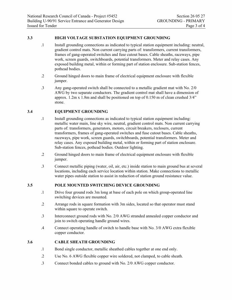
National Research Council of Canada - Project #5452 Section 26 05 27 Building U-90/91 Service Entrance and Generator Design GROUNDING - PRIMARY Issued for Tender Page 3 of 4
3.3 HIGH VOLTAGE SUBSTATION EQUIPMENT GROUNDING
.1 Install grounding connections as indicated to typical station equipment including: neutral, gradient control mats. Non current carrying parts of: transformers, current transformers, frames of gang-operated switches and fuse cutout bases. Cable sheaths, raceways, pipe work, screen guards, switchboards, potential transformers. Meter and relay cases. Any exposed building metal, within or forming part of station enclosure. Sub-station fences, pothead bodies.
.2 Ground hinged doors to main frame of electrical equipment enclosure with flexible jumper.
.3 Any gang-operated switch shall be connected to a metallic gradient mat with No. 2/0 AWG by two separate conductors. The gradient control mat shall have a dimension of approx. 1.2m x 1.8m and shall be positioned on top of 0.150 m of clean crushed 3/4” stone.
3.4 EQUIPMENT GROUNDING
.1 Install grounding connections as indicated to typical station equipment including: metallic water main, line sky wire, neutral, gradient control mats. Non current carrying parts of: transformers, generators, motors, circuit breakers, reclosers, current transformers, frames of gang-operated switches and fuse cutout bases. Cable sheaths, raceways, pipe work, screen guards, switchboards, potential transformers. Meter and relay cases. Any exposed building metal, within or forming part of station enclosure. Sub-station fences, pothead bodies. Outdoor lighting.
.2 Ground hinged doors to main frame of electrical equipment enclosure with flexible jumper.
.3 Connect metallic piping (water, oil, air, etc.) inside station to main ground bus at several locations, including each service location within station. Make connections to metallic water pipes outside station to assist in reduction of station ground resistance value.
3.5 POLE MOUNTED SWITCHING DEVICE GROUNDING
.1 Drive four ground rods 3m long at base of each pole on which group-operated line switching devices are mounted.
.2 Arrange rods in square formation with 3m sides, located so that operator must stand within square to operate switch.
.3 Interconnect ground rods with No. 2/0 AWG stranded annealed copper conductor and join to switch operating handle ground wires.
.4 Connect operating handle of switch to handle base with No. 3/0 AWG extra flexible copper conductor.
3.6 CABLE SHEATH GROUNDING
.1 Bond single conductor, metallic sheathed cables together at one end only.
.2 Use No. 6 AWG flexible copper wire soldered, not clamped, to cable sheath.
.3 Connect bonded cables to ground with No. 2/0 AWG copper conductor.

National Research Council of Canada - Project #5452 Section 26 05 27 Building U-90/91 Service Entrance and Generator Design GROUNDING - PRIMARY Issued for Tender Page 4 of 4
3.7 FIELD QUALITY CONTROL
.1 Perform tests in accordance with Section 26 05 10 – Electrical Testing.
.2 The station ground grid resistance will be measured after completion of construction and changes if required shall be made to ensure that the design resistance was achieved. Use the ‘Fall of Potential’ method as per IEEE 81-1983, ‘IEEE Guide for Measuring Earth Resistivity, Ground Impedance, and Earth Surface Potentials of a Ground System’ to satisfy OESC Rule 36-304 (4).
.3 The ‘Fall of Potential’ measurement steps should be from 10 to 90% percent of the full distance at 5% increments. The full distance from C1 to C2 must be at least 12 times the longest dimension across the ground grid, requiring lead lengths typically at least 150m. The ground straps between the building and external substation should be lifted (unless required as part of the design) to remove the influence of the building upon the ground electrode resistance. Ensure and provide documentation that a proper 4 probe measurement device is being used to remove the error introduced by the C1/C2 lead lengths. The resultant readings should be tabulated and graphed to show the point of inflection to determine the actual station resistance.
.4 Please note that this measurement has the potential to be hazardous during live operation of the substation (in the event of a fault) and should only be performed if safe conditions can be arranged, preferably while the station is de-energized.
.5 Perform test before energizing electrical system.
END OF SECTION

National Research Council of Canada - Project #5452 Section 26 05 28 Building U-90/91 Service Entrance and Generator Design GROUNDING - SECONDARY Issued for Tender Page 1 of 3
Part 1 General
1.1 RELATED REQUIREMENTS
.1 Section 26 05 27 – Primary Grounding
1.2 REFERENCE STANDARDS
.1 American National Standards Institute /Institute of Electrical and Electronics Engineers (ANSI/IEEE)
.1 ANSI/IEEE 837, IEEE Standard for Qualifying Permanent Connections Used in Substation Grounding.
.2 CSA International
1.3 ACTION AND INFORMATIONAL SUBMITTALS
.1 Submit in accordance with Section 01 33 00 - Submittal Procedures.
.2 Product Data:
.1 Submit manufacturer's instructions, printed product literature and data sheets for grounding equipment and include product characteristics, performance criteria, physical size, finish and limitations.
1.4 CLOSEOUT SUBMITTALS
.1 Submit in accordance with Section 01 78 00 - Closeout Submittals.
1.5 DELIVERY, STORAGE AND HANDLING
.1 Delivery and Acceptance Requirements: deliver materials to site in original factory packaging, labelled with manufacturer's name and address.
.2 Storage and Handling Requirements:
.1 Store materials indoors, in dry location, off ground and in accordance with manufacturer's recommendations in clean, dry, well-ventilated area.
.2 Store and protect grounding equipment from nicks, scratches, and blemishes.
.3 Replace defective or damaged materials with new.
Part 2 Products
2.1 EQUIPMENT
.1 Copper conductor: bare, stranded, soft annealed, size as indicated.
.2 Rod electrodes: 19mm diameter copper clad steel by minimum 3m long.
.3 Grounding conductors: bare stranded copper, soft annealed, size as indicated.
.4 Insulated grounding conductors: green, copper conductors, size as indicated.

National Research Council of Canada - Project #5452 Section 26 05 28 Building U-90/91 Service Entrance and Generator Design GROUNDING - SECONDARY Issued for Tender Page 2 of 3
.5 Non-corroding accessories necessary for grounding system, type, size, material as indicated, including but not necessarily limited to:
.1 Grounding and bonding bushings.
.2 Protective type clamps.
.3 Bolted type conductor connectors.
.4 Thermit welded type conductor connectors.
.5 Bonding jumpers, straps.
.6 Pressure wire connectors.
Part 3 Execution
3.1 EXAMINATION
.1 Verification of Conditions: verify that conditions of substrate previously installed under other Sections or Contracts are acceptable for grounding equipment installation in accordance with manufacturer's written instructions.
.1 Visually inspect substrate in presence of Departmental Representative.
.2 Inform Departmental Representative of unacceptable conditions immediately upon discovery.
.3 Proceed with installation only after unacceptable conditions have been remedied and after receipt of written approval to proceed from Departmental Representative.
3.2 INSTALLATION GENERAL
.1 Install complete permanent, continuous grounding system including, electrodes, conductors, connectors, accessories. Where EMT is used, run ground wire in conduit.
.2 Install connectors in accordance with manufacturer's instructions.
.3 Protect exposed grounding conductors from mechanical injury.
.4 Make buried connections, and connections to conductive water main, electrodes, using copper welding by thermit process.
.5 Use mechanical connectors for grounding connections to equipment provided with lugs.
.6 Soldered joints not permitted.
.7 Install bonding wire for flexible conduit, connected at one end to grounding bushing, solderless lug, clamp or cup washer and screw. Neatly cleat bonding wire to exterior of flexible conduit.
.8 Install flexible ground straps for bus duct enclosure joints, where such bonding is not inherently provided with equipment.
.9 Bond single conductor, metallic armoured cables to cabinet at supply end, and provide non-metallic entry plate at load end.
.10 Ground secondary service pedestals.

National Research Council of Canada - Project #5452 Section 26 05 28 Building U-90/91 Service Entrance and Generator Design GROUNDING - SECONDARY Issued for Tender Page 3 of 3
3.3 ELECTRODES
.1 Make ground connections to continuously conductive underground water pipe on street side of water meter.
.2 Install water metre shunt.
.3 Install concrete encased electrodes in building foundation footings, with terminal connected to grounding network.
.4 Install rod electrodes and make grounding connections as indicated.
.5 Bond separate, multiple electrodes together.
.6 Use size 2/0 AWG copper conductors for connections to electrodes.
.7 Make special provision for installing electrodes that will give acceptable resistance to ground value where rock or sand terrain prevails. Ground as indicated.
3.4 SYSTEM AND CIRCUIT GROUNDING
.1 Install system and circuit grounding connections to transformer neutral.
3.5 EQUIPMENT GROUNDING
.1 Install grounding connections to typical equipment included in, but not necessarily limited to following list. Service equipment, transformers, switchgear, duct systems, frames of motors, motor control centres, starters, control panels, building steel work, generators, elevators and escalators, distribution panels, outdoor lighting, cable trays.
3.6 FIELD QUALITY CONTROL
.1 Perform tests in accordance with Section 26 05 10 – Electrical Testing.
.2 Perform ground continuity and resistance tests using method appropriate to site conditions and to approval of Departmental Representative and local authority having jurisdiction over installation.
.3 Perform tests before energizing electrical system.
.4 Disconnect ground fault indicator during tests.
END OF SECTION


National Research Council of Canada - Project #5452 Section 26 05 29 Building U-90/91 Service Entrance and Generator Design HANGERS AND SUPPORTS FOR ELECTRICAL SYSTEMS Issued for Tender Page 1 of 2
Part 1 General
1.1 RELATED REQUIREMENTS
.1 Section 26 05 00 – Common Work Results for Electrical
1.2 REFERENCE STANDARDS
.1 Not applicable.
1.3 ACTION AND INFORMATIONAL SUBMITTALS
.1 Submit in accordance with Section 01 33 00 - Submittal Procedures.
1.4 DELIVERY, STORAGE AND HANDLING
.1 Deliver, store and handle materials in accordance with Section with manufacturer's written instructions.
Part 2 Products
2.1 SUPPORT CHANNELS
.1 U shape, size 41 x 41mm, 2.5mm thick, set in poured concrete walls and ceilings, suspended, surface mounted.
Part 3 Execution
3.1 INSTALLATION
.1 Secure equipment to solid masonry, tile and plaster surfaces with lead anchors or nylon shields.
.2 Secure equipment to poured concrete with expandable inserts.
.3 Secure equipment to hollow masonry walls or suspended ceilings with toggle bolts.
.4 Secure surface mounted equipment with twist clip fasteners to inverted T bar ceilings. Ensure that T bars are adequately supported to carry weight of equipment specified before installation.
.5 Support equipment, conduit or cables using clips, spring loaded bolts, cable clamps designed as accessories to basic channel members.
.6 Fasten exposed conduit or cables to building construction or support system using straps.
.1 One-hole malleable iron straps to secure surface conduits and cables 50 mm and smaller.
.2 Two-hole steel straps for conduits and cables larger than 50 mm.
.3 Beam clamps to secure conduit to exposed steel work.

National Research Council of Canada - Project #5452 Section 26 05 29 Building U-90/91 Service Entrance and Generator Design HANGERS AND SUPPORTS FOR ELECTRICAL SYSTEMS Issued for Tender Page 2 of 2
.7 Suspended support systems.
.1 Support individual cable or conduit runs with 6 mm diameter threaded rods and spring clips.
.2 Support 2 or more cables or conduits on channels supported by 6 mm diameter threaded rod hangers where direct fastening to building construction is impractical.
.8 For surface mounting of two or more conduits use channels at 1m on centre spacing.
.9 Provide metal brackets, frames, hangers, clamps and related types of support structures where indicated or as required to support conduit and cable runs.
.10 Ensure adequate support for raceways and cables dropped vertically to equipment where there is no wall support.
.11 Do not use wire lashing or perforated strap to support or secure raceways or cables.
.12 Do not use supports or equipment installed for other trades for conduit or cable support except with permission of other trade and approval of Departmental Representative.
.13 Install fastenings and supports as required for each type of equipment cables and conduits, and in accordance with manufacturer's installation recommendations.
END OF SECTION

National Research Council of Canada - Project #5452 Section 26 05 32 Building U-90/91 Service Entrance and Generator Design OUTLET BOXES, CONDUIT BOXES AND FITTINGS Issued for Tender Page 1 of 2
Part 1 General
1.1 RELATED REQUIREMENTS
.1 Section 26 05 00 – Common Work Results for Electrical
1.2 REFERENCE STANDARDS
.1 Canadian Standards Association (CSA International)
.1 CSA C22.1, Canadian Electrical Code, Part 1, 20th Edition.
1.3 ACTION AND INFORMATIONAL SUBMITTALS
.1 Provide submittals in accordance with Section 01 33 00 - Submittal Procedures.
Part 2 Products
2.1 OUTLET AND CONDUIT BOXES GENERAL
.1 Size boxes in accordance with CSA C22.1.
.2 102mm square or larger outlet boxes as required.
.3 Gang boxes where wiring devices are grouped.
.4 Blank cover plates for boxes without wiring devices.
.5 347 V outlet boxes for 347 V switching devices.
.6 Combination boxes with barriers where outlets for more than one system are grouped.
2.2 CONCRETE BOXES
.1 Electro-galvanized sheet steel concrete type boxes for flush mount in concrete with matching extension and plaster rings as required.
2.3 CONDUIT BOXES
.1 Cast FS or FD boxes with factory-threaded hubs and mounting feet for surface wiring of devices.
2.4 OUTLET BOXES FOR NON-METALLIC SHEATHED CABLE
.1 Electro-galvanized, sectional, screw ganging steel boxes, minimum size 76 x 50 x 63mm with two double clamps to take non-metallic sheathed cables.
2.5 FITTINGS - GENERAL
.1 Bushing and connectors with nylon insulated throats.
.2 Knock-out fillers to prevent entry of debris.
.3 Conduit outlet bodies for conduit up to 35mm and pull boxes for larger conduits.

National Research Council of Canada - Project #5452 Section 26 05 32 Building U-90/91 Service Entrance and Generator Design OUTLET BOXES, CONDUIT BOXES AND FITTINGS Issued for Tender Page 2 of 2
.4 Double locknuts and insulated bushings on sheet metal boxes.
2.6 SERVICE FITTINGS
.1 'High tension' receptacle fitting made of 2 piece die-cast aluminum with brushed aluminum housing finish for two duplex receptacles. Bottom plate with two knockouts for centered or offset installation. 12 x 102 mm extension piece as indicated.
Part 3 Execution
3.1 INSTALLATION
.1 Support boxes independently of connecting conduits.
.2 Fill boxes with paper, sponges or foam or similar approved material to prevent entry of debris during construction. Remove upon completion of work.
.3 For flush installations mount outlets flush with finished wall using plaster rings to permit wall finish to come within 6 mm of opening.
.4 Provide correct size of openings in boxes for conduit, mineral insulated and armoured cable connections. Do not install reducing washers.
.5 Vacuum clean interior of outlet boxes before installation of wiring devices.
.6 Identify systems for outlet boxes as required.
END OF SECTION

National Research Council of Canada - Project #5452 Section 26 05 34 Building U-90/91 Service Entrance and Generator Design CONDUITS, CONDUIT FASTENINGS AND CONDUIT FITTINGS Issued for Tender Page 1 of 3
Part 1 General
1.1 RELATED REQUIREMENTS
.1 Section 26 05 00 – Common Work Results for Electrical
1.2 REFERENCE STANDARDS
.1 Canadian Standards Association (CSA International)
.1 CAN/CSA C22.2 No. 18-06(R2003), Outlet Boxes, Conduit Boxes, Fittings and Associated Hardware, A National Standard of Canada.
.2 CSA C22.2 No. 45-M1981(R2003), Rigid Metal Conduit.
.3 CSA C22.2 No. 56-13, Flexible Metal Conduit and Liquid-Tight Flexible Metal Conduit.
.4 CSA C22.2 No. 83-M1985(R2003), Electrical Metallic Tubing.
.5 CSA C22.2 No. 211.2-M1984(R2003), Rigid PVC (Unplasticized) Conduit.
.6 CAN/CSA C22.2 No. 227.3-05(R2010), Flexible Nonmetallic Tubing.
1.3 ACTION AND INFORMATIONAL SUBMITTALS
.1 Provide submittals in accordance with Section 01 33 00 - Submittal Procedures.
Part 2 Products
2.1 CABLES AND REELS
.1 Provide cables on reels or coils.
.1 Mark or tag each cable and outside of each reel or coil, to indicate cable length, voltage rating, conductor size, and manufacturer's lot number and reel number.
.2 Each coil or reel of cable to contain only one continuous cable without splices.
.3 Identify cables for exclusively dc applications.
.4 Reel and mark shielded cables rated 2,001volts and above.
2.2 CONDUITS
.1 Rigid metal conduit: to CSA C22.2 No. 45, galvanized steel threaded.
.2 Electrical metallic tubing (EMT): to CSA C22.2 No. 83.
.3 Rigid PVC conduit: to CSA C22.2 No. 211.2.
.4 Flexible metal conduit: to CSA C22.2 No. 56, liquid-tight flexible metal.
2.3 CONDUIT FASTENINGS
.1 One hole malleable iron straps to secure surface conduits 50 mm and smaller.

National Research Council of Canada - Project #5452 Section 26 05 34 Building U-90/91 Service Entrance and Generator Design CONDUITS, CONDUIT FASTENINGS AND CONDUIT FITTINGS Issued for Tender Page 2 of 3
.1 Two hole steel straps for conduits larger than 50 mm.
.2 Beam clamps to secure conduits to exposed steel work.
.3 Channel type supports for two or more conduits at 1m on centre.
.4 Threaded rods, 6mm diameter, to support suspended channels.
2.4 CONDUIT FITTINGS
.1 Fittings: to CAN/CSA C22.2 No. 18, manufactured for use with conduit specified. Coating: same as conduit.
.2 Ensure factory "ells" where 90 degrees bends for 25 mm and larger conduits.
.3 Watertight connectors and couplings for EMT.
.1 Set-screws are not acceptable.
2.5 EXPANSION FITTINGS FOR RIGID CONDUIT
.1 Weatherproof expansion fittings with internal bonding assembly suitable for 100mm linear expansion.
.2 Watertight expansion fittings with integral bonding jumper suitable for linear expansion and 19 mm deflection.
.3 Weatherproof expansion fittings for linear expansion at entry to panel.
2.6 FISH CORD
.1 Polypropylene.
Part 3 Execution
3.1 MANUFACTURER'S INSTRUCTIONS
.1 Compliance: comply with manufacturer's written recommendations or specifications, including product technical bulletins, handling, storage and installation instructions, and datasheets.
3.2 INSTALLATION
.1 Install conduits to conserve headroom in exposed locations and cause minimum interference in spaces through which they pass.
.2 Conceal conduits except in mechanical and electrical service rooms and in unfinished areas.
.3 Surface mount conduits except where otherwise noted.
.4 Use electrical metallic tubing (EMT) above 2.4 m not subject to mechanical injury.
.5 Use rigid PVC conduit underground.
.6 Use flexible metal conduit for work in movable metal partitions.

National Research Council of Canada - Project #5452 Section 26 05 34 Building U-90/91 Service Entrance and Generator Design CONDUITS, CONDUIT FASTENINGS AND CONDUIT FITTINGS Issued for Tender Page 3 of 3
.7 Use liquid tight flexible metal conduit for connection to motors or vibrating equipment in damp, wet or corrosive locations.
.8 Bend conduit cold:
.1 Replace conduit if kinked or flattened more than 1/10th of its original diameter.
.9 Mechanically bend steel conduit over 19 mm diameter.
.10 Field threads on rigid conduit must be of sufficient length to draw conduits up tight.
.11 Install fish cord in empty conduits.
.12 Remove and replace blocked conduit sections.
.1 Do not use liquids to clean out conduits.
.13 Dry conduits out before installing wire.
3.3 SURFACE CONDUITS
.1 Run parallel or perpendicular to building lines.
.2 Locate conduits behind infrared or gas fired heaters with 1.5 m clearance.
.3 Run conduits in flanged portion of structural steel.
.4 Group conduits wherever possible on surface channels.
.5 Do not pass conduits through structural members except as indicated.
.6 Do not locate conduits less than 75 mm parallel to steam or hot water lines with minimum of 25 mm at crossovers.
3.4 CONCEALED CONDUITS
.1 Run parallel or perpendicular to building lines.
.2 Do not install horizontal runs in masonry walls.
.3 Do not install conduits in terrazzo or concrete toppings.
3.5 CONDUITS UNDERGROUND
.1 Slope conduits to provide drainage.
.2 Waterproof joints (PVC excepted) with heavy coat of bituminous paint.
.3 Encase conduits in concrete
END OF SECTION

National Research Council of Canada - Project #5452 Section 26 05 43.01 Building U-90/91 Service Entrance and Generator Design INSTALLATION OF CABLES IN TRENCHES AND IN DUCTS Issued for Tender Page 1 of 4
Part 1 General
1.1 RELATED REQUIREMENTS
.1 Section 26 05 00 – Common Work Results for Electrical
.2 Section 26 05 10 – Electrical Testing
.3 Section 31 23 10 – Excavating, Trenching and Backfilling
.4 Section 33 65 73 - Concrete Encased Duct Banks and Manholes
.5 Section 33 65 76 – Direct Buried Underground Cable Ducts
1.2 REFERENCE STANDARDS
.1 Insulated Cable Engineers Association, Inc. (ICEA)
1.3 ACTION AND INFORMATIONAL SUBMITTALS
.1 Submit in accordance with Section 01 33 00 - Submittal Procedures.
.2 Product Data:
.1 Submit manufacturer's instructions, printed product literature and data sheets for cables and include product characteristics, performance criteria, physical size, finish and limitations.
1.4 DELIVERY, STORAGE AND HANDLING
.1 Deliver, store and handle materials in accordance with Section with manufacturer's written instructions.
.2 Delivery and Acceptance Requirements: deliver materials to site in original factory packaging, labelled with manufacturer's name and address.
.3 Storage and Handling Requirements:
.1 Store materials indoors, in dry location, off ground and in accordance with manufacturer's recommendations in clean, dry, well-ventilated area.
.2 Store and protect cables from nicks, scratches, and blemishes.
.3 Replace defective or damaged materials with new.
Part 2 Products
2.1 CABLE PROTECTION
.1 38 x 140mm planks pressure treated with coloured or copper naphthenate or 5% pentachlorophenol solution, water repellent preservative.

National Research Council of Canada - Project #5452 Section 26 05 43.01 Building U-90/91 Service Entrance and Generator Design INSTALLATION OF CABLES IN TRENCHES AND IN DUCTS Issued for Tender Page 2 of 4
2.2 MARKERS
.1 Concrete type cable markers: 600 x 600 x 100mm with words: cable, joint or conduit impressed in top surface, with arrows to indicate change in direction of cable and duct runs.
.1 Cedar post type markers: to CAN/CSA-Z809 or FSC or SFI 89 x 89 mm, 1500 Mm long, pressure treated with coloured, or copper naphthenate or 5% pentachlorophenol solution, water repellent preservative, with nameplate fastened near post top, on side facing cable or conduit to indicate depth and direction of duct and cable runs.
.1 Nameplate: aluminum anodized 89 x 125mm, 1.5mm thick mounted on cedar post with mylar label 0.125 mm thick with words Cable, Joint or Conduit with arrows to indicate change in direction.
Part 3 Execution
3.1 EXAMINATION
.1 Verification of Conditions: verify that conditions of substrate previously installed under other Sections or Contracts are acceptable for cable installation in accordance with manufacturer's written instructions.
.1 Visually inspect substrate in presence of Departmental Representative.
.2 Inform Departmental Representative of unacceptable conditions immediately upon discovery.
.3 Proceed with installation only after unacceptable conditions have been remedied and after receipt of written approval to proceed from Departmental Representative.
3.2 DIRECT BURIAL OF CABLES
.1 After sand bed in accordance with Section 31 23 10 - Excavating, Trenching and Backfilling, is in place, lay cables maintaining 75mm clearance from each side of trench to nearest cable.
.1 Do not pull cable into trench.
.2 Include offsets for thermal action and minor earth movements.
.1 Offset cables 150 mm minimum for each 60 m run, maintaining minimum cable separation and bending radius requirements.
.3 Underground cable splices not acceptable.
.4 Minimum permitted radius at cable bends for rubber, plastic or lead covered cables, 8 times diameter of cable or in accordance with manufacturer's written recommendations; for metallic armoured cables, 12 times diameter of cables or in accordance with manufacturer's instructions.
.5 Cable separation:
.1 Maintain 75 mm minimum separation between cables of different circuits.

National Research Council of Canada - Project #5452 Section 26 05 43.01 Building U-90/91 Service Entrance and Generator Design INSTALLATION OF CABLES IN TRENCHES AND IN DUCTS Issued for Tender Page 3 of 4
.2 Maintain 300 mm minimum horizontal separation between low and high voltage cables.
.3 When low voltage cables cross high voltage cables maintain 300 mm vertical separation with low voltage cables in upper position.
.4 At crossover, maintain 75 mm minimum vertical separation between low voltage cables and 150 mm between high voltage cables.
.5 Maintain 300 mm minimum lateral and vertical separation for fire alarm and control cables when crossing other cables, with fire alarm and control cables in upper position.
.6 Install treated planks on lower cables 0.6 m minimum in each direction at crossings.
.6 After sand protective cover specified in Section 31 23 10 - Excavating, Trenching and Backfilling, is in place, install continuous row of interlocking cable blocks overlapping pressure treated planks as indicated to cover length of run.
3.3 CABLE INSTALLATION IN DUCTS
.1 Install cables as indicated in ducts.
.2 Do not pull spliced cables inside ducts.
.3 Install multiple cables in duct simultaneously.
.4 Use CSA approved lubricants of type compatible with cable jacket to reduce pulling tension.
.5 To facilitate matching of colour coded multiconductor control cables reel off in same direction during installation.
.6 Before pulling cable into ducts and until cables are properly terminated, seal ends of lead covered cables with wiping solder; seal ends of non-leaded cables with moisture seal tape.
.7 After installation of cables, seal duct ends with duct sealing compound.
3.4 MARKERS
.1 Mark cable every 150m along cable and duct runs and changes in direction.
.2 Where markers are removed to permit installation of additional cables, reinstall existing markers.
.3 Install cedar post type markers.
.4 Lay concrete markers flat and centred over cable with top flush with finish grade.
3.5 FIELD QUALITY CONTROL
.1 Perform tests in accordance with Section 26 05 00 - Common Work Results for Electrical.
.2 Perform tests using qualified personnel.
.1 Include necessary instruments and equipment.

National Research Council of Canada - Project #5452 Section 26 05 43.01 Building U-90/91 Service Entrance and Generator Design INSTALLATION OF CABLES IN TRENCHES AND IN DUCTS Issued for Tender Page 4 of 4
.3 Check phase rotation and identify each phase conductor of each feeder.
.4 Check each feeder for continuity, short circuits and grounds.
.1 Ensure resistance to ground of circuits is not less than 50 megohms.
.5 Pre-acceptance tests:
.1 After installing cable but before splicing and terminating, perform insulation resistance test with 1000V megger on each phase conductor.
.2 Check insulation resistance after each splice and/or termination to ensure that cable system is ready for acceptance testing.
.6 Acceptance Tests:
.1 Perform tests in accordance with Section 26 05 10 – Electrical Testing.
.7 Provide Departmental Representative with list of test results showing location at which each test was made, circuit tested and result of each test.
.8 Remove and replace entire length of cable if cable fails to meet any of test criteria.
3.6 CLEANING
.1 Leave Work area clean at end of each day.
3.7 PROTECTION
.1 Repair damage to adjacent materials caused by cables installation.
END OF SECTION

National Research Council of Canada - Project #5452 Section 26 09 23.01 Building U-90/91 Service Entrance and Generator Design METERING AND SWITCHBOARD INSTRUMENTS Issued for Tender Page 1 of 4
Part 1 General
1.1 RELATED REQUIREMENTS
.1 Section 26 05 00 – Common Work Results for Electrical
1.2 REFERENCE STANDARDS
.1 CSA International
.1 CAN3-C17-M84(R2015), Alternating - Current Electricity Metering.
1.3 ACTION AND INFORMATIONAL SUBMITTALS
.1 Submit in accordance with Section 01 33 00 - Submittal Procedures.
.2 Indicate meter, outline dimensions, panel drilling dimensions and include cutout template.
.3 Include complete wiring diagrams for all existing and new wiring from instrument transformers through all terminal blocks, to digital metering system. Ensure all wiring numbers are unique and logically assigned.
1.4 DELIVERY, STORAGE AND HANDLING
.1 Delivery and Acceptance Requirements: deliver materials to site in original factory packaging, labelled with manufacturer's name and address.
1.5 WARRANTY
.1 The manufacturer to warrant the meters for three (3) years from the acceptance date.
Part 2 Products
2.1 DIGITAL METERING SYSTEM (DMS)
.1 Main incoming feed is to be equipped with a polyphase, digital electrical meter, capable of performing the following measurements:
.1 Power, Energy, and Demand
.1 Voltage and Current per phase/neutral/ground; max, min, average, unbalance
.2 Power: real, reactive, apparent, power factor, frequency
.3 Energy: bi-directional, total, import, export, net
.4 Demand: block, rolling block, thermal, predicted
.2 Power Quality
.1 Sag/Swell monitoring
.2 Harmonics: individual, even, odd, total up to 63rd
.3 Sampling rate, maximum samples per cycle, 512
National Research Council of Canada - Project #5452 Section 26 09 23.01 Building U-90/91 Service Entrance and Generator Design METERING AND SWITCHBOARD INSTRUMENTS Issued for Tender Page 2 of 4
.4 Transient detection, 5MHz
.5 Flicker
.3 Logging and Recording
.1 Minimum memory capacity 32MB
.2 Min/max logging for any parameter
.3 Timestamp resolution in seconds, 1ms
.4 Historical trend information via front panel display
.5 Adjustable setpoints
.4 Communications and I/O
.1 IEC61850
.2 RS-232 ports, 1, for local programming
.3 RS-485 ports, 1, with Modbus RTU slave protocol
.4 Ethernet ports, 1, 10/100 Base-T, Ethernet TCP/IP
.5 Digital inputs, 8, configurable for various alarms
.6 Relay outputs, 3, configurable for various alarms
.7 KYZ solid state outputs, 1
.8 Analog output, 2, configurable for various parameters
.9 Embedded Web Server
.5 Revenue Metering & Standards
.1 ANSI C12.16 accuracy compliant
.2 ANSI C12.20 0.2 compliant, Class 10 & 20
.3 Instrument Transformer Correction
.2 .2 5 Amp, 120 Volt standard input
.3 Device shall be two part unit, allowing current and voltage input portion to be placed at the back of the cubicle, and readout or faceplate to be mounted on door of cubicle for easy access.
.4 Acceptable Products:
.1 Schneider Electric (PML) 7650
2.2 TEST AND SHORTING TERMINAL BLOCKS
.1 Provide and install Shorting Terminal Blocks in the secondary circuits of all current transformers associated with the meters, if not already present.
.2 Where indicated on the drawings, provide Test Shorting Blocks (similar to Westinghouse Flexi-test style) on all instrument transformers associated with the meters.
.1 Testing Terminal Blocks shall be ABB Flexitest, AVO, or equivalent
.1 Provide 10 pole units to allow interruption of all voltage and current inputs
National Research Council of Canada - Project #5452 Section 26 09 23.01 Building U-90/91 Service Entrance and Generator Design METERING AND SWITCHBOARD INSTRUMENTS Issued for Tender Page 3 of 4
.2 Ensure Testing switch is designed and wired to allow current and voltage inputs to bypass meter or device under test and continue to next device on the shared instrument transformer secondary without interruption.
2.3 COMMUNICATION PORT
.1 Provide and mount Cat 6e Ethernet communication port with metal flip cover on control cubicle door, similar to Hubbell Panel-Safe Power and Data Access Port.
.2 Provide Ethernet wiring or patch cord from DMS base module Ethernet port to Cubicle Door Ethernet port
.3 Support and protect patch cord within hinge-crossing plastic spiral wrapped wire bundle.
Part 3 Execution
3.1 METERING INSTALLATION
.1 Install meters in location free from vibration and shock.
.2 Make connections in accordance with manufacturer’s diagrams. Ensure connections across a hinged opening are completely protected by flexible plastic protective spiral wrap and are pre-flexed and arranged to ensure wiring does not get pinched in the door or impinge upon terminal blocks or other devices.
.3 If applicable, ensure power factor corrective equipment connected on load side of meter.
.4 Connect meter cabinets to ground.
.5 Locate meters within 9 m of instrument transformers. Use 32 mm conduit for interconnections. Use separate conduit for each set of current transformer connections, exclusive for metering.
.6 All voltage sensing connections shall be made with 2A fuses.
.7 Meters must be powered from an auxiliary power supply, and not powered from the same potential transformers feeding the voltage sensing inputs.
3.2 INSTALLATION ON SHOP
.1 Install meters, instrument transformers, and accessories in control compartment of switchboard.
.2 Install meter faceplate on switchboard door in punched hole on door.
3.3 SETUP AND COMMISSIONING
.1 Select and program meter with correct system and control parameters.
.2 Select and program meter with typical thresholds for alarms, typical trending values, and other advanced system parameters. Typical parameters values would have to be modified for the specifics of each installation area but would typically include the following:
.1 Trend every 15 minutes on typical system parameters such as phase and average amps, volts, kW, kVA, PF, kWHr, THD current, THD voltage, etc.

National Research Council of Canada - Project #5452 Section 26 09 23.01 Building U-90/91 Service Entrance and Generator Design METERING AND SWITCHBOARD INSTRUMENTS Issued for Tender Page 4 of 4
.2 Alarm on surges or sags outside of acceptable CAN/CSA 235 normal voltage limits.
.3 Alarm and save waveforms for transients outside of acceptable CAN/CSA 235 extreme voltage limits.
.4 Alarm on THD’s outside of normal limits, typically 20% for current and 5% voltage, but set per the location installed
.5 All setup parameters for communications and I/O, including scaling for analog I/O and logical mapping for digital I/O
.6 Memory should be set on a first-in first-out configuration
.3 Provide complete list of initial programming setup values to the client for review and acceptance.
3.4 FIELD QUALITY CONTROL
.1 Megger all wiring with meter disconnected.
.2 Conduct tests in accordance with Section 26 05 00 - Electrical General Requirements and in accordance with manufacturer's recommendations.
.3 Perform simulated operation tests with metering, instruments disconnected from permanent signal and other electrical sources.
.4 Verify correctness of connections, polarities and calibration of instrument transformers, correct scaling of meters, and acceptable inputs or outputs from transducers, signal sources, and electrical supplies.
.5 Communications outputs of the relay shall be tested and proved to be working before acceptance by the Owner, even if meters are not connected to networking at time of installation.
.6 Perform tests to confirm correct calibration.
3.5 PROTECTION
.1 Protect installed products and components from damage during construction.
.2 Repair damage to adjacent materials caused by metering and switchboard instrument installation.
END OF SECTION

National Research Council of Canada - Project #5452 Section 26 11 00.01 Building U-90/91 Service Entrance and Generator Design OUTDOOR SUBSTATION TO 27.6 KV Issued for Tender Page 1 of 4
Part 1 General
1.1 RELATED REQUIREMENTS
.1 Section 26 05 00 – Common Work Results for Electrical
.2 Section 33 65 73 - Concrete Encased Duct Banks and Manholes
.3 Section 31 05 16 – General Aggregates
.4 Section 03 30 00 - Cast-in-Place Concrete
.5 Section 26 05 27 - Grounding – Primary
1.2 REFERENCE STANDARDS
.1 American National Standards Institute (ANSI)
.1 A ANSI/NEMA C29.18-2013 American National Standard for Composite Insulators.
.2 Canadian Standards Association (CSA International)
.1 CSA C22.2 No. 31-2014 – Switchgear Assemblies
.2 CAN/CSA C227.4 - 06 Three-phase, Pad-Mounted Distribution Transformers with Separable Insulated High-Voltage Connectors
.3 CSA-G40.20-04/G40.21-04, General Requirements for Rolled or Welded Structural Quality Steel/Structural Quality Steels.
.4 CAN/CSA S16-01, Consolidated (This is a consolidated reprint, incorporating Update No. 1 - June 2003, Update No. 2 - December 2003 and Supplement No. 1 - January 2005).
.5 CAN/CSA S16-01, Limit States Design of Steel Structures.
1.3 SYSTEM DESCRIPTION
.1 Supply system data: 27.6 kV primary voltage, 60Hz, 3 phase, 3 wire, grounded, 1,000kV, symmetrical fault capacity 150 kV BIL.
.2 Verify co-ordination of substation protection with NRC’s protection.
1.4 ACTION AND INFORMATIONAL SUBMITTALS
.1 Provide submittals in accordance with Section 01 33 00 - Submittal Procedures.
.2 Obtain certification from inspecting authority, for integrated items indicated on plot plan.
.3 Indicate:
.1 Floor anchoring method and dimensioned foundation drawings.
.2 Foundation loadings under loaded conditions.
.3 Dimensioned position and size of bus bars and connections showing electrical clearances.
.4 Identified dimensioned layout of components.
.5 Protection co-ordination time current characteristics.

National Research Council of Canada - Project #5452 Section 26 11 00.01 Building U-90/91 Service Entrance and Generator Design OUTDOOR SUBSTATION TO 27.6 KV Issued for Tender Page 2 of 4
.4 Submit structure design criteria for Departmental Representative's review.
.5 Quality Assurance Submittals:
.1 Certificates: submit certificates signed by manufacturer certifying that materials comply with specified performance characteristics and physical properties.
.2 Instructions: submit manufacturer's installation instructions.
.1 Departmental Representative will make available 1 copy of systems supplier's installation instructions.
.6 Closeout Submittals
.1 Provide operation and maintenance data for substation for incorporation into manual.
1.5 DELIVERY, STORAGE AND HANDLING
.1 Ship foundation anchoring devices in advance of substation structure.
1.6 SEQUENCING
.1 Co-ordinate time-current characteristics of protective fuses and relays.
1.7 EXTRA MATERIALS
.1 Three power fuse refills, non-expulsion type, of each type installed.
Part 2 Products
2.1 MATERIALS
.1 Concrete Encased Ductbanks and Manholes in accordance with Section 33 65 73 – Concrete Encased Ductbanks and Manholes.
.2 Steel structural members: to CSA-G40.20/G40.21.
.3 High tensile, hot dipped galvanized, bolts, nuts, washers: to CAN/CSA-S16.
.4 Support insulators, station post type, coloured grey: to ANSI C29.9.
.5 All parts of the Outdoor Substation (switchboards, panels, enclosures, transformers, etc.) shall be tamper resistant as defined by ESA Bulletin 36-15-*, and certified to standards CSA C22.2 No. 31 and CAN/CSA C227, Tamper Resistant Design.
.6 Overall short-circuit current rating of 25 kA rms symmetrical depending on installation location in the system.
2.2 CIRCUIT BREAKERS
.1 Circuit Breakers; to Section 26 24 13 - Switchboards.
2.3 FUSE CUTOUTS
.1 Fuse cutouts: to Section 26 28 13.01 - Fuse Cutouts and Fuse Links non-explosion type, with grey station post type insulators, operating hook stick and mounting bracket.

National Research Council of Canada - Project #5452 Section 26 11 00.01 Building U-90/91 Service Entrance and Generator Design OUTDOOR SUBSTATION TO 27.6 KV Issued for Tender Page 3 of 4
2.4 TRANSFORMERS
.1 Transformers: to Section 26 12 13 - Pad Mounted, Liquid Filled, Medium Voltage Transformers.
2.5 CABLE TERMINATIONS
.1 Cable terminations: to Section 26 05 22 - Connectors and Terminations.
2.6 LIGHTNING ARRESTERS
.1 Lightning arresters: to Section 26 41 01.01 - Primary Lightning Arresters.
2.7 METERING
.1 Metering: to Section 26 09 23.01 - Metering and Switchboard Instruments.
2.8 STRAIN INSULATORS
.1 Strain insulators: to Section 33 71 20 - Pole Lines and Hardware.
2.9 SUBSTATION GROUNDING
.1 Provide Substation grounding in accordance with Section 26 05 27 – Grounding - Primary and as shown on drawings.
2.10 GRAVEL
.1 Provide 150mm layer of clear, washed, 19mm limestone extending out 2m from transformer pad. in accordance with Section 31 05 16 – Aggregates Geneal and design drawings.
2.11 WARNING SIGNS
.1 Provide warning signs in accordance with Section 26 05 00 - Common Work Results for Electrical.
.2 Suitable warning signs shall be installed as required by OESC Rules 36-006, 36- 100(4) and ESA Bulletin 36-6*.
.3 Warning signs to caution against fuse changing.
.4 Danger signs, warning against high voltage as required by inspection department.
2.12 SINGLE LINE AND BLOCK DIAGRAMS
.1 Upon completion of the installation of the Outdoor Substation, the Contractor shall affix a single line diagram and block diagram as per Section 26 05 00 - Common Work Results for Electrical in compliance to OESC Rule 36-006.
.2 The contractor shall maintain up to date diagrams on the Outdoor Substation for the duration of the project.

National Research Council of Canada - Project #5452 Section 26 11 00.01 Building U-90/91 Service Entrance and Generator Design OUTDOOR SUBSTATION TO 27.6 KV Issued for Tender Page 4 of 4
Part 3 Execution
3.1 MANUFACTURER'S INSTRUCTIONS
.1 Compliance: comply with manufacturer's written recommendations or specifications, including product technical bulletins, handling, storage and installation instructions, and datasheets.
3.2 INSTALLATION
.1 Install underground ductbanks and manholes.
.2 Install substation grounding in and OESC Sections 10 and 36.
.3 Install Transformer, Switchboard and Panels and make field connections.
.4 Connect equipment, lightning arrestors, structure to station ground system.
.5 Co-ordinate connection to supply, with power supply authority. Identify phases.
3.3 FIELD QUALITY CONTROL
.1 Perform tests in accordance with Section 26 05 00 - Common Work Results for Electrical.
.2 Arrange for pre-service inspection, oil sample and insulation test.
.3 Operate interrupter closing and tripping mechanism and verify correct functioning.
.4 Simulate instrument transformer, transducer signal sources of protective relays, check relays for correct operation, calibration, settings.
.5 Perform dc voltage test for 15 kV cables.
.6 Check insulation of substation assembly with 1000 V megger with feeder cables and connections disconnected.
.7 Conduct high potential tests on substation assembly to Departmental Representative's written instructions.
.8 Verify phase rotation of each feeder.
.9 Check continuity of each feeder.
END OF SECTION

National Research Council of Canada - Project #5452 Section 26 12 19 Building U-90/91 Service Entrance and Generator Design PAD MOUNTED, LIQUID FILLED, MEDIUM VOLTAGE TRANSFORMERS Issued for Tender Page 1 of 7
Part 1 General
1.1 RELATED REQUIREMENTS
.1 Section 26 05 00 – Common Work Results for Electrical.
1.2 REFERENCE STANDARDS
.1 American National Standards Institute (ANSI)/Institute of Electrical and Electronics Engineers, Inc. (IEEE)
.1 ANSI/IEEE 386-95(R2001), Separable Insulated Connector Systems for Power Distribution Systems Above 600 V.
.2 ANSI/IEEE C57.12.00 - 2010 Standard General Requirements for Liquid-Immersed Distribution, Power and Regulating Transformers
.3 ANSI/IEEE C57.12.22 - 1995 Pad-Mounted, Compartmental-Type, Self-Cooled Three-Phase Distribution Transformer with High-Voltage Bushings, 2500 kVA and Smaller: High Voltage, 34500 Grd Y / 19920 Volts and Below; Low Voltage, 480 Volts and Below
.4 ANSI/IEEE C57.12.26 - 1992 Pad-Mounted, Compartmental-Type, Self-Cooled, Three-Phase Distribution Transformer with Separable Insulated High-Voltage Connectors (34500 Grd Y / 19920 Volts and Below; 2500 kVA and Smaller)
.5 ANSI/IEEE C57.12.28 - 2005 Standard for Pad-Mounted Equipment Enclosure Integrity
.6 ANSI/IEEE C57.12.90 - 2010 Standard Test Code for Liquid Immersed Distribution, Power, and Regulating Transformers
.7 ANSI/IEEE C57.106 - 2006 Guide for Acceptance and Maintenance of Insulating Oil in Equipment
.2 Canadian Standards Association (CSA International)
.1 CAN/CSA C88-M90 (R2009) – Power Transformers and Reactors.
.2 CAN/CSA-C2.1-06, Single-Phase and Three Phase Distribution Transformers
.3 CSA C227.4-06, Three-phase, Pad-Mounted Distribution Transformers with Separable Insulated High-Voltage Connectors
.4 CAN/CSA-C802.3-2015, Minimum Efficiency Values for Power Transformers
1.3 ACTION AND INFORMATIONAL SUBMITTALS
.1 Provide submittals in accordance with Section 01 33 00 - Submittal Procedures.
.2 Product Data:
.1 Submit manufacturer's printed product literature, specifications and datasheet and include product characteristics, performance criteria, and limitations.
.3 Submit shop drawings and indicate:
.1 Transformer: type, rating, weight and descriptive information.

National Research Council of Canada - Project #5452 Section 26 12 19 Building U-90/91 Service Entrance and Generator Design PAD MOUNTED, LIQUID FILLED, MEDIUM VOLTAGE TRANSFORMERS Issued for Tender Page 2 of 7
.2 General outline drawing of complete assembly showing the enclosure and transformer dimensions, the layout of the equipment inside the enclosure and installation methods.
.3 Oil type.
.4 Transformer nameplate data.
.5 Load-break switch: model, type, rating.
.6 NGR: model, type, rating.
.7 Anchoring method and dimensioned foundation template.
.8 Dimensioned cable entry locations.
.9 Dimensioned cable termination height.
.10 In addition to the above items the following shall also be supplied:
.1 Secondary bushing;
.2 Dead break elbows;
.3 All gauges;
.4 Tap switch; and
.5 Current limiting fuse.
.11 Factory Testing Results from tests outlined in Section 1.6.
.12 Terms of warranty.
.4 Identified internal and external component layout on assembly drawing.
.5 Insulating liquid capacity.
.6 Submit primary fuse and secondary breaker time-current characteristics.
1.4 DELIVERY, STORAGE AND HANDLING
.1 Ship the transformer completely assembled and oil filled suitably protected from damage during transportation.
1.5 MAINTENANCE
.1 Provide maintenance materials in accordance with Section 01 78 00 - Closeout Submittals.
.2 Include insulating liquid maintenance data.
.3 Provide recommended spare parts list.
1.6 INSPECTION AND FACTORY TESTING
.1 The transformer shall be inspected at each stage of manufacture in accordance with the Manufacturer’s Quality Assurance Program and shall be completely assembled in the works. All deficiencies shall be corrected before shipment.
.2 Each transformer shall be completely factory tested and the results certified, proving the performance of the units to provide capacities as listed in these Specifications.
.3 Supplier shall perform complete test on the transformer prior to shipping from the factory. Testing shall be performed in accordance with a written test plan, which

National Research Council of Canada - Project #5452 Section 26 12 19 Building U-90/91 Service Entrance and Generator Design PAD MOUNTED, LIQUID FILLED, MEDIUM VOLTAGE TRANSFORMERS Issued for Tender Page 3 of 7
complies with IEEE C57.12.90, CSA C2.1 and CSA C88. As a minimum, tests shall include the following for both 2.4kV and 13.8kV as primary voltage along with 13.8kV.
.1 DC resistance measurement on all windings.
.2 Ratio tests using all tap settings.
.3 Polarity and phase relation tests.
.4 Audible sound level tests (Type Test).
.5 Induced potential tests.
.6 Full wave impulse test.
.7 No load losses at rated voltages and losses at 25%, 50%, 75%, and 100% load.
.8 Total losses at rated current.
.9 Percent impedance and load loss test.
.10 Excitation current at rated voltage.
.11 Insulation test.
.12 Vacuum link test.
.13 Laboratory test of insulating liquid
.14 Oil sampling before and after testing.
.15 Applied potential test.
.16 Induced potential test.
.17 Impulse tests: Primary & Secondary (Type Test)
.18 Pressure test.
.19 Dissipation factor test.
.20 Heat run, temperature rise tests on one of each design of transformer. (Type Test). The heat run tests and impulse tests may be witnessed by the Departmental Representative. Submit test certificate to the Departmental Representative.
.4 Carry out following insulation tests using megger with 20,000 mega ohm scale and resulting insulation resistance corrected to base of 20°C:
.1 High voltage to ground with secondary grounded for duration of test.
.2 Low voltage to ground with primary grounded for duration of test.
.3 High to low voltage.
.5 Inspect primary and secondary connections for tightness and for signs of overheating.
.6 Inspect and clean bushings and insulators.
.7 Check oil level and temperature indicators.
.8 Set transformer taps to rated voltage as specified.
.9 Inspect for oil leaks and excessive rusting.
.10 Inspect for oil level.
.11 Check for grounding and neutral continuity between primary and secondary circuits of transformer

National Research Council of Canada - Project #5452 Section 26 12 19 Building U-90/91 Service Entrance and Generator Design PAD MOUNTED, LIQUID FILLED, MEDIUM VOLTAGE TRANSFORMERS Issued for Tender Page 4 of 7
.12 Contractor shall provide written test plan to Departmental Representative for review and approval prior to factory testing.
.13 Provide certified testing report as indicated in Section 1.3 to Departmental Representative for review.
.14 If the transformer test results are not acceptable, the core and oil must be replaced, and factory testing redone, including all reports of the same.
Part 2 Products
2.1 EQUIPMENT
.1 Separable insulated connectors for power distribution systems above 600 V: to ANSI/IEEE 386.
.2 Oil filled pad mounted distribution transformer complete with primary and secondary cable compartments, primary fused load-break switch, options and accessories to form complete factory assembled, self contained, steel fabricated unit for mounting on concrete pad.
.3 The terminals shall be designed as per the requirements of CSA C227.4, enclosed the high and low voltage compartments side by side, separated by steel barrier and bolted to transformer tank.
.4 Separable insulated connectors.
.5 Primary cable terminals with hole for 9.5 mm diameter, 16 thread bolt for attachment of solder lug or clamp connector in vertical plane.
.6 Spade type low voltage terminals - 4 hole NEMA.
.7 Connectors for primary and secondary cables to be supplied by contractor. Secondary lugs to be long shank 2 holes NEMA.
.8 Three fused three blade primary disconnect switches for:
.1 Single source primary feed.
.9 Primary protection current limiting fuse in load break dry well.
.10 28kV inserts BIL rating of 140kV
.11 Mechanical interlock to prevent access to primary compartment unless primary supply is isolated at source. Separate padlocking for primary compartment door.
.12 Three 27.6kV, lightning arresters: to Section 26 41 00.01 - Primary Lighting Arresters.
.13 Load break inserts for elbow connectors.
.14 Stays to hold compartment doors in 110 degrees open position.
2.2 TRANSFORMER CHARACTERISTICS
.1 Primary voltage: 27.6 kV, 60Hz, wye connected, 3phase, 3 wire
.2 Secondary voltage: 600 V, wye connected, 3 phase, 4 wire, neutral solidly grounded.

National Research Council of Canada - Project #5452 Section 26 12 19 Building U-90/91 Service Entrance and Generator Design PAD MOUNTED, LIQUID FILLED, MEDIUM VOLTAGE TRANSFORMERS Issued for Tender Page 5 of 7
.3 Capacity: 1000 kVA
.4 Basic impulse level: 125 kV
.5 Maximum rms short-circuit: 50kA
.6 Impedance: 5%
.7 Cooling method: self-cooled (KNAN).
.8 Insulating fluid: Envirotemp FR3 fire-resistance fluid.
.9 Winding conductors: copper.
.10 Sound level: in accordance with the requirement of CSA-C802.1-00
.11 Losses to C802.1-00
2.3 VOLTAGE TAPS
.1 Primary winding taps: full capacity high voltage taps, two 2.5% below and two 2.5% above the nominal voltage, externally operated off-circuit tap changer with provisions for locking the handle in any position.
2.4 ENCLOSURE
.1 Door bolts: Penta-head Hex Head
.2 Low voltage door with three-point latching mechanism, vault type handle, and single padlocking provision.
.3 High voltage door fastenings inaccessible until low voltage door has been opened.
2.5 TAP CHANGER
.1 Externally operated off-load tap changer, with provision for padlocking on 3 phase units.
2.6 ACCESSORIES
.1 Liquid temperature thermometer with one set of contacts.
.2 Liquid level gauge with one set of contacts.
.3 Pressure relief device.
.4 50 mm drain valve.
.5 25 mm filler plug.
2.7 GROUNDING
.1 Copper grounding bus size 5 x 25 mm.
.2 Connectors for grounding conductors size as indicated.
2.8 FINISH
.1 Finish exterior of unit in accordance with Section 26 05 00 - Common Work Results for Electrical.

National Research Council of Canada - Project #5452 Section 26 12 19 Building U-90/91 Service Entrance and Generator Design PAD MOUNTED, LIQUID FILLED, MEDIUM VOLTAGE TRANSFORMERS Issued for Tender Page 6 of 7
2.9 EQUIPMENT IDENTIFICATION
.1 Provide equipment identification in accordance with Section 26 05 00 - Common Work Results for Electrical.
.2 Nameplate showing information in accordance with CSA C2.
2.10 WARNING SIGNS
.1 Provide warning signs in accordance with Section 26 05 00 - Common Work Results for Electrical.
2.11 SOURCE QUALITY CONTROL
.1 Submit to Departmental Representative standard factory test certificates of each transformer and type test of each transformer with high voltage accessories in accordance with CSA C2.
Part 3 Execution
3.1 MANUFACTURER'S INSTRUCTIONS
.1 Compliance: comply with manufacturer's written recommendations or specifications, including product technical bulletins, handling, storage and installation instructions, and datasheets.
3.2 INSPECTION
.1 Check factory made connections of transformer unit for mechanical security and electrical continuity.
.2 Check transformer insulating liquid for correct quantity and specification according to manufacturer's instructions.
3.3 INSTALLATION
.1 Ensure concrete pad is fully cured before transformer is installed.
.2 Set and secure transformer unit in place, rigid, plumb and square.
.3 Make connections.
.4 Connect transformer unit ground bus to system ground.
.5 Wire one set of contacts on liquid temperature thermometer, liquid level gauge, to set of terminal blocks.
.6 Ensure care is taken to prevent contamination of liquid and components when field filling transformer.
.7 Use only metal hose when field-filling transformer with oil: do not use rubber hose.
.8 Set taps to produce rated secondary voltage at no-load.

National Research Council of Canada - Project #5452 Section 26 12 19 Building U-90/91 Service Entrance and Generator Design PAD MOUNTED, LIQUID FILLED, MEDIUM VOLTAGE TRANSFORMERS Issued for Tender Page 7 of 7
3.4 FIELD QUALITY CONTROL
.1 Perform tests in accordance with Section 26 05 00 - Common Work Results for Electrical and Section 26 05 10 - Electrical Testing.
.2 Carry out following insulation tests using megger with 20,000 megohm scale and resulting insulation resistance corrected to base of 20 degrees C.
.1 High voltage to ground with secondary grounded for duration of test.
.2 Low voltage to ground with primary grounded for duration of test.
.3 High to low voltage.
.3 Inspect primary and secondary connections for tightness and for signs of overheating.
.4 Inspect and clean bushings and insulators.
.5 Check oil level and temperature indicators.
.6 Set transformer taps to rated voltage as specified.
.7 Inspect for oil leaks and excessive rusting.
.8 Inspect oil level.
.9 Check fuses for correctness of type and size.
.10 Check for grounding and neutral continuity between primary and secondary circuits of transformer.
END OF SECTION


National Research Council of Canada - Project #5452 Section 26 22 19 Building U-90/91 Service Entrance and Generator Design CONTROL AND SIGNAL TRANSFORMERS Issued for Tender Page 1 of 2
Part 1 General
1.1 RELATED REQUIREMENTS
.1 Section 26 05 00 – Common Work Results for Electrical.
1.2 REFERENCE STANDARDS
.1 CSA International
.1 CSA C13-M83(R2015), Instrument Transformers.
1.3 ACTION AND INFORMATIONAL SUBMITTALS
.1 Submit in accordance with Section 01 33 00 - Submittal Procedures.
.2 Product Data:
.1 Submit manufacturer's instructions, printed product literature and data sheets for control and signal transformers and include product characteristics, performance criteria, physical size, finish and limitations.
1.4 CLOSEOUT SUBMITTALS
.1 Submit in accordance with Section 01 78 00 - Closeout Submittals.
.2 Operation and Maintenance Data: submit operation and maintenance data for control and signal transformers for incorporation into manual.
1.5 DELIVERY, STORAGE AND HANDLING
.1 Delivery and Acceptance Requirements: deliver materials to site in original factory packaging, labelled with manufacturer's name and address.
Part 2 Products
2.1 POTENTIAL TRANSFORMERS
.1 Potential transformers: to CSA C13, dry type for indoor use, with following characteristics:
.1 Nominal voltage class: 600V.
.2 Rated frequency: 60 Hz
.3 Basic impulse level: 600:120V
.4 Accuracy rating: 0.3 WXM
.2 Potential transformers equipped with fuse holder and fuses.
2.2 CURRENT TRANSFORMERS
.1 Current transformers: to CSA C13, dry type for indoor use with following characteristics:
.1 Nominal voltage class: 600V.

National Research Council of Canada - Project #5452 Section 26 22 19 Building U-90/91 Service Entrance and Generator Design CONTROL AND SIGNAL TRANSFORMERS Issued for Tender Page 2 of 2
.2 Rated frequency: 60 Hz
.3 Basic impulse level: 10 kV
.4 Metering accuracy rating: 0.3B0.9
.5 Rated primary and secondary current: 1.33@30C.
.2 Wiring on current transformer secondaries to be #10 AWG minimum.
.3 Positive action automatic short-circuiting device in secondary terminals.
.1 Standard of acceptance:
.1 Bussman KUXSC
.2 GE EB-27
2.3 MOUNTING BRACKETS
.1 Instrument transformers mounted and/or supported by channel type mounting brackets.
.2 Fabricate brackets and channels from electrogalvanized code gauge painted steel or GPO Glastic material, sized appropriately for mechanical stresses.
Part 3 Execution
3.1 INSTALLATION
.1 Install instrument transformers and ensure accessibility.
3.2 PROTECTION
.1 Protect installed products and components from damage during construction.
.2 Repair damage to adjacent materials caused by control and signal transformers installation.
END OF SECTION

National Research Council of Canada - Project #5452 Section 26 23 00 Building U-90/91 Service Entrance and Generator Design SECONDARY SWITCHBOARD Issued for Tender Page 1 of 5
Part 1 General
1.1 SECTION INCLUDES
.1 Materials and installation for low voltage switchgear.
1.2 RELATED SECTIONS
.1 Section 01 33 00 – Submittal Procedures
.2 Section 01 78 00 – Closeout Submittal
.3 Section 26 05 00 – Electrical General Requirement
.4 Section 26 28 16.02 – Moulded Case Circuit Breakers
.5 Section 26 09 23.01 – Metering and Switchboard Instruments
.6 Section 26 22 19 – Control and Signal Transformers
1.3 REFERENCES
.1 CAN/CSA-C22.2 No.31-M89(R2000), Switchgear Assemblies.
.2 NEMA SG-5 Power Switchgear Assemblies
.3 CSA C22.2 No.244 (R2015) Switchboards
1.4 SHOP DRAWINGS PRODUCT DATA
.1 Submit shop drawings and product data in accordance with Section 01 33 00 – Submittal Procedures.
.2 Indicate on shop drawings:
.1 Floor anchoring method and foundation template.
.2 Dimensioned cable entry and exit locations.
.3 Dimensioned position and size of bus.
.4 Overall length, height and depth of complete switchboard.
.5 Dimensioned layout of internal and front panel mounted components.
.6 Model numbers, Catalog numbers, Certifications, and Ratings of all components
.7 All field installed components shall be identified, with ratings
.3 Indicate on product data:
.1 Time-current characteristic curves for each type of solid state trip units.
1.5 QUALITY ASSURANCE
.1 Submit 6 copies of certified factory test results.

National Research Council of Canada - Project #5452 Section 26 23 00 Building U-90/91 Service Entrance and Generator Design SECONDARY SWITCHBOARD Issued for Tender Page 2 of 5
1.6 CLOSEOUT SUBMITTALS
.1 Provide maintenance data for secondary switchboard for incorporation into manual in accordance with Section 01 78 00 – Closeout Submittals.
.2 6 copies maintenance data for complete switchgear assembly including components.
1.7 STORAGE AND PROTECTION
.1 Store switchboard on site in protected, dry location. Cover with plastic to keep off dust.
.2 If not within climate controlled area, provide energized strip heater in each cell to maintain dry condition during storage.
.3 Replace defective or damaged material with new.
1.8 EXTRA MATERIALS
.1 Provide maintenance materials in accordance with Section 01 78 00 – Closeout Submittals.
Part 2 Products
2.1 MATERIALS
.1 Switchboard assembly: to CAN/CSA-C22.2 No.31.
2.2 RATING
.1 Service Entrance Board: to CSA C22.2 No.31
.2 Secondary switchboard: indoor, 600 V, 1200 A, 3 phase, 4 wire, 60 Hz, minimum interrupting rating 50kA at 600V.
2.3 ENCLOSURE
.1 Two cell sections to contain:
.1 Main and Feeder Moulded Case circuit breakers sized as indicated.
.2 Digital Metering System.
.3 3 potential transformers
.4 3 current transformers
.5 Surge Suppression Device.
.6 Copper bus, from main section to distribution sections including vertical bussing.
.7 Top entry for incoming feed
.2 Blanked off spaces for future units.
.3 Free standing, floor mounted, dead front, indoor, CSA Enclosure unit.
.4 Access from front only.

National Research Council of Canada - Project #5452 Section 26 23 00 Building U-90/91 Service Entrance and Generator Design SECONDARY SWITCHBOARD Issued for Tender Page 3 of 5
.5 Minimum Hardware Grade 5
.6 Provide front access to all circuit breaker secondary connections.
.7 Enclosure shall provide sprinkler proof construction including 100mm overhang roof at front.
.8 The switchboard line up shall be constructed in shipping splits, not to exceed 72” wide. Each split shall be capable of being lifted overhead or by forklift.
.9 Each shipping split shall have all secondary and control interconnections done using locking pull-apart terminal blocks.
.10 All customer secondary control and communications connections shall be made from the front of the switchgear lineup.
.11 All secondary and communication wiring shall be securely fastened to the switchboard without the use of adhesive backed wire anchors.
.12 All cover plates for moulded case circuit breakers shall include cutouts to allow clear access to all breaker and trip unit settings, nameplates, secondary trip buttons, rating plugs, and other items that may require adjustment or confirmation in the future, but to properly protect against inadvertent access to live parts.
2.4 BUSBARS
.1 Three phase bare busbars plus 100% neutral, continuous current rating 1200 A self-cooled, extending full width of multi-section switch board, suitably supported on insulators.
.2 Main connections between bus and major switching components to have continuous current rating to match major switching components.
.3 Busbars and main connections: 99.30% conductivity copper.
.4 Tin plated joints, secured with non-corrosive bolts and Belleville washers.
.5 Identify phases of busbars by suitable marking.
.6 Busbar connectors, when switchboard shipped in more than one section.
.7 Bus Bracing to 50kA at 600V minimum
2.5 GROUNDING
.1 Copper ground bus not smaller than 50 x 6 mm extending full width switchboard and situated at bottom.
.2 Lugs at each end for size 4/0 AWG grounding cable.

National Research Council of Canada - Project #5452 Section 26 23 00 Building U-90/91 Service Entrance and Generator Design SECONDARY SWITCHBOARD Issued for Tender Page 4 of 5
2.6 MOLDED CASE CIRCUIT BREAKERS
.1 As per Section 26 28 16.02 – Moulded Case Circuit Breakers
.2 Main breaker to be equipped with:
.1 120VAC electrical trip coil
.2 120VAC charging motor
.3 120VAC close coil.
.4 Remote operating station to open an close main breaker located as indicated on drawings. Supply all required conduit and wire from main breaker to remote operating station.
.5 Supply 120VAC source from emergency panel board ELX.
2.7 HYDRO OTTAWA METERING COMPARTMENT
.1 Hydro Ottawa metering cell to meet Hydro Ottawa metering specification
.2 Side hinged access door(s)
.3 Compartment identified as “For Supply Authority Only”
.4 Lockable Compartment
.5 Mounting bolts or nuts for support of the base of the instrument transformers. Mounting supports shall permit complete installation and removal of the instrument transformer from within the compartment. Fixed mounting studs using nuts or bolts shall be required. Mounting base are to be designed to accommodate 3x Itron ME7 voltage transformers 360/120v and 3x GE CTM-O Bar Type 1200:5 amp current transformers. Potential transformers and current transformers will be installed by Hydro Ottawa on site.
.6 Accessible grounding stud with connections suitable for a #10 AWG copper wire or ground bar provided with three (3) 10-24 tapped holes. Grounding facility within compartment shall be connected directly to switchboard ground bus.
.7 Accessible continuous Neutral Copper bus of 25MM x 3MM or equivalent #6 AWG copper white TW75 wire with three (3) 10-24 tapped holes. If neutral buss passes through compartment provide three (3) individual 10-24 tapped holes.
.8 Compartment shall not contain raceways, pass throughs or storage.
2.8 SECONDARY METERS
.1 As per Section 26 09 23.01 – Metering and Switchboard Instruments.
2.9 INSTRUMENT TRANSFORMERS
.1 As per Section 26 22 19 – Control and Signal Transformers.
2.10 TRANSIENT VOLTAGE SURGE SUPPRESSORS
.1 As per Section 26 43 00 – Surge Protective Devices to 600V

National Research Council of Canada - Project #5452 Section 26 23 00 Building U-90/91 Service Entrance and Generator Design SECONDARY SWITCHBOARD Issued for Tender Page 5 of 5
2.11 FINISHES
.1 Apply finishes in accordance with Section 26 05 00 – Common Work Results for Electrical.
.1 Switchboard to be finished with gray ASA 61.
2.12 EQUIPMENT IDENTIFICATION
.1 Provide equipment identification in accordance with Section 26 05 00 – Common Work Results for Electrical.
2.13 SOURCE QUALITY CONTROL
.1 Engineer to have option to witness final factory tests.
.2 Notify Engineer in writing 10 business days in advance that switchgear assembly is ready for testing.
Part 3 Execution
3.1 INSTALLATION
.1 Locate switchboard assembly as indicated and bolt to base channels.
.2 Remake sections which have been separated for shipping purposes.
.3 Connect main secondary power supply to main breaker bus.
.4 Connect load side of breakers in distribution panel to existing feeders, extend cables and conduits as require.
.5 Check factory made connections for mechanical security and electrical continuity.
.6 Run two grounding conductors 4/0AWG bare copper in 25 mm conduit from ground bus to ground.
.7 Check trip unit settings against co-ordination study to ensure proper working and protection of components.
END OF SECTION


National Research Council of Canada - Project #5452 Section 26 24 13 Building U-90/91 Service Entrance and Generator Design OUTDOOR SWITCHBOARDS Issued for Tender Page 1 of 3
Part 1 General
1.1 REFERENCES
.1 CSA C22.2 No. 31-2014 – Switchgear
1.2 ACTION AND INFORMATIONAL SUBMITTALS
.1 Submit in accordance with Section 01 33 00 - Submittal Procedures.
.2 Product Data:
.1 Submit manufacturer's instructions, printed product literature and data sheets for switchboards and include product characteristics, performance criteria, physical size, finish and limitations.
.1 Surge Protective Device as per Section 26 43 00 – Surge Protective Devices to 600V
.2 High-Resistance Ground Fault Detection – Feeder Module:
.1 Manufacturer product data including installation instructions.
.3 Thermostat:
.1 Manufacturer product data including installation instructions.
.4 Heater:
.1 Manufacturer product data including installation instructions.
.2 Submit shop drawing of proposed attachment to concrete base, sealed by a Structural Engineer licensed to practice in the Province of Ontario, Canada.
1.3 MAINTENANCE MATERIAL SUBMITTALS
.1 Submit maintenance materials in accordance with Section 01 78 00 - Closeout Submittals.
.2 Provide spare parts as recommended by manufacturer for maintenance period of 2 years minimum.
1.4 DELIVERY, STORAGE AND HANDLING
.1 Deliver, store and handle materials in accordance with Section 01 61 00 - Common Product Requirements and with manufacturer's written instructions.
.2 Delivery and Acceptance Requirements: deliver materials to site in original factory packaging, labelled with manufacturer's name and address.
.3 Storage and Handling Requirements:
.1 Store materials indoors and in accordance with manufacturer's recommendations in clean, dry, well-ventilated area.
.2 Store and protect switchboards from nicks, scratches, and blemishes.
.3 Replace defective or damaged materials with new.

National Research Council of Canada - Project #5452 Section 26 24 13 Building U-90/91 Service Entrance and Generator Design OUTDOOR SWITCHBOARDS Issued for Tender Page 2 of 3
.4 Packaging Waste Management: remove for reuse and return of pallets, crates, padding, packaging materials as specified in Construction Waste Management Plan in accordance with Section 01 74 21 - Construction/Demolition Waste Management and Disposal.
1.5 QUALITY ASSURANCE
.1 Refer to Section 26 05 00 – Common Work Results - Electrical.
Part 2 Products
2.1 SWITCHBOARD
.1 The 600V switchboards to be rated as shown on drawings.
.2 Manufacturer: Metalec Industrial Switchgear Solutions of Sudbury, Ontario or approved equal.
.3 Tin plated copper ground bus, 7mm x 50mm, complete with 2/0 crimp lugs.
.4 Short-circuit current withstand rating of 25kA rms symmetrical.
2.2 ENCLOSURE
.1 Doors shall be key lockable and tamper proof.
.2 Floor shall be fabricated from 11 Gauge mild steel CSA/NEMA Type 3R painted grey, fully insulated. Finish: in accordance with EEMAC 2Y-1-1958, grey baked enamel with urethane coating for UV protection.
.3 Spare fuse holder shall be mounted to the inside of all doors.
.4 Shall be tamper resistant as defined by ESA Bulletin 36-15-*, and certified to standards CSA C22.2 No. 31, Tamper Resistant Design.
2.3 CIRCUIT BREAKERS
.1 Circuit Breakers as per Section 26 28 16.02 – Moulded Case Circuit Breaker.
2.4 METERING
.1 Not required for outdoor switchboard.
2.5 ACCESSORIES
.1 Enclosure to be complete with 350W heater fed from a 600-120V current transformer, lights and integrated thermostat in each section of the switchboard:
.1 Lights:
.1 Lights shall be industrial strip fixture with 120V, LED source.
.2 Lights shall be rated for operation in -40 deg. C to +50 deg. C.
.3 Lights shall be interlocked with the enclosure doors. Lights shall come on automatically when the enclosure doors are opened, and turn off automatically when the enclosure doors are closed.

National Research Council of Canada - Project #5452 Section 26 24 13 Building U-90/91 Service Entrance and Generator Design OUTDOOR SWITCHBOARDS Issued for Tender Page 3 of 3
.2 Thermostat:
.1 Thermostat shall be provided behind cover.
.3 Heater:
.1 120V, 350W strip heater.
.4 Lights, thermostat and heater shall be installed and tested by the switchboard manufacturer prior to shipping.
Part 3 Execution
3.1 EXAMINATION
.1 Verification of Conditions: verify that conditions of substrate previously installed under other Sections or Contracts are acceptable for switchboard installation in accordance with manufacturer's written instructions.
.1 Visually inspect substrate in presence of the Departmental Representative.
.2 Inform the Departmental Representative of unacceptable conditions immediately upon discovery.
.3 Proceed with installation only after unacceptable conditions have been remedied and after receipt of written approval to proceed from the Departmental Representative.
3.2 MANUFACTURER'S INSTRUCTIONS
.1 Compliance: comply with manufacturer's written recommendations or specifications, including product technical bulletins, handling, storage and installation instructions, and datasheets.
3.3 INSTALLATION
.1 Install Switchboard on pre-cast concrete base and pad.
.2 Attach to structure of pad in accordance with approved shop drawings.
.3 Install switchboard in accordance with equipment manufacturer’s recommendations.
.4 Install thermostat and heater in accordance with manufacturer’s recommendations.
3.4 CLEANING
.1 Final Cleaning: upon completion remove surplus materials, rubbish, tools and equipment.
END OF SECTION


National Research Council of Canada - Project #5452 Section 26 24 16.01 Building U-90/91 Service Entrance and Generator Design PANELBOARDS BREAKER TYPE Issued for Tender Page 1 of 3
Part 1 General
1.1 RELATED REQUIREMENTS
.1 Section 26 05 00 – Common Work Results for Electrical
.2 Section 26 28 16.02 – Moulded Case Circuit Breakers
1.2 REFERENCE STANDARDS
.1 CSA International
.1 CSA C22.2 No.29, Panelboards and Enclosed Panelboards.
1.3 ACTION AND INFORMATIONAL SUBMITTALS
.1 Submit in accordance with Section 01 33 00 - Submittal Procedures.
.2 Shop Drawings:
.1 Include on drawings:
.1 Electrical detail of panel, branch breaker type, quantity, ampacity and enclosure dimension.
.2 Cable entry location.
.3 Short circuit bus bracing withstand capacity.
1.4 CLOSEOUT SUBMITTALS
.1 Submit in accordance with Section 01 78 00 - Closeout Submittals.
1.5 DELIVERY, STORAGE AND HANDLING
.1 Deliver, store and handle materials in accordance with manufacturer's written instructions].
.2 Delivery and Acceptance Requirements: deliver materials to site in original factory packaging, labelled with manufacturer's name and address.
.3 Storage and Handling Requirements:
.1 Store materials off ground, indoors, in dry location and in accordance with manufacturer's recommendations in clean, dry, well-ventilated area.
.2 Store and protect panelboards from nicks, scratches, and blemishes.
.3 Replace defective or damaged materials with new.
Part 2 Products
2.1 PANELBOARDS
.1 Panelboards: to CSA C22.2 No.29 and product of one manufacturer.
.1 Install circuit breakers in panelboards before shipment.

National Research Council of Canada - Project #5452 Section 26 24 16.01 Building U-90/91 Service Entrance and Generator Design PANELBOARDS BREAKER TYPE Issued for Tender Page 2 of 3
.2 In addition to CSA requirements manufacturer's nameplate must show fault current that panel including breakers has been built to withstand.
.2 600V panelboards: bus and breakers rated for 25kA
.3 Sequence phase bussing with odd numbered breakers on left and even on right, with each breaker identified by permanent number identification as to circuit number and phase.
.4 Panelboards: mains, number of circuits, and number and size of branch circuit breakers as indicated.
.5 Factory installed drip cover
.6 Minimum of 2 flush locks for each panel board.
.7 Two keys for each panelboard and key panelboards alike.
.8 Copper bus with neutral of same ampere rating of mains.
.9 Mains: suitable for bolt-on breakers.
.10 Trim with concealed front bolts and hinges.
.11 Trim and door finish: grey baked enamel.
.12 All cover plates for circuit breakers shall include cutouts to allow clear access to all breaker and trip unit settings, nameplates, secondary trip buttons, rating plugs, and other items that may require adjustment or confirmation in the future, but to properly protect against inadvertent access to live parts.
.13 Include grounding busbar with 3 of terminals for bonding conductor equal to breaker capacity of the panel board.
2.2 BREAKERS
.1 Breakers: to Section 26 28 16.02 - Moulded Case Circuit Breakers.
.2 Breakers with thermal and magnetic tripping in panelboards except as indicated otherwise.
.3 Main breaker: separately mounted on top or bottom of panel to suit cable entry. When mounted vertically, down position should open breaker.
2.3 EQUIPMENT IDENTIFICATION
.1 Provide equipment identification in accordance with Section 26 05 00 - Common Work Results for Electrical.
.2 Nameplate for each panelboard size 4 engraved as indicated.
.3 Nameplate for each circuit in distribution panelboards size 2 engraved as indicated.
.4 Complete circuit directory with typewritten legend showing location and load of each circuit, mounted in plastic envelope at inside of panel door.
.5 Circuits supplying Patient Care Areas must be entered in circuit directory with Bold Font.

National Research Council of Canada - Project #5452 Section 26 24 16.01 Building U-90/91 Service Entrance and Generator Design PANELBOARDS BREAKER TYPE Issued for Tender Page 3 of 3
Part 3 Execution
3.1 INSTALLATION
.1 Locate panelboards as indicated and mount securely, plumb, true and square, to adjoining surfaces.
.2 Install surface mounted panelboards on unistrut supports where required. Where practical, group panelboards on common support.
.3 Mount panelboards to height specified in Section 26 05 00 - Common Work Results for Electrical or as indicated.
.4 Connect loads to circuits.
.5 Connect neutral conductors to common neutral bus with respective neutral identified.
3.2 PROTECTION
.1 Protect installed products and components from damage during construction.
.2 Repair damage to adjacent materials caused by panelboards installation.
END OF SECTION


National Research Council of Canada - Project #5452 Section 26 27 26 Building U-90/91 Service Entrance and Generator Design WIRING DEVICES Issued for Tender Page 1 of 3
Part 1 General
1.1 RELATED REQUIREMENTS
.1 Section 26 05 00 – Common Work Results for Electrical
1.2 REFERENCE STANDARDS
.1 CSA International
.1 CSA C22.2 No.42, General Use Receptacles, Attachment Plugs and Similar Devices.
.2 CAN/CSA C22.2 No.42.1-00(R2009), Cover Plates for Flush-Mounted Wiring Devices (Bi-national standard, with UL 514D).
.3 CSA C22.2 No.55-M1986(R2008), Special Use Switches.
.4 CSA C22.2 No.111-10, General-Use Snap Switches (Bi-national standard, with UL 20).
1.3 ACTION AND INFORMATIONAL SUBMITTALS
.1 Submit in accordance with Section 01 33 00 - Submittal Procedures.
1.4 CLOSEOUT SUBMITTALS
.1 Submit in accordance with Section 01 78 00 - Closeout Submittals.
1.5 DELIVERY, STORAGE AND HANDLING
.1 Deliver, store and handle materials in accordance with manufacturer's written instructions.
.2 Delivery and Acceptance Requirements: deliver materials to site in original factory packaging, labelled with manufacturer's name and address.
Part 2 Products
2.1 SWITCHES
.1 120 V, single pole switches to: CSA C22.2 No.55
.2 Manually-operated general purpose AC switches with following features:
.1 Terminal holes approved for No. 10 AWG wire.
.2 Silver alloy contacts.
.3 Urea or melamine moulding for parts subject to carbon tracking.
.4 Suitable for back and side wiring.
.5 White toggle.
.3 Toggle operated fully rated for LED lamps, and up to 80% of rated capacity of motor loads.

National Research Council of Canada - Project #5452 Section 26 27 26 Building U-90/91 Service Entrance and Generator Design WIRING DEVICES Issued for Tender Page 2 of 3
.4 Switches of one manufacturer throughout project.
2.2 RECEPTACLES
.1 Duplex receptacles, decora style, CSA type 5-20 R, 125 V, 20 A, U ground, to: CSA C22.2 No.42 with following features:
.1 Urea moulded housing:
.1 White finish.
.2 Suitable for No. 10 AWG for back and side wiring.
.3 Break-off links for use as split receptacles.
.4 Eight back wired entrances, four side wiring screws.
.5 Triple wipe contacts and rivetted grounding contacts.
.6 Specification Grade.
.2 Other receptacles with ampacity and voltage as indicated.
.3 Receptacles of one manufacturer throughout project.
2.3 COVER PLATES
.1 Cover plates for wiring devices to: CSA C22.2 No.42.1.
.2 Sheet steel utility box cover for wiring devices installed in surface-mounted utility boxes.
.3 Stainless steel, vertically brushed, 1 mm thick cover plates for wiring devices mounted in flush-mounted outlet box.
.4 Sheet metal cover plates for wiring devices mounted in surface-mounted FS or FD type conduit boxes.
.5 Weatherproof double lift spring-loaded cast aluminum cover plates, complete with gaskets for duplex receptacles as indicated.
.6 Weatherproof spring-loaded cast aluminum cover plates complete with gaskets for single receptacles or switches.
2.4 SOURCE QUALITY CONTROL
.1 Cover plates from one manufacturer throughout project.
Part 3 Execution
3.1 INSTALLATION
.1 Switches:
.1 Install single throw switches with handle in "UP" position when switch closed.
.2 Install switches in gang type outlet box when more than one switch is required in one location.
.3 Mount toggle switches at height in accordance with Section 26 05 00- Common Work Results for Electrical.

National Research Council of Canada - Project #5452 Section 26 27 26 Building U-90/91 Service Entrance and Generator Design WIRING DEVICES Issued for Tender Page 3 of 3
.2 Receptacles:
.1 Install receptacles in gang type outlet box when more than one receptacle is required in one location.
.2 Mount receptacles at height in accordance with Section 26 05 00 - Common Work Results for Electrical.
.3 Where split receptacle has one portion switched, mount vertically and switch upper portion.
.4 Install GFI type receptacles as required.
.3 Cover plates:
.1 Install suitable common cover plates where wiring devices are grouped.
.2 Do not use cover plates meant for flush outlet boxes on surface-mounted boxes.
3.2 PROTECTION
.1 Protect installed products and components from damage during construction.
.2 Protect stainless steel cover plate finish with paper or plastic film until painting and other work is finished.
.3 Repair damage to adjacent materials caused by wiring device installation.
END OF SECTION


National Research Council of Canada - Project #5452 Section 26 28 18 Building U-90/91 Service Entrance and Generator Design FUSED CUTOUTS AND LINKS Issued for Tender Page 1 of 2
Part 1 General
1.1 RELATED SECTIONS
.1 Section 26 05 00 – Common Work Results for Electrical.
.2 Section 33 71 20 - Pole Lines
1.2 REFERENCES
.1 American National Standards Institute (ANSI)
.1 ANSI C37.42-1996, Switchgear - Distribution Cutouts and Fuse Links - Specifications.
1.3 SHOP DRAWINGS AND PRODUCT DATA
.1 Submit shop drawings and product data in accordance with Section 01 33 00 - Submittal Procedures.
1.4 DELIVERY AND STORAGE
.1 Ship cutouts and fuses in original containers, store in moisture free location.
1.5 MAINTENANCE MATERIALS
.1 Provide maintenance materials in accordance with Section 01 78 00 - Closeout Submittals.
.2 Three spare fuses of each type and size installed above 600 A.
Part 2 Products
2.1 MATERIALS
.1 Fuse cutouts and fuse links: to ANSI C37.42.
2.2 FUSE CUTOUTS
.1 Outdoor open cutout, vertical mounted, c/w fuseholder, continuous rating 100 A at 27.6 kV, interrupting rating 25 kA, hook stick operated.
2.3 FUSE HOLDERS AND LINKS
.1 Fuse holders: automatic indicating drop-out type, heavy duty, 100 A rating.
.2 Fuse links: electrically and mechanically interchangeable between various makes and types, button head design. ANSI type K, sized as indicated.

National Research Council of Canada - Project #5452 Section 26 28 18 Building U-90/91 Service Entrance and Generator Design FUSED CUTOUTS AND LINKS Issued for Tender Page 2 of 2
Part 3 Execution
3.1 INSTALLATION
.1 Mount Fused Cutouts.
.2 Low Resistance Measure each fuse link.
END OF SECTION

National Research Council of Canada - Project #5452 Section 26 28 16.02 Building U-90/91 Service Entrance and Generator Design MOULDED CASE CIRCUIT BREAKERS Issued for Tender Page 1 of 3
Part 1 General
1.1 RELATED REQUIREMENTS
.1 Section 26 05 00 – Common Work Results for Electrical
1.2 REFERENCE STANDARDS
.1 CSA International
.1 CSA C22.2 No. 5, Molded-Case Circuit Breakers, Molded-Case Switches and Circuit-Breaker Enclosures (Tri-national standard with UL 489, and NMX-J-266-ANCE-2010).
1.3 ACTION AND INFORMATIONAL SUBMITTALS
.1 Submit in accordance with Section 01 33 00 - Submittal Procedures.
.2 Include time-current characteristic curves for all breakers with solid state trip units or an ampacity of 250A and over.
1.4 DELIVERY, STORAGE AND HANDLING
.1 Deliver, store and handle materials in accordance with manufacturer's written instructions.
.2 Delivery and Acceptance Requirements: deliver materials to site in original factory packaging, labelled with manufacturer's name and address.
Part 2 Products
2.1 BREAKERS GENERAL
.1 Plug-on moulded case circuit breaker: quick- make, quick-break type, for manual and automatic operation with temperature compensation for 40°C ambient for all 600V and 208V feeder breakers.
.2 Bolt-on moulded case circuit breaker: quick- make, quick-break type, for manual and automatic operation with temperature compensation for 40°C ambient for the
.3 Common-trip breakers: with single handle for multi-pole applications.
.4 Circuit breakers with interchangeable trips as indicated.
.5 All 600V breakers shall be equipped with solid state trip units. Refer to drawings to determine which breakers ampacity and the trip elements that are to be provided for each breaker. (LSI, LSIG).
.6 The circuit breakers minimum symmetrical rms interrupting capacity ratings are listed below.

National Research Council of Canada - Project #5452 Section 26 28 16.02 Building U-90/91 Service Entrance and Generator Design MOULDED CASE CIRCUIT BREAKERS Issued for Tender Page 2 of 3
2.2 THERMAL MAGNETIC BREAKERS DESIGN A
.1 Moulded case circuit breaker to operate automatically by means of thermal and magnetic tripping devices to provide inverse time current tripping and instantaneous tripping for short circuit protection.
2.3 SOLID STATE TRIP BREAKERS (DESIGN D)
.1 Moulded case circuit breaker to operate by means of a solid-state trip unit with associated current monitors and self-powered shunt trip to provide inverse time current trips under overload or short circuit conditions.
.1 Trip unit to have adjustable long delay pickup settings from 50-100% of the sensor and/or plug size, without replacing sensors or rating plug or breaker parts; and/or
.2 Trip unit to have adjustable or replaceable rating plugs allowing breaker to be set down to a long delay pickup of 50% of the sensor size, without replacing sensors.
.3 Trip unit to have adjustable Long Delay Time Delay
.4 Trip unit to have adjustable Short Delay Pick Up
.5 Trip unit to have adjustable Short Delay Time Delay
.6 Trip unit to have adjustable Instantaneous, or the ability to turn the instantaneous off, however, in any case an instantaneous override should be present for breaker self protection.
.2 If indicated by drawings, ground fault protection elements shall be provided within the same trip unit with a time delay, not with an external module.
.1 Ground Fault Pickup to be adjustable
.2 Ground Fault Time Delay to be adjustable
.3 Breakers on 4 wire system to use neutral CT within a 4 CT residual ground fault detection system.
.3 Trip unit to be true RMS sensing
.4 Trip units shall be self-powered, and not require the use of a battery or other external power supply to function properly during operation.
2.4 OPTIONAL FEATURES
.1 Include:
.1 Shunt trip where indicated.
.2 Auxiliary switch.
.3 Motor-operated mechanism c/w time delay unit.
.4 Under-voltage release.
.5 On-off locking device.
.6 Handle mechanism.

National Research Council of Canada - Project #5452 Section 26 28 16.02 Building U-90/91 Service Entrance and Generator Design MOULDED CASE CIRCUIT BREAKERS Issued for Tender Page 3 of 3
Part 3 Execution
3.1 INSTALLATION
.1 Install circuit breakers as indicated.
END OF SECTION


National Research Council of Canada - Project #5452 Section 26 36 23 Building U-90/91 Service Entrance and Generator Design AUTOMATIC TRANSFER SWITCHES Issued for Tender Page 1 of 5
Part 1 General
1.1 RELATED REQUIREMENTS
.1 Section 26 05 00 – Common Works for Electrical
1.2 REFERENCE STANDARDS
.1 CSA International
.1 CSA C22.2 No.5, Moulded-Case Circuit Breakers, Molded-Case Switches and Circuit-Breaker Enclosures (Tri-national standard with UL 489, NMX-J-266-ANCE-2010).
.2 CSA C22.2 No.178.1, Automatic Transfer Switches.
.3 CAN/CSA C60044-1, Instrument Transformers.
.2 National Electrical Manufacturers Association (NEMA)
.1 NEMA ICS 2-1996(R2009), Controllers, Contactors, and Overload Relays, Rated Not More Than 2000 Volts AC or 750 Volts DC, Part 8: Disconnect Devices for Use in Industrial Control Equipment.
1.3 ACTION AND INFORMATIONAL SUBMITTALS
.1 Submit in accordance with Section 01 33 00 - Submittal Procedures.
.2 Product Data:
.1 Submit manufacturer's instructions, printed product literature and data sheets for transfer switches and include product characteristics, performance criteria, physical size, finish and limitations.
.3 Shop Drawings:
.1 Indicate on drawings:
.1 Make, model and type.
.2 Load classification:
.3 Single line diagram showing controls and relays.
.4 Description of equipment operation including:
.1 Automatic starting and transfer to standby unit and back to normal power.
.2 Test control.
.3 Manual control.
.4 Automatic shutdown.
1.4 CLOSEOUT SUBMITTALS
.1 Submit in accordance with Section 01 78 00 - Closeout Submittals.
.2 Operation and Maintenance Data: submit operation and maintenance data for transfer switches for incorporation into manual.

National Research Council of Canada - Project #5452 Section 26 36 23 Building U-90/91 Service Entrance and Generator Design AUTOMATIC TRANSFER SWITCHES Issued for Tender Page 2 of 5
.3 Detailed instructions to permit effective operation, maintenance and repair.
.4 Technical data:
.1 Schematic diagram of components, controls and relays.
.2 Illustrated parts lists with parts catalogue numbers.
.3 Certified copy of factory test results.
1.5 DELIVERY, STORAGE AND HANDLING
.1 Deliver, store and handle materials in accordance with manufacturer's written instructions.
.2 Delivery and Acceptance Requirements: deliver materials to site in original factory packaging, labelled with manufacturer's name and address.
Part 2 Products
2.1 SYSTEM DESCRIPTION
.1 Automatic load transfer equipment to:
.1 Monitor voltage on phases of normal power supply.
.2 Initiate cranking of standby generator unit on normal power failure or abnormal voltage on any one phase below preset adjustable limits for adjustable period of time.
.3 Transfer load from normal supply to standby unit when standby unit reaches rated frequency and voltage pre-set adjustable limits.
.4 Transfer load from standby unit to normal power supply when normal power restored, confirmed by sensing of voltage on phases above adjustable pre-set limit for adjustable time period.
.5 Shut down standby unit after running unloaded to cool down using adjustable time delay relay.
.2 Manufacturer:
.1 Acceptable product: ASCO 7000 series.
.2 No rear access.
2.2 MATERIALS
.1 Instrument transformers: to CAN/CSA C60044-1.
.2 Contactors: to NEMA ICS2.
2.3 CONTACTOR TYPE TRANSFER EQUIPMENT
.1 Contact Type Transfer Equipment: to CSA C22.2 No.178.1.
.2 Two-4 pole contactors mounted on common frame, in double throw arrangement, mechanically and electrically interlocked, with CSA enclosure.
.3 Rated: 600 V, 60Hz, 200A & 100A, 4wire

National Research Council of Canada - Project #5452 Section 26 36 23 Building U-90/91 Service Entrance and Generator Design AUTOMATIC TRANSFER SWITCHES Issued for Tender Page 3 of 5
.4 Main contacts: silver surfaced, protected by arc disruption means.
.5 Switch and relay contacts, coils, spring and control elements accessible for inspection and maintenance from front of panel without removal of switch panel or disconnection of drive linkages and power conductors.
.6 Auxiliary contact: silver plated, to initiate emergency generator start-up on failure of normal power.
.7 Fault withstand rating: 50kA
.8 Lever to operate switch manually when switch is isolated.
.9 Make-before break operation.
2.4 CONTROLS
.1 Selector switch – 2 position "Manual", "Auto”.
.1 Auto position - normal operation of transfer switch on failure of normal power; retransfers on return of normal voltage and shuts down engine.
.2 Manual position - transfer switch may be operated by manual handle but transfer switch will not operate automatically and engine will not start.
.2 Control transformers: dry type with 120 V secondary to isolate control circuits from:
.1 Normal power supply.
.2 Emergency power supply.
.3 Relays: continuous duty, industrial control type, with wiping action contacts rated 10 A minimum:
.1 Voltage sensing: 3 phase for normal power and on one phase only for emergency, solid state type, adjustable drop out and pick up, close differential, 2 V minimum undervoltage and over voltage protection.
.2 Time delay: normal power to standby, adjustable solid state, 20 s to 15 minutes.
.3 Time delay during transfer to stop transfer action in neutral position to prevent fast transfer, adjustable, 5 s intervals to 180 s.
.4 Frequency sensing, to prevent transfer from normal power supply until frequency of standby unit reaches preset adjustable values.
.5 Neutral disconnected position delay: allow time for motors to delay between live sources, adjustable, 0 to 5 s.
.4 Solid state electronic in-phase monitor.
2.5 ACCESSORIES
.1 Ensure pilot lights indicate power availability normal and standby, switch position, green for normal, red for standby, mounted in panel.
.2 Auxiliary relay to provide 2 N.O. and 2 N.C. contacts for remote alarms.
.3 Instruments:
.1 Digital true RMS, indicating type 2% accuracy, flush panel mounting:
.1 Voltmeter: ac, scale 0 to 1000V

National Research Council of Canada - Project #5452 Section 26 36 23 Building U-90/91 Service Entrance and Generator Design AUTOMATIC TRANSFER SWITCHES Issued for Tender Page 4 of 5
.2 Ammeter: ac, scale 0 to 150 A
.3 Frequency meter: scale 55 to 65 Hz.
.4 Voltmeter selector switch: rotary, maintained contacts, panel mounting type, round notched handle, four position, labelled "OFF-Phase A-Phase B-Phase C".
.5 Potential and potential transformers as per Section 26 22 19 – Control and Signal Transformers.
.6 Ammeter selector switch: rotary, maintained contacts, panel mounting type, designed to prevent opening of current circuits, round notched handle, four position labelled "OFF - Phase A - Phase B - Phase C".
.7 Manual bypass and isolator: to emergency supply.
2.6 EQUIPMENT IDENTIFICATION
.1 Identify equipment in accordance with Section 26 05 00 - Common Work Results for Electrical.
2.7 SOURCE QUALITY CONTROL
.1 Complete equipment, including transfer mechanism, controls, relays and accessories factory assembled and tested Departmental Representative.
.2 Notify Departmental Representative 5 days minimum in advance of date of factory test.
.3 Tests:
.1 Operate equipment both mechanically and electrically to ensure proper performance.
.2 Check selector switch, in modes of operation Auto, Manual and record results.
.3 Check voltage sensing and time delay relay settings.
.4 Check:
.1 Automatic starting and transfer of load on failure of normal power.
.2 Retransfer of load when normal power supply resumed.
.3 Automatic shutdown.
.4 In-phase monitor operation.
Part 3 Execution
3.1 INSTALLATION
.1 Locate, install and connect transfer equipment as indicated.
.2 Check relays, solid state monitors and adjust as required to ensure correct operation.
.3 Install and connect remote alarms and battery.
3.2 FIELD QUALITY CONTROL
.1 Perform tests in accordance with Section 26 05 00 - Common Work Results for Electrical and 26 05 10 - Electrical Testing.

National Research Council of Canada - Project #5452 Section 26 36 23 Building U-90/91 Service Entrance and Generator Design AUTOMATIC TRANSFER SWITCHES Issued for Tender Page 5 of 5
.2 Energize transfer equipment from normal power supply.
.3 Set selector switch in "Manual" position and check to ensure proper performance.
.4 Set selector switch in "Auto" position and open normal power supply disconnect. Standby should start, come up to rated voltage and frequency, and then load should transfer to standby. Allow to operate for 10 minutes, then close main power supply disconnect. Load should transfer back to normal power supply and standby should shutdown.
END OF SECTION


National Research Council of Canada - Project #5452 Section 26 41 00.01 Building U-90/91 Service Entrance and Generator Design PRIMARY LIGHTNING ARRESTERS Issued for Tender Page 1 of 2
Part 1 General
1.1 REFERENCES
.1 American National Standards Institute (ANSI)/Institute of Electrical and Electronics Engineers (IEEE)
.1 ANSI/IEEE CC62.36-2000, Standard Test Methods for Surge Protectors Used in Low Voltage Data Communications and Signaling Circuits, Standard Test Methods.
.2 Canadian Standards Associate (CSA International)
.1 CAN/CSA-C233.1-87(R1999), Gapless Metal Oxide Surge Arresters for Alternating Current Systems.
1.2 ACTION AND INFORMATIONAL SUBMITTALS
.1 Submit in accordance with Section 01 33 00 - Submittal Procedures.
.2 Product Data:
.1 Submit manufacturer's instructions, printed product literature and data sheets for primary lighting arresters and include product characteristics, performance criteria, physical size, finish and limitations.
.3 Shop Drawings:
.1 Provide shop drawings: in accordance with Section 01 33 00 - Submittal Procedures.
1.3 CLOSEOUT SUBMITTALS
.1 Submit in accordance with Section 01 78 00 - Closeout Submittals.
.2 Operation and Maintenance Data: submit operation and maintenance data for primary lighting arresters for incorporation into manual.
1.4 DELIVERY, STORAGE AND HANDLING
.1 Delivery and Acceptance Requirements: deliver materials to site in original factory packaging, labelled with manufacturer's name and address.
.2 Storage and Handling Requirements:
.1 Store materials indoors and in accordance with manufacturer's recommendations in clean, dry, well-ventilated area.
.2 Store and protect primary lighting arresters from nicks, scratches, and blemishes.
.3 Replace defective or damaged materials with new.
1.5 QUALITY ASSURANCE
.1 Refer to Section 26 05 00 – Common Work Results - Electrical.

National Research Council of Canada - Project #5452 Section 26 41 00.01 Building U-90/91 Service Entrance and Generator Design PRIMARY LIGHTNING ARRESTERS Issued for Tender Page 2 of 2
Part 2 Products
2.1 MATERIALS
.1 Arrester component parts: to ANSI/IEEE-C62.11.
.2 Arrester characteristics:
.1 Station Intermediate Distribution arrester.
.2 System highest voltage line to line: 27.6 kV.
.3 MCOV (maximum continuous operating voltage): 27.6 kV.
.4 Outdoor type.
.5 Housing: polymer.
Part 3 Execution
3.1 INSTALLATION
.1 Mount arresters adjacent to primary cable of pad mounted transformer and connect line terminals to phase conductors. Connect ground terminals to ground electrode.
3.2 CLEANING
.1 Progress Cleaning: clean in accordance with Section 01 74 11 - Cleaning.
.1 Leave Work area clean at end of each day.
.2 Final Cleaning: upon completion remove surplus materials, rubbish, tools and equipment in accordance with Section 01 74 11 - Cleaning.
END OF SECTION

National Research Council of Canada - Project #5452 Section 26 43 00 Building U-90/91 Service Entrance and Generator Design SURGE PROTECTIVE DEVICES TO 600V Issued for Tender Page 1 of 3
Part 1 General
1.1 SECTION INCLUDES
.1 Materials and installation for surge protective devices (SPDs) to 600V.
1.2 RELATED SECTIONS
.1 Section 26 05 00 – General Electrical Requirements
1.3 REFERENCES
.1 UL 1449 4th Edition for surge protective devices.
.2 Tested as per NEMA LS-1 and ANSI/IEEE C62.45.
1.4 SHOP DRAWINGS PRODUCT DATA
.1 Submit shop drawings and product data, including:
.1 Manufacturer, Model, and Catalog numbers
.2 Dimensions of unit.
.3 Technical data and installation methods for unit, including external and internal wiring diagrams illustrating all modes of protection in each type of SPD required, wiring diagram showing all required field connections, and manufacturer’s recommended wire and breaker sizes.
.4 UL 1449 3rd Edition Listing documentation verifying:
.1 Short Circuit Current Rating (SCCR)
.2 Voltage Protection Ratings (VPRs) for all modes
.3 Maximum Continuous Operating Voltage (MCOV) rating
.4 I-nominal rating (I-n)
.5 Type 1 or 2 Device Listing
.5 Minimum of ten (10) year warranty
Part 2 Products
2.1 MATERIALS
.1 Surge Suppression Device (SPD), previously called Transient Voltage Surge Suppressor (SPD)
.1 Rated for 250 kA surge amps per phase
.2 All units shall have a In = 250kA regardless of operating voltage. SPDs having an In less than 250kA shall be rejected.
.3 Rated for 3Ph/4W solidly grounded 600(347)V Wye system
.4 All SPDs ahead of the service entrance disconnect shall be Type 1 SPDs,

National Research Council of Canada - Project #5452 Section 26 43 00 Building U-90/91 Service Entrance and Generator Design SURGE PROTECTIVE DEVICES TO 600V Issued for Tender Page 2 of 3
.5 Directly connected to switchboard bus through short length of bus or cable to molded case breaker rated for local interrupting amps duty and integrated within the switchboard, not externally mounted
.6 The maximum UL 1449 3rd Edition VPR for the device when Circuit Breaker Interfaced must not exceed the following:
Protection Mode L-N L-G N-G L-L
240S 700V 700V 600V 1000V
208Y 700V 700V 600V 1000V
480Y 1000V 1200V 1000V 1800V
600Y 1500V 1500V 1200V 2500V
208D N/A 1000V N/A 1000V
480D N/A 2000V N/A 1800V
600D N/A 2500V N/A 2500V
240H 700V 700V 600V 1000V
.7 The maximum UL 1449 3rd Edition VPR for the device when Direct Bus Mounted must not exceed the following:
Protection Mode L-N L-G N-G L-L
240S 500V 600V 500V 900V
208Y 500V 600V 500V 900V
480Y 1000V 1200V 1000V 1800V
600Y 1200V 1500V 1200V 2500V
208D N/A 1000V N/A 900V
480D N/A 1800V N/A 1800V
600D N/A 2500V N/A 2500V
240H 500V 600V 500V 900V
.8 The minimum MCOV for each unit shall be:
Protection Mode L-N L-G N-G L-L
240S 150V 150V 150V 300V
208Y 150V 150V 150V 300V
480Y 320V 320V 320V 6400V
600Y 420V 420V 420V 840V
208D N/A 320V N/A 320V
480D N/A 640V N/A 640V
600D N/A 840V N/A 840V
240H 150V 150V 150V 300V
.9 Use Thermally protected Metal Oxide Varistors. Do not use silicon avalanche diodes, selenium cells, or air gaps.
.10 Dual coloured Indicator lights for acceptable operation of each phase
.11 Form ‘C’ contact and audible alarm with reset button for alarm conditions

National Research Council of Canada - Project #5452 Section 26 43 00 Building U-90/91 Service Entrance and Generator Design SURGE PROTECTIVE DEVICES TO 600V Issued for Tender Page 3 of 3
.12 Provide a 6 digit surge counter with a reset button, with counter stored in non-volatile memory without requiring battery backup.
.13 Provide display remotely mounted using acceptably sized remote display cable
.14 Eaton (Cutler-Hammer) Visor CPS160600YAC or equivalent
Part 3 Execution
3.1 INSTALLATION
.1 Install SPD and breaker on GPO3 Glastic 3/8” U channels or backboard or steel unistrut (depending on product’s specific insulating requirements) with SPD readout and breaker handle completely through opening in front cover or door.
.1 Ensure breaker handle and SPD readout openings are punched, or cut accurately, filed down, and any door scratches touched up with paint to match surrounding door.
.2 Ensure cabling from bus to breaker, and from breaker to SPD, is as short as possible. Provide twists in the cabling to minimize inductance in the circuit, at least 1 full twist per 10cm length.
.3 Megger installation, including cables, breaker, and SPD to ensure acceptable insulation values.
.4 Ductor breaker to ensure acceptable contact resistance.
END OF SECTION


National Research Council of Canada - Project #5452 Section 31 05 16 Building U-90/91 Service Entrance and Generator Design AGGREGATES: GENERAL Issued for Tender Page 1 of 3
Part 1 General
1.1 RELATED SECTIONS
.1 Section 01 33 00 – Submittal Procedures
1.2 REFERENCES
.1 American Society for Testing and Materials (ASTM)
.1 ASTM D4791-99, Standard Test Method for Flat Particles, Elongated Particles, or Flat and Elongated Particles in Coarse Aggregate.
1.3 SAMPLES
.1 Submit samples in accordance with Section 01 33 00 – Submittal Procedures.
.2 Allow continual sampling by Departmental Representative during production.
.3 Provide Departmental Representative with access to source and processed material for sampling.
Part 2 Products
2.1 MATERIALS
.1 Aggregate quality: sound, hard, durable material free from soft, thin, elongated or laminated particles, organic material, clay lumps or minerals, or other substances that would act in deleterious manner for use intended.
.2 Flat and elongated particles of coarse aggregate: to ASTM D4791.
.1 Greatest dimension to exceed five times least dimension.
.3 Fine aggregates satisfying requirements of applicable section to be one, or blend of following:
.1 Natural sand.
.2 Manufactured sand.
.3 Screenings produced in crushing of quarried rock, boulders, gravel or slag.
.4 Coarse aggregates satisfying requirements of applicable section to be one of or blend of following:
.1 Crushed rock.
.2 Gravel and crushed gravel composed of naturally formed particles of stone.
.3 Light weight aggregate, including slag and expanded shale.
2.2 SOURCE QUALITY CONTROL
.1 Inform Departmental Representative of proposed source of aggregates and provide access for sampling at least 4 weeks prior to commencing production.

National Research Council of Canada - Project #5452 Section 31 05 16 Building U-90/91 Service Entrance and Generator Design AGGREGATES: GENERAL Issued for Tender Page 2 of 3
.2 If, in opinion of Departmental Representative, materials from proposed source do not meet, or cannot reasonably be processed to meet, specified requirements, locate an alternative source or demonstrate that material from source in question can be processed to meet specified requirements.
.3 Advise Departmental Representative 4 weeks in advance of proposed change of material source.
.4 Acceptance of material at source does not preclude future rejection if it fails to conform to requirements specified, lacks uniformity, or if its field performance is found to be unsatisfactory.
Part 3 Execution
3.1 PREPARATION
.1 Topsoil stripping
.1 Do not handle topsoil while in wet or frozen condition or in any manner in which soil structure is adversely affected.
.2 Begin topsoil stripping of areas as directed by Departmental Representative after area has been cleared of weeds and grasses and removed from site.
.3 Strip topsoil to depths as directed by Departmental Representative. Avoid mixing topsoil with subsoil.
.4 Stockpile in locations as directed by Departmental Representative. Stockpile height not to exceed 2 m.
.5 Dispose of topsoil off site.
.2 Aggregate source preparation
.1 Prior to excavating materials for aggregate production, clear and grub area to be worked, and strip unsuitable surface materials. Dispose of cleared, grubbed and unsuitable materials as directed by Departmental Representative.
.2 Where clearing is required, leave screen of trees between cleared area and roadways as directed.
.3 Clear, grub and strip area ahead of quarrying or excavating operation sufficient to prevent contamination of aggregate by deleterious materials.
.4 When excavation is completed dress sides of excavation to nominal 1.5:1 slope, and provide drains or ditches as required to prevent surface standing water.
.5 Trim off and dress slopes of waste material piles and leave site in neat condition.
.3 Processing
.1 Process aggregate uniformly using methods that prevent contamination, segregation and degradation.
.2 Blend aggregates, if required, to obtain gradation requirements, percentage of crushed particles, or particle shapes, as specified. Use methods and equipment approved by Departmental Representative.
.3 Wash aggregates, if required to meet specifications. Use only equipment approved by Departmental Representative.

National Research Council of Canada - Project #5452 Section 31 05 16 Building U-90/91 Service Entrance and Generator Design AGGREGATES: GENERAL Issued for Tender Page 3 of 3
.4 When operating in stratified deposits use excavation equipment and methods that produce uniform, homogeneous aggregate.
.4 Handling
.1 Handle and transport aggregates to avoid segregation, contamination and degradation.
.5 Stockpiling
.1 Stockpile aggregates on site in locations as indicated unless directed otherwise by Departmental Representative. Do not stockpile on completed pavement surfaces.
.2 Stockpile aggregates in sufficient quantities to meet Project schedules.
.3 Stockpiling sites to be level, well drained, and of adequate bearing capacity and stability to support stockpiled materials and handling equipment.
.4 Except where stockpiled on acceptably stabilized areas, provide compacted sand base not less than 300 mm in depth to prevent contamination of aggregate. Stockpile aggregates on ground but do not incorporate bottom 300 mm of pile into Work.
.5 Separate different aggregates by strong, full depth bulkheads, or stockpile far enough apart to prevent intermixing.
.6 Do not use intermixed or contaminated materials. Remove and dispose of rejected materials as directed by Departmental Representative within 48 h of rejection.
.7 Stockpile materials in uniform layers of thickness as follows:
.1 Max 1.5 m for coarse aggregate and base course materials.
.2 Max 1.5 m for fine aggregate and sub-base materials.
.3 Max 1.5 m for other materials.
.8 Uniformly spot-dump aggregates delivered to stockpile in trucks and build up stockpile as specified.
.9 Do not cone piles or spill material over edges of piles.
.10 Do not use conveying stackers.
.11 During winter operations, prevent ice and snow from becoming mixed into stockpile or in material being removed from stockpile.
3.2 CLEANING
.1 Leave aggregate stockpile site in tidy, well drained condition, free of standing surface water.
.2 Leave any unused aggregates in neat compact stockpiles as directed by Departmental Representative.
END OF SECTION


National Research Council of Canada - Project #5452 Section 31 23 10 Building U-90/91 Service Entrance and Generator Design EXCAVATING, TRENCHING AND BACKFILLING Issued for Tender Page 1 of 7
Part 1 General
1.1 RELATED SECTIONS
.1 Section 31 05 16 - Aggregates: General.
1.2 REFERENCES
.1 American Society for Testing and Materials (ASTM)
.1 ASTM C117-95, Standard Test Method for Material Finer Than 0.075 mm (No.200) Sieve in Mineral Aggregates by Washing.
.2 ASTM C136-96a, Standard Test Method for Sieve Analysis of Fine and Coarse Aggregates.
.3 ASTM D422-98, Standard Test Method for Particle-Size Analysis of Soils.
.4 ASTM D698-00a, Standard Test Methods for Laboratory Compaction Characteristics of Soil Using Standard Effort (12,400 ft-lbf/ft 3) (600 kN-m/m 3).
.5 ASTM D1557-00, Test Method for Laboratory Compaction Characteristics of Soil Using Modified Effort (56,000 ft-lbf/ft 3) (2,700 kN-m/m 3).
.6 ASTM D4318-00, Standard Test Methods for Liquid Limit, Plastic Limit, and Plasticity Index of Soils.
.2 Canadian General Standards Board (CGSB)
.1 CAN/CGSB-8.1-88, Sieves, Testing, Woven Wire, Inch Series.
.2 CAN/CGSB-8.2-M88, Sieves, Testing, Woven Wire, Metric.
.3 Canadian Standards Association (CSA)
.1 CAN/CSA-A3000-98-A5-98, Portland Cement.
.2 CAN/CSA-A23.1-00, Concrete Materials and Methods of Concrete Construction.
1.3 DEFINITIONS
.1 Excavation classes: two classes of excavation will be recognized; common excavation and rock excavation.
.1 Rock : any solid material in excess of 0.25 m 3 and which cannot be removed by means of heavy duty mechanical excavating equipment with 0.95 to 1.15 m3 bucket. Frozen material not classified as rock.
.2 Common excavation: excavation of materials of whatever nature, which are not included under definitions of rock excavation.
.2 Unclassified excavation: excavation of deposits of whatever character encountered in Work.
.3 Topsoil: material capable of supporting good vegetative growth and suitable for use in top dressing, landscaping and seeding.
.4 Waste material: excavated material unsuitable for use in Work or surplus to requirements.

National Research Council of Canada - Project #5452 Section 31 23 10 Building U-90/91 Service Entrance and Generator Design EXCAVATING, TRENCHING AND BACKFILLING Issued for Tender Page 2 of 7
.5 Borrow material: material obtained from locations outside area to be graded, and required for construction of fill areas or for other portions of Work.
.6 Unsuitable materials:
.1 Weak and compressible materials under excavated areas.
.2 Frost susceptible materials under excavated areas.
.3 Frost susceptible materials:
.1 Fine grained soils with plasticity index less than 10 when tested to ASTM D4318, and gradation within limits specified when tested to ASTM D422 and ASTM C136 : Sieve sizes to CAN/CGSB-8.1 CAN/CGSB-8.2.
.2 Table Sieve Designation % Passing 2.00 mm 100 0.10 mm 45 – 100 0.02 mm 10 – 80 0.005 mm 0 – 45
.3 Coarse grained soils containing more than 20 % by mass passing 0.075 mm sieve.
.7 Unshrinkable fill: very weak mixture of Portland cement, concrete aggregates and water that resists settlement when placed in utility trenches, and capable of being readily excavated.
1.4 PROTECTION OF EXISTING FEATURES
.1 Protect existing features in accordance with applicable local regulations.
.2 Existing buried utilities and structures:
.1 Size, depth and location of existing utilities and structures as indicated are for guidance only. Completeness and accuracy are not guaranteed.
.2 Prior to commencing excavation Work, notify applicable Owner or authorities having jurisdiction, establish location and state of use of buried utilities and structures. Owners or authorities having jurisdiction to clearly mark such locations to prevent disturbance during Work.
.3 Confirm locations of buried utilities by careful test excavations.
.4 Maintain and protect from damage, water, sewer, gas, electric, telephone and other utilities and structures encountered as indicated.
.5 Where utility lines or structures exist in area of excavation, obtain direction of Departmental Representative before removing, re-routing.
.6 Record location of maintained, re-routed and abandoned underground lines.
.7 Confirm locations of recent excavations adjacent to area of excavation.
.3 Existing buildings and surface features:
.1 Conduct, with Departmental Representative, condition survey of existing buildings, trees and other plants, lawns, fencing, service poles, wires, rail tracks, pavement, survey bench marks and monuments which may be affected by Work.

National Research Council of Canada - Project #5452 Section 31 23 10 Building U-90/91 Service Entrance and Generator Design EXCAVATING, TRENCHING AND BACKFILLING Issued for Tender Page 3 of 7
.2 Protect existing buildings and surface features from damage while Work is in progress. In event of damage, immediately make repair to approval of Departmental Representative.
.3 Where required for excavation, cut roots or branches as approved by Departmental Representative.
Part 2 Products
2.1 MATERIALS
.1 Type 1 and Type 2 fill: properties to Section 31 05 16 - Aggregates: General and the following requirements:
.1 Crushed, pit run or screened stone, gravel or sand.
.2 Gradations to be within limits specified when tested to ASTM C136 and ASTM C117. Sieve sizes to CAN/CGSB-8.1, CAN/CGSB-8.2.
.3 Table Sieve Designation % Passing Type 1 Type 2 75 mm - 100 50 mm - - 37.5 mm - - 25 mm 100 - 19 mm 75-100 - 12.5 mm - - 9.5 mm 50-100 - 4.75 mm 30-70 22-85 2.00 mm 20-45 - 0.425 mm 10-25 5-30 0.180 mm - - 0.075 mm 3-8 0-10
.2 Type 3 fill: selected material from excavation or other sources, approved by Departmental Representative for use intended, unfrozen and free from rocks larger than 75 mm, cinders, ashes, sods, refuse or other deleterious materials.
.3 Unshrinkable fill: proportioned and mixed to provide:
.1 Maximum compressive strength of 0.4 MPa at 28 days.
.2 Maximum Portland cement content of 25 kg/m 3 with 40% fly ash replacement: to CAN/CSA-A3000-A5, Type 10.
.3 Minimum strength of 0.07 MPa at 24 h.
.4 Concrete aggregates: to CAN/CSA-A23.1.
.5 Portland cement: Type 10.
.6 Slump: 160 to 200 mm.
.4 Shearmat: honeycomb type bio-degradable cardboard 100 mm thick, treated to provide sufficient structural support for poured concrete until concrete cured.

National Research Council of Canada - Project #5452 Section 31 23 10 Building U-90/91 Service Entrance and Generator Design EXCAVATING, TRENCHING AND BACKFILLING Issued for Tender Page 4 of 7
.5 Upon request and at contractors expense the contractor to provide representative with samples of all material proposed to be used. Each sample shall contain no less than 23kg.
Part 3 Execution
3.1 SITE PREPARATION
.1 Remove obstructions, ice and snow, from surfaces to be excavated within limits indicated.
.2 Cut pavement or sidewalk neatly along limits of proposed excavation in order that surface may break evenly and cleanly.
3.2 STRIPPING OF TOPSOIL
.1 Commence topsoil stripping of areas as directed by Departmental Representative after area has been cleared of brush, weeds and grasses and removed from site.
.2 Strip topsoil to depths as directed by Departmental Representative. Do not mix topsoil with subsoil.
.3 Stockpile in locations as directed by. Stockpile height not to exceed 2 m.
.4 Dispose of unused topsoil to location off site.
3.3 STOCKPILING
.1 Stockpile fill materials in areas designated by Departmental Representative. Stockpile granular materials in manner to prevent segregation.
.2 Protect fill materials from contamination.
3.4 DEWATERING AND HEAVE PREVENTION
.1 Keep excavations free of water while Work is in progress.
.2 Submit for Departmental Representative's review details of proposed dewatering or heave prevention methods, such as dikes, well points, and sheet pile cut-offs.
.3 Avoid excavation below groundwater table if quick condition or heave is likely to occur. Prevent piping or bottom heave of excavations by groundwater lowering, sheet pile cut-offs, or other means.
.4 Protect open excavations against flooding and damage due to surface run-off.
.5 Dispose of water in manner not detrimental to public and private property, or any portion of Work completed or under construction.

National Research Council of Canada - Project #5452 Section 31 23 10 Building U-90/91 Service Entrance and Generator Design EXCAVATING, TRENCHING AND BACKFILLING Issued for Tender Page 5 of 7
.6 Provide flocculation tanks, settling basins, or other treatment facilities to remove suspended solids or other materials before discharging to storm sewers, water courses or drainage areas.
3.5 EXCAVATION
.1 Advise Departmental Representative at least 7 days in advance of excavation operations for initial cross sections to be taken.
.2 Excavate to lines, grades, elevations and dimensions as directed by Departmental Representative.
.3 Remove concrete and other obstructions encountered during excavation in that surface may break evenly and cleanly.
.4 Excavation must not interfere with bearing capacity of adjacent foundations.
.5 Do not disturb soil within branch spread of trees or shrubs that are to remain. If excavating through roots, excavate by hand and cut roots with sharp axe or saw.
.6 For trench excavation, unless otherwise authorized by Departmental Representative in writing, do not excavate more than 30 m of trench in advance of installation operations and do not leave open more than 15 m at end of day's operation.
.7 Keep excavated and stockpilled materials a safe distance away from edge of trench as directed by Departmental Representative.
.8 Restrict vehicle operations directly adjacent to open trenches.
.9 Dispose of surplus and unsuitable excavated material off site.
.10 Do not obstruct flow of surface drainage or natural watercourses.
.11 Earth bottoms of excavations to be undisturbed soil, level, free from loose, soft or organic matter.
.12 Notify Departmental Representative when bottom of excavation is reached.
.13 Obtain Departmental Representative approval of completed excavation.
.14 Remove unsuitable material from trench bottom to extent and depth as directed by Departmental Representative.
.15 Correct unauthorized over-excavation as follows:
.1 Fill under bearing surfaces and footings with concrete specified for footings fill concrete.
.2 Fill under other areas with Type 2 fill compacted to not less than 95 % of corrected maximum dry density.

National Research Council of Canada - Project #5452 Section 31 23 10 Building U-90/91 Service Entrance and Generator Design EXCAVATING, TRENCHING AND BACKFILLING Issued for Tender Page 6 of 7
.16 Hand trim, make firm and remove loose material and debris from excavations. Where material at bottom of excavation is disturbed, compact foundation soil to density at least equal to undisturbed soil. Clean out rock seams and fill with concrete mortar or grout to approval of Departmental Representative.
3.6 FILL TYPES AND COMPACTION
.1 Use fill of types as indicated or specified below. Compaction densities are percentages of maximum densities obtained from ASTM D698, ASTM.
.1 Exterior side of perimeter walls: use Type 3 fill to subgrade level. Compact to 95 %.
.2 Within building area: use Type 2 to underside of base course for floor slabs. Compact to 98 %.
.3 Under concrete slabs: provide 150 mm compacted thickness base course of Type 1 fill topped with shearmat filler as indicated to underside of slab. Compact base course to 100 %.
.4 Place unshrinkable fill in areas as indicated.
3.7 BEDDING AND SURROUND OF UNDERGROUND SERVICES
.1 Place and compact granular material for bedding and surround of underground services as indicated. Place bedding and surround material in unfrozen condition.
3.8 BACKFILLING
.1 Do not proceed with backfilling operations until Departmental Representative has inspected and approved installations.
.2 Areas to be backfilled to be free from debris, snow, ice, water and frozen ground.
.3 Do not use backfill material which is frozen or contains ice, snow or debris.
.4 Place backfill material in uniform layers not exceeding 150 mm compacted thickness up to grades indicated. Compact each layer before placing succeeding layer.
.5 Backfilling around installations.
.1 Place bedding and surround material as specified elsewhere.
.2 Do not backfill around or over cast-in-place concrete within 24 hours after placing of concrete.
.3 Place layers simultaneously on both sides of installed Work to equalize loading. Difference not to exceed 1 m.
.4 Where temporary unbalanced earth pressures are liable to develop on walls or other structures:
.1 Permit concrete to cure for minimum 14 days or until it has sufficient strength to withstand earth and compaction pressure and approval obtained from Departmental Representative or:

National Research Council of Canada - Project #5452 Section 31 23 10 Building U-90/91 Service Entrance and Generator Design EXCAVATING, TRENCHING AND BACKFILLING Issued for Tender Page 7 of 7
.2 If approved by Departmental Representative, erect bracing or shoring to counteract unbalance, and leave in place until removal is approved by Departmental Representative.
.6 Place unshrinkable fill in areas as indicated.
.7 Consolidate and level unshrinkable fill with internal vibrators.
.8 Install drainage system in backfill as indicated as directed by Departmental Representative.
3.9 RESTORATION
.1 Upon completion of Work, remove waste materials and, trim slopes, and correct defects as directed by Departmental Representative.
.2 Replace topsoil as directed by Departmental Representative.
.3 Reinstate lawns to elevation which existed before excavation.
.4 Reinstate pavements and sidewalks disturbed by excavation to thickness, structure and elevation which existed before excavation.
.5 Clean and reinstate areas affected by Work as directed by Departmental Representative.
.6 Use temporary plating to support traffic loads over unshrinkable fill for initial 24 hours.
END OF SECTION


National Research Council of Canada - Project #5452 Section 33 65 73 Building U-90/91 Service Entrance and Generator Design CONCRETE ENCASED DUCT BANKS AND MANHOLES Issued for Tender Page 1 of 4
Part 1 General
1.1 RELATED REQUIREMENTS
.1 Section 26 05 27 – Primary Grounding
1.2 REFERENCE STANDARDS
.1 American Society for Testing and Materials International (ASTM)
.1 ASTM A82/A82M-05a, Standard Specification for Steel Wire, Plain, for Concrete Reinforcement.
.2 ASTM A185/A185M-05a, Standard Specification for Steel Welded Wire Reinforcement, Plain, for Concrete.
.3 ASTM C139-05, Standard Specification for Concrete Masonry Units for Construction of Catch Basins and Manholes.
.4 ASTM C 478/C478M-06, Standard Specification for Precast Reinforced Concrete Manhole Sections.
.5 ASTM D1056-00, Standard Specification for Flexible Cellular Materials - Sponge or Expanded Rubber.
.2 Canadian Standards Association (CSA International)
.1 CAN/CSA-A3000-03(R2005), Cementitious Materials Compendium (Consists of A3001, A3002, A3003, A3004 and A3005).
.1 CSA-A3001-03, Cementitious Materials for Use in Concrete.
.2 CSA A23.1/A23.2-04, Concrete Materials and Methods of Concrete Construction/Methods of Test and Standard Practices for Concrete.
.3 CAN/CSA-G30.18-M92(R2002), Billet-Steel Bars for Concrete Reinforcement.
.3 Health Canada/Workplace Hazardous Materials Information System (WHMIS)
.1 Material Safety Data Sheets (MSDS).
1.3 ACTION AND INFORMATIONAL SUBMITTALS
.1 Provide submittals in accordance with Section 01 33 00 - Submittal Procedures.
1.4 QUALITY ASSURANCE
.1 Pre-Installation Meetings: convene pre-installation meeting one week prior to beginning on-site installation, with Departmental Representative to:
.1 Verify project requirements.
.2 Review installation and substrate conditions.
.3 Co-ordination with other building subtrades.
.4 Review manufacturer's installation instructions and warranty requirements.

National Research Council of Canada - Project #5452 Section 33 65 73 Building U-90/91 Service Entrance and Generator Design CONCRETE ENCASED DUCT BANKS AND MANHOLES Issued for Tender Page 2 of 4
1.5 DELIVERY, STORAGE AND HANDLING
.1 Packing, shipping, handling and unloading:
.1 Deliver, store and handle materials in accordance with manufacturer's written instructions.
Part 2 Products
2.1 PVC DUCTS
.1 PVC ducts, type DB2, encased in reinforced concrete.
2.2 PVC DUCT FITTINGS
.1 Rigid PVC opaque solvent welded type couplings, bell end fittings, plugs, caps, adaptors as required to make complete installation.
.2 Expansion joints.
.3 Rigid PVC 5 degree angle couplings.
2.3 GROUNDING
.1 Ground rods: in accordance with Section 26 05 27 - Grounding – Primary for cable rack grounding.
2.4 CABLE RACKS
.1 Hot dipped galvanized cable racks and supports.
.2 12 x 100 mm preset inserts for rack mounting.
2.5 CABLE PULLING EQUIPMENT
.1 Pulling iron: galvanized steel rods, size and shape as indicated.
.2 Pull rope: 6 mm stranded polypropylene, tensile strength 15kN, continuous throughout each duct run with 3m spare rope at each end.
2.6 MARKERS
.1 Concrete type cable markers: 600 x 600 x 100 mm, with words: "Cable", "Joint", "Conduit" impressed in top surface, with arrows to indicate change in direction of duct runs.
Part 3 Execution
3.1 MANUFACTURER'S INSTRUCTIONS
.1 Compliance: comply with manufacturer's written recommendations or specifications, including product technical bulletins, handling, storage and installation instructions, and datasheets.

National Research Council of Canada - Project #5452 Section 33 65 73 Building U-90/91 Service Entrance and Generator Design CONCRETE ENCASED DUCT BANKS AND MANHOLES Issued for Tender Page 3 of 4
3.2 INSTALLATION GENERAL
.1 Install underground duct banks including formwork.
.2 Build duct bank on undisturbed soil or on well compacted granular fill not less than 150 mm thick, compacted to 95% of maximum proctor dry density.
.3 Open trench completely between manholes before ducts are laid and ensure that no obstructions will necessitate change in grade of ducts.
.4 Prior to laying ducts, construct "mud slab" not less than 75mm thick.
.5 Install ducts at elevations and with slope as indicated and minimum slope of 1 to 400.
.6 Install base spacers at maximum intervals of 1.5m levelled to grades indicated for bottom layer of ducts.
.7 Lay PVC ducts with configuration and reinforcing as indicated with preformed interlocking, rigid plastic intermediate spacers to maintain spacing between ducts at not less than 75mm horizontally and vertically.
.1 Stagger joints in adjacent layers at least 150mm and make joints watertight.
.2 Encase duct bank with 75mm thick concrete cover.
.3 Use galvanized steel conduit for sections extending above finished grade level.
.8 Make transpositions, offsets and changes in direction using 5 degree bend sections, do not exceed a total of 20 degree with duct offset.
.9 Use bell ends at duct terminations in manholes or buildings.
.10 Use conduit to duct adapters when connecting to conduits.
.11 Terminate duct runs with duct coupling set flush with end of concrete envelope when dead ending duct bank for future extension.
.12 Cut, ream and taper end of ducts in field in accordance with manufacturer's recommendations, so that duct ends are fully equal to factory-made ends.
.13 Allow concrete to attain 50% of its specified strength before backfilling.
.14 Use anchors, ties and trench jacks as required to secure ducts and prevent moving during placing of concrete.
.1 Tie ducts to spacers with twine or other non-metallic material.
.2 Remove weights or wood braces before concrete has set and fill voids.
.15 Clean ducts before laying:
.1 Cap ends of ducts during construction and after installation to prevent entrance of foreign materials.
.16 Duct cleaning:
.1 Pull 300mm long x diameter 6mm less than internal diameter of duct mandrel through each duct, immediately after placing of concrete.
.2 Then pull stiff bristle brush through duct; avoid disturbing or damaging ducts where concrete has not set completely.

National Research Council of Canada - Project #5452 Section 33 65 73 Building U-90/91 Service Entrance and Generator Design CONCRETE ENCASED DUCT BANKS AND MANHOLES Issued for Tender Page 4 of 4
.3 Pull stiff bristle brush through each duct immediately before pulling-in cables.
.17 Install four 3m lengths of 15M reinforcing rods, one in each corner of duct bank when connecting duct to manholes or buildings.
.1 Wire rods to 10M dowels at manhole or building and support from duct spacers.
.2 Protect existing cables and equipment when breaking into existing manholes.
.3 Place concrete down sides of duct bank filling space under and around ducts.
.4 Rod concrete with flat bar between vertical rows filling voids.
.18 Install pull rope continuous throughout each duct run with 3m spare rope at each end.
3.3 MARKERS
.1 Mark location of duct runs under hard surfaced areas not terminating in manhole with railway spike driven flush in edge of pavement, directly over run.
.1 Place concrete duct marker at ends of such duct runs.
.2 Construct markers and install flush with grade.
.2 Mark ducts every 150m along straight runs and changes in direction.
.3 Where markers are removed to permit installation of additional duct, reinstall existing markers.
.4 Lay concrete markers flat and centered over duct with top 25 mm above earth surface.
.5 Submit drawings showing locations of markers.
END OF SECTION

National Research Council of Canada - Project #5452 Section 33 71 20 Building U-90/91 Service Entrance and Generator Design POLE LINES AND HARDWARE Issued for Tender Page 1 of 3
Part 1 General
1.1 RELATED SECTIONS
.1 Section 26 05 27 - Grounding - Primary.
.2 Section 26 05 14 - Power Cable and Overhead Conductors (1001 V).
.3 Section 26 05 22 - Connectors and Terminations.
.4 Section 26 41 01 - Primary Lightning Arrestors.
1.2 SAFETY REQUIREMENTS
.1 Worker protection:
.1 Workers must wear gloves, eye protection, protective clothing when applying preservative materials.
.2 Workers must not eat, drink or smoke while applying preservative material.
.3 Clean up spills of preservative materials immediately with absorbent material and safely discard to sanitary landfill.
1.3 REFERENCES
.1 American National Standards Institute (ANSI)
.1 ANSI C29.18 – 2003, American National Standard for Insulators—Composite-Distribution Line Post Type
.2 ANSI C29.1-1988 (R2002) Test Methods for Electrical Power Insulators
.3 ANSI C29.10-1989 (R2002) American National Standard for Wet-Process Porcelain Insulators—Indoor Apparatus Type
.4 ANSI C29.11-1989 (R1996) American National Standard for Composite Suspension Insulators for Overhead Transmission Lines—Tests
.5 ANSI C29.12-1997 (R2002) American National Standard for Insulators—Composite Suspension Type
.6 ANSI C29.13-2000 American National Standard for Insulators—Composite-Distribution Deadend Type
.7 ANSI C29.17-2002 American National Standard for Insulators—Composite-Line Post Type
.2 Canadian Standards Association (CSA)
.1 CAN/CSA-G12-92(R1998), Zinc-Coated Steel Wire Strand.
.2 CAN/CSA-C83-96(R2000), Communication and Power Line Hardware.
.3 CAN/CSA-O80 Series-97, Wood Preservation.
.4 CAN/CSA-O15-90(R1999), Wood Utility Poles and Reinforcing Stubs.
.5 CSA O116-1969(R1999), Power and Communication Sawn Wood Crossarms.
.6 CSA O124-1957(R1999), Specification for the Physical Properties of Power and Communication Wood Insulator Pins.

National Research Council of Canada - Project #5452 Section 33 71 20 Building U-90/91 Service Entrance and Generator Design POLE LINES AND HARDWARE Issued for Tender Page 2 of 3
1.4 PRODUCT DATA
.1 Submit product data in accordance with Section 01 33 00 – Submittal Procedures.
1.5 SHOP DRAWINGS
.1 Submit shop drawings in accordance with Section 01 33 00 – Submittal Procedures.
Part 2 Products
2.1 MATERIALS
.1 Wood preservation: to CAN/CSA O80 Series.
.2 Power line hardware: to CAN/CSA-C83.
2.2 CORNER AND TANGENT POLES
.1 Wood utility poles: to CAN/CSA-O15, wood species Red Pine, Class 1, preservative treated.
.1 Length of poles: as per drawings.
.2 Wood preservative: pentachlorophenol.
2.3 INSULATORS
.1 Primary insulators:
.1 Line Post type: to ANSI C29.17, nominal rating 28 kV, for primary conductors.
.2 Acceptable manufacturers: K-line or approved equivalent
.2 Suspension insulators:
.1 Dead-end type: nominal rating 28kV, for primary conductors.
.2 Acceptable manufacturers: K-line or approved equivalent
.3 Guy strain insulators:
.1 Strain type: to EEMAC1B-1, nominal rating 1 kV, one per guy wire.
.4 Guy strain insulator rod:
.1 Strain type: with U.V. protective coating, 65kN breaking strength, clevis end fittings.
2.4 GUYS AND ANCHORS
.1 Guy wire: to CAN/CSA-G12, 9 mm nominal diameter, stranded, galvanized steel for dead ends and guys.
.2 Guy grips: Galvanized steel, formed wire and must develop full rated tensile strength of the guy strand.
.3 Eye bolt: 19 mm thimble, length to suit, four hole guy straps and 16 mm machine bolt with square washer to attach guy wire to pole.

National Research Council of Canada - Project #5452 Section 33 71 20 Building U-90/91 Service Entrance and Generator Design POLE LINES AND HARDWARE Issued for Tender Page 3 of 3
.4 Anchor rod: 19 mm diameter x 2.7 m long, galvanized steel with thimble eye.
.5 Anchor: heavy duty expanding type, four way, expanded area 1290 mm2.
.6 Guy guard: plastic, colored yellow, 2.7 m long.
2.5 PRIMARY CONDUCTORS
.1 In accordance with Section 26 05 14 - Power Cable and Overhead Conductors (1001 V)..
2.6 LIGHTNING ARRESTERS
.1 In accordance with Section 26 41 00.01 - Primary Lightning Arrestors.
2.7 WIRE CONNECTORS
.1 In accordance with Section 26 05 22 - Connectors and Terminations.
2.8 GROUND RODS, GROUND CONDUCTORS AND GRADIENT MAT
.1 In accordance with Section 26 05 27 - Grounding - Primary.
2.9 EQUIPMENT IDENTIFICATION
.1 Rustproof number nails with 50 mm high designated number.
Part 3 Execution
3.1 INSTALLATION
.1 Set new poles P1 and P2. Set poles to maintain even grade. Allow for contour of terrain and do not exceed grading of 1.5 m per pole.
.2 Replace backfill in 150 mm layers. Tamp each layer, and apply final layer to drain water away from pole.
.3 Locate and install guy wires and anchors at dead-ends, corner poles, and start of branch feeders.
.4 Insert anchor at least 1.8 m into ground. Backfill and tamp in 150 mm layers.
.5 Install insulators.
.6 Install number nails on each pole.
END OF SECTION