page 91-116 _Lourenco_ - CiteSeerX
26
Historical Constructions, P.B. Lourenço, P. Roca (Eds.), Guimarães, 2001 91 1 INTRODUCTION The analysis of historical masonry constructions is a complex task. Firstly, limited resources have been allocated to the study of the mechanical behaviour of masonry, which includes non de- structive in situ testing, adequate laboratorial experimental testing and development of reliable numerical tools. Nevertheless, significant contributions have occurred recently in the cited re- search fields. Secondly, and most important, the difficulties in using the existing knowledge are inherent to the analysis of historical structures. Usually, salient aspects are: - Geometry data is missing; - Information about the inner core of the structural elements is also missing; - Characterization of the mechanical properties of the materials used is difficult and expensive; - Large variability of mechanical properties, due to workmanship and use of natural materials; - Significant changes in the core and constitution of structural elements, associated with long construction periods; - Construction sequence is unknown; - Existing damage in the structure is unknown; - Regulations and codes are non-applicable. Conservation and restoration of monuments and historical areas, both urban or rural, are disci- plines that require specific training. The continuous changes in materials and construction tech- niques, that swiftly moved away from traditional practice, and the challenging technical and sci- entifical developments, which make new possibilities available for all the agents involved in the preservation of the architectural heritage, are key aspects in the division between the science of construction and the art of conservation and restoration. These aspects add an intrinsic dimension and character to the field and it seems extremely difficult to respect historical buildings without a broad knowledge. The necessary knowledge includes a wide variety of non-traditional fields in most university curricula in civil engineering and architecture, such as: archaeology, history of architecture and civil engineering, urban planning, the structural shapes in architecture and the use of traditional building materials, study of deterioration, consolidation and replacement of tra- ditional building materials, or conservation theories and ethics. The quality of any intervention is based on the integration of the above concepts by the coordi- nator, who must have general qualification in the areas described and must have the capacity to Analysis of historical constructions: From thrust-lines to advanced simulations Paulo B. Lourenço University of Minho, Department of Civil Engineering, Guimarães, Portugal ABSTRACT: Do we need modelling and analysis of historical constructions? The answer seems to be yes and this activity is receiving more and more attention in the challenging issues of con- servation and restoration. The actual point is what type of analysis should be used. In this paper, the possibilities of analysis of historical constructions are addressed and a set of guidelines is proposed. Several case studies, of different complexity levels are also presented, illustrating the application of different tools of analysis.
-
Upload
khangminh22 -
Category
Documents
-
view
2 -
download
0
Transcript of page 91-116 _Lourenco_ - CiteSeerX
Historical Constructions, P.B. Lourenço, P. Roca (Eds.), Guimarães, 2001 91
1 INTRODUCTION
The analysis of historical masonry constructions is a complex task. Firstly, limited resources have been allocated to the study of the mechanical behaviour of masonry, which includes non de-structive in situ testing, adequate laboratorial experimental testing and development of reliable numerical tools. Nevertheless, significant contributions have occurred recently in the cited re-search fields. Secondly, and most important, the difficulties in using the existing knowledge are inherent to the analysis of historical structures. Usually, salient aspects are: − Geometry data is missing; − Information about the inner core of the structural elements is also missing; − Characterization of the mechanical properties of the materials used is difficult and expensive; − Large variability of mechanical properties, due to workmanship and use of natural materials; − Significant changes in the core and constitution of structural elements, associated with long
construction periods; − Construction sequence is unknown; − Existing damage in the structure is unknown; − Regulations and codes are non-applicable.
Conservation and restoration of monuments and historical areas, both urban or rural, are disci-plines that require specific training. The continuous changes in materials and construction tech-niques, that swiftly moved away from traditional practice, and the challenging technical and sci-entifical developments, which make new possibilities available for all the agents involved in the preservation of the architectural heritage, are key aspects in the division between the science of construction and the art of conservation and restoration. These aspects add an intrinsic dimension and character to the field and it seems extremely difficult to respect historical buildings without a broad knowledge. The necessary knowledge includes a wide variety of non-traditional fields in most university curricula in civil engineering and architecture, such as: archaeology, history of architecture and civil engineering, urban planning, the structural shapes in architecture and the use of traditional building materials, study of deterioration, consolidation and replacement of tra-ditional building materials, or conservation theories and ethics.
The quality of any intervention is based on the integration of the above concepts by the coordi-nator, who must have general qualification in the areas described and must have the capacity to
Analysis of historical constructions: From thrust-lines to advanced simulations
Paulo B. Lourenço University of Minho, Department of Civil Engineering, Guimarães, Portugal
ABSTRACT: Do we need modelling and analysis of historical constructions? The answer seems to be yes and this activity is receiving more and more attention in the challenging issues of con-servation and restoration. The actual point is what type of analysis should be used. In this paper, the possibilities of analysis of historical constructions are addressed and a set of guidelines is proposed. Several case studies, of different complexity levels are also presented, illustrating the application of different tools of analysis.
92 Historical Constructions
bring adequate specialists to the team, should they be required. Modern principles of intervention seem to include aspects like: − Retractability, as reversibility seems to be an outdated concept; − Unobtrusiveness, minimum repair and respect by the original conception; − Safety of the construction; − Durability and compatibility of the materials; − Balance between cost and available financial resources.
The consideration of these aspects is complex and calls for qualified analysts that combine ad-vanced knowledge in the area and engineering reasoning, as well as a careful, humble and, usu-ally, time consuming approach.
Several methods and computational tools are available for the assessment of the mechanical behaviour of historical constructions. The methods resort to different theories or approaches, re-sulting in: different levels of complexity (from simple graphical methods and hand calculations to complex mathematical formulations and large systems of non-linear equations), different avail-ability for the practitioner (from readily available in any consulting engineer office to scarcely available in a few research oriented institutions and large consulting offices), different time re-quirements (from a few seconds of computer time to a few days of processing) and, of course, different costs. It should also be expected that results of different approaches might be also dif-ferent, but this is not a sufficient reason to prefer one method over the other. In fact, a more com-plex analysis tool does not necessarily provide better results than a simplified tool. Key aspects to be considered include: − Adequacy between the analysis tool and the sought information; − Analysis tools available to the practitioner involved in the project (it is of fundamental impor-
tance that the available engineering is compatible with the analysis tools); − Cost, available financial resources and time requirements.
This paper addresses the possibilities of analysis of historical constructions and presents sev-eral case studies of different complexity. It is advocated that most techniques of analysis are ade-quate, possibly for different applications, if combined with proper engineering reasoning.
2 BASIC CONCEPTS
The Structural Engineer, the official journal of the British Institution of Civil Engineers, portrays the following definition of its subject: “Structural engineering is the science and art of designing and making, with economy and elegance, buildings, bridges, frameworks and other similar struc-tures so that they can safely resist the forces to which they are subjected”. Such a definition, as any other definition of structural engineering, is debatable. An encouraging aspect of this defini-tion is the somewhat official declaration that engineering is either science and art, adjectives that are often both denied.
Another interesting aspect of the above definition is that it seems to suit well the architects of the past. The mathematical development of structural analysis and the scientifical, technical and industrial instruction of architects and engineers occurred around from the middle 18th century (in France) to the second half of the 19th century (in other countries), see Pfammatter (2000) and Ferguson (1992). Until this date the difference between what we call today Architecture and En-gineering was blurred. Therefore, in the field of the architectural heritage, it seems debatable and inconsistent to dissociate architecture and engineering.
Architecture is a recent activity when compared to the history of mankind, approximately 10.000 years old, Musgrove and Fletcher (1987). The development of architecture is linked to the earliest civilization and simultaneously masonry arises as a building technique. The primitive savage endeavours of mankind to secure protection against the elements and from attack included seeking shelter in rock caves, learning how to build tents of bark, skins, turves or brushwood and huts of wattle-and-daub. Some of such types crystallized into houses of stone, clay or timber, ma-terials that have been used as the two main materials available for building up to approximately 100 years ago. Due to the ephemeral nature of wood, masonry structures represent the vast ma-jority of the architectural heritage of today.

Paulo B. Lourenço 93
2.1 Structural Engineering today
A key term in engineering is Design, defined as “invent and bring into being”, Lexicon (1989). The adequacy of the cited definition on Structural Engineering is now clear as the conception of a design for a new structure can involve as much a leap of imagination and as much a synthesis of experience and knowledge as any artist needs. And once the design is articulated by the engineer as artist, it must be analysed by the engineer as scientist in as rigorous an application of the sci-entific knowledge as any scientist, Petroski (1992). In fact, this approach represents the rigorous concept of “Applied Science” in opposition to the concept of “Technology”, which seems to be often erroneously misunderstood as non-scientific.
The British Institution’s definition of structural engineering adds the ideas of economy and ele-gance. Economic constraints are often imposed by the demands of the marketplace, but the re-quirement for elegance is often self-imposed by the best in profession.
Finally, the definition concludes with the idea of safety, an objective that is ultimately the most important, for mistakes in engineering that cost a single life are no longer accepted by the society (here, it is noted that mistakes, in the past, represented valuable information in the process of de-veloping empirical knowledge for construction “technology”) and, if a structure collapses, the as-pects of economy and aesthetics become meaningless. The idea of structures being safe if they can resist the forces to which they may be subjected is a simple one, but putting it into practice might become complex. On the one hand, the resistance of the materials varies and is not pre-cisely known. On the other hand, predicting the forces to which a structure may be subjected at any time in the future is not trivial, particularly for natural hazards such as earthquakes. Hence, structural engineering must deal with probabilities and safety levels.
Engineering design can be understood as a contingent process, subject to unforeseen complica-tions and influences as the design develops. The precise outcome cannot be deduced from its ini-tial goal but, pragmatically, it might be assumed that design can be divided in the following steps: Definition, conception, detailing and, specification and communication, see also Cross (1989). Here, definition includes the analysis and statement of the problem, conception includes inventing a solution for the problem, being the noblest part of the process, detailing includes the embodi-ment of selected schemes making use of techniques of structural analysis and, specification and communication include working drawings, material and technical specifications. Of course it must be stressed that iterations in the design process occur along feedback processes and, often, the steps in the design process may all be going on at once, Ferguson (1992).
All four different steps referred above are important for the success of the structural engineer-ing. Because structural analysis and detailing are complex, educators and professionals seem to overestimate the relevance of this step. Noteworthy, a subcommittee of the U.S. House of Repre-sentatives Committee on Science and Technology held hearings in 1982 to examine the problem of structural failures in the country. It reported lists of significant factors that are important in preventing structural failures, including six critical factors: − Communications and organization in the constructions industry; − Inspection of construction by the structural engineer; − General quality of design; − Structural connection design details and drawings; − Selection of architects and engineers; − Timely dissemination of technical data.
Among some of the moderately significant factors are cost cutting in construction, and among the least significant factors are the adequacy of building codes, the impact for fast-track schedul-ing and the need for legislative changes.
Things might have been changed it the last decades with the democratisation of computers to perform the tasks of structural analysis and detailing. The inherent reduction in time should free the engineer to spend more time in creative thought but, in general, it seems that it is allowing the engineer to complete more work with less creative thought. As stated by MacGregor (1990), “be-cause the computer analysis is available it will be used. Because the answers are so precise there is a tendency to believe them implicitly. The increased volume of numerical work can become a substitute for assessing the true structural action of a building as a whole. Thus, the use of com-puters in design must be policed by knowledgeable and experienced designers who can rapidly evaluate the value of an answer and the practicality of a detail. More than ever before, the chal-

94 Historical Constructions
lenge to the profession and to educators is to develop designers who will be able to stand up to and reject or modify the results of a computer aided analysis and design.”
2.2 Some basic concepts in engineering
In this section, some very basic concepts of engineering are introduced for the reader less used with such concepts. A splendid book for those who find it difficult to communicate with engineers is Gordon (1978).
The basic principle in engineering is about action and reaction being equal and opposite. Here action represents any effect on a structure, such as its own weight, wind, temperature, etc. If order for a structure to resist an action, it must “oppose” the action, with an equal and opposite reaction, see Fig.1.
(a) (b)
Figure1: Principle of action and reaction: (a) The weight of the brick, acting downwards, must be supported by an equal and opposite upward pull or tension in the string, if two bricks are hung,
then the string will produce twice as much upward force; (b) In the cat’s tail, the reaction is provided by the living biological activity of the muscles but it does not matter if the cat is pulling or not, also a wall would provide the same reaction, Gordon (1978).
The relevant question now is “how can an inert or passive thing like a string, a wall – or a ca-
thedral – produce the large reactive forces which are needed?” In 1676, Robert Hooke introduced the basis of the well-known theory of elasticity, later firmly established in the 19th century, ob-serving that every kind of solid changes its shape when a mechanical force is applied to it and it is this change of shape that enables the solid to push back. Thus, when we hang a brick from the end of a piece of string, the string gets longer, and the internal force associated with this stretch-ing enables the string to pull upwards on the brick and so prevent it from falling. Similarly, when a cathedral is supported in its foundations, the soil deforms and, if the soils deforms too much, the movements in the cathedral will result in several cracks appearing. All materials and struc-tures deflect when they are loaded, see Fig. 2. The theory of elasticity is about the interactions be-tween forces and deflections. This relation is termed stiffness.
(a) (b)
Figure 2: Forces interact with deflections: (a) When the monkey climbs the tree, (b) the material of the bough is stretched near its upper surface and compressed or contracted
near its lower face by the weight of the monkey, Gordon (1978). Hooke made a further important step in his reasoning, realizing that, when a structure changes
shape, the material from which it is made is itself stretched or contracted internally, down to a
Paulo B. Lourenço 95
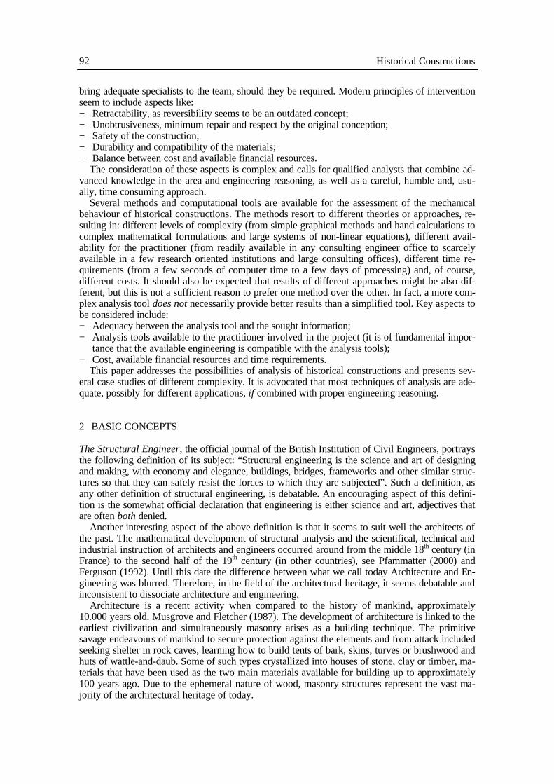
very fine scale. In fact, the millions of chemical bonds which join the atoms together produce the required large forces of reaction by stretching or compressing, see Fig. 3. Hooke’s measurements indicated that the load was usually proportional to the force and most of the solids recovered their original shape upon load removal. Such linear elastic behaviour was translated to the famous “Hooke’s law”: ut tensio sic vis or, as the extension so the force,.
(a)
(b) (c) Figure 3: Simplified model of distortion of interatomic bonds under mechanical strain: (a) Neutral, re-laxed or strain-free position; (b) Materials strained in compression, atoms closer together, material gets
shorter; (c) Materials strained in tension, atoms further apart, material gets longer, Gordon (1978). However, the majority of materials, tested with more accurate modern methods, exhibit indeed
inelastic or non-linear material behaviour, resulting in (a) permanent deformation and damage after a certain load level or after a certain number of load cycles and (b) a non-proportional rela-tion between force and displacement, as it is the case of masonry.
2.3 The stress-strain relationship
Rather than trying to deal with the forces and displacements of the structure as a whole, engineers felt the need to analyse the forces and extensions which could be shown to exist at any given point within the material. The concept of the elastic conditions at a specified point inside a material is the concept of stress and strain.
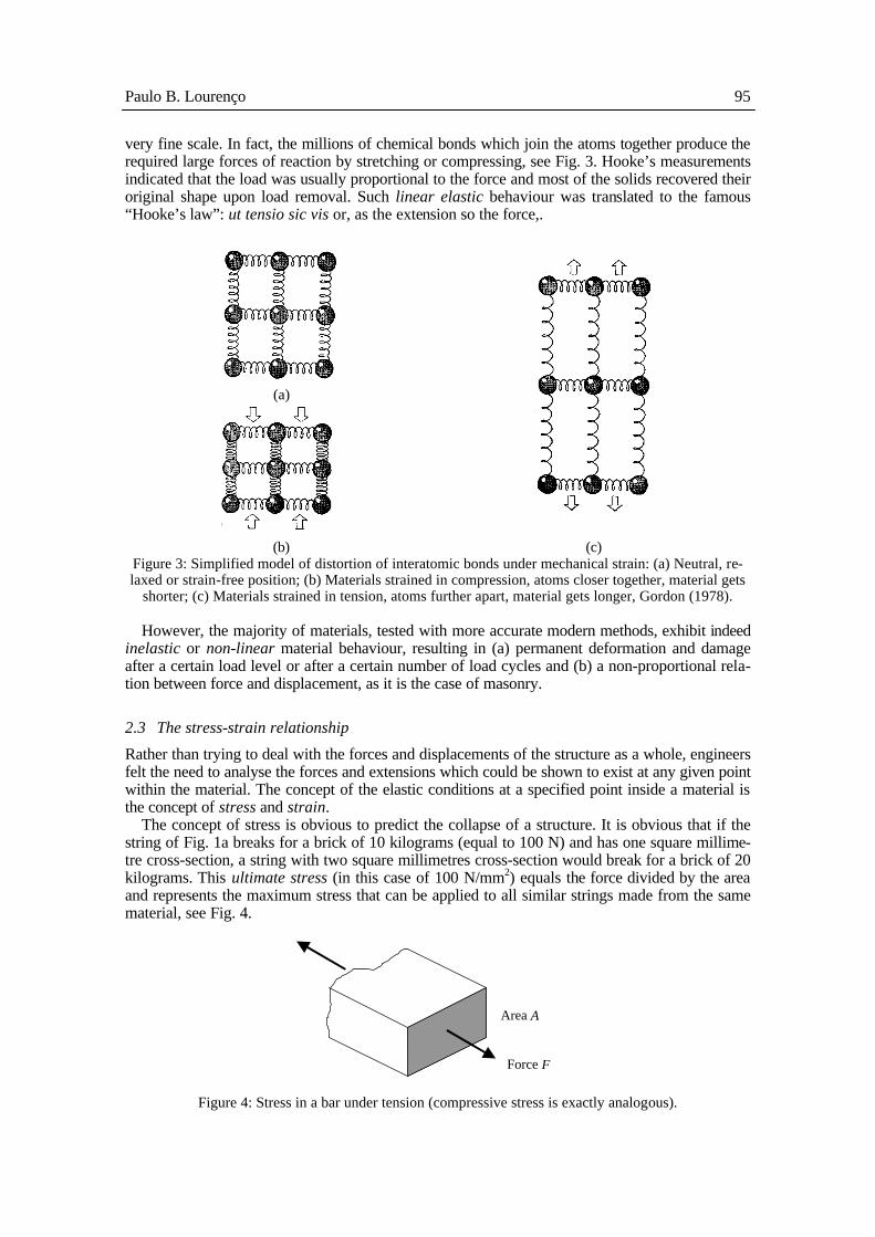
The concept of stress is obvious to predict the collapse of a structure. It is obvious that if the string of Fig. 1a breaks for a brick of 10 kilograms (equal to 100 N) and has one square millime-tre cross-section, a string with two square millimetres cross-section would break for a brick of 20 kilograms. This ultimate stress (in this case of 100 N/mm2) equals the force divided by the area and represents the maximum stress that can be applied to all similar strings made from the same material, see Fig. 4.
Area A
Force F
Figure 4: Stress in a bar under tension (compressive stress is exactly analogous).

96 Historical Constructions
In 1822, Augustin Cauchy perceived that this idea of stress can be used, not only to predict when a material breaks, but also to describe the condition at any point inside a solid in a much more general kind of way. Numerically, the stress σ at a certain point is
AF
=σ , (1)
where F is the force and A is the area over which the force F can be considered as acting. Just as stress tell us how much force is present in the atoms at any point being pulled apart, so
strain indicates how much the bonds between the atoms are stretched. Thus, if the string, with an original length of L, is caused to stretch by an amount l, see Fig. 5, then the strain ε, or the pro-portionate change of length is given by
Ll
=ε . (2)
F
F
Original length L
Length increase l due to the application of force F
Figure 5: Strain in a bar under tension (compressive stress is exactly analogous). As it has been stressed in the previous section, Hooke’s law does not generally applies to most
engineering materials. In order to characterize the mechanical behaviour of the materials, experi-mental tests are usually carried out and, for testing a material, a sample is usually provided. The shapes of the samples vary significantly according to the material to be tested, e.g. concrete, ma-sonry or steel, and the mechanical characteristic to be tested, e.g. tensile strength, compressive strength or shear strength. With adequate testing devices it is possible to obtain stress-strain rela-tionships as the one indicated in Fig. 6. Here, fc indicates the ultimate compressive strength of the material in uniaxial compression and the initial slope of the diagram E is defined as the Young’s modulus or the elastic modulus.
ε
fc σ
E
Figure 6: Typical stress-strain diagram for concrete-like materials under uniaxial compression.
Paulo B. Lourenço 97
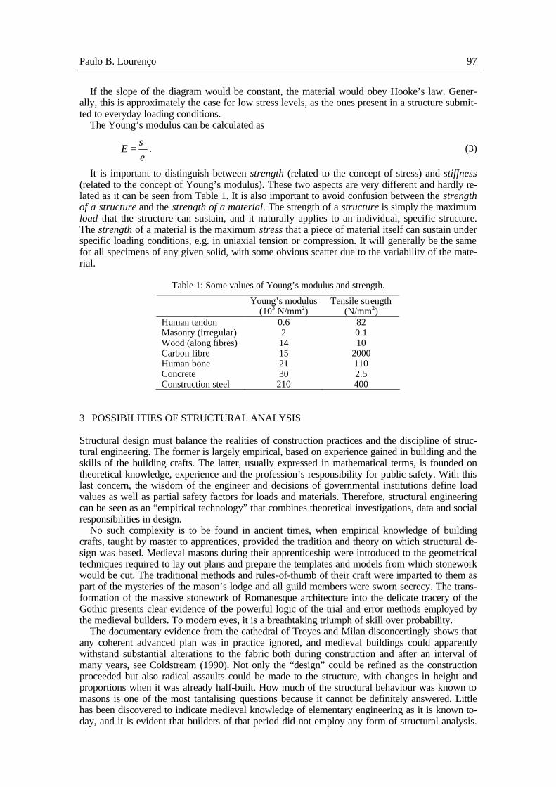
If the slope of the diagram would be constant, the material would obey Hooke’s law. Gener-ally, this is approximately the case for low stress levels, as the ones present in a structure submit-ted to everyday loading conditions.
The Young’s modulus can be calculated as
εσ
=E . (3)
It is important to distinguish between strength (related to the concept of stress) and stiffness (related to the concept of Young’s modulus). These two aspects are very different and hardly re-lated as it can be seen from Table 1. It is also important to avoid confusion between the strength of a structure and the strength of a material. The strength of a structure is simply the maximum load that the structure can sustain, and it naturally applies to an individual, specific structure. The strength of a material is the maximum stress that a piece of material itself can sustain under specific loading conditions, e.g. in uniaxial tension or compression. It will generally be the same for all specimens of any given solid, with some obvious scatter due to the variability of the mate-rial.
Table 1: Some values of Young’s modulus and strength.
Young’s modulus Tensile strength (103 N/mm2) (N/mm2) Human tendon 0.6 82 Masonry (irregular) 2 0.1 Wood (along fibres) 14 10 Carbon fibre 15 2000 Human bone 21 110 Concrete 30 2.5 Construction steel 210 400
3 POSSIBILITIES OF STRUCTURAL ANALYSIS
Structural design must balance the realities of construction practices and the discipline of struc-tural engineering. The former is largely empirical, based on experience gained in building and the skills of the building crafts. The latter, usually expressed in mathematical terms, is founded on theoretical knowledge, experience and the profession’s responsibility for public safety. With this last concern, the wisdom of the engineer and decisions of governmental institutions define load values as well as partial safety factors for loads and materials. Therefore, structural engineering can be seen as an “empirical technology” that combines theoretical investigations, data and social responsibilities in design.
No such complexity is to be found in ancient times, when empirical knowledge of building crafts, taught by master to apprentices, provided the tradition and theory on which structural de-sign was based. Medieval masons during their apprenticeship were introduced to the geometrical techniques required to lay out plans and prepare the templates and models from which stonework would be cut. The traditional methods and rules-of-thumb of their craft were imparted to them as part of the mysteries of the mason’s lodge and all guild members were sworn secrecy. The trans-formation of the massive stonework of Romanesque architecture into the delicate tracery of the Gothic presents clear evidence of the powerful logic of the trial and error methods employed by the medieval builders. To modern eyes, it is a breathtaking triumph of skill over probability.
The documentary evidence from the cathedral of Troyes and Milan disconcertingly shows that any coherent advanced plan was in practice ignored, and medieval buildings could apparently withstand substantial alterations to the fabric both during construction and after an interval of many years, see Coldstream (1990). Not only the “design” could be refined as the construction proceeded but also radical assaults could be made to the structure, with changes in height and proportions when it was already half-built. How much of the structural behaviour was known to masons is one of the most tantalising questions because it cannot be definitely answered. Little has been discovered to indicate medieval knowledge of elementary engineering as it is known to-day, and it is evident that builders of that period did not employ any form of structural analysis.

98 Historical Constructions
Medieval masons had no means of calculating the amount of buttressing required by any particu-lar design, and seem to have discovered the margins of safety through observation and experi-ence.
While craft traditions had sufficed for the remarkable traceries of the Gothic construction, theoretical explanations were sought in the Renaissance, see Elliot (1994). Leonardo da Vinci could have been the first to contend that the thrust followed a path that remained within the arch, but much of the lengthy study that commenced in the Renaissance focused on the construction of domes. In experiments, chains were draped to represent the curves that might be the inverted lines of thrusts and intricate graphic solutions attempted to follow forces from stone to stone. Long af-ter Leonardo, in 1586, Simon Stevinus published a book on statics; its translation to Latin in 1608 as “Mathematicorum Hypomnemata de Statica” made his knowledge accessible to scientists and mathematicians throughout Europe, and provided the basis for nineteenth century graphic statics, which enabled the solution of structural problems through drawings.
Today, the finite element method is usually adopted to achieve sophisticated simulations of the structural behaviour. A mathematical description of the material behaviour, which yields the rela-tion between the stress and strain tensor in a material point of the body, is necessary for this pur-pose. This mathematical description is commonly named a constitutive model. Constitutive mod-els of interest for practice are normally developed according to a phenomenological approach in which the observed mechanisms are represented in such a fashion that simulations are in reason-able agreement with experiments. It is not realistic to try to formulate constitutive models which fully incorporate all the interacting mechanisms of a specific material because any constitutive model or theory is a simplified representation of reality.
The last decades have witnessed a huge development in numerical methods and programs of structural analysis. Today, with the help of a computer, it is possible to analyse structures with a high level of accuracy. The material science (dependent on the observation and analysis of the experimental behaviour) has suffered a slower evolution but, in the last years, important advances in constitutive models have occurred in various fields. New numerical methods and new analysis capabilities have been absorbed in the practice of structural engineering (even if not always in an adequate form), but material mechanics has not, see also Lourenço (1998).
Finally, it is pointed out that analyses are carried out using idealisations of both the geometry and the behaviour of the structures, being naturally assumed that the selected idealisations are appropriate to the problem under consideration.
3.1 Idealisation of the geometry
The geometry can be idealised in different ways, namely, by considering the structure to be made of linear elements, two-dimensional elements, shell elements or fully three-dimensional elements. Differently from modern structures, it is not straightforward to define the conditions under which a given idealisation of the geometry is applicable. Usually, the geometry of historical masonry structural is rather complex as there is no distinction between decorative and structural elements. Therefore, as a first impression, it would seem reasonable to advise the use of three-dimensional elements. But this impression is erroneous!
Given the difficulties addressed before, it is obvious that practical analysis of historical ma-sonry structures entails severe simplifications. As a rule, the geometric idealisation should be kept as simple as possible, as long as it can be considered adequate for the problem being considered. In particular, it is stressed that: − Fully three-dimensional models are usually very time consuming with respect to preparation of
the model, to perform the actual calculations and to analyse the results. Additionally, in the case of the widely spread Finite Element Method, several authors have been using eight-noded bricks in the analyses, with solely one element over the thickness of the walls. The errors as-sociated with such a discretisation are very large already in the case of a linear elastic analy-sis, yielding meaningless results;
− The results of models incorporating shell elements are reasonably difficult to analyse due to the variation of stresses along the thickness of the elements. In addition, the large thickness of the structural elements might yield a poor approximation of the actual state of stress;
− Increasing the details and size of the model might result in a large amount of information that blurs the important aspects.

Paulo B. Lourenço 99
In the author’s opinion, if possible, it is better: (a) to use two-dimensional models than three-dimensional models, (b) to avoid using shell elements in areas important for the global behaviour of the structure and (c) to model structural parts and details instead of modelling complete and large structures, see Figs. 7-9 for examples.
(a)
(b)
(c)
(d)
Figure 7: Cloister of a Cistercian monastery in Salzedas (18th century). The barrel vaults of the second level exhibits severe longitudinal cracking. The two-dimensional model (a) was adopted for performing a non-linear analysis (b) that allowed to understand the damage of the structure and to assess its safety. The three-dimensional model (c) is shown only for academic purposes. For a linear elastic analysis in-
cluding soil-structure interaction (d), the difference in displacements and stresses at specific control points at the barrel vault was less than 10%, see Lourenço et al. (2001b) for details.
(a) (b)
Figure 8: Refectory of Monastery of Jerónimos: In a modal analysis, the fully three-dimensional model (a,b) yields similar results to the simplified shell model (c,d) for the first two vibration modes.
Nevertheless, the need for correcting the thickness of walls, to take into account the additional stiffness provided by the intersection of the thick walls, precludes any non-linear
analysis using the shell model, see Lourenço and Mourão (2001) for details (cont.).

100 Historical Constructions
(c) (d)
Figure 8: Refectory of Monastery of Jerónimos: In a modal analysis, the fully three-dimensional model (a,b) yields similar results to the simplified shell model (c,d) for the first two vibration modes.
Nevertheless, the need for correcting the thickness of walls, to take into account the additional stiffness provided by the intersection of the thick walls, precludes any non-linear
analysis using the shell model, see Lourenço and Mourão (2001)for details (contd.).
(a) (b)
(c) (d)
Figure 9: Analysis of a 17th century church. A plane analysis (a) and a out-of-plane analysis with shell elements (b) demonstrated the need to adopt a fully three-dimensional contact analysis
to justify the observed damage in the façade. Only the central part of the façade needed to be considered (c), while the choir was analysed in a separate model, using shell
and beam elements (d), see Lourenço et al. (2001a) for details.

Paulo B. Lourenço 101
3.2 Idealisation of the behaviour
Masonry is a complex composite material made of units and mortar. The description of the me-chanical behaviour of masonry is not pursued here and the reader is referred to Lourenço (1998) for this purpose. Nevertheless, the mechanical behaviour of masonry has generally this salient feature: a very low tensile strength. This property is so important that it has determined the shape of historical constructions.
Common idealisations of the behaviour used for analysis are elastic behaviour (with or without redistribution), plastic behaviour and non-linear behaviour. Non-linear analysis is the most pow-erful method of analysis, able to trace the complete response of a structure from the elastic range, through cracking and crushing, up to complete failure. It is possible to include the construction sequence in the analysis. The effects of previous applications of loading and the way the intensity of loads are applied yield different results. Different types of non-linear behaviour may be com-bined, namely, physical (related to the non-linearity of the material), geometrical (related to the fact that the point of application of loads changes with the increase of actions and structures buckle due to instability) and contact (related to the addition or removal of supports, or to the change of contact between bodies with the increase of actions), see Fig. 10. It may be used for both Ultimate Limit States (ULS) and Serviceability Limit States (SLS).
Gf
ft
w
σ
F
(a) (b) (c) Figure 10: Examples of different manifestations of non-linearity: (a) Typical stress-displacement
diagram of masonry under uniaxial tension; (b) Buckling of a rod subjected to compression; (c) Squashing of a rubber ball.
Plastic analysis or limit analysis aims at evaluating the structural load at failure. It shall only
be used for verification of ULS and, theoretically, the material must exhibit a ductile response. This method can be assumed as adequate for the analysis of historical masonry structures if a zero tensile stress is assumed. The plastic analysis is either based on the lower bound (static) method or on the upper bound (kinematic) method. Thrust-line analysis is an example of the static method and yield hinges method for arches is an example of the kinematic method. The effects of previous applications of loading may generally be ignored and a monotonic increase of the inten-sity of actions may be assumed.
Linear elastic analysis assumes that the material obeys Hooke’s law. This is hardly the case of masonry under tension, which cracks at very low stress levels. Linear elastic analysis, based on the theory of elasticity, has been widely used for the verification of both ULS and SLS of, e.g., reinforced concrete structures. But, for serviceability limit states, a gradual evolution of cracking should be considered and, for ultimate limit states, careful detailing of the reinforcement to cover all zones where tensile stresses may appear is required. Linear elastic analysis with redistribution may be applied for the verification of ULS, assuming a reduced stiffness corresponding to fully cracked areas.
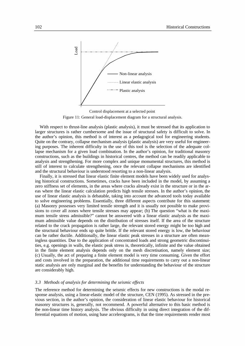
Fig. 11 tries to illustrate the application of the different idealisations of the behaviour. In the author’s opinion, non-linear analysis is the reference analysis that should be primarily considered for understanding the behaviour of historical masonry constructions. Several commercial finite element packages that consider non-linear behaviour are available but one problem is that its use require postgraduate structural analysts as the inherent complexity of the subject precludes mass teaching in civil engineering graduations.
102 Historical Constructions
L
oad
Control displacement at a selected point
Plastic analysis
Linear elastic analysis
Non-linear analysis
Figure 11: General load-displacement diagram for a structural analysis.
With respect to thrust-line analysis (plastic analysis), it must be stressed that its application to
larger structures is rather cumbersome and the issue of structural safety is difficult to solve. In the author’s opinion, this method is of interest as a pedagogical tool for engineering students. Quite on the contrary, collapse mechanism analysis (plastic analysis) are very useful for engineer-ing purposes. The inherent difficulty in the use of this tool is the selection of the adequate col-lapse mechanism for a given load combination. In the author’s opinion, for traditional masonry constructions, such as the buildings in historical centres, the method can be readily applicable to analysis and strengthening. For more complex and unique monumental structures, this method is still of interest to calculate strengthening, once the relevant collapse mechanisms are identified and the structural behaviour is understood resorting to a non-linear analysis.
Finally, it is stressed that linear elastic finite element models have been widely used for analys-ing historical constructions. Sometimes, cracks have been included in the model, by assuming a zero stiffness set of elements, in the areas where cracks already exist in the structure or in the ar-eas where the linear elastic calculation predicts high tensile stresses. In the author’s opinion, the use of linear elastic analysis is debatable, taking into account the advanced tools today available to solve engineering problems. Essentially, three different aspects contribute for this statement: (a) Masonry possesses very limited tensile strength and it is usually not possible to make provi-sions to cover all zones where tensile stresses may appear; (b) The question “what is the maxi-mum tensile stress admissible?” cannot be answered with a linear elastic analysis as the maxi-mum admissible value depends on the distribution of stresses itself. If the area of the structure related to the crack propagation is rather large, the relevant stored energy might be too high and the structural behaviour ends up quite brittle. If the relevant stored energy is low, the behaviour can be rather ductile. Additionally, the linear elastic peak stresses in a structure are often mean-ingless quantities. Due to the application of concentrated loads and strong geometric discontinui-ties, e.g. openings in walls, the elastic peak stress is, theoretically, infinite and the value obtained in the finite element analysis depends only on the mesh discretisation, namely element size; (c) Usually, the act of preparing a finite element model is very time consuming. Given the effort and costs involved in the preparation, the additional time requirements to carry out a non-linear static analysis are only marginal and the benefits for understanding the behaviour of the structure are considerably high.
3.3 Methods of analysis for determining the seismic effects
The reference method for determining the seismic effects for new constructions is the modal re-sponse analysis, using a linear-elastic model of the structure, CEN (1995). As stressed in the pre-vious section, in the author’s opinion, the consideration of linear elastic behaviour for historical masonry structures is, generally, not recommend. A powerful alternative to this basic method is the non-linear time history analysis. The obvious difficulty in using direct integration of the dif-ferential equations of motion, using base accelerograms, is that the time requirements render most

Paulo B. Lourenço 103
analyses non-feasible. It is noticed that a minimum of five accelerograms should be used, multi-plied by two different seismic actions, multiplied by two orthogonal directions. This results in twenty different analysis, without considering the horizontal components of the seismic action acting simultaneously and the vertical component of the seismic action.
In the author’s opinion, and as suggested by Part 1-4 of Eurocode 8, it is more appropriate if the analysis is carried out using approximate static non-linear methods. In the static methods, the seismic effect is defined by the base shear coefficient, coined as seismic coefficient, which defines the percentage of the total weight of the building that must be considered as a horizontal force, also total, applied to the structure. For modern buildings, existing codes adopt detailed proce-dures to calculate the seismic coefficient applicable for each case, and as a function of the seismic zone, soil type, fundamental frequency of vibration for the structure, and the available ductility and damping. These procedures have been extensively calibrated against results obtained by the general methods, but historical buildings possess characteristics considerably different from the ones used to calibrate the codes. For areas of significant seismic risk, the seismic coefficient can be assumed to vary between 0.1 and 0.3, Meli (1998).
4 A DISCUSSION ON THE USE OF DIFFERENT METHODS OF ANALYSIS
The engineering assessment of ancient masonry structures requires practical computational tools and different approaches have been introduced in the previous section. In the following, different methods of structural analysis are applied to two simple cases of masonry arches, a semi-circular arch and a pointed arch, see Fig. 12. The arches have a span of 5.0 m, a rise of 2.5 m, a thickness of 0.3 m and a width of 1.0 m. The radius of the semi-circular arch is 2.5 m and the radius of the pointed arch is 3.95 m. A backfill up to a height of 3.0 m is considered in the analyses.
5
2.53
1.2510 kN
5
2.53
1.2510 kN
(a) (b) Figure 12: Geometry of the arches adopted for analysis: (a) semi-circular arch and (b) pointed arch.
The loads considered in the analyses include, as dead load, the weight of the arch (volumetric
weight γ = 20 kN/m3) and fill (γ =15 kN/m3), and, as live load, a point load of 10 kN at quarter span.
The following analyses have been carried out for these structures: linear elastic finite element analysis, kinematic limit analysis, limit analysis for the calculation of the so-called geometric safety factor, non-linear physical finite element analysis and non-linear combined physical / geo-metrical finite element analysis. In all cases, the dead load is applied first, followed by the mono-tonic application of the live load up to failure.
4.1 Linear elastic finite element analysis
Eight-noded plane stress elements, combined with six-noded line interface elements, were adopted for the analysis. In case of a linear elastic analysis, it is necessary to know the elastic properties of the materials. The following properties have been assumed in the analyses: Unit – Young’s modulus E = 10 × 103 N/mm2 and Poisson ratio ν = 0.2; Interface – Normal stiffness kn = 2.4 ×

104 Historical Constructions
103 N/mm3 and transverse stiffness kt = 1.0 × 10³ N/mm3. The results of the analysis are shown in Fig. 13, in terms of maximum and minimum principal stresses.
(a) (b)
(c) (d)
Figure 13: Results of linear elastic finite element analysis for a quarter span point load: (a,b) maximum and (c,d) minimum principal stresses for semi-circular and pointed arch, respectively.
In order to establish the safety of the structures being considered, it is necessary to introduce
the concept of “allowable maximum stress”. If the allowable maximum stress is zero, then no load can be applied to the arches. Therefore, it is necessary to adopt a relatively low value, as usually exhibited by masonry. Here, a maximum allowable tensile stress fta of 0.2 N/mm2 and unlimited compressive stress were assumed. For the adopted mesh discretisations, the obtained safety factors are 0.3 and 0.9 for the semi-circular and pointed arch, respectively. It is stressed that, as a general rule, the peak values of the stresses depend on the mesh discretisation and the proposed procedure is debatable.
4.2 Limit analysis
A non-linear programming implementation of limit analysis has been adopted for this purpose, see Orduña and Lourenço (2001). In case of a limit analysis, it is necessary to know the ultimate strength properties of the materials, being the elastic properties of the materials irrelevant. It has been assumed that failure can only occur in the joints of the model and the following properties have been assumed for the joints: zero tensile strength ft, unlimited compressive stress strength, friction angle φ of 37º (tanφ = 0.75) and zero dilatancy ψ. The results of the analyses are shown in Fig. 14, in terms of collapse mechanisms and thrust lines.
Safety of the structures is automatically evaluated when using limit analysis. The kinematic safety factors are 1.8 and 2.3 for the semi-circular and the pointed arch, respectively. Another popular concept is the so-called “geometric safety factor”, see Heyman (1969), which represents the ratio between the actual thickness of the arch and the minimum thickness of an internal arch with the original span and able to resist the original applied load. This geometric safety factors are 1.2 and 1.3 for the semi-circular arch and the pointed arch, respectively.
4.3 Non-linear finite element analysis
The finite element meshes used in Section 4.1 are again adopted for the non-linear analyses. In the case of a non-linear analysis, it is necessary to know the elastic and inelastic properties of the materials. Therefore, the properties given in the previous section were considered together. Both physical and combined physical / geometrical non-linear behaviour were analysed. The results of the physically non-linear analyses are shown in Fig. 15, in terms of minimum principal
Peak value : 0.64 N/mm2 Peak value : 0.23 N/mm2
Peak value : -1.0 N/mm2 Peak value : -0.91 N/mm2
Paulo B. Lourenço 105
(a) (b)
(c) (d)
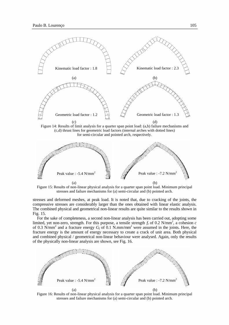
Figure 14: Results of limit analysis for a quarter span point load: (a,b) failure mechanisms and (c,d) thrust lines for geometric load factors (internal arches with dotted lines)
for semi-circular and pointed arch, respectively.
(a) (b)
Figure 15: Results of non-linear physical analysis for a quarter span point load. Minimum principal stresses and failure mechanisms for (a) semi-circular and (b) pointed arch.
stresses and deformed meshes, at peak load. It is noted that, due to cracking of the joints, the compressive stresses are considerably larger than the ones obtained with linear elastic analysis. The combined physical and geometrical non-linear results are quite similar to the results shown in Fig. 15.
For the sake of completeness, a second non-linear analysis has been carried out, adopting some limited, yet non-zero, strength. For this purpose, a tensile strength ft of 0.2 N/mm2, a cohesion c of 0.3 N/mm2 and a fracture energy Gf of 0.1 N.mm/mm2 were assumed in the joints. Here, the fracture energy is the amount of energy necessary to create a crack of unit area. Both physical and combined physical / geometrical non-linear behaviour were analysed. Again, only the results of the physically non-linear analysis are shown, see Fig. 16.
(a) (b)
Figure 16: Results of non-linear physical analysis for a quarter span point load. Minimum principal stresses and failure mechanisms for (a) semi-circular and (b) pointed arch.
Kinematic load factor : 1.8 Kinematic load factor : 2.3
Geometric load factor : 1.2 Geometric load factor : 1.3
Peak value : -5.4 N/mm2
Peak value : -7.2 N/mm2
Peak value : -5.4 N/mm2
Peak value : -7.2 N/mm2

106 Historical Constructions
Safety of the structures is automatically evaluated when using non-linear analysis. For zero tensile strength and physically non-linear analysis, the ultimate load factors are 1.8 and 2.3 for the semi-circular and the pointed arch. As it should be expected, the values are similar to the val-ues obtained with the kinematic limit analysis. The ultimate load factors for the rest of the cases studied are given in the next section, together with a discussion of the results.
4.4 Comparison between the different analyses
Fig. 17 presents the load-displacement diagrams for the non-linear analyses calculations together with the ultimate load factors for kinematic limit analysis and Table 2 indicates the safety factors obtained in the different analyses.
0.0
0.5
1.0
1.5
2.0
2.5
3.0
0 2 4 6 8 10 12 14Vertical displacement at quarter span (mm)
Loa
d fa
ctor
Limit analysisft = 0, Physically non-linearft = 0, Physically / Geometrically non-linearft = 0.2 N/mm2, Physically non-linearft = 0.2 N/mm2, Physically / Geometrically non-linear
(a)
0.0
0.5
1.0
1.5
2.0
2.5
3.0
0 2 4 6 8 10 12 14Vertical displacement at quarter span (mm)
Loa
d fa
ctor
Limit analysisft = 0, Physically non-linearft = 0, Physically / Geometrically non-linearft = 0.2 N/mm2, Physically non-linearft = 0.2 N/mm2, Physically / Geometrically non-linear
(b)
Figure 17: Load-displacements diagrams for the different non-linear analyses and limit analysis safety factors for (a) semi-circular and (b) pointed arch.
Table 2: Safety factors for the different analyses considered.
Approach/Analysis type Semi-circular arch Pointed arch Allowable stresses (fta=0.2 N/mm2) 0.31 0.87 Kinematic limit analysis 1.8 2.3 Geometric safety factor 1.2 1.3 ft = 0, Physically non-linear 1.8 2.3 ft = 0, Physically and geometrically non-linear 1.7 2.0 ft = 0.2 N/mm2, Physically non-linear 2.5 2.8 ft = 0.2 N/mm2, Physically and geometrically non-linear 2.5 2.7

Paulo B. Lourenço 107
The results obtained allow to stress the following aspects: − Linear elastic analysis requires the elastic properties of the materials and maximum allowable
stresses, resulting in information on the deformational behaviour and stress distribution of the structure. Limit analysis requires the strength of the materials, resulting in information on the failure mechanism of the structure. Non-linear analysis require the elastic properties, the strength of the materials and additional inelastic information (the stress-strain diagrams), re-sulting in information on the deformational behaviour, stress distribution and on the failure mechanism of the structure.
− The “safety factors” associated with a linear elastic analysis (and a maximum allowable stress) and with a static limit analysis (the so-called geometric safety factor) cannot be com-pared with the remaining safety factors. When such particular approaches are used, special care should be adopted if structural safety is a relevant issue;
− For the simple structures presented, physically non-linear analysis and kinematic limit analysis yield the same failure mechanisms and safety factors, if a zero tensile strength is assumed. In complex structures, when using simple hand calculations, it might be difficult to find the cor-rect failure mechanism by using limit analysis. Additionally, if geometrically non-linear be-haviour is also included in the analysis, the safety factor is reduced by around 10%, for the arches studied;
− The consideration of a non-zero, yet low and degrading, tensile strength increased the safety factors considerably (between 20% and 50%). Therefore, when using non-zero tensile strength, special care might be necessary in real case applications: (a) tensile strength is diffi-cult to assess and (b) tensile strength might be severely reduced at critical locations. It is noteworthy to stress that different failure mechanisms are triggered in both analyses, see Fig. 15 and 16. In the case of the semi-circular arch, this is a minor difference (left top joint) and the non-zero tensile strength solution converges to the zero tensile strength solution, upon pro-gressive tensile strength degradation. In the case of the pointed arch, the difference in failure mechanisms is more relevant (around the key stone) and no convergence between the solutions is found, upon strength degradation. The non-zero tensile strength final solution exhibits al-ways higher strength than the zero tensile strength solution. Finally, when using non-zero ten-sile strength, the consideration of geometrically non-linear behaviour seems to affect only marginally the calculation of the safety factors;
− The post-peak response obtained in a non-linear analysis is an important issue, when address-ing safety factors. Indeed, brittle responses are dangerous and, from a reliability point of view, yield lower safety margins. In specific cases, it may be sensible to adopt as safety factor the residual plateau found in the physically non-linear analyses. Of course, in the case of com-bined physically and geometrically non-linear analysis, no plateau will be found;
− The fact that different methods of analysis lead to different safety factors and different com-pleteness of results, is not a sufficient reason to select one method over the other, see also Section 5 .
5 SELECTED CASE STUDIES
Finally, in this section, selected case studies will be presented with the objective of demonstrating engineering applications of different analysis tools and approaches.
5.1 Lethes Theatre, Faro
The Lethes theatre occupies an old Jesuit college (c. 1650), see Fig. 18. The stalls and stage are covered by a cylindrical vault made from brick masonry, which is supported on thick side walls made from large irregular sandstone pieces laid with thick lime mortar. Above the stage, the ex-trados of the vault is flat, which results in the most heavily loaded part of the vault.
The present geometry of the vault is represented in the plan view of Fig. 19. The vault is fully cracked along the key and exhibits very large abnormal vertical displacements, with a maximum at the key of 0.40 m. Given the localized damage in the construction and the, basically, two-dimensional behaviour of the vault, a plane stress model of the vault, walls and infill was consid-ered adequate for the analysis.

108 Historical Constructions
MONET OBLECTANDO
(a) (b)
Figure 18: Architecture of the Lethes Theatre: (a) main façade view and (b) transversal section.
23.00
22.75
23.00
22.75
22.5022.25
22.00
22.25
22.75
22.50
22.50
23.00
23.00
22.0022.2
522.50
22.25
22.75
22.75
22.00
22.5022.7
5
23.00
22.5022.
25
23.00
22.0022.2
5
22.75
23.00
23.00
22.50
22.00
22.25
21.75
22.00
22.25
22.50
22.75
23.3
23.4
23.4
23.3
23.2
23.4
23.1
23.5
23.123.2
23.3
23.4
23.3
23.123.2
23.1
23.223.3
23.3
23.4
23.623.
5
23.1
23.523.6
23.4
23.1
23.2
23.3
23.2
23.5
23.4
23.2
23.4
23.5
23.5
23.6
23.123.
223.
3
23.1
Esc: 1/100
Thickness of the vault at the key
(a) (b) Figure 19: Levelling of the vault: (a) intrados and (b) longitudinal section at the vault key.
Due to the pre-collapse condition of the structure, different finite element models were adopted
to decide on temporary shoring, while in situ investigation was being carried out, Fig. 20a,b. Once the adequate model was defined, given the large displacements at the key of the vault, a combined physically and geometrically non-linear analysis was completed, Fig. 20c. The analysis allowed to demonstrate that the safety level of the structure was around the unit value and a re-markable aspect is how the asymmetry of the structure affects the results, see Lourenço (2000) for details.
(a) (b) (c)
Figure 20: Finite element analysis: (a,b) successive models adopted to define the load-bearing structure and (c) predicted collapse mechanism.
5.2 Holy Christ Church, Outeiro
The church of Saint Christ in Outeiro (Bragança), in the North of Portugal, was built in 1698-1738, see Figure 21. The structure is mostly made of local shale stone and thick lime mortar (rubble shale masonry), even if regular masonry (granite ashlars and dry thin joints) was used in doors and windows frames, and the façade. The damage of the structure is localized in the main façade and in the choir. The façade features large movements, vertically, in the vicinity of the
0 5 10 15 20 25
x-coordinate
1.0 0.5 0.0
Sandstone masonry
Brick masonry
Sandstone masonry
Paulo B. Lourenço 109
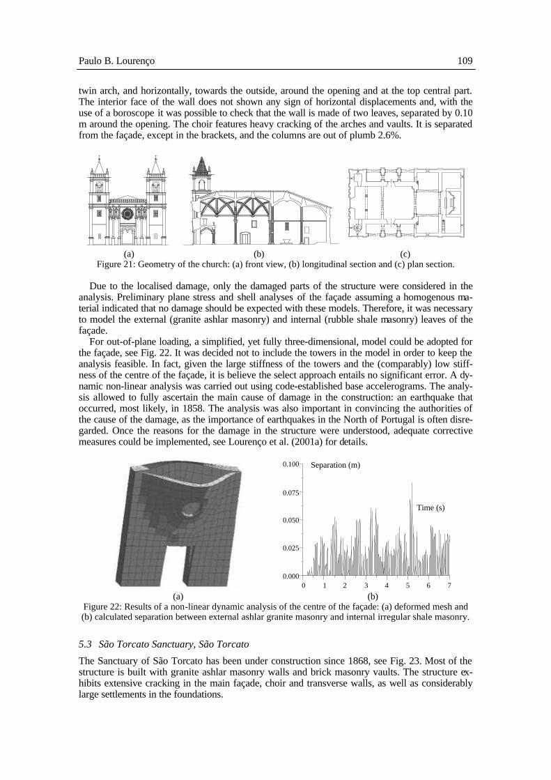
twin arch, and horizontally, towards the outside, around the opening and at the top central part. The interior face of the wall does not shown any sign of horizontal displacements and, with the use of a boroscope it was possible to check that the wall is made of two leaves, separated by 0.10 m around the opening. The choir features heavy cracking of the arches and vaults. It is separated from the façade, except in the brackets, and the columns are out of plumb 2.6%.
(a) (b) (c) Figure 21: Geometry of the church: (a) front view, (b) longitudinal section and (c) plan section.
Due to the localised damage, only the damaged parts of the structure were considered in the
analysis. Preliminary plane stress and shell analyses of the façade assuming a homogenous ma-terial indicated that no damage should be expected with these models. Therefore, it was necessary to model the external (granite ashlar masonry) and internal (rubble shale masonry) leaves of the façade.
For out-of-plane loading, a simplified, yet fully three-dimensional, model could be adopted for the façade, see Fig. 22. It was decided not to include the towers in the model in order to keep the analysis feasible. In fact, given the large stiffness of the towers and the (comparably) low stiff-ness of the centre of the façade, it is believe the select approach entails no significant error. A dy-namic non-linear analysis was carried out using code-established base accelerograms. The analy-sis allowed to fully ascertain the main cause of damage in the construction: an earthquake that occurred, most likely, in 1858. The analysis was also important in convincing the authorities of the cause of the damage, as the importance of earthquakes in the North of Portugal is often disre-garded. Once the reasons for the damage in the structure were understood, adequate corrective measures could be implemented, see Lourenço et al. (2001a) for details.
0.100
0.075
0.050
0.025
0.000 0 1 2 3 4 5 6 7
Time (s)
Separation (m)
(a) (b)
Figure 22: Results of a non-linear dynamic analysis of the centre of the façade: (a) deformed mesh and (b) calculated separation between external ashlar granite masonry and internal irregular shale masonry.
5.3 São Torcato Sanctuary, São Torcato
The Sanctuary of São Torcato has been under construction since 1868, see Fig. 23. Most of the structure is built with granite ashlar masonry walls and brick masonry vaults. The structure ex-hibits extensive cracking in the main façade, choir and transverse walls, as well as considerably large settlements in the foundations.

110 Historical Constructions
(a) (b) (c) (d)
Figure 23: Construction phases: (a) detail of the columns of the main panel, (b) construction of the main façade, (c) construction of the towers and (d) conclusion of the transept.
The main nave presents well distributed cracking but the transept of the Sanctuary presents no
damage. The geotechnical survey indicated that the towers are located in an area of a poor quality embankment while, in the transept zone, the bed rock is very close to the surface. In order to jus-tify the damage in the structure and understand the complex soil-structure interaction, a three-dimensional model of the main nave was necessary, see Fig. 24. It was decided not to include the transept in the analysis in order to greatly reduce the size of the model. Given the good conditions of the foundations of the transept and total absence of damage, it is believed that the errors asso-ciated with the selected approach are only marginal.
A static non-linear analysis with soil-structure interaction was carried out with the purpose of establishing the causes of the apparent damage. The damage obtained in the analysis was com-pared with the damage observed in the structure (location and width of cracks) and the displace-ments of the model could be compared with the actual displacements in the construction. It is noted that the soil conditions are the main cause for the damage and the structural behaviour of the construction is substantially changed due to the soil settlements. The main reasons for the damage in the structure could be understood and movements in the construction are currently be-ing monitored, while adequate corrective measures are being designed, see Lourenço et al. (2000a) for details.
(a) (b) (c) (d)
Figure 24: Finite element analysis: (a) adopted mesh, predicted damage in the (b) main façade, (c) trans-verse walls and (d) main nave vault.
5.4 Saint Francis Church, Horta
The Saint Francis Church is located in the Faial island in Azores. The construction was carried out during the last decade of the 17th century and the first decade of the 18th century. The church was damaged to some extent by earthquake of July 1, 1998, see Fig. 25.
In order to assess the safety of the construction against seismic actions, a complete three-dimensional, model was obviously necessary, see Fig. 26. The construction presents generalised damage but the areas close to the main façade and the altar exhibit the largest damage and the most complex geometry. For these reasons, it was decided to use a fully three dimensional model only in these areas. The rest of the structure (transverse external and internal walls) possess a relatively simple structural behaviour, being modelled with a relatively coarse mesh of shell ele-ments. Static non-linear analyses with soil-structure interaction were carried out. As the safety of

Paulo B. Lourenço 111
the structure was clearly insufficient with respect to the seismic actions, a strengthening project was completed, see Pedrosa et al. (2001) for details.
(a) (c)
Figure 25: Examples of damage in the church: (a) main façade and (b) side wall.
(a) (b)
Figure 26: Finite element analysis: (a) adopted mesh (partly with volume elements and partly with shell elements) and (b) predicted damage for longitudinal seismic action.
5.5 Donim Bridge, Donim
Donim bridge has a total length of 63 m, including three semi-circular arches and one flood arch. The bridge exhibits severe longitudinal cracking in the first arch and in the flood arch, together with significant lateral movements in the spandrel walls. In addition, the vegetation caused severe damage in one cutwater and, very locally, in one spandrel. Given the three-dimensional character of the structure and the importance of the infill in the results, it was necessary to adopt a fully three-dimensional model for the analysis, see Fig. 27. A complete investigation and the design of adequate strengthening are currently being performed.
(a)
(b) (c)
Figure 27: Geometry and analysis: (a) aspect of the central arches of the bridge, (b) adopted finite ele-ment mesh and (c) predicted damage for code-vehicle load.

112 Historical Constructions
5.6 Typical downtown construction of Lisbon
The so-called “Baixa Pombalina” (18th century historical centre of Lisbon) represents an impor-tant architectural and cultural compound. Since their construction, but particularly after the onset of reinforced concrete, the buildings of “Baixa” have been subject to modifications. The block of Martinho da Arcada, which faces the Praça do Comércio in Lisbon, is of a considerable size, with an area of 62.5 × 43.5 m2 in plan and a height ranging from 18 to 25 m, see Fig. 28. This block has been selected for a safety assessment, with respect to earthquake loading, see Silva et al. (2001) for details.
The adopted finite element model included shell elements, to represent the reinforced concrete slabs, the composite slabs and most masonry vaults on ground level, and volume elements, to rep-resent masonry walls, masonry arches and stone vaults in the arcades as well as reinforced con-crete columns, Fig. 28b. The slabs were considered in the model only to simplify the definition of loads and to introduce their rigid diaphragm effect for seismic analysis. The results seem to indi-cate that the constructions require additional strengthening, Fig. 28c. Given the size of the mesh, it was decided to study in detail a simpler isolated building so that the adequacy of the large model to represent the structural behaviour of the total block could be assessed. After this pre-liminary assessment, complete static non-linear analyses were carried out in the large model, in order to simulate the seismic actions.
(a)
(b)
(c) (d)
Figure 28: Geometry and analysis: (a) main façade, (b) adopted finite element mesh, (c) results of non-linear static analysis and (d) analysis of a small building including additional details.
5.7 Design of several elements
Fig. 29 shows the design of strengthening for several structural elements resorting to kinematic limit analysis.
Examples (a,b) are real case applications of calculations for designing anchoring rods, see Pedrosa et al. (2001). The collapse mechanisms shown are based on the non-linear results of a three-dimensional finite element model. Examples (c-e) illustrate straightforward calculations for safety assessment in historical constructions and strengthening design, see e.g. Giuffrè (1993) for comprehensive calculation details.

Paulo B. Lourenço 113
(a) (b) (c)
(d) (e)
Figure 29: Examples of strengthening calculation.
5.8 Visigoth Church in Plaza del Rey, Barcelona, Spain
Remainings of a 7th century Visigoth Church were recently found in Barcelona, see Fig. 30a,b. The thickness and constitution of the walls, the large foundations, the size in plan of the structure, and the corresponding spans indicate that the construction would be one of the largest temples in Europe at that time. Unfortunately, not much is known about the architecture of this period and few constructions survived until today.
(a)
(b)
Enchimento
(c) (d) Figure 30: Archaeological findings and analysis: (a) reconstituted plan, (b) remainings of walls and col-
umns, (c) proposed possible superstructure and (d) structural evaluation with thrust-line analysis.

114 Historical Constructions
Using the knowledge and construction shapes available at that period, two different structural solutions have been proposed for the superstructure, Fig. 30c, see Lourenço et al. (2000b) for de-tails. A first solution adopts solely a wooden roof for the central space but crossed stone vaults for the wings. This solution is simpler and probably more likely in agreement with the empirical knowledge of the Visigoth period. A second solution adopts diaphragmatic arches and barrel vaults, so that a full stone cover would be possible. This solution is more daring and monumental. Given the available knowledge and the time constraints of the co-worker involved in this study, the stability of both solutions was studied using thrust-line methods, see Fig. 30d.
5.9 Comparison between the different case studies
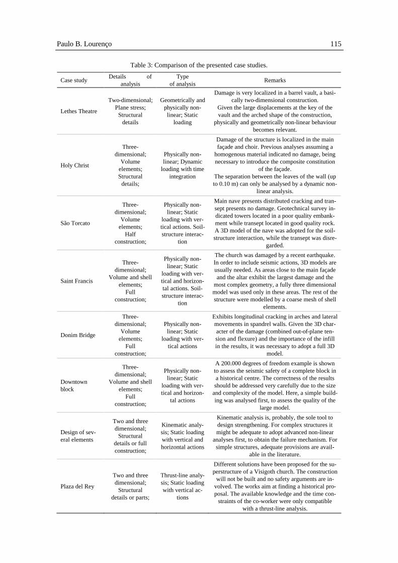
Table 3 indicates a summary of the relevant aspects for the different case studies. It can be seen that a multiplicity of approaches have been adopted including: both two-dimensional and three-dimensional models; both structural details, structural parts and full constructions; both static and dynamic loading; both using and neglecting soil-structure interaction; both combined physical and geometrical non-linear behaviour, or solely physical non-linear behaviour; both non-linear analysis, kinematic analysis and thrust-line analysis. The motto governing the decision to select one approach over the others was: Prefer simplicity over complexity, using the analysis tool be-lieved adequate. Here, it must be stressed that, as pointed out in Section 3.2, linear elastic behav-iour was never considered in the analysis.
6 CONCLUSIONS
In this paper, several approaches and methods for the analysis of historical structures have been discussed. An interesting question for the analysis of historical construction is “Do we need ad-vance modelling?”. Constraints to be considered in the use of advanced modelling are the cost, the need of an experienced user / engineer, the need for validation and the use of the results. Cost and the need of an experienced used seem straightforward arguments. The need of validation is a key issue, meaning that the results of a complex analysis, using a complex model, might be useless if the results are not validated against in situ observations, such as cracking, crushing, displace-ments, flat-jack tests, etc. The final aspect of the use of results is also quite relevant. Non-linear analysis allows us to reproduce the complete behaviour of a structure, including linear elastic be-haviour, cracking, crushing, time dependency, ultimate strength and geometric instability. Addi-tionally, phased analysis is possible meaning that the building sequence and strengthening can be also included in the analysis. According to the author experience and the case studies presented in this paper, the obtained results have been most valuable in understanding the structural behaviour of the constructions. But it should not be concluded that non-linear analysis is the sole numerical tool to be used for all constructions, by all engineers.
As a rule, advanced modelling is a necessary means for understanding the behaviour and dam-age of (complex) historical constructions but this requires specialized consulting engineers and it is less effective for designing strengthening. On the other hand, simplified modelling, such as limit analysis (kinematic method), is a great tool for everyday constructions, such as the buildings in historical centres. Only constructions, which structural behaviour is well-known and fully under-stood, require standard consulting engineers, being simplified modelling a very effective tool for designing strengthening. It may be possible that additional validation of the simplified tools is still necessary.
The key message in the present paper is “One should prefer simplicity over complexity and one should adopt the analysis tool, one can validate and feel comfortable with”. General recommenda-tions are: − It is better to model structural parts than complete structures; − Do not use three-dimensional models unless it is necessary; − Avoid making linear elastic calculations for historical constructions.
Paulo B. Lourenço 115
Table 3: Comparison of the presented case studies.
Case study Details of analysis
Type of analysis Remarks
Lethes Theatre
Two-dimensional; Plane stress;
Structural details
Geometrically and physically non-linear; Static
loading
Damage is very localized in a barrel vault, a basi-cally two-dimensional construction.
Given the large displacements at the key of the vault and the arched shape of the construction,
physically and geometrically non-linear behaviour becomes relevant.
Holy Christ
Three-dimensional;
Volume elements; Structural
details;
Physically non-linear; Dynamic
loading with time integration
Damage of the structure is localized in the main façade and choir. Previous analyses assuming a
homogenous material indicated no damage, being necessary to introduce the composite constitution
of the façade. The separation between the leaves of the wall (up to 0.10 m) can only be analysed by a dynamic non-
linear analysis.
São Torcato
Three-dimensional;
Volume elements;
Half construction;
Physically non-linear; Static
loading with ver-tical actions. Soil-structure interac-
tion
Main nave presents distributed cracking and tran-sept presents no damage. Geotechnical survey in-dicated towers located in a poor quality embank-ment while transept located in good quality rock. A 3D model of the nave was adopted for the soil-structure interaction, while the transept was disre-
garded.
Saint Francis
Three-dimensional;
Volume and shell elements;
Full construction;
Physically non-linear; Static
loading with ver-tical and horizon-tal actions. Soil-structure interac-
tion
The church was damaged by a recent earthquake. In order to include seismic actions, 3D models are usually needed. As areas close to the main façade and the altar exhibit the largest damage and the
most complex geometry, a fully three dimensional model was used only in these areas. The rest of the structure were modelled by a coarse mesh of shell
elements.
Donim Bridge
Three-dimensional;
Volume elements;
Full construction;
Physically non-linear; Static
loading with ver-tical actions
Exhibits longitudinal cracking in arches and lateral movements in spandrel walls. Given the 3D char-acter of the damage (combined out-of-plane ten-sion and flexure) and the importance of the infill in the results, it was necessary to adopt a full 3D
model.
Downtown block
Three-dimensional;
Volume and shell elements;
Full construction;
Physically non-linear; Static
loading with ver-tical and horizon-
tal actions
A 200.000 degrees of freedom example is shown to assess the seismic safety of a complete block in a historical centre. The correctness of the results should be addressed very carefully due to the size
and complexity of the model. Here, a simple build-ing was analysed first, to assess the quality of the
large model.
Design of sev-eral elements
Two and three dimensional;
Structural details or full construction;
Kinematic analy-sis; Static loading with vertical and horizontal actions
Kinematic analysis is, probably, the sole tool to design strengthening. For complex structures it might be adequate to adopt advanced non-linear
analyses first, to obtain the failure mechanism. For simple structures, adequate provisions are avail-
able in the literature.
Plaza del Rey
Two and three dimensional;
Structural details or parts;
Thrust-line analy-sis; Static loading with vertical ac-
tions
Different solutions have been proposed for the su-perstructure of a Visigoth church. The construction
will not be built and no safety arguments are in-volved. The works aim at finding a historical pro-posal. The available knowledge and the time con-
straints of the co-worker were only compatible with a thrust-line analysis.

116 Historical Constructions
ACKNOWLEDGMENTS
The author gratefully acknowledges the special contribution of A. Orduña in the preparation of the results shown in Section 4. The valuable contributions of E. Alves, P. Gregorczyk, S. Mourão, D. Oliveira, A. Orduña, J. Poças Martins, L. Ramos and G. Vasconcelos in the analyses presented in Section 5 are also acknowledged.
REFERENCES
Cen, 1995. Eurocode 8. Design provisions for earthquake resistance of structures. Bruxelles : CEN. Coldstream, N. 1990. Medieval Craftsmen: Masons and Sculptors. London : British Museum Press. Cross, N. 1989. Engineering design methods. New York : Wiley. Elliot, C.D. 1994. Technics and Architecture: The Development of Materials and Systems for Buildings.
MIT Press : Cambridge, Massachusetts. Ferguson, E.S. 1992. Engineering and the mind’s eye. Cambridge, Massachusetts : The MIT Press. Gordon, J.E. 1991. Structures or why things don’t fall down. London : Penguin Books. Giuffrè, A. 1993. Safety and conservation of historical centres: The Ortigia case (in Italian). Editori La-
terza : Bari. Heyman, J. 1969. The safety of masonry arches. Int. J. Mech. Sci., vol. 11, p. 363-385. Lexicon (1989). Webster’s Dictionary of the English language. New York : Lexicon Publications. Lourenço, P.B. 1998. Experimental and numerical issues in the modelling of the mechanical behaviour
of masonry. In: P. Roca et al. (ed) Structural Analysis of Historical Constructions, p. 57-91, Barce-lona : CIMNE.
Lourenço, P.B. 2000. A case study about using sophisticated masonry models in practice: The Lethes theatre (C. 1650). In: B.H.V. Topping and G. de Roeck. (ed) Fifth International Conference on Com-putational Structures Technology, p. 433-442, Edinburgh : Civil-Comp Press.
Lourenço, P.B., Ramos, L., Martins, F.F. 2000a. Detailed study about the São Torcato Sanctuary (in Por-tuguese). In: S. Pompeu Santos et al. (ed) National Meeting on Structural Conservation and Rehabilitation, p. 417-426, Lisbon : LNEC.
Lourenço, P.B., Roca, P., Alves, E., 2000b. Proposals for the superstructure of the Visigoth church in Plaza del Rey (in Portuguese). In: S. Pompeu Santos et al. (ed) National Meeting on Structural Con-servation and Rehabilitation, p. 437-446, Lisbon : LNEC.
Lourenço, P.B., Mourão, S. 2001. Safety assessment of Monastery of Jerónimos, Lisbon. In: P.B. Lourenço, P. Roca (ed) Historical Constructions, Guimarães : University of Minho.
Lourenço, P.B., Oliveira, D.V., Mourão, S. 2001a. Numerical analysis as a tool to understand historical structures. The example of the Church of Outeiro. In: G. Arun, N. Seçkin (ed) Studies in Ancient Structures, p. 355-364. Istanbul : Yildiz Technical University.
Lourenço, P.B., Vasconcelos, G., Ramos, L. 2001b. Assessment of the stability conditions of a Cistercian cloister. In: G. Arun, N. Seçkin (ed) Studies in Ancient Structures, p. 669-678. Istanbul : Yildiz Tech-nical Univeristy.
MacGregor, J. 1990. Dimensioning and detailing. Structural Concrete, IABSE, vol. 62, p. 391-407. Meli, R. 1998. Structural engineering of historical buildings (in Spanish). Mexico City : Fundación
ICA. Musgrove, J. and Fletcher, B. 1987. Sir Banister Fletcher's: A history of architecture. London : Butter-
worths. Orduña, A., Lourenço, P.B. 2001. Limit analysis as a tool for the simplified assessment of ancient ma-
sonry structures. In: P.B. Lourenço, P. Roca (ed) Historical Constructions, Guimarães : University of Minho.
Pedrosa, L., Vicente, A., Silva, V.C., Lourenço, P.B., Orduña,, A. 2001, Maximize the study, minimize the intervention, as a way to safeguard the architectural heritage: The example of Saint Francis Church, Horta. In: Sísmica 2001, São Miguel : Laboratório Regional de Engenharia Civil.
Pfammatter, U. 2000. The making of the modern architect and engineer. Basel : Birkhäuser. Petroski, H. 1992. To engineer is human: The role of failure in successful design. New York : Vintage
Books. Silva, V.C., Lourenço, P.B., Ramos, L.F., Mesquita, C.G. 2001. Accounting for the “block effect” in
structural interventions in Lisbon’s old “Pombaline” downtown buildings. In: P.B. Lourenço, P. Roca (ed) Historical Constructions, Guimarães : University of Minho.