SPECIFICATION PACKAGE 116-12 for FEEDWATER ...
48
Working Together for a Better Tomorrow. Today. SPECIFICATION PACKAGE 116-12 for FEEDWATER HEATER #5 REPLACEMENT Bid Opening Date/Time Tuesday, November 13, 2012 @ 2:00 p.m. (Local time) City of Grand Island, City Hall 100 East 1 st Street, P.O. Box 1968 Grand Island, NE 68802-1968 Contact City of Grand Island – Utilities Department Platte Generating Station 308/385-5496 Date issued: October 18, 2012
-
Upload
khangminh22 -
Category
Documents
-
view
1 -
download
0
Transcript of SPECIFICATION PACKAGE 116-12 for FEEDWATER ...

Working Together for a
Better Tomorrow. Today.
SPECIFICATION PACKAGE
116-12
for
FEEDWATER HEATER #5 REPLACEMENT
Bid Opening Date/Time Tuesday, November 13, 2012 @ 2:00 p.m. (Local time)
City of Grand Island, City Hall 100 East 1st Street, P.O. Box 1968
Grand Island, NE 68802-1968
Contact City of Grand Island – Utilities Department
Platte Generating Station 308/385-5496
Date issued: October 18, 2012

ADVERTISEMENT TO BIDDERS
FOR FEEDWATER HEATER #5 REPLACEMENT
FOR CITY OF GRAND ISLAND, NEBRASKA
Sealed bids will be received at the office of the City Clerk, 100 E. First Street, P.O. Box 1968, Grand Island, Nebraska 68802, until Tuesday, November 13, 2012 at 2:00 p.m. local time for Feedwater Heater #5 Replacement, FOB the City of Grand Island, freight prepaid. Bids will be publicly opened at this time in the Grand Island City Hall Council Conference Room #1 located on 1st floor of City Hall. Submit an original and three copies. Bid proposal package is also available on-line at www.grand-island.com under Business-Bid Calendar. Bids received after the specified time will be returned unopened to sender. The successful bidder will be required to comply with fair labor standards as required by Nebraska R.R.S.73-102 and comply with Nebraska R.R.S. 48-657 pertaining to contributions to the Unemployment Compensation Fund of the State of Nebraska. Successful bidder shall maintain a drug free workplace policy. Every public contractor and his, her or its subcontractors who are awarded a contract by the City for the physical performance of services within the State of Nebraska shall register with and use a federal immigration verification system to determine the work eligibility status of new employees physically performing services within the State of Nebraska. Each bidder shall submit with the bid a certified check, a cashiers check, or bid bond payable to the City Treasurer in an amount no less than five percent (5%) of the bid price which shall guarantee good faith on the part of the bidder and the entering into a contract within fourteen (14) days at the bid price if accepted by the City. Your certified check, cashier's check or bid bond must be submitted in a separate envelope attached to the outside of the envelope containing the bid. Each envelope must be clearly marked indicating its contents. Failure to submit the necessary qualifying information in clearly marked and separate envelopes will result in your bid not being opened or considered. Surety companies authorized to do business in the State of Nebraska must issue bid bonds. Bids will be evaluated by the Purchaser based on price, schedule, quality, adherence to schedule, plan and specifications, economy and efficiency of operation, experience and reputation of the bidder, ability, capacity, and skill of the bidder to perform contract required and adaptability of the particular items to the specific use intended. The Purchaser reserves the right to reject any or all bids, to waive irregularities therein, and to accept whichever bid that may be in the best interest of the City, at its sole discretion. No bidder may withdraw his bid for a period of thirty (30) days after date of bid opening.
RaNae Edwards, City Clerk
116-12
Page 2 of 48

FEEDWATER HEATER #5 REPLACEMENT BID DATA FORM
CITY OF GRAND ISLAND GRAND ISLAND, NE The undersigned bidder, having examined all specifications and other bidding documents, and all addenda thereto, and being acquainted with and fully understanding all conditions relative to the specified materials and equipment, hereby proposes to provide such equipment FOB the City of Grand Island, freight prepaid, at the following price: ITEM DESCRIPTION EXTENDED COST
Base Bid: Material $ _______________ Labor $ _______________
Applicable Sales tax* $ _______________ Total Base Bid $ _______________ * If bidder fails to include sales tax in their bid price or takes exception to including sales tax in their bid price, the City will add a 7.0% figure to the bid price for evaluation purposes; however, the City will only pay actual sales tax due. By checking this box, Bidder acknowledges that Addenda Number(s) _________
were received and considered in Bid preparation. By checking this box, Bidder acknowledges the specified completion date of the
project is September 6, 2013. According to Nebraska Sales and Use Tax Requirements, Section 1-017, Contractors, check which option you have selected to file with the Nebraska Department of Revenue: Nebraska law provides a sales and use tax exemption on contractor labor charges for the construction, repair, or annexation of any structure used for the generation, transmission, or distribution of electricity. Separately stated contractor labor would be exempt, all materials are taxable according to the contractor's option.
Option 1 (Section 1-017.05)_____ Option 2 (Section 1-017.06)_____ Option 3 (Section 1-017.07)_____
If the Nebraska sales and use tax election is not filed or noted above, the contractor will be treated as a retailer under Option 1 for sales and use tax purposes.
_____________________________________________________________________________ Bidder Company Name Date _____________________________________________________________________________ Company Address City State Zip _____________________________________________________________________________ Print Name of Person Completing Bid Signature Telephone No.______________________ Fax No.____________________ By checking this box, Bidder acknowledges there are Exceptions noted to the bid. NOTE: Any exceptions to specifications must be fully explained on a separate sheet attached to bid.
116-12
Page 3 of 48

CHECKLIST FOR BID SUBMISSION
FOR
FEEDWATER HEATER #5 REPLACEMENT
Bids must be received by the City Clerk before 2:00 p.m. on Tuesday, November 13, 2012. The following items must be completed for your bid to be considered.
A signed original and three copies of the bidding documents.
A reference list of at least three projects of similar scope and complexity.
A summary of the experience of the service supervisor proposed for this project.
Firm lump sum pricing; firm unit pricing in case adjustments are necessary, and breakout of sales tax pricing.
A proposed construction/test schedule.
A description of the system proposed, including equipment, controls, alarms and operation.
Selection of Nebraska Sales Tax Option.
Acknowledgment of Addenda Number(s) .
Bidders must complete and sign the Bid Data Form provided in these Documents. All blank
spaces must be filled in. Bidders shall acknowledge receipt of any Addenda information on the Bid Data Form.
A certified check, cashiers check or bid bond in a separate envelope attached to the outside of the envelope containing the bid. Each envelope must be clearly marked indicating its contents. Failure to submit the necessary qualifying information in clearly marked and separate envelopes will result in your bid not being opened.
Please check off each item as completed.
________________________________________ ____________________________________________ Company Signature Telephone No. _____________________________ Fax No. ________________________
116-12
Page 4 of 48

INSTRUCTIONS TO BIDDERS
1. GENERAL INFORMATION.
The following instructions outline the procedure for preparing and submitting Bids. Bidders must fulfill all requirements as specified in these Documents.
2. TYPE OF BID.
Bidders shall be required to submit prices for all items listed in the Bid Data Form. 3. PREPARATION OF BIDS.
Bidders shall use only the Bid Data Form provided in these Documents. All blank spaces in the Bid Data Form, must be filled in, preferably in BLACK ink, in both words and figures where required. No changes to the wording or content of the forms is permitted. Written amounts shall govern in case of discrepancy between the amounts stated in writing and the amounts stated in figures.
Prices stated shall be f.o.b. with freight and full insurance paid by Bidder, to the job site located in
Grand Island. The Bidder shall acknowledge receipt of all addenda in the Bid Data Form. Bids received without
acknowledgement or without the Addendum enclosed will be considered informal. 4. SUBMISSION OF BIDS.
All Bids must be submitted intact not later than the time prescribed, at the place, and in the manner set forth in the ADVERTISEMENT FOR BIDS. Bids must be made on the Bid Data Form provided here in. Each Bid must be submitted intact in a sealed envelope, so marked as to indicate its contents without being opened, and delivered in person or addressed and mailed in conformance with the instructions in the ADVERTISEMENT FOR BIDS.
5. BID SECURITY.
Bids must be accompanied by cash, a certified check, or cashier’s check drawn on a bank which is insured by the Federal Deposit Insurance Corporation, or a bid bond issued by a Surety authorized to issue such bonds in the state where the Work is located, in the amount of 5 percent of the bid amount payable to OWNER. This bid security shall be given as a guarantee that the Bidder will not withdraw his Bid for a period of 30 days after bid opening, and that if awarded the Contract, the successful Bidder will execute the attached Contract and furnish a properly executed Performance Bond and Payment Bond each in the full amount of the Contract price within the time specified.
The Attorney-in-Fact that executes this bond in behalf of the Surety must attach a notarized copy of his power of attorney as evidence of his authority to bind the Surety on the date of execution of the bond. Where State Statue requires, certification by a resident agent shall also be provided.
6. RETURN OF BID SECURITY.
Within 15 days after the award of the Contract, the OWNER will return the bid securities to all Bidders whose Bids are not to be further considered in awarding the contract. All other retained bid securities will be held until the Contract has been finally executed, after which all bid securities, other than Bidders’ bonds and guarantees which have been fortified, will be returned to the respective Bidders whose Bids they accompanied.
7. BASIS OF AWARD.
The award will be made by the OWNER on the basis of the Bid from the lowest responsive, responsible Bidder which, in the OWNER’s sole and absolute judgment will best serve the interest of the OWNER. All Bids will be considered on the following basis:
Conformance with the terms of the Bid Documents.
Bid price. Cost of installation.
116-12
Page 5 of 48

Suitability to project requirements. Delivery time.
Responsibility and qualification of Bidder.
The OWNER reserves the right to reject all Bids, or any Bid not in conformance with the intent of the Bid Documents, and to waive any informalities and irregularities in said Bids.
8. EXECUTION OF CONTRACT.
The successful Bidder shall, within 15 days after receiving notice of award, sign and deliver to the OWNER the Contract hereto attached together with the acceptable bonds as required in these Bid Documents. Within 15 days after receiving the signed Contract with acceptable bond(s) from the successful Bidder, the OWNER’s authorized agent will sign the Contract. Signature by both parties constitutes execution of the Contract.
9. PERFORMANCE AND PAYMENT BONDS.
The successful Bidder shall file with the OWNER Performance and Payment Bonds in the full amount (100 percent) of the Contract price, as security for the faithful performance of the Contract and the payment of all persons supplying labor and materials for the Work under this Contract, and to cover all guarantees against defective workmanship or materials, or both, for a period of 1 year after the date of final acceptance of the Work by the OWNER. The Surety furnishing these bonds shall have a record of service satisfactory to the OWNER, be authorized to do business in the State where the OWNER’s project is located and shall be named on the current list of approved Surety Companies, acceptable on Federal bonds as published by the Audit Staff, Bureau of Accounts, U.S. Treasury Department.
The Attorney-in-Fact (Resident Agent) who executes these bonds on behalf of the Surety must attach a notarized copy of his power-of-attorney as evidence of his authority to bind the Surety on the date of execution of the bond.
10. TIME OF COMPLETION.
The time of completion of the Work to be performed under this Contract is the essence of the Contract. The time allowed for the completion of the Work is stated in the Bid Data Form.
11. GRATUITIES AND KICKBACKS.
City Code states that it is unethical for any person to offer, give, or agree to give any City employee or former City employee, or for any City employee or former City employee to solicit, demand, accept, or agree to accept from another person, a gratuity or an offer of employment in connection with any decision, approval, disapproval, recommendation, or preparation of any part of a program requirement or a purchase request, influencing the content of any specification or procurement standard, rendering of advice, investigation, auditing, or in any other advisory capacity in any proceeding or application, request for ruling, determination, claim or controversy, or other particular matter, pertaining to any program requirement or a contract or subcontract, or to any solicitation or proposal therefor. It shall be unethical for any payment, gratuity, or offer of employment to be made by or on behalf of a subcontractor under a contract to the prime contractor or higher tier subcontractor or any person associated therewith, as an inducement for the award of a subcontract or order.
12. FISCAL YEAR.
The City of Grand Island, Nebraska operates on a fiscal year beginning October 1st and ending on the following September 30th. It is understood and agreed that any portion of this agreement which will be performed in a future fiscal year is contingent upon the City Council adopting budget statements and appropriations sufficient to fund such performance.
116-12
Page 6 of 48

DRAFT
CONTRACT AGREEMENT THIS AGREEMENT made and entered into by and between [SUCCESSFUL BIDDER], hereinafter called the Contractor, and the CITY OF GRAND ISLAND, NEBRASKA, hereinafter called the City.
WITNESSETH:
THAT, WHEREAS, in accordance with law, the City has caused contract documents to be prepared and an advertisement calling for bids to be published for FEEDWATER HEATER #5 REPLACEMENT; and WHEREAS, the City, in the manner prescribed by law, has publicly opened, examined, and canvassed the bids submitted, and has determined the aforesaid Contractor to be the lowest responsive and responsible bidder, and has duly awarded to the said Contractor a contract therefore, for the sum or sums named in the Contractor’s bid, a copy thereof being attached to and made a part of this contract; NOW, THEREFORE, in consideration of the compensation to be paid to the Contractor and of the mutual agreements herein contained, the parties have agreed and hereby agree, the City for itself and its successors, and the Contractor for itself, himself, or themselves, and its, his, or their successors, as follows: ARTICLE I. That the following documents shall comprise the Contract, and shall together be referred to as the “Agreement” or the “Contract Documents”;
1. This Contract Agreement.
2. City of Grand Island’s Specification for this project.
3. [NAME OF SUCCESSFUL BIDDER] bid signed and dated [DATE OF BID].
In the event of any conflict between the terms of the Contract Documents, the provisions of the document first listed shall prevail.
ARTICLE II. That the contractor shall (a) furnish all tools, equipment, superintendence, transportation, and other construction materials, services and facilities; (b) furnish, as agent for the City, all materials, supplies and equipment specified and required to be incorporated in and form a permanent part of the completed work; (c) provide and perform all necessary labor; and (d) in a good substantial and workmanlike manner and in accordance with the requirements, stipulations, provisions, and conditions of the contract documents as listed in the attached General Specifications, said documents forming the contract and being as fully a part thereof as if repeated verbatim herein, perform, execute, construct and complete all work included in and covered by the City’s official award of this contract to the said Contractor, such award being based on the acceptance by the City of the Contractor’s bid; ARTICLE III. That the City shall pay to the Contractor for the performance of the work embraced in this contract and the Contractor will accept as full compensation therefore the sum (subject to adjustment as provided by the contract) of [DOLLAR AMOUNT] ($00.00) for all services, materials, and work covered by and included in the contract award and designated in the foregoing Article II; payments thereof to be made in cash or its equivalent in the manner provided in the General Specifications. The total cost of the Contract includes:
116-12
Page 7 of 48

DRAFT
Base Bid: $ .00
Sales Tax on Materials/Equipment: $ .00
Sales Tax on Labor: $ .00
Total $ .00 The City of Grand Island, Nebraska operates on a fiscal year beginning October 1st and ending on the following September 30th. It is understood and agreed that any portion of this agreement which will be performed in a future fiscal year is contingent upon the City Council adopting budget statements and appropriations sufficient to fund such performance. ARTICLE IV. The Contractor hereby agrees to act as agent for the City in purchasing materials and supplies for the City for this project. The City shall be obligated to the vendor of the materials and supplies for the purchase price, but the Contractor shall handle all payments hereunder on behalf of the City. The vendor shall make demand or claim for payment of the purchase price from the City by submitting an invoice to the Contractor. Title to all materials and supplies purchased hereunder shall vest in the City directly from the vendor. Regardless of the method of payment, title shall vest immediately in the City. The Contractor shall not acquire title to any materials and supplies incorporated into the project. All invoices shall bear the Contractor’s name as agent for the City. This paragraph will apply only to these materials and supplies actually incorporated into and becoming a part of the finished product of the Feedwater Heater #5 Replacement. ARTICLE V. That the Contractor shall start work as soon as possible after the contract is signed and the required bonds and insurance are approved, and that the Contractor shall deliver the equipment, tools, supplies, and materials F.O.B. Platte Generating Station, and complete the work on or before September 6, 2013.
ARTICLE VI. The Contractor agrees to comply with all applicable State fair labor standards in the execution of this contract as required by Section 73-102, R.R.S. 1943. The Contractor further agrees to comply with the provisions of Section 48-657, R.R.S. 1943, pertaining to contributions to the Unemployment Compensation Fund of the State of Nebraska. During the performance of this contract, the Contractor and all subcontractors agree not to discriminate in hiring or any other employment practice on the basis, of race, color, religion, sex, national origin, age or disability. The Contractor agrees to comply with all applicable Local, State and Federal rules and regulations. The Contractor agrees to maintain a drug-free workplace policy and will provide a copy of the policy to the City upon request. Every public contractor and his, her or its subcontractors who are awarded a contract by the City for the physical performance of services within the State of Nebraska shall register with and use a federal immigration verification system to determine the work eligibility status of new employees physically performing services within the State of Nebraska. GRATUITIES AND KICKBACKS
City Code states that it is unethical for any person to offer, give, or agree to give any City employee or former City employee, or for any City employee or former City employee to solicit, demand, accept, or agree to accept from another person, a gratuity or an offer of employment in connection with any decision, approval, disapproval, recommendation, or preparation of any part of a program requirement or a purchase request, influencing the content of any specification or procurement standard, rendering of advice, investigation, auditing, or in any other advisory capacity in any proceeding or application, request for ruling, determination, claim or controversy, or other particular matter, pertaining to any program requirement or a contract or
116-12
Page 8 of 48
DRAFT
subcontract, or to any solicitation or proposal therefor. It shall be unethical for any payment, gratuity, or offer of employment to be made by or on behalf of a subcontractor under a contract to the prime contractor or higher tier subcontractor or any person associated therewith, as an inducement for the award of a subcontract or order.
[SUCCESSFUL BIDDER] By____________________________________ Date ____________________ Title___________________________________ CITY OF GRAND ISLAND, NEBRASKA By_____________________________________ Date ____________________ Mayor
Attest:__________________________________ City Clerk
The contract is in due form according to law and hereby approved. _______________________________________ Date ____________________ Attorney for the City
116-12
Page 9 of 48

R E Q U E S T F O R B I D S - GENERAL SPECIFICATIONS
The Bid shall be in accordance with the following and with all attached BID DATA and DETAILED SPECIFICATIONS. All prices are to be furnished and installed FOB, Grand Island, Nebraska. All prices shall be firm, and shall include all sales and use taxes as lawfully assessed under laws and regulations of the State of Nebraska. * If bidder fails to include sales tax in their bid price or takes exception to including sales tax in their bid price, the City will add a 7.0% figure to the bid price for evaluation purposes; however, the City will only pay actual sales tax due. Bids shall include the following on the outside of the mailing envelope: “Feedwater Heater #5 Replacement”. All sealed bids are due no later than Tuesday, November 13, 2012 at 2:00 p.m. local time. Submit an original and three copies of the bid to: Mailing Address: City Clerk Street Address: City Clerk
City Hall City Hall P. O. Box 1968 100 E. First Street Grand Island, NE 68802 Grand Island, NE 68801
Bids will be opened at this time in the City Hall Council Conference Room #1 located on 1st floor of City Hall. Any bid received after the specified date will not be considered. No verbal bid will be considered. Bids will be evaluated by the Purchaser based on price, schedule, quality, adherence to schedule, plan and specifications, economy and efficiency of operation, experience and reputation of the bidder, ability, capacity, and skill of the bidder to perform contract required and adaptability of the particular items to the specific use intended. The successful bidder will be required to comply with fair labor standards as required by Nebraska R.R.S.73-102 and comply with Nebraska R.R.S. 48-657 pertaining to contributions to the Unemployment Compensation Fund of the State of Nebraska. Contractor shall maintain a drug free workplace policy. Every public contractor and his, her or its subcontractors who are awarded a contract by the City for the physical performance of services within the State of Nebraska shall register with and use a federal immigration verification system to determine the work eligibility status of new employees physically performing services within the State of Nebraska. The equipment and materials must be new, the latest make or model, unless otherwise specified. Prior to approving the invoice for payment, the City reserves the right to thoroughly inspect and test the equipment to confirm compliance with specifications. Any equipment or material which does not meet the City’s requirements will be returned at vendor’s expense for correction. The invoice will be paid after approval at the next regularly scheduled Council meeting and occurring after departmental approval of invoice; the City Council typically meets the second and fourth Tuesday of each month. Invoices must be received well in advance of Council date to allow evaluation and processing time. Each bidder shall submit with the bid a certified check, a cashiers’ check, or bid bond payable to the City Treasurer in an amount no less than five percent (5%) of the bid price which shall guarantee good faith on the part of the bidder and the entering into a contract within fourteen (14) days at the bid price if accepted by the City. Your certified check, cashier's check or bid bond must be submitted in a separate envelope attached to the outside of the envelope containing the bid. Each envelope must be clearly marked indicating its contents. Failure to submit the necessary qualifying information in clearly marked and separate envelopes will result in your bid not being opened or considered. Surety companies authorized to do business in the State of Nebraska must issue bid bonds. Successful bidder shall comply with the City’s insurance requirements; performance and payment bonds are required for this project as outlined in the Detailed Specifications and Instructions to Bidders. All bids shall be valid for at least thirty (30) working days after the bid deadline for evaluation purposes. All bids must be on the bid form and must be signed and dated to be accepted. Please contact Ryan Schmitz at 308-385-5495, for questions concerning this specification.
Platte Generating Station / 1035 W. Wildwood Drive / Box 1968 / Grand Island, Nebraska 68802-1968 Phone (308) 385-5496 / FAX (308) 385-5353
116-12
Page 10 of 48

DETAILED SPECIFICATIONS
Feedwater Heater #5 Replacement General These specifications cover the description, performance, and testing requirements for the replacement of High Pressure Feedwater Heater #5 at the City of Grand Island, Platte Generating Station located at 1035 W. Wildwood Drive, on the south side of Grand Island, Nebraska. The equipment shall be furnished as specified herein. A base bid shall be prepared for the scope of supply indicated below, which is generally described as an entire replacement heater with shell connections matching the original heater as depicted on the original equipment outline drawings. Due to the lower thermal conductivity of 304N, a shell length increase of up to a maximum of four (4) feet is allowed. NOTE: ASME SA213 T-22 low alloy carbon steel is an acceptable alternative tube material to the 304N stainless steel tubing requirement listed in this specification. Contractor must specify tube material being used when submitting bid. In cases where the Contractor’s standard design provisions vary from the requirements of this specification and the Contractor recommends the use of such standard design, such variances shall be documented in the bid, along with the benefits of such standard provisions, and the cost adder or cost deduct to incorporate the Contractor’s standard. For example: Contractor A standard for shell venting is to include X in the lieu of Y per the specifications. Accepting the Contractor A standard would result in a deduct of $Z. All variances from this specification shall be clearly identified in the Contractor’s proposal. Scope of Supply Scope of supply shall include the entire replacement heater. This includes, but is not limited to, the feedwater heater tube bundle, tubesheet, channel, and shell extension piece to result in performance as indicated on the Feedwater Heater Specification Sheet included with this specification. Essentially, all the external components above the designated cut plane (see included Setting Plan) and all internal components shall be furnished by the contractor. The equipment furnished shall be designed to match the existing shell and feedwater connections. The feedwater heater and all accessories shall be delivered F.O.B. Platte Generating Station no later than Sept.6, 2013 and no earlier than July 8, 2013. The plant is serviced by Union Pacific rail, which may be used for shipment if preferable. Plan drawings, detail drawings, customary QA/QC documentation, and Instruction Manuals with installation instruction to support the installation of the furnished equipment shall be furnished with the equipment, and delivered to Platte Generating Station no later than Sept. 6, 2013. Items Furnished by Others and Interfaces It is the responsibility of the Contractor to determine if field modifications will be necessary to accommodate the removal/replacement of the existing feedwater heater. Such field modifications will be performed by the Owner, but a detailed plan indicating the necessary modifications shall be provided by the Contractor. Items furnished by others and not in this scope of supply include the following:
Field Installation Foundations and anchor bolts Insulation and lagging Field hydrostatic testing
116-12
Page 11 of 48

Performance and Design Requirements Performance and design requirements for the equipment to be furnished are indicated on the Feedwater Heater Specification Sheet included with this specification. Codes and Standards Work performed under these specifications shall be done in accordance with the following codes and standards. Unless otherwise specified, the applicable governing edition and addenda to be used for all references to codes or standards specified herein shall be interpreted to be the jurisdictionally approved edition and addenda. If a code or standard is not jurisdictionally mandated, then the current edition and addenda in effect at the date of this document shall apply. These references shall govern the work except where they conflict with the Owner's specifications. In case of conflict, the latter shall govern to the extent of such difference:
Work In Accordance With
Feedwater heater design and construction
Heat Exchange Institute (HEI) Standards for Closed Feedwater Heaters; ASME Boiler and Pressure Vessel Code, Section VIII, Division 1; ASME B31.1; OSHA
Tube fouling resistance HEI Standards for Closed Feedwater Heaters
Maximum tube metal temperatures HEI Standards for Closed Feedwater Heaters
Heater shell and shell skirt wall thickness ASME Boiler and Pressure Vessel Code, Section VIII, Division 1
Design of tube bundle supports for areas of low shell flow velocity
HEI Standards for Closed Feedwater Heaters
Feedwater heater nameplate ASME Code; National Board of Boiler and Pressure Vessel Inspectors
Cleaning of austenitic stainless steel components ASTM A380 Code D
Rating for all 2 inch (50 mm) and smaller couplings ANSI B16.11 Class 6000
Welds of heat exchangers HEI; Tubular Exchanger Manufacturers Association (TEMA); ASME Boiler and Pressure Vessel Code, Section VIII, Division 1
Heat exchanger tube-to-tubesheet welding procedures ASME Section VIII, Division 2, Article F-3
Commercial blast cleaning for interior surfaces to be abrasive blast cleaned SSPC-SP6
Materials The following materials shall be used:
Component Material
Channel and channel cover Forged steel, ASME SA-350 Grade LF2
116-12
Page 12 of 48

Component Material
Tube Material Stainless steel, ASME SA-688 TP-304N
Shell (replacement or extension pieces) Carbon steel, ASME SA-516 Grade 70
Shell skirt Alloy steel, ASME SA-387 Grade 11 or 12, Class 1
Tubesheets Forged steel, ASME SA-350 Grade LF2
Support plates Carbon steel, ASME SA-516 Grade 70
Air and segmental baffles Carbon steel, ASME SA-516 Grade 70
Impingement baffles Manufacturer's standard
Desuperheating and drain cooling zone shrouds
Carbon steel, ASME SA-516 Grade 70, or alloy steel if required
Tie rods and spacers Carbon steel, Manufacturer's standard
External bolting studs/stud bolts Alloy steel, ASME SA-193 Grade B7
External bolting nuts Alloy steel, ASME SA-194 Grade 2H
Internal bolting bolts, studs, and stud bolts Stainless steel, ASME SA-193 Grade B8
Connection materials See Tables on Sheet 9 & 10
Internal bolting nuts Stainless Steel, ASME SA-194 Grade 8 Asbestos containing materials will not be allowed. Test Requirements The following testing shall be conducted in accordance with the specified source. This testing is to be considered part of the defined Scope of Work, and all associated costs are the responsibility of the Contractor unless specifically identified as a Bid Option or Owner-conducted. Tests identified as an option are to be priced separately. If identified as Owner-conducted, costs for the initial test will be the responsibility of the Owner. However, the Contractor is responsible for all costs associated with correcting deficiencies and retesting in the event of a test failure:
Tests In Accordance With Conducted By
Feedwater heater/drain cooler performance tests
ASME Performance Test Code 12.1 Owner
Shop Hydrostatic Test of Tube Bundle
ASME Boiler and Pressure Vessel Code Section VIII, Division 1 and as specified herein
Contractor
Field hydrostatic test of modified shell
ASME Boiler and Pressure Vessel Code Section VIII, Division 1
Owner
Technical Attachments The following attachments accompany these specifications in either paper or electronic format. The information contained in these documents is intended to supplement the Feedwater Heater Specification Sheets, and shall be used to confirm furnished equipment will be compatible with existing system components:
116-12
Page 13 of 48

Document Number Title
3-78-06-53028D1 Setting Plan for High Pressure Feedwater Heater (existing feedwater heater outline drawing
3-78-06-53028 Struthers Wells Feedwater Heater Specification Sheet
C-17 through C-24 Heat Balance Tabular Data
LTSD-2554F-1 Heat Balance Diagram, Maximum Continuous Rating
Supplemental Requirements Supplemental requirements are included at the back of this specification. Submittals Technical data shall be submitted in electronic format. Six hard copy prints of the electronic files shall also be submitted. The hard copy prints shall be submitted to an address provided by the Owner. Submittals shall include the following as a minimum: Outline Drawings Arrangement Drawings Connection Details Specification Sheet Instruction Manuals Manufacturing Schedule Quality Related Documentation Drawings Drawings shall be in sufficient detail to indicate the kind, size, arrangement, component weight, breakdown for shipment, and operation of component materials and devices; the external connections, anchorages, and supports required; the dimensions needed for installation and correlation with other materials and equipment; and the information specifically requested in the Schedule of Submittals. Contractor shall fully complete and certify drawings for compliance with the requirements. Drawings shall have title block entries that clearly indicate the drawing is certified. Each submitted drawing shall be project unique and shall be clearly marked with the name of the project, unit designation, project equipment or structure nomenclature, component identification numbers, and Owner's name. Equipment, instrumentation, and other components requiring Owner-assigned identification tag numbers shall be clearly identified on the drawings. If standard drawings are submitted, the applicable equipment and devices furnished for the project shall be clearly marked. Catalog pages are not acceptable, except as drawings for standard non-engineered products and when the catalog pages provide all dimensional data, all external termination data, and mounting data. The catalog page shall be submitted with a typed cover page clearly indicating the name of the project, unit designation, specification title, specification number, component identification numbers, model number, Contractor’s drawing number, and Owner's name. Drawings shall be submitted with all numerical values in English units. Blue line on white background or color prints are not acceptable. All drawings shall be suitable for electronic imaging and shall have the maximum contrast. Print size shall not exceed 34 inches by 44 inches. Drawings shall be folded to 8-1/2 inches by 11 inches. Drawings shall be collated in sets.
116-12
Page 14 of 48
Contractor’s engineering schedule shall allow a minimum of three (3) weeks for mailing, processing, and review of drawings and data by Owner. Resubmittals If during or subsequent to the completion of the submittal process, Contractor makes further changes to the equipment and materials shown on submittals that have been reviewed by Owner, the changes shall be clearly marked on the submittal by Contractor and the submittal process shall be repeated. If changes are made by Contractor after delivery to the Jobsite, as-built drawings indicating the changes shall be prepared by Contractor and submitted to Owner for review. Any resubmittal of information shall clearly identify the revisions by footnote or by a form of back-circle, with revision block update, as appropriate. Owner’s Review Owner's review of drawings and other submittals will cover only general conformity of the data to the Specifications and Drawings, external connections, interfaces with equipment and materials furnished under separate specifications, and dimensions that affect plant arrangements. Owner's review does not include a thorough review of all dimensions, quantities, and details of the equipment, material, device, or item indicated or the accuracy of the information submitted. Review and comment by Owner of Contractor's Drawings or other submittals shall not relieve Contractor of its sole responsibility to meet the Completion Dates requirement of these specifications and to supply Goods that conform to the requirements of these specifications. Instruction Manuals Two (2) hard proof copies and four (4) hard final copies of the instruction manuals shall be submitted to an address to be provided by the Owner. Contractor shall furnish proof and final instruction manuals for the unloading, storage, installation, operation, and maintenance of the equipment. Manuals shall include the following information specific to the furnished equipment:
Table of contents and index tabs. (If multiple volumes are required, a table of contents listing materials included in each volume shall be supplied for each volume.) Specifications, test data, and all performance curves specified in the technical specifications. Description of the equipment, including illustrations showing elevations, cross section, and all details of the equipment with all parts named, numbered, and identified with Owner's tag numbers. When multiple model numbers are shown on the drawings, the equipment supplied for the project shall be clearly identified. Complete and detailed operating instructions, including safety precautions, philosophy of operation and, where applicable, process optimization techniques. Detailed minor and major maintenance instructions, including description, use of special tools furnished, and preventive maintenance schedule. Instructions for receiving, inspection, storage, and handling of equipment prior to installation. Installation instructions. Inspection procedures. Troubleshooting guide. Illustrated parts breakdown. Assembly drawings.
116-12
Page 15 of 48

Parts lists. List of recommended spare parts.
The above listed requirements are the minimum requirements; however, requirements that are clearly not applicable to the equipment may be deleted with Owner's approval. Additional information that is necessary for proper operation and care of the equipment shall also be included. Each copy of the manuals shall be assembled and bound in three-ring or post binders designed for rough usage. Light-duty binders will not be acceptable. Front covers and backbones of the manuals shall be permanently marked with lettering and shall be submitted to the Owner for approval. Code Documentation The Heater shall be furnished as an ASME Code Stamped vessel, already registered with the National Boiler and Pressure Vessel Inspectors, and suitable documentation provided for Owner reference. Support Verification If the weight of the proposed Heater is greater than that of the existing Heater, it is the Contractors responsibility to verify that all supporting members are sufficient for the new installation. Products Equipment furnished shall be for a heater of the vertical shell and tube type, designed for use with extraction steam in boiler feedwater service. An integral drain cooling section and a desuperheating zone shall be included with the tube bundle assembly. Code Requirements Feedwater heater shall bear the ASME Code Symbol Stamp and National Board of Boiler and Pressure Vessel Inspectors Registration. Feedwater heater components furnished under this specification shall be hydrotested to not less than 1.3 times the design pressure requirement. This requirement shall take precedence over any code requirements that are less stringent. Arrangement Equipment furnished shall be for a heater with a tube-pull arrangement, designed for pulling the channel and tube bundle from the heater shell vertically. Design Heater shall be designed for safe and reliable operation under the conditions reflected on the Heat Balance Tabular Data, with extraction steam pressures and enthalpies equal to the specified design values for other heaters remaining in service. Heater shall be designed to operate under conditions of frequent generating unit startup and shutdown, including a full load trip. Shell side pressure drop shall include the pressure drop through the desuperheating section, the condensing section, and the drain cooler section. Tube inlets shall be designed to provide optimum hydraulic flow conditions. Entrance velocity shall be limited to values that prevent tube inlet end erosion. Tube side feedwater velocities shall be in accordance with HEI standards.
116-12
Page 16 of 48

A minimum fouling resistance shall be applied to the feedwater heater tube side, and an additional fouling resistance shall be applied for the outer tube surfaces in the desuperheating and drain cooling zones as recommended by the specified standards. Performance Heater shall be designed for continuous operation under the specified thermal conditions. The heater thermal performance specified on the Feedwater Heater Specification Sheet shall be guaranteed by the Contractor and shall match existing heater performance. Feedwater heater performance tests will be conducted using calibrated plant instruments to determine compliance with guarantee. Tests will be conducted at approximately the specified design conditions. For conditions that do not correspond with the specified design conditions, proper corrections will be made in the calculations. The Contractor will be given written notice of the tests in advance of the scheduled date. The Contractor's representative may witness the performance tests. The Contractor shall be responsible for all expenses incurred by the representative. If tests indicate that the feedwater heater fails to comply with the performance guarantee, the Contractor shall modify and retest, at the expense of the Contractor, the heater as required to obtain the guaranteed performance. Construction Heater construction shall conform to ASME Boiler Vessel Code and HEI Standards where applicable. Maximum fluid temperatures for tube material considerations are specified on the Feedwater Heater Specification Sheet. The maximum metal temperature for pressure components other than tubes shall be limited to the following:
Carbon steel: 750° F (400° C). Alloy steel - 1/2 moly: 875° F (470° C). Alloy steel - 1/2 chrome - 1/2 moly: 975° F (520° C).
Flanges, fittings, and valves manufactured in the People's Republic of China shall meet following requirements.
Manufacturer’s quality system shall be in accordance with ISO 9001 and the manufacturer shall hold a valid ISO 9001 certificate issued by the certified ISO 9000 certification organization. Manufacturer shall hold a manufacture license issued by the Center of Boiler and Pressure Vessel Inspection and Research (CBPVI) under General Administration of Quality Supervision, Inspection and Quarantine of the People's Republic of China (AQSIQ). Products shall have markings as required by ANSI B16.1, ANSI B16.5, ANSI B16.9, ANSI B16.10, ANSI B16.11, B16.25, or ANSI B16.34 as applicable. The final quality certificate and quality inspection documents shall bear the official stamp of CBPVI or its branches.
Partial penetration welds shall not be used unless specifically authorized per the General Welding Requirements of these specifications. Channel
116-12
Page 17 of 48

Channel shall be of forged steel construction. Channel shall be of sufficient depth for maintenance requirements. An access manhole shall be provided and shall be removable without disturbing piping connections. Access cover shall include installed hardware to facilitate removal and handling. A bolted cover shall be provided for the access opening in the pass partition plate. Cover shall be constructed so that the differential pressure created by the tube side pressure drop will tend to seal the cover joints, or shall be a full access bolted and gasketed closure (where gasket is to be welded diaphragm or flexitalic). Bolts shall be stainless steel with cover nuts wired in place with stainless steel wire to prevent loosening. Channel pass partition cover and seating area shall have both gasket contact surfaces machined. Two handles or stainless steel nuts shall be welded to the outside of the cover at appropriate locations for insertion of eyebolts to assist in plate removal and handling. The cover shall have tapped holes for use of jacking screws during cover removal. Shells Replacement heater shell and shell skirt (the shell closest to the channel, which shall contain the desuperheater) wall thickness shall be determined in accordance with the ASME code, using the allowable stress value for the shell material at the design pressure and temperature specified on the Feedwater Heater Specification Sheet. The minimum wall thickness for shells and skirts shall be 3/8 inch (9 mm). The shell side of all heaters shall be designed and code stamped for full vacuum in addition to the specified positive design pressure. All necessary documentation required for code stamping of the replacement section of the shell shall be submitted by the Contractor. Replacement shell shall be of all-welded construction, with one or more cutting planes for tube bundle access. Permanent stainless steel backup plates shall be provided inside the shell on all cutting planes to prevent torch and weld spatter damage to tubes when a section of the shell is removed or replaced. The location of cutting planes shall be clearly indicated on outline drawings and marked on the shell. Tubes Tubes shall be suitable for the design pressures and temperatures specified. Full length U-tube (tube legs and U-bent section) shall be made from a single continuous length of Type 304N stainless steel tubing and tubes shall not contain more than 0.05 percent carbon. Heater tubes shall be welded to the tubesheets and then rolled or explosively expanded. Tubes shall be expanded into the tubesheets by methods that will not change the size of the tubesheet openings. All stainless steel tubes with U-bends shall be solution annealed after bending. All tubes shall be supported to prevent tube sagging and excessive vibration. The tube bundles shall be designed to withstand flow-induced excitation from the shell side flow (cross flow and parallel flow). Excitation due to vortex shedding, turbulent buffeting, and fluid-elastic whirling must be considered without any resulting acoustic resonance during all operating conditions. Bundle guides, skids, and rollers shall be furnished as required to match existing equipment. Tube ends shall be completely deburred on the inside and outside diameters by wire brushing or with a radius tool. Maximum radius of curvature of deburred end shall be less than one-half the wall thickness. Tube ends shall be free of chips, scratches, or other injurious defects that could interfere with tubing or rolling operations. After assembly, tubes shall be free from injurious longitudinal scratches, gouges, or dents. U-tubes shall be hydrotested after bending and heat treatment. Tubesheets Tubesheets shall have a minimum thickness of 1 inch (25 mm). HEI Standards shall be followed in design of tubesheet. Tube holes shall be laid out on a triangular pitch. Tube hole edges shall be
116-12
Page 18 of 48

chamfered on both sides to prevent scoring of tubes. The bridge between tube holes shall not be less than nominally 3/16 inch (4.8 mm) or 25 percent of the tube diameter, whichever is greater. Materials of the tubesheet shall be such that the tube to tubesheet weld is a similar material weld. Any tubesheet overlays shall be identified in the bid as to material, thickness, method of application, and non-destructive testing to be conducted. Impingement Protection Steam and drain inlet openings on heater shells shall be properly baffled to prevent impingement damage to heater tubes and shell. Drain inlet baffles and surrounding shell interior areas shall be protected with stainless steel. Desuperheater Zones Desuperheater zone shall be provided and based on the manufacturer's design standards. Drain Subcoolers Integral type drain subcoolers shall be designed to minimize reheating of the drains by heat transfer from the condensing or desuperheating zones. The drain cooling section shall be designed so that a liquid environment will be maintained during all operating conditions to prevent flashing. The drain cooling zone entrance shall be designed so that flashing will not occur during load changes. Air Vents Air baffling and air vent openings shall be provided for properly removing noncondensable vapors from the heater shell. Internal piping and baffles shall be stainless steel. Internal vent piping shall line up with existing shell vent connections, if possible. The drain cooler shall be internally vented to the vent connections. Connections. Existing connections on the shell shall remain whenever possible, and additional necessary connections shall conform to these specifications. Connections provided shall include, but not necessarily be limited to, the connections specified on the Feedwater Heater Specification Sheet and connections shown on the existing feedwater heater Setting Plan. Location, number, size, and special design features of all connections shall be acceptable to the Owner. Any additional required connections not specified on the Feedwater Heater Specification Sheet shall be a minimum size of 1 inch (25 mm) and shall be socket welded. Internal connection accessories, such as liners or impingement plates, shall be manufacturer's standard and may vary from the provisions included on the original heater. Connections shall be provided to drain low points and pockets on the shell and tube side not otherwise drained by nozzles. Vent connections shall be provided on both the shell and tube sides of the heater. Heater shall be provided with permanent connections that are suitable for nitrogen blanketing of shell and tube sides of the heater. The furnished channel shall be designed to align with existing feedwater piping as indicated on included Setting Plan. Butt-welding connections shall have the ends machined in accordance with the following table (Not as indicated on the Struthers Setting Plan end-preparation details).
116-12
Page 19 of 48

Root Pass Weld Process
Backing Rings Permitted
Wall Type Wall Thickness ANSI B 16.25 Detail
GTAW (Note 1) No Nominal (schedule)
Over 7/8 inch (22 mm) Figure 3, Detail C
5/8 inch (16 mm) to 7/8 inch (22 mm) Figure 2, Detail C
Under 5/8 inch (16 mm) Figure 2, Detail A All nozzles furnished for the connections listed below shall extend an additional three (3) inches further than indicated on the Struthers Setting Plan, so that the existing pipe can be cut and prepared for welding. This makes the dimension from the heater’s vertical centerline to nozzle-end 3’ - 1 1/2”. The field connections to be provided are listed in the Table below. Field Connections1 Size
End Preparation Material
Counterbore2 Schedule
Feedwater Inlet/Outlet
10” See Table Above
ASME SA-106-B 8.740” 160
Steam Inlet 8” See Table Above
ASME SA-335-P11 7.981” 80
Drains Outlet 4” See Table Above
ASME SA-106-B 4.026” 80
1Additional connections associated with optional bid (replacement heater) to be per Struthers Setting Plan 2Tolerance Per ANSI B16.25 Figure and Detail referenced above Rough flame cuts will not be acceptable. Connections indicated as 5 percent chrome alloy shall be stress relieved after they are welded in place. Fabrication tolerances for location of nozzles shall not exceed the following and shall not be cumulative:
Nozzles shall be within 1/8 inch (3.2 mm) of the locations indicated on the drawings. Angular misalignment of flange faces and nozzle butt weld ends shall be limited so that the distance from any point on the weld end or flange circumference to the true plane does not exceed 1/8 inch (3.2 mm). Flanged connections shall have bolt holes that straddle equipment center lines, with a 1 degree maximum rotational misalignment.
Special consideration shall be given to the design of safety valve mounting nozzles and adjacent support vessel as affected by the maximum forces and moments imposed by valves relieving at full capacity. Equipment Interface Allowables Allowable forces and moments shall be submitted for each attachment location. Allowables shall be provided for normal operating conditions. The allowables shall be in the form of forces and moments that can be imposed on the equipment connections based on an orthogonal coordinate system. For forces, allowables shall be provided for two translational and one axial direction. For moments, allowables shall be provided for one torsional and two bending directions. Heater Supports Heater supports shall be designed for supporting the entire heater in the normal operating position with the heater completely flooded with water. Internal tube bundle must be self supporting. Appropriate
116-12
Page 20 of 48

measures shall be taken to allow for thermal growth. Replacement shell shall have mounting provisions to match the existing shell. Accessories Relief Valves The existing tube side sentinel valve shall be evaluated by the Contractor for re-use to determine if it is in accordance with the recommendations of the HEI Standards for Closed Feedwater Heaters and other applicable codes and standards. The existing valve is a ¾” x 1” Dresser-Consolidated model 1970C sentinel valve with a set point of 3300 psi. If the valve cannot be confirmed to be adequate, a sentinel type valve with a carbon steel body, spring enclosure, and packed lifting lever, shall be furnished by the Contractor to meet applicable codes and standards as part of the scope of work. The existing shell side relief valve shall be evaluated by the Contractor for re-use to determine if it is in accordance with the recommendations of the HEI Standards for Closed Feedwater Heaters and other applicable codes and standards. The existing valve is a 6” x 10” Dresser-Consolidated model 1912P/P2 relief valve with a set point of 625 psi. If the valve cannot be confirmed to be adequate, a replacement shall be furnished by the Contractor as part of the scope of work. Cover Handling Device A suitable means shall be provided for handling the channel covers of the heater. Cover handling devices shall be heavily constructed and complete with all equipment required to make them ready for use in removing or installing covers. Temporary Closures for Shipping Socket-weld heater connections shall be closed with round solid plugs fillet welded or threaded in place. If plugs are welded in socket-weld couplings, plugs shall be of the same material as the coupling. Other openings shall be closed with steel covers designed to withstand an internal pressure of at least 15 psig (1.03 bar g or 100 kPa g). Cover plates shall be attached so that they can be removed in the field without damaging the heater or nozzle walls and without dropping debris into the openings. Welding All welding shall be performed in accordance with the requirements included in this specification Stainless steel nozzles, integral piping, and attachments shall not be subjected to stress relieving temperature. Carbon steel or alloy steel welding on heater requiring stress relief shall be completed prior to stress relief. Stainless steel welding on heater requiring stress relief shall be performed subsequent to stress relief and shall be accomplished in such a manner so as not to invalidate the heater stress relief operation. Interior Protection All internal surfaces of the heater, except for tubes and machined surfaces, shall be cleaned by blasting with nonsilica bearing steel grit or shot. Specific written approval from the Owner is required to use blasting material other than 100 percent pure steel. Shot material containing silica in any form is not acceptable. Tubesheets, tube support plates, and baffles shall be blast cleaned prior to drilling. After cleaning, interior surfaces shall be thoroughly air blown, coated with water soluble preservative, and the heater sealed. Shop hydrostatic tests shall be conducted with clean, potable water containing an oil free rust inhibitor. After testing, the heater shall be thoroughly drained and dried by heating with hot, dry air, evacuated, and purged with dry nitrogen. After the drying operation, all connections and openings shall be sealed. Due to the uniqueness of this equipment purchase, an appropriate plan to safely protect the internal and external surfaces of the heater shall be developed by the Contractor for approval by the Owner. The shell and tube sides of the heater shall be purged with nitrogen. After purging, both sides of the heater shall be pressurized to 15 psig with nitrogen. Pressure gauges, valves, and suitable connections shall be provided to monitor and restore nitrogen pressure. The heaters shall be checked for leakage 24 hours
116-12
Page 21 of 48

after pressurization. After the leakage check confirms that no leakage is present, the nitrogen pressure may be reduced to 10 psig for shipment. Maintenance of the nitrogen pressure in the heaters shall be the responsibility of the Contractor until the heater is received at the plant site. Exterior Protection The exterior surfaces of feedwater heater channel and shell extension shall be blasted to SSPC surface preparation and prime painted with manufacturer's standard primer. Preservative Coatings Ferrous surfaces which should not be painted and are subject to corrosion shall be protected with preservative coatings. All preservative coatings which are used to protect surfaces of equipment that are exposed to the feedwater or steam shall be completely water soluble. Other surfaces shall be coated with a rust-preventive compound. Preservative coatings shall not be applied to stainless steel. Machined surfaces of weld-end preparations shall be coated with consumable rust-preventive coating. Preservative coating materials shall be as follows. Other materials may be proposed provided manufacturer's data is submitted to the Owner for acceptance prior to application:
Application Manufacturer
Rust-preventive compound - oil soluble Houghton Rust Veto 344
Consumable rust-preventive coating AACCO, "Deoxaluminite" or Tempil, Division of Big Three Industries, "Bioxide"
Water soluble preservative Dubois 500, Cortec Corporation VCI-309, or Hougton3 CMT Fluid 8-56 MRT at 5 percent mixture
Manufacturer’s Standard Coating The manufacturer's standard coating systems can be used for ferrous metal surfaces of equipment and materials, but shall be approved by the Owner prior to application. The coating systems shall provide resistance to corrosion caused by weather and industrial environments. Surfaces that will be inaccessible after assembly shall be protected for the life of the equipment. Coating material and application shall conform to the regulations of the air quality management agency having jurisdiction. Materials shall be formulated to contain less than 0.06 percent lead or chromium in the dried film. Surfaces shall be cleaned, prepared, and coated in accordance with the coating manufacturer's instructions and specified codes. Surfaces to be painted shall be filled, as necessary, to provide a smooth, uniform base for painting. Touchup paint shall be provided for repair painting of at least 10 percent of the finish painted equipment surface. The touchup paint shall be the same type and color as the shop applied material. Application instructions shall be provided. No coating shall be applied to surfaces within 3 inches (75 mm) of field welded connections. Shop drawings shall identify the shop applied coating systems. Data to be provided shall include the coating system manufacturer's name and product designation, the degree of surface preparation, dry film thickness, finish color, and Material Safety and Data Sheets (MSDS).
116-12
Page 22 of 48

Nameplates Each heater shall be provided with a nameplate for the ASME Code Stamping and National Board Registration. The nameplate shall be unpainted stainless steel and shall be permanently attached to the heater on a raised bracket to clear the insulation. Bracket details, location, and nameplate data shall be indicated on the drawings.
116-12
Page 23 of 48

General Quality System Requirements Quality System Requirements These requirements do not supersede any requirements of the purchase order. If the Contractor believes that an inconsistency exists between this document and the specification(s) and referenced codes and standards, the Contractor shall immediately notify Owner for resolution. Quality System The Contractor and subtier Contractors shall define and implement a detailed and documented quality management system that is compliant with the International Organization for Standardization (ISO) 9001:2000 Quality Management System requirements and the American Society of Mechanical Engineers (ASME) Boiler and Pressure Vessel Code. The Contractor's quality management system shall ensure that all equipment, services, and commodities supplied are in conformance with the contract drawings and/or specifications and shall meet the requirements set forth in this document. The quality management system shall provide assurance that design, procurement, materials, manufacturing process, inspection and testing of equipment, shipping, storage, and related services comply with the requirements of the purchase order. This quality management system shall be available to the Owner for review and/or audit. Quality System Manual The quality management system shall be documented in the Contractor's quality system manual. One quality system manual and copy of applicable ASME Certificates of Authorization shall be submitted to the Owner within 30 days after contract award. If the Contractor's program has been certified by a registered certification agency as satisfying the requirements of ISO 9001, a copy of the Certification Letter or Certification of Authorization shall be submitted along with the quality system manual. Revisions to the quality system manual shall be submitted to the Owner throughout the life of this purchase order. Subtier Contractors The Contractor shall obtain the Owner's approval in writing prior to using subtier Contractors for manufacturing activities. Material Contractors are exempted from these requirements. All applicable requirements of the purchase order (i.e., technical, quality, and administrative) shall be passed on to the applicable organizations within the Contractor and subtier Contractor's company. The Contractor shall ensure that subtier Contractors have the capabilities to fulfill purchase order requirements. Contractors shall submit required procedures, drawings, and/or other submittals when required for approval and/or information of subtier Contractor's capabilities, processes, or in-process work involving the fabricating and manufacturing of equipment and commodities for the Owner. In accordance with this Supplemental Specification, subtier Contractor qualification and monitoring are the responsibility of the Contractor to ensure adherence to the same quality standards of the Contractor. When deemed necessary, the Owner has the authority to perform quality audits and inspections, and monitor and/or review subtier Contractor processes and facilities. Inspection and Test Plan A detailed inspection and test plan (i.e., a Quality Assurance/Quality Control Plan) for the work/equipment shall be submitted to the Owner 30 days prior to starting fabrication. The Owner will designate any test witness points or other inspection points required. The inspection and test plan shall identify the inspection and testing points, including the acceptance criteria, for major components of the work and it shall be maintained current throughout the contract. The plan shall include the Contractor's strategy for inspecting subtier Contractor's work, including inspection by the Contractor at his subtier Contractor's facilities. The Contractor shall inspect the work of subtier Contractors to the extent necessary to ensure that proper materials and equipment are furnished and that fabrication and assembly are accomplished in
116-12
Page 24 of 48

accordance with the contract documents. Commercial, off-the-shelf, manufactured items may be exempted from these requirements. The Contractor shall keep the Owner informed of the progress of the work and shall notify the Owner at least 10 working days in advance of the appropriate times for inspections and testing, when such inspection and test points have been designated by the Owner as witness and/or hold points. The work shall not progress past the Owner's designated hold point until the Owner has verified the work or witnessed the designated test. A witness point is an important step in manufacturing in which the Contractor is obligated to notify the Owner in advance of the performed operation so that it may be witnessed. If the Owner is not present at the time and date specified by the Contractor, the Contractor may proceed. A hold point is a designated stopping place during or following a specific activity at which the Owner's inspection or witness is required before further work can be performed. The Contractor may not proceed beyond the hold point without inspection or witness by the Owner unless prior written authorization is obtained from the Owner. The Owner may waive the witness of tests; waivers for hold points shall be in writing. Waivers in no way absolve or relieve the Contractor of complying with contractual requirements. If the Contractor has notified the Owner defining the specific test date and time and the Contractor is not ready to conduct the test at the stated date and time, the Contractor shall be accountable for expenses incurred by the Owner. Inspections by Owner The Owner may elect to perform assessments, quality audits, or witness testing at any time during the manufacturing process. The Owner may designate an authorized agent for assessments, witness testing, or quality audits. Authorized agent may be an employee of the Owner or an outside agency. When an outside agency is designated as an authorized agent for the Owner, such designation will be in writing with a copy provided to the Contractor. Hereinafter, when the term "Owner's representative" is used, it may also mean the Owner or the authorized agent. The following requirements shall apply for Owner's inspection at the Contractor's mill, factory, yard, warehouse, or subtier Contractor's facilities. Access The Owner shall have the right to access the Contractor's and subtier Contractor's work and related documents during the manufacturing process without delaying the schedule. The Contractor shall provide, without cost, reasonable facilities including tools, personnel, and instruments for demonstrating acceptability of the work. Surveillance Activities In accordance with the purchase order designated hold points for witnessing, mill and/or factory tests shall be performed in the presence of the Owner's representative unless waived in writing by the Owner's representative. The Contractor shall bear all costs for such tests, except the compensation and expense of the Owner's representative. Control of Special Process It is Contractor's responsibility to ensure that qualified personnel are employed to perform special processes such as welding, nondestructive examination (NDE), coating, painting, etc. If special processes were conducted by unqualified employees, the Owner has the right to validate and test the product at Contractor's expense and/or reject the product. Corrective Action
116-12
Page 25 of 48
Upon identification of a noncompliance with the requirements of the purchase order, the Contractor shall document the noncompliance issue. For noncompliance issues where the nonconforming characteristic can be restored to a condition such that the capability of an item to function reliably and safely is unimpaired, even though that item still does not conform to the original requirement, the Contractor shall submit the noncompliance to the Owner for approval. During witness and hold point activities, if the Owner's representative identifies a noncompliance issue, the Contractor shall document the noncompliance issue and provide a copy of the report to the Owner's representative. If the Contractor disagrees and does not document the noncompliance, the Owner's representative shall issue a corrective action report to the Contractor for disposition and action. The Contractor shall correct, in a timely manner, all deficiencies identified. Rejection If any items or articles are identified that do not meet the requirements of the specifications, the lot, or any faulty portion thereof, may be rejected. Before offering specified materials or equipment for shipment, the Contractor shall inspect the material and equipment and eliminate any items that are defective or do not meet the requirements of the purchase order. The fact that equipment or materials have been previously inspected, tested, and accepted does not relieve the Contractor of responsibility in the case of later discovery of flaws or defects. Receipt Inspection Materials or equipment purchased under this purchase order may be inspected at the specified receiving points and will either be accepted or rejected. Receipt inspection will include testing to determine com-pliance with the purchase specifications. Initial receipt inspection acceptance tests will be performed by the Owner at the Owner's expense. Items found to be defective may be returned to the Contractor for correction at the Contractor's expense, including shipping cost, or the cost to correct and inspect the item will be charged to the Contractor. General Welding Requirements Unless otherwise specified, the applicable governing edition and addenda to be used for all references to codes or standards specified herein shall be interpreted to be the jurisdictionally approved edition and addenda. If a code or standard is not jurisdictionally mandated, then the current edition and addenda in effect at the time of (contract or specification) approval shall govern. General The information on Sheets 4 through 11 shall be used in conjunction with the other Welding Technical Supplemental Specification sections, except “Brazing of Copper Tubing” and “Soldering of Copper Tubing”. Where requirements of a referenced code or standard differ from the Welding Technical Supplemental Specification sections, the more stringent or restrictive requirements shall apply. Any request for deviation from specified requirements shall be submitted in writing and shall include the proposed deviation, rationale for the deviation, any technical data supporting the deviation, and historical experience supporting the deviation. Welding Processes Unless otherwise specified, only shielded metal arc welding (SMAW), gas metal arc welding (GMAW), flux cored arc welding (FCAW), submerged arc welding (SAW), plasma arc welding (PAW), stud welding, and gas tungsten arc welding (GTAW) processes shall be permitted within the restrictions or limitations specified in the applicable Welding Technical Supplemental Specification section. Any limitation or restriction specified for GMAW short-circuit arc transfer or a variation of GMAW short-circuit arc transfer marketed by welding equipment manufacturers shall be applied the same, whether a constant voltage (CV) power supply or other power supply developed by a welding equipment manufacturer is used. Other
116-12
Page 26 of 48

welding processes may be used, provided the governing code or standard permits it and written approval has been granted by Owner. Welding Procedure Qualification Welding procedures shall be prepared and qualified in accordance with the referenced code. Unless otherwise specified, each manufacturer or contractor is responsible for conducting the tests required by the referenced code to qualify the Welding Procedure Specification (WPS). Welding procedure qualification with GMAW short-circuit arc transfer using a CV power supply shall not qualify a welding procedure for GMAW using a controlled variation of short-circuit arc transfer by a power supply other than CV or vice versa. WPSs and applicable Procedure Qualification Records (PQRs) shall be submitted for review by Owner prior to start of fabrication. Submittal of welding procedures and applicable PQRs shall apply to all Contractors and subContractors. Contractors shall review the documents in accordance with the applicable code and specification requirements and shall accept all of their subContractors' welding procedures and applicable PQRs prior to submitting accepted documents to Owner. Due to the number of different nickel alloys within a nickel alloy P-number or S-number, WPSs for welding P-number or S-number 41 through 49, nickel alloy materials should identify the base materials by the Unified Numbering System (UNS) to aid in the proper application of the WPS, e.g., P45 (UNS N08367). As an alternative to identifying the UNS number on the WPS, the UNS number of the base material from the WPS may be cross referenced to the WPS by other means. Standard Welding Procedure Specifications (SWPSs) produced by the American Welding Society (AWS) may be used when permitted by the jurisdictional code. Any supplemental requirements mandated by the jurisdictional code shall be met. Welder/Welding Operator Performance Qualification Welders and welding operators shall be qualified in accordance with the referenced code. The welder and welding operator qualification records shall be available at the shop facility or construction site and shall be made available for review when requested. Welders and welding operators qualified for GMAW short-circuit arc transfer using a CV power supply shall not qualify a welder or welding operator for GMAW using a controlled variation of short-circuit arc transfer by a power supply other than CV or vice versa. Each manufacturer or contractor is responsible for the qualification of welders or welding operators. Field welder or welding operator performance qualification testing shall be performed under the full supervision and control of the manufacturer or contractor at the project site or approved offsite testing facility. Filler Materials Welding filler metal shall comply with the requirements of the referenced code and any modified requirements specified herein. The filler metal shall be as specified in the applicable WPS. Unless otherwise specified, the welding filler metal shall have a chemical composition as similar as possible to the base materials to be welded. The finished weld as deposited, or after postweld heat treatment (PWHT) when required, shall be at least equal to the base metal as to strength, ductility, notch toughness, corrosion-erosion resistance, or other physical or thermal properties. Unless otherwise approved in writing, the GTAW or PAW process shall require the addition of filler metal. Unless otherwise specified, the use of the -G electrode/wire classification is prohibited. SAW multipass weld deposits shall use an essentially neutral flux for welding carbon steels. Alloy, semiactive, or active fluxes shall not be used except as specified otherwise. Fluxes that compensate for
116-12
Page 27 of 48

losses of alloying elements are permitted. Active flux may be used for single pass welding of carbon steels, provided the weld deposit thickness is approximately 1/4 inch (6 mm) maximum each side for a double-V-groove joint design or approximately 1/4 inch (6 mm) one side for a single-V-groove joint design. The joint thickness shall not exceed 1/2 inch (13 mm) nominal. The SAW process shall not use recrushed slag. SMAW low-hydrogen type electrodes, including stainless steel and nickel and nickel alloy electrodes, shall be purchased in hermetically sealed or vacuum packed containers only. Filler Material for Welding Miscellaneous Materials For the SMAW process, all filler metal shall be of the low-hydrogen type when welding on either carbon steel or low alloy steel materials. Nonlow-hydrogen type electrodes (E6010 or E7010-A1 only) may be used only for root pass welding on carbon steel piping, unless otherwise specified by other Welding Technical Supplemental Specification sections. SMAW low-hydrogen type ferrous electrodes for all fill passes shall have a minimum tensile strength of 70,000 psi (495 MPa) as defined by the applicable SFA or AWS specification. When welding is required for existing unknown carbon steel materials, the carbon content shall not exceed 0.30 percent or 0.40 percent carbon equivalent [CE] as determined by CE=C%+ [Mn%/6+Si%/6]). For the FCAW process of carbon steel materials, only E7XT-1, -5, -9, -12, or E7XT-1M, -5M, -9M, or -12M carbon steel electrodes with shielding gas shall be used. The low carbon (-B2L, -B3L, -B6L, and -B8L), low alloy filler metal classifications are prohibited for welding of 1-1/4 Cr - 1/2 Mo, 2-1/4 Cr - 1 Mo, 5 Cr-Mo, and 9 Cr-Mo alloy materials. The filler metal for welding these materials shall have a carbon content greater than 0.05 percent. Filler metals for welding pressure retaining component materials of carbon steel or low alloy steel to austenitic stainless steel shall be in accordance with the following:
Service <500° F (260° C) Service >500° F (260° C)
ASME Specification
AWS Classification
ASME Specification
AWS Classification
SFA 5.9 or SFA 5.14
ER309 or ER309L ERNiCr-3
SFA 5.14 ERNiCr-3
SFA 5.4 or SFA 5.11
E309 or E309L ENiCrFe-3
SFA 5.11 ENiCrFe-3
SFA 5.22 E309TX-X or E309LTX-X
N/A N/A
Where carbon steel or low alloy steel piping is to be welded to austenitic stainless steel components, and the carbon or low alloy steel piping is of such a thickness as to require PWHT, the end of the carbon or low alloy steel pipe shall be buttered with Type 309L, ERNiCr-3, or ENiCrFe-3 filler metal for system service <500° F (260° C) and shall be buttered with Type ERNiCr-3 or ENiCrFe-3 filler metal for system service >500° F (260° C); the buttered end shall be postweld heat treated. The weld joint shall then be made between the austenitic stainless steel and the buttering on the carbon or low alloy steel as applicable. This joining method is applicable only to groove welds unless written approval has been granted by Owner. Filler metals for welding carbon steel to nickel alloy steel shall be in accordance with the following:
ASME Specification AWS Classification
116-12
Page 28 of 48

ASME Specification AWS Classification
SFA 5.14 ERNiCr-3
SFA 5.11 ENiCrFe-3 Filler metals for welding carbon steel to superaustenitic stainless steel Alloy AL6XN, UNS N08367, P-number 45 shall be in accordance with the following:
ASME Specification AWS Classification
SFA 5.14 ERNiCrMo-3 or ERNiCr-3
SFA 5.11 ENiCrMo-3 or ENiCrFe-3 Filler metals for welding superaustenitic stainless steel Alloy AL6XN, UNS N08367, P-number 45 shall be in accordance with the following:
ASME Specification AWS Classification
SFA 5.14 ERNiCrMo-3
SFA 5.11 ENiCrMo-3 Filler metals for welding stainless steel Alloy 20, UNS N08020, P-number 45 shall be in accordance with the following:
ASME Specification AWS Classification
SFA 5.9 ER320LR
SFA 5.4 E320LR Filler metal for welding austenitic stainless steel, ASME P-number 8 or S-number 8 base materials shall be in accordance with the following:
Base Material Type/Grade 304 shall use Type 308 or 308L filler metal. Base Material Type/Grade 304L shall use Type 308L filler metal. Base Material Type/Grade 316, shall use Type 316 or 316L filler metal. Base Material Type/Grade 316L shall use Type 316L filler metal.
Filler Material Control Storage, handling, and drying of SMAW electrodes and SAW flux shall, as a minimum, be in accordance with the manufacturers' recommendations. In addition, SMAW low-hydrogen type carbon and low alloy steel electrodes shall be stored in ovens at 250° F (120° C) minimum after the hermetically sealed or vacuum packed container is opened. Bare rod in straight lengths shall be individually flag tagged, stamped, or otherwise identified with the AWS classification or product classification. Each spool of solid or cored rod shall be tagged, labeled, or otherwise identified with the AWS classification or product classification. SMAW low-hydrogen type covered electrodes shall only be reconditioned one time. Any SMAW low-hydrogen type electrodes that have been wet or have damaged coatings shall not be used. Any welding filler metals or fluxes not readily identifiable shall not be used. A written procedure for storing, handling, issuing, and reconditioning electrodes, wires, and fluxes shall be submitted for review by Owner.
116-12
Page 29 of 48

Fabrication Controls Welding Preheat and Interpass Temperature The preheat and interpass temperature requirements are mandatory values and shall be in accordance with the referenced code and as specified herein. The WPS for the material being welded shall specify the minimum preheat and maximum interpass temperature requirements. The thickness used to determine preheat requirements shall be the thickness of the thickest part at the point of welding. The minimum preheat temperature shall be obtained prior to any welding. This shall include tack welding or temporary tack welding. Preheating shall provide uniform heating over the complete weld or thermal removal process area. Preheat and interpass temperatures shall be monitored and checked by temperature indicating crayons, thermocouples, surface contact pyrometers or thermometers, or other suitable methods. Preheat of pressure retaining components for carbon steel P-number 1 or S-number 1 materials shall be 175° F (79° C) when the material specified carbon content is in excess of 0.30 percent and the nominal thickness at the joint is in excess of 1 inch (25 mm). In addition, 200° F (93° C) minimum preheat is required for nominal thickness over 1.25 inches (32 mm), regardless of carbon content. A minimum preheat temperature of 50° F (10° C) is required for all other carbon steel P-number 1 or S-number 1 materials. The maximum interpass temperature for welding carbon steel and low alloy steel materials shall be 600° F (315° C). The maximum interpass temperature for welding carbon steel when impact testing is required shall be 500° F (260° C). The maximum preheat and interpass temperature for stainless steel, nickel alloy, copper alloy, and titanium alloy materials shall be 350° F (176° C). The minimum preheat temperature shall be sufficient to ensure that moisture is removed from the material to be welded.
Postweld Heat Treatment (PWHT) PWHT shall be performed in accordance with the referenced code and any modified requirements specified herein. Postweld heat treating may be accomplished by electric resistance heating, furnace heating, or other suitable heating methods that will provide the desired heating and cooling rates, the required metal temperature, temperature uniformity, and temperature control. Direct flame heating shall not be used for PWHT. When PWHT is performed in a furnace or locally, sufficient thermocouples shall be properly attached directly to the materials to accurately indicate the metal temperature uniformity throughout the heat treating cycle. PWHT equipment recorders shall be calibrated in accordance with the manufacturer's standard or other suitable standard to ensure the accuracy of the recorded temperatures. Thermocouples and thermocouple wire shall be Type K chromel/alumel. Thermocouple wire may be temporarily attached directly to materials by using the capacitor discharge method of welding. The capacitor discharge method of welding shall be performed in accordance with the referenced code, as applicable. A time-temperature recording chart/record traceable to the item being postweld heat treated shall be made for all PWHTs and shall be made available to Owner when requested.
116-12
Page 30 of 48

Detailed PWHT procedures shall be submitted for review by Owner. The PWHT procedure shall provide details to accomplish the code required PWHT, including PWHT operator qualification, weld joint preparation, weld joint documentation, heating and cooling rates, holding times, holding temperatures, minimum size of heated zones, precautions to preclude damage, attachment of thermocouples, welding specifications for attaching welding thermocouple wire using the capacitor discharge method (when used), weld joint insulation, defined nominal thickness, and recorder calibration. Fabrication Controls for Austenitic Stainless, Superaustenitic Stainless, or Nickel Alloy Steels The following requirements shall apply when fabricating austenitic stainless, superaustenitic stainless, or nickel alloy steel components. Grinding shall be by aluminum oxide, zirconium oxide, or silicon carbide grinding wheels that shall not have been used on carbon or low alloy steels. Hand or power wire brushing shall be by stainless steel brushes that shall not have been used on carbon or low alloy steels. All tools used in fabrication shall be protected to minimize contact with steels or free iron. Grinding wheels and brushes shall be identified and controlled for their use on these materials only to ensure that contamination of these materials does not occur. Antispatter compounds, marking fluids, marking pens, tape, temperature indicating crayons, and other tools shall have a total halogen content of less than 200 parts per million. Heat input control for welding shall be specified in the applicable WPS and shall not exceed 55 KJ/in. (2.2 KJ/mm) as determined by the following formula:
Heat Input [J/in. (J/mm)] = Voltage x Amperage x 60 Travel Speed [in./min (mm/min)]
Austenitic stainless steel instrument tubing shall be welded using only the GTAW process. Socket welds or butt welds in all austenitic stainless steel instrument tubing lines shall require an inert gas backing (purge) using argon during welding to avoid oxidation. When service conditions require that austenitic stainless steel material maintain its corrosion resistance, the austenitic stainless steel material shall not be postweld heat treated except by solution annealing. If solution annealing is performed, a procedure detailing the solution annealing process shall be submitted for review by Owner prior to performing solution annealing. For materials that have been contaminated with steels or free iron, Owner may request a ferroxyl test or wet/dry test to identify iron contamination. Iron contamination identified by the ferroxyl or wet/dry test or by other identification means (e.g., visible rusting) shall be removed by cleaning (and/or the material passivated if required by Owner). Cleaning and passivation shall be performed in accordance with ASTM A380, Paragraph 6.4 and Annex A2. If requested, a ferroxyl or wet/dry test procedure and cleaning and passivation procedure shall be submitted to Owner for review. Miscellaneous Fabrication Control Requirements Welding shall not be performed when surfaces of the parts to be welded are wet. The parts to be welded shall be protected from deleterious contamination and from rain, snow, and excessive wind during welding. Prior to welding, the weld preparation and adjacent base material surfaces shall be cleaned and kept free from paint, oil, grease, dirt, scale, rust, and other foreign materials. The weld end preparation on carbon and low alloy steel materials that will be stored for extended periods of time may consist of coating with deoxaluminate or an equivalent protective material. This coating may be welded through if applied within the manufacturer's maximum weldable limit of 1.25 mils. Complete
116-12
Page 31 of 48
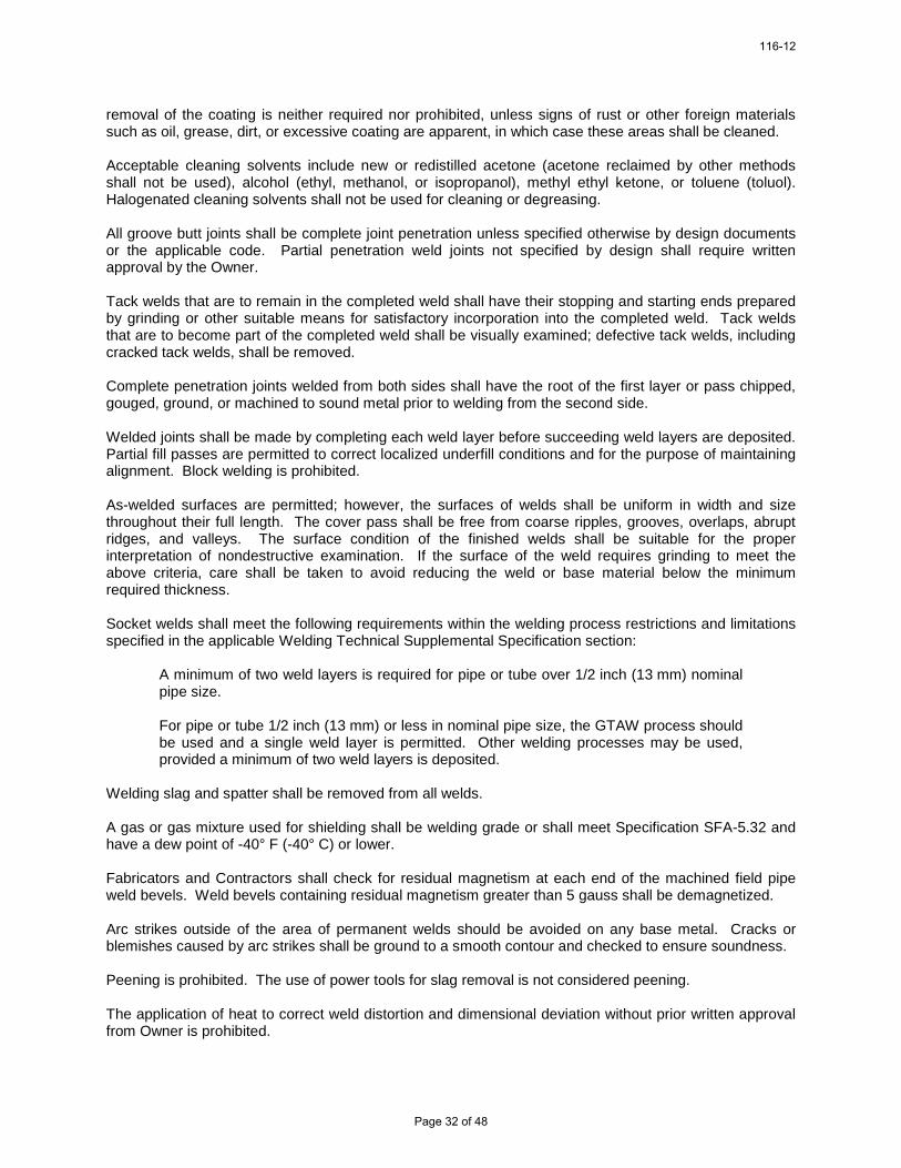
removal of the coating is neither required nor prohibited, unless signs of rust or other foreign materials such as oil, grease, dirt, or excessive coating are apparent, in which case these areas shall be cleaned. Acceptable cleaning solvents include new or redistilled acetone (acetone reclaimed by other methods shall not be used), alcohol (ethyl, methanol, or isopropanol), methyl ethyl ketone, or toluene (toluol). Halogenated cleaning solvents shall not be used for cleaning or degreasing. All groove butt joints shall be complete joint penetration unless specified otherwise by design documents or the applicable code. Partial penetration weld joints not specified by design shall require written approval by the Owner. Tack welds that are to remain in the completed weld shall have their stopping and starting ends prepared by grinding or other suitable means for satisfactory incorporation into the completed weld. Tack welds that are to become part of the completed weld shall be visually examined; defective tack welds, including cracked tack welds, shall be removed. Complete penetration joints welded from both sides shall have the root of the first layer or pass chipped, gouged, ground, or machined to sound metal prior to welding from the second side. Welded joints shall be made by completing each weld layer before succeeding weld layers are deposited. Partial fill passes are permitted to correct localized underfill conditions and for the purpose of maintaining alignment. Block welding is prohibited. As-welded surfaces are permitted; however, the surfaces of welds shall be uniform in width and size throughout their full length. The cover pass shall be free from coarse ripples, grooves, overlaps, abrupt ridges, and valleys. The surface condition of the finished welds shall be suitable for the proper interpretation of nondestructive examination. If the surface of the weld requires grinding to meet the above criteria, care shall be taken to avoid reducing the weld or base material below the minimum required thickness. Socket welds shall meet the following requirements within the welding process restrictions and limitations specified in the applicable Welding Technical Supplemental Specification section:
A minimum of two weld layers is required for pipe or tube over 1/2 inch (13 mm) nominal pipe size. For pipe or tube 1/2 inch (13 mm) or less in nominal pipe size, the GTAW process should be used and a single weld layer is permitted. Other welding processes may be used, provided a minimum of two weld layers is deposited.
Welding slag and spatter shall be removed from all welds. A gas or gas mixture used for shielding shall be welding grade or shall meet Specification SFA-5.32 and have a dew point of -40° F (-40° C) or lower. Fabricators and Contractors shall check for residual magnetism at each end of the machined field pipe weld bevels. Weld bevels containing residual magnetism greater than 5 gauss shall be demagnetized. Arc strikes outside of the area of permanent welds should be avoided on any base metal. Cracks or blemishes caused by arc strikes shall be ground to a smooth contour and checked to ensure soundness. Peening is prohibited. The use of power tools for slag removal is not considered peening. The application of heat to correct weld distortion and dimensional deviation without prior written approval from Owner is prohibited.
116-12
Page 32 of 48

Temporary attachments to pressure boundary components should be avoided and only used when absolutely necessary. When required, clamps, welded clips, tack welds, or other appropriate means shall be used to properly align the joint for welding. Welded attachments used for fit-up shall be compatible with the base material and shall be welded with a qualified welding procedure. Attachments shall not be knocked off base material. The attachments shall be removed by suitable methods, such as grinding, machining, or sawing, followed by grinding flush with the base material. When thermal cutting is used to remove attachments, approximately 3/16 inch of material shall be left for final removal by grinding. The ground area shall then be visually examined for defects. The area from which attachments have been removed shall be examined as required by the governing code or specification. Any defects found shall be repaired. All defects in welds or base materials shall be removed and repaired in accordance with the referenced code. A written procedure for root side purging shall be described in detail and shall be submitted concurrently with the welding procedures for review by Owner. Welding machine ground leads and clamps shall be located to avoid passing welding current through equipment, snubbers, bearings, or any other items where transfer of electrical current may result in damage to equipment. A complete repair procedure for repairs that are documented as the basis of a nonconformance report shall be submitted to Owner for review and approval in writing prior to performing the repair. If repair by welding is required, the applicable WPSs and supporting PQRs shall be submitted with the repair procedure. All nonconformance report dispositions shall comply with applicable code requirements. Nondestructive Examination (NDE) All NDE shall be performed in accordance with the methods specified in the referenced code and any supplemental NDE specified within the other Welding Technical Supplemental Specification sections. NDE shall be performed in accordance with written procedures that are prepared in accordance with the referenced code and as specified herein. NDE procedures shall be submitted for review by Owner prior to their use. NDE personnel performing NDE other than visual shall be qualified and certified for the applicable NDE method. Personnel shall meet written practice ASNT SNT-TC-1A, unless permitted otherwise by the referencing code or prior written approval from Owner is obtained. NDE personnel qualification records shall be made available for review when requested. Personnel performing or supervising the visual examination of welds, including ASME Boiler and Pressure Vessel components, shall be qualified as a Certified Welding Inspector (CWI) in accordance with the American Welding Society AWS QC 1 or previously approved equivalent program as determined by Owner. Visual inspectors' qualifications and certificates shall be submitted for review and verification. All welds shall receive 100 percent visual examination. Visual weld examination acceptance criteria and other NDE acceptance criteria shall be in accordance with applicable referenced codes and design documents. Records of these examinations shall be documented. The NDE results shall be provided in a NDE Report that is evaluated, interpreted, and accepted by a Level II or Level III NDE personnel. Contractor shall obtain and pay for the services of an independent testing laboratory to provide the required field nondestructive examination. Any defective weld shall be removed, repaired, and retested at the Contractor's expense.
116-12
Page 33 of 48

Owner may order NDE by an independent laboratory in addition to any examinations specified herein. The NDE type, extent, and method shall be the same as that required for the original weld. If the weld is defective, the laboratory costs shall be paid by the Contractor. If the weld is not defective, the laboratory costs will be paid by Owner. Repair of defective welds and reexamination shall be at the Contractor's expense. Weld acceptance standards shall be in accordance with applicable codes and design specifications. If an individual interpretation is in question, the final authority shall be the responsibility of Owner. Records Records of inspections, NDE, impact testing, hardness testing, PWHT charts or records, base material test reports, filler material test reports, radiographic film with applicable reader sheets, deviation requests including resolution documentation, nonconformance reports, and other records, as required, shall be retained by the Contractor for 5 years after completion of the work. Records shall be submitted to the Owner, if requested. Quality records, including applicable Data Report Forms generated by a manufacturer or assembler in accordance with an approved Quality Control System and applicable Certificates of Authorization from the ASME Boiler & Pressure Vessel Code, shall be provided in accordance with the approved contract or purchase order. Quality records shall be legible, appropriately completed, and sufficiently detailed to permit traceability to the item or activity involved. Welding of ASME Pressure Vessels and Heat Exchangers General This Technical Supplemental Specification provides requirements for welding pressure vessel, heat exchanger, and condenser components, including parts and appurtenances manufactured in accordance with ASME Section VIII Division 1; Heat Exchange Institute (HEI); and Tubular Exchanger Manufacturers Association (TEMA), as applicable, and shall be used in conjunction with Section Q100 of the Welding Technical Supplemental Specifications. ASME Section VIII Code Cases shall only be permitted for use as specifically approved by the Owner. Welding Processes Permitted welding processes shall be as specified in General Welding Requirements and shall include the restrictions and limitations applicable to those processes as specified herein. Welding Process Restrictions and Limitations The Gas Metal Arc Welding (GMAW) process shall not be used for welding P-5B (9 Cr-1 Mo-V) material. The GMAW process utilizing the short-circuiting transfer mode shall not be used in any application, except the GMAW short-circuiting transfer mode may be used for root pass installation only when the root pass is subsequently removed by backgouging and back welded. The weld progression for manual or semiautomatic vertical position welds shall be uphill, except when the GMAW short-circuiting transfer mode is used for root pass installation, then the progression may be uphill or downhill. The Gas Tungsten Arc Welding (GTAW) process may be performed without the addition of filler metal for tube-to-tubesheet welds. The Flux Cored Arc Welding (FCAW) process shall only be used with shielding gas. The FCAW process shall not be used for root pass applications in single welded joints without backing or without backgouging and back welding.
116-12
Page 34 of 48

The Shielded Metal Arc Welding (SMAW) process shall not be used for root pass applications in single welded joints of low alloy steel, stainless steel, or nickel alloy steel materials without backing or without backgouging and back welding. Welding Procedure Qualification Welding procedures shall be prepared and qualified in accordance with ASME Section VIII, Division 1 and ASME Section IX, as applicable, except that tube-to-tubesheet welding procedures shall be qualified in accordance with the requirements of the latest Article F-3 of ASME Section VIII, Division 2, "Special Requirements for Tube-to-Tubesheet Welds." Welder/Welding Operator Performance Qualification Welders and welding operators shall be qualified in accordance with ASME Section VIII, Division 1 and ASME Section IX, as applicable. Welding operators performing tube-to-tubesheet automatic welding operations shall also be qualified by testing, and the test shall be documented on a performance qualification test record. Fabrication Control Fabrication, assembly, and erection shall be in accordance with ASME Section VIII, Division 1; HEI; TEMA; and the design documents as applicable. Backing and Retainers Backing strips used at longitudinal welded joints shall be removed. Nonmetallic retainers or nonfusing metal retainers shall not be used unless specified in the Welding Procedure Specification (WPS). When used, they shall be removed. Preheat and Postweld Heat Treatment Preheat shall be performed in accordance with the WPS applicable to the materials being welded and as permitted in ASME Section VIII, Table UCS-56, and the design documents. Postweld heat treatment shall be in accordance with ASME Section VIII, Division 1 and the design documents. Weld End Preparation Joint design and weld end preparation for the pressure vessel, heat exchanger, or condenser components shall be in accordance with the fabricator's standard end preparation details and the WPS, and shall be as specified by the design documents. Preparation of piping butt welding ends for field welds shall be in accordance with the contract drawings. Nondestructive Examination (NDE) NDE of welds shall be performed in accordance with ASME Section VIII, Division 1; HEI; or TEMA (as applicable) and as specified by the design documents.
116-12
Page 35 of 48

MINIMUM INSURANCE REQUIREMENTS CITY OF GRAND ISLAND, NEBRASKA
The successful bidder shall obtain insurance from companies authorized to do business in Nebraska of such types and in such amounts as may be necessary to protect the bidder and the interests of the City against hazards or risks of loss as hereinafter specified. This insurance shall cover all aspects of the Bidder's operations and completed operations. Failure to maintain adequate coverage shall not relieve bidder of any contractual responsibility or obligation. Minimum insurance coverage shall be the amounts stated herein or the amounts required by applicable law, whichever are greater. 1. WORKERS COMPENSATION AND EMPLOYER'S LIABILITY This insurance shall protect the Bidder against all claims under applicable State workers compensation laws. This insurance shall provide coverage in every state in which work for this project might be conducted. The liability limits shall not be less than the following: Workers Compensation Statutory Limits Employers Liability $100,000 each accident
$100,000 each employee $500,000 policy limit
2. BUSINESS AUTOMOBILE LIABILITY This insurance shall be written in comprehensive form and shall protect the Bidder, Bidder’s employees, or subcontractors from claims due to the ownership, maintenance, or use of a motor vehicle. The liability limits shall be not less than the following: Bodily Injury & Property Damage $ 500,000 Combined Single Limit 3. COMPREHENSIVE GENERAL LIABILITY The comprehensive general liability coverage shall contain no exclusion relative to explosion, collapse, or underground property. The liability limits shall be not less than the following: Bodily Injury & Property Damage $ 500,000 each occurrence
$1,000,000 aggregate 4. UMBRELLA LIABILITY INSURANCE This insurance shall protect the Bidder against claims in excess of the limits provided under employer's liability, comprehensive automobile liability, and commercial general liability policies. The umbrella policy shall follow the form of the primary insurance, including the application of the primary limits. The liability limits shall not be less than the following: Bodily Injury & Property Damage $1,000,000 each occurrence
$1,000,000 general aggregate
5. ADDITIONAL REQUIREMENTS The City may require insurance covering a Bidder or subcontractor more or less than the standard requirements set forth herein depending upon the character and extent of the work to be performed by such Bidder or subcontractor. Insurance as herein required shall be maintained in force until the City releases the Bidder of all obligations under the Contract.
116-12
Page 36 of 48
The Bidder shall provide and carry any additional insurance as may be required by special provisions of these specifications. 6. CERTIFICATE OF INSURANCE Satisfactory certificates of insurance shall be filed with the City prior to starting any work on this Contract. The certificates shall show the City as an additional insured on all coverage except Workers Compensation. The certificate shall state that thirty (30) days written notice shall be given to the City before any policy is cancelled (strike the "endeavor to" wording often shown on certificate forms). If the bidder cannot have the “endeavor to” language stricken, the bidder may elect to provide a new certificate of insurance every 30 days during the contract. Bidder shall immediately notify the City if there is any reduction of coverage because of revised limits or claims paid which affect the aggregate of any policy.
116-12
Page 37 of 48


116-12
Page 39 of 48

116-12
Page 40 of 48

116-12
Page 41 of 48

116-12
Page 42 of 48

116-12
Page 43 of 48

116-12
Page 44 of 48

116-12
Page 45 of 48

116-12
Page 46 of 48

116-12
Page 47 of 48

1800 PSIG-1000"/1000~ F-2 .5"i lG. A. 2 X 16.5" LSD
Locus of Valve Point Ileat Bllance
0
1, tiENLIft\L ELECTIf I C CO. Q\ LYhrti, U;lSS,
5/1/77
116-12
Page 48 of 48