modernization of feedwater pumps at the kostromskaya power ...
12
1 MODERNIZATION OF FEEDWATER PUMPS AT THE KOSTROMSKAYA POWER PLANT W. Uffelmann, KSB SE & Co. KGaA, Germany, Frankenthal, E-mail: [email protected] V.V. Svetushkov, JSC “Inter RAO – Electric Power Plants,” Moscow O.A. Savin, Kostromskaya SDPP, JSC “Inter RAO – Electric Power Plants,” Kostroma Region, Volgorechensk Translated from Elektricheskie Stantsii, No. 2, February 2021, pp. 36-47, DOI: 10.34831/EP.2021.1075.2.005 Based on the example of a two-stage modernization of all turbine driven feedwater pumps of the Kostromskaya State District Power Plant (SDPP), the experience of development, optimization, and successful operation of this equip- ment with a high degree of reliability is described. All the tasks assigned by the plant management were completed as demonstrated by the long-term repair-free operation of the feedwater pumps. As a result, employees were able to concen- trate on fulfilling the priority task of generating electricity at optimal efficiency and maximal availability factor. Keywords: feedwater pumps, rehabilitation, modernization, optimization of pumping equipment The reliability of power units at thermal power plants is ensured by the reliable operation of the most important components of the steam power cycle. As is well known from thermodynamics, one of the four el- ements of the Carnot cycle in a power plant involves adiabatic compression. This essential process for gen- erating electricity in a thermal power plant is mainly supported by feedwater pumps. Although the boiler, steam turbine, and condenser may seem to be the larger and more expensive components of the steam- power unit, the fundamental role of the feedwater pump in the overall operation of the power plant should not be underestimated. This article presents the experience of a two-stage modernization carried out on all turbine driven feedwater pumps at the Ko- stromskaya SDPP, which involved the development, optimization, and successful operationalization of this equipment to the highest reliability standards. As demonstrated by the resultant long-term repair-free operation of the feedwater pumps, all the tasks estab- lished by the plant management were fulfilled. As a result, employees were able to concentrate on ful- filling the essential mission of generating electricity with the highest efficiency and availability factor. KSB SE & Co. KGaA (hereinafter KSB) has been actively working in the Russian energy market follow- ing the successful completion of pump modernization works carried out at the Permskaya SDPP. Represent- atives of the Kostromskaya SDPP first made contact with KSB in 1999 during the testing of feedwater pumps for Permskaya SDPP. The attention of the Ko- stromskaya SDPP management was attracted by the presented design solutions, pump characteristics – and, above all, numerous references as a guarantor of reliable and trouble-free equipment operation. The Kostromskaya SDPP operated by JSC “Inter RAO – Electric Power Plants” consists of a thermal power plant located within the Central Economic Re- gion in the town of Volgorechensk of Kostroma Re- gion at the center of the European part of Russia. The installed electric power capacity of the station com- prises 3600 MW and an installed thermal capacity of 450 Gcal/h. Along with eight power units of 300 MW, the plant boasts the world’s largest steam power unit (1200 MW) according to the Guinness Book of Rec- ords. In terms of the fuel for the boiler units, both nat- ural gas and M-100 fuel oil are used. Prior to the modernization, the work of the plant operating personnel was complicated by frequent fail- ures of feedwater pumps, which negatively affected the operational reliability of power units. Among the most common malfunctions of the tur- bine driven boiler feedwater pumps (TDBFP) were: increased vibration caused by incorrect hydraulic design. In such cases, an incorrectly selected ratio be- tween the number of impeller and diffuser blades led to the excitation of high-amplitude auto-oscillations. Such vibrations were intensified to resonance level by the insufficient stiffness of other pump components and assemblies; malfunctions and unreliable operation of throttling shaft seals (unacceptably high level of leakage); malfunctions and failures of the balancing device with subsequent damage to the impellers and diffus- ers; leakage of casing part gaskets and destruction of the graphite gaskets with subsequent washout in the area of the casing seat surfaces, affecting other pump assemblies and elements; jamming of the rotor during run-out and in barring mode. All these faults, along with their various combina- tions, led to a significant decrease in efficiency in- volving frequent shutdowns of feedwater pumps. The start of the project as detailed in this article occurred in 2001 when the first contract for the mod- ernization of the TDBFP at the 1200 MW power unit was signed.
-
Upload
khangminh22 -
Category
Documents
-
view
3 -
download
0
Transcript of modernization of feedwater pumps at the kostromskaya power ...
1
MODERNIZATION OF FEEDWATER PUMPS AT THE KOSTROMSKAYA POWER PLANT
W. Uffelmann, KSB SE & Co. KGaA, Germany, Frankenthal, E-mail: [email protected] V.V. Svetushkov, JSC “Inter RAO – Electric Power Plants,” Moscow O.A. Savin, Kostromskaya SDPP, JSC “Inter RAO – Electric Power Plants,” Kostroma Region, Volgorechensk
Translated from Elektricheskie Stantsii, No. 2, February 2021, pp. 36-47, DOI: 10.34831/EP.2021.1075.2.005
Based on the example of a two-stage modernization of all turbine driven feedwater pumps of the Kostromskaya State District Power Plant (SDPP), the experience of development, optimization, and successful operation of this equip-ment with a high degree of reliability is described. All the tasks assigned by the plant management were completed as demonstrated by the long-term repair-free operation of the feedwater pumps. As a result, employees were able to concen-trate on fulfilling the priority task of generating electricity at optimal efficiency and maximal availability factor.
Keywords: feedwater pumps, rehabilitation, modernization, optimization of pumping equipment
The reliability of power units at thermal power plants is ensured by the reliable operation of the most important components of the steam power cycle. As is well known from thermodynamics, one of the four el-ements of the Carnot cycle in a power plant involves adiabatic compression. This essential process for gen-erating electricity in a thermal power plant is mainly supported by feedwater pumps. Although the boiler, steam turbine, and condenser may seem to be the larger and more expensive components of the steam-power unit, the fundamental role of the feedwater pump in the overall operation of the power plant should not be underestimated. This article presents the experience of a two-stage modernization carried out on all turbine driven feedwater pumps at the Ko-stromskaya SDPP, which involved the development, optimization, and successful operationalization of this equipment to the highest reliability standards. As demonstrated by the resultant long-term repair-free operation of the feedwater pumps, all the tasks estab-lished by the plant management were fulfilled. As a result, employees were able to concentrate on ful-filling the essential mission of generating electricity with the highest efficiency and availability factor.
KSB SE & Co. KGaA (hereinafter KSB) has been actively working in the Russian energy market follow-ing the successful completion of pump modernization works carried out at the Permskaya SDPP. Represent-atives of the Kostromskaya SDPP first made contact with KSB in 1999 during the testing of feedwater pumps for Permskaya SDPP. The attention of the Ko-stromskaya SDPP management was attracted by the presented design solutions, pump characteristics – and, above all, numerous references as a guarantor of reliable and trouble-free equipment operation.
The Kostromskaya SDPP operated by JSC “Inter RAO – Electric Power Plants” consists of a thermal power plant located within the Central Economic Re-gion in the town of Volgorechensk of Kostroma Re-gion at the center of the European part of Russia. The
installed electric power capacity of the station com-prises 3600 MW and an installed thermal capacity of 450 Gcal/h. Along with eight power units of 300 MW, the plant boasts the world’s largest steam power unit (1200 MW) according to the Guinness Book of Rec-ords. In terms of the fuel for the boiler units, both nat-ural gas and M-100 fuel oil are used.
Prior to the modernization, the work of the plant operating personnel was complicated by frequent fail-ures of feedwater pumps, which negatively affected the operational reliability of power units.
Among the most common malfunctions of the tur-bine driven boiler feedwater pumps (TDBFP) were: increased vibration caused by incorrect hydraulic design. In such cases, an incorrectly selected ratio be-tween the number of impeller and diffuser blades led to the excitation of high-amplitude auto-oscillations. Such vibrations were intensified to resonance level by the insufficient stiffness of other pump components and assemblies; malfunctions and unreliable operation of throttling shaft seals (unacceptably high level of leakage); malfunctions and failures of the balancing device with subsequent damage to the impellers and diffus-ers; leakage of casing part gaskets and destruction of the graphite gaskets with subsequent washout in the area of the casing seat surfaces, affecting other pump assemblies and elements; jamming of the rotor during run-out and in barring mode.
All these faults, along with their various combina-tions, led to a significant decrease in efficiency in-volving frequent shutdowns of feedwater pumps.
The start of the project as detailed in this article occurred in 2001 when the first contract for the mod-ernization of the TDBFP at the 1200 MW power unit was signed.

2
Fig. 1. PTN 1500-350 feedwater pump: 1, connecting coupling casing; 2, bearing housing; 3, O-ring; 4, inlet chamber; 5, barrel; 6, pump section; 7, stud; 8, balancing device; 9, bush; 10, collar; 11, cap nut; 12, balancing disc; 13, bearing housing; 14, bearing end cover; 15, axial shift sensor; 16, shaft; 17, radial bearing; 18, bearing bracket; 19, shaft seal cover; 20, discharge cover; 21, O-ring; 22, support frame; 23, guide; 24, shaft seal cover; 25, bearing bracket; 26, radial bearing; 27, bearing support; 28, centrifugal thrower
TDBFP of Unit No. 9 (1200 MW): Initial situa-tion and task setting. Presenting themselves as poten-tial objects for modernization were TDBFP 1500-350 feedwater pumps (3 x 33%) manufactured by JSC “Proletarsky Zavod” and employing a drive turbine manufactured by the Kaluga Turbine Plant (Fig. 1). As a cost-saving measure, the management of the Ko-stromskaya SDPP insisted on preserving the existing outer casings, as well as, if possible, the heavy dis-charge covers.
The KSB specialists were tasked with achieving the following pump operating parameters:
Flow rate, m3/h ....................................... 1500 - 1800 Inlet pressure, kgf/cm2 ........................... 22.5 Discharge pressure, kgf/cm2 ................... 350 Inlet water temperature, °С .................... 165 Rotation frequency, rpm......................... 2660 - 4700 Allowable NPSH3%, MPa ....................... 0.8
Efficiency, % ............................................. 86.5 Power consumption, kW, not more ........... 18000
In addition, the following requirements were spec-ified for the reliability of the pumps:
availability factor – 96%; operating time between major overhaul re-
pairs – 50,000–80,000 hours or 10 years; service life – 300,000 hours; vibration level of bearings – 2.8 and 4.0 mm/s
in the flow control range of 750–1650 m3/h and 375–750 m3/h, respectively.
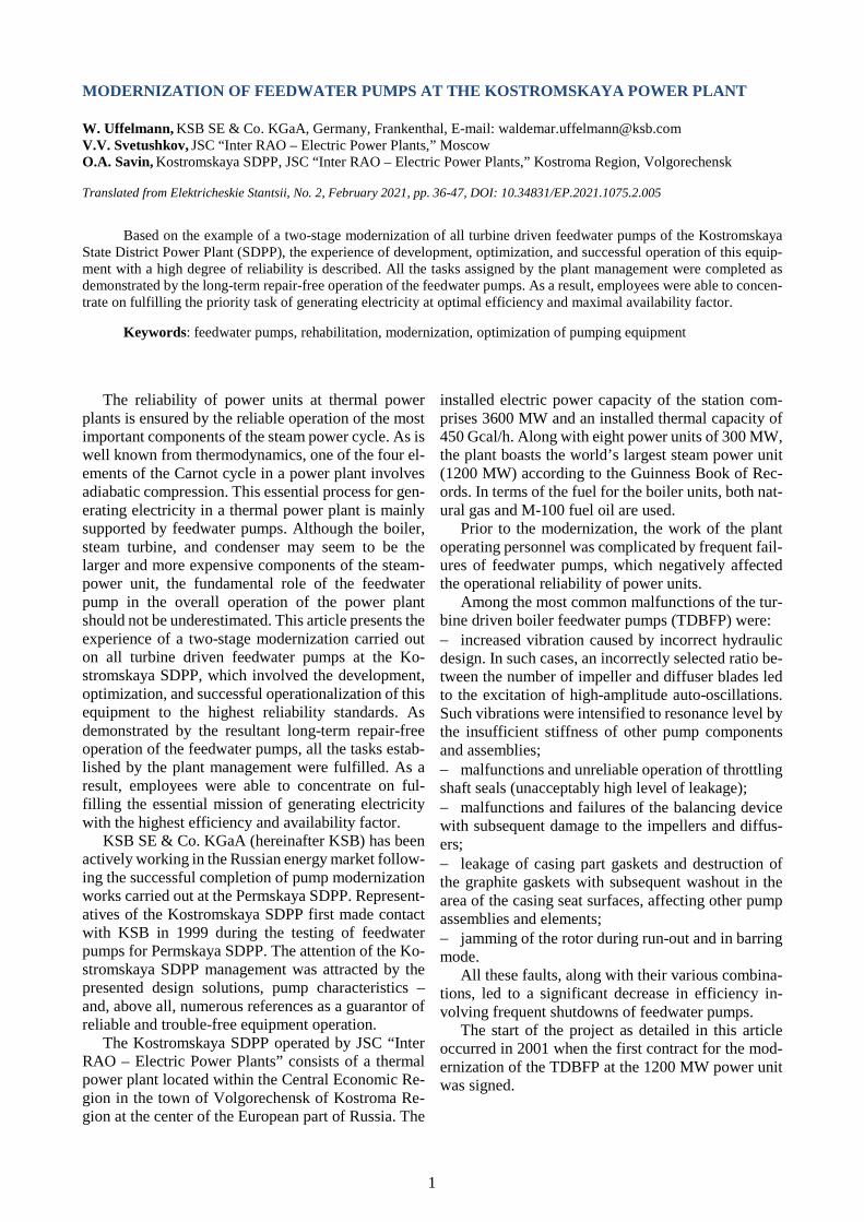
Thus, the Kostromskaya SDPP specialists were presented with a modernization project comprising a number of measures for improving the design and in-creasing the reliability of the feedwater pumps (Fig. 2).
3
Fig. 2. Feedwater pump modernization project
The KSB specialists additionally recommended re-placing the feedwater pumps in their entirety, whose subsequent delivery together with the barrel and al-ready installed on a support frame would have signif-icantly saved time for the implementation of work, re-duced risks, as well as increasing the quality outcome of the modernization process. However, proceeding from economic considerations, along with the availa-bility of excellent technological equipment and highly qualified repair personnel at the Kostromskaya SDPP, it was decided instead to purchase pump cartridges and adjust the internal contours of the existing pump casings to the new cartridges.
A more detailed description of technical solutions for the modernization of pumps and their advantages is presented in the section of this article entitled “Main structural elements and their characteristics”.
Test results of modernized turbine driven feedwa-ter pumps of Unit No. 9 (1200 MW). Below, the TDBFP indicators before and after rehabilitation are provided as confirmed during acceptance tests at the KSB manufacturing plant (at rated load). __________________________________________
before after Flow rate, m3/h .................................. 1500 1500 Inlet pressure, bar .............................. 20.6 20.6 Discharge pressure, bar ..................... 345.9 345.9 Pump head, m ................................... 3675 3675 Inlet water temperature, °С ............... 165 165 Rotation frequency, rpm ................... – 4568 Allowable NPSH3%, MPa .................. – 56.1
Efficiency, % ..................................... 80.0 86.5 Power consumption, kW ................... 16937.5 15697.1 _________________________________________
Thus, the power consumption for each turbine driven feedwater pump of Unit No. 9 was reduced by 1266.4 kW, translating into a value of 3799.3 kW for all three pumps in total.
Following the successful modernization of the TDBFP at Unit No. 9, the power station's specialists were tasked with modernizing the pumps of the re-maining eight 300 MW units. During the period from 2005 to 2012, an investment project was carried out at the Kostromskaya SDPP aimed at modernizing the turbine driven feedwater pumps by replacing the TDBFP inner casing manufactured by Leningradsky Metallichesky Zavod (LMZ) with a cartridge from KSB at Units 1–8.
Initial situation with TDBFP of Power Units 1-8 (300 MW). Before modernization, the 300 MW units were equipped with feedwater pumps of the SVPT-340-1000 type designed and manufactured during the 1960s by LMZ. During the operation of LMZ pumps, the following shortcomings were identified: insufficient efficiency (lower than 80%) of the LMZ pump due to the outdated of the design of the hydraulic parts and the physical wear of its elements (operating time of the pumps was 220-250 thousand hours); periodic damage of the balancing device, accom-panied by significant damage of the hydraulic parts of
4
the pump; observed cases of rupture of the gasket between the inner casing and barrel, leading to internal leakage of water from the discharge to the suction side and a sharp decrease in the efficiency of the pump; increased vibration frequency of the non driven end bearing support of the pump at reduced loads.
Based on the experience of modernizing the TDBFP of Unit No. 9, all proposals of potential sup-pliers of pumping equipment were thoroughly evalu-ated. The main evaluation criteria included optimal technical and economic indicators of the proposed equipment.
The CHTD 7/6 pump produced by KSB offered a number of design advantages as compared to compet-itors’ proposals: the inlet chamber is optimized to reduce swirling and velocity at the pump inlet, as well as to improve cavitation and vibration characteristics; impeller wear rings have a cellular profile and a number of advantages (increased efficiency by reduc-ing leakages through the gaps, high damping proper-ties and increased rotor stability, good anti-seize char-acteristics); the sealing between the cartridge and the barrel of the pump is created with a profile gasket, providing reliable protection against leakages and sealing insta-bility in transient operating modes; the pump rotor is “ stiff” (the critical rotor speed is much higher than the operating speed), which im-proves the vibration characteristics; the sections of the diffusers are integral, sealed without gaskets due to the precise fitting of the sur-faces, and interconnected on a sliding fit without fas-teners; shaft mechanical seals manufactured by Burgmann (Germany) have minimal leakages resulting in in-creased pump efficiency and are equipped with an am-moniac dosing unit for water treatment in the seal coolant circuit in order to prevent damage to the work-ing surfaces of the seals under the action of electro-chemical erosion; the combined balancing system, consisting of a
double drum in combination with balance disc, serv-ing as the second stage of protection against axial forces, offers significantly reduced leakage reliability, which significantly increases the efficiency of the pump; closed pump bearing housings without horizontal split are directly attached to the pump casing, contrib-uting to a stiffer bearing vibration characteristic; the thrust bearing with cardanic ring uniforms au-tomatically load on tilting pads and provides reliable protection against damage to the pump in the event of transient axial forces.
Test results of modernized turbine driven feedwa-ter pumps in Unit No. 2 (300 MW). Further, indica-tors of TDBFP before and after modernization are provided and confirmed during acceptance tests as a part of Unit No. 2 (300 MW) at Kostromskaya SDPP (at rated load). __________________________________________
before after Flow rate, m3/h ............................. 1081.1 1081.1 Inlet pressure, bar ......................... 24.1 24.1 Pump head, m .............................. 3193.0 3193.4 Inlet water temperature, °С .......... 173.0 173.7 Rotation frequency, rpm .............. – 4778 Efficiency, % ............................... 78.0 85.8 Power consumption, kW .............. 10859.1 9878.5 _________________________________________
During the modernization of the turbine feedwater pump of Unit No. 2, power consumption was reduced by 980.6 kW, representing a total saving of 7845.1 kW for all eight power units.
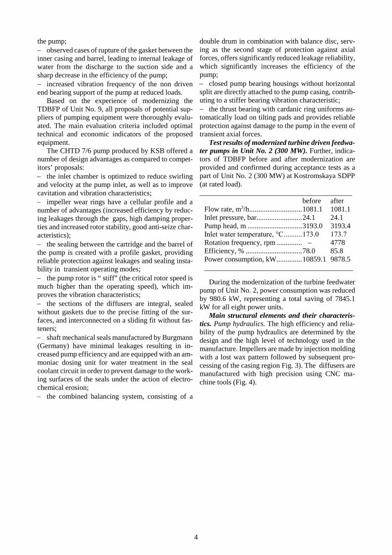
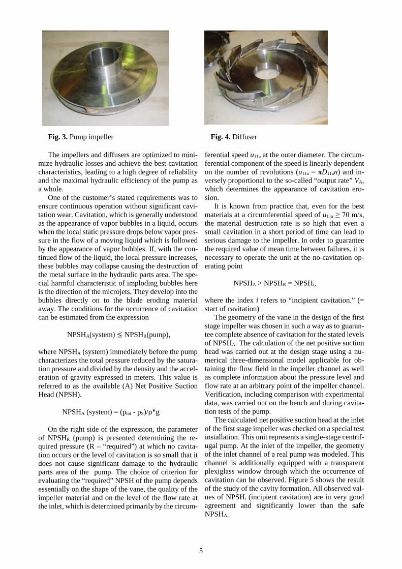
Main structural elements and their characteris-tics. Pump hydraulics. The high efficiency and relia-bility of the pump hydraulics are determined by the design and the high level of technology used in the manufacture. Impellers are made by injection molding with a lost wax pattern followed by subsequent pro-cessing of the casing region Fig. 3). The diffusers are manufactured with high precision using CNC ma-chine tools (Fig. 4).
5
The impellers and diffusers are optimized to mini-mize hydraulic losses and achieve the best cavitation characteristics, leading to a high degree of reliability and the maximal hydraulic efficiency of the pump as a whole.
One of the customer’s stated requirements was to ensure continuous operation without significant cavi-tation wear. Cavitation, which is generally understood as the appearance of vapor bubbles in a liquid, occurs when the local static pressure drops below vapor pres-sure in the flow of a moving liquid which is followed by the appearance of vapor bubbles. If, with the con-tinued flow of the liquid, the local pressure increases, these bubbles may collapse causing the destruction of the metal surface in the hydraulic parts area. The spe-cial harmful characteristic of imploding bubbles here is the direction of the microjets. They develop into the bubbles directly on to the blade eroding material away. The conditions for the occurrence of cavitation can be estimated from the expression
NPSHA(system) ≤ NPSHR(pump),
where NPSHA (system) immediately before the pump characterizes the total pressure reduced by the satura-tion pressure and divided by the density and the accel-eration of gravity expressed in meters. This value is referred to as the available (A) Net Positive Suction Head (NPSH).
NPSHA (system) = (ptot - pS)/ρ*g
On the right side of the expression, the parameter of NPSHR (pump) is presented determining the re-quired pressure (R – “required”) at which no cavita-tion occurs or the level of cavitation is so small that it does not cause significant damage to the hydraulic parts area of the pump. The choice of criterion for evaluating the “required” NPSH of the pump depends essentially on the shape of the vane, the quality of the impeller material and on the level of the flow rate at the inlet, which is determined primarily by the circum-
ferential speed u11a at the outer diameter. The circum-ferential component of the speed is linearly dependent on the number of revolutions (u11a = πD11an) and in-versely proportional to the so-called “output rate” VA, which determines the appearance of cavitation ero-sion.
It is known from practice that, even for the best materials at a circumferential speed of u11a ≥ 70 m/s, the material destruction rate is so high that even a small cavitation in a short period of time can lead to serious damage to the impeller. In order to guarantee the required value of mean time between failures, it is necessary to operate the unit at the no-cavitation op-erating point
NPSHA > NPSHR = NPSHi,
where the index i refers to “incipient cavitation.” (= start of cavitation)
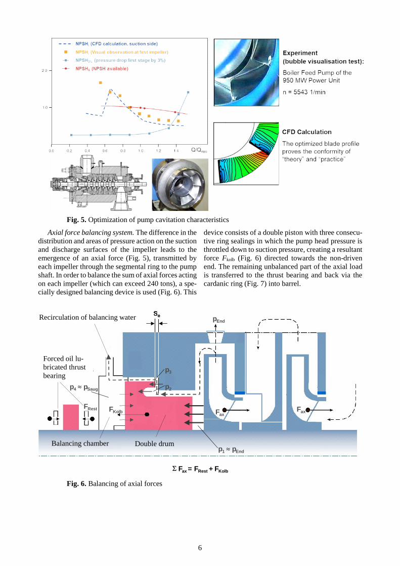
The geometry of the vane in the design of the first stage impeller was chosen in such a way as to guaran-tee complete absence of cavitation for the stated levels of NPSHA. The calculation of the net positive suction head was carried out at the design stage using a nu-merical three-dimensional model applicable for ob-taining the flow field in the impeller channel as well as complete information about the pressure level and flow rate at an arbitrary point of the impeller channel. Verification, including comparison with experimental data, was carried out on the bench and during cavita-tion tests of the pump.
The calculated net positive suction head at the inlet of the first stage impeller was checked on a special test installation. This unit represents a single-stage centrif-ugal pump. At the inlet of the impeller, the geometry of the inlet channel of a real pump was modeled. This channel is additionally equipped with a transparent plexiglass window through which the occurrence of cavitation can be observed. Figure 5 shows the result of the study of the cavity formation. All observed val-ues of NPSHi (incipient cavitation) are in very good agreement and significantly lower than the safe NPSHA.
Fig. 3. Pump impeller Fig. 4. Diffuser
6
Fig. 5. Optimization of pump cavitation characteristics
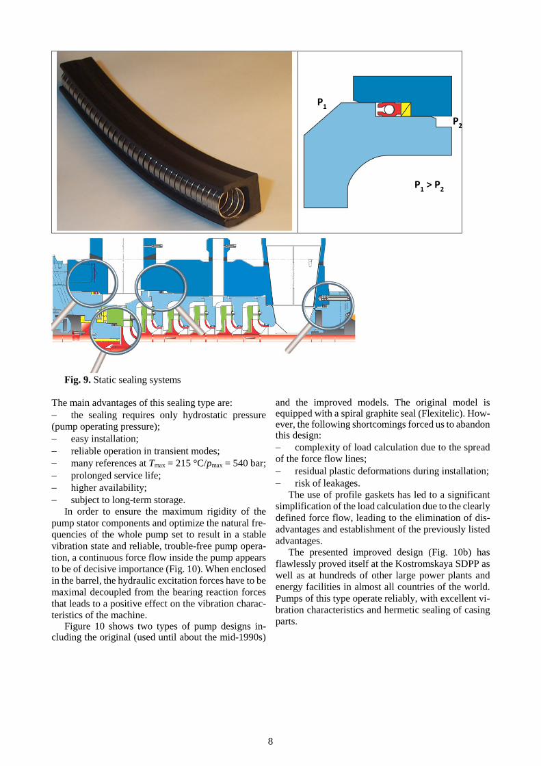
Axial force balancing system. The difference in the distribution and areas of pressure action on the suction and discharge surfaces of the impeller leads to the emergence of an axial force (Fig. 5), transmitted by each impeller through the segmental ring to the pump shaft. In order to balance the sum of axial forces acting on each impeller (which can exceed 240 tons), a spe-cially designed balancing device is used (Fig. 6). This
device consists of a double piston with three consecu-tive ring sealings in which the pump head pressure is throttled down to suction pressure, creating a resultant force Fkolb (Fig. 6) directed towards the non-driven end. The remaining unbalanced part of the axial load is transferred to the thrust bearing and back via the cardanic ring (Fig. 7) into barrel.
Fig. 6. Balancing of axial forces
Entlastungswasserrückführung
ÖlgeschmiertesAxiallager
pEnd
FaxFax
p2
p3
FKolbFRest
p4 pSaug
p1 pEnd
Fax = FRest + FKolb
Recirculation of balancing water
Forced oil lu-bricated thrust bearing
Balancing chamber Double drum

7
It is important to note that the elastic element, of the cardanic ring, allows the rotor to make small axial movements, which leads to a change in the axial gap of the drum and thus increases the drum reaction forces.
That way a sudden vaporization on the suction side will cause additional axial thrust and the rotor will shift towards the suction side. The thrust balancing system will respond such that the maximum permissi-ble load on the bearing cannot be exceeded, because the double drum will balance more of the additional thrust caused by the narrowing of the axial clearance gap and thus limits the load on the bearing.
The operating experience of such multi-lobe jour-nal bearings has demonstrated their superior load-car-rying capacity and stable dynamic behavior, justifying their use in our pump. Like thrust bearings, these bear-ings are oil-lubricated under pressure from the unit lu-brication system. Because the thrust bearing is dou-ble-sided, it reliably protects the pump from sudden changes in the direction of the axial unsteady load (Fig. 7).
Fig. 7. Thrust bearing with cardanic ring
Wear rings. Wear rings are currently used in three designs: smooth, grooved surface or cellular sur-face (the latter design was developed by KSB). The design of the last ring type is based on so-called cells (honeycombs), which have been specially designed to work with water. These rings were originally used for gas sealing. Figure 8 shows a comparison of these
three ring sealing configurations and their character-istic leakage losses.
Ring
type
Smooth
surface
Grooved
surface
Cellular
surface
Leakage 2,5% 2,0% 1,5%
Stiffness 1 0,3 1,1
Fig. 8. Types of ring sealing
Cellular wear rings are commonly used in high power pumps to ensure a significant (up to 1.5%) in-crease of the internal efficiency of the pump (relative to smooth surface wear rings). These rings are high-tech, efficient, and virtually wear-free. Additional ad-vantages offered by these cellular wear rings include their excellent anti-seizure properties due to the mini-mization of the area of contact surfaces, as well as maintenance of the stable operation in case of contact with foreign objects, e.g., foreign particle. In this case, the constraining of foreign objects into the cavity of the cell helps to avoid pump rotor jamming, which may occur when smooth surface rings are used.
By carefully adjusting the stator to the rotor deflec-tion, clearances can be reduced without compromising pump reliability. In addition to reducing internal losses or leakages, this type of wear rings helps to in-crease the efficiency of the pumps.
Static sealing systems. The quality of the static seals is also very important. These are designed as profiled gaskets to provide a maximum pressure of up to 500 bar on the discharge side. The sealing effect is achieved due to the operating pressure, which is suf-ficient to press the sealing lips against the sealed struc-tural elements without the need for additional forces (Fig. 9). Nevertheless, they contribute to the develop-ment of the defined line of the action of forces without the use of springs that reduce sealing function of suc-tions.
8
Fig. 9. Static sealing systems
The main advantages of this sealing type are: the sealing requires only hydrostatic pressure (pump operating pressure); easy installation; reliable operation in transient modes; many references at Tmax = 215 °C/pmax = 540 bar; prolonged service life; higher availability; subject to long-term storage.
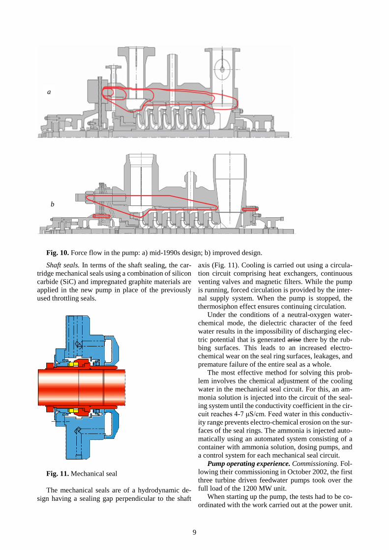
In order to ensure the maximum rigidity of the pump stator components and optimize the natural fre-quencies of the whole pump set to result in a stable vibration state and reliable, trouble-free pump opera-tion, a continuous force flow inside the pump appears to be of decisive importance (Fig. 10). When enclosed in the barrel, the hydraulic excitation forces have to be maximal decoupled from the bearing reaction forces that leads to a positive effect on the vibration charac-teristics of the machine.
Figure 10 shows two types of pump designs in-cluding the original (used until about the mid-1990s)
and the improved models. The original model is equipped with a spiral graphite seal (Flexitelic). How-ever, the following shortcomings forced us to abandon this design: complexity of load calculation due to the spread of the force flow lines; residual plastic deformations during installation; risk of leakages.
The use of profile gaskets has led to a significant simplification of the load calculation due to the clearly defined force flow, leading to the elimination of dis-advantages and establishment of the previously listed advantages.
The presented improved design (Fig. 10b) has flawlessly proved itself at the Kostromskaya SDPP as well as at hundreds of other large power plants and energy facilities in almost all countries of the world. Pumps of this type operate reliably, with excellent vi-bration characteristics and hermetic sealing of casing parts.
P1
P2
P1 > P2
9
Fig. 10. Force flow in the pump: a) mid-1990s design; b) improved design.
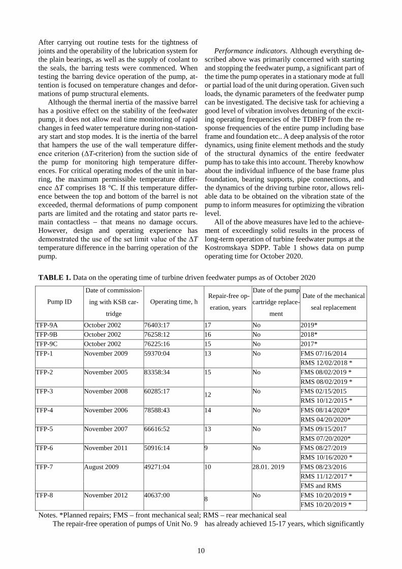
Shaft seals. In terms of the shaft sealing, the car-tridge mechanical seals using a combination of silicon carbide (SiC) and impregnated graphite materials are applied in the new pump in place of the previously used throttling seals.
Fig. 11. Mechanical seal
The mechanical seals are of a hydrodynamic de-sign having a sealing gap perpendicular to the shaft
axis (Fig. 11). Cooling is carried out using a circula-tion circuit comprising heat exchangers, continuous venting valves and magnetic filters. While the pump is running, forced circulation is provided by the inter-nal supply system. When the pump is stopped, the thermosiphon effect ensures continuing circulation.
Under the conditions of a neutral-oxygen water-chemical mode, the dielectric character of the feed water results in the impossibility of discharging elec-tric potential that is generated arise there by the rub-bing surfaces. This leads to an increased electro-chemical wear on the seal ring surfaces, leakages, and premature failure of the entire seal as a whole.
The most effective method for solving this prob-lem involves the chemical adjustment of the cooling water in the mechanical seal circuit. For this, an am-monia solution is injected into the circuit of the seal-ing system until the conductivity coefficient in the cir-cuit reaches 4-7 μS/cm. Feed water in this conductiv-ity range prevents electro-chemical erosion on the sur-faces of the seal rings. The ammonia is injected auto-matically using an automated system consisting of a container with ammonia solution, dosing pumps, and a control system for each mechanical seal circuit.
Pump operating experience. Commissioning. Fol-lowing their commissioning in October 2002, the first three turbine driven feedwater pumps took over the full load of the 1200 MW unit.
When starting up the pump, the tests had to be co-ordinated with the work carried out at the power unit.
a
b
10
After carrying out routine tests for the tightness of joints and the operability of the lubrication system for the plain bearings, as well as the supply of coolant to the seals, the barring tests were commenced. When testing the barring device operation of the pump, at-tention is focused on temperature changes and defor-mations of pump structural elements.
Although the thermal inertia of the massive barrel has a positive effect on the stability of the feedwater pump, it does not allow real time monitoring of rapid changes in feed water temperature during non-station-ary start and stop modes. It is the inertia of the barrel that hampers the use of the wall temperature differ-ence criterion (ΔT-criterion) from the suction side of the pump for monitoring high temperature differ-ences. For critical operating modes of the unit in bar-ring, the maximum permissible temperature differ-ence ΔT comprises 18 °C. If this temperature differ-ence between the top and bottom of the barrel is not exceeded, thermal deformations of pump component parts are limited and the rotating and stator parts re-main contactless – that means no damage occurs. However, design and operating experience has demonstrated the use of the set limit value of the ΔTtemperature difference in the barring operation of the pump.
Performance indicators. Although everything de-scribed above was primarily concerned with starting and stopping the feedwater pump, a significant part of the time the pump operates in a stationary mode at full or partial load of the unit during operation. Given such loads, the dynamic parameters of the feedwater pump can be investigated. The decisive task for achieving a good level of vibration involves detuning of the excit-ing operating frequencies of the TDBFP from the re-sponse frequencies of the entire pump including base frame and foundation etc.. A deep analysis of the rotor dynamics, using finite element methods and the study of the structural dynamics of the entire feedwater pump has to take this into account. Thereby knowhow about the individual influence of the base frame plus foundation, bearing supports, pipe connections, and the dynamics of the driving turbine rotor, allows reli-able data to be obtained on the vibration state of the pump to inform measures for optimizing the vibration level.
All of the above measures have led to the achieve-ment of exceedingly solid results in the process of long-term operation of turbine feedwater pumps at the Kostromskaya SDPP. Table 1 shows data on pump operating time for October 2020.
TABLE 1. Data on the operating time of turbine driven feedwater pumps as of October 2020
Pump ID
Date of commission-
ing with KSB car-
tridge
Operating time, h Repair-free op-
eration, years
Date of the pump
cartridge replace-
ment
Date of the mechanical
seal replacement
TFP-9A October 2002 76403:17 17 No 2019*
TFP-9B October 2002 76258:12 16 No 2018*
TFP-9C October 2002 76225:16 15 No 2017*
TFP-1 November 2009 59370:04 13 No FMS 07/16/2014
RMS 12/02/2018 *
TFP-2 November 2005 83358:34 15 No FMS 08/02/2019 *
RMS 08/02/2019 *
TFP-3 November 2008 60285:17 12
No FMS 02/15/2015
RMS 10/12/2015 *
TFP-4 November 2006 78588:43 14 No FMS 08/14/2020*
RMS 04/20/2020*
TFP-5 November 2007 66616:52 13 No FMS 09/15/2017
RMS 07/20/2020*
TFP-6 November 2011 50916:14 9 No FMS 08/27/2019
RMS 10/16/2020 *
TFP-7 August 2009 49271:04 10 28.01. 2019 FMS 08/23/2016
RMS 11/12/2017 *
FMS and RMS
TFP-8 November 2012 40637:00 8
No FMS 10/20/2019 *
FMS 10/20/2019 *
Notes. *Planned repairs; FMS – front mechanical seal; RMS – rear mechanical seal The repair-free operation of pumps of Unit No. 9 has already achieved 15-17 years, which significantly

11
exceeds the operating time of similar equipment at other energy facilities in the country. The current re-pair-free operating time at the 300 MW power units ranges from 8 to 15 years. It should be noted that un-der the conditions of application of the system for cor-rective treatment of the feed water cooling circuit, the operating time of mechanical seals also reached a rec-ord period of 15-17 years.
Maintenance and repair. Having experienced the operation of the pumps previously installed at the power units, the operating personnel of the power sta-tion mentioned their initial astonishment at the re-markably stable alert-free operation of the turbine feedwater pumps following the successful start-up; no emergency shutdowns were reported. During the pe-riod that followed, previous problems were forgotten; operation proceeded according to the principle of “don’t touch a running system.” Based on economic considerations and the technical condition of the equipment, maintenance of the feedwater pumps was limited to control inspections and the replacement of
certain parts subject to intense wear, such as mechan-ical seals. Moreover, maintenance intervals between the replacement of mechanical seals during operation were significantly increased due to the good condition of the pump assemblies and parts.
Unfortunately, following 10 years of successful operation, the balancing device at the TDBFP of Unit No. 7 (300 MW) developed a fault. As a result, the feed water in the balancing device found an alternate route to the balancing chamber resulting in a washout occurring in the area of the throttling sleeve mounting flange.
Working alongside the station operating personnel, specialist representatives of the manufacturer care-fully studied the situation at the site of equipment op-eration and agreed on measures to solve the problem along with the determination of measures aimed at preventing future failures and breakdowns.
As a result, the pump manufacturer drew up and optimized a maintenance plan with recommended pre-ventive measures (Table 2).
TABLE 2. Maintenance plan for turbine driven feedwater pumps
Assembly Measure Works carried out Maintenance criteria Maintenance
period
Mechanical seals and plain bear-ings
Inspection as part of a power unit audit
According to the manufac-turer’s documentation
According to the manufacturer’s documenta-tion
Every 2 years
Thrust bear-ing
Inspection as part of a power unit audit
Visual inspection of bearings for damage and wear. Re-place bearings if necessary
Slight signs of wear are permissible (visual inspection)
Inspection as a part of mechan-ical seal inspec-tion
Radial bearings
Inspection as part of a power unit audit
Visual inspection of bearings for damage and wear. Re-place bearings if necessary
Slight signs of wear are permissible (visual inspection)
Inspection as a part of mechan-ical seal inspec-tion
Axial force balancing system
Inspection as part of a power unit audit
Visual inspection of the bal-ancing system for damage and wear. If necessary, make control measurements and alignment of the rotor
One-tenth wear (<0.1 mm) in the SE gap (SL3) is permitted (visual inspection). Replace at 1.5x (or more) gap (S6 or S7) be-tween balance drum and throttling bush or balance drum. Attention! When replacing the balancing sys-tem, the rotor clearances must be checked (between the wear ring and the impeller, as well as between the impeller and the inter-stage bush), this work is carried out earlier than planned!
Every 4 years
Rotor gap between im-peller and wear ring
Inspection as part of a power unit audit
Visual inspection for wear. Align if necessary. Measure the gap and record them in the protocol. Replace ring sealings if necessary
Replace at 1.5-times (or more) increase of the gap (S1) between ring sealing and impeller
Every 8 years or when chang-ing the balanc-ing device

12
Rotor gap between im-peller and in-terstage bush
Inspection as part of a power unit audit
Visual inspection for wear. Align if necessary. Measure the gap and record them in the protocol. Replace inter-stage bushes if necessary
Replace at 1.5-times (or more) increase of the gap (S4) between the interstage bush and im-peller
Every 8 years or when chang-ing the balanc-ing mechanism
Economic effect of modernization of turbine driven feedwater pumps at Units 1–8 having a capac-ity of 300 MW (data from the archive of Ko-stromskaya SDPP). The results of calculating the eco-nomic outcomes at Unit No. 2, which were carried out in 2005 according to the pump tests at rated load, are presented below.
Initial data for calculation: KSB pump efficiency according to the test
data at rated load hFP2 = 0.858; LMZ pump efficiency according to the test
data at rated load hFP2 = 0.780; specific consumption of equivalent fuel at 300
MW units in 2005 with a load close to the rated one, b = 303.1 g/(kW h);
number of operating hours of Unit No. 2 in 2005 at a load close to the rated one, T = 268 h;
rated power of Unit No. 2 Nrate = 300,000 kW. Calculation of economic benefits:
decrease in the water enthalpy rising in the pump as a result of an increase in its efficiency Δh = 0.869 kcal/kg (calculated by the formula of Ivanovo Power Engineering University);
reduction of the specific heat consumption for the turbine unit (according to the typical energy char-acteristic of the K-300-240 LMZ turbine, ORGRES publication) Δq = 0.235%;
decrease in specific fuel consumption per unit Δb = Δqb/100 = 0.235 · 303.1/100 = 0.712 g/(kW·h);
saving of equivalent fuel at the st. No. 2 unit in 2005
ΔB = ΔbNnomT = 0.712 · 300,000 · 268 = 57,244,800 ≈ 57.2 t.
These calculations were carried out for 268 hours of operation at rated load. According to the operating experience of 300 MW units at the Kostromskaya SDPP, the annual operating time is approximately 5,500 hours (see the data for TFP-2 in Table 1). More-over, during daytime hours from 10:00 to 22:00, the unit operates at rated load, while, at night, the load is reduced to 120 MW. Thus, the annual operating time of the unit at rated load comprises 2,750 hours.
The annual savings of equivalent fuel at a 300 MW unit at rated load is
ΔB = ΔbNrateT = 0.712 · 300,000 · 2,750 = 587,400,000 ≈ 587.4 t/year.
Conclusions Based on the example of a two-stage moderniza-
tion of all turbine driven feedwater pumps of the Ko-stromskaya SDPP, the stages of development, optimi-zation, and successful operation of this equipment at an optimal reliability level were realized. All tasks set by the power station management were successfully completed as demonstrated by the long-term repair-free operation of the feedwater pumps.
The modernization of the turbine feedwater pumps ensured an increase in the pump efficiency from 80 to 86.5% and up to 85.7% at the 1200 and 300 MW units, respectively. This, in turn, led to a 0.7 g decrease in the specific equivalent fuel consumption for the gen-eration of 1 kW·h at a rated load. Thus, the plant em-ployees were able to concentrate on fulfilling their im-mediate task of generating electricity at the highest ef-ficiency and availability factor.
References 1. J.H. Schill, “Wellenabdichtungen fur Kesselspei-sepumpen mit grossen Antriebsleistungen,” Pump Users International Forum, Karlsruhe, Fachbeitrag 9-2 (2000). 2. J.H. Schill, “Turbine-driven High-powered Boiler Feed Pumps,” 3rd International Conference on Pumps and Fans, Beijing, October (1998). 3. P. Hergt, “Kavitation in Kreiselpumpen,” Sonder-druck der KSB Aktiengesellschaft, Frankenthal. 4. S. Baumgarten, “Numerische Berechnungen zur beginnenden Kavitation an einem Kesselspeisepum-pen-Laufrad,” Haus der Technik Tagung, Nov., No-vember (2001). 5. P. Krieger, “Spezielle Profilierung an Laufradern von Kreiselpumpen zur Senkung von NPSHi,” VGB Kraftwerkstechnik, 72, No. 5 (1992). 6. T. Elsaesser, “Operating Behavior of Boiler Feed Pumps Under Transient Conditions,” 2nd Interna-tional Conference on Pumps and Fans, Beijing, Octo-ber, (1995). 7. T. Elsaesser, B. Brecht, S. Baumgarthen, and W. Uffelmann, “Design features and operating experi-ence of a 40 MW turbine power plant at Niederauβem TPP,” Elektricheskie Stantsii [In Russian], No. 6 (2018).