NetApp Deployment Guidelines for MEDITECH Environments
41
Technical Report NetApp deployment guidelines for MEDITECH environments Brahmanna Chowdary Kodavali, NetApp December 2021 | TR-4319
-
Upload
khangminh22 -
Category
Documents
-
view
3 -
download
0
Transcript of NetApp Deployment Guidelines for MEDITECH Environments

Technical Report
NetApp deployment guidelines for MEDITECH environments Brahmanna Chowdary Kodavali, NetApp
December 2021 | TR-4319

2 NetApp deployment guidelines for MEDITECH environments © 2021 NetApp, Inc. All Rights Reserved.
TABLE OF CONTENTS
Introduction ................................................................................................................................................. 5
Intended audience ...................................................................................................................................................5
Scope ......................................................................................................................................................................5
Using this guide .......................................................................................................................................................6
Deployment example .................................................................................................................................. 6
MEDITECH and BridgeHead requirements .............................................................................................................7
Deployment components .........................................................................................................................................7
NetApp hardware configuration ................................................................................................................ 9
Storage controller deployment .................................................................................................................................9
DS2246 Series disk shelves .................................................................................................................................. 11
Clustered Data ONTAP setup .................................................................................................................. 12
Information required to set up an AFF or FAS controller ....................................................................................... 12
Initial setup of clustered Data ONTAP ................................................................................................................... 13
Information required to assign disk ownership....................................................................................................... 13
Assign disk ownership ........................................................................................................................................... 13
Information required to configure a spare disk....................................................................................................... 14
Configure a spare disk ........................................................................................................................................... 14
Node root aggregates and volumes ....................................................................................................................... 14
Storage virtual machine setup ................................................................................................................ 14
Information required to set up an SVM .................................................................................................................. 15
Create an aggregate for the SVM root volume ...................................................................................................... 15
Create an SVM instance (vsm_mt) ........................................................................................................................ 15
Storage layout setup template use ......................................................................................................... 16
Information required to create and configure data aggregates for MEDITECH hosts ............................................ 16
Create data aggregates ......................................................................................................................................... 16
Configure data aggregates .................................................................................................................................... 17
Set up Flash Pool for data aggregates .................................................................................................................. 17
Delegate volume creation to SVM vsm_mt ............................................................................................................ 17
Information required to create and configure volumes for MEDITECH hosts ........................................................ 18
Create volumes ..................................................................................................................................................... 18
Configure volumes ................................................................................................................................................. 19
Configure Snapshot Autodelete on volumes ......................................................................................................... 20
Information required to create and configure LUNs for MEDITECH hosts ............................................................. 20
3 NetApp deployment guidelines for MEDITECH environments © 2021 NetApp, Inc. All Rights Reserved.
Create and configure LUNs ................................................................................................................................... 21
FC setup and configuration ..................................................................................................................... 23
Information required to set up FC storage transport .............................................................................................. 23
Set up the FC service and FC port type ................................................................................................................ 24
Create FC LIFs on the SVM vsm_mt ..................................................................................................................... 24
Storage presentation ............................................................................................................................................. 24
Information required to create an FC igroup for MEDITECH hosts........................................................................ 24
Create an FC igroup for MEDITECH hosts ............................................................................................................ 25
Map LUNs to MEDITECH hosts ............................................................................................................................ 25
Information required to create an FC igroup for BridgeHead backup servers ........................................................ 27
Create an FC igroup for BridgeHead backup servers ............................................................................................ 28
iSCSI setup and configuration ................................................................................................................ 28
Information required to set up iSCSI storage transport .......................................................................................... 28
Set up the iSCSI Service and iSCSI LIFs .............................................................................................................. 28
Storage presentation ............................................................................................................................................. 29
Information required to create an iSCSI igroup for MEDITECH hosts ................................................................... 29
Create an iSCSI igroup for MEDITECH hosts ....................................................................................................... 29
Map LUNs to MEDITECH hosts ............................................................................................................................ 30
Information required to create an iSCSI igroup for BridgeHead backup servers ................................................... 31
Create an iSCSI igroup for BridgeHead backup servers ....................................................................................... 31
Storage presentation to BridgeHead backup servers ............................................................................................ 31
Intercluster data replication setup and configuration .......................................................................... 31
Information required to set up intercluster LIFs ..................................................................................................... 32
Set up cluster peering ............................................................................................................................................ 32
Set up SVM peering .............................................................................................................................................. 32
Create and initialize SnapMirror relationships ....................................................................................................... 33
Set up a SnapMirror update interval ...................................................................................................................... 34
Miscellaneous setup ................................................................................................................................. 34
Information required to set up Network Time Protocol ........................................................................................... 34
Configure NTP service on nodes ........................................................................................................................... 34
Information required to create ONTAPI access credentials for the BridgeHead backup application ..................... 35
Create Data ONTAP credentials for BridgeHead servers ...................................................................................... 35
Appendix A: Deployment information—Gathering worksheet ............................................................. 35
Appendix B: Flash Cache setup and configuration .............................................................................. 38

4 NetApp deployment guidelines for MEDITECH environments © 2021 NetApp, Inc. All Rights Reserved.
Appendix C: Flash Pool setup and configuration ................................................................................. 39
Where to find additional information ...................................................................................................... 39
Version history .......................................................................................................................................... 40
LIST OF TABLES
Table 1) Disk shelf deployment prerequisites. .............................................................................................................. 11
Table 2) Information required for controller A (node 1) before running clustered Data ONTAP setup. ......................... 12
Table 3) Information required for controller B (node 2) before running clustered Data ONTAP setup. ......................... 12
Table 4) Information common to both controllers and required before executing setup. .............................................. 13
Table 5) Information required for disk assignment. ...................................................................................................... 13
Table 6) Information required to set the min_spare_count Data ONTAP option. .................................................... 14
Table 7) Node root aggregates and volumes. .............................................................................................................. 14
Table 8) Information required for SVM setup to manage storage for MEDITECH host database files. ........................ 15
Table 9) Information necessary to configure the required aggregates. ........................................................................ 16
Table 10) Information necessary to configure the required aggregates. ...................................................................... 18
Table 11) Information necessary to configure the required LUNs. ............................................................................... 20
Table 12) Information required to configure FC storage transport per storage controller. ............................................ 23
Table 13) Information required to create an FC igroup for MEDITECH hosts. ............................................................. 25
Table 14) Information required to create an FC igroup for BridgeHead backup servers. ............................................. 27
Table 15) Information required to configure iSCSI storage transport per storage controller. ........................................ 28
Table 16) Information required to create an iSCSI igroup for the MEDITECH hosts. ................................................... 29
Table 17) Information required to create an iSCSI igroup for BridgeHead backup servers. ......................................... 31
Table 18) Information required to create the intercluster LIFs on all nodes in the primary and the disaster recovery clusters. ........................................................................................................................................................................ 32
Table 19) Information required to set up NTP. ............................................................................................................. 34
Table 20) Information required to create ONTAPI credentials for BridgeHead backup servers. ................................... 35
Table 21) Deployment information-gathering worksheet. ............................................................................................. 35
Table 22) Information required to configure Flash Cache. ........................................................................................... 38
LIST OF FIGURES
Figure 1) High-level overview of the deployment components. ......................................................................................8

5 NetApp deployment guidelines for MEDITECH environments © 2021 NetApp, Inc. All Rights Reserved.
Introduction
This document explains how to deploy NetApp® AFF and FAS systems to provide database file storage
for MEDITECH hosts. It also identifies the procedures that are required to integrate NetApp AFF and FAS
systems with the MEDITECH hosts (database servers) and with BridgeHead backup servers. The
following sections address these subjects:
• “Deployment Example,” describes a deployment use case for setting up a NetApp AFF or FAS system to support the MEDITECH hosts and the BridgeHead backup servers.
• “NetApp Hardware Configuration,” describes the high-level requirements for the physical setup and deployment of a NetApp AFF or FAS controller.
• “Clustered Data ONTAP Setup,” describes how to perform the initial software setup of a new NetApp AFF or FAS system.
• “Storage Virtual Machine Setup,” describes how to set up a storage virtual machine (SVM, formerly called Vserver).
• “Storage Layout Setup,” gives examples of the steps that are required to provision the storage on the FAS8040 or AFF8060 for use by the MEDITECH hosts. Examples include the steps to create aggregates, volumes, and LUNs.
• “FC Setup and Configuration,” describes the protocols that must be configured for the deployment.
• “iSCSI Setup and Configuration,” describes the procedure to configure the iSCSI service on a storage system.
• “Intercluster Data Replication Setup and Configuration,” describes the steps that are required to establish and perform asynchronous data replication between the primary cluster and the disaster recovery cluster through NetApp SnapMirror® technology.
• “Miscellaneous Setup,” describes how to configure time service, the NetApp Data ONTAP® API (called the NetApp ONTAPI® library) access to the BridgeHead server, and so on.
Intended audience
The audience for this technical report includes anyone who is responsible for deploying NetApp AFF and
FAS systems for use with MEDITECH hosts and BridgeHead backup servers. The reader is assumed to
have made the following preparations:
• Gained a good understanding of NetApp AFF and FAS system deployment, configuration, and administration
• Gained a good understanding of advanced disk partitioning (ADP) concepts
• Read and understood the document TR-4190: NetApp Sizing Guidelines for MEDITECH Environments
• Read and understood the document TR-4300i: NetApp FAS and All Flash Storage Systems for MEDITECH Environments Best Practices Guide
Questions or comments about this technical report can be e-mailed to [email protected].
Scope
This document provides detailed instructions for deploying new NetApp AFF and FAS systems that run
the NetApp clustered Data ONTAP 8.2.x or 8.3.x operating system. It also explains how to provide
database file storage for MEDITECH hosts (database servers) and how to integrate with BridgeHead
backup servers.
This document does not cover the following topics:

6 NetApp deployment guidelines for MEDITECH environments © 2021 NetApp, Inc. All Rights Reserved.
• Storage deployment for Data ONTAP operating in 7-Mode. For the 7-Mode equivalents of the commands that are used in this guide, see the 7-Mode documentation in the Data ONTAP 8 product documentation library on the NetApp Support site.
• Storage deployment for other MEDITECH servers. This document covers sizing guidelines for MEDITECH hosts only. (These hosts are also known as database servers, file servers, or MAGIC machines.)
Note: When you deploy the NetApp storage for a MEDITECH system, you must also consider other MEDITECH servers in the environment. These servers might include MEDITECH’s data repository application, its scanning and archiving application, background job clients, connection servers, print servers, and so on. NetApp systems engineers in the field should understand all MEDITECH servers that are intended to run on the NetApp storage. They should also consult with the NetApp MEDITECH independent software vendor (ISV) team to determine a proper and complete deployment configuration.
• Storage deployment for other backup vendors that are integrated with MEDITECH. BridgeHead backup software is the only backup solution that is covered in this document.
This document is based on the following storage configurations:
• AFF8060HA on clustered Data ONTAP 8.3.1
• FAS8040HA on clustered Data ONTAP 8.3
• FAS2552HA on clustered Data ONTAP 8.2.3
• FAS3250HA and FAS3220HA on Data ONTAP 8.1.2 operating in 7-Mode
• FAS3250HA on clustered Data ONTAP 8.2.1
• FAS2240-2HA on clustered Data ONTAP 8.2.1
All these configurations have been certified and tested by MEDITECH. For more information about
certified and tested storage configurations, see TR-4190: NetApp Sizing Guidelines for MEDITECH
Environments.
Using this guide
The configuration described in this guide is based on a deployment example that is specified in the
“Deployment example” section, which provides a high-level description of the MEDITECH hosts and the
BridgeHead application requirements. This deployment example also describes the proposed solution.
In subsequent sections, tables list the information that is required to complete the steps in each section.
These tables are populated with values that apply to the deployment example. You can use the
deployment information-gathering worksheet in Appendix A to collect all the information that is required to
deploy a NetApp storage system for use by MEDITECH hosts and BridgeHead backup servers. If you use
this guide in a real deployment, complete the worksheet before you begin the deployment and substitute
the appropriate values as required.
Deployment example
This section provides an example of deployment specifications and requirements. The example illustrates
the steps that are involved in setting up NetApp AFF and FAS systems to support the MEDITECH hosts
and the BridgeHead backup servers.
This document focuses on the specific steps that are required to deploy a NetApp AFF or FAS system. To
understand the rationale behind the deployment steps, read the MEDITECH sizing and best practices
guides and follow the NetApp best practices recommendations for NetApp AFF and FAS systems. For
more information, see TR-4190: NetApp Sizing Guidelines for MEDITECH Environments and TR-4300i:
NetApp FAS and All Flash Storage Systems for MEDITECH Environments Best Practices Guide.
7 NetApp deployment guidelines for MEDITECH environments © 2021 NetApp, Inc. All Rights Reserved.
Note: ADP is a new feature in AFF systems. Clustered Data ONTAP administration and command syntaxes are the same for both platforms.
MEDITECH and BridgeHead requirements
In this scenario, a customer has chosen NetApp to provide storage for a new installation of the
MEDITECH (category 2) 6.x platform with 60 MEDITECH host (database) servers. The customer has also
chosen BridgeHead as the backup solution for the MEDITECH hosts.
Two clusters must be deployed: a primary cluster and a disaster recovery (DR) cluster a few miles away
from the primary site. To avoid repeating the deployment steps, this guide assumes that the DR site
installation and configuration of clustered Data ONTAP 8.3.x and the storage layout are complete.
The MEDITECH 6.x platform has the following requirements:
• All 60 MEDITECH hosts must be virtualized by using VMware vSphere Hypervisor.
• Each MEDITECH host virtual machine (VM) must run with Microsoft Windows 2008 R2 64-bit Enterprise Edition.
• The storage for the MEDITECH host database files must be presented as block devices through FC to the MEDITECH host Windows VMs as the E: drive.
The BridgeHead backup application has the following requirements:
• Four BridgeHead backup servers must be set up, and they must run on physical machines.
• The BridgeHead backup servers must run on Windows 2008 R2 64-bit Enterprise Edition.
• The BridgeHead backup servers must have block device access through FC to the NetApp AFF or FAS system at the primary site for performing the BridgeHead backup operations.
• The BridgeHead backup application must have administrator role access to the Data ONTAP clusters at both the primary site and the DR site. It must also be assigned the vsadmin role so that it can access the cluster SVM at the primary site for ONTAPI integration.
For more information about the performance and integration requirements of the MEDITECH host per
platform and about the BridgeHead backup application, see TR-4190: NetApp Sizing Guidelines for
MEDITECH Environments and TR-4300i: NetApp FAS and All Flash Storage Systems for MEDITECH
Environments Best Practices Guide.
Deployment components
These deployment components are derived from the “MEDITECH and BridgeHead Requirements”
section.
MEDITECH hosts
For the MEDITECH hosts, 12 VMware ESXi servers are used to host the 60 MEDITECH host VMs (5
MEDITECH host VMs per ESXi server). The ESXi servers are managed by the VMware vSphere
management tool. Each ESXi server is equipped with two FC 16Gb host bus adapter (HBA) ports for data
transport and two 1Gbps Ethernet ports for the management network. Each MEDITECH host VM is
assigned four vCPUs and 4GB of RAM virtual resources.
BridgeHead backup servers
Four physical machines are used for the BridgeHead backup servers. Each backup server is equipped
with two FC 16Gb HBA ports for data transport and two 1Gbps Ethernet ports for the management
network.
8 NetApp deployment guidelines for MEDITECH environments © 2021 NetApp, Inc. All Rights Reserved.
NetApp AFF or FAS systems at the primary site
For the NetApp AFF or FAS system at the primary site, a two-node FAS8040 system that runs clustered
Data ONTAP 8.3.x is deployed:
• For FAS8040: The DS2246 disk shelves are populated with 200GB solid-state drives (SSDs) and 600GB 10K RPM SAS drives to create a NetApp Flash Pool™ aggregate. The data aggregates use the Flash Pool aggregate for storing the database files that the MEDITECH hosts use.
• For AFF8060: The DS2246 disk shelves are populated with 400GB SSDs to create data aggregates to use for storing the database files that the MEDITECH hosts use. You can safely ignore Flash Pool options in AFF configurations.
A The SVM vs_mt is created to provide storage and ONTAPI access for the MEDITECH and BridgeHead
applications.
NetApp AFF or FAS systems at the disaster recovery site
The DR site has a two-node NetApp FAS8040 or AFF8060 system that runs clustered Data ONTAP 8.3.x:
• For FAS8040: The storage system’s DS2246 disk shelves are populated with 200GB SSDs and 600GB 10K RPM SAS drives. This configuration creates a Flash Pool aggregate in which the data aggregates can store the data that is replicated from the primary site.
• For AFF8060: The storage system’s DS2246 disk shelves are populated with 400GB SSDs. This configuration creates data aggregates that can store the data that is replicated from the primary site.
A 1Gbps Ethernet WAN connection is used for data transport between the two sites.
NetApp SnapMirror in asynchronous mode is used to replicate the data from the primary site to the DR
site. The SVM vsm_mt_dr is created to manage SnapMirror destination volumes and to provide ONTAPI
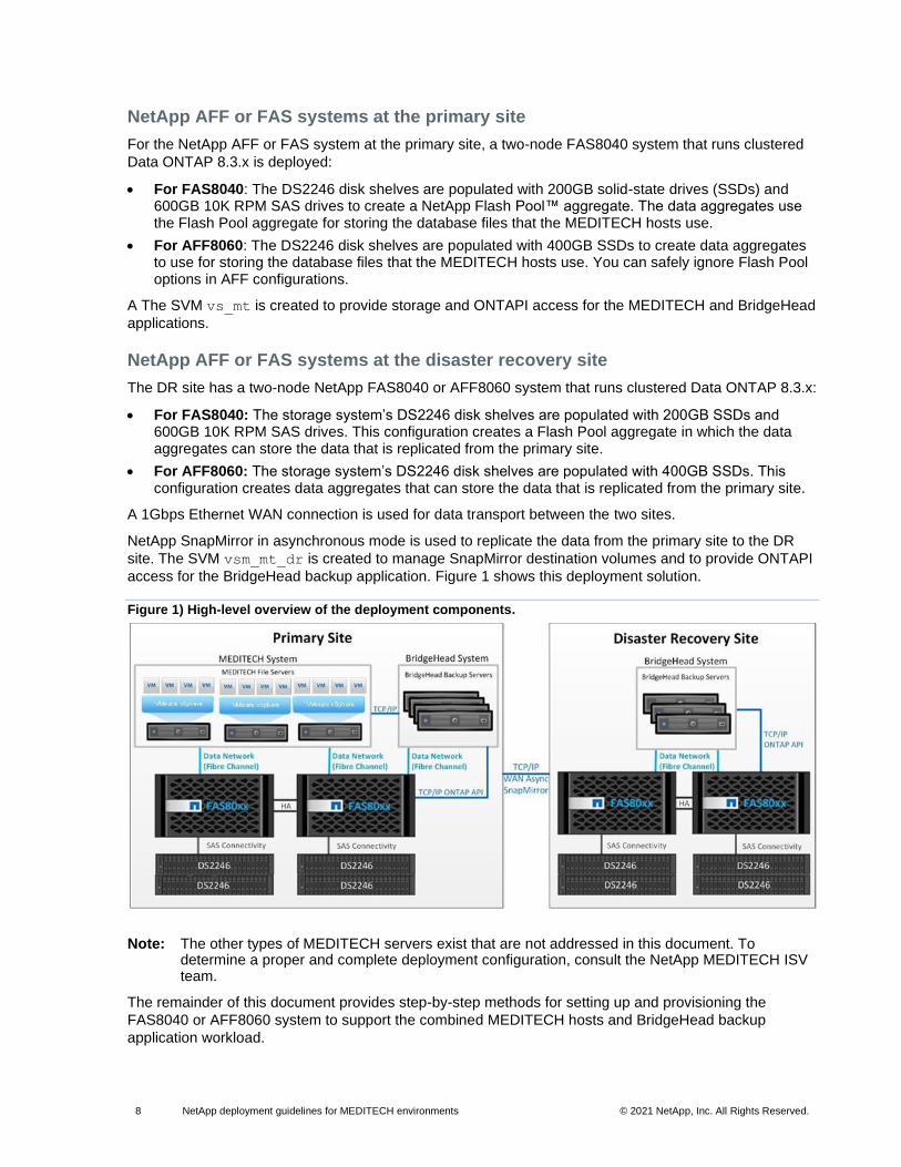
access for the BridgeHead backup application. Figure 1 shows this deployment solution.
Figure 1) High-level overview of the deployment components.
Note: The other types of MEDITECH servers exist that are not addressed in this document. To determine a proper and complete deployment configuration, consult the NetApp MEDITECH ISV team.
The remainder of this document provides step-by-step methods for setting up and provisioning the
FAS8040 or AFF8060 system to support the combined MEDITECH hosts and BridgeHead backup
application workload.

9 NetApp deployment guidelines for MEDITECH environments © 2021 NetApp, Inc. All Rights Reserved.
NetApp hardware configuration
This section provides the high-level requirements for the physical setup and deployment of NetApp AFF
and FAS controllers with DS2246 disk shelves. All documents pertaining to the NetApp AFF and FAS
systems can be found on the Documentation page of the NetApp Support site.
Storage controller deployment
Before you begin the storage controller deployment, log in to the NetApp Hardware Universe (HWU)
application to see the NetApp hardware specifications, supported shelves and drives, and power
requirements for the storage controllers.
The web-based HWU tool replaces the NetApp System Configuration Guide with a visual presentation of
the complete NetApp line of hardware products. It also replaces the NetApp Site Requirements Guide,
which included controller information about a variety of chassis details. Those details included electrical
requirements in worst-case and typical situations, clearance information, temperature ranges, humidity
levels, altitude parameters, acoustic noise, and so on.
The following references provide additional useful information:
• Site Requirements Guide Replacement Tutorial
• Hardware Installation and Setup Poster
• Hardware Universe v 4.7 User Guide
• NetApp Interoperability Matrix Tool (IMT)
System configuration compatibility
Use the NetApp HWU application for the important task of confirming the set of hardware and software
components that are currently supported by NetApp. This web-based tool offers a visual presentation of
the complete NetApp line of hardware products. The HWU provides a powerful configuration resource by
consolidating hardware specifications for the following products and components:
• Controllers: FAS/V-Series and AFF
• Adapters
• Shelves
• Drives
• Cabinets
• Cables.
To determine system configuration compatibility through the HWU tool, complete the following steps:
1. Go to the HWU and provide credentials to log in to the tool.
2. In the Platforms tab, click Start with OS and select the version of Data ONTAP that you want to verify. In this example, 8.3 Clustered Data ONTAP is selected.

10 NetApp deployment guidelines for MEDITECH environments © 2021 NetApp, Inc. All Rights Reserved.
3. From the platform list, select FAS8040. (Select AFF80xx if it is an all-flash array.)
4. In the Specifications panel, select items of interest, such as Max DS2246 Shelves (HA).
5. Click Show Results to show the queried information. These results can be exported as a PDF.

11 NetApp deployment guidelines for MEDITECH environments © 2021 NetApp, Inc. All Rights Reserved.
Storage controller physical installation
Follow the physical installation procedures for the controller model that is being deployed. Controller
deployment procedures can be found on the Documentation page of the NetApp Support site.
For FAS8040 installation and setup instructions, complete the following steps:
1. Go to the Documentation page of the NetApp Support site.
2. Click FAS8000 Series for FAS8040 documentation.
3. Click the All Documents link for FAS8040.
4. Click Installation and Setup Instructions for FAS8040 systems
For AFF8060 installation and setup instructions, complete the following steps:
1. Go to the Documentation page of the NetApp Support site.
2. Click AFF8000 Series for AFF8060 documentation.
3. Click the All Documents link for AFF8060.
4. Click Installation and Setup Instructions for AFF8060 systems.
Storage controller cabling requirements
In addition to the storage network connections, the remote LAN management or the service processor
must be cabled to provide connectivity for storage system management and hardware-assisted failover.
Deployments that use the DS2246 disk shelves also require the alternate control path (ACP) connection
of both controllers to be cabled.
DS2246 Series disk shelves
This section provides high-level requirements and prerequisites for the deployment of the DS2246 disk
shelves. Before you deploy any DS2246 disk shelves, verify that all the prerequisites in Table 1 have
been met.
Table 1) Disk shelf deployment prerequisites.
Prerequisite number Description
DS2246-001 Minimum software requirements:
Your system must be installed with at least Data ONTAP 7.3.3. For later versions of supported software releases, see the HWU.
DS2246-002 SAS disk drive and SSD support:
A DS2246 disk shelf must contain only SAS disk drives or only SSDs.
DS2246-003 Disk bay numbering:
The DS2246 disk shelf has 24 disk bays, numbered 0 through 23. The numbering
sequence is displayed on the left and right ear covers of the disk shelf.
DS2246-004 Disk shelf IDs, unique ID per system:
Each disk shelf in a storage system must have a unique ID; a valid shelf ID is from 0 through 98. For example, in a storage system with two stacks of 10 disk shelves, the disk shelves would be numbered from 0 to 19.
DS2246-005 The 30-second rule:
You must always power-cycle a disk shelf when you change the shelf ID. However, when you change the shelf ID on a disk shelf that is running Data ONTAP, you must wait at least 30 seconds before you turn the power back on. This pause confirms that Data ONTAP can properly delete the old disk shelf address and update the copy of the new disk shelf address.
12 NetApp deployment guidelines for MEDITECH environments © 2021 NetApp, Inc. All Rights Reserved.
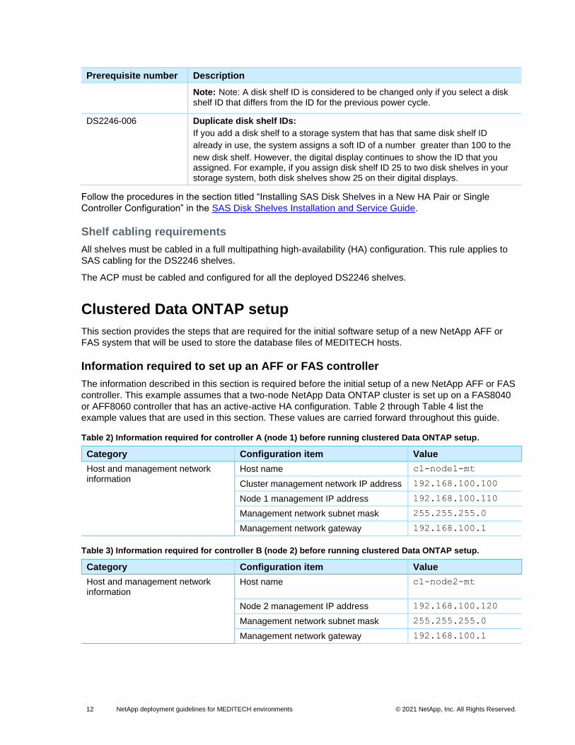
Prerequisite number Description
Note: Note: A disk shelf ID is considered to be changed only if you select a disk shelf ID that differs from the ID for the previous power cycle.
DS2246-006 Duplicate disk shelf IDs:
If you add a disk shelf to a storage system that has that same disk shelf ID
already in use, the system assigns a soft ID of a number greater than 100 to the
new disk shelf. However, the digital display continues to show the ID that you assigned. For example, if you assign disk shelf ID 25 to two disk shelves in your storage system, both disk shelves show 25 on their digital displays.
Follow the procedures in the section titled “Installing SAS Disk Shelves in a New HA Pair or Single
Controller Configuration” in the SAS Disk Shelves Installation and Service Guide.
Shelf cabling requirements
All shelves must be cabled in a full multipathing high-availability (HA) configuration. This rule applies to
SAS cabling for the DS2246 shelves.
The ACP must be cabled and configured for all the deployed DS2246 shelves.
Clustered Data ONTAP setup
This section provides the steps that are required for the initial software setup of a new NetApp AFF or
FAS system that will be used to store the database files of MEDITECH hosts.
Information required to set up an AFF or FAS controller
The information described in this section is required before the initial setup of a new NetApp AFF or FAS
controller. This example assumes that a two-node NetApp Data ONTAP cluster is set up on a FAS8040
or AFF8060 controller that has an active-active HA configuration. Table 2 through Table 4 list the
example values that are used in this section. These values are carried forward throughout this guide.
Table 2) Information required for controller A (node 1) before running clustered Data ONTAP setup.
Category Configuration item Value
Host and management network information
Host name c1-node1-mt
Cluster management network IP address 192.168.100.100
Node 1 management IP address 192.168.100.110
Management network subnet mask 255.255.255.0
Management network gateway 192.168.100.1
Table 3) Information required for controller B (node 2) before running clustered Data ONTAP setup.
Category Configuration item Value
Host and management network information
Host name c1-node2-mt
Node 2 management IP address 192.168.100.120
Management network subnet mask 255.255.255.0
Management network gateway 192.168.100.1

13 NetApp deployment guidelines for MEDITECH environments © 2021 NetApp, Inc. All Rights Reserved.
Table 4) Information common to both controllers and required before executing setup.
Category Configuration item Value
Host and management network information
Time zone EST
Physical system location Boston, Massachusetts, USA
Language for multiprotocol files C
Authentication information Cluster administrative user name admin
Administrative user password adminpasswd
Root user password rootpasswd
Alternate control path information Interface name e0P
ACP subnet 192.15.1.0
ACP netmask 255.255.255.0
Initial setup of clustered Data ONTAP
For instructions on how to set up clustered Data ONTAP, see the Clustered Data ONTAP 8.3 Software
Setup Guide.
Information required to assign disk ownership
Table 5 lists the information that is required for disk assignment.
Table 5) Information required for disk assignment.
Data ONTAP cluster node Disk type Number assigned
FAS8040 disk assignment
c1-node1-mt 10K RPM SAS 90
SSD (200GB, for example) 6
c1-node2-mt 10K RPM SAS 90
SSD (200GB, for example) 6
AFF8060 disk assignment
c1-node1-mt SSD (400GB, for example) 40
c1-node2-mt SSD (400GB, for example) 40
Note: In addition to the number of disks indicated in Table 5, node 1 requires more disks create the root aggregate for the storage virtual machine (SVM). More disks are necessary because NetApp recommends placing the root volume on an aggregate that is separate from the data aggregate.
Assign disk ownership
To assign disks to the storage controllers, complete the following steps:
1. Log in to the cluster to start a clustershell session.
2. Assign disks to the storage controller in node 1.
Primary_cluster::> disk assign -owner c1-node1-mt -count 80-type SAS
Primary_cluster::> disk assign -owner c1-node1-mt -count 7 -type SSD
3. Assign disks to the storage controller in node 2.
Primary_cluster::> disk assign -owner c1-node2-mt -count 80-type SAS
Primary_cluster::> disk assign -owner c1-node2-mt -count 7 -type SSD

14 NetApp deployment guidelines for MEDITECH environments © 2021 NetApp, Inc. All Rights Reserved.
Note: For information about how to assign disk ownership on AFF platforms, see Clustered Data ONTAP 8.3: Using All Flash FAS with Clustered Data ONTAP.
Information required to configure a spare disk
After disk assignment, one spare disk per disk type is available to each controller. Set the Data ONTAP
option raid.min_spare_count on each controller to the number of managed spares. This
configuration notifies the storage administrator about any disk failure.
Table 6 lists the information that is required to set the min_spare_count Data ONTAP option.
Table 6) Information required to set the min_spare_count Data ONTAP option.
Cluster node per controller Disk type Number of spare disks
FAS8040
c1-node1-mt 10K RPM SAS 2
SSD 1
c1-node2-mt 10K RPM SAS 2
SSD 1
AFF8060
c1-node1-mt SSD 2
c1-node2-mt SSD 2
Configure a spare disk
To set the minimum number of spare disks option, complete the following steps:
1. Log in to the cluster to start a clustershell session.
2. Set the minimum number of spare disks to have available.
Primary_cluster::> node run -node c1-node1-mt –c options raid.min_spare_count 2
Primary_cluster::> node run -node c1-node2-mt –c options raid.min_spare_count 2
Node root aggregates and volumes
Table 7 lists the Data ONTAP node root aggregates and volumes.
Table 7) Node root aggregates and volumes.
Node Aggregate Volume Notes
c1-node1-mt aggr0_c1_node
1
vol0_c1_node
1
• Created by Data ONTAP system during cluster setup
• Renamed from default aggr0 and vol0
c1-node2-mt aggr0_c1_node
2
vol0_c1_node
2
• Created by Data ONTAP system during cluster setup
• Renamed from default aggr0 and vol0
Storage virtual machine setup
This section provides the procedures for setting up the software of a new NetApp AFF or FAS system so
that it can store the database files of MEDITECH hosts.
15 NetApp deployment guidelines for MEDITECH environments © 2021 NetApp, Inc. All Rights Reserved.
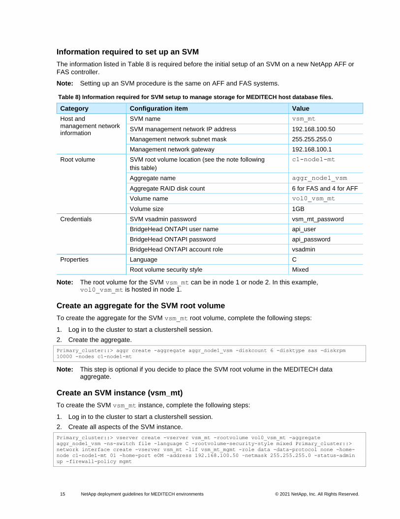
Information required to set up an SVM
The information listed in Table 8 is required before the initial setup of an SVM on a new NetApp AFF or
FAS controller.
Note: Setting up an SVM procedure is the same on AFF and FAS systems.
Table 8) Information required for SVM setup to manage storage for MEDITECH host database files.
Category Configuration item Value
Host and management network information
SVM name vsm_mt
SVM management network IP address 192.168.100.50
Management network subnet mask 255.255.255.0
Management network gateway 192.168.100.1
Root volume SVM root volume location (see the note following
this table)
c1-node1-mt
Aggregate name aggr_node1_vsm
Aggregate RAID disk count 6 for FAS and 4 for AFF
Volume name vol0_vsm_mt
Volume size 1GB
Credentials SVM vsadmin password vsm_mt_password
BridgeHead ONTAPI user name api_user
BridgeHead ONTAPI password api_password
BridgeHead ONTAPI account role vsadmin
Properties Language C
Root volume security style Mixed
Note: The root volume for the SVM vsm_mt can be in node 1 or node 2. In this example, vol0_vsm_mt is hosted in node 1.
Create an aggregate for the SVM root volume
To create the aggregate for the SVM vsm_mt root volume, complete the following steps:
1. Log in to the cluster to start a clustershell session.
2. Create the aggregate.
Primary_cluster::> aggr create -aggregate aggr_node1_vsm -diskcount 6 -disktype sas -diskrpm
10000 -nodes c1-node1-mt
Note: This step is optional if you decide to place the SVM root volume in the MEDITECH data aggregate.
Create an SVM instance (vsm_mt)
To create the SVM vsm_mt instance, complete the following steps:
1. Log in to the cluster to start a clustershell session.
2. Create all aspects of the SVM instance.
Primary_cluster::> vserver create -vserver vsm_mt -rootvolume vol0_vsm_mt -aggregate
aggr_node1_vsm -ns-switch file -language C -rootvolume-security-style mixed Primary_cluster::>
network interface create -vserver vsm_mt -lif vsm_mt_mgmt -role data -data-protocol none -home-
node c1-node1-mt 01 -home-port e0M –address 192.168.100.50 –netmask 255.255.255.0 -status-admin
up -firewall-policy mgmt

16 NetApp deployment guidelines for MEDITECH environments © 2021 NetApp, Inc. All Rights Reserved.
Storage layout setup template use
This section describes the steps that are required to provision the storage on the FAS8040 or AFF8060
for use by the MEDITECH hosts, including the creation of aggregates, volumes, and LUNs.
The data layout for the configuration includes the following categories:
• Aggregates. Create one Flash Pool data aggregate on each FAS controller:
aggr_node1_mtfs_db, aggr_node2_mtfs_db
Note: No Flash Pool configurations are required for all-flash arrays.
• Volumes. Distribute the volumes equally per Flash Pool data aggregate on each storage controller.
• LUNs. Create two or three LUNs per volume.
The purpose of this layout is to achieve a balanced distribution of MEDITECH and BridgeHead
workloads.
Note: VMDK storage is not accounted for and must be created on a separate aggregate.
Note: On the DR cluster, set up the same aggregate and volume name for SnapMirror operations. At the DR site, however, use a different SVM name.
Information required to create and configure data aggregates for MEDITECH hosts
In this example, one aggregate per node is used for storing the database files that the MEDITECH hosts
use. The aggregates are maintained and managed by the SVM vsm_mt.
Table 9 lists the information that is necessary to configure the required aggregates.
Table 9) Information necessary to configure the required aggregates.
Cluster node Aggregate Disk type RAID group size Aggregate type
FAS8040
c1-node1-mt aggr_node1_mtfs_d
b
SAS 24 64-bit
c1-node1-mt aggr_node2_mtfs_d
b
SAS 24 64-bit
AFF8060
c1-node1-mt aggr_node1_mtfs_d
b
SSD 18 64-bit
c1-node1-mt aggr_node2_mtfs_d
b
SSD 18 64-bit
Create data aggregates
To create the data aggregates, complete the following steps:
1. Log in to the cluster to start a clustershell session.
2. Create the aggregate for storing MEDITECH host database files on node 1:
− For FAS8040:
Primary_cluster::> aggr create -aggregate aggr_node1_mtfs_db -diskcount 72 -disktype SAS -diskrpm
10000 –maxraidsize 24 -node c1-node1-mt
3. Create the aggregate for storing MEDITECH host database files on node 2:

17 NetApp deployment guidelines for MEDITECH environments © 2021 NetApp, Inc. All Rights Reserved.
Primary_cluster::> aggr create -aggregate aggr_node2_mtfs_db -diskcount 72 -disktype SAS -diskrpm
10000 –maxraidsize 24 -node c1-node2-mt
− For AFF8060:
In the following example, 36 SSD disk partitions are used on each node:
Primary_cluster::> aggr create -aggregate aggr_node1_mtfs_db -diskcount 36 -disktype SSD –
maxraidsize 24 -node c1-node1-mt
Primary_cluster::> aggr create -aggregate aggr_node2_mtfs_db -diskcount 36 -disktype SSD –
maxraidsize 24 -node c1-node2-mt
Configure data aggregates
To configure the data aggregates, complete the following steps:
1. Log in to the cluster to start a clustershell session
2. Configure the aggregate aggr_node1_mtfs_db.
Primary_cluster::> aggregate modify -aggregate aggr_node1_mtfs_db -percent-snapshot-space 0
Primary_cluster::> node run -node c1-node1-mt
Type 'exit' or 'Ctrl-D' to return to the CLI
c1-node1-mt > snap sched -A aggr_node1_mtfs_db 0 0 0
c1-node1-mt > aggr options aggr_node1_mtfs_db nosnap true
3. Configure the aggregate aggr_node2_mtfs_db.
aggregate modify -aggregate aggr_node2_mtfs_db -percent-snapshot-space 0
node run -node c1-node2-mt
Type 'exit' or 'Ctrl-D' to return to the CLI
c1-node2-mt > snap sched -A aggr_node2_mtfs_db 0 0 0
c1-node2-mt > aggr options aggr_node2_mtfs_db nosnap true
Set up Flash Pool for data aggregates
To set up NetApp Flash Pool intelligent caching for the data aggregates, complete the following steps:
1. Log in to the cluster to start a clustershell session.
2. Configure the aggregate to host Flash Pool.
Primary_cluster::> aggregate modify -aggregate aggr_node1_mtfs_db –hybrid-enabled true
Primary_cluster::> aggregate modify -aggregate aggr_node2_mtfs_db –hybrid-enabled true
3. Add Flash Pool to aggregates aggr_node1_mtfs_db and aggr_node2_mtfs_db.
Primary_cluster::> aggregate add-disks -aggregate aggr_node1_mtfs_db -disktype SSD -diskcount 6
Primary_cluster::> aggregate add-disks -aggregate aggr_node2_mtfs_db -disktype SSD -diskcount 6
Note: Use this procedure only for Flash Pool on hybrid storage systems. For systems that require the setup of NetApp Flash Cache™ caching, see Appendix B: Flash Cache Setup and Configuration.
Delegate volume creation to SVM vsm_mt
To delegate volume creation to the SVM vsm_mt, complete the following steps:
1. Log in to the cluster to start a clustershell session.
2. Delegate volume creation to the SVM vs_mt.
Primary_cluster::> vserver modify -vserver vs_mt -aggr-list aggr_node1_mtfs_db,aggr_node2_mtfs_db

18 NetApp deployment guidelines for MEDITECH environments © 2021 NetApp, Inc. All Rights Reserved.
Information required to create and configure volumes for MEDITECH hosts
In this example, one aggregate per node is used to store the database files that the MEDITECH hosts
use. Table 10 lists the information that is needed to configure the required aggregates.
Table 10) Information necessary to configure the required aggregates.
Cluster Node SVM Aggregate Volume Size
c1-node1-
mt
vsm_mt aggr_node1_mtfs_db vol_mtdb_00
vol_mtdb_02
vol_mtdb_04
vol_mtdb_06
vol_mtdb_08
vol_mtdb_10
vol_mtdb_12
vol_mtdb_14
vol_mtdb_16
vol_mtdb_18
1100GB per volume (3 LUNs)
c1-node2-
mt
aggr_node2_mtfs_db vol_mtdb_01
vol_mtdb_03
vol_mtdb_05
vol_mtdb_07
vol_mtdb_09
vol_mtdb_11
vol_mtdb_13
vol_mtdb_15
vol_mtdb_17
vol_mtdb_19
Note: Volume size might vary based on the number of LUNs that are placed in the volume.
Create volumes
To create volumes, complete the following steps:
1. Log in to the cluster to start a clustershell session.
2. Create the volumes for storing MEDITECH host database files on node 1.
Primary_cluster::> volume create -volume vol_mt_00 -aggregate aggr_node1_mtfs_db -size 1100GB -
state online -type RW -space-guarantee volume
Primary_cluster::> volume create -volume vol_mt_02 -aggregate aggr_node1_mtfs_db -size 1100GB -
state online -type RW -space-guarantee volume
Primary_cluster::> volume create -volume vol_mt_04 -aggregate aggr_node1_mtfs_db -size 1100GB -
state online -type RW -space-guarantee volume
Primary_cluster::> volume create -volume vol_mt_06 -aggregate aggr_node1_mtfs_db -size 1100GB -
state online -type RW -space-guarantee volume
Primary_cluster::> volume create -volume vol_mt_08 -aggregate aggr_node1_mtfs_db -size 1100GB -
state online -type RW -space-guarantee volume
Primary_cluster::> volume create -volume vol_mt_10 -aggregate aggr_node1_mtfs_db -size 1100GB -
state online -type RW -space-guarantee volume
Primary_cluster::> volume create -volume vol_mt_12 -aggregate aggr_node1_mtfs_db -size 1100GB -
state online -type RW -space-guarantee volume
Primary_cluster::> volume create -volume vol_mt_14 -aggregate aggr_node1_mtfs_db -size 1100GB -
state online -type RW -space-guarantee volume
Primary_cluster::> volume create -volume vol_mt_16 -aggregate aggr_node1_mtfs_db -size 1100GB -
state online -type RW -space-guarantee volume
Primary_cluster::> volume create -volume vol_mt_18 -aggregate aggr_node1_mtfs_db -size 1100GB -
state online -type RW -space-guarantee volume
3. Create the volumes for storing MEDITECH host database files on node 2.
Primary_cluster::> volume create -volume vol_mt_01 -aggregate aggr_node2_mtfs_db -size 1100GB -
state online -type RW -space-guarantee volume

19 NetApp deployment guidelines for MEDITECH environments © 2021 NetApp, Inc. All Rights Reserved.
Primary_cluster::> volume create -volume vol_mt_03 -aggregate aggr_node2_mtfs_db -size 1100GB -
state online -type RW -space-guarantee volume
Primary_cluster::> volume create -volume vol_mt_05 -aggregate aggr_node2_mtfs_db -size 1100GB -
state online -type RW -space-guarantee volume
Primary_cluster::> volume create -volume vol_mt_07 -aggregate aggr_node2_mtfs_db -size 1100GB -
state online -type RW -space-guarantee volume
Primary_cluster::> volume create -volume vol_mt_09 -aggregate aggr_node2_mtfs_db -size 1100GB -
state online -type RW -space-guarantee volume
Primary_cluster::> volume create -volume vol_mt_11 -aggregate aggr_node2_mtfs_db -size 1100GB -
state online -type RW -space-guarantee volume
Primary_cluster::> volume create -volume vol_mt_13 -aggregate aggr_node2_mtfs_db -size 1100GB -
state online -type RW -space-guarantee volume
Primary_cluster::> volume create -volume vol_mt_15 -aggregate aggr_node2_mtfs_db -size 1100GB -
state online -type RW -space-guarantee volume
Primary_cluster::> volume create -volume vol_mt_17 -aggregate aggr_node2_mtfs_db -size 1100GB -
state online -type RW -space-guarantee volume
Primary_cluster::> volume create -volume vol_mt_19 -aggregate aggr_node2_mtfs_db -size 1100GB -
state online -type RW -space-guarantee volume
Configure volumes
To configure volumes, complete the following steps:
1. Log in to the cluster to start a clustershell session.
2. Configure the volumes on node 1.
Primary_cluster::> volume modify -volume vol_mt_00 -autosize-increment 5G -percent-snapshot-space
0 -snapshot-policy none -fractional-reserve 0
Primary_cluster::> volume modify -volume vol_mt_02 -autosize-increment 5G -percent-snapshot-space
0 -snapshot-policy none -fractional-reserve 0
Primary_cluster::> volume modify -volume vol_mt_04 -autosize-increment 5G -percent-snapshot-space
0 -snapshot-policy none -fractional-reserve 0
Primary_cluster::> volume modify -volume vol_mt_06 -autosize-increment 5G -percent-snapshot-space
0 -snapshot-policy none -fractional-reserve 0
Primary_cluster::> volume modify -volume vol_mt_08 -autosize-increment 5G -percent-snapshot-space
0 -snapshot-policy none -fractional-reserve 0
Primary_cluster::> volume modify -volume vol_mt_10 -autosize-increment 5G -percent-snapshot-space
0 -snapshot-policy none -fractional-reserve 0
Primary_cluster::> volume modify -volume vol_mt_12 -autosize-increment 5G -percent-snapshot-space
0 -snapshot-policy none -fractional-reserve 0
Primary_cluster::> volume modify -volume vol_mt_14 -autosize-increment 5G -percent-snapshot-space
0 -snapshot-policy none -fractional-reserve 0
Primary_cluster::> volume modify -volume vol_mt_16 -autosize-increment 5G -percent-snapshot-space
0 -snapshot-policy none -fractional-reserve 0
Primary_cluster::> volume modify -volume vol_mt_18 -autosize-increment 5G -percent-snapshot-space
0 -snapshot-policy none -fractional-reserve 0
3. Configure the volumes on node 2.
Primary_cluster::> volume modify -volume vol_mt_01 -autosize-increment 5G -percent-snapshot-space
0 -snapshot-policy none -fractional-reserve 0
Primary_cluster::> volume modify -volume vol_mt_03 -autosize-increment 5G -percent-snapshot-space
0 -snapshot-policy none -fractional-reserve 0
Primary_cluster::> volume modify -volume vol_mt_05 -autosize-increment 5G -percent-snapshot-space
0 -snapshot-policy none -fractional-reserve 0
Primary_cluster::> volume modify -volume vol_mt_07 -autosize-increment 5G -percent-snapshot-space
0 -snapshot-policy none -fractional-reserve 0
Primary_cluster::> volume modify -volume vol_mt_09 -autosize-increment 5G -percent-snapshot-space
0 -snapshot-policy none -fractional-reserve 0
Primary_cluster::> volume modify -volume vol_mt_11 -autosize-increment 5G -percent-snapshot-space
0 -snapshot-policy none -fractional-reserve 0
Primary_cluster::> volume modify -volume vol_mt_13 -autosize-increment 5G -percent-snapshot-space
0 -snapshot-policy none -fractional-reserve 0
Primary_cluster::> volume modify -volume vol_mt_15 -autosize-increment 5G -percent-snapshot-space
0 -snapshot-policy none -fractional-reserve 0
Primary_cluster::> volume modify -volume vol_mt_17 -autosize-increment 5G -percent-snapshot-space
0 -snapshot-policy none -fractional-reserve 0
Primary_cluster::> volume modify -volume vol_mt_19 -autosize-increment 5G -percent-snapshot-space
0 -snapshot-policy none -fractional-reserve 0

20 NetApp deployment guidelines for MEDITECH environments © 2021 NetApp, Inc. All Rights Reserved.
Configure Snapshot Autodelete on volumes
To configure the Volume Snapshot Autodelete setting for all volumes, complete the following steps:
1. Log in to the cluster to start a clustershell session.
2. Change the Volume Snapshot Autodelete setting to true for all data volumes in the storage system.
Primary_cluster::> snapshot autodelete modify -vserver vs_mt -volume vol_mt_00 -enabled true
Primary_cluster::> snapshot autodelete modify -vserver vs_mt -volume vol_mt_01 -enabled true
Primary_cluster::> snapshot autodelete modify -vserver vs_mt -volume vol_mt_02 -enabled true
Primary_cluster::> snapshot autodelete modify -vserver vs_mt -volume vol_mt_03 -enabled true
Primary_cluster::> snapshot autodelete modify -vserver vs_mt -volume vol_mt_04 -enabled true
Primary_cluster::> snapshot autodelete modify -vserver vs_mt -volume vol_mt_05 -enabled true
Primary_cluster::> snapshot autodelete modify -vserver vs_mt -volume vol_mt_06 -enabled true
Primary_cluster::> snapshot autodelete modify -vserver vs_mt -volume vol_mt_07 -enabled true
Primary_cluster::> snapshot autodelete modify -vserver vs_mt -volume vol_mt_08 -enabled true
Primary_cluster::> snapshot autodelete modify -vserver vs_mt -volume vol_mt_09 -enabled true
Primary_cluster::> snapshot autodelete modify -vserver vs_mt -volume vol_mt_10 -enabled true
Primary_cluster::> snapshot autodelete modify -vserver vs_mt -volume vol_mt_11 -enabled true
Primary_cluster::> snapshot autodelete modify -vserver vs_mt -volume vol_mt_12 -enabled true
Primary_cluster::> snapshot autodelete modify -vserver vs_mt -volume vol_mt_13 -enabled true
Primary_cluster::> snapshot autodelete modify -vserver vs_mt -volume vol_mt_14 -enabled true
Primary_cluster::> snapshot autodelete modify -vserver vs_mt -volume vol_mt_15 -enabled true
Primary_cluster::> snapshot autodelete modify -vserver vs_mt -volume vol_mt_16 -enabled true
Primary_cluster::> snapshot autodelete modify -vserver vs_mt -volume vol_mt_17 -enabled true
Primary_cluster::> snapshot autodelete modify -vserver vs_mt -volume vol_mt_18 -enabled true
Primary_cluster::> snapshot autodelete modify -vserver vs_mt -volume vol_mt_19 -enabled true
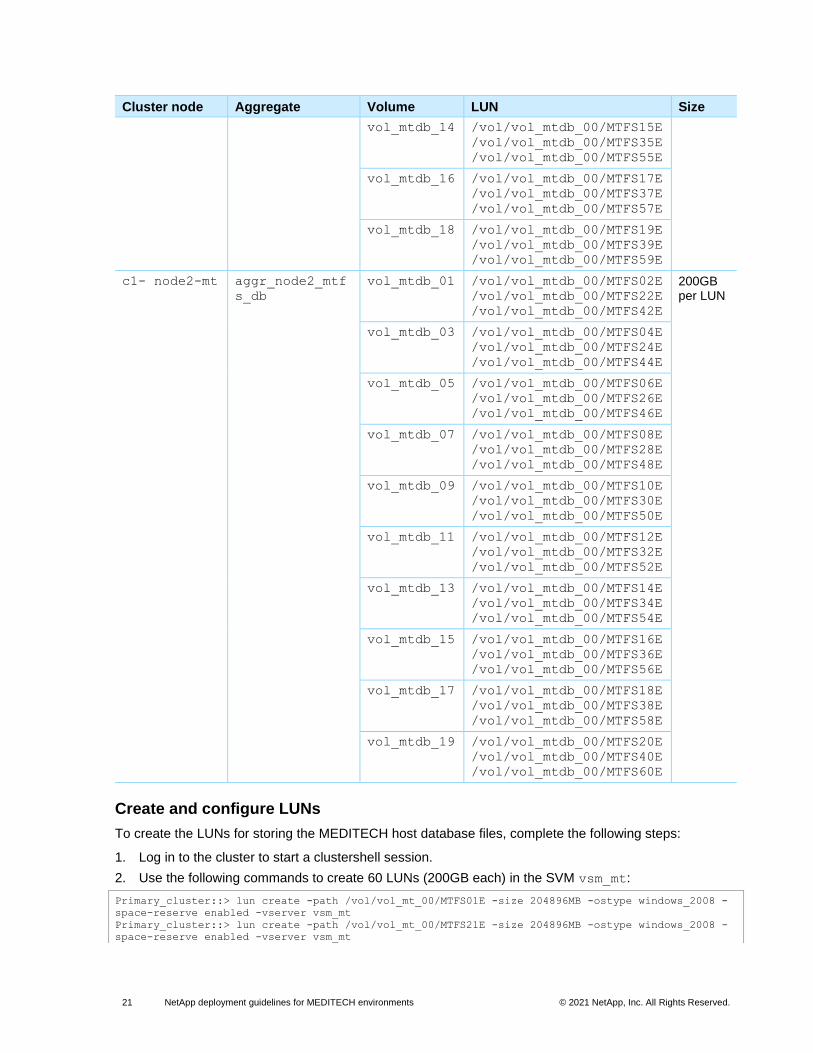
Information required to create and configure LUNs for MEDITECH hosts
Table 11 lists the information that is necessary to configure the required LUNs. In this example, 60 LUNs
are created for storing the database files that the 60 MEDITECH hosts use.
Table 11) Information necessary to configure the required LUNs.
Cluster node Aggregate Volume LUN Size
c1-node1-mt aggr_node1_mtf
s_db
vol_mtdb_00 /vol/vol_mtdb_00/MTFS01E
/vol/vol_mtdb_00/MTFS21E
/vol/vol_mtdb_00/MTFS41E
200GB per LUN
vol_mtdb_02 /vol/vol_mtdb_00/MTFS03E
/vol/vol_mtdb_00/MTFS23E
/vol/vol_mtdb_00/MTFS43E
vol_mtdb_04 /vol/vol_mtdb_00/MTFS05E
/vol/vol_mtdb_00/MTFS25E
/vol/vol_mtdb_00/MTFS45E
vol_mtdb_06 /vol/vol_mtdb_00/MTFS07E
/vol/vol_mtdb_00/MTFS27E
/vol/vol_mtdb_00/MTFS47E
vol_mtdb_08 /vol/vol_mtdb_00/MTFS09E
/vol/vol_mtdb_00/MTFS29E
/vol/vol_mtdb_00/MTFS49E
vol_mtdb_10 /vol/vol_mtdb_00/MTFS11E
/vol/vol_mtdb_00/MTFS31E
/vol/vol_mtdb_00/MTFS51E
vol_mtdb_12 /vol/vol_mtdb_00/MTFS13E
/vol/vol_mtdb_00/MTFS33E
/vol/vol_mtdb_00/MTFS53E
21 NetApp deployment guidelines for MEDITECH environments © 2021 NetApp, Inc. All Rights Reserved.
Cluster node Aggregate Volume LUN Size
vol_mtdb_14 /vol/vol_mtdb_00/MTFS15E
/vol/vol_mtdb_00/MTFS35E
/vol/vol_mtdb_00/MTFS55E
vol_mtdb_16 /vol/vol_mtdb_00/MTFS17E
/vol/vol_mtdb_00/MTFS37E
/vol/vol_mtdb_00/MTFS57E
vol_mtdb_18 /vol/vol_mtdb_00/MTFS19E
/vol/vol_mtdb_00/MTFS39E
/vol/vol_mtdb_00/MTFS59E
c1- node2-mt aggr_node2_mtf
s_db
vol_mtdb_01 /vol/vol_mtdb_00/MTFS02E
/vol/vol_mtdb_00/MTFS22E
/vol/vol_mtdb_00/MTFS42E
200GB per LUN
vol_mtdb_03 /vol/vol_mtdb_00/MTFS04E
/vol/vol_mtdb_00/MTFS24E
/vol/vol_mtdb_00/MTFS44E
vol_mtdb_05 /vol/vol_mtdb_00/MTFS06E
/vol/vol_mtdb_00/MTFS26E
/vol/vol_mtdb_00/MTFS46E
vol_mtdb_07 /vol/vol_mtdb_00/MTFS08E
/vol/vol_mtdb_00/MTFS28E
/vol/vol_mtdb_00/MTFS48E
vol_mtdb_09 /vol/vol_mtdb_00/MTFS10E
/vol/vol_mtdb_00/MTFS30E
/vol/vol_mtdb_00/MTFS50E
vol_mtdb_11 /vol/vol_mtdb_00/MTFS12E
/vol/vol_mtdb_00/MTFS32E
/vol/vol_mtdb_00/MTFS52E
vol_mtdb_13 /vol/vol_mtdb_00/MTFS14E
/vol/vol_mtdb_00/MTFS34E
/vol/vol_mtdb_00/MTFS54E
vol_mtdb_15 /vol/vol_mtdb_00/MTFS16E
/vol/vol_mtdb_00/MTFS36E
/vol/vol_mtdb_00/MTFS56E
vol_mtdb_17 /vol/vol_mtdb_00/MTFS18E
/vol/vol_mtdb_00/MTFS38E
/vol/vol_mtdb_00/MTFS58E
vol_mtdb_19 /vol/vol_mtdb_00/MTFS20E
/vol/vol_mtdb_00/MTFS40E
/vol/vol_mtdb_00/MTFS60E
Create and configure LUNs
To create the LUNs for storing the MEDITECH host database files, complete the following steps:
1. Log in to the cluster to start a clustershell session.
2. Use the following commands to create 60 LUNs (200GB each) in the SVM vsm_mt:
Primary_cluster::> lun create -path /vol/vol_mt_00/MTFS01E -size 204896MB -ostype windows_2008 -
space-reserve enabled -vserver vsm_mt
Primary_cluster::> lun create -path /vol/vol_mt_00/MTFS21E -size 204896MB -ostype windows_2008 -
space-reserve enabled -vserver vsm_mt
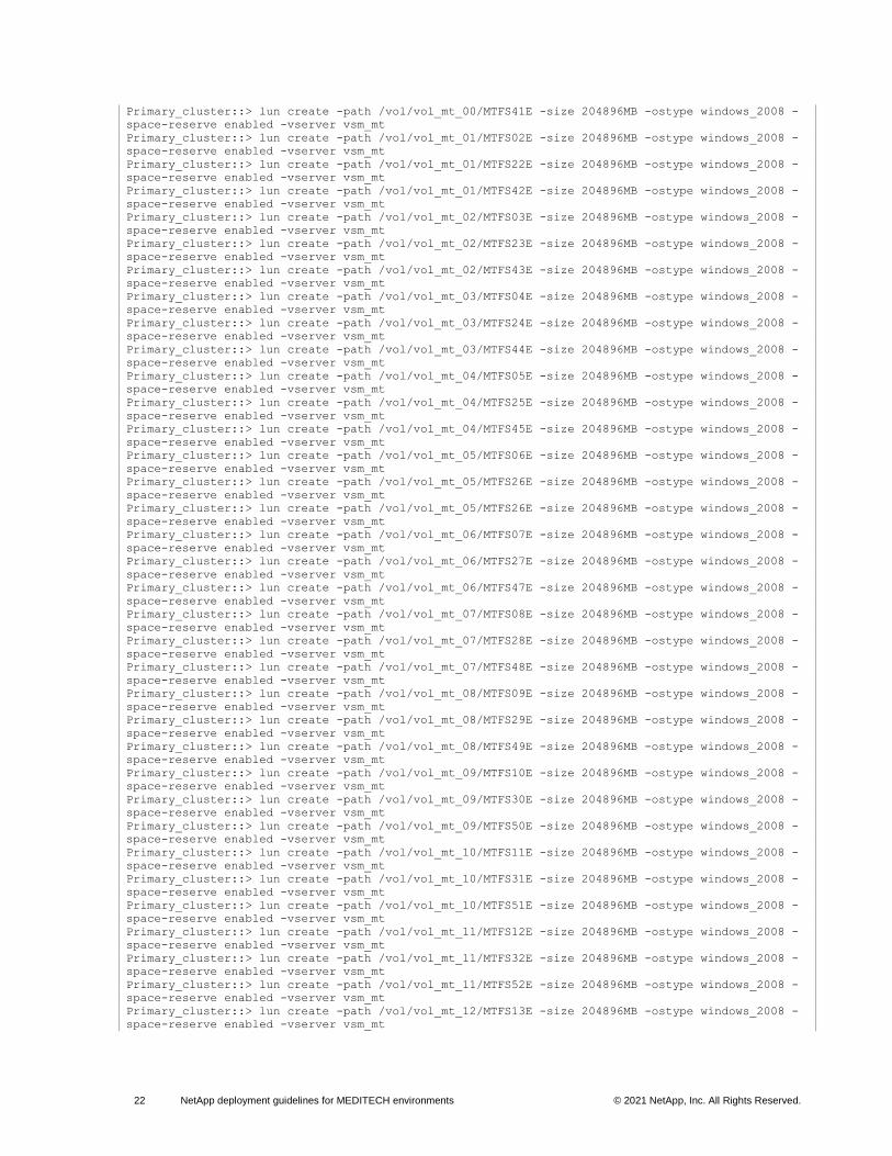
22 NetApp deployment guidelines for MEDITECH environments © 2021 NetApp, Inc. All Rights Reserved.
Primary_cluster::> lun create -path /vol/vol_mt_00/MTFS41E -size 204896MB -ostype windows_2008 -
space-reserve enabled -vserver vsm_mt
Primary_cluster::> lun create -path /vol/vol_mt_01/MTFS02E -size 204896MB -ostype windows_2008 -
space-reserve enabled -vserver vsm_mt
Primary_cluster::> lun create -path /vol/vol_mt_01/MTFS22E -size 204896MB -ostype windows_2008 -
space-reserve enabled -vserver vsm_mt
Primary_cluster::> lun create -path /vol/vol_mt_01/MTFS42E -size 204896MB -ostype windows_2008 -
space-reserve enabled -vserver vsm_mt
Primary_cluster::> lun create -path /vol/vol_mt_02/MTFS03E -size 204896MB -ostype windows_2008 -
space-reserve enabled -vserver vsm_mt
Primary_cluster::> lun create -path /vol/vol_mt_02/MTFS23E -size 204896MB -ostype windows_2008 -
space-reserve enabled -vserver vsm_mt
Primary_cluster::> lun create -path /vol/vol_mt_02/MTFS43E -size 204896MB -ostype windows_2008 -
space-reserve enabled -vserver vsm_mt
Primary_cluster::> lun create -path /vol/vol_mt_03/MTFS04E -size 204896MB -ostype windows_2008 -
space-reserve enabled -vserver vsm_mt
Primary_cluster::> lun create -path /vol/vol_mt_03/MTFS24E -size 204896MB -ostype windows_2008 -
space-reserve enabled -vserver vsm_mt
Primary_cluster::> lun create -path /vol/vol_mt_03/MTFS44E -size 204896MB -ostype windows_2008 -
space-reserve enabled -vserver vsm_mt
Primary_cluster::> lun create -path /vol/vol_mt_04/MTFS05E -size 204896MB -ostype windows_2008 -
space-reserve enabled -vserver vsm_mt
Primary_cluster::> lun create -path /vol/vol_mt_04/MTFS25E -size 204896MB -ostype windows_2008 -
space-reserve enabled -vserver vsm_mt
Primary_cluster::> lun create -path /vol/vol_mt_04/MTFS45E -size 204896MB -ostype windows_2008 -
space-reserve enabled -vserver vsm_mt
Primary_cluster::> lun create -path /vol/vol_mt_05/MTFS06E -size 204896MB -ostype windows_2008 -
space-reserve enabled -vserver vsm_mt
Primary_cluster::> lun create -path /vol/vol_mt_05/MTFS26E -size 204896MB -ostype windows_2008 -
space-reserve enabled -vserver vsm_mt
Primary_cluster::> lun create -path /vol/vol_mt_05/MTFS26E -size 204896MB -ostype windows_2008 -
space-reserve enabled -vserver vsm_mt
Primary_cluster::> lun create -path /vol/vol_mt_06/MTFS07E -size 204896MB -ostype windows_2008 -
space-reserve enabled -vserver vsm_mt
Primary_cluster::> lun create -path /vol/vol_mt_06/MTFS27E -size 204896MB -ostype windows_2008 -
space-reserve enabled -vserver vsm_mt
Primary_cluster::> lun create -path /vol/vol_mt_06/MTFS47E -size 204896MB -ostype windows_2008 -
space-reserve enabled -vserver vsm_mt
Primary_cluster::> lun create -path /vol/vol_mt_07/MTFS08E -size 204896MB -ostype windows_2008 -
space-reserve enabled -vserver vsm_mt
Primary_cluster::> lun create -path /vol/vol_mt_07/MTFS28E -size 204896MB -ostype windows_2008 -
space-reserve enabled -vserver vsm_mt
Primary_cluster::> lun create -path /vol/vol_mt_07/MTFS48E -size 204896MB -ostype windows_2008 -
space-reserve enabled -vserver vsm_mt
Primary_cluster::> lun create -path /vol/vol_mt_08/MTFS09E -size 204896MB -ostype windows_2008 -
space-reserve enabled -vserver vsm_mt
Primary_cluster::> lun create -path /vol/vol_mt_08/MTFS29E -size 204896MB -ostype windows_2008 -
space-reserve enabled -vserver vsm_mt
Primary_cluster::> lun create -path /vol/vol_mt_08/MTFS49E -size 204896MB -ostype windows_2008 -
space-reserve enabled -vserver vsm_mt
Primary_cluster::> lun create -path /vol/vol_mt_09/MTFS10E -size 204896MB -ostype windows_2008 -
space-reserve enabled -vserver vsm_mt
Primary_cluster::> lun create -path /vol/vol_mt_09/MTFS30E -size 204896MB -ostype windows_2008 -
space-reserve enabled -vserver vsm_mt
Primary_cluster::> lun create -path /vol/vol_mt_09/MTFS50E -size 204896MB -ostype windows_2008 -
space-reserve enabled -vserver vsm_mt
Primary_cluster::> lun create -path /vol/vol_mt_10/MTFS11E -size 204896MB -ostype windows_2008 -
space-reserve enabled -vserver vsm_mt
Primary_cluster::> lun create -path /vol/vol_mt_10/MTFS31E -size 204896MB -ostype windows_2008 -
space-reserve enabled -vserver vsm_mt
Primary_cluster::> lun create -path /vol/vol_mt_10/MTFS51E -size 204896MB -ostype windows_2008 -
space-reserve enabled -vserver vsm_mt
Primary_cluster::> lun create -path /vol/vol_mt_11/MTFS12E -size 204896MB -ostype windows_2008 -
space-reserve enabled -vserver vsm_mt
Primary_cluster::> lun create -path /vol/vol_mt_11/MTFS32E -size 204896MB -ostype windows_2008 -
space-reserve enabled -vserver vsm_mt
Primary_cluster::> lun create -path /vol/vol_mt_11/MTFS52E -size 204896MB -ostype windows_2008 -
space-reserve enabled -vserver vsm_mt
Primary_cluster::> lun create -path /vol/vol_mt_12/MTFS13E -size 204896MB -ostype windows_2008 -
space-reserve enabled -vserver vsm_mt

23 NetApp deployment guidelines for MEDITECH environments © 2021 NetApp, Inc. All Rights Reserved.
Primary_cluster::> lun create -path /vol/vol_mt_12/MTFS33E -size 204896MB -ostype windows_2008 -
space-reserve enabled -vserver vsm_mt
Primary_cluster::> lun create -path /vol/vol_mt_12/MTFS53E -size 204896MB -ostype windows_2008 -
space-reserve enabled -vserver vsm_mt
Primary_cluster::> lun create -path /vol/vol_mt_13/MTFS14E -size 204896MB -ostype windows_2008 -
space-reserve enabled -vserver vsm_mt
Primary_cluster::> lun create -path /vol/vol_mt_13/MTFS34E -size 204896MB -ostype windows_2008 -
space-reserve enabled -vserver vsm_mt
Primary_cluster::> lun create -path /vol/vol_mt_13/MTFS54E -size 204896MB -ostype windows_2008 -
space-reserve enabled -vserver vsm_mt
Primary_cluster::> lun create -path /vol/vol_mt_14/MTFS15E -size 204896MB -ostype windows_2008 -
space-reserve enabled -vserver vsm_mt
Primary_cluster::> lun create -path /vol/vol_mt_14/MTFS35E -size 204896MB -ostype windows_2008 -
space-reserve enabled -vserver vsm_mt
Primary_cluster::> lun create -path /vol/vol_mt_14/MTFS55E -size 204896MB -ostype windows_2008 -
space-reserve enabled -vserver vsm_mt
Primary_cluster::> lun create -path /vol/vol_mt_15/MTFS16E -size 204896MB -ostype windows_2008 -
space-reserve enabled -vserver vsm_mt
Primary_cluster::> lun create -path /vol/vol_mt_15/MTFS36E -size 204896MB -ostype windows_2008 -
space-reserve enabled -vserver vsm_mt
Primary_cluster::> lun create -path /vol/vol_mt_15/MTFS56E -size 204896MB -ostype windows_2008 -
space-reserve enabled -vserver vsm_mt
Primary_cluster::> lun create -path /vol/vol_mt_16/MTFS17E -size 204896MB -ostype windows_2008 -
space-reserve enabled -vserver vsm_mt
Primary_cluster::> lun create -path /vol/vol_mt_16/MTFS37E -size 204896MB -ostype windows_2008 -
space-reserve enabled -vserver vsm_mt
Primary_cluster::> lun create -path /vol/vol_mt_16/MTFS57E -size 204896MB -ostype windows_2008 -
space-reserve enabled -vserver vsm_mt
Primary_cluster::> lun create -path /vol/vol_mt_17/MTFS18E -size 204896MB -ostype windows_2008 -
space-reserve enabled -vserver vsm_mt
Primary_cluster::> lun create -path /vol/vol_mt_17/MTFS38E -size 204896MB -ostype windows_2008 -
space-reserve enabled -vserver vsm_mt
Primary_cluster::> lun create -path /vol/vol_mt_17/MTFS58E -size 204896MB -ostype windows_2008 -
space-reserve enabled -vserver vsm_mt
Primary_cluster::> lun create -path /vol/vol_mt_18/MTFS19E -size 204896MB -ostype windows_2008 -
space-reserve enabled -vserver vsm_mt
Primary_cluster::> lun create -path /vol/vol_mt_18/MTFS39E -size 204896MB -ostype windows_2008 -
space-reserve enabled -vserver vsm_mt
Primary_cluster::> lun create -path /vol/vol_mt_18/MTFS59E -size 204896MB -ostype windows_2008 -
space-reserve enabled -vserver vsm_mt
Primary_cluster::> lun create -path /vol/vol_mt_19/MTFS20E -size 204896MB -ostype windows_2008 -
space-reserve enabled -vserver vsm_mt
Primary_cluster::> lun create -path /vol/vol_mt_19/MTFS40E -size 204896MB -ostype windows_2008 -
space-reserve enabled -vserver vsm_mt
Primary_cluster::> lun create -path /vol/vol_mt_19/MTFS60E -size 204896MB -ostype windows_2008 -
space-reserve enabled -vserver vsm_mt
FC setup and configuration
Information required to set up FC storage transport
Be sure to apply the paragraph styles to the content in a consistent manner. Do not use manual overrides
or styling from the Word Home panel. To apply paragraph styles, complete the following steps:
Note: License numbers that are provided in this document are examples only. Be sure to obtain the correct licensing information before you deploy NetApp AFF or FAS systems for use with MEDITECH hosts.
Table 12 lists the information that is required to configure FC storage transport per storage controller.
Table 12) Information required to configure FC storage transport per storage controller.
Configuration item Value
FC license 8DJ3KIDHE3
FC target port 1 0c
24 NetApp deployment guidelines for MEDITECH environments © 2021 NetApp, Inc. All Rights Reserved.
Configuration item Value
FC target port 2 0d
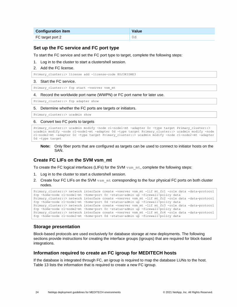
Set up the FC service and FC port type
To start the FC service and set the FC port type to target, complete the following steps:
1. Log in to the cluster to start a clustershell session.
2. Add the FC license.
Primary_cluster::> license add -license-code 8DJ3KIDHE3
3. Start the FC service.
Primary_cluster::> fcp start -vserver vsm_mt
4. Record the worldwide port name (WWPN) or FC port name for later use.
Primary_cluster::> fcp adapter show
5. Determine whether the FC ports are targets or initiators.
Primary_cluster::> ucadmin show
6. Convert two FC ports to targets
Primary_cluster::> ucadmin modify -node c1-node1-mt -adapter 0c -type target Primary_cluster::>
ucadmin modify -node c1-node1-mt -adapter 0d -type target Primary_cluster::> ucadmin modify -node
c1-node2-mt -adapter 0c -type target Primary_cluster::> ucadmin modify -node c1-node2-mt -adapter
0d -type target
Note: Only fiber ports that are configured as targets can be used to connect to initiator hosts on the SAN.
Create FC LIFs on the SVM vsm_mt
To create the FC logical interfaces (LIFs) for the SVM vsm_mt, complete the following steps:
1. Log in to the cluster to start a clustershell session.
2. Create four FC LIFs on the SVM vsm_mt corresponding to the four physical FC ports on both cluster
nodes.
Primary_cluster::> network interface create -vserver vsm_mt -lif mt_fc1 -role data -data-protocol
fcp -home-node c1-node1-mt -home-port 0c -status-admin up -firewall-policy data
Primary_cluster::> network interface create -vserver vsm_mt -lif mt_fc2 -role data -data-protocol
fcp -home-node c1-node1-mt -home-port 0d -status-admin up -firewall-policy data
Primary_cluster::> network interface create -vserver vsm_mt -lif mt_fc3 -role data -data-protocol
fcp -home-node c1-node2-mt -home-port 0c -status-admin up -firewall-policy data
Primary_cluster::> network interface create -vserver vsm_mt -lif mt_fc4 -role data -data-protocol
fcp -home-node c1-node2-mt -home-port 0d -status-admin up -firewall-policy data
Storage presentation
Block-based protocols are used exclusively for database storage at new deployments. The following
sections provide instructions for creating the interface groups (igroups) that are required for block-based
integrations.
Information required to create an FC igroup for MEDITECH hosts
If the database is integrated through FC, an igroup is required to map the database LUNs to the host.
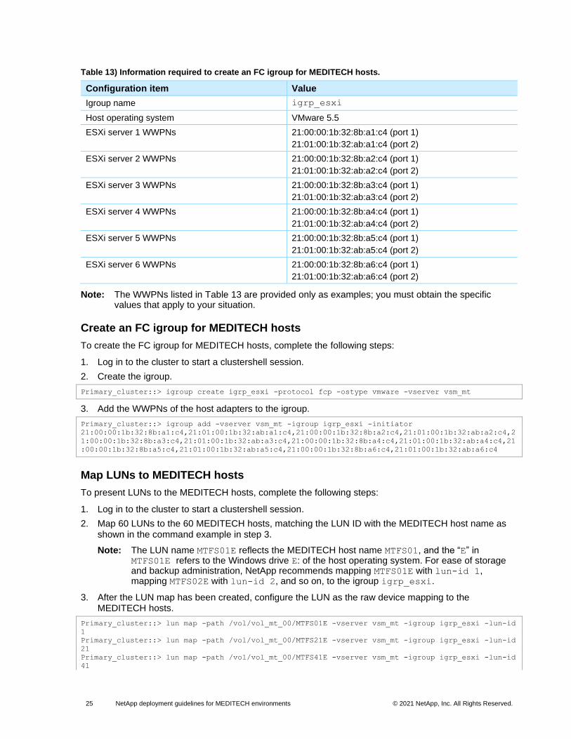
Table 13 lists the information that is required to create a new FC igroup.
25 NetApp deployment guidelines for MEDITECH environments © 2021 NetApp, Inc. All Rights Reserved.
Table 13) Information required to create an FC igroup for MEDITECH hosts.
Configuration item Value
Igroup name igrp_esxi
Host operating system VMware 5.5
ESXi server 1 WWPNs 21:00:00:1b:32:8b:a1:c4 (port 1)
21:01:00:1b:32:ab:a1:c4 (port 2)
ESXi server 2 WWPNs 21:00:00:1b:32:8b:a2:c4 (port 1)
21:01:00:1b:32:ab:a2:c4 (port 2)
ESXi server 3 WWPNs 21:00:00:1b:32:8b:a3:c4 (port 1)
21:01:00:1b:32:ab:a3:c4 (port 2)
ESXi server 4 WWPNs 21:00:00:1b:32:8b:a4:c4 (port 1)
21:01:00:1b:32:ab:a4:c4 (port 2)
ESXi server 5 WWPNs 21:00:00:1b:32:8b:a5:c4 (port 1)
21:01:00:1b:32:ab:a5:c4 (port 2)
ESXi server 6 WWPNs 21:00:00:1b:32:8b:a6:c4 (port 1)
21:01:00:1b:32:ab:a6:c4 (port 2)
Note: The WWPNs listed in Table 13 are provided only as examples; you must obtain the specific values that apply to your situation.
Create an FC igroup for MEDITECH hosts
To create the FC igroup for MEDITECH hosts, complete the following steps:
1. Log in to the cluster to start a clustershell session.
2. Create the igroup.
Primary_cluster::> igroup create igrp_esxi -protocol fcp -ostype vmware -vserver vsm_mt
3. Add the WWPNs of the host adapters to the igroup.
Primary_cluster::> igroup add -vserver vsm_mt -igroup igrp_esxi -initiator
21:00:00:1b:32:8b:a1:c4,21:01:00:1b:32:ab:a1:c4,21:00:00:1b:32:8b:a2:c4,21:01:00:1b:32:ab:a2:c4,2
1:00:00:1b:32:8b:a3:c4,21:01:00:1b:32:ab:a3:c4,21:00:00:1b:32:8b:a4:c4,21:01:00:1b:32:ab:a4:c4,21
:00:00:1b:32:8b:a5:c4,21:01:00:1b:32:ab:a5:c4,21:00:00:1b:32:8b:a6:c4,21:01:00:1b:32:ab:a6:c4
Map LUNs to MEDITECH hosts
To present LUNs to the MEDITECH hosts, complete the following steps:
1. Log in to the cluster to start a clustershell session.
2. Map 60 LUNs to the 60 MEDITECH hosts, matching the LUN ID with the MEDITECH host name as shown in the command example in step 3.
Note: The LUN name MTFS01E reflects the MEDITECH host name MTFS01, and the “E” in MTFS01E refers to the Windows drive E: of the host operating system. For ease of storage and backup administration, NetApp recommends mapping MTFS01E with lun-id 1, mapping MTFS02E with lun-id 2, and so on, to the igroup igrp_esxi.
3. After the LUN map has been created, configure the LUN as the raw device mapping to the MEDITECH hosts.
Primary_cluster::> lun map -path /vol/vol_mt_00/MTFS01E -vserver vsm_mt -igroup igrp_esxi -lun-id
1
Primary_cluster::> lun map -path /vol/vol_mt_00/MTFS21E -vserver vsm_mt -igroup igrp_esxi -lun-id
21
Primary_cluster::> lun map -path /vol/vol_mt_00/MTFS41E -vserver vsm_mt -igroup igrp_esxi -lun-id
41

26 NetApp deployment guidelines for MEDITECH environments © 2021 NetApp, Inc. All Rights Reserved.
Primary_cluster::> lun map -path /vol/vol_mt_01/MTFS02E -vserver vsm_mt -igroup igrp_esxi -lun-id
2
Primary_cluster::> lun map -path /vol/vol_mt_01/MTFS22E -vserver vsm_mt -igroup igrp_esxi -lun-id
22
Primary_cluster::> lun map -path /vol/vol_mt_01/MTFS42E -vserver vsm_mt -igroup igrp_esxi -lun-id
42
Primary_cluster::> lun map -path /vol/vol_mt_02/MTFS03E -vserver vsm_mt -igroup igrp_esxi -lun-id
3
Primary_cluster::> lun map -path /vol/vol_mt_02/MTFS23E -vserver vsm_mt -igroup igrp_esxi -lun-id
23
Primary_cluster::> lun map -path /vol/vol_mt_02/MTFS43E -vserver vsm_mt -igroup igrp_esxi -lun-id
43
Primary_cluster::> lun map -path /vol/vol_mt_03/MTFS04E -vserver vsm_mt -igroup igrp_esxi -lun-id
4
Primary_cluster::> lun map -path /vol/vol_mt_03/MTFS24E -vserver vsm_mt -igroup igrp_esxi -lun-id
24
Primary_cluster::> lun map -path /vol/vol_mt_03/MTFS44E -vserver vsm_mt -igroup igrp_esxi -lun-id
44
Primary_cluster::> lun map -path /vol/vol_mt_04/MTFS05E -vserver vsm_mt -igroup igrp_esxi -lun-id
5
Primary_cluster::> lun map -path /vol/vol_mt_04/MTFS25E -vserver vsm_mt -igroup igrp_esxi -lun-id
25
Primary_cluster::> lun map -path /vol/vol_mt_04/MTFS45E -vserver vsm_mt -igroup igrp_esxi -lun-id
45
Primary_cluster::> lun map -path /vol/vol_mt_05/MTFS06E -vserver vsm_mt -igroup igrp_esxi -lun-id
6
Primary_cluster::> lun map -path /vol/vol_mt_05/MTFS26E -vserver vsm_mt -igroup igrp_esxi -lun-id
26
Primary_cluster::> lun map -path /vol/vol_mt_05/MTFS26E -vserver vsm_mt -igroup igrp_esxi -lun-id
46
Primary_cluster::> lun map -path /vol/vol_mt_06/MTFS07E -vserver vsm_mt -igroup igrp_esxi -lun-id
7
Primary_cluster::> lun map -path /vol/vol_mt_06/MTFS27E -vserver vsm_mt -igroup igrp_esxi -lun-id
27
Primary_cluster::> lun map -path /vol/vol_mt_06/MTFS47E -vserver vsm_mt -igroup igrp_esxi -lun-id
47
Primary_cluster::> lun map -path /vol/vol_mt_07/MTFS08E -vserver vsm_mt -igroup igrp_esxi -lun-id
8
Primary_cluster::> lun map -path /vol/vol_mt_07/MTFS28E -vserver vsm_mt -igroup igrp_esxi -lun-id
28
Primary_cluster::> lun map -path /vol/vol_mt_07/MTFS48E -vserver vsm_mt -igroup igrp_esxi -lun-id
48
Primary_cluster::> lun map -path /vol/vol_mt_08/MTFS09E -vserver vsm_mt -igroup igrp_esxi -lun-id
9
Primary_cluster::> lun map -path /vol/vol_mt_08/MTFS29E -vserver vsm_mt -igroup igrp_esxi -lun-id
29
Primary_cluster::> lun map -path /vol/vol_mt_08/MTFS49E -vserver vsm_mt -igroup igrp_esxi -lun-id
49
Primary_cluster::> lun map -path /vol/vol_mt_09/MTFS10E -vserver vsm_mt -igroup igrp_esxi -lun-id
10
Primary_cluster::> lun map -path /vol/vol_mt_09/MTFS30E -vserver vsm_mt -igroup igrp_esxi -lun-id
30
Primary_cluster::> lun map -path /vol/vol_mt_09/MTFS50E -vserver vsm_mt -igroup igrp_esxi -lun-id
50
Primary_cluster::> lun map -path /vol/vol_mt_10/MTFS11E -vserver vsm_mt -igroup igrp_esxi -lun-id
11
Primary_cluster::> lun map -path /vol/vol_mt_10/MTFS31E -vserver vsm_mt -igroup igrp_esxi -lun-id
31
Primary_cluster::> lun map -path /vol/vol_mt_10/MTFS51E -vserver vsm_mt -igroup igrp_esxi -lun-id
51
Primary_cluster::> lun map -path /vol/vol_mt_11/MTFS12E -vserver vsm_mt -igroup igrp_esxi -lun-id
12
Primary_cluster::> lun map -path /vol/vol_mt_11/MTFS32E -vserver vsm_mt -igroup igrp_esxi -lun-id
32
Primary_cluster::> lun map -path /vol/vol_mt_11/MTFS52E -vserver vsm_mt -igroup igrp_esxi -lun-id
52
Primary_cluster::> lun map -path /vol/vol_mt_12/MTFS13E -vserver vsm_mt -igroup igrp_esxi -lun-id
13
Primary_cluster::> lun map -path /vol/vol_mt_12/MTFS33E -vserver vsm_mt -igroup igrp_esxi -lun-id
33

27 NetApp deployment guidelines for MEDITECH environments © 2021 NetApp, Inc. All Rights Reserved.
Primary_cluster::> lun map -path /vol/vol_mt_12/MTFS53E -vserver vsm_mt -igroup igrp_esxi -lun-id
53
Primary_cluster::> lun map -path /vol/vol_mt_13/MTFS14E -vserver vsm_mt -igroup igrp_esxi -lun-id
14
Primary_cluster::> lun map -path /vol/vol_mt_13/MTFS34E -vserver vsm_mt -igroup igrp_esxi -lun-id
34
Primary_cluster::> lun map -path /vol/vol_mt_13/MTFS54E -vserver vsm_mt -igroup igrp_esxi -lun-id
54
Primary_cluster::> lun map -path /vol/vol_mt_14/MTFS15E -vserver vsm_mt -igroup igrp_esxi -lun-id
15
Primary_cluster::> lun map -path /vol/vol_mt_14/MTFS35E -vserver vsm_mt -igroup igrp_esxi -lun-id
35
Primary_cluster::> lun map -path /vol/vol_mt_14/MTFS55E -vserver vsm_mt -igroup igrp_esxi -lun-id
55
Primary_cluster::> lun map -path /vol/vol_mt_15/MTFS16E -vserver vsm_mt -igroup igrp_esxi -lun-id
16
Primary_cluster::> lun map -path /vol/vol_mt_15/MTFS36E -vserver vsm_mt -igroup igrp_esxi -lun-id
36
Primary_cluster::> lun map -path /vol/vol_mt_15/MTFS56E -vserver vsm_mt -igroup igrp_esxi -lun-id
56
Primary_cluster::> lun map -path /vol/vol_mt_16/MTFS17E -vserver vsm_mt -igroup igrp_esxi -lun-id
17
Primary_cluster::> lun map -path /vol/vol_mt_16/MTFS37E -vserver vsm_mt -igroup igrp_esxi -lun-id
37
Primary_cluster::> lun map -path /vol/vol_mt_16/MTFS57E -vserver vsm_mt -igroup igrp_esxi -lun-id
57
Primary_cluster::> lun map -path /vol/vol_mt_17/MTFS18E -vserver vsm_mt -igroup igrp_esxi -lun-id
18
Primary_cluster::> lun map -path /vol/vol_mt_17/MTFS38E -vserver vsm_mt -igroup igrp_esxi -lun-id
38
Primary_cluster::> lun map -path /vol/vol_mt_17/MTFS58E -vserver vsm_mt -igroup igrp_esxi -lun-id
58
Primary_cluster::> lun map -path /vol/vol_mt_18/MTFS19E -vserver vsm_mt -igroup igrp_esxi -lun-id
19
Primary_cluster::> lun map -path /vol/vol_mt_18/MTFS39E -vserver vsm_mt -igroup igrp_esxi -lun-id
39
Primary_cluster::> lun map -path /vol/vol_mt_18/MTFS59E -vserver vsm_mt -igroup igrp_esxi -lun-id
59
Primary_cluster::> lun map -path /vol/vol_mt_19/MTFS20E -vserver vsm_mt -igroup igrp_esxi -lun-id
20
Primary_cluster::> lun map -path /vol/vol_mt_19/MTFS40E -vserver vsm_mt -igroup igrp_esxi -lun-id
40
Primary_cluster::> lun map -path /vol/vol_mt_19/MTFS60E -vserver vsm_mt -igroup igrp_esxi -lun-id
60
Information required to create an FC igroup for BridgeHead backup servers
BridgeHead backup servers have access to the controller to perform backup tasks. Usually, multiple
BridgeHead servers are needed if the MEDITECH file server LUN count is higher. Contact BridgeHead to
calculate the number of BridgeHead servers that are required to handle multiple LUN backups at a time.
The following example uses 4 BridgeHead servers for 60 MEDITECH file servers.
Table 14 lists the information that is required to create an FC igroup for the BridgeHead backup servers.
Table 14) Information required to create an FC igroup for BridgeHead backup servers.
Configuration item Value
Igroup name igrp_bh
Host operating system Windows 2008 R2 64-bit Enterprise Edition
BridgeHead backup server 1 WWPNs 21:00:03:1b:32:8b:a1:c4 (port 1)
21:01:03:1b:32:ab:a1:c4 (port 2)
BridgeHead backup server 2 WWPNs 21:00:03:1b:32:8b:a2:c4 (port 1)
21:01:03:1b:32:ab:a2:c4 (port 2)
BridgeHead backup server 3 WWPNs 21:00:03:1b:32:8b:a3:c4 (port 1)

28 NetApp deployment guidelines for MEDITECH environments © 2021 NetApp, Inc. All Rights Reserved.
Configuration item Value
21:01:03:1b:32:ab:a3:c4 (port 2)
BridgeHead backup server 4 WWPNs 21:00:03:1b:32:8b:a4:c4 (port 1)
21:01:03:1b:32:ab:a4:c4 (port 2)
Create an FC igroup for BridgeHead backup servers
To create the FC igroup for the BridgeHead backup servers, complete the following steps:
1. Log in to the cluster to start a clustershell session.
2. Create the igroup.
Primary_cluster::> igroup create igrp_bh -protocol fcp -ostype windows -vserver vsm_mt
3. Add the WWPNs of the host adapters to the igroup.
Primary_cluster::> igroup add -vserver vsm_mt -igroup igrp_bh -initiator
21:00:03:1b:32:8b:a1:c4,21:01:03:1b:32:ab:a1:c4,21:00:03:1b:32:8b:a2:c4,21:01:03:1b:32:ab:a2:c4,2
1:00:03:1b:32:8b:a3:c4, 21:01:03:1b:32:ab:a3:c4, 21:00:03:1b:32:8b:a4:c4,
21:01:03:1b:32:ab:a4:c4,
iSCSI setup and configuration
Information required to set up iSCSI storage transport
For smaller MEDITECH implementations, iSCSI can be used as an alternative to FC. The following
procedure configures the iSCSI service on a storage system. Execute the procedure on all the storage
controllers or cluster nodes that host the LUNs that the MEDITECH hosts use.
Note: The license numbers that are provided in this document are only examples. Be sure to obtain the correct licensing information before you deploy NetApp FAS systems for use with MEDITECH hosts.
Table 15 lists the information that is required to configure iSCSI storage transport per storage controller.
Table 15) Information required to configure iSCSI storage transport per storage controller.
Configuration Item Value
iSCSI license W84OIUHJS9
iSCSI interfaces iscsi_node1_lif
iscsi_node2_lif
Set up the iSCSI Service and iSCSI LIFs
To start the iSCSI service and set the iSCSI port type to target, complete the following steps:
1. Log in to the cluster to start a clustershell session.
2. Add the iSCSI license.
Primary_cluster::> license add -license-code W84OIUHJS9
3. Start the iSCSI service.
Primary_cluster::> iscsi start -vserver vsm_mt
4. Enable iSCSI on the LIFs.
Primary_cluster::> iscsi interface enable iscsi_node1_lif
Primary_cluster::> iscsi interface enable iscsi_node2_lif
stl-meditech-cmode-03::> network port show

29 NetApp deployment guidelines for MEDITECH environments © 2021 NetApp, Inc. All Rights Reserved.
Auto-Negot Duplex Speed (Mbps)
Node Port Role Link MTU Admin/Oper Admin/Oper Admin/Oper
------ ------ ------------ ---- ----- ----------- ---------- ------------
stl-cmode-meditech-03-01
a0a data up 1500 true/- auto/full auto/1000
a0a-3108
dataup1500 true/-auto/full auto/1000
…
stl-cmode-meditech-03-02
a0a dataup1500 true/-auto/full auto/1000
a0a-3108
dataup1500 true/-auto/full auto/1000
…
18 entries were displayed.
stl-meditech-cmode-03::> ifgrp show
(network port ifgrp show)
PortDistributionActive
Node IfGrp Function MAC Address Ports Ports
-------- ---------- ------------ ----------------- ------- -------------------
stl-cmode-meditech-03-01
a0a port 02:a0:98:40:8e:da full e0b, e0c, e0d
stl-cmode-meditech-03-02
a0a port 02:a0:98:40:a2:22 full e0b, e0c, e0dps)
Storage presentation
Block-based protocols are used exclusively for database storage at new deployments. This section
provides instructions for creating the igroups that are required for block-based integrations.
Information required to create an iSCSI igroup for MEDITECH hosts
If the database is integrated through iSCSI, an igroup is required for mapping the database LUNs to the
host. Table 16 lists the information that is required to create a new igroup. The iSCSI Qualified Names
(IQNs) that are listed in the table are provided only as examples; you must obtain the specific values that
apply to your situation.
Table 16) Information required to create an iSCSI igroup for the MEDITECH hosts.
Configuration Item Value
Igroup name igrp_esxi
Host operating system VMware 5.5
ESXi server 1 IQN iqn.1998-01.com.vmware:localhost-2577f525
ESXi server 2 IQN iqn.1998-01.com.vmware:localhost-016229d8
Create an iSCSI igroup for MEDITECH hosts
To create the iSCSI igroup for MEDITECH hosts, complete the following steps:
1. Log in to the cluster to start a clustershell session.
2. Create the igroup.
Primary_cluster::> igroup create igrp_esxi -protocol iscsi -ostype vmware -vserver vsm_mt
3. Add the IQNs of ESX virtual iSCSI adapters to the igroup.
Primary_cluster::> igroup add -vserver vsm_mt -igroup igrp_esxi -initiator iqn.1998-
01.com.vmware:localhost-2577f525
Primary_cluster::> igroup add -vserver vsm_mt -igroup igrp_esxi -initiator iqn.1998-
01.com.vmware:localhost-016229d8

30 NetApp deployment guidelines for MEDITECH environments © 2021 NetApp, Inc. All Rights Reserved.
Map LUNs to MEDITECH hosts
To present LUNs to the MEDITECH hosts, complete the following steps:
1. Log in to the cluster to start a clustershell session.
2. Map 30 LUNs to the 30 MEDITECH hosts, matching the LUN ID with the MEDITECH host name as shown in the command example in step 3.
Note: In this example, the host name for MEDITECH host 01 is MTFS01. The “E” in MTFS01E is the Windows drive E: of the host operating system.
3. After the LUN map has been created, configure the LUN as the raw device mapping to the MEDITECH hosts.
Primary_cluster::> lun map -vserver vsm_mt -path /vol/vol_mt_00/MTFS01E -igroup igrp_esxi -lun-id
1
Primary_cluster::> lun map -vserver vsm_mt -path /vol/vol_mt_00/MTFS03E -igroup igrp_esxi -lun-id
3
Primary_cluster::> lun map -vserver vsm_mt -path /vol/vol_mt_02/MTFS05E -igroup igrp_esxi -lun-id
5
Primary_cluster::> lun map -vserver vsm_mt -path /vol/vol_mt_02/MTFS07E -igroup igrp_esxi -lun-id
7
Primary_cluster::> lun map -vserver vsm_mt -path /vol/vol_mt_04/MTFS09E -igroup igrp_esxi -lun-id
9
Primary_cluster::> lun map -vserver vsm_mt -path /vol/vol_mt_04/MTFS11E -igroup igrp_esxi -lun-id
11
Primary_cluster::> lun map -vserver vsm_mt -path /vol/vol_mt_06/MTFS13E -igroup igrp_esxi -lun-id
13
Primary_cluster::> lun map -vserver vsm_mt -path /vol/vol_mt_06/MTFS15E -igroup igrp_esxi -lun-id
15
Primary_cluster::> lun map -vserver vsm_mt -path /vol/vol_mt_08/MTFS17E -igroup igrp_esxi -lun-id
17
Primary_cluster::> lun map -vserver vsm_mt -path /vol/vol_mt_08/MTFS19E -igroup igrp_esxi -lun-id
19
Primary_cluster::> lun map -vserver vsm_mt -path /vol/vol_mt_10/MTFS21E -igroup igrp_esxi -lun-id
21
Primary_cluster::> lun map -vserver vsm_mt -path /vol/vol_mt_10/MTFS23E -igroup igrp_esxi -lun-id
23
Primary_cluster::> lun map -vserver vsm_mt -path /vol/vol_mt_12/MTFS25E -igroup igrp_esxi -lun-id
25
Primary_cluster::> lun map -vserver vsm_mt -path /vol/vol_mt_12/MTFS27E -igroup igrp_esxi -lun-id
27
Primary_cluster::> lun map -vserver vsm_mt -path /vol/vol_mt_14/MTFS29E -igroup igrp_esxi -lun-id
29
Primary_cluster::> lun map -vserver vsm_mt -path /vol/vol_mt_01/MTFS02E -igroup igrp_esxi -lun-id
2
Primary_cluster::> lun map -vserver vsm_mt -path /vol/vol_mt_01/MTFS04E -igroup igrp_esxi -lun-id
4
Primary_cluster::> lun map -vserver vsm_mt -path /vol/vol_mt_03/MTFS06E -igroup igrp_esxi -lun-id
6
Primary_cluster::> lun map -vserver vsm_mt -path /vol/vol_mt_03/MTFS08E -igroup igrp_esxi -lun-id
8
Primary_cluster::> lun map -vserver vsm_mt -path /vol/vol_mt_05/MTFS10E -igroup igrp_esxi -lun-id
10
Primary_cluster::> lun map -vserver vsm_mt -path /vol/vol_mt_05/MTFS12E -igroup igrp_esxi -lun-id
12
Primary_cluster::> lun map -vserver vsm_mt -path /vol/vol_mt_07/MTFS14E -igroup igrp_esxi -lun-id
14
Primary_cluster::> lun map -vserver vsm_mt -path /vol/vol_mt_07/MTFS16E -igroup igrp_esxi -lun-id
16
Primary_cluster::> lun map -vserver vsm_mt -path /vol/vol_mt_09/MTFS18E -igroup igrp_esxi -lun-id
18
Primary_cluster::> lun map -vserver vsm_mt -path /vol/vol_mt_09/MTFS20E -igroup igrp_esxi -lun-id
20
Primary_cluster::> lun map -vserver vsm_mt -path /vol/vol_mt_11/MTFS22E -igroup igrp_esxi -lun-id
22
Primary_cluster::> lun map -vserver vsm_mt -path /vol/vol_mt_11/MTFS24E -igroup igrp_esxi -lun-id
24
Primary_cluster::> lun map -vserver vsm_mt -path /vol/vol_mt_13/MTFS26E -igroup igrp_esxi -lun-id
26
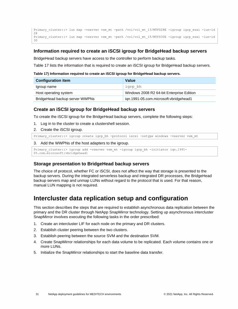
31 NetApp deployment guidelines for MEDITECH environments © 2021 NetApp, Inc. All Rights Reserved.
Primary_cluster::> lun map -vserver vsm_mt -path /vol/vol_mt_13/MTFS28E -igroup igrp_esxi -lun-id
28
Primary_cluster::> lun map -vserver vsm_mt -path /vol/vol_mt_15/MTFS30E -igroup igrp_esxi -lun-id
30
Information required to create an iSCSI igroup for BridgeHead backup servers
BridgeHead backup servers have access to the controller to perform backup tasks.
Table 17 lists the information that is required to create an iSCSI igroup for BridgeHead backup servers.
Table 17) Information required to create an iSCSI igroup for BridgeHead backup servers.
Configuration item Value
Igroup name igrp_bh
Host operating system Windows 2008 R2 64-bit Enterprise Edition
BridgeHead backup server WWPNs iqn.1991-05.com.microsoft:vbridgehead1
Create an iSCSI igroup for BridgeHead backup servers
To create the iSCSI igroup for the BridgeHead backup servers, complete the following steps:
1. Log in to the cluster to create a clustershell session.
2. Create the iSCSI igroup.
Primary_cluster::> igroup create igrp_bh -protocol iscsi -ostype windows -vserver vsm_mt
3. Add the WWPNs of the host adapters to the igroup.
Primary_cluster::> igroup add -vserver vsm_mt -igroup igrp_bh -initiator iqn.1991-
05.com.microsoft:vbridgehead1
Storage presentation to BridgeHead backup servers
The choice of protocol, whether FC or iSCSI, does not affect the way that storage is presented to the
backup servers. During the integrated serverless backup and integrated DR processes, the BridgeHead
backup servers map and unmap LUNs without regard to the protocol that is used. For that reason,
manual LUN mapping is not required.
Intercluster data replication setup and configuration
This section describes the steps that are required to establish asynchronous data replication between the
primary and the DR cluster through NetApp SnapMirror technology. Setting up asynchronous intercluster
SnapMirror involves executing the following tasks in the order prescribed:
1. Create an intercluster LIF for each node on the primary and DR clusters.
2. Establish cluster peering between the two clusters.
3. Establish peering between the source SVM and the destination SVM.
4. Create SnapMirror relationships for each data volume to be replicated. Each volume contains one or more LUNs.
5. Initialize the SnapMirror relationships to start the baseline data transfer.
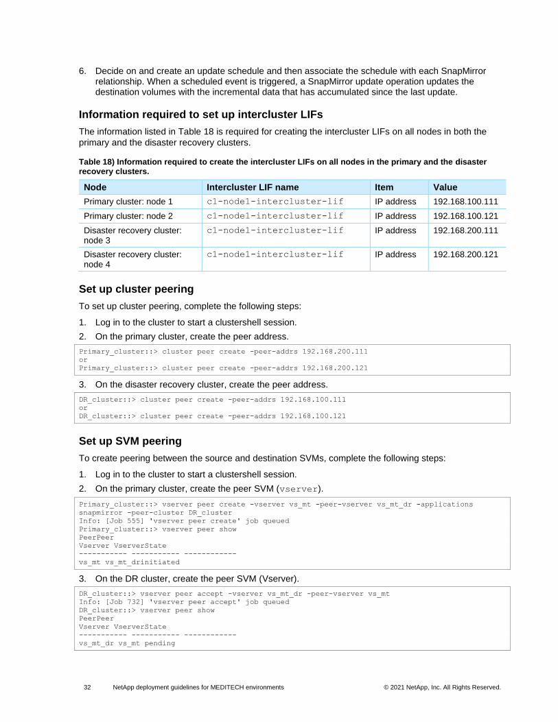
32 NetApp deployment guidelines for MEDITECH environments © 2021 NetApp, Inc. All Rights Reserved.
6. Decide on and create an update schedule and then associate the schedule with each SnapMirror relationship. When a scheduled event is triggered, a SnapMirror update operation updates the destination volumes with the incremental data that has accumulated since the last update.
Information required to set up intercluster LIFs
The information listed in Table 18 is required for creating the intercluster LIFs on all nodes in both the
primary and the disaster recovery clusters.
Table 18) Information required to create the intercluster LIFs on all nodes in the primary and the disaster recovery clusters.
Node Intercluster LIF name Item Value
Primary cluster: node 1 c1-node1-intercluster-lif IP address 192.168.100.111
Primary cluster: node 2 c1-node1-intercluster-lif IP address 192.168.100.121
Disaster recovery cluster: node 3
c1-node1-intercluster-lif IP address 192.168.200.111
Disaster recovery cluster: node 4
c1-node1-intercluster-lif IP address 192.168.200.121
Set up cluster peering
To set up cluster peering, complete the following steps:
1. Log in to the cluster to start a clustershell session.
2. On the primary cluster, create the peer address.
Primary_cluster::> cluster peer create -peer-addrs 192.168.200.111
or
Primary_cluster::> cluster peer create -peer-addrs 192.168.200.121
3. On the disaster recovery cluster, create the peer address.
DR_cluster::> cluster peer create -peer-addrs 192.168.100.111
or
DR_cluster::> cluster peer create -peer-addrs 192.168.100.121
Set up SVM peering
To create peering between the source and destination SVMs, complete the following steps:
1. Log in to the cluster to start a clustershell session.
2. On the primary cluster, create the peer SVM (vserver).
Primary_cluster::> vserver peer create -vserver vs_mt -peer-vserver vs_mt_dr -applications
snapmirror -peer-cluster DR_cluster
Info: [Job 555] 'vserver peer create' job queued
Primary_cluster::> vserver peer show
PeerPeer
Vserver VserverState
----------- ----------- ------------
vs_mt vs_mt_drinitiated
3. On the DR cluster, create the peer SVM (Vserver).
DR_cluster::> vserver peer accept -vserver vs_mt_dr -peer-vserver vs_mt
Info: [Job 732] 'vserver peer accept' job queued
DR_cluster::> vserver peer show
PeerPeer
Vserver VserverState
----------- ----------- ------------
vs_mt_dr vs_mt pending

33 NetApp deployment guidelines for MEDITECH environments © 2021 NetApp, Inc. All Rights Reserved.
Note: In the CLI, SVMs are referred to by their former name, Vservers.
Create and initialize SnapMirror relationships
To create and initialize the SnapMirror relationships between the source and destination SVMs, complete
the following steps:
Note: This example creates 20 SnapMirror destination volumes in the DR cluster for the MEDITECH 60-host FC primary cluster.
1. Log in to the DR cluster to start a clustershell session.
2. On the DR cluster, create the aggregate and the volumes for the SnapMirror setup on node 1. The volumes to be created on node 1 include vol_mt_00, vol_mt_02, vol_mt_04, and so on,
through vol_mt_20.
DR_cluster::> aggr create -aggregate aggr_mtfs_dr1 –vserver vs_mt_dr -diskcount 28 -disktype SATA
–maxraidsize 28 -nodes c1-node1-dr
DR_cluster::> vol create -volume vol_mt_00 –vserver vs_mt_dr -aggregate aggr_mtfs_dr1 -size 1100G
-state online -type DP
(volume create)
[Job 733] Job succeeded: Successful
3. Repeat the volume creation command used in step 2 for the rest of the nine volumes on DR cluster node 1.
… << repeat for the rest of 9 volumes on Node 1>>
4. Create the aggregate and volumes for the SnapMirror setup on node 2. The volumes to be created on node 2 include vol_mt_01, vol_mt_03, vol_mt_05, and so on, through vol_mt_19.
DR_cluster::> aggr create -aggregate aggr_mtfs_dr2 –vserver vs_mt_dr -diskcount 28 -disktype SATA
–maxraidsize 28 -nodes c1-node2-dr
DR_cluster::> vol create -volume vol_mt_01 –vserver vs_mt_dr -aggregate aggr_mtfs_dr2 -size 1100G
-state online -type DP
(volume create)
[Job 733] Job succeeded: Successful
5. Repeat the volume creation command used in step 4 for the rest of the nine volumes on node 2.
… << repeat for the rest of 9 volumes on Node 2>>
6. Create the SnapMirror source and destination paths to establish the SnapMirror relationship.
DR_cluster::> snapmirror create -source-path vs_mt:vol_mt_00 -destination-path vs_mt_dr:vol_mt_00
Operation succeeded: snapmirror create the relationship with destination vs_mt_dr:vol_mt_00.
7. Use the snapmirror show command to display the relationships that were established.
DR_cluster::> snapmirror show
Progress
SourceDestination Mirror Relationship TotalLast
PathType PathState Status Progress Healthy Updated
----------- ---- ------------ ------- -------------- --------- ------- --------
vs_mt:vol_mt_00
DP vs_mt_dr:vol_mt_00
Uninitialized
Idle -true-
…
DR_cluster::> snapmirror initialize *
Operation is queued: snapmirror initialize of destination vs_mt_dr:vol_mt_00.
Operation is queued: snapmirror initialize of destination vs_mt_dr:vol_mt_01.
Operation is queued: snapmirror initialize of destination vs_mt_dr:vol_mt_02.
Operation is queued: snapmirror initialize of destination vs_mt_dr:vol_mt_03.
Operation is queued: snapmirror initialize of destination vs_mt_dr:vol_mt_04.
Operation is queued: snapmirror initialize of destination vs_mt_dr:vol_mt_05.
Operation is queued: snapmirror initialize of destination vs_mt_dr:vol_mt_06.
Operation is queued: snapmirror initialize of destination vs_mt_dr:vol_mt_07.

34 NetApp deployment guidelines for MEDITECH environments © 2021 NetApp, Inc. All Rights Reserved.
Operation is queued: snapmirror initialize of destination vs_mt_dr:vol_mt_08.
Operation is queued: snapmirror initialize of destination vs_mt_dr:vol_mt_09.
Operation is queued: snapmirror initialize of destination vs_mt_dr:vol_mt_10.
Operation is queued: snapmirror initialize of destination vs_mt_dr:vol_mt_11.
Operation is queued: snapmirror initialize of destination vs_mt_dr:vol_mt_12.
Operation is queued: snapmirror initialize of destination vs_mt_dr:vol_mt_13.
Operation is queued: snapmirror initialize of destination vs_mt_dr:vol_mt_14. Operation is
queued: snapmirror initialize of destination vs_mt_dr:vol_mt_15. Operation is queued: snapmirror
initialize of destination vs_mt_dr:vol_mt_16.
Operation is queued: snapmirror initialize of destination vs_mt_dr:vol_mt_17.
Operation is queued: snapmirror initialize of destination vs_mt_dr:vol_mt_18.
Operation is queued: snapmirror initialize of destination vs_mt_dr:vol_mt_19.
20 entries were acted on.
Set up a SnapMirror update interval
To create a schedule for SnapMirror updates, complete the following steps:
1. Log in to the cluster to start a clustershell session.
2. Create a schedule for SnapMirror.
DR_cluster::> schedule cron create -name 10min -minute 0,10,20,30,40,50
(job schedule cron create)
DR_cluster::> schedule show
(job schedule show)
NameType Description
----------- --------- -----------------------------------------------------
10mincron @:00,:10,:20,:30,:40,:50
1 entry was displayed.
3. Apply the schedule to the SnapMirror relationships.
DR_cluster::> snapmirror modify -destination-path vs_mt_dr: vol_mt_00 -schedule 10min
Operation succeeded: snapmirror modify for the relationship with destination "vs_mt_dr:vs_mt_
00".
4. Repeat these steps for the remainder of the 19 volumes.
Miscellaneous setup
Information required to set up Network Time Protocol
It is mandatory that the controllers and the application server maintain the same date and time. Table 19
lists the information required to set up Network Time Protocol (NTP).
Table 19) Information required to set up NTP.
NTP server name IP address
pool.ntp.org 91.207.136.50
ntp.lucier.us 198.58.104.131
Configure NTP service on nodes
To configure NTP service on the nodes, complete the following steps:
1. Log in to the cluster to start a clustershell session.
2. Add NTP servers to node 1 of the primary cluster.
Primary_cluster::> ntp server create -node c1-node1-mt -server 91.207.136.50 -version max
Primary_cluster::> ntp server create -node c1-node1-mt -server 198.58.104.131 -server -version
max

35 NetApp deployment guidelines for MEDITECH environments © 2021 NetApp, Inc. All Rights Reserved.
3. Add NTP servers to node 2 of the primary cluster.
Primary_cluster::> ntp server create -node c1-node2-mt -server 91.207.136.50 -version max
Primary_cluster::> ntp server create -node c1-node2-mt -server 198.58.104.131 -server -version
max
Information required to create ONTAPI access credentials for the BridgeHead backup application
To enable NetApp ONTAPI access, the BridgeHead backup application requires administrator-level
access to the SVM vsm_mt and to the cluster. If the deployment includes a DR cluster, a cluster-level
credential must also be created. The user name and password for the BridgeHead application ONTAPI
access must be the same for each credential that is created.
Table 20 lists the information that is required to create ONTAPI credentials for BridgeHead backup
servers.
Table 20) Information required to create ONTAPI credentials for BridgeHead backup servers.
Configuration item Role Data ONTAP application Value
Primary cluster credential admin ONTAPI User name: bh_user
Password: bh_password
DR cluster credential (if it exists) admin ONTAPI User name: bh_user
Password: bh_password
SVM vsm_mt vsadmin ONTAPI User name: bh_user
Password: bh_password
Create Data ONTAP credentials for BridgeHead servers
To create Data ONTAP credentials for the BridgeHead backup servers, complete the following steps:
1. Log in to the cluster to start a clustershell session.
2. On the primary cluster, create a user name.
3. Enter and confirm a password for api_user.
Primary_cluster::> security login create -username api_user -application ontapi -authmethod
password -role admin -vserver Primary_cluster
Please enter a password for user 'api_user':
Please enter it again:
Primary_cluster::> security login create -username api_user -application ontapi -authmethod
password -role vsadmin -vserver vs_mt
Please enter a password for user 'api_user':
Please enter it again:
4. Repeat steps 2 and 3 on the DR cluster.
Appendix A: Deployment information—Gathering worksheet
Before you deploy your NetApp AFF or FAS system, work with the account system engineer to complete
the information-gathering worksheet in Table 21.
Table 21) Deployment information-gathering worksheet.
Document section Controller Configuration Item Value
Information Required to Set Up a
Controller 1 Controller A host name
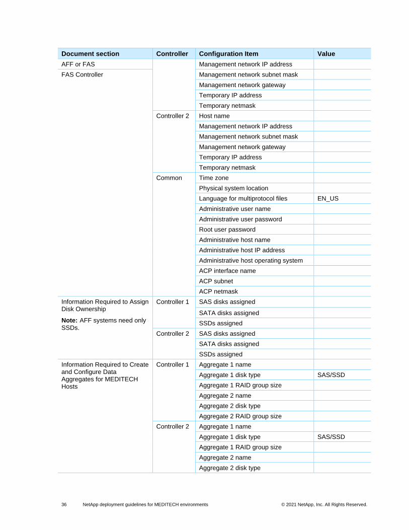
36 NetApp deployment guidelines for MEDITECH environments © 2021 NetApp, Inc. All Rights Reserved.
Document section Controller Configuration Item Value
AFF or FAS Management network IP address
FAS Controller Management network subnet mask
Management network gateway
Temporary IP address
Temporary netmask
Controller 2 Host name
Management network IP address
Management network subnet mask
Management network gateway
Temporary IP address
Temporary netmask
Common Time zone
Physical system location
Language for multiprotocol files EN_US
Administrative user name
Administrative user password
Root user password
Administrative host name
Administrative host IP address
Administrative host operating system
ACP interface name
ACP subnet
ACP netmask
Information Required to Assign Disk Ownership
Note: AFF systems need only SSDs.
Controller 1 SAS disks assigned
SATA disks assigned
SSDs assigned
Controller 2 SAS disks assigned
SATA disks assigned
SSDs assigned
Information Required to Create and Configure Data Aggregates for MEDITECH Hosts
Controller 1 Aggregate 1 name
Aggregate 1 disk type SAS/SSD
Aggregate 1 RAID group size
Aggregate 2 name
Aggregate 2 disk type
Aggregate 2 RAID group size
Controller 2 Aggregate 1 name
Aggregate 1 disk type SAS/SSD
Aggregate 1 RAID group size
Aggregate 2 name
Aggregate 2 disk type

37 NetApp deployment guidelines for MEDITECH environments © 2021 NetApp, Inc. All Rights Reserved.
Document section Controller Configuration Item Value
Aggregate 2 RAID group size
Node Root Aggregates and Volumes
Appendix B: Flash Cache Setup and Configuration
Common Root volume size (GB)
Root volume NetApp Snapshot® copy reserve
Controller 1 Aggregate hosting root volume
Controller 2 Aggregate hosting root volume
Common Flash Cache license key
NetApp FlexScale™ option enabled? [on|off]
on
Low-priority blocks enabled? [on|off] off
Normal data blocks enabled? [on|off] on
Appendix C: Flash Pool Setup and Configuration
Note: AFF systems need only SSDs.
Controller 1 Data_Aggregate1 (-hybrid-enabled? [true/false])
true
Controller 2 Data_Aggregate2 (-hybrid-enabled? [true/false])
true
Storage Presentation Controller 1 Interface group name ig0
Interface group mode type [lacp|multi] lacp
Interface group load-balancing type ip
Interface group links e0a e0b
Storage network IP address
Storage network netmask
Storage network gateway
Controller 2 Interface group name ig0
Interface group mode type [lacp|multi] lacp
Interface group load-balancing type ip
Interface group links e0a e0b
Storage network IP address
Storage network netmask
Storage network gateway
Information Required to Set Up Network Time Protocol
Common Domain name
Name server 1 IP address
Name server 2 IP address
Common Time server 1 IP or DNS name
Time server 2 IP or DNS name
Time server 3 IP or DNS name
Set Up the FC Service and FC Port Type
Common FC license key
FC target port 1 0a
FC target port 2 0b
Information Required to Set Up iSCSI Storage Transport
Common iSCSI license key Yes
iSCSI interface e0c e0d
Common NFS license key
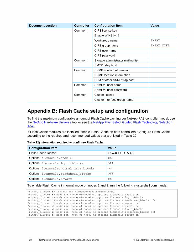
38 NetApp deployment guidelines for MEDITECH environments © 2021 NetApp, Inc. All Rights Reserved.
Document section Controller Configuration Item Value
Common CIFS license key
Enable WINS [y|n] n
Workgroup name IMPAX
CIFS group name IMPAX_CIFS
CIFS user name
CIFS password
Common Storage administrator mailing list
SMTP relay host
Common SNMP contact information
SNMP location information
DFM or other SNMP trap host
Common SNMPv3 user name
SNMPv3 user password
Common Cluster license
Cluster interface group name
Appendix B: Flash Cache setup and configuration
To find the maximum configurable amount of Flash Cache caching per NetApp FAS controller model, use
the NetApp Hardware Universe tool or see the NetApp FlashSelect Guided Flash Technology Selection
Tool.
If Flash Cache modules are installed, enable Flash Cache on both controllers. Configure Flash Cache
according to the required and recommended values that are listed in Table 22.
Table 22) Information required to configure Flash Cache.
Configuration Item Value
Flash Cache license LAW4UEUOEARJ
Options flexscale.enable on
Options flexscale.lopri_blocks off
Options flexscale.normal_data_blocks on
Options flexscale.readahead_blocks off
Options flexscale.rewarm on
To enable Flash Cache in normal mode on nodes 1 and 2, run the following clustershell commands:
Primary_cluster::> license add -license-code LAW4UEUOEARJ
Primary_cluster::> node run -node c1-node1-mt options flexscale.enable on
Primary_cluster::> node run -node c1-node1-mt options flexscale.lopri_blocks
Primary_cluster::> node run -node c1-node1-mt options flexscale.readahead_blocks off
Primary_cluster::> node run -node c1-node1-mt options flexscale.rewarm on
Primary_cluster::> node run -node c1-node2-mt options flexscale.enable on
Primary_cluster::> node run -node c1-node2-mt options flexscale.lopri_blocks
Primary_cluster::> node run -node c1-node2-mt options flexscale.readahead_blocks off
Primary_cluster::> node run -node c1-node2-mt options flexscale.rewarm on

39 NetApp deployment guidelines for MEDITECH environments © 2021 NetApp, Inc. All Rights Reserved.
Appendix C: Flash Pool setup and configuration
To find the maximum configurable amount of NetApp Flash Pool caching per FAS controller model, use
the NetApp Hardware Universe tool or see the NetApp FlashSelect Guided Flash Technology Selection
Tool.
Flash Pool is the newest addition to the NetApp Virtual Storage Tier. NetApp Flash Pool technology
enables you to combine flash technology in the form of SSDs with traditional hard disk drives to form a
single NetApp Data ONTAP aggregate. No license is required for Flash Pool.
To set up Flash Pool, complete the following steps:
1. Log in to the cluster to start a clustershell session.
2. Enable the Flash Pool feature on the existing data aggregate.
Primary_cluster::> aggr modify -aggregate aggr_node1_mtfs_db -hybrid-enabled true
Primary_cluster::> aggr modify -aggregate aggr_node2_mtfs_db -hybrid-enabled true
3. Add SSDs to these aggregates to enable Flash Pool on the aggregates.
Primary_cluster::> aggr add-disks -aggregate aggr_node1_mtfs_db -disktype SSD -diskcount 6
Primary_cluster::> aggr add-disks -aggregate aggr_node2_mtfs_db -disktype SSD –diskcount 6
For more information about Flash Pool, see TR-4070: Flash Pool Design and Implementation Guide.
Where to find additional information
The following documents and resources are relevant to this report:
• Clustered Data ONTAP 8.3 Software Setup Guide https://library.netapp.com/ecm/ecm_download_file/ECMP1654308
• Data ONTAP 8 product documentation library http://support.netapp.com/documentation/productlibrary/index.html?productID=30092
• Documentation page of the NetApp Support site http://support.netapp.com/documentation/productsatoz/index.html
• Hardware Installation and Setup Poster http://mysupport.netapp.com/documentation/bytype/index.html?subtypeID=61031
• Hardware Universe User Guide https://hwu.netapp.com/Resources/hwu_ug.pdf
• NetApp FlashSelect Guided Flash Technology Selection Tool https://one.netapp.com/flashselect/kdw
• NetApp Hardware Universe http://hwu.netapp.com/
• NetApp Interoperability Matrix Tool (IMT) http://mysupport.netapp.com/NOW/products/interoperability/
• SAS Disk Shelves Installation and Service Guide https://library.netapp.com/ecm/ecm_download_file/ECMP1119629
• Site Requirements Guide Replacement Tutorial https://library.netapp.com/ecm/ecm_get_file/ECMP12373002
• TR-3832: Flash Cache Best Practices Guide https://fieldportal.netapp.com/content/190843
• TR-4070: NetApp Flash Pool Design and Implementation Guide https://fieldportal.netapp.com/content/196235

40 NetApp deployment guidelines for MEDITECH environments © 2021 NetApp, Inc. All Rights Reserved.
• TR-4300i: NetApp FAS and All Flash Storage Systems for MEDITECH Environments Best Practices Guide https://fieldportal.netapp.com/content/201762
• TR-4190: NetApp Sizing Guidelines for MEDITECH Environments https://fieldportal.netapp.com/?oparams=140924
Version history
Version Date Document version history
Version 3.1 December 2021 Reformatted document using updated template.
Version 3.0 February 2016 Updated with latest and all-flash information.
Version 2.0 October 2015 Updated with latest information.
Version 1.0 August 2014 Initial release.

41 NetApp deployment guidelines for MEDITECH environments © 2021 NetApp, Inc. All Rights Reserved.
Refer to the Interoperability Matrix Tool (IMT) on the NetApp Support site to validate that the exact product and feature versions described in this document are supported for your specific environment. The NetApp IMT defines the product components and versions that can be used to construct configurations that are supported by NetApp. Specific results depend on each customer’s installation in accordance with published specifications.
Copyright information
Copyright © 2021 NetApp, Inc. All Rights Reserved. Printed in the U.S. No part of this document covered by copyright may be reproduced in any form or by any means—graphic, electronic, or mechanical, including photocopying, recording, taping, or storage in an electronic retrieval system—without prior written permission of the copyright owner.
Software derived from copyrighted NetApp material is subject to the following license and disclaimer:
THIS SOFTWARE IS PROVIDED BY NETAPP “AS IS” AND WITHOUT ANY EXPRESS OR IMPLIED WARRANTIES, INCLUDING, BUT NOT LIMITED TO, THE IMPLIED WARRANTIES OF MERCHANTABILITY AND FITNESS FOR A PARTICULAR PURPOSE, WHICH ARE HEREBY DISCLAIMED. IN NO EVENT SHALL NETAPP BE LIABLE FOR ANY DIRECT, INDIRECT, INCIDENTAL, SPECIAL, EXEMPLARY, OR CONSEQUENTIAL DAMAGES (INCLUDING, BUT NOT LIMITED TO, PROCUREMENT OF SUBSTITUTE GOODS OR SERVICES; LOSS OF USE, DATA, OR PROFITS; OR BUSINESS INTERRUPTION) HOWEVER CAUSED AND ON ANY THEORY OF LIABILITY, WHETHER IN CONTRACT, STRICT LIABILITY, OR TORT (INCLUDING NEGLIGENCE OR OTHERWISE) ARISING IN ANY WAY OUT OF THE USE OF THIS SOFTWARE, EVEN IF ADVISED OF THE POSSIBILITY OF SUCH DAMAGE.
NetApp reserves the right to change any products described herein at any time, and without notice. NetApp assumes no responsibility or liability arising from the use of products described herein, except as expressly agreed to in writing by NetApp. The use or purchase of this product does not convey a license under any patent rights, trademark rights, or any other intellectual property rights of NetApp.
The product described in this manual may be protected by one or more U.S. patents, foreign patents, or pending applications.
Data contained herein pertains to a commercial item (as defined in FAR 2.101) and is proprietary to NetApp, Inc. The U.S. Government has a non-exclusive, non-transferrable, non-sublicensable, worldwide, limited irrevocable license to use the Data only in connection with and in support of the U.S. Government contract under which the Data was delivered. Except as provided herein, the Data may not be used, disclosed, reproduced, modified, performed, or displayed without the prior written approval of NetApp, Inc. United States Government license rights for the Department of Defense are limited to those rights identified in DFARS clause 252.227-7015(b).
Trademark information
NETAPP, the NETAPP logo, and the marks listed at http://www.netapp.com/TM are trademarks of NetApp, Inc. Other company and product names may be trademarks of their respective owners.
TR-4319-1221