Deployment Automation - Serena Documentation Center
417
Deployment Automation User's Guide
-
Upload
khangminh22 -
Category
Documents
-
view
4 -
download
0
Transcript of Deployment Automation - Serena Documentation Center

Deployment AutomationUser's Guide

Copyright © 2011-2020 Micro Focus or one of its affiliates. All rights reserved.
The only warranties for products and services of Micro Focus and its affiliates and licensors (“Micro Focus”) areset forth in the express warranty statements accompanying such products and services. Nothing herein shouldbe construed as constituting an additional warranty. Micro Focus shall not be liable for technical or editorialerrors or omissions contained herein. The information contained herein is subject to change without notice.
Contains Confidential Information. Except as specifically indicated otherwise, a valid license is required forpossession, use or copying. Consistent with FAR 12.211 and 12.212, Commercial Computer Software, ComputerSoftware Documentation, and Technical Data for Commercial Items are licensed to the U.S. Government undervendor's standard commercial license.
Part number: 6.3.1
Publication date: 2020-02-27
2 Deployment Automation

Table of ContentsPart 1: Introduction .......................................................................................... 19
Chapter 1: Welcome to Deployment Automation ................................................ 21
About This Documentation.............................................................................. 21
Chapter 2: Deployment Automation Overview ................................................... 23
User Interface Overview................................................................................. 24
Examples and the Community ........................................................................ 25
Terminology ................................................................................................ 25
A Typical Sequence ....................................................................................... 26
Part 2: Installation .......................................................................................... 29
Chapter 3: Architecture Overview ..................................................................... 31
Clients......................................................................................................... 32
Data Tier ................................................................................................... 32
Service Tier ................................................................................................ 32
Agent Architecture ....................................................................................... 33
Agent Communication.................................................................................... 34
Agent Relay Communication ........................................................................... 35
Services ...................................................................................................... 36
Chapter 4: Installing Servers and Agents............................................................ 41
Installation Checklist .................................................................................... 41
Installation Considerations for Optimal Performance .......................................... 43
Using AES256 Encryption .............................................................................. 43
System Requirements.................................................................................... 43
Server Minimum Requirements ..................................................................... 44
Server Recommended Configuration ............................................................ 44
Agent Minimum Requirements ..................................................................... 45
Agent Relay Minimum Requirements ............................................................ 45
Preparing Your Database .............................................................................. 45
Server Installation ....................................................................................... 47
Running the Interactive Installer .................................................................. 47
User's Guide 3

Manual Server Installation ........................................................................... 50
Silent Mode Server Installation ..................................................................... 52
(Windows) Server Silent Installation............................................................ 52
(Windows) Server Silent Installation Options ............................................. 53
(Windows) Server Silent Installation: OptionsFile.txt Examples ..................... 54
(UNIX/Linux) Server Silent Installation ...................................................... 56
(UNIX/Linux) Server Silent Installation Options .......................................... 56
(UNIX/Linux) Server Silent Installation: optionsFile.txt Examples .................. 59
Uninstalling Servers .................................................................................... 60
Reconfiguring Server Installation Settings ...................................................... 61
Agent Relay Installation ................................................................................. 63
Interactive Agent Relay Installation ............................................................... 63
Child Relay Installation .............................................................................. 64
Agent Relay Installation Options .................................................................. 65
Silent Mode Agent Relay Installation ............................................................ 67
(Windows) Agent Relay Silent Installation ................................................... 68
(Windows) Agent Relay Silent Install Options ............................................. 68
(Windows) Agent Relay Silent Install Options Example ................................. 70
(UNIX/Linux) Agent Relay Silent Installation ................................................ 71
(UNIX/Linux) Agent Relay Silent Install Options .......................................... 71
(UNIX/Linux) Agent Relay Silent Install Options Example ........................... 73
Upgrading Agent Relays and Servers ............................................................ 74
Server and Agent Communication Configuration ............................................. 75
Agent-initiated HTTP Communication Using Agent Relays .............................. 76
Server-initiated HTTP Communication Using Agent Relays .............................. 77
Agent Installation.......................................................................................... 78
Interactive Agent Installation........................................................................ 79
Agent Installation Options ........................................................................ 80
Silent Mode Agent Installation ..................................................................... 82
(Windows) Agent Silent Installation ............................................................ 82
(Windows) Agent Silent Installation Options ............................................. 82
4 Deployment Automation

(Windows) Agent Silent Installation Options Example ................................. 84
(UNIX/Linux) Agent Silent Installation ......................................................... 85
(UNIX/Linux) Agent Silent Installation Options .......................................... 85
(UNIX/Linux) Agent Silent Installation Options Examples.............................. 87
Uninstalling Agents .................................................................................... 87
About Agent Upgrades ................................................................................. 88
Installing and Configuring the z/OS Agent ...................................................... 89
Installing for a High Availability Implementation ................................................ 91
Installing the First Server ........................................................................... 91
Installing Additional Servers ........................................................................ 95
High Availability Configurations ..................................................................... 96
Configuring Agents for High Availability (Recommended) .............................. 96
Configuring Agents for High Availability (Alternate) ....................................... 97
Configuring Agent Relay Failover ............................................................... 98
Disaster Recovery with Hot Standby ............................................................ 98
Disaster Recovery with Cold Standby ......................................................... 99
Chapter 5: Running Deployment Automation ................................................... 101
Starting and Stopping the Server ............................................................... 101
Starting and Stopping an Agent Relay ......................................................... 101
Starting and Stopping an Agent .................................................................. 102
Permission for Users Running Agents ......................................................... 102
Accessing Deployment Automation ............................................................... 103
Part 3: Administration .................................................................................... 105
Chapter 6: Administration Overview ............................................................... 107
Chapter 7: Automation Administration ............................................................ 109
Managing Plugins ....................................................................................... 109
Loading Plugins ....................................................................................... 109
Upgrading Plugins .................................................................................... 110
Managing External Source Configuration Types ............................................. 110
Locks ...................................................................................................... 110
Managing Locks ....................................................................................... 110
User's Guide 5

Post-Processing Scripts .............................................................................. 111
Defining Statuses....................................................................................... 112
Using Inventory Statuses ........................................................................ 113
Using Version Statuses ........................................................................... 114
Using Snapshot Statuses........................................................................... 114
Chapter 8: Security Administration ............................................................... 117
Setting up Security .................................................................................... 117
Role Configuration .................................................................................... 118
Default Role Types ................................................................................. 119
Creating and Editing Roles ........................................................................ 120
Server Roles and System Security ............................................................ 120
Web UI Roles and UI Security .................................................................. 122
Authorization Realms and Groups ............................................................... 123
Creating an Internal Storage Authorization Realm ....................................... 123
Creating an LDAP Authorization Realm ...................................................... 124
Limiting LDAP to a Set of Groups ............................................................ 125
Creating Groups....................................................................................... 125
Authentication Realms and Users.................................................................. 126
Creating Authentication Realms ............................................................... 126
Creating Users ....................................................................................... 127
Creating LDAP Authentication Realms ......................................................... 128
LDAP Authentication Configuration ............................................................ 129
LDAP User Permissions ........................................................................... 129
Importing LDAP Users ........................................................................... 130
Limiting LDAP Users by Group ............................................................... 130
Creating PKI Certificate Authentication Realms............................................. 130
PKI Certificate Parsing ........................................................................... 134
PKI Certificate Authentication Configuration ................................................ 135
Configuring the Server to Support PKI Certificates .................................... 135
Importing CA Certificates ........................................................................ 136
Configuring Internal Revocation Verification ............................................. 136
6 Deployment Automation

Configuring Polling for Certificate Revocation Lists .................................... 137
Configuring PKI Certification for Agents ................................................... 138
Default Permissions .................................................................................... 138
Setting Default Permissions ..................................................................... 139
Adding Users to Groups .............................................................................. 139
Setting Role Membership by Product Area...................................................... 140
Tokens...................................................................................................... 140
Viewing Online Users ................................................................................. 141
Security Report Overview ........................................................................... 141
Application Security Report........................................................................ 142
Application Security Fields ..................................................................... 142
Component Security Report ..................................................................... 142
Component Security Fields ..................................................................... 142
Environment Security Report ..................................................................... 143
Environment Security Fields .................................................................. 143
Resource Security Report ........................................................................ 144
Resource Security Fields ........................................................................ 144
Chapter 9: System Administration .................................................................. 145
Licenses ................................................................................................... 145
Adding a License .................................................................................... 145
Adding Agents to a License........................................................................ 145
Modifying or Deleting a License .................................................................. 146
Configuring Email Notifications..................................................................... 146
Configuring Notification Schemes ............................................................... 147
Creating Notification Templates.................................................................. 149
Properties for Notification Templates......................................................... 150
Examples of Keys in the Properties Map ................................................... 152
Basic Velocity Examples ........................................................................ 153
Output Log................................................................................................ 153
Adding System Properties ........................................................................... 154
System Settings ....................................................................................... 155
User's Guide 7
ALF Events ................................................................................................ 157
Scheduling Version Cleanup ........................................................................ 159
Chapter 10: Agent Connectivity Status Checks ................................................ 161
Configuring the Server-Initiated Agent Status Check....................................... 162
Configuring the Agent-Initiated Agent Status Check ....................................... 163
Configuring the User-Initiated Agent Status Check.......................................... 164
Chapter 11: Secure Socket Layer (SSL) Configuration ....................................... 167
Configuring Unauthenticated Mode for HTTP Communication ........................... 167
Configuring Mutual Authentication Mode ...................................................... 168
Property Settings for Mutual Authentication ................................................ 168
Adding an Alias to an Agent ..................................................................... 169
Adding an Alias to an Agent Relay ............................................................ 169
Mutual Authentication: Server and Agents ................................................... 170
Mutual Authentication: Server, Agent Relay, and Agents .............................. 171
Chapter 12: Configuring Server Settings ......................................................... 175
Configuring Component Version Import ......................................................... 175
Configuring the Auto-select for Export Option ................................................ 176
Configuring the Default for Only Changed Versions Option .............................. 177
Configuring Agent Connectivity Settings ...................................................... 177
Chapter 13: Artifact Repository ..................................................................... 179
Artifact Repository Overview........................................................................ 179
Relocating the Repository ........................................................................... 180
Chapter 14: Managing Execution History ......................................................... 181
Pre-Cleanup ............................................................................................. 181
Rules of Execution History Cleanup............................................................... 182
Running Execution History Cleanup............................................................... 183
Execution History Cleanup Audit .................................................................. 183
Post-Cleanup ............................................................................................. 183
Chapter 15: Data Collection and Check for Update .......................................... 185
Data Collected .......................................................................................... 185
Data Collection FAQ.................................................................................... 187
8 Deployment Automation

Upgrade Eligibility Information Collected ...................................................... 188
Suggestions for Upgrade ........................................................................... 189
Checking for Updates Manually .................................................................. 191
Properties Encryption.................................................................................... 191
Chapter 16: Troubleshooting ........................................................................ 195
Conflict with WebDAV in IIS ........................................................................ 195
Installation Failure Due to Interruption ......................................................... 195
Import Failure or Issues After Import ............................................................ 196
SSO Login Failure After a Tomcat Upgrade ................................................... 196
Process Failures or False Successes ............................................................ 197
Navigation Tips .......................................................................................... 197
Part 4: Management ....................................................................................... 199
Chapter 17: Management Overview ............................................................... 201
Chapter 18: Managing Components ............................................................... 203
Components Page Overview ........................................................................ 203
Creating Components ................................................................................. 204
Source Configuration Type Fields ............................................................... 207
File System (Basic) .............................................................................. 209
File System (Versioned) ........................................................................ 210
AnthillPro ............................................................................................. 211
Artifactory .......................................................................................... 212
Dimensions .......................................................................................... 214
Git ...................................................................................................... 216
Jenkins ................................................................................................ 217
Maven ................................................................................................ 218
Nexus Sonatype .................................................................................... 219
PVCS ................................................................................................... 221
Subversion .......................................................................................... 222
TeamCity ............................................................................................. 224
TFS...................................................................................................... 224
User's Guide 9

TFS vNext............................................................................................. 226
TFS_SCM ............................................................................................. 228
TeamForge .......................................................................................... 229
Component Properties .............................................................................. 230
Adding Component Properties .................................................................. 230
Adding Component Environment Properties ................................................ 231
Adding Component Version Properties......................................................... 232
Importing/Exporting Components ............................................................... 233
Exporting Components.............................................................................. 234
Importing Components ........................................................................... 234
Component Versions ................................................................................. 235
Importing Component Versions .................................................................. 235
Importing Versions Automatically ............................................................ 236
Importing Versions Manually .................................................................. 237
Maintaining Versions Externally ............................................................... 237
Viewing the Version Import Queue ......................................................... 238
Adding Statuses to Component Versions...................................................... 238
Setting Component Version Property Values ................................................ 239
Deleting Component Versions .................................................................. 239
Inactivating Component Versions ............................................................... 239
Component Version Cleanup ..................................................................... 240
Downloading Version Artifacts .................................................................. 241
Displaying the Number of Active Component Versions ................................. 242
Component History .................................................................................... 242
Component Processes ................................................................................. 242
Creating Component Processes .................................................................. 243
Component Process Details ..................................................................... 245
Designing Component Processes ............................................................... 245
Adding Process Steps .............................................................................. 247
Connecting Process Steps ........................................................................ 249
10 Deployment Automation

Component Process Step Details ............................................................... 251
Plugins ................................................................................................ 252
Component Process Utility Steps ............................................................ 252
Using Expression Language in Processes ................................................... 255
Using Conditions and Switch Steps in Processes ....................................... 256
User Impersonation .............................................................................. 258
User Impersonation on UNIX/Linux ...................................................... 258
Impersonation on Windows Systems ...................................................... 260
Adding Component Process Properties ...................................................... 261
Plugin Post Processes .............................................................................. 262
Running Component Processes .................................................................. 262
Component Tasks....................................................................................... 263
Creating Component Tasks ........................................................................ 263
Creating Component Templates .................................................................. 264
Importing/Exporting Component Templates ................................................ 264
Exporting Component Templates ............................................................ 264
Importing Component Templates ............................................................ 265
Adding Component Template Properties ...................................................... 265
Using Component Templates ..................................................................... 266
Configuration Templates.............................................................................. 267
Creating Configuration Templates ............................................................... 267
Deleting and Deactivating Components ......................................................... 267
Chapter 19: Managing Applications ............................................................... 269
Applications Page Overview ........................................................................ 269
Creating Applications ................................................................................. 270
Application Configuration ........................................................................... 271
Adding Components to Applications ............................................................ 271
Adding Application Properties ..................................................................... 272
Copying Applications ................................................................................. 273
Importing/Exporting Applications ............................................................... 273
Exporting Applications .............................................................................. 274
User's Guide 11
Importing Applications.............................................................................. 274
Application Environments ........................................................................... 276
Adding Environments to Applications ......................................................... 277
Adding Application Environment Properties ................................................ 278
Mapping Application Components to Resources .......................................... 279
Setting Component Environment Property Values ....................................... 280
Comparing Environments ........................................................................ 281
Application Processes ................................................................................. 281
Creating Application Processes .................................................................. 282
Designing Application Processes ............................................................... 283
Application Process Step Details ............................................................... 285
Finish ................................................................................................... 285
Install Component ................................................................................. 285
Uninstall Component .............................................................................. 286
Rollback Component .............................................................................. 287
Run Process for Each Version .................................................................. 288
Apply Configuration .............................................................................. 289
Application Process Snapshot Steps ......................................................... 290
Create Snapshot Step........................................................................... 290
Update Snapshot Step ........................................................................ 291
Add Status to Snapshot Step ............................................................... 291
Remove Status from Snapshot Step ...................................................... 292
Application Process Utility Steps............................................................... 292
Adding Application Process Properties ......................................................... 295
Running Application Processes .................................................................. 296
Application Tasks ....................................................................................... 297
Creating Application Tasks ........................................................................ 298
Approvals ................................................................................................ 298
Designing Approval Processes .................................................................. 298
Approving Requests ................................................................................. 299
12 Deployment Automation

Snapshots ................................................................................................ 300
Creating Snapshots ................................................................................. 301
Viewing Snapshot Environments ............................................................... 301
Configuring Snapshots .............................................................................. 302
Adding Component Versions to Snapshots ................................................... 303
Adding Statuses to Snapshots .................................................................. 303
Viewing Snapshot Tasks ........................................................................... 304
Comparing Snapshots .............................................................................. 304
Gates ...................................................................................................... 304
Creating Gates ....................................................................................... 305
Chapter 20: Managing Environments ............................................................ 307
Environments Page Overview ..................................................................... 307
Creating Environments .............................................................................. 308
Configuring and Monitoring Environments...................................................... 308
Mapping Agents and other Resources to Environments .................................... 309
Adding Environment Properties .................................................................. 310
Importing/Exporting Environments ............................................................... 311
Exporting Environments ........................................................................... 311
Importing Environments ........................................................................... 311
Chapter 21: Managing Pipelines ..................................................................... 313
Pipelines Page Overview.............................................................................. 313
Creating Pipelines .................................................................................... 313
Configuring Pipelines ................................................................................. 314
Adding Pipelines to Applications .................................................................. 314
Importing/Exporting Pipelines ..................................................................... 315
Exporting Pipelines ................................................................................. 315
Importing Pipelines ................................................................................. 315
Chapter 22: Managing Resources .................................................................. 317
Resources Page Overview ........................................................................... 317
Resources ................................................................................................ 318
Creating Resources .................................................................................... 318
User's Guide 13

Resource Configuration .............................................................................. 319
Agents...................................................................................................... 320
Managing Agents and Agent Pools ............................................................... 320
Assigning Notification Schemes to Agents ................................................... 321
Installing Agents Remotely ........................................................................ 321
Managing Agents Remotely ..................................................................... 323
Upgrading Agents .................................................................................... 324
Dynamically Registering Agents ............................................................... 324
Agent Pools ............................................................................................. 325
Creating Agent Pools .............................................................................. 325
Adding Agents to Agent Pools .................................................................. 325
Updating Agent Pools ........................................................................... 326
Agent Relays ............................................................................................. 326
Managing Agent Relays .............................................................................. 326
Configuring Agent Relays ........................................................................ 327
Detecting Agent Relays ........................................................................... 328
Managing Network Relays ........................................................................... 329
Resource Groups ....................................................................................... 329
Creating Resource Groups ........................................................................ 330
Adding Resource Properties ........................................................................ 330
Resource Roles .......................................................................................... 331
Creating Resource Roles ........................................................................... 332
Adding Resource Roles to Resources ......................................................... 332
Adding Resource Role Properties ............................................................... 333
Chapter 23: Managing Deployment Packages ................................................... 335
Creating Deployment Packages .................................................................. 335
Deployment Package Configuration............................................................... 336
Deployment Package Processes .................................................................. 337
Designing Deployment Package Processes ................................................... 337
Deployment Package Process Utility Steps ................................................... 339
Adding Deployment Package Properties ...................................................... 341
14 Deployment Automation

Running Deployment Package Processes ................................................... 342
Deployment Package Inventory.................................................................. 343
Deployment Package Tasks ........................................................................ 344
Creating Deployment Package Tasks ......................................................... 344
Chapter 24: Managing Global Processes ......................................................... 345
Creating Global Processes ........................................................................... 345
Designing Global Processes ........................................................................ 346
Global Process Utility Steps ........................................................................ 346
Adding Global Process Properties.................................................................. 348
Importing/Exporting Global Processes ......................................................... 349
Exporting Global Processes........................................................................ 350
Importing Global Processes ..................................................................... 350
Running Global Processes ........................................................................... 350
Chapter 25: Properties ................................................................................. 351
Built-in Properties .................................................................................... 351
User-Defined Properties .............................................................................. 353
All Properties Pairs .................................................................................... 354
How Properties Are Resolved ..................................................................... 355
Property Picker .......................................................................................... 356
Chapter 26: Configuring Within the Application Hierarchy ................................. 359
Chapter 27: Replication................................................................................. 361
Replication Import Strategies ..................................................................... 362
Exporting Replication Data ........................................................................ 363
Importing Replication Data ........................................................................ 365
Replication Export Details ........................................................................... 366
Replication Import Details ........................................................................... 369
Replication Merge Strategies........................................................................ 371
Part 5: Deployment ....................................................................................... 375
Chapter 28: Deployment Overview ............................................................... 377
Chapter 29: Ways of Deploying ..................................................................... 379
Scheduling Deployments ........................................................................... 380
User's Guide 15

Setting Deployment Blackout Dates ............................................................ 380
Chapter 30: Analyzing Deployments ............................................................... 383
Viewing Timelines .................................................................................... 383
Viewing Application Deployments ............................................................... 385
Viewing Deployment History ........................................................................ 386
Viewing an Application Process Request......................................................... 386
Viewing a Component Process Request ......................................................... 387
Deployment Results in E-mail Notifications ................................................... 389
Chapter 31: Inventory Management ............................................................... 391
Viewing the Environment Inventory ............................................................ 391
Advanced Inventory Management ............................................................... 392
Chapter 32: Deployment Report Overview ...................................................... 395
Deployment Average Duration Report ......................................................... 395
Deployment Average Duration Fields ......................................................... 396
Running the Deployment Average Duration Report ....................................... 396
Sample Reports: Deployment Average Duration .......................................... 398
Deployment Total Duration Report ............................................................... 398
Deployment Total Duration Fields ............................................................... 399
Running the Deployment Total Duration Report .......................................... 399
Sample Reports: Deployment Total Duration ................................................ 401
Deployment Count Report ........................................................................... 402
Deployment Count fields ........................................................................... 402
Running the Deployment Count Report ...................................................... 403
Report Samples: Deployment Count ......................................................... 404
Deployment Detail Report ........................................................................... 405
Deployment Detail Fields........................................................................... 406
Running the Deployment Detail Report ...................................................... 407
Report Samples: Deployment Detail ......................................................... 408
Saving and Printing Reports ........................................................................ 409
Saving Report Data ................................................................................. 409
Saving Report Filters .............................................................................. 409
16 Deployment Automation

Printing Reports ....................................................................................... 410
Glossary ...................................................................................................... 411
User's Guide 17

18 Deployment Automation

Part 1: Introduction
This section contains introductory information on Deployment Automation. Included arethe following topics:
• Chapter 1: Welcome to Deployment Automation [page 21]
• Chapter 2: Deployment Automation Overview [page 23]
User's Guide 19

Part 1: Introduction
20 Deployment Automation

Chapter 1: Welcome to DeploymentAutomation
Deployment Automation enables you to automate the deployment of application changes.Benefits include continuous delivery and DevOps automation, reduction of developmentcosts, and increased deployment frequency without increased risk.
About This DocumentationThis documentation guides you through installing and using the Deployment Automationproduct and is intended for all users. This information is also included in the User's onlineHelp in HTML format.
The information is organized into parts to help you find the information you need.
User's Guide 21

Part 1: Introduction
22 Deployment Automation

Chapter 2: Deployment AutomationOverview
Deployment Automation automates software deployment, which is the process of movingsoftware through various pre-production stages to final production. Typically, each stagerepresents a step of higher criticality, such as quality assurance to production.
Software deployment complexity increases with more releases to deploy, moredeployment targets, more types of deployment targets, shortened deployment cycles, andchanges in technology.
Deployment Automation helps you meet the deployment challenge by providing tools thatimprove deployment speeds while simultaneously improving their reliability.
With Deployment Automation, you can:
• Model processes that orchestrate complex deployments across every environmentand approval gate with complete visibility into n-tiered deployments
• Visualize the end-to-end deployment process and develop the big picture, the What,How, and Where of the deployment workflow, using drag-and-drop design tools
▪ What: the deployable artifacts that Deployment Automation delivers to targetdestinations: binaries, static content, middleware updates, database changes andconfigurations, and anything else associated with the software.
▪ How: by combining deployable artifacts with processes to create components anddesigning applications that coordinate and orchestrate multi-componentdeployments.
▪ Where: the target destination's hosts and environments
Deployment Automation
User's Guide 23

User Interface OverviewDeployment Automation enables you to create and configure elements and initiate thedeployment of your component versions. You can only view and access the elements forwhich you are authorized. These are some of the common user interface elements:
1. Click the navigation button and select the module you want to work in.Depending on your role and privileges, you will see some or all of the followingmodules:
• Management: create and configure the primary elements of DeploymentAutomation, design your processes, and run deployments.
• Deployment: view information about deployments on a timeline, rundeployments, and schedule deployments and blackouts.
• Administration: configure selections that will be available to users when theywork with Deployment Automation .
2. The dashboard is shown at the top of the page. Options include:
• Version Import Queue: view active version import requests.
• Pending Approval Requests: view requests awaiting approval.
• Processes: view processes executed within a given range of time.
• User Profile menu: select from options to configure preferences such as locale,get help, visit the user community, view information about the product version,and sign out.
In the dashboard you may also see a message indicator. Click to see importantmessages such as upgrade suggestions for your server and agent versions.
3. Select an option from the navigation menu to view and manage information. Thisexample shows Components selected.
4. To filter the information shown in the content area, click the filter buttons to selector toggle filter criteria. The filter Search box searches various columns and furtherfilters the list by showing only items that match the search string. In this example,
Part 1: Introduction
24 Deployment Automation

the list is filtered by components that belong to the current user, and inactivecomponents are not shown.
5. Create or import an instance of the selected element.
6. The content area of the page. In this example, the list of components is shown.
7. Click any links in the content area to see more information. For example, forcomponents, click the number under Used in Apps to see the names of theapplications the component is associated with.
8. Select from actions available for listed items. For example, in the component listclick the Delete button to delete a component.
Examples and the CommunityAfter you have installed and configured Deployment Automation, log in to the userinterface.
Get started by configuring and running a simple deployment. See the DeploymentAutomation Walk-through or visit the Community website to get pre-configured processesthat you can import and run. A number of videos and other resources are also availableon the Community website.
TerminologyBefore you get started with Deployment Automation, here are some terms you shouldknow.
• Application
Applications bring together components with their deployment targets andorchestrate multi-component deployments.
• Component
Components typically map to a functional part of a real world application, andrepresent deployable items, or artifacts, such as files, images, databases, andconfiguration materials.
• Plugins
Plugins provide functionality in discrete steps to be used in component and globalprocesses for configuration of or deployment into target environments.
• Environment
Environments represent logical deployment locations. Your deployment processesmust run in at least one environment. Environments and their resources are used byapplications and components at runtime.
• Resource
Resources represent a deployment target on a Deployment Automation environment.Examples include physical machines, virtual machines, databases, or J2EEcontainers.
• Pipeline
User's Guide 25

A pipeline is a pre-defined sequence of environments in which application processrequests are executed.
• Agent
Agents are physical resources for deployment. To run a deployment, an agent mustbe installed on the target server.
• Agent Relay
Agent relays are used to manage communication between servers and agents. Agentrelays are typically used when agents are dispersed across geographic locations ormust communicate through firewalls. Agent relays can also be used to managenetwork traffic in implementations where you have many agents.
• Deployment Package
Deployment packages enable you to deploy artifacts for multiple applications. Theymay also include component processes where components are shared amongmultiple applications and associated versions are to be deployed as part of the largerpackage.
A Typical SequenceAlthough there is no set order, a typical sequence for configuring Deployment Automationelements and deploying artifacts is as follows:
1. Create components and set your source configuration type and version importapproach. The source configuration type points to where the artifacts for acomponent are stored. You can import the artifacts into Deployment AutomationCodeStation automatically or manually.
2. Create and design component processes, defining the processes you want performedon target machines before, during, and after deployment of the component artifacts.
3. Create resources to represent logical locations on agent machines.
4. Create environments and assign resources to them.
5. Create and configure pipelines, sequencing environments and adding approvals.
6. Create an application, selecting the pipeline it will use.
7. Add components to the application.
8. Add environments to the application that are not included in the pipeline and mapcomponents to the environment resources they will use.
9. Create and design an application process to control the deployment. An applicationprocess typically initiates multiple component processes.
10. Run the application process to deploy the components.
11. Create and design deployment packages to run multi-application deployments.
Related Topics
Creating Components [page 204]
Part 1: Introduction
26 Deployment Automation

Designing Component Processes [page 245]
Creating Resources [page 318]
Creating Environments [page 308]
Mapping Agents and other Resources to Environments [page 309]
Configuring Pipelines [page 314]
Application Configuration [page 271]
Adding Environments to Applications [page 277]
Mapping Application Components to Resources [page 279]
Designing Application Processes [page 283]
Chapter 28: Deployment Overview [page 377]
User's Guide 27

Part 1: Introduction
28 Deployment Automation

Part 2: Installation
This section contains information on installing and configuring Deployment Automation asdetailed in the following topics:
• Chapter 3: Architecture Overview [page 31]
• Chapter 4: Installing Servers and Agents [page 41]
• Chapter 5: Running Deployment Automation [page 101]
User's Guide 29

Part 2: Installation
30 Deployment Automation

Chapter 3: Architecture Overview
Deployment Automation architecture consists of clients, a service tier, a data tier, andlocal and remote agents. Local agents are agents that communicate directly with theserver; remote agents are those that communicate with the server through agent relays.
Deployment Automation Architecture
The following topics give more information on the architecture.
• Clients [page 32]
• Data Tier [page 32]
• Service Tier [page 32]
• Agent Architecture [page 33]
• Agent Communication [page 34]
User's Guide 31

• Agent Relay Communication [page 35]
• Services [page 36]
ClientsDeployment Automation clients include the following:
• Web browser-based user interface: a Rich Internet Application (RIA) that maintainsmuch of its functionality in the web browser
• Command line: provides most of features found in the Web browser-based userinterface
Clients:
• communicate with the server through HTTP or HTTPS
• may be deployed locally, on the same LAN as the server
• may be deployed remotely
• interact with RESTful (representational state transfer) services on the server asneeded
Note: WebSocket communication is used for notification counters shown in theupper right of the web browser-based user interface.
Data TierThe data tier's relational database stores configuration and run-time data. The data tier'sfile store, CodeStation, contains log files, artifacts, and other non-structured data objects.Reporting tools can connect directly to the relational database.
Service TierThe service tier has a central server that provides a web server front-end and coreservices, such as workflow, agent management, deployment, inventory, and security.Workflow requests are initiated with either the user interface, the command line interface(CLI), or through REST service calls through integrating products, such as SBM.
Deployment Automation uses stateless communications for the JMS-based server-agentcommunications as well as client-web service communications. Stateless, as used here,means the server retains little session information between requests and each requestcontains all the information required to handle it.
The server sets up listening sockets and listens for agents, relays, and users (clients). Bydefault the server listens on only three ports: port 7918 for JMS, 8080 for HTTP, and 8443for HTTPS.
The default server communication is shown in the following figure.
Default Server Communication
Part 2: Installation
32 Deployment Automation

The actual ports used depend on the specific implementation, and if DeploymentAutomation is used natively with an SBM solution such as Release Control, the ports usedto access Deployment Automation would be the same ports as those used for the SBMsolution.
The communication mechanisms and default ports used by the server to access an Oraclerelational database management system, Release Control and SBM, agents or agentrelays, and CodeStation are shown in the following example.
Extended Server Communication
Agent ArchitectureAll processes, packaging, configuration, deployments, and so on, requested by theDeployment Automation server are executed on hardware assigned to agents.
Typically, an agent runs on the host where the resources it handles are located. A singleagent can handle all resources on its host. If a host has several resources, an agentprocess is invoked separately for each resource. For example, a test environment mightcontain a single web server, a single middleware server, and a single database server all
User's Guide 33

running on the same host machine. A deployment to this environment might have oneagent and three separate resources.
Agents are an important part of Deployment Automation scalability. By adding moreagents, the throughput and capacity of the system increases almost exponentially and socan scale to fit even the largest enterprise.
Depending on the number of hosts in an environment, a deployment might require a largenumber of agents. Agents are unobtrusive and secure. Once an installed agent has beenstarted, the agent opens a socket connection to the Deployment Automation server.Communication between server and agents uses a JMS-based (Java Message Service)protocol and can be secured using SSL, with optional mutual key-based authentication foreach end-point. This communication protocol is stateless and resilient to network outages.The benefits of statelessness are discussed in Agent Communication [page 34].
While we characterize an agent as a single process, technically an agent consists of amonitor process and a worker process, as shown in the following figure.
Agent Processes
• The monitor is a service that manages the worker process, for example, starting andstopping and handling restarts, upgrades, and security.
• The worker is a multi-threaded process that performs the actual deployment workafter receiving commands from the server.
• Work commands come from plugin steps, which provide seamless integration withmany third-party tools.
Agent CommunicationMost agent communication is done with JMS, but some agent activities use the web tierthrough HTTP as needed. For example:
• The server uses JMS to send agent commands.
• The agent monitor service uses JMS for all server communications and for sendingcommands, such as "run step," to the worker process.
Part 2: Installation
34 Deployment Automation

• The worker process uses JMS for system communications, and HTTP REST serviceswhen performing plugin steps or retrieving information from the server.
• Agent activities such as posting logs, transmitting test results, and posting files toCodeStation use the web tier through HTTP or HTTPS
• Most clients use browsers to communicate with the web server through HTTP orHTTPS
Stateless server-agent communication provides significant benefits to performance,security, availability, and disaster recovery. Because each agent request is self-contained,a transaction consists of an independent message that can be synchronized to secondarystorage as it occurs. Either the server or agent can be taken down and brought back upwithout repercussion, other than lost time. If communications fail mid-transaction, nomessages are lost.
Once reconnected, the server and agent automatically determine which messages gotthrough and what work was successfully completed. After an outage, the systemsynchronizes the endpoints and recovers affected processes. The results of any workperformed by an agent during the outage are communicated to the server.
In the following figure, the arrow represents the direction in which the statelesscommunication was established, but the flow is in both directions with JMS.
Stateless Communication
For added security, agents do not listen on ports. Agents send requests when they areready to make the transition to a new state. Because JMS connections are persistent andnot based on a request-response protocol, Deployment Automation does not have tocontinually open and close ports, which enables the server to communicate with agents atany time while remaining secure and scalable.
REST-style services achieve statelessness by ensuring that requests include all the dataneeded by the server to make a coherent response.
Agent Relay CommunicationAs long as there is at least a low bandwidth WAN connection between the server andremote agents, the server can send work to agents located in other geographic locations.To aid performance and ease maintenance, Deployment Automation uses agent relays tocommunicate with remote agents. When you configure agents to connect though an agentrelay, this requires only a single machine in the remote network, the agent relay, to
User's Guide 35

contact the server. This enables all agent-server communication from the remote networkto go through the agent relay to the server.
The following, a simple artifact move, illustrates the mechanics of remotecommunications:
1. A remote agent starts and establishes a connection to the agent relay through JMS,and the agent relay then alerts the server through JMS that the remote agent isonline.
2. The server sends an artifact download command to the agent relay through JMS,and the agent relay delivers the message to the remote agent, also through JMS.
3. The server locates the artifacts, and then:
a. Uploads the artifacts over HTTP(S) to the agent relay, which begins streamingthem directly to the agent over the server-to-agent relay HTTP(S) connection.
b. Once the remote agent completes the work, it informs the server through JMS.
Agent Relays in a Cross-Network Configuration
Remote agents open connections to the agent relay. By default, agent relays open theconnection to the server, but the direction can be reversed to be server-initiated if yourfirewall requires it. See Server-initiated HTTP Communication Using Agent Relays [page77].
ServicesDeployment Automation is a services-based system. This section explains what happensbehind the scenes when a deployment process is requested in the DeploymentAutomation user interface. Use this section to understand deployment process runtimeactivities, to help troubleshoot any execution issues, and to gain an understanding ofintegration points.
The Deployment Automation server provides a variety of services, such as:
Part 2: Installation
36 Deployment Automation

• the user interface
• component and application configuration tools
• workflow engine
• security services
A service can be thought of as a self-contained mechanism for hosting a piece of businesslogic. Services can be consumed by clients, agents, or other services.
Many Deployment Automation services are REST-type (representational state transfer).REST-type services are web services that focus on transferring resources over HTTP.
Workflow requests are initiated with either the user interface user interface or the CLI(command line interface). When a workflow is requested, many services are used to fulfillthe request.
Services and Process Workflow
User's Guide 37

Table 1. Services Table
Service Description
UserInterface
Used to create components and fashion workflows, request processesand manage security and resources, among other things. REST-based.
Part 2: Installation
38 Deployment Automation

Service Description
WorkflowEngine
Manages workflows, application and component processes. Calls theagent responsible for performing the workflow's current plugin step.When the workflow is finished, alerts the notification and inventoryservices. Called by the deploy service. REST-based.
Agent Tracks installed agents and routes plugin commands to affected agents.Commands come from plugin steps. Invoked by the workflow service.REST-based.
Work Item Operates in tandem with the approval service; provides approver alertsand enables approvers to accept or reject workflows. If a scheduledworkflow remains unapproved at run-time, the job fails automatically.REST-based.
PluginManager
Deployment Automation can interact with virtually any system throughits extensible plugin system; plugins provide functions by breaking-down tool features into automated steps. Plugins can be configured atdesign- and run-time. When a plugin step executes, the controllingagent invokes its run-time process to execute the step.
When a new component version is available, the agent compares thecurrent component version and downloads and only new or changedartifacts.
Event The event service is ubiquitous; it alerts other services as varioustrigger conditions occur.
DeploymentService
Manages deployments. When a deployment process is requested,invokes the workflow engine to perform the process. Works in tandemwith the security service to ensure users have required permissions.REST-based.
NotificationManager
Notifies users about the status of deployments; notifications are sent toapprovers if the system is configured with an email server and the userhas an email address. Invoked by the workflow manager. REST-based.
InventoryManager
When a workflow finishes, the inventory manager updates affectedinventory records. Deployment Automation maintains an inventory ofevery deployed artifact in every environment, which provides completevisibility across environments. REST-type service.
ApprovalEngine
Enables creation of approval-requiring jobs and approver roles. Works intandem with the work item service to ensure required approvals aremade before scheduled jobs. REST-based.
Security Controls what users can do and see; maps to organizational structuresby teams, roles, activities, etc. REST-based.
User's Guide 39

Service Description
Calendar Used to schedule processes to being at some future point; works intandem with the approval and work item services. REST-based.
CodeStation Handles versioning of artifacts; agents invoke it when downloadingcomponent versions. REST-based.
Part 2: Installation
40 Deployment Automation

Chapter 4: Installing Servers and Agents
The following topics lead you through a Deployment Automation installation.
• Installation Checklist [page 41]
• Installation Considerations for Optimal Performance [page 43]
• Using AES256 Encryption [page 43]
• System Requirements [page 43]
• Preparing Your Database [page 45]
• Server Installation [page 47]
• Agent Relay Installation [page 63]
• Agent Installation [page 78]
• Installing for a High Availability Implementation [page 91]
Installation ChecklistThis checklist gives an overview of each of the installation steps for a basic installationand links to the detailed procedures.
Tip: Keep this open or print it and follow along as you install to ensure youperform all the necessary steps.
Note:
For instructions on upgrading an existing server installation, see the DeploymentAutomation Release Notes.
A single-server installation consists of a server, a database, and at least one agent. Thesteps to install a single-server installation are as follows:
1. Review installation recommendations and system requirements
Review the installation considerations and system requirements.
See Installation Considerations for Optimal Performance [page 43] and SystemRequirements [page 43].
2. Create your database
Create an empty database for Deployment Automation. If you want to installDeployment Automation for evaluation purposes, you can install the lightweightDerby database that is provided by the installer.
See Preparing Your Database [page 45].
3. Download installation files
User's Guide 41

If you haven't already, from the Support website download the server and agentinstallers and any others you want to use, such as the agent relay installer orcommand line client zip file. Some of the installers are specific to platform and thereare 32-bit and 64-bit versions. Extract compressed (zipped) files before running theembedded executables.
4. Install the server
Install the server using the Deployment Automation server installer for yourplatform.
The installer automatically installs or points to the supporting application server andJRE. It will prompt you to supply values for the IP address, ports for HTTPcommunication, and other connection information.
Note: (UNIX/Linux) Root privileges are required to install the DeploymentAutomation server.
See Server Installation [page 47].
5. Install agent relays (optional)
If you are using an agent relay, install the agent relay using the DeploymentAutomation agent relay installer for your platform. Agent relays are not needed in asimple installation, but are needed if the server and agents need to communicateover firewalls or if you are configuring a high availability, enterprise-levelimplementation.
See Agent Relay Installation [page 63].
6. Install agents
Install agents on target machines that will communicate with the server using theDeployment Automation agent installer for your platform. When installing an agent,you supply several values defined during server installation. If you are using anagent relay, the agent relay must be installed first so that you can specify the agentrelay host information for the agent to use for connection.
Solaris: JRE version 8 or higher is required.
See Agent Installation [page 78].
7. Validate the installation
Start the server and agents. To determine if the agent is in communication with theserver, in the user interface, navigate to Management > Resources > Agents. Avalue of Online in the agent's Status field means the agent is successfullyconnected.
See Chapter 5: Running Deployment Automation [page 101].
8. Configure your Deployment Automation system as needed
Configure Server Communication, Single Sign-On (SSO), Secure Socket Layer (SSL),File Versioning, Users, Groups, Roles, and so on as needed for your organization.This may include loading additional automation plugins to use in your componentprocesses. See corresponding sections for details as listed in Part 3: Administration[page 105].
Part 2: Installation
42 Deployment Automation

Installation Considerations for Optimal PerformanceFor optimal performance, do the following:
• Install the server as the root user or system user account. The server shouldbe installed as the root user on UNIX/Linux and as a local system user on Windows.Running in this manner avoids all permission errors. Deployment Automation needsthis level of permissions because it writes into protected location such as /opt and/var/opt.
• Install each agent as a dedicated system account. Ideally, the account shouldonly be used by Deployment Automation. Because Deployment Automation agentsare command execution engines, it is advisable to limit what they can do on hostmachines by creating dedicated users and then granting them appropriate privileges.If you install an agent as the root user (or local system user on Windows), ensurethat agent processes cannot adversely affect the host file system.
• Install a single agent per host machine. If multiple agents are running on thesame machine, they can negatively impact each other's performance. If you installmultiple agents on the same machine, you must ensure the machine has adequatecapacity to meet the system requirements for all of the agents. Otherwise, you maysee performance degradation when multiple agents are busy simultaneously.
Using AES256 EncryptionTo use AES256 encryption on a server, agent or agent relay, the directory <jre>/lib/security must contain Java Cryptography Extension (JCE) Unlimited Strength JurisdictionPolicy .jar files. These files are included in the installer in this directory:
<jre>/lib/security/policy/unlimitedIf your custom JRE does not contain these files, download them using the links below to<jre>/lib/security. Overwrite existing files if required.
Oracle JCE (HPUX, Solaris)
https://www.oracle.com/technetwork/java/javase/downloads/jce-all-download-5170447.html
IBM JCE (AIX)
https://www-01.ibm.com/marketing/iwm/iwm/web/dispatcher.do?source=jcesdk
System RequirementsDeployment Automation will run on Windows and UNIX-based systems.
While the minimum requirements provided are sufficient for an evaluation, you must useserver-class machines for production deployments.
The Deployment Automation server uses threading and takes advantage of any additionalCPU cores assigned to it. A small to midrange server with 2 to 4 multi-core CPUs is ideal.However, because you can move an existing Deployment Automation server installation toa new machine, starting small and scaling as needed is a viable strategy. The memoryavailable to the application tier should also be increased from the default 256 MB toapproximately 1 GB.
User's Guide 43

Specific requirements are given in the following topics:
• Server Minimum Requirements [page 44]
• Server Recommended Configuration [page 44]
• Agent Minimum Requirements [page 45]
• Agent Relay Minimum Requirements [page 45]
Server Minimum RequirementsThe minimum server installation requirements are as follows. The minimum configurationshould be used only for demonstration or evaluation purposes.
• Processor: Single core, 1.5 GHz or better
• Memory: 2.5 GB or more, with 256 MB available to Deployment Automation
• Disk Space: 300 MB or more
• Java version: Java JRE or JDK 1.8.0.25 or later; either 32-bit or 64-bit as isappropriate to the operating system.
Note: This is installed automatically as part of the server installation.
Note: For a list of supported platforms, see the Supported Platform List for yourversion of Deployment Automation on the Support website.
Server Recommended Configuration
The recommended server installation configuration is as follows. The recommendedconfiguration should be used for enterprise-level implementations.
• Multiple server-class machines: For production environments, it is recommendedto use a multiple-server, active-active approach to distribute the processing load ofagent communication.
• Separate machine for the database
• Network Gigabit (1000) Ethernet with low-latency to the database.
• Processor: 2 CPUs, 2+ cores for each, with 1.5 GHz or better for each core
• Memory: 8 GB or more
• Disk Space and Database Storage: Individual requirements depend on usage,retention policies, and application types. The amount of storage depends on thenumber of artifacts kept in the Deployment Automation artifact repository(CodeStation).
Note: CodeStation is installed when the server is installed.
Part 2: Installation
44 Deployment Automation

For production environments, use the following guidelines to determine storagerequirements:
▪ 10-20 GB of database storage should be sufficient for most environments.
▪ To calculate CodeStation storage requirements:
average artifact size * number of versions imported per day * averagenumber of days before cleanup
▪ Approximately 1MB per deployment of database storage; varies based on localrequirements.
For further assistance in determining storage requirements, contact Support.
• Java version: Java JRE or JDK 1.8.0.25 or later; either 32-bit or 64-bit as isappropriate to the operating system.
Note: This is installed automatically as part of the server installation.
Agent Minimum RequirementsDesigned to be minimally intrusive, agents require the following minimum systemconfiguration:
• Processor: An idle agent uses about 5MHz of CPU. Additional requirements aredetermined by the processes the agent will run.
• Disk Space: 100 MB
• Memory: 256 MB (768 MB recommended)
• Java version: Java JRE or JDK 1.7.0.25 or later, 1.8.0.25 or later; either 32-bit or64-bit as is appropriate to the operating system.
Important: To restrict security protocols, you must use version Java 8.0.
Agent Relay Minimum RequirementsAgent relays, if used, require the following minimum system configuration:
• Processor: Single core, 1.5 GHz or better
• Disk Space: 100 MB
• Memory: 256 MB (768 MB recommended)
• Java version: Java JRE or JDK 1.8.0.25 or later; either 32-bit or 64-bit as isappropriate to the operating system.
Preparing Your DatabaseYour relational database is a critical element for performance and disaster recovery.Consult your DBA, and ensure that your database is configured for high availability and
User's Guide 45

high performance and that database will be backed up regularly. For details on supportedversions, see the Supported Platform List for your version of Deployment Automation onthe Support website.
Before you install Deployment Automation, you must create an empty database in yourDBMS. If you are evaluating Deployment Automation, you can install the database on thesame machine that will host the Deployment Automation server. You can optionally usethe lightweight Derby database that is provided by the installer for evaluation purposes. Ifyou select the built-in Derby database, you do not need to prepare the database beforeyou run the installer; the database is created as part of the installation.
Creating a SQL Server DatabaseFor SQL Server databases, a clustered configuration is recommended. When you areready to install the Deployment Automation server, you will need to provide the valuesyou enter here, including the SQL Server connection information and the da user accountthat has table creation privileges.
For more information, see http://technet.microsoft.com/en-us/sqlserver/default.
To create the SQL Server database, execute the following commands:
CREATE DATABASE da;USE da;CREATE LOGIN da WITH PASSWORD = 'password';CREATE USER da FOR LOGIN da WITH DEFAULT_SCHEMA =da;CREATE SCHEMA da AUTHORIZATION da;GRANT BACKUP DATABASE, BACKUP LOG, CREATE DATABASE,CREATE DEFAULT, CREATE FUNCTION, CREATE PROCEDURE,CREATE RULE, CREATE TABLE, CREATE VIEW to da;
Creating an Oracle DatabaseFor Oracle databases, an architecture based on Oracle RAC is recommended. When youare ready to install the Deployment Automation server, you will need to provide thevalues you enter here, including the Oracle connection information and the da useraccount that has table creation privileges.
Use the instructions for your Oracle DBMS version in the following sections.
Oracle 12 and later
To create the database in Oracle 12 or later, execute the following commands:
ALTER SESSION SET "_ORACLE_SCRIPT"=true;CREATE USER da IDENTIFIED by password;GRANT CONNECT TO da;GRANT RESOURCE TO da;GRANT UNLIMITED TABLESPACE TO da;
Oracle 10g or 11g
To create the database in Oracle 10g or 11g, execute the following commands:
Part 2: Installation
46 Deployment Automation
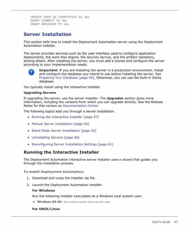
CREATE USER da IDENTIFIED by da;GRANT CONNECT TO da;GRANT RESOURCE TO da;
Server InstallationThis section tells how to install the Deployment Automation server using the DeploymentAutomation installer.
The server provides services such as the user interface used to configure applicationdeployments, the work flow engine, the security service, and the artifact repository,among others. After installing the server, you must add a license and configure the serveraccording to your implementation needs.
Important: If you are installing the server in a production environment, installand configure the database you intend to use before installing the server. SeePreparing Your Database [page 45]. Otherwise, you can use the built-in Derbydatabase.
You typically install using the interactive installer.
Upgrading Servers
If upgrading the server, use the server installer. The Upgrades section gives moreinformation, including the versions from which you can upgrade directly. See the ReleaseNotes for this version on Documentation Center.
The following topics lead you through a server installation.
• Running the Interactive Installer [page 47]
• Manual Server Installation [page 50]
• Silent Mode Server Installation [page 52]
• Uninstalling Servers [page 60]
• Reconfiguring Server Installation Settings [page 61]
Running the Interactive Installer
The Deployment Automation interactive server installer uses a wizard that guides youthrough the installation process.
To install Deployment Automation:
1. Download and unzip the installer zip file.
2. Launch the Deployment Automation installer.
For Windows
Run the following installer executable as a Windows local system user:
• Windows 64-bit: MicroFocusDA-Server64.exe
For UNIX/Linux
User's Guide 47

Run the following installer executable as a user with root privileges:
MicroFocusDA-Server.binNote: The interactive server installer is available only for Linux and AIX.For other UNIX platforms, you must manually install. See Manual ServerInstallation [page 50].
After the welcome dialog box appears, click Next
3. Accept the license agreement. Click Next.
4. Specify the path where you want to install Deployment Automation. Click Next.
5. In the General Program Settings dialog box, select the location where settings willbe saved. Click Change to select a different directory. Configure the followingoptions:
• Use existing settings
Select this option to install the server using existing settings and maintain thecurrent database.
• Skip database creation
Select this option if you are installing Deployment Automation on an additionalserver for high availability and do not want to overwrite the settings you providedduring the initial install.
If selected, decryption keys should be available in the DA profile. The propertyskipEncKeysCreation (default value: true) is automatically added toinstalled.properties located in the DA server directory. When the serverstarts, random encryption keys are not created in the profile directory even ifthey do not exist. Hard-coded encryption keys are used instead.
To add decryption keys, copy the folder enc-keys from <existing profilelocation>/conf/server to <new profile location>/conf/server. Restart theserver
• JMS connection port
Enter the JMS port that agents will use to connect to the server.
• Agent Mutual Authentication
Select this option to configure increased security between agents and the server.
Click Next.
6. In the Database Selection dialog box, select the type of database you will use.Click Next.
7. In the Database Details dialog box, edit the Database Connection String foryour database, and then enter the database user name and password.
Part 2: Installation
48 Deployment Automation
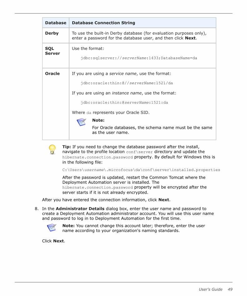
Database Database Connection String
Derby To use the built-in Derby database (for evaluation purposes only),enter a password for the database user, and then click Next.
SQLServer
Use the format:
jdbc:sqlserver://serverName:1433;DatabaseName=da
Oracle If you are using a service name, use the format:
jdbc:oracle:thin:@//serverName:1521/da
If you are using an instance name, use the format:
jdbc:oracle:thin:@serverName:1521:da
Where da represents your Oracle SID.
Note:
For Oracle databases, the schema name must be the sameas the user name.
Tip: If you need to change the database password after the install,navigate to the profile location conf\server directory and update thehibernate.connection.password property. By default for Windows this isin the following file:
C:\Users\username\.microfocus\da\conf\server\installed.propertiesAfter the password is updated, restart the Common Tomcat where theDeployment Automation server is installed. Thehibernate.connection.password property will be encrypted after theserver starts if it is not already encrypted.
After you have entered the connection information, click Next.
8. In the Administrator Details dialog box, enter the user name and password tocreate a Deployment Automation administrator account. You will use this user nameand password to log in to Deployment Automation for the first time.
Note: You cannot change this account later; therefore, enter the username according to your organization's naming standards.
Click Next.
User's Guide 49

9. In the Configuration Details dialog box, enter the port number for CommonTomcat. The default is 8080.
Note: For Windows installations, Common Tomcat is run under theWindows System Account by default. If it's necessary to run this under aspecific user, such as when you are using network shares that DeploymentAutomation must have permission to access as part of its core processing,you must change the login information in the Common Tomcat serviceproperties. The default service name is Micro Focus Common Tomcat 8.For details on changing Tomcat service properties, see the Apache Tomcatdocumentation.
Click Next.
10. Click Install. The Deployment Automation server installation finishes and thesummary dialog box appears.
The properties set during the server installation are recorded in theinstalled.properties file located in the profile directory. By default for Windows this is:
C:\Users\username\.microfocus\da\conf\server
Deployment Automation is installed and connected to your database. You can nowconfigure Deployment Automation by logging in to the Web application using theadministrator account that you created.
If you want to start configuring your system and defer agent installation until later,continue with Chapter 6: Administration Overview [page 107].
If you are ready to install agent relays or agents, continue with the respective section atAgent Relay Installation [page 63] or Agent Installation [page 78].
Manual Server InstallationIf you want to install the server on a UNIX platform other than Linux or AIX, you cannotuse the interactive or silent installers. Therefore, you will need to install manually usingthe following procedure.
If you do not need to manually install a server, either continue with one of the otherinstallation options as described in Server Installation [page 47] or continue with the nextstep in the Installation Checklist [page 41].
To install the server on UNIX platforms for which no interactive installer isprovided:
1. Prepare your database. For a typical UNIX/Linux installation, you should use Oracle.See Preparing Your Database [page 45].
Note: You should use Derby only if this installation is for evaluation or testpurposes. Derby is included in the da.war file and you configure it as partof the Deployment Automation configuration.
2. Install Tomcat if it is not already installed. If you can run the Common Tomcatinstaller, you should install that. If not, you must install Tomcat according to theApache instructions. See http://tomcat.apache.org/.
Part 2: Installation
50 Deployment Automation

• You must install the version of Tomcat supported by your version of DeploymentAutomation. For supported versions, see the Supported Platform List for yourversion of Deployment Automation on the Support website.
• You should NOT use the root user or super user to own and run Tomcat. Any newfiles created will be owned by the user running Tomcat, so this should be a userwho you want to be authorized to remove or overwrite any files under Tomcat.
• You should set 755 permissions for the Tomcat installation location.
• Before continuing, start Tomcat and verify that it is installed properly by enteringits URL in a web browser. For example: http://localhost:8080As only the owning user has write permission in the Tomcat location, this is theuser who should be used to start and stop Tomcat.
3. Download and install the JDBC driver specific to the database edition you are usingand save it in the Tomcat lib directory. For the Oracle JDBC driver, seehttp://www.oracle.com/technetwork/indexes/downloads/index.html.
4. Install JRE 8.0 if it is not already installed. See http://www.oracle.com/technetwork/java/javase/downloads/jre8-downloads-2133155.html. Set the necessaryenvironment variables for the owning user's session to point to this location, such asadding the JRE paths to the PATH environment variable and setting JAVA_HOME.
5. From the Support website, download the Deployment Automation Server WARInstaller (MicroFocusDA-Other.zip) and extract the da.war file.
6. Stop Tomcat.
7. Copy and paste the da.war file into your Common Tomcat webapps folder.
8. Start Tomcat. Starting Tomcat automatically unpacks the da.war file.
9. Launch a browser and navigate to http://serverName:8080/da.
The configuration setup displays.
10. Modify any configuration parameters as needed:
• Install location
• External Web URL
• Agent port and choice of mutual authentication
• Database (port, schema, user, password)
11. Click Install.
User's Guide 51

12. You should set 755 permissions for the profile directory and its subdirectories for theuser that the installation will run under. The default directory structure is: /opt/MicroFocus/da/microfocus/.microfocus/da
Note: The Deployment Automation repository, CodeStation, is under theprofile directory structure by default. If you relocate it, you need to set thesame level of permissions for the alternate location. See Relocating theRepository [page 180].
When the server installation is complete, the Deployment Automation login page displays.
Silent Mode Server InstallationYou can install a Deployment Automation server in silent mode if you want to automatethe installation.
This section contains information about how to implement a silent installation of theDeployment Automation server on Windows, Linux, and AIX. For other platforms, youmust manually install. See Manual Server Installation [page 50].
If you do not plan to install using silent mode but have not yet installed the server,continue with one of the other installation options as described in Server Installation[page 47]. If you have already installed your server, continue with the next step in theInstallation Checklist [page 41].
The following topics lead you through a silent mode server installation.
• (Windows) Server Silent Installation [page 52]
• (UNIX/Linux) Server Silent Installation [page 56]
(Windows) Server Silent Installation
You can install in silent mode as an alternative to using the interactive installer.
To install the server in silent mode:
1. Download the installation files.
2. Create an options file and save as C:/optionsFile.txt (see (Windows) ServerSilent Installation Options [page 53]).
3. In Windows as a local system user, issue the command:
cmd /c MicroFocusDA-Server.exe /s /V"/qn /L*vx "%TEMP%\silent-install.log" PROPFILE=\"c:\optionsFile.txt\" "Where:
• "%TEMP%\silent-install.log" is an absolute path to a log file.
• PROPFILE=\"c:\optionsFile.txt\" is an absolute path to the options file youcreated in Step 2.
• You have included the required space between the final two quotes.
For examples of the optionsFile.txt, see (Windows) Server Silent Installation:OptionsFile.txt Examples [page 54]).
Part 2: Installation
52 Deployment Automation

(Windows) Server Silent Installation Options
This section provides the list and description of the Windows silent installation options.
For examples of the option settings needed for each database type, see (Windows) ServerSilent Installation: OptionsFile.txt Examples [page 54].
Option Default/if notspecified
Description
AgreeToLicense No Must be set to Yes
USE_EXISTING_SETTINGS Set to UseExisting if you want to skipthe database installation andadministration part of the installation.
Important: Use only ifthere are existingDeployment Automationsettings populated in thedirectory specified by:SRA_USER_INSTALLDIR.
SRA_USER_INSTALLDIR c:\Documentsand Settings\→Administrator\→.microfocus\da
Directory in which to install the server,or if using theUSE_EXISTING_SETTINGS=→UseExisting option, the directorywhere your Deployment Automationsettings already exist.
SKIP_DB To skip the database creation, includeand set this option: SKIP_DB=SkipDB
Note: To use this option, theSRA_USER_INSTALLDIR mustnot already exist.
AGENT_MUTUAL_AUTH N If using agent mutual authentication,set this to Y. For more information,see Chapter 11: Secure Socket Layer(SSL) Configuration [page 167].
JMS_PORT 7918 Server port
DB_TYPE derby Use this to specify a database vendorother than the default: ORA|SQLSVR
<DB>_USER da Database user ID, where <DB> is:DERBY|ORA|SQLSVR
User's Guide 53

Option Default/if notspecified
Description
<DB>_PASSWORD password Password for the database user ID,where <DB> is: DERBY|ORA|SQLSVR
ORA_DB_SCHEMA Required for Oracle, the databaseschema
DERBY_PORT Required for Derby, specify the Derbyport 11377
<DB>_DB_CONN Required for databases other thanDerby, the database connection,where <DB> is ORA|SQLSVR
IS_INSTALL_MODE Required; installation mode must beset to silent
SRA_ADMIN Required installation owner'sadministration user name
CAUTION:
Once created, you cannotremove the built-inadministrative user throughthe user interface.Therefore, you should createthis user using yourorganization's namingstandards.
SRA_ADMIN_PWD Required user-defined password forthe user name set by the SRA_ADMINoption
TC_PORT 8080 Common Tomcat port, required onlyfor new installations
(Windows) Server Silent Installation: OptionsFile.txt Examples
This section contains examples of how to configure the installation options in anoptionsFile.txt file for a server silent installation on Windows.
Examples are given for Oracle and SQL Server as those are expected to be used in aproduction environment.
Part 2: Installation
54 Deployment Automation

Oracle Database optionsFile.txt exampleIn the following example, all defaults are used except for the TC_PORT, which is set to8081.
AgreeToLicense=YesSRA_USER_INSTALLDIR=C:\Documents and Settings\Administrator\.microfocus\daSKIP_DB=""AGENT_MUTUAL_AUTH=""JMS_PORT=7918DB_TYPE=oracleORA_DB_CONN=jdbc:oracle:thin:@//serverName:1521/daORA_DB_SCHEMA=daORA_PASSWORD=password123IS_INSTALL_MODE=silentSRA_ADMIN=admin1SRA_ADMIN_PWD=1TC_PORT=8081
MS SQL Server Database optionsFile.txt exampleIn the following example, all defaults are used except for the TC_PORT, which is set to8088.
AgreeToLicense=YesSRA_USER_INSTALLDIR=C:\Documents and Settings\Administrator\.microfocus\daSKIP_DB=""AGENT_MUTUAL_AUTH=""JMS_PORT=7918DB_TYPE=sqlserverSQLSVR_DB_CONN=jdbc:sqlserver://serverName:1433;DatabaseName=daSRA_ADMIN=admin1SRA_ADMIN_PWD=1SQLSVR_USER=daSQLSVR_PASSWORD=mypasswordIS_INSTALL_MODE=silentTC_PORT=8088
MS SQL Database "Skip Database Creation" optionsFile.txt exampleIn the following example, the SRA_USER_INSTALLDIR specified must not already exist.Using this optionsFile.txt file, because the SKIP_DB=skipDB option is specified, theDB_TYPE option cannot be set to derby, and the SRA_ADMIN and SRA_ADMIN_PWD optionscannot be set during the server installation.
AgreeToLicense=YesSRA_USER_INSTALLDIR=C:\Documents and Settings\Administrator\.microfocus\daSKIP_DB=SkipDBAGENT_MUTUAL_AUTH=""JMS_PORT=7918DB_TYPE=sqlserverSQLSVR_DB_CONN=jdbc:sqlserver://serverName:1433;DatabaseName=daSQLSVR_USER=daSQLSVR_PASSWORD=mypassword
User's Guide 55

IS_INSTALL_MODE=silentTC_PORT=8080
MS SQL Database "Use Existing Settings" optionsFile.txt exampleThis is an example of a new installation of the server that points to an existing profile. TheDeployment Automation profile location already exists as specified by theSRA_USER_INSTALLDIR option. Using this optionsFile.txt file, the server will be installedand the existing settings will be used for the installation.
AgreeToLicense=YesUSE_EXISTING_SETTINGS=UseExistingSRA_USER_INSTALLDIR=C:\Documents and Settings\Administrator\.microfocus\daSRA_ADMIN=admin1234SRA_ADMIN_PWD=password123TC_PORT=8080
(UNIX/Linux) Server Silent Installation
The following instructions are for silent installations of the server on platforms for whichthe server installer is provided, Linux and AIX.
To install the server in silent mode:
1. Download the installation files.
2. Create an optionsFile.txt and save it to the root directory. See (UNIX/Linux)Server Silent Installation Options.
3. As a user with root privileges, issue the command:
MicroFocusDA-Server.bin -silent -options optionsFile.txtWhere:
optionsFile.txt is a file that contains the properties you have set for your system.
For examples of the optionsFile.txt, see (UNIX/Linux) Server Silent Installation:optionsFile.txt Examples [page 59].
(UNIX/Linux) Server Silent Installation Options
This section provides the list and description of the UNIX/Linux silent installation options,and examples of the option settings needed for each type of database.
For examples of the option settings needed for each database type, see (UNIX/Linux)Server Silent Installation: optionsFile.txt Examples [page 59].
Option Default Description
-V IS_SELECTED_INSTALLATION_TYPEtypical Must be set to typical; do not
enclose in quotes
Part 2: Installation
56 Deployment Automation

Option Default Description
-P installLocationSpecify the directory into whichto install the DeploymentAutomation server. The –Pproperty is used by the silentinstallation tool as the locationto place files on disk. This shouldbe set to /opt/microfocus/da
-V ServerDetailsInstallLocSpecify the path to theDeployment Automation profilelocation. The value depends onthe user specified in the -VSctTomcatOwner option. Thisshould be set to:
/opt/microfocus/da/<SctTomcatOwnerValue>/.microfocus/da
-V ServerDetailsUseExistingfalse To skip the database installation
and administration part of theinstallation, include this and setit to true.
Important: Use onlyif there are existingDeploymentAutomation settingspopulated in thedirectory specified by:SRA_USER_INSTALLDIR.
-V ServerDetailsSkipDbfalse To skip the database creation,
include this and set it to true.
-V ServerDetailsPort7918 Server port
-V ServerDetailsMutualAuthfalse To use agent mutual
authentication, specify this andset it to true. For moreinformation, see Chapter 11:Secure Socket Layer (SSL)Configuration [page 167].
User's Guide 57

Option Default Description
-V SctFoundLocTo reuse an existing installationof Common Tomcat, specify thisand set it to true. When this isset to true, you must alsoinclude the SctInstallLocoption.
-V SctInstallLoc(Required) If you specify theSctFoundLoc option to reuse anexisting installation of CommonTomcat, you must use thisoption to specify the location ofthe existing Common Tomcat.
-V DbDetailsVendorderby Use this to specify a database
vendor other than the default:oracle or sqlserver
-V DbDetailsUserda Database user ID
-V DbDetailsPwdpassword Password for database user ID
-V DbDetailsDatabaseNameDatabase name (SQL Serveronly)
-V DbDetailsSchema(Required for Oracle) Databaseschema
-V dbDetailsDriverFilenameRequired for a database otherthan Derby; specify a databasedriver file.
Note:
The first "d" must belowercase in thisparameter only.
-V DbDetailsDerbyPortRequired for Derby, this specifiesthe Derby port, 11377
Part 2: Installation
58 Deployment Automation

Option Default Description
-V DbDetailsConnectionDatabase connection
-V IS_INSTALL_MODERequired; installation mode mustbe set to silent
-V AdminDetailsNameRequired installation owner'sadministration user name
CAUTION:
Once created, youcannot remove thebuilt-in administrativeuser through the userinterface. Therefore,you should create thisuser using yourorganization's namingstandards.
-V AdminDetailsPwdRequired user-defined passwordfor the username set by theAdminDetailsName option
-V SctTomcatOwnerSystem user to own theCommon Tomcat files, requiredonly for new Common Tomcatinstallations
-V SctTomcatPort8080 Common Tomcat port, required
only for new installations. Seethe SctFoundLoc option.
(UNIX/Linux) Server Silent Installation: optionsFile.txt Examples
This section contains examples of how to configure the installation options in anoptionsFile.txt file for a server silent installation on UNIX/Linux.
Examples are given for Oracle and SQL Server as those are expected to be used in aproduction environment.
Oracle Database optionsFile.txt example
-V IS_SELECTED_INSTALLATION_TYPE=typical-P installLocation="/opt/microfocus/da"-V ServerDetailsInstallLoc="/opt/microfocus/da/dmsys/.microfocus/da"
User's Guide 59

-V DbDetailsVendor="oracle"-V DbDetailsUser="User02"-V DbDetailsPwd="MyPassword"-V DbDetailsSchema="da"-V DbDetailsConnection="jdbc\:oracle\:thin\:@//serverName\:1521/sraoracle"-V ServerDetailsMutualAuth="false"-V IS_INSTALL_MODE="silent"-V AdminDetailsName="admin123"-V AdminDetailsPwd="mypassword123"-V SctTomcatOwner="dmsys"-V SctTomcatPort="8080"-V ServerDetailsSkipDb=false-V ServerDetailsUseExisting=false-V DbDetailsVendorDerby=false
MS SQL Server Database optionsFile.txt example
-V IS_SELECTED_INSTALLATION_TYPE=typical-P installLocation="/opt/microfocus/da"-V ServerDetailsInstallLoc="/opt/microfocus/da/dmsys/.microfocus/da"-V DbDetailsVendor="sqlserver"-V DbDetailsUser="User03"-V DbDetailsPwd="MyPassword"-V DbDetailsDatabaseName="da"-V DbDetailsConnection="jdbc\:jtds\:sqlserver\://serverName\:1433/da"-V ServerDetailsMutualAuth="false"-V IS_INSTALL_MODE="silent"-V AdminDetailsName="admin123"-V AdminDetailsPwd="mypassword123"-V SctTomcatOwner="dmsys"-V SctTomcatPort="8080"-V DbDetailsVendorDerby=false
Uninstalling ServersIf you need to uninstall your Deployment Automation server, use the provided uninstallexecutables as follows.
For Windows
Run the interactive installer for the version of the product that you have installed. This willdetect that you have an existing installation. Select the option to uninstall and follow theprompts to complete the uninstall process.
Run the following installer executable as a Windows local system user:
• Windows 64-bit: MicroFocusDA-Server64.exe
For UNIX/Linux
Navigate to the _uninst folder, for example /opt/microfocus/da/_uninst, and run thefollowing uninstall executable as a user with root privileges. Follow the prompts tocomplete the uninstall process.
uninstaller.bin
Part 2: Installation
60 Deployment Automation

Reconfiguring Server Installation SettingsIf you need to reconfigure server settings for any reason, you can reconfigure them usingthe following procedure. For example, you may need to use this procedure if you specifiedthe wrong connection information when you installed Deployment Automation.
To reconfigure the server settings:
1. Stop the application server where Deployment Automation is installed.
2. Navigate to the directory or folder where the web application is installed. Forexample:
C:\Program Files\Micro Focus\common\tomcat\8.5\webapps\da\conf
3. Backup the contents of the following file:
installed.properties
4. Edit the installed.properties file installLocation line to delete the path thatfollows the equal sign. You should have just the following on that line.
installLocation=
CAUTION:
There is another installed.properties file in the profile directory, somake sure you are only changing the one in the user interface serverdirectory structure.
5. Save the file.
6. Start the application server.
7. Enter the URL for the Deployment Automation user interface. For example:
http://serverName:8080/daThe configuration panel should appear instead of the login page.
8. Enter the server settings as follows:
Setting Description
InstallLocation
The path to the program installation location. For example:
(Windows)
C:\Users\<username>\.microfocus\da(UNIX/Linux)
/opt/microfocus/da
External WebURL
Specify the URL on which agents will be able to reach the server.
User's Guide 61

Setting Description
Agent Port Specify the port on which agents will make JMS connections tothe server.
Agent MutualAuthentication
Specify whether to use agent mutual authentication.
Skip DBInstall
Do not install the database schema or seed data as part of theinstall. Select this if installing to a second or more server in aclustered installation.
DatabaseVendor
Select the database vendor. For example, Derby.
Note: For example settings for all supported databaseselections, see the example settings used in SilentMode Agent Installation [page 82].
Derby Port The port that Derby should use for database connections
DatabaseUser
The user name to use to connect to the database
DatabasePassword
The password to use to connect to the database
ConfirmDatabasePassword
Confirm the password to be used by the Deployment Automationadministrator.
AdministratorUser
The user name to be used by the Deployment Automationadministrator
AdministratorPassword
The password to be used by the Deployment Automationadministrator
ConfirmAdministratorPassword
Confirm the password to be used by the Deployment Automationadministrator.
9. Click Install.
After you have saved the configuration settings, Deployment Automation detects that theconfiguration file exists and does not prompt you for them when the user interface isinvoked.
Part 2: Installation
62 Deployment Automation

Agent Relay InstallationDepending on the server configuration your organization needs, you may need to installone or more agent relays. If you are doing a basic installation of Deployment Automationand are not installing agent relays, skip this section and continue on to Agent Installation[page 78].
If you do plan to use agent relays, the agent relays must be installed before you canconnect agents to them. You can reconfigure agents to go through agent relays if youchange the configuration later. For information on configuring the server and agentcommunication, see Server and Agent Communication Configuration [page 75].
The following topics lead you through an agent relay installation.
• Interactive Agent Relay Installation [page 63]
• Child Relay Installation [page 64]
• Agent Relay Installation Options [page 65]
• Silent Mode Agent Relay Installation [page 67]
• Upgrading Agent Relays and Servers [page 74]
• Server and Agent Communication Configuration [page 75]
Interactive Agent Relay InstallationInstallation Prerequisites
Before installing an agent relay, ensure that:
• A supported version of Java is installed. See Agent Minimum Requirements [page45].
• The server with which the agent relay will connect is already installed.
Important: If you are installing on a 64-bit Linux system, be aware that theUNIX installers are 32-bit applications, and your system may not support 32-bitapplications by default. Before running the installer on a 64-bit Linux system,ensure that the following are installed:
• Motif: This is usually available by default
• 32-bit compatibility libraries: C/C++ runtime
To install an agent relay using the interactive installer:
1. Download the agent relay installation package from the Support website.
2. Expand the compressed installation bundle.
3. Ensure that the system environment variable JAVA_HOME is set to the correct pathfor the Java files. For example: JAVA_HOME=C:\Program Files\MicroFocus\common\jre\8.0
User's Guide 63

4. Ensure that the system environment variable PATH is set to the correct path for theJava executable. For example: PATH=%PATH%;C:\Program Files\MicroFocus\common\jre\8.0\bin
5. Open a command prompt and from the expanded agent-relay-install directory,run the installation script.
For Windows, run:
install.cmdFor UNIX/Linux platforms, run:
install.sh
6. The installation program will prompt you for the Agent Relay Installation Options[page 65]. Accept any default values suggested by the program, displayed withinbrackets, by pressing Enter. If two options are given, such as Y/n, the capitalizedoption is the default value.
After you complete the agent relay installation, continue to Agent Installation [page 78].
Child Relay InstallationYou can connect an agent relay to a DA server through another agent relay.
1. Perform a normal installation of an agent relay.
2. After the installation has finished, open this file:<relay_installation>\conf\agentrelay.properties
3. Specify values for the following properties:
• agentrelay.http_proxy.parent_proxy_host The IP or hostname of the parentagent relay.
• agentrelay.http_proxy.parent_proxy_port The http proxy port of the parentagent relay. Default: 20080
• agentrelay.jms_proxy.server_host The IP or hostname of the parent agentrelay.
• agentrelay.jms_proxy.server_port The port the parent agent relay uses forJMS communication. Default: 7916
Limitations:
• Only one level of connection is supported. The connection will look like this: DAserver <-> Agent relay 1 (parent) <-> Agent relay 2 (child) <-> Agent
• Unidirectional communication is only supported for parent agent relays.
• The maximum number of agent that can connect to child relays is 500. Exceedingthis number may cause connectivity issues.
Part 2: Installation
64 Deployment Automation

Agent Relay Installation OptionsWhen prompted by the installer, specify the options according to the information in thefollowing table. Where Windows and UNIX/Linux options differ, operating system-specificinformation is included.
Agent Relay Configuration Table
InstallationOption
Description
Please enter thedirectory whereyou would like toinstall the agentrelay.
Enter the directory where you want the agent relay installed. Ifit does not exist, you will be prompted on whether to create it.For example:
Windows
C:\Program Files\Micro Focus\agentrelayUnix/Linux
/opt/MicroFocus/agentrelay
Please enter yourjava home.
Enter the directory where Java is installed. Ensure that theJAVA_HOME environment variable points to this directory. Forexample:
Windows
C:\Program Files\Micro Focus\common\jre\8.0Unix/Linux
/opt/MicroFocus/common/jreImportant: On Windows, JRE 8.0 is required for anagent relay to be installed as a service. On allplatforms, to restrict the security protocols, you mustuse version Java 8.0.
Enter the name ofthis relay.
Enter the name of the agent relay. Each agent relay must have aunique name. The default name is agent-relay.
Enter the IP orhostname whichthis agent relayshould use
Enter the IP address or hostname on which the agent relay willlisten for HTTP requests coming from agents.
User's Guide 65

InstallationOption
Description
Enter the portwhich this agentrelay should proxyHTTP requests on
Enter the port on which the agent relay will listen for HTTPrequests coming from agents. The default is 20080.
Note: Agent relays can also communicate throughHTTPS. To ensure this, you must configure the serverto work through HTTPS and change the external agentlink to use HTTPS. Agents will then automaticallyconnect through HTTPS. Agent relays willautomatically use HTTPS when agents request HTTPSlinks.
Port which thisagent relay shoulduse forcommunication.
Enter the port on which the agent relay will use for JMS-basedcommunications with remote agents. The default is 7916.
Connect the agentrelay to a centralserver?
Specify whether you want the agent relay to connect to theDeployment Automation server as follows:
• Default: If you plan to use this agent relay in agent-initiatedcommunication, or active mode, enter Y. See Agent-initiatedHTTP Communication Using Agent Relays [page 76].
• If you plan to use this agent relay in server-initiatedcommunication or passive mode, enter n. By doing this, youwill have the option to select Server-Initiated for the agentrelay in the user interface. See Server-initiated HTTPCommunication Using Agent Relays [page 77].
Note: If you aren't sure, take the default (Y). If youwant to change it later, you can change this in theagentrelay.properties file located in therelay_installation\conf directory.
Enter the IP orhostname of yourcentral server
If you selected Y in the option to connect the agent relay to theserver, enter the IP or host name where the agent relay cancontact the server.
Enter the portwhich the centralserver uses forcommunication
If you selected Y in the option to connect the agent relay to theserver, enter the port the server uses to communicate withagents. The default is 7918.
Use mutualauthenticationbetween the agent,relay and server.
If mutual authentication is required, enter Y. For moreinformation, see Chapter 11: Secure Socket Layer (SSL)Configuration [page 167].
Part 2: Installation
66 Deployment Automation

InstallationOption
Description
Do you want toinstall the AgentRelay as Windowsservice?
If you are installing the agent relay on Windows, you can installit as a Windows service. The default value is N. If you specify Y,see the following table entries.
Enter a uniqueservice name forthe Agent Relay.No spaces please.
(Required for running as a Windows service) Enter a uniquename for the service. The default is agentrelay.
Enter the useraccount nameincluding domainpath to run theservice as (for localuse '.\.' beforelogin).
(Required for running as a Windows service) Enter an accountname, including the domain path under which to run the service.For a local user, insert ".\" before the user name. The default is.\localsystem
Enter the passwordfor the'.\localsystem' useraccount.
(Optional for running as a Windows service) Enter a passwordfor the Windows service user account name. The default is nopassword.
Do you want tostart the serviceautomatically?
(Required for running as a Windows service) Specify whether ornot (y|N) you want the Windows service to be startedautomatically. The default is N.
Note: If you need to change the agent relay configuration, you can edit theseproperties in the agentrelay.properties file located in the<relay_installation>\conf directory. You can also do some agent relaymanagement through the user interface. See Managing Agent Relays [page326].
Silent Mode Agent Relay InstallationThis section contains information about how to configure and run a silent installation of aDeployment Automation agent relay on Windows and UNIX/Linux platforms.
Important: Before you can run a silent install of an agent relay, you mustcreate and save an optionsFile.properties.
The following topics lead you through a silent mode agent relay installation.
• (Windows) Agent Relay Silent Installation [page 68]
• (UNIX/Linux) Agent Relay Silent Installation [page 71]
User's Guide 67

(Windows) Agent Relay Silent Installation
To install an agent relay in silent mode:
1. Download the appropriate agent relay installer for your platform.
2. Create an options file and save as:
C:/optionsFile.propertiesNote: Your optionsFile should be in ANSI format; the agent relay installerdoes not support UTF.
3. Issue the command:
install.cmd -silent -options optionsFile.propertieswhere
optionsFile.propertiesis the options file you created in Step 2.
(Windows) Agent Relay Silent Install Options
This section provides the list and description of the Windows agent relay silent installoptions.
For an example of the option settings, see (Windows) Agent Relay Silent Install OptionsExample [page 70].
Installation Option Description
AGENT_RELAY_HOME Enter the directory where you want the agent relayinstalled. If it does not exist, you will be promptedon whether to create it. For example:
C:\Program Files\Micro Focus\agentrelayNote: This is the only option that isrequired to run the agent relay silentinstallation. If only this property isincluded, the rest of the options will havethe default values.
JAVA_HOME Enter the directory where Java is installed. Ensurethat the JAVA_HOME environment variable points tothis directory. For example:
C:\Program Files\Micro Focus\common\jre\8.0
AGENT_RELAY_NAME Enter the name of the agent relay. Each agent relaymust have a unique name. The default name isagent-relay.
Part 2: Installation
68 Deployment Automation
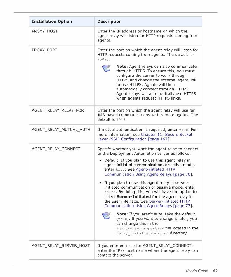
Installation Option Description
PROXY_HOST Enter the IP address or hostname on which theagent relay will listen for HTTP requests coming fromagents.
PROXY_PORT Enter the port on which the agent relay will listen forHTTP requests coming from agents. The default is20080.
Note: Agent relays can also communicatethrough HTTPS. To ensure this, you mustconfigure the server to work throughHTTPS and change the external agent linkto use HTTPS. Agents will thenautomatically connect through HTTPS.Agent relays will automatically use HTTPSwhen agents request HTTPS links.
AGENT_RELAY_RELAY_PORT Enter the port on which the agent relay will use forJMS-based communications with remote agents. Thedefault is 7916.
AGENT_RELAY_MUTUAL_AUTH If mutual authentication is required, enter true. Formore information, see Chapter 11: Secure SocketLayer (SSL) Configuration [page 167].
AGENT_RELAY_CONNECT Specify whether you want the agent relay to connectto the Deployment Automation server as follows:
• Default: If you plan to use this agent relay inagent-initiated communication, or active mode,enter true. See Agent-initiated HTTPCommunication Using Agent Relays [page 76].
• If you plan to use this agent relay in server-initiated communication or passive mode, enterfalse. By doing this, you will have the option toselect Server-Initiated for the agent relay inthe user interface. See Server-initiated HTTPCommunication Using Agent Relays [page 77].
Note: If you aren't sure, take the default(true). If you want to change it later, youcan change this in theagentrelay.properties file located in therelay_installation\conf directory.
AGENT_RELAY_SERVER_HOST If you entered true for AGENT_RELAY_CONNECT,enter the IP or host name where the agent relay cancontact the server.
User's Guide 69
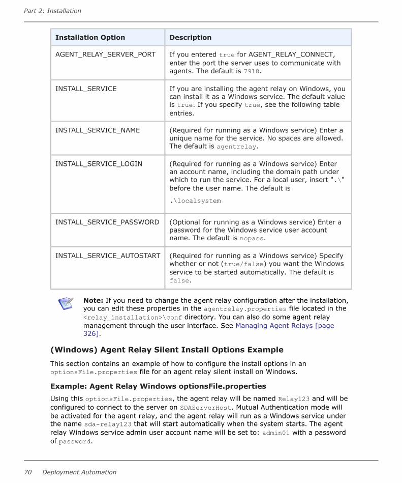
Installation Option Description
AGENT_RELAY_SERVER_PORT If you entered true for AGENT_RELAY_CONNECT,enter the port the server uses to communicate withagents. The default is 7918.
INSTALL_SERVICE If you are installing the agent relay on Windows, youcan install it as a Windows service. The default valueis true. If you specify true, see the following tableentries.
INSTALL_SERVICE_NAME (Required for running as a Windows service) Enter aunique name for the service. No spaces are allowed.The default is agentrelay.
INSTALL_SERVICE_LOGIN (Required for running as a Windows service) Enteran account name, including the domain path underwhich to run the service. For a local user, insert ".\"before the user name. The default is
.\localsystem
INSTALL_SERVICE_PASSWORD (Optional for running as a Windows service) Enter apassword for the Windows service user accountname. The default is nopass.
INSTALL_SERVICE_AUTOSTART (Required for running as a Windows service) Specifywhether or not (true/false) you want the Windowsservice to be started automatically. The default isfalse.
Note: If you need to change the agent relay configuration after the installation,you can edit these properties in the agentrelay.properties file located in the<relay_installation>\conf directory. You can also do some agent relaymanagement through the user interface. See Managing Agent Relays [page326].
(Windows) Agent Relay Silent Install Options Example
This section contains an example of how to configure the install options in anoptionsFile.properties file for an agent relay silent install on Windows.
Example: Agent Relay Windows optionsFile.propertiesUsing this optionsFile.properties, the agent relay will be named Relay123 and will beconfigured to connect to the server on SDAServerHost. Mutual Authentication mode willbe activated for the agent relay, and the agent relay will run as a Windows service underthe name sda-relay123 that will start automatically when the system starts. The agentrelay Windows service admin user account name will be set to: admin01 with a passwordof password.
Part 2: Installation
70 Deployment Automation

AGENT_RELAY_HOME=C:\Program Files\Micro Focus\agentrelayJAVA_HOME=C:\Program Files\Micro Focus\common\jre\8.0AGENT_RELAY_NAME=Relay123PROXY_HOST=0.0.0.0PROXY_PORT=20080AGENT_RELAY_RELAY_PORT=7916AGENT_RELAY_MUTUAL_AUTH=trueAGENT_RELAY_CONNECT=trueAGENT_RELAY_SERVER_HOST=DAServerHostAGENT_RELAY_SERVER_PORT=7918INSTALL_SERVICE=trueINSTALL_SERVICE_NAME=sda-relay123INSTALL_SERVICE_LOGIN=admin01INSTALL_SERVICE_PASSWORD=passwordINSTALL_SERVICE_AUTOSTART=true
(UNIX/Linux) Agent Relay Silent Installation
The following instructions are for silent installations of agent relays.
Important: If you are installing on a 64-bit Linux system, be aware that theUNIX installers are 32-bit applications, and your system may not support 32-bitapplications by default. Before running the installer on a 64-bit Linux system,ensure that the following are installed:
• Motif: This is usually available by default
• 32-bit compatibility libraries: C/C++ runtime
To install an agent relay in silent mode:
1. Download the appropriate agent relay installer for your platform.
2. Create an options file and save as:
optionsFile.propertiesNote: Your optionsFile should be in ANSI format; the agent relayinstaller does not support UTF.
3. Issue the command:
install.sh –silent –options optionsFile.propertieswhere
optionsFile.propertiesis the options file you created in Step 2.
(UNIX/Linux) Agent Relay Silent Install Options
This section provides the list and description of the UNIX/Linux agent relay silent installoptions.
For an example of the option settings, see (UNIX/Linux) Agent Relay Silent Install OptionsExample [page 73].
User's Guide 71

Installation Option Description
AGENT_RELAY_HOME Enter the directory where you want the agent relayinstalled. If it does not exist, you will be prompted onwhether to create it. For example:
/opt/MicroFocus/agentrelayNote: This is the only option that isrequired to run the agent relay silentinstallation. If only this property is included,the rest of the options will have the defaultvalues.
JAVA_HOME Enter the directory where Java is installed. Ensurethat the JAVA_HOME environment variable points tothis directory. For example:
/opt/MicroFocus/common/jre
AGENT_RELAY_NAME Enter the name of the agent relay. Each agent relaymust have a unique name. The default name isagent-relay.
PROXY_HOST Enter the IP address or hostname on which the agentrelay will listen for HTTP requests coming fromagents.
PROXY_PORT Enter the port on which the agent relay will listen forHTTP requests coming from agents. The default is20080.
Note: Agent relays can also communicatethrough HTTPS. To ensure this, you mustconfigure the server to work through HTTPSand change the external agent link to useHTTPS. Agents will then automaticallyconnect through HTTPS. Agent relays willautomatically use HTTPS when agentsrequest HTTPS links.
AGENT_RELAY_RELAY_PORT Enter the port on which the agent relay will use forJMS-based communications with remote agents. Thedefault is 7916.
AGENT_RELAY_MUTUAL_AUTH If mutual authentication is required, enter true. Formore information, see Chapter 11: Secure SocketLayer (SSL) Configuration [page 167].
Part 2: Installation
72 Deployment Automation

Installation Option Description
AGENT_RELAY_CONNECT Specify whether you want the agent relay to connectto the Deployment Automation server as follows:
• Default: If you plan to use this agent relay inagent-initiated communication, or active mode,enter true. See Agent-initiated HTTPCommunication Using Agent Relays [page 76].
• If you plan to use this agent relay in server-initiated communication or passive mode, enterfalse. By doing this, you will have the option toselect Server-Initiated for the agent relay in theuser interface. See Server-initiated HTTPCommunication Using Agent Relays [page 77].
Note: If you aren't sure, take the default(true). If you want to change it later, youcan change this in theagentrelay.properties file located in the<relay_installation>\conf directory.
AGENT_RELAY_SERVER_HOST If you entered true for AGENT_RELAY_CONNECT,enter the IP or host name where the agent relay cancontact the server.
AGENT_RELAY_SERVER_PORT If you entered true for AGENT_RELAY_CONNECT,enter the port the server uses to communicate withagents. The default is 7918.
AGENTRELAY_USER UNIX/Linux user name under which to run the agentrelay.
AGENTRELAY_GROUP UNIX/Linux group name under which to run the agentrelay.
Note: If you need to change the agent relay configuration after the installation,you can edit these properties in the agentrelay.properties file located in the<relay_installation>\conf directory. You can also do some agent relaymanagement through the user interface. See Managing Agent Relays [page326].
(UNIX/Linux) Agent Relay Silent Install Options Example
This section contains an example of how to configure the install options in anoptionsFile.properties file for an agent relay silent install on UNIX/Linux.
User's Guide 73

Example: Agent Relay UNIX/Linux optionsFile.propertiesUsing this optionsFile.properties, the agent relay will be named Relay123 and will beconfigured to connect to the server on SDAServerHost. Mutual Authentication mode willbe activated for the agent relay.
AGENT_RELAY_HOME=/opt/MicroFocus/agentrelayJAVA_HOME=/opt/MicroFocus/common/jreAGENT_RELAY_NAME=Relay123PROXY_HOST=0.0.0.0PROXY_PORT=20080AGENT_RELAY_RELAY_PORT=7916AGENT_RELAY_MUTUAL_AUTH=trueAGENT_RELAY_CONNECT=trueAGENT_RELAY_SERVER_HOST=DAServerHostAGENT_RELAY_SERVER_PORT=7918AGENTRELAY_USER=agentrelayAGENTRELAY_GROUP=agentrelay
Upgrading Agent Relays and ServersWhen upgrading agent relays, make sure to follow the following recommended upgradeorder for agent relays and servers.
Upgrade Sequence for Agent Relays and Servers
1. Shut down all agent relays.
2. Shut down all servers to which the agent relays you are upgrading are pointing.
3. Upgrade all the agent relays according to the instructions in the following section.
4. If upgrading the server, upgrade the server using the server installer. See theRelease Notes Upgrades section for information on versions from which you canupgrade directly.
Note: Agent relays for version 5.1.5 and later that are configured forserver-initiated connection are compatible only with DeploymentAutomation servers version 5.1.5 and later. You cannot connect to version5.1.5 and later agent relays through network relays as was possible inearlier server versions. If you attempt to do this, the agents connectedthrough the agent relay will not be in Online status.
Note: Agent relays version 6.3 and earlier that are configured for server-initiated connections must be upgraded to version 6.3.1 to connect toserver version 6.3.1 (and later).
5. Start the server.
6. Start the agent relays.
Agent Relay Upgrade Instructions
To upgrade your agent relays:
1. Ensure the agent relay is stopped.
Part 2: Installation
74 Deployment Automation

2. Run the agent relay installer. See Agent Relay Installation [page 63].
3. When prompted for the destination directory, enter the path to the directory of theexisting agent relay location.
4. When prompted to upgrade, enter Y.
After upgrading your agent relays and starting the servers and agent relays, navigate toManagement > Resources > Relays. You should see all your upgraded agent relayslisted. It may take some time before the agent relays come online.
See Managing Agent Relays [page 326] for information on configuring agent relays.
Server and Agent Communication ConfigurationServers and agents communicate either directly or through an agent relay. If an agentrelay is used, the agent connects to the server through the agent relay, and the agentrelay manages the requests to the server.
If your agents are dispersed across geographic locations or must communicate throughfirewalls, you should configure the agents to connect to the server through agent relays.You should also use agent relays to manage network traffic in implementations where youhave many agents, even if they are on the same network and don't necessarily have to gothrough firewalls.
Once a JMS connection is established between the server and the agent, regardless ofwhether an agent relay is used, that connection is kept open as long as the entitiesinvolved are online. The server provides HTTP endpoints that the agents trigger toperform service operations. The most common HTTP operations are as follows. All of theseoperations are initiated by agents by default.
• Download plugins
• Check plugin versions
• Upload log steps
• Download files
• Upload files
You can configure agent-server communication as follows:
• Agent-to-Server: To configure your agents to communicate directly with the server,when installing the agents, point the agents to the server.
• Agent-initiated with Agent Relay: To configure your agents and servers foragent-initiated HTTP communication through agent relays, do the following:
▪ When installing and configuring the agent relays, enter Y when prompted forwhether to connect to the server. This is the default setting. When a process isrunning, the agent relay will connect to the server.
▪ When installing the agents, point the agents to the agent relay instead of directlyto the server.
• Server-initiated with Agent Relay: To configure your agents and servers forserver-initiated HTTP communication, do the following:
User's Guide 75
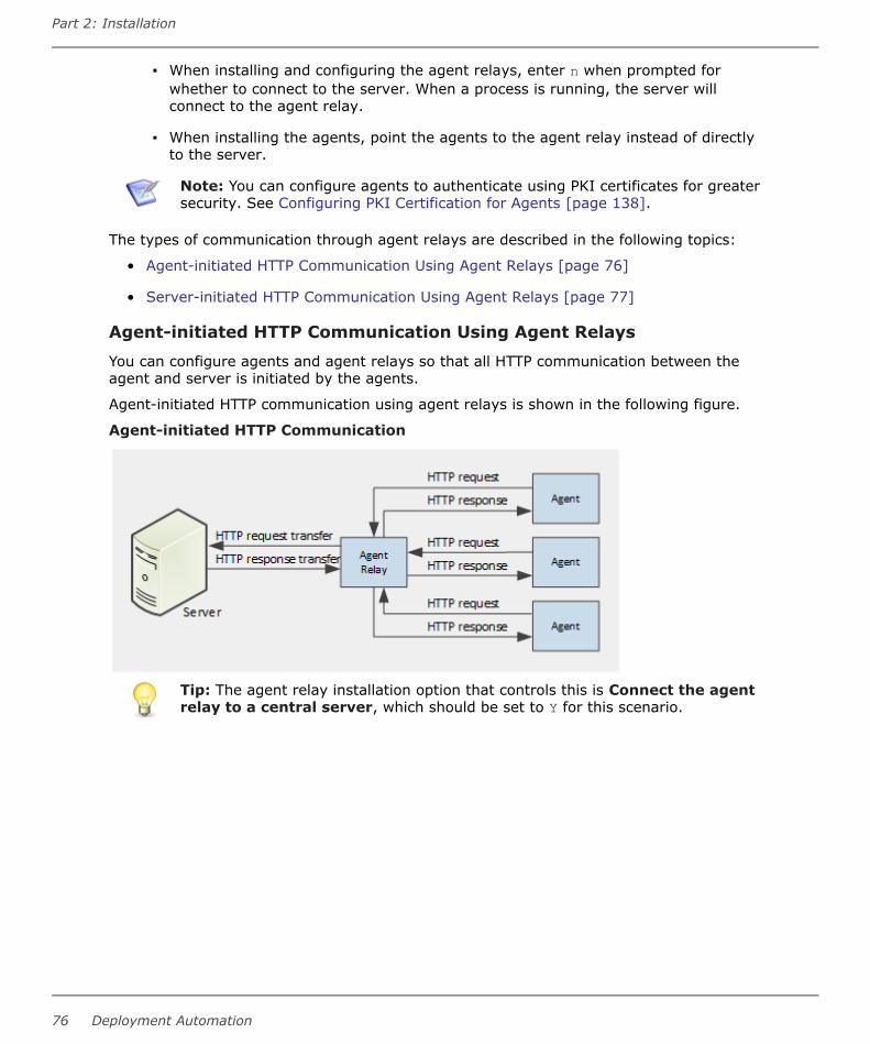
▪ When installing and configuring the agent relays, enter n when prompted forwhether to connect to the server. When a process is running, the server willconnect to the agent relay.
▪ When installing the agents, point the agents to the agent relay instead of directlyto the server.
Note: You can configure agents to authenticate using PKI certificates for greatersecurity. See Configuring PKI Certification for Agents [page 138].
The types of communication through agent relays are described in the following topics:
• Agent-initiated HTTP Communication Using Agent Relays [page 76]
• Server-initiated HTTP Communication Using Agent Relays [page 77]
Agent-initiated HTTP Communication Using Agent Relays
You can configure agents and agent relays so that all HTTP communication between theagent and server is initiated by the agents.
Agent-initiated HTTP communication using agent relays is shown in the following figure.
Agent-initiated HTTP Communication
Tip: The agent relay installation option that controls this is Connect the agentrelay to a central server, which should be set to Y for this scenario.
Part 2: Installation
76 Deployment Automation

Server-initiated HTTP Communication Using Agent Relays
You can configure agents and agent relays so that the server initiates the upload of HTTPrequests over a designated size. This enables the server to control the traffic across thenetwork so that the volume of incoming requests from many agents does not overload thenetwork. The agent still initiates the HTTP request as part of the process being executed,and a certain amount of information is passed through to the server on every request.However, the agent relay suspends any HTTP requests that are too large to pass throughdirectly and enables the server to process them when it is ready.
Note:
• This type of communication is sometimes referred to as unidirectionalcommunication, and the agent relay is referred to as passive, because theserver is initiating and regulating the HTTP communication.
• Only the inbound JMS port needs to be opened and the server initiates allcommunications over the JMS tunnel.
Server-initiated HTTP communication using agent relays is shown in the following figure.
Server-initiated HTTP Communication
1. Agents send concurrent requests through HTTP. Requests 1a, 1b and 1c will beprocessed concurrently, but the figure shows only the processing of request 1a.
2. Every request coming to an agent relay from an agent will be put on hold before theresponse from the server is provided. All the requests coming from agents will bequeued on an agent relay. The agent relay processes the requests and assigns aninternal ID to each of them.
3. The server periodically polls the agent relay, and detects that the agent relay has anincoming request. The agent relay sends the request ID information to the serverusing JMS.
4. When the server receives the request ID, it sends an HTTP request to get therequest body from the agent relay.
Depending on the size of the initial request, this step may be omitted. For smallrequests, the body can be transferred using JMS during the previous step.
5. After the server receives the body of the request, it processes it as needed.
User's Guide 77

6. After processing the request, the server sends the response to the agent relay.
7. The agent relay returns the response to the agent from the agent relay using HTTP.
Tip: The agent relay installation option that controls this is Connect the agentrelay to a central server, which should be set to n for this scenario.
Agent InstallationYou must install at least one agent for a basic installation. You can install agents onsupported operating systems using an interactive installer, a silent installer, consoleinstallation mode, or manual installation steps.
CAUTION:
Windows: the agent installer uses a standard distribution technique of the JREthat redistributes the Java runtime files in accordance with Java standards. Thiscreates a private JRE instance that will not interfere with other Java applicationsthat are installed. However, if you create references to the Java files that areinstalled by the agent, or if you interfere with the agent's private installationdirectory, you may corrupt other existing Java applications on the host machine.
Note: Solaris: download and install a Solaris JRE 8 before running the agentinstaller. To run the installer, specify the path to the JRE: SerenaDA-agent.bin-is:javahome <path to local JRE>
Multiple Agents on Multiple Machines
If you plan to run deployments on several machines, a separate agent with a unique nameshould be installed on each machine. If, for example, your testing environment consists ofthree machines, install an agent on each one. Follow the same procedure for eachenvironment the application uses.
Multiple Agents on One Machine
If you plan to install multiple agents on a single machine, make sure that all names areunique: installation directory name, agent name, and service name, if running the agentas a service.
Installing Agents Remotely
For UNIX environments, you can install agents remotely through the user interface. SeeInstalling Agents Remotely [page 321].
Upgrading Agents
Agents are upgraded through the user interface. See Upgrading Agents [page 324].
The following topics lead you through an agent installation.
• Interactive Agent Installation [page 79]
• Silent Mode Agent Installation [page 82]
• Uninstalling Agents [page 87]
• About Agent Upgrades [page 88]
• Installing and Configuring the z/OS Agent [page 89]
Part 2: Installation
78 Deployment Automation

Interactive Agent InstallationThe interactive agent installer uses a wizard that guides you through the installationprocess.
For Windows
Run the following installer executable as a Windows local system user:
DA-agent.exeFor UNIX/Linux
Important: If you are installing on a 64-bit Linux system, be aware that theUNIX installers are 32-bit applications, and your system may not support 32-bitapplications by default. Before running the installer on a 64-bit Linux system,ensure that the following are installed:
• Motif: This is usually available by default
• 32-bit compatibility libraries: C/C++ runtime
Run the following installer executable as a user with full access rights to the installationlocation:
DA-agent.binNote:
• The interactive agent installer is available for Linux, AIX, Solaris SPARCand x86, and HPUX Itanium.
• To run the interactive installer in console mode, use:
DA-agent.bin -console
For Solaris
Run the following installer executable as a user with full access rights to the installationlocation:
SerenaDA-agent.bin -is:javahome <path to local JRE>Installation options
You can add agent installer options in this format:
MicroFocusDA-agent.bin [Option] [Parameter]• -is:javahome <dir> Specifies the JRE home that points to the directory containing
bin/java. Do not include spaces in the path.
• -is:tempdir <dir> Specifies a temporary directory used by the installer. Do notinclude spaces in the path.
• -cp:a <classpath> Append a classpath to the installer.
• -cp:p <classpath> Prepend a classpath to the installer.
• -is:log <filename> Specify a filename for log debug messages.
• -is:extract Extracts the contents of the archive.
User's Guide 79

• -is:nospacecheck Turns off installer disk space checker.
• -is:version Returns the installer version and exits.
• -is:help Prints this help and exits.
Specify additional installation information as follows.
Agent Installation Options
In the agent installation wizard panels, specify the options according to the information inthe following table. Where Windows and UNIX/Linux options differ, operating system-specific information is included.
Option Description
Install DeploymentAutomation Agent to
Specify the location into which the agent will be installed.For example:
Windows:
C:\Program Files (x86)\Micro Focus\DeploymentAutomation AgentUNIX/Linux:
/opt/Micro \ Focus/Deployment Automation Agent
Agent Name Specify the name of the agent. The agent name should beunique.
Server AgentCommunication to useMutual Authenticationwith SSL
Select this if mutual authentication will be used with theserver. For more information, see Chapter 11: SecureSocket Layer (SSL) Configuration [page 167].
Will the agent connect toan agent relay instead ofdirectly to the server?
Select Yes to use an agent relay. Default: No
Hostname or address If an agent relay is being used, specify the hostname ofthe agent relay. Default: localhost
Agent RelayCommunication Port
If an agent relay is being used, specify the port numberthat will be used for JMS communication with the agentrelay. Default: 7916
HTTP Proxy Port If an agent relay is being used, specify the proxy portnumber of the agent relay for HTTP communication.Default: 20080
Part 2: Installation
80 Deployment Automation
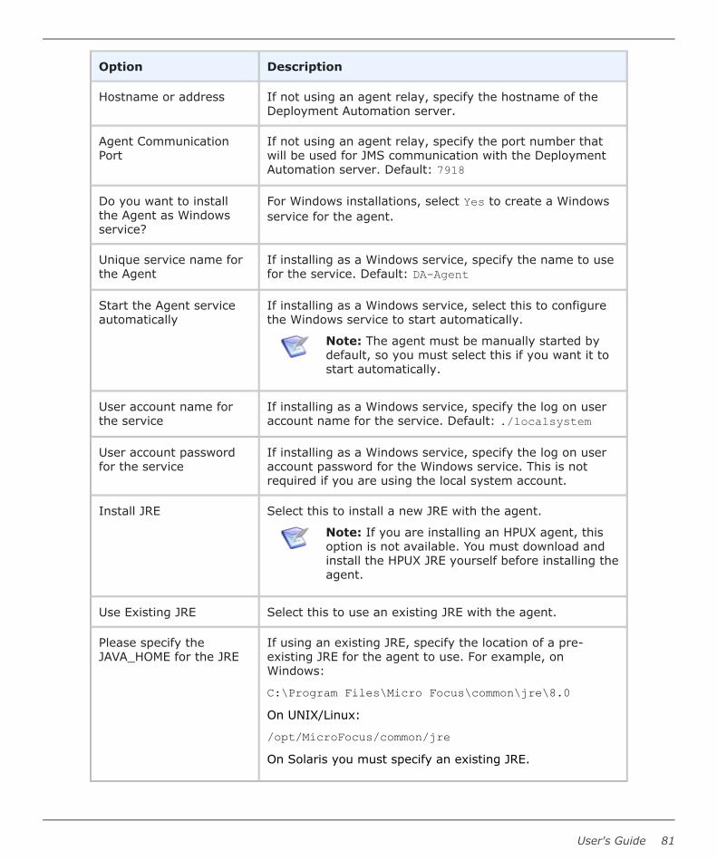
Option Description
Hostname or address If not using an agent relay, specify the hostname of theDeployment Automation server.
Agent CommunicationPort
If not using an agent relay, specify the port number thatwill be used for JMS communication with the DeploymentAutomation server. Default: 7918
Do you want to installthe Agent as Windowsservice?
For Windows installations, select Yes to create a Windowsservice for the agent.
Unique service name forthe Agent
If installing as a Windows service, specify the name to usefor the service. Default: DA-Agent
Start the Agent serviceautomatically
If installing as a Windows service, select this to configurethe Windows service to start automatically.
Note: The agent must be manually started bydefault, so you must select this if you want it tostart automatically.
User account name forthe service
If installing as a Windows service, specify the log on useraccount name for the service. Default: ./localsystem
User account passwordfor the service
If installing as a Windows service, specify the log on useraccount password for the Windows service. This is notrequired if you are using the local system account.
Install JRE Select this to install a new JRE with the agent.
Note: If you are installing an HPUX agent, thisoption is not available. You must download andinstall the HPUX JRE yourself before installing theagent.
Use Existing JRE Select this to use an existing JRE with the agent.
Please specify theJAVA_HOME for the JRE
If using an existing JRE, specify the location of a pre-existing JRE for the agent to use. For example, onWindows:
C:\Program Files\Micro Focus\common\jre\8.0On UNIX/Linux:
/opt/MicroFocus/common/jreOn Solaris you must specify an existing JRE.
User's Guide 81

Silent Mode Agent InstallationThis section contains information about how to configure and run a silent installation of aDeployment Automation agent on Windows and UNIX/Linux platforms.
Important: Before you can run a silent install of an agent, you must create andsave an optionsFile.txt.
The following topics lead you through a silent mode agent installation.
• (Windows) Agent Silent Installation [page 82]
• (UNIX/Linux) Agent Silent Installation [page 85]
(Windows) Agent Silent Installation
To install an agent in silent mode:
1. Download the appropriate agent installer for your platform.
2. Create an options file and save as:
C:/optionsFile.propertiesNote: Your optionsFile should be in ANSI format; the agent installer doesnot support UTF.
3. Issue the command:
c:\agent-relay-install\install.cmd -silent -optionsoptionsFile.propertieswhere
optionsFile.propertiesis the options file you created in Step 2.
(Windows) Agent Silent Installation Options
This section provides the list and description of the Windows agent silent installationoptions.
For examples of the option settings, see (Windows) Agent Silent Installation OptionsExample [page 84].
Option Description
-P installLocation(Required) The location into which the agent will beinstalled
-V IS_DESTINATION(Required) Location into which the agent will be installed
Part 2: Installation
82 Deployment Automation

Option Description
-V AgentName(Required) Name of the agent. You can also specifyproperties that are resolved dynamically on the server.For more information see Dynamically RegisteringAgents [page 324].
-V UseRelayYes(Required) To use an agent relay set this to true, if not,set it to false.
-V RelayHost(Required only if -V UseRelayYes=true is specified) Thehostname of the agent relay to be used
-V RelayPort(Required only if -V UseRelayYes=true is specified) Theport number of the agent relay to be used
-V RelayProxyPort(Required only if -V UseRelayYes=true is specified) Theproxy port number of the agent relay
-V ServerHost(Required if -V UseRelayYes=false) The hostname ofthe Deployment Automation server
-V ServerPort(Required if -V UseRelayYes=false) The port numberof the Deployment Automation server
-V ServerMutAuth(Required) If mutual authentication will be used with theserver, set this to true; otherwise, set it to false. Formore information, see Chapter 11: Secure Socket Layer(SSL) Configuration [page 167].
-V JreNew(Required) To install a new JRE with the agent, set thisto true, otherwise set it to false.
-V JreInstallLoc(Required if -V JreNew=false) Use this to specify thelocation of a pre-existing JRE for the agent to use.
-V ServiceYes(Windows Required) To create a Windows service for theagent, set this to true; otherwise, set it to false. Thisoption is valid only for Windows systems.
User's Guide 83

Option Description
Note: The following fields are only required when you specify -VServiceYes=True and only apply to Windows systems.
-V ServiceNameRequired only when -V ServiceYes=True is specified.The name to use for the Windows service.
-V ServiceStartAutoRequired only when -V ServiceYes=True is specified.To configure the Windows service to start automatically,set to true, if not set to false.
-V ServiceAccNameRequired only when -V ServiceYes=True is specified.To specify the log on user account name for theWindows service.
-V ServiceAccPassRequired only when -V ServiceYes=true is specified.To specify the log on user account password for theWindows service.
(Windows) Agent Silent Installation Options Example
This section contains an example of how to configure the installation options in anoptionsFile.txt file for an agent silent installation on Windows.
Example: Agent Windows optionsFile.txtUsing this optionsFile.txt, the agent will be named agent123, be configured to connectdirectly to the server on serverabc (not through an agent relay), and will point to a newinstallation of a JRE. Mutual Authentication mode will be activated for the agent, and theagent will run as a Windows service under the name SRA-Agent123 that will startautomatically when the system starts. The agent Windows service admin user accountname will be set to: admin01, with the password: password.
-P installLocation="C:\Program Files (x86)\Micro Focus\Deployment Automation Agent"-V IS_DESTINATION="C:\Program Files (x86)\Micro Focus\Deployment Automation Agent"-V AgentName="agent123"-V UseRelayYes="false"-V ServerHost="serverabc"-V ServerPort="7918"-V ServerMutAuth="true"-V ServiceYes="true"-V ServiceName="da-agent123"-V ServiceStartAuto="true"-V ServiceAccName="admin01"-V ServiceAccPass="password"-V JreNew="true"
Part 2: Installation
84 Deployment Automation

(UNIX/Linux) Agent Silent Installation
The following instructions are for silent installations of agents on platforms for which theagent installer is provided. These include Linux, AIX, Solaris SPARC, and HPUX Itaniumplatforms.
Important: If you are installing on a 64-bit Linux system, be aware that theUNIX installers are 32-bit applications, and your system may not support 32-bitapplications by default. Before running the installer on a 64-bit Linux system,ensure that the following are installed:
• Motif: This is usually available by default
• 32-bit compatibility libraries: C/C++ runtime
To install an agent in silent mode:
1. Download the appropriate agent installer for your platform.
2. Create an options file and save as:
optionsFile.txtNote: Your optionsFile should be in ANSI format; the agent installer doesnot support UTF.
3. Issue the command:
DA-agent.bin –silent –options optionsFile.txtwhere
optionsFile.txtis the options file you created in Step 2.
(UNIX/Linux) Agent Silent Installation Options
This section provides the list and description of the UNIX/Linux silent installation options,and examples of the option settings.
For examples of the option settings, see (UNIX/Linux) Server Silent Installation:optionsFile.txt Examples [page 59].
Option Description
-P installLocation(Required) Location into which the agent will be installed.
-V IS_DESTINATION(Required) Location into which the agent will be installed.
User's Guide 85

Option Description
-V AgentName(Required) Name of the agent. You can also specifyproperties that are resolved dynamically on the server.For more information see Dynamically Registering Agents[page 324].
-V UseRelayYes(Required) To use an agent relay set to true, if not, setto false.
-V RelayHost(Required only if -V UseRelayYes="true" is specified.)The hostname of the agent relay to be used.
-V RelayPort(Required only if -V UseRelayYes="true" is specified.)The port number of the agent relay to be used.
-V RelayProxyPort(Required only if -V UseRelayYes="true" is specified.)The proxy port number of the agent relay.
-V ServerHost(Required if -V RelayPortYes="false") The hostame ofthe Deployment Automation server.
-V ServerPort(Required if -V UseRelayYes="false") The port numberof the Deployment Automation server.
-V ServerMutAuth(Required) If mutual authentication will be used with theserver set to true, otherwise set to false. For moreinformation, see Chapter 11: Secure Socket Layer (SSL)Configuration [page 167].
-V JreNew(Required) To install a new JRE with the agent, set totrue, if not then set to false.
Note: If you are installing an HPUX or Solarisagent, this option must be set to false. Youmust download and install the HPUX or SolarisJRE yourself before installing the agent.
-V JreInstallLoc(Required if -V JreNew="false") To specify the locationof a pre-existing JRE for the agent to use.
Part 2: Installation
86 Deployment Automation

Option Description
-V ServiceYes(Windows Required) To create a Windows service for theagent, set to true, otherwise set to false. This option isonly valid for Windows systems.
(UNIX/Linux) Agent Silent Installation Options Examples
This section contain examples of optionsFile.txt file configurations for an agent silentinstallation on a Linux or a UNIX platform.
Example 1: Agent UNIX/Linux platforms optionsFile.txtUsing this optionsFile.txt, during installation the agent will be configured to connectdirectly with the server on serverabc (not through an agent relay), will turn mutualauthentication mode on for the agent and install a new JRE.
-P installLocation="/opt/Micro \ Focus/Deployment Automation Agent"-V IS_DESTINATION="/opt/Micro \ Focus/Deployment Automation Agent"-V AgentName="agent123"-V UseRelayYes="false"-V ServerHost=serverabc-V ServerPort="7918"-V ServerMutAuth="true"-V JreNew="true"
Example 2: Agent UNIX/Linux platforms optionsFile.txtUsing this optionsFile.txt, during installation the agent will be configured to use anagent relay named relayagent01 on port 7916 to connect to the server. MutualAuthentication for the agent will be turned on, and the agent will be configured to point toand use the JRE that currently exists in: /opt/Java/.
-P installLocation="/opt/Micro \ Focus/Deployment Automation Agent"-V IS_DESTINATION="/opt/Micro \ Focus/Deployment Automation Agent"-V AgentName="agentABC"-V UseRelayYes="true"-V RelayHost="relayagent01"-V RelayPort="7916"-V ServerMutAuth="true"-V JreNew="false"-V JreInstallLoc="/opt/Java/"
Uninstalling AgentsYou can inactivate agents and delete them from servers through the web application.However, if you want to completely uninstall the agent files from an agent machine, youcan uninstall as follows.
For Windows
User's Guide 87

Run the following interactive uninstaller executable in the installation path _uninstsubdirectory as a Windows local system user. For example:
C:\Program Files (x86)\Micro Focus\Deployment AutomationAgent\_uninst\uninstaller.exeFor UNIX/Linux
The uninstall process for UNIX/Linux agents is manual.
To uninstall a UNIX/Linux agent:
1. Stop and kill all agent processes as follows:
a. Stop the agent:
i. Navigate to the installation directory core/bin subdirectory. For example:
cd /opt/Micro \ Focus/Deployment \ Automation \ Agent/core/bin
ii. Source the agent service executable using the stop parameter. For example:
./sraagent stop
b. Find the process IDs and kill them. Typically there are two processes, althoughthe previous step should have stopped them.
i. Enter a command to list any processes of the name Deployment AutomationAgent. For example:
ps -ef | grep "Deployment Automation Agent"
ii. If you find any processes running for Deployment Automation Agent, enterthe command to kill each process using the corresponding process ID.
kill <pid>
2. Once the agent processes are stopped and killed, remove the following directories:
a. Installation files: /opt/Micro \ Focus/Deployment Automation Agent
b. Inventory files (if found): /tmp/microfocus/var/
c. Temp install files (if found): /tmp/da_agent_install
About Agent UpgradesAfter upgrading to a new version of the server or receiving notice of available agentupgrades, you can upgrade your agents from the Deployment Automation user interface.
The agent installer does not upgrade agents. It lets you install a different version of theagent on the same machine that runs in parallel with any existing agents. When installinga second agent on the same machine, you must specify a unique port number, as theinstaller does not check to see if the port number is already in use by another agent.
For details on upgrading the server, see the Release Notes Upgrades tab. The ReleaseNotes are posted on the Documentation Center.
Part 2: Installation
88 Deployment Automation

For details on upgrading the agent, see Upgrading Agents [page 324].
Note: You cannot upgrade the z/OS agent from Deployment Automation.
Installing and Configuring the z/OS Agentz/OS mainframe system requirements:
• z/OS Java Virtual Machine 86 (JVMLDM86)
• Java 8 64-bit
During the installation you will need the names of:
• The PDS/E load library where JVMLDM86 is installed.
• The UNIX directory where Java 64-bit is installed.
Note: sudo, ssh, and su impersonation is not available with the z/OS agent.
To install the z/OS Deployment Automation agent:
1. Download the z/OS agent archive, for example: zos-agent-6.3.0.243.24.zip
2. Unzip the downloaded file. This should create a folder called: zos-agent-install
3. Create the z/OS mainframe PDS dataset where the DA agent JCL procedure andbatch job will be deployed, for example: MF.DAAGENT.JCLLIB
4. Edit the file zos.properties and set values for the following z/OS installationproperties:
z/OS DA Agent environment properties
zos.agent.name: agent name, for example: ZOS_DA-Agent
zos.agent.home.dir: home directory where the agent will be installed, for example:/MicroFocus/DA-Agent
zos.java.home.dir: Java home directory where Java 8 64-bit is installed.
da.server.hostname: Micro Focus Deployment Automation server host name.
zos.java.debug.opts: optional Java virtual machine debug options, for example: "-Xdebug -Xrunjdwp:transport=dt_socket,address=localhost:10001,server=y,suspend=n -Dcom.sun.management.jmxremote"
zos.java.opts: optional Java virtual machine debug options, for example: "-Xmx512m"
z/OS DA Agent encoding properties
zos.agent.stdout.encoding: z/OS encoding used for plugin steps output, forexample: Cp1047
zos.agent.console.encoding: z/OS console encoding, for example: Cp1047
zos.agent.file.encoding: z/OS file encoding, for example: Cp1047
User's Guide 89

z/OS Connection properties
zos.hostname: host name where the DA agent will be installed.
zos.ftp.port: port used for FTP on z/OS.
zos.ftp.userid: user that will be used to install the DA agent into z/OS.
zos.ftp.pwd: user password.
z/OS DA Agent Batch Job or Started Task properties
zos.da.jcllib: the mainframe PDS dataset where the batch or started task procedureand batch job will be deployed, for example: CHGMAN.B.CMN.DAAGENT.JCLLIB
zos.java.loadlib: the mainframe PDS dataset load library where the Java VirtualMachine module is installed, for example: CHGMAN.B.CMN.JZOS.LOAD
zos.taskname: the DA agent task name to use.
zos.jobname: the DA agent batch job name to use when the batch job is submitted.
zos.jobclass: the system job class assigned to the DA agent batch job. The class willdetermine the dispatching priority of the batch job.
zos.jobowner: the job owner of the DA agent batch job.
zos.java.use.lpa: specify whether to run JZOS in LPA (true/false).
5. Use the following command to deploy the z/OS agent to DA:
UNIX/Linux: deploy-agent.shWindows: deploy-agent.bat
6. Choose one of the following install options:
installAgent: configure the DA agent properties based on information specified inzos.properties. Deploys the DA agent to z/OS.
uninstallAgent: remove the DA agent from z/OS based on information specified inzos.properties.
reinstallAgent: perform uninstallAgent and then installAgent (as described above).
7. To start the agent run this z/OS command: /S zos.tasknameTo stop the agent run this z/OS command: /P zos.tasknameReplace zos.taskname with the DA agent task name (see zos.properties).
8. When running the agent as a started task, set a RACF STARTED profile: RDEFSTARTED procname*.* STDATA(USER(userid) TRUSTED(NO))
9. When running with JZOS in LPA, execute the following command once per LPAR IPL:SETPROG ADD,LPA,DSN=java.loadlib,MEMBER=JVMLDM86
10. To run the DA Agent as a batch job execute the following TSO command:
TSO SUBMIT 'zos.da.jcllib(zos.jobname)'Replace the variable zos.da.jcllib with the name of the mainframe PDS datasetwhere the DA agent procedure and batch job is installed (see zos.properties).
Part 2: Installation
90 Deployment Automation

Replace the variable zos.jobname with the name of the batch job (seezos.properties).
Verify that the owner or submitter of the z/OS DA agent batch job has fullpermission to access the z/OS DA agent home directory.
Installing for a High Availability ImplementationAn active-active high availability server implementation distributes the processing load ofagent communication across multiple servers rather than relying on the processing of asingle server. In large enterprise production environments where many agents arecommunicating at once, this enables faster response times.
If you are not installing multiple servers for a high availability, or active-active,Deployment Automation server implementation, you can skip this section.
For details on high availability implementations, see the following:
• Installing the First Server [page 91]
• Installing Additional Servers [page 95]
• High Availability Configurations [page 96]
Installing the First ServerInstall the first server for a high availability (active-active) implementation asfollows:
1. Create an Oracle or SQL Server database on a separate machine. See Preparing YourDatabase [page 45].
2. Install the first Deployment Automation server. This installs a profile into thedesignated installation folder, which by default is the following:
C:\Users\username\.microfocus\daThis profile will be shared with subsequent server installations. Ensure that theinstallation folder can be accessed by all the machines on the active-active cluster.
See Server Installation [page 47].
3. Update the Hibernate cache properties in the installation properties file as follows:
a. Open the Deployment Automation shared user profile installed.propertiesfile. The default path is as follows:
C:\Users\username\.microfocus\da/conf/server/installed.properties
b. Disable the Hibernate query cache property as follows:
hibernate.cache.use_query_cache=falseNote: For increased I/O throughput, query caching is used by default.However, the Hibernate cache must be disabled in active-activeconfigurations, because it doesn't work across multiple serverinstances.
c. Enable the Hibernate second level cache property as follows:
User's Guide 91

hibernate.cache.use_second_level_cache=true
d. Change the following line. This references the cache file you will create in thenext step.
net.sf.ehcache.configurationResourceName=ehcache-active-active.xml
4. Create a cache properties file for your active-active servers as follows:
a. Copy and paste the following into a new file called ehcache-active-active.xml.
<ehcache updateCheck="false"><diskStore path="java.io.tmpdir" /><cacheManagerPeerProviderFactoryclass="net.sf.ehcache.distribution.RMICacheManagerPeerProviderFactory"properties="peerDiscovery=manual,rmiUrls=//<ip_server1>:<port>/deployServerCache|//<ip_server1>:<port>/securityServerCache|//<ip_server1>:<port>/vcCache|//<ip_server1>:<port>/org.hibernate.cache.internal.StandardQueryCache|//<ip_server1>:<port>/org.hibernate.cache.spi.UpdateTimestampsCache|//<ip_server1>:<port>/defaultCache|//<ip_server2>:<port>/deployServerCache|//<ip_server2>:<port>/securityServerCache|//<ip_server2>:<port>/vcCache|//<ip_server2>:<port>/org.hibernate.cache.internal.StandardQueryCache|//<ip_server2>:<port>/org.hibernate.cache.spi.UpdateTimestampsCache|//<ip_server2>:<port>/defaultCache" />
<cacheManagerPeerListenerFactoryclass="net.sf.ehcache.distribution.RMICacheManagerPeerListenerFactory"properties="port=<port>, socketTimeoutMillis=200000"/>
<cache name="deployServerCache"maxElementsInMemory="10000"eternal="false"timeToLiveSeconds="86400"overflowToDisk="true"maxElementsOnDisk="100000"diskPersistent="true"diskExpiryThreadIntervalSeconds="86400" ><cacheEventListenerFactoryclass="net.sf.ehcache.distribution.RMICacheReplicatorFactory"/>
</cache><cache name="securityServerCache"maxElementsInMemory="10000"eternal="false"timeToLiveSeconds="86400"overflowToDisk="true"maxElementsOnDisk="100000"diskPersistent="true"diskExpiryThreadIntervalSeconds="86400" ><cacheEventListenerFactoryclass="net.sf.ehcache.distribution.RMICacheReplicatorFactory"/>
</cache><cache name="vcCache"maxElementsInMemory="10000"eternal="false"
Part 2: Installation
92 Deployment Automation

timeToLiveSeconds="86400"overflowToDisk="true"maxElementsOnDisk="100000"diskPersistent="true"diskExpiryThreadIntervalSeconds="86400" ><cacheEventListenerFactoryclass="net.sf.ehcache.distribution.RMICacheReplicatorFactory"/>
</cache><cache name="org.hibernate.cache.internal.StandardQueryCache"maxElementsInMemory="10000"eternal="false"timeToLiveSeconds="86400"overflowToDisk="true"maxElementsOnDisk="100000"diskPersistent="true"diskExpiryThreadIntervalSeconds="86400" ><cacheEventListenerFactoryclass="net.sf.ehcache.distribution.RMICacheReplicatorFactory"/>
</cache><cachename="org.hibernate.cache.spi.UpdateTimestampsCache"maxEntriesLocalHeap="10000"eternal="true"><cacheEventListenerFactoryclass="net.sf.ehcache.distribution.RMICacheReplicatorFactory"/>
</cache><defaultCachemaxElementsInMemory="10000"eternal="false"timeToLiveSeconds="86400"overflowToDisk="true"maxElementsOnDisk="100000"diskPersistent="true"diskExpiryThreadIntervalSeconds="120" ><cacheEventListenerFactoryclass="net.sf.ehcache.distribution.RMICacheReplicatorFactory"/>
</defaultCache></ehcache>
b. Save the file to the Deployment Automation shared user profile server directory.For example:
C:\Users\username\.microfocus\da/conf/server/ehcache-active-active.xml
c. Search for the rmiUrls property. In that property, modify and add lines forserver IP addresses and port to match those for the servers and port you areusing in your active-active configuration.
In the following example, the first server is 10.136.40.114 and the secondserver is 10.136.40.250. The port is 40001.
<cacheManagerPeerProviderFactoryclass="net.sf.ehcache.distribution.RMICacheManagerPeerProviderFactory"
User's Guide 93

properties="peerDiscovery=manual,rmiUrls=//10.136.40.114:40001/deployServerCache|//10.136.40.114:40001/securityServerCache|//10.136.40.114:40001/vcCache|//10.136.40.114:40001/org.hibernate.cache.internal.StandardQueryCache|//10.136.40.114:40001/org.hibernate.cache.spi.UpdateTimestampsCache|//10.136.40.114:40001/defaultCache|//10.136.40.250:40001/deployServerCache|//10.136.40.250:40001/securityServerCache|//10.136.40.250:40001/vcCache|//10.136.40.250:40001/org.hibernate.cache.internal.StandardQueryCache|//10.136.40.250:40001/org.hibernate.cache.spi.UpdateTimestampsCache|//10.136.40.250:40001/defaultCache" />
d. Save the file.
5. Update the Common Tomcat set environment file as follows:
a. Navigate to the Common Tomcat path bin directory. For example:
C:\Program Files\Micro Focus\common\tomcat\8.5\bin
b. Edit setenv.bat for Windows or setenv.sh for Unix/Linux.
c. Find the line JAVA_OPTS=... for Windows or CATALINA_OPTS=... for Unix/Linuxand add the following property to it:
-Djava.rmi.server.hostname=<ip_server1>where <ip_server1> is the IP address of this first server
d. Restart Common Tomcat.
6. Share the directory where the Deployment Automation profile is stored. Configureproper access to its content for network clients. To share the profile location, use thefollowing guidelines:
• The shared network storage should not reside on any of the DeploymentAutomation servers; otherwise it introduces a dependency on one node alwaysbeing available and invalidates High Availability principles.
• Shared storage should be accessed using a symbolic directory link or mappeddrive created on each of the Deployment Automation servers.
CAUTION:
If you use a UNC path on Windows, you cannot run DeploymentAutomation as a service. Instead, use a mapped drive.
• The Common Tomcat service on each of the Deployment Automation serversneeds to be configured to run using a domain service account. That account mustbe given full access to the following:
▪ The shared network location
▪ The Deployment Automation and Common Tomcat installation directories oneach Deployment Automation server
Part 2: Installation
94 Deployment Automation

7. In the Deployment Automation user interface for this first server, create a networkrelay for each server that is part of your active-active configuration.
a. In the Deployment Automation user interface, navigate to Management >Resources.
b. In the selection box, select Relays.
c. Click the Relay Actions button and then select Create Network Relay.
d. In the Create Network Relay dialog, enter a Name for the server.
e. In the Host field, enter ip_servern, where ip_servern is the IP address ofserver 1 (this server) through n. This is the remote hostname or IP address towhich current server will connect.
f. Enter the JMS Port number, such as 7918, that the current server will use toconnect to another server using the network relay.
g. Select the Active check box to tell the server to start the connection withanother server using the network relay.
h. Click Save.
i. Repeat this process for each server.
8. If you are connecting the agents to a single endpoint, with your DeploymentAutomation servers defined as a cluster with a load balancer, do the following:
a. In the first server installed in your active-active installation, in the DeploymentAutomation user interface, navigate to Administration > System.
b. Select System Settings in the selection box.
c. Modify the External Agent URL and External User URL fields to use the IPaddress or the DNS name and port of the load balancer server.
Installing Additional ServersInstall additional servers (servers 2 through n) for a high availability (active-active)implementation as follows:
1. If installing on Unix/Linux, make sure you have mounted the network share with theDeployment Automation profile as follows:
a. Open the /etc/fstab file for editing.
b. Add a line for your profile share. For example:
//serverName/Temp/sharedProfile /mnt/localProfileDir cifs _netdev,uid=1000,iocharset=utf8,sec=ntlm,[email protected],password=password,noserverino 0 0
c. Save the file.
2. Run the installer and set the Server Install Location field to the sharedDeployment Automation profile.
User's Guide 95

3. Select the Use existing settings option so that the installation will use the samedatabase as the first server installation.
4. Update the Common Tomcat set environment file as follows:
a. Navigate to the Common Tomcat path bin directory. For example:
C:\Program Files\Micro Focus\common\tomcat\8.5\bin
b. Edit setenv.bat for Windows or setenv.sh for Unix/Linux.
c. Find the line JAVA_OPTS=... for Windows or CATALINA_OPTS=... for Unix/Linuxand add the following property to it:
-Djava.rmi.server.hostname=<ip_servern>where <ip_servern> is the IP address of the second or nth server
d. Restart Common Tomcat on all servers.
5. Install agents as described in High Availability Configurations [page 96].
High Availability ConfigurationsFor information on high availability implementations, including disaster recoveryscenarios, see the following topics:
• Configuring Agents for High Availability (Recommended) [page 96]
• Configuring Agents for High Availability (Alternate) [page 97]
• Configuring Agent Relay Failover [page 98]
• Disaster Recovery with Hot Standby [page 98]
• Disaster Recovery with Cold Standby [page 99]
Related Topics
Server and Agent Communication Configuration [page 75]
Configuring Agents for High Availability (Recommended)
The preferred approach for High Availability (HA) in enterprise environments is to connectagents to a single server endpoint that is part of cluster with a load balancer.
Note: In certain circumstances, for example where high availability is requiredbut enterprise level support is not, the alternative approach, Configuring Agentsfor High Availability (Alternate) [page 97], may also be taken.
To configure agents to connect to a single server endpoint:
1. Install the Deployment Automation server application on n servers for the active-active feature. See Installing for a High Availability Implementation [page 91]. Thesen servers are used as a cluster with a load balancer, so make sure you have set thefirst server's External Agent URL and External User URL system settings to pointto the IP address or the DNS name and port of the load balancer cluster .
Part 2: Installation
96 Deployment Automation

2. To make it possible for agents to communicate with each of the server nodes withinthe cluster, during the agent installation, the agent must point to the load balancerserver. In this scenario, the load balancer will choose which of the server nodescommunicates with the agent.
To ensure each agent communicates properly through the load balancer server, dothe following:
a. When installing the agents:
• In the agent installer Server Details in Hostname or address, use the IPaddress or the DNS name of the load balancer server.
• In the agent installer Server Details in Agent Communication Port, usethe port number of the load balancer server.
See Agent Installation [page 78].
Configuring Agents for High Availability (Alternate)
Another approach for maintaining high availability is to connect agents to a series ofendpoints. However enterprise-level scalability is not supported with this approach and itis difficult to maintain with a full list of all servers. Use this approach with caution. Thepreferred approach for high availability in enterprise environments is Configuring Agentsfor High Availability (Recommended) [page 96].
The following steps describe how to connect agents to a series of server endpoints withwhich, in the case of a server failure, the agents will attempt to communicate.
For the purpose of this example, the following procedure assumes a two-node cluster. Twoexample cluster nodes have the following IP addresses: ip_node_1 and ip_node_2 (or youcan use DNS names).
To configure agents to connect to a series of endpoints:
Assuming that during installation, an agent was set to communicate with the server atip_node_1, to enable the agent to also communicate with the server on the cluster nodeip_node_2, you should configure the two servers with a network relay as follows:
1. Install the Deployment Automation server application on two servers for the active-active feature. See Installing the First Server [page 91]. These two servers are notused as a cluster with a load balancer.
2. In the Deployment Automation user interface, navigate to Management >Resources .
3. In the selection box, select Relays.
4. Click the Relay Actions button and then select Create Network Relay.
5. In the Create Network Relay dialog:
a. Enter a Name for the second server.
b. In the Host field, enter ip_node2. This is the remote hostname or IP address theserver will use to connect to the network relay.
c. Enter the JMS Port number that the server will use to communicate with thenetwork relay over JMS protocol.
User's Guide 97

d. Select the Active check box to tell the server to start the connection to thenetwork relay.
e. Click Save.
6. Repeat this process for each cluster node.
Configuring Agent Relay Failover
To configure agent relay failover specify two or more target servers for the agent relay toconnect to. If a server fails the agent relay switches to another server from the list.
When the agent relay starts, it connects to the master server defined in theagentrelay.jms_proxy.server_host parameter. If that server fails, the agent relayselects a failover server from the list. The agent relay continues to use the server until itfails, even if the previous or master server becomes available again.
Example with two failover servers:
agentrelay.jms_proxy.failover_hosts_with_ports=failover_da_server1:7918,failover_da_server2:7918Separate each server definition with a comma.
Note: If a large number of agents are configured to use failover, reconnectingcan take a while.
To configure agent relay failover:
1. Open the agent relay properties file: \conf\agentrelay.properties
2. In the agentrelay.jms_proxy.failover_hosts_with_ports parameter enter a listof failover server locations in this format: <IP address or hostname>:JMS_port
Disaster Recovery with Hot Standby
For disaster recovery where high availability is required, you can use a hot standbystrategy to ensure server availability in case of system failure. In this strategy, youmaintain two servers and backup the file store and database as part of your regularly-scheduled system backup procedures. This enables you to immediately switch to the hotstandby system should the primary system fail. A hot standby system configuration isshown in the following figure.
Disaster Recovery with a Hot Standby System
Part 2: Installation
98 Deployment Automation

Disaster Recovery with Cold Standby
For disaster recovery where high availability is not required, you can use a cold standbystrategy to ensure server availability in case of system failure. When the primary systemfails, the cold standby is brought online and promoted to the primary server. Once online,the standby reestablishes connections with all agents, performs recovery, and proceedswith any queued processes. Because the most intense work is handed-off to agents, ahigh performance configuration should not have an agent installed on the same hardwareas the main server.
When using the cold standby data center configuration, you should typically configure thedata tier with network storage and a clustered database. The service tier performs bestwhen it's on a dedicated, stable, multi-core machine with a fast connection to the datatier. A standby machine should be maintained and kept ready in case the primary servergoes down.
A typical cold standby data center configuration is shown in the following figure.
Disaster Recovery with a Cold Standby System
User's Guide 99

Part 2: Installation
100 Deployment Automation

Chapter 5: Running DeploymentAutomation
The following topics describe how you start the Deployment Automation services after youhave finished your installation.
• Starting and Stopping the Server [page 101]
• Starting and Stopping an Agent Relay [page 101]
• Starting and Stopping an Agent [page 102]
• Accessing Deployment Automation [page 103]
Starting and Stopping the ServerThe installer installs Deployment Automation under the application server and starts theservice automatically.
To start or stop the server service:
For Windows
Use Administrative Tools > Services to start or stop Common Tomcat.
For UNIX/Linux
Execute the associated command script as follows:
1. Navigate to the server_installation/bin directory. For example: /opt/MicroFocus/da/common/tomcat/8.5/bin
2. Run startup.sh to start the server or shutdown.sh to stop it.
Starting and Stopping an Agent RelayIf you are using an agent relay and you install the agent relay as a service, the agentrelay installer installs the agent relay service but does not start the service. It is set tomanual start by default.
Start the agent relay service on your agent relay machine according to the followingprocedure.
Note: If you are using an agent relay, you must start it before starting anyagents that will communicate through it.
To stop or start an agent relay service:
• In Windows, use Administrative Tools > Services to start or stop the agentrelay of the name you gave it during the installation. The default name isagentrelay.
User's Guide 101
• On UNIX/Linux, to start or stop the agent relay, execute the associated commandscript as follows:
1. Navigate to the agent_relay_installation/bin directory. For example: /opt/MicroFocus/agentrelay/bin
2. Run agentrelay start to start the server in a new shell. Run agentrelay stop tostop it.
Starting and Stopping an AgentThe agent installer installs the agent service, but does not start the service. It is set tomanual start by default.
Note: If you are using an agent relay, you must start it before starting anyagents that will communicate through it.
To stop or start an agent service:
For Windows
Use Administrative Tools > Services to start or stop the agent, DA-Agent.
For UNIX/Linux
Execute the associated command script as follows:
1. Navigate to the agent_installation/bin directory. For example:
/opt/microfocus/Deployment Automation Agent/core/bin
2. Run agent {start|stop} to start or stop the agent.
Note: For information on configuring your agents to start automaticallyunder a dedicated account, see the Community website.
Once the agent has started, in the Deployment Automation user interface, navigate toManagement > Resources and select Relays in the selection box. The agent should belisted with a status of Connected.
Permission for Users Running AgentsEach agent needs the appropriate permission to communicate with the DeploymentAutomation server.
• For production environments, you should create a user account dedicated to runningthe agent on the machine where the agent is installed.
• For simple evaluations, the administrative user can run the agent on the machinewhere the server is located.
At a minimum, the user running the agent should have permission to do the following:
• Create a cache. By default, the cache is located in the home directory of the userrunning the agent. The cache can be moved or disabled.
• Open a TCP connection. The agent uses a TCP connection to communicate with theserver's JMS port.
Part 2: Installation
102 Deployment Automation
• Open a HTTP(S) connection. The agent must be able to connect to theDeployment Automation user interface to download artifacts from CodeStation.
• Access the file system. Many agents need read/write permission to items on thefile system.
Accessing Deployment AutomationAfter you have completed at minimum a server installation, you can login to the userinterface to start configuring Deployment Automation.
To access the Deployment Automation user interface:
1. Open a web browser and enter the following URL:
http://serverName:port/da/Use the host name and port for the application server where you installedDeployment Automation. The default port is 8080 for Common Tomcat.
2. Log in to the server using the credentials (Username and Password) you set upduring the server installation.
User's Guide 103

Part 2: Installation
104 Deployment Automation

Part 3: Administration
This section contains information on configuring Deployment Automation as detailed in thefollowing topics:
• Chapter 6: Administration Overview [page 107]
• Chapter 7: Automation Administration [page 109]
• Chapter 8: Security Administration [page 117]
• Chapter 9: System Administration [page 145]
• Chapter 10: Agent Connectivity Status Checks [page 161]
• Chapter 11: Secure Socket Layer (SSL) Configuration [page 167]
• Chapter 12: Configuring Server Settings [page 175]
• Chapter 13: Artifact Repository [page 179]
• Chapter 14: Managing Execution History [page 181]
• Chapter 15: Data Collection and Check for Update [page 185]
• Properties Encryption [page 191]
• Chapter 16: Troubleshooting [page 195]
User's Guide 105

Part 3: Administration
106 Deployment Automation
Chapter 6: Administration Overview
You configure selections that will be available to users when they work with DeploymentAutomation through the Administration page.
• Automation
See Chapter 7: Automation Administration [page 109].
• Security
See Chapter 8: Security Administration [page 117].
• System
See Chapter 9: System Administration [page 145].
• Reports
See Security Report Overview [page 141].
• Timeline
See Scheduling Version Cleanup [page 159].
• Action
Select from administration actions, including the following:
▪ New: User, Group, License
▪ Replication: Export, Import
▪ View Output Log
▪ Print Page
▪ Help
User's Guide 107

Part 3: Administration
108 Deployment Automation

Chapter 7: Automation Administration
The Administration Automation options enable you to load plugins, manage process locks,and configure other entities that support automation, as documented in the followingtopics:
• Managing Plugins [page 109]
• Managing External Source Configuration Types [page 110]
• Locks [page 110]
• Post-Processing Scripts [page 111]
• Defining Statuses [page 112]
Managing PluginsDeployment Automation includes several standard plugins that are available when youinstall. Many additional plugins are available for you to download and use for your specificneeds. Plugins can be installed, or loaded, at any time, directly from the DeploymentAutomation user interface.
For more information, see the following topics:
• Loading Plugins [page 109]
• Upgrading Plugins [page 110]
Loading PluginsAfter you have downloaded a plugin, you can load it so that it becomes available to use inthe Process Editor.
Note: If you download a bundled zip file that contains multiple plugins, you willneed to extract the individual plugin zip files from the bundle. You should notdecompress the individual plugin zip files.
To load a plugin:
1. Navigate to Administration > Automation.
2. Select the Plugins tab.
3. Click the Load Plugin button.
4. Click Choose File and select the compressed plugin (.zip) file.
5. Click Load.
After the plugin load process completes successfully, when you are designing processesfor components, the plugin is listed in the Process Editor on the Automation Pluginspane. Once loaded, plugin functionality is available immediately.
User's Guide 109

Upgrading PluginsWhen a new version of a plugin is available, you can upgrade the plugin to take advantageof new steps, new fields, and any other improvements.
To upgrade a plugin:
1. Load the new version of the plugin. See Loading Plugins [page 109]. All processesthat use this plugin are automatically upgraded to use the new version.
2. Re-test the processes as needed.
Managing External Source Configuration TypesYou can load, view information about, and delete external source configuration types inthe Automation > Source Config Type page.
• External source configuration types enable closer interaction between DeploymentAutomation and the tool being accessed by the source configuration type. If Copy toCodeStation is not selected for these types, you can use the corresponding pluginto download artifacts directly from that tool.
• Custom source configuration types can be developed by Java programmers using theexternal source configuration type architecture.
For information on creating and loading custom external source configuration types, see"Creating External Source Configuration Types" in the Deployment Automation IntegrationGuide.
Note: Deployment Automation includes several built-in source configurationtypes that are installed with the product. These are automatically available whencreating components and include external and non-external source configurationtypes. See Source Configuration Type Fields [page 207].
LocksDeployment Automation uses locks to ensure that processes do not interfere with oneanother. Normally, once a lock is no longer needed, it is released. Sometimes a lock willnot get released and its associated process will be unable to complete. The lockmanagement feature enables you to quickly identify and resolve abnormal lock conditions.
Managing LocksA running process with a lock, like all active processes, appears with a status of Running.If a locked process takes longer to complete than expected, you can cancel the process,or investigate it fully from the Locks page.
1. Navigate to Administration > Automation.
2. Select the Locks tab.
The Locks page lists any locks with the following information:
Part 3: Administration
110 Deployment Automation
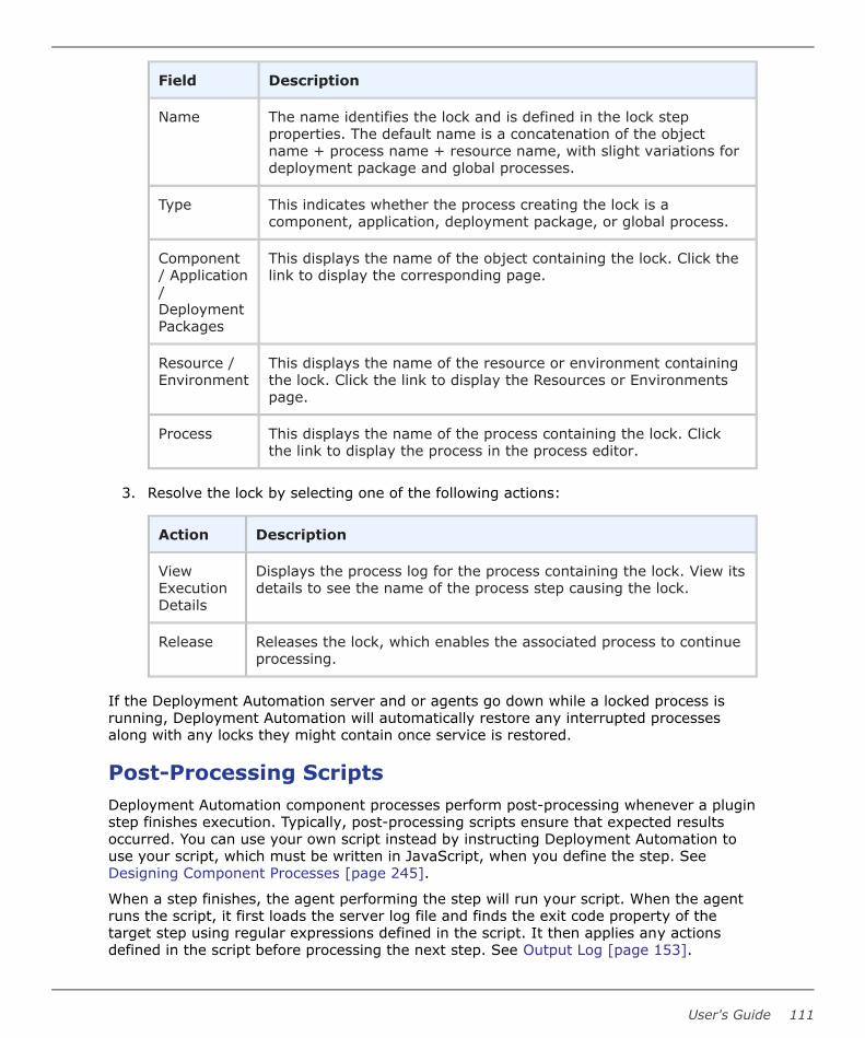
Field Description
Name The name identifies the lock and is defined in the lock stepproperties. The default name is a concatenation of the objectname + process name + resource name, with slight variations fordeployment package and global processes.
Type This indicates whether the process creating the lock is acomponent, application, deployment package, or global process.
Component/ Application/DeploymentPackages
This displays the name of the object containing the lock. Click thelink to display the corresponding page.
Resource /Environment
This displays the name of the resource or environment containingthe lock. Click the link to display the Resources or Environmentspage.
Process This displays the name of the process containing the lock. Clickthe link to display the process in the process editor.
3. Resolve the lock by selecting one of the following actions:
Action Description
ViewExecutionDetails
Displays the process log for the process containing the lock. View itsdetails to see the name of the process step causing the lock.
Release Releases the lock, which enables the associated process to continueprocessing.
If the Deployment Automation server and or agents go down while a locked process isrunning, Deployment Automation will automatically restore any interrupted processesalong with any locks they might contain once service is restored.
Post-Processing ScriptsDeployment Automation component processes perform post-processing whenever a pluginstep finishes execution. Typically, post-processing scripts ensure that expected resultsoccurred. You can use your own script instead by instructing Deployment Automation touse your script, which must be written in JavaScript, when you define the step. SeeDesigning Component Processes [page 245].
When a step finishes, the agent performing the step will run your script. When the agentruns the script, it first loads the server log file and finds the exit code property of thetarget step using regular expressions defined in the script. It then applies any actionsdefined in the script before processing the next step. See Output Log [page 153].
User's Guide 111

To create a post-processing script:
1. Navigate to Administration > Automation.
2. Select the Post Processing Scripts tab.
3. Click the Create button.
4. Enter a name for the script into the Name field. The name must match the nameyou specified when you defined the process step. See Designing ComponentProcesses [page 245].
5. Enter or paste the Javascript script into the Script Body field. See the roll-over helpnext to the field for information about the properties and variables available for user-defined scripts.
6. Click Save.
Defining StatusesYou can pre-define implementation-specific inventory, component version, and snapshotstatus values and subsequently use them to do the following:
• Apply inventory statuses to component versions when they are successfully deployedto resources
• Apply and enforce conditions on application gates based on statuses of componentversions and snapshots
To add status values, navigate to Administration > Automation > Statuses. Addvalues as needed for your implementation.
Each status has a required name and several optional values, as described in the followingtable:
Part 3: Administration
112 Deployment Automation

Status Attributes Table
Value Description
Name Identifies the status; appears in user-interface. Used to create gates,and available in process steps.
Color Hexadecimal color definition; determines the color displayed in theuser interface.
Unique Boolean value (true|false). Only one component version with thisstatus/attribute will be deployed to the environment.
RequiredComponentRole
Security role required by user to add this status to the componentversion.
Note: While you can add as many values as you like, you cannot create newstatus types. Only Inventory, Version, and Snapshot status types are supported.
Note: Process completion status is built in and cannot be changed. This shouldnot be confused with these other status types.
The following topics describe the use of the statuses.
• Using Inventory Statuses [page 113]
• Using Version Statuses [page 114]
• Using Snapshot Statuses [page 114]
Using Inventory StatusesInventory statuses are used with component processes to apply statuses to componentversions upon successful deployment to a target environment or resource. Active is thedefault setting, which indicates that a component version has been successfully deployedto its target resource.
You use inventory statuses as follows:
1. Define the statuses
Navigate to Administration > Automation > Statuses. Select the Inventory taband click Create. Define the inventory statuses for your implementation. Forexample, UAT_Ready, INT_Ready, Prod_Ready.
2. Select the inventory status
When you create or edit a component process, select the inventory status that is tobe set for this process. See Creating Component Processes [page 243].
3. Request a process
When the component process executes successfully, the selected status is applied tocomponent versions for which the process was defined. The inventory status appears
User's Guide 113

on the Inventory tab for the component itself and in environments that ran thecomponent process. See Running Application Processes [page 296].
Note:
You can check the inventory status of an environment as part ofcomponent and global processes using the DA Environment plugin VerifyInventory Status step.
See Creating Component Processes [page 243] for more information on the use ofinventory statuses for your inventory management.
Using Version StatusesVersion statuses are used with environment gates to ensure that components aredeployed or otherwise processed if they are in a designated status. You can select fromavailable version statuses when you define gates for applications. There is no defaultsetting.
You use version statuses as follows:
1. Define the statuses
Navigate to Administration > Automation > Statuses. Select the Version taband click Create. Define the version statuses for your implementation. For example,INT_Ready, UAT_Ready, PROD_Ready.
2. Add the condition
See Gates [page 304].
Note: In the Add a new condition selection box, both version statusesand snapshot statuses appear for selection.
3. Set the specific component version's statusSee Adding Statuses to Component Versions [page 238].
Note: You can also set version status as part of component and globalprocesses using the DA Version plugin.
4. Request a process to deploy the component
The requested process will not run if any of the included component versions are notset to the status or statuses specified in the application environment's Gates tab.See Chapter 29: Ways of Deploying [page 379].
Using Snapshot StatusesSnapshot statuses are used with environment gates to ensure that snapshots aredeployed or otherwise processed only if they are in a designated status. You can selectfrom available snapshot statuses when you define gates for applications. There is nodefault setting.
You use snapshot statuses as follows:
1. Define the statuses
Part 3: Administration
114 Deployment Automation

Navigate to Administration > Automation > Statuses. Select the Snapshot taband click Create. Define the snapshot statuses for your implementation. Forexample, INT_Ready, UAT_Ready, PROD_Ready.
2. Add the condition
See Gates [page 304].
3. Set the specific snapshot's status
See Adding Statuses to Snapshots [page 303].
4. Request a process to deploy the snapshot
The requested process will not run if the snapshot is not set to the status or statusesspecified in the application environment's Gates tab. See Chapter 29: Ways ofDeploying [page 379].
User's Guide 115

Part 3: Administration
116 Deployment Automation

Chapter 8: Security Administration
Deployment Automation provides a flexible role-based security model that maps to yourorganizational structure, as described by the following topics:
• Setting up Security [page 117]
• Role Configuration [page 118]
• Authorization Realms and Groups [page 123]
• Authentication Realms and Users [page 126]
• Default Permissions [page 138]
• Adding Users to Groups [page 139]
• Setting Role Membership by Product Area [page 140]
• Tokens [page 140]
• Viewing Online Users [page 141]
• Security Report Overview [page 141]
Setting up SecurityTypically, you perform the following steps in order when setting up DeploymentAutomation your initial security. Thereafter, you will administer each security area asneeded.
• Create Roles
Create roles and define permissions for the various product areas. For mostevaluations, the default roles should be adequate.
See Role Configuration [page 118].
• Create Authorization Realms and Groups
Authorization realms are used by authentication realms to associate users withgroups and to determine user access.
See Authorization Realms and Groups [page 123].
• Define Default Permissions
Set default permissions by product area. You can set default permissions for all usersor by group.
See Default Permissions [page 138].
• Create Authentication Realms and Add Users
User's Guide 117

The authentication realm is used to determine a user's identity within anauthorization realm. Add users to appropriate authentication realms. If more thanone realm has been configured, user authentication is determined following thehierarchy of realms defined on the Authentication pane. When a user attempts to login, all realms are polled for matching credentials.
See Authentication Realms and Users [page 126].
• Add Users to Groups
Add members to groups. Users who are members of groups inherit the groups'permissions.
See Adding Users to Groups [page 139].
• Set Role Membership by Product Area
To further refine the permissions by role, you can give groups and users rolemembership as follows:
▪ For most product areas, set these in the Security tab for each specific productarea and item.
▪ Set System Security and UI Security in the Administration > Securityoptions of the same names.
Note: Environment and component security settings can be set at thedirect object level and within the applications to which they are associated.
For component security, no matter whether you set the security on thecomponent level or application component level, the settings are appliedeverywhere.
Environment security settings are handled as follows:
▪ Upon initial association with an application, the security that is set forthe environment is inherited by the application environment.
▪ After an environment is associated with an application, if the security ischanged directly on the environment, the setting for the applicationenvironment is not affected.
▪ If the security is changed for the application environment, the setting atthe direct environment level is not affected.
See Setting Role Membership by Product Area [page 140].
Role ConfigurationRoles provide the building blocks for the security system. Roles have permissions thatdefine the actions the roles can perform with product features. Typical actions includechanging or executing an item, such as an application process, or modifying its securitysettings. Users or groups assigned to a role are automatically granted the permissionsconfigured for it. The default roles can be edited and new roles can be created.
Deployment Automation maps key product features or areas to security roles. Each areahas several permissions defined for it. When you create a role, you first specify theproduct area. Selecting a product area defines the set of permissions available to the newrole; only permissions defined for the area are available.
Part 3: Administration
118 Deployment Automation

Use the UI security area to quickly assign access permissions to the different areas of theDeployment Automation Web application. Use the system security area to assign usagepermissions, including the ability to define security for other users.
For information on configuring roles, see the following topics:
• Default Role Types [page 119]
• Creating and Editing Roles [page 120]
• Server Roles and System Security [page 120]
• Web UI Roles and UI Security [page 122]
Default Role TypesDeployment Automation ships with several role types mapped to product areas. Each roletype has a default set of roles that are given permissions relevant for that role type. Youcan define additional user-defined roles within each role type and give those rolespermissions that you need for your implementation of Deployment Automation.
Each role type has one role, typically called Admin or Administrator, which has allpermissions available for that area. Deleting a default Admin role for one role type doesnot affect the Admin role for another type.
Default Admin Role Permissions Table
The following table lists the default permissions for the default Admin role for each defaultrole type except for Server and Web UI role types. For information on those role types,see Server Roles and System Security [page 120] and Web UI Roles and UI Security[page 122] respectively.
Role Type Read Wrt. Sec. Exec. Mng.
Snps.
Run
Cmp.
Proc.
Mng.
Vers.
Clean
Exec.
Hist.
Agents X X X
Applications X X X X X X
ComponentTemplates
X X X
Components X X X X X
DA Server: See Server Roles and System Security [page 120]
DeploymentPackages
X X X X
Environments X X X X
User's Guide 119

Role Type Read Wrt. Sec. Exec. Mng.
Snps.
Run
Cmp.
Proc.
Mng.
Vers.
Clean
Exec.
Hist.
Licenses X X X
Pipelines X X X
Processes X X X X
Relays X X X
Resources X X X X
Web UI: See Web UI Roles and UI Security [page 122]
Creating and Editing RolesTo create and edit roles:
1. Navigate to Administration > Security.
2. Select the Role Configuration tab.
3. On the side menu select the role type for which you want to add a role.
4. To create a role, click the Create Role button. To edit a role, click the Edit iconbeside the role.
All permissions available for this role type appear.
By default, for most product areas, Deployment Automation provides an Admin rolewith all configured permissions granted.
For default permissions by role, see Default Role Types [page 119].
Exceptions are for Server Roles and Web UI Roles. For information on defaultpermissions for these, see Server Roles and System Security [page 120] and Web UIRoles and UI Security [page 122] respectively.
5. Select the permissions you want granted to this role.
6. Click Save.
Server Roles and System SecurityServer roles define the functions users can perform with the Deployment Automationserver. Available permissions are described in the following table.
Server Permissions Table
Part 3: Administration
120 Deployment Automation

Permission Grants Users Ability To ...
Check for Update Check for available updates for server versions
Create Applications Create applications
Create ComponentTemplates
Create component templates
Create Components Create components
Create DeploymentPackages
Create deployment packages
Create Environments Create environments
Create Pipelines Create pipelines
Create Relays Create relays
Create Subresources Create sub-resources
Create/ManageResource Roles
Create and delete resource roles
Data Collection Select the option to allow data collection for your DeploymentAutomation server
Manage CustomSource Config Types
Load and delete custom source config types.
Manage Licenses Add and remove licenses
Manage Plugins Install new plugins
Security Manage security configuration; users without this permissioncannot access or change the security functions
To add users to system security roles:
1. Navigate to Administration > Security.
2. Select the System Security tab.
All defined roles appear.
Default Server Roles Table
User's Guide 121
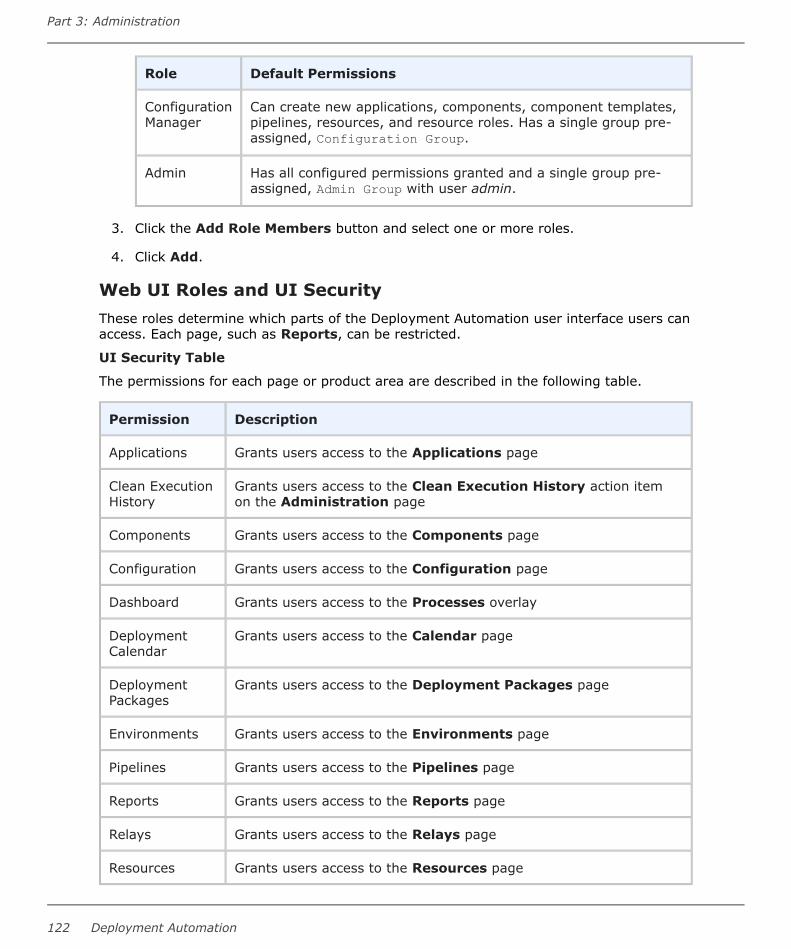
Role Default Permissions
ConfigurationManager
Can create new applications, components, component templates,pipelines, resources, and resource roles. Has a single group pre-assigned, Configuration Group.
Admin Has all configured permissions granted and a single group pre-assigned, Admin Group with user admin.
3. Click the Add Role Members button and select one or more roles.
4. Click Add.
Web UI Roles and UI SecurityThese roles determine which parts of the Deployment Automation user interface users canaccess. Each page, such as Reports, can be restricted.
UI Security Table
The permissions for each page or product area are described in the following table.
Permission Description
Applications Grants users access to the Applications page
Clean ExecutionHistory
Grants users access to the Clean Execution History action itemon the Administration page
Components Grants users access to the Components page
Configuration Grants users access to the Configuration page
Dashboard Grants users access to the Processes overlay
DeploymentCalendar
Grants users access to the Calendar page
DeploymentPackages
Grants users access to the Deployment Packages page
Environments Grants users access to the Environments page
Pipelines Grants users access to the Pipelines page
Reports Grants users access to the Reports page
Relays Grants users access to the Relays page
Resources Grants users access to the Resources page
Part 3: Administration
122 Deployment Automation

Permission Description
Settings Grants users access to the System Settings page
Work Items Grants users access to the Approval Requests overlay
To add users to user interface roles:
1. Navigate to Administration > Security.
2. Select the UI Security tab.
All defined roles appear.
Default Web UI Roles Table
The default permission settings for the user interface roles are described in thefollowing table.
Role Default Permissions
Admin Can access all pages except Clean Execution History
Approver Can access the Reports pages and Approval Requests andProcesses overlays
ConfigurationEngineer
Can access all pages except Calendar and Approval Requests
DeploymentEngineer
Can access the Reports and Calendar pages and ApprovalRequests and Processes overlays
3. Click the Add Role Members button and then select one or more roles.
4. Click Add.
Authorization Realms and GroupsAuthorization realms associate users with roles and work with authentication realms todetermine which users can access Deployment Automation.
For information on creating and configuring authorization realms and groups, see thefollowing topics:
• Creating an Internal Storage Authorization Realm [page 123]
• Creating an LDAP Authorization Realm [page 124]
• Creating Groups [page 125]
Creating an Internal Storage Authorization RealmInternal Storage type authorization realms are stored in the Deployment Automationdatabase and use internal role management.
User's Guide 123

The default authorization realm, Internal Security, is of the Internal Storage type, andincludes the following default groups:
• Admin Group
• Approve Group
• Configuration Group
• Deploy Group
• Read Only Group
If you want to create additional Internal Storage authorization realms, you can do sousing the following procedure.
To create an Internal Security authorization realm:
1. Navigate to Administration > Security.
2. Select the Authorization (Groups) tab.
3. Select Authorization Realms in the side menu.
4. Click the Create Authorization Realm button.
5. In Type select Internal Storage and specify a unique name.
Creating an LDAP Authorization RealmAn LDAP authorization realm uses an external LDAP server for authorization and usesexternal LDAP role management.
Deployment Automation includes an internal database for storing security information andprovides an integration with the Lightweight Directory Access Protocol (LDAP). LDAP is awidely-used protocol for accessing distributed directory information over IP networks. Ifyou are implementing a production version of Deployment Automation, the LDAPintegration is recommended. If you are evaluating Deployment Automation, it is notnecessary to set up the LDAP integration; full security is configured and enforced by theserver.
To create an LDAP authorization realm:
1. Navigate to Administration > Security.
2. Select the Authorization (Groups) tab.
3. Select Authorization Realms in the side menu.
4. Click the Create Authorization Realm button.
5. From the Type list select LDAP and specify a unique name along with the followinginformation:
Part 3: Administration
124 Deployment Automation

Field Description
UserGroupAttribute
Name of the attribute that contains role names in the user directoryentry. If user groups are defined in LDAP as an attribute of the user,the Group Attribute configuration must be used
GroupSearchBase
Base directory used to execute group searches, such asou=employees,dc=mydomain,dc=com.
GroupSearchFilter
LDAP filter expression used when searching for user entries. Thename will be substituted in place of 0 in the pattern, such as uid={0}.If this is not part of the DN pattern, wrap the value in parenthesis,such as ud=(0).
GroupName
Directory name used to bind to LDAP for searches, such ascn=Manager,dc=mycompany,dc=com. If not specified, an anonymousconnection will be made. Required if the LDAP server cannot beanonymously accessed.
SearchGroupSubtree
If selected, searches the subtree for the roles.
For an example, see the following:
• Limiting LDAP to a Set of Groups [page 125]
Limiting LDAP to a Set of Groups
To limit the LDAP authorization realm to a set of groups, you must use the LDAP filter asfollows:
1. Navigate to Administration > Security.
2. Select the Authorization (Groups) tab.
3. Create or edit an LDAP authorization realm that is associated with yourauthentication realm.
4. In the Create Authorization Realm dialog box, in the Group Search Filter field,specify the name of the group you want to allow.
For example:
(&(name=automation)(member={0}))This filter limits the import of groups from LDAP to just the automation group.
Creating GroupsGroups are logical containers that serve as a mechanism to grant permissions to multipleusers; members automatically share a group's permissions. Permissions are granted to
User's Guide 125

groups (or all users), not individual users. Additionally, when a group is assigned a role,its members are automatically assigned the role.
To create a group:
1. Navigate to Administration > Security.
2. Select the Authorization (Groups) tab.
3. Select Groups in the side menu.
4. Click the Create Group button.
5. Provide a name for the group.
6. Select an authorization realm.
Groups are valid only for the selected authorization realm.
Authentication Realms and UsersAuthentication realms determine a user's identity within an authorization realm. Forexample, a user listed in the LDAP realm may have different authorizations from those inthe other realms.
For information on creating and configuring authentication realms and users, see thefollowing topics:
• Creating Authentication Realms [page 126]
• Creating Users [page 127]
• Creating LDAP Authentication Realms [page 128]
• LDAP Authentication Configuration [page 129]
• Creating PKI Certificate Authentication Realms [page 130]
• PKI Certificate Authentication Configuration [page 135]
Creating Authentication RealmsTo create an authentication realm:
1. Navigate to Administration > Security.
2. Select the Authentication (Users) tab.
3. On the side panel click the '+' button (Create Authentication Realm)
4. Enter a unique name, an optional description, and other basic parameters:
Allowed LoginAttempts
Number of attempts allowed. A value of 0 means unlimitedattempts.
AuthorizationRealm
Requires that the authorization realm was previouslycreated.
Part 3: Administration
126 Deployment Automation

Type Select from the following types:
• Internal Storage
• LDAP
• Single Sign On
• PKI Certificate
Depending on the Type you select, additional parameters may be available as follows:
• For Internal Storage authentication realms, only basic parameters are available.
• For LDAP authentication realms, see Creating LDAP Authentication Realms [page128].
• For PKI Certificate authentication realms, see Creating PKI CertificateAuthentication Realms [page 130].
• For Single Sign On authentication realms, used with SBM, the following additionalparameters are available:
▪ User Header Name: The header name for an authorization token that is used bythe SSO provider. For example, ALFSSOAuthNToken.
▪ Logout Url: (Optional) When this parameter is specified, Deployment Automationredirects the logout request to the provided URL to inform the SSO provider thatthe session should be terminated.
For details on configuring SSO, see the Deployment Automation IntegrationGuide.
Important: You cannot use SSO and PKI Certificate authentication realms inthe same implementation; they are incompatible. If you want to use SmartCards with SSO, you should configure this in SBM. See the SBM documentationfor details.
Creating UsersYou create or import users differently depending on the type of authentication realm.
Internal Security / Internal Storage Type UsersFor Internal Storage type authentication realms, such as the default Internal Securityauthentication realm, you create users using the Create New User button.
When adding a new user, the user name and password is what the individual will usewhen logging into Deployment Automation. The user name will also be displayed whensetting up additional security.
Once the new user has been successfully added to a group, you might need to configureadditional permissions. This can happen when the new user is mapped to a group that haslimited permissions.
Include an email ID for the user if you want them to be eligible to receive emailnotifications. See Configuring Email Notifications [page 146].
User's Guide 127

LDAP UsersOnce LDAP configuration is complete, when a new user logs on using their LDAPcredentials, they will be listed on the Authentication Realms pane. You should notmanage user passwords or remove users from the list. If an active user is removed fromDeployment Automation, they will still be able to log in to the server as long as their LDAPcredentials are valid.
Single Signon UsersSBM solutions, such as Release Control, can use Single Sign-On (SSO) to accessDeployment Automation functionality. The users are created in SBM, and whenDeployment Automation is accessed the first time from SBM, the corresponding user isautomatically created in Deployment Automation.
PKI Certificate UsersUsers authenticated through PKI Certificate authentication are automatically created withthe first login using the associated CA certificate. Users authenticated with PKI Certificateare automatically added to an authentication realm of PKI Certificate type.
They are assigned to a group based on the Default security group set in the systemsettings; they are not assigned to a group if the default security group is not configured.See System Settings [page 155].
Administrators can also add users to the PKI Certificate authentication realm withoutproviding users' client certificates. The administrator can assign the users to groupsmanually and otherwise configure their permissions on a user by user basis. When userslog in with their certificates, they are identified by their login name and their data isupdated from the properties provided in the certificate, such as user name and email ID.
Administrators map certificate properties to user properties during configuration of the PKICertificate authentication realm. See Creating PKI Certificate Authentication Realms [page130].
Creating LDAP Authentication RealmsIf you are using LDAP, you can import users and map them to the security system. If youcreate an LDAP type of authentication realm, you need to provide information about yourLDAP installation as described in the following table.
For additional configuration requirements, see LDAP Authentication Configuration [page129].
LDAP Authentication Realm Properties Table
Field Description
ContextFactory
Enter the context factory class to use to connect. This may varydepending upon your Java implementation. The default for Sun Javaimplementations: com.sun.jndi.ldap.LdapCtxFactory.
LDAP URL URL to the LDAP server beginning with ldap:// or ldaps://. Separateadditional servers with spaces.
Part 3: Administration
128 Deployment Automation
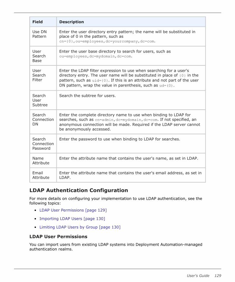
Field Description
Use DNPattern
Enter the user directory entry pattern; the name will be substituted inplace of 0 in the pattern, such ascn={0},ou=employees,dc=yourcompany,dc=com.
UserSearchBase
Enter the user base directory to search for users, such asou=employees,dc=mydomain,dc=com.
UserSearchFilter
Enter the LDAP filter expression to use when searching for a user'sdirectory entry. The user name will be substituted in place of {0} in thepattern, such as uid={0}. If this is an attribute and not part of the userDN pattern, wrap the value in parenthesis, such as ud=(0).
SearchUserSubtree
Search the subtree for users.
SearchConnectionDN
Enter the complete directory name to use when binding to LDAP forsearches, such as cn=admin,dc=mydomain,dc=com. If not specified, ananonymous connection will be made. Required if the LDAP server cannotbe anonymously accessed.
SearchConnectionPassword
Enter the password to use when binding to LDAP for searches.
NameAttribute
Enter the attribute name that contains the user's name, as set in LDAP.
EmailAttribute
Enter the attribute name that contains the user's email address, as set inLDAP.
LDAP Authentication ConfigurationFor more details on configuring your implementation to use LDAP authentication, see thefollowing topics:
• LDAP User Permissions [page 129]
• Importing LDAP Users [page 130]
• Limiting LDAP Users by Group [page 130]
LDAP User Permissions
You can import users from existing LDAP systems into Deployment Automation-managedauthentication realms.
User's Guide 129

Unless they are part of an LDAP authorization realm (group), valid LDAP users can log onbut will have no permissions. To provide permissions, import the LDAP users and definetheir permissions before they log on.
Importing LDAP Users
To import LDAP users:
1. Navigate to Administration > Security.
2. Select the Authentication (Users) tab.
3. On the side menu select an LDAP realm and click the Import User button.
4. Enter the name of the user.
If you enter a search filter in the Username field, the filter must be enclosed inparentheses.
5. Click Import.
Limiting LDAP Users by Group
To limit the LDAP authentication realm users by a specific group, you must use the LDAPfilter as follows:
1. Navigate to Administration > Security.
2. Select the Authentication (Users) tab.
3. Create or edit an LDAP authentication realm.
4. In the Create Authentication Realm window, in the User Search Filter field specifythe name of the group you want to use as a restriction.
For example:
(&(memberOf=CN=automation,OU=LDAPTestGroups,DC=ldaptest,DC=net)(sAMAccountName={0}))The first condition here, (memberOf=CN=automation,OU=LDAPTestGroups,DC=ldaptest,DC=net), limits the LDAP authentication realm to only theusers belonging to the automation group.
Creating PKI Certificate Authentication RealmsIf you are using a public key infrastructure (PKI) to create and manage digital certificatesfor login security, you can configure Deployment Automation to use your organization'sPKI certificates for user authentication. When this authentication is configured properly,user authentication happens automatically based on a PKI certificate installed in the user'sweb browser.
Important: You cannot use SSO and PKI Certificate authentication realms inthe same implementation; they are incompatible. If you want to use SmartCards with SSO, you should configure this in SBM. See the SBM documentationfor details.
Part 3: Administration
130 Deployment Automation

Multiple PKI Certificate authentication realms can be set up to support multiple CAcertificates.
When you create a PKI Certificate authentication realm in Deployment Automation, youmust provide information about your PKI Certificate installation as described in thefollowing table.
For additional configuration requirements, see PKI Certificate Authentication Configuration[page 135].
PKI Certificate Authentication Realm Properties Table
Field Description
AuthorizationRealm
Select Internal Security; PKI Certificate authentication realm alwaysuses Internal Security for authorization
CACertificateFile
Specify the path, including the file, where you have stored the issuer'scertificate information. For example:
D:\auth\ca.crt
UsernameAttribute
Select either Subject or Alternative Subject and then select fromthe available attributes. This attribute should map to the value in yourcertificate that your certificate implementation uses for username. SeePKI Certificate Parsing [page 134].
EmailAttribute
Select either Subject or Alternative Subject and then select fromthe available attributes. This attribute should map to the value in yourcertificate that your certificate implementation uses for email ID. SeePKI Certificate Parsing [page 134].
Full NameAttribute
Select either Subject or Alternative Subject and then select fromthe available attributes. This attribute should map to the value in yourcertificate that your certificate implementation uses for full name. SeePKI Certificate Parsing [page 134].
VerifyRevocation
Select this if you want to check to see if the user certificate has beenrevoked since it was last authenticated through the PKI certificate.
RevocationStrategy
If Verify Revocation is selected, select the revocation strategy youwant to use. Options are as follows:
• Strict: (Default) This strategy sets the certificate revocation statusto true if any exception happens during verification process. Forexample, if an OCSP service URL is inaccessible or a downloadedCRL cannot be read or parsed, the certificate is considered revoked.
• Mild: This strategy ignores exceptions described for strictverification and continues verification using the next verificationpoint. If all verification points are ignored or revocation status isfalse for all of them then the resulting revocation status is false.
User's Guide 131

Field Description
RevocationSource Type
If Verify Revocation is selected, select the revocation source typeyou want to use. Options are as follows:
• Internal: Select this to verify using a certificate revocation list thatyou have identified to the Deployment Automation server. SeeConfiguring Internal Revocation Verification [page 136]. Thisverifies the revocation status against OCSP URLs and CRL lists thatare specified in the certificate file you have identified in the serverconfiguration.
The following CRL distribution point URL formats are supported:
http(s)
For example:
http://serverName:8080/crl.pem, https://serverName:8443/crl.derldap
For example:
"ldap://ldapserverName:389/ou=Users,dc=da,dc=com?certificateRevocationList;binary"
• External: (Default) Select this to verify using the certificaterevocation list in the location that you specify in the CRLDistribution Point field.
The following CRL distribution point URL formats are supported:
http(s)
For example:
http://serverName:8080/crl.pem, https://serverName:8443/crl.derldap
For example:
"ldap://ldapserverName:389/ou=Usersdc=da,dc=com?certificateRevocationList;binary"
file
"file:///D:/StrongAuth/crl.der"
• Both: Select this to verify using both internal and externalcertificate revocation lists.
Part 3: Administration
132 Deployment Automation

Field Description
OCSP ServerURL
If Revocation Source Type is set to External or Both and you want touse an Online Certificate Service Provider (OCSP) to verify certificaterevocation, enter the URL that points to the service. For example:
http://ServerName:9999Note: The Deployment Automation server and OCSP servermust use the same time and time zone. Otherwise,depending on your selection for Revocation Strategy, thefollowing will occur:
• If Strict, the login will fail
• If Mild, verification using OCSP will be skipped
CRLDistributionPoint
If Revocation Source Type is set to External or Both and you want topoint to a certificate revocation list file, specify the URL that points toyour file. For example:
http://ServerName:8080/crl.file
UseRevocationCache
If Verify Revocation is selected, you can select this option to cachethe results from the last revocation verification to avoid performancedegradation for each login to the server. The following are cached forthe number of hours specified in the Revocation Cache ExpirationPeriod.
• Revocation status: The last certification revocation status isstored in the cache and are used without additional verification forsubsequent requests that have this certificate in their attributes.
• Certificate Revocation Lists (CRL): Keeps downloaded lists inmemory and stores them locally in the Deployment Automationprofile in the var/cache/pki directory. For example:
C:\Users\username\.microfocus\da/var/cache/pkiMultiple simultaneous downloads of CRL lists from single endpointis not allowed; if there is already an active download of a CRL list,all other requests are postponed until the download is completed.
Both caches are cleared when the authentication realm is updated.
RevocationCacheExpirationPeriod
If Use Revocation Cache is selected, specify the time period in hoursafter which to refresh the cache. The default is 24 hours.
User's Guide 133

PKI Certificate Parsing
Every PKI certificate has two sections to hold information related to the person for whomthis certificate was issued, Subject and Alternative Subject Name.
A Subject section example value is as follows:
Subject: C=UA, L=Kiev, O=microfocus, OU=DA, CN=sample name/[email protected]/street=sample street, SN=sample/name=sampleAn Alternative Subject Name section example value is as follows:
X509v3 Subject Alternative Name: email:[email protected], DNS:dns-sample, IPAddress:1.2.3.4, URI:uri test, Registered ID:1.2.3.4.5.6Subject Attributes
The attributes that can be selected for parsing in the Subject field are as follows:
C
O
T
OU
CN
L
ST
SN
EmailAddress
DC
UID
STREET
SURNAME
GIVENNAME
INITIALS
GENERATION
UnstructuredAddress
UnstructuredName
UNIQUE_IDENTIFIER
DN_QUALIFIER
PSEUDONYM
POSTAL_ADDRESS
NAME_AT_BIRTH
COUNTRY_OF_CITIZENSHIP
COUNTRY_OF_RESIDENCE
Part 3: Administration
134 Deployment Automation

GENDER
PLACE_OF_BIRTH
DATE_OF_BIRTH
POSTAL_CODE
BUSINESS_CATEGORY
TELEPHONE_NUMBER
NAME
Alternative Subject Attributes
The attributes that can be selected for parsing in the Alternative Subject Name sectionare as follows:
otherName
DNS
URI
IP Address
Registered ID
PKI Certificate Authentication ConfigurationFor more details on configuring your implementation to use PKI Certificate authentication,see the following topics:
• Configuring the Server to Support PKI Certificates [page 135]
• Importing CA Certificates [page 136]
• Configuring Internal Revocation Verification [page 136]
• Configuring Polling for Certificate Revocation Lists [page 137]
• Configuring PKI Certification for Agents [page 138]
Configuring the Server to Support PKI Certificates
Before you can use PKI certificates for authentication, you must configure the server toexpect certificate-based authentication upon requested access.
To configure the server to support use of PKI Certificates for authentication:
1. Navigate to the Common Tomcat conf directory. For example:
C:\Program Files\Micro Focus\common\tomcat\8.5\webapps\da\conf
2. Edit the following file: server.xml
3. Copy and paste the following Connector entry into the file to create a newConnector entry. For example, in the following, the port is 8643. You must ensureyou don't use the same port number that is used in an existing Connector entry and
User's Guide 135

you must ensure the clientAuth value is set to true, as shown in the followingexample.
<Connector port="8643" SSLEnabled="true"scheme="https" secure="true" sslProtocol="TLS"sslEnabledProtocols="TLSv1.2,TLSv1.1,TLSv1"maxHttpHeaderSize="8192"maxThreads="150" minSpareThreads="25"enableLookups="false" disableUploadTimeout="true"acceptCount="100"keystoreFile="conf/sample-ssl.jks"keystorePass="microfocus" keyAlias="tomcat"truststoreFile="conf/sample-ssl.jks" truststorePass="serena"clientAuth="true" />
This tells Common Tomcat that the server can be accessed only if the user provides acertificate in the request. If you try logging into Deployment Automation and don't have avalid certificate in your browser, you will receive the following message:
Certificate-based authentication failed
Importing CA Certificates
CA certificates from your certification centers must be imported into the Java KeyStore fileas a trusted certificate before using any user certificate signed by this CA certificate.
To add CA certificates:
1. Navigate to the Common Tomcat conf directory. For example: C:\ProgramFiles\Micro Focus\common\tomcat\8.5\webapps\da\conf
2. Using an appropriate editor such as the Oracle Java keytool utility, unlock and editthe jks file that you specified in the connector keystoreFile parameter. Forexample: sample-ssl.jks
3. Import the CA certificate as a trusted certificate.
After you import a CA certificate, you will be able to select it in your web browser whenyou enter the secure URL pointing to Deployment Automation. For example:
https://MyServer:8643/da
Configuring Internal Revocation Verification
Before you can use the Internal PKI certificate revocation verification option, you mustconfigure the server to support this. If you use the External PKI certificate revocation, youdo not need to configure this. See Creating PKI Certificate Authentication Realms [page130].
To configure the server for internal revocation verification:
1. Navigate to the Common Tomcat conf directory. For example: C:\ProgramFiles\Micro Focus\common\tomcat\8.5\webapps\da\conf
Part 3: Administration
136 Deployment Automation

2. Edit the following file: server.xml
3. Edit the Connector entry that you added or modified in Configuring the Server toSupport PKI Certificates [page 135]. Add the attribute crlFile=”../list.crl,where list.crl is a file that contains your certificate revocation list, as shown inthe following example.
<Connector port="8643" SSLEnabled="true"scheme="https" secure="true" sslProtocol="TLS"sslEnabledProtocols="TLSv1.2,TLSv1.1,TLSv1"maxHttpHeaderSize="8192"maxThreads="150" minSpareThreads="25"enableLookups="false" disableUploadTimeout="true"acceptCount="100"keystoreFile="conf/sample-ssl.jks"keystorePass="microfocus" keyAlias="tomcat"truststoreFile="conf/sample-ssl.jks" truststorePass="serena"clientAuth="true" crlFile=”../list.crl”/>
The Revocation Source Type of Internal can now be used to verify against the specifiedcertificate revocation list.
Configuring Polling for Certificate Revocation Lists
To handle large Certificate Revocation Lists (CRL), a CRL poller service can be run as partof the server startup. This service downloads the updated CRL for all enabled PKICertificate authentication realms once a day. Downloaded lists are stored within theDeployment Automation profile folder. For example:
C:\Users\username\.microfocus\da/var/cache/pkiThe CRL poller service downloads CRL lists only if the following are true:
• A PKI Certificate authentication realm is configured to use External or Bothrevocation verification source types
• The CRL Distribution Point property is configured for the PKI Certificateauthentication realm
• The CRL poller flag is set to true in the server configuration file
If you use the Internal PKI certificate revocation, you do not need to configure this. SeeCreating PKI Certificate Authentication Realms [page 130].
To configure the poller service:
1. Navigate to the Common Tomcat webapps\da\WEB-INF\classes directory. Forexample: C:\Program Files\Micro Focus\common\tomcat\8.5\webapps\da\WEB-INF\classes
2. Edit the following file: da_config.xml
3. Add or edit the pkiConfig entries:
crlPollerEnabled: If set to true, the poller service runs; if set to false, it doesn't
User's Guide 137

crlPollerStartHour: Set to an integer value from 0 through 23 in 24 hour timeformat. If this is not set, the default is 0.
In the following example, the poller is enabled and the start hour is 0, which meansit runs at midnight.
<pkiConfig><crlPollerEnabled>true</crlPollerEnabled><crlPollerStartHour>0</crlPollerStartHour>
</pkiConfig>
Configuring PKI Certification for Agents
For additional security, agents can be configured to authenticate through PKI certificates.Use the following procedure to configure each agent that you want to authenticate thisway.
Note: No corresponding users are created in Deployment Automation whenagents authenticate through PKI certificates. For information on userauthentication through PKI certificates, see Creating Users [page 127].
To configure agents to authenticate using PKI certificates:
1. Navigate to the agent's conf directory. For example: C:\Program Files(x86)\Micro Focus\Deployment Automation Agent/conf/sra.keystore
2. Using an appropriate editor such as the Oracle Java keytool utility, remove thedefault key from the agent's sra.keystore file.
3. Add the client certificate issued by your CA for this particular agent to the agent'ssra.keystore file.
4. Update the conf/installed.properties in the agent's conf directory to have thecorrect passwords for the sra.keystore file and for the key itself (locked/agent.keystore.pwd and locked/agent.keystore.key.pwd respectively).Passwords can be entered unencrypted, and will be encrypted the next time theagent starts.
Default PermissionsDefault permissions can be set globally for all users for a product area, or for individualuser groups within an area. By default, a product area's permissions are not enabled forany user or group, except for the admin user, which has all permissions for all role typesgranted. Use the Default Permissions page to set default permissions for the groups youcreate and for those included with the product.
Users added to a group inherit the group's default permissions.
Deployment Automation includes several role types mapped to product areas. Each roletype has default roles with permissions that are appropriate for those roles. Groups addedto a role inherit the role's permissions. For more information, see Role Configuration [page118].
Note: Default permissions cannot be granted for system and UI security.
Part 3: Administration
138 Deployment Automation
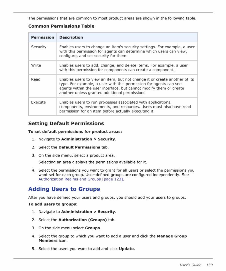
The permissions that are common to most product areas are shown in the following table.
Common Permissions Table
Permission Description
Security Enables users to change an item's security settings. For example, a userwith this permission for agents can determine which users can view,configure, and set security for them.
Write Enables users to add, change, and delete items. For example, a userwith this permission for components can create a component.
Read Enables users to view an item, but not change it or create another of itstype. For example, a user with this permission for agents can seeagents within the user interface, but cannot modify them or createanother unless granted additional permissions.
Execute Enables users to run processes associated with applications,components, environments, and resources. Users must also have readpermission for an item before actually executing it.
Setting Default PermissionsTo set default permissions for product areas:
1. Navigate to Administration > Security.
2. Select the Default Permissions tab.
3. On the side menu, select a product area.
Selecting an area displays the permissions available for it.
4. Select the permissions you want to grant for all users or select the permissions youwant set for each group. User-defined groups are configured independently. SeeAuthorization Realms and Groups [page 123].
Adding Users to GroupsAfter you have defined your users and groups, you should add your users to groups.
To add users to groups:
1. Navigate to Administration > Security.
2. Select the Authorization (Groups) tab.
3. On the side menu select Groups.
4. Select the group to which you want to add a user and click the Manage GroupMembers icon.
5. Select the users you want to add and click Update.
User's Guide 139

Setting Role Membership by Product AreaAfter you have defined your roles, groups, and users, you then give groups or users rolesin specific product areas.
• For most product areas, you set these in the Security tab for each specific productarea and item.
• System Security and UI Security are set in the Administration > Security optionsof the same names.
• Environment and component security settings can be set at the direct object leveland within the applications to which they are associated.
▪ For component security, no matter whether you set the security on thecomponent level or application component level, the settings are appliedeverywhere.
▪ Environment security settings are handled as follows:
▪ Upon initial association with an application, the security that is set for theenvironment is inherited by the application environment.
▪ After an environment is associated with an application, if the security ischanged directly on the environment, the setting for the applicationenvironment is not affected.
▪ If the security is changed for the application environment, the setting at thedirect environment level is not affected.
To add groups or users to roles:
1. Navigate to the Security tab for the product area for which you want to definesecurity roles.
For example, for agents or agent resources, navigate to Management >Resources. Select the Pools tab, select a pool, and select the Security tab.
Exceptions are for Server Roles and Web UI Roles. For information on adding groupsand users to these roles, see Server Roles and System Security [page 120] and WebUI Roles and UI Security [page 122] respectively.
2. Select a role and click the Add Member button on the right.
3. Select members from the eligible groups and users and then click Add.
TokensTokens provide authorization for agents and users. Agents use tokens when performingprocess steps and communicating with the server and external services. Users can usetokens instead of supplying a user name and password in certain situations. Tokens canalso be used with the command line client.
You can create tokens in addition to those included with the product.
To create a token:
1. Navigate to Administration > Security.
Part 3: Administration
140 Deployment Automation

2. Select Tokens and click Create.
3. From the User drop-down list box, select the user who will use the token.
4. Specify the expiration date and time.
Tokens can be used immediately after being created.
Viewing Online UsersYou can view all users who are online and invalidate sessions if needed.
To view online users:
1. Navigate to Administration > Security.
2. Select Online Users.
A list appears of all users who are currently online. You can:
• Click a user's email ID to contact the user.
• Easily see what authentication realm each user belongs to.
• See session start time and last access time for each user.
• Click the delete icon beside a user ID to invalidate that user's session.
• Refresh the page to see an updated view of online users.
Security Report OverviewSecurity reports provide information about user and group roles and privileges definedwith the Deployment Automation security system. Following are some of the things youcan do on the Administration > Reports page.
• Select the report you want to run.
• Print the selected report.
• Export the selected report. This saves the report to a file in HTML format.
• View the report listing.
For information on each report, see the following topics:
• Application Security Report [page 142]
• Component Security Report [page 142]
• Environment Security Report [page 143]
• Resource Security Report [page 144]
User's Guide 141

Application Security ReportThe Application Security Report provides information about user and group roles andprivileges defined for Deployment Automation-managed applications. Each report rowrepresents an individual application. When selected, the report runs automatically for allapplications.
For details on configuring and running this report, see the following topics:
• Application Security Fields [page 142]
Application Security Fields
The application security fields are shown in the following table.
Application Security Fields Table
Field Description
Application Name of the application
Clean ExecutionHistory
Users and groups who have privileges to clean execution history
Execute Users and groups who have application execution privileges
Manage Snapshots Users and groups who have snapshot management privileges
Read Users and groups who can review information about theapplication but not change it
Run ComponentProcesses
Users and groups who have component process executionprivileges
Security Users and groups who can define privileges for other users andgroups
Write Users and groups who can access and edit the application
Component Security ReportThe Component Security Report provides information about user and group roles andprivileges defined for components. Each report row represents an individual component.When selected, the report runs automatically for all components.
For details on configuring and running this report, see the following topics:
• Component Security Fields [page 142]
Component Security Fields
The component security fields are shown in the following table.
Component Security Fields Table
Part 3: Administration
142 Deployment Automation

Field Description
Component Name of the component.
Execute Users and groups who have component process execution privileges.
Security Users and groups who can define privileges for other users and groups.
Read Users and groups who can review information about the component butnot change it.
Write Users and groups who can access and edit the component.
Environment Security ReportThe Environment Security Report provides information about user and group roles andprivileges defined for environments. Each report row represents an individualenvironment. When selected, the report runs automatically for all environments.
For details on configuring and running this report, see the following topics:
• Environment Security Fields [page 143]
Environment Security Fields
The environment security fields are shown in the following table.
Environment Security Fields Table
Field Description
Application Name of the application
Clean ExecutionHistory
Users and groups who have privileges to clean execution history
Environment Name of the environment
Execute Users and groups who have execution privileges for theenvironment
Security Users and groups who can define privileges for other users andgroups
Read Users and groups who can review information about theenvironment (but not change it)
Write Users and groups who can access and edit the environment
User's Guide 143

Resource Security ReportThe Resource Security Report provides information about user and group roles andprivileges defined for resources. Each report row represents an individual resource. Whenselected, the report runs automatically for all resources.
For details on configuring and running this report, see the following topics:
• Resource Security Fields [page 144]
Resource Security Fields
The resource security fields are shown in the following table.
Resource Security Fields Table
Field Description
Resource Name of the resource.
Execute Users and groups who have execution privileges for the resource.
Security Users and groups who can define privileges for other users and groups.
Read Users and groups who can review information about the resource but notchange it.
Write Users and groups who can access and edit the resource.
Part 3: Administration
144 Deployment Automation

Chapter 9: System Administration
You can use the Administration System options of the user interface to access, create,and/or modify features, as documented in the following topics:
• Licenses [page 145]
• Configuring Email Notifications [page 146]
• Output Log [page 153]
• Adding System Properties [page 154]
• System Settings [page 155]
• ALF Events [page 157]
• Scheduling Version Cleanup [page 159]
LicensesYou can manage user licenses by adding or deleting licenses and assigning agents tothem.
• Adding a License [page 145]
• Adding Agents to a License [page 145]
• Modifying or Deleting a License [page 146]
Adding a LicenseTo add a license:
1. Navigate to Administration > System.
2. Select Licenses.
3. Click the Add License button.
4. Paste the license text supplied by Micro Focus into the License field.
5. (Optional) Add a description.
6. Click Save.
To see information about a license, click Details.
Adding Agents to a LicenseAgents can be assigned to licenses automatically or manually. This section explains howto add agents manually. To automatically add agents, ensure that the Automatic LicenseManagement check box on the System Settings pane is selected.
User's Guide 145

To add an agent to a license manually:
1. Click the Assign Agents icon beside the license in the license list.
2. Optional. You can filter the listed agents by entering search text into the text field.
3. Select the agent or agents you want to add to the license.
4. When you are finished, click Add.
Modifying or Deleting a LicenseTo modify or update an existing license:
1. Click the ID of the license you want to change.
2. Click the Edit License button.
3. Edit the information shown in the License field.
4. Click Save.
To delete an existing license, click the Delete link for the selected license.
Configuring Email NotificationsDeployment Automation can send email notifications whenever user-defined triggerevents occur. For example, notifications can be sent when a deployment finishes or anapproval is required.
To send email notifications to users, you must do the following:
• Define notification templates or use the provided templates. These define the formatof notification emails for different types of notifications.
• Define the notification schemes you want to use or use the default scheme. Thesedefine the triggering events and roles for the notifications.
• Include an email ID as part of the user details for each user who will receive emailnotifications. See Creating Users [page 127].
• Define the email server information in system settings. See System Settings [page155].
• If you are sending notifications for applications or agents, select the notificationscheme in the specific applications or agents for which you want to sendnotifications.
• When the triggering event defined in the notification scheme is invoked, an emailnotification is sent. The trigger happens when a process request either succeeds orfails and is sent only to users who have a role in the notification scheme.
A typical use of notifications is as follows:
• When an application process is run for an environment requiring approval, an emailis triggered indicating that the process request must be approved.
Part 3: Administration
146 Deployment Automation

• When the request is approved, the approval process completes and an email istriggered indicating that the application process is ready to run.
• After the application process completes, an email is triggered to indicate the successof failure of the process.
For details on configuring email notification schemes and templates, see the followingtopics:
• Configuring Notification Schemes [page 147]
• Creating Notification Templates [page 149]
Configuring Notification Schemes
Prerequisites:
Deployment Automation relies on LDAP and an associated email server to sendnotifications. You must set up LDAP prior to configuring notifications. Notificationrecipients are defined with the security system's LDAP integration. See Chapter 8:Security Administration [page 117].
Deployment Automation requires an external SMTP mail server to send notifications.For information about configuring a mail server, see Chapter 9: System Administration[page 145].
Notification schemes define what events should generate notifications and who should getthem. When setting up notification schemes, to determine which users will receivenotifications, you select the triggering events and the role. For example, it is common foran administrator or environment owner to be notified when a work item, as part of theapproval process, has been generated.
You can configure the default scheme and set up additional schemes as needed for yourimplementation. You should select the template to use based on the reason for thenotification and the recipients of the notification.
To configure a notification scheme:
1. Navigate to Administration > System.
2. Select Notification Schemes.
3. Select and edit an existing scheme, such as Default Notification Scheme, or clickCreate to create a scheme.
4. Set the available notification scheme options as follows.
Option Description
Name Specify a name for the scheme.
Description Specify a description for the scheme.
User's Guide 147

Option Description
Attach Logs Select this to include a log file attachment for each targetthat shows the success or failure status of each step.
Attachmentmaximum beforearchival
Specify the number of logs to attach before the logs arecompressed into an archive.
5. Click Save.
To edit or add notification entries, select the notification scheme.
6. Edit an existing notification entry, such as Process Failure or Process Success, orclick the Create Notification Entry button to create an entry.
7. Set the available notification entry options as follows.
Option Description
Type Select an event type for which to send notifications. The event typeis typically determined by the type of recipient. For example, adeployment engineer would be interested in being notified about afailed deployment (Process Failure).
Available types are:
• Process Success
• Process Failure
• Process Started
• Approval Completed
• Approval Failed
• Agent Goes Offline
• Deployment Package Success
• Deployment Package Failure
• Deployment Package Started
Part 3: Administration
148 Deployment Automation

Option Description
Target Select notification targets:
• Application: Notifications are sent when the event typecorresponds to an application. For example, the Process Successevent, when paired with the Application target, would initiate anotification when a process, such as an application deployment,is successful. See Creating Applications [page 270].
• Environment: Notifications are sent when the event typecorresponds to an environment. For example, the ProcessSuccess event would initiate a notification when a successfuldeployment has been run in an environment, such as SIT orPROD.
• Agent: Notifications are sent when the event type correspondsto an agent. For example, the Agent Goes Offline event wouldinitiate a notification when an agent goes offline. See AssigningNotification Schemes to Agents [page 321].
Role Select a role to be notified. Each user who is assigned the selectedrole will receive an email.
Note: The role corresponds to those set in RoleConfiguration. See Creating and Editing Roles [page120].
TemplateName
Select a notification template name. This selection is limited by theType and Target selections.
8. Click Save.
Creating Notification TemplatesNotification templates define the format of the information that you want to send in theemail notifications for given situations. Default templates include the following:
• AgentGoesOffline
• ApplicationDeploymentFailure
• ApplicationDeploymentSuccess
• ApprovalCreated
• ApprovalFailed
• DeploymentReadied
• DeploymentPackageFailure
• DeploymentPackageStarted
User's Guide 149

• DeploymentPackageSuccess
• ProcessRequestStarted
• TaskCreated
Notification Templates are XML files located in the server profile's conf/server/notification-template file folder.
If the default notification templates do not suit your needs, you can create new ones.
To create a notification template:
1. Create an XML file.
2. Enter a script.
Note: Notification templates support only Velocity reports. For moreinformation on Velocity templates, see http://velocity.apache.org/engine/.
3. Save the file in the server profile's conf/server/notification-template file folder.The default locations on Windows and UNIX/Linux are as follows:C:\Users\username\.microfocus\da\server\notification-templates /opt/MicroFocus/da/username/.microfocus/da/server/notification-templates
4. Restart the server.
Related Topics
• Configuring Email Notifications [page 146]
Properties for Notification Templates
Properties from the various objects in Deployment Automation can be used in yournotification templates. Some of the properties that are most useful in notificationtemplates are given in the following tables.
Common Properties
Propertyname
Description Type
fn Object with helper functions DeployTemplateHelper
snapshot Object containing data about the applicationsnapshot; nullable
Snapshot
environment Object containing data about the environmentwhere the process was executed
Environment
Part 3: Administration
150 Deployment Automation

Propertyname
Description Type
application Object containing data about the applicationthat contains the executed process; nullable
Application
externalUrl URL of the Deployment Automation server String
Process Execution Request Properties
Property name Description Type
workflowTrace Trace of request execution; nullable WorkflowTrace
analysis Results of the execution, available ifworkflowTrace is not null; nullable
FilteredAnalysis
failureAnalysis Results of the execution, filtered byonly failed steps and available ifworkflowTrace is not null; nullable
FilteredFailureAnalysis
request Object with request data ApplicationProcessRequest
applicationProcess Object with application process data ApplicationProcess
versions List of component versions List<Version>
properties Map with process properties; see theexample of its values in Examples ofKeys in the Properties Map [page152]
Map<String, String>
user User who submitted the request User
resourceFactory Provides access to other DeploymentAutomation objects
ResourceFactory
User's Guide 151

Approval Request Properties
Propertyname
Description Type
approval Approval request data Approval
tasks List of approval tasks List<ApprovalTask>
appRequest Object containing data about theprocess request; is null if compRequestis available (nullable)
ApplicationProcessRequest
compRequest Object containing data about theprocess request; is null if appRequest isavailable (nullable)
ComponentProcessRequest
requester User who submitted the request User
scheduledDate Data of approval Date
processId Process ID String
requestType Type of request String
Examples of Keys in the Properties Map
Examples of keys that can be used in the properties map, or dictionary, for processexecution requests are as follows:
• applicationProcess.id
• applicationProcess.name
• deploymentPackage.id
• deploymentPackage.name
• dpRequest.id
• dpRequest.user.name
• dpRequest.user.displayName
• dpRequest.user.id
• environment.id
Part 3: Administration
152 Deployment Automation

• environment.name
• request.id
• request.user.name
• request.user.displayName
• request.user.id
• server.url
Note: The default templates use getName(), but the listed keys can also beused.
Basic Velocity Examples
The following examples show how the notification template properties may be used incommon Velocity statements.
1. If-then-else statement in general form:
#if (CONDITION)
***Statements/HTML to output
#else
***Statements/HTML to output
#end
Checking null values:
#if ($snapshot)
<tr><td>Snapshot:</td>
<td>$snapshot.getName()</td>
</tr>
#end
2. Creating a new variable; setting the new value to an existing variable:
#set ($var = "odd")
3. Iterating collections:
#foreach ($item in $collection)
***Statements/HTML to output
#end
Output LogYou can download the Deployment Automation server log from within the user interface.
To display and download the log file:
User's Guide 153

1. Navigate to Administration > System.
2. Select Log.
3. Click Download to save the file.
Note: You can download the file directly from the System options byclicking the Download link under Output Log.
The Deployment Automation server log file default location is: DeploymentAutomation_root\var\log\deployserver.out
Adding System PropertiesYou can set global system properties that are then available to be referenced by anyprocess step.
To enter system properties:
1. Navigate to Administration > System.
2. Select Properties.
3. To set a single property, click Add Property.
a. Fill in the fields as shown in the following table.
Field Description
Name Property name
Description Property description
Secure Select this if the property should be secure.
Secure properties are stored encrypted and displayed obscuredin the Deployment Automation user interface.
Value Value for the property that will be used by steps in a process
4. To set multiple properties, click Batch Edit.
a. In the Properties box, enter multiple properties and their values on separatelines as property=value.
For example, if you had properties host and port, you would enter them asfollows:
host=myServer
Part 3: Administration
154 Deployment Automation

port=8080Note:
The following restrictions apply to batch edit:
• The Secure option cannot be set.
• The value cannot contain the "=" symbol.
You can now reference the property value in processes using ${p:system/<propertyname>}.
System SettingsSystem settings let you specify values and preferences that work best for yourimplementation of Deployment Automation.
To set system settings:
1. Navigate to Administration > System.
2. Select System Settings. The system setting are shown on the page in view-onlymode.
3. To preview the component versions that will be archived the next time an archive fileis created, click the Preview Version Cleanup button.
4. To update the system settings, click the Edit button.
The system settings are as follows:
Setting Description
ExternalAgent URL
URL for agents to access the Deployment Automation web UI.
ExternalUser URL
URL for users to access the Deployment Automation web UI.
Only Groupsin SecurityRoles
When this is enabled, individual users cannot be grantedpermissions to anything. All permissions must be granted togroups.
Defaultsecuritygroup
The security group that external users will be associated withwhen users are auto-registered.
AutomaticVersionImportCheckPeriod(seconds)
The number of seconds between polls for new versions for allcomponents with this option turned on. Requires a server restartto take effect. It is not recommend to set this to less than 15.
User's Guide 155

Setting Description
Mail ServerHost
Hostname of the mail server for notifications. Leave this blank todisable notifications.
Mail ServerPort
SMTP port for email notifications.
Secure MailServerConnection
Whether the SMTP connection should be secured.
Mail ServerSenderAddress
Address to use for the "from" address for email notifications.
Mail ServerUsername
Username to use for sending email notifications.
Mail ServerPassword
Password to use for sending email notifications.
Days toKeepVersions
Number of days to keep component versions. -1 will keepindefinitely.
Number ofVersions toKeep
Number of versions to keep for each component. -1 will keep all.
Archive Path Path to write a zip file containing the artifacts of each versioncleaned up. If this is blank, archives will not be written.
MinimumPasswordLength
The minimum length of passwords allowed to be created.
RequireComplexPasswords
This will validate new passwords created through the UI orcommand line interface to ensure the password is complex. Topass validation, it must use 2 of the 4 character classes: upper,lower,digits, and special. It must be as long or longer than thepassword minimum length.
AutomationLicenseManagement
Whether the server should automatically assign new agents toopen license slots.
Part 3: Administration
156 Deployment Automation

Setting Description
Allowconflictingname foragents
The server automatically add suffixes to conflicting agent namesto allow an agent to connect to the server.
EnablePropertyPicker
Enables property indexing and property picker suggestions.
Allow RepeatRequest
Enables the repeat request button.
ALF EventsDeployment Automation can emit Application Lifecycle Framework (ALF) events to a targetendpoint server. ALF is an integrative layer that is used for custom integrations from SBMto Deployment Automation.
Connection InformationTo use ALF events, you must specify the following connection information.
Field Description
SBM Link A full URL to an SBM event generation service or a root URL to the SBMserver where the event manager is hosted.
The link format should be as follows: protocol://host:portNote: To import the Deployment Automation event definitionsinto SBM Composer, use the SRAALFEvent.wsdl file providedwith your Deployment Automation installation.
UserName
User name used to perform authorization on the SBM server.
UserPassword
Password used to perform authorization on the SBM server.
ALF Event SettingsThe ALF events apply to the several categories, and there are corresponding sections inthe user interface that you can expand or collapse individually. You can use the followingcontrol buttons to more easily work with the ALF event options:
• Set All
• Clear All
User's Guide 157

• Expand All
• Collapse All
The ALF events categories and their options are given in the following sections.
Agent
Event Description
Statuschanged
If this option is selected, ALF Events will be emitted from DeploymentAutomation for agent status changes.
Application
Event Description
ApprovalRequired
If this option is selected, ALF Events will be emitted from DeploymentAutomation if approval is required for application processes.
ProcessStarted
If this option is selected, ALF Events for application process start will beemitted from Deployment Automation.
ProcessFinished
If this option is selected, ALF Events for application process finish will beemitted from Deployment Automation.
ProcessStarted
If this option is selected, ALF Events for application process start will beemitted from Deployment Automation.
ManualTaskCreated
If this option is selected, ALF Events for manual task creation will beemitted from Deployment Automation.
SnapshotModified
If this option is selected, ALF Events for application snapshot deletion willbe emitted from Deployment Automation.
ApprovalRequired
If this option is selected, ALF Events will be emitted when applicationapproval is required.
ManualTaskCreated
If this option is selected, ALF Events will be emitted when manual tasksare created for application processes.
Component
Event Description
ApprovalRequired
If this option is selected, ALF Events will be emitted from DeploymentAutomation if approval is required for component processes.
Part 3: Administration
158 Deployment Automation

Event Description
VersionCreated
If this option is selected, ALF Events for component version creation willbe emitted from Deployment Automation.
VersionDeleted
If this option is selected, ALF Events for component version deletion willbe emitted from Deployment Automation.
ProcessStarted
If this option is selected, ALF Events for component process start will beemitted from Deployment Automation.
ProcessFinished
If this option is selected, ALF Events for component process finish will beemitted from Deployment Automation.
ManualTaskCreated
If this option is selected, ALF Events will be emitted when manual tasksare created for component processes.
Environment
Event Description
ApprovalRequired
If this option is selected, ALF Events will be emitted when environmentapproval is required.
Global Process
Event Description
ProcessStarted
If this option is selected, ALF Events will be emitted from DeploymentAutomation when global processes start.
ProcessFinished
If this option is selected, ALF Events will be emitted from DeploymentAutomation when global processes finish.
Manual TaskCreated
If this option is selected, ALF Events will be emitted when manual tasksare created for global processes.
Scheduling Version CleanupYou can create a schedule to automatically cleanup deployment versions.
1. Navigate to Administration > Timeline.
2. Click Schedule and select Version Clean-up.
3. Select properties for the schedule:
• Name
User's Guide 159

• Start date
• Start time
• An optional recurring pattern, for example, daily
4. Click Submit. The scheduled clean-up is now displayed on the timeline.
Part 3: Administration
160 Deployment Automation

Chapter 10: Agent Connectivity StatusChecks
Agent connectivity can be checked periodically to ensure that the status in the userinterface shows the true connectivity status. The following options control aspects of thestatus checks. You can optionally configure these options to fine-tune yourimplementation.
Agent-initiated:
• Agents send regular keepalive messages to the server to keep connections open.
• The server monitors the keepalive messages and updates agents' status accordingly.
• Agent relays track keepalive message statistics from connected agents and sendthem regularly to the server.
• Default: enabled
• Server-initiated:
▪ The server can check the status of all agent endpoints in a single call.
▪ The status check can be set to recur periodically.
▪ Status check requests and responses are stored in the database for analysis.
▪ Cleanup of the stored data can be scheduled to recur periodically.
▪ In an active-active environment, the server that initiated the status request is theone that performs the subsequent analysis.
▪ Minimum supported agent version for the agent and server initiated status check:6.1.2
▪ Default: disabled
• User-initiated:
▪ In the Agent / Pools page of the user interface, when users click the Test icon () beside an agent, the agent status is checked and reset in the UI accordingly.
▪ Connectivity is tested for response through JMS protocol and then through JMS toHTTP protocol; messages are given for each.
▪ The connectivity test timeout is configurable.
For more information, see the following topics:
• Configuring the Server-Initiated Agent Status Check [page 162]
• Configuring the Agent-Initiated Agent Status Check [page 163]
User's Guide 161

• Configuring the User-Initiated Agent Status Check [page 164]
Related Topics
Managing Agents and Agent Pools [page 320]
Configuring the Server-Initiated Agent Status CheckTo configure the server-initiated agent status options:
1. Navigate to the directory or folder where the Deployment Automation serverconfiguration is stored. For example:
..\Users\username\.microfocus\da\conf\server
2. Edit the da_config.xml file keepAliveRollCallConfig settings as needed.Descriptions of each setting are given in the following table.
Setting Description
enabled Turns on or off the scheduled run of keep alive rollcalls. The default value is false.
pollingPeriodInMinutes Specifies the keep alive roll call polling period inminutes. This is the time wait before performing thenext keep alive roll call verification. The default value is1.
executePeriodInMinutes Specifies how often to initiate scheduled keep alive rollcalls, in minutes. The default value is 10.
durationInSeconds Specifies the time in seconds to wait for responses tothe roll call. The default value is 20.
cleanupEnabled Turns on or off the scheduled run of cleanup for keepalive roll calls. The default value is true.
cleanupStartHour The hour to run the cleanup for keep alive roll calls.The default value is 1.
cleanupDaysToKeep The amount of days to keep roll call requests andcorresponding responses. The default value is 15.
Example Server-Initiated Settings
Following are example settings for server-initiated agent status options in theda_config.xml file.
Part 3: Administration
162 Deployment Automation

<keepAliveRollCallConfig><enabled>true</enabled><pollingPeriodInMinutes>1</pollingPeriodInMinutes><executePeriodInMinutes>10</executePeriodInMinutes><durationInSeconds>20</durationInSeconds><cleanupEnabled>true</cleanupEnabled><cleanupStartHour>1</cleanupStartHour><cleanupDaysToKeep>15</cleanupDaysToKeep>
</keepAliveRollCallConfig>
Configuring the Agent-Initiated Agent Status CheckKeepalive messages are enabled by default on agents. These messages are used byActiveMQ to keep the connection between an agent and a server (or relay) open. You canconfigure a server to respond to those messages and update agent status accordingly.
To configure an agent-initiated status check:
• Navigate to the directory or folder where the Deployment Automation agent isstored. For example:
..\Users\username\.microfocus\da\conf\server
• Edit the agentStatusTracking settings in the da_config.xml file:
Setting Description
enabled Turns the agent status tracker on or off.Default: false
verificationPeriodInSec Specifies how often to initiate scheduledagent status verifications (in seconds).Default: 60
bringingOnlineTimeoutInSec Specifies the timeout period (in seconds) tobring an agent online after it is connected. Ifthis timeout is reached and the agent is notonline, the server re-sends a connectivitytest and waits for another timeout. Thisprocess is repeated until the agent goesonline. Default: 150
busyWhenQueueSizeIsHigherThen Specifies the maximum average number ofagents in a connection queue. If there aremore agents than specified, agent statuschecks do not run until the average numbergoes below the specified value. Default: 20
User's Guide 163

Setting Description
busyCountPeriodInMs Specifies the number of milliseconds for thetime period when the average is calculatedfor busyWhenQueueSizeIsHigherThen.Default: 2500
Example Agent Status Tracker Settings
Example settings for agent status check options in the da_config.xml file.
<agentStatusTracker><enabled>true</enabled><verificationPeriodInSec>60</verificationPeriodInSec>
<bringingOnlineTimeoutInSec>150</bringingOnlineTimeoutInSec><busyWhenQueueSizeIsHigherThen>20</busyWhenQueueSizeIsHigherThen><busyCountPeriodInMs>2500</busyCountPeriodInMs>
</agentStatusTracker>
Note: Agent status checks do not run when:
▪ A server has more connected agents than allowed(busyWhenQueueSizeIsHigherThen)
▪ When an agent actor manager or the system is busy, see Chapter 12:Configuring Server Settings [page 175].
Note: Status checks for agents connected through the agent relay onlywork with version 6.2.2 or higher. Versions earlier than 6.2.2 cannot passagent keepalive information to the server and are ignored.
Configuring the User-Initiated Agent Status CheckTo configure the user-initiated agent status options:
1. Navigate to the directory or folder where the Deployment Automation serverconfiguration is stored. For example:
..\Users\username\.microfocus\da\conf\server
2. Edit the da_config.xml file connectivityTestConfig settings as needed.Descriptions of each setting are given in the following table.
Setting Description
firstLevelTestTimeoutInSeconds Specifies the time in seconds to wait for aresponse to the first level (JMS) connectionstatus request. The default value is 10.
Part 3: Administration
164 Deployment Automation

Setting Description
secondLevelTestTimeoutInSeconds Specifies the time in seconds to wait for aresponse to the second level (JMS to HTTP)connection status request. The default valueis 60.
Example User-Initiated Settings
Following are example settings for user-initiated agent status options in theda_config.xml file.
<connectivityTestConfig><firstLevelTestTimeoutInSeconds>10
</firstLevelTestTimeoutInSeconds><secondLevelTestTimeoutInSeconds>60
</secondLevelTestTimeoutInSeconds></connectivityTestConfig>
User's Guide 165

Part 3: Administration
166 Deployment Automation

Chapter 11: Secure Socket Layer (SSL)Configuration
Secure Socket Layer (SSL) technology enables clients and servers to communicatesecurely by encrypting all communications. Data are encrypted before being sent anddecrypted by the recipient so that communications cannot be deciphered or modified bythird-parties.
Deployment Automation enables the server to communicate with its agents using SSL intwo modes: unauthenticated and mutual authentication. Unauthenticated mode for HTTPand mutual authentication mode for JMS are optional; you can implement one withoutimplementing the other, or implement both.
• Configuring Unauthenticated Mode for HTTP Communication [page 167]
• Configuring Mutual Authentication Mode [page 168]
Configuring Unauthenticated Mode for HTTPCommunicationIn unauthenticated mode, communication is encrypted but users do not have toauthenticate or verify their credentials. Deployment Automation automatically uses thismode for JMS-based server/agent communication. You cannot turn this off.
SSL unauthenticated mode can also be used for HTTP communication. You can implementthis mode for HTTP communication during server/agent/agent relay installation, oractivate it afterward.
By default Deployment Automation uses this mode for its JMS-based server/agentcommunication on port 7918.
Important: Because agent relays do not automatically activate SSL security,you must turn it on during relay installation or before attempting to connect tothe relay. Without SSL security active, agent relays cannot communicate withthe server or remote agents.
To activate unauthenticated mode for HTTP:
1. Open the installed.properties file which is located in the server_installation/conf/server directory.
The installed.properties file contains the properties that were set duringinstallation.
2. Ensure that the install.server.web.always.secure property is set to Y.
3. Ensure that the install.server.web.ip property is set to the port the servershould use for HTTPS requests.
4. Save the file and restart the server.
User's Guide 167

Configuring Mutual Authentication ModeIn mutual authentication mode, communications are encrypted as usual, but users arealso required to authenticate themselves by providing digital certificates. A digitalcertificate is a cryptographically signed document intended to assure others as to theidentity of the certificate's owner. Deployment Automation certificates are self-signed.
When mutual authentication mode is active, Deployment Automation uses it for JMS-based server/agent communication. In this mode, the Deployment Automation serverprovides a digital certificate to each agent, and each agent provides one to the server.This mode can be implemented during server/agent installation, or activated afterward.
To activate this mode, the Deployment Automation server provides a digital certificate toeach local agent and agent relay, and each local agent and agent relay provides one tothe server.
Agent relays, in addition to swapping certificates with the server, must swap certificateswith the remote agents that will use the relay. Remote agents do not have to swapcertificates with the server, just with the agent relay they will use to communicate withthe server.
This mode can be implemented during installation or activated afterward.
Note: When using mutual authentication mode, you must turn it on for theserver, agents, and agent relays, otherwise they will not be able to connect toone another. If one party uses mutual authentication mode, they must all use it.
Important: The server and agent properties must be set prior to configuringmutual authentication and exchanging keys.
To prepare for using mutual authentication, follow the following procedures in order:
• Property Settings for Mutual Authentication [page 168]
• Adding an Alias to an Agent [page 169]
• Adding an Alias to an Agent Relay [page 169]
• Mutual Authentication: Server and Agents [page 170]
• Mutual Authentication: Server, Agent Relay, and Agents [page 171]
Property Settings for Mutual AuthenticationBefore you can configure mutual authentication between a server and agents, or betweena server, agent relay, and agents, you must set the following properties.
Table 1. Property Settings Required Before Exchanging Keys table
Property Location Value
If not set during install:server.mutual_auth
In the server installation directory'sinstalled.properties file; for example:.microfocus\da\conf\server\installed.properties
true
Part 3: Administration
168 Deployment Automation

Property Location Value
server.jms.mutualAuth In the server installation directory'sinstalled.properties file; for example:.microfocus\da\conf\server\installed.properties
true
For each agent:
locked/agent.mutual_authIn the agent installation directory'sinstalled.properties file:[agent_installdir]\conf\agent\installed.properties
true
For each agent relay:
agentrelay.jms_proxy.secureIn the agent relay installation directory'sagentrelay.properties file:[agentrelay_installdir]\conf\agentrelay.properties
true
For each agent relay:
agentrelay.jms_proxy.mutualAuthIn the agent relay installation directory'sagentrelay.properties file:[agentrelay_installdir]\conf\agentrelay.properties
true
Adding an Alias to an Agent
Before you generate a certificate for an agent, you must add an alias to the agent.
To add an alias to an agent:
Note: You must have administrative privileges to perform this procedure.
1. Make sure your agent machine JAVA_HOME environment variable points to thedirectory where java is installed.
2. Open a shell and navigate to the agent install location \conf directory.
3. From within the agent's [install_location]\conf directory, run the followingcommand:
keytool -genkeypair -dname "cn=[alias_name]" -alias [alias_name]-keypass changeit -keystore sra.keystore -storepass changeit-keyalg RSA -keysize 1024 -validity 7305
where [alias_name] is the name you give the agent alias; we recommend using theagent's name.
4. To check the result, run the command:
keytool -list -keystore sra.keystore
Adding an Alias to an Agent RelayBefore you generate a certificate for an agent relay, you must add an alias to the agentrelay.
User's Guide 169

To add an alias to an agent relay:
Note: You must have administrative privileges to perform this procedure.
1. Make sure your agent relay machine JAVA_HOME environment variable points to thedirectory where java is installed.
2. Open a shell and navigate to the agent relay install location \conf\jms-relaydirectory.
3. From within the agent relay's [install_location]\conf\jms-relay directory, runthe following command:
keytool -genkeypair -dname "cn=[alias_name]" -alias [alias_name]-keypass changeit -keystore agentrelay.keystore -storepass changeit-keyalg RSA -keysize 1024 -validity 7305
where [alias_name] is the name you give the agent relay alias; we recommendusing the agent relay's name.
4. To check the result, run the command:
keytool -list -keystore agentrelay.keystore
Mutual Authentication: Server and AgentsMake sure your server and agents are not running before you start this configuration.
To configure mutual authentication between a server and agent:
1. Open a shell and navigate to the server install location \conf directory. Forexample:
.microfocus\da\conf
2. Export the server key as a certificate by running:
keytool -export -keystore server.keystore -storepass changeit-alias server -file server.crt
Note: When you install a server, the alias server to be used for certificatekey generation is assigned to the server.
You should see the message:
Certificate stored in file server.crt
3. Copy the exported server.crt (certificate file) to the agent[install_location]\[agent_name]\conf directory.
where [agent_name] is the unique name you gave the agent during install.
Part 3: Administration
170 Deployment Automation

4. From within the agent's [install_location]\[agent_name]\conf directory, importthe server.crt file by running:
keytool -import -keystore sra.keystore -storepass changeit -alias server-file server.crt -keypass changeit -noprompt
You should see the message:
Certificate was added to keystore
5. From within the agent's [install_location]\[agent_name]\conf directory, exportthe agent key as a certificate by running:
keytool -export -keystore sra.keystore -storepass changeit-alias [agent_alias] -file [agent_name].crt
The certificate is stored in the [agent_name].crt file.
Important: Before you export an agent key, you must first add an alias tothe agent (see Adding an Alias to an Agent [page 169]).
6. Copy the exported [agent_name].crt (certificate file) to the server installationlocation \conf directory.
7. From within the server's install location .microfocus\da\conf directory, import the[agent_name].crt file by running:
keytool -import -keystore server.keystore -storepass changeit-alias [agent_alias] -file [agent_alias].crt -keypass changeit -noprompt
You should see the message:
Certificate was added to keystore
8. For additional agents, repeat from step 5.
9. Start the server and agents.
Mutual Authentication: Server, Agent Relay, and AgentsThese instructions are for configuring mutual authentication for a server, agent relays,and agents that communicate with the server through agent relays. Make sure yourserver and agents are not running before you start this configuration.
To configure mutual authentication between a server, agent relay, and agents:
1. Open a shell and navigate to the server installation location \conf directory. Forexample:
.microfocus\da\conf
2. Export the server key as a certificate by running:
User's Guide 171

keytool -export -keystore server.keystore -storepass changeit-alias server -file server.crt
You should see the message:
Certificate stored in file server.crt
3. Copy the exported server.crt (certificate file) to the agent relay[install_location]\[agentrelay_name]\conf\jms-relay directory.
where [agent-relay_name] is the unique name you gave the agent relay duringinstall.
4. From within the agent relay directory:
[install_location]\[agent-relay_name]\conf\jms-relay
import the server.crt file by running:
keytool -import -keystore agentrelay.keystore -storepass changeit-alias server -file server.crt -keypass changeit -noprompt
You should see the message:
Certificate was added to keystore
Important: Before you can export an agent relay key, you must first addan alias to the agent relay. See Adding an Alias to an Agent Relay [page169].
5. From within the agent relay directory:
[install_location]\[agent-relay_name]\conf\jms-relay
export the agent relay key as a certificate by running:
keytool -export -keystore agentrelay.keystore -storepass changeit-alias [agent-relay_alias] -file [agent-relay_name].crt
You should see the message:
Certificate is stored in file [agent-relay_name].crt
6. Copy the exported [agent-relay_name].crt (certificate file) to the serverinstallation location .microfocus\da\conf directory.
7. From within the server's install location .microfocus\da\conf directory, import the[agent-relay_name].crt file by running:
keytool -import -keystore server.keystore -storepass changeit-alias [agent-relay_alias] -file [agent-relay_name].crt-keypass changeit -noprompt
Part 3: Administration
172 Deployment Automation

You should see the message:
Certificate was added to keystore
8. For an agent that is configured to connect to the agent relay, copy the exported[agent-relay_name].crt (certificate file) to the agent[install_location]\[agent_name]\conf directory.
where [agent_name] is the unique name you gave the agent during install.
9. From within the agent's [install_location]\[agent_name]\conf directory, importthe [agent-relay_name].crt file by running:
keytool -import -keystore sra.keystore -storepass changeit-alias [agent-relay_alias] -file [agent-relay].crt-keypass changeit -noprompt
You should see the message:
Certificate was added to keystore
10. From within the agent's [install_location]\[agent_name]\conf directory, exportthe agent key as a certificate by running:
keytool -export -keystore sra.keystore -storepass changeit-alias [agent_alias] -file [agent_name].crt
You should see the message:
Certificate is stored in file [agent_name].crt
Important: Before you can export an agent's certificate key, you mustfirst add an alias to the agent. See Adding an Alias to an Agent [page169].
11. Copy the exported [agent_name].crt (certificate file) to the agent relay[install_location]\[agent-relay_name]\conf\jms-relay\ directory.
12. From within the agent relay [install_location]\[agent-relay_name]\conf\jms-relay directory, import the [agent_name].crt file by running:
keytool -import -keystore agentrelay.keystore -storepass changeit-alias [agent_alias] -file [agent_name].crt -keypass changeit -noprompt
You should see the message:
Certificate was added to keystore
User's Guide 173

13. To configure another agent that communicates with the server through this agentrelay, repeat from step 10.
Attention: For each agent, make sure you change the name of the -aliasargument [agent_alias], and the -file argument [agent_name].
14. Restart the server, agent relay, and agents.
Part 3: Administration
174 Deployment Automation

Chapter 12: Configuring Server Settings
Several default settings for options in Deployment Automation are controlled in the serverconfiguration file. This section gives information on settings you may want to change inyour implementation. For details on reconfiguring settings you designated during theinstallation of Deployment Automation, see Reconfiguring Server Installation Settings[page 61].
Tip: If there is a particular behavior or timeout value you want to change thatisn't documented here, try searching the Knowledgebase.
For details on configuring server settings, see the following topics:
• Configuring Component Version Import [page 175]
• Configuring the Auto-select for Export Option [page 176]
• Configuring the Default for Only Changed Versions Option [page 177]
• Configuring Agent Connectivity Settings [page 177]
Configuring Component Version ImportComponent versions are imported into Deployment Automation from various sourceconfiguration tools. This topic describes the way this works and tells how to configure it.For details on importing component versions, see Component Versions [page 235].
When a component version import is requested, the request is added to the queue and amessage is displayed in the user interface that the request was successful. Requests runasynchronously on the server in the order they were placed in the queue. Incoming tasksare queued up until the queue is full.
CAUTION:
A successful request does not necessarily mean that the component versionimport will be successful.
The Versions page is automatically refreshed every 15 seconds following submission of aversion import. You can also manually refresh the page using the Refresh Page button.
The maximum integration task count parameter controls the capacity of the queue ofsubmitted versions for each component. The default value is 1. This parameter affectsboth automatic and manual version import for all source configuration types.
To change the capacity of the component version import queue:
1. Navigate to the Deployment Automation profile directory. For example:
..\Users\myUser\.microfocus\da\conf\server
2. Edit the da_config.xml file.
User's Guide 175

3. Update the <maxIntegrationTaskCount> parameter as follows, where # is a value 1or above:
<componentIntegrationTaskConfig><maxIntegrationTaskCount>#</maxIntegrationTaskCount></componentIntegrationTaskConfig>
CAUTION:
When changing this number, be aware of the following:
• Do not set it to 0. If you do so, it will prevent versions from beingimported.
• If you set this to a number higher than 1, you should ensure that yoursystem is capable of handling the number of version imports allowed.
Configuring the Auto-select for Export OptionWhen you create or edit an environment, you can select the Auto-select for Exportoption, which causes the environment to appear in the list of environments to export inthe replication export wizard if you later export using replication export. By default, theAuto-select for Export option is selected. If you prefer the option to be de-selected bydefault, you can configure this using the following procedure.
The Auto-select for Export option can be selected or de-selected in the environmentdetails regardless of the setting of this flag. This simply controls the default setting. SeeCreating Environments [page 308].
Tip: If you want most or all environments to be exported during replicationexport, you should leave this flag set to true, as that will make the selectionfaster when you go through the replication export wizard. However, to exportonly a few environments with any extra choices being explicitly added to theselection list in the export wizard, you should set this flag to false. For example,to select only pre-production and production environments for replication, andnot select others such as development and testing environments, setting this tofalse may be the better choice for you.
To configure the Auto-select for Export option default setting:
1. Navigate to the directory the Deployment Automation server da\WEB-INF\classesdirectory. For example: C:\Program Files\MicroFocus\common\tomcat\8.5\webapps\da\WEB-INF\classes
2. Edit the following file: da_config.xml
3. Change the environment export flag default value, <envAuto-select forExportFlagDefValue>, to false as follows:
<importExportConfig><ignoreImportErrors>false</ignoreImportErrors><exportInactive>false</exportInactive><envAuto-select for ExportFlagDefValue>false</envAuto-select for ExportFlagDefValue>
</importExportConfig>
Part 3: Administration
176 Deployment Automation

4. Save your changes.
5. Restart the Deployment Automation server.
The Auto-select for Export option for environments will now be de-selected by default.
Configuring the Default for Only Changed VersionsOptionWhen you create an application process, you can select the Default for Only ChangedVersions option, which subsequently controls the setting of the Only Changed Versionsoption in the Run Application Process wizard. By default, the Default for Only ChangedVersions option is selected. If you prefer the option to be de-selected by default, you canconfigure this using the following procedure.
The Default for Only Changed Versions option can be selected or de-selected in theapplication process details regardless of the setting of this flag. This simply controls thedefault setting. See Creating Application Processes [page 282].
To configure the Default for Only Changed Versions option default setting:
1. Navigate to the directory the Deployment Automation server da\WEB-INF\classesdirectory. For example: C:\Program Files\MicroFocus\common\tomcat\8.5\webapps\da\WEB-INF\classes
2. Edit the following file: da_config.xml
3. Change the systemConfig applicationProcessDefaultForOnlyChangedVersionsvalue to false as follows:
<systemConfig><applicationProcessDefaultForOnlyChangedVersions>false</applicationProcessDefaultForOnlyChangedVersions>
</systemConfig>
4. Save your changes.
5. Restart the Deployment Automation server.
The Default for Only Changed Versions option in application process details will nowbe de-selected by default.
Configuring Agent Connectivity SettingsWhen agents are connected to a server, every request goes to an actor pool. All requestsare spread evenly between actors in a pool. You can configure:
• How many actors are available for processing agent requests.
• When a server should stop checking agent connectivity status due to a large numberof requests, see Chapter 10: Agent Connectivity Status Checks [page 161].
To configure agent connectivity settings:
User's Guide 177

1. Navigate to the directory where the Deployment Automation server configuration isstored, for example: ..\Users\username\.microfocus\da\conf\server
2. Edit the agentActorManager settings in da_config.xml:
Setting Description
threadPoolSizeMultiplicationCoefficient Specifies a multiplication coefficient foran actor pool. The number of logicalCPUs is multiplied by this coefficient tocalculate the number of actors in theactor pool. For example, if the coefficientis 0.75 and the server has 4 logicalCPUs, the actor pool size is 3. Default:0.75
busyWhenQueueSizeIsHigherThen Specifies the maximum average numberof connectivity tasks that can beprocessed during a verification period. Ifthere are more connectivity tasks thenspecified, the agent manager isconsidered to be busy and agent statuschecks are not performed. For detailssee Chapter 10: Agent ConnectivityStatus Checks [page 161]. Default: 100
busyWhenConnectedMoreThen Specifies the maximum average numberof connectivity tasks that can beprocessed during a verification period. Ifthere are more connectivity tasks thenspecified, the agent manager isconsidered to be busy and agent statuschecks are not performed. For detailssee Chapter 10: Agent ConnectivityStatus Checks [page 161]. Default: 500
Example Agent Connectivity Settings
Example settings for agent connectivity options in da_config.xml.
<agentActorManager><threadPoolSizeMultiplicationCoefficient>0.75
</threadPoolSizeMultiplicationCoefficient><busyWhenQueueSizeIsHigherThen>100</busyWhenQueueSizeIsHigherThen><busyWhenConnectedMoreThen>500</busyWhenConnectedMoreThen>
</agentActorManager>
Part 3: Administration
178 Deployment Automation

Chapter 13: Artifact Repository
The following topics explain the architecture of the artifact repository in DeploymentAutomation.
• Artifact Repository Overview [page 179]
• Relocating the Repository [page 180]
Artifact Repository OverviewArtifact versioning in Deployment Automation is handled by CodeStation. You can directDeployment Automation to introduce artifacts into CodeStation from the file system orfrom external source control tools that you identify when you select the Source ConfigType for a component.
CodeStation artifacts represent deployable items such as files, images, databases,configuration materials, or anything else associated with a software project. By default,these are stored in the var subdirectory in the Deployment Automation server installationdirectory.
Deployment Automation's secure and tamper-proof artifact repository ensures thatdeployed components are identical to those tested in pre-production environments.Without the repository, artifacts would have to be pulled from network shares or someother system, increasing both security risks and the potential for error.
The artifact repository uses content addressable storage to maximize efficiency whileminimizing disk use. The repository tracks file versions and maintains a complete historyfor all components. Maximizing efficiency is important, since the artifact repository storesfiles that are much larger than source files.
Association of files with Components is built into the system. Without any configuration,each Component gets its own area of the repository for its files. There is no chance ofconfusion or mix-up of files to Components. And, each Component Package is mapped toa specific set of files and versions corresponding to the Component.
The artifact repository comes with a client application that provides remote access to therepository. Using the client, the user can add/modify files, create Packages, retrieve files,as well as view the history of changes.
The client application provides a file transfer capability that can be used to deliver files totarget servers during deployments. This built-in transfer mechanism verifies the integrityof all transferred files against their expected cryptographic signatures, thus guaranteeingthat files have not been corrupted during transmission or tampered with during storage.
In addition to the client application, the artifact repository exposes REST-based webservices. These services are used to build integrations between build systems such asAnthillPro and Deployment Automation. Such integrations automatically place the artifactsproduced by the build process in the artifact repository, thus making the artifactsavailable for deployment.
In an enterprise environment, the default installation might not be ideal. See Relocatingthe Repository [page 180] for a discussion about enterprise options.
User's Guide 179

Relocating the RepositoryFor enterprise implementations, due to storage requirements, you may need to relocateyour CodeStation files so that they are stored on a different machine than yourDeployment Automation server. A good formula for determining CodeStation storagerequirements is: average artifact size * number of versions imported per day *average number of days before cleanup.
File storage is organized as follows on a default Deployment Automation serverinstallation:
• Execution log files are located in .microfocus\da\logs folder
• CodeStation respository files are located in .microfocus\da\var\repository
• Plugin files are located in .microfocus\da\var\plugins
• This folder .microfocus\da\var\db contains Derby database files if Derby is used.
Relocate the CodeStation files as follows:
1. Stop the server before moving the folder location.
2. To relocate log files, you must relocate the \logs folder.
3. You can either relocate the whole var folder, or if you want to relocate only therepository files, you can relocate just the \var\repository folder.
4. Use the following to configure your network storage in an optimal way:
• This data should be stored on robust network storage that is regularlysynchronized with an off-site disaster recovery facility.
• The Deployment Automation server should have a fast network connection tostorage (agents do not need access to the storage location).
• In Unix environments, you can use symbolic links from the var subdirectory tonetwork storage.
• On Windows platforms there are several options for redirecting logs and artifacts,including mklink (supported in Windows 7 and later).
• Distributed teams should also take advantage of location-specific CodeStationproxies to improve performance and lower WAN usage.
Part 3: Administration
180 Deployment Automation

Chapter 14: Managing Execution History
Typically you should keep your execution history, since that is an audit trail of yoursystem. However, you may want to clean up execution history that is no longer needed inyour system. The Execution History Cleanup action enables you to do this.
For details, see the following:
• Pre-Cleanup [page 181]
• Rules of Execution History Cleanup [page 182]
• Running Execution History Cleanup [page 183]
• Execution History Cleanup Audit [page 183]
• Post-Cleanup [page 183]
Pre-CleanupBefore running the execution history cleanup, consider the following:
• While running, execution history cleanup can effect Deployment Automationperformance and could result in process execution delays. Therefore, the cleanupshould be planned ahead of time and run at a low or no activity time.
• To avoid causing confusion when execution history data has been deleted, you shouldnotify users to let them know when the cleanup is being run.
• Backup your Deployment Automation database in case of system failure while thecleanup is running.
Before running the execution history cleanup, you must ensure the proper permissions areset as follows:
• In Administration > Security > Role Configuration > Web UI, ensure that theClean Execution History permission is selected for the role who will run thecleanup, such as Admin, for each of the following product areas:
▪ Web UI
▪ Applications
▪ Environments
• Ensure that the users or groups who will run the cleanup have membership in therole.
User's Guide 181

See Role Configuration [page 118].
Note: In Administration > Security > Default Permissions, you can setClean Execution History permission for All Users Permissions and GroupsPermissions. This will cause this permission to be set whenever new users orgroups are created. However, since the cleanup should be run only by selectusers in a controlled situation, you should not typically add this permission as adefault.
Rules of Execution History CleanupWhoever runs the execution history cleanup must have the Clean Execution Historypermission through their role. This includes the following product areas:
• Web UI: to run the Execution History Cleanup action
• Applications: to select specific applications in the Execution History Cleanupwizard
• Environments: to clean up process requests for specific environments
Note: The Execution History Cleanup action is available by default only forthe root administrative user defined in your installation.
An execution history cleanup request will not delete any history in the following situations:
• A process request that is not started yet
• A process request that is currently running
• A process request that is waiting for approval
• An application process request that has at least one component process request thatis part of the resource inventory
• A standalone component process request that is part of the resource inventory
• An application process request that is part of the latest desired inventory
A cleanup request is initiated for each process request to be cleaned up. If a cleanuprequest cannot be completed for any reason, the data is rolled back to its original state forjust that one cleanup request. For each process request that is eligible to be deleted, thefollowing information is deleted:
• Logs
• Attachments
• Approvals
• Workflow traces
• Tasks
• Basic process requests
Part 3: Administration
182 Deployment Automation

• Deployment process requests for application process requests (not deleted if thedeployment process request has more than one application process request)
• Pipeline execution requests
• Process request property contexts
• Process request property sheets
Running Execution History CleanupA wizard leads you through the cleanup of your execution history.
To cleanup execution history:
1. Navigate to Administration > System.
2. Click Run Execution History Cleanup.
3. Select the applications that you want to cleanup and click Next.
4. Enter or select the start and end dates and times for the execution history data to becleaned.
5. Click Submit.
Detailed results of the execution history cleanup are shown. Select given tabs to see moreinformation on any failed application or component requests. p>
Note: By default, a sweep job is automatically run at set intervals to cancel orkill cleanup requests that have hung. The settings for the sweep can beconfigured, including whether or not to run the job at all. For details, refer toKnowledgebase item S141764.
Execution History Cleanup AuditAfter running execution history cleanup, audit information is available for the cleanuprequests.
To access the audit:
• Navigate to Administration > System and select Execution History Cleanup.
In this page you can do the following:
• View a summary list of Execution History Cleanup request executions.
• Click the eye icon beside a request to view more detail.
• Click the Run Execution History Cleanup button in the upper right of the pane toinitiate another cleanup.
Post-CleanupSince the execution history cleanup action is not something to be run without priorplanning and communication to users, it is recommended that after running the cleanupthat you consider deselecting the Clean Execution History permissions that you
User's Guide 183

selected in Pre-Cleanup [page 181]. This will prevent any users from running anunplanned cleanup.
Part 3: Administration
184 Deployment Automation

Chapter 15: Data Collection and Check forUpdate
Allow Data Collection
Micro Focus can optionally collect statistics on your product usage of DeploymentAutomation. Users are prompted for permission to collect this data at their first login to anew or upgraded installation of Deployment Automation. If they agree there or in theiruser profile preferences, Micro Focus collects data on the use of various DeploymentAutomation objects. This option can be selected only by users with the Data collectionpermission.
Allow Check for Update
Micro Focus can optionally detect and suggest server, agent, and plugin upgrades. Usersare prompted for permission to allow check for update at their first login to a new orupgraded installation of Deployment Automation. If they agree there or in their userprofile preferences, they are alerted of available updates. This option can be selected onlyby users with the Check for upgrade permission.
For information on setting these permissions, see Server Roles and System Security [page120].
See the following topics for more information about the data collected.
• Data Collected [page 185]
• Data Collection FAQ [page 187]
• Upgrade Eligibility Information Collected [page 188]
• Suggestions for Upgrade [page 189]
• Checking for Updates Manually [page 191]
Data CollectedThe following statistics are collected for each user who agrees to and is allowed to havedata collection.
Information is encrypted before it is sent, and the receiving Micro Focus server will rejectany unencrypted data.
Name Description
Server Version The version of the Deployment Automation server software in useby this user
User's Guide 185

Name Description
Server URL The external URL of the Deployment Automation server in use bythis user
Server MACaddress
The MAC address of the Deployment Automation server in use bythis user
IP address The IP address of the Deployment Automation server in use by thisuser
Server ID The UUID specific to this Deployment Automation server
User ID The UUID of the user who authorized the data collection
Number of logins The number of times each user whose ID is provided has loggedinto the system
Start date The start date and time, to the second, of the period for which datais collected
End date The end date and time, to the second, of the period for which datais collected
Number of compprocess requests
The number of component process requests made on thisDeployment Automation server that this user is authorized to view
Number of appprocess requests
The number of application process requests made on thisDeployment Automation server that this user is authorized to view
Number ofglobal processrequests
The number of global process requests on this DeploymentAutomation server that this user is authorized to view
Number ofagents
The number of agents registered to this Deployment Automationserver that this user is authorized to view
Min AgentVersion
The minimum version of any agent on this Deployment Automationserver for which this user is authorized
Max AgentVersion
The maximum version of any agent on this Deployment Automationserver for which this user is authorized
Part 3: Administration
186 Deployment Automation

Name Description
Components IDs of components that this user is authorized to view and namesof the plugins used in these components
Community This is set to true if the server uses only a community license andhas no commercial licenses installed. Otherwise it is set to false.
Data Collection FAQFollowing are some frequently asked questions on the data collected.
1. How does Micro Focus collect information?
If authorized through the data collection option, your Deployment Automation serverautomatically collects Deployment Automation usage data and sends thatinformation to the Micro Focus data collection server. It also suggests server andagent upgrades for which your implementation is eligible. See Suggestions forUpgrade [page 189].
2. What information does it collect?
For information on user statistics collected, see Data Collected [page 185]. Forinformation on global server and agent upgrade eligibility, see Upgrade EligibilityInformation Collected [page 188].
3. Who can see the data that is collected?
This server is stored on a Micro Focus data collection server and is visible only toauthorized Micro Focus employees.
4. Will it collect information if I say No?
Micro Focus only collects statistics for users who authorize it to do so by clicking Yeswhen prompted at login, or by selecting the Allow Data Collection check box intheir user profile Preferences. However, if any user agrees to data collection, MicroFocus will detect server and agent data for upgrade eligibility suggestions.
5. How often will it collect information?
Data is collected for each user's usage and sent to the data collection server once aweek.
6. Will it slow down my server?
Since the data collection happens only once a week and sends only a limited amountof data, you should notice no performance degradation on your server as a result ofthis.
7. Can I turn it off if I said Yes?
If you click Yes, then change your mind later, you can turn it off at any timethrough Preferences in your user profile.
8. Can I turn off the reminder?
User's Guide 187

If you click Ask again later, you will be reminded weekly. To turn off the reminder,you can simply answer No the next time you are reminded.
9. Will it save my personal information?
No, the data is sent anonymously and contains encoded information. Although eachuser must authorize the sending of the data on his or her behalf, the data sentdoesn't contain any identifying information that could be used to tie the sessionsback to a particular user ID or IP address.
10. Why does it collect my IP address?
The IP address of your Deployment Automation server may be used by Micro Focusfor statistical roll-up of information over time to determine numbers of servers beingused as single servers or active-active configurations.
11. Is it secure?
Yes, the connection sends data to a secure Micro Focus server. It collects informationabout the use of Deployment Automation only for the particular users whoauthorized it. It does not collect or send usage information for individual DeploymentAutomation users other than the ones who have authorized it.
12. What will Micro Focus use it for?
Micro Focus will use the information to help improve Deployment Automation. Byunderstanding how our users work with Deployment Automation, we can prioritizethe most-used areas of the product for enhancements and maintenance.
13. Will Micro Focus sell the data?
Micro Focus will not sell the data. It will be used only as stated.
Upgrade Eligibility Information CollectedThe following upgrade eligibility information is collected globally for the server and allagents and plugins associated with it.
Information is encrypted before it is sent, and the receiving Micro Focus server will rejectany unencrypted data.
Name Description
Server URL The external URL of the Deployment Automation server in use by thisuser
Server ID The UUID specific to this Deployment Automation server
ServerVersion
The version of the Deployment Automation server software in use by thisuser
Community This is set to true if the server uses only a community license and has nocommercial licenses installed. Otherwise it is set to false.
Part 3: Administration
188 Deployment Automation

Name Description
JavaVersion
Version of Java being used by the Deployment Automation server
Platform Operating system on which the Deployment Automation server isrunning, including name, version, and architecture
Database Database used by the Deployment Automation server, including nameand version
Agent All agent information for each agent associated with the server, includingthe following:
• Agent Version
• Agent ID
• Operating System Name, Architecture, and Version
• Java Version
Plugin All plugin information for each agent associated with the server,including the following:
• Plugin Name
• Plugin Version
Suggestions for UpgradeIf given permission, Micro Focus informs you when your server and agents are eligible forupgrade.
When upgrade eligibility is detected, in the dashboard at the top of the Deployment
Automation page you will see a message indicator . Click this to see the upgradesuggestions for your server, agent, and plugin versions. Suggestions are shown in anoverlay in separate sections as follows:
• Server Upgrade Messages [page 189]
• Agent Upgrade Messages [page 190]
• Plugin Upgrade Messages [page 190]
Server Upgrade MessagesServer upgrade message options are as follows:
• Download new version: If you click this, you will be redirected to a download pagewhere you can download and upgrade the server.
User's Guide 189

• Ask again later: Click this to temporarily dismiss the messages. You will receive themessages again a week later.
• Never for this version: If you click this, you will not be notified again about thesuggested version. However, when a new version becomes available, you will benotified.
• More info: Click this to be directed to the documentation for this option.
Messages indicate how critical the suggested upgrade is and include color coding asfollows:
• critical (red)
• important (yellow)
• recommended (green)
• optional (grey)
Agent Upgrade MessagesAgent upgrade options are as follows:
• Upgrade: If you click this, you will be redirected to the Deployment AutomationAgents / Pools page for where you can upgrade the agents.
• Ask again later: Click this to temporarily dismiss the messages. You will receive themessages again a week later.
• Never for this version: If you click this, you will not be notified again about thesuggested version. However, when a new version becomes available, you will benotified.
• More info: Click this to be directed to the documentation for this option.
Messages indicate how critical the suggested upgrade is and include color coding asfollows:
• critical (red): At least one agent requires a critical upgrade
• important (yellow): At least one agent requires an important upgrade and noagents require critical upgrades
• recommended (green): At least one agent requires a recommended upgrade andno agents require critical or important upgrades
• optional (grey): At least one agent requires an optional upgrade and no otherupgrade types are required
The Management > Resources > Agents / Pools page shows upgrade status foragents if you have agreed to Check for Upgrade and have the permission. Beside eachagent with eligible upgrades, the upgrade status is shown.
For the procedure to upgrade agents, see Upgrading Agents [page 324].
Plugin Upgrade MessagesPlugin upgrade options are as follows:
Part 3: Administration
190 Deployment Automation

• Download: If you click this, you will be redirected to the Deployment AutomationPlugins page for where you can upgrade the plugins.
• Ask again later: Click this to temporarily dismiss the messages. You will receive themessages again a week later.
• Never for this version: If you click this, you will not be notified again about thesuggested version. However, when a new version becomes available, you will benotified.
• More info: Click this to be directed to the documentation for this option.
The Administration > Automation > Plugins page shows Download links for pluginseligible for upgrade if you have agreed to Check for Upgrade and have the permission.After you have upgraded the plugins, the Download links no longer appear.
For the procedure to upgrade agents, see Upgrading Agents [page 324].
Checking for Updates ManuallyIf your system is eligible for upgrade and your server is behind a firewall, your servercan't automatically check for updates. However, you can still request update informationthrough the web application.
If the checking period elapses and you don't have any update messages, you'll receive awarning in your alerts. This prompts you to request the update information manually.
To check for updates manually:
1. In your user profile, select About.
2. Click Check For Updates.
Properties EncryptionYou can specify the encryption type used by a Deployment Automation server, agent, oragent relay. The encryption setting is used to protect secured values.
Supported encryption types
• LEGACY (uses the legacy method to encrypt data)
• AES256
• RSA
Keys
External encryption and decryption keys are provided by the user or generatedautomatically when a server starts (the folder enc-keys is created and stores the keys).
Each key is stored with a file name using this pattern:
User's Guide 191

Pattern Description
<encryptiontype>-<keyindex>-E
Stores the encryption key.
<encryptiontype>-<keyindex>-D
Stores the decryption key.
<encryptiontype>-<keyindex>
Used as a fallback if no files with the above names are found (usedwhen a –E or –D key with the corresponding index cannot befound).
• If there are no files in the folder enc-keys when a server, agent relay, or agent arestarted, random keys are stored for the encryption type.
• The key index can contain one character only.
• If a key is not found or an error occurs during encryption or decryption, the defaulthard-coded key is used.
• The ‘!’ symbol is reserved for the default key index.
• Data is always encrypted using the latest key (the one with the biggest index).
• All keys are reloaded when a server restarts.
• Encrypted data contains the index of the encryption key. The correspondingdecryption key should have the same index and be present in the profile.
Server
• Default encryption type: AES256
• To set the server encryption type, edit the property systemConfig/encryptionAlgorithm in da_config.xml.
• RSA is not supported and needs length DB fields that contain encrypted values to beincreased.
• The folder enc-keys is created in: <profile location>/conf/server
• Data that is encrypted in DB is not re-encrypted during a server upgrade or after theencryption algorithm property changes. If the property changes, secure properties inthe file installed.properties are re-encrypted when the server starts.
Agent
• Default encryption type: LEGACY
• To set the agent encryption type, edit the property locked/agent.strict.encryption.type in agent.properties.
Part 3: Administration
192 Deployment Automation

• Non-default encryption is not compatible with old plugins, however the default is lesssecure.
• The folder enc-keys is created in: <agent location>/conf/agent
• If the encryption type property is changed, secure properties in agent.propertiesfile are re-encrypted when an agent starts.
Agent Relay
• Default encryption type: AES256
• To set the agent relay encryption type, edit the propertyagentrelay.encryption.type in agentrelay.properties.
• The folder enc-keys is created in: <agent relay location>/conf
• If the encryption type property is changed, secure properties inagentrelay.properties file are re-encrypted when an agent relay starts.
User's Guide 193

Part 3: Administration
194 Deployment Automation

Chapter 16: Troubleshooting
Following are some known issues to review when troubleshooting DeploymentAutomation.
• Conflict with WebDAV in IIS [page 195]
• Installation Failure Due to Interruption [page 195]
• Import Failure or Issues After Import [page 196]
• SSO Login Failure After a Tomcat Upgrade [page 196]
• Process Failures or False Successes [page 197]
• Navigation Tips [page 197]
For more help with troubleshooting, see the Knowledgebase and the Community website.
Conflict with WebDAV in IISIf you are running Deployment Automation under JBOSS and IIS, you must ensure thatWebDAV is removed from IIS on the server that hosts Deployment Automation. WebDAVprevents Deployment Automation from using critical web service DELETE and PUToperations. For example, you cannot even apply a license in Deployment Automation.
To remove WebDAV:
1. Select the website in IIS.
2. Edit the Handler Mappings and remove WebDAV.
3. Navigate back to the website Home page.
4. Edit the Modules and remove the WebDAVModule.
Installation Failure Due to InterruptionYour installation may fail due to system interruption the first time you attempt to install.In this case, the installation runs very quickly and on the Install Wizard Completeddialog box, a message similar to the following appears:
The installation wizard was interrupted before Deployment Automation couldbe completely installed.Your system has not been modified. To complete installation at another time,please run setup again.To complete the failed installation:
1. Run the installer again to remove the installation.
2. Run the installer again to install.
User's Guide 195

This time, the installation should take a longer time to copy the files and you'll receive amessage with installation details on the Install Wizard Completed dialog box.
Import Failure or Issues After ImportGenerally export files are backward compatible, but you may encounter an issue whenimporting export files from prior versions of Deployment Automation.
Following are some examples of the types of errors you may encounter and ways toresolve them.
Error Type Resolution
You receive an error when youtry to import environments thatwere exported from a priorversion of DeploymentAutomation.
You should upgrade the primary DeploymentAutomation server and then export the objectsagain. You should then be able to import them into atarget server of the same version.
You cannot import anapplication from a json filebecause it was exported whileusing a different version of theplugin than the one you have.For example, you receive anerror similar to "Plugin DAVersioned File Storage Version20 does not exist."
You can use the resolution in the prior entry, or youcan edit the exported application json file using atext editor to change some of the parameters andtry the import again. To resolve the error given inthe example, you must change all occurrences ofpluginName and pluginVersion in the json file touse to the updated name and version for the pluginyou have loaded. In our example, pluginNameshould be changed to DA Versioned File Storage andpluginVersion should be changed to 20.
Your import appears to work,but when you try to deploy,you receive a generic run error.This means the structure of theapplication may have beenimported incorrectly. Forexample, if you can deploy atthe component level but notthe application level, there is astructure mismatch in theimported files.
You can typically fix this by removing and re-addingthe component to the application.
SSO Login Failure After a Tomcat UpgradeIf you have configured Single Sign-On (SSO) with one version of Common Tomcat andhave upgraded Deployment Automation to a version that uses a different version, youmust configure Common Tomcat for SSO again, including setting the parameters in thegatekeeper-core-config.xml file. Otherwise, the SSO login will fail.
You must set these parameters by copying over the corresponding strings from earlierversion of the gatekeeper-core-config.xml file. Copying and replacing the entire filefrom the earlier Common Tomcat installation does not work.
Part 3: Administration
196 Deployment Automation

For instructions on setting up SSO, refer to the Deployment Automation IntegrationGuide.
Process Failures or False SuccessesSome common reasons for process failures and false successes are covered here.
Issue Resolution
The process runs quickly and thestatus is Success, but the processdidn't run and the output log saysthat the component already exists inthat environment.
If you want to run the process in thatenvironment regardless of whether thecomponent already exists, deselect the OnlyChanged Version check box when you runthe process.
The process runs as a global processbut when you try to run it as acomponent process, it fails.
You may not have mapped resources for thecomponent within the application environment.This is required for component processes. SeeMapping Application Components to Resources[page 279].
When using a plugin, the status ofthe process doesn't show the samestatus as that in the integratingproduct.
Click the Refresh button to see the lateststatus. In some cases, additional action maybe necessary. See the documentation for yourspecific plugin.
Navigation TipsNew or occasional users may find the following tips helpful as you navigate the userinterface.
Navigation Point Resolution
When you're in the processeditor, you click otheroptions but the processeditor still shows on thescreen.
You must click the x in the upper right of the pagebeside the other controls to close the process editorbefore you can continue navigation to other options.See Designing Component Processes [page 245].
When you click ViewDetails for an applicationenvironment, the pagewon't open.
If the click is released too slowly, the page sometimesdoesn't open. If a quick single-click won't work, trydouble-clicking. See Application Environments [page276].
You clicked a link after youran a process request, andnow can't get back to thepage that shows theprocess results.
For information on viewing process request information,see Viewing an Application Process Request [page 386]and Viewing a Component Process Request [page 387].
User's Guide 197
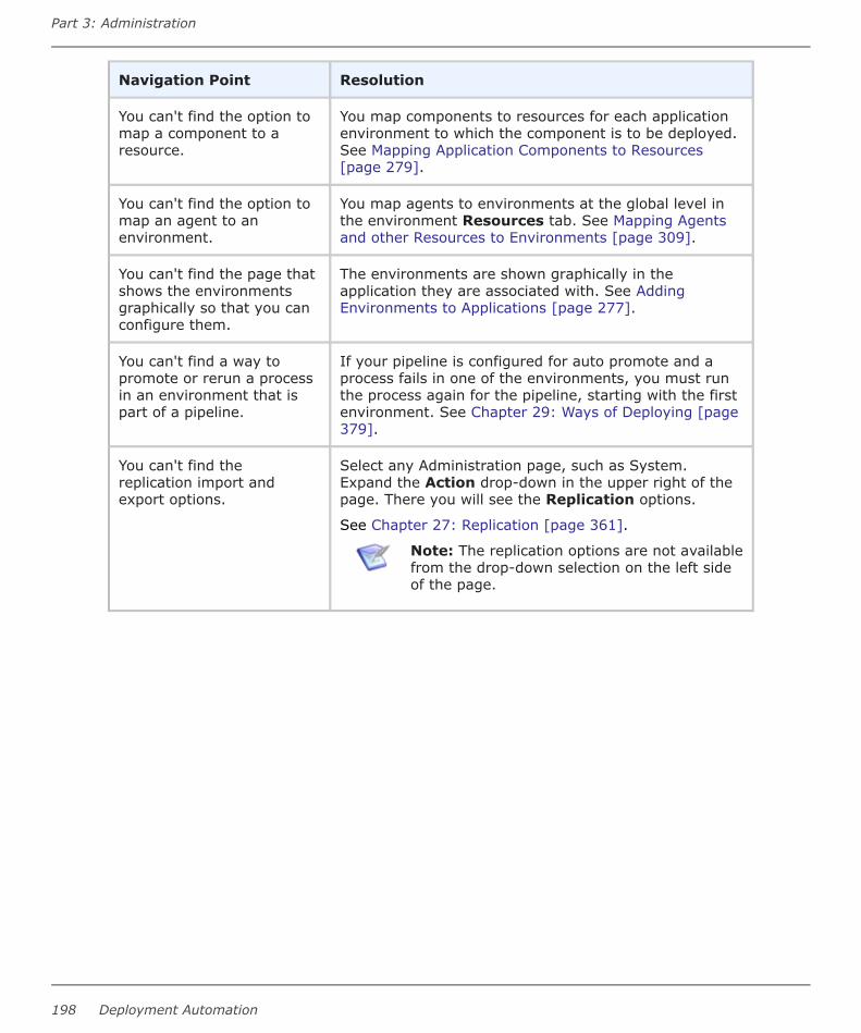
Navigation Point Resolution
You can't find the option tomap a component to aresource.
You map components to resources for each applicationenvironment to which the component is to be deployed.See Mapping Application Components to Resources[page 279].
You can't find the option tomap an agent to anenvironment.
You map agents to environments at the global level inthe environment Resources tab. See Mapping Agentsand other Resources to Environments [page 309].
You can't find the page thatshows the environmentsgraphically so that you canconfigure them.
The environments are shown graphically in theapplication they are associated with. See AddingEnvironments to Applications [page 277].
You can't find a way topromote or rerun a processin an environment that ispart of a pipeline.
If your pipeline is configured for auto promote and aprocess fails in one of the environments, you must runthe process again for the pipeline, starting with the firstenvironment. See Chapter 29: Ways of Deploying [page379].
You can't find thereplication import andexport options.
Select any Administration page, such as System.Expand the Action drop-down in the upper right of thepage. There you will see the Replication options.
See Chapter 27: Replication [page 361].
Note: The replication options are not availablefrom the drop-down selection on the left sideof the page.
Part 3: Administration
198 Deployment Automation

Part 4: Management
This section contains information on using Deployment Automation.
Included are the following topics:
• Chapter 17: Management Overview [page 201]
• Chapter 18: Managing Components [page 203]
• Chapter 19: Managing Applications [page 269]
• Chapter 20: Managing Environments [page 307]
• Chapter 21: Managing Pipelines [page 313]
• Chapter 22: Managing Resources [page 317]
• Chapter 23: Managing Deployment Packages [page 335]
• Chapter 24: Managing Global Processes [page 345]
• Chapter 25: Properties [page 351]
• Chapter 26: Configuring Within the Application Hierarchy [page 359]
• Chapter 27: Replication [page 361]
User's Guide 199

Part 4: Management
200 Deployment Automation

Chapter 17: Management Overview
The Management page is where you create and configure the primary elements ofDeployment Automation, design your processes, and initiate deployments. The followingoverview of the Management page will help get you started managing your DeploymentAutomation processes. Following are some of the selections on this page.
• Applications
See Chapter 19: Managing Applications [page 269].
• Components
See Chapter 18: Managing Components [page 203].
• Environments
See Chapter 20: Managing Environments [page 307].
• Deployment Packages
See Chapter 23: Managing Deployment Packages [page 335].
• Pipelines
See Chapter 21: Managing Pipelines [page 313].
• Resources
See Chapter 22: Managing Resources [page 317].
• Global Processes
See Chapter 24: Managing Global Processes [page 345].
• Configuration
See Chapter 26: Configuring Within the Application Hierarchy [page 359].
• Action
Select from management actions, including the following:
▪ New: Application, Component, Environment, Deployment Package, GlobalProcess, Pipeline, Resource, Template (Component)
▪ Import: Application, Component, Environment, Global Process, Pipeline,Template (Component)
User's Guide 201

Part 4: Management
202 Deployment Automation

Chapter 18: Managing Components
Components typically map to a functional part of a real world application, and representdeployable items, or artifacts, such as files, images, databases, and configurationmaterials.
Components have user-defined component processes that operate on those items, usuallyby deploying them. Components have versions, which are used to ensure that propercomponent instances get deployed.
When you create a component, you identify the source and define how the artifacts will bebrought into Deployment Automation. The artifacts can come from a number of sources,such as file systems, build servers such as Jenkins, configuration management systemssuch as Dimensions CM, source control systems such as Subversion and PVCS, and Mavenrepositories. Each component represents artifacts from a single source.
Upon automatic or manual version import, Deployment Automation imports thecomponent's artifacts into the Deployment Automation artifact repository, CodeStation.This stores component versions.
You create and configure components in the user interface as detailed in the followingtopics:
• Components Page Overview [page 203]
• Creating Components [page 204]
• Component Properties [page 230]
• Importing/Exporting Components [page 233]
• Component Versions [page 235]
• Component History [page 242]
• Component Processes [page 242]
• Component Tasks [page 263]
• Creating Component Templates [page 264]
• Configuration Templates [page 267]
• Deleting and Deactivating Components [page 267]
Components Page OverviewYou typically manage components in the Components page of the user interface.Following are some of the things you can do from this page.
• Filter the component list by components or component templates.
• Filter by the components created by you or by all users.
User's Guide 203

• Toggle the Inactive button to include or exclude inactive components.
• Click the Component Actions button to create or import components.
• Click the Component Template Actions button to create or import componenttemplates.
• Click the name to open the page for a listed component or component template.
• Click an icon beside a specific component or component template in the list to do thefollowing:
▪ Edit
▪ Copy
▪ Inactivate/Activate
▪ Export
▪ Delete
Creating ComponentsYou can create a new component or import an existing one. See Importing/ExportingComponents [page 233] for information about importing components.
To create a component:
1. Ensure that any artifacts you want to import into Deployment Automation are readyand are in the location from which you want to import them, such as your filesystem or a source configuration tool.
2. Navigate to Management > Components.
3. Click Create.
4. Enter the information needed to create the component as follows:
Option Description
Name Identifies the component; appears in many UI features.Required.
Description The optional description can be used to convey additionalinformation about the component. If the component is used bymore than one application, for example, entering "Used inapplications A and B" can help identify how the component isused.
Part 4: Management
204 Deployment Automation

Option Description
Template A component template enables you to reuse componentdefinitions; components based on templates inherit thetemplate's source configuration, properties, and process. Anypreviously created templates are listed. A component can havea single template associated with it. The default value is None.If you select a template, the Template Version field isdisplayed, which is used to select a template version. Bycontrolling the version, you can roll out template changes asrequired. The default value is Latest Version which means thecomponent will automatically use the newest version, bycreation date. See Creating Component Templates [page 264].
Note: If you select a template that already has asource config type, the dialog box will change toreflect values defined for the template. Several fields,including the Source Config Type field, will becomepopulated and locked.
SourceConfig Type
Defines the location from which to load the component'sartifacts into Deployment Automation. All artifacts for acomponent must have the same source configuration type.Selecting a value displays additional fields associated with theselection. For more information see Source Configuration TypeFields [page 207].
Note: If you selected a template, this field is lockedand its value is inherited from the template.
ImportVersionsAutomatically
If selected, the source location is periodically polled for newversions; any found are automatically imported.
• Polling Period
The time period in seconds between each poll for newversions. The polling interval is controlled by the AutomaticVersion Import Check Period (seconds) in Administration> System > System Settings. The default value is 15seconds.
• Quiet Period
The time period in minutes in which no polling is done. Thequiet period starts after the last polling period that detectedchanges. There is no default quiet period; you must set itfor each source type.
If left deselected, you can manually create versions by usingthe Versions pane. By default, the check box is deselected.
See Importing Versions Automatically [page 236] for moreinformation.
User's Guide 205

Option Description
Copy toCodeStation
This option, selected by default, creates a tamper-proof copy ofthe artifacts and stores them in the embedded artifactmanagement system, CodeStation. For optimal use ofDeployment Automation, the check box should be selected.
This option cannot be deselected if the selected sourceconfiguration type cannot be used to populate versions directly.If the option to deselect is available, see your sourceconfiguration type in Source Configuration Type Fields [page207] for more details.
DefaultVersion Type
Required. Defines how versions are imported into CodeStation.
Full means the version is comprehensive and contains allartifacts; Incremental means the version contains a subset ofthe component's artifacts. The default value is Full.
InheritCleanupSettings
Determines how many component versions are kept inCodeStation, and how long they are kept. If selected, thecomponent will use the values specified in Administration >System > System Settings. If deselected, additional fieldsappear.
Days to KeepVersions
If Inherit Cleanup Settings is not selected, this field appears,which enables you to define custom values. This is initially setto -1, keep indefinitely.
Number ofVersions toKeep
If Inherit Cleanup Settings is not selected, this field appears,which enables you to define custom values. This is initially setto -1, keep indefinitely.
Run processafter creatinga newversion
If selected, you may specify an application process andenvironment. The given application process will be run after anew version of the component is created.
5. To create additional components click Save and New. To start configuring thecomponent you just created, click Build Out.
Saved components are listed in the Components page. If you have selected ImportVersions Automatically, the initial versions will appear under the component'sVersions after the polling period plus any quiet period have elapsed. If not, you mustimport the initial versions manually. See Component Versions [page 235].
Note: You can also create components from a selected application, with theoption to create and then add the component in one dialog.
Part 4: Management
206 Deployment Automation
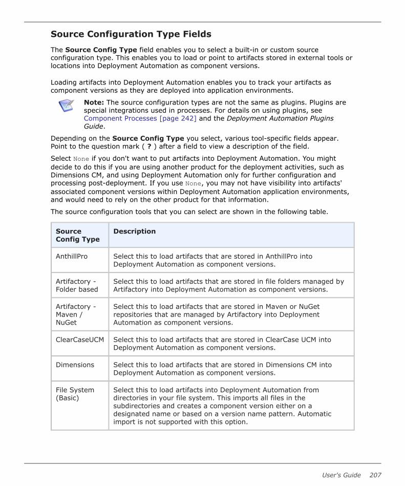
Source Configuration Type Fields
The Source Config Type field enables you to select a built-in or custom sourceconfiguration type. This enables you to load or point to artifacts stored in external tools orlocations into Deployment Automation as component versions.
Loading artifacts into Deployment Automation enables you to track your artifacts ascomponent versions as they are deployed into application environments.
Note: The source configuration types are not the same as plugins. Plugins arespecial integrations used in processes. For details on using plugins, seeComponent Processes [page 242] and the Deployment Automation PluginsGuide.
Depending on the Source Config Type you select, various tool-specific fields appear.Point to the question mark ( ? ) after a field to view a description of the field.
Select None if you don't want to put artifacts into Deployment Automation. You mightdecide to do this if you are using another product for the deployment activities, such asDimensions CM, and using Deployment Automation only for further configuration andprocessing post-deployment. If you use None, you may not have visibility into artifacts'associated component versions within Deployment Automation application environments,and would need to rely on the other product for that information.
The source configuration tools that you can select are shown in the following table.
SourceConfig Type
Description
AnthillPro Select this to load artifacts that are stored in AnthillPro intoDeployment Automation as component versions.
Artifactory -Folder based
Select this to load artifacts that are stored in file folders managed byArtifactory into Deployment Automation as component versions.
Artifactory -Maven /NuGet
Select this to load artifacts that are stored in Maven or NuGetrepositories that are managed by Artifactory into DeploymentAutomation as component versions.
ClearCaseUCM Select this to load artifacts that are stored in ClearCase UCM intoDeployment Automation as component versions.
Dimensions Select this to load artifacts that are stored in Dimensions CM intoDeployment Automation as component versions.
File System(Basic)
Select this to load artifacts into Deployment Automation fromdirectories in your file system. This imports all files in thesubdirectories and creates a component version either on adesignated name or based on a version name pattern. Automaticimport is not supported with this option.
User's Guide 207

SourceConfig Type
Description
File System(Versioned)
Select this to load artifacts into Deployment Automation fromdirectories in your file system, creating a component version for eachsubdirectory in the base path.
Git Select this to load artifacts that are stored in Git into DeploymentAutomation as component versions.
Jenkins Select this to load artifacts that are stored in Jenkins into DeploymentAutomation as component versions. This does not display additionalfields, but rather indicates that the Jenkins plugin for DeploymentAutomation is configured and activated.
Luntbuild Select this to load artifacts that are stored in Luntbuild intoDeployment Automation as component versions.
Maven Select this to load artifacts that are stored in Maven into DeploymentAutomation as component versions.
Nexus Select this to load artifacts that are stored in Nexus into DeploymentAutomation as component versions.
PVCS Select this to load artifacts that are stored in PVCS into DeploymentAutomation as component versions.
Perforce Select this to load artifacts that are stored in a Perforce versioningengine into Deployment Automation as component versions.
StarTeam Select this to load artifacts that are stored in Borland StarTeam intoDeployment Automation as component versions.
Subversion Select this to load artifacts that are stored in Subversion intoDeployment Automation as component versions.
TFS Select this to load artifacts that are stored in Microsoft TeamFoundation Server (TFS) into Deployment Automation as componentversions. Use this if using XAML build automation.
TFS vNext Select this to load artifacts that are stored in Microsoft TeamFoundation Server (TFS) 2015 and above into DeploymentAutomation as component versions. If you are using XAML buildautomation, use the TFS source configuration type.
TFS_SCM Select this to load artifacts that are stored in TFS_SCM intoDeployment Automation as component versions.
TeamCity Select this to load artifacts that are stored in JetBrains TeamCity intoDeployment Automation as component versions.
Part 4: Management
208 Deployment Automation

SourceConfig Type
Description
TeamForge Select this to load artifacts that are stored in CollabNet TeamForgeinto Deployment Automation as component versions.
For information on some of the source configuration types' fields, see the following topics.
• File System (Basic) [page 209]
• File System (Versioned) [page 210]
• AnthillPro [page 211]
• Artifactory [page 212]
• Dimensions [page 214]
• Git [page 216]
• Jenkins [page 217]
• Maven [page 218]
• Nexus Sonatype [page 219]
• PVCS [page 221]
• Subversion [page 222]
• TeamCity [page 224]
• TFS [page 224]
• TFS vNext [page 226]
• TFS_SCM [page 228]
• TeamForge [page 229]
File System (Basic)
The File System (Basic) source configuration type is implemented as an external type.
When you select File System (Basic) for Source Config Type, Deployment Automationimports all contents of a designated directory from the file system as follows:
• At import, imports everything in the given base path, including all files at the basepath level, its subdirectories, and all files in all of its subdirectories.
• If you specify the Version Name Pattern and Next Version Number, DeploymentAutomation auto-increments version numbers and assigns them as the componentversion names. With this option, you can use Import Versions Automatically orimport manually.
User's Guide 209

• If you do not specify a version name pattern, you must manually import thecomponent version, and you will be prompted to enter a version name at the time ofmanual import. The Import Versions Automatically option, if selected, is ignored.
File System (Basic) Source Fields Table
Field Description
Base Path Base path for artifact storage.
Always UseNamePattern
When selected, the Version Name Pattern will be used for new versionnames at the time of import. If this is not selected, the user is promptedfor the version name at the time of import.
VersionNamePattern
An optional field to create a template for automatic version names. Use${version} to reference the Next Version Number field.
NextVersionNumber
An integer used for the next version created. This number isautomatically incremented for every version created.
PreserveExecutePermissions
When enabled, file execute permissions are saved with the files.
Use LatestComponentPropertiesfor VersionDownload
If this is selected, the current component properties are used todownload this component's version artifacts in Versions > Artifacts.You should deselect this if the component's storage location orconnection details have changed since the version artifacts you want todownload were imported, so that the component properties that wereset when the version was created are used instead. See MaintainingVersions Externally [page 237].
Copy toCodeStation
This option, selected by default, creates a tamper-proof copy of theartifacts and stores them in the embedded artifact management system,CodeStation. For optimal use of Deployment Automation, the check boxshould be selected.
If you deselect Copy to Codestation for this source configuration type,pointers to versions are saved in Deployment Automation rather thanthe versions themselves. This enables you to track the versions, butlimits some functionality in Deployment Automation. See MaintainingVersions Externally [page 237].
File System (Versioned)
The File System (Versioned) source configuration type is implemented as an externaltype.
Part 4: Management
210 Deployment Automation

When you select File System (Versioned) for Source Config Type, Deployment Automationimports the subdirectories of a designated directory from the file system as follows:
• At import, imports only the subdirectories and contents of subdirectories; it does notinclude the contents directly in the base path.
• The first level subdirectory in the base path becomes a component version and theversion name is the name of the subdirectory.
• It does not prompt for version name during manual import; version naming is alwaysautomatic and is always the first subdirectory name.
File System (Versioned) Source Fields Table
Field Description
Base Path Path to directory containing artifacts. The content of each subdirectorywithin the base directory is considered a distinct component version.The subdirectory with the most recent time-stamp is considered the"latest version"; however, is a good practice to name the subdirectoriesaccording to your version scheme, such as v1.0, v1.1, and so on.
PreserveExecutePermissions
When enabled, file execute permissions are saved with the files.
Use LatestComponentPropertiesfor VersionDownload
If this is selected, the current component properties are used todownload this component's version artifacts in Versions > Artifacts.You should deselect this if the component's storage location orconnection details have changed since the version artifacts you want todownload were imported, so that the component properties that wereset when the version was created are used instead. See MaintainingVersions Externally [page 237].
Copy toCodeStation
This option, selected by default, creates a tamper-proof copy of theartifacts and stores them in the embedded artifact management system,CodeStation. For optimal use of Deployment Automation, the check boxshould be selected.
If you deselect Copy to Codestation for this source configuration type,pointers to versions are saved in Deployment Automation rather thanthe versions themselves. This enables you to track the versions, butlimits some functionality in Deployment Automation. See MaintainingVersions Externally [page 237].
AnthillPro
IBM AnthillPro combines continuous integration with automated deployments and testorchestration to create a continuous delivery pipeline.
User's Guide 211

To use AnthillPro as an artifact source, select AnthillPro from the Source Config Type drop-down list box and then configure the type-specific fields described here. For informationabout creating components, see Creating Components [page 204].
AnthillPro Fields Table
Field Description
AnthillProURL
AnthillPro Repository URL
User AnthillPro username
Password Password for the specified username
Project Name of the project in Anthill
Workflow Name of the workflow in Anthill from which to import builds
Status Only builds with this status will be imported
ArtifactSets
A new-line-separated list of artifact sets to resolve from Anthill when Copyto CodeStation is enabled
Artifactory
JFrog Artifactory is a universal artifact repository manager. You can use Artifactory withartifacts stored in folders or with Maven or Nuget as an artifact source.
To use Artifactory as an artifact source, select Artifactory in Source Config Type andthen configure the type-specific fields. For information about creating components, seeCreating Components [page 204].
Use the Copy to CodeStation option as follows:
• If you deselect Copy to CodeStation for a component using this sourceconfiguration type:
▪ Empty versions are created in Deployment Automation upon import. To downloadArtifactory-managed versions in processes, you must use the Artifactory plugin.See the JFrog Artifactory section in the Deployment Automation Plugins Guide.
▪ You must use the Artifactory plugin to download artifacts as part of yourcomponent processes. You cannot use the DA VFS plugin to download them.
• If you select Copy to CodeStation for a component, you must use the DA VFSplugin to download artifacts.
See the Deployment Automation Plugins Guide for plugin details.
Note: If you are using Apache Maven without Artifactory as your sourceconfiguration type, see Maven [page 218].
Part 4: Management
212 Deployment Automation

Artifactory - Folder Based Fields TablePrerequisite:
To use this option, you must do the following:
1. On the Artifactory server, navigate to Admin > General Configuration > FolderDownload Settings.
2. Select Enable Folder Download.
Following are the fields for Artifactory with artifacts stored in folders as an artifact source.
Field Description
Server URL The base URL for the Artifactory server, such ashttp://serverName:8081/artifactory
Username Username for authentication to the Artifactory server
Password Password for authentication to the Artifactory server
Repository Name of the repository
Module Module path to the artifacts in the specified repository
Latest Artifact Count The maximum number of latest artifact versions to be imported
Version NamePattern
If specified, only versions with names matching this regularexpression will be imported.
Preserve ExecutePermissions
If this is selected, file execute permissions are saved with thefiles.
Artifactory - Maven / NuGet Fields TableFollowing are the fields for Artifactory with Maven or Nuget as an artifact source.
Field Description
Server URL The base URL for the Artifactory server, such ashttp://serverName:8081/artifactory
Username Username for authentication to the Artifactory server
Password Password for authentication to the Artifactory server
User's Guide 213

Field Description
Repository Name of Maven or NuGet repository
PackageType
Select the type of package to be used as the repository, Maven orNuGet.
Group ID For Maven only, this is the group ID of the artifact, such ascom.mycompany or com/mycompany. For NuGet, leave this field blank.
Tip: Group ID is the <groupid> parameter in the Mavendependency within the Artifactory artifact.
Artifact IDor nuget.id
Enter the name of the artifact to be imported. For Maven it should be theartifact ID, such as mypackage-test. For NuGet it should be the value ofthe artifact nuget.id property, such as EntityFramework.
Tip: Artifact ID is the <artifactid> parameter in the Mavendependency within the Artifactory artifact.
File NamePattern
If specified, only files with names matching this regular expression willbe imported.
LatestArtifactCount
The maximum number of latest artifact versions to be imported
VersionNamePattern
If specified, only versions with names matching this regular expressionwill be imported. For a snapshot repository, specify the snapshotversion, such as 1.0-SNAPSHOT.
PreserveExecutePermissions
If this is selected, file execute permissions are saved with the files.
Dimensions
The Dimensions CM source configuration type is implemented as an external type.
Dimensions CM is a process management and change control system that helps youorganize, manage, and protect your software development projects.
Part 4: Management
214 Deployment Automation
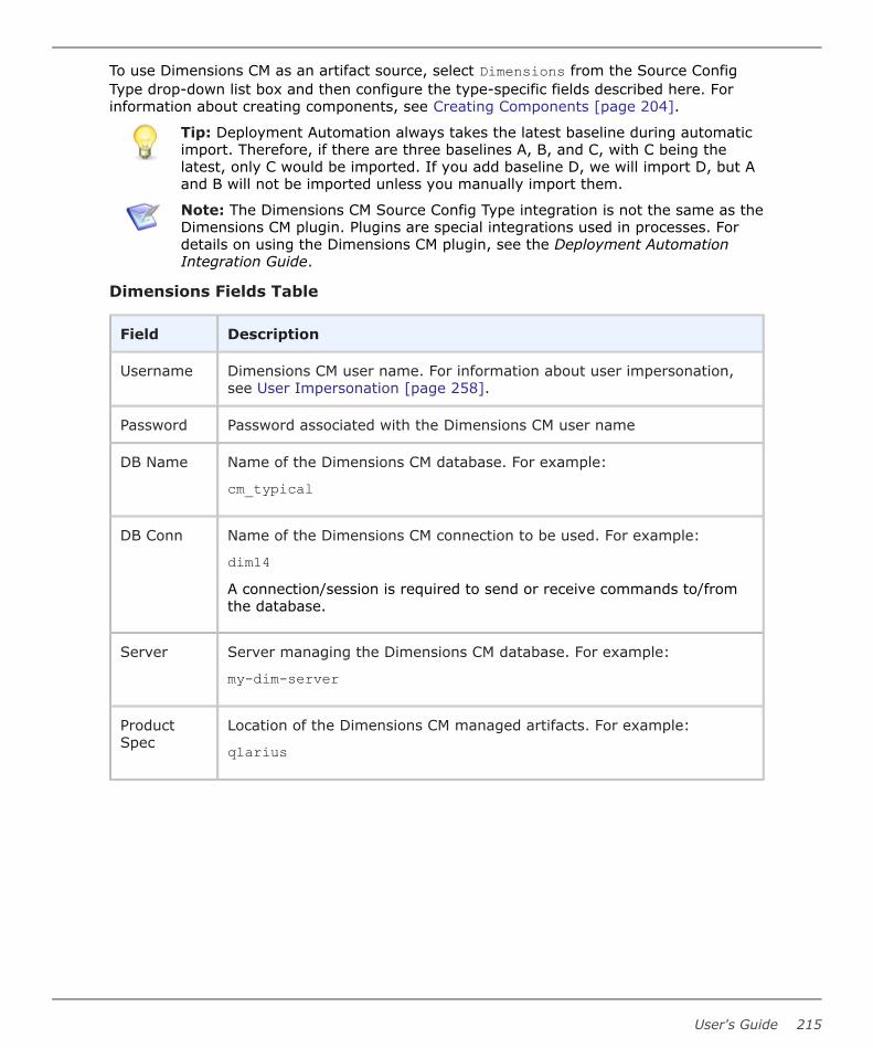
To use Dimensions CM as an artifact source, select Dimensions from the Source ConfigType drop-down list box and then configure the type-specific fields described here. Forinformation about creating components, see Creating Components [page 204].
Tip: Deployment Automation always takes the latest baseline during automaticimport. Therefore, if there are three baselines A, B, and C, with C being thelatest, only C would be imported. If you add baseline D, we will import D, but Aand B will not be imported unless you manually import them.
Note: The Dimensions CM Source Config Type integration is not the same as theDimensions CM plugin. Plugins are special integrations used in processes. Fordetails on using the Dimensions CM plugin, see the Deployment AutomationIntegration Guide.
Dimensions Fields Table
Field Description
Username Dimensions CM user name. For information about user impersonation,see User Impersonation [page 258].
Password Password associated with the Dimensions CM user name
DB Name Name of the Dimensions CM database. For example:
cm_typical
DB Conn Name of the Dimensions CM connection to be used. For example:
dim14A connection/session is required to send or receive commands to/fromthe database.
Server Server managing the Dimensions CM database. For example:
my-dim-server
ProductSpec
Location of the Dimensions CM managed artifacts. For example:
qlarius
User's Guide 215

Field Description
Includes Specify patterns to match files to include in the upload. You can matchexact file paths and file names, or you can specify wildcards. The defaultvalue is **/*, for all directories and files.
You can specify exact file path and file name combinations with oneentry per line. For example,
Maestro/RLM.jobsMaestro/RLM.schedYou can specify wildcards to match directories and files where thewildcard ** indicates every directory and the wildcard * indicates everyfile. For example, the pattern dist/**/* would retrieve the entire filetree under the dist directory.
Excludes Specify patterns to match files to exclude from the upload. You canmatch exact file paths and file names, or you can specify wildcards. Seethe examples in the previous table entry.
Use LatestComponentPropertiesfor VersionDownload
If this is selected, the current component properties are used todownload this component's version artifacts in Versions > Artifacts.You should deselect this if the component's storage location orconnection details have changed since the version artifacts you want todownload were imported, so that the component properties that wereset when the version was created are used instead. See MaintainingVersions Externally [page 237].
Copy toCodeStation
This option, selected by default, creates a tamper-proof copy of theartifacts and stores them in the embedded artifact management system,CodeStation. For optimal use of Deployment Automation, the check boxshould be selected.
If you deselect Copy to Codestation for this source configuration type,pointers to versions are saved in Deployment Automation rather thanthe versions themselves. This enables you to track the versions, butlimits some functionality in Deployment Automation. See MaintainingVersions Externally [page 237].
Git
The Git source configuration type is implemented as an external type.
Git is a free and open source distributed version control system.
To use Git as an artifact source, select Git from the Source Config Type drop-down listbox and then configure the type-specific fields described here. For information aboutcreating components, see Creating Components [page 204].
Part 4: Management
216 Deployment Automation

Git Fields Table
Field Description
RepositoryURL
Enter the base URL for the Git repository.
Branch Enter the Git branch from which to get artifacts, such as master.
Watch fortags
If selected, Deployment Automation watches for new tags instead ofnew versions.
Includes The patterns to match files to upload. The wildcard ** indicates everydirectory and * indicates every file. For example, dist/**/* retrievesthe entire file tree under the dist directory.
Excludes The patterns to match files to exclude from the upload.
GIT Path Enter the Git client executable, using the full path if necessary. Forexample:
git
PreserveExecutePermissions
If selected, file execute permissions are saved with the files.
Use LatestComponentPropertiesfor VersionDownload
If this is selected, the current component properties are used todownload this component's version artifacts in Versions > Artifacts.You should deselect this if the component's storage location orconnection details have changed since the version artifacts you want todownload were imported, so that the component properties that wereset when the version was created are used instead. See MaintainingVersions Externally [page 237].
Copy toCodeStation
This option, selected by default, creates a tamper-proof copy of theartifacts and stores them in the embedded artifact management system,CodeStation. For optimal use of Deployment Automation, the check boxshould be selected.
If you deselect Copy to Codestation for this source configuration type,pointers to versions are saved in Deployment Automation rather thanthe versions themselves. This enables you to track the versions, butlimits some functionality in Deployment Automation. See MaintainingVersions Externally [page 237].
Jenkins
Jenkins is an extendable open source continuous integration server.
User's Guide 217

To use Jenkins as an artifact source, you must install the "Serena Deploy" plugin on yourJenkins system. All of the configuration of the plugin is done in Jenkins. For details, seethe Community website and search for "Jenkins / Hudson HPI".
When the Jenkins / Hudson HPI plugin is configured, a Jenkins post-build step pushes thebuilt artifacts into the Deployment Automation CodeStation repository and either deploysthem immediately, if the Run process after creating a new version option is selected,or deploys later when a deployment process associated with the component is executed.
When you select Jenkins in the Source Config Type field, no additional fields appear.Selecting Jenkins in the Source Config Type is optional, as it simply indicates that you areusing the plugin that is configured and running in Jenkins.
For information about creating components, see Creating Components [page 204].
Important: The Jenkins Source Config Type integration is not a DeploymentAutomation plugin; it is a Jenkins plugin.
Maven
Apache Maven is a software project management and comprehension tool.
To use Maven as an artifact source, select Maven in Source Config Type and thenconfigure the type-specific fields. For information about creating components, seeCreating Components [page 204].
If you deselect Copy to CodeStation for a component using this source configurationtype:
• Empty versions are created in Deployment Automation upon import.
• You must use the Apache Maven plugin to download artifacts as part of yourcomponent processes. You cannot use the DA VFS plugin to download them.
If you select Copy to CodeStation for a component, you must use the DA VFS plugin todownload artifacts.
See the Deployment Automation Plugins Guide for plugin details.
Note: If you are using Maven through Artifactory as your source configurationtype, see Artifactory [page 212].
Maven Fields Table
Field Description
RepositoryURL
Base URL for the Maven repository
User Maven user name
Password Password associated with the user name
Group ID Maven group ID
Part 4: Management
218 Deployment Automation

Field Description
Artifact ID Maven artifact ID
MavenQualifier
Specify the name to append to the filename after the version. Leaveblank if not applicable.
FileExtension
Extension of the file to be pulled from Maven for new versions
Latest BuildCount
Number of most recent builds in Maven to load into DeploymentAutomation
VersionNamePattern
If set, only versions with names matching this pattern will be imported.For each group matching the first capturing group, the desired numberof latest builds will be loaded into Deployment Automation. This propertyis only necessary when tracking 'older' branches that contain new builds.Example: To return n versions of each 1.0.*, 1.1.*, 1.2.*, ..., use thefollowing regex: (1.[0-9]+).*
PreserveExecutePermissions
When enabled, file execute permissions are saved with the files.
Nexus Sonatype
The Nexus Sonatype source type component supports granular access and filtering forartifacts stored in Nexus repositories.
To use Nexus as an artifact source, select Nexus in Source Config Type and thenconfigure the type-specific fields. For information about creating components, seeCreating Components [page 204].
Nexus Fields Table
Field Description
Server URL Base URL and port for the Nexus server, for example:http://localhost:8081
User Name Nexus user name
Password Password for the Nexus user
Repository The name of the Nexus repository
NexusComponent
Specify a Nexus component name if you only want to import versionsof that component. Use this field when you have multiple componentsin the same repository, for example, for NPM repositories.
User's Guide 219

Field Description
ComponentGroup
The group ID of the component to which the assets belong. In Mavenrepositories the ID follows Java package naming rules, for example,org.apache.maven.
Importfolders asversions
Applies to repository types that do not have specific versions, forexample, 'raw'. Folders with subfiles are imported as separateversions.
Import allnew versions
Selected: all missing versions are imported.
Not selected: only the latest version is imported.
Skip emptyversions
Versions without content are not imported.
Include files Specify patterns to match files to include in the upload. You can matchexact file paths and file names, or you can specify wildcards. Thedefault value is **/*, for all directories and files.
You can specify exact file path and file name combinations with oneentry per line. For example,
Maestro/RLM.jobsMaestro/RLM.schedYou can specify wildcards to match directories and files where thewildcard ** indicates every directory and the wildcard * indicates everyfile. For example, the pattern dist/**/* would retrieve the entire filetree under the dist directory.
Exclude files Specify patterns to match files to exclude from the upload. You canmatch exact file paths and file names, or you can specify wildcards.See the examples in the row above.
Preserveexecutepermissions
File execute permissions are preserved.
Importversionsautomatically
Configured version source are polled periodically for new versions.
Part 4: Management
220 Deployment Automation

Field Description
Copy toCodeStation
This option, selected by default, creates a tamper-proof copy of theartifacts and stores them in the embedded artifact managementsystem, CodeStation. For optimal use of Deployment Automation, thecheck box should be selected.
If you deselect Copy to Codestation for this source configurationtype, pointers to versions are saved in Deployment Automation ratherthan the versions themselves. This enables you to track the versions,but limits some functionality in Deployment Automation. SeeMaintaining Versions Externally [page 237].
Use latestcomponentpropertiesfor versionsdownload
When component version artifacts are downloaded, the properties setfor the associated component are used instead of the properties setwhen the version is created.
Component version properties are always preserved when a version iscreated.
DefaultVersion Type
The default version type to be created for imported versions.
Inheritcleanupsettings
This environment will inherit version cleanup configurations from thesettings of each component or the system.
PVCS
PVCS Version Manager is a version control management tool.
To use PVCS as an artifact source, select PVCS from the Source Config Type drop-down listbox and then configure the type-specific fields described here. For information aboutcreating components, see Creating Components [page 204].
PVCS Fields Table
Field Description
PCLI Path Path to the PVCS CLI tool.
DatabasePath
Path to the PVCS database.
Base Path Base path of the repository.
ProjectPath
Path to the project.
User's Guide 221

Field Description
ArchivePath
The location of the archive relative to the database path.
Includes The patterns to match files to upload. The wild card ** indicates everydirectory and the wildcard * indicates every file. For example, thepattern dist/**/* would retrieve the entire file tree under the distdirectory.
Excludes The patterns to exclude files from the upload.
User PVCS username. For information about user impersonation, see UserImpersonation [page 258]
Password Password associated with the PVCS username.
Always UseNamePattern
If this option is selected, the Version Name Pattern specified will alwaysbe used. Not selected by default.
VersionNamePattern
An optional template for automatic version names. Use ${version} toreference the Next Version Number field.
NextVersionNumber
An integer used for the next version created. The number isautomatically incremented for each version created.
PreserveExecutePermissions
To save file execute permissions with the files, select this check box. Notselected by default.
Subversion
The Subversion source configuration type is implemented as an external type.
Subversion (SVN) is an open source version control system.
To use Subversion as an artifact source, select Subversion from the Source Config Typedrop-down list box and then configure the type-specific fields described here. Forinformation about creating components, see Creating Components [page 204].
Note: The Subversion Source Config Type integration is not the same as theSubversion plugin. Plugins are special integrations used in processes. For detailson using the Subversion plugin, see the Deployment Automation Plugins Guide.
Part 4: Management
222 Deployment Automation
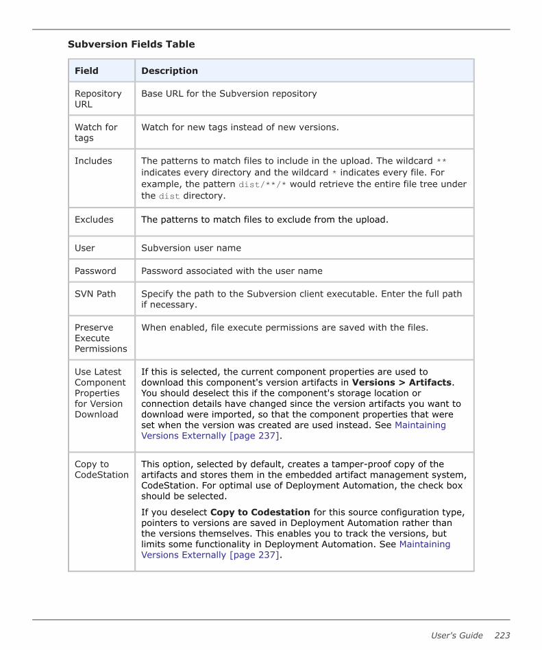
Subversion Fields Table
Field Description
RepositoryURL
Base URL for the Subversion repository
Watch fortags
Watch for new tags instead of new versions.
Includes The patterns to match files to include in the upload. The wildcard **indicates every directory and the wildcard * indicates every file. Forexample, the pattern dist/**/* would retrieve the entire file tree underthe dist directory.
Excludes The patterns to match files to exclude from the upload.
User Subversion user name
Password Password associated with the user name
SVN Path Specify the path to the Subversion client executable. Enter the full pathif necessary.
PreserveExecutePermissions
When enabled, file execute permissions are saved with the files.
Use LatestComponentPropertiesfor VersionDownload
If this is selected, the current component properties are used todownload this component's version artifacts in Versions > Artifacts.You should deselect this if the component's storage location orconnection details have changed since the version artifacts you want todownload were imported, so that the component properties that wereset when the version was created are used instead. See MaintainingVersions Externally [page 237].
Copy toCodeStation
This option, selected by default, creates a tamper-proof copy of theartifacts and stores them in the embedded artifact management system,CodeStation. For optimal use of Deployment Automation, the check boxshould be selected.
If you deselect Copy to Codestation for this source configuration type,pointers to versions are saved in Deployment Automation rather thanthe versions themselves. This enables you to track the versions, butlimits some functionality in Deployment Automation. See MaintainingVersions Externally [page 237].
User's Guide 223

TeamCity
TeamCity is a Java-based build management and continuous integration server fromJetBrains.
To use TeamCity as an artifact source, select TeamCity from the Source Config Type drop-down list box and then configure the type-specific fields described here. For informationabout creating components, see Creating Components [page 204].
TeamCity Fields Table
Field Description
Repository URL Base URL for the TeamCity repository.
User TeamCity user name.
Password Password associated with the user name.
Project Name of the TeamCity project that contains the buildconfiguration.
BuildConfiguration
Name of the build configuration in the TeamCity project thatcontains the builds to use in the component.
Build Type ID of the TeamCity build type.
Preserve ExecutePermissions
When enabled, file execute permissions are saved with the files.
TFS
Microsoft Visual Studio Team Foundation Server (TFS) is the collaboration platform at thecore of Microsoft's application lifecycle management (ALM) solution.
For more information on using TFS, see the Microsoft documentation.
Select TFS from the Source Config Type drop-down list box and then configure the type-specific fields described here. For information about creating components, see CreatingComponents [page 204].
Note: This brings your built artifacts from TFS into Deployment Automation. Ifyou want to bring TFS source controlled artifacts into Deployment Automation,see TFS_SCM [page 228].
Prerequisites
Before you can use TFS source configuration type, ensure the following prerequisites aremet.
• An executable named tftoolxxxx.exe (where xxxx is the version of TFS, and can be2008, 2010, 2012, 2013, 2015, or 2017) must be installed on the DeploymentAutomation server.
Part 4: Management
224 Deployment Automation

The Deployment Automation server installer in Deployment Automation version 5.1.5and later automatically installs the supported tftool executables. These are placedin the Deployment Automation server tools\tfs directory in folders that match eachexe name. For example, the tftool2013.exe is installed here by default:
C:\Program Files\Micro Focus\Deployment Automation Server\tools\tfs\tftool2013\tftool2013.exe
• The Deployment Automation server and the TFS software must be installed on thesame machine, because there are certain TFS DLL files required by the tftoolexecutable.
• The installation folder is specified in the tfsToolLocation property in the serverinstallation's conf\server\installed.properties file, so there is no need toinclude this in the Path variable.
Note: If the tftool executable is not found in the in designated folder, anerror message similar to the following will appear:
"You must provide a valid TFS tool; C:\Program Files\MicroFocus\Deployment Automation Server\tools\tfs\tftool2013\tftool2013.exe was not found."
• If you upgraded or reinstalled and selected the Use Existing Settings option on theGeneral Program Settings panel during installation, the tfsToolLocation propertymay not be set in the server installation's conf\server\installed.properties file.In that case, you'll need to add the property to the file manually and set it to thedirectory path where your tftool executables reside. For example:
tfsToolLocation=C:\Program Files\Micro Focus\Deployment Automation Server\tools\tfs
TFS Fields Table
Field Description
TFS URL Specify the TFS server URL. For example:
http://tfs2013:8080/tfs/mycollection
TFSVersion
Select the version of the TFS libraries that you want to use. These arelisted from those installed on the Deployment Automation server. See thePrerequisites for details.
Note: Use 2015 or 2017 with the TFS source configuration typeonly if you are using XAML builds. Otherwise, see TFS vNext[page 226].
TFSUsername
Specify a username if you need to use different credentials than the onesused for the Deployment Automation process.
User's Guide 225

Field Description
TFSPassword
Specify a password if you specified a username.
TFS TeamProject
The name of the TFS team project where the build definition resides
BuildDefinition
The name of the build definition to monitor for new builds
BuildStatus
Limit builds to a given status.
BuildQuality
Limit builds to a given build quality.
DirectoryOffset
Directory offset within the root of the build artifacts
FileIncludes
Specify a new-line-separated list of files to include. Leave blank or use**/* to include all.
FileExcludes
Specify a new-line-separated list of files to exclude.
TFS vNext
Microsoft Visual Studio Team Foundation Server (TFS) is the collaboration platform at thecore of Microsoft's application lifecycle management (ALM) solution. For more informationon using TFS, see the Microsoft documentation.
The TFS vNext source configuration type is implemented as an external type and is to beused with TFS 2015 and 2017. If you are using earlier versions of TFS, see TFS [page224].
Part 4: Management
226 Deployment Automation

Select TFS vNext from the Source Config Type drop-down list box and then configurethe type-specific fields described here. For information about creating components, seeCreating Components [page 204].
Tip:
When you import a version for a component that uses this source configurationtype, you are prompted for build number. There you should enter the build thathas the artifacts you want to import. If you leave it blank, the latest build'sartifacts are imported.
Note: This brings your built artifacts from TFS into Deployment Automation. Ifyou want to bring TFS source controlled artifacts into Deployment Automation,see TFS_SCM [page 228].
Important: If TFS build artifacts are published to a network share, you mustensure that the Deployment Automation application server, Common Tomcat, isrunning under a user account that has access to that network share. See ServerInstallation [page 47].
TFS vNext Fields Table
Field Description
TFS URL Specify the TFS server URL. For example:
http://tfs2017:8080/tfs/DefaultCollection
TFSUsername
A username that can access the TFS API
TFS AccessToken
If using access tokens, specify a valid TFS access token for a TFS userwith build (read) permissions. If using basic authentication, specify theuser password.
Note: The TFS vNext source configuration type isimplemented using the REST API. Access tokens can becreated to access the REST API in TFS 2017. This access tokenmust have build (read) permission.
TFS TeamProject
The name of the TFS team project where the build definition resides
BuildDefinition
Specify the name of the build definition to monitor for new builds
Build Result Select one or more results to limit the builds that are eligible for versionimport.
User's Guide 227

Field Description
Use LatestComponentPropertiesfor VersionDownload
If this is selected, the current component properties are used todownload this component's version artifacts in Versions > Artifacts.You should deselect this if the component's storage location orconnection details have changed since the version artifacts you want todownload were imported, so that the component properties that wereset when the version was created are used instead. See MaintainingVersions Externally [page 237].
Copy toCodeStation
This option, selected by default, creates a tamper-proof copy of theartifacts and stores them in the embedded artifact management system,CodeStation. For optimal use of Deployment Automation, the check boxshould be selected.
If you deselect Copy to Codestation for this source configuration type,pointers to versions are saved in Deployment Automation rather thanthe versions themselves. This enables you to track the versions, butlimits some functionality in Deployment Automation. See MaintainingVersions Externally [page 237].
TFS_SCM
TFS_SCM is a Microsoft extension for TFS, Source Control Explorer.
To use TFS_SCM as an artifact source, select TFS_SCM from the Source Config Type drop-down list box and then configure the type-specific fields described here. For informationabout creating components, see Creating Components [page 204].
For more information on using TFS_SCM, see https://docs.microsoft.com/en-us/vsts/tfvc/use-source-control-explorer-manage-files-under-version-control.
Note: This brings your source controlled artifacts from TFS into DeploymentAutomation. If you want to bring TFS build artifacts into DeploymentAutomation, see TFS [page 224].
TFS_SCM Fields Table
Field Description
TFS URL Specify the TFS Repository URL.
User Specify a username if you need to use different credentials than theones used for the Deployment Automation process.
Password Specify a password if you specified a username.
tf.exe Path tf.exe client executable. Enter the full path if necessary.
Part 4: Management
228 Deployment Automation

Field Description
Workspace Enter the name of the TFS workspace to use. It will be created if itdoes not exist.
Server Folder The TFS server folder to load
Local Folder The local folder of the workspace
PreserveExecutePermissions
When enabled, file execute permissions are saved with the files.
TeamForge
CollabNet TeamForge is an integrated Web-based platform that enables teams to workcollaboratively through the various stages of the application life cycle.
To use TeamForge as an artifact source, select TeamForge from the Source Config Typedrop-down list box and then configure the type-specific fields described here. Forinformation about creating components, see Creating Components [page 204].
For more information on using TeamForge, see http://www.collab.net/products/teamforge.
Note: The TeamForge Source Config Type integration is not the same as theTeamForge plugin. Plugins are special integrations used in processes. For detailson using the TeamForge plugin, see the Deployment Automation Plugins Guide.
TeamForge Fields Table
Field Description
TeamForge URL Base URL of the TeamForge server.
Username Username for authenticating with TeamForge.
Password Password for authenticating with TeamForge.
Project Name TeamForge project name from which to import componentversions.
Package Name TeamForge package name from which to import componentversions.
Preserve ExecutePermissions
When enabled, file execute permissions are saved with thefiles.
User's Guide 229

Component PropertiesComponent properties include not only properties to be resolved for the component, butalso settings that can be overridden for each environment the component is mapped toand for each version of the component.
For more information on the use of properties in Deployment Automation, see Chapter 25:Properties [page 351].
The types of properties available to add to components are as follows:
• Properties
These user-defined component properties can be used in scripts and plugins.Properties inherited from templates cannot be modified on the component level.
• Environment Property Definitions
These user-defined environment properties are available to environments that usethe component. Values can be set at the individual environment level.
• Version Property Definitions
These user-defined version properties are available to this component's versions.Values can be set at the individual version level.
For information on working with component properties, see the following topics:
• Adding Component Properties [page 230]
• Adding Component Environment Properties [page 231]
• Adding Component Version Properties [page 232]
Adding Component PropertiesAdd properties to a component for information that may have values specific to thatcomponent. A component property value would override the value for the same-namedproperty at the application level.
To add a property to the selected component:
1. Navigate to Management > Components > [select component].
2. Select Properties and then click the Properties tab.
3. To set a single property, click Add Property.
a. Fill in the fields as shown in the following table.
Field Description
Name Property name
Description Property description
Part 4: Management
230 Deployment Automation

Field Description
Secure Select this if the property should be secure.
Secure properties are stored encrypted and displayed obscuredin the Deployment Automation user interface.
Value Value for the property that will be used by steps in a process
4. To set multiple properties, click Batch Edit.
a. In the Properties box, enter multiple properties and their values on separatelines as property=value.
For example, if you had properties host and port, you would enter them asfollows:
host=myServerport=8080
Note:
The following restrictions apply to batch edit:
• The Secure option cannot be set.
• The value cannot contain the "=" symbol.
5. Click Save.
To use the property in a process, reference it when you configure a step that uses it. Usethe following syntax: ${p:component/<property name>}
Adding Component Environment PropertiesComponent environment properties are user-defined properties that you can define on thecomponent and then give unique values for each of the environments mapped to thecomponent. This lets you run the same process step in multiple environments that havedifferent configurations; Deployment Automation resolves the property values as thecomponent is deployed to each environment. For example, you may have different webserver instances on each environment, and can add a component environment propertyand enter a different value for each environment, DEV, INT, UAT, and PROD.
To add component environment properties:
1. Navigate to Management > Components > [select component].
2. Select Properties and then click the Environment PropDefs tab.
3. Click the Add Property button.
4. Fill in the fields as shown in the following table.
User's Guide 231

Field Description
Name Property name
Description Property description
Label Enter a label to be associated with the property in the userinterface.
Required Select this if the property is required.
Type Specify the type of expected value. The supported types are asfollows:
• text
• text area
• check box
• select
• multi select
• secure
The default type is text.
DefaultValue
Enter a default value (if any).
5. Click Save.
You can now set values for the property in each of this component's applicationenvironments. See Setting Component Environment Property Values [page 280].
Adding Component Version PropertiesComponent version properties are user-defined properties that you can define on thecomponent and then give unique property values for each version of the component.
To add component version properties:
1. Navigate to Management > Components > [select component].
2. Select Properties and then click the Version PropDefs tab.
3. Click the Add Property button.
4. Fill in the fields as shown in the following table.
Part 4: Management
232 Deployment Automation

Field Description
Name Property name
Description Property description
Label Enter a label to be associated with the property in the userinterface.
Required Select this if the property is required.
Type Specify the type of expected value. The supported types are asfollows:
• text
• text area
• check box
• select
• multi select
• secure
The default type is text.
DefaultValue
Enter a default value (if any).
5. Click Save.
You can now set values for the property in each of this component's versions. See SettingComponent Version Property Values [page 239].
Importing/Exporting ComponentsComponents can be exported and then imported into another server. This can be useful ifyou have multiple Deployment Automation servers, such as test and production servers,where you create and validate the components on the test server and then export themand import them into the production server.
• Exporting Components [page 234]
• Importing Components [page 234]
Related Topics
Chapter 27: Replication [page 361]
User's Guide 233

Exporting ComponentsExporting a component creates a JSON file that contains the component's sourceconfiguration information, properties, and processes. For information about JSON, seewww.json.org.
To export a component:
1. Navigate to Management > Components.
2. In the column beside a component, click Export.
You can load the file into a text editor, or save it. If you save it, a file is created with thesame name as the selected component, such as helloWorld.json.
Importing ComponentsWhen you import a component, you can create a new component or upgrade an existingone. Additionally, if the imported component was created from a template, you can use itor create a new one.
Note: If the imported component has the Import Versions Automaticallyproperty set to true, the new component will automatically import componentversions as long as the artifacts are accessible to the importing server.
To import a component
1. Navigate to Management > Components.
2. Click Import.
3. If you want to upgrade an existing component, select Upgrade Component.
If the component's name in the JSON file (not the name of the file itself) matches anexisting component, the component's properties are updated with the new values,and new items, such as processes, are added. If the name of the component is notfound, the command has no effect.
Note: The component's name is the first property in the JSON file; forexample,
"name": "helloWorld",
4. If the imported component was originally created from a template, use theComponent Template Upgrade Type options to specify how you want to use thetemplate. For these options, the template must be on the importing server. If theimported component was not created from a template, these options are ignored.
• To use the imported component's template, select Use Existing Template. Thenew component will be an exact copy of the imported one and contain a pointerto the imported component's template. This option is especially useful if you areimporting a lot of components based on the same template.
If you are upgrading, the component will also point to the imported template.
• To create a new template, select Create Template. The new component will bean exact copy of the imported one and contain a pointer to the newly createdtemplate (which is based on the imported component's template).
Part 4: Management
234 Deployment Automation

If you are upgrading a component, a new template is also created used.
• When you want to create a fresh installation and ensure a template is not on theimporting server, select Fail if Template Exists. If you are creating acomponent, it will create both a new component and template unless thetemplate already exists, in which case the component is not imported.
If you are upgrading a component, the upgrade will fail if the importedcomponent's template already exists.
• To ensure the template is on the importing server, select Fail if Template DoesNot Exist. If you are creating a component, it will create both a new componentand template unless the template does not exist, in which case the component isnot imported.
If you are upgrading a component, the upgrade will fail if the importedcomponent's template does not exist on the importing server.
• To upgrade the template, select Upgrade if Exists. This option creates a newcomponent and upgrades the template on the importing server. If the templatedoes not exist, a new one is created.
5. Click Choose File and select the JSON file containing the component.
6. Click Import.
Component VersionsDeployment Automation tracks all artifact changes, which enables you to roll backcomponents or deploy multiple versions of the same component.
For information on working with component versions, see the following topics:
• Importing Component Versions [page 235]
• Adding Statuses to Component Versions [page 238]
• Setting Component Version Property Values [page 239]
• Deleting Component Versions [page 239]
• Inactivating Component Versions [page 239]
• Component Version Cleanup [page 240]
• Downloading Version Artifacts [page 241]
• Displaying the Number of Active Component Versions [page 242]
Importing Component VersionsAfter defining a component's source and processes, you import its artifacts into theDeployment Automation artifact repository, CodeStation.
By default, a complete copy of an artifact's content is imported into CodeStation. Theoriginal artifacts are untouched. This provides tamper-proof storage and the ability toreview and validate artifacts with the Deployment Automation user interface.
User's Guide 235

If you use a source configuration type that supports maintaining versions externally, youcan limit CodeStation to using references to the artifacts instead of actually copying them.
Each time a component is imported, including the first time, it is versioned. Versions canbe assigned automatically by Deployment Automation, applied manually, or come from abuild server. Every time a component's artifacts are modified and re-imported, a newversion of the component is created.
A component may have several unique versions in CodeStation. A version can be full orincremental. A full version contains all component artifacts; an incremental versioncontains only the artifacts modified since the previous version was created.
Note: Typically, you can use the DA VFS plugin to download and deploy theartifacts as part of your component and global processes. See the DeploymentAutomation Plugins Guide for plugin details.
For administrative information, see Configuring Component Version Import [page 175].
For information on how to import, see the following topics:
• Importing Versions Automatically [page 236]
• Importing Versions Manually [page 237]
• Maintaining Versions Externally [page 237]
• Viewing the Version Import Queue [page 238]
Importing Versions Automatically
When the Import Versions Automatically check box is selected for a component, thesource location is periodically polled for new versions; any found are automaticallyimported. The default polling period is 15 seconds, which can be changed in SystemSettings. See Import Versions Automatically [page 0].
If you have multiple versions of files that you are trying to import at once intoDeployment Automation, such as Dimensions CM baselines, only the latest version isimported through automatic import. If you want versions other than the latest to beimported, you must manually import the earlier versions.
CAUTION:
If you set this value too low, it is possible for the loading of the previous pollingto be interrupted, causing partial import of the component version. You shouldnot set this to less than the default of 15 seconds, but you may set it higher asneeded.
You can also set a quiet period. Specified in minutes, the quiet period gives time for anychanges detected in a particular polling period to be imported before the next pollingperiod starts. This prevents any changes done during processing to be missed in the nextpolling period.
Part 4: Management
236 Deployment Automation

Importing Versions Manually
If the Import Versions Automatically check box is not selected for a component, youmust manually import the files and assign the versions.
To import versions manually:
1. Navigate to Versions for the component you want to use, Management >Components > [select component].
2. Select the Versions tab and click Import. Any new version of the componentartifacts that is detected in the source configuration location for the component isimported
Maintaining Versions Externally
If you deselect Copy to CodeStation for a component, this tells Deployment Automationto maintain the full versions for that component only in the integrating sourceconfiguration tool.
If you do this, the version management for the component is limited as follows:
• In the Versions > Artifacts page, you cannot download individual version artifacts;to download them, you must download them all using the Download All button.
• Version information is obtained only during the version import. If anyone modifiesthe artifact version in the source configuration tool, metadata stored about thatversion is not updated in CodeStation.
• If you change connection parameters to external systems, this may affect the abilityto download existing versions. For example, if credentials to a Dimensions CM serverhave changed or a file share location has been moved, the metadata stored forexisting versions will not have the updated information.
To mitigate this, if you want to download an earlier version, edit the componentdetails and deselect Use Latest Component Properties for Version Download.By selecting or deselecting this setting before downloading, you can downloadversions from the current or original location, based on the component propertysettings. If you have changed the repository or connection parameters more thanonce between imports, you may not be able to download some versions.
CAUTION:
If you modify the source folder, you will not be able to download it again.The download procedure now strictly verifies that the content matcheswhat was originally imported, including file set and size of the files.
To ensure better performance, versions that are not stored in CodeStation are cached inlocal storage in the server profile. By default, versions are kept in local storage for 24hours, and then deleted. When a new download request is initiated, the server checkslocal storage first and provides the content from there if it is found. Otherwise, the serverdownloads the version and puts it in local storage. If needed, you can change the cachetime as follows:
1. Navigate to your Deployment Automation server profile directory. For example:
C:\Users\username\.microfocus\da\conf\server
User's Guide 237

or
/opt/MicroFocus/da/username/.microfocus/da/conf/server
2. Modify the da_config.xml to set the scheduledTimeInHRS property to the time youwant the local storage cache to be retained. For example:
<versionCacheCleanUpConfig><scheduledTimeInHRS>12</scheduledTimeInHRS>
</versionCacheCleanUpConfig>
If you decide to select Copy to CodeStation after previously deselecting, DeploymentAutomation begins copying the full version into CodeStation. The inventory maintains itsintegrity.
Viewing the Version Import Queue
As versions are being imported for various components, you can view the version importrequests that are running or queued up to run.
To view the queue of component version imports:
1. In the upper right of the Deployment Automation user interface, click the VersionImport View icon. The number on the icon indicates the number of import requestscurrently in the queue.
2. In the resulting Version Import View overlay, you can:
• See the list of current import requests.
• See information about each request such as import type, time scheduled, who didthe import, and status.
• Click the component name link to open the page for that component.
Adding Statuses to Component VersionsComponent version statuses are user-managed values that can be added to componentversions. Once a status is added to a version, the value can be used in componentprocesses or application gates. See Gates [page 304].
Before you can add a status, statuses must be defined. See Defining Statuses [page 112]for information on defining version statuses.
To add statuses to component versions:
1. Navigate to Management > Components > [select component].
2. Select the Versions tab, select a version, and click Statuses.
3. Click Add.
4. Select the statuses you want to add.
5. Click Add.
You can also set statuses in processes using the Add Status to Version plugin step.
Part 4: Management
238 Deployment Automation

Setting Component Version Property ValuesOn this page you set values for the version properties defined for a component. If youhave not added version properties for the component, none will appear here.
You cannot add the properties themselves on this page; the version properties must beadded at the component level. See Adding Component Version Properties [page 232].
To create component version properties:
1. Navigate to Management > Components > [select component].
2. Select the Properties tab.
3. Select the version and click Edit.
4. Enter values for the version properties that were previously defined for thecomponent. See Adding Component Version Properties [page 232].
5. Click Save.
To use the property in a process, reference it when you configure a step that uses it. Usethe following syntax: {p:component/<property name>}.
Deleting Component VersionsYou can delete any component version.
To delete component versions:
1. Navigate to Management > Components > [select component].
2. Select the Versions tab.
3. In the list beside the version you want to delete, click the Delete icon.
4. To confirm that you want to delete the version, click Yes.
This removes associated version metadata from the repository; original artifacts areunaffected.
Inactivating Component VersionsYou can inactivate any component version. Unlike deleted versions, inactive componentversions remain in the repository but cannot be deployed.
To inactivate component versions:
1. Navigate to Management > Components > [select component].
2. Select the Versions tab.
3. In the list beside the version you want to inactivate, click the Inactivate icon.
4. To confirm that you want to inactivate the version, click Yes.
User's Guide 239

To make an inactive version active, use the Show Inactive filter to show inactiveversions and then in the list beside the version you want to activate, click the Activateicon.
Component Version CleanupComponent versions are automatically cleaned up, or deleted, based on rules that youdefine in the administration timeline. By default, the cleanup runs every 24 hours. You cancreate your own cleanup schedules, see Scheduling Version Cleanup [page 159].
The following parameters are used to determine whether versions should be kept.
• Days to Keep Versions – number of days to keep versions after they are created.
Example: A version was created on the 1st of July. If Days to Keep Versions is setto 30 days, this version will be kept at least until the 30th of July.
• Number of Versions to Keep – number of versions for the current component,ordered in reverse order, to keep. After a new version is created and cleanup isstarted, the oldest version will be candidate for removing.
There are multiple levels at which the parameters may be set. They are evaluated inascending order of priority.
1. System level. Settings for those parameters can be found in System Settings.Allowed values for both of the parameters are “-1” or “integer greater then 0”.
2. Component level. Settings for those parameters can be found when you edit acomponent. To enable them you should clear the Inherit Cleanup Settingscheckbox. Allowed values for both of the parameters are “-1”, “0”, or “integergreater then 0”.
3. Environment level. Settings for those parameters can be found when you editan environment at the application level. To enable them you should uncheck theInherit Cleanup Settings checkbox. Allowed values for both of the parameters are“-1”, “0”, or “integer greater then 0”.
Environment and component level settings are deselected by default for each componentand environment.
The cleanup procedure starts with retrieving all components from the database andlooping through their versions in descending order. Every version is evaluated as follows:
1. What values of Days to Keep Versions and Number of Versions to Keep shouldbe used for this version?
a. Initial parameter values are set to be equal to system level values.
b. If the component overrides at least one of these values with a non-zero value,use both of them from the component level instead.
c. Get a list of environments that ever had this version used in a process request.
d. Iterate them sequentially. If an environment has cleanup parameters overridden,use the following criteria:
i. For Days to Keep Versions parameter, extend, if needed, the amount ofdays to the environment level value.
Part 4: Management
240 Deployment Automation

ii. For Number of Versions to Keep, save the environment level value for lateruse.
2. Sequentially check this version against the set of rules. If a rule indicates the versionshould be kept, the version is not deleted.
a. If either Days to Keep Versions and Number of Versions to Keep is set to“-1”, keep this version.
b. If both Days to Keep Versions and Number of Versions to Keep is set to“0”, keep this version.
c. If this version fits the “days to keep version” rule, in that the specified amount ofdays has not yet passed, keep this version.
d. If this version fits the “number of versions to keep” rule, in that the version indexis less then specified number of versions to keep, keep this version.
e. If this version has active inventory, keep this version.
f. If this version fits the “number of versions to keep” on some environment asdetermined in the previous pass, in that the version index is less than thespecified number of versions to keep for this environment, keep this version.
Related Topics
System Settings [page 155]
Downloading Version ArtifactsYou can download version artifacts in the Component Versions UI or in component orglobal processes.
To download version artifacts in the UI:
1. Navigate to Management > Components > [select component].
2. Select the Versions tab.
3. Select the version for which you want to download artifacts.
4. On the Artifacts tab, do one of the following:
• Click Download beside a version to download a specific artifact.
• Click Download All above the version list to download all associated artifacts ina zip file.
For information on downloading artifacts in processes, see the DA VFS plugin informationin the Deployment Automation Plugins Guide.
Note: If your source configuration type requires a different plugin for artifactdownload, that information is included in the source configuration typedocumentation. See Source Configuration Type Fields [page 207].
User's Guide 241

Displaying the Number of Active Component VersionsYou can add a counter that displays the number of active component versions. Thecounter excludes all archived and inactive versions.
1. Navigate to the directory or folder where the Deployment Automation serverconfiguration is stored. For example:
..\Users\username\.microfocus\da\conf\server
2. Open da_config.xml.
3. Add:
<versionCounterConfig><includeArchived>true</includeArchive><includeInactive>true</includeInactive></versionCounterConfig>
Component HistoryDeployment Automation retains information about modifications to components so thatyou can keep the history of change for your Deployment Automation components and thehistory of processes run against the components.
To view component change and deployment history:
1. Navigate to Management > Components > [select component] > History.
2. Select the Change History or Deployment History tab.
Component ProcessesComponent processes define how the component should be deployed, installed orinteracted with. A process typically contains a number of plugin steps that are inter-dependent, and may include complex logic for actions to perform if a step of the processfails.
For information on creating and designing component processes, see the following topics:
• Creating Component Processes [page 243]
• Component Process Details [page 245]
• Designing Component Processes [page 245]
• Adding Process Steps [page 247]
• Connecting Process Steps [page 249]
• Component Process Step Details [page 251]
• Adding Component Process Properties [page 261]
• Plugin Post Processes [page 262]
Part 4: Management
242 Deployment Automation

• Running Component Processes [page 262]
Creating Component ProcessesEach component has at least one process defined for it and can have several. Thesetypically define the configuration information you want to do on the target resources foreach component. Frequently-used processes can be saved in component templates andapplied to other components.
A component process is created in two steps:
1. Create the component process to configure basic information, such as name
2. Design the process using the process editor
To create a component process:
1. Navigate to Management > Components > [select component] .
2. Select the Processes tab.
3. Click Create.
4. Complete the fields.
Field Description
Name Identifies the process; appears in many UI elements. Required.
Description The optional description can be used to convey additionalinformation about the process.
User's Guide 243

Field Description
ProcessType
Required. Defines the process type. Available values are:
• Deployment: deploys a component version to the targetresource and updates the inventory after a successfulexecution.
• Configuration Deployment: configuration-only deploymentwith no component version or artifacts; applies theconfiguration (using properties, or configuration templates) tothe target agent and updates the resource configurationinventory afterwards.
• Uninstall: standard uninstall that removes a componentversion from a target resource and the resource's inventory.
• Operational (With Version): operational process that doesnot add or remove any artifacts or configuration; runs arbitrarysteps given a component version. Useful when you want to startor stop some service for a previously-deployed componentversion.
• Operational (No Version Needed): same as the previoustype, but does not require a component version.
InventoryStatus
Required. Status applied to component versions after beingsuccessfully executed by this process. Active is a built-in statusthat indicates the component version is deployed to its targetresource. An example of a user-defined status is Staged, that couldindicate that the component version is in a pre-deploymentlocation. The status appears on the Inventory panes for thecomponent itself and environments that ran the process. SeeDefining Statuses [page 112].
DefaultWorkingDirectory
Required. Defines the location used by the agent running theprocess, for temporary file storage. The default value resolves toagent_directory\work\component_name_directory. The defaultproperties work for most components; you might need to change itif a component process cannot be run at the agent's location.
RequiredComponentRole
Restricts who can run the process. The available options arederived from the Deployment Automation security system. Thedefault value is None, meaning anyone can run the process. Forinformation about security roles, see Chapter 8: SecurityAdministration [page 117].
5. To create additional components processes click Save and New.
Part 4: Management
244 Deployment Automation
Component Process DetailsAfter you create a process, beside the process in the process list, click the Details button( ) to open the process details page. From this page you can view and edit the processdetails, add properties, and view its changes.
1. Click the Design button to add and edit process steps.
2. Edit the process details.
3. Select the Properties tab to access process properties; select the Changes tab toview change history for the process.
4. Click the Add Properties button to add process properties.
5. Click the associated icon to edit or delete a listed property.
Designing Component ProcessesYou can design component processes to tell Deployment Automation what to do when youdeploy components.
You design processes using the process editor. In the process editor you drag processsteps from a menu of steps onto the design space and configure them immediately. Asyou place additional steps, you visually define their relationships with one another.
User's Guide 245

Component Process Design
1. Select from the following in the process designer tools palette:
• Zoom In
• Zoom Out
• Actual Size
• Poster Print
• Save
• Cancel
• Show Outline Box: Use this to move the whole process design around in thedesign area. For example:
▪ Drag its corner inward and move it over parts of the process design to zoomin.
Part 4: Management
246 Deployment Automation

▪ Drag its corner outward again to zoom out.
• Show Connection Options: Select this to show the options for all connections.
2. In Tools, select process steps.
3. Use the Search box to find a step by name.
4. Select and drag plugin steps to the design area to add them to your process.
5. Properties are automatically shown when you select a step.
6. Connect process steps and edit or delete existing steps or connections.
Tip: Select a connection to explicitly show its options if the ShowConnection Options is not selected. Connections are color-coded for theprocess path: Success (green), Failure (red), and Always (gray).
Adding Process Steps
Component processes may use only one plugin step or may have many steps andrelationships. When you initially implement Deployment Automation, you will typically usethese process steps to replace existing deployment scripts and manual processes.
To add a step:
1. In Tools, drag the step you want to use from available plugin steps onto the designspace.
2. Release the step over the design space. You can place the step anywhere on thedesign space for now and reposition it later.
3. Configure the step's properties in Properties.
You can add connections immediately after placing a step, or place multiple steps beforedefining connections. You can save or cancel at any time.
Adding a step:
User's Guide 247

Configuring properties:
Part 4: Management
248 Deployment Automation

Connecting Process StepsConnections control process flow. The originating step will process before the target step.Creating a connection between steps is a simple process; drag a connection from theoriginating step to the target step. Connections are formed one at a time between twosteps, the originating step and the target step.
To create a connection:
User's Guide 249

1. After you have added your steps, the graphical design tools available when steps areselected include a delete option and a connection handle, as shown in the followingfigure. The Start step cannot be deleted or edited.
Graphical Design Tools
2. Point to the step that you want to use as the connection's origin.
The cursor changes to the connection handle.
Connection Handle
3. Hold and drag the connection tool over the target step.
Connecting the Steps
4. Release the connection tool over the target step to complete the connection.
Part 4: Management
250 Deployment Automation

Completed Connection
5. In the Properties panel select a connection type, for example, Success. See UsingConditions and Switch Steps in Processes [page 256].
6. To add a conditional transition, in the Properties panel select Conditional andenter properties. You can use arithmetical (+, -, %, /, *), and logical operators (==,!=, >, <). The transition is successful only if the condition is resolved to true. Youcannot add conditional properties to Switch transitions and the transition from theStart step.
Note: The Spring Expression Language (SpEL) is used to evaluateproperties. Strings are delimited by single quotes. To put a single quote ina string, use double quote characters, for example: ''Hello World''. Formore information about SpeL see the help: https://docs.spring.io/spring/docs/4.3.10.RELEASE/spring-framework-reference/html/expressions.html
7. Continue with additional steps as needed.
8. After configuring the steps and their properties, to save the process design, click theSave icon ( ); if you don't want to save your changes, click the Discard Changesicon ( ).
If saved, the step is on the design space and ready to be connected to other steps.
Component Process Step DetailsAfter you create a component process, select it to design the process steps. Thecomponent process steps are described in the following topics:
• Plugins [page 252]
• Component Process Utility Steps [page 252]
• Using Expression Language in Processes [page 255]
• Using Conditions and Switch Steps in Processes [page 256]
• User Impersonation [page 258]
User's Guide 251

Plugins
Plugins provide functionality in discrete steps to be used in component and globalprocesses for configuration of or deployment into target environments.
Plugins provide the selection of process steps for component and global processes. Theseinclude basic Deployment Automation and file operation functions as well as manyintegrations with third-party tools. Deployment Automation ships with plugins for manycommon deployment process needs.
Plugins break down a tool's functions into steps such as detecting if a server is stopped,stopping a server, and starting a server. When you use plugins to create a componentprocess, you typically use steps from several plugins. For example, you might create aprocess using a plugin for a source control tool that deploys a component to a middlewareserver, and another plugin to configure a step that removes the component from theserver.
Deployment Automation provides plugins for:
• Executing standard utility processes, such as inventory management and workflowcontrol and native Deployment Automation operations
• Executing common processes, such as downloading and uploading artifacts, andretrieving environment information
• Interacting with a variety of tools, such as middleware tools, databases, and servers
For a reference of provided plugins, see the Deployment Automation Plugins Guide. Forplugins written by others, check the Community website.
Related Topics
Loading Plugins [page 109]
Upgrading Plugins [page 110]
Component Process Utility Steps
Several utility steps are provided for component processes.
Process SleepThe Process Sleep step enables you to enter time in seconds for a process to wait untilcontinuing with the next steps in the process. The following table describes the propertyfor this step.
Property Description
Sleep Time Default: 30
Acquire Lock and Release LockThe Acquire Lock and Release Lock steps enable you to lock and release a process fora designated resource.
Locks are typically used to prevent specific processes from modifying the same resourceat the same time, such as when a database is being updated.
Part 4: Management
252 Deployment Automation

In an Acquire Lock step, the process tries to acquire a lock with the specified name. Ifthere is no other lock with that exact name, the process acquires the lock with that nameand continues. If another process is using a lock with that exact name, the process waitsuntil the lock is released by the other process. Any processes that access the resourcewithout a lock or with a lock of a different name do not wait on this lock.
Locks are released automatically when the process completes, but you can also releasethe lock using the Release Lock step if you need to release it explicitly before continuinglater steps in a process. Administrators can also release locks. See Managing Locks [page110].
The following table describes the property for these steps.
Property Description
LockName
Specify the lock name. The default setting is as follows:${p:component.name}-${p:componentProcess.name}-${p:resource.name}
Tip: The default lock name setting is set using a default variable.Therefore, to make the lock names exactly the same for differentobjects and processes, you can enter a static string for the nameor use variables that will resolve to the same in both processes.For example, if you want to lock a resource against concurrentuse for two processes in different components that are mappedto the same resource, you could use ${p:resource.name} as thelock name for both.
Set StatusThe Set Status step enables you to explicitly set the status of a process. The followingtable describes the property for this step.
Property Description
Status Values: Success or Failed
Set PropertyThe Set Property step enables you to set a value of a property. The following tabledescribes the properties for this step.
Property Description
Name Enter a name for the step.
Property Name Enter a name for the property.
Property Value Enter a value for the property.
User's Guide 253

SwitchThe Switch step enables you to define a conditional step. The outbound connections forthis step are set to check for values to determine the ongoing path of the process. SeeUsing Conditions and Switch Steps in Processes [page 256]. The following table describesthe properties for this step.
Property Description
Name Enter a name for the step.
PropertyName
Enter a name for the property to be checked for values in the outgoingconnections.
JoinThe Join step enables you to join steps in a process. There are no properties for this step.
For the Join step to continue processing on to its outboard connections, all its inboundconnection paths must be valid. To be valid, all that should evaluate to success do so, allthat should evaluate to failure do so, all that should evaluate to any value do so, and allthat should evaluate to a specific switch value do so.
You can do an implicit join without the Join step by having multiple inbound connectionsfor another step. Regardless of whether it is an implicit or explicit join, all incomingconnections must be valid for the joining step to be executed.
One reason you should choose an explicit Join step is when your process has multiplesteps that must all complete to a certain outcome and then should continue on to multipleoutbound steps without additional processing between them.
Manual TaskThe Manual Task step enables you to interrupt a process until some manual intervention isperformed according to a pre-configured component task. Component tasks must be setfor an component before you can select them for this step. See Component Tasks [page263].
The following table describes the properties for this step.
Field Description
Name Enter a descriptive name for the step.
TaskDefinition
Used to select a previously-defined user-defined task. See ApplicationTasks [page 297].
EnvironmentRole
Select the role expected to respond. The user mapped to this role mustrespond to the generated work item before the process can continue.
ComponentRole
Select the role expected to respond. The user mapped to this role mustrespond to the generated work item before the process can continue.
Part 4: Management
254 Deployment Automation

Field Description
ResourceRole
Select the role expected to respond. The user mapped to this role mustrespond to the generated work item before the process can continue.
All roles are required, so all affected users must respond before the process can continue.
Add Inventory Status and Remove Inventory StatusThe Add Inventory Status and Remove Inventory Status steps enable you to add aninventory status as part of your process. See Using Inventory Statuses [page 113].
The following table describes the property for these steps.
Property Description
Status Select the status to add or remove.
Run Component ProcessThe Run Component Process step enables you to run a component process as part ofthe current process. The following table describes the properties for this step.
Property Description
Name Enter a name for the step.
Component Process Select the component process name.
Run Global ProcessThe Run Global Process step enables you to run a global process as part of the currentprocess. The following table describes the properties for this step.
Property Description
Name Enter a name for the step.
Process Select the global process name.
Resource Name Enter the resource name. The default value is as follows:
${p:resource.name}
Using Expression Language in Processes
You can use Java Unified Expression Language (EL) in your processes in the followingUtility Steps:
• Set Property
User's Guide 255

• Switch
• Run Component Process
For example, if in Set Property you used the expression ${p:propA}+1 in the PropertyValue field for a property called propB, if the value of propA was 5, the value of propBwould be set to 6.
Using Conditions and Switch Steps in Processes
Conditions and switch steps can be used in processes to enable dynamic decision makingwithin the processes.
ConditionsEach connection, except that from the Start step, has a conditional flag. The conditionalflag enables you to set a condition on a connection. The condition refers to the processingstatus of the originating step. Possible flag conditions are:
Success
The process completed successfully. When set, the connection is green.
Failure
The process did not finish successfully. When set, the connection is red.
Always
Accept either status. When set, the connection is gray.
By default, all connections have the flag selected, meaning the originating step mustsuccessfully end processing before the target step starts processing.
To change a flag's value, select the connection and cycle through possible values byclicking the flag. You can also select the value in Properties.
Part 4: Management
256 Deployment Automation

Process with Switch StepA switch step is a utility step that enables you to branch a process based on the value of aproperty.
The following figure illustrates a switch step. In this example, the switch property isversion.name. The connections from the switch step represent process branchesdepending on the value of version.name. In this example, regardless of which branch istaken after the switch, the process converges to the Run WLDeploy step.
Note:
Run WLDeploy has success and fail conditions. See the Deployment AutomationPlugins Guide for more information.
User's Guide 257

Switch steps are processed as follows:
• If a step has multiple connections that eventually reach the same target step,determining whether the target will execute depends on the value of the interveningflags. If all of the intervening connections have success flags, the target will onlyprocess if all the steps are successful. If the intervening connections consist of anassortment of success and fail flags, the target will process the first time one ofthese connections is used.
• Regular expression matching is used to evaluate the switch step values. If a value isnot a properly-formed regular expression, the step will fail. For example, if yourvalue is a directory name, such as C:\temp\store, you must escape the : and \ tomake it a valid regular expression as follows:
C\:\\temp\\store
• For a process to succeed, execution must reach a Finish step. If it does not end withFinish, the process will fail every time.
Note: By default, Deployment Automation resolves expressions in Set andSwitch steps, but you can configure the server so that it doesn't. For details,refer to Knowledgebase item S141763.
User Impersonation
Deployment Automation can use user impersonation when an agent must execute acommand for which it might not otherwise have permission, or when a specific user mustbe employed for a given process.
For example, to run a database update script, an agent might need to be the "oracle"user; but to update the application, the agent might need to be the "websphere" user. Byusing impersonation, the same agent can run the script and update the application, whichenables you to combine these steps into a single process.
• On UNIX/Linux systems, the ssh, sudo, or su commands are used to impersonateusers. See User Impersonation on UNIX/Linux [page 258].
• On Windows, Deployment Automation provides a utility program to handleimpersonation. See Impersonation on Windows Systems [page 260].
User Impersonation on UNIX/Linux
For agents running on UNIX/Linux platforms, when you configure a process step you canprovide the agents with the user impersonation capability.
You can select ssh, sudo, or su options.
Note: ssh, sudo, and su are short for secure shell, super user "doer", and superuser respectively.
When a process step runs that has user impersonation configured, the ssh, sudo, or sucommand runs the step as the impersonated user.
Part 4: Management
258 Deployment Automation

Process steps can be considered individual shells; the ssh, sudo, or su command enablesa user to start a shell as another user.
Note: Each process step that needs user impersonation must be configuredindependently.
To configure impersonation:
1. In the Process Editor, in the process step's Properties, select Use Impersonation.
2. Enter the following information:
Field Description
User The username to authenticate as during impersonation.
Password The password to use during impersonation.
• For *nix impersonation types:
▪ SSH: The password of user to impersonate.
▪ Sudo: The password of user that the agent is runningunder (if required).
▪ Su: The password should be blank.
• For Windows: The password of user to impersonate.
User's Guide 259

Field Description
*nixImpersonationType
Select ssh, sudo, or su.
If you select ssh, SSH authentication will be used to performimpersonation. You must install, configure, and start the SSHdaemon on your agent machines if you want to use this option.
If you select su, it can be used only on agents running under theroot account.
If you select sudo, before it can be used, you must provideimpersonation privileges as follows:
• Password Required. Impersonation privileges must bedefined in the /etc/sudoers file along with grant privilegesto run scripts from the agent .temp folder. For example:
User1<>ALL=(User2)/home/User1/agent/var/temp/*
Grants User1 the privilege to impersonate User2 to runplugin steps as User2.
Defaults:X!requirettyX ALL=(Y)
where X and Y are user names, and user X can run anycommand as user Y.
• No Password Required. Impersonation privileges must bedefined in the /etc/sudoers file. For example:
Defaults:X!requirettyX ALL=(Y) NOPASSWD: ALL
where X and Y are user names, and user X can run anycommand as user Y without supplying a password.
See the UNIX/Linux documentation for more information onconfiguring ssh, sudo, and su.
Impersonation on Windows Systems
For agents running on Windows platforms, Deployment Automation provides a programthat handles impersonation.
You implement impersonation for Windows-based agents the same way you do for UNIX-or Linux-based agents. When you configure a process step, you specify the credentialsthat will be used to login on the agent when the step is processed. This is a different userthan the user under which the agent normally runs.
To run process steps on a Windows agent, the user must:
• have a user name and password stored on the target agent computer
Part 4: Management
260 Deployment Automation

• be part of the Administrators group
• have, at a minimum, the following privileges:
SE_INCREASE_QUOTA_NAME (adjust memory quotas for a process)SE_ASSIGNPRIMARYTOKEN_NAME (replace a process-level token)SE_RESTORE_NAME (Restore files and directories)SE_BACKUP_NAME (Back up files and directories)SE_TCB_NAME (Act as part of the operating system; Required for Windows Vista and later)
In addition, they must have at least one of the following logon permissions.
SE_INTERACTIVE_LOGON_NAME (Log on locally)SE_SERVICE_LOGON_NAME (Log on as a service)SE_BATCH_LOGON_NAME (Log on as a batch job)
Adding Component Process PropertiesAdd properties to a component process for information that may have values specific tothe scope of that process.
To define a component process property:
1. Navigate to Management > Components > [select component] > Processes.
2. In the processes list, next to the process for which you want to define a property,click the Details icon ( ).
3. On the Properties tab, click the Add Property button.
4. Fill in the fields as shown in the following table.
Field Description
Name Property name
Description Property description
Label Enter a label to be associated with the property in the userinterface.
Required Select this if the property is required.
User's Guide 261

Field Description
Type Specify the type of expected value. The supported types are asfollows:
• text
• text area
• check box
• select
• multi select
• secure
The default type is text.
DefaultValue
Enter a default value (if any).
5. Click Save.
You can use this property in the same process where it is defined by referencing it in oneof the steps. Use the following syntax: ${p:<property name>}
Plugin Post ProcessesWhen a plugin step finishes processing, its default post-processing element is executed.The post-processing element is defined in the plugin's XML definition.
You can override the default behavior by entering your own script into the step's PostProcessing Script field. A post-processing script can contain any valid JavaScript code.Although not required, it's recommended that scripts be wrapped in a CDATA element.
See the Deployment Automation Plugins Guide for more information.
Running Component Processes
You can run a component process directly or initiate it as part of an application ordeployment package process. This topic tells how to run it directly.
No matter how you run a component process, you must identify the application you wantto use for the process, because within the applications you map specific environmentresources to components. For more about deployment, see Chapter 28: DeploymentOverview [page 377].
To run a component process directly:
1. Navigate to Management > Applications > [select application].
2. Select the Components tab.
Part 4: Management
262 Deployment Automation

3. Click Run Component Process for the component where you want to run aprocess.
4. Select an environment to deploy to.
5. Select a resource to use.
6. Select the process to run.
7. Select other options.
8. Click Submit.
When a process starts, the Request page is displayed so that you can review the processrequest progress. After the request completes, you can review the results on that andother related pages. See Chapter 30: Analyzing Deployments [page 383].
Note: If gate conditions are defined for a target environment, the componentversion is deployed into that environment only if its status meets thoseconditions. See Gates [page 304].
Component TasksA component task is used to interrupt a component process until some manualintervention is performed. A task-interrupted process will remain suspended until thetargeted user or users respond. Typically, component tasks are removed after the processhas been tested or automated.
Like approvals, triggered component tasks alert targeted users. Alerts are associated withcomponent-, environment-, or resource-defined user roles. Unlike approvals, componenttasks can be incorporated within a component process.
The person alerted for the task can indicate that it is complete by approving the step fromthe request's log in Approval Requests. See Approving Requests [page 299].
Create and use tasks as follows:
1. Create component tasks in components.
2. Insert a manual task step in a component process.
See Manual Task [page 254].
Creating Component TasksTo create a component task:
1. Navigate to Components > [select component] > Tasks.
2. Click the Create button.
3. Name the task then select a template from the Template Name field.
The individual tasks map to the notification scheme used by the application (seeCreating Notification Templates [page 149]). If a scheme is not specified, the defaultscheme is used. The available task notification template is:
• TaskCreated
User's Guide 263

4. Click Save.
Creating Component TemplatesComponent templates enable you to save and reuse component processes and propertiesand create new components from them; template-based components inherit the templateproperties and processes.
To create a template:
1. Navigate to Management > Components.
2. Click the Component Template tab and select Create.
3. Enter the template's name in the Name field.
4. Enter a description in the Description field.
The optional description can be used to convey additional information about thetemplate.
5. Select the source location of your artifacts in Source Config Type, and thencomplete the additional fields specific to that source configuration type. See SourceConfiguration Type Fields [page 207].
6. To continue creating component templates and stay in the list, click Save. To startconfiguring the component template you just created, click Build Out.
You create a process for the template in the same way processes are created forcomponents. For information about creating component processes, see ComponentProcesses [page 242].
Importing/Exporting Component TemplatesComponent templates can be exported and then imported into another server. This can beuseful if you have multiple Deployment Automation servers, such as test and productionservers, where you create and validate the component templates on the test server andthen export them and import them into the production server.
• Exporting Component Templates [page 264]
• Importing Component Templates [page 265]
Related Topics
Chapter 27: Replication [page 361]
Exporting Component Templates
Exporting a template creates a JSON file that contains the template's configurationinformation, properties, and processes.
To export a template:
1. Navigate to Management > Components.
2. Click the Component Templates tab.
Part 4: Management
264 Deployment Automation

3. In the column beside a component template, click the Export icon. You can load thefile into a text editor or save it. If you save it, a file is created with the same nameas the selected component, such as helloWorldTemplate.json.
Importing Component Templates
When you import a component template, you can create an entirely new template orupgrade an existing one.
To import a component template:
1. Navigate to Management > Components.
2. Select the Component Templates tab and click Import.
3. If you want to upgrade an existing template, select Upgrade Template.
If the template's name in the JSON file (not the name of the file itself) matches anexisting template, the template will be upgraded. If the name is not found, thecommand has no effect.
Note: The template's name is the first parameter in the JSON file. Forexample:
"name": "helloWorldTemplate"
4. In the Choose File field navigate to the JSON file containing the template.
5. Click Import.
Adding Component Template PropertiesComponent template properties ensure that every component created from a templatehas the same properties. The three types of available properties are described in thefollowing table.
To add component template properties:
1. Navigate to Management > Components > Component Templates.
2. Select a template and select the Properties tab.
3. Select one of these component template property tabs and click Add Property:
• Properties
These user-defined properties can be used in scripts and plugins. Properties inheritedfrom templates cannot be modified on the component level. If you change the value,the change will be reflected in components created from the template, includingthose previously created.
• Component Property Definitions
Every component will have this property; it will appear on the Create Componentdialog box for every component created from this template. A value defined here canbe changed by created components. Each property must have a type.
• Environment Property Definitions
User's Guide 265

Every environment that uses a component created by this template will have thisproperty. The property will appear on the environment's Component Mappings atApplications > [select application] > Environments > [select environment]> View Details > Component Mapping. A value defined here can be changed byenvironment. Each property must have a type.
• Version Property Definitions
Type
You must select a type for each component and environment property. The available typesare as follows:
• Text
Enables users to enter text characters.
• Text Area
Enables users to enter an arbitrary amount of text, limited to 4064 characters.
• Check Box
Displays a check box. If selected, a value of true will be used; otherwise theproperty is not set.
• Select
Requires a list of one or more values that will be displayed in a drop-down list box.Enables a single selection.
• Multi SelectRequires a list of one or more values that will be displayed in a drop-down list box.Enables multiple selections.
• SecureUsed for passwords. This is similar to Text except values are redacted.
Using Component TemplatesWhen you create a component based on a template, the component inherits anyprocesses and properties from the template.
To create a template-based component:
1. Navigate to Management > Components > Create.
The Create Component dialog is used to configure the component.
2. From the Template list select a component template. Properties defined in thetemplate are predefined. If a source was selected in the template, the source is sethere and the Source Config Type field is locked. For information about using thisdialog, see Creating Components [page 204].
3. After configuring editable properties, save the component.
Templates used to create components are listed in the Templates view.
Part 4: Management
266 Deployment Automation

Components created from templates are listed in the Components view.
Configuration TemplatesYou can use configuration templates to save and reuse configuration data in processes.Typically, the data is for server configurations, for example on Tomcat servers, but thedata can be for any purpose.
Preparing to Use Configuration Templates
Before you can use configuration templates, you must do the following preparation steps.
To prepare for using configuration templates:
1. Load the DAConfigManagement plugin.
2. Create a configuration template for your component.
3. In a component process, use the Resource Tools > Configuration Management >Install Template step to download the template from the Deployment Automationserver and do token replacement based on environment or other properties.
Note: Configuration templates are not the same as component templates. Forinformation on component templates, see Creating Component Templates [page264].
For information on working with configuration templates, see the following topics:
• Creating Configuration Templates [page 267]
Creating Configuration TemplatesAfter you have prepared to use configuration templates, you can create them.
To create a configuration template:
1. Navigate to the Management > Components > [select component] >Templates.
2. Click Create.
3. Enter a name in the Name field.
4. In the Template field, enter or paste the template text. The amount of text is basedon the database used by Deployment Automation. In general, there is no limit to theamount of text used for a configuration template. For an example, see theCommunity website.
5. Click Save.
To edit a configuration template, click the Edit icon beside it in the list.
Deleting and Deactivating ComponentsComponents can be deactivated or deleted. To delete or deactivate a component, use thedesired action on the Components page for the intended component.
User's Guide 267

When a component is deactivated, it remains in the database and CodeStation and can beactivated later. To activate a component, first click the Show Inactive Componentscheck box, then use the Activate action for the component.
When a component is deleted, it is removed, along with all versions, from the databaseand CodeStation and cannot be activated at a later time. The original artifacts are notaffected; only the CodeStation copies are deleted.
Note: Components cannot be deleted if they are used by an application. Todelete a component used by an application, first remove the component fromthe application.
Part 4: Management
268 Deployment Automation

Chapter 19: Managing Applications
Applications bring together components with their deployment targets and orchestratemulti-component deployments.
Applications have processes that are used to automate deployments and rollbacks, andapplication snapshots are used to manage versions of applications.
Note: Before configuring an application, you should ensure that at least oneagent has been installed and mapped to a target environment. See Chapter 22:Managing Resources [page 317].
For details on managing applications, see the following topics:
• Applications Page Overview [page 269]
• Creating Applications [page 270]
• Application Configuration [page 271]
• Adding Components to Applications [page 271]
• Adding Application Properties [page 272]
• Copying Applications [page 273]
• Importing/Exporting Applications [page 273]
• Application Environments [page 276]
• Application Processes [page 281]
• Application Tasks [page 297]
• Approvals [page 298]
• Snapshots [page 300]
• Gates [page 304]
Related Topics
Chapter 20: Managing Environments [page 307]
Chapter 22: Managing Resources [page 317]
Chapter 18: Managing Components [page 203]
A Typical Sequence [page 26]
Applications Page OverviewYou typically manage applications in the Applications page of the user interface. Followingare some of the things you can do from this page.
• Filter the applications created by you or by all users.
User's Guide 269

• Filter by Success or Failure.
• Toggle the Inactive button to include or exclude inactive applications.
• Click the Applications Actions button to create or import applications.
• Click the name to open the page for a listed application.
• Click an icon beside an application to do the following:
▪ Edit
▪ Inactivate/Activate
▪ Export
▪ Copy
Creating ApplicationsYou can create a new application or import an existing one. See Importing/ExportingApplications [page 273] for information about importing applications.
To create an application:
1. Navigate to Management > Applications.
2. Click Create.
3. Enter the information needed to create the application as follows:
Field Description
Name andDescription
Enter a name and description. These typically relate to the real-world application you plan on deploying.
NotificationScheme
Select a notification scheme if you want to send email notificationsbased on triggering events, such as when an applicationdeployment fails or succeeds or when a request needs approval.See Configuring Email Notifications [page 146].
Pipeline Select the pipeline you want to use for this application's processrequests. See Chapter 21: Managing Pipelines [page 313].
EnforceCompleteSnapshots
If selected, the application requires every component to beversioned.
4. To create additional applications click Save and New. To start configuring theapplication you just created, click Build Out.
Part 4: Management
270 Deployment Automation

Application ConfigurationAfter you create an application, select it in the Applications page to configure it.Following are some of the things you can do from this page.
• Activity: View a graphical roll-up of activity for the selected application, includingdeployment summary, next scheduled deployment, and deployments toenvironments by process.
• Details: View and edit the application details, including designating the pipeline.From this page you can also add application properties.
• Components: After defining the application, identify the components it will manage.Associating a component makes its processes and properties available to theapplication. An application can have any number of components associated with it.
• Environments: Add environments for the application to use and map theenvironments' resources to components. Mapping means assigning an agent tomanage the component. Each component can be mapped to the same agent, adifferent one, or some combination. An application can have more than oneenvironment associated with it.
• Processes: Create application processes using the process editor, with a toolkit ofprocess steps specifically for application processes. Previously defined componentprocesses can be incorporated into the process.
• Tasks: Configure manual tasks that you will later incorporate into an applicationprocess.
• Snapshots: Capture information about the application for a given environment,including the component versions, process versions, and properties.
• History: View application deployment and change history.
• Security: Set role membership and default permissions for this application.
• Run: Run application and component processes.
• Action: Select from actions for this application, including the following:
▪ New: Property, Component, Process, Task, Snapshot
▪ Add: Component, Environment
▪ Export
▪ Print Page
▪ Help
Adding Components to ApplicationsAdd at least one component to the application. Applications bring the differentcomponents (their versions and processes) together so they can be deployed as a singleunit.
To add components to an application:
User's Guide 271
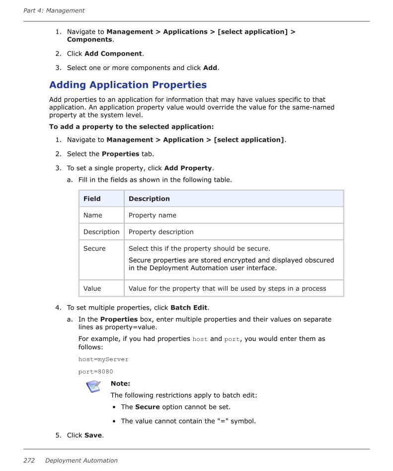
1. Navigate to Management > Applications > [select application] >Components.
2. Click Add Component.
3. Select one or more components and click Add.
Adding Application PropertiesAdd properties to an application for information that may have values specific to thatapplication. An application property value would override the value for the same-namedproperty at the system level.
To add a property to the selected application:
1. Navigate to Management > Application > [select application].
2. Select the Properties tab.
3. To set a single property, click Add Property.
a. Fill in the fields as shown in the following table.
Field Description
Name Property name
Description Property description
Secure Select this if the property should be secure.
Secure properties are stored encrypted and displayed obscuredin the Deployment Automation user interface.
Value Value for the property that will be used by steps in a process
4. To set multiple properties, click Batch Edit.
a. In the Properties box, enter multiple properties and their values on separatelines as property=value.
For example, if you had properties host and port, you would enter them asfollows:
host=myServerport=8080
Note:
The following restrictions apply to batch edit:
• The Secure option cannot be set.
• The value cannot contain the "=" symbol.
5. Click Save.
Part 4: Management
272 Deployment Automation

To use the application property in a process, reference it when you configure a step thatuses it. Use the following syntax: ${p:application/<property name>}
Copying ApplicationsYou can create a new application based on an existing application and run the sameoperations as the original. Application snapshots and component versions are not copied.The copied application contains copies of:
• Environments
• Processes
• Task definitions
• Property sheets
• Security and application settings
By default, the new application references the original components and processes.Modifications made to the original components affect the behavior of the copiedapplication.
You can optionally create a copy of an application that does not reference existingcomponents. Modifications made to the original components do not affect the copiedapplication.
To copy an application:
1. Navigate to Management > Applications.
2. Select the application's row and click Copy.
3. Enter a name and description for the new application.
4. To specify new names for the components that will be copied and not reference theoriginal components, select Deep copy components. Enter a new name for eachcomponent.
5. Click Save.
Importing/Exporting ApplicationsApplications can be exported and then imported into another server. This can be useful ifyou have multiple Deployment Automation servers, such as test and production servers,where you create and validate the applications on the test server and then export themand import them into the production server.
• Exporting Applications [page 274]
• Importing Applications [page 274]
Related Topics
Chapter 27: Replication [page 361]
User's Guide 273

Exporting ApplicationsExporting an application creates a JSON file (file extension json) that contains theapplication's properties, processes, and components and their associated properties andprocesses. For information about JSON, see http://www.json.org/.
To export an application:
1. Navigate to Management > Applications.
2. Select the application's row and click Export.
You can load the file into a text editor, or save it. If you save it, a file is created with thesame name as the selected component, such as helloWorldApplication.json.
Importing ApplicationsWhen you import an application, you can create a new application or upgrade an existingone. Components associated with the application are also imported, including thecomponent properties and processes if they are available to the importing server.
Note: If imported components have Import Versions Automatically selected,Deployment Automation will automatically import component versions as longas the artifacts are accessible to the importing server.
To import an application:
1. Navigate to Management > Applications.
2. Click Import.
3. If you want to upgrade an existing application, select Override Application.
If the application's name in the JSON file (not the name of the file itself) matches anexisting application, the application's parameters are updated with new values, andnew items, such as processes, environments, and components, are added. If thename is not found, the command has no effect.
Note: The application's name is the first parameter in the JSON file. Forexample:
"name": "helloWorldApplication",
4. Specify how imported components should be handled with the ComponentUpgrade Type options. For these options, the components must be on theimporting server.
• To use the same components used by the imported application, select UseExisting Component. The new application will contain references to theimported applications components. This option is especially useful if you areimporting a lot of applications.
If you are upgrading, the application will use the imported components, and nolonger use any not used by the imported application.
• To create new components based on those used by the imported application,select Create Component. New components will be created (based on theimported application's components).
Part 4: Management
274 Deployment Automation

If you are upgrading, the application will use the newly created components andno longer use any it previously used.
• When you want to create a fresh installation, select Fail if Component Exists. Ifyou are creating an application, it will create both a new application andcomponent unless the component already exists, in which case the application isnot imported.
If you are upgrading, the upgrade will fail if any imported components alreadyexist on the importing server.
• To ensure a component is on the importing server, select Fail if ComponentDoes Not Exist. If you are creating an application, it will create both a newapplication and component unless the component does not exist, in which casethe application is not imported.
If you are upgrading, the upgrade will fail if an imported component does notalready exist on the importing server.
• To upgrade existing components, select Upgrade if Exists. This option createsan application and upgrades existing components with data from the importedapplication.
If you are upgrading and existing components match imported ones (all mustmatch), the components will be upgraded. If none of the imported componentsmatch existing ones, the imported components will be used.
5. Click Choose File and select the JSON file containing the application.
6. Click Import.
User's Guide 275

Application EnvironmentsAfter you have created environments in the Environments page, you can add them toapplications individually or as part of a pipeline.
On an Environments page you can:
• Add more environments to an application.
• Scroll a graphical view of environments. Any pipeline is indicated by a shaded box;any individual environments follow.
• Click an environment name and select from a menu of options for that environment.Only relevant options appear. Possible options are:
▪ Run Process: Run an application process in this environment.
▪ Promote: Execute the active process in the next environment in the pipeline.This appears only for environments in pipelines are mandatory but without autopromote.
▪ View Details: View and configure application-specific settings for the selectedenvironment.
▪ Compare: Compare the inventory of up to four environments.
▪ Copy: Create an environment based on this environment. Upon creation, theenvironment is automatically added to the application.
▪ Inactivate: Set the environment to inactive status. Inactive environments arenot shown in the list by default. You can use the Show Inactive check box toshow them in the list.
• Click Resources to get a quick view of the resources associated with anenvironment. From there you can click View Resources to open the resources tabfor the environment.
Part 4: Management
276 Deployment Automation
• See a breakdown of the number of environments in online, offline, and unknownstatus.
• Click the double arrows beside the pipeline to contract or expand the pipeline in theview.
• Move individual environments to another position.
Note: Pipelines cannot be moved. Only one pipeline can be associated withan application at a time and it always comes before any individualenvironments.
• Filter the components shown in the list by using search criteria.
• View environment inventory and compliancy.
For details on creating environments and configuring global settings, see Chapter 20:Managing Environments [page 307].
For more details about the environment inventory, see Viewing the Environment Inventory[page 391].
For more details on configuring application-specific environment settings, see thefollowing topics:
• Adding Environments to Applications [page 277]
• Adding Application Environment Properties [page 278]
• Mapping Application Components to Resources [page 279]
• Setting Component Environment Property Values [page 280]
• Comparing Environments [page 281]
Adding Environments to ApplicationsAfter you create an environment, you add it to an application. Environments may be usedby multiple applications.
Note: When you add a pipeline to an application, the environments in thepipeline are automatically added to the application. Environments that are partof a pipeline are grouped together in a section labeled with the pipeline name.
To add an environment to an application:
1. Navigate to Management > Applications > [select application] >Environments.
2. Click the Add Environment button.
3. Enter the environment information as follows:
Field Description
Environment Select an environment. For information on creating environments,see Creating Environments [page 308].
User's Guide 277

Field Description
RequireApprovals
To require an approval before components can be deployed to theenvironment, select this check box. If selected, DeploymentAutomation will enforce an approval process before thedeployment can be deployed to the environment. Initialdeployments are typically done in uncontrolled environments, butonce the deployment is successful, you can configure an approvalsprocess as the application moves along the development pipeline.If you are setting up more than one environment, considercreating an approvals process for at least one of them.
LockSnapshots
If you want all snapshots used in this environment to be locked toprevent changes, select the check box.
InheritCleanupSettings
Determines how many component versions are kept inCodeStation, and how long they are kept. If selected, thecomponent will use the values specified in Administration >System > System Settings. If deselected, additional fieldsappear.
Days toKeepVersions
If Inherit Cleanup Settings is not selected, this field appears,which enables you to define custom values. This is initially set to-1, keep indefinitely.
Number ofVersions toKeep
If Inherit Cleanup Settings is not selected, this field appears,which enables you to define custom values. This is initially set to-1, keep indefinitely.
4. Click Save.
Adding Application Environment PropertiesYou can define environment properties at the application environment level. Theapplication environment properties are specific to the application's use of an environment.Environment properties added at this level appear under the application environment'sProperties tab, and not under the environment's Properties tab, because they are setfor this application only.
Environment property values for same-named properties are resolved at the most specificlevel. An environment property value set at the application level overrides one with thesame name set directly on the environment property level. An environment property valueset at the component level overrides any with the same name set directly on theenvironment property level or on the application environment level.
If component environment properties have been added for a component mapped to theenvironment and you want to set those values, see Setting Component EnvironmentProperty Values [page 280].
To create application environment properties:
1. Navigate to Management > Application > [select application].
Part 4: Management
278 Deployment Automation
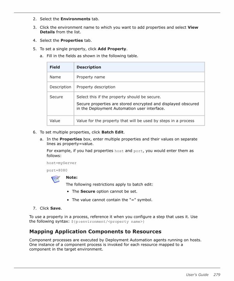
2. Select the Environments tab.
3. Click the environment name to which you want to add properties and select ViewDetails from the list.
4. Select the Properties tab.
5. To set a single property, click Add Property.
a. Fill in the fields as shown in the following table.
Field Description
Name Property name
Description Property description
Secure Select this if the property should be secure.
Secure properties are stored encrypted and displayed obscuredin the Deployment Automation user interface.
Value Value for the property that will be used by steps in a process
6. To set multiple properties, click Batch Edit.
a. In the Properties box, enter multiple properties and their values on separatelines as property=value.
For example, if you had properties host and port, you would enter them asfollows:
host=myServerport=8080
Note:
The following restrictions apply to batch edit:
• The Secure option cannot be set.
• The value cannot contain the "=" symbol.
7. Click Save.
To use a property in a process, reference it when you configure a step that uses it. Usethe following syntax: ${p:environment/<property name>}
Mapping Application Components to ResourcesComponent processes are executed by Deployment Automation agents running on hosts.One instance of a component process is invoked for each resource mapped to acomponent in the target environment.
User's Guide 279

After you have added a component to the application, define where its artifacts should bedeployed by selecting a resource (agent) or resource group. See Chapter 22: ManagingResources [page 317].
1. Navigate to Applications > [select application].
2. Select the Environments tab.
3. Click the environment name to which you want to map components and select theView Details option.
4. Select the Component Mapping tab.
5. If the application has several components associated with it, select the one you wantto use from the component list on the left. Each component associated with thisapplication can be mapped to a different resource.
6. To associate resources with the selected component, click Add, and select one of thefollowing:
• Add Resource To All Components and select one or more resources.
• Add Resource Group To All Components and select a resource group. Forinformation about creating resources, see Resource Groups [page 329].
• To map multiple resources at once, use the following options:
▪ Add all resources and groups to all the components
▪ Add all resources and groups to the selected component
▪ Remove all resources and groups from all the components
▪ Remove all resources and groups from the selected component
Setting Component Environment Property ValuesAfter you have added component environment properties at the component level, you canset the values for them for each environment to which the component is mapped.
To set component environment properties:
1. Navigate to Management > Applications > [select application].
2. Select the Environments tab.
3. Click the environment name to which you want to add property values and selectView Details.
4. Select the Component Mapping tab.
5. Select the Properties tab.
6. Click Edit.
7. Edit values for the environment properties that were previously defined for thecomponent. See Adding Component Environment Properties [page 231].
Part 4: Management
280 Deployment Automation

8. Click Save.
You can reference the property value in processes using ${p:environment/<propertyname>}.
Comparing EnvironmentsYou can compare environments to each other to see how their inventories differ.
To compare environments:
1. Navigate to Management > Applications > [select an application].
2. Select the Environments tab.
3. Click the Compare button.
4. Select the environments that you want to compare. You can compare up to fourenvironments at a time.
5. Click Compare. The inventories of the selected environments are compared and thedifferences are displayed.
6. In the selection box, select from the following views to see the associatedcomparative information:
• Versions
• Files
• Configurations
Application ProcessesApplication processes typically initiate component processes defined for their associatedcomponents.
Application processes can run manually, automatically on some trigger condition, or on auser-defined schedule. When a component has several processes defined for it, theapplication determines which ones are executed and in which order. For example, an n-tiered application might have a web tier, a middleware tier, and a database tier. Thedatabase tier must be updated before the other two, which are then deployedconcurrently. An application can orchestrate the entire process, including putting serverson- and off-line for load-balancing as required.
When an application process executes, it interacts with a specific environment. At leastone environment must be associated with the application before the process can beexecuted.
Application processes can be designed independently of any particular environment. Thisenables a single application to interact with separate environments, such as QA orproduction. To use the same application process with multiple environments, you canassociate the application with a pipeline, associate individual environments with theapplication, or a combination of both.
User's Guide 281

In addition to deployments, several other common processes are available, such as rollingback deployments. Deployment Automation tracks the history of each component version,which enables application processes to restore environments to any point.
Application processes can be initiated as part of deployment packages to run multiple-application deployments. See Chapter 23: Managing Deployment Packages [page 335].
For information on creating and designing application processes, see the following topics:
• Creating Application Processes [page 282]
• Designing Application Processes [page 283]
• Application Process Step Details [page 285]
• Adding Application Process Properties [page 295]
• Running Application Processes [page 296]
Creating Application Processes
Application processes, like component and global processes, are created with the processeditor.
To create an application process:
1. Navigate to Management > Applications > [select application].
2. Select the Processes tab and click Create.
3. Enter the following information:
Field Description
Name/Description
Typically the name and description correspond to the applicationyou plan on deploying.
RequiredApplicationRole
Select the role a user must have in order to run the application.For information about creating application roles, see RoleConfiguration [page 118]. The default value is None.
InventoryManagement
To have inventory handled automatically, leave the default value,Automatic, selected. If you want to handle inventory manually,select Advanced.
See Chapter 31: Inventory Management [page 391].
Part 4: Management
282 Deployment Automation

Field Description
OfflineAgentHandling
Select the option for how the process should react if expectedagents are offline:
Check Before ExecutionChecks to see if expected agents are online before runningthe process. If agents are offline, the process will not run.
Use All Available; Report Failure:The process will run as long as at least one agent defined inthe environment is online; this reports any faileddeployments due to offline agents. This is useful for rollbacksor configuration deployments.
Always Report SuccessThe process will run as long as at least one agent defined inthe environment is online; this reports successfuldeployments.
Default forOnlyChangedVersions
If this is selected, the Only Changed Versions option will beselected by default in the Run Application Process wizard. If it isdeselected, the Only Changed Versions option will bedeselected by default. The Only Changed Versions option canbe selected or deselected in the wizard regardless of the defaultsetting.
If you want to change the default setting of Default for OnlyChanged Versions, see Configuring the Default for OnlyChanged Versions Option [page 177].
ExecutionTimeout
Specify how long the process will execute for in hours andminutes. Default: indefinitely
4. To create additional application processes, click Save and New. To start configuringthe application process you just created, click Build Out.
Designing Application ProcessesApplication processes tell Deployment Automation what to do when you deploy wholeapplications.
You design processes using the process editor. In the process editor you drag processsteps from a menu of steps onto the design space and configure them immediately. Asyou place additional steps, you visually define their relationships with one another.
For application processes, you select from a menu of utility steps and other steps such asinstalling components. These enable you to operate on sets of components associatedwith the application.
User's Guide 283

Application Process Design
• Select from a set of options for the process designer, including the following:
▪ Zoom In
▪ Zoom Out
▪ Actual Size
▪ Poster Print
▪ Save
▪ Cancel
▪ Show Outline Box: Use this to move the whole process design around in thedesign area. For example:
▪ Drag its corner inward and move it over parts of the process design to zoomin.
Part 4: Management
284 Deployment Automation

▪ Drag its corner outward again to zoom out.
▪ Show Connection Options: Select this to show the options for all connections.
• In Tools, select process steps.
• Use the Search box to find a step by name.
• Select and drag steps to the design area to add them to your process.
• Connect process steps and edit or delete existing steps or connections, seeConnecting Process Steps [page 249].
• Properties are automatically shown when you select a step.
Application Process Step DetailsAfter you create an application process, select it to design the process steps. Theapplication process steps are described in the following topics:
• Finish [page 285]
• Install Component [page 285]
• Uninstall Component [page 286]
• Rollback Component [page 287]
• Run Process for Each Version [page 288]
• Apply Configuration [page 289]
• Application Process Snapshot Steps [page 290]
• Application Process Utility Steps [page 292]
Finish
The Finish step ends processing. A process can have more than one Finish step.
Install Component
The Install Component step installs the selected component using one of the processesdefined for the component.
Install Component Properties Table
Field Description
Name Can be referenced by other process steps.
Component Component used by the step; a step can affect a single component. Allcomponents associated with the application are available. If you want toinstall another component, add another install step to the process.
User's Guide 285

Field Description
UseVersionsWithoutStatus
Restricts the components that can be used by the step. Componentswith the selected status are ignored. Available statuses: Active meansignore components currently deployed; Staged means ignorecomponents currently in pre-deployment locations.
ComponentProcess
Select a process for the component selected above. All processesdefined for the component are available. Only one process can beselected per step.
IgnoreFailure
When selected, the step will be considered to have run successfully.
Limit toResourceRole
User-defined resource role the agent running the step must have.
Fail Fast When this is selected, this step will not start any more componentprocesses if one fails.
Run on FirstOnlineResourceOnly
Instead of being run by all agents mapped to the application, the stepwill only be run by the first online agent identified by DeploymentAutomation. The mechanism used to identify the "first" agent isdatabase-dependent (thus indeterminate).
Precondition A JavaScript script that defines a condition that must exist before thestep can run. The condition must resolve to true or false.
Uninstall Component
The Uninstall Component step uninstalls the selected component.
Uninstall Component Properties Table
Field Description
Name Can be referenced by other process steps.
Component Component used by the step; a step can affect a single component. Allcomponents associated with the application are available. If you want touninstall another component, add another uninstall step to the process.
RemoveVersionsWith Status
Restricts the components that are affected by the step, onlycomponents with the selected status are affected. Available statuses:Active means use components currently deployed; Staged means usecomponents currently in pre-deployment locations.
Part 4: Management
286 Deployment Automation

Field Description
ComponentProcess
Select a process for the component selected above. All processesdefined for the component are available. Only one process can beselected per step.
IgnoreFailure
When selected, the step will be considered to have run successfully.
Limit toResourceRole
User-defined resource role the agent running the step must have.
Run on FirstOnlineResourceOnly
Instead of being run by all agents mapped to the application, the stepwill only be run by the first online agent identified by DeploymentAutomation. The mechanism used to identify the "first" agent isdatabase-dependent (thus indeterminate).
Precondition A JavaScript script that defines a condition that must exist before thestep can run. The condition must resolve to true or false.
Rollback Component
The Rollback Component step rolls back a component version and replaces it with anearlier one.
Rollback Component Properties
Field Description
Name Can be referenced by other process steps.
Component Component used by the step; a step can affect a single component. Allcomponents associated with the application are available. If you want toroll back another component, add another rollback step to the process.
RemoveVersionsWith Status
Restricts the components that are affected by the step, onlycomponents with the selected status are affected. Available statuses:Active means use components currently deployed; Staged means usecomponents currently in pre-deployment locations.
ComponentProcess
Select a process for the component selected above. All processesdefined for the component are available. Only one process can beselected per step.
IgnoreFailure
When selected, the step will be considered to have run successfully.
User's Guide 287

Field Description
Limit toResourceRole
User-defined resource role the agent running the step must have.
Rollbacktype
Determines the type of rollback. Available statuses: Remove UndesiredIncremental Versions and Replace with Last Deployed.
Run on FirstOnlineResourceOnly
Instead of being run by all agents mapped to the application, the stepwill only be run by the first online agent identified by DeploymentAutomation. The mechanism used to identify the "first" agent isdatabase-dependent (thus indeterminate).
Precondition A JavaScript script that defines a condition that must exist before thestep can run. The condition must resolve to true or false.
Run Process for Each Version
The Run Process for Each Version runs a selected component process for eachcomponent version.
Run Process for Each Version Properties
Field Description
Name Can be referenced by other process steps.
Component Component used by the step; a step can affect a single component. Allcomponents associated with the application are available. If you want torun a process for another component, add another Run Process for EachVersion step to the process.
ComponentProcess
Select a process for the component selected above. All processesdefined for the component are available. Only one process can beselected per step.
IgnoreFailure
When selected, the step will be considered to have run successfully.
Limit toResourceRole
User-defined resource role the agent running the step must have.
Max # ofconcurrentjobs
The maximum number of concurrent component processes to run at anytime. Use -1 for unlimited.
Fail Fast When this is selected, this step will not start any more componentprocesses if one fails.
Part 4: Management
288 Deployment Automation

Field Description
Run on FirstOnlineResourceOnly
When this is selected, this step will only use one resource. It will not runon all resources.
Precondition A JavaScript script that defines a condition that must exist before thestep can run. The condition must resolve to true or false.
Apply Configuration
The Apply Configuration step applies configuration properties to a selected componentversion.
Apply Configuration Properties
Field Description
Name Can be referenced by other process steps.
Component Component used by the step; a step can affect a single component. Allcomponents associated with the application are available. If you want toapply a configuration to another component, add another ApplyConfiguration step to the process.
ComponentProcess
Select a process for the component selected above. All processesdefined for the component are available. Only one process can beselected per step.
Note: Only processes set as Operational (No Version Needed)or Configuration Deployment can be used here.
IgnoreFailure
When selected, the step will be considered to have run successfully.
Limit toResourceRole
User-defined resource role the agent running the step must have.
Max # ofconcurrentjobs
The maximum number of concurrent component processes to run at anytime. Use -1 for unlimited.
Fail Fast When this is selected, this step will not start any more componentprocesses if one fails.
User's Guide 289

Field Description
Run on FirstOnlineResourceOnly
When this is selected, this step will only use one resource. It will not runon all resources.
Precondition A JavaScript script that defines a condition that must exist before thestep can run. The condition must resolve to true or false.
Application Process Snapshot Steps
Several snapshot steps are provided for application processes to enable you todynamically work with snapshots as part of your application processes. These include thefollowing:
• Create Snapshot Step [page 290]
• Update Snapshot Step [page 291]
• Add Status to Snapshot Step [page 291]
• Remove Status from Snapshot Step [page 292]
Create Snapshot Step
The Create Snapshot step enables you to create snapshots as part of your applicationprocesses. The following table describes the property for this step.
Property Description
SnapshotName
Enter a unique name for the snapshot to be created. The default is${p:datetime}.
Tip: Combine text with the predefined date and timeproperty to make a unique name, such as Appname-${p:dateTime}-auto. This will avoid step failure fromduplicate snapshot names.
Description Enter the description of the snapshot to be created.
Skip this stepfor snapshotprocessrequests
If selected, this step will be skipped for processes requested forsnapshots. This option does not apply to processes requested forcomponent versions.
Part 4: Management
290 Deployment Automation

Update Snapshot Step
The Update Snapshot step enables you to update snapshots as part of your applicationprocesses. The following table describes the property for this step.
Property Description
Snapshot Name Enter the name of the snapshot to be updated.
Description Enter the description of the snapshot to be updated.
Create a new snapshot ifone does not exist
If selected, this step will create a new snapshot if asnapshot with the name specified does not exist.
Reset snapshotconfiguration to latest
If selected and a snapshot updated, its configuration willbe reset to all of the latest versions.
Add Status to Snapshot Step
The Add Status to Snapshot step enables you to add statuses to snapshots as part ofyour application processes. The following table describes the property for this step.
Property Description
Status Select the status to be added to the snapshot.
SnapshotName
Select the snapshot to which the status should be added. Select from thelist of application snapshots or one of the following:
• Snapshot from step nameAdd the status to the snapshot created in a preceding CreateSnapshot step in the same process.
• Use request snapshotAdd the status to the snapshot for which you have requested thisprocess.
Important: If you select the Use request snapshot option,before executing the application progress request, ensurethat the snapshot you have selected for the process requestis configured to always use latest version. Otherwise, thisstep will never be executed.
User's Guide 291

Remove Status from Snapshot Step
The Remove Status from Snapshot step enables you to remove statuses fromsnapshots as part of your application processes. The following table describes the propertyfor this step.
Property Description
Status Select the status to be removed from the snapshot.
SnapshotName
Select the snapshot from which the status should be removed. Select fromthe list of application snapshots or one of the following:
• Snapshot from step nameRemove the status from the snapshot created in a preceding CreateSnapshot step in the same process.
• Use request snapshotRemove the status from the snapshot for which you have requestedthis process.
Important: If you select the Use request snapshot option,before executing the application progress request, ensurethat the snapshot you have selected for the process requestis configured to always use latest version. Otherwise, thisstep will never be executed.
Application Process Utility Steps
Several utility steps are provided for application processes.
Note: Processes that you have defined that are configuration only and are notrelated to any component also appear here to be selected for applicationprocesses.
Part 4: Management
292 Deployment Automation

Acquire Lock and Release LockThe Acquire Lock and Release Lock steps enable you to lock and release a process in adesignated environment.
Locks are typically used to prevent specific processes from modifying the same resourceat the same time, such as when a database is being updated.
In an Acquire Lock step, the process tries to acquire a lock with the specified name. Ifthere is no other lock with that exact name, the process acquires the lock with that nameand continues. If another process is using a lock with that exact name, the process waitsuntil the lock is released by the other process. Any processes that access the resourcewithout a lock or with a lock of a different name do not wait on this lock.
Locks are released automatically when the process completes, but you can also releasethe lock using the Release Lock step if you need to release it explicitly before continuinglater steps in a process. Administrators can also release locks. See Managing Locks [page110].
The following table describes the property for these steps.
Property Description
LockName
Specify the lock name. The default setting is as follows:${p:application.name}-${p:applicationProcess.name}-${p:environment.name}
Tip: The default lock name setting is set using a default variable.Therefore, to make the lock names exactly the same for differentobjects and processes, you can enter a static string for the nameor use variables that will resolve to the same in both processes.For example, if you want to lock a resource against concurrentuse for two processes in different components that are mappedto the same resource, you could use ${p:resource.name} as thelock name for both.
Set StatusThe Set Status step enables you to explicitly set the status of a process. The followingtable describes the property for this step.
Property Description
Status Values: Success or Failed
User's Guide 293

Process SleepThe Process Sleep step enables you to enter time in seconds for a process to wait untilcontinuing with the next steps in the process. The following table describes the propertyfor this step.
Property Description
Sleep Time Default: 30
JoinThe Join step enables you to join steps in a process. There are no properties for this step.
For the Join step to continue processing on to its outboard connections, all its inboundconnection paths must be valid. To be valid, all that should evaluate to success do so, allthat should evaluate to failure do so, all that should evaluate to any value do so, and allthat should evaluate to a specific switch value do so.
You can do an implicit join without the Join step by having multiple inbound connectionsfor another step. Regardless of whether it is an implicit or explicit join, all incomingconnections must be valid for the joining step to be executed.
One reason you should choose an explicit Join step is when your process has multiplesteps that must all complete to a certain outcome and then should continue on to multipleoutbound steps without additional processing between them.
Manual Application TaskThe Manual Application Task step enables you to interrupt a process until some manualintervention is performed according to a pre-configured application task. Application tasksmust be set for an application before you can select them for this step. See ApplicationTasks [page 297].
The following table describes the properties for this step.
Field Description
Name Enter a descriptive name for the step.
TaskDefinition
Used to select a previously-defined user-defined task. See ApplicationTasks [page 297].
EnvironmentRole
Select the role expected to respond. The user mapped to this role mustrespond to the generated work item before the process can continue.
ApplicationRole
Select the role expected to respond. The user mapped to this role mustrespond to the generated work item before the process can continue.
If both roles are selected, all affected users must respond before the process cancontinue.
Part 4: Management
294 Deployment Automation

Inventory UpdateThe Inventory Update step appears only if you have selected Advanced for the InventoryManagement option for the application process. Use this step to implement your owninventory management process.
Adding Application Process PropertiesAdd properties to an application process for information that may have values specific tothe scope of that process.
To define an application process property:
1. Navigate to Management > Applications > [select application].
2. Select the Processes tab.
3. In the processes list, next to the process for which you want to define a property,click the Details icon ( ).
4. On the Properties tab, click the Add Property button.
5. Complete the fields as shown in the following table.
Field Description
Name Property name
Description Property description
Label Enter a label to be associated with the property in the userinterface.
Required Select this if the property is required.
Type Specify the type of expected value. The supported types are asfollows:
• text
• text area
• check box
• select
• multi select
• secure
The default type is text.
DefaultValue
Enter a default value (if any).
User's Guide 295

6. Click Save.
You can use this property in the same process where it is defined by referencing it in oneof the steps. Use the following syntax: ${p:<property name>}
Running Application Processes
Application processes deploy artifacts for a single application.
To deploy to a particular environment, you run the application process defined for thatenvironment. For more about deployment, see Chapter 28: Deployment Overview [page377].
To run an application process:
1. Navigate to Management > Applications > [select application].
2. Select the Environments tab.
3. Click the name of the environment where you want to perform the deployment andselect Run Process. The process wizard is displayed with the application andenvironment pre-selected.
Note: If environments are in a pipeline and the pipeline is mandatory, theRun Process command appears only for the first environment.
4. On the Process page select the process you want to run and click Next.
5. On the Options page select Only Changed Version to ensure that only changedversions are deployed. If selected, no previously deployed versions will be deployed.For example, if you check the box and select a specific version that was alreadydeployed, the version will not be redeployed. Do not select this if you want to deploya version regardless of whether or not it was already deployed, such as when theinventory is out of date.
6. If you want to use a snapshot, select it from the Snapshot drop-down list-box. Ifyou select a snapshot, the deployment will automatically use the componentversions defined for the snapshot. For information about snapshots, see Snapshots[page 300].
7. If you did not select a snapshot, select a component version from the Version list-box. If more than one component is mapped to the application, each one is listedseparately.
VersionOption
Description
None No version for this component. Useful when performing multi-component deployments or testing.
SpecificVersion
Enables you select any version already in CodeStation.
Part 4: Management
296 Deployment Automation

VersionOption
Description
LatestVersion
Automatically uses the most recently imported version.
Latest WithStatus
Automatically uses the most recently imported version with thespecified status. Example status values are: Latest (defaultvalue), Passed Test, Archived.
All WithStatus
All component versions with the selected status will be deployed.
All inEnvironment
All component versions already deployed in the environment withthe selected status will be deployed.
All inEnvironment(Reversed)
All component versions already deployed in the environment withthe selected status will be deployed in reverse order. Examplestatus values are: Active (default), Staged.
8. Optionally add a description.
9. Click Submit to start the process.
When a process starts, the Request page is displayed so that you can review the processrequest progress. After the request completes, you can review the results on that andother related pages. See Chapter 30: Analyzing Deployments [page 383].
People notified for any approvals must approve or reject. See Approving Requests [page299].
Note: If gate conditions are defined for a target environment, the componentversions or snapshots are deployed into that environment only if their statusmeets those conditions. See Gates [page 304].
Application TasksAn application task is used to interrupt an application process until some manualintervention is performed. A task-interrupted process is suspended until the assigned useror users respond. Typically, application manual tasks are removed after the process hasbeen tested or automated.
Like approvals, triggered application tasks notify assigned users. Notifications areassociated with environment- or application-defined user roles. Unlike approvals,application tasks can be incorporated within an application process.
The person notified for the task can indicate that it is complete by approving the stepfrom the request's log in Approval Requests. See Approving Requests [page 299].
Create and use tasks as follows:
1. Create application tasks in applications.
2. Insert a manual task step in an application process.
User's Guide 297

See Manual Application Task [page 294].
Creating Application TasksTo create an application task:
1. Navigate to Management > Applications > [select application] > Tasks.
2. Click Create.
3. Name the task then select a template from the Template Name field.
The individual tasks map to the notification scheme used by the application. SeeCreating Notification Templates [page 149]. If a scheme is not specified, the defaultscheme is used. The available task notification template is:
• TaskCreated
ApprovalsApproval processes tell Deployment Automation what to do when an applicationenvironment requires approval. An approval process must be created if the RequiresApproval check box is selected when adding or editing an application environment.
When a process requires approval to run, approvers are responsible for verifying that thedeployment is ready to run and deciding when they will release it to run by approving it. Ifthe system is configured with an email server and the user has an email address set,notifications are sent to users who are eligible to complete an approval step.
If a scheduled deployment requiring approval reaches its start time without approvalgiven, the process will not run and will instead fail with a message that it could not start.To resubmit a request, you must request a new process. If an approval-requesting processdoes not have a scheduled deployment time, the process will remain idle until a responsehas been made.
For more information on approval processes, see the following topics:
• Designing Approval Processes [page 298]
• Approving Requests [page 299]
Designing Approval Processes
If an application environment requires approvals, you must design an approval process forit.
You design processes using the process editor. In the process editor you drag processsteps from a menu of steps onto the design space and configure them immediately. Asyou place additional steps, you visually define their relationships with one another.
To create an approval process:
1. To activate the options to create an approval process for an application environment,select the Require Approvals option for the environment. See AddingEnvironments to Applications [page 277].
2. Navigate to Management > Applications > [select application].
Part 4: Management
298 Deployment Automation

3. Select the Environments tab.
4. Click the environment name for which you want to create, design, or edit anapproval process and select View Details. The Approval Process button appearsat the upper right of the page and the environment information indicates thatapprovals are required. If these do not appear on the page, see step 1.
5. Click Approval Process.The process designer for the approval process appears. Available approval steps arebased on the security roles for the corresponding entities:
• Applications
• Components
• Environments
6. Expand the approval levels and drag a security role to the design area to create anapproval step. Do this for each role that you want to approve process requests forthis application, its components, and this environment. You can define steps for eachlevel and role as needed. Any users assigned to the role on the correspondingentities, either directly or as part of a group, have permission to approve.
Note: In versions prior to 6.1.5, DA only runs approvals for componentswith versions. To maintain this behavior in version 6.2.2, in the Propertiesdialog box select this option: Only for Components with Versions
Approving RequestsWhen approval is pending, in the dashboard the Pending Approval Requests buttonshows the number of pending approvals. The request's Log tab indicates that the processis waiting to start.
Viewing and Responding to RequestsApprovers can view and respond to requests in the dashboard Approval Requestsoverlay or in the Approvals tab of the process request.
In the Approval Requests overlay, approvers can:
User's Guide 299

• Expand approval requests to see the processes and tasks included
• View the name of the process, when the request was submitted, who requested theprocess, and the snapshot or version used.
• View environment or resource details by clicking the link in the Environment/Resource column.
• View request details by clicking the View button.
• In the expanded view, view the entity to be approved by clicking the link in theName column.
Respond to the request by clicking the Approve or Reject button. Optionally entercomments.
If you reject a request, the process will not run. If you approve, the process will start.
SnapshotsA snapshot represents a specific state of an application in an environment. Snapshotsspecify the combination of component versions that you are going to deploy together.When a snapshot is created, Deployment Automation gathers together information aboutthe application for a given environment, including the component versions, processversions, and properties.
Typically, the snapshot is generated in an uncontrolled environment, where there are noapproval processes or gates defined. Once a snapshot is created, it can then be promotedthrough a deployment pipeline. For example, as the application moves through varioustesting environments, Deployment Automation ensures that the exact versions, bit for bit,are used in every environment. Once all the appropriate stages and approvals for asnapshot are complete, the snapshot is deployed to production.
Snapshots help manage complex deployments, such as deployments with multiple tiersand development teams. For example, after testing and confirming that team A'scomponent works with teams B's, a snapshot can be taken. Then, as developmentprogresses, additional snapshots can be taken and used to model the effort and drive theentire deployment, coordinating versions, configurations, and processes.
Snapshots include the following:
• Component Versions
When you create a snapshot, you can manually specify the version for eachcomponent, or you can copy the versions used in a specified environment orsnapshot.
• Configuration
A snapshot contains the versions of the processes that have been designed, theproperties that these processes use, and other information. From the configuration,you can view and set the versions of the processes and properties used in thesnapshot.
• Status
You can apply a status to a snapshot, which typically indicates whether the snapshothas been deployed successfully to an environment. You can use this status along
Part 4: Management
300 Deployment Automation

with gates, which enable you to allow deployments to an environment only if thesnapshot has reached a particular status. For example, you could set the INTenvironment gate condition so that if the status is set to Dev_Complete, thesnapshot can be deployed to the INT environment.
• Locks
You can lock snapshots when they are deployed to a particular environment,ensuring that nothing can be changed. Typically, you lock a snapshot when it goesinto a pre-production environment before being deployed to production.
Creating SnapshotsTo create a snapshot:
1. Navigate to Management > Applications > [select application] > Snapshots.
2. Click Create.
3. Enter a name and description.
4. Click Save.
The current versions of all elements are saved in the snapshot. After you have created asnapshot, select the snapshot to view and configure it.
Viewing Snapshot Environments
You can view and work with environments using the selected snapshot's Environmentstab.
User's Guide 301

1. View a list of environments mapped to this snapshot.
2. Run the snapshot processes in the selected environment. For environments inpipelines, this is available only on the first environment.
3. Select the Request History tab to view a list of processes run for this snapshot.
4. Select the Changes tab to view a history of changes made to component versionsand resources in this snapshot.
5. Click a process name link to go to the process page.
6. Click the Details button to go to the process request page.
Configuring Snapshots
After you create a snapshot, you can configure the property versions.
To configure a snapshot:
1. Navigate to Management > Applications > [select application].
2. Select the Snapshots tab and then a snapshot.
3. Click the Configuration tab.
4. Expand the items in the tree to see the property version numbers that are currentlyselected in this snapshot. Included is property version information for the following:
• Components
• Component Versions
• Component Processes
• Applications
• Application Processes
• Application Environments
• Resources
• System Properties
5. To update all of the property versions, select an option:
• Reset All to Latest: Reset all configuration targets to the latest version.
• Lock Loose Entries: Lock all configuration targets that are automatically usingthe latest version available. Select this only if you are sure you want to lock thesetargets.
• Copy from Snapshot: This uses the component configuration from the selectedsnapshot. Warning: If you have already added a component configuration to thesnapshot to which you are copying, this action will remove it and replace it withthe one from the selected snapshot.
Part 4: Management
302 Deployment Automation

6. To view the property details, beside the property click the Details icon.
7. To set the version to a specific version or set it to always use the latest version,beside the property click the Set Version button.
Adding Component Versions to Snapshots
You can add component versions to snapshots directly or copy from environments or othersnapshots.
To add component versions to a snapshot:
1. Navigate to Management > Applications > [select application].
2. Select the Snapshots tab and then a snapshot.
3. Click the Component Versions tab.
4. To add component versions, do one of the following:
• To add component versions directly in the list of component versions, click the +(Add) button next to the component to which you want to add the version. Youcan then select any version in CodeStation for the component.
• To copy component versions, click Copy from Environment or Copy fromSnapshot.
5. Expand the components in the list to see the component versions now included inthis snapshot.
Adding Statuses to SnapshotsSnapshot statuses are user-managed values that can be added to snapshots. Once astatus is added to a snapshot, the value can be used in component processes orapplication environment gates. See Gates [page 304].
Before you can add a status, statuses must be defined. See Defining Statuses [page 112].
To add statuses to snapshots:
1. Navigate to Management > Applications > [select application] > Snapshots >[select snapshot] > Statuses.
2. Click the Add Status button.
3. Select the statuses you want to add.
4. Click Add.
You can also set snapshot status as part of application processes using the Snapshotsteps, Add Status to Snapshot and Remove Status from Snapshot.
User's Guide 303

Viewing Snapshot Tasks
If you require approvals for an application to be run in an environment, a snapshot of theapplication will require the same. When the process is run for the snapshot, informationabout the approval request appears in the snapshot's Tasks tab.
To view snapshot tasks:
Navigate to Management > snapshots > [select snapshot] > Tasks.
Comparing Snapshots
You can compare snapshots to see how their component versions or configurations differ.
To compare snapshots:
1. Navigate to Management > Applications > [select application] > Snapshots.
2. Click the Compare button.
3. Select snapshots to compare.
4. Click Compare.
5. In the selection box, select Versions or Configurations.
Tip: If the Configurations comparison is selected, you can click Only ShowDifferences to narrow the view to just what has changed.
GatesGates ensure that component versions or snapshots are deployed into environments onlyif their status meets certain conditions. For example, you could specify a gate conditionthat allows deploying a component version to a Production environment only if the statusindicates that the version was successfully deployed to and tested in the UATenvironment.
Gates can be defined for each environment associated with the application, and eachenvironment can have one set of gate conditions.
Before you can select conditions for gates, you must first do the following:
1. Define version and snapshot status values. See Defining Statuses [page 112].
2. Set the status on the element that you want to use to enforce a gate as follows:
• Set the status of a component version. See Adding Statuses to ComponentVersions [page 238].
• Set the status of a snapshot. See Adding Statuses to Snapshots [page 303].
After you have deployed, you can see the statuses of the component versions andsnapshots in the deployment results. See Chapter 30: Analyzing Deployments [page 383].
Part 4: Management
304 Deployment Automation

Creating GatesYou must add status values before creating gates. See Using Version Statuses [page 114]and Using Snapshot Statuses [page 114].
To create a gate:
1. Navigate to Management > Applications > [select application] >Environments > [select environment] > View Details > Gates.
2. Click the Edit button on the gates page. The Edit Gates dialog box appears.
3. Select a value.
Note: To view and define the available statuses, see Defining Statuses[page 112].
The selection list includes both version and snapshot statuses. Selecting a valueprovides both And and Or selection boxes.
To use And:
Click Add Condition. This adds an additional value to the condition that must besatisfied. For example, defining the gate Passed Tests And Latest means that onlycomponent versions with both statuses, Passed Tests and Latest, satisfy thecondition and can be deployed into the environment. A single condition can have asmany And-ed values as there are statuses defined.
To use Or:
Click Add Condition Group. Using the Or box adds a condition group to the gate.Additional conditions are defined in the same way as the first one. A gate with two ormore conditions means the component will be deployed if it meets any of theconditions. For example, if you define the gate Passed Tests Or Latest, acomponent will pass the gate if it has either status (or both). A single gate can haveany number of conditions.
To remove a condition:
Click the - beside the latest selection.
4. Click Save.
See Defining Statuses [page 112] for more information about version and snapshotstatuses.
User's Guide 305

Part 4: Management
306 Deployment Automation
Chapter 20: Managing Environments
Environments represent logical deployment locations. Your deployment processes mustrun in at least one environment. Environments and their resources are used byapplications and components at runtime.
An environment brings together components with the agent that deploys them.Deployment Automation maintains an inventory of every artifact deployed to eachenvironment and tracks the differences between them.
Environments are created at the global level and used by multiple applications. Thisenables IT organizations to use either shared or application-specific environments.Environments are typically modeled on stages of the software project life cycle, such asdevelopment, QA, and production.
Environments can have different topologies. For example, an environment can consist of asingle machine, be spread over several machines, or be spread over clusters of machines.Approvals are often required before processes can be run in an environment.
After you have created environments, you can create pipelines, which are sequences ofenvironments where application process requests are propagated. You can associate apre-configured pipeline of environments and individual environments to an application.
Before you can run a deployment, you must create at least one environment andassociate the environment with an application. In the application, you configure theenvironment specifically for that application and its component versions. The applicationenvironment configuration associates components with an agent on the target host. Fordetails on environment configuration at the application level, see ApplicationEnvironments [page 276].
The following topics describe how to manage environments.
• Environments Page Overview [page 307]
• Creating Environments [page 308]
• Configuring and Monitoring Environments [page 308]
• Mapping Agents and other Resources to Environments [page 309]
• Adding Environment Properties [page 310]
• Importing/Exporting Environments [page 311]
Environments Page OverviewYou typically manage environments in the Environments page of the user interface.Following are some of the things you can do from this page.
• Filter by the environments created by you or by all users.
• Toggle the Inactive button to include or exclude inactive environments.
• Click the Environment Actions button to create or import environments.
User's Guide 307

• Click the name to open the page for a listed environment.
• Click an icon beside an item to do the following:
▪ Edit
▪ Inactivate/Activate
▪ Export
Note: Environments cannot be deleted. This prevents any alteration of thedeployment history for the environments.
Creating EnvironmentsYou can create environments or import existing ones. See Importing/ExportingEnvironments [page 311] for information about importing environments.
To create an environment:
1. Navigate to Management > Environments.
2. Click Create.
3. Enter the information needed to create the environment as follows:
Field Description
Name Enter the name according to the typical use of the environment. Forexample, if this represents your system integration testingenvironment, you could use the name SIT.
Description Enter an optional description.
Color Select a color to visually identify the environment in the userinterface.
Auto-select forExport
If this is selected, this environment will be added to the selectionlist during a replication export. It can be manually removed fromthe selection list before export if needed.
4. To continue creating environments and stay in the list, click Save. To startconfiguring the environment you just created, click Build Out.
Configuring and Monitoring EnvironmentsAfter you create environments, you associate them with agents or agent resources andmap the environments to applications. You can also make them part of a pipeline.
You can monitor environment activity by selecting an environment. Following are some ofthe things you can do from an environment's page.
• See all applications associated with this environment.
Part 4: Management
308 Deployment Automation

• View the inventory for this environment.
See Chapter 31: Inventory Management [page 391].
• View the timeline specific to this environment.
See Viewing Timelines [page 383].
• View resources associated with this environment.
See Mapping Agents and other Resources to Environments [page 309].
• View and set properties for this environment.
See Adding Environment Properties [page 310].
• View and add role members and view default permissions for this environment.
See Setting up Security [page 117].
• Schedule application processes and blackouts.
See Scheduling Deployments [page 380] and Setting Deployment Blackout Dates[page 380] respectively.
• Select from the following actions:
▪ Print Page
▪ Help
• Edit the selected environment details, including name, description, and color.
Note: Some configuration of environments is application-specific, and thereforeis done as part of the application configuration. This includes overrides tosecurity. For more information, see Adding Environments to Applications [page277].
Mapping Agents and other Resources to EnvironmentsEach environment must have at least one agent associated with it. You must do thisbefore you can map the environment resource to components.
To map an agent to an environment:
1. Navigate to Management > Environments > [select an environment].
2. Select the Resources tab.
3. Click Add a Resource.
4. Select agents or other resources.
5. Click Add.
The added resources are now available to be mapped to components in the relatedapplication environment. See Mapping Application Components to Resources [page 279].
User's Guide 309

Adding Environment PropertiesAdd properties to an environment for information that may have values specific to thatenvironment. If an environment is shared by multiple applications, and if all or most ofthe applications should use the same value for an environment property setting, youshould set the value at the environment level. You can override the value for the same-named property at the application environment level as needed.
Note: If component environment properties have been added for a componentmapped to the environment, those properties will appear in the environment'sComponent Mapping page with the defined fields available for you to entervalues. See Adding Component Environment Properties [page 231].
To create environment properties:
1. Navigate to Management > Environments > [select environment].
2. Select the Properties tab.
3. To set a single property, click Add Property.
a. Fill in the fields as shown in the following table.
Field Description
Name Property name
Description Property description
Secure Select this if the property should be secure.
Secure properties are stored encrypted and displayed obscuredin the Deployment Automation user interface.
Value Value for the property that will be used by steps in a process
4. To set multiple properties, click Batch Edit.
a. In the Properties box, enter multiple properties and their values on separatelines as property=value.
For example, if you had properties host and port, you would enter them asfollows:
host=myServerport=8080
Note:
The following restrictions apply to batch edit:
• The Secure option cannot be set.
• The value cannot contain the "=" symbol.
5. Click Save.
Part 4: Management
310 Deployment Automation

To use an environment property in a process, reference it when you configure a step thatuses it. Use the following syntax: ${p:environment/<property name>}
Importing/Exporting EnvironmentsEnvironments can be exported and then imported into another server. This can be usefulif you have multiple Deployment Automation servers, such as test and production servers,where you create and validate the environments on the test server and then export themand import them into the production server.
• Exporting Environments [page 311]
• Importing Environments [page 311]
Related Topics
Chapter 27: Replication [page 361]
Exporting EnvironmentsExporting an environment creates a JSON file that contains the environment'sconfiguration information. For information about JSON, see www.json.org.
To export an environment:
1. Navigate to Management > Environments.
2. In the column beside an environment, click the Export icon.
You can open the file in a text editor or save it. If you save it, a file is created with thesame name as the selected environment, such as UAT.json.
Importing EnvironmentsWhen you import an environment, you can create a new environment or upgrade anexisting one.
To import an environment:
1. Navigate to Management > Environments.
2. Click Import.
3. If you want to upgrade an existing environment, select Upgrade Environment.
If the environment's name in the JSON file (not the name of the file itself) matchesan existing environment, the environment's properties are updated with the newvalues, and new items, such as resources, are added. If the name of theenvironment is not found, the command has no effect.
Note: The environment's name is the first parameter in the JSON file. Forexample:
"name": "UAT"
4. Click Choose File and select the JSON file containing the environment.
5. Click Import.
User's Guide 311

Part 4: Management
312 Deployment Automation

Chapter 21: Managing Pipelines
A pipeline is a pre-defined sequence of environments in which application processrequests are executed.
For details on creating and configuring pipelines, see the following topics:
• Pipelines Page Overview [page 313]
• Creating Pipelines [page 313]
• Configuring Pipelines [page 314]
• Adding Pipelines to Applications [page 314]
• Importing/Exporting Pipelines [page 315]
Pipelines Page OverviewYou typically manage pipelines in the Pipelines page of the user interface. Following aresome of the things you can do from this page.
• Filter the pipelines created by you or by all users.
• Click the Pipeline Actions button to create or import pipelines.
• Click the name link to open the page for a specific pipeline.
• Click an icon beside an item to do the following:
▪ Edit
▪ Export
Creating PipelinesYou can create pipelines or import existing ones. See Importing/Exporting Pipelines [page315] for information about importing pipelines.
To create a pipeline:
1. Navigate to Management > Pipelines. Click Create.
• Name and Description
Enter a name and description that indicate the purpose of the pipeline.
• Mandatory
If selected, you can request a process only on the first environment in thepipeline. Thereafter, you can only promote on subsequent environments. Thisensures that the same configuration is used for each environment in the pipeline.
If not selected, you can request processes on all of the environments in thepipeline.
User's Guide 313

The default is deselected.
Note: If you promote multiple requests for a particular process andthey queue up waiting to be executed, only the last request for thatprocess is executed in the target environment and the earlier ones areignored.
• Auto promote
If selected, after the process is requested in the first environment, uponsuccessful deployment into that environment, the application is automaticallypromoted to the next environment in the pipeline sequence. If each promotion issuccessful, the auto-promotion continues from environment to environment untilpromotion into the last environment in the pipeline. The Promote button will notbe available for environments belonging to an auto-promoted pipeline.
Pipeline execution request operations are not queued if there are several requestscoming to the same environment. Requests for each process are executed andmay be done in parallel on the same environment.
Note: If a situation occurs where multiple requests for the sameprocess are done before execution in an environment, the last requestfor that process is executed and the earlier ones are ignored.
The default is deselected.
2. To continue creating pipelines and stay in the list, click Save. To start configuringthe pipeline you just created, click Build Out.
Configuring PipelinesAfter you create a pipeline, you must configure it to define the sequence of environments.
To configure a pipeline:
1. Navigate to Management > Pipelines > [select pipeline].
2. In the Pipeline tab, click Add/Remove Environments.
3. Drag environments to the Pipeline section.
4. Reorder by dragging the environments to different positions.
5. Remove an environment by dragging it out of the pipeline.
6. Click Save.
Adding Pipelines to ApplicationsAfter you have configured a pipeline, you can add it to an application. An application canhave only one pipeline.
Part 4: Management
314 Deployment Automation

When you associate a pipeline with an application, all environments associated with thepipeline are automatically added to the application. When you add a pipeline to anapplication that already has environments associated with it, the order of environments inthe pipeline will override the order of any duplicate environments already mapped to theapplication.
Note: You can add a pipeline to an application as you create the application, oryou can add or change a pipeline selection in an existing application.
To add a pipeline to an existing application:
1. Navigate to Management > Applications.
2. Beside the application to which you want to add a pipeline, click the Edit icon.
3. From the Pipeline list, select the pipeline you want to add.
4. Click Save.
Importing/Exporting PipelinesPipelines can be exported and then imported into another server. This can be useful if youhave multiple Deployment Automation servers, such as test and production servers,where you create and validate the pipelines on the test server and then export them andimport them into the production server.
• Exporting Pipelines [page 315]
• Importing Pipelines [page 315]
Related Topics
Chapter 27: Replication [page 361]
Exporting PipelinesExporting a pipeline creates a JSON file (file extension json) that contains the pipeline'sconfiguration information. For information about JSON, see www.json.org.
To export a pipeline:
1. Navigate to Management > Pipelines.
2. In the column beside a pipeline, click the Export icon.
You can open the file in a text editor or save it. If you save it, a JSON file is created withthe same name as the selected pipeline.
Importing PipelinesWhen you import a pipeline, you can create a new pipeline or upgrade an existing one.
To import a pipeline:
1. Navigate to Management > Pipelines > Import.
2. Click Choose File and select the JSON file containing the pipeline.
User's Guide 315

3. If you want to upgrade an existing pipeline, select Upgrade Pipeline.
If the pipeline's name in the JSON file (not the name of the file itself) matches anexisting pipeline, the pipeline's properties are updated with the new values, and newitems, such as resources, are added. If the name of the pipeline is not found, thecommand has no effect.
Note: The pipeline's name is the first parameter in the JSON file.
4. Click Import.
Part 4: Management
316 Deployment Automation

Chapter 22: Managing Resources
The term resources in Deployment Automation refers to all objects managed through theresources page. This includes:
• Deployment targets, such as the agent itself, or entities managed by the agent, suchas databases or J2EE containers. Resources managed by agents are usually found onthe same target server where the agent that manages them is located. The targetserver can be a physical machine, virtual machine, or a cloud-based location.
• Agent relays and network relays, which define the connection details and managethe communication between the server and agent.
For details on the various entities managed through the Resources page, see the followingtopics:
• Resources Page Overview [page 317]
• Resources [page 318]
• Creating Resources [page 318]
• Resource Configuration [page 319]
• Agents [page 320]
• Managing Agents and Agent Pools [page 320]
• Agent Relays [page 326]
• Managing Agent Relays [page 326]
• Managing Network Relays [page 329]
• Resource Groups [page 329]
• Adding Resource Properties [page 330]
• Resource Roles [page 331]
Resources Page OverviewYou typically manage resources in the Resources page of the user interface. Followingare some of the things you can do from this page.
• Filter the resources list by the type of resource by selecting from the drop-downmenu.
• Filter by the resources created by the Status: Online, Offline, or Unknown.
• Toggle the Inactive button to include or exclude inactive resources.
• Click the Add Resources button to create resources.
User's Guide 317

• Click the name to open the page for a listed resource.
• See the status of the resource.
• Click an icon beside a resource to do the following:
▪ Edit
▪ Copy
▪ Inactivate/Activate
▪ Delete
ResourcesResources represent a deployment target on a Deployment Automation environment.Examples include physical machines, virtual machines, databases, or J2EE containers.
The agents themselves appear in the Resources tab list, as do resources logically definedto subdivide or group the agents. Resources generally reside on the same host where itsmanaging agent runs. If an agent is configured to handle multiple resources, a separateagent process is invoked for each one. Components are deployed to resources by agents,which are physical processes.
A resource can represent a physical machine, which is the simplest configuration, or aspecific target on a machine, such as a database or server. A host machine can haveseveral resources represented on it. In addition, a resource can represent a processdistributed over several physical or virtual machines.
To perform a deployment, at least one resource must be defined and for non-trivialdeployments, at least one agent must be defined. Typically, each host in a participatingenvironment has an agent running on it to handle the resources located there.
A proxy resource is a resource effected by an agent on a host other than the one wherethe resource is located. If an agent does not require direct interaction with the file systemor with process management on the host, a proxy resource can be used. When adeployment needs to interact with a service exposed on the network, such as a databaseor J2EE server, the interaction can happen from any machine that has access to thenetworked service.
Creating ResourcesYou can create resources to make logical mappings for agents, agent resources, and agentpools.
To create an agent resource:
1. Navigate to Management > Resources.
2. Click Create.
3. Enter the information needed to create the resource as follows:
Part 4: Management
318 Deployment Automation

Field Description
Name Property name
Description Property description
Child of Select the parent of the resource from the following options:
• Agent
• Resource
• Agent Pool
Agent /ResourceParent / AgentPool*
Select the parent of the resource.
DefaultImpersonation
If you want to use user impersonation, fill out the resultingfields for the default login for the given resource. See UserImpersonation [page 258].
Always UseDefaultImpersonation
Select this if this login should be used each time this resourceis accessed.
* The field name changes depending on the option selected in the Child of field.
4. Click Save.
Resource ConfigurationAfter you create a resource, select it in the Resources page to configure it. Following aresome of the things you can do from this page.
• View the resource details.
• Edit the resource details. From here you can change the parent of sub-resources ifneeded.
• Inventory: Select from the selection box for the following pages:
▪ Current: View the current inventory for this resource
▪ Configuration: View the properties set for this resource and all its associations
▪ Sub-Resources: View and create sub-resources for this resource. This listsresources that are children of the selected resource. From here you can createadditional resources. See Creating Resources [page 318].
• Roles & Properties: Select from the selection box for the following pages:
▪ Roles: Add resource roles that you've previously created to this resource.
User's Guide 319

▪ Properties: Add resource properties.
• History: View resource deployment and change history.
• Security: Set role membership and default permissions for this resource.
• Select the number of resources to view per page.
AgentsAgents are physical resources for deployment. To run a deployment, an agent must beinstalled on the target server.
Typically, an agent is installed in every environment that an application passes through.
An agent is a lightweight process that runs on a target server and communicates with theDeployment Automation server. Agents are integral to the client/server architecture.Agents perform the actual work of deploying components and so relieves the server fromthe task, making large deployments involving thousands of targets possible.
Process requests, such as deployments, are orchestrated by the server and performed byagents distributed throughout the network. Server-agent communication is built aroundtransferring, or deploying, components.
Simple Server-Agent Communication
Managing Agents and Agent PoolsAfter an agent is installed and communication is established between the server andagent, the agent will be visible in the Deployment Automation user interface where it canbe configured. Active agents, regardless of operating system, can be upgraded using theuser interface.
Agent configuration consists of assigning an agent to at least one environment; agentscan be assigned to multiple environments. If an agent is assigned to severalenvironments, it can perform work on behalf of all of them.
Agents can be grouped into sets of agents called agent pools.
You typically manage agents and agent pools in the Resources page of the user interfacein the Agents / Pools pane. Following are some of the things you can do from this page.
• Click an icon beside an agent or agent pool to do the following:
▪ Edit
Part 4: Management
320 Deployment Automation

▪ Restart
▪ Upgrade
▪ Test Connectivity
▪ Inactivate
▪ Remove
• Click the name link to open the page for a specific agent or agent pool.
• Click the agent relay name link to open the page for the agent relay to which anagent is connected.
For information on managing agents and agent pools through the web application, see thefollowing topics:
• Assigning Notification Schemes to Agents [page 321]
• Installing Agents Remotely [page 321]
• Managing Agents Remotely [page 323]
• Upgrading Agents [page 324]
• Dynamically Registering Agents [page 324]
• Agent Pools [page 325]
Assigning Notification Schemes to AgentsIf you want to send email notifications to appropriate personnel when agents go offline,you can configure and assign notification schemes to specific agents.
For details on configuring notification schemes See Configuring Email Notifications [page146] .
To assign a notification scheme to an agent:
1. Navigate to Management > Resources.
2. Select the Agents tab.
3. Click the edit icon beside the agent for which you want to send notifications.
4. In the Notification Scheme field, select the scheme you configured for thispurpose.
Installing Agents RemotelyYou can install an agent onto a UNIX machine using the web application. A remotely-installed agent cannot be installed as a service.
To install an agent:
1. Navigate to Management > Resources.
2. Select the Agents tab.
User's Guide 321

3. Click Install Agent.
4. Enter the information needed to install the agent as follows:
Field Description
Target Hosts* Host names or IP addresses of the machines where the agentwill be installed.
SSH Port* Secure Shell (SSH) port addresses of the machines where theagent will be installed.
SSHUsername*
SSH user name used on the machines where the agent will beinstalled.
Use Public KeyAuthentication
Check this box if you want to authenticate using public keyauthentication instead of a password.
SSH Password* SSH password associated with the user name used on themachines where the agent will be installed.
Agent Name* Name of the agent.
Agent Dir* Directory where agent should be installed.
Java HomePath*
Path to Java on the machine where the agent will be installed.
Temp Dir Path* Path to the directory used to perform the installation on thetarget machine.
Server Host* Host name or IP address of the Deployment Automation serveror agent relay to which the agent will connect.
Server Port* Deployment Automation server port (7918) or agent relay(7916) to which the agent will connect.
Mutual Auth Check this box if the agent should enforce certificate validationfor mutual authentication.
Proxy Host Host name or IP address of the agent relay if used.
Proxy Port HTTP port of the agent relay (20080) if used.
5. Click Save.
Remotely installed agents will start running automatically. If a remotely installed agentstops running, it must be restarted on the host machine.
Part 4: Management
322 Deployment Automation

Managing Agents RemotelyOnce an agent is installed, you can manage many of its features from the DeploymentAutomation user interface. Agent properties can be also changed directly on the agentmachine by editing the agent's conf/agent/installed.properties file and restarting theagent.
To manage an agent:
1. Navigate to Management > Resources.
2. Select the Agents tab.
In the user interface, you can see the following information about each agent:
• Name and description
• Licenses assigned
• Status, such as Offline, Connected, and Online
• Version
• Agent relay it is connected through, if any
3. Click an action link for the desired agent.
Action Description
Edit This option enables you to edit the agent's description andimpersonation settings. You can also specify an internal agent namethat is resolved dynamically to a regular agent name. The serverupdates the agent name with the internal agent name that youspecified. For more information see Dynamically Registering Agents[page 324].
Restart This option will stop and restart the agent. While the agent isstopped, its status will be Offline.
Upgrade This option will stop the agent and apply the upgrade. While theagent is stopped, its status will be Offline. After the upgrade isapplied, the agent will be restarted. Before its status is Online, itmight briefly be Connected.
Test This option will perform an agent settings and connection test. Testresults are displayed in the Connection Test dialog.
Inactivate This option will deactivate the agent. Agents that are deactivatedcannot perform deployments. To reactivate the agent, check theShow Inactive Agents check box on the Agents pane, then clickActivate for the agent.
Delete Removes the agent.
User's Guide 323

Upgrading AgentsAfter upgrading to a new version of the server or receiving notice of available agentupgrades, you can upgrade your agents from the Deployment Automation user interface.The agents must be online to be upgraded.
To upgrade your agents:
1. Navigate to Management > Resources.
2. Select the Agents tab.
3. If any agents are noted as eligible for upgrade in the Upgrade Status column,review any important messages indicated by the messages icon ( ) beforeproceeding. Upgrade status will appear only if data collection is enabled for yourimplementation. See Chapter 15: Data Collection and Check for Update [page 185].
4. To upgrade your agents:
a. Select one or more agents in the list using the check boxes at the left of theagent names and then click the Upgrade Selected Agents button in the upperright. If you want to upgrade a single agent, you can click the Upgrade buttonbeside the agent that you want to upgrade.
Note: If the agent is not eligible for upgrade through the userinterface, neither the check box nor the Upgrade button will appear.
b. To confirm that you want to upgrade, click Yes.
All existing agents using Java 6 and greater will be upgraded by the server.
Note:
• Deployment Automation version 4.5 and later agents use Java 6 and later.Any agents using Java 6 or above can be upgraded and do not have to beuninstalled.
• Any 4.0.1 and prior agent using Java 5 cannot be upgraded. Most of thenew functionality will not work with these agents. You must uninstall theagents using Java 5 before installing the Java 6 and later agents.
Dynamically Registering AgentsYou can dynamically register agents by specifying internal agent names, which areresolved automatically on remote machines. Property values are taken from theselocations:
• Agent: system and Java properties that are collected from an agent when it connectsto a server.
• System: located in Administration -> System -> Properties.
You can use short and full notations when specifying an internal agent name:
• Short: ${propertyName}
• Long: ${p:propertyName}
Part 4: Management
324 Deployment Automation

When an agent connects or re-connects to a server, the server resolves the agent's nameby reading its properties. When you modify an internal agent name, the server updatesthe name with the value that you specified. The server notifies you if the change succeedsor fails.
Conflicting Names
If you specify a conflicting name, the agent's regular name is modified and a suffix isadded. This enables you to modify the internal agent name on the server at a later date.Conflicting names are enabled by default. This behavior is controlled by the setting "Allowconflicting name for agents" in System | System Settings.
Agent PoolsAn agent pool is a group of agents. Agent pools help you organize and manage agentsinstalled in different environments.
For information on agent pools, see the following topics:
• Creating Agent Pools [page 325]
• Adding Agents to Agent Pools [page 325]
• Updating Agent Pools [page 326]
Creating Agent Pools
To create an agent pool:
1. Navigate to Management > Resources.
2. Select the Pools tab.
3. Click Create.
4. Enter the pool name in the Name field.
5. Optionally enter a description in the Description field.
6. Click Save.
Adding Agents to Agent Pools
To create an agent pool:
1. Navigate to Management > Resources.
2. Select the Pool tab.
3. In the list, select the agent pool to which you want to add agents.
4. Click the Add Agents button.
5. Select the agent or agents to add to the pool. Optionally, you can filter the listedagents by entering search text into the text field.
6. Click Add.
User's Guide 325

Updating Agent Pools
To update agent pools:
1. Navigate to Management > Resources.
2. Select the Pools tab.
3. Click an action icon for the desired agent pool. Actions are described in the followingtable.
Action Description
Edit Add and remove agents and edit the agent pool's name anddescription.
Duplicate Copy and create a new agent pool with the same agents as theselected agent pool.
Inactivate Deactivate the agent pool.
Remove Remove the agent pool.
Agent RelaysAgent relays are used to manage communication between servers and agents. Agentrelays are typically used when agents are dispersed across geographic locations or mustcommunicate through firewalls. Agent relays can also be used to manage network trafficin implementations where you have many agents.
Simple Agent Relay Communication
Managing Agent RelaysYou can do the following through the user interface:
• Remotely restart or delete agent relays.
Part 4: Management
326 Deployment Automation

If a large number of agents are connected to a single agent relay, the restart/shutdown period may be too short and the agent relay will shutdown. The defaultagent relay restart/shutdown timeout is 5000 milliseconds.
To modify the default, edit this file <relay_installation>\conf\worker-args.confand change the value on line 6. Restart the agent relay to apply the change.
• Change name, description, and set whether HTTP communication is server or agentinitiated.
• Detect agent relays that were upgraded from agent relays or network relays inprevious versions of Deployment Automation .
For information on managing agent relays through the user interface, see the followingtopics:
• Configuring Agent Relays [page 327]
• Detecting Agent Relays [page 328]
Configuring Agent Relays
After you have installed an agent relay and detected it as needed, you can change theconfiguration as needed for your implementation.
The full set of options are set for agent relays at the time of installation. You can modifysome, but not all, of the options of the agent relays remotely from the user interface.These can be changed only if the agent relay is online.
To change agent relay settings that cannot be changed through the user interface, editthe agentrelay.properties file located in the relay_installation\conf directory. SeeAgent Relay Installation Options [page 65].
To edit an agent relay:
1. Ensure that the agent relay is installed and is online.
2. Select the Agent Relays tab.
3. Select the agent relay.
4. View and change the agent relay information as follows:
Option Description
Name Name of the agent relay. This field can be edited only if the agentrelay is online.
Host Remote hostname or IP address the server will use to connect to theagent relay. This field can be edited only for agent relays that areonline and have Server Initiated selected.
User's Guide 327

Option Description
JMSPort
View only. Remote port used to communicate over JMS protocol.
ServerInitiated
Select this if you want to ensure that the server initiates HTTPcommunication for requests over a given size. See Server-initiatedHTTP Communication Using Agent Relays [page 77].
CAUTION:
Agent relays for version 5.1.5 that are configured with Server Initiatedselected are compatible only with Deployment Automation servers version5.1.5 and later. If you attempt to connect a version 5.1.5 agent relay thathas Server Initiated selected to a server earlier than version 5.1.5, theagents connected through the agent relay will not be in Online status.
5. Click Save.
Detecting Agent Relays
If you upgrade a server configuration where the agent relays communicate with the serverthrough network relays, the server cannot automatically detect the agent relay, and youwill need to tell the server where to find it.
After upgrading an agent relay:
• If the agent relay name appears as an automatically-generated name with an IDstring appended to it and no status information appears, you must use the DetectAgent Relay option for that agent relay.
• If the agent relay name appears as the correct name of the agent relay and you cansee the status information, you must not use the Detect Agent Relay option.
Note: If you take the server offline and upgrade all agent relays before bringingthe server back online, you may not need to use the Detect Agent Relayoption. This should be used only if necessary.
To detect an agent relay:
1. Upgrade your agent relays. See Upgrading Agent Relays and Servers [page 74].
2. Navigate to Management > Resources > Relays.
3. If the agent relay name does not appear as the correct name and the Status field isblank, click Detect Agent Relay.
4. Enter the requested information as follows:
Part 4: Management
328 Deployment Automation

Option Description
Host Remote hostname or IP address the server will use to connect to therelay
JMSPort
Remote port used to communicate over JMS protocol
Timeout How long the search should continue before timing out, in seconds
5. Click Save. In the Relays list, the agent relay should now appear with its givenname.
6. If the agent relay shows a status of Offline, in the Actions column, click Activateto activate it on this server.
The correct name, status, and other important information should now appear for thedetected agent relay.
Managing Network RelaysNetwork relays can be used in multiple-server configurations to manage thecommunication between servers, and are used in high availability, active-active serverimplementations. For configuring server to agent communication for either agent- orserver-initiated communication of HTTP communication, you should use agent relays.
To create and configure a network relay, see Configuring Agents for High Availability(Alternate) [page 97].
Click the Filter Network Relays filter to see the network relays in the Relays page list.
Note: The behavior of agent and network relays changed in version 5.1.5 ofDeployment Automation. Ensure you are using the correct version of thedocumentation for your version of Deployment Automation. If you are using aDeployment Automation server of version 5.1.5 or later, ensure all agent relaysare upgraded to version 5.1.5 or later.
Resource GroupsA resource group is a logical collection of resources. Resource groups help you organizeand manage the agents installed in different environments throughout the network. Forexample, resource groups can help you manage multi-tenant scenarios in which severalmachines share the same resources.
The groups you create and how you organize the groups, such as using subgroups,depends on your existing organizational processes and infrastructure.
Note: Before continuing, ensure that at least one agent has been installed in atarget environment.
See the following.
• Creating Resource Groups [page 330]
User's Guide 329

Creating Resource GroupsTo create a resource group:
1. Navigate to Management > Resources > Groups.
2. Expand All Resource Groups in the left pane and select the resource where youwant to create a group.
3. Click Create Resource Group.
4. Enter the information needed to create the resource group as follows:
Field Description
Name Typically, the name will correspond to either the environment theresource participates in, the component that uses the resourcegroup, or a combination of both, for example SIT, DB, or SIT-DB.
Description Give a description that tells how you intend to use the resource towhich this group is assigned.
Type Select a type. Options are:
• Static: Typical
• Dynamic: If you select this, you can add conditions to directthe system to find and select a resource name to add to thegroup. This lets you use name patterns so that resources ofcertain naming conventions are dynamically added to the group.
5. To continue creating resource groups and stay in the list, click Save. To startconfiguring the resource group you just created, click Build Out. Once you assign agroup to a resource, you can add sub-resources. A sub-resource enables you toapply logical identifiers, or categories, within any given group. During deploymentconfiguration, you can select a given sub-resource that the process will run on.
6. To create a sub-resource, select a group and click Create Resource Group.
Adding Resource PropertiesAdd properties to a resource for information that may have values specific to thatresource. If a resource is shared by multiple components, and if all or most of thecomponents should use the same value for a resource property setting, you should set thevalue at the resource level. For more information, see How Properties Are Resolved [page355].
To create resource properties:
1. Navigate to Management > Resources > [select resource].
2. Select the Properties tab.
3. To set a single property, click Add Property.
Part 4: Management
330 Deployment Automation

a. Fill in the fields as shown in the following table.
Field Description
Name Property name
Description Property description
Secure Select this if the property should be secure.
Secure properties are stored encrypted and displayed obscuredin the Deployment Automation user interface.
Value Value for the property that will be used by steps in a process
4. To set multiple properties, click Batch Edit.
a. In the Properties box, enter multiple properties and their values on separatelines as property=value.
For example, if you had properties host and port, you would enter them asfollows:
host=myServerport=8080
Note:
The following restrictions apply to batch edit:
• The Secure option cannot be set.
• The value cannot contain the "=" symbol.
5. Click Save.
To use a property in a process, reference it when you configure a step that uses it. Usethe following syntax: ${p:resource/<property name>}
Resource RolesA role enables you to further refine how a resource is used, and is similar to subresources. For most deployments, you will not need to define a role.
During process configuration, you select a specific role when determining the resource. Arole can be used to set up Deployment Automation for rolling deployments, balancing, andso on.
For example, you can set up your process as follows:
1. First do a partial deployment to only a small percentage of target machines
2. Next require a manual task for the first role to execute after they have tested thepartial deployment
User's Guide 331

3. Finally, once the manual task has completed, assign the rest of the process to asecond role who is responsible for deploying to the rest of the target machines
See the following:
• Creating Resource Roles [page 332]
• Adding Resource Roles to Resources [page 332]
• Adding Resource Role Properties [page 333]
Creating Resource RolesYou can create resource roles to limit activities during deployment to resources that play acertain role in your network configuration or application deployment strategy.
To create resource roles:
1. Navigate to Management > Resources > Roles.
2. Click Create.
3. Fill in the fields as shown in the following table.
Field Description
Name Resource role name
Description Resource role description
Color Select a color to visually identify the resource role in the userinterface.
4. Click Save.
You can now add the resource role to a resource.
Adding Resource Roles to ResourcesAfter you create resource roles, you can add them to resources. This enables you to limitactivities during deployment to resources that play a certain role in your networkconfiguration or application deployment strategy.
To add resource roles to resources:
1. Navigate to Management > Resources > [select resource].
2. Select the Roles tab.
3. Click Add Resource Roles.
4. Select roles resource roles and click Add.
Part 4: Management
332 Deployment Automation

Adding Resource Role PropertiesAdd properties to a resource role for information that may have values specific to thatresource role.
To define an application process property:
1. Navigate to Management > Resources > Roles.
2. Select a resource role for which you want to define a property.
3. Select the Properties tab.
4. Click Add Property.
5. Fill in the fields as shown in the following table.
Field Description
Name Property name
Description Property description
Label Enter a label to be associated with the property in the userinterface.
Required Select this if the property is required.
Type Specify the type of expected value. The supported types are asfollows:
• text
• text area
• check box
• select
• multi select
• secure
The default type is text.
DefaultValue
Enter a default value (if any).
6. Click Save.
You can now use the resource role property in a process. Use the following syntax:${p:resource/<resource role>/<property name>}
User's Guide 333

For example, if you create a WS resource role and define a property for it namedserverURL, you can access the property value from a process step as follows:${p:resource/WS/serverURL}
Part 4: Management
334 Deployment Automation

Chapter 23: Managing DeploymentPackages
Deployment packages enable you to deploy artifacts for multiple applications. They mayalso include component processes where components are shared among multipleapplications and associated versions are to be deployed as part of the larger package.
For details on managing deployment packages, see the following topics:
• Creating Deployment Packages [page 335]
• Deployment Package Configuration [page 336]
• Deployment Package Processes [page 337]
• Deployment Package Tasks [page 344]
Related Topics
• Chapter 19: Managing Applications [page 269]
• Part 5: Deployment [page 375]
Creating Deployment PackagesCreate deployment packages if you want to deploy multiple applications from a singleprocess.
To create a deployment package:
1. Navigate to Management > Deployment Packages.
2. Click Create.
3. Enter the information needed to create the deployment package as follows:
Field Description
Name andDescription
Enter a name and description.
NotificationScheme
Select a notification scheme if you want to send email notificationsbased on triggering events, such as when an applicationdeployment fails or succeeds or when a request needs approval.See Configuring Email Notifications [page 146].
User's Guide 335

Field Description
Pipeline Select the pipeline you want to use for this deployment package'srequests. See Chapter 21: Managing Pipelines [page 313].
Note: Deployment packages cannot be deployed throughpipelines that differ from the pipelines used in theapplication processes they initiate.
ExecutionTimeout
(Recommended) Enter how long the process execution shouldcontinue before timing out, in minutes. If this value is set to 0, theprocess may run indefinitely.
4. To continue creating deployment packages and stay in the list, click Save. To startconfiguring the deployment package you just created, click Build Out.
Deployment Package ConfigurationAfter you create a deployment package, select it in the Deployment Packages page toview and configure it. Following are some of the things you can view and do from thispage.
Details: Click the Details button at the top right of the page to view deployment packageinformation.
• Activity: View a graphical roll-up of activity for the selected deployment package,including deployment summary and scheduled deployments.
• Details: View and edit the deployment package details, including designating thepipeline. From this page you can also add deployment package properties.
• Inventory: View deployments to all application environments updated by thedeployment package.
• Tasks: Configure manual tasks that you will later incorporate into a deploymentpackage process.
• History: View deployment package deployment and change history.
• Security: Set role membership and default permissions for this deploymentpackage.
Design: Click the Design button at the top right of the page to invoke the process designeditor for deployment packages.
See Designing Deployment Package Processes [page 337].
Run: Click the Run button at the top right of the page to invoke the process wizard.
See Running Deployment Package Processes [page 342].
Part 4: Management
336 Deployment Automation

Deployment Package ProcessesDeployment package processes deploy artifacts for multiple applications and componentsthat span applications.
Deployment package processes can run manually, automatically on some triggercondition, or on a user-defined schedule. When a deployment has several applicationprocesses or a combination of application and component processes defined for it, thedeployment package determines which ones are executed and in which order. Forexample, deployment package might deploy all applications for a quarterly release. Adeployment package can orchestrate the entire process, including all included processesplus additional utility steps included at the deployment package level.
For information on application processes, see Application Processes [page 281].
For information on creating and designing deployment package processes, see thefollowing topics:
• Designing Deployment Package Processes [page 337]
• Deployment Package Process Utility Steps [page 339]
• Adding Deployment Package Properties [page 341]
• Running Deployment Package Processes [page 342]
• Deployment Package Inventory [page 343]
Designing Deployment Package ProcessesYou design deployment package processes to tell Deployment Automation what to dowhen you deploy multiple applications or components that span applications.
You design processes using the process editor. In the process editor you drag processsteps from a menu of steps onto the design space and configure them immediately. Asyou place additional steps, you visually define their relationships with one another.
Deployment package processes can run manually, automatically on some triggercondition, or on a user-defined schedule. When you want to deploy multiple applicationsor components that span applications, the deployment package determines which onesare executed and in which order.
For deployment package processes, you can run application and component processes andselect from a menu of utility steps.
User's Guide 337

Deployment Package Process Design
• Select from a set of options for the process designer, including the following:
▪ Zoom In
▪ Zoom Out
▪ Actual Size
▪ Poster Print
▪ Save
▪ Cancel
▪ Show Outline Box: Use this to move the whole process design around in thedesign area. For example:
▪ Drag its corner inward and move it over parts of the process design to zoomin.
Part 4: Management
338 Deployment Automation

▪ Drag its corner outward again to zoom out.
▪ Show Connection Options: Select this to show the options for all connections.
• In Tools, select process steps.
• Use the Search box to find a step by name.
• Select and drag steps to the design area to add them to your process. Select fromthe following:
▪ Finish
▪ Run Component Process
▪ Run Application Process
▪ Utility Steps
• Connect process steps and edit or delete existing steps or connections, seeConnecting Process Steps [page 249].
• Properties are automatically shown when you select a step.
• Click Run to initiate the Run Deployment Package process wizard.
Deployment Package Process Utility Steps
Several utility steps are provided for deployment package processes.
User's Guide 339

Acquire Lock and Release LockThe Acquire Lock and Release Lock steps enable you to lock and release a deploymentpackage process in a designated environment.
Locks are typically used to prevent specific processes from modifying the same resourceat the same time, such as when a database is being updated.
In an Acquire Lock step, the process tries to acquire a lock with the specified name. Ifthere is no other lock with that exact name, the process acquires the lock with that nameand continues. If another process is using a lock with that exact name, the process waitsuntil the lock is released by the other process. Any processes that access the resourcewithout a lock or with a lock of a different name do not wait on this lock.
Locks are released automatically when the process completes, but you can also releasethe lock using the Release Lock step if you need to release it explicitly before continuinglater steps in a process. Administrators can also release locks. See Managing Locks [page110].
The following table describes the property for these steps.
Property Description
LockName
Specify the lock name. The default setting is as follows:${p:deploymentPackage.name}
Tip: The default lock name setting is set using a default variable.Therefore, to make the lock names exactly the same for differentobjects and processes, you can enter a static string for the nameor use variables that will resolve to the same in both processes.For example, if you want to lock a resource against concurrentuse for two processes in different components that are mappedto the same resource, you could use ${p:resource.name} as thelock name for both.
Set StatusThe Set Status step enables you to set the status of a deployment package process. Thefollowing table describes the property for this step.
Property Description
Status Values: Success or Failed
Process SleepThe Process Sleep step enables you to enter time in seconds for a process to wait untilcontinuing with the next steps in the process. The following table describes the propertyfor this step.
Property Description
Sleep Time Default: 30
Part 4: Management
340 Deployment Automation
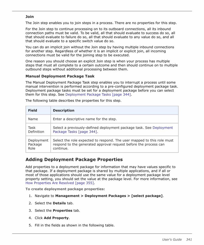
JoinThe Join step enables you to join steps in a process. There are no properties for this step.
For the Join step to continue processing on to its outboard connections, all its inboundconnection paths must be valid. To be valid, all that should evaluate to success do so, allthat should evaluate to failure do so, all that should evaluate to any value do so, and allthat should evaluate to a specific switch value do so.
You can do an implicit join without the Join step by having multiple inbound connectionsfor another step. Regardless of whether it is an implicit or explicit join, all incomingconnections must be valid for the joining step to be executed.
One reason you should choose an explicit Join step is when your process has multiplesteps that must all complete to a certain outcome and then should continue on to multipleoutbound steps without additional processing between them.
Manual Deployment Package TaskThe Manual Deployment Package Task step enables you to interrupt a process until somemanual intervention is performed according to a pre-configured deployment package task.Deployment package tasks must be set for a deployment package before you can selectthem for this step. See Deployment Package Tasks [page 344].
The following table describes the properties for this step.
Field Description
Name Enter a descriptive name for the step.
TaskDefinition
Select a previously-defined deployment package task. See DeploymentPackage Tasks [page 344].
DeploymentPackageRole
Select the role expected to respond. The user mapped to this role mustrespond to the generated approval request before the process cancontinue.
Adding Deployment Package PropertiesAdd properties to a deployment package for information that may have values specific tothat package. If a deployment package is shared by multiple applications, and if all ormost of those applications should use the same value for a deployment package levelproperty setting, you should set the value at the package level. For more information, seeHow Properties Are Resolved [page 355].
To create deployment package properties:
1. Navigate to Management > Deployment Packages > [select package].
2. Select the Details tab.
3. Select the Properties tab.
4. Click Add Property.
5. Fill in the fields as shown in the following table.
User's Guide 341

Field Description
Name Property name
Description Property description
Label Enter a label to be associated with the property in the userinterface.
Required Select this if the property is required.
Type Specify the type of expected value. The supported types are asfollows:
• text
• text area
• check box
• select
• multi select
• secure
The default type is text.
DefaultValue
Enter a default value (if any).
6. Click Save.
To use a property in a deployment package process, reference it when you configure astep that uses it. Use the following syntax: ${p:<property name>}
Running Deployment Package Processes
Deployment packages typically deploy artifacts for multiple applications.
For more about deployment, see Part 5: Deployment [page 375].
To run a deployment package process:
1. Navigate to Management > Deployment Packages.
2. Select a deployment package.
3. Click Run. The process wizard is displayed.
4. If the deployment package has a pipeline associated with it, select an executiontype. Click Next.
Part 4: Management
342 Deployment Automation

5. If prompted, select one or more environments in which to run the package. Thesemay be limited based on the pipeline or environment you select.
• If you selected Do not use pipeline, selected environments do not initiate apipeline execution even if you select the first environment in the pipeline.
• If you select multiple environments, they are executed in parallel and steps thatdo not have environments use the same set of environments.
• The list shows environments that have application environment counterparts inall used applications. If you select Show all available environments,environments that are used in at least one of the used applications are added tothe list.
Click Next.
6. If prompted, enter or select values. The selections for versions, snapshots, and otherproperties are taken from the application or component process properties.
7. Click Submit to start the process. When a process starts, the Request page isdisplayed with a visual indication of the progress. The status of each step is shown incolor on the process graphic:
• Blue: Waiting to start
• Yellow: Running
• Green: Succeeded
• Red: Failed
• Grey: Cancelled
Information for each step is displayed in the process list.
See Chapter 30: Analyzing Deployments [page 383].
People notified for any approvals must approve or reject. See Approving Requests [page299].
Note: If gate conditions are defined for a target environment, the componentversions or snapshots are deployed into that environment only if their statusmeets those conditions. See Gates [page 304].
Deployment Package Inventory
When you deploy using a deployment package, the inventory is tracked in the deploymentpackage and in included applications.
Select a deployment package Inventory tab to see the environment inventories that havebeen updated using that deployment package.
• For application processes, the inventory is taken from the application.
• A deployment package process execution updates both deployment package andapplication inventory. However, an application process executed outside of adeployment package updates only the application process. If an application process
User's Guide 343

contained in a deployment package process is executed outside of the deploymentpackage, it will appear as non-compliant in the deployment package.
• For component processes, the inventory is created.
• If a component version with different statuses or different component versions aredeployed on the same environment, the one with the later date overrides earlierversions.
• Inventory for a deployment package is compliant for an environment only if allmapped resources for that environment are compliant.
Deployment Package TasksA deployment package task is used to interrupt a deployment package process until somemanual intervention is performed. A task-interrupted process is suspended until theassigned user or users respond. Typically, deployment package manual tasks are removedafter the process has been tested or automated.
Like approvals, triggered deployment package tasks notify assigned users. Unlikeapprovals, deployment package tasks can be incorporated within a deployment packageprocess.
The person notified for the task can indicate that it is complete by approving the stepfrom the request's log in Approval Requests. See Approving Requests [page 299].
Create and use tasks as follows:
1. Create deployment package tasks in deployment packages.
2. Insert a manual task step in a deployment package process.
See Manual Deployment Package Task [page 341].
Creating Deployment Package TasksTo create a deployment package task:
1. Navigate to Management > Deployment Packages > [select deploymentpackage].
2. Select the Tasks tab and click Create.
3. Name the task and select a template from the Template Name field.
The individual tasks map to the notification scheme used by the deploymentpackage. See Creating Notification Templates [page 149]. The default available tasknotification template is:
• TaskCreated
Part 4: Management
344 Deployment Automation

Chapter 24: Managing Global Processes
You can define processes that are not associated with a particular application orcomponent.
For details on global processes, see the following topics:
• Creating Global Processes [page 345]
• Designing Global Processes [page 346]
• Global Process Utility Steps [page 346]
• Adding Global Process Properties [page 348]
• Importing/Exporting Global Processes [page 349]
• Running Global Processes [page 350]
Creating Global ProcessesA process is created in two steps:
1. Create the process to configure basic information, such as name, description, anddefault working directory
2. Design the process using the process editor
To create a global process:
1. Navigate to Management > Global Processes.
2. Click Create.
3. Fill in the fields as shown in the following table.
Field Description
Name Identifies the process; appears in many UI elements. Required.
Description The optional description can be used to convey additionalinformation about the process.
DefaultWorkingDirectory
Required. Defines the location used by the agent running theprocess, for temporary file storage. The default value resolves toagent_directory\work\component_name_directory. The defaultproperties work for most components; you might need to change itif a component process cannot be run at the agent's location.
ExecutionTimeout
Specifies the timeout in hours and minutes. Default: run indefinitely
User's Guide 345

4. To create additional global processes, click Save and New. To start configuring theglobal process you just created, click Build Out.
Designing Global ProcessesYou design processes using the process editor. In the process editor you drag processsteps from a menu of steps onto the design space and configure them immediately. Asyou place additional steps, you visually define their relationships with one another.
For information on designing processes, see Designing Component Processes [page 245].
Global Process Utility StepsSeveral utility steps are provided for global processes.
Acquire Lock and Release LockThe Acquire Lock and Release Lock steps enable you to lock and release a process fora designated resource.
Locks are typically used to prevent specific processes from modifying the same resourceat the same time, such as when a database is being updated.
In an Acquire Lock step, the process tries to acquire a lock with the specified name. Ifthere is no other lock with that exact name, the process acquires the lock with that nameand continues. If another process is using a lock with that exact name, the process waitsuntil the lock is released by the other process. Any processes that access the resourcewithout a lock or with a lock of a different name do not wait on this lock.
Locks are released automatically when the process completes, but you can also releasethe lock using the Release Lock step if you need to release it explicitly before continuinglater steps in a process. Administrators can also release locks. See Managing Locks [page110].
The following table describes the property for these steps.
Property Description
LockName
Specify the lock name. The default setting is as follows:${p:component.name}-${p:componentProcess.name}-${p:resource.name}
Tip: The default lock name setting is set using a default variable.Therefore, to make the lock names exactly the same for differentobjects and processes, you can enter a static string for the nameor use variables that will resolve to the same in both processes.For example, if you want to lock a resource against concurrentuse for two processes in different components that are mappedto the same resource, you could use ${p:resource.name} as thelock name for both.
Part 4: Management
346 Deployment Automation

Set StatusThe Set Status step enables you to explicitly set the status of a process. The followingtable describes the property for this step.
Property Description
Status Values: Success or Failed
Set PropertyThe Set Property step enables you to set a value of a property. The following tabledescribes the properties for this step.
Property Description
Name Enter a name for the step.
Property Name Enter a name for the property.
Property Value Enter a value for the property.
SwitchThe Switch step enables you to define a conditional step. The outbound connections forthis step are set to check for values to determine the ongoing path of the process. SeeUsing Conditions and Switch Steps in Processes [page 256]. The following table describesthe properties for this step.
Property Description
Name Enter a name for the step.
PropertyName
Enter a name for the property to be checked for values in the outgoingconnections.
JoinThe Join step enables you to join steps in a process. There are no properties for this step.
For the Join step to continue processing on to its outboard connections, all its inboundconnection paths must be valid. To be valid, all that should evaluate to success do so, allthat should evaluate to failure do so, all that should evaluate to any value do so, and allthat should evaluate to a specific switch value do so.
You can do an implicit join without the Join step by having multiple inbound connectionsfor another step. Regardless of whether it is an implicit or explicit join, all incomingconnections must be valid for the joining step to be executed.
One reason you should choose an explicit Join step is when your process has multiplesteps that must all complete to a certain outcome and then should continue on to multipleoutbound steps without additional processing between them.
User's Guide 347

Manual TaskThe Manual Task step enables you to interrupt a process until some manual intervention isperformed. Manual tasks in global processes are submitted dynamically as part of thestep.
The following table describes the properties for this step.
Field Description
Name Enter a name for the step. Include clearly identifiable information in thename as it appears in the notification about the task.
Users Select the users who can approve or reject this task.
Groups Select the groups who can approve or reject this task.
TemplateName
Enter the template name to use for the task notifications. The default isTaskCreated.
RequireComment
Require a comment upon approval or rejection.
CommentPrompt
Enter a prompt for the comment box that appears in the approval form.For example:
Enter reason and phone number:
All roles are required, so all affected users must respond before the process can continue.
Run Global ProcessThe Run Global Process step enables you to run a global process as part of the currentprocess. The following table describes the properties for this step.
Property Description
Name Enter a name for the step.
Process Select the global process name.
Resource Name Enter the resource name. The default value is as follows:
${p:resource.name}
Adding Global Process PropertiesAdd properties to a global process for information that may have values specific to thescope of that process.
To define a global process property:
Part 4: Management
348 Deployment Automation
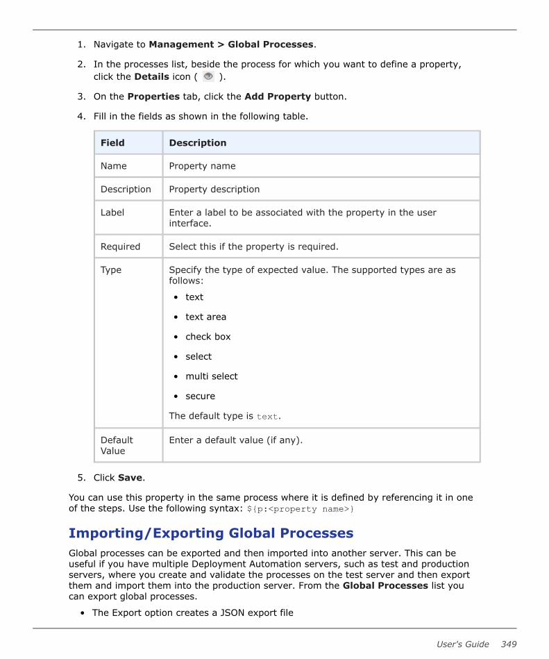
1. Navigate to Management > Global Processes.
2. In the processes list, beside the process for which you want to define a property,click the Details icon ( ).
3. On the Properties tab, click the Add Property button.
4. Fill in the fields as shown in the following table.
Field Description
Name Property name
Description Property description
Label Enter a label to be associated with the property in the userinterface.
Required Select this if the property is required.
Type Specify the type of expected value. The supported types are asfollows:
• text
• text area
• check box
• select
• multi select
• secure
The default type is text.
DefaultValue
Enter a default value (if any).
5. Click Save.
You can use this property in the same process where it is defined by referencing it in oneof the steps. Use the following syntax: ${p:<property name>}
Importing/Exporting Global ProcessesGlobal processes can be exported and then imported into another server. This can beuseful if you have multiple Deployment Automation servers, such as test and productionservers, where you create and validate the processes on the test server and then exportthem and import them into the production server. From the Global Processes list youcan export global processes.
• The Export option creates a JSON export file
User's Guide 349

• You can then import the JSON file into a global process on another server
Exporting Global ProcessesExporting a global process creates a JSON file that contains the global process'sconfiguration information. For information about JSON, see www.json.org.
To export a global process:
1. Navigate to Management > Global Processes.
2. In the column beside a global process, click Export.
You can open the file in a text editor or save it. If you save it, a JSON file is created withthe same name as the selected global process.
Importing Global ProcessesWhen you import a global process, you can create a new global process or upgrade anexisting one.
To import a global process:
1. Navigate to Management > Global Processes.
2. Click Import.
3. Select the JSON file containing the global process.
4. Click Import.
Running Global ProcessesYou can run global processes directly from the Global Processes page or you can run themfrom component and other global processes using the Utility Steps > Run GlobalProcess step. For more about deployment, see Chapter 28: Deployment Overview [page377].
To run a global process from the Global Processes page:
1. Navigate to Management > Global Processes.
2. Select a global process.
3. Click Run.
4. Select resources and options.
5. Click Submit.
When a process starts, the Request page is displayed so that you can review the processrequest progress. After the request completes, you can review the results on that andother related pages. See Chapter 30: Analyzing Deployments [page 383].
Part 4: Management
350 Deployment Automation

Chapter 25: Properties
Properties are parameters that are referenced in process steps. Values can be preset orresolved at runtime. For process properties, like plugin step properties themselves, a userinterface is created so that users can enter values as input properties at runtime.Properties can also be written as output from a process. Property versions are maintainedand remain available.
Property names can be user-defined or built-in. A number of built-in properties areavailable for referencing in your process steps. If there is no built-in property that suitsyour needs, you can define your own properties at the levels you may need them anddesignate the default values according to the logic of your configuration.
Property values are restricted to 4,000 characters.
For details on available properties, see the following topics:
• Built-in Properties [page 351]
• User-Defined Properties [page 353]
• All Properties Pairs [page 354]
• How Properties Are Resolved [page 355]
• Property Picker [page 356]
Built-in PropertiesDeployment Automation has a number of built-in properties that can be used by yourprocesses. These are described in the following table. To use a property in a process,reference it when you configure a step using the syntax shown in the Reference Syntaxcolumn.
Built-in Properties Table
Property Name Reference Syntax Description
agent.id ${p:agent.id} Agent ID is the unique numberDeployment Automation gives anagent at installation to distinguish itfrom others.
agent.name ${p:agent.name} Agent name is a user-defined namegiven at installation that distinguishesthe agent from others. The agentname can be changed by editing theagent's conf/agent/installed.properties file andrestarting the agent.
User's Guide 351

Property Name Reference Syntax Description
application.id ${p:application.id} An application ID is a unique numberDeployment Automation gives theapplication at creation to distinguish itfrom others.
application.name ${p:application.name} An application name is a user-definedname that distinguishes theapplication from others. It is enteredwhen editing or creating a newapplication.
component.id ${p:component.id} Component ID is the unique numberDeployment Automation gives acomponent at creation to distinguish itfrom others.
component.name ${p:component.name} A component name is a user-definedname that distinguishes thecomponent from others. It is enteredwhen creating or editing acomponent.
environment.id ${p:environment.id} Environment ID is the unique numberDeployment Automation gives anenvironment at creation to distinguishit from others.
environment.name ${p:environment.name} An environment name is a user-defined name that distinguishes theenvironment from others. It isentered when creating or editing anenvironment.
resource.id ${p:resource.id} Resource ID is the unique numberDeployment Automation gives aresource at creation to distinguish itfrom others.
resource.name ${p:resource.name} A resource name is a user-definedname that distinguishes the resourcefrom others. It is entered whencreating or editing a resource.
version.id ${p:version.id} Version ID is the number assigned toa version when it is imported intoCodeStation.
Part 4: Management
352 Deployment Automation

Property Name Reference Syntax Description
version.name ${p:version.name} A version name is a user-definedname that distinguishes the versionfrom others. It is given when theversion is imported.
prevStep ${p:prevStep/<propertyname>}
This enables you to access previousstep values without having toexplicitly fill in the previous stepname.
Warning: If a step hasmultiple possible previoussteps in a conditionalprocess design, the resultswill be unpredictable.
logPath ${p:<step name>/logPath}
This is an output property thatresolves to the full path of a givenstep's log file during processexecution. For example, this can beused with the prevStep property asfollows:
${p:prevStep/logPath}Important: Thisfunctionality was introducedin Deployment Automationversion 5.1.5. Processesthat were executed beforethis functionality wasimplemented will not havethe logPath property.
User-Defined PropertiesIf there is no built-in property that suits your needs, you can define your own propertiesat the levels you may need them. The user-defined properties are described in thefollowing table. To use a property in a process, reference it when you configure a stepusing the syntax shown in the Reference Syntax column.
User-Defined Properties Table
Property Name ReferenceSyntax
Description
agent/<propertyname>
${p:agent/<propertyname>}
Agent properties are user-defined and areset on the agent's Properties tab.
User's Guide 353

Property Name ReferenceSyntax
Description
application/<property name>
${p:application/<propertyname>}
Application properties are user-defined andare set on the application’s Properties tab.
component/property_name
${p:component/<propertyname>}
Component properties are user-defined andare set on the component’s Properties tab.
environment/property_name
${p:environment/<propertyname>}
Environment properties are user-defined andcan be set on the environment, applicationenvironment, and component Propertiestabs. Values for same-named environmentproperties are overridden at the mostspecific level, with component being themost specific.
<property_name> ${p:<propertyname>}
You can define properties on a process'sProperties tab and enter them in a process.If the property does not have an assignedvalue, the user running the process isprompted for the value.
resource/<property name>
${p:resource/<propertyname>}
Resource properties are user-defined andare set on the resource's Roles &Properties tab.
resource/<rolename>/<propertyname>
${p:resource/<role name>/<propertyname>}
Resource role properties are user-definedand are defined on the resource's Roles &Properties tab. The values are set whenadding a role to a resource.
<stepname>/<property name>
${p:<stepname>/<propertyname>}
You can reference a property name in aprocess step that is set in a previous stepname in the same process. The propertyvalue is set as output from the named step.
system/<propertyname>
${p:system/<propertyname>}
System properties are user-defined and areset in Administration > System >Properties. These can be thought of asglobal properties, and should be used to setvalues that are system-wide defaults.
All Properties PairsIf you want to parse properties you have defined during a process, you can have allproperties returned to subsequent steps. You can then search for a required property orproperty value and use that as part of your process. After the allProperties property is
Part 4: Management
354 Deployment Automation

resolved, all of the properties for the given element are listed in a comma-separatedseries of name=value, including each property on the given element.
These are available only during process execution, and are not automatically written tothe process request's Output Properties. You can echo the properties in a step of yourprocess to list them to the output.
If you use the wrong property name, your property name string won’t be replaced. Forexample, for component/allProperties, it would remain ${p:component/allProperties}.If the system passes or echos an empty string, this indicates that there are no propertiesfor the property name you specified.
All Properties Pairs TableThe available All Properties pairs are shown in the following table.
PropertyName
ReferenceSyntax
Description
component/allProperties
${p:component/allProperties}
Selects all the properties with the same value in agiven component.
environment/allProperties
${p:environment/allProperties}
Selects all the properties with the same value in agiven environment.
resource/allProperties
${p:resource/allProperties}
Selects all properties with the same value in agiven resource.
CAUTION:
${p:agent/allProperties} will returnproperties most of the time, butbecause it usually contains a carriagereturn, the step may fail.
system/allProperties
${p:system/allProperties}
Selects all properties with the same value in agiven system.
How Properties Are ResolvedTo use a user-defined property in a process, reference it when you configure a step thatuses it. Use the following syntax:
${p:<element>/<property name>}where the ${ indicates the start of the reference, p stands for property, <element> is theelement the property is defined on, such as component, <property name> is the user-defined property name, and } indicates the end of the reference. If the property is definedfor a process, you can reference that property in the same process as ${p:<propertyname>}.
A running process fills in values for properties from various property settings, includingthe following:
User's Guide 355

1. system
2. environment
3. resource
4. resource role
5. application environment
6. application
7. application process
8. component environment
9. component
10. component process
11. component version
12. global process
13. properties set by process steps
For example, a component process step has access to properties set before or during theprocess execution, including those that are:
• set earlier by other steps within the process
• set within the scope of the currently executing process
• set by the component
• set by the application
• set for the target environment and resource
• set at the system level
Step property values become unavailable once the component process ends.
Typically, you set the value for a same-named property where the value is most likely tochange. For example, the value for a web server port number would probably be set inthe environment or resource properties. This helps to make the processes flexible enoughto execute in multiple environments, such as INT, UAT, and PROD.
The process resolves the values from one of the settings in hierarchical order, with valuesgiven for properties closest to the process step overriding any previous values. If theproperty value is unresolved, the process can prompt users for information at runtime andthen incorporate the values into the process.
Property PickerA typical DA environment may contain hundreds of properties. You do not have toremember the names of all properties, instead use the property picker to find and selectthem. The picker displays properties:
Part 4: Management
356 Deployment Automation

• alphabetically in ascending order.
• that are based on your current context and any linked context.
• for which you have security permission.
You can use the property picker in the:
• Process designer
• Process wizard
• Properties editor
Note: The first time that you start a new DA server, the properties are indexedand the picker may take a while to display. In subsequent start ups the propertypicker is available immediately. To disable the property picker go toAdministration | System | System Settings.
Using the property picker
1. To invoke the property picker, in a properties field do one of the following:
• Enter: ${
• Press the Control and Space keys together.
The picker opens and displays a list of all available properties.
2. Do one of the following:
• To find a property, scroll down the list.
• To search for a property, start typing its name after the ${ characters. The listdisplays all the properties that match the string, for example:
▪ To search for all properties that have 'da' in their name, type: da
▪ To narrow the list and search for agent properties that have 'da' in their name,type: agent.da or agent/da
3. To close the property picker, enter } or press ESC.
User's Guide 357

Part 4: Management
358 Deployment Automation

Chapter 26: Configuring Within theApplication Hierarchy
You can configure properties, resources, and configuration templates directly through theapplication hierarchy on the Configuration page.
Configuration Page
1. Navigate to Management > Configuration.
2. Select how the Deployment Automation elements are sequenced in the hierarchy:
• Application / Component / Environment
• Environment / Application / Component
• Component / Application / Environment
3. Search for the name of the application, component, or environment you want toconfigure. You can also filter the results by owner—those owned by the current useror those owned by all users.
4. Scroll the list to see the applications, components, and environments. The resultsare displayed based on the selected sequence, search key, and owner filter.
5. Select the application, component, or environment you want to configure.
6. The following tabs are available
• For applications: Properties
• For components: Properties, Environment Properties, Version Properties, andTemplates (configuration templates)
• For environments: Properties, Component Properties, and Resources (resourcesand resource groups)
7. View the listing for your selection.
User's Guide 359

8. Use the edit, add, or create button that appears for your selection to add propertyvalues, add properties, create resources, and create configuration templates.
Part 4: Management
360 Deployment Automation

Chapter 27: Replication
You can export and import whole sets of Deployment Automation objects usingreplication.
You can export from a source server and import on a target server to replicate a cluster ofobjects from one server to another. This can be used to maintain automation databetween master and slave servers, even across an air gap.
Data is exported to and imported from a single file. If the servers are not physicallyconnected, a flat file that contains source server data must be manually uploaded to thetarget server.
Replication is implemented as follows:
• You can select a set of applications that you want to export. All the linked objects,such as components, environments, and pipelines, are exported automatically withthe applications.
• You can select a set of environments that you want to export. If an environment thatis part of a pipeline is omitted from the selection, the pipeline is also omitted fromthe export.
• Exported files contain component versions with files of the associated components.
• Snapshots can be used instead of component versions if needed.
• Export and Import works with a single file containing all the data.
• Process execution history is not exported.
• Component mapping works only if the target server has agents with the same namesas those on the source server.
• During the import procedure, the creation date for all objects is set to that of thecurrent system. The creation date from the source server is ignored.
• All objects imported to the target server will have the same ID as correspondingobjects from the source server. The import procedure identifies whether the objectwas previously imported from the source server based on its ID.
For details, see the following topics:
• Replication Import Strategies [page 362]
• Exporting Replication Data [page 363]
• Importing Replication Data [page 365]
• Replication Export Details [page 366]
• Replication Import Details [page 369]
User's Guide 361

• Replication Merge Strategies [page 371]
Replication Import StrategiesReplication strategies enable you to import objects when there are conflicts betweennames in a replication file and a server. There are two strategies:
• Import Strategy: specifies how conflicts between objects are resolved.
• Properties Merge Strategy: specifies how conflicts between Property Sheets andProperty Sheet Definitions are merged. This strategy was previously called MergeStrategy and its functionality is the same.
Import replication can be:
• Object ID based
• Object name and ID based
The replication strategy defines how two objects from a server and replication file arematched.
Object ID based replication
This is the legacy replication import strategy. It matches two objects based on their IDsand considers them to be identical if the IDs match. Allows mainly master-slavereplication scenarios.
Object name and ID based replication
Tip: Use as the default.
This strategy matches two objects based on ID and name using this sequence:
1. Uses the ID based import strategy (see above).
2. If that fails, finds two matching objects with different IDs but identical names. Thetwo objects are treated as a match.
3. If there are no matching objects, creates a new object on the server.
This strategy works as follows:
• When a versioned entity is imported the server remembers its path and versionnumber and does not import it again.
• When a server imports an object matched by name, all versions that were notpreviously imported are imported as the latest version, maintaining the order fromthe replication file. For example, a server has app1 with id1 and one version of theproperties. The server imports app1 with id2 with two versions of the properties. Theproperties for app1 look like this:
▪ app1, id1, version 1 properties (version 1 on the server)
▪ app1, id2, version 1 properties (version 2 on the server)
▪ app1, id2, version 2 properties (version 3 on the server, the latest version)
The table below explains how name conflicts are resolved.
Part 4: Management
362 Deployment Automation

Example Server Replication Result Description
ID Name ID Name ID Name
1 id1 name1 id1 name2 id1 name2 No conflict.
2 id1 name1 id2 name1 id1 name1 Two entities with differentIDs have the same name.The conflict is resolved byreplacing the ID of thereplication entity with the IDof the server entity.
id1 name1 id1 name23
id2 name2 id2 name1
Conflict No resolution and there is aconflict.
Long name conflict resolution
You can import replication files with entities names that are longer than permitted. Longnames are shortened to the first name that is legal and not occupied. A shortened namelooks like this:
<first part of the name> < text> <length limit exceeds ~31>If the system identifies a conflict with one of the existing names, the index isautomatically incremented to resolve conflicts.
Exporting Replication DataYou can export replication data for one or more applications. You would typically exportreplication data from a primary or master server. You can also use the replication data toshare processes across testing and demonstration servers.
To export replication data:
1. Navigate to Management > Applications.
2. From the Replication menu select Export.
3. Select the applications that you want to export and click Next.
4. Select the environments that you want to export and click Next.
5. Select the export options as follows:
User's Guide 363

Option Description
Componentversions
Determines which component versions to export. Select one of thefollowing:
• Deployed: include all deployed versions from the currentinventory status of the environments (default)
• All: include all component versions
• Latest: include only the latest versions of the components
• None: do not include component versions
Note:
Inactive component versions are not exported even if allcomponent versions are selected.
Versionsobjects
Determines which property sheet or process versions to export.Select one of the following:
• Latest: include only the latest versions (default)
• All: include all versions
Includesnapshots
Select this to include snapshot information in the export. Thedefault is selected.
Note:
If snapshots are included in the export, all relatedcomponent, process, and property sheet versions will beexported with them regardless of the selections forComponent versions and Versioned objects options.
Includeplugins
Select this to include plugins in the export. The default is selected.
Exportformat
Determines the metadata export format. Select one of thefollowing:
• JSON (default)
• XML
6. Click Export.
The exported replication data is saved in a single zipped file that contains the file typedesignated in the Export format option. Component version files will be saved withinfolders named by component ID and version ID. The zipped file is saved to the downloadslocation defined in your web browser.
Part 4: Management
364 Deployment Automation

Importing Replication DataYou can import replication data that has been exported from another server. You wouldtypically import data into a secondary or slave server.
To import replication data:
1. Navigate to Management > Applications.
2. From the Replication menu select Import.
3. Select the replication data file that you want to import.
4. Select the import options as follows:
Option Description
Merge strategy Determines the mergestrategy to be usedduring import. Select oneof the following:
• Override
• Merge withoutconflicts
• Merge with masterpriority
• Merge with slavepriority
For more details, seeReplication MergeStrategies [page 371].
Disable auto-import Select to disableautomatic import forcomponent versionsduring the importprocedure. The default isselected. For informationon automatic import ofcomponent versions, seeImporting VersionsAutomatically [page236].
User's Guide 365

Option Description
Override resource mapping Select this if you wantresource mapping forenvironments andapplication environmentsto be imported and theexisting resourcemapping overridden. Thedefault is deselected.
5. From this point you can either import the export file information as-is, or you canselectively import as follows:
• To import without changing the application and environment selections, clickFinish.
• To change the application and environment selections, click Next.
6. If you selected Next, continue as follows:
a. Select the applications that you want to import and click Next.
b. Select the environments that you want to import and click Import.
The imported replication data is populated on this server as defined in the import options.
See also:
Replication Import Strategies [page 362]
Replication Export DetailsThe following sections explain how replication export processing is done for each kind ofobject that is exported.
Dependency Analysis
The export procedure automatically identifies all dependencies associated with theselected applications set, such as components, component templates, global processes,environments, resources, resource groups, agent pools, plugins, statuses, notificationschemes, resource roles, and security roles. Inactive component versions, snapshots, andenvironments are excluded from the export. The rest of the objects are exportedregardless of their status.
If the Include Snapshots option is selected, the export procedure automaticallyidentifies all the versions used in snapshots and adds those versions to the exported file.Therefore, even if the Versioned Objects parameter is set to Latest, earlier versions willbe added to the exported file if they are used in snapshots and the Include Snapshotsoption is selected.
Environments
Environments selected in the export wizard are exported.
List of items exported with an environment:
Part 4: Management
366 Deployment Automation

• List of Resources (only resources associated with selected environments areincluded)
• Associated Pipeline (included only if all environments in the pipeline are selected forexport)
Applications
Applications selected in the export wizard are exported.
List of items exported with an application:
• List of Environments (only environments selected for export are included)
• List of Components
• Component Mapping
• Application Processes
• Application Snapshots
• Tasks Definition
• PropSheet
• Associated Pipeline
Inactive applications and environments within the application are not exported.
Components
List of items exported with a component:
• Component Versions (both full and incremental versions are supported)
• Component Processes
• Post-processing scripts
• Tasks Definition
• Templates
• PropSheet
Global Processes
List of items exported with a global process:
• PropSheet
• Post-processing scripts
Although a Global Process is a versioned object, only the latest version of a Global Processis exported from the source environment. This happens because users can't use a GlobalProcess version on the source server other than the latest one.
Component Templates
List of items exported with a component template:
User's Guide 367

• Processes
• PropSheet
Pipelines
Only those pipelines that are associated with applications are exported.
Environments
Only those environments that are associated with applications are exported.
List of items exported with an environment:
• Resource Set
Resources
Only objects used in environment resource sets are exported.
Resource Groups
Only objects used in environment resource sets are exported.
Agent Pools
Linked agents are not included in the export. Only agent pools used in exported resourcesets are exported.
Plugins
If the Include plugins option is selected, the export procedure automatically determineswhich plugins are used in the exported processes and includes them in the data file. Onlyused plugins are included.
Statuses
Only statuses used in exported component versions and snapshots are included.
Notification Schemes
Only notification schemes used in exported applications are included.
Resource Roles
Only resource roles used in exported resources are included.
Security Roles
Only security roles used in exported processes, notification schemes, and version statusesare included.
Export Errors
You cannot export a process version if it invokes another process that has already beendeleted, uses a plugin that has been removed from the system, or references a securityrole that has been removed. In these cases, the export procedure tries to remove thespecific version of the process from the exported file. However, if after the process versionis removed there are no versions of the process selected that can be exported, an error isgenerated and the export operation cancelled.
You cannot export component and global processes that contain recursive processinvocation; for example, where process A invokes process B and process B in turn invokesprocess A. If you attempt this, the export procedure will immediately fail. Exportparameters should be set up to exclude any recursive process invocation.
Part 4: Management
368 Deployment Automation

Replication Import DetailsThe following sections explain how replication import processing is done for each kind ofobject that is imported.
Environments
Environments that are exported are automatically selected for import. However, they canbe de-selected in the import details if needed.
An environment is created on the target server if an environment with the given namedoes not already exist. If an environment with the given name already exists and its ID isdifferent from the ID of the imported environment, an error is generated and the importoperation is cancelled. During environment creation, the set of resources and resourcegroups associated with the environment are recreated on the target server based onresource and resource group IDs.
A list of resources and resource groups are recreated for the existing environment if theOverride resource mapping option is specified during the import procedure.
Component Templates
Component templates are fully imported to the target server. If a component templatewith the given name already exists and its ID is different from the ID of the importedcomponent template, an error is generated and the import operation is cancelled. If theIDs match, a new version of component template is created based on the data provided inthe data file.
Components
Components are fully imported to the target server. Component versions (artifacts)contained in a data file are imported as well. If a component with the given name alreadyexists and its ID is different from the ID of the imported component, an error is generatedand the import operation is cancelled. If the IDs match, the existing componentparameters are overridden based on the data provided in the data file. If the componentwas deleted on the target server but it exists in a data file, the component is recreated onthe target server.
Old versions (artifacts) are not deleted, but any new versions are imported to thecomponent. There are no limitations on using component version type for importedcomponent versions. Both full and incremental modes are fully supported by the importprocedure.
Global Processes
Global processes are fully imported to the target server. If a global process with the givenname already exists and its ID is different from the ID of the imported global process, anerror is generated and the import operation is cancelled. If the IDs match, a new versionof the global process is created based on the data provided in the data file.
Applications
Applications that are exported are automatically selected for import. However, they canbe de-selected in the import details if needed.
Applications are fully imported to the target server. If an application with the given namealready exists and its ID is different from the ID of the imported application, an error isgenerated and the import operation cancelled. If the IDs match, the existing applicationparameters are overridden based on the data provided in the data file.
User's Guide 369

Environment to environment linkage will be performed based on environment namesrather than IDs.
Component mapping are performed based on the existing resource set. If some of theresources are missing, they are omitted during the component mapping import.
Application snapshots are fully imported, including dependencies on the componentversions, application processes, component processes, properties, and other objects.During the import procedure, the snapshots are automatically linked to the importedversions of the corresponding objects used on the target environment.
Resources
Resources are fully imported to the target server. If a resource with the given namealready exists and its ID is different from the ID of the imported resource, an error isgenerated and the import operation cancelled. If the IDs match, the existing resourceparameters are overridden based on the data provided in the data file.
If an environment is deselected for the import and resources are dependent on thatenvironment, those resources will not be imported.
Resource Groups
Resource group meta-information is fully imported to the target server.
Agent Pools
Only basic meta-information related to agent pools is imported to the target server.
Plugins
During the import procedure, all plugins with the same version as those contained in thedata file are overridden on the target server. Plugins added on the target server are notdeleted during the import procedure.
Statuses
The same rules apply as for the Resources import.
Notification Schemas
The same rules apply as for the Resources import.
Resource Roles
The same rules apply as for the Resources import.
Security Roles
The same rules apply as for the Resources import.
Pipelines
The same rules apply as for the Resources import.
If an environment is deselected for the import and it is part of a pipeline, that pipeline willnot be imported.
Versioned Objects
Versioned objects, such as property sheets and processes, are imported according to themerge technique described below. According to this technique, new versions are added onthe target server.
Part 4: Management
370 Deployment Automation

The following example explains what happens if the Versioned objects option isspecified as All.
1. Assume there are 2 versions of a property sheet on the master server:
Master 1, 2
2. The replication procedure recreates these versions on the slave server:
Slave 1, 2
3. After this, a release engineer decides to make some changes on the slave server:
Slave 1, 2, 3*
4. Another release engineer makes changes on the master server:
Master 1, 2, 3
5. In the end, replication is performed and all versions added on the master serversince the last import will be imported as new versions.
Master 1, 2, 3*, 4 (3)
In this example, if there was a snapshot referring to version 3 on the master server, it willrefer to version 4 on the slave server after the import procedure is performed.
The replication mechanism keeps track of all the imports that were previously performedon the target environment and during import, omits versions that have already beenimported to the target environment. In the preceding example, versions 1 and 2 from thesource server won't be imported to the target sever during the second import becausethey were already imported during the first import.
This technique can be used to get rid of unnecessary versions on the slave server duringthe replication procedure. The following example explains what happens if the Versionedobjects option is specified as Deployed.
1. Assume that we have 2 versions of a property sheet on the master server and onlyversion 2 is used by the deployed process:
Master 2
2. The replication procedure recreates this version on the slave server:
Slave 1(2)
In the example above, if there was a snapshot referring to version 2 on the master server,it will refer to version 1 on the slave server after the import procedure is performed.
Replication Merge StrategiesYou can specify a properties merge strategy for the import procedure. Properties can bemerged according to one of the following strategies:
• Override: The new version is created solely based on data from a data file. Targetserver changes are ignored and will be overridden.
• Merge without conflicts: The new version is created as a result of a propertiesmerge from source and target servers. If a property was changed on either thetarget or source server, the merge result will be successful and the updated property
User's Guide 371
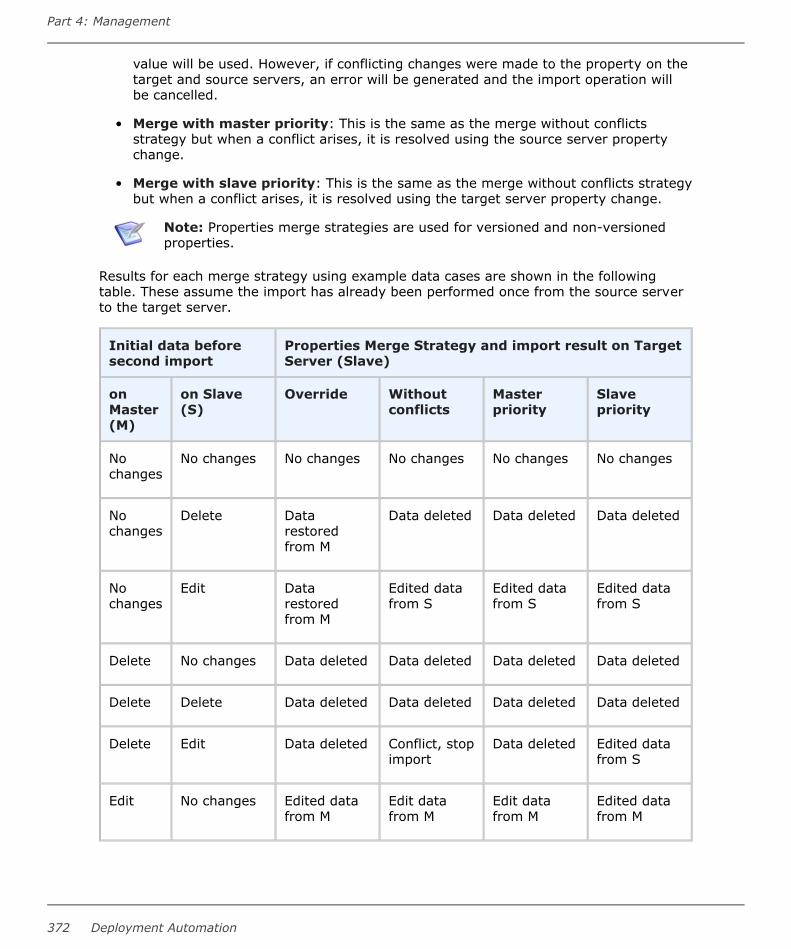
value will be used. However, if conflicting changes were made to the property on thetarget and source servers, an error will be generated and the import operation willbe cancelled.
• Merge with master priority: This is the same as the merge without conflictsstrategy but when a conflict arises, it is resolved using the source server propertychange.
• Merge with slave priority: This is the same as the merge without conflicts strategybut when a conflict arises, it is resolved using the target server property change.
Note: Properties merge strategies are used for versioned and non-versionedproperties.
Results for each merge strategy using example data cases are shown in the followingtable. These assume the import has already been performed once from the source serverto the target server.
Initial data beforesecond import
Properties Merge Strategy and import result on TargetServer (Slave)
onMaster(M)
on Slave(S)
Override Withoutconflicts
Masterpriority
Slavepriority
Nochanges
No changes No changes No changes No changes No changes
Nochanges
Delete Datarestoredfrom M
Data deleted Data deleted Data deleted
Nochanges
Edit Datarestoredfrom M
Edited datafrom S
Edited datafrom S
Edited datafrom S
Delete No changes Data deleted Data deleted Data deleted Data deleted
Delete Delete Data deleted Data deleted Data deleted Data deleted
Delete Edit Data deleted Conflict, stopimport
Data deleted Edited datafrom S
Edit No changes Edited datafrom M
Edit datafrom M
Edit datafrom M
Edited datafrom M
Part 4: Management
372 Deployment Automation

Initial data beforesecond import
Properties Merge Strategy and import result on TargetServer (Slave)
onMaster(M)
on Slave(S)
Override Withoutconflicts
Masterpriority
Slavepriority
Edit Delete Edited datafrom M
Conflict, stopimport
Edit datafrom M
Data deleted
Edit Edit Edited datafrom M
Conflict, stopimport
Edit datafrom M
Edited datafrom S
Adddata onM
Add data onS
Only addedM data
Added M andS data
Added M andS data
Added M andS data
User's Guide 373

Part 4: Management
374 Deployment Automation

Part 5: Deployment
This section contains information on deployment in Deployment Automation.
Included are the following topics:
• Chapter 28: Deployment Overview [page 377]
• Chapter 29: Ways of Deploying [page 379]
• Chapter 30: Analyzing Deployments [page 383]
• Chapter 31: Inventory Management [page 391]
• Chapter 32: Deployment Report Overview [page 395]
User's Guide 375

Part 5: Deployment
376 Deployment Automation

Chapter 28: Deployment Overview
You typically manage deployments in the Deployment page of the user interface. TheDeployment page is one of several places you can view deployment-related information.
Following are some of the selections on this page.
• Timeline
See Chapter 30: Analyzing Deployments [page 383].
• Inventory
See Chapter 31: Inventory Management [page 391].
• Reports
See Chapter 32: Deployment Report Overview [page 395].
• Schedule
Select from options to schedule a deployment to run later and set blackout dates.See Scheduling Deployments [page 380] and Setting Deployment Blackout Dates[page 380].
• Run
Select a deployment to run now. See Chapter 29: Ways of Deploying [page 379].
• Action
Select from deployment actions, including the following:
▪ Print Page
▪ Help
User's Guide 377

Part 5: Deployment
378 Deployment Automation

Chapter 29: Ways of Deploying
There are several ways to run processes in Deployment Automation. Although not allprocesses are deployment processes, for simplicity, we refer to running processes as"deploying" here. Deployment options are available in both Management andDeployment pages so that deployment can be done by those users with access to onlyone or the other in the user interface.
Regardless of where you select the Run option, the process wizard is displayed.Depending on the context, some of the selections are pre-selected.
• In Management, you run processes from the element whose processes you want torun: deployment package, application, component, or global.
• In Deployment, you can select and run a process using the Run option in the globalmenu. In this menu, you can select from the following:
▪ Application Process: This invokes the application process wizard.
▪ Promote Application Process: This invokes the application process wizard andlets you select and run a process in the next environment in a pipeline. You willsee only applications that have a pipeline in them and will see only thoseenvironments where there are pending pipeline executions. This is used tocontinue promotion for pipelines that do not require auto-promote, and theprocess must already have been run in a prior environment in the pipeline.
▪ Deployment Package: This invokes the deployment package process wizard.
▪ Promote Deployment Package: This invokes the deployment package processwizard and lets you select and run a process in the next environment in apipeline. You will see only applications that have a pipeline in them and will seeonly those environments where there are pending pipeline executions. This isused to continue promotion for pipelines that do not require auto-promote, andthe process must already have been run in a prior environment in the pipeline.
▪ Component Process: This invokes the component process wizard.
▪ Global Process: This invokes the global process wizard.
See the following for running processes from Management. The procedures are the samefor running the same type of processes from Deployment other than the initialnavigation and any pre-selected information based on context.
• Running Deployment Package Processes [page 342]
• Running Application Processes [page 296]
• Running Component Processes [page 262]
• Running Global Processes [page 350]
For more information on deploying, see the following topics:
• Scheduling Deployments [page 380]
User's Guide 379

• Setting Deployment Blackout Dates [page 380]
Scheduling DeploymentsDeployment Automation has a built-in deployment scheduling system for setting updeployments that occur on a regular basis.
You can schedule deployments for applications and deployment packages into applicationenvironments.
To schedule a deployment:
1. Do one of the following:
• In Deployment, in the global menu, click Schedule and then select ApplicationProcess.
• In Management > Environments > (selected environment), in the globalmenu, click Schedule and then select Application Process or DeploymentPackage.
2. Follow the Schedule Application Process wizard to make your selections.Selections are relevant for deployment requests for applications, depending on youare deploying.
3. In Options, give the date and time you want the deployment to run. Click MakeRecurring to deploy the application on a regular schedule. For example, if you arepracticing continuous delivery, you could select the Daily option to deployapplications to the target environment every day.
4. When finished, click Submit to start the process, which will remain pending until thescheduled time.
The selected processes do not start until the scheduled time. After you have scheduledthe deployment, it will be added to the Timeline. In the Timeline grid or table view youcan you can view, edit, and delete the deployment.
Setting Deployment Blackout DatesA blackout can be set at the global environment level or application environment level.Once set, no deployments or snapshots can be scheduled to occur in the designatedenvironment.
To set up a blackout:
1. In Deployment, in the global menu, click Schedule and then select one of theBlackout options as follows:
• Application Environment Blackout
• Global Environment Blackout
2. Follow the Schedule Blackout wizard to make your selections. Selections arerelevant for application or global environments, depending on at what level you areadding the blackout.
3. Select an environment for which to set the blackout.
Part 5: Deployment
380 Deployment Automation

4. Select the date and time range for which you want the blackout to remain in effect.Optionally, you can enter a name for the blackout.
5. Click Submit.
In the Timeline, the blackout dates now have a black icon to indicate a blackout has beenset. An A or G indicate the environment level for the blackout, application or global. In theTimeline grid or table view you can view, edit, or delete the blackout.
Important: If any previously-scheduled deployments to the environment arewithin the blackout date range, they will fail.
User's Guide 381

Part 5: Deployment
382 Deployment Automation

Chapter 30: Analyzing Deployments
Deployment Automation provides a rich set of information about your deployments intothe application environments. Drill down to see successive levels of detail.
Following are some of the ways you can analyze the results of your deployments into yourenvironments and ensure the environments have the component versions andconfigurations you need.
• Viewing Timelines [page 383]
• Viewing Application Deployments [page 385]
• Viewing Deployment History [page 386]
• Viewing an Application Process Request [page 386]
• Viewing a Component Process Request [page 387]
• Deployment Results in E-mail Notifications [page 389]
Viewing TimelinesTimelines show overview information on the processes run and link to more detail forconvenient access to information.
You can view timeline information by navigating to:
• Deployment > Timeline: Timeline of all deployments run in the given time rangefor this Deployment Automation server
• Management > Environments > (selected environment) > Timeline: Timelineof all deployments run in the given time range for each application environmentbased on this environment
User's Guide 383

On a timeline you can do the following:
• Select to show deployments for applications, components, snapshots, or deploymentpackages. (Applications and deployment packages selections are available inenvironment timelines.)
• Search for a request name; this narrows the display to just the entries including thatname.
• Filter by deployments owned by you or by everyone.
• Click the calendar view icon to see the calendar view.
• Click the grid view icon to view a list of processes.
• Use the arrows to change the year, month, week, or day viewed in the calendar,depending on the period selected.
• Select the period to show.
• In the month and year views, click anywhere in the blank area of a block to show thelist of requests for that date block in a tabular view.
Depending on the view and selection, columns include the following:
▪ Status
Part 5: Deployment
384 Deployment Automation

▪ Time
▪ Name (click to go to the process request page)
▪ Application (click to go to the application page)
▪ Component for the process (click to go to the component page)
▪ Process Version
▪ Environment (click to go to the application environment page)
▪ Process Version
▪ Deployment Owner
• In the month view, status icons give you a quick view of the health of the processes.Point to a status icon for a quick view of information about the request. Click the iconto open the request page.
• In the month view, icons indicate scheduled processes and global and applicationenvironment blackouts. Point to an icon for a quick view or click the icon to open therelated page.
Tip: In the tabular view, you can view, edit, and delete blackout andschedule entries.
Related Topics
Chapter 31: Inventory Management [page 391]
Configuring and Monitoring Environments [page 308]
Viewing Application DeploymentsSelect an application's Activity tab see its deployment summary. This gives a graphicaloverview and allows you to select a time range of information to view. Information givenincludes the following:
• Deployment Summary
See a graphical view of deployments by status in the selected time period.
• Next Scheduled Deployment
See the date and time the next deployment for this application is scheduled.
• Last Scheduled Deployment
See the date and time the last deployment for this application was run.
• Deployments to Environments by Process
View a list of processes with the number of times they were run in each environmentin the selected time period. You can select the time period independently of theDeployment Summary view.
• View Deployment History
User's Guide 385

In one click go to the application's Deployment History page.
Related Topics
Chapter 31: Inventory Management [page 391]
Viewing Timelines [page 383]
Configuring and Monitoring Environments [page 308]
Viewing Deployment HistoryYou can view deployment history in the History tab of application, applicationenvironment, and component pages.
To view the applications that have been deployed into a particular environment:
1. Navigate to Applications > [select application].
2. Select the Environments tab.
3. Click the name of an environment and select View Details.
4. Select History > Deployment History. From there you can click name links andthe View Execution Details icon to view deployment request information.
Viewing an Application Process RequestThere are several ways to navigate to application process request details in context as yourun processes and view deployment information.
To navigate from anywhere to the application request details:
1. Navigate to Management > Applications > [select application].
2. Select the History tab.
Part 5: Deployment
386 Deployment Automation

3. Select the Deployment History tab.
4. Locate the application in the list of processes and click View Execution Details.
Note: The process list item indicates the environment in which the process wasrun.
The following figure shows application process request details for a selected environment:
Click Repeat Request to repeat the process request using the same options.
The tabs display the following information:
• Log: View the results of each process step.
• Properties: View the properties used in the process.
• Manifest: View the artifacts deployed by the process.
On the Log tab you can:
• Expand process steps to see information about each step and link to additionalinformation.
• Click a resource name to go that resource's page.
• Click a version name to go to the component version's Artifacts tab where you canview and download the artifacts for this version.
• Click Details to see the step-by-step breakdown of the execution.
Viewing a Component Process RequestTo view the component process request details, you can view them in context immediatelyafter running the process or you can navigate to the details in several different ways. Ifyou continue to drill down into the details when viewing an application process request,
User's Guide 387

you will see the component request details. You can also navigate to the componentprocess request details directly from the resource on which you ran the process.
To view the details for a process request for a selected resource:
1. Navigate to Management > Resources > [select resource].
2. Select the History tab.
3. Select the Deployment History tab.
4. Locate the application in the list of processes and click View Execution Details .The component process request results for each step in the process is displayed.From here you can review the deployment's output log, error log, and input/outputproperties.
On a component process request page you can:
1. View the request summary.
2. Select the Log tab to view the list of steps.
3. Select the Properties tab to view the property values that were in effect when thisprocess request was run.
4. View an overview of each step.
5. Click the link in the Type column to view the artifacts.
6. Click an icon to view more information:
• Output Log: View the output log for the selected process request.
• Error Log: View the error log for the selected process request.
• Input/Output Properties: View a dialog that lets you toggle between views ofthe input and output property values for the selected process step.
Part 5: Deployment
388 Deployment Automation

Deployment Results in E-mail NotificationsIf email notification schemes are configured, deployment results are sent to the email IDsof users with the selected roles as follows:
• The body of a notification email shows the details and the success or failure status ofthe deployment for each target.
• If the email notification scheme is configured to attach logs, the email notificationincludes a log file for each target that shows the success or failure status of eachstep.
Attached log files may be compressed into a zip file, depending on whether the maximumarchival level is met by the number of log files to attach. The zip file includes a directoryfor each target with subdirectories for the log files for each step.
The log file naming convention and structure are as follows:
• If the log files are not zipped, they have the following naming convention:
CompProcessStepIndex_CompProcessStepName_CompletionStatus.txtExample
1_Download Artifacts_SUCCEEDED.txt
• If the log files are zipped, each zip file is named the same as the correspondingapplication process and has the following structure and naming convention:
AppProcessStepIndex_AppProcessStepNameAgentName
ComponentVersionName (if more than one version is deployed)CompProcessStepIndex_CompProcessStepName_CompletionStatus.txt
Example
Zip file name:
helloWorld App Process.zipZip file contents:
1_hello_worldInstall\test_agent1\1_Download Artifacts_SUCCEEDED.txt
Related Topics
Configuring Notification Schemes [page 147]
User's Guide 389

Part 5: Deployment
390 Deployment Automation
Chapter 31: Inventory Management
You can track the components, snapshots, and configurations deployed to any resource byusing the inventory management features provided in Deployment Automation.
Only the latest process request is added to the inventory, rewriting all previous ones.Operational process types are not added to the inventory.
You can view inventory information on Inventory tabs in several places in the userinterface, including the following:
• The Deployment page
• A selected component: shows applications and resources with that component
• A selected resource: shows the current inventory of component versions for thatresource and the configuration inventory, which includes properties for all levels forthat resource
• An application environment's details: shows component version inventory withineach resource for that environment; you can toggle the view to see versions bycomponent or by resource
• A selected environment: shows component version inventory for each applicationenvironment based on this environment; you can click the link in the Environmentcolumn of an inventory item to go to the application environment view
Inventory statuses can be used to associate more meaningful information with thecomponent versions shown in the resource inventory.
To compare the inventory of two environments, see Comparing Environments [page 281].
Following is additional information about inventory management.
• Viewing the Environment Inventory [page 391]
• Advanced Inventory Management [page 392]
Viewing the Environment InventorySelect an application in the Deployment > Inventory page to see the inventoryinformation for each environment associated with the application.
User's Guide 391

On an Inventory page with an application selected you can:
• Click Resources to get a quick view of the resources associated with theenvironment. From there you can click View Resources to open the resources tabfor the environment.
• Compare the inventories of up to four environments.
• Use the search box to narrow the display to those components you are interested inviewing.
• View the components and latest compliant version of each component. Click acomponent name to open the page for that component.
• Click the version name to go to the component version's Artifacts tab, where youcan view and download the artifacts for this version.
• See whether each environment is compliant. An environment is compliant if the lastrequested processes were successfully executed in that environment.
This is a subset of the information shown on the application's Environments page. Formore details, see Application Environments [page 276].
Advanced Inventory ManagementWhen you create an application process, if you set the Inventory Management field toAdvanced, an additional step appears in the Process Editor Component / Processwindow called Inventory Update. You can use this step to implement manual inventorymanagement for application processes.
The options for the Inventory Update step are as follows:
• Add Desired Inventory
• Remove Desired Inventory
By managing your own inventory, you can control the compliancy of the inventory on theenvironments based on success or failure of the deployment process. For example, if youare trying to install a specific version of the component and the deployment fails, you canremove that component from the inventory, so that it isn't added and the environment
Part 5: Deployment
392 Deployment Automation

becomes non-compliant. If it is successful, you can add the desired component version tothe inventory and the environment remains compliant.
If you use automatic inventory management, for a failed step, the inventory won't beupdated, but the environment will remain compliant. For a successful step, both types ofinventory management update the inventory and the environment remains compliant.
Related TopicsUsing Inventory Statuses [page 113]
Creating Application Processes [page 282]
Inventory Update [page 295]
User's Guide 393

Part 5: Deployment
394 Deployment Automation

Chapter 32: Deployment Report Overview
Deployment reports contain historical information about deployments, such as the totalnumber executed and their average duration. On a report page you can:
• Select from default reports or reports that you've saved with specific report criteria.When you select the report that you want to run, the selected report appears on thepage.
• Select from report filters, which vary by report type.
• Run the report to apply your filter selections.
• Save the report selections. Saved reports appear in the My Reports section of theselection box.
• Export the report. The tabular data is downloaded in HTML format.
• Print the report.
• View a graphical or listing report, depending on the report type.
• For graphical reports, view the report key to see the meaning of lines by color andgraph point shape.
• For graphical reports, you can hold your cursor over a graph point to see moreinformation, or grab a point on the graph and drag to zoom in or out.
For information on each report, see the following topics:
• Deployment Average Duration Report [page 395]
• Deployment Total Duration Report [page 398]
• Deployment Count Report [page 402]
• Deployment Detail Report [page 405]
• Saving and Printing Reports [page 409]
Deployment Average Duration ReportThe Deployment Average Duration Report provides average deployment times forapplications executed during a user-specified reporting period. The report provides both atabular presentation and line graph of the data. Each table row represents an environmentused by an application for the reporting period and interval.
The line graph elements are:
• y-axis represents deployment duration average times
• x-axis represents reporting intervals
• plot lines represent environments used by the applications
User's Guide 395

The units along the y-axis are scaled to the number of records reported. The units alongthe x-axis represent the reporting interval, which can be: months, weeks, or days. Eachcolor-coded plot line represents a single environment used by the deployment during thereporting period.
When selected, the report runs automatically for the default reporting period (currentmonth)and reporting interval (days), and with all filters set to Any. The default reportprovides average deployment times for all deployments that ran during the currentmonth.
For details on configuring and running this report, see the following topics:
• Deployment Average Duration Fields [page 396]
• Running the Deployment Average Duration Report [page 396]
• Sample Reports: Deployment Average Duration [page 398]
Deployment Average Duration FieldsThe deployment average duration fields are shown in the following table.
Average Duration Fields
Field Description
Application Name of the application that executed the deployment.
Environment Name of the environment used by the application.
ReportingInterval
The remaining columns display the average deployment times for thereporting interval.
Running the Deployment Average Duration ReportTo run a report:
1. Set the reporting period.
Use the Date Range selection to set the report's start and end dates. The selectedvalues determine the columns in the tabular report and the coordinate interval onthe graph's x-axis. Default value: Current Month.
Date Range
Field Description
Current,Prior Week
Start day is either Sunday or Monday, depending on what isdefined in your system. Reporting interval is set to days.
Current,Prior Month
Start day is first day of the month. Reporting interval is set todays.
Part 5: Deployment
396 Deployment Automation

Field Description
Current,PriorQuarter
Quarters are bound by calendar year. Reporting interval is set toweeks.
Current,Prior Year
Reporting interval is set to months.
Custom Displays the Custom pop-up which enables you to pick anarbitrary start and end date.
The start-time is automatically set to 00:00 (24-hour clock) for the selected date inthe reporting period.
The end-time is automatically set to 24:00 for the selected date.
2. Set report filters.
You can select from the following filters.
Filters Table
Field Description
Application Only deployments executed by the selected applications appear inthe report. To select applications:
a. Click the Application button.
b. To include an application in the report, click the correspondingcheck box.
If a large number of applications are listed, type the first fewletters of the application's name in the text box to scroll the list.Multiple applications can be selected.
c. Click OK.
Status Only deployments with the selected status appear in the report.Default value: Success or Failure, which means all deployments.
Plugin Only deployments that used the selected plugin appear in thereport. Default value: Any.
Note: Any value also includes deployments that did notuse a plugin.
3. Run the report.
Click Run to apply your filter conditions to the data and produce the report.
User's Guide 397

A line graph and tabular report are displayed. Each environment used by a reportingapplication is represented by an individual plot line and table row.
You can interact with the view to show or hide information, as follows:
• Hide/Show a plot line by clicking the corresponding item in the graph legend.
• See information about a graph coordinate by moving your pointer over the graphpoint.
• Zoom a graph area by dragging the pointer over the area. Click Reset Zoom to returnto the normal view.
Sample Reports: Deployment Average DurationThe following table contains examples of reports that can be produced using theDeployment Average Duration Report.
Sample Reports Table
Field Description
Show me: Average durations for two specificapplications during the past ten days that useda particular plugin
• Application: Select bothapplications from theApplications dialog.
• Status: Success or Failure
• Plugin: Select the plugin fromthe drop-down list box.
• Date Range: Use the Custompop-up to set the ten-day range.
Show me: Average durations for successfuldeployments for a given application during thepast six months
• Application: Select theapplication from the Applicationsdialog.
• Status: Success
• Date Range: Use the Custompop-up to set the range to theprevious six months.
Deployment Total Duration ReportThe Deployment Total Duration Report provides total deployment times for applicationsexecuted during a user-specified reporting period. The report provides both a tabularpresentation and line graph of the data. Each table row represents an environment usedby one of the selected applications for the reporting period and interval.
The line graph elements are:
Part 5: Deployment
398 Deployment Automation
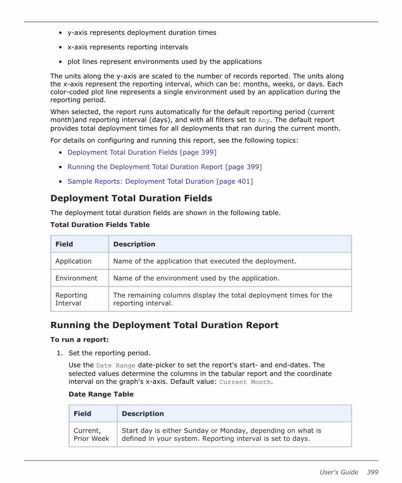
• y-axis represents deployment duration times
• x-axis represents reporting intervals
• plot lines represent environments used by the applications
The units along the y-axis are scaled to the number of records reported. The units alongthe x-axis represent the reporting interval, which can be: months, weeks, or days. Eachcolor-coded plot line represents a single environment used by an application during thereporting period.
When selected, the report runs automatically for the default reporting period (currentmonth)and reporting interval (days), and with all filters set to Any. The default reportprovides total deployment times for all deployments that ran during the current month.
For details on configuring and running this report, see the following topics:
• Deployment Total Duration Fields [page 399]
• Running the Deployment Total Duration Report [page 399]
• Sample Reports: Deployment Total Duration [page 401]
Deployment Total Duration FieldsThe deployment total duration fields are shown in the following table.
Total Duration Fields Table
Field Description
Application Name of the application that executed the deployment.
Environment Name of the environment used by the application.
ReportingInterval
The remaining columns display the total deployment times for thereporting interval.
Running the Deployment Total Duration ReportTo run a report:
1. Set the reporting period.
Use the Date Range date-picker to set the report's start- and end-dates. Theselected values determine the columns in the tabular report and the coordinateinterval on the graph's x-axis. Default value: Current Month.
Date Range Table
Field Description
Current,Prior Week
Start day is either Sunday or Monday, depending on what isdefined in your system. Reporting interval is set to days.
User's Guide 399

Field Description
Current,Prior Month
Start day is first day of the month. Reporting interval is set todays.
Current,PriorQuarter
Quarters are bound by calendar year. Reporting interval is set toweeks.
Current,Prior Year
Reporting interval is set months.
Custom Displays the Custom pop-up which enables you to pick anarbitrary start- and end-date.
The start-time is automatically set to 00:00 (24-hour clock) for the selected date inthe reporting period.
The end-time is automatically set to 24:00 for the selected date.
2. Set the report filters.
You can select from the following filters.
Filters Table
Field Description
Application Only deployments executed by the selected applications appear inthe report. To select applications:
a. Click the Application button.
b. To include an application in the report, click the correspondingcheck box.
If a large number of applications are listed, type the first fewletters of the application's name in the text box to scroll the list.Multiple applications can be selected.
c. Click OK.
Status Only deployments with the selected status appear in the report.Default value: Success or Failure, which means all deployments.
Plugin Only deployments that used the selected plugin appear in thereport. Default value: Any.
Note: The Any value also includes deployments that didnot use a plugin.
Part 5: Deployment
400 Deployment Automation

3. Run the report.
Click the Run button to apply your filter conditions to the data and produce thereport.
A line graph and tabular report are displayed. Each environment used by a reportingapplication is represented by an individual plot line and table row.
You can interact with the view to show or hide information, as follows:
• Hide/Show a plot line by clicking the corresponding item in the graph legend.
• See information about a graph coordinate by moving your pointer over the graphpoint.
• Zoom a graph area by dragging the pointer over the area. Click Reset Zoom to returnto the normal view.
Sample Reports: Deployment Total DurationThe following table contains examples of reports that can be produced using theDeployment Total Duration report.
Sample Reports Table
Field Description
Show me: Total duration times for two specificapplications during the past ten days that used aparticular plugin
• Application: Select bothapplications from theApplications dialog.
• Status: Success orFailure
• Plugin: Select the pluginfrom the drop-down listbox.
• Date Range: Use theCustom pop-up to set theten-day range.
User's Guide 401
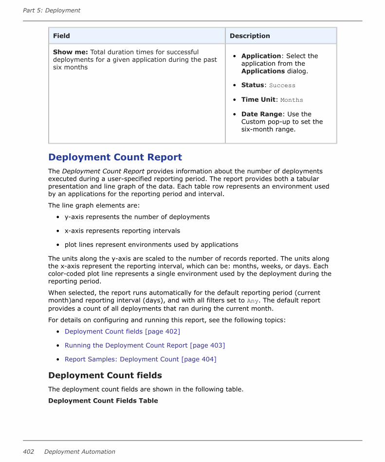
Field Description
Show me: Total duration times for successfuldeployments for a given application during the pastsix months
• Application: Select theapplication from theApplications dialog.
• Status: Success
• Time Unit: Months
• Date Range: Use theCustom pop-up to set thesix-month range.
Deployment Count ReportThe Deployment Count Report provides information about the number of deploymentsexecuted during a user-specified reporting period. The report provides both a tabularpresentation and line graph of the data. Each table row represents an environment usedby an applications for the reporting period and interval.
The line graph elements are:
• y-axis represents the number of deployments
• x-axis represents reporting intervals
• plot lines represent environments used by applications
The units along the y-axis are scaled to the number of records reported. The units alongthe x-axis represent the reporting interval, which can be: months, weeks, or days. Eachcolor-coded plot line represents a single environment used by the deployment during thereporting period.
When selected, the report runs automatically for the default reporting period (currentmonth)and reporting interval (days), and with all filters set to Any. The default reportprovides a count of all deployments that ran during the current month.
For details on configuring and running this report, see the following topics:
• Deployment Count fields [page 402]
• Running the Deployment Count Report [page 403]
• Report Samples: Deployment Count [page 404]
Deployment Count fieldsThe deployment count fields are shown in the following table.
Deployment Count Fields Table
Part 5: Deployment
402 Deployment Automation
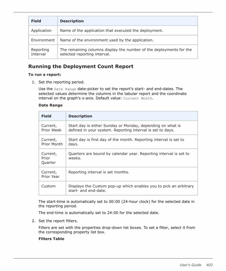
Field Description
Application Name of the application that executed the deployment.
Environment Name of the environment used by the application.
ReportingInterval
The remaining columns display the number of the deployments for theselected reporting interval.
Running the Deployment Count ReportTo run a report:
1. Set the reporting period.
Use the Date Range date-picker to set the report's start- and end-dates. Theselected values determine the columns in the tabular report and the coordinateinterval on the graph's x-axis. Default value: Current Month.
Date Range
Field Description
Current,Prior Week
Start day is either Sunday or Monday, depending on what isdefined in your system. Reporting interval is set to days.
Current,Prior Month
Start day is first day of the month. Reporting interval is set todays.
Current,PriorQuarter
Quarters are bound by calendar year. Reporting interval is set toweeks.
Current,Prior Year
Reporting interval is set months.
Custom Displays the Custom pop-up which enables you to pick an arbitrarystart- and end-date.
The start-time is automatically set to 00:00 (24-hour clock) for the selected date inthe reporting period.
The end-time is automatically set to 24:00 for the selected date.
2. Set the report filters.
Filters are set with the properties drop-down list boxes. To set a filter, select it fromthe corresponding property list box.
Filters Table
User's Guide 403

Field Description
Application Only deployments executed by the selected applications appear inthe report. To select applications:
a. Click Application.
b. To include an application in the report, click the correspondingcheck box. If a large number of applications are listed, type thefirst few letters of the application's name in the text box toscroll the list. Multiple applications can be selected.
c. Click OK.
Status Only deployments with the selected status appear in the report.Default value: Success or Failure, which means all deployments.
Plugin Only deployments that used the selected plugin appear in thereport. Default value: Any. Note: The Any value also includesdeployments that did not use a plugin.
3. Run the report.
Click Run to apply your filter conditions to the data and produce the report.
A line graph and tabular report are displayed. Each environment used by a reportingapplication is represented by an individual plot line and table row.
You can interact with the view to show or hide information, as follows:
• Hide/Show a plot line by clicking the corresponding item in the graph legend.
• See information about a graph coordinate by moving your pointer over the graphpoint.
• Zoom a graph area by dragging the pointer over the area. Click Reset Zoom to returnto the normal view.
Report Samples: Deployment CountThe following table contains examples of reports that can be produced using theDeployment Count Report.
Part 5: Deployment
404 Deployment Automation

Sample Reports Table
Field Description
Show me: The number of successful deployments fortwo specific applications during the past ten days thatused a particular plugin
• Application: Select bothapplications from theApplications dialog.
• Status: Success
• Plugin: Select the pluginfrom the drop-down listbox.
• Date Range: Use theCustom pop-up to setthe ten-day range.
Show me: The number of failed deployments for agiven application during the past month • Application: Select the
value from theApplications dialog.
• Status: Failure
• Date Range: SelectPrior Month.
Show me: The number of failed deployments thatused a specific plugin yesterday • Application: Select the
applications from theApplications dialog.
• Status: Failure
• Plugin: Select the valuefrom the drop-down listbox.
• Date Range: Use theCustom pop-up to selectthe previous day.
Deployment Detail ReportThe Deployment Detail Report provides information about deployments executed during auser-specified reporting period. Each report row represents a deployment that executedduring the reporting period and matched the filter conditions.
User's Guide 405

When selected, the report runs automatically for the default reporting period, currentmonth, and with all filters set to Any. The default report represents all deployments thatran during the current month.
For details on configuring and running this report, see the following topics:
• Deployment Detail Fields [page 406]
• Running the Deployment Detail Report [page 407]
• Report Samples: Deployment Detail [page 408]
Deployment Detail FieldsThe deployment detail fields are shown in the following table.
Deployment Detail Fields Table
Field Description
Application Name of the application that executed the deployment.
Environment Target environment of the deployment.
Date Date and time when the deployment was executed.
User Name of the user who performed the deployment.
Status Final disposition of the deployment. Possible values are:
• Success
• Failure
• Running
• Scheduled
• Approval Rejected
• Awaiting Approval
Duration Amount of time the deployment ran. For a successful deployment, thevalue represents the amount of time taken to complete successfully. Ifdeployment failed to start, no value is given. If a deployment startedbut failed to complete, the value represents the amount of time it ranbefore it failed or was cancelled.
Action This field provides links to additional information about the deployment.The View Request link displays the Application Process Requestpane See Chapter 19: Managing Applications [page 269].
Part 5: Deployment
406 Deployment Automation

Running the Deployment Detail ReportTo run a report:
1. Use the Date Range date-picker to set the report's start- and end-dates.
Date Range Table
Field Description
Current, PriorWeek
Start day is either Sunday or Monday, depending on what isdefined in your system.
Current, PriorMonth
Start day is first day of the month.
Current, PriorQuarter
Quarters are bound by calendar year.
Current, PriorYear
Current year includes today's date.
Custom Displays the Custom pop-up which enables you to pick anarbitrary start- and end-date.
The start-time is automatically set to 00:00 (24-hour clock) for the selected date inthe reporting period.
The end-time is automatically set to 24:00 for the selected date.
2. Set the report filters.
Filters are set with the properties drop-down list boxes. To set a filter, select it fromthe corresponding property list box.
Report Filters Table
Field Description
Application Only deployments executed by the selected application appear inthe report. Default value: Any.
Environment Only deployments executed by the application selected with theApplication list box that also used this environment appear in thereport. If the application value is Any, the available value is Any;otherwise, environments defined for the selected application arelisted.
User Only deployments executed by the selected user appear in thereport. Default value: Any.
User's Guide 407

Field Description
Status Only deployments with the selected status appear in the report.Default value: Any.
Plugin Only deployments that used the selected plugin appear in thereport. Default value: Any. Note: the Any value also includesdeployments that did not use a plugin.
3. Run the report.
Click the Run button to apply your filter conditions to the data and produce thereport.
By default, the report is sorted by application. You can sort the report on any field byclicking on the column header.
Report Samples: Deployment DetailThe following table contains examples of reports that can be produced using theDeployment Detail Report.
Sample Reports Table
Field Description
Show me: All failed deploymentsthat occurred on July 4th duringthe previous year.
• Application: Any
• Status: Failure
• Date Range: Use the Custom pop-up to setthe start- and end-dates to July 4th.
Show me: Deployments for anapplication that used a specificenvironment.
• Application: Select the value from the drop-down list box.
• Environment: Select the environment fromthe drop-down list box.
When an application is selected, onlyenvironments defined for it are available inthe Environment drop-down list box.
Part 5: Deployment
408 Deployment Automation

Field Description
Show me: Failed deploymentsthat used a specific pluginyesterday.
• Status: Failure
• Plugin: Select the value from the drop-downlist box.
• Date Range: Use the Custom pop-up to setthe start- and end-dates to the previous day.
Show me: My deployments thatused a specific application duringthe past month.
• Application: Select the value from the drop-down list box.
• User: Select your user ID.
• Date Range: Select Prior Month.
Saving and Printing ReportsYou can save and print report data for all report types. In addition, you can save filter andsort order information for deployment-type reports.
For details, see the following topics:
• Saving Report Data [page 409]
• Saving Report Filters [page 409]
• Printing Reports [page 410]
Saving Report DataDeployment Automation saves report data in CSV files (comma separated value).
To save report data:
1. Set the filters (if any) and run the report.
2. Click CSV.
3. Use the Opening File dialog. You can save the data to file, or open the data with anapplication associated with CSV-type files on your system.
Note: Sort-order and hidden/visible column information is not preserved in theCSV file.
Saving Report FiltersYou can save filter and sort-order settings for deployment reports. Saved reports can beretrieved from the Reports page > My Reports menu.
To save a report:
User's Guide 409

1. Set the filter conditions.
2. Define the reporting period.
3. Run the report.
4. Optional. Set the sort order.
You can change the sort order for any column by clicking the column header.
5. Optional. Change column visibility. Click Edit to display the Select Columns dialog.By default, all columns are selected to appear in a report. To hide a column, click thecorresponding check box.
6. Click Save. The Save Current Filters dialog displays.
7. Enter a name for the file, and save your work.
To run your report, click the report name in the My Reports menu.
To delete your report, click Delete.
Printing ReportsTo print a report:
1. Set the filter conditions.
2. Define the reporting period.
3. Run the report.
4. Optional. Set the sort order.
Your changes are reflected in the printed report.
5. Optional. Change column visibility. By default, all columns are selected to appear inthe printed report. Hidden columns will not appear in the output.
6. Click Print to print your report.
Part 5: Deployment
410 Deployment Automation

GlossaryAgents
Agents are physical resources for deployment. To run a deployment, an agent mustbe installed on the target server.
See Managing Agents and Agent Pools [page 320].
Agent PoolsAn agent pool is a set of agents that is logically grouped together.
See Managing Agents and Agent Pools [page 320].
Agent Relays
Agent relays are used to manage communication between servers and agents. Agentrelays are typically used when agents are dispersed across geographic locations ormust communicate through firewalls. Agent relays can also be used to managenetwork traffic in implementations where you have many agents.
See Managing Agent Relays [page 326].
ALF EventsALF (Application Lifecycle Framework) is an integrative layer for some Micro Focusproducts. These events can be used for custom integrations from SBM to DeploymentAutomation.
See ALF Events [page 157] and the Deployment Automation User's Guide.
AliasesAliases are alternate names that are assigned to agents and agent relays whenconfiguring mutual authentication. See Configuring Mutual Authentication Mode [page168].
Applications
Applications bring together components with their deployment targets andorchestrate multi-component deployments.
See Chapter 19: Managing Applications [page 269].
Application EnvironmentsApplication environments are environments that have been added to an application.Each application environment has its own set of operations and data within thecontext of the application, including inventory and compliance status. Environmentscan be added to multiple applications individually or as part of pipelines [page 415].
See Adding Environments to Applications [page 277].
User's Guide 411

Application ProcessesApplication processes are typically configured from processes defined for theirassociated components. See Application Processes [page 281].
Application TasksAn application task is used to interrupt an application process until some manualintervention is performed. See Application Tasks [page 297].
ApprovalsApprovals enable process requests to execute in application environments thatrequire them. See Approvals [page 298].
Approval ProcessesApproval processes tell Deployment Automation what to do when an applicationenvironment requires approval. See Approvals [page 298].
ArtifactsFiles or other software elements associated with components. See Components [page413].
Artifact RepositorySee CodeStation [page 412].
Authentication RealmsAuthentication realms determine a user's identity within an authorization realm. SeeChapter 8: Security Administration [page 117].
Authorization RealmsAuthorization realms associate users with roles and work with authentication realmsto determine which users can access Deployment Automation. See Chapter 8:Security Administration [page 117].
Blackout
A blackout of a date means that no deployments can be scheduled and no snapshotscan be made on that date. A blackout is set per environment, per application. SeeSetting Deployment Blackout Dates [page 380].
CodeStationCodeStation handles artifact versioning in Deployment Automation. You can directDeployment Automation to introduce artifacts into CodeStation from the file systemor from external source control tools that you identify when you select the SourceConfig Type for a component. See Chapter 13: Artifact Repository [page 179].
Glossary
412 Deployment Automation
CompliancyAn environment is compliant if the last requested processes were successfullyexecuted in that environment. See Chapter 31: Inventory Management [page 391].
Components
Components typically map to a functional part of a real world application, andrepresent deployable items, or artifacts, such as files, images, databases, andconfiguration materials.
See Chapter 18: Managing Components [page 203].
Component ProcessesComponent processes define how the component should be deployed, installed orinteracted with. A process typically contains a number of plugin steps that are inter-dependent, and may include complex logic for actions to perform if a step of theprocess fails.
See Component Processes [page 242].
Component TasksA component task is used to interrupt a component process until some manualintervention is performed. See Component Tasks [page 263].
Component TemplatesComponent templates enable you to save and reuse component processes andproperties and create new components from them; template-based componentsinherit the template properties and processes. See Creating Configuration Templates[page 267].
Component VersionsInstances of a Deployment Automation component. See Component Versions [page235].
Configuration TemplatesConfiguration templates enable you to save and reuse configuration data inprocesses. Typically, the data is for server configurations, for example on Tomcatservers, but the data can be for any purpose. See Configuration Templates [page267].
DeploymentDeployment is a process request execution that results in component versions orsnapshots being installed onto one or more target environments. See Chapter 29:Ways of Deploying [page 379].
User's Guide 413

Deployment Packages
Deployment packages enable you to deploy artifacts for multiple applications. Theymay also include component processes where components are shared among multipleapplications and associated versions are to be deployed as part of the larger package.
See Chapter 23: Managing Deployment Packages [page 335].
Environments
Environments represent logical deployment locations. Your deployment processesmust run in at least one environment. Environments and their resources are used byapplications and components at runtime.
See Chapter 20: Managing Environments [page 307].
ExportYou can export objects from a Deployment Automation server and subsequentlyimport [page 414] them into another Deployment Automation server. Export is doneon an object by object basis, whereas replication export can alternatively be used toexport an entire application. See Replication [page 416].
GatesGates ensure that component versions or snapshots are deployed into environmentsonly if their status meets certain conditions. See Gates [page 304].
Global ProcessesGlobal processes are processes that are not associated with a particular application orcomponent. See Chapter 24: Managing Global Processes [page 345].
GroupsSee Authorization Realms [page 412].
ImportYou can export [page 414] objects from a Deployment Automation server andsubsequently import them into another Deployment Automation server. Import isdone on an object by object basis, whereas replication import can alternatively beused to import an entire application. See Replication [page 416].
InventoryThe components, snapshots, and configurations deployed to any resource. SeeChapter 31: Inventory Management [page 391].
Inventory StatusesInventory statuses can be applied to component versions when they are successfullydeployed to resources. See Defining Statuses [page 112].
Glossary
414 Deployment Automation

LocksDeployment Automation uses locks to ensure that processes do not interfere with oneanother. See Locks [page 110].
Network RelaysNetwork relays can be used in multiple-server configurations to manage thecommunication between servers, and are used in high availability, active-activeserver implementations. For configuring server to agent communication for eitheragent- or server-initiated communication of HTTP communication, you should useagent relays [page 411]. See Managing Network Relays [page 329].
Notification SchemesNotification schemes define what events should generate notifications and who shouldget them. See Configuring Email Notifications [page 146].
Notification TemplatesNotification templates define the format of the information that you want to send inthe email notifications for given situations. See Configuring Email Notifications [page146].
Mutual AuthenticationIn mutual authentication mode, communications are encrypted as usual, but usersare also required to authenticate themselves by providing digital certificates. SeeConfiguring Mutual Authentication Mode [page 168].
Output LogThe output log is the Deployment Automation server log. See Output Log [page 153].
Pipelines
A pipeline is a pre-defined sequence of environments in which application processrequests are executed.
See Chapter 21: Managing Pipelines [page 313] .
Plugins
Plugins provide functionality in discrete steps to be used in component and globalprocesses for configuration of or deployment into target environments.
See Plugins [page 252].
ProcessesSee Component Processes [page 413], Application Processes [page 412], GlobalProcesses [page 414], and Approval Processes [page 412].
User's Guide 415

PropertiesProperties are parameters that are referenced in process steps. See Chapter 25:Properties [page 351].
ReplicationReplication enables you to export and import whole sets of Deployment Automationobjects. See Chapter 27: Replication [page 361].
Resources
Resources represent a deployment target on a Deployment Automation environment.Examples include physical machines, virtual machines, databases, or J2EE containers.
See Resources [page 318].
Resource GroupsA resource group is a logical collection of resources. Resource groups help youorganize and manage the agents installed in different environments throughout thenetwork. See Resource Groups [page 329].
RolesRoles provide the building blocks for the security system. Roles have permissions thatdefine the actions their members, users or groups, can perform with productfeatures. See Role Configuration [page 118] and Setting Role Membership by ProductArea [page 140].
Schedule
The schedule option enables you to schedule application processes and blackoutdates for application environments. See Scheduling Deployments [page 380].
SSL (Secure Socket Layer)
SSL (Secure Socket Layer) Secure Socket Layer (SSL) technology enables clients andservers to communicate securely by encrypting all communications. See Chapter 11:Secure Socket Layer (SSL) Configuration [page 167].
Single Sign-On (SSO)
Single Sign-On (SSO) enables Deployment Automation to integrate more easily withother Micro Focus products. Login information is passed automatically through SSO sothat there is no need to prompt for login credentials as information flows betweenproducts. See Creating Authentication Realms [page 126].
Snapshots
A snapshot captures an application's current state, and as the application movesthrough different environments, the snapshot ensures that proper componentversions are used. See Snapshots [page 300].
Glossary
416 Deployment Automation
Snapshot StatusesYou can apply and enforce conditions on application gates based on snapshotstatuses. See Defining Statuses [page 112].
Source Config TypeAn integration from which you can load artifacts into Deployment Automation ascomponent versions. See Source Configuration Type Fields [page 207].
Statuses
See Inventory Statuses [page 414], Snapshot Statuses [page 417], and VersionStatuses [page 417].
TasksSee Application Tasks [page 412] and Component Tasks [page 413].
TimelinesTimelines show the number of processes run and graphical indicators of success orfailure. See Viewing Timelines [page 383].
TokensTokens provide authorization for agents and users. See Tokens [page 140].
UsersSee Authorization Realms [page 412].
VersionsSee Component Versions [page 413].
Version StatusesYou can apply and enforce conditions on application gates based on componentversion statuses. See Defining Statuses [page 112].
User's Guide 417