
NetApp® CN1610 Network Switch CLI Command Reference
546
NetApp® CN1610 Network Switch CLI Command Reference NetApp, Inc. 495 East Java Drive Sunnyvale, CA 94089 U.S.A. Telephone: +1 (408) 822-6000 Fax: +1 (408) 822-4501 Support telephone: +1 (888) 4-NETAPP Documentation comments: [email protected] Information Web: www.netapp.com Part number: 215-12603_A0 July 2013
-
Upload
khangminh22 -
Category
Documents
-
view
1 -
download
0
Transcript of NetApp® CN1610 Network Switch CLI Command Reference

NetApp® CN1610 Network SwitchCLI Command Reference
NetApp, Inc.495 East Java DriveSunnyvale, CA 94089 U.S.A.Telephone: +1 (408) 822-6000Fax: +1 (408) 822-4501Support telephone: +1 (888) 4-NETAPPDocumentation comments: [email protected] Web: www.netapp.com
Part number: 215-12603_A0July 2013

Copyright and trademark information
Copyright information
Copyright © 1994-2013 NetApp, Inc. All rights reserved. Printed in the U.S.A.
Software derived from copyrighted NetApp material is subject to the following license and disclaimer:
THIS SOFTWARE IS PROVIDED BY NETAPP “AS IS” AND WITHOUT ANY EXPRESS OR IMPLIED WARRANTIES, INCLUDING, BUT NOT LIMITED TO, THE IMPLIED WARRANTIES OF MERCHANTABILITY AND FITNESS FOR A PARTICULAR PURPOSE, WHICH ARE HEREBY DISCLAIMED. IN NO EVENT SHALL NETAPP BE LIABLE FOR ANY DIRECT, INDIRECT, INCIDENTAL, SPECIAL, EXEMPLARY, OR CONSEQUENTIAL DAMAGES (INCLUDING, BUT NOT LIMITED TO, PROCUREMENT OF SUBSTITUTE GOODS OR SERVICES; LOSS OF USE, DATA, OR PROFITS; OR BUSINESS INTERRUPTION) HOWEVER CAUSED AND ON ANY THEORY OF LIABILITY, WHETHER IN CONTRACT, STRICT LIABILITY, OR TORT (INCLUDING NEGLIGENCE OR OTHERWISE) ARISING IN ANY WAY OUT OF THE USE OF THIS SOFTWARE, EVEN IF ADVISED OF THE POSSIBILITY OF SUCH DAMAGE.
NetApp reserves the right to change any products described herein at any time, and without notice. NetApp assumes no responsibility or liability arising from the use of products described herein, except as expressly agreed to in writing by NetApp. The use or purchase of this product does not convey a license under any patent rights, trademark rights, or any other intellectual property rights of NetApp.
The product described in this manual may be protected by one or more U.S.A. patents, foreign patents, or pending applications.
RESTRICTED RIGHTS LEGEND: Use, duplication, or disclosure by the government is subject to restrictions as set forth in subparagraph (c)(1)(ii) of the Rights in Technical Data and Computer Software clause at DFARS 252.277-7103 (October 1988) and FAR 52-227-19 (June 1987).
Trademark information
NetApp, the NetApp logo, Network Appliance, the Network Appliance logo, Akorri, ApplianceWatch, ASUP, AutoSupport, BalancePoint, BalancePoint Predictor, Bycast, Campaign Express, ComplianceClock, Cryptainer, CryptoShred, Data ONTAP, DataFabric, DataFort, Decru, Decru DataFort, FAServer, FilerView, FlexCache, FlexClone, FlexScale, FlexShare, FlexSuite, FlexVol, FPolicy, GetSuccessful, gFiler, Go further, faster, Imagine Virtually Anything, Lifetime Key Management, LockVault, Manage ONTAP, MetroCluster, MultiStore, NearStore, NetCache, NOW (NetApp on the Web), ONTAPI, OpenKey, RAID-DP, ReplicatorX, SANscreen, SecureAdmin, SecureShare, Select, Shadow Tape, Simulate ONTAP, SnapCopy, SnapDirector, SnapDrive, SnapFilter, SnapLock, SnapManager, SnapMigrator, SnapMirror, SnapMover, SnapRestore, Snapshot, SnapSuite, SnapValidator, SnapVault, StorageGRID, StoreVault, the StoreVault logo, SyncMirror, Tech OnTap, The evolution of storage, Topio, vFiler, VFM, Virtual File Manager, VPolicy, WAFL, and Web Filer are trademarks or registered trademarks of NetApp, Inc. in the United States, other countries, or both.
IBM, the IBM logo, and ibm.com are trademarks or registered trademarks of International Business Machines Corporation in the United States, other countries, or both. A complete and current list of other IBM trademarks is available on the Web at www.ibm.com/legal/copytrade.shtml.
ii

Apple is a registered trademark and QuickTime is a trademark of Apple, Inc. in the U.S.A. and/or other countries. Microsoft is a registered trademark and Windows Media is a trademark of Microsoft Corporation in the U.S.A. and/or other countries. RealAudio, RealNetworks, RealPlayer, RealSystem, RealText, and RealVideo are registered trademarks and RealMedia, RealProxy, and SureStream are trademarks of RealNetworks, Inc. in the U.S.A. and/or other countries.
Broadcom®, the pulse logo, Connecting everything®, the Connecting everything logo, and FASTPATH® are among the trademarks of Broadcom Corporation and/or its affiliates in the United States, certain other countries and/or the EU.
All other brands or products are trademarks or registered trademarks of their respective holders and should be treated as such.
NetApp, Inc. is a licensee of the CompactFlash and CF Logo trademarks. NetApp, Inc. NetCache is certified RealSystem compatible.
iii

iv

Table of Contents
Chapter 1 About This Document . . . . . . . . . . . . . . . . . . . . . . . . . . . . . . 5
Chapter 2 Using the Command-Line Interface . . . . . . . . . . . . . . . . . . . . . . 7
Command Syntax . . . . . . . . . . . . . . . . . . . . . . . . . . . . . . . . . 8
Command Conventions . . . . . . . . . . . . . . . . . . . . . . . . . . . . . . 9
Common Parameter Values. . . . . . . . . . . . . . . . . . . . . . . . . . . 10
Slot/Port Naming Convention . . . . . . . . . . . . . . . . . . . . . . . . . 12
Using the no Form of a Command . . . . . . . . . . . . . . . . . . . . . . . 14
CN1610 Software Modules. . . . . . . . . . . . . . . . . . . . . . . . . . . 15
Command Modes . . . . . . . . . . . . . . . . . . . . . . . . . . . . . . . . 16
Command Completion and Abbreviation . . . . . . . . . . . . . . . . . . . 22
CLI Error Messages . . . . . . . . . . . . . . . . . . . . . . . . . . . . . . 23
CLI Line-Editing Conventions . . . . . . . . . . . . . . . . . . . . . . . . . 24
Using CLI Help . . . . . . . . . . . . . . . . . . . . . . . . . . . . . . . . . 26
Accessing the CLI . . . . . . . . . . . . . . . . . . . . . . . . . . . . . . . 28
Chapter 3 Management Commands . . . . . . . . . . . . . . . . . . . . . . . . . . . 29
Access Commands . . . . . . . . . . . . . . . . . . . . . . . . . . . . . . . 30
Configuration Scripting Commands . . . . . . . . . . . . . . . . . . . . . . 32
Console Port Access Commands . . . . . . . . . . . . . . . . . . . . . . . . 35
Management Security Commands . . . . . . . . . . . . . . . . . . . . . . . 38
Network Interface Commands . . . . . . . . . . . . . . . . . . . . . . . . . 39
Pre-login Banner, System Prompt, and Host Name Commands . . . . . . . . 45
RADIUS Commands . . . . . . . . . . . . . . . . . . . . . . . . . . . . . . 47
Secure Shell Commands . . . . . . . . . . . . . . . . . . . . . . . . . . . . 64
SNMP Commands . . . . . . . . . . . . . . . . . . . . . . . . . . . . . . . 67
TACACS+ Commands . . . . . . . . . . . . . . . . . . . . . . . . . . . . . 80
Telnet Commands . . . . . . . . . . . . . . . . . . . . . . . . . . . . . . . 84
Table of Contents 1

User Account Commands. . . . . . . . . . . . . . . . . . . . . . . . . . . . 90
Chapter 4 Utility Commands . . . . . . . . . . . . . . . . . . . . . . . . . . . . . . .117
AutoInstall Commands . . . . . . . . . . . . . . . . . . . . . . . . . . . . .118
Cable Test Command. . . . . . . . . . . . . . . . . . . . . . . . . . . . . .122
DNS Client Commands. . . . . . . . . . . . . . . . . . . . . . . . . . . . .124
Dual Image Commands. . . . . . . . . . . . . . . . . . . . . . . . . . . . .130
Email Alerting and Mail Server Commands . . . . . . . . . . . . . . . . . .132
IP Address Conflict Commands . . . . . . . . . . . . . . . . . . . . . . . .140
Logging Commands . . . . . . . . . . . . . . . . . . . . . . . . . . . . . .141
Serviceability Packet Tracing Commands . . . . . . . . . . . . . . . . . . .147
sFlow Commands. . . . . . . . . . . . . . . . . . . . . . . . . . . . . . . .157
Simple Network Time Protocol Commands . . . . . . . . . . . . . . . . . .163
System Information and Statistics Commands . . . . . . . . . . . . . . . . .170
System Utility and Clear Commands . . . . . . . . . . . . . . . . . . . . . .194
Chapter 5 Switching Commands . . . . . . . . . . . . . . . . . . . . . . . . . . . . .209
Denial of Service Commands. . . . . . . . . . . . . . . . . . . . . . . . . .211
DHCP Client Commands . . . . . . . . . . . . . . . . . . . . . . . . . . . .222
DHCP L2 Relay Agent Commands . . . . . . . . . . . . . . . . . . . . . .224
DHCP Snooping Configuration Commands . . . . . . . . . . . . . . . . . .232
Double VLAN Commands . . . . . . . . . . . . . . . . . . . . . . . . . . .243
Dynamic ARP Inspection Commands . . . . . . . . . . . . . . . . . . . . .248
802.1X Supplicant Commands . . . . . . . . . . . . . . . . . . . . . . . . .256
GARP Commands . . . . . . . . . . . . . . . . . . . . . . . . . . . . . . .261
GMRP Commands . . . . . . . . . . . . . . . . . . . . . . . . . . . . . . .264
GVRP Commands . . . . . . . . . . . . . . . . . . . . . . . . . . . . . . .268
IGMP Snooping Configuration Commands . . . . . . . . . . . . . . . . . .271
IGMP Snooping Querier Commands . . . . . . . . . . . . . . . . . . . . . .281
ISDP Commands . . . . . . . . . . . . . . . . . . . . . . . . . . . . . . . .286
2 Table of Contents

LLDP (802.1AB) Commands . . . . . . . . . . . . . . . . . . . . . . . . .292
LLDP-MED Commands . . . . . . . . . . . . . . . . . . . . . . . . . . . .303
Link Local Protocol Filtering Commands . . . . . . . . . . . . . . . . . . .311
MAC Database Commands. . . . . . . . . . . . . . . . . . . . . . . . . . .313
MLD Snooping Commands . . . . . . . . . . . . . . . . . . . . . . . . . .316
MLD Snooping Querier Commands . . . . . . . . . . . . . . . . . . . . . .324
Port-Based Network Access Control Commands . . . . . . . . . . . . . . .328
Port Channel/LAG (802.3ad) Commands . . . . . . . . . . . . . . . . . . .349
Port Configuration Commands . . . . . . . . . . . . . . . . . . . . . . . . .369
Port Mirroring Commands . . . . . . . . . . . . . . . . . . . . . . . . . . .375
Port Security Commands . . . . . . . . . . . . . . . . . . . . . . . . . . . .378
Protected Ports Commands . . . . . . . . . . . . . . . . . . . . . . . . . . .382
Provisioning (IEEE 802.1p) Commands . . . . . . . . . . . . . . . . . . . .385
Spanning Tree Protocol Commands . . . . . . . . . . . . . . . . . . . . . .386
Static MAC Filtering Commands. . . . . . . . . . . . . . . . . . . . . . . .409
Storm-Control Commands . . . . . . . . . . . . . . . . . . . . . . . . . . .414
VLAN Commands . . . . . . . . . . . . . . . . . . . . . . . . . . . . . . .427
Voice VLAN Commands . . . . . . . . . . . . . . . . . . . . . . . . . . . .444
Chapter 6 IPv6 Management Commands . . . . . . . . . . . . . . . . . . . . . . . .447
IPv6 Management Commands . . . . . . . . . . . . . . . . . . . . . . . . .448
Chapter 7 Quality of Service Commands . . . . . . . . . . . . . . . . . . . . . . . .461
Auto-Voice over IP Commands . . . . . . . . . . . . . . . . . . . . . . . .462
Class of Service Commands . . . . . . . . . . . . . . . . . . . . . . . . . .464
Differentiated Services Commands. . . . . . . . . . . . . . . . . . . . . . .475
DiffServ Class Commands . . . . . . . . . . . . . . . . . . . . . . . . . . .477
DiffServ Policy Commands . . . . . . . . . . . . . . . . . . . . . . . . . .486
DiffServ Service Commands . . . . . . . . . . . . . . . . . . . . . . . . . .494
DiffServ Show Commands . . . . . . . . . . . . . . . . . . . . . . . . . . .496
Table of Contents 3

IP Access Control List Commands . . . . . . . . . . . . . . . . . . . . . . .505
IPv6 Access Control List Commands . . . . . . . . . . . . . . . . . . . . .515
MAC Access Control List Commands . . . . . . . . . . . . . . . . . . . . .520
Time Range Commands for Time-Based ACLs . . . . . . . . . . . . . . . .526
Command Index . . . . . . . . . . . . . . . . . . . . . . . . . . . . . . . .531
4 Table of Contents

1
About This DocumentIntroduction This document describes command-line interface (CLI) commands you use to view and configure the CN1610 software. You can access the CLI by using a direct connection to the serial port or by using Telnet or SSH over a remote network connection.
NoteThis document contains standalone commands. Stacking commands are not supported on the CN1610 switch.
NoteSome commands in this document may not be available with your version of the FASTPATH software. Enter a question mark (?) after typing one or more characters of a word to list the available commands or parameters that begin with the letters. See “Using CLI Help” on page 26 for more information.
Audience This document is for system administrators who configure and operate systems using FASTPATH® software. It provides an understanding of the configuration options of the FASTPATH software.
Software engineers who integrate FASTPATH software into their hardware platform can also benefit from a description of the configuration options.
This document assumes that you have an understanding of the FASTPATH software base and have read the appropriate specification for the relevant networking device platform. It also assumes that you have a basic knowledge of Ethernet and networking concepts.
Refer to the release notes for the FASTPATH application-level code. The release notes detail the platform-specific functionality of the Switching, SNMP, Configuration, Management, and other packages. The suite of features the FASTPATH packages support is not available on all the platforms to which FASTPATH software has been ported.
About FASTPATH Software
FASTPATH software has two purposes:◆ Assist attached hardware in switching frames, based on Layer 2, 3, or 4
information contained in the frames.
5

About This Document
◆ Provide a complete device management portfolio to the network administrator.
Scope FASTPATH software encompasses both hardware and software support. The software is partitioned to run in the following processors:◆ CPU
This code runs the networking device management portfolio and controls the overall networking device hardware. It also assists in frame forwarding, as needed and specified. This code is designed to run on multiple platforms with minimal changes from platform to platform.
◆ Networking device processorThis code does the majority of the packet switching, usually at wire speed. This code is platform-dependent, and substantial changes might exist across products.
Product Concept Fast Ethernet and Gigabit Ethernet switching continues to evolve from high-end backbone applications to desktop switching applications. The price of the technology continues to decline, while performance and feature sets continue to improve. Devices that are capable of switching Layers 2, 3, and 4 are increasingly in demand. FASTPATH software provides a flexible solution to these ever-increasing needs.
The exact functionality provided by each networking device on which the FASTPATH software base runs varies depending upon the platform and requirements of the FASTPATH software.
FASTPATH software includes a set of comprehensive management functions for managing both FASTPATH software and the network. You can manage the FASTPATH software by using one of the following two methods: ◆ Command-Line Interface (CLI)◆ Simple Network Management Protocol (SNMP)
Each of the FASTPATH management methods enables you to configure, manage, and control the software locally or remotely using in-band or out-of-band mechanisms. Management is standards-based, with configuration parameters and a private Management Information Base (MIB) providing control for functions not completely specified in the MIBs.
6

Chapter 2: Using the Command-Line Interface
2
Using the Command-Line InterfaceAbout this chapter The command-line interface (CLI) is a text-based way to manage and monitor the system. You can access the CLI by using a direct serial connection or by using a remote logical connection with Telnet or SSH.
Topics in this chapter
This chapter describes the CLI syntax, conventions, and modes. It contains the following sections:◆ “Command Syntax” on page 8◆ “Command Conventions” on page 9◆ “Common Parameter Values” on page 10◆ “Slot/Port Naming Convention” on page 12◆ “Using the no Form of a Command” on page 14◆ “CN1610 Software Modules” on page 15◆ “Command Modes” on page 16◆ “Command Completion and Abbreviation” on page 22◆ “CLI Error Messages” on page 23◆ “CLI Line-Editing Conventions” on page 24◆ “Using CLI Help” on page 26◆ “Accessing the CLI” on page 28
7

Command Syntax
A command is one or more words that might be followed by one or more parameters. Parameters can be required or optional values.
Some commands, such as show network or clear vlan, do not require parameters. Other commands, such as network parms, require that you supply a value after the command. You must type the parameter values in a specific order, and optional parameters follow required parameters. The following example describes the network parms command syntax: network parms ipaddr netmask [gateway]
◆ network parms is the command name. ◆ ipaddr and netmask are parameters and represent required values that you
must enter after you type the command keywords.◆ [gateway] is an optional parameter, so you are not required to enter a value
in place of the parameter.
The NetApp CN1610 Network Switch CLI Command Reference lists each command by the command name and provides a brief description of the command. Each command reference also contains the following information:◆ Format shows the command keywords and the required and optional
parameters.◆ Mode identifies the command mode you must be in to access the command.◆ Default shows the default value, if any, of a configurable setting on the
device.
The show commands also contain a description of the information that the command shows.
8 Command Syntax

Command Conventions
The parameters for a command might include mandatory values, optional values, or keyword choices. Parameters are order-dependent. The following Parameter Conventions table describes the conventions this document uses to distinguish between value types:
Symbol Example Description
[] square brackets [value] Indicates an optional parameter.
italic font in a parameter.
value or [value] Indicates a variable value. You must replace the italicized text and brackets with an appropriate value, which might be a name or number.
{} curly braces {choice1 | choice2} Indicates that you must select a parameter from the list of choices.
| Vertical bars choice1 | choice2 Separates the mutually exclusive choices.
[{}] Braces within square brackets
[{choice1|choice2}] Indicates a choice within an optional element.
Chapter 2: Using the Command-Line Interface 9

Common Parameter Values
Parameter values might be names (strings) or numbers. To use spaces as part of a name parameter, enclose the name value in double quotes. For example, the expression “System Name with Spaces” forces the system to accept the spaces. Empty strings (““) are not valid user-defined strings. The following Parameter Descriptions table describes common parameter values and value formatting:
Parameter Description
ipaddr This parameter is a valid IP address. You can enter the IP address in the following formats:a (32 bits)a.b (8.24 bits)a.b.c (8.8.16 bits)a.b.c.d (8.8.8.8)
In addition to these formats, the CLI accepts decimal, hexadecimal, and octal formats through the following input formats (where n is any valid hexadecimal, octal or decimal number):
0xn (CLI assumes hexadecimal format.)
0n (CLI assumes octal format with leading zeros.)
n (CLI assumes decimal format.)
ipv6-address FE80:0000:0000:0000:020F:24FF:FEBF:DBCB, orFE80:0:0:0:20F:24FF:FEBF:DBCB, orFE80::20F24FF:FEBF:DBCB, orFE80:0:0:0:20F:24FF:128:141:49:32
For additional information, refer to RFC 3513.
Interface or slot/port
Valid slot and port number separated by a forward slash. For example, 0/1 represents slot number 0 and port number 1.
Logical Interface Represents a logical slot and port number. This is applicable in the case of a port-channel (LAG). You can use the logical slot/port to configure the port-channel.
10 Common Parameter Values

Character strings Use double quotation marks to identify character strings, for example, “System Name with Spaces”. An empty string (“”) is not valid.
Parameter Description
Chapter 2: Using the Command-Line Interface 11

Slot/Port Naming Convention
FASTPATH software references physical entities such as cards and ports by using a slot/port naming convention. The FASTPATH software also uses this convention to identify certain logical entities, such as Port-Channel interfaces.
The slot number has two uses. In the case of physical ports, it identifies the card containing the ports. In the case of logical and CPU ports it also identifies the type of interface or port.
The port identifies the specific physical port or logical interface being managed on a given slot.
Slot Type Description
Physical slot numbers Physical slot numbers begin with zero, and are allocated up to the maximum number of physical slots.
Logical slot numbers Logical slots immediately follow physical slots and identify port-channel (LAG) or router interfaces.
CPU slot numbers The CPU slots immediately follow the logical slots.
Port Type Description
Physical ports The physical ports for each slot are numbered sequentially starting from zero.
Logical interfaces There are four types of logical interfaces:◆ Port-channel or Link Aggregation Group
(LAG) interfaces are logical interfaces that are only used for bridging functions.
◆ VLAN routing interfaces are only used for routing functions.
◆ Loopback interfaces are logical interfaces that are always up.
◆ Tunnel interfaces are logical point-to-point links that carry encapsulated packets.
12 Slot/Port Naming Convention

NoteIn the CLI, loopback and tunnel interfaces do not use the slot/port format. To specify a loopback interface, use the loopback ID. To specify a tunnel interface, use the tunnel ID.
CPU ports CPU ports are handled by the driver as one or more physical entities located on physical slots.
Port Type Description
Chapter 2: Using the Command-Line Interface 13
Using the no Form of a Command
The no keyword is a specific form of an existing command and does not represent a new or distinct command. Almost every configuration command has a no form. In general, use the no form to reverse the action of a command or reset a value back to the default. For example, the no shutdown configuration command reverses the shutdown of an interface. Use the command without the keyword no to re-enable a disabled feature or to enable a feature that is disabled by default. Only the configuration commands are available in the no form.
14 Using the no Form of a Command

CN1610 Software Modules
The CN1610 software consists of flexible modules that can be applied in various combinations to develop advanced Layer 2/3/4+ products. The commands and command modes available on your switch depend on the installed modules. Additionally, for some show commands, the output fields might change based on the modules included in the CN1610 software.
The CN1610 software suite includes the following modules:◆ Switching (Layer 2)◆ Quality of Service◆ Management (CLI and SNMP)◆ IPv6 Management—Allows management of the CN1610 switch through an
IPv6 address without requiring the IPv6 Routing package in the system. The management address can be associated with the network port (front-panel switch ports), a routine interface (port or VLAN), and the Service port.
◆ Security
Chapter 2: Using the Command-Line Interface 15

Command Modes
The CLI groups commands into modes according to the command function. Each of the command modes supports specific CN1610 software commands. The commands in one mode are not available until you switch to that particular mode, with the exception of the User EXEC mode commands. You can execute the User EXEC mode commands in the Privileged EXEC mode.
The command changes in each command mode to help you identify the current mode. The following CLI Command Modes table describes the command modes and the prompts visible in that mode:
Command Mode Prompt Mode Description
User EXEC (CN1610)> Contains a limited set of commands to view basic system information.
Privileged EXEC (CN1610)# Allows you to enter any EXEC command, enter the VLAN mode, or enter the Global Configuration mode.
Global Config (CN1610) (Config)# Groups general setup commands and permits you to make modifications to the running configuration.
VLAN Config (CN1610)(Vlan)# Groups all the VLAN commands.
16 Command Modes

Interface Config (CN1610) (Interface slot/port)#
(CN1610) (Interface Loopback id)#
(CN1610) (Interface Tunnel id)#
(CN1610) (Interface slot/port (startrange)-slot/port(endrange)#
Manages the operation of an interface and provides access to the router interface configuration commands.
Use this mode to set up a physical port for a specific logical connection operation.
You can also use this mode to manage the operation of a range of interfaces. For example, the prompt may display as follows:
(CN1610) (Interface
1/0/1-1/0/4) #
Line Console (CN1610) (config-line)#
Contains commands to configure outbound Telnet settings and console interface settings, as well as to configure console login/enable authentication.
Line SSH (CN1610) (config-ssh)#
Contains commands to configure SSH login/enable authentication.
Command Mode Prompt Mode Description
Chapter 2: Using the Command-Line Interface 17
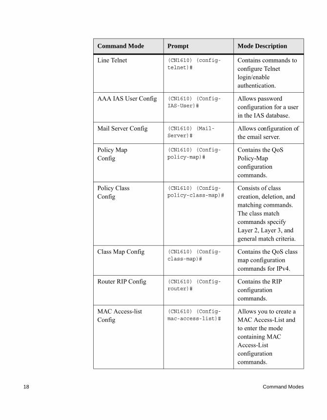
Line Telnet (CN1610) (config-telnet)#
Contains commands to configure Telnet login/enable authentication.
AAA IAS User Config (CN1610) (Config-IAS-User)#
Allows password configuration for a user in the IAS database.
Mail Server Config (CN1610) (Mail-Server)#
Allows configuration of the email server.
Policy Map Config
(CN1610) (Config-policy-map)#
Contains the QoS Policy-Map configuration commands.
Policy Class Config
(CN1610) (Config-policy-class-map)#
Consists of class creation, deletion, and matching commands. The class match commands specify Layer 2, Layer 3, and general match criteria.
Class Map Config (CN1610) (Config-class-map)#
Contains the QoS class map configuration commands for IPv4.
Router RIP Config (CN1610) (Config-router)#
Contains the RIP configuration commands.
MAC Access-list Config
(CN1610) (Config-mac-access-list)#
Allows you to create a MAC Access-List and to enter the mode containing MAC Access-List configuration commands.
Command Mode Prompt Mode Description
18 Command Modes

The following CLI Mode Access and Exit table explains how to enter or exit each mode:
TACACS Config (CN1610) (Tacacs)# Contains commands to configure properties for the TACACS servers.
DHCPv6 Pool Config
(CN1610) (Config dhcp6-pool)#
Contains the DHCPv6 server IPv6 address pool configuration commands.
ARP Access-List Config Mode
(CN1610) (Config-arp-access-list)#
Contains commands to add ARP ACL rules in an ARP Access List.
Command Mode Prompt Mode Description
User EXEC This is the first level of access.
To exit, enter logout.
Privileged EXEC From the User EXEC mode, enter enable.
To exit to the User EXEC mode, enter exit or press Ctrl-Z.
Global Config From the Privileged EXEC mode, enter configure.
To exit to the Privileged EXEC mode, enter exit, or press Ctrl-Z.
VLAN Config From the Privileged EXEC mode, enter vlan database.
To exit to the Privileged EXEC mode, enter exit, or press Ctrl-Z.
Command Mode Prompt Mode Description
Chapter 2: Using the Command-Line Interface 19

Interface Config From the Global Config mode, enter:
interface slot/port or
interface loopback id or
interface tunnel id orinterface slot/port(startrange)-slot/port(endrange)
To exit to the Global Config mode, enter exit. To return to the Privileged EXEC mode, enter Ctrl-Z.
Line Console From the Global Config mode, enter line console.
To exit to the Global Config mode, enter exit. To return to the Privileged EXEC mode, enter Ctrl-Z.
AAA IAS User Config
From the Global Config mode, enter aaa ias-user username
name.
To exit to the Global Config mode, enter exit. To return to the Privileged EXEC mode, enter Ctrl-Z.
Mail Server Config From the Global Config mode, enter mail-server address.
To exit to the Global Config mode, enter exit. To return to the Privileged EXEC mode, enter Ctrl-Z.
Policy-Map Config
From the Global Config mode, enter policy-map.
To exit to the Global Config mode, enter exit. To return to the Privileged EXEC mode, enter Ctrl-Z.
Policy-Class-Map Config
From the Policy Map mode, enter class.
To exit to the Policy Map mode, enter exit. To return to the Privileged EXEC mode, enter Ctrl-Z.
Command Mode Prompt Mode Description
20 Command Modes
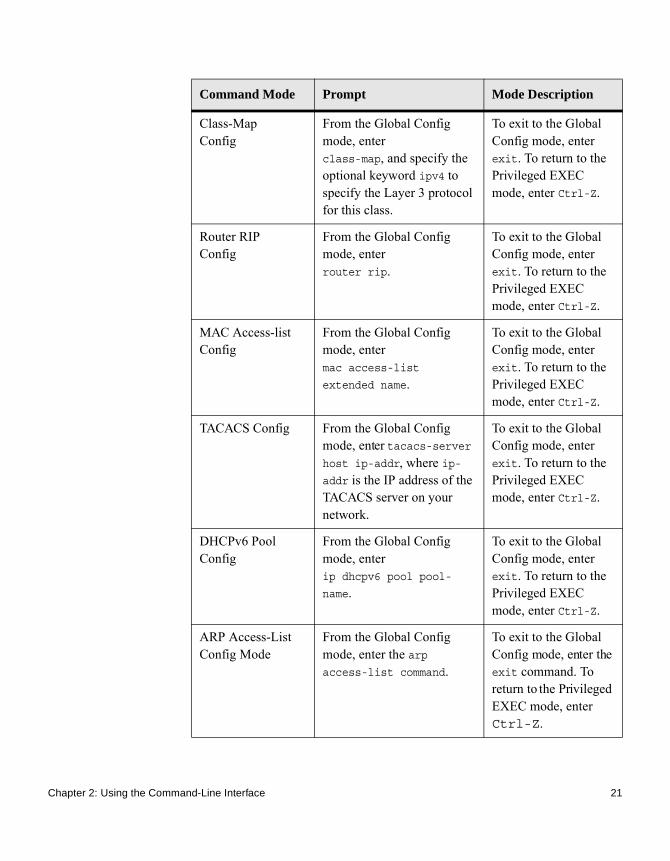
Class-Map Config
From the Global Config mode, enter class-map, and specify the optional keyword ipv4 to specify the Layer 3 protocol for this class.
To exit to the Global Config mode, enter exit. To return to the Privileged EXEC mode, enter Ctrl-Z.
Router RIP Config
From the Global Config mode, enter router rip.
To exit to the Global Config mode, enter exit. To return to the Privileged EXEC mode, enter Ctrl-Z.
MAC Access-list Config
From the Global Config mode, enter mac access-list
extended name.
To exit to the Global Config mode, enter exit. To return to the Privileged EXEC mode, enter Ctrl-Z.
TACACS Config From the Global Config mode, enter tacacs-server host ip-addr, where ip-addr is the IP address of the TACACS server on your network.
To exit to the Global Config mode, enter exit. To return to the Privileged EXEC mode, enter Ctrl-Z.
DHCPv6 Pool Config
From the Global Config mode, enter ip dhcpv6 pool pool-
name.
To exit to the Global Config mode, enter exit. To return to the Privileged EXEC mode, enter Ctrl-Z.
ARP Access-List Config Mode
From the Global Config mode, enter the arp access-list command.
To exit to the Global Config mode, enter the exit command. To return to the Privileged EXEC mode, enter Ctrl-Z.
Command Mode Prompt Mode Description
Chapter 2: Using the Command-Line Interface 21

Command Completion and Abbreviation
Command completion finishes spelling the command when you type enough letters of a command to uniquely identify the command keyword. Once you have entered enough letters, press the SPACEBAR or TAB key to complete the word.
Command abbreviation allows you to execute a command when you have entered enough letters to uniquely identify the command. You must enter all of the required keywords and parameters before you enter the command.
22 Command Completion and Abbreviation

CLI Error Messages
If you enter a command and the system is unable to execute it, an error message appears. The following table describes the most common CLI error messages:
Message Text Description
% Invalid input detected at '^' marker. Indicates that you entered an incorrect or unavailable command. The carat (^) shows where the invalid text is detected. This message also appears if any of the parameters or values are not recognized.
Command not found / Incomplete command. Use ? to list commands.
Indicates that you did not enter the required keywords or values.
Ambiguous command Indicates that you did not enter enough letters to uniquely identify the command.
Chapter 2: Using the Command-Line Interface 23

CLI Line-Editing Conventions
The following CLI editing conventions table describes the key combinations you can use to edit commands or increase the speed of command entry. You can access this list from the CLI by entering help from the User or Privileged EXEC modes.
Key Sequence Description
DEL or Backspace Delete previous character.
Ctrl-A Go to beginning of line.
Ctrl-E Go to end of line.
Ctrl-F Go forward one character.
Ctrl-B Go backward one character.
Ctrl-D Delete current character.
Ctrl-U, X Delete to beginning of line.
Ctrl-K Delete to end of line.
Ctrl-W Delete previous word.
Ctrl-T Transpose previous character.
Ctrl-P Go to previous line in history buffer.
Ctrl-R Rewrites or pastes the line.
Ctrl-N Go to next line in history buffer.
Ctrl-Y Prints last deleted character.
Ctrl-Q Enables serial flow.
Ctrl-S Disables serial flow.
Ctrl-Z Return to root command prompt.
Tab, <SPACE> Command-line completion.
Exit Go to next lower command prompt.
24 CLI Line-Editing Conventions

? List available commands, keywords, or parameters.
Key Sequence Description
Chapter 2: Using the Command-Line Interface 25

Using CLI Help
Enter a question mark (?) at the command prompt to display the commands available in the current mode: (CN1610)>?
enable Enter into user privilege mode.
help Display help for various special keys.
logout Exit this session. Any unsaved changes are lost.
ping Send ICMP echo packets to a specified IP address.
quit Exit this session. Any unsaved changes are lost.
show Display Switch Options and Settings.
telnet Telnet to a remote host.
Enter a question mark (?) after each word you enter to display available command keywords or parameters:(CN1610)#network ?
mgmt_vlan Configure the Management VLAN ID of the switch.
parms Configure Network Parameters of the router.
protocol Select DHCP, BootP, or None as the network config
protocol.
If the help output shows a parameter in angle brackets, you must replace the parameter with a value:(CN1610)#network parms ?
<ipaddr> Enter the IP address.
If there are no additional command keywords or parameters, or if additional parameters are optional, the following message appears in the output:<cr> Press Enter to execute the command
26 Using CLI Help

You can also enter a question mark (?) after typing one or more characters of a word to list the available command or parameters that begin with the letters, as shown in the following example:(CN1610) #show m?
mac-addr-table mac-address-table monitor
Chapter 2: Using the Command-Line Interface 27

Accessing the CLI
You can access the CLI by using a direct console connection or by using a Telnet or SSH connection from a remote management host.
For the initial connection, you must use a direct connection to the console port. You cannot access the system remotely until the system has an IP address, subnet mask, and default gateway. You can set the network configuration information manually, or you can configure the system to accept these settings from a BOOTP server on your network. For more information, see “Console Port Access Commands” on page 35.
28 Accessing the CLI

Chapter 3: Management Commands
3
Management CommandsAbout this chapter This chapter describes the management commands available with the CN1610 CLI.
Topics in this chapter
This chapter includes the following sections:◆ “Access Commands” on page 30◆ “Configuration Scripting Commands” on page 32◆ “Console Port Access Commands” on page 35◆ “Management Security Commands” on page 38◆ “Network Interface Commands” on page 39◆ “Pre-login Banner, System Prompt, and Host Name Commands” on page 45◆ “RADIUS Commands” on page 47◆ “Secure Shell Commands” on page 64◆ “SNMP Commands” on page 67◆ “TACACS+ Commands” on page 80◆ “Telnet Commands” on page 84◆ “User Account Commands” on page 90
CAUTIONThe commands in this chapter are in one of three functional groups:◆ Show commands display switch settings, statistics, and other information.◆ Configuration commands configure features and options of the switch. For
every configuration command, there is a show command that displays the configuration setting.
◆ Clear commands clear some or all of the settings to factory defaults.
29

Access Commands
Introduction Use the commands in this section to close remote connections or to view information about connections to the system.
disconnect This command closes HTTP, HTTPS, Telnet, or SSH sessions. Use all to close all active sessions, or use session-id to specify the session ID to close. To view the possible values for session-id, use the show loginsession command.
show loginsession This command displays current Telnet, SSH, and serial port connections to the switch. This command displays truncated user names. Use the show loginsession long command to display the complete usernames.
Format disconnect {session_id | all}
Mode Privileged EXEC
Format show loginsession
Mode Privileged EXEC
Output Description
ID Login session ID.
User Name The name the user entered to log on to the system.
Connection From IP address of the remote client machine or EIA-232 for the serial port connection.
Idle Time Time this session has been idle.
Session Time Total time this session has been connected.
Session Type Shows the type of session, which can be HTTP, HTTPS, Telnet, serial, or SSH.
30 Access Commands

show loginsession long
This command displays the complete user names of the users currently logged in to the switch.
Example: The following shows an example of the command:(CN1610) #show loginsession longUser Name------------admintest1111test1111test1111test1111test1111test1111test1111test1111
Format show loginsession long
Mode Privileged EXEC
Chapter 3: Management Commands 31

Configuration Scripting Commands
Introduction Configuration scripting allows you to generate text-formatted script files representing the current configuration of a system. You can upload these configuration script files to a PC or UNIX system and edit them. Then, you can download the edited files to the system and apply the new configuration. You can apply configuration scripts to one or more switches with no or minor modifications.
Use the show running-config command (see “show running-config” on page 190) to capture the running configuration into a script. Use the copy command (see “copy” on page 200) to transfer the configuration script to or from the switch.
You should use scripts on systems with default configuration; however, you are not prevented from applying scripts on systems with nondefault configurations.
Scripts must conform to the following rules:◆ The file extension must be .scr.◆ A maximum of ten scripts are allowed on the switch.◆ The combined size of all script files on the switch cannot exceed 2048 KB.◆ The maximum number of configuration file command lines is 2000.
You can type single-line annotations at the command prompt to use when you write test or configuration scripts to improve script readability. The exclamation point (!) character flags the beginning of a comment. The comment flag character can begin a word anywhere on the command line, and all input following this character is ignored. Any command line that begins with the! character is recognized as a comment line and ignored by the parser.
The following lines show an example of a script:! Script file for displaying management access
show telnet !Displays the information about remote connections
! Display information about direct connections
show serial
! End of the script file!
32 Configuration Scripting Commands

NoteTo specify a blank password for a user in the configuration script, you must specify it as a space within quotes. For example, to change the password for user jane from a blank password to hello, the script entry is as follows: users passwd jane" "hellohello
script apply This command executes the commands in the script, applying them to the running configuration.
script delete This command deletes a specified script where the scriptname parameter is the name of the script to delete. The all option deletes all the scripts present on the switch.
script list This command lists all of the scripts present on the switch as well as the remaining available space.
Format script apply scriptname
Mode Privileged EXEC
Format script delete {scriptname | all}
Mode Privileged EXEC
Format script list
Mode Privileged EXEC
Output Description
Configuration Script Name
The name of the script.
Chapter 3: Management Commands 33

Example: The following shows sample output from this command:(CN1610) #script listConfiguration Script Name Size(Bytes)--------------------------- ------------runconfig-17Jan.scr 25861 configuration script(s) found.2045 Kbytes free.
script show This command displays the contents of a script file, which is called a scriptname.
script validate This command validates a script file by parsing each line in the script file where scriptname is the name of the script to validate.The validate option is intended to be used as a tool for script development. Validation identifies potential problems. It might not identify all problems with a given script on any given device.
Size The size of the script, in bytes.
Output Description
Format script show scriptname
Mode Privileged EXEC
Output Description
Output Format line number: line contents
Format script validate scriptname
Mode Privileged EXEC
34 Configuration Scripting Commands

Console Port Access Commands
Introduction This section describes the commands you use to configure the console port. You can use a serial cable to connect a management host directly to the console port of the switch.
configuration This command gives you access to the Global Config mode. From the Global Config mode, you can configure a variety of system settings, including user accounts. From the Global Config mode, you can enter other command modes, including Line Config mode.
line This command gives you access to the Line Console mode, which allows you to configure various Telnet settings and the console port, as well as to configure console login/enable authentication.
Example: The following example shows a CLI display:(CN1610)(config)#line telnet(CN1610)(config-telnet)#
Format configuration
Mode Privileged EXEC
Format line {console | telnet | ssh}
Mode Global Config
Parameter Description
console Console terminal line.
telnet Virtual terminal for remote console access (Telnet).
ssh Virtual terminal for secured remote console access (SSH).
Chapter 3: Management Commands 35

serial baudrate This command specifies the communication rate of the terminal interface. The supported rates are 1200, 2400, 4800, 9600, 19200, 38400, 57600, 115200.
no serial baudrate This command sets the communication rate of the terminal interface.
serial timeout This command specifies the maximum connect time, in minutes, without console activity. A value of 0 indicates that a console can be connected indefinitely. The time range is 0 to 160.
no serial timeout This command sets the maximum connect time, in minutes, without console activity.
Default 9600
Format serial baudrate {1200 | 2400 | 4800 | 9600 | 19200 |
38400 | 57600 | 115200}
Mode Line Config
Format no serial baudrate
Mode Line Config
Default 5
Format serial timeout 0-160
Mode Line Config
Format no serial timeout
Mode Line Config
36 Console Port Access Commands

show serial This command displays serial communication settings for the switch.
Example: The following shows sample output from this command:(CN1610) >show serialSerial Port Login Timeout (minutes)............ 5Baud Rate (bps)................................ 9600Character Size (bits).......................... 8Flow Control................................... DisableStop Bits...................................... 1Parity......................................... none
Format show serial
Mode ◆ Privileged EXEC◆ User EXEC
Output Description
Serial Port Login Timeout (minutes)
The time, in minutes, of inactivity on a serial port connection, after which the switch will close the connection. Any numeric value between 0 and 160 is allowed, the factory default is 5. A value of 0 disables the timeout.
Baud Rate (bps) The default baud rate at which the serial port will try to connect. The available values are 1200, 2400, 4800, 9600, 19200, 38400, 57600, and 115200 baud. The factory default is 9600 baud.
Character Size (bits)
The number of bits in a character. The number of bits is always 8.
Flow Control Whether Hardware Flow-Control is enabled or disabled. Hardware Flow Control is always disabled.
Stop Bits The number of stop bits per character. The number of stop bits is always 1.
Parity Type The Parity Type used on the Serial Port. The Parity Type is always None.
Chapter 3: Management Commands 37
Management Security Commands
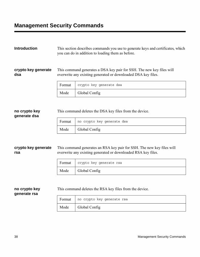
Introduction This section describes commands you use to generate keys and certificates, which you can do in addition to loading them as before.
crypto key generate dsa
This command generates a DSA key pair for SSH. The new key files will overwrite any existing generated or downloaded DSA key files.
no crypto key generate dsa
This command deletes the DSA key files from the device.
crypto key generate rsa
This command generates an RSA key pair for SSH. The new key files will overwrite any existing generated or downloaded RSA key files.
no crypto key generate rsa
This command deletes the RSA key files from the device.
Format crypto key generate dsa
Mode Global Config
Format no crypto key generate dsa
Mode Global Config
Format crypto key generate rsa
Mode Global Config
Format no crypto key generate rsa
Mode Global Config
38 Management Security Commands

Network Interface Commands
Introduction This section describes the commands you use to configure a logical interface for management access. To configure the management VLAN, see “network mgmt_vlan” on page 427.
enable (Privileged EXEC access)
This command gives you access to the Privileged EXEC mode. From the Privileged EXEC mode, you can configure the network interface.
serviceport ip This command sets the IP address, the netmask, and the gateway of the network management port. You can specify the none option to clear the IPv4 address and mask and the default gateway (for example, reset each of these values to 0.0.0.0).
serviceport protocol
This command specifies the network management port configuration protocol. If you modify this value, the change is effective immediately. If you use the bootp parameter, the switch periodically sends requests to a BootP server until a response is received. If you use the dhcp parameter, the switch periodically sends requests to a DHCP server until a response is received. If you use the none parameter, you must configure the network information for the switch manually.
Format enable
Mode User EXEC
Format serviceport ip {ipaddr netmask [gateway] | none}
Mode Privileged EXEC
Format serviceport protocol {none | bootp | dhcp}
Mode Privileged EXEC
Chapter 3: Management Commands 39
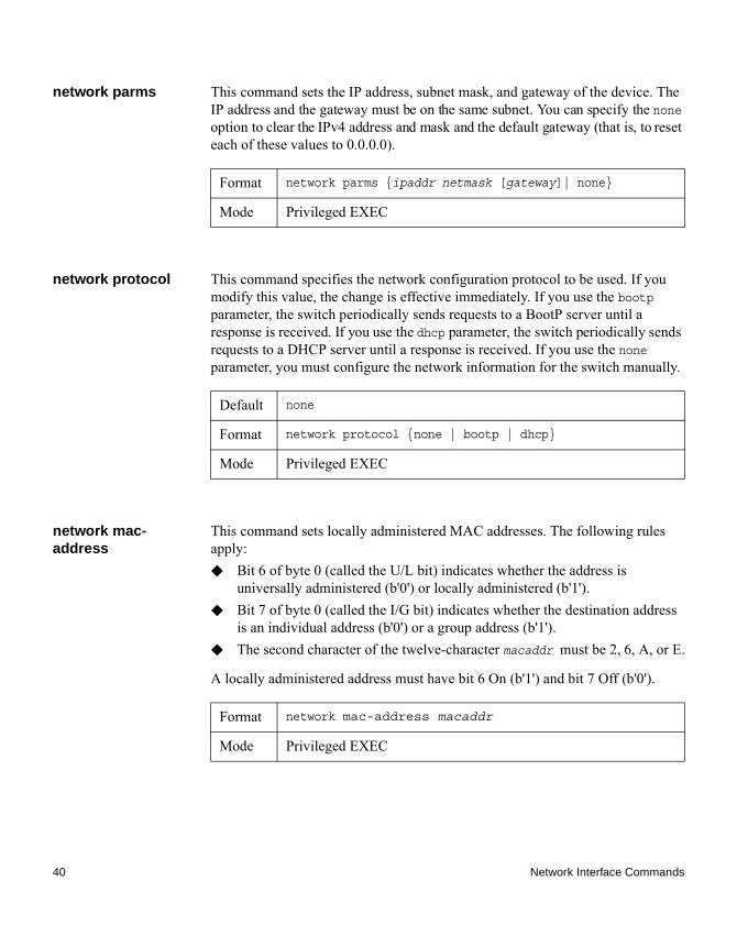
network parms This command sets the IP address, subnet mask, and gateway of the device. The IP address and the gateway must be on the same subnet. You can specify the none option to clear the IPv4 address and mask and the default gateway (that is, to reset each of these values to 0.0.0.0).
network protocol This command specifies the network configuration protocol to be used. If you modify this value, the change is effective immediately. If you use the bootp parameter, the switch periodically sends requests to a BootP server until a response is received. If you use the dhcp parameter, the switch periodically sends requests to a DHCP server until a response is received. If you use the none parameter, you must configure the network information for the switch manually.
network mac-address
This command sets locally administered MAC addresses. The following rules apply:◆ Bit 6 of byte 0 (called the U/L bit) indicates whether the address is
universally administered (b'0') or locally administered (b'1'). ◆ Bit 7 of byte 0 (called the I/G bit) indicates whether the destination address
is an individual address (b'0') or a group address (b'1'). ◆ The second character of the twelve-character macaddr must be 2, 6, A, or E.
A locally administered address must have bit 6 On (b'1') and bit 7 Off (b'0').
Format network parms {ipaddr netmask [gateway]| none}
Mode Privileged EXEC
Default none
Format network protocol {none | bootp | dhcp}
Mode Privileged EXEC
Format network mac-address macaddr
Mode Privileged EXEC
40 Network Interface Commands
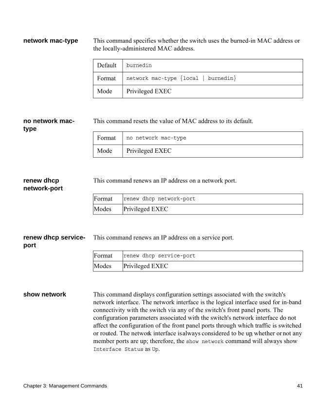
network mac-type This command specifies whether the switch uses the burned-in MAC address or the locally-administered MAC address.
no network mac-type
This command resets the value of MAC address to its default.
renew dhcp network-port
This command renews an IP address on a network port.
renew dhcp service-port
This command renews an IP address on a service port.
show network This command displays configuration settings associated with the switch's network interface. The network interface is the logical interface used for in-band connectivity with the switch via any of the switch's front panel ports. The configuration parameters associated with the switch's network interface do not affect the configuration of the front panel ports through which traffic is switched or routed. The network interface is always considered to be up, whether or not any member ports are up; therefore, the show network command will always show Interface Status as Up.
Default burnedin
Format network mac-type {local | burnedin}
Mode Privileged EXEC
Format no network mac-type
Mode Privileged EXEC
Format renew dhcp network-port
Modes Privileged EXEC
Format renew dhcp service-port
Modes Privileged EXEC
Chapter 3: Management Commands 41

Format show network
Mode ◆ Privileged EXEC◆ User EXEC
Output Description
Interface Status The network interface status; it is always considered to be up.
IP Address The IP address of the interface. The factory default value is 0.0.0.0.
Subnet Mask The IP subnet mask for this interface. The factory default value is 0.0.0.0.
Default Gateway The default gateway for this IP interface. The factory default value is 0.0.0.0.
IPv6 Administrative Mode
Whether enabled or disabled.
IPv6 Prefix The IPv6 address and length.
IPv6 Default Router
The IPv6 default router address.
Burned In MAC Address
The burned in MAC address used for in-band connectivity.
42 Network Interface Commands

Locally Administered MAC Address
If desired, a locally administered MAC address can be configured for in-band connectivity. To take effect, MAC Address Type must be set to Locally Administered. Enter the address as twelve hexadecimal digits (6 bytes) with a colon between each byte. Bit 1 of byte 0 must be set to a 1 and bit 0 to a 0, for example, byte 0 should have the mask xxxx xx10. The MAC address used by this bridge when it must be referred to in a unique fashion. It is recommended that this be the numerically smallest MAC address of all ports that belong to this bridge. However it is only required to be unique. When concatenated with dot1dStpPriority a unique Bridge Identifier is formed which is used in the Spanning Tree Protocol.
MAC Address Type The MAC address which should be used for in-band connectivity. The choices are the burned in or the Locally Administered address. The factory default is to use the burned in MAC address.
Configured IPv4 Protocol
The IPv4 network protocol being used. The options are bootp | dhcp | none.
Configured IPv6 Protocol
The IPv6 network protocol being used. The options are dhcp | none.
DHCPv6 Client DUID The DHCPv6 client’s unique client identifier. This row is displayed only when the configured IPv6 protocol is dhcp.
IPv6 Autoconfig Mode
Whether IPv6 Stateless address autoconfiguration is enabled or disabled.
Output Description
Chapter 3: Management Commands 43

Example: The following shows example CLI display output for the network port:(CN1610) #show network
Interface Status............................... Always UpIP Address..................................... 10.250.3.1Subnet Mask.................................... 255.255.255.0Default Gateway................................ 10.250.3.3IPv6 Administrative Mode....................... EnabledIPv6 Prefix is ................................ fe80::210:18ff:fe82:64c/64IPv6 Prefix is ................................ 2003::1/128IPv6 Default Router is ........................ fe80::204:76ff:fe73:423aBurned In MAC Address.......................... 00:10:18:82:06:4CLocally Administered MAC address............... 00:00:00:00:00:00MAC Address Type............................... Burned InConfigured IPv4 Protocol ...................... NoneConfigured IPv6 Protocol ...................... DHCPDHCPv6 Client DUID ............................ 00:03:00:06:00:10:18:82:06:4CIPv6 Autoconfig Mode........................... DisabledManagement VLAN ID............................. 1
44 Network Interface Commands

Pre-login Banner, System Prompt, and Host Name Commands
Introduction This section describes the commands you use to configure the pre-login banner and the system prompt. The pre-login banner is the text that displays before you login at the User: prompt.
copy (pre-login banner)
This command includes the option to upload or download the CLI Banner to or from the switch. You can specify local URLs by using TFTP, SFTP, SCP, or Xmodem.
NoteThe parameter ip6address is also a valid parameter for routing packages that support IPv6.
set prompt This command changes the name of the prompt. The length of prompt_string may be up to 64 alphanumeric characters.
Default none
Format copy <tftp://<ipaddr>/<filepath>/<filename>> nvram:clibanner
copy nvram:clibanner <tftp://<ipaddr>/<filepath>/<filename>>
Mode Privileged EXEC
Format set prompt prompt_string
Mode Privileged EXEC
Chapter 3: Management Commands 45

hostname This command sets the system hostname. It also changes the prompt. The length of hostname may be up to 64 alphanumeric, case-sensitive characters.
Format hostname hostname
Mode Privileged EXEC
46 Pre-login Banner, System Prompt, and Host Name Commands

RADIUS Commands
Introduction This section describes the commands you use to configure the switch to use a Remote Authentication Dial-In User Service (RADIUS) server on your network for authentication and accounting.
authorization network radius
This command enables the switch so it can accept VLAN assignment by the RADIUS server.
no authorization network radius
This command disables the switch so it can accept VLAN assignment by the RADIUS server.
radius accounting mode
This command enables the RADIUS accounting function.
no radius accounting mode
This command sets the RADIUS accounting function to the default value, that is, the RADIUS accounting function is disabled.
Default disable
Format authorization network radius
Mode Global Config
Format no authorization network radius
Mode Global Config
Default disabled
Format radius accounting mode
Mode Global Config
Format no radius accounting mode
Chapter 3: Management Commands 47

radius server attribute 4
This command specifies the RADIUS client to use the NAS-IP Address attribute (4) in the RADIUS requests. If the specific IP address is configured while enabling this attribute, the RADIUS client uses that IP address while sending the NAS-IP-Address attribute in RADIUS communication.
no radius server attribute 4
The no version of this command disables the NAS-IP-Address attribute global parameter for the RADIUS client. When this parameter is disabled, the RADIUS client does not send the NAS-IP-Address attribute in RADIUS requests.
Example: The following shows an example of the command:(CN1610)(Config) #radius server attribute 4 192.168.37.60
(CN1610)(Config) #radius server attribute 4
Mode Global Config
Format radius server attribute 4 [ipaddr]
Mode Global Config
Parameter Description
4 The NAS-IP-Address attribute to be used in RADIUS requests.
ipaddr The IP address of the server.
Format no radius server attribute 4 [ipaddr]
Mode Global Config
48 RADIUS Commands

radius server host This command configures the IP address or DNS name to use for communicating with the RADIUS server of a selected server type. While configuring the IP address or DNS name for the authenticating or accounting servers, you can also configure the port number and server name. If the authenticating and accounting servers are configured without a name, the command uses Default_RADIUS_Auth_Server and Default_RADIUS_Acct_Server as the default names, respectively. The same name can be configured for more than one authenticating servers and the name should be unique for accounting servers. The RADIUS client allows the configuration of a maximum 32 authenticating and accounting servers.
If you use the auth parameter, the command configures the IP address or hostname to use to connect to a RADIUS authentication server. You can configure up to three servers per RADIUS client. If the maximum number of configured servers is reached, the command fails until you remove one of the servers by entering the no form of the command. If you use the optional port parameter, the command configures the UDP port number to use when connecting to the configured RADIUS server. The port number range is 1 to 65535, with 1812 being the default value.
NoteTo reconfigure a RADIUS authentication server to use the default UDP port, set the port parameter to 1812.
If you use the acct token, the command configures the IP address or hostname to use for the RADIUS accounting server. You can only configure one accounting server. If an accounting server is currently configured, use the no form of the command to remove it from the configuration. The IP address or hostname you specify must match that of a previously configured accounting server. If you use the optional port parameter, the command configures the UDP port to use when connecting to the RADIUS accounting server. If a port is already configured for the accounting server, the new port replaces the previously configured port. The port must be a value in the range 0 to 65535, with 1813 being the default.
NoteTo reconfigure a RADIUS accounting server to use the default UDP port, set the port parameter to 1813..
Format radius server host {auth | acct} {ipaddr|dnsname} [name servername] [port 0-65535]
Mode Global Config
Chapter 3: Management Commands 49

no radius server host
The no version of this command deletes the configured server entry from the list of configured RADIUS servers. If the RADIUS authenticating server being removed is the active server in the servers that are identified by the same server name, then the RADIUS client selects another server for making RADIUS transactions. If the auth token is used, the previously configured RADIUS authentication server is removed from the configuration. Similarly, if the acct token is used, the previously configured RADIUS accounting server is removed from the configuration. The ipaddr|dnsname parameter must match the IP address or DNS name of the previously configured RADIUS authentication / accounting server.
Example: The following shows an example of the command:(CN1610)(Config) #radius server host acct 192.168.37.60(CN1610)(Config) #radius server host acct 192.168.37.60 port 1813(CN1610)(Config) #radius server host auth 192.168.37.60 name Network1_RS port 1813(CN1610)(Config) #radius server host acct 192.168.37.60 name Network2_RS(CN1610)(Config) #no radius server host acct 192.168.37.60
radius server key This command configures the key to use in RADIUS client communication with the specified server. Depending on whether the auth or acct token is used, the shared secret is configured for the RADIUS authentication or RADIUS accounting server. The IP address or hostname provided must match a previously configured server. When this command is executed, the secret is prompted.
Parameter Description
ipaddr The IP address of the server.
dnsname The DNS name of the server.
0-65535 The port number to use to connect to the specified RADIUS server.
servername The alias name to identify the server.
Format no radius server host {auth | acct} {ipaddr|dnsname}
Mode Global Config
50 RADIUS Commands

Text-based configuration supports the RADIUS server’s secrets in encrypted and nonencrypted format. When you save the configuration, these secret keys are stored in encrypted format only. If you want to enter the key in encrypted format, enter the key along with the encrypted keyword. In the show running config command’s display, these secret keys are displayed in encrypted format. You cannot show these keys in plain text format.
NoteThe secret must be an alphanumeric value not exceeding 16 characters.
Example: The following shows an example of the command:radius server key acct 10.240.4.10 encrypted encrypt-string
radius server msgauth
This command enables the message authenticator attribute to be used for the specified RADIUS Authenticating server.
Format radius server key {auth | acct} {ipaddr|dnsname} encrypted password
Mode Global Config
Parameter Description
ipaddr The IP address of the server.
dnsname The DNS name of the server.
password The password in encrypted format.
Format radius server msgauth ipaddr|dnsname
Mode Global Config
Parameter Description
ipaddr The IP address of the server.
dnsname The DNS name of the server.
Chapter 3: Management Commands 51

no radius server msgauth
The no version of this command disables the message authenticator attribute to be used for the specified RADIUS Authenticating server.
radius server primary
This command specifies a configured server that should be the primary server in the group of servers that have the same server name. Multiple primary servers can be configured for each number of servers that have the same name. When the RADIUS client has to perform transactions with an authenticating RADIUS server of specified name, the client uses the primary server that has the specified server name by default. If the RADIUS client fails to communicate with the primary server for any reason, the client uses the backup servers configured with the same server name. These backup servers are identified as the Secondary type.
radius server retransmit
This command configures the global parameter for the RADIUS client that specifies the number of transmissions of the messages to be made before attempting the fall back server upon unsuccessful communication with the current RADIUS authenticating server. When the maximum number of retries are exhausted for the RADIUS accounting server and no response is received, the client does not communicate with any other server. The number of retries allowed ranges from 1 to 15. The default number of retries is 4.
Format no radius server msgauth ipaddr|dnsname
Mode Global Config
Format radius server primary {ipaddr|dnsname}
Mode Global Config
Parameter Description
ipaddr The IP address of the RADIUS Authenticating server.
dnsname The DNS name of the server.
Default 4
Format radius server retransmit retries
52 RADIUS Commands

no radius server retransmit
The no version of this command sets the value of this global parameter to the default value.
radius server timeout
This command configures the global parameter for the RADIUS client that specifies the timeout value, in seconds, after which a request must be retransmitted to the RADIUS server if no response is received. The timeout value is an integer in the range of 1 to 30. The default is 5 seconds.
no radius server timeout
The no version of this command sets the timeout global parameter to the default value.
Mode Global Config
Parameter Description
retries The maximum number of transmission attempts in the range of 1 to 15.
Format no radius server retransmit
Mode Global Config
Default 5
Format radius server timeout seconds
Mode Global Config
Parameter Description
seconds The timeout value, in seconds, after which a request must be retransmitted. Range is 1 to 30.
Format no radius server timeout
Chapter 3: Management Commands 53

show radius This command displays the values configured for the global parameters of the RADIUS client.
Mode Global Config
Format show radius
Mode Privileged EXEC
Output Description
Number of Configured Authentication Servers
The number of RADIUS Authentication servers that have been configured.
Number of Configured Accounting Servers
The number of RADIUS Accounting servers that have been configured.
Number of Named Authentication Server Groups
The number of configured named RADIUS server groups.
Number of Named Accounting Server Groups
The number of configured named RADIUS server groups.
Number of Retransmits
The configured value of the maximum number of times a request packet is retransmitted.
Time Duration The configured timeout value, in seconds, for request retransmissions.
RADIUS Accounting Mode
A global parameter to indicate whether or not the accounting mode for all the servers is enabled.
RADIUS Attribute 4 Mode
A global parameter to indicate whether the NAS-IP-Address attribute has been enabled for use in RADIUS requests.
54 RADIUS Commands

Example: The following shows example CLI display output for the command:(CN1610) #show radius
Number of Configured Authentication Servers......... 32Number of Configured Accounting Servers............. 32Number of Named Authentication Server Groups........ 15Number of Named Accounting Server Groups............ 3Number of Retransmits............................... 4Time Duration....................................... 10RADIUS Accounting Mode.............................. DisableRADIUS Attribute 4 Mode............................. EnableRADIUS Attribute 4 Value ............................192.168.37.60
show radius servers This command displays the summary and details of RADIUS authenticating servers configured for the RADIUS client.
RADIUS Attribute 4 Value
A global parameter that specifies the IP address to be used in the NAS-IP-Address attribute of RADIUS requests.
Output Description
Format show radius servers [{ipaddr|dnsname | name [servername]}]
Mode Privileged EXEC
Output Description
ipaddr The IP address of the authenticating server.
dnsname The DNS name of the authenticating server.
servername The alias name to identify the server.
Current The * symbol preceding the server host address specifies that the server is currently active.
Host Address The IP address of the host.
Server Name The name of the authenticating server.
Chapter 3: Management Commands 55

Example: The following shows example CLI display output for the command:(CN1610)#show radius servers
Current Host Address Server Name Port Type
------- ---------------- ---------------------- ----- ----------
* 192.168.37.200 Network1_RADIUS_Server 1813 Primary
192.168.37.201 Network2_RADIUS_Server 1813 Secondary
192.168.37.202 Network3_RADIUS_Server 1813 Primary
192.168.37.203 Network4_RADIUS_Server 1813 Secondary
Port The port used for communication with the authenticating server.
Type Specifies whether this server is a primary or secondary type.
Current Host Address
The IP address of the currently active authenticating server.
Secret Configured Yes or No Boolean value that indicates whether this server is configured with a secret.
Number of Retransmits
The configured value of the maximum number of times a request packet is retransmitted.
Message Authenticator
A global parameter to indicate whether the Message Authenticator attribute is enabled or disabled.
Time Duration The configured timeout value, in seconds, for request retransmissions.
RADIUS Accounting Mode
A global parameter to indicate whether the accounting mode for all the servers is enabled or not.
RADIUS Attribute 4 Mode
A global parameter to indicate whether the NAS-IP-Address attribute has been enabled for use in RADIUS requests.
RADIUS Attribute 4 Value
A global parameter that specifies the IP address to be used in the NAS-IP-Address attribute of RADIUS requests.
Output Description
56 RADIUS Commands
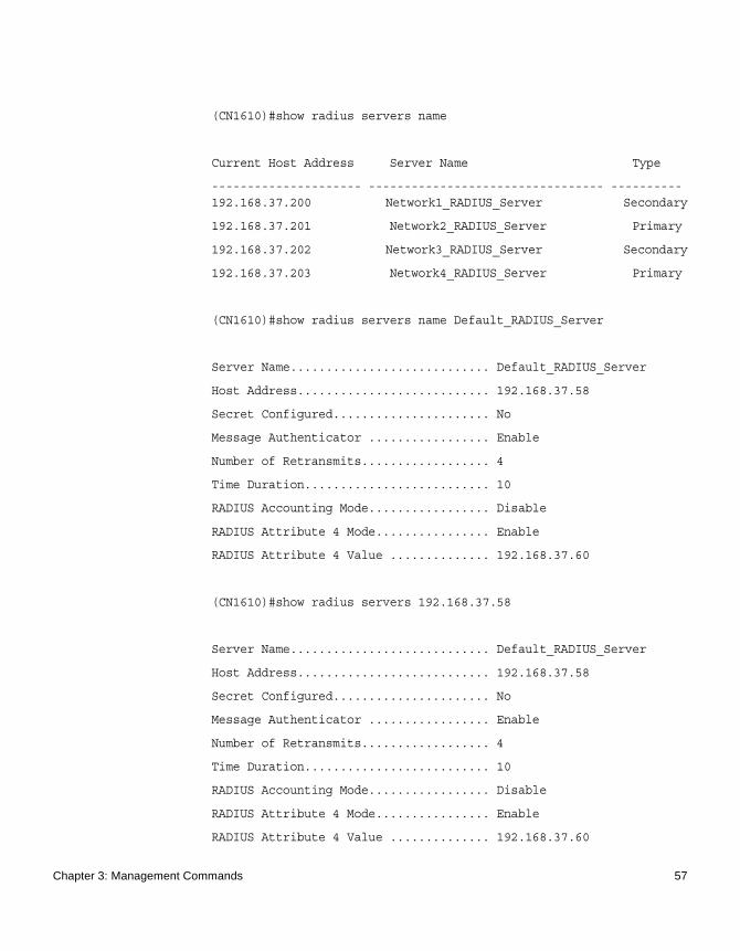
(CN1610)#show radius servers name
Current Host Address Server Name Type
--------------------- --------------------------------- ----------192.168.37.200 Network1_RADIUS_Server Secondary
192.168.37.201 Network2_RADIUS_Server Primary
192.168.37.202 Network3_RADIUS_Server Secondary
192.168.37.203 Network4_RADIUS_Server Primary
(CN1610)#show radius servers name Default_RADIUS_Server
Server Name............................ Default_RADIUS_Server
Host Address........................... 192.168.37.58
Secret Configured...................... No
Message Authenticator ................. Enable
Number of Retransmits.................. 4
Time Duration.......................... 10
RADIUS Accounting Mode................. Disable
RADIUS Attribute 4 Mode................ Enable
RADIUS Attribute 4 Value .............. 192.168.37.60
(CN1610)#show radius servers 192.168.37.58
Server Name............................ Default_RADIUS_Server
Host Address........................... 192.168.37.58
Secret Configured...................... No
Message Authenticator ................. Enable
Number of Retransmits.................. 4
Time Duration.......................... 10
RADIUS Accounting Mode................. Disable
RADIUS Attribute 4 Mode................ Enable
RADIUS Attribute 4 Value .............. 192.168.37.60
Chapter 3: Management Commands 57
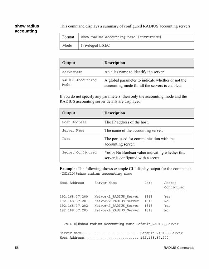
show radius accounting
This command displays a summary of configured RADIUS accounting servers.
If you do not specify any parameters, then only the accounting mode and the RADIUS accounting server details are displayed.
Example: The following shows example CLI display output for the command:(CN1610)#show radius accounting name
Host Address Server Name Port SecretConfigured
-------------- ---------------------- ----- -----------192.168.37.200 Network1_RADIUS_Server 1813 Yes192.168.37.201 Network2_RADIUS_Server 1813 No192.168.37.202 Network3_RADIUS_Server 1813 Yes192.168.37.203 Network4_RADIUS_Server 1813 No
(CN1610)#show radius accounting name Default_RADIUS_Server
Server Name............................ Default_RADIUS_ServerHost Address........................... 192.168.37.200
Format show radius accounting name [servername]
Mode Privileged EXEC
Output Description
servername An alias name to identify the server.
RADIUS Accounting Mode
A global parameter to indicate whether or not the accounting mode for all the servers is enabled.
Output Description
Host Address The IP address of the host.
Server Name The name of the accounting server.
Port The port used for communication with the accounting server.
Secret Configured Yes or No Boolean value indicating whether this server is configured with a secret.
58 RADIUS Commands

RADIUS Accounting Mode................. DisablePort .................................. 1813Secret Configured ..................... Yes
show radius accounting statistics
This command displays a summary of statistics for the configured RADIUS accounting servers.
Format show radius accounting statistics {ipaddr|dnsname | name servername}
Mode Privileged EXEC
Output Description
ipaddr The IP address of the server.
dnsname The DNS name of the server.
servername The alias name to identify the server.
RADIUS Accounting Server Name
The name of the accounting server.
Host Address The IP address of the host.
Round Trip Time The time interval, in hundredths of a second, between the most recent Accounting-Response and the Accounting-Request that matched it from this RADIUS accounting server.
Requests The number of RADIUS Accounting-Request packets sent to this server. This number does not include retransmissions.
Retransmissions The number of RADIUS Accounting-Request packets retransmitted to this RADIUS accounting server.
Responses The number of RADIUS packets received on the accounting port from this server.
Chapter 3: Management Commands 59

Example: The following shows example CLI display output for the command:(CN1610)#show radius accounting statistics 192.168.37.200
RADIUS Accounting Server Name................. Default_RADIUS_ServerHost Address.................................. 192.168.37.200Round Trip Time............................... 0.00Requests...................................... 0Retransmissions............................... 0Responses..................................... 0Malformed Responses........................... 0Bad Authenticators............................ 0Pending Requests.............................. 0Timeouts...................................... 0Unknown Types................................. 0Packets Dropped............................... 0
Malformed Responses
The number of malformed RADIUS Accounting-Response packets received from this server. Malformed packets include packets with an invalid length. Bad authenticators or signature attributes or unknown types are not included as malformed accounting responses.
Bad Authenticators The number of RADIUS Accounting-Response packets containing invalid authenticators received from this accounting server.
Pending Requests The number of RADIUS Accounting-Request packets sent to this server that have not yet timed out or received a response.
Timeouts The number of accounting timeouts to this server.
Unknown Types The number of RADIUS packets of unknown types, which were received from this server on the accounting port.
Packets Dropped The number of RADIUS packets received from this server on the accounting port and dropped for some other reason.
Output Description
60 RADIUS Commands

(CN1610)#show radius accounting statistics name Default_RADIUS_Server
RADIUS Accounting Server Name................. Default_RADIUS_ServerHost Address.................................. 192.168.37.200Round Trip Time............................... 0.00Requests...................................... 0Retransmissions............................... 0Responses..................................... 0Malformed Responses........................... 0Bad Authenticators............................ 0Pending Requests.............................. 0Timeouts...................................... 0Unknown Types................................. 0Packets Dropped............................... 0
show radius statistics
This command displays the summary statistics of configured RADIUS Authenticating servers.
Format show radius statistics {ipaddr|dnsname | name servername}
Mode Privileged EXEC
Output Description
ipaddr The IP address of the server.
dnsname The DNS name of the server.
servername The alias name to identify the server.
RADIUS Server Name The name of the authenticating server.
Server Host Address
The IP address of the host.
Access Requests The number of RADIUS Access-Request packets sent to this server. This number does not include retransmissions.
Access Retransmissions
The number of RADIUS Access-Request packets retransmitted to this RADIUS authentication server.
Chapter 3: Management Commands 61

Access Accepts The number of RADIUS Access-Accept packets, including both valid and invalid packets, that were received from this server.
Access Rejects The number of RADIUS Access-Reject packets, including both valid and invalid packets, that were received from this server.
Access Challenges The number of RADIUS Access-Challenge packets, including both valid and invalid packets, that were received from this server.
Malformed Access Responses
The number of malformed RADIUS Access-Response packets received from this server. Malformed packets include packets with an invalid length. Bad authenticators or signature attributes or unknown types are not included as malformed access responses.
Bad Authenticators The number of RADIUS Access-Response packets containing invalid authenticators or signature attributes received from this server.
Pending Requests The number of RADIUS Access-Request packets destined for this server that have not yet timed out or received a response.
Timeouts The number of authentication timeouts to this server.
Unknown Types The number of packets of unknown type that were received from this server on the authentication port.
Packets Dropped The number of RADIUS packets received from this server on the authentication port and dropped for some other reason.
Output Description
62 RADIUS Commands

Example: The following shows example CLI display output for the command:(CN1610)#show radius statistics 192.168.37.200
RADIUS Server Name............................ Default_RADIUS_ServerServer Host Address........................... 192.168.37.200Access Requests............................... 0.00Access Retransmissions........................ 0Access Accepts................................ 0Access Rejects................................ 0Access Challenges............................. 0Malformed Access Responses.................... 0Bad Authenticators............................ 0Pending Requests.............................. 0Timeouts...................................... 0Unknown Types................................. 0Packets Dropped............................... 0
(CN1610)#show radius statistics name Default_RADIUS_Server
RADIUS Server Name............................ Default_RADIUS_ServerServer Host Address........................... 192.168.37.200Access Requests............................... 0.00Access Retransmissions........................ 0Access Accepts................................ 0Access Rejects................................ 0Access Challenges............................. 0Malformed Access Responses.................... 0Bad Authenticators............................ 0Pending Requests.............................. 0Timeouts...................................... 0Unknown Types................................. 0Packets Dropped............................... 0
Chapter 3: Management Commands 63
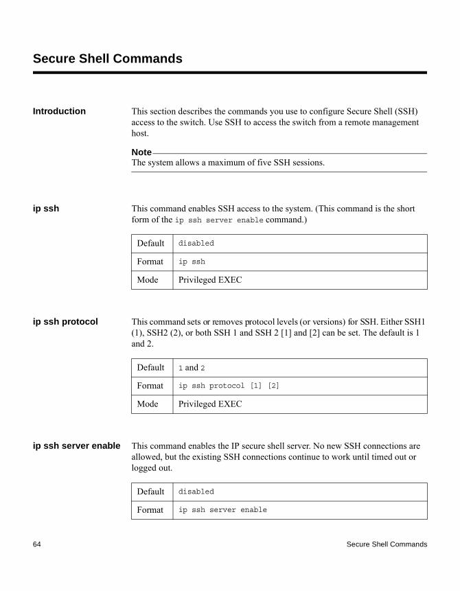
Secure Shell Commands
Introduction This section describes the commands you use to configure Secure Shell (SSH) access to the switch. Use SSH to access the switch from a remote management host.
NoteThe system allows a maximum of five SSH sessions.
ip ssh This command enables SSH access to the system. (This command is the short form of the ip ssh server enable command.)
ip ssh protocol This command sets or removes protocol levels (or versions) for SSH. Either SSH1 (1), SSH2 (2), or both SSH 1 and SSH 2 [1] and [2] can be set. The default is 1 and 2.
ip ssh server enable This command enables the IP secure shell server. No new SSH connections are allowed, but the existing SSH connections continue to work until timed out or logged out.
Default disabled
Format ip ssh
Mode Privileged EXEC
Default 1 and 2
Format ip ssh protocol [1] [2]
Mode Privileged EXEC
Default disabled
Format ip ssh server enable
64 Secure Shell Commands

no ip ssh server enable
This command disables the IP secure shell server.
sshcon maxsessions
This command specifies the maximum number of SSH connection sessions that can be established. A value of 0 indicates that no SSH connection can be established. The range is 0 to 5.
no sshcon maxsessions
This command sets the maximum number of allowed SSH connection sessions to the default value.
sshcon timeout This command sets the SSH connection session timeout value, in minutes. A session is active as long as the session has been idle for the value set. The time is a decimal value from 1 to 160. The default is 5 minutes.
Changing the timeout value for active sessions does not become effective until the session is reaccessed. Also, any keystroke activates the new timeout duration.
Mode Privileged EXEC
Format no ip ssh server enable
Mode Privileged EXEC
Default 5
Format sshcon maxsessions 0-5
Mode Privileged EXEC
Format no sshcon maxsessions
Mode Privileged EXEC
Default 5
Format sshcon timeout 1–160
Mode Privileged EXEC
Chapter 3: Management Commands 65

no sshcon timeout This command sets the SSH connection session timeout value, in minutes, to the default.
Changing the timeout value for active sessions does not become effective until the session is reaccessed. Also, any keystroke activates the new timeout duration.
show ip ssh This command displays the SSH settings.
Format no sshcon timeout
Mode Privileged EXEC
Format show ip ssh
Mode Privileged EXEC
Output Description
Administra-tive Mode
This field indicates whether the administrative mode of SSH is enabled or disabled.
Protocol Level
The protocol level may have the values of version 1, version 2 or both versions 1 and 2.
SSH Sessions Currently Active
The number of SSH sessions currently active.
Max SSH Sessions Allowed
The maximum number of SSH sessions allowed.
SSH Timeout The SSH timeout value, in minutes.
Keys Present Indicates whether the SSH RSA and DSA key files are present on the device.
Key Generation in Progress
Indicates whether RSA or DSA key files generation is currently in progress.
66 Secure Shell Commands

SNMP Commands
Introduction This section describes the commands you use to configure Simple Network Management Protocol (SNMP) on the switch. You can configure the switch to act as an SNMP agent so that it can communicate with SNMP managers on your network.
snmp-server This command sets the name and the physical location of the switch, and the organization responsible for the network. The parameters name, loc, and con can be up to 255 characters in length.
snmp-server community
This command adds (and names) a new SNMP community. A community name is a name associated with the switch and a set of SNMP managers that manage it with a specified privileged level. The length of name can be up to 16 case-sensitive characters.
NoteCommunity names in the SNMP Community Table must be unique. When making simple entries using the same community name, the first entry is kept and processed and all duplicate entries are ignored.
Format snmp-server {sysname name | location loc | contact con}
Mode Global Config
Default ◆ Public and private, which you can rename.◆ Default values for the remaining four community names are
blank.
Format snmp-server community name
Mode Global Config
Chapter 3: Management Commands 67

no snmp-server community
This command removes this community name from the table. The name is the community name to be deleted.
snmp-server community ipaddr
This command sets a client IP address for an SNMP community. The address is the associated community SNMP packet sending address. It is used along with the client IP mask value to denote a range of IP addresses from which SNMP clients may use that community to access the device. A value of 0.0.0.0 allows access from any IP address. Otherwise, this value is ANDed with the mask to determine the range of allowed client IP addresses. The name is the applicable community name.
no snmp-server community ipaddr
This command sets a client IP address for an SNMP community to 0.0.0.0. The name is the applicable community name.
snmp-server community ipmask
This command sets a client IP mask for an SNMP community. The address is the associated community SNMP packet sending address and is used along with the client IP address value to denote a range of IP addresses from which SNMP clients may use that community to access the device. A value of 255.255.255.255 will allow access from only one station, and will use that machine's IP address for the client IP address. A value of 0.0.0.0 will allow access from any IP address. The name is the applicable community name.
Format no snmp-server community name
Mode Global Config
Default 0.0.0.0
Format snmp-server community ipaddr ipaddr name
Mode Global Config
Format no snmp-server community ipaddr name
Mode Global Config
Default 0.0.0.0
68 SNMP Commands

no snmp-server community ipmask
This command sets a client IP mask for an SNMP community to 0.0.0.0. The name is the applicable community name. The community name may be up to 16 alphanumeric characters.
snmp-server community mode
This command activates an SNMP community. If a community is enabled, an SNMP manager associated with this community manages the switch according to its access right.
no snmp-server community mode
This command deactivates an SNMP community. If the community is disabled, no SNMP requests using this community are accepted. In this case the SNMP manager associated with this community cannot manage the switch until the Status is changed back to Enable.
Format snmp-server community ipmask ipmask name
Mode Global Config
Format no snmp-server community ipmask name
Mode Global Config
Default ◆ private and public communities - Enabled◆ other four communities - Disabled
Note: A maximum of six communities can be assigned for this switch, which leaves four since two (public and private) are assigned by default. See the command “show snmpcommunity” on page 75.
Format snmp-server community mode name
Mode Global Config
Format no snmp-server community mode name
Mode Global Config
Chapter 3: Management Commands 69

snmp-server community ro
This command restricts access to switch information. The access mode is read-only (also called public).
snmp-server community rw
This command restricts access to switch information. The access mode is read/write (also called private).
snmp-server enable traps violation
This command enables the sending of new violation traps designating when a packet with a disallowed MAC address is received on a locked port. You can use this command to configure a single interface or a range of interfaces.
NoteFor other port security commands, see “Port Security Commands” on page 378.
no snmp-server enable traps violation
This command disables the sending of new violation traps.
snmp-server enable traps
This command enables the Authentication Flag.
Format snmp-server community ro name
Mode Global Config
Format snmp-server community rw name
Mode Global Config
Default disabled
Format snmp-server enable traps violation
Mode Interface Config
Format no snmp-server enable traps violation
Mode Interface Config
Default enabled
70 SNMP Commands

no snmp-server enable traps
This command disables the Authentication Flag.
snmp-server enable traps linkmode
This command enables Link Up/Down traps for the entire switch. When enabled, link traps are sent only if the Link Trap flag setting associated with the port is enabled. See “snmp trap link-status” on page 74.
no snmp-server enable traps linkmode
This command disables Link Up/Down traps for the entire switch.
snmp-server enable traps multiusers
This command enables Multiple User traps. When the traps are enabled, a Multiple User Trap is sent when a user logs in to the terminal interface (EIA 232 or Telnet) and there is an existing terminal interface session.
Format snmp-server enable traps
Mode Global Config
Format no snmp-server enable traps
Mode Global Config
Default enabled
Format snmp-server enable traps linkmode
Mode Global Config
Format no snmp-server enable traps linkmode
Mode Global Config
Default enabled
Format snmp-server enable traps multiusers
Mode Global Config
Chapter 3: Management Commands 71

no snmp-server enable traps multiusers
This command disables Multiple User traps.
snmp-server enable traps stpmode
This command enables the sending of new root traps and topology change notification traps.
no snmp-server enable traps stpmode
This command disables the sending of new root traps and topology change notification traps.
snmptrap This command adds an SNMP trap receiver. The maximum length of name is 16 case-sensitive alphanumeric characters. The value for ipaddr or ip6addr can be an IPv4 address, IPv6 address, or hostname. The snmpversion is the version of SNMP. The snmpversion parameter options are snmpv1 or snmpv2. The default is snmpv2. The SNMP trap address can be set using both an IPv4 address format as well as an IPv6 global address format.
NoteThe name parameter does not need to be unique; however, the name and receiver pair must be unique. Multiple entries can exist with the same name, as long as they are associated with a different receiver IP address or hostname. The reverse scenario is also acceptable. The name is the community name used when sending the trap to the receiver, but the name is not directly associated with the SNMP Community Table. See “snmp-server community” on page 67.
Format no snmp-server enable traps multiusers
Mode Global Config
Default enabled
Format snmp-server enable traps stpmode
Mode Global Config
Format no snmp-server enable traps stpmode
Mode Global Config
72 SNMP Commands

Example: The following shows an example of the CLI command:(CN1610) # snmptrap mytrap ip6addr 3099::2
no snmptrap This command deletes trap receivers for a community.
snmptrap snmpversion
This command modifies the SNMP version of a trap. The maximum length of name is 16 case-sensitive alphanumeric characters. The snmpversion parameter options are snmpv1 or snmpv2. The default is snmpv2.
NoteThis command does not support a no form.
Default snmpv2
Format snmptrap name {ipaddr | ip6addr} {ipaddr | ip6addr | hostname} [snmpversion snmpversion]
Mode Global Config
Format no snmptrap name {ipaddr | ip6addr} {ipaddr | ip6addr | hostname}
Mode Global Config
Default snmpv2
Format snmptrap snmpversion name {ipaddr | ip6addr | hostname} snmpversion
Mode Global Config
Chapter 3: Management Commands 73

snmptrap ipaddr This command assigns an IP address to a specified community name. The maximum length of name is 16 case-sensitive alphanumeric characters.
NoteIP addresses in the SNMP trap receiver table must be unique. If you make multiple entries using the same IP address, the first entry is retained and processed. All duplicate entries are ignored.
snmptrap mode This command activates or deactivates an SNMP trap. Enabled trap receivers are active (able to receive traps). Disabled trap receivers are inactive (not able to receive traps).
no snmptrap mode This command deactivates an SNMP trap. Disabled trap receivers are unable to receive traps.
snmp trap link-status
This command enables link status traps on an interface or range of interfaces.
NoteThis command is valid only when the Link Up/Down Flag is enabled. See “snmp-server enable traps linkmode” on page 71.
Format snmptrap ipaddr name ipaddrold {ipaddrnew | hostnamenew}
Mode Global Config
Format snmptrap mode name {ipaddr | ip6addr | hostname}
Mode Global Config
Format no snmptrap mode name {ipaddr | ip6addr | hostname}
Mode Global Config
Format snmp trap link-status
Mode Interface Config
74 SNMP Commands
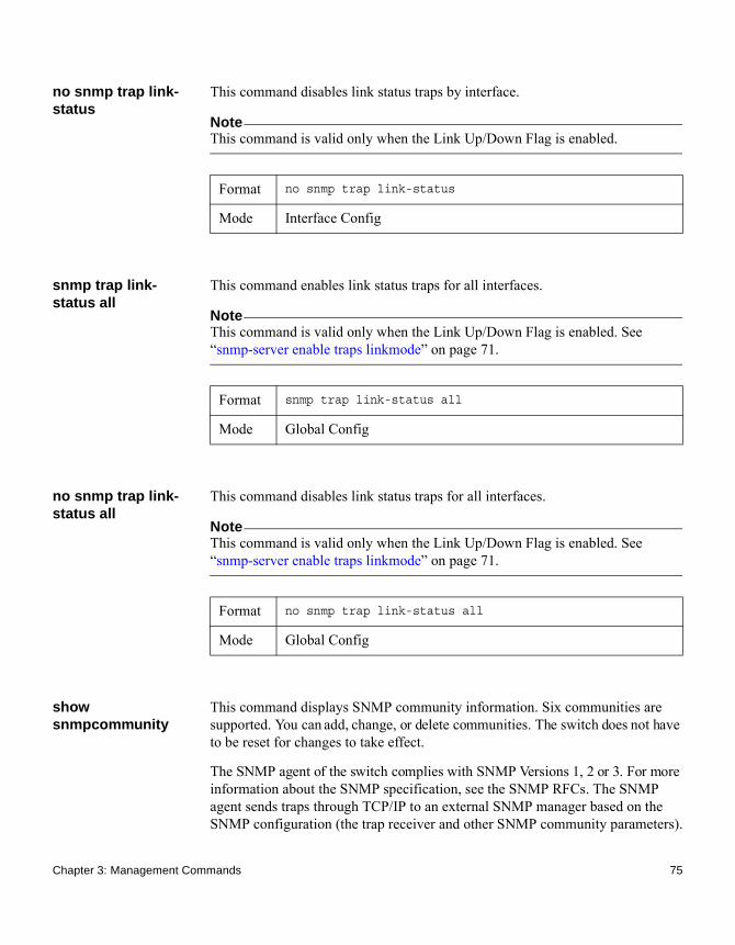
no snmp trap link-status
This command disables link status traps by interface.
NoteThis command is valid only when the Link Up/Down Flag is enabled.
snmp trap link-status all
This command enables link status traps for all interfaces.
NoteThis command is valid only when the Link Up/Down Flag is enabled. See “snmp-server enable traps linkmode” on page 71.
no snmp trap link-status all
This command disables link status traps for all interfaces.
NoteThis command is valid only when the Link Up/Down Flag is enabled. See “snmp-server enable traps linkmode” on page 71.
show snmpcommunity
This command displays SNMP community information. Six communities are supported. You can add, change, or delete communities. The switch does not have to be reset for changes to take effect.
The SNMP agent of the switch complies with SNMP Versions 1, 2 or 3. For more information about the SNMP specification, see the SNMP RFCs. The SNMP agent sends traps through TCP/IP to an external SNMP manager based on the SNMP configuration (the trap receiver and other SNMP community parameters).
Format no snmp trap link-status
Mode Interface Config
Format snmp trap link-status all
Mode Global Config
Format no snmp trap link-status all
Mode Global Config
Chapter 3: Management Commands 75

Format show snmpcommunity
Mode Privileged EXEC
Output Description
SNMP Community Name
The community string to which this entry grants access. A valid entry is a case-sensitive alphanumeric string of up to 16 characters. Each row of this table must contain a unique community name.
Client IP Address An IP address (or portion thereof) from which this device will accept SNMP packets with the associated community. The requesting entity's IP address is ANDed with the Subnet Mask before being compared to the IP address.
Note: If the subnet mask is set to 0.0.0.0, an IP address of 0.0.0.0 matches all IP addresses. The default value is 0.0.0.0.
Client IP Mask A mask to be ANDed with the requesting entity's IP address before comparison with the IP address. If the result matches with the IP address then the address is an authenticated IP address. For example, if the IP address = 9.47.128.0 and the corresponding subnet mask = 255.255.255.0 a range of incoming IP addresses would match, for example, the incoming IP address could equal 9.47.128.0 - 9.47.128.255. The default value is 0.0.0.0.
Access Mode The access level for this community string.
Status The status of this community access entry.
76 SNMP Commands

Example: The following shows sample output from this command:(CN1610) #show snmpcommunity
SNMP Community Name Client IP Address Client IP Mask Access Mode Status------------------- ----------------- ----------------- ----------- -------public 0.0.0.0 0.0.0.0 Read Only Enableprivate 0.0.0.0 0.0.0.0 Read/Write Enablenetapp 0.0.0.0 0.0.0.0 Read Only Enable
show snmptrap This command displays SNMP trap receivers. Trap messages are sent across a network to an SNMP Network Manager. These messages alert the manager to events occurring within the switch or on the network. Six trap receivers are simultaneously supported.
Example: The following shows an example of the CLI command:(CN1610) #show snmptrap
SNMP Trap Name IP Address IPv6 Address SNMP Version Status-------------- ------------- ------------- ------------- ---------Mytrap 2.2.2.2 snmpv2 Enable
Format show snmptrap
Mode Privileged EXEC
Output Description
SNMP Trap Name The community string of the SNMP trap packet sent to the trap manager. The string is case-sensitive and can be up to 16 alphanumeric characters in length.
IP Address The IPv4 address to receive SNMP traps from this device.
IPv6 Address The IPv6 address to receive SNMP traps from this device.
SNMP Version SNMPv2
Status The receiver's status (enabled or disabled).
Chapter 3: Management Commands 77

show trapflags This command displays trap conditions. The command’s display shows all the enabled OSPFv2 and OSPFv3 trapflags. Configure which traps the switch should generate by enabling or disabling the trap condition. If a trap condition is enabled and the condition is detected, the SNMP agent on the switch sends the trap to all enabled trap receivers. You do not have to reset the switch to implement the changes. Cold and warm start traps are always generated and cannot be disabled.
Format show trapflags
Mode Privileged EXEC
Output Description
Authentication Flag
Status can be Enable or Disable. The factory default is enabled. Indicates whether authentication failure traps will be sent.
Link Up/Down Flag Status can be Enable or Disable. The factory default is enabled. Indicates whether link status traps will be sent.
Multiple Users Flag
Status can be Enable or Disable. The factory default is enabled. Indicates whether a trap will be sent when the same user ID is logged into the switch more than once at the same time (either through Telnet or the serial port).
Spanning Tree Flag Status can be Enable or Disable. The factory default is enabled. Indicates whether spanning tree traps are sent.
ACL Traps Status can be Enable or Disable. The factory default is disabled. Indicates whether ACL traps are sent.
BGP4 Traps Status can be Enable or Disable. The factory default is Disable. Indicates whether BGP4 traps are sent. (This field appears only on systems with the BGPv4 software package installed.)
78 SNMP Commands

Example: The following shows an example of this command:(CN1610) #show trapflags
Authentication Flag............................ EnableLink Up/Down Flag.............................. EnableMultiple Users Flag............................ EnableSpanning Tree Flag............................. EnableACL Traps...................................... Disable
DVMRP Traps Status can be Enable or Disable. The factory default is Disable. Indicates whether DVMRP traps are sent.
OSPFv2 Traps Status can be Enable or Disable. The factory default is disabled. Indicates whether OSPF traps are sent. If any of the OSPF trap flags are not enabled, then the command displays Disable. Otherwise, the command shows all the enabled OSPF traps’ information.
OSPFv3 Traps Status can be Enable or Disable. The factory default is disabled. Indicates whether OSPF traps are sent. If any of the OSPFv3 trap flags are not enabled, then the command displays Disable. Otherwise, the command shows all the enabled OSPFv3 traps’ information.
PIM Traps Status can be Enable or Disable. The factory default is Disable. Indicates whether PIM traps are sent.
Output Description
Chapter 3: Management Commands 79

TACACS+ Commands
Introduction TACACS+ provides access control for networked devices via one or more centralized servers. Similar to RADIUS, this protocol simplifies authentication by making use of a single database that can be shared by many clients on a large network. TACACS+ is based on the TACACS protocol (described in RFC1492) but additionally provides for separate authentication, authorization, and accounting services. The original protocol was UDP based with messages passed in clear text over the network; TACACS+ uses TCP to ensure reliable delivery and a shared key configured on the client and daemon server to encrypt all messages.
tacacs-server host Use this tacacs-server host command in Global Configuration mode to configure a TACACS+ server. This command enters into the TACACS+ configuration mode. The ip-address|hostname parameter is the IP address or hostname of the TACACS+ server. To specify multiple hosts, you can use multiple tacacs-server host commands.
no tacacs-server host
This command deletes the specified hostname or IP address. The ip-address|hostname parameter is the IP address of the TACACS+ server.
tacacs-server key This command sets the authentication and encryption key for all TACACS+ communications between the switch and the TACACS+ daemon. The key-string parameter has a range of 0 to 128 characters and specifies the authentication and encryption key for all TACACS communications between the switch and the TACACS+ server. This key must match the key used on the TACACS+ daemon.
Format tacacs-server host ip-address|hostname
Mode Global Config
Format no tacacs-server host ip-address|hostname
Mode Global Config
80 TACACS+ Commands

Text-based configuration supports TACACS server’s secrets in encrypted and nonencrypted format. When you save the configuration, these secret keys are stored in encrypted format only. If you want to enter the key in encrypted format, enter the key along with the encrypted keyword. In the “show running-config” command’s display, these secret keys are displayed in encrypted format. You cannot show these keys in plain text format.
no tacacs-server key
This command disables the authentication and encryption key for all TACACS+ communications between the switch and the TACACS+ daemon. The key-string parameter has a range of 0 to 128 characters This key must match the key used on the TACACS+ daemon.
tacacs-server timeout
This command sets the timeout value for communication with the TACACS+ servers. The timeout parameter has a range of 1 to 30 and is the timeout value in seconds. The default is 5 seconds.
no tacacs-server timeout
This command restores the default timeout value for all TACACS+ servers.
Format tacacs-server key [key-string | encrypted key-string]
Mode Global Config
Format no tacacs-server key key-string
Mode Global Config
Default 5
Format tacacs-server timeout timeout
Mode Global Config
Format no tacacs-server timeout
Mode Global Config
Chapter 3: Management Commands 81

key Use this command in TACACS Configuration mode to specify the authentication and encryption key for all TACACS+ communications between the device and the TACACS+ server. This key must match the key used on the TACACS+ daemon. The key-string parameter specifies the key name. For an empty string use “ ”. The range is 0 to 128 characters.
Text-based configuration supports TACACS+ server’s secrets in encrypted and nonencrypted format. When you save the configuration, these secret keys are stored in encrypted format only. If you want to enter the key in encrypted format, enter the key along with the encrypted keyword. In the “show running-config” command’s display, these secret keys are displayed in encrypted format. You cannot show these keys in plain text format.
port Use this command in TACACS Configuration mode to specify a server port number. The server port-number range is 0 to 65535.
priority Use this command in TACACS Configuration mode to specify the order in which servers are used, where 0 (zero) is the highest priority. The priority parameter specifies the priority for servers. The highest priority is 0 (zero), the default, and the range is 0 to 65535.
Format key [key-string | encrypted key-string]
Mode TACACS Config
Default 49
Format port port-number
Mode TACACS Config
Default 0
Format priority priority
Mode TACACS Config
82 TACACS+ Commands
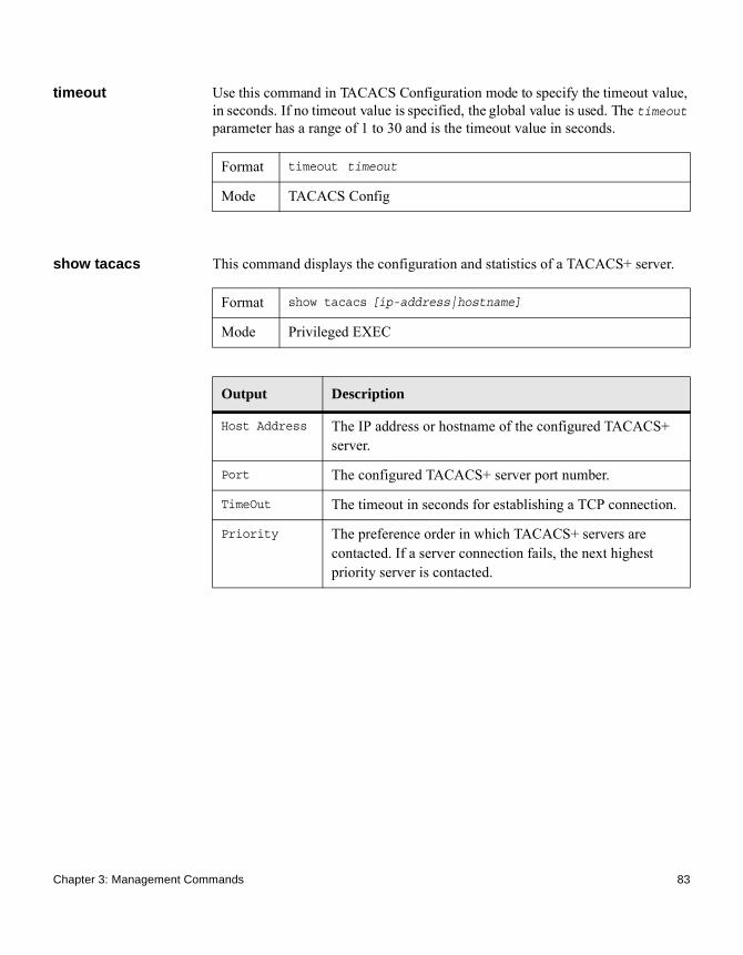
timeout Use this command in TACACS Configuration mode to specify the timeout value, in seconds. If no timeout value is specified, the global value is used. The timeout parameter has a range of 1 to 30 and is the timeout value in seconds.
show tacacs This command displays the configuration and statistics of a TACACS+ server.
Format timeout timeout
Mode TACACS Config
Format show tacacs [ip-address|hostname]
Mode Privileged EXEC
Output Description
Host Address The IP address or hostname of the configured TACACS+ server.
Port The configured TACACS+ server port number.
TimeOut The timeout in seconds for establishing a TCP connection.
Priority The preference order in which TACACS+ servers are contacted. If a server connection fails, the next highest priority server is contacted.
Chapter 3: Management Commands 83
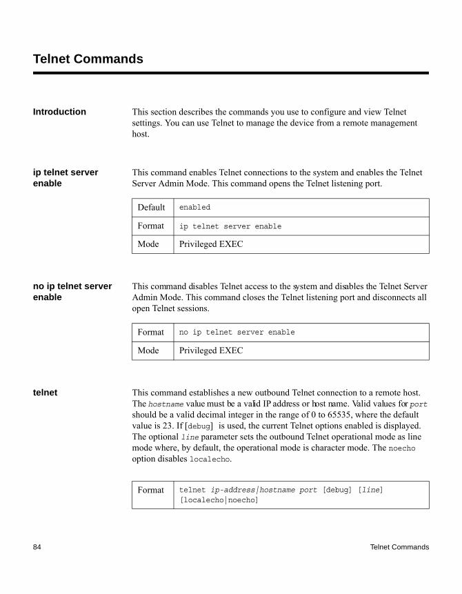
Telnet Commands
Introduction This section describes the commands you use to configure and view Telnet settings. You can use Telnet to manage the device from a remote management host.
ip telnet server enable
This command enables Telnet connections to the system and enables the Telnet Server Admin Mode. This command opens the Telnet listening port.
no ip telnet server enable
This command disables Telnet access to the system and disables the Telnet Server Admin Mode. This command closes the Telnet listening port and disconnects all open Telnet sessions.
telnet This command establishes a new outbound Telnet connection to a remote host. The hostname value must be a valid IP address or host name. Valid values for port should be a valid decimal integer in the range of 0 to 65535, where the default value is 23. If [debug] is used, the current Telnet options enabled is displayed. The optional line parameter sets the outbound Telnet operational mode as line mode where, by default, the operational mode is character mode. The noecho option disables localecho.
Default enabled
Format ip telnet server enable
Mode Privileged EXEC
Format no ip telnet server enable
Mode Privileged EXEC
Format telnet ip-address|hostname port [debug] [line] [localecho|noecho]
84 Telnet Commands

transport input telnet
This command regulates new Telnet sessions. If enabled, new Telnet sessions can be established until there are no more sessions available. An established session remains active until the session is ended or an abnormal network error ends the session.
NoteIf the Telnet Server Admin Mode is disabled, Telnet sessions cannot be established. Use the command “ip telnet server enable” on page 84 to enable Telnet Server Admin mode.
no transport input telnet
This command prevents new Telnet sessions from being established.
transport output telnet
This command regulates new outbound Telnet connections. If enabled, new outbound Telnet sessions can be established until the system reaches the maximum number of simultaneous outbound Telnet sessions allowed. An established session remains active until the session is ended or an abnormal network error ends it.
no transport output telnet
Use this command to prevent new outbound Telnet connections from being established.
Mode ◆ Privileged EXEC◆ User EXEC
Default enabled
Format transport input telnet
Mode Line Config
Format no transport input telnet
Mode Line Config
Default enabledFormat transport output telnet
Mode Line Config
Chapter 3: Management Commands 85

session-limit This command specifies the maximum number of simultaneous outbound Telnet sessions. A value of 0 indicates that no outbound Telnet session can be established.
no session-limit This command sets the maximum number of simultaneous outbound Telnet sessions to the default value.
session-timeout This command sets the Telnet session timeout value. The timeout value unit of time is minutes.
no session-timeout This command sets the Telnet session timeout value to the default. The timeout value unit of time is minutes.
Format no transport output telnet
Mode Line Config
Default 5Format session-limit 0-5
Mode Line Config
Format no session-limit
Mode Line Config
Default 5Format session-timeout 1-160
Mode Line Config
Format no session-timeout
Mode Line Config
86 Telnet Commands

telnetcon maxsessions
This command specifies the maximum number of Telnet connection sessions that can be established. A value of 0 indicates that no Telnet connection can be established. The range is 0 to 5.
no telnetcon maxsessions
This command sets the maximum number of Telnet connection sessions that can be established to the default value.
telnetcon timeout This command sets the Telnet connection session timeout value, in minutes. A session is active as long as the session has not been idle for the value set. The time is a decimal value from 1 to 160.
NoteWhen you change the timeout value, the new value is immediately applied to all active and inactive sessions. Any sessions that have been idle longer than the new timeout value are disconnected immediately.
no telnetcon timeout
This command sets the Telnet connection session timeout value to the default.
NoteChanging the timeout value for active sessions does not become effective until the session is accessed again. Also, any keystroke activates the new timeout duration.
Default 5
Format telnetcon maxsessions 0-5
Mode Privileged EXEC
Format no telnetcon maxsessions
Mode Privileged EXEC
Default 5
Format telnetcon timeout 1-160
Mode Privileged EXEC
Format no telnetcon timeout
Mode Privileged EXEC
Chapter 3: Management Commands 87

show telnet This command displays the current outbound Telnet settings. In other words, these settings apply to Telnet connections initiated from the switch to a remote system.
show telnetcon This command displays the current inbound Telnet settings. In other words, these settings apply to Telnet connections initiated from a remote system to the switch.
Format show telnet
Mode◆ Privileged EXEC◆ User EXEC
Output Description
Outbound Telnet Login Timeout
The number of minutes an outbound Telnet session is allowed to remain inactive before being logged off.
Maximum Number of Outbound Telnet Sessions
The number of simultaneous outbound Telnet connections allowed.
Allow New Outbound Telnet Sessions
Indicates whether outbound Telnet sessions will be allowed.
Format show telnetcon
Modes ◆ Privileged EXEC◆ User EXEC
Output Description
Remote Connection Login Timeout (minutes)
This object indicates the number of minutes a remote connection session is allowed to remain inactive before being logged off. May be specified as a number from 1 to 160. The factory default is 5.
Maximum Number of Remote Connection Sessions
This object indicates the number of simultaneous remote connection sessions allowed. The factory default is 5.
88 Telnet Commands

Allow New Telnet Sessions
New Telnet sessions will not be allowed when this field is set to no. The factory default value is yes.
Output Description
Chapter 3: Management Commands 89

User Account Commands
Introduction This section describes the commands you use to add, manage, and delete system users. FASTPATH software has two default users: admin and guest. The admin user can view and configure system settings, and the guest user can view settings.
NoteYou cannot delete the admin user. There is only one user allowed with read/write privileges. You can configure up to five read-only users on the system.
aaa authentication login
This command sets authentication at login. The default and optional list names created with the command are used with the aaa authentication login command. Create a list by entering the aaa authentication login list-name method command for a particular protocol, where list-name is any character string used to name this list. The method argument identifies the list of methods that the authentication algorithm tries, in the given sequence.
The additional methods of authentication are used only if the previous method returns an error, not if there is an authentication failure. To ensure that the authentication succeeds even if all methods return an error, specify none as the final method in the command line. For example, if none is specified as an authentication method after RADIUS, no authentication is used if the RADIUS server is down.
Default ◆ defaultList. Used by the console and only contains the method none.
◆ networkList. Used by Telnet and SSH and only contains the method local.
Format aaa authentication login {default | list-name} method1 [method2...]
Mode Global Config
90 User Account Commands

Example: The following shows an example of the command:(CN1610)(config)# aaa authentication login default radius local enable none
no aaa authentication login
This command returns to the default.
Parameter Description
default Uses the listed authentication methods that follow this argument as the default list of methods when a user logs in.
list-name Character string of up to 12 characters used to name the list of authentication methods activated when a user logs in.
method1...[method2...]
At least one from the following:◆ enable. Uses the enable password for
authentication.◆ line. Uses the line password for authentication.◆ local. Uses the local username database for
authentication.◆ none. Uses no authentication.◆ radius. Uses the list of all RADIUS servers for
authentication.◆ tacacs. Uses the list of all TACACS+ servers
for authentication.
Format no aaa authentication login {default | list-name}
Mode Global Config
Chapter 3: Management Commands 91

aaa authentication enable
This command sets authentication for accessing higher privilege levels. The default enable list is enableList. It is used by console, Telnet, and SSH and only contains the method none.
The default and optional list names created with the aaa authentication enable command are used with the enable authentication command. Create a list by entering the aaa authentication enable list-name method command where list-name is any character string used to name this list. The method argument identifies the list of methods that the authentication algorithm tries in the given sequence.
The additional methods of authentication are used only if the previous method returns an error, not if it fails. To ensure that the authentication succeeds even if all methods return an error, specify none as the final method in the command line.
NoteEnable will not succeed for a level one user if no authentication method is defined. A level one user must authenticate to get to privileged EXEC mode. For example, if none is specified as an authentication method after radius, no authentication is used if the RADIUS server is down.
NoteRequests sent by the switch to a RADIUS server include the username $enabx$, where x is the requested privilege level. For enable to be authenticated on RADIUS servers, add $enabx$ users to them. The login user ID is now sent to TACACS+ servers for enable authentication.
Default default
Format aaa authentication enable {default | list-name} method1 [method2...]
Mode Global Config
Parameter Description
default Uses the listed authentication methods that follow this argument as the default list of methods, when using higher privilege levels.
92 User Account Commands

Example: The following example sets authentication when accessing higher privilege levels: (CN1610)(config)# aaa authentication enable default enable
no aaa authentication enable
This command returns to the default configuration.
enable authentication
This command specifies the authentication method list when accessing a higher privilege level from a remote Telnet or console.
list-name Character string used to name the list of authentication methods activated, when using access higher privilege levels. The range is 1 to 12 characters.
method1[method2...]
Specify at least one from the following:◆ enable. Uses the enable password for authentication.◆ line. Uses the line password for authentication.◆ none. Uses no authentication.◆ radius. Uses the list of all RADIUS servers for
authentication.◆ tacacs. Uses the list of all TACACS+ servers for
authentication.
Parameter Description
Format no aaa authentication enable {default | list-name}
Mode Global Config
Format enable authentication {default | list-name}
Mode Line Config
Parameter Description
default Uses the default list created with the aaa authentication enable command.
Chapter 3: Management Commands 93

Example: The following example specifies the default authentication method when accessing a higher privilege level console:(CN1610)(config)# line console
(CN1610)(config-line)# enable authentication default
no enable authentication
This command returns to the default specified by the enable authentication command.
username This command adds a new user to the local user database. The default privilege level is 1. Using the encrypted keyword allows the administrator to transfer local user passwords between devices without having to know the passwords. When the password parameter is used along with encrypted parameter, the password must be exactly 128 hexadecimal characters in length. If the password strength feature is enabled, this command checks for password strength and returns an appropriate error if it fails to meet the password strength criteria. Giving the optional parameter override-complexity-check disables the validation of the password strength.
list-name Uses the indicated list created with the aaa authentication enable command.
Parameter Description
Format no enable authentication
Mode Line Config
Format username name password password [level level][encrypted][override-complexity-check]
Mode Global Config
Parameter Description
name The name of the user. The name can be 1 to 32 characters in length.
94 User Account Commands

Example: The following example configures user bob with password xxxyyymmmm and user level 15:(CN1610)(config)# username bob password xxxyyymmmm level 15
Example: The following example configures user test with password testPassword and assigns a user level of 1 (read-only). The password strength will not be validated.(CN1610)(config)# username test password testPassword level 1 override-complexity-check
no username This command removes a user name.
password The authentication password for the user. The range is 8 to 64 characters in length. This value can be zero if the no passwords min-length command has been executed. The special characters allowed in the password include ! # $ % & ' ( ) * + , - . / : ; < = > @ [ \ ] ^ _ ` { | } ~.
level The user level. Level 0 can be assigned by a level 15 user to another user to suspend that user’s access. The levels range from 0 to 15. Enter access level 1 for Read Access or 15 for Read/Write Access.
encrypted Encrypted password entered or copied from another switch configuration.
override-complexity-check
Disables the validation of the password strength.
Parameter Description
Format no username name
Mode Global Config
Chapter 3: Management Commands 95

username name nopassword
This command removes an existing user’s password (NULL password).
username name unlock
This command allows a locked user account to be unlocked. Only a user with read/write access can re-activate a locked user account.
username snmpv3 accessmode
This command specifies the SNMPv3 access privileges for the specified login user. The valid accessmode values are readonly or readwrite. The username is the login user name for which the specified access mode applies. The default is readwrite for the admin user and readonly for all other users. You must enter the username in the same case you used when you added the user. To see the case of the username, enter the show users command.
Format username name nopassword [level level]
Mode Global Config
Parameter Description
name The name of the user. The range is 1 to 32 characters in length.
level The user level. Level 0 can be assigned by a level 15 user to another user to suspend that user’s access. The range of user levels is 0 to 15.
Format username name unlock
Mode Global Config
Default ◆ admin - readwrite
◆ other - readonly
Format username snmpv3 accessmode username {readonly |
readwrite}
Mode Global Config
96 User Account Commands

no username snmpv3 accessmode
This command sets the SNMPv3 access privileges for the specified user as readwrite for the admin user and readonly for all other users. The username value is the user name for which the specified access mode will apply.
username snmpv3 authentication
This command specifies the authentication protocol to be used for the specified user. The valid authentication protocols are none, md5, or sha. If you specify md5 or sha, the login password is also used as the SNMPv3 authentication password and therefore must be at least eight characters in length. The username is the user name associated with the authentication protocol. You must enter the username in the same case you used when you added the user. To see the case of the username, enter the show users command.
no username snmpv3 authentication
This command specifies the authentication protocol to be used for the specified user to none. The username is the user name for which the specified authentication protocol is used.
Format no username snmpv3 accessmode username
Mode Global Config
Default none (no authentication)
Format username snmpv3 authentication username {none | md5 |
sha}
Mode Global Config
Format no username snmpv3 authentication username
Mode Global Config
Chapter 3: Management Commands 97

username snmpv3 encryption
This command specifies the encryption protocol used for the specified user. The valid encryption protocols are des or none.
If you select des, you can specify the required key on the command line. The encryption key must be 8 to 64 characters long. If you select the des protocol but do not provide a key, the user is prompted for the key. When you use the des protocol, the login password is also used as the SNMPv3 encryption password, so it must be a minimum of eight characters. If you select none, you do not need to provide a key.
The username value is the login user name associated with the specified encryption. You must enter the username in the same case you used when you added the user. To see the case of the username, enter the show users command.
no username snmpv3 encryption
This command sets the encryption to none. The username is the login user name for which the specified encryption protocol will be used.
username snmpv3 encryption encrypted
This command specifies the des encryption protocol and the required encryption key for the specified user. The encryption key must be 8 to 64 characters long.
Default none (no encryption)
Format username snmpv3 encryption username {none | des[key]}
Mode Global Config
Format no username snmpv3 encryption username
Mode Global Config
Default no encryption
Format username snmpv3 encryption encrypted username des key
Mode Global Config
98 User Account Commands

show users This command displays the configured user names and their settings. The show users command displays truncated user names. Use the show users long command to display the complete usernames. The show users command is only available for users with Read/Write privileges. The SNMPv3 fields will only be displayed if SNMP is available on the system.
Format show users
Mode Privileged EXEC
Output Description
User Name The name the user enters to login using the serial port, Telnet or Web.
Access Mode Shows whether the user is able to change parameters on the switch (Read/Write) or is only able to view them (Read Only). As a factory default, the admin user has Read/Write access and the guest has Read Only access.
SNMPv3 Access Mode The SNMPv3 Access Mode. If the value is set to ReadWrite, the SNMPv3 user is able to set and retrieve parameters on the system. If the value is set to ReadOnly,the SNMPv3 user is only able to retrieve parameter information. The SNMPv3 access mode may be different than the CLI and Web access mode.
SNMPv3 Authentication
The authentication protocol to be used for the specified login user.
SNMPv3 Encryption The encryption protocol to be used for the specified login user.
Chapter 3: Management Commands 99

show users long This command displays the complete usernames of the configured users on the switch.
Example: The following shows an example of this command:(CN1610)#show users longUser Name------------adminguesttest1111test1111test1111test1111
show users accounts
This command displays the local user status with respect to user account lockout and password aging.This command displays truncated user names. Use the show users long command to display the complete usernames.
Format show users long
Mode Privileged EXEC
Format show users accounts [detail]
Mode Privileged EXEC
Output Description
UserName The local user account’s username.
Access Level
The user’s access level (1 for read-only or 15 for read/write).
Password Aging
Number of days, since the password was configured, until the password expires.
Password Expiry Date
The current password expiration date in date format.
Lockout Indicates whether the user account is locked out (true or false).
100 User Account Commands

If the detail keyword is used, the following additional fields are displayed.
Example: The following example displays information about the local user database:(CN1610)#show users accounts
UserName Privilege Password Password Lockout
Aging Expiry date
------------------- --------- -------- ------------ -------
admin 15 --- --- False
guest 1 --- --- False
console#show users accounts detail
UserName....................................... admin
Privilege...................................... 15
Password Aging................................. ---
Password Expiry................................ ---
Lockout........................................ False
Override Complexity Check...................... Disable
Password Strength.............................. ---
Output Description
Override Complexity Check
Displays the user's password override complexity check status. By default it is disabled.
Password Strength
Displays the user password's strength (Strong or Weak). This field is displayed only if the Password Strength feature is enabled.
Chapter 3: Management Commands 101

show users login-history
This command displays information about the login history of users.
Example: The following example shows user login history output:
Login Time Username Protocol Location
-------------------- --------- --------- ---------------
Jan 19 2005 08:23:48 Bob Serial
Jan 19 2005 08:29:29 Robert HTTP 172.16.0.8
Jan 19 2005 08:42:31 John SSH 172.16.0.1
Jan 19 2005 08:49:52 Betty Telnet 172.16.1.7
login authentication This command specifies the login authentication method list for a line (console, Telnet, or SSH). The default configuration uses the default set with the command aaa authentication login.
Format show users login-history [long]
Mode Privileged EXEC
Output Description
Username Name of the user. The name is 1 to 20 characters in length.
Format login authentication {default | list-name}
Mode Line Configuration
Parameter Description
default Uses the default list created with the aaa authentication login command.
list-name Uses the indicated list created with the aaa authentication login command.
102 User Account Commands

Example: The following example specifies the default authentication method for a console:(CN1610)(config)# line console
(CN1610)(config-line)# login authentication default
no login authentication
This command returns to the default specified by the authentication login command.
password (Line Configuration)
This command specifies a password on a line. The default configuration is that no password is specified.
Example: The following example specifies a password mcmxxyyy on a line:(CN1610)(config-line)# password mcmxxyyy
no password (Line Configuration)
This command removes the password on a line.
Format no login authentication
Mode Line Configuration
Format password password [encrypted]
Mode Line Config
Parameter Description
password Password for this level. The length is from 8 to 64 characters.
encrypted Encrypted password to be entered or copied from another switch configuration.
Format no password password
Mode Line Config
Chapter 3: Management Commands 103

password (User EXEC)
This command allows a user to change the password for only that user. This command should be used after the password has aged. The user is prompted to enter the old password and the new password.
Example: The following example shows the prompt sequence for executing the password command:(CN1610)>password
Enter old password: ********
Enter new password: ********
Confirm new password: ********
enable password This command prompts you to change the Privileged EXEC password. Passwords are a maximum of 64 alphanumeric characters. The password is case-sensitive.
no enable password This command removes the password requirement.
enable password encrypted
This command allows the administrator to transfer the enable password between devices without having to know the password. The password parameter must be exactly 128 hexadecimal characters.
Format password
Mode User EXEC
Format enable password password
Mode Privileged EXEC
Format no enable password
Mode Privileged EXEC
Format enable password encrypted [encrypted]
Mode Privileged EXEC
104 User Account Commands

passwords min-length
This command enforces a minimum password length for local users. The value also applies to the enable password. The valid range is 8 to 64 characters.
no passwords min-length
This command sets the minimum password length to the default value.
passwords history This command sets the number of previous passwords to be stored for each user account. When a local user changes his or her password, the user will not be able to reuse any password stored in the password history. This ensures that users cannot reuse their passwords often. The valid range is 0 to 10. The default is 0.
no passwords history
This command sets the password history to the default value.
Parameter Description
encrypted Encrypted password entered or copied from another switch configuration.
Default 8
Format passwords min-length 8–64
Mode Global Config
Format no passwords min-length
Mode Global Config
Default 0
Format passwords history 0–10
Mode Global Config
Format no passwords history
Mode Global Config
Chapter 3: Management Commands 105
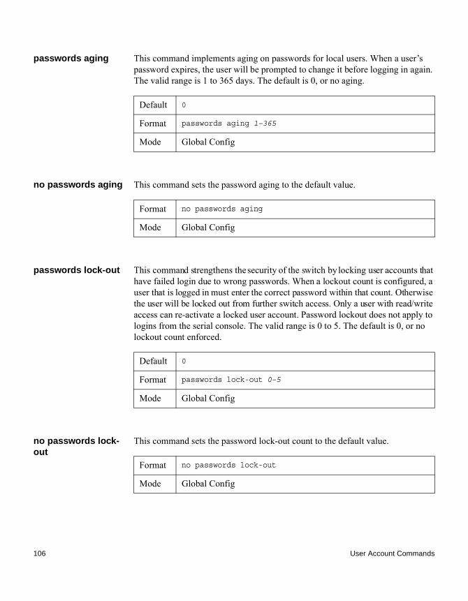
passwords aging This command implements aging on passwords for local users. When a user’s password expires, the user will be prompted to change it before logging in again. The valid range is 1 to 365 days. The default is 0, or no aging.
no passwords aging This command sets the password aging to the default value.
passwords lock-out This command strengthens the security of the switch by locking user accounts that have failed login due to wrong passwords. When a lockout count is configured, a user that is logged in must enter the correct password within that count. Otherwise the user will be locked out from further switch access. Only a user with read/write access can re-activate a locked user account. Password lockout does not apply to logins from the serial console. The valid range is 0 to 5. The default is 0, or no lockout count enforced.
no passwords lock-out
This command sets the password lock-out count to the default value.
Default 0
Format passwords aging 1–365
Mode Global Config
Format no passwords aging
Mode Global Config
Default 0
Format passwords lock-out 0–5
Mode Global Config
Format no passwords lock-out
Mode Global Config
106 User Account Commands

passwords strength-check
This command enables the password strength feature. It is used to verify the strength of a password during configuration.
no passwords strength-check
This command enables the password strength checking to the default value.
passwords strength minimum uppercase-letters
This command enforces a minimum number of uppercase letters that a password should contain. The valid range is 0 to 16. The default is 2; 0 means there is no restriction on that set of characters.
no passwords strength minimum uppercase-letters
This command resets the minimum number of uppercase letters required in a password to the default value.
Default disable
Format passwords strength-check
Mode Global Config
Format no passwords strength-check
Mode Global Config
Default 2
Format passwords strength minimum uppercase-letters 0-16
Mode Global Config
Format no passwords strength minimum uppercase-letters
Mode Global Config
Chapter 3: Management Commands 107
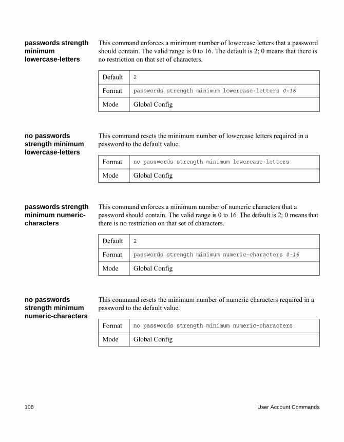
passwords strength minimum lowercase-letters
This command enforces a minimum number of lowercase letters that a password should contain. The valid range is 0 to 16. The default is 2; 0 means that there is no restriction on that set of characters.
no passwords strength minimum lowercase-letters
This command resets the minimum number of lowercase letters required in a password to the default value.
passwords strength minimum numeric-characters
This command enforces a minimum number of numeric characters that a password should contain. The valid range is 0 to 16. The default is 2; 0 means that there is no restriction on that set of characters.
no passwords strength minimum numeric-characters
This command resets the minimum number of numeric characters required in a password to the default value.
Default 2
Format passwords strength minimum lowercase-letters 0-16
Mode Global Config
Format no passwords strength minimum lowercase-letters
Mode Global Config
Default 2
Format passwords strength minimum numeric–characters 0-16
Mode Global Config
Format no passwords strength minimum numeric–characters
Mode Global Config
108 User Account Commands
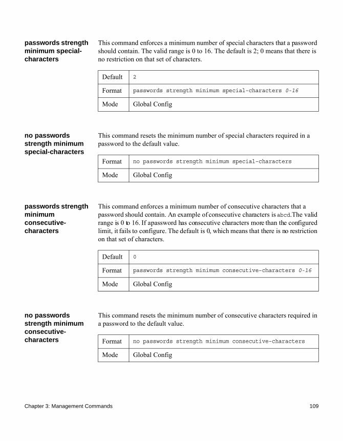
passwords strength minimum special-characters
This command enforces a minimum number of special characters that a password should contain. The valid range is 0 to 16. The default is 2; 0 means that there is no restriction on that set of characters.
no passwords strength minimum special-characters
This command resets the minimum number of special characters required in a password to the default value.
passwords strength minimum consecutive-characters
This command enforces a minimum number of consecutive characters that a password should contain. An example of consecutive characters is abcd.The valid range is 0 to 16. If a password has consecutive characters more than the configured limit, it fails to configure. The default is 0, which means that there is no restriction on that set of characters.
no passwords strength minimum consecutive-characters
This command resets the minimum number of consecutive characters required in a password to the default value.
Default 2
Format passwords strength minimum special–characters 0-16
Mode Global Config
Format no passwords strength minimum special–characters
Mode Global Config
Default 0
Format passwords strength minimum consecutive–characters 0-16
Mode Global Config
Format no passwords strength minimum consecutive–characters
Mode Global Config
Chapter 3: Management Commands 109

passwords strength minimum repeated-characters
This command enforces a minimum number of repeated characters that a password should contain. An example of repeated characters is aaaa.The valid range is 0 to 16. If a password has a repetition of characters more than the configured limit, it fails to configure. The default is 0, which means that there is no restriction on that set of characters.
no passwords strength minimum repeated-characters
This command resets the minimum number of repeated characters required in a password to the default value.
passwords strength minimum character-classes
This command enforces a minimum number of characters classes that a password should contain. Character classes are uppercase letters, lowercase letters, numeric characters and special characters. The valid range is 0 to 4. The default is 4.
no passwords strength minimum character-classes
This command resets the minimum number of characters classes required in a password to the default value.
Default 0
Format passwords strength minimum repeated–characters 0-16
Mode Global Config
Format no passwords strength minimum repeated–characters
Mode Global Config
Default 4
Format passwords strength minimum character–classes 0-4
Mode Global Config
Format no passwords strength minimum character–classes
Mode Global Config
110 User Account Commands

passwords strength exclude-keyword
This command excludes the specified keyword while configuring the password. The password does not accept the keyword in any form (in between the string, case-insensitive and reverse) as a substring. The user can configure up to a maximum of three keywords.
no passwords strength exclude-keyword
This command resets the restriction for the specified keyword or all the keywords configured.
user password This command allows the currently logged in user to change his or her password without having read/write privileges.
show passwords configuration
This command displays the configured password management settings.
Format passwords strength exclude–keyword keyword
Mode Global Config
Format no passwords strength exclude–keyword [keyword]
Mode Global Config
Format user name password pwd
Mode User EXEC
Format show passwords configuration
Mode Privileged EXEC
Output Description
Minimum Password Length
Minimum number of characters required when changing passwords.
Password History Number of passwords to store for reuse prevention.
Password Aging Length, in days, that a password is valid.
Chapter 3: Management Commands 111

show passwords result
This command displays the last password set result information.
Lockout Attempts Number of failed password login attempts before lockout.
Minimum Password Uppercase Letters
Minimum number of uppercase characters required when configuring passwords.
Minimum Password Lowercase Letters
Minimum number of lowercase characters required when configuring passwords.
Minimum Password Numeric Characters
Minimum number of numeric characters required when configuring passwords.
Maximum Password Consecutive Characters
Maximum number of consecutive characters required that the password should contain when configuring passwords.
Maximum Password Repeated Characters
Maximum number of repetition of characters that the password should contain when configuring passwords.
Minimum Password Character Classes
Minimum number of character classes (uppercase, lowercase, numeric, and special) required when configuring passwords.
Password Exclude-Keywords
The set of keywords to be excluded from the configured password when strength checking is enabled.
Output Description
Format show passwords result
Mode Privileged EXEC
Output Description
Last User Whose Password is Set
Shows the name of the user with the most recently set password.
112 User Account Commands

memory free low-watermark processor
This command configures the CPU Free Memory monitoring threshold. The valid range is 1 to 776966.
write memory This command saves running configuration changes to NVRAM so that the changes you make will persist across a reboot. This command is the same as copy system:running-config nvram:startup-config.
aaa ias-user username
The Internal Authentication Server (IAS) database is a dedicated internal database used for local authentication of users for network access through the IEEE 802.1X feature.
This command adds the specified user to the internal user database. This command also changes the mode to AAA User Config mode.
Password Strength Check
Shows whether password strength checking is enabled.
Last Password Set Result
Shows whether the attempt to set a password was successful. If the attempt failed, the reason for the failure is included.
Output Description
Format memory free low-watermark processor 1-776996
Mode Global Config
Format write memory
Mode Privileged EXEC
Format aaa ias-user username user
Mode Global Config
Chapter 3: Management Commands 113

no aaa ias-user username
This command removes the specified user from the internal user database.
password (AAA IAS User Configuration)
This command specifies a password for a user in the IAS database.
no password (AAA IAS User Configuration)
This command removes the password for the user.
clear aaa ias-users This command removes all users from the IAS database.
Format no aaa ias-user username user
Mode Global Config
Format password password [encrypted]
Mode AAA IAS User Config
Parameter Description
password Password for this level. The range is 8 to 64 characters in length.
encrypted Encrypted password to be entered or copied from another switch configuration.
Format no password password [encrypted]
Mode AAA IAS User Config
Format clear aaa ias-users
Mode Privileged EXEC
114 User Account Commands

show aaa ias-users This command displays configured IAS users and their attributes. Passwords configured are not shown in the show command output.
Format show aaa ias-users
Mode Privileged EXEC
Chapter 3: Management Commands 115

116 User Account Commands

Chapter 4: Utility Commands
4
Utility CommandsAbout this chapter This chapter describes the utility commands available in the CN1610 command line interface (CLI).
Topics in this chapter
This chapter includes the following sections:◆ “AutoInstall Commands” on page 118◆ “Cable Test Command” on page 122◆ “DNS Client Commands” on page 124◆ “Dual Image Commands” on page 130◆ “Email Alerting and Mail Server Commands” on page 132◆ “IP Address Conflict Commands” on page 140◆ “Logging Commands” on page 141◆ “Serviceability Packet Tracing Commands” on page 147◆ “sFlow Commands” on page 157◆ “Simple Network Time Protocol Commands” on page 163◆ “System Information and Statistics Commands” on page 170◆ “System Utility and Clear Commands” on page 194
CAUTIONThe commands in this chapter are in one of four functional groups:◆ Show commands display switch settings, statistics, and other information.◆ Configuration commands configure features and options of the switch. For
every configuration command, there is a show command that displays the configuration setting.
◆ Copy commands transfer or save configuration and informational files to and from the switch.
◆ Clear commands clear some or all of the settings to factory defaults.
117

AutoInstall Commands
Introduction The AutoInstall feature enables the automatic update of the image and configuration of the switch. This feature enables touchless or low-touch provisioning to simplify switch configuration and imaging.
AutoInstall includes the following support:◆ Downloading an image from a TFTP server using DHCP option 125. The
image update can result in a downgrade or upgrade of the firmware on the switch.
◆ Automatically downloading a configuration file from a TFTP server when the switch is booted with no saved configuration file.
◆ Automatically downloading an image from a TFTP server in the following situations:❖ When the switch is booted with no saved configuration found.❖ When the switch is booted with a saved configuration that has
AutoInstall enabled.
When the switch boots and no configuration file is found, it attempts to obtain an IP address from a network DHCP server. The response from the DHCP server includes the IP address of the TFTP server where the image and configuration flies are located.
After acquiring an IP address and the additional relevant information from the DHCP server, the switch downloads the image file or configuration file from the TFTP server. A downloaded image is automatically installed. A downloaded configuration file is saved to nonvolatile memory.
NoteAutoInstall from a TFTP server can run on any IP interface, including the network port, service port, and in-band routing interfaces (if supported). To support AutoInstall, the DHCP client is enabled operationally on the service port, if it exists, or the network port, if there is no service port.
boot autoinstall This command operationally starts or stops the AutoInstall process on the switch. The command is nonpersistent and is not saved in the startup or running configuration file.
118 AutoInstall Commands

boot host retrycount
This command sets the number of attempts to download a configuration file from the TFTP server. The valid range is 1 to 3 attempts. The default is 3.
no boot host retrycount
This command sets the number of attempts to download a configuration file to the default value.
boot host dhcp This command enables AutoInstall on the switch for the next reboot cycle. The command does not change the current behavior of AutoInstall and saves the command to NVRAM. The default is disabled.
no boot host dhcp This command disables AutoInstall for the next reboot cycle.
boot host autosave This command automatically saves the downloaded configuration file to the startup-config file on the switch. When autosave is disabled, you must explicitly save the downloaded configuration to nonvolatile memory by using the write
Default stopped
Format boot autoinstall {start | stop}
Mode Privileged EXEC
Default 3
Format boot host retrycount 1-3
Mode Privileged EXEC
Format no boot host retrycount
Mode Privileged EXEC
Default disabled
Format boot host dhcp
Mode Privileged EXEC
Format no boot host dhcp
Mode Privileged EXEC
Chapter 4: Utility Commands 119

memory or copy system:running-config nvram:startup-config command. If the switch reboots and the downloaded configuration has not been saved, the AutoInstall process begins, if the feature is enabled. The default value is disabled.
no boot host autosave
This command automatically disables saving the downloaded configuration on the switch.
boot host autoreboot
This command allows the switch to automatically reboot after successfully downloading an image. When auto reboot is enabled, no administrative action is required to activate the image and reload the switch. The default value is enabled.
no boot host autoreboot
This command prevents the switch from automatically rebooting after the image is downloaded by using the AutoInstall feature.
erase startup-config This command erases the text-based configuration file stored in nonvolatile memory. If the switch boots and no startup-config file is found, the AutoInstall process automatically begins.
Default disabled
Format boot host autosave
Mode Privileged EXEC
Format no boot host autosave
Mode Privileged EXEC
Default enabled
Format boot host autoreboot
Mode Privileged EXEC
Format no boot host autoreboot
Mode Privileged EXEC
Format erase startup-config
Mode Privileged EXEC
120 AutoInstall Commands

show autoinstall This command displays the current status of the AutoInstall process.
Example: The following example shows CLI display output for the command:(CN1610)#show autoinstall
AutoInstall Mode............................... StoppedAutoInstall Persistent Mode.................... DisabledAutoSave Mode.................................. DisabledAutoReboot Mode................................ EnabledAutoInstall Retry Count........................ 3
Format show autoinstall
Mode Privileged EXEC
Chapter 4: Utility Commands 121

Cable Test Command
Introduction The cable test feature enables you to determine the cable connection status on a selected port.
NoteThe cable test feature is supported only for copper cable. It is not supported for optical fiber cable and NetApp twinax cables.
cablestatus This command returns the status of the specified port.
NoteThe shipped configuration and supported molex cables are not supported by this command. For example:(NetApp CS)#cablestatus 0/9
Invalid cable type.Cable status can only be tested on a copper cable.
Format cablestatus slot/port
Mode Privileged EXEC
Output Description
Cable Status One of the following statuses is returned:◆ Normal: The cable is working correctly.◆ Open: The cable is disconnected or there is a
faulty connector.◆ Short: There is an electrical short in the cable.◆ Cable Test Failed: The cable status could not
be determined. The cable may in fact be working.
122 Cable Test Command

Cable Length If this feature is supported by the PHY for the current link speed, the cable length is displayed as a range between the shortest estimated length and the longest estimated length. Note that if the link is down and a cable is attached to a 10/100 Ethernet adapter, then the cable status may display as Open or Short because some Ethernet adapters leave unused wire pairs unterminated or grounded. Unknown is displayed if the cable length could not be determined.
Output Description
Chapter 4: Utility Commands 123

DNS Client Commands
Introduction These commands are used in the Domain Name System (DNS), an Internet directory service. DNS is how domain names are translated into IP addresses. When enabled, the DNS client provides a hostname lookup service to other components of FASTPATH.
ip domain lookup This command enables the DNS client.
no ip domain lookup
This command disables the DNS client.
ip domain name This command defines a default domain name that FASTPATH software uses to complete unqualified host names (names with a domain name). By default, no default domain name is configured in the system. name may not be longer than 255 characters and should not include an initial period. This name should be used only when the default domain name list, configured using the ip domain list command,is empty.
Default enabled
Format ip domain lookup
Mode Global Config
Format no ip domain lookup
Mode Global Config
Default none
Format ip domain name name
Mode Global Config
124 DNS Client Commands

Example: The CLI command ip domain name yahoo.com will configure yahoo.com as a default domain name. For an unqualified hostname xxx, a DNS query is made to find the IP address corresponding to xxx.yahoo.com.
no ip domain name This command removes the default domain name configured using the ip domain name command.
ip domain list This command defines a list of default domain names to complete unqualified names. By default, the list is empty. Each name must be no more than 256 characters, and should not include an initial period. The default domain name, configured using the ip domain name command, is used only when the default domain name list is empty. A maximum of 32 names can be entered in to this list.
no ip domain list This command deletes a name from a list.
ip name server This command configures the available name servers. Up to eight servers can be defined in one command or by using multiple commands. The parameter server address is a valid IPv4 or IPv6 address of the server. The preference of the servers is determined by the order they were entered.
Format no ip domain name
Mode Global Config
Default none
Format ip domain list name
Mode Global Config
Format no ip domain list name
Mode Global Config
Format ip name server address1 address2
Mode Global Config
Chapter 4: Utility Commands 125

no ip name server This command removes a name server.
ip host This command defines static host name-to-address mapping in the host cache. The parameter name is the host name and ipaddress is the IP address of the host. The host name can include from 1 to 158 alphanumeric characters, periods, hyphens, underscores, and nonconsecutive spaces. Host names that include one or more spaces must be enclosed in quotation marks, for example “lab-pc 45”.
no ip host This command removes the name-to-address mapping.
ipv6 host This command defines static host name-to-IPv6 address mapping in the host cache. The parameter name is host name and v6 address is the IPv6 address of the host. The host name can include 1 to 158 alphanumeric characters, periods, hyphens, and spaces. Host names that include one or more space must be enclosed in quotation marks, for example “lab-pc 45”.
Format no ip name server address1 address2
Mode Global Config
Default none
Format ip host name ipaddress
Mode Global Config
Format no ip host name
Mode Global Config
Default none
Format ipv6 host name v6 address
Mode Global Config
126 DNS Client Commands

no ipv6 host This command removes the static host name-to-ipv6 address mapping in the host cache.
ip domain retry This command specifies the number of times to retry sending Domain Name System (DNS) queries. The parameter number indicates the number of times to retry sending a DNS query to the DNS server. This number ranges from 0 to 100.
no ip domain retry This command returns to the default.
ip domain timeout This command specifies the amount of time to wait for a response to a DNS query. The parameter seconds specifies the time, in seconds, to wait for a response to a DNS query. The parameter seconds ranges from 0 to 3600. The default is 3 seconds.
no ip domain timeout
This command returns to the default setting.
Format no ipv6 host name
Mode Global Config
Default 2
Format ip domain retry number
Mode Global Config
Format no ip domain retry number
Mode Global Config
Default 3
Format ip domain timeout seconds
Mode Global Config
Format no ip domain timeout seconds
Chapter 4: Utility Commands 127

clear host This command deletes entries from the host name-to-address cache. This command clears the entries from the DNS cache maintained by the software. This command clears both IPv4 and IPv6 entries.
show hosts This command displays the default domain name, a list of name server hosts, the static and the cached list of host names and addresses. The parameter name ranges from 1 to 255 characters. This command displays both IPv4 and IPv6 entries.
Mode Global Config
Format clear host {name | all}
Mode Privileged EXEC
Parameter Description
name A particular host entry to remove. The parameter name ranges from 1 to 255 characters.
all Removes all entries.
Format show hosts [name]
Mode User EXEC
Output Description
Host name Domain host name.
Default domain
Default domain name.
Default domain list
Default domain list.
Domain name lookup
DNS client enabled/disabled.
128 DNS Client Commands
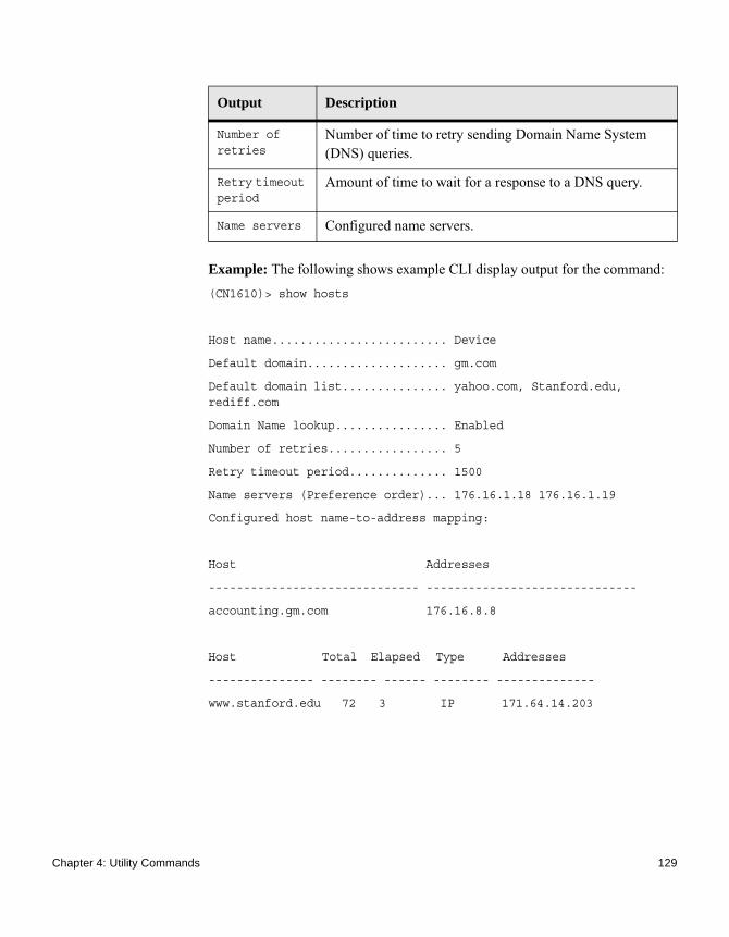
Example: The following shows example CLI display output for the command:(CN1610)> show hosts
Host name......................... Device
Default domain.................... gm.com
Default domain list............... yahoo.com, Stanford.edu, rediff.com
Domain Name lookup................ Enabled
Number of retries................. 5
Retry timeout period.............. 1500
Name servers (Preference order)... 176.16.1.18 176.16.1.19
Configured host name-to-address mapping:
Host Addresses
------------------------------ ------------------------------
accounting.gm.com 176.16.8.8
Host Total Elapsed Type Addresses
--------------- -------- ------ -------- --------------
www.stanford.edu 72 3 IP 171.64.14.203
Number of retries
Number of time to retry sending Domain Name System (DNS) queries.
Retry timeout period
Amount of time to wait for a response to a DNS query.
Name servers Configured name servers.
Output Description
Chapter 4: Utility Commands 129

Dual Image Commands
Introduction FASTPATH software supports a dual image feature that allows the switch to have two software images in the permanent storage. You can specify which image is the active image to be loaded in subsequent reboots. This feature allows reduced downtime when you upgrade or downgrade the software.
delete backup This command deletes the backup image file from the permanent storage.
boot system This command activates the specified image. It will be the active image for subsequent reboots and will be loaded by the boot loader. The current active image is marked as the backup image for subsequent reboots. If the specified image does not exist on the system, this command returns an error message.
show bootvar This command displays the version information and the activation status for the current active and backup images. The command also displays any text description associated with an image. This command displays the switch activation status.
filedescr This command associates a given text description with an image. Any existing description will be replaced.
Format delete backup
Mode Privileged EXEC
Format boot system {active | backup}
Mode Privileged EXEC
Format show bootvar
Mode Privileged EXEC
130 Dual Image Commands

update bootcode This command updates the bootcode (boot loader) on the switch. The bootcode is read from the active image for subsequent reboots.
Format filedescr {active | backup} text-description
Mode Privileged EXEC
Format update bootcode
Mode Privileged EXEC
Chapter 4: Utility Commands 131

Email Alerting and Mail Server Commands
Introduction Email Alerting is an extension of the logging system. The logging system allows you to configure a set of destinations for log messages. The feature includes email configuration, through which the log messages are sent to a configured SMTP server such that an administrator may receive the log in an email account of the administrator’s choice.
logging email This command enables email alerting and sets the lowest severity level for which log messages are emailed. If you specify a severity level, log messages at or above this severity level, but below the urgent severity level, are emailed in a non-urgent manner by collecting them together until the log time expires. You can specify the severitylevel value as either an integer from 0 to 7 or symbolically through one of the following keywords: emergency (0), alert (1), critical (2), error (3), warning (4), notice (5), info (6), or debug (7).
no logging email This command disables email alerting.
logging email urgent
This command sets the lowest severity level at which log messages are emailed immediately in a single email message. Specify the severitylevel value as either an integer from 0 to 7 or symbolically through one of the following keywords: emergency (0), alert (1), critical (2), error (3), warning (4), notice (5), info (6), or debug (7). Specify none to indicate that log messages are collected and sent in a batch email at a specified interval.
Default disabled; when enabled, log messages at or above severity warning (4) are emailed
Format logging email [severitylevel]
Mode Global Config
Format no logging email
Mode Global Config
132 Email Alerting and Mail Server Commands

no logging email urgent
This command resets the urgent severity level to the default value.
logging email message-type to-addr
This command configures the email address to which messages are sent. The message types supported are urgent, non-urgent, and both. For each supported severity level, multiple email addresses can be configured. The to-email-addr variable is a standard email address, for example [email protected]. No dashes or dots can be included in the hostname in the e-mail addresses.
no logging email message-type to-addr
This command removes the configured to-addr field of email.
logging email from-addr
This command configures the email address of the sender (the switch). No dashes or dots can be included in the hostname in the e-mail addresses.
Default Alert (1) and emergency (0) messages are sent immediately.
Format logging email urgent {severitylevel | none}
Mode Global Config
Format no logging email urgent
Mode Global Config
Format logging email message-type {urgent |non-urgent |both} to-addr to-email-addr
Mode Global Config
Format no logging email message-type {urgent |non-urgent |both} to-addr to-email-addr
Mode Global Config
Default [email protected]
Format logging email from-addr from-email-addr
Chapter 4: Utility Commands 133

no logging email from-addr
This command removes the configured email source address.
logging email message-type subject
This command configures the subject line of the email for the specified type.
no logging email message-type subject
This command removes the configured email subject for the specified message type and restores it to the default email subject.
logging email logtime
This command configures how frequently non-urgent email messages are sent. Non-urgent messages are collected and sent in a batch email at the specified interval. The valid range is every 30 to 1440 minutes.
Mode Global Config
Format no logging email from-addr from-email-addr
Mode Global Config
Default For urgent messages: Urgent Log Messages
For non-urgent messages: Non Urgent Log Messages
Format logging email message-type {urgent |non-urgent |both} subject subject
Mode Global Config
Format no logging email message-type {urgent |non-urgent |both} subject
Mode Global Config
Default 30 minutes
Format logging email logtime minutes
Mode Global Config
134 Email Alerting and Mail Server Commands

no logging email logtime
This command resets the non-urgent log time to the default value.
logging traps This command sets the severity at which SNMP traps are logged and sent in an email. Specify the severitylevel value as either an integer from 0 to 7 or symbolically through one of the following keywords: emergency (0), alert (1), critical (2), error (3), warning (4), notice (5), info (6), or debug (7).
no logging traps This command resets the SNMP trap logging severity level to the default value.
logging email test message-type
This command sends an email to the SMTP server to test the email alerting function.
show logging email config
This command displays information about the email alert configuration.
Format no logging email logtime
Mode Global Config
Default Info (6) messages and higher are logged.
Format logging traps severitylevel
Mode Global Config
Format no logging traps
Mode Global Config
Format logging email test message-type {urgent |non-urgent |both} message-body message-body
Mode Global Config
Format show logging email config
Mode Global Config
Chapter 4: Utility Commands 135

show logging email statistics
This command displays email alerting statistics.
Output Description
Email Alert Logging
The administrative status of the feature: enabled or disabled.
Email Alert From Address
The email address of the sender (the switch).
Email Alert Urgent Severity Level
The lowest severity level that is considered urgent. Messages of this type are sent immediately.
Email Alert Non Urgent Severity Level
The lowest severity level that is considered non-urgent. Messages of this type, up to the urgent level, are collected and sent in a batch email. Log messages that are less severe are not sent in an email message at all.
Email Alert Trap Severity Level
The lowest severity level at which traps are logged.
Email Alert Notification Period
The amount of time to wait between non-urgent messages.
Email Alert To Address Table
The configured email recipients.
Email Alert Subject Table
The subject lines included in urgent (Type 1) and non-urgent (Type 2) messages.
For Msg Type urgent, subject is
The configured email subject for sending urgent messages.
For Msg Type non-urgent, subject is
The configured email subject for sending non-urgent messages.
Format show logging email statistics
Mode Privileged EXEC
136 Email Alerting and Mail Server Commands

clear logging email statistics
This command resets the email alerting statistics.
mail-server This command configures the SMTP server to which the switch sends email alert messages and changes the mode to Mail Server Configuration mode. The server address can be in the IPv4, IPv6, or DNS name format.
no mail-server This command removes the specified SMTP server from the configuration.
Output Description
Email Alert Operation Status
The operational status of the email alerting feature.
No of Email Failures
The number of email messages that have attempted to be sent but were unsuccessful.
No of Email Sent The number of email messages that were sent from the switch since the counter was cleared.
Time Since Last Email Sent
The amount of time that has passed since the last email was sent from the switch.
Format clear logging email statistics
Mode Privileged EXEC
Format mail-server {ip-address | ipv6-address | hostname}
Mode Privileged EXEC
Format no mail-server {ip-address | ipv6-address | hostname}
Mode Privileged EXEC
Chapter 4: Utility Commands 137

security This command sets the email alerting security protocol by enabling the switch to use TLS authentication with the SMTP Server. If the TLS mode is enabled on the switch but the SMTP sever does not support TLS mode, no email is sent to the SMTP server.
port This command configures the TCP port to use for communication with the SMTP server. The recommended port for TLSv1 is 465, and for no security (that is, none) it is 25. However, any nonstandard port in the range 1 to 65535 is also allowed.
username This command configures the login ID the switch uses to authenticate with the SMTP server.
password This command configures the password the switch uses to authenticate with the SMTP server.
Default none
Format security {tlsv1 | none}
Mode Mail Server Config
Default 25
Format port {465 | 25 | 1–65535}
Mode Mail Server Config
Default admin
Format username name
Mode Mail Server Config
Default admin
Format password password
Mode Mail Server Config
138 Email Alerting and Mail Server Commands

show mail-server config
This command displays information about the email alert configuration.
Format show mail-server {ip-address | hostname | all} config
Mode Privileged EXEC
Output Description
No. of mail servers configured
The number of SMTP servers configured on the switch.
Email Alert Mail Server Address
The IPv4/IPv6 address or DNS host name of the configured SMTP server.
Email Alert Mail Server Port
The TCP port the switch uses to send email to the SMTP server
Email Alert Security Protocol
The security protocol (TLS or none) the switch uses to authenticate with the SMTP server.
Email Alert Username
The username the switch uses to authenticate with the SMTP server.
Email Alert Password
The password the switch uses to authenticate with the SMTP server.
Chapter 4: Utility Commands 139
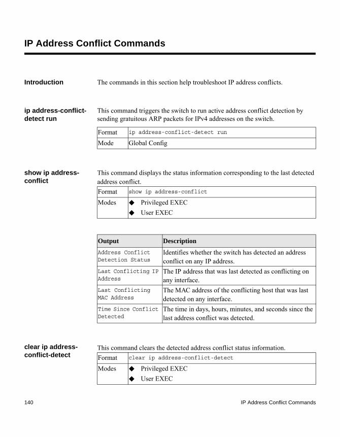
IP Address Conflict Commands
Introduction The commands in this section help troubleshoot IP address conflicts.
ip address-conflict-detect run
This command triggers the switch to run active address conflict detection by sending gratuitous ARP packets for IPv4 addresses on the switch.
show ip address-conflict
This command displays the status information corresponding to the last detected address conflict.
clear ip address-conflict-detect
This command clears the detected address conflict status information.
Format ip address-conflict-detect run
Mode Global Config
Format show ip address-conflict
Modes ◆ Privileged EXEC◆ User EXEC
Output Description
Address Conflict Detection Status
Identifies whether the switch has detected an address conflict on any IP address.
Last Conflicting IP Address
The IP address that was last detected as conflicting on any interface.
Last Conflicting MAC Address
The MAC address of the conflicting host that was last detected on any interface.
Time Since Conflict Detected
The time in days, hours, minutes, and seconds since the last address conflict was detected.
Format clear ip address-conflict-detect
Modes ◆ Privileged EXEC◆ User EXEC
140 IP Address Conflict Commands

Logging Commands
Introduction This section describes the commands you use to configure system logging, and to view logs and the logging settings.
logging buffered This command enables logging to an in-memory log that keeps up to 128 logs.
no logging buffered This command disables logging to an in-memory log.
logging buffered wrap
This command enables wrapping of in-memory logging when the log file reaches full capacity. Otherwise, when the log file reaches full capacity, logging stops.
no logging buffered wrap
This command disables wrapping of in-memory logging and configures logging to stop when the log file capacity is full.
Default disabled; critical when enabled
Format logging buffered
Mode Global Config
Format no logging buffered
Mode Global Config
Default enabled
Format logging buffered wrap
Mode Privileged EXEC
Format no logging buffered wrap
Mode Privileged EXEC
Chapter 4: Utility Commands 141

logging cli-command
This command enables the CLI command logging feature, which enables the FASTPATH software to log all CLI commands entered on the system.
no logging cli-command
This command disables the CLI command logging feature.
logging console This command enables logging to the console. You can specify the severitylevel value as either an integer from 0 to 7 or symbolically through one of the following keywords: emergency (0), alert (1), critical (2), error (3), warning (4), notice (5), info (6), or debug (7).
no logging console This command disables logging to the console.
logging host This command enables logging to a host. You can configure up to eight hosts. The ipaddr|hostname is the IP address of the logging host. The addresstype indicates the type of address ipv4 or ipv6 or DNS being passed. The port value is a port number from 1 to 65535. You can specify the severitylevel value as
Default enabled
Format logging cli-command
Mode Global Config
Format no logging cli-command
Mode Global Config
Default disabled; critical when enabled
Format logging console [severitylevel]
Mode Global Config
Format no logging console
Mode Global Config
142 Logging Commands

either an integer from 0 to 7 or symbolically through one of the following keywords: emergency (0), alert (1), critical (2), error (3), warning (4), notice (5), info (6), or debug (7).
logging host reconfigure
This command enables logging host reconfiguration. The hostindex is the Logging Host index for which to change the IP address.
logging host remove
This command disables logging to host. See “show logging hosts” on page 145 for a list of host indexes.
logging port This command sets the local port number of the LOG client for logging messages. The portid can be in the range from 1 to 65535. The default is 514.
no logging port This command resets the local logging port to the default.
Default ◆ port: 514
◆ severitylevel: critical (2)
Format logging host {ipaddr|hostname} addresstype [port][severitylevel]
Mode Global Config
Format logging host reconfigure hostindex
Mode Global Config
Format logging host remove hostindex
Mode Global Config
Default 514
Format logging port portid
Mode Global Config
Chapter 4: Utility Commands 143

logging syslog This command enables syslog logging. The portid parameter is an integer with a range of 1 to 65535.
no logging syslog This command disables syslog logging.
show logging This command displays logging configuration information.
Format no logging port
Mode Global Config
Default disabled
Format logging syslog [port portid]
Mode Global Config
Format no logging syslog
Mode Global Config
Format show logging
Mode Privileged EXEC
Output Description
Logging Client Local Port
Port on the collector/relay to which syslog messages are sent.
CLI Command Logging
Shows whether CLI command logging is enabled.
Console Logging
Shows whether console logging is enabled.
144 Logging Commands

show logging buffered
This command displays buffered logging (system startup and system operation logs).
show logging hosts This command displays all configured logging hosts.
Console Logging Severity Filter
The minimum severity to log to the console log. Messages with an equal or lower numerical severity are logged.
Buffered Logging
Shows whether buffered logging is enabled.
Syslog Logging
Shows whether syslog logging is enabled.
Log Messages Received
Number of messages received by the log process. This includes messages that are dropped or ignored.
Log Messages Dropped
Number of messages that could not be processed due to error or lack of resources.
Log Messages Relayed
Number of messages sent to the collector/relay.
Output Description
Format show logging buffered
Mode Privileged EXEC
Output Description
Buffered (In-Memory) Logging
Shows whether the In-Memory log is enabled or disabled.
Buffered Logging Wrapping Behavior
The behavior of the In-Memory log when faced with a log full situation.
Buffered Log Count The count of valid entries in the buffered log.
Chapter 4: Utility Commands 145

show logging traplogs
This command displays SNMP trap events and statistics.
Format show logging hosts
Mode Privileged EXEC
Output Description
Host Index (Used for deleting hosts.)
IP Address / Hostname
IP address or hostname of the logging host.
Severity Level The minimum severity to log to the specified address. The possible values are emergency (0), alert (1), critical (2), error (3), warning (4), notice (5), info (6), or debug (7).
Port The server port number, which is the port on the local host from which syslog messages are sent.
Host Status The state of logging to configured syslog hosts. If the status is disable, no logging occurs.
Output Description
Number of Traps Since Last Reset
The number of traps since the last boot.
Trap Log Capacity The number of traps the system can retain.
Number of Traps Since Log Last Viewed
The number of new traps since the command was last executed.
Log The log number.
System Time Up How long the system had been running at the time the trap was sent.
Trap The text of the trap message.
146 Logging Commands

Serviceability Packet Tracing Commands
Introduction These commands improve the capability of diagnosing conditions affecting FASTPATH.
AttentionThe output of debug commands can be long and may adversely affect system performance.
debug clear This command disables all previously enabled “debug” traces.
debug console This command enables the display of “debug” trace output on the login session in which it is executed. Debug console display must be enabled in order to view any trace output. The output of debug trace commands will appear on all login sessions for which debug console has been enabled. The configuration of this command remains in effect for the life of the login session. The effect of this command is not persistent across resets.
no debug console This command disables the display of “debug” trace output on the login session in which it is executed.
Default disabled
Format debug clear
Mode Privileged EXEC
Default disabled
Format debug console
Mode Privileged EXEC
Format no debug console
Mode Privileged EXEC
Chapter 4: Utility Commands 147

debug dhcp packet This command displays “debug” information about DHCPv4 client activities and traces DHCPv4 packets to and from the local DHCPv4 client.
no debug dhcp packet
This command disables the display of “debug” trace output for DHCPv4 client activity.
debug dot1x packet This command enables dot1x packet debug trace on the transmit or receive path.
no debug dot1x packet
This command disables dot1x packet debug trace.
debug igmpsnooping packet
This command enables tracing of IGMP Snooping packets received and transmitted by the switch.
Default disabled
Format debug dhcp packet [transmit | receive]
Mode Privileged EXEC
Format no debug dhcp packet [transmit | receive]
Mode Privileged EXEC
Default disabled
Format debug dot1x packet [transmit|receive]
Mode Privileged EXEC
Format no debug dot1x packet
Mode Privileged EXEC
Default disabled
Format debug igmpsnooping packet
148 Serviceability Packet Tracing Commands

no debug igmpsnooping packet
This command disables tracing of IGMP Snooping packets.
debug igmpsnooping packet transmit
This command enables tracing of IGMP Snooping packets transmitted by the switch. Snooping should be enabled on the device and the interface in order to monitor packets for a particular interface.
A sample output of the trace message is shown in this example:<15> JAN 01 02:45:06 192.168.17.29-1 IGMPSNOOP[185429992]: igmp_snooping_debug.c(116) 908 % Pkt TX - Intf: 1/0/20(20), Vlan_Id:1 Src_Mac: 00:03:0e:00:00:00 Dest_Mac: 01:00:5e:00:00:01 Src_IP: 9.1.1.1 Dest_IP: 225.0.0.1 Type: V2_Membership_Report Group: 225.0.0.1
The following parameters are displayed in the trace message:
Mode Privileged EXEC
Format no debug igmpsnooping packet
Mode Privileged EXEC
Default disabled
Format debug igmpsnooping packet transmit
Mode Privileged EXEC
Output Description
TX A packet transmitted by the device.
Intf The interface that the packet went out on. The format used is slot/port (internal interface number). The unit is always shown as 1 for interfaces on a nonstacking device.
Src_Mac Source MAC address of the packet.
Dest_Mac Destination multicast MAC address of the packet.
Src_IP The source IP address in the IP header in the packet.
Chapter 4: Utility Commands 149

no debug igmpsnooping transmit
This command disables tracing of transmitted IGMP snooping packets.
debug igmpsnooping packet receive
This command enables tracing of IGMP Snooping packets received by the switch. Snooping should be enabled on the device and the interface in order to monitor packets for a particular interface.
A sample output of the trace message is shown in this example:<15> JAN 01 02:45:06 192.168.17.29-1 IGMPSNOOP[185429992]: igmp_snooping_debug.c(116) 908 % Pkt RX - Intf: 1/0/20(20), Vlan_Id:1 Src_Mac: 00:03:0e:00:00:10 Dest_Mac: 01:00:5e:00:00:05
Dest_IP The destination multicast IP address in the packet.
Type The type of IGMP packet. Type can be one of the following:◆ Membership Query – IGMP Membership
Query◆ V1_Membership_Report – IGMP Version
1 Membership Report◆ V2_Membership_Report – IGMP Version
2 Membership Report◆ V3_Membership_Report – IGMP Version
3 Membership Report◆ V2_Leave_Group – IGMP Version 2 Leave
Group
Group Multicast group address in the IGMP header.
Output Description
Format no debug igmpsnooping transmit
Mode Privileged EXEC
Default disabled
Format debug igmpsnooping packet receive
Mode Privileged EXEC
150 Serviceability Packet Tracing Commands

Src_IP: 11.1.1.1 Dest_IP: 225.0.0.5 Type: Membership_Query Group: 225.0.0.5
The following parameters are displayed in the trace message:
no debug igmpsnooping packet receive
This command disables tracing of received IGMP Snooping packets.
Output Description
RX A packet received by the device.
Intf The interface that the packet went out on. The format used is slot/port (internal interface number). The unit is always shown as 1 for interfaces on a nonstacking device.
Src_Mac Source MAC address of the packet.
Dest_Mac Destination multicast MAC address of the packet.
Src_IP The source IP address in the IP header in the packet.
Dest_IP The destination multicast IP address in the packet.
Type The type of IGMP packet. Type can be one of the following:◆ Membership Query – IGMP Membership
Query◆ V1_Membership_Report – IGMP Version
1 Membership Report◆ V2_Membership_Report – IGMP Version
2 Membership Report◆ V3_Membership_Report – IGMP Version
3 Membership Report◆ V2_Leave_Group – IGMP Version 2 Leave
Group
Group Multicast group address in the IGMP header.
Format no debug igmpsnooping packet receive
Mode Privileged EXEC
Chapter 4: Utility Commands 151

debug ping packet This command enables tracing of ICMP echo requests and responses. The command traces pings on the network port/ serviceport for switching packages. For routing packages, pings are traced on the routing ports as well.
A sample output of the trace message is shown in the following example:<15> JAN 01 00:21:22 192.168.17.29-1 SIM[181040176]: sim_debug.c(128) 20 % Pkt TX - Intf: 1/0/1(1),SRC_IP:10.50.50.2, DEST_IP:10.50.50.1, Type:ECHO_REQUEST
<15> JAN 01 00:21:22 192.168.17.29-1 SIM[182813968]: sim_debug.c(82) 21 % Pkt RX - Intf: 1/0/1(1), SRC_IP:10.50.50.1, DEST_IP:10.50.50.2, Type:ECHO_REPLY
The following parameters are displayed in the trace message:
no debug ping packet
This command disables tracing of ICMP echo requests and responses.
Default disabled
Format debug ping packet
Mode Privileged EXEC
Output Description
TX/RX TX refers to a packet transmitted by the device. RX refers to packets received by the device.
Intf The interface that the packet came in or went out on. The format used is slot/port (internal interface number). Unit is always shown as 1 for interfaces on a nonstacking device.
SRC_IP The source IP address in the IP header in the packet.
DEST_IP The destination IP address in the IP header in the packet.
Type Type determines whether or not the ICMP message is a REQUEST or a RESPONSE.
Format no debug ping packet
152 Serviceability Packet Tracing Commands

debug sflow packet This command enables sFlow debug packet trace.
no debug sflow packet
This command disables sFlow debug packet trace.
debug spanning-tree bpdu
This command enables tracing of spanning tree BPDUs received and transmitted by the switch.
no debug spanning-tree bpdu
This command disables tracing of spanning tree BPDUs.
debug spanning-tree bpdu receive
This command enables tracing of spanning tree BPDUs received by the switch. The spanning tree should be enabled on the device and on the interface in order to monitor packets for a particular interface.
Mode Privileged EXEC
Default disabled
Format debug sflow packet
Mode Privileged EXEC
Format no debug sflow packet
Mode Privileged EXEC
Default disabled
Format debug spanning-tree bpdu [receive|transmit]
Mode Privileged EXEC
Format no debug spanning-tree bpdu
Mode Privileged EXEC
Chapter 4: Utility Commands 153

A sample output of the trace message is shown in the following example:<15> JAN 01 01:02:04 192.168.17.29-1 DOT1S[191096896]: dot1s_debug.c(1249) 101 % Pkt RX - Intf: 1/0/9(9), Source_Mac: 00:11:88:4e:c2:10 Version: 3, Root Mac: 00:11:88:4e:c2:00, Root Priority: 0x8000 Path Cost: 0
The following parameters are displayed in the trace message:
no debug spanning-tree bpdu receive
This command disables tracing of received spanning tree BPDUs.
Default disabled
Format debug spanning-tree bpdu receive
Mode Privileged EXEC
Output Description
RX A packet received by the device.
Intf The interface that the packet came in on. The format used is slot/port (internal interface number). The unit is always shown as 1 for interfaces on a nonstacking device.
Source_MAC The Source MAC address of the packet.
Version Spanning tree protocol version (0-3). 0 refers to STP, 2 RSTP and 3 MSTP.
Root Mac MAC address of the CIST root bridge.
Root Priority Priority of the CIST root bridge. The value is between 0 and 61440. It is displayed in hex in multiples of 4096.
Path Cost External root path cost component of the BPDU.
Format no debug spanning-tree bpdu receive
Mode Privileged EXEC
154 Serviceability Packet Tracing Commands

debug spanning-tree bpdu transmit
This command enables tracing of spanning tree BPDUs transmitted by the switch. The spanning tree should be enabled on the device and on the interface in order to monitor packets on a particular interface.
A sample output of the trace message is shown in the following example:<15> JAN 01 01:02:04 192.168.17.29-1 DOT1S[191096896]: dot1s_debug.c(1249) 101 % Pkt TX - Intf: 1/0/7(7), Source_Mac: 00:11:88:4e:c2:00 Version: 3, Root_Mac: 00:11:88:4e:c2:00, Root_Priority: 0x8000 Path_Cost: 0
The following parameters are displayed in the trace message:
no debug spanning-tree bpdu transmit
This command disables tracing of transmitted spanning tree BPDUs.
Default enabled
Format debug spanning-tree bpdu transmit
Mode Privileged EXEC
Output Description
TX A packet transmitted by the device.
Intf The interface that the packet went out on. The format used is slot/port (internal interface number). The unit is always shown as 1 for interfaces on a nonstacking device.
Source_MAC The Source MAC address of the packet.
Version The spanning tree protocol version (0 to 3). 0 refers to STP, 2 RSTP and 3 MSTP.
Root_Mac MAC address of the CIST root bridge.
Root_Priority Priority of the CIST root bridge. The value is between 0 and 61440. It is displayed in hex in multiples of 4096.
Path_Cost External root path cost component of the BPDU.
Format no debug spanning-tree bpdu transmit
Chapter 4: Utility Commands 155

logging persistent This command configures the persistent logging for the switch. The severity level of logging messages is specified at severity level. Possible values for severity level are emergency|0, alert|1, critical|2, error|3, warning|4, notice|5, info|6, debug|7.
no logging persistent
This command disables the persistent logging in the switch.
show debugging Use this command to display enabled packet tracing configurations.
Example: The following shows example CLI display output for the command:(CN1610)#debug arpArp packet tracing enabled.
(CN1610)# show debuggingArp packet tracing enabled.
no show debugging Use this command to disable packet tracing configurations.
Mode Privileged EXEC
Default disabled
Format logging persistent severity level
Mode Global Config
Format no logging persistent
Mode Global Config
Format show debugging
Mode Privileged EXEC
Format no show debugging
Mode Privileged EXEC
156 Serviceability Packet Tracing Commands

sFlow Commands
Introduction sFlow® is the standard for monitoring high-speed switched and routed networks. sFlow technology is built into network equipment and gives complete visibility into network activity, enabling effective management and control of network resources.
sflow receiver This command configures the sFlow collector parameters (owner string, receiver timeout, max datagram size, IP address, and port).
Format sflow receiver rcvr_idx owner owner-string timeout
rcvr_timeout max datagram size ip/ipv6 ip port port
Mode Global Config
Output Description
Receiver Owner
The identity string for the receiver, the entity making use of this sFlowRcvrTable entry. The range is 127 characters. The default is a null string. The empty string indicates that the entry is currently unclaimed and the receiver configuration is reset to the default values. An entity wishing to claim an sFlowRcvrTable entry must ensure that the entry is unclaimed before trying to claim it. The entry is claimed by setting the owner string to a non-null value. The entry must be claimed before assigning a receiver to a sampler or poller.
Receiver Timeout
The time, in seconds, remaining before the sampler or poller is released and stops sending samples to receiver. A management entity wanting to maintain control of the sampler is responsible for setting a new value before the old one expires. The allowed range is 0 to 4294967295 seconds. The default is zero (0).
Receiver Max Datagram Size
The maximum number of data bytes that can be sent in a single sample datagram. The management entity should set this value to avoid fragmentation of the sFlow datagrams. The allowed range is 200 to 9116). The default is 1400.
Receiver IP The sFlow receiver IP address. If set to 0.0.0.0, no sFlow datagrams will be sent. The default is 0.0.0.0.
Chapter 4: Utility Commands 157

no sflow receiver This command sets the sFlow collector parameters back to the defaults.
sflow sampler A data source configured to collect flow samples is called a poller. This command configures a new sFlow sampler instance on an interface or range of interfaces for this data source if rcvr_idx is valid.
Receiver Port
The destination Layer4 UDP port for sFlow datagrams. The range is 1 to 65535. The default is 6343.
Output Description
Format no sflow receiver indx {ip ip-address | maxdatagram size | owner string timeout interval | port 14-port}
Mode Global Config
Format sflow sampler {rcvr-indx | rate sampling-rate | maxheadersize size}
Mode Interface Config
Output Description
Receiver Index
The sFlow Receiver for this sFlow sampler to which flow samples are to be sent. A value of zero (0) means that no receiver is configured, no packets will be sampled. Only active receivers can be set. If a receiver expires, then all samplers associated with the receiver will also expire. Possible values are 1 through 8. The default is 0.
Maxheadersize The maximum number of bytes that should be copied from the sampler packet. The range is 20 to 256. The default is 128. When set to zero (0), all the sampler parameters are set to their corresponding default value.
Sampling Rate The statistical sampling rate for packet sampling from this source. A sampling rate of 1 counts all packets. A value of zero (0) disables sampling. A value of N means that out of N incoming packets, 1 packet will be sampled. The range is 1024 to 65536 and 0. The default is 0.
158 sFlow Commands

no sflow sampler This command resets the sFlow sampler instance to the default settings.
sflow poller A data source configured to collect counter samples is called a poller. This command enables a new sFlow poller instance on an interface or range of interfaces for this data source if rcvr_idx is valid.
no sflow poller This command resets the sFlow poller instance to the default settings.
show sflow agent The sFlow agent collects time-based sampling of network interface statistics and flow-based samples. These are sent to the configured sFlow receivers. This command displays the sFlow agent information.
Format no sflow sampler {rcvr-indx | rate sampling-rate | maxheadersize size}
Mode Interface Config
Format sflow poller {rcvr-indx | interval poll-interval}
Mode Interface Config
Output Description
Receiver Index
Enter the sFlow Receiver associated with the sampler/poller. A value of zero (0) means that no receiver is configured. The range is 1 to 8. The default is 0.
Poll Interval
Enter the sFlow instance polling interval. A poll interval of zero (0) disables counter sampling. When set to zero (0), all the poller parameters are set to their corresponding default value. The range is 0 to 86400. The default is 0. A value of N means once in N seconds a counter sample is generated.
Format no sflow poller {rcvr-indx | interval poll-interval}
Mode Interface Config
Format show sflow agent
Mode Privileged EXEC
Chapter 4: Utility Commands 159

Example: The following shows example CLI display output for the command:(CN1610)#show sflow agent
sFlow Version.................................. 1.3;NetApp Corp;1.0IP Address..................................... 10.131.12.66
show sflow pollers This command displays the sFlow polling instances created on the switch. To indicate a range, use a hyphen (-).
show sflow receivers
This command displays configuration information related to the sFlow receivers.
Output Description
sFlow Version
Uniquely identifies the version and implementation of this MIB. The version string must have the following structure: MIB Version; Organization; Software Revision where:◆ MIB Version: 1.3, the version of this MIB.◆ Organization: NetApp◆ Revision: 1.0
IP Address The IP address associated with this agent.
Format show sflow pollers
Mode Privileged EXEC
Output Description
Poller Data Source
The sFlowDataSource (slot/port) for this sFlow sampler. This agent will support Physical ports only.
Receiver Index
The sFlowReceiver associated with this sFlow counter poller.
Poller Interval
The number of seconds between successive samples of the counters associated with this data source.
Format show sflow receivers [index]
Mode Privileged EXEC
160 sFlow Commands

Example: The following shows example CLI display output for the command:(CN1610)#show sflow receivers 1Receiver Index................................. 1Owner String...................................Time out....................................... 0IP Address:.................................... 0.0.0.0Address Type................................... 1Port........................................... 6343Datagram Version............................... 5Maximum Datagram Size.......................... 1400
show sflow samplers
This command displays the sFlow sampling instances created on the switch.
Output Description
Receiver Index The sFlow Receiver associated with the sampler/poller. Owner String The identity string for receiver, the entity making use of this
sFlowRcvrTable entry.Time Out The time (in seconds) remaining before the receiver is
released and stops sending samples to sFlow receiver.Max Datagram Size
The maximum number of bytes that can be sent in a single sFlow datagram.
Port The destination Layer4 UDP port for sFlow datagrams. IP Address The sFlow receiver IP address.Address Type The sFlow receiver IP address type. For an IPv4 address, the
value is 1 and for an IPv6 address, the value is 2.Datagram Version
The sFlow protocol version to be used while sending samples to sFlow receiver.
Format show sflow samplers
Mode Privileged EXEC
Output Description
Sampler Data Source
The sFlowDataSource (slot/port) for this sFlow sampler. This agent will support Physical ports only.
Receiver Index The sFlowReceiver configured for this sFlow sampler.Packet Sampling Rate
The statistical sampling rate for packet sampling from this source.
Chapter 4: Utility Commands 161

Max Header Size The maximum number of bytes that should be copied from a sampled packet to form a flow sample.
Output Description
162 sFlow Commands

Simple Network Time Protocol Commands
Introduction This section describes the commands you use to automatically configure the system time and date by using Simple Network Time Protocol (SNTP).
sntp broadcast client poll-interval
This command sets the poll interval for SNTP broadcast clients in seconds as a power of two where poll-interval can be a value from 6 to 16. The default is 6 seconds.
no sntp broadcast client poll-interval
This command resets the poll interval for SNTP broadcast client back to the default value.
sntp client mode This command enables Simple Network Time Protocol (SNTP) client mode and may set the mode to either broadcast or unicast.
no sntp client mode This command disables Simple Network Time Protocol (SNTP) client mode.
Default 6
Format sntp broadcast client poll-interval poll-interval
Mode Global Config
Format no sntp broadcast client poll-interval
Mode Global Config
Default disabled
Format sntp client mode [broadcast | unicast]
Mode Global Config
Format no sntp client mode
Chapter 4: Utility Commands 163

sntp client port This command sets the SNTP client port ID to a value from 1 to 65535. The default value is 0, which means that the SNTP port is not configured by the user. In the default case, the actual client port value used in SNTP packets is assigned by the underlying operating system.
no sntp client port This command resets the SNTP client port back to its default value.
sntp unicast client poll-interval
This command sets the poll interval for SNTP unicast clients, in seconds, as a power of two where poll-interval can be a value from 6 to 16. The default is 6 seconds.
no sntp unicast client poll-interval
This command resets the poll interval for SNTP unicast clients to its default value.
Mode Global Config
Default 0
Format sntp client port portid
Mode Global Config
Format no sntp client port
Mode Global Config
Default 6
Format sntp unicast client poll-interval poll-interval
Mode Global Config
Format no sntp unicast client poll-interval
Mode Global Config
164 Simple Network Time Protocol Commands

sntp unicast client poll-timeout
This command will set the poll timeout for SNTP unicast clients, in seconds, to a value from 1 to 30. The default is 5 seconds.
no sntp unicast client poll-timeout
This command will reset the poll timeout for SNTP unicast clients to its default value.
sntp unicast client poll-retry
This command will set the poll retry for SNTP unicast clients to a value from 0 to 10. The default is 1 retry.
no sntp unicast client poll-retry
This command will reset the poll retry for SNTP unicast clients to its default value.
sntp multicast client poll-interval
This command will set the poll interval for SNTP multicast clients, in seconds, as a power of two where poll-interval can be a value from 6 to 16. The default is 6 seconds.
Default 5
Format sntp unicast client poll-timeout poll-timeout
Mode Global Config
Format no sntp unicast client poll-timeout
Mode Global Config
Default 1
Format sntp unicast client poll-retry poll-retry
Mode Global Config
Format no sntp unicast client poll-retry
Mode Global Config
Default 6
Chapter 4: Utility Commands 165
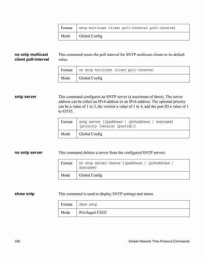
no sntp multicast client poll-interval
This command resets the poll interval for SNTP multicast clients to its default value.
sntp server This command configures an SNTP server (a maximum of three). The server address can be either an IPv4 address or an IPv6 address. The optional priority can be a value of 1 to 3, the version a value of 1 to 4, and the port ID a value of 1 to 65535.
no sntp server This command deletes a server from the configured SNTP servers.
show sntp This command is used to display SNTP settings and status.
Format sntp multicast client poll-interval poll-interval
Mode Global Config
Format no sntp multicast client poll-interval
Mode Global Config
Format sntp server {ipaddress | ipv6address | hostname} [priority [version [portid]]]
Mode Global Config
Format no sntp server remove {ipaddress | ipv6address | hostname}
Mode Global Config
Format show sntp
Mode Privileged EXEC
166 Simple Network Time Protocol Commands
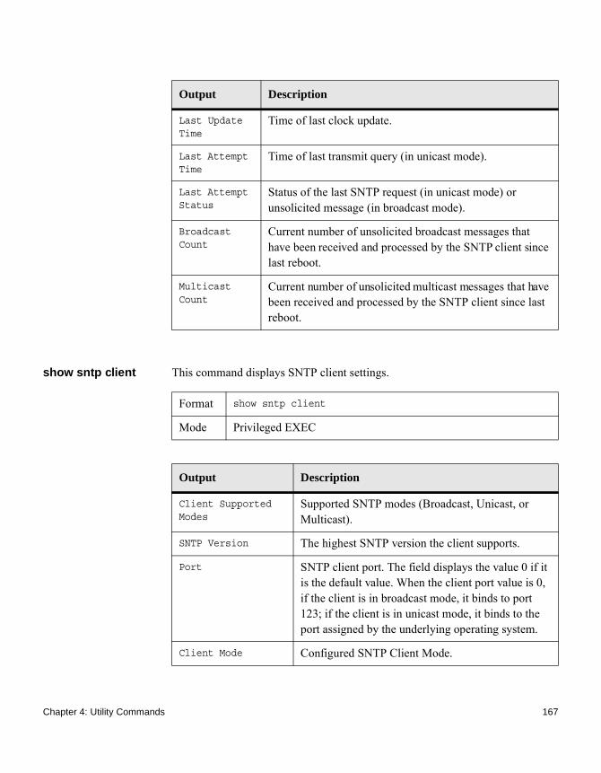
show sntp client This command displays SNTP client settings.
Output Description
Last Update Time
Time of last clock update.
Last Attempt Time
Time of last transmit query (in unicast mode).
Last Attempt Status
Status of the last SNTP request (in unicast mode) or unsolicited message (in broadcast mode).
Broadcast Count
Current number of unsolicited broadcast messages that have been received and processed by the SNTP client since last reboot.
Multicast Count
Current number of unsolicited multicast messages that have been received and processed by the SNTP client since last reboot.
Format show sntp client
Mode Privileged EXEC
Output Description
Client Supported Modes
Supported SNTP modes (Broadcast, Unicast, or Multicast).
SNTP Version The highest SNTP version the client supports.
Port SNTP client port. The field displays the value 0 if it is the default value. When the client port value is 0, if the client is in broadcast mode, it binds to port 123; if the client is in unicast mode, it binds to the port assigned by the underlying operating system.
Client Mode Configured SNTP Client Mode.
Chapter 4: Utility Commands 167

show sntp server This command displays SNTP server settings and configured servers.
For each configured server:
Format show sntp server
Mode Privileged EXEC
Output Description
Server IP Address / Hostname
IP address or hostname of the configured SNTP server.
Server Type Address type of server (IPv4, IPv6, or DNS).
Server Stratum Claimed stratum of the server for the last received valid packet.
Server Reference ID
Reference clock identifier of the server for the last received valid packet.
Server Mode SNTP server mode.
Server Maximum Entries
Total number of SNTP servers allowed.
Server Current Entries
Total number of SNTP configured.
Output Description
IP Address / Hostname
IP address or hostname of the configured SNTP server.
Address Type Address Type of configured SNTP server (IPv4, IPv6, or DNS).
Priority IP priority type of the configured server.
Version SNTP version number of the server. The protocol version used to query the server in unicast mode.
Port Server port number.
Last Attempt Time Last server attempt time for the specified server.
168 Simple Network Time Protocol Commands

Last Update Status Last server attempt status for the server.
Total Unicast Requests
Number of requests to the server.
Failed Unicast Requests
Number of failed requests from server.
Output Description
Chapter 4: Utility Commands 169

System Information and Statistics Commands
Introduction This section describes the commands you use to view information about system features, components, and configurations.
show arp switch This command displays the contents of the IP stack’s Address Resolution Protocol (ARP) table. The IP stack only learns ARP entries associated with the management interfaces, which are the network or service ports. ARP entries associated with routing interfaces are not listed.
show eventlog This command displays the event log, which contains error messages from the system. The event log is not cleared on a system reset.
NoteEvent log information is retained across a switch reset.
Format show arp switch
Mode Privileged EXEC
Output Description
IP address IP address of the management interface or another device on the management network.
MAC Address Hardware MAC address of that device.
Interface For a service port the output is Management. For a network port, the output is the slot/port of the physical interface.
Format show eventlog
Mode Privileged EXEC
170 System Information and Statistics Commands

show hardware This command displays inventory information for the switch.
NoteThe show version command and the show hardware command display the same information. In future releases of the software, the show hardware command will not be available. For a description of the command output, see the command “show version” on page 171.
show version This command displays inventory information for the switch.
NoteThe show version command will replace the show hardware command in future releases of the software.
Output Description
File The file in which the event originated.
Line The line number of the event.
Task Id The task ID of the event.
Code The event code.
Time The time this event occurred.
Format show hardware
Mode Privileged EXEC
Format show version
Mode Privileged EXEC
Chapter 4: Utility Commands 171

show interface This command displays a summary of statistics for a specific interface or a count of all CPU traffic based upon the argument.
The output display, when the argument is slot/port, is as follows:
Output Description
System Description Text used to identify the product name of this switch.
Machine Type The machine model as defined by the Vital Product Data.
Machine Model The machine model as defined by the Vital Product Data
Serial Number The unique box serial number for this switch.
FRU Number The field replaceable unit number.
Part Number Manufacturing part number.
Maintenance Level Hardware changes that are significant to software.
Manufacturer Manufacturer descriptor field.
Burned in MAC Address
Universally assigned network address.
Software Version The release.version.revision number of the code currently running on the switch.
Operating System The operating system currently running on the switch.
Network Processing Device
The type of the processor microcode.
Additional Packages
The additional packages incorporated into this system.
Format show interface {slot/port | switchport}
Mode Privileged EXEC
172 System Information and Statistics Commands

The output display, when the argument is switchport, is as follows:
Output Description
Packets Received Without Error
The total number of packets (including broadcast packets and multicast packets) received by the processor.
Packets Received With Error
The number of inbound packets that contained errors preventing them from being deliverable to a higher-layer protocol.
Broadcast Packets Received
The total number of packets received that were directed to the broadcast address. Note that this does not include multicast packets.
Packets Transmitted Without Error
The total number of packets transmitted out of the interface.
Transmit Packets Errors
The number of outbound packets that could not be transmitted because of errors.
Collisions Frames The best estimate of the total number of collisions on this Ethernet segment.
Time Since Counters Last Cleared
The elapsed time, in days, hours, minutes, and seconds since the statistics for this port were last cleared.
Output Description
Broadcast Packets Received
The total number of packets received that were directed to the broadcast address. Note that this does not include multicast packets.
Packets Received With Error
The number of inbound packets that contained errors preventing them from being deliverable to a higher-layer protocol.
Packets Transmitted Without Error
The total number of packets transmitted out of the interface.
Chapter 4: Utility Commands 173

show interface ethernet
This command displays detailed statistics for a specific interface or for all CPU traffic based upon the argument.
When you specify a value for slot/port, the command displays the following information:
Broadcast Packets Transmitted
The total number of packets that higher-level protocols requested to be transmitted to the broadcast address, including those that were discarded or not sent.
Transmit Packet Errors
The number of outbound packets that could not be transmitted because of errors.
Address Entries Currently In Use
The total number of Forwarding Database Address Table entries now active on the switch, including learned and static entries.
VLAN Entries Currently In Use
The number of VLAN entries presently occupying the VLAN table.
Time Since Counters Last Cleared
The elapsed time, in days, hours, minutes, and seconds since the statistics for this switch were last cleared.
Output Description
Format show interface ethernet {slot/port | switchport}
Mode Privileged EXEC
174 System Information and Statistics Commands

Output Description
Packets Received
◆ Total Packets Received (Octets) - The total number of octets of data (including those in bad packets) received on the network (excluding framing bits but including Frame Check Sequence (FCS) octets). This object can be used as a reasonable estimate of Ethernet utilization. If greater precision is desired, the etherStatsPkts and etherStatsOctets objects should be sampled before and after a common interval. The result of this equation is the value Utilization which is the percent utilization of the Ethernet segment on a scale of 0 to 100 percent.
◆ Packets Received 64 Octets - The total number of packets (including bad packets) received that were 64 octets in length (excluding framing bits but including FCS octets).
◆ Packets Received 65–127 Octets - The total number of packets (including bad packets) received that were between 65 and 127 octets in length inclusive (excluding framing bits but including FCS octets).
Chapter 4: Utility Commands 175

◆ Packets Received 128–255 Octets - The total number of packets (including bad packets) received that were between 128 and 255 octets in length inclusive (excluding framing bits but including FCS octets).
◆ Packets Received 256–511 Octets - The total number of packets (including bad packets) received that were between 256 and 511 octets in length inclusive (excluding framing bits but including FCS octets).
◆ Packets Received 512–1023 Octets - The total number of packets (including bad packets) received that were between 512 and 1023 octets in length inclusive (excluding framing bits but including FCS octets).
◆ Packets Received 1024–1518 Octets - The total number of packets (including bad packets) received that were between 1024 and 1518 octets in length inclusive (excluding framing bits but including FCS octets).
◆ Packets Received > 1522 Octets - The total number of packets received that were longer than 1522 octets (excluding framing bits, but including FCS octets) and were otherwise well formed.
◆ Packets RX and TX 64 Octets - The total number of packets (including bad packets) received and transmitted that were 64 octets in length (excluding framing bits but including FCS octets).
◆ Packets RX and TX 65–127 Octets - The total number of packets (including bad packets) received and transmitted that were between 65 and 127 octets in length inclusive (excluding framing bits but including FCS octets).
◆ Packets RX and TX 128–255 Octets - The total number of packets (including bad packets) received and transmitted that were between 128 and 255 octets in length inclusive (excluding framing bits but including FCS octets).
Output Description
176 System Information and Statistics Commands
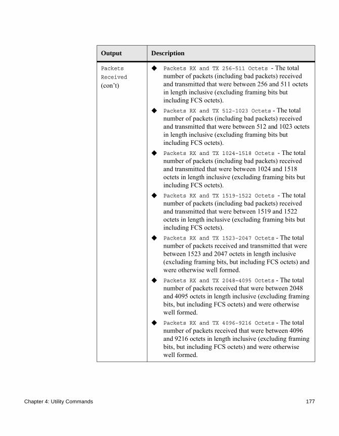
Output Description
Packets
Received (con’t)
◆ Packets RX and TX 256–511 Octets - The total number of packets (including bad packets) received and transmitted that were between 256 and 511 octets in length inclusive (excluding framing bits but including FCS octets).
◆ Packets RX and TX 512–1023 Octets - The total number of packets (including bad packets) received and transmitted that were between 512 and 1023 octets in length inclusive (excluding framing bits but including FCS octets).
◆ Packets RX and TX 1024–1518 Octets - The total number of packets (including bad packets) received and transmitted that were between 1024 and 1518 octets in length inclusive (excluding framing bits but including FCS octets).
◆ Packets RX and TX 1519–1522 Octets - The total number of packets (including bad packets) received and transmitted that were between 1519 and 1522 octets in length inclusive (excluding framing bits but including FCS octets).
◆ Packets RX and TX 1523–2047 Octets - The total number of packets received and transmitted that were between 1523 and 2047 octets in length inclusive (excluding framing bits, but including FCS octets) and were otherwise well formed.
◆ Packets RX and TX 2048–4095 Octets - The total number of packets received that were between 2048 and 4095 octets in length inclusive (excluding framing bits, but including FCS octets) and were otherwise well formed.
◆ Packets RX and TX 4096–9216 Octets - The total number of packets received that were between 4096 and 9216 octets in length inclusive (excluding framing bits, but including FCS octets) and were otherwise well formed.
Chapter 4: Utility Commands 177

Packets Received Successfully
◆ Total Packets Received Without Error - The total number of packets received that were without errors.
◆ Unicast Packets Received - The number of subnetwork-unicast packets delivered to a higher-layer protocol.
◆ Multicast Packets Received - The total number of good packets received that were directed to a multicast address. Note that this number does not include packets directed to the broadcast address.
◆ Broadcast Packets Received - The total number of good packets received that were directed to the broadcast address. Note that this does not include multicast packets.
Output Description
178 System Information and Statistics Commands

Packets Received with MAC Errors
◆ Total - The total number of inbound packets that contained errors preventing them from being deliverable to a higher-layer protocol.
◆ Jabbers Received - The total number of packets received that were longer than 1518 octets (excluding framing bits, but including FCS octets), and had either a bad Frame Check Sequence (FCS) with an integral number of octets (FCS Error) or a bad FCS with a non-integral number of octets (Alignment Error). Note that this definition of jabber is different than the definition in IEEE-802.3 section 8.2.1.5 (10BASE5) and section 10.3.1.4 (10BASE2). These documents define jabber as the condition where any packet exceeds 20 ms. The allowed range to detect jabber is between 20 ms and 150 ms.
◆ Fragments/Undersize Received - The total number of packets received that were less than 64 octets in length (excluding framing bits but including FCS octets).
◆ Alignment Errors - The total number of packets received that had a length (excluding framing bits, but including FCS octets) of between 64 and 1518 octets, inclusive, but had a bad Frame Check Sequence (FCS) with a non-integral number of octets.
◆ Rx FCS Errors - The total number of packets received that had a length (excluding framing bits, but including FCS octets) of between 64 and 1518 octets, inclusive, but had a bad Frame Check Sequence (FCS) with an integral number of octets.
◆ Overruns - The total number of frames discarded as this port was overloaded with incoming packets, and could not keep up with the inflow.
Output Description
Chapter 4: Utility Commands 179

Received Packets Not Forwarded
◆ Total - A count of valid frames received which were discarded (in other words, filtered) by the forwarding process
◆ Local Traffic Frames - The total number of frames dropped in the forwarding process because the destination address was located off of this port.
◆ 802.3x Pause Frames Received - A count of MAC Control frames received on this interface with an opcode indicating the PAUSE operation. This counter does not increment when the interface is operating in half-duplex mode.
◆ Unacceptable Frame Type - The number of frames discarded from this port due to being an unacceptable frame type.
◆ Multicast Tree Viable Discards - The number of frames discarded when a lookup in the multicast tree for a VLAN occurs while that tree is being modified.
◆ Reserved Address Discards - The number of frames discarded that are destined to an IEEE 802.1 reserved address and are not supported by the system.
◆ Broadcast Storm Recovery - The number of frames discarded that are destined for FF:FF:FF:FF:FF:FF when Broadcast Storm Recovery is enabled.
◆ CFI Discards - The number of frames discarded that have CFI bit set and the addresses in RIF are in non-canonical format.
◆ Upstream Threshold - The number of frames discarded due to lack of cell descriptors available for that packet's priority level.
Output Description
180 System Information and Statistics Commands

Packets Transmitted Octets
◆ Total Bytes - The total number of octets of data (including those in bad packets) received on the network (excluding framing bits but including FCS octets). This object can be used as a reasonable estimate of Ethernet utilization. If greater precision is desired, the etherStatsPkts and etherStatsOctets objects should be sampled before and after a common interval.
◆ Packets Transmitted 64 Octets - The total number of packets (including bad packets) received that were 64 octets in length (excluding framing bits but including FCS octets).
◆ Packets Transmitted 65-127 Octets - The total number of packets (including bad packets) received that were between 65 and 127 octets in length inclusive (excluding framing bits but including FCS octets).
◆ Packets Transmitted 128-255 Octets - The total number of packets (including bad packets) received that were between 128 and 255 octets in length inclusive (excluding framing bits but including FCS octets).
◆ Packets Transmitted 256-511 Octets - The total number of packets (including bad packets) received that were between 256 and 511 octets in length inclusive (excluding framing bits but including FCS octets).
◆ Packets Transmitted 512-1023 Octets - The total number of packets (including bad packets) received that were between 512 and 1023 octets in length inclusive (excluding framing bits but including FCS octets).
◆ Packets Transmitted 1024-1518 Octets - The total number of packets (including bad packets) received that were between 1024 and 1518 octets in length inclusive (excluding framing bits but including FCS octets).
◆ Max Frame Size - The maximum size of the Info (non-MAC) field that this port will receive or transmit.
Output Description
Chapter 4: Utility Commands 181

Packets Transmitted Successfully
◆ Total - The number of frames that have been transmitted by this port to its segment.
◆ Unicast Packets Transmitted - The total number of packets that higher-level protocols requested be transmitted to a subnetwork-unicast address, including those that were discarded or not sent.
◆ Multicast Packets Transmitted - The total number of packets that higher-level protocols requested be transmitted to a Multicast address, including those that were discarded or not sent.
◆ Broadcast Packets Transmitted - The total number of packets that higher-level protocols requested be transmitted to the Broadcast address, including those that were discarded or not sent.
Transmit Errors
◆ Total Errors - The sum of Single, Multiple, and Excessive Collisions.
◆ Tx FCS Errors - The total number of packets transmitted that had a length (excluding framing bits, but including FCS octets) of between 64 and 1518 octets, inclusive, but had a bad Frame Check Sequence (FCS) with an integral number of octets.
◆ Oversized - The total number of frames that exceeded the max permitted frame size. This counter has a max increment rate of 815 counts per sec. at 10 Mb/s.
◆ Underrun Errors - The total number of frames discarded because the transmit FIFO buffer became empty during frame transmission.
Output Description
182 System Information and Statistics Commands

Transmit Discards
◆ Total Discards - The sum of single collision frames discarded, multiple collision frames discarded, and excessive frames discarded.
◆ Single Collision Frames - A count of the number of successfully transmitted frames on a particular interface for which transmission is inhibited by exactly one collision.
◆ Multiple Collision Frames - A count of the number of successfully transmitted frames on a particular interface for which transmission is inhibited by more than one collision.
◆ Excessive Collisions - A count of frames for which transmission on a particular interface fails due to excessive collisions.
◆ Port Membership Discards - The number of frames discarded on egress for this port due to egress filtering being enabled.
Output Description
Chapter 4: Utility Commands 183

Protocol Statistics
◆ 802.3x Pause Frames Transmitted - A count of MAC Control frames transmitted on this interface with an opcode indicating the PAUSE operation. This counter does not increment when the interface is operating in half-duplex mode.
◆ GVRP PDUs Received - The count of GVRP PDUs received in the GARP layer.
◆ GVRP PDUs Transmitted - The count of GVRP PDUs transmitted from the GARP layer.
◆ GVRP Failed Registrations - The number of times attempted GVRP registrations could not be completed.
◆ GMRP PDUs Received - The count of GMRP PDUs received in the GARP layer.
◆ GMRP PDUs Transmitted - The count of GMRP PDUs transmitted from the GARP layer.
◆ GMRP Failed Registrations - The number of times attempted GMRP registrations could not be completed.
◆ STP BPDUs Transmitted - Spanning Tree Protocol Bridge Protocol Data Units sent.
◆ STP BPDUs Received - Spanning Tree Protocol Bridge Protocol Data Units received.
◆ RST BPDUs Transmitted - Rapid Spanning Tree Protocol Bridge Protocol Data Units sent.
◆ RSTP BPDUs Received - Rapid Spanning Tree Protocol Bridge Protocol Data Units received.
◆ MSTP BPDUs Transmitted - Multiple Spanning Tree Protocol Bridge Protocol Data Units sent.
◆ MSTP BPDUs Received - Multiple Spanning Tree Protocol Bridge Protocol Data Units received.
Dot1x Statistics
◆ EAPOL Frames Received - The number of valid EAPOL frames of any type that have been received by this authenticator.
◆ EAPOL Frames Transmitted - The number of EAPOL frames of any type that have been transmitted by this authenticator.
Output Description
184 System Information and Statistics Commands

If you use the switchport keyword, the following information appears:
Time Since Counters Last Cleared
The elapsed time, in days, hours, minutes, and seconds since the statistics for this port were last cleared.
Output Description
Octets Received
The total number of octets of data received by the processor (excluding framing bits but including FCS octets).
Total Packets Received Without Error
The total number of packets (including broadcast packets and multicast packets) received by the processor.
Unicast Packets Received
The number of subnetwork-unicast packets delivered to a higher-layer protocol.
Multicast Packets Received
The total number of packets received that were directed to a multicast address. Note that this number does not include packets directed to the broadcast address.
Broadcast Packets Received
The total number of packets received that were directed to the broadcast address. Note that this does not include multicast packets.
Receive Packets Discarded
The number of inbound packets which were chosen to be discarded even though no errors had been detected to prevent their being deliverable to a higher-layer protocol. A possible reason for discarding a packet could be to free up buffer space.
Octets Transmitted
The total number of octets transmitted out of the interface, including framing characters.
Packets Transmitted without Errors
The total number of packets transmitted out of the interface.
Output Description
Chapter 4: Utility Commands 185

Unicast Packets Transmitted
The total number of packets that higher-level protocols requested be transmitted to a subnetwork-unicast address, including those that were discarded or not sent.
Multicast Packets Transmitted
The total number of packets that higher-level protocols requested be transmitted to a Multicast address, including those that were discarded or not sent.
Broadcast Packets Transmitted
The total number of packets that higher-level protocols requested be transmitted to the Broadcast address, including those that were discarded or not sent.
Transmit Packets Discarded
The number of outbound packets which were chosen to be discarded even though no errors had been detected to prevent their being deliverable to a higher-layer protocol. A possible reason for discarding a packet could be to free up buffer space.
Most Address Entries Ever Used
The highest number of Forwarding Database Address Table entries that have been learned by this switch since the most recent reboot.
Address Entries in Use
The number of Learned and static entries in the Forwarding Database Address Table for this switch.
Maximum VLAN Entries
The maximum number of Virtual LANs (VLANs) allowed on this switch.
Most VLAN Entries Ever Used
The largest number of VLANs that have been active on this switch since the last reboot.
Static VLAN Entries
The number of presently active VLAN entries on this switch that have been created statically.
Dynamic VLAN Entries
The number of presently active VLAN entries on this switch that have been created by GVRP registration.
VLAN Deletes The number of VLANs on this switch that have been created and then deleted since the last reboot.
Output Description
186 System Information and Statistics Commands

show mac-addr-table
This command displays the forwarding database entries. These entries are used by the transparent bridging function to determine how to forward a received frame.
Enter the all parameter to display the entire table. Enter a MAC address and VLAN ID to display the table entry for the requested MAC address on the specified VLAN. Enter the count parameter to view summary information about the forwarding database table. Use the interface slot/port parameter to view MAC addresses on a specific interface. Use the vlan vlan_id parameter to display information about MAC addresses on a specified VLAN.
The following information displays if you do not enter a parameter, the keyword all, or the MAC address and VLAN ID:
Time Since Counters Last Cleared
The elapsed time, in days, hours, minutes, and seconds, since the statistics for this switch were last cleared.
Output Description
Format show mac-addr-table [{macaddr vlan_id | all | count | interface slot/port | vlan vlan_id}]
Mode Privileged EXEC
Output Description
VLAN ID The VLAN in which the MAC address is learned.
MAC Address A unicast MAC address for which the switch has forwarding and or filtering information. The format is six 2-digit hexadecimal numbers that are separated by colons, for example: 01:23:45:67:89:AB.
Interface The port through which this address was learned.
Interface Index This object indicates the ifIndex of the interface table entry associated with this port.
Chapter 4: Utility Commands 187

If you enter vlan vlan_id, only the MAC Address, Interface, and Status fields appear. If you enter the interface slot/port parameter, in addition to the MAC Address and Status fields, the VLAN ID field also appears.
The following information displays if you enter the count parameter:
Status The status of this entry. The meanings of the values are:◆ Static—The value of the corresponding
instance was added by the system or a user when a static MAC filter was defined. It cannot be relearned.
◆ Learned—The value of the corresponding instance was learned by observing the source MAC addresses of incoming traffic, and is currently in use.
◆ Management—The value of the corresponding instance (system MAC address) is also the value of an existing instance of dot1dStaticAddress. It is identified with interface 0/1. and is currently used when enabling VLANs for routing.
◆ Self—The value of the corresponding instance is the address of one of the switch’s physical interfaces (the system’s own MAC address).
◆ GMRP Learned—The value of the corresponding was learned via GMRP and applies to Multicast.
◆ Other—The value of the corresponding instance does not fall into one of the other categories.
Output Description
Dynamic Address count
Number of MAC addresses in the forwarding database that were automatically learned.
Static Address (User-defined) count
Number of MAC addresses in the forwarding database that were manually entered by a user.
Output Description
188 System Information and Statistics Commands

process cpu threshold type total rising
This command configures CPU Utilization monitoring threshold parameters.
show process cpu This command provides the percentage utilization of the CPU by different tasks.
NoteIt is not necessarily the traffic to the CPU, but different tasks that keep the CPU busy.
NoteThis command is available in VxWorks and Linux 2.6 only.
Example: The following shows example CLI display output for the command using Linux:(CN1610) #show process cpu Memory Utilization Reportstatus bytes------ ----------free 106450944alloc 423227392
CPU Utilization:
Total MAC Addresses in use
Number of MAC addresses currently in the forwarding database.
Total MAC Addresses available
Number of MAC addresses the forwarding database can handle.
Output Description
Format show process cpu threshold type total rising 1-100 interval 5-86400 falling 1-100 interval 5-86400
Mode Privileged EXEC
Format show process cpu
Mode Privileged EXEC
Chapter 4: Utility Commands 189

PID Name 5 Secs 60 Secs 300 Secs----------------------------------------------------------------- 765 _interrupt_thread 0.00% 0.01% 0.02% 767 bcmL2X.0 0.58% 0.35% 0.28% 768 bcmCNTR.0 0.77% 0.73% 0.72% 773 bcmRX 0.00% 0.04% 0.05% 786 cpuUtilMonitorTask 0.19% 0.23% 0.23% 834 dot1s_task 0.00% 0.01% 0.01% 810 hapiRxTask 0.00% 0.01% 0.01% 805 dtlTask 0.00% 0.02% 0.02% 863 spmTask 0.00% 0.01% 0.00% 894 ip6MapLocalDataTask 0.00% 0.01% 0.01% 908 RMONTask 0.00% 0.11% 0.12%----------------------------------------------------------------- Total CPU Utilization 1.55% 1.58% 1.50%
Example: The following shows example CLI display output for the command using VxWorks:(CN1610)#show process cpu Memory Utilization Report status bytes ------ ---------- free 192980480 alloc 53409968 Task Utilization Report Task Utilization ----------------------- ----------- bcmL2X.0 0.75% bcmCNTR.0 0.20% bcmLINK.0 0.35% DHCP snoop 0.10% Dynamic ARP Inspection 0.10% dot1s_timer_task 0.10% dhcpsPingTask 0.20%
show running-config
This command displays or captures the current setting of different protocol packages supported on the switch. This command displays or captures commands with settings and configurations that differ from the default value. To display or capture the commands with settings and configurations that are equal to the default value, include the all option.
190 System Information and Statistics Commands
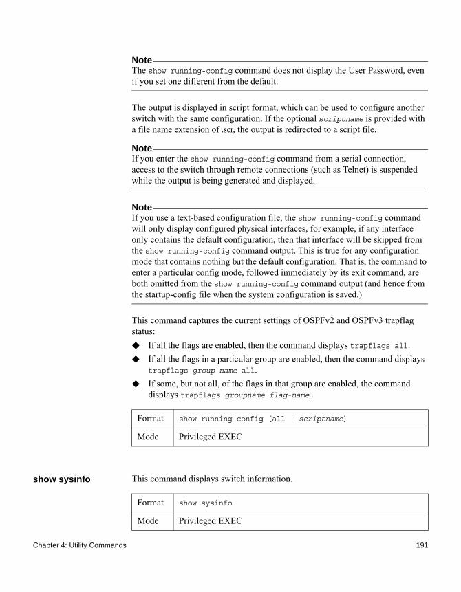
NoteThe show running-config command does not display the User Password, even if you set one different from the default.
The output is displayed in script format, which can be used to configure another switch with the same configuration. If the optional scriptname is provided with a file name extension of .scr, the output is redirected to a script file.
NoteIf you enter the show running-config command from a serial connection, access to the switch through remote connections (such as Telnet) is suspended while the output is being generated and displayed.
NoteIf you use a text-based configuration file, the show running-config command will only display configured physical interfaces, for example, if any interface only contains the default configuration, then that interface will be skipped from the show running-config command output. This is true for any configuration mode that contains nothing but the default configuration. That is, the command to enter a particular config mode, followed immediately by its exit command, are both omitted from the show running-config command output (and hence from the startup-config file when the system configuration is saved.)
This command captures the current settings of OSPFv2 and OSPFv3 trapflag status:◆ If all the flags are enabled, then the command displays trapflags all.◆ If all the flags in a particular group are enabled, then the command displays
trapflags group name all.◆ If some, but not all, of the flags in that group are enabled, the command
displays trapflags groupname flag-name.
show sysinfo This command displays switch information.
Format show running-config [all | scriptname]
Mode Privileged EXEC
Format show sysinfo
Mode Privileged EXEC
Chapter 4: Utility Commands 191

show tech-support Use the show tech-support command to display system and configuration information when you contact technical support. The output of the show tech-support command combines the output of the following commands:◆ show version
◆ show sysinfo
◆ show port all
◆ show isdp neighbors
◆ show logging
◆ show event log
◆ show logging buffered
◆ show trap log
◆ show running config
Output Description
Switch Description
Text used to identify this switch.
System Name Name used to identify the switch.The factory default is blank. To configure the system name, see “snmp-server” on page 67.
System Location
Text used to identify the location of the switch. The factory default is blank. To configure the system location, see “snmp-server” on page 67.
System Contact
Text used to identify a contact person for this switch. The factory default is blank. To configure the system location, see “snmp-server” on page 67.
System ObjectID
The base object ID for the switch’s enterprise MIB.
System Up Time
The time in days, hours, and minutes since the last switch reboot.
MIBs Supported
A list of MIBs supported by this agent.
Format show tech-support
192 System Information and Statistics Commands
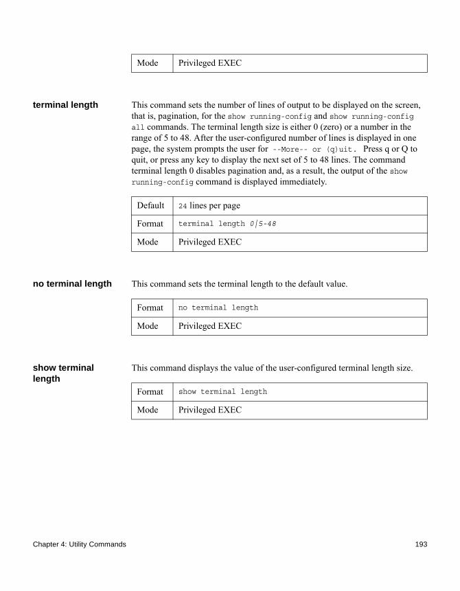
terminal length This command sets the number of lines of output to be displayed on the screen, that is, pagination, for the show running-config and show running-config all commands. The terminal length size is either 0 (zero) or a number in the range of 5 to 48. After the user-configured number of lines is displayed in one page, the system prompts the user for --More-- or (q)uit. Press q or Q to quit, or press any key to display the next set of 5 to 48 lines. The command terminal length 0 disables pagination and, as a result, the output of the show running-config command is displayed immediately.
no terminal length This command sets the terminal length to the default value.
show terminal length
This command displays the value of the user-configured terminal length size.
Mode Privileged EXEC
Default 24 lines per page
Format terminal length 0|5-48
Mode Privileged EXEC
Format no terminal length
Mode Privileged EXEC
Format show terminal length
Mode Privileged EXEC
Chapter 4: Utility Commands 193

System Utility and Clear Commands
Introduction This section describes the commands you use to help troubleshoot connectivity issues and to restore various configurations to their factory defaults.
traceroute This command finds the routes that packets actually take when traveling to their destination through the network on a hop-by-hop basis. The traceroute command continues to provide a synchronous response when initiated from the CLI.
Using the following options, you can specify the initial and maximum time-to-live (TTL) in probe packets, the maximum number of failures before termination, the number of probes sent for each TTL, and the size of each probe.
Default ◆ count: 3 probes◆ interval: 3 seconds◆ size: 0 bytes◆ port: 33434◆ maxTtl: 30 hops◆ maxFail: 5 probes◆ initTtl: 1 hop
Format traceroute {ipaddr|hostname} [initTtl initTtl] [maxTtl maxTtl][maxFail maxFail] [interval interval] [count count][port port] [size size]
Mode Privileged EXEC
Parameter Description
ipaddr/hostname The ipaddr value should be a valid IP address. The hostname value should be a valid hostname.
194 System Utility and Clear Commands

The following are examples that use the traceroute command:
Example of a successful traceroute:(CN1610)# traceroute 10.240.10.115 initTtl 1 maxTtl 4 maxFail 0 interval 1 count 3 port 33434 size 43 Traceroute to 10.240.10.115 ,4 hops max 43 byte packets:1 10.240.4.1 708 msec 41 msec 11 msec2 10.240.10.115 0 msec 0 msec 0 msec
Hop Count = 1 Last TTL = 2 Test attempt = 6 Test Success = 6
initTtl Use initTtl to specify the initial time-to-live (TTL), the maximum number of router hops between the local and remote system. Range is 0 to 255.
maxTtl Use maxTtle to specify the maximum TTL. The range is 1 to 255.
maxFail Use maxFail to terminate the traceroute after failing to receive a response for this number of consecutive probes. The range is 0 to 255.
interval If a response is not received within this interval, then traceroute considers that probe a failure (printing *) and sends the next probe. If traceroute does receive a response to a probe within this interval, then it sends the next probe immediately. The range is 1 to 60 seconds.
count Use this optional parameter to specify the number of probes to send for each TTL value. The range is 1 to 10 probes.
port Use this optional parameter to specify the destination UDP port of the probe. This should be an unused port on the remote destination system. The range is 1 to 65535.
size Use this optional parameter to specify the size, in bytes, of the payload of the Echo Requests sent. The range is 0 to 65507 bytes.
Parameter Description
Chapter 4: Utility Commands 195

Example of a traceroute failure:
(CN1610)# traceroute 10.40.1.1 initTtl 1 maxFail 0 interval 1 count 3port 33434 size 43Traceroute to 10.40.1.1 ,30 hops max 43 byte packets:1 10.240.4.1 19 msec 18 msec 9 msec2 10.240.1.252 0 msec 0 msec 1 msec3 172.31.0.9 277 msec 276 msec 277 msec4 10.254.1.1 289 msec 327 msec 282 msec5 10.254.21.2 287 msec 293 msec 296 msec6 192.168.76.2 290 msec 291 msec 289 msec7 0.0.0.0 0 msec *Hop Count = 6 Last TTL = 7 Test attempt = 19 Test Success = 18
traceroute ipv6 Use this command to discover the routes that packets actually take when traveling to their destination through the network on a hop-by-hop basis. The {ipv6-address | hostname} parameter must be a valid IPv6 address or hostname. The optional port parameter is the UDP port used as the destination of packets sent as part of the traceroute. This port should be an unused port on the destination system. The range for port is zero (0) to 65535. The default value is 33434.
clear config This command resets the configuration to the factory defaults without powering off the switch. When you enter this command, a prompt appears to confirm that the reset should proceed. When you enter y, you automatically reset the current configuration on the switch to the default values. It does not reset the switch.
Default port: 33434
Format traceroute ipv6 {ipv6-address | hostname} [port port]
Mode Privileged EXEC
Format clear config
Mode Privileged EXEC
196 System Utility and Clear Commands

clear counters This command clears the statistics for a specified slot/port, for all the ports, or for the entire switch based upon the argument.
clear igmpsnooping This command clears the tables managed by the IGMP Snooping function and attempts to delete these entries from the Multicast Forwarding Database.
clear pass This command resets all user passwords to the factory defaults without powering off the switch. You are prompted to confirm that the password reset should proceed.
clear traplog This command clears the trap log.
clear vlan This command resets VLAN configuration parameters to the factory defaults.
Format clear counters {slot/port | all}
Mode Privileged EXEC
Format clear igmpsnooping
Mode Privileged EXEC
Format clear pass
Mode Privileged EXEC
Format clear traplog
Mode Privileged EXEC
Format clear vlan
Mode Privileged EXEC
Chapter 4: Utility Commands 197

logout This command closes the current Telnet connection or resets the current serial connection.
NoteSave the configuration changes before logging out.
ping This command determines whether another computer is on the network. It provides a synchronous response when initiated from the CLI and Web interfaces.
Using the following options, you can specify the number and size of Echo Requests and the interval between Echo Requests.
Format logout
Mode ◆ Privileged EXEC ◆ User EXEC
Default ◆ The default count is 1.◆ The default interval is 3 seconds.◆ The default size is 0 bytes.
Format ping {ipaddress | hostname}[count count] [interval interval] [size size]
Mode ◆ Privileged EXEC ◆ User EXEC
Parameter Description
count Use this parameter to specify the number of ping packets (ICMP Echo requests) that are sent to the destination address specified by the ip-address field. The range for count is 1 to 15 requests.
interval Use this parameter to specify the time between Echo Requests, in seconds. The range is 1 to 60 seconds.
198 System Utility and Clear Commands

The following are examples that use the ping command.
Example of a successful ping:(CN1610) #ping 10.254.2.160 count 3 interval 1 size 255
Pinging 10.254.2.160 with 255 bytes of data:
Received response for icmp_seq = 0. time = 275268 usec
Received response for icmp_seq = 1. time = 274009 usec
Received response for icmp_seq = 2. time = 279459 usec
----10.254.2.160 PING statistics----
3 packets transmitted, 3 packets received, 0% packet loss
round-trip (msec) min/avg/max = 274/279/276
Example of a ping failure:
Unreachable Destination:(CN1610)# ping 192.168.254.222 count 3 interval 1 size 255Pinging 192.168.254.222 with 255 bytes of data:Received Response: Unreachable DestinationReceived Response :Unreachable DestinationReceived Response :Unreachable Destination----192.168.254.222 PING statistics----3 packets transmitted,3 packets received, 0% packet lossround-trip (msec) min/avg/max = 0/0/0
Request Timed Out example:(CN1610)# ping 1.1.1.1 count 1 interval 3 Pinging 1.1.1.1 with 0 bytes of data: ----1.1.1.1 PING statistics----1 packets transmitted,0 packets received, 100% packet lossround-trip (msec) min/avg/max = 0/0/0
size Use this parameter to specify the size, in bytes, of the payload of the Echo Requests sent. The range is 0 to 65507 bytes.
Parameter Description
Chapter 4: Utility Commands 199

quit This command closes the current Telnet connection or resets the current serial connection. The system asks you whether to save configuration changes before quitting.
reload This command resets the switch without powering it off. Reset means that all network connections are terminated and the boot code executes. The switch uses the stored configuration to initialize the switch. You are prompted to confirm that the reset should proceed. The LEDs on the switch indicate a successful reset.
copy This command uploads and downloads files to and from the switch. You can also use the copy command to manage the dual images (active and backup) on the file system. Upload and download files from a server by using TFTP or Xmodem. SFTP and SCP are available as additional transfer methods if the software package supports secure management.
Replace the source and destination parameters with the options in the following Source/Destination/Description table. For the url source or destination, use one of the following values:{xmodem | tftp://ipaddr|hostname | ip6address|hostname/filepath/filename [noval]| sftp|scp://username@ipaddr | ipv6address/filepath/filename}
NoteThe maximum length for the file path is 160 characters, and the maximum length for the file name is 32 characters.
Format quit
Mode ◆ Privileged EXEC ◆ User EXEC
Format reload
Mode Privileged EXEC
Format copy source destination
Mode Privileged EXEC
200 System Utility and Clear Commands

For TFTP, SFTP and SCP, the ipaddr|hostname parameter is the IP address or host name of the server, filepath is the path to the file, and filename is the name of the file you want to upload or download. For SFTP and SCP, the username parameter is the username for logging into the remote server via SSH.
Noteip6address is also a valid parameter for routing packages that support IPv6.
CAUTIONRemember to upload the existing fastpath.cfg file off the switch prior to loading a new release image in order to make a backup.
Source Destination Description
nvram:backup-config
nvram:startup-config
Copies the backup configuration to the startup configuration.
nvram:clibanner url Copies the CLI banner to a server.nvram:errorlog url Copies the error log file to a server.nvram:fastpath.cfg
url Uploads the binary config file to a server.
nvram:log url Copies the log file to a server.nvram:script scriptname
url Copies a specified configuration script file to a server.
nvram:startup-config
nvram:backup-config
Copies the startup configuration to the backup configuration.
nvram:startup-config
url Copies the startup configuration to a server.
nvram:traplog url Copies the trap log file to a server.system:running-config
nvram:startup-config
Saves the running configuration to nvram.
url nvram:clibanner Downloads the CLI banner to the system.
url nvram:fastpath.cfg
Downloads the binary configuration file to the system.
Chapter 4: Utility Commands 201

url nvram:script destfilename
Downloads a configuration script file to the system. During the download of a configuration script, the copy command validates the script. In case of any error, the command lists all the lines at the end of the validation process and prompts you to confirm before copying the script file.
url nvram:script destfilename noval
When you use this option, the copy command will not validate the downloaded script file. An example of the CLI command follows:
(CN1610)#copy
tftp://1.1.1.1/file.scr
nvram:script file.scr noval
(CN1610)#copy tftp://1.1.1.1/file.scr nvram:script file.scr noval
url nvram:sshkey-dsa
Downloads an SSH key file. For more information, see “Secure Shell Commands” on page 64.
url nvram:sshkey-rsa1
Downloads an SSH key file.
url nvram:sshkey-rsa2
Downloads an SSH key file.
url nvram:startup-config
Downloads the startup configuration file to the system.
url nvram:system-image
Downloads a code image to the system.
url kernel Downloads a code file to the system.url ias-users Downloads an IAS users database file to
the system. When the IAS users file is downloaded, the switch IAS user’s database is replaced with the users and their attributes available in the downloaded file.
url {active | backup}
Downloads an image from the remote server to either image.
Source Destination Description
202 System Utility and Clear Commands

environment temprange
This command sets the allowed temperature range for normal operations.
environment trap fan
This command enables the fan status trap.
environment trap powersupply
This command enables the power supply status trap.
{active | backup}
url Uploads either image to the remote server.
active backup Copies the active image to the backup image.
backup active Copies the backup image to the active image.
Source Destination Description
Format environment temprange min -100-100 max -100-100
Mode Global Config
Parameter Description
min Minimum allowed temperature for normal operation. The value is within the range -100 to 100 degrees Fahrenheit.
max Maximum allowed temperature for normal operation. The value is within the range -100 to 100 degrees Fahrenheit.
Format environment trap fan
Mode Global Config
Format environment trap powersupply
Chapter 4: Utility Commands 203

environment trap temperature
This command enables the temperature status trap.
show environment This command displays vital environment status data.
slot This command configures a slot in the system. The slot/port is the slot identifier of the slot. The cardindex is the index into the database of the supported card types, indicating the type of card being preconfigured in the specified slot. The card index is a 32-bit integer. If a card is currently present in the slot that is unconfigured, the configured information will be deleted and the slot will be reconfigured with default information for the card.
NoteYou can get the cardindex by entering the show supported cardtype command in User EXEC mode.
no slot This command removes configured information from an existing slot in the system.
Mode Global Config
Format environment trap temperature
Mode Global Config
Format show environment
Mode Privileged EXEC
Format slot slot/port cardindex
Mode Global Config
Format no slot slot/port cardindex
Mode Global Config
204 System Utility and Clear Commands

NoteYou can get the cardindex by entering the show supported cardtype command in User EXEC mode.
set slot disable This command configures the administrative mode of the slot(s). If you specify [all], the command is applied to all slots, otherwise the command is applied to the slot identified by slot/port.
If a card or other module is present in the slot, the administrative mode will effectively be applied to the contents of the slot. If the slot is empty, the administrative mode will be applied to any module that is inserted into the slot. If a card is disabled, all the ports on the device are operationally disabled and shown as unplugged on management screens.
no set slot disable This command unconfigures the administrative mode of the slot(s). If you specify [all], the command removes the configuration from all slots, otherwise the configuration is removed from the slot identified by slot/port.
set slot power This command configures the power mode of the slot(s), and allows power to be supplied to a card located in the slot. If you specify all, the command is applied to all slots, otherwise the command is applied to the slot identified by slot/port.
Format set slot disable [slot/port]|all]
Mode Global Config
Format no set slot disable [slot/port]|all]
Mode Global Config
Format set slot power [slot/port]|all]
Mode Global Config
Chapter 4: Utility Commands 205

no set slot power This command unconfigures the power mode of the slot(s), and prohibits power from being supplied to a card located in the slot. If you specify all, the command prohibits power to all slots, otherwise the command prohibits power to the slot identified by slot/port.
show slot This command displays information about all the slots in the system or for a specific slot.
If you supply a value for slot, the following additional information appears:
Format set slot power [slot/port]|all]
Mode Global Config
Format show slot [slot]
Mode User EXEC
Output Description
Slot The slot identifier.
Slot Status The slot is empty, full, or has encountered an error
Admin State The slot administrative mode is enabled or disabled.
Power State The slot power mode is enabled or disabled.
Configured Card Model Identifier
The model identifier of the card preconfigured in the slot. Model Identifier is a 32-character field used to identify a card.
Pluggable Cards are pluggable or non-pluggable in the slot.
Power Down Indicates whether the slot can be powered down.
206 System Utility and Clear Commands
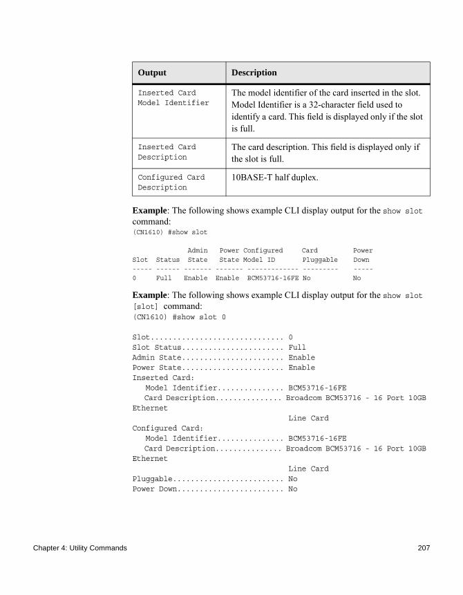
Example: The following shows example CLI display output for the show slot command:(CN1610) #show slot
Admin Power Configured Card PowerSlot Status State State Model ID Pluggable Down----- ------ ------- ------- ------------- --------- -----0 Full Enable Enable BCM53716-16FE No No
Example: The following shows example CLI display output for the show slot [slot] command:(CN1610) #show slot 0
Slot.............................. 0Slot Status....................... FullAdmin State....................... EnablePower State....................... EnableInserted Card: Model Identifier............... BCM53716-16FE Card Description............... Broadcom BCM53716 - 16 Port 10GB Ethernet Line CardConfigured Card: Model Identifier............... BCM53716-16FE Card Description............... Broadcom BCM53716 - 16 Port 10GB Ethernet Line CardPluggable......................... NoPower Down........................ No
Output Description
Inserted Card Model Identifier
The model identifier of the card inserted in the slot. Model Identifier is a 32-character field used to identify a card. This field is displayed only if the slot is full.
Inserted Card Description
The card description. This field is displayed only if the slot is full.
Configured Card Description
10BASE-T half duplex.
Chapter 4: Utility Commands 207
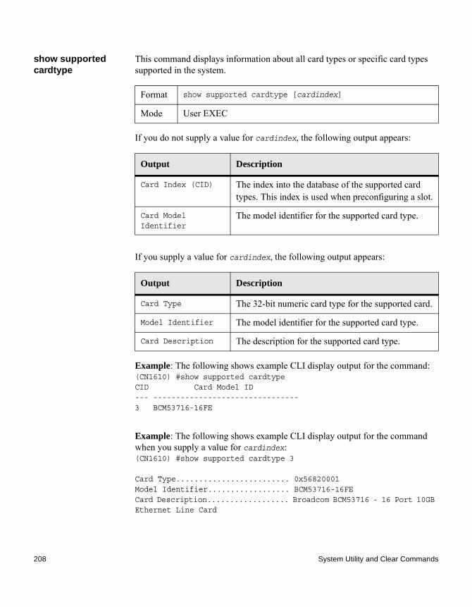
show supported cardtype
This command displays information about all card types or specific card types supported in the system.
If you do not supply a value for cardindex, the following output appears:
If you supply a value for cardindex, the following output appears:
Example: The following shows example CLI display output for the command:(CN1610) #show supported cardtypeCID Card Model ID--- --------------------------------3 BCM53716-16FE
Example: The following shows example CLI display output for the command when you supply a value for cardindex:(CN1610) #show supported cardtype 3
Card Type......................... 0x56820001Model Identifier.................. BCM53716-16FECard Description.................. Broadcom BCM53716 - 16 Port 10GB Ethernet Line Card
Format show supported cardtype [cardindex]
Mode User EXEC
Output Description
Card Index (CID) The index into the database of the supported card types. This index is used when preconfiguring a slot.
Card Model Identifier
The model identifier for the supported card type.
Output Description
Card Type The 32-bit numeric card type for the supported card.
Model Identifier The model identifier for the supported card type.
Card Description The description for the supported card type.
208 System Utility and Clear Commands

Chapter 5: Switching Commands
5
Switching CommandsAbout this chapter This chapter describes the switching commands available in the CN1610 command line interface (CLI).
Topics in this chapter
This chapter includes the following sections:◆ “Denial of Service Commands” on page 211◆ “DHCP Client Commands” on page 222◆ “DHCP L2 Relay Agent Commands” on page 224◆ “DHCP Snooping Configuration Commands” on page 232◆ “Double VLAN Commands” on page 243◆ “Dynamic ARP Inspection Commands” on page 248◆ “802.1X Supplicant Commands” on page 256◆ “GARP Commands” on page 261◆ “GMRP Commands” on page 264◆ “GVRP Commands” on page 268◆ “IGMP Snooping Configuration Commands” on page 271◆ “IGMP Snooping Querier Commands” on page 281◆ “ISDP Commands” on page 286◆ “LLDP (802.1AB) Commands” on page 292◆ “LLDP-MED Commands” on page 303◆ “Link Local Protocol Filtering Commands” on page 311◆ “MAC Database Commands” on page 313◆ “MLD Snooping Commands” on page 316◆ “MLD Snooping Querier Commands” on page 324◆ “Port-Based Network Access Control Commands” on page 328◆ “Port Channel/LAG (802.3ad) Commands” on page 349◆ “Port Configuration Commands” on page 369◆ “Port Mirroring Commands” on page 375◆ “Port Security Commands” on page 378◆ “Protected Ports Commands” on page 382◆ “Provisioning (IEEE 802.1p) Commands” on page 385◆ “Spanning Tree Protocol Commands” on page 386◆ “Static MAC Filtering Commands” on page 409
209
◆ “Storm-Control Commands” on page 414◆ “VLAN Commands” on page 427◆ “Voice VLAN Commands” on page 444
CAUTIONThe commands in this chapter are in one of three functional groups:◆ Show commands display switch settings, statistics, and other information.◆ Configuration commands configure features and options of the switch. For
every configuration command, there is a show command that displays the configuration setting.
◆ Clear commands clear some or all of the settings to factory defaults.
210 Switching Commands

Denial of Service Commands
Introduction This section describes the commands you use to configure Denial of Service (DoS) Control. FASTPATH software provides support for classifying and blocking specific types of Denial of Service attacks. You can configure your system to monitor and block these types of attacks:◆ SIP = DIP: Source IP address = Destination IP address.◆ First Fragment:TCP Header size smaller than configured value.◆ TCP Fragment: IP Fragment Offset = 1.◆ TCP Flag: TCP Flag SYN set and Source Port < 1024 or TCP Control Flags
= 0 and TCP Sequence Number = 0 or TCP Flags FIN, URG, and PSH set and TCP Sequence Number = 0 or TCP Flags SYN and FIN set.
◆ L4 Port: Source TCP/UDP Port = Destination TCP/UDP Port.◆ ICMP: Limiting the size of ICMP Ping packets.◆ SMAC = DMAC: Source MAC address = Destination MAC address.◆ TCP Port: Source TCP Port = Destination TCP Port.◆ UDP Port: Source UDP Port = Destination UDP Port.◆ TCP Flag & Sequence: TCP Flag SYN set and Source Port < 1024 or TCP
Control Flags = 0 and TCP Sequence Number = 0 or TCP Flags FIN, URG, and PSH set and TCP Sequence Number = 0 or TCP Flags SYN and FIN set.
◆ TCP Offset: TCP Header Offset = 1.◆ TCP SYN: TCP Flag SYN set.◆ TCP SYN & FIN: TCP Flags SYN and FIN set.◆ TCP FIN & URG & PSH: TCP Flags FIN and URG and PSH set and TCP
Sequence Number = 0.◆ ICMP V6: Limits the size of ICMPv6 Ping packets.◆ ICMP Fragment: Checks for fragmented ICMP packets.
dos-control all This command enables Denial of Service protection checks globally.
Default disabled
Format dos-control all
Mode Global Config
Chapter 5: Switching Commands 211

no dos-control all This command disables Denial of Service prevention checks globally.
dos-control sipdip This command enables Source IP address = Destination IP address (SIP = DIP) Denial of Service protection. If the mode is enabled, Denial of Service prevention is active for this type of attack. If packets ingress with SIP = DIP, the packets will be dropped if the mode is enabled.
no dos-control sipdip
This command disables Source IP address = Destination IP address (SIP = DIP) Denial of Service prevention.
dos-control firstfrag This command enables Minimum TCP Header Size Denial of Service protection. If the mode is enabled, Denial of Service prevention is active for this type of attack. If packets ingress having a TCP Header Size smaller than the configured value, the packets will be dropped if the mode is enabled.The default is disabled. If you enable dos-control firstfrag, but do not provide a Minimum TCP Header Size, the system sets that value to 20. The Minimum TCP Header Size can range from 0 to 255.
no dos-control firstfrag
This command sets Minimum TCP Header Size Denial of Service protection to the default value of disabled.
Format no dos-control all
Mode Global Config
Default disabled
Format dos-control sipdip
Mode Global Config
Format no dos-control sipdip
Mode Global Config
Default disabled (20)
Format dos-control firstfrag [0-255]
Mode Global Config
Format no dos-control firstfrag
212 Denial of Service Commands

dos-control tcpfrag This command enables TCP Fragment Denial of Service protection. If the mode is enabled, Denial of Service prevention is active for this type of attack. If packets ingress having IP Fragment Offset equal to one (1), the packets will be dropped if the mode is enabled.
no dos-control tcpfrag
This command disables TCP Fragment Denial of Service protection.
dos-control tcpflag This command enables TCP Flag Denial of Service protections. If the mode is enabled, Denial of Service prevention is active for this type of attacks. If packets ingress having TCP Flag SYN set and a source port less than 1024 or having TCP Control Flags set to 0 and TCP Sequence Number set to 0 or having TCP Flags FIN, URG, and PSH set and TCP Sequence Number set to 0 or having TCP Flags SYN and FIN both set, the packets will be dropped if the mode is enabled.
no dos-control tcpflag
This command disables TCP Flag Denial of Service protections.
Mode Global Config
Default disabled
Format dos-control tcpfrag
Mode Global Config
Format no dos-control tcpfrag
Mode Global Config
Default disabled
Format dos-control tcpflag
Mode Global Config
Format no dos-control tcpflag
Mode Global Config
Chapter 5: Switching Commands 213
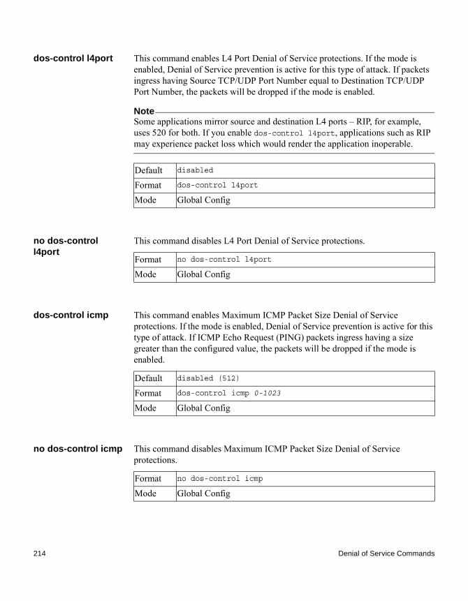
dos-control l4port This command enables L4 Port Denial of Service protections. If the mode is enabled, Denial of Service prevention is active for this type of attack. If packets ingress having Source TCP/UDP Port Number equal to Destination TCP/UDP Port Number, the packets will be dropped if the mode is enabled.
NoteSome applications mirror source and destination L4 ports – RIP, for example, uses 520 for both. If you enable dos-control l4port, applications such as RIP may experience packet loss which would render the application inoperable.
no dos-control l4port
This command disables L4 Port Denial of Service protections.
dos-control icmp This command enables Maximum ICMP Packet Size Denial of Service protections. If the mode is enabled, Denial of Service prevention is active for this type of attack. If ICMP Echo Request (PING) packets ingress having a size greater than the configured value, the packets will be dropped if the mode is enabled.
no dos-control icmp This command disables Maximum ICMP Packet Size Denial of Service protections.
Default disabled
Format dos-control l4port
Mode Global Config
Format no dos-control l4port
Mode Global Config
Default disabled (512)
Format dos-control icmp 0-1023
Mode Global Config
Format no dos-control icmp
Mode Global Config
214 Denial of Service Commands

dos-control smacdmac
This command enables Source MAC address = Destination MAC address (SMAC = DMAC) Denial of Service protection. If the mode is enabled, Denial of Service prevention is active for this type of attack. If packets ingress with SMAC = DMAC, the packets will be dropped if the mode is enabled.
no dos-control smacdmac
This command disables Source MAC address = Destination MAC address (SMAC = DMAC) DoS protection.
dos-control tcpport This command enables TCP L4 source = destination port number (Source TCP Port = Destination TCP Port) Denial of Service protection. If the mode is enabled, Denial of Service prevention is active for this type of attack. If packets ingress with Source TCP Port = Destination TCP Port, the packets will be dropped if the mode is enabled.
no dos-control tcpport
This command disables TCP L4 source = destination port number (Source TCP Port = Destination TCP Port) Denial of Service protection.
dos-control udpport This command enables UDP L4 source = destination port number (Source UDP Port = Destination UDP Port) DoS protection. If the mode is enabled, Denial of Service prevention is active for this type of attack. If packets ingress with Source UDP Port = Destination UDP Port, the packets will be dropped if the mode is enabled.
Default disabled
Format dos-control smacdmac
Mode Global Config
Format no dos-control smacdmac
Mode Global Config
Default disabled
Format dos-control tcpport
Mode Global Config
Format no dos-control tcpport
Mode Global Config
Chapter 5: Switching Commands 215

no dos-control udpport
This command disables UDP L4 source = destination port number (Source UDP Port = Destination UDP Port) Denial of Service protection.
dos-control tcpflagseq
This command enables TCP Flag and Sequence Denial of Service protections. If the mode is enabled, Denial of Service prevention is active for this type of attack. If packets ingress having TCP Flag SYN set and a source port less than 1024 or having TCP Control Flags set to 0 and TCP Sequence Number set to 0 or having TCP Flags FIN, URG, and PSH set and TCP Sequence Number set to 0 or having TCP Flags SYN and FIN both set, the packets will be dropped if the mode is enabled.
no dos-control tcpflagseq
This command disables TCP Flag and Sequence Denial of Service protection.
dos-control tcpoffset
This command enables TCP Offset Denial of Service protection. If the mode is enabled, Denial of Service prevention is active for this type of attack. If packets ingress having TCP Header Offset equal to one (1), the packets will be dropped if the mode is enabled.
Default disabled
Format dos-control udpport
Mode Global Config
Format no dos-control udpport
Mode Global Config
Default disabled
Format dos-control tcpflagseq
Mode Global Config
Format no dos-control tcpflagseq
Mode Global Config
Default disabled
Format dos-control tcpoffset
216 Denial of Service Commands

no dos-control tcpoffset
This command disables TCP Offset Denial of Service protection.
dos-control tcpsyn This command enables TCP SYN and L4 source = 0-1023 Denial of Service protection. If the mode is enabled, Denial of Service prevention is active for this type of attack. If packets ingress having TCP flag SYN set and an L4 source port from 0 to 1023, the packets will be dropped if the mode is enabled.
no dos-control tcpsyn
This command disables TCP SYN and L4 source = 0-1023 Denial of Service protection.
dos-control tcpsynfin
This command enables TCP SYN and FIN Denial of Service protection. If the mode is enabled, Denial of Service prevention is active for this type of attack. If packets ingress having TCP flags SYN and FIN set, the packets will be dropped if the mode is enabled.
no dos-control tcpsynfin
This command disables TCP SYN & FIN Denial of Service protection.
Mode Global Config
Format no dos-control tcpoffset
Mode Global Config
Default disabled
Format dos-control tcpsyn
Mode Global Config
Format no dos-control tcpsyn
Mode Global Config
Default disabled
Format dos-control tcpsynfin
Mode Global Config
Format no dos-control tcpsynfin
Chapter 5: Switching Commands 217

dos-control tcpfinurgpsh
This command enables TCP FIN and URG and PSH and SEQ = 0 checking Denial of Service protections. If the mode is enabled, Denial of Service prevention is active for this type of attack. If packets ingress having TCP FIN, URG, and PSH all set and TCP Sequence Number set to 0, the packets will be dropped if the mode is enabled.
no dos-control tcpfinurgpsh
This command disables TCP FIN and URG and PSH and SEQ = 0 checking Denial of Service protections.
dos-control icmpv4 This command enables Maximum ICMPv4 Packet Size Denial of Service protections. If the mode is enabled, Denial of Service prevention is active for this type of attack. If ICMPv4 Echo Request (PING) packets ingress having a size greater than the configured value, the packets will be dropped if the mode is enabled.
no dos-control icmpv4
This command disables Maximum ICMP Packet Size Denial of Service protections.
Mode Global Config
Default disabled
Format dos-control tcpfinurgpsh
Mode Global Config
Format no dos-control tcpfinurgpsh
Mode Global Config
Default disabled (512)
Format dos-control icmpv4 0-16384
Mode Global Config
Format no dos-control icmpv4
Mode Global Config
218 Denial of Service Commands

dos-control icmpv6 This command enables Maximum ICMPv6 Packet Size Denial of Service protections. If the mode is enabled, Denial of Service prevention is active for this type of attack. If ICMPv6 Echo Request (PING) packets ingress having a size greater than the configured value, the packets will be dropped if the mode is enabled.
no dos-control icmpv6
This command disables Maximum ICMP Packet Size Denial of Service protections.
dos-control icmpfrag
This command enables ICMP Fragment Denial of Service protection. If the mode is enabled, Denial of Service prevention is active for this type of attack. If packets ingress having fragmented ICMP packets, the packets will be dropped if the mode is enabled.
no dos-control icmpfrag
This command disables ICMP Fragment Denial of Service protection.
show dos-control This command displays Denial of Service configuration information.
Default disabled (512)
Format dos-control icmpv6 0-16384
Mode Global Config
Format no dos-control icmpv6
Mode Global Config
Default disabled
Format dos-control icmpfrag
Mode Global Config
Format no dos-control icmpfrag
Mode Global Config
Format show dos-control
Mode Privileged EXEC
Chapter 5: Switching Commands 219

Output Description
First Fragment Mode May be enabled or disabled. The factory default is disabled.
Min TCP Hdr Size <0-255>
The factory default is 20.
ICMP Mode May be enabled or disabled. The factory default is disabled.
Max ICMPv4 Pkt Size The range is 0 to 1023. The factory default is 512.Max ICMPv6 Pkt Size The range is 0 to 16384. The factory default is 512.ICMP Fragment Mode May be enabled or disabled. The factory default is
disabled.L4 Port Mode May be enabled or disabled. The factory default is
disabled.TCP Port Mode May be enabled or disabled. The factory default is
disabled.UDP Port Mode May be enabled or disabled. The factory default is
disabled.SIPDIP Mode May be enabled or disabled. The factory default is
disabled.SMACDMAC Mode May be enabled or disabled. The factory default is
disabled.TCP Flag Mode May be enabled or disabled. The factory default is
disabled.TCP FIN&URG& PSH Mode May be enabled or disabled. The factory default is
disabled.TCP Flag & Sequence Mode
May be enabled or disabled. The factory default is disabled.
TCP SYN Mode May be enabled or disabled. The factory default is disabled.
TCP SYN & FIN Mode May be enabled or disabled. The factory default is disabled.
TCP Fragment Mode May be enabled or disabled. The factory default is disabled.
TCP Offset Mode May be enabled or disabled. The factory default is disabled.
220 Denial of Service Commands

vlan–list The VLAN ID. Enter VLAN IDs in the range of 1 to 4093. Use a dash (–) to specify a range. Use a comma (,) to separate non-consecutive IDs in a list. Spaces and zeros are not permitted.
Output Description
Chapter 5: Switching Commands 221

DHCP Client Commands
Introduction FASTPATH can include vendor and configuration information in DHCP client requests relayed to a DHCP server. This information is included in DHCP Option 60, Vendor Class Identifier. The information is a string of 128 octets.
dhcp client vendor-id-option
This command enables the inclusion of DHCP Option-60, Vendor Class Identifier included in the requests transmitted to the DHCP server by the DHCP client operating in the FASTPATH switch.
no dhcp client vendor-id-option
This command disables the inclusion of DHCP Option-60, Vendor Class Identifier included in the requests transmitted to the DHCP server by the DHCP client operating in the FASTPATH switch.
dhcp client vendor-id-option-string
This command sets the DHCP Vendor Option-60 string to be included in the requests transmitted to the DHCP server by the DHCP client operating in the FASTPATH switch.
no dhcp client vendor-id-option-string
This command clears the DHCP Vendor Option-60 string.
Format dhcp client vendor-id-option string
Mode Global Config
Format no dhcp client vendor-id-option
Mode Global Config
Format dhcp client vendor-id-option-string string
Mode Global Config
Format no dhcp client vendor-id-option-string
Mode Global Config
222 DHCP Client Commands
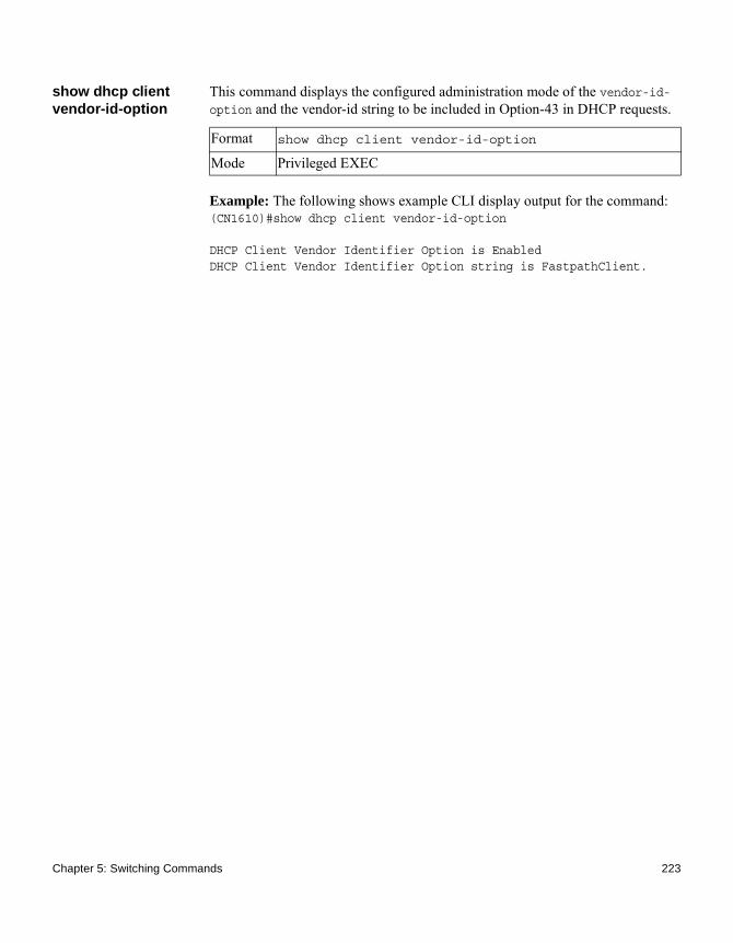
show dhcp client vendor-id-option
This command displays the configured administration mode of the vendor-id-option and the vendor-id string to be included in Option-43 in DHCP requests.
Example: The following shows example CLI display output for the command:(CN1610)#show dhcp client vendor-id-option
DHCP Client Vendor Identifier Option is EnabledDHCP Client Vendor Identifier Option string is FastpathClient.
Format show dhcp client vendor-id-option
Mode Privileged EXEC
Chapter 5: Switching Commands 223

DHCP L2 Relay Agent Commands
You can enable the switch to operate as a DHCP Layer 2 relay agent to relay DHCP requests from clients to a Layer 3 relay agent or server. The Circuit ID and Remote ID can be added to DHCP requests relayed from clients to a DHCP server. This information is included in DHCP Option 82, as specified in sections 3.1 and 3.2 of RFC3046.
dhcp l2relay This command enables the DHCP Layer 2 Relay agent for an interface a range of interfaces in, or all interfaces. The subsequent commands mentioned in this section can only be used when the DHCP L2 relay is enabled.
no dhcp l2relay This command disables DHCP Layer 2 relay agent for an interface or range of interfaces.
dhcp l2relay circuit-id subscription-name
This command sets the Option 82 Circuit ID for a given service subscription identified by subscription-string on a given interface. The subscription-string is a character string that needs to be matched with a configured DOT1AD subscription string for correct operation. When circuit-id is enabled using this command, all Client DHCP requests that fall under this service subscription are added with Option 82 Circuit ID as the incoming interface number.
Format dhcp l2relay
Mode ◆ Global Config◆ Interface Config
Format no dhcp l2relay
Mode ◆ Global Config◆ Interface Config
Default disabled
Format dhcp l2relay circuit-id subscription-name subscription-string
Mode Interface Config
224 DHCP L2 Relay Agent Commands
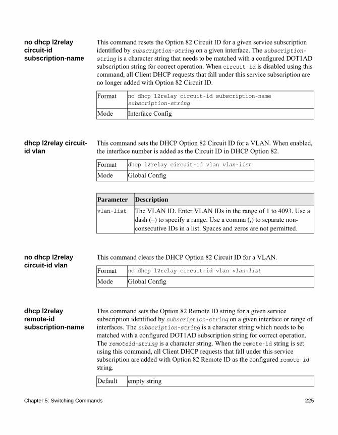
no dhcp l2relay circuit-id subscription-name
This command resets the Option 82 Circuit ID for a given service subscription identified by subscription-string on a given interface. The subscription-string is a character string that needs to be matched with a configured DOT1AD subscription string for correct operation. When circuit-id is disabled using this command, all Client DHCP requests that fall under this service subscription are no longer added with Option 82 Circuit ID.
dhcp l2relay circuit-id vlan
This command sets the DHCP Option 82 Circuit ID for a VLAN. When enabled, the interface number is added as the Circuit ID in DHCP Option 82.
no dhcp l2relay circuit-id vlan
This command clears the DHCP Option 82 Circuit ID for a VLAN.
dhcp l2relay remote-id subscription-name
This command sets the Option 82 Remote ID string for a given service subscription identified by subscription-string on a given interface or range of interfaces. The subscription-string is a character string which needs to be matched with a configured DOT1AD subscription string for correct operation. The remoteid-string is a character string. When the remote-id string is set using this command, all Client DHCP requests that fall under this service subscription are added with Option 82 Remote ID as the configured remote-id string.
Format no dhcp l2relay circuit-id subscription-name subscription-string
Mode Interface Config
Format dhcp l2relay circuit-id vlan vlan-list
Mode Global Config
Parameter Description
vlan–list The VLAN ID. Enter VLAN IDs in the range of 1 to 4093. Use a dash (–) to specify a range. Use a comma (,) to separate non-consecutive IDs in a list. Spaces and zeros are not permitted.
Format no dhcp l2relay circuit-id vlan vlan-list
Mode Global Config
Default empty string
Chapter 5: Switching Commands 225

no dhcp l2relay remote-id subscription-name
This command resets the Option 82 Remote ID string for a given service subscription identified by subscription-string on a given interface. The subscription-string is a character string which needs to be matched with a configured DOT1AD subscription string for correct operation. When the remote-id string is reset using this command, the Client DHCP requests that fall under this service subscription are not added with Option 82 Remote ID.
dhcp l2relay remote-id vlan
This parameter sets the DHCP Option 82 Remote ID for a VLAN and subscribed service (based on subscription-name).
no dhcp l2relay remote-id vlan
This parameter clears the DHCP Option 82 Remote ID for a VLAN and subscribed service (based on subscription-name).
Format dhcp l2relay remote-id remoteid-string subscription-name subscription-string
Mode Interface Config
Format no dhcp l2relay remote-id remoteid-string subscription-name subscription-string
Mode Interface Config
Format dhcp l2relay remote-id remote-id-string vlan vlan-list
Mode Global Config
Parameter Description
vlan–list The VLAN ID. Enter VLAN IDs in the range of 1 to 4093. Use a dash (–) to specify a range. Use a comma (,) to separate non-consecutive IDs in a list. Spaces and zeros are not permitted.
Format no dhcp l2relay remote-id vlan vlan-list
Mode Global Config
226 DHCP L2 Relay Agent Commands

dhcp l2relay subscription-name
This command enables relaying DHCP packets on an interface or range of interfaces that fall under the specified service subscription. The subscription-string is a character string that needs to be matched with configured DOT1AD subscription string for correct operation.
no dhcp l2relay subscription-name
This command disables relaying DHCP packets that fall under the specified service subscription. The subscription-string is a character string that needs to be matched with configured DOT1AD subscription string for correct operation.
dhcp l2relay trust This command configures an interface or range of interfaces as trusted for Option 82 reception.
no dhcp l2relay trust
This command configures an interface to the default untrusted for Option 82 reception.
dhcp l2relay vlan This command enables the DHCP L2 Relay agent for a set of VLANs. All DHCP packets which arrive on interfaces in the configured VLAN are subject to L2 Relay processing.
Default disabled (that is, no DHCP packets are relayed)Format dhcp l2relay subscription-name subscription-string
Mode Interface Config
Format no dhcp l2relay subscription-name subscription-string
Mode Interface Config
Default untrusted
Format dhcp l2relay trust
Mode Interface Config
Format no dhcp l2relay trust
Mode Interface Config
Default disable
Chapter 5: Switching Commands 227

no dhcp l2relay vlan This command disables the DHCP L2 Relay agent for a set of VLANs.
show dhcp l2relay all
This command displays the summary of DHCP L2 Relay configuration.
Example: The following shows example CLI display output for the command:(CN1610)#show dhcp l2relay all
DHCP L2 Relay is Enabled.
Interface L2RelayMode TrustMode---------- ----------- -------------- 0/2 Enabled untrusted 0/4 Disabled trusted
VLAN Id L2 Relay CircuitId RemoteId--------- ---------- ----------- ------------ 3 Disabled Enabled --NULL-- 5 Enabled Enabled --NULL-- 6 Enabled Enabled broadcom 7 Enabled Disabled --NULL-- 8 Enabled Disabled --NULL-- 9 Enabled Disabled --NULL-- 10 Enabled Disabled --NULL--
Format dhcp l2relay vlan vlan-list
Mode Global Config
Output Description
vlan–list The VLAN ID. Enter VLAN IDs in the range of 1 to 4093. Use a dash (–) to specify a range. Use a comma (,) to separate non-consecutive IDs in a list. Spaces and zeros are not permitted.
Format no dhcp l2relay vlan vlan-list
Mode Global Config
Format show dhcp l2relay all
Mode Privileged EXEC
228 DHCP L2 Relay Agent Commands

show dhcp l2relay circuit-id vlan
This command displays the DHCP L2 Relay circuit-id vlan configuration.
show dhcp l2relay interface
This command displays DHCP L2 relay configuration specific to interfaces.
Example: The following shows example CLI display output for the command:(CN1610)#show dhcp l2relay interface all
DHCP L2 Relay is Enabled.
Interface L2RelayMode TrustMode---------- ----------- -------------- 0/2 Enabled untrusted 0/4 Disabled trusted
show dhcp l2relay remote-id vlan
This command displays the DHCP L2 Relay remote-id vlan configuration.
Format show dhcp l2relay circuit-id vlan vlan-list
Mode Privileged EXEC
Output Description
vlan–list The VLAN ID. Enter VLAN IDs in the range of 1 to 4093. Use a dash (–) to specify a range. Use a comma (,) to separate non-consecutive IDs in a list. Spaces and zeros are not permitted.
Format show dhcp l2relay interface {all | interface-num}
Mode Privileged EXEC
Format show dhcp l2relay remote-id vlan vlan-list
Mode Privileged EXEC
Output Description
vlan–list The VLAN ID. Enter VLAN IDs in the range of 1 to 4093. Use a dash (–) to specify a range. Use a comma (,) to separate non-consecutive IDs in a list. Spaces and zeros are not permitted.
Chapter 5: Switching Commands 229

show dhcp l2relay stats interface
This command displays statistics specific to DHCP L2 Relay configured interface.
Example: The following shows example CLI display output for the command:(CN1610)#show dhcp l2relay stats interface all
DHCP L2 Relay is Enabled.
Interface UntrustedServer UntrustedClient TrustedServer TrustedClient MsgsWithOpt82 MsgsWithOpt82 MsgsWithoutOpt82 MsgsWithoutOpt82 --------- --------------- ----------------- ----------------- -------------- 0/1 0 0 0 0 0/2 0 0 3 7 0/3 0 0 0 0 0/4 0 12 0 0 0/5 0 0 0 0 0/6 3 0 0 0 0/7 0 0 0 0 0/8 0 0 0 0 0/9 0 0 0 0
show dhcp l2relay subscription interface
This command displays DHCP L2 Relay configuration specific to a service subscription on an interface.
Example: The following shows example CLI display output for the command:(CN1610)#show dhcp l2relay subscription interface allInterface SubscriptionName L2Relay mode Circuit-Id mode Remote-Id
mode mode mode----------- ---------------- ------------- --------------- --------------- 0/1 sub1 Enabled Disabled --NULL-- 0/2 sub3 Enabled Disabled EnterpriseSwitch 0/2 sub22 Disabled Enabled --NULL-- 0/4 sub4 Enabled Enabled --NULL--
Format show dhcp l2relay stats interface {all | interface-num}
Mode Privileged EXEC
Format show dhcp l2relay subscription interface {all|interface-num}
Mode Privileged EXEC
230 DHCP L2 Relay Agent Commands

show dhcp l2relay agent-option vlan
This command displays the DHCP L2 Relay Option 82 configuration specific to VLAN.
Example: The following shows example CLI display output for the command:(CN1610)#show dhcp l2relay agent-option vlan 5-10
DHCP L2 Relay is Enabled.
VLAN Id L2 Relay CircuitId RemoteId--------- ---------- ----------- ------------5 Enabled Enabled --NULL--6 Enabled Enabled broadcom7 Enabled Disabled --NULL--8 Enabled Disabled --NULL--9 Enabled Disabled --NULL--10 Enabled Disabled --NULL--
show dhcp l2relay vlan
This command displays the DHCP L2 Relay VLAN configuration.
clear dhcp l2relay statistics interface
This command resets the DHCP L2 relay counters to zero. Specify the port with the counters to clear, or use the all keyword to clear the counters on all ports.
Format show dhcp l2relay agent-option vlan vlan-range
Mode Privileged EXEC
Format show dhcp l2relay vlan vlan-list
Mode Privileged EXEC
Output Description
vlan–list The VLAN ID. Enter VLAN IDs in the range of 1 to 4093. Use a dash (–) to specify a range. Use a comma (,) to separate non-consecutive IDs in a list. Spaces and zeros are not permitted.
Format clear dhcp l2relay statistics interface {slot/port | all}
Mode Privileged EXEC
Chapter 5: Switching Commands 231
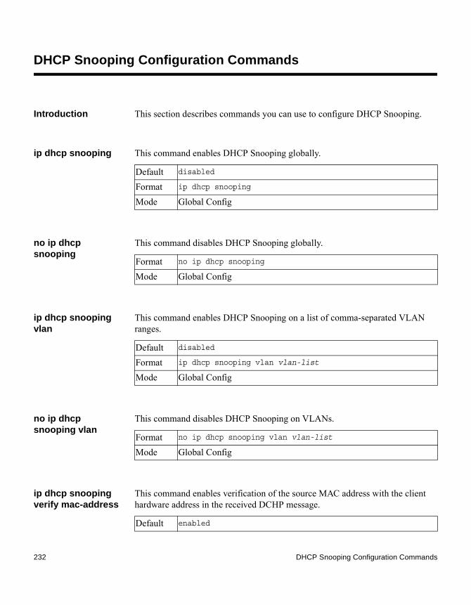
DHCP Snooping Configuration Commands
Introduction This section describes commands you can use to configure DHCP Snooping.
ip dhcp snooping This command enables DHCP Snooping globally.
no ip dhcp snooping
This command disables DHCP Snooping globally.
ip dhcp snooping vlan
This command enables DHCP Snooping on a list of comma-separated VLAN ranges.
no ip dhcp snooping vlan
This command disables DHCP Snooping on VLANs.
ip dhcp snooping verify mac-address
This command enables verification of the source MAC address with the client hardware address in the received DCHP message.
Default disabled
Format ip dhcp snooping
Mode Global Config
Format no ip dhcp snooping
Mode Global Config
Default disabled
Format ip dhcp snooping vlan vlan-list
Mode Global Config
Format no ip dhcp snooping vlan vlan-list
Mode Global Config
Default enabled
232 DHCP Snooping Configuration Commands

no ip dhcp snooping verify mac-address
This command disables verification of the source MAC address with the client hardware address.
ip dhcp snooping database
This command configures the persistent location of the DHCP Snooping database. This can be local or a remote file on a given IP machine.
ip dhcp snooping database write-delay
This command configures the interval, in seconds, at which the DHCP Snooping database will be persisted. The interval value ranges from 15 to 86400 seconds.
no ip dhcp snooping database write-delay
This command sets the write delay value to the default value.
ip dhcp snooping binding
This command configures static DHCP Snooping binding.
Format ip dhcp snooping verify mac-address
Mode Global Config
Format no ip dhcp snooping verify mac-address
Mode Global Config
Default local
Format ip dhcp snooping database {local|tftp://hostIP/filename}
Mode Global Config
Default 300 seconds
Format ip dhcp snooping database write-delay in seconds
Mode Global Config
Format no ip dhcp snooping database write-delay
Mode Global Config
Format ip dhcp snooping binding mac-address vlan vlan id ip address interface interface id
Mode Global Config
Chapter 5: Switching Commands 233

no ip dhcp snooping binding
This command removes the DHCP static entry from the DHCP Snooping database.
ip verify binding This command configures static IP source guard (IPSG) entries.
no ip verify binding This command removes the IPSG static entry from the IPSG database.
ip dhcp snooping limit
This command controls the rate at which the DHCP Snooping messages come on an interface or range of interfaces. By default, rate limiting is disabled. When enabled, the rate can range from 0 to 30 packets per second. The burst level range is 1 to 15 seconds.
no ip dhcp snooping limit
This command sets the rate at which the DHCP Snooping messages come, and the burst level, to the defaults.
Format no ip dhcp snooping binding mac-address
Mode Global Config
Format ip verify binding mac-address vlan vlan id ip address interface interface id
Mode Global Config
Format no ip verify binding mac-address vlan vlan id ip address interface interface id
Mode Global Config
Default disabled (no limit)
Format ip dhcp snooping limit {rate pps [burst interval seconds]}
Mode Interface Config
Format no ip dhcp snooping limit
Mode Interface Config
234 DHCP Snooping Configuration Commands

ip dhcp snooping log-invalid
This command controls the logging DHCP messages filtration by the DHCP Snooping application. Use this command to configure a single interface or a range of interfaces.
no ip dhcp snooping log-invalid
This command disables the logging DHCP messages filtration by the DHCP Snooping application.
ip dhcp snooping trust
This command configures an interface or range of interfaces as trusted.
no ip dhcp snooping trust
This command configures the port as untrusted.
ip verify source This command configures the IPSG source ID attribute to filter the data traffic in the hardware. Source ID is the combination of IP address and MAC address. Normal command allows data traffic filtration based on the IP address. With the port-security option, the data traffic will be filtered based on the IP and MAC addresses.
This command can be used to configure a single interface or a range of interfaces.
Default disabled
Format ip dhcp snooping log-invalid
Mode Interface Config
Format no ip dhcp snooping log-invalid
Mode Interface Config
Default disabled
Format ip dhcp snooping trust
Mode Interface Config
Format no ip dhcp snooping trust
Mode Interface Config
Default the source ID is the IP address
Format ip verify source {port-security}
Chapter 5: Switching Commands 235

no ip verify source This command disables the IPSG configuration in the hardware. You cannot disable port-security alone if it is configured.
show ip dhcp snooping
This command displays the DHCP Snooping global configurations and per port configurations.
Example: The following shows example CLI display output for the command:(CN1610)#show ip dhcp snooping
DHCP snooping is DisabledDHCP snooping source MAC verification is enabledDHCP snooping is enabled on the following VLANs:11 - 30, 40
Interface Trusted Log Invalid Pkts --------- -------- ----------------0/1 Yes No 0/2 No Yes 0/3 No Yes 0/4 No No0/6 No No
Mode Interface Config
Format no ip verify source
Mode Interface Config
Format show ip dhcp snooping
Mode ◆ Privileged EXEC◆ User EXEC
Output Description
Interface The interface for which data is displayed.Trusted If it is enabled, DHCP Snooping considers the port as trusted. The
factory default is disabled.Log Invalid Pkts
If it is enabled, DHCP Snooping application logs invalid packets on the specified interface.
236 DHCP Snooping Configuration Commands

show ip dhcp snooping binding
This command displays the DHCP Snooping binding entries. To restrict the output, use the following options:◆ Dynamic: Restrict the output based on DCHP snooping.◆ Interface: Restrict the output based on a specific interface.◆ Static: Restrict the output based on static entries.◆ VLAN: Restrict the output based on VLAN.
Example: The following shows example CLI display output for the command:(CN1610)#show ip dhcp snooping binding
Total number of bindings: 2
MAC Address IP Address VLAN Interface Type Lease time (Secs)------------------ ------------ ---- --------- ---- ------------------00:02:B3:06:60:80 210.1.1.3 10 0/1 8640000:0F:FE:00:13:04 210.1.1.4 10 0/1 86400
show ip dhcp snooping database
This command displays the DHCP Snooping configuration related to the database persistency.
Format show ip dhcp snooping binding [{static/dynamic}] [interface slot/port] [vlan id]
Mode ◆ Privileged EXEC◆ User EXEC
Output Description
MAC Address Displays the MAC address for the binding that was added. The MAC address is the key to the binding database.
IP Address Displays the valid IP address for the binding rule.VLAN The VLAN for the binding rule.Interface The interface to add a binding into the DHCP snooping interface.Type Binding type; statically configured from the CLI or dynamically
learned.Lease (sec) The remaining lease time for the entry.
Format show ip dhcp snooping database
Mode ◆ Privileged EXEC◆ User EXEC
Chapter 5: Switching Commands 237

Example: The following shows example CLI display output for the command:(CN1610)#show ip dhcp snooping database
agent url: /10.131.13.79:/sai1.txt
write-delay: 5000
show ip dhcp snooping interfaces
This command shows the DHCP Snooping status of the interfaces.
Example: The following shows example CLI display output for the command:(CN1610)#show ip dhcp snooping interfaces
Interface Trust State Rate LimitBurst Interval(pps) (seconds)
----------- ---------- ---------- --------------1/g1 No 15 11/g2 No 15 11/g3 No 15 1
(CN1610)#show ip dhcp snooping interfaces ethernet 1/g15
Interface Trust State Rate LimitBurst Interval(pps) (seconds)
----------- ---------- ---------- --------------1/g15 Yes 15 1
show ip dhcp snooping statistics
This command lists statistics for DHCP Snooping security violations on untrusted ports.
Output Description
Agent URL Bindings database agent URL.Write Delay The maximum write time to write the database into local or
remote.
Format show ip dhcp snooping interfaces
Mode Privileged EXEC
Format show ip dhcp snooping statistics
238 DHCP Snooping Configuration Commands
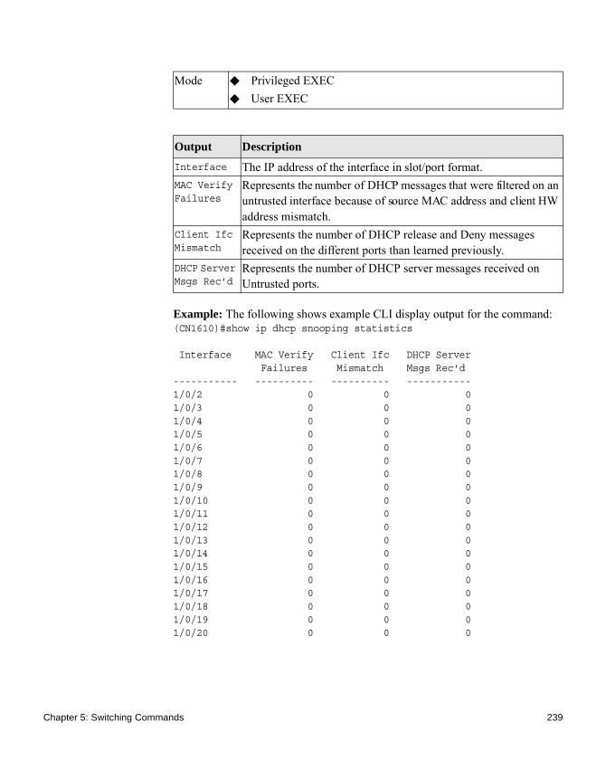
Example: The following shows example CLI display output for the command:(CN1610)#show ip dhcp snooping statistics
Interface MAC Verify Client Ifc DHCP Server Failures Mismatch Msgs Rec'd----------- ---------- ---------- -----------1/0/2 0 0 01/0/3 0 0 01/0/4 0 0 01/0/5 0 0 01/0/6 0 0 01/0/7 0 0 01/0/8 0 0 01/0/9 0 0 01/0/10 0 0 01/0/11 0 0 01/0/12 0 0 01/0/13 0 0 01/0/14 0 0 01/0/15 0 0 01/0/16 0 0 01/0/17 0 0 01/0/18 0 0 01/0/19 0 0 01/0/20 0 0 0
Mode ◆ Privileged EXEC◆ User EXEC
Output Description
Interface The IP address of the interface in slot/port format.MAC Verify Failures
Represents the number of DHCP messages that were filtered on an untrusted interface because of source MAC address and client HW address mismatch.
Client Ifc Mismatch
Represents the number of DHCP release and Deny messages received on the different ports than learned previously.
DHCP Server Msgs Rec’d
Represents the number of DHCP server messages received on Untrusted ports.
Chapter 5: Switching Commands 239
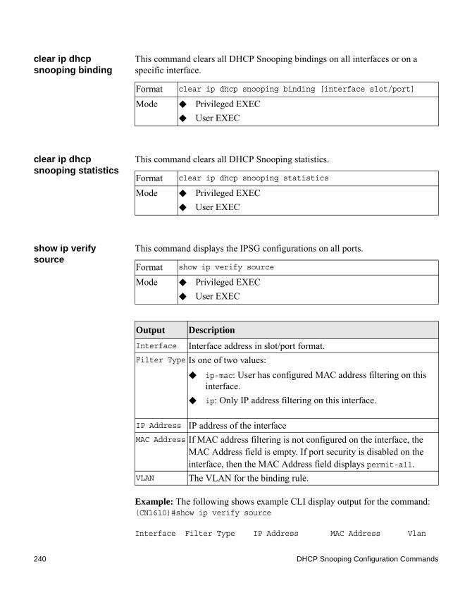
clear ip dhcp snooping binding
This command clears all DHCP Snooping bindings on all interfaces or on a specific interface.
clear ip dhcp snooping statistics
This command clears all DHCP Snooping statistics.
show ip verify source
This command displays the IPSG configurations on all ports.
Example: The following shows example CLI display output for the command:(CN1610)#show ip verify source
Interface Filter Type IP Address MAC Address Vlan
Format clear ip dhcp snooping binding [interface slot/port]
Mode ◆ Privileged EXEC◆ User EXEC
Format clear ip dhcp snooping statistics
Mode ◆ Privileged EXEC◆ User EXEC
Format show ip verify source
Mode ◆ Privileged EXEC◆ User EXEC
Output Description
Interface Interface address in slot/port format.Filter Type Is one of two values:
◆ ip-mac: User has configured MAC address filtering on this interface.
◆ ip: Only IP address filtering on this interface.
IP Address IP address of the interfaceMAC Address If MAC address filtering is not configured on the interface, the
MAC Address field is empty. If port security is disabled on the interface, then the MAC Address field displays permit-all.
VLAN The VLAN for the binding rule.
240 DHCP Snooping Configuration Commands

--------- ----------- --------------- ----------------- ----- 0/1 ip-mac 210.1.1.3 00:02:B3:06:60:80 10 0/1 ip-mac 210.1.1.4 00:0F:FE:00:13:04 10
show ip verify interface
This command displays the IPSG filter type for a specific interface.
show ip source binding
This command displays the IPSG bindings.
This command displays the following output:
Format show ip verify interface slot/port
Mode ◆ Privileged EXEC◆ User EXEC
Output Description
Interface Interface address in slot/port format.Filter Type Is one of two values:
◆ ip-mac: User has configured MAC address filtering on this interface.
◆ ip: Only IP address filtering on this interface.
Format show ip source binding [dhcp-snooping][{static/dynamic}] [interface slot/port] [vlan id]
Mode ◆ Privileged EXEC◆ User EXEC
Parameter Description
dhcp-snooping
Restrict the output based on DHCP snooping.
static or dynamic
Restrict the output based on static or dynamic entries.
interface Restrict the output based on a specific interface.vlan id Restrict the output based on vlan.
Output Description
MAC Address The MAC address for the entry that is added.
Chapter 5: Switching Commands 241

Example: The following shows example CLI display output for the command:(CN1610)#show ip source binding
MAC Address IP Address Type VLAN Interface----------------- --------------- ---------- ----- -------------00:00:00:00:00:08 1.2.3.4 dhcp-snooping 2 1/0/100:00:00:00:00:09 1.2.3.4 dhcp-snooping 3 1/0/100:00:00:00:00:0A 1.2.3.4 dhcp-snooping 4 1/0/1
IP Address The IP address of the entry that is added.Type Entry type; statically configured from CLI or dynamically learned
from DHCP Snooping.VLAN VLAN for the entry.Interface IP address of the interface in slot/port format.
Output Description
242 DHCP Snooping Configuration Commands
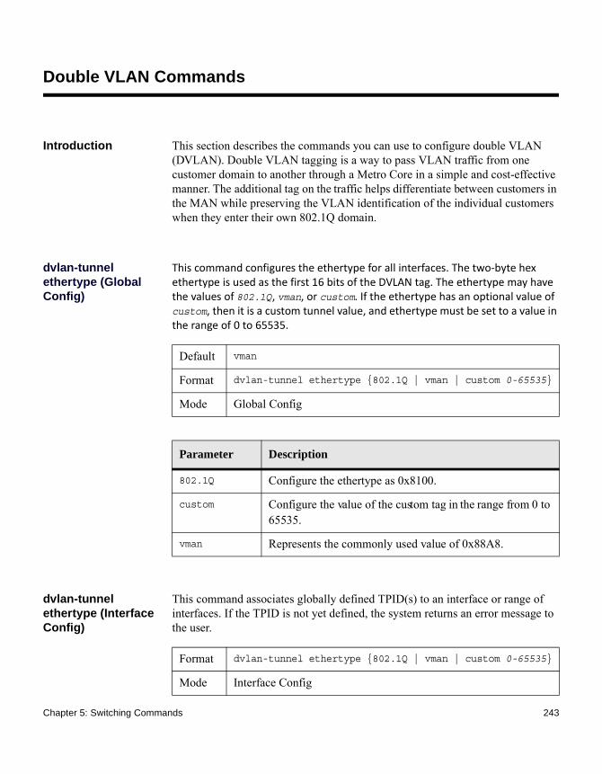
Double VLAN Commands
Introduction This section describes the commands you can use to configure double VLAN (DVLAN). Double VLAN tagging is a way to pass VLAN traffic from one customer domain to another through a Metro Core in a simple and cost-effective manner. The additional tag on the traffic helps differentiate between customers in the MAN while preserving the VLAN identification of the individual customers when they enter their own 802.1Q domain.
dvlan-tunnel ethertype (Global Config)
This command configures the ethertype for all interfaces. The two-byte hex ethertype is used as the first 16 bits of the DVLAN tag. The ethertype may have the values of 802.1Q, vman, or custom. If the ethertype has an optional value of custom, then it is a custom tunnel value, and ethertype must be set to a value in the range of 0 to 65535.
dvlan-tunnel ethertype (Interface Config)
This command associates globally defined TPID(s) to an interface or range of interfaces. If the TPID is not yet defined, the system returns an error message to the user.
Default vman
Format dvlan-tunnel ethertype {802.1Q | vman | custom 0-65535}
Mode Global Config
Parameter Description
802.1Q Configure the ethertype as 0x8100.
custom Configure the value of the custom tag in the range from 0 to 65535.
vman Represents the commonly used value of 0x88A8.
Format dvlan-tunnel ethertype {802.1Q | vman | custom 0-65535}
Mode Interface Config
Chapter 5: Switching Commands 243

no dvlan-tunnel ethertype (Interface Config)
Use the no form of this command to disassociate globally defined TPID(s) to an interface.
dvlan-tunnel ethertype default-tpid
This command creates a new TPID and associate it with the next available TPID register. If no TPID registers are empty, the system returns an error to the user. Specifying the optional keyword [default–tpid] forces the TPID value to be configured as the default TPID at index 0.
Parameter Description
802.1Q Configure the ethertype as 0x8100.
custom Configure the value of the custom tag in the range from 0 to 65535.
vman Represents the commonly used value of 0x88A8.
Format no dvlan-tunnel ethertype {802.1Q | vman | custom 0-65535}
Mode Interface Config
Format dvlan-tunnel ethertype {802.1Q | vman | custom 0–65535} [default-tpid]
Mode Global Config
Parameter Description
802.1Q Configure the ethertype as 0x8100.
custom Configure the value of the custom tag in the range from 0 to 65535.
vman Represents the commonly used value of 0x88A8.
244 Double VLAN Commands

no dvlan-tunnel ethertype default–tpid
Use the no form of this command to set the TPID register to 0. (At initialization, all TPID registers will be set to their default values.)
mode dot1q-tunnel This command enables double VLAN tunneling on the specified interface.
no mode dot1q-tunnel
This command disables double VLAN tunneling on the specified interface. By default, double VLAN tunneling is disabled.
mode dvlan-tunnel This command enables double VLAN tunneling on the specified interface.
NoteWhen you use the mode dvlan-tunnel command on an interface, it becomes a service provider port. Ports that do not have double VLAN tunneling enabled are customer ports.
Format no dvlan-tunnel ethertype {802.1Q | vman | custom 0–65535} [default-tpid]
Mode Global Config
Default disabled
Format mode dot1q-tunnel
Mode Interface Config
Format no mode dot1q-tunnel
Mode Interface Config
Default disabled
Format mode dvlan-tunnel
Mode Interface Config
Chapter 5: Switching Commands 245
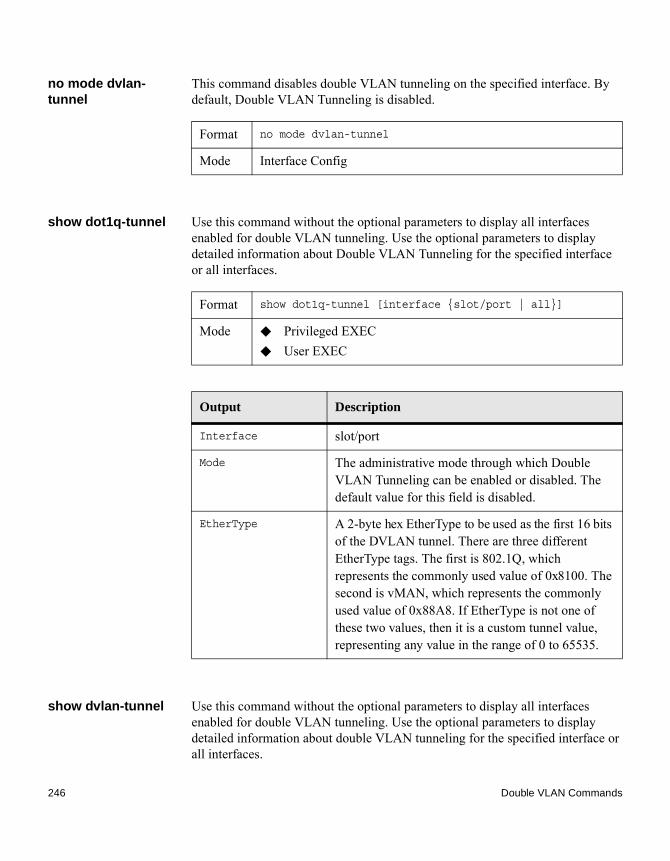
no mode dvlan-tunnel
This command disables double VLAN tunneling on the specified interface. By default, Double VLAN Tunneling is disabled.
show dot1q-tunnel Use this command without the optional parameters to display all interfaces enabled for double VLAN tunneling. Use the optional parameters to display detailed information about Double VLAN Tunneling for the specified interface or all interfaces.
show dvlan-tunnel Use this command without the optional parameters to display all interfaces enabled for double VLAN tunneling. Use the optional parameters to display detailed information about double VLAN tunneling for the specified interface or all interfaces.
Format no mode dvlan-tunnel
Mode Interface Config
Format show dot1q-tunnel [interface {slot/port | all}]
Mode ◆ Privileged EXEC◆ User EXEC
Output Description
Interface slot/port
Mode The administrative mode through which Double VLAN Tunneling can be enabled or disabled. The default value for this field is disabled.
EtherType A 2-byte hex EtherType to be used as the first 16 bits of the DVLAN tunnel. There are three different EtherType tags. The first is 802.1Q, which represents the commonly used value of 0x8100. The second is vMAN, which represents the commonly used value of 0x88A8. If EtherType is not one of these two values, then it is a custom tunnel value, representing any value in the range of 0 to 65535.
246 Double VLAN Commands

Example: The following shows examples of the CLI display for this command:(CN1610) #show dvlan-tunnel
TPIDs Configured............................... 0x88a8Default TPID................................... 0x88a8Interfaces Enabled for DVLAN Tunneling......... None
(CN1610)#
(CN1610)#show dvlan-tunnel interface 1/0/1
Interface Mode EtherType--------- ------- ------------
1/0/1 Disable 0x88a8
Format show dvlan-tunnel [interface {slot/port | all}]
Mode ◆ Privileged EXEC◆ User EXEC
Output Description
Interface The valid slot and port numbers separated by slashes.
Mode The administrative mode through which Double VLAN Tunneling can be enabled or disabled. The default value for this field is disabled.
EtherType A 2-byte hex EtherType to be used as the first 16 bits of the DVLAN tunnel. There are three different EtherType tags. The first is 802.1Q, which represents the commonly used value of 0x8100. The second is vMAN, which represents the commonly used value of 0x88A8. If EtherType is not one of these two values, then it is a custom tunnel value, representing any value in the range of 0 to 65535.
Chapter 5: Switching Commands 247

Dynamic ARP Inspection Commands
Introduction Dynamic ARP Inspection (DAI) is a security feature that rejects invalid and malicious ARP packets. DAI prevents a class of man-in-the-middle attacks, where an unfriendly station intercepts traffic for other stations by poisoning the ARP caches of its unsuspecting neighbors. The miscreant sends ARP requests or responses mapping another station’s IP address to its own MAC address.
DAI relies on DHCP snooping. DHCP snooping listens to DHCP message exchanges and builds a binding database of valid {MAC address, IP address, VLAN, and interface} tuples.
When DAI is enabled, the switch drops ARP packets whose sender MAC address and sender IP address do not match an entry in the DHCP snooping bindings database. You can optionally configure additional ARP packet validation.
ip arp inspection vlan
This command enables Dynamic ARP Inspection on a list of comma-separated VLAN ranges.
no ip arp inspection vlan
This command disables Dynamic ARP Inspection on a list of comma-separated VLAN ranges.
ip arp inspection validate
This command enables additional validation checks like source-mac validation, destination-mac validation, and ip address validation on the received ARP packets. Each command overrides the configuration of the previous command. For example, if a command enables src-mac and dst-mac validations, and a second command enables IP validation only, the src-mac and dst-mac validations are disabled as a result of the second command.
Default disabled
Format ip arp inspection vlan vlan-list
Mode Global Config
Format no ip arp inspection vlan vlan-list
Mode Global Config
248 Dynamic ARP Inspection Commands

no ip arp inspection validate
This command disables the additional validation checks on the received ARP packets.
ip arp inspection vlan logging
This command enables logging of invalid ARP packets on a list of comma-separated VLAN ranges.
no ip arp inspection vlan logging
This command disables logging of invalid ARP packets on a list of comma-separated VLAN ranges.
ip arp inspection trust
This command configures an interface or range of interfaces as trusted for Dynamic ARP Inspection.
no ip arp inspection trust
This command configures an interface as untrusted for Dynamic ARP Inspection.
Default disabled
Format ip arp inspection validate {[src-mac] [dst-mac] [ip]}
Mode Global Config
Format no ip arp inspection validate {[src-mac] [dst-mac] [ip]}
Mode Global Config
Default enabled
Format ip arp inspection vlan vlan-list logging
Mode Global Config
Format no ip arp inspection vlan vlan-list logging
Mode Global Config
Default enabled
Format ip arp inspection trust
Mode Interface Config
Format no ip arp inspection trust
Chapter 5: Switching Commands 249

ip arp inspection limit
This command configures the rate limit and burst interval values for an interface or range of interfaces. Configuring none for the limit means the interface is not rate limited for Dynamic ARP Inspections. The maximum pps value shown in the range for the rate option might be more than the hardware allowable limit. Therefore you need to understand the switch performance and configure the maximum rate pps accordingly.
NoteThe user interface will accept a rate limit for a trusted interface, but the limit will not be enforced unless the interface is configured to be untrusted.
no ip arp inspection limit
This command sets the rate limit and burst interval values for an interface to the default values of 15 pps and 1 second, respectively.
ip arp inspection filter
This command configures the ARP ACL used to filter invalid ARP packets on a list of comma-separated VLAN ranges. If the static keyword is given, packets that do not match a permit statement are dropped without consulting the DHCP snooping bindings.
no ip arp inspection filter
This command unconfigures the ARP ACL used to filter invalid ARP packets on a list of comma-separated VLAN ranges.
Mode Interface Config
Default 15 pps for rate and 1 second for burst-interval
Format ip arp inspection limit {rate pps [burst interval seconds] | none}
Mode Interface Config
Format no ip arp inspection limit
Mode Interface Config
Default No ARP ACL is configured on a VLAN
Format ip arp inspection filter acl-name vlan vlan-list [static]
Mode Global Config
250 Dynamic ARP Inspection Commands

arp access-list This command creates an ARP ACL.
no arp access-list This command deletes a configured ARP ACL.
permit ip host mac host
This command configures a rule for a valid IP address and MAC address combination used in ARP packet validation.
no permit ip host mac host
This command deletes a rule for a valid IP and MAC combination.
show ip arp inspection
This command displays the Dynamic ARP Inspection global configuration and configuration on all the VLANs. With the vlan-list argument (that is, comma- separated VLAN ranges), the command displays the global configuration and configuration on all the VLANs in the given VLAN list. The global configuration includes the source mac validation, destination mac validation and invalid IP validation information.
Format no ip arp inspection filter acl-name vlan vlan-list [static]
Mode Global Config
Format arp access-list acl-name
Mode Global Config
Format no arp access-list acl-name
Mode Global Config
Format permit ip host sender-ip mac host sender-mac
Mode ARP Access-list Config
Format no permit ip host sender-ip mac host sender-mac
Mode ARP Access-list Config
Format show ip arp inspection [vlan vlan-list]
Chapter 5: Switching Commands 251
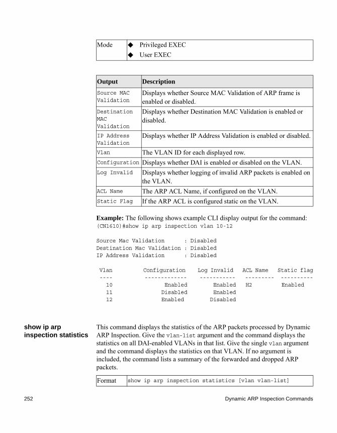
Example: The following shows example CLI display output for the command:(CN1610)#show ip arp inspection vlan 10-12
Source Mac Validation : DisabledDestination Mac Validation : DisabledIP Address Validation : Disabled
Vlan Configuration Log Invalid ACL Name Static flag ---- ------------- ----------- --------- ---------- 10 Enabled Enabled H2 Enabled 11 Disabled Enabled 12 Enabled Disabled
show ip arp inspection statistics
This command displays the statistics of the ARP packets processed by Dynamic ARP Inspection. Give the vlan-list argument and the command displays the statistics on all DAI-enabled VLANs in that list. Give the single vlan argument and the command displays the statistics on that VLAN. If no argument is included, the command lists a summary of the forwarded and dropped ARP packets.
Mode ◆ Privileged EXEC◆ User EXEC
Output Description
Source MAC Validation
Displays whether Source MAC Validation of ARP frame is enabled or disabled.
Destination MAC Validation
Displays whether Destination MAC Validation is enabled or disabled.
IP Address Validation
Displays whether IP Address Validation is enabled or disabled.
Vlan The VLAN ID for each displayed row.Configuration Displays whether DAI is enabled or disabled on the VLAN.Log Invalid Displays whether logging of invalid ARP packets is enabled on
the VLAN.ACL Name The ARP ACL Name, if configured on the VLAN.Static Flag If the ARP ACL is configured static on the VLAN.
Format show ip arp inspection statistics [vlan vlan-list]
252 Dynamic ARP Inspection Commands

Example: The following shows example CLI display output for the command show ip arp inspection statistics which lists the summary of forwarded and dropped ARP packets on all DAI-enabled VLANs:
(CN1610)# show ip arp inspection statistics
VLAN Forwarded Dropped---- --------- ------- 10 90 14 20 10 3
Example: The following shows example CLI display output for the command:(CN1610)# show ip arp inspection statistics vlan vlan-list
VLAN DHCP ACL DHCP ACL Bad Src Bad Dest InvalidDrops Drops Permits Permits MAC MAC IP----- -------- --------- ----------- --------- ---------- --------- -----10 11 1 65 25 1 1 0
Mode ◆ Privileged EXEC◆ User EXEC
Output Description
VLAN The VLAN ID for each displayed row.Forwarded The total number of valid ARP packets forwarded in this VLAN.Dropped The total number of not valid ARP packets dropped in this VLAN.DHCP Drops The number of packets dropped due to DHCP snooping binding
database match failure.ACL Drops The number of packets dropped due to ARP ACL rule match
failure.DHCP Permits
The number of packets permitted due to DHCP snooping binding database match.
ACL Permits The number of packets permitted due to ARP ACL rule match.Bad Src MAC The number of packets dropped due to Source MAC validation
failure.Bad Dest MAC
The number of packets dropped due to Destination MAC validation failure.
Invalid IP The number of packets dropped due to invalid IP checks.
Chapter 5: Switching Commands 253

20 1 0 8 2 0 1 1
clear ip arp inspection statistics
This command resets the statistics for Dynamic ARP Inspection on all VLANs.
show ip arp inspection interfaces
This command displays the Dynamic ARP Inspection configuration on all the DAI-enabled interfaces. An interface is said to be enabled for DAI if at least one VLAN, that the interface is a member of, is enabled for DAI. Given a slot/port interface argument, the command displays the values for that interface whether the interface is enabled for DAI or not.
Example: The following shows example CLI display output for the command:(CN1610)#show ip arp inspection interfaces
Interface Trust State Rate Limit Burst Interval (pps) (seconds) --------------- ----------- ---------- --------------- 0/1 Untrusted 15 1 0/2 Untrusted 10 10
Default none
Format clear ip arp inspection statistics
Mode Privileged EXEC
Format show ip arp inspection interfaces [slot/port]
Mode ◆ Privileged EXEC◆ User EXEC
Output Description
Interface The interface ID for each displayed row.Trust State Whether the interface is trusted or untrusted for DAI.Rate Limit The configured rate limit value in packets per second.Burst Interval
The configured burst interval value in seconds.
254 Dynamic ARP Inspection Commands

clear arp-switch This command clears the contents of the switch’s Address Resolution Protocol (ARP) table that contains entries learned through the Management port. To observe whether this command is successful, ping from the remote system to the DUT. Issue the show arp switch command to see the ARP entries. Then issue the clear arp-switch command and check the show arp switch entries. There will be no more ARP entries.
show arp access-list
This command displays the configured ARP ACLs with the rules. Giving an ARP ACL name as the argument will display only the rules in that ARP ACL.
Example: The following shows example CLI display output for the command:(CN1610)#show arp access-list
ARP access list H2 permit ip host 1.1.1.1 mac host 00:01:02:03:04:05 permit ip host 1.1.1.2 mac host 00:03:04:05:06:07ARP access list H3ARP access list H4 permit ip host 2.1.1.2 mac host 00:03:04:05:06:08
Format clear arp-switch
Mode Privileged EXEC
Format show arp access-list [acl-name]
Mode ◆ Privileged EXEC◆ User EXEC
Chapter 5: Switching Commands 255

802.1X Supplicant Commands
Introduction CN1610 supports 802.1X (dot1x) supplicant functionality on point-to-point ports. The administrator can configure the user name and password used in authentication and capabilities of the supplicant port.
dot1x pae This command sets the port’s dot1x role. The port can serve as either a supplicant or an authenticator.
dot1x supplicant port-control
This command sets the ports authorization state (Authorized or Unauthorized) either manually or by setting the port to auto-authorize upon startup. By default all the ports are authenticators. If the port’s attribute needs to be moved from <authenticator to supplicant> or <supplicant to authenticator>, use this command.
Format dot1x pae {supplicant | authenticator}
Mode Interface Config
Default auto
Format dot1x supplicant port-control {auto | force-authorized | force_unauthorized}
Mode Interface Config
Parameter Description
auto The port is in the Unauthorized state until it presents its user name and password credentials to an authenticator. If the authenticator authorizes the port, then it is placed in the Authorized state.
force-authorized Sets the authorization state of the port to Authorized, bypassing the authentication process.
256 802.1X Supplicant Commands
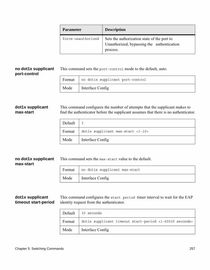
no dot1x supplicant port-control
This command sets the port-control mode to the default, auto.
dot1x supplicant max-start
This command configures the number of attempts that the supplicant makes to find the authenticator before the supplicant assumes that there is no authenticator.
no dot1x supplicant max-start
This command sets the max-start value to the default.
dot1x supplicant timeout start-period
This command configures the start period timer interval to wait for the EAP identity request from the authenticator.
force-unauthorized Sets the authorization state of the port to Unauthorized, bypassing the authentication process.
Parameter Description
Format no dot1x supplicant port-control
Mode Interface Config
Default 3
Format dot1x supplicant max-start <1-10>
Mode Interface Config
Format no dot1x supplicant max-start
Mode Interface Config
Default 30 seconds
Format dot1x supplicant timeout start-period <1-65535 seconds>
Mode Interface Config
Chapter 5: Switching Commands 257

no dot1x supplicant timeout start-period
This command sets the start-period value to the default.
dot1x supplicant timeout held-period
This command configures the held-period timer interval to wait for the next authentication on previous authentication fail.
no dot1x supplicant timeout held-period
This command sets the held-period value to the default value.
dot1x supplicant timeout auth-period
This command configures the authentication period timer interval to wait for the next EAP request challenge from the authenticator.
no dot1x supplicant timeout auth-period
This command sets the auth-period value to the default value.
Format no dot1x supplicant timeout start-period
Mode Interface Config
Default 30 seconds
Format dot1x supplicant timeout held-period <1-65535 seconds>
Mode Interface Config
Format no dot1x supplicant timeout held-period
Mode Interface Config
Default 30 seconds
Format dot1x supplicant timeout auth-period <1-65535 seconds>
Mode Interface Config
Format no dot1x supplicant timeout auth-period
Mode Interface Config
258 802.1X Supplicant Commands

dot1x supplicant user
This command maps the given user to the port.
show dot1x statistics
This command displays the dot1x port statistics in detail.
Format dot1x supplicant user
Mode Interface Config
Format show dot1x statistics slot/port
Mode ◆ Privileged EXEC◆ User EXEC
Output Description
EAPOL Frames Received
Displays the number of valid EAPOL frames received on the port.
EAPOL Frames Transmitted
Displays the number of EAPOL frames transmitted via the port.
EAPOL Start Frames Transmitted
Displays the number of EAPOL Start frames transmitted via the port.
EAPOL Logoff Frames Received
Displays the number of EAPOL Log off frames that have been received on the port.
EAP Resp/ID Frames Received
Displays the number of EAP Respond ID frames that have been received on the port.
EAP Response Frames Received
Displays the number of valid EAP Respond frames received on the port.
EAP Req/ID Frames Transmitted
Displays the number of EAP Requested ID frames transmitted via the port.
Chapter 5: Switching Commands 259

Example: The following shows example CLI display output for the command:(CN1610)#show dot1x statistics 0/1Port........................................... 0/1EAPOL Frames Received.......................... 0EAPOL Frames Transmitted....................... 0EAPOL Start Frames Transmitted................. 3EAPOL Logoff Frames Received................... 0EAP Resp/Id frames transmitted................. 0EAP Response frames transmitted................ 0EAP Req/Id frames transmitted.................. 0EAP Req frames transmitted..................... 0Invalid EAPOL frames received.................. 0EAP length error frames received............... 0Last EAPOL Frame Version....................... 0Last EAPOL Frame Source........................ 00:00:00:00:02:01
EAP Req Frames Transmitted
Displays the number of EAP Request frames transmitted via the port.
Invalid EAPOL Frames Received
Displays the number of unrecognized EAPOL frames received on this port.
EAP Length Error Frames Received
Displays the number of EAPOL frames with an invalid Packet Body Length received on this port.
Last EAPOL Frames Version
Displays the protocol version number attached to the most recently received EAPOL frame.
Last EAPOL Frames Source
Displays the source MAC Address attached to the most recently received EAPOL frame.
Output Description
260 802.1X Supplicant Commands

GARP Commands
Introduction This section describes the commands you use to configure Generic Attribute Registration Protocol (GARP) and view GARP status. These commands affect both GARP VLAN Registration Protocol (GVRP) and GARP Multicast Registration Protocol (GMRP). GARP is a protocol that allows client stations to register with the switch for membership in VLANS (by using GVMP) or multicast groups (by using GVMP).
set garp timer join This command sets the GVRP join time per GARP for one interface, a range of interfaces, or all interfaces. The join time is the interval between the transmission of GARP Protocol Data Units (PDUs) registering (or re-registering) membership for a VLAN or multicast group. This command has an effect only when GVRP is enabled. The time is from 10 to 100 (centiseconds). The default value 20 centiseconds is 0.2 seconds.
no set garp timer join
This command sets the GVRP join time to the default and only has an effect when GVRP is enabled.
set garp timer leave This command sets the GVRP leave time for one interface, a range of interfaces, or all interfaces or all ports and only has an effect when GVRP is enabled. The leave time is the time to wait after receiving an unregister request for a VLAN or a multicast group before deleting the VLAN entry. This can be considered a buffer time for another station to assert registration for the same attribute in order
Default 20
Format set garp timer join 10-100
Mode ◆ Interface Config◆ Global Config
Format no set garp timer join
Mode ◆ Interface Config◆ Global Config
Chapter 5: Switching Commands 261

to maintain uninterrupted service. The leave time is 20 to 600 (centiseconds). The value 60 centiseconds is 0.6 seconds. The leave time must be greater than or equal to three times the join time.
no set garp timer leave
This command sets the GVRP leave time on all ports or a single port to the default and only has an effect when GVRP is enabled.
set garp timer leaveall
This command sets how frequently Leave All PDUs are generated. A Leave All PDU indicates that all registrations will be unregistered. Participants would need to rejoin in order to maintain registration. The value applies per port and per GARP participation. The time may range from 200 to 6000 (centiseconds). The default value 1000 centiseconds is 10 seconds. You can use this command on all ports (Global Config mode), or on a single port or a range of ports (Interface Config mode) and it only has an effect only when GVRP is enabled. The leave all time must be greater than the leave time.
no set garp timer leaveall
This command sets how frequently Leave All PDUs are generated the default and only has an effect when GVRP is enabled.
Default 60
Format set garp timer leave 20-600
Mode ◆ Interface Config◆ Global Config
Format no set garp timer leave
Mode ◆ Interface Config◆ Global Config
Default 1000
Format set garp timer leaveall 200-6000
Mode ◆ Interface Config◆ Global Config
Format no set garp timer leaveall
Mode ◆ Interface Config◆ Global Config
262 GARP Commands

show garp This command displays GARP information.
Format show garp
Mode ◆ Privileged EXEC◆ User EXEC
Output Description
GMRP Admin Mode
The administrative mode of GARP Multicast Registration Protocol (GMRP) for the system.
GVRP Admin Mode
The administrative mode of GARP VLAN Registration Protocol (GVRP) for the system.
Chapter 5: Switching Commands 263

GMRP Commands
Introduction This section describes the commands you use to configure and view GARP Multicast Registration Protocol (GMRP) information. Like IGMP snooping, GMRP helps control the flooding of multicast packets.GMRP-enabled switches dynamically register and deregister group membership information with the MAC networking devices attached to the same segment. GMRP also allows group membership information to propagate across all networking devices in the bridged LAN that support Extended Filtering Services.
NoteIf GMRP is disabled, the system does not forward GMRP messages.
set gmrp adminmode
This command enables GARP Multicast Registration Protocol (GMRP) on the system.
no set gmrp adminmode
This command disables GARP Multicast Registration Protocol (GMRP) on the system.
set gmrp interfacemode
This command enables GARP Multicast Registration Protocol on a single interface (Interface Config mode), a range of interfaces, or all interfaces (Global Config mode). If an interface which has GARP enabled is enabled for routing or is enlisted as a member of a port channel (LAG), GARP functionality is disabled on that interface. GARP functionality is subsequently re-enabled if routing is disabled and port channel (LAG) membership is removed from an interface that has GARP enabled.
Default disabled
Format set gmrp adminmode
Mode Privileged EXEC
Format no set gmrp adminmode
Mode Privileged EXEC
Default disabled
264 GMRP Commands

no set gmrp interfacemode
This command disables GARP Multicast Registration Protocol on a single interface or all interfaces. If an interface which has GARP enabled is enabled for routing or is enlisted as a member of a port channel (LAG), GARP functionality is disabled. GARP functionality is subsequently re-enabled if routing is disabled and port channel (LAG) membership is removed from an interface that has GARP enabled.
show gmrp configuration
This command displays Generic Attributes Registration Protocol (GARP) information for one or all interfaces.
Format set gmrp interfacemode
Mode ◆ Interface Config ◆ Global Config
Format no set gmrp interfacemode
Mode ◆ Interface Config◆ Global Config
Format show gmrp configuration {slot/port | all}
Mode ◆ Privileged EXEC◆ User EXEC
Output Description
Interface The slot/port of the interface that this row in the table describes.Join Timer The interval between the transmission of GARP PDUs registering
(or reregistering) membership for an attribute. Current attributes are a VLAN or multicast group. There is an instance of this timer on a per-port, per-GARP participant basis. Permissible values are 10 to 100 centiseconds (0.1 to 1.0 seconds). The factory default is 20 centiseconds (0.2 seconds). The finest granularity of specification is 1 centisecond (0.01 seconds).
Chapter 5: Switching Commands 265

show mac-address-table gmrp
This command displays the GMRP entries in the Multicast Forwarding Database (MFDB) table.
Leave Timer The period of time to wait after receiving an unregister request for an attribute before deleting the attribute. Current attributes are a VLAN or multicast group. This may be considered a buffer time for another station to assert registration for the same attribute in order to maintain uninterrupted service. There is an instance of this timer on a per-Port, per-GARP participant basis. Permissible values are 20 to 600 centiseconds (0.2 to 6.0 seconds). The factory default is 60 centiseconds (0.6 seconds).
LeaveAll Timer
This Leave All Time controls how frequently LeaveAll PDUs are generated. A LeaveAll PDU indicates that all registrations will shortly be deregistered. Participants will need to rejoin in order to maintain registration. There is an instance of this timer on a per-Port, per-GARP participant basis. The Leave All Period Timer is set to a random value in the range of LeaveAllTime to 1.5*LeaveAllTime. Permissible values are 200 to 6000 centiseconds (2 to 60 seconds). The factory default is 1000 centiseconds (10 seconds).
Port GMRP Mode
The GMRP administrative mode for the port. It may be enabled or disabled. If this parameter is disabled, Join Time, Leave Time and Leave All Time have no effect.
Output Description
Format show mac-address-table gmrp
Mode Privileged EXEC
Output Description
VLAN ID The VLAN in which the MAC Address is learned.MAC Address A unicast MAC address for which the switch has forwarding and
or filtering information. The format is 6 two-digit hexadecimal numbers that are separated by colons, for example, 01:23:45:67:89:AB.
266 GMRP Commands

Type The type of the entry. Static entries are those that are configured by the end user. Dynamic entries are added to the table as a result of a learning process or protocol.
Description The text description of this multicast table entry.Interfaces The list of interfaces that are designated for forwarding (Fwd:)
and filtering (Flt:).
Output Description
Chapter 5: Switching Commands 267

GVRP Commands
Introduction This section describes the commands you use to configure and view GARP VLAN Registration Protocol (GVRP) information. GVRP-enabled switches exchange VLAN configuration information, which allows GVRP to provide dynamic VLAN creation on trunk ports and automatic VLAN pruning.
NoteIf GVRP is disabled, the system does not forward GVRP messages.
set gvrp adminmode
This command enables GVRP on the system.
no set gvrp adminmode
This command disables GVRP.
set gvrp interfacemode
This command enables GVRP on a single port (Interface Config mode), a range of ports (Interface Range mode), or all ports (Global Config mode).
Default disabled
Format set gvrp adminmode
Mode Privileged EXEC
Format no set gvrp adminmode
Mode Privileged EXEC
Default disabled
Format set gvrp interfacemode
Mode ◆ Interface Config◆ Interface Range◆ Global Config
268 GVRP Commands

no set gvrp interfacemode
This command disables GVRP on a single port (Interface Config mode) or all ports (Global Config mode). If GVRP is disabled, Join Time, Leave Time, and Leave All Time have no effect.
show gvrp configuration
This command displays Generic Attributes Registration Protocol (GARP) information for one or all interfaces.
Format no set gvrp interfacemode
Mode ◆ Interface Config◆ Global Config
Format show gvrp configuration {slot/port | all}
Mode ◆ Privileged EXEC◆ User EXEC
Output Description
Interface slot/portJoin Timer The interval between the transmission of GARP PDUs registering
(or re-registering) membership for an attribute. Current attributes are a VLAN or multicast group. There is an instance of this timer on a per-port, per-GARP participant basis. Permissible values are 10 to 100 centiseconds (0.1 to 1.0 seconds). The factory default is 20 centiseconds (0.2 seconds). The finest granularity of specification is one centisecond (0.01 seconds).
Leave Timer The period of time to wait after receiving an unregister request for an attribute before deleting the attribute. Current attributes are a VLAN or multicast group. This may be considered a buffer time for another station to assert registration for the same attribute in order to maintain uninterrupted service. There is an instance of this timer on a per-port, per-GARP participant basis. Permissible values are 20 to 600 centiseconds (0.2 to 6.0 seconds). The factory default is 60 centiseconds (0.6 seconds).
Chapter 5: Switching Commands 269

LeaveAll Timer
Controls how frequently LeaveAll PDUs are generated. A LeaveAll PDU indicates that all registrations will shortly be deregistered. Participants will need to rejoin in order to maintain registration. There is an instance of this timer on a per-port, per-GARP participant basis. The LeaveAll Timer is set to a random value in the range of LeaveAllTime to 1.5*LeaveAllTime. Permissible values are 200 to 6000 centiseconds (2 to 60 seconds). The factory default is 1000 centiseconds (10 seconds).
Port GMRP Mode
The GMRP administrative mode for the port, which is enabled or disabled (default). If this parameter is disabled, Join Timer, Leave Timer, and LeaveAll Timer have no effect.
Output Description
270 GVRP Commands

IGMP Snooping Configuration Commands
Introduction This section describes the commands you use to configure IGMP snooping. FASTPATH software supports IGMP Versions 1, 2, and 3. The IGMP snooping feature can help conserve bandwidth because it allows the switch to forward IP multicast traffic only to connected hosts that request multicast traffic. IGMPv3 adds source filtering capabilities to IGMP Versions 1 and 2.
set igmp This command enables IGMP snooping on the system (Global Config Mode), an interface, or a range of interfaces. This command also enables IGMP snooping on a particular VLAN (VLAN Config Mode) and can enable IGMP snooping on all interfaces participating in a VLAN.
If an interface has IGMP snooping enabled and you enable this interface for routing or enlist it as a member of a port channel (LAG), IGMP Snooping functionality is disabled on that interface. IGMP snooping functionality is re-enabled if you disable routing or remove port channel (LAG) membership from an interface that has IGMP snooping enabled.
The IGMP application supports the following activities: ◆ Validation of the IP header checksum (as well as the IGMP header
checksum) and discarding of the frame upon checksum error.◆ Maintenance of the forwarding table entries based on the MAC address
versus the IP address.◆ Flooding of unregistered multicast data packets to all ports in the VLAN
no set igmp This command disables IGMP snooping on the system, an interface, a range of interfaces, or a VLAN.
Default disabled
Format set igmp [vlan_id]
Mode ◆ Global Config◆ Interface Config◆ VLAN Config
Chapter 5: Switching Commands 271

set igmp interfacemode
This command enables IGMP snooping on all interfaces. If an interface has IGMP snooping enabled and you enable this interface for routing or enlist it as a member of a port channel (LAG), IGMP snooping functionality is disabled on that interface. IGMP snooping functionality is re-enabled if you disable routing or remove port channel (LAG) membership from an interface that has IGMP snooping enabled.
no set igmp interfacemode
This command disables IGMP snooping on all interfaces.
set igmp fast-leave This command enables or disables IGMP snooping fast-leave admin mode on a selected interface, a range of interfaces, or a VLAN. Enabling fast-leave allows the switch to immediately remove the Layer 2 LAN interface from its forwarding table entry upon receiving an IGMP leave message for that multicast group without first sending out MAC-based general queries to the interface.
You should enable fast-leave admin mode only on VLANs where only one host is connected to each Layer 2 LAN port. This prevents the inadvertent dropping of the other hosts that were connected to the same Layer 2 LAN port but were still interested in receiving multicast traffic directed to that group. Also, fast-leave processing is supported only with IGMP Version 2 hosts.
Format no set igmp [vlan_id]
Mode ◆ Global Config◆ Interface Config◆ VLAN Config
Default disabled
Format set igmp interfacemode
Mode Global Config
Format no set igmp interfacemode
Mode Global Config
272 IGMP Snooping Configuration Commands

no set igmp fast-leave
This command disables IGMP snooping fast-leave admin mode on a selected interface.
set igmp groupmembership-interval
This command sets the IGMP Group Membership Interval time on a VLAN, one interface, a range of interfaces, or all interfaces. The Group Membership Interval time is the amount of time, in seconds, that a switch waits for a report from a particular group on a particular interface before deleting the interface from the entry. This value must be greater than the IGMPv3 Maximum Response time value. The range is 2 to 3600 seconds.
no set igmp groupmembership-interval
This command sets the IGMPv3 Group Membership Interval time to the default value.
Default disabled
Format set igmp fast-leave [vlan_id]
Mode ◆ Interface Config◆ Interface Range◆ VLAN Config
Format no set igmp fast-leave [vlan_id]
Mode ◆ Interface Config◆ Interface Range◆ VLAN Config
Default 260 seconds
Format set igmp groupmembership-interval [vlan_id] 2-3600
Mode ◆ Interface Config◆ Global Config◆ VLAN Config
Format no set igmp groupmembership-interval [vlan_id]
Chapter 5: Switching Commands 273

set igmp maxresponse
This command sets the IGMP Maximum Response time for the system, on a particular interface or VLAN, or on a range of interfaces. The Maximum Response time is the amount of time in seconds that a switch will wait after sending a query on an interface because it did not receive a report for a particular group in that interface. This value must be less than the IGMP Query Interval time value. The range is 1 to 25 seconds.
no set igmp maxresponse
This command sets the max response time (on the interface or VLAN) to the default value.
set igmp mcrtrexpiretime
This command sets the Multicast Router Present Expiration time. The time is set for the system, on a particular interface or VLAN, or on a range of interfaces. This is the amount of time, in seconds, that a switch waits for a query to be received on an interface before the interface is removed from the list of interfaces with multicast routers attached. The range is 0 to 3600 seconds. A value of 0 indicates an infinite time-out, that is, no expiration.
Mode ◆ Interface Config◆ Global Config◆ VLAN Config
Default 10 seconds
Format set igmp maxresponse [vlan_id] 1-25
Mode ◆ Global Config◆ Interface Config◆ VLAN Config
Format no set igmp maxresponse [vlan_id]
Mode ◆ Global Config◆ Interface Config◆ VLAN Config
Default 0
274 IGMP Snooping Configuration Commands

no set igmp mcrtrexpiretime
This command sets the Multicast Router Present Expiration time to 0. The time is set for the system, on a particular interface or a VLAN.
set igmp mrouter This command configures the VLAN ID (vlan_id) that has the multicast router mode enabled.
no set igmp mrouter This command disables multicast router mode for a particular VLAN ID (vlan_id).
set igmp mrouter interface
This command configures the interface or range of interfaces as a multicast router interface. When configured as a multicast router interface, the interface is treated as a multicast router interface in all VLANs.
Format set igmp mcrtrexpiretime [vlan_id] 0-3600
Mode ◆ Global Config◆ Interface Config◆ VLAN Config
Format no set igmp mcrtrexpiretime [vlan_id]
Mode ◆ Global Config◆ Interface Config◆ VLAN Config
Format set igmp mrouter vlan_id
Mode Interface Config
Format no set igmp mrouter vlan_id
Mode Interface Config
Default disabled
Chapter 5: Switching Commands 275
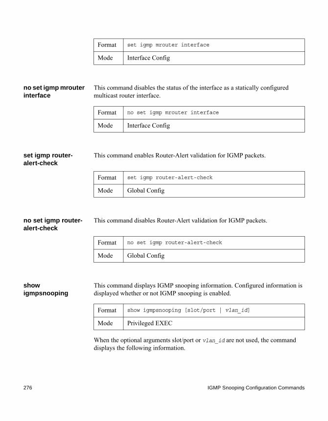
no set igmp mrouter interface
This command disables the status of the interface as a statically configured multicast router interface.
set igmp router-alert-check
This command enables Router-Alert validation for IGMP packets.
no set igmp router-alert-check
This command disables Router-Alert validation for IGMP packets.
show igmpsnooping
This command displays IGMP snooping information. Configured information is displayed whether or not IGMP snooping is enabled.
When the optional arguments slot/port or vlan_id are not used, the command displays the following information.
Format set igmp mrouter interface
Mode Interface Config
Format no set igmp mrouter interface
Mode Interface Config
Format set igmp router-alert-check
Mode Global Config
Format no set igmp router-alert-check
Mode Global Config
Format show igmpsnooping [slot/port | vlan_id]
Mode Privileged EXEC
276 IGMP Snooping Configuration Commands

When you specify the slot/port values, the following information appears:
Output Description
Admin Mode Indicates whether or not IGMP snooping is active on the switch.
Multicast Control Frame Count
The number of multicast control frames that are processed by the CPU.
Interface Enabled for IGMP Snooping
The list of interfaces on which IGMP snooping is enabled.
VLANS Enabled for IGMP Snooping
The list of VLANs on which IGMP snooping is enabled.
Output Description
IGMP Snooping Admin Mode
Indicates whether IGMP snooping is active on the interface.
Fast Leave Mode
Indicates whether IGMP snooping Fast-leave is active on the interface.
Group Membership Interval
The amount of time, in seconds, that a switch will wait for a report from a particular group on a particular interface before deleting the interface from the entry.This value may be configured.
Maximum Response Time
The amount of time the switch waits after it sends a query on an interface because it did not receive a report for a particular group on that interface. This value may be configured.
Multicast Router Expiry Time
The amount of time to wait before removing an interface from the list of interfaces with multicast routers attached. The interface is removed if a query is not received. This value may be configured.
Chapter 5: Switching Commands 277

When you specify a value for vlan_id, the following information appears.
show igmpsnooping mrouter interface
This command displays information about statically configured ports.
Output Description
VLAN ID The VLAN ID.
IGMP Snooping Admin Mode
Indicates whether IGMP snooping is active on the VLAN.
Fast Leave Mode
Indicates whether IGMP snooping Fast-leave is active on the VLAN.
Group Membership Interval
The amount of time, in seconds, that a switch will wait for a report from a particular group on a particular interface, which is participating in the VLAN, before deleting the interface from the entry.This value may be configured.
Maximum Response Time
The amount of time the switch waits after it sends a query on an interface, participating in the VLAN, because it did not receive a report for a particular group on that interface. This value may be configured.
Multicast Router Expiry Time
The amount of time to wait before removing an interface that is participating in the VLAN from the list of interfaces with multicast routers attached. The interface is removed if a query is not received. This value may be configured.
Format show igmpsnooping mrouter interface slot/port
Mode Privileged EXEC
Output Description
Interface The port on which multicast router information is being displayed.
Multicast Router Attached
Indicates whether multicast router is statically enabled on the interface.
278 IGMP Snooping Configuration Commands

show igmpsnooping mrouter vlan
This command displays information about statically configured ports.
show mac-address-table igmpsnooping
This command displays the IGMP snooping entries in the MFDB table.
VLAN ID The list of VLANs of which the interface is a member.
Output Description
Format show igmpsnooping mrouter vlan slot/port
Mode Privileged EXEC
Output Description
Interface The port on which multicast router information is being displayed.
VLAN ID The list of VLANs of which the interface is a member.
Format show mac-address-table igmpsnooping
Mode Privileged EXEC
Output Description
VLAN ID The VLAN in which the MAC address is learned.
MAC Address A multicast MAC address for which the switch has forwarding or filtering information. The format is 6 two-digit hexadecimal numbers that are separated by colons, for example, 01:23:45:67:89:AB.
Type The type of the entry, which is either static (added by the user) or dynamic (added to the table as a result of a learning process or protocol).
Chapter 5: Switching Commands 279

Description The text description of this multicast table entry.
Interfaces The list of interfaces that are designated for forwarding (Fwd:) and filtering (Flt:).
Output Description
280 IGMP Snooping Configuration Commands

IGMP Snooping Querier Commands
Introduction IGMP snooping requires that one central switch or router periodically query all end-devices on the network to announce their multicast memberships. This central device is the “IGMP Querier”. The IGMP query responses, known as IGMP reports, keep the switch updated with the current multicast group membership on a port-by-port basis. If the switch does not receive updated membership information in a timely fashion, it will stop forwarding multicasts to the port where the end device is located.
This section describes commands used to configure and display information on IGMP snooping queriers on the network and, separately, on VLANs.
set igmp querier This command enables IGMP snooping querier on the system, using Global Config mode, or on a VLAN. Using this command, you can specify the IP Address that the snooping querier switch should use as the source address while generating periodic queries.
If a VLAN has IGMP snooping querier enabled and IGMP snooping is operationally disabled on it, IGMP snooping querier functionality is disabled on that VLAN. IGMP snooping functionality is re-enabled if IGMP snooping is operational on the VLAN.
NoteThe Querier IP Address assigned for a VLAN takes preference over global configuration.
The IGMP snooping querier application supports sending periodic general queries on the VLAN to solicit membership reports.
Default disabled
Format set igmp querier [vlan-id] [address ipv4_address]
Mode ◆ Global Config◆ VLAN Mode
Chapter 5: Switching Commands 281

no set igmp querier This command disables IGMP snooping querier on the system. Use the optional address parameter to reset the querier address to 0.0.0.0.
set igmp querier query-interval
This command sets the IGMP Querier Query Interval time. It is the amount of time, in seconds, that the switch waits before sending another general query.
no set igmp querier query-interval
This command sets the IGMP Querier Query Interval time to its default value.
set igmp querier timer expiry
This command sets the IGMP Querier timer expiration period. It is the time period that the switch remains in Non-Querier mode once it has discovered that there is a Multicast Querier in the network.
no set igmp querier timer expiry
This command sets the IGMP Querier timer expiration period to its default value.
Format no set igmp querier [vlan-id] [address]
Mode ◆ Global Config◆ VLAN Mode
Default disabled
Format set igmp querier query-interval 1-18000
Mode Global Config
Format no set igmp querier query-interval
Mode Global Config
Default 60 seconds
Format set igmp querier timer expiry 60-300
Mode Global Config
Format no set igmp querier timer expiry
282 IGMP Snooping Querier Commands

set igmp querier version
This command sets the IGMP version of the query that the snooping switch is going to send periodically.
no set igmp querier version
This command sets the IGMP Querier version to its default value.
set igmp querier election participate
This command enables the snooping querier to participate in the Querier Election process when it discovers the presence of another Querier in the VLAN. When this mode is enabled, if the snooping querier finds that the other Querier’s source address is better (less) than the snooping querier’s address, it stops sending periodic queries. If the snooping querier wins the election, then it will continue sending periodic queries.
no set igmp querier election participate
This command sets the snooping querier to not participate in querier election but go into non-querier mode as soon as it discovers the presence of another querier in the same VLAN.
Mode Global Config
Default 1
Format set igmp querier version 1–2
Mode Global Config
Format no set igmp querier version
Mode Global Config
Default disabled
Format set igmp querier election participate
Mode VLAN Config
Format no set igmp querier election participate
Chapter 5: Switching Commands 283

show igmpsnooping querier
This command displays IGMP snooping querier information. Configured information is displayed whether or not IGMP snooping querier is enabled.
When the optional argument vlanid is not used, the command displays the following information:
When you specify a value for vlanid is not used, the following additional information appears:
Mode VLAN Config
Format show igmpsnooping querier [{detail | vlan vlanid}]
Mode Privileged EXEC
Output Description
Admin Mode Indicates whether or not IGMP snooping querier is active on the switch.
Admin Version The version of IGMP that will be used while sending out the queries.
Querier Address
The IP Address which will be used in the IPv4 header while sending out IGMP queries. It can be configured using the appropriate command.
Query Interval
The amount of time in seconds that a snooping querier waits before sending out the periodic general query.
Querier Timeout
The amount of time to wait in the Non-Querier operational state before moving to a Querier state.
Output Description
VLAN Admin Mode
Indicates whether iGMP snooping querier is active on the VLAN.
284 IGMP Snooping Querier Commands

When the optional argument detail is used, the command shows the global information and the information for all Querier-enabled VLANs.
VLAN Operational State
Indicates whether IGMP snooping querier is in Querier or Non-Querier state. When the switch is in Querier state, it will send out periodic general queries. When in Non-Querier state, it will wait for moving to Querier state and does not send out any queries.
VLAN Operational Max Response Time
Indicates the time to wait before removing a Leave from a host upon receiving a Leave request. This value is calculated dynamically from the Queries received from the network. If the Snooping Switch is in Querier state, then it is equal to the configured value.
Querier Election Participation
Indicates whether the IGMP snooping querier participates in querier election if it discovers the presence of a querier in the VLAN.
Querier VLAN Address
The IP address will be used in the IPv4 header while sending out IGMP queries on this VLAN. It can be configured using the appropriate command.
Operational Version
The version of IPv4 will be used while sending out IGMP queries on this VLAN.
Last Querier Address
Indicates the IP address of the most recent Querier from which a Query was received.
Last Querier Version
Indicates the IGMP version of the most recent Querier from which a Query was received on this VLAN.
Output Description
Chapter 5: Switching Commands 285

ISDP Commands
Introduction This section describes the commands you use to configure the industry standard Discovery Protocol (ISDP).
isdp run This command enables ISDP on the switch.
no isdp run This command disables ISDP on the switch.
isdp holdtime This command configures the hold time for ISDP packets that the switch transmits. The hold time specifies how long a receiving device should store information sent in the ISDP packet before discarding it. The range is given in seconds.
isdp timer This command sets the period of time between sending new ISDP packets. The range is given in seconds.
Default Enabled
Format isdp run
Mode Global Config
Format no isdp run
Mode Global Config
Default 180 seconds
Format isdp holdtime 10-255
Mode Global Config
Default 30 seconds
Format isdp timer 5-254
Mode Global Config
286 ISDP Commands

isdp advertise-v2 This command enables the sending of ISDP Version 2 packets from the device.
no isdp advertise-v2
This command disables the sending of ISDP Version 2 packets from the device.
isdp enable This command enables ISDP on an interface or range of interfaces.
NoteISDP must be enabled both globally and on the interface in order for the interface to transmit ISDP packets. If ISDP is globally disabled on the switch, the interface will not transmit ISDP packets, regardless of the ISDP status on the interface. To enable ISDP globally, use the command “isdp run” on page 286.
no isdp enable This command disables ISDP on the interface.
clear isdp counters This command clears ISDP counters.
clear isdp table This command clears entries in the ISDP table.
Default Enabled
Format isdp advertise-v2
Mode Global Config
Format no isdp advertise-v2
Mode Global Config
Default EnabledFormat isdp enable
Mode Interface Config
Format no isdp enable
Mode Interface Config
Format clear isdp counters
Mode Privileged EXEC
Format clear isdp table
Chapter 5: Switching Commands 287

show isdp This command displays global ISDP settings.
Mode Privileged EXEC
Format show isdp
Mode Privileged EXEC
Output Description
Timer The frequency with which this device sends ISDP packets. This value is given in seconds.
Hold Time The length of time the receiving device should save information sent by this device. This value is given in seconds.
ISDPv2 Advertisements
The setting for sending ISDPv2 packets. If disabled, Version 1 packets are transmitted.
Device ID The Device ID advertised by this device. The format of this Device ID is characterized by the value of the Device ID Format object.
Device ID Format Capability
Indicates the Device ID format capability of the device.◆ serialNumber indicates that the device uses a
serial number as the format for its Device ID.◆ macAddress indicates that the device uses a Layer
2 MAC address as the format for its Device ID.◆ other indicates that the device uses its platform-
specific format as the format for its Device ID.Device ID Format Indicates the Device ID format of the device.
◆ serialNumber indicates that the value is in the form of an ASCII string containing the device serial number.
◆ macAddress indicates that the value is in the form of a Layer 2 MAC address.
◆ other indicates that the value is in the form of a platform specific ASCII string containing info that identifies the device. For example, ASCII string contains serialNumber appended/prepended with system name.
288 ISDP Commands

show isdp interface This command displays ISDP settings for the specified interface.
show isdp entry This command displays ISDP entries. If the device ID is specified, then only entries for that device are shown.
show isdp neighbors
This command displays the list of neighboring devices.
Format show isdp interface {all | slot/port}
Mode Privileged EXEC
Output Description
Mode ISDP mode enabled/disabled status for the interface(s).
Format show isdp entry {all | deviceid}
Mode Privileged EXEC
Output Description
Device ID The device ID associated with the neighbor which advertised the information.
IP Addresses The IP address(es) associated with the neighbor.Platform The hardware platform advertised by the neighbor.Interface The interface (slot/port) on which the neighbor's
advertisement was received.Port ID The port ID of the interface from which the neighbor
sent the advertisement.Hold Time The hold time advertised by the neighbor.Version The software version that the neighbor is running.Advertisement Version
The version of the advertisement packet received from the neighbor.
Capability ISDP functional capabilities advertised by the neighbor.
Format show isdp neighbors [{slot/port | detail}]
Mode Privileged EXEC
Chapter 5: Switching Commands 289

Example: The following shows example CLI display output for the command:(CN1610)#show isdp neighbors detail
Device ID 0001f45f1bc0Address(es): IP Address: 10.27.7.57Capability Router Trans Bridge Switch IGMPPlatform SecureStack C2Interface 0/48Port ID ge.3.14Holdtime 131Advertisement Version 2Entry last changed time 0 days 00:01:59Version:05.00.56
show isdp traffic This command displays ISDP statistics.
Output Description
Device ID The device ID associated with the neighbor which advertised the information.
IP Addresses The IP addresses associated with the neighbor.Capability ISDP functional capabilities advertised by the neighbor.Platform The hardware platform advertised by the neighbor.Interface The interface (slot/port) on which the neighbor's
advertisement was received.Port ID The port ID of the interface from which the neighbor sent
the advertisement.Hold Time The hold time advertised by the neighbor.Advertisement Version
The version of the advertisement packet received from the neighbor.
Entry Last Changed Time
Displays when the entry was last modified.
Version The software version that the neighbor is running.
Format show isdp trafficMode Privileged EXEC
290 ISDP Commands

debug isdp packet This command enables tracing of ISDP packets processed by the switch. ISDP must be enabled on both the device and the interface in order to monitor packets for a particular interface.
no debug isdp packet
This command disables tracing of ISDP packets on the receive or the transmit sides or on both sides.
Output Description
ISDP Packets Received
Total number of ISDP packets received.
ISDP Packets Transmitted
Total number of ISDP packets transmitted.
ISDPv1 Packets Received
Total number of ISDPv1 packets received.
ISDPv1 Packets Transmitted
Total number of ISDPv1 packets transmitted.
ISDPv2 Packets Received
Total number of ISDPv2 packets received.
ISDPv2 Packets Transmitted
Total number of ISDPv2 packets transmitted.
ISDP Bad Header Number of packets received with a bad header.ISDP Checksum Error
Number of packets received with a checksum error.
ISDP Transmission Failure
Number of packets which failed to transmit.
ISDP Invalid Format
Number of invalid packets received.
ISDP Table Full Number of times a neighbor entry was not added to the table due to a full database.
ISDP IP Address Table Full
Displays the number of times a neighbor entry was added to the table without an IP address.
Format debug isdp packet [{receive | transmit}]
Mode Privileged EXEC
Format no debug isdp packet [{receive | transmit}]
Mode Privileged EXEC
Chapter 5: Switching Commands 291

LLDP (802.1AB) Commands
Introduction This section describes the commands you use to configure Link Layer Discovery Protocol (LLDP), which is defined in the IEEE 802.1AB specification. LLDP allows stations on an 802 LAN to advertise major capabilities and physical descriptions. The advertisements allow a network management system (NMS) to access and display this information.
lldp transmit This command enables the LLDP advertise capability on an interface or a range of interfaces.
no lldp transmit This command returns the local data transmission capability to the default.
lldp receive This command enables the LLDP receive capability on an interface or a range of interfaces.
no lldp receive This command returns the reception of LLDPDUs to the default value.
Default disabled
Format lldp transmit
Mode Interface Config
Format no lldp transmit
Mode Interface Config
Default disabled
Format lldp receive
Mode Interface Config
292 LLDP (802.1AB) Commands

lldp timers This command sets the timing parameters for local data transmission on ports enabled for LLDP. The interval-seconds determines the number of seconds to wait between transmitting local data LLDPDUs. The range is 1 to 32768 seconds. The hold-value is the multiplier on the transmit interval that sets the TTL in local data LLDPDUs. The multiplier range is 2 to 10. The reinit-seconds is the delay before re-initialization, and the range is 1 to 10 seconds.
no lldp timers This command returns any or all timing parameters for local data transmission on ports enabled for LLDP to the default values.
lldp transmit-tlv This command specifies which optional type length values (TLVs) in the 802.1AB basic management set are transmitted in the LLDPDUs from an interface or range of interfaces. Use sys-name to transmit the system name TLV. Use sys-desc to transmit the system description TLV. Use sys-cap to transmit the system capabilities TLV. Use port-desc to transmit the port description TLV.
Format no lldp receive
Mode Interface Config
Default ◆ interval—30 seconds
◆ hold—4
◆ reinit—2 seconds
Format lldp timers [interval interval-seconds] [hold hold-value] [reinit reinit-seconds]
Mode Global Config
Format no lldp timers [interval] [hold] [reinit]
Mode Global Config
Default no optional TLVs are included
Format lldp transmit-tlv [sys-desc] [sys-name] [sys-cap] [port-desc]
Chapter 5: Switching Commands 293

no lldp transmit-tlv This command removes an optional TLV from the LLDPDUs. Use the command without parameters to remove all optional TLVs from the LLDPDU.
lldp transmit-mgmt This command includes transmission of the local system management address information in the LLDPDUs. You can use this command to configure a single interface or a range of interfaces.
no lldp transmit-mgmt
This command cancels inclusion of the management information in the LLDPDUs.
lldp notification This command enables remote data change notifications on an interface or a range of interfaces.
no lldp notification This command disables notifications.
Mode Interface Config
Format no lldp transmit-tlv [sys-desc] [sys-name] [sys-cap] [port-desc]
Mode Interface Config
Format lldp transmit-mgmt
Mode Interface Config
Format no lldp transmit-mgmt
Mode Interface Config
Default disabled
Format lldp notification
Mode Interface Config
294 LLDP (802.1AB) Commands

lldp notification–interval
This command configures how frequently the system sends remote data change notifications. The interval parameter is the number of seconds to wait between sending notifications. The valid interval range is 5 to 3600 seconds.
no lldp notification–interval
This command returns the notification interval to the default value.
clear lldp statistics This command resets all LLDP statistics, including MED-related information.
clear lldp remote–data
This command deletes all information from the LLDP remote data table, including MED-related information.
Default disabled
Format no lldp notification
Mode Interface Config
Default 5
Format lldp notification-interval interval
Mode Global Config
Format no lldp notification-interval
Mode Global Config
Format clear lldp statistics
Mode Privileged Exec
Format clear lldp remote-data
Mode Global Config
Chapter 5: Switching Commands 295

show lldp This command displays a summary of the current LLDP configuration.
show lldp interface This command displays a summary of the current LLDP configuration for a specific interface or for all interfaces.
Format show lldp
Mode Privileged EXEC
Output Description
Transmit Interval How frequently the system transmits local data LLDPDUs, in seconds.
Transmit Hold Multiplier
The multiplier on the transmit interval that sets the TTL in local data LLDPDUs.
Re-initialization Delay
The delay before re-initialization, in seconds.
Notification Interval
How frequently the system sends remote data change notifications, in seconds.
Format show lldp interface {slot/port | all}
Mode Privileged EXEC
Output Description
Interface The interface in a slot/port format.
Link Shows whether the link is up or down.
Transmit Shows whether the interface transmits LLDPDUs.
Receive Shows whether the interface receives LLDPDUs.
Notify Shows whether the interface sends remote data change notifications.
296 LLDP (802.1AB) Commands

show lldp statistics This command displays the current LLDP traffic and remote table statistics for a specified interface or for all interfaces.
The table contains the following column headings:
TLVs Shows whether the interface sends optional TLVs in the LLDPDUs. The TLV codes can be 0 (Port Description), 1 (System Name), 2 (System Description), or 3 (System Capability).
Mgmt Shows whether the interface transmits system management address information in the LLDPDUs.
Output Description
Format show lldp statistics {slot/port | all}
Mode Privileged EXEC
Output Description
Last Update The amount of time since the last update to the remote table in days, hours, minutes, and seconds.
Total Inserts Total number of inserts to the remote data table.
Total Deletes Total number of deletes from the remote data table.
Total Drops Total number of times the complete remote data received was not inserted due to insufficient resources.
Total Ageouts Total number of times a complete remote data entry was deleted because the Time to Live interval expired.
Output Description
Interface The interface in slot/port format.
Transmit Total
Total number of LLDP packets transmitted on the port.
Chapter 5: Switching Commands 297

show lldp remote–device
This command displays summary information about remote devices that transmit current LLDP data to the system. You can show information about LLDP remote data received on all ports or on a specific port.
Example: The following shows example CLI display output for the command:
Receive Total Total number of LLDP packets received on the port.
Discards Total number of LLDP frames discarded on the port for any reason.
Errors The number of invalid LLDP frames received on the port.
Ageouts Total number of times a complete remote data entry was deleted for the port because the Time to Live interval expired.
TVL Discards The number of TLVs discarded.
TVL Unknowns Total number of LLDP TLVs received on the port where the type value is in the reserved range, and not recognized.
Output Description
Format show lldp remote–device {slot/port | all}
Mode Privileged EXEC
Output Description
Local Interface
The interface that received the LLDPDU from the remote device.
RemID An internal identifier to the switch to mark each remote device to the system.
Chassis ID The ID that is sent by a remote device as part of the LLDP message, it is usually a MAC address of the device.
Port ID The port number that transmitted the LLDPDU.
System Name The system name of the remote device.
298 LLDP (802.1AB) Commands

(CN1610)#show lldp remote-device all
LLDP Remote Device Summary
LocalInterface RemID Chassis ID Port ID System Name------- ------- -------------------- ------------------ ------0/10/20/30/40/50/60/7 2 00:FC:E3:90:01:0F 00:FC:E3:90:01:110/7 3 00:FC:E3:90:01:0F 00:FC:E3:90:01:120/7 4 00:FC:E3:90:01:0F 00:FC:E3:90:01:130/7 5 00:FC:E3:90:01:0F 00:FC:E3:90:01:140/7 1 00:FC:E3:90:01:0F 00:FC:E3:90:03:110/7 6 00:FC:E3:90:01:0F 00:FC:E3:90:04:110/80/90/100/110/12--More-- or (q)uit
show lldp remote–device detail
This command displays detailed information about remote devices that transmit current LLDP data to an interface on the system.
Format show lldp remote–device detail slot/port
Mode Privileged EXEC
Output Description
Local Interface
The interface that received the LLDPDU from the remote device.
Remote Identifier
An internal identifier to the switch to mark each remote device to the system.
Chapter 5: Switching Commands 299
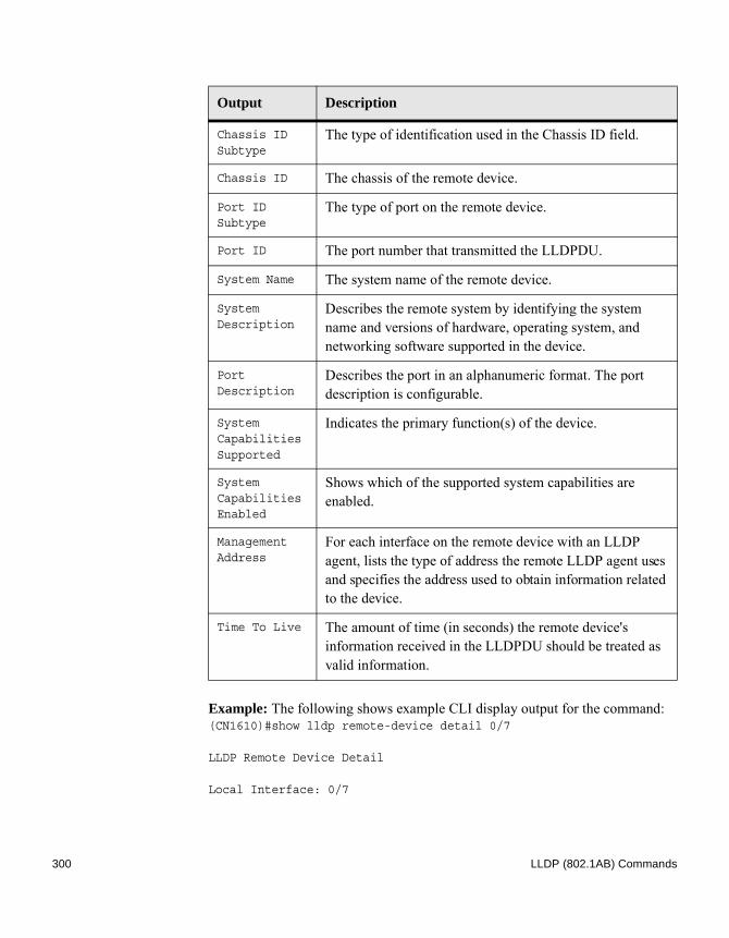
Example: The following shows example CLI display output for the command:(CN1610)#show lldp remote-device detail 0/7
LLDP Remote Device Detail
Local Interface: 0/7
Chassis ID Subtype
The type of identification used in the Chassis ID field.
Chassis ID The chassis of the remote device.
Port ID Subtype
The type of port on the remote device.
Port ID The port number that transmitted the LLDPDU.
System Name The system name of the remote device.
System Description
Describes the remote system by identifying the system name and versions of hardware, operating system, and networking software supported in the device.
Port Description
Describes the port in an alphanumeric format. The port description is configurable.
System Capabilities Supported
Indicates the primary function(s) of the device.
System Capabilities Enabled
Shows which of the supported system capabilities are enabled.
Management Address
For each interface on the remote device with an LLDP agent, lists the type of address the remote LLDP agent uses and specifies the address used to obtain information related to the device.
Time To Live The amount of time (in seconds) the remote device's information received in the LLDPDU should be treated as valid information.
Output Description
300 LLDP (802.1AB) Commands

Remote Identifier: 2Chassis ID Subtype: MAC AddressChassis ID: 00:FC:E3:90:01:0FPort ID Subtype: MAC AddressPort ID: 00:FC:E3:90:01:11System Name:System Description:Port Description:System Capabilities Supported:System Capabilities Enabled:Time to Live: 24 seconds
show lldp local–device
This command displays summary information about the advertised LLDP local data. This command can display summary information or detail for each interface.
show lldp local–device detail
This command displays detailed information about the LLDP data a specific interface transmits.
Format show lldp local-device {slot/port | all}
Mode Privileged EXEC
Output Description
Interface The interface in a slot/port format.
Port ID The port ID associated with this interface.
Port Description
The port description associated with the interface.
Format show lldp local-device detail slot/port
Mode Privileged EXEC
Output Description
Interface The interface that sends the LLDPDU.
Chapter 5: Switching Commands 301

Chassis ID Subtype
The type of identification used in the Chassis ID field.
Chassis ID The chassis of the local device.
Port ID Subtype
The type of port on the local device.
Port ID The port number that transmitted the LLDPDU.
System Name The system name of the local device.
System Description
Describes the local system by identifying the system name and versions of hardware, operating system, and networking software supported in the device.
Port Description
Describes the port in an alphanumeric format.
System Capabilities Supported
Indicates the primary function(s) of the device.
System Capabilities Enabled
Shows which of the supported system capabilities are enabled.
Management Address
The type of address and the specific address the local LLDP agent uses to send and receive information.
Output Description
302 LLDP (802.1AB) Commands
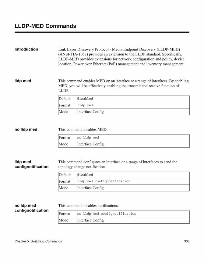
LLDP-MED Commands
Introduction Link Layer Discovery Protocol - Media Endpoint Discovery (LLDP-MED) (ANSI-TIA-1057) provides an extension to the LLDP standard. Specifically, LLDP-MED provides extensions for network configuration and policy, device location, Power over Ethernet (PoE) management and inventory management.
lldp med This command enables MED on an interface or a range of interfaces. By enabling MED, you will be effectively enabling the transmit and receive function of LLDP.
no lldp med This command disables MED.
lldp med confignotification
This command configures an interface or a range of interfaces to send the topology change notification.
no ldp med confignotification
This command disables notifications.
Default disabled
Format lldp med
Mode Interface Config
Format no lldp med
Mode Interface Config
Default disabled
Format lldp med confignotification
Mode Interface Config
Format no lldp med confignotification
Mode Interface Config
Chapter 5: Switching Commands 303

lldp med transmit-tlv
This command specifies which optional Type Length Values (TLVs) in the LLDP-MED set will be transmitted in the Link Layer Discovery Protocol Data Units (LLDPDUs) from this interface or a range of interfaces.
no lldp med transmit-tlv
This command removes a TLV.
lldp med all This command configures LLDP-MED on all the ports.
lldp med confignotification all
This command configures all the ports to send the topology change notification.
Default By default, the capabilities and network policy TLVs are included.Format lldp med transmit-tlv [capabilities] [ex-pd] [ex-pse]
[inventory] [location] [network-policy]
Mode Interface Config
Parameter Description
capabilities Transmit the LLDP capabilities TLV.ex-pd Transmit the LLDP extended PD TLV.ex-pse Transmit the LLDP extended PSE TLV.inventory Transmit the LLDP inventory TLV.location Transmit the LLDP location TLV.network-policy Transmit the LLDP network policy TLV.
Format no lldp med transmit-tlv [capabilities] [network-policy] [ex-pse] [ex-pd] [location] [inventory]
Mode Interface Config
Format lldp med all
Mode Global Config
Format lldp med confignotification all
Mode Global Config
304 LLDP-MED Commands
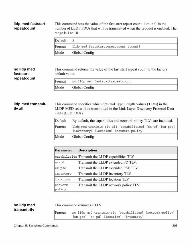
lldp med faststart-repeatcount
This command sets the value of the fast start repeat count. [count] is the number of LLDP PDUs that will be transmitted when the product is enabled. The range is 1 to 10.
no lldp med faststart-repeatcount
This command returns the value of the fast start repeat count to the factory default value.
lldp med transmit-tlv all
This command specifies which optional Type Length Values (TLVs) in the LLDP-MED set will be transmitted in the Link Layer Discovery Protocol Data Units (LLDPDUs).
no lldp med transmit-tlv
This command removes a TLV.
Default 3
Format lldp med faststartrepeatcount [count]
Mode Global Config
Format no lldp med faststartrepeatcount
Mode Global Config
Default By default, the capabilities and network policy TLVs are included.Format lldp med transmit-tlv all [capabilities] [ex-pd] [ex-pse]
[inventory] [location] [network-policy]
Mode Global Config
Parameter Description
capabilities Transmit the LLDP capabilities TLV.ex-pd Transmit the LLDP extended PD TLV.ex-pse Transmit the LLDP extended PSE TLV.inventory Transmit the LLDP inventory TLV.location Transmit the LLDP location TLV.network-policy
Transmit the LLDP network policy TLV.
Format no lldp med transmit-tlv [capabilities] [network-policy] [ex-pse] [ex-pd] [location] [inventory]
Chapter 5: Switching Commands 305

show lldp med This command displays a summary of the current LLDP-MED configuration.
Example: The following shows example CLI display output for the command:(CN1610) #show lldp medLLDP-MED Global Configuration
Fast Start Repeat Count: 3Device Class: Network Connectivity
(CN1610) #
show lldp med interface
This command displays a summary of the current LLDP-MED configuration for a specific interface. The slot/port indicates a specific physical interface. all indicates all valid LLDP interfaces.
Example: The following shows example CLI display output for the command:(CN1610) #show lldp med interface all
Interface Link configMED operMED ConfigNotify TLVsTx--------- ------ --------- -------- ------------ -----------1/0/1 Down Disabled Disabled Disabled 0,11/0/2 Up Disabled Disabled Disabled 0,11/0/3 Down Disabled Disabled Disabled 0,11/0/4 Down Disabled Disabled Disabled 0,11/0/5 Down Disabled Disabled Disabled 0,11/0/6 Down Disabled Disabled Disabled 0,11/0/7 Down Disabled Disabled Disabled 0,11/0/8 Down Disabled Disabled Disabled 0,11/0/9 Down Disabled Disabled Disabled 0,11/0/10 Down Disabled Disabled Disabled 0,11/0/11 Down Disabled Disabled Disabled 0,11/0/12 Down Disabled Disabled Disabled 0,11/0/13 Down Disabled Disabled Disabled 0,1
Mode Global Config
Format show lldp med
Mode Privileged Exec
Format show lldp med interface {slot/port | all}
Mode Privileged Exec
306 LLDP-MED Commands

1/0/14 Down Disabled Disabled Disabled 0,1
TLV Codes: 0- Capabilities, 1- Network Policy 2- Location, 3- Extended PSE 4- Extended Pd, 5- Inventory--More-- or (q)uit(CN1610) #show lldp med interface 1/0/2
Interface Link configMED operMED ConfigNotify TLVsTx--------- ------ --------- -------- ------------ -----------1/0/2 Up Disabled Disabled Disabled 0,1
TLV Codes: 0- Capabilities, 1- Network Policy 2- Location, 3- Extended PSE 4- Extended Pd, 5- Inventory
(CN1610) #
show lldp med local-device detail
This command displays detailed information about the LLDP MED data that a specific interface transmits. slot/port indicates a specific physical interface.
Example: The following shows example CLI display output for the command:(CN1610) #show lldp med local-device detail 1/0/8
LLDP-MED Local Device Detail
Interface: 1/0/8
Network PoliciesMedia Policy Application Type : voiceVlan ID: 10Priority: 5DSCP: 1Unknown: FalseTagged: True
Media Policy Application Type : streamingvideoVlan ID: 20Priority: 1DSCP: 2Unknown: FalseTagged: True
Format show lldp med local-device detail slot/port
Mode Privileged EXEC
Chapter 5: Switching Commands 307

InventoryHardware Rev: xxx xxx xxxFirmware Rev: xxx xxx xxxSoftware Rev: xxx xxx xxxSerial Num: xxx xxx xxxMfg Name: xxx xxx xxx Model Name: xxx xxx xxxAsset ID: xxx xxx xxx
LocationSubtype: elinInfo: xxx xxx xxx
Extended POEDevice Type: pseDevice
Extended POE PSEAvailable: 0.3 WattsSource: primaryPriority: critical
Extended POE PD
Required: 0.2 WattsSource: localPriority: low
show lldp med remote-device
This command displays the summary information about remote devices that transmit current LLDP-MED data to the system. You can show information about LLDP-MED remote data received on all valid LLDP interfaces or on a specific physical interface.
Format show lldp med remote-device {slot/port | all}
Mode Privileged EXEC
Output Description
Local Interface
The interface that received the LLDPDU from the remote device.
Remote ID An internal identifier to the switch to mark each remote device to the system.
308 LLDP-MED Commands

Example: The following shows example CLI display output for the command:(CN1610) #show lldp med remote-device all
LLDP-MED Remote Device Summary
Local Interface Remote ID Device Class --------- --------- ------------ 1/0/8 1Class I 1/0/9 2Not Defined 1/0/10 3Class II1/0/11 4Class III1/0/12 5 Network Con
show lldp med remote-device detail
This command displays detailed information about remote devices that transmit current LLDP-MED data to an interface on the system.
Example: The following shows example CLI display output for the command:(CN1610) #show lldp med remote-device detail 1/0/8
LLDP-MED Remote Device Detail
Local Interface: 1/0/8Remote Identifier: 18CapabilitiesMED Capabilities Supported: capabilities, networkpolicy, location, extendedpseMED Capabilities Enabled: capabilities, networkpolicyDevice Class: Endpoint Class I
Network PoliciesMedia Policy Application Type : voiceVlan ID: 10Priority: 5DSCP: 1Unknown: False
Device Class
Device classification of the remote device.
Output Description
Format show lldp med remote-device detail slot/port
Mode Privileged EXEC
Chapter 5: Switching Commands 309

Tagged: True
Media Policy Application Type : streamingvideoVlan ID: 20Priority: 1DSCP: 2Unknown: FalseTagged: True
InventoryHardware Rev: xxx xxx xxxFirmware Rev: xxx xxx xxxSoftware Rev: xxx xxx xxxSerial Num: xxx xxx xxxMfg Name: xxx xxx xxx Model Name: xxx xxx xxxAsset ID: xxx xxx xxx
LocationSubtype: elinInfo: xxx xxx xxx
Extended POEDevice Type: pseDevice
Extended POE PSEAvailable: 0.3 WattsSource: primaryPriority: critical
Extended POE PD
Required: 0.2 WattsSource: localPriority: low
310 LLDP-MED Commands
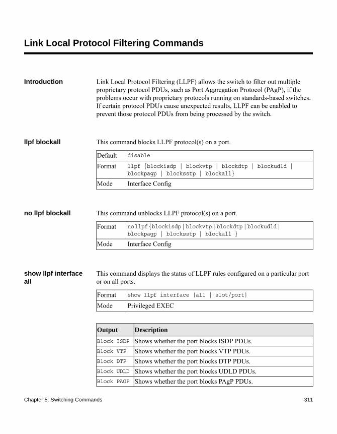
Link Local Protocol Filtering Commands
Introduction Link Local Protocol Filtering (LLPF) allows the switch to filter out multiple proprietary protocol PDUs, such as Port Aggregation Protocol (PAgP), if the problems occur with proprietary protocols running on standards-based switches. If certain protocol PDUs cause unexpected results, LLPF can be enabled to prevent those protocol PDUs from being processed by the switch.
llpf blockall This command blocks LLPF protocol(s) on a port.
no llpf blockall This command unblocks LLPF protocol(s) on a port.
show llpf interface all
This command displays the status of LLPF rules configured on a particular port or on all ports..
Default disable
Format llpf {blockisdp | blockvtp | blockdtp | blockudld | blockpagp | blocksstp | blockall}
Mode Interface Config
Format no llpf {blockisdp | blockvtp | blockdtp | blockudld | blockpagp | blocksstp | blockall }
Mode Interface Config
Format show llpf interface [all | slot/port]
Mode Privileged EXEC
Output Description
Block ISDP Shows whether the port blocks ISDP PDUs.Block VTP Shows whether the port blocks VTP PDUs.Block DTP Shows whether the port blocks DTP PDUs.Block UDLD Shows whether the port blocks UDLD PDUs.Block PAGP Shows whether the port blocks PAgP PDUs.
Chapter 5: Switching Commands 311

Block SSTP Shows whether the port blocks SSTP PDUs.Block All Shows whether the port blocks all proprietary PDUs available for
the LLDP feature.
Output Description
312 Link Local Protocol Filtering Commands

MAC Database Commands
Introduction This section describes the commands you use to configure and view information about the Media Access Control (MAC) databases.
bridge aging-time This command configures the forwarding database address aging timeout in seconds. The seconds parameter must be within the range of 10 to 1,000,000 seconds.
no bridge aging-time
This command sets the forwarding database address aging timeout to the default value.
show forwardingdb agetime
This command displays the timeout for address aging. In an IVL system, the [fdbid | all] parameter is required.
Default 300
Format bridge aging-time seconds
Mode Global Config
Format no bridge aging-time
Mode Global Config
Default all
Format show forwardingdb agetime [fdbid | all]
Mode Privileged EXEC
Output Description
Forwarding DB ID
Fdbid (Forwarding database ID) indicates the forwarding database whose aging timeout is to be shown. The all option is used to display the aging timeouts associated with all forwarding databases. This field displays the forwarding database ID in an IVL system.
Chapter 5: Switching Commands 313
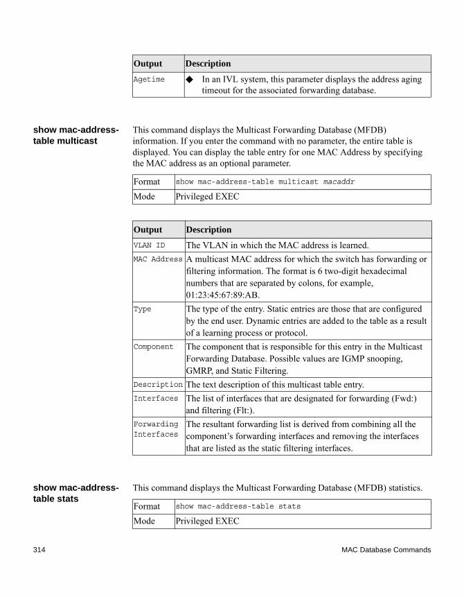
show mac-address-table multicast
This command displays the Multicast Forwarding Database (MFDB) information. If you enter the command with no parameter, the entire table is displayed. You can display the table entry for one MAC Address by specifying the MAC address as an optional parameter.
show mac-address-table stats
This command displays the Multicast Forwarding Database (MFDB) statistics.
Agetime ◆ In an IVL system, this parameter displays the address aging timeout for the associated forwarding database.
Output Description
Format show mac-address-table multicast macaddr
Mode Privileged EXEC
Output Description
VLAN ID The VLAN in which the MAC address is learned.MAC Address A multicast MAC address for which the switch has forwarding or
filtering information. The format is 6 two-digit hexadecimal numbers that are separated by colons, for example, 01:23:45:67:89:AB.
Type The type of the entry. Static entries are those that are configured by the end user. Dynamic entries are added to the table as a result of a learning process or protocol.
Component The component that is responsible for this entry in the Multicast Forwarding Database. Possible values are IGMP snooping, GMRP, and Static Filtering.
Description The text description of this multicast table entry.Interfaces The list of interfaces that are designated for forwarding (Fwd:)
and filtering (Flt:).Forwarding Interfaces
The resultant forwarding list is derived from combining all the component’s forwarding interfaces and removing the interfaces that are listed as the static filtering interfaces.
Format show mac-address-table stats
Mode Privileged EXEC
314 MAC Database Commands

Output Description
Total Entries
The total number of entries that can possibly be in the Multicast Forwarding Database table.
Most MFDB Entries Ever Used
The largest number of entries that have been present in the Multicast Forwarding Database table. This value is also known as the MFDB high-water mark.
Current Entries
The current number of entries in the MFDB.
Chapter 5: Switching Commands 315
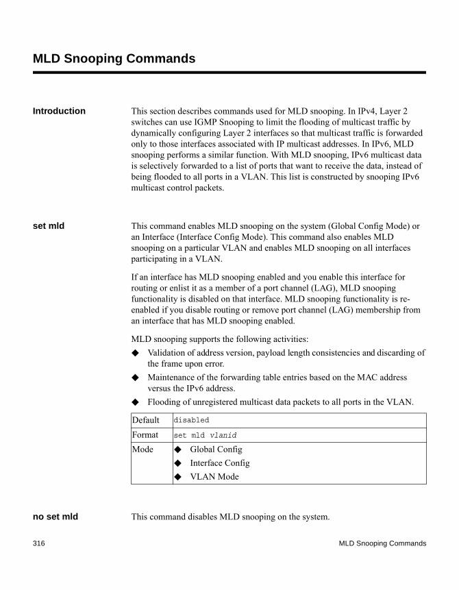
MLD Snooping Commands
Introduction This section describes commands used for MLD snooping. In IPv4, Layer 2 switches can use IGMP Snooping to limit the flooding of multicast traffic by dynamically configuring Layer 2 interfaces so that multicast traffic is forwarded only to those interfaces associated with IP multicast addresses. In IPv6, MLD snooping performs a similar function. With MLD snooping, IPv6 multicast data is selectively forwarded to a list of ports that want to receive the data, instead of being flooded to all ports in a VLAN. This list is constructed by snooping IPv6 multicast control packets.
set mld This command enables MLD snooping on the system (Global Config Mode) or an Interface (Interface Config Mode). This command also enables MLD snooping on a particular VLAN and enables MLD snooping on all interfaces participating in a VLAN.
If an interface has MLD snooping enabled and you enable this interface for routing or enlist it as a member of a port channel (LAG), MLD snooping functionality is disabled on that interface. MLD snooping functionality is re-enabled if you disable routing or remove port channel (LAG) membership from an interface that has MLD snooping enabled.
MLD snooping supports the following activities:◆ Validation of address version, payload length consistencies and discarding of
the frame upon error.◆ Maintenance of the forwarding table entries based on the MAC address
versus the IPv6 address.◆ Flooding of unregistered multicast data packets to all ports in the VLAN.
no set mld This command disables MLD snooping on the system.
Default disabled
Format set mld vlanid
Mode ◆ Global Config◆ Interface Config◆ VLAN Mode
316 MLD Snooping Commands

set mld interfacemode
This command enables MLD snooping on all interfaces. If an interface has MLD snooping enabled and you enable this interface for routing or enlist it as a member of a port channel (LAG), MLD snooping functionality is disabled on that interface. MLD snooping functionality is re-enabled if you disable routing or remove port channel (LAG) membership from an interface that has MLD snooping enabled.
no set mld interfacemode
This command disables MLD snooping on all interfaces.
set mld fast-leave This command enables MLD snooping fast-leave admin mode on a selected interface or VLAN. Enabling fast-leave allows the switch to immediately remove the Layer 2 LAN interface from its forwarding table entry upon receiving and MLD done message for that multicast group without first sending out MAC-based general queries to the interface.
NoteYou should enable fast-leave admin mode only on VLANs where only one host is connected to each Layer 2 LAN port. This prevents the inadvertent dropping of the other hosts that were connected to the same layer 2 LAN port but were still interested in receiving multicast traffic directed to that group.
NoteFast-leave processing is supported only with MLD version 1 hosts.
Format set mld vlanid
Mode ◆ Global Config◆ Interface Config◆ VLAN Mode
Default disabled
Format set mld interfacemode
Mode Global Config
Format no set mld interfacemode
Mode Global Config
Chapter 5: Switching Commands 317

no set mld fast-leave
This command disables MLD snooping fast-leave admin mode on a selected interface.
set mld groupmembership-interval
This command sets the MLD Group Membership Interval time on a VLAN, one interface or all interfaces. The Group Membership Interval time is the amount of time in seconds that a switch waits for a report from a particular group on a particular interface before deleting the interface from the entry. This value must be greater than the MLDv2 Maximum Response time value. The range is 2 to 3600 seconds.
no set groupmembership-interval
This command sets the MLDv2 Group Membership Interval time to the default value.
Default disabled
Format set mld fast-leave vlanid
Mode ◆ Interface Config◆ VLAN Mode
Format no set mld fast-leave vlanid
Mode ◆ Interface Config◆ VLAN Mode
Default 260 seconds
Format set mld groupmembership-interval vlanid 2-3600
Mode ◆ Interface Config◆ Global Config◆ VLAN Mode
Format no set mld groupmembership-interval
Mode ◆ Interface Config◆ Global Config◆ VLAN Mode
318 MLD Snooping Commands

set mld maxresponse
This command sets the MLD Maximum Response time for the system, on a particular interface or VLAN. The Maximum Response time is the amount of time in seconds that a switch will wait after sending a query on an interface because it did not receive a report for a particular group in that interface. This value must be less than the MLD Query Interval time value. The range is 1 to 65 seconds.
no set mld maxresponse
This command sets the max response time (on the interface or VLAN) to the default value.
set mld mcrtexpiretime
This command sets the Multicast Router Present Expiration time. The time is set for the system, on a particular interface or VLAN. This is the amount of time in seconds that a switch waits for a query to be received on an interface before the interface is removed from the list of interfaces with multicast routers attached. The range is 0 to 3600 seconds. A value of 0 indicates an infinite timeout, i.e. no expiration.
no set mld mcrtexpiretime
This command sets the Multicast Router Present Expiration time to 0. The time is set for the system, on a particular interface or a VLAN.
Default 10 seconds
Format set mld maxresponse 1-65
Mode ◆ Global Config◆ Interface Config◆ VLAN Mode
Format no set mld maxresponse
Mode ◆ Global Config◆ Interface Config◆ VLAN Mode
Default 0
Format set mld mcrtexpiretime vlanid 0-3600
Mode ◆ Global Config◆ Interface Config
Chapter 5: Switching Commands 319

set mld mrouter This command configures the VLAN ID for the VLAN that has the multicast router attached mode enabled.
no set mld mrouter This command disables multicast router attached mode for a VLAN with a particular VLAN ID.
set mld mrouter interface
This command configures the interface as a multicast router-attached interface. When configured as a multicast router interface, the interface is treated as a multicast router-attached interface in all VLANs.
no set mld mrouter interface
This command disables the status of the interface as a statically configured multicast router-attached interface.
show mldsnooping This command displays MLD snooping information. Configured information is displayed whether or not MLD snooping is enabled.
Format no set mld mcrtexpiretime vlanid
Mode ◆ Global Config◆ Interface Config
Format set mld mrouter vlanid
Mode Interface Config
Format no set mld mrouter vlanid
Mode Interface Config
Default disabled
Format set mld mrouter interface
Mode Interface Config
Format no set mld mrouter interface
Mode Interface Config
320 MLD Snooping Commands

When the optional arguments slot/port or vlanid are not used, the command displays the following information.
When you specify the slot/port values, the following information displays.
Format show mldsnooping [slot/port | vlanid]
Mode Privileged EXEC
Output Description
Admin Mode Indicates whether or not MLD snooping is active on the switch.Interfaces Enabled for MLD Snooping
Interfaces on which MLD snooping is enabled.
MLD Control Frame Count
Displays the number of MLD Control frames that are processed by the CPU.
VLANs Enabled for MLD Snooping
VLANs on which MLD snooping is enabled.
Output Description
MLD Snooping Admin Mode
Indicates whether MLD snooping is active on the interface.
Fast Leave Mode
Indicates whether MLD snooping Fast Leave is active on the VLAN.
Group Membership Interval
Shows the amount of time in seconds that a switch will wait for a report from a particular group on a particular interface, which is participating in the VLAN, before deleting the interface from the entry. This value may be configured.
Max Response Time
Displays the amount of time the switch waits after it sends a query on an interface, participating in the VLAN, because it did not receive a report for a particular group on that interface. This value may be configured.
Multicast Router Present Expiration Time
Displays the amount of time to wait before removing an interface that is participating in the VLAN from the list of interfaces with multicast routers attached. The interface is removed if a query is not received. This value may be configured.
Chapter 5: Switching Commands 321

When you specify a value for vlanid, the following information appears.
show mldsnooping mrouter interface
This command displays information about statically configured multicast router attached interfaces.
show mldsnooping mrouter vlan
This command displays information about statically configured multicast router-attached interfaces.
show mac-address-table mldsnooping
This command displays the MLD snooping entries in the Multicast Forwarding Database (MFDB) table.
Output Description
VLAN Admin Mode
Indicates whether MLD snooping is active on the VLAN.
Format show mldsnooping mrouter interface slot/port
Mode Privileged EXEC
Output Description
Interface Shows the interface on which multicast router information is being displayed.
Multicast Router Attached
Indicates whether multicast router is statically enabled on the interface.
VLAN ID Displays the list of VLANs of which the interface is a member.
Format show mldsnooping mrouter vlan slot/port
Mode Privileged EXEC
Output Description
Interface Shows the interface on which multicast router information is being displayed.
VLAN ID Displays the list of VLANs of which the interface is a member.
Format show mac-address-table mldsnooping
322 MLD Snooping Commands

clear mldsnooping This command deletes all MLD snooping entries from the MFDB table.
Mode Privileged EXEC
Output Description
VLAN ID The VLAN in which the MAC address is learned.MAC Address A multicast MAC address for which the switch has forwarding or
filtering information. The format is 6 two-digit hexadecimal numbers that are separated by colons, for example, 01:23:45:67:89:AB.
Type The type of entry, which is either static (added by the user) or dynamic (added to the table as a result of a learning process or protocol.)
Description
The text description of this multicast table entry.
Interfaces The list of interfaces that are designated for forwarding (Fwd:) and filtering (Flt:).
Format clear mldsnooping
Mode Privileged EXEC
Chapter 5: Switching Commands 323

MLD Snooping Querier Commands
Introduction In an IPv6 environment, MLD snooping requires that one central switch or router periodically query all end-devices on the network to announce their multicast memberships. This central device is the MLD querier. The MLD query responses, known as MLD reports, keep the switch updated with the current multicast group membership on a port-by-port basis. If the switch does not receive updated membership information in a timely fashion, it will stop forwarding multicasts to the port where the end device is located.
This section describes the commands you use to configure and display information on MLD snooping queries on the network and, separately, on VLANs.
set mld querier This command enables MLD snooping querier on the system (Global Config Mode) or on a VLAN. Using this command, you can specify the IP address that the snooping querier switch should use as a source address while generating periodic queries.
If a VLAN has MLD snooping querier enabled and MLD snooping is operationally disabled on it, MLD snooping querier functionality is disabled on that VLAN. MLD snooping functionality is re-enabled if MLD snooping is operational on the VLAN.
The MLD snooping querier sends periodic general queries on the VLAN to solicit membership reports.
no set mld querier This command disables MLD snooping querier on the system. Use the optional parameter address to reset the querier address.
Default disabled
Format set mld querier [vlan-id] [address ipv6_address]
Mode ◆ Global Config◆ VLAN Mode
Format no set mld querier [vlan-id][address]
324 MLD Snooping Querier Commands
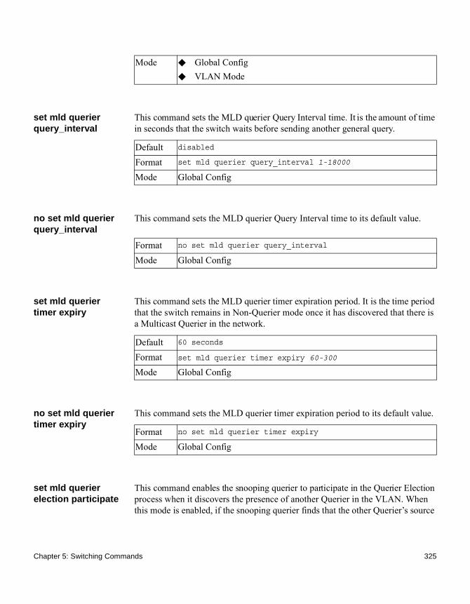
set mld querier query_interval
This command sets the MLD querier Query Interval time. It is the amount of time in seconds that the switch waits before sending another general query.
no set mld querier query_interval
This command sets the MLD querier Query Interval time to its default value.
set mld querier timer expiry
This command sets the MLD querier timer expiration period. It is the time period that the switch remains in Non-Querier mode once it has discovered that there is a Multicast Querier in the network.
no set mld querier timer expiry
This command sets the MLD querier timer expiration period to its default value.
set mld querier election participate
This command enables the snooping querier to participate in the Querier Election process when it discovers the presence of another Querier in the VLAN. When this mode is enabled, if the snooping querier finds that the other Querier’s source
Mode ◆ Global Config◆ VLAN Mode
Default disabled
Format set mld querier query_interval 1-18000
Mode Global Config
Format no set mld querier query_interval
Mode Global Config
Default 60 seconds
Format set mld querier timer expiry 60-300
Mode Global Config
Format no set mld querier timer expiry
Mode Global Config
Chapter 5: Switching Commands 325

address is better (less) than the snooping querier’s address, it stops sending periodic queries. If the snooping querier wins the election, then it will continue sending periodic queries.
no set mld querier election participate
This command sets the snooping querier not to participate in querier election but go into a non-querier mode as soon as it discovers the presence of another querier in the same VLAN.
show mldsnooping querier
This command displays MLD snooping querier information. Configured information is displayed whether or not MLD snooping querier is enabled.
When the optional arguments vlanid are not used, the command displays the following information:
Default disabled
Format set mld querier election participate
Mode VLAN Config
Format no set mld querier election participate
Mode VLAN Config
Format show mldsnooping querier [{detail | vlan vlanid}]
Mode Privileged EXEC
Output Description
Admin Mode Indicates whether or not MLD snooping querier is active on the switch.
Admin Version
Indicates the version of MLD that will be used while sending out the queries. This is defaulted to MLD v1 and it cannot be changed.
Querier Address
Shows the IP address which will be used in the IPv6 header while sending out MLD queries. It can be configured using the appropriate command.
Query Interval
Shows the amount of time in seconds that a snooping querier waits before sending out the periodic general query.
Querier Timeout
Displays the amount of time to wait in the Non-Querier operational state before moving to a Querier state.
326 MLD Snooping Querier Commands

When you specify a value for vlanid, the following information appears:
When the optional argument detail is used, the command shows the global information and the information for all Querier-enabled VLANs.
Output Description
VLAN Admin Mode Indicates whether MLD snooping querier is active on the VLAN.
VLAN Operational State
Indicates whether MLD snooping querier is in “Querier” or “Non-Querier” state. When the switch is in Querier state, it will send out periodic general queries. When in Non-Querier state, it will wait for moving to Querier state and does not send out any queries.
VLAN Operational Max Response Time
Indicates the time to wait before removing a Leave from a host upon receiving a Leave request. This value is calculated dynamically from the Queries received from the network. If the Snooping Switch is in Querier state, then it is equal to the configured value.
Querier Election Participate
Indicates whether the MLD snooping querier participates in querier election if it discovers the presence of a querier in the VLAN.
Querier VLAN Address
The IP address will be used in the IPv6 header while sending out MLD queries on this VLAN. It can be configured using the appropriate command.
Operational Version
This version of IPv6 will be used while sending out MLD queriers on this VLAN.
Last Querier Address
Indicates the IP address of the most recent Querier from which a Query was received.
Last Querier Version
Indicates the MLD version of the most recent Querier from which a Query was received on this VLAN.
Chapter 5: Switching Commands 327

Port-Based Network Access Control Commands
Introduction This section describes the commands you use to configure port-based network access control (IEEE 802.1X). Port-based network access control allows you to permit access to network services only to devices that are authorized and authenticated.
aaa authentication dot1x default
This command configures the authentication method for port-based access to the switch. The additional methods of authentication are used only if the previous method returns an error, not if there is an authentication failure. The possible methods are as follows:◆ ias. Uses the internal authentication server users database for
authentication.◆ local. Uses the local username database for authentication.◆ none. Uses no authentication.◆ radius. Uses the list of all RADIUS servers for authentication.
clear dot1x statistics
This command resets the 802.1X statistics for the specified port or for all ports.
clear dot1x authentication-history
This command clears the authentication history table captured during successful and unsuccessful authentication on all interface or the specified interface.
Format aaa authentication dot1x default method1 [method2...]
Mode Global Config
Format clear dot1x statistics {slot/port | all}
Mode Privileged EXEC
Format clear dot1x authentication-history [slot/port]
Mode Privileged EXEC
328 Port-Based Network Access Control Commands

clear radius statistics
This command clears all of the RADIUS statistics.
dot1x dynamic-vlan enable
This command enables the switch to create VLANs dynamically when a RADIUS-assigned VLAN does not exist in the switch.
no dot1x dynamic-vlan enable
This command prevents the switch from creating VLANs when a RADIUS-assigned VLAN does not exist in the switch.
dot1x guest-vlan This command configures VLAN as guest vlan on an interface or a range of interfaces. The command specifies an active VLAN as an IEEE 802.1X guest VLAN. The range is 1 to the maximum VLAN ID supported by the platform.
no dot1x guest-vlan This command disables guest VLAN on the interface.
Format clear radius statistics
Mode Privileged EXEC
Default disabled
Format dot1x dynamic-vlan enable
Mode Global Config
Format no dot1x dynamic-vlan enable
Mode Global Config
Default disabled
Format dot1x guest-vlan vlan-id
Mode Interface Config
Format no dot1x guest-vlan
Mode Interface Config
Chapter 5: Switching Commands 329

dot1x initialize This command begins the initialization sequence on the specified port. This command is only valid if the control mode for the specified port is auto or MAC-based. If the control mode is not auto or MAC-based, an error will be returned.
dot1x max-req This command sets the maximum number of times the authenticator state machine on an interface or range of interfaces will transmit an EAPOL EAP Request/Identity frame before timing out the supplicant. The count value must be in the range 1 to 10.
no dot1x max-req This command sets the maximum number of times the authenticator state machine on this port will transmit an EAPOL EAP Request/Identity frame before timing out the supplicant.
dot1x max-users This command sets the maximum number of clients supported on an interface or range of interfaces when MAC-based dot1x authentication is enabled on the port. The maximum users supported per port is dependent on the product. The count value is in the range 1 to 16.
Format dot1x initialize slot/port
Mode Privileged EXEC
Default 2
Format dot1x max-req count
Mode Interface Config
Format no dot1x max-req
Mode Interface Config
Default 16
Format dot1x max-users count
Mode Interface Config
330 Port-Based Network Access Control Commands

no dot1x max-users This command resets the maximum number of clients allowed per port to its default value.
dot1x port-control This command sets the authentication mode to use on the specified interface or range of interfaces. Use the force-unauthorized parameter to specify that the authenticator PAE unconditionally sets the controlled port to unauthorized. Use the force-authorized parameter to specify that the authenticator PAE unconditionally sets the controlled port to authorized. Use the auto parameter to specify that the authenticator PAE sets the controlled port mode to reflect the outcome of the authentication exchanges between the supplicant, authenticator and the authentication server. If the mac-based option is specified, then MAC-based dot1x authentication is enabled on the port.
no dot1x port-control
This command sets the 802.1X port control mode on the specified port to the default value.
dot1x port-control all
This command sets the authentication mode to use on all ports. Select force-unauthorized to specify that the authenticator PAE unconditionally sets the controlled port to unauthorized. Select force-authorized to specify that the authenticator PAE unconditionally sets the controlled port to authorized. Select auto to specify that the authenticator PAE sets the controlled port mode to reflect the outcome of the authentication exchanges between the supplicant, authenticator and the authentication server. If the mac-based option is specified, then MAC-based dot1x authentication is enabled on the port.
Format no dot1x max-users count
Mode Interface Config
Default auto
Format dot1x port-control {force-unauthorized | force-authorized | auto | mac-based}
Mode Interface Config
Format no dot1x port-control
Mode Interface Config
Chapter 5: Switching Commands 331

no dot1x port-control all
This command sets the authentication mode on all ports to the default value.
dot1x re-authenticate
This command begins the re-authentication sequence on the specified port. This command is only valid if the control mode for the specified port is auto or MAC-based. If the control mode is not auto or MAC-based, an error will be returned.
dot1x re-authentication
This command enables re-authentication of the supplicant for the specified interface or range of interfaces.
no dot1x re-authentication
This command disables re-authentication of the supplicant for the specified port.
Default auto
Format dot1x port-control all {force-unauthorized | force-authorized | auto | mac-based}
Mode Global Config
Format no dot1x port-control all
Mode Global Config
Format dot1x re-authenticate slot/port
Mode Privileged EXEC
Default disabled
Format dot1x re-authentication
Mode Interface Config
Format no dot1x re-authentication
332 Port-Based Network Access Control Commands

dot1x system-auth-control
This command enables the dot1x authentication support on the switch. While disabled, the dot1x configuration is retained and can be changed, but is not activated.
no dot1x system-auth-control
This command disables the dot1x authentication support on the switch.
dot1x system-auth-control monitor
This command enables the 802.1X monitor mode on the switch. The purpose of Monitor mode is to help troubleshoot port-based authentication configuration issues without disrupting network access for hosts connected to the switch. In Monitor mode, a host is granted network access to an 802.1X-enabled port even if it fails the authentication process. The results of the process are logged for diagnostic purposes.
no dot1x system-auth-control monitor
This command disables the 802.1X Monitor mode on the switch.
Mode Interface Config
Default disabled
Format dot1x system-auth-control
Mode Global Config
Format no dot1x system-auth-control
Mode Global Config
Default disabled
Format dot1x system-auth-control monitor
Mode Global Config
Format no dot1x system-auth-control monitor
Mode Global Config
Chapter 5: Switching Commands 333

dot1x timeout This command sets the value, in seconds, of the timer used by the authenticator state machine on an interface or range of interfaces.
Depending on the token used and the value (in seconds) passed, various timeout configurable parameters are set. The following tokens are supported:
Default ◆ guest-vlan-period: 90 seconds
◆ reauth-period: 3600 seconds
◆ quiet-period: 60 seconds
◆ tx-period: 30 seconds
◆ supp-timeout: 30 seconds
◆ server-timeout: 30 seconds
Format dot1x timeout {{guest-vlan-period seconds} |{reauth-period seconds} | {quiet-period seconds} | {tx-period seconds} | {supp-timeout seconds} | {server-timeout seconds}}
Mode Interface Config
Tokens Description
guest-vlan-period The time, in seconds, for which the authenticator waits to see if any EAPOL packets are received on a port before authorizing the port and placing the port in the guest VLAN (if configured). The guest VLAN timer is only relevant when the guest VLAN has been configured on that specific port.
reauth-period The value, in seconds, of the timer used by the authenticator state machine on this port to determine when re-authentication of the supplicant takes place. The reauth-period must be a value in the range 1 to 65535.
334 Port-Based Network Access Control Commands

no dot1x timeout This command sets the value, in seconds, of the timer used by the authenticator state machine on this port to the default values. Depending on the token used, the corresponding default values are set.
dot1x unauthenticated-vlan
This command configures the unauthenticated VLAN associated with the specified interface or range of interfaces. The unauthenticated VLAN ID can be a valid VLAN ID from 0 to maximum supported VLAN ID (4093 for FASTPATH). The unauthenticated VLAN must be statically configured in the
quiet-period The value, in seconds, of the timer used by the authenticator state machine on this port to define periods of time in which it will not attempt to acquire a supplicant. The quiet-period must be a value in the range 0 to 65535.
tx-period The value, in seconds, of the timer used by the authenticator state machine on this port to determine when to send an EAPOL EAP Request/Identity frame to the supplicant. The tx-period must be a value in the range 1 to 65535.
supp-timeout The value, in seconds, of the timer used by the authenticator state machine on this port to timeout the supplicant. The supp-timeout must be a value in the range 1 to 65535.
server-timeout The value, in seconds, of the timer used by the authenticator state machine on this port to timeout the authentication server. The server-timeout must be a value in the range 1 to 65535.
Tokens Description
Format no dot1x timeout {guest-vlan-period | reauth-period | quiet-period | tx-period | supp-timeout | server-timeout}
Mode Interface Config
Chapter 5: Switching Commands 335

VLAN database to be operational. By default, the unauthenticated VLAN is 0, that is, invalid and not operational.
no dot1x unauthenticated-vlan
This command resets the unauthenticated VLAN associated with the port to its default value.
dot1x user This command adds the specified user to the list of users with access to the specified port or all ports. The user parameter must be a configured user.
no dot1x user This command removes the user from the list of users with access to the specified port or all ports.
users defaultlogin This command assigns the authentication login list to use for nonconfigured users when attempting to log in to the system. This setting is overridden by the authentication login list assigned to a specific user if the user is configured locally. If this value is not configured, users will be authenticated using local authentication only.
Default 0
Format dot1x unauthenticated-vlan vlan id
Mode Interface Config
Format no dot1x unauthenticated-vlan
Mode Interface Config
Format dot1x user user {slot/port | all}
Mode Global Config
Format no dot1x user user {slot/port | all}
Mode Global Config
336 Port-Based Network Access Control Commands

users login This command assigns the specified authentication login list to the specified user for system login. The user must be a configured user and the listname must be a configured login list.
If the user is assigned a login list that requires remote authentication, all access to the interface from all CLI, web, and Telnet sessions will be blocked until the authentication is complete.
NoteThe login list associated with the admin user cannot be changed to prevent accidental lockout from the switch.
show authentication
This command displays the ordered authentication methods for all authentication login lists.
Format users defaultlogin listname
Mode Global Config
Format users login user listname
Mode Global Config
Format show authentication
Mode Privileged EXEC
Output Description
Authentication Login List
The authentication login listname.
Method 1 The first method in the specified authentication login list, if any.
Method 2 The second method in the specified authentication login list, if any.
Chapter 5: Switching Commands 337

show authentication methods
This command displays information about the authentication methods.
Example: The following example displays the authentication configuration:(CN1610)#show authentication methods
Login Authentication Method Lists---------------------------------defaultList : local
Enable Authentication Method Lists----------------------------------enableList : local
Line Login Method List Enable Method List------- ----------------- ------------------Console defaultList enableListTelnet defaultList enableListSSH defaultList enableList
HTTPS :localHTTP :localDOT1X :none
show authentication users
This command displays information about the users assigned to the specified authentication login list. If the login is assigned to non-configured users, the user default will appear in the user column.
Method 3 The third method in the specified authentication login list, if any.
Output Description
Format show authentication methods
Mode Privileged EXEC
Format show authentication users listname
Mode Privileged EXEC
338 Port-Based Network Access Control Commands

show dot1x This command shows a summary of the global dot1x configuration, summary information of the dot1x configuration for a specified port or all ports, the detailed dot1x configuration for a specified port, and the dot1x statistics for a specified port, depending on the tokens used.
If you do not use the optional parameters slot/port or all, the command displays the global dot1x mode, the VLAN Assignment mode, and the Dynamic VLAN Creation mode.
If you use the optional parameter summary {slot/port | all}, the dot1x configuration for the specified port or all ports are displayed:
Format show dot1x [{summary {slot/port | all} | detail slot/port | statistics slot/port]
Mode Privileged EXEC
Output Description
Administrative Mode
Indicates whether authentication control on the switch is enabled or disabled.
VLAN Assignment Mode
Indicates whether assignment of an authorized port to a RADIUS-assigned VLAN is allowed (enabled) or not (disabled).
Dynamic VLAN Creation Mode
Indicates whether the switch can dynamically create a RADIUS-assigned VLAN if it does not currently exist on the switch.
Monitor Mode Indicates whether the dot1x Monitor mode on the switch is enabled or disabled.
Output Description
Interface The interface whose configuration is displayed.
Control Mode The configured control mode for this port. Possible values are force-unauthorized | force-authorized | auto | mac-based | authorized |
unauthorized.
Chapter 5: Switching Commands 339

Example: The following shows example CLI display output for the command:
(CN1610)#show dot1x summary 0/1
OperatingInterface Control Mode Control Mode Port Status--------- ------------ ------------ -----------0/1 auto auto Authorized
If you use the optional parameter detail slot/port, the detailed dot1x configuration for the specified port is displayed:
Operating Control Mode
The control mode under which this port is operating. Possible values are authorized | unauthorized.
Reauthentication Enabled
Indicates whether reauthentication is enabled on this port.
Port Status Indicates whether the port is authorized or unauthorized. Possible values are authorized | unauthorized.
Output Description
Port The interface whose configuration is displayed.
Protocol Version The protocol version associated with this port. The only possible value is 1, corresponding to the first version of the dot1x specification.
PAE Capabilities The port access entity (PAE) functionality of this port. Possible values are Authenticator or Supplicant.
Control Mode The configured control mode for this port. Possible values are force-unauthorized|force-authorized|auto|mac-based.
Output Description
340 Port-Based Network Access Control Commands

Authenticator PAE State
Current state of the authenticator PAE state machine. Possible values are Initialize, Disconnected, Connecting, Authenticating, Authenticated, Aborting, Held, ForceAuthorized, and ForceUnauthorized. When MAC-based authentication is enabled on the port, this parameter is deprecated.
Backend Authentication State
Current state of the backend authentication state machine. Possible values are Request, Response, Success, Fail, Timeout, Idle, and Initialize. When MAC-based authentication is enabled on the port, this parameter is deprecated.
Quiet Period The timer used by the authenticator state machine on this port to define periods of time in which it will not attempt to acquire a supplicant. The value is expressed in seconds and will be in the range 0 to 65535.
Transmit Period The timer used by the authenticator state machine on the specified port to determine when to send an EAPOL EAP Request/Identity frame to the supplicant. The value is expressed in seconds and will be in the range of 1 to 65535.
Guest-VLAN ID The guest VLAN identifier configured on the interface.
Guest VLAN Period
The time, in seconds, for which the authenticator waits before authorizing and placing the port in the Guest VLAN, if no EAPOL packets are detected on that port.
Supplicant Timeout
The timer used by the authenticator state machine on this port to timeout the supplicant. The value is expressed in seconds and will be in the range of 1 to 65535.
Output Description
Chapter 5: Switching Commands 341

Server Timeout The timer used by the authenticator on this port to timeout the authentication server. The value is expressed in seconds and will be in the range of 1 to 65535.
Maximum Requests The maximum number of times the authenticator state machine on this port will retransmit an EAPOL EAP Request/Identity before timing out the supplicant. The value will be in the range of 1 to 10.
VLAN-assigned The VLAN assigned to the port by the RADIUS server. This is only valid when the port control mode is not MAC-based.
VLAN Assigned Reason
The reason the VLAN identified in the VLAN-assigned field has been assigned to the port. Possible values are RADIUS, Unauthenticated VLAN, Guest VLAN, default, and Not Assigned. When the VLAN Assigned Reason is Not Assigned, it means that the port has not been assigned to any VLAN by dot1x. This only valid when the port control mode is not MAC-based.
Reauthentication Period
The timer used by the authenticator state machine on this port to determine when reauthentication of the supplicant takes place. The value is expressed in seconds and will be in the range of 1 to 65535.
Reauthentication Enabled
Indicates if reauthentication is enabled on this port. Possible values are True or False.
Key Transmission Enabled
Indicates if the key is transmitted to the supplicant for the specified port. Possible values are True or False.
Control Direction
The control direction for the specified port or ports. Possible values are both or in.
Maximum Users The maximum number of clients that can get authenticated on the port in the MAC-based dot1x authentication mode. This value is used only when the port control mode is not MAC-based.
Output Description
342 Port-Based Network Access Control Commands

Example: The following shows example CLI display output for the command:(CN1610)#show dot1x detail 0/1Port........................................... 0/1Protocol Version............................... 1PAE Capabilities............................... SupplicantControl Mode................................... autoSupplicant PAE State........................... InitializeSupplicant Backend Authentication State........ InitializeMaximum Start trails........................... 3Start Period (secs)............................ 30Held Period (secs)............................. 60Authentication Period (secs)................... 30EAP Method..................................... MD5-Challenge
For each client authenticated on the port, the show dot1x detail slot/port command will display the following MAC-based dot1x parameters if the port-control mode for that specific port is MAC-based.
Unauthenticated VLAN ID
Indicates the unauthenticated VLAN configured for this port. This value is valid for the port only when the port control mode is not MAC-based.
Session Timeout Indicates the time for which the given session is valid. The time period, in seconds, is returned by the RADIUS server on authentication of the port. This value is valid for the port only when the port control mode is not MAC-based.
Session Termination Action
This value indicates the action to be taken once the session timeout expires. Possible values are Default, Radius-Request. If the value is Default, the session is terminated the port goes into unauthorized state. If the value is Radius-Request, then a reauthentication of the client authenticated on the port is performed. This value is valid for the port only when the port control mode is not MAC-based.
Output Description
Supplicant MAC-Address
The MAC address of the supplicant.
Output Description
Chapter 5: Switching Commands 343

If you use the optional parameter statistics slot/port, the following dot1x statistics for the specified port appear:
Authenticator PAE State
Current state of the authenticator PAE state machine. Possible values are Initialize, Disconnected, Connecting, Authenticating, Authenticated, Aborting, Held, ForceAuthorized, and ForceUnauthorized.
Backend Authentication State
Current state of the backend authentication state machine. Possible values are Request, Response, Success, Fail, Timeout, Idle, and Initialize.
VLAN-Assigned The VLAN assigned to the client by the RADIUS server.
Logical Port The logical port number associated with the client.
Output Description
Port The interface whose statistics are displayed.
EAPOL Frames Received
The number of valid EAPOL frames of any type that have been received by this authenticator.
EAPOL Frames Transmitted
The number of EAPOL frames of any type that have been transmitted by this authenticator.
EAPOL Start Frames Received
The number of EAPOL start frames that have been received by this authenticator.
EAPOL Logoff Frames Received
The number of EAPOL logoff frames that have been received by this authenticator.
Last EAPOL Frame Version
The protocol version number carried in the most recently received EAPOL frame.
Last EAPOL Frame Source
The source MAC address carried in the most recently received EAPOL frame.
Output Description
344 Port-Based Network Access Control Commands
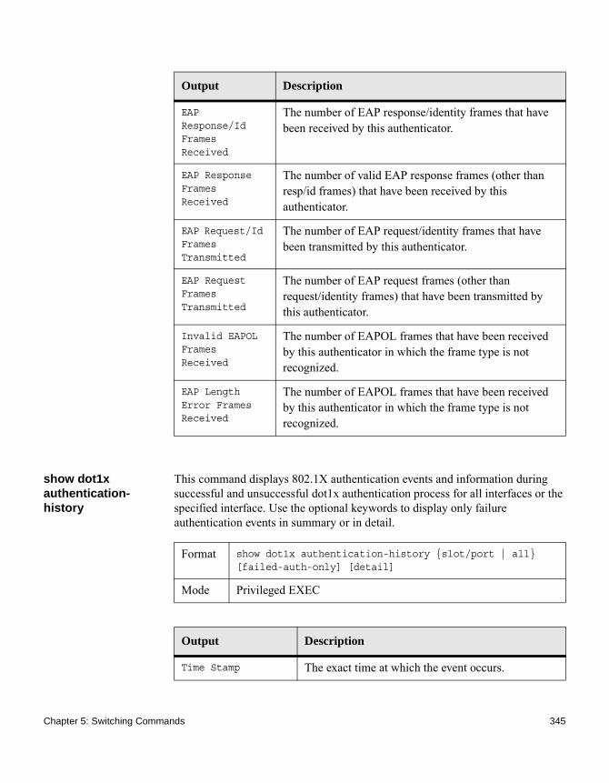
show dot1x authentication-history
This command displays 802.1X authentication events and information during successful and unsuccessful dot1x authentication process for all interfaces or the specified interface. Use the optional keywords to display only failure authentication events in summary or in detail.
EAP Response/Id Frames Received
The number of EAP response/identity frames that have been received by this authenticator.
EAP Response Frames Received
The number of valid EAP response frames (other than resp/id frames) that have been received by this authenticator.
EAP Request/Id Frames Transmitted
The number of EAP request/identity frames that have been transmitted by this authenticator.
EAP Request Frames Transmitted
The number of EAP request frames (other than request/identity frames) that have been transmitted by this authenticator.
Invalid EAPOL Frames Received
The number of EAPOL frames that have been received by this authenticator in which the frame type is not recognized.
EAP Length Error Frames Received
The number of EAPOL frames that have been received by this authenticator in which the frame type is not recognized.
Output Description
Format show dot1x authentication-history {slot/port | all} [failed-auth-only] [detail]
Mode Privileged EXEC
Output Description
Time Stamp The exact time at which the event occurs.
Chapter 5: Switching Commands 345

show dot1x clients This command displays 802.1X client information. This command also displays information about the number of clients that are authenticated using Monitor mode and using 802.1X.
Interface Physical port on which the event occurs.
MAC-Address The supplicant/client MAC address.
VLAN Assigned The VLAN assigned to the client/port on authentication.
VLAN Assigned Reason
The type of VLAN ID assigned, which can be Guest VLAN, Unauth, Default, RADIUS Assigned, or Montior Mode VLAN ID.
Auth Status The authentication status.
Reason The actual reason behind the successful or failed authentication.
Output Description
Format show dot1x clients {slot/port | all} [detail]
Mode Privileged EXEC
Output Description
Clients Authenticated using Monitor Mode
Indicates the number of the dot1x clients authenticated using Monitor mode.
Clients Authenticated using Dot1x
Indicates the number of dot1x clients authenticated using 802.1x authentication process.
Logical Interface The logical port number associated with a client.
Interface The physical port to which the supplicant is associated.
346 Port-Based Network Access Control Commands

show dot1x users This command displays 802.1X port security user information for locally configured users.
User Name The user name used by the client to authenticate to the server.
Supplicant MAC Address
The supplicant device MAC address.
Session Time The time since the supplicant is logged on.
Filter ID Identifies the Filter ID returned by the RADIUS server when the client was authenticated. This is a configured DiffServ policy name on the switch.
VLAN ID The VLAN assigned to the port.
VLAN Assigned The reason the VLAN identified in the VLAN ID field has been assigned to the port. Possible values are RADIUS, Unauthenticated VLAN, Monitor Mode, or Default. When the VLAN Assigned reason is Default, it means that the VLAN was assigned to the port because the P-VID of the port was that VLAN ID.
Session Timeout This value indicates the time for which the given session is valid. The time period, in seconds, is returned by the RADIUS server on authentication of the port. This value is valid for the port only when the port-control mode is not MAC-based.
Session Termination Action
This value indicates the action to be taken once the session timeout expires. Possible values are Default and Radius-Request. If the value is Default, the session is terminated and client details are cleared. If the value is Radius-Request, then a reauthentication of the client is performed.
Output Description
Format show dot1x users slot/port
Chapter 5: Switching Commands 347
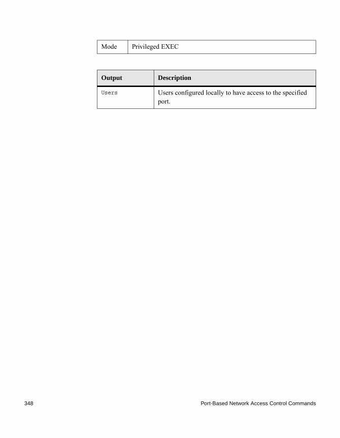
Mode Privileged EXEC
Output Description
Users Users configured locally to have access to the specified port.
348 Port-Based Network Access Control Commands

Port Channel/LAG (802.3ad) Commands
Introduction This section describes the commands you use to configure port channels, which are defined in the 802.3ad specification, and that are also known as link aggregation groups (LAGs). Link aggregation allows you to combine multiple full-duplex Ethernet links into a single logical link. Network devices treat the aggregation as if it were a single link, which increases fault tolerance and provides load sharing. The LAG feature initially load shares traffic based upon the source and destination MAC address. Assign the port channel (LAG) VLAN membership after you create a port channel. If you do not assign VLAN membership, the port channel might become a member of the management VLAN which can result in learning and switching issues.
A port channel (LAG) interface can be either static or dynamic, but not both. All members of a port channel must participate in the same protocols.) A static port channel interface does not require a partner system to be able to aggregate its member ports.
NoteIf you configure the maximum number of dynamic port channels (LAGs) that your platform supports, any additional port channels that you configure are automatically static.
port-channel This command configures a new port channel (LAG) and generates a logical slot/port number for the port channel. The name field is a character string which allows the dash (-) character as well as alphanumeric characters. Use the show port channel command to display the slot/port number for the logical interface.
NoteBefore you include a port in a port channel, set the port physical mode. For more information, see “no shutdown” on page 371.
no port-channel This command deletes a port channel (LAG).
Format port-channel name
Mode Global Config
Chapter 5: Switching Commands 349

addport This command adds one port to the port channel (LAG). The first interface is a logical slot/port number of a configured port channel. You can add a range of ports by specifying the port range when you enter Interface Config mode (for example, interface 1/0/1-1/0/4.
NoteBefore adding a port to a port channel, set the physical mode of the port. For more information, see “no shutdown” on page 371.
deleteport (Interface Config)
This command deletes a port or a range of ports from the port channel (LAG). The interface is a logical slot/port number of a configured port channel (or range of port channels).
deleteport (Global Config)
This command deletes all configured ports from the port channel (LAG). The interface is a logical slot/port number of a configured port channel. To clear the port channels, see “clear traplog” on page 197.
Format no port-channel {logical slot/port | all}
Mode Global Config
Format addport logical slot/port
Mode Interface Config
Format deleteport logical slot/port
Mode Interface Config
Format deleteport {logical slot/port | all}
Mode Global Config
350 Port Channel/LAG (802.3ad) Commands
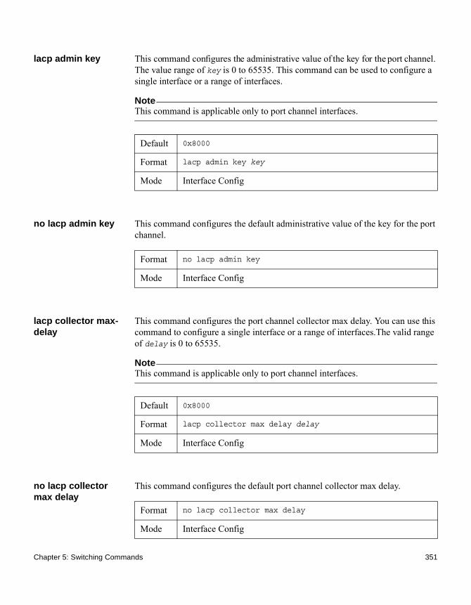
lacp admin key This command configures the administrative value of the key for the port channel. The value range of key is 0 to 65535. This command can be used to configure a single interface or a range of interfaces.
NoteThis command is applicable only to port channel interfaces.
no lacp admin key This command configures the default administrative value of the key for the port channel.
lacp collector max-delay
This command configures the port channel collector max delay. You can use this command to configure a single interface or a range of interfaces.The valid range of delay is 0 to 65535.
NoteThis command is applicable only to port channel interfaces.
no lacp collector max delay
This command configures the default port channel collector max delay.
Default 0x8000
Format lacp admin key key
Mode Interface Config
Format no lacp admin key
Mode Interface Config
Default 0x8000
Format lacp collector max delay delay
Mode Interface Config
Format no lacp collector max delay
Mode Interface Config
Chapter 5: Switching Commands 351

lacp actor admin This command configures the LACP actor admin parameters.
lacp actor admin key
This command configures the administrative value of the LACP actor admin key on an interface or range of interfaces. The valid range for key is 0 to 65535.
NoteThis command is applicable only to physical interfaces.
no lacp actor admin key
This command configures the default administrative value of the key.
lacp actor admin state
This command configures the administrative value of actor state as transmitted by the actor in the LACPDUs. The valid value range is 0x00 to 0xFF. This command can be used to configure a single interfaces or a range of interfaces.
NoteThis command is applicable only to physical interfaces.
Format lacp actor admin
Mode Interface Config
Default Internal Interface Number of this Physical Port
Format lacp actor admin key key
Mode Interface Config
Format no lacp actor admin key
Mode Interface Config
Default 0x07
Format lacp actor admin state {individual|longtimeout|passive}
Mode Interface Config
352 Port Channel/LAG (802.3ad) Commands

no lacp actor admin state
This command configures the default administrative values of actor state as transmitted by the actor in LACPDUs.
lacp actor admin state individual
This command sets the LACP actor admin state to individual.
NoteThis command is applicable only to physical interfaces.
no lacp actor admin state individual
This command sets the LACP actor admin state to aggregation.
lacp actor admin state longtimeout
This command sets the LACP actor admin state to longtimeout.
NoteThis command is applicable only to physical interfaces.
no lacp actor admin state longtimeout
This command sets the LACP actor admin state to short timeout.
Format no lacp actor admin state {individual|longtimeout|passive}
Mode Interface Config
Format lacp actor admin state individual
Mode Interface Config
Format no lacp actor admin state individual
Mode Interface Config
Format lacp actor admin state longtimeout
Mode Interface Config
Chapter 5: Switching Commands 353

NoteThis command is applicable only to physical interfaces.
lacp actor admin state passive
This command sets the LACP actor admin state to passive.
NoteThis command is applicable only to physical interfaces.
no lacp actor admin state passive
This command sets the LACP actor admin state to active.
lacp actor port This command configures LACP actor port priority key.
lacp actor port priority
This command configures the priority value assigned to the aggregation port for an interface or range of interfaces. The valid range for priority is 0 to 255.
NoteThis command is applicable only to physical interfaces.
Format no lacp actor admin state longtimeout
Mode Interface Config
Format lacp actor admin state passive
Mode Interface Config
Format no lacp actor admin state passive
Mode Interface Config
Format lacp actor port
Mode Interface Config
354 Port Channel/LAG (802.3ad) Commands
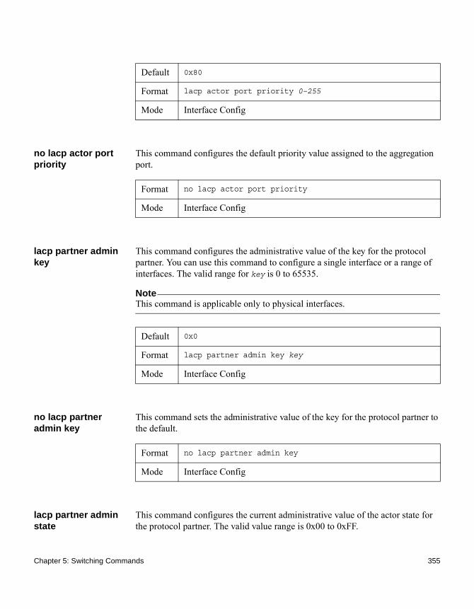
no lacp actor port priority
This command configures the default priority value assigned to the aggregation port.
lacp partner admin key
This command configures the administrative value of the key for the protocol partner. You can use this command to configure a single interface or a range of interfaces. The valid range for key is 0 to 65535.
NoteThis command is applicable only to physical interfaces.
no lacp partner admin key
This command sets the administrative value of the key for the protocol partner to the default.
lacp partner admin state
This command configures the current administrative value of the actor state for the protocol partner. The valid value range is 0x00 to 0xFF.
Default 0x80
Format lacp actor port priority 0–255
Mode Interface Config
Format no lacp actor port priority
Mode Interface Config
Default 0x0
Format lacp partner admin key key
Mode Interface Config
Format no lacp partner admin key
Mode Interface Config
Chapter 5: Switching Commands 355
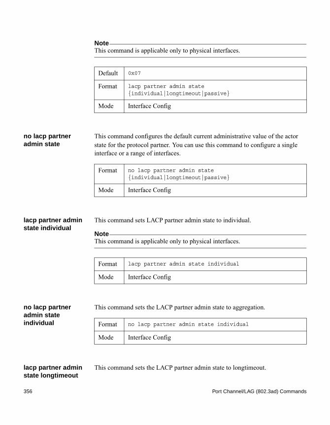
NoteThis command is applicable only to physical interfaces.
no lacp partner admin state
This command configures the default current administrative value of the actor state for the protocol partner. You can use this command to configure a single interface or a range of interfaces.
lacp partner admin state individual
This command sets LACP partner admin state to individual.
NoteThis command is applicable only to physical interfaces.
no lacp partner admin state individual
This command sets the LACP partner admin state to aggregation.
lacp partner admin state longtimeout
This command sets the LACP partner admin state to longtimeout.
Default 0x07
Format lacp partner admin state {individual|longtimeout|passive}
Mode Interface Config
Format no lacp partner admin state {individual|longtimeout|passive}
Mode Interface Config
Format lacp partner admin state individual
Mode Interface Config
Format no lacp partner admin state individual
Mode Interface Config
356 Port Channel/LAG (802.3ad) Commands

NoteThis command is applicable only to physical interfaces.
no lacp partner admin state longtimeout
This command sets the LACP partner admin state to short timeout.
NoteThis command is applicable only to physical interfaces.
lacp partner admin state passive
This command sets the LACP partner admin state to passive.
NoteThis command is applicable only to physical interfaces.
no lacp partner admin state passive
This command sets the LACP partner admin state to active.
lacp partner port id This command configures the LACP partner port ID. You can use this command to configure a single interface or a range of interfaces. The valid range for port-id is 0 to 65535.
Format lacp partner admin state longtimeout
Mode Interface Config
Format no lacp partner admin state longtimeout
Mode Interface Config
Format lacp partner admin state passive
Mode Interface Config
Format no lacp partner admin state passive
Mode Interface Config
Chapter 5: Switching Commands 357

NoteThis command is applicable only to physical interfaces.
no lacp partner port id
This command sets the LACP partner port ID to the default.
lacp partner port priority
This command configures the LACP partner port priority. You can use this command to configure a single interface or a range of interfaces. The valid range for priority is 0 to 255.
NoteThis command is applicable only to physical interfaces.
no lacp partner port priority
This command configures the default LACP partner port priority.
Default 0x80
Format lacp partner port-id port-id
Mode Interface Config
Format no lacp partner port-id
Mode Interface Config
Default 0x0
Format lacp partner port priority priority
Mode Interface Config
Format no lacp partner port priority
Mode Interface Config
358 Port Channel/LAG (802.3ad) Commands
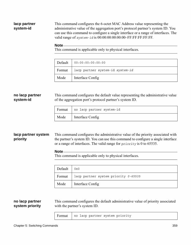
lacp partner system-id
This command configures the 6-octet MAC Address value representing the administrative value of the aggregation port’s protocol partner’s system ID. You can use this command to configure a single interface or a range of interfaces. The valid range of system-id is 00:00:00:00:00:00–FF:FF:FF:FF:FF.
NoteThis command is applicable only to physical interfaces.
no lacp partner system-id
This command configures the default value representing the administrative value of the aggregation port’s protocol partner’s system ID.
lacp partner system priority
This command configures the administrative value of the priority associated with the partner’s system ID. You can use this command to configure a single interface or a range of interfaces. The valid range for priority is 0 to 65535.
NoteThis command is applicable only to physical interfaces.
no lacp partner system priority
This command configures the default administrative value of priority associated with the partner’s system ID.
Default 00:00:00:00:00:00
Format lacp partner system-id system-id
Mode Interface Config
Format no lacp partner system-id
Mode Interface Config
Default 0x0
Format lacp partner system priority 0-65535
Mode Interface Config
Format no lacp partner system priority
Chapter 5: Switching Commands 359

port-channel static This command enables the static mode on a port channel (LAG) interface or range of interfaces. By default the static mode for a new port channel is disabled, which means the port channel is dynamic. However if the maximum number of allowable dynamic port channels are already present in the system, the static mode for a new port channel is enabled, which means the port channel is static.You can only use this command on port channel interfaces.
no port-channel static
This command sets the static mode on a particular port channel (LAG) interface to the default value. This command will be executed only for interfaces of type port channel (LAG).
port lacpmode This command enables Link Aggregation Control Protocol (LACP) on a port or range of ports.
no port lacpmode This command disables Link Aggregation Control Protocol (LACP) on a port.
Mode Interface Config
Default disabled
Format port-channel static
Mode Interface Config
Format no port-channel static
Mode Interface Config
Default enabled
Format port lacpmode
Mode Interface Config
Format no port lacpmode
360 Port Channel/LAG (802.3ad) Commands

port lacpmode all This command enables Link Aggregation Control Protocol (LACP) on all ports.
no port lacpmode all
This command disables Link Aggregation Control Protocol (LACP) on all ports.
port lacptimeout (Interface Config)
This command sets the timeout on a physical interface or range of interfaces of a particular device type (actor or partner) to either long or short timeout.
no port lacptimeout (Interface Config)
This command sets the timeout back to its default value on a physical interface of a particular device type (actor or partner).
port lacptimeout (Global Config)
This command sets the timeout for all interfaces of a particular device type (actor or partner) to either long or short timeout.
Mode Interface Config
Format port lacpmode all
Mode Global Config
Format no port lacpmode all
Mode Global Config
Default long
Format port lacptimeout {actor | partner} {long | short}
Mode Interface Config
Format no port lacptimeout {actor | partner}
Mode Interface Config
Default long
Chapter 5: Switching Commands 361

no port lacptimeout (Global Config)
This command sets the timeout for all physical interfaces of a particular device type (actor or partner) back to their default values.
port-channel adminmode
This command enables a port channel (LAG). The option all sets every configured port channel with the same administrative mode setting.
no port-channel adminmode
This command disables a port channel (LAG). The option all sets every configured port channel with the same administrative mode setting.
port-channel linktrap
This command enables link trap notifications for the port channel (LAG). The interface is a logical slot/port for a configured port channel. The option all sets every configured port channel with the same administrative mode setting.
Format port lacptimeout {actor | partner} {long | short}
Mode Global Config
Format no port lacptimeout {actor | partner}
Mode Global Config
Format port-channel adminmode [all]
Mode Global Config
Format no port-channel adminmode [all]
Mode Global Config
Default enabled
Format port-channel linktrap {logical slot/port | all}
Mode Global Config
362 Port Channel/LAG (802.3ad) Commands

no port-channel linktrap
This command disables link trap notifications for the port channel (LAG). The interface is a logical slot and port for a configured port channel. The option all sets every configured port channel with the same administrative mode setting.
port-channel load-balance
This command selects the load-balancing option used on a port channel (LAG). Traffic is balanced on a port channel (LAG) by selecting one of the links in the channel over which to transmit specific packets. The link is selected by creating a binary pattern from selected fields in a packet, and associating that pattern with a particular link.
Load-balancing is not supported on every device. The range of options for load-balancing may vary per device.
This command can be configured for a single interface, a range of interfaces, or all interfaces.
Format no port-channel linktrap {logical slot/port | all}
Mode Global Config
Default 3
Format port-channel load-balance {1 | 2 | 3 | 4 | 5 | 6} {slot/port | all}
Mode ◆ Interface Config◆ Global Config
Parameter Description
1 Source MAC, VLAN, EtherType, and incoming port associated with the packet
2 Destination MAC, VLAN, EtherType, and incoming port associated with the packet
3 Source/Destination MAC, VLAN, EtherType, and incoming port associated with the packet
4 Source IP and Source TCP/UDP fields of the packet
Chapter 5: Switching Commands 363

no port-channel load-balance
This command reverts to the default load balancing configuration.
port-channel name This command defines a name for the port channel (LAG). The interface is a logical slot/port for a configured port channel, and name is an alphanumeric string up to 15 characters.
5 Destination IP and Destination TCP/UDP Port fields of the packet
6 Source/Destination IP and source/destination TCP/UDP Port fields of the packet
slot/port| all Global Config Mode only: The interface is a logical slot/port number of a configured port channel. All applies the command to all currently configured port channels.
Parameter Description
Format no port-channel load-balance {slot/port | all}
Mode ◆ Interface Config◆ Global Config
Parameter Description
slot/port| all Global Config Mode only: The interface is a logical slot/port number of a configured port channel. all applies the command to all currently configured port channels.
Format port-channel name {logical slot/port | all | name}
Mode Global Config
364 Port Channel/LAG (802.3ad) Commands

port-channel system priority
This command configures port channel system priority. The valid range of priority is 0 to 65535.
no port-channel system priority
This command configures the default port channel system priority value.
show lacp actor This command displays LACP actor attributes.
The following output parameters are displayed:
show lacp partner This command displays LACP partner attributes.
Default 0x8000
Format port-channel system priority priority
Mode Global Config
Format no port-channel system priority
Mode Global Config
Format show lacp actor {slot/port|all}
Mode Privileged EXEC
Output Description
System Priority The administrative value of the key.
Actor Admin Key The administrative value of the key.
Port Priority The priority value assigned to the aggregation port.
Admin State The administrative values of the actor state as transmitted by the actor in LACPDUs.
Format show lacp actor {slot/port|all}
Mode Privileged EXEC
Chapter 5: Switching Commands 365

The following output parameters are displayed:
show port-channel This command displays an overview of all port channels (LAGs) on the switch.
Output Description
System Priority The administrative value of priority associated with the partner’s system ID.
System-ID Represents the administrative value of the aggregation port’s protocol partner’s system ID.
Admin Key The administrative value of the key for the protocol partner.
Port Priority The administrative value of the key for protocol partner.
Port-ID The administrative value of the port number for the protocol partner.
Admin State The administrative values of the actor state for the protocol partner.
Format show port-channel {logical slot/port | all}
Mode ◆ Privileged EXEC ◆ User EXEC
Output Description
Logical Interface The valid slot/port of the logical interface.
Port Channel Name The name of this port channel (LAG). You may enter any string of up to 15 alphanumeric characters.
Link-State Indicates whether the link is up or down.
Admin Mode May be enabled or disabled. The factory default is enabled.
366 Port Channel/LAG (802.3ad) Commands

show port-channel brief
This command displays the static capability of all port channel (LAG) interfaces on the device as well as a summary of individual port channel interfaces.
For each port channel the following information is displayed:
Type The status designating whether a particular port channel (LAG) is statically or dynamically maintained. ◆ Static - The port channel is statically
maintained.◆ Dynamic - The port channel is dynamically
maintained.
Mbr Ports A listing of the ports that are members of this port channel (LAG), in slot/port notation. There can be a maximum of eight ports assigned to a given port channel (LAG).
Device Timeout For each port, lists the timeout (long or short) for Device Type (actor or partner).
Port Speed Speed of the port channel port.
Active Ports The ports that are actively participating in the port channel.
Load Balance Option
The load balance option associated with this LAG. See “port-channel load-balance” on page 363.
Output Description
Format show port-channel brief
Mode ◆ Privileged EXEC ◆ User EXEC
Output Description
Logical Interface The slot/port of the logical interface.
Port Channel Name The name of the port channel (LAG) interface.
Chapter 5: Switching Commands 367

show port-channel system priority
This command displays the port channel system priority.
Link-State Shows whether the link is up or down.
Trap Flag Shows whether trap flags are enabled or disabled.
Type Shows whether the port channel is statically or dynamically maintained.
Mbr Ports The members of this port channel.
Active Ports The ports that are actively participating in the port channel.
Output Description
Format show port-channel system priority
Mode Privileged EXEC
368 Port Channel/LAG (802.3ad) Commands

Port Configuration Commands
Introduction This section describes the commands you use to view and configure port settings.
interface This command gives you access to the Interface Config mode, which allows you to enable or modify the operation of an interface (port). You can also specify a range of ports to configure at the same time by specifying the starting slot/port and ending slot/port, separated by a hyphen.
Example: The following example enters Interface Config mode for port 1/0/1:(CN1610)#configure(CN1610)(config)#interface 1/0/1(CN1610)(interface 1/0/1)#
Example: The following example enters Interface Config mode for ports 1/0/1 through 1/0/4:(CN1610)#configure(CN1610)(config)#interface 1/0/1-1/0/4(CN1610)(interface 1/0/1-1/0/4)#
adminmode This command lets you enter the port channel interface administratively.
auto-negotiate This command enables automatic negotiation on a port or range of ports.
Format interface {slot/port | slot/port(startrange)-slot/port(endrange)}
Mode Global Config
Format adminmode
Mode Interface Config
Default enabled
Format auto-negotiate
Chapter 5: Switching Commands 369

no auto-negotiate This command disables automatic negotiation on a port.
NoteAutomatic sensing is disabled when automatic negotiation is disabled.
auto-negotiate all This command enables automatic negotiation on all ports.
no auto-negotiate all
This command disables automatic negotiation on all ports.
description This command creates an alphanumeric description of an interface or range of interfaces.
Mode Interface Config
Format no auto-negotiate
Mode Interface Config
Default enabled
Format auto-negotiate all
Mode Global Config
Format no auto-negotiate all
Mode Global Config
Format description description
Mode Interface Config
370 Port Configuration Commands

mtu Use the mtu command to set the maximum transmission unit (MTU) size, in bytes, for frames that ingress or egress the interface. You can use the mtu command to configure jumbo frame support for physical and port channel (LAG) interfaces. For the standard FASTPATH implementation, the MTU size is a valid integer between 1522 to 9216 for tagged packets and a valid integer between 1518 to 9216 for untagged packets.
NoteTo receive and process packets, the Ethernet MTU must include any extra bytes that Layer-2 headers might require.
no mtu This command sets the default MTU size (in bytes) for the interface.
shutdown This command disables a port or range of ports.
NoteYou can use the shutdown command on physical and port channel (LAG) interfaces, but not on VLAN routing interfaces.
no shutdown This command enables a port.
Default 1518 (untagged)
Format mtu 1518-9216
Mode Interface Config
Format no mtu
Mode Interface Config
Default enabled
Format shutdown
Mode Interface Config
Format no shutdown
Chapter 5: Switching Commands 371

shutdown all This command disables all ports.
NoteYou can use the shutdown all command on physical and port channel (LAG) interfaces, but not on VLAN routing interfaces.
no shutdown all This command enables all ports.
speed This command lets you set the speed and duplex setting for an interface or range of interfaces.
Mode Interface Config
Default enabled
Format shutdown all
Mode Global Config
Format no shutdown all
Mode Global Config
Format speed {100 | 10} {half-duplex | full-duplex}
Mode Interface Config
Acceptable Values Description
100h 100BASE-T half duplex
100f 100BASE-T full duplex
10h 10BASE-T half duplex
10f 10BASE-T full duplex
372 Port Configuration Commands

speed all This command lets you set the speed and duplex setting for all interfaces.
show port This command displays port information.
Format speed all {100 | 10} {half-duplex | full-duplex}
Mode Global Config
Acceptable Values Description
100h 100BASE-T half duplex
100f 100BASE-T full duplex
10h 10BASE-T half duplex
10f 10BASE-T full duplex
Format show port {slot/port | all}
Mode Privileged EXEC
Output Description
Interface slot/port
Type If not blank, this field indicates that this port is a special type of port. The possible values are:◆ Mirror — this port is a monitoring port. For more
information, see “Port Mirroring Commands” on page 375.
◆ PC Mbr — this port is a member of a port channel (LAG).
◆ Probe — this port is a probe port.
Chapter 5: Switching Commands 373

Admin Mode The port control administration state. The port must be enabled in order for it to be allowed into the network. May be enabled or disabled. The factory default is enabled.
Physical Mode The desired port speed and duplex mode. If auto-negotiation support is selected, then the duplex mode and speed is set from the auto-negotiation process.
NoteThe maximum capability of the port (full duplex -100M) is advertised. Otherwise, this object determines the port's duplex mode and transmission rate. The factory default is auto.
Physical Status
The port speed and duplex mode.
Link Status The Link is up or down.
Link Trap This object determines whether or not to send a trap when link status changes. The factory default is enabled.
LACP Mode LACP is enabled or disabled on this port.
Output Description
374 Port Configuration Commands

Port Mirroring Commands
Introduction Port mirroring, which is also known as port monitoring, selects network traffic that you can analyze with a network analyzer, such as a SwitchProbe device or other Remote Monitoring (RMON) probe.
monitor session This command configures a probe port and a monitored port for monitor session (port monitoring). Use the source interface slot/port parameter to specify the interface to monitor. Use rx to monitor only ingress packets, or use tx to monitor only egress packets. If you do not specify an {rx | tx} option, the destination port monitors both ingress and egress packets. Use the destination interface slot/port to specify the interface to receive the monitored traffic. Use the mode parameter to enabled the administrative mode of the session. If enabled, the probe port monitors all the traffic received and transmitted on the physical monitored port.
no monitor session Use this command without optional parameters to remove the monitor session (port monitoring) designation from the source probe port, the destination monitored port, and all VLANs. Once the port is removed from the VLAN, you must manually add the port to any desired VLANs. Use the source interface slot/port parameter or destination interface to remove the specified interface from the port monitoring session. Use the mode parameter to disable the administrative mode of the session.
NoteSince the current version of CN1610 software only supports one session, if you do not supply optional parameters, the behavior of this command is similar to the behavior of the no monitor command.
Format monitor session session-id {source interface slot/port [{rx | tx}] | destination interface slot/port | mode}
Mode Global Config
Format no monitor session session-id [{source interface slot/port | destination interface | mode}]
Chapter 5: Switching Commands 375

no monitor This command removes all the source ports and a destination port and restores the default value for mirroring session mode for all the configured sessions.
NoteThis is a standalone no command. This command does not have a normal form.
show monitor session
This command displays the port monitoring information for a particular mirroring session.
NoteThe session-id parameter is an integer value used to identify the session. In the current version of the software, the session-id parameter is always one (1).
Mode Global Config
Default enabled
Format no monitor
Mode Global Config
Format show monitor session session-id
Mode Privileged EXEC
Output Description
Session ID An integer value used to identify the session. Its value can be anything between 1 and the maximum number of mirroring sessions allowed on the platform.
Monitor Session Mode
Indicates whether the Port Mirroring feature is enabled or disabled for the session identified with session-id. The possible values are Enabled and Disabled.
376 Port Mirroring Commands

Probe Port Probe port (destination port) for the session identified with session-id. If the probe port is not set then this field is blank.
Source Port The port, which is configured as a mirrored port (source port) for the session identified with session-id. If no source port is configured for the session then this field is blank.
Type Direction in which the source port is configured for port mirroring. Types are tx for transmitted packets and rx for receiving packets.
Output Description
Chapter 5: Switching Commands 377

Port Security Commands
Introduction This section describes the commands you use to configure port security on the switch. Port security, which is also known as port MAC locking, allows you to secure the network by locking allowable MAC addresses on a given port. Packets with a matching source MAC address are forwarded normally, and all other packets are discarded.
NoteTo enable the SNMP trap specific to port security, see “snmp-server enable traps violation” on page 70.
port-security This command enables port locking on an interface, a range of interfaces, or at the system level.
no port-security This command disables port locking for one (Interface Config) or all (Global Config) ports.
port-security max-dynamic
This command sets the maximum number of dynamically locked MAC addresses allowed on a specific port.
Default disabled
Format port-security
Mode ◆ Global Config (to enable port locking globally)◆ Interface Config (to enable port locking on an interface or range
of interfaces)
Format no port-security
Mode ◆ Global Config◆ Interface Config
Default 600
Format port-security max-dynamic maxvalue
378 Port Security Commands

no port-security max-dynamic
This command resets the maximum number of dynamically locked MAC addresses allowed on a specific port to its default value.
port-security max-static
This command sets the maximum number of statically locked MAC addresses allowed on a port.
no port-security max-static
This command sets maximum number of statically locked MAC addresses to the default value.
port-security mac-address
This command adds a MAC address to the list of statically locked MAC addresses for an interface or range of interfaces. The vid is the VLAN ID.
no port-security mac-address
This command removes a MAC address from the list of statically locked MAC addresses.
Mode Interface Config
Format no port-security max-dynamic Mode Interface Config
Default 20
Format port-security max-static maxvalueMode Interface Config
Format no port-security max-static
Mode Interface Config
Format port-security mac-address mac-address vid
Mode Interface Config
Format no port-security mac-address mac-address vid
Mode Interface Config
Chapter 5: Switching Commands 379

port-security mac-address move
This command converts dynamically locked MAC addresses to statically locked addresses for an interface or range of interfaces.
show port-security This command displays the port security settings. If you do not use a parameter, the command displays the settings for the entire system. Use the optional parameters to display the settings on a specific interface or on all interfaces.
For each interface, or for the interface you specify, the following information appears:
show port-security dynamic
This command displays the dynamically locked MAC addresses for the port.
show port-security static
This command displays the statically locked MAC addresses for port.
Format port-security mac-address move
Mode Interface Config
Format show port-security [{slot/port | all}]
Mode Privileged EXEC
Output Description
Admin Mode Port locking mode for the interface.Dynamic Limit
Maximum dynamically allocated MAC addresses.
Static Limit
Maximum statically allocated MAC addresses.
Violation Trap Mode
Whether violation traps are enabled.
Format show port-security dynamic slot/portMode Privileged EXEC
Output Description
MAC Address MAC address of dynamically locked MAC.
Format show port-security static slot/port
380 Port Security Commands
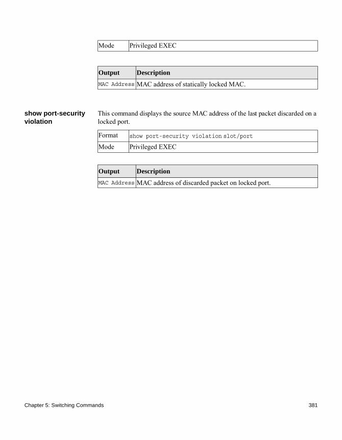
show port-security violation
This command displays the source MAC address of the last packet discarded on a locked port.
Mode Privileged EXEC
Output Description
MAC Address MAC address of statically locked MAC.
Format show port-security violation slot/portMode Privileged EXEC
Output Description
MAC Address MAC address of discarded packet on locked port.
Chapter 5: Switching Commands 381

Protected Ports Commands
Introduction This section describes the commands you use to configure and view protected ports on a switch. Protected ports do not forward traffic to each other, even if they are on the same VLAN. However, protected ports can forward traffic to all unprotected ports in their group. Unprotected ports can forward traffic to both protected and unprotected ports. Ports are unprotected by default.
If an interface is configured as a protected port, and you add that interface to a port channel or Link Aggregation Group (LAG), the protected port status becomes operationally disabled on the interface, and the interface follows the configuration of the LAG port. However, the protected port configuration for the interface remains unchanged. Once the interface is no longer a member of a LAG, the current configuration for that interface automatically becomes effective.
switchport protected (Global Config)
This command creates a protected port group. The groupid parameter identifies the set of protected ports. Use the name name pair to assign a name to the protected port group. The name can be up to 32 alphanumeric characters long, including blanks. The default is blank.
NotePort protection occurs within a single switch. Protected port configuration does not affect traffic between ports on two different switches. No traffic forwarding is possible between two protected ports.
no switchport protected (Global Config)
This command removes a protected port group. The groupid parameter identifies the set of protected ports. The name keyword specifies the name to remove from the group.
Default unprotected
Format switchport protected groupid name name
Mode Global Config
Format no switchport protected groupid name
382 Protected Ports Commands

switchport protected (Interface Config)
This command adds an interface to a protected port group. The groupid parameter identifies the set of protected ports to which this interface is assigned. You can only configure an interface as protected in one group.
NotePort protection occurs within a single switch. Protected port configuration does not affect traffic between ports on two different switches. No traffic forwarding is possible between two protected ports.
no switchport protected (Interface Config)
This command configures a port as unprotected. The groupid parameter identifies the set of protected ports to which this interface is assigned.
show switchport protected
This command displays the status of all the interfaces, including protected and unprotected interfaces.
Mode Global Config
Default unprotected
Format switchport protected groupid
Mode Interface Config
Format no switchport protected groupid name
Mode Interface Config
Format show switchport protected groupid
Mode ◆ Privileged EXEC◆ User EXEC
Output Description
Group ID The number that identifies the protected port group.
Chapter 5: Switching Commands 383

show interfaces switchport
This command displays the status of the interface (protected and unprotected) under the groupid.
Name An optional name of the protected port group. The name can be up to 32 alphanumeric characters long, including blanks. The default is blank.
List of Physical Ports
List of ports, which are configured as protected for the group identified with groupid. If no port is configured as protected for this group, this field is blank.
Output Description
Format show interfaces switchport slot/port groupid
Mode ◆ Privileged EXEC◆ User EXEC
Output Description
Name A string associated with this group as a convenience. The name can be up to 32 alphanumeric characters long, including blanks. The default is blank. This field is optional.
Protected Indicates whether the interface is protected or not. It displays TRUE or FALSE. If the group is a multiple group, then TRUE is displayed in groupid.
384 Protected Ports Commands

Provisioning (IEEE 802.1p) Commands
Introduction This section describes the commands you use to configure provisioning (IEEE 802.1p,) which allows you to prioritize ports.
vlan port priority all This command configures the port priority assigned for untagged packets for all ports presently plugged into the device. The range for the priority is 0 to 7. Any subsequent per port configuration will override this configuration setting.
vlan priority This command configures the default 802.1p port priority assigned for untagged packets for a specific interface. The range for the priority is 0 to 7.
Format vlan port priority all priority
Mode Global Config
Default 0
Format vlan priority priority
Mode Interface Config
Chapter 5: Switching Commands 385
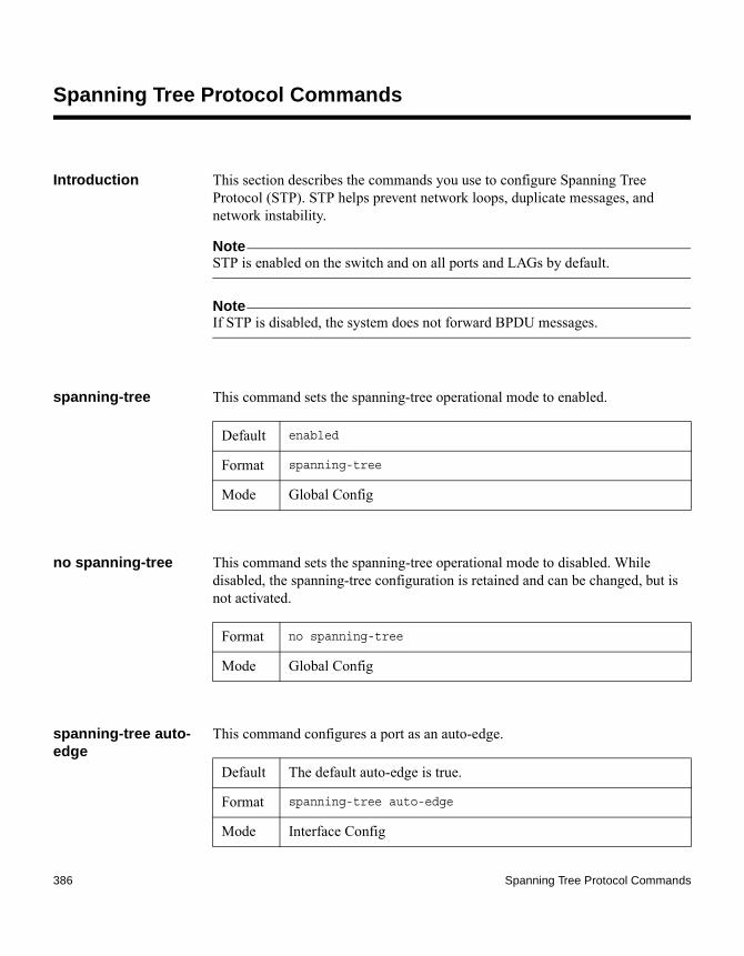
Spanning Tree Protocol Commands
Introduction This section describes the commands you use to configure Spanning Tree Protocol (STP). STP helps prevent network loops, duplicate messages, and network instability.
NoteSTP is enabled on the switch and on all ports and LAGs by default.
NoteIf STP is disabled, the system does not forward BPDU messages.
spanning-tree This command sets the spanning-tree operational mode to enabled.
no spanning-tree This command sets the spanning-tree operational mode to disabled. While disabled, the spanning-tree configuration is retained and can be changed, but is not activated.
spanning-tree auto-edge
This command configures a port as an auto-edge.
Default enabled
Format spanning-tree
Mode Global Config
Format no spanning-tree
Mode Global Config
Default The default auto-edge is true.
Format spanning-tree auto-edge
Mode Interface Config
386 Spanning Tree Protocol Commands
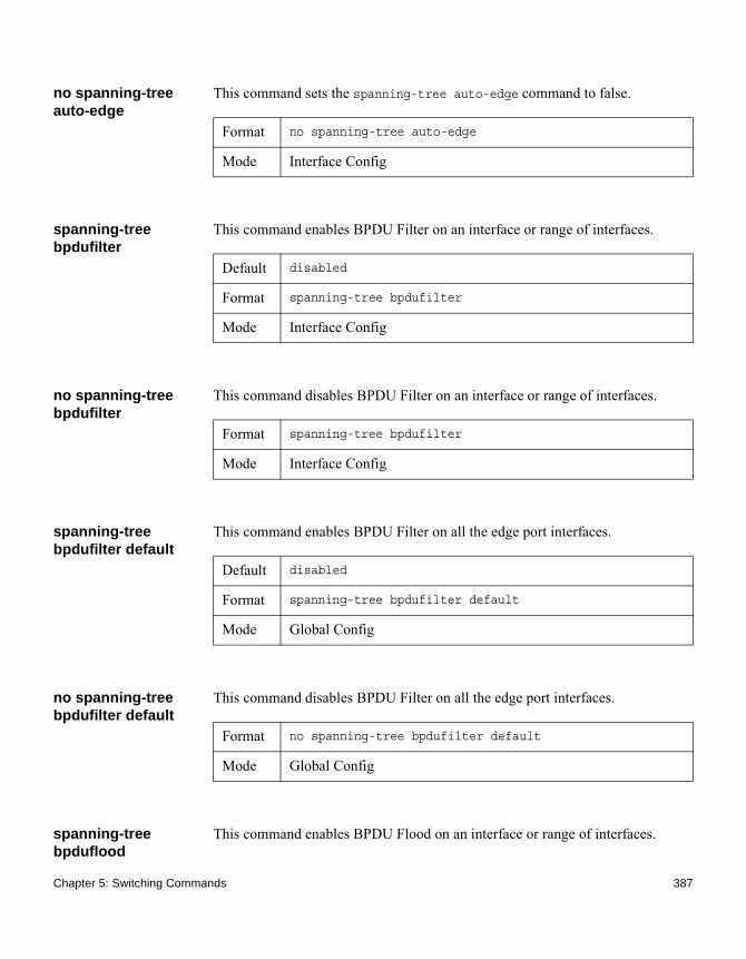
no spanning-tree auto-edge
This command sets the spanning-tree auto-edge command to false.
spanning-tree bpdufilter
This command enables BPDU Filter on an interface or range of interfaces.
no spanning-tree bpdufilter
This command disables BPDU Filter on an interface or range of interfaces.
spanning-tree bpdufilter default
This command enables BPDU Filter on all the edge port interfaces.
no spanning-tree bpdufilter default
This command disables BPDU Filter on all the edge port interfaces.
spanning-tree bpduflood
This command enables BPDU Flood on an interface or range of interfaces.
Format no spanning-tree auto-edge
Mode Interface Config
Default disabled
Format spanning-tree bpdufilter
Mode Interface Config
Format spanning-tree bpdufilter
Mode Interface Config
Default disabled
Format spanning-tree bpdufilter default
Mode Global Config
Format no spanning-tree bpdufilter default
Mode Global Config
Chapter 5: Switching Commands 387
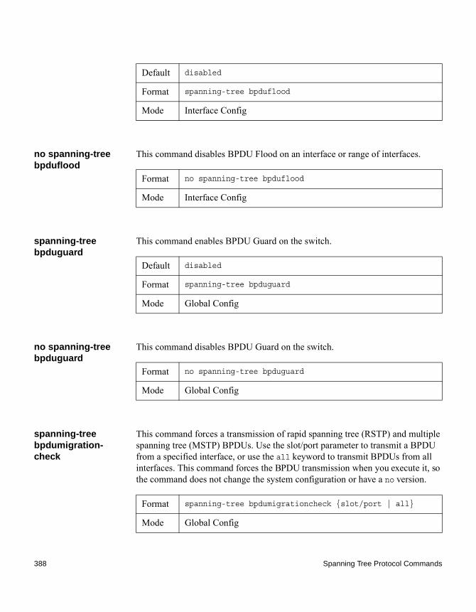
no spanning-tree bpduflood
This command disables BPDU Flood on an interface or range of interfaces.
spanning-tree bpduguard
This command enables BPDU Guard on the switch.
no spanning-tree bpduguard
This command disables BPDU Guard on the switch.
spanning-tree bpdumigration-check
This command forces a transmission of rapid spanning tree (RSTP) and multiple spanning tree (MSTP) BPDUs. Use the slot/port parameter to transmit a BPDU from a specified interface, or use the all keyword to transmit BPDUs from all interfaces. This command forces the BPDU transmission when you execute it, so the command does not change the system configuration or have a no version.
Default disabled
Format spanning-tree bpduflood
Mode Interface Config
Format no spanning-tree bpduflood
Mode Interface Config
Default disabled
Format spanning-tree bpduguard
Mode Global Config
Format no spanning-tree bpduguard
Mode Global Config
Format spanning-tree bpdumigrationcheck {slot/port | all}
Mode Global Config
388 Spanning Tree Protocol Commands

spanning-tree configuration name
This command sets the Configuration Identifier Name for use in identifying the configuration that this switch is currently using. The name is a string of up to 32 characters.
no spanning-tree configuration name
This command resets the Configuration Identifier Name to its default.
spanning-tree configuration revision
This command sets the Configuration Identifier Revision Level for use in identifying the configuration that this switch is currently using. The Configuration Identifier Revision Level is a number in the range of 0 to 65535.
no spanning-tree configuration revision
This command sets the Configuration Identifier Revision Level, for use in identifying the configuration that this switch is currently using, to the default value.
spanning-tree cost This command specifies an external path cost for the port used by an MST instance. Use an integer in the range of 1 to 200000000.
Default base MAC address in hexadecimal notation
Format spanning-tree configuration name name
Mode Global Config
Format no spanning-tree configuration name
Mode Global Config
Default 0
Format spanning-tree configuration revision 0–65535
Mode Global Config
Format no spanning-tree configuration revision
Mode Global Config
Chapter 5: Switching Commands 389
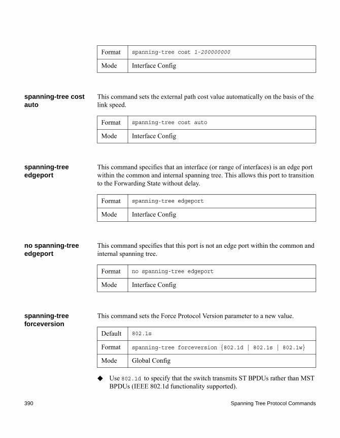
spanning-tree cost auto
This command sets the external path cost value automatically on the basis of the link speed.
spanning-tree edgeport
This command specifies that an interface (or range of interfaces) is an edge port within the common and internal spanning tree. This allows this port to transition to the Forwarding State without delay.
no spanning-tree edgeport
This command specifies that this port is not an edge port within the common and internal spanning tree.
spanning-tree forceversion
This command sets the Force Protocol Version parameter to a new value.
◆ Use 802.1d to specify that the switch transmits ST BPDUs rather than MST BPDUs (IEEE 802.1d functionality supported).
Format spanning-tree cost 1-200000000
Mode Interface Config
Format spanning-tree cost auto
Mode Interface Config
Format spanning-tree edgeport
Mode Interface Config
Format no spanning-tree edgeport
Mode Interface Config
Default 802.1s
Format spanning-tree forceversion {802.1d | 802.1s | 802.1w}
Mode Global Config
390 Spanning Tree Protocol Commands

◆ Use 802.1s to specify that the switch transmits MST BPDUs (IEEE 802.1s functionality supported).
◆ Use 802.1w to specify that the switch transmits RST BPDUs rather than MST BPDUs (IEEE 802.1w functionality supported).
no spanning-tree forceversion
This command sets the Force Protocol Version parameter to the default value.
spanning-tree forward-time
This command sets the Bridge Forward Delay parameter to a new value for the common and internal spanning tree. The forward-time value is in seconds within a range of 4 to 30, with the value being greater than or equal to (Bridge Max Age / 2) + 1.
no spanning-tree forward-time
This command sets the Bridge Forward Delay parameter for the common and internal spanning tree to the default value.
spanning-tree guard
This command selects whether loop guard or root guard is enabled on an interface or range of interfaces. If neither is enabled, then the port operates in accordance with the multiple spanning tree protocol.
Format no spanning-tree forceversion
Mode Global Config
Default 15
Format spanning-tree forward-time 4-30
Mode Global Config
Format no spanning-tree forward-time
Mode Global Config
Default none
Format spanning-tree guard {none | root | loop}
Chapter 5: Switching Commands 391

no spanning-tree guard
This command disables loop guard or root guard on the interface.
spanning-tree hold-count
This command sets the Bridge Tx hold-count parameter to a new value for the common and internal spanning tree. The Bridge Tx hold count value is an integer from 1 to 10.
no spanning-tree hold-count
This command sets the Bridge Tx hold-count parameter to the default value.
spanning-tree max-age
This command sets the Bridge max-age parameter to a new value for the common and internal spanning tree. The max-age value is, in seconds, within a range of 6 to 40, with the value being less than or equal to 2 x (Bridge Forward Delay - 1).
Mode Interface Config
Format no spanning-tree guard
Mode Interface Config
Default 3
Format spanning-tree hold-count
Mode Global Config
Format spanning-tree hold-count
Mode Global Config
Default 20
Format spanning-tree max-age 6-40
Mode Global Config
392 Spanning Tree Protocol Commands

no spanning-tree max-age
This command sets the Bridge max-age parameter for the common and internal spanning tree to the default value.
spanning-tree max-hops
This command sets the MSTP max-hops parameters to a new value for the common and internal spanning tree. The max-hops value is a range from 1 to 127.
no spanning-tree max-hops
This command sets the Bridge max-hops parameter for the common and internal spanning tree to the default value.
spanning-tree mst This command sets the Path Cost or Port Priority for this port within the multiple spanning tree instance or in the common and internal spanning tree. If you specify an mstid parameter that corresponds to an existing multiple spanning tree instance, the configurations are done for that multiple spanning tree instance. If you specify 0 (defined as the default CIST ID) as the mstid value the configurations are done for the common and internal spanning tree instance.
If you specify the cost option, the command sets the path cost for this port within a multiple spanning tree instance or the common and internal spanning tree instance, depending on the mstid parameter. You can set the path cost as a number in the range of 1 to 200000000 or auto. If you select auto, the path cost value is set based on link speed.
If you specify the external-cost option, this command sets the external-path cost for MST instance 0, that is, CIST instance. You can set the external cost as a
Format no spanning-tree max-age
Mode Global Config
Default 20
Format spanning-tree max-hops 1-127
Mode Global Config
Format no spanning-tree max-hops
Mode Global Config
Chapter 5: Switching Commands 393

number in the range of 1 to 200000000 or auto. If you specify auto, the external path cost value is set based on Link Speed.
If you specify the port-priority option, this command sets the priority for this port within a specific multiple spanning tree instance or the common and internal spanning tree instance, depending on the mstid parameter. The port-priority value is a number in the range of 0 to 240 in increments of 16.
no spanning-tree mst
This command sets the path cost or port priority for this port, within the multiple spanning tree instance, or in the common and internal spanning tree, to the respective default values. If you specify an mstid parameter that corresponds to an existing multiple spanning tree instance, the configurations are done for that multiple spanning tree instance. If you specify 0 (defined as the default CIST ID) as the mstid value, the configurations are done for the common and internal spanning tree instance.
If you specify the cost option, the command sets the path cost for this port within a multiple spanning tree instance or the common and internal spanning tree instance, depending on the mstid parameter, to the default value, that is, a path cost value based on the link speed.
If you specify the external-cost option, this command sets the external-path cost for MST instance 0, that is, CIST instance. You can set the external cost as a number in the range of 1 to 200000000 or auto. If you specify auto, the external path cost value is set based on Link Speed.
If you specify the port-priority option, this command sets the priority for this port within a specific multiple spanning tree instance or the common and internal spanning tree instance, depending on the mstid parameter, to the default value.
Default ◆ cost—auto
◆ external-cost—auto
◆ port-priority—128
Format spanning-tree mst mstid {{cost 1-200000000 | auto} |
{external-cost 1-200000000 | auto} | port-priority 0-
240}
Mode Interface Config
394 Spanning Tree Protocol Commands

spanning-tree mst instance
This command adds a multiple spanning tree instance to the switch. The mstid is a number within a range of 1 to 4094, which corresponds to the new instance ID to be added. The maximum number of multiple instances supported by the switch is 4.
spanning-tree mst priority
This command sets the bridge priority for a specific multiple spanning tree instance. The mstid parameter is a number that corresponds to the desired existing multiple spanning tree instance. The priority value is a number within a range of 0 to 61440 in increments of 4096.
If you specify 0 (defined as the default CIST ID) as the mstid, this command sets the bridge priority parameter to a new value for the common and internal spanning tree. The bridge priority value is a number within a range of 0 to 61440. The twelve least significant bits are masked according to the 802.1s specification. This causes the priority to be rounded down to the next lower valid priority.
no spanning-tree mst priority
This command sets the bridge priority for a specific multiple spanning tree instance to the default value. The mstid parameter is a number that corresponds to the desired existing multiple spanning tree instance.
Format no spanning-tree mst mstid {cost | external-cost |
port-priority}
Mode Interface Config
Default none
Format spanning-tree mst instance mstid
Mode Global Config
Default 32768
Format spanning-tree mst priority mstid 0-61440
Mode Global Config
Chapter 5: Switching Commands 395

If 0 (defined as the default CIST ID) is passed as the mstid parameter, this command sets the bridge priority parameter for the common and internal spanning tree to the default value.
spanning-tree mst vlan
This command adds an association between a multiple spanning tree instance and one or more VLANs so that the VLAN(s) are no longer associated with the common and internal spanning tree. The mstid parameter is a number that corresponds to the desired existing multiple spanning tree instance. The vlanid can be specified as a single VLAN, a list, or a range of values. To specify a list of VLANs, enter a list of VLAN IDs, each separated by a comma with no spaces in between. To specify a range of VLANs, separate the beginning and ending VLAN ID with a dash (-). The VLAN IDs may or may not exist in the system.
no spanning-tree mst vlan
This command removes an association between a multiple spanning tree instance and one or more VLANs so that the VLAN(s) are again associated with the common and internal spanning tree.
spanning-tree port mode
This command sets the Administrative Switch Port State for this port to enabled.
Format no spanning-tree mst priority mstid
Mode Global Config
Format spanning-tree mst vlan mstid vlanid
Mode Global Config
Format no spanning-tree mst vlan mstid vlanid
Mode Global Config
Default enabled
Format spanning-tree port mode
Mode Interface Config
396 Spanning Tree Protocol Commands

no spanning-tree port mode
This command sets the Administrative Switch Port State for this port to disabled.
spanning-tree port mode all
This command sets the Administrative Switch Port State for all ports to enabled.
no spanning-tree port mode all
This command sets the Administrative Switch Port State for all ports to disabled.
spanning-tree tcnguard
This command configures a port for TCN guard.
show spanning-tree This command displays spanning tree settings for the common and internal spanning tree.
The following details are displayed:
Format no spanning-tree port mode
Mode Interface Config
Default enabled
Format spanning-tree port mode all
Mode Global Config
Format no spanning-tree port mode all
Mode Global Config
Default off
Format spanning-tree tcnguard
Mode Interface Config
Format show spanning-tree
Mode ◆ Privileged EXEC◆ User EXEC
Chapter 5: Switching Commands 397
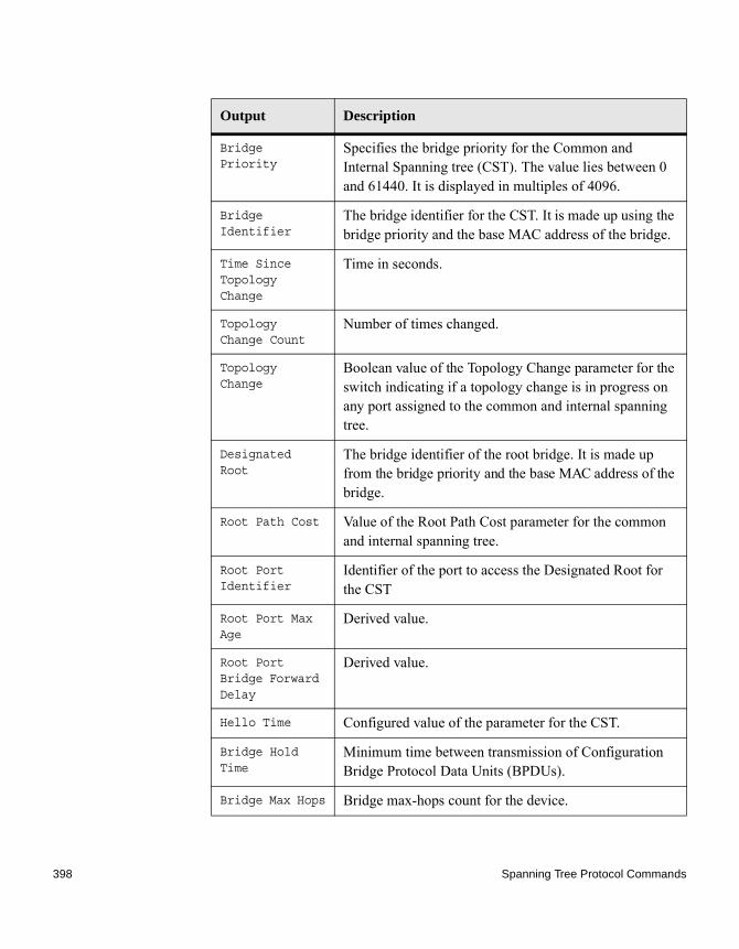
Output Description
Bridge Priority
Specifies the bridge priority for the Common and Internal Spanning tree (CST). The value lies between 0 and 61440. It is displayed in multiples of 4096.
Bridge Identifier
The bridge identifier for the CST. It is made up using the bridge priority and the base MAC address of the bridge.
Time Since Topology Change
Time in seconds.
Topology Change Count
Number of times changed.
Topology Change
Boolean value of the Topology Change parameter for the switch indicating if a topology change is in progress on any port assigned to the common and internal spanning tree.
Designated Root
The bridge identifier of the root bridge. It is made up from the bridge priority and the base MAC address of the bridge.
Root Path Cost Value of the Root Path Cost parameter for the common and internal spanning tree.
Root Port Identifier
Identifier of the port to access the Designated Root for the CST
Root Port Max Age
Derived value.
Root Port Bridge Forward Delay
Derived value.
Hello Time Configured value of the parameter for the CST.
Bridge Hold Time
Minimum time between transmission of Configuration Bridge Protocol Data Units (BPDUs).
Bridge Max Hops Bridge max-hops count for the device.
398 Spanning Tree Protocol Commands

show spanning-tree brief
This command displays spanning tree settings for the bridge.
The following information is displayed:
CST Regional Root
Bridge Identifier of the CST Regional Root. It is made up using the bridge priority and the base MAC address of the bridge.
Regional Root Path Cost
Path Cost to the CST Regional Root.
Associated FIDs
List of forwarding database identifiers currently associated with this instance.
Associated VLANs
List of VLAN IDs currently associated with this instance.
Output Description
Format show spanning-tree brief
Mode ◆ Privileged EXEC◆ User EXEC
Output Description
Bridge Priority
Configured value.
Bridge Identifier
The bridge identifier for the selected MST instance. It is made up using the bridge priority and the base MAC address of the bridge.
Bridge Max Age Configured value.
Bridge Max Hops Bridge max-hops count for the device.
Bridge Hello Time
Configured value.
Bridge Forward Delay
Configured value.
Chapter 5: Switching Commands 399

show spanning-tree interface
This command displays the settings and parameters for a specific switch port within the common and internal spanning tree. The slot/port is the desired switch port.
The following details are displayed on execution of the command:
Bridge Hold Time
Minimum time between transmission of Configuration Bridge Protocol Data Units (BPDUs).
Output Description
Format show spanning-tree interface slot/port
Mode ◆ Privileged EXEC◆ User EXEC
Output Description
Hello Time Admin hello time for this port.
Port Mode Enabled or disabled.
BPDU Guard Effect
Enabled or disabled.
Root Guard Enabled or disabled.
Loop Guard Enabled or disabled.
TCN Guard Enable or disable the propagation of received topology change notifications and topology changes to other ports.
BPDU Filter Mode
Enabled or disabled.
BPDU Flood Mode Enabled or disabled.
Auto Edge To enable or disable the feature that causes a port that has not seen a BPDU for edge delay time, to become an edge port and transition to forwarding faster.
400 Spanning Tree Protocol Commands

show spanning-tree mst detailed
This command displays the detailed settings for an MST instance.
show spanning-tree mst port detailed
This command displays the detailed settings and parameters for a specific switch port within a particular multiple spanning tree instance. The mstid parameter is a number that corresponds to the desired existing multiple spanning tree instance. The slot/port is the desired switch port.
Port Up Time Since Counters Last Cleared
Time since port was reset, displayed in days, hours, minutes, and seconds.
STP BPDUs Transmitted
Spanning Tree Protocol Bridge Protocol Data Units sent.
STP BPDUs Received
Spanning Tree Protocol Bridge Protocol Data Units received.
RSTP BPDUs Transmitted
Rapid Spanning Tree Protocol Bridge Protocol Data Units sent.
RSTP BPDUs Received
Rapid Spanning Tree Protocol Bridge Protocol Data Units received.
MSTP BPDUs Transmitted
Multiple Spanning Tree Protocol Bridge Protocol Data Units sent.
MSTP BPDUs Received
Multiple Spanning Tree Protocol Bridge Protocol Data Units received.
Output Description
Format show spanning-tree mst detailed mstid
Mode ◆ Privileged EXEC◆ User EXEC
Parameter Description
mstid A multiple spanning tree instance identifier. The value is 0 to 4094.
Chapter 5: Switching Commands 401

Format show spanning-tree mst port detailed mstid slot/port
Mode ◆ Privileged EXEC◆ User EXEC
Output Description
MST Instance ID The ID of the existing MST instance.
Port Identifier
The port identifier for the specified port within the selected MST instance. It is made up from the port priority and the interface number of the port.
Port Priority The priority for a particular port within the selected MST instance. The port priority is displayed in multiples of 16.
Port Forwarding State
Current spanning tree state of this port.
Port Role Each enabled MST Bridge Port receives a Port Role for each spanning tree. The port role is one of the following values: Root Port, Designated Port, Alternate Port, Backup Port, Master Port, or Disabled Port.
Auto-Calculate Port Path Cost
Indicates whether auto calculation for Port Path Cost is enabled.
Port Path Cost Configured value of the Internal Port Path Cost parameter.
Designated Root
The identifier of the designated root for this port.
Root Path Cost The path cost to get to the root bridge for this instance. The root path cost is zero if the bridge is the root bridge for that instance.
Designated Bridge
Bridge identifier of the bridge with the Designated Port.
Designated Port Identifier
Port on the Designated Bridge that offers the lowest cost to the LAN.
402 Spanning Tree Protocol Commands

If you specify 0 (defined as the default CIST ID) as the mstid, this command displays the settings and parameters for a specific switch port within the common and internal spanning tree. The slot/port is the desired switch port. In this case, the following are displayed:
Loop Inconsistent State
The current loop inconsistent state of this port in this MST instance. When in loop inconsistent state, the port has failed to receive BPDUs while configured with loop guard enabled. Loop inconsistent state maintains the port in a blocking state until a subsequent BPDU is received.
Transitions Into Loop Inconsistent State
The number of times this interface has transitioned into loop inconsistent state.
Transitions Out of Loop Inconsistent State
The number of times this interface has transitioned out of loop inconsistent state.
Output Description
Port Identifier The port identifier for this port within the CST.
Port Priority The priority of the port within the CST.
Port Forwarding State
The forwarding state of the port within the CST.
Port Role The role of the specified interface within the CST.
Auto-Calculate Port Path Cost
Indicates whether auto calculation for port path cost is enabled or not (disabled).
Port Path Cost The configured path cost for the specified interface.
Auto-Calculate External Port Path Cost
Indicates whether auto calculation for external port path cost is enabled.
Output Description
Chapter 5: Switching Commands 403

External Port Path Cost
The cost to get to the root bridge of the CIST across the boundary of the region. This means that if the port is a boundary port for an MSTP region, then the external path cost is used.
Designated Root Identifier of the designated root for this port within the CST.
Root Path Cost The root path cost to the LAN by the port.
Designated Bridge The bridge containing the designated port.
Designated Port Identifier
Port on the Designated Bridge that offers the lowest cost to the LAN.
Topology Change Acknowledgement
Value of the flag in the next Configuration Bridge Protocol Data Unit (BPDU) transmission indicating if a topology change is in progress for this port.
Hello Time The hello time in use for this port.
Edge Port The configured value indicating if this port is an edge port.
Edge Port Status The derived value of the edge port status. True if operating as an edge port; false otherwise.
Point To Point MAC Status
Derived value indicating if this port is part of a point to point link.
CST Regional Root The regional root identifier in use for this port.
CST Internal Root Path Cost
The internal root path cost to the LAN by the designated external port.
Loop Inconsistent State
The current loop inconsistent state of this port in this MST instance. When in loop inconsistent state, the port has failed to receive BPDUs while configured with loop guard enabled. Loop inconsistent state maintains the port in a blocking state until a subsequent BPDU is received.
Output Description
404 Spanning Tree Protocol Commands

show spanning-tree mst port summary
This command displays the settings of one or all ports within the specified multiple spanning tree instance. The mstid parameter indicates a particular MST instance. The {slot/port | all} parameter indicates the desired switch port or all ports.
If you specify 0 (defined as the default CIST ID) as the mstid, the status summary displays for one or all ports within the common and internal spanning tree.
Transitions Into Loop Inconsistent State
The number of times this interface has transitioned into loop inconsistent state.
Transitions Out of Loop Inconsistent State
The number of times this interface has transitioned out of loop inconsistent state.
Output Description
Format show spanning-tree mst port summary mstid {slot/port | all}
Mode ◆ Privileged EXEC◆ User EXEC
Output Description
MST Instance ID The MST instance associated with this port.
Interface slot/port
STP Mode Indicates whether spanning tree is enabled or disabled on the port.
Type Currently not used.
STP State The forwarding state of the port in the specified spanning tree instance.
Port Role The role of the specified port within the spanning tree.
Chapter 5: Switching Commands 405

show spanning-tree mst port summary active
This command displays settings for the ports within the specified multiple spanning tree instance that are active links.
show spanning-tree mst summary
This command displays summary information about all multiple spanning tree instances in the switch.
Desc Indicates whether the port is in loop inconsistent state or not. This field is blank if the loop guard feature is not available.
Output Description
Format show spanning-tree mst port summary mstid active
Mode ◆ Privileged EXEC◆ User EXEC
Output Description
MST Instance ID The ID of the existing MST instance.
Interface slot/port
STP Mode Indicates whether spanning tree is enabled or disabled on the port.
Type Currently not used.
STP State The forwarding state of the port in the specified spanning tree instance.
Port Role The role of the specified port within the spanning tree.
Desc Indicates whether the port is in loop inconsistent state or not. This field is blank if the loop guard feature is not available.
Format show spanning-tree mst summary
406 Spanning Tree Protocol Commands

On execution, the following details are displayed:
show spanning-tree summary
This command displays spanning tree settings and parameters for the switch.
The following details are displayed on execution of the command.
Mode ◆ Privileged EXEC◆ User EXEC
Output Description
MST Instance ID List
List of multiple spanning tree IDs currently configured.
For each MSTID:◆ Associated
FIDs
◆ Associated VLANs
◆ List of forwarding database identifiers associated with this instance.
◆ List of VLAN IDs associated with this instance.
Format show spanning-tree summary
Mode ◆ Privileged EXEC◆ User EXEC
Output Description
Spanning Tree Adminmode
Enabled or disabled.
Spanning Tree Version
Version of 802.1 currently supported (IEEE 802.1s, IEEE 802.1w, or IEEE 802.1d) based upon the Force Protocol Version parameter.
BPDU Guard Mode Enabled or disabled.
BPDU Filter Mode Enabled or disabled.
Configuration Name Identifier used to identify the configuration currently being used.
Chapter 5: Switching Commands 407

show spanning-tree vlan
This command displays the association between a VLAN and a multiple spanning tree instance. The vlanid corresponds to an existing VLAN ID.
Configuration Revision Level
Identifier used to identify the configuration currently being used.
Configuration Digest Key
A generated key used in the exchange of the BPDUs.
Configuration Format Selector
Specifies the version of the configuration format being used in the exchange of BPDUs. The default value is zero.
MST Instances List of all multiple spanning tree instances configured on the switch.
Output Description
Format show spanning-tree vlan vlanid
Mode ◆ Privileged EXEC◆ User EXEC
Output Description
VLAN Identifier The VLANs associated with the selected MST instance.
Associated Instance
Identifier for the associated multiple spanning tree instance or CST if associated with the common and internal spanning tree.
408 Spanning Tree Protocol Commands

Static MAC Filtering Commands
Introduction The commands in this section describe how to configure static MAC filtering. Static MAC filtering allows you to configure destination ports for a static multicast MAC filter irrespective of the platform.
macfilter This command adds a static MAC filter entry for the MAC address macaddr on the VLAN vlanid. The value of the macaddr parameter is a 6-byte hexadecimal number in the format of b1:b2:b3:b4:b5:b6. The restricted MAC addresses are: 00:00:00:00:00:00, 01:80:C2:00:00:00 to 01:80:C2:00:00:0F, 01:80:C2:00:00:20 to 01:80:C2:00:00:21, and FF:FF:FF:FF:FF:FF. The vlanid parameter must identify a valid VLAN.
The number of static MAC filters supported on the system is different for MAC filters where source ports are configured and MAC filters where destination ports are configured. For example:◆ For unicast MAC address filters and multicast MAC address filters with
source port lists, the maximum number of static MAC filters supported is 20.◆ For multicast MAC address filters with destination ports configured, the
maximum number of static filters supported is 256.
For the NetApp CN1610 switches, you can configure the following combinations:◆ Unicast MAC and source port (max = 20)◆ Multicast MAC and source port (max = 20)◆ Multicast MAC and destination port (only) (max = 256)◆ Multicast MAC and source ports and destination ports (max = 20)
no macfilter This command removes all filtering restrictions and the static MAC filter entry for the MAC address macaddr on the VLAN vlanid. The macaddr parameter must be specified as a 6-byte hexadecimal number in the format of b1:b2:b3:b4:b5:b6.
Format macfilter macaddr vlanid
Mode Global Config
Chapter 5: Switching Commands 409

The vlanid parameter must identify a valid VLAN.
macfilter adddest This command adds the interface or range of interfaces to the destination filter set for the MAC filter with the given macaddr and VLAN of vlanid. The macaddr parameter must be specified as a 6-byte hexadecimal number in the format of b1:b2:b3:b4:b5:b6. The vlanid parameter must identify a valid VLAN.
NoteConfiguring a destination port list is only valid for multicast MAC addresses.
no macfilter adddest
This command removes a port from the destination filter set for the MAC filter with the given macaddr and VLAN of vlanid. The macaddr parameter must be specified as a 6-byte hexadecimal number in the format of b1:b2:b3:b4:b5:b6. The vlanid parameter must identify a valid VLAN.
macfilter adddest all This command adds all interfaces to the destination filter set for the MAC filter with the given macaddr and VLAN of vlanid. The macaddr parameter must be specified as a 6-byte hexadecimal number in the format of b1:b2:b3:b4:b5:b6. The vlanid parameter must identify a valid VLAN.
NoteConfiguring a destination port list is only valid for multicast MAC addresses.
Format no macfilter macaddr vlanid
Mode Global Config
Format macfilter adddest macaddr vlanid
Mode Interface Config
Format no macfilter adddest macaddr vlanid
Mode Interface Config
Format macfilter adddest all macaddr vlanid
Mode Global Config
410 Static MAC Filtering Commands

no macfilter adddest all
This command removes all ports from the destination filter set for the MAC filter with the given macaddr and VLAN of vlanid. The macaddr parameter must be specified as a 6-byte hexadecimal number in the format of b1:b2:b3:b4:b5:b6. The vlanid parameter must identify a valid VLAN.
macfilter addsrc This command adds the interface or range of interfaces to the source filter set for the MAC filter with the MAC address of macaddr and VLAN of vlanid. The macaddr parameter must be specified as a 6-byte hexadecimal number in the format of b1:b2:b3:b4:b5:b6. The vlanid parameter must identify a valid VLAN.
no macfilter addsrc This command removes a port from the source filter set for the MAC filter with the MAC address of macaddr and VLAN of vlanid. The macaddr parameter must be specified as a 6-byte hexadecimal number in the format of b1:b2:b3:b4:b5:b6. The vlanid parameter must identify a valid VLAN.
macfilter addsrc all This command adds all interfaces to the source filter set for the MAC filter with the MAC address of macaddr and vlanid. You must specify the macaddr parameter as a 6-byte hexadecimal number in the format of b1:b2:b3:b4:b5:b6. The vlanid parameter must identify a valid VLAN.
no macfilter addsrc all
This command removes all interfaces to the source filter set for the MAC filter with the MAC address of macaddr and VLAN of vlanid. You must specify the macaddr parameter as a 6-byte hexadecimal number in the format of b1:b2:b3:b4:b5:b6.
Format no macfilter adddest all macaddr vlanid
Mode Global Config
Format macfilter addsrc macaddr vlanid
Mode Interface Config
Format no macfilter addsrc macaddr vlanid
Mode Interface Config
Format macfilter addsrc all macaddr vlanid
Mode Global Config
Chapter 5: Switching Commands 411

The vlanid parameter must identify a valid VLAN.
show mac-address-table static
This command displays the static MAC filtering information for all static MAC filters. If you specify all, all the static MAC filters in the system are displayed. If you supply a value for macaddr, you must also enter a value for vlanid, and the system displays static MAC filter information only for that MAC address and VLAN.
NoteOnly multicast address filters will have destination port lists.
show mac-address-table staticfiltering
This command displays the static filtering entries in the Multicast Forwarding Database (MFDB) table.
Format no macfilter addsrc all macaddr vlanid
Mode Global Config
Format show mac-address-table static {macaddr vlanid | all}
Mode Privileged EXEC
Output Description
MAC Address The MAC Address of the static MAC filter entry.VLAN ID The VLAN ID of the static MAC filter entry.Source Port(s)
The source port filter set's slot and port(s).
Format show mac-address-table staticfiltering
Mode Privileged EXEC
Output Description
VLAN ID The VLAN in which the MAC address is learned.
412 Static MAC Filtering Commands

MAC Address A unicast MAC address for which the switch has forwarding and/ or filtering information. As the data is gleaned from the MFDB, the address will be a multicast address. The format is six 2-digit hexadecimal numbers that are separated by colons, for example, 01:23:45:67:89:AB.
Type The type of the entry. Static entries are those that are configured by the end user. Dynamic entries are added to the table as a result of a learning process or protocol.
Description The text description of this multicast table entry. Interfaces The list of interfaces that are designated for forwarding (Fwd:)
and filtering (Flt:).
Output Description
Chapter 5: Switching Commands 413

Storm-Control Commands
Introduction This section describes commands you use to configure storm-control and view storm-control configuration information. A traffic storm is a condition that occurs when incoming packets flood the LAN, which creates performance degradation in the network. The Storm-Control feature protects against this condition.
FASTPATH provides broadcast, multicast, and unicast storm recovery for individual interfaces. Unicast Storm-Control protects against traffic whose MAC addresses are not known by the system. For broadcast, multicast, and unicast storm-control, if the rate of traffic ingressing on an interface increases beyond the configured threshold for that type, the traffic is dropped.
To configure storm-control, you will enable the feature for all interfaces or for individual interfaces, and you will set the threshold (storm-control level) beyond which the broadcast, multicast, or unicast traffic will be dropped. The Storm-Control feature allows you to limit the rate of specific types of packets through the switch on a per-port, per-type, basis.
Configuring a storm-control level also enables that form of storm-control. Disabling a storm-control level (using the no version of the command) sets the storm-control level back to the default value and disables that form of storm-control. Using the no version of the storm-control command (not stating a level) disables that form of storm-control but maintains the configured level (to be active the next time that form of storm-control is enabled.)
NoteThe actual rate of ingress traffic required to activate storm-control is based on the size of incoming packets and the hard-coded average packet size of 512 bytes –used to calculate a packet-per-second (pps) rate – as the forwarding-plane requires pps versus an absolute rate kbps. For example, if the configured limit is 10%, this is converted to ~25000 pps, and this pps limit is set in forwarding plane (hardware). You get the approximate desired output when 512-byte packets are used.
414 Storm-Control Commands

storm-control broadcast
This command enables broadcast storm recovery mode for a specific interface or range of interfaces. If the mode is enabled, broadcast storm recovery is active and, if the rate of L2 broadcast traffic ingressing on an interface increases beyond the configured threshold, the traffic will be dropped. Therefore, the rate of broadcast traffic will be limited to the configured threshold.
no storm-control broadcast
This command disables broadcast storm recovery mode for a specific interface or range of interfaces.
storm-control broadcast level
This command configures the broadcast storm recovery threshold for an interface as a percentage of link speed and enables broadcast storm recovery. If the mode is enabled, broadcast storm recovery is active, and if the rate of L2 broadcast traffic ingressing on an interface increases beyond the configured threshold, the traffic is dropped. Therefore, the rate of broadcast traffic is limited to the configured threshold.
no storm-control broadcast level
This command sets the broadcast storm recovery threshold to the default value for an interface and disables broadcast storm recovery.
Default disabled
Format storm-control broadcast
Mode ◆ Global Config◆ Interface Config
Format no storm-control broadcast
Mode ◆ Global Config◆ Interface Config
Default 5
Format storm-control broadcast level 0-100
Mode Interface Config
Format no storm-control broadcast level
Chapter 5: Switching Commands 415

storm-control broadcast rate
This command configures the broadcast storm recovery threshold for an interface in packets per second. If the mode is enabled, broadcast storm recovery is active, and if the rate of L2 broadcast traffic ingressing on an interface increases beyond the configured threshold, the traffic is dropped. Therefore, the rate of broadcast traffic is limited to the configured threshold.
no storm-control broadcast rate
This command configures the broadcast storm recovery threshold to the default value for an interface and disables broadcast storm recovery.
storm-control broadcast all
This command enables broadcast storm recovery mode for all interfaces. If the mode is enabled, broadcast storm recovery is active, and if the rate of L2 broadcast traffic ingressing on an interface increases beyond the configured threshold, the traffic will be dropped. Therefore, the rate of broadcast traffic will be limited to the configured threshold.
no storm-control broadcast all
This command disables broadcast storm recovery mode for all interfaces.
Mode Interface Config
Default 0
Format storm-control broadcast rate 0-33554431
Mode Interface Config
Format no storm-control broadcast rate
Mode Interface Config
Default disabled
Format storm-control broadcast all
Mode Global Config
Format no storm-control broadcast all
416 Storm-Control Commands

storm-control broadcast all level
This command configures the broadcast storm recovery threshold for all interfaces as a percentage of link speed and enables broadcast storm recovery. If the mode is enabled, broadcast storm recovery is active, and if the rate of L2 broadcast traffic ingressing on an interface increases beyond the configured threshold, the traffic will be dropped. Therefore, the rate of broadcast traffic will be limited to the configured threshold.This command also enables broadcast storm recovery mode for all interfaces.
no storm-control broadcast all level
This command sets the broadcast storm recovery threshold to the default value for all interfaces and disables broadcast storm recovery.
storm-control broadcast all rate
This command configures the broadcast storm recovery threshold for all interfaces in packets per second. If the mode is enabled, broadcast storm recovery is active, and if the rate of L2 broadcast traffic ingressing on an interface increases beyond the configured threshold, the traffic is dropped. Therefore, the rate of broadcast traffic is limited to the configured threshold.
no storm-control broadcast all rate
This command sets the broadcast storm recovery threshold to the default value for all interfaces and disables broadcast storm recovery.
Mode Global Config
Default 5
Format storm-control broadcast all level 0-100
Mode Global Config
Format no storm-control broadcast all level
Mode Global Config
Default 0
Format storm-control broadcast all rate 0-33554431
Mode Global Config
Chapter 5: Switching Commands 417
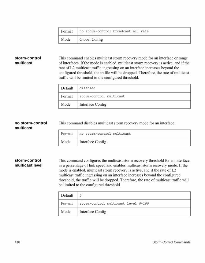
storm-control multicast
This command enables multicast storm recovery mode for an interface or range of interfaces. If the mode is enabled, multicast storm recovery is active, and if the rate of L2 multicast traffic ingressing on an interface increases beyond the configured threshold, the traffic will be dropped. Therefore, the rate of multicast traffic will be limited to the configured threshold.
no storm-control multicast
This command disables multicast storm recovery mode for an interface.
storm-control multicast level
This command configures the multicast storm recovery threshold for an interface as a percentage of link speed and enables multicast storm recovery mode. If the mode is enabled, multicast storm recovery is active, and if the rate of L2 multicast traffic ingressing on an interface increases beyond the configured threshold, the traffic will be dropped. Therefore, the rate of multicast traffic will be limited to the configured threshold.
Format no storm-control broadcast all rate
Mode Global Config
Default disabled
Format storm-control multicast
Mode Interface Config
Format no storm-control multicast
Mode Interface Config
Default 5
Format storm-control multicast level 0-100
Mode Interface Config
418 Storm-Control Commands

no storm-control multicast level
This command sets the multicast storm recovery threshold to the default value for an interface and disables multicast storm recovery.
storm-control multicast rate
This command configures the multicast storm recovery threshold for an interface in packets per second. If the mode is enabled, multicast storm recovery is active, and if the rate of L2 broadcast traffic ingressing on an interface increases beyond the configured threshold, the traffic is dropped. Therefore, the rate of multicast traffic is limited to the configured threshold.
no storm-control multicast rate
Use this command sets the multicast storm recovery threshold to the default value for an interface and disables multicast storm recovery.
storm-control multicast all
This command enables multicast storm recovery mode for all interfaces. If the mode is enabled, multicast storm recovery is active, and if the rate of L2 multicast traffic ingressing on an interface increases beyond the configured threshold, the traffic will be dropped. Therefore, the rate of multicast traffic will be limited to the configured threshold.
Format no storm-control multicast level 0-100
Mode Interface Config
Default 0
Format storm-control multicast rate 0-33554431
Mode Interface Config
Format no storm-control multicast rate
Mode Interface Config
Default disabled
Format storm-control multicast all
Mode Global Config
Chapter 5: Switching Commands 419

no storm-control multicast all
This command disables multicast storm recovery mode for all interfaces.
storm-control multicast all level
This command configures the multicast storm recovery threshold for all interfaces as a percentage of link speed and enables multicast storm recovery mode. If the mode is enabled, multicast storm recovery is active, and if the rate of L2 multicast traffic ingressing on an interface increases beyond the configured threshold, the traffic will be dropped. Therefore, the rate of multicast traffic will be limited to the configured threshold.
no storm-control multicast all level
This command sets the multicast storm recovery threshold to the default value for all interfaces and disables multicast storm recovery.
storm-control multicast all rate
This command configures the multicast storm recovery threshold for all interfaces in packets per second. If the mode is enabled, multicast storm recovery is active, and if the rate of L2 broadcast traffic ingressing on an interface increases beyond the configured threshold, the traffic is dropped. Therefore, the rate of multicast traffic is limited to the configured threshold.
Format no storm-control multicast all
Mode Global Config
Default 5
Format storm-control multicast all level 0-100
Mode Global Config
Format no storm-control multicast all level
Mode Global Config
Default 0
Format storm-control multicast all rate 0-33554431
Mode Global Config
420 Storm-Control Commands

no storm-control multicast all rate
This command sets the multicast storm recovery threshold to the default value for all interfaces and disables multicast storm recovery.
storm-control unicast
This command enables unicast storm recovery mode for an interface or range of interfaces. If the mode is enabled, unicast storm recovery is active, and if the rate of unknown L2 unicast (destination lookup failure) traffic ingressing on an interface increases beyond the configured threshold, the traffic will be dropped. Therefore, the rate of unknown unicast traffic will be limited to the configured threshold.
no storm-control unicast
This command disables unicast storm recovery mode for an interface.
storm-control unicast level
This command configures the unicast storm recovery threshold for an interface as a percentage of link speed, and enables unicast storm recovery. If the mode is enabled, unicast storm recovery is active, and if the rate of unknown L2 unicast (destination lookup failure) traffic ingressing on an interface increases beyond the configured threshold, the traffic will be dropped. Therefore, the rate of unknown unicast traffic will be limited to the configured threshold. This command also enables unicast storm recovery mode.
Format no storm-control multicast all rate
Mode Global Config
Default disabled
Format storm-control unicast
Mode Interface Config
Format no storm-control unicast
Mode Interface Config
Default 5
Format storm-control unicast level 0-100
Mode Interface Config
Chapter 5: Switching Commands 421

no storm-control unicast level
This command sets the unicast storm recovery threshold to the default value for an interface and disables unicast storm recovery.
storm-control unicast rate
This command configures the unicast storm recovery threshold for an interface in packets per second. If the mode is enabled, unicast storm recovery is active, and if the rate of L2 broadcast traffic ingressing on an interface increases beyond the configured threshold, the traffic is dropped. Therefore, the rate of unicast traffic is limited to the configured threshold.
no storm-control unicast rate
This command sets the unicast storm recovery threshold to the default value for an interface and disables unicast storm recovery.
storm-control unicast all
This command enables unicast storm recovery mode for all interfaces. If the mode is enabled, unicast storm recovery is active, and if the rate of unknown L2 unicast (destination lookup failure) traffic ingressing on an interface increases beyond the configured threshold, the traffic will be dropped. Therefore, the rate of unknown unicast traffic will be limited to the configured threshold.
Format no storm-control unicast level
Mode Interface Config
Default 0
Format storm-control unicast rate 0-33554431
Mode Interface Config
Format no storm-control unicast rate
Mode Interface Config
Default disabled
Format storm-control unicast all
Mode Global Config
422 Storm-Control Commands

no storm-control unicast all
This command disables unicast storm recovery mode for all interfaces.
storm-control unicast all level
This command configures the unicast storm recovery threshold for all interfaces as a percentage of link speed, and enables unicast storm recovery. If the mode is enabled, unicast storm recovery is active, and if the rate of unknown L2 unicast (destination lookup failure) traffic ingressing on an interface increases beyond the configured threshold, the traffic will be dropped. Therefore, the rate of unknown unicast traffic will be limited to the configured threshold.
no storm-control unicast all level
This command sets the unicast storm recovery threshold to the default value and disables unicast storm recovery for all interfaces.
storm-control unicast all rate
This command configures the unicast storm recovery threshold for all interfaces in packets per second. If the mode is enabled, unicast storm recovery is active, and if the rate of L2 broadcast traffic ingressing on an interface increases beyond the configured threshold, the traffic is dropped. Therefore, the rate of unicast traffic is limited to the configured threshold.
Format no storm-control unicast all
Mode Global Config
Default 5
Format storm-control unicast all level 0-100
Mode Global Config
Format no storm-control unicast all level
Mode Global Config
Default 0
Format storm-control unicast all rate 0-33554431
Mode Global Config
Chapter 5: Switching Commands 423

no storm-control unicast all rate
This command sets the multicast storm recovery threshold to the default value for an interface and disables multicast storm recovery.
storm-control flowcontrol
This command enables 802.3x flow control for the switch and applies only to full-duplex mode ports.
Note802.3x flow control works by pausing a port when the port becomes oversubscribed and dropping all traffic for small bursts of time during the congestion condition. This can lead to high-priority and/or network control traffic loss.
no storm-control flowcontrol
This command disables 802.3x flow control for the switch.
NoteThis command applies only to full-duplex mode ports.
show storm-control This command displays switch configuration information. If you do not use any of the optional parameters, this command displays global storm control configuration parameters:
Format no storm-control unicast all rate
Mode Global Config
Default disabled
Format storm-control flowcontrol
Mode ◆ Interface Config◆ Global Config
Format no storm-control flowcontrol
Mode ◆ Interface Config◆ Global Config
424 Storm-Control Commands

◆ Broadcast Storm Recovery Mode may be enabled or disabled. The factory default is disabled.
◆ 802.3x Flow Control Mode may be enabled or disabled. The factory default is disabled.
Use the all keyword to display the per-port configuration parameters for all interfaces, or specify the slot/port to display information about a specific interface.
Example: The following shows example CLI display output for the command:(CN1610)#show storm-control802.3x Flow Control Mode....................... Disable
Example: The following shows example CLI display output for the command:(CN1610)#show storm-control 1/0/1
Bcast Bcast Mcast Mcast Ucast Ucast Intf Mode Level Mode Level Mode Level------ ------- -------- ------- -------- ------- -------- 1/0/1 Disable 5% Disable 5% Disable 5%
Format show storm-control [all | slot/port]
Mode Privileged EXEC
Output Description
Bcast Mode Shows whether the broadcast storm control mode is enabled or disabled. The factory default is disabled.
Bcast Level The broadcast storm control level.
Mcast Mode Shows whether the multicast storm control mode is enabled or disabled.
Mcast Level The multicast storm control level.
Ucast Mode Shows whether the Unknown Unicast or DLF (Destination Lookup Failure) storm control mode is enabled or disabled.
Ucast Level The Unknown Unicast or DLF (Destination Lookup Failure) storm control level.
Chapter 5: Switching Commands 425

Example: The following shows an example of part of the CLI display output for the command:(CN1610)#show storm-control all
Bcast Bcast Mcast Mcast Ucast Ucast Intf Mode Level Mode Level Mode Level------ ------- -------- ------- -------- ------- -------- 1/0/1 Disable 5% Disable 5% Disable 5%1/0/2 Disable 5% Disable 5% Disable 5%1/0/3 Disable 5% Disable 5% Disable 5%1/0/4 Disable 5% Disable 5% Disable 5%1/0/5 Disable 5% Disable 5% Disable 5%
426 Storm-Control Commands
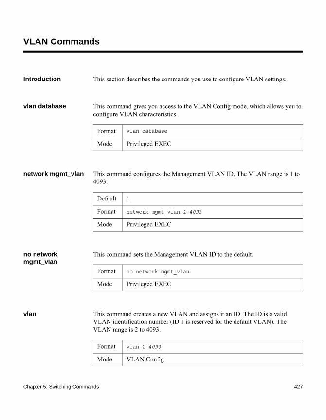
VLAN Commands
Introduction This section describes the commands you use to configure VLAN settings.
vlan database This command gives you access to the VLAN Config mode, which allows you to configure VLAN characteristics.
network mgmt_vlan This command configures the Management VLAN ID. The VLAN range is 1 to 4093.
no network mgmt_vlan
This command sets the Management VLAN ID to the default.
vlan This command creates a new VLAN and assigns it an ID. The ID is a valid VLAN identification number (ID 1 is reserved for the default VLAN). The VLAN range is 2 to 4093.
Format vlan database
Mode Privileged EXEC
Default 1
Format network mgmt_vlan 1-4093
Mode Privileged EXEC
Format no network mgmt_vlan
Mode Privileged EXEC
Format vlan 2-4093
Mode VLAN Config
Chapter 5: Switching Commands 427

no vlan This command deletes an existing VLAN. The ID is a valid VLAN identification number (ID 1 is reserved for the default VLAN). The VLAN range is 2 to 4093.
vlan acceptframe This command sets the frame acceptance mode on an interface or range of interfaces. For VLAN Only mode, untagged frames or priority frames received on this interface are discarded. For Admit All mode, untagged frames or priority frames received on this interface are accepted and assigned the value of the interface VLAN ID for this port. With either option, VLAN tagged frames are forwarded in accordance with the IEEE 802.1Q VLAN Specification.
no vlan acceptframe
This command resets the frame acceptance mode for the interface or range of interfaces to the default value.
vlan ingressfilter This command enables ingress filtering on an interface or range of interfaces. If ingress filtering is disabled, frames received with VLAN IDs that do not match the VLAN membership of the receiving interface are admitted and forwarded to ports that are members of that VLAN.
Format no vlan 2-4093
Mode VLAN Config
Default all
Format vlan acceptframe {vlanonly | all}
Mode Interface Config
Format no vlan acceptframe
Mode Interface Config
Default disabled
Format vlan ingressfilter
Mode Interface Config
428 VLAN Commands

no vlan ingressfilter This command disables ingress filtering. If ingress filtering is disabled, frames received with VLAN IDs that do not match the VLAN membership of the receiving interface are admitted and forwarded to ports that are members of that VLAN.
vlan makestatic This command changes a dynamically created VLAN (created by GVRP registration) to a static VLAN (one that is permanently configured and defined). The ID is a valid VLAN identification number. VLAN range is 2 to 4093.
vlan name This command changes the name of a VLAN. The name is an alphanumeric string of up to 32 characters, and the ID is a valid VLAN identification number. The ID range is 1 to 4093.
no vlan name This command sets the name of a VLAN to a blank string.
vlan participation This command configures the degree of participation for a specific interface or range of interfaces in a VLAN. The ID is a valid VLAN identification number, and the interface is a valid interface number.
Format no vlan ingressfilter
Mode Interface Config
Format vlan makestatic 2–4093
Mode VLAN Config
Default ◆ VLAN ID 1 - default◆ other VLANs - blank string
Format vlan name 1-4093 name
Mode VLAN Config
Format no vlan name
Mode VLAN Config
Chapter 5: Switching Commands 429

Participation options are:
vlan participation all
This command configures the degree of participation for all interfaces in a VLAN. The ID is a valid VLAN identification number.
Participation options are:
Format vlan participation {exclude | include | auto} 1-4093
Mode Interface Config
Parameter Description
include The interface is always a member of this VLAN. This is equivalent to registration fixed.
exclude The interface is never a member of this VLAN. This is equivalent to registration forbidden.
auto The interface is dynamically registered in this VLAN by GVRP and will not participate in this VLAN unless a join request is received on this interface. This is equivalent to registration normal.
Format vlan participation all {exclude | include | auto} 1-4093
Mode Global Config
Parameter Description
include The interface is always a member of this VLAN. This is equivalent to registration fixed.
430 VLAN Commands

vlan port acceptframe all
This command sets the frame acceptance mode for all interfaces.
The modes are defined as follows:
With either option, VLAN tagged frames are forwarded in accordance with the IEEE 802.1Q VLAN Specification.
no vlan port acceptframe all
This command sets the frame acceptance mode for all interfaces to Admit All. For Admit All mode, untagged frames or priority frames received on this interface are accepted and assigned the value of the interface VLAN ID for this port. With either option, VLAN tagged frames are forwarded in accordance with the IEEE 802.1Q VLAN Specification.
exclude The interface is never a member of this VLAN. This is equivalent to registration forbidden.
auto The interface is dynamically registered in this VLAN by GVRP and will not participate in this VLAN unless a join request is received on this interface. This is equivalent to registration normal.
Parameter Description
Default all
Format vlan port acceptframe all {vlanonly | all}
Mode Global Config
Parameter Description
VLAN Only mode Untagged frames or priority frames received on this interface are discarded.
Admit All mode Untagged frames or priority frames received on this interface are accepted and assigned the value of the interface VLAN ID for this port.
Format no vlan port acceptframe all
Chapter 5: Switching Commands 431
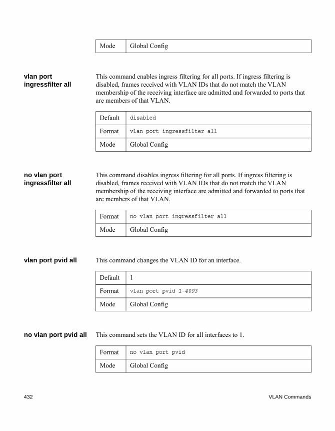
vlan port ingressfilter all
This command enables ingress filtering for all ports. If ingress filtering is disabled, frames received with VLAN IDs that do not match the VLAN membership of the receiving interface are admitted and forwarded to ports that are members of that VLAN.
no vlan port ingressfilter all
This command disables ingress filtering for all ports. If ingress filtering is disabled, frames received with VLAN IDs that do not match the VLAN membership of the receiving interface are admitted and forwarded to ports that are members of that VLAN.
vlan port pvid all This command changes the VLAN ID for an interface.
no vlan port pvid all This command sets the VLAN ID for all interfaces to 1.
Mode Global Config
Default disabled
Format vlan port ingressfilter all
Mode Global Config
Format no vlan port ingressfilter all
Mode Global Config
Default 1
Format vlan port pvid 1-4093
Mode Global Config
Format no vlan port pvid
Mode Global Config
432 VLAN Commands

vlan port tagging all This command configures the tagging behavior for all interfaces in a VLAN to enabled. If tagging is enabled, traffic is transmitted as tagged frames. If tagging is disabled, traffic is transmitted as untagged frames. The ID is a valid VLAN identification number.
no vlan port tagging all
This command configures the tagging behavior for all interfaces in a VLAN to disabled. If tagging is disabled, traffic is transmitted as untagged frames. The ID is a valid VLAN identification number.
vlan protocol group This command adds protocol-based VLAN groups to the system. The groupid is a unique number from 1–128 that is used to identify the group in subsequent commands.
vlan protocol group name
This command assigns a name to a protocol-based VLAN groups. The groupname variable can be a character string of 0 to 16 characters.
no vlan protocol group name
This command removes the name from the group identified by groupid.
Format vlan port tagging all 1–4093
Mode Global Config
Format no vlan port tagging all
Mode Global Config
Format vlan protocol group groupid
Mode Global Config
Format vlan protocol group name groupid groupname
Mode Global Config
Format no vlan protocol group name groupid
Chapter 5: Switching Commands 433

vlan protocol group add protocol
This command adds the protocol to the protocol-based VLAN identified by groupid. A group may have more than one protocol associated with it. Each interface and protocol combination can only be associated with one group. If adding a protocol to a group causes any conflicts with interfaces currently associated with the group, this command fails and the protocol is not added to the group. The possible values for protocol-list are ip, arp, and ipx and hexadecimal or decimal values ranging from 0x0600 (1536) to 0xFFFF (65535). The protocol list can accept up to 16 protocols separated by a comma.
no vlan protocol group add protocol
This command removes the protocols specified in the protocol-list from this protocol-based VLAN group that is identified by this groupid.
protocol group This command attaches a vlanid to the protocol-based VLAN identified by groupid. A group may only be associated with one VLAN at a time, however the VLAN association can be changed.
Mode Global Config
Default none
Format vlan protocol group add protocol groupid ethertype protocol-list
Mode Global Config
Format no vlan protocol group add protocol groupid ethertype protocol-list
Mode Global Config
Default none
Format protocol group groupid vlanid
Mode VLAN Config
434 VLAN Commands
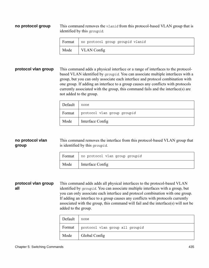
no protocol group This command removes the vlanid from this protocol-based VLAN group that is identified by this groupid.
protocol vlan group This command adds a physical interface or a range of interfaces to the protocol-based VLAN identified by groupid. You can associate multiple interfaces with a group, but you can only associate each interface and protocol combination with one group. If adding an interface to a group causes any conflicts with protocols currently associated with the group, this command fails and the interface(s) are not added to the group.
no protocol vlan group
This command removes the interface from this protocol-based VLAN group that is identified by this groupid.
protocol vlan group all
This command adds adds all physical interfaces to the protocol-based VLAN identified by groupid. You can associate multiple interfaces with a group, but you can only associate each interface and protocol combination with one group. If adding an interface to a group causes any conflicts with protocols currently associated with the group, this command will fail and the interface(s) will not be added to the group.
Format no protocol group groupid vlanid
Mode VLAN Config
Default none
Format protocol vlan group groupid
Mode Interface Config
Format no protocol vlan group groupid
Mode Interface Config
Default none
Format protocol vlan group all groupid
Mode Global Config
Chapter 5: Switching Commands 435

no protocol vlan group all
This command removes all interfaces from this protocol-based VLAN group that is identified by this groupid.
show port protocol This command displays the Protocol-Based VLAN information for either the entire system, or for the indicated group.
vlan pvid This command changes the VLAN ID on an interface or range of interfaces.
no vlan pvid This command sets the VLAN ID on an interface or range of interfaces to 1.
Format no protocol vlan group all groupid
Mode Global Config
Format show port protocol {groupid | all}
Mode Privileged EXEC
Output Description
Group Name The group name of an entry in the Protocol-based VLAN table.
Group ID The group identifier of the protocol group.
VLAN The VLAN associated with this Protocol Group.
Protocol(s) The type of protocol(s) for this group.
Interface(s) Lists the slot/port interface(s) that are associated with this Protocol Group.
Default 1
Format vlan pvid 1–4093
Mode ◆ Interface Config◆ Interface Range Config
436 VLAN Commands
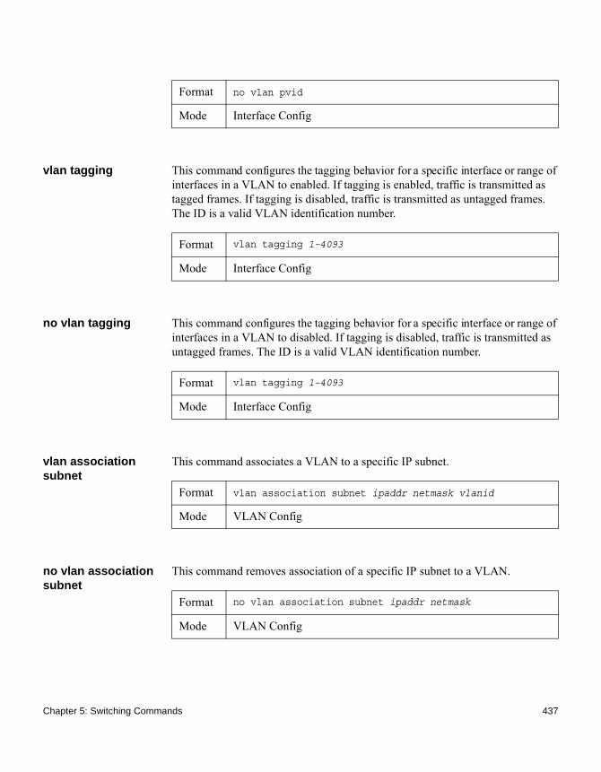
vlan tagging This command configures the tagging behavior for a specific interface or range of interfaces in a VLAN to enabled. If tagging is enabled, traffic is transmitted as tagged frames. If tagging is disabled, traffic is transmitted as untagged frames. The ID is a valid VLAN identification number.
no vlan tagging This command configures the tagging behavior for a specific interface or range of interfaces in a VLAN to disabled. If tagging is disabled, traffic is transmitted as untagged frames. The ID is a valid VLAN identification number.
vlan association subnet
This command associates a VLAN to a specific IP subnet.
no vlan association subnet
This command removes association of a specific IP subnet to a VLAN.
Format no vlan pvid
Mode Interface Config
Format vlan tagging 1–4093
Mode Interface Config
Format vlan tagging 1–4093
Mode Interface Config
Format vlan association subnet ipaddr netmask vlanid
Mode VLAN Config
Format no vlan association subnet ipaddr netmask
Mode VLAN Config
Chapter 5: Switching Commands 437

vlan association mac
This command associates a MAC address to a VLAN.
no vlan association mac
This command removes the association of a MAC address to a VLAN.
show vlan This command displays detailed information, including interface information, for a specified VLAN. The ID is a valid VLAN identification number in the range 1 to 4093.
Format vlan association mac macaddr vlanid
Mode VLAN database
Format no vlan association mac macaddr
Mode VLAN database
Format show vlan vlanid
Mode ◆ Privileged EXEC◆ User EXEC
Output Description
VLAN ID There is a VLAN Identifier (VID) associated with each VLAN. The range of the VLAN ID is 1 to 4093.
VLAN Name A string associated with this VLAN as a convenience. It can be up to 32 alphanumeric characters long, including blanks. The default is blank. VLAN ID 1 always has a name of Default. This field is optional.
VLAN Type Type of VLAN, which can be the default (VLAN ID = 1) or static (one that is configured and permanently defined), or a dynamic. A dynamic VLAN can be created by GVRP registration or during the 802.1X authentication process (DOT1X) if a RADIUS-assigned VLAN does not exist on the switch.
438 VLAN Commands

Interface slot/port. It is possible to set the parameters for all ports by using the selectors on the top line.
Current The degree of participation of this port in this VLAN. The permissible values are: ◆ Include - This port is always a member of this
VLAN. This is equivalent to registration fixed in the IEEE 802.1Q standard.
◆ Exclude - This port is never a member of this VLAN. This is equivalent to registration forbidden in the IEEE 802.1Q standard.
◆ Autodetect - To allow the port to be dynamically registered in this VLAN via GVRP. The port will not participate in this VLAN unless a join request is received on this port. This is equivalent to registration normal in the IEEE 802.1Q standard.
Configured The configured degree of participation of this port in this VLAN. The permissible values are: ◆ Include - This port is always a member of this
VLAN. This is equivalent to registration fixed in the IEEE 802.1Q standard.
◆ Exclude - This port is never a member of this VLAN. This is equivalent to registration forbidden in the IEEE 802.1Q standard.
◆ Autodetect - To allow the port to be dynamically registered in this VLAN via GVRP. The port will not participate in this VLAN unless a join request is received on this port. This is equivalent to registration normal in the IEEE 802.1Q standard.
Tagging The tagging behavior for this port in this VLAN.◆ Tagged - Transmit traffic for this VLAN as tagged
frames.◆ Untagged - Transmit traffic for this VLAN as
untagged frames.
Output Description
Chapter 5: Switching Commands 439

show vlan internal usage
This command displays a list of all configured VLANs.
show vlan brief This command displays a list of all configured VLANs.
Format show vlan internal usage
Mode ◆ Privileged EXEC◆ User EXEC
Output Description
Base VLAN ID Identifies the base VLAN ID for internal allocation of VLANs to the routing interface.
Allocation Policy Identifies whether the system allocates VLAN IDs in ascending or descending order.
Format show vlan brief
Mode ◆ Privileged EXEC◆ User EXEC
Output Description
VLAN ID There is a VLAN identifier (vlanid) associated with each VLAN. The range of the VLAN ID is 1 to 4093.
VLAN Name A string associated with this VLAN as a convenience. It can be up to 32 alphanumeric characters long, including blanks. The default is blank. VLAN ID 1 always has a name of Default. This field is optional.
VLAN Type Type of VLAN, which can be the default (VLAN ID = 1) or static (one that is configured and permanently defined), or dynamic (one that is created by GVRP registration).
440 VLAN Commands

show vlan port This command displays VLAN port information.
Format show vlan port {slot/port|all}
Mode ◆ Privileged EXEC◆ User EXEC
Output Description
Interface slot/port. It is possible to set the parameters for all ports by using the selectors on the top line.
Port VLAN ID The VLAN ID that this port will assign to untagged frames or priority tagged frames received on this port. The value must be for an existing VLAN. The factory default is 1.
Acceptable Frame Types
The types of frames that may be received on this port. The options are VLAN only and Admit All. When set to VLAN only, untagged frames or priority tagged frames received on this port are discarded. When set to Admit All, untagged frames or priority tagged frames received on this port are accepted and assigned the value of the Port VLAN ID for this port. With either option, VLAN tagged frames are forwarded in accordance to the 802.1Q VLAN specification.
Ingress Filtering May be enabled or disabled. When enabled, the frame is discarded if this port is not a member of the VLAN with which this frame is associated. In a tagged frame, the VLAN is identified by the VLAN ID in the tag. In an untagged frame, the VLAN is the Port VLAN ID specified for the port that received this frame. When disabled, all frames are forwarded in accordance with the 802.1Q VLAN bridge specification. The factory default is disabled.
GVRP May be enabled or disabled.
Chapter 5: Switching Commands 441

show vlan association subnet
This command displays the VLAN associated with a specific configured IP-Address and net mask. If no IP address and net mask are specified, the VLAN associations of all the configured IP-subnets are displayed.
show vlan association mac
This command displays the VLAN associated with a specific configured MAC address. If no MAC address is specified, the VLAN associations of all the configured MAC addresses are displayed.
Default Priority The 802.1p priority assigned to tagged packets arriving on the port.
Output Description
Format show vlan association subnet [ipaddr netmask]
Mode Privileged EXEC
Output Description
IP Address The IP address assigned to each interface.
Net Mask The subnet mask.
VLAN ID There is a VLAN Identifier (VID) associated with each VLAN.
Format show vlan association mac [macaddr]
Mode Privileged EXEC
Output Description
MAC Address A MAC address for which the switch has forwarding and or filtering information. The format is 6 or 8 two-digit hexadecimal numbers that are separated by colons, for example, 01:23:45:67:89:AB. In an IVL system the MAC address will be displayed as 8 bytes.
442 VLAN Commands

VLAN ID There is a VLAN Identifier (VID) associated with each VLAN.
Output Description
Chapter 5: Switching Commands 443
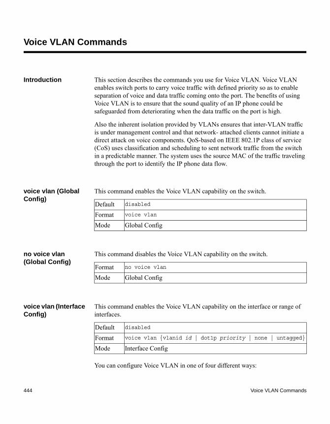
Voice VLAN Commands
Introduction This section describes the commands you use for Voice VLAN. Voice VLAN enables switch ports to carry voice traffic with defined priority so as to enable separation of voice and data traffic coming onto the port. The benefits of using Voice VLAN is to ensure that the sound quality of an IP phone could be safeguarded from deteriorating when the data traffic on the port is high.
Also the inherent isolation provided by VLANs ensures that inter-VLAN traffic is under management control and that network- attached clients cannot initiate a direct attack on voice components. QoS-based on IEEE 802.1P class of service (CoS) uses classification and scheduling to sent network traffic from the switch in a predictable manner. The system uses the source MAC of the traffic traveling through the port to identify the IP phone data flow.
voice vlan (Global Config)
This command enables the Voice VLAN capability on the switch.
no voice vlan (Global Config)
This command disables the Voice VLAN capability on the switch.
voice vlan (Interface Config)
This command enables the Voice VLAN capability on the interface or range of interfaces.
You can configure Voice VLAN in one of four different ways:
Default disabled
Format voice vlan
Mode Global Config
Format no voice vlan
Mode Global Config
Default disabled
Format voice vlan {vlanid id | dot1p priority | none | untagged}
Mode Interface Config
444 Voice VLAN Commands

no voice vlan (Interface Config)
This command disables the Voice VLAN capability on the interface.
voice vlan data priority
This command either trusts or untrusts the data traffic arriving on the Voice VLAN interface or range of interfaces being configured.
show voice vlan This command displays the global or interface VLAN parameters.
When the interface parameter is not specified, only the global mode of the Voice VLAN is displayed.
Parameter Description
vlanid Configure the IP phone to forward all voice traffic through the specified VLAN. Valid VLAN ID’s are from 1 to 4093 (the maximum supported by the platform).
dot1p Configure the IP phone to use 802.1p priority tagging for voice traffic and to use the default native VLAN (VLAN 0) to carry all traffic. Valid priority range is 0 to 7.
none Allow the IP phone to use its own configuration to send untagged voice traffic.
untagged Configure the phone to send untagged voice traffic.
Format no voice vlan
Mode Interface Config
Default trust
Format voice vlan data priority {untrust | trust}
Mode Interface Config
Format show voice vlan [interface {slot/port | all}]
Mode Privileged EXEC
Output Description
Administrative Mode
The Global Voice VLAN mode.
Chapter 5: Switching Commands 445

When the interface is specified:.
Output Description
Voice VLAN Mode The admin mode of the Voice VLAN on the interface.Voice VLAN ID The Voice VLAN ID.Voice VLAN Priority The do1p priority for the Voice VLAN on the port.Voice VLAN Untagged The tagging option for the Voice VLAN traffic.Voice VLAN CoS Override
The Override option for the voice traffic arriving on the port.
Voice VLAN Status The operational status of Voice VLAN on the port.
446 Voice VLAN Commands

Chapter 6: IPv6 Management Commands
6
IPv6 Management CommandsAbout this chapter This chapter describes the IPv6 commands available in the CN1610 CLI.
Topics in this chapter
This chapter includes the following sections:◆ “IPv6 Management Commands” on page 448
CAUTIONThe commands in this chapter are in one of three functional groups:◆ Show commands display switch settings, statistics, and other information.◆ Configuration commands configure features and options of the switch. For
every configuration command, there is a show command that displays the configuration setting.
◆ Clear commands clear some or all of the settings to factory defaults.
447

IPv6 Management Commands
Introduction IPv6 Management commands allow a device to be managed via an IPv6 address in a switch or IPv4 routing (that is, independent from the IPv6 Routing package). For Routing/IPv6 builds of FASTPATH, dual IPv4/IPv6 operation over the service port is enabled. FASTPATH has capabilities such as:◆ Static assignment of IPv6 addresses and gateways for the service/network
ports.◆ The ability to ping an IPv6 link-local address over the service/network port.◆ Using IPv6 Management commands, you can send SNMP traps and queries
via the service/network port.◆ The user can manage a device via the network port (in addition to a Routing
Interface or the Service port).
serviceport ipv6 enable
This command enables IPv6 operation on the service port.
no serviceport ipv6 enable
This command disables IPv6 operation on the service port.
network ipv6 enable This command enables IPv6 operation on the network port.
Default enabled
Format serviceport ipv6 enable
Mode Privileged EXEC
Format no serviceport ipv6 enable
Mode Privileged EXEC
Default enabled
Format network ipv6 enable
Mode Privileged EXEC
448 IPv6 Management Commands

no network ipv6 enable
This command disables IPv6 operation on the network port.
serviceport ipv6 address
Use the options of this command to manually configure IPv6 global address, enable/disable stateless global address autoconfiguration, and to enable/disable dhcpv6 client protocol information on the service port.
NoteMultiple IPv6 prefixes can be configured on the service port.
no serviceport ipv6 address
Use this command to remove all configured IPv6 prefixes on the service port interface.
Use the command with the address option to remove the manually configured IPv6 global address on the network port interface.
Use the command with the autoconfig option to disable the stateless global address autoconfiguration on the service port.
Format no network ipv6 enable
Mode Privileged EXEC
Format serviceport ipv6 address {address/prefix-length
[eui64]|autoconfig|dhcp}
Mode Privileged EXEC
Parameter Description
address IPv6 prefix in IPv6 global address format.
prefix-length
IPv6 prefix length value.
eui64 Formulate IPv6 address in eui64 address format.
autoconfig Configure stateless global address autoconfiguration capability.
dhcp Configure dhcpv6 client protocol.
Chapter 6: IPv6 Management Commands 449

Use the command with the dhcp option to disable the dhcpv6 client protocol on the service port.
serviceport ipv6 gateway
This command configures IPv6 gateway (for example, default routers) information for the service port.
NoteOnly a single IPv6 gateway address can be configured for the service port. There may be a combination of IPv6 prefixes and gateways that are explicitly configured and those that are set through auto-address configuration with a connected IPv6 router on their service port interface.
no serviceport ipv6 gateway
This command removes IPv6 gateways on the service port interface.
network ipv6 address
This command lets you manually configure IPv6 global address, enable/disable stateless global address autoconfiguration, and enable/disable dhcpv6 client protocol information for the network port. You can configure multiple IPv6 addresses on the network port.
Format no serviceport ipv6 address {address/prefix-length
[eui64] | autoconfig | dhcp}
Mode Privileged EXEC
Format serviceport ipv6 gateway gateway-address
Mode Privileged EXEC
Parameter Description
gateway-address
Gateway address in IPv6 global or link-local address format.
Format no serviceport ipv6 gateway
Mode Privileged EXEC
450 IPv6 Management Commands

no network ipv6 address
This command removes all configured IPv6 prefixes.
Use this command with the address option to remove the manually configured IPv6 global address on the network port interface.
Use this command with the autoconfig option to disable the stateless global address autoconfiguration on the network port.
Use this command with the dhcp option to disable the dhcpv6 client protocol on the network port.
network ipv6 gateway
This command configures the IPv6 gateway (that is, default routers) information for the network port.
Format network ipv6 address {address/prefix-length [eui64] |
autoconfig | dhcp}
Mode Privileged EXEC
Parameter Description
address IPv6 prefix in IPv6 global address format.
prefix-length
IPv6 prefix length value.
eui64 Formulate IPv6 address in eui64 format.
autoconfig Configure stateless global address autoconfiguration capability.
dhcp Configure DHCPv6 client protocol.
Format no network ipv6 address {address/prefix-length [eui64] | autoconfig | dhcp}
Mode Privileged EXEC
Format network ipv6 gateway gateway-address
Chapter 6: IPv6 Management Commands 451

no network ipv6 gateway
This command removes IPv6 gateways on the network port interface.
show network ndp This command displays NDP cache information for the network port.
Mode Privileged EXEC
Parameter Description
gateway-address
Gateway address in IPv6 global or link-local address format.
Format no network ipv6 gateway
Mode Privileged EXEC
Default enabled
Format show network ndp
Mode ◆ Privileged EXEC ◆ User EXEC
Output Description
IPv6 Address The IPv6 address of the interface.
MAC Address The MAC address used.
isRtr Specifies the router flag.
Neighbor State
The state of the neighbor cache entry. Possible values are Reachable and Delay.
Age Updated The time, in seconds, that has elapsed since an entry was added to the cache.
452 IPv6 Management Commands

Example: The following shows example CLI display output for the command:(CN1610) #show network ndp
Neighbor AgeIPv6 Address MAC Address isRtr State Updated--------------------- -------------- ------- -------- -----3017::204:76FF:FE73:423A 00:04:76:73:42:3a Reachable 447535FE80::204:76FF:FE73:423A 00:04:76:73:42:3a Delay 447540
show serviceport This command displays service port configuration information.
Format show serviceport
Mode ◆ Privileged EXEC◆ User EXEC
Output Description
Interface Status The network interface status. It is always considered to be up.
IP Address The IP address of the interface. The factory default value is 0.0.0.0.
Subnet Mask The IP subnet mask for this interface. The factory default value is 0.0.0.0.
Default Gateway The default gateway for this IP interface. The factory default value is 0.0.0.0.
IPv6 Administrative Mode
Whether enabled or disabled. The default value is enabled.
IPv6 Prefix The IPv6 address and length. The default is Link Local format.
IPv6 Default Router
The IPv6 default router address on the service port. The factory default value is an unspecified address.
Configured IPv4 Protocol
The IPv4 network protocol being used. The options are: bootp | dhcp | none.
Chapter 6: IPv6 Management Commands 453

Example: The following shows example CLI display output for the service port:(CN1610) #show serviceport
Interface Status............................... Up
IP Address..................................... 10.230.3.51
Subnet Mask.................................... 255.255.255.0
Default Gateway................................ 10.230.3.1
IPv6 Administrative Mode....................... Enabled
IPv6 Prefix is ................................ fe80::210:18ff:fe82:640/64
IPv6 Prefix is ................................ 2005::21/128
IPv6 Default Router is ........................ fe80::204:76ff:fe73:423a
Configured IPv4 Protocol ...................... DHCP
Configured IPv6 Protocol ...................... DHCP
DHCPv6 Client DUID ............................ 00:03:00:06:00:10:18:82:06:4C
IPv6 Autoconfig Mode........................... Disabled
Burned In MAC Address.......................... 00:10:18:82:06:4D
Configured IPv6 Protocol
The IPv6 network protocol being used. The options are: dhcp | none.
DHCPv6 Client DUID The DHCPv6 client’s unique client identifier. This row is displayed only when the configured IPv6 protocol is dhcp.
IPv6 Autoconfig Mode
Whether IPv6 Stateless address autoconfiguration is enabled or disabled.
Burned In MAC Address
The burned in MAC address used for in-band connectivity.
Output Description
454 IPv6 Management Commands
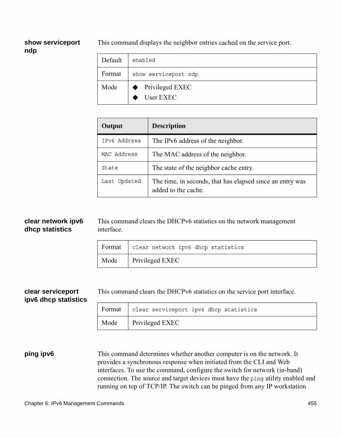
show serviceport ndp
This command displays the neighbor entries cached on the service port.
clear network ipv6 dhcp statistics
This command clears the DHCPv6 statistics on the network management interface.
clear serviceport ipv6 dhcp statistics
This command clears the DHCPv6 statistics on the service port interface.
ping ipv6 This command determines whether another computer is on the network. It provides a synchronous response when initiated from the CLI and Web interfaces. To use the command, configure the switch for network (in-band) connection. The source and target devices must have the ping utility enabled and running on top of TCP/IP. The switch can be pinged from any IP workstation
Default enabled
Format show serviceport ndp
Mode ◆ Privileged EXEC ◆ User EXEC
Output Description
IPv6 Address The IPv6 address of the neighbor.
MAC Address The MAC address of the neighbor.
State The state of the neighbor cache entry.
Last Updated The time, in seconds, that has elapsed since an entry was added to the cache.
Format clear network ipv6 dhcp statistics
Mode Privileged EXEC
Format clear serviceport ipv6 dhcp statistics
Mode Privileged EXEC
Chapter 6: IPv6 Management Commands 455
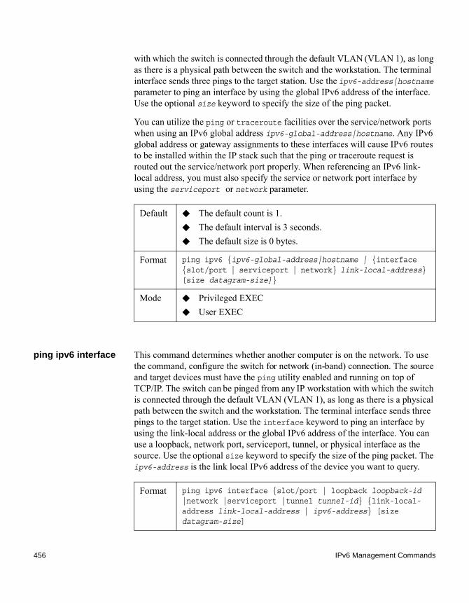
with which the switch is connected through the default VLAN (VLAN 1), as long as there is a physical path between the switch and the workstation. The terminal interface sends three pings to the target station. Use the ipv6-address|hostname parameter to ping an interface by using the global IPv6 address of the interface. Use the optional size keyword to specify the size of the ping packet.
You can utilize the ping or traceroute facilities over the service/network ports when using an IPv6 global address ipv6-global-address|hostname. Any IPv6 global address or gateway assignments to these interfaces will cause IPv6 routes to be installed within the IP stack such that the ping or traceroute request is routed out the service/network port properly. When referencing an IPv6 link-local address, you must also specify the service or network port interface by using the serviceport or network parameter.
ping ipv6 interface This command determines whether another computer is on the network. To use the command, configure the switch for network (in-band) connection. The source and target devices must have the ping utility enabled and running on top of TCP/IP. The switch can be pinged from any IP workstation with which the switch is connected through the default VLAN (VLAN 1), as long as there is a physical path between the switch and the workstation. The terminal interface sends three pings to the target station. Use the interface keyword to ping an interface by using the link-local address or the global IPv6 address of the interface. You can use a loopback, network port, serviceport, tunnel, or physical interface as the source. Use the optional size keyword to specify the size of the ping packet. The ipv6-address is the link local IPv6 address of the device you want to query.
Default ◆ The default count is 1.◆ The default interval is 3 seconds.◆ The default size is 0 bytes.
Format ping ipv6 {ipv6-global-address|hostname | {interface {slot/port | serviceport | network} link-local-address} [size datagram-size]}
Mode ◆ Privileged EXEC ◆ User EXEC
Format ping ipv6 interface {slot/port | loopback loopback-id |network |serviceport |tunnel tunnel-id} {link-local-address link-local-address | ipv6-address} [size datagram-size]
456 IPv6 Management Commands

traceroute ipv6 This command discovers the routes that packets actually take when traveling to their destination through the network on a hop-by-hop basis. The ipv6-address parameter must be a valid IPv6 address. The optional port parameter is the UDP port used as the destination of packets sent as part of the traceroute. This port should be an unused port on the destination system. The range for port is 0 (zero) to 65535.The default value is 33434.
show network ipv6 dhcp statistics
This command displays the statistics of the DHCPv6 client running on the network management interface.
Mode ◆ Privileged EXEC ◆ User EXEC
Format traceroute ipv6 ipv6-address [port]
Mode Privileged EXEC
Format show network ipv6 dhcp statistics
Mode ◆ Privileged EXEC◆ User EXEC
Output Description
DHCPv6 Advertisement Packets Received
The number of DHCPv6 Advertisement packets received on the network interface.
DHCPv6 Reply Packets Received
The number of DHCPv6 Reply packets received on the network interface.
Received DHCPv6 Advertisement Packets Discarded
The number of DHCPv6 Advertisement packets discarded on the network interface.
Chapter 6: IPv6 Management Commands 457

Example: The following shows example CLI display output for this command:(CN1610) #show network ipv6 dhcp statistics
DHCPv6 Client Statistics-------------------------DHCPv6 Advertisement Packets Received.......... 0DHCPv6 Reply Packets Received.................. 0Received DHCPv6 Advertisement Packets Discard.. 0Received DHCPv6 Reply Packets Discarded........ 0
Received DHCPv6 Reply Packets Discarded
The number of DHCPv6 Reply packets discarded on the network interface.
DHCPv6 Malformed Packets Received
The number of DHCPv6 packets that are received malformed on the network interface.
Total DHCPv6 Packets Received
The total number of DHCPv6 packets received on the network interface.
DHCPv6 Solicit Packets Transmitted
The number of DHCPv6 Solicit packets transmitted on the network interface.
DHCPv6 Request Packets Transmitted
The number of DHCPv6 Request packets transmitted on the network interface.
DHCPv6 Renew Packets Transmitted
The number of DHCPv6 Renew packets transmitted on the network interface.
DHCPv6 Rebind Packets Transmitted
The number of DHCPv6 Rebind packets transmitted on the network interface.
DHCPv6 Release Packets Transmitted
The number of DHCPv6 Release packets transmitted on the network interface.
Total DHCPv6 Packets Transmitted
The total number of DHCPv6 packets transmitted on the network interface.
Output Description
458 IPv6 Management Commands

DHCPv6 Malformed Packets Received.............. 0Total DHCPv6 Packets Received.................. 0DHCPv6 Solicit Packets Transmitted............. 0DHCPv6 Request Packets Transmitted............. 0DHCPv6 Renew Packets Transmitted............... 0DHCPv6 Rebind Packets Transmitted.............. 0DHCPv6 Release Packets Transmitted............. 0Total DHCPv6 Packets Transmitted............... 0
show serviceport ipv6 dhcp statistics
This command displays IPv6 DHCP statistics.
Format show serviceport ipv6 dhcp statistics
Mode ◆ Privileged EXEC◆ User EXEC
Output Description
DHCPv6 Advertisement Packets Received
The number of DHCPv6 Advertisement packets received on the network interface.
DHCPv6 Reply Packets Received
The number of DHCPv6 Reply packets received on the network interface.
Received DHCPv6 Advertisement Packets Discarded
The number of DHCPv6 Advertisement packets discarded on the network interface.
Received DHCPv6 Reply Packets Discarded
The number of DHCPv6 Reply packets discarded on the network interface.
DHCPv6 Malformed Packets Received
The number of DHCPv6 packets that are received malformed on the network interface.
Total DHCPv6 Packets Received
The total number of DHCPv6 packets received on the network interface.
Chapter 6: IPv6 Management Commands 459

Example: The following shows example CLI display output for the command:(CN1610) >show serviceport ipv6 dhcp statistics
DHCPv6 Client Statistics-------------------------DHCPv6 Advertisement Packets Received.......... 0DHCPv6 Reply Packets Received.................. 0Received DHCPv6 Advertisement Packets Discard.. 0Received DHCPv6 Reply Packets Discarded........ 0DHCPv6 Malformed Packets Received.............. 0Total DHCPv6 Packets Received.................. 0DHCPv6 Solicit Packets Transmitted............. 0DHCPv6 Request Packets Transmitted............. 0DHCPv6 Renew Packets Transmitted............... 0DHCPv6 Rebind Packets Transmitted.............. 0DHCPv6 Release Packets Transmitted............. 0Total DHCPv6 Packets Transmitted............... 0
DHCPv6 Solicit Packets Transmitted
The number of DHCPv6 Solicit packets transmitted on the network interface.
DHCPv6 Request Packets Transmitted
The number of DHCPv6 Request packets transmitted on the network interface.
DHCPv6 Renew Packets Transmitted
The number of DHCPv6 Renew packets transmitted on the network interface.
DHCPv6 Rebind Packets Transmitted
The number of DHCPv6 Rebind packets transmitted on the network interface.
DHCPv6 Release Packets Transmitted
The number of DHCPv6 Release packets transmitted on the network interface.
Total DHCPv6 Packets Transmitted
The total number of DHCPv6 packets transmitted on the network interface.
Output Description
460 IPv6 Management Commands

Chapter 7: Quality of Service Commands
7
Quality of Service CommandsAbout this chapter This chapter describes the Quality of Service (QoS) commands available with the CN1610 CLI.
Topics in this chapter
This chapter includes the following sections:◆ “Auto-Voice over IP Commands” on page 462◆ “Class of Service Commands” on page 464◆ “Differentiated Services Commands” on page 475◆ “DiffServ Class Commands” on page 477◆ “DiffServ Policy Commands” on page 486◆ “DiffServ Service Commands” on page 494◆ “DiffServ Show Commands” on page 496◆ “IP Access Control List Commands” on page 505◆ “IPv6 Access Control List Commands” on page 515◆ “MAC Access Control List Commands” on page 520◆ “Time Range Commands for Time-Based ACLs” on page 526
CAUTIONThe commands in this chapter are divided into two functional groups:◆ Show commands display switch settings, statistics, and other information.◆ Configuration commands configure features and options of the switch. For
every configuration command, there is a show command that displays the configuration setting.
461

Auto-Voice over IP Commands
Introduction This section describes the commands you use to configure Auto-Voice over IP (VoIP) commands. The Auto-VoIP feature explicitly matches VoIP streams in Ethernet switches and provides them with a better class-of-service than ordinary traffic. When you enable the Auto-VoIP feature on an interface, the interface scans incoming traffic for the following call-control protocols:◆ Session Initiation Protocol (SIP)◆ H.323◆ Skinny Client Control Protocol (SCCP)
When a call-control protocol is detected, the switch assigns the traffic in that session to the highest CoS queue, which is generally used for time-sensitive traffic.
auto-voip all This command enables VoIP Profile on the interfaces of the switch.
no auto-voip all This command disables VoIP Profile on the interfaces of the switch.
auto-voip This command enables VoIP Profile on an interface or range of interfaces.
Default disabled
Format auto-voip all
Mode Global Config
Format no auto-voip all
Mode Global Config
Default disabled
Format auto-voip
Mode Interface Config
462 Auto-Voice over IP Commands
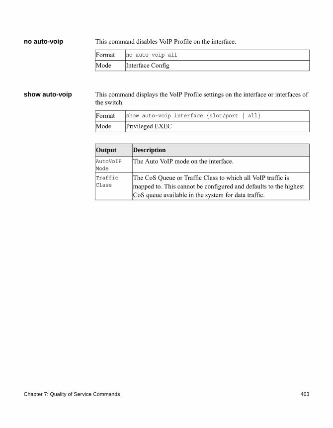
no auto-voip This command disables VoIP Profile on the interface.
show auto-voip This command displays the VoIP Profile settings on the interface or interfaces of the switch.
Format no auto-voip all
Mode Interface Config
Format show auto-voip interface {slot/port | all}
Mode Privileged EXEC
Output Description
AutoVoIP Mode
The Auto VoIP mode on the interface.
Traffic Class
The CoS Queue or Traffic Class to which all VoIP traffic is mapped to. This cannot be configured and defaults to the highest CoS queue available in the system for data traffic.
Chapter 7: Quality of Service Commands 463

Class of Service Commands
Introduction This section describes the commands you use to configure and view Class of Service (CoS) settings for the switch. The commands in this section allow you to control the priority and transmission rate of traffic.
NoteCommands you enter in the Interface Config mode only affect a single interface. Commands you enter in the Global Config mode affect all interfaces.
classofservice dot1p-mapping
This command maps an 802.1p priority to an internal traffic class. The userpriority values can range from 0 to 7. The trafficclass values range from 0 to 6, although the actual number of available traffic classes depends on the platform.
no classofservice dot1p-mapping
This command maps each 802.1p priority to its default internal traffic class value.
classofservice ip-dscp-mapping
This command maps an IP DSCP value to an internal traffic class. The ipdscp value is specified as either an integer from 0 to 63, or symbolically through one of the following keywords: af11, af12, af13, af21, af22, af23, af31, af32, af33, af41, af42, af43, be, cs0, cs1, cs2, cs3, cs4, cs5, cs6, cs7, ef.
The trafficclass values can range from 0 to 6, although the actual number of available traffic classes depends on the platform.
Format classofservice dot1p-mapping userpriority trafficclass
Mode ◆ Global Config◆ Interface Config
Format no classofservice dot1p-mapping
Mode ◆ Global Config◆ Interface Config
464 Class of Service Commands

no classofservice ip-dscp-mapping
This command maps each IP DSCP value to its default internal traffic class value.
classofservice trust This command sets the class of service trust mode of an interface or range of interfaces. You can set the mode to trust one of the Dot1p (802.1p), IP DSCP, or IP Precedence packet markings. You can also set the interface mode to untrusted. If you configure an interface to use Dot1p, the mode does not appear in the output of the show running config command because Dot1p is the default.
NoteThe classofservice trust dot1p command will not be supported in future releases of the software because Dot1p is the default value. Use the no classofservice trust command to set the mode to the default value.
no classofservice trust
This command sets the interface mode to the default value.
Format classofservice ip-dscp-mapping ipdscp trafficclass
Mode Global Config
Format no classofservice ip-dscp-mapping
Mode Global Config
Default dot1p
Format classofservice trust {dot1p | ip-dscp | ip-precedence | untrusted}
Mode ◆ Global Config◆ Interface Config
Format no classofservice trust
Mode ◆ Global Config◆ Interface Config
Chapter 7: Quality of Service Commands 465

cos-queue min-bandwidth
This command specifies the minimum transmission bandwidth guarantee for each interface queue on an interface, a range of interfaces, or all interfaces. The total number of queues supported per interface is platform specific. A value from 0 to 100 (percentage of link rate) must be specified for each supported queue, with 0 indicating no guaranteed minimum bandwidth. The sum of all values entered must not exceed 100.
no cos-queue min-bandwidth
This command restores the default for each queue's minimum bandwidth value.
cos-queue random-detect
This command activates weighted random early discard (WRED) for each specified queue on the interface. Specific WRED parameters are configured using the random-detect queue-parms and the random-detect exponential-weighting-constant commands.
When specified in Interface Config mode, this command affects a single interface only, whereas in Global Config mode, it applies to all interfaces.
At least one, but no more than n, queue-id values are specified with this command. Duplicate queue-id values are ignored. Each queue-id value ranges from 0 to (n–1), where n is the total number of queues supported per interface. The number n is platform-dependent and corresponds to the number of supported queues (traffic classes).
Format cos-queue min-bandwidth bw-0 bw-1 … bw-n
Mode ◆ Global Config◆ Interface Config
Format no cos-queue min-bandwidth
Mode ◆ Global Config◆ Interface Config
Format cos-queue random-detect queue-id-1 [queue-id-2 … queue-id-n]
Mode ◆ Global Config◆ Interface Config
466 Class of Service Commands

no cos-queue random-detect
This command disables WRED, which restores the default tail drop operation for the specified queues on the interface.
cos-queue strict This command activates the strict priority scheduler mode for each specified queue for an interface queue on an interface, a range of interfaces, or all interfaces.
no cos-queue strict This command restores the default weighted scheduler mode for each specified queue.
random-detect This command enables WRED for the interface as a whole, and is only available when per-queue WRED activation control is not supported by the device. Specific WRED parameters are configured using the random-detect queue-parms and the random-detect exponential-weighting-constant commands.
Format no cos-queue random-detect queue-id-1 [queue-id-2 … queue-id-n]
Mode ◆ Global Config◆ Interface Config
Format cos-queue strict queue-id-1 [queue-id-2 … queue-id-n]
Mode ◆ Global Config◆ Interface Config
Format no cos-queue strict queue-id-1 [queue-id-2 … queue-id-n]
Mode ◆ Global Config◆ Interface Config
Format random-detect
Mode ◆ Global Config◆ Interface Config
Chapter 7: Quality of Service Commands 467
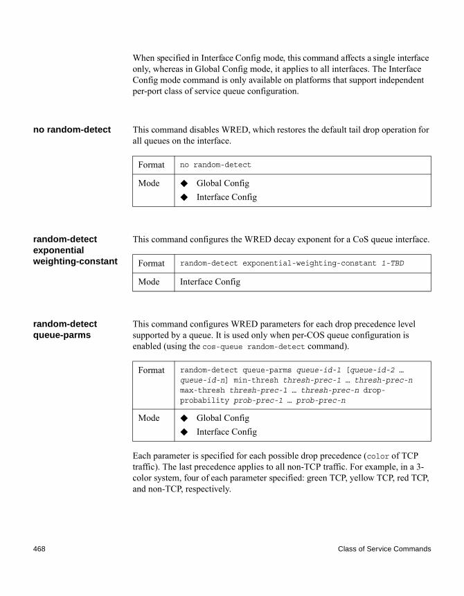
When specified in Interface Config mode, this command affects a single interface only, whereas in Global Config mode, it applies to all interfaces. The Interface Config mode command is only available on platforms that support independent per-port class of service queue configuration.
no random-detect This command disables WRED, which restores the default tail drop operation for all queues on the interface.
random-detect exponential weighting-constant
This command configures the WRED decay exponent for a CoS queue interface.
random-detect queue-parms
This command configures WRED parameters for each drop precedence level supported by a queue. It is used only when per-COS queue configuration is enabled (using the cos-queue random-detect command).
Each parameter is specified for each possible drop precedence (color of TCP traffic). The last precedence applies to all non-TCP traffic. For example, in a 3-color system, four of each parameter specified: green TCP, yellow TCP, red TCP, and non-TCP, respectively.
Format no random-detect
Mode ◆ Global Config◆ Interface Config
Format random-detect exponential-weighting-constant 1-TBD
Mode Interface Config
Format random-detect queue-parms queue-id-1 [queue-id-2 … queue-id-n] min-thresh thresh-prec-1 … thresh-prec-n max-thresh thresh-prec-1 … thresh-prec-n drop-probability prob-prec-1 … prob-prec-n
Mode ◆ Global Config◆ Interface Config
468 Class of Service Commands

no random-detect queue-parms
This command sets the WRED configuration back to the default.
traffic-shape This command specifies the maximum transmission bandwidth limit for the interface as a whole. You can also specify this value for a range of interfaces or all interfaces. Also known as rate shaping, traffic shaping has the effect of smoothing temporary traffic bursts over time so that the transmitted traffic rate is bounded.
Parameter Description
min-thresh The minimum threshold the queue depth (as a percentage) where WRED starts marking and dropping traffic.
max-thresh The maximum threshold is the queue depth (as a percentage) above which WRED marks / drops all traffic.
drop-probability The percentage probability that WRED will mark/drop a packet, when the queue depth is at the maximum threshold. (The drop probability increases linearly from 0 just before the minimum threshold, to this value at the maximum threshold, then goes to 100% for larger queue depths).
Format no random-detect queue-parms queue-id-1 [queue-id-2 … queue-id-n]
Mode ◆ Global Config◆ Interface Config
Format traffic-shape bw
Mode ◆ Global Config◆ Interface Config
Chapter 7: Quality of Service Commands 469

no traffic-shape This command restores the interface shaping rate to the default value.
show classofservice dot1p-mapping
This command displays the current Dot1p (802.1p) priority mapping to internal traffic classes for a specific interface. The slot/port parameter is optional and is only valid on platforms that support independent per-port class of service mappings. If specified, the 802.1p mapping table of the interface is displayed. If omitted, the most recent global configuration settings are displayed.
The following information is repeated for each user priority:
show classofservice ip-precedence-mapping
This command displays the current IP Precedence mapping to internal traffic classes for a specific interface. The slot/port parameter is optional and is only valid on platforms that support independent per-port class of service mappings. If specified, the IP Precedence mapping table of the interface is displayed. If omitted, the most recent global configuration settings are displayed.
The following information is repeated for each user priority:
Format no traffic-shape
Mode ◆ Global Config◆ Interface Config
Format show classofservice dot1p-mapping [slot/port]
Mode Privileged EXEC
Output Description
User Priority The 802.1p user priority value.
Traffic Class The traffic class internal queue identifier to which the user priority value is mapped.
Format show classofservice ip-precedence-mapping [slot/port]
Mode Privileged EXEC
470 Class of Service Commands

show classofservice ip-dscp-mapping
This command displays the current IP DSCP mapping to internal traffic classes for the global configuration settings.
The following information is repeated for each user priority.
show classofservice trust
This command displays the current trust mode setting for a specific interface. The slot/port parameter is optional and is only valid on platforms that support independent per-port class of service mappings. If you specify an interface, the command displays the port trust mode of the interface. If you do not specify an interface, the command displays the most recent global configuration settings.
Output Description
IP Precedence The IP Precedence value.
Traffic Class The traffic class internal queue identifier to which the IP Precedence value is mapped.
Format show classofservice ip-dscp-mapping
Mode Privileged EXEC
Output Description
IP DSCP The IP DSCP value.
Traffic Class The traffic class internal queue identifier to which the IP DSCP value is mapped.
Format show classofservice trust [slot/port]
Mode Privileged EXEC
Chapter 7: Quality of Service Commands 471
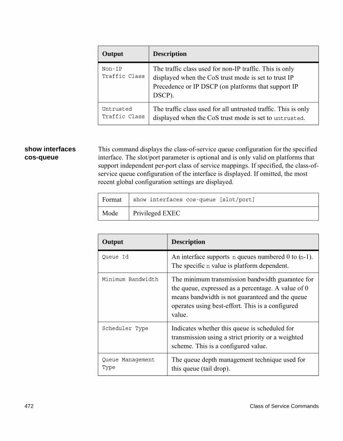
show interfaces cos-queue
This command displays the class-of-service queue configuration for the specified interface. The slot/port parameter is optional and is only valid on platforms that support independent per-port class of service mappings. If specified, the class-of-service queue configuration of the interface is displayed. If omitted, the most recent global configuration settings are displayed.
Output Description
Non-IP Traffic Class
The traffic class used for non-IP traffic. This is only displayed when the CoS trust mode is set to trust IP Precedence or IP DSCP (on platforms that support IP DSCP).
Untrusted Traffic Class
The traffic class used for all untrusted traffic. This is only displayed when the CoS trust mode is set to untrusted.
Format show interfaces cos-queue [slot/port]
Mode Privileged EXEC
Output Description
Queue Id An interface supports n queues numbered 0 to (n-1). The specific n value is platform dependent.
Minimum Bandwidth The minimum transmission bandwidth guarantee for the queue, expressed as a percentage. A value of 0 means bandwidth is not guaranteed and the queue operates using best-effort. This is a configured value.
Scheduler Type Indicates whether this queue is scheduled for transmission using a strict priority or a weighted scheme. This is a configured value.
Queue Management Type
The queue depth management technique used for this queue (tail drop).
472 Class of Service Commands

If you specify the interface, the command also displays the following information:
show interfaces random-detect
This command displays the global WRED settings for each CoS queue. If you specify the slot/port, the command displays the WRED settings for each CoS queue on the specified interface.
Output Description
Interface The slot/port of the interface. If displaying the global configuration, this output line is replaced with a Global Config indication.
Interface Shaping Rate
The maximum transmission bandwidth limit for the interface as a whole. It is independent of any per-queue maximum bandwidth value(s) in effect for the interface. This is a configured value.
Format show interfaces random-detect [slot/port]
Mode Privileged EXEC
Output Description
Queue ID An interface supports n queues numbered 0 to (n-1). The specific n value is platform dependent.
WRED Minimum Threshold
The configured minimum threshold the queue depth (as a percentage) where WRED starts marking and dropping traffic.
WRED Maximum Threshold
The configured maximum threshold is the queue depth (as a percentage) above which WRED marks / drops all traffic.
Chapter 7: Quality of Service Commands 473

WRED Drop Probability
The configured percentage probability that WRED will mark/drop a packet, when the queue depth is at the maximum threshold. (The drop probability increases linearly from 0 just before the minimum threshold, to this value at the maximum threshold, then goes to 100% for larger queue depths).
Output Description
474 Class of Service Commands

Differentiated Services Commands
Introduction This section describes the commands you use to configure QoS Differentiated Services (DiffServ).
You configure DiffServ in several stages by specifying three DiffServ components:
1. Classa. Creating and deleting classesb. Defining match criteria for a class
2. Policya. Creating and deleting policiesb. Associating classes with a policyc. Defining policy statements for a policy/class combination
3. Servicea. Adding and removing a policy to/from an inbound interface
The DiffServ class defines the packet filtering criteria. The attributes of a DiffServ policy define the way the switch processes packets. You can define policy attributes on a per-class instance basis. The switch applies these attributes when a match occurs.
Packet processing begins when the switch tests the match criteria for a packet. The switch applies a policy to a packet when it finds a class match within that policy.
The following rules apply when you create a DiffServ class:◆ Each class can contain a maximum of one referenced (nested) class◆ Class definitions do not support hierarchical service policies
A given class definition can contain a maximum of one reference to another class. You can combine the reference with other match criteria. The referenced class is truly a reference and not a copy since additions to a referenced class affect all classes that reference it. Changes to any class definition currently referenced by any other class must result in valid class definitions for all derived classes, otherwise the switch rejects the change. You can remove a class reference from a class definition.
Chapter 7: Quality of Service Commands 475
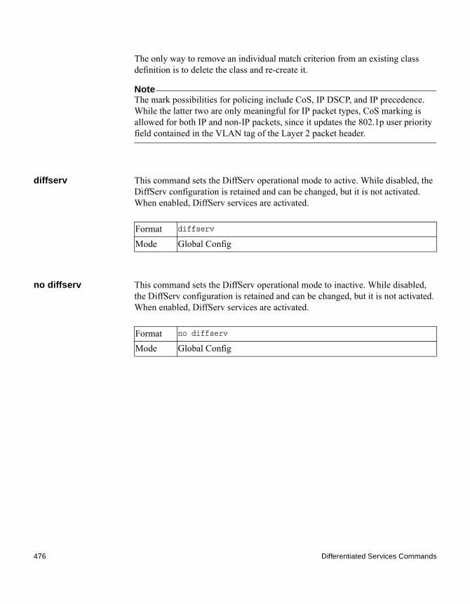
The only way to remove an individual match criterion from an existing class definition is to delete the class and re-create it.
NoteThe mark possibilities for policing include CoS, IP DSCP, and IP precedence. While the latter two are only meaningful for IP packet types, CoS marking is allowed for both IP and non-IP packets, since it updates the 802.1p user priority field contained in the VLAN tag of the Layer 2 packet header.
diffserv This command sets the DiffServ operational mode to active. While disabled, the DiffServ configuration is retained and can be changed, but it is not activated. When enabled, DiffServ services are activated.
no diffserv This command sets the DiffServ operational mode to inactive. While disabled, the DiffServ configuration is retained and can be changed, but it is not activated. When enabled, DiffServ services are activated.
Format diffserv
Mode Global Config
Format no diffserv
Mode Global Config
476 Differentiated Services Commands

DiffServ Class Commands
Introduction Use the DiffServ class commands to define traffic classification. To classify traffic, specify Behavior Aggregate (BA) which is based on DSCP and Multi-Field (MF) classes of traffic (name, match criteria)
This set of commands consists of class creation/deletion and matching, with the class match commands specifying Layer 3, Layer 2, and general match criteria. The class match criteria are also known as class rules, with a class definition consisting of one or more rules to identify the traffic that belongs to the class.
NoteOnce you create a class match criterion for a class, you cannot change or delete the criterion. To change or delete a class match criterion, you must delete and re-create the entire class.
The CLI command root is class-map.
class-map This command defines a DiffServ class of type match-all. When used without any match condition, this command enters the class-map mode. The class-map-name is a case-sensitive alphanumeric string from 1 to 31 characters uniquely identifying an existing DiffServ class.
NoteThe class-map-name default is reserved and must not be used.
The class type of match-all indicates all of the individual match conditions must be true for a packet to be considered a member of the class.This command may be used without specifying a class type to enter the Class-Map Config mode for an existing DiffServ class.
NoteThe optional keywords [{ipv4 | ipv6}] specify the Layer 3 protocol for this class. If not specified, this parameter defaults to ipv4. This maintains backward compatibility for configurations defined on systems before IPv6 match items were supported.
Chapter 7: Quality of Service Commands 477

NoteThe CLI mode is changed to Class-Map Config when this command is successfully executed depending on the [{ipv4 | ipv6}] keyword specified.
no class-map This command eliminates an existing DiffServ class. The class-map-name is the name of an existing DiffServ class. (The class name default is reserved and is not allowed here.) This command may be issued at any time; if the class is currently referenced by one or more policies or by any other class, the delete action fails.
class-map rename This command changes the name of a DiffServ class. The class-map-name is the name of an existing DiffServ class. The new-class-map-name parameter is a case-sensitive alphanumeric string from 1 to 31 characters uniquely identifying the class.
match ethertype This command adds to the specified class definition a match condition based on the value of the ethertype. The ethertype value is specified as one of the following keywords: appletalk, arp, ibmsna, ipv4, ipv6, ipx, mplsmcast, mplsucast, netbios, novell, pppoe, rarp or as a custom EtherType value in the range of 0x0600-0xFFFF.
Format class-map match-all class-map-name [{ipv4 | ipv6}]
Mode Global Config
Format no class-map class-map-name
Mode Global Config
Default none
Format class-map rename class-map-name new-class-map-name
Mode Global Config
Format match ethertype {keyword | custom 0x0600-0xFFFF}
Mode Class-Map Config
478 DiffServ Class Commands

match any This command adds to the specified class definition a match condition whereby all packets are considered to belong to the class.
match class-map This command adds to the specified class definition the set of match conditions defined for another class. The refclassname is the name of an existing DiffServ class whose match conditions are being referenced by the specified class definition.
Note
◆ The parameters refclassname and class-map-name cannot be the same.◆ Only one other class may be referenced by a class.◆ Any attempts to delete the refclassname class while the class is still
referenced by any class-map-name fails. ◆ The combined match criteria of class-map-name and refclassname must
be an allowed combination based on the class type. ◆ Any subsequent changes to the refclassname class match criteria must
maintain this validity, or the change attempt fails.◆ The total number of class rules formed by the complete reference class chain
(including both predecessor and successor classes) must not exceed a platform-specific maximum. In some cases, each removal of a refclass rule reduces the maximum number of available rules in the class definition by one.
no match class-map This command removes from the specified class definition the set of match conditions defined for another class. The refclassname is the name of an existing DiffServ class whose match conditions are being referenced by the specified class definition.
Default none
Format match any
Mode Class-Map Config
Default none
Format match class-map refclassname
Mode Class-Map Config
Chapter 7: Quality of Service Commands 479

match cos This command adds to the specified class definition a match condition for the Class of Service (CoS) value (the only tag in a single tagged packet or the first or outer 802.1Q tag of a double VLAN tagged packet). The value may be from 0 to 7.
match secondary-cos
This command adds to the specified class definition a match condition for the secondary Class of Service (CoS) value (the inner 802.1Q tag of a double VLAN tagged packet). The value may be from 0 to 7.
match destination-address mac
This command adds to the specified class definition a match condition based on the destination MAC address of a packet. The macaddr parameter is any Layer 2 MAC address formatted as six 2-digit hexadecimal numbers separated by colons (for example, 00:11:22:dd:ee:ff). The macmask parameter is a Layer 2 MAC address bit mask, which need not be contiguous, and is formatted as six 2-digit hexadecimal numbers separated by colons (for example, ff:07:23:ff:fe:dc).
Format no match class-map refclassname
Mode Class-Map Config
Default none
Format match cos 0-7
Mode Class-Map Config
Default none
Format match secondary-cos 0-7
Mode Class-Map Config
Default none
Format match destination-address mac macaddr macmask
Mode Class-Map Config
480 DiffServ Class Commands

match dstip This command adds to the specified class definition a match condition based on the destination IP address of a packet. The ipaddr parameter specifies an IP address. The ipmask parameter specifies an IP address bit mask and must consist of a contiguous set of leading 1 bits.
match dstl4port This command adds to the specified class definition a match condition based on the destination Layer 4 port of a packet using a single keyword or numeric notation. To specify the match condition as a single keyword, the value for portkey is one of the supported port name keywords. The currently supported portkey values are: domain, echo, ftp, ftpdata, http, smtp, snmp, telnet, tftp, www. Each of these translates into its equivalent port number. To specify the match condition using a numeric notation, one Layer 4 port number is required. The port number is an integer from 0 to 65535.
match ip dscp This command adds to the specified class definition a match condition based on the value of the IP DiffServ Code Point (DSCP) field in a packet, which is defined as the high-order six bits of the Service Type octet in the IP header (the low-order two bits are not checked).
The dscpval value is specified as either an integer from 0 to 63, or symbolically through one of the following keywords: af11, af12, af13, af21, af22, af23, af31, af32, af33, af41, af42, af43, be, cs0, cs1, cs2, cs3, cs4, cs5, cs6, cs7, ef.
NoteThe IP DSCP, IP Precedence, and IP ToS match conditions are alternative ways to specify a match criterion for the same Service Type field in the IP header, but with a slightly different user notation.
Default none
Format match dstip ipaddr ipmask
Mode Class-Map Config
Default none
Format match dstl4port {portkey | 0-65535}
Mode Class-Map Config
Default none
Format match ip dscp dscpval
Chapter 7: Quality of Service Commands 481

match ip precedence
This command adds to the specified class definition a match condition based on the value of the IP Precedence field in a packet, which is defined as the high-order three bits of the Service Type octet in the IP header (the low-order five bits are not checked). The precedence value is an integer from 0 to 7.
NoteThe IP DSCP, IP Precedence, and IP ToS match conditions are alternative ways to specify a match criterion for the same Service Type field in the IP header, but with a slightly different user notation.
match ip tos This command adds to the specified class definition a match condition based on the value of the IP ToS field in a packet, which is defined as all eight bits of the Service Type octet in the IP header. The value of tosbits is a two-digit hexadecimal number from 00 to ff. The value of tosmask is a two-digit hexadecimal number from 00 to ff. The tosmask denotes the bit positions in tosbits that are used for comparison against the IP ToS field in a packet. For example, to check for an IP ToS value having bits 7 and 5 set and bit 1 clear, where bit 7 is most significant, use a tosbits value of a0 (hex) and a tosmask of a2 (hex).
NoteThe IP DSCP, IP Precedence, and IP ToS match conditions are alternative ways to specify a match criterion for the same Service Type field in the IP header, but with a slightly different user notation.
NoteThis “free form” version of the IP DSCP/Precedence/ToS match specification gives the user complete control when specifying which bits of the IP Service Type field are checked.
Mode Class-Map Config
Default none
Format match ip precedence 0-7
Mode Class-Map Config
Default none
Format match ip tos tosbits tosmask
482 DiffServ Class Commands

match protocol This command adds to the specified class definition a match condition based on the value of the IP Protocol field in a packet using a single keyword notation or a numeric value notation.
To specify the match condition using a single keyword notation, the value for protocol-name is one of the supported protocol name keywords. The currently supported values are: icmp, igmp, ip, tcp, udp. A value of ip matches all protocol number values.
To specify the match condition using a numeric value notation, the protocol number is a standard value assigned by IANA and is interpreted as an integer from 0 to 255.
NoteThis command does not validate the protocol number value against the current list defined by IANA.
match source-address mac
This command adds to the specified class definition a match condition based on the source MAC address of a packet. The address parameter is any Layer 2 MAC address formatted as six 2-digit hexadecimal numbers separated by colons (for example, 00:11:22:dd:ee:ff). The macmask parameter is a Layer 2 MAC address bit mask, which may not be contiguous, and is formatted as six 2-digit hexadecimal numbers separated by colons (for example, ff:07:23:ff:fe:dc).
Mode Class-Map Config
Default none
Format match protocol {protocol-name | 0-255}
Mode Class-Map Config
Default none
Format match source-address mac address macmask
Mode Class-Map Config
Chapter 7: Quality of Service Commands 483

match srcip This command adds to the specified class definition a match condition based on the source IP address of a packet. The ipaddr parameter specifies an IP address. The ipmask parameter specifies an IP address bit mask and must consist of a contiguous set of leading 1 bits.
match srcip6 This command adds to the specified class definition a match condition based on the source IP address of a packet.
match srcl4port This command adds to the specified class definition a match condition based on the source Layer 4 port of a packet using a single keyword or numeric notation. To specify the match condition as a single keyword notation, the value for portkey is one of the supported port name keywords (listed below). Currently supported portkey values are: domain, echo, ftp, ftpdata, http, smtp, snmp, telnet, tftp, www. Each of these translates into its equivalent port number, which is used as both the start and end of a port range.
To specify the match condition as a numeric value, one Layer 4 port number is required. The port number is an integer from 0 to 65535.
match vlan This command adds to the specified class definition a match condition based on the value of the Layer 2 VLAN Identifier field (the only tag in a single tagged packet or the first or outer tag of a double VLAN tagged packet). The VLAN ID is an integer from 0 to 4095.
Default none
Format match srcip ipaddr ipmask
Mode Class-Map Config
Default none
Format match srcip6 source-ipv6-prefix/prefix-length
Mode IPv6-Class-Map Config
Default none
Format match srcl4port {portkey | 0-65535}
Mode Class-Map Config
484 DiffServ Class Commands

match secondary-vlan
This command adds to the specified class definition a match condition based on the value of the Layer 2 secondary VLAN Identifier field (the inner 802.1Q tag of a double VLAN tagged packet). The secondary VLAN ID is an integer from 0 to 4095.
Default none
Format match vlan 0-4095
Mode Class-Map Config
Default none
Format match secondary-vlan 0-4095
Mode Class-Map Config
Chapter 7: Quality of Service Commands 485
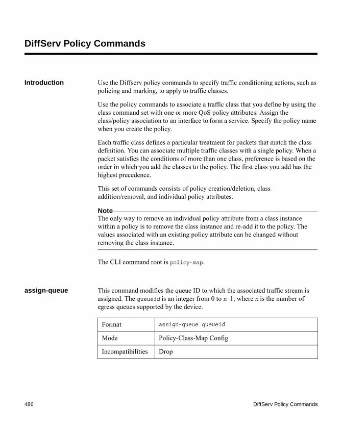
DiffServ Policy Commands
Introduction Use the Diffserv policy commands to specify traffic conditioning actions, such as policing and marking, to apply to traffic classes.
Use the policy commands to associate a traffic class that you define by using the class command set with one or more QoS policy attributes. Assign the class/policy association to an interface to form a service. Specify the policy name when you create the policy.
Each traffic class defines a particular treatment for packets that match the class definition. You can associate multiple traffic classes with a single policy. When a packet satisfies the conditions of more than one class, preference is based on the order in which you add the classes to the policy. The first class you add has the highest precedence.
This set of commands consists of policy creation/deletion, class addition/removal, and individual policy attributes.
NoteThe only way to remove an individual policy attribute from a class instance within a policy is to remove the class instance and re-add it to the policy. The values associated with an existing policy attribute can be changed without removing the class instance.
The CLI command root is policy-map.
assign-queue This command modifies the queue ID to which the associated traffic stream is assigned. The queueid is an integer from 0 to n–1, where n is the number of egress queues supported by the device.
Format assign-queue queueid
Mode Policy-Class-Map Config
Incompatibilities Drop
486 DiffServ Policy Commands

drop This command specifies that all packets for the associated traffic stream are to be dropped at ingress.
mirror This command specifies that all incoming packets for the associated traffic stream are copied to a specific egress interface (physical port or LAG).
redirect This command specifies that all incoming packets for the associated traffic stream are redirected to a specific egress interface (physical port or port channel).
conform-color This command enables color-aware traffic policing and define the conform-color class map. Used in conjunction with the police command where the fields for the conform level are specified. The class-map-name parameter is the name of an existing DiffServ class map.
NoteThis command may only be used after specifying a police command for the policy-class instance.
Format drop
Mode Policy-Class-Map Config
Incompatibilities Assign Queue, Mark (all forms), Mirror, Police, Redirect
Format mirror slot/port
Mode Policy-Class-Map Config
Incompatibilities Drop, Redirect
Format redirect slot/port
Mode Policy-Class-Map Config
Incompatibilities Drop, Mirror
Format conform-color class-map-name
Mode Policy-Class-Map Config
Chapter 7: Quality of Service Commands 487

class This command creates an instance of a class definition within the specified policy for the purpose of defining treatment of the traffic class through subsequent policy attribute statements. The classname is the name of an existing DiffServ class.
NoteThis command causes the specified policy to create a reference to the class definition.
NoteThe CLI mode is changed to Policy-Class-Map Config when this command is successfully executed.
no class This command deletes the instance of a particular class and its defined treatment from the specified policy. classname is the name of an existing DiffServ class.
NoteThis command removes the reference to the class definition for the specified policy.
mark cos This command marks all packets for the associated traffic stream with the specified Class of Service (CoS) value in the priority field of the 802.1p header (the only tag in a single tagged packet or the first or outer 802.1Q tag of a double VLAN tagged packet). If the packet does not already contain this header, one is inserted. The CoS value is an integer from 0 to 7.
Format class classname
Mode Policy-Map Config
Format no class classname
Mode Policy-Map Config
Default 1
Format mark-cos 0–7
Mode Policy-Class-Map Config
488 DiffServ Policy Commands
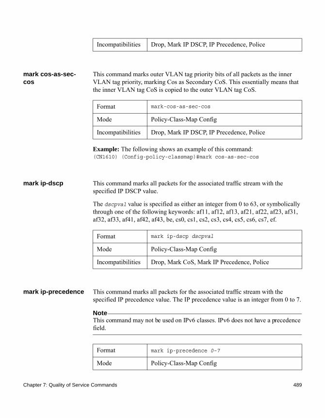
mark cos-as-sec-cos
This command marks outer VLAN tag priority bits of all packets as the inner VLAN tag priority, marking Cos as Secondary CoS. This essentially means that the inner VLAN tag CoS is copied to the outer VLAN tag CoS.
Example: The following shows an example of this command:(CN1610) (Config-policy-classmap)#mark cos-as-sec-cos
mark ip-dscp This command marks all packets for the associated traffic stream with the specified IP DSCP value.
The dscpval value is specified as either an integer from 0 to 63, or symbolically through one of the following keywords: af11, af12, af13, af21, af22, af23, af31, af32, af33, af41, af42, af43, be, cs0, cs1, cs2, cs3, cs4, cs5, cs6, cs7, ef.
mark ip-precedence This command marks all packets for the associated traffic stream with the specified IP precedence value. The IP precedence value is an integer from 0 to 7.
NoteThis command may not be used on IPv6 classes. IPv6 does not have a precedence field.
Incompatibilities Drop, Mark IP DSCP, IP Precedence, Police
Format mark-cos-as-sec-cos
Mode Policy-Class-Map Config
Incompatibilities Drop, Mark IP DSCP, IP Precedence, Police
Format mark ip-dscp dscpval
Mode Policy-Class-Map Config
Incompatibilities Drop, Mark CoS, Mark IP Precedence, Police
Format mark ip-precedence 0–7
Mode Policy-Class-Map Config
Chapter 7: Quality of Service Commands 489

police-simple This command establishes the traffic policing style for the specified class. The simple form of the police command uses a single data rate and burst size, resulting in two outcomes: conform and violate. The conforming data rate is specified in kilobits-per-second (Kbps) and is an integer from 1 to 4294967295. The conforming burst size is specified in kilobytes (KB) and is an integer from 1 to 128.
For each outcome, the only possible actions are drop, set-cos-as-sec-cos, set-cos-transmit, set-sec-cos-transmit, set-dscp-transmit, set-prec-transmit, or transmit. In this simple form of the police command, the conform action defaults to transmit and the violate action defaults to drop. These actions can be set with this command once the style has been configured.
For set-dscp-transmit, a dscpval value is required and is specified as either an integer from 0 to 63, or symbolically through one of the following keywords: af11, af12, af13, af21, af22, af23, af31, af32, af33, af41, af42, af43, be, cs0, cs1, cs2, cs3, cs4, cs5, cs6, cs7, ef.
For set-prec-transmit, an IP precedence value is required and is specified as an integer from 0 to 7.
For set-cos-transmit, an 802.1p priority value is required and is specified as an integer from 0 to 7.
Example: The following shows an example of this command:
Incompatibilities Drop, Mark CoS, Mark IP Precedence, Police
Policy Type In
Format police-simple {1-4294967295 1-128 conform-
action {drop | set-cos-as-sec-cos | set-cos-
transmit 0-7 | set-sec-cos-transmit 0-7 | set-
prec-transmit 0-7 | set-dscp-transmit 0-63 |
transmit} [violate-action {drop | set-cos-as-
sec-cos | set-cos-transmit 0-7 | set-sec-cos-
transmit 0-7 | set-prec-transmit 0-7 | set-
dscp-transmit 0-63 | transmit}]}
Mode Policy-Class-Map Config
Incompatibilities Drop, Mark (all forms)
490 DiffServ Policy Commands

(CN1610) (Config-policy-classmap)#police-simple 1 128 conform-action transmit violate-action drop
police-single-rate This command is the single-rate form of the police command and is used to establish the traffic policing style for the specified class. For each outcome, the only possible actions are drop, set-cos-as-sec-cost, set-cos-transmit, set-sec-cos-transmit, set-dscp-transmit, set-prec-transmit, or transmit. In this single-rate form of the police command, the conform action defaults to transmit, the exceed action defaults to drop, and the violate action defaults to drop. These actions can be set with this command once the style has been configured.
police-two-rate This command is the two-rate form of the police command and is used to establish the traffic policing style for the specified class. For each outcome, the only possible actions are drop, set-cos-as-sec-cos, set-cos-transmit, set-sec-cos-transmit, set-dscp-transmit, set-prec-transmit, or transmit. In this two-rate form of the police command, the conform action defaults to transmit, the exceed action defaults to drop, and the violate action defaults to drop. These actions can be set with this command once the style has been configured.
Format police-single-rate {1-4294967295 1-128 1-128 conform-action {drop | set-cos-as-sec-cos | set-cos-transmit 0-7 | set-sec-cos-transmit 0-7 | set-prec-transmit 0-7 | set-dscp-transmit 0-63 | transmit} exceed-action {drop | set-cos-as-sec-cos | set-cos-transmit 0-7 | set-sec-cos-transmit 0-7 | set-prec-transmit 0-7 | set-dscp-transmit 0-63 | transmit} [violate-action {drop | set-cos-as-sec-cos-transmit | set-cos-transmit 0-7 | set-sec-cos-transmit 0-7 | set-prec-transmit 0-7 | set-dscp-transmit 0-63 | transmit}]}
Mode Policy-Class-Map Config
Chapter 7: Quality of Service Commands 491

policy-map This command establishes a new DiffServ policy. The policy-name parameter is a case-sensitive alphanumeric string from 1 to 31 characters uniquely identifying the policy. The type of policy is specific to the inbound or outbound traffic direction as indicated by the in or out parameter.
NoteThe CLI mode is changed to Policy-Map Config when this command is successfully executed.
no policy-map This command eliminates an existing DiffServ policy. The policy-name parameter is the name of an existing DiffServ policy. This command may be issued at any time. If the policy is currently referenced by one or more interface service attachments, this delete attempt fails.
Format police-two-rate {1-4294967295 1-4294967295 1-128 1-128 conform-action {drop | set-cos-as-sec-cos | set-cos-transmit 0-7 | set-sec-cos-transmit 0-7 | set-prec-transmit 0-7 | set-dscp-transmit 0-63 | transmit} exceed-action {drop | set-cos-as-sec-cos | set-cos-transmit 0-7 | set-sec-cos-transmit 0-7 | set-prec-transmit 0-7 | set-dscp-transmit 0-63 | transmit} [violate-action {drop | set-cos-as-sec-cos | set-cos-transmit 0-7 | set-sec-cos-transmit 0-7 | set-prec-transmit 0-7 | set-dscp-transmit 0-63 | transmit}]}
Mode Policy-Class-Map Config
Format policy-map policy-name [in|out]
Mode Global Config
Format no policy-map policy-name
Mode Global Config
492 DiffServ Policy Commands

policy-map rename This command changes the name of a DiffServ policy. The policyname is the name of an existing DiffServ class. The newpolicyname parameter is a case-sensitive alphanumeric string from 1 to 31 characters uniquely identifying the policy.
Format policy-map rename policy-name newpolicyname
Mode Global Config
Chapter 7: Quality of Service Commands 493
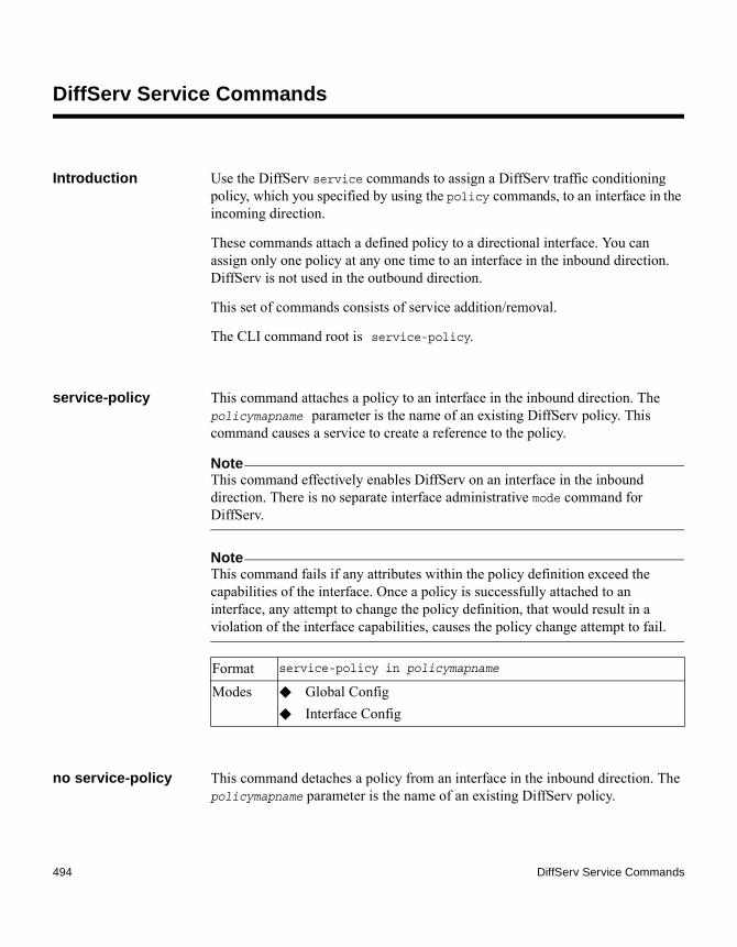
DiffServ Service Commands
Introduction Use the DiffServ service commands to assign a DiffServ traffic conditioning policy, which you specified by using the policy commands, to an interface in the incoming direction.
These commands attach a defined policy to a directional interface. You can assign only one policy at any one time to an interface in the inbound direction. DiffServ is not used in the outbound direction.
This set of commands consists of service addition/removal.
The CLI command root is service-policy.
service-policy This command attaches a policy to an interface in the inbound direction. The policymapname parameter is the name of an existing DiffServ policy. This command causes a service to create a reference to the policy.
NoteThis command effectively enables DiffServ on an interface in the inbound direction. There is no separate interface administrative mode command for DiffServ.
NoteThis command fails if any attributes within the policy definition exceed the capabilities of the interface. Once a policy is successfully attached to an interface, any attempt to change the policy definition, that would result in a violation of the interface capabilities, causes the policy change attempt to fail.
no service-policy This command detaches a policy from an interface in the inbound direction. The policymapname parameter is the name of an existing DiffServ policy.
Format service-policy in policymapname
Modes ◆ Global Config ◆ Interface Config
494 DiffServ Service Commands

NoteThis command causes a service to remove its reference to the policy. This command effectively disables DiffServ on an interface in the inbound direction. There is no separate interface administrative mode command for DiffServ.
Format no service-policy in policymapname
Modes ◆ Global Config ◆ Interface Config
Chapter 7: Quality of Service Commands 495

DiffServ Show Commands
Introduction Use the DiffServ show commands to display configuration and status information for classes, policies, and services. You can display DiffServ information in summary or detailed formats. The status information is only shown when the DiffServ administrative mode is enabled.
show class-map This command displays all configuration information for the specified class. The class-name is the name of an existing DiffServ class.
If the class-name is specified the following fields are displayed:
If you do not specify the Class Name, this command displays a list of all defined DiffServ classes. The following fields are displayed:
Format show class-map class-name
Modes ◆ Privileged EXEC◆ User EXEC
Output Description
Class Name The name of this class.Class Type A class type of all means every match criterion defined for the
class is evaluated simultaneously and must all be true to indicate a class match.
L3 Proto The Layer 3 protocol for this class. The only allowed values are IPv4 and IPv6.
Match Criteria
The Match Criteria fields are only displayed if they have been configured. Not all platforms support all match criteria values. They are displayed in the order entered by the user. The fields are evaluated in accordance with the class type. The possible Match Criteria fields are: Destination IP Address, Destination Layer 4 Port, Destination MAC Address, Ethertype, Source MAC Address, VLAN, Class of Service, Every, IP DSCP, IP Precedence, IP ToS, Protocol Keyword, Reference Class, Source IP Address, and Source Layer 4 Port.
Values The values of the Match Criteria.
496 DiffServ Show Commands

show diffserv This command displays the DiffServ General Status Group information, which includes the current administrative mode setting as well as the current and maximum number of rows in each of the main DiffServ private MIB tables. This command takes no options.
Output Description
Class Name The name of this class. (Note that the order in which classes are displayed is not necessarily the same order in which they were created.)
Class Type A class type of all means every match criterion defined for the class is evaluated simultaneously and must all be true to indicate a class match.
Ref Class Name
The name of an existing DiffServ class whose match conditions are being referenced by the specified class definition.
Format show diffserv
Mode Privileged EXEC
Output Description
DiffServ Admin mode The current value of the DiffServ administrative mode.
Class Table Size The current number of entries (rows) in the Class Table.
Class Table Max The maximum allowed entries (rows) for the Class Table.
Class Rule Table Size The current number of entries (rows) in the Class Rule Table.
Class Rule Table Max The maximum allowed entries (rows) for the Class Rule Table.
Policy Table Size The current number of entries (rows) in the Policy Table.
Policy Table Max The maximum allowed entries (rows) for the Policy Table.
Policy Instance Table Size
Current number of entries (rows) in the Policy Instance Table.
Chapter 7: Quality of Service Commands 497

show policy-map This command displays all configuration information for the specified policy. The policyname is the name of an existing DiffServ policy.
If the Policy Name is specified the following fields are displayed:
The following information is repeated for each class associated with this policy (only those policy attributes actually configured are displayed):
Policy Instance Table Max
Maximum allowed entries (rows) for the Policy Instance Table.
Policy Attribute Table Size
Current number of entries (rows) in the Policy Attribute Table.
Policy Attribute Table Max
Maximum allowed entries (rows) for the Policy Attribute Table.
Service Table Size The current number of entries (rows) in the Service Table.
Service Table Max The maximum allowed entries (rows) for the Service Table.
Output Description
Format show policy-map [policyname]
Mode Privileged EXEC
Output Description
Policy Name The name of this policy.Policy Type The policy type (only inbound policy definitions are supported for
this platform.)
Output Description
Assign Queue
Directs traffic stream to the specified QoS queue. This allows a traffic classifier to specify which one of the supported hardware queues are used for handling packets belonging to the class.
Class Name The name of this class.Committed Burst Size (KB)
The committed burst size, used in simple policing.
Committed Rate (Kbps)
The committed rate, used in simple policing.
498 DiffServ Show Commands

Conform Action
The current setting for the action taken on a packet considered to conform to the policing parameters. This is not displayed if policing is not in use for the class under this policy.
Conform Color Mode
The current setting for the color mode. Policing uses either color blind or color aware mode. Color blind mode ignores the coloration (marking) of the incoming packet. Color aware mode takes into consideration the current packet marking when determining the policing outcome.
Conform COS The CoS mark value if the conform-action action is set-cos-transmit.
Conform DSCP Value
The DSCP mark value if the conform-action action is set-dscp-transmit.
Conform IP Precedence Value
The IP Precedence mark value if the conform-action action is set-prec-transmit.
Drop Drop a packet upon arrival. This is useful for emulating access control list operation using DiffServ, especially when DiffServ and ACL cannot co-exist on the same interface.
Exceed Action
The action taken on traffic that exceeds settings that the network administrator specifies.
Exceed Color Mode
The current setting for the color of exceeding traffic that the user may optionally specify.
Mark CoS The class of service value that is set in the 802.1p header of inbound packets. This is not displayed if the Mark CoS was not specified.
Mark CoS as Secondary CoS
The secondary 802.1p priority value (second/inner VLAN tag. Same as CoS (802.1p) marking, but the dot1p value used for remarking is picked from the dot1p value in the secondary (i.e. inner) tag of a double-tagged packet.
Mark IP DSCP
The mark/remark value used as the DSCP for traffic matching this class. This is not displayed if Mark IP description is not specified.
Mark IP Precedence
The mark/re-mark value used as the IP Precedence for traffic matching this class. This is not displayed if Mark IP Precedence is not specified.
Output Description
Chapter 7: Quality of Service Commands 499
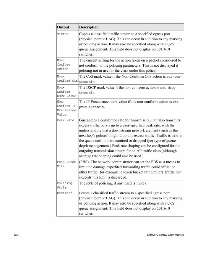
Mirror Copies a classified traffic stream to a specified egress port (physical port or LAG). This can occur in addition to any marking or policing action. It may also be specified along with a QoS queue assignment. This field does not display on CN1610 switches.
Non-Conform Action
The current setting for the action taken on a packet considered to not conform to the policing parameters. This is not displayed if policing not in use for the class under this policy.
Non-Conform COS
The CoS mark value if the Non-Conform CoS action is set-cos-transmit.
Non-Conform DSCP Value
The DSCP mark value if the non-conform action is set-dscp-transmit.
Non-Conform IP Precedence Value
The IP Precedence mark value if the non-conform action is set-prec-transmit.
Peak Rate Guarantees a committed rate for transmission, but also transmits excess traffic bursts up to a user-specified peak rate, with the understanding that a downstream network element (such as the next hop’s policer) might drop this excess traffic. Traffic is held in the queue until it is transmitted or dropped (per type of queue depth management.) Peak rate shaping can be configured for the outgoing transmission stream for an AP traffic class (although average rate shaping could also be used.)
Peak Burst Size
(PBS). The network administrator can set the PBS as a means to limit the damage expedited forwarding traffic could inflict on other traffic (for example, a token bucket rate limiter) Traffic that exceeds this limit is discarded.
Policing Style
The style of policing, if any, used (simple).
Redirect Forces a classified traffic stream to a specified egress port (physical port or LAG). This can occur in addition to any marking or policing action. It may also be specified along with a QoS queue assignment. This field does not display on CN1610 switches.
Output Description
500 DiffServ Show Commands

If the Policy Name is not specified this command displays a list of all defined DiffServ policies. The following fields are displayed:
Example: The following shows example CLI display output including the mark-cos-as-sec-cos option specified in the policy action:(CN1610) #show policy-map p1 Policy Name.................................... p1Policy Type.................................... In Class Name..................................... c1 Mark CoS as Secondary CoS...................... Yes
Example: The following shows example CLI display output including the mark-cos-as-sec-cos action used in the policing (simple-police, police-single-rate, police two-rate) command.(CN1610) #show policy-map p2 Policy Name....................... p2 Policy Type....................... In Class Name........................ c2 Policing Style.................... Police Two Rate Committed Rate.................... 1 Committed Burst Size.............. 1 Peak Rate......................... 1 Peak Burst Size................... 1 Conform Action.................... Mark CoS as Secondary CoS Exceed Action..................... Mark CoS as Secondary CoS Non-Conform Action................ Mark CoS as Secondary CoS Conform Color Mode................ Blind Exceed Color Mode................. Blind
show diffserv service
This command displays policy service information for the specified interface and direction. The slot/port parameter specifies a valid slot/port number for the system.
Output Description
Policy Name The name of this policy. (The order in which the policies are displayed is not necessarily the same order in which they were created.)
Policy Type The policy type (Only inbound is supported).Class Members
List of all class names associated with this policy.
Format show diffserv service slot/port in|out
Chapter 7: Quality of Service Commands 501

show diffserv service brief
This command displays all interfaces in the system to which a DiffServ policy has been attached. The inbound or outbound direction parameter is optional.
The following information is repeated for interface and direction (only those interfaces configured with an attached policy are shown):
Mode Privileged EXEC
Output Description
DiffServ Admin Mode
The current setting of the DiffServ administrative mode. An attached policy is only in effect on an interface while DiffServ is in an enabled mode.
Interface slot/portDirection The traffic direction of this interface service, inbound or
outbound.Operational Status
The current operational status of this DiffServ service interface.
Policy Name The name of the policy attached to the interface in the indicated direction.
Policy Details
Attached policy details, whose content is identical to that described for the show policy-map policymapname command (content not repeated here for brevity).
Format show diffserv service brief [in|out]
Mode Privileged EXEC
Output Description
DiffServ Mode
The current setting of the DiffServ administrative mode. An attached policy is only active on an interface while DiffServ is in an enabled mode.
Output Description
Interface slot/portDirection The traffic direction of this interface service, inbound or
outbound.
502 DiffServ Show Commands
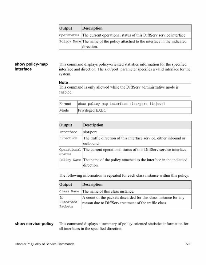
show policy-map interface
This command displays policy-oriented statistics information for the specified interface and direction. The slot/port parameter specifies a valid interface for the system.
NoteThis command is only allowed while the DiffServ administrative mode is enabled.
The following information is repeated for each class instance within this policy:
show service-policy This command displays a summary of policy-oriented statistics information for all interfaces in the specified direction.
OperStatus The current operational status of this DiffServ service interface.Policy Name The name of the policy attached to the interface in the indicated
direction.
Output Description
Format show policy-map interface slot/port [in|out]
Mode Privileged EXEC
Output Description
Interface slot/portDirection The traffic direction of this interface service, either inbound or
outbound.Operational Status
The current operational status of this DiffServ service interface.
Policy Name The name of the policy attached to the interface in the indicated direction.
Output Description
Class Name The name of this class instance.In Discarded Packets
A count of the packets discarded for this class instance for any reason due to DiffServ treatment of the traffic class.
Chapter 7: Quality of Service Commands 503

The following information is repeated for each interface and direction (only those interfaces configured with an attached policy are shown):
Format show service-policy [in|out]
Mode Privileged EXEC
Output Description
Interface slot/portOperational Status
The current operational status of this DiffServ service interface.
Policy Name The name of the policy attached to the interface.
504 DiffServ Show Commands

IP Access Control List Commands
Introduction This section describes the commands you use to configure IP Access Control List (ACL) settings. IP ACLs ensure that only authorized users have access to specific resources and block any unwarranted attempts to reach network resources.
The following rules apply to IP ACLs:◆ FASTPATH software does not support IP ACL configuration for IP packet
fragments.◆ The maximum number of ACLs you can create is hardware dependent. The
limit applies to all ACLs, regardless of type.◆ The maximum number of rules per IP ACL is hardware dependent.◆ On CN1610 switches, if you configure a MAC ACL on an interface, you
cannot configure an IP ACL on the same interface.◆ Wildcard masking for ACLs operates differently from a subnet mask. A
wildcard mask is in essence the inverse of a subnet mask. With a subnet mask, the mask has ones (1s) in the bit positions that are used for the network address, and has zeros (0s) for the bit positions that are not used. In contrast, a wildcard mask has zeros (0s) in a bit position that must be checked. A 1 in a bit position of the ACL mask indicates the corresponding bit can be ignored.
access-list This command creates an IP Access Control List (ACL) that is identified by the access list number, which is 1 to 99 for standard ACLs or 100 to 199 for extended ACLs. The following parameter table describes the parameters for the access-list command.
IP Standard ACL:
Format access-list 1-99 {deny | permit} {every | srcip srcmask} [log] [time-range time-range-name][assign-queue queue-id] [{mirror | redirect} slot/port]
Mode Global Config
Chapter 7: Quality of Service Commands 505

IP Extended ACL:
Format access-list 100-199 {deny | permit} {every | {{icmp | igmp | ip | tcp | udp | number} srcip srcmask[{eq {portkey | 0-65535} dstip dstmask [{eq {portkey| 0-65535}] [precedence precedence | tos tos tosmask | dscp dscp][log][time-range time-range-name][assign-queue queue-id] [{mirror | redirect} slot/port]
Mode Global Config
Parameter Description
1-99 or 100-199
Range 1 to 99 is the access list number for an IP standard ACL. Range 100 to 199 is the access list number for an IP extended ACL.
{deny | permit}
Specifies whether the IP ACL rule permits or denies an action.
every Match every packet.
{icmp | igmp | ip | tcp | udp | number}
Specifies the protocol to filter for an extended IP ACL rule.
srcip srcmask Specifies a source IP address and source netmask for match condition of the IP ACL rule.
[{eq {portkey | 0-65535}]
Specifies the source Layer 4 port match condition for the IP ACL rule. You can use the port number, which ranges from 0 to 65535, or you specify the portkey, which can be one of the following keywords: domain, echo, ftp, ftpdata, http, smtp, snmp, telnet, tftp, and www. Each of these keywords translates into its equivalent port number, which is used as both the start and end of a port range.
dstip dstmask Specifies a destination IP address and netmask for match condition of the IP ACL rule.
506 IP Access Control List Commands

no access-list This command deletes an IP ACL that is identified by the parameter accesslistnumber from the system. The range for accesslistnumber 1 to 99 for standard access lists and 100 to 199 for extended access lists.
[precedence precedence | tos tos tosmask | dscp dscp]
Specifies the ToS for an IP ACL rule depending on a match of precedence or DSCP values using the parameters dscp, precedence, tos tosmask.
[log] Specifies that this rule is to be logged.
[time-range time-range-name]
Allows you to set an imposing time limitation on the ACL rule as defined by the parameter time-range-name. If a time range with the specified name does not exist and the ACL containing this ACL rule is applied to an interface or bound to a VLAN, then the ACL rule is applied immediately. If a time range with a specified name exists and the ACL containing this ACL rule is applied to an interface or bound to a VLAN, then the ACL rule is applied when the time-range with the specified name becomes active. The ACL rule is removed when the time-range with the specified name becomes inactive.
[assign-queue queue-id]
Specifies the assign-queue, which is the queue identifier to which packets matching this rule are assigned.
[{mirror | redirect} slot/port]
For CN1610 switches, specifies the mirror or redirect interface which is the slot/port to which packets matching this rule are copied or forwarded, respectively. The mirror and redirect parameters are not available on the CN1610 switch.
Parameter Description
Format no access-list accesslistnumber
Mode Global Config
Chapter 7: Quality of Service Commands 507

ip access-list This command creates an extended IP Access Control List (ACL) identified by name, consisting of classification fields defined for the IP header of an IPv4 frame. The name parameter is a case-sensitive alphanumeric string from 1 to 31 characters uniquely identifying the IP access list.
If an IP ACL by this name already exists, this command enters IPv4-Access_List config mode to allow updating the existing IP ACL.
NoteThe CLI mode changes to IPv4-Access-List Config mode when you successfully execute this command.
no ip access-list This command deletes the IP Access Control List (ACL) identified by name from the system.
ip access-list rename
This command changes the name of an IP Access Control List (ACL). The name parameter is the names of an existing IP ACL. The newname parameter is a case-sensitive alphanumeric string from 1 to 31 characters uniquely identifying the IP access list.
This command fails if an IP ACL by the name newname already exists.
Format ip access-list name
Mode Global Config
Format no ip access-list name
Mode Global Config
Format ip access-list rename name newname
Mode Global Config
508 IP Access Control List Commands

{deny|permit} (IP ACL)
This command creates a new rule for the current IP access list. Each rule is appended to the list of configured rules for the list.
NoteThe no form of this command is not supported, since the rules within an IP ACL cannot be deleted individually. Rather, the entire IP ACL must be deleted and re-specified.
NoteAn implicit deny all IP rule always terminates the access list.
A rule may either deny or permit traffic according to the specified classification fields. At a minimum, either the every keyword or the protocol, source address, and destination address values must be specified. The source and destination IP address fields may be specified using the keyword any to indicate a match on any value in that field. The remaining command parameters are all optional, but the most frequently used parameters appear in the same relative order as shown in the command format.
The time-range parameter allows imposing time limitation on the IP ACL rule as defined by the specified time range. If a time range with the specified name does not exist and the ACL containing this ACL rule is applied to an interface or bound to a VLAN, then the ACL rule is applied immediately. If a time range with the specified name exists and the ACL containing this ACL rule is applied to an interface or bound to a VLAN, then the ACL rule is applied when the time-range with the specified name becomes active. The ACL rule is removed when the time-range with the specified name becomes inactive.
The assign-queue parameter allows specification of a particular hardware queue for handling traffic that matches this rule. The allowed queue-id value is 0-(n-1), where n is the number of user configurable queues available for the hardware platform. The assign-queue parameter is valid only for a permit rule.
Format {deny | permit} {every | {{icmp | igmp | ip | tcp | udp | number} srcip srcmask[{eq {portkey | 0-65535} dstip dstmask [{eq {portkey| 0-65535}] [precedence precedence | tos tos tosmask | dscp dscp] [log] [time-range time-range-name] [assign-queue queue-id] [{mirror | redirect} slot/port]
Mode Ipv4-Access-List Config
Chapter 7: Quality of Service Commands 509
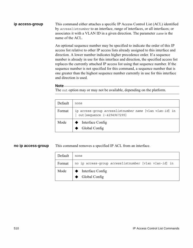
ip access-group This command either attaches a specific IP Access Control List (ACL) identified by accesslistnumber to an interface, range of interfaces, or all interfaces; or associates it with a VLAN ID in a given direction. The parameter name is the name of the ACL.
An optional sequence number may be specified to indicate the order of this IP access list relative to other IP access lists already assigned to this interface and direction. A lower number indicates higher precedence order. If a sequence number is already in use for this interface and direction, the specified access list replaces the currently attached IP access list using that sequence number. If the sequence number is not specified for this command, a sequence number that is one greater than the highest sequence number currently in use for this interface and direction is used.
NoteThe out option may or may not be available, depending on the platform.
no ip access-group This command removes a specified IP ACL from an interface.
Default none
Format ip access-group accesslistnumber name [vlan vlan-id] in | out[sequence 1-4294967295]
Mode ◆ Interface Config◆ Global Config
Default none
Format no ip access-group accesslistnumber [vlan vlan-id] in
Mode ◆ Interface Config◆ Global Config
510 IP Access Control List Commands

acl-trapflags This command enables the ACL trap mode.
no acl-trapflags This command disables the ACL trap mode.
show ip access-lists This command displays summary information about all IP ACLs configured on the switch. To view more detailed information about a specific access list, specify the ACL number or name that is used to identify the IP ACL.
Default disabled
Format acl-trapflags
Mode Global Config
Format no acl-trapflags
Mode Global Config
Format show ip access-lists [accesslistnumber | name]
Mode Privileged EXEC
Output Description
ACL ID/Name Identifies the configured ACL number or name.
Rules Identifies the number of rules configured for the ACL.
Direction Shows whether the ACL is applied to traffic coming into the interface (ingress) or leaving the interface (egress).
Interface(s) Identifies the interface(s) to which the ACL is applied (ACL interface bindings).
VLAN(s) Identifies the VLANs to which the ACL is applied (ACL VLAN bindings).
Chapter 7: Quality of Service Commands 511

If you specify an IP ACL number or name, the following information displays:
NoteOnly the access list fields that you configure are displayed.
Output Description
Rule Number The number identifier for each rule that is defined for the IP ACL.
Action The action associated with each rule. The possible values are Permit or Deny.
Match All Indicates whether this access list applies to every packet. Possible values are True or False.
Protocol The protocol to filter for this rule.
Source IP Address
The source IP address for this rule.
Source IP Mask
The source IP Mask for this rule.
Source L4 Port Keyword
The source port for this rule.
Destination IP Address
The destination IP address for this rule.
Destination IP Mask
The destination IP Mask for this rule.
Destination L4 Port Keyword
The destination port for this rule.
IP DSCP The value specified for IP DSCP.
IP Precedence The value specified for IP Precedence.
IP ToS The value specified for IP ToS.
Log Displays when you enable logging for the rule.
Assign Queue The queue identifier to which packets matching this rule are assigned.
512 IP Access Control List Commands

show access-lists interface
This command displays IP ACLs, IPv6 ACLs, and MAC access control lists information for a designated interface and direction.
Mirror Interface
The slot/port to which packets matching this rule are copied.
Redirect Interface
The slot/port to which packets matching this rule are forwarded.
Time Range Name
Displays the name of the time-range if the IP ACL rule has referenced a time range.
Rule Status Status (Active/Inactive) of the IP ACL rule.
Output Description
Format show access-lists interface slot/port in|out
Mode Privileged EXEC
Output Description
ACL Type Type of access list (IP, IPv6, or MAC).
ACL ID Access control list name for a MAC or IPv6 access list or the numeric identifier for an IP access list.
Sequence Number An optional sequence number may be specified to indicate the order of this access list relative to other access lists already assigned to this interface and direction. A lower number indicates higher precedence order. If a sequence number is already in use for this interface and direction, the specified access list replaces the currently attached access list using that sequence number. If the sequence number is not specified by the user, a sequence number that is one greater than the highest sequence number currently in use for this interface and direction is used. Valid range is (1 to 4294967295).
Chapter 7: Quality of Service Commands 513

show access-lists vlan
This command displays Access List information for a particular VLAN ID and direction.
in|out ◆ in–Display Access List information for a particular interface in the in direction.
◆ out–Display Access List information for a particular interface in the out direction.
Output Description
Format show access-lists vlan vlan-id in|out
Mode Privileged EXEC
Output Description
vlan-id A VLAN ID.
in|out ◆ in–Display Access List information for a particular VLAN ID in the in direction.
◆ out–Display Access List information for a particular VLAN ID in the out direction.
514 IP Access Control List Commands
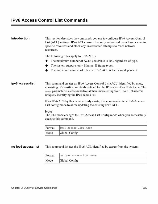
IPv6 Access Control List Commands
Introduction This section describes the commands you use to configure IPv6 Access Control List (ACL) settings. IPv6 ACLs ensure that only authorized users have access to specific resources and block any unwarranted attempts to reach network resources.
The following rules apply to IPv6 ACLs:◆ The maximum number of ACLs you create is 100, regardless of type.◆ The system supports only Ethernet II frame types.◆ The maximum number of rules per IPv6 ACL is hardware dependent.
ipv6 access-list This command creates an IPv6 Access Control List (ACL) identified by name, consisting of classification fields defined for the IP header of an IPv6 frame. The name parameter is a case-sensitive alphanumeric string from 1 to 31 characters uniquely identifying the IPv6 access list.
If an IPv6 ACL by this name already exists, this command enters IPv6-Access-List config mode to allow updating the existing IPv6 ACL.
NoteThe CLI mode changes to IPv6-Access-List Config mode when you successfully execute this command.
no ipv6 access-list This command deletes the IPv6 ACL identified by name from the system.
Format ipv6 access-list name
Mode Global Config
Format no ipv6 access-list name
Mode Global Config
Chapter 7: Quality of Service Commands 515

ipv6 access-list rename
This command changes the name of an IPv6 ACL. The name parameter is the name of an existing IPv6 ACL. The newname parameter is a case-sensitive alphanumeric string from 1 to 31 characters uniquely identifying the IPv6 access list.
This command fails is an IPv6 ACL by the name newname already exists.
{deny | permit} (IPv6)
This command creates a new rule for the current IPv6 access list. Each rule is appended to the list of configured rules for the list.
NoteThe no form of this command is not supported, since the rules within an IPv6 ACL cannot be deleted individually. Rather, the entire IPv6 ACL must be deleted and respecified.
NoteAn implicit deny all IPv6 rule always terminates the access list.
A rule may either deny or permit traffic according to the specified classification fields. At a minimum, either the every keyword or the protocol, source address, and destination address values must be specified. The source and destination IPv6 address fields may be specified using the keyword any to indicate a match on any value in that field. The remaining command parameters are all optional, but the most frequently used parameters appear in the same relative order as shown in the command format.
The time-range parameter allows imposing time limitation on the IPv6 ACL rule as defined by the parameter time-range-name. If a time range with the specified name does not exist and the IPv6 ACL containing this ACL rule is applied to an interface or bound to a VLAN, then the ACL rule is applied immediately. If a time range with specified name exists and the IPv6 ACL containing this ACL rule is applied to an interface or bound to a VLAN, then the ACL rule is applied when the time-range with specified name becomes active. The ACL rule is removed when the time-range with specified name becomes inactive. For information about configuring time ranges, see “Time Range Commands for Time-Based ACLs” on page 526.
Format ipv6 access-list rename name newname
Mode Global Config
516 IPv6 Access Control List Commands

The assign-queue parameter allows specification of a particular hardware queue for handling traffic that matches this rule. The allowed queue-id value is 0-(n-1), where n is the number of user configurable queues available for the hardware platform. The assign-queue parameter is valid only for a permit rule.
For the CN1610 switch, the mirror parameter allows the traffic matching this rule to be copied to the specified slot/port, while the redirect parameter allows the traffic matching this rule to be forwarded to the specified slot/port. The assign-queue and redirect parameters are only valid for a permit rule.
ipv6 traffic-filter This command either attaches a specific IPv6 ACL identified by name to an interface or range of interfaces, or associates it with a VLAN ID in a given direction. The name parameter must be the name of an existing IPv6 ACL.
An optional sequence number may be specified to indicate the order of this mac access list relative to other IPv6 access lists already assigned to this interface and direction. A lower number indicates higher precedence order. If a sequence number is already in use for this interface and direction, the specifiedIPv6 access list replaces the currently attached IPv6 access list using that sequence number. If the sequence number is not specified for this command, a sequence number that is one greater than the highest sequence number currently in use for this interface and direction is used.
This command specified in Interface Config mode only affects a single interface, whereas the Global Config mode setting is applied to all interfaces. The vlan keyword is only valid in the Global Config mode. The Interface Config mode command is only available on platforms that support independent per-port class of service queue configuration.
NoteYou should be aware that the out option may or may not be available, depending on the platform.
Format {deny | permit} {every | {{icmpv6 | ipv6 | tcp | udp | number}[log] [time-range time-range-name] [assign-queue queue-id] [{mirror | redirect} slot/port]
Mode IPv6-Access-List Config
Format ipv6 traffic-filter name [vlan vlan-id] {in | out} [sequence 1-4294967295]
Modes ◆ Global Config ◆ Interface Config
Chapter 7: Quality of Service Commands 517

no ipv6 traffic-filter This command removes an IPv6 ACL identified by name from the interface(s) in a given direction.
show ipv6 access-lists
This command displays an IPv6 access list and all of the rules that are defined for the IPv6 ACL. Use the [name] parameter to identify a specific IPv6 ACL to display.
Format no ipv6 traffic-filter name [vlan vlan-id] in [sequence 1-4294967295]
Modes ◆ Global Config◆ Interface Config
Format show ipv6 access-lists [name]
Mode Privileged EXEC
Output Description
Rule Number The ordered rule number identifier defined within the IPv6 ACL.Action The action associated with each rule. The possible values are
Permit or Deny.Match All Indicates whether this access list applies to every packet. Possible
values are True or False.Protocol The protocol to filter for this rule.Source IP Address
The source IP address for this rule.
Source L4 Port Keyword
The source port for this rule.
Destination IP Address
The destination IP address for this rule.
Destination L4 Port Keyword
The destination port for this rule.
IP DSCP The value specified for IP DSCP.Flow Label The value specified for IPv6 Flow Label.Log Displays when you enable logging for the rule.Assign Queue
The queue identifier to which packets matching this rule are assigned.
518 IPv6 Access Control List Commands

Mirror Interface
The slot/port to which packets matching this rule are copied.
Redirect Interface
The slot/port to which packets matching this rule are forwarded.
Time Range Name
Displays the name of the time-range if the IPv6 ACL rule has referenced a time range.
Rule Status Status (Active/Inactive) of the IPv6 ACL rule.
Output Description
Chapter 7: Quality of Service Commands 519

MAC Access Control List Commands
Introduction This section describes the commands you use to configure MAC Access Control List (ACL) settings. MAC ACLs ensure that only authorized users have access to specific resources and block any unwarranted attempts to reach network resources.
The following rules apply to MAC ACLs:◆ The maximum number of ACLs you can create is hardware-dependent. The
limit applies to all ACLs, regardless of type.◆ The system supports only Ethernet II frame types.◆ The maximum number of rules per MAC ACL is hardware-dependent.◆ For the CN1610 switch, if you configure an IP ACL on an interface, you
cannot configure a MAC ACL on the same interface.
mac access-list extended
This command creates a MAC Access Control List (ACL) identified by name, consisting of classification fields defined for the Layer 2 header of an Ethernet frame. The name parameter is a case-sensitive alphanumeric string from 1 to 31 characters uniquely identifying the MAC access list.
If a MAC ACL by this name already exists, this command enters Mac-Access-List config mode to allow updating the existing MAC ACL.
NoteThe CLI mode changes to Mac-Access-List Config mode when you successfully execute this command.
no mac access-list extended
This command deletes a MAC ACL identified by name from the system.
Format mac access-list extended name
Mode Global Config
Format no mac access-list extended name
Mode Global Config
520 MAC Access Control List Commands

mac access-list extended rename
This command changes the name of a MAC Access Control List (ACL). The name parameter is the name of an existing MAC ACL. The newname parameter is a case-sensitive alphanumeric string from 1 to 31 characters uniquely identifying the MAC access list.
This command fails if a MAC ACL by the name newname already exists.
{deny / permit} (MAC ACL)
This command creates a new rule for the current MAC access list. Each rule is appended to the list of configured rules for the list.
NoteThe no form of this command is not supported, since the rules within a MAC ACL cannot be deleted individually. Rather, the entire MAC ACL must be deleted and re-specified.
NoteAn implicit deny all MAC rule always terminates the access list.
A rule may either deny or permit traffic according to the specified classification fields. At a minimum, the source and destination MAC value must be specified, each of which may be substituted using the keyword any to indicate a match on any value in that field. The remaining command parameters are all optional, but the most frequently used parameters appear in the same relative order as shown in the command format.
The Ethertype may be specified as either a keyword or a four-digit hexadecimal value from 0x0600-0xFFFF, as shown in the following table. The currently supported ethertypekey values are: appletalk, arp, ibmsna, ipv4, ipv6, ipx, mplsmcast, mplsucast, netbios, novell, pppoe, rarp. Each of these translates into its equivalent Ethertype value(s).
Format mac access-list extended rename name newname
Mode Global Config
Ethertype Keyword Corresponding Value
appletalk 0x809B
arp 0x0806
ibmsna 0x80D5
Chapter 7: Quality of Service Commands 521

The vlan and cos parameters refer to the VLAN identifier and 802.1p user priority fields, respectively, of the VLAN tag. For packets containing a double VLAN tag, this is the first (or outer) tag.
The time-range parameter allows imposing time limitation on the MAC ACL rule as defined by the parameter time-range-name. If a time range with the specified name does not exist and the MAC ACL containing this ACL rule is applied to an interface or bound to a VLAN, then the ACL rule is applied immediately. If a time range with a specified name exists and the MAC ACL containing this ACL rule is applied to an interface or bound to a VLAN, then the ACL rule is applied when the time-range with the specified name becomes active. The ACL rule is removed when the time-range with the specified name becomes inactive.
The assign-queue parameter allows specification of a particular hardware queue for handling traffic that matches this rule. The allowed queue-id value is 0-(n-1), where n is the number of user configurable queues available for the hardware platform. The assign-queue parameter is valid only for a permit rule.
For the CN1610 switch, the mirror parameter allows the traffic matching this rule to be copied to the specified slot/port, while the redirect parameter allows the traffic matching this rule to be forwarded to the specified slot/port. The assign-queue and redirect parameters are only valid for a permit rule.
ipv4 0x0800
ipv6 0x86DD
ipx 0x8037
mplsmcast 0x8848
mplsucast 0x8847
netbios 0x8191
novell 0x8137, 0x8138
pppoe 0x8863, 0x8864
rarp 0x8035
Ethertype Keyword Corresponding Value
522 MAC Access Control List Commands

NoteThe special command form {deny | permit} any any is used to match all Ethernet Layer 2 packets, and is the equivalent of the IP access list match every rule.
mac access-group This command either attaches a specific MAC Access Control List (ACL) identified by name to an interface or range of interfaces, or associates it with a VLAN ID, in a given direction. The name parameter must be the name of an existing MAC ACL.
An optional sequence number may be specified to indicate the order of this MAC access list relative to other MAC access lists already assigned to this interface and direction. A lower number indicates higher precedence order. If a sequence number is already in use for this interface and direction, the specified MAC access list replaces the currently attached MAC access list using that sequence number. If the sequence number is not specified for this command, a sequence number that is one greater than the highest sequence number currently in use for this interface and direction is used.
This command specified in Interface Config mode only affects a single interface, whereas the Global Config mode setting is applied to all interfaces. The vlan keyword is only valid in the Global Config mode. The Interface Config mode command is only available on platforms that support independent per-port class of service queue configuration.
NoteThe out option may or may not be available, depending on the platform.
Format {deny|permit} {srcmac | any} {dstmac | any} [ethertypekey | 0x0600-0xFFFF] [vlan {eq 0-4095}] [cos 0-7] [[log] [time-range time-range-name] [assign-queue queue-id]] [{mirror | redirect} slot/port]
Mode Mac-Access-List Config
Format mac access-group name [vlan vlan-id] [in|out] [sequence 1-4294967295]
Mode ◆ Global Config◆ Interface Config
Chapter 7: Quality of Service Commands 523

no mac access-group
This command removes a MAC ACL identified by name from the interface in a given direction.
show mac access-lists
This command displays a MAC access list and all of the rules that are defined for the MAC ACL. Use the [name] parameter to identify a specific MAC ACL to display.
Format no mac access-group name [vlan vlan-id] in
Mode ◆ Global Config◆ Interface Config
Format show mac access-lists [name]
Mode Privileged EXEC
Output Description
Rule Number The ordered rule number identifier defined within the MAC ACL.
Action The action associated with each rule. The possible values are Permit or Deny.
Source MAC Address
The source MAC address for this rule.
Destination MAC Address
The destination MAC address for this rule.
Ethertype The EtherType keyword or custom value for this rule.
VLAN ID The VLAN identifier value or range for this rule.
COS The COS (802.1p) value for this rule.
Log Displays when you enable logging for the rule.
Assign Queue The queue identifier to which packets matching this rule are assigned.
Mirror Interface
On CN1610 switches, the slot/port to which packets matching this rule are copied.
524 MAC Access Control List Commands

Redirect Interface
On CN1610 switches, the slot/port to which packets matching this rule are forwarded.
Time Range Name
Displays the name of the time-range if the MAC ACL rule has referenced a time range.
Rule Status Status (Active/Inactive) of the MAC ACL rule.
Output Description
Chapter 7: Quality of Service Commands 525
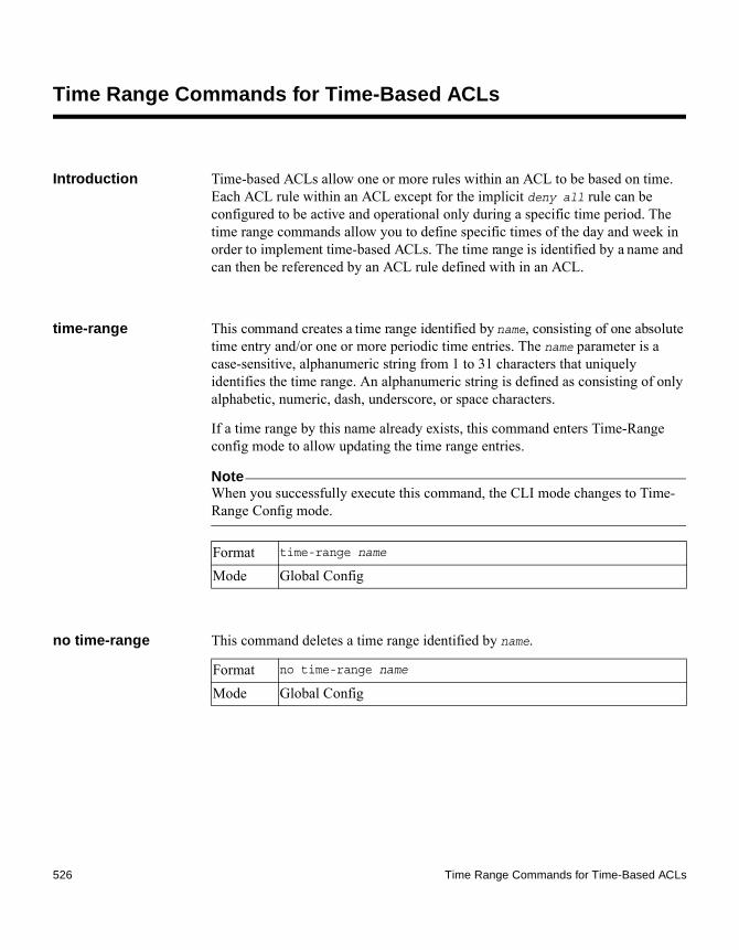
Time Range Commands for Time-Based ACLs
Introduction Time-based ACLs allow one or more rules within an ACL to be based on time. Each ACL rule within an ACL except for the implicit deny all rule can be configured to be active and operational only during a specific time period. The time range commands allow you to define specific times of the day and week in order to implement time-based ACLs. The time range is identified by a name and can then be referenced by an ACL rule defined with in an ACL.
time-range This command creates a time range identified by name, consisting of one absolute time entry and/or one or more periodic time entries. The name parameter is a case-sensitive, alphanumeric string from 1 to 31 characters that uniquely identifies the time range. An alphanumeric string is defined as consisting of only alphabetic, numeric, dash, underscore, or space characters.
If a time range by this name already exists, this command enters Time-Range config mode to allow updating the time range entries.
NoteWhen you successfully execute this command, the CLI mode changes to Time-Range Config mode.
no time-range This command deletes a time range identified by name.
Format time-range name
Mode Global Config
Format no time-range name
Mode Global Config
526 Time Range Commands for Time-Based ACLs

absolute This command adds an absolute time entry to a time range. Only one absolute time entry is allowed per time range. The time parameter is based on the currently configured time zone.
The [start time date] parameters indicate the time and date at which the configuration that referenced the time range starts going into effect. The time is expressed in a 24-hour clock, in the form of hours:minutes. For example, 8:00 is 8:00 AM and 20:00 is 8:00 PM. The date is expressed in the format day month year. If no start time and date are specified, the configuration statement is in effect immediately.
The [end time date] parameters indicate the time and date at which the configuration that referenced the time range is no longer in effect. The end time and date must be after the start time and date. If no end time and date are specified, the configuration statement is in effect indefinitely.
no absolute This command deletes the absolute time entry in the time range.
periodic This command adds a periodic time entry to a time range. The time parameter is based off of the currently configured time zone.
The first occurrence of the days-of-the-week argument is the starting day(s) from which the configuration that referenced the time range starts going into effect. The second occurrence is the ending day or days from which the configuration that referenced the time range is no longer in effect. If the end days-of-the-week are the same as the start, they can be omitted.
This argument can be any single day or combinations of days: Monday, Tuesday, Wednesday, Thursday, Friday, Saturday, Sunday. Other possible values are: ◆ daily—Monday through Sunday ◆ weekdays—Monday through Friday ◆ weekend—Saturday and Sunday
If the ending days of the week are the same as the starting days of the week, they can be omitted.
Format absolute {[start time date] [end time date]}
Mode Time-Range Config
Format no absolute
Mode Time-Range Config
Chapter 7: Quality of Service Commands 527

The first occurrence of the time argument is the starting hours:minutes which the configuration that referenced the time range starts going into effect. The second occurrence is the ending hours:minutes at which the configuration that referenced the time range is no longer in effect.
The hours:minutes are expressed in a 24-hour clock. For example, 8:00 is 8:00 AM and 20:00 is 8:00 PM.
no periodic This command deletes a periodic time entry from a time range.
clock set This command sets the current (UTC) date or time. You can configure the time in the hh:mm:ss format or the date in mm/dd/yyyy format.
clock timezone This command sets the offset to Coordinated Universal Time (UTC). If the optional parameters are not specified, they will be read as either 0 or \0 as appropriate. The acronym parameter is the acronym that represents the time zone and can be up to four characters.
show clock detail This command displays time zone and summertime configuration.
Format periodic {days-of-the-week time} to {[days-of-the-week] time}
Mode Time-Range Config
Format no periodic {days-of-the-week time} to {[days-of-the-week] time}
Mode Time-Range Config
Format clock set {hh:mm:ss | mm/dd/yyyy}
Mode Global Config
Format clock timezone {hours} [minutes minutes] [zone acronym]
Mode Global Config
Format show clock detail
528 Time Range Commands for Time-Based ACLs

show time-range This command displays a time range and all the absolute/periodic time entries that are defined for the time range. Use the name parameter to identify a specific time range to display. When name is not specified, all the time ranges defined in the system are displayed.
Mode Privileged EXEC
Format show time-range name
Mode Privileged EXEC
Output Description
Number of Time Ranges
Number of time ranges configured in the system.
Time Range Name
Name of the time range.
Time Range Status
Status of the time range (active/inactive)
Absolute start Start time and day for absolute time entry.
Absolute end End time and day for absolute time entry.
Periodic Entries
Number of periodic entries in a time-range.
Periodic start Start time and day for periodic entry.
Periodic end End time and day for periodic entry.
Chapter 7: Quality of Service Commands 529

530 Time Range Commands for Time-Based ACLs

Command Index
Symbols{deny / permit} (MAC ACL) 521{deny|permit} (IP ACL) 509
Numerics802.1X Supplicant Commands 256
Aaaa authentication dot1x default 328aaa authentication enable 92aaa authentication login 90aaa ias-user username 113About this chapter 29, 117, 209, 447, 461absolute 527Access Commands 30access-list 505acl-trapflags 511addport 350adminmode 369AutoInstall Commands 118auto-negotiate 369auto-negotiate all 370Auto-Voice over IP Commands 462auto-voip 462auto-voip all 462
Bboot autoinstall 118boot host autoreboot 120boot host autosave 119boot host dhcp 119boot host retrycount 119boot system 130bridge aging-time 313
CCable Test Command 122cablestatus 122
clear aaa ias-users 114clear config 196clear counters 197clear dot1x authentication-history 328clear dot1x statistics 328clear host 128clear igmpsnooping 197clear ip address-conflict-detect 140clear isdp counters 287clear isdp table 287clear lldp remote–data 295clear lldp statistics 295clear logging email statistics 137clear network ipv6 dhcp statistics 455clear pass 197clear radius statistics 329clear traplog 197clear vlan 197clock set 528clock timezone 528configuration 35Configuration Scripting Commands 32Console Port Access Commands 35copy 200copy (pre-login banner) 45crypto key generate dsa 38crypto key generate rsa 38
Ddebug clear 147debug console 147debug dhcp packet 148debug dot1x packet 148debug igmpsnooping packet 148debug igmpsnooping packet receive 150debug igmpsnooping packet transmit 149debug isdp packet 291debug ping packet 152debug spanning-tree bpdu 153debug spanning-tree bpdu receive 153debug spanning-tree bpdu transmit 155
Command Index 531

delete backup 130deleteport (Global Config) 350deleteport (Interface Config) 350Denial of Service Commands 211description 370device configuration commands
201 commands ??–236, ??–237, ??–237, ??–238, ??–239, ??–240, ??–240, ??–240, ??–241, ??–241
disconnect 30DNS Client Commands 124dos-control all 211dos-control firstfrag 212dos-control icmp 214dos-control icmpfrag 219dos-control icmpv4 218dos-control icmpv6 219dos-control l4port 214dos-control sipdip 212dos-control smacdmac 215dos-control tcpfinurgpsh 218dos-control tcpflag 213dos-control tcpflagseq 216dos-control tcpfrag 213dos-control tcpoffset 216dos-control tcpport 215dos-control tcpsyn 217dos-control tcpsynfin 217dos-control udpport 215dot1x guest-vlan 329dot1x initialize 330dot1x max-req 330dot1x max-users 330dot1x pae 256dot1x port-control 331dot1x port-control all 331dot1x re-authenticate 332dot1x re-authentication 332dot1x supplicant max-start 257dot1x supplicant port-control 256dot1x supplicant timeout auth-period 258dot1x supplicant timeout held-period 258dot1x supplicant timeout start-period 257dot1x supplicant user 259dot1x system-auth-control 333
dot1x system-auth-control monitor 333dot1x timeout 334dot1x unauthenticated-vlan 335dot1x user 336Dual Image Commands 130
EEmail Alerting and Mail Server Commands 132enable (Privileged EXEC access) 39enable authentication 93enable password 104enable password encrypted 104environment temprange 203environment trap fan 203environment trap powersupply 203environment trap temperature 204erase startup-config 120
Ffiledescr 130
GGARP Commands 261GMRP Commands 264GVRP Commands 268
Hhostname 46
IIGMP Snooping Configuration Commands 271IGMP Snooping Querier Commands 281interface 369inventory 518IP Access Control List Commands 505ip access-group 510ip access-list 508ip access-list rename 508IP Address Conflict Commands 140ip address-conflict-detect run 140ip domain list 125
532 Command Index

ip domain lookup 124ip domain name 124ip domain retry 127ip domain timeout 127ip host 126ip name server 125ip ssh 64ip ssh protocol 64ip ssh server enable 64ip telnet server enable 84ipv6 host 126IPv6 Management Commands 447, 448isdp advertise-v2 287ISDP Commands 286isdp enable 287isdp holdtime 286isdp run 286isdp timer 286
Kkey 82
Llacp actor admin 352lacp actor admin key 352lacp actor admin state 352lacp actor admin state individual 353lacp actor admin state longtimeout 353lacp actor admin state passive 354lacp actor port 354lacp actor port priority 354lacp admin key 351lacp collector max-delay 351lacp partner admin key 355lacp partner admin state 355lacp partner admin state individual 356lacp partner admin state longtimeout 356lacp partner admin state passive 357lacp partner port id 357lacp partner port priority 358lacp partner system priority 359lacp partner system-id 359line 35LLDP (802.1AB) Commands 292
lldp med 303lldp med all 304lldp med confignotification 303lldp med confignotification all 304lldp med faststart-repeatcount 305lldp med transmit-tlv 304lldp med transmit-tlv all 305lldp notification 294lldp notification–interval 295lldp receive 292lldp timers 293lldp transmit 292lldp transmit-mgmt 294lldp transmit-tlv 293LLDP-MED Commands 303logging buffered 141logging buffered wrap 141logging cli-command 142Logging Commands 141logging console 142logging email 132logging email from-addr 133logging email logtime 134logging email message-type subject 134logging email message-type to-addr 133logging email test message-type 135logging email urgent 132logging host 142logging host reconfigure 143logging host remove 143logging persistent 156logging port 143logging syslog 144logging traps 135login authentication 102logout 198
MMAC Access Control List Commands 520mac access-group 523mac access-list extended 520mac access-list extended rename 521MAC Database Commands 313macfilter 409
Command Index 533

macfilter adddest 410macfilter adddest all 410macfilter addsrc 411macfilter addsrc all 411mail-server 137Management Commands 29management commands
201 commands ??–85, ??–85, ??–86, ??–86, ??–86, ??–86, ??–86, ??–86, ??–86, ??–86, ??–86, ??–86, ??–88
Management Security Commands 38memory free low-watermark processor 113monitor session 375mtu 371
Nnetwork configuration commands
201 commands ??–85, ??–85, ??–86, ??–86, ??–86, ??–86, ??–86, ??–86, ??–86, ??–86, ??–86, ??–86, ??–88
Network Interface Commands 39network ipv6 address 450network ipv6 enable 448network ipv6 gateway 451network mac-address 40network mac-type 41network mgmt_vlan 427network parms 40network protocol 40no aaa authentication enable 93no aaa authentication login 91no aaa ias-user username 114no absolute 527no access-list 507no acl-trapflags 511no auto-negotiate 370no auto-negotiate all 370no auto-voip 463no auto-voip all 462no boot host autoreboot 120no boot host autosave 120no boot host dhcp 119no boot host retrycount 119no bridge aging-time 313
no crypto key generate dsa 38no crypto key generate rsa 38no debug console 147no debug dhcp packet 148no debug dot1x packet 148no debug igmpsnooping packet 149no debug igmpsnooping packet receive 151no debug igmpsnooping transmit 150no debug isdp packet 291no debug ping packet 152no debug spanning-tree bpdu 153no debug spanning-tree bpdu receive 154no debug spanning-tree bpdu transmit 155no dos-control all 212no dos-control firstfrag 212no dos-control icmp 214no dos-control icmpfrag 219no dos-control icmpv4 218no dos-control icmpv6 219no dos-control l4port 214no dos-control sipdip 212no dos-control smacdmac 215no dos-control tcpfinurgpsh 218no dos-control tcpflag 213no dos-control tcpflagseq 216no dos-control tcpfrag 213no dos-control tcpoffset 217no dos-control tcpport 215no dos-control tcpsyn 217no dos-control tcpsynfin 217no dos-control udpport 216no dot1x guest-vlan 329no dot1x max-req 330no dot1x max-users 331no dot1x port-control 331no dot1x port-control all 332no dot1x re-authentication 332no dot1x supplicant max-start 257no dot1x supplicant port-control 257no dot1x supplicant timeout auth-period 258no dot1x supplicant timeout held-period 258no dot1x supplicant timeout start-period 258no dot1x system-auth-control 333no dot1x system-auth-control monitor 333no dot1x timeout 335
534 Command Index

no dot1x unauthenticated-vlan 336no dot1x user 336no enable authentication 94no enable password 104no ip access-group 510no ip access-list 508no ip domain list 125no ip domain lookup 124no ip domain name 125no ip domain retry 127no ip domain timeout 127no ip host 126no ip name server 126no ip ssh server enable 65no ip telnet server enable 84no ipv6 host 127no isdp advertise-v2 287no isdp enable 287no isdp run 286no lacp actor admin key 352no lacp actor admin state 353no lacp actor admin state individual 353no lacp actor admin state longtimeout 353no lacp actor admin state passive 354no lacp actor port priority 355no lacp admin key 351no lacp collector max delay 351no lacp partner admin key 355no lacp partner admin state 356no lacp partner admin state individual 356no lacp partner admin state longtimeout 357no lacp partner admin state passive 357no lacp partner port id 358no lacp partner port priority 358no lacp partner system priority 359no lacp partner system-id 359no ldp med confignotification 303no lldp med 303no lldp med faststart-repeatcount 305no lldp med transmit-tlv 304, 305no lldp notification 294no lldp notification–interval 295no lldp receive 292no lldp timers 293no lldp transmit 292
no lldp transmit-mgmt 294no lldp transmit-tlv 294no logging buffered 141no logging buffered wrap 141no logging cli-command 142no logging console 142no logging email 132no logging email from-addr 134no logging email logtime 135no logging email message-type subject 134no logging email message-type to-addr 133no logging email urgent 133no logging persistent 156no logging port 143no logging syslog 144no logging traps 135no login authentication 103no mac access-group 524no mac access-list extended 520no macfilter 409no macfilter adddest 410no macfilter adddest all 411no macfilter addsrc 411no macfilter addsrc all 411no mail-server 137no monitor 376no monitor session 375no mtu 371no network ipv6 address 451no network ipv6 enable 449no network ipv6 gateway 452no network mac-type 41no network mgmt_vlan 427no password (AAA IAS User Configuration) 114no password (Line Configuration) 103no passwords aging 106no passwords history 105no passwords lock-out 106no passwords min-length 105no passwords strength exclude-keyword 111no passwords strength minimum character-classes 110no passwords strength minimum consecutive-characters 109no passwords strength minimum lowercase-letters
Command Index 535

108no passwords strength minimum numeric-characters 108no passwords strength minimum repeated-characters 110no passwords strength minimum special-characters 109no passwords strength minimum uppercase-letters 107no passwords strength-check 107no periodic 528no port lacpmode 360no port lacpmode all 361no port lacptimeout (Global Config) 362no port lacptimeout (Interface Config) 361no port-channel 349no port-channel adminmode 362no port-channel linktrap 363no port-channel load-balance 364no port-channel static 360no port-channel system priority 365no port-security 378no port-security mac-address 379no port-security max-dynamic 379no port-security max-static 379no radius accounting mode 47no radius server attribute 4 48no radius server host 50no radius server msgauth 52no radius server retransmit 53no radius server timeout 53no serial baudrate 36no serial timeout 36no set garp timer join 261no set garp timer leave 262no set garp timer leaveall 262no set gmrp adminmode 264no set gmrp interfacemode 265no set gvrp adminmode 268no set gvrp interfacemode 269no set igmp 271no set igmp fast-leave 273no set igmp groupmembership-interval 273no set igmp interfacemode 272no set igmp maxresponse 274
no set igmp mcrtrexpiretime 275no set igmp mrouter 275no set igmp mrouter interface 276no set igmp querier 282no set igmp querier election participate 283no set igmp querier query-interval 282no set igmp querier timer expiry 282no set igmp querier version 283no set igmp router-alert-check 276no set slot disable 205no set slot power 206no show debugging 156no shutdown 371no shutdown all 372no slot 204no snmp trap link-status 75no snmp trap link-status all 75no snmp-server community 68no snmp-server community ipaddr 68no snmp-server community ipmask 69no snmp-server community mode 69no snmp-server enable traps 71no snmp-server enable traps linkmode 71no snmp-server enable traps multiusers 72no snmp-server enable traps stpmode 72no snmp-server enable traps violation 70no snmptrap 73no snmptrap mode 74no sntp broadcast client poll-interval 163no sntp client mode 163no sntp client port 164no sntp multicast client poll-interval 166no sntp server 166no sntp unicast client poll-interval 164no sntp unicast client poll-retry 165no sntp unicast client poll-timeout 165no spanning-tree 386no spanning-tree auto-edge 387no spanning-tree configuration name 389no spanning-tree configuration revision 389no spanning-tree edgeport 390no spanning-tree forceversion 391no spanning-tree forward-time 391no spanning-tree hold-count 392no spanning-tree max-age 393
536 Command Index
no spanning-tree max-hops 393no spanning-tree mst 394no spanning-tree mst priority 395no spanning-tree mst vlan 396no spanning-tree port mode 397no spanning-tree port mode all 397no sshcon maxsessions 65no sshcon timeout 66no storm-control broadcast 415no storm-control broadcast all 416no storm-control broadcast all level 417no storm-control broadcast all rate 417no storm-control broadcast level 415no storm-control broadcast rate 416no storm-control flowcontrol 424no storm-control multicast 418no storm-control multicast all 420no storm-control multicast all level 420no storm-control multicast all rate 421no storm-control multicast level 419no storm-control multicast rate 419no storm-control unicast 421no storm-control unicast all 423no storm-control unicast all level 423no storm-control unicast all rate 424no storm-control unicast level 422no storm-control unicast rate 422no switchport protected (Global Config) 382no switchport protected (Interface Config) 383no tacacs-server host 80no tacacs-server key 81no tacacs-server timeout 81no telnetcon maxsessions 87no telnetcon timeout 87no terminal length 193no time-range 526no transport input telnet 85no username 95no username snmpv3 accessmode 97no username snmpv3 authentication 97no username snmpv3 encryption 98no vlan 428no vlan acceptframe 428no vlan association mac 438no vlan ingressfilter 429
no vlan name 429no vlan port acceptframe all 431no vlan port ingressfilter all 432no vlan port pvid all 432no vlan port tagging all 433no vlan pvid 436no vlan tagging 437no voice vlan (Global Config) 444no voice vlan (Interface Config) 445
Ppassword 138password (AAA IAS User Configuration) 114password (Line Configuration) 103password (User EXEC) 104passwords aging 106passwords history 105passwords lock-out 106passwords min-length 105passwords strength exclude-keyword 111passwords strength minimum character-classes 110passwords strength minimum consecutive-characters 109passwords strength minimum lowercase-letters 108passwords strength minimum numeric-characters 108passwords strength minimum repeated-characters 110passwords strength minimum special-characters 109passwords strength minimum uppercase-letters 107passwords strength-check 107periodic 527ping 198ping ipv6 455ping ipv6 interface 456port 82, 138Port Channel/LAG (802.3ad) Commands 349Port Configuration Commands 369port lacpmode 360port lacpmode all 361
Command Index 537

port lacptimeout (Global Config) 361port lacptimeout (Interface Config) 361Port Mirroring Commands 375Port Security Commands 378Port-Based Network Access Control Commands 328port-channel 349port-channel adminmode 362port-channel linktrap 362port-channel load-balance 363port-channel name 364port-channel static 360port-channel system priority 365port-security 378port-security mac-address 379port-security mac-address move 380port-security max-dynamic 378port-security max-static 379Pre-login Banner, System Prompt, and Host Name Commands 45priority 82process cpu threshold type total rising 189Protected Ports Commands 382Provisioning (IEEE 802.1p) Commands 385
QQuality of Service Commands 461quit 200
Rradius accounting mode 47RADIUS Commands 47radius server attribute 4 48radius server host 49radius server key 50radius server msgauth 51radius server primary 52radius server retransmit 52radius server timeout 53reload 200renew dhcp network-port 41renew dhcp service-port 41
Sscript apply 33script delete 33script list 33script show 34script validate 34Secure Shell Commands 64security 138serial baudrate 36serial timeout 36Serviceability Packet Tracing Commands 147set garp timer join 261set garp timer leave 261set garp timer leaveall 262set gmrp adminmode 264set gmrp interfacemode 264set gvrp adminmode 268set gvrp interfacemode 268set igmp 271set igmp fast-leave 272set igmp groupmembership-interval 273set igmp interfacemode 272set igmp maxresponse 274set igmp mcrtrexpiretime 274set igmp mrouter 275set igmp mrouter interface 275set igmp querier 281set igmp querier election participate 283set igmp querier query-interval 282set igmp querier timer expiry 282set igmp querier version 283set igmp router-alert-check 276set prompt 45set slot disable 205set slot power 205show aaa ias-users 115show access-lists interface 513show access-lists vlan 514show arp switch 170show authentication 337show authentication methods 338show authentication users 338show autoinstall 121show auto-voip 463show bootvar 130
538 Command Index

show clock detail 528show commands
show inventory 518show debugging 156show dos-control 219show dot1x 339show dot1x authentication-history 345show dot1x clients 346show dot1x statistics 259show dot1x users 347show environment 204show eventlog 170show forwardingdb agetime 313show garp 263show gmrp configuration 265show gvrp configuration 269show hardware 171show hosts 128show igmpsnooping 276show igmpsnooping mrouter interface 278show igmpsnooping mrouter vlan 279show igmpsnooping querier 284show interface 172show interface ethernet 174show interfaces switchport 384show inventory 477show ip access-lists 511show ip address-conflict 140show ip ssh 66show isdp 288show isdp entry 289show isdp interface 289show isdp neighbors 289show isdp traffic 290show lacp actor 365show lacp partner 365show lldp 296show lldp interface 296show lldp local–device 301show lldp local–device detail 301show lldp med 306show lldp med interface 306show lldp med local-device detail 307show lldp med remote-device 308show lldp med remote-device detail 309
show lldp remote–device 298show lldp remote–device detail 299show lldp statistics 297show logging 144show logging buffered 145show logging email config 135show logging email statistics 136show logging hosts 145show logging traplogs 146show loginsession 30show loginsession long 31show mac access-lists 524show mac-address-table gmrp 266show mac-address-table igmpsnooping 279show mac-address-table multicast 314show mac-address-table static 412show mac-address-table staticfiltering 412show mac-address-table stats 314show mac-addr-table 187show mail-server config 139show monitor session 376show network 41show network ipv6 dhcp statistics 457show network ndp 452show passwords configuration 111show passwords result 112show port 373show port-channel 366show port-channel brief 367show port-channel system priority 368show port-security 380show port-security dynamic 380show port-security static 380show port-security violation 381show process cpu 189show radius 54show radius accounting 58show radius accounting statistics 59show radius servers 55show radius statistics 61show running-config 190show serial 37show slot 206show snmpcommunity 75show snmptrap 77
Command Index 539

show sntp 166show sntp client 167show sntp server 168show spanning-tree 397show spanning-tree brief 399show spanning-tree interface 400show spanning-tree mst detailed 401show spanning-tree mst port detailed 401show spanning-tree mst port summary 405show spanning-tree mst port summary active 406show spanning-tree mst summary 406show spanning-tree summary 407show spanning-tree vlan 408show storm-control 424show supported cardtype 208show switchport protected 383show sysinfo 191show tacacs 83show tech-support 192show telnetcon 88show terminal length 193show time-range 529show trapflags 78show users 99show users accounts 100show users login-history 102show users long 100show version 171show vlan 438show vlan brief 440show vlan internal usage 440show vlan port 441show voice vlan 445shutdown 371shutdown all 372Simple Network Time Protocol Commands 163slot 204SNMP Commands 67snmp trap link-status 74snmp trap link-status all 75snmp-server 67snmp-server community 67snmp-server community ipaddr 68snmp-server community ipmask 68snmp-server community mode 69
snmp-server community ro 70snmp-server community rw 70snmp-server enable traps 70snmp-server enable traps linkmode 71snmp-server enable traps multiusers 71snmp-server enable traps stpmode 72snmp-server enable traps violation 70snmptrap 72snmptrap ipaddr 74snmptrap mode 74snmptrap snmpversion 73sntp broadcast client poll-interval 163sntp client mode 163sntp client port 164sntp multicast client poll-interval 165sntp server 166sntp unicast client poll-interval 164sntp unicast client poll-retry 165sntp unicast client poll-timeout 165Spanning Tree Protocol Commands 386spanning-tree 386spanning-tree auto-edge 386spanning-tree bpdumigration-check 388spanning-tree configuration name 389spanning-tree configuration revision 389spanning-tree cost 389spanning-tree cost auto 390spanning-tree edgeport 390spanning-tree forceversion 390spanning-tree forward-time 391spanning-tree hold-count 392spanning-tree max-age 392spanning-tree max-hops 393spanning-tree mst 393spanning-tree mst instance 395spanning-tree mst priority 395spanning-tree mst vlan 396spanning-tree port mode 396spanning-tree port mode all 397speed 372speed all 373sshcon maxsessions 65sshcon timeout 65Static MAC Filtering Commands 409storm-control broadcast 415
540 Command Index

storm-control broadcast all 416storm-control broadcast all level 417storm-control broadcast all rate 417storm-control broadcast level 415storm-control broadcast rate 416Storm-Control Commands 414storm-control flowcontrol 424storm-control multicast 418storm-control multicast all 419storm-control multicast all level 420storm-control multicast all rate 420storm-control multicast level 418storm-control multicast rate 419storm-control unicast 421storm-control unicast all 422storm-control unicast all level 423storm-control unicast all rate 423storm-control unicast level 421storm-control unicast rate 422switch
inventory 518Switching Commands 209switchport protected (Global Config) 382switchport protected (Interface Config) 383System Information and Statistics Commands 170System Utility and Clear Commands 194
TTACACS+ Commands 80tacacs-server host 80tacacs-server key 80tacacs-server timeout 81Telnet Commands 84telnetcon maxsessions 87telnetcon timeout 87terminal length 193Time Range Commands for Time-Based ACLs 526timeout 83time-range 526Topics in this chapter 29, 117, 209, 447, 461traceroute 194traceroute ipv6 196, 457transport input telnet 85
Uupdate bootcode 131User Account Commands 90user password 111username 94, 138username name nopassword 96username name unlock 96username snmpv3 accessmode 96username snmpv3 authentication 97username snmpv3 encryption 98username snmpv3 encryption encrypted 98users defaultlogin 336users login 337Utility Commands 117
Vvlan 427vlan acceptframe 428vlan association mac 438VLAN Commands 427vlan database 427vlan ingressfilter 428vlan makestatic 429vlan name 429vlan participation 429vlan participation all 430vlan port acceptframe all 431vlan port ingressfilter all 432vlan port priority all 385vlan port pvid all 432vlan port tagging all 433vlan priority 385vlan pvid 436vlan tagging 437voice vlan (Global Config) 444voice vlan (Interface Config) 444Voice VLAN Commands 444voice vlan data priority 445
Wwrite memory 113
Command Index 541

542 Command Index