NCL30388 - Power Factor Corrected LED Driver ... - onsemi
18
© Semiconductor Components Industries, LLC, 2018 February, 2020 − Rev. 3 1 Publication Order Number: NCL30388/D Power Factor Corrected LED Driver Featuring Primary Side CC / CV Control NCL30388 The NCL30388 is a power factor corrected controller targeting isolated and non−isolated constant current LED drivers. Designed to support flyback, buck−boost and SEPIC topologies, the controller operates in a quasi−resonant mode to provide high efficiency. Due to a novel control method, the device is able to tightly regulate a constant LED current from the primary side and provides near−unity power factor. This removes the need for secondary side feedback circuitry, its biasing and for an optocoupler. The device is highly integrated with a minimum number of external components. A robust suite of safety protection is built in to simplify the design. This device is specifically intended for very compact space efficient designs and also provides a constant voltage regulation of the output if no load is connected to the LED driver. Features • High Voltage Startup • Quasi−resonant Peak Current−mode Control Operation • Primary Side Feedback • CC / CV Control • Tight LED Constant Current Regulation of ±2% Typical • Digital Power Factor Correction • Cycle by Cycle Peak Current Limit • Wide Operating V CC Range • −40 to + 125°C • Robust Protection Features ♦ Brown−Out ♦ OVP on V CC ♦ Constant Voltage / LED Open Circuit Protection ♦ Winding Short Circuit Protection ♦ Secondary Diode Short Protection ♦ Output Short Circuit Protection ♦ Thermal Shutdown Typical Applications • Integral LED Bulbs • LED Power Driver Supplies • LED Light Engines SOIC−7 CASE 751U See detailed ordering and shipping information on page 15 of this data sheet. ORDERING INFORMATION MARKING DIAGRAM www. onsemi.com L30388 = Specific Device Code x = Version A = Assembly Location L = Wafer Lot Y = Year W = Work Week G = Pb−Free Package PIN CONNECTIONS L30388x ALYWX G 1 8 COMP ZCD CS GND HV 1 2 3 4 5 6 8 VCC DRV
-
Upload
khangminh22 -
Category
Documents
-
view
1 -
download
0
Transcript of NCL30388 - Power Factor Corrected LED Driver ... - onsemi

© Semiconductor Components Industries, LLC, 2018
February, 2020 − Rev. 31 Publication Order Number:
NCL30388/D
Power Factor CorrectedLED Driver FeaturingPrimary Side CC / CVControl
NCL30388The NCL30388 is a power factor corrected controller targeting
isolated and non−isolated constant current LED drivers. Designed tosupport flyback, buck−boost and SEPIC topologies, the controlleroperates in a quasi−resonant mode to provide high efficiency. Due to anovel control method, the device is able to tightly regulate a constantLED current from the primary side and provides near−unity powerfactor. This removes the need for secondary side feedback circuitry, itsbiasing and for an optocoupler.
The device is highly integrated with a minimum number of externalcomponents. A robust suite of safety protection is built in to simplifythe design. This device is specifically intended for very compact spaceefficient designs and also provides a constant voltage regulation of theoutput if no load is connected to the LED driver.
Features• High Voltage Startup
• Quasi−resonant Peak Current−mode Control Operation
• Primary Side Feedback
• CC / CV Control
• Tight LED Constant Current Regulation of ±2% Typical
• Digital Power Factor Correction
• Cycle by Cycle Peak Current Limit
• Wide Operating VCC Range
• −40 to + 125°C
• Robust Protection Features♦ Brown−Out♦ OVP on VCC♦ Constant Voltage / LED Open Circuit Protection♦ Winding Short Circuit Protection♦ Secondary Diode Short Protection♦ Output Short Circuit Protection♦ Thermal Shutdown
Typical Applications• Integral LED Bulbs
• LED Power Driver Supplies
• LED Light Engines
SOIC−7CASE 751U
See detailed ordering and shipping information on page 15 ofthis data sheet.
ORDERING INFORMATION
MARKINGDIAGRAM
www.onsemi.com
L30388 = Specific Device Codex = VersionA = Assembly LocationL = Wafer LotY = YearW = Work Week� = Pb−Free Package
PIN CONNECTIONS
L30388xALYWX
�
1
8
COMP
ZCD
CS
GND
HV1
2
3
4 5
6
8
VCC
DRV

NCL30388
www.onsemi.com2
Figure 1. Typical Application Schematic in a Flyback Converter
.
.
.
NCL30388
1
2
3
4 5
8
6
PIN FUNCTION DESCRIPTION NCL30388
Pin No Pin Name Function Pin Description
1 COMP OTA output for CV loop This pin receives a compensation network to stabilize the CV loop
2 ZCD Zero crossing DetectionVaux sensing
This pin connects to the auxiliary winding and is used to detect thecore reset event.This pin also senses the auxiliary winding voltage for accurate out-put voltage control
3 CS Current sense This pin monitors the primary peak current.
4 GND − The controller ground
5 DRV Driver output The driver’s output to an external MOSFET
6 VCC Supplies the controller This pin is connected to an external auxiliary voltage.
8 HV High Voltage sensing This pin connects after the diode bridge to provide the startup cur-rent and internal high voltage sensing function.

NCL30388
www.onsemi.com3
INTERNAL CIRCUIT ARCHITECTURE
Figure 2. Internal Circuit Architecture NCL30388
COMP
ZCDZero Crossing Detection Logic
(ZCD Blanking , Time−Out, ...) Valley Selection
CSConstant-C urrent Control
LeadingEdgeBlanking
W inding andOutput diodeShort CircuitProtection
Max. Peak
Current
LimitIpkmax
W OD_SCP
Qdrv
VCC Management
VCC
DRV
VCC Ov er Voltage
Protection
VCC
InternalThermal
Shutdown FaultManagement
ClampCircuit
HVBrown−OutBO_NOK
S
R
Q
Q
CS_reset
STOP
UVLO
OFF
Latch
STOP
W OD_SCP
Ipkmax
BO_NOK
GND
STOP
QdrvAux. W inding Short Circuit Prot. Aux_SCP
Aux_SCP
VCC_max
FF_mode
V
Linefeed-fo rward
HVdiv
Enable
VHVdiv
Ipkmax
VCV
VCV
VREFVDD
VREFVHVdiv
VREF(PFC)
VVLY
Enable
CS ShortProtection CS_shorted
CS_shorted
Generation of the
Reference Voltage
for Power Factor Corr.
VREF(PFC)
Frequency Foldback
FF_mode
Constant Voltage Control
HVSTUP
VHVdiv
VREFsetpoint
VREF

NCL30388
www.onsemi.com4
MAXIMUM RATINGS TABLE
Symbol Rating Value Unit
VCC(MAX)ICC(MAX)
Maximum Power Supply voltage, VCC pin, continuous voltageMaximum current for VCC pin
−0.3 to 30Internally limited
VmA
VDRV(MAX)IDRV(MAX)
Maximum driver pin voltage, DRV pin, continuous voltageMaximum current for DRV pin
−0.3, VDRV (Note 1)−300, +500
VmA
VHV(MAX)IHV(MAX)
Maximum voltage on HV pinMaximum current for HV pin (dc current self−limited if operated within the allowed range)
−0.3, +700±20
VmA
VMAXIMAX
Maximum voltage on low power pins (except pins HV, DRV and VCC)Current range for low power pins (except pins HV, DRV and VCC)
−0.3, 5.5 (Notes 2 and 6)−2, +5
VmA
RθJ−A Thermal Resistance Junction−to−Air 180 °C/W
TJ(MAX) Maximum Junction Temperature 150 °C
Operating Temperature Range −40 to +125 °C
Storage Temperature Range −65 to +150 °C
ESD Capability, HBM model (Note 3) 2 kV
ESD Capability, MM model (Note 3) 300 V
ESD Capability, CDM model (Note 3) 1 kV
Stresses exceeding those listed in the Maximum Ratings table may damage the device. If any of these limits are exceeded, device functionalityshould not be assumed, damage may occur and reliability may be affected.1. VDRV is the DRV clamp voltage VDRV(high) when VCC is higher than VDRV(high). VDRV is VCC otherwise.2. This level is low enough to guarantee not to exceed the internal ESD diode and 5.5 V ZENER diode. More positive and negative voltages
can be applied if the pin current stays within the −2 mA / 5 mA range.3. This device series contains ESD protection and exceeds the following tests: Human Body Model 2000 V per Mil−Std−883, Method 3015.
Charged Device Model 2000 V per JEDEC Standard JESD22−C101D4. This device contains latch−up protection and exceeds 100 mA per JEDEC Standard JESD78.
ELECTRICAL CHARACTERISTICS(Unless otherwise noted: For typical values TJ = 25°C, VCC = 12 V, VZCD = 0 V, , VCS = 0 V) For min/max values TJ = −40°C to +125°C, Max TJ = 150°C, VCC = 12 V)
Description Test Condition Symbol Min Typ Max Unit
HIGH VOLTAGE SECTION
High voltage current source VCC = VCC(on) – 200 mV IHV(start2) 3.3 4.7 6.1 mA
High voltage current source VCC = 0 V IHV(start1) 300 �A
VCC level for IHV(start1) to IHV(start2) transition VCC(TH) 2 V
Minimum startup voltage VCC = 0 V VHV(MIN) − 17 − V
HV source leakage current VHV = 450 V IHV(leak) 4.5 10 �A
Maximum rms input voltage for correct operation of the PFCloop (TJ = −20°C to 125°C)
VHV(OL) 265 Vrms
SUPPLY SECTION
Supply VoltageStartup ThresholdThreshold for turning off DSS (Note 5)Minimum Operating VoltageHysteresis VCC(on) – VCC(off)Internal logic reset
VCC increasingVCC increasingVCC decreasingVCC decreasing
VCC(on)VCC(on2)VCC(off)
VCC(HYS)VCC(reset)
169.778.27.84
1810.508.8−5
2011.249.4−6
V
Over Voltage ProtectionVCC OVP threshold
VCC(OVP) 25.0 26.5 28 V
VCC(off) noise filter (Note 6)VCC(reset) noise filter− (Note 6)
tVCC(off)tVCC(reset)
−−
520
−−
�s
Supply CurrentDevice Disabled/Fault Device Enabled/No output load on pin 5Device Switching (Fsw = 65 kHz) Device switching (Fsw = 15 kHz)
VCC > VCC(off)Fsw = 65 kHz
CDRV = 470 pF, Fsw = 65 kHz
VREFX = 10%of max value
ICC1ICC2ICC3ICC4
1.2–−−
1.53.03.32.9
1.83.54.03.4
mA
5. Refer to ordering table option at the end of the document6. Guaranteed by design.

NCL30388
www.onsemi.com5
ELECTRICAL CHARACTERISTICS(Unless otherwise noted: For typical values TJ = 25°C, VCC = 12 V, VZCD = 0 V, , VCS = 0 V) For min/max values TJ = −40°C to +125°C, Max TJ = 150°C, VCC = 12 V)
Description UnitMaxTypMinSymbolTest Condition
CURRENT SENSE
Maximum Internal current limit VILIM 1.31 1.38 1.45 V
Leading Edge Blanking Duration for VILIM tLEB 270 330 390 ns
Propagation delay from current detection to gate off−state tILIM − 100 150 ns
Maximum on−time (option B) ton(MAX) 29 39 49 �s
Maximum on−time (option A) ton(MAX2) 16 20 24 �s
Threshold for immediate fault protection activation (140% of VILIM) VCS(stop) 1.91 1.99 2.07 V
Leading Edge Blanking Duration for VCS(stop) tBCS − 170 − ns
Current source for CS to GND short detection ICS(short) 400 500 600 �A
Current sense threshold for CS to GND short detection VCS rising VCS(low) 20 60 100 mV
GATE DRIVE
Drive Resistance
DRV Sink
DRV Source
RSNK
RSRC
−
−
13
30
−
−
�
Drive current capability
DRV Sink (Note GBD)
DRV Source (Note GBD)
ISNK
ISRC
−
−
500
300
−
−
mA
Rise Time (10 % to 90 %) CDRV = 470 pF tr – 30 − ns
Fall Time (90 % to 10 %) CDRV = 470 pF tf – 20 − ns
DRV Low Voltage VCC = VCC(off)+0.2 VCDRV = 470 pF,RDRV=33 k�
VDRV(low) 8 – − V
DRV High Voltage VCC = VCC(MAX)CDRV = 470 pF,RDRV=33 k�
VDRV(high) 10 12 14 V
ZERO VOLTAGE DETECTION CIRCUIT
Upper ZCD threshold voltage VZCD rising VZCD(rising) − 90 150 mV
Lower ZCD threshold voltage VZCD falling VZCD(falling) 35 55 − mV
ZCD hysteresis VZCD(HYS) 15 − − mV
Propagation Delay from valley detection to DRV high VZCD decreasing tZCD(DEM) − − 150 ns
Blanking delay after on−time (ZCD blank option B) VREFX > 0.35 V tZCD(blank1)B 1.1 1.5 1.9 �s
Blanking Delay at light load (ZCD blank option B) VREFX < 0.25 V tZCD(blank2)B 0.6 0.8 1.0 �s
Blanking delay after on−time (ZCD blank option A) VREFX > 0.35 V tZCD(blank1)A 0.75 1.0 1.25 �s
Blanking Delay at light load (ZCD blank option A) VREFX < 0.25 V tZCD(blank2)A 0.45 0.6 0.75 �s
Timeout after last DEMAG transition tTIMO 5 6.5 8 �s
Pulling−down resistor VZCD = VZCD(falling) RZCD(pd) 200 k�
CONSTANT CURRENT CONTROL
Reference Voltage at TJ = 25°C to 85°C VREF 0.326 0.333 0.340 V
Reference Voltage TJ = −40°C to 125°C VREF 0.323 0.333 0.343 V
Current sense lower threshold for detection of the leakage in-ductance reset time
VCS falling VCS(low) 20 50 100 mV
Blanking time for leakage inductance reset detection tCS(low) − 120 − ns
CONSTANT VOLTAGE SECTION
Internal voltage reference for constant voltage regulation TJ = 25°C
VREF(CV) 2.42 2.48 2.54 V
Internal voltage reference for constant voltage regulation TJ = −40°C to 125°C
VREF(CV) 2.38 2.48 2.58 V

NCL30388
www.onsemi.com6
ELECTRICAL CHARACTERISTICS(Unless otherwise noted: For typical values TJ = 25°C, VCC = 12 V, VZCD = 0 V, , VCS = 0 V) For min/max values TJ = −40°C to +125°C, Max TJ = 150°C, VCC = 12 V)
Description UnitMaxTypMinSymbolTest Condition
CONSTANT VOLTAGE SECTION
CV Error amplifier Gain GEA 40 50 60 �S
Error amplifier current capability VREFX=VREF IEA ±60 �A
COMP pin lower clamp voltage VCV(clampL) 0.6 V
COMP pin higher clamp voltage VCV(clampH) 4.1 V
ZCD pin voltage below which the CV OTA is boosted VREF(CV)* 80% Vboost(CV) 1.88 2 2.12 V
Error amplifier current capability during boost phase IEAboost ±140 �A
ZCD slow OVP threshold (Vref(CV)*115%) VOVP1 2.69 2.87 3.04 V
Switching period during slow OVP Tsw(OVP1) 1.5 ms
ZCD voltage at which slow OVP is exit (Vref(CV)*105%) VOVP1rst 2.625 V
ZCD fast OVP threshold VOVP2 3.29 3.43 3.57 V
ZCD pin voltage below which the CV OTA is boosted VREF(CV) * 80% Vboost(CV) 1.88 2 2.12 V
LINE FEED FORWARD
VHV to ICS(offset) conversion ratio KLFF 0.153 0.185 0.217 �A/V
Offset current maximum value VHV > 400 V Ioffset(MAX) 76 95 114 �A
Line feed−forward current DRV high, VHV = 200 V IFF 32 37 42 �A
VALLEY LOCKOUT SECTION
Threshold for line range detection Vin increasing VHV increases VHL 252 264 276 V
Threshold for line range detection Vin decreasing VHV decreases VLL 241 253 265 V
Blanking time for line range detection tHL(blank) 15 25 35 ms
Valley thresholds (expressed as a percentage of VREF)1st to 2nd valley transition at LL and 2nd to 3rd valley HL, VREF decr.2nd to 1st valley transition at LL and 3rd to 2nd valley HL, VREF incr.2nd to 3rd valley transition at LL and 3rd to 4th valley HL, VREF decr.3rd to 2nd valley transition at LL and 4th to 3rd valley HL, VREF incr.3rd to 4th valley transition at LL and 4th to 5th valley HL, VREF decr.4th to 3th valley transition at LL and 5th to 4th valley HL, VREF incr.4th to 5th valley transition at LL and 5th to 6th valley HL, VREF decr.5th to 4th valley transition at LL and 6th to 5th valley HL, VREF incr.
VREF decreasesVREF increasesVREF decreasesVREF increasesVREF decreasesVREF increasesVREF decreasesVREF increases
VVLY1−2/2−3VVLY2−1/3−2VVLY2−3/3−4VVLY3−2/4−3VVLY3−4/4−5VVLY4−3/5−4VVLY4−5/5−6VVLY5−4/6−5
8090657550603545
%
VREF value at which the FF mode is activated VREF decreases VFFstart 25 %
VREF value at which the FF mode is removed VREF increases VFFstop 35 %
FREQUENCY FOLDBACK
Added dead time VREFX = 25%VREF tFF1LL 1.4 2.0 2.6 �s
Added dead time VREFX = 8% VREF tFFchg − 40 − �s
Dead−time clamp (Maximum dead−time option C) VREFX < 1 mV tFFend 1.4 − ms
Dead−time clamp (Maximum dead−time option B) VREFX < 3 mV tFFend2 − 687 − �s
Dead−time clamp (Maximum dead−time option A) VREFX < 11.2 mV tFFend3 − 250 − �s
FAULT PROTECTION
Thermal Shutdown Device switching (FSWaround 65 kHz)
TSHDN 130 150 170 °C
Thermal Shutdown Hysteresis TSHDN(HYS) − 50 – °C
Threshold voltage for output short circuit or aux. winding shortcircuit detection
VZCD(short) 0.8 1.0 1.2 V
Short circuit detection Timer VZCD < VZCD(short) tOVLD 70 90 110 ms
Auto−recovery Timer trecovery 3 4 5 s

NCL30388
www.onsemi.com7
ELECTRICAL CHARACTERISTICS(Unless otherwise noted: For typical values TJ = 25°C, VCC = 12 V, VZCD = 0 V, , VCS = 0 V) For min/max values TJ = −40°C to +125°C, Max TJ = 150°C, VCC = 12 V)
Description UnitMaxTypMinSymbolTest Condition
BROWN−OUT AND LINE SENSING
Brown−Out ON level (IC start pulsing) VHV increasing VHVBO(on) 104 110 116 V
Brown−Out OFF level (IC stops pulsing) VHV decreasing VHVBO(off) 93 99 105 V
BO comparators delay tBO(delay) 30 �s
Brown−Out blanking time tBO(blank) 15 25 35 ms
HV pin voltage above which the sampling of ZCD is enabled VHV decreasing VsampEN 55 V
Sampling Enable comparator hysteresis VHV increasing VsampHYS 5 V
TYPICAL CHARACTERISTICS
Figure 3. VCC(on) vs. Junction Temperature Figure 4. VCC(off) vs. Junction Temperature
TJ, JUNCTION TEMPERATURE (°C) TJ, JUNCTION TEMPERATURE (°C)
1007550 125250−25−5018.00
18.05
18.10
18.15
18.20
18.25
18.30
100 1257550250−25−508.76
8.78
8.80
8.82
8.84
8.86
8.88
8.90
Figure 5. VCC(OVP) vs. Junction Temperature Figure 6. VILIM vs. Junction Temperature
TJ, JUNCTION TEMPERATURE (°C) TJ, JUNCTION TEMPERATURE (°C)
10075 12550250−25−5025.0
25.5
26.0
26.5
27.5
28.0
1251007550250−25−501.31
1.33
1.35
1.37
1.41
1.43
1.45
VC
C(o
n) (
V)
VC
C(o
ff) (
V)
VC
C(O
VP
) (V
)
VIL
IM (
V)
27.0
1.39

NCL30388
www.onsemi.com8
TYPICAL CHARACTERISTICS
Figure 7. VCS(low)F vs. Junction Temperature Figure 8. VCS(stop) vs. Junction Temperature
TJ, JUNCTION TEMPERATURE (°C) TJ, JUNCTION TEMPERATURE (°C)
1007550 125250−25−5020
30
50
60
70
90
100
100 1257550250−25−501.91
1.93
1.95
1.97
1.99
2.03
2.05
2.07
Figure 9. tILIM vs. Junction Temperature Figure 10. VREF vs. Junction Temperature
TJ, JUNCTION TEMPERATURE (°C) TJ, JUNCTION TEMPERATURE (°C)
10075 12550250−25−5064
74
84
94
104
124
134
144
1251007550250−25−50330.5
331.5
332.5
333.5
334.5
335.5
Figure 11. VREF(CV) vs. Junction Temperature Figure 12. GEA vs. Junction Temperature
TJ, JUNCTION TEMPERATURE (°C) TJ, JUNCTION TEMPERATURE (°C)
1007550 125250−25−502.466
2.471
2.476
2.481
2.486
2.496
2.501
2.491
1007550 125250−25−5040
44
50
52
54
58
VC
S(lo
w)F
(V
)
VC
S(s
top)
(V
)
t ILIM
(ns
)
VR
EF (
V)
VR
EF
(CV
) (V
)
GE
A (�S
)
114
2.511
40
80
2.506
2.01
60
56
48
46
42

NCL30388
www.onsemi.com9
TYPICAL CHARACTERISTICS
Figure 13. VOVP1 vs. Junction Temperature Figure 14. VOVP2 vs. Junction Temperature
TJ, JUNCTION TEMPERATURE (°C) TJ, JUNCTION TEMPERATURE (°C)
1007550 125250−25−502.838
2.843
2.853
2.863
2.868
2.873
2.883
100 1257550250−25−503.40
3.42
3.44
3.45
3.46
Figure 15. KLFF vs. Junction Temperature Figure 16. IFF vs. Junction Temperature
TJ, JUNCTION TEMPERATURE (°C) TJ, JUNCTION TEMPERATURE (°C)
10075 12550250−25−500.180
1251007550250−25−5036.0
36.4
36.6
37.0
37.2
37.6
37.8
Figure 17. VHVBO(on) vs. Junction Temperature Figure 18. VHVBO(off) vs. Junction Temperature
TJ, JUNCTION TEMPERATURE (°C) TJ, JUNCTION TEMPERATURE (°C)
1007550 125250−25−50109.2
109.7
110.2
111.2
110.7
1007550 125250−25−5098.2
100.2
VO
VP
1 (V
)
VO
VP
2 (V
)
KLF
F (�A
/V)
I FF (�A
)
VH
VB
O(o
n) (
V)
2.848
2.858
2.878
3.41
3.43
0.182
0.184
0.186
0.188
0.190
99.7
99.2
98.7
VH
VB
O(o
ff) (
V)
36.2
36.8
37.4
NCL30388
www.onsemi.com10
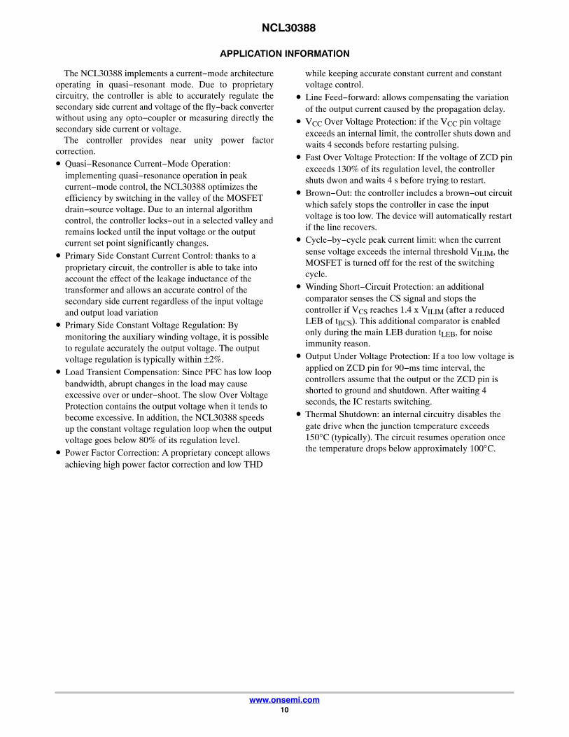
APPLICATION INFORMATION
The NCL30388 implements a current−mode architectureoperating in quasi−resonant mode. Due to proprietarycircuitry, the controller is able to accurately regulate thesecondary side current and voltage of the fly−back converterwithout using any opto−coupler or measuring directly thesecondary side current or voltage.
The controller provides near unity power factorcorrection.• Quasi−Resonance Current−Mode Operation:
implementing quasi−resonance operation in peakcurrent−mode control, the NCL30388 optimizes theefficiency by switching in the valley of the MOSFETdrain−source voltage. Due to an internal algorithmcontrol, the controller locks−out in a selected valley andremains locked until the input voltage or the outputcurrent set point significantly changes.
• Primary Side Constant Current Control: thanks to aproprietary circuit, the controller is able to take intoaccount the effect of the leakage inductance of thetransformer and allows an accurate control of thesecondary side current regardless of the input voltageand output load variation
• Primary Side Constant Voltage Regulation: Bymonitoring the auxiliary winding voltage, it is possibleto regulate accurately the output voltage. The outputvoltage regulation is typically within ±2%.
• Load Transient Compensation: Since PFC has low loopbandwidth, abrupt changes in the load may causeexcessive over or under−shoot. The slow Over VoltageProtection contains the output voltage when it tends tobecome excessive. In addition, the NCL30388 speedsup the constant voltage regulation loop when the outputvoltage goes below 80% of its regulation level.
• Power Factor Correction: A proprietary concept allowsachieving high power factor correction and low THD
while keeping accurate constant current and constantvoltage control.
• Line Feed−forward: allows compensating the variationof the output current caused by the propagation delay.
• VCC Over Voltage Protection: if the VCC pin voltageexceeds an internal limit, the controller shuts down andwaits 4 seconds before restarting pulsing.
• Fast Over Voltage Protection: If the voltage of ZCD pinexceeds 130% of its regulation level, the controllershuts dwon and waits 4 s before trying to restart.
• Brown−Out: the controller includes a brown−out circuitwhich safely stops the controller in case the inputvoltage is too low. The device will automatically restartif the line recovers.
• Cycle−by−cycle peak current limit: when the currentsense voltage exceeds the internal threshold VILIM, theMOSFET is turned off for the rest of the switchingcycle.
• Winding Short−Circuit Protection: an additionalcomparator senses the CS signal and stops thecontroller if VCS reaches 1.4 x VILIM (after a reducedLEB of tBCS). This additional comparator is enabledonly during the main LEB duration tLEB, for noiseimmunity reason.
• Output Under Voltage Protection: If a too low voltage isapplied on ZCD pin for 90−ms time interval, thecontrollers assume that the output or the ZCD pin isshorted to ground and shutdown. After waiting 4seconds, the IC restarts switching.
• Thermal Shutdown: an internal circuitry disables thegate drive when the junction temperature exceeds150°C (typically). The circuit resumes operation oncethe temperature drops below approximately 100°C.

NCL30388
www.onsemi.com11
POWER FACTOR AND CONSTANT CURRENTCONTROL
The NCL30388 embeds an analog/digital block to controlthe power factor and regulate the output current bymonitoring the ZCD, CS and HV pin voltages (signalsVZCD, VHV_DIV, VCS). This circuit generates the currentsetpoint VCTRL_DIV and compares it to the current sensesignal to turn the MOSFET off. The HV pin provides thesinusoidal reference necessary for shaping the input current.The obtained current reference is further modulated so thatwhen averaged over a half line period, it is equal to theoutput current reference (VREFX). The modulation andaveraging process is made internally by a digital circuit. Ifthe HV pin properly conveys the sinusoidal shape, powerfactor will be close to 1. Also, the Total Harmonic Distortion(THD) will be low especially if the output voltage ripple issmall.
The output current will be well regulated,
following the equation below:
IOUT �
VREFX
2NspRsense(eq. 1)
Where:♦ Nsp is the secondary to primary transformer turns
ratio: Nsp = NS / NP.♦ Rsense is the current sense resistor♦ VREFX is the output current reference: VREFX =
VREF if VCOMP ≥ 4 VThe output current reference (VREFX) is VREF unless the
constant voltage mode is activated.
CONSTANT VOLTAGE CONTROLThe auxiliary winding voltage is sampled internally
through the ZCD pin.A precise internal voltage reference VREF(CV) sets the
voltage target for the CV loop.The sampled voltage is applied to the negative input of the
CV OTA and compared to VREFCV.A type 2 compensator is needed at the CV OTA output to
stabilize the loop. The COMP pin voltage modify the theoutput current internal reference in order to regulate theoutput voltage.
When VCOMP ≥ 4 V, VREFX = VREF.When VCOMP < 0.6 V, VREFX = 0 V
.
ZCD & signalsampling
RZCDU
RZCDL
ZCDCOMP
VREF(CV)
R1
C1
C2
VZCDsamp
OTA
Gm
Aux.
Figure 19. Constant Voltage Feedback Circuit
STARTUP PHASE (HV STARTUP)It is generally requested that the LED driver starts to emit
light in less than 1 s and possibly within 300 ms. It ischallenging since the start−up consists of the time to chargethe VCC capacitor and that necessary to charge the outputcapacitor until sufficient current flows into the LED string.This second phase can be particularly long in dimming caseswhere the secondary current is a portion of the nominal one.
The NCL30388 features a high voltage startup circuit thatallows charging VCC capacitor very fast.
When the power supply is first connected to the mainsoutlet, the internal current source is biased and charges upthe VCC capacitor. When the voltage on this VCC capacitorreaches the VCC(on) level, the current source turns off. At thistime, the controller is only supplied by the VCC capacitor,and the auxiliary supply should take over before VCCcollapses below VCC(off).
The HV startup circuitry is made of two startup currentlevels, IHV(start1) and IHV(start1). This helps to protect thecontroller against short−circuit between VCC and GND. Atpower−up, as long as VCC is below VCC(TH), the sourcedelivers IHV(start1) (around 300 �A typical). Then, whenVCC reaches VCC(TH), the source smoothly transitions toIHV(start2) and delivers its nominal value.
To speed−up the output voltage rise, the following isimplemented:• The digital OTA output is increased until VREF(PFC)
signal reaches VREFX. Again, this is to speed−up thecontrol signal rise to their steady state value.
• At the beginning of each operating phase of a VCCcycle, the digital OTA output is set to 0. Actually, thedigital OTA output is set to 0 in the case of a coldstart−up or in the case of a start−up sequence followingan operation interruption due to a fault. On the otherhand, if the VCC hiccups just because the system fails tostart−up in one VCC cycle (DSS option not activated),the digital OTA output is not reset to ease the second(or more) attempt.
• If the load is shorted, the circuit will operate in hiccupmode with VCC oscillating between VCC(off) andVCC(on) until the output under voltage protection (UVP)trips. UVP is triggered if the ZCD pin voltage does notexceed 1 V within a 90 ms operation of time. Thisindicates that the ZCD pin is shorted to ground or thatan excessive load prevents the output voltage fromrising.

NCL30388
www.onsemi.com12
CYCLE−BY−CYCLE CURRENT LIMITWhen the current sense voltage exceeds the internal
threshold VILIM, the MOSFET is turned off for the rest of theswitching cycle.
WINDING AND OUTPUT DIODE SHORT−CIRCUITPROTECTION
In parallel to the cycle−by−cycle sensing of the CS pin,another comparator with a reduced LEB (tBCS) and athreshold of (VCS(stop) = 140% *VILIM) monitors the CS pinto detect a winding or an output diode short circuit. Thecontroller shuts down if it detects four consecutive pulsesduring which the CS pin voltage exceeds VCS(stop).
The controller goes into auto−recovery mode.
VALLEY LOCKOUTQuasi−Square wave resonant systems have a wide
switching frequency excursion. The switching frequencyincreases when the output load decreases or when the inputvoltage increases. The switching frequency of such systemsmust be limited.
The NCL30388 changes valley as VREFX decreases and asthe input voltage increases and as the output current setpointis varied during dimming. This limits the frequencyexcursion.
By default, when the output current is not dimmed, thecontroller operates in the first valley at low line and in thesecond valley at high line.
REFX value at which thecontroller changes valley
(Iout decreasing)
HV pin voltage for valley changeVREFX value at which thecontroller changes valley
(Iout increasing)
0 −−LL −− 230 V −−HL −− 400 V100%
1st 2nd 100%
80% 85%
2nd 3rd
65% 70%
3rd 4th
50% 55%4th 5th
35% 40%5th 6th
25% 30%FF mode FF mode
0% 0%0 −−LL −− 240 V −−HL −− 400 V
HV pin voltage for valley change
Iout increase
Figure 20. TABLE II: Valley Selection
I out
dec
reas
es
ZERO CROSSING DETECTION BLOCKThe ZCD pin allows detecting when the drain−source
voltage of the power MOSFET reaches a valley.A valley is detected when the ZCD pin voltage crosses
below the 55 mV internal threshold.At startup or in case of extremely damped free
oscillations, the ZCD comparator may not be able to detectthe valleys. To avoid such a situation, the NCL30388 aTime−Out circuit that generates pulses if the voltage on ZCDpin stays below the 55 mV threshold for 6.5 �s.
The Time−out also acts as a substitute clock for the valleydetection and simulates a missing valley in case of toodamped free oscillations.
At startup, the output voltage reflected on the auxiliarywinding is low. Because of the ZCD resistor bridge settingthe constant voltage regulation target, the voltage on theZCD pin is very low and the ZCD comparator might beunable to detect the valleys. In this condition, setting theDRV Latch with the 6.5−�s time−out leads to a continuousconduction mode operation (CCM) at the beginning of thesoft−start. This CCM operation only last a few cycles untilthe voltage on ZCD pin becomes high enough and trips theZCD comparator.

NCL30388
www.onsemi.com13
Iout decreases or Vin
Vin increases
VVIN
increases
low
high
Clock
TimeOut
low
high
low
high
low
43
14
12
15
16
17
high
ZCD comp
2nd , 3rd
VZCD
VZCD(th)
Figure 21.
If the ZCD pin or the auxiliary winding happen to beshorted the time−out function would normally make thecontroller keep switching and hence lead to improperregulation of the LED current.
The Under Voltage Protection (UVP) is implemented toavoid these scenarios: a secondary timer starts countingwhen the ZCD voltage is below the VZCD(short) threshold. Ifthis timer reaches 90 ms, the controller detects a fault andenters the auto−recovery fault mode.
ZCD PIN OVER VOLTAGE PROTECTION.Because of the power factor correction, it is necessary to
set the crossover frequency of the CV loop very low (target10 Hz, depending on power stage phase shift). Because theloop is slow, the output voltage can reach high value duringstartup or during an output load step. It is necessary to limitthe output voltage excursion. For this, the NCL30388
features a slow over voltage protection (slow OVP) and afast over voltage protection (fast OVP) on ZCD pin.
Slow OVPIf ZCD voltage exceed VZCD(OVP1) for four consecutive
switching cycles, the controller stops switching during1.4 ms. After 1.4 ms, the controller initiates a new DRVpulse to refresh ZCD sampling voltage. If VZCD is still toohigh (VZCD > 110%VREF(CV)), the controller continues toswitch with a 1.4 ms period. The controller resumes itsnormal operation when VZCD < 110%VREF(CV).
Fast OVPIf ZCD voltage exceeds VZCD(OVP2) (130% of VREF(CV))
for 4 consecutive switching cycles (slow OVP not triggered)or for 2 switching cycles if the slow OVP has already beentriggered, the controller detects a fault and starts theauto−recovery fault mode (cf: Protections Section)

NCL30388
www.onsemi.com14
LINE FEEDFORWARD
HV
CS
vDD
Rsense
RLFFICS(offset)
Q_drv
KLFF
vVS
+
−
BO_NOK25 msBlanking
1 V / 0.9 V
Figure 22. Line Feed−Forward and Brown−out Schematic
The line voltage is sensed by the HV pin and convertedinto a current. By adding an external resistor in seriesbetween the sense resistor and the CS pin, a voltage offsetproportional to the line voltage is added to the CS signal. Theoffset is applied only during the MOSFET on−time in orderto not influence the detection of the leakage inductancereset.
The offset is always applied even at light load in order toimprove the current regulation at low output load.
BROWN−OUTIn order to protect the supply against a very low input
voltage, the NCL30388 features a brown−out circuit with afixed ON/OFF threshold. The controller is allowed to startif a voltage higher than 100 V is applied to the HV pin andshuts−down if the HV pin voltage decreases and stays below90 V for 25 ms typical. Exiting a brown−out conditionoverrides the hiccup on VCC (VCC does not wait to reachVCC(off)) and the IC immediately goes into startup mode.
PROTECTIONSThe circuit incorporates a large variety of protections to
make the LED driver very rugged.
Among them, we can list:• Fault of the GND connection
If the GND pin is properly connected, the supplycurrent drawn from the positive terminal of the VCCcapacitor, flows out of the GND pin to return to thenegative terminal of the VCC capacitor. If the GND pinis not connected, the circuit ESD diodes offer anotherreturn path. The accidental non connection of the GNDpin can hence be detected by detecting that one of this
ESD diode is conducting. Practically, the ESD diode ofCS pin is monitored. If such a fault is detected for200 �s, the circuit stops generating DRV pin.
• Output short circuit situation (Output Under VoltageProtection)Overload is detected by monitoring the ZCD pinvoltage: if it remains below VZCD(short) for 90 ms, anoutput short circuit is detected and the circuit stopsgenerating pulses for 4 s. When this 4 s delay haselapsed, the circuit attempts to restart.
• ZCD pin incorrect connection:♦ If the ZCD pin grounded, the circuit will detect an
output short circuit situation when 90 ms delay haselapsed.
♦ A 200 k� resistor pulls down the ZCD pin so thatthe output short circuit detection trips if the ZCD pinis not connected (floating).
• Winding or Output Diode Short Circuit protectionThe circuit detects this failure when 4 consecutive DRVpulses occur within which the CS pin voltage exceeds(VCS(stop)=140% *VILIM). In this case, the controllerenters auto−recovery mode (4 s operation interruptionbetween active bursts).
• VCC Over Voltage ProtectionThe circuit stops generating pulses if the VCC exceedsVCC(OVP) and enters auto−recovery mode (4 s operationinterruption between active bursts). This feature protects the circuit if output LEDs happento be disconnected.

NCL30388
www.onsemi.com15
• ZCD fast OVPIf ZCD voltage exceeds VZCD(OVP2) for 4 consecutiveswitching cycles (slow OVP not triggered) or for 2switching cycles if the slow OVP has already beentriggered, the controller detects a fault and entersauto−recovery mode (4−s operation interruptionbetween active bursts).
• Die Over Temperature (TSD)The circuit stops operating if the junction temperature(TJ) exceeds 150°C typically. The controller remainsoff until TJ goes below nearly 100°C.
• Brown−Out Protection (BO)The circuit prevents operation when the line voltage istoo low to avoid an excessive stress of the LED driver.Operation resumes as soon as the line voltage is highenough and VCC is higher than VCC(on).
• CS pin short to groundThe CS pin is checked at start−up (cold start−up or aftera brown−out event). A current source (Ics(short)) isapplied to the pin and no DRV pulse is generated untilthe CS pin exceeds Vcs(low). Ics(short) and Vcs(low) are500 �A and 60 mV typically (VCS rising). The typicalminimum impedance to be placed on the CS pin foroperation is then 120 �. In practice, it is recommendedto place more than 250 � to take into account possibleparametric deviations.Also, along the circuit operation, the CS pin couldhappen to be grounded. If it is grounded, the MOSFETconduction time is limited by the maximum on−time. Ifsuch an event occurs, a new pin impedance test ismade.
ORDERING TABLE OPTION
OPN #
DSS Maximum Dead−time VREF Max. On−time ZCD BlankingLine Range
Detector
Y N A B C U V A B A B Y N
On Off 250 �s 687 �s 1.4 ms 250 mV 333 mV 20 �s 33 �s 1 �s 1.5 �s On Off
NCL30388A1 x x x x x x
NCL30388B1 x x x x x x
ORDERING INFORMATION2
Device Marking Package type Shipping†
NCL30388A1DR2G L30388A1 SOIC8 – P7 COMP VHV PBFH 2500 / Tape & Reel
NCL30388B1DR2G L30388B1 SOIC8 – P7 COMP VHV PBFH 2500 / Tape & Reel
†For information on tape and reel specifications, including part orientation and tape sizes, please refer to our Tape and Reel PackagingSpecifications Brochure, BRD8011/D.

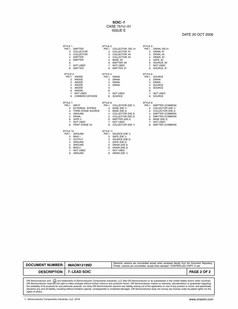
SOIC−7CASE 751U−01
ISSUE EDATE 20 OCT 2009
SEATINGPLANE
14
58
R
J
X 45�
K
NOTES:1. DIMENSIONING AND TOLERANCING PER
ANSI Y14.5M, 1982.2. CONTROLLING DIMENSION: MILLIMETER.3. DIMENSION A AND B ARE DATUMS AND T
IS A DATUM SURFACE.4. DIMENSION A AND B DO NOT INCLUDE
MOLD PROTRUSION.5. MAXIMUM MOLD PROTRUSION 0.15 (0.006)
PER SIDE.
S
DH
C
SCALE 1:1
DIMA
MIN MAX MIN MAXINCHES
4.80 5.00 0.189 0.197
MILLIMETERS
B 3.80 4.00 0.150 0.157C 1.35 1.75 0.053 0.069D 0.33 0.51 0.013 0.020G 1.27 BSC 0.050 BSCH 0.10 0.25 0.004 0.010J 0.19 0.25 0.007 0.010K 0.40 1.27 0.016 0.050M 0 8 0 8 N 0.25 0.50 0.010 0.020S 5.80 6.20 0.228 0.244
−A−
−B−
G
MBM0.25 (0.010)
−T−
BM0.25 (0.010) T S A S
M
XXX = Specific Device CodeA = Assembly LocationL = Wafer LotY = YearW = Work Week� = Pb−Free Package
GENERICMARKING DIAGRAM
7 PL� � � �
*This information is generic. Please refer todevice data sheet for actual part marking.Pb−Free indicator, “G” or microdot “ �”,may or may not be present.
XXXXXALYWX
�1
8
STYLES ON PAGE 2
1.520.060
7.00.275
0.60.024
1.2700.050
4.00.155
� mminches
�SCALE 6:1
*For additional information on our Pb−Free strategy and solderingdetails, please download the ON Semiconductor Soldering andMounting Techniques Reference Manual, SOLDERRM/D.
SOLDERING FOOTPRINT*
MECHANICAL CASE OUTLINE
PACKAGE DIMENSIONS
ON Semiconductor and are trademarks of Semiconductor Components Industries, LLC dba ON Semiconductor or its subsidiaries in the United States and/or other countries.ON Semiconductor reserves the right to make changes without further notice to any products herein. ON Semiconductor makes no warranty, representation or guarantee regardingthe suitability of its products for any particular purpose, nor does ON Semiconductor assume any liability arising out of the application or use of any product or circuit, and specificallydisclaims any and all liability, including without limitation special, consequential or incidental damages. ON Semiconductor does not convey any license under its patent rights nor therights of others.
98AON12199DDOCUMENT NUMBER:
DESCRIPTION:
Electronic versions are uncontrolled except when accessed directly from the Document Repository.Printed versions are uncontrolled except when stamped “CONTROLLED COPY” in red.
PAGE 1 OF 27−LEAD SOIC
© Semiconductor Components Industries, LLC, 2019 www.onsemi.com
SOIC−7CASE 751U−01
ISSUE EDATE 20 OCT 2009
STYLE 4:PIN 1. ANODE
2. ANODE3. ANODE4. ANODE5. ANODE6. ANODE7. NOT USED8. COMMON CATHODE
STYLE 1:PIN 1. EMITTER
2. COLLECTOR3. COLLECTOR4. EMITTER5. EMITTER6.7. NOT USED8. EMITTER
STYLE 2:PIN 1. COLLECTOR, DIE, #1
2. COLLECTOR, #13. COLLECTOR, #24. COLLECTOR, #25. BASE, #26. EMITTER, #27. NOT USED8. EMITTER, #1
STYLE 3:PIN 1. DRAIN, DIE #1
2. DRAIN, #13. DRAIN, #24. DRAIN, #25. GATE, #26. SOURCE, #27. NOT USED8. SOURCE, #1
STYLE 6:PIN 1. SOURCE
2. DRAIN3. DRAIN4. SOURCE5. SOURCE6.7. NOT USED8. SOURCE
STYLE 5:PIN 1. DRAIN
2. DRAIN3. DRAIN4. DRAIN5.6.7. NOT USED8. SOURCE
STYLE 7:PIN 1. INPUT
2. EXTERNAL BYPASS3. THIRD STAGE SOURCE4. GROUND5. DRAIN6. GATE 37. NOT USED8. FIRST STAGE Vd
STYLE 8:PIN 1. COLLECTOR (DIE 1)
2. BASE (DIE 1)3. BASE (DIE 2)4. COLLECTOR (DIE 2)5. COLLECTOR (DIE 2)6. EMITTER (DIE 2)7. NOT USED8. COLLECTOR (DIE 1)
STYLE 9:PIN 1. EMITTER (COMMON)
2. COLLECTOR (DIE 1)3. COLLECTOR (DIE 2)4. EMITTER (COMMON)5. EMITTER (COMMON)6. BASE (DIE 2)7. NOT USED8. EMITTER (COMMON)
STYLE 10:PIN 1. GROUND
2. BIAS 13. OUTPUT4. GROUND5. GROUND6. BIAS 27. NOT USED8. GROUND
STYLE 11:PIN 1. SOURCE (DIE 1)
2. GATE (DIE 1)3. SOURCE (DIE 2)4. GATE (DIE 2)5. DRAIN (DIE 2)6. DRAIN (DIE 2)7. NOT USED8. DRAIN (DIE 1)
ON Semiconductor and are trademarks of Semiconductor Components Industries, LLC dba ON Semiconductor or its subsidiaries in the United States and/or other countries.ON Semiconductor reserves the right to make changes without further notice to any products herein. ON Semiconductor makes no warranty, representation or guarantee regardingthe suitability of its products for any particular purpose, nor does ON Semiconductor assume any liability arising out of the application or use of any product or circuit, and specificallydisclaims any and all liability, including without limitation special, consequential or incidental damages. ON Semiconductor does not convey any license under its patent rights nor therights of others.
98AON12199DDOCUMENT NUMBER:
DESCRIPTION:
Electronic versions are uncontrolled except when accessed directly from the Document Repository.Printed versions are uncontrolled except when stamped “CONTROLLED COPY” in red.
PAGE 2 OF 27−LEAD SOIC
© Semiconductor Components Industries, LLC, 2019 www.onsemi.com

onsemi, , and other names, marks, and brands are registered and/or common law trademarks of Semiconductor Components Industries, LLC dba “onsemi” or its affiliatesand/or subsidiaries in the United States and/or other countries. onsemi owns the rights to a number of patents, trademarks, copyrights, trade secrets, and other intellectual property.A listing of onsemi’s product/patent coverage may be accessed at www.onsemi.com/site/pdf/Patent−Marking.pdf. onsemi reserves the right to make changes at any time to anyproducts or information herein, without notice. The information herein is provided “as−is” and onsemi makes no warranty, representation or guarantee regarding the accuracy of theinformation, product features, availability, functionality, or suitability of its products for any particular purpose, nor does onsemi assume any liability arising out of the application or useof any product or circuit, and specifically disclaims any and all liability, including without limitation special, consequential or incidental damages. Buyer is responsible for its productsand applications using onsemi products, including compliance with all laws, regulations and safety requirements or standards, regardless of any support or applications informationprovided by onsemi. “Typical” parameters which may be provided in onsemi data sheets and/or specifications can and do vary in different applications and actual performance mayvary over time. All operating parameters, including “Typicals” must be validated for each customer application by customer’s technical experts. onsemi does not convey any licenseunder any of its intellectual property rights nor the rights of others. onsemi products are not designed, intended, or authorized for use as a critical component in life support systemsor any FDA Class 3 medical devices or medical devices with a same or similar classification in a foreign jurisdiction or any devices intended for implantation in the human body. ShouldBuyer purchase or use onsemi products for any such unintended or unauthorized application, Buyer shall indemnify and hold onsemi and its officers, employees, subsidiaries, affiliates,and distributors harmless against all claims, costs, damages, and expenses, and reasonable attorney fees arising out of, directly or indirectly, any claim of personal injury or deathassociated with such unintended or unauthorized use, even if such claim alleges that onsemi was negligent regarding the design or manufacture of the part. onsemi is an EqualOpportunity/Affirmative Action Employer. This literature is subject to all applicable copyright laws and is not for resale in any manner.
PUBLICATION ORDERING INFORMATIONTECHNICAL SUPPORTNorth American Technical Support:Voice Mail: 1 800−282−9855 Toll Free USA/CanadaPhone: 011 421 33 790 2910
LITERATURE FULFILLMENT:Email Requests to: [email protected]
onsemi Website: www.onsemi.com
Europe, Middle East and Africa Technical Support:Phone: 00421 33 790 2910For additional information, please contact your local Sales Representative
◊


![PhD Thesis [Corrected Version] - Minjie Cai](https://static.fdokumen.com/doc/165x107/6327dcb3e491bcb36c0b7db0/phd-thesis-corrected-version-minjie-cai.jpg)