CORRECTED GYROCOMPASS SYNTHESIS AS A SYSTEM ...
7
Copyright © 2014 Vilnius Gediminas Technical University (VGTU) Press http://www.tandfonline.com/TAVI CORRECTED GYROCOMPASS SYNTHESIS AS A SYSTEM WITH CHANGEABLE STRUCTURE FOR AVIATION GRAVIMETRIC SYSTEM WITH PIEZOELECTRIC GRAVIMETER Elena Nikolaevna BEZVESILNAYA 1 , Andriy Hennadiiovych TKACHUK 2 1 National Technical University of Ukraine “Kiev Polytechnic Institute”, Peremogy Ave. 37, Kyev 03056, Ukraine 2 Zhytomyr State Technological University, Chernyakhovskogo str. 103, Zhytomyr 10005, Ukraine E-mail: [email protected] (corresponding author) Received 20 November 2013; accepted 20 August 2014 Elena Nikolaevna BEZVESILNAYA, Prof. Education: sp. degree in gyroscopic instruments and navigation devices, National Technical University of Ukraine “Kiev Polytechnic Institute”, Faculty of Instrumentation. 1972 to 1991: Candidate of Science, PhD in Science (Dr. techn. Science), National Technical University of Ukraine “Kiev Polytechnic Institute”, Faculty of Instrumentation; Academician of the Academy of Engineering Sciences in Ukraine, Member of New York Academy of Sciences, Honored Worker of Science in Ukraine. Affiliations and functions: 1991 to present: professor, National Technical University of Ukraine “Kiev Polytechnic Institute”, Department of Instrumentation. Research interest: fundamental and applied problems of mechanics of gyroscopic navigation devices and moving objects, dynamics of air electromechanical systems. Publications: 15 monographs, 9 books approved by the Ministry of Education and Science of Ukraine, 30 patents, more than 100 scientific articles. Andriy Hennadiiovych TKACHUK, PhD Education: MSc degree in automated processes technological control, Zhytomyr State Technological University, Faculty of Information and Computer Technologies. Affiliations and functions: 2011 to 2014: PhD studies, Zhytomyr State Technological University, specialization: instruments and methods for measuring mechanical values. Research interest: gravimetric measurements and instruments, automatic control system. Publications: Author of 15 scientific articles and co-author of 21 conference papers, 2 monographs, 3 patents. Abstract. e present article introduces the development of a corrected gyrocompass with an automatic switch of the gyrocompass into the gyroazimuth mode. e issues of multi-criterion synthesis of the gyrocompass control loop have been studied. e necessity of temporary delay input (with selected values) under the previously mentioned switching is shown. On the basis of given requirements, we chose the parameters which provide the device with a switching-back into the gyrocompass mode under any initial gyrocompass deviations in the horizontal plane. An al- gorithm of gyrocompass ballistic deviation compensation due to the amendment generated by the special observing device, without recourse to external information regarding the ship’s acceleration, was developed. Keywords: gyrocompass, automatic switch, gravimetric system, piezoelectric gravimeter. AVIATION ISSN 1648-7788 / eISSN 1822-4180 2014 Volume 18(3): 134–140 doi:10.3846/16487788.2014.969878
-
Upload
khangminh22 -
Category
Documents
-
view
0 -
download
0
Transcript of CORRECTED GYROCOMPASS SYNTHESIS AS A SYSTEM ...
Copyright © 2014 Vilnius Gediminas Technical University (VGTU) Press http://www.tandfonline.com/TAVI
CORRECTED GYROCOMPASS SYNTHESIS AS A SYSTEM WITH CHANGEABLE STRUCTURE FOR AVIATION GRAVIMETRIC SYSTEM
WITH PIEZOELECTRIC GRAVIMETER
Elena Nikolaevna BEZVESILNAYA1, Andriy Hennadiiovych TKACHUK2
1National Technical University of Ukraine “Kiev Polytechnic Institute”, Peremogy Ave. 37, Kyev 03056, Ukraine
2Zhytomyr State Technological University, Chernyakhovskogo str. 103, Zhytomyr 10005, UkraineE-mail: [email protected] (corresponding author)
Received 20 November 2013; accepted 20 August 2014
Elena Nikolaevna BEZVESILNAYA, Prof. Education: sp. degree in gyroscopic instruments and navigation devices, National Technical University of Ukraine “Kiev Polytechnic Institute”, Faculty of Instrumentation. 1972 to 1991: Candidate of Science, PhD in Science (Dr. techn. Science), National Technical University of Ukraine “Kiev Polytechnic Institute”, Faculty of Instrumentation; Academician of the Academy of Engineering Sciences in Ukraine, Member of New York Academy of Sciences, Honored Worker of Science in Ukraine.Affiliations and functions: 1991 to present: professor, National Technical University of Ukraine “Kiev Polytechnic Institute”, Department of Instrumentation. Research interest: fundamental and applied problems of mechanics of gyroscopic navigation devices and moving objects, dynamics of air electromechanical systems.Publications: 15 monographs, 9 books approved by the Ministry of Education and Science of Ukraine, 30 patents, more than 100 scientific articles.
Andriy Hennadiiovych TKACHUK, PhD Education: MSc degree in automated processes technological control, Zhytomyr State Technological University, Faculty of Information and Computer Technologies. Affiliations and functions: 2011 to 2014: PhD studies, Zhytomyr State Technological University, specialization: instruments and methods for measuring mechanical values. Research interest: gravimetric measurements and instruments, automatic control system.Publications: Author of 15 scientific articles and co-author of 21 conference papers, 2 monographs, 3 patents.
Abstract. The present article introduces the development of a corrected gyrocompass with an automatic switch of the gyrocompass into the gyroazimuth mode. The issues of multi-criterion synthesis of the gyrocompass control loop have been studied. The necessity of temporary delay input (with selected values) under the previously mentioned switching is shown. On the basis of given requirements, we chose the parameters which provide the device with a switching-back into the gyrocompass mode under any initial gyrocompass deviations in the horizontal plane. An al-gorithm of gyrocompass ballistic deviation compensation due to the amendment generated by the special observing device, without recourse to external information regarding the ship’s acceleration, was developed.
Keywords: gyrocompass, automatic switch, gravimetric system, piezoelectric gravimeter.
AVIATIONISSN 1648-7788 / eISSN 1822-4180
2014 Volume 18(3): 134–140
doi:10.3846/16487788.2014.969878
Aviation, 2014, 18(3): 134–140 135
1. Introduction
The accuracy requirements for the navigation paramet-ers of basic aviation gravimetric system (AGS) subsys-tems with the resulting measurement accuracy of grav-ity anomalies with 1 mGal are included in (Bezvesilna 2001): course - 1.43 ang, width - 0.5 ang, velocity - 0.05 m/s, way - 1.5 m, vertical velocity - 0.5·102 m/s, vertical acceleration - 1·10-5m/s2.
A new piezoelectric gravimeter that is a part of the AGS is proposed in (Bezvesilna, Tkachuk 2014; Bezvesil-naya et al. 2013).
Usually, to determine the course on a plane, the gyropolukompas (GPK) is mainly used. However, the real errors of GPK are so great that definite accuracy can-not be obtained.
The purpose of this paper is to provide a correc-ted gyrocompass synthesis as a system with a change-able structure for the aviation gravimetric system with a piezoelectric gravimeter.
2. The gyroscope compass
Gyroscope compasses are the principal course-detecting devices for ships. The development of corrected gyro-compasses (CGC) on the basis of a biaxial platform with dynamically tuned gyroscopes has become one of the directions for developing a device that can meet the in-creased requirements for operational characteristics of navigation equipment. The main advantage of the CGC is the possibility to change the structure and control loop parameters depending on the device’s operation mode. In particular, an effective method for decreasing the indication errors while the ship is maneuvering is to switch the device into the gyroazimuth mode, which can be done either manually or automatically. However, automatic switching into the gyroazimuth mode can re-sult in cases when the device is not switched back to the gyrocompass mode. This issue has not been studied in full so far. The synthesis technique for a two-mode gyrocompass control loop remains a problem.
The given report presents the experience of devel-oping such corrected gyrocompasses like CRUISE and SLAVUTICH by the Public Corporation “Kiev Plant of Automation named after G. Petrovsky” and “Marinex Company Limited” (Ukraine). The key aim of the studies was to maximally exhaust the possibilities for an autono-mous change of the device operation mode.
Let’s consider the peculiarities of CGC dynamics as a two-mode device (Malovichko, Kostitsyn 1992). Equa-tions of motion are as follows:
( )( )
1 20
20
;
;
( ) sin ;
cos
cos ,
x
z
n n
r
r
Ô ð g W p K
J f mgl ml W p K
f p K
η ξ
η ζ
-η
η γ ξ
γ
a - ω b + ω γ = -bγ + δ
b + ω a - ω γ = aγ - δ
δ = b + - ϕζ γ + γ + γ = - ϕζ +
+ ϕ
(1)
where a, b indicate tilt angles of the main gyro axis from the direction to the North and from the horizon plane; δ - accelerometer filter output; γ - platform tilt angle;
ϕ - roll angle; xr , zr - coefficients; 1( )1
pTp
Φ =+
-
transfer function of the accelerometer filter, T - filter time constant; ξω , ηω - the East and North compo-nents of the Earth’s rotation angular speed; Wη - the North component of ship movement acceleration;
0ζ - the distance from the centre of gyro to the device installation place Jη , fγ , nl - platform parameters; g - gravitational acceleration.
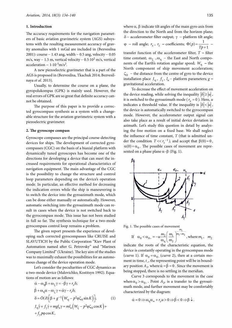
To decrease the effect of movement acceleration on the device reading, while solving the inequality uδ ≥ , it is switched to the gyroazimuth mode ( 0xr = ). Here, u indicates a threshold value. If the inequality is uδ < , the device is automatically switched to the gyrocompass mode. However, the accelerometer output signal can also take place as a result of initial device deviation in azimuth. Let’s study this question in detail by analyz-ing the free motion on a fixed base. We shall neglect the influence of time constant, T (that is admitted un-der the condition 1
zT r -<< ), and accept that (0) 0b = , 0(0)a = a . The possible cases of movement are repre-
sented on a phase plane a–b (Fig. 1).
Fig. 1. The possible cases of movement
If
1
1 22 10 0~
2,
mm mm m
um
-
η
a < a = - ω
where 1m , 2m
indicate the roots of the characteristic equation, the device is constantly operating in the gyrocompass mode (curve 1). If 0 0~a = a (curve 2), then at a certain mo-ment in time, t~, the representing point will be in bound-ary position A1, where 0a = b = . Since the movement is being stopped, there is no settling in the meridian.
Curve 3 corresponds to the movement in the case when 0 0~a > a . Point A2, is a transfer to the gyroazi-muth mode, and further movement may be comfortably characterized by the diagram:
0 0 0 .zr uη ≈a = ⇒ ω a + > ⇒ b < ⇒ b ↓
136 E. N. Bezvesilnaya, A. H. Tkachuk. Corrected gyrocompass synthesis as a system with changeable structure...
The representing point will move down to the equi-librium position A3. There is no settling in the meridian.
It is important to find out, when settling in the meridian will occur, under any initial condi-tions. One of the ways to execute this task is to in-crease coefficient zr , when ub = . In this case we have
0 0zr uη ≈′ω a + < ⇒ b > ⇒ b ↑ ( zr ′ indicates value zr , in
the gyroazimuth mode). For this, it is necessary to select
coefficient zr ′ from the condition zr uη ≈ω a′ > , or more
accurately, sin
zr uη ≈ω a′ > . If zr u
ηω′ > , then the CGC
will be set in the meridian under any initial angle 0a .However, an increase of coefficient zr is not enough:
it is necessary to also input a temporary delay ga gc-τ switching the device from the gyroazimuth mode to the gyrocompass one. Then, during the delay time interval, the representing point will move upward in the gyroazi-muth mode. In point 3A ′ the device will be switched to the gyrocompass mode. This process is repeated further on. We can see that there is settling in the meridian.
Curve 4 represents the movement after the input of delay gc ga-τ , during the transfer from the gyrocompass mode to the gyroazimuth one. We see that settling in the meridian exists as well. It is efficient to input both delays.
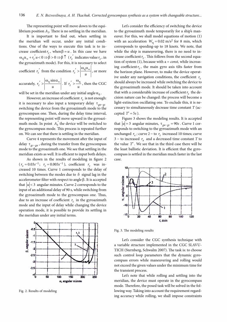
As shown in the results of modeling in figure 2 ( 10.03xr s-= ; 10.003zr s-= ), coefficient zr was in-creased 10 times. Curve 1 corresponds to the delay of switching between the modes due to δ signal lag in the accelerometer filter with respect to angle b. It is accepted that 3u < angular minutes. Curve 2 corresponds to the input of an additional delay of 90 s, while switching from the gyroazimuth mode to the gyrocompass one. Thus, due to an increase of coefficient zr in the gyroazimuth mode and the input of delay while changing the device operation mode, it is possible to provide its settling in the meridian under any initial terms.
Fig. 2. Results of modeling
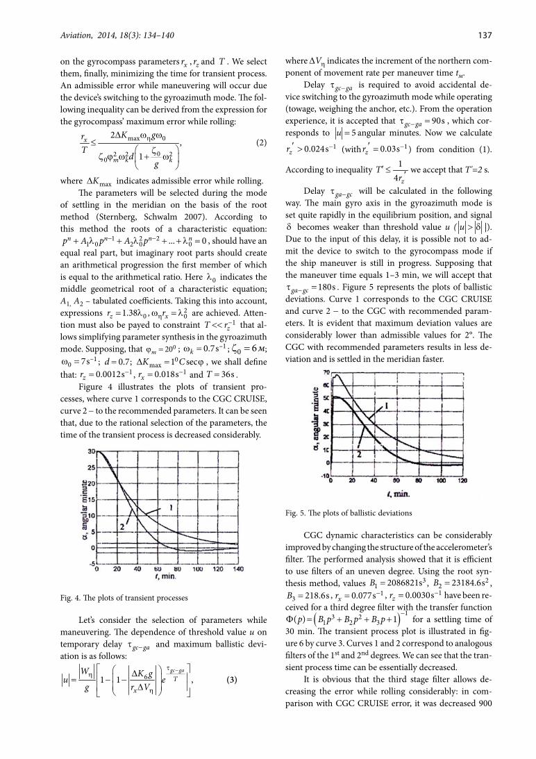
Let’s consider the efficiency of switching the device to the gyroazimuth mode temporarily for a ship’s man-euver. For this, we shall model equations of motion (1) with an acceleration 0.02Wη = m/s2 for 8 min, which corresponds to speeding-up to 18 knots. We note, that while the ship is maneuvering, there is no need to in-crease coefficient zr . This follows from the second equa-tion of system (1), because with a = const, while increas-ing coefficient zr , the main gyro axis tilts faster from the horizon plane. However, to make the device operat-ive under any navigation conditions, the coefficient zr should always be increased while switching the device to the gyroazimuth mode. It should be taken into account that with a considerable increase of coefficient zr the de-cision nature can be changed: the process will become a light-extinction oscillating one. To exclude this, it is ne-cessary to simultaneously decrease time constant T (ac-cepted 5T s′ = ).
Figure 3 shows the modeling results. It is accepted that 3u = angular minutes, 90ga gc s-τ = . Curve 1 cor-responds to switching to the gyroazimuth mode with an unchanged xr ; curve 2 - to zr increased 10 times; curve 3 - to increased xr and a decreased time constant T to the value T ′ . We see that in the third case there will be the least ballistic deviation. It is efficient that the gyro-compass is settled in the meridian much faster in the last case.
Fig. 3. The modeling results
Let’s consider the CGC synthesis technique with a variable structure implemented in the CGC SLAVU-TICH (Sternberg, Schwalm 2007). The task is: to choose such control loop parameters that the dynamic gyro-compass errors while maneuvering and rolling would not exceed the given values under the minimum time for the transient process.
Let’s note that while rolling and settling into the meridian, the device must operate in the gyrocompass mode. Therefore, the posed task will be solved in the fol-lowing way. Taking into account the requirement regard-ing accuracy while rolling, we shall impose constraints
Aviation, 2014, 18(3): 134–140 137
on the gyrocompass parameters xr , zr and T . We select them, finally, minimizing the time for transient process. An admissible error while maneuvering will occur due the device’s switching to the gyroazimuth mode. The fol-lowing inequality can be derived from the expression for the gyrocompass’ maximum error while rolling:
max 0
02 2 20
2,
1
x
m k k
K grT
dg
η∆ ω ω≤
ζζ ϕ ω + ω
(2)
where maxK∆ indicates admissible error while rolling.The parameters will be selected during the mode
of settling in the meridian on the basis of the root method (Sternberg, Schwalm 2007). According to this method the roots of a characteristic equation:
1 2 21 0 2 0 0... 0n n n np A p A p- -+ λ + λ + + λ = , should have an
equal real part, but imaginary root parts should create an arithmetical progression the first member of which is equal to the arithmetical ratio. Here 0λ indicates the middle geometrical root of a characteristic equation; A1, A2 – tabulated coefficients. Taking this into account, expressions 01.38zr = λ , 2
0xrηω = λ are achieved. Atten-tion must also be payed to constraint 1
zT r-<< that al-lows simplifying parameter synthesis in the gyroazimuth mode. Supposing, that 020mϕ = ; ω = –10.7sk ; 0 6мζ = ; ω = –1
0 7s ; 0.7d = ; 0max 1 secK C∆ = ϕ , we shall define
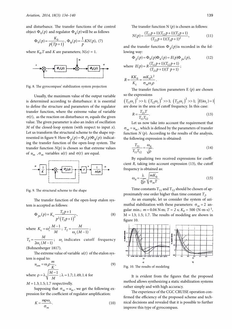
that: -= 10.0012szr , -= 10.018sxr and = 36sT .Figure 4 illustrates the plots of transient pro-
cesses, where curve 1 corresponds to the CGC CRUISE, curve 2 - to the recommended parameters. It can be seen that, due to the rational selection of the parameters, the time of the transient process is decreased considerably.
Fig. 4. The plots of transient processes
Let’s consider the selection of parameters while maneuvering. The dependence of threshold value u on temporary delay gc ga-τ and maximum ballistic devi-ation is as follows:
61 1 ,gc ga
Tx
W K gu e
g r V
-τη
η
∆ = - - ∆
(3)
where Vη∆ indicates the increment of the northern com-ponent of movement rate per maneuver time tм.
Delay gc ga-τ is required to avoid accidental de-vice switching to the gyroazimuth mode while operating (towage, weighing the anchor, etc.). From the operation experience, it is accepted that -τ = 90sgc ga , which cor-responds to 5u = angular minutes. Now we calculate
-′ > 10.024szr (with -′ = 10.03szr ) from condition (1).
According to inequality 14 z
Tr
′ ≤ ′ we accept that T'=2 s.
Delay ga gc-τ will be calculated in the following way. The main gyro axis in the gyroazimuth mode is set quite rapidly in the equilibrium position, and signal δ becomes weaker than threshold value u ( u > δ |). Due to the input of this delay, it is possible not to ad-mit the device to switch to the gyrocompass mode if the ship maneuver is still in progress. Supposing that the maneuver time equals 1–3 min, we will accept that
-τ =180sga gc . Figure 5 represents the plots of ballistic deviations. Curve 1 corresponds to the CGC CRUISE and curve 2 - to the CGC with recommended param-eters. It is evident that maximum deviation values are considerably lower than admissible values for 2°. The CGC with recommended parameters results in less de-viation and is settled in the meridian faster.
Fig. 5. The plots of ballistic deviations
CGC dynamic characteristics can be considerably improved by changing the structure of the accelerometer’s filter. The performed analysis showed that it is efficient to use filters of an uneven degree. Using the root syn-thesis method, values = 3
1 2086821sB , = 22 23184.6sB ,
=3 218.6sB , -= 10.077sxr , -= 10.0030szr have been re-ceived for a third degree filter with the transfer function
( ) 13 21 2 3( ) 1p B p B p B p
-Φ = + + + for a settling time of 30 min. The transient process plot is illustrated in fig-ure 6 by curve 3. Curves 1 and 2 correspond to analogous filters of the 1st and 2nd degrees. We can see that the tran-sient process time can be essentially decreased.
It is obvious that the third stage filter allows de-creasing the error while rolling considerably: in com-parison with CGC CRUISE error, it was decreased 900

138 E. N. Bezvesilnaya, A. H. Tkachuk. Corrected gyrocompass synthesis as a system with changeable structure...
times. This allows installing the device at a considerable distance from the center of rolling (30 m and more).
Error reduction on the basis of information estim-ation with the help of observing devices is one of the ef-fective methods to increase the accuracy of navigation systems. Let us take under consideration the application of this method to decrease gyrocompass ballistic devi-ations (Malovichko, Kostitsyn 1992).
Fig. 6. The transient process plot
We shall take the following equations as the gyro-compass model:
( )( )
1
2
;
;
0,
m xm m m
m m zm m
m m m m
r k
r k
Tη
a - δ = δ - δ
b + ω a + = δ - δ
δ +δ -b =
(4)
where ma , mb and mδ indicate the model variables corresponding to real variables; xmr , zmr , mT - model parameters; k, k2 - coefficients.
Indicating that m∆a = a - a , m∆b = b -b ,
m∆δ = δ - δ and supposing that xm xr r= , zm zr r= , we shall get the following system of equations for calculat-ing estimation errors:
1
2
( ) 0;
( ) 0;
/ .
x
z
r k
r k
T W gη
η
∆a - - ∆δ =
∆b + ω ∆a + + ∆δ =
∆δ + ∆δ - ∆b =
(5)
Moving on to the question of coefficient selection of k, k2, for the time of the maneuver, we will accept that
1 xk r= , 2 z zk r r′= - . In this case, the equations of errors (5) become:
2
0;
( ) 0;
/ .zr k
T W gη
η
∆a =
∆b + ω ∆a + + ∆δ =
∆δ + ∆δ - ∆b =
(6)
It is evident that estimation error ∆a does not de-pend on the acceleration value and is defined only by its initial value. As physically the gyrocompass is not switched to the gyroazimuth mode, we shall call this concept “the mode of analytical switching to the gyroazi-muth mode”.
After maneuver termination, we accept that k1 = k2 = 0. In this case, the equations of errors with the ac-curacy up to designations will meet the equations of the gyrocompass free motion.
To change the coefficients of the observing device, it is necessary to have the information about either the availability or absence of ship movement acceleration, which can be obtained by analysing the output signal level of the horizon indicator.
The modeling of the gyrocompass dynamics with an observing device while the ship is moving with an ac-celeration 0.172Wη = m/s2 within 1 min., which corre-sponds to the speeding-up to 20 knots, was carried out to check the efficiency of the proposed ballistic deviation compensation algorithm.
In figure 7, curve 1 corresponds to ballistic devia-tion under physical switching of the gyrocompass to the gyroazimuth mode and curve 2 to analytical switching. The estimation error of ballistic deviation of the observ-ing device, under permanent operation of the gyrocom-pass in the main mode (curve 2), is slightly different from ballistic deviation under physical device switching to the gyroazimuth mode.
While using the observing device, the apparatus is operating in the gyrocompass mode all the time; there-fore, it is not a problem for the main axis to set in the meridian under large initial deviation angles. There is, hence, no need to increase coefficient zr for the time of operation in the gyroazimuth mode (curve 3).
Fig. 7. Ballistic deviation under physical switching of the gyrocompass to the gyroazimuth mode
The matters of gyrocompass stabilization system projection will be discussed further (Bohnenberger 1817). The structural scheme of the gyrocompass’ stabi-lization system projection is shown in figure 8, where x and σ indicate the input and output variables; m - dis-turbance. To exclude static errors, let us regard the sta-bilization system as a static one according to both input
Aviation, 2014, 18(3): 134–140 139
The transfer function N (p) is chosen as follows:
11 12 22
21 3
( 1)( 1)( 1)( ) ,
( 1)( 1)T p T p T p
N pT p T p+ + +
=+ +
(11)
and the transfer function ( )p pΦ is recorded in the fol-lowing way:
0( ) ( ) ( ) ( ) ( ),p k pep p p E p pΦ = Φ Φ = Φ (12)
where 11 12
21
( 1)( 1)( )
( 1)( 1)T p T p
E p RT p T p
+ +=
+ +;
20 0
m c
KK mKR
Kε
λ= =
σ ω ρ.
The transfer function parameters E (p) are chosen so the expressions
( ) ( ) ( )2 2 211 12 211; 1; 1; ( ) 1c c c cT T T E iω >> ω >> ω >> ω =
are done in the area of cutoff frequency. In this case:21
11 12.
T TR
T T= (13)
Let us now take into account the requirement thatm muσ = , which is defined by the parameters of transfer
function N (p). According to the results of the analysis, the following expression is obtained:
21
11 12.ñT
T Tω
=ρ
(14)
By equalizing two received expressions for coeffi-cient R, taking into account expression (13), the cutoff frequency is obtained as:
04
.ñm
mKT
λω =
σρ (15)
Time constants T11 and T12 should be chosen of ap-proximately one order higher than time constant T2.
As an example, let us consider the system of azi-muthal stabilization with these parameters: 2mσ = an-gular min.; 0.04m = N·m; T = 2 s; K0 = 500 (N-m-s)-1, M = l.3; 1.5; 1.7. The results of modeling are shown in figure 10.
Fig. 10. The results of modeling
It is evident from the figures that the proposed method allows synthesizing a static stabilization systems rather simply and with high accuracy.
The experience of the CGC CRUISE operation con-firmed the efficiency of the proposed scheme and tech-nical decisions and revealed that it is possible to further improve this type of gyrocompass.
and disturbance. The transfer functions of the control object 0( )pΦ and regulator ( )pφΦ will be as follows
( )0
0( )1
Kp
p TpΦ =
+, 1( ) ( ),p KN p
pφΦ = (7)
where K0,T and K are parameters; N(o) = 1.
Fig. 8. The gyrocompass’ stabilization system projection
Usually, the maximum value of the output variable is determined according to disturbance: it is essential to define the structure and parameters of the regulator transfer function, where the extreme value of variable
( ),tσ as the reaction on disturbance m, equals the given value. The given parameter is also an index of oscillation M of the closed-loop system (with respect to input x). Let us transform the structural scheme to the shape rep-resented in figure 9. Here 0( ) ( ) ( )p p p pφΦ = Φ Φ : indicat-ing the transfer function of the open-loop system. The transfer function N(p) is chosen so that extreme values of mu , mσ variables ( )u t and ( )tσ are equal.
Fig. 9. The structural scheme to the shape
The transfer function of the open-loop etalon sys-tem is accepted as follows:
( )2
223
1( ) ,
1pe
T pp K
p T pε
+Φ =
+ (8)
where 2 1c
MKMε-
= ω ; 2 ( 1)c
MTM
=ω -
;
3 2 ( 1)c
MTM
=ω -
; cω indicates cutoff frequency
(Bohnenberger 1817). The extreme value of variable ( )u t of the etalon sys-
tem is equal to:,em c
muK
= ω ρ (9)
where 1MM-
ρ = λ ; λ =1.7; 1.49; 1.4 for
=1.3; 1.5; 1.7M respectivelly.Supposing that m muσ = , we get the following ex-
pression for the coefficient of regulator amplification:
.c
m
mK
ρω=
σ (10)

140 E. N. Bezvesilnaya, A. H. Tkachuk. Corrected gyrocompass synthesis as a system with changeable structure...
3. Сonclusions
The corrected gyrocompass synthesis as a system with a changeable structure for the aviation gravimetric system with a piezoelectric gravimeter is provided in this pa-per. The experience of developing such corrected gyro-compasses like CRUISE and SLAVUTICH by the Public Corporation “Kiev Plant of Automation named after G. Petrovsky” and “Marinex Company Limited” (Ukraine) are presented.
Modeling was conducted and found that due to an increase of coefficient zr in the gyroazimuth mode and the input of delay while changing the device operation mode, it is possible to provide its settling in the meridian under any initial terms; CGC dynamic characteristics can be considerably improved by changing the structure of the accelerometer’s filter; error reduction on the basis of information estimation with the help of observing devices is one of the effective methods to increase the accuracy of navigation systems.
ReferencesBezvesilna, O. M. 2001. Vysmirjuvannja pryskoren. Kyiv: Lybid.
(in Ukrainian).Bezvesilna, O. M.; Tkachuk, A. G. 2014. Naukovo-teoretych-
ni doslidzhennja novogo p’jezoelektrychnogo gravimetra avtomatyzovanoi’ aviacijnoi’ gravimetrychnoi’ systemy v ekstremal’nyh umovah z vykorystannjam nejronnyh merezh. Zhytomyr: ZhDTU. (in Russian).
Bezvesilnaya, E.; Tkachuk, А.; Ostapchuk, A., et al. 2013. Angle measurement device for posting the sensitivity axis of avia-tion gravimeter, The Advanced Science Journal (12): 31–37.
Bohnenberger, J. G. F. 1817. Beschreibung Einer Maschine zur Erläuterung der Gesetze der Umdrehung der Erde um ihre Axe, und der Veränderung der Lage der Letzteren [Description of a machine for the explanation of the laws of rotation of the Earth around its axis, and of the change of the orientation of the latter], Tübinger Blätter für Naturwissenschaften und Arzneikunde 3: 72–83. (in Ger-man).
Malovichko, A. K.; Kostitsyn, V. I. 1992. Gravirazvedka. Mosk-va: Nedra. (in Russian).
Sternberg, H.; Schwalm, C. 2007. Qualification process for MEMS gyroscopes for the use in navigation systems, in Proceedings of International Society for Photogrammetry and Remote Sensing, 2007, Hamburg, Germany.