National GIS Lebanon
146
Summary © E.U./C.M. 10.1996 1 1 FOREWORD 6 2 INTRODUCTION 8 2.1 Definition: Geographical Information Systems (GIS) 8 2.2 Definition of National GIS 11 2.3 Prerequisites for working with Geographical Information Systems 12 2.4 Datatypes in GIS 13 2.4.1 Geometry data 13 2.4.2 Subject data, attributes 14 2.5 Precision of the spatial information 15 2.5.1 Hard data 15 2.5.2 Soft data 15 2.6 Acquisition of data / precision of data 15 2.6.1 Scanning maps and images 16 2.6.2 Scanning with subsequent vectorisation 18 2.6.3 Digitising 18 2.6.4 Keyboard entry 19 2.6.5 Reading in data / tables 19 2.7 Scale in a GIS 20 2.8 Classification of GISs 20 2.8.1 vector-based GIS 20 2.8.2 raster-oriented GIS 20 2.8.3 hybrid GIS 20 2.9 Distinctive types of GIS 21 2.9.1 Land Information System (LIS) 21 2.9.2 Network Information System (NIS) 21 2.9.3 Spatial Information System (SIS) 22 2.9.4 Environment Information System (EIS) 22 2.9.5 (ExIS) Expert Information System 22 2.10 Necessary hardware 23 2.10.1 Data Capture 23 2.10.2 Equipment for processing data 26 2.10.3 Tertiary storage (tape drives, optical disks) 32 2.11 Operating systems 33 2.11.1 UNIX 33 2.11.2 Windows NT 34 2.12 Essential software 36 2.13 GIS database systems 36 2.13.1 Filesystem 37 2.13.2 Relational database : 37 2.14 Networking 38 2.14.1 Network architecture 38 2.14.2 Network components 38
-
Upload
independent -
Category
Documents
-
view
0 -
download
0
Transcript of National GIS Lebanon

Summary
© E.U./C.M. 10.1996 1
1 FOREWORD 6
2 INTRODUCTION 8
2.1 Definition: Geographical Information Systems (GIS) 8
2.2 Definition of National GIS 11
2.3 Prerequisites for working with Geographical Information Systems 12
2.4 Datatypes in GIS 13
2.4.1 Geometry data 13
2.4.2 Subject data, attributes 14
2.5 Precision of the spatial information 15
2.5.1 Hard data 15
2.5.2 Soft data 15
2.6 Acquisition of data / precision of data 15
2.6.1 Scanning maps and images 16
2.6.2 Scanning with subsequent vectorisation 18
2.6.3 Digitising 18
2.6.4 Keyboard entry 19
2.6.5 Reading in data / tables 19
2.7 Scale in a GIS 20
2.8 Classification of GISs 20
2.8.1 vector-based GIS 20
2.8.2 raster-oriented GIS 20
2.8.3 hybrid GIS 20
2.9 Distinctive types of GIS 21
2.9.1 Land Information System (LIS) 21
2.9.2 Network Information System (NIS) 21
2.9.3 Spatial Information System (SIS) 22
2.9.4 Environment Information System (EIS) 22
2.9.5 (ExIS) Expert Information System 22
2.10 Necessary hardware 23
2.10.1 Data Capture 23
2.10.2 Equipment for processing data 26
2.10.3 Tertiary storage (tape drives, optical disks) 32
2.11 Operating systems 33
2.11.1 UNIX 33
2.11.2 Windows NT 34
2.12 Essential software 36
2.13 GIS database systems 36
2.13.1 Filesystem 37
2.13.2 Relational database : 37
2.14 Networking 38
2.14.1 Network architecture 38
2.14.2 Network components 38

Summary
© E.U./C.M. 10.1996 2
2.14.3 Network topologies 39
2.14.4 Interfaces 40
2.14.5 Transfer media 43
2.14.6 Network protocols 45
2.14.7 Distributed filesystems 50
2.14.8 Ethernet 53
2.14.9 FDDI 53
3 ARCHITECTURE OF AN IDEAL NATIONAL GIS 56
3.1 General fundamental principles 56
3.1.1 Regional land survey 56
3.1.2 Allocation of responsibilities / responsibility for data 56
3.1.3 Base information 57
3.1.4 General data acquisition 58
3.1.5 Internal precision of the system 59
3.1.6 Generalisation 59
3.1.7 Common layer structure 60
3.1.8 Coordination of the legends 60
3.1.9 Unified database interface / database design 61
3.1.10 Quality control 61
3.1.11 Management / Information library 62
3.1.12 Access permissions 62
3.2 Hardware 62
3.2.1 Computers 63
3.2.2 Operating systems 63
3.2.3 Integration of a RAID system 63
3.3 Software 64
3.4 Data exchange formats 64
3.5 Networking 65
3.5.1 Local area network (LAN) 65
3.5.2 Wide area network (WAN) 65
4 CONDITIONS ON SITE 67
4.1 Land surveying 67
4.1.1 Coordinate systems 68
4.1.2 Quantitative aspects of land surveying 68
4.1.3 Qualitative aspects of land surveying 69
4.2 Allocation of tasks 69
4.3 Captured data 70
4.4 Existing stand-alone solutions (Quantity of data) 70
4.4.1 Ministry of Defence (DAG), Humphreys 70
4.4.2 Ministry of Post and Telecommunications (P.T.T.) 71
4.4.3 General Cadastre Direction 71
4.4.4 EDL 71
4.4.5 IDAL 71
4.4.6 General Administration for Statistics 72
4.4.7 Lebanese University 72
4.4.8 Katib & Alami 72
4.4.9 Dar Al Handasa 72

Summary
© E.U./C.M. 10.1996 3
4.4.10 Sukleen Sukkar 72
4.4.11 SOLIDERE 73
4.4.12 Philiptchenko surveying agency 73
4.4.13 CNRSL 73
4.5 Planned stand-alone solutions 73
4.5.1 Ministry of Transport 74
4.5.2 Ministry for Hydraulic- and Electrical Resources 74
4.5.3 Office National du Litani 74
4.5.4 Ministry of Public Works 74
4.5.5 Commisions Executive des Grand Projects 74
4.5.6 Ministry of Agriculture 75
4.5.7 Ministry of Environment 75
4.5.8 CDR 75
4.5.9 Office des Eaux de Beirut 75
4.5.10 Summary 75
4.6 Quality of the captured data 76
5 SYNTHESIS OF CHAPTERS 3 AND 4 78
5.1 National land surveying 78
5.1.1 Block triangulation 78
5.1.2 GPS (Global Positioning System) 78
5.2 atabase interface 79
5.3 Responsibilities 79
5.4 Data acquisition (Base Information) 80
5.5 Data acquisition (period of time) 83
5.6 Unified data criteria 84
5.7 Hardware structure of the institutions concerned 84
5.8 Databases 85
5.9 Software structure of the participating institutions 85
5.10 Networking 86
5.10.1 Internal networking (LAN) 86
5.10.2 External networking (WAN) 86
6 NATIONAL GIS CENTRE 88
6.1 Principles 88
6.2 Task setting 88
6.2.1 Advice 88
6.2.2 Compilation of standards 89
6.2.3 Integration of digital data 89
6.2.4 Provision of existing data 90
6.2.5 Management of all GIS activities 91
6.3 Software structure 92

Summary
© E.U./C.M. 10.1996 4
6.4 Database 93
6.5 Network 93
6.6 Steps for development 93
6.7 Personnel requirements 94
7 ESSENTIAL PRELIMINARY WORK FOR THE NATIONAL GIS 96
7.1 Unified database interface / database design 96
7.2 Clarification on responsibility for surveying 96
7.3 Study: surveying 96
7.3.1 Block offset of the lowest level of the survey grid 96
7.3.2 GPS and reference stations 97
7.4 Study: data telecommunications (WAN) for the national GIS 98
8 GIS CENTRE (CDR) 99
8.1 Prerequisites 99
8.2 Task 99
8.3 Steps for development 100
8.4 Hardware and software 100
8.5 Networking 100
9 OUTLOOK 101
Feasibility, Preliminary Design, and Tender Documents for the Design of a Geographical
Informatin System (GIS) in Lebanon
Christoph Mehrens Linzer Weg 21-23
D - 24147 Kiel Phone : (++49) 431 / 78 05 0 - 0 Fax : (++49) 431 / 78 05 0 -13
E-mail : mts-kiel @ t-online.de
This report was prepared with financial assistance from the Commission of the European Communities. The views expressed herein are those of the Consultant, and do not represent any official view of the Commission.

Foreword
© E.U./C.M. 10.1996 6
1 Foreword
On the basis of the information available at the time, it was assumed at the beginning of the mission that the introduction of a National GIS for Lebanon could be planned without being influenced to any great extent by already-existing activities, since these were either rudimentary or in the planning phase. This idea is further made clear by the fact that the integration and utilisation of already available databases was not taken into consideration in the “Objectives of the main project”.
With every passing day of the stay in Lebanon, new indications of already existing databases came to light which were very surprising as regards their variable quality and the scope of the work, and which led to a shift of emphasis regarding the implementation and objectives of the mission.
The absence of fundamental requirements governing the planning of the architecture or the design of such a complex type of problem, together with already existing extensive databases, prevents a purely “technical solution”.
Existing literature (protocols, proposals, etc.; see list in the draft report) is widely available yet hardly well-known.
As a review of this literature showed, the existing difficulties regarding the multitude of stand-alone solutions that were found could not be resolved by (already undertaken) attempts to simplify the problem of implementing GIS using schematic representations and descriptions.
Large discrepancies with regard to specialist knowledge, together with a degree of resistance on the part of the decision-makers to examine the fundamental requirements of working with GIS, and a variable interest regarding the objective of such an interdisciplinary system of national significance, are seen as the causes of the current unsatisfactory situation.
It must be emphasised that in order to make decisions regarding planning and working with GIS, a knowledge of the fundamental contents and structure are inevitably necessary (this is not usually necessary with any other software) as is a knowledge of its possibilities and limitations both with regard to the GIS hardware itself and to the various GIS software products and their different philosophies.
For this reason this aspect is elaborated in this report - in order to create a mutual basis for further dialogue in future discussions. In addition, the fundamental principles of GIS are clarified in so far as they are relevant to the consideration of the construction of a national GIS centre.
The reproach - which has already been expressed - that the report is too concerned with technical details and does not sufficiently simplify the problems is accepted.
This report attempts to demonstrate the fundamental difficulties via an analysis of the existing activities within the field of GIS. A proposal for the ideal requirements for a GIS with regard to the current situation in Lebanon follows; this is then synthesised and expanded into the design of a national GIS.

Foreword
© E.U./C.M. 10.1996 7
The assessment of the situation regarding already existing and planned GIS solutions is based, on the whole, on secondary information. The current situation more than clearly demonstrates that hardly any primary information was obtained.
This assessment is supported by the organisational difficulties surrounding the provision of test data; this data should be made available from different sources to allow a demonstration of strategies for the construction of databases for a national GIS.
Particular thanks go to all those institutions and persons who have supported this mission - sometimes without regard to their own interests - to the benefit of a national solution.
__________________

Introduction
© E.U./C.M. 10.1996 8
2 Introduction
2.1 Definition: Geographical Information Systems (GIS)
In discussions it often becomes apparent that considerable communication problems arise when the concepts used have not been previously defined. This is particularly so for the term Geographical Information System.
In the literature there is a multitude of definitions, which contributes more to confusion than to a clarification of the term GIS.
Since many decision-makers in the field of GIS have hardly even considered the elementary data processing principles and philosophies of GIS, this factor of an ill-defined term is to some extent welcome. This factor gives more or less everyone the chance of participating in discussions. The emotions which arise again and again at such discussions can be put down to the fact that objective talks are almost out of the question because of the lack of a common basis for discussion.
Since merely the knowledge of these difficulties leads to a better understanding for those taking part in the discussion, this factor is alluded to; the variable meaning of the term GIS is examined and a definition of GIS is established for use in this report.
From the multitude of sources available in Lebanon, one representative publication is quoted (Jacques Ekmekji and Faisal Alami, Abu Dhabi Project Management Conference December 5-7,1993). They define a GIS as:
“an organized collection of computer hardware, software, geographic data, and personnel designed to efficiently capture, store, update, manipulate, analyse, and display all forms of geographically referenced information. Furthermore it is believed that definitions vary considerably depending on : Experience, Applications, User Needs.”
Ekmejki quotes the following further definitions of a GIS in his paper:
- “A system for capturing, storing, checking, manipulating, analysing and displaying data which are specially referenced to the earth” (Department of Environment, 1987:132DoE)
- “A system with advanced Geo-modelling capabilities” (Koshkariov, Tikomov and Trofimov 1989:259)
- “An information technology which stores, analyses, and displays both spatial and non-spatial data” (Parker 1988:1547)
- “A powerful set of tools for collecting, retrieving at will, transforming, and displaying spatial data from the real world” (Burrough 1986:6)

Foreword
© E.U./C.M. 10.1996 9
- “Any manual or computer based set of procedures used to store and manipulate geographically referenced data” (Aronoff 1989:39)
- “An institutional entity, reflecting an organizational structure that integrates technology with a database, expertise and continuing financial support over time” (Carter 1989:3)
- “A database system in which most of the data are spatially indexed, and upon which a set of procedures are operated in order to answer queries about spatial entities in the database” (Smith et al. 1987:13)
- “A decision support system involving the integration of spatially referenced data in a problem solving environment” (Cowen 1988:1554)
In conclusion Ejmekji and Alami emphasise:
“GIS could be any one of the above definitions or it could be all of them collectively.”
However no definition, in their opinion, is capable of portraying what GIS is or can do unless one lives the GIS experience.
Ekmejki and Alami are not alone with this appraisal that, in the last analysis, GIS cannot be exactly defined. The following statement is not without foundation: if three different GIS experts are asked for the definition, six different answers are provided.
In order to reach an understanding of this situation (which is completely unsatisfactory for the decision-maker), it is helpful to examine the reasons for the lack of an exact definition of the term GIS.
These reasons may be split - inter alia- into a commercial field and a technical field.
Since GIS is not based upon one subject area, like e.g. data processing, but affects the entire bandwidth of engineering science and natural science, there can be no comprehensive definition which simultaneously expresses exact statements - the requirements and applications are too variable.
Each simplification is combined with a loss of information and, in the final analysis, leads to an abstraction which is no longer sufficiently meaningful. Flowcharts and the large number of colourful pictures reinforce the user’s false assumption that such complex systems are simple to set up, to understand and to control.
On the commercial side, GIS is currently the application with the highest growth rates. It is obvious that many want to share in this development. This is also a reason why the definition of
GIS is so greatly extended and diluted, so that for example CAD systems can

Foreword
© E.U./C.M. 10.1996 10
be marketed under this term. At the same time an ill-defined term and misconceptions about the requirements always offers the sellers the possibility to fall back on their own interpretations.
In the last analysis, this situation has led to frustration on the part of the decision-makers and also explains the emotional reactions that can be put down to these 'communication difficulties'. In order to avoid mistakes in the use of such systems, users subscribe to the finished philosophies of hardware and software products of the market leaders without taking into account their own types of problems and requirements.
With this course of action, the decisions taken can be best justified retrospectively, with reference to the 'standard solutions'.
As a last definition of GIS, one by Molenaar (Data Structures and Query Paces) is quoted, which comes close to the ideas of the author of this study :
“Geo-information systems are a special class of information systems, they handle data referring to objects and processes at the earth surface. Geometry is the important aspect of these data, setting GIS apart from other information systems. The geometric aspect is also found in CAD Systems, but those systems emphasis on construction tasks, whereas GIS generally emphasizes spatial analysis and spatial monitoring and management. Due to this difference the requirements for spatial data structures are different for CAD and GIS in addition to the fact that GIS also require a link between geometry and attribute data, whereas this link is less dominant in CAD.”
If one looks at the value of GIS from a purely commercial viewpoint, one will realise that the costs of data acquisition far exceed the expenditure on hardware and software. In calculating the total costs for a GIS solution it can be assumed that on average just over 90% of the costs are allocated to data acquisition and manipulation while for hardware and software one can reckon on around 5% each of the total cost. The significance of data in a GIS can be deduced from this finding. In the definition of the National GIS this consideration is taken into account.

Foreword
© E.U./C.M. 10.1996 11
2.2 Definition of National GIS
Under the term National GIS is understood an information system which enables geographically referenced data, as well as non-spatial data, from all participating institutions to be exchanged and interconnected with each other. The National GIS thus consists of the intersection of the available data from the participating institutions.
The fundamental principles for an exchange are an unambiguous space reference for the data, the agreement on common data structures and formats, unambiguous attributes, a clear distribution of competence within the participating institutions, and accurately defined areas of responsibility for the individual participants.
On the one hand, all participants should retain their independence, but on the other hand the interfaces between the different areas must be agreed upon.
Hardware and software play a subordinate role in this definition. They are solely the means to solve the tasks of the national GIS. Their selection has to be guided by the requirements of the different types of problems, not the reverse.

Introduction
© E.U./C.M. 10.1996 12
2.3 Prerequisites for working with Geographical Information Systems
As described in Molenaar's definition, geometry is the most important aspect of a GIS. All geographical data in the system must have an unambiguous spatial reference, on the basis of which it can be described, edited and manipulated. This observation is one of the most important findings in dealing with GIS and has considerable consequences for the setting-up of data.
Besides the geometric elements, the terms used must also be unambiguously defined. Under no circumstances should different descriptions be used for the one term. The same goes for describing different terms with one name.
GISs are employed in a variety of different specialist fields. The consequence of this is that besides general applications, special requirements also have to be covered. Even if these are performed with the same hardware and software, the requirements for data capture and data manipulation may be different.
Exactly defined descriptions of :
the types of problems
the jobs
the responsibilities
at all levels of the institutions concerned, are an imperative prerequisite for adapting the GIS to the demands of the user.
Only on the basis of these available or planned structures can (i) the resulting multitude of data be calculated, (ii) the required hardware, appropriate operating system and software be chosen, and (iii) access rights and data transfer solutions be elaborated, which optimally perform the tasks.
If what has been said applies to stand-alone solutions, it is very easy to understand that in planning a National GIS these statements are even more applicable since a national GIS ought to guarantee the interaction of data of different stand-alone solutions with the help of a GIS centre.
Only when the individual GIS solutions are correctly structured and set up can the successful interconnection of the different GISs be achieved.
Every GIS application gains in value if it is possible to link the ascertained data with other external data.
So, for example, a land-use map represents a valuable - albeit narrowly restricted - source of information within the field of pedology. Through interconnection with other information such as ownership conditions, morphological features, administration zones etc., the information content can be substantially increased and also used in other specialist fields.
Rules for these interconnections are essential; these rules will be gone into in more detail.

Introduction
© E.U./C.M. 10.1996 13
2.4 Datatypes in GIS
In GIS basically two different types of data can be distinguished:
Geometry data : Here one is dealing with geometric data which has a direct space reference and whose position is fixed precisely by the assignment of coordinates.
Subject data : In contrast to this, subject - or alphanumeric - data has no direct space reference since it is not linked directly with the coordinates.
2.4.1 Geometry data
The group of geometry data is subdivided into two types:
1) Vector data :
Vector data is the description of spatially-related objects by means of points whose position is unambiguously specified by a spatial coordinate system.
Basic elements of vector data are the point, the line, and the area. The area is defined as a closed continuous line. The coordinates can be as precise as one likes.
2) Raster data :
In contrast to vector data, in raster data one talks not of precision but of resolution. In raster images the precision is fixed by the pixel size. Pixels are arranged in columns and rows in a grid of uniform square or rectangular cells, and are a two-dimensional picture element. Raster data recognises no logical association between the individual picture elements, and it holds numeric values on the characteristics of the pixel (e.g. grey or colour values).

Introduction
© E.U./C.M. 10.1996 14
2.4.2 Subject data, attributes
In a GIS, subject data is defined as thematic data or attributes. It represents all non-geometric alphanumeric elements, such as text, tables, names, characteristics, etc.
Examples for attributes are :
- city : name, poulation, size
- political boundery : type
- urban land : urban landuse type, acreage
etc.
mapping
photographic aerial
survey
digitizing
vector data alphanum. data
alphanumerical Input
avail. alphanum. data
raster data
satellite
aerial photographs
scanner

Introduction
© E.U./C.M. 10.1996 15
2.5 Precision of the spatial information
The correct estimation of the precision of the geometric information is an essential prerequisite when working with GISs. The required precision or resolution is determined by the application. So, for example, substantially greater emphasis is placed on positional precision when dealing with cadastre information than when recording a water catchment area.
With reference to positional precision of geometry data, a distinction can be made between two groups :
2.5.1 Hard data
By hard data one understands information that has, for example, a legal significance. Cadaster boundaries fall into this group. In a best-case scenario this information should possess the same precision in the GIS that it had when it was collected.
If, when surveying, one assumes a standard precision of < 5 cm for boundary points which then becomes legally binding when entered into the cadastre register, then it makes no sense to produce a digital cadastre map which does not meet this legal requirement. According to information from the cadastre department of the Ministry of Finance in Lebanon, the deviation of the area size from reality, for example, may amount to not more than 2%.
Besides cadastre matters, similar demands on the precision of information occur in all areas of civil engineering. Even if this data is not legally binding, imprecision can lead (e.g. in line construction) to the eventual failure of the exercise.
2.5.2 Soft data
Soft information describes for example the boundary limits of the spread of air pollution, water contamination, ground-water levels etc.
In contrast to hard information, soft information cannot be recorded with such a high precision.
An example of this type of information is the precipitation map. It is easy to appreciate that the boundaries between the individual rainfall regions can be determined only approximately. The same is true for geological boundaries, whose outcrop is not sharply demarcated and is covered by layers of soil.
2.6 Acquisition of data / precision of data
A fundamental requisite for working with GIS is the availability of data. In order to judge the quality of the data, knowledge about the methods of data capture and their achievable precision is necessary.
The map series 1:20.000 of Lebanon in scanned form (which consists of

Introduction
© E.U./C.M. 10.1996 16
around 121 maps and was drawn up in the scale of 1:10.000) is considered by many institutions as the base information for their stand-alone solutions. It therefore makes sense to look at data acquisition and achieved precision with the help of this map series.
The following strategies are used in data acquisition :
2.6.1 Scanning maps and images
Raster data is produced with the aid of scanners. The data precision is a function of two factors:
the resolution of the scanner and
the scale of the scanned-in map.
According to information from various sources, 300 dpi (dots per inch) were used for the scanning of topographical maps of Lebanon of scale 1:20.000.
The dimensions of a map are 58.5 cm (width) x 46.0 cm (height). The following calculations can be made with regard to the resolution.
Calculation of the edge length of a dpi or pixel :
dpi = dots per inch = pixel (width) per inch
1 inch = 2.54 cm
300 dpi = 300 pixel/2.54 cm
118 pixel = 1 cm
On the map, 1:20.000 represents 1cm : 20.000 cm (i.e. 200 m) in reality.
1 pixel = 200/118 = 1.7 m
Thus the length of a pixel edge is 1.7 m, the area 2.9 m2. For a positive
identification the minimum object size must be least 2-3 pixels otherwise a geometric structure will not be recognised. The recognisability of smaller objects is further hindered by mixed pixels. The consequence of this is that elements which are smaller than 4.25 m (or smaller in area than 18 m
2) are
not clearly recognised when a map of scale 1:20.000 is scanned using 300 dpi.
Other considerations likewise call into question the use of this map series for extracting hard data. All information in the 1:20.000 map is generalised. The width of a minor road, for example, is 1 mm in this map series, which

Introduction
© E.U./C.M. 10.1996 17
corresponds to 20 m in reality. The geometric accuracy of the representation on the map was deliberately sacrificed in favour of better recognisability.
Further factors which lead to a deterioration in precision are the lack of rectification following scanning and bad map originals. Rectification is absolutely necessary since the input media (paper, transparencies) bend and go out of shape depending on temperature and dampness. The suitability of the 1:20.000 map series as a foundation for hard data should be rejected on the basis of these considerations.
Besides the 1:20.000 map series, the cadastre maps in scale 1:500 where available are of major interest to many institutions. Therefore a calculation of the pixel size for this map series is also performed :
For cadastre maps of 1:500:
300 dpi = 300 pixels / 2.54cm
118 pixels = 1cm
1cm on the map 1:500 corresponds to 500 cm (= 5m) in reality.
1 pixel = 5cm/118 = 4.2 cm
Since 2-3 pixels are necessary for a positive recognition of information, at best the smallest recognisable information is 10.5 cm, or an area of 110.25 cm
2.
If one assumes a desired resolution of 3 cm in the cadastre map, one can calculate the required dpi figure as follows:
3 cm /2.5 pixel = 1.2 cm per pixel = the required pixel edge length in reality
1.2 cm pixel edge length in reality = 0.0024 cm in the 1:500 map
1 cm = 417 pixel or 1059 dots per inch
On scanning a map of scale 1:500, 1059 dots per inch is theoretically the minimum required, in order to get recognition of objects 3 cm in size under optimal conditions. Rectification after scanning the map is also definitely required in this case.
It must be said that in the scanning of maps, aerial photographs etc. the

Introduction
© E.U./C.M. 10.1996 18
data obtained is in a matrix which contains no spatial reference. This has to be produced with the help of geocoding where the corner points of at least two pixels are assigned a set of coordinates. After this, the matrix is calculated anew and can be used in a GIS.
2.6.2 Scanning with subsequent vectorisation
It is often attempted to convert scanned data (which is in the form of raster data) into vector data, using vectorisation. For a long time now, modules are being developed that perform a transformation automatically or interactively. The advertising literature from the relevant software companies stresses the great time and cost savings in using a vectorisation program rather than manual digitising.
In the area of GIS satisfactory results are achievable with simple maps. Since with these methods the vector data is generated indirectly via scanning, the vectors obtained cannot have a precision better than the resolution of the raster. The higher the dpi figure on scanning, the better the results that can be attained by vectorisation. Dpi figures smaller than 600 should, in general, be rejected.
Before a decision in favour of scanning with subsequent vectorisation, extensive tests should be performed in order to be able to assess the usefulness of the maps and the vectorisation software.
2.6.3 Digitising
The method most used for the production of hard data is digitising with the aid of a mouse and digitising table. There are different opinions about the precision of this type of data capture.
Some sources report that a precision of less than 0.25 mm can be reached with digitising. For precision digitising under optimal conditions this is not denied; however, in reality, such results can only be achieved for extensive work involving large expenditure.
Personal experience shows that a precision of between 0.25 mm and 0.5 mm over lengthy time-scales are acceptable values. Going by this interval gives source precisions for each of the different map scales in the order of
1:500 = 0.25 cm - 0.125 cm
1:1.000 = 0.5 cm - 0.25 cm
1:10.000 = 5 m - 2.5 m
1:20.000 = 10 m - 5 m etc.
Also with this kind of data capture, one needs to consider whether it meets the requirements regarding spatial data precision.

Introduction
© E.U./C.M. 10.1996 19
2.6.4 Keyboard entry
The suggestion of considering keyboard entry of the coordinates - as well as OCR - when capturing geographical information (such as the coordinates of the control points from the analogue cadastre coordinate-register ) may be unusual, but it should, however, be considered.
Although this method often cannot be put into effect (supposedly due to reasons of cost), this does not mean that it is unsuitable. The great advantage in this kind of recording is that the coordinates are entered in the same precision with which they were recorded.
This observation is very significant for cadastre applications since both the coordinates of the points and the areas resulting from them correspond in full to the statutory requirements. This topic was the subject of preliminary talks with the Ministry of Finance.
Given the existing wage-structure in Lebanon, according to provisional estimates the cost structure of keyboard entry using simple data-processing (alphanumeric PCs) compares favourably - at least in some areas - with the costly hardware & software used for scanning.
The reworking that is necessary either for improving the digitised results or for the data capture by scanning and its subsequent vectorisation has been taken into account in these considerations. Nevertheless, the precision one would get with keyboard entry cannot be achieved.
When coordinates are entered manually by keyboard, a digital management system for survey points can be simultaneously constructed - without great extra expenditure - using a digital coordinate-register. The same holds for the desired geographical information concerning cadastre areas, which are filed and managed in the cadastre-register. Agreement with the Ministry of Finance on the proposed recording of cadastre maps, within the framework of a forthcoming project, would appear to be a matter of urgent necessity.
2.6.5 Reading in data / tables
Given a decision in favour of the manual entry of the coordinates, the optimal course of action then has to be considered: instead of first entering the coordinates into the GIS and thereafter using them for the setting-up of the digital cadastre-register, it makes more sense to create digital lists of the survey points for the cadastre areas, including their attributes and alphanumeric information. From these digital lists and tables, the coordinates and information can be adopted into the GIS and the corresponding areas generated automatically.
When recording in the field using modern surveying equipment, these lists and tables are (already) digitally produced at the time of data capture. They can be adopted for the coordinate-register as well as for generating areas and lines in the GIS.

Introduction
© E.U./C.M. 10.1996 20
2.7 Scale in a GIS
Since in a GIS the representation of the geometrical information is not linked to scale owing to the zoom functions that are available, GISs are scale-free. Often, however, the connection between the scale in which the geometrical data was acquired, and the precision or imprecision of the data associated with it, is not taken into consideration.
A typical example is that data - for various reasons - is captured in a very small scale e.g. the national borders of Lebanon in a scale 1:50.000. With this acquisition scale, however, an accuracy for the spatial data no better than approximately 25 m can be achieved.
This does not prevent many users from intersecting this map with others of a larger scale (e.g. 1:1.000) which also possess a substantially higher acquisition precision for the spatial data.
If the national border (scale 1:50.000, precision 25 m) runs at a distance of 10 m from the road (scale 1:1.000, precision approximately 0.25 m), the two parallel pieces of information form spurious polygons after an intersection has been made.
For many discussions it is helpful to not use the term “scale” in the field of data acquisition, but rather to speak of data-, or acquisition-precision.
2.8 Classification of GISs
GISs are complex software products with different emphases which can be sub-divided into three groups :
2.8.1 vector-based GIS
If data in a GIS is composed of a combination of vector data and subject data, then one is dealing with a vector-oriented GIS. It is not possible to process or integrate raster data with this system.
2.8.2 raster-oriented GIS
Analogous to this, one talks about a raster-oriented system if the data is composed of a combination of raster data and subject data. It is not possible to process or integrate vector data with this system.
2.8.3 hybrid GIS
By hybrid GIS is understood the union of a raster-oriented GIS with a vector-oriented GIS. Processing and integration of both raster and vector data is possible. The emphasis of this system lies in the interconnection of raster and vector data. More often than not, with these systems neither the level of functioning of the pure vector-oriented systems in the vector field, nor that of the raster-oriented in the raster field can be achieved.

Introduction
© E.U./C.M. 10.1996 21
The choice of the appropriate system - or of the combination of differently-oriented systems - can therefore only be made after intimate knowledge of the requirements and the types of problems to be solved. It is often necessary for all three differently-oriented systems to be employed within the one field of activity.
2.9 Distinctive types of GIS
Since within GIS there are many different applications, GIS solutions with special emphases have arisen for different fields. These can be classified as follows :
2.9.1 Land Information System (LIS)
(scales from 1:500 to 1:10.000)
A Land Information System is an instrument for decision-making in law, management and business as well as an aid to planning and development in this field. It consists on the one hand of a collection of data which contains land specific data from a specified region, and on the other hand of procedures and methods for the systematic capture, updating, processing and transformation of this data.
The basis of a LIS forms a unified, spatial reference system for the stored data that also facilitates (or even, makes possible) the interconnection of this stored data with other land-specific data. It is purely vector-oriented.
Above all, the range of applications lie in the area of surveying with the emphasis on the real-estate cadastre (real-estate map; links with the real estate register), on the national land survey (position, and elevation, points of reference; topographical geodetic survey; links with the coordinates register) and on municipal and engineering surveying. There is a very close link with the land registry administration (inventory; title of ownership; charges and restrictions; financial debits / taxes).
2.9.2 Network Information System (NIS)
(scales from 1:100 to 1:10.000)
A network information system is an instrument for the capture, management, analysis and distribution of resources data. It relates to the network topology, which must be given with unified terms of reference. In many cases network information systems use the geometric representations of the real-estate cadastre (LIS). The system is vector-oriented, but also possesses hybrid parts.

Introduction
© E.U./C.M. 10.1996 22
2.9.3 Spatial Information System (SIS)
(scales from 1:10.000 to 1:1.000.000)
A spatial information system is an instrument for planning and developing in the field of spatial observation as well as for decision-making. It consists of a collection of data on population, business, and housing area development; on infrastructure development; on zoning; and on the resources which are important for regional development programs and for projects where location is significant.
The procedures and methods for the capture, updating and transformation of this data are themselves also an essential component of the information system.
The basis forms the unified spatial reference which interconnects different sets of data with each other. The orientation of the system is hybrid, but has a very high vector component. The main fields of application lie in area planning; in official statistics; and in the general development plan, regional planning and national planning.
2.9.4 Environment Information System (EIS)
(entire scale spectrum)
An Environment Information System is an expanded Geo-information system for the capture, storage, processing and presentation of spatial, time, and content specific data. It is used for describing the condition of the environment in the light of pollution and endangerments, and constitutes the basis for environmental protection measures. This system holds a multitude of different spatial-referenced data.
Among other things, studies into ecological and environmental compatibility can be carried out using this data.
Further areas of application are the recording and the monitoring of air, land, and water quality; detection of environmental damage and health risks; discovery and surveillance of nature reserves (water, biotopes) as well as the minimisation of the harmful environmental affects of waste disposal. The EIS is a classical example of a hybrid GIS.
2.9.5 (ExIS) Expert Information System
(entire scale spectrum)
The expert information system constitutes a special class within GISs. This system embraces all the specialist applications not covered by the other distinctive types of GIS. Among other things, this includes the construction of a digital roadmap which can, for example, serve as a basis for the planning and upkeep in the course of a digital road management system (or for a revision of same), or for vehicle navigation.
Further applications are found in the area of telecommunications, where wave propagations or transmission planning are dealt with. Expert Information systems are to be classified as hybrid systems.

Introduction
© E.U./C.M. 10.1996 23
Vector Raster Hybrid
power supply (NIS)
sewerage (NIS)
telecommunications (NIS)
cadastre (LIS) photogrammetry (LIS) photogrammetry (LIS)
municipal administration (LIS) cartography (LIS)
land-use zoning (LIS) land-use zoning (LIS)
civil engineering (SIS) traffic route construction (SIS)
development planning (SIS) ecological compatibility (SIS)
area planning statistics (SIS) remote sensing (SIS)
infrastructure construction (SIS) thematic cartography. (SIS)
raw material documentation (SIS) raw material exploration (SIS) raw material documentation (SIS)
geography (SIS) geography (SIS) geography (SIS)
geology (SIS) geology (SIS)
water resources (SIS) water resources (SIS)
environmental documentation (UIS) environmental exploration (EIS) environmental exploration (EIS)
biotope-type mapping (EIS) biotope-type mapping (EIS)
climatology research (EIS) climatology research (EIS)
forestry (EIS) forestry (EIS)
vehicle navigation (ExIS)
shipping (ExIS)
military (ExIS) military (ExIS) military (ExIS)
The various fields of application for distinctive types of GIS
2.10 Necessary hardware
In addition to a computer which supports colour and graphics, Geographical Information Systems require special equipment which can be described as “peripherals”. If one considers GIS as a system consisting of hardware and software then the following subdivision seems sensible :
2.10.1 Data Capture
2.10.1.1 Digitising table :
The analogue information of a map is converted interactively into digital data using a digitising table. This is done either via single point recording (in which the single points are separately captured) or via a dynamic capture in which the respective positions are automatically captured after a pre-selected time - or distance - interval. The best resolution of a digitising table is currently quoted at 0.025 mm. When choosing a digitising table, the digitising surface should be sufficiently large and special consideration should be given to ergonomic factors.

Introduction
© E.U./C.M. 10.1996 24
2.10.1.2 Technical surveying equipment
The electronic tachymeter is an example of technical surveying equipment that supplies a direct input to a GIS. Field-recorded data is transferred to a storage medium and made available to the GIS using a special software program.
Besides this, the Global Positioning System (GPS) in combination with reference stations is gaining in importance. The Global Positioning System is a constellation of 24 satellites, constantly emitting GPS signals. GPS receivers on earth calculate their positions by making distance measurements to four or more satellites.
Individual distance measurements to each satellite are determined by analysing the time it takes for a signal to travel from a satellite, whose location is known through monitoring, to a GPS receiver. Using some relatively simple geometry, the receiver determines its position. GPS mapping systems utilise Differential GPS (DGPS) techniques to obtain a very high level of accuracy.
2.10.1.3 Photogrammetric evaluation systems
With instruments for digital photogrammetric evaluations, x,y,z data is captured using electromagnetic wayfinders and transmitted to the GIS through an interface. This information is in a vector format which digitally represents the lines and points in the photograph.
2.10.1.4 Scanners
Data acquired using scanners is in raster format. With regard to the analogue information, maps and images that are to be processed, the user has to define and take account of the different requirements regarding resolution of the images.
Above all, considerable difficulties arise with the scanning of aerial photographs because of the size of the files that result from high dpi-figures. The reason for this lies in the software which controls the data recording during the scanning process and which can mostly address only about 500 MB because of the operating system used.
Furthermore, when scanners are used for data acquisition, attention should be paid to the geometric precision of the scanner during the scanning process. Before using a scanner, one should therefore investigate whether it is designed for the Desk Top Publishing (DTP) field or for use within a GIS (e.g. the scanning of aerial photographs). Here, it is the physical resolution that should be considered rather than the dpi-figure with interpolation.
The possibility of scanning transparent media, such as aerial survey film, is essential when using scanners. In addition the scanners used should be equipped with a SCSI-interface. The most important consideration regarding scanning is the bit-depth to which the

Introduction
© E.U./C.M. 10.1996 25
scanning process is carried out. To prevent information loss, the capture of colour information should be done to a depth of at least 24 bit.
2.10.1.5 Satellite sensors / scanned-in aerial photographs
For many GIS applications (particularly remote sensing), satellite or aerial photograph recordings are the most important source of data. In all applications the different depths of colour of the information should be considered and if need be matched.
There are mainly three different areas of application for this data within a GIS :
Interpretation :
The existing information in the satellite or aerial photograph is used to capture thematic information (e.g. land use). When interconnecting this with other data, it is important to set the resolution of the obtained raster data in relation to the precision of the other data and, if applicable, to bring it into line with it.
When the geometry of the areas to be investigated is in vector form, the pixel structure of the satellite or aerial photo recordings can be significantly better investigated using an intersection of the vector map with raster information, since the boundaries of the areas in the raster image are precisely defined by the vectors. This is especially helpful for the evaluation of the mixed-pixels in marginal areas.
In some hybrid GISs vector information can be produced by on-line digitising on-screen. In this case, though, it is also true that the vectors can, at best, only be as accurate as the resolution of the pixels. Raster-oriented systems can display the geometry of the areas, using in part the formation of equidensity lines.
Monitoring :
In monitoring, the main purpose of the investigation is not the capture of the geometry of the areas to be investigated or their content since it can be assumed that this information is already known from a previous version. Through monitoring, the changes in areas are recognised, documented and, if need be, analysed. Also, if relevant vector data exists, then its integration into the evaluation process is urgently recommended.
Through the intersecting of exact vector area boundaries with raster information, the problems of the mixed-pixel are avoided and thus the pixels relating to the appropriate areas are accurately captured.
Overlaying :
The overlaying of vector maps with satellite or aerial photography recordings is of great interest in the representation of the spatial

Introduction
© E.U./C.M. 10.1996 26
position of thematic maps, since in most cases thematic maps are not meaningful enough for this task.
In order to keep the size of the raster files as small as possible (to aid processing techniques) the raster information should be no more than 8 bit. Since it is not a question of evaluation but simply an improvement to the spatial layout, the loss of information from the back-calculation from 16 or 24 bit to 8 bit is acceptable. For this application, the differences in precision between vector and raster information do not play such an important role either, but they should be checked as regards their layout.
2.10.2 Equipment for processing data
GISs require high computing throughput. With regard to the performance figures of the processing components of the computer, the power of (I) the processors, (ii) the interfaces to the peripherals and (iii) the bus systems is to be considered.
2.10.2.1 Processors
The complex architecture of CISC (Complex Instruction Set Computer) processors requires lengthy signal execution times and several basic cycles to process a complex instruction.
The reduction of the instruction set in the RISC (Reduced Instruction Set Computer) is based on the knowledge that only 20% of all instructions are frequently used. Thereby higher performance figures ensue (e.g. SUN’s Sparc processor, DEC’s ALPHA-AXP).
Introduction
© E.U./C.M. 10.1996 27
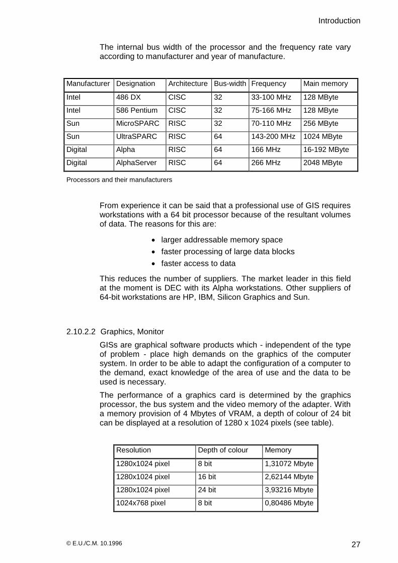
The internal bus width of the processor and the frequency rate vary according to manufacturer and year of manufacture.
Manufacturer Designation Architecture Bus-width Frequency Main memory
Intel 486 DX CISC 32 33-100 MHz 128 MByte
Intel 586 Pentium CISC 32 75-166 MHz 128 MByte
Sun MicroSPARC RISC 32 70-110 MHz 256 MByte
Sun UltraSPARC RISC 64 143-200 MHz 1024 MByte
Digital Alpha RISC 64 166 MHz 16-192 MByte
Digital AlphaServer RISC 64 266 MHz 2048 MByte
Processors and their manufacturers
From experience it can be said that a professional use of GIS requires workstations with a 64 bit processor because of the resultant volumes of data. The reasons for this are:
larger addressable memory space
faster processing of large data blocks
faster access to data
This reduces the number of suppliers. The market leader in this field at the moment is DEC with its Alpha workstations. Other suppliers of 64-bit workstations are HP, IBM, Silicon Graphics and Sun.
2.10.2.2 Graphics, Monitor
GISs are graphical software products which - independent of the type of problem - place high demands on the graphics of the computer system. In order to be able to adapt the configuration of a computer to the demand, exact knowledge of the area of use and the data to be used is necessary.
The performance of a graphics card is determined by the graphics processor, the bus system and the video memory of the adapter. With a memory provision of 4 Mbytes of VRAM, a depth of colour of 24 bit can be displayed at a resolution of 1280 x 1024 pixels (see table).
Resolution Depth of colour Memory
1280x1024 pixel 8 bit 1,31072 Mbyte
1280x1024 pixel 16 bit 2,62144 Mbyte
1280x1024 pixel 24 bit 3,93216 Mbyte
1024x768 pixel 8 bit 0,80486 Mbyte

Introduction
© E.U./C.M. 10.1996 28
1024x768 pixel 16 bit 1,60972 Mbyte
Memory requirements of graphics cards
In order to comply with the requirements for an ergonomic GIS workstation, the monitor must emit low levels of radiation, it must have a high colour fidelity, and must have a picture repetition frequency of 70Hz in high resolution.
2.10.2.3 8 bit graphics
8 bit graphics systems permit a simultaneous display of 256 colours or grey scale values, dependent on the colour or grey scale value table available. If chiefly vector data is worked with and raster information (satellite data, scanned aerial photographs etc.) only deposited, these graphics systems can be completely adequate.
It is to be noted in this case, however, that much raster information possesses 16, 24 or even 32 bit information , which then has to be adapted to the 8 bit graphics system.
2.10.2.4 Graphics systems of larger bit sizes
For many evaluations of satellite recordings and aerial photographs, 256 colours are often not enough. Most satellite recordings are supplied in 18 or 24 bits. In these cases a reduction to 8 bit would represent a considerable loss of information. For the evaluation of raster information with larger bit figures, these requirements should be taken into account in the configuration of the computer system.
2.10.2.5 Main memory
The size of the main memory (RAM = Random Access Memory) is an important aspect in assessing the performance figures of a computer. The actual memory required depends on the type of problem (file sizes), the operating system used, and the software’s dependence on working memory. A server should be equipped in principle with the largest possible memory capacity (128 Mbyte on a Pentium board).
In the case of workstation computers for alphanumeric applications, a minimum memory capacity of 8 Mb is recommended for MS-Windows for Workgroups applications. Windows 95 requires 16-20 Mbyte and with Windows NT, 32 Mbyte are the basis for an acceptable working speed. Graphics applications can require substantially more memory capacity.
With Unix operating systems, the requirements for memory depend moreover on the Unix derivative which is being used. In general, with

Introduction
© E.U./C.M. 10.1996 29
Unix the operating system adapts itself to the existing hardware components (size of the delivery file and I-nodes of the RAM management). At least 32 Mbyte should be available in association with a graphical user interface.
There are different types of memory component :
PS/2 SIMM 72-pin-Module with 70 µs access time and
SIMM with 32-pin connector and 70 µs.
In principle it can be said that performance improves with a larger main memory. Since some GISs are dependent on main memory because files can only be processed whose size does not exceed the main memory that is not occupied by the operating system, the processing limits can be very quickly reached.
The same goes for systems which guarantee (via swapping) the processing of files which are larger than the freely available working memory. Also it is absolutely essential in this case to conduct the corresponding considerations of the size of the RAM in the light of the task specifications.
In GIS applications which manage extensive raster or vector data and large files, software products which are dependent only on secondary storage should be used wherever possible. With appropriate programming, the processing speed for directly accessing the disk is faster than a partial processing in RAM with temporary storing of the intermediate data to the disk (swapping). The reason is a lower expenditure on the management of the data.
If the GIS software is on a server and the users are attached with the help of X terminals, exact knowledge of the job descriptions is even more urgently required, since the requirements on the main memory of the server is dependent on the number and application of the attached X servers. Certainly this solution should be assessed critically.
2.10.2.6 Secondary storage (hard-disks, RAID systems)
Mass-storage which makes random access (direct access to the blocks of information) to the data possible is considered to be secondary storage.
In general it can be said that the hardware structure must be open to expansion. Therefore memory systems which are equipped with a SCSI-interface should be used in preferance.
Since it can be assumed that within a national GIS there will be large volumes of data, the use of RAID systems should be taken into account when the system architecture is being considered.
The following requirements for data storage must be satisfied :
security from failure
Introduction
© E.U./C.M. 10.1996 30
fault tolerance
modular construction
flexible expandability of the system
The RAID (Redundant Array of Independent Disks) system fulfills these requirements. The redundant (multiple) storing of the data increases the security from failure, and improves the availability of the data. In addition, the RAID system in itself must be secure from failure, i.e. the individual components in turn are designed to be correspondingly redundant. On failure of a hard disk work can continue undisturbed, since the defect disk can be exchanged during the current operation (hot swap). The Controller reconstructs the data which is then written to the replaced disk with only a slight loss of performance.
Different types of RAID systems can be distinguished, according to the RAID level. With this the following techniques apply :
Mirroring: mirroring of two or more drives on one controller
Duplexing: mirroring with two separate controllers
Striping: combining of several drives into a logical unit and distributing the data in blocks among these drives.
RAID level 0 :
Level 0 describes a file re-distribution (striping). Several drives are combined into one large logical drive in this type.
Data is distributed across several disks. The number of bytes written onto one of the drives on each transfer is determined by the striping factor. There is an increase of the data request rate and data transfer rate on data segments of different lengths, since all drives are accessed practically at the same time.
On failure of an individual drive, the entire data can no longer be accessed. Since striping taken by itself provides no data security, it can consequently be used in the handling of data with no strategic importance.
RAID Level 1 :
RAID Level 1 works with the complete mirroring of all disks. There are two complete sets of all user data. On failure of a disk the data remains preserved. In each case one half of the available space is at the disposal of the original data, the other half is enlisted to hold the redundant data. RAID 1 provides security for strategically important data.
RAID Level 0+1 :
combines Level 0 and Level 1 (striping and mirroring). It offers the optimal performance of striping and the availability and security of mirroring.

Introduction
© E.U./C.M. 10.1996 31
RAID Level 2 :
RAID 2 uses the ECC (Error Correction Code) algorithm for error detection and correction. A group of drives is complemented by a correction drive. The data is partitioned over the drives of the stripe set. In addition, the ECC-bits are written to the correction drive. On the simultaneous failure of two drives no data is lost.
RAID Level 3 :
RAID-3 works with a single parity-drive. The striping factor is a single byte. On each write-access the parity disk must be accessed.
RAID Level 4 :
RAID 4 corresponds to RAID 3, only with a striping factor of one or even several blocks. With short accesses a good performance can be achieved.
RAID Level 5:
RAID 5 disperses - with so-called parity algorithms - the data all over the disks of the array. On failure of a disk the data resident on it can be automatically reconstructed from supplied “replacement disks”.
Level Technique read
performance
write
performance
Capacity Remarks
Level 0 Striping >=single drive >=single drive 100% no data security
Level 1 Mirroring max. double speed = single drive 50% high data security
Level
0+1
Striping + Mirroring
max. double speed >=single drive 50%
Level 2 Striping, Error Detection and Correction (Error Correction Code)
>=single drive >=single drive 70% time-consuming ECC calculations
Level 3 Parity drive is used for Error Detection and Correction
= single drive >>single drive 80-90% slow write access
Level 4 RAID-3, with Striping factor > 1 byte
>=single drive >>single drive 80-90% Performance as Level 3
Level 5 Level 3 with distributed parity
>=single drive >>single drive 80-90% lower performance

Introduction
© E.U./C.M. 10.1996 32
2.10.3 Tertiary storage (tape drives, optical disks)
Back-up data storage :
Data security is one of the most important jobs when dealing with data processing. Hardware faults, external influences like fire or water, viruses or programming errors can all destroy data. Even experienced administrators can delete disk contents through operator errors. (For example, with the common TAR command, a root partition can be overwritten).
It is therefore absolutely essential to regularly copy a backup onto a storage medium which can be kept safe afterwards in a separate place. Changeable storage media are on offer for data security. In selecting the media the following criteria should be taken into account :
the length of time required for both the backup and the restoring of the data; the capacity and transportability of the medium; and data security as an archive solution.
the compatibility of the backup system with different file systems and its network capability should be guaranteed.
2.10.3.1 CD-ROM
CD-ROM (ReadOnlyMemory) is a changeable, optical medium, which once written can only be read. The storage media are very secure. These disks are suited to the mass storage of data. The capacity of a CD-ROM ranges from 128 to 650 Mbyte.
With CD-ROM recorders, blanks (write-once CDs) can be written. Thus the manufacture of small editions of pre-recorded CD-ROMs e.g. with base information or satellite maps of Lebanon, is possible from a commercial point of view. The CD is suited to long-term archiving. A subsequent modification to the data is not possible.
In CD-ROM changers several single storage media are cascaded. These can then be logically considered as single drives. The change time per CD is between 3 to 10 seconds. Changer systems permit - in one single peripheral unit - the management of amounts of data in the terabyte range.
2.10.3.2 EXABYTE Subsystems
The technology of the EXABYTE magnetic tape cassette drives has its origin in Video8 technology. This technology has been further developed for the requirements of data security and makes it possible to store large amounts of data on 8 mm cassettes. EXABYTE drives record data with the IDRC (Improved Data Recording Capability)

Introduction
© E.U./C.M. 10.1996 33
algorithm. With compression, the capacity of a 160 m cassette lies between 7 and 40 Gbyte. The capacity is halved when compression is not used.
Connection to the computer is achieved via the single-ended SCSI interface or with a 50-channel Centronics plug or even by being built-in.
EXABYTE has developed into a standard exchange medium in remote sensing.
2.10.3.3 DAT drives
DAT drives for 4 mm cassettes are a further development from the field of audio. The standard format for DAT drives is DDS (Digital Data Storage) developed by HP and Sony. With the DDS2 format a capacity - with data compression - of 8 Gbyte (120m tape) with a transfer rate of 1 Mbyte/sec is achieved.
DDS3 drives can store up to 24 Gbyte with a transfer rate of a maximum of 2 Mbyte/sec.
2.10.3.4 Magnetic Optic / Direct Overwrite Optical Disks
Magnetic Optical disk drives allow a double-sided usable storage medium to be written to. The MO surface is heated by laser and written to by simultaneously bringing a magnetic field close to the surface. This data can be read again later by the laser. The Direct Overwrite (DO) technology uses media which can be directly overwritten by laser. When writing, the laser works at a higher power level.
The storage media themselves are small, light and attractively priced. The drives can be used by the computer like a normal disk drive. The average transfer rate is around 0.8 - 1.6 Mbyte/sec, whereas the writing process takes longer since the same block is handled three times (deletion, writing, control). The new DO drives roughly correspond in performance to ordinary disk drives.
2.11 Operating systems
2.11.1 UNIX
The most important operating system in the field of workstations is UNIX. Its portability and wide circulation, the availability of many software products, and its extensive processor-independence are the decisive advantages. Further important features of UNIX are :

Introduction
© E.U./C.M. 10.1996 34
multi-user operation, i.e. several users can work on the system at the same time. Each user logs on with his own name and his password. Data is protected appropriately via the granting of access rights.
multi-tasking, i.e. each user can run several programs in parallel.
timesharing, i.e. when several processes run at the same time, space in main memory or in the processor is alternately assigned to the individual processes according to a priority routine.
individual access rights for files, i.e. it is established via access rights who may look at (read), modify (write) and execute data, devices or directories. In this, one distinguishes between user, group and others.
availability of numerous programming languages, which is dependent on the availability of the appropriate compiler. ADA, APL, BASIC, C, C++, COBOL, FORTRAN77, LISP, MODULA-2, PASCAL, PROLOG and many more languages run under UNIX.
shell - user interface, command interpreter and job control language, i.e. via the shell job command language, which has a functionality similar to a high-level programming language, the running of programs can be controlled.
multitude of software tools i.e. over 300 commands are available to the UNIX user.
The UNIX derivatives of the hardware manufacturers are to be taken into consideration. Owing to the different capabilities of the compilers, difficulties can arise when porting software.
The alternative UNIX-CALDERA derivative “Linux” is of great interest. It is obtainable as a freeware operating system and is about to be granted the X/Open certificate “Unix 95”.
2.11.2 Windows NT
2.11.2.1 Windows NT™ Workstation :
Windows NT Workstation is a 32 bit operating system which guarantees a high stability both for 16 and 32 bit applications via protected address regions. The NT Workstation guarantees full compatibility with standard Windows 95 and Windows for Workgroups applications. The file system NTFS prevents unauthorised access to systems and to confidential GIS, project and personal data. Owing to modest demands for working memory for individual applications, NT makes very large memory resources available. An effective utilisation of memory is achieved by caching of large amounts of data.
Portability onto various processors like Intel® x86/Pentium™, MIPS® R4x00, Alpha AXP™ and PowerPC™, and the support of symmetrical

Introduction
© E.U./C.M. 10.1996 35
multiprocessing (SMP) makes upgradability from single to multi processor systems possible for Windows NT.
NT is the appropriate client in the network . System priorities for interactive applications and network users, and preemptive Multitasking are features of high performance and they allow computer-bound applications for data processing of large construction tasks or statistical problems.
Support for high-end APIs like OpenGL for 3D graphics programming provides the requirements for professional CAD applications. Windows NT Workstation provides the base functionality for simple operation, management and connectivity.
2.11.2.2 Windows NT™ Server 3.51 :
NT Server is a Client/Server platform, scaleable up to a 32 CPU multiprocessor system. The 32 bit operating system supports multithreading and 4 GB RAM per system, 2 GB of virtual working memory per application and 402 million terabyte data storage per system. As well as the capabilities of the NT Workstation version like processor independence, preemptive multitasking and memory protection, NT Server is a multipurpose operating system for file, print, messaging and application services and the following network performance :
Protocols :
TCP/IP, NetBEUI, IPX/SPX, DLC and AppleTalk. Telnet and FTP Clients, FTP Server, services for the Macintosh, Network Client Manager for the network installation of Client Software with support from Windows® 95.
Integrated messaging services :
Client Service for NetWare® (CSNW) makes access possible to the file and print services of a NetWare 3.X server. Access over IPX/SPX and IP is possible. The Gateway Service for NetWare® (GSNW) gives workstations in the Windows NT™ Server Network (without IPX/SPX) access to the resources of the NetWare® Server. The integration of TCP/IP networks: Dynamic Host Configuration Protocol (DHCP) makes the dynamic set-up and management of TCP/IP addresses possible. Windows Internet Naming Service (WINS) allocates names to the TCP/IP addresses.
Remote Access Service (RAS) in the Server is extended to 256 workstations and Point-to-Point Protocol (PPP) and the Serial Line Interface Protocol (SLIP) are supported.

Introduction
© E.U./C.M. 10.1996 36
Diskless MSDOS and Windows workstations are integrated into the network with Remote Boot Support.
2.12 Essential software
A number of additional software products can be required for a successful GIS operation. In a GIS, integrated spreadsheet programs, statistical analysis systems, layout programs, CAD etc. are not considered the optimal solution.
All these different applications are obtainable in the form of independent, powerful software products both in the field of workstations and PCs. Their scope of function is superior to those integrated in the GIS. Moreover, they can be used independently of a PC and therefore do not tie up GIS workstations.
A smaller dependence on GIS software manufacturers and a favourable cost structure are further advantages. Over and above, these software products are already known to many users and this reduces the necessary training period.
2.13 GIS database systems
Similar considerations apply to databases. Here also GISs are on the market both with their own databases and systems which lie on top of external databases.
GISs which contain both possibilities are also obtainable and should be preferred, at least in the initial stage, without forgoing the option of tying in later to an external database.
Distributed database systems play an increasingly important role in larger computer units which work together in a combine. In such a combine it is important to ensure the compatibility of the database manipulation language within the entire system. From experience it appears that even when a standard (e.g. SQL) is used, different derivatives - dependent on the different products - exist, which makes a smooth exchange of data difficult.
Further observations with regard to the holding of data must be made. Thus it should be examined in what way the data in the databases is to be managed. The data can be held centrally or on a distributed basis.
Advantages of a central holding of data are simpler carrying out of data security, and the fact that the location of the data is known at all times. Holding data with the help of distributed databases means that data can be filed where it is most frequently used. Because of this, the load on the network is relieved.
Other advantages are the simple maintenance of data by the responsible institutions in whose databases the information resides. With the use of

Introduction
© E.U./C.M. 10.1996 37
FDDI networks, the disadvantages from losses of performance of data transfer in distributed databases step into the background.
2.13.1 Filesystem
The results of different tasks are stored in appropriate files. With the manipulation of cadastre data, the base information contained is always re-saved in every single map, for example, which leads to a redundant data stock. Problems arise through redundancy on modification to information, since this modification must be placed in all appropriate files independently of each other. Inconsistencies are the inevitable consequence of this.
A loose collection of single geography files is not a database !.
2.13.2 Relational database :
A database is the model of a given system . With the formation of the model, the objects of the real world - the system components - are to be regarded as entities (given sizes), between which certain relationships exist (entity relationships). Each entity is characterised by attributes. Each attribute can take different values. Data elements which belong together are combined in data sets to data groups, or tables. Tables are real expressions of data groups.
Elements which produce the association among various datagroups (tables) are called keys, all other fields are attributes. Keys are the holders of association between datagroups. They serve as the identification of data sets in the database (relative pointers). The index formation via a table is an optimising process for access to special data sets. Keys can be used for index formation.
The logical decoupling of datagroups makes it possible for data to be held free of redundancy. A relation is a table with particular characteristics. The task of database design is the forming of stable data structures through the normalisation of relations. The mathematical normalisation process forms the basic requirements for freedom from redundancy, consistency of data and the prevention of anomalies.
Relational database management systems represent at the moment the state of the art. A database system provides appropriate tools for the manipulation of data. It consists of the database management system and the actual data. In addition, there are tools with whose help an appropriate work environment can be set up. The creation of menus and masks for data entry, support for software development as well as for integration into the network are part of this. Access rights in a database system are firmly controlled.

Introduction
© E.U./C.M. 10.1996 38
2.14 Networking
Apart from the use of GIS, networking is the most important component for the type of problem to be solved. Therefore the relevant principles are gone into in some detail in the following sections.
2.14.1 Network architecture
LAN : A Local Area Network is the basic component of a network. Existing resources are used jointly by connecting individual computers. Single LAN segments can be connected by means of repeaters, bridges or routers. This architecture applies to Data Processing (DP) solutions within the institutions.
MAN : A Metropolitan Area Network describes the uniting of systems and networks in a densely-populated area. This architecture applies to the Beirut area.
WAN : A Wide Area Network is a public, wide traffic network. This architecture applies to Lebanon.
GAN : A Global Area Network is the global worldwide network which links countries and continents via satellite.
2.14.2 Network components
The components of the communications model: transmitter <-> receiver, become in the network : client <-> server model. Client/Server systems bring higher computing power to workstation computers. The user accesses as a client the resources and services of a server.
joint use of peripherals (printer, plotter, storage …)
connection to external providers (computer centres, databases…)
data exchange with each other
security, reliability and availability due to :
back-up
redundant data holding
redundant components
Network components can be classified as follows:
Data combine :
In a data combine it is possible to access data which is stored on a remote system from a workstation system.
Function combine :
The network has the task of making available to the workstation, the applications, functions and capabilities of a server station.
Load combine :

Introduction
© E.U./C.M. 10.1996 39
In a load combine two and more computers jointly share the set task. Hence an appropriate task is processed in parallel by several systems and completed in a shorter time.
Availability combine :
If a station in a system breaks down, another station can continue to process the task. This increases the availability of the system.
Communications combine :
Such a combine helps the exchange of messages with one another via electronic mail (e-mail) or other message systems.
2.14.3 Network topologies
A network topology describes the kind of physical connection of individual stations in a net. A distinction between a diffusion network and a store-and-forward network can be made.
In the diffusion network (bus topology) the network stations communicate over a common segment. Typical representatives of this topology are Ethernet’s Cheapernet and directional radio links or satellite links.
All further possible connections are branched, and described as store-and-forward networks. To these belong star, tree and ring structures.
If the connection of the individual network nodes is self-contained, this is a ring. Typical representatives are the Token Ring and FDDI networks.
WS
WS
WS
Ethernet: 10BASE2
server
terminator
LAN local aerea network
bus topology
WS
WS WS
LAN
star topology
hub
server
twisted pair
In a star topology, there is a point to point connection from a central network node to individual computers or segments. For example: an Ethernet hub to which several stations or network segments are connected.

Introduction
© E.U./C.M. 10.1996 40
If single star couplers (hubs) or concentrators are cascaded via point to point connections, this is a tree structure. In this, the network nodes are connected to the ports which are not required for cascading. 100VG-AnyLAN is a representative of this topology.
Networks are not limited to one topology. A complex LAN system can combine several different topologies.
2.14.4 Interfaces
Network adapters with an AUI-(DB15-) socket, a 10BASE-T port or a 10BASE2 (BNC) connector are offered as plug-in cards and are firmly fixed into the computer. AUI adapters can - with the appropriate transceivers (Yellow Cable, Cheapernet, TwistedPair or fibre optic waveguide) - connect different media.
Repeaters :
A repeater is a signal regenerator which works on Level 1 of the OSI model. Repeaters are used in the Ethernet, if , on expansion, the permissible cable length (185 m for 10BASE2, 500 m for 10BASE5) or number of stations is exceeded.
IEEE 802.3 limits the maximum number of repeaters to four and the total length attainable to 2.500 m. With the coupling of several Ethernet segments, repeaters prevent the transfer of faulty electrical signals from one segment to another. Usage is not dependent on cable type (Yellow Cable, Cheapernet).
The essential functions are as follows :
regeneration of the amplitudes
correction of the frequency edges
buffered repeaters synchronise the frequency
testing of the line for activity
collision detection
JAM signal generating
WS
WS
WS
WS
WS
WS
tree topology
server
twisted pair
switch
switch
switch
(1.4)
(1.4)
(2.3)
(2.3)
(2.3)
(2.3)
(5.2)(5.2)
(5.2)(1.1)

Introduction
© E.U./C.M. 10.1996 41
Concentrators :
Concentrators are the connecting devices in the double-ring topology. Here we are dealing with intelligent hubs for connecting FDDI devices like Single Attached Stations (SAS). Concentrators are modularly constructed and have space for building-in different port modules.
The ports are configured by software as M ports for the connection of SAS stations and as A and B ports for the connection of Dual Attached Stations (DAS). Digital offers Physical Media Depent Cards (PMD) which can be very flexibly equipped in the choice of the cable type. By cascading concentrators, a topology with a tree structure is obtained.
It is not absolutely necessary to connect such a tree to a ring.
A star topology can be supported with a concentrator.
Bridges :
Bridges are used as links between Ethernet and FDDI. Translating Bridges work according to IEEE 802.1d, 802.3 and the ANSI FDDI standard. They lay upon the Link Layer (2) of the OSI reference model and are hence protocol-independent. Bridges connect physical layers of all sorts of types with each other (FDDI/Ethernet). A bridge extends the network beyond the number of nodes and maximum distance specified in the Ethernet.
In FDDI to Ethernet transfer, bridges perform the following functions :
frame converting
reversing the bit order (address bits)
calculation of a new Checksum
production of a dummy priority
compensation of the various data transfer rates
Bridges have several Ethernet connectors at their disposal and can be integrated into the network as SAS or DAS. Interferences in a segment are not transferred by the bridge. Bridges are capable of learning, in that they store the sender and receiver addresses in an internal address table. The packet traffic in the part segments is thus filtered.
By means of configuration of the subnetwork mask, the flow of information between individual nodes can be reduced, which improves data security. In the separated segments, different data packets can be transferred at the same time. Bridges work at the same time with TCP/IP, DECnet, IPX and LAT.
Switches are multiport bridges with several Ethernet ports. Switching (store and forward) is supported between the ports.

Introduction
© E.U./C.M. 10.1996 42
Switches for Ethernet and 100 Mbit/s FDDI :
There are two different switching methods:
cut-through and
store-and-forward.
The cut-through technique - developed by Kalpana - is based on a cross-point switch matrix and is also called on-the-fly switching. Cut-through does not comply with the IEEE specifications which led to the giving of the name “switch”.
Transfer time is shortened here with a lower response time which is a result of the intermediate storing of data packets. With the receipt of a 6-byte long target address, a block is passed on without CRC-check (Cyclic Redundancy Checksum). A check does not take place until the target segment is occupied. A checksum can only be established from a packet which has been fully read, therefore faulty data blocks can also be transferred to the target segment. If the percentage figure of collisions in a segment increases, the performance of the whole network combine can be negatively influenced.
Store-and-forward satisfies the IEEE conventions. In the meantime, all multiport bridges are described as switches. With the store-and-forward technique the whole packet is subject to error checking. Because of this the passing on of data between the individual nodes is delayed, however faulty packets are discovered and filtered out.
There are switches which use both techniques, and - with the appropriate user-defined configuration - switch automatically into store-and-forward on frequent occurrence of CRC faults.
Switches are put into use when workgroups with high data traffic must be separated from the network to relieve the rest of the combine. The partsystems which come into existence when this happens can be coupled in a star formation with each port of the switch.
Packets can be transferred with maximum speed among the individual ports. Switches make simultaneous data traffic possible in several different segments.
The integration of a switch into a FDDI backbone is possible both as SAS and DAS. An Ethernet coupling with Thin and Thick wire and fibre optic waveguide can be set up with AUI connectors over transceivers.
Routers :
Routers are assigned to layer 3 (Network Layer of the OSI reference model). They connect network segments with different layers of 1 and 2. The higher protocols, like those of the Transport Layer, must be identical and above all routeable. Routers are able to recognise all protocols in use and to convert data packets appropriately. They adjust the packet length of the data to that of the receiver segment and thus connect different network types in this way. Routers perform a speed adjustment (Ethernet/FDDI).
Functions:

Introduction
© E.U./C.M. 10.1996 43
routing: passing on of data packets suitable for the destination
load balancing: route selecting by locating alternative paths to the destination station, when direct connections are disrupted by congestion or overload.
address mapping and protocol conversion.
The optimal path between transmitter and receiver is determined from protocol-dependent algorithms by the router. There is a distinction between Distance Vector (RIP = Router Information Protocol) and Link State Protocols (NLSP=NetWare Link State Protocol).
Multiprotocol routers support the following protocols: IP, IPX, DECnet, AppleTalk, OSI, XNS, VINES and Apollo Domain. For protocols like LAT and NetBIOS, which are not communicable, the router uses its bridge functions.
2.14.5 Transfer media
Cabling is a long-term investment. A cabling infrastructure must last for longer than the devices, which after a few years are out-moded and exchanged. Observations on structured cabling follow from this :
Primary : Outdoor cabling between buildings with high transfer capacity via fibre optic waveguide.
Secondary : Linking of the floors inside a building via ‘pipelines’ to the distribution rooms (backbone).
Tertiary : Connection to the terminals
Transfer media are covered in three categories:
the baseband
broadband
fibre optic transfer system
Normally the baseband type is used. This system is the most widespread. With this type only Ethernet signals are transferred onto the cable.
With broadband type, different carrier frequencies can transfer various signals at the same time on one cable. They are both similar with a transfer rate of 10 MBits/sec.
2.14.5.1 10BASE5, Yellow Cable
The thick Yellow Cable may be up to 500 m long and incorporate up to 100 transceivers with a minimum interval of 2.5 m. A transceiver (transmitter/receiver) forms the interface between station and cable. The transceiver cable is connected to the station via an AUI socket.
A transceiver contains transmission and receiving logic, with which carrier sensing, collision detection and the generation of synchronisation signals is carried out. Several cable segments can be coupled to each
Introduction
© E.U./C.M. 10.1996 44
other up to the maximum length with the appropriate connection plugs. Further couplings are possible via repeaters or bridges. Both ends are terminated with a 50-ohm terminator. The cable is earthed at one (not both) ends.
2.14.5.2 10BASE2, ThinWire, Cheapernet
Cheapernet’s 50-ohm coaxial cable is substantially thinner, more flexible and cheaper than Yellow Cable, hence the name.
There are NET-JET ThinWire sockets and TAED connectors, which are hard-installed like a telephone connection socket. Since Cheapernet is limited to a total cable length of 185 m, every connector must be calculated as an extension to the segment. A Cheapernet segment can incorporate 30 stations with a minimum interval of 0.5 m.
2.14.5.3 10BASE-T, TwistedPair
TwistedPair is connected as a point-to-point connection. Normally there is a 10BASE-T-Multiport-Repeater (Hub) at one end of the cable (maximum 100 m), while at the other end either a transceiver with a single device or else a convertor to another cable type is found.
The Twisted Pair cable distinguishes between transmit and receive line pairs. In the cascading of repeaters, the transmit and receive line must be crossed, or the transmit and receiver port must be switchable. In 1993 the FDDI standard was extended to the TP-PMD standard (Twisted Pair Physical Medium Dependent) - based on Twisted Pair cables - so that data may be forwarded according to the FDDI specification over 10Base-T cables.
2.14.5.4 10BASE-F Ethernet Fibre Optic Waveguide
Fibre optic waveguides have a high bandwidth and high transfer rate with low signal loss. They are bugproof and comply with the strict Euro norms on electro-magnetic emissions. They form an electrical separation between the stations.
Fibre optic systems can be used in the Ethernet as well as with Twisted Pair only for point-to-point connections. Fibre optic waveguides have a use between bridges and/or repeaters, between a repeater and a single station or between two stations. One station is connected to a transceiver which takes over the opto-electrical conversion and signal regeneration. With the industry standard FOIRL (Fiber Optic Inter Repeater Link), products from different manufacturers can be mixed.
The 10BASE-F standard for the use of fibre optic waveguide cable describes four chapters :
1. Specification of the fibre optic waveguide cable, the topology and the types of connection.
2. 10BASE-FP contains guidelines for passive optical fibre hubs.
Introduction
© E.U./C.M. 10.1996 45
3. 10BASE-FB describes the usage of 10BASE-F as a backbone.
4. 10BASE-FL replaces the present FOIRL standard: it regulates the connection of repeaters with each other and the connection of an end-device to the repeater.
Since fibre optic waveguides are relatively expensive they were used in the past mainly for spanning larger distances. However they form in addition the requirement as a transport medium for high-speed FDDI networks.
There is a multitude of network products each of which offers a different service in the network. Such a service appears to the user, for example, as FileTransferProtocol (FTP), SimpleMailTransportProtocol (SMTP) or HyperTextTransmissionProtocol (HTTP).
2.14.6 Network protocols
There is a multitude of network products each of which offers a different service in the network. Such a service appears to the user, for example, as FileTransferProtocol (FTP), SimpleMailTransportProtocol (SMTP) or HyperTextTransmissionProtocol (HTTP).
OSI reference model of the ISO
The 7-layer model of the International Standardization Organisation (ISO) - also called Open Systems Interconnection (OSI) - has established itself as the official standard. OSI describes an open system, for which even future developments can be standardised. The 7-layer model specifies in each layer the protocol used and the functions of the protocol with which the computers involved - even in a heterogeneous environment - communicate. OSI is a strictly hierarchical system in which the lower levels form the requirements for the higher ones. The following layers are defined:
Level 1 : Physical layer
Provision of functional, procedural, mechanical, electrical and electronic resources for the transfer of bit sequences across any medium. Support of different kinds of transfer. Elementary errors which arise in the physical transfer should be detectable and rectifiable.
Level 2 : Link layer
Combining of data into blocks; block synchronisation. The error detection and correction follows the CRC method (Cyclic Redundancy Checksum). On setting up a fault-free connection between end-system and the network port - bridging - a checksum is determined from the bit pattern of the data blocks, transferred (appended), and checked.
Level 3 : Network Layer
Selection and control of the transport network - routing. The optimal path here is not only dependent on the number of intermediate nodes but also on the load and susceptibility to interference of the connection

Introduction
© E.U./C.M. 10.1996 46
route. Relaying to, and coupling of, different transport networks, multiplexing of a physical network port.
Level 4: Transport layer
Link between the message transport system and the users. Set-up and maintenance of a (virtual) connection between two end users (end-to-end), provision of a network-independent transport mechanism, addressing of an end subscriber.
Level 5: Session layer
Establishment and control of sessions, access control, connection set-up. Definition of attaching points.
Level 6: Presentation layer
A global, unified information representation and interpretation is achieved in the presentation layer. Character sets and attributes are made available, which enables the application layer to name terms unambiguously. Rules are laid down here as to how the information represented in the common language is to be exchanged. (Encoding and data compression).
Level 7: Application layer
Provides the logical communication-technical support for specific applications :
- file transfer (FTP)
- remote access to files (Telnet, rlogin)
- job transfer, message systems SMTP,
- distributed databases (remote database access),
- DomainNameService DNS.
OSI Function
7 Application Layer Network Management: logical and communication technical support for applications
6 Presentation Layer Transformation into a standard format
5 Session Layer Control of sessions, access control, connection set-up
4 Transport Layer Connection of two end systems (End-to-End)
3 Network Layer Routing
2 Link Layer Connection of end system and network port
1 Physical Layer Physical bit transfer
OSI 7-layer model

Introduction
© E.U./C.M. 10.1996 47
2.14.6.1 TCP/IP
TCP/IP (Transmission Control Protocol/ Internet Protocol) is at present the most common network protocol. The structure of the TCP/IP family appears conceptionally in four levels, built on top of one another :
1. Network Access Layer is the physical level for transfer in the respective networks.
2. Internet Layer describes how a connection between any computers is set up and maintained over the individual stations.
3. Host to Host Layer sets up protected End to End connections, allowing data to be exchanged.
4. Application Layer
The following protocols are standard applications based upon the Application Layer :
TELNET (TELetype NETwork)
SMTP (Simple Mail Transport Protocol)
FTP (File Transfer Protocol)
Rlogin (Remote Login)
SNMP (Simple Network Management Protocol).
TCP/IP is usable on different media and computers and is thus the network protocol for linking heterogeneous systems. The operating systems Unix (or SunOS, OSF/1, HP-UX, AIX), OpenVMS, WindowsNT, Windows95 and NextStep support TCP/IP. Packet drivers for TCP/IP, SLIP and PPP are installable even under DOS or Windows for Workgroups.
File transfer between the different computing worlds in the national GIS is possible with TCP/IP. In this way a file is converted during the transfer from a VAX to a Sun computer into the correct format in one operation. The User Datagram Protocol (UDP) makes data exchange possible for application processes without a virtual connection having to be set up. TCP and UDP lay upon the Internet Protocol (IP).
ISO layers Protocols Architecture Function
7
6
5
Application
Presentation
Session
SNMP
FTP
SMTP
Telnet
Application Layer
Application-oriented service for mail, data transfer and remote access.
4 Transport TCP Host to Host Layer End-to-End Protocol
3
Network
IP
Internet Layer
connectionless
Internet protocol

Introduction
© E.U./C.M. 10.1996 48
2
1
Link
Physical
Network Access Layer
Network infrastructures
The DoD (Department of Defense) Protocol family

Introduction
© E.U./C.M. 10.1996 49
2.14.6.2 IPX
IPX (Internetwork Packet Exchange Protocol) is the network protocol of the NetWare network operating system from Novell. With its multi-user and multi-tasking architecture, it is conceived as a fileserver operating system. NetWare processes simultaneously various requests from workstation computers and supports several different operating systems.
With NLM components (NetWare Loadable Modules) the wishes of the individual user are complied with. The NetWare protocol supports the Network layer of the OSI and is hence to be found in many multi-protocol routers.
ISO NetWare Function
7
Application layer
File/Print service, other functions with VAPs and NLMs
Management of the File/Print service
6 Presentation layer NetWare Shell adapting formats and functions
5 Session layer NetWare Core function
tuning LAN, Server and PC operating system
4 Transport layer SPX Transport functions
3 Network layer IPX Routing to alternative networks
2
Link layer Controller on
LAN Adapter card
Access control
Data protection
1
Physical layer Transceiver on
LAN Adapter card
electrical or optical transmit/receive techniques
NetWare Architecture
2.14.6.3 NetBIOS
NetBIOS (Network Basic Input Output System) is a network protocol developed by IBM for peer to peer communication between PCs. The OS/2 LAN Server supports this protocol. NetBIOS networks are simple to manage as long as they remain limited to the size of a workgroup.
2.14.6.4 NetBEUI
NetBEUI is a standard protocol from Microsoft, which is used chiefly by Windows for Workgroups (WfW), Windows95 and the Windows NT Server.

Introduction
© E.U./C.M. 10.1996 50
2.14.6.5 DECnet
DECnet belongs to the protocol family of DEC computers (Digital Equipment Corporation). The DNA architecture (Digital Network Architecture) is very close to the ISO/OSI model. DECnet uses various connections like Ethernet and X.25.
With TCP/IP support, PCs can also be integrated into DECnet. The connection to Wide Area Networks (WAN) is likewise possible, as is the setting up of an SNA (System Network Architecture) connection via a DECnet/SNA Gateway.
DECnet has been developed in phases and with each phase new functions are added. At present Phase V has been reached.
ISO DNA
7 Application Layer User Network Management
6 Presentation Layer Network Application
5 Session Layer Session Control
4 Transport Layer End-to-End Communication
3 Network Layer Routing
2 Link Layer Data Link
1 Physical Layer Physical Link
DNA model
2.14.7 Distributed filesystems
Distributed filesystems have been developed in order to be able to support file and print management on several different hardware platforms. Since there is no clear demarcation between such management systems, the described network protocols and the computer operating systems concerned, these are introduced as network operating systems :
2.14.7.1 NFS from SUN
The NFS (Network File System) - based on the TCP/IP protocol - is a transparent machine-independent and operating system-independent communications user interface. All files and filesystems released to the user appear to be transparent and local on his workstation. The entire memory space of the network is at his disposal. The access technique remains invisible to the user. The transparency of NFS extends to files of many different structures on different operating systems.
The necessary conversion takes place as part of the transfer. Obviously the restriction of DOS filenames to eight characters simply remains.
Introduction
© E.U./C.M. 10.1996 51
Extended (longer) names of the Unix systems are to some extent mutilated beyond recognition.
NFS accesses are possible not only in a local network but via any TCP/IP connections. They should - owing to the high response time on LAN connections - remain restricted. NFS is however not a LAN operating system . It does not comply with the Client/Server model. NFS is a network service under which each computer can behave as Server and Client. DOS PCs, which can only work as clients, are an exception here.
2.14.7.2 PATHWORKS
The Personal Computing Systems Architecture (PCSA) from Digital is based on a client-server relationship, in which the service of one or several servers is at the disposal of the clients. It is of no importance here whether the server is on a LAN or a WAN.
PATHWORKS is supported as a server platform under OSF/1, OpenVMS, NetWare, ULTRIX, OS/2 and SCO Unix. There are client solutions for DOS, Windows, Macintosh and WindowsNT. Accordingly the network protocols DECnet/OSI, TCP/IP, IPX, AppleTalk, NetBIOS and NetBEUI are supported. PATHWORKS combines the different software products for the integration of PCs and servers. Ethernet, Token-Ring and FDDI are offered as topologies.
2.14.7.3 NetWare
NetWare is independent software for one or several network servers. The server runs in so-called dedicated mode and devotes itself exclusively to central file and printer management. With all its functions and capabilities it sits more or less in the centre.
There is no possibility of directly accessing the application software from the server. This remains reserved for the connected clients who - running under their own operating system (generally under MS-DOS) and extended by a NetWare shell or the Virtual Loadable Modules (VLM) - must also take over the administration. NetWare supports all current topologies: Ethernet, Arcnet, Token-Ring and FDDI.
The server station is only intended for administration of the network. A powerful machine with the greatest possible amount of dynamic memory and SCSI support (NetWare 4.x onwards) for hard disk drives in the multiple gigabyte range, it is not available to application programs.
2.14.7.4 Windows for Workgroups :
Windows for Workgroups (WfW) from Microsoft is a Peer-to-Peer-network under Windows. Central functions of a local network are integrated in the operating system . This lets small work groups form.

Introduction
© E.U./C.M. 10.1996 52
Windows for Workgroups provides no strict separation between server and client, all machines can work virtually having the same rights. The user decides whether the data and peripheral devices of his station are made available to the network. Correspondingly, he can as a client call on the service of other servers. Such a Windows workgroup can be linked as a client to Windows NT, Windows NT Server and NetWare Server (3.12 and 4.x).
With packet drivers, which are normally offered by the network card manufacturers, and appropriate LAN managers, a TCP, SLIP and PPP client binding can be made.
2.14.7.5 Windows 95
Windows 95 is to be regarded as a further development of Windows for Workgroups. It is a 32bit operating system with pre-emptive multitasking. Earlier 16bit applications of the 3.xx version are capable of being run. Available network protocols are NetBEUI, TCP/IP and IPX.
An automatic address management Dynamic Host Configuration Protocol (DHCP), Remote Access Services (RAS) over the Point to Point Protocol (PPP), and Serial Link Internet Protocol (SLIP) are achievable through an extra installation.
The Windows 95 computer can be used as a client in the TCP network. At the moment there are no server applications (FTP or HTTP daemons). Windows 95 can be integrated in a workgroup under NetBEUI.
2.14.7.6 Windows NT Server :
Microsoft delivers two Windows NT Versions: the Workstation and the Server. With the Workstation version several NT-machines can be connected in a peer-to-peer network. Corresponding to Workgroups, this concept is suitable only for small networks since for each individual machine - provided that it offers services in the network - all configurations (like access rights) must be laid down and attended to locally. The running cost for the system administrators is correspondingly high.
With the Server version Windows makes available an operating system which contains the complete features of a network system. With Server, all network relevant information is centrally stored and managed on a domain controller. In contrast to NetWare, this machine continues to be available for applications programs. Windows NT is a complete 32bit multi-user and multi-tasking system. With the establishment of trusted domains, the user can obtain via a single log-in transparent access to all resources and further servers managed by the Server.
Here also the concept diverges from the strict client-server model. Microsoft talks of distributed networks, through which computational
Introduction
© E.U./C.M. 10.1996 53
power can be distributed evenly on the network. NT fileserver is compatible with the LAN Manager of Microsoft itself, the LAN Manager for Unix, Windows for Workgroups, IBM OS/2-LAN-Server and PATHWORKS from Digital. The NFS-System from SUN is only fully supported with the appropriate supplementary software.
The network protocols NetBEUI, TCP/IP and IPX, as well as Remote Access Services (RAS) over the Point to Point Protocol (PPP) and Serial Link Internet Protocol (SLIP) are contained in the NT system. Dynamic Host Configuration Protocol (DHCP) makes an automatic IP address management possible. The support of RAID 1 and RAID 5 is implemented.
2.14.8 Ethernet
IEEE 802.3 defines a synchronisation process CSMA, with which - as in the Ethernet - the use of a single communication channel by several stations is possible (Carrier Sense Multiple Access / Collision Detect CSMA/CD).
Carrier Sense means that a station which wishes to transfer data monitors the signals in the cable in order to establish whether the transfer channel is enabled. The station only starts transferring the data when the medium is free.
The receiving station recognises the addressed data packet and takes it from the line. If an answer is now dispatched from the receiver isochronously (Multiple Access) to the transmitting process of another station, a collision occurs on the line and the bit information gets lost.
If such a collision is detected (Collision Detect), Jam signals are transmitted so that other stations notice the collision too. The transmission stations wait for a period of time and then start with a new transfer. Through this delay, one of the two stations receives automatically the right to transmit.
2.14.9 FDDI
In the use of GIS applications, the transfer rates possible with Ethernet are no longer sufficient - above all with an increased use of raster information - to transport the accruing amounts of data in times which are acceptable.
Even with an X-server in the Unix system, which must support several X-window terminals, the limits of Ethernet can be reached. The use of the clearly faster FDDI (Fiber Distributed Data Interface) technology provides a remedy.
2.14.9.1 FDDI topology :
The topology of FDDI is the ring, with fibre optics as the medium of transfer. There are two different possible connections:
1. Single Attached Station (SAS) as single connection via a concentrator.
Introduction
© E.U./C.M. 10.1996 54
2. Dual Attached Station (DAS) in a double ring with four connections to the transmit and receive lines of the primary and secondary rings.
In the double ring, data is normally transferred on the primary ring. On an interruption, the station lying ahead of the defect notices the fault. The block of data is now transferred onto the connection of the secondary ring and sent in the opposite direction to the other side of the point of interruption. The station there recognised likewise the fault and puts the packet back onto the primary ring in the original direction. Thus the failure of a station is bypassed by its adjoining ones. Breaking up a ring at a single point does not lead to the interruption of the network.
An FDDI ring is formed not only from individual stations, but also - for the coupling of Ethernet segments - from trees of stations in a star topology. This is then a central high-speed backbone. Central servers can be directly linked into the FDDI ring. The transfer rate is 100Mbit/sec. The length of a ring can total 100 km. The maximum number of connections is 1.000, or 500 stations with double connection.
The use of fibre optics results in an electromagnetic immunity. The fibre optic cable is fixed as multi-mode gradient fibre with a maximum distance of 2 km between two stations. The single-mode fibre optic permits a maximum distance of 40 km between two stations. In place of glass fibre cable, twisted pair copper cable can also be used. The TP-PMD standard regulates the use of Unshielded Twisted Pair cable (UTP) in FDDI networks. In this case the maximum length is reduced to 100 m.
2.14.9.2 FDDI-Standard Protocol
The FDDI standard is modularly constructed from four parts which embrace levels 1 and 2 in the ISO/OSI model. Specifications for the physical layer are laid down in the Physical Medium Dependent (PMD) and Physical Layer Protocol (PHY). The access procedure is defined in the Media Access Control (MAC) and the FDDI management in the Station Management (SMT).
The optical features of the connector and the optical waveguide are described in the PMD document. With the PHY layer, PMD forms the Physical Bit layer of the OSI reference model. The PHY is independent from the transfer medium; it codes and encodes (4 to 5 bits) the data exchanged between PMD and MAC and synchronises the transmitter and receiver.
The MAC layer performs a monitoring of the ring. The MAC protocol distinguishes between synchronous and asynchronous traffic. By synchronous traffic is understood the transfer of time-critical data such as audio and video from multimedia applications (real time transfer). The priority with which (in relation to normal asynchronous traffic) data can be synchronously transferred is determined in the Synchronous Bandwidth Allocation Process.
The SMT layer is responsible for the initialisation and operation of the ring and it coordinates the set-up during the initiation of the network. It

Introduction
© E.U./C.M. 10.1996 55
manages the remaining layers as well as timers, counters, and statistics. It carries out the control and elimination of faults.
2.14.9.3 Possibilities for usage :
FDDI is ideal as a fast backbone network.
Ethernet segments can be connected to FDDI via bridges. Since the addressing within FDDI and Ethernet is the same, computers on the Ethernet can also directly communicate with computers on FDDI. Communication between computers on the linked Ethernet segments is also possible. FDDI will not replace Ethernet in the years to come but will increasingly complement it. At the moment FDDI components are more expensive than Ethernet components of a comparable function.
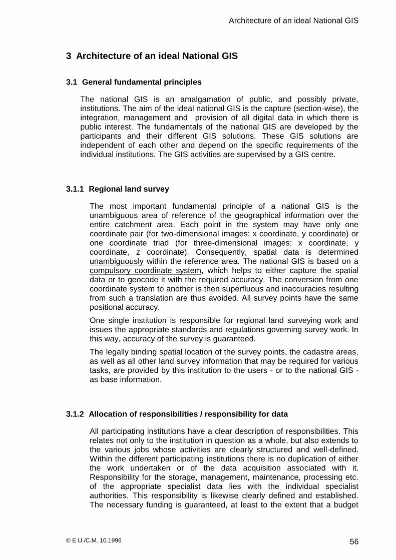
Architecture of an ideal National GIS
© E.U./C.M. 10.1996 56
3 Architecture of an ideal National GIS
3.1 General fundamental principles
The national GIS is an amalgamation of public, and possibly private, institutions. The aim of the ideal national GIS is the capture (section-wise), the integration, management and provision of all digital data in which there is public interest. The fundamentals of the national GIS are developed by the participants and their different GIS solutions. These GIS solutions are independent of each other and depend on the specific requirements of the individual institutions. The GIS activities are supervised by a GIS centre.
3.1.1 Regional land survey
The most important fundamental principle of a national GIS is the unambiguous area of reference of the geographical information over the entire catchment area. Each point in the system may have only one coordinate pair (for two-dimensional images: x coordinate, y coordinate) or one coordinate triad (for three-dimensional images: x coordinate, y coordinate, z coordinate). Consequently, spatial data is determined unambiguously within the reference area. The national GIS is based on a compulsory coordinate system, which helps to either capture the spatial data or to geocode it with the required accuracy. The conversion from one coordinate system to another is then superfluous and inaccuracies resulting from such a translation are thus avoided. All survey points have the same positional accuracy.
One single institution is responsible for regional land surveying work and issues the appropriate standards and regulations governing survey work. In this way, accuracy of the survey is guaranteed.
The legally binding spatial location of the survey points, the cadastre areas, as well as all other land survey information that may be required for various tasks, are provided by this institution to the users - or to the national GIS - as base information.
3.1.2 Allocation of responsibilities / responsibility for data
All participating institutions have a clear description of responsibilities. This relates not only to the institution in question as a whole, but also extends to the various jobs whose activities are clearly structured and well-defined. Within the different participating institutions there is no duplication of either the work undertaken or of the data acquisition associated with it. Responsibility for the storage, management, maintenance, processing etc. of the appropriate specialist data lies with the individual specialist authorities. This responsibility is likewise clearly defined and established. The necessary funding is guaranteed, at least to the extent that a budget

Architecture of an ideal National GIS
© E.U./C.M. 10.1996 57
exists that enables the statutory obligations to be implemented. Taking into consideration the statutory regulations and compulsory arrangements, each institution determines to what extent external users can access the data. This data can be made available within the external users’ own GIS solution, it can be passed on to the GIS centre or be distributed to the various databases within the national GIS.
In the production of the data, the jointly-acquired standards of the GIS centre are taken into consideration.
3.1.3 Base information
Base information is acquired by a group of involved parties together with the GIS centre. For hard data, the following are inter alia regarded as base information :
survey points;
cadastre land-parcels;
ground plans of buildings;
street boundaries; mid-points of streets;
contour lines; natural borders;
political borders; digital terrain model (DTM).
The following are considered, inter alia, as base information for soft data :
digital, geocoded and rectified satellite maps;
orthographic photo maps;
propagation models.
The following points should be taken into account with regard to base information for the national GIS :
- in the thematic preparation of maps it is sometimes necessary for the layout to leave topographic information in the thematic maps, in order to enable the observer to place the map in its geographical context and to enhance the map’s readability. This is done using digitised (for vector data) or scanned (for raster data) topographic maps.
One could also consider using aerial photographs (for large-scale work) or satellite photographs (for small-scale work) as the raster image for the thematic vector maps. Unlike with topographic vector maps, this procedure generates large quantities of data since raster information remains.
- The parties involved in the GIS centre undertake to use the base information of their own thematic work as the basis for the entry of their subject-specific spatial data. Should the thematic geometric information of the participating institutions be identical to that of the base information , then the base information does not have to be re-digitised.
In such cases their appropriate geometric structures must be adopted into the thematic map. In this way one avoids the repeated capture of

Architecture of an ideal National GIS
© E.U./C.M. 10.1996 58
geometric information that all involved parties make use of (such repeated recording would involve the use of different restart points and levels of accuracy, and if there were intersections, then spurious polygons would occur).
The same applies to base data in the form of digital terrain models, satellite maps, orthographic aerial photograph maps etc. which exist in the form of geocoded and adjusted vector maps and raster maps also. In this case, only one common data basis is accessed since the geocoding and adjustment by different users would lead to differing results.
Since the generation of base data by one single institution is very costly and time-consuming, guidelines and regulations are issued to enable involved parties to capture base information, to file it in the agreed layers and to forward it to the GIS centre for integration into the common base data, in a standardised fashion.
Consequently the construction and provision of base data as a foundation for the exchange of digital thematic maps is considerably accelerated.
When generating base information, the institutions must first of all find out from the GIS centre whether this information exists within the national GIS. If this is the case, the existing data must be used. If not, then the required data may be produced by the institution concerned.
For raster information, base data of various resolutions (depending on the scale used) is held by the GIS centre in various layers, in a defined format, for general use. In addition, 24 bit or 16 bit information is reduced to 8 bit and likewise made available. This guarantees that the data can be used for different graphic systems.
3.1.4 General data acquisition
Standards and guidelines are worked out for the general acquisition of data, just as they are for base information . In order to avoid spurious polygons, appropriate geometric base information is adopted into the thematic maps as they are drawn up.
Outside the national GIS, the same regulations are applicable to all producers of land survey data. Architects, civil engineers, land surveyors etc. are required to present their survey data to the contracting institutions in a digital form, in accordance with the regulations, layer structures, standardised descriptions etc. At the same time these authorities are given rights of use to the data which in turn enables the data to be adopted, processed and transferred to the GIS centre once it has been quality checked. The authorities make existing base data available to external contractors so that new data can be integrated.
And so, for example, an architect gets the appropriate extract from the digital cadastre map (base map) for the planning of a multi-storey building. The plans are entered into this digital map. Once the digital data has been handed over to the institution concerned and a quality check has been

Architecture of an ideal National GIS
© E.U./C.M. 10.1996 59
done, then the base plan, for example, can be adopted into the cadastre map on construction of the new building. This procedure extends to all planning and construction measures. If it is not possible for the planning office to produce digital information, a supplementary fee is levied which enables a digital adoption of the analogue information. This work can be undertaken by the GIS centre, in agreement with the responsible institution.
3.1.5 Internal precision of the system
In the generation of spatial data, one must be careful to define all edges in the same way. This is best done by using the start and end point.
Furthermore, the base information should only be comprised of straight-line elements (edges, lines, polylines) in order to avoid problems with circles, arcs, segments of a circle, ellipses, B-splines, Bezier curves and similar elements when information exchange takes place. Some software products cannot process this information and convert it into polygons on adoption.
This conversion may lead to different results. If the participants who work with such routines adopt the base information and then carry out an appropriate intersection with data which was generated using the above-mentioned routines, then spurious polygons occur again. Since these are then in the local GIS, it should be (entirely) up to the user whether he accepts the occurrence of these spurious polygons, removes them, or in future works only with the commonly-accepted geometric elements (edges, points, areas). If there are spurious polygons, they must first be eliminated before adoption into the national GIS .
Within the GIS centre, one works with the same internal precision, i.e. for coordinates, the number of places after the decimal point is stipulated compulsorily for all parties involved. Thus, when data is exchanged the same accuracy of the coordinates is guaranteed with respect to places after the decimal point, and one avoids rounding errors.
Software products which do not comply with these conditions may adopt only data - but under no circumstances can spatial data be transferred to the national GIS without first being reviewed by the GIS centre, since different coordinates are generated when identical points have a variation in the number of places after the decimal point.
3.1.6 Generalisation
Geometric objects are assigned scale-referenced attributes by the GIS centre so that the relevant information for the various types of problems - with their different scale levels - is made available.
Rivers and streets are compiled in large scales with their exact geometry i.e. two-dimensionally. The centre line is generated using appropriate routines. When small scales are used, then the two dimensional representation is omitted and only the median line is represented in the

Architecture of an ideal National GIS
© E.U./C.M. 10.1996 60
appropriately desired form. Different information applies to each of the scale ranges such as for example state borders. If desired, their representation can change in accordance with the different scale sizes.
Through these procedures one manages to attain spatial data from all scale levels with the same degree of accuracy, since this spatial data derives from only one data capture scale.
Temporary layers are made available by the GIS centre for different scale ranges; these are comprised of the appropriate generalised information. This generalisation applies both to base information and to the thematic spatial data.
Example:
Individual cadastre boundaries require a scale of up to 1:2,000 - they are assigned the attribute : represent up to a scale of 1:2,000. On a smaller scale, only the cadastre boundaries that are necessary for the representation of residential areas are shown. These are assigned the attribute : represent up to a scale of 1:10,000. If the scale of the map is further reduced, then this is also omitted, and only the cadastre boundaries which form boundaries of town districts are represented, etc.
3.1.7 Common layer structure
The base-map information is filed in various layers according to type and content. The layer structure is developed and managed by the GIS centre with the cooperation of the participating institutions.
Each institution is assigned a defined layer number for the management of their particular thematic section beyond the base information. Relevant, generally accessible information from the individual institutions’ specialist field are entered by them into the defined layers and made accessible.
3.1.8 Coordination of the legends
Within the GIS centre, the different institutions develop their own specialist legends and attribute descriptions. They are presented to all the participants for discussion via the GIS centre and checked for unambiguity.
The legends are hierarchically subdivided. The concepts of the upper hierarchy levels should be chosen in such a way that they meet the requirements of the other users as much as possible. Furthermore, there should be the opportunity of reducing the depth of hierarchy of the legends when maps are exchanged. These specialist legends and attributes are then integrated into the national GIS by the GIS centre.

Architecture of an ideal National GIS
© E.U./C.M. 10.1996 61
3.1.9 Unified database interface / database design
With a unified database design in the ideal national GIS, one has a data structure which enables the exchange of information among all participants.
Since data transfer over a hardware interface (ASCII) only guarantees data exchange on a character level, the meaning of the information (i.e. its content) must be treated separately. It is essential to develop relevant software data formats within the ideal GIS in order to evaluate the transferred information by computer. In Germany, attempts have been made to realise this database design with the unified database system (EDBS)
An example should clarify the problem: when two participants (a Lebanese and a German) who speak only Arabic and German respectively want to have a telephone conversation, they must choose a third language which they both have equal command of (English). To begin with, in learning this foreign language both parties have to contribute personally towards the future communication. The result now is a conversation, in English, that is held on equal terms with respect to the linguistic level.
This ‘language’ level (English) must be developed as a data format by the GIS centre and accepted by all participants (unified database interface). In this example the telephone line and the telephone represent the ASCII interface.
3.1.10 Quality control
Quality control is absolutely essential in the setting-up of complex databases. Quality control is composed of an information technology component and a technical component.
Information technology component :
The work should be checked with regard to :
adherence to the data and layer structures,
the precision of the geometric information (with a view to preventing spurious polygons),
data redundancy,
adjustment,
correct geocoding.
Technical area:
In the technical area the following should, in particular, be checked: the methods and work of spatially capturing the data; and the quality and consistency etc. of the attributes.
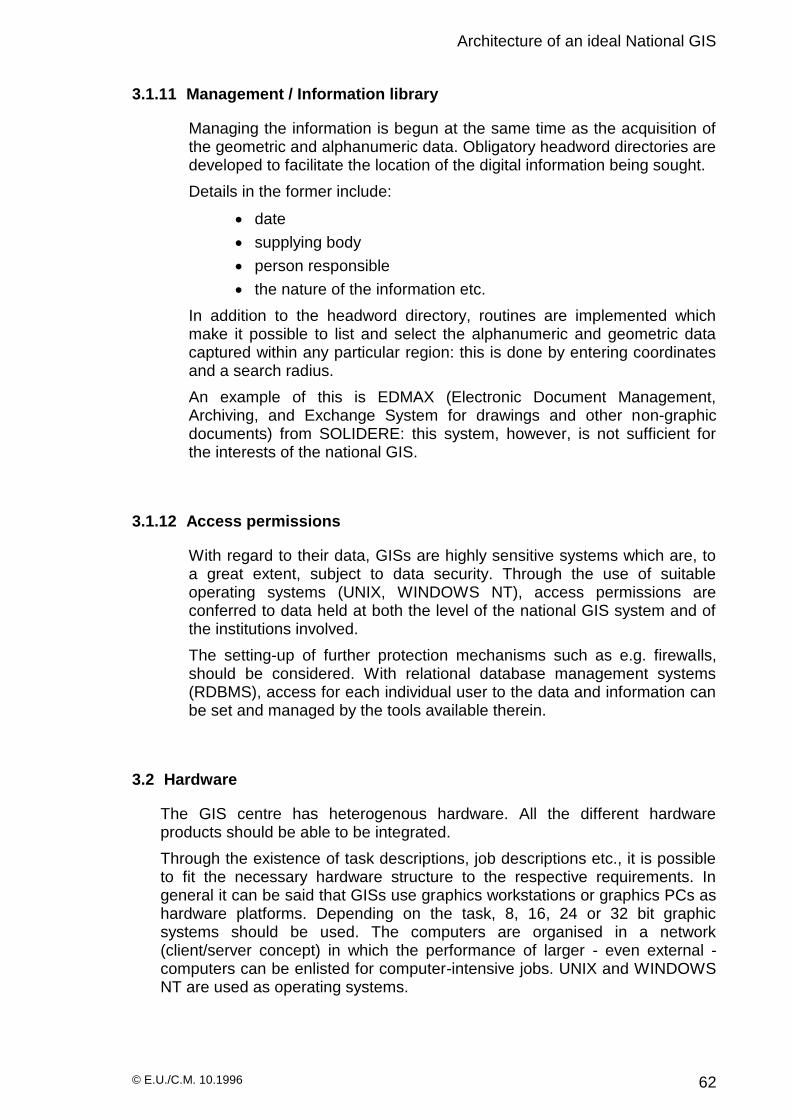
Architecture of an ideal National GIS
© E.U./C.M. 10.1996 62
3.1.11 Management / Information library
Managing the information is begun at the same time as the acquisition of the geometric and alphanumeric data. Obligatory headword directories are developed to facilitate the location of the digital information being sought.
Details in the former include:
date
supplying body
person responsible
the nature of the information etc.
In addition to the headword directory, routines are implemented which make it possible to list and select the alphanumeric and geometric data captured within any particular region: this is done by entering coordinates and a search radius.
An example of this is EDMAX (Electronic Document Management, Archiving, and Exchange System for drawings and other non-graphic documents) from SOLIDERE: this system, however, is not sufficient for the interests of the national GIS.
3.1.12 Access permissions
With regard to their data, GISs are highly sensitive systems which are, to a great extent, subject to data security. Through the use of suitable operating systems (UNIX, WINDOWS NT), access permissions are conferred to data held at both the level of the national GIS system and of the institutions involved.
The setting-up of further protection mechanisms such as e.g. firewalls, should be considered. With relational database management systems (RDBMS), access for each individual user to the data and information can be set and managed by the tools available therein.
3.2 Hardware
The GIS centre has heterogenous hardware. All the different hardware products should be able to be integrated.
Through the existence of task descriptions, job descriptions etc., it is possible to fit the necessary hardware structure to the respective requirements. In general it can be said that GISs use graphics workstations or graphics PCs as hardware platforms. Depending on the task, 8, 16, 24 or 32 bit graphic systems should be used. The computers are organised in a network (client/server concept) in which the performance of larger - even external - computers can be enlisted for computer-intensive jobs. UNIX and WINDOWS NT are used as operating systems.

Architecture of an ideal National GIS
© E.U./C.M. 10.1996 63
Local disk capacities, back-up solutions etc., can be calculated and installed on the strength of clear task descriptions and the amounts of data that could derive from these. It must be possible to expand the system.
Hardware interfaces of the GIS participants should be allocated on the basis of the task, and job, descriptions in such a way that their necessary data transfer (within their own data processing departments, or to and from the centre) is guaranteed within a reasonable period of time.
3.2.1 Computers
Workstations (64 bit) :
In estimating the hardware requirements for the operation of a national GIS centre, it can be said from experience that workstations with a 64 bit operating system are required for the processing of large volumes of data.
Graphics PCs / Multia
For smaller-scale computer operations and for operating system-related tasks, graphics PCs (such as Multias) are used. These are very compact PCs with Alpha - or alternatively Pentium - processors.
PCs (Pentium)
These are an important aid for the processing of alphanumeric data. They are used to carry out basic office management tasks. Their use with respect to GIS systems is limited to the viewing of data and smaller applications. In digitising they are used preferentially as inexpensive alternatives. These computers represent the lower performance range within the national GIS.
3.2.2 Operating systems
All workstations uniformly use the Unix operating system; Windows NT is used for the graphics PCs. The PC’s operating system is such that it can communicate with the workstations using appropriate network operating systems.
Great attention should be paid to the development of the Unix derivative LINUX by the GIS centre. Its use would be sensible in this respect, since it can run on PCs.
On the workstations WINDOWS programs are integrated with UNIX using suitable software products (e.g. Wabi from SunSoft).
Windows NT is the operating system for the graphics and alphanumeric PCs.
3.2.3 Integration of a RAID system
The ideal national GIS has sufficient storage at its disposal. This requirement is best realised in the start-up phase with the help of RAID systems. It can be assumed that such systems would be required at the
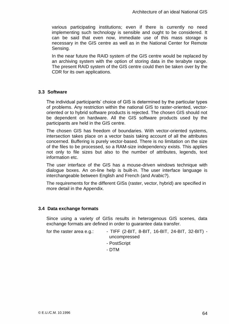
Architecture of an ideal National GIS
© E.U./C.M. 10.1996 64
various participating institutions; even if there is currently no need implementing such technology is sensible and ought to be considered. It can be said that even now, immediate use of this mass storage is necessary in the GIS centre as well as in the National Center for Remote Sensing.
In the near future the RAID system of the GIS centre would be replaced by an archiving system with the option of storing data in the terabyte range. The present RAID system of the GIS centre could then be taken over by the CDR for its own applications.
3.3 Software
The individual participants’ choice of GIS is determined by the particular types of problems. Any restriction within the national GIS to raster-oriented, vector-oriented or to hybrid software products is rejected. The chosen GIS should not be dependent on hardware. All the GIS software products used by the participants are held in the GIS centre.
The chosen GIS has freedom of boundaries. With vector-oriented systems, intersection takes place on a vector basis taking account of all the attributes concerned. Buffering is purely vector-based. There is no limitation on the size of the files to be processed, so a RAM-size independency exists. This applies not only to file sizes but also to the number of attributes, legends, text information etc.
The user interface of the GIS has a mouse-driven windows technique with dialogue boxes. An on-line help is built-in. The user interface language is interchangeable between English and French (and Arabic?).
The requirements for the different GISs (raster, vector, hybrid) are specified in more detail in the Appendix.
3.4 Data exchange formats
Since using a variety of GISs results in heterogenous GIS scenes, data exchange formats are defined in order to guarantee data transfer.
for the raster area e.g.: - TIFF (2-BIT, 8-BIT, 16-BIT, 24-BIT, 32-BIT) - uncompressed
- PostScript
- DTM

Architecture of an ideal National GIS
© E.U./C.M. 10.1996 65
for the vector area e.g.: - DXF
- PostScript (EPS),
- DTM
for the alphanumeric area: - ASCII - general database interface
Other file formats can likewise be used provided that both the deliverer of the data and the receiver of the data have corresponding facilities, and the data communicated is not of general interest.
3.5 Networking
3.5.1 Local area network (LAN)
In general, for networking only one network protocol (TCP/IP) is used, if possible. PCs are integrated into the UNIX world via suitable software products e.g. PCNFS.
The institutions are connected to the WAN using a gateway. Within the separate network solution a FDDI backbone is built in. The server, the archive and the databases are connected to it, as are computers whose function is to deal with very large amounts of data.
Access to the subordinate network systems is realised via a FDDI/Ethernet switch. STP or UTP cables can be used, since in 1993 the FDDI standard was extended to the TM-PmD-Standard (Twisted Pair Physical Medium Dependent) which is based on Twisted Pair cables; fiber optic cables are, however, preferred.
3.5.2 Wide area network (WAN)
In the ideal GIS the individual institutions are connected via a high power network, that offers the performance needed. Such a network is set-up using FDDI. It is possible to cover an area of up to 100 km. The largest distance between two nodes connected by optical waveguide must not exceed 2 km. The topology consists of a ring structure, laid out in duplicate, which consequently offers a high security against failure. Up to 500 institutions can be connected to this ring, for which the network forms the FDDI backbone.

Architecture of an ideal National GIS
© E.U./C.M. 10.1996 66
Optical waveguide is used as the transfer medium for the WAN. The deterministic, token-passing access procedure promises an efficient use of the bandwidth. Almost 100 Mbit/sec are achieved as the network bandwidth; the error rate is six times smaller than with Ethernet. All institutions should be connected to the WAN via Class A network connectors: through Class A stations they are connected directly to both primary and secondary rings.
The double ring configuration allows a separate reconfiguration of the FDDI network should a fault occur. Each Class A station in the double ring possesses two transceivers. Under normal circumstances data is transmitted over the primary ring: the secondary ring serves as security. This technology is standardised and proven.
Conditions on site
© E.U./C.M. 10.1996 67
4 Conditions on site
4.1 Land surveying
On investigating the situation in the field of land surveying, things proved to be somewhat confusing. For a long time, a law has existed which gives the responsibility for all geographical and topographical undertakings, as well as for the production and sale of any kind of map, to the armed forces (DAG; Direction des Affaires Geographiques). Whether the DAG does justice to the job is not the subject of this study; here merely the prerequisites for the framework of a national GIS are being investigated.
All maps are subject to an obligation to maintain confidentiality (see the relevant remark on the maps). Unfortunately, it was not possible to arrange a meeting to discuss matters, despite repeatedly establishing contact and despite promises on the part of the DAG. The tense political situation at the time could well explain the DAG’s actions regarding this.
The fact is that only a few private and public institutions comply with this legal monopoly on the manufacture and sale of maps by the DAG.
Because cartographic map documents are urgently needed and they are not, in fact, available, many users have begun to either produce the relevant maps themselves or to acquire them from sources outside the immediate area of responsibility of the DAG.
A consequence of this situation (a situation which is unsatisfactory for all parties concerned) is that the analogue map series 1:20.000 has established itself as the basis for most (planning) jobs within the public and private spheres. The value of the information content of this map series in view of its accuracy and generalization has already been discussed. The existing map series 1:50.000 (27 pages) or 1:100.000 (6 pages) are not dealt with further since these are even less suitable for use within the national GIS.
To compound matters, the map series 1:20000 (121 pages) exists in a wealth of impressions outside the area of responsibility of the DAG. Here one is dealing with cartographic representations that are now obsolete: they describe the information stand during the period 1962-1976.
According to the DAG representative at the meeting of the future participants which was held at the CDR, a new revised edition of this map series has been completed. Unfortunately it could not be established whether these maps are in digital or analogue form and whether they can also be freely accessed by private persons.
The following impressions of the older map series could be found :
original (analogue) maps 1:20,000; 5 colours, morphology, hydrography, vegetation, sea-bed contours, traffic network, political boundaries, grid: Lambert projection, point network: stereographic projection
black and white copies of the original (analogue) maps

Conditions on site
© E.U./C.M. 10.1996 68
black and white copies (analogue and digital) of individual printer’s copies with relevant separated information such as e.g. :
- copy of the printer’s copy for contour lines
- copy of the printer’s copy for traffic network
- copy of the printer’s copy for building development
- copy of the printer’s copy for lettering
(in digital form, this information has various dpi resolutions),
black and white copy (digital) of the entire map series in one layer, allegedly also in several layers with information from the individual printers’ copies (with different dpi counts?, geocoded?, rectified?)
Besides the scale level 1:20.000, there also exists in Lebanon a greater number of analogue cadastre maps in scale levels 1:500 to 1:2.000. The Ministry of Finance, or the cadastre office appears to be responsible for these scale levels. The consequences of this are that the higher order survey grids (i.e. the survey grids that cover the entire region of Lebanon, first- and second-order) fall within the area of responsibility of the DAG.
It could not be established who has definite responsibility for the local survey grid (third-order?) which is linked to the survey points of the higher-order survey networks. Since no - or insufficient - resources seem to exist within the Ministry of Finance for the maintenance and upkeep of these secondary survey networks, it can only be assumed that the latter are similarly the responsibility of the armed forces.
4.1.1 Coordinate systems
During the investigation in Beirut it was possible to establish that in the main, two coordinate systems are employed :
the Lambert projection
the stereographic projection
It was reported from several sources that the armed forces are currently working on the introduction of the UTM system. If such information is correct, one would consequently assume that three different projections are being used for land surveying in Lebanon.
4.1.2 Quantitative aspects of land surveying
No clear information is available regarding the extent of land survey work in Lebanon. What is certain is that the analogue map series 1:100,000, 1:50,000 and 1:20,000 cover the entire expanse of Lebanon.
Analogue cadastre maps ought to be available in the scale levels 1:500 to 1:1000 for most urban areas. It should be noted, though, that cadastre maps for Beirut are no longer available in their original form.

Conditions on site
© E.U./C.M. 10.1996 69
It must be assumed then, that a land survey covering about 50-60% of Lebanon was undertaken for the cadastre level.
4.1.3 Qualitative aspects of land surveying
When considering setting up a database which is to be jointly used by all participants, one has to examine the accuracy of the cadastre data. Following several discussions in the course of the mission, it has to be concluded that the basics of land surveying that currently exist cannot be used as a basis for the national information system.
The reason for this lies in the apparent absence of block triangulation which in turn means that no block offset of the lower level of the land survey grid has been carried out. The consequence of this is that in the overlap area between two survey grids, the adjoining points of the various local survey grids which, for example, are 10 cm apart when measured on site could - after the arithmetical analysis - show a distance of several metres when surveyed through connection with the respective accompanying survey grid. This unsatisfactory situation is worsened by the fact that some survey points have not been marked.
4.2 Allocation of tasks
According to current investigations there are currently no arrangements as regards the allocation of tasks: one gets the impression that similar projects are being undertaken by different institutions with no coordination. And so, on consultation, the same - or strikingly similar - projects were presented by several Ministries as being optimally suited to being dealt with by GIS. From comments that were made one can presume that data is likewise already being acquired by several authorities without mutual collaboration.
An example of this activity “in isolation” and thus of the capture of redundant data can be seen in the coastal strip. According to available information the following institutions work in this area with no coordination of activities:
- CDR : study of the coastal strip; testing of the ecological harmlessness of materials; search for fresh-water sources
- Ministry of Transport : land use and development; illegal dumping into the sea to reclaim land; search for fresh-water sources
- Ministry of Defence : illegal land reclamation
- CNRLS : search for fresh-water sources
It can be assumed that other institutions also work in this region in an uncoordinated way.

Conditions on site
© E.U./C.M. 10.1996 70
4.3 Captured data
Since consulting firms work for different public customers, it is quite possible that the same digital bases were used for the processing of several types of problems and that there is therefore a common quality standard. If this data were available for integration into a national GIS then there could be a substantial reduction in the work required to record base information. However a review of the quality of the data is essential at the outset in order to estimate the cost of inclusion in the national GIS.
Since these facts only became apparent after the production of the draft report, an additional colleague was sent, to demonstrate the processing techniques of the GIS in the course of database construction, in order to get a first impression of the data material available in Lebanon.
A further important issue in the assessment of data is its conditions of ownership. Thus it was ascertained during the mission that some institutions and consulting firms are perfectly prepared to make available to the national GIS the digital data produced in the carrying out of public contracts, and to do this without additional financial costs. For others this was dependent on the payment of a price that could be negotiated.
Thus according to the Ministry of Transport, the Ministry of Defence has offered digital maps of the coastal area in an acquisition scale of 1:1.000 at a price of $300,000; individual maps cost about $1000.
4.4 Existing stand-alone solutions (Quantity of data)
The size of the volumes of data (data already acquired in the different stand-alone solutions) was very surprising, since initially it was not known that consulting firms had already been using GIS on a large scale for many years to carry out government contracts. There follows here a brief survey of both the activities found in the field of GIS and of the data produced, in so far as this information was available.
4.4.1 Ministry of Defence (DAG), Humphreys
The entire topographic map series 1:20,000 was supposedly independently scanned both by a commissioned office, on behalf of the DAG, and by the company Humphreys. Humphreys has made this data available to the CDR on CD-ROM. Unfortunately it was not possible to assess these digital maps during the mission as they were not accessible. It could not be established which of the users of the GIS used information from the one or the other digital base map to deal with which type of problem. Both Humphreys and the Ministry of Defence use AutoCAD on PCs for carrying out the work. In addition, the surveying software SOFTDESK from the company DCA is used by Humphreys. In collaboration with a bureau, the DAG is to produce services worked out with the INTERGRAPH GIS .

Conditions on site
© E.U./C.M. 10.1996 71
As well as the digital map series 1:20,000 (raster), Humphreys have a wealth of project data at their disposal - e.g. planning documents in the field of hydraulic engineering (supply lines, reservoirs etc.) - which is in the form of vector maps and could be suitable for integration into the national GIS . No statement could be obtained on what data exists within the Ministry of Defence but, since data like this was offered to the Ministry of Transport, one can assume the existence of an appropriately large database.
4.4.2 Ministry of Post and Telecommunications (P.T.T.)
The Ministry of Post and Telecommunications has likewise drawn up a considerable number of digital maps. According to the PTT 370,000 telephone lines have already been recorded. One is dealing here not only with the actual network but also with base information such as ground plans of buildings and cadastre boundaries. The analogue maps in scale 1:10,000 are enlarged, the appropriate information is inserted and the maps are then digitised.
A large proportion of the work was carried out by the firm SOFRACOM. Additional suppliers of digital maps for PTT are Siemens, Ericsson and Alcatel. In the network planning department there are several digitising tables which help capture the data. The hardware consists of PCs installed with the software AutoCAD12, BOQ (Bill of Quantity) and the AutoCAD-Application CARL. The adoption of further software for the administration of the network is being considered.
4.4.3 General Cadastre Direction
Digital cadastre maps exist at the General Cadastre Direction. This test data does not just apply to Beirut but comprises also test areas outside Beirut. AutoCAD on PCs and the surveying software LISCAD is used here to perform the work. The digital maps are stored as individual files and can be output in DXF format when required.
4.4.4 EDL
At EDL one would expect a considerable database of different acquisition scales. The large-scale recording of the centre of Beirut as a test area (including the available base data in this region) is virtually completed. EDL has given the total volume of data as approximately 4 GB (vector data). SUN Workstations are used as the hardware platforms, running ArcINFO as the GIS.
4.4.5 IDAL
At the moment the volume of data at IDAL is very low; the digital map series 1:100,000 is, however, to be bought as base data from the company Katib & Alami. The REGIS product is used on 2 PCs as GIS software.

Conditions on site
© E.U./C.M. 10.1996 72
4.4.6 General Administration for Statistics
Data capture has likewise just begun at the General Administration for Statistics. So far, 10,000 islands (about 40 buildings per islands) have been digitally processed. The basis for this work is the analogue map series 1:20,000, in which missing information is added. In addition, a legend has been developed for classifying the different industries. The data processing consists of 30 PCs and 1 Unix server (BULL). Networking is done using Novell. ORACLE is used as a database, SPSS is used for statistical analysis. In the near future the introduction of ArcINFO as a GIS solution is planned.
4.4.7 Lebanese University
The Lebanese University has begun to branch out into GIS with the help of Katib & Alami. The software ArcINFO is being used there for a joint project (dealing with the southern suburbs of Beirut) in collaboration with Dar Al Handasa. Further information was not available.
4.4.8 Katib & Alami
Besides a set of test data for the centre of Beirut, Katib & Alami have drawn up a wealth of project data which should be considered for integration into the common database of the national GIS. Further details about the quantity of data could not be established during the mission. As representatives of the firm ESRI, Katib & Alami use ArcINFO on Sun workstations.
4.4.9 Dar Al Handasa
By their own account, the company Dar Al Handasa has drawn up a digital street map (acquisition scale 1:10,000) on behalf of the CDR, and updated it from aerial photographs. Besides this, there are also digital maps of larger urban areas of Beirut. ATLAS is used as a GIS. According to Dar Al Handasa, only data that is in the internal format of ATLAS can be made available at the moment.
4.4.10 Sukleen Sukkar
The company Sukleen Sukkar likewise holds a digital plan of Beirut city centre. The basis for the data capture is also the analogue map series 1:20,000, which is enlarged appropriately, in order to add the necessary information; afterwards these maps are then digitised. As at IDAL, the GIS solution here consists of the software package REGIS, run on 2 PCs.
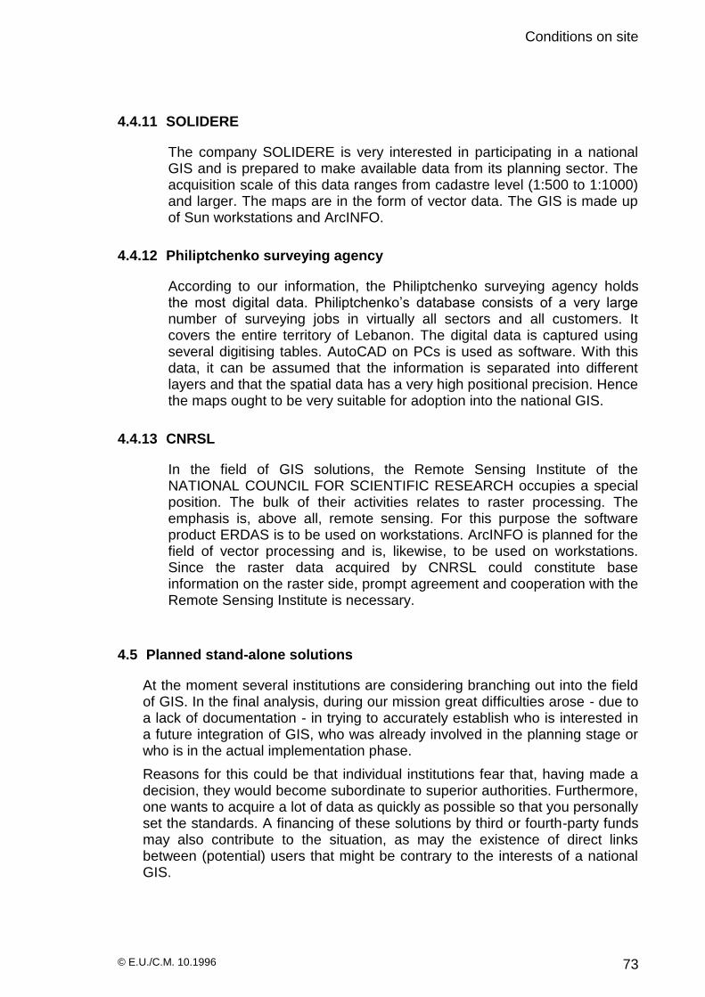
Conditions on site
© E.U./C.M. 10.1996 73
4.4.11 SOLIDERE
The company SOLIDERE is very interested in participating in a national GIS and is prepared to make available data from its planning sector. The acquisition scale of this data ranges from cadastre level (1:500 to 1:1000) and larger. The maps are in the form of vector data. The GIS is made up of Sun workstations and ArcINFO.
4.4.12 Philiptchenko surveying agency
According to our information, the Philiptchenko surveying agency holds the most digital data. Philiptchenko’s database consists of a very large number of surveying jobs in virtually all sectors and all customers. It covers the entire territory of Lebanon. The digital data is captured using several digitising tables. AutoCAD on PCs is used as software. With this data, it can be assumed that the information is separated into different layers and that the spatial data has a very high positional precision. Hence the maps ought to be very suitable for adoption into the national GIS.
4.4.13 CNRSL
In the field of GIS solutions, the Remote Sensing Institute of the NATIONAL COUNCIL FOR SCIENTIFIC RESEARCH occupies a special position. The bulk of their activities relates to raster processing. The emphasis is, above all, remote sensing. For this purpose the software product ERDAS is to be used on workstations. ArcINFO is planned for the field of vector processing and is, likewise, to be used on workstations. Since the raster data acquired by CNRSL could constitute base information on the raster side, prompt agreement and cooperation with the Remote Sensing Institute is necessary.
4.5 Planned stand-alone solutions
At the moment several institutions are considering branching out into the field of GIS. In the final analysis, during our mission great difficulties arose - due to a lack of documentation - in trying to accurately establish who is interested in a future integration of GIS, who was already involved in the planning stage or who is in the actual implementation phase.
Reasons for this could be that individual institutions fear that, having made a decision, they would become subordinate to superior authorities. Furthermore, one wants to acquire a lot of data as quickly as possible so that you personally set the standards. A financing of these solutions by third or fourth-party funds may also contribute to the situation, as may the existence of direct links between (potential) users that might be contrary to the interests of a national GIS.

Conditions on site
© E.U./C.M. 10.1996 74
4.5.1 Ministry of Transport
On the part of the Ministry of Transport serious interest in branching out into the national GIS via the GIS centre has been clearly expressed. In the near future, investigations are due to be undertaken recording depths in the coastal areas which could constitute the basis for further GIS applications. Further types of problem could be the mapping of the sea-bed with regard to sand deposits and the recording of illegal land reclamation, in so far as the latter is not dealt with by the Ministry of Defence. It could not be ascertained to what extent this type of problem is an integral part of the study into the use of the 8km wide coastal strip, assigned by the CDR to ECODIT.
4.5.2 Ministry for Hydraulic- and Electrical Resources
The Ministry for Hydraulic- and Electrical Resources is likewise considering branching into GIS. There the GIS solution is to be taken over by EDL. In the interim, alphanumeric data on a large scale is being captured in a project for the recording and inventory of the pumping stations in Lebanon (52MM). Unfortunately this data is filed as Word files which prevents easy inclusion into a future GIS.
4.5.3 Office National du Litani
At the moment great interest also exists within the Office National du Litani. It can be assumed that already there are jobs that can only be completed using GIS. Among these are the drawing up of a pedologic map; network planning and management; projects on land-use zoning in the Bekaa; management of plots of land; planning for irrigation projects, etc. As for hardware, 19 PCs are already available there, of which 9 are used for technical applications.
4.5.4 Ministry of Public Works
The Ministry of Public Works is also intensively working on getting into GIS. A lot of digital data already exists there which has been drawn up by external agencies but cannot be used within the Ministry. Important areas are the planning, maintenance and management of roads, project management and the planning of green spaces. Hardware (PCs) has already been bought but not yet installed. AutoCAD under Windows 95 is to be installed.
4.5.5 Commisions Executive des Grand Projects
Very similar types of problems are also being handled by the Commisions Executive des Grand Projects, which is also striving to branch into GIS. As with the Ministry of Transport, the main obstacle is a lack of budgetary funds.

Conditions on site
© E.U./C.M. 10.1996 75
4.5.6 Ministry of Agriculture
At the Ministry of Agriculture they are on the threshold of introducing GIS. Here one is also striving for a GIS solution using workstations and ArcINFO. The immediate objective is the drawing up, and continuation, of a digital ground map for the FAO project.
4.5.7 Ministry of Environment
No detailed information was obtained from the Ministry of Environment. Here, similar to the situation at IDAL, one deals with the identification of industrial areas. A further area of activity is waste deposit management. Since the use of GIS is very useful for both fields of work, work has already begun vis-à-vis branching into GIS and PCs have been ordered.
4.5.8 CDR
According to the CDR, the software product AutoCAD is used for their data processing. It is difficult to analyse the quality of the data in as much as it was not possible to obtain specific information about the extent of past and current projects in which spatial data is/was recorded and used. By their own account, this data is located with the contractor. The ground map that was produced within the framework of a FAO project could prove of interest for integration into a future national GIS.
The necessity of branching out into GIS is recognised by the CDR, and it clearly appreciates its deficits vis-à-vis communication and in the coordination of communication with other institutions. The CDR assumes that both agreement of the various institutions within the framework of a GIS centre and the setting up of a national GIS are urgently required.
The hardware available at the CDR is divided into two partial networks (NOVELL) and consists of 91 PCs, 59 printers, 6 Hubs, 1 UNIX server, 2 NOVELL servers.
4.5.9 Office des Eaux de Beirut
Hard as it is to comprehend, no interest whatsoever in GIS was found on a visit to the Office des Eaux de Beirut. At this meeting, they were against any idea of working using such systems in the future. Within this authority it is - by their own accounts - of little importance to establish and document the precise location of water supply lines. Analogue maps were shown which suggest plotter output since they were of excellent quality.
4.5.10 Summary
It has to be assumed that this list is not complete. Not all institutions were prepared to give (or, were in a position to give) more exact information on the quantity of data and on areas of application for GIS; this attitude could perhaps be accounted for by the monopoly of the DAG in this area.

Conditions on site
© E.U./C.M. 10.1996 76
On the other hand, there is an exceptionally large business interest in the commercialisation side; here, according to provisional findings the quantitative aspect is the only decision criterion considered vis-à-vis purchase. The quality of the data seems to be of no importance in the purchase decision. This position leads to the unsatisfactory situation that everyone wants to know what data is available, but hardly anyone provides information unless they are seriously interested in adopting the data available there.
The large amount of available data necessitates an investigation into its integration into the national GIS. The costs of producing this data are hard to estimate but they may be, in total, somewhat more than USD $20 million.
4.6 Quality of the captured data
During the mission there was an opportunity to adopt various data and read it into a GIS. In the course of this work the circumstances that have been described earlier became obvious - the very issues that call into question the setting up of a common data base.
The layer structure has not been agreed between the individual institutions and ministries. According to statements from EDL, the data from the test project is filed in two layers. The first layer contains vectors for the plot boundaries, whilst the vectors for the building boundaries were stored in the second layer. This layer structure differentiates the geometric base information of plot and building boundaries in the same acquisition scale. In contrast to this, IDAL uses four layers to manage the data in a scale-oriented fashion. There, all data relevant to the planning level (1:500) is filed in one single layer. If, say, the plot boundaries are to be adopted, this would cause no great difficulty for EDL since a layer exists that contains exactly this information. The IDAL data would have to be processed accordingly: the plots have to be selected from the planning scale layer and stored anew in a separate layer. Only after this separation of the “plot” information from the other information in the layer can the data be available for adoption.
Furthermore it can be said with complete certainty that the attribute designations and legends within all available stand-alone solutions have not been agreed on. The consequence of this is that the same terms can exist with different meanings. On integration into the common database, the meaning of the expressions used becomes so blurred that an analysis can lead to false results on the basis of the inaccurate definitions of the contents.
Most maps were produced by AutoCAD. Although with AutoCAD one has the facility to use the geographical coordinate system when digitising, this was not utilised by the users. Instead, the spatial data was filed in a Cartesian coordinate system with the origin coordinates 0|0. Because of this way of proceeding, the maps have no geometric relationship; this has to be produced subsequently using geocoding. For raster maps the desired coordinates have to be allocated to at least two of the points on the map. Thereafter all points are recalculated and geographical coordinate pairs are put in the matrix..

Conditions on site
© E.U./C.M. 10.1996 77
A typical shortcoming of maps produced by AutoCAD is the appearance of incomplete polygons. Since however closed polygons must definitely be available in a GIS for the generation of areas, it is necessary to check maps produced by AutoCAD for such flaws and to correct them where appropriate. The most suitable GIS for this, is one with a search function for locating and editing incomplete poly lines.
A further problem arises when digital maps are converted from Lambert projection into stereographic projection or vice versa. In conversion of the different mathematical projections, inaccuracies are generated which no longer guarantee the unambiguity of the spatial information. Also in this case, after the conversion has taken place all maps must be checked for any variation in the coordinate pairs, and corrected. The duplicate coordinates can be combined using the GIS’s editing and search radius functions and converted into unambiguous information.
Major difficulties in the combination of data are caused by the inexact acquisition scale 1:10,000 of the 1:20,000 map series. The second inaccuracy results from the very small dpi figure (300 dpi) used in scanning. The impression was given that after scanning, the maps were neither adjusted nor geocoded; this leads to a further deterioration in accuracy. In addition comes the fact that we are dealing here with generalised maps, which - because of the way they are compiled - possess no exact geometric information. This fact is either not known to the users, or they attach no significance to it. All these factors - individually or collectively - can lead to the fact that the relevant maps are unsuitable for a long-term integration in the national GIS. An investigation is required to find out whether their inaccuracies can be improved by a subsequent digital revision.

Synthesis of Chapter 3 and 4
© E.U./C.M. 10.1996 78
5 Synthesis of Chapters 3 and 4
5.1 National land surveying
It is hard to imagine that all aspects of national surveying (i.e. not only the military aspects) are carried out and managed by the DAG. There does not appear to be the data processing equipment required for this.
It would follow from this that the experience necessary for carrying out the new tasks of digital national surveying and digital map compilation is, likewise, not present within the DAG. On the political side, it can be assumed that the permanent assignment of the responsibility for the civil branch of national surveying to the Ministry of Defence is not achievable and neither is it conducive to further development of the peace process.
In interviews, it came to light that a great many institutions either refuse to collaborate with the DAG or are sceptical about such collaboration.
It would seem more sensible to transfer the civil tasks of surveying to the responsibility of the Finance Ministry, and to grant the Ministry of Defence full access to the data and allow them a say in areas which concern national defence.
In conclusion it can be said that an unambiguity of the land survey data existing in Lebanon is a matter of urgent necessity.
In order to achieve this unambiguity in the spatial data, the following ways of proceeding emerge from the observations in Chapter 3 and 4.
5.1.1 Block triangulation
One opportunity for obtaining exact coordinate pairs for the spatial information of the national GIS lies in carrying out a block offset for the lowest survey grid in Lebanon and thereafter recalculating all surveyed points. The expenditure for this process cannot be estimated. It should be investigated by of an additional study and contrasted to the reorganisation of the survey grid using GPS.
5.1.2 GPS (Global Positioning System)
A further opportunity of eliminating deficits in the national survey is a reorganisation of the survey grid using GPS. The advantages of this process are :
- the positional precision of the survey points of the survey grid is similar throughout the country (<5cm)
- the expenditure of survey work is reduced
- there is an opportunity of financing the GPS from private users, who pay fees for the use of the official GPS network. The use of GPS can be decreed for official survey work.

Synthesis of Chapter 3 and 4
© E.U./C.M. 10.1996 79
- shortcomings in the present survey grid are removed by the resurveying (work)
- a compulsorily decreed measuring method allows comparability of the data and its integration into the national GIS
- the acquired survey data can be much more easily used for GIS than that which is provided by conventional surveying.
Since high precisions must be realised, GPS should be used in differential mode. In addition it will be necessary to establish appropriate fixed reference stations throughout the country.
Both the most suitable process (differential GPS on-line or off-line) and the method of measuring must be compiled in an additional study.
Likewise for the number and approximate position of the reference stations and the scale of costs. These results must be contrasted with the study into block triangulation, and they form the basis for the inevitable decision.
5.2 atabase interface
A further great challenge in the setting up of a national GIS is the development of a unified database interface with whose help information can be digitally exchanged. This work must be commenced immediately, independently of the further planning and implementation of the national GIS.
The database interface is an absolutely essential prerequisite for complete communication between the existing and planned stand-alone solutions. It must be system-independent and should not favour any particular manufacturer. In this connection the development pursued (since 1987) of a unified database interface in Germany (EDBS) is referred to.
To avoid mistakes in the setting up of such a complex task, these experiences should be fallen back on at all events. However an uncritical adoption of this solution as it exists in Germany should be avoided.
5.3 Responsibilities
A successful outcome in the setting up of a national GIS is only possible with a clear allocation of the appropriate responsibilities to the participants. They must though also be in a position to accept the responsibility on the strength of assured financing. Should missing requirements for some participants make a direct integration in the national GIS not possible, their interests at least in the start-up phase can be taken over by the GIS centre.
Since an acceptance of responsibility by the individual institutions in sections of the national GIS is only sensible with a simultaneous say in the relevant decisions, a committee must be available in which the relevant participants can champion their interests. In setting up this committee, missing experience or a lack of cooperation by participants must not be allowed to interfere with the carrying out of the necessary work.

Synthesis of Chapter 3 and 4
© E.U./C.M. 10.1996 80
5.4 Data acquisition (Base Information)
The thematic data acquisition is made by the appropriate institutions. In the case of missing requirements of the relevant participants, the tasks can also in this case be accepted by the GIS centre in the start-up phase within a narrow professional collaboration. Since this can only be a temporary solution however, the participants should as quickly as possible be put in a position to handle their own types of problems.
In the project, base information occupies a special position in the data acquisition. In the investigations in Lebanon, it appeared that at the moment without further agreement, several institutions (EDL, P.T.T., IDAL, DAG, General Cadastre Direction, General Administration for Statistics, SOLIDERE) are employed in the capture of such information for their own interests. It should be assumed that the data capture is being made with different precisions.
The General Cadastre Direction, which should normally be entrusted with this task is overtaxed both financially and personnel-wise in the scope of setting up a national GIS with the provision of the base information within a very short time span, approximately one to two years.
As quickly as possible therefore a smaller group of institutions should start to solve this extensive task and to compile the principles for a future interchangeability of data. Moreover, in this way expenditure on multiple capture could be saved, redundancy of the data could be avoided, and a quicker provision of the data for larger regions could be achieved. This is all the more important since all questioned interested parties in the national GIS hope for access to the urgently required base data.
In order to be able to carry out this work, appropriate rules and regulations must be devised within the group. Study-groups are to be founded, to which the skilled experts of the participating institutions will belong.
The basis for these meetings, arrangements and realisations should be the GIS centre.
The following illustration shows a schematic representation of the base information as well as a possible arrangement from different data of the institutions concerned. The listed institutions should be members of this group.

Synthesis of Chapter 3 and 4
© E.U./C.M. 10.1996 81
LOT LINES
BUILDING
FOOTPRINTS
NATURAL
BOUNDARIES
RIGHT OF WAY
STREET
CENTERLINE
BASE - INFORMATION
POLITICAL
BOUNDARIES
INSITUTE FOR REMOTE SENSING
MINISTRY OF PUBLIC WORKS
CDR
PTT
MINISTRY OF DEFENCE
MINISTRY OF FINANCE
EDL
DATA PRECISION < 5 cm
RASTER DATA
SATELLITE-
MAPS
CDR
MINISTRY OF PUBLIC WORKS
CDR
CDR
MINISTRY OF FINANCE
MINISTRY OF FINANCE
CDR
MINISTRY OF FINANCE
MINISTRY OF PUBLIC WORKS
NATURAL BOUNDARIES :
RIVER (AREA), COASTLINE, etc
POLITICAL BOUNDARIES :
CASA, MOUHAFAZAT, CITIES, DISTRICTS etc.
CONTOUR
LINES
MINISTRY OF DEFENCE
CDR
MINISTRY OF DEFENCE
VECTOR - DATA
The contour lines should be particularly described from the base data on the grounds of non compliance. It was astonishing in the investigations in Beirut how little attention was paid to the digital terrain model (DTM). Some people we talked to did not realise the benefit of such data whilst others held its capture for the whole territory of Lebanon as a dream.

Synthesis of Chapter 3 and 4
© E.U./C.M. 10.1996 82
On our return to Germany therefore research was again carried out to bring the newest state of the art into the considerations. It is possible to model the whole of Lebanon in a digital terrain model with a height precision of better then 10cm. The distance between measuring points is 2.5 m and can be reduced to 0.5 m if
required. The capturing is supported by aeroplanes using radar. The costs for the complete DTM amount to a maximum of 80 DM/km2. At the same time the radar information is in the form of raster images with the appropriate resolution. It can only urgently be recommended to make the capture of the DTM part of the base information.
The value of this data can be discussed beforehand with Dr. Khwawlie from the National Center For Remote Sensing and the surveying office Philiptchenko. Other fields of application are conceivable in the course of the reorganisation of the national survey and the mapping of Beirut or other cities. For the recording of Beirut, data resolutions of distinctly <0.25m are possible with a special data capture method. Distortions as they crop up during conventional methods of aerial photography route-flying can be prevented by special calculation methods. Likewise, diagonally portrayed buildings do not occur.

Synthesis of Chapter 3 and 4
© E.U./C.M. 10.1996 83
5.5 Data acquisition (period of time)
When one compares sections 3.1.4 (General data acquisition) and 4.6 (Quality of the captured data) one can appreciate that all the captured data is unsuitable for an uncontrolled adoption into the national GIS. However since a large amount of data scattered across the various institutions cannot be replaced by qualitatively better data within a short time, an interim solution must be found. It can be assumed that for a complete recapturing of the base data, the required timeframe is so long that the participants could not be expected to wait for the results.
The optimal requirement for the setting up of a national GIS would be without doubt to start again recapturing the data from the very beginning. The consequence would be that the institutions concerned would concentrate their entire activities on capturing the base information, and only after it was available would they then be in a position to begin their actual thematic work incorporating this (new) base data.
If it is decided to go for this solution, the time until the data can be utilised must be kept as short as possible. It is sensible to draw up a list of priorities for the regions. As soon as the new base information for these individual areas is available, there one can begin working on the thematic processing in parallel with the continuing data capture. In carrying out this work, the fact that there is no agreement regarding layer management and attribute description and that there is no unified database interface must of course be taken into account.
Since this agreement is lacking, only the geometric structures can be recorded in this first step. As with the regional capturing of the geometric data, at this point also one does not have to wait for the complete results of the agreements. If suitable sections have been chosen, the continued processing of the geometric information can be commenced in parallel with the establishing of agreements within these defined areas. If one is to proceed in this way, an absolute prerequisite is the unambiguity of the captured data: this required appropriate preliminary work within the national survey.
Parallel to the action described above, it is suggested that all available data which can be accessed is gathered in the GIS centre and converted into a database.
After that, this data should be examined to see if it can be used temporarily there. If it is found that this data can be worked with for a defined period of time, then an attempt must be made to enhance the quality of the data (within financially justifiable limits).
Simultaneously, strategies must be developed to either replace this data in the future with the improved database or, if possible, to enhance the quality of the data to such an extent that it can eventually be adopted into the future national GIS.

Synthesis of Chapter 3 and 4
© E.U./C.M. 10.1996 84
Another crucial point in data acquisition is the utilisation of all externally ascertained digital spatial data. In this field also, regulations concerning capture must be compiled as quickly as possible. Here it is also an indispensable prerequisite that the national survey is reformed, either via block offset in the lower level of the surveying grid or via rebuilding using GPS. When this is available, as already described, all externally ascertained data from different planning levels, planning regions and planning districts can be accepted by the GIS centre into the national GIS. Since wide areas of the country will also be re-surveyed in the future in the course of the Lebanon reconstruction program, it can be assumed that in the future there will be great potential vis-à-vis the volume of surveying work that is necessary.
5.6 Unified data criteria
The necessity has already been pointed out in the text for unified data criteria i.e. exactly defined layer structures and agreed legend and attribute descriptions. It should be observed that no activities in this area could be found during the mission. For this field also teams (possibly corresponding to the German DIN standards committee) must be formed to take over these tasks.
Since the treatment of this type of problem is of a theoretical base, one can likewise begin immediately to carry out the agreement work concerned. The circle of participants should comprise if possible all participants of the future national GIS, and treat the various thematic requirements in an interdisciplinary fashion. In this case, the GIS centre should also represent the necessary basis for discussion of the work. The quicker these agreements take place, the quicker a solid data structure can be set up.
5.7 Hardware structure of the institutions concerned
The solutions that were found have a heterogenous hardware structure. This structure consists of PCs and workstations, most of which were ordered in the course of the GIS implementation. Concepts regarding the specifications and expandability of this hardware could not be found.
In principle there is no argument against this heterogenous hardware . However ideas should at least exist as to how extension and expansion are to be dealt with in the future, and whether this has to be compatible with the prevailing hardware solutions. These decisions should lie within the area of responsibility of the individual institutions.
The GIS centre should, however, be put in a position to advise and support the relevant institutions when requested.
Furthermore it is important that a client/server structure is implemented. The simplest level of client/server computing is the use of a filesystem server. With this process the communication between client and server is confined to the level of file operations such as „open file“ or „read the next 500 bytes“. The disadvantage of this lowest level of the client server model is that substantial

Synthesis of Chapter 3 and 4
© E.U./C.M. 10.1996 85
amounts of data pass between the two over the network. Performance and stability problems arise as the number of users in the network grows.
These problems are solved by making a qualitative change in the protocol, as is the case with SQL-based database management systems (DBMS). Thus the client no longer makes his inquiries on the file operation level but on the level of database operation. The database server is responsible for the entire database including index files. The consequence is that the application becomes more stable and performance increases considerably since the extent of the data transfer between client and server is substantially reduced.
5.8 Databases
Without much further investigation one can assume that within no time at all, amounts of data in the range of more than 1 TB (terabyte = 10
9 byte) will have
to be acquired and managed within the national GIS. This volume of data should be taken into account in the database architecture. The proposed RAID systems can manage amounts of data of this dimension, but represent though they are only a sensible interim solution in a medium term plan (2 years) for the exclusive holding of data by the GIS centre.
With the use of distributed databases using RAID systems - which are then also held by the participants in the national GIS and are available in parts to all participants - the use of a larger archiving system within the GIS centre can be delayed. However, an archiving system which is made accessible centrally, in the GIS centre, to all participants and which can manage data up to 1PB (petabyte = 10
12 bytes) is the better middle- and long term solution.
In the software field, the developments and requirements of the unified database interface should be taken into consideration. Should, however, a file database system be preferred in the stand-alone solutions for the GIS applications (as is currently the case in most of the GIS applications within Lebanon), it should be noted that for a further extension or for integration into the national GIS, relational database management systems will be used.
5.9 Software structure of the participating institutions
It is not absolutely essential that every participant in the national GIS has software that can process data in the terabyte range. Such assessments affecting the whole of Lebanon should be dealt with by the GIS centre. It can be assumed that the other participants carry out assessments of sections or do assessments using a reduced resolution - hence appreciably smaller amounts of data occur.
It is pointed out once again at this point that for a more accurate assessment of what software is needed, a knowledge of the requirements and fields of work of the different users must be on hand. As long as the interchangeability of data is guaranteed, then the participating institutions can begin, on their own, to set up a GIS and to select software which corresponds to their needs.

Synthesis of Chapter 3 and 4
© E.U./C.M. 10.1996 86
5.10 Networking
During the mission we learned that a FDDI network is currently being set up within Beirut. Unfortunately detailed information about the extent and route of the network could not be obtained. The costs and timescales for integrating the participating institutions is the subject of a proposed study.
5.10.1 Internal networking (LAN)
In some of the stand-alone solutions LANs were encountered. A more accurate analysis of the networks could not be undertaken due to lack of time. It can be presumed that the integration of Novell networks and Windows for Workgroups is widespread. On the setting up of the national GIS, these structures should be investigated and documented with respect to the individual participants.
It would seem wise to standardise the LANs and to restrict the network protocol to TCP/IP. Similarly, it is advisable that participants who have demanding GIS applications use an internal FDDI network to which graphics workstations and the server unit are connected. Depending on the degree of the demands, this can be done using 10BaseT cable or with fibre optic waveguide. One assumes that deliberations on this are the responsibility of the individual institutions and that the GIS centre can only give recommendations. It is imperative, however, that these local networks be connected to the joint WAN.
5.10.2 External networking (WAN)
As already described, a WAN is currently being set up in Beirut using an FDDI network.
Via FDDI
This WAN is of optical fibre and, according to our information, uses FDDI technology. It has to be investigated to what extent the use of this network can be realised by the national GIS. In addition to the running costs, integration into the FDDI ring should be assessed (range, laying of additional cable, costs).
Via transceiver
It should be assumed that not all participants can be connected in the short-term by optical fibre to the WAN, because of the distance to the FDDI Ring that is being constructed. Data transfer using directional radio links is a possible alternative. Whether this solution is sensible depends, likewise, on the type of problem and the associated requirements of individual participants and the national GIS. Since the data throughput here is smaller than that of optical fibre by a factor of 10, another kind of data processing may be necessary. With the FDDI network, working on-line on the RAID system of the GIS centre is possible without any great restrictions for most applications.

Synthesis of Chapter 3 and 4
© E.U./C.M. 10.1996 87
However, with data transfer via directional radio link, the transfer times for large amounts of data can take much longer; it should be considered whether, say, at night the data should be transferred and stored onto local storage media.
This has the advantage that during the day an increased performance within the LAN can be used. A disadvantage, however, is the appropriate storage capacities.
National GIS Centre
© E.U./C.M. 10.1996 88
6 National GIS Centre
6.1 Principles
There is agreement within the institutions - with few exceptions - on the necessity for introducing a national GIS. However, opinions diverge on the setting up of a GIS centre as nucleus and hub of the national GIS. Various institutions make a collaboration in the national GIS dependent on the GIS centre being integrated within their sphere of responsibility. In the investigations however, no participant could offer sufficient basis for a successful independent setting up of the GIS centre. The CDR has at the moment the largest data processing empire of the institutions concerned and has therefore appropriate experience in DP. Because of this and other qualifications, for instance:
- international experience in the area of organisation of large projects
- execution and contract negotiations of international projects
- experience in international financing opportunities etc,
it is sensible to assign the responsibility for the setting up of the GIS centre to the CDR.
As a first step towards realising this goal the CDR should therefore start as quickly as possible with the implementation of the centre. However since the DP department of the CDR is fully occupied with existing tasks, the GIS centre should become an independent department of the CDR. Because of the shortage of space and the essential eventuality of a quick expansion of the centre, a physical separation should be taken into consideration. This GIS centre should however protect the interests of the CDR at least up to the point of its becoming independent.
Following the analysis in Lebanon it does not appear sensible to pursue the planning of the national GIS on only a theoretical basis in the near future. On the contrary, using „learning by doing“ tied in with external experiences, a start should be made to set up the centre and compile the necessary prerequisites for the national GIS (hardware, software, unified database interface, database concept, structure of the legends, layer concepts, digitising regulations, production of the base information, etc,) as well as to utilize the existing data. Synergetic effects are optimally exploited by this parallel theoretical and practical work.
6.2 Task setting
The GIS centre should be entrusted, in setting up the national GIS, with the coordination and execution of the work in agreement with the institutions which are involved in producing the base information.
6.2.1 Advice
It can be assumed that in the setting up of the GIS applications, demand for advice from the various participants will be needed. Since external experts

National GIS Centre
© E.U./C.M. 10.1996 89
are to be employed in the setting up and implementation of the GIS Centre, it is proposed to extend their field of work and areas of activities to include an advisory capacity. At the same time, in the start up phase the compiling of different performance specifications for the various distinctive types of GIS for the participants in the national GIS, as well as for the hardware solutions associated with these, are well to the fore.
Already-existing GIS applications should be investigated for their effectiveness. Further advice can be given as regards the planning of future projects taking the requirements of the GIS into account. This applies both to the integration of the appropriate standards in the contracts as well as to the assessment of the method for carrying out the data acquisition.
6.2.2 Compilation of standards
The importance of standards has been pointed out in this report. Since the national GIS will not be a closed system, not only standards which have an immediate current benefit are of interest, but it also appears important that the development of future standards is followed up - and where appropriate influenced - by the GIS Centre. It follows from this that representatives of the GIS Centre should be represented in all external consultation committees for the fixing of standards.
For the development of standards within the national GIS the requirements of all present and future participants must be taken into account. Otherwise it would be necessary to check and adjust the standards every time the circle of participants of the national GIS was extended. To what extent these tasks should in general be taken over from the office of the Minister of State for Administrative Reform cannot be decided by this study.
It is proposed that all internal national GIS standards should be developed by the participants themselves under the control of the GIS Centre. However before these come into force, their effects must be investigated in the external sector.
It would be helpful for the development of standards if an appropriate literature collection of experiences from other countries could be created. These tasks could be performed by research institutes (Remote Sensing Institute) or universities (Lebanese University).
For the purposes of theses an attempt could be made to collaborate with the GIS Centre, to make these external experiences all or partially applicable in Lebanon.
6.2.3 Integration of digital data
The integration of digital data means - as a first step - to put all existing and available data in Lebanon at the disposal of the GIS Centre. As was shown during the mission, this essential preparatory work is very difficult and time-

National GIS Centre
© E.U./C.M. 10.1996 90
consuming. After the data is made available it must be catalogued which means that all information associated with the data, such as :
supplier of the data
time of creation
hardware and software used
format of the data
owner
relevant project
purpose etc.
must be recorded. This can be done in an analogue form for the time being until an appropriate digital library management is set up.
Thereafter the data is transferred to the existing storage media of the GIS Centre and investigated and analysed with suitable software products. The results of this investigation will give an early indication for the development of the future layer structures, attribute descriptions and the unified database interface. After the separate treatment of the individual data an attempt must be made to convert it into a common database.
Another large field of work is the integration of digital remote sensing data into the national GIS. In this field a close collaboration with the Remote Sensing Institute is the aim. The possibilities for evaluating the remote sensing data - available in great quantity - must be constantly observed and their use in Lebanon must be investigated. Here too the setting up of a subject library presents itself. Cooperation agreements with relevant research institutes outside Lebanon should be concluded. The objective of these cooperations is a transfer of technology in the following fields :
processing and editing of satellite data
holding and management of data
application of satellite data
Contacts have already been established between the Remote Sensing Institute in Beirut (Dr. Khwalie) and the leader of the Deutschen Forschuungsanstalt für Luft- und Raumfahrt e.V., Deutsches Fernerkundungszentrum (German Research Institute for Air and Space Travel, German Remote Sensing Centre) in Neustrelitz, Germany, (Dr. Bettac).
An intensification of this relationship should be made through an exchange program between the scientists and experts. The results of this technology transfer will afterwards be made available to all participants on the national GIS.
6.2.4 Provision of existing data
The provision of data takes place - once the GIS Centre has been connected - mostly over the network. In this process appropriate access permissions must be conferred. At the moment there is no idea yet of how

National GIS Centre
© E.U./C.M. 10.1996 91
costs will be shared and paid for by users. If the data is not made available free of charge, methods to check the transfer of data and the settling of accounts for this should be developed.
Since connecting to the MAN or WAN will not be fully realised in the near future, exchange of data using tertiary storage should be undertaken. EXABYTE has become established in remote sensing as an exchange and storage medium. Both read/write CD-ROMS and Zip drives are recommended as well. In addition, the centre should produce a digital map series of the base information, recorded as boundary-free files of the 1:20,000 maps on CD-ROM, and make this available to the users.
6.2.5 Management of all GIS activities
Research clearly shows that there is a great lack of coordination in the GIS activities in Lebanon. The effectiveness of data acquisition can be clearly improved by a central management, and can lead to an estimated reduction in expenditure of more than 50%. Merely the fact that there is an institution which is informed about the existence of the data, can lead fundamentally to an improvement in the present obscure situation.
A minimum goal for the management of the GIS activities would be to document the existing data and the future planned data surveys. After the construction of the wide area network all users could access this information via the network. It can be assumed that from GIS users’ own interests, if working with spatial data is authenticated, the appropriate information from the institutions will be made available.
The amount of data expected calls for the use of 64 bit processors, at least for the area of central data processing (server unit, workstation unit) within the GIS Centre. Furthermore, as a consequence of the already existing volume of data, the integration of a RAID system is essential. The proposal is that this system be equipped with the lowest number of disks (5) of the largest disk capacity (9 GB), giving a total storage capacity of 45 GB. The option of equipping the RAID system with further disks at any time at short notice when required must exist. It should be assumed that within one year capacities above 600 GB will have to be provided.

National GIS Centre
© E.U./C.M. 10.1996 92
6.3 Software structure
As is seen clearly from our research, the vector-based GIS ArcINFO and the CAD software AutoCAD are widespread in Lebanon. The suggestion is that both systems be kept in the GIS Centre. On the raster side, the integration of the appropriate software should be agreed with the Remote Sensing Institute. These systems should run under both Unix and Windows NT.
From experience it should be assumed that these standard software products will not cover all requirements. In the short term therefore several alternatives should be discussed:
1. the national GIS is restricted to the facilities offered by the standard software products. In this case an attempt should be made to conclude collective licences with the software manufacturers for all participants in the national GIS.
2. the national GIS begins programming a GIS itself.
3. the national GIS co-operates in a GIS development. It can develop the essential modules which are missing with the appropriate firm and/or have an influence on the development.
The last possibility promises the greatest prospects for success. A further advantage is economies in costs since payments for licences are no longer incurred in a such a scale as in the first recommendation. The risks in comparison to the self-development solution are much reduced. There are options for inserting into an appropriate contract the complete taking over of the source code (e.g. on bankruptcy, or abandonment of further development).
The second recommendation is time-consuming. A development time of between 2 to 4 years is assumed. The costs may be significantly higher than in the third recommendation. The advantage of developing one’s own software is that it is fully owned by the GIS Centre.
In addition to GIS software the integration of software products from the following areas is necessary :
CAD
digitising software
office communication
image processing
DeskTopPublishing
librarianship
The standard product MS Office should be relied on for office communications. In the CAD field AutoCAD is a standard and owing to its wide circulation must be available in the GIS Centre. The decisions for the other areas can be made at short notice during the setting up or start-up phases.

National GIS Centre
© E.U./C.M. 10.1996 93
6.4 Database
The decision on a standard database (RDBMS) should be delayed for as long as possible until a relational or object-oriented database model is produced for all applications in the national GIS. The developments in this field are not clear at the moment. Moreover, at the present time there is too little knowledge to make a decision. It can be assumed that at least in the start-up phase working with the GIS’s own database will suffice.
6.5 Network
The planning of the setting up of the Wide Area Network is dependent on the results of the study and can be started once the results are published.
6.6 Steps for development
The most important factor for the setting up of the GIS Centre is the provision of the premises.
Further steps are recommended, as follows :
I. Set up of the GIS Centre
Hardware and software: - a server
- a RAID system 5x 9 GB = 45 GB disk storage capacity
- two 64 bit workstations
- 2 graphics PCs
- 2 PCs for Office applications
- one digitising table
- one scanner (DIN A3), colour
- one scanner >A0, black and white
- one EXABYTE unit
- GIS software (ArcINFO, ERDAS)
- CAD software (AutoCAD)
Networking : - Set up of an local FDDI network
Integration of : server, RAID system, 2 workstations, 2 graphics PCs
2) Set up of the following teams:
- unified database interface
- standards committee for legends, attributes
- production of the base data

National GIS Centre
© E.U./C.M. 10.1996 94
6.7 Personnel requirements
An immediate requirement exists for personnel in the following fields of activity:
- Co-ordination :
establishing contact with other users; forming study-groups and teams; carrying on consultations (base information, agreement on attributes and layers, unified database interface); gathering available data; working on the production of the base data; co-ordinating the obtaining of data between the various institutions; co-ordinating GIS projects; assessing and acquiring data which is required in the future; setting-up contacts with external co-operation partners and firms
- GIS systems :
installing the GIS, adopting the available data and its assessment and integration, working on the production of the base data, working in the various study-groups, advising on software; developing suitable procedures for the acquisition of data; supporting the other institutions during data capture; defining the requirements for the unified database interface / database design from the point of view of the GIS; geocoding and adjusting existing data material;
- Networks :
working out the design of the network and the request for tender documentation for the WAN and LAN within the National GIS ; the setting-up, further development and technical support of the LAN in the GIS Centre; connecting the institutions to the GIS Centre; working on the production of the base data;
- Hardware:
installation and technical support of the hardware and the operating systems; working on the production of the base data; advising and supporting the other institutions; installing port permissions; agreeing the different hardware concepts within the National GIS ;
- Databases:
working out the database concepts and conditions for the unified database interface; co-operating with the appropriate teams; integrating available databases into the National GIS; working on the production of the base data;
- Programming
programming the necessary interfaces and modules for data entry, data manipulation, and data management; assessing external data and its integration; working on the production of the base data;
It should be assumed that for each field of activity at least one external expert must be allowed for, the system administration can if necessary be divided among the experts or taken on by a counterpart. The tasks of the experts should be interdisciplinary and require team-work. Feasibility studies, tender documents etc.

National GIS Centre
© E.U./C.M. 10.1996 95
are to be produced within the team. The essential preliminary work for the national GIS should be carried out by or in sections with the involvement of these teams.
The length and extent of the activities depends on the availability of counterparts and their experience. The aim must be to carry out a technology transfer as quickly as possible with the objective of continuing the work under the responsibility of the counterparts. A time frame of two years should be assumed for the execution of the described tasks. After that the counterparts should be able to carry on the work independently. In addition, approximately 20 MM should be earmarked for the use of short term experts in the neighbouring special fields.

Essential preliminary work for National GIS
© E.U./C.M. 10.1996 96
7 Essential preliminary work for the National GIS
7.1 Unified database interface / database design
The development of a unified database interface and a database design are of fundamental importance for data exchange within the national GIS. A basic prerequisite of this is system-independence and an alliance to no one manufacturer. The possibility of integrating this work into the GIS software products and databases - available now or to be acquired - is to be investigated.
7.2 Clarification on responsibility for surveying
A clear decision should be made at a political level on the responsibility for the reorganisation of the survey grid. The present uncertain situation is preventing all further deliberations on the setting up of the national GIS. The proposed studies could be the basis for this political decision.
The coordination meeting which was being discussed between the CDR and Ministry of Finance in Beirut should be carried out.
7.3 Study: surveying
The study into the surveying has the job of providing essential information for the political decision. In the case of a block offset we are dealing with an established method. In contrast to that, a restructuring of the survey grid using GPS is branching into new technology. Without anticipating the result, it can be said that by reorganising using modern GPS technology, a unique opportunity emerges for superseding the old inadequate survey grid; organising anew; and creating the optimum conditions for the national GIS.
7.3.1 Block offset of the lowest level of the survey grid
When examining the block offset of the lowest level of the survey grid, the following items - inter alia - should be discussed :
how accurate is the higher survey grid
what accuracies do the survey points have, with which the block offset is carried out
what accuracy is to be expected after the block offset
the number of survey points affected by the block offset
how high are the costs for carrying out the block offset
what time frame is required
how high are the maintenance costs
In carrying out this study an efficient local surveying office should be consulted. On the strength of talks already held, a collaboration with the

Essential preliminary work for National GIS
© E.U./C.M. 10.1996 97
Bureaux d’Etudes Topographiques, Michel Philiptchenko suggests itself, as this firm has the necessary experience and knowledge of the country. This study is estimated to take four months to carry out, the costs being estimated at a maximum of USD$85,000. It is proposed that the firms involved have a coordination meeting in which the eventual scope of the project is laid down. Afterwards an accurate calculation can be presented.
7.3.2 GPS and reference stations
The following considerations should be taken into account in the study into the introduction of a GPS network :
compression of the survey grid of the first order using GPS
number of necessary survey grid levels
precision to be reached across the country (<5cm)
number of necessary reference stations
position of the necessary reference stations
step by step action or complete reorganisation for the entire national territory
necessary timeframe
making the GPS available for a fee
- what user potential can be expected
- cost / use analysis
how is the data within the GPS transferred (directional radio link, integration into the telephone network, etc.)
interface to the national GIS
costs of the GPS solution
The execution of this work affects several spheres of activity :
surveying
GPS hardware and software
data telecommunications
connection to the GIS
It is suggested that a team be formed from consulting firms with different areas of experience.
For the field of surveying the firm Bureaux d’Etudes Topographiques, Michel Philiptchenko is recommended.
The proposal is made that the following Lebanese firm be involved in compiling the study, including the preliminary investigation into suitable locations for the reference stations, and the determination of the number required :

Essential preliminary work for National GIS
© E.U./C.M. 10.1996 98
TELETEL Electronic Communication Systems,
Roger E. Younes.
Phone 01-893 452, Fax 896 655,
For this study also costs in the region of USD $ 85,000 are to be reckoned with, depending on the extent of the work to be done. The duration is estimated at 4 months. Both studies should be carried out in parallel.
7.4 Study: data telecommunications (WAN) for the national GIS
For the area of the data telecommunications for the national GIS, the following investigations are necessary in the course of a feasibility study:
Nature of the data telecommunications dependent on the location of the participants :
via FDDI
distance to the existing or planned FDDI network in Beirut
opportunity for connection (laying of connecting cable)
integration to the LAN
analysis of costs for connection and usage
via directional radio links
feasibility study of an appropriate radio link network for participants in the national GIS who cannot be directly connected to the FDDI network
integration to the LAN
analysis of costs for carrying out the work and maintenance of the radio link network
The time required to carry out the study is estimated at 3 months and the cost should not exceed USD $ 45,000. To enable a final calculation coordination meetings are in this case also necessary. We propose that the firm TELETEL be involved in carrying out the study.

GIS Centre (CDR)
© E.U./C.M. 10.1996 99
8 GIS CENTRE (CDR)
8.1 Prerequisites
As already suggested, in the start-up phase of the national GIS, the CDR should look after the interests of the national GIS centre. After the GIS Centre has been consolidated, the CDR should determine a date by which time a GIS department - independent of the GIS Centre - should be installed. The experiences of the national GIS should be relied upon for this.
In order to be able to set up this GIS department successfully, it is necessary to analyse the data available at the CDR. In particular a connection to the existing management systems must be established, enabling the use of and integration to the information filed there.
Furthermore it is also essential to analyse the existing hardware and software structure within the CDR with reference to the various tasks. It should be assumed that with the setting up of the GIS department, restructuring measures within the existing data processing empire will be necessary. These impact in particular on :
- introduction of new operating systems
- replacement of available PCs through graphics workstations/PCs
- introduction or expansion of a FDDI network (LAN)
- network protocols
- connection to a WAN/MAN.
8.2 Task
The task of the GIS department within the CDR will be to integrate the available alphanumeric data into the GIS applications and make it visible to the users in the form of graphical information for the processing of tasks. This affects above all the following areas :
Project management
- physical location of the projects
- status of the projects
planning, execution, completion
Project information
- size of the projects,
- contractor,
- client
etc.
In addition to displaying the information there will be opportunities to combine, evaluate and display it as one wishes, such as :
GIS Centre (CDR)
© E.U./C.M. 10.1996 100
- data available in certain spatial areas
- spatial representation of a contractor’s projects
- spatial representation of all projects of a certain dimension
- spatial representation of all projects in the planning phase
- spatial representation of the projects of a group of contractors in the planning phase and of a certain size
etc.
The acquisition of data and maintenance of the stock of data is another major task of the GIS department. It should be presumed that mainly vector data will be processed. However since the integration of raster information seems sensible in some sections (Layout) a hybrid GIS is proposed.
8.3 Steps for development
It should be considered whether a stand-alone solution within the CDR should be started right now in parallel with the setting up of the GIS Centre. This course of action has the advantage that the members of staff can collect experience about how to deal with GIS and become aware of the problems presented in the study. The AutoCAD data already available in the CDR should be integrated into the GIS. Smaller tasks not impacting on the national GIS should be carried out for exercise purposes. This stand-alone solution can be further developed in agreement with the national GIS centre if required.
8.4 Hardware and software
The following hardware is proposed for the stand-alone solution :
a powerful graphics PC/Multia or a workstation (disk capacity of 6 GB)
a digitising table, including a PC and appropriate software for data capture
a plotter >DIN A00
back-up or data transfer media (EXABYTE and ZIP drives).
In deciding on a software product, the integration of AutoCAD into the GIS solution should be taken into consideration in any event.
8.5 Networking
For the start-up phase networking plays a minor role. It should though be possible to integrate the GIS application using the described protocol into the existing network within the CDR. This work can be carried out either by the data processing department of the CDR on its own or in collaboration with the national GIS centre.
Outlook
© E.U./C.M. 10.1996 101
9 Outlook
If one assumes that, in awarding the study, the client is hoping for a solution to the problems that are already cropping up in Lebanon in association with GIS, then it has to be realised that it has not been possible to fully meet this expectation.
The situation on-site does not allow anything more than the rudimentary draft of an architecture, or design, of a national GIS. As with the building of a house, where agreement between the householder and the architect on the situation of the house, its purpose, the building materials and the costs must be reached before even the first line is drawn; such collaboration must precede the design of the architecture of a national GIS. One can indeed build the roof first (stand-alone solutions), lift it up with a crane and then start on the foundations (unified database interface, database design) but whether this method is the correct way may be strongly doubted.
If one observes the GIS scene world-wide and tries to look behind the scenes, one will notice that there is no satisfactory solution to a project that is comparable with the production of a national GIS in Lebanon. Regrettably, the parties interested in the national GIS concentrate too much on the hardware and software. The situation can be clarified using a further example:
If you have built a vehicle (hardware) and also solved the fuel problem (software), the car can be sold full of fuel to the customer (GIS user). The buyer puts it in his garden and can, if the operating instructions are well-written, start the motor and drive to and fro across his field. He will soon notice that the garden is too small and that the vehicle is not suited for use on grass. If he is lucky, then paths, roads or motorways (networks, data exchange) exist. To be able to drive on these he has to sit a driving test; here he is told about the traffic laws and rules of the road that he has to comply with.
There is none of in Lebanon this but all the same there is functioning road traffic. The reason for this is the low density of traffic and the Right of the Mighty. Step by step, traffic lights are now introduced; parking tickets are given for illegal parking; and even driving on the wrong side of the road is penalised. This development is based on the realisation and experience that without compulsory orderliness, nothing works.
If this example is transferred into the GIS scene, you can see that only in very few cases are “driving tests” taken. No rules for data traffic exist; everyone does what he wants. The one with the largest car (or the largest computer, or the most data) dominates the others. And so a truck is bought even although one really wants to be a taxi-driver.
As soon as those responsible manage to emphasise the development of strategies and rules for the national GIS rather than the short-term production of colourful maps and images, then one has medium-term success. With every month and every project the need for action grows greater - unless one continues to accept data cemeteries.

Outlook
© E.U./C.M. 10.1996 102
Every planner loses the race vis-à-vis hardware and software if he has no budget at his disposal beyond the short-term. Even during the four month duration of the study, new trends in hardware emerged: as already described, this aspect, however, plays a minor role. It is data that costs money and nothing else. Therefore all energies should be devoted to creating the prerequisites for establishing a solid database, as described in the study. Every man-month invested here is more important than an intensive assessment of hardware and software. Poor hardware or software can be exchanged: with acquired data it is not quite so simple.
It remains to be decided whether a large consulting firm or a group of independent smaller companies (or a group of smaller companies working in cooperation) should be entrusted with solving the impending tasks. Flexibility, innovation and creativity characterise the smaller firms whereas stability and a conservative attitude is found in the large consulting firms.
Independent of this decision, a sufficiently long timescale must be chosen for the execution of the work so that the very demanding and time-intensive work can be carried out. A dissection into several smaller project steps leads to planning uncertainty since continuity of the work cannot be guaranteed. This applies, above all, to the database design, the production of concepts for layer and attribute management etc. A timescale of two years can be assumed for working these out to an initial preliminary basis. Co-ordination of the entire range of GIS activities - including the preliminary work - is an indispensable prerequisite for solving the problems.
For this first timescale at least, external support will be essential. The client should see to it that appropriate counterparts are available to the external consultants; they should be so used to the problems facing them that later only accompanying support is necessary. The key to success in setting up the national GIS lies in the right choice of advisors and the trustful collaboration of all participants.
________________________________

Outlook
103
GIS / CAD SOFTWARE 104
CLIENT / CONTRACTOR Fehler! Textmarke nicht definiert.
CDR - REQUIREMENTS IN GIS 106
PRINCIPLE USERS AND IDENTIFIED USES OF GIS (OUTSIDE CDR) 107
CHECKLIST FOR NATIONAL GIS DEVELOPMENT 111
GIS TENDER DOCUMENTS 115
TENDER DOCUMENTS GIS CENTER 120
TENDER DOCUMENTS GIS (CDR) 133
EXPANSION GIS CENTER Fehler! Textmarke nicht definiert.
SPURIOS POLYGONS 138
LIST AND DESCRIPTION OF IMMEDIATLY IMPENDING PROJECTSFehler! Textmarke nicht definiert.
1) Production of satellite raster maps of the whole of Lebanon. 140
2) Processing the maps of the Ministry of Telecom (telephone lines) 141
3) Production of a bathymetric map of the coastal area 141
4) Digital terrain model 142
10

Outlook
104
11 GIS / CAD Software in use
I Ministries :
- CDR X 1 X
- Ministry of Agriculture X X
- Ministry of Administrative Reforms
- Ministry of Defence 1 1 (1)
- Ministry of Environment
- Ministry of Finance: - - - - - - -
- Cadastre General Direction 1 1
- Cadastre Automation Group
- Ministry for Hydraulic- and Electrical Resources X
- Ministry of Municipalities and Rural affairs X
- Ministry of Post and Telecommunication 1
- Ministry of Public Works: - - - - - - -
- Roads and Buildings General Direction X
- Urbanism General Direction X
- Ministry of Transport X
II other Administrations :
- CEGP-Commision de Executive de Grands ProJets (Beyrouth)
- EDL 1 1
- General Administration for Statistics X X X
- IDAL 1
- Office National du Litani X
- Water Authority of Beyrouth ?
- National Council for Scientific Research X X
III University :
- Lebanese University 1 1
IV Consultants :
- ATKINS 1
- CGE-Compangnie Générale des Eaux 1 1
- ESRI 1 1
- Dar Al Handasah 1
- Ecodit 1 1
- Information Management Ltd.
- Humphreys 1
- Khatib & Alami 1 1
- Oger International
- PlanGraphics 1
- Philiptchenko 1
- SIU-1 (Water)
- SIU-3 (Solid Waste Management)
- SIU-4 (Public Works) 1
- Skygazer
- STAT 1
- Transcad 1 1 1
V private Companies :
- Dar Al Handasah 1
- Khatib & Alami 1 1
- Philiptchenko 1
- SOLIDERE 1 1
- SUKKAR Engineering Group 1 1
Anzahl 18 25 3 1 2 1 3
1= Is already using __ = Has no actual project of implementation or no information available X= Intends to use
The most widespread vector software product is the CAD AutoCAD and the GIS software ArcINFO. ERDAS is gaining acceptance on the raster side. It seems sensible to use these products in the National GIS centre.

Outlook
105
12 Client / Contractor
I Ministries : - CDR x x x x x x x
- Ministry of Agriculture
- Ministry of Administrative Reforms
- Ministry of Defence x
- Ministry of Environment x
- Ministry of Finance:
- Cadastre General Direction
- Cadastre Automation Group x
- Ministry for Hydraulic- and Electrical Resources x
- Ministry of Municipalities and Rural affairs
- Ministry of Post and Telecommunication
- Ministry of Public Works: x
- Roads and Buildings General Direction
- Urbanism General Direction x
- Ministry of Rual Affairs
- Ministry of Transport x
II other Administrations :
- CEGP-Commision de Executive de Grands Procets
x x x
- EDL x x
- General Administration for Statistics x
- IDAL
- Office National du Litani x x
- Water Authority of Beyrouth
- National Council for Scientific Research x
III University :
- Lebanese University x x
V private Companies :
- Dar Al Handasah x
- Khatib & Alami x x x
- SOLIDERE x x
- SUKKAR Engineering Group x
Consultants
- Atkins
- CGE Compangie General des Eaux
- ESRI
- Dar Al Handasah x
- Ecodit
- Information Management Ltd.
- Humphreys x
- Khatib & Alami
- Oger International x
- Philiptchenko
- SIU-1 x
- SIU-2
- SIU-3
- SIU-4 x
- Skygazer
- STAT
- TransCAD x
The surveying office Philiptchenko uses the CAD software AutoCAD and clearly has the most contacts. This shows the importance of vector data in DXF format.

Outlook
106
13 CDR - REQUIREMENTS IN GIS
1. in the field of planning : - natural resource inventories, mapping and forecasting of uses - census, sampling, inquiries; mapping and forecasting of socio-economic indicators - land use planning and settlement patterns - inventories, mapping and forecasting of sectoral indicatorsand planning targets - mapping of physical installations of infrastructural facilities - mapping of financial indicators of infrastructural investments - selection of priority areas of intervention 2. in the field of programming : - mapping of individual sites and infrastructural systems - mapping of overall design parameters and review results - optimisation of sequences of evolution of infrastructural facilities - mapping of public land holdings and site characteristics - spatial planning of input requirements of investment programmes (land, labour, etc.) - planning of industrial zones, nature reserves, publicspaces etc. - mapping of environmental impacts of investment programmes 3. in the field of project management : - design, review of projects - physical coordination of project execution in time and space - management of project related traffic and transports - site logistics - progress monitoring of physical installations - mapping and evaluation of change orders, claims etc. - reprogramming of project and contract execution - evaluation of project impacts in space (technical, economical, social, environmental etc.) 4. in the field of finance and accounts : - spatial distribution of public investment expenditure - design of tariff, cost recovery and billing systems - mapping of financial and accounts indicators and contract statistics 5. in the field of administration : - mapping of land holdings and expropriation needs - mapping of construction permits and land-owner status

Outlook
107
14 PRINCIPLE USERS AND IDENTIFIED USES OF GIS (OUTSIDE
CDR)
1. Ministry of Finance :
Cadastre DPT. :
- cadstrial map automation and registration - land and property transactions registration
Revenue DPT. :
- land and property transaction taxes - land and property taxes
Expenditure DPT. : - registers of p.e. recipients
2. Ministry of Hydro- and Electric Resources :
* Water, waste water and irrigation
planning purposes - inventories of hydro-recources, relevant indicators and balances - interseasonal variations of indicators - mapping and characterisation of individual springs, watertables, catchment areas etc. - assessments, forecasts and planning of water uses by types and balances - site identification of hydro-resource uses - detailed design of installations for water uses - design of resource protection measures and retention laces and dams - design and evaluation of multiple uses and recycling measures management and supervision purposes - scheduling in space and progress monitoring - site logistics and site management
operational purposes
- capital asset register of installations - flows optimisation, leakage detection and demand side management - operating and maintenance planning and supervision - tariff, costing, billing, cost recovery and clients registers; mapping and monitoring - legal and concessional aspects of water resource management
3. EDL :
planning purposes
- expansion planning of transmission and distribution systems - detailed tracing and engineering of installation - resource assessment, site identification, design and engineering of hydroelectric - resource assessment, site identification, design and engineering of other renewable
energy resources - detailed engineering of individual sites
management and supervision purposes
- land acquisitions and transmission rights - scheduling in space and progress monitoring

Outlook
108
- site logistics and site management - change order; claims and handover certificate registers

Outlook
109
operational purposes
- capital asset register of installations - load flow optimisation, loss reduction and demand side management - O & M planning and supervision - tariff, casting, billing, cost recovery and clients register; mapping and monitoring - accountancy and financial control - legal and concessional aspects of systems operation
4. Ministries of Public Works and Transport :
roads and transport
planning purposes
- road transport modelling and forecasting - capacity design of road networks - optimum routing; intersections, bridges, excavations and refills - comparative cost evaluation of design alternatives - detailed engineering of roadsections and works - evaluation and design of environmental protection measures - by-pass planning during construction
management and supervision purposes
- scheduling in space and progress monitoring - site logistics and site management - physical coordination of works and traffic management - land acquisition and transport rights
operational purposes
- capital asset register of installations - O & M planning and supervision - traffic management, signalling and bottleneck elimination Schools, Health and Public Buildings
planning purposes
- mapping and forecasting of planning indicators - mapping and forecasting of students-, patients-, clients-, catchment areas - detailed design and engineering - functional flowcharts and interactions of public service systems
management and supervision purposes
- scheduling in space and progress monitoring - site logistics and site management - physical coordination of works and traffic management - land acquisition and transport rights
operational purposes
- capital asset register of installations - O & M planning and supervision

Outlook
110
5. Ministry of Environment :
planning purposes
- natural resource evaluation planning of investigation measures - mapping of environmental indicators, forecasting of their evolution - planning and optimisation of waste collection, disposal systems and catchment areas - mapping of water and air pollution indicators and planning of investigation
measures - E.I.A. studies of projects and mapping of areas of influence - planning and design of networks of control systems - mapping of quarries and landslides
management and supervision purposes
- scheduling in space and monitoring of waste disposal works progress - site logistics and transport management of disposal systems
operation purposes
- asset registers of waste disposal installations - o and m planning and supervision - tariffing, costing, billing and cost recovery of waste disposal - financial control and auditing of waste disposal operations
5. Ministry of P.T.T. :
Telecommunication
planning purposes
- studies, planning and design of telecommunication systems - detailed design and engineering of networks, transmitter and stations
management and supervision purposes
- scheduling in space and monitoring of Telecom-works progress - physical coordination of Telecom-works - site logistics and transport management of works operations purposes - asset register of Telecom-installations - on-line monitoring of network control systems - o and m planning and supervision - tariffing, costing, billing, cost recovery and clients register - financial control and auditing of Telecom-operations
Postal services
planning purposes
- studies, planning, design of transport and distribution systems - detailed design and engineering of postal buildings - cadastral maps of postal premises
management and supervision purposes
- scheduling in space and monitoring of works progress - physical coordination of works - site logistics and transport management of works
operation purposes
- asset register of postal installations - O & M planning and supervision - on-line control of sorting and exchange facilities - transport planning and supervision of postal services - financial control and auditing of postal operations

Outlook
111
15 Checklist for National GIS development
scale :
1:500
1:20.000
> 1:20.000
Aerial photograph :
B/W
Colour
CIR
1:5.000
1:10.000
Satellite-photograph:
B/W
Colour
Satellite-images:
< 5 Channels
> 5 Channels
Radar
Data acquisition:
Scanning
< 310 dpi
< 610 dpi
> 610 dpi
Digitizing/scale:
1:1.000
1:10.000
1:20.000
1:50.000
> 1:50.000
source:
internal data
external data
Analog data (thematic)
1:1.000
1:10.000
1:20.000
1:50.000
1:100.000
digital data (thematic)
1:1.000

Outlook
112
1:10.000
1:20.000
1:50.000
1:100.000
Dataformat (raster):
TIFF
RLC
BMP
GIF
JPEG
GIF
PS
DTM
SAR-images
other
Dataformat (vector):
DXF
PS
ARC/INFO
SICAD
INTERGRAPH
other
Database
Oracle
Informix
INGRES
Access
other
Hardware:
PC
Workstation
Network
Novell
TCP/IP
WfW

Outlook
113
Software
GIS
ArcINFO (WS)
ArcVIEW (PC)
INTERGRAPH
REGIS
ERDAS
PCI
0ther GIS
CAD
AutoCAD
ACAD additional
other CAD
Textverarbeitung
WINWORD
WORDPERFECT
other
Spreed sheet
EXCEL
SPSS
SAS
other
Preconditions
Budget (GIS)
< 51.000 $
< 101.000 $
< 251.000 $
< 501.000 $
< 1 Mill. $
> 1 Mill. $
Personal:
number
Projects :
planned
specs
tendered
realization
Cooperation:
internal National GIS
external National GIS
task discription:
institute

Outlook
114
department
employee (GIS section)
job discription
Coop. with GIS center
yes
no

Outlook
115
16 GIS tender documents
Data aquisition
- adoption of external data
- ASCII
- DXF
- EPS
- ArcINFO
- DTM
- entry via digitising table
- on screen digitising
Generation of
- poliýlines
- aerea
Editing facilities
- point
- lines
- polylines
- area
- generated area
Editing facilities
move
rotate
delete
split
amalgate
position
UNDO - Function
Find functions
adjustable
- during digitising
- during editing
Treatment of incomplete polygons
- recognition of incomplete polygons
- display of incomplete polygons
- closing of incomplete polygons
- automatically
- interactively
Management of legends
- reclassification
- insertion/removal of attributes
- insertion /removal of attribute classes
- search function for finding attributes
- search functions for finding attribute classes
- search functions for finding attribute legends
- search functions for finding attribute texts
- Export / Import functionen

Outlook
116
Intersection
- without accompanying attribute
- with accompanying attribute
- on raster basis
- on vector basis
Allocation of area contents, line and point information
- by mouse click
- read in via In-point
Retrival / Select Functions
- point information
- line information
- area information
- attributes
- text
- scope of query possibilities
- boolean operators
Zoom funcktions
- freely selectable zoom steps
- zoom on grid boundarieszen
- simultanous zoom in sveral windows
- use scale to define zoom window
- screen contens scrollable
- zoom Stepp back possible
- number of steps
freedom of bounderies
Computed Geometry
- size of area
- with islands
- without islands
- circumference of area
- number of area
- line length
- number of edges line length
- edge length
- number of points
- point coordinates
- point characteristics
- node
- including nimber of edges
- edge and point
Topology
Node-node relationship
- listing of neighbouring nodes
- number of neighbouring nodes
- distance between nodes
Node-edge relationship
- which nodes belong to an edge
- to how many edges the node belong

Outlook
117
Node-area relationship
- number of nodes per area
- how many areas belong to one node
Edge-edge relationship
- listing of neighbouring edges
- listing of edges which cross over / cross under
- difference in height of the edges
Edge-area relationship
- which edge ends in an area
- which edge belongs to an area
- which areas belong to an edge
Area-area relationship
- listing of neighbouring areas
- number of neighbouring areas
- listing of islands in areas
Rectification algorithms
Graphically selected control points
- Affin transformation
- Helmert transformation
Entry of control point coordinates
- Affin transformation
- Helmert transformation
Interface for integrating own programs
- available
- programming language
Protocol control
- all entries
- graphical
- alphanumeric
User control
- windows technique with dialog boxes and mouse control
- menue driven
- keyboard entry
- on line help
Languages
Multi-lingual version
- english
- french
- german
- arabic
Data conversion
raster - vektor
vektor - raster
Buffer generation

Outlook
118
- points
- lines
- areas
- on raster basis
- on vector basis
Hybride file structure
- raster-vektor Intersectiong
- overlaying of raster information
- tranparency of areas
- intersection of vectors and rasters
- overlaying of vector maps
Raster funktions
Grey-scale manipulation
- dithering (on colour images for colour reduction)
- contrast amplification
- linear contrast dilution, percentage drop
- linear contrast dilution, by parameter
- histogram flattening
- histogram parameters via a look-up table
- edge amplification filters
- edge extraction
- high pass
- Laplace-Operator
- edge smoothing
- varied mean
- median filter
- edge preserving smoothing
- Kansas Filter
- Speckle Filter
Feste Ortsfilter
- 3x3 – local filter
- 5x5 – local filter
- 7x7 – local filter
Free selectable local filter
- available
- maximum size
- relative rectification
- polynomial
- brightness
Filter operationsn
- median
- Spike Removal
- Edge Preserving
- Smoothing
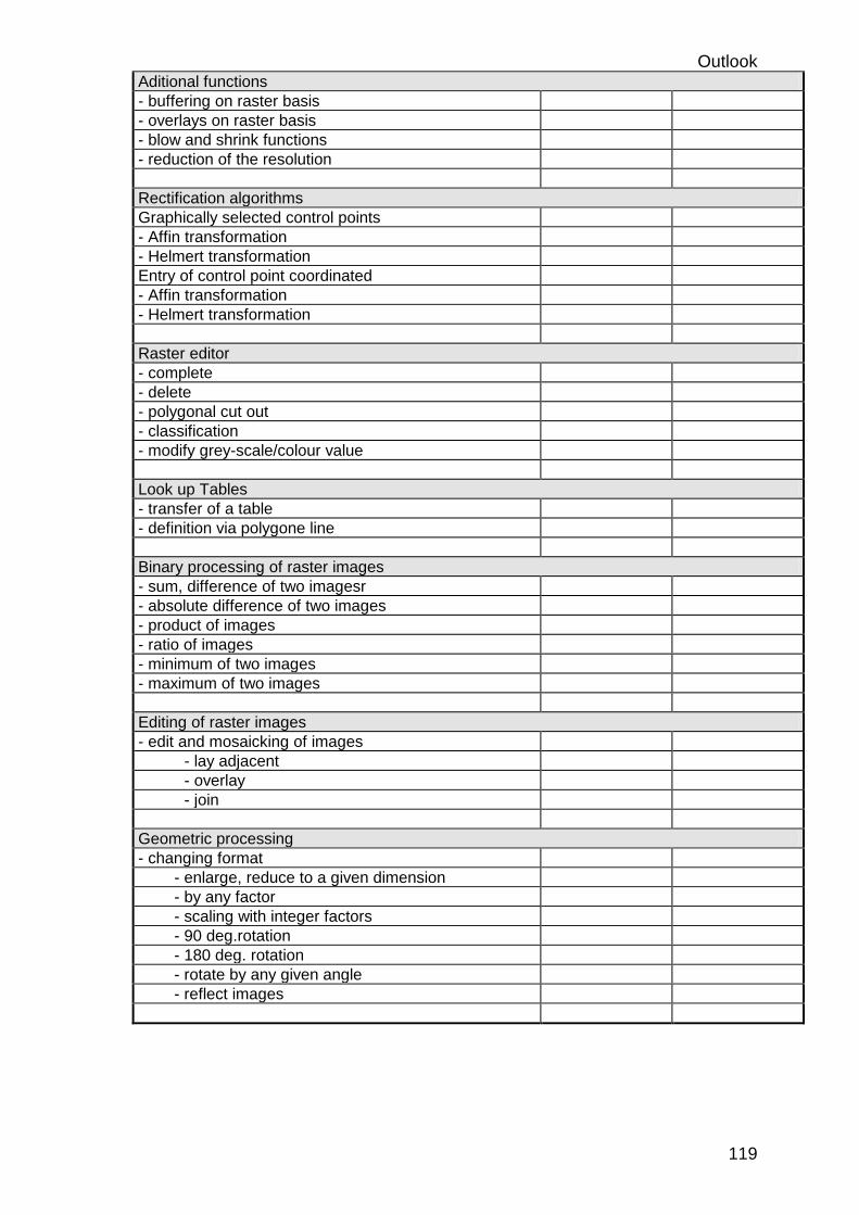
Outlook
119
Aditional functions
- buffering on raster basis
- overlays on raster basis
- blow and shrink functions
- reduction of the resolution
Rectification algorithms
Graphically selected control points
- Affin transformation
- Helmert transformation
Entry of control point coordinated
- Affin transformation
- Helmert transformation
Raster editor
- complete
- delete
- polygonal cut out
- classification
- modify grey-scale/colour value
Look up Tables
- transfer of a table
- definition via polygone line
Binary processing of raster images
- sum, difference of two imagesr
- absolute difference of two images
- product of images
- ratio of images
- minimum of two images
- maximum of two images
Editing of raster images
- edit and mosaicking of images
- lay adjacent
- overlay
- join
Geometric processing
- changing format
- enlarge, reduce to a given dimension
- by any factor
- scaling with integer factors
- 90 deg.rotation
- 180 deg. rotation
- rotate by any given angle
- reflect images

Outlook
120
17 Tender documents GIS Center (I)
WS
WS WS WS
WS
switch
WAN
file server
scanner
laser
printer
plotter digitizer
high speed
workstationrouter
raid system
alphanumerical
stations
high speed
workstation
100BASE T
(1.1) (1.2)
(1.3)
(1.4)
graphical PCs(3.1) (3.2)
(2.1) (2.2) (2.3)
(5.1)
(5.2)
(4.1) (4.2) (4.3)
(4.4)
EXABYTE
(4.5)
(SCSI)
FDDIoptical fibre
10BASE T
1
1.1 File Server 40.000 $
1.2 RAID - System 50.000 $ 90.000 $
1.3 High Speed Workstation 34.000 $ 124.000 $
1.4 High Speed Workstation 31.000 $ 155.000 $
2 graphical PCs
2.1 graphical PC 10.000 $ 165.000 $
2.2 graphical PC 10.000 $ 175.000 $
2.3 graphical PC 10.000 $ 185.000 $
3 alphanumerical PCs
3.1 alphanumerical PC 6.500 $ 191.500 $
3.2 alphanumerical PC 6.000 $ 195.500 $
4 Periperials
4.1 Scanner 18.000 $ 213.500 $
4.2 Plotter 11.500 $ 225.000 $
4.3 Digitizer 8.500 $ 233.500 $
4.4 Laser Printer 2.000 $ 235.500 $
4.5 EXABYTE 4.500 $ 240.000 $
5 Network
5.1 Router 12.500 $ 252.500 $
5.2 Switch 6.500 $ 259.000 $
5.3 utilities 1.000 $ 260.000 $

Outlook
121
(1.1) Server Unit Price
(U.S.D)
Processor
Model
& Speed
RISC 64-bit running more than 240 Mhz Clock Speed
Cache Memory 2-Mbyte ECC onboard cache.
System
Performance
SPECint92 > 190 SPECfp92 > 260
Memory 128 MB expandable to 1 GB
I/O Support - 2 PCI slots (@ 132 MB/s) - 7 EISA slots (@ 33 MB/s) - 1 PCI/EISA combination slot - Integrated PCI-based Fast SCSI-2 controller with DMA and external SCSI-2 connector - PCI based Ethernet - 2 asynchronous serial ports with full modem control - Bi-directional enhanced parallel port - PS/2 style keyboard port & mouse port
Monitor 17 “ color, LR, MPR2
Floppy Drive 1.44 Mbyte diskette drive
Hard Drive 1 x 2 GB SCSI expandable to: - 28 GB internally - 440 GB and more using expansion cabinets
CD-ROM 600 MB double speed
Tape drive 5 GB, 8mm, tabletop, tape drive
Network
Interface
EISA-based FDDI controller, dual attachment
Operating
Systems
Unix Concurrent use 8-user license Media and Documentation included
40.000 $
(1.2) RAID-System Unit Price
(U.S.D)
- RAID support and optional external hot-swappable disks (120 GB) -Dual SCSI backplane -Remote diagnostics -Memory failover -3 button mouse
50.000 $
(1.3) Work Station Unit Price
(U.S.D)
Processor
Model
& Speed
RISC 64-bit running more then 240 Mhz Clock Speed
Cache memory 2 MB on-board cache

Outlook
122
System
performance
Memory 96 MB RAM expandable to 512 MB RAM ECC
I/O Support 256-bit wide memory bus 5 storage slots 1 x 64-bit PCI, 3 x 32-bit PCI slots
Monitor 21” color, LR, MPR2
Floppy Drive 1.44 Mbyte diskette drive
Hard Drive 1 x 2 GB SCSI expandable to: - 28 GB internally - 440 GB and more using expansion cabinets
CD-ROM CD-ROM
Tape drive
Network
interface
EISA-based FDDI controller, dual attachment
Operating
systems
Unix operating system
Harad drive 2 x 2.1 GB Fast wide SCSI drive
Multi media Built-in stereo-quality audio, microphone, and headphones
34.000 $

Outlook
123
(1.4) Work Station
Processor
Model
& Speed
RISC 64-bit running more then 300 Mhz Clock Speed
$ 31,000
Cache memory 1 MB on-board cache
System
performance
Memory 64 MB RAM expandable to 512 MB RAM ECC
I/O Support 128-bit wide memory bus 5 storage slots 2 x PCI, 1 x PCI/ISA, 1 x ISA slots
Monitor 21” color, LR, MPR2
Floppy Drive 1.4 Mbyte diskette drive
Hard Drive 1 x 2.1 GB Fast wide SCSI drive 1 x 4.3 GB Fast wide SCSI drive
CD-ROM CD-ROM
Tape drive
Network
interface
EISA-based FDDI controller, dual attachment
Operating
systems
Unix operating system
Multi media 31.000 $
(2.1-2.3) graphical PC Unit Price
(U.S.D)
Processor
Model
& Speed
RISC 32-bit running min. at 200 Mhz Clock Speed
10.000 $
Cache memory 256 KB -512 KB expandable Cache
System
performance
Memory 32 MB SIMM memory
I/O Support AT Bus PCI 2 PCMCIA (Type 1 & 2) slots SCSI II I/O port Two High speed serial ports one bi-directional parallel port
Monitor 21” high resolution 1600x1200 mon.
Floppy Drive 3.5” 1.4 Mbyte diskette drive
Hard Drive 4 GB 3.5” SCSI Hard drive
CD-ROM
Graphic
adapter
24 BIT graphic card VRAM 4MB on Board
Network
interface
Integrated 10BaseT Ethernet

Outlook
124
Operating
systems
Operating System WINDOWS NT X11.R6 Server included
Multi media 30.000 $
3.1 alphanumercial PC Price
Processor Pentium P5- “INTEL”
Speed 200 Mhz
MBRD RHINO 6 + Controller
RAM 32 MB RAM, ( 72 Pins ) With Parity.
Controller EIDE built-in For 2 FDD & 4 EIDE devices
Input/Output 2 Serial, 1 Parallel
Graphic Card SVGA 1MB “PCI“
Monitor SVGA Color Monitor 21",0.28 < Full Screen > " CTX “ ( Non Interlaced & Low Radiation )
FDD 1.44 MB " TEAC "
HDD 2 GB Conner SCSI
Keyboard US 101 Keys (Windows 95 layout)
Casing Minitower Case
Mouse Genius Mouse + Pad
Controller
SCSI
PCI Adaptec controller AHA2940
CDROM SCSI CDROM 4X
6.500 $
3.2 alphanumerical PC Price
Processor Pentium P5- “INTEL”
Speed 200 Mhz
MBRD RHINO 6 + Controller
RAM 16 MB RAM, ( 72 Pins ) With Parity.
Controller EIDE built-in FOR 2 FDD & 4EIDE devices
Input/Output 2 Serial, 1 Parallel
Graphic Card SVGA 1MB “PCI“
Monitor SVGA Color Monitor 21",0.28 < Full Screen > " CTX “ ( Non Interlaced & Low Radiation )
FDD 1.44 MB " TEAC "
HDD 1.2 GB Conner SCSI
Keyboard US 101 Keys (Windows 95 layout)
Casing Minitower Case
Mouse Genius Mouse + Pad
Controller
SCSI
PCI Adaptec controller AHA2940 6.000 $
Peripherals
4.1 Scanner, min. Scan Width 90 cm,
min. 800 dpi
18.000 $

Outlook
125
4.2 A0 Cut/Roll color inkjet 720/360 dpi w/
stand & basket
11.500 $
4.3 Digitizer,
48” x 60” (over A0) high accuracy (0.002”)
8.200 $
FDDI Network Unit Price
(U.S.D)
5.1 Router : specifications available with the
WAN-design
(13.000 $ ? )
5.2 FDDI / Ethernet Switch, > 4 10BASE2
(BNC),
> $ 10 BASE-T, > 4 10 BASE-FL, AUI-
Buchsen, minimum 2 FDDI; Cut-Through,
Store and Forward, Full-Wire-Speed-
Filtering, Full-Wire-Speed-
Forwarding,Protocol Filter, SNPM
6.500 $
optical fibre
10BASE T
additionals 1.000 $
Item Software Qtty Unit Price
(U.S.D)
1 GIS - Software (vector - based) PC
3 16,000 $ 48.000 $
2 GIS - Software (vector - based) WS
1 34.000 $ 82.000 $
3 GIS - Software (raster - based)
1 30.000 $ 112.000 $
4 - C++ -ANSI/ISO compliant 3,000 $ 115.000 $
5 RDBMS 60.000 $ 175.000 $
6 - CAD - Software (PC 1 5,000 $ 180.000 $
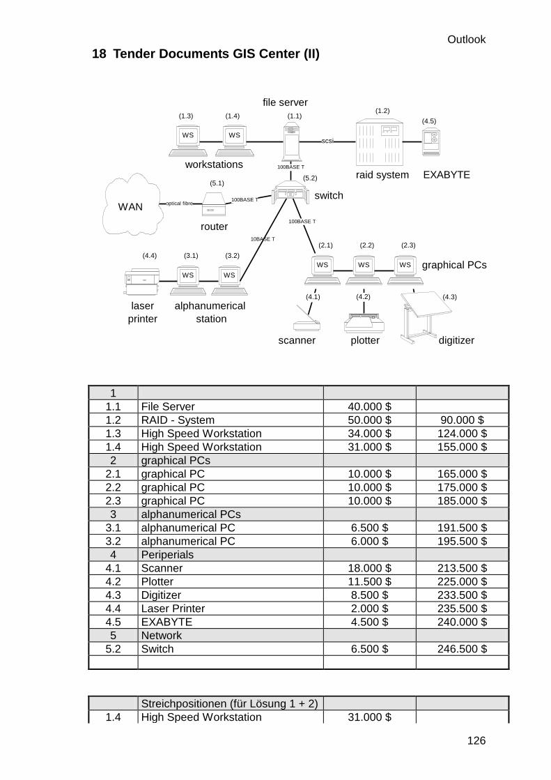
Outlook
126
18 Tender Documents GIS Center (II)
WS
WS
WS WS
WS
WS
switchWAN
file server
scanner
laser
printer
plotter digitizer
router
raid system
alphanumerical
station
workstations
100BASE T
(1.1)(1.2)
(1.3) (1.4)
graphical PCs(3.1) (3.2)
(2.1) (2.2) (2.3)
(5.1)(5.2)
(4.1) (4.2) (4.3)
(4.4)
100BASE T
100BASE T
optical fibre
EXABYTE
(4.5)
scsi
WS
10BASE T
1
1.1 File Server 40.000 $
1.2 RAID - System 50.000 $ 90.000 $
1.3 High Speed Workstation 34.000 $ 124.000 $
1.4 High Speed Workstation 31.000 $ 155.000 $
2 graphical PCs
2.1 graphical PC 10.000 $ 165.000 $
2.2 graphical PC 10.000 $ 175.000 $
2.3 graphical PC 10.000 $ 185.000 $
3 alphanumerical PCs
3.1 alphanumerical PC 6.500 $ 191.500 $
3.2 alphanumerical PC 6.000 $ 195.500 $
4 Periperials
4.1 Scanner 18.000 $ 213.500 $
4.2 Plotter 11.500 $ 225.000 $
4.3 Digitizer 8.500 $ 233.500 $
4.4 Laser Printer 2.000 $ 235.500 $
4.5 EXABYTE 4.500 $ 240.000 $
5 Network
5.2 Switch 6.500 $ 246.500 $
Streichpositionen (für Lösung 1 + 2)
1.4 High Speed Workstation 31.000 $
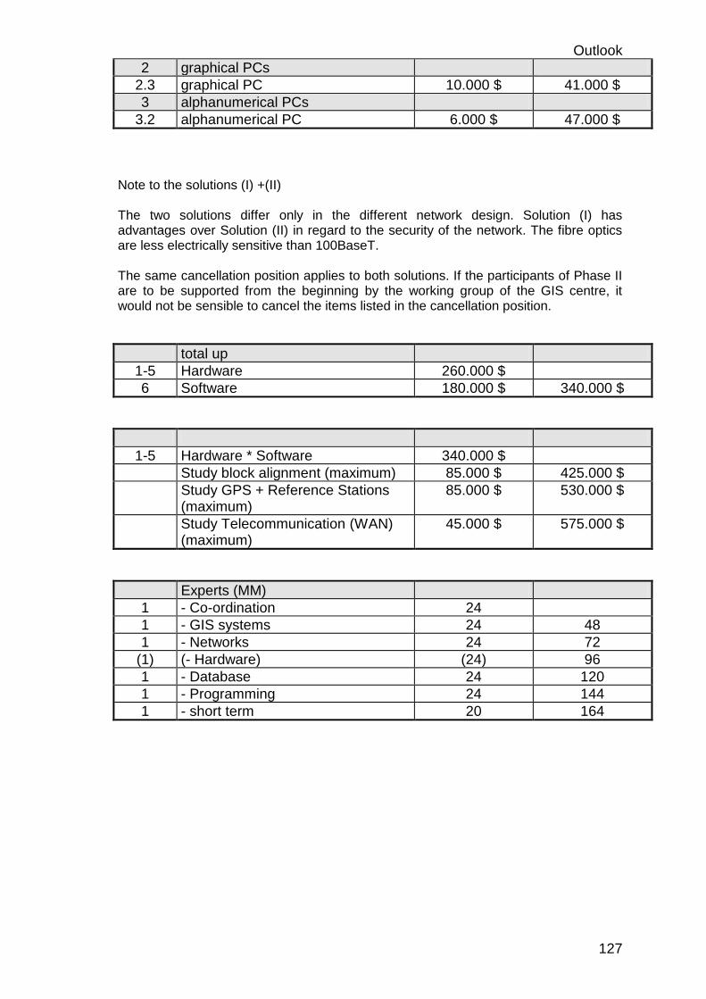
Outlook
127
2 graphical PCs
2.3 graphical PC 10.000 $ 41.000 $
3 alphanumerical PCs
3.2 alphanumerical PC 6.000 $ 47.000 $
Note to the solutions (I) +(II) The two solutions differ only in the different network design. Solution (I) has advantages over Solution (II) in regard to the security of the network. The fibre optics are less electrically sensitive than 100BaseT. The same cancellation position applies to both solutions. If the participants of Phase II are to be supported from the beginning by the working group of the GIS centre, it would not be sensible to cancel the items listed in the cancellation position.
total up
1-5 Hardware 260.000 $
6 Software 180.000 $ 340.000 $
1-5 Hardware * Software 340.000 $
Study block alignment (maximum) 85.000 $ 425.000 $
Study GPS + Reference Stations (maximum)
85.000 $ 530.000 $
Study Telecommunication (WAN) (maximum)
45.000 $ 575.000 $
Experts (MM)
1 - Co-ordination 24
1 - GIS systems 24 48
1 - Networks 24 72
(1) (- Hardware) (24) 96
1 - Database 24 120
1 - Programming 24 144
1 - short term 20 164

Outlook
128
GIS - CENTER (HARDWARE)

Outlook
129
1-Server
Server
Server Unit Price (U.S.D)
Processor Model & Speed
RISC 64-bit running more than 240 Mhz Clock Speed
$ 52,000
Cache Memory 2-Mbyte ECC onboard cache.
System Performance
SPECint92 197.5 SPECfp92 263.8
Memory 128 MB expandable to 1 GB
I/O Support - 2 PCI slots (@ 132 MB/s) - 7 EISA slots (@ 33 MB/s) - 1 PCI/EISA combination slot - Integrated PCI-based Fast SCSI-2 controller with DMA and external SCSI-2 connector - PCI based Ethernet - 2 asynchronous serial ports with full modem control - Bi-directional enhanced parallel port - PS/2 style keyboard port & mouse port
Monitor 17 “ color, LR, MPR2
Floppy Drive 1.44 Mbyte diskette drive
Hard Drive 1 x 2 GB SCSI expandable to: - 28 GB internally - 440 GB and more using expansion cabinets
CD-ROM 600 MB double speed
Tape drive 5 GB, 8mm, tabletop, tape drive
Network
Interface
EISA-based FDDI controller, dual attachment
Operating Systems
Unix Concurrent use 8-user license Media and Documentation included
Other features - RAID support and optional external hot-swappable disks (120 GB) -Dual SCSI backplane -Remote diagnostics -Memory failover -3 button mouse
$ 75.000

Outlook
130
2- Standalone Workstations
Item Description Unit Price
(U.S.D)
1 Work Station RISC 64-bit running more then 240 Mhz Clock Speed Digital Unix operating system 256-bit wide memory bus 2 MB on-board cache 96 MB RAM expandable to 512 MB RAM ECC 2 x 2.1 GB Fast wide SCSI drive PowerStorm 3D10 graphics Integrated 10BaseT/10Base2 Ethernet 1.4 Floppy drive 4 x CD-ROM Built-in stereo-quality audio, Microphone, and headphones 5 storage slots I/O Expansion: one 64-bit PCI, three 32-bit PCI slots 21” color monitor
$ 35,000
2 Work Station RISC 64-bit running at 300 Mhz Clock Speed Unix operating system 128-bit wide memory bus 1 MB on-board cache 64 MB RAM expandable to 512 MB RAM ECC 1 x 2.1 GB Fast wide SCSI drive 1 x 4.3 GB Fast wide SCSI drive Integrated 10BaseT/10Base2 Ethernet 1.4 Floppy drive 4 x CD-ROM 5 storage slots I/O Expansion: 2 PCI, 1PCI/ISA, 1 ISA slots 21” color monitor
$ 31.000

Outlook
131
3- Personal Workstations
Item Description Quantity Unit Price
(U.S.D)
Total
Price
(U.S.D)
1 running min. at 200 Mhz Clock Speed 3.5” 1.44 MB Floppy Drive 1 GB 3.5” SCSI Hard drive 256 KB -512 KB expandable Cache 32 MB SIMM memory 24 BIT graphic card VRAM 2MB on Board 2 PCMCIA (Type 1 & 2) slots SCSI II I/O port Ethernet included Two High speed serial ports one bi-directional parallel port Operating System WINDOWS NT X11.R6 Server included 21” high resolution 1600x1200 mon.
3 $ 9,000 $ 27,000
2 Intel 100 Mhz Pentium 3.5” 1.44 MB Floppy Drive 810 MB Hard drive 256 KB expandable Cache 32 MB SIMM memory VRAM 2MB on Board 24 BIT graphic card 2 PCMCIA (Type 1 & 2) slots SCSI II I/O port PCI FDDI controller Two High speed serial ports one bi-directional parallel port Operating System WINDOWS NT X11.R6 Server included 21” high resolution 1600x1200 mon.
3 $ 10,500 $ 31,500

Outlook
132
4- Peripherals
Item Description Qtty Unit Price
(U.S.D)
Total Price
(U.S.D)
1 Switch 900EF single slot hub
module
1 3,000 3,000
2 A0 Cut/Roll color inkjet 720/360 dpi
w/ stand & basket
1 11,500 11,500
3 Scanner, min. Scan Width 90 cm,
min. 800 dpi
1 18,000 18,000
4 Interface kit 1 1,250 1,250
5 Digitizer,
48” x 60” (over A0)high accuracy
(0.002”)
1 8,200 8,200
6 Manual Lift- Manual tilt base 1 870 870
$ 294,320
Item Description Qtty Unit
Price
(U.S.D)
Total Price
(U.S.D)
1 GIS - Software (vector - based) PC 1 15,800 $ 15.800 $
1
GIS - Software (vector - based) WS 1 28.800 $ 28.800 $
1 GIS - Software (raster - based) 1 26.500 $ 26.500 $
- C++ -ANSI/ISO compliant
2,800 $ 2,800 $
5 - CAD - Software (PC)
1 4,000 $ 4,000$
77,900 $

Outlook
133
19 Tender Documents GIS (CDR)
PC
WS
WS
Link to the
CDR Network
10BASE T
EXABYTEServer
graphical PC
PC for
digitizing
Digitizer
Laser Printer
Plotter
CDR LAN (1.1)
(4.5)
(1.3)
(4.2)
(4.4)
(2.1)
(4.3)
(2.1)
1.3 High Speed Workstation 34.000 $
1.1 Server 40.000 $ 74.000 $
2.1 graphical PC 10.000 $ 84.000 $
3.1 alphanumerical PC 6.500 $ 90.500 $
4.4 Laser Printer 2.000 $ 92.500 $
4.2 Plotter 11.500 $ 104.000 $
4.3 Digitizer 8.500 $ 112.500 $
4.5 EXABYTE 4.500 $ 117.000 $
5.3 utilities 1.000 $ 118.000 $
Streichpositionen
4.2 Plotter 11.500 $ 11.500 $
Software
GIS - Software (vector - based) 34.000 $
GIS - Software (raster - based) 30.000 $ 64.000 $
CAD - Software (PC) 5,000 $ 69.000 $
total up
Hardware 118.000 $
Software 69.000 $ 177.000 $
20

Outlook
134
APPRAISAL+ BASIS ARCHITECTURE
+ DEMONSTRTION
Phase 1.1
CDR - GISDETAILLED ARCHITECTURE
NATIONAL -GISBASIC ARCHITECTURE
CDR - GISIMPLEMENTATION
NATIONAL - GISTOR + TENDER
Phase 1.2
NATIONAL GIS - PROGRAMME
PREFEASIBILITY GPS
PREAFEASIBILITY
WAN (WIDE AREA NETWORK)
HARDWARE
SOFTWARE
LAN (LOCAL AREA NETWORK)
PERIPHERALS
AMOUNT OF REFERENCE STATIONS
SITE SEARCH AND COVERAGE
+ COST ESTIMATION
COPPER LINE
OPTICAL FIBRE
MICRO WAVE LINK
ISDN
+ COST ESTIMATION
Phase 2.1
- Data-akquisition
for satellite images
- Methodology for for
Basemaps, DTM
- processing
Basemaps 1 : 20.000
BASE
PREFEASIBILITYSTUDY (BASEMAPS)
BEIRUT
COORDINATES MISSING
VERY HIGH PRIORITY
_____________________
METHODE A
TRIPOLI
COORDINATES AVAILIBLE
HIGH PRIORITY
______________________
METHODE B
METHODE A
SCANNING CADASTRE MAPS
RECTIFING SCANNED CADSTRE MAPS
VETORISATION RASTER MAPS
DIGITAL VECTOR CADASTRE MAPS
DIGITAL COORDINATES OF LOTS
FIELD SURVEY
OVERLAY FIELD SURVEY / DIGITAL MAPS
IF NECESSARY NEW DESIGN OF LOTS
METHODE B
DESIGN OF INPUTMASK (COORDINATES)
PROGRAMMING ROUTINES FOR GENER
ATING LOTS
DESIGN OF DIGITAL CADASTRE-BOOK

Outlook
135
EUROPEAN T.A.
1.500.000, -
NATIONAL T.A.
(CDR)
300.000, -
EQUIPMENT +
SOFTWARE
(CDR)
100.000, -
MEASURMENT
CAMPAIGN
CDR PROJECT
EQUIPMENT
50.000, -
OPERATIONS
150.000, -
OPERATIONS
15 % OF 1 - 3 :
1.000.000, -
TRAINING,
DIFFUSION ETC.
5 % OF 1 - 3 :
300.000, -
EUROPEAN T.A.
175.000, -
CDR-EQUIPMENT
175.000, -
NATIONAL T.A.
75.000, -
EUROPEAN T.A.
75.000,-
OTHERS
5 x 600.000, -
OTHERS
5 x 250.000, -
PHASE 1.1
PHASE 1.2
PHASE 2.1
75.000, -
7.000.000, -8.225.000, -
CUMULATIVE
75.000, -
425.000, -
575.000, -

Outlook
136
21 Expansion phases NATIONAL GIS centre
CDRTECHNICAL ASSISTANCE
INTERNATIONAL
TECHNICAL ASSISTANCE
NATIONAL
MINISTRY OF FINANCE
MINISTRY OF TRANSPORT
P.T.T.MINISTRY OF DEFENCE
MINISTRY OF PUBLIC
WORKS
MINISTRY OF
ENVIRONMENT
MINISTRY OF HYDRO-
AND ELECTRICAL
RESSOURCES
GIS - CENTER (CDR)
NATIONAL GIS CENTER (PHASE 2)
MINISTRY OF
MUNICIPALITIES AND
RURAL AFFAIRS
ADMINISTRATION
CENTRALE DES
STATISTIQUES
MINISTRY OF
AGRICULTURE
EDL
DIRECTION GENERALE DE
L' URBANISME
CNRS - INSTITUTE FOR
REMOTE SENSING
IDALUNIVERSITY OF LEBANON
MINISTRY FOR
ADMINISTRATIVE REFORMCEGP
NATIONAL GIS - CENTER (PHASE 3)
OFF. NAT. LITANI
(PHASE 1)
Phase1:
In this phase the GIS centre is set up. 4.5 months are estimated for this. In the invitation to tender, be careful that the hardware, operating systems and appropriate drivers for the peripherals are set up and installed by the contractors. The System administrator and the GIS expert support the work and take over responsibility for it after completion. The studies should be carried out in parallel to the setting up of the GIS centre.
Phase 2:
During this phase, teams are formed and available data is gathered and integrated into the GIS. A workgroup is formed for producing the base data, a strategy is developed for its acquisition - independent of the results of the study - and an agreement between the institutions involved is reached. All interested participants are supported by the GIS centre when setting up their applications. GIS projects are coordinated. The development of the general database interface / the database design for the national GIS is started. All essential agreements (attributes, legends, layers) are reached.

Outlook
137
Phase 3 :
In this phase all other interested parties of the national GIS are integrated in steps. This integration should be started in parallel during the second phase. The participants are connected to a WAN.

Outlook
138
22 Spurios Polygons
The spurious polygons shown in this example are an inevitable consequence of the use of different base data in various thematic maps with subsequent intersecting. They lead to extremely long computer processing times and prevent exact geometry details. It can be assumed that if spurious polygons continue to be worked with, the entire database will become worthless within a short space of time.
Example : This picture shows the Litani river with cadastre boundaries entered. Four different cadastre area are captured
In this picture the various soil conditions of the same region are depicted. The Litani river was digitsed for a second time.
On intersecting the cadastre map with the soil map spurious polygons appear (hatched area) since the base information of the river was digitised by two different persons and are not identical. In this drawing the two different river courses are represented in an exaggerated fashion for reason of clarity.

Outlook
139
23
Attributes Spatial Data
Data acquisition
RegistrationDigital data
Analog Data
Digitizing
(vector)
Scan
(raster)
Convert to
vector
Build Topology
Geocoding Geocoding
Rectification
Check
EditLink Attributes to
Spatial Data
Layer
Administration
Legends
Text files
GIS Database
Data Collection
Layer
Concept
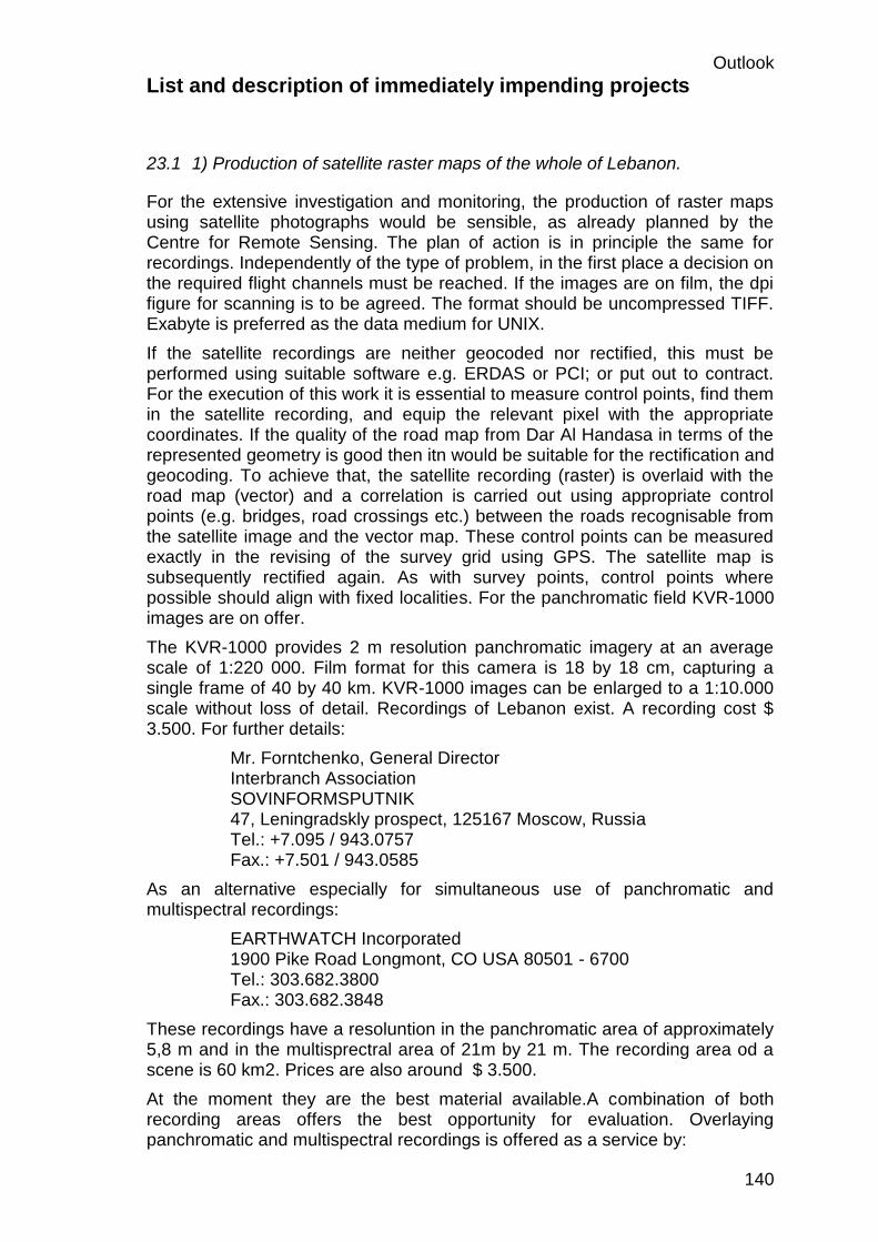
Outlook
140
List and description of immediately impending projects
23.1 1) Production of satellite raster maps of the whole of Lebanon.
For the extensive investigation and monitoring, the production of raster maps using satellite photographs would be sensible, as already planned by the Centre for Remote Sensing. The plan of action is in principle the same for recordings. Independently of the type of problem, in the first place a decision on the required flight channels must be reached. If the images are on film, the dpi figure for scanning is to be agreed. The format should be uncompressed TIFF. Exabyte is preferred as the data medium for UNIX.
If the satellite recordings are neither geocoded nor rectified, this must be performed using suitable software e.g. ERDAS or PCI; or put out to contract. For the execution of this work it is essential to measure control points, find them in the satellite recording, and equip the relevant pixel with the appropriate coordinates. If the quality of the road map from Dar Al Handasa in terms of the represented geometry is good then itn would be suitable for the rectification and geocoding. To achieve that, the satellite recording (raster) is overlaid with the road map (vector) and a correlation is carried out using appropriate control points (e.g. bridges, road crossings etc.) between the roads recognisable from the satellite image and the vector map. These control points can be measured exactly in the revising of the survey grid using GPS. The satellite map is subsequently rectified again. As with survey points, control points where possible should align with fixed localities. For the panchromatic field KVR-1000 images are on offer.
The KVR-1000 provides 2 m resolution panchromatic imagery at an average scale of 1:220 000. Film format for this camera is 18 by 18 cm, capturing a single frame of 40 by 40 km. KVR-1000 images can be enlarged to a 1:10.000 scale without loss of detail. Recordings of Lebanon exist. A recording cost $ 3.500. For further details:
Mr. Forntchenko, General Director Interbranch Association SOVINFORMSPUTNIK 47, Leningradskly prospect, 125167 Moscow, Russia Tel.: +7.095 / 943.0757 Fax.: +7.501 / 943.0585
As an alternative especially for simultaneous use of panchromatic and multispectral recordings:
EARTHWATCH Incorporated 1900 Pike Road Longmont, CO USA 80501 - 6700 Tel.: 303.682.3800 Fax.: 303.682.3848
These recordings have a resoluntion in the panchromatic area of approximately 5,8 m and in the multisprectral area of 21m by 21 m. The recording area od a scene is 60 km2. Prices are also around $ 3.500.
At the moment they are the best material available.A combination of both recording areas offers the best opportunity for evaluation. Overlaying panchromatic and multispectral recordings is offered as a service by:

Outlook
141
Dr. Steffen Kuntz Kayser-Threde GmbH Wolfratshauser str. 48 D-81379 München Tel.: 049 89 / 72495-0 Fax : 049 724 95 291
If this preliminary work is utilised the appropriate scenes are available for interpretation. A contact has already been set up between Dr. Khwalie (Remote Sensing Institute) and Dr. Kuntz. It would be sensible to hold a one-week course in Beirut once the GIS centre is set up on the handling and processing of these images.
If there is only interest in the raw data, the following is responsible for the territory of Lebanon:
Herr Dr. Bettac DLR/DFD Neustrelitz Kalkhorstweg 53 D-17235 Neustrelitz Tel.: 049 3981 / 480 - 115 Fax: 049 3981 / 480 - 299
A cooperation between the German Remote Sensing Centre and the Remote Sensing Institute was being put in place.
23.2 2) Processing the maps of the ministry of Telecom (telephone lines)
An agreement between the firms involved (Ericsson, Siemens, Alcatel and the P.T.T.) in respect of legends, attributes, symbols and layer management is to be worked towards. After that, the maps need appropriate rework. Since during digitising the Cartesian coordinate system was used, the maps must be geocoded. Subsequently the existing maps in separate files should be transferred via DXF interface to the GIS system and held there with freedom of boundaries. After the revision of the survey grid the maps should be rectified accordingly.
23.3 3) Production of a bathymetric map of the coastal area
According to information from the Ministry of Transport, a bathymetric map of the entire Lebanese coastal area must be produced by international arrangement in the near future. It is important in carrying out this work to make a complete digital recording. The echo-sounder should supply digital values which are geocoded using GPS online. The data must be adoptable by the GIS (DFX interface). After the data is adopted an appropriate depth model can be produced on vector basis using triangle meshing, from which the depth lines can be derived.

Outlook
142
The largest part of the costs in this job will be for chartering the ship. It is proposed that a sediment echo-sounder is used instead a simple digital echo-sounder; so not only depths but the type of sediment can be ascertained. The extra costs incurred are much less in proportion than the additional information acquired. With respect to the demand for natural building materials in Lebanon, this information should prove extraordinarily valuable. The depth model forms an offshore addition to the digital terrain model proposed in the study.
23.4 4) digital terrain model
The importance of a digital terrain model has already been mentioned in the study. This data can be used for the following immediately impending projects:
- irrigation of South Lebanon (Off. Nat. Litani) - drinking water supply (Ministry of Hydro- and Electrical Ressources) - hydraulic and reservoir construction - route planning for supply lines (EDL) - road planning - erosion threats
The data acquisition is supported by aeroplane. The flying can be done either with an on-site plane or with a supplier’s plane. Flight permission is essential. Since we are dealing with radar recordings, the performance is relatively unaffected by weather conditions.

Outlook
143
24 Tender Documents GIS Center (PHASE II)
National GIS-Center -
COMPLICATION
Unit Price (US$) CUMUL TOTAL
(US$)
1.2 CAPT. EXT. RAIDSYSTEM 40.000 $
2.3 graphical PC 8.000 $ 48.000 $
3 alphanumerical PCs
3.2 alphanumerical PC 5.200 $ 53.200 $
4 Periperials
4.4 Laser Printer 1.600 $ 54.800 $
4.5 CD-ROM WRITER 6.000 $ 60.800 $
5 Network
5.1 Router 12.500 $ 73.300 $
Item Software Qtty Unit Price (US$) CUMUL TOTAL
(US$)
1 GIS - Software (vector - based) PC
3 16,000 $ 48.000 $
2 GIS - Software (vector - based) WS
1 34.000 $ 82.000 $
3 GIS - Software (raster - based)
1 30.000 $ 112.000 $
4 - C++ -ANSI/ISO compliant 3,000 $ 115.000 $
5 RDBMS 60.000 $ 175.000 $
6 - CAD - Software (PC 1 5,000 $ 180.000 $
Experts (MM)
1 - Co-ordination 24
1 - GIS systems 24 48
1 - Networks 24 72
1 - Hardware 24 96
1 - Database 24 120
1 - Programming 24 144
1 - short term 24 168
*) at 1.264 US$/ECU

Outlook
144
25 Tender Documents : LOCAL GIS-SUBSYSTEM
UNIT PRICE (US$)*
CUMUL TOTAL (US$)*
1.1 Server 32.000 $
1.3 High Speed Workstation 27.000 $ 59.000 $
2.1 graphical PC 8.000 $ 67.000 $
3.1 alphanumerical PC 5.200 $ 72.200 $
4.2 Plotter 9.200 $ 81.400 $
4.3 Digitizer 6.800 $ 88.200 $
4.4 Laser Printer 2.000 $ 90.200 $
4.5 EXABYTE 3.600 $ 93.800 $
5.3 utilities 1.100 $ 94.900 $
Software
GIS - Software (vector - based) 34.000 $
GIS - Software (raster - based) 30.000 $ 64.000 $
CAD - Software (PC) 5,000 $ 69.000 $
total up
Hardware 94.900 $
Software 69.000 $ 163.900 $
*) at 1.264 US$/ECU

Outlook
145
Central
Archive
of Lebanon
Central Archive of
Lebanon
- CARL -
Inputs Base Data / Spatial
Data Descriptive Data
NATIONAL GIS
WP1000
WP2000
WP3000
WP4000
TP1000
JAN APR JUL OKT JAN APR JUL OKT DEZ
Starting Point End Point Meeting Midterm Report and Presentation
1998 1999
Kick - off
NATIONAL GIS / CARL - Schedule (PHASE II)
Decision
Final Presentation
2000
24 MM
42 MM
30 MM
72 MM

Outlook
146
NATIONAL GIS / Central Archive of Lebanon ( PHASE II )
Contacts
Reporting
Travellings and Meetings
Cost Control Quality Assurance
WP 1000
Management
WP 2500
Analysis of
Systems Operation
WP 2400
Interfaces
WP 2300
Data Base Model
WP 2200
GPS
Network and Service
WP 2100
WAN
WP 2000
Definition of
System Approach
WP 3500
Training and
Know-how Transfere
WP 3400
Creation of Satellite
Maps of Lebanon
WP 3300
Linking of Des-
criptive Data
WP 3200
Integration of Existing
Spatial Lebanese Data
WP 3100
Installation of Initial
Hard- and Software
WP 3000
Installation, Data
Integration and Training
WP 4200
Realisation of
Demonstrator
WP 4100
Data Import / Export
WP 4000
Technical Installations
CARL
Work Breakdown Structure