LargeN solution of the heterotic CP(N-1) model with twisted masses
Upload
khangminh22Category
view
7download
0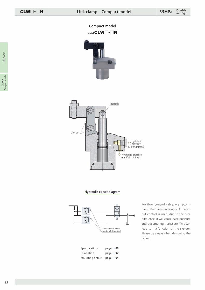
CLW□-□N Link clamp Compact model 35MPa Double acting
Link clamp
CLW-N
Compact model
Link pin
Rod pin
Hydraulic pressure(manifold piping)
Hydraulic pressure(G port piping)
Flow control valvemodel VCH (option)
For flow control valve, we recom-
mend the meter-in control. If meter-
out control is used, due to the area
difference, it will cause back pressure
and become high pressure. This can
lead to malfunction of the system.
Please be aware when designing the
circuit.
Hydraulic circuit diagram
Compact model
model CLW□-□N
Specifications
Dimentions
Mounting details
page → 89
page → 92
page → 94
88
To download CAD data / To get updated information, visit www.pascaleng.co.jp
CLW□-□N Link clamp Compact model 35MPa Double acting
Link clamp
CLW-N
Compact model
Hydraulic pressure(2 circuits)
Hydraulic pressure(2 circuits)
Plug
O-ring
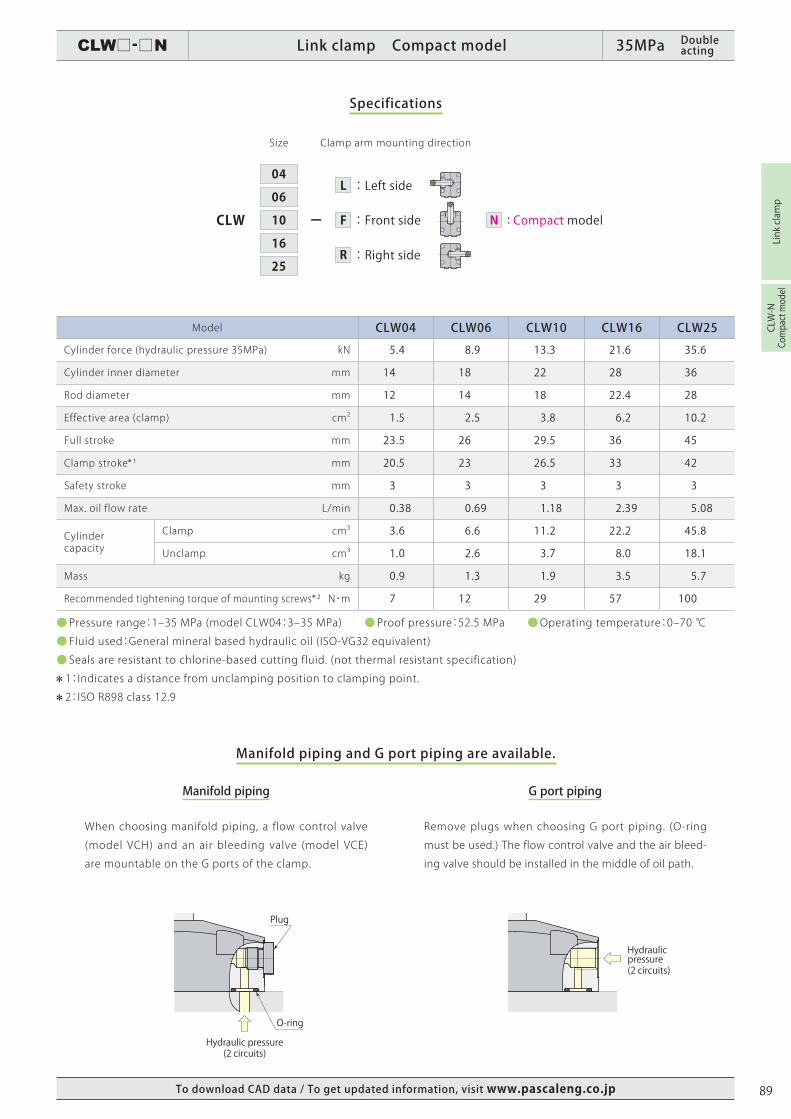
Model CLW04 CLW06 CLW10 CLW16 CLW25
Cylinder force (hydraulic pressure 35MPa) kN 5.4 8.9 13.3 21.6 35.6
Cylinder inner diameter mm 14 18 22 28 36
Rod diameter mm 12 14 18 22.4 28
Effective area (clamp) cm2 1.5 2.5 3.8 6.2 10.2
Full stroke mm 23.5 26 29.5 36 45
Clamp stroke 1 mm 20.5 23 26.5 33 42
Safety stroke mm 3 3 3 3 3
Max. oil flow rate L/min 0.38 0.69 1.18 2.39 5.08
Cylindercapacity
Clamp cm3 3.6 6.6 11.2 22.2 45.8
Unclamp cm3 1.0 2.6 3.7 8.0 18.1
Mass kg 0.9 1.3 1.9 3.5 5.7
Recommended tightening torque of mounting screws 2 N・m 7 12 29 57 100
● Pressure range:1‒35 MPa (model CLW04:3‒35 MPa) ● Proof pressure:52.5 MPa ●Operating temperature:0‒70 ℃
● Fluid used:General mineral based hydraulic oil (ISO-VG32 equivalent)
● Seals are resistant to chlorine-based cutting fluid. (not thermal resistant specification)
1:Indicates a distance from unclamping position to clamping point.
2:ISO R898 class 12.9
ーCLW
06
04
10
16
25
Size
: Compact modelN
:Left side
:Front side
:Right side
L
R
F
Specifications
Manifold piping and G port piping are available.
Manifold piping G port piping
Remove plugs when choosing G port piping. (O-ring
must be used.) The flow control valve and the air bleed-
ing valve should be installed in the middle of oil path.
When choosing manifold piping, a flow control valve
(model VCH) and an air bleeding valve (model VCE)
are mountable on the G ports of the clamp.
Clamp arm mounting direction
89
CLW□-□N Link clamp Compact model 35MPa Double acting
Link clamp
CLW-N
Compact model
LH =100
LH =60
LH =69.5
LH =80
LH =120LH =140LH =160LH =180
0 5 10 15 20 25 30 35
22.0
20.0
15.0
10.0
5.0
0.0
14.0
10.0
5.0
0.00
LH =60LH =56.5
LH =50
LH =80
LH =100LH =120LH =140LH =160
LH =40
7.0
6.0
5.0
4.0
3.0
2.0
1.0
0.00 53 110 15 20 25 30 35
1 35
LH =50
LH =42
LH =35
LH =60
LH =80LH =100LH =120
LH =30
9.0
8.0
7.0
6.0
5.0
4.0
3.0
2.0
1.0
0.00 5
1
10 15 20 25 30 35
LH =35
LH =50
LH =45
LH =60
LH =80LH =100LH =120
5 10 15 20 25 30
LH =100
LH =87.5
LH =120
LH =140LH =160LH =180LH =200
0 5 10 15 20 25 30 35
36.0
30.0
20.0
10.0
0.0
1
LH =65
LH =60
LH =50
Clamping force (kN)
Hydraulic pressure (MPa) Hydraulic pressure (MPa)
Nonusablerange
Nonusablerange
Nonusablerange
Clamping force (kN)
Hydraulic pressure (MPa) Hydraulic pressure (MPa)
Nonusablerange
Nonusablerange
Hydraulic pressure (MPa)
Clamping force (kN)
Clamping force (kN)
Clamping force (kN)
Hydraulic pressure P(MPa)
Clamp arm length LH(mm)
Clamping force F(kN)
Cylinder force(kN)
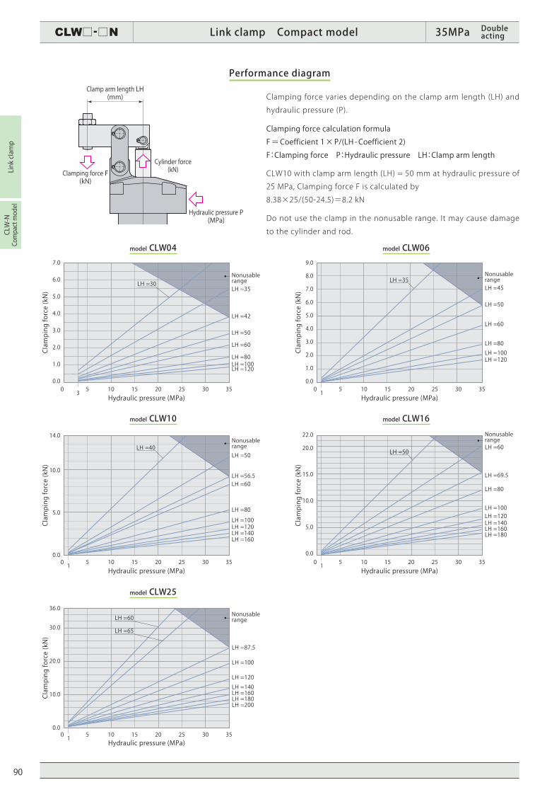
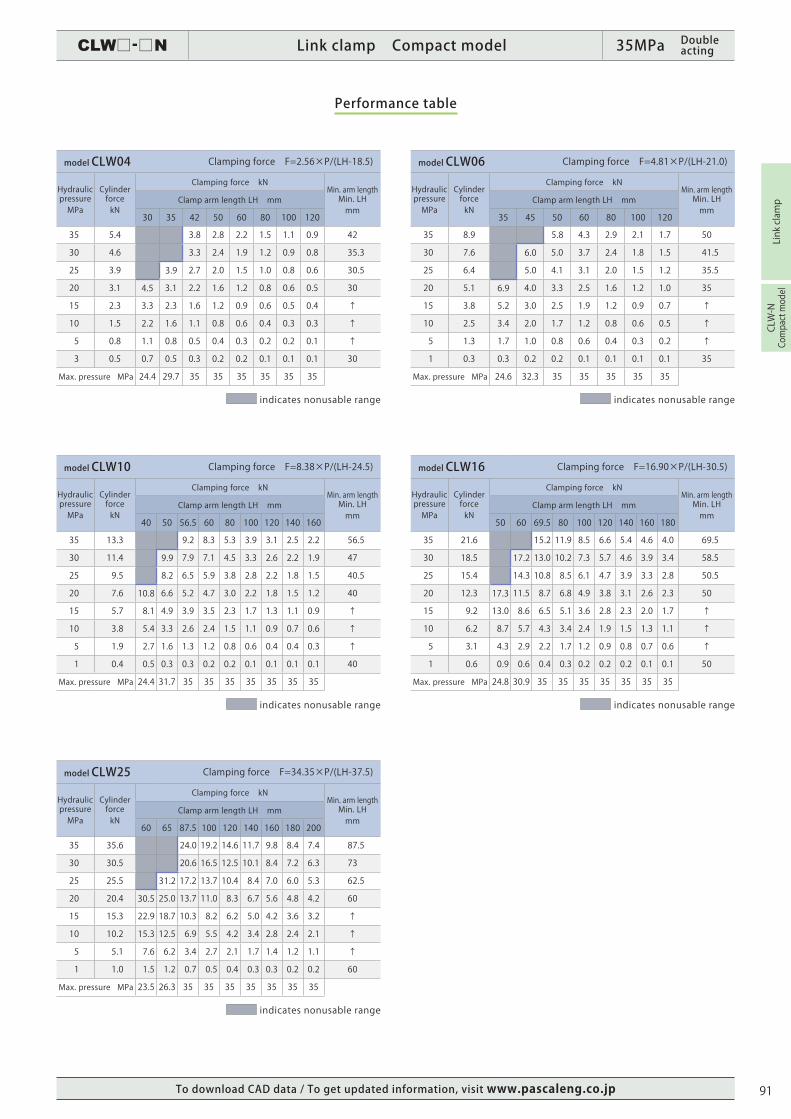
Performance diagram
Clamping force varies depending on the clamp arm length (LH) and
hydraulic pressure (P).
Clamping force calculation formula
F=Coefficient 1×P/(LH -Coefficient 2)
F:Clamping force P:Hydraulic pressure LH:Clamp arm length
CLW10 with clamp arm length (LH) = 50 mm at hydraulic pressure of
25 MPa, Clamping force F is calculated by
8.38×25/(50-24.5)=8.2 kN
Do not use the clamp in the nonusable range. It may cause damage
to the cylinder and rod.
model CLW06
model CLW16
model CLW04
model CLW10
model CLW25
90
To download CAD data / To get updated information, visit www.pascaleng.co.jp
CLW□-□N Link clamp Compact model 35MPa Double acting
Link clamp
CLW-N
Compact model
model CLW04 Clamping force F=2.56×P/(LH-18.5)
Hydraulic pressure MPa
Cylinder forcekN
Clamping force kNMin. arm length Min. LHmm
Clamp arm length LH mm
30 35 42 50 60 80 100 120
35 5.4 3.8 2.8 2.2 1.5 1.1 0.9 42
30 4.6 3.3 2.4 1.9 1.2 0.9 0.8 35.3
25 3.9 3.9 2.7 2.0 1.5 1.0 0.8 0.6 30.5
20 3.1 4.5 3.1 2.2 1.6 1.2 0.8 0.6 0.5 30
15 2.3 3.3 2.3 1.6 1.2 0.9 0.6 0.5 0.4 ↑
10 1.5 2.2 1.6 1.1 0.8 0.6 0.4 0.3 0.3 ↑
5 0.8 1.1 0.8 0.5 0.4 0.3 0.2 0.2 0.1 ↑
3 0.5 0.7 0.5 0.3 0.2 0.2 0.1 0.1 0.1 30
Max. pressure MPa 24.4 29.7 35 35 35 35 35 35
indicates nonusable range
model CLW10 Clamping force F=8.38×P/(LH-24.5)
Hydraulic pressure MPa
Cylinder forcekN
Clamping force kNMin. arm length Min. LHmm
Clamp arm length LH mm
40 50 56.5 60 80 100 120 140 160
35 13.3 9.2 8.3 5.3 3.9 3.1 2.5 2.2 56.5
30 11.4 9.9 7.9 7.1 4.5 3.3 2.6 2.2 1.9 47
25 9.5 8.2 6.5 5.9 3.8 2.8 2.2 1.8 1.5 40.5
20 7.6 10.8 6.6 5.2 4.7 3.0 2.2 1.8 1.5 1.2 40
15 5.7 8.1 4.9 3.9 3.5 2.3 1.7 1.3 1.1 0.9 ↑
10 3.8 5.4 3.3 2.6 2.4 1.5 1.1 0.9 0.7 0.6 ↑
5 1.9 2.7 1.6 1.3 1.2 0.8 0.6 0.4 0.4 0.3 ↑
1 0.4 0.5 0.3 0.3 0.2 0.2 0.1 0.1 0.1 0.1 40
Max. pressure MPa 24.4 31.7 35 35 35 35 35 35 35
indicates nonusable range
model CLW25 Clamping force F=34.35×P/(LH-37.5)
Hydraulic pressure MPa
Cylinder forcekN
Clamping force kNMin. arm length Min. LHmm
Clamp arm length LH mm
60 65 87.5 100 120 140 160 180 200
35 35.6 24.0 19.2 14.6 11.7 9.8 8.4 7.4 87.5
30 30.5 20.6 16.5 12.5 10.1 8.4 7.2 6.3 73
25 25.5 31.2 17.2 13.7 10.4 8.4 7.0 6.0 5.3 62.5
20 20.4 30.5 25.0 13.7 11.0 8.3 6.7 5.6 4.8 4.2 60
15 15.3 22.9 18.7 10.3 8.2 6.2 5.0 4.2 3.6 3.2 ↑
10 10.2 15.3 12.5 6.9 5.5 4.2 3.4 2.8 2.4 2.1 ↑
5 5.1 7.6 6.2 3.4 2.7 2.1 1.7 1.4 1.2 1.1 ↑
1 1.0 1.5 1.2 0.7 0.5 0.4 0.3 0.3 0.2 0.2 60
Max. pressure MPa 23.5 26.3 35 35 35 35 35 35 35
indicates nonusable range
model CLW16 Clamping force F=16.90×P/(LH-30.5)
Hydraulic pressure MPa
Cylinder forcekN
Clamping force kNMin. arm length Min. LHmm
Clamp arm length LH mm
50 60 69.5 80 100 120 140 160 180
35 21.6 15.2 11.9 8.5 6.6 5.4 4.6 4.0 69.5
30 18.5 17.2 13.0 10.2 7.3 5.7 4.6 3.9 3.4 58.5
25 15.4 14.3 10.8 8.5 6.1 4.7 3.9 3.3 2.8 50.5
20 12.3 17.3 11.5 8.7 6.8 4.9 3.8 3.1 2.6 2.3 50
15 9.2 13.0 8.6 6.5 5.1 3.6 2.8 2.3 2.0 1.7 ↑
10 6.2 8.7 5.7 4.3 3.4 2.4 1.9 1.5 1.3 1.1 ↑
5 3.1 4.3 2.9 2.2 1.7 1.2 0.9 0.8 0.7 0.6 ↑
1 0.6 0.9 0.6 0.4 0.3 0.2 0.2 0.2 0.1 0.1 50
Max. pressure MPa 24.8 30.9 35 35 35 35 35 35 35
indicates nonusable range
model CLW06 Clamping force F=4.81×P/(LH-21.0)
Hydraulic pressure MPa
Cylinder forcekN
Clamping force kNMin. arm length Min. LHmm
Clamp arm length LH mm
35 45 50 60 80 100 120
35 8.9 5.8 4.3 2.9 2.1 1.7 50
30 7.6 6.0 5.0 3.7 2.4 1.8 1.5 41.5
25 6.4 5.0 4.1 3.1 2.0 1.5 1.2 35.5
20 5.1 6.9 4.0 3.3 2.5 1.6 1.2 1.0 35
15 3.8 5.2 3.0 2.5 1.9 1.2 0.9 0.7 ↑
10 2.5 3.4 2.0 1.7 1.2 0.8 0.6 0.5 ↑
5 1.3 1.7 1.0 0.8 0.6 0.4 0.3 0.2 ↑
1 0.3 0.3 0.2 0.2 0.1 0.1 0.1 0.1 35
Max. pressure MPa 24.6 32.3 35 35 35 35 35
indicates nonusable range
Performance table
91
CLW□-□N Link clamp Compact model 35MPa Doubleacting
Link clamp
CLW-N
Compact model
4-øW
V
V3
CA
V2±0.1
V1
HG
øT
øH
B4
R2
R3
CC
CB
øG -0.1-0.2
4-Z
U -0.1
-0.2
E D
C□F
R2 B
2-øB1 f7 øB2 f7
N
L
15° M
S
K
A
R1
øY3
V4 HA
4-øX
2-B3CD
Clamping hydraulic port
L:Left side F:Front side R:Right side
Unclamping hydraulic port
Clamp stroke
2-O-ring
Clamp arm
Clamping hydraulic port Y1
Unclamping hydraulic port Y1
Y2 (plug projection depth)Safety stroke 3
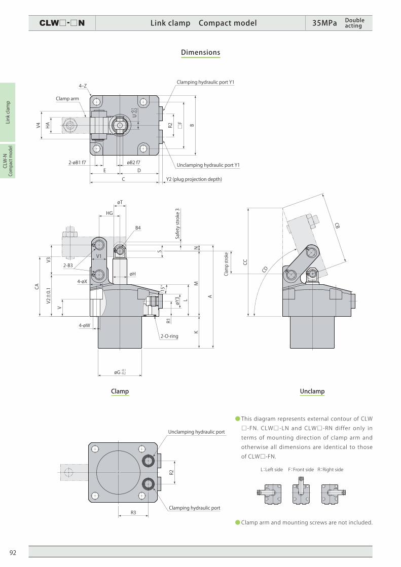
Dimensions
UnclampClamp
● This diagram represents external contour of CLW
□-FN. CLW□-LN and CLW□-RN differ only in
terms of mounting direction of clamp arm and
otherwise all dimensions are identical to those
of CLW□-FN.
●Clamp arm and mounting screws are not included.
92
To download CAD data / To get updated information, visit www.pascaleng.co.jp
CLW□-□N Link clamp Compact model 35MPa Doubleacting
Link clamp
CLW-N
Compact model
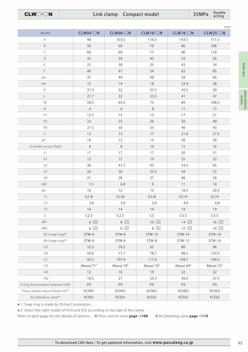
mm
Model CLW04-□N CLW06-□N CLW10-□N CLW16-□N CLW25-□N A 96 103.5 116.5 143.5 171.5
B 50 60 70 86 108
C 60 69 77 96 110
D 35 39 42 53 56
E 25 30 35 43 54
F 40 47 54 65 85
ø G 35 44 48 58 66
ø H 12 14 18 22.4 28
K 31.5 32 35.5 43.5 50
L 27.7 32 33.5 41 47
M 58.5 65.5 73 89 108.5
N 6 6 8 11 13
R1 12.5 15 15 17 21
R2 22 23 26 30 40
R3 27.5 30 33 40 43
S 13 13 17 21.8 27.5
ø T 10 12 15 20 26
U (width across flats) 6 8 10 11 16
V 17 17 17 20 21
V1 13 15 19 25 32
V2 36 41.5 45 54.5 65
V3 26 30 35.5 44 53
V4 21 28 37 46 56
ø W 5.5 6.8 9 11 14
ø X 10 12 15 18.5 20.5
Y1 G1/8 G1/8 G1/8 G1/4 G1/4
Y2 3.8 3.8 3.8 4.8 4.8
Y3 14 14 14 19 19
Z C2.5 C2.5 C3 C3.5 C5.5
ø B1 6 -0.010-0.022 8 -0.013-0.028 10 -0.013-0.028 14 -0.016-0.034 16 -0.016-0.034
ø B2 6 -0.010-0.022 6 -0.010-0.022 8 -0.013-0.028 12 -0.016-0.034 14 -0.016-0.034
B3 (snap ring) 1 STW-6 STW-8 STW-10 STW-14 STW-16
B4 (snap ring) 1 STW-6 STW-6 STW-8 STW-12 STW-14
CA 52.5 59.5 65 80 96
CB 59.6 71.7 78.7 98.2 133.5
CC 92.5 107.9 117.4 144.7 189.2
CD About 71° About 70° About 70° About 69° About 72°
HA 12 16 19 22 32
HG 18.5 21 24.5 30.5 37.5
O-ring (fluorocarbon hardness Hs90) P9 P9 P9 P9 P9
Flow control valve (meter-in) 2 VCH01 VCH01 VCH01 VCH02 VCH02
Air bleeding valve 2 VCE01 VCE01 VCE01 VCE02 VCE02
1:Snap ring is made by Ochiai Corporation.
2:Select the right model of VCH and VCE according to the size of the clamp.
Refer to each page for the details of options. ● Flow control valve page →108 ●Air bleeding valve page →110
93
CLW□-□N Link clamp Compact model 35MPa Double acting
Link clamp
CLW-N
Compact model
X-X
XX
R2
2-Max. øBC
□F 4-BB
R3
Max. øBA
C 0.5
Rz6.3
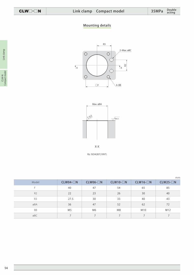
mm
Model CLW04-□N CLW06-□N CLW10-□N CLW16-□N CLW25-□N
F 40 47 54 65 85
R2 22 23 26 30 40
R3 27.5 30 33 40 43
ø BA 36 47 52 62 72
BB M5 M6 M8 M10 M12
ø BC 7 7 7 7 7
Mounting details
Rz: ISO4287(1997)
94
To download CAD data / To get updated information, visit www.pascaleng.co.jp
CLW□-□N Link clamp Compact model 35MPa Double acting
Link clamp
CLW-N
Compact model
S
F±0.1
D
EG±0.1
øH H7(Min. C 0.2)
øJ H7(Min. C 0.2)
B
T45°
R P
C 0.8
A 0
-0.1
N +0.1 0
mm
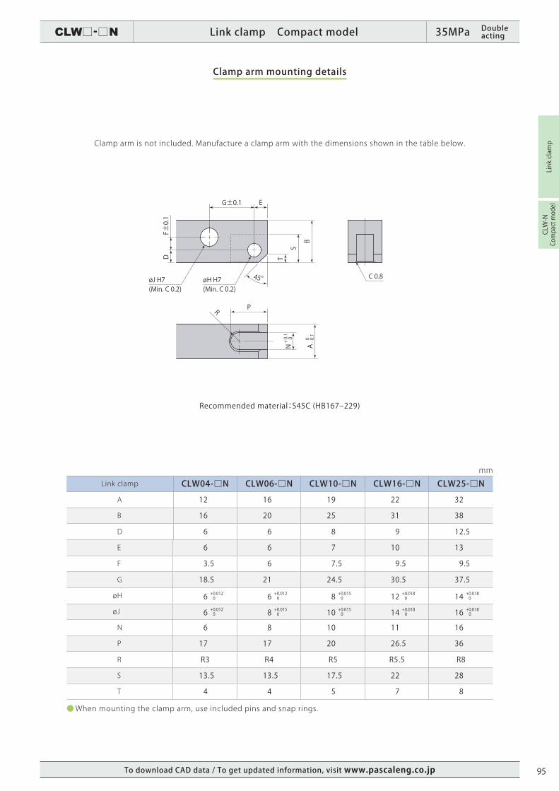
Link clamp CLW04-□N CLW06-□N CLW10-□N CLW16-□N CLW25-□N
A 12 16 19 22 32
B 16 20 25 31 38
D 6 6 8 9 12.5
E 6 6 7 10 13
F 3.5 6 7.5 9.5 9.5
G 18.5 21 24.5 30.5 37.5
ø H 6 + 0.012 0 6 + 0.012 0 8 + 0.015 0 12 + 0.018 0 14 + 0.018 0
ø J 6 + 0.012 0 8 + 0.015 0 10 + 0.015 0 14 + 0.018 0 16 + 0.018 0
N 6 8 10 11 16
P 17 17 20 26.5 36
R R3 R4 R5 R5.5 R8
S 13.5 13.5 17.5 22 28
T 4 4 5 7 8
● When mounting the clamp arm, use included pins and snap rings.
Clamp arm mounting details
Clamp arm is not included. Manufacture a clamp arm with the dimensions shown in the table below.
Recommended material:S45C (HB167‒229)
95
CLW□-□N Link clamp Compact model 35MPa Double acting
Link clamp
CLW-N
Compact model
LH LH
Ordinary clamp armEccentric shape clamp arm
Clamping point
Amount ofeccentricity
Clamping point
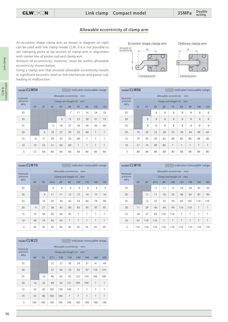
model CLW04 indicates nonusable range
Hydraulic pressure MPa
Allowable eccentricity mm
Clamp arm length LH mm
30 35 42 50 60 70 80 100 120
35 7 11 16 24 33
30 9 15 22 28 41 53
25 6 18 27 36 45 60 60
20 6 18 27 39 52 60 ↑ ↑
15 8 17 29 42 59 60 ↑ ↑ ↑
10 19 32 51 60 60 ↑ ↑ ↑ ↑
5 52 60 60 60 60 60 60 60 60
model CLW10 indicates nonusable range
Hydraulic pressure MPa
Allowable eccentricity mm
Clamp arm length LH mm
40 50 56.5 60 80 100 120 140 160
35 9 9 9 9 9 9 9
30 9 11 11 12 13 14 15 16
25 16 25 30 42 54 66 78 90
20 9 27 38 45 80 95 95 95 95
15 19 44 60 69 95 ↑ ↑ ↑ ↑
10 40 79 95 95 ↑ ↑ ↑ ↑ ↑
5 95 95 95 95 95 95 95 95 95
model CLW25 indicates nonusable range
Hydraulic pressure MPa
Allowable eccentricity mm
Clamp arm length LH mm
60 65 87.5 100 120 140 160 180 200
35 21 27 30 34 37 41 44
30 31 46 70 83 97 110 123
25 16 46 65 95 125 154 160 160
20 16 25 68 92 131 160 160 ↑ ↑
15 32 45 105 139 160 ↑ ↑ ↑ ↑
10 65 86 160 160 ↑ ↑ ↑ ↑ ↑
5 160 160 160 160 160 160 160 160 160
model CLW16 indicates nonusable range
Hydraulic pressure MPa
Allowable eccentricity mm
Clamp arm length LH mm
50 60 69.5 80 100 120 140 160 180
35 11 11 13 24 34 45 56
30 11 11 16 32 48 65 81 96
25 12 23 35 59 83 107 110 110
20 11 29 46 64 99 110 110 ↑ ↑
15 30 57 83 110 110 ↑ ↑ ↑ ↑
10 67 110 110 ↑ ↑ ↑ ↑ ↑ ↑
5 110 110 110 110 110 110 110 110 110
model CLW06 indicates nonusable range
Hydraulic pressure MPa
Allowable eccentricity mm
Clamp arm length LH mm
35 45 50 60 70 80 90 100 120
35 8 8 8 8 8 8 8
30 8 8 8 8 8 8 8 8
25 8 8 8 8 8 8 8 8
20 10 20 23 28 33 38 44 49 60
15 19 43 50 65 80 80 80 80 80
10 37 74 80 80 ↑ ↑ ↑ ↑ ↑
5 80 80 80 80 80 80 80 80 80
Allowable eccentricity of clamp arm
An eccentric shape clamp arm, as shown in diagram on right can be used with link clamp model CLW, if it is not possible to set clamping point at tip section of clamp arm in alignment with center line of piston rod and clamp arm.Amount of eccentricity, however, must be within allowable eccentricity shown below. Using a clamp arm that exceeds allowable eccentricity results in significant eccentric load on link mechanism and piston rod, leading to malfunction.
96
To download CAD data / To get updated information, visit www.pascaleng.co.jp
CLW□-□N Link clamp Compact model 35MPa Double acting
Link clamp
CLW-N
Compact model
3°
3°
Parallel
Workpiece Workpiece
Workpiece
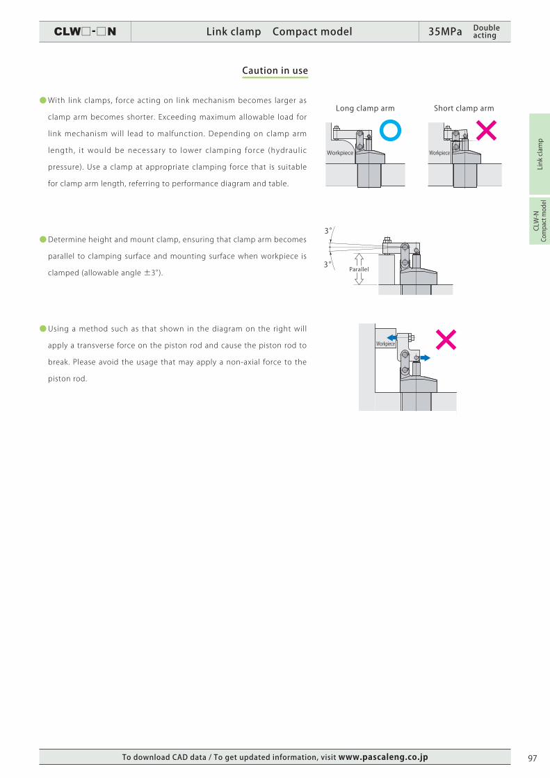
Long clamp arm Short clamp arm● With link clamps, force acting on link mechanism becomes larger as
clamp arm becomes shorter. Exceeding maximum allowable load for
link mechanism will lead to malfunction. Depending on clamp arm
length, i t would be necessary to lower clamping force (hydraulic
pressure). Use a clamp at appropriate clamping force that is suitable
for clamp arm length, referring to performance diagram and table.
● Determine height and mount clamp, ensuring that clamp arm becomes
parallel to clamping surface and mounting surface when workpiece is
clamped (allowable angle ±3°).
● Using a method such as that shown in the diagram on the right will
apply a transverse force on the piston rod and cause the piston rod to
break. Please avoid the usage that may apply a non-axial force to the
piston rod.
Caution in use
97
Copyright © 2022 FDOKUMEN


![N -[4-( N -Cyclohexylsulfamoyl)phenyl]acetamide](https://static.fdokumen.com/doc/165x107/632f4f4de68feab59a0210b7/n-4-n-cyclohexylsulfamoylphenylacetamide.jpg)