Equivalence between Closed Connected n-G-Maps without Multi-Incidence and n-Surfaces
Upload
independentCategory
view
0download
0
M A N N I N G
IN ACTIONMartin EvansJoshua NobleJordan Hochenbaum

Arduino in Action

Arduino in Action
MARTIN EVANSJOSHUA NOBLE
JORDAN HOCHENBAUM
M A N N I N G
SHELTER ISLAND

For online information and ordering of this and other Manning books, please visitwww.manning.com. The publisher offers discounts on this book when ordered in quantity. For more information, please contact
Special Sales DepartmentManning Publications Co.20 Baldwin RoadPO Box 261Shelter Island, NY 11964Email: [email protected]
©2013 by Manning Publications Co. All rights reserved.
No part of this publication may be reproduced, stored in a retrieval system, or transmitted, in any form or by means electronic, mechanical, photocopying, or otherwise, without prior written permission of the publisher.
Photographs in this book were created by Martin Evans and Jordan Hochenbaum, unless otherwise noted. Illustrations were created by Martin Evans, Joshua Noble, and Jordan Hochenbaum. Fritzing (fritzing.org) was used to create some of the circuit diagrams.
Many of the designations used by manufacturers and sellers to distinguish their products are claimed as trademarks. Where those designations appear in the book, and Manning Publications was aware of a trademark claim, the designations have been printed in initial caps or all caps.
Recognizing the importance of preserving what has been written, it is Manning’s policy to have the books we publish printed on acid-free paper, and we exert our best efforts to that end. Recognizing also our responsibility to conserve the resources of our planet, Manning booksare printed on paper that is at least 15 percent recycled and processed without the use of elemental chlorine.
Manning Publications Co. Development editor: Cynthia Kane20 Baldwin Road Copyeditor: Andy CarrollPO Box 261 Proofreader: Katie TennantShelter Island, NY 11964 Typesetter: Dennis Dalinnik
Cover designer: Marija Tudor
ISBN: 9781617290244Printed in the United States of America1 2 3 4 5 6 7 8 9 10 – MAL – 19 18 17 16 15 14 13
brief contentsPART 1 GETTING STARTED . ......................................................1
1 ■ Hello Arduino 3
2 ■ Digital input and output 21
3 ■ Simple projects: input and output 41
PART 2 PUTTING ARDUINO TO WORK ......................................594 ■ Extending Arduino 61
5 ■ Arduino in motion 81
6 ■ Object detection 114
7 ■ LCD displays 129
8 ■ Communications 152
9 ■ Game on 188
10 ■ Integrating the Arduino with iOS 216
11 ■ Making wearables 244
12 ■ Adding shields 261
13 ■ Software integration 278
v

contentspreface xvacknowledgments xviiabout this book xixabout the cover illustration xxii
PART 1 GETTING STARTED. ...........................................1
1 Hello Arduino 31.1 A brief history of the Arduino 41.2 The Arduino hardware 5
Arduino Uno 5 ■ Arduino Duemilanove 5 Arduino Ethernet 6 ■ Arduino Mega 6Other Arduino boards 7 ■ Attack of the clones 8Getting an Arduino 9
1.3 Setting up your working environment 10Software for Arduino 10 ■ Basic hardware setup 10Your Arduino toolbox 11
1.4 Make something happen! 11Your first blinking LED 11 ■ Sketch to make an LED blink 12Connecting everything 12 ■ Uploading and testing 13
vii
CONTENTSviii
1.5 Touring the IDE 14The main editor 14 ■ Serial monitor 15 ■ Catching errors 16Process 16
1.6 Anatomy of a sketch 17A routine called setup 17 ■ The endless loop 18
1.7 Commenting code 181.8 Summary 20
2 Digital input and output 212.1 Getting started 21
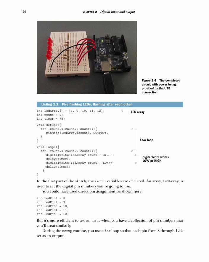
Using a breadboard 22 ■ Circuit diagram 22Adding the LEDs 24 ■ Connecting the hardware 24Sketch to flash five LEDs 25 ■ Upload and test 27
2.2 Gaining control 27Circuit diagram 27 ■ Connections 28Interrupts butting in 29 ■ Sketch to control the LEDs with a push button 30 ■ Upload and test 32 ■ Time for a break 32Upload and test 33
2.3 Reaction tester 33Circuit diagram 33 ■ Connections 33 ■ Sketch to test reaction speed 33 ■ Upload and test 36
2.4 Reactometer: Who really has the fastest reaction time? 37Sketch to measure reaction speed 37 ■ Upload and test 38
2.5 Summary 39
3 Simple projects: input and output 413.1 Time to get analog 42
What’s the difference between analog and digital? 42Reading a potentiometer 43 ■ Connecting the hardware 43Sketch to read a potentiometer 44 ■ Upload and test 45
3.2 A piezoelectric transducer 46The circuit diagram 47 ■ Connecting the hardware 48Sketch to measure output from a piezoelectric transducer 49Upload and test 51 ■ Circuit with added speaker 51Connecting the hardware 51 ■ Sketch to generate a tone 53Upload and test 53
CONTENTS ix
3.3 Making a pentatonic or five-tone keyboard 54Circuit diagram 54 ■ Connecting the hardware 54Sketch to create a pentatonic keyboard 56 ■ Upload and test 57
3.4 Summary 58
PART 2 PUTTING ARDUINO TO WORK ..........................59
4 Extending Arduino 614.1 Extending the Arduino with libraries 624.2 Core library 624.3 Standard libraries 63
Test-driven development with ArduinoTestSuite 63Storing values using EEPROM 64 ■ Storing more data with SD 65 ■ Get connected with Ethernet 67Serial communication with Firmata 68 ■ Displaying data using the LiquidCrystal library 69 ■ Controlling a servo motor 70 ■ Turning a stepper motor 70Communicating with SPI peripherals 71Communicating with the two-wire interface 72Get more serial ports with SoftwareSerial 74
4.4 Contributed libraries 75Installing a new library 76
4.5 Expanding the Arduino with shields 76Common shields 77 ■ Gotchas: will it work with my Arduino? 80
4.6 Summary 80
5 Arduino in motion 815.1 Getting up to speed with DC motors 82
Stopping and starting 83 ■ Sketch to turn a small DC motor on and off 84 ■ Connecting the hardware 84Upload and test 86
5.2 Speed control and reverse 87PWM to the rescue 87 ■ The H-bridge for motor control 89The L293D dual H driver 90 ■ Connecting the hardware 91Sketch to control a motor with an L293D 92Upload and test 93 ■ Changing motor speed 93Upload and test 94
CONTENTSx
5.3 Stepper motors: one step at a time 94Unipolar or bipolar 95 ■ Connecting the hardware 98Stepper motor library functions 99 ■ Sketch to control a stepper motor 101 ■ Upload and test 101
5.4 Try not to get in a flap with servomotors 102Controlling a servomotor 102 ■ Servomotor functions and methods 103 ■ Sketch to control a servomotor 104Connecting the hardware 105 ■ Upload and test 105
5.5 Mighty power comes in small packages with brushless DC motors 106Why go brushless 106 ■ Gaining control 107 ■ Sketch to control a brushless motor 108 ■ Connecting the hardware 109Upload and test 110 ■ Reverse 110 ■ Sketch to reverse a brushless motor 110 ■ Connecting the hardware 111Upload and test 111
5.6 The motor control shield for more motors 1125.7 Summary 113
6 Object detection 1146.1 Object detection with ultrasound 115
Choosing an ultrasonic sensor 115 ■ Three wires or four 116Sketches for ultrasonic object finding 116 ■ Connecting the hardware 118 ■ Upload and test 118
6.2 Infrared for range finding 119Infrared and ultrasound together 120 ■ The Sharp GP2D12 range finder 121 ■ Nonlinear algorithm for calculating distance 121 ■ Sketch for range finding 122Connecting the hardware 123 ■ Upload and test 123
6.3 Passive infrared to detect movement 124Using the Parallax PIR sensor 125 ■ Sketch for infrared motion detection 125 ■ Connecting the hardware 127Upload and test 128
6.4 Summary 128
7 LCD displays 1297.1 Introduction to LCDs 130
String variables: String type vs. char type 130
7.2 Parallel character LCDs: the Hitachi HD44780 1334-bit or 8-bit? 133 ■ Library and functions 133Circuit diagram 134 ■ Connecting everything up
CONTENTS xi
in 4-bit mode 135 ■ Sketch for writing to the Hitachi HD44780 137 ■ Upload and test 138
7.3 Serial LCD weather station 139Serial vs. parallel LCDs 139 ■ SerLCD library and functions 139 ■ The Maxim IC DS18B20 temperature sensor 141 ■ OneWire and DallasTemperature libraries 141 ■ Circuit diagram 142 ■ Connecting everything up 143 ■ Sketch for an LCD weather station 144Upload and test 145
7.4 Graphic LCDs: the Samsung KS0108 GLCD 146Library and functions 146 ■ Circuit diagram 147Connecting everything up 148 ■ Sketch for drawing to a GLCD 150 ■ Upload and test 151
7.5 Summary 151
8 Communications 1528.1 Ethernet 153
The Ethernet library 154 ■ Ethernet Shield with SD data card 155
8.2 Arduino web server 156Setting up the server 156 ■ Sketch for creating a web server 158Upload and test 159 ■ Troubleshooting 159
8.3 Tweet tweet: talking to Twitter 159Of Twitter and tokens 160 ■ Libraries and functions 160Circuit diagram and connecting the hardware 161 ■ Sketch for the Twitter button-press tweeter 161 ■ Upload and test 163
8.4 Wi-Fi 163Arduino Wifi Shield 164 ■ WiFi library and functions 165Gestures: wireless accelerometers 167 ■ Connecting the hardware 168 ■ Sketch for Bluetooth communication 168Upload and test 171
8.5 Bluetooth wireless 171ArduinoBT 172 ■ Adding Bluetooth 172Establishing a Bluetooth connection 173Sketch for Bluetooth communication 174
8.6 Serial peripheral interface (SPI) 175SPI library 176 ■ SPI devices and digital potentiometers 176Circuit diagram and connecting the hardware 177Sketch for a digital LED dimmer 178
CONTENTSxii
8.7 Data logging 179Types of memory 180 ■ SD cards and SD library 180Sketch for an SD card sensor logger 181
8.8 Cosm 182Sign up for an account and get an API key 182 ■ Creating a new data feed 183 ■ Sketch for Cosm sensor logging 184Upload and test 186
8.9 Summary 186
9 Game on 1889.1 Nintendo Wii salutes you 188
Wii Nunchuk 189 ■ Nunchuk connections 191Wii will talk 193 ■ Wii will test 201
9.2 Release the Xbox 202Getting connected 203 ■ USB Host library 203Learning about the Xbox controller using the USB Host Shield 204Xbox reporting for duty 206 ■ Let’s boot it 208Interfacing with code 208 ■ Xboxhid.ino 210Hardware connections and testing 213
9.3 Summary 214
10 Integrating the Arduino with iOS 21610.1 Connecting your device to the Arduino 218
The Redpark serial cable 218 ■ The final connection 220
10.2 iOS code 220Creating a single-view application in Xcode 221Writing the code 225
10.3 The Arduino gets involved 228Sketch to switch LED from iOS device 229Testing the sketch 229
10.4 Doing more with Xcode 230Adding a Slider control 230
10.5 Arduino sliding 235Arduino slider circuit 236 ■ Testing the circuit 236
10.6 Moving data to the iOS device 237Xcode coding 237 ■ The GP2D12 IR distance sensor 241Testing 243
10.7 Summary 243
CONTENTS xiii
11 Making wearables 24411.1 Introducing the LilyPad 245
LilyPad accessories 247 ■ Conductive thread and fabric 247
11.2 Creating a turn-signal jacket 249
11.3 Creating a wearable piano 251
11.4 The Arduino Pro Mini 254
11.5 Creating a smart headphone 254
11.6 Creating a jacket with a compass 257
11.7 Summary 260
12 Adding shields 26112.1 Shield basics 26112.2 The Adafruit motor shield 262
The AFMotor library 263 ■ Using the motor shield with a stepper motor 264 ■ Using the motor shield with a DC motor 265 ■ Getting a motor shield 269
12.3 Creating your own shield 269Memory 269 ■ Level shifters 270 ■ The SD card holder 270Connecting the SD card to the Arduino 271Preparing the perfboard 273 ■ Testing the shield 276
12.4 Summary 277
13 Software integration 27813.1 The serial channel 279
13.2 Servos for face tracking 280Assembling the face-tracking hardware 281Code for face-tracking 282
13.3 Using Firmata to create an equalizer 286Using Firmata in your application 286 ■ Audio analysis in Processing 287 ■ Assembling the equalizer hardware 288Code for the equalizer 288
13.4 Using Pure Data to create a synthesizer 292Assembling the synthesizer hardware 293Code for the synthesizer 294
CONTENTSxiv
13.5 Using Python to monitor temperatures 296The Serial library in Python 296Assembling the thermometer hardware 298Code for monitoring temperatures 299
13.6 Summary 301
appendix A Installing the Arduino IDE 302appendix B Coding primer 310appendix C Libraries 324appendix D Components list 328appendix E Useful links 332
index 334
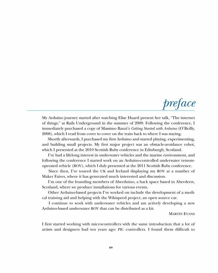
prefaceMy Arduino journey started after watching Elise Huard present her talk, “The internetof things,” at Rails Underground in the summer of 2009. Following the conference, Iimmediately purchased a copy of Massimo Banzi’s Getting Started with Arduino (O’Reilly,2008), which I read from cover to cover on the train back to where I was staying.
Shortly afterwards, I purchased my first Arduino and started playing, experimenting,and building small projects. My first major project was an obstacle-avoidance robot,which I presented at the 2010 Scottish Ruby conference in Edinburgh, Scotland.
I’ve had a lifelong interest in underwater vehicles and the marine environment, andfollowing the conference I started work on an Arduino-controlled underwater remote-operated vehicle (ROV), which I duly presented at the 2011 Scottish Ruby conference.
Since then, I’ve toured the UK and Ireland displaying my ROV at a number ofMaker Faires, where it has generated much interested and discussion.
I’m one of the founding members of Aberduino, a hack space based in Aberdeen,Scotland, where we produce installations for various events.
Other Arduino-based projects I’ve worked on include the development of a medi-cal training aid and helping with the Wikispeed project, an open source car.
I continue to work with underwater vehicles and am actively developing a newArduino-based underwater ROV that can be distributed as a kit.
MARTIN EVANS
I first started working with microcontrollers with the same introduction that a lot ofartists and designers had ten years ago: PIC controllers. I found them difficult to
xv
PREFACExvi
understand, finicky, slow to build with, and yet they were the only option. Later I dis-covered Teleo controllers and then Wiring boards, but when the Arduino arrived inmy world, I was hooked.
I’ve used Arduinos for everything from prototyping smart spray-paint cans tobuilding interactive exhibits for museums to creating tools for science experiments.I’m in love with the boards, the environment, and, most especially, the communitythat has grown up around the Arduino and that’s so willing to teach, experiment,explore, and share.
JOSHUA NOBLE
My interest in music technology led me to discover the Arduino as a platform forrapid development and physical computing sometime around 2008. I was originallyintroduced to the Arduino as a tool for designing musical interfaces for live perfor-mance. This led to the Arduinome project, an open source port of the popularMonome USB MIDI controller, which I worked on with longtime collaborator OwenVallis. The success of the Arduinome project was a true testament to the uniqueness ofthe Arduino itself—a device that empowers musicians and artists of all technical back-grounds to create unique and powerful tools for expression. Around the same time, Iwas taking a course in musical robotics and kinetic sculpture, and we used the Ardu-ino to drive a collaborative musical robotic instrument.
Since then, the Arduino has been at the heart of my work. In 2009 I began pursu-ing my PhD, which investigated the affordances of multimodal sensor systems formusical performance and pedagogy. Using the Arduino, I’ve built numerous inter-faces and hyperinstruments for capturing data and metrics from musical perfor-mance. I built the SmartFiducial, which added z-depth (in-air proximity) and pressuresensing to tangible tabletop surfaces. Embedding multimodal sensing systems withininstruments or placing them on human performers, I’ve investigated a wide variety ofmachine learning tasks, such as performer recognition and drum-hand recognition.I completed my PhD and became a professor in Music Technology: Interaction, Intel-ligence, and Design at California Institute of the Arts in 2012, and the Arduino con-tinues to be an important part of my artistic and academic practice. My work with theArduino has been featured online and in print, including in WIRED and ComputerArts magazine, and my current Arduino-based projects range from kinetic surfacesfor live projection mapping and visuals to wireless sensing systems for interactivedance performance.
JORDAN HOCHENBAUM
acknowledgmentsWe would like to thank the following people at Manning: Sebastian Stirling for hisendless patience and support; Cynthia Kane for guiding us and giving gentle prodsover the final review stages to bring the manuscript to publication; Troy Mott whohandled the preproduction stages; technical editors Sharon Cichelli and Daniel Soltiswho offered help and advice on how to improve the final manuscript; and copyeditorAndy Carroll who carefully combed through the manuscript, removing unnecessarywords and tidying everything up.
We also want to thank our reviewers who helped clarify parts of the book thatneeded further explanation and who pointed out inconsistencies. Thanks to AlanBurlison, Andrew Davidson, Bill Westfield, Daniel Soltis, George Entenman, HowardR. Hansen, Jeroen Benckhuijsen, John Raines, Margriet Bruggeman, Matt Scarpino,Nikander Bruggeman, P. David Pull, Philipp K. Janert, Scott Couprie, Scott Howard,Steve Prior, and Ursin Stauss.
MARTIN EVANS would like to thank his wife Henrietta and children Leanne, Heather,and Luke, who all in one way or another encouraged him to keep on working on thisbook. He would also like to thank Paul and the team at Symposium Coffee House,Peterhead, who kept him fueled with coffee when most needed.
JOSHUA NOBLE would like to acknowledge a huge debt of gratitude to Simona Maschi,David Gauthier, and everyone at CIID who let him slack off a little on his thesis proj-ect so he could finish his chapters for this book, his lovely girlfriend Rachel Buker,
xvii
ACKNOWLEDGMENTSxviii
and of course the man who originally taught him to program in his first halting steps,Morgan Schwartz.
JORDAN HOCHENBAUM would like acknowledge his friend and mentor Ajay Kapur forintroducing him to the Arduino and to systematically thinking about musical inter-face design. He’d also like to thank longtime friend and collaborator Owen Vallis forhis help as they stumbled through their first Arduino sketches together and delveddeeper into the world of the AVR.
about this bookThis book is organized into two parts. Part 1 discusses the Arduino in general andincludes a tutorial that introduces you to your first project before looking at a coupleof simple projects that use the Arduino inputs and outputs. Part 2 looks at the Ardu-ino in more depth, and this is where we really start to put the Arduino to work with anumber of advanced techniques that you can use in your own projects.
Code for the sketches covered in each chapter is available online via the book’swebsite: www.manning.com/ArduinoinAction. We suggest trying to follow along withthe projects in the book as much as you can. Typing in the individual code listings willhelp to fix concepts and ideas into your mind.
This book is suitable for both beginners and intermediate Arduino users. It startsfrom a very basic level and assumes no prior knowledge, but we think even expertusers will gain things from the second part of the book, which covers a wide variety ofsubjects, many of which can be combined into your own projects. A basic understand-ing of electronics will help with some project circuits, although we endeavor toexplain them as much as we can.
RoadmapPart 1 of the book discusses the Arduino in general.
Chapter 1 explains how to get started by setting up your development environ-ment and a basic software and hardware toolbox. It shows you how to blink your firstLED and walks you through the anatomy of an Arduino sketch.
xix
ABOUT THIS BOOKxx
Chapter 2 takes the form of a tutorial that introduces your first project and coversa number of key concepts.
Chapter 3 builds on the knowledge gained in chapter 2 by looking at a couple ofsimple projects that use the Arduino inputs and outputs.
Part 2 of the book looks at the Arduino in more depth. This is where we put theArduino to work.
Chapter 4 covers software libraries that extend the Arduino’s functionality. Chapter 5 gets the Arduino into motion by showing how an Arduino can be used
to control a range of motors. Object detection is covered in chapter 6 with a section on how ultrasound and
ultrasonic sensors can be interfaced. Chapter 7 is all about outputting data to LCD displays. It covers communication
with the Hitachi HD44780 parallel LCD as well as the KS0108 graphic LCD that can alsodisplay graphics.
In chapter 8 we cover communication with the external world. We start by using anEthernet Shield to create a web server and then move on to tweeting messages froman Arduino to Twitter, using a Wi-Fi network and Bluetooth communication, loggingdata to an SD card and the internet using the Cosm service, and communicating withother devices over the serial peripheral interface (SPI).
Chapter 9 details connecting an Arduino to game controllers, starting with thewidely available Wii Nunchuk over I2C. Then we take a detailed look at using a USBshield to interface with a USB Xbox controller.
Chapter 10 covers integration with iOS devices like the iPhone and iPad using theRedpark serial cable.
In chapter 11 we look at two alternative forms of the Arduino that can be used aswearables: the LilyPad that can be sewn into clothing, and the Arduino Mini Pro,which is a special customized version of the Arduino notable for its small size.
Chapter 12 looks at shields, which provide a simple method of extending orenhancing the Arduino hardware. This chapter includes instructions for creating yourown shields.
Finally, chapter 13 is on software integration, and it covers communicating withthe Arduino from other software programs.
There are also several appendices. Appendix A is about installing the Arduino software on Windows, Mac OS X, and
Linux operating systems. Appendix B is a coding primer for the Arduino language. Appendix C is about Arduino software libraries and their structure. Appendix D provides a listing of all the components required to complete the indi-
vidual projects in each chapter. Appendix E is a list of useful links.
ABOUT THIS BOOK xxi
Code conventions and downloadsThere are many code examples in this book, edited using the Arduino integrateddevelopment environment (IDE). Source code in listings and text is in a fixed-widthfont like this, to separate it from ordinary text, and code annotations accompanymany of the listings.
You’ll find the source code for the examples in this book available from the pub-lisher’s website at www.manning.com/ArduinoinAction.
Author OnlineThe purchase of Arduino in Action includes free access to a private web forum run byManning Publications, where you can make comments about the book, ask technicalquestions, and receive help from the authors and from other users. To access the forumand subscribe to it, point your web browser to www.manning.com/ArduinoinAction.This page provides information on how to get on the forum once you are registered,what kind of help is available, and the rules of conduct on the forum.
Manning’s commitment to our readers is to provide a venue where a meaningfuldialogue between individual readers and between readers and the authors can takeplace. It is not a commitment to any specific amount of participation on the part ofthe authors, whose contribution to the forum remains voluntary (and unpaid). Wesuggest you try asking the authors some challenging questions lest their interest stray!
The Author Online forum and the archives of previous discussions will be accessi-ble from the publisher’s website as long as the book is in print.

about the cover illustrationThe figure on the cover of Arduino in Action is captioned “Travailleur de déplace-ment,” which means an itinerant laborer. The illustration is taken from a 19th-centuryedition of Sylvain Maréchal’s four-volume compendium of regional dress customspublished in France. Each illustration is finely drawn and colored by hand. The richvariety of Maréchal’s collection reminds us vividly of how culturally apart the world’stowns and regions were just 200 years ago. Isolated from each other, people spoke dif-ferent dialects and languages. In the streets or in the countryside, it was easy to iden-tify where they lived and what their trade or station in life was just by their dress.
Dress codes have changed since then and the diversity by region, so rich at thetime, has faded away. It is now hard to tell apart the inhabitants of different conti-nents, let alone different towns or regions. Perhaps we have traded cultural diversityfor a more varied personal life—certainly for a more varied and fast-paced technolog-ical life.
At a time when it is hard to tell one computer book from another, Manning cele-brates the inventiveness and initiative of the computer business with book coversbased on the rich diversity of regional life of two centuries ago, brought back to life byMaréchal’s pictures.
xxii
Part 1
Getting started
Part 1 of this book (chapters 1 to 3) is a discussion of the Arduino in general.You’ll start by learning your way around the Arduino and its developmentenvironment and completing a tutorial that introduces you to your first proj-ect. Then you’ll look at a couple of simple projects that use the Arduino inputsand outputs.

Hello Arduino
What can the Arduino be used for? The answers are surprisingly diverse. The Ardu-ino has been used in a wide variety of projects:
■ Video games such as Pong and Space Invaders that will remind some readersof their childhood and introduce others to the games their parents playedwhen they were young, complete with monochrome graphics and simplesound effects
■ Line-following robots that introduce robotics principles but are also used infactories and warehouses to deliver components along predetermined paths
■ Light harps that produce music with a wave of your hands, as used interna-tionally by the performer Little Boots
■ MIDI controllers that control a series of instruments■ Self-balancing robots that mimic the Segway
This chapter covers■ The history of the Arduino■ Arduino hardware■ Hardware and software setup■ The first blinking LED
3
4 CHAPTER 1 Hello Arduino
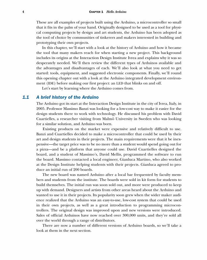
These are all examples of projects built using the Arduino, a microcontroller so smallthat it fits in the palm of your hand. Originally designed to be used as a tool for physi-cal computing projects by design and art students, the Arduino has been adopted asthe tool of choice by communities of tinkerers and makers interested in building andprototyping their own projects.
In this chapter, we’ll start with a look at the history of Arduino and how it becamethe tool that many makers reach for when starting a new project. This backgroundincludes its origins at the Interaction Design Institute Ivrea and explains why it was sodesperately needed. We’ll then review the different types of Arduinos available andthe advantages and disadvantages of each. We’ll also look at what you need to getstarted: tools, equipment, and suggested electronic components. Finally, we’ll roundthis opening chapter out with a look at the Arduino integrated development environ-ment (IDE) before making our first project: an LED that blinks on and off.
Let’s start by learning where the Arduino comes from.
1.1 A brief history of the ArduinoThe Arduino got its start at the Interaction Design Institute in the city of Ivrea, Italy, in2005. Professor Massimo Banzi was looking for a low-cost way to make it easier for thedesign students there to work with technology. He discussed his problem with DavidCuartielles, a researcher visiting from Malmö University in Sweden who was lookingfor a similar solution, and Arduino was born.
Existing products on the market were expensive and relatively difficult to use.Banzi and Cuartielles decided to make a microcontroller that could be used by theirart and design students in their projects. The main requirements were that it be inex-pensive—the target price was to be no more than a student would spend going out fora pizza—and be a platform that anyone could use. David Cuartielles designed theboard, and a student of Massimo’s, David Mellis, programmed the software to runthe board. Massimo contacted a local engineer, Gianluca Martino, who also workedat the Design Institute helping students with their projects. Gianluca agreed to pro-duce an initial run of 200 boards.
The new board was named Arduino after a local bar frequented by faculty mem-bers and students from the institute. The boards were sold in kit form for students tobuild themselves. The initial run was soon sold out, and more were produced to keepup with demand. Designers and artists from other areas heard about the Arduino andwanted to use it in their projects. Its popularity soon grew when the wider maker audi-ence realized that the Arduino was an easy-to-use, low-cost system that could be usedin their own projects, as well as a great introduction to programming microcon-trollers. The original design was improved upon and new versions were introduced.Sales of official Arduinos have now reached over 300,000 units, and they’re sold allover the world through a range of distributors.
There are now a number of different versions of Arduino boards, so we’ll take alook at them in the next section.
5The Arduino hardware
1.2 The Arduino hardwareThere have been a number of Arduino versions, all based on an 8-bit Atmel AVRreduced instruction set computer (RISC) microprocessor. The first board was basedon the ATmega8 running at a clock speed of 16 MHz with 8 KB flash memory; laterboards such as the Arduino NG plus and the Diecimila (Italian for 10,000) used theATmega168 with 16 KB flash memory. The most recent Arduino versions, Duemilanoveand Uno, use the ATmega328 with 32 KB flash memory and can switch automaticallybetween USB and DC power. For projects requiring more I/O and memory, there’s theArduino Mega1280 with 128 KB memory or the more recent Arduino Mega2560 with256 KB memory.
The boards have 14 digital pins, each of which can be set as either an input or out-put, and six analog inputs. In addition, six of the digital pins can be programmed toprovide a pulse width modulation (PWM) analog output. A variety of communicationprotocols are available, including serial, serial peripheral interface bus (SPI), and I2C/TWI. Included on each board as standard features are an in-circuit serial program-ming (ICSP) header and reset button.
NOTE Specialist boards called shields can expand the basic functionalityof the Arduino; these can be stacked on top of each other to add evenmore functionality.
We’re now going to look at the more commonly available Arduino models, startingwith the Arduino Uno.
1.2.1 Arduino Uno
“Dinner is Served” was the blog title announcing on September 25, 2010, the arrival ofthe Arduino Uno (meaning one in Italian), and its bigger brother, the Mega2560. TheArduino Uno is pin-compatible with previous Arduinos, including the Duemilanoveand its predecessor the Diecimila.
The major difference between the Uno and its predecessors is the inclusion of anATmega8U2 microcontroller programmed as a USB-to-serial converter, replacing theageing FTDI chipset used by previous versions. The ATmega8U2 can be reprogrammedto make the Arduino look like another USB device, such as a mouse, keyboard, or joy-stick. Another difference is that it has a more reliable onboard 3.3 volts, which helpswith the stability of some shields that have caused problems in the past. See appendixC for the full technical specifications.
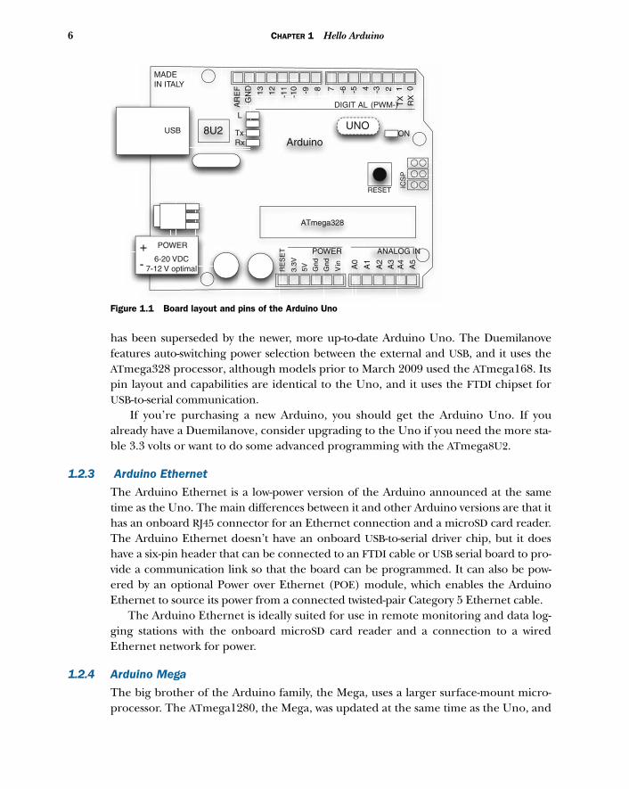
Figure 1.1 shows the board layout and pins of the Arduino Uno. The Uno is a good all-purpose Arduino and is your best bet for a starter board with
its auto-switching power supply and regulated onboard 3.3 volts.
1.2.2 Arduino Duemilanove
The Duemilanove (which means 2009 in Italian) is one of the most popular Arduinoboards produced, having replaced its predecessor, the Arduino Diecimila. But it, in turn,
6 CHAPTER 1 Hello Arduino
has been superseded by the newer, more up-to-date Arduino Uno. The Duemilanovefeatures auto-switching power selection between the external and USB, and it uses theATmega328 processor, although models prior to March 2009 used the ATmega168. Itspin layout and capabilities are identical to the Uno, and it uses the FTDI chipset forUSB-to-serial communication.
If you’re purchasing a new Arduino, you should get the Arduino Uno. If youalready have a Duemilanove, consider upgrading to the Uno if you need the more sta-ble 3.3 volts or want to do some advanced programming with the ATmega8U2.
1.2.3 Arduino Ethernet
The Arduino Ethernet is a low-power version of the Arduino announced at the sametime as the Uno. The main differences between it and other Arduino versions are that ithas an onboard RJ45 connector for an Ethernet connection and a microSD card reader.The Arduino Ethernet doesn’t have an onboard USB-to-serial driver chip, but it doeshave a six-pin header that can be connected to an FTDI cable or USB serial board to pro-vide a communication link so that the board can be programmed. It can also be pow-ered by an optional Power over Ethernet (POE) module, which enables the ArduinoEthernet to source its power from a connected twisted-pair Category 5 Ethernet cable.
The Arduino Ethernet is ideally suited for use in remote monitoring and data log-ging stations with the onboard microSD card reader and a connection to a wiredEthernet network for power.
1.2.4 Arduino Mega
The big brother of the Arduino family, the Mega, uses a larger surface-mount micro-processor. The ATmega1280, the Mega, was updated at the same time as the Uno, and
8U2Arduino
USB
POWER
ICS
P
POWER ANALOG IN
Vin
RE
SE
T
3.3V
5V Gnd
TxRx
L
TX
RX
AR
EF
GN
D
ON
Gnd
ATmega328
+- 6-20 VDC
7-12 V optimal A0
A1
A2
A3
A4
A5
13 12 -11
-10 -9 8 7 -6 -5 4 -3 2 1 0
DIGIT AL (PWM-)
RESET
UNO
MADEIN ITALY
Figure 1.1 Board layout and pins of the Arduino Uno

7The Arduino hardware
the microprocessor now used is the ATmega2560. The new version has 256 KB of flashmemory compared to the 128 KB of the original.
The Mega provides significantly increased input-output functionality compared tothe standard Arduino, so with the increased memory, it’s ideal for those larger proj-ects that control lots of LEDs, have a large number of inputs and outputs, or needmore than one hardware serial port—the Arduino Mega has four. The boards have 54digital input-output pins, 14 of which can provide PWM analog output, and 16 analoginput pins. Communication is handled with up to four hardware serial ports. SPI com-munication and support for I2C/TWI devices is also available. The board also includesan ICSP header and reset button. An ATmega8U2 replaces the FTDI chipset used by itspredecessor and handles USB serial communication.
The Mega works with the majority of the shields available, but it’s a good idea tocheck that a shield will be compatible with your Mega before purchasing it. Purchasethe Mega when you have a clear need for the additional input-output pins and largermemory. See appendix C for the full technical specifications.
Figure 1.2 shows the pin and board layout. Now let’s take a look at a few more specialized Arduino options.
1.2.5 Other Arduino boardsThe original Arduino has spawned a number of variations that package the design indifferent ways, usually in response to a need. Let’s take a look at two of them: the Lily-Pad and the Nano.
LILYPAD ARDUINO
Designed by SparkFun Electronics and Leah Buechley, the LilyPad Arduino is greatfor textile projects and for strutting your stuff on the catwalk. It’s designed with large
8U2USB
POWER
ICS
P
POWER ANALOG IN
Vin
RE
SE
T
3.3V
5V Gnd
TxRx
L
TX
0
RX
0AR
EF
GN
D
ON
Gnd
+- 6-20 VDC
7-12V optimal A0
A1
A2
A3
A4
A5
13 12 11 10 9 8 7 6 5 4 3 2 1 0
PWM
RE
SE
T
6 A7 A8
A9
A10
A11
A12
A13
A14
A15
525048464442403836
3432302826
5351494745434139373533
242214 15 16 17 18 19 20 21
TX
3
31
MEGA2560
ARDUINO
ATmega2560
RX
3
TX
2
RX
2
TX
1
RX
1
SD
A
SC
L
COMMUNICATION
DIG
ITA
L
MADEIN ITALY
Figure 1.2 The Arduino Mega pins and layout; note the additional input-output pins and the extra serial ports compared to the Arduino Uno.
8 CHAPTER 1 Hello Arduino
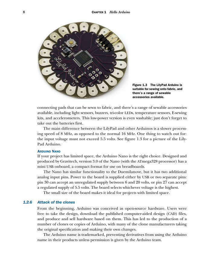
connecting pads that can be sewn to fabric, and there’s a range of sewable accessoriesavailable, including light sensors, buzzers, tri-color LEDs, temperature sensors, E-sewingkits, and accelerometers. This low-power version is even washable; just don’t forget totake out the batteries first.
The main difference between the LilyPad and other Arduinos is a slower process-ing speed of 8 MHz, as opposed to the normal 16 MHz. One thing to watch out for:the input voltage must not exceed 5.5 volts. See figure 1.3 for a picture of the Lily-Pad Arduino.
ARDUINO NANO If your project has limited space, the Arduino Nano is the right choice. Designed andproduced by Gravitech, version 3.0 of the Nano (with the ATmega328 processor) has amini USB onboard, a compact format for use on breadboards.
The Nano has similar functionality to the Duemilanove, but it has two additionalanalog input pins. Power to the board is supplied either by USB or two separate pins:pin 30 can accept an unregulated supply between 6 and 20 volts, or pin 27 can accepta regulated supply of 5.5 volts. The board selects whichever voltage is the highest.
The small size of the board makes it ideal for projects with limited space.
1.2.6 Attack of the clones
From the beginning, Arduino was conceived as open-source hardware. Users werefree to take the design, download the published computer-aided design (CAD) files,and produce and sell hardware based on them. This has led to the production of anumber of clones or copies of Arduino, with many of the clone manufacturers takingthe original specification and making their own changes.
The Arduino name is trademarked, preventing derivatives from using the Arduinoname in their products unless permission is given by the Arduino team.
Figure 1.3 The LilyPad Arduino is suitable for sewing onto fabric, and there’s a range of sewable accessories available.
9The Arduino hardware
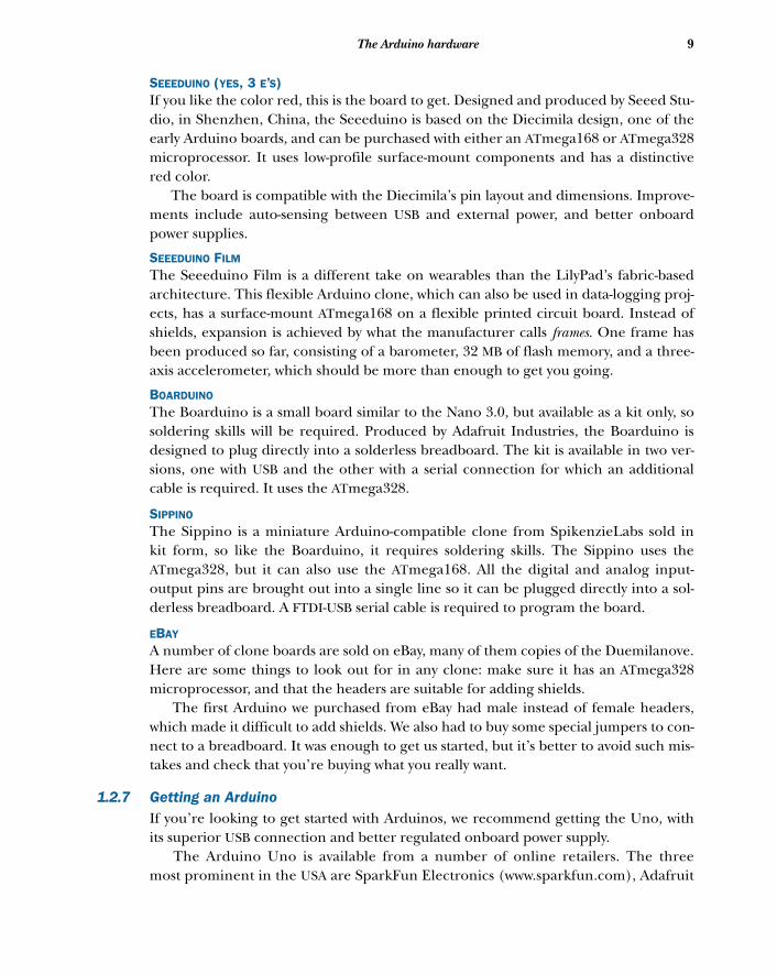
SEEEDUINO (YES, 3 E’S) If you like the color red, this is the board to get. Designed and produced by Seeed Stu-dio, in Shenzhen, China, the Seeeduino is based on the Diecimila design, one of theearly Arduino boards, and can be purchased with either an ATmega168 or ATmega328microprocessor. It uses low-profile surface-mount components and has a distinctivered color.
The board is compatible with the Diecimila’s pin layout and dimensions. Improve-ments include auto-sensing between USB and external power, and better onboardpower supplies.
SEEEDUINO FILM
The Seeeduino Film is a different take on wearables than the LilyPad’s fabric-basedarchitecture. This flexible Arduino clone, which can also be used in data-logging proj-ects, has a surface-mount ATmega168 on a flexible printed circuit board. Instead ofshields, expansion is achieved by what the manufacturer calls frames. One frame hasbeen produced so far, consisting of a barometer, 32 MB of flash memory, and a three-axis accelerometer, which should be more than enough to get you going.
BOARDUINO
The Boarduino is a small board similar to the Nano 3.0, but available as a kit only, sosoldering skills will be required. Produced by Adafruit Industries, the Boarduino isdesigned to plug directly into a solderless breadboard. The kit is available in two ver-sions, one with USB and the other with a serial connection for which an additionalcable is required. It uses the ATmega328.
SIPPINO The Sippino is a miniature Arduino-compatible clone from SpikenzieLabs sold inkit form, so like the Boarduino, it requires soldering skills. The Sippino uses theATmega328, but it can also use the ATmega168. All the digital and analog input-output pins are brought out into a single line so it can be plugged directly into a sol-derless breadboard. A FTDI-USB serial cable is required to program the board.
EBAY A number of clone boards are sold on eBay, many of them copies of the Duemilanove.Here are some things to look out for in any clone: make sure it has an ATmega328microprocessor, and that the headers are suitable for adding shields.
The first Arduino we purchased from eBay had male instead of female headers,which made it difficult to add shields. We also had to buy some special jumpers to con-nect to a breadboard. It was enough to get us started, but it’s better to avoid such mis-takes and check that you’re buying what you really want.
1.2.7 Getting an ArduinoIf you’re looking to get started with Arduinos, we recommend getting the Uno, withits superior USB connection and better regulated onboard power supply.
The Arduino Uno is available from a number of online retailers. The threemost prominent in the USA are SparkFun Electronics (www.sparkfun.com), Adafruit
10 CHAPTER 1 Hello Arduino
Industries (http://adafruit.com), and Maker Shed (http://makershed.com/). In theUK, there are SK Pang Electronics (http://skpang.co.uk) and oomlout (http://oomlout.co.uk). A full list of worldwide distributors is available at the main Arduinowebsite (http://arduino.cc/en/Main/Buy).
Once you have an Arduino, you can move on to connecting it to your system andsetting up your working environment.
1.3 Setting up your working environmentOnce you receive a shiny new Arduino, you’ll probably be itching to get started.This section should help scratch that itch, as we’ll look at connecting your Arduinoto your computer for the first time, and you’ll learn what’s required to set up yourworking environment.
To get started, you’ll need an Arduino. As mentioned in the previous section, aDuemilanove or a Uno is a good place to start. You’ll also need a USB cable to connectthe Arduino to your computer.
1.3.1 Software for Arduino
At the moment, your Arduino is just a board with some electronic components on it.To make it do some useful work, you need to give it instructions, which is why youneed the Arduino software IDE. The Arduino software IDE provides everythingrequired for programming the Arduino, including a number of example programs orsketches that demonstrate how to connect it to and communicate with some commondevices, such as LEDs, LCDs, and some sensors.
You’ll be glad to know that, just like the hardware, the software for Arduino is opensource and can be freely downloaded from http://arduino.cc/en/Main/Software.Just make sure you download the correct version for your system. Versions of the IDEare available for Windows, Mac OS X, and Linux. For full installation instructions foreach platform see appendix A.
It’s important to familiarize yourself with the IDE because it’s where you’ll write allyour code. In the world of Arduino, a block of code is called a sketch. A sketch gives anArduino a list of instructions and the Arduino goes off and sketches out your idea.The IDE helps to hide much of the complexity of the Arduino, making it much easierto develop projects.
NOTE The term sketch comes from Processing, a language often taught todesign and art students, and on which the Arduino IDE is based. Thosealready familiar with programming should think of a sketch as being like asoftware program.
1.3.2 Basic hardware setup
The Arduino board connects to your computer via USB. The USB cable provides the 5volts required to power the Arduino, and it provides enough power to light up a cou-ple of LEDs and allow for some basic experimentation.
11Make something happen!
1.3.3 Your Arduino toolbox
Here’s a shopping list we recommend to someone just starting with Arduino:
■ Arduino (Uno or Duemilanove)■ Mini breadboard and jumpers (used to build small circuits)■ Selection of LEDs ■ Selection of resistors■ 9 volt battery■ Battery connector ■ Light-dependent resistor■ Small DC motor or servo■ Piezo buzzer (a type of small loudspeaker, like those found in musical cards)■ Potentiometer (a type of variable resistor)
Typical projects you could build with these components include flashing LEDs, modeltraffic lights, a musical buzzer, and a light-activated switch.
If you’re feeling a little more adventurous, you could add the following components:
■ Adafruit GPS and data logging shield for recording sensor data, time, and position■ Adafruit Wave shield for playing audio from an SD memory card for special effects■ Motor shield for driving a couple of motors, possibly the beginnings of robot
motion
A kit of basic components, including an Arduino and a selection of components, canbe purchased from a number of sellers, who often offer a discount when you purchasea kit.
Now that your working environment is set up, it’s time to write your first sketchand perform the hardware equivalent of “Hello World.”
1.4 Make something happen!Before you rush out to pick up all those exciting attachments, all you need for yourfirst example is an Arduino, because all of them have an onboard LED connected todigital pin 13. For this first example, you’re going to make an LED blink on andoff repeatedly.
NOTE In case you want to be a little more adventurous, we’ve also includedinstructions for adding an external LED in section 1.4.3.
1.4.1 Your first blinking LED
LEDs are available in a range of colors, but the LED connected to pin 13 on the Ardu-ino is normally green. The LED lights up when a current is applied to it, so you can usepin 13 like a switch. When you switch it on, it will light up the LED, and when youswitch it off, it will turn off the LED.
Let’s start by writing the sketch.
12 CHAPTER 1 Hello Arduino
1.4.2 Sketch to make an LED blink
Start up the Arduino IDE and copy the following code. It might look a little over-whelming at first, but don’t worry. We’ll go into more detail about what this all meanslater in the chapter.
void setup(){ pinMode(13, OUTPUT);}
void loop(){ digitalWrite(13, HIGH); delay(1000); digitalWrite(13, LOW); delay(1000); }
The code is straightforward. You’re assigning digital pin 13 as an output, and thenyou’re looping through some code that switches pin 13 on to HIGH or LOW for 1 sec-ond. The delay value is given in milliseconds, so 1000 milliseconds give you a delaytime of 1 second.
NOTE Make sure that you copy the listing exactly. Watch out for the semi-colon (;) at the end of some lines and the correct use of capital letters. As faras Arduino is concerned, digitalwrite isn’t the same as digitalWrite.
1.4.3 Connecting everything If you connect your Arduino to your computer via the USB cable, this sketch will con-trol the onboard LED next to pin 13.
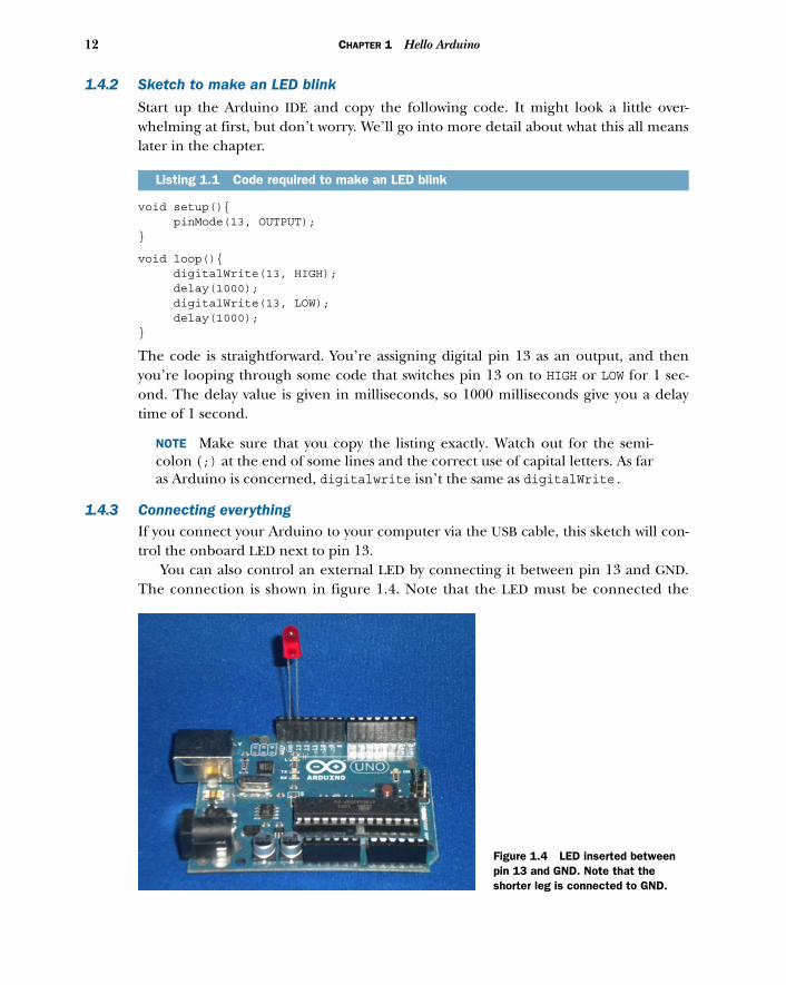
You can also control an external LED by connecting it between pin 13 and GND.The connection is shown in figure 1.4. Note that the LED must be connected the
Listing 1.1 Code required to make an LED blink
Figure 1.4 LED inserted between pin 13 and GND. Note that the shorter leg is connected to GND.
13Make something happen!
correct way around—the shorter leg is the cathode or –, and the longer is the anode or+, so push the longer lead into pin 13 and the shorter into GND. If you’re struggling withsome of the electronics terms, a good primer can be found at www.kpsec.freeuk.com/compon.htm.
NOTE A current-limiting resistor would normally be required to prevent theLED from burning out, and we’ll cover that in chapter 2. For now, let’s justuse the existing onboard LED.
Once the LED has been inserted, you can move on to the next section to test the sketch.
1.4.4 Uploading and testing
Time to see if your sketch works! First, connect the Arduino to your computer via a USBcable. You now have a couple of settings to make between the software and the Arduino.
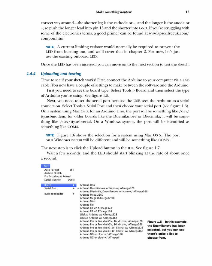
First you need to set the board type. Select Tools > Board and then select the typeof Arduino you’re using. See figure 1.5.
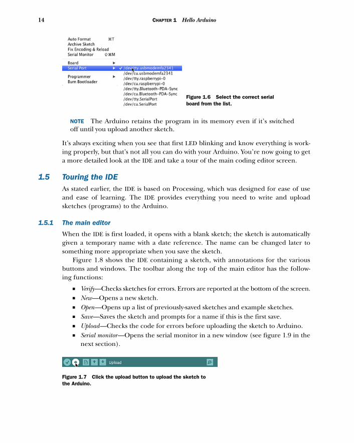
Next, you need to set the serial port because the USB sees the Arduino as a serialconnection. Select Tools > Serial Port and then choose your serial port (see figure 1.6).On a system using Mac OS X for an Arduino Uno, the port will be something like /dev/tty.usbmodem; for older boards like the Duemilanove or Diecimila, it will be some-thing like /dev/tty.usbserial. On a Windows system, the port will be identified assomething like COM3.
NOTE Figure 1.6 shows the selection for a system using Mac OS X. The porton a Windows system will be different and will be something like COM3.
The next step is to click the Upload button in the IDE. See figure 1.7. Wait a few seconds, and the LED should start blinking at the rate of about once
a second.
Figure 1.5 In this example, the Duemilanove has been selected, but you can see there’s quite a list to choose from.
14 CHAPTER 1 Hello Arduino
NOTE The Arduino retains the program in its memory even if it’s switchedoff until you upload another sketch.
It’s always exciting when you see that first LED blinking and know everything is work-ing properly, but that’s not all you can do with your Arduino. You’re now going to geta more detailed look at the IDE and take a tour of the main coding editor screen.
1.5 Touring the IDEAs stated earlier, the IDE is based on Processing, which was designed for ease of useand ease of learning. The IDE provides everything you need to write and uploadsketches (programs) to the Arduino.
1.5.1 The main editor
When the IDE is first loaded, it opens with a blank sketch; the sketch is automaticallygiven a temporary name with a date reference. The name can be changed later tosomething more appropriate when you save the sketch.
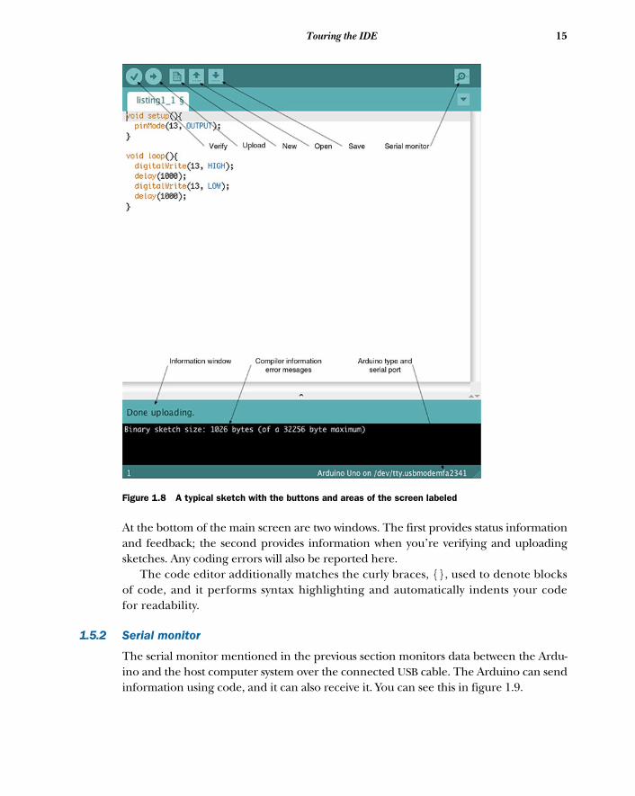
Figure 1.8 shows the IDE containing a sketch, with annotations for the variousbuttons and windows. The toolbar along the top of the main editor has the follow-ing functions:
■ Verify—Checks sketches for errors. Errors are reported at the bottom of the screen.■ New—Opens a new sketch.■ Open—Opens up a list of previously-saved sketches and example sketches.■ Save—Saves the sketch and prompts for a name if this is the first save.■ Upload—Checks the code for errors before uploading the sketch to Arduino.■ Serial monitor—Opens the serial monitor in a new window (see figure 1.9 in the
next section).
Figure 1.6 Select the correct serial board from the list.
Figure 1.7 Click the upload button to upload the sketch to the Arduino.
15Touring the IDE
At the bottom of the main screen are two windows. The first provides status informationand feedback; the second provides information when you’re verifying and uploadingsketches. Any coding errors will also be reported here.
The code editor additionally matches the curly braces, {}, used to denote blocksof code, and it performs syntax highlighting and automatically indents your codefor readability.
1.5.2 Serial monitor
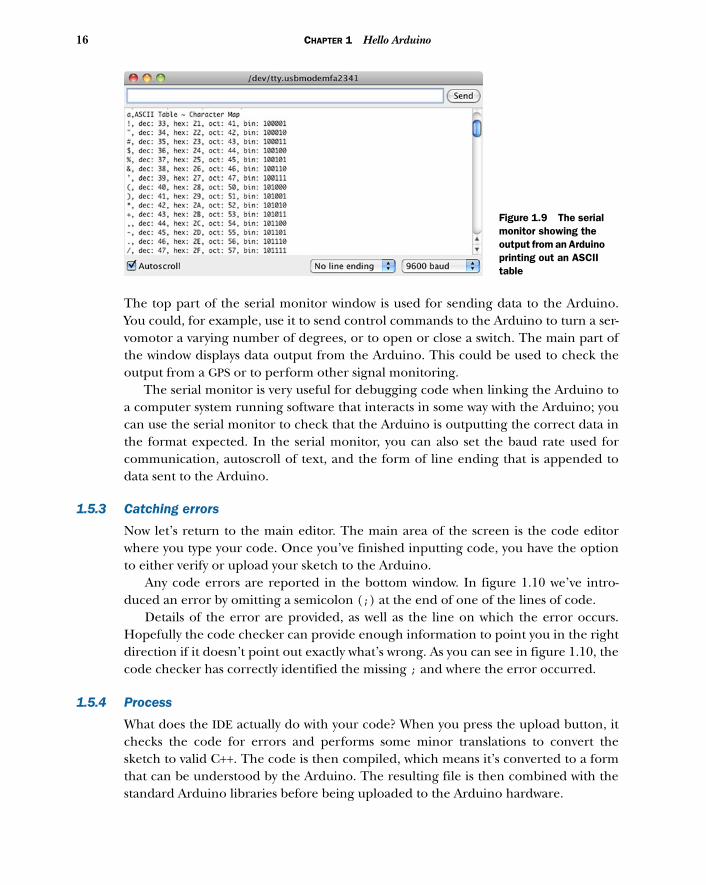
The serial monitor mentioned in the previous section monitors data between the Ardu-ino and the host computer system over the connected USB cable. The Arduino can sendinformation using code, and it can also receive it. You can see this in figure 1.9.
Figure 1.8 A typical sketch with the buttons and areas of the screen labeled
16 CHAPTER 1 Hello Arduino
The top part of the serial monitor window is used for sending data to the Arduino.You could, for example, use it to send control commands to the Arduino to turn a ser-vomotor a varying number of degrees, or to open or close a switch. The main part ofthe window displays data output from the Arduino. This could be used to check theoutput from a GPS or to perform other signal monitoring.
The serial monitor is very useful for debugging code when linking the Arduino toa computer system running software that interacts in some way with the Arduino; youcan use the serial monitor to check that the Arduino is outputting the correct data inthe format expected. In the serial monitor, you can also set the baud rate used forcommunication, autoscroll of text, and the form of line ending that is appended todata sent to the Arduino.
1.5.3 Catching errors
Now let’s return to the main editor. The main area of the screen is the code editorwhere you type your code. Once you’ve finished inputting code, you have the optionto either verify or upload your sketch to the Arduino.
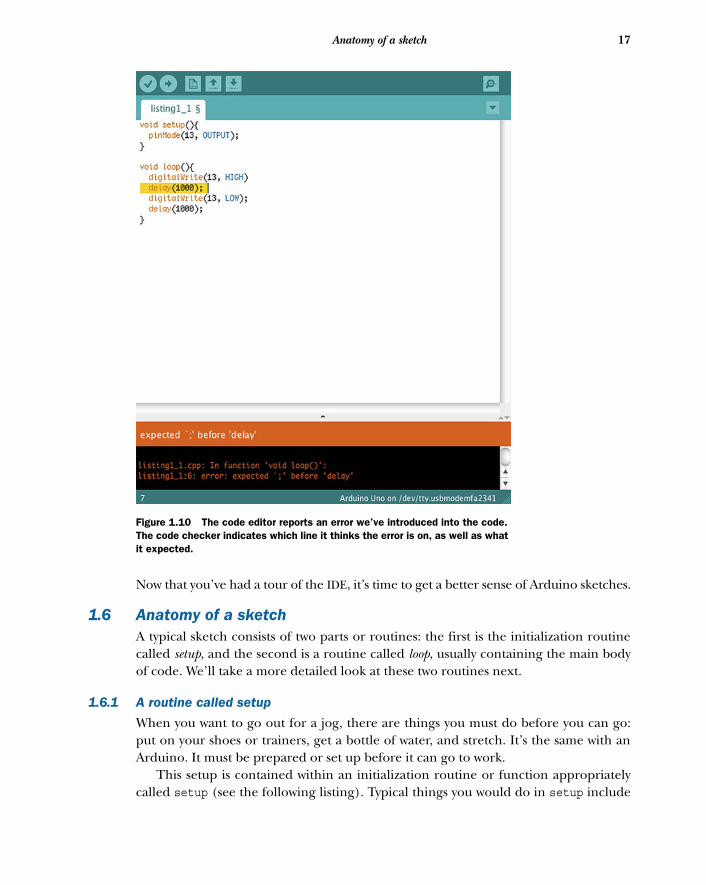
Any code errors are reported in the bottom window. In figure 1.10 we’ve intro-duced an error by omitting a semicolon (;) at the end of one of the lines of code.
Details of the error are provided, as well as the line on which the error occurs.Hopefully the code checker can provide enough information to point you in the rightdirection if it doesn’t point out exactly what’s wrong. As you can see in figure 1.10, thecode checker has correctly identified the missing ; and where the error occurred.
1.5.4 Process
What does the IDE actually do with your code? When you press the upload button, itchecks the code for errors and performs some minor translations to convert thesketch to valid C++. The code is then compiled, which means it’s converted to a formthat can be understood by the Arduino. The resulting file is then combined with thestandard Arduino libraries before being uploaded to the Arduino hardware.
Figure 1.9 The serial monitor showing the output from an Arduino printing out an ASCII table
17Anatomy of a sketch
Now that you’ve had a tour of the IDE, it’s time to get a better sense of Arduino sketches.
1.6 Anatomy of a sketchA typical sketch consists of two parts or routines: the first is the initialization routinecalled setup, and the second is a routine called loop, usually containing the main bodyof code. We’ll take a more detailed look at these two routines next.
1.6.1 A routine called setup
When you want to go out for a jog, there are things you must do before you can go:put on your shoes or trainers, get a bottle of water, and stretch. It’s the same with anArduino. It must be prepared or set up before it can go to work.
This setup is contained within an initialization routine or function appropriatelycalled setup (see the following listing). Typical things you would do in setup include
Figure 1.10 The code editor reports an error we’ve introduced into the code. The code checker indicates which line it thinks the error is on, as well as what it expected.
18 CHAPTER 1 Hello Arduino
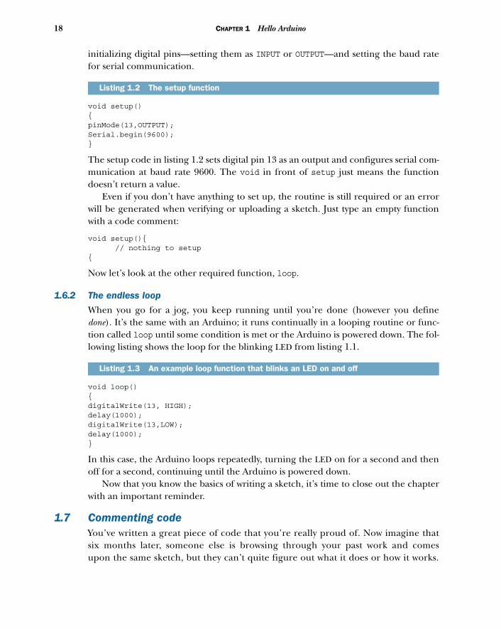
initializing digital pins—setting them as INPUT or OUTPUT—and setting the baud ratefor serial communication.
void setup() {pinMode(13,OUTPUT);Serial.begin(9600);}
The setup code in listing 1.2 sets digital pin 13 as an output and configures serial com-munication at baud rate 9600. The void in front of setup just means the functiondoesn’t return a value.
Even if you don’t have anything to set up, the routine is still required or an errorwill be generated when verifying or uploading a sketch. Just type an empty functionwith a code comment:
void setup(){ // nothing to setup{
Now let’s look at the other required function, loop.
1.6.2 The endless loop
When you go for a jog, you keep running until you’re done (however you definedone). It’s the same with an Arduino; it runs continually in a looping routine or func-tion called loop until some condition is met or the Arduino is powered down. The fol-lowing listing shows the loop for the blinking LED from listing 1.1.
void loop(){digitalWrite(13, HIGH);delay(1000);digitalWrite(13,LOW);delay(1000);}
In this case, the Arduino loops repeatedly, turning the LED on for a second and thenoff for a second, continuing until the Arduino is powered down.
Now that you know the basics of writing a sketch, it’s time to close out the chapterwith an important reminder.
1.7 Commenting codeYou’ve written a great piece of code that you’re really proud of. Now imagine thatsix months later, someone else is browsing through your past work and comesupon the same sketch, but they can’t quite figure out what it does or how it works.
Listing 1.2 The setup function
Listing 1.3 An example loop function that blinks an LED on and off
19Commenting code
A simple description would help enormously. This is where commenting your codebecomes invaluable.
There are two main ways to place comments in a sketch: either as a single line or asa block. A single line comment has a double slash (//) at the start of the line. Thistells the compiler that it’s just a comment and can be ignored. When you want to adda block of code as a comment, start the block with /* and end with */.
Both methods are demonstrated here:
// This is a single-line comment
/* And this is a block carried overa couple of lines*/
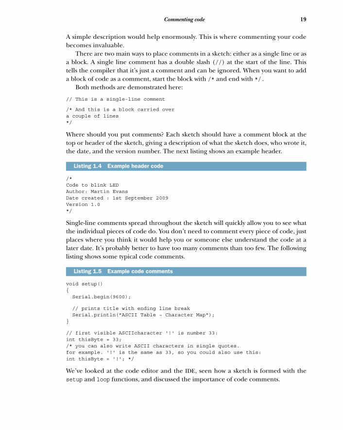
Where should you put comments? Each sketch should have a comment block at thetop or header of the sketch, giving a description of what the sketch does, who wrote it,the date, and the version number. The next listing shows an example header.
/* Code to blink LED Author: Martin EvansDate created : 1st September 2009Version 1.0*/
Single-line comments spread throughout the sketch will quickly allow you to see whatthe individual pieces of code do. You don’t need to comment every piece of code, justplaces where you think it would help you or someone else understand the code at alater date. It’s probably better to have too many comments than too few. The followinglisting shows some typical code comments.
void setup() { Serial.begin(9600);
// prints title with ending line break Serial.println("ASCII Table ~ Character Map"); }
// first visible ASCIIcharacter '!' is number 33:int thisByte = 33; /* you can also write ASCII characters in single quotes.for example. '!' is the same as 33, so you could also use this:int thisByte = '!'; */
We’ve looked at the code editor and the IDE, seen how a sketch is formed with thesetup and loop functions, and discussed the importance of code comments.
Listing 1.4 Example header code
Listing 1.5 Example code comments
20 CHAPTER 1 Hello Arduino
1.8 SummaryThis has been a busy chapter, and we’ve covered a lot of ground. We started by learn-ing a little of the history of Arduino and its beginnings at the Interaction Design Insti-tute in Italy. We saw the layout of the pins and main components of the Arduino Unoand Mega. We caught a glimpse of some other Arduino versions, including the Lily-Pad and the Seeeduino Film, and what they offer. You set up a working environmentand wrote your first sketch, getting to see your Arduino come to life.
We looked in detail at the Arduino software IDE and the components of a sketch,with the setup and loop routines, we looked at using the serial monitor, and we sawthe importance of commenting your code.
The next chapter is a tutorial that covers the gradual development of a project andthe steps involved in completing it.

Digital input and output
Now that you have a sense of what an Arduino can do and have completed yourfirst test run, it’s time to delve deeper. You’re going to build on what you learned inchapter 1 and build your first complete project, a reactometer that uses LEDs, apush button, and a timer to record reaction times.
Let’s get started.
2.1 Getting startedTo complete your reactometer, you need a handful of components:
■ A breadboard on which to assemble the project■ A selection of jumpers to connect components together■ Six red LEDs; you can use other colors if you want
This chapter covers■ Blinking more than one LED■ Using a push button to control a sequence of
blinking LEDs■ Building a project step by step■ Learning about interrupts ■ Building a reactometer
21
22 CHAPTER 2 Digital input and output
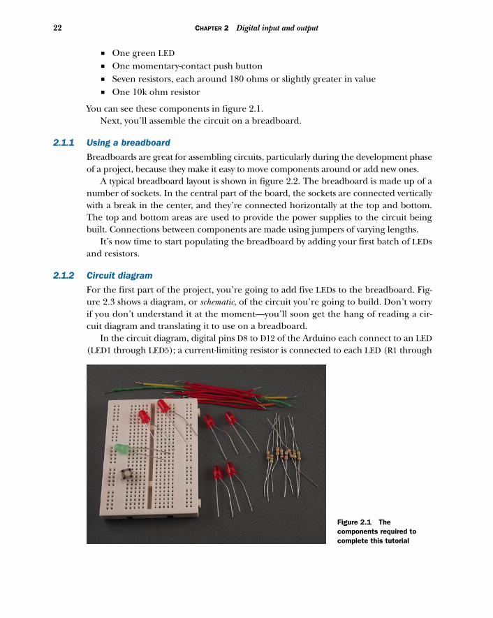
■ One green LED■ One momentary-contact push button■ Seven resistors, each around 180 ohms or slightly greater in value■ One 10k ohm resistor
You can see these components in figure 2.1. Next, you’ll assemble the circuit on a breadboard.
2.1.1 Using a breadboard
Breadboards are great for assembling circuits, particularly during the development phaseof a project, because they make it easy to move components around or add new ones.
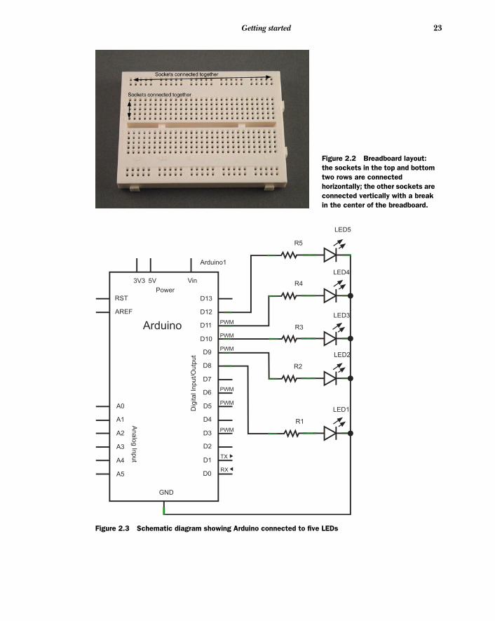
A typical breadboard layout is shown in figure 2.2. The breadboard is made up of anumber of sockets. In the central part of the board, the sockets are connected verticallywith a break in the center, and they’re connected horizontally at the top and bottom.The top and bottom areas are used to provide the power supplies to the circuit beingbuilt. Connections between components are made using jumpers of varying lengths.
It’s now time to start populating the breadboard by adding your first batch of LEDsand resistors.
2.1.2 Circuit diagram
For the first part of the project, you’re going to add five LEDs to the breadboard. Fig-ure 2.3 shows a diagram, or schematic, of the circuit you’re going to build. Don’t worryif you don’t understand it at the moment—you’ll soon get the hang of reading a cir-cuit diagram and translating it to use on a breadboard.
In the circuit diagram, digital pins D8 to D12 of the Arduino each connect to an LED(LED1 through LED5); a current-limiting resistor is connected to each LED (R1 through
Figure 2.1 The components required to complete this tutorial
23Getting started
Figure 2.2 Breadboard layout: the sockets in the top and bottom two rows are connected horizontally; the other sockets are connected vertically with a break in the center of the breadboard.
Arduino1
Vin
Power
3V3 5V
RST
AREF
Arduino
D13
D12
D11
D10
D9
D8
D7
D6
D5
D4
D3
D2
D1
D0
GND
A0
A1
A2
A3
A4
A5
An
alo
g In
pu
t
Dig
ita
l In
pu
t/O
utp
ut
PWM
PWM
PWM
PWM
PWM
PWM
TX
RX
LED5
R5
R4
R3
R2
R1
LED1
LED2
LED3
LED4
Figure 2.3 Schematic diagram showing Arduino connected to five LEDs
24 CHAPTER 2 Digital input and output
R5). The cathode, normally the shorter leg of each LED, is connected to GND on theArduino. Power for the circuit is provided by the USB connection to your computer.
When you’ve made yourself familiar with the circuit diagram and have seen howthe LEDs, resistors, and Arduino connect together, you can move onto placing thecomponents into the breadboard.
2.1.3 Adding the LEDs
In figure 2.3, LED1 through LED5 are connected to digital pins 8 through 12 on theArduino, which are labeled D8 through D12 on the schematic diagram. Each LED goesto a separate pin.
A resistor is connected in series with each LED; these are current-limiting resistors,and they act to limit the amount of current that flows through the LEDs, protectingthem from burning out.
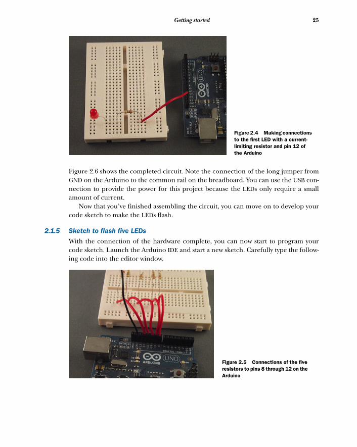
2.1.4 Connecting the hardware
Make sure the Arduino isn’t connected to your computer yet; you don’t want to have itpowered up while you’re connecting the hardware.
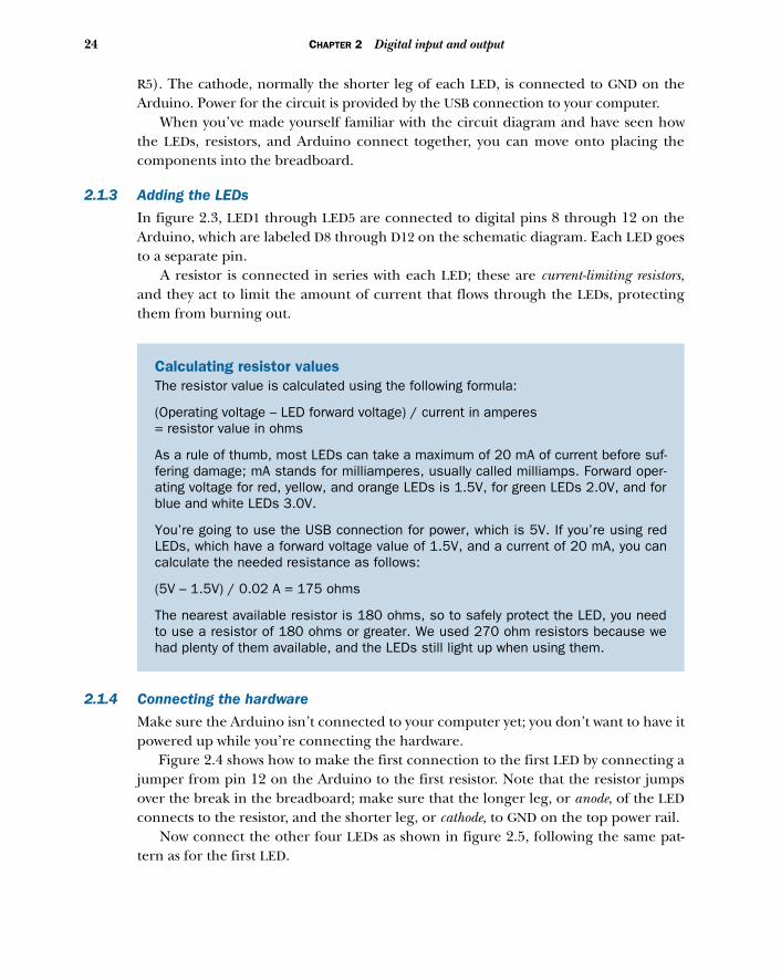
Figure 2.4 shows how to make the first connection to the first LED by connecting ajumper from pin 12 on the Arduino to the first resistor. Note that the resistor jumpsover the break in the breadboard; make sure that the longer leg, or anode, of the LEDconnects to the resistor, and the shorter leg, or cathode, to GND on the top power rail.
Now connect the other four LEDs as shown in figure 2.5, following the same pat-tern as for the first LED.
Calculating resistor values The resistor value is calculated using the following formula:
(Operating voltage – LED forward voltage) / current in amperes = resistor value in ohms
As a rule of thumb, most LEDs can take a maximum of 20 mA of current before suf-fering damage; mA stands for milliamperes, usually called milliamps. Forward oper-ating voltage for red, yellow, and orange LEDs is 1.5V, for green LEDs 2.0V, and forblue and white LEDs 3.0V.
You’re going to use the USB connection for power, which is 5V. If you’re using redLEDs, which have a forward voltage value of 1.5V, and a current of 20 mA, you cancalculate the needed resistance as follows:
(5V – 1.5V) / 0.02 A = 175 ohms
The nearest available resistor is 180 ohms, so to safely protect the LED, you needto use a resistor of 180 ohms or greater. We used 270 ohm resistors because wehad plenty of them available, and the LEDs still light up when using them.
25Getting started
Figure 2.6 shows the completed circuit. Note the connection of the long jumper fromGND on the Arduino to the common rail on the breadboard. You can use the USB con-nection to provide the power for this project because the LEDs only require a smallamount of current.
Now that you’ve finished assembling the circuit, you can move on to develop yourcode sketch to make the LEDs flash.
2.1.5 Sketch to flash five LEDs
With the connection of the hardware complete, you can now start to program yourcode sketch. Launch the Arduino IDE and start a new sketch. Carefully type the follow-ing code into the editor window.
Figure 2.4 Making connections to the first LED with a current-limiting resistor and pin 12 of the Arduino
Figure 2.5 Connections of the five resistors to pins 8 through 12 on the Arduino
26 CHAPTER 2 Digital input and output
int ledArray[] = {8, 9, 10, 11, 12}; int count = 0;int timer = 75;
void setup(){ for (count=0;count<5;count++){ pinMode(ledArray[count], OUTPUT); }}
void loop(){ for (count=0;count<5;count++){ digitalWrite(ledArray[count], HIGH); delay(timer); digitalWrite(ledArray[count], LOW); delay(timer); }}
In the first part of the sketch, the sketch variables are declared. An array, ledArray, isused to set the digital pin numbers you’re going to use.
You could have used direct pin assignment, as shown here:
int ledPin1 = 8;int ledPin2 = 9;int ledPin3 = 10;int ledPin4 = 11;int ledPin5 = 12;
But it’s more efficient to use an array when you have a collection of pin numbers thatyou’ll treat similarly.
During the setup routine, you use a for loop so that each pin from 8 through 12 isset as an output.
Listing 2.1 Five flashing LEDs, flashing after each other
Figure 2.6 The completed circuit with power being provided by the USB connection
LED array
A for loop
digitalWrite writes LOW or HIGH
27Gaining control
In the sketch’s main loop, you use another for loop to set each pin in turn to HIGH,turning the LED on with a digitalWrite function that accesses the LED to be writtento from the ledArray array by its index value, count. Then, after a delay of 75 millisec-onds, the pin is set to LOW and the LED is turned off again using digitalWrite.
The loop continues to run, turning each LED on and off in turn, with a slight delayin between. You could alter the delay time by changing the value of the timer variable.
NOTE The digitalWrite function works by writing either a HIGH or a LOWvalue to the pin. If the pin is set to HIGH, digitalWrite sets the pin at 5V,which is enough to power an LED; if the pin is set to LOW, digitalWrite setsthe pin at 0V, which turns the LED off.
Now that you’ve built your circuit and written your sketch, let’s move on and test it.
2.1.6 Upload and testConnect the USB cable between your computer and the Arduino and then verify thatthe sketch will compile. If any errors are generated, check that you’ve typed the codeexactly as shown in listing 2.1. Pay careful attention to opening and closing braces, {},and to the semicolons (;). Once the sketch compiles correctly, upload it to the Ardu-ino. If you see any error messages, check that the correct Arduino type and serial porthave been selected.
Once the sketch has been uploaded to the Arduino, and after a short delay, theLEDs should start to flash in turn. If no errors are generated and the sketch uploadscorrectly to the Arduino, but the LEDs don’t flash, disconnect the Arduino from theUSB cable and carefully check your connections. Check that the LEDs are plugged incorrectly, with the cathodes connected to ground, and then try connecting the USBcable again.
NOTE You shouldn’t need to re-upload the sketch because the Arduinoshould retain the code in its onboard memory.
Your LEDs are now flashing, so it’s time to make things more complex. In the nextpart of the tutorial, you’re going to add a push button to the circuit.
2.2 Gaining controlNow that your sketch is working, with the LEDs flashing on and off in turn, it’s time toadd some control to the circuit by adding a push button. This will be used to start andstop the LEDs’ flashing sequence.
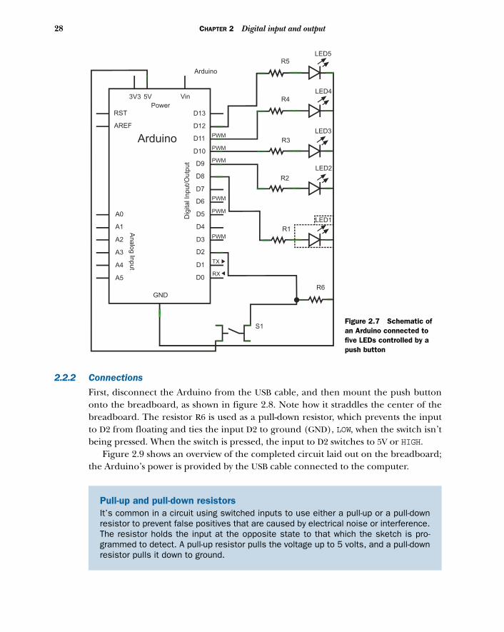
2.2.1 Circuit diagramThe circuit diagram is shown in figure 2.7. You’ll keep the same components that youused for the first version and add a push button (S1) and a resistor (R6) with a value of10k ohms.
Once you’ve had a chance to study the updated circuit diagram, you can add thenew components to the breadboard.
28 CHAPTER 2 Digital input and output
2.2.2 Connections
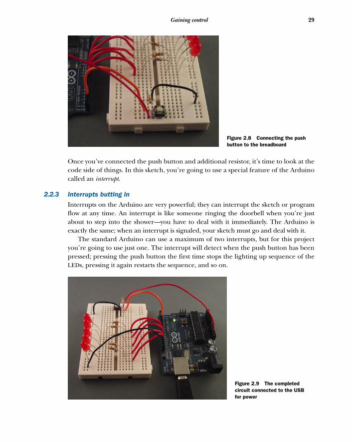
First, disconnect the Arduino from the USB cable, and then mount the push buttononto the breadboard, as shown in figure 2.8. Note how it straddles the center of thebreadboard. The resistor R6 is used as a pull-down resistor, which prevents the inputto D2 from floating and ties the input D2 to ground (GND), LOW, when the switch isn’tbeing pressed. When the switch is pressed, the input to D2 switches to 5V or HIGH.
Figure 2.9 shows an overview of the completed circuit laid out on the breadboard;the Arduino’s power is provided by the USB cable connected to the computer.
Pull-up and pull-down resistorsIt’s common in a circuit using switched inputs to use either a pull-up or a pull-downresistor to prevent false positives that are caused by electrical noise or interference.The resistor holds the input at the opposite state to that which the sketch is pro-grammed to detect. A pull-up resistor pulls the voltage up to 5 volts, and a pull-downresistor pulls it down to ground.
Arduino
Vin
Power
3V3 5V
RST
AREF
Arduino
D13
D12
D11
D10
D9
D8
D7
D6
D5
D4
D3
D2
D1
D0
GND
A0
A1
A2
A3
A4
A5
Analo
g In
put
Dig
ital In
put/
Outp
ut
PWM
PWM
PWM
PWM
PWM
PWM
TX
RX
LED5R5
R4
R3
R2
R1
LED1
LED2
LED3
LED4
R6
S1Figure 2.7 Schematic of an Arduino connected to five LEDs controlled by a push button
29Gaining control
Once you’ve connected the push button and additional resistor, it’s time to look at thecode side of things. In this sketch, you’re going to use a special feature of the Arduinocalled an interrupt.
2.2.3 Interrupts butting in
Interrupts on the Arduino are very powerful; they can interrupt the sketch or programflow at any time. An interrupt is like someone ringing the doorbell when you’re justabout to step into the shower—you have to deal with it immediately. The Arduino isexactly the same; when an interrupt is signaled, your sketch must go and deal with it.
The standard Arduino can use a maximum of two interrupts, but for this projectyou’re going to use just one. The interrupt will detect when the push button has beenpressed; pressing the push button the first time stops the lighting up sequence of theLEDs, pressing it again restarts the sequence, and so on.
Figure 2.8 Connecting the push button to the breadboard
Figure 2.9 The completed circuit connected to the USB for power
30 CHAPTER 2 Digital input and output
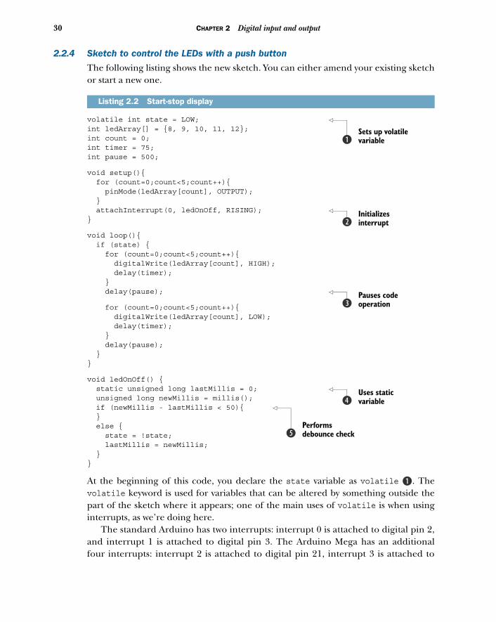
2.2.4 Sketch to control the LEDs with a push button
The following listing shows the new sketch. You can either amend your existing sketchor start a new one.
volatile int state = LOW; int ledArray[] = {8, 9, 10, 11, 12};int count = 0;int timer = 75;int pause = 500;
void setup(){ for (count=0;count<5;count++){ pinMode(ledArray[count], OUTPUT); } attachInterrupt(0, ledOnOff, RISING); }
void loop(){ if (state) { for (count=0;count<5;count++){ digitalWrite(ledArray[count], HIGH); delay(timer); } delay(pause);
for (count=0;count<5;count++){ digitalWrite(ledArray[count], LOW); delay(timer); } delay(pause); }}
void ledOnOff() { static unsigned long lastMillis = 0; unsigned long newMillis = millis(); if (newMillis - lastMillis < 50){ } else { state = !state; lastMillis = newMillis; }}
At the beginning of this code, you declare the state variable as volatile B. Thevolatile keyword is used for variables that can be altered by something outside thepart of the sketch where it appears; one of the main uses of volatile is when usinginterrupts, as we’re doing here.
The standard Arduino has two interrupts: interrupt 0 is attached to digital pin 2,and interrupt 1 is attached to digital pin 3. The Arduino Mega has an additionalfour interrupts: interrupt 2 is attached to digital pin 21, interrupt 3 is attached to
Listing 2.2 Start-stop display
Sets up volatile variableb
Initializes interruptc
Pauses code operationd
Uses static variablee
Performs debounce checkf
31Gaining control
digital pin 20, interrupt 4 is attached to digital pin 19, and interrupt 5 is attachedto digital pin 18.
NOTE The function attachInterrupt(interrupt, function, mode) takes threearguments. The first is interrupt, which can be set to 0 or 1; the second isthe function to call, which must have no arguments and return nothing;and the third is the mode that generates the interrupt. This mode can haveone of four values: LOW triggers whenever the pin is low; CHANGE triggers when-ever the pin changes value; RISING triggers whenever the pin changes from LOWto HIGH; and FALLING triggers whenever the pin changes from HIGH to LOW.
In this sketch, you set the interrupt to RISING c. The interrupt will be triggered whenthe push button is pressed and the pin switches from LOW to HIGH. Another change inthis sketch is that now the LEDs light up one after the other with a slight delay betweeneach; then, when all the LEDs are lit, there is a slight pause d and all the LEDs areswitched off. The sequence then repeats. Pressing the push button stops the sequence;pressing it again restarts it.
In this sketch, you counter the effect of the switch bouncing by using a static variablecalled lastMillis e. Static variables keep their values between calls to a function.The millis() function returns the number of milliseconds since the program started,and each time the interrupt-service routine is called, you assign the value of millis()to the variable newMillis. You then compare the value of newMillis to lastMillis f;if the result is less than 50 milliseconds (the bounce period), you do nothing andreturn to the main sketch loop. If the value is greater than or equal to 50 milliseconds,you’re outside the bounce period, meaning that the button has really been pressedagain. In that case, you update the state variable and assign the value of newMillis tolastMillis before returning to the main sketch loop.
CAUTION Many people consider interrupts an advanced technique, but ifyou're careful, you should have no problem using them. During interrupt-service routines, keep your sketch code as small as possible; this will help youavoid unexpected things happening in the rest of your sketch. Another caveatis that you can’t use the delay function inside an interrupt-service routine.
Let’s move on now and test our newest sketch.
DebounceIn the interrupt-service routine, the ledOnOff() function, we’ve also included somecode to help with a problem found in mechanical switches called bounce. When aswitch is pressed and moves from an open to a closed position, the contact often isn’tperfect and produces a number of spurious signals called bounces, causing the con-nected pin to switch from LOW to HIGH a number of times until it settles to a constantstate. It normally takes between 10 and 50 milliseconds to settle, but you can try lon-ger values if you’re getting strange results that you suspect are caused by bounce.
32 CHAPTER 2 Digital input and output
2.2.5 Upload and test
Connect the Arduino to your computer with the USB cable. Verify that the sketchcompiles correctly, and then upload it to the Arduino. When the sketch has com-pleted uploading, no LEDs will be lit until you press the push button. Try pressing thepush button a few times to see how the LED sequence starts and stops.
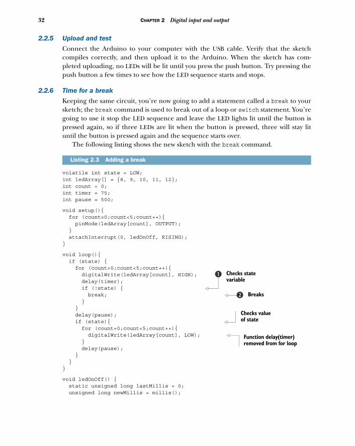
2.2.6 Time for a break
Keeping the same circuit, you’re now going to add a statement called a break to yoursketch; the break command is used to break out of a loop or switch statement. You’regoing to use it stop the LED sequence and leave the LED lights lit until the button ispressed again, so if three LEDs are lit when the button is pressed, three will stay lituntil the button is pressed again and the sequence starts over.
The following listing shows the new sketch with the break command.
volatile int state = LOW;int ledArray[] = {8, 9, 10, 11, 12};int count = 0;int timer = 75;int pause = 500;
void setup(){ for (count=0;count<5;count++){ pinMode(ledArray[count], OUTPUT); } attachInterrupt(0, ledOnOff, RISING);}
void loop(){ if (state) { for (count=0;count<5;count++){ digitalWrite(ledArray[count], HIGH); delay(timer); if (!state) { break; } } delay(pause); if (state){ for (count=0;count<5;count++){ digitalWrite(ledArray[count], LOW); } delay(pause); } }}
void ledOnOff() { static unsigned long lastMillis = 0; unsigned long newMillis = millis();
Listing 2.3 Adding a break
Checks state variable
b
Breaksc
Checks value of state
Function delay(timer) removed from for loop
33Reaction tester
if (newMillis - lastMillis < 50){ } else { state = !state; lastMillis = newMillis; }}
After each LED lights up, you check the status of the state variable to see if the pushbutton has been pressed B. If the button has been pressed, the break statement iscalled and the sketch exits from the loop c. When the button is pressed again, thesequence restarts.
It’s now time to check that your sketch functions correctly.
2.2.7 Upload and test
Verify that the sketch compiles correctly, and then upload and test it. When the but-ton is pressed the sequence of flashing LEDs should halt; pressing it again shouldrestart the sequence.
It’s now time to move on to the next stage of your project. You’re going to make areaction tester.
2.3 Reaction testerThis is the last circuit change you’re going to make in this chapter. You’re going toadd two LEDs to the circuit, preferably a green one and a red one, to be used as startand stop indicators. The red LED will initially be lit; when it goes out and the greenLED lights up, you’ll have to press the push button as quickly as you can to halt thelight sequence you set up in the previous section. Someone with an average reactiontime should be able to stop the sequence when two or three LEDs are lit.
2.3.1 Circuit diagram
Look at the circuit diagram in figure 2.10 and note how the two new LEDs connect tothe Arduino. Green LED6 and red LED7 have been added to the circuit, along withtwo 220 ohm current-limiting resistors, R7 and R8.
2.3.2 Connections
Figure 2.11 shows the completed connections between the Arduino and breadboard,with the two additional LEDs and resistors added to the existing circuit.
That’s the circuit completed for this chapter. It’s now time to look at your penulti-mate sketch for this chapter.
2.3.3 Sketch to test reaction speed
The next listing shows the sketch for the reaction meter; type it carefully into anew sketch.
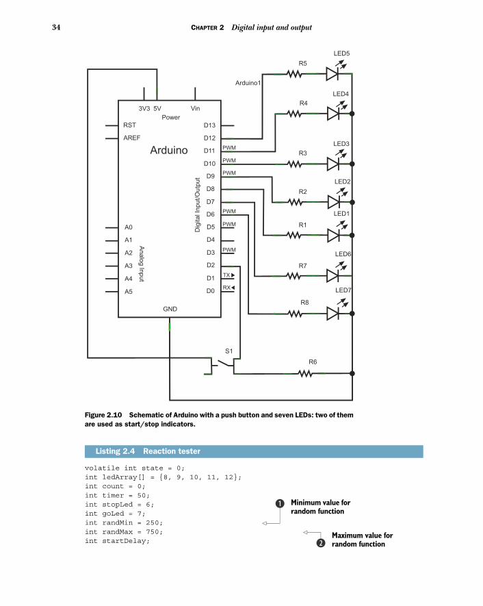
34 CHAPTER 2 Digital input and output
volatile int state = 0;int ledArray[] = {8, 9, 10, 11, 12};int count = 0;int timer = 50;int stopLed = 6;int goLed = 7;int randMin = 250; int randMax = 750; int startDelay;
Listing 2.4 Reaction tester
Arduino1
Vin
Power
3V3 5V
RST
AREF
Arduino
D13
D12
D11
D10
D9
D8
D7
D6
D5
D4
D3
D2
D1
D0
GND
A0
A1
A2
A3
A4
A5
An
alo
g In
pu
t
Dig
ita
l In
pu
t/O
utp
ut
PWM
PWM
PWM
PWM
PWM
PWM
TX
RX
LED5
R5
R4
R3
R2
R1
LED1
LED2
LED3
LED4
R7
R6
S1
R8
LED7
LED6
Figure 2.10 Schematic of Arduino with a push button and seven LEDs: two of them are used as start/stop indicators.
Minimum value for random function
b
Maximum value for random functionc
35Reaction tester
void setup(){ for (count=0;count<5;count++){ pinMode(ledArray[count], OUTPUT); } attachInterrupt(0, ledOnOff, RISING); pinMode(stopLed, OUTPUT); pinMode(goLed, OUTPUT); randomSeed(analogRead(0)); }
void loop(){ //start state if (state == 0) { digitalWrite(stopLed, HIGH); digitalWrite(goLed, LOW); for (count=0;count<5;count++){ digitalWrite(ledArray[count], LOW); } } // start button pressed if (state == 1) { // random start startDelay = random(randMin,randMax); delay(startDelay); digitalWrite(stopLed, LOW); digitalWrite(goLed, HIGH); for (count=0;count<5;count++){ digitalWrite(ledArray[count], HIGH); delay(timer); if (state == 2) { break; } } }}
void ledOnOff() { static unsigned long lastMillis = 0; unsigned long newMillis = millis(); if (newMillis - lastMillis < 50){ } else { state = state++; if (state == 3) { state = 0; } lastMillis = newMillis; }}
In this sketch, you set the two pins 6 and 7, which are connected to your two newLEDs, as OUTPUTs. You also use one of the Arduino functions, random, which can taketwo arguments—in this case, randMin B and randMax c. The function returns a longvalue between randMin, inclusive, and randMax, exclusive.
Function to generate random seedd
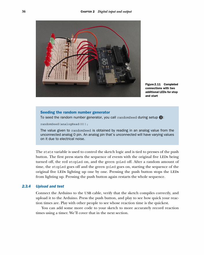
36 CHAPTER 2 Digital input and output
The state variable is used to control the sketch logic and is tied to presses of the pushbutton. The first press starts the sequence of events with the original five LEDs beingturned off, the red stopLed on, and the green goLed off. After a random amount oftime, the stopLed goes off and the green goLed goes on, starting the sequence of theoriginal five LEDs lighting up one by one. Pressing the push button stops the LEDsfrom lighting up. Pressing the push button again restarts the whole sequence.
2.3.4 Upload and test
Connect the Arduino to the USB cable, verify that the sketch compiles correctly, andupload it to the Arduino. Press the push button, and play to see how quick your reac-tion times are. Play with other people to see whose reaction time is the quickest.
You can add some more code to your sketch to more accurately record reactiontimes using a timer. We’ll cover that in the next section.
Seeding the random number generatorTo seed the random number generator, you call randomSeed during setup d:
randomSeed(analogRead(0));
The value given to randomSeed is obtained by reading in an analog value from theunconnected analog 0 pin. An analog pin that’s unconnected will have varying valueson it due to electrical noise.
Figure 2.11 Completed connections with two additional LEDs for stop and start
37Reactometer: Who really has the fastest reaction time?
2.4 Reactometer: Who really has the fastest reaction time?For the last sketch of this chapter, you’re going to more accurately measure your reac-tion times using a timer. The circuit stays the same, but you’re going to make somechanges to the sketch.
2.4.1 Sketch to measure reaction speed
The following listing shows your new reactometer sketch; either edit the previoussketch or create a new one and type in the following listing.
volatile int state = 0;int ledArray[] = {8, 9, 10, 11, 12};int count = 0;int timer = 50;int stopLed = 6;int goLed = 7;int randMin = 250;int randMax = 750;int startDelay;volatile float time;float start_time;
void setup(){ for (count=0;count<5;count++){ pinMode(ledArray[count], OUTPUT); } attachInterrupt(0, ledOnOff, RISING); pinMode(stopLed, OUTPUT); pinMode(goLed, OUTPUT); randomSeed(analogRead(0)); Serial.begin(9600); }
void loop(){ //start state if (state == 0) { digitalWrite(stopLed, HIGH); digitalWrite(goLed, LOW); for (count=0;count<5;count++){ digitalWrite(ledArray[count], LOW); } } // start button pressed if (state == 1) { // random start startDelay = random(randMin,randMax); delay(startDelay); start_time = millis(); digitalWrite(stopLed, LOW);
Listing 2.5 Reaction timer
Sets up serial communication.
b
38 CHAPTER 2 Digital input and output
digitalWrite(goLed, HIGH); for (count=0;count<5;count++){ delay(timer); if (state == 2) { time = (time - start_time)/1000; Serial.print("Reaction time: "); Serial.print(time); Serial.println(" seconds"); delay(1000); break; } digitalWrite(ledArray[count], HIGH); } }}
void ledOnOff() { static unsigned long lastMillis = 0; unsigned long newMillis = millis(); if (newMillis - lastMillis < 50){ } else { state = state++; if (state == 2){ time = millis(); } if (state == 3) { state = 0; } lastMillis = newMillis; }}
In this sketch you’ve added a timer so you can more accurately determine your reac-tion time. When it has been calculated, the time is sent out to the serial port. Theserial port is enabled during the setup function in your sketch with this command B:
Serial.begin(9600);
The 9600 is the baud rate, or speed, at which the Arduino sends data. To understandthe data, the host computer (in this case, the serial monitor) must have its baud rateset to the same speed.
When printing out the data, you use two functions: Serial.print c andSerial.println d. The only difference between the two is that the Serial.printlnfunction appends a carriage return and newline character to the end of the string.
2.4.2 Upload and test
Verify that the sketch compiles correctly and then upload it to the Arduino. As before,the push button controls the start and stop of the reactometer. Figure 2.12 shows theworking completed project.
Serial.print prints the reaction time.
c
Serial.println prints a carriage return at the end of the line.d
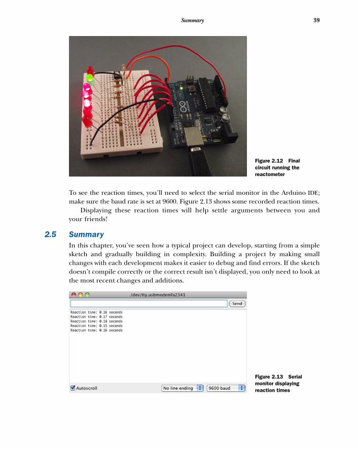
39Summary
To see the reaction times, you’ll need to select the serial monitor in the Arduino IDE;make sure the baud rate is set at 9600. Figure 2.13 shows some recorded reaction times.
Displaying these reaction times will help settle arguments between you andyour friends!
2.5 SummaryIn this chapter, you’ve seen how a typical project can develop, starting from a simplesketch and gradually building in complexity. Building a project by making smallchanges with each development makes it easier to debug and find errors. If the sketchdoesn’t compile correctly or the correct result isn’t displayed, you only need to look atthe most recent changes and additions.
Figure 2.12 Final circuit running the reactometer
Figure 2.13 Serial monitor displaying reaction times
40 CHAPTER 2 Digital input and output
This project introduced you to the digital world with digital inputs and outputs: HIGHor LOW. You’ve explored some of the capabilities of Arduino, including the availablefunctions, such as interrupts, which can be powerful. In later chapters, you’ll look fur-ther at some of the digital pins and at the more specialized functionality those pinscan have.
In the next chapter, you’re going to leave the digital world for a while and look atsome of the analog functionality that Arduino provides.
Simple projects:input and output
In the previous chapter, we looked at the digital side of the Arduino, building aseries of incremental projects that showed off Arduino features like digital inputsand outputs and interrupts. In this chapter we’re going to look at another aspect ofthe Arduino and how it interfaces with the world around us.
In basic terms, the world around us can be split into two parts—digital and analog—and in this chapter we’re going to investigate interacting with the analog part. We’llonce again start from a basic component, a potentiometer, which reads analog inputsinto the Arduino. Then we’ll experiment by adding a sensor—a piezo transducer thatcan be used as an analog input or output. We’ll round up by adding four more piezotransducers and a small speaker to build a working five-key pentatonic keyboard.
These are the components required to complete this chapter:
■ An Arduino board.■ A breadboard and a selection of jumper leads.
This chapter covers■ Looking at the analog world■ Reading an analog input■ Producing sound from a speaker■ Building a pentatonic keyboard
41

42 CHAPTER 3 Simple projects: input and output
■ A small potentiometer. (A trimpot is ideal, as it can easily plug into a breadboard.)■ Five zener diodes, 0.5 watt 5V1. (We used a BZX55C5V.)■ Five uncased piezoelectric transducers (knock sensors) with wire connectors.■ Five resistors, 1M ohm (1 mega ohm).■ One resistor, 1k ohm.■ A small speaker, 8 ohm.
Let’s start by learning the basics of working in analog.
3.1 Time to get analogIn previous chapters, you experimented with buttons that could be either on or off,but what if you wanted to measure an analog input like a photo or force-sensing resis-tor? If the Arduino was purely a digital device, you wouldn’t be able to measure thesedevices, which would limit the scope of your projects. Luckily, the Arduino has thiscovered and can interact with the analog world as well.
The Arduino can alter the brightness of an LED not by varying the voltage appliedto it but by using a special technique called pulse width modulation, or PWM (more onthis in a moment). In addition to providing an analog output using PWM, the Arduinocan also take an analog input of between 0 and 5 volts.
The standard Arduino has six analog inputs labeled ANALOG IN A0, A1, A2, A3, A4,A5; in addition, there are six analog outputs.
In this chapter, we’ll concentrate on the analogRead function; we’ll leave analog-Write to a later chapter.
Let’s start by taking a look at the difference between digital and analog devices.
3.1.1 What’s the difference between analog and digital?So what’s the difference between the analog and digital worlds? In the digital world,everything has two states; a switch can only be on or off, an LED is either lit or it isn’t,you’re either awake or asleep. These states can be thought of in a variety of ways asones or zeros, on or off, high or low. The Arduino digital pins work in the same way;when set as an output, they’re either 0 or 5 volts, with a 0 voltage being a logical zeroand 5 volts being logical one. In the analog world, things have a range of values. Musichas notes that span a range of frequencies, a car accelerates through a range ofspeeds, a sine wave flows smoothly between maximum and minimum values, and tem-perature varies between a maximum and minimum.
We often want to explore the analog world, and the Arduino has six analog inputsthat help us with this. But the Arduino is still a digital device, so you need a means ofconverting the input signal to a digital representation. This is done with an analog-to-digital converter (ADC). Table 3.1 shows the resolution, voltage range, and pins used foranalog input and output for the Arduino and Arduino Mega.
In the next section, you’re going to use a potentiometer to provide an analoginput that you can manually vary, and you’ll instantly see the effect of these changes bydisplaying the results using the serial monitor.
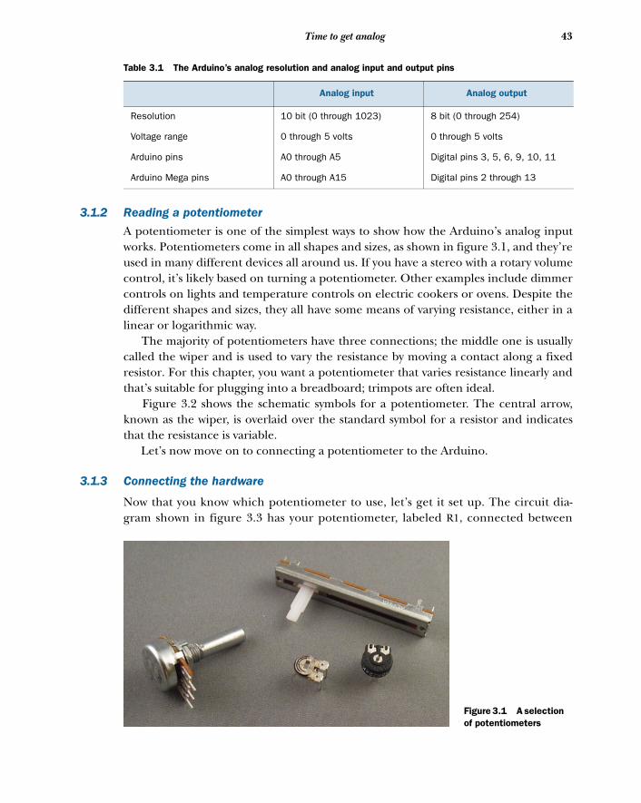
43Time to get analog
3.1.2 Reading a potentiometer
A potentiometer is one of the simplest ways to show how the Arduino’s analog inputworks. Potentiometers come in all shapes and sizes, as shown in figure 3.1, and they’reused in many different devices all around us. If you have a stereo with a rotary volumecontrol, it’s likely based on turning a potentiometer. Other examples include dimmercontrols on lights and temperature controls on electric cookers or ovens. Despite thedifferent shapes and sizes, they all have some means of varying resistance, either in alinear or logarithmic way.
The majority of potentiometers have three connections; the middle one is usuallycalled the wiper and is used to vary the resistance by moving a contact along a fixedresistor. For this chapter, you want a potentiometer that varies resistance linearly andthat’s suitable for plugging into a breadboard; trimpots are often ideal.
Figure 3.2 shows the schematic symbols for a potentiometer. The central arrow,known as the wiper, is overlaid over the standard symbol for a resistor and indicatesthat the resistance is variable.
Let’s now move on to connecting a potentiometer to the Arduino.
3.1.3 Connecting the hardware
Now that you know which potentiometer to use, let’s get it set up. The circuit dia-gram shown in figure 3.3 has your potentiometer, labeled R1, connected between
Table 3.1 The Arduino’s analog resolution and analog input and output pins
Analog input Analog output
Resolution 10 bit (0 through 1023) 8 bit (0 through 254)
Voltage range 0 through 5 volts 0 through 5 volts
Arduino pins A0 through A5 Digital pins 3, 5, 6, 9, 10, 11
Arduino Mega pins A0 through A15 Digital pins 2 through 13
Figure 3.1 A selection of potentiometers
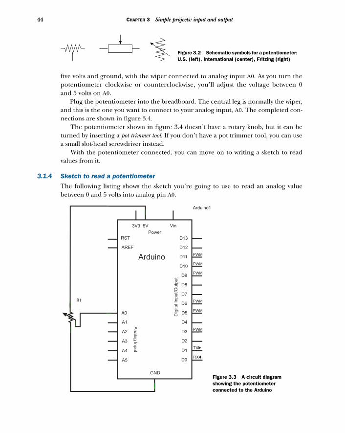
44 CHAPTER 3 Simple projects: input and output
five volts and ground, with the wiper connected to analog input A0. As you turn thepotentiometer clockwise or counterclockwise, you’ll adjust the voltage between 0and 5 volts on A0.
Plug the potentiometer into the breadboard. The central leg is normally the wiper,and this is the one you want to connect to your analog input, A0. The completed con-nections are shown in figure 3.4.
The potentiometer shown in figure 3.4 doesn’t have a rotary knob, but it can beturned by inserting a pot trimmer tool. If you don’t have a pot trimmer tool, you can usea small slot-head screwdriver instead.
With the potentiometer connected, you can move on to writing a sketch to readvalues from it.
3.1.4 Sketch to read a potentiometer
The following listing shows the sketch you’re going to use to read an analog valuebetween 0 and 5 volts into analog pin A0.
Figure 3.2 Schematic symbols for a potentiometer: U.S. (left), International (center), Fritzing (right)
Arduino1
Vin
Power
3V3 5V
RST
AREF
Arduino
D13
D12
D11
D10
D9
D8
D7
D6
D5
D4
D3
D2
D1
D0
GND
A0
A1
A2
A3
A4
A5
Analo
g In
put
Dig
ital In
put/O
utp
ut
PWM
PWM
PWM
PWM
PWM
PWM
TX
RX
R1
Figure 3.3 A circuit diagram showing the potentiometer connected to the Arduino
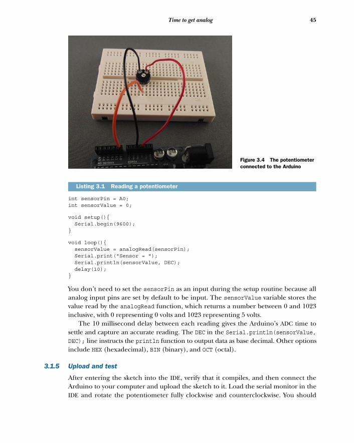
45Time to get analog
int sensorPin = A0;int sensorValue = 0;
void setup(){ Serial.begin(9600);}
void loop(){ sensorValue = analogRead(sensorPin); Serial.print("Sensor = "); Serial.println(sensorValue, DEC); delay(10); }
You don’t need to set the sensorPin as an input during the setup routine because allanalog input pins are set by default to be input. The sensorValue variable stores thevalue read by the analogRead function, which returns a number between 0 and 1023inclusive, with 0 representing 0 volts and 1023 representing 5 volts.
The 10 millisecond delay between each reading gives the Arduino’s ADC time tosettle and capture an accurate reading. The DEC in the Serial.println(sensorValue,DEC); line instructs the println function to output data as base decimal. Other optionsinclude HEX (hexadecimal), BIN (binary), and OCT (octal).
3.1.5 Upload and test
After entering the sketch into the IDE, verify that it compiles, and then connect theArduino to your computer and upload the sketch to it. Load the serial monitor in theIDE and rotate the potentiometer fully clockwise and counterclockwise. You should
Listing 3.1 Reading a potentiometer
Figure 3.4 The potentiometer connected to the Arduino
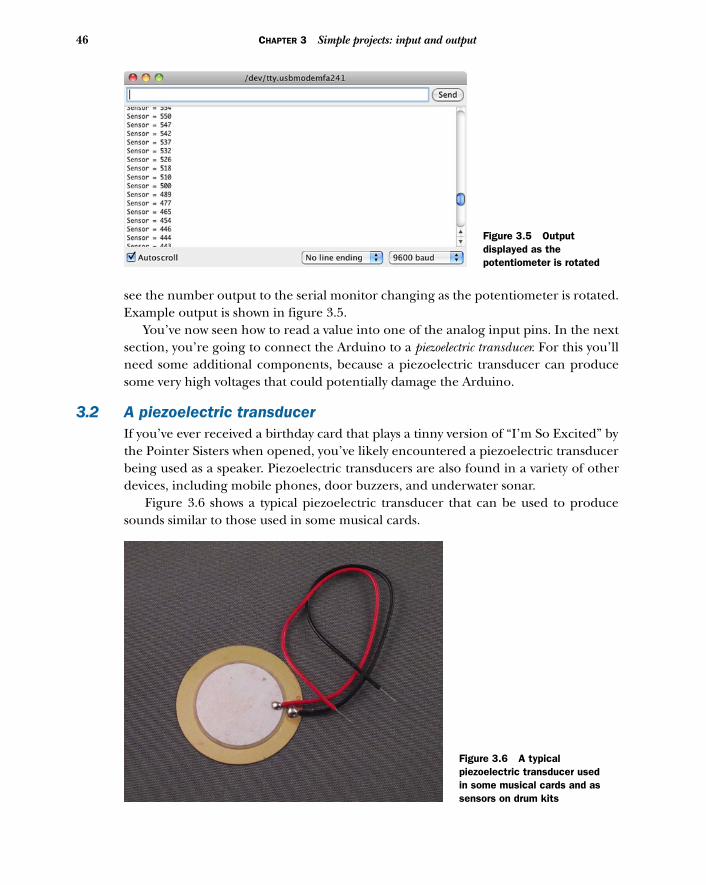
46 CHAPTER 3 Simple projects: input and output
see the number output to the serial monitor changing as the potentiometer is rotated.Example output is shown in figure 3.5.
You’ve now seen how to read a value into one of the analog input pins. In the nextsection, you’re going to connect the Arduino to a piezoelectric transducer. For this you’llneed some additional components, because a piezoelectric transducer can producesome very high voltages that could potentially damage the Arduino.
3.2 A piezoelectric transducerIf you’ve ever received a birthday card that plays a tinny version of “I’m So Excited” bythe Pointer Sisters when opened, you’ve likely encountered a piezoelectric transducerbeing used as a speaker. Piezoelectric transducers are also found in a variety of otherdevices, including mobile phones, door buzzers, and underwater sonar.
Figure 3.6 shows a typical piezoelectric transducer that can be used to producesounds similar to those used in some musical cards.
Figure 3.5 Output displayed as the potentiometer is rotated
Figure 3.6 A typical piezoelectric transducer used in some musical cards and as sensors on drum kits
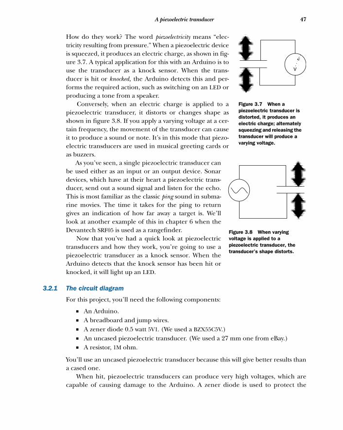
47A piezoelectric transducer
How do they work? The word piezoelectricity means “elec-tricity resulting from pressure.” When a piezoelectric deviceis squeezed, it produces an electric charge, as shown in fig-ure 3.7. A typical application for this with an Arduino is touse the transducer as a knock sensor. When the trans-ducer is hit or knocked, the Arduino detects this and per-forms the required action, such as switching on an LED orproducing a tone from a speaker.
Conversely, when an electric charge is applied to apiezoelectric transducer, it distorts or changes shape asshown in figure 3.8. If you apply a varying voltage at a cer-tain frequency, the movement of the transducer can causeit to produce a sound or note. It’s in this mode that piezo-electric transducers are used in musical greeting cards oras buzzers.
As you’ve seen, a single piezoelectric transducer canbe used either as an input or an output device. Sonardevices, which have at their heart a piezoelectric trans-ducer, send out a sound signal and listen for the echo.This is most familiar as the classic ping sound in subma-rine movies. The time it takes for the ping to returngives an indication of how far away a target is. We’lllook at another example of this in chapter 6 when theDevantech SRF05 is used as a rangefinder.
Now that you’ve had a quick look at piezoelectrictransducers and how they work, you’re going to use apiezoelectric transducer as a knock sensor. When theArduino detects that the knock sensor has been hit orknocked, it will light up an LED.
3.2.1 The circuit diagram
For this project, you’ll need the following components:
■ An Arduino.■ A breadboard and jump wires.■ A zener diode 0.5 watt 5V1. (We used a BZX55C5V.)■ An uncased piezoelectric transducer. (We used a 27 mm one from eBay.)■ A resistor, 1M ohm.
You’ll use an uncased piezoelectric transducer because this will give better results thana cased one.
When hit, piezoelectric transducers can produce very high voltages, which arecapable of causing damage to the Arduino. A zener diode is used to protect the
V
Figure 3.7 When a piezoelectric transducer is distorted, it produces an electric charge; alternately squeezing and releasing the transducer will produce a varying voltage.
Figure 3.8 When varying voltage is applied to a piezoelectric transducer, the transducer’s shape distorts.
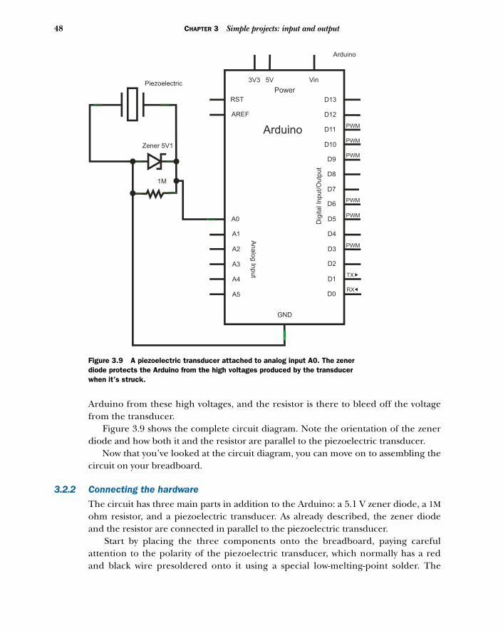
48 CHAPTER 3 Simple projects: input and output
Arduino from these high voltages, and the resistor is there to bleed off the voltagefrom the transducer.
Figure 3.9 shows the complete circuit diagram. Note the orientation of the zenerdiode and how both it and the resistor are parallel to the piezoelectric transducer.
Now that you’ve looked at the circuit diagram, you can move on to assembling thecircuit on your breadboard.
3.2.2 Connecting the hardware
The circuit has three main parts in addition to the Arduino: a 5.1 V zener diode, a 1Mohm resistor, and a piezoelectric transducer. As already described, the zener diodeand the resistor are connected in parallel to the piezoelectric transducer.
Start by placing the three components onto the breadboard, paying carefulattention to the polarity of the piezoelectric transducer, which normally has a redand black wire presoldered onto it using a special low-melting-point solder. The
Arduino
Vin
Power
3V3 5V
RST
AREF
Arduino
D13
D12
D11
D10
D9
D8
D7
D6
D5
D4
D3
D2
D1
D0
GND
A0
A1
A2
A3
A4
A5
Analo
g In
put
Dig
ital In
put/O
utp
ut
PWM
PWM
PWM
PWM
PWM
PWM
TX
RX
Zener 5V1
1M
Piezoelectric
Figure 3.9 A piezoelectric transducer attached to analog input A0. The zener diode protects the Arduino from the high voltages produced by the transducer when it’s struck.
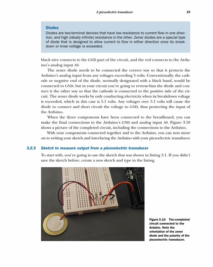
49A piezoelectric transducer
black wire connects to the GND part of the circuit, and the red connects to the Ardu-ino’s analog input A0.
The zener diode needs to be connected the correct way so that it protects theArduino’s analog input from any voltages exceeding 5 volts. Conventionally, the cath-ode or negative end of the diode, normally designated with a black band, would beconnected to GND, but in your circuit you’re going to reverse-bias the diode and con-nect it the other way so that the cathode is connected to the positive side of the cir-cuit. The zener diode works by only conducting electricity when its breakdown voltageis exceeded, which in this case is 5.1 volts. Any voltages over 5.1 volts will cause thediode to connect and short circuit the voltage to GND, thus protecting the input ofthe Arduino.
When the three components have been connected to the breadboard, you canmake the final connections to the Arduino’s GND and analog input A0. Figure 3.10shows a picture of the completed circuit, including the connections to the Arduino.
With your components connected together and to the Arduino, you can now moveon to writing your sketch and interfacing the Arduino with your piezoelectric transducer.
3.2.3 Sketch to measure output from a piezoelectric transducer
To start with, you’re going to use the sketch that was shown in listing 3.1. If you didn’tsave the sketch before, create a new sketch and type in the listing.
DiodesDiodes are two-terminal devices that have low resistance to current flow in one direc-tion, and high (ideally infinite) resistance in the other. Zener diodes are a special typeof diode that is designed to allow current to flow in either direction once its break-down or knee voltage is exceeded.
Figure 3.10 The completed circuit connected to the Arduino. Note the orientation of the zener diode and the polarity of the piezoelectric transducer.
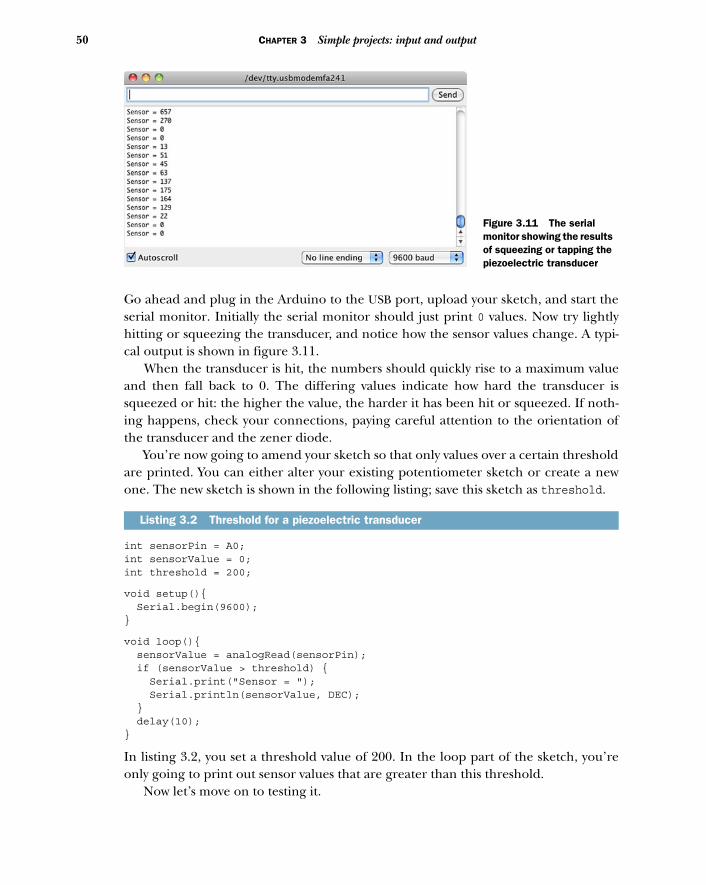
50 CHAPTER 3 Simple projects: input and output
Go ahead and plug in the Arduino to the USB port, upload your sketch, and start theserial monitor. Initially the serial monitor should just print 0 values. Now try lightlyhitting or squeezing the transducer, and notice how the sensor values change. A typi-cal output is shown in figure 3.11.
When the transducer is hit, the numbers should quickly rise to a maximum valueand then fall back to 0. The differing values indicate how hard the transducer issqueezed or hit: the higher the value, the harder it has been hit or squeezed. If noth-ing happens, check your connections, paying careful attention to the orientation ofthe transducer and the zener diode.
You’re now going to amend your sketch so that only values over a certain thresholdare printed. You can either alter your existing potentiometer sketch or create a newone. The new sketch is shown in the following listing; save this sketch as threshold.
int sensorPin = A0;int sensorValue = 0;int threshold = 200;
void setup(){ Serial.begin(9600);}
void loop(){ sensorValue = analogRead(sensorPin); if (sensorValue > threshold) { Serial.print("Sensor = "); Serial.println(sensorValue, DEC); } delay(10); }
In listing 3.2, you set a threshold value of 200. In the loop part of the sketch, you’reonly going to print out sensor values that are greater than this threshold.
Now let’s move on to testing it.
Listing 3.2 Threshold for a piezoelectric transducer
Figure 3.11 The serial monitor showing the results of squeezing or tapping the piezoelectric transducer
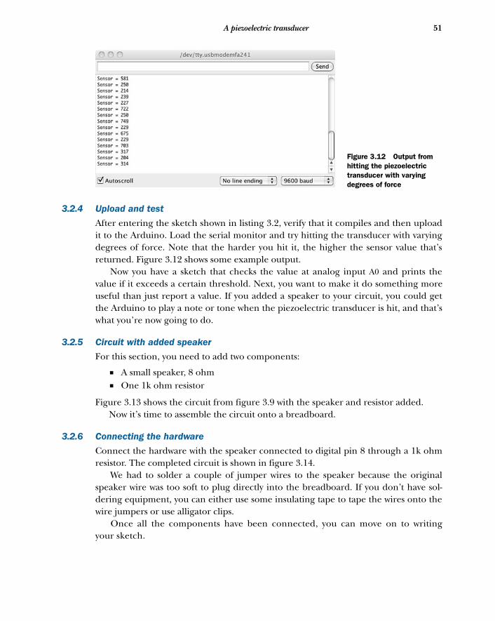
51A piezoelectric transducer
3.2.4 Upload and test
After entering the sketch shown in listing 3.2, verify that it compiles and then uploadit to the Arduino. Load the serial monitor and try hitting the transducer with varyingdegrees of force. Note that the harder you hit it, the higher the sensor value that’sreturned. Figure 3.12 shows some example output.
Now you have a sketch that checks the value at analog input A0 and prints thevalue if it exceeds a certain threshold. Next, you want to make it do something moreuseful than just report a value. If you added a speaker to your circuit, you could getthe Arduino to play a note or tone when the piezoelectric transducer is hit, and that’swhat you’re now going to do.
3.2.5 Circuit with added speaker
For this section, you need to add two components:
■ A small speaker, 8 ohm■ One 1k ohm resistor
Figure 3.13 shows the circuit from figure 3.9 with the speaker and resistor added. Now it’s time to assemble the circuit onto a breadboard.
3.2.6 Connecting the hardware
Connect the hardware with the speaker connected to digital pin 8 through a 1k ohmresistor. The completed circuit is shown in figure 3.14.
We had to solder a couple of jumper wires to the speaker because the originalspeaker wire was too soft to plug directly into the breadboard. If you don’t have sol-dering equipment, you can either use some insulating tape to tape the wires onto thewire jumpers or use alligator clips.
Once all the components have been connected, you can move on to writingyour sketch.
Figure 3.12 Output from hitting the piezoelectric transducer with varying degrees of force
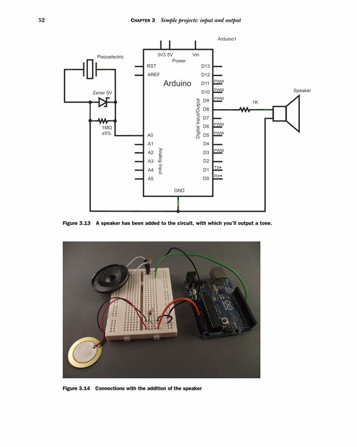
52 CHAPTER 3 Simple projects: input and output
Arduino1
Vin
Power
3V3 5V
RST
AREF
Arduino
D13
D12
D11
D10
D9
D8
D7
D6
D5
D4
D3
D2
D1
D0
GND
A0
A1
A2
A3
A4
A5
An
alo
g In
pu
tD
igita
l In
pu
t/O
utp
ut
PWM
PWM
PWM
PWM
PWM
PWM
TX
RX
Zener 5V
Piezoelectric
1MΩ
±5%
1K
Speaker
Figure 3.13 A speaker has been added to the circuit, with which you’ll output a tone.
Figure 3.14 Connections with the addition of the speaker
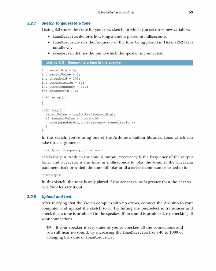
53A piezoelectric transducer
3.2.7 Sketch to generate a tone
Listing 3.3 shows the code for your new sketch, in which you set three new variables:
■ toneDuration denotes how long a tone is played in milliseconds. ■ toneFrequency sets the frequency of the tone being played in Hertz (262 Hz is
middle C). ■ speakerPin defines the pin to which the speaker is connected.
int sensorPin = 0;int sensorValue = 0;int threshold = 200;int toneDuration = 40;int toneFrequency = 262;int speakerPin = 8;
void setup(){
}
void loop(){ sensorValue = analogRead(sensorPin); if (sensorValue > threshold) { tone(speakerPin,toneFrequency,toneDuration); }}
In this sketch, you’re using one of the Arduino’s built-in libraries, tone, which cantake three arguments:
tone (pin, frequency, duration)
pin is the pin to which the tone is output; frequency is the frequency of the outputtone; and duration is the time in milliseconds to play the tone. If the durationparameter isn’t provided, the tone will play until a noTone command is issued to it:
noTone(pin)
In this sketch, the tone is only played if the sensorValue is greater than the thresh-old. Now let’s try it out.
3.2.8 Upload and test
After verifying that the sketch compiles with no errors, connect the Arduino to yourcomputer and upload the sketch to it. Try hitting the piezoelectric transducer andcheck that a tone is produced in the speaker. If no sound is produced, try checking allyour connections.
TIP If your speaker is very quiet or you’ve checked all the connections andyou still hear no sound, try increasing the toneDuration from 40 to 1000 orchanging the value of toneFrequency.
Listing 3.3 Generating a tone in the speaker
54 CHAPTER 3 Simple projects: input and output
Once everything is working, you can change the value of the toneFrequency variableto alter the note that the speaker plays. The higher the frequency, the higher thepitch; the lower the frequency, the lower the pitch. You can also try altering the valueof the threshold variable. The lower the value, the softer you can hit the transducerto play a note from the speaker.
In the next section, you’re going to add more piezoelectric transducers to your cir-cuit so you can make a keyboard, with the transducers acting as keys.
3.3 Making a pentatonic or five-tone keyboardThe word pentatonic comes from penta, meaning five, and tonic, meaning tones. A pen-tatonic scale has five notes per octave, compared to the heptatonic scale, which hasseven notes per octave. Pentatonic scales are popular the world over and are featuredin a variety of musical types and styles including blues, Celtic, jazz, and ancient Greekmusic. The pentatonic scale is ideal for introducing children to music. Its simplicityand ease of use make it easy to quickly produce recognizable tunes, and many nurseryrhymes are based on a pentatonic scale.
You’re now going to build the final project in this chapter by adding another fourpiezoelectric transducers to your existing circuit, for a total of five piezoelectric trans-ducers, which you’ll use as keys. When each key is hit, it will produce a different note,or tone, from the speaker—hence, a pentatonic keyboard.
3.3.1 Circuit diagram
Each additional piezoelectric transducer requires a 1M ohm resistor and a zener diodein parallel, exactly the same as the first one you used. Figure 3.15 shows the completecircuit diagram. It looks complex with the additional components, but you’re onlyrepeating the circuit used in figure 3.9.
The circuit diagram shows the five piezoelectric transducers, each with a parallelresistor and diode. You use the analog inputs A0 through A4 as inputs to the Arduino.
Now it’s time to connect the hardware together.
3.3.2 Connecting the hardware
Add the additional piezoelectric transducers, resistors, and diodes to the breadboard.Pay careful attention to the orientation of the piezoelectric transducers and the zenerdiodes. As you can see in figure 3.16, I’ve made a common ground using one of thehorizontal strips on the breadboard.
Having completed the assembly of the keyboard, it’s a good idea to check thateach transducer is connected correctly. You can do this by uploading the sketch fromlisting 3.3 to the Arduino and testing that the transducer connected to analog inputA0 produces a sound from the speaker when hit. If no sound is produced, check thatall connections are properly made; it’s easy to plug a component into the wrong holeon the breadboard, because the board is now getting crowded. Also check the orienta-tion of the zener diode and the polarity of the piezoelectric transducer.
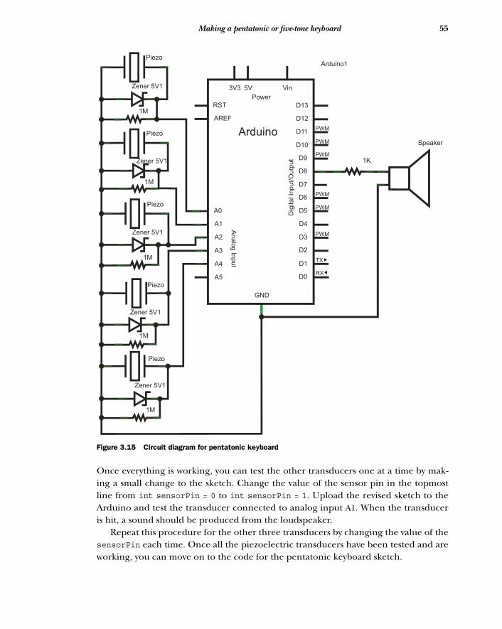
55Making a pentatonic or five-tone keyboard
Once everything is working, you can test the other transducers one at a time by mak-ing a small change to the sketch. Change the value of the sensor pin in the topmostline from int sensorPin = 0 to int sensorPin = 1. Upload the revised sketch to theArduino and test the transducer connected to analog input A1. When the transduceris hit, a sound should be produced from the loudspeaker.
Repeat this procedure for the other three transducers by changing the value of thesensorPin each time. Once all the piezoelectric transducers have been tested and areworking, you can move on to the code for the pentatonic keyboard sketch.
1M
1M
1M
1M
1M
Arduino1
Vin
Power
3V3 5V
RST
AREF
Arduino
D13
D12
D11
D10
D9
D8
D7
D6
D5
D4
D3
D2
D1
D0
GND
A0
A1
A2
A3
A4
A5
Analo
g In
put
Dig
ital In
put/O
utp
ut
PWM
PWM
PWM
PWM
PWM
PWM
TX
RX
Zener 5V1
Zener 5V1
Zener 5V1
Zener 5V1
Zener 5V1
Piezo
Piezo
Piezo
Piezo
Piezo
1K
Speaker
Figure 3.15 Circuit diagram for pentatonic keyboard
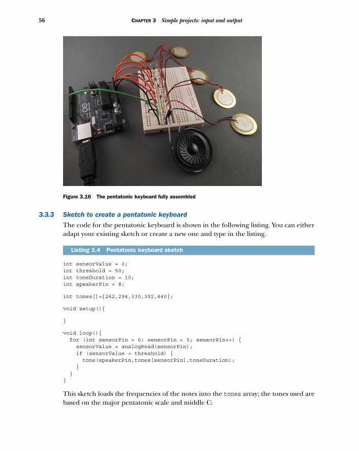
56 CHAPTER 3 Simple projects: input and output
3.3.3 Sketch to create a pentatonic keyboard
The code for the pentatonic keyboard is shown in the following listing. You can eitheradapt your existing sketch or create a new one and type in the listing.
int sensorValue = 0;int threshold = 50;int toneDuration = 10;int speakerPin = 8;
int tones[]={262,294,330,392,440};
void setup(){
}
void loop(){ for (int sensorPin = 0; sensorPin < 5; sensorPin++) { sensorValue = analogRead(sensorPin); if (sensorValue > threshold) { tone(speakerPin,tones[sensorPin],toneDuration); } }}
This sketch loads the frequencies of the notes into the tones array; the tones used arebased on the major pentatonic scale and middle C:
Listing 3.4 Pentatonic keyboard sketch
Figure 3.16 The pentatonic keyboard fully assembled
57Making a pentatonic or five-tone keyboard
■ C = 262 Hz■ D = 294 Hz■ E = 330 Hz■ G = 392 Hz■ A = 440 Hz
The loop routine tests the value of each analog input in turn. When a tap on a piezo-electric transducer is detected, and the value returned is above the threshold value,the corresponding tone is played through the speaker for 10 milliseconds.
NOTE In this sketch, the threshold is set at 50. You previously used a value of200, but we found during testing that one of the transducers needed to be hitmuch harder than the others, so we reduced the threshold to 50, thus makingthe keys more sensitive.
Once all the code has been typed into the sketch, save it with a memorable name. Youcan then move on to uploading and testing your pentatonic keyboard. You might evenwant to try playing a couple of tunes.
3.3.4 Upload and test
Verify that the sketch compiles. When it does, connect the Arduino to your computerand upload the sketch to it. Now you can test that everything is working by tapping thetransducers and making sure each produces a tone. Try playing some simple tunes. Itmight sound a little tinny because you’re only using a small speaker, but you’ve builtyour own working keyboard.
You can alter the notes by changing the frequencies loaded into the tones array.You might try the C minor pentatonic scale with the following values:
■ C = 262 Hz■ E = 311 Hz■ F = 349 Hz■ G = 392 Hz■ B = 466 Hz
By loading different frequencies into the tones array, you can produce very differentsounds and tunes.
The main thing is to have fun and show off your new creation. Using the majorpentatonic scale, try the following note progressions. See if you can recognize thetunes, or better yet, see if someone else can recognize them.
1 GGAGCB GGAGDC—Hint: everybody has one of these each year.2 CDECCDEC EFG EFG—French brother.3 CCGGAAG FFEEDC—Heavenly.
Now try making some of your own note progressions. One of the beauties of using thepentatonic scale is that it’s relatively easy to produce pleasant-sounding melodies.
58 CHAPTER 3 Simple projects: input and output
3.4 SummaryIn this chapter you looked at the analog-input side of the Arduino using analogRead.You experimented by reading values from two separate analog devices, a potentiom-eter and a piezoelectric transducer. You saw how the analog signal is converted to adigital format using an analog-to-digital converter (ADC) that can be interpreted bythe Arduino. This approach allows you to confidently read data from many otheranalog devices.
Your final project in this chapter made extensive use of analogRead, and you builta pentatonic keyboard with five piezoelectric transducers that each produced a differ-ent note when hit. Hopefully you had some fun showing off your musical prowess toanyone who would listen, even if the sound was a little tinny.
In the next chapter, you’ll look at the two main ways of extending the Arduino: thefirst using software libraries that enable the Arduino to communicate with other sen-sors, such as two-wire devices and SPI communication, and the second using hardwareshields that plug directly into the headers of the Arduino. You’ll also look at a coupleof the most common shields.
Part 2
Putting Arduino to work
Part 2 of this book (chapters 4 to 13) looks at the Arduino in more depth, andthis is where you’ll really start to put the Arduino to work, learning a number ofadvanced techniques that you can use in your own projects. This part of thebook includes chapters on using libraries, controlling various motors, using sen-sors and LCD displays, communicating with other devices, connecting to gamecontrollers and iOS devices, creating wearables, building your own Arduinoshields, and integrating with other software packages.

Extending Arduino
In previous chapters, you looked at the digital input and output and analog inputfunctionality of the Arduino, and you constructed a few projects based on this func-tionality, including a reactometer and a pentatonic keyboard. But the Arduino iscapable of much more, and you can also extend its functionality by using softwarelibraries or hardware shields. In this chapter you’re going to learn different ways ofconnecting the Arduino to other devices or equipment.
For example, if you were building an obstacle-avoidance robot that could detectobjects in its path and maneuver around them, the Arduino would be an obviouschoice. There are software libraries and hardware shields readily available that canenable the Arduino to drive motors, connect to infrared or ultrasonic sensors thatdetect objects, and communicate over Wi-Fi.
Let’s get started by learning about software libraries.
This chapter covers■ Software libraries ■ The Arduino core and standard libraries■ Contributed libraries■ Hardware shields■ Some common shields
61
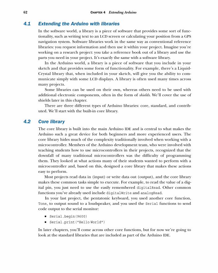
62 CHAPTER 4 Extending Arduino
4.1 Extending the Arduino with libraries In the software world, a library is a piece of software that provides some sort of func-tionality, such as writing text to an LCD screen or calculating your position from a GPSnavigation system. Software libraries work in the same way as conventional referencelibraries: you request information and then use it within your project. Imagine you’reworking on a research project: you take a reference book out of a library and use theparts you need in your project. It’s exactly the same with a software library.
In the Arduino world, a library is a piece of software that you include in yoursketch and that provides some form of functionality. For example, there’s a Liquid-Crystal library that, when included in your sketch, will give you the ability to com-municate simply with some LCD displays. A library is often used many times acrossmany projects.
Some libraries can be used on their own, whereas others need to be used withadditional electronic components, often in the form of shields. We’ll cover the use ofshields later in this chapter.
There are three different types of Arduino libraries: core, standard, and contrib-uted. We’ll start with the built-in core library.
4.2 Core libraryThe core library is built into the main Arduino IDE and is central to what makes theArduino such a great device for both beginners and more experienced users. Thecore library hides much of the complexity traditionally involved when working with amicrocontroller. Members of the Arduino development team, who were involved withteaching students how to use microcontrollers in their projects, recognized that thedownfall of many traditional microcontrollers was the difficulty of programmingthem. They looked at what actions many of their students wanted to perform with amicrocontroller and, based on this, designed a core library that makes these actionseasy to perform.
Most projects read data in (input) or write data out (output), and the core librarymakes these common tasks simple to execute. For example, to read the value of a dig-ital pin, you just need to use the easily remembered digitalRead. Other commonfunctions you’ve already used include digitalWrite and analogRead.
In your last project, the pentatonic keyboard, you used another core function,Tone, to output sound to a loudspeaker, and you used the Serial functions to sendcode output to the serial monitor:
■ Serial.begin(9600)
■ Serial.print("Hello World")
In later chapters, you’ll come across other core functions, but for now we’re going tolook at the standard libraries that are included as part of the Arduino IDE.

63Standard libraries
4.3 Standard librariesWhen you downloaded and installed the Arduino IDE, some standard libraries wereincluded with the installation. The standard libraries are ones that the Arduino devel-opment team thinks will be needed by many people in their own projects. They aren’tincluded by default in your projects like the core library, because the Arduino has lim-ited resources; automatically including the libraries would be a waste of these resources,leaving little room for code in your own sketches.
To use the standard libraries, you have to explicitly include them in your sketches.To do so, you need to add an include statement at the top of your sketch. For exam-ple, if you wanted to include the LiquidCrystal library, which is used to display data onan LCD screen, you would place the following at the top of your sketch:
#include <LiquidCrystal.h>
NOTE The name of the library is bounded by angle brackets: < and >. Also,the line doesn’t end with a semicolon (;) as is usual.
The standard libraries are described in the following sections:
■ ArduinoTestSuite library■ EEPROM library■ SD library■ Ethernet library■ Firmata library■ LiquidCrystal library■ Servo library■ Stepper library■ SPI library■ Wire library■ SoftwareSerial library
We’ll also revisit some of these libraries in later chapters, where we’ll go into muchmore detail about them.
4.3.1 Test-driven development with ArduinoTestSuite
The ways that code and sketches are written and developed are always evolving, andhopefully improving. One of the more recent innovations is a software process calledtest-driven development (TDD).
In TDD, a software project is split into small pieces, and before you write any of thepieces of code, you first write tests, with each test checking a particular function.When you write the code, it’s run against the tests and must pass for that piece to workcorrectly; if it doesn’t pass, you correct any errors and test the code again. When thepiece of code passes its tests, you repeat the process for the next piece of code. Thiscontinues until the project is finished. If a change is made to a piece of code at a later
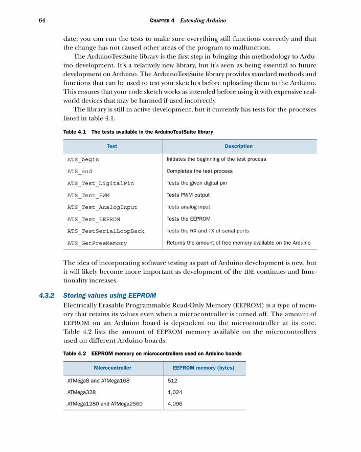
64 CHAPTER 4 Extending Arduino
date, you can run the tests to make sure everything still functions correctly and thatthe change has not caused other areas of the program to malfunction.
The ArduinoTestSuite library is the first step in bringing this methodology to Ardu-ino development. It’s a relatively new library, but it’s seen as being essential to futuredevelopment on Arduino. The ArduinoTestSuite library provides standard methods andfunctions that can be used to test your sketches before uploading them to the Arduino.This ensures that your code sketch works as intended before using it with expensive real-world devices that may be harmed if used incorrectly.
The library is still in active development, but it currently has tests for the processeslisted in table 4.1.
The idea of incorporating software testing as part of Arduino development is new, butit will likely become more important as development of the IDE continues and func-tionality increases.
4.3.2 Storing values using EEPROMElectrically Erasable Programmable Read-Only Memory (EEPROM) is a type of mem-ory that retains its values even when a microcontroller is turned off. The amount ofEEPROM on an Arduino board is dependent on the microcontroller at its core.Table 4.2 lists the amount of EEPROM memory available on the microcontrollersused on different Arduino boards.
Table 4.1 The tests available in the ArduinoTestSuite library
Test Description
ATS_begin Initiates the beginning of the test process
ATS_end Completes the test process
ATS_Test_DigitalPin Tests the given digital pin
ATS_Test_PWM Tests PWM output
ATS_Test_AnalogInput Tests analog input
ATS_Test_EEPROM Tests the EEPROM
ATS_TestSerialLoopBack Tests the RX and TX of serial ports
ATS_GetFreeMemory Returns the amount of free memory available on the Arduino
Table 4.2 EEPROM memory on microcontrollers used on Arduino boards
Microcontroller EEPROM memory (bytes)
ATMega8 and ATMega168 512
ATMega328 1,024
ATMega1280 and ATMega2560 4,096
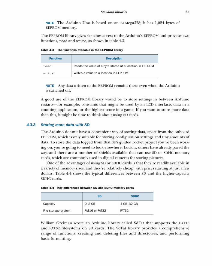
65Standard libraries
NOTE The Arduino Uno is based on an ATMega328; it has 1,024 bytes ofEEPROM memory.
The EEPROM library gives sketches access to the Arduino’s EEPROM and provides twofunctions, read and write, as shown in table 4.3.
NOTE Any data written to the EEPROM remains there even when the Arduinois switched off.
A good use of the EEPROM library would be to store settings in between Arduinorestarts—for example, constants that might be used by an LCD interface, data in acounting application, or the highest score in a game. If you want to store more datathan this, it might be time to think about using SD cards.
4.3.3 Storing more data with SD
The Arduino doesn’t have a convenient way of storing data, apart from the onboardEEPROM, which is only suitable for storing configuration settings and tiny amounts ofdata. To store the data logged from that GPS guided rocket project you’ve been work-ing on, you’re going to need to look elsewhere. Luckily, others have already paved theway, and there are a number of shields available that can use SD or SDHC memorycards, which are commonly used in digital cameras for storing pictures.
One of the advantages of using SD or SDHC cards is that they’re readily available ina variety of memory sizes, and they’re relatively cheap, with prices starting at just a fewdollars. Table 4.4 shows the typical differences between SD and the higher-capacitySDHC cards.
William Greiman wrote an Arduino library called SdFat that supports the FAT16and FAT32 filesystems on SD cards. The SdFat library provides a comprehensiverange of functions: creating and deleting files and directories, and performingbasic formatting.
Table 4.3 The functions available in the EEPROM library
Function Description
read Reads the value of a byte stored at a location in EEPROM
write Writes a value to a location in EEPROM
Table 4.4 Key differences between SD and SDHC memory cards
SD SDHC
Capacity 0–2 GB 4 GB–32 GB
File storage system FAT16 or FAT32 FAT32
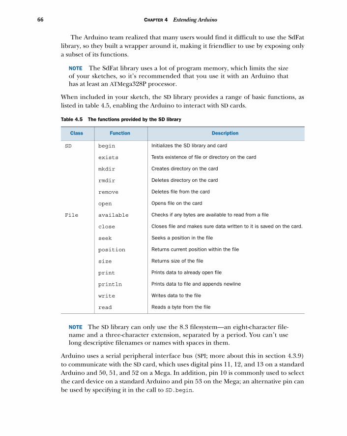
66 CHAPTER 4 Extending Arduino
The Arduino team realized that many users would find it difficult to use the SdFatlibrary, so they built a wrapper around it, making it friendlier to use by exposing onlya subset of its functions.
NOTE The SdFat library uses a lot of program memory, which limits the sizeof your sketches, so it’s recommended that you use it with an Arduino thathas at least an ATMega328P processor.
When included in your sketch, the SD library provides a range of basic functions, aslisted in table 4.5, enabling the Arduino to interact with SD cards.
NOTE The SD library can only use the 8.3 filesystem—an eight-character file-name and a three-character extension, separated by a period. You can’t uselong descriptive filenames or names with spaces in them.
Arduino uses a serial peripheral interface bus (SPI; more about this in section 4.3.9)to communicate with the SD card, which uses digital pins 11, 12, and 13 on a standardArduino and 50, 51, and 52 on a Mega. In addition, pin 10 is commonly used to selectthe card device on a standard Arduino and pin 53 on the Mega; an alternative pin canbe used by specifying it in the call to SD.begin.
Table 4.5 The functions provided by the SD library
Class Function Description
SD begin Initializes the SD library and card
exists Tests existence of file or directory on the card
mkdir Creates directory on the card
rmdir Deletes directory on the card
remove Deletes file from the card
open Opens file on the card
File available Checks if any bytes are available to read from a file
close Closes file and makes sure data written to it is saved on the card.
seek Seeks a position in the file
position Returns current position within the file
size Returns size of the file
print Prints data to already open file
println Prints data to file and appends newline
write Writes data to the file
read Reads a byte from the file
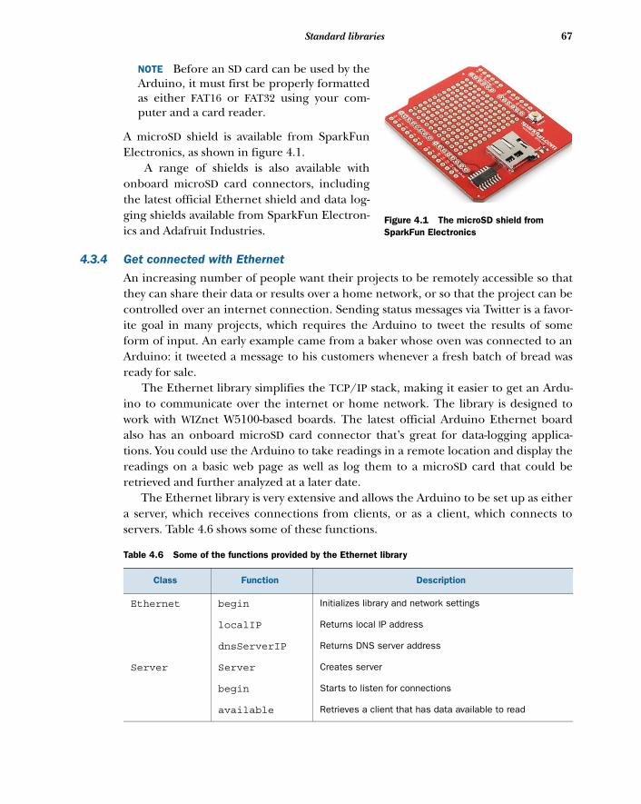
67Standard libraries
NOTE Before an SD card can be used by theArduino, it must first be properly formattedas either FAT16 or FAT32 using your com-puter and a card reader.
A microSD shield is available from SparkFunElectronics, as shown in figure 4.1.
A range of shields is also available withonboard microSD card connectors, includingthe latest official Ethernet shield and data log-ging shields available from SparkFun Electron-ics and Adafruit Industries.
4.3.4 Get connected with Ethernet
An increasing number of people want their projects to be remotely accessible so thatthey can share their data or results over a home network, or so that the project can becontrolled over an internet connection. Sending status messages via Twitter is a favor-ite goal in many projects, which requires the Arduino to tweet the results of someform of input. An early example came from a baker whose oven was connected to anArduino: it tweeted a message to his customers whenever a fresh batch of bread wasready for sale.
The Ethernet library simplifies the TCP/IP stack, making it easier to get an Ardu-ino to communicate over the internet or home network. The library is designed towork with WIZnet W5100-based boards. The latest official Arduino Ethernet boardalso has an onboard microSD card connector that’s great for data-logging applica-tions. You could use the Arduino to take readings in a remote location and display thereadings on a basic web page as well as log them to a microSD card that could beretrieved and further analyzed at a later date.
The Ethernet library is very extensive and allows the Arduino to be set up as eithera server, which receives connections from clients, or as a client, which connects toservers. Table 4.6 shows some of these functions.
Table 4.6 Some of the functions provided by the Ethernet library
Class Function Description
Ethernet begin Initializes library and network settings
localIP Returns local IP address
dnsServerIP Returns DNS server address
Server Server Creates server
begin Starts to listen for connections
available Retrieves a client that has data available to read
Figure 4.1 The microSD shield from SparkFun Electronics
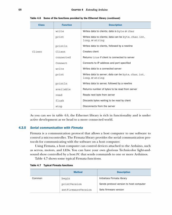
68 CHAPTER 4 Extending Arduino
As you can see in table 4.6, the Ethernet library is rich in functionality and is underactive development as we head to a more connected world.
4.3.5 Serial communication with Firmata
Firmata is a communication protocol that allows a host computer to use software tocontrol a microcontroller. The Firmata library provides the serial communication pro-tocols for communicating with the software on a host computer.
Using Firmata, a host computer can control devices attached to the Arduino, suchas servos, motors, and LEDs. You can have your own glorious Technicolor light-and-sound show controlled by a host PC that sends commands to one or more Arduinos.
Table 4.7 shows some typical Firmata functions.
write Writes data to clients; data is byte or char
print Writes data to clients; data can be byte, char, int, long, or string
println Writes data to clients, followed by a newline
Client Client Creates client
connected Returns true if client is connected to server
Connect Connects to IP address and port specified
write Writes data to a connected server
print Writes data to server; data can be byte, char, int, long, or string
println Writes data to server, followed by a newline
available Returns number of bytes to be read from server
read Reads next byte from server
flush Discards bytes waiting to be read by client
stop Disconnects from the server
Table 4.7 Typical Firmata functions
Method Description
Common begin Initializes Firmata library
printVersion Sends protocol version to host computer
setFirmwareVersion Sets firmware version
Table 4.6 Some of the functions provided by the Ethernet library (continued)
Class Function Description
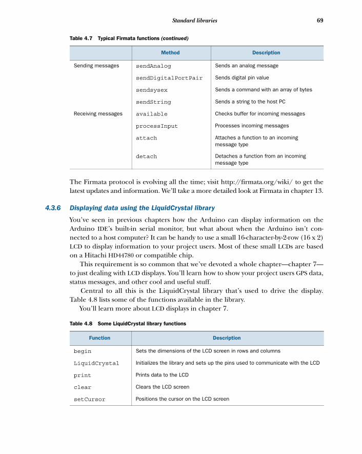
69Standard libraries
The Firmata protocol is evolving all the time; visit http://firmata.org/wiki/ to get thelatest updates and information. We’ll take a more detailed look at Firmata in chapter 13.
4.3.6 Displaying data using the LiquidCrystal library
You’ve seen in previous chapters how the Arduino can display information on theArduino IDE’s built-in serial monitor, but what about when the Arduino isn’t con-nected to a host computer? It can be handy to use a small 16-character-by-2-row (16 x 2)LCD to display information to your project users. Most of these small LCDs are basedon a Hitachi HD44780 or compatible chip.
This requirement is so common that we’ve devoted a whole chapter—chapter 7—to just dealing with LCD displays. You’ll learn how to show your project users GPS data,status messages, and other cool and useful stuff.
Central to all this is the LiquidCrystal library that’s used to drive the display.Table 4.8 lists some of the functions available in the library.
You’ll learn more about LCD displays in chapter 7.
Sending messages sendAnalog Sends an analog message
sendDigitalPortPair Sends digital pin value
sendsysex Sends a command with an array of bytes
sendString Sends a string to the host PC
Receiving messages available Checks buffer for incoming messages
processInput Processes incoming messages
attach Attaches a function to an incoming message type
detach Detaches a function from an incoming message type
Table 4.8 Some LiquidCrystal library functions
Function Description
begin Sets the dimensions of the LCD screen in rows and columns
LiquidCrystal Initializes the library and sets up the pins used to communicate with the LCD
print Prints data to the LCD
clear Clears the LCD screen
setCursor Positions the cursor on the LCD screen
Table 4.7 Typical Firmata functions (continued)
Method Description
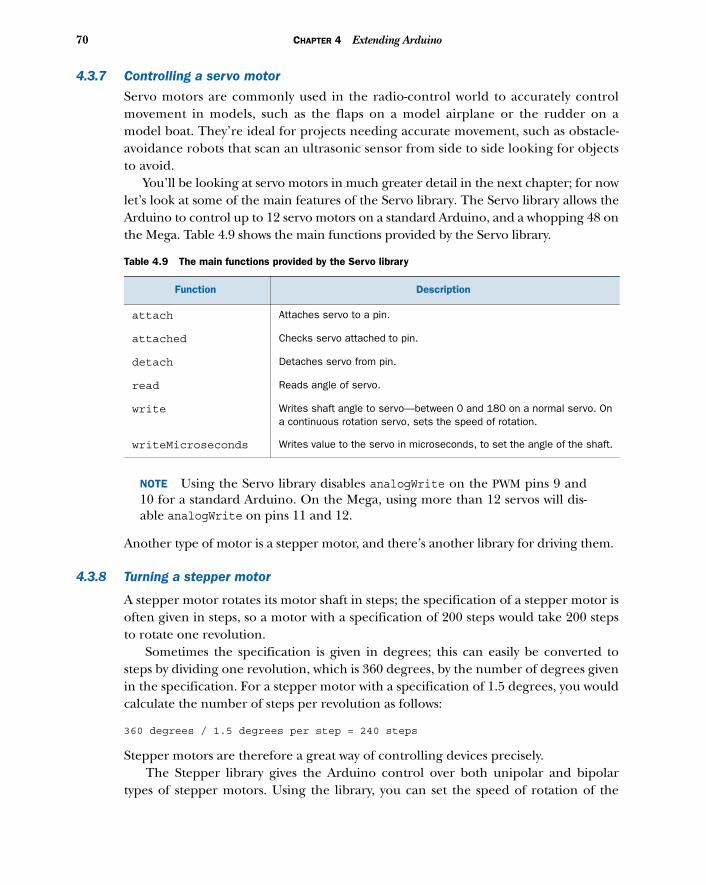
70 CHAPTER 4 Extending Arduino
4.3.7 Controlling a servo motor
Servo motors are commonly used in the radio-control world to accurately controlmovement in models, such as the flaps on a model airplane or the rudder on amodel boat. They’re ideal for projects needing accurate movement, such as obstacle-avoidance robots that scan an ultrasonic sensor from side to side looking for objectsto avoid.
You’ll be looking at servo motors in much greater detail in the next chapter; for nowlet’s look at some of the main features of the Servo library. The Servo library allows theArduino to control up to 12 servo motors on a standard Arduino, and a whopping 48 onthe Mega. Table 4.9 shows the main functions provided by the Servo library.
NOTE Using the Servo library disables analogWrite on the PWM pins 9 and10 for a standard Arduino. On the Mega, using more than 12 servos will dis-able analogWrite on pins 11 and 12.
Another type of motor is a stepper motor, and there’s another library for driving them.
4.3.8 Turning a stepper motor
A stepper motor rotates its motor shaft in steps; the specification of a stepper motor isoften given in steps, so a motor with a specification of 200 steps would take 200 stepsto rotate one revolution.
Sometimes the specification is given in degrees; this can easily be converted tosteps by dividing one revolution, which is 360 degrees, by the number of degrees givenin the specification. For a stepper motor with a specification of 1.5 degrees, you wouldcalculate the number of steps per revolution as follows:
360 degrees / 1.5 degrees per step = 240 steps
Stepper motors are therefore a great way of controlling devices precisely. The Stepper library gives the Arduino control over both unipolar and bipolar
types of stepper motors. Using the library, you can set the speed of rotation of the
Table 4.9 The main functions provided by the Servo library
Function Description
attach Attaches servo to a pin.
attached Checks servo attached to pin.
detach Detaches servo from pin.
read Reads angle of servo.
write Writes shaft angle to servo—between 0 and 180 on a normal servo. On a continuous rotation servo, sets the speed of rotation.
writeMicroseconds Writes value to the servo in microseconds, to set the angle of the shaft.
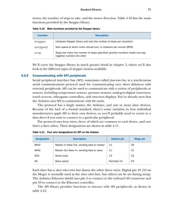
71Standard libraries
motor, the number of steps to take, and the motor direction. Table 4.10 lists the mainfunctions provided by the Stepper library.
We’ll cover the Stepper library in much greater detail in chapter 5, where we’ll alsolook at the different types of stepper motors available.
4.3.9 Communicating with SPI peripheralsSerial peripheral interface bus (SPI), sometimes called four-wire bus, is a synchronousserial communications protocol used for communicating over short distances withexternal peripherals. SPI can be used to communicate with a variety of peripherals orsensors, including temperature sensors, pressure sensors, analog-to-digital converters,touch screens, videogame controllers, and onscreen displays. You’ve already seen thatthe Arduino uses SPI to communicate with SD cards.
The protocol has a single master, the Arduino, and one or more slave devices.Because of the lack of a formal standard, there’s some variation in how individualmanufacturers apply SPI to their own devices, so you’ll probably need to resort to adata sheet if you want to connect to a particular peripheral.
The protocol uses four wires, three of which are common to each device, and onethat’s a slave select. Their designations are shown in table 4.11.
Each slave has a slave select wire but shares the other three wires. Digital pin 10 (53 onthe Mega) is normally used as the slave select line, but others can be set during setup.The Arduino Ethernet shield uses pin 4 to connect to the onboard SD connector andpin 10 to connect to the Ethernet controller.
The SPI library provides functions to interact with SPI peripherals, as shown intable 4.12.
Table 4.10 Main functions provided by the Stepper library
Function Description
Stepper Initializes Stepper library and sets the number of steps per revolution
setSpeed Sets speed at which motor should turn, in rotations per minute (RPM)
step Steps the motor the number of steps specified; positive numbers rotate one way, negative numbers the other
Table 4.11 Four wire designations for SPI on the Arduino
Designation Description Arduino pin Mega pin
MISO Master In Slave Out, sending data to master 12 50
MOSI Master Out Slave In, sending data to slave 11 51
SCK Serial clock 13 52
SS Slave select Normally 10 53
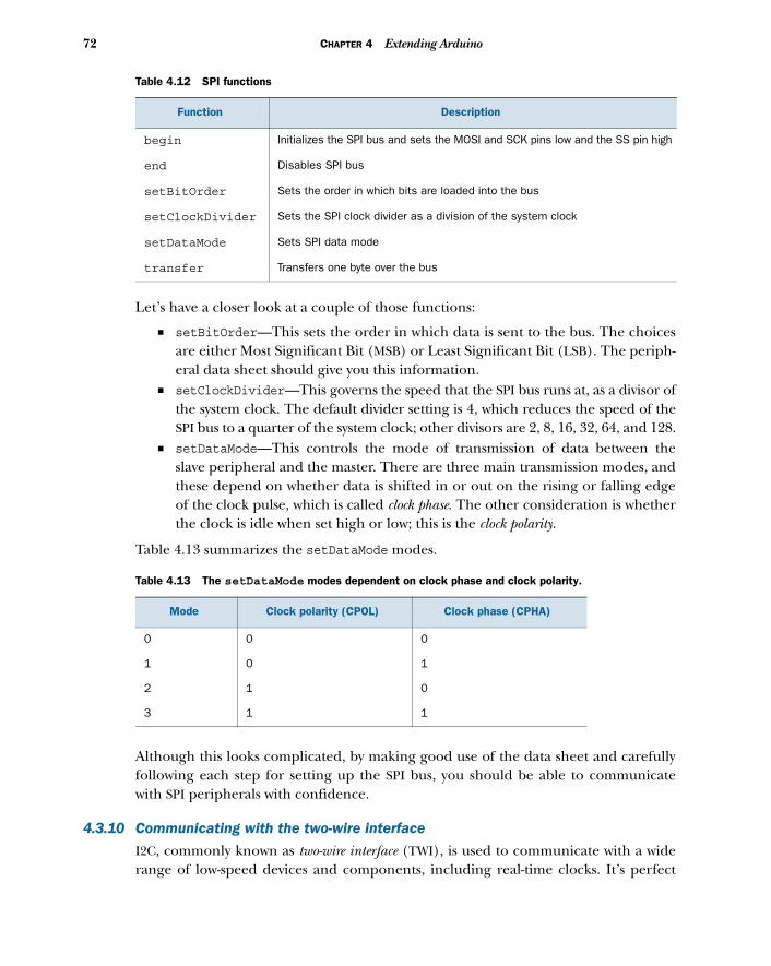
72 CHAPTER 4 Extending Arduino
Let’s have a closer look at a couple of those functions:
■ setBitOrder—This sets the order in which data is sent to the bus. The choicesare either Most Significant Bit (MSB) or Least Significant Bit (LSB). The periph-eral data sheet should give you this information.
■ setClockDivider—This governs the speed that the SPI bus runs at, as a divisor ofthe system clock. The default divider setting is 4, which reduces the speed of theSPI bus to a quarter of the system clock; other divisors are 2, 8, 16, 32, 64, and 128.
■ setDataMode—This controls the mode of transmission of data between theslave peripheral and the master. There are three main transmission modes, andthese depend on whether data is shifted in or out on the rising or falling edgeof the clock pulse, which is called clock phase. The other consideration is whetherthe clock is idle when set high or low; this is the clock polarity.
Table 4.13 summarizes the setDataMode modes.
Although this looks complicated, by making good use of the data sheet and carefullyfollowing each step for setting up the SPI bus, you should be able to communicatewith SPI peripherals with confidence.
4.3.10 Communicating with the two-wire interface
I2C, commonly known as two-wire interface (TWI), is used to communicate with a widerange of low-speed devices and components, including real-time clocks. It’s perfect
Table 4.12 SPI functions
Function Description
begin Initializes the SPI bus and sets the MOSI and SCK pins low and the SS pin high
end Disables SPI bus
setBitOrder Sets the order in which bits are loaded into the bus
setClockDivider Sets the SPI clock divider as a division of the system clock
setDataMode Sets SPI data mode
transfer Transfers one byte over the bus
Table 4.13 The setDataMode modes dependent on clock phase and clock polarity.
Mode Clock polarity (CPOL) Clock phase (CPHA)
0 0 0
1 0 1
2 1 0
3 1 1
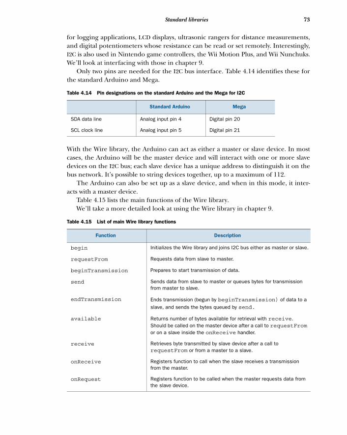
73Standard libraries
for logging applications, LCD displays, ultrasonic rangers for distance measurements,and digital potentiometers whose resistance can be read or set remotely. Interestingly,I2C is also used in Nintendo game controllers, the Wii Motion Plus, and Wii Nunchuks.We’ll look at interfacing with those in chapter 9.
Only two pins are needed for the I2C bus interface. Table 4.14 identifies these forthe standard Arduino and Mega.
With the Wire library, the Arduino can act as either a master or slave device. In mostcases, the Arduino will be the master device and will interact with one or more slavedevices on the I2C bus; each slave device has a unique address to distinguish it on thebus network. It’s possible to string devices together, up to a maximum of 112.
The Arduino can also be set up as a slave device, and when in this mode, it inter-acts with a master device.
Table 4.15 lists the main functions of the Wire library. We’ll take a more detailed look at using the Wire library in chapter 9.
Table 4.14 Pin designations on the standard Arduino and the Mega for I2C
Standard Arduino Mega
SDA data line Analog input pin 4 Digital pin 20
SCL clock line Analog input pin 5 Digital pin 21
Table 4.15 List of main Wire library functions
Function Description
begin Initializes the Wire library and joins I2C bus either as master or slave.
requestFrom Requests data from slave to master.
beginTransmission Prepares to start transmission of data.
send Sends data from slave to master or queues bytes for transmission from master to slave.
endTransmission Ends transmission (begun by beginTransmission) of data to a slave, and sends the bytes queued by send.
available Returns number of bytes available for retrieval with receive. Should be called on the master device after a call to requestFromor on a slave inside the onReceive handler.
receive Retrieves byte transmitted by slave device after a call to requestFrom or from a master to a slave.
onReceive Registers function to call when the slave receives a transmission from the master.
onRequest Registers function to be called when the master requests data from the slave device.
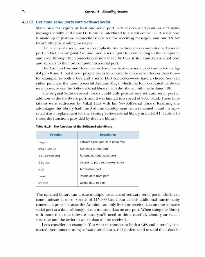
74 CHAPTER 4 Extending Arduino
4.3.11 Get more serial ports with SoftwareSerial
Many projects require at least one serial port. GPS devices send position and statusmessages serially, and some LCDs can be interfaced to a serial controller. A serial portis made up of just two connections: one RX for receiving messages, and one TX fortransmitting or sending messages.
The beauty of a serial port is its simplicity. At one time every computer had a serialport; in fact, the original Arduino used a serial port for connecting to the computer,and even through the connection is now made by USB, it still emulates a serial portand appears to the host computer as a serial port.
The Arduino Uno and Duemilanove have one hardware serial port connected to dig-ital pins 0 and 1, but if your project needs to connect to more serial devices than this—for example, to both a GPS and a serial LCD controller—you have a choice. You caneither purchase the more powerful Arduino Mega, which has four dedicated hardwareserial ports, or use the SoftwareSerial library that’s distributed with the Arduino IDE.
The original SoftwareSerial library could only provide one software serial port inaddition to the hardware port, and it was limited to a speed of 9600 baud. These limi-tations were addressed by Mikal Hart with his NewSoftSerial library. Realizing theadvantages this library had, the Arduino development team renamed it and incorpo-rated it as a replacement for the existing SoftwareSerial library in mid-2011. Table 4.16shows the functions provided by the new library.
The updated library can create multiple instances of software serial ports, which cancommunicate at up to speeds of 115,000 baud. But all this additional functionalitycomes at a price, because the Arduino can only listen or receive data on one softwareserial port at a time, although it can transmit data on any port. When using the librarywith more than one software port, you’ll need to think carefully about your sketchstructure and the order in which data will be received.
Let’s consider an example: You want to connect to both a GPS and a serially con-nected thermometer using software serial ports. GPS devices tend to send their data in
Table 4.16 The functions of the SoftwareSerial library
Function Description
begin Activates port and sets baud rate
available Switches to that port
isListening Returns current active port
listen Listens to port and makes active
end Terminates port
read Reads data from port
write Writes data to port
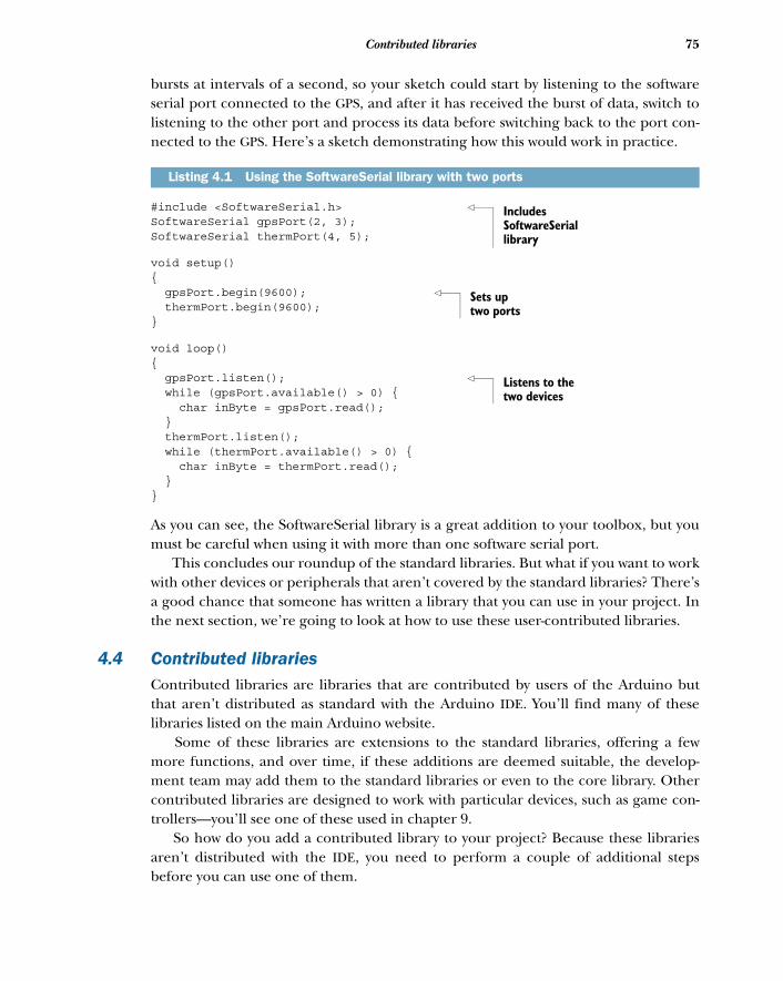
75Contributed libraries
bursts at intervals of a second, so your sketch could start by listening to the softwareserial port connected to the GPS, and after it has received the burst of data, switch tolistening to the other port and process its data before switching back to the port con-nected to the GPS. Here’s a sketch demonstrating how this would work in practice.
#include <SoftwareSerial.h> SoftwareSerial gpsPort(2, 3);SoftwareSerial thermPort(4, 5);
void setup(){ gpsPort.begin(9600); thermPort.begin(9600);}
void loop(){ gpsPort.listen(); while (gpsPort.available() > 0) { char inByte = gpsPort.read(); } thermPort.listen(); while (thermPort.available() > 0) { char inByte = thermPort.read(); }}
As you can see, the SoftwareSerial library is a great addition to your toolbox, but youmust be careful when using it with more than one software serial port.
This concludes our roundup of the standard libraries. But what if you want to workwith other devices or peripherals that aren’t covered by the standard libraries? There’sa good chance that someone has written a library that you can use in your project. Inthe next section, we’re going to look at how to use these user-contributed libraries.
4.4 Contributed librariesContributed libraries are libraries that are contributed by users of the Arduino butthat aren’t distributed as standard with the Arduino IDE. You’ll find many of theselibraries listed on the main Arduino website.
Some of these libraries are extensions to the standard libraries, offering a fewmore functions, and over time, if these additions are deemed suitable, the develop-ment team may add them to the standard libraries or even to the core library. Othercontributed libraries are designed to work with particular devices, such as game con-trollers—you’ll see one of these used in chapter 9.
So how do you add a contributed library to your project? Because these librariesaren’t distributed with the IDE, you need to perform a couple of additional stepsbefore you can use one of them.
Listing 4.1 Using the SoftwareSerial library with two ports
Includes SoftwareSerial library
Sets up two ports
Listens to the two devices
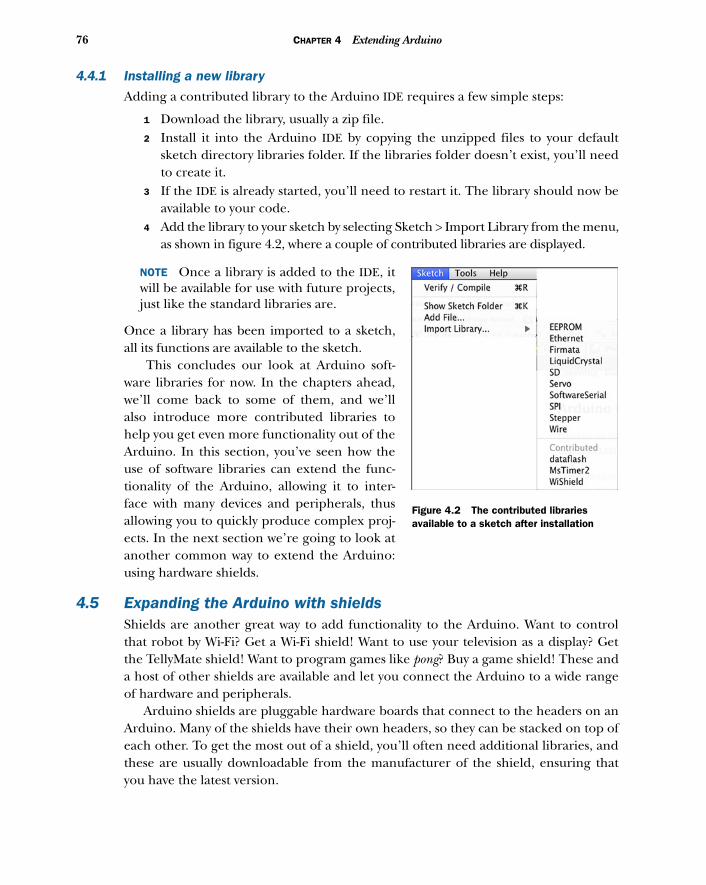
76 CHAPTER 4 Extending Arduino
4.4.1 Installing a new library
Adding a contributed library to the Arduino IDE requires a few simple steps:
1 Download the library, usually a zip file.2 Install it into the Arduino IDE by copying the unzipped files to your default
sketch directory libraries folder. If the libraries folder doesn’t exist, you’ll needto create it.
3 If the IDE is already started, you’ll need to restart it. The library should now beavailable to your code.
4 Add the library to your sketch by selecting Sketch > Import Library from the menu,as shown in figure 4.2, where a couple of contributed libraries are displayed.
NOTE Once a library is added to the IDE, itwill be available for use with future projects,just like the standard libraries are.
Once a library has been imported to a sketch,all its functions are available to the sketch.
This concludes our look at Arduino soft-ware libraries for now. In the chapters ahead,we’ll come back to some of them, and we’llalso introduce more contributed libraries tohelp you get even more functionality out of theArduino. In this section, you’ve seen how theuse of software libraries can extend the func-tionality of the Arduino, allowing it to inter-face with many devices and peripherals, thusallowing you to quickly produce complex proj-ects. In the next section we’re going to look atanother common way to extend the Arduino:using hardware shields.
4.5 Expanding the Arduino with shieldsShields are another great way to add functionality to the Arduino. Want to controlthat robot by Wi-Fi? Get a Wi-Fi shield! Want to use your television as a display? Getthe TellyMate shield! Want to program games like pong? Buy a game shield! These anda host of other shields are available and let you connect the Arduino to a wide rangeof hardware and peripherals.
Arduino shields are pluggable hardware boards that connect to the headers on anArduino. Many of the shields have their own headers, so they can be stacked on top ofeach other. To get the most out of a shield, you’ll often need additional libraries, andthese are usually downloadable from the manufacturer of the shield, ensuring thatyou have the latest version.
Figure 4.2 The contributed libraries available to a sketch after installation
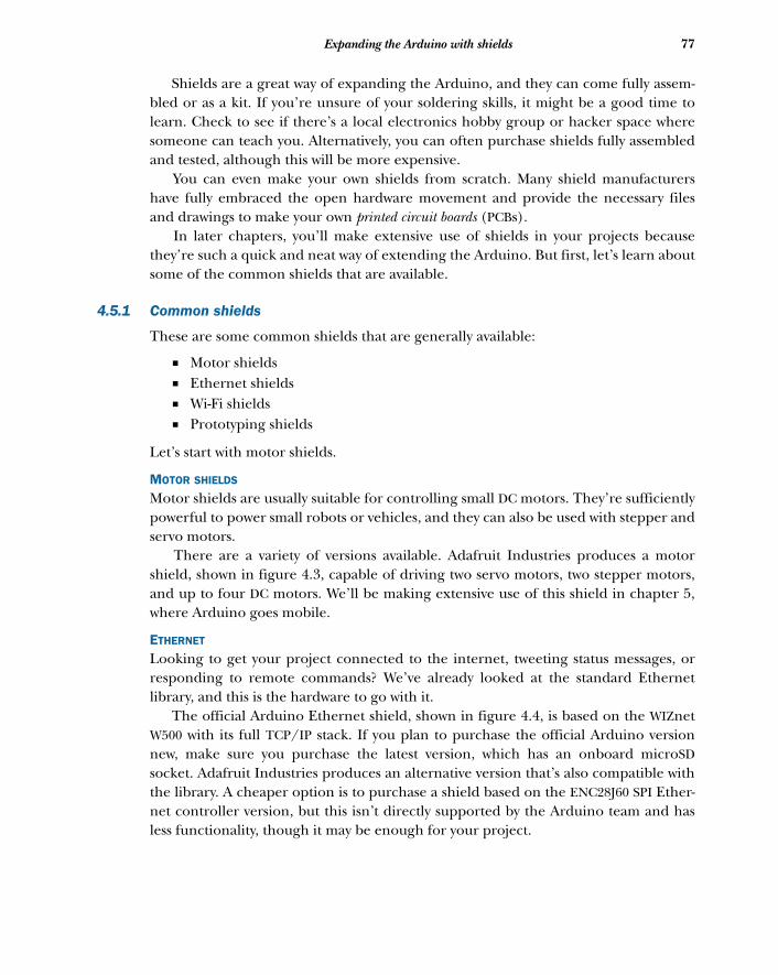
77Expanding the Arduino with shields
Shields are a great way of expanding the Arduino, and they can come fully assem-bled or as a kit. If you’re unsure of your soldering skills, it might be a good time tolearn. Check to see if there’s a local electronics hobby group or hacker space wheresomeone can teach you. Alternatively, you can often purchase shields fully assembledand tested, although this will be more expensive.
You can even make your own shields from scratch. Many shield manufacturershave fully embraced the open hardware movement and provide the necessary filesand drawings to make your own printed circuit boards (PCBs).
In later chapters, you’ll make extensive use of shields in your projects becausethey’re such a quick and neat way of extending the Arduino. But first, let’s learn aboutsome of the common shields that are available.
4.5.1 Common shields
These are some common shields that are generally available:
■ Motor shields■ Ethernet shields■ Wi-Fi shields■ Prototyping shields
Let’s start with motor shields.
MOTOR SHIELDS
Motor shields are usually suitable for controlling small DC motors. They’re sufficientlypowerful to power small robots or vehicles, and they can also be used with stepper andservo motors.
There are a variety of versions available. Adafruit Industries produces a motorshield, shown in figure 4.3, capable of driving two servo motors, two stepper motors,and up to four DC motors. We’ll be making extensive use of this shield in chapter 5,where Arduino goes mobile.
ETHERNET
Looking to get your project connected to the internet, tweeting status messages, orresponding to remote commands? We’ve already looked at the standard Ethernetlibrary, and this is the hardware to go with it.
The official Arduino Ethernet shield, shown in figure 4.4, is based on the WIZnetW500 with its full TCP/IP stack. If you plan to purchase the official Arduino versionnew, make sure you purchase the latest version, which has an onboard microSDsocket. Adafruit Industries produces an alternative version that’s also compatible withthe library. A cheaper option is to purchase a shield based on the ENC28J60 SPI Ether-net controller version, but this isn’t directly supported by the Arduino team and hasless functionality, though it may be enough for your project.
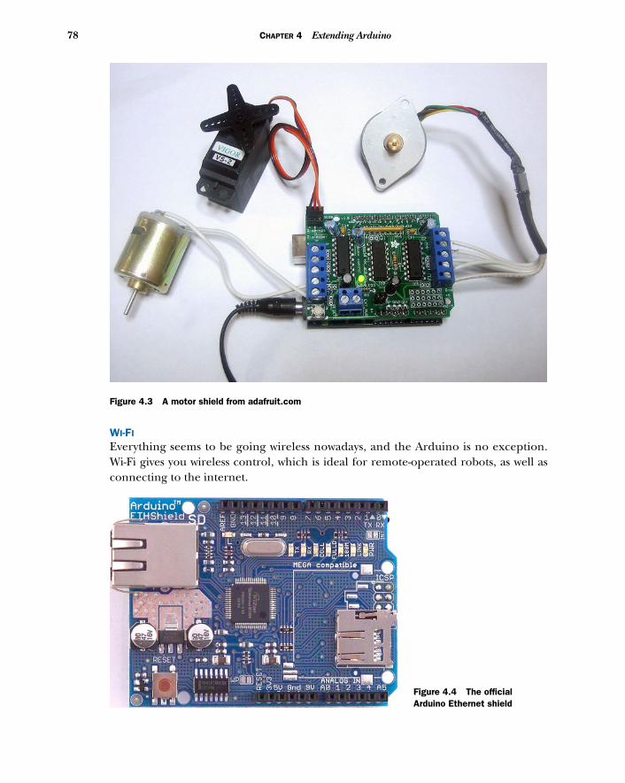
78 CHAPTER 4 Extending Arduino
WI-FI
Everything seems to be going wireless nowadays, and the Arduino is no exception.Wi-Fi gives you wireless control, which is ideal for remote-operated robots, as well asconnecting to the internet.
Figure 4.3 A motor shield from adafruit.com
Figure 4.4 The official Arduino Ethernet shield
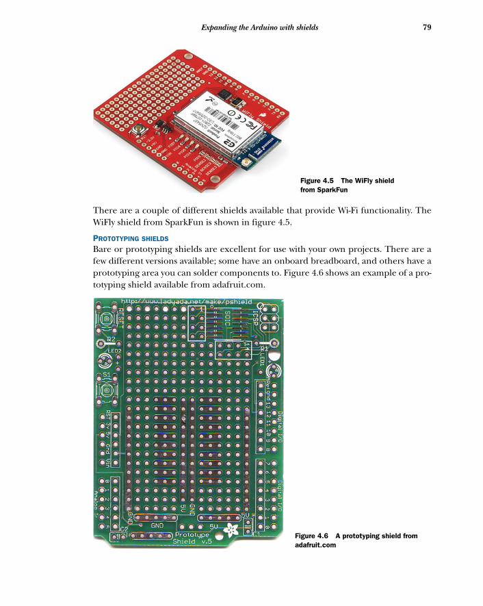
79Expanding the Arduino with shields
There are a couple of different shields available that provide Wi-Fi functionality. TheWiFly shield from SparkFun is shown in figure 4.5.
PROTOTYPING SHIELDS
Bare or prototyping shields are excellent for use with your own projects. There are afew different versions available; some have an onboard breadboard, and others have aprototyping area you can solder components to. Figure 4.6 shows an example of a pro-totyping shield available from adafruit.com.
Figure 4.5 The WiFly shield from SparkFun
Figure 4.6 A prototyping shield from adafruit.com
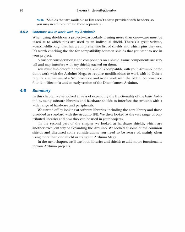
80 CHAPTER 4 Extending Arduino
NOTE Shields that are available as kits aren’t always provided with headers, soyou may need to purchase these separately.
4.5.2 Gotchas: will it work with my Arduino?
When using shields on a project—particularly if using more than one—care must betaken as to which pins are used by an individual shield. There’s a great website,www.shieldlist.org, that has a comprehensive list of shields and which pins they use.It’s worth checking the site for compatibility between shields that you want to use inyour project.
A further consideration is the components on a shield. Some components are verytall and may interfere with any shields stacked on them.
You must also determine whether a shield is compatible with your Arduino. Somedon’t work with the Arduino Mega or require modifications to work with it. Othersrequire a minimum of a 328 processor and won’t work with the older 168 processorfound in Diecimila and an early version of the Duemilanove Arduino.
4.6 SummaryIn this chapter, we’ve looked at ways of expanding the functionality of the basic Ardu-ino by using software libraries and hardware shields to interface the Arduino with awide range of hardware and peripherals.
We started off by looking at software libraries, including the core library and thoseprovided as standard with the Arduino IDE. We then looked at the vast range of con-tributed libraries and how they can be used in your projects.
In the second part of the chapter we looked at hardware shields, which areanother excellent way of expanding the Arduino. We looked at some of the commonshields and discussed some considerations you need to be aware of, mainly whenusing more than one shield or using the Arduino Mega.
In the next chapter, we’ll use both libraries and shields to add motor functionalityto your Arduino projects.
Arduino in motion
Earlier chapters provided you with a strong foundation for using the Arduino tocommunicate in the digital and analog worlds. You’ve built and developed a smallnumber of projects from start to finish that have demonstrated these principles.You’ve also explored how to use libraries and shields to extend the basic functional-ity of the Arduino and enable it to work with an increasingly wide range of devices.
It’s now time to consider the ways that the Arduino can be used in your ownprojects, whether it’s a tweeting bread oven, an internet remote-controlled robot,or an automatic cat door. This and successive chapters will give you the tools andtechniques to achieve these goals.
Starting with this chapter, you’re going to look at ways of adding mobility to aproject. You’ll examine different ways of controlling a variety of off-the-shelf motors
This chapter covers■ Connecting to small DC motors■ Reverse and speed control of DC motors■ Stepper motors■ Servomotors■ Brushless motors■ Using a purpose-designed motor shield
81
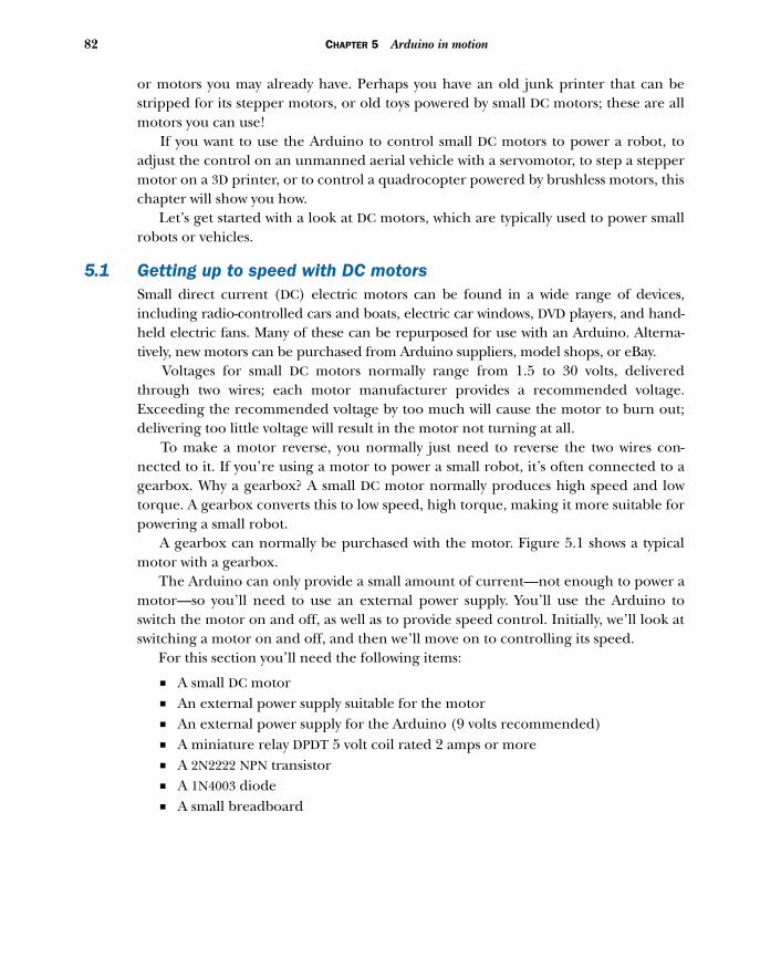
82 CHAPTER 5 Arduino in motion
or motors you may already have. Perhaps you have an old junk printer that can bestripped for its stepper motors, or old toys powered by small DC motors; these are allmotors you can use!
If you want to use the Arduino to control small DC motors to power a robot, toadjust the control on an unmanned aerial vehicle with a servomotor, to step a steppermotor on a 3D printer, or to control a quadrocopter powered by brushless motors, thischapter will show you how.
Let’s get started with a look at DC motors, which are typically used to power smallrobots or vehicles.
5.1 Getting up to speed with DC motorsSmall direct current (DC) electric motors can be found in a wide range of devices,including radio-controlled cars and boats, electric car windows, DVD players, and hand-held electric fans. Many of these can be repurposed for use with an Arduino. Alterna-tively, new motors can be purchased from Arduino suppliers, model shops, or eBay.
Voltages for small DC motors normally range from 1.5 to 30 volts, deliveredthrough two wires; each motor manufacturer provides a recommended voltage.Exceeding the recommended voltage by too much will cause the motor to burn out;delivering too little voltage will result in the motor not turning at all.
To make a motor reverse, you normally just need to reverse the two wires con-nected to it. If you’re using a motor to power a small robot, it’s often connected to agearbox. Why a gearbox? A small DC motor normally produces high speed and lowtorque. A gearbox converts this to low speed, high torque, making it more suitable forpowering a small robot.
A gearbox can normally be purchased with the motor. Figure 5.1 shows a typicalmotor with a gearbox.
The Arduino can only provide a small amount of current—not enough to power amotor—so you’ll need to use an external power supply. You’ll use the Arduino toswitch the motor on and off, as well as to provide speed control. Initially, we’ll look atswitching a motor on and off, and then we’ll move on to controlling its speed.
For this section you’ll need the following items:
■ A small DC motor■ An external power supply suitable for the motor■ An external power supply for the Arduino (9 volts recommended)■ A miniature relay DPDT 5 volt coil rated 2 amps or more■ A 2N2222 NPN transistor■ A 1N4003 diode■ A small breadboard
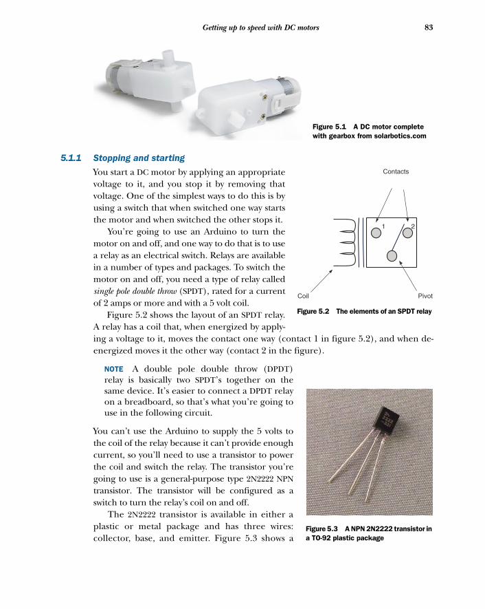
83Getting up to speed with DC motors
5.1.1 Stopping and starting
You start a DC motor by applying an appropriatevoltage to it, and you stop it by removing thatvoltage. One of the simplest ways to do this is byusing a switch that when switched one way startsthe motor and when switched the other stops it.
You’re going to use an Arduino to turn themotor on and off, and one way to do that is to usea relay as an electrical switch. Relays are availablein a number of types and packages. To switch themotor on and off, you need a type of relay calledsingle pole double throw (SPDT), rated for a currentof 2 amps or more and with a 5 volt coil.
Figure 5.2 shows the layout of an SPDT relay.A relay has a coil that, when energized by apply-ing a voltage to it, moves the contact one way (contact 1 in figure 5.2), and when de-energized moves it the other way (contact 2 in the figure).
NOTE A double pole double throw (DPDT)relay is basically two SPDT’s together on thesame device. It’s easier to connect a DPDT relayon a breadboard, so that’s what you’re going touse in the following circuit.
You can’t use the Arduino to supply the 5 volts tothe coil of the relay because it can’t provide enoughcurrent, so you’ll need to use a transistor to powerthe coil and switch the relay. The transistor you’regoing to use is a general-purpose type 2N2222 NPNtransistor. The transistor will be configured as aswitch to turn the relay’s coil on and off.
The 2N2222 transistor is available in either aplastic or metal package and has three wires:collector, base, and emitter. Figure 5.3 shows a
Figure 5.1 A DC motor complete with gearbox from solarbotics.com
Coil Pivot
Contacts
1 2
Figure 5.2 The elements of an SPDT relay
Figure 5.3 A NPN 2N2222 transistor in a TO-92 plastic package
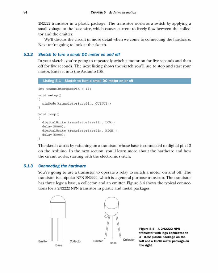
84 CHAPTER 5 Arduino in motion
2N2222 transistor in a plastic package. The transistor works as a switch by applying asmall voltage to the base wire, which causes current to freely flow between the collec-tor and the emitter.
We’ll discuss the circuit in more detail when we come to connecting the hardware.Next we’re going to look at the sketch.
5.1.2 Sketch to turn a small DC motor on and off
In your sketch, you’re going to repeatedly switch a motor on for five seconds and thenoff for five seconds. The next listing shows the sketch you’ll use to stop and start yourmotor. Enter it into the Arduino IDE.
int transistorBasePin = 13;
void setup(){ pinMode(transistorBasePin, OUTPUT);}
void loop(){ digitalWrite(transistorBasePin, LOW); delay(5000); digitalWrite(transistorBasePin, HIGH); delay(5000);}
The sketch works by switching on a transistor whose base is connected to digital pin 13on the Arduino. In the next section, you’ll learn more about the hardware and howthe circuit works, starting with the electronic switch.
5.1.3 Connecting the hardware
You’re going to use a transistor to operate a relay to switch a motor on and off. Thetransistor is a bipolar NPN 2N2222, which is a general-purpose transistor. The transistorhas three legs: a base, a collector, and an emitter. Figure 5.4 shows the typical connec-tions for a 2N2222 NPN transistor in plastic and metal packages.
Listing 5.1 Sketch to turn a small DC motor on or off
Emitter
Base
Collector EmitterBase
Collector
Figure 5.4 A 2N2222 NPN transistor with legs connected to a TO-92 plastic package on the left and a TO-18 metal package on the right
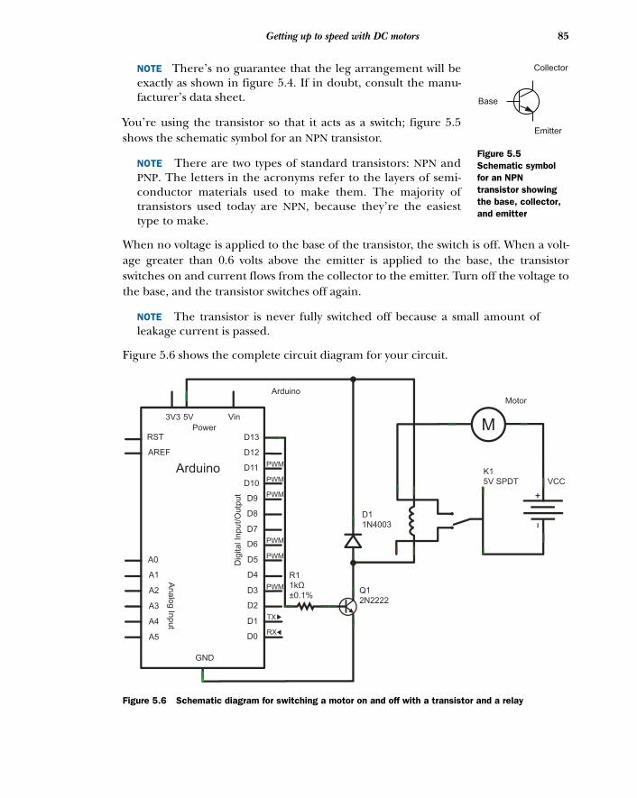
85Getting up to speed with DC motors
NOTE There’s no guarantee that the leg arrangement will beexactly as shown in figure 5.4. If in doubt, consult the manu-facturer’s data sheet.
You’re using the transistor so that it acts as a switch; figure 5.5shows the schematic symbol for an NPN transistor.
NOTE There are two types of standard transistors: NPN andPNP. The letters in the acronyms refer to the layers of semi-conductor materials used to make them. The majority oftransistors used today are NPN, because they’re the easiesttype to make.
When no voltage is applied to the base of the transistor, the switch is off. When a volt-age greater than 0.6 volts above the emitter is applied to the base, the transistorswitches on and current flows from the collector to the emitter. Turn off the voltage tothe base, and the transistor switches off again.
NOTE The transistor is never fully switched off because a small amount ofleakage current is passed.
Figure 5.6 shows the complete circuit diagram for your circuit.
Collector
Base
Emitter
Figure 5.5Schematic symbol for an NPN transistor showing the base, collector, and emitter
Arduino
Vin
Power
3V3 5V
RST
AREF
Arduino
D13
D12
D11
D10
D9
D8
D7
D6
D5
D4
D3
D2
D1
D0
GND
A0
A1
A2
A3
A4
A5
Analo
g In
pu
t
Dig
ital In
put/O
utp
ut
PWM
PWM
PWM
PWM
PWM
PWM
TX
RX
M
Motor
K1
5V SPDT VCC
Q1
2N2222
D1
1N4003
R1
1kΩ
±0.1%
Figure 5.6 Schematic diagram for switching a motor on and off with a transistor and a relay
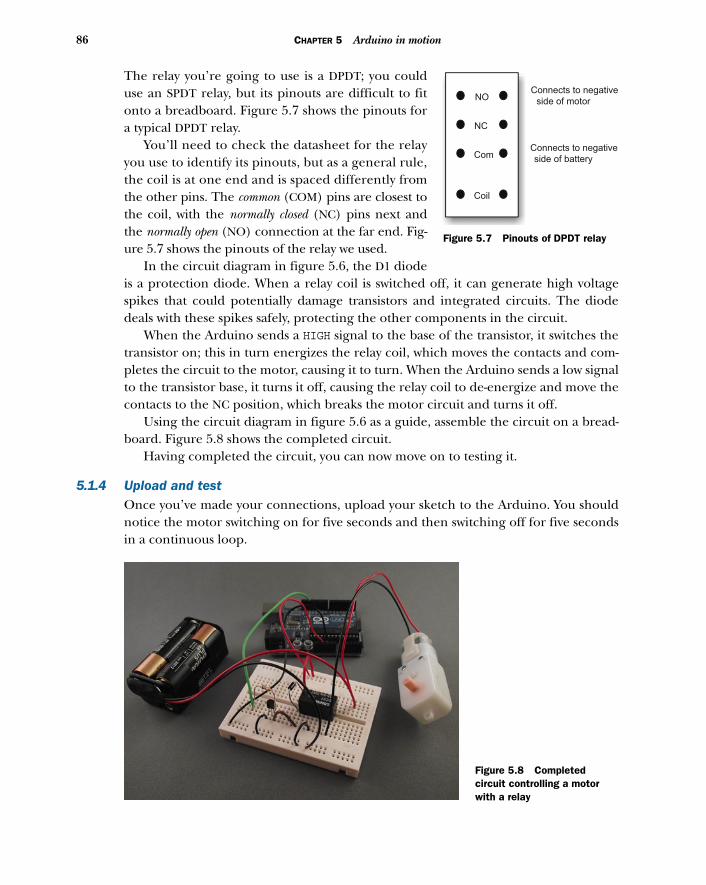
86 CHAPTER 5 Arduino in motion
The relay you’re going to use is a DPDT; you coulduse an SPDT relay, but its pinouts are difficult to fitonto a breadboard. Figure 5.7 shows the pinouts fora typical DPDT relay.
You’ll need to check the datasheet for the relayyou use to identify its pinouts, but as a general rule,the coil is at one end and is spaced differently fromthe other pins. The common (COM) pins are closest tothe coil, with the normally closed (NC) pins next andthe normally open (NO) connection at the far end. Fig-ure 5.7 shows the pinouts of the relay we used.
In the circuit diagram in figure 5.6, the D1 diodeis a protection diode. When a relay coil is switched off, it can generate high voltagespikes that could potentially damage transistors and integrated circuits. The diodedeals with these spikes safely, protecting the other components in the circuit.
When the Arduino sends a HIGH signal to the base of the transistor, it switches thetransistor on; this in turn energizes the relay coil, which moves the contacts and com-pletes the circuit to the motor, causing it to turn. When the Arduino sends a low signalto the transistor base, it turns it off, causing the relay coil to de-energize and move thecontacts to the NC position, which breaks the motor circuit and turns it off.
Using the circuit diagram in figure 5.6 as a guide, assemble the circuit on a bread-board. Figure 5.8 shows the completed circuit.
Having completed the circuit, you can now move on to testing it.
5.1.4 Upload and testOnce you’ve made your connections, upload your sketch to the Arduino. You shouldnotice the motor switching on for five seconds and then switching off for five secondsin a continuous loop.
Coil
Com
NO
NC
Connects to negative
side of motor
Connects to negative
side of battery
Figure 5.7 Pinouts of DPDT relay
Figure 5.8 Completed circuit controlling a motor with a relay
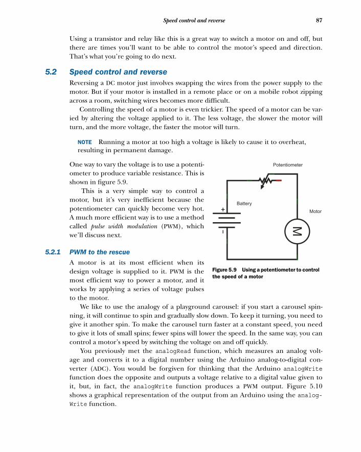
87Speed control and reverse
Using a transistor and relay like this is a great way to switch a motor on and off, butthere are times you’ll want to be able to control the motor’s speed and direction.That’s what you’re going to do next.
5.2 Speed control and reverseReversing a DC motor just involves swapping the wires from the power supply to themotor. But if your motor is installed in a remote place or on a mobile robot zippingacross a room, switching wires becomes more difficult.
Controlling the speed of a motor is even trickier. The speed of a motor can be var-ied by altering the voltage applied to it. The less voltage, the slower the motor willturn, and the more voltage, the faster the motor will turn.
NOTE Running a motor at too high a voltage is likely to cause it to overheat,resulting in permanent damage.
One way to vary the voltage is to use a potenti-ometer to produce variable resistance. This isshown in figure 5.9.
This is a very simple way to control amotor, but it’s very inefficient because thepotentiometer can quickly become very hot.A much more efficient way is to use a methodcalled pulse width modulation (PWM), whichwe’ll discuss next.
5.2.1 PWM to the rescue
A motor is at its most efficient when itsdesign voltage is supplied to it. PWM is themost efficient way to power a motor, and itworks by applying a series of voltage pulsesto the motor.
We like to use the analogy of a playground carousel: if you start a carousel spin-ning, it will continue to spin and gradually slow down. To keep it turning, you need togive it another spin. To make the carousel turn faster at a constant speed, you needto give it lots of small spins; fewer spins will lower the speed. In the same way, you cancontrol a motor’s speed by switching the voltage on and off quickly.
You previously met the analogRead function, which measures an analog volt-age and converts it to a digital number using the Arduino analog-to-digital con-verter (ADC). You would be forgiven for thinking that the Arduino analogWritefunction does the opposite and outputs a voltage relative to a digital value given toit, but, in fact, the analogWrite function produces a PWM output. Figure 5.10shows a graphical representation of the output from an Arduino using the analog-Write function.
M
Potentiometer
Battery
Motor
Figure 5.9 Using a potentiometer to control the speed of a motor
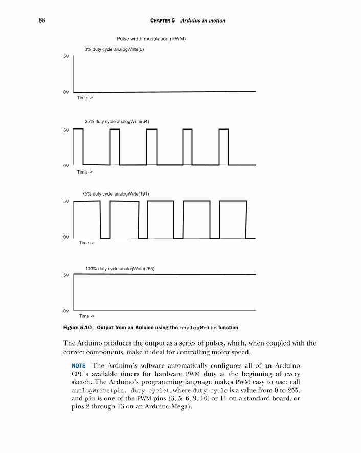
88 CHAPTER 5 Arduino in motion
The Arduino produces the output as a series of pulses, which, when coupled with thecorrect components, make it ideal for controlling motor speed.
NOTE The Arduino’s software automatically configures all of an ArduinoCPU’s available timers for hardware PWM duty at the beginning of everysketch. The Arduino’s programming language makes PWM easy to use: callanalogWrite(pin, duty cycle), where duty cycle is a value from 0 to 255,and pin is one of the PWM pins (3, 5, 6, 9, 10, or 11 on a standard board, orpins 2 through 13 on an Arduino Mega).
0V
5V
0V
5V
0V
5V
0V
5V
Pulse width modulation (PWM)
Time ->
Time ->
Time ->
Time ->
0% duty cycle analogWrite(0)
25% duty cycle analogWrite(64)
75% duty cycle analogWrite(191)
100% duty cycle analogWrite(255)
Figure 5.10 Output from an Arduino using the analogWrite function
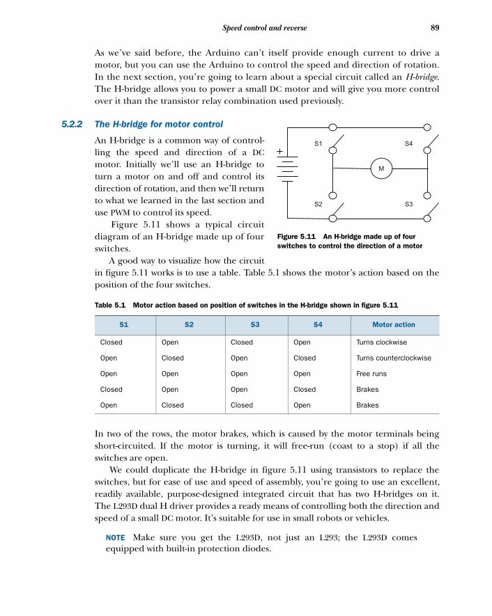
89Speed control and reverse
As we’ve said before, the Arduino can’t itself provide enough current to drive amotor, but you can use the Arduino to control the speed and direction of rotation.In the next section, you’re going to learn about a special circuit called an H-bridge.The H-bridge allows you to power a small DC motor and will give you more controlover it than the transistor relay combination used previously.
5.2.2 The H-bridge for motor control
An H-bridge is a common way of control-ling the speed and direction of a DCmotor. Initially we’ll use an H-bridge toturn a motor on and off and control itsdirection of rotation, and then we’ll returnto what we learned in the last section anduse PWM to control its speed.
Figure 5.11 shows a typical circuitdiagram of an H-bridge made up of fourswitches.
A good way to visualize how the circuitin figure 5.11 works is to use a table. Table 5.1 shows the motor’s action based on theposition of the four switches.
In two of the rows, the motor brakes, which is caused by the motor terminals beingshort-circuited. If the motor is turning, it will free-run (coast to a stop) if all theswitches are open.
We could duplicate the H-bridge in figure 5.11 using transistors to replace theswitches, but for ease of use and speed of assembly, you’re going to use an excellent,readily available, purpose-designed integrated circuit that has two H-bridges on it.The L293D dual H driver provides a ready means of controlling both the direction andspeed of a small DC motor. It’s suitable for use in small robots or vehicles.
NOTE Make sure you get the L293D, not just an L293; the L293D comesequipped with built-in protection diodes.
Table 5.1 Motor action based on position of switches in the H-bridge shown in figure 5.11
S1 S2 S3 S4 Motor action
Closed Open Closed Open Turns clockwise
Open Closed Open Closed Turns counterclockwise
Open Open Open Open Free runs
Closed Open Open Closed Brakes
Open Closed Closed Open Brakes
M
S1
S2 S3
S4
Figure 5.11 An H-bridge made up of four switches to control the direction of a motor
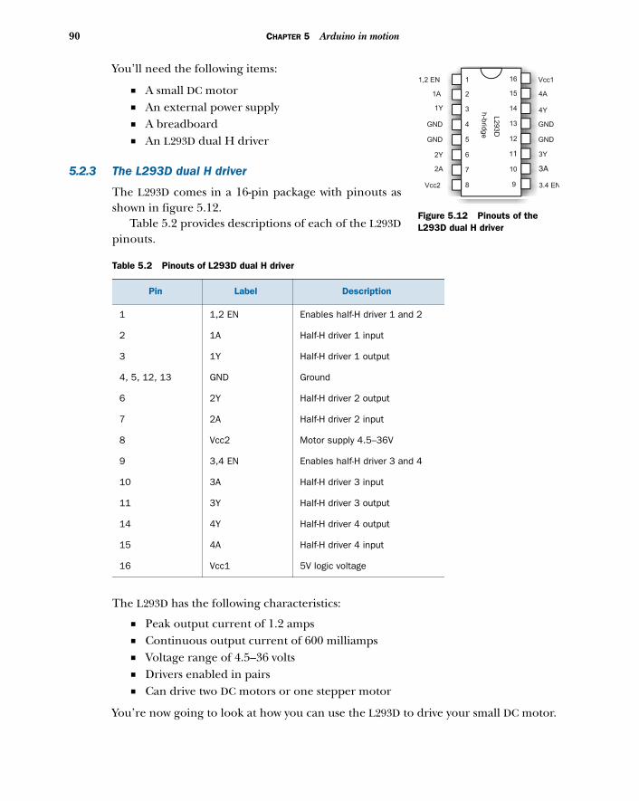
90 CHAPTER 5 Arduino in motion
You’ll need the following items:
■ A small DC motor■ An external power supply■ A breadboard■ An L293D dual H driver
5.2.3 The L293D dual H driver
The L293D comes in a 16-pin package with pinouts asshown in figure 5.12.
Table 5.2 provides descriptions of each of the L293Dpinouts.
The L293D has the following characteristics:
■ Peak output current of 1.2 amps■ Continuous output current of 600 milliamps■ Voltage range of 4.5–36 volts■ Drivers enabled in pairs■ Can drive two DC motors or one stepper motor
You’re now going to look at how you can use the L293D to drive your small DC motor.
Table 5.2 Pinouts of L293D dual H driver
Pin Label Description
1 1,2 EN Enables half-H driver 1 and 2
2 1A Half-H driver 1 input
3 1Y Half-H driver 1 output
4, 5, 12, 13 GND Ground
6 2Y Half-H driver 2 output
7 2A Half-H driver 2 input
8 Vcc2 Motor supply 4.5–36V
9 3,4 EN Enables half-H driver 3 and 4
10 3A Half-H driver 3 input
11 3Y Half-H driver 3 output
14 4Y Half-H driver 4 output
15 4A Half-H driver 4 input
16 Vcc1 5V logic voltage
L293D
h-b
ridge
1
2
3
4
5
6
7
8
16
15
14
13
12
11
10
9
1,2 EN
1Y
1A
2Y
2A
GND
GND
GND
GND
Vcc2 3.4 EN
3A
3Y
4A
4Y
Vcc1
Figure 5.12 Pinouts of the L293D dual H driver
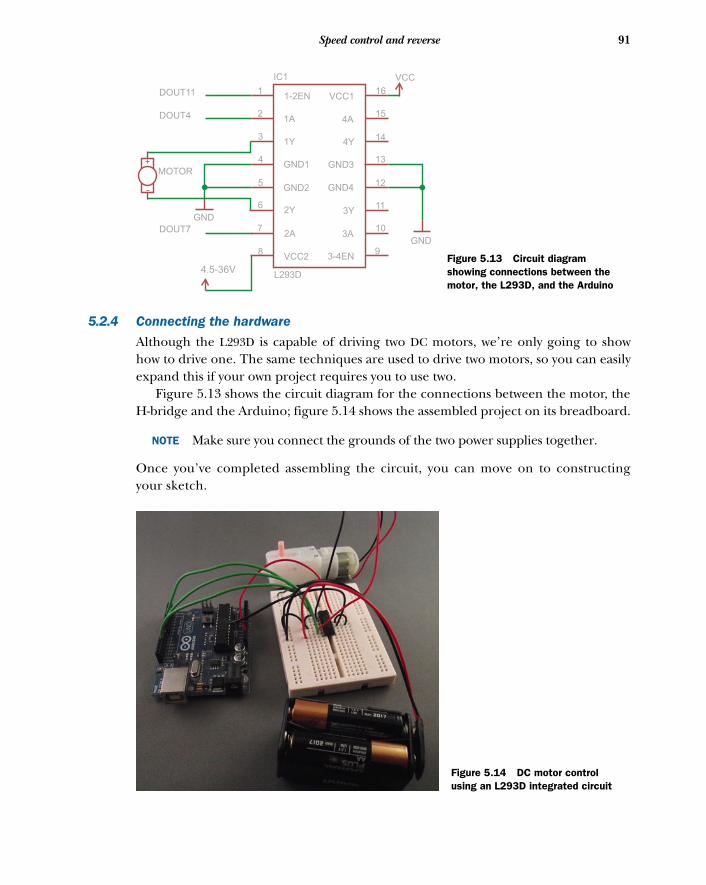
91Speed control and reverse
5.2.4 Connecting the hardware
Although the L293D is capable of driving two DC motors, we’re only going to showhow to drive one. The same techniques are used to drive two motors, so you can easilyexpand this if your own project requires you to use two.
Figure 5.13 shows the circuit diagram for the connections between the motor, theH-bridge and the Arduino; figure 5.14 shows the assembled project on its breadboard.
NOTE Make sure you connect the grounds of the two power supplies together.
Once you’ve completed assembling the circuit, you can move on to constructingyour sketch.
9
10
11
12
13
14
15
16VCC11-2EN
4A1A
4Y1Y
GND3GND1
GND4GND2
3Y2Y
3A2A
3-4ENVCC28
7
6
5
4
3
2
1
IC1
DOUT11
DOUT4
L293D
DOUT7
4.5-36V
VCC
GND
GND
MOTOR
Figure 5.13 Circuit diagram showing connections between the motor, the L293D, and the Arduino
Figure 5.14 DC motor control using an L293D integrated circuit
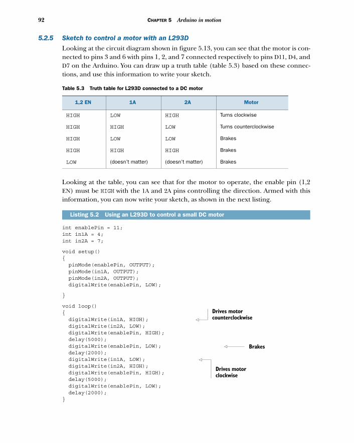
92 CHAPTER 5 Arduino in motion
5.2.5 Sketch to control a motor with an L293D
Looking at the circuit diagram shown in figure 5.13, you can see that the motor is con-nected to pins 3 and 6 with pins 1, 2, and 7 connected respectively to pins D11, D4, andD7 on the Arduino. You can draw up a truth table (table 5.3) based on these connec-tions, and use this information to write your sketch.
Looking at the table, you can see that for the motor to operate, the enable pin (1,2EN) must be HIGH with the 1A and 2A pins controlling the direction. Armed with thisinformation, you can now write your sketch, as shown in the next listing.
int enablePin = 11;int in1A = 4;int in2A = 7;
void setup(){ pinMode(enablePin, OUTPUT); pinMode(in1A, OUTPUT); pinMode(in2A, OUTPUT); digitalWrite(enablePin, LOW);
}
void loop(){ digitalWrite(in1A, HIGH); digitalWrite(in2A, LOW); digitalWrite(enablePin, HIGH); delay(5000); digitalWrite(enablePin, LOW); delay(2000); digitalWrite(in1A, LOW); digitalWrite(in2A, HIGH); digitalWrite(enablePin, HIGH); delay(5000); digitalWrite(enablePin, LOW); delay(2000);}
Table 5.3 Truth table for L293D connected to a DC motor
1,2 EN 1A 2A Motor
HIGH LOW HIGH Turns clockwise
HIGH HIGH LOW Turns counterclockwise
HIGH LOW LOW Brakes
HIGH HIGH HIGH Brakes
LOW (doesn’t matter) (doesn’t matter) Brakes
Listing 5.2 Using an L293D to control a small DC motor
Drives motor counterclockwise
Brakes
Drives motor clockwise
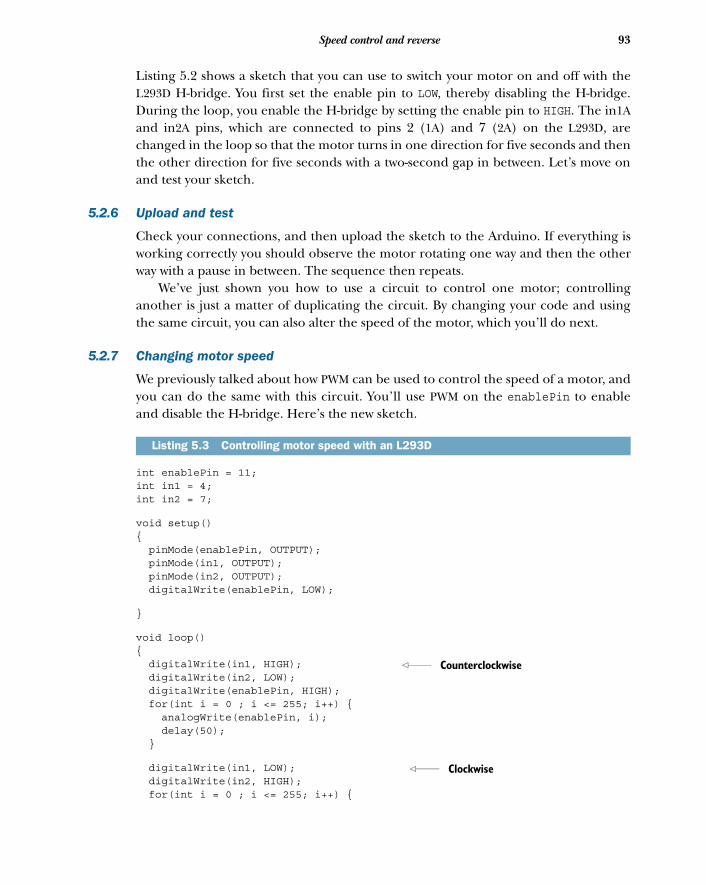
93Speed control and reverse
Listing 5.2 shows a sketch that you can use to switch your motor on and off with theL293D H-bridge. You first set the enable pin to LOW, thereby disabling the H-bridge.During the loop, you enable the H-bridge by setting the enable pin to HIGH. The in1Aand in2A pins, which are connected to pins 2 (1A) and 7 (2A) on the L293D, arechanged in the loop so that the motor turns in one direction for five seconds and thenthe other direction for five seconds with a two-second gap in between. Let’s move onand test your sketch.
5.2.6 Upload and test
Check your connections, and then upload the sketch to the Arduino. If everything isworking correctly you should observe the motor rotating one way and then the otherway with a pause in between. The sequence then repeats.
We’ve just shown you how to use a circuit to control one motor; controllinganother is just a matter of duplicating the circuit. By changing your code and usingthe same circuit, you can also alter the speed of the motor, which you’ll do next.
5.2.7 Changing motor speed
We previously talked about how PWM can be used to control the speed of a motor, andyou can do the same with this circuit. You’ll use PWM on the enablePin to enableand disable the H-bridge. Here’s the new sketch.
int enablePin = 11;int in1 = 4;int in2 = 7;
void setup(){ pinMode(enablePin, OUTPUT); pinMode(in1, OUTPUT); pinMode(in2, OUTPUT); digitalWrite(enablePin, LOW);
}
void loop(){ digitalWrite(in1, HIGH); digitalWrite(in2, LOW); digitalWrite(enablePin, HIGH); for(int i = 0 ; i <= 255; i++) { analogWrite(enablePin, i); delay(50); }
digitalWrite(in1, LOW); digitalWrite(in2, HIGH); for(int i = 0 ; i <= 255; i++) {
Listing 5.3 Controlling motor speed with an L293D
Counterclockwise
Clockwise
94 CHAPTER 5 Arduino in motion
analogWrite(enablePin, i); delay(50); }
}
This sketch is similar to the previous one; you’re using a for loop that varies the PWMoutput on the enablePin from 0 to 255, first rotating the motor in one direction andthen the other. After either changing your existing sketch or creating a new one, youcan move on to testing it.
5.2.8 Upload and test
Check over your connections, and then upload the sketch to the Arduino. If every-thing is working correctly, you should see the motor rotating in one direction andthen the other, with the motor gradually increasing in speed from stationary to full.The sequence then repeats.
NOTE You may notice a delay between each start of the motor because it mayneed a minimum PWM value to start turning. This depends on an individualmotor’s characteristics, but is perfectly normal.
We’ve shown you how to use this circuit to control one motor, but as before, control-ling another is just a matter of duplicating the circuit.
The circuit you’ve built in this example is only suitable for driving small motors.Large DC motors can be similarly controlled with PWM, but they require suitablyrated components; unfortunately, these components tend to be more specializedand expensive.
This concludes our look at controlling small DC motors. Next, we’ll look at steppermotors, which can be precisely controlled
5.3 Stepper motors: one step at a timeA stepper motor is a special type of motor that can move in a series of discrete steps.Stepper motors are a good choice for projects requiring controlled and accuratemovement. Typical projects include 3D printers, telescope positioning systems, andcomputer numerical control (CNC) lathes and mills.
Good sources for obtaining stepper motors are old inkjet or laser printers, wherethey’re used to move the print heads and to control paper feed. You can also purchasenew ones from electronics suppliers or from eBay.
Figure 5.15 shows a typical stepper motor purchased from eBay. Stepper motors are classified according to their frame size, which corresponds to the
diameter of the body: a size 11 has a body diameter of 1.1 inches, and a size 23 has abody diameter of 2.3 inches. Stepper motors are also often rated in terms of the torquethey can provide, with the torque being proportional to body length: the longer thebody, the greater the torque. The step angle is also normally provided; a stepper motorwith an angle of 9 degrees will require 40 steps to complete a full revolution.
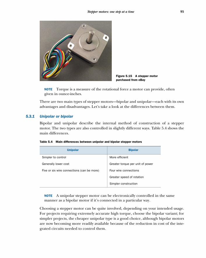
95Stepper motors: one step at a time
NOTE Torque is a measure of the rotational force a motor can provide, oftengiven in ounce-inches.
There are two main types of stepper motors—bipolar and unipolar—each with its ownadvantages and disadvantages. Let’s take a look at the differences between them.
5.3.1 Unipolar or bipolar
Bipolar and unipolar describe the internal method of construction of a steppermotor. The two types are also controlled in slightly different ways. Table 5.4 shows themain differences.
NOTE A unipolar stepper motor can be electronically controlled in the samemanner as a bipolar motor if it’s connected in a particular way.
Choosing a stepper motor can be quite involved, depending on your intended usage.For projects requiring extremely accurate high torque, choose the bipolar variant; forsimpler projects, the cheaper unipolar type is a good choice, although bipolar motorsare now becoming more readily available because of the reduction in cost of the inte-grated circuits needed to control them.
Table 5.4 Main differences between unipolar and bipolar stepper motors
Unipolar Bipolar
Simpler to control More efficient
Generally lower cost Greater torque per unit of power
Five or six wire connections (can be more) Four wire connections
Greater speed of rotation
Simpler construction
Figure 5.15 A stepper motor purchased from eBay
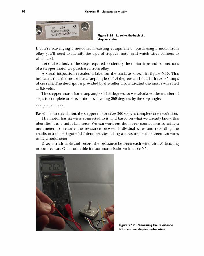
96 CHAPTER 5 Arduino in motion
If you’re scavenging a motor from existing equipment or purchasing a motor fromeBay, you’ll need to identify the type of stepper motor and which wires connect towhich coil.
Let’s take a look at the steps required to identify the motor type and connectionsof a stepper motor we purchased from eBay.
A visual inspection revealed a label on the back, as shown in figure 5.16. Thisindicated that the motor has a step angle of 1.8 degrees and that it draws 0.5 ampsof current. The description provided by the seller also indicated the motor was ratedat 6.5 volts.
The stepper motor has a step angle of 1.8 degrees, so we calculated the number ofsteps to complete one revolution by dividing 360 degrees by the step angle:
360 / 1.8 = 200
Based on our calculation, the stepper motor takes 200 steps to complete one revolution. The motor has six wires connected to it, and based on what we already know, this
identifies it as a unipolar motor. We can work out the motor connections by using amultimeter to measure the resistance between individual wires and recording theresults in a table. Figure 5.17 demonstrates taking a measurement between two wiresusing a multimeter.
Draw a truth table and record the resistance between each wire, with X denotingno connection. Our truth table for our motor is shown in table 5.5.
Figure 5.16 Label on the back of a stepper motor
Figure 5.17 Measuring the resistance between two stepper motor wires
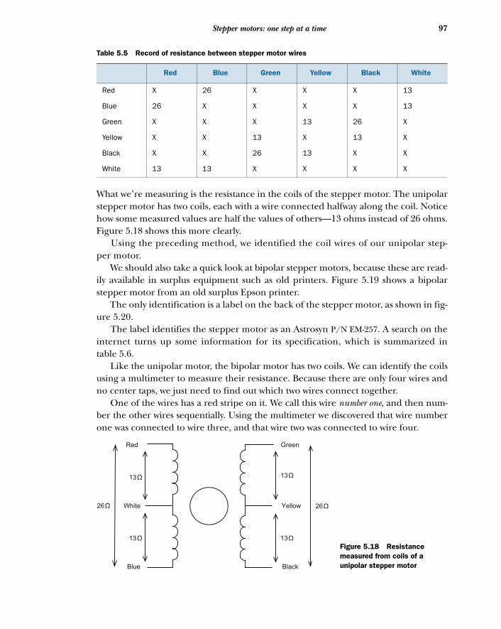
97Stepper motors: one step at a time
What we’re measuring is the resistance in the coils of the stepper motor. The unipolarstepper motor has two coils, each with a wire connected halfway along the coil. Noticehow some measured values are half the values of others—13 ohms instead of 26 ohms.Figure 5.18 shows this more clearly.
Using the preceding method, we identified the coil wires of our unipolar step-per motor.
We should also take a quick look at bipolar stepper motors, because these are read-ily available in surplus equipment such as old printers. Figure 5.19 shows a bipolarstepper motor from an old surplus Epson printer.
The only identification is a label on the back of the stepper motor, as shown in fig-ure 5.20.
The label identifies the stepper motor as an Astrosyn P/N EM-257. A search on theinternet turns up some information for its specification, which is summarized intable 5.6.
Like the unipolar motor, the bipolar motor has two coils. We can identify the coilsusing a multimeter to measure their resistance. Because there are only four wires andno center taps, we just need to find out which two wires connect together.
One of the wires has a red stripe on it. We call this wire number one, and then num-ber the other wires sequentially. Using the multimeter we discovered that wire numberone was connected to wire three, and that wire two was connected to wire four.
Table 5.5 Record of resistance between stepper motor wires
Red Blue Green Yellow Black White
Red X 26 X X X 13
Blue 26 X X X X 13
Green X X X 13 26 X
Yellow X X 13 X 13 X
Black X X 26 13 X X
White 13 13 X X X X
26
Red
White
Blue
Green
Yellow
Black
26
13
13 13
13
Figure 5.18 Resistance measured from coils of a unipolar stepper motor
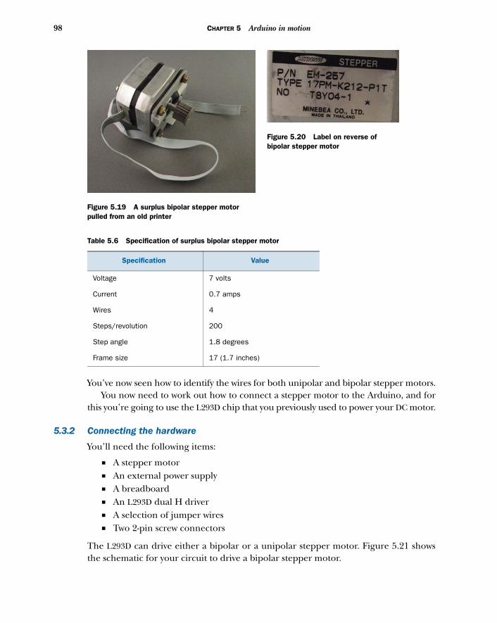
98 CHAPTER 5 Arduino in motion
You’ve now seen how to identify the wires for both unipolar and bipolar stepper motors. You now need to work out how to connect a stepper motor to the Arduino, and for
this you’re going to use the L293D chip that you previously used to power your DC motor.
5.3.2 Connecting the hardware
You’ll need the following items:
■ A stepper motor■ An external power supply■ A breadboard■ An L293D dual H driver■ A selection of jumper wires■ Two 2-pin screw connectors
The L293D can drive either a bipolar or a unipolar stepper motor. Figure 5.21 showsthe schematic for your circuit to drive a bipolar stepper motor.
Table 5.6 Specification of surplus bipolar stepper motor
Specification Value
Voltage 7 volts
Current 0.7 amps
Wires 4
Steps/revolution 200
Step angle 1.8 degrees
Frame size 17 (1.7 inches)
Figure 5.19 A surplus bipolar stepper motor pulled from an old printer
Figure 5.20 Label on reverse of bipolar stepper motor
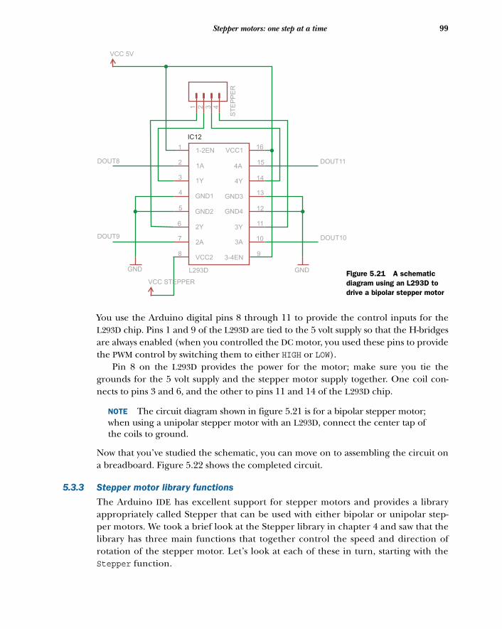
99Stepper motors: one step at a time
You use the Arduino digital pins 8 through 11 to provide the control inputs for theL293D chip. Pins 1 and 9 of the L293D are tied to the 5 volt supply so that the H-bridgesare always enabled (when you controlled the DC motor, you used these pins to providethe PWM control by switching them to either HIGH or LOW).
Pin 8 on the L293D provides the power for the motor; make sure you tie thegrounds for the 5 volt supply and the stepper motor supply together. One coil con-nects to pins 3 and 6, and the other to pins 11 and 14 of the L293D chip.
NOTE The circuit diagram shown in figure 5.21 is for a bipolar stepper motor;when using a unipolar stepper motor with an L293D, connect the center tap ofthe coils to ground.
Now that you’ve studied the schematic, you can move on to assembling the circuit ona breadboard. Figure 5.22 shows the completed circuit.
5.3.3 Stepper motor library functions
The Arduino IDE has excellent support for stepper motors and provides a libraryappropriately called Stepper that can be used with either bipolar or unipolar step-per motors. We took a brief look at the Stepper library in chapter 4 and saw that thelibrary has three main functions that together control the speed and direction ofrotation of the stepper motor. Let’s look at each of these in turn, starting with theStepper function.
VCC 5V
9
10
11
12
13
14
15
16
ST
EP
PE
R
43
VCC11-2EN
4A1A
4Y1Y
GND3GND1
GND4GND2
3Y2Y
3A2A
3-4ENVCC28
7
6
5
4
3
2
1
IC12
21
DOUT11DOUT8
L293D
VCC STEPPER
GNDGND
DOUT10DOUT9
Figure 5.21 A schematic diagram using an L293D to drive a bipolar stepper motor
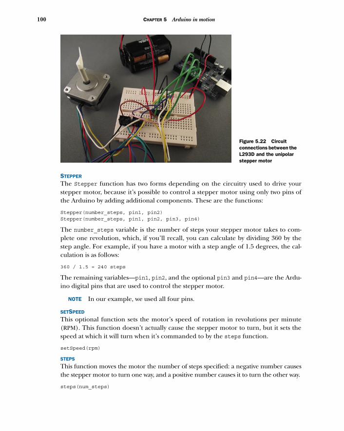
100 CHAPTER 5 Arduino in motion
STEPPER
The Stepper function has two forms depending on the circuitry used to drive yourstepper motor, because it’s possible to control a stepper motor using only two pins ofthe Arduino by adding additional components. These are the functions:
Stepper(number_steps, pin1, pin2)Stepper(number_steps, pin1, pin2, pin3, pin4)
The number_steps variable is the number of steps your stepper motor takes to com-plete one revolution, which, if you’ll recall, you can calculate by dividing 360 by thestep angle. For example, if you have a motor with a step angle of 1.5 degrees, the cal-culation is as follows:
360 / 1.5 = 240 steps
The remaining variables—pin1, pin2, and the optional pin3 and pin4—are the Ardu-ino digital pins that are used to control the stepper motor.
NOTE In our example, we used all four pins.
SETSPEED
This optional function sets the motor’s speed of rotation in revolutions per minute(RPM). This function doesn’t actually cause the stepper motor to turn, but it sets thespeed at which it will turn when it’s commanded to by the steps function.
setSpeed(rpm)
STEPS
This function moves the motor the number of steps specified: a negative number causesthe stepper motor to turn one way, and a positive number causes it to turn the other way.
steps(num_steps)
Figure 5.22 Circuit connections between the L293D and the unipolar stepper motor
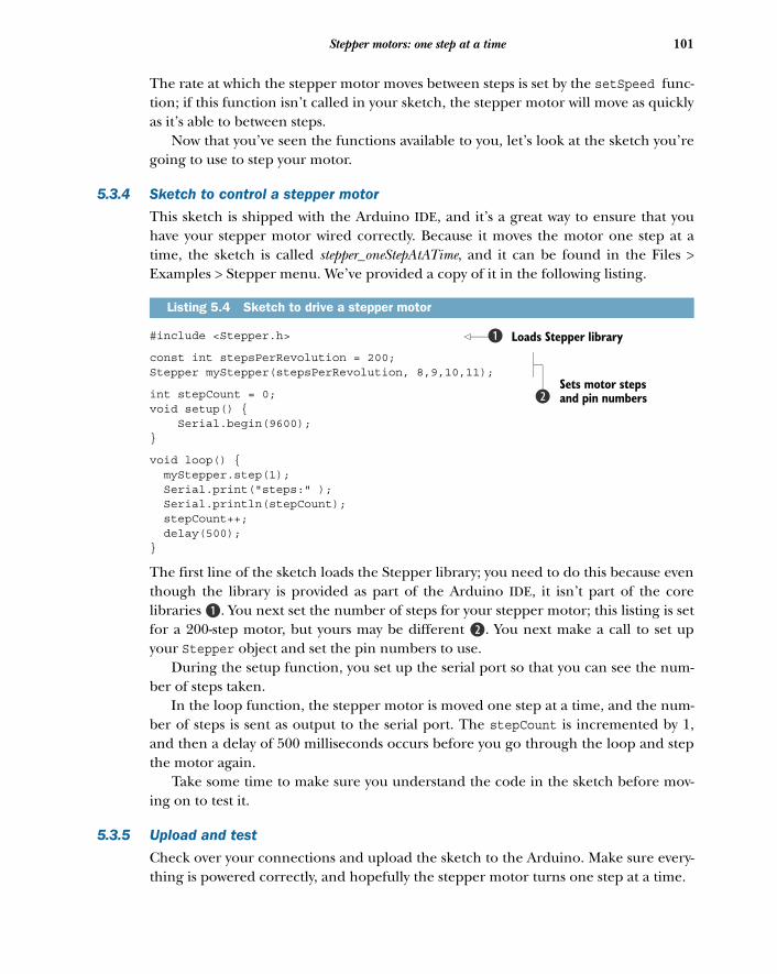
101Stepper motors: one step at a time
The rate at which the stepper motor moves between steps is set by the setSpeed func-tion; if this function isn’t called in your sketch, the stepper motor will move as quicklyas it’s able to between steps.
Now that you’ve seen the functions available to you, let’s look at the sketch you’regoing to use to step your motor.
5.3.4 Sketch to control a stepper motor
This sketch is shipped with the Arduino IDE, and it’s a great way to ensure that youhave your stepper motor wired correctly. Because it moves the motor one step at atime, the sketch is called stepper_oneStepAtATime, and it can be found in the Files >Examples > Stepper menu. We’ve provided a copy of it in the following listing.
#include <Stepper.h>
const int stepsPerRevolution = 200; Stepper myStepper(stepsPerRevolution, 8,9,10,11);
int stepCount = 0;void setup() { Serial.begin(9600);}
void loop() { myStepper.step(1); Serial.print("steps:" ); Serial.println(stepCount); stepCount++; delay(500);}
The first line of the sketch loads the Stepper library; you need to do this because eventhough the library is provided as part of the Arduino IDE, it isn’t part of the corelibraries B. You next set the number of steps for your stepper motor; this listing is setfor a 200-step motor, but yours may be different c. You next make a call to set upyour Stepper object and set the pin numbers to use.
During the setup function, you set up the serial port so that you can see the num-ber of steps taken.
In the loop function, the stepper motor is moved one step at a time, and the num-ber of steps is sent as output to the serial port. The stepCount is incremented by 1,and then a delay of 500 milliseconds occurs before you go through the loop and stepthe motor again.
Take some time to make sure you understand the code in the sketch before mov-ing on to test it.
5.3.5 Upload and test
Check over your connections and upload the sketch to the Arduino. Make sure every-thing is powered correctly, and hopefully the stepper motor turns one step at a time.
Listing 5.4 Sketch to drive a stepper motor
Loads Stepper libraryb
Sets motor steps and pin numbersc
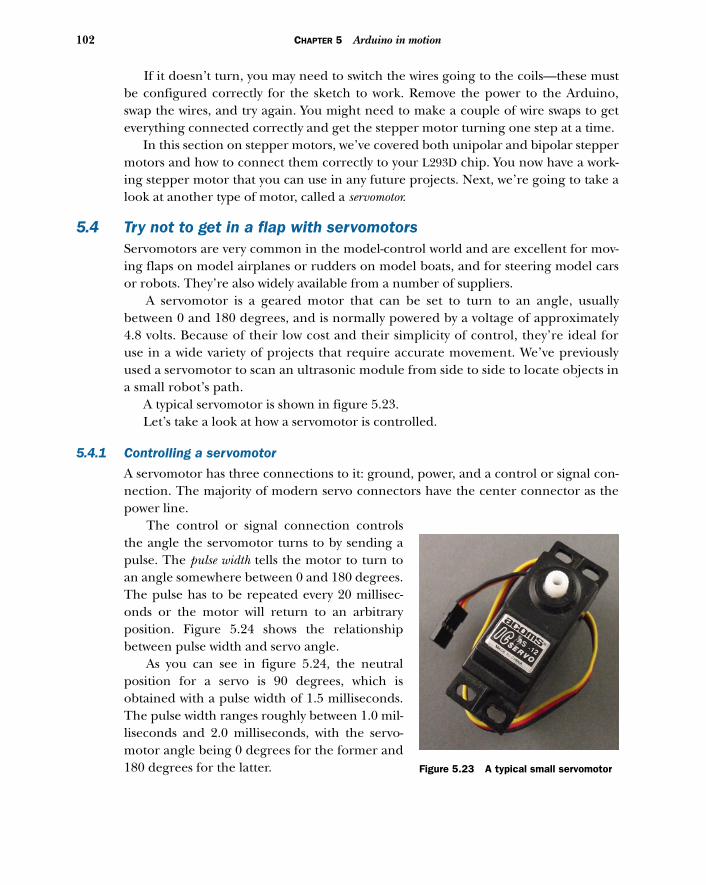
102 CHAPTER 5 Arduino in motion
If it doesn’t turn, you may need to switch the wires going to the coils—these mustbe configured correctly for the sketch to work. Remove the power to the Arduino,swap the wires, and try again. You might need to make a couple of wire swaps to geteverything connected correctly and get the stepper motor turning one step at a time.
In this section on stepper motors, we’ve covered both unipolar and bipolar steppermotors and how to connect them correctly to your L293D chip. You now have a work-ing stepper motor that you can use in any future projects. Next, we’re going to take alook at another type of motor, called a servomotor.
5.4 Try not to get in a flap with servomotorsServomotors are very common in the model-control world and are excellent for mov-ing flaps on model airplanes or rudders on model boats, and for steering model carsor robots. They’re also widely available from a number of suppliers.
A servomotor is a geared motor that can be set to turn to an angle, usuallybetween 0 and 180 degrees, and is normally powered by a voltage of approximately4.8 volts. Because of their low cost and their simplicity of control, they’re ideal foruse in a wide variety of projects that require accurate movement. We’ve previouslyused a servomotor to scan an ultrasonic module from side to side to locate objects ina small robot’s path.
A typical servomotor is shown in figure 5.23. Let’s take a look at how a servomotor is controlled.
5.4.1 Controlling a servomotor
A servomotor has three connections to it: ground, power, and a control or signal con-nection. The majority of modern servo connectors have the center connector as thepower line.
The control or signal connection controlsthe angle the servomotor turns to by sending apulse. The pulse width tells the motor to turn toan angle somewhere between 0 and 180 degrees.The pulse has to be repeated every 20 millisec-onds or the motor will return to an arbitraryposition. Figure 5.24 shows the relationshipbetween pulse width and servo angle.
As you can see in figure 5.24, the neutralposition for a servo is 90 degrees, which isobtained with a pulse width of 1.5 milliseconds.The pulse width ranges roughly between 1.0 mil-liseconds and 2.0 milliseconds, with the servo-motor angle being 0 degrees for the former and180 degrees for the latter. Figure 5.23 A typical small servomotor
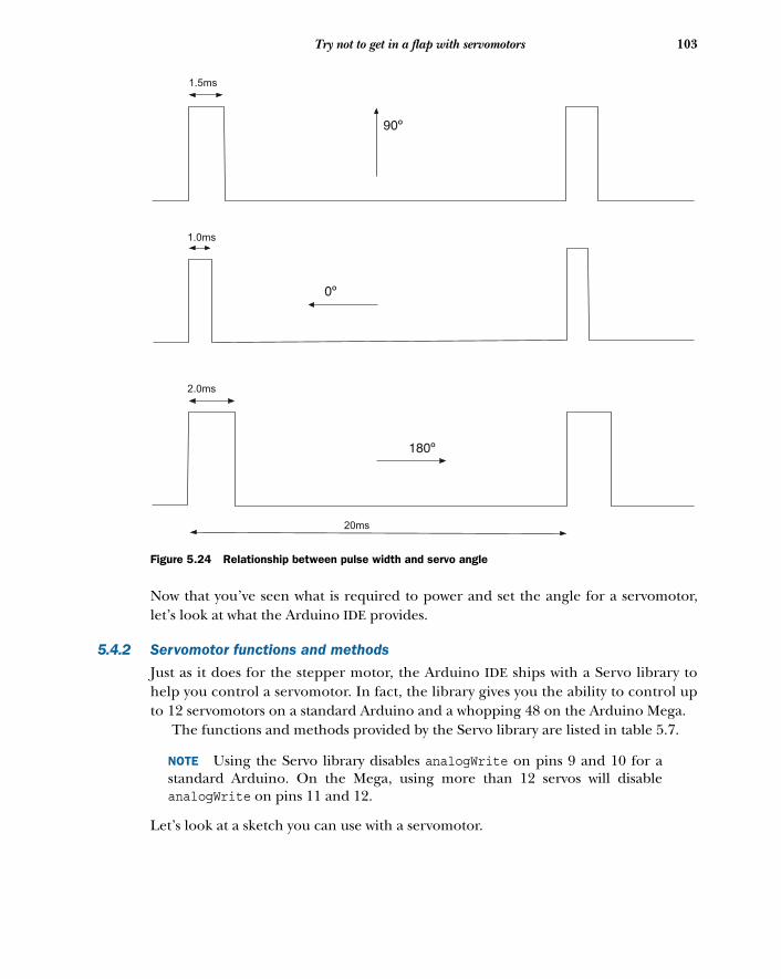
103Try not to get in a flap with servomotors
Now that you’ve seen what is required to power and set the angle for a servomotor,let’s look at what the Arduino IDE provides.
5.4.2 Servomotor functions and methods
Just as it does for the stepper motor, the Arduino IDE ships with a Servo library tohelp you control a servomotor. In fact, the library gives you the ability to control upto 12 servomotors on a standard Arduino and a whopping 48 on the Arduino Mega.
The functions and methods provided by the Servo library are listed in table 5.7.
NOTE Using the Servo library disables analogWrite on pins 9 and 10 for astandard Arduino. On the Mega, using more than 12 servos will disableanalogWrite on pins 11 and 12.
Let’s look at a sketch you can use with a servomotor.
20ms
1.5ms
1.0ms
2.0ms
Figure 5.24 Relationship between pulse width and servo angle
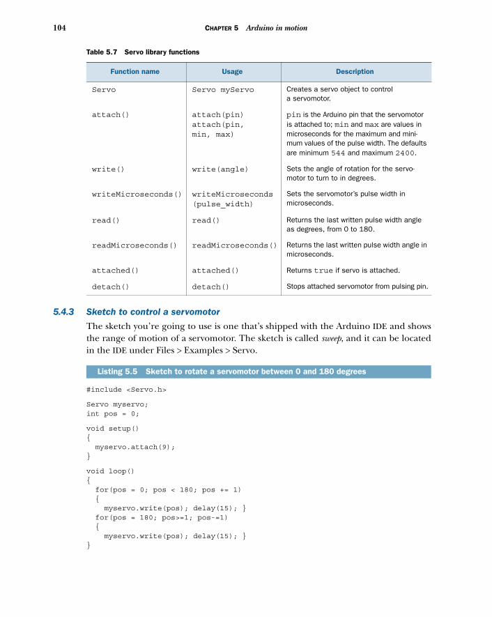
104 CHAPTER 5 Arduino in motion
5.4.3 Sketch to control a servomotor
The sketch you’re going to use is one that’s shipped with the Arduino IDE and showsthe range of motion of a servomotor. The sketch is called sweep, and it can be locatedin the IDE under Files > Examples > Servo.
#include <Servo.h>
Servo myservo; int pos = 0;
void setup() { myservo.attach(9); }
void loop() { for(pos = 0; pos < 180; pos += 1) { myservo.write(pos); delay(15); } for(pos = 180; pos>=1; pos-=1) { myservo.write(pos); delay(15); } }
Table 5.7 Servo library functions
Function name Usage Description
Servo Servo myServo Creates a servo object to control a servomotor.
attach() attach(pin)attach(pin, min, max)
pin is the Arduino pin that the servomotor is attached to; min and max are values in microseconds for the maximum and mini-mum values of the pulse width. The defaults are minimum 544 and maximum 2400.
write() write(angle) Sets the angle of rotation for the servo-motor to turn to in degrees.
writeMicroseconds() writeMicroseconds(pulse_width)
Sets the servomotor’s pulse width in microseconds.
read() read() Returns the last written pulse width angle as degrees, from 0 to 180.
readMicroseconds() readMicroseconds() Returns the last written pulse width angle in microseconds.
attached() attached() Returns true if servo is attached.
detach() detach() Stops attached servomotor from pulsing pin.
Listing 5.5 Sketch to rotate a servomotor between 0 and 180 degrees
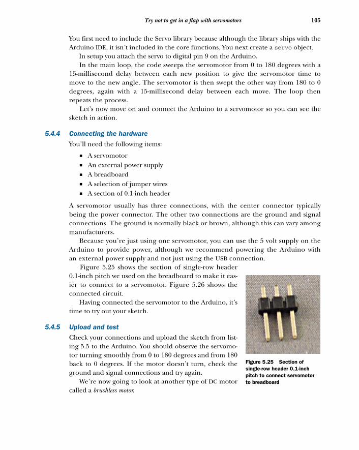
105Try not to get in a flap with servomotors
You first need to include the Servo library because although the library ships with theArduino IDE, it isn’t included in the core functions. You next create a servo object.
In setup you attach the servo to digital pin 9 on the Arduino. In the main loop, the code sweeps the servomotor from 0 to 180 degrees with a
15-millisecond delay between each new position to give the servomotor time tomove to the new angle. The servomotor is then swept the other way from 180 to 0degrees, again with a 15-millisecond delay between each move. The loop thenrepeats the process.
Let’s now move on and connect the Arduino to a servomotor so you can see thesketch in action.
5.4.4 Connecting the hardware
You’ll need the following items:
■ A servomotor■ An external power supply■ A breadboard■ A selection of jumper wires■ A section of 0.1-inch header
A servomotor usually has three connections, with the center connector typicallybeing the power connector. The other two connections are the ground and signalconnections. The ground is normally black or brown, although this can vary amongmanufacturers.
Because you’re just using one servomotor, you can use the 5 volt supply on theArduino to provide power, although we recommend powering the Arduino withan external power supply and not just using the USB connection.
Figure 5.25 shows the section of single-row header0.1-inch pitch we used on the breadboard to make it eas-ier to connect to a servomotor. Figure 5.26 shows theconnected circuit.
Having connected the servomotor to the Arduino, it’stime to try out your sketch.
5.4.5 Upload and test
Check your connections and upload the sketch from list-ing 5.5 to the Arduino. You should observe the servomo-tor turning smoothly from 0 to 180 degrees and from 180back to 0 degrees. If the motor doesn’t turn, check theground and signal connections and try again.
We’re now going to look at another type of DC motorcalled a brushless motor.
Figure 5.25 Section of single-row header 0.1-inch pitch to connect servomotor to breadboard
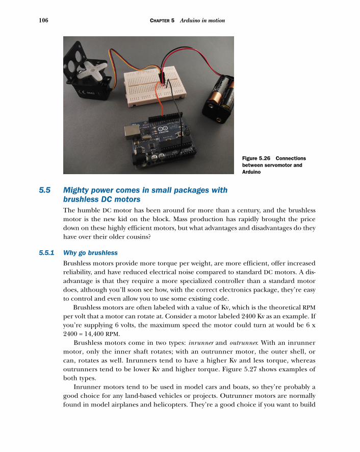
106 CHAPTER 5 Arduino in motion
5.5 Mighty power comes in small packages with brushless DC motorsThe humble DC motor has been around for more than a century, and the brushlessmotor is the new kid on the block. Mass production has rapidly brought the pricedown on these highly efficient motors, but what advantages and disadvantages do theyhave over their older cousins?
5.5.1 Why go brushless
Brushless motors provide more torque per weight, are more efficient, offer increasedreliability, and have reduced electrical noise compared to standard DC motors. A dis-advantage is that they require a more specialized controller than a standard motordoes, although you’ll soon see how, with the correct electronics package, they’re easyto control and even allow you to use some existing code.
Brushless motors are often labeled with a value of Kv, which is the theoretical RPMper volt that a motor can rotate at. Consider a motor labeled 2400 Kv as an example. Ifyou’re supplying 6 volts, the maximum speed the motor could turn at would be 6 x2400 = 14,400 RPM.
Brushless motors come in two types: inrunner and outrunner. With an inrunnermotor, only the inner shaft rotates; with an outrunner motor, the outer shell, orcan, rotates as well. Inrunners tend to have a higher Kv and less torque, whereasoutrunners tend to be lower Kv and higher torque. Figure 5.27 shows examples ofboth types.
Inrunner motors tend to be used in model cars and boats, so they’re probably agood choice for any land-based vehicles or projects. Outrunner motors are normallyfound in model airplanes and helicopters. They’re a good choice if you want to build
Figure 5.26 Connections between servomotor and Arduino
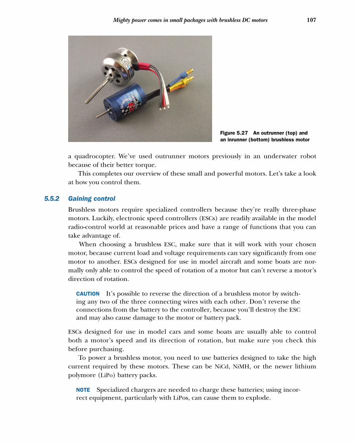
107Mighty power comes in small packages with brushless DC motors
a quadrocopter. We’ve used outrunner motors previously in an underwater robotbecause of their better torque.
This completes our overview of these small and powerful motors. Let’s take a lookat how you control them.
5.5.2 Gaining control
Brushless motors require specialized controllers because they’re really three-phasemotors. Luckily, electronic speed controllers (ESCs) are readily available in the modelradio-control world at reasonable prices and have a range of functions that you cantake advantage of.
When choosing a brushless ESC, make sure that it will work with your chosenmotor, because current load and voltage requirements can vary significantly from onemotor to another. ESCs designed for use in model aircraft and some boats are nor-mally only able to control the speed of rotation of a motor but can’t reverse a motor’sdirection of rotation.
CAUTION It’s possible to reverse the direction of a brushless motor by switch-ing any two of the three connecting wires with each other. Don’t reverse theconnections from the battery to the controller, because you’ll destroy the ESCand may also cause damage to the motor or battery pack.
ESCs designed for use in model cars and some boats are usually able to controlboth a motor’s speed and its direction of rotation, but make sure you check thisbefore purchasing.
To power a brushless motor, you need to use batteries designed to take the highcurrent required by these motors. These can be NiCd, NiMH, or the newer lithiumpolymore (LiPo) battery packs.
NOTE Specialized chargers are needed to charge these batteries; using incor-rect equipment, particularly with LiPos, can cause them to explode.
Figure 5.27 An outrunner (top) and an inrunner (bottom) brushless motor
108 CHAPTER 5 Arduino in motion
One of the great things about ESCs is that they can be controlled in exactly the sameway as servomotors; this means you can use the Servo library and the things youlearned in the last section to control them. Just like servomotors, they expect a pulseevery 20 milliseconds with a width of between 1.0 and 2.0 milliseconds, with 1.0 milli-second being the slowest speed and 2.0 milliseconds being the highest. With ESCs thatcan reverse direction, the pulse range will be different: a width of 1.5 milliseconds willcause the motor to stop, a 2.0-millisecond pulse width will be the fastest forwardspeed, and a 1.0 millisecond pulse width will be the fastest reverse speed.
When a motor and its controller are first powered on, the motor won’t instantlystart—this is a safety feature—but it will wait a period of time and may expect a partic-ular pulse width before starting. You’ll need to consult the ESC’s manual to see if thisis the case. The first brushless motor we used expected a 1.0-millisecond pulse widthfor a period of one second before it would function correctly.
NOTE You’ll often hear a series of tones when an ESC and its motor are firstpowered up; this is all part of the normal startup process and can even soundquite musical.
Now that you have a basic understanding of how to control a brushless motor, let’smove on and look at some code in a sketch.
5.5.3 Sketch to control a brushless motorTake a look at the next listing. You should recognize the code because it’s almost thesame as the code in listing 5.5, with the addition of a start pulse during setup to allowthe ESC and motor to stabilize.
#include <Servo.h>
Servo myservo; int pos = 0;
void setup() { myservo.attach(9); myservo.write(pos); delay(1000);
}
void loop() { for(pos = 0; pos < 180; pos += 1) { myservo.write(pos); delay(15); } for(pos = 180; pos>=1; pos-=1) { myservo.write(pos); delay(15); } }
Listing 5.6 Sketch to control a brushless motor in one direction
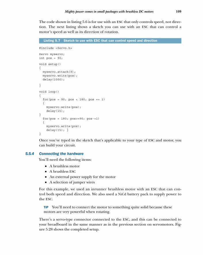
109Mighty power comes in small packages with brushless DC motors
The code shown in listing 5.6 is for use with an ESC that only controls speed, not direc-tion. The next listing shows a sketch you can use with an ESC that can control amotor’s speed as well as its direction of rotation.
#include <Servo.h>
Servo myservo; int pos = 90;
void setup() { myservo.attach(9); myservo.write(pos); delay(1000);
}
void loop() { for(pos = 90; pos < 180; pos += 1) { myservo.write(pos); delay(15); } for(pos = 180; pos>=90; pos-=1) { myservo.write(pos); delay(15); } }
Once you’ve typed in the sketch that’s applicable to your type of ESC and motor, youcan build your circuit.
5.5.4 Connecting the hardware
You’ll need the following items:
■ A brushless motor■ A brushless ESC■ An external power supply for the motor■ A selection of jumper wires
For this example, we used an inrunner brushless motor with an ESC that can con-trol both speed and direction. We also used a NiCd battery pack to supply power tothe ESC.
TIP You’ll need to connect the motor to something quite solid because thesemotors are very powerful when rotating.
There’s a servo-type connector connected to the ESC, and this can be connected toyour breadboard in the same manner as in the previous section on servomotors. Fig-ure 5.28 shows the completed setup.
Listing 5.7 Sketch to use with ESC that can control speed and direction
110 CHAPTER 5 Arduino in motion
When you’ve completed your connections, you can move on and test your circuit.
5.5.5 Upload and test
Upload your sketch to the Arduino before connecting the power pack to the ESC. Oncethe sketch has uploaded, connect the power pack to the ESC and reset the Arduino.After a short delay, you should observe the motor speeding up and then slowing down.
Once you’ve completed this part, it’s time to control the direction of rotation aswell as speed.
5.5.6 Reverse
To control the direction as well as the speed of a brushless motor requires an ESCthat’s normally found in radio-control model cars and some boats. Controlling themstill involves treating the control as a type of servo, but instead of the 1.5-millisecondpulse width being the midrange speed, it’s the motor’s off position. The 2.0-millisecondpulse width is now the full forward direction, and the 1.0-millisecond pulse width isthe full reverse position. You need to change your sketch to reflect this.
5.5.7 Sketch to reverse a brushless motor
The new sketch is shown in the following listing. It’s similar to listing 5.7, with afew additions.
#include <Servo.h>
Servo myservo; int pos = 90;
Listing 5.8 Sketch to control a brushless motor in both forward and reverse
Figure 5.28 Brushless motor controlled by an Arduino
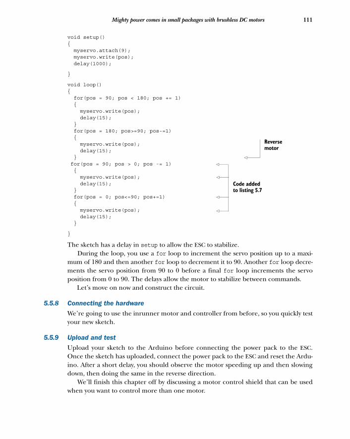
111Mighty power comes in small packages with brushless DC motors
void setup() { myservo.attach(9); myservo.write(pos); delay(1000);
}
void loop() { for(pos = 90; pos < 180; pos += 1) { myservo.write(pos); delay(15); } for(pos = 180; pos>=90; pos-=1) { myservo.write(pos); delay(15); } for(pos = 90; pos > 0; pos -= 1) { myservo.write(pos); delay(15); } for(pos = 0; pos<=90; pos+=1) { myservo.write(pos); delay(15); }
}
The sketch has a delay in setup to allow the ESC to stabilize. During the loop, you use a for loop to increment the servo position up to a maxi-
mum of 180 and then another for loop to decrement it to 90. Another for loop decre-ments the servo position from 90 to 0 before a final for loop increments the servoposition from 0 to 90. The delays allow the motor to stabilize between commands.
Let’s move on now and construct the circuit.
5.5.8 Connecting the hardware
We’re going to use the inrunner motor and controller from before, so you quickly testyour new sketch.
5.5.9 Upload and test
Upload your sketch to the Arduino before connecting the power pack to the ESC.Once the sketch has uploaded, connect the power pack to the ESC and reset the Ardu-ino. After a short delay, you should observe the motor speeding up and then slowingdown, then doing the same in the reverse direction.
We’ll finish this chapter off by discussing a motor control shield that can be usedwhen you want to control more than one motor.
Reverse motor
Code added to listing 5.7
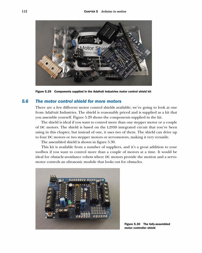
112 CHAPTER 5 Arduino in motion
5.6 The motor control shield for more motorsThere are a few different motor control shields available; we’re going to look at onefrom Adafruit Industries. The shield is reasonably priced and is supplied as a kit thatyou assemble yourself. Figure 5.29 shows the components supplied in the kit.
The shield is ideal if you want to control more than one stepper motor or a coupleof DC motors. The shield is based on the L293D integrated circuit that you’ve beenusing in this chapter, but instead of one, it uses two of them. The shield can drive upto four DC motors or two stepper motors or servomotors, making it very versatile.
The assembled shield is shown in figure 5.30. This kit is available from a number of suppliers, and it’s a great addition to your
toolbox if you want to control more than a couple of motors at a time. It would beideal for obstacle-avoidance robots where DC motors provide the motion and a servo-motor controls an ultrasonic module that looks out for obstacles.
Figure 5.29 Components supplied in the Adafruit Industries motor control shield kit
Figure 5.30 The fully-assembled motor controller shield
113Summary
5.7 SummaryIn this chapter you’ve looked at a variety of different motors and have seen whichtypes of projects they would be suitable for and how you can control them using anArduino and a handful of components.
You started with a small DC motor that can be used to power a wide range ofrobotic vehicles, and you learned how to control both its speed and direction using anL293D integrated circuit.
You then investigated stepper motors that can be accurately and precisely con-trolled and are used in CNC mills, lathes, and 3D printers. You learned how to identifythe different types of commonly available stepper motors and then learned how tocontrol them using the Stepper library shipped with the Arduino IDE.
Next, you learned about servomotors, which are commonly used in radio-controlledmodels. These small, powerful, geared motors are great in projects requiring accuratemovement, like moving an ultrasonic transducer on an obstacle-avoidance robot. Youused the Servo library that lets you control up to 12 servomotors on a standard Ardu-ino, and for those more ambitious projects, up to 48 on an Arduino Mega.
You then applied what you learned about servomotors to control brushless motors.These highly efficient powerhouses are suitable for a wide range of projects, includingquadrocopters and remote-piloted drones.
We ended the chapter with a brief look at a motor controller shield kit from Adafruitthat’s capable of controlling up to four DC motors or two stepper motors or servomotors.
In chapter 6, you’re going to look at using ultrasonic and infrared sensors with anArduino and see how they can be used for object detection.
Object detection
In this chapter we’re going to begin exploring how to get meaningful datafrom the objects and environments around your Arduino controller and use itin your Arduino programs. Of course, meaningful data could mean any numberof things: temperature, sound, light, color, and so on. To start, we’ll focus ondetecting objects.
There are a number of fields where this is important, including robotics, moni-toring, interactive applications, security, and home automation, to name a few.There are three simple technologies that this chapter will explore: ultrasonic sen-sors, active infrared sensors, and passive infrared sensors. All are relatively low-powerand easy to configure and control, but each has distinct advantages and disadvan-tages that you’ll want to understand before creating sensing applications.
We’ll start with ultrasound.
This chapter covers■ Detecting objects with ultrasound■ Range finding with active infrared■ Detecting motion with passive infrared
114
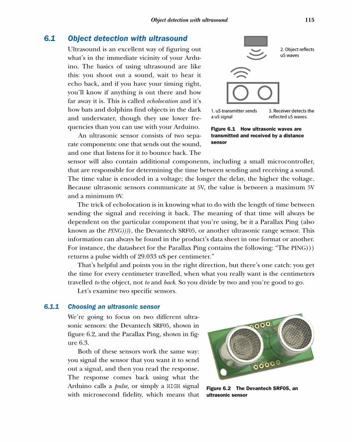
115Object detection with ultrasound
6.1 Object detection with ultrasoundUltrasound is an excellent way of figuring outwhat’s in the immediate vicinity of your Ardu-ino. The basics of using ultrasound are likethis: you shoot out a sound, wait to hear itecho back, and if you have your timing right,you’ll know if anything is out there and howfar away it is. This is called echolocation and it’show bats and dolphins find objects in the darkand underwater, though they use lower fre-quencies than you can use with your Arduino.
An ultrasonic sensor consists of two sepa-rate components: one that sends out the sound,and one that listens for it to bounce back. Thesensor will also contain additional components, including a small microcontroller,that are responsible for determining the time between sending and receiving a sound.The time value is encoded in a voltage; the longer the delay, the higher the voltage.Because ultrasonic sensors communicate at 5V, the value is between a maximum 5Vand a minimum 0V.
The trick of echolocation is in knowing what to do with the length of time betweensending the signal and receiving it back. The meaning of that time will always bedependent on the particular component that you’re using, be it a Parallax Ping (alsoknown as the PING)))), the Devantech SRF05, or another ultrasonic range sensor. Thisinformation can always be found in the product’s data sheet in one format or another.For instance, the datasheet for the Parallax Ping contains the following: “The PING)))returns a pulse width of 29.033 uS per centimeter.”
That’s helpful and points you in the right direction, but there’s one catch: you getthe time for every centimeter travelled, when what you really want is the centimeterstravelled to the object, not to and back. So you divide by two and you’re good to go.
Let’s examine two specific sensors.
6.1.1 Choosing an ultrasonic sensor
We’re going to focus on two different ultra-sonic sensors: the Devantech SRF05, shown infigure 6.2, and the Parallax Ping, shown in fig-ure 6.3.
Both of these sensors work the same way:you signal the sensor that you want it to sendout a signal, and then you read the response.The response comes back using what theArduino calls a pulse, or simply a HIGH signalwith microsecond fidelity, which means that
Figure 6.1 How ultrasonic waves are transmitted and received by a distance sensor
Figure 6.2 The Devantech SRF05, an ultrasonic sensor
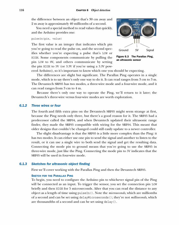
116 CHAPTER 6 Object detection
the difference between an object that’s 30 cm away and2 m away is approximately 40 millionths of a second.
You need a special method to read values that quickly,and the Arduino provides one:
pulseIn(pin, value)
The first value is an integer that indicates which pinyou’re going to read the pulse on, and the second spec-ifies whether you’re expecting a pulse that’s LOW orHIGH. Some components communicate by pulling thepin LOW to 0V, and others communicate by settingthe pin HIGH to 5V (or 3.3V if you’re using a 3.3V pow-ered Arduino), so it’s important to know which one you should be expecting.
The differences are slight but significant. The Parallax Ping operates in a singlemode, which is to say there’s only one way to do it. It can read ranges from 3 cm to 3 m.The Devantech SRF05 has two modes, a three-wire mode and a four-wire mode, and itcan read ranges from 3 cm to 4 m.
Because there’s only one way to operate the Ping, we’ll return to it later; theDevantech’s three-wire versus four-wire modes are worth exploration.
6.1.2 Three wires or four
The fourth and fifth extra pins on the Devantech SRF05 might seem strange at first,because the Ping needs only three, but there’s a good reason for it. The SRF05 had apredecessor called the SRF04, and when Devantech updated their ultrasonic rangefinder, they made the SRF05 compatible with wiring for the SRF04. This meant thatolder designs that couldn’t be changed could still easily update to a newer controller.
The slight disadvantage is that the SRF05 is a little more complex than the Ping: ithas two modes. It can either use one pin to send the signal and another to listen to theresult, or it can use a single wire to both send the signal and get the resulting data.Connecting the mode pin to ground means that you’re going to use the SRF05 inthree-wire mode, just like the Ping. Connecting the mode pin to 5V indicates that theSRF05 will be used in four-wire mode.
6.1.3 Sketches for ultrasonic object finding
First we’ll cover working with the Parallax Ping and then the Devantech SRF05.
SKETCH FOR THE PARALLAX PING
To begin, you need to configure the Arduino pin to whichever signal pin of the Pingwill be connected as an input. To trigger the sensor, you set the connection pin LOWbriefly and then HIGH for 5 microseconds. After that you can read the distance to anyobject as a length of time using pulseIn(). Note the microseconds, which are millionthsof a second and can be set using delayMicroseconds(); they’re not milliseconds, whichare thousandths of a second and can be set using delay().
Figure 6.3 The Parallax Ping, an ultrasonic sensor
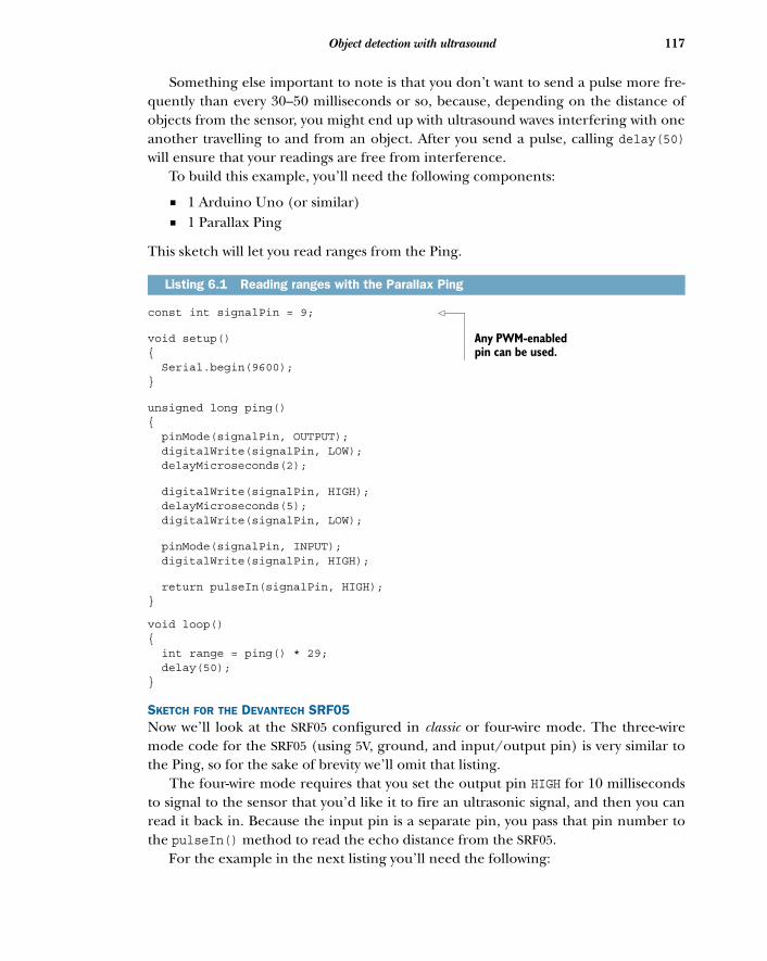
117Object detection with ultrasound
Something else important to note is that you don’t want to send a pulse more fre-quently than every 30–50 milliseconds or so, because, depending on the distance ofobjects from the sensor, you might end up with ultrasound waves interfering with oneanother travelling to and from an object. After you send a pulse, calling delay(50)will ensure that your readings are free from interference.
To build this example, you’ll need the following components:
■ 1 Arduino Uno (or similar)■ 1 Parallax Ping
This sketch will let you read ranges from the Ping.
const int signalPin = 9;
void setup(){ Serial.begin(9600);}
unsigned long ping(){ pinMode(signalPin, OUTPUT); digitalWrite(signalPin, LOW); delayMicroseconds(2);
digitalWrite(signalPin, HIGH); delayMicroseconds(5); digitalWrite(signalPin, LOW);
pinMode(signalPin, INPUT); digitalWrite(signalPin, HIGH);
return pulseIn(signalPin, HIGH);}
void loop(){ int range = ping() * 29; delay(50);}
SKETCH FOR THE DEVANTECH SRF05Now we’ll look at the SRF05 configured in classic or four-wire mode. The three-wiremode code for the SRF05 (using 5V, ground, and input/output pin) is very similar tothe Ping, so for the sake of brevity we’ll omit that listing.
The four-wire mode requires that you set the output pin HIGH for 10 millisecondsto signal to the sensor that you’d like it to fire an ultrasonic signal, and then you canread it back in. Because the input pin is a separate pin, you pass that pin number tothe pulseIn() method to read the echo distance from the SRF05.
For the example in the next listing you’ll need the following:
Listing 6.1 Reading ranges with the Parallax Ping
Any PWM-enabled pin can be used.
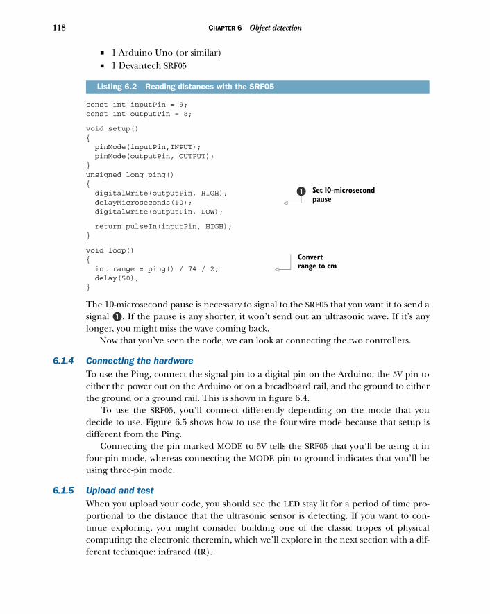
118 CHAPTER 6 Object detection
■ 1 Arduino Uno (or similar)■ 1 Devantech SRF05
const int inputPin = 9;const int outputPin = 8;
void setup(){ pinMode(inputPin,INPUT); pinMode(outputPin, OUTPUT);}unsigned long ping(){ digitalWrite(outputPin, HIGH); delayMicroseconds(10); digitalWrite(outputPin, LOW);
return pulseIn(inputPin, HIGH);}
void loop(){ int range = ping() / 74 / 2; delay(50);}
The 10-microsecond pause is necessary to signal to the SRF05 that you want it to send asignal B. If the pause is any shorter, it won’t send out an ultrasonic wave. If it’s anylonger, you might miss the wave coming back.
Now that you’ve seen the code, we can look at connecting the two controllers.
6.1.4 Connecting the hardwareTo use the Ping, connect the signal pin to a digital pin on the Arduino, the 5V pin toeither the power out on the Arduino or on a breadboard rail, and the ground to eitherthe ground or a ground rail. This is shown in figure 6.4.
To use the SRF05, you’ll connect differently depending on the mode that youdecide to use. Figure 6.5 shows how to use the four-wire mode because that setup isdifferent from the Ping.
Connecting the pin marked MODE to 5V tells the SRF05 that you’ll be using it infour-pin mode, whereas connecting the MODE pin to ground indicates that you’ll beusing three-pin mode.
6.1.5 Upload and testWhen you upload your code, you should see the LED stay lit for a period of time pro-portional to the distance that the ultrasonic sensor is detecting. If you want to con-tinue exploring, you might consider building one of the classic tropes of physicalcomputing: the electronic theremin, which we’ll explore in the next section with a dif-ferent technique: infrared (IR).
Listing 6.2 Reading distances with the SRF05
Set 10-microsecond pause
b
Convert range to cm
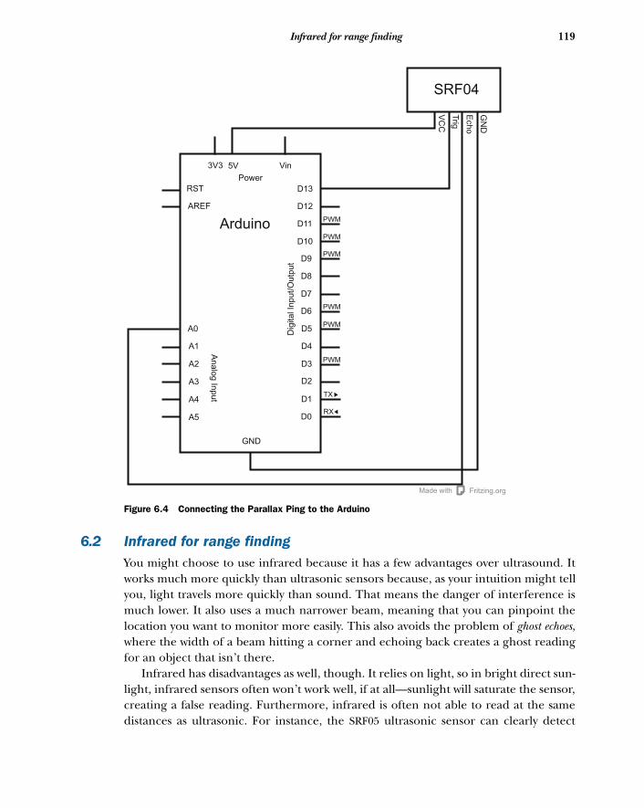
119Infrared for range finding
6.2 Infrared for range findingYou might choose to use infrared because it has a few advantages over ultrasound. Itworks much more quickly than ultrasonic sensors because, as your intuition might tellyou, light travels more quickly than sound. That means the danger of interference ismuch lower. It also uses a much narrower beam, meaning that you can pinpoint thelocation you want to monitor more easily. This also avoids the problem of ghost echoes,where the width of a beam hitting a corner and echoing back creates a ghost readingfor an object that isn’t there.
Infrared has disadvantages as well, though. It relies on light, so in bright direct sun-light, infrared sensors often won’t work well, if at all—sunlight will saturate the sensor,creating a false reading. Furthermore, infrared is often not able to read at the samedistances as ultrasonic. For instance, the SRF05 ultrasonic sensor can clearly detect
Fritzing.orgMade with
SRF04
Vin
Power
3V3 5V
RST
AREF
Arduino
D13
D12
D11
D10
D9
D8
D7
D6
D5
D4
D3
D2
D1
D0
GND
A0
A1
A2
A3
A4
A5
An
alo
g In
pu
t
Dig
ita
l In
pu
t/O
utp
ut
PWM
PWM
PWM
PWM
PWM
PWM
TX
RX
GN
D
Ech
o
Trig
VC
C
Figure 6.4 Connecting the Parallax Ping to the Arduino
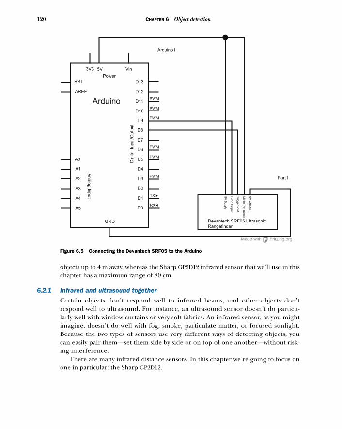
120 CHAPTER 6 Object detection
objects up to 4 m away, whereas the Sharp GP2D12 infrared sensor that we’ll use in thischapter has a maximum range of 80 cm.
6.2.1 Infrared and ultrasound together
Certain objects don’t respond well to infrared beams, and other objects don’trespond well to ultrasound. For instance, an ultrasound sensor doesn’t do particu-larly well with window curtains or very soft fabrics. An infrared sensor, as you mightimagine, doesn’t do well with fog, smoke, particulate matter, or focused sunlight.Because the two types of sensors use very different ways of detecting objects, youcan easily pair them—set them side by side or on top of one another—without risk-ing interference.
There are many infrared distance sensors. In this chapter we’re going to focus onone in particular: the Sharp GP2D12.
Fritzing.orgMade with
Vin
Power
3V3 5V
RST
AREF
Arduino
Arduino1
D13
D12
D11
D10
D9
D8
D7
D6
D5
D4
D3
D2
D1
D0
GND
A0
A1
A2
A3
A4
A5
Analo
g In
put
Dig
ital In
put/
Outp
ut
PWM
PWM
PWM
PWM
PWM
PWM
TX
RX
Devantech SRF05 Ultrasonic
Rangefinder
Part1
0V
Gro
un
d
Mo
de
(no
t use
d)
Trig
ge
rInp
ut
Ech
o O
utp
ut
5V
Su
pp
ly
Figure 6.5 Connecting the Devantech SRF05 to the Arduino
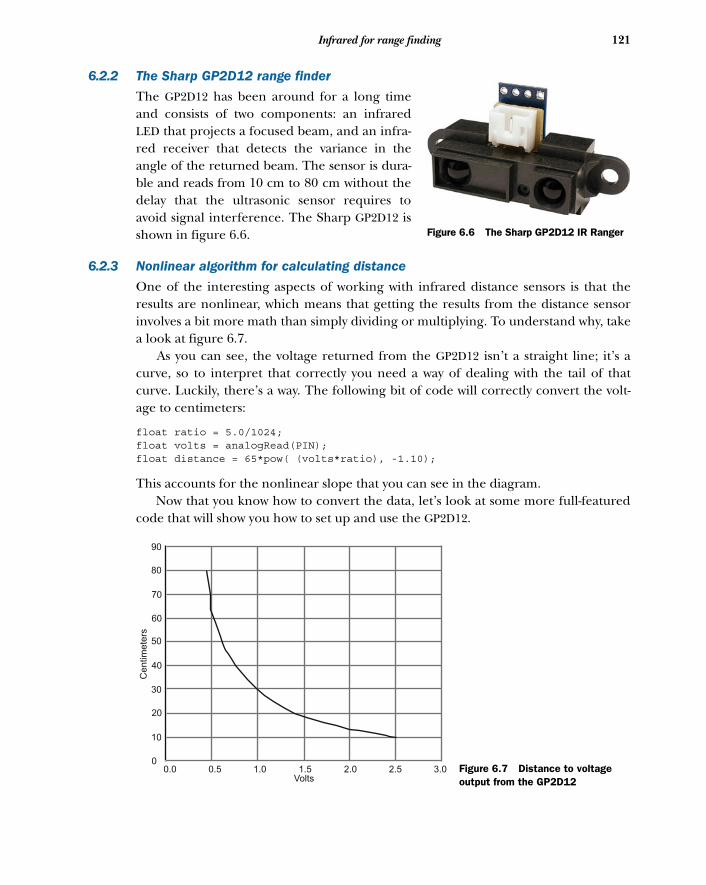
121Infrared for range finding
6.2.2 The Sharp GP2D12 range finder
The GP2D12 has been around for a long timeand consists of two components: an infraredLED that projects a focused beam, and an infra-red receiver that detects the variance in theangle of the returned beam. The sensor is dura-ble and reads from 10 cm to 80 cm without thedelay that the ultrasonic sensor requires toavoid signal interference. The Sharp GP2D12 isshown in figure 6.6.
6.2.3 Nonlinear algorithm for calculating distance
One of the interesting aspects of working with infrared distance sensors is that theresults are nonlinear, which means that getting the results from the distance sensorinvolves a bit more math than simply dividing or multiplying. To understand why, takea look at figure 6.7.
As you can see, the voltage returned from the GP2D12 isn’t a straight line; it’s acurve, so to interpret that correctly you need a way of dealing with the tail of thatcurve. Luckily, there’s a way. The following bit of code will correctly convert the volt-age to centimeters:
float ratio = 5.0/1024;float volts = analogRead(PIN);float distance = 65*pow( (volts*ratio), -1.10);
This accounts for the nonlinear slope that you can see in the diagram. Now that you know how to convert the data, let’s look at some more full-featured
code that will show you how to set up and use the GP2D12.
Figure 6.6 The Sharp GP2D12 IR Ranger
90
80
70
60
50
40
30
20
10
00.0 0.5 1.0 1.5 2.0 2.5 3.0
Volts
Centim
ete
rs
Figure 6.7 Distance to voltage output from the GP2D12
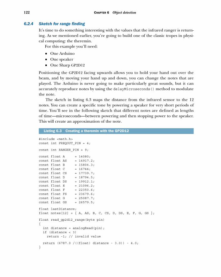
122 CHAPTER 6 Object detection
6.2.4 Sketch for range finding
It’s time to do something interesting with the values that the infrared ranger is return-ing. As we mentioned earlier, you’re going to build one of the classic tropes in physi-cal computing: the theremin.
For this example you’ll need:
■ One Arduino■ One speaker■ One Sharp GP2D12
Positioning the GP2D12 facing upwards allows you to hold your hand out over thebeam, and by moving your hand up and down, you can change the notes that areplayed. The Arduino is never going to make particularly great sounds, but it canaccurately reproduce notes by using the delayMicroseconds() method to modulatethe note.
The sketch in listing 6.3 maps the distance from the infrared sensor to the 12notes. You can create a specific tone by powering a speaker for very short periods oftime. You’ll see in the following sketch that different notes are defined as lengthsof time—microseconds—between powering and then stopping power to the speaker.This will create an approximation of the note.
#include <math.h>const int FREQOUT_PIN = 4;
const int RANGER_PIN = 9;
const float A = 14080;const float AS = 14917.2;const float B = 15804.3;const float C = 16744;const float CS = 17739.7;const float D = 18794.5;const float DS = 19912.1;const float E = 21096.2;const float F = 22350.6;const float FS = 23679.6;const float G = 25087.7;const float GS = 26579.5;
float lastDistance;float notes[12] = { A, AS, B, C, CS, D, DS, E, F, G, GS };
float read_gp2d12_range(byte pin) { int distance = analogRead(pin); if (distance < 3) return -1; // invalid value
return (6787.0 /((float) distance - 3.0)) - 4.0;}
Listing 6.3 Creating a theremin with the GP2D12
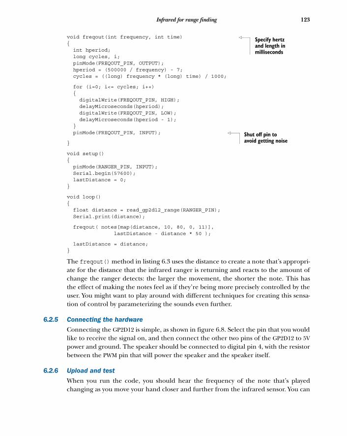
123Infrared for range finding
void freqout(int frequency, int time) { int hperiod; long cycles, i; pinMode(FREQOUT_PIN, OUTPUT); hperiod = (500000 / frequency) - 7; cycles = ((long) frequency * (long) time) / 1000;
for (i=0; i<= cycles; i++) { digitalWrite(FREQOUT_PIN, HIGH); delayMicroseconds(hperiod); digitalWrite(FREQOUT_PIN, LOW); delayMicroseconds(hperiod - 1); } pinMode(FREQOUT_PIN, INPUT);
}
void setup(){ pinMode(RANGER_PIN, INPUT); Serial.begin(57600); lastDistance = 0;}
void loop(){ float distance = read_gp2d12_range(RANGER_PIN); Serial.print(distance);
freqout( notes[map(distance, 10, 80, 0, 11)], lastDistance - distance * 50 );
lastDistance = distance;}
The freqout() method in listing 6.3 uses the distance to create a note that’s appropri-ate for the distance that the infrared ranger is returning and reacts to the amount ofchange the ranger detects: the larger the movement, the shorter the note. This hasthe effect of making the notes feel as if they’re being more precisely controlled by theuser. You might want to play around with different techniques for creating this sensa-tion of control by parameterizing the sounds even further.
6.2.5 Connecting the hardware
Connecting the GP2D12 is simple, as shown in figure 6.8. Select the pin that you wouldlike to receive the signal on, and then connect the other two pins of the GP2D12 to 5Vpower and ground. The speaker should be connected to digital pin 4, with the resistorbetween the PWM pin that will power the speaker and the speaker itself.
6.2.6 Upload and test
When you run the code, you should hear the frequency of the note that’s playedchanging as you move your hand closer and further from the infrared sensor. You can
Specify hertz and length in milliseconds
Shut off pin to avoid getting noise
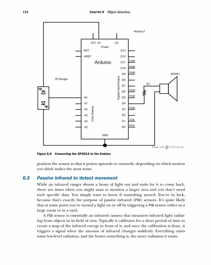
124 CHAPTER 6 Object detection
position the sensor so that it points upwards or outwards, depending on which motionyou think makes the most sense.
6.3 Passive infrared to detect movementWhile an infrared ranger shoots a beam of light out and waits for it to come back,there are times when you might want to monitor a larger area and you don’t needsuch specific data. You simply want to know if something moved. You’re in luck,because that’s exactly the purpose of passive infrared (PIR) sensors. It’s quite likelythat at some point you’ve turned a light on or off by triggering a PIR sensor either in alarge room or in a yard.
A PIR sensor is essentially an infrared camera that measures infrared light radiat-ing from objects in its field of view. Typically it calibrates for a short period of time tocreate a map of the infrared energy in front of it, and once the calibration is done, ittriggers a signal when the amount of infrared changes suddenly. Everything emitssome low-level radiation, and the hotter something is, the more radiation it emits.
Fritzing.orgMade with
Vin
Power
3V3 5V
RST
AREF
Arduino
Arduino1
D13
D12
D11
D10
D9
D8
D7
D6
D5
D4
D3
D2
D1
D0
GND
A0
A1
A2
A3
A4
A5
An
alo
g In
pu
tD
igita
l In
pu
t/O
utp
ut
PWM
PWM
PWM
PWM
PWM
PWM
TX
RX
R1
SPKR1
IR Ranger
Figure 6.8 Connecting the GP2D12 to the Arduino
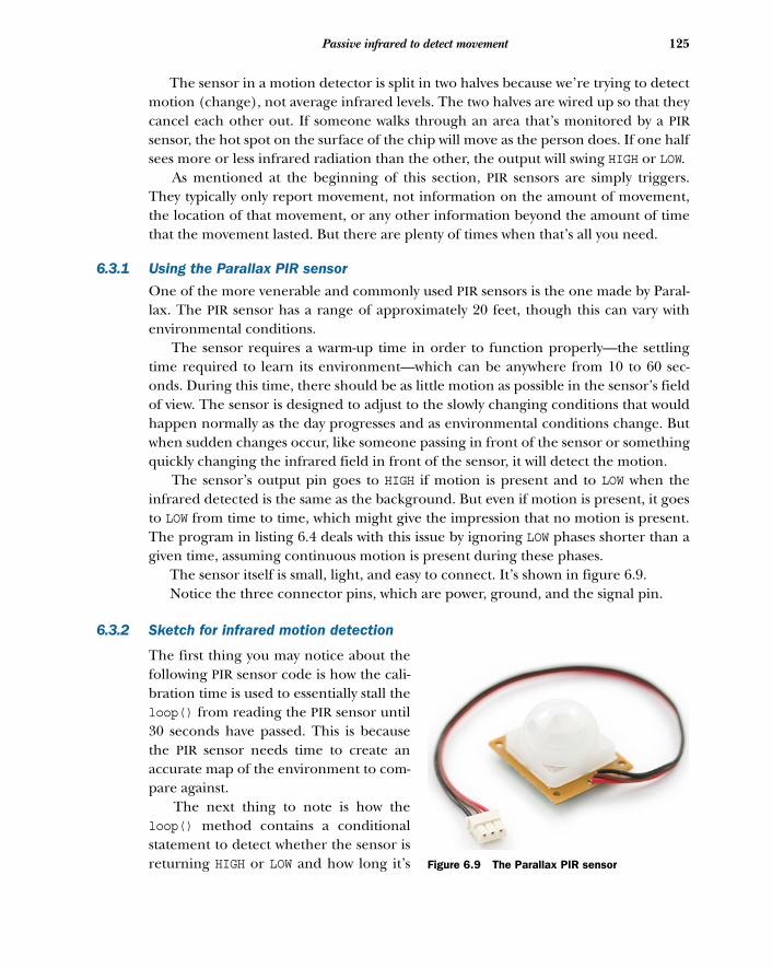
125Passive infrared to detect movement
The sensor in a motion detector is split in two halves because we’re trying to detectmotion (change), not average infrared levels. The two halves are wired up so that theycancel each other out. If someone walks through an area that’s monitored by a PIRsensor, the hot spot on the surface of the chip will move as the person does. If one halfsees more or less infrared radiation than the other, the output will swing HIGH or LOW.
As mentioned at the beginning of this section, PIR sensors are simply triggers.They typically only report movement, not information on the amount of movement,the location of that movement, or any other information beyond the amount of timethat the movement lasted. But there are plenty of times when that’s all you need.
6.3.1 Using the Parallax PIR sensor
One of the more venerable and commonly used PIR sensors is the one made by Paral-lax. The PIR sensor has a range of approximately 20 feet, though this can vary withenvironmental conditions.
The sensor requires a warm-up time in order to function properly—the settlingtime required to learn its environment—which can be anywhere from 10 to 60 sec-onds. During this time, there should be as little motion as possible in the sensor’s fieldof view. The sensor is designed to adjust to the slowly changing conditions that wouldhappen normally as the day progresses and as environmental conditions change. Butwhen sudden changes occur, like someone passing in front of the sensor or somethingquickly changing the infrared field in front of the sensor, it will detect the motion.
The sensor’s output pin goes to HIGH if motion is present and to LOW when theinfrared detected is the same as the background. But even if motion is present, it goesto LOW from time to time, which might give the impression that no motion is present.The program in listing 6.4 deals with this issue by ignoring LOW phases shorter than agiven time, assuming continuous motion is present during these phases.
The sensor itself is small, light, and easy to connect. It’s shown in figure 6.9. Notice the three connector pins, which are power, ground, and the signal pin.
6.3.2 Sketch for infrared motion detection
The first thing you may notice about thefollowing PIR sensor code is how the cali-bration time is used to essentially stall theloop() from reading the PIR sensor until30 seconds have passed. This is becausethe PIR sensor needs time to create anaccurate map of the environment to com-pare against.
The next thing to note is how theloop() method contains a conditionalstatement to detect whether the sensor isreturning HIGH or LOW and how long it’s Figure 6.9 The Parallax PIR sensor
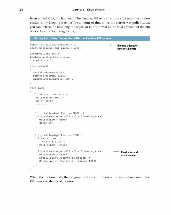
126 CHAPTER 6 Object detection
been pulled HIGH, if it has been. The Parallax PIR sensor returns HIGH until the motionceases, so by keeping track of the amount of time since the sensor was pulled HIGH,you can determine how long the object or entity moved in the field of vision of the PIRsensor (see the following listing).
const int calibrationTime = 30; const unsigned long pause = 5000;
unsigned long lowIn; boolean waitForLow = true;int pirPin = 3;
void setup(){ Serial.begin(57600); pinMode(pirPin, INPUT); digitalWrite(pirPin, LOW);}
void loop(){ if(calibrationTime > 1) { calibrationTime--; delay(1000); return; }
if(digitalRead(pirPin) == HIGH) { if(!waitForLow && millis() - lowIn > pause) { waitForLow = true; delay(50); } }
if(digitalRead(pirPin) == LOW) { if(waitForLow) { lowIn = millis(); waitForLow = false; } if(!waitForLow && millis() - lowIn > pause) { waitForLow = true; Serial.print("length of motion "); Serial.print((millis() - pause)/1000); } }}
When the motion ends, the program writes the duration of the motion in front of thePIR sensor to the serial monitor.
Listing 6.4 Detecting motion with the Parallax PIR sensor
Ensures adequate time to calibrate
Checks for end of movement
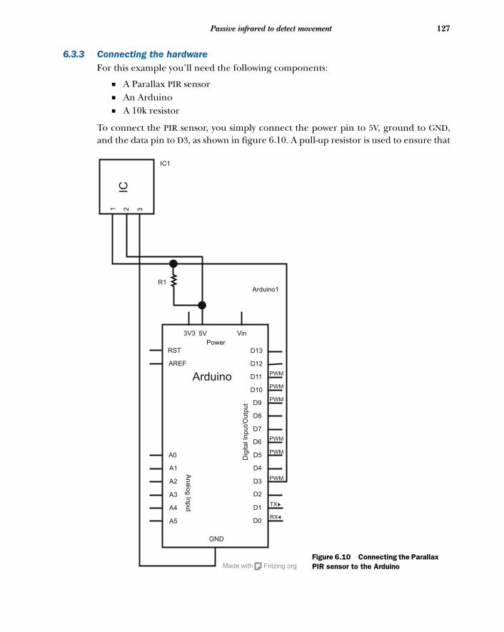
127Passive infrared to detect movement
6.3.3 Connecting the hardwareFor this example you’ll need the following components:
■ A Parallax PIR sensor■ An Arduino■ A 10k resistor
To connect the PIR sensor, you simply connect the power pin to 5V, ground to GND,and the data pin to D3, as shown in figure 6.10. A pull-up resistor is used to ensure that
Vin
Power
3V3 5V
RST
AREF
Arduino
Arduino1
D13
D12
D11
D10
D9
D8
D7
D6
D5
D4
D3
D2
D1
D0
GND
A0
A1
A2
A3
A4
A5
An
alo
g In
pu
t
Dig
ita
l In
pu
t/O
utp
ut
PWM
PWM
PWM
PWM
PWM
PWM
TX
RX
Fritzing.orgMade with
1 32IC
IC1
R1
Figure 6.10 Connecting the Parallax PIR sensor to the Arduino
128 CHAPTER 6 Object detection
the pin stays HIGH until it’s actually pulled low by the PIR sensor. Without this, thereadings from the sensor might float after the initial HIGH reading.
6.3.4 Upload and test
An easy way to test that the sensor is detecting motion is to point it at the ceiling,count to 30, and then wave your hand a meter or so above the sensor. You should seethe length of time that your hand moves in front of the sensor returned in the Ardu-ino IDE serial monitor. This will also give you a sense of the width of the field of visionof the sensor.
6.4 SummaryIn this chapter, you’ve learned a few different techniques to make the Arduino con-textually aware, enabling it to perform simple object detection, range finding, andmotion detection. This sort of capability goes a long way toward making interactivesystems that can react to their users and respond to the location of their users orobjects in their environments. These are the first steps toward creating autonomousvehicles, detection systems, security systems, simple presence-activated systems, and ofcourse, fun musical instruments.
In the next chapter, you’ll learn about using LCD screens with your Arduino.

LCD displays
By now you’ve begun to master the art of interacting with your Arduino in both theanalog and digital domains. You’ve made LEDs blink, you’ve transformed piezosinto pentatonic musical keyboards, and in chapter 6 you graduated from interfac-ing with everyday components such as potentiometers to working with ultrasonicand infrared distance sensors.
Aside from blinking your first LEDs in chapter 1, most of your interaction withthe Arduino thus far has been concerned with obtaining real-world input and out-put from your Arduino. Most of the work you do with the Arduino will be con-cerned with doing exactly that. But you’ll also encounter scenarios where yourproject will need to receive information back from the Arduino, so in this chapterwe’ll revisit the realm of visual feedback by exploring various liquid crystal displays,more commonly called LCDs.
This chapter covers■ Communicating with the common Hitachi
HD44780 parallel LCD■ Building a serial LCD weather station■ Displaying text and images on the KS0108
graphic LCD
129
130 CHAPTER 7 LCD displays
LCDs are embeddable screens found in all sorts of consumer electronics. There aremany different types of LCDs, however, so in section 7.1 you’ll learn about the com-mon LCDs you’ll use in your future Arduino endeavors.
7.1 Introduction to LCDsLiquid crystal displays (LCDs) have become ubiquitous: from the moment you wakeup to the moment you go to bed, your day is guided by many interactions withLCD screens.
You wake up in the morning and, upon seeing the LCD on your alarm clock, yourealize you’re running an hour late. You use the LCD on your mp3 player to navigateto the song you absolutely must listen to next. You look at the number on yourphone’s LCD and decide to answer or ignore the call. And before bed, you look at thealarm clock again to make sure it’s set for tomorrow.
Viewing LCD displays is one of the primary ways we experience electronic data, andin this chapter we’ll look at the common types of LCDs you can add to your futureArduino projects.
The first two types of LCD displays are parallel and serial LCDs, and they’re nor-mally character displays. Character displays are ideal for displaying some sort of textto the user, and even small shapes or icons (usually 5 x 7 pixels). The other type ofLCD we’ll cover in this chapter is basic graphic LCDs, which as you may have guessedare great for drawing graphics and images.
But before we explore character displays, let’s take a look at String variables,which are how we deal with text in Arduino.
7.1.1 String variables: String type vs. char type
Pairing an Arduino with an LCD is a great way to display text feedback and addmenu-browsing capabilities to your project. So how exactly does one send text toan LCD?
In the Arduino and other computer programming languages, text is thought of asa sequence of characters. For example, if you were to put together the four charactersT, e, x, t, you would make the word Text. In this way, all text is represented in code asan array of characters.
There are two main ways to create your text in code (or, more generally, to createany sequence of characters). One way is to use the String data type, and the other isto use a null-terminated array of type char. If that makes complete sense to you, great!If not, don’t worry; it’s much simpler than it sounds. Let’s take a look and see what thefuss is all about.
As previously mentioned, all text in your code will actually be an array of charac-ters. For more control, a container class called the String class was created, whichenables you to manipulate this array of characters in many complex ways. You cancompare two Strings against each other to see if they’re the same, search a String oftext for a substring, and append characters to the end of a String or even concatenate
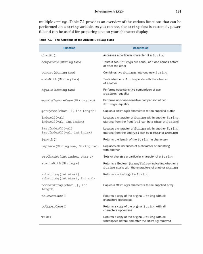
131Introduction to LCDs
multiple Strings. Table 7.1 provides an overview of the various functions that can beperformed on a String variable. As you can see, the String class is extremely power-ful and can be useful for preparing text on your character display.
Table 7.1 The functions of the Arduino String class
Function Description
charAt() Accesses a particular character of a String
compareTo(String two) Tests if two Strings are equal, or if one comes before or after the other
concat(String two) Combines two Strings into one new String
endsWith(String two) Tests whether a String ends with the chars of another
equals(String two) Performs case-sensitive comparison of two Strings’ equality
equalsIgnoreCase(String two) Performs non-case-sensitive comparison of two Strings’ equality
getBytes(char [ ], int length) Copies a String’s characters to the supplied buffer
indexOf(val)indexOf(val, int index)
Locates a character or String within another String, starting from the front (val can be a char or String)
lastIndexOf(val)lastIndexOf(val, int index)
Locates a character of String within another String, starting from the end (val can be a char or String)
length() Returns the length of the String in characters
replace(String one, String two) Replaces all instances of a character or substring with another
setCharAt(int index, char c) Sets or changes a particular character of a String
startsWith(String s) Returns a Boolean (true/false) indicating whether a String starts with the characters of another String
substring(int start)substring(int start, int end)
Returns a substring of a String
toCharArray(char [ ], intlength)
Copies a String’s characters to the supplied array
toLowerCase() Returns a copy of the original String with all characters lowercase
toUpperCase() Returns a copy of the original String with all characters uppercase
Trim() Returns a copy of the original String with all whitespace before and after the String removed
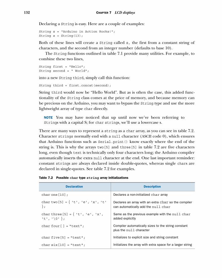
132 CHAPTER 7 LCD displays
Declaring a String is easy. Here are a couple of examples:
String s = "Arduino in Action Rocks!"; String s = String(13);
Both of these lines will create a String called s, the first from a constant string ofcharacters, and the second from an integer number (defaults to base 10).
The String functions outlined in table 7.1 provide many utilities. For example, tocombine these two lines,
String first = "Hello"; String second = " World";
into a new String third, simply call this function:
String third = first.concat(second);
String third would now be “Hello World”. But as is often the case, this added func-tionality of the String class comes at the price of memory, and because memory canbe precious on the Arduino, you may want to bypass the String type and use the morelightweight array of type char directly.
NOTE You may have noticed that up until now we’ve been referring toStrings with a capital S; for char strings, we’ll use a lowercase s.
There are many ways to represent a string as a char array, as you can see in table 7.2.Character strings normally end with a null character (ASCII code 0), which ensuresthat Arduino functions such as Serial.print() know exactly where the end of thestring is. This is why the arrays two[5] and three[5] in table 7.2 are five characterslong, even though text is technically only four characters long; the Arduino compilerautomatically inserts the extra null character at the end. One last important reminder:constant strings are always declared inside double-quotes, whereas single chars aredeclared in single-quotes. See table 7.2 for examples.
Table 7.2 Possible char type string array initializations
Declaration Description
char one[10]; Declares a non-initialized char array
char two[5] = { 't', 'e', 'x', 't'};
Declares an array with an extra char so the compiler can automatically add the null char
char three[5] = { 't', 'e', 'x','t', '\0' };
Same as the previous example with the null charadded explicitly
char four[ ] = "text"; Compiler automatically sizes to the string constant plus the null character
char five[5] = "text"; Initializes to explicit size and string constant
char six[10] = "text"; Initializes the array with extra space for a larger string
133Parallel character LCDs: the Hitachi HD44780
At this point, we’ve hopefully demystified the differences between the String typeand the array of char type strings that you’ll encounter when working with the Ardu-ino and LCDs. Next we’ll look at wiring up your first LCD, so without further ado,please welcome the Hitachi HD44780.
7.2 Parallel character LCDs: the Hitachi HD44780The Hitachi HD44780 is one of the most common LCD controller chips designed forembedded systems and microcontrollers. The chip supports many shapes and sizesof displays, and in this example, we’ll use one to drive a 16 x 2 LCD (2 rows, 16 char-acters long).
The pervasiveness of the Hitachi HD44780 controller (and other similar LCD chips)is great news for you, because they can usually be purchased cheaply or salvaged fromyour old machines. Some are even pretty fancy, offering single and multicolor (RGB)backlighting.
Backlit LCDs have lights (LEDs) embedded in the screen, which can be turned onto make the screen glow. This isn’t only great for low-lit situations, but also for visualfeedback. For example, an LCD such as the Hitachi HD44780 that has an RGB backlightcan light the screen with different colors, reporting the status of your Arduino. Youmight turn the screen red to let the user know something is wrong, or green to signalthat things are OK.
7.2.1 4-bit or 8-bit?
Hitachi HD44780-based LCDs come in many different configurations, but there are twoways in which you can interface with the Hitachi HD44780 LCD: 4-bit and 8-bit. Themain tradeoff between the 4-bit and 8-bit configurations is the number of pins neededon the Arduino versus speed of execution.
Because it’s a parallel LCD, the simplest means of communication would be tosend the full byte (8-bits) of data all at once (in a 1-byte message). To do this wouldrequire at least 10 I/O pins on the Arduino. In contrast, the 4-bit mode requires just 6I/O pins and splits the byte into two 4-bit nibbles. This saves pins but takes a littlemore time (two messages versus one message). The 4-bit mode is still “parallel” in thesense that you receive 4 bits at a time, but it’s split into two messages that are sent oneafter another.
7.2.2 Library and functions
Luckily for us, working with LCDs based on the Hitachi HD44780 chipset (or other sim-ilar chipsets) is a breeze. As was mentioned in chapter 4, one of the standard librariespreinstalled in the Arduino IDE is the LiquidCrystal LCD library. It’s compatible withboth 4-bit and 8-bit configurations and provides you with many useful functions forcontrolling your LCD.
Table 7.3 details the functions available in the LiquidCrystal library.
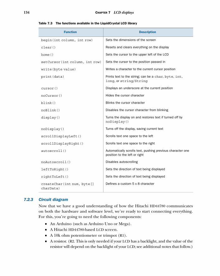
134 CHAPTER 7 LCD displays
7.2.3 Circuit diagram
Now that we have a good understanding of how the Hitachi HD44780 communicateson both the hardware and software level, we’re ready to start connecting everything.For this, you’re going to need the following components:
■ An Arduino (such as Arduino Uno or Mega).■ A Hitachi HD44780-based LCD screen.■ A 10k ohm potentiometer or trimpot (R1).■ A resistor. (R2. This is only needed if your LCD has a backlight, and the value of the
resistor will depend on the backlight of your LCD; see additional notes that follow.)
Table 7.3 The functions available in the LiquidCrystal LCD library
Function Description
begin(int column, int row) Sets the dimensions of the screen
clear() Resets and clears everything on the display
home() Sets the cursor to the upper left of the LCD
setCursor(int column, int row) Sets the cursor to the position passed in
write(byte value) Writes a character to the current cursor position
print(data) Prints text to the string; can be a char, byte, int, long, or string/String
cursor() Displays an underscore at the current position
noCursor() Hides the cursor character
blink() Blinks the cursor character
noBlink() Disables the cursor character from blinking
display() Turns the display on and restores text if turned off by noDisplay()
noDisplay() Turns off the display, saving current text
scrollDisplayLeft() Scrolls text one space to the left
scrollDisplayRight() Scrolls text one space to the right
autoscroll() Automatically scrolls text, pushing previous character one position to the left or right
noAutoscroll() Disables autoscrolling
leftToRight() Sets the direction of text being displayed
rightToLeft() Sets the direction of text being displayed
createChar(int num, byte[]charData)
Defines a custom 5 x 8 character
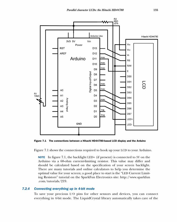
135Parallel character LCDs: the Hitachi HD44780
Figure 7.1 shows the connections required to hook up your LCD to your Arduino.
NOTE In figure 7.1, the backlight LED+ (if present) is connected to 5V on theArduino via a 68-ohm current-limiting resistor. This value may differ andshould be calculated based on the specification of your screen backlight.There are many tutorials and online calculators to help you determine theoptimal value for your screen; a good place to start is the “LED Current Limit-ing Resistors” tutorial on the SparkFun Electronics site: http://www.sparkfun.com/tutorials/219.
7.2.4 Connecting everything up in 4-bit mode
To save your precious I/O pins for other sensors and devices, you can connecteverything in 4-bit mode. The LiquidCrystal library automatically takes care of the
Figure 7.1 The connections between a Hitachi HD44780-based LCD display and the Arduino
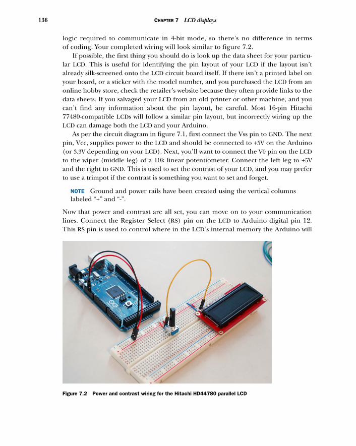
136 CHAPTER 7 LCD displays
logic required to communicate in 4-bit mode, so there’s no difference in termsof coding. Your completed wiring will look similar to figure 7.2.
If possible, the first thing you should do is look up the data sheet for your particu-lar LCD. This is useful for identifying the pin layout of your LCD if the layout isn’talready silk-screened onto the LCD circuit board itself. If there isn’t a printed label onyour board, or a sticker with the model number, and you purchased the LCD from anonline hobby store, check the retailer’s website because they often provide links to thedata sheets. If you salvaged your LCD from an old printer or other machine, and youcan’t find any information about the pin layout, be careful. Most 16-pin Hitachi77480-compatible LCDs will follow a similar pin layout, but incorrectly wiring up theLCD can damage both the LCD and your Arduino.
As per the circuit diagram in figure 7.1, first connect the Vss pin to GND. The nextpin, Vcc, supplies power to the LCD and should be connected to +5V on the Arduino(or 3.3V depending on your LCD). Next, you’ll want to connect the V0 pin on the LCDto the wiper (middle leg) of a 10k linear potentiometer. Connect the left leg to +5Vand the right to GND. This is used to set the contrast of your LCD, and you may preferto use a trimpot if the contrast is something you want to set and forget.
NOTE Ground and power rails have been created using the vertical columnslabeled “+” and “-”.
Now that power and contrast are all set, you can move on to your communicationlines. Connect the Register Select (RS) pin on the LCD to Arduino digital pin 12.This RS pin is used to control where in the LCD’s internal memory the Arduino will
Figure 7.2 Power and contrast wiring for the Hitachi HD44780 parallel LCD
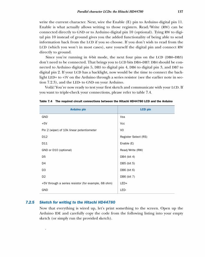
137Parallel character LCDs: the Hitachi HD44780
write the current character. Next, wire the Enable (E) pin to Arduino digital pin 11.Enable is what actually allows writing to those registers. Read/Write (RW) can beconnected directly to GND or to Arduino digital pin 10 (optional). Tying RW to digi-tal pin 10 instead of ground gives you the added functionality of being able to sendinformation back from the LCD if you so choose. If you don’t wish to read from theLCD (which you won’t in most cases), save yourself the digital pin and connect RWdirectly to ground.
Since you’re running in 4-bit mode, the next four pins on the LCD (DB0–DB3)don’t need to be connected. That brings you to LCD bits DB4–DB7: DB4 should be con-nected to Arduino digital pin 5, DB5 to digital pin 4, DB6 to digital pin 3, and DB7 todigital pin 2. If your LCD has a backlight, now would be the time to connect the back-light LED+ to +5V on the Arduino through a series resistor (see the earlier note in sec-tion 7.2.3), and the LED- to GND on your Arduino.
Voilà! You’re now ready to test your first sketch and communicate with your LCD. Ifyou want to triple-check your connections, please refer to table 7.4.
7.2.5 Sketch for writing to the Hitachi HD44780
Now that everything is wired up, let’s print something to the screen. Open up theArduino IDE and carefully copy the code from the following listing into your emptysketch (or simply run the provided sketch).
.
Table 7.4 The required circuit connections between the Hitachi HD44780 LCD and the Arduino
Arduino pin LCD pin
GND Vss
+5V Vcc
Pin 2 (wiper) of 10k linear potentiometer V0
D12 Register Select (RS)
D11 Enable (E)
GND or D10 (optional) Read/Write (RW)
D5 DB4 (bit 4)
D4 DB5 (bit 5)
D3 DB6 (bit 6)
D2 DB6 (bit 7)
+5V through a series resistor (for example, 68 ohm) LED+
GND LED-
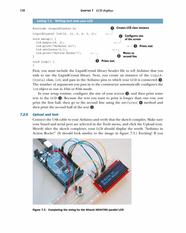
138 CHAPTER 7 LCD displays
#include <LiquidCrystal.h>
LiquidCrystal lcd(12, 11, 5, 4, 3, 2);
void setup() { lcd.begin(16, 2); lcd.print("Arduino in"); lcd.setCursor(0,1); lcd.print("Action Rocks!"); }
void loop() {}
First, you must include the LiquidCrystal library header file to tell Arduino that youwish to use the LiquidCrystal library. Next, you create an instance of the Liquid-Crystal class, lcd, and pass in the Arduino pins to which your LCD is connected B.The number of arguments you pass in to the constructor automatically configures thelcd object to run in 4-bit or 8-bit mode.
In your setup routine, configure the size of your screen c, and then print sometext to the LCD d. Because the text you want to print is longer than one row, youprint the first half, then go to the second line using the setCursor e method andthen print the second half of the text f.
7.2.6 Upload and testConnect the USB cable to your Arduino and verify that the sketch compiles. Make sureyour board and serial port are selected in the Tools menu, and click the Upload icon.Shortly after the sketch completes, your LCD should display the words “Arduino inAction Rocks!” (It should look similar to the image in figure 7.3.) Exciting! If you
Listing 7.1 Writing text onto your LCD
Creates LCD class instanceb
Configures size of the screen
c
Prints textd
Moves to second linee
Prints textf
Figure 7.3 Completing the wiring for the Hitachi HD44780 parallel LCD
139Serial LCD weather station
don’t see anything displayed on the screen, or if the text is too dim, turn the potenti-ometer wired to V0 to adjust the contrast of the screen.
Seeing text on your LCD for the first time is always very exciting, especially whenthe display is giving you useful information. Now that you’ve tackled displaying statictext in your first LCD project, let’s build a weather station to monitor temperature inreal time. And while we’re at it, let’s also learn about another type of character display,the serial LCD.
7.3 Serial LCD weather stationWant to save even more pins on your Arduino, or perhaps you’d just prefer fewer dan-gling wires? Serial LCDs are another affordable option, and they require only threepins to operate. They work a little differently than parallel LCDs, interpreting serialcommands (TTL or transistor-transistor logic, to be exact) over your Arduino’s TX pininto special commands or output to the LCD (more on this later). The catch is thatthey’re a little more expensive than their parallel brethren, although prices havecome down significantly in recent years. Additionally, you can purchase a serial LCDbackpack, turning your Hitachi HD44780 parallel LCD into a serial LCD.
In this section, we’re going to look at connecting and communicating with a serialLCD and build a real-time weather station to monitor the temperature of your home.
7.3.1 Serial vs. parallel LCDsThe way in which serial LCDs communicate with the Arduino is fundamentally dif-ferent than the parallel LCDs we saw in section 7.2, although operationally they’revery similar.
If you remember our study of parallel LCDs, we sent either 4- or 8-bit messagesfrom the Arduino to the LCD, instructing it to move the cursor or print a character tothe screen. The main difference is that serial LCDs send messages one bit at a time(serially), requiring only one communication line. Once wired up, communicatingwith the serial LCD is as easy as sending the appropriate single-byte command flagusing Serial.print(command) to perform various tasks (move the cursor, turn thedisplay off, and so on) or you can send plain old characters to print text to the screen:Serial.print("text").
There are a number of commands you can send to the screen, so it would be help-ful to create helper functions that automatically set the appropriate command beforepassing the message you want. Luckily, the Arduino community has already done thisfor various serial LCD models, and it has created Serial LCD libraries based on the offi-cial LiquidCrystal library, but with a few added features.
7.3.2 SerLCD library and functionsThe library you’ll be using to communicate with your serial LCD in this section iscalled SerLCD. The library is written to be used with the 16 x 2 SparkFun (or compati-ble) serial LCDs and backpacks, but with a simple modification the library can be usedwith most serial LCDs on the market.
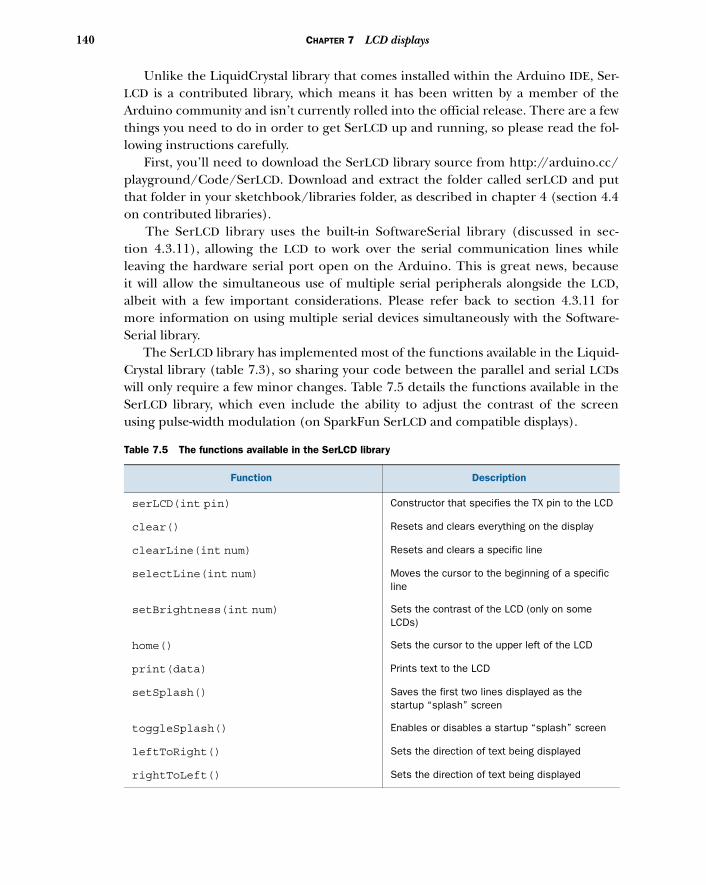
140 CHAPTER 7 LCD displays
Unlike the LiquidCrystal library that comes installed within the Arduino IDE, Ser-LCD is a contributed library, which means it has been written by a member of theArduino community and isn’t currently rolled into the official release. There are a fewthings you need to do in order to get SerLCD up and running, so please read the fol-lowing instructions carefully.
First, you’ll need to download the SerLCD library source from http://arduino.cc/playground/Code/SerLCD. Download and extract the folder called serLCD and putthat folder in your sketchbook/libraries folder, as described in chapter 4 (section 4.4on contributed libraries).
The SerLCD library uses the built-in SoftwareSerial library (discussed in sec-tion 4.3.11), allowing the LCD to work over the serial communication lines whileleaving the hardware serial port open on the Arduino. This is great news, becauseit will allow the simultaneous use of multiple serial peripherals alongside the LCD,albeit with a few important considerations. Please refer back to section 4.3.11 formore information on using multiple serial devices simultaneously with the Software-Serial library.
The SerLCD library has implemented most of the functions available in the Liquid-Crystal library (table 7.3), so sharing your code between the parallel and serial LCDswill only require a few minor changes. Table 7.5 details the functions available in theSerLCD library, which even include the ability to adjust the contrast of the screenusing pulse-width modulation (on SparkFun SerLCD and compatible displays).
Table 7.5 The functions available in the SerLCD library
Function Description
serLCD(int pin) Constructor that specifies the TX pin to the LCD
clear() Resets and clears everything on the display
clearLine(int num) Resets and clears a specific line
selectLine(int num) Moves the cursor to the beginning of a specific line
setBrightness(int num) Sets the contrast of the LCD (only on some LCDs)
home() Sets the cursor to the upper left of the LCD
print(data) Prints text to the LCD
setSplash() Saves the first two lines displayed as the startup “splash” screen
toggleSplash() Enables or disables a startup “splash” screen
leftToRight() Sets the direction of text being displayed
rightToLeft() Sets the direction of text being displayed
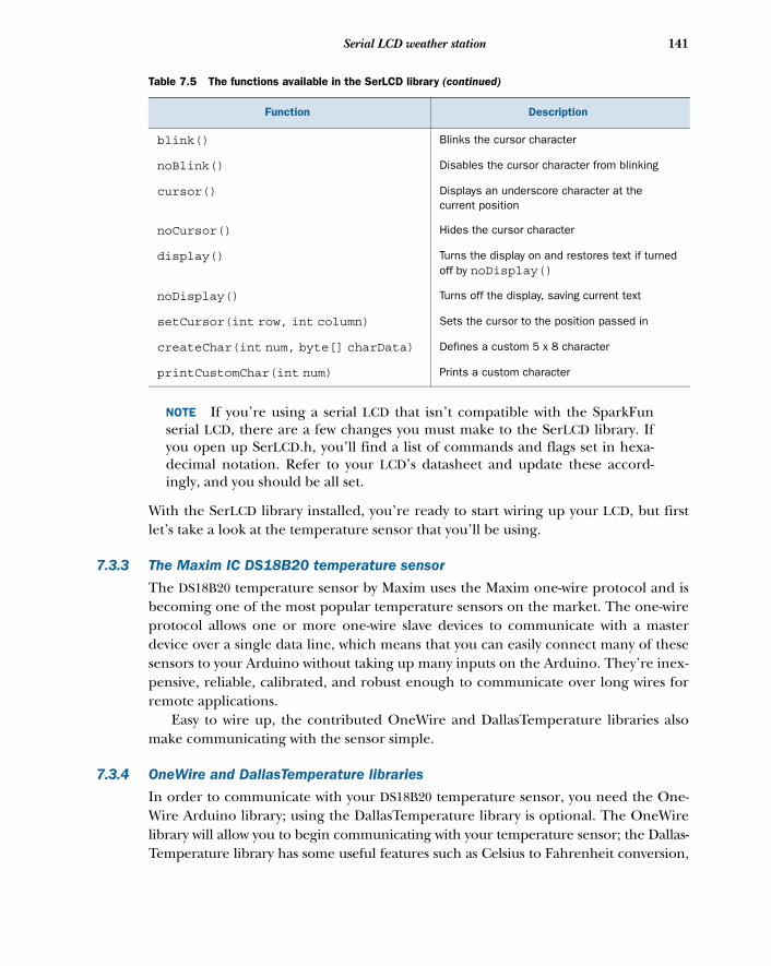
141Serial LCD weather station
NOTE If you’re using a serial LCD that isn’t compatible with the SparkFunserial LCD, there are a few changes you must make to the SerLCD library. Ifyou open up SerLCD.h, you’ll find a list of commands and flags set in hexa-decimal notation. Refer to your LCD’s datasheet and update these accord-ingly, and you should be all set.
With the SerLCD library installed, you’re ready to start wiring up your LCD, but firstlet’s take a look at the temperature sensor that you’ll be using.
7.3.3 The Maxim IC DS18B20 temperature sensor
The DS18B20 temperature sensor by Maxim uses the Maxim one-wire protocol and isbecoming one of the most popular temperature sensors on the market. The one-wireprotocol allows one or more one-wire slave devices to communicate with a masterdevice over a single data line, which means that you can easily connect many of thesesensors to your Arduino without taking up many inputs on the Arduino. They’re inex-pensive, reliable, calibrated, and robust enough to communicate over long wires forremote applications.
Easy to wire up, the contributed OneWire and DallasTemperature libraries alsomake communicating with the sensor simple.
7.3.4 OneWire and DallasTemperature libraries
In order to communicate with your DS18B20 temperature sensor, you need the One-Wire Arduino library; using the DallasTemperature library is optional. The OneWirelibrary will allow you to begin communicating with your temperature sensor; the Dallas-Temperature library has some useful features such as Celsius to Fahrenheit conversion,
blink() Blinks the cursor character
noBlink() Disables the cursor character from blinking
cursor() Displays an underscore character at the current position
noCursor() Hides the cursor character
display() Turns the display on and restores text if turned off by noDisplay()
noDisplay() Turns off the display, saving current text
setCursor(int row, int column) Sets the cursor to the position passed in
createChar(int num, byte[] charData) Defines a custom 5 x 8 character
printCustomChar(int num) Prints a custom character
Table 7.5 The functions available in the SerLCD library (continued)
Function Description
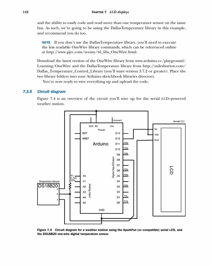
142 CHAPTER 7 LCD displays
and the ability to easily code and read more than one temperature sensor on the samebus. As such, we’re going to be using the DallasTemperature library in this example,and recommend you do too.
NOTE If you don’t use the DallasTemperature library, you’ll need to executethe less readable OneWire library commands, which can be referenced onlineat http://www.pjrc.com/teensy/td_libs_OneWire.html.
Download the latest version of the OneWire library from www.arduino.cc/playground/Learning/OneWire and the DallasTemperature library from http://milesburton.com/Dallas_Temperature_Control_Library (you’ll want version 3.7.2 or greater). Place thetwo library folders into your Arduino sketchbook libraries directory.
You’re now ready to wire everything up and upload the code.
7.3.5 Circuit diagram
Figure 7.4 is an overview of the circuit you’ll wire up for the serial LCD–poweredweather station.
Figure 7.4 Circuit diagram for a weather station using the SparkFun (or compatible) serial LCD, and the DS18B20 one-wire digital temperature sensor
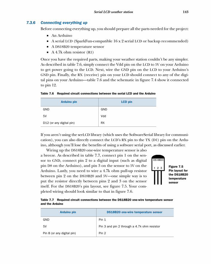
143Serial LCD weather station
7.3.6 Connecting everything up
Before connecting everything up, you should prepare all the parts needed for the project:
■ An Arduino■ A serial LCD (SparkFun-compatible 16 x 2 serial LCD or backup recommended)■ A DS18B20 temperature sensor■ A 4.7k ohm resistor (R1)
Once you have the required parts, making your weather station couldn’t be any simpler.As described in table 7.6, simply connect the Vdd pin on the LCD to 5V on your Arduinoto get power going to the LCD. Next, wire the GND pin on the LCD to your Arduino’sGND pin. Finally, the RX (receive) pin on your LCD should connect to any of the digi-tal pins on your Arduino—table 7.6 and the schematic in figure 7.4 show it connectedto pin 12.
If you aren’t using the serLCD library (which uses the SoftwareSerial library for communi-cation), you can also directly connect the LCD’s RX pin to the TX (D1) pin on the Ardu-ino, although you’ll lose the benefits of using a software serial port, as discussed earlier.
Wiring up the DS18B20 one-wire temperature sensor is alsoa breeze. As described in table 7.7, connect pin 1 on the sen-sor to GND, connect pin 2 to a digital input (such as digitalpin D8 on the Arduino), and pin 3 on the sensor to 5V on theArduino. Lastly, you need to wire a 4.7k ohm pull-up resistorbetween pin 2 on the DS18B20 and 5V—one simple way is toput the resistor directly between pins 2 and 3 on the sensoritself. For the DS18B20’s pin layout, see figure 7.5. Your com-pleted wiring should look similar to that in figure 7.6.
Table 7.6 Required circuit connections between the serial LCD and the Arduino
Arduino pin LCD pin
GND GND
5V Vdd
D12 (or any digital pin) RX
Table 7.7 Required circuit connections between the DS18B20 one-wire temperature sensor and the Arduino
Arduino pin DS18B20 one-wire temperature sensor
GND Pin 1
5V Pin 3 and pin 2 through a 4.7k ohm resistor
Pin 8 (or any digital pin) Pin 2
Figure 7.5Pin layout for the DS18B20 temperature sensor
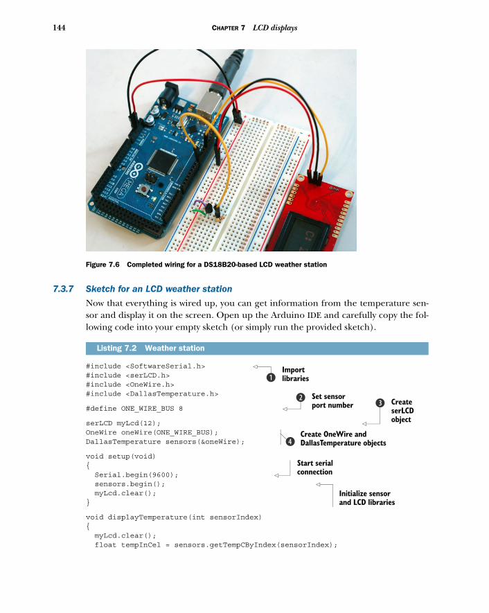
144 CHAPTER 7 LCD displays
7.3.7 Sketch for an LCD weather station
Now that everything is wired up, you can get information from the temperature sen-sor and display it on the screen. Open up the Arduino IDE and carefully copy the fol-lowing code into your empty sketch (or simply run the provided sketch).
#include <SoftwareSerial.h> #include <serLCD.h>#include <OneWire.h>#include <DallasTemperature.h>
#define ONE_WIRE_BUS 8
serLCD myLcd(12); OneWire oneWire(ONE_WIRE_BUS); DallasTemperature sensors(&oneWire);
void setup(void){ Serial.begin(9600); sensors.begin(); myLcd.clear();}
void displayTemperature(int sensorIndex){ myLcd.clear(); float tempInCel = sensors.getTempCByIndex(sensorIndex);
Listing 7.2 Weather station
Figure 7.6 Completed wiring for a DS18B20-based LCD weather station
Import librariesb
Set sensor port number
c Create serLCD object
d
Create OneWire and DallasTemperature objectse
Start serial connection
Initialize sensor and LCD libraries
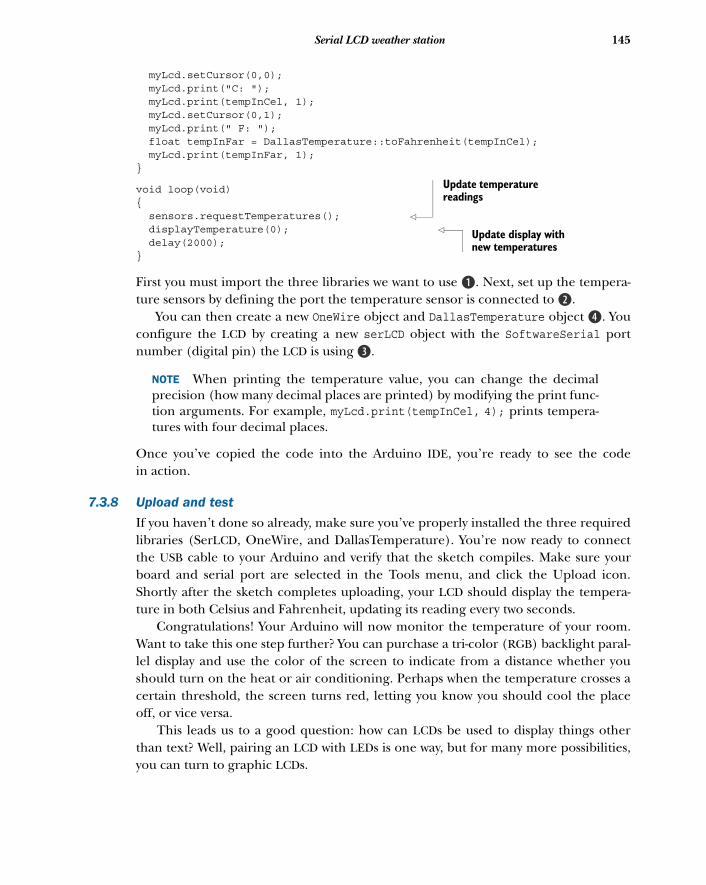
145Serial LCD weather station
myLcd.setCursor(0,0); myLcd.print("C: "); myLcd.print(tempInCel, 1); myLcd.setCursor(0,1); myLcd.print(" F: "); float tempInFar = DallasTemperature::toFahrenheit(tempInCel); myLcd.print(tempInFar, 1);}
void loop(void){ sensors.requestTemperatures(); displayTemperature(0); delay(2000);}
First you must import the three libraries we want to use B. Next, set up the tempera-ture sensors by defining the port the temperature sensor is connected to c.
You can then create a new OneWire object and DallasTemperature object e. Youconfigure the LCD by creating a new serLCD object with the SoftwareSerial portnumber (digital pin) the LCD is using d.
NOTE When printing the temperature value, you can change the decimalprecision (how many decimal places are printed) by modifying the print func-tion arguments. For example, myLcd.print(tempInCel, 4); prints tempera-tures with four decimal places.
Once you’ve copied the code into the Arduino IDE, you’re ready to see the codein action.
7.3.8 Upload and test
If you haven’t done so already, make sure you’ve properly installed the three requiredlibraries (SerLCD, OneWire, and DallasTemperature). You’re now ready to connectthe USB cable to your Arduino and verify that the sketch compiles. Make sure yourboard and serial port are selected in the Tools menu, and click the Upload icon.Shortly after the sketch completes uploading, your LCD should display the tempera-ture in both Celsius and Fahrenheit, updating its reading every two seconds.
Congratulations! Your Arduino will now monitor the temperature of your room.Want to take this one step further? You can purchase a tri-color (RGB) backlight paral-lel display and use the color of the screen to indicate from a distance whether youshould turn on the heat or air conditioning. Perhaps when the temperature crosses acertain threshold, the screen turns red, letting you know you should cool the placeoff, or vice versa.
This leads us to a good question: how can LCDs be used to display things otherthan text? Well, pairing an LCD with LEDs is one way, but for many more possibilities,you can turn to graphic LCDs.
Update temperature readings
Update display with new temperatures
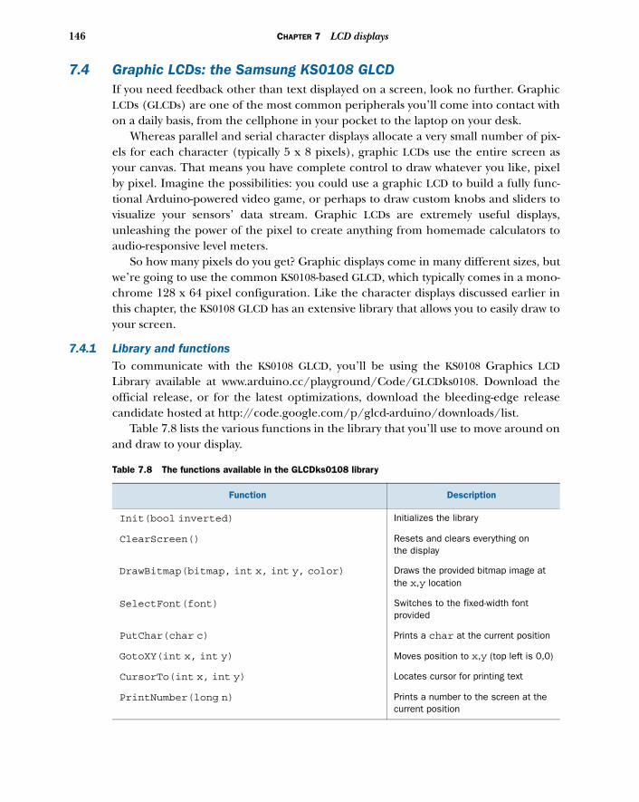
146 CHAPTER 7 LCD displays
7.4 Graphic LCDs: the Samsung KS0108 GLCDIf you need feedback other than text displayed on a screen, look no further. GraphicLCDs (GLCDs) are one of the most common peripherals you’ll come into contact withon a daily basis, from the cellphone in your pocket to the laptop on your desk.
Whereas parallel and serial character displays allocate a very small number of pix-els for each character (typically 5 x 8 pixels), graphic LCDs use the entire screen asyour canvas. That means you have complete control to draw whatever you like, pixelby pixel. Imagine the possibilities: you could use a graphic LCD to build a fully func-tional Arduino-powered video game, or perhaps to draw custom knobs and sliders tovisualize your sensors’ data stream. Graphic LCDs are extremely useful displays,unleashing the power of the pixel to create anything from homemade calculators toaudio-responsive level meters.
So how many pixels do you get? Graphic displays come in many different sizes, butwe’re going to use the common KS0108-based GLCD, which typically comes in a mono-chrome 128 x 64 pixel configuration. Like the character displays discussed earlier inthis chapter, the KS0108 GLCD has an extensive library that allows you to easily draw toyour screen.
7.4.1 Library and functionsTo communicate with the KS0108 GLCD, you’ll be using the KS0108 Graphics LCDLibrary available at www.arduino.cc/playground/Code/GLCDks0108. Download theofficial release, or for the latest optimizations, download the bleeding-edge releasecandidate hosted at http://code.google.com/p/glcd-arduino/downloads/list.
Table 7.8 lists the various functions in the library that you’ll use to move around onand draw to your display.
Table 7.8 The functions available in the GLCDks0108 library
Function Description
Init(bool inverted) Initializes the library
ClearScreen() Resets and clears everything on the display
DrawBitmap(bitmap, int x, int y, color) Draws the provided bitmap image at the x,y location
SelectFont(font) Switches to the fixed-width font provided
PutChar(char c) Prints a char at the current position
GotoXY(int x, int y) Moves position to x,y (top left is 0,0)
CursorTo(int x, int y) Locates cursor for printing text
PrintNumber(long n) Prints a number to the screen at the current position
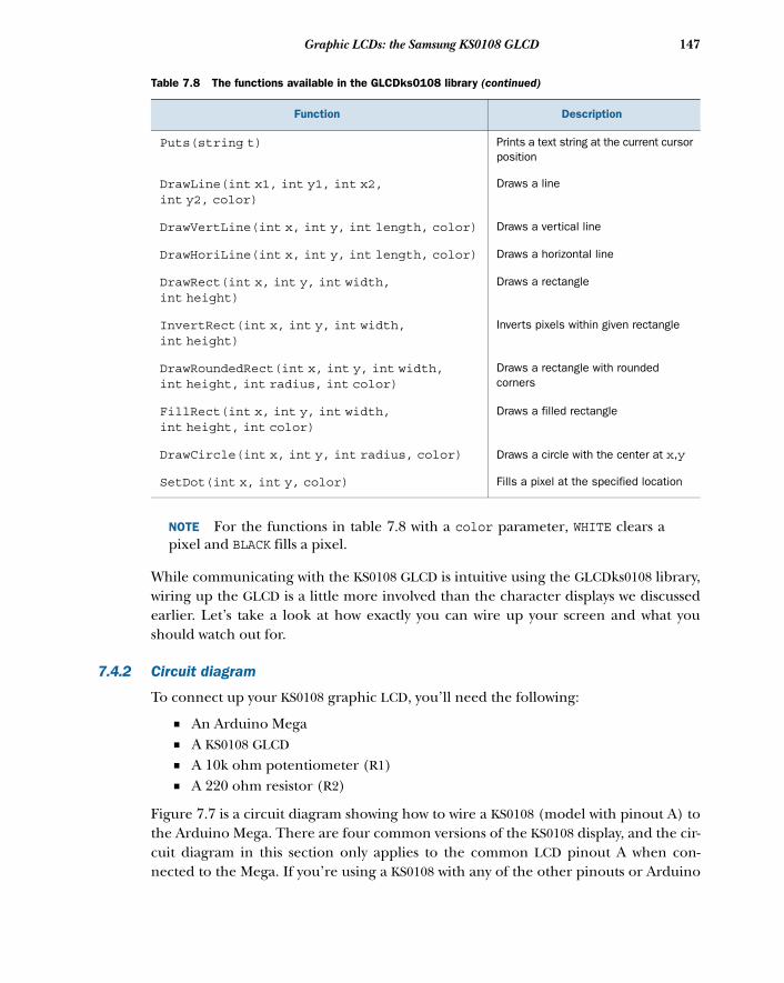
147Graphic LCDs: the Samsung KS0108 GLCD
NOTE For the functions in table 7.8 with a color parameter, WHITE clears apixel and BLACK fills a pixel.
While communicating with the KS0108 GLCD is intuitive using the GLCDks0108 library,wiring up the GLCD is a little more involved than the character displays we discussedearlier. Let’s take a look at how exactly you can wire up your screen and what youshould watch out for.
7.4.2 Circuit diagram
To connect up your KS0108 graphic LCD, you’ll need the following:
■ An Arduino Mega■ A KS0108 GLCD■ A 10k ohm potentiometer (R1)■ A 220 ohm resistor (R2)
Figure 7.7 is a circuit diagram showing how to wire a KS0108 (model with pinout A) tothe Arduino Mega. There are four common versions of the KS0108 display, and the cir-cuit diagram in this section only applies to the common LCD pinout A when con-nected to the Mega. If you’re using a KS0108 with any of the other pinouts or Arduino
Puts(string t) Prints a text string at the current cursor position
DrawLine(int x1, int y1, int x2,int y2, color)
Draws a line
DrawVertLine(int x, int y, int length, color) Draws a vertical line
DrawHoriLine(int x, int y, int length, color) Draws a horizontal line
DrawRect(int x, int y, int width,int height)
Draws a rectangle
InvertRect(int x, int y, int width,int height)
Inverts pixels within given rectangle
DrawRoundedRect(int x, int y, int width,int height, int radius, int color)
Draws a rectangle with rounded corners
FillRect(int x, int y, int width,int height, int color)
Draws a filled rectangle
DrawCircle(int x, int y, int radius, color) Draws a circle with the center at x,y
SetDot(int x, int y, color) Fills a pixel at the specified location
Table 7.8 The functions available in the GLCDks0108 library (continued)
Function Description
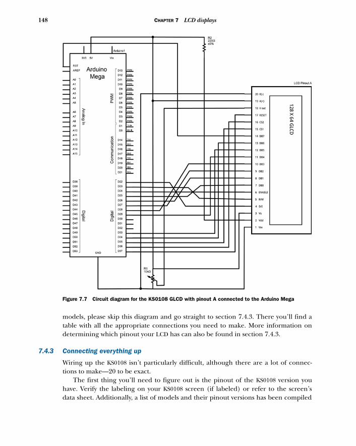
148 CHAPTER 7 LCD displays
models, please skip this diagram and go straight to section 7.4.3. There you’ll find atable with all the appropriate connections you need to make. More information ondetermining which pinout your LCD has can also be found in section 7.4.3.
7.4.3 Connecting everything up
Wiring up the KS0108 isn’t particularly difficult, although there are a lot of connec-tions to make—20 to be exact.
The first thing you’ll need to figure out is the pinout of the KS0108 version youhave. Verify the labeling on your KS0108 screen (if labeled) or refer to the screen’sdata sheet. Additionally, a list of models and their pinout versions has been compiled
Figure 7.7 Circuit diagram for the KS0108 GLCD with pinout A connected to the Arduino Mega
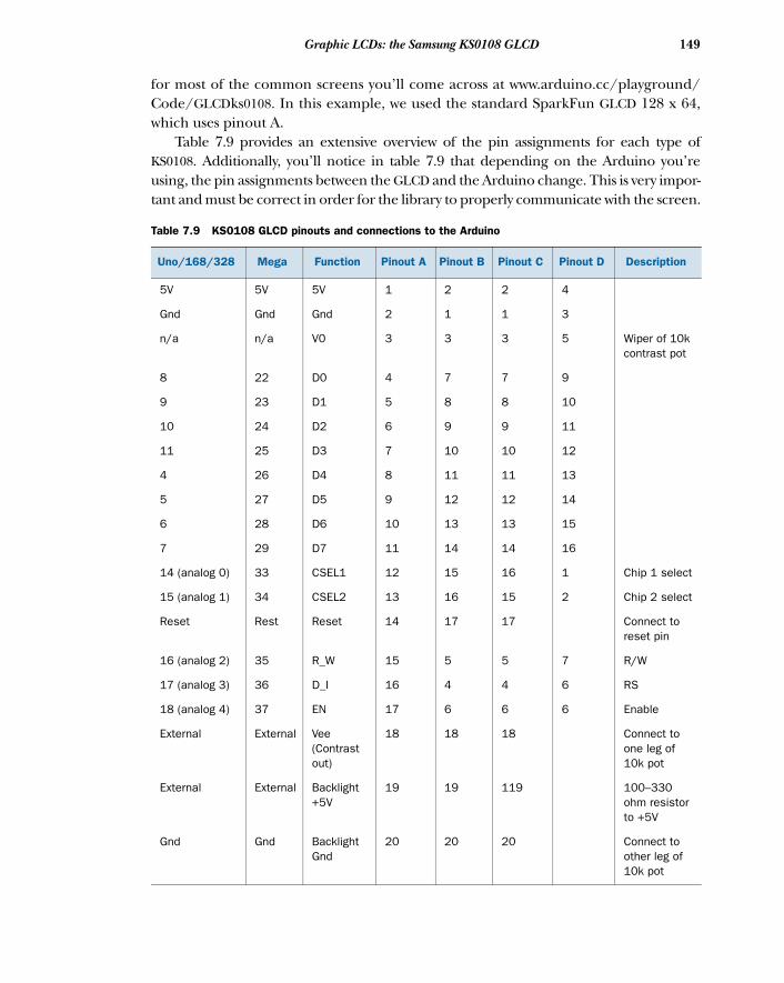
149Graphic LCDs: the Samsung KS0108 GLCD
for most of the common screens you’ll come across at www.arduino.cc/playground/Code/GLCDks0108. In this example, we used the standard SparkFun GLCD 128 x 64,which uses pinout A.
Table 7.9 provides an extensive overview of the pin assignments for each type ofKS0108. Additionally, you’ll notice in table 7.9 that depending on the Arduino you’reusing, the pin assignments between the GLCD and the Arduino change. This is very impor-tant and must be correct in order for the library to properly communicate with the screen.
Table 7.9 KS0108 GLCD pinouts and connections to the Arduino
Uno/168/328 Mega Function Pinout A Pinout B Pinout C Pinout D Description
5V 5V 5V 1 2 2 4
Gnd Gnd Gnd 2 1 1 3
n/a n/a V0 3 3 3 5 Wiper of 10k contrast pot
8 22 D0 4 7 7 9
9 23 D1 5 8 8 10
10 24 D2 6 9 9 11
11 25 D3 7 10 10 12
4 26 D4 8 11 11 13
5 27 D5 9 12 12 14
6 28 D6 10 13 13 15
7 29 D7 11 14 14 16
14 (analog 0) 33 CSEL1 12 15 16 1 Chip 1 select
15 (analog 1) 34 CSEL2 13 16 15 2 Chip 2 select
Reset Rest Reset 14 17 17 Connect to reset pin
16 (analog 2) 35 R_W 15 5 5 7 R/W
17 (analog 3) 36 D_I 16 4 4 6 RS
18 (analog 4) 37 EN 17 6 6 6 Enable
External External Vee (Contrast out)
18 18 18 Connect to one leg of 10k pot
External External Backlight +5V
19 19 119 100–330 ohm resistor to +5V
Gnd Gnd Backlight Gnd
20 20 20 Connect to other leg of 10k pot
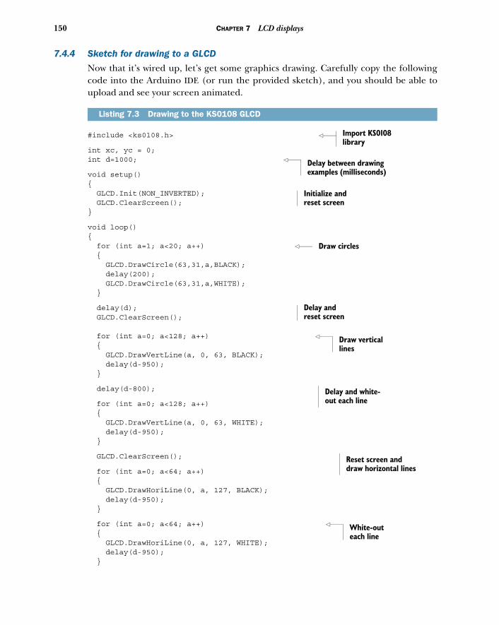
150 CHAPTER 7 LCD displays
7.4.4 Sketch for drawing to a GLCD
Now that it’s wired up, let’s get some graphics drawing. Carefully copy the followingcode into the Arduino IDE (or run the provided sketch), and you should be able toupload and see your screen animated.
#include <ks0108.h>
int xc, yc = 0;int d=1000;
void setup(){ GLCD.Init(NON_INVERTED); GLCD.ClearScreen(); }
void loop(){ for (int a=1; a<20; a++) { GLCD.DrawCircle(63,31,a,BLACK); delay(200); GLCD.DrawCircle(63,31,a,WHITE); }
delay(d); GLCD.ClearScreen(); for (int a=0; a<128; a++) { GLCD.DrawVertLine(a, 0, 63, BLACK); delay(d-950); }
delay(d-800);
for (int a=0; a<128; a++) { GLCD.DrawVertLine(a, 0, 63, WHITE); delay(d-950); }
GLCD.ClearScreen();
for (int a=0; a<64; a++) { GLCD.DrawHoriLine(0, a, 127, BLACK); delay(d-950); }
for (int a=0; a<64; a++) { GLCD.DrawHoriLine(0, a, 127, WHITE); delay(d-950); }
Listing 7.3 Drawing to the KS0108 GLCD
Import KS0108 library
Delay between drawing examples (milliseconds)
Initialize and reset screen
Draw circles
Delay and reset screen
Draw vertical lines
Delay and white-out each line
Reset screen and draw horizontal lines
White-out each line
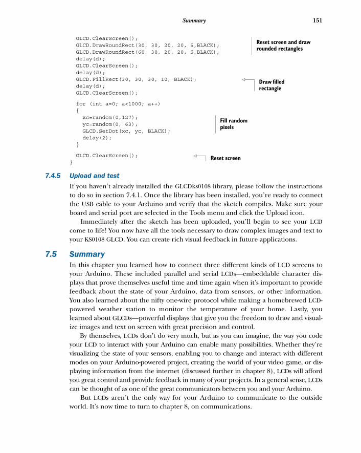
151Summary
GLCD.ClearScreen(); GLCD.DrawRoundRect(30, 30, 20, 20, 5,BLACK); GLCD.DrawRoundRect(60, 30, 20, 20, 5,BLACK); delay(d); GLCD.ClearScreen(); delay(d); GLCD.FillRect(30, 30, 30, 10, BLACK); delay(d); GLCD.ClearScreen();
for (int a=0; a<1000; a++) { xc=random(0,127); yc=random(0, 63); GLCD.SetDot(xc, yc, BLACK); delay(2); }
GLCD.ClearScreen(); }
7.4.5 Upload and test
If you haven’t already installed the GLCDks0108 library, please follow the instructionsto do so in section 7.4.1. Once the library has been installed, you’re ready to connectthe USB cable to your Arduino and verify that the sketch compiles. Make sure yourboard and serial port are selected in the Tools menu and click the Upload icon.
Immediately after the sketch has been uploaded, you’ll begin to see your LCDcome to life! You now have all the tools necessary to draw complex images and text toyour KS0108 GLCD. You can create rich visual feedback in future applications.
7.5 SummaryIn this chapter you learned how to connect three different kinds of LCD screens toyour Arduino. These included parallel and serial LCDs—embeddable character dis-plays that prove themselves useful time and time again when it’s important to providefeedback about the state of your Arduino, data from sensors, or other information.You also learned about the nifty one-wire protocol while making a homebrewed LCD-powered weather station to monitor the temperature of your home. Lastly, youlearned about GLCDs—powerful displays that give you the freedom to draw and visual-ize images and text on screen with great precision and control.
By themselves, LCDs don’t do very much, but as you can imagine, the way you codeyour LCD to interact with your Arduino can enable many possibilities. Whether they’revisualizing the state of your sensors, enabling you to change and interact with differentmodes on your Arduino-powered project, creating the world of your video game, or dis-playing information from the internet (discussed further in chapter 8), LCDs will affordyou great control and provide feedback in many of your projects. In a general sense, LCDscan be thought of as one of the great communicators between you and your Arduino.
But LCDs aren’t the only way for your Arduino to communicate to the outsideworld. It’s now time to turn to chapter 8, on communications.
Reset screen and draw rounded rectangles
Draw filled rectangle
Fill random pixels
Reset screen

Communications
In the previous chapter, we investigated how you can receive visual feedback fromthe Arduino by communicating with LCD screens. Imagine if you could displayinformation from the Arduino on an external screen, and also send it out over theinternet for the world to see! What if you could control your Arduino remotely?
Getting your Arduino on the internet and remotely talking to your computerare two of the many communication channels possible with the Arduino. We’ll lookat communicating with your Arduino via Ethernet, Wi-Fi, Bluetooth, and SPI.
As many of your projects will involve communicating over the internet, let’s diveright in and look at how to communicate with the Arduino over a computer network.
This chapter covers■ Creating an Ethernet web server to query data
from your Arduino■ Tweeting messages from your Arduino to Twitter■ Wi-Fi network and Bluetooth communication
with the Arduino■ Data logging onto an SD card and to the
internet using the Cosm service■ Communicating with other devices over the
Serial Peripheral Interface (SPI) protocol
152
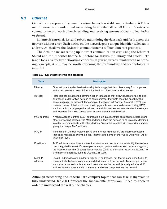
153Ethernet
8.1 EthernetOne of the most powerful communication channels available on the Arduino is Ether-net. Ethernet is a standardized networking facility that allows all kinds of devices tocommunicate with each other by sending and receiving streams of data (called packetsor frames).
Ethernet is extremely fast and robust, transmitting the data back and forth across thenetwork without error. Each device on the network gets a unique identifier called an IPaddress, which allows the devices to communicate via different internet protocols.
The Arduino makes setting up internet communication easy using the EthernetShield and the Ethernet library, but before we discuss the library and shield, let’stake a look at a few key networking concepts. If you’re already familiar with network-ing concepts, it still may be worth reviewing the terminology and technologies intable 8.1.
Although networking and Ethernet are complex topics that can take many years tofully understand, table 8.1 presents the fundamental terms you’ll need to know inorder to understand the rest of the chapter.
Table 8.1 Key Ethernet terms and concepts
Term Description
Ethernet Ethernet is a standardized networking technology that describes a way for computers and other devices to send information back and forth over a wired network.
Protocol Protocols are established communication languages that allow devices to talk to one another. In order for two devices to communicate, they both must be speaking the same language, or protocol. For example, the Hypertext Transfer Protocol (HTTP) is a common protocol that you’ll use to set up your Arduino as a web server. Using HTTP, you’ll establish a language that allows the Arduino web server to understand messages and requests from web clients such as a computer’s web browser.
MAC address A Media Access Control (MAC) address is a unique identifier assigned to Ethernet and other networking devices. The MAC address allows the devices to be uniquely identified in order to communicate with other devices. Your Arduino shield will come with a sticker giving it a unique MAC address.
TCP/IP Transmission Control Protocol (TCP) and Internet Protocol (IP) are internet protocols that pass messages over the global internet (the home of the “world wide web” we all know and love).
IP address An IP address is a unique address that devices and servers use to identify themselves over the global internet. For example, when you go to a website, such as manning.com, the internet uses the Directory Name Service (DNS) to translate http://google.com/ to a numeric IP address, such as 209.85.148.139.
Local IP address
Local IP addresses are similar to regular IP addresses, but they’re used specifically to communicate between computers and devices on a local network. For example, when you set up a network at home, each computer on the network is assigned a local IP address to communicate with the router and other computers on the network.
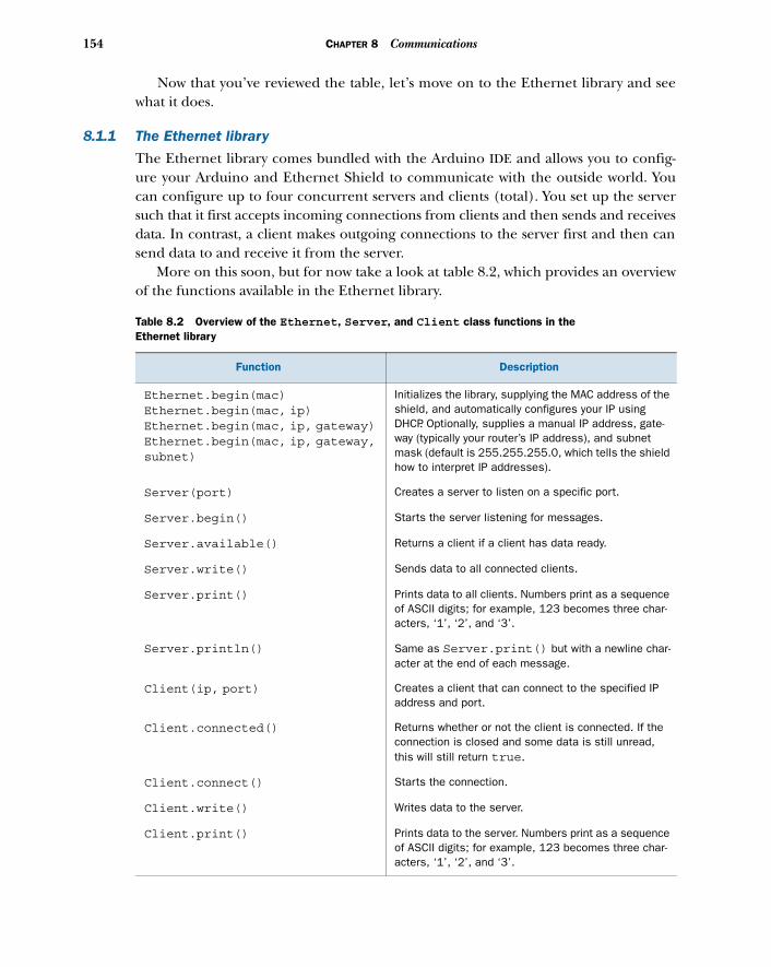
154 CHAPTER 8 Communications
Now that you’ve reviewed the table, let’s move on to the Ethernet library and seewhat it does.
8.1.1 The Ethernet library
The Ethernet library comes bundled with the Arduino IDE and allows you to config-ure your Arduino and Ethernet Shield to communicate with the outside world. Youcan configure up to four concurrent servers and clients (total). You set up the serversuch that it first accepts incoming connections from clients and then sends and receivesdata. In contrast, a client makes outgoing connections to the server first and then cansend data to and receive it from the server.
More on this soon, but for now take a look at table 8.2, which provides an overviewof the functions available in the Ethernet library.
Table 8.2 Overview of the Ethernet, Server, and Client class functions in the Ethernet library
Function Description
Ethernet.begin(mac)Ethernet.begin(mac, ip)Ethernet.begin(mac, ip, gateway)Ethernet.begin(mac, ip, gateway,subnet)
Initializes the library, supplying the MAC address of the shield, and automatically configures your IP using DHCP. Optionally, supplies a manual IP address, gate-way (typically your router’s IP address), and subnet mask (default is 255.255.255.0, which tells the shield how to interpret IP addresses).
Server(port) Creates a server to listen on a specific port.
Server.begin() Starts the server listening for messages.
Server.available() Returns a client if a client has data ready.
Server.write() Sends data to all connected clients.
Server.print() Prints data to all clients. Numbers print as a sequence of ASCII digits; for example, 123 becomes three char-acters, ‘1’, ‘2’, and ‘3’.
Server.println() Same as Server.print() but with a newline char-acter at the end of each message.
Client(ip, port) Creates a client that can connect to the specified IP address and port.
Client.connected() Returns whether or not the client is connected. If the connection is closed and some data is still unread, this will still return true.
Client.connect() Starts the connection.
Client.write() Writes data to the server.
Client.print() Prints data to the server. Numbers print as a sequence of ASCII digits; for example, 123 becomes three char-acters, ‘1’, ‘2’, and ‘3’.
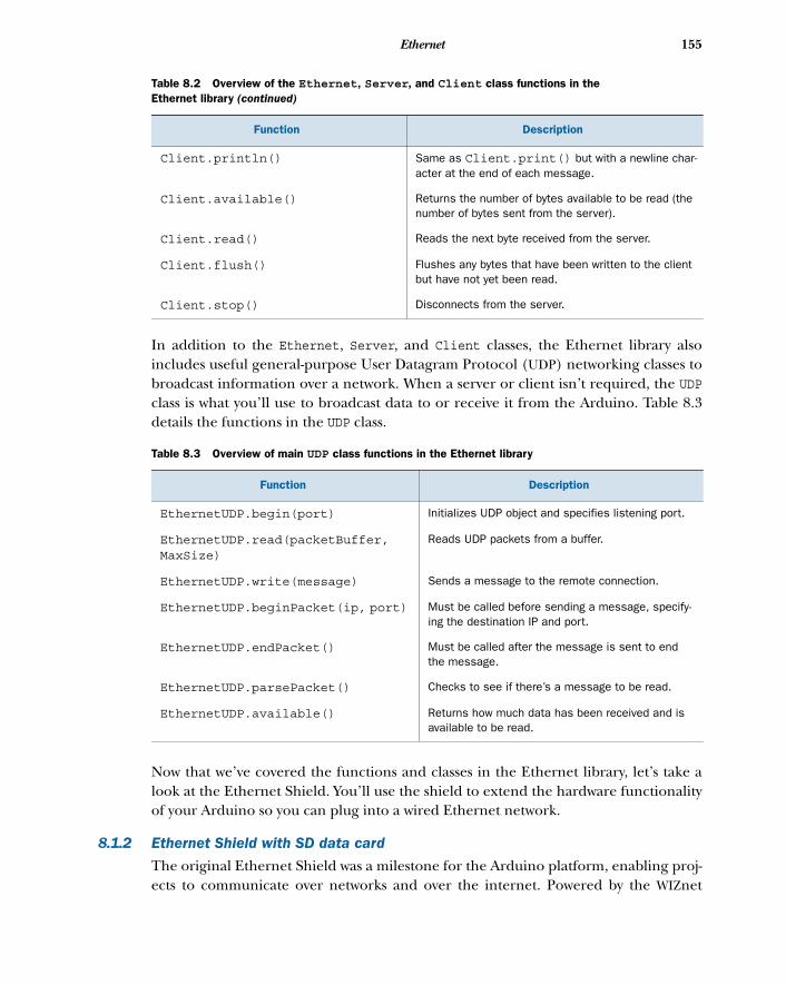
155Ethernet
In addition to the Ethernet, Server, and Client classes, the Ethernet library alsoincludes useful general-purpose User Datagram Protocol (UDP) networking classes tobroadcast information over a network. When a server or client isn’t required, the UDPclass is what you’ll use to broadcast data to or receive it from the Arduino. Table 8.3details the functions in the UDP class.
Now that we’ve covered the functions and classes in the Ethernet library, let’s take alook at the Ethernet Shield. You’ll use the shield to extend the hardware functionalityof your Arduino so you can plug into a wired Ethernet network.
8.1.2 Ethernet Shield with SD data card
The original Ethernet Shield was a milestone for the Arduino platform, enabling proj-ects to communicate over networks and over the internet. Powered by the WIZnet
Client.println() Same as Client.print() but with a newline char-acter at the end of each message.
Client.available() Returns the number of bytes available to be read (the number of bytes sent from the server).
Client.read() Reads the next byte received from the server.
Client.flush() Flushes any bytes that have been written to the client but have not yet been read.
Client.stop() Disconnects from the server.
Table 8.3 Overview of main UDP class functions in the Ethernet library
Function Description
EthernetUDP.begin(port) Initializes UDP object and specifies listening port.
EthernetUDP.read(packetBuffer,MaxSize)
Reads UDP packets from a buffer.
EthernetUDP.write(message) Sends a message to the remote connection.
EthernetUDP.beginPacket(ip, port) Must be called before sending a message, specify-ing the destination IP and port.
EthernetUDP.endPacket() Must be called after the message is sent to end the message.
EthernetUDP.parsePacket() Checks to see if there’s a message to be read.
EthernetUDP.available() Returns how much data has been received and is available to be read.
Table 8.2 Overview of the Ethernet, Server, and Client class functions in the Ethernet library (continued)
Function Description
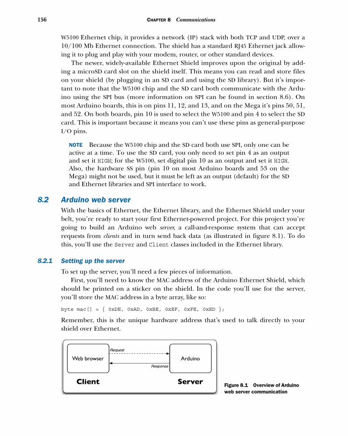
156 CHAPTER 8 Communications
W5100 Ethernet chip, it provides a network (IP) stack with both TCP and UDP, over a10/100 Mb Ethernet connection. The shield has a standard RJ45 Ethernet jack allow-ing it to plug and play with your modem, router, or other standard devices.
The newer, widely-available Ethernet Shield improves upon the original by add-ing a microSD card slot on the shield itself. This means you can read and store fileson your shield (by plugging in an SD card and using the SD library). But it’s impor-tant to note that the W5100 chip and the SD card both communicate with the Ardu-ino using the SPI bus (more information on SPI can be found in section 8.6). Onmost Arduino boards, this is on pins 11, 12, and 13, and on the Mega it’s pins 50, 51,and 52. On both boards, pin 10 is used to select the W5100 and pin 4 to select the SDcard. This is important because it means you can’t use these pins as general-purposeI/O pins.
NOTE Because the W5100 chip and the SD card both use SPI, only one can beactive at a time. To use the SD card, you only need to set pin 4 as an outputand set it HIGH; for the W5100, set digital pin 10 as an output and set it HIGH.Also, the hardware SS pin (pin 10 on most Arduino boards and 53 on theMega) might not be used, but it must be left as an output (default) for the SDand Ethernet libraries and SPI interface to work.
8.2 Arduino web serverWith the basics of Ethernet, the Ethernet library, and the Ethernet Shield under yourbelt, you’re ready to start your first Ethernet-powered project. For this project you’regoing to build an Arduino web server, a call-and-response system that can acceptrequests from clients and in turn send back data (as illustrated in figure 8.1). To dothis, you’ll use the Server and Client classes included in the Ethernet library.
8.2.1 Setting up the server
To set up the server, you’ll need a few pieces of information. First, you’ll need to know the MAC address of the Arduino Ethernet Shield, which
should be printed on a sticker on the shield. In the code you’ll use for the server,you’ll store the MAC address in a byte array, like so:
byte mac[] = { 0xDE, 0xAD, 0xBE, 0xEF, 0xFE, 0xED };
Remember, this is the unique hardware address that’s used to talk directly to yourshield over Ethernet.
Figure 8.1 Overview of Arduino web server communication
157Arduino web server
If you have an older Ethernet Shield without the sticker, or you’ve lost your sticker,you can use the MAC address from the preceding example. The important thing isthat if you have more than one device on the network, they all must have uniqueMAC addresses.
Next, you’ll need your IP address. Since Arduino 1.0, the built-in Ethernet librarysupports Dynamic Host Configuration Protocol (DHCP), enabling Arduino to auto-matically discover your IP address. This will automatically configure your IP addresswhether you’re connected directly to your modem or to a networked router, as long asthey have DHCP enabled (which is typically the case).
You’ll only need to find out the IP of your router and manually specify an IPaddress for your Arduino Ethernet Shield if your network isn’t using DHCP, or ifyou’re using a version of Arduino prior to 1.0. There are different techniques fordoing so, depending on your setup.
If your Arduino is connected directly to your modem, the IP address will be sup-plied by your internet service provider (ISP). To find your IP address in this case, itmay be easiest to connect a computer to your modem—there are many websites thatcan report your IP address. (A quick internet search for the term IP lookup should getyou an address, or you can try www.whatismyip.com/.) Note that your IP address isautomatically assigned by your ISP and may change from time to time.
If your Arduino is connected to your network via a router, you’ll have to assign anunused local network IP address to your Ethernet Shield instead. To manually assign yourArduino an unused local IP, you’ll need to know a bit more about your network’s config-uration. You can discover your router’s IP address by using a web service via a computerconnected to the network as described previously. Alternatively, you can go into yourrouter’s administration control panel. Normally, you can do this by opening your webbrowser and going to the default router IP, typically http://192.168.1.1 for Linksys andmany other brands, or http://10.0.0.1. If your router’s IP address is 192.168.1.1, you’llwant to give your Arduino an IP address of 192.168.1.x, where x is any number from 1 to255. Each computer or network device on your network will have a unique 192.168.1.xaddress, where the final number identifies the device on the network, so make sure yourArduino Ethernet Shield doesn’t conflict with other devices. The same rules apply ifyour router is using another addressing pattern, such as the 10.0.0.x address.
If you do have to manually supply your IP address, you’ll do so in an IPAddressobject, like this:
IPAddress manualIP(192, 168, 1, 2);
The numbers in the preceding code line should be the IP address you want to set. Finally, if you’re on a network and using the router to connect to the internet, you
may also need to specify your router as the gateway. Create a byte array and store therouter’s IP address to be used as the gateway. Here’s an example:
byte gateway[] = { 192, 168, 1, 1};
Now that you know the IP configuration for your network, let’s move on to the code.
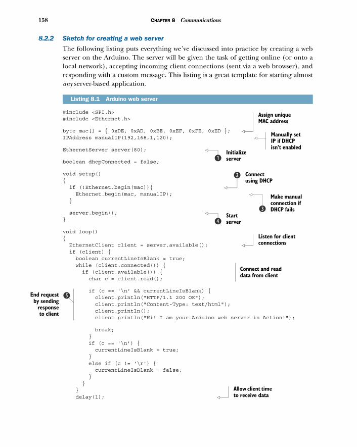
158 CHAPTER 8 Communications
E
8.2.2 Sketch for creating a web server
The following listing puts everything we’ve discussed into practice by creating a webserver on the Arduino. The server will be given the task of getting online (or onto alocal network), accepting incoming client connections (sent via a web browser), andresponding with a custom message. This listing is a great template for starting almostany server-based application.
#include <SPI.h>#include <Ethernet.h>
byte mac[] = { 0xDE, 0xAD, 0xBE, 0xEF, 0xFE, 0xED }; IPAddress manualIP(192,168,1,120);
EthernetServer server(80);
boolean dhcpConnected = false;
void setup(){ if (!Ethernet.begin(mac)){ Ethernet.begin(mac, manualIP); }
server.begin(); }
void loop(){ EthernetClient client = server.available(); if (client) { boolean currentLineIsBlank = true; while (client.connected()) { if (client.available()) { char c = client.read();
if (c == '\n' && currentLineIsBlank) { client.println("HTTP/1.1 200 OK"); client.println("Content-Type: text/html"); client.println(); client.println("Hi! I am your Arduino web server in Action!");
break; } if (c == '\n') { currentLineIsBlank = true; } else if (c != '\r') { currentLineIsBlank = false; } } } delay(1);
Listing 8.1 Arduino web server
Assign unique MAC address
Manually set IP if DHCP isn’t enabled
Initialize serverb
Connect using DHCP
c
Make manual connection if DHCP failsd
Start servere
Listen for client connections
Connect and read data from client
nd requestby sending
responseto client
f
Allow client time to receive data
159Tweet tweet: talking to Twitter
client.stop(); }}
First, you initialize the server on HTTP port 80 B. Once it’s initialized, you can tryto connect the Arduino to the Ethernet network using DHCP c, or using a manualIP address if DHCP fails d. Then you start the server and start polling in the mainloop e.
Once you’ve connected to a client and the data is received, a newline characterdelineates the end of a message, and you send a response back to the client f.
8.2.3 Upload and test
Carefully copy the code from listing 8.1 into the Arduino IDE, and you’re ready toupload the sketch to your Arduino.
Once you’ve uploaded the code and it’s running, you can connect to the Ardu-ino server remotely by opening up any web browser and going to http://your_arduinos_network_ip_address. Your web browser (the client) will send a connection request outto your Arduino web server, which will respond by sending back the message, “Hi! I amyour Arduino web server in Action!” That’s it.
Want to see real-time data? Try connecting a potentiometer or sensor up to analoginput 0, and change the line
client.println("Hi! I am your Arduino web server in Action!");
to this:
client.println(analogRead(0));
We hope this has worked without a hitch, but if you aren’t getting a response, pleaseread the following brief troubleshooting section.
8.2.4 Troubleshooting
If you can’t establish a connection, the first thing to double-check is your IP settings. If you’re positive that your settings are correct and you’re on a home network, it’s
possible that you need to set up port forwarding on your router. Setting up port for-warding will tell your router to forward incoming messages specifically to your Ardu-ino. Setting up port forwarding isn’t difficult, but you’ll have to do it through yourrouter’s configuration. See your router’s documentation for more information onhow to set up forwarding to your Arduino’s IP address, and you should be good to go.
8.3 Tweet tweet: talking to TwitterCreating a web server to communicate with the outside world is great, but anotherpowerful option is to hook into other online services. One service that’s great to tapinto is Twitter.
The way Twitter works is simple. Once you have a Twitter account, you can broad-cast tweets (messages) up to 140 characters long to the entire Twitter network. People
Close connection
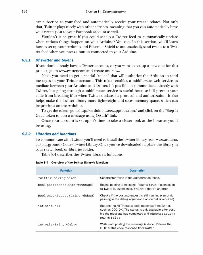
160 CHAPTER 8 Communications
can subscribe to your feed and automatically receive your tweet updates. Not onlythat, Twitter plays nicely with other services, meaning that you can automatically haveyour tweets post to your Facebook account as well.
Wouldn’t it be great if you could set up a Twitter feed to automatically updatewhen various things happen on your Arduino? You can. In this section, you’ll learnhow to set up your Arduino and Ethernet Shield to automatically send tweets to a Twit-ter feed when you press a button connected to your Arduino.
8.3.1 Of Twitter and tokensIf you don’t already have a Twitter account, or you want to set up a new one for thisproject, go to www.twitter.com and create one now.
Next, you need to get a special “token” that will authorize the Arduino to sendmessages to your Twitter account. This token enables a middleware web service tomediate between your Arduino and Twitter. It’s possible to communicate directly withTwitter, but going through a middleware service is useful because it’ll prevent yourcode from breaking if or when Twitter updates its protocol and authorization. It alsohelps make the Twitter library more lightweight and saves memory space, which canbe precious on the Arduino.
To get the token, go to http://arduino-tweet.appspot.com/ and click on the “Step 1:Get a token to post a message using OAuth” link.
Once your account is set up, it’s time to take a closer look at the libraries you’llbe using.
8.3.2 Libraries and functionsTo communicate with Twitter, you’ll need to install the Twitter library from www.arduino.cc/playground/Code/TwitterLibrary. Once you’ve downloaded it, place the library inyour sketchbook or libraries folder.
Table 8.4 describes the Twitter library’s functions.
Table 8.4 Overview of the Twitter library’s functions
Function Description
Twitter(string token) Constructor takes in the authorization token.
bool post(const char *message) Begins posting a message. Returns true if connection to Twitter is established, false if there’s an error.
bool checkStatus(Print *debug) Checks if the posting request is still running (can omit passing in the debug argument if no output is required).
int status() Returns the HTTP status code response from Twitter, such as 200–OK. The status is only available after post-ing the message has completed and checkStatus()returns false.
int wait(Print *debug) Waits until posting the message is done. Returns the HTTP status code response from Twitter.
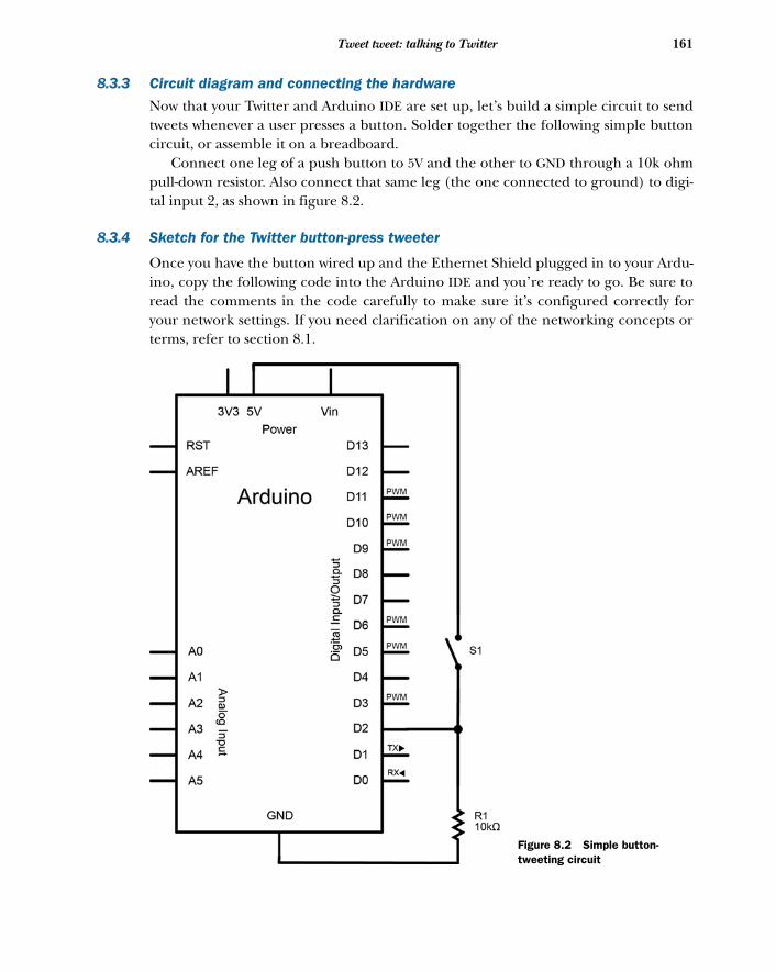
161Tweet tweet: talking to Twitter
8.3.3 Circuit diagram and connecting the hardware
Now that your Twitter and Arduino IDE are set up, let’s build a simple circuit to sendtweets whenever a user presses a button. Solder together the following simple buttoncircuit, or assemble it on a breadboard.
Connect one leg of a push button to 5V and the other to GND through a 10k ohmpull-down resistor. Also connect that same leg (the one connected to ground) to digi-tal input 2, as shown in figure 8.2.
8.3.4 Sketch for the Twitter button-press tweeter
Once you have the button wired up and the Ethernet Shield plugged in to your Ardu-ino, copy the following code into the Arduino IDE and you’re ready to go. Be sure toread the comments in the code carefully to make sure it’s configured correctly foryour network settings. If you need clarification on any of the networking concepts orterms, refer to section 8.1.
Figure 8.2 Simple button-tweeting circuit
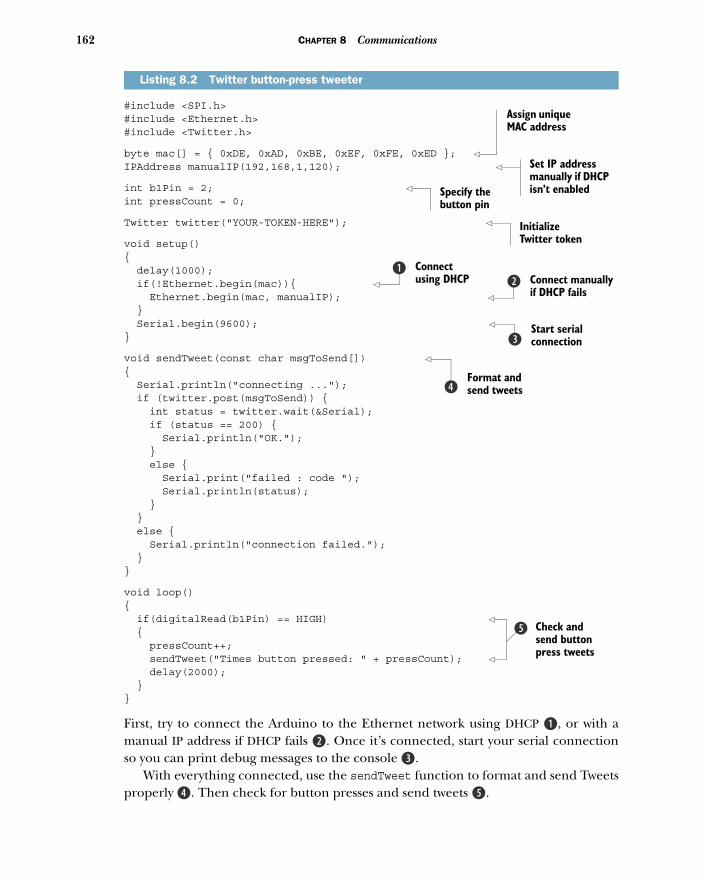
162 CHAPTER 8 Communications
#include <SPI.h>#include <Ethernet.h>#include <Twitter.h>
byte mac[] = { 0xDE, 0xAD, 0xBE, 0xEF, 0xFE, 0xED }; IPAddress manualIP(192,168,1,120);
int b1Pin = 2; int pressCount = 0;
Twitter twitter("YOUR-TOKEN-HERE");
void setup(){ delay(1000); if(!Ethernet.begin(mac)){ Ethernet.begin(mac, manualIP); } Serial.begin(9600); }
void sendTweet(const char msgToSend[]) { Serial.println("connecting ..."); if (twitter.post(msgToSend)) { int status = twitter.wait(&Serial); if (status == 200) { Serial.println("OK."); } else { Serial.print("failed : code "); Serial.println(status); } } else { Serial.println("connection failed."); }}
void loop(){ if(digitalRead(b1Pin) == HIGH) { pressCount++; sendTweet("Times button pressed: " + pressCount); delay(2000); }}
First, try to connect the Arduino to the Ethernet network using DHCP B, or with amanual IP address if DHCP fails c. Once it’s connected, start your serial connectionso you can print debug messages to the console d.
With everything connected, use the sendTweet function to format and send Tweetsproperly e. Then check for button presses and send tweets f.
Listing 8.2 Twitter button-press tweeter
Assign unique MAC address
Set IP address manually if DHCP isn’t enabledSpecify the
button pin
Initialize Twitter token
Connect using DHCP
bConnect manually if DHCP fails
c
Start serial connectiond
Format and send tweetse
Check and send button press tweets
f
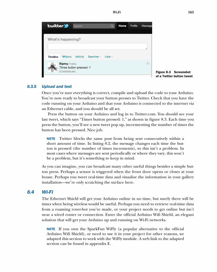
163Wi-Fi
8.3.5 Upload and test
Once you’re sure everything is correct, compile and upload the code to your Arduino.You’re now ready to broadcast your button presses to Twitter. Check that you have thecode running on your Arduino and that your Arduino is connected to the internet viaan Ethernet cable, and you should be all set.
Press the button on your Arduino and log in to Twitter.com. You should see yourlast tweet, which says “Times button pressed: 1,” as shown in figure 8.3. Each time youpress the button, you’ll see a new tweet pop up, incrementing the number of times thebutton has been pressed. Nice job.
NOTE Twitter blocks the same post from being sent consecutively within ashort amount of time. In listing 8.2, the message changes each time the but-ton is pressed (the number of times increments), so this isn’t a problem. Inmost cases where messages are sent periodically or where they vary, this won’tbe a problem, but it’s something to keep in mind.
As you can imagine, you can broadcast many other useful things besides a simple but-ton press. Perhaps a sensor is triggered when the front door opens or closes at yourhouse. Perhaps you tweet real-time data and visualize the information in your galleryinstallation—we’re only scratching the surface here.
8.4 Wi-FiThe Ethernet Shield will get your Arduino online in no time, but surely there will betimes when being wireless would be useful. Perhaps you need to retrieve real-time datafrom a roaming rover-bot you’ve made, or your project needs to get online but isn’tnear a wired router or connection. Enter the official Arduino Wifi Shield, an elegantsolution that will get your Arduino up and running on Wi-Fi networks.
NOTE If you own the SparkFun WiFly (a popular alternative to the officialArduino Wifi Shield), or need to use it in your project for other reasons, weadapted this section to work with the WiFly module. A web link to the adaptedsection can be found in appendix E.
Figure 8.3 Screenshot of a Twitter button tweet
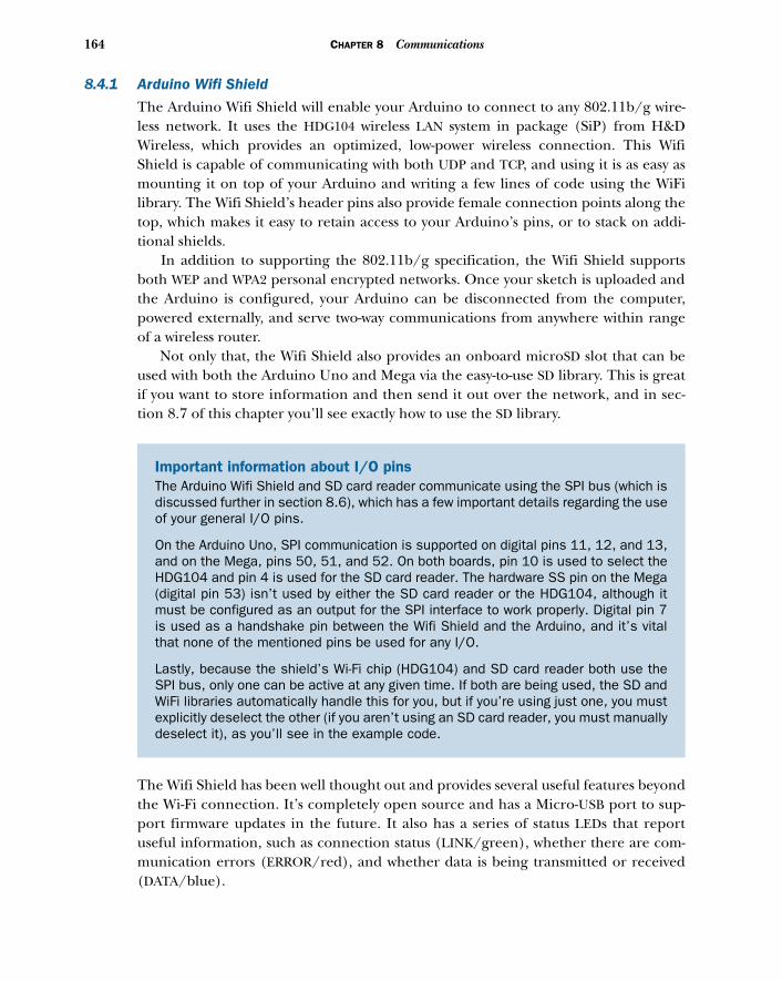
164 CHAPTER 8 Communications
8.4.1 Arduino Wifi Shield
The Arduino Wifi Shield will enable your Arduino to connect to any 802.11b/g wire-less network. It uses the HDG104 wireless LAN system in package (SiP) from H&DWireless, which provides an optimized, low-power wireless connection. This WifiShield is capable of communicating with both UDP and TCP, and using it is as easy asmounting it on top of your Arduino and writing a few lines of code using the WiFilibrary. The Wifi Shield’s header pins also provide female connection points along thetop, which makes it easy to retain access to your Arduino’s pins, or to stack on addi-tional shields.
In addition to supporting the 802.11b/g specification, the Wifi Shield supportsboth WEP and WPA2 personal encrypted networks. Once your sketch is uploaded andthe Arduino is configured, your Arduino can be disconnected from the computer,powered externally, and serve two-way communications from anywhere within rangeof a wireless router.
Not only that, the Wifi Shield also provides an onboard microSD slot that can beused with both the Arduino Uno and Mega via the easy-to-use SD library. This is greatif you want to store information and then send it out over the network, and in sec-tion 8.7 of this chapter you’ll see exactly how to use the SD library.
The Wifi Shield has been well thought out and provides several useful features beyondthe Wi-Fi connection. It’s completely open source and has a Micro-USB port to sup-port firmware updates in the future. It also has a series of status LEDs that reportuseful information, such as connection status (LINK/green), whether there are com-munication errors (ERROR/red), and whether data is being transmitted or received(DATA/blue).
Important information about I/O pins The Arduino Wifi Shield and SD card reader communicate using the SPI bus (which isdiscussed further in section 8.6), which has a few important details regarding the useof your general I/O pins.
On the Arduino Uno, SPI communication is supported on digital pins 11, 12, and 13,and on the Mega, pins 50, 51, and 52. On both boards, pin 10 is used to select theHDG104 and pin 4 is used for the SD card reader. The hardware SS pin on the Mega(digital pin 53) isn’t used by either the SD card reader or the HDG104, although itmust be configured as an output for the SPI interface to work properly. Digital pin 7is used as a handshake pin between the Wifi Shield and the Arduino, and it’s vitalthat none of the mentioned pins be used for any I/O.
Lastly, because the shield’s Wi-Fi chip (HDG104) and SD card reader both use theSPI bus, only one can be active at any given time. If both are being used, the SD andWiFi libraries automatically handle this for you, but if you’re using just one, you mustexplicitly deselect the other (if you aren’t using an SD card reader, you must manuallydeselect it), as you’ll see in the example code.
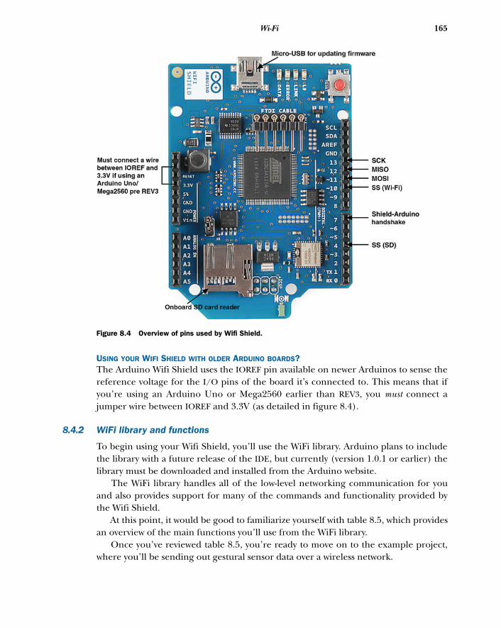
165Wi-Fi
USING YOUR WIFI SHIELD WITH OLDER ARDUINO BOARDS?The Arduino Wifi Shield uses the IOREF pin available on newer Arduinos to sense thereference voltage for the I/O pins of the board it’s connected to. This means that ifyou’re using an Arduino Uno or Mega2560 earlier than REV3, you must connect ajumper wire between IOREF and 3.3V (as detailed in figure 8.4).
8.4.2 WiFi library and functions
To begin using your Wifi Shield, you’ll use the WiFi library. Arduino plans to includethe library with a future release of the IDE, but currently (version 1.0.1 or earlier) thelibrary must be downloaded and installed from the Arduino website.
The WiFi library handles all of the low-level networking communication for youand also provides support for many of the commands and functionality provided bythe Wifi Shield.
At this point, it would be good to familiarize yourself with table 8.5, which providesan overview of the main functions you’ll use from the WiFi library.
Once you’ve reviewed table 8.5, you’re ready to move on to the example project,where you’ll be sending out gestural sensor data over a wireless network.
Figure 8.4 Overview of pins used by Wifi Shield.
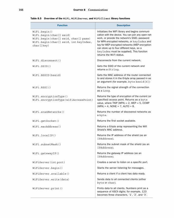
166 CHAPTER 8 Communications
Table 8.5 Overview of the WiFi, WiFiServer, and WiFiClient library functions
Function Description
WiFi.begin()WiFi.begin(char[] ssid)WiFi.begin(char[] ssid, char[] pass)WiFi.begin(char[] ssid, int keyIndex,char[]key)
Initializes the WiFi library and begins communi-cation with the device. You can join any open net-work, or provide the network’s SSID, password for WPA encrypted networks, or keyIndex and key for WEP encrypted networks (WEP encryption can store up to four different keys, so a keyIndex must be supplied). This function returns the Wi-Fi status.
WiFi.disconnect() Disconnects from the current network.
WiFi.SSID() Gets the SSID of the current network and returns a String.
WiFi.BSSID(bssid) Gets the MAC address of the router connected to and stores it in the 6-byte array passed in as an argument (for example, byte bssid[6])
WiFi.RSSI() Returns the signal strength of the connection as a Long.
WiFi.encryptionType()WiFi.encryptionType(wifiAccessPoint)
Returns the type of encryption of the current (or specified) access point. Returns as a bytevalue, where TKIP (WPA) = 2, WEP = 5, CCMP (WPA) = 4, NONE = 7, AUTO = 8.
WiFi.scanNetworks() Returns the number of discovered networks as a byte.
WiFi.getSocket() Returns the first socket available.
WiFi.macAddress() Returns a 6-byte array representing the Wifi Shield’s MAC address.
WiFi.localIP() Returns the IP address of the shield (as an IPAddress).
WiFi.subnetMask() Returns the subnet mask of the shield (as an IPAddress).
WiFi.gatewayIP() Returns the gateway IP address (as an IPAddress).
WiFiServer(int port) Creates a server to listen on a specific port.
WiFiServer.begin() Starts the server listening for messages.
WiFiServer.available() Returns a client if a client has data ready.
WiFiServer.write(data) Sends data to all connected clients (either byte or char).
WiFiServer.print() Prints data to all clients. Numbers print as a sequence of ASCII digits; for example, 123 becomes three characters, ‘1’, ‘2’, and ‘3’.
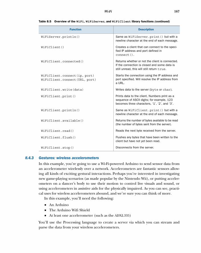
167Wi-Fi
8.4.3 Gestures: wireless accelerometers
In this example, you’re going to use a Wi-Fi-powered Arduino to send sensor data froman accelerometer wirelessly over a network. Accelerometers are fantastic sensors allow-ing all kinds of exciting gestural interactions. Perhaps you’re interested in investigatingnew game-playing scenarios (as made popular by the Nintendo Wii), or putting acceler-ometers on a dancer’s body to use their motion to control live visuals and sound, orusing accelerometers in assistive aids for the physically impaired. As you can see, practi-cal uses for wireless accelerometers abound, and we’re sure you can think of more.
In this example, you’ll need the following:
■ An Arduino■ The Arduino Wifi Shield■ At least one accelerometer (such as the ADXL335)
You’ll use the Processing language to create a server via which you can stream andparse the data from your wireless accelerometers.
WiFiServer.println() Same as WiFiServer.print() but with a newline character at the end of each message.
WiFiClient() Creates a client that can connect to the speci-fied IP address and port defined in connect().
WiFiClient.connected() Returns whether or not the client is connected. If the connection is closed and some data is still unread, this will still return true.
WiFiClient.connect(ip, port)WiFiClient.connect(URL, port)
Starts the connection using the IP address and port specified. Will resolve the IP address from a URL.
WiFiClient.write(data) Writes data to the server (byte or char).
WiFiClient.print() Prints data to the client. Numbers print as a sequence of ASCII digits; for example, 123 becomes three characters, ‘1’, ‘2’, and ‘3’.
WiFiClient.println() Same as WiFiClient.print() but with a newline character at the end of each message.
WiFiClient.available() Returns the number of bytes available to be read (the number of bytes sent from the server).
WiFiClient.read() Reads the next byte received from the server.
WiFiClient.flush() Flushes any bytes that have been written to the client but have not yet been read.
WiFiClient.stop() Disconnects from the server.
Table 8.5 Overview of the WiFi, WiFiServer, and WiFiClient library functions (continued)
Function Description
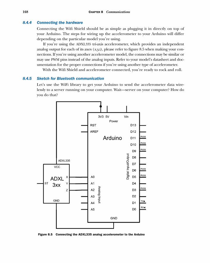
168 CHAPTER 8 Communications
8.4.4 Connecting the hardware
Connecting the Wifi Shield should be as simple as plugging it in directly on top ofyour Arduino. The steps for wiring up the accelerometer to your Arduino will differdepending on the particular model you’re using.
If you’re using the ADXL335 tri-axis accelerometer, which provides an independentanalog output for each of its axes (x,y,z), please refer to figure 8.5 when making your con-nections. If you’re using another accelerometer model, the connections may be similar ormay use PWM pins instead of the analog inputs. Refer to your model’s datasheet and doc-umentation for the proper connections if you’re using another type of accelerometer.
With the Wifi Shield and accelerometer connected, you’re ready to rock and roll.
8.4.5 Sketch for Bluetooth communication
Let’s use the WiFi library to get your Arduino to send the accelerometer data wire-lessly to a server running on your computer. Wait—server on your computer? How doyou do that?
Figure 8.5 Connecting the ADXL335 analog accelerometer to the Arduino
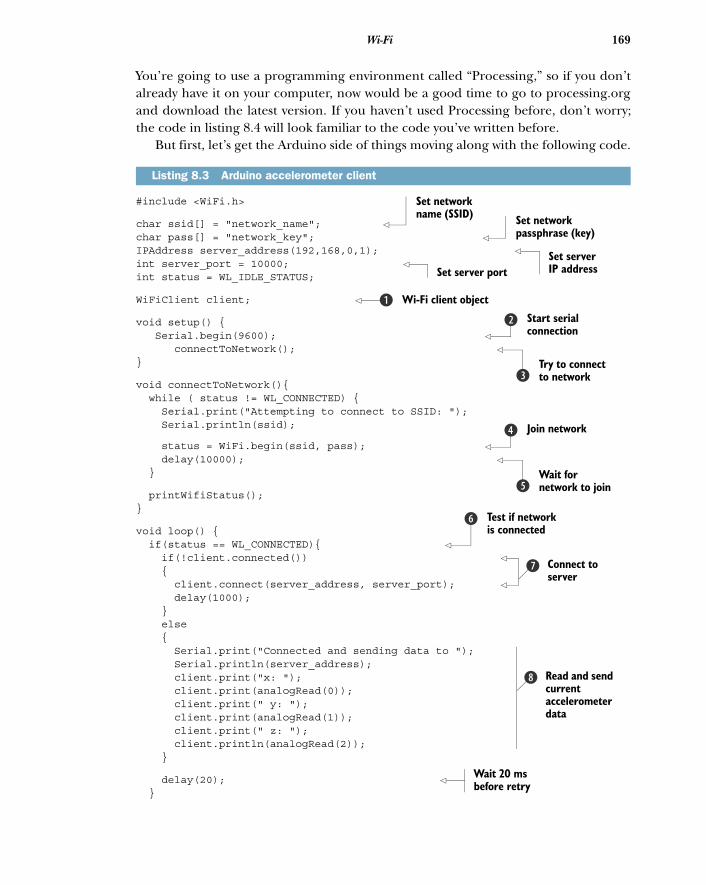
169Wi-Fi
You’re going to use a programming environment called “Processing,” so if you don’talready have it on your computer, now would be a good time to go to processing.organd download the latest version. If you haven’t used Processing before, don’t worry;the code in listing 8.4 will look familiar to the code you’ve written before.
But first, let’s get the Arduino side of things moving along with the following code.
#include <WiFi.h>
char ssid[] = "network_name"; char pass[] = "network_key"; IPAddress server_address(192,168,0,1); int server_port = 10000; int status = WL_IDLE_STATUS;
WiFiClient client;
void setup() { Serial.begin(9600); connectToNetwork(); }
void connectToNetwork(){ while ( status != WL_CONNECTED) { Serial.print("Attempting to connect to SSID: "); Serial.println(ssid);
status = WiFi.begin(ssid, pass); delay(10000); }
printWifiStatus();}
void loop() { if(status == WL_CONNECTED){ if(!client.connected()) { client.connect(server_address, server_port); delay(1000); } else { Serial.print("Connected and sending data to "); Serial.println(server_address); client.print("x: "); client.print(analogRead(0)); client.print(" y: "); client.print(analogRead(1)); client.print(" z: "); client.println(analogRead(2)); }
delay(20); }
Listing 8.3 Arduino accelerometer client
Set network name (SSID) Set network
passphrase (key)
Set server IP addressSet server port
Wi-Fi client objectbStart serial connection
c
Try to connect to networkd
Join networke
Wait for network to joinf
Test if network is connected
g
Connect to server
h
Read and send current accelerometer data
i
Wait 20 ms before retry
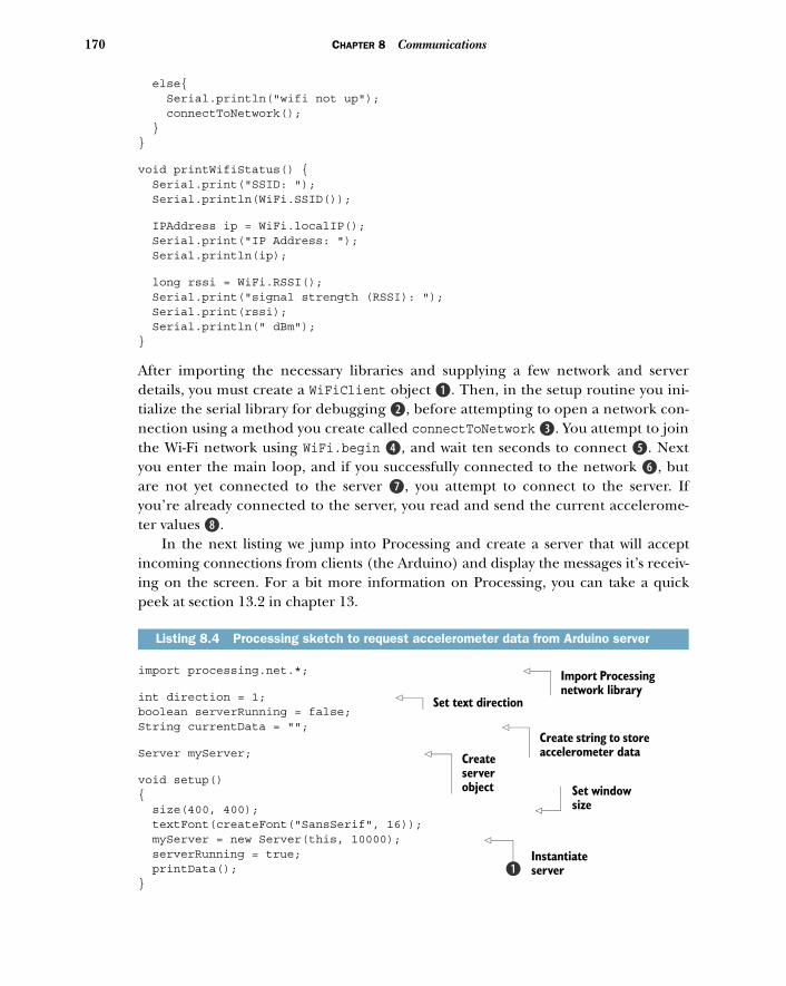
170 CHAPTER 8 Communications
else{ Serial.println("wifi not up"); connectToNetwork(); }}
void printWifiStatus() { Serial.print("SSID: "); Serial.println(WiFi.SSID());
IPAddress ip = WiFi.localIP(); Serial.print("IP Address: "); Serial.println(ip);
long rssi = WiFi.RSSI(); Serial.print("signal strength (RSSI): "); Serial.print(rssi); Serial.println(" dBm");}
After importing the necessary libraries and supplying a few network and serverdetails, you must create a WiFiClient object B. Then, in the setup routine you ini-tialize the serial library for debugging c, before attempting to open a network con-nection using a method you create called connectToNetwork d. You attempt to jointhe Wi-Fi network using WiFi.begin e, and wait ten seconds to connect f. Nextyou enter the main loop, and if you successfully connected to the network g, butare not yet connected to the server h, you attempt to connect to the server. Ifyou’re already connected to the server, you read and send the current accelerome-ter values i.
In the next listing we jump into Processing and create a server that will acceptincoming connections from clients (the Arduino) and display the messages it’s receiv-ing on the screen. For a bit more information on Processing, you can take a quickpeek at section 13.2 in chapter 13.
import processing.net.*;
int direction = 1; boolean serverRunning = false;String currentData = "";
Server myServer;
void setup(){ size(400, 400); textFont(createFont("SansSerif", 16)); myServer = new Server(this, 10000); serverRunning = true; printData();}
Listing 8.4 Processing sketch to request accelerometer data from Arduino server
Import Processing network library
Set text direction
Create string to store accelerometer dataCreate
server object Set window
size
Instantiate serverb
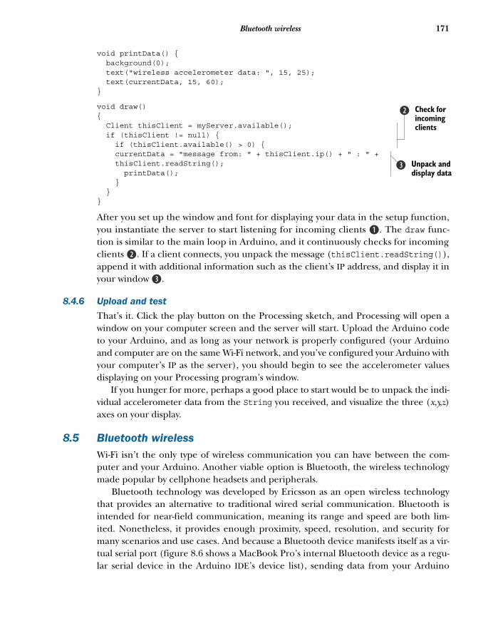
171Bluetooth wireless
void printData() { background(0); text("wireless accelerometer data: ", 15, 25); text(currentData, 15, 60);}
void draw(){ Client thisClient = myServer.available(); if (thisClient != null) { if (thisClient.available() > 0) { currentData = "message from: " + thisClient.ip() + " : " + thisClient.readString(); printData(); } }}
After you set up the window and font for displaying your data in the setup function,you instantiate the server to start listening for incoming clients B. The draw func-tion is similar to the main loop in Arduino, and it continuously checks for incomingclients c. If a client connects, you unpack the message (thisClient.readString()),append it with additional information such as the client’s IP address, and display it inyour window d.
8.4.6 Upload and test
That’s it. Click the play button on the Processing sketch, and Processing will open awindow on your computer screen and the server will start. Upload the Arduino codeto your Arduino, and as long as your network is properly configured (your Arduinoand computer are on the same Wi-Fi network, and you’ve configured your Arduino withyour computer’s IP as the server), you should begin to see the accelerometer valuesdisplaying on your Processing program’s window.
If you hunger for more, perhaps a good place to start would be to unpack the indi-vidual accelerometer data from the String you received, and visualize the three (x,y,z)axes on your display.
8.5 Bluetooth wirelessWi-Fi isn’t the only type of wireless communication you can have between the com-puter and your Arduino. Another viable option is Bluetooth, the wireless technologymade popular by cellphone headsets and peripherals.
Bluetooth technology was developed by Ericsson as an open wireless technologythat provides an alternative to traditional wired serial communication. Bluetooth isintended for near-field communication, meaning its range and speed are both lim-ited. Nonetheless, it provides enough proximity, speed, resolution, and security formany scenarios and use cases. And because a Bluetooth device manifests itself as a vir-tual serial port (figure 8.6 shows a MacBook Pro’s internal Bluetooth device as a regu-lar serial device in the Arduino IDE’s device list), sending data from your Arduino
Check for incoming clients
c
Unpack and display data
d
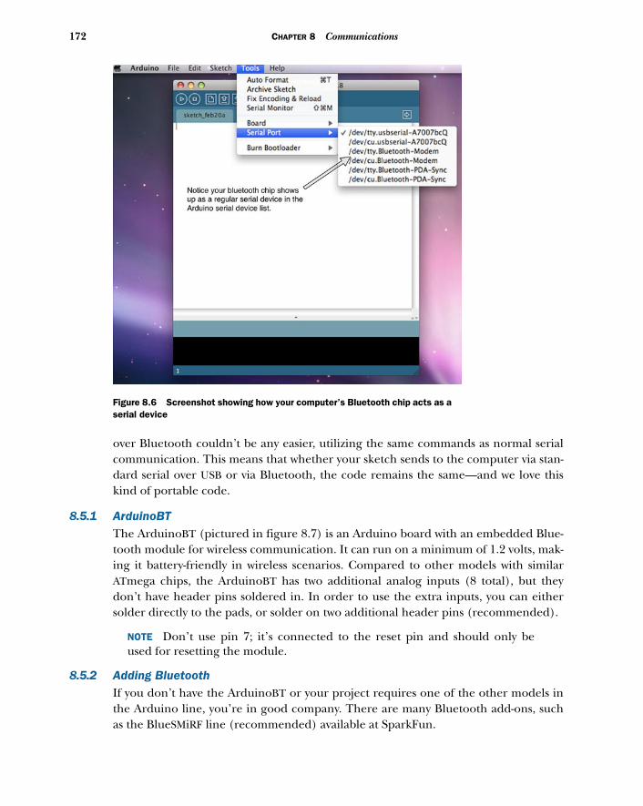
172 CHAPTER 8 Communications
over Bluetooth couldn’t be any easier, utilizing the same commands as normal serialcommunication. This means that whether your sketch sends to the computer via stan-dard serial over USB or via Bluetooth, the code remains the same—and we love thiskind of portable code.
8.5.1 ArduinoBTThe ArduinoBT (pictured in figure 8.7) is an Arduino board with an embedded Blue-tooth module for wireless communication. It can run on a minimum of 1.2 volts, mak-ing it battery-friendly in wireless scenarios. Compared to other models with similarATmega chips, the ArduinoBT has two additional analog inputs (8 total), but theydon’t have header pins soldered in. In order to use the extra inputs, you can eithersolder directly to the pads, or solder on two additional header pins (recommended).
NOTE Don’t use pin 7; it’s connected to the reset pin and should only beused for resetting the module.
8.5.2 Adding BluetoothIf you don’t have the ArduinoBT or your project requires one of the other models inthe Arduino line, you’re in good company. There are many Bluetooth add-ons, suchas the BlueSMiRF line (recommended) available at SparkFun.
Figure 8.6 Screenshot showing how your computer’s Bluetooth chip acts as a serial device
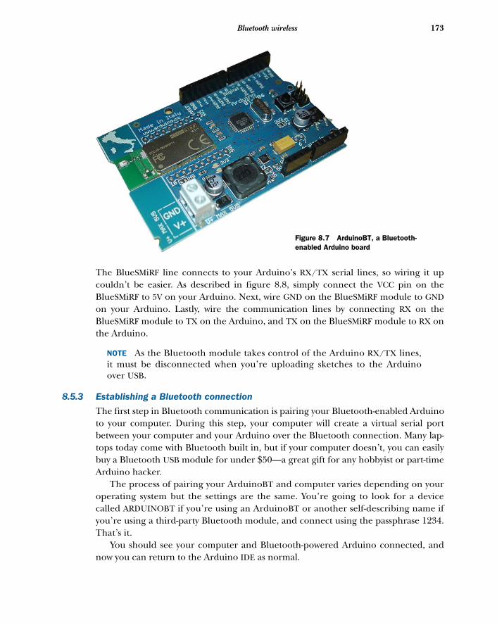
173Bluetooth wireless
The BlueSMiRF line connects to your Arduino’s RX/TX serial lines, so wiring it upcouldn’t be easier. As described in figure 8.8, simply connect the VCC pin on theBlueSMiRF to 5V on your Arduino. Next, wire GND on the BlueSMiRF module to GNDon your Arduino. Lastly, wire the communication lines by connecting RX on theBlueSMiRF module to TX on the Arduino, and TX on the BlueSMiRF module to RX onthe Arduino.
NOTE As the Bluetooth module takes control of the Arduino RX/TX lines,it must be disconnected when you’re uploading sketches to the Arduinoover USB.
8.5.3 Establishing a Bluetooth connection
The first step in Bluetooth communication is pairing your Bluetooth-enabled Arduinoto your computer. During this step, your computer will create a virtual serial portbetween your computer and your Arduino over the Bluetooth connection. Many lap-tops today come with Bluetooth built in, but if your computer doesn’t, you can easilybuy a Bluetooth USB module for under $50—a great gift for any hobbyist or part-timeArduino hacker.
The process of pairing your ArduinoBT and computer varies depending on youroperating system but the settings are the same. You’re going to look for a devicecalled ARDUINOBT if you’re using an ArduinoBT or another self-describing name ifyou’re using a third-party Bluetooth module, and connect using the passphrase 1234.That’s it.
You should see your computer and Bluetooth-powered Arduino connected, andnow you can return to the Arduino IDE as normal.
Figure 8.7 ArduinoBT, a Bluetooth-enabled Arduino board
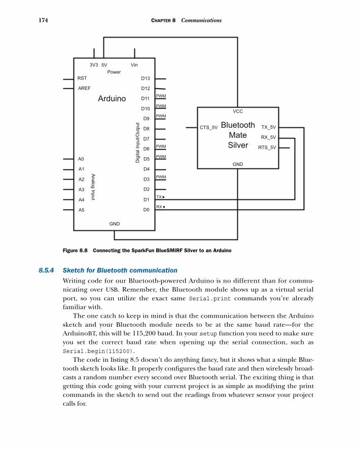
174 CHAPTER 8 Communications
8.5.4 Sketch for Bluetooth communication
Writing code for our Bluetooth-powered Arduino is no different than for commu-nicating over USB. Remember, the Bluetooth module shows up as a virtual serialport, so you can utilize the exact same Serial.print commands you’re alreadyfamiliar with.
The one catch to keep in mind is that the communication between the Arduinosketch and your Bluetooth module needs to be at the same baud rate—for theArduinoBT, this will be 115,200 baud. In your setup function you need to make sureyou set the correct baud rate when opening up the serial connection, such asSerial.begin(115200).
The code in listing 8.5 doesn’t do anything fancy, but it shows what a simple Blue-tooth sketch looks like. It properly configures the baud rate and then wirelessly broad-casts a random number every second over Bluetooth serial. The exciting thing is thatgetting this code going with your current project is as simple as modifying the printcommands in the sketch to send out the readings from whatever sensor your projectcalls for.
Vin
Power
3V3 5V
RST
AREF
Arduino
D13
D12
D11
D10
D9
D8
D7
D6
D5
D4
D3
D2
D1
D0
GND
A0
A1
A2
A3
A4
A5
An
alo
g In
pu
t
Dig
ita
l In
pu
t/O
utp
ut
PWM
PWM
PWM
PWM
PWM
PWM
TX
RX
VCC
CTS_5V TX_5V
RX_5V
RTS_5V
GND
Bluetooth
Mate
Silver
Figure 8.8 Connecting the SparkFun BlueSMiRF Silver to an Arduino
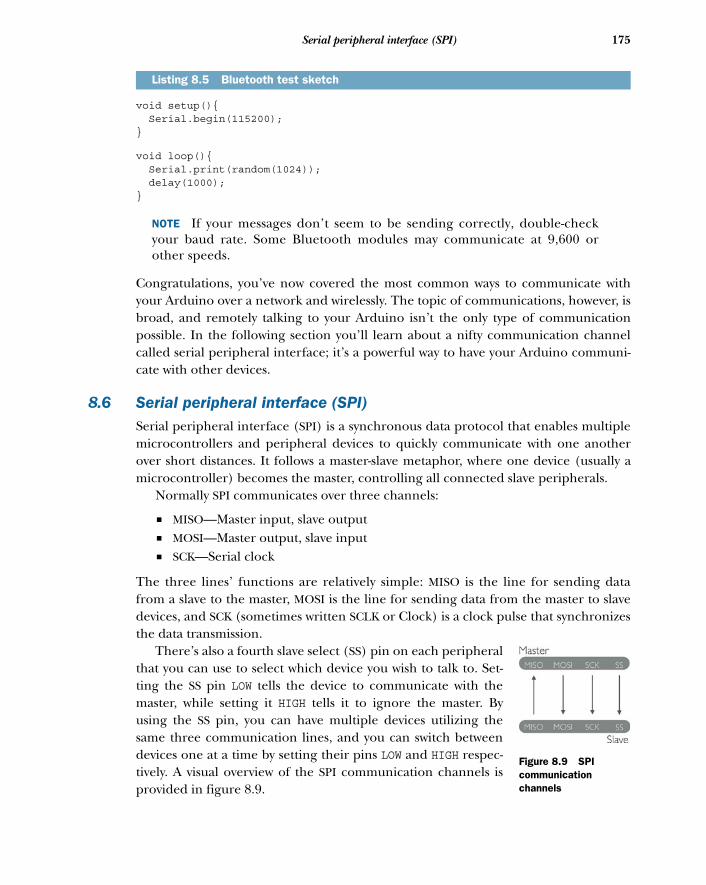
175Serial peripheral interface (SPI)
void setup(){ Serial.begin(115200); }
void loop(){ Serial.print(random(1024)); delay(1000); }
NOTE If your messages don’t seem to be sending correctly, double-checkyour baud rate. Some Bluetooth modules may communicate at 9,600 orother speeds.
Congratulations, you’ve now covered the most common ways to communicate withyour Arduino over a network and wirelessly. The topic of communications, however, isbroad, and remotely talking to your Arduino isn’t the only type of communicationpossible. In the following section you’ll learn about a nifty communication channelcalled serial peripheral interface; it’s a powerful way to have your Arduino communi-cate with other devices.
8.6 Serial peripheral interface (SPI)Serial peripheral interface (SPI) is a synchronous data protocol that enables multiplemicrocontrollers and peripheral devices to quickly communicate with one anotherover short distances. It follows a master-slave metaphor, where one device (usually amicrocontroller) becomes the master, controlling all connected slave peripherals.
Normally SPI communicates over three channels:
■ MISO—Master input, slave output ■ MOSI—Master output, slave input ■ SCK—Serial clock
The three lines’ functions are relatively simple: MISO is the line for sending datafrom a slave to the master, MOSI is the line for sending data from the master to slavedevices, and SCK (sometimes written SCLK or Clock) is a clock pulse that synchronizesthe data transmission.
There’s also a fourth slave select (SS) pin on each peripheralthat you can use to select which device you wish to talk to. Set-ting the SS pin LOW tells the device to communicate with themaster, while setting it HIGH tells it to ignore the master. Byusing the SS pin, you can have multiple devices utilizing thesame three communication lines, and you can switch betweendevices one at a time by setting their pins LOW and HIGH respec-tively. A visual overview of the SPI communication channels isprovided in figure 8.9.
Listing 8.5 Bluetooth test sketch
Figure 8.9 SPI communication channels
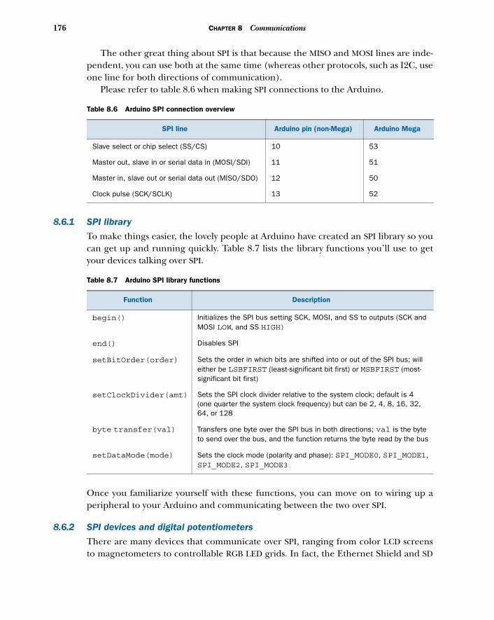
176 CHAPTER 8 Communications
The other great thing about SPI is that because the MISO and MOSI lines are inde-pendent, you can use both at the same time (whereas other protocols, such as I2C, useone line for both directions of communication).
Please refer to table 8.6 when making SPI connections to the Arduino.
8.6.1 SPI library
To make things easier, the lovely people at Arduino have created an SPI library so youcan get up and running quickly. Table 8.7 lists the library functions you’ll use to getyour devices talking over SPI.
Once you familiarize yourself with these functions, you can move on to wiring up aperipheral to your Arduino and communicating between the two over SPI.
8.6.2 SPI devices and digital potentiometers
There are many devices that communicate over SPI, ranging from color LCD screensto magnetometers to controllable RGB LED grids. In fact, the Ethernet Shield and SD
Table 8.6 Arduino SPI connection overview
SPI line Arduino pin (non-Mega) Arduino Mega
Slave select or chip select (SS/CS) 10 53
Master out, slave in or serial data in (MOSI/SDI) 11 51
Master in, slave out or serial data out (MISO/SDO) 12 50
Clock pulse (SCK/SCLK) 13 52
Table 8.7 Arduino SPI library functions
Function Description
begin() Initializes the SPI bus setting SCK, MOSI, and SS to outputs (SCK and MOSI LOW, and SS HIGH)
end() Disables SPI
setBitOrder(order) Sets the order in which bits are shifted into or out of the SPI bus; will either be LSBFIRST (least-significant bit first) or MSBFIRST (most-significant bit first)
setClockDivider(amt) Sets the SPI clock divider relative to the system clock; default is 4 (one quarter the system clock frequency) but can be 2, 4, 8, 16, 32, 64, or 128
byte transfer(val) Transfers one byte over the SPI bus in both directions; val is the byte to send over the bus, and the function returns the byte read by the bus
setDataMode(mode) Sets the clock mode (polarity and phase): SPI_MODE0, SPI_MODE1, SPI_MODE2, SPI_MODE3
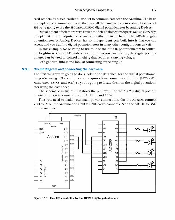
177Serial peripheral interface (SPI)
card readers discussed earlier all use SPI to communicate with the Arduino. The basicprinciples of communicating with them are all the same, so to demonstrate basic use ofSPI we’re going to use the SPI-based AD5206 digital potentiometer by Analog Devices.
Digital potentiometers are very similar to their analog counterparts we use every day,except that they’re adjusted electronically rather than by hand. The AD5206 digitalpotentiometer by Analog Devices has six independent pots built into it that you canaccess, and you can find digital potentiometers in many other configurations as well.
In this example, we’re going to use four of the built-in potentiometers to controlthe brightness of four LEDs independently, but as you can imagine, the digital potenti-ometer can be used to control anything that requires a varying voltage.
Let’s get right into it and look at connecting everything up.
8.6.3 Circuit diagram and connecting the hardwareThe first thing you’re going to do is look up the data sheet for the digital potentiome-ter you’re using. SPI communication requires four communication pins (MOSI/SDI,MISO/SDO, SS/CS, and SCK), so you’re going to locate them on the digital potentiom-eter using the data sheet.
The schematic in figure 8.10 shows the pin layout for the AD5206 digital potenti-ometer and how it connects to your Arduino and LEDs.
First you need to make your main power connections. On the AD5206, connectVDD to 5V on the Arduino and GND to GND. Next, connect VSS on the AD5206 to GNDon the Arduino.
Figure 8.10 Four LEDs controlled by the AD5206 digital potentiometer
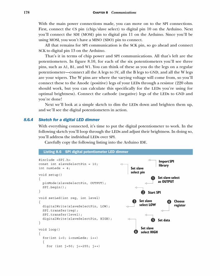
178 CHAPTER 8 Communications
With the main power connections made, you can move on to the SPI connections.First, connect the CS pin (chip/slave select) to digital pin 10 on the Arduino. Nextyou’ll connect the SDI (MOSI) pin to digital pin 11 on the Arduino. Since you’ll beusing MOSI, you won’t have a MISO (SDO) pin to connect.
All that remains for SPI communication is the SCK pin, so go ahead and connectSCK to digital pin 13 on the Arduino.
That’s it in terms of chip power and SPI communications. All that’s left are thepotentiometers. In figure 8.10, for each of the six potentiometers you’ll see threepins, such as A1, B1, and W1. You can think of these as you do the legs on a regularpotentiometer—connect all the A legs to 5V, all the B legs to GND, and all the W legsare your wipers. The W pins are where the varying voltage will come from, so you’llconnect these to the Anode (positive) legs of your LEDs through a resistor (220 ohmshould work, but you can calculate this specifically for the LEDs you’re using foroptimal brightness). Connect the cathode (negative) legs of the LEDs to GND andyou’re done!
Next we’ll look at a simple sketch to dim the LEDs down and brighten them up,and we’ll see the digital potentiometers in action.
8.6.4 Sketch for a digital LED dimmer
With everything connected, it’s time to put the digital potentiometer to work. In thefollowing sketch you’ll loop through the LEDs and adjust their brightness. In doing so,you’ll address the individual LEDs over SPI.
Carefully copy the following listing into the Arduino IDE.
#include <SPI.h> const int slaveSelectPin = 10; int numLeds = 4;
void setup(){ pinMode(slaveSelectPin, OUTPUT); SPI.begin(); }
void setLed(int reg, int level){ digitalWrite(slaveSelectPin, LOW); SPI.transfer(reg); SPI.transfer(level); digitalWrite(slaveSelectPin, HIGH); }
void loop(){ for(int i=0; i<numLeds; i++) { for (int j=50; j<=255; j++)
Listing 8.6 SPI digital potentiometer LED dimmer
Import SPI library
Set slave select pin
Set slave select as OUTPUT
b
Start SPIc
Set slave select LOW
d Choose register
e
Set dataf
Set slave select HIGHg
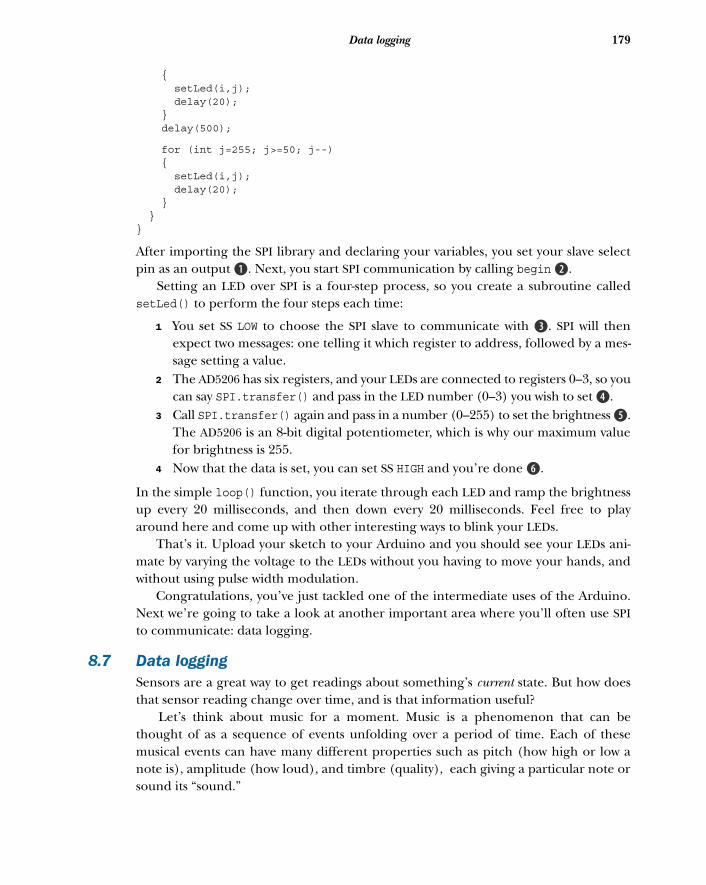
179Data logging
{ setLed(i,j); delay(20); } delay(500);
for (int j=255; j>=50; j--) { setLed(i,j); delay(20); } }}
After importing the SPI library and declaring your variables, you set your slave selectpin as an output B. Next, you start SPI communication by calling begin c.
Setting an LED over SPI is a four-step process, so you create a subroutine calledsetLed() to perform the four steps each time:
1 You set SS LOW to choose the SPI slave to communicate with d. SPI will thenexpect two messages: one telling it which register to address, followed by a mes-sage setting a value.
2 The AD5206 has six registers, and your LEDs are connected to registers 0–3, so youcan say SPI.transfer() and pass in the LED number (0–3) you wish to set e.
3 Call SPI.transfer() again and pass in a number (0–255) to set the brightness f.The AD5206 is an 8-bit digital potentiometer, which is why our maximum valuefor brightness is 255.
4 Now that the data is set, you can set SS HIGH and you’re done g.
In the simple loop() function, you iterate through each LED and ramp the brightnessup every 20 milliseconds, and then down every 20 milliseconds. Feel free to playaround here and come up with other interesting ways to blink your LEDs.
That’s it. Upload your sketch to your Arduino and you should see your LEDs ani-mate by varying the voltage to the LEDs without you having to move your hands, andwithout using pulse width modulation.
Congratulations, you’ve just tackled one of the intermediate uses of the Arduino.Next we’re going to take a look at another important area where you’ll often use SPIto communicate: data logging.
8.7 Data loggingSensors are a great way to get readings about something’s current state. But how doesthat sensor reading change over time, and is that information useful?
Let’s think about music for a moment. Music is a phenomenon that can bethought of as a sequence of events unfolding over a period of time. Each of thesemusical events can have many different properties such as pitch (how high or low anote is), amplitude (how loud), and timbre (quality), each giving a particular note orsound its “sound.”
180 CHAPTER 8 Communications
In isolation, these notes or events have no musical context. Once played in succes-sion, however, in the context of the composition, different relationships form betweenthe events. Melodies and rhythmic patterns emerge; higher-level structures build fromthin air. Even non-musicians with “untrained” ears are great at recognizing these rela-tionships. Even if we can’t express these relationships in musical terms, we possess theability to embody and feel them. This is because the human brain has long- and short-term memory that’s able to store the relationships of the sounds as they’re played, andeven to compare the relationships to the library of sounds and tunes you’ve heard inthe past. Our brains can recall and connect the dots for us!
Similarly, if you want to begin to understand the patterns and high-level relation-ships and information within your sensor data, you must collect the data over a periodof time and look for these patterns. In this section, we’re going to look at how you canstart logging your data on your Arduino.
8.7.1 Types of memory
In order to log data locally on the Arduino, you need to store it somewhere. Usuallythis is done with some sort of external memory, like the memory in your computer,cellphone, or thumb drive. The great thing about external memory is that once thememory is stored, it remains even after the device is powered off. This is also true ofthe EEPROM, Arduino’s built-in memory.
While the EEPROM can retain its memory even when the Arduino is turned off,its space is severely limited. Depending on your Arduino model, you’ll only havebetween 512 and 4096 bytes of EEPROM memory. This makes the EEPROM good forstoring variables and small amounts of data that need to persist between uses of theArduino, but not very usable in most data-logging scenarios. Because of this, you’lloften turn to other external memory solutions, such as Secure Digital (SD) cardsand memory sticks.
8.7.2 SD cards and SD library
SD cards are one of the best ways to store data externally. You can get high-capacity SDcards that should have plenty of space not only for data logging but also hosting otherresource files (such as sound files to play or pictures to display), and Arduino comeswith an SD library, making reading from and writing to SD cards easy.
Table 8.8 provides an overview of the main SD class functions available in the SDlibrary, but there are many more File class functions enabling you to read from andwrite to files. Table 8.9 provides a list of the main File class functions, but please referto the online documentation for a full list of available functions at www.arduino.cc/en/Reference/SD.
Whether you’re using one of the SD card shields or the SD card reader built intoyour Arduino Ethernet Shield, communicating with the SD libraries is always thesame. If you’re comfortable with the functions we covered previously, you’re morethan ready to write a sketch to log some real data.
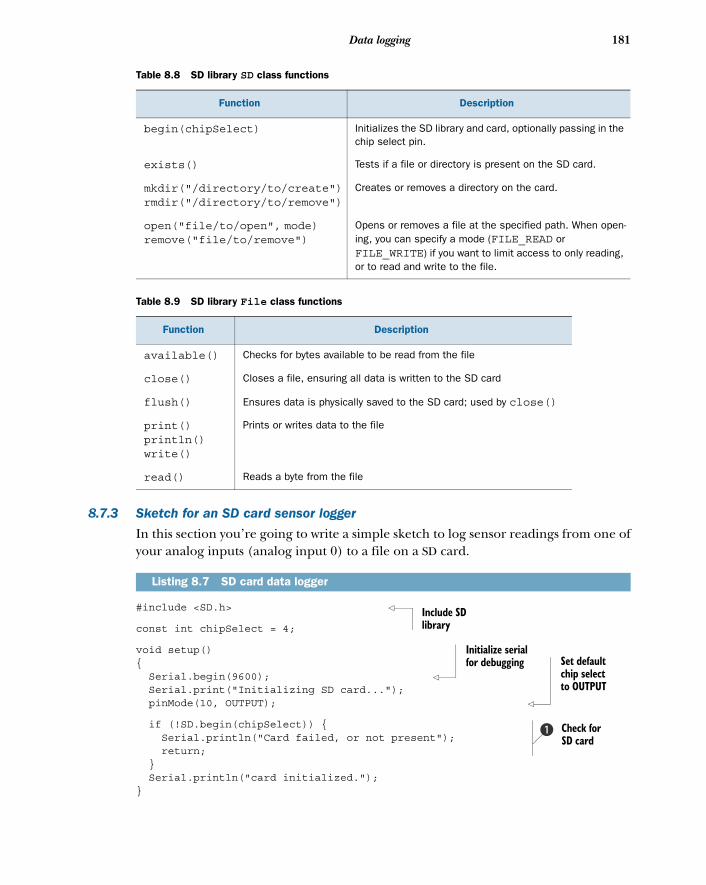
181Data logging
8.7.3 Sketch for an SD card sensor logger
In this section you’re going to write a simple sketch to log sensor readings from one ofyour analog inputs (analog input 0) to a file on a SD card.
#include <SD.h>
const int chipSelect = 4;
void setup(){ Serial.begin(9600); Serial.print("Initializing SD card..."); pinMode(10, OUTPUT);
if (!SD.begin(chipSelect)) { Serial.println("Card failed, or not present"); return; } Serial.println("card initialized.");}
Table 8.8 SD library SD class functions
Function Description
begin(chipSelect) Initializes the SD library and card, optionally passing in the chip select pin.
exists() Tests if a file or directory is present on the SD card.
mkdir("/directory/to/create")rmdir("/directory/to/remove")
Creates or removes a directory on the card.
open("file/to/open", mode)remove("file/to/remove")
Opens or removes a file at the specified path. When open-ing, you can specify a mode (FILE_READ or FILE_WRITE) if you want to limit access to only reading, or to read and write to the file.
Table 8.9 SD library File class functions
Function Description
available() Checks for bytes available to be read from the file
close() Closes a file, ensuring all data is written to the SD card
flush() Ensures data is physically saved to the SD card; used by close()
print()println()write()
Prints or writes data to the file
read() Reads a byte from the file
Listing 8.7 SD card data logger
Include SD library
Initialize serial for debugging Set default
chip select to OUTPUT
Check for SD card
b
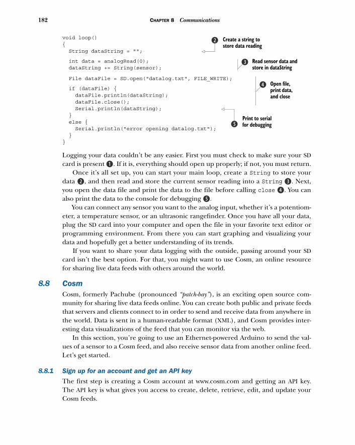
182 CHAPTER 8 Communications
void loop(){ String dataString = "";
int data = analogRead(0); dataString += String(sensor);
File dataFile = SD.open("datalog.txt", FILE_WRITE);
if (dataFile) { dataFile.println(dataString); dataFile.close(); Serial.println(dataString); } else { Serial.println("error opening datalog.txt"); } }
Logging your data couldn’t be any easier. First you must check to make sure your SDcard is present B. If it is, everything should open up properly; if not, you must return.
Once it’s all set up, you can start your main loop, create a String to store yourdata c, and then read and store the current sensor reading into a String d. Next,you open the data file and print the data to the file before calling close e. You canalso print the data to the console for debugging f.
You can connect any sensor you want to the analog input, whether it’s a potentiom-eter, a temperature sensor, or an ultrasonic rangefinder. Once you have all your data,plug the SD card into your computer and open the file in your favorite text editor orprogramming environment. From there you can start graphing and visualizing yourdata and hopefully get a better understanding of its trends.
If you want to share your data logging with the outside, passing around your SDcard isn’t the best option. For that, you might want to use Cosm, an online resourcefor sharing live data feeds with others around the world.
8.8 CosmCosm, formerly Pachube (pronounced “patch-bay”), is an exciting open source com-munity for sharing live data feeds online. You can create both public and private feedsthat servers and clients connect to in order to send and receive data from anywhere inthe world. Data is sent in a human-readable format (XML), and Cosm provides inter-esting data visualizations of the feed that you can monitor via the web.
In this section, you’re going to use an Ethernet-powered Arduino to send the val-ues of a sensor to a Cosm feed, and also receive sensor data from another online feed.Let’s get started.
8.8.1 Sign up for an account and get an API key
The first step is creating a Cosm account at www.cosm.com and getting an API key.The API key is what gives you access to create, delete, retrieve, edit, and update yourCosm feeds.
Create a string to store data reading
c
Read sensor data and store in dataString
d
Open file, print data, and close
e
Print to serial for debuggingf
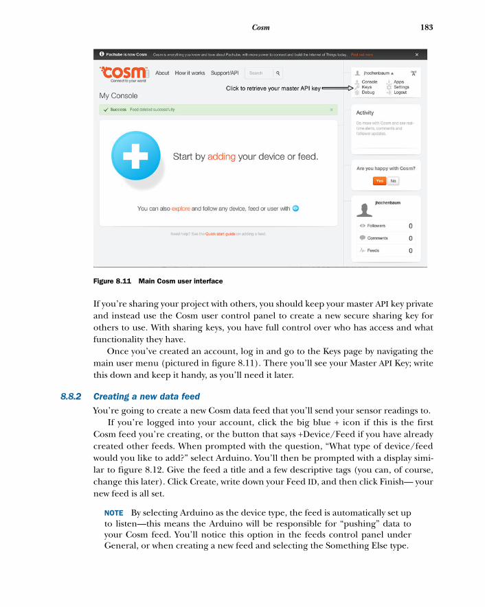
183Cosm
If you’re sharing your project with others, you should keep your master API key privateand instead use the Cosm user control panel to create a new secure sharing key forothers to use. With sharing keys, you have full control over who has access and whatfunctionality they have.
Once you’ve created an account, log in and go to the Keys page by navigating themain user menu (pictured in figure 8.11). There you’ll see your Master API Key; writethis down and keep it handy, as you’ll need it later.
8.8.2 Creating a new data feed
You’re going to create a new Cosm data feed that you’ll send your sensor readings to. If you’re logged into your account, click the big blue + icon if this is the first
Cosm feed you’re creating, or the button that says +Device/Feed if you have alreadycreated other feeds. When prompted with the question, “What type of device/feedwould you like to add?” select Arduino. You’ll then be prompted with a display simi-lar to figure 8.12. Give the feed a title and a few descriptive tags (you can, of course,change this later). Click Create, write down your Feed ID, and then click Finish— yournew feed is all set.
NOTE By selecting Arduino as the device type, the feed is automatically set upto listen—this means the Arduino will be responsible for “pushing” data toyour Cosm feed. You’ll notice this option in the feeds control panel underGeneral, or when creating a new feed and selecting the Something Else type.
Figure 8.11 Main Cosm user interface

184 CHAPTER 8 Communications
Your feed is now set up and it’s ready to receive information. With your account, APIkey, and feed ID ready to go, you’re set to get logging in section 8.8.3. If you forgot towrite down your feed ID, you can retrieve it by browsing to your feed (simply click yourfeed name from the Cosm console).
8.8.3 Sketch for Cosm sensor logging
Talking to Cosm is easy. In this example, you’ll log the readings from a potentiometerto a Cosm feed every ten seconds.
NOTE In order to understand the workings of communicating with Cosm,you’ll connect and send everything by hand in this example. Once you’refamiliar with how things work, you can save on a few lines of code—check outthe wonderful Cosm Arduino library downloadable at https://cosm.com/support/libraries.
Enter the following code in the Arduino IDE.
#include <SPI.h>#include <Ethernet.h>
#define APIKEY "YOUR API KEY GOES HERE" #define FEEDID 12345 #define PROJECTNAME "Arduino In Action"
Listing 8.8 Cosm sensor logging code
Figure 8.12 Creating a new Cosm feed to log sensor data
Configure Cosm feed settings
b
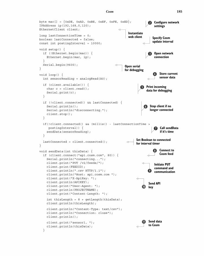
185Cosm
byte mac[] = {0xDE, 0xAD, 0xBE, 0xEF, 0xFE, 0xED}; IPAddress ip(192,168,0,120); EthernetClient client;
long lastConnectionTime = 0;boolean lastConnected = false; const int postingInterval = 10000;
void setup() { if (!Ethernet.begin(mac)) { Ethernet.begin(mac, ip); } Serial.begin(9600); }
void loop() { int sensorReading = analogRead(A0);
if (client.available()) { char c = client.read(); Serial.print(c); }
if (!client.connected() && lastConnected) { Serial.println(); Serial.println("disconnecting."); client.stop(); }
if(!client.connected() && (millis() - lastConnectionTime > postingInterval)) {
sendData(sensorReading); }
lastConnected = client.connected(); }
void sendData(int thisData) { if (client.connect("api.cosm.com", 80)) { Serial.println("connecting..."); client.print("PUT /v2/feeds/"); client.print(FEEDID); client.println(".csv HTTP/1.1"); client.println("Host: api.cosm.com "); client.print("X-ApiKey: "); client.println(APIKEY); client.print("User-Agent: "); client.println(PROJECTNAME); client.print("Content-Length: ");
int thisLength = 8 + getLength(thisData); client.println(thisLength);
client.println("Content-Type: text/csv"); client.println("Connection: close"); client.println();
client.print("sensor1, "); client.println(thisData); }
Configure network settings
c
Instantiate web client Specify Cosm
update interval
Open network connection
d
Open serial for debugging
Store current sensor data
e
Print incoming data for debugging
f
Stop client if no longer connected
g
Call sendData if it’s time
h
Set Boolean to connected for interval timer
Connect to Cosm feed
i
Initiate PUT command and communicationj
Send API key1)
Send data to Cosm
1!
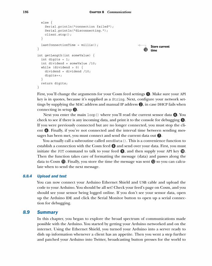
186 CHAPTER 8 Communications
else { Serial.println("connection failed"); Serial.println("disconnecting."); client.stop(); }
lastConnectionTime = millis(); }
int getLength(int someValue) { int digits = 1; int dividend = someValue /10; while (dividend > 0) { dividend = dividend /10; digits++; } return digits;}
First, you’ll change the arguments for your Cosm feed settings B. Make sure your APIkey is in quotes, because it’s supplied as a String. Next, configure your network set-tings by supplying the MAC address and manual IP address c, in case DHCP fails whenconnecting in setup d.
Next you enter the main loop() where you’ll read the current sensor data e. Youcheck to see if there is any incoming data, and print it to the console for debugging f.If you were previously connected but are no longer connected, you must stop the cli-ent g. Finally, if you’re not connected and the interval time between sending mes-sages has been met, you must connect and send the current data out h.
You actually call a subroutine called sendData(). This is a convenience function toestablish a connection with the Cosm feed i and send over your data. First, you mustinitiate the PUT command to talk to your feed j, and then supply your API key 1).Then the function takes care of formatting the message (data) and passes along thedata to Cosm 1!. Finally, you store the time the message was sent 1@ so you can calcu-late when to send the next message.
8.8.4 Upload and test
You can now connect your Arduino Ethernet Shield and USB cable and upload thecode to your Arduino. You should be all set! Check your feed’s page on Cosm, and youshould see your sensor being logged online. If you don’t see your sensor data, openup the Arduino IDE and click the Serial Monitor button to open up a serial connec-tion for debugging.
8.9 SummaryIn this chapter, you began to explore the broad spectrum of communications madepossible with the Arduino. You started by getting your Arduino networked and on theinternet. Using the Ethernet Shield, you turned your Arduino into a server ready todish up information whenever a client has an appetite. Then you went a step furtherand patched your Arduino into Twitter, broadcasting button presses for the world to
Store current time1@
187Summary
see. Because communicating with the Arduino wirelessly is useful in so many applica-tions, we also explored communication with your Arduino both over Wi-Fi and Blue-tooth technology.
The communication channels possible with your Arduino are far-reaching, andthere are many ways you can communicate with other devices and peripherals. Onesuch channel is called SPI, and in this chapter you learned how other devices andshields (such as the SD card and Ethernet Shields) use SPI to communicate with theArduino. You even used SPI yourself to control digital potentiometers.
With all of these powerful means of communication at your disposal, we looked atdata logging, an essential aspect of communication and interaction. Not only did weinvestigate storing information on local memory, but also storing it online using thepowerful data logging service called Cosm.
How and what you choose to share is up to you; perhaps you want to have remotesensors in various environments that send their data to your feed, and are later soni-fied in a gallery installation. Perhaps you want to tap into other public feeds that arelogging everything from seismic data to the temperature, humidity, dew point, andsoil moisture of a garden in the UK, and use that to influence a virtual space. Whateverthe scenario, there are virtually unlimited possibilities when it comes to the types ofinformation your data feed can communicate, and the way you choose to interpretthe information.
The applications discussed in this chapter are the tip of the iceberg. You can usethe communication topics covered here in many ways, and it’s this open-endednessthat makes the Arduino such a powerful communication tool. Think about your proj-ect’s goals and ask yourself whether putting your project online for the world to see orinteract with would be useful. Could it tap into online resources? Does it need to com-municate with other peripherals? Would it be useful to log certain data over time?With Arduino, the tools are in your hands.
But let’s not stop there. Next, in chapter 9, we’re going to look at how to inter-face the Arduino with game peripherals such as the Nintendo Wii Nunchuk andXbox controller.
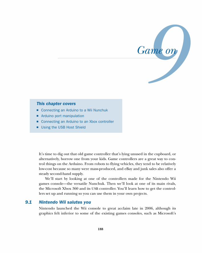
Game on
It’s time to dig out that old game controller that’s lying unused in the cupboard, oralternatively, borrow one from your kids. Game controllers are a great way to con-trol things on the Arduino. From robots to flying vehicles, they tend to be relativelylow-cost because so many were mass-produced, and eBay and junk sales also offer asteady second-hand supply.
We’ll start by looking at one of the controllers made for the Nintendo Wiigames console—the versatile Nunchuk. Then we’ll look at one of its main rivals,the Microsoft Xbox 360 and its USB controller. You’ll learn how to get the control-lers set up and running so you can use them in your own projects.
9.1 Nintendo Wii salutes youNintendo launched the Wii console to great acclaim late in 2006, although itsgraphics felt inferior to some of the existing games consoles, such as Microsoft’s
This chapter covers■ Connecting an Arduino to a Wii Nunchuk■ Arduino port manipulation■ Connecting an Arduino to an Xbox controller■ Using the USB Host Shield
188
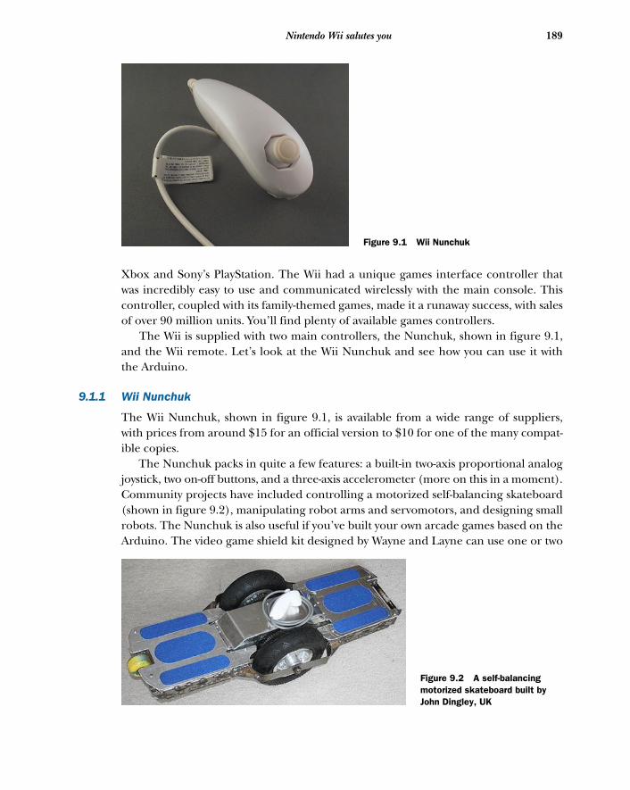
189Nintendo Wii salutes you
Xbox and Sony’s PlayStation. The Wii had a unique games interface controller thatwas incredibly easy to use and communicated wirelessly with the main console. Thiscontroller, coupled with its family-themed games, made it a runaway success, with salesof over 90 million units. You’ll find plenty of available games controllers.
The Wii is supplied with two main controllers, the Nunchuk, shown in figure 9.1,and the Wii remote. Let’s look at the Wii Nunchuk and see how you can use it withthe Arduino.
9.1.1 Wii Nunchuk
The Wii Nunchuk, shown in figure 9.1, is available from a wide range of suppliers,with prices from around $15 for an official version to $10 for one of the many compat-ible copies.
The Nunchuk packs in quite a few features: a built-in two-axis proportional analogjoystick, two on-off buttons, and a three-axis accelerometer (more on this in a moment).Community projects have included controlling a motorized self-balancing skateboard(shown in figure 9.2), manipulating robot arms and servomotors, and designing smallrobots. The Nunchuk is also useful if you’ve built your own arcade games based on theArduino. The video game shield kit designed by Wayne and Layne can use one or two
Figure 9.1 Wii Nunchuk
Figure 9.2 A self-balancing motorized skateboard built by John Dingley, UK
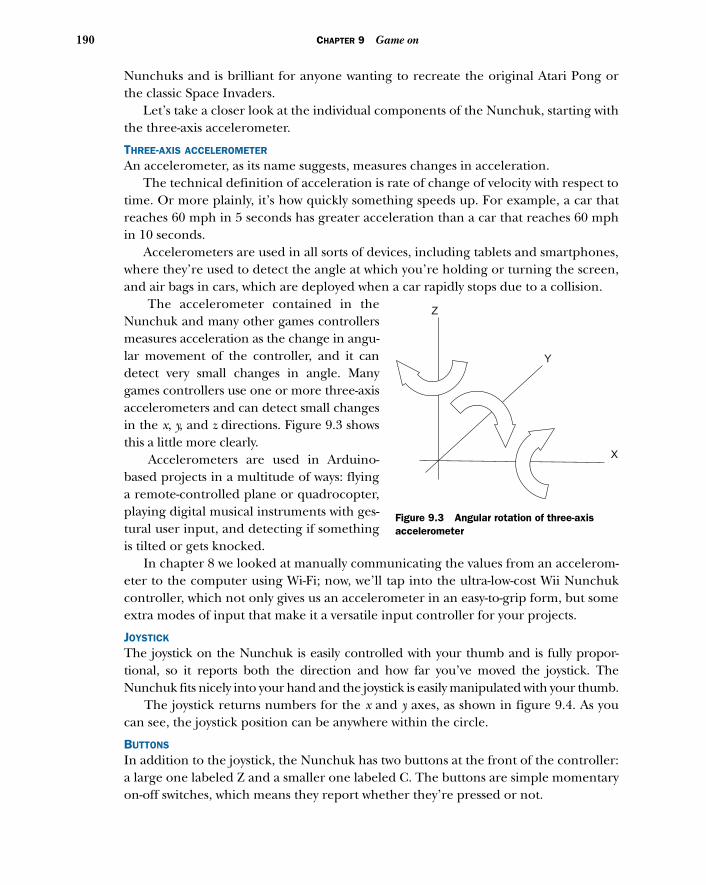
190 CHAPTER 9 Game on
Nunchuks and is brilliant for anyone wanting to recreate the original Atari Pong orthe classic Space Invaders.
Let’s take a closer look at the individual components of the Nunchuk, starting withthe three-axis accelerometer.
THREE-AXIS ACCELEROMETER
An accelerometer, as its name suggests, measures changes in acceleration. The technical definition of acceleration is rate of change of velocity with respect to
time. Or more plainly, it’s how quickly something speeds up. For example, a car thatreaches 60 mph in 5 seconds has greater acceleration than a car that reaches 60 mphin 10 seconds.
Accelerometers are used in all sorts of devices, including tablets and smartphones,where they’re used to detect the angle at which you’re holding or turning the screen,and air bags in cars, which are deployed when a car rapidly stops due to a collision.
The accelerometer contained in theNunchuk and many other games controllersmeasures acceleration as the change in angu-lar movement of the controller, and it candetect very small changes in angle. Manygames controllers use one or more three-axisaccelerometers and can detect small changesin the x, y, and z directions. Figure 9.3 showsthis a little more clearly.
Accelerometers are used in Arduino-based projects in a multitude of ways: flyinga remote-controlled plane or quadrocopter,playing digital musical instruments with ges-tural user input, and detecting if somethingis tilted or gets knocked.
In chapter 8 we looked at manually communicating the values from an accelerom-eter to the computer using Wi-Fi; now, we’ll tap into the ultra-low-cost Wii Nunchukcontroller, which not only gives us an accelerometer in an easy-to-grip form, but someextra modes of input that make it a versatile input controller for your projects.
JOYSTICK
The joystick on the Nunchuk is easily controlled with your thumb and is fully propor-tional, so it reports both the direction and how far you’ve moved the joystick. TheNunchuk fits nicely into your hand and the joystick is easily manipulated with your thumb.
The joystick returns numbers for the x and y axes, as shown in figure 9.4. As youcan see, the joystick position can be anywhere within the circle.
BUTTONS
In addition to the joystick, the Nunchuk has two buttons at the front of the controller:a large one labeled Z and a smaller one labeled C. The buttons are simple momentaryon-off switches, which means they report whether they’re pressed or not.
X
Y
Z
Figure 9.3 Angular rotation of three-axis accelerometer
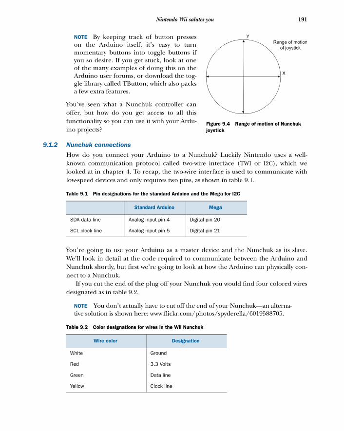
191Nintendo Wii salutes you
NOTE By keeping track of button presseson the Arduino itself, it’s easy to turnmomentary buttons into toggle buttons ifyou so desire. If you get stuck, look at oneof the many examples of doing this on theArduino user forums, or download the tog-gle library called TButton, which also packsa few extra features.
You’ve seen what a Nunchuk controller canoffer, but how do you get access to all thisfunctionality so you can use it with your Ardu-ino projects?
9.1.2 Nunchuk connections
How do you connect your Arduino to a Nunchuk? Luckily Nintendo uses a well-known communication protocol called two-wire interface (TWI or I2C), which welooked at in chapter 4. To recap, the two-wire interface is used to communicate withlow-speed devices and only requires two pins, as shown in table 9.1.
You’re going to use your Arduino as a master device and the Nunchuk as its slave.We’ll look in detail at the code required to communicate between the Arduino andNunchuk shortly, but first we’re going to look at how the Arduino can physically con-nect to a Nunchuk.
If you cut the end of the plug off your Nunchuk you would find four colored wiresdesignated as in table 9.2.
NOTE You don’t actually have to cut off the end of your Nunchuk—an alterna-tive solution is shown here: www.flickr.com/photos/spyderella/6019588705.
Table 9.1 Pin designations for the standard Arduino and the Mega for I2C
Standard Arduino Mega
SDA data line Analog input pin 4 Digital pin 20
SCL clock line Analog input pin 5 Digital pin 21
Table 9.2 Color designations for wires in the Wii Nunchuk
Wire color Designation
White Ground
Red 3.3 Volts
Green Data line
Yellow Clock line
X
YRange of motion
of joystick
Figure 9.4 Range of motion of Nunchuk joystick
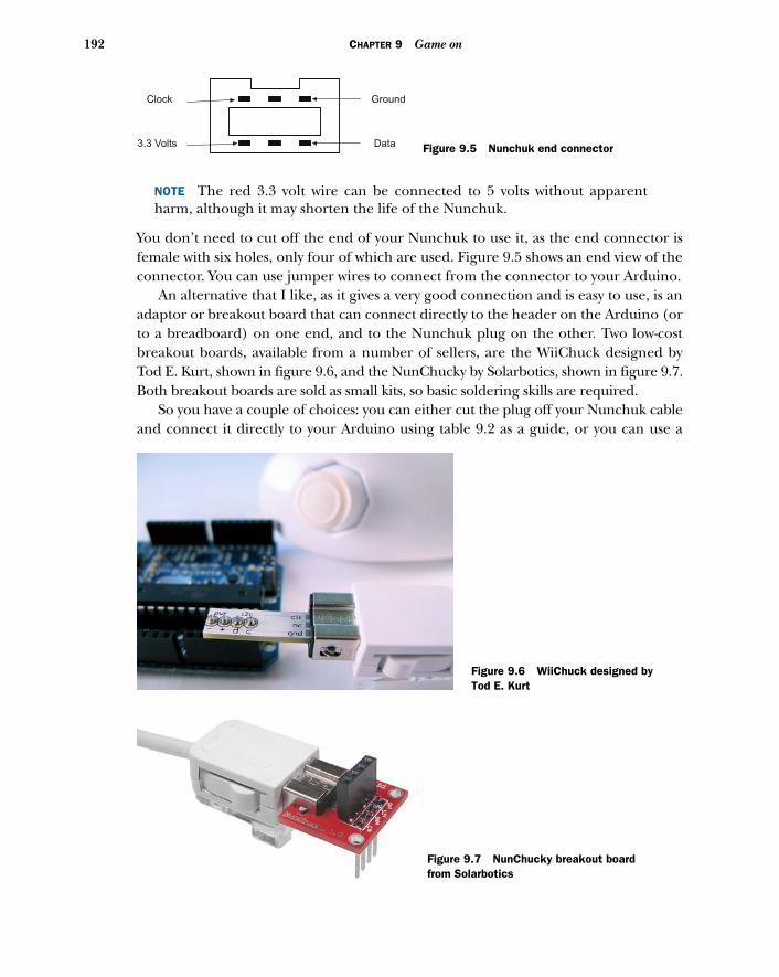
192 CHAPTER 9 Game on
NOTE The red 3.3 volt wire can be connected to 5 volts without apparentharm, although it may shorten the life of the Nunchuk.
You don’t need to cut off the end of your Nunchuk to use it, as the end connector isfemale with six holes, only four of which are used. Figure 9.5 shows an end view of theconnector. You can use jumper wires to connect from the connector to your Arduino.
An alternative that I like, as it gives a very good connection and is easy to use, is anadaptor or breakout board that can connect directly to the header on the Arduino (orto a breadboard) on one end, and to the Nunchuk plug on the other. Two low-costbreakout boards, available from a number of sellers, are the WiiChuck designed byTod E. Kurt, shown in figure 9.6, and the NunChucky by Solarbotics, shown in figure 9.7.Both breakout boards are sold as small kits, so basic soldering skills are required.
So you have a couple of choices: you can either cut the plug off your Nunchuk cableand connect it directly to your Arduino using table 9.2 as a guide, or you can use a
GroundClock
3.3 Volts Data Figure 9.5 Nunchuk end connector
Figure 9.6 WiiChuck designed by Tod E. Kurt
Figure 9.7 NunChucky breakout board from Solarbotics
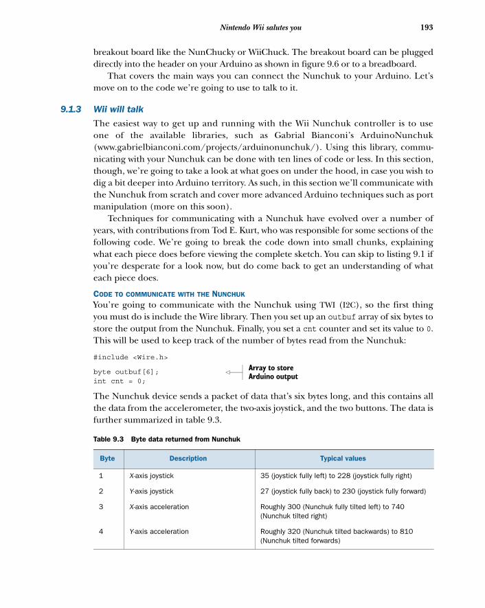
193Nintendo Wii salutes you
breakout board like the NunChucky or WiiChuck. The breakout board can be pluggeddirectly into the header on your Arduino as shown in figure 9.6 or to a breadboard.
That covers the main ways you can connect the Nunchuk to your Arduino. Let’smove on to the code we’re going to use to talk to it.
9.1.3 Wii will talk
The easiest way to get up and running with the Wii Nunchuk controller is to useone of the available libraries, such as Gabrial Bianconi’s ArduinoNunchuk(www.gabrielbianconi.com/projects/arduinonunchuk/). Using this library, commu-nicating with your Nunchuk can be done with ten lines of code or less. In this section,though, we’re going to take a look at what goes on under the hood, in case you wish todig a bit deeper into Arduino territory. As such, in this section we’ll communicate withthe Nunchuk from scratch and cover more advanced Arduino techniques such as portmanipulation (more on this soon).
Techniques for communicating with a Nunchuk have evolved over a number ofyears, with contributions from Tod E. Kurt, who was responsible for some sections of thefollowing code. We’re going to break the code down into small chunks, explainingwhat each piece does before viewing the complete sketch. You can skip to listing 9.1 ifyou’re desperate for a look now, but do come back to get an understanding of whateach piece does.
CODE TO COMMUNICATE WITH THE NUNCHUK
You’re going to communicate with the Nunchuk using TWI (I2C), so the first thingyou must do is include the Wire library. Then you set up an outbuf array of six bytes tostore the output from the Nunchuk. Finally, you set a cnt counter and set its value to 0.This will be used to keep track of the number of bytes read from the Nunchuk:
#include <Wire.h>
byte outbuf[6]; int cnt = 0;
The Nunchuk device sends a packet of data that’s six bytes long, and this contains allthe data from the accelerometer, the two-axis joystick, and the two buttons. The data isfurther summarized in table 9.3.
Table 9.3 Byte data returned from Nunchuk
Byte Description Typical values
1 X-axis joystick 35 (joystick fully left) to 228 (joystick fully right)
2 Y-axis joystick 27 (joystick fully back) to 230 (joystick fully forward)
3 X-axis acceleration Roughly 300 (Nunchuk fully tilted left) to 740 (Nunchuk tilted right)
4 Y-axis acceleration Roughly 320 (Nunchuk tilted backwards) to 810 (Nunchuk tilted forwards)
Array to store Arduino output
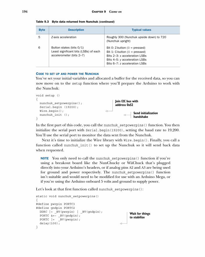
194 CHAPTER 9 Game on
CODE TO SET UP AND POWER THE NUNCHUK
You’ve set your initial variables and allocated a buffer for the received data, so you cannow move on to the setup function where you’ll prepare the Arduino to work withthe Nunchuk:
void setup (){ nunchuk_setpowerpins(); Serial.begin (19200); Wire.begin(); nunchuk_init (); }
In the first part of this code, you call the nunchuk_setpowerpins() function. You theninitialize the serial port with Serial.begin(19200), setting the baud rate to 19,200.You’ll use the serial port to monitor the data sent from the Nunchuk.
Next it’s time to initialize the Wire library with Wire.begin(). Finally, you call afunction called nunchuk_init() to set up the Nunchuk so it will send back datawhen requested.
NOTE You only need to call the nunchuk_setpowerpins() function if you’reusing a breakout board like the NunChucky or WiiChuck that’s pluggeddirectly into your Arduino’s headers, or if analog pins A2 and A3 are being usedfor ground and power respectively. The nunchuk_setpowerpins() functionisn’t suitable and would need to be modified for use with an Arduino Mega, orif you’re using the Arduino onboard 5 volts and ground to supply power.
Let’s look at that first function called nunchuk_setpowerpins():
static void nunchuk_setpowerpins(){#define pwrpin PORTC3#define gndpin PORTC2 DDRC |= _BV(pwrpin) | _BV(gndpin); PORTC &=~ _BV(gndpin); PORTC |= _BV(pwrpin); delay(100); }
5 Z-axis acceleration Roughly 300 (Nunchuk upside down) to 720 (Nunchuk upright)
6 Button states (bits 0/1)Least significant bits (LSBs) of each accelerometer (bits 2–7)
Bit 0: Z-button (0 = pressed)Bit 1: C-button (0 = pressed)Bits 2–3: x acceleration LSBsBits 4–5: y acceleration LSBsBits 6–7: z acceleration LSBs
Table 9.3 Byte data returned from Nunchuk (continued)
Byte Description Typical values
Join I2C bus with address 0x52
Send initialization handshake
Wait for things to stabilize
195Nintendo Wii salutes you
At first glance this function looks fairly complicated, but we’ll break it down to seewhat’s going on. The function uses port manipulation to set analog pin 3 to power(5 volts), and analog pin 2 to ground.
In the nunchuk_setpowerpins() function, the #define pwrpin PORTC3 and #definegndpin PORTC2 lines assign bit offsets, so PORTC2 is bit 2 of the PORTC register.
In the next line, you have this:
DDRC |= _BV(pwrpin) | _BV(gndpin);
DDRC is the direction register for port C, so this line sets the pwrpin and gndpin bits asoutputs using the _BV macro.
Port manipulationArduinos based on the ATMega328 chip, such as the Uno, have three ports that pro-vide fast low-level manipulation of the Arduino input/output pins. Each port givesaccess to a discrete set of pins:
■ Port B gives access to digital pins 8–13■ Port C gives access to analog pins A0–A5■ Port D gives access to digital pins 0–7
Additionally, three registers control each port; the three registers are DDR, PORTand PIN:
■ DDR register—This register sets individual pins as either input or output. Theregister state can be written to and read from.
■ PORT register—This register sets the state of a pin’s output: HIGH or LOW. Theregister state can be written to and read from.
■ PIN register—This register can only be read from and provides the state ofthe inputs.
Each bit of each port controls a single pin. For example, the PORTC register controls portC. Port C consists of analog pins A0–A5 (A6 and A7 are only available on the Mini).
The bits in the DDRC register (the DDR register for port C) control whether a pin is aninput or an output in PORTC. For example, the following command sets pins 1 and 3as inputs and the rest as outputs:
DDRC = B11111010;
PORTC is the register for the state of the outputs. The following command sets pins1 and 3–7 HIGH; these pins will only be set at 5 volts if they have previously been setas outputs by the DDR register:
PORTC = B11111010;
Reading the PINC register would allow you to read the state of all the PORTC pinssimultaneously.
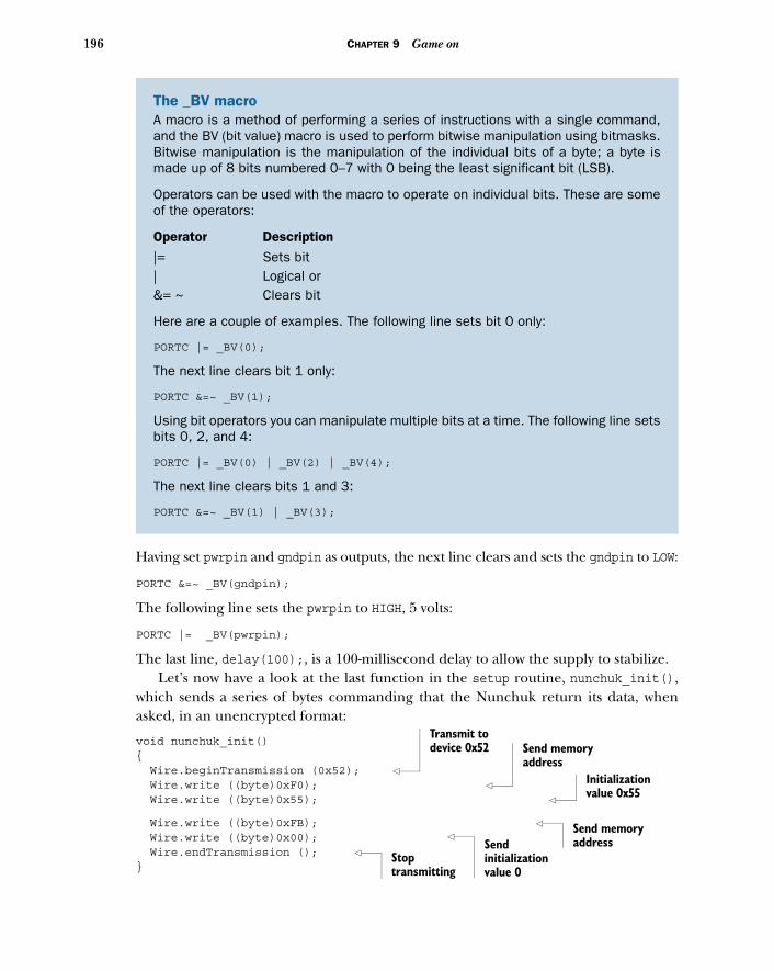
196 CHAPTER 9 Game on
Having set pwrpin and gndpin as outputs, the next line clears and sets the gndpin to LOW:
PORTC &=~ _BV(gndpin);
The following line sets the pwrpin to HIGH, 5 volts:
PORTC |= _BV(pwrpin);
The last line, delay(100);, is a 100-millisecond delay to allow the supply to stabilize. Let’s now have a look at the last function in the setup routine, nunchuk_init(),
which sends a series of bytes commanding that the Nunchuk return its data, whenasked, in an unencrypted format:
void nunchuk_init(){ Wire.beginTransmission (0x52); Wire.write ((byte)0xF0); Wire.write ((byte)0x55);
Wire.write ((byte)0xFB); Wire.write ((byte)0x00); Wire.endTransmission (); }
The _BV macroA macro is a method of performing a series of instructions with a single command,and the BV (bit value) macro is used to perform bitwise manipulation using bitmasks.Bitwise manipulation is the manipulation of the individual bits of a byte; a byte ismade up of 8 bits numbered 0–7 with 0 being the least significant bit (LSB).
Operators can be used with the macro to operate on individual bits. These are someof the operators:
Operator Description|= Sets bit| Logical or&= ~ Clears bit
Here are a couple of examples. The following line sets bit 0 only:
PORTC |= _BV(0);
The next line clears bit 1 only:
PORTC &=~ _BV(1);
Using bit operators you can manipulate multiple bits at a time. The following line setsbits 0, 2, and 4:
PORTC |= _BV(0) | _BV(2) | _BV(4);
The next line clears bits 1 and 3:
PORTC &=~ _BV(1) | _BV(3);
Transmit to device 0x52 Send memory
addressInitialization value 0x55
Send memory addressSend
initialization value 0
Stop transmitting
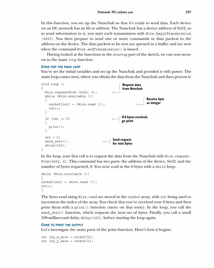
197Nintendo Wii salutes you
In this function, you set up the Nunchuk so that it’s ready to send data. Each deviceon an I2C network has an ID or address. The Nunchuk has a device address of 0x52, soto send information to it, you start each transmission with Wire.beginTransmission(0x52). You then prepare to send one or more commands or data packets to theaddress on the device. The data packets to be sent are queued in a buffer and are sentwhen the command Wire.endTransmission() is issued.
Having looked at the functions in the startup part of the sketch, we can now moveon to the main loop function.
CODE FOR THE MAIN LOOP
You’ve set the initial variables and set up the Nunchuk and provided it with power. Themain loop comes next, where you obtain the data from the Nunchuk and then process it:
void loop (){ Wire.requestFrom (0x52, 6); while (Wire.available ()) { outbuf[cnt] = (Wire.read ()); cnt++; }
if (cnt >= 5) { print(); }
cnt = 0; send_zero(); delay(100);}
In the loop, your first call is to request the data from the Nunchuk with Wire.request-From(0x52, 6). This command has two parts: the address of the device, 0x52, and thenumber of bytes requested, 6. You next read in the 6 bytes with a while loop:
while (Wire.available ()){outbuf[cnt] = (Wire.read ());cnt++;}
The bytes read using Wire.read are stored in the outbuf array, with cnt being used toincrement the index of the array. You check that you’ve received your 6 bytes and thenprint them with a print() function (more on that soon). In the loop, you call thesend_zero() function, which requests the next set of bytes. Finally, you call a small100-millisecond delay, delay(100), before starting the loop again.
CODE TO PRINT THE OUTPUT
Let’s investigate the main parts of the print function. Here’s how it begins:
int joy_x_axis = outbuf[0];int joy_y_axis = outbuf[1];
Request data from Nunchuk
Receive byte as integer
If 6 bytes received, go print
Send request for next bytes
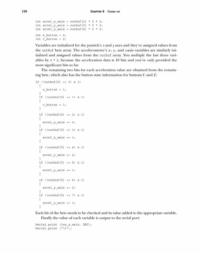
198 CHAPTER 9 Game on
int accel_x_axis = outbuf[2] * 2 * 2;int accel_y_axis = outbuf[3] * 2 * 2;int accel_z_axis = outbuf[4] * 2 * 2;
int z_button = 0;int c_button = 0;
Variables are initialized for the joystick’s x and y axes and they’re assigned values fromthe outbuf byte array. The accelerometer’s x-, y-, and z-axis variables are similarly ini-tialized and assigned values from the outbuf array. You multiply the last three vari-ables by 2 * 2, because the acceleration data is 10 bits and you’ve only provided themost significant bits so far.
The remaining two bits for each acceleration value are obtained from the remain-ing byte, which also has the button state information for buttons C and Z:
if ((outbuf[5] >> 0) & 1) { z_button = 1; } if ((outbuf[5] >> 1) & 1) { c_button = 1; }
if ((outbuf[5] >> 2) & 1) { accel_x_axis += 2; } if ((outbuf[5] >> 3) & 1) { accel_x_axis += 1; }
if ((outbuf[5] >> 4) & 1) { accel_y_axis += 2; } if ((outbuf[5] >> 5) & 1) { accel_y_axis += 1; }
if ((outbuf[5] >> 6) & 1) { accel_z_axis += 2; } if ((outbuf[5] >> 7) & 1) { accel_z_axis += 1; }
Each bit of the byte needs to be checked and its value added to the appropriate variable. Finally the value of each variable is output to the serial port:
Serial.print (joy_x_axis, DEC);Serial.print ("\t");
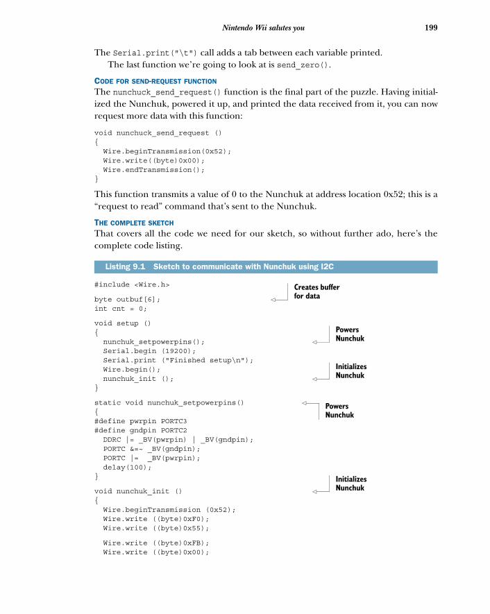
199Nintendo Wii salutes you
The Serial.print("\t") call adds a tab between each variable printed. The last function we’re going to look at is send_zero().
CODE FOR SEND-REQUEST FUNCTION
The nunchuck_send_request() function is the final part of the puzzle. Having initial-ized the Nunchuk, powered it up, and printed the data received from it, you can nowrequest more data with this function:
void nunchuck_send_request (){ Wire.beginTransmission(0x52); Wire.write((byte)0x00); Wire.endTransmission();}
This function transmits a value of 0 to the Nunchuk at address location 0x52; this is a“request to read” command that’s sent to the Nunchuk.
THE COMPLETE SKETCH
That covers all the code we need for our sketch, so without further ado, here’s thecomplete code listing.
#include <Wire.h>
byte outbuf[6]; int cnt = 0;
void setup (){ nunchuk_setpowerpins(); Serial.begin (19200); Serial.print ("Finished setup\n"); Wire.begin(); nunchuk_init (); }
static void nunchuk_setpowerpins() {#define pwrpin PORTC3#define gndpin PORTC2 DDRC |= _BV(pwrpin) | _BV(gndpin); PORTC &=~ _BV(gndpin); PORTC |= _BV(pwrpin); delay(100);}
void nunchuk_init () { Wire.beginTransmission (0x52); Wire.write ((byte)0xF0); Wire.write ((byte)0x55);
Wire.write ((byte)0xFB); Wire.write ((byte)0x00);
Listing 9.1 Sketch to communicate with Nunchuk using I2C
Creates buffer for data
Powers Nunchuk
Initializes Nunchuk
Powers Nunchuk
Initializes Nunchuk
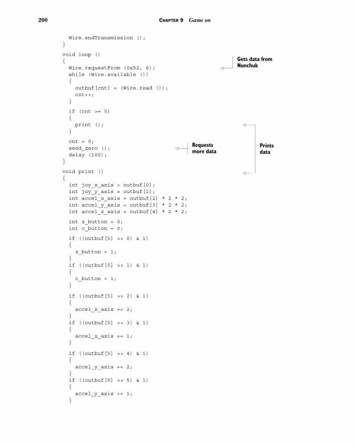
200 CHAPTER 9 Game on
Wire.endTransmission ();}
void loop (){ Wire.requestFrom (0x52, 6); while (Wire.available ()) { outbuf[cnt] = (Wire.read ()); cnt++; }
if (cnt >= 5) { print (); }
cnt = 0; send_zero (); delay (100);}
void print () { int joy_x_axis = outbuf[0]; int joy_y_axis = outbuf[1]; int accel_x_axis = outbuf[2] * 2 * 2; int accel_y_axis = outbuf[3] * 2 * 2; int accel_z_axis = outbuf[4] * 2 * 2;
int z_button = 0; int c_button = 0;
if ((outbuf[5] >> 0) & 1) { z_button = 1; } if ((outbuf[5] >> 1) & 1) { c_button = 1; }
if ((outbuf[5] >> 2) & 1) { accel_x_axis += 2; } if ((outbuf[5] >> 3) & 1) { accel_x_axis += 1; }
if ((outbuf[5] >> 4) & 1) { accel_y_axis += 2; } if ((outbuf[5] >> 5) & 1) { accel_y_axis += 1; }
Gets data from Nunchuk
Prints data
Requests more data
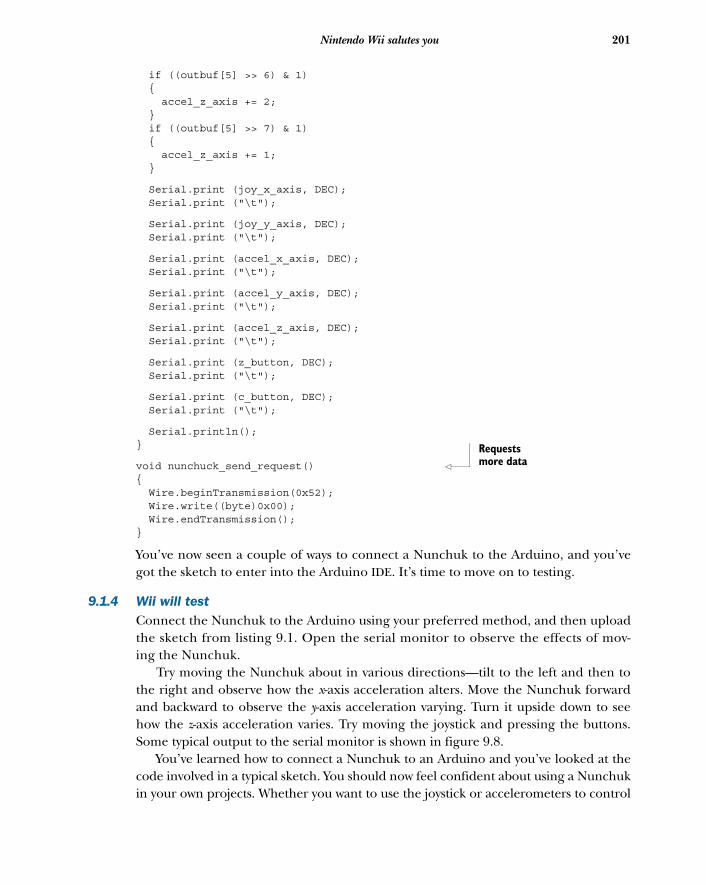
201Nintendo Wii salutes you
if ((outbuf[5] >> 6) & 1) { accel_z_axis += 2; } if ((outbuf[5] >> 7) & 1) { accel_z_axis += 1; }
Serial.print (joy_x_axis, DEC); Serial.print ("\t");
Serial.print (joy_y_axis, DEC); Serial.print ("\t");
Serial.print (accel_x_axis, DEC); Serial.print ("\t");
Serial.print (accel_y_axis, DEC); Serial.print ("\t");
Serial.print (accel_z_axis, DEC); Serial.print ("\t");
Serial.print (z_button, DEC); Serial.print ("\t");
Serial.print (c_button, DEC); Serial.print ("\t");
Serial.println();}
void nunchuck_send_request() { Wire.beginTransmission(0x52); Wire.write((byte)0x00); Wire.endTransmission();}
You’ve now seen a couple of ways to connect a Nunchuk to the Arduino, and you’vegot the sketch to enter into the Arduino IDE. It’s time to move on to testing.
9.1.4 Wii will testConnect the Nunchuk to the Arduino using your preferred method, and then uploadthe sketch from listing 9.1. Open the serial monitor to observe the effects of mov-ing the Nunchuk.
Try moving the Nunchuk about in various directions—tilt to the left and then tothe right and observe how the x-axis acceleration alters. Move the Nunchuk forwardand backward to observe the y-axis acceleration varying. Turn it upside down to seehow the z-axis acceleration varies. Try moving the joystick and pressing the buttons.Some typical output to the serial monitor is shown in figure 9.8.
You’ve learned how to connect a Nunchuk to an Arduino and you’ve looked at thecode involved in a typical sketch. You should now feel confident about using a Nunchukin your own projects. Whether you want to use the joystick or accelerometers to control
Requests more data
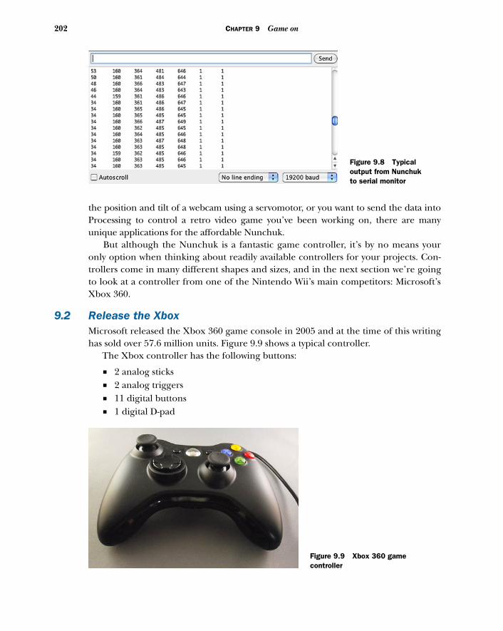
202 CHAPTER 9 Game on
the position and tilt of a webcam using a servomotor, or you want to send the data intoProcessing to control a retro video game you’ve been working on, there are manyunique applications for the affordable Nunchuk.
But although the Nunchuk is a fantastic game controller, it’s by no means youronly option when thinking about readily available controllers for your projects. Con-trollers come in many different shapes and sizes, and in the next section we’re goingto look at a controller from one of the Nintendo Wii’s main competitors: Microsoft’sXbox 360.
9.2 Release the XboxMicrosoft released the Xbox 360 game console in 2005 and at the time of this writinghas sold over 57.6 million units. Figure 9.9 shows a typical controller.
The Xbox controller has the following buttons:
■ 2 analog sticks■ 2 analog triggers■ 11 digital buttons■ 1 digital D-pad
Figure 9.8 Typical output from Nunchuk to serial monitor
Figure 9.9 Xbox 360 game controller
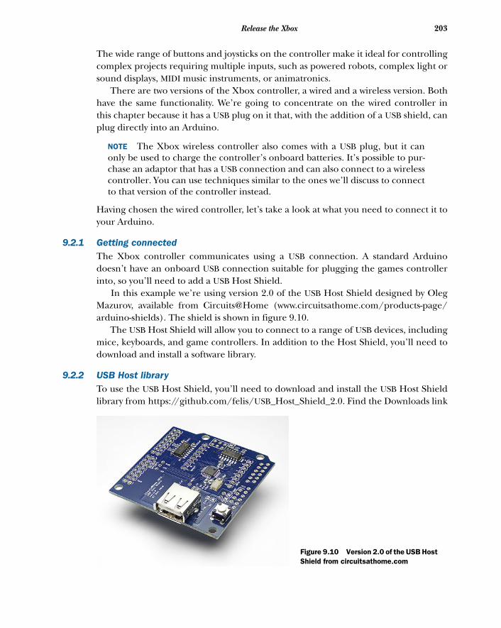
203Release the Xbox
The wide range of buttons and joysticks on the controller make it ideal for controllingcomplex projects requiring multiple inputs, such as powered robots, complex light orsound displays, MIDI music instruments, or animatronics.
There are two versions of the Xbox controller, a wired and a wireless version. Bothhave the same functionality. We’re going to concentrate on the wired controller inthis chapter because it has a USB plug on it that, with the addition of a USB shield, canplug directly into an Arduino.
NOTE The Xbox wireless controller also comes with a USB plug, but it canonly be used to charge the controller’s onboard batteries. It’s possible to pur-chase an adaptor that has a USB connection and can also connect to a wirelesscontroller. You can use techniques similar to the ones we’ll discuss to connectto that version of the controller instead.
Having chosen the wired controller, let’s take a look at what you need to connect it toyour Arduino.
9.2.1 Getting connectedThe Xbox controller communicates using a USB connection. A standard Arduinodoesn’t have an onboard USB connection suitable for plugging the games controllerinto, so you’ll need to add a USB Host Shield.
In this example we’re using version 2.0 of the USB Host Shield designed by OlegMazurov, available from Circuits@Home (www.circuitsathome.com/products-page/arduino-shields). The shield is shown in figure 9.10.
The USB Host Shield will allow you to connect to a range of USB devices, includingmice, keyboards, and game controllers. In addition to the Host Shield, you’ll need todownload and install a software library.
9.2.2 USB Host libraryTo use the USB Host Shield, you’ll need to download and install the USB Host Shieldlibrary from https://github.com/felis/USB_Host_Shield_2.0. Find the Downloads link
Figure 9.10 Version 2.0 of the USB Host Shield from circuitsathome.com
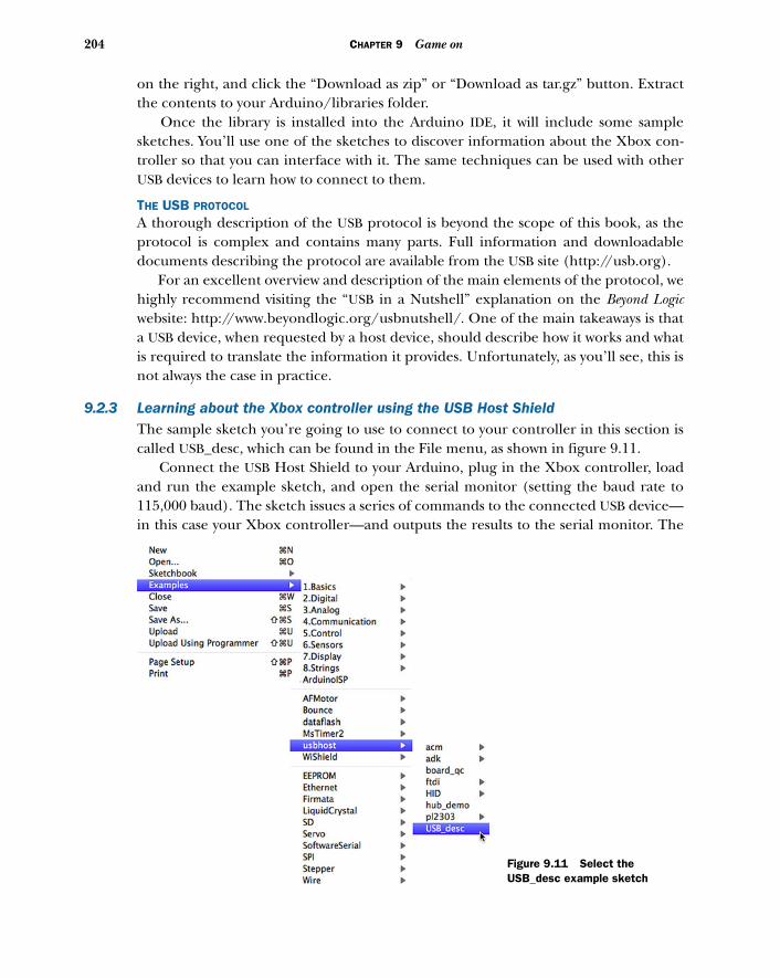
204 CHAPTER 9 Game on
on the right, and click the “Download as zip” or “Download as tar.gz” button. Extractthe contents to your Arduino/libraries folder.
Once the library is installed into the Arduino IDE, it will include some samplesketches. You’ll use one of the sketches to discover information about the Xbox con-troller so that you can interface with it. The same techniques can be used with otherUSB devices to learn how to connect to them.
THE USB PROTOCOL
A thorough description of the USB protocol is beyond the scope of this book, as theprotocol is complex and contains many parts. Full information and downloadabledocuments describing the protocol are available from the USB site (http://usb.org).
For an excellent overview and description of the main elements of the protocol, wehighly recommend visiting the “USB in a Nutshell” explanation on the Beyond Logicwebsite: http://www.beyondlogic.org/usbnutshell/. One of the main takeaways is thata USB device, when requested by a host device, should describe how it works and whatis required to translate the information it provides. Unfortunately, as you’ll see, this isnot always the case in practice.
9.2.3 Learning about the Xbox controller using the USB Host ShieldThe sample sketch you’re going to use to connect to your controller in this section iscalled USB_desc, which can be found in the File menu, as shown in figure 9.11.
Connect the USB Host Shield to your Arduino, plug in the Xbox controller, loadand run the example sketch, and open the serial monitor (setting the baud rate to115,000 baud). The sketch issues a series of commands to the connected USB device—in this case your Xbox controller—and outputs the results to the serial monitor. The
Figure 9.11 Select the USB_desc example sketch
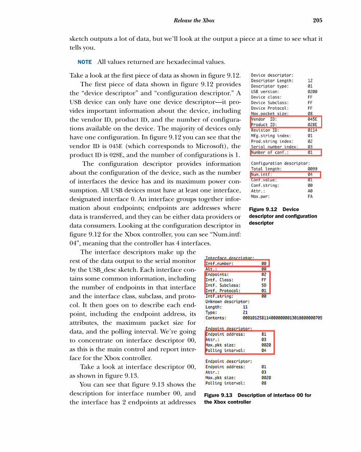
205Release the Xbox
sketch outputs a lot of data, but we’ll look at the output a piece at a time to see what ittells you.
NOTE All values returned are hexadecimal values.
Take a look at the first piece of data as shown in figure 9.12. The first piece of data shown in figure 9.12 provides
the “device descriptor” and “configuration descriptor.” AUSB device can only have one device descriptor—it pro-vides important information about the device, includingthe vendor ID, product ID, and the number of configura-tions available on the device. The majority of devices onlyhave one configuration. In figure 9.12 you can see that thevendor ID is 045E (which corresponds to Microsoft), theproduct ID is 028E, and the number of configurations is 1.
The configuration descriptor provides informationabout the configuration of the device, such as the numberof interfaces the device has and its maximum power con-sumption. All USB devices must have at least one interface,designated interface 0. An interface groups together infor-mation about endpoints; endpoints are addresses wheredata is transferred, and they can be either data providers ordata consumers. Looking at the configuration descriptor infigure 9.12 for the Xbox controller, you can see “Num.intf:04”, meaning that the controller has 4 interfaces.
The interface descriptors make up therest of the data output to the serial monitorby the USB_desc sketch. Each interface con-tains some common information, includingthe number of endpoints in that interfaceand the interface class, subclass, and proto-col. It then goes on to describe each end-point, including the endpoint address, itsattributes, the maximum packet size fordata, and the polling interval. We’re goingto concentrate on interface descriptor 00,as this is the main control and report inter-face for the Xbox controller.
Take a look at interface descriptor 00,as shown in figure 9.13.
You can see that figure 9.13 shows thedescription for interface number 00, andthe interface has 2 endpoints at addresses
Figure 9.12 Device descriptor and configuration descriptor
Figure 9.13 Description of interface 00 for the Xbox controller
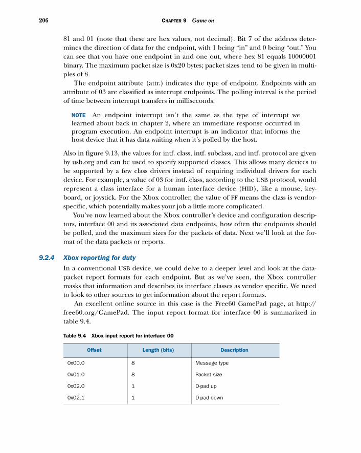
206 CHAPTER 9 Game on
81 and 01 (note that these are hex values, not decimal). Bit 7 of the address deter-mines the direction of data for the endpoint, with 1 being “in” and 0 being “out.” Youcan see that you have one endpoint in and one out, where hex 81 equals 10000001binary. The maximum packet size is 0x20 bytes; packet sizes tend to be given in multi-ples of 8.
The endpoint attribute (attr.) indicates the type of endpoint. Endpoints with anattribute of 03 are classified as interrupt endpoints. The polling interval is the periodof time between interrupt transfers in milliseconds.
NOTE An endpoint interrupt isn’t the same as the type of interrupt welearned about back in chapter 2, where an immediate response occurred inprogram execution. An endpoint interrupt is an indicator that informs thehost device that it has data waiting when it’s polled by the host.
Also in figure 9.13, the values for intf. class, intf. subclass, and intf. protocol are givenby usb.org and can be used to specify supported classes. This allows many devices tobe supported by a few class drivers instead of requiring individual drivers for eachdevice. For example, a value of 03 for intf. class, according to the USB protocol, wouldrepresent a class interface for a human interface device (HID), like a mouse, key-board, or joystick. For the Xbox controller, the value of FF means the class is vendor-specific, which potentially makes your job a little more complicated.
You’ve now learned about the Xbox controller’s device and configuration descrip-tors, interface 00 and its associated data endpoints, how often the endpoints shouldbe polled, and the maximum sizes for the packets of data. Next we’ll look at the for-mat of the data packets or reports.
9.2.4 Xbox reporting for duty
In a conventional USB device, we could delve to a deeper level and look at the data-packet report formats for each endpoint. But as we’ve seen, the Xbox controllermasks that information and describes its interface classes as vendor specific. We needto look to other sources to get information about the report formats.
An excellent online source in this case is the Free60 GamePad page, at http://free60.org/GamePad. The input report format for interface 00 is summarized intable 9.4.
Table 9.4 Xbox input report for interface 00
Offset Length (bits) Description
0x00.0 8 Message type
0x01.0 8 Packet size
0x02.0 1 D-pad up
0x02.1 1 D-pad down
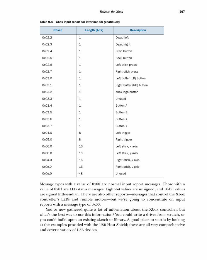
207Release the Xbox
Message types with a value of 0x00 are normal input report messages. Those with avalue of 0x01 are LED status messages. Eight-bit values are unsigned, and 16-bit valuesare signed little-endian. There are also other reports—messages that control the Xboxcontroller’s LEDs and rumble motors—but we’re going to concentrate on inputreports with a message type of 0x00.
You’ve now gathered quite a lot of information about the Xbox controller, butwhat’s the best way to use this information? You could write a driver from scratch, oryou could build upon an existing sketch or library. A good place to start is by lookingat the examples provided with the USB Host Shield; these are all very comprehensiveand cover a variety of USB devices.
0x02.2 1 D-pad left
0x02.3 1 D-pad right
0x02.4 1 Start button
0x02.5 1 Back button
0x02.6 1 Left stick press
0x02.7 1 Right stick press
0x03.0 1 Left buffer (LB) button
0x03.1 1 Right buffer (RB) button
0x03.2 1 Xbox logo button
0x03.3 1 Unused
0x03.4 1 Button A
0x03.5 1 Button B
0x03.6 1 Button X
0x03.7 1 Button Y
0x04.0 8 Left trigger
0x05.0 8 Right trigger
0x06.0 16 Left stick, x axis
0x08.0 16 Left stick, y axis
0x0a.0 16 Right stick, x axis
0x0c.0 16 Right stick, y axis
0x0e.0 48 Unused
Table 9.4 Xbox input report for interface 00 (continued)
Offset Length (bits) Description
208 CHAPTER 9 Game on
You know that the Xbox controller is really a HID device. You also know that it doesn’tprovide a comprehensive description of its report format, but from research you doknow what the format is. The closest examples provided with the USB Host Shieldlibrary are the boot keyboard and mouse examples. These use a known report formatto parse the report messages sent by these USB devices.
9.2.5 Let’s boot it
Mice and keyboards have a default or boot configuration that can be read. For example,all mice have a boot protocol of six bytes that provides information about which but-ton has been pressed and the x and y coordinates of the mouse position. Similarly, key-boards have a default boot protocol, with the data returned providing informationabout which key has been pressed.
A default boot configuration enables the device to be easily read by a variety of hostdevices. Devices using a given configuration will all return at least this type of informa-tion, even though they may have more advanced capabilities, such as the sound con-trols on some keyboards or the scroll wheel on some mice.
You know the format of the reports and details for the interface produced by theXbox controller, so you can do the same thing for the Xbox controller as for mice andkeyboards—you can treat an Xbox controller as a boot device.
Let’s now look at the steps involved in interfacing the Arduino with the Xboxcontroller.
9.2.6 Interfacing with code
The HID boot examples use a number of libraries. The library we’re interested in isthe hidboot library; this is made up of two files, hidboot.h and hidboot.cpp.
NOTE On Windows, the files are normally found in the My Documents/Arduino/libraries/usbhost folder; on Mac OS X they’re in the Documents/Arduino/libraries/usbhost folder.
To dig deeper, carefully study these files, as the code you’re going to use is closely basedon them, with a few tweaks here and there. To keep the code listings shorter in the
Big-endian and little-endianBig-endian and little-endian describe the order in which a sequence of bytes repre-senting a value is stored. Big-endian is where the “big end” (most significant value)is stored first. Little-endian is where the “little end” (least significant value) is storedfirst. In a big-endian computer, the two bytes required for the hexadecimal numberFC62 would be stored as FC62. In a little-endian system, it would be stored as 62FC.
The big-endian and little-endian names derive from Jonathan Swift’s Gulliver’s Travels,in which the Big-endians were a political faction that broke their eggs at the large endand rebelled against the Lilliputian emperor who required his subjects, the Little-endians, to break their eggs at the small end.
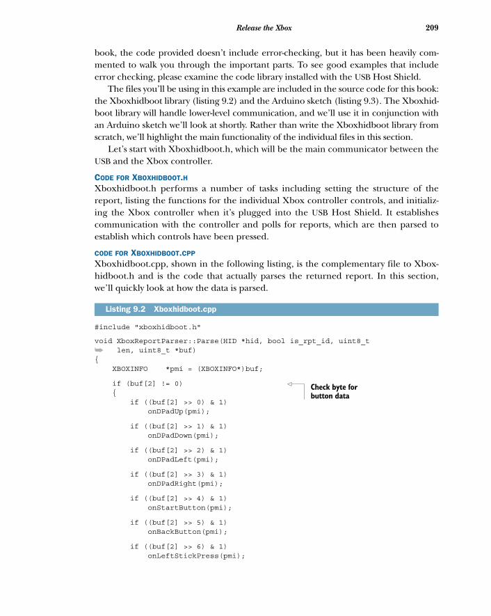
209Release the Xbox
book, the code provided doesn’t include error-checking, but it has been heavily com-mented to walk you through the important parts. To see good examples that includeerror checking, please examine the code library installed with the USB Host Shield.
The files you’ll be using in this example are included in the source code for this book:the Xboxhidboot library (listing 9.2) and the Arduino sketch (listing 9.3). The Xboxhid-boot library will handle lower-level communication, and we’ll use it in conjunction withan Arduino sketch we’ll look at shortly. Rather than write the Xboxhidboot library fromscratch, we’ll highlight the main functionality of the individual files in this section.
Let’s start with Xboxhidboot.h, which will be the main communicator between theUSB and the Xbox controller.
CODE FOR XBOXHIDBOOT.HXboxhidboot.h performs a number of tasks including setting the structure of thereport, listing the functions for the individual Xbox controller controls, and initializ-ing the Xbox controller when it’s plugged into the USB Host Shield. It establishescommunication with the controller and polls for reports, which are then parsed toestablish which controls have been pressed.
CODE FOR XBOXHIDBOOT.CPP
Xboxhidboot.cpp, shown in the following listing, is the complementary file to Xbox-hidboot.h and is the code that actually parses the returned report. In this section,we’ll quickly look at how the data is parsed.
#include "xboxhidboot.h"
void XboxReportParser::Parse(HID *hid, bool is_rpt_id, uint8_t
➥ len, uint8_t *buf){ XBOXINFO *pmi = (XBOXINFO*)buf;
if (buf[2] != 0) { if ((buf[2] >> 0) & 1) onDPadUp(pmi);
if ((buf[2] >> 1) & 1) onDPadDown(pmi);
if ((buf[2] >> 2) & 1) onDPadLeft(pmi);
if ((buf[2] >> 3) & 1) onDPadRight(pmi);
if ((buf[2] >> 4) & 1) onStartButton(pmi);
if ((buf[2] >> 5) & 1) onBackButton(pmi);
if ((buf[2] >> 6) & 1) onLeftStickPress(pmi);
Listing 9.2 Xboxhidboot.cpp
Check byte for button data
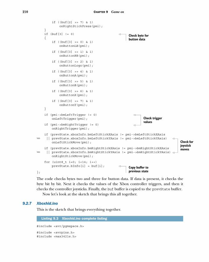
210 CHAPTER 9 Game on
k for ick s
if ((buf[2] >> 7) & 1) onRightStickPress(pmi); } if (buf[3] != 0) { if ((buf[3] >> 0) & 1) onButtonLB(pmi);
if ((buf[3] >> 1) & 1) onButtonRB(pmi);
if ((buf[3] >> 2) & 1) onButtonLogo(pmi);
if ((buf[3] >> 4) & 1) onButtonA(pmi);
if ((buf[3] >> 5) & 1) onButtonB(pmi);
if ((buf[3] >> 6) & 1) onButtonX(pmi);
if ((buf[3] >> 7) & 1) onButtonY(pmi); }
if (pmi->bmLeftTrigger != 0) onLeftTrigger(pmi);
if (pmi->bmRightTrigger != 0) onRightTrigger(pmi);
if (prevState.xboxInfo.bmLeftStickXAxis != pmi->bmLeftStickXAxis
➥ || prevState.xboxInfo.bmLeftStickYAxis != pmi->bmLeftStickYAxis) onLeftStickMove(pmi);
if (prevState.xboxInfo.bmRightStickXAxis != pmi->bmRightStickXAxis
➥ || prevState.xboxInfo.bmRightStickYAxis != pmi->bmRightStickYAxis) onRightStickMove(pmi);
for (uint8_t i=0; i<14; i++) prevState.bInfo[i] = buf[i];
};
The code checks bytes two and three for button data. If data is present, it checks thebyte bit by bit. Next it checks the values of the Xbox controller triggers, and then itchecks the controller joysticks. Finally, the buf buffer is copied to the prevState buffer.
Now let’s look at the sketch that brings this all together.
9.2.7 Xboxhid.ino
This is the sketch that brings everything together.
#include <avr/pgmspace.h>
#include <avrpins.h>#include <max3421e.h>
Listing 9.3 Xboxhid.ino complete listing
Check byte for button data
Check trigger values
Checjoystmove
Copy buffer to previous state
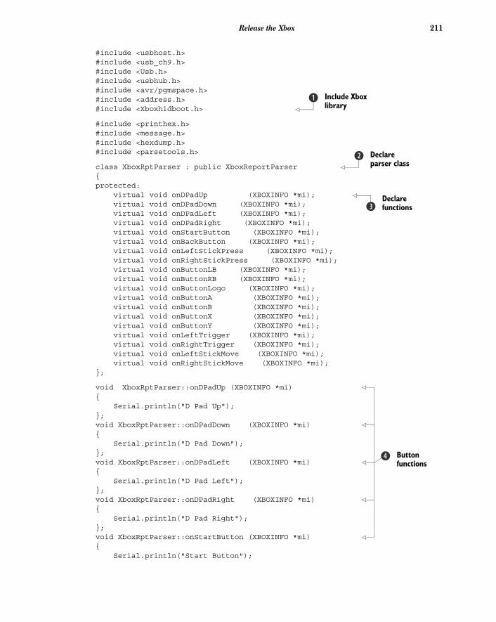
211Release the Xbox
#include <usbhost.h>#include <usb_ch9.h>#include <Usb.h>#include <usbhub.h>#include <avr/pgmspace.h>#include <address.h>#include <Xboxhidboot.h>
#include <printhex.h>#include <message.h>#include <hexdump.h>#include <parsetools.h>
class XboxRptParser : public XboxReportParser {protected: virtual void onDPadUp (XBOXINFO *mi); virtual void onDPadDown (XBOXINFO *mi); virtual void onDPadLeft (XBOXINFO *mi); virtual void onDPadRight (XBOXINFO *mi); virtual void onStartButton (XBOXINFO *mi); virtual void onBackButton (XBOXINFO *mi); virtual void onLeftStickPress (XBOXINFO *mi); virtual void onRightStickPress (XBOXINFO *mi); virtual void onButtonLB (XBOXINFO *mi); virtual void onButtonRB (XBOXINFO *mi); virtual void onButtonLogo (XBOXINFO *mi); virtual void onButtonA (XBOXINFO *mi); virtual void onButtonB (XBOXINFO *mi); virtual void onButtonX (XBOXINFO *mi); virtual void onButtonY (XBOXINFO *mi); virtual void onLeftTrigger (XBOXINFO *mi); virtual void onRightTrigger (XBOXINFO *mi); virtual void onLeftStickMove (XBOXINFO *mi); virtual void onRightStickMove (XBOXINFO *mi);};
void XboxRptParser::onDPadUp (XBOXINFO *mi) { Serial.println("D Pad Up");};void XboxRptParser::onDPadDown (XBOXINFO *mi) { Serial.println("D Pad Down");};void XboxRptParser::onDPadLeft (XBOXINFO *mi) { Serial.println("D Pad Left");};void XboxRptParser::onDPadRight (XBOXINFO *mi) { Serial.println("D Pad Right");};void XboxRptParser::onStartButton (XBOXINFO *mi) { Serial.println("Start Button");
Include Xbox library
b
Declare parser class
c
Declare functionsd
Button functions
e

212 CHAPTER 9 Game on
};void XboxRptParser::onBackButton (XBOXINFO *mi) { Serial.println("Back Button");};void XboxRptParser::onLeftStickPress (XBOXINFO *mi) { Serial.println("Left Stick Press");};void XboxRptParser::onRightStickPress (XBOXINFO *mi) { Serial.println("Right Stick Press");};void XboxRptParser::onButtonLB (XBOXINFO *mi) { Serial.println("Button LB Press");};void XboxRptParser::onButtonRB (XBOXINFO *mi) { Serial.println("Button RB Press");};void XboxRptParser::onButtonLogo (XBOXINFO *mi) { Serial.println("Button Logo Press");};void XboxRptParser::onButtonA (XBOXINFO *mi) { Serial.println("Button A Press");};void XboxRptParser::onButtonB (XBOXINFO *mi) { Serial.println("Button B Press");};void XboxRptParser::onButtonX (XBOXINFO *mi) { Serial.println("Button X Press");};void XboxRptParser::onButtonY (XBOXINFO *mi) { Serial.println("Button Y Press");};void XboxRptParser::onLeftTrigger (XBOXINFO *mi) { Serial.print("Left Trigger: "); Serial.println(mi->bmLeftTrigger, DEC);};void XboxRptParser::onRightTrigger (XBOXINFO *mi) { Serial.print("Right Trigger: "); Serial.println(mi->bmRightTrigger, DEC);};
void XboxRptParser::onLeftStickMove (XBOXINFO *mi) {
Button functions
e
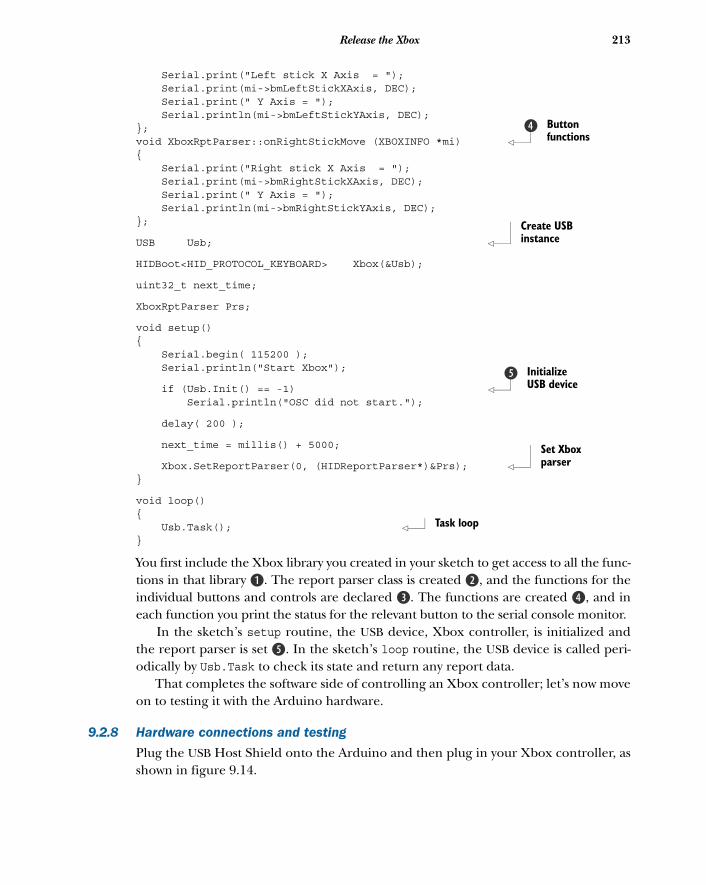
213Release the Xbox
Serial.print("Left stick X Axis = "); Serial.print(mi->bmLeftStickXAxis, DEC); Serial.print(" Y Axis = "); Serial.println(mi->bmLeftStickYAxis, DEC);};void XboxRptParser::onRightStickMove (XBOXINFO *mi) { Serial.print("Right stick X Axis = "); Serial.print(mi->bmRightStickXAxis, DEC); Serial.print(" Y Axis = "); Serial.println(mi->bmRightStickYAxis, DEC);};
USB Usb;
HIDBoot<HID_PROTOCOL_KEYBOARD> Xbox(&Usb);
uint32_t next_time;
XboxRptParser Prs;
void setup(){ Serial.begin( 115200 ); Serial.println("Start Xbox");
if (Usb.Init() == -1) Serial.println("OSC did not start.");
delay( 200 );
next_time = millis() + 5000;
Xbox.SetReportParser(0, (HIDReportParser*)&Prs); }
void loop(){ Usb.Task(); }
You first include the Xbox library you created in your sketch to get access to all the func-tions in that library B. The report parser class is created c, and the functions for theindividual buttons and controls are declared d. The functions are created e, and ineach function you print the status for the relevant button to the serial console monitor.
In the sketch’s setup routine, the USB device, Xbox controller, is initialized andthe report parser is set f. In the sketch’s loop routine, the USB device is called peri-odically by Usb.Task to check its state and return any report data.
That completes the software side of controlling an Xbox controller; let’s now moveon to testing it with the Arduino hardware.
9.2.8 Hardware connections and testing
Plug the USB Host Shield onto the Arduino and then plug in your Xbox controller, asshown in figure 9.14.
Button functions
e
Create USB instance
Initialize USB device
f
Set Xbox parser
Task loop
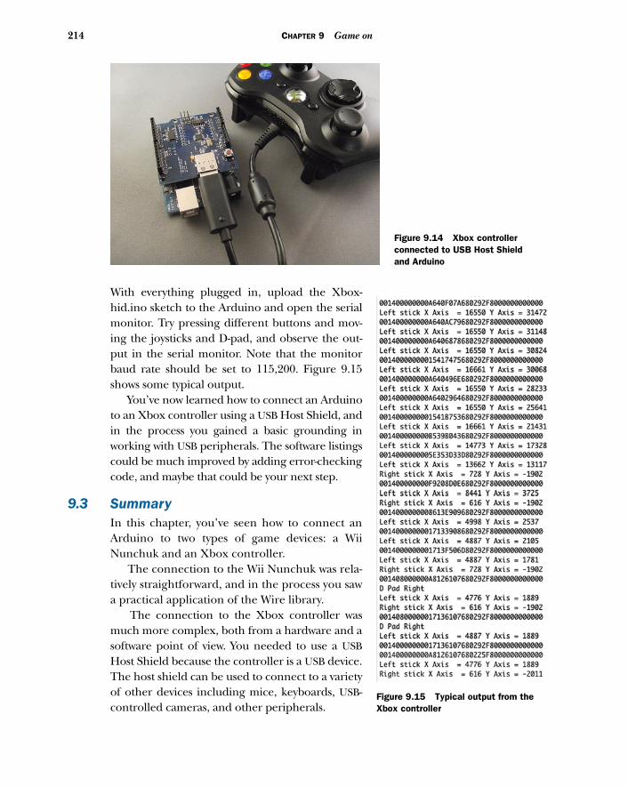
214 CHAPTER 9 Game on
With everything plugged in, upload the Xbox-hid.ino sketch to the Arduino and open the serialmonitor. Try pressing different buttons and mov-ing the joysticks and D-pad, and observe the out-put in the serial monitor. Note that the monitorbaud rate should be set to 115,200. Figure 9.15shows some typical output.
You’ve now learned how to connect an Arduinoto an Xbox controller using a USB Host Shield, andin the process you gained a basic grounding inworking with USB peripherals. The software listingscould be much improved by adding error-checkingcode, and maybe that could be your next step.
9.3 SummaryIn this chapter, you’ve seen how to connect anArduino to two types of game devices: a WiiNunchuk and an Xbox controller.
The connection to the Wii Nunchuk was rela-tively straightforward, and in the process you sawa practical application of the Wire library.
The connection to the Xbox controller wasmuch more complex, both from a hardware and asoftware point of view. You needed to use a USBHost Shield because the controller is a USB device.The host shield can be used to connect to a varietyof other devices including mice, keyboards, USB-controlled cameras, and other peripherals.
Figure 9.14 Xbox controller connected to USB Host Shield and Arduino
Figure 9.15 Typical output from the Xbox controller
215Summary
This is just the beginning! The real benefit of these controllers is that they’re afford-able devices offering a number of easily manipulated controls at your fingertips. There’snothing stopping you from connecting a graphical LCD as discussed in chapter 7, andusing the joysticks on the Xbox controller to make your own Etch-A-Sketch-type ofdevice. In fact, using an accelerometer, you can even shake the devices to clear thescreen, just like the real thing. Hopefully you see the potential.
Next, in chapter 10, we’re going to look at how to connect the Arduino to iOSdevices like the iPad, iPhone, and iPod Touch.
Integrating the Arduinowith iOS
The focus of this chapter isn’t iOS programming but instead the fundamentals ofhow to connect the Arduino to your iOS device. In this chapter, which is for thoseprogramming on a Mac only, we’re going to look at using the Arduino with aniPhone or iPad.
We recommend several other Manning books for learning iOS programming. Ifyou’re new to coding, we suggest reading iOS in Practice by Bear Cahill. For moreexperienced programmers, we suggest either iPhone and iPad in Action by Brandon
This chapter covers■ Connecting your iOS device to the Arduino■ Using the Redpark serial cable■ Switching an Arduino LED from your iOS device■ Using a Slider control to vary the brightness of
an LED connected to an Arduino■ Displaying output from an infrared distance
sensor on your iOS device
216

217Integrating the Arduino with iOS
Trebitowski, Christopher Allen, and Shannon Appelcline, or Hello iOS Development byLou Franco and Eitan Mendelowitz.
Apple has sold over 400 million iOS devices since they first launched the iPhone in2007. You may have an iPhone or iPod touch in your pocket right now, and you mightbe wondering if you can use it with an Arduino. Well, you’re in luck! Previously if youwanted to connect an iOS device directly to an Arduino, the iOS device would need tobe what is called “jail broken.” This invalidates the warranty and can cause other prob-lems. Fortunately, in 2011 Redpark Product Development released a serial cableapproved for use by Apple. The Redpark serial cable can be used to connect directlyto a range of iOS devices including the iPhone 3GS, iPhone 4, iPad 1, iPad 2, andiPod touch version 4 and above. For devices that use the Apple Lightning connector,adapters are available to connect them to the Redpark serial cable. At time of writ-ing, Redpark was developing a serial cable that would directly connect to Lightningconnector devices.
The Redpark serial cable has opened up many opportunities to use an Arduinowith an iOS device. As of yet, few examples are available, but we expect to see manyexciting projects appear as more people get the cable.
This chapter will discuss the basic tools you’ll need and show you how to connectthe Arduino to an iOS device. First, we’ll see how to connect the cable to an Arduinoand how to send commands from your iOS device to control devices connected to theArduino. Then we’ll demonstrate how data from a sensor connected to an Arduinocan be sent to an iOS device and displayed on its screen.
To complete this chapter, you’ll need the following:
■ A Mac computer capable of running Xcode 4.0 or above■ An iOS device■ An Arduino■ A Redpark serial cable■ A Lightning adapter, if required■ The Redpark SDK■ A RS232 to TTL adapter■ Xcode 4.0 or above■ A breadboard■ A selection of jumper wires■ A colored LED
iOS Developer ProgramTo complete and run the example code in this chapter you’ll need to become a mem-ber of the iOS Developer Program for an annual fee of $99. Details can be obtainedfrom http://developer.apple.com/programs/ios/.
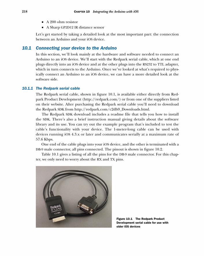
218 CHAPTER 10 Integrating the Arduino with iOS
■ A 200 ohm resistor■ A Sharp GP2D12 IR distance sensor
Let’s get started by taking a detailed look at the most important part: the connectionbetween an Arduino and your iOS device.
10.1 Connecting your device to the ArduinoIn this section, we’ll look mainly at the hardware and software needed to connect anArduino to an iOS device. We’ll start with the Redpark serial cable, which at one endplugs directly into an iOS device and at the other plugs into the RS232 to TTL adapter,which in turn connects to the Arduino. Once we’ve looked at what’s required to phys-ically connect an Arduino to an iOS device, we can have a more detailed look at thesoftware side.
10.1.1 The Redpark serial cable
The Redpark serial cable, shown in figure 10.1, is available either directly from Red-park Product Development (http://redpark.com/) or from one of the suppliers listedon their website. After purchasing the Redpark serial cable you’ll need to downloadthe Redpark SDK from http://redpark.com/c2db9_Downloads.html.
The Redpark SDK download includes a readme file that tells you how to installthe SDK. There’s also a brief instruction manual giving details about the softwarelibrary and its use. You can try out the example program that’s included to test thecable’s functionality with your device. The 1-meter-long cable can be used withdevices running iOS 4.3.x or later and communicates serially at a maximum rate of57.6 Kbps.
One end of the cable plugs into your iOS device, and the other is terminated with aDB-9 male connector, all pins connected. The pinout is shown in figure 10.2.
Table 10.1 gives a listing of all the pins for the DB-9 male connector. For this chap-ter, we only need to worry about the RX and TX pins.
Figure 10.1 The Redpark Product Development serial cable for use with older iOS devices
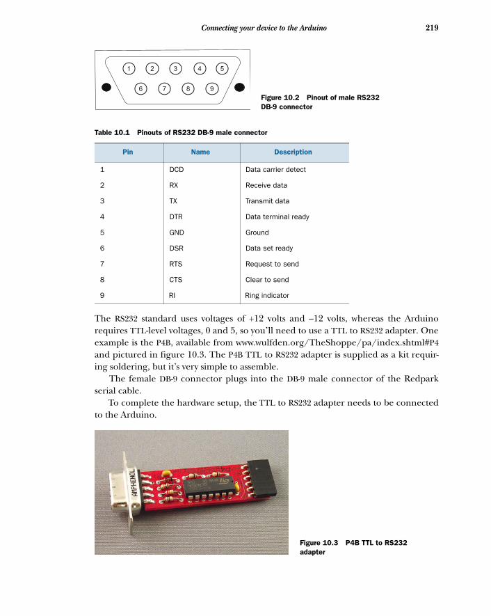
219Connecting your device to the Arduino
The RS232 standard uses voltages of +12 volts and –12 volts, whereas the Arduinorequires TTL-level voltages, 0 and 5, so you’ll need to use a TTL to RS232 adapter. Oneexample is the P4B, available from www.wulfden.org/TheShoppe/pa/index.shtml#P4and pictured in figure 10.3. The P4B TTL to RS232 adapter is supplied as a kit requir-ing soldering, but it’s very simple to assemble.
The female DB-9 connector plugs into the DB-9 male connector of the Redparkserial cable.
To complete the hardware setup, the TTL to RS232 adapter needs to be connectedto the Arduino.
Table 10.1 Pinouts of RS232 DB-9 male connector
Pin Name Description
1 DCD Data carrier detect
2 RX Receive data
3 TX Transmit data
4 DTR Data terminal ready
5 GND Ground
6 DSR Data set ready
7 RTS Request to send
8 CTS Clear to send
9 RI Ring indicator
1 3 52 4
6 7 8 9
Figure 10.2 Pinout of male RS232 DB-9 connector
Figure 10.3 P4B TTL to RS232 adapter
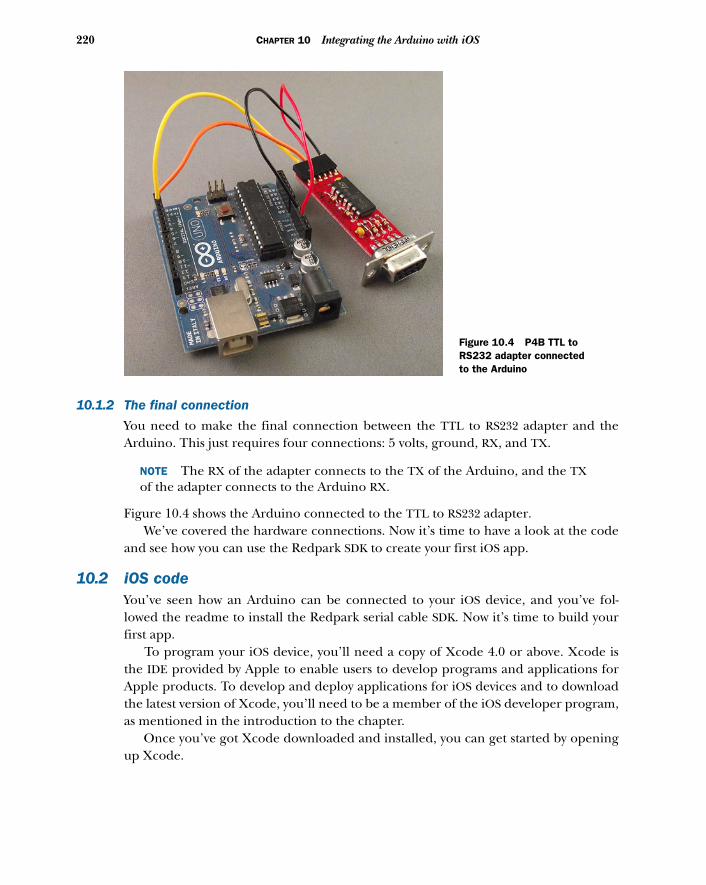
220 CHAPTER 10 Integrating the Arduino with iOS
10.1.2 The final connection
You need to make the final connection between the TTL to RS232 adapter and theArduino. This just requires four connections: 5 volts, ground, RX, and TX.
NOTE The RX of the adapter connects to the TX of the Arduino, and the TXof the adapter connects to the Arduino RX.
Figure 10.4 shows the Arduino connected to the TTL to RS232 adapter. We’ve covered the hardware connections. Now it’s time to have a look at the code
and see how you can use the Redpark SDK to create your first iOS app.
10.2 iOS codeYou’ve seen how an Arduino can be connected to your iOS device, and you’ve fol-lowed the readme to install the Redpark serial cable SDK. Now it’s time to build yourfirst app.
To program your iOS device, you’ll need a copy of Xcode 4.0 or above. Xcode isthe IDE provided by Apple to enable users to develop programs and applications forApple products. To develop and deploy applications for iOS devices and to downloadthe latest version of Xcode, you’ll need to be a member of the iOS developer program,as mentioned in the introduction to the chapter.
Once you’ve got Xcode downloaded and installed, you can get started by openingup Xcode.
Figure 10.4 P4B TTL to RS232 adapter connected to the Arduino
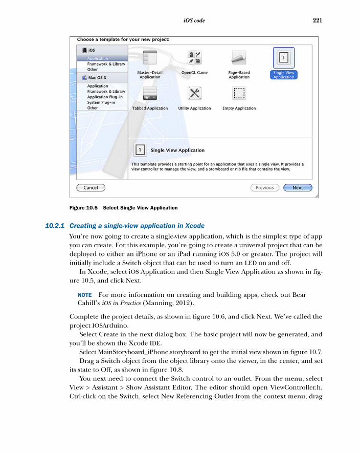
221iOS code
10.2.1 Creating a single-view application in Xcode
You’re now going to create a single-view application, which is the simplest type of appyou can create. For this example, you’re going to create a universal project that can bedeployed to either an iPhone or an iPad running iOS 5.0 or greater. The project willinitially include a Switch object that can be used to turn an LED on and off.
In Xcode, select iOS Application and then Single View Application as shown in fig-ure 10.5, and click Next.
NOTE For more information on creating and building apps, check out BearCahill’s iOS in Practice (Manning, 2012).
Complete the project details, as shown in figure 10.6, and click Next. We’ve called theproject IOSArduino.
Select Create in the next dialog box. The basic project will now be generated, andyou’ll be shown the Xcode IDE.
Select MainStoryboard_iPhone.storyboard to get the initial view shown in figure 10.7. Drag a Switch object from the object library onto the viewer, in the center, and set
its state to Off, as shown in figure 10.8. You next need to connect the Switch control to an outlet. From the menu, select
View > Assistant > Show Assistant Editor. The editor should open ViewController.h.Ctrl-click on the Switch, select New Referencing Outlet from the context menu, drag
Figure 10.5 Select Single View Application
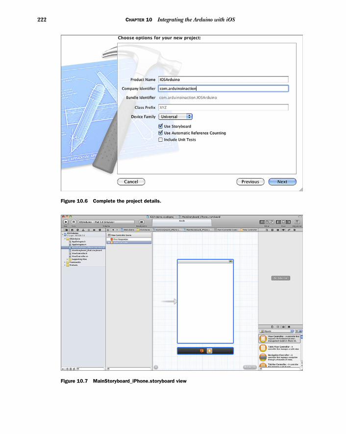
222 CHAPTER 10 Integrating the Arduino with iOS
Figure 10.6 Complete the project details.
Figure 10.7 MainStoryboard_iPhone.storyboard view
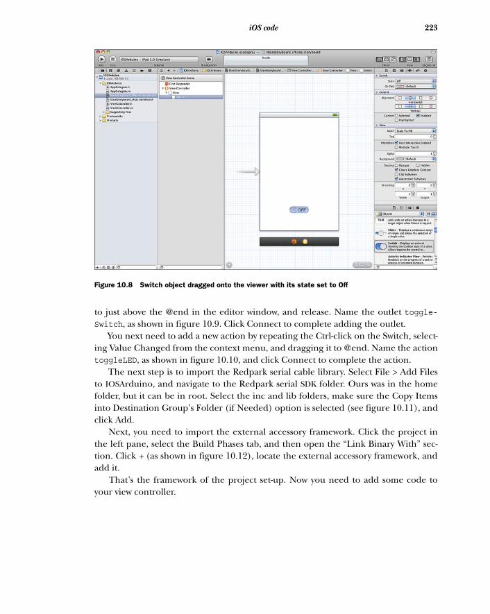
223iOS code
to just above the @end in the editor window, and release. Name the outlet toggle-Switch, as shown in figure 10.9. Click Connect to complete adding the outlet.
You next need to add a new action by repeating the Ctrl-click on the Switch, select-ing Value Changed from the context menu, and dragging it to @end. Name the actiontoggleLED, as shown in figure 10.10, and click Connect to complete the action.
The next step is to import the Redpark serial cable library. Select File > Add Filesto IOSArduino, and navigate to the Redpark serial SDK folder. Ours was in the homefolder, but it can be in root. Select the inc and lib folders, make sure the Copy Itemsinto Destination Group’s Folder (if Needed) option is selected (see figure 10.11), andclick Add.
Next, you need to import the external accessory framework. Click the project inthe left pane, select the Build Phases tab, and then open the “Link Binary With” sec-tion. Click + (as shown in figure 10.12), locate the external accessory framework, andadd it.
That’s the framework of the project set-up. Now you need to add some code toyour view controller.
Figure 10.8 Switch object dragged onto the viewer with its state set to Off
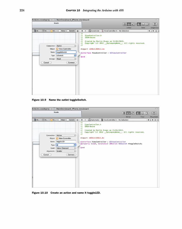
224 CHAPTER 10 Integrating the Arduino with iOS
Figure 10.9 Name the outlet toggleSwitch.
Figure 10.10 Create an action and name it toggleLED.
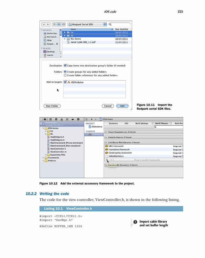
225iOS code
10.2.2 Writing the code
The code for the view controller, ViewController.h, is shown in the following listing.
#import <UIKit/UIKit.h>#import "RscMgr.h"
#define BUFFER_LEN 1024
Listing 10.1 ViewController.h
Figure 10.11 Import the Redpark serial SDK files.
Figure 10.12 Add the external accessory framework to the project.
Import cable library and set buffer length
b
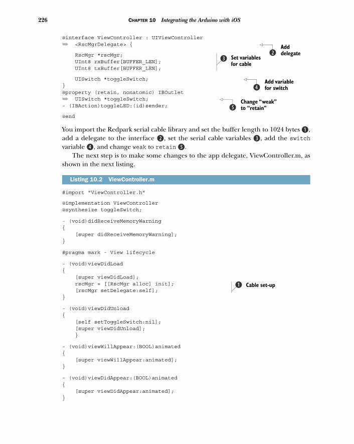
226 CHAPTER 10 Integrating the Arduino with iOS
@interface ViewController : UIViewController
➥ <RscMgrDelegate> {
RscMgr *rscMgr; UInt8 rxBuffer[BUFFER_LEN]; UInt8 txBuffer[BUFFER_LEN];
UISwitch *toggleSwitch; }@property (retain, nonatomic) IBOutlet
➥ UISwitch *toggleSwitch; - (IBAction)toggleLED:(id)sender;
@end
You import the Redpark serial cable library and set the buffer length to 1024 bytes B,add a delegate to the interface c, set the serial cable variables d, add the switchvariable e, and change weak to retain f.
The next step is to make some changes to the app delegate, ViewController.m, asshown in the next listing.
#import "ViewController.h"
@implementation ViewController@synthesize toggleSwitch;
- (void)didReceiveMemoryWarning{ [super didReceiveMemoryWarning];}
#pragma mark - View lifecycle
- (void)viewDidLoad{ [super viewDidLoad]; rscMgr = [[RscMgr alloc] init]; [rscMgr setDelegate:self]; }
- (void)viewDidUnload{ [self setToggleSwitch:nil]; [super viewDidUnload]; }
- (void)viewWillAppear:(BOOL)animated{ [super viewWillAppear:animated];}
- (void)viewDidAppear:(BOOL)animated{ [super viewDidAppear:animated];}
Listing 10.2 ViewController.m
Add delegatec
Set variables for cable
d
Add variable for switche
Change “weak” to “retain”f
Cable set-upb
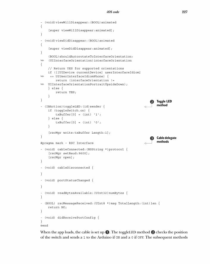
227iOS code
- (void)viewWillDisappear:(BOOL)animated{ [super viewWillDisappear:animated];}
- (void)viewDidDisappear:(BOOL)animated{ [super viewDidDisappear:animated];} (BOOL)shouldAutorotateToInterfaceOrientation:
➥ (UIInterfaceOrientation)interfaceOrientation{ // Return YES for supported orientations if ([[UIDevice currentDevice] userInterfaceIdiom]
➥ == UIUserInterfaceIdiomPhone) { return (interfaceOrientation !=
➥ UIInterfaceOrientationPortraitUpsideDown); } else { return YES; }}
- (IBAction)toggleLED:(id)sender { if (toggleSwitch.on) { txBuffer[0] = (int) '1'; } else { txBuffer[0] = (int) '0'; }
[rscMgr write:txBuffer Length:1]; }
#pragma mark – RSC Interface
- (void) cableConnected:(NSString *)protocol { [rscMgr setBaud:9600]; [rscMgr open];}
- (void) cableDisconnected {
}
- (void) portStatusChanged {
}
- (void) readBytesAvailable:(UInt32)numBytes {}
- (BOOL) rscMessageReceived:(UInt8 *)msg TotalLength:(int)len { return NO;}
- (void) didReceivePortConfig {}@end
When the app loads, the cable is set up B. The toggleLED method c checks the positionof the switch and sends a 1 to the Arduino if ON and a 0 if OFF. The subsequent methods
Toggle LED method
c
Cable delegate methods
d
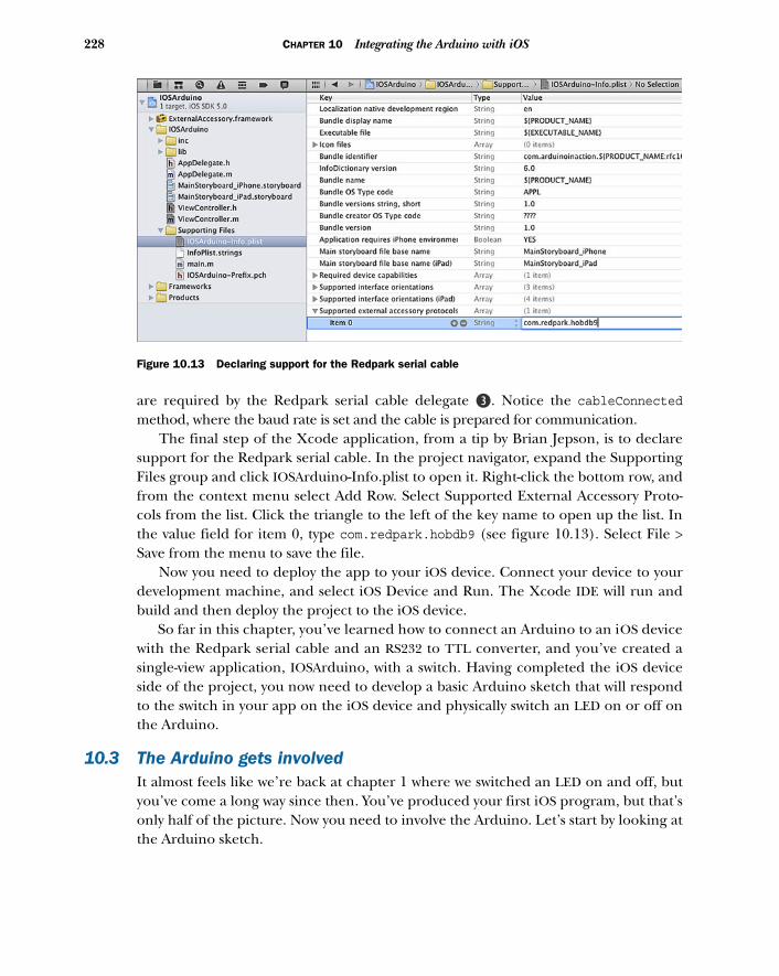
228 CHAPTER 10 Integrating the Arduino with iOS
are required by the Redpark serial cable delegate d. Notice the cableConnectedmethod, where the baud rate is set and the cable is prepared for communication.
The final step of the Xcode application, from a tip by Brian Jepson, is to declaresupport for the Redpark serial cable. In the project navigator, expand the SupportingFiles group and click IOSArduino-Info.plist to open it. Right-click the bottom row, andfrom the context menu select Add Row. Select Supported External Accessory Proto-cols from the list. Click the triangle to the left of the key name to open up the list. Inthe value field for item 0, type com.redpark.hobdb9 (see figure 10.13). Select File >Save from the menu to save the file.
Now you need to deploy the app to your iOS device. Connect your device to yourdevelopment machine, and select iOS Device and Run. The Xcode IDE will run andbuild and then deploy the project to the iOS device.
So far in this chapter, you’ve learned how to connect an Arduino to an iOS devicewith the Redpark serial cable and an RS232 to TTL converter, and you’ve created asingle-view application, IOSArduino, with a switch. Having completed the iOS deviceside of the project, you now need to develop a basic Arduino sketch that will respondto the switch in your app on the iOS device and physically switch an LED on or off onthe Arduino.
10.3 The Arduino gets involvedIt almost feels like we’re back at chapter 1 where we switched an LED on and off, butyou’ve come a long way since then. You’ve produced your first iOS program, but that’sonly half of the picture. Now you need to involve the Arduino. Let’s start by looking atthe Arduino sketch.
Figure 10.13 Declaring support for the Redpark serial cable
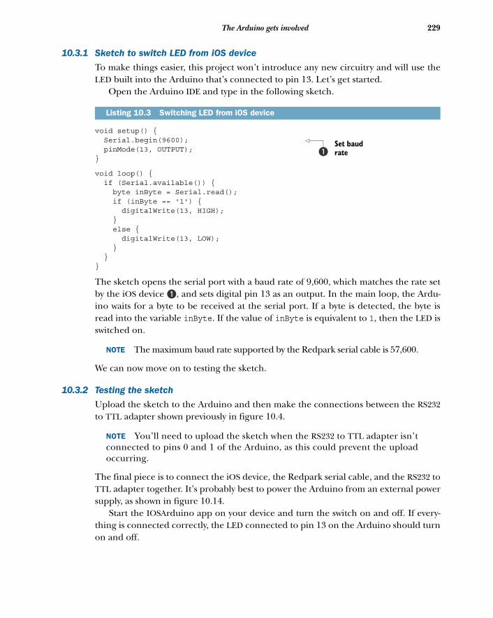
229The Arduino gets involved
10.3.1 Sketch to switch LED from iOS device
To make things easier, this project won’t introduce any new circuitry and will use theLED built into the Arduino that’s connected to pin 13. Let’s get started.
Open the Arduino IDE and type in the following sketch.
void setup() { Serial.begin(9600); pinMode(13, OUTPUT); }
void loop() { if (Serial.available()) { byte inByte = Serial.read(); if (inByte == '1') { digitalWrite(13, HIGH); } else { digitalWrite(13, LOW); } }}
The sketch opens the serial port with a baud rate of 9,600, which matches the rate setby the iOS device B, and sets digital pin 13 as an output. In the main loop, the Ardu-ino waits for a byte to be received at the serial port. If a byte is detected, the byte isread into the variable inByte. If the value of inByte is equivalent to 1, then the LED isswitched on.
NOTE The maximum baud rate supported by the Redpark serial cable is 57,600.
We can now move on to testing the sketch.
10.3.2 Testing the sketch
Upload the sketch to the Arduino and then make the connections between the RS232to TTL adapter shown previously in figure 10.4.
NOTE You’ll need to upload the sketch when the RS232 to TTL adapter isn’tconnected to pins 0 and 1 of the Arduino, as this could prevent the uploadoccurring.
The final piece is to connect the iOS device, the Redpark serial cable, and the RS232 toTTL adapter together. It’s probably best to power the Arduino from an external powersupply, as shown in figure 10.14.
Start the IOSArduino app on your device and turn the switch on and off. If every-thing is connected correctly, the LED connected to pin 13 on the Arduino should turnon and off.
Listing 10.3 Switching LED from iOS device
Set baud rateb
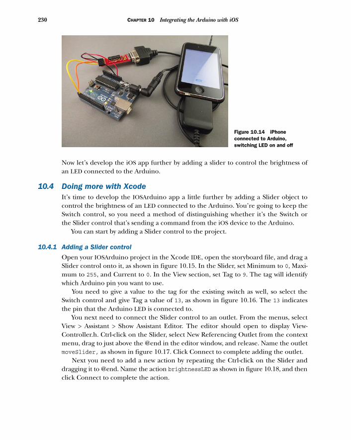
230 CHAPTER 10 Integrating the Arduino with iOS
Now let’s develop the iOS app further by adding a slider to control the brightness ofan LED connected to the Arduino.
10.4 Doing more with XcodeIt’s time to develop the IOSArduino app a little further by adding a Slider object tocontrol the brightness of an LED connected to the Arduino. You’re going to keep theSwitch control, so you need a method of distinguishing whether it’s the Switch orthe Slider control that’s sending a command from the iOS device to the Arduino.
You can start by adding a Slider control to the project.
10.4.1 Adding a Slider control
Open your IOSArduino project in the Xcode IDE, open the storyboard file, and drag aSlider control onto it, as shown in figure 10.15. In the Slider, set Minimum to 0, Maxi-mum to 255, and Current to 0. In the View section, set Tag to 9. The tag will identifywhich Arduino pin you want to use.
You need to give a value to the tag for the existing switch as well, so select theSwitch control and give Tag a value of 13, as shown in figure 10.16. The 13 indicatesthe pin that the Arduino LED is connected to.
You next need to connect the Slider control to an outlet. From the menus, selectView > Assistant > Show Assistant Editor. The editor should open to display View-Controller.h. Ctrl-click on the Slider, select New Referencing Outlet from the contextmenu, drag to just above the @end in the editor window, and release. Name the outletmoveSlider, as shown in figure 10.17. Click Connect to complete adding the outlet.
Next you need to add a new action by repeating the Ctrl-click on the Slider anddragging it to @end. Name the action brightnessLED as shown in figure 10.18, and thenclick Connect to complete the action.
Figure 10.14 iPhone connected to Arduino, switching LED on and off
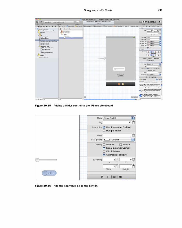
231Doing more with Xcode
Figure 10.15 Adding a Slider control to the iPhone storyboard
Figure 10.16 Add the Tag value 13 to the Switch.
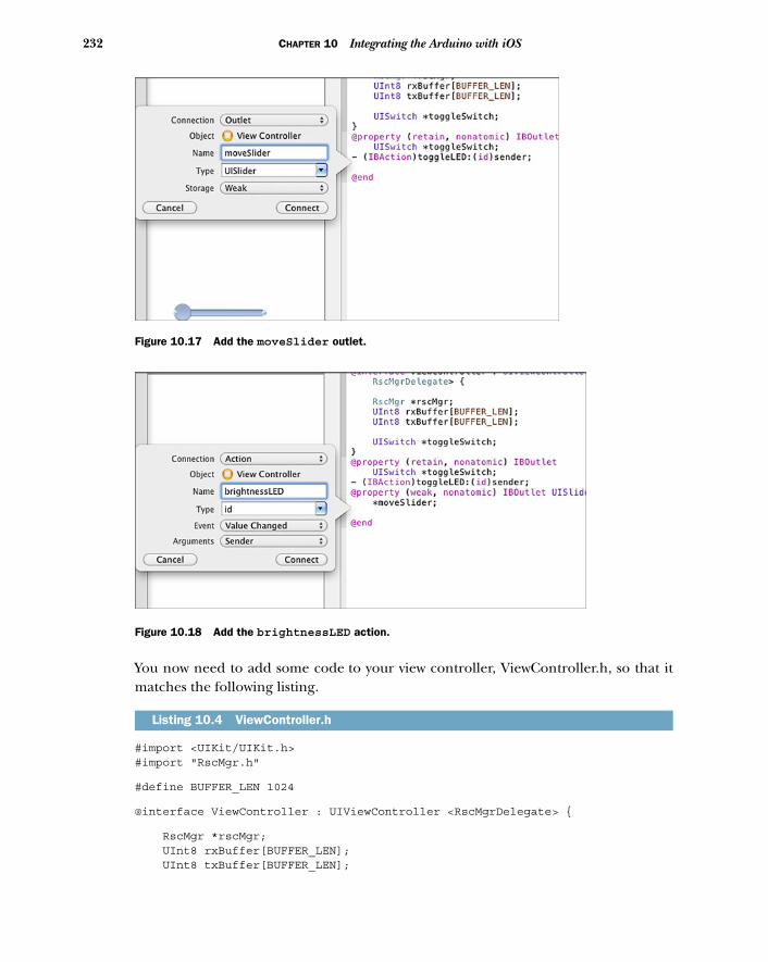
232 CHAPTER 10 Integrating the Arduino with iOS
You now need to add some code to your view controller, ViewController.h, so that itmatches the following listing.
#import <UIKit/UIKit.h>#import "RscMgr.h"
#define BUFFER_LEN 1024
@interface ViewController : UIViewController <RscMgrDelegate> {
RscMgr *rscMgr; UInt8 rxBuffer[BUFFER_LEN]; UInt8 txBuffer[BUFFER_LEN];
Listing 10.4 ViewController.h
Figure 10.17 Add the moveSlider outlet.
Figure 10.18 Add the brightnessLED action.
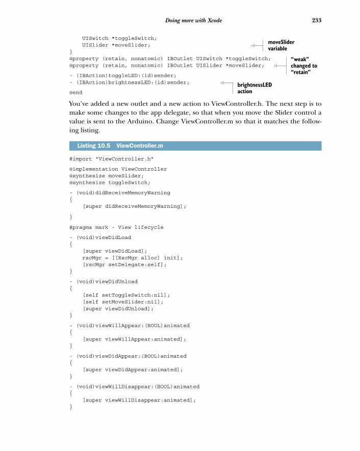
233Doing more with Xcode
UISwitch *toggleSwitch; UISlider *moveSlider; }@property (retain, nonatomic) IBOutlet UISwitch *toggleSwitch;@property (retain, nonatomic) IBOutlet UISlider *moveSlider;
- (IBAction)toggleLED:(id)sender;- (IBAction)brightnessLED:(id)sender;
@end
You’ve added a new outlet and a new action to ViewController.h. The next step is tomake some changes to the app delegate, so that when you move the Slider control avalue is sent to the Arduino. Change ViewController.m so that it matches the follow-ing listing.
#import "ViewController.h"
@implementation ViewController@synthesize moveSlider;@synthesize toggleSwitch;
- (void)didReceiveMemoryWarning{ [super didReceiveMemoryWarning];
}
#pragma mark - View lifecycle
- (void)viewDidLoad{ [super viewDidLoad]; rscMgr = [[RscMgr alloc] init]; [rscMgr setDelegate:self];}
- (void)viewDidUnload{ [self setToggleSwitch:nil]; [self setMoveSlider:nil]; [super viewDidUnload];}
- (void)viewWillAppear:(BOOL)animated{ [super viewWillAppear:animated];}
- (void)viewDidAppear:(BOOL)animated{ [super viewDidAppear:animated];}
- (void)viewWillDisappear:(BOOL)animated{ [super viewWillDisappear:animated];}
Listing 10.5 ViewController.m
moveSlider variable
“weak” changed to “retain”
brightnessLED action
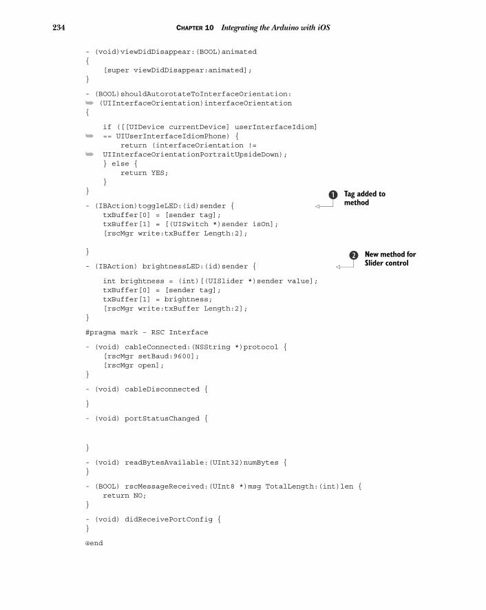
234 CHAPTER 10 Integrating the Arduino with iOS
- (void)viewDidDisappear:(BOOL)animated{ [super viewDidDisappear:animated];}
- (BOOL)shouldAutorotateToInterfaceOrientation:
➥ (UIInterfaceOrientation)interfaceOrientation{
if ([[UIDevice currentDevice] userInterfaceIdiom]
➥ == UIUserInterfaceIdiomPhone) { return (interfaceOrientation !=
➥ UIInterfaceOrientationPortraitUpsideDown); } else { return YES; }}
- (IBAction)toggleLED:(id)sender { txBuffer[0] = [sender tag]; txBuffer[1] = [(UISwitch *)sender isOn]; [rscMgr write:txBuffer Length:2]; }
- (IBAction) brightnessLED:(id)sender {
int brightness = (int)[(UISlider *)sender value]; txBuffer[0] = [sender tag]; txBuffer[1] = brightness; [rscMgr write:txBuffer Length:2]; }
#pragma mark – RSC Interface
- (void) cableConnected:(NSString *)protocol { [rscMgr setBaud:9600]; [rscMgr open];}
- (void) cableDisconnected {
}
- (void) portStatusChanged {
}
- (void) readBytesAvailable:(UInt32)numBytes {}
- (BOOL) rscMessageReceived:(UInt8 *)msg TotalLength:(int)len { return NO;}
- (void) didReceivePortConfig {}
@end
Tag added to method
b
New method for Slider control
c
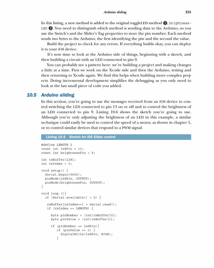
235Arduino sliding
In this listing, a new method is added to the original toggleLED method B, brightness-LED c. You need to distinguish which method is sending data to the Arduino, so youuse the Switch’s and the Slider’s Tag properties to store the pin number. Each methodsends two bytes to the Arduino, the first identifying the pin and the second the value.
Build the project to check for any errors. If everything builds okay, you can deployit to your iOS device.
It’s now time to look at the Arduino side of things, beginning with a sketch, andthen building a circuit with an LED connected to pin 9.
You can probably see a pattern here: we’re building a project and making changesa little at a time. First we work on the Xcode side and then the Arduino, testing andthen returning to Xcode again. We find this helps when building more complex proj-ects. Doing incremental development simplifies the debugging as you only need tolook at the last small piece of code you added.
10.5 Arduino slidingIn this section, you’re going to use the messages received from an iOS device to con-trol switching the LED connected to pin 13 on or off and to control the brightness ofan LED connected to pin 9. Listing 10.6 shows the sketch you’re going to use.Although you’re only adjusting the brightness of an LED in this example, a similartechnique could easily be used to control the speed of a motor, as shown in chapter 5,or to control similar devices that respond to a PWM signal.
#define LENGTH 2const int ledPin = 13;const int brightnessPin = 9;
int rxBuffer[128];int rxIndex = 0;
void setup() { Serial.begin(9600); pinMode(ledPin, OUTPUT); pinMode(brightnessPin, OUTPUT);}
void loop (){ if (Serial.available() > 0) {
rxBuffer[rxIndex++] = Serial.read(); if (rxIndex == LENGTH) {
byte pinNumber = (int)rxBuffer[0]; byte pinValue = (int)rxBuffer[1];
if (pinNumber == ledPin){ if (pinValue == 1) { digitalWrite(ledPin, HIGH); }
Listing 10.6 Sketch for iOS Slider control
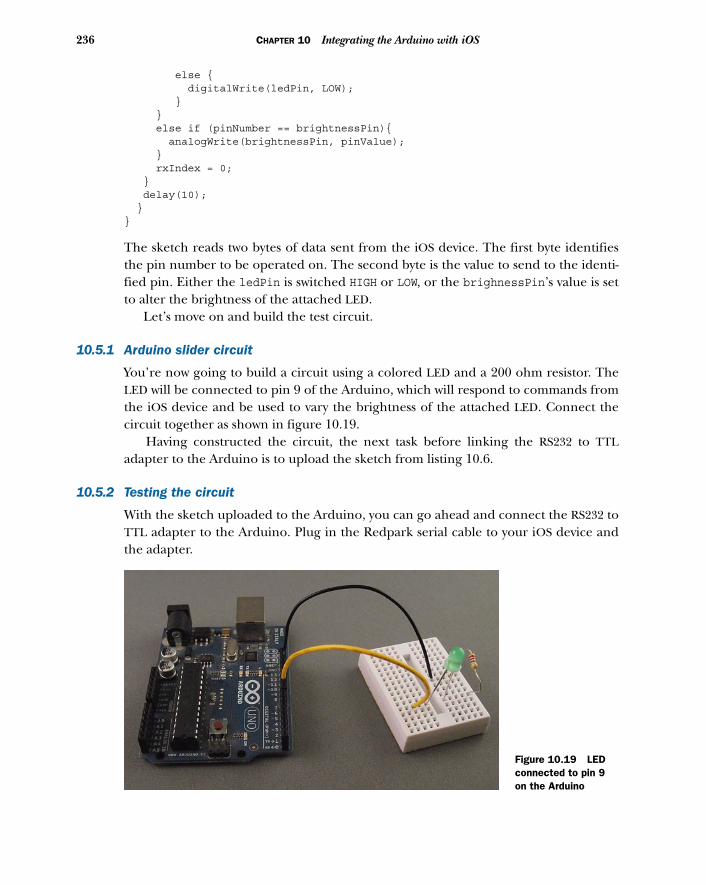
236 CHAPTER 10 Integrating the Arduino with iOS
else { digitalWrite(ledPin, LOW); } } else if (pinNumber == brightnessPin){ analogWrite(brightnessPin, pinValue); } rxIndex = 0; } delay(10); }}
The sketch reads two bytes of data sent from the iOS device. The first byte identifiesthe pin number to be operated on. The second byte is the value to send to the identi-fied pin. Either the ledPin is switched HIGH or LOW, or the brighnessPin’s value is setto alter the brightness of the attached LED.
Let’s move on and build the test circuit.
10.5.1 Arduino slider circuit
You’re now going to build a circuit using a colored LED and a 200 ohm resistor. TheLED will be connected to pin 9 of the Arduino, which will respond to commands fromthe iOS device and be used to vary the brightness of the attached LED. Connect thecircuit together as shown in figure 10.19.
Having constructed the circuit, the next task before linking the RS232 to TTLadapter to the Arduino is to upload the sketch from listing 10.6.
10.5.2 Testing the circuit
With the sketch uploaded to the Arduino, you can go ahead and connect the RS232 toTTL adapter to the Arduino. Plug in the Redpark serial cable to your iOS device andthe adapter.
Figure 10.19 LED connected to pin 9 on the Arduino
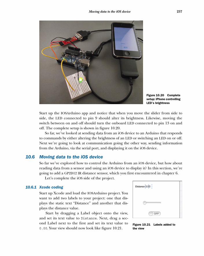
237Moving data to the iOS device
Start up the IOSArduino app and notice that when you move the slider from side toside, the LED connected to pin 9 should alter its brightness. Likewise, moving theswitch between on and off should turn the onboard LED connected to pin 13 on andoff. The complete setup is shown in figure 10.20.
So far, we’ve looked at sending data from an iOS device to an Arduino that respondsto commands by either altering the brightness of an LED or switching an LED on or off.Next we’re going to look at communication going the other way, sending informationfrom the Arduino, via the serial port, and displaying it on the iOS device.
10.6 Moving data to the iOS deviceSo far we’ve explored how to control the Arduino from an iOS device, but how aboutreading data from a sensor and using an iOS device to display it? In this section, we’regoing to add a GP2D12 IR distance sensor, which you first encountered in chapter 6.
Let’s complete the iOS side of the project.
10.6.1 Xcode coding
Start up Xcode and load the IOSArduino project. Youwant to add two labels to your project: one that dis-plays the static text “Distance” and another that dis-plays the distance value.
Start by dragging a Label object onto the view,and set its text value to Distance. Next, drag a sec-ond Label next to the first and set its text value to0.00. Your view should now look like figure 10.21.
Figure 10.20 Complete setup: iPhone controlling LED’s brightness
Figure 10.21 Labels added to the view
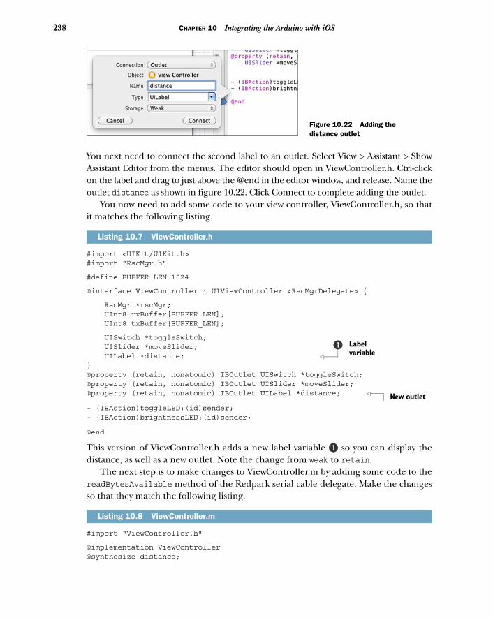
238 CHAPTER 10 Integrating the Arduino with iOS
You next need to connect the second label to an outlet. Select View > Assistant > ShowAssistant Editor from the menus. The editor should open in ViewController.h. Ctrl-clickon the label and drag to just above the @end in the editor window, and release. Name theoutlet distance as shown in figure 10.22. Click Connect to complete adding the outlet.
You now need to add some code to your view controller, ViewController.h, so thatit matches the following listing.
#import <UIKit/UIKit.h>#import "RscMgr.h"
#define BUFFER_LEN 1024
@interface ViewController : UIViewController <RscMgrDelegate> {
RscMgr *rscMgr; UInt8 rxBuffer[BUFFER_LEN]; UInt8 txBuffer[BUFFER_LEN];
UISwitch *toggleSwitch; UISlider *moveSlider; UILabel *distance; }@property (retain, nonatomic) IBOutlet UISwitch *toggleSwitch;@property (retain, nonatomic) IBOutlet UISlider *moveSlider;@property (retain, nonatomic) IBOutlet UILabel *distance;
- (IBAction)toggleLED:(id)sender;- (IBAction)brightnessLED:(id)sender;
@end
This version of ViewController.h adds a new label variable B so you can display thedistance, as well as a new outlet. Note the change from weak to retain.
The next step is to make changes to ViewController.m by adding some code to thereadBytesAvailable method of the Redpark serial cable delegate. Make the changesso that they match the following listing.
#import "ViewController.h"
@implementation ViewController@synthesize distance;
Listing 10.7 ViewController.h
Listing 10.8 ViewController.m
Figure 10.22 Adding the distance outlet
Label variable
b
New outlet
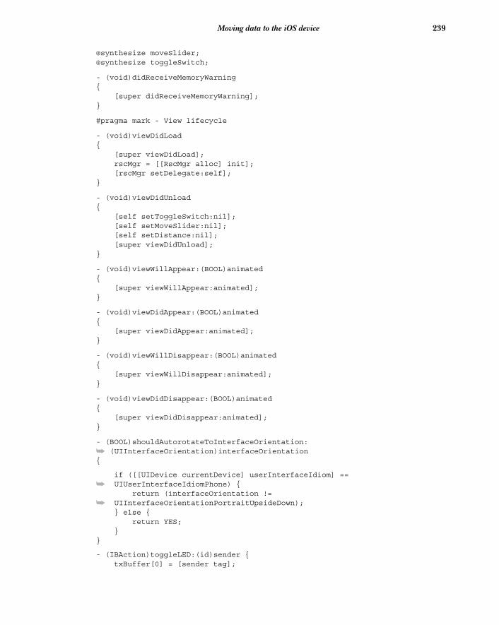
239Moving data to the iOS device
@synthesize moveSlider;@synthesize toggleSwitch;
- (void)didReceiveMemoryWarning{ [super didReceiveMemoryWarning];}
#pragma mark - View lifecycle
- (void)viewDidLoad{ [super viewDidLoad]; rscMgr = [[RscMgr alloc] init]; [rscMgr setDelegate:self]; }
- (void)viewDidUnload{ [self setToggleSwitch:nil]; [self setMoveSlider:nil]; [self setDistance:nil]; [super viewDidUnload];}
- (void)viewWillAppear:(BOOL)animated{ [super viewWillAppear:animated];}
- (void)viewDidAppear:(BOOL)animated{ [super viewDidAppear:animated];}
- (void)viewWillDisappear:(BOOL)animated{ [super viewWillDisappear:animated];}
- (void)viewDidDisappear:(BOOL)animated{ [super viewDidDisappear:animated];}
- (BOOL)shouldAutorotateToInterfaceOrientation:
➥ (UIInterfaceOrientation)interfaceOrientation{
if ([[UIDevice currentDevice] userInterfaceIdiom] ==
➥ UIUserInterfaceIdiomPhone) { return (interfaceOrientation !=
➥ UIInterfaceOrientationPortraitUpsideDown); } else { return YES; }}
- (IBAction)toggleLED:(id)sender { txBuffer[0] = [sender tag];
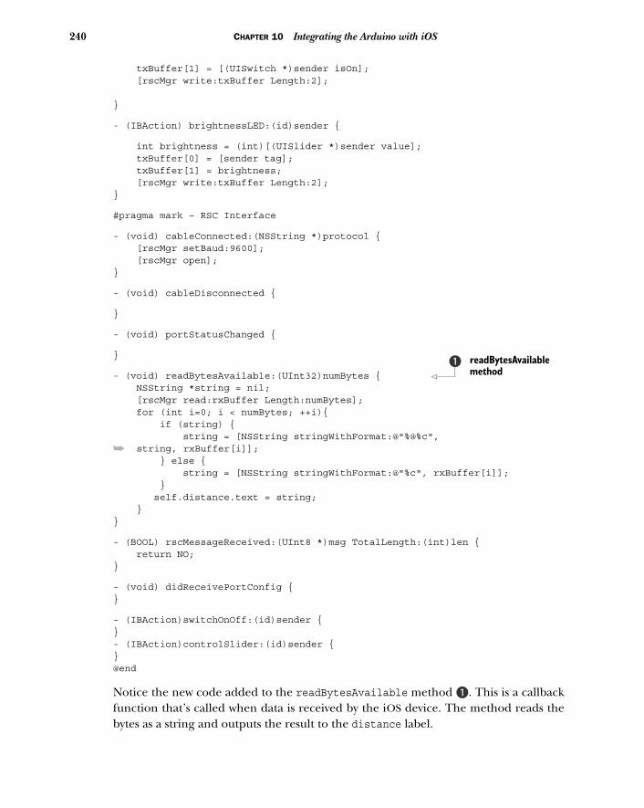
240 CHAPTER 10 Integrating the Arduino with iOS
txBuffer[1] = [(UISwitch *)sender isOn]; [rscMgr write:txBuffer Length:2]; }
- (IBAction) brightnessLED:(id)sender {
int brightness = (int)[(UISlider *)sender value]; txBuffer[0] = [sender tag]; txBuffer[1] = brightness; [rscMgr write:txBuffer Length:2]; }
#pragma mark – RSC Interface
- (void) cableConnected:(NSString *)protocol { [rscMgr setBaud:9600]; [rscMgr open];}
- (void) cableDisconnected {
}
- (void) portStatusChanged {
}
- (void) readBytesAvailable:(UInt32)numBytes { NSString *string = nil; [rscMgr read:rxBuffer Length:numBytes]; for (int i=0; i < numBytes; ++i){ if (string) { string = [NSString stringWithFormat:@"%@%c",
➥ string, rxBuffer[i]]; } else { string = [NSString stringWithFormat:@"%c", rxBuffer[i]]; } self.distance.text = string; }}
- (BOOL) rscMessageReceived:(UInt8 *)msg TotalLength:(int)len { return NO;}
- (void) didReceivePortConfig {}
- (IBAction)switchOnOff:(id)sender {}- (IBAction)controlSlider:(id)sender {}@end
Notice the new code added to the readBytesAvailable method B. This is a callbackfunction that’s called when data is received by the iOS device. The method reads thebytes as a string and outputs the result to the distance label.
readBytesAvailable method
b
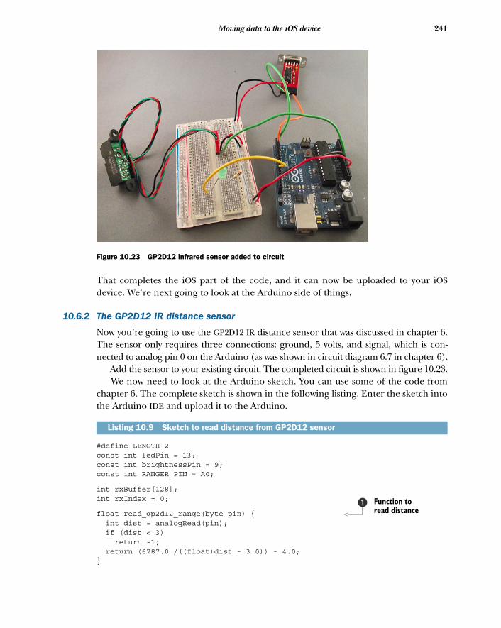
241Moving data to the iOS device
That completes the iOS part of the code, and it can now be uploaded to your iOSdevice. We’re next going to look at the Arduino side of things.
10.6.2 The GP2D12 IR distance sensor
Now you’re going to use the GP2D12 IR distance sensor that was discussed in chapter 6.The sensor only requires three connections: ground, 5 volts, and signal, which is con-nected to analog pin 0 on the Arduino (as was shown in circuit diagram 6.7 in chapter 6).
Add the sensor to your existing circuit. The completed circuit is shown in figure 10.23. We now need to look at the Arduino sketch. You can use some of the code from
chapter 6. The complete sketch is shown in the following listing. Enter the sketch intothe Arduino IDE and upload it to the Arduino.
#define LENGTH 2const int ledPin = 13;const int brightnessPin = 9;const int RANGER_PIN = A0;
int rxBuffer[128];int rxIndex = 0;
float read_gp2d12_range(byte pin) { int dist = analogRead(pin); if (dist < 3) return -1; return (6787.0 /((float)dist - 3.0)) - 4.0;}
Listing 10.9 Sketch to read distance from GP2D12 sensor
Figure 10.23 GP2D12 infrared sensor added to circuit
Function to read distance
b
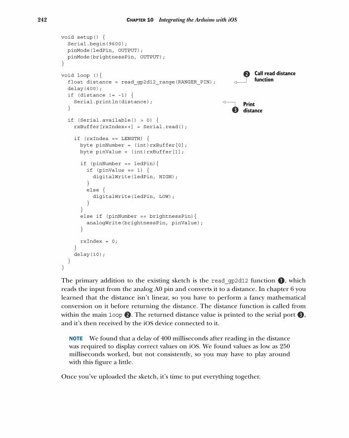
242 CHAPTER 10 Integrating the Arduino with iOS
void setup() { Serial.begin(9600); pinMode(ledPin, OUTPUT); pinMode(brightnessPin, OUTPUT);}
void loop (){ float distance = read_gp2d12_range(RANGER_PIN); delay(400); if (distance != -1) { Serial.println(distance); }
if (Serial.available() > 0) { rxBuffer[rxIndex++] = Serial.read();
if (rxIndex == LENGTH) { byte pinNumber = (int)rxBuffer[0]; byte pinValue = (int)rxBuffer[1];
if (pinNumber == ledPin){ if (pinValue == 1) { digitalWrite(ledPin, HIGH); } else { digitalWrite(ledPin, LOW); } } else if (pinNumber == brightnessPin){ analogWrite(brightnessPin, pinValue); }
rxIndex = 0; } delay(10); }}
The primary addition to the existing sketch is the read_gp2d12 function B, whichreads the input from the analog A0 pin and converts it to a distance. In chapter 6 youlearned that the distance isn’t linear, so you have to perform a fancy mathematicalconversion on it before returning the distance. The distance function is called fromwithin the main loop c. The returned distance value is printed to the serial port d,and it’s then received by the iOS device connected to it.
NOTE We found that a delay of 400 milliseconds after reading in the distancewas required to display correct values on iOS. We found values as low as 250milliseconds worked, but not consistently, so you may have to play aroundwith this figure a little.
Once you’ve uploaded the sketch, it’s time to put everything together.
Call read distance function
c
Print distanced
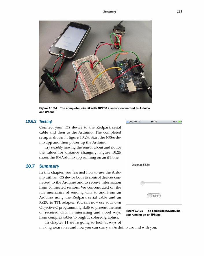
243Summary
10.6.3 Testing
Connect your iOS device to the Redpark serialcable and then to the Arduino. The completedsetup is shown in figure 10.24. Start the IOSArdu-ino app and then power up the Arduino.
Try steadily moving the sensor about and noticethe values for distance changing. Figure 10.25shows the IOSArduino app running on an iPhone.
10.7 SummaryIn this chapter, you learned how to use the Ardu-ino with an iOS device both to control devices con-nected to the Arduino and to receive informationfrom connected sensors. We concentrated on theraw mechanics of sending data to and from anArduino using the Redpark serial cable and anRS232 to TTL adapter. You can now use your ownObjective-C programming skills to present the sentor received data in interesting and novel ways,from complex tables to brightly colored graphics.
In chapter 11 we’re going to look at ways ofmaking wearables and how you can carry an Arduino around with you.
Figure 10.25 The complete IOSArduino app running on an iPhone
Figure 10.24 The completed circuit with GP2D12 sensor connected to Arduino and iPhone
Making wearables
The term “wearable” generally refers to clothing and accessories that incorporatecomputer and advanced-electronic technologies. The designs often incorporatepractical functions and features as well as make a statement or establish a techno-logical look.
Another way of imagining a wearable is that it’s a dynamic surface around yourbody that is capable of connecting you to devices around you, people, and places.These days most people carry a mobile phone, always on them and always on, butit’s not hard to imagine a near future in which most of our communication toolswill be even smaller, perhaps even integrated into clothing or accessories that wecarry with us. Wearables can be clothing like jackets or sweaters, accessories likehats or scarves, or objects that are worn or carried like necklaces or headphones.
This chapter covers ■ Creating wearable projects with
the LilyPad Arduino ■ Working with conductive thread■ Creating a turn-signal jacket■ Creating a wearable piano■ Making a wearable compass
244
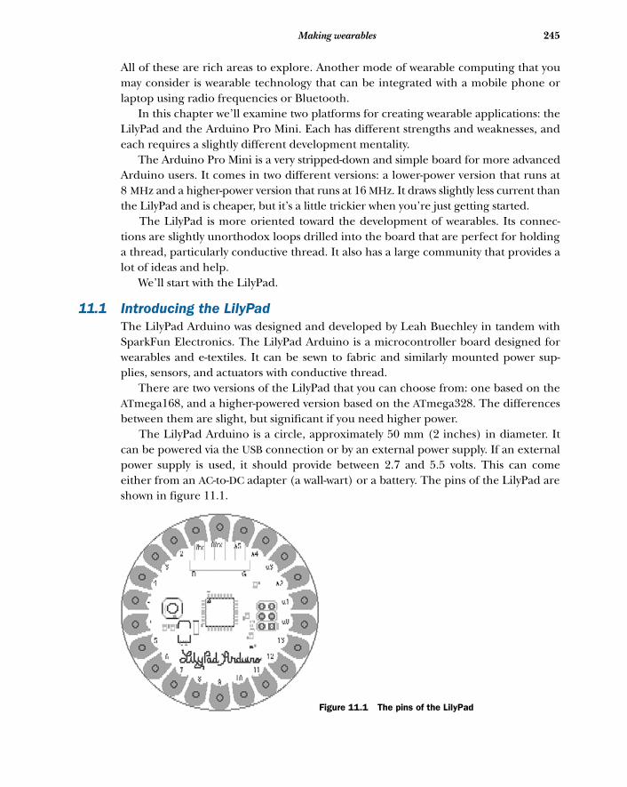
245Making wearables
All of these are rich areas to explore. Another mode of wearable computing that youmay consider is wearable technology that can be integrated with a mobile phone orlaptop using radio frequencies or Bluetooth.
In this chapter we’ll examine two platforms for creating wearable applications: theLilyPad and the Arduino Pro Mini. Each has different strengths and weaknesses, andeach requires a slightly different development mentality.
The Arduino Pro Mini is a very stripped-down and simple board for more advancedArduino users. It comes in two different versions: a lower-power version that runs at8 MHz and a higher-power version that runs at 16 MHz. It draws slightly less current thanthe LilyPad and is cheaper, but it’s a little trickier when you’re just getting started.
The LilyPad is more oriented toward the development of wearables. Its connec-tions are slightly unorthodox loops drilled into the board that are perfect for holdinga thread, particularly conductive thread. It also has a large community that provides alot of ideas and help.
We’ll start with the LilyPad.
11.1 Introducing the LilyPadThe LilyPad Arduino was designed and developed by Leah Buechley in tandem withSparkFun Electronics. The LilyPad Arduino is a microcontroller board designed forwearables and e-textiles. It can be sewn to fabric and similarly mounted power sup-plies, sensors, and actuators with conductive thread.
There are two versions of the LilyPad that you can choose from: one based on theATmega168, and a higher-powered version based on the ATmega328. The differencesbetween them are slight, but significant if you need higher power.
The LilyPad Arduino is a circle, approximately 50 mm (2 inches) in diameter. Itcan be powered via the USB connection or by an external power supply. If an externalpower supply is used, it should provide between 2.7 and 5.5 volts. This can comeeither from an AC-to-DC adapter (a wall-wart) or a battery. The pins of the LilyPad areshown in figure 11.1.
Figure 11.1 The pins of the LilyPad
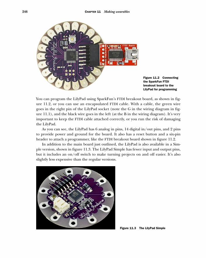
246 CHAPTER 11 Making wearables
You can program the LilyPad using SparkFun’s FTDI breakout board, as shown in fig-ure 11.2, or you can use an encapsulated FTDI cable. With a cable, the green wiregoes in the right pin of the LilyPad socket (note the G in the wiring diagram in fig-ure 11.1), and the black wire goes in the left (at the B in the wiring diagram). It’s veryimportant to keep the FTDI cable attached correctly, or you run the risk of damagingthe LilyPad.
As you can see, the LilyPad has 6 analog in pins, 14 digital in/out pins, and 2 pinsto provide power and ground for the board. It also has a reset button and a six-pinheader to attach a programmer, like the FTDI breakout board shown in figure 11.2.
In addition to the main board just outlined, the LilyPad is also available in a Sim-ple version, shown in figure 11.3. The LilyPad Simple has fewer input and output pins,but it includes an on/off switch to make turning projects on and off easier. It’s alsoslightly less expensive than the regular versions.
Figure 11.2 Connecting the SparkFun FTDI breakout board to the LilyPad for programming
Figure 11.3 The LilyPad Simple
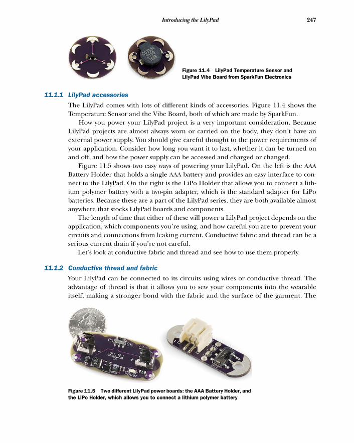
247Introducing the LilyPad
11.1.1 LilyPad accessories
The LilyPad comes with lots of different kinds of accessories. Figure 11.4 shows theTemperature Sensor and the Vibe Board, both of which are made by SparkFun.
How you power your LilyPad project is a very important consideration. BecauseLilyPad projects are almost always worn or carried on the body, they don’t have anexternal power supply. You should give careful thought to the power requirements ofyour application. Consider how long you want it to last, whether it can be turned onand off, and how the power supply can be accessed and charged or changed.
Figure 11.5 shows two easy ways of powering your LilyPad. On the left is the AAABattery Holder that holds a single AAA battery and provides an easy interface to con-nect to the LilyPad. On the right is the LiPo Holder that allows you to connect a lith-ium polymer battery with a two-pin adapter, which is the standard adapter for LiPobatteries. Because these are a part of the LilyPad series, they are both available almostanywhere that stocks LilyPad boards and components.
The length of time that either of these will power a LilyPad project depends on theapplication, which components you’re using, and how careful you are to prevent yourcircuits and connections from leaking current. Conductive fabric and thread can be aserious current drain if you’re not careful.
Let’s look at conductive fabric and thread and see how to use them properly.
11.1.2 Conductive thread and fabric
Your LilyPad can be connected to its circuits using wires or conductive thread. Theadvantage of thread is that it allows you to sew your components into the wearableitself, making a stronger bond with the fabric and the surface of the garment. The
Figure 11.4 LilyPad Temperature Sensor and LilyPad Vibe Board from SparkFun Electronics
Figure 11.5 Two different LilyPad power boards: the AAA Battery Holder, and the LiPo Holder, which allows you to connect a lithium polymer battery
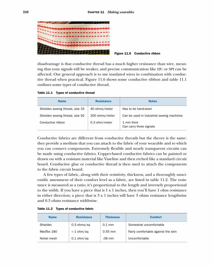
248 CHAPTER 11 Making wearables
disadvantage is that conductive thread has a much higher resistance than wire, mean-ing that your signals will be weaker, and precise communication like I2C or SPI can beaffected. Our general approach is to use insulated wires in combination with conduc-tive thread when practical. Figure 11.6 shows some conductive ribbon and table 11.1outlines some types of conductive thread.
Conductive fabrics are different from conductive threads but the theory is the same:they provide a medium that you can attach to the fabric of your wearable and to whichyou can connect components. Extremely flexible and nearly transparent circuits canbe made using conductive fabrics. Copper-based conductive fabrics can be painted ordrawn on with a resistant material like Vaseline and then etched like a standard circuitboard. Conductive glue or conductive thread is then used to attach the componentsto the fabric circuit board.
A few types of fabric, along with their resistivity, thickness, and a thoroughly unsci-entific assessment of their comfort level as a fabric, are listed in table 11.2. The resis-tance is measured as a ratio; it’s proportional to the length and inversely proportionalto the width. If you have a piece that is 1 x 1 inches, then you’ll have 1 ohm resistancein either direction; a piece that is 3 x 1 inches will have 3 ohms resistance lengthwiseand 0.3 ohms resistance widthwise.
Table 11.1 Types of conductive thread
Name Resistance Notes
Shieldex sewing thread, size 33 40 ohms/meter Has to be hand-sewn
Shieldex sewing thread, size 92 300 ohms/meter Can be used in industrial sewing machines
Conductive ribbon 0.3 ohm/meter 1 mm thick Can carry three signals
Table 11.2 Types of conductive fabric
Name Resistance Thickness Comfort
Shieldex 0.3 ohms/sq 0.1 mm Somewhat uncomfortable
MedTex 180 < 1 ohm/sq 0.55 mm Fairly comfortable against the skin
Nickel mesh 0.1 ohm/sq .08 mm Uncomfortable
Figure 11.6 Conductive ribbon
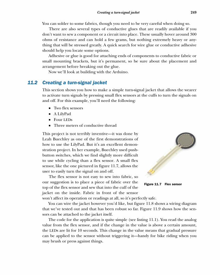
249Creating a turn-signal jacket
You can solder to some fabrics, though you need to be very careful when doing so. There are also several types of conductive glues that are readily available if you
don’t want to sew a component or a circuit into place. These usually hover around 300ohms of resistance and can hold a few grams, but nothing extremely heavy or any-thing that will be stressed greatly. A quick search for wire glue or conductive adhesiveshould help you locate some options.
Adhesive or glue is good for attaching ends of components to conductive fabric orsmall mounting brackets, but it’s permanent, so be sure about the placement andarrangement before breaking out the glue.
Now we’ll look at building with the Arduino.
11.2 Creating a turn-signal jacketThis section shows you how to make a simple turn-signal jacket that allows the wearerto activate turn signals by pressing small flex sensors at the cuffs to turn the signals onand off. For this example, you’ll need the following:
■ Two flex sensors■ A LilyPad■ Four LEDs■ Three meters of conductive thread
This project is not terribly inventive—it was done byLeah Buechley as one of the first demonstrations ofhow to use the LilyPad. But it’s an excellent demon-stration project. In her example, Buechley used push-button switches, which we find slightly more difficultto use while cycling than a flex sensor. A small flexsensor, like the one pictured in figure 11.7, allows theuser to easily turn the signal on and off.
The flex sensor is not easy to sew into fabric, soour suggestion is to place a piece of fabric over thetop of the flex sensor and sew that into the cuff of thejacket on the inside. Fabric in front of the sensorwon’t affect its operation or readings at all, so it’s perfectly safe.
You can wire the jacket however you’d like, but figure 11.8 shows a wiring diagramthat we’ve tested out and that has been robust so far. Figure 11.9 shows how the sen-sors can be attached to the jacket itself.
The code for the application is quite simple (see listing 11.1). You read the analogvalue from the flex sensor, and if the change in the value is above a certain amount,the LEDs are lit for 10 seconds. This change in the value means that gradual pressurecan be applied to the sensor without triggering it—handy for bike riding when youmay brush or press against things.
Figure 11.7 Flex sensor

250 CHAPTER 11 Making wearables
const int LFORCE = 0;const int RFORCE = 1;
const int pressLength = 10000;
const int LTURNSIGNAL = 2; const int RTURNSIGNAL = 3;
int lPrevious, rPrevious;
boolean leftOn, rightOn;
int pressTime;
Listing 11.1 TurnSignals.ino
A2/16
A1/15
A0/14
RST
SCK
MOSI
D10
D9
D6
D5
D3
GND
MISO
VCC
LilyPad
Arduino
Simple
Board
Fritzing.orgMade with
Part1
LED5
red
R4
R3
LED2
red
LED3
red
LED4
red
Figure 11.8 Connecting the LilyPad, LEDs, and flex sensors
Figure 11.9 Sewing the components into the jacket
Each “signal” has two LEDs for better visibility.
251Creating a wearable piano
void setup(){ pinMode(LTURNSIGNAL, OUTPUT); pinMode(RTURNSIGNAL, OUTPUT);
leftOn = false; rightOn = false;}
void loop(){ int lCurr = analogRead(LFORCE); int rCurr = analogRead(RFORCE); if( lCurr - lPrevious > 200) { pressTime = millis(); leftOn = true; } lPrevious = lCurr;
if( rCurr - rPrevious > 200) { pressTime = millis(); rightOn = true; } rPrevious = rCurr;
if(leftOn) { digitalWrite(LTURNSIGNAL, HIGH); if( millis() - pressTime > pressLength) { leftOn = false; } }
if(rightOn) { digitalWrite(RTURNSIGNAL, HIGH); if( millis() - pressTime > pressLength) { rightOn = false; } }
}
One thought for improving the jacket might be to add a sound from a speaker or abuzz from a vibration motor to indicate to the user when the turn signals are on. Let’smove on to another project to explore attaching a small speaker to a jacket.
11.3 Creating a wearable pianoAnother classic example of garment-sized wearables is a musical instrument outfit. Forthis example you’ll need the following:
■ A LilyPad Arduino■ A 0.25 W speaker■ 10 thin pieces of copper■ 5 thin pieces of rubber foam■ Thread
Only listen for changes.
Turn off after a while.
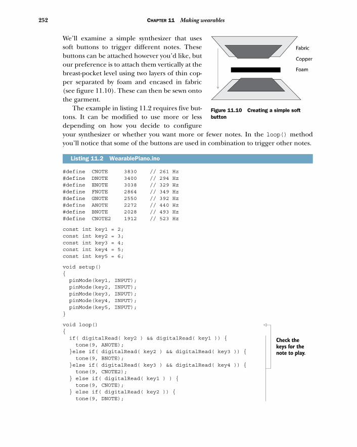
252 CHAPTER 11 Making wearables
We’ll examine a simple synthesizer that usessoft buttons to trigger different notes. Thesebuttons can be attached however you’d like, butour preference is to attach them vertically at thebreast-pocket level using two layers of thin cop-per separated by foam and encased in fabric(see figure 11.10). These can then be sewn ontothe garment.
The example in listing 11.2 requires five but-tons. It can be modified to use more or lessdepending on how you decide to configureyour synthesizer or whether you want more or fewer notes. In the loop() methodyou’ll notice that some of the buttons are used in combination to trigger other notes.
#define CNOTE 3830 // 261 Hz #define DNOTE 3400 // 294 Hz #define ENOTE 3038 // 329 Hz #define FNOTE 2864 // 349 Hz #define GNOTE 2550 // 392 Hz #define ANOTE 2272 // 440 Hz #define BNOTE 2028 // 493 Hz #define CNOTE2 1912 // 523 Hz
const int key1 = 2;const int key2 = 3;const int key3 = 4;const int key4 = 5;const int key5 = 6;
void setup(){ pinMode(key1, INPUT); pinMode(key2, INPUT); pinMode(key3, INPUT); pinMode(key4, INPUT); pinMode(key5, INPUT);}
void loop() { if( digitalRead( key2 ) && digitalRead( key1 )) { tone(9, ANOTE); }else if( digitalRead( key2 ) && digitalRead( key3 )) { tone(9, BNOTE); }else if( digitalRead( key3 ) && digitalRead( key4 )) { tone(9, CNOTE2); } else if( digitalRead( key1 ) ) { tone(9, CNOTE); } else if( digitalRead( key2 )) { tone(9, DNOTE);
Listing 11.2 WearablePiano.ino
Figure 11.10 Creating a simple soft button
Check the keys for the note to play.
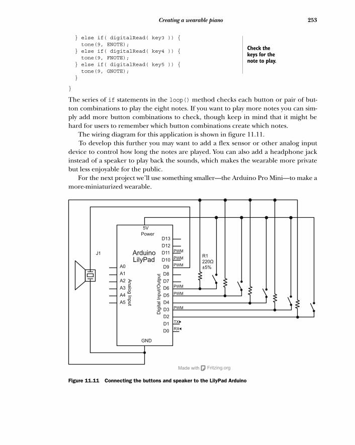
253Creating a wearable piano
} else if( digitalRead( key3 )) { tone(9, ENOTE); } else if( digitalRead( key4 )) { tone(9, FNOTE); } else if( digitalRead( key5 )) { tone(9, GNOTE); }
}
The series of if statements in the loop() method checks each button or pair of but-ton combinations to play the eight notes. If you want to play more notes you can sim-ply add more button combinations to check, though keep in mind that it might behard for users to remember which button combinations create which notes.
The wiring diagram for this application is shown in figure 11.11. To develop this further you may want to add a flex sensor or other analog input
device to control how long the notes are played. You can also add a headphone jackinstead of a speaker to play back the sounds, which makes the wearable more privatebut less enjoyable for the public.
For the next project we’ll use something smaller—the Arduino Pro Mini—to make amore-miniaturized wearable.
Check the keys for the note to play.
Power
Arduino
D13
D12
D11
D10
D9
D8
D7
D6
D5
D4
D3
D2
D1
D0
GND
A0
A1
A2
A3
A4
A5
An
alo
g In
pu
t
Dig
ita
l In
pu
t/O
utp
ut
PWM
PWM
PWM
PWM
PWM
PWM
TX
RX
Fritzing.orgMade with
LilyPadJ1
R1
220Ω
±5%
5V
Figure 11.11 Connecting the buttons and speaker to the LilyPad Arduino
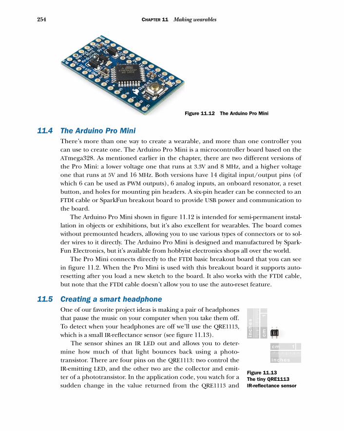
254 CHAPTER 11 Making wearables
11.4 The Arduino Pro MiniThere’s more than one way to create a wearable, and more than one controller youcan use to create one. The Arduino Pro Mini is a microcontroller board based on theATmega328. As mentioned earlier in the chapter, there are two different versions ofthe Pro Mini: a lower voltage one that runs at 3.3V and 8 MHz, and a higher voltageone that runs at 5V and 16 MHz. Both versions have 14 digital input/output pins (ofwhich 6 can be used as PWM outputs), 6 analog inputs, an onboard resonator, a resetbutton, and holes for mounting pin headers. A six-pin header can be connected to anFTDI cable or SparkFun breakout board to provide USB power and communication tothe board.
The Arduino Pro Mini shown in figure 11.12 is intended for semi-permanent instal-lation in objects or exhibitions, but it’s also excellent for wearables. The board comeswithout premounted headers, allowing you to use various types of connectors or to sol-der wires to it directly. The Arduino Pro Mini is designed and manufactured by Spark-Fun Electronics, but it’s available from hobbyist electronics shops all over the world.
The Pro Mini connects directly to the FTDI basic breakout board that you can seein figure 11.2. When the Pro Mini is used with this breakout board it supports auto-resetting after you load a new sketch to the board. It also works with the FTDI cable,but note that the FTDI cable doesn’t allow you to use the auto-reset feature.
11.5 Creating a smart headphoneOne of our favorite project ideas is making a pair of headphonesthat pause the music on your computer when you take them off.To detect when your headphones are off we’ll use the QRE1113,which is a small IR-reflectance sensor (see figure 11.13).
The sensor shines an IR LED out and allows you to deter-mine how much of that light bounces back using a photo-transistor. There are four pins on the QRE1113: two control theIR-emitting LED, and the other two are the collector and emit-ter of a phototransistor. In the application code, you watch for asudden change in the value returned from the QRE1113 and
Figure 11.12 The Arduino Pro Mini
Figure 11.13The tiny QRE1113 IR-reflectance sensor
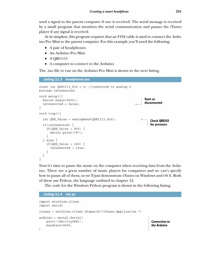
255Creating a smart headphone
send a signal to the parent computer if one is received. The serial message is receivedby a small program that monitors the serial communication and pauses the iTunesplayer if any signal is received.
At its simplest, this program requires that an FTDI cable is used to connect the Ardu-ino Pro Mini to the parent computer. For this example you’ll need the following:
■ A pair of headphones■ An Arduino Pro Mini■ A QRE1113■ A computer to connect to the Arduino
The .ino file to run on the Arduino Pro Mini is shown in the next listing.
const int QRE1113_Pin = 0; //connected to analog 0boolean isConnected;
void setup(){ Serial.begin(9600); isConnected = false; }
void loop(){
int QRE_Value = analogRead(QRE1113_Pin);
if(isConnected) { if(QRE_Value > 900) { Serial.print("X"); } } else { if(QRE_Value > 300) { isConnected = true; } }}
Now it’s time to pause the music on the computer when receiving data from the Ardu-ino. There are a great number of music players for computers and we can’t specifyhow to pause all of them, so we’ll just demonstrate iTunes on Windows and OS X. Bothof these use Python, the language outlined in chapter 12.
The code for the Windows Python program is shown in the following listing.
import win32com.clientimport serial
itunes = win32com.client.Dispatch("iTunes.Application ")
arduino = serial.Serial( port='/dev/ttyUSB1', baudrate=9600, )
Listing 11.3 headphones.ino
Listing 11.4 win.py
Start as disconnected
Check QRE1113 for presence
Connection to the Arduino
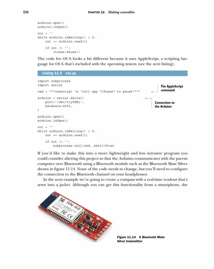
256 CHAPTER 11 Making wearables
arduino.open()arduino.isOpen()
out = '' while arduino.inWaiting() > 0: out += arduino.read(1)
if out != '': itunes.Pause()
The code for OS X looks a bit different because it uses AppleScript, a scripting lan-guage for OS X that’s included with the operating system (see the next listing).
import subprocessimport serial
cmd = """osascript -e 'tell app "iTunes" to pause'"""
arduino = serial.Serial( port='/dev/ttyUSB1', baudrate=9600,)
arduino.open()arduino.isOpen()
out = ''while arduino.inWaiting() > 0: out += arduino.read(1)
if out != '': subprocess.call(cmd, shell=True)
If you’d like to make this into a more lightweight and less intrusive program youcould consider altering this project so that the Arduino communicates with the parentcomputer over Bluetooth using a Bluetooth module such as the Bluetooth Mate Silvershown in figure 11.14. None of the code needs to change, but you’ll need to configurethe connection to the Bluetooth channel on your headphones.
In the next example we’re going to create a compass with a real-time readout that’ssewn into a jacket. Although you can get this functionality from a smartphone, the
Listing 11.5 osx.py
The AppleScript command
Connection to the Arduino
Figure 11.14 A Bluetooth Mate Silver transmitter
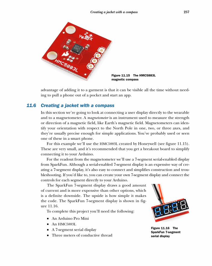
257Creating a jacket with a compass
advantage of adding it to a garment is that it can be visible all the time without need-ing to pull a phone out of a pocket and start an app.
11.6 Creating a jacket with a compassIn this section we’re going to look at connecting a user display directly to the wearableand to a magnetometer. A magnetometer is an instrument used to measure the strengthor direction of a magnetic field, like Earth’s magnetic field. Magnetometers can iden-tify your orientation with respect to the North Pole in one, two, or three axes, andthey’re usually precise enough for simple applications. You’ve probably used or seenone of these in a smart phone.
For this example we’ll use the HMC5883L created by Honeywell (see figure 11.15).These are very small, and it’s recommended that you get a breakout board to simplifyconnecting it to your Arduino.
For the readout from the magnetometer we’ll use a 7-segment serial-enabled displayfrom SparkFun. Although a serial-enabled 7-segment display is an expensive way of cre-ating a 7-segment display, it’s also easy to connect and simplifies construction and trou-bleshooting. If you’d like to, you can create your own 7-segment display and connect thecontrols for each segment directly to your Arduino.
The SparkFun 7-segment display draws a good amountof current and is more expensive than other options, whichis a definite downside. The upside is how simple it makesthe code. The SparkFun 7-segment display is shown in fig-ure 11.16.
To complete this project you’ll need the following:
■ An Arduino Pro Mini■ An HMC5883L■ A 7-segment serial display■ Three meters of conductive thread
Figure 11.15 The HMC5883L magnetic compass
Figure 11.16 The SparkFun 7-segment serial display
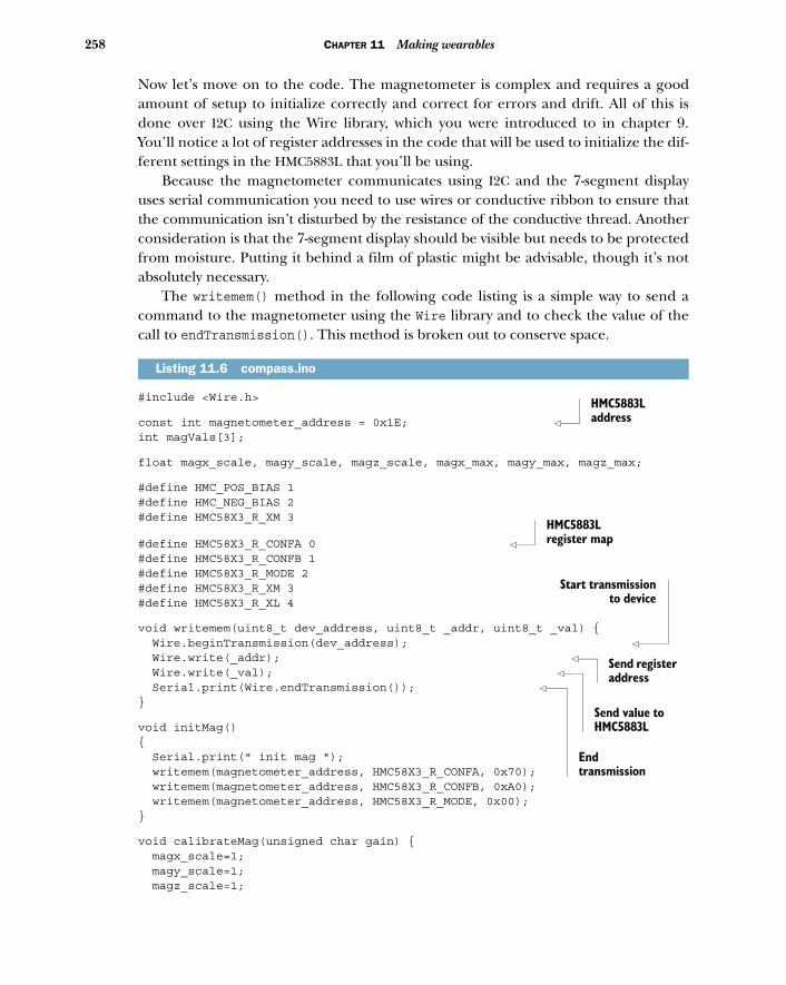
258 CHAPTER 11 Making wearables
Now let’s move on to the code. The magnetometer is complex and requires a goodamount of setup to initialize correctly and correct for errors and drift. All of this isdone over I2C using the Wire library, which you were introduced to in chapter 9.You’ll notice a lot of register addresses in the code that will be used to initialize the dif-ferent settings in the HMC5883L that you’ll be using.
Because the magnetometer communicates using I2C and the 7-segment displayuses serial communication you need to use wires or conductive ribbon to ensure thatthe communication isn’t disturbed by the resistance of the conductive thread. Anotherconsideration is that the 7-segment display should be visible but needs to be protectedfrom moisture. Putting it behind a film of plastic might be advisable, though it’s notabsolutely necessary.
The writemem() method in the following code listing is a simple way to send acommand to the magnetometer using the Wire library and to check the value of thecall to endTransmission(). This method is broken out to conserve space.
#include <Wire.h>
const int magnetometer_address = 0x1E; int magVals[3];
float magx_scale, magy_scale, magz_scale, magx_max, magy_max, magz_max;
#define HMC_POS_BIAS 1#define HMC_NEG_BIAS 2#define HMC58X3_R_XM 3
#define HMC58X3_R_CONFA 0 #define HMC58X3_R_CONFB 1#define HMC58X3_R_MODE 2#define HMC58X3_R_XM 3#define HMC58X3_R_XL 4
void writemem(uint8_t dev_address, uint8_t _addr, uint8_t _val) { Wire.beginTransmission(dev_address); Wire.write(_addr); Wire.write(_val); Serial.print(Wire.endTransmission()); }
void initMag(){ Serial.print(" init mag "); writemem(magnetometer_address, HMC58X3_R_CONFA, 0x70); writemem(magnetometer_address, HMC58X3_R_CONFB, 0xA0); writemem(magnetometer_address, HMC58X3_R_MODE, 0x00);}
void calibrateMag(unsigned char gain) { magx_scale=1; magy_scale=1; magz_scale=1;
Listing 11.6 compass.ino
HMC5883L address
HMC5883L register map
Start transmissionto device
Send register address
Send value to HMC5883L
End transmission
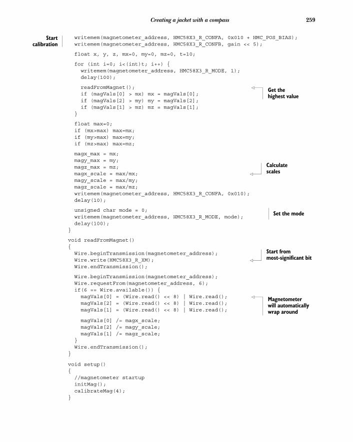
259Creating a jacket with a compass
cal
writemem(magnetometer_address, HMC58X3_R_CONFA, 0x010 + HMC_POS_BIAS); writemem(magnetometer_address, HMC58X3_R_CONFB, gain << 5);float x, y, z, mx=0, my=0, mz=0, t=10;
for (int i=0; i<(int)t; i++) { writemem(magnetometer_address, HMC58X3_R_MODE, 1); delay(100);
readFromMagnet(); if (magVals[0] > mx) mx = magVals[0]; if (magVals[2] > my) my = magVals[2]; if (magVals[1] > mz) mz = magVals[1]; }
float max=0; if (mx>max) max=mx; if (my>max) max=my; if (mz>max) max=mz;
magx_max = mx; magy_max = my; magz_max = mz; magx_scale = max/mx; magy_scale = max/my; magz_scale = max/mz; writemem(magnetometer_address, HMC58X3_R_CONFA, 0x010); delay(10);
unsigned char mode = 0; writemem(magnetometer_address, HMC58X3_R_MODE, mode); delay(100);}
void readFromMagnet(){ Wire.beginTransmission(magnetometer_address); Wire.write(HMC58X3_R_XM); Wire.endTransmission();
Wire.beginTransmission(magnetometer_address); Wire.requestFrom(magnetometer_address, 6); if(6 == Wire.available()) { magVals[0] = (Wire.read() << 8) | Wire.read(); magVals[2] = (Wire.read() << 8) | Wire.read(); magVals[1] = (Wire.read() << 8) | Wire.read();
magVals[0] /= magx_scale; magVals[2] /= magy_scale; magVals[1] /= magz_scale; } Wire.endTransmission();}
void setup() { //magnetometer startup initMag(); calibrateMag(4);}
Startibration
Get the highest value
Calculate scales
Set the mode
Start from most-significant bit
Magnetometer will automatically wrap around
260 CHAPTER 11 Making wearables
void loop(){ readFromMagnet(); char str[3]; itoa(magVals[2], str, 10); Serial.print('x'); // print a 0 Serial.print(str[0]); Serial.print(str[1]); Serial.print(str[2]); delay(100);
}
The preceding application is complex but its functionality is fairly straightforward:turn on the magnetometer, initialize it correctly, and compensate for the scale that itreturns. Once that’s completed, the loop() method simply reads the values from theHMC5883L and writes them to the 7-segment display using the hardware serial connec-tion on the Arduino Pro Mini. The calibration routine is necessary to ensure that thecompass isn’t overly influenced by noise in the environment or its default settings.
If you’re interested in how the HMC5883L actually understands each commandyou can check out the datasheet for it, which is available at the Honeywell website:http://honeywell.com/.
11.7 SummaryIn this chapter you learned how to use two new Arduino-compatible controllers, andalso learned about an entire new range of applications for your Arduino skills. Thepossibilities of using microcontrollers to add computational capability to a small unob-trusive object worn on the body is one of the most exciting ways of working with theArduino and of thinking about how to add intelligence and functionality to our lives.
You’ve seen two different Arduino-compatible boards that are small, lightweight,and easily powered by small batteries, all of which are important considerations whenmaking a wearable. The Arduino LilyPad is larger, but it’s built specifically for attach-ing conductive thread and has a large community of users creating wearables. TheArduino Pro Mini is a small board that’s very lightweight, but it’s slightly more difficultto use with conductive thread, lacking the easy-to-sew eyelets of the Arduino LilyPad. Itis, however, significantly smaller and provides more pins for you to use in your projects.
In the next chapter you’ll learn about connecting your Arduino to other applica-tions written in a variety of programming languages, which will allow you to makelarger and more complex projects than you would be able to with just an Arduino.
Print ASCII
Adding shields
Up to this point, you’ve used shields in several examples, but this chapter will focuson what a shield is, how shields are made, what they’re supposed to do, and howyou can make your own. Shields are boards that can be plugged into the Arduinoboard to extend its capabilities. Making a shield means collecting a discrete set ofcomponents for a specific task, like playing back MP3 files or communicating with aGPS device, and then fitting the components to the form factor of the Arduinodevice and adding pins so that they can be easily snapped into place or removedwithout soldering.
12.1 Shield basicsAlmost of all of the Arduino shields follow the same philosophy as the original tool-kit: they are easy to mount and friendly to work with. Figure 12.1 shows a motorshield developed by Adafruit that allows you to easily control up to two servomo-tors, four DC motors, or two stepper motors.
This chapter covers■ What Arduino shields are■ Using libraries with shields■ Making your own shields
261
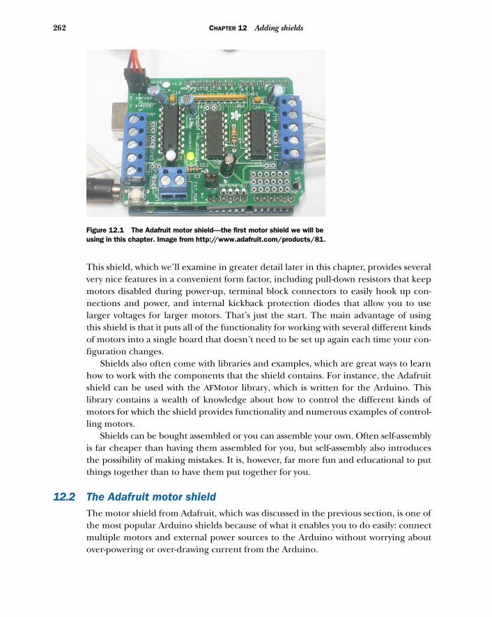
262 CHAPTER 12 Adding shields
This shield, which we’ll examine in greater detail later in this chapter, provides severalvery nice features in a convenient form factor, including pull-down resistors that keepmotors disabled during power-up, terminal block connectors to easily hook up con-nections and power, and internal kickback protection diodes that allow you to uselarger voltages for larger motors. That’s just the start. The main advantage of usingthis shield is that it puts all of the functionality for working with several different kindsof motors into a single board that doesn’t need to be set up again each time your con-figuration changes.
Shields also often come with libraries and examples, which are great ways to learnhow to work with the components that the shield contains. For instance, the Adafruitshield can be used with the AFMotor library, which is written for the Arduino. Thislibrary contains a wealth of knowledge about how to control the different kinds ofmotors for which the shield provides functionality and numerous examples of control-ling motors.
Shields can be bought assembled or you can assemble your own. Often self-assemblyis far cheaper than having them assembled for you, but self-assembly also introducesthe possibility of making mistakes. It is, however, far more fun and educational to putthings together than to have them put together for you.
12.2 The Adafruit motor shieldThe motor shield from Adafruit, which was discussed in the previous section, is one ofthe most popular Arduino shields because of what it enables you to do easily: connectmultiple motors and external power sources to the Arduino without worrying aboutover-powering or over-drawing current from the Arduino.
Figure 12.1 The Adafruit motor shield—the first motor shield we will be using in this chapter. Image from http://www.adafruit.com/products/81.
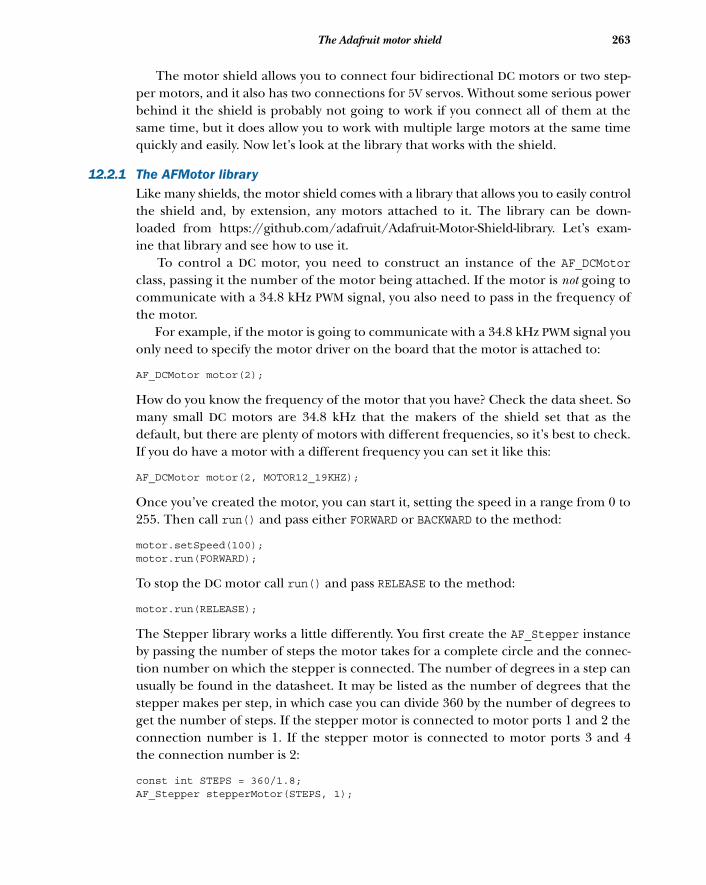
263The Adafruit motor shield
The motor shield allows you to connect four bidirectional DC motors or two step-per motors, and it also has two connections for 5V servos. Without some serious powerbehind it the shield is probably not going to work if you connect all of them at thesame time, but it does allow you to work with multiple large motors at the same timequickly and easily. Now let’s look at the library that works with the shield.
12.2.1 The AFMotor libraryLike many shields, the motor shield comes with a library that allows you to easily controlthe shield and, by extension, any motors attached to it. The library can be down-loaded from https://github.com/adafruit/Adafruit-Motor-Shield-library. Let’s exam-ine that library and see how to use it.
To control a DC motor, you need to construct an instance of the AF_DCMotorclass, passing it the number of the motor being attached. If the motor is not going tocommunicate with a 34.8 kHz PWM signal, you also need to pass in the frequency ofthe motor.
For example, if the motor is going to communicate with a 34.8 kHz PWM signal youonly need to specify the motor driver on the board that the motor is attached to:
AF_DCMotor motor(2);
How do you know the frequency of the motor that you have? Check the data sheet. Somany small DC motors are 34.8 kHz that the makers of the shield set that as thedefault, but there are plenty of motors with different frequencies, so it’s best to check.If you do have a motor with a different frequency you can set it like this:
AF_DCMotor motor(2, MOTOR12_19KHZ);
Once you’ve created the motor, you can start it, setting the speed in a range from 0 to255. Then call run() and pass either FORWARD or BACKWARD to the method:
motor.setSpeed(100);motor.run(FORWARD);
To stop the DC motor call run() and pass RELEASE to the method:
motor.run(RELEASE);
The Stepper library works a little differently. You first create the AF_Stepper instanceby passing the number of steps the motor takes for a complete circle and the connec-tion number on which the stepper is connected. The number of degrees in a step canusually be found in the datasheet. It may be listed as the number of degrees that thestepper makes per step, in which case you can divide 360 by the number of degrees toget the number of steps. If the stepper motor is connected to motor ports 1 and 2 theconnection number is 1. If the stepper motor is connected to motor ports 3 and 4the connection number is 2:
const int STEPS = 360/1.8;AF_Stepper stepperMotor(STEPS, 1);
264 CHAPTER 12 Adding shields
To advance the motor call step() with the number of steps and the direction that youwant to turn the stepper:
stepperMotor.step(1, FORWARD);
You can also set the type of step that you want the stepper motor to turn. These arethe available options:
■ SINGLE—Single-coil activation ■ DOUBLE—Two coils activated at once for slightly higher torque ■ INTERLEAVE—Alternates between single- and double-coil activation to get twice
the resolution but half the speed■ MICROSTEP—Attempts to turn the stepper smoothly to its next position using a
PWM signal
Not all steppers can perform all of these actions, so you’ll want to check the data sheetand perhaps the Adafruit forums for info on your particular motor.
12.2.2 Using the motor shield with a stepper motor
For this example you’ll need the following:
■ An Arduino■ An Adafruit motor shield■ A 5V stepper motor■ Two AA batteries or a power source sufficient to drive the stepper motor ■ Two buttons■ Two resistors (5k ohms or similar)
This application uses the two buttons to control the direction of the stepper. Each but-ton acts as a toggle to turn the stepper on and off and determine in which direction itwill turn, if it turns at all.
The connections are shown in figure 12.2. Note the battery pack attached to themotor shield to power the stepper motor. The two buttons have pull-down resistors onthem to ensure that they only read HIGH when pressed.
You’ll also need to install the AFMotor library, which you can download fromGitHub at www.github.com/adafruit/Adafruit-Motor-Shield-library. Here’s the codethat will drive the stepper motor.
#include <AFMotor.h>
AF_Stepper stepper(48, 1);
const int STEPPER_BWD_BUTTON = 2;const int STEPPER_FWD_BUTTON = 13;
const int BACKWARDS = 2;const int FORWARDS = 1;
Listing 12.1 MotorDriving.pde
265The Adafruit motor shield
const int STOPPED = 0;
int motorState;
void setup() { }
void loop() {
int fwd = digitalRead(STEPPER_FWD_BUTTON); int bwd = digitalRead(STEPPER_BWD_BUTTON);
if(fwd == HIGH) { if( motorState == FORWARDS ) { motorState = STOPPED; } else { motorState = FORWARDS; } }
if(bwd == HIGH) { if( motorState == BACKWARDS ) { motorState = STOPPED; } else { motorState = BACKWARDS; } }
if(motorState == FORWARDS) { stepper.step(1, FORWARD, INTERLEAVE); } else if(motorState == BACKWARDS) { stepper.step(1, BACKWARD, INTERLEAVE); }
}
12.2.3 Using the motor shield with a DC motor
Controlling a DC motor is equally simple: create an instance of the AF_DCMotor classand set the controller block it’s attached to in its constructor. For instance, a DC motorconnected to the second motor block (marked with M2) would be declared like this:
AF_DCMotor motor(2);
For the next project we’ll control a motor’s speed with a potentiometer and control itsdirection with a pair of buttons. For this project you’ll need the following:
■ An Arduino■ An Adafruit motor shield■ A small DC motor■ Two buttons■ Two resistors (5k ohms or similar)■ A servomotor■ Two AA batteries or a power source sufficient to drive the motor■ One potentiometer
Toggles directions
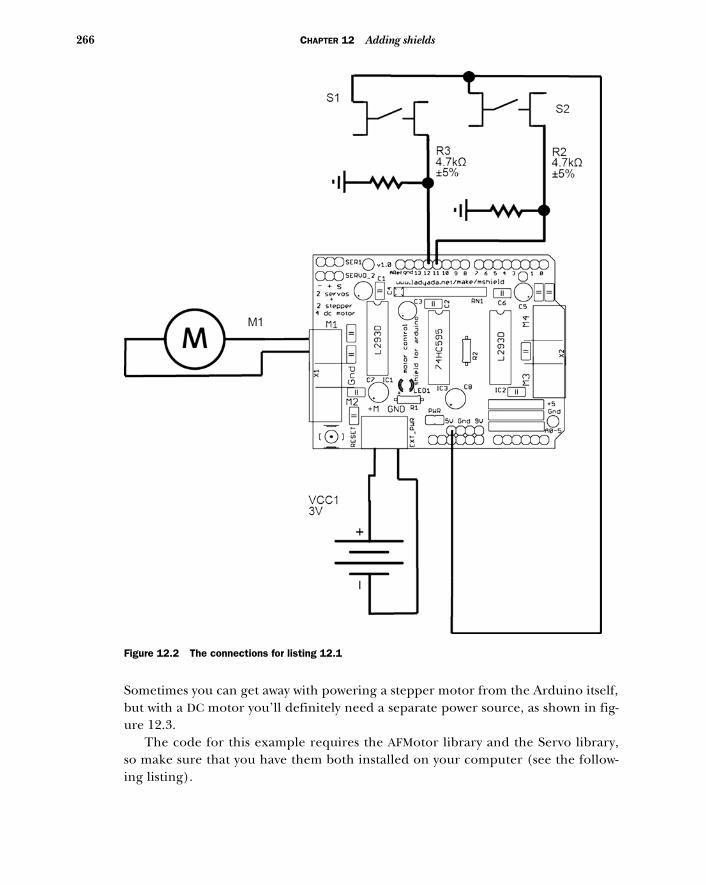
266 CHAPTER 12 Adding shields
Sometimes you can get away with powering a stepper motor from the Arduino itself,but with a DC motor you’ll definitely need a separate power source, as shown in fig-ure 12.3.
The code for this example requires the AFMotor library and the Servo library,so make sure that you have them both installed on your computer (see the follow-ing listing).
Figure 12.2 The connections for listing 12.1
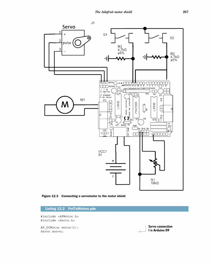
267The Adafruit motor shield
#include <AFMotor.h>#include <Servo.h>
AF_DCMotor motor(1);Servo servo;
Listing 12.2 PotToMotors.pde
Figure 12.3 Connecting a servomotor to the motor shield
Servo connection 1 is Arduino D9
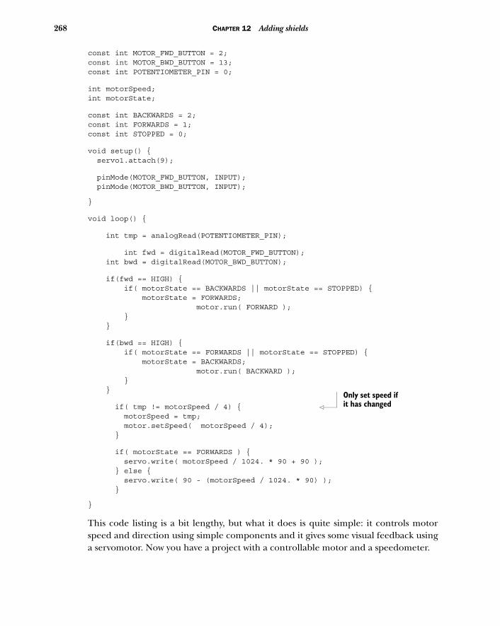
268 CHAPTER 12 Adding shields
const int MOTOR_FWD_BUTTON = 2;const int MOTOR_BWD_BUTTON = 13;const int POTENTIOMETER_PIN = 0;
int motorSpeed;int motorState;
const int BACKWARDS = 2;const int FORWARDS = 1;const int STOPPED = 0;
void setup() { servo1.attach(9);
pinMode(MOTOR_FWD_BUTTON, INPUT); pinMode(MOTOR_BWD_BUTTON, INPUT);
}
void loop() {
int tmp = analogRead(POTENTIOMETER_PIN);
int fwd = digitalRead(MOTOR_FWD_BUTTON); int bwd = digitalRead(MOTOR_BWD_BUTTON);
if(fwd == HIGH) { if( motorState == BACKWARDS || motorState == STOPPED) { motorState = FORWARDS; motor.run( FORWARD ); } }
if(bwd == HIGH) { if( motorState == FORWARDS || motorState == STOPPED) { motorState = BACKWARDS; motor.run( BACKWARD ); } }
if( tmp != motorSpeed / 4) { motorSpeed = tmp; motor.setSpeed( motorSpeed / 4); }
if( motorState == FORWARDS ) { servo.write( motorSpeed / 1024. * 90 + 90 ); } else { servo.write( 90 - (motorSpeed / 1024. * 90) ); }
}
This code listing is a bit lengthy, but what it does is quite simple: it controls motorspeed and direction using simple components and it gives some visual feedback usinga servomotor. Now you have a project with a controllable motor and a speedometer.
Only set speed if it has changed
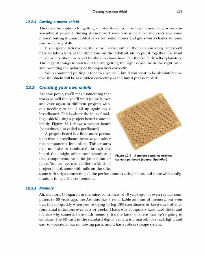
269Creating your own shield
12.2.4 Getting a motor shield
There are two options for getting a motor shield: you can buy it assembled, or you canassemble it yourself. Buying it assembled saves you some time and costs you somemoney; buying it unassembled saves you some money and gives you a chance to honeyour soldering skills.
If you go the latter route, the kit will arrive with all the pieces in a bag, and you’llhave to take a look at the directions on the Adafruit site to put it together. To avoidneedless repetition, we won’t list the directions here, but they’re fairly self-explanatory.The biggest things to watch out for are getting the right capacitor in the right placeand orienting the polarity of the capacitors correctly.
We recommend putting it together yourself, but if you want to be absolutely surethat the shield will be assembled correctly you can buy it preassembled.
12.3 Creating your own shieldAt some point, you’ll make something thatworks so well that you’ll want to use it overand over again in different projects with-out needing to set it all up again on abreadboard. This is where the idea of mak-ing a shield using a project board comes inhandy. Figure 12.4 shows a project board(sometimes also called a perfboard).
A project board is a little more perma-nent than a breadboard because you solderthe components into place. This ensuresthat no noise is conducted through theboard that might affect your circuit andthat components can’t be jostled out ofplace. You can get many different kinds ofproject board, some with rails on the side,some with strips connecting all the perforations in a single line, and some with config-urations for specific components.
12.3.1 Memory
Ah, memory. Compared to the microcontrollers of 10 years ago, or even regular com-puters of 30 years ago, the Arduino has a remarkable amount of memory, but eventhat fills up quickly when you’re trying to log GPS coordinates or keep track of envi-ronmental indicators over days or weeks. That’s why computers have hard disks, andit’s also why cameras have flash memory; it’s the latter of these that we’re going toemulate. The SD card in the standard digital camera is a marvel: it’s small, light, andeasy to operate, it has no moving parts, and it has a robust storage system.
Figure 12.4 A project board, sometimes called a perfboard (source: SparkFun)
270 CHAPTER 12 Adding shields
The most common type of memory card is the SD card, and these generally comein two formats: microSD and SD. These two types differ not only in protocol andcapacity, but also in the physical size of the card: one is larger and the other is muchsmaller. There’s another important difference between these two cards: microSD gen-erally uses a format called FAT32, whereas SD cards use FAT16. The differencesbetween these formats are in how files are allocated and stored. This isn’t importantfor you at the moment, but it’s good to know which variety you’re getting because thestorage system will affect how you read data from and write it to the card.
In this example we’re going to focus on the regular SD card because it’s easier towork with by hand. As we write this book, the capacity of SD cards ranges from 64 MBall the way up to 32 GB, but by the time you read this they may be even larger.
Connecting an SD card to an Arduino presents a few problems. As you may recallfrom chapter 9 where you were introduced to I2C, the I2C protocol transmits databetween the component and the Arduino using short bursts of digital informationthat represent the bits of each byte. SD cards operate at 3.3V, and that means that theyneed to be powered with 3.3V and they also need to be communicated with at 3.3V.This is a problem for the Arduino, because the digitalRead() method sometimeswon’t register a 3.3V signal as HIGH when performing a digital read. You might guesswhere this is going: we need a way to turn the signals from the Arduino into 3.3V sig-nals, and the signals from the SD card to 5V signals. Luckily, there’s a component thatdoes it for us.
12.3.2 Level shifters
A level shift does one thing well: it shifts any level received on one of the input pinsdown to whatever voltage is received on the voltage-in pin. Applying 3.3V to the levelshifter means that any signal sent through it will come out at 3.3V, which is exactlywhat you want to avoid damaging your SD card.
There are a lot of level shifters available with varying precision and different num-bers of inputs and outputs. For this example, you really only need two level shifters tocommunicate safely with the SD card, but one of the most readily available and cheap-est level shifters has six outputs. It’s the 74HC4050 from NXP Semiconductors, and thepinout is shown in figure 12.5.
The voltage level pin determines the voltage that all the output current will bestepped down to, the ground grounds the current, and the rest of the pins are eitherinput, output, or don’t connect (marked here as DNC).
That’s the first challenge of the SD card shield handled. Now how do you connectthe SD card to the shield so that it can be easily inserted and removed without trouble?The answer is an SD card holder.
12.3.3 The SD card holder
You’ve probably used a card holder for an SD card before, but you may not have got-ten a good look at it because they’re usually hidden inside a camera or a computer
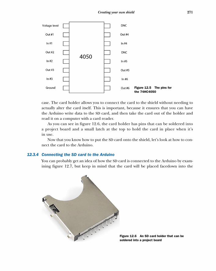
271Creating your own shield
case. The card holder allows you to connect the card to the shield without needing toactually alter the card itself. This is important, because it ensures that you can havethe Arduino write data to the SD card, and then take the card out of the holder andread it on a computer with a card reader.
As you can see in figure 12.6, the card holder has pins that can be soldered intoa project board and a small latch at the top to hold the card in place when it’sin use.
Now that you know how to put the SD card onto the shield, let’s look at how to con-nect the card to the Arduino.
12.3.4 Connecting the SD card to the Arduino
You can probably get an idea of how the SD card is connected to the Arduino by exam-ining figure 12.7, but keep in mind that the card will be placed facedown into the
Figure 12.5 The pins for the 74HC4050
Figure 12.6 An SD card holder that can be soldered into a project board
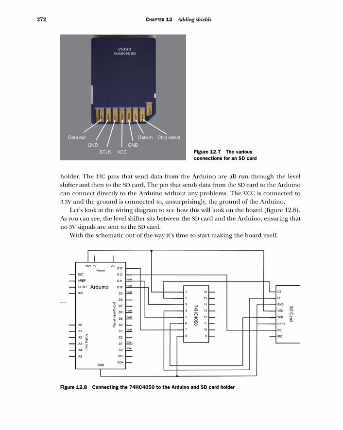
272 CHAPTER 12 Adding shields
holder. The I2C pins that send data from the Arduino are all run through the levelshifter and then to the SD card. The pin that sends data from the SD card to the Arduinocan connect directly to the Arduino without any problems. The VCC is connected to3.3V and the ground is connected to, unsurprisingly, the ground of the Arduino.
Let’s look at the wiring diagram to see how this will look on the board (figure 12.8).As you can see, the level shifter sits between the SD card and the Arduino, ensuring thatno 5V signals are sent to the SD card.
With the schematic out of the way it’s time to start making the board itself.
Figure 12.7 The various connections for an SD card
Figure 12.8 Connecting the 74HC4050 to the Arduino and SD card holder
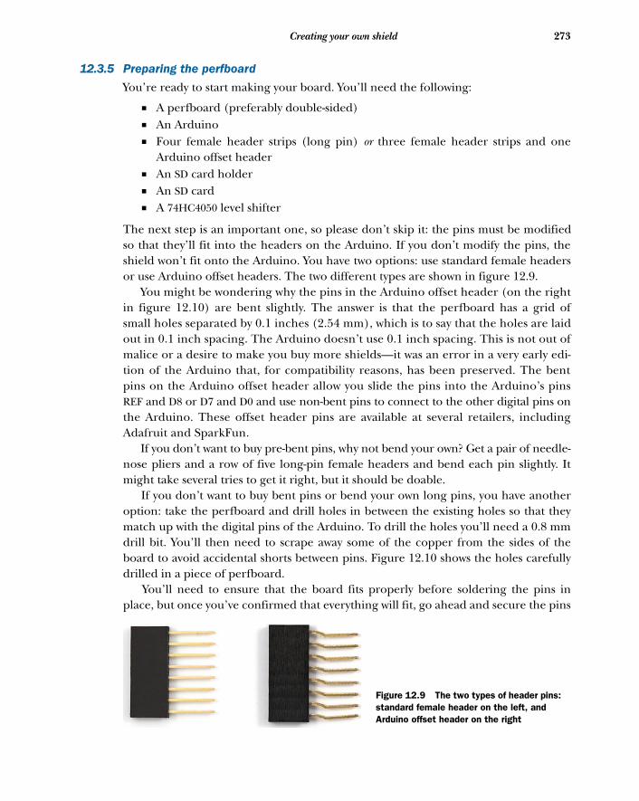
273Creating your own shield
12.3.5 Preparing the perfboard
You’re ready to start making your board. You’ll need the following:
■ A perfboard (preferably double-sided)■ An Arduino ■ Four female header strips (long pin) or three female header strips and one
Arduino offset header■ An SD card holder■ An SD card■ A 74HC4050 level shifter
The next step is an important one, so please don’t skip it: the pins must be modifiedso that they’ll fit into the headers on the Arduino. If you don’t modify the pins, theshield won’t fit onto the Arduino. You have two options: use standard female headersor use Arduino offset headers. The two different types are shown in figure 12.9.
You might be wondering why the pins in the Arduino offset header (on the rightin figure 12.10) are bent slightly. The answer is that the perfboard has a grid ofsmall holes separated by 0.1 inches (2.54 mm), which is to say that the holes are laidout in 0.1 inch spacing. The Arduino doesn’t use 0.1 inch spacing. This is not out ofmalice or a desire to make you buy more shields—it was an error in a very early edi-tion of the Arduino that, for compatibility reasons, has been preserved. The bentpins on the Arduino offset header allow you slide the pins into the Arduino’s pinsREF and D8 or D7 and D0 and use non-bent pins to connect to the other digital pins onthe Arduino. These offset header pins are available at several retailers, includingAdafruit and SparkFun.
If you don’t want to buy pre-bent pins, why not bend your own? Get a pair of needle-nose pliers and a row of five long-pin female headers and bend each pin slightly. Itmight take several tries to get it right, but it should be doable.
If you don’t want to buy bent pins or bend your own long pins, you have anotheroption: take the perfboard and drill holes in between the existing holes so that theymatch up with the digital pins of the Arduino. To drill the holes you’ll need a 0.8 mmdrill bit. You’ll then need to scrape away some of the copper from the sides of theboard to avoid accidental shorts between pins. Figure 12.10 shows the holes carefullydrilled in a piece of perfboard.
You’ll need to ensure that the board fits properly before soldering the pins inplace, but once you’ve confirmed that everything will fit, go ahead and secure the pins
Figure 12.9 The two types of header pins: standard female header on the left, and Arduino offset header on the right
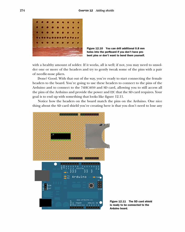
274 CHAPTER 12 Adding shields
with a healthy amount of solder. If it works, all is well; if not, you may need to unsol-der one or more of the headers and try to gently tweak some of the pins with a pairof needle-nose pliers.
Done? Good. With that out of the way, you’re ready to start connecting the femaleheaders to the board. You’re going to use these headers to connect to the pins of theArduino and to connect to the 74HC4050 and SD card, allowing you to still access allthe pins of the Arduino and provide the power and I2C that the SD card requires. Yourgoal is to end up with something that looks like figure 12.11.
Notice how the headers on the board match the pins on the Arduino. One nicething about the SD card shield you’re creating here is that you don’t need to lose any
Figure 12.10 You can drill additional 0.8 mm holes into the perfboard if you don’t have pre-bent pins or don’t want to bend them yourself.
Figure 12.11 The SD card shield is ready to be connected to the Arduino board.
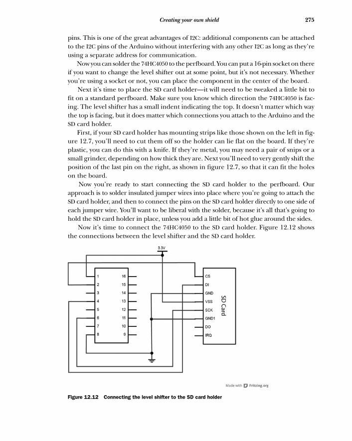
275Creating your own shield
pins. This is one of the great advantages of I2C: additional components can be attachedto the I2C pins of the Arduino without interfering with any other I2C as long as they’reusing a separate address for communication.
Now you can solder the 74HC4050 to the perfboard. You can put a 16-pin socket on thereif you want to change the level shifter out at some point, but it’s not necessary. Whetheryou’re using a socket or not, you can place the component in the center of the board.
Next it’s time to place the SD card holder—it will need to be tweaked a little bit tofit on a standard perfboard. Make sure you know which direction the 74HC4050 is fac-ing. The level shifter has a small indent indicating the top. It doesn’t matter which waythe top is facing, but it does matter which connections you attach to the Arduino and theSD card holder.
First, if your SD card holder has mounting strips like those shown on the left in fig-ure 12.7, you’ll need to cut them off so the holder can lie flat on the board. If they’replastic, you can do this with a knife. If they’re metal, you may need a pair of snips or asmall grinder, depending on how thick they are. Next you’ll need to very gently shift theposition of the last pin on the right, as shown in figure 12.7, so that it can fit the holeson the board.
Now you’re ready to start connecting the SD card holder to the perfboard. Ourapproach is to solder insulated jumper wires into place where you’re going to attach theSD card holder, and then to connect the pins on the SD card holder directly to one side ofeach jumper wire. You’ll want to be liberal with the solder, because it’s all that’s going tohold the SD card holder in place, unless you add a little bit of hot glue around the sides.
Now it’s time to connect the 74HC4050 to the SD card holder. Figure 12.12 showsthe connections between the level shifter and the SD card holder.
Figure 12.12 Connecting the level shifter to the SD card holder
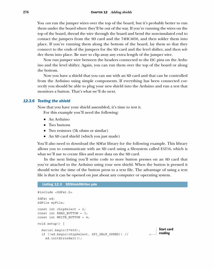
276 CHAPTER 12 Adding shields
You can run the jumper wires over the top of the board, but it’s probably better to runthem under the board where they’ll be out of the way. If you’re running the wires on thetop of the board, thread the wire through the board and bend the non-insulated end tocontact the jumpers from the SD card and the 74HC4050, and then solder them intoplace. If you’re running them along the bottom of the board, lay them so that theyconnect to the ends of the jumpers for the SD card and the level shifter, and then sol-der them into place. Be sure to clip away any extra length of the jumper wire.
Now run jumper wire between the headers connected to the I2C pins on the Ardu-ino and the level shifter. Again, you can run them over the top of the board or alongthe bottom.
Now you have a shield that you can use with an SD card and that can be controlledfrom the Arduino using simple components. If everything has been connected cor-rectly you should be able to plug your new shield into the Arduino and run a test thatmonitors a button. That’s what we’ll do next.
12.3.6 Testing the shield
Now that you have your shield assembled, it’s time to test it. For this example you’ll need the following:
■ An Arduino■ Two buttons■ Two resistors (5k ohms or similar)■ An SD card shield (which you just made)
You’ll also need to download the SDFat library for the following example. This libraryallows you to communicate with an SD card using a filesystem called FAT16, which iswhat we’ll use to create files and store data on the SD card.
In the next listing you’ll write code to store button presses on an SD card thatyou’ve attached to the Arduino using your new shield. When the button is pressed itshould write the time of the button press to a text file. The advantage of using a textfile is that it can be opened on just about any computer or operating system.
#include <SdFat.h>
SdFat sd;SdFile myFile;
const int chipSelect = 2;const int READ_BUTTON = 3;const int WRITE_BUTTON = 4;
void setup() {
Serial.begin(57600); if (!sd.begin(chipSelect, SPI_HALF_SPEED)) // sd.initErrorHalt();
Listing 12.3 SDShieldWriter.pde
Start card reading
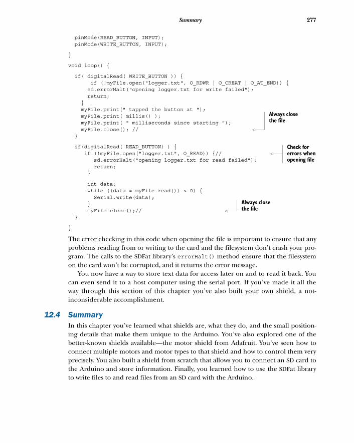
277Summary
pinMode(READ_BUTTON, INPUT); pinMode(WRITE_BUTTON, INPUT);
}
void loop() {
if( digitalRead( WRITE_BUTTON )) { if (!myFile.open("logger.txt", O_RDWR | O_CREAT | O_AT_END)) { sd.errorHalt("opening logger.txt for write failed"); return; } myFile.print(" tapped the button at "); myFile.print( millis() ); myFile.print( " milliseconds since starting "); myFile.close(); // }
if(digitalRead( READ_BUTTON) ) { if (!myFile.open("logger.txt", O_READ)) {// sd.errorHalt("opening logger.txt for read failed"); return; }
int data; while ((data = myFile.read()) > 0) { Serial.write(data); } myFile.close();// }
}
The error checking in this code when opening the file is important to ensure that anyproblems reading from or writing to the card and the filesystem don’t crash your pro-gram. The calls to the SDFat library’s errorHalt() method ensure that the filesystemon the card won’t be corrupted, and it returns the error message.
You now have a way to store text data for access later on and to read it back. Youcan even send it to a host computer using the serial port. If you’ve made it all theway through this section of this chapter you’ve also built your own shield, a not-inconsiderable accomplishment.
12.4 SummaryIn this chapter you’ve learned what shields are, what they do, and the small position-ing details that make them unique to the Arduino. You’ve also explored one of thebetter-known shields available—the motor shield from Adafruit. You’ve seen how toconnect multiple motors and motor types to that shield and how to control them veryprecisely. You also built a shield from scratch that allows you to connect an SD card tothe Arduino and store information. Finally, you learned how to use the SDFat libraryto write files to and read files from an SD card with the Arduino.
Always close the file
Check for errors when opening file
Always close the file
Software integration
The Arduino is a potent tool on its own, but it becomes all the more powerfulwhen you connect it to a full-featured computer, like a laptop or a desktop com-puter. In fact, you do this whenever you connect the Arduino to your computerwith a USB cable to upload code from the Arduino IDE to your Arduino board.The reason you take this step when you’re programming the Arduino is to takeadvantage of the power of your desktop or laptop to compile your code and runthe Arduino IDE.
You may be thinking of the other powerful things your desktop computer cando that your Arduino can’t: computer vision, audio synthesis, network communica-tions, and so on. But your computer is unmistakably a computer, and that’s theadvantage of the Arduino: it allows you to create a new interface to your computerthat doesn’t need to look or feel computer-like.
This chapter covers■ Using serial ports to communicate with
applications■ Connecting an Arduino board to a Processing
application■ Connecting an Arduino board to a Python
application
278
279The serial channel
You can set up an Arduino and another computer to speak to one another usingserial communication, sometimes called RS232. You’ve seen it in action if you’ve usedthe Serial.print() method to send messages from the Arduino to the Arduino IDEfor debugging. But the Arduino IDE isn’t the only device that can receive messagesfrom and send them to your Arduino. In this chapter, we’ll show you how your Ardu-ino can communicate with several different programming platforms on a desktopcomputer to make new interfaces between your computer and your Arduino.
13.1 The serial channelYou’ve already used the serial channel to send debugging messages to the ArduinoIDE using the Serial.print() method. Lots of devices other than the Arduino useserial communication to communicate with a parent computer: Bluetooth-enableddevices, GPS sensors, older printers and mice, barcode scanners, and, of course, theArduino board. As a communication protocol, it’s rather low-level and can be quitesimple or quite complex, depending on what you need from it.
Connecting the Arduino to a computer with a USB cable announces to your com-puter’s operating system that you’ve connected a serial device. When you install theArduino IDE, you also install several drivers that allow the Arduino to be recognized asa device that communicates over a serial connection. Once your computer’s operatingsystem recognizes the Arduino any programming language can be set up to listen andsend data over the serial channel.
The important thing to remember is that, as with the Arduino IDE, the program lis-tening on your computer needs to be communicating at the same baud rate as yourArduino. If your Arduino is using 9,600 the program on your computer needs to be setthe same way. Another element you need to consider is that the 9,600 may be acceptablefor some purposes, but for an application that requires faster communication betweenyour controllers and your computer you might want to use a faster baud rate.
When the serial channel is set up at 9,600 bps 12 bytes of data takes about 1/100 sec.to transfer. The fastest transfer rate currently is 115,200 bps, which means those same12 bits take about 1/1000 sec., which works out to a rate of 1 kHz. This rate is some-times unnecessary, but in extremely time-critical applications (tangible musical inter-faces are a great example), that sort of speed can be important in creating greaterfidelity for the person using your application.
Once your Arduino has broadcast your message you’ll need to receive it. Mostprogramming languages, and we do mean almost all of them, provide ways for youto send and receive messages on the serial port of the machine they’re running on.This means that anything your computer can do, you can network with your Ardu-ino, and anything that your Arduino is capable of can be controlled or networkedwith your computer.
You can use several different strategies to set up serial communication betweenyour Arduino and a computer. In the next few sections we’ll outline some of the morecommon strategies and look at some example code for each. First, we’ll use face tracking
280 CHAPTER 13 Software integration
in Processing to control servomotors connected to an Arduino in order to ensure thata detected face stays in the center of the frame.
13.2 Servos for face trackingProcessing is one of the most influential and oldest creative code projects. Originallydeveloped at MIT by Ben Fry and Casey Reas, it’s now maintained by a larger team. It’swritten in Java, so anyone familiar with Java will understand the platform instantly.It’s also designed to be friendly to designers and artists who don’t have deep technicalbackgrounds so that they can begin making visual or interactive projects. It’s opensource, free to download, and has versions for all the major platforms, so it’s easy toget up to speed and easy to port your projects from computer to computer or evenonto the internet.
We don’t want to dig too deeply into how Processing works in this chapter, butyou’ll notice a few similarities between projects in the Arduino IDE and almost all Pro-cessing applications right away. For example, the Arduino setup() and loop() meth-ods become setup() and draw() in Processing. The IDEs look more or less the same,and the libraries are organized similarly. The two projects share a lot of history as wellas a design attitude that allows for exploration and quick prototyping.
SERIAL COMMUNICATION IN PROCESSING
Processing has a library that allows serial communication, and it’s called, unsurpris-ingly, Serial. The following code lets you easily import this library into your project:
import processing.serial.*;
To create a serial connection you’ll want to create an instance of the Serial class:
Serial arduinoPort;
Next you need to set up the communication between the Arduino and the Processingapplication. In the setup() method of your application, where your application is ini-tialized, you initialize the Serial instance:
arduinoPort = new Serial(this, "", 9600);
The constructor for the Serial class looks like this:
Serial(this, port, rate)
Let’s break this down further:
■ this—The application that will run the Serial instance■ port—The name of the serial device that represents the connected Arduino■ rate—The baud rate that the communication will use
If you don’t know the name of the port off the top of your head you can callSerial.list(). It’ll return an array of the names of all devices attached to the serialports of the computer as Strings which will allow you to easily do something likethe following:
arduinoPort = new Serial(this, Serial.list()[0], 9600);

281Servos for face tracking
This selects the first String representing the name of a serial device. For instance, youmight want to use the third serial device, so you’d pass the third item from the resultof Serial.list() as the second argument to the Serial constructor:
arduinoPort = new Serial(this, Serial.list()[2], 9600);
To send a message to the serial port call the following method:
arduinoPort.write();
To read data from a serial port, you check whether there’s any data available in theserial buffer and read from it until none is left. This works because each call to read()pulls the byte out of the buffer so that it’s only read once. The buffer shrinks as youread each byte:
while(Serial.available() > 0) { print(arduinoPort.read());}
Now that you’ve seen how a Processing application can interact with an Arduinoyou’re ready to look at a project that leverages both of these tools.
13.2.1 Assembling the face-tracking hardware
One of the things that Processing makes easy and painless is interfacing with periph-eral devices, such as a camera. Reading data from a webcam attached to your com-puter can be a hassle in C++ or other programming languages, but in Processing it’s abreeze. The same goes for doing complex computer vision tasks like detecting faces.You might be getting some idea of where this is going: in this example we’re going tobuild a simple face tracker using Processing and an Arduino.
For this project you’ll need the following:
■ Two servo motors■ A pan and tilt kit for the servos, or materials to make your own■ A breadboard and jump wires■ An Arduino■ A desktop or laptop computer with Processing installed on it■ A USB webcam
Let’s assemble and wire the structure that the Arduino will use to position the webcamat the center of the detected face. The basic idea is that one servomotor should con-trol the x rotation of the servo and the other should control the y rotation of the ser-vomotor. There are kits that allow you to do this quickly, such as the Lynx Pan and Tiltkit shown in figure 13.1.
If you don’t want to get a Lynx you can easily create a simple mount for your servo-motor out of acrylic, metal, or even light wood, and then attach it to the servo diskwith hot glue or screws. As long as the x-axis servo is facing upright and the y-axisservo is facing sideways you’ll have full 180-degree rotation across a hemisphere. Thetrick then becomes attaching the camera atop the servo that’s providing the y-axis
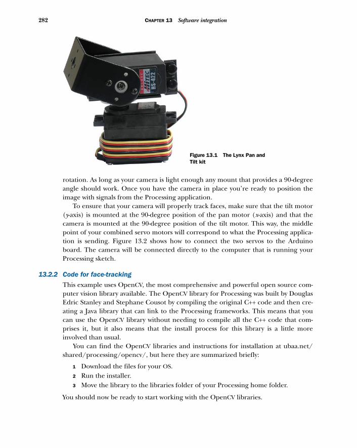
282 CHAPTER 13 Software integration
rotation. As long as your camera is light enough any mount that provides a 90-degreeangle should work. Once you have the camera in place you’re ready to position theimage with signals from the Processing application.
To ensure that your camera will properly track faces, make sure that the tilt motor(y-axis) is mounted at the 90-degree position of the pan motor (x-axis) and that thecamera is mounted at the 90-degree position of the tilt motor. This way, the middlepoint of your combined servo motors will correspond to what the Processing applica-tion is sending. Figure 13.2 shows how to connect the two servos to the Arduinoboard. The camera will be connected directly to the computer that is running yourProcessing sketch.
13.2.2 Code for face-tracking
This example uses OpenCV, the most comprehensive and powerful open source com-puter vision library available. The OpenCV library for Processing was built by DouglasEdric Stanley and Stephane Cousot by compiling the original C++ code and then cre-ating a Java library that can link to the Processing frameworks. This means that youcan use the OpenCV library without needing to compile all the C++ code that com-prises it, but it also means that the install process for this library is a little moreinvolved than usual.
You can find the OpenCV libraries and instructions for installation at ubaa.net/shared/processing/opencv/, but here they are summarized briefly:
1 Download the files for your OS.2 Run the installer.3 Move the library to the libraries folder of your Processing home folder.
You should now be ready to start working with the OpenCV libraries.
Figure 13.1 The Lynx Pan and Tilt kit
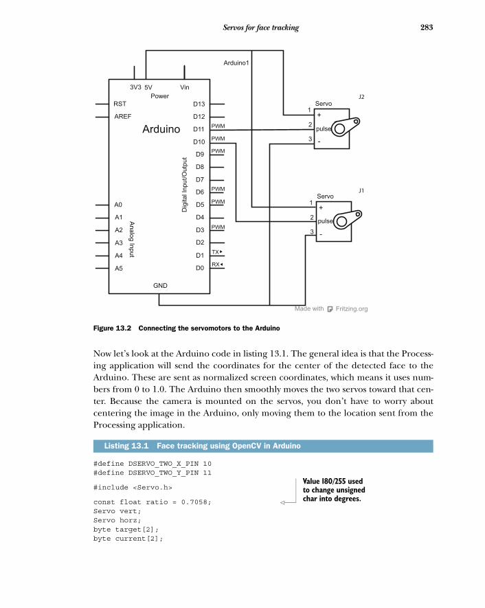
283Servos for face tracking
Now let’s look at the Arduino code in listing 13.1. The general idea is that the Process-ing application will send the coordinates for the center of the detected face to theArduino. These are sent as normalized screen coordinates, which means it uses num-bers from 0 to 1.0. The Arduino then smoothly moves the two servos toward that cen-ter. Because the camera is mounted on the servos, you don’t have to worry aboutcentering the image in the Arduino, only moving them to the location sent from theProcessing application.
#define DSERVO_TWO_X_PIN 10#define DSERVO_TWO_Y_PIN 11
#include <Servo.h>
const float ratio = 0.7058; Servo vert;Servo horz;byte target[2];byte current[2];
Listing 13.1 Face tracking using OpenCV in Arduino
pulse
Servo1
2
3
+
-
pulse
Servo1
2
3
+
-
Vin
Power
3V3 5V
RST
AREF
Arduino
Arduino1
D13
D12
D11
D10
D9
D8
D7
D6
D5
D4
D3
D2
D1
D0
GND
A0
A1
A2
A3
A4
A5
Analo
g In
put
Dig
ital In
put/O
utp
ut
PWM
PWM
PWM
PWM
PWM
PWM
TX
RX
J2
J1
Fritzing.orgMade with
Figure 13.2 Connecting the servomotors to the Arduino
Value 180/255 used to change unsigned char into degrees.
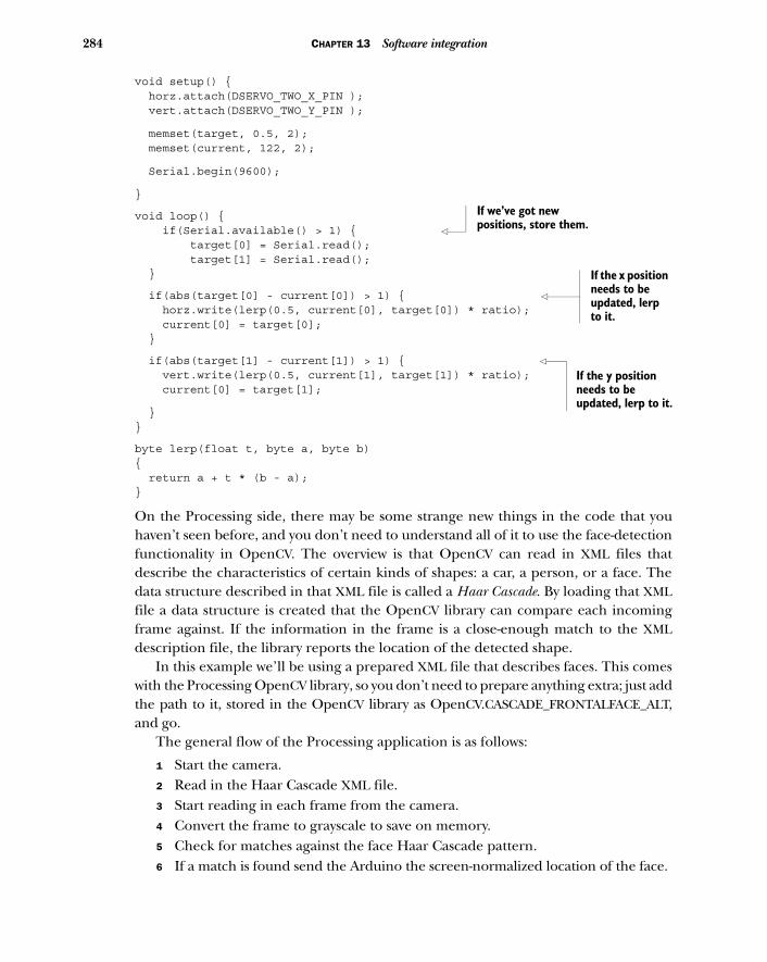
284 CHAPTER 13 Software integration
void setup() { horz.attach(DSERVO_TWO_X_PIN ); vert.attach(DSERVO_TWO_Y_PIN );
memset(target, 0.5, 2); memset(current, 122, 2);
Serial.begin(9600);
}
void loop() { if(Serial.available() > 1) { target[0] = Serial.read(); target[1] = Serial.read(); }
if(abs(target[0] - current[0]) > 1) { horz.write(lerp(0.5, current[0], target[0]) * ratio); current[0] = target[0]; }
if(abs(target[1] - current[1]) > 1) { vert.write(lerp(0.5, current[1], target[1]) * ratio); current[0] = target[1];
}}
byte lerp(float t, byte a, byte b){ return a + t * (b - a); }
On the Processing side, there may be some strange new things in the code that youhaven’t seen before, and you don’t need to understand all of it to use the face-detectionfunctionality in OpenCV. The overview is that OpenCV can read in XML files thatdescribe the characteristics of certain kinds of shapes: a car, a person, or a face. Thedata structure described in that XML file is called a Haar Cascade. By loading that XMLfile a data structure is created that the OpenCV library can compare each incomingframe against. If the information in the frame is a close-enough match to the XMLdescription file, the library reports the location of the detected shape.
In this example we’ll be using a prepared XML file that describes faces. This comeswith the Processing OpenCV library, so you don’t need to prepare anything extra; just addthe path to it, stored in the OpenCV library as OpenCV.CASCADE_FRONTALFACE_ALT,and go.
The general flow of the Processing application is as follows:
1 Start the camera.2 Read in the Haar Cascade XML file.3 Start reading in each frame from the camera.4 Convert the frame to grayscale to save on memory.5 Check for matches against the face Haar Cascade pattern.6 If a match is found send the Arduino the screen-normalized location of the face.
If we’ve got new positions, store them.
If the x position needs to be updated, lerp to it.
If the y position needs to be updated, lerp to it.
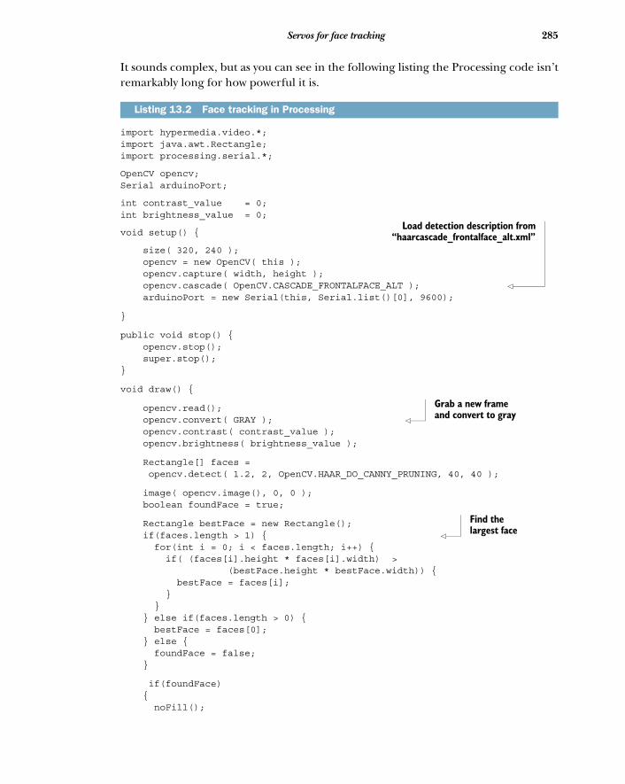
285Servos for face tracking
It sounds complex, but as you can see in the following listing the Processing code isn’tremarkably long for how powerful it is.
import hypermedia.video.*;import java.awt.Rectangle;import processing.serial.*;
OpenCV opencv;Serial arduinoPort;
int contrast_value = 0;int brightness_value = 0;
void setup() {
size( 320, 240 ); opencv = new OpenCV( this ); opencv.capture( width, height ); opencv.cascade( OpenCV.CASCADE_FRONTALFACE_ALT ); arduinoPort = new Serial(this, Serial.list()[0], 9600);
}
public void stop() { opencv.stop(); super.stop();}
void draw() {
opencv.read(); opencv.convert( GRAY ); opencv.contrast( contrast_value ); opencv.brightness( brightness_value );
Rectangle[] faces = opencv.detect( 1.2, 2, OpenCV.HAAR_DO_CANNY_PRUNING, 40, 40 );
image( opencv.image(), 0, 0 ); boolean foundFace = true;
Rectangle bestFace = new Rectangle(); if(faces.length > 1) { for(int i = 0; i < faces.length; i++) { if( (faces[i].height * faces[i].width) > (bestFace.height * bestFace.width)) { bestFace = faces[i]; } } } else if(faces.length > 0) { bestFace = faces[0]; } else { foundFace = false; }
if(foundFace) { noFill();
Listing 13.2 Face tracking in Processing
Load detection description from“haarcascade_frontalface_alt.xml”
Grab a new frame and convert to gray
Find the largest face
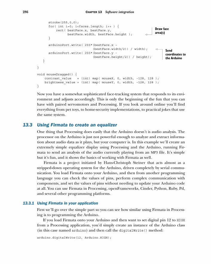
286 CHAPTER 13 Software integration
stroke(255,0,0); for( int i=0; i<faces.length; i++ ) { rect( bestFace.x, bestFace.y, bestFace.width, bestFace.height ); }
arduinoPort.write( 255*(bestFace.x – (bestFace.width/2)) / width); arduinoPort.write( 255*(bestFace.y – (bestFace.height/2)) / height); }
}
void mouseDragged() { contrast_value = (int) map( mouseX, 0, width, -128, 128 ); brightness_value = (int) map( mouseY, 0, width, -128, 128 );}
Now you have a somewhat sophisticated face-tracking system that responds to its envi-ronment and adjusts accordingly. This is only the beginning of the fun that you canhave with paired servomotors and Processing. If you look around online you’ll findeverything from pet toys, to home-security implementations, to practical jokes that usethe same system.
13.3 Using Firmata to create an equalizerOne thing that Processing does easily that the Arduino doesn’t is audio analysis. Theprocessor on the Arduino is just not powerful enough to analyze and extract informa-tion about audio data as it plays, but your computer is. In this example we’ll create anextremely simple equalizer display using Processing and the Arduino, running Fir-mata to send an analysis of the audio currently playing from an MP3 file. It’s simplebut it’s fun, and it shows the basics of working with Firmata as well.
Firmata is a project initiated by Hans-Christoph Steiner that acts almost as astripped-down operating system for the Arduino, driven completely by serial commu-nication. You load Firmata onto your Arduino, and then from another programminglanguage you can check the values of pins, perform complex communication withcomponents, and set the values of pins without needing to update your Arduino codeat all. You can use Firmata in Processing, openFrameworks, Cinder, Python, Ruby, Pd,and several other programming platforms.
13.3.1 Using Firmata in your application
First we’ll go over the simple part so you can see how similar using Firmata in Process-ing is to programming the Arduino.
If you load Firmata onto your Arduino and then want to set digital pin 12 to HIGHfrom a Processing application, you’d simply create an instance of the Arduino class(in this case named arduino) and then call the digitalWrite() method:
arduino.digitalWrite(12, Arduino.HIGH);
Draw face area(s)
Send coordinates to the Arduino
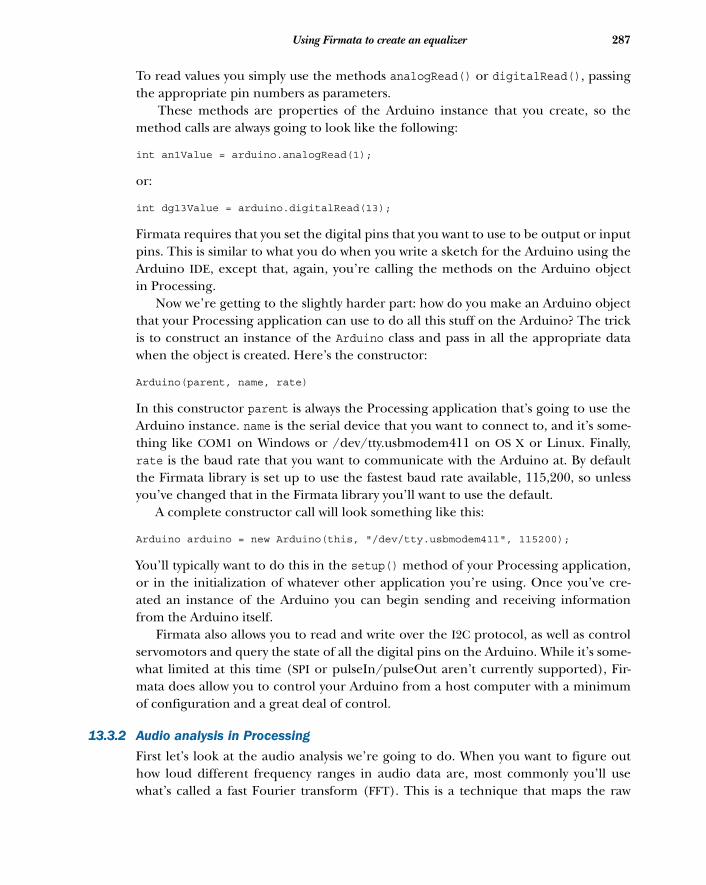
287Using Firmata to create an equalizer
To read values you simply use the methods analogRead() or digitalRead(), passingthe appropriate pin numbers as parameters.
These methods are properties of the Arduino instance that you create, so themethod calls are always going to look like the following:
int an1Value = arduino.analogRead(1);
or:
int dg13Value = arduino.digitalRead(13);
Firmata requires that you set the digital pins that you want to use to be output or inputpins. This is similar to what you do when you write a sketch for the Arduino using theArduino IDE, except that, again, you’re calling the methods on the Arduino objectin Processing.
Now we’re getting to the slightly harder part: how do you make an Arduino objectthat your Processing application can use to do all this stuff on the Arduino? The trickis to construct an instance of the Arduino class and pass in all the appropriate datawhen the object is created. Here’s the constructor:
Arduino(parent, name, rate)
In this constructor parent is always the Processing application that’s going to use theArduino instance. name is the serial device that you want to connect to, and it’s some-thing like COM1 on Windows or /dev/tty.usbmodem411 on OS X or Linux. Finally,rate is the baud rate that you want to communicate with the Arduino at. By defaultthe Firmata library is set up to use the fastest baud rate available, 115,200, so unlessyou’ve changed that in the Firmata library you’ll want to use the default.
A complete constructor call will look something like this:
Arduino arduino = new Arduino(this, "/dev/tty.usbmodem411", 115200);
You’ll typically want to do this in the setup() method of your Processing application,or in the initialization of whatever other application you’re using. Once you’ve cre-ated an instance of the Arduino you can begin sending and receiving informationfrom the Arduino itself.
Firmata also allows you to read and write over the I2C protocol, as well as controlservomotors and query the state of all the digital pins on the Arduino. While it’s some-what limited at this time (SPI or pulseIn/pulseOut aren’t currently supported), Fir-mata does allow you to control your Arduino from a host computer with a minimumof configuration and a great deal of control.
13.3.2 Audio analysis in Processing
First let’s look at the audio analysis we’re going to do. When you want to figure outhow loud different frequency ranges in audio data are, most commonly you’ll usewhat’s called a fast Fourier transform (FFT). This is a technique that maps the raw
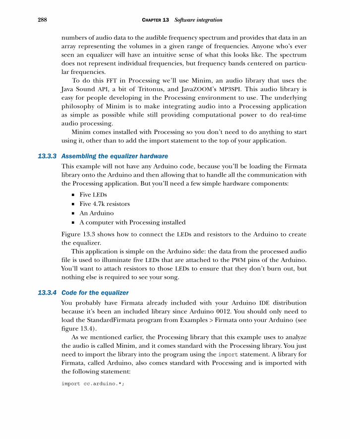
288 CHAPTER 13 Software integration
numbers of audio data to the audible frequency spectrum and provides that data in anarray representing the volumes in a given range of frequencies. Anyone who’s everseen an equalizer will have an intuitive sense of what this looks like. The spectrumdoes not represent individual frequencies, but frequency bands centered on particu-lar frequencies.
To do this FFT in Processing we’ll use Minim, an audio library that uses theJava Sound API, a bit of Tritonus, and JavaZOOM’s MP3SPI. This audio library iseasy for people developing in the Processing environment to use. The underlyingphilosophy of Minim is to make integrating audio into a Processing applicationas simple as possible while still providing computational power to do real-timeaudio processing.
Minim comes installed with Processing so you don’t need to do anything to startusing it, other than to add the import statement to the top of your application.
13.3.3 Assembling the equalizer hardware
This example will not have any Arduino code, because you’ll be loading the Firmatalibrary onto the Arduino and then allowing that to handle all the communication withthe Processing application. But you’ll need a few simple hardware components:
■ Five LEDs■ Five 4.7k resistors■ An Arduino■ A computer with Processing installed
Figure 13.3 shows how to connect the LEDs and resistors to the Arduino to createthe equalizer.
This application is simple on the Arduino side: the data from the processed audiofile is used to illuminate five LEDs that are attached to the PWM pins of the Arduino.You’ll want to attach resistors to those LEDs to ensure that they don’t burn out, butnothing else is required to see your song.
13.3.4 Code for the equalizer
You probably have Firmata already included with your Arduino IDE distributionbecause it’s been an included library since Arduino 0012. You should only need toload the StandardFirmata program from Examples > Firmata onto your Arduino (seefigure 13.4).
As we mentioned earlier, the Processing library that this example uses to analyzethe audio is called Minim, and it comes standard with the Processing library. You justneed to import the library into the program using the import statement. A library forFirmata, called Arduino, also comes standard with Processing and is imported withthe following statement:
import cc.arduino.*;
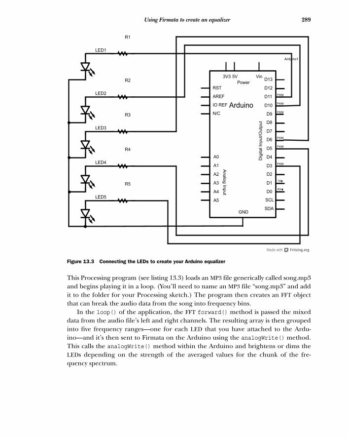
289Using Firmata to create an equalizer
This Processing program (see listing 13.3) loads an MP3 file generically called song.mp3and begins playing it in a loop. (You’ll need to name an MP3 file “song.mp3” and addit to the folder for your Processing sketch.) The program then creates an FFT objectthat can break the audio data from the song into frequency bins.
In the loop() of the application, the FFT forward() method is passed the mixeddata from the audio file’s left and right channels. The resulting array is then groupedinto five frequency ranges—one for each LED that you have attached to the Ardu-ino—and it’s then sent to Firmata on the Arduino using the analogWrite() method.This calls the analogWrite() method within the Arduino and brightens or dims theLEDs depending on the strength of the averaged values for the chunk of the fre-quency spectrum.
N/C
IO REF
SCL
SDA
RST
AREF
A0
A1
A2
A3
A4
A5
3V3 5V Vin
Analo
g In
put
D11
D10
D9
D8
D7
D6
D5
D4
D3PWM
TX
RX
PWM
PWM
PWM
PWM
PWM
D2
D1
D13
D12
D0
Dig
ital In
put/
Outp
ut
Power
Arduino
GND
LED1
LED2
LED3
LED4
LED5
R1
R5
R3
R4
R2
Arduino1
Figure 13.3 Connecting the LEDs to create your Arduino equalizer
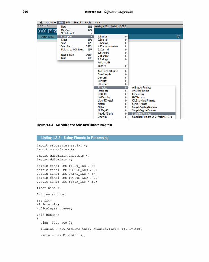
290 CHAPTER 13 Software integration
import processing.serial.*;import cc.arduino.*;
import ddf.minim.analysis.*;import ddf.minim.*;
static final int FIRST_LED = 3;static final int SECOND_LED = 5;static final int THIRD_LED = 6;static final int FOURTH_LED = 10;static final int FIFTH_LED = 11;
float bins[];
Arduino arduino;
FFT fft;Minim minim;AudioPlayer player;
void setup(){ size( 300, 300 );
arduino = new Arduino(this, Arduino.list()[0], 57600);
minim = new Minim(this);
Listing 13.3 Using Firmata in Processing
Figure 13.4 Selecting the StandardFirmata program
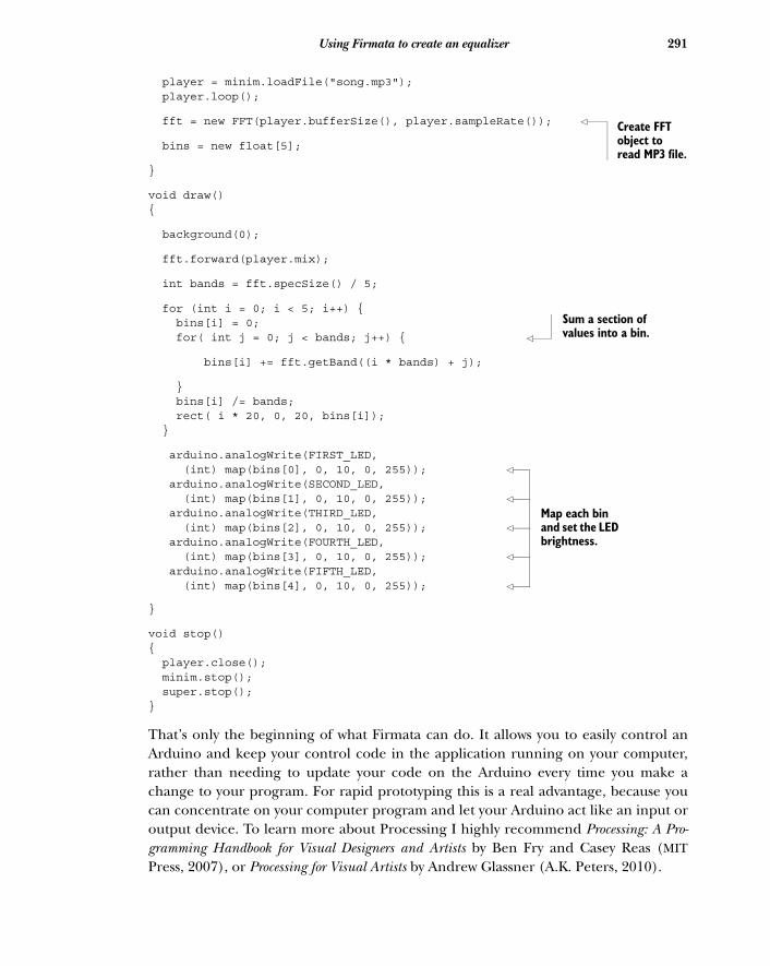
291Using Firmata to create an equalizer
player = minim.loadFile("song.mp3"); player.loop();
fft = new FFT(player.bufferSize(), player.sampleRate());
bins = new float[5];
}
void draw(){
background(0);
fft.forward(player.mix);
int bands = fft.specSize() / 5;
for (int i = 0; i < 5; i++) { bins[i] = 0; for( int j = 0; j < bands; j++) {
bins[i] += fft.getBand((i * bands) + j);
} bins[i] /= bands; rect( i * 20, 0, 20, bins[i]); }
arduino.analogWrite(FIRST_LED, (int) map(bins[0], 0, 10, 0, 255)); arduino.analogWrite(SECOND_LED, (int) map(bins[1], 0, 10, 0, 255)); arduino.analogWrite(THIRD_LED, (int) map(bins[2], 0, 10, 0, 255)); arduino.analogWrite(FOURTH_LED, (int) map(bins[3], 0, 10, 0, 255)); arduino.analogWrite(FIFTH_LED, (int) map(bins[4], 0, 10, 0, 255));
}
void stop(){ player.close(); minim.stop(); super.stop();}
That’s only the beginning of what Firmata can do. It allows you to easily control anArduino and keep your control code in the application running on your computer,rather than needing to update your code on the Arduino every time you make achange to your program. For rapid prototyping this is a real advantage, because youcan concentrate on your computer program and let your Arduino act like an input oroutput device. To learn more about Processing I highly recommend Processing: A Pro-gramming Handbook for Visual Designers and Artists by Ben Fry and Casey Reas (MITPress, 2007), or Processing for Visual Artists by Andrew Glassner (A.K. Peters, 2010).
Create FFT object to read MP3 file.
Sum a section of values into a bin.
Map each bin and set the LED brightness.
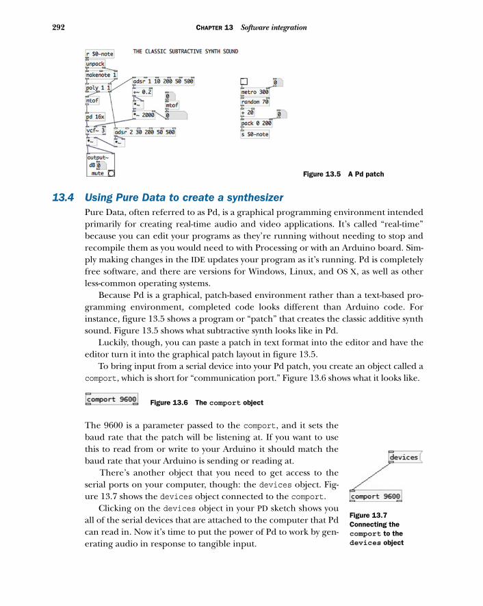
292 CHAPTER 13 Software integration
13.4 Using Pure Data to create a synthesizerPure Data, often referred to as Pd, is a graphical programming environment intendedprimarily for creating real-time audio and video applications. It’s called “real-time”because you can edit your programs as they’re running without needing to stop andrecompile them as you would need to with Processing or with an Arduino board. Sim-ply making changes in the IDE updates your program as it’s running. Pd is completelyfree software, and there are versions for Windows, Linux, and OS X, as well as otherless-common operating systems.
Because Pd is a graphical, patch-based environment rather than a text-based pro-gramming environment, completed code looks different than Arduino code. Forinstance, figure 13.5 shows a program or “patch” that creates the classic additive synthsound. Figure 13.5 shows what subtractive synth looks like in Pd.
Luckily, though, you can paste a patch in text format into the editor and have theeditor turn it into the graphical patch layout in figure 13.5.
To bring input from a serial device into your Pd patch, you create an object called acomport, which is short for “communication port.” Figure 13.6 shows what it looks like.
The 9600 is a parameter passed to the comport, and it sets thebaud rate that the patch will be listening at. If you want to usethis to read from or write to your Arduino it should match thebaud rate that your Arduino is sending or reading at.
There’s another object that you need to get access to theserial ports on your computer, though: the devices object. Fig-ure 13.7 shows the devices object connected to the comport.
Clicking on the devices object in your PD sketch shows youall of the serial devices that are attached to the computer that Pdcan read in. Now it’s time to put the power of Pd to work by gen-erating audio in response to tangible input.
Figure 13.5 A Pd patch
Figure 13.6 The comport object
Figure 13.7Connecting the comport to the devices object
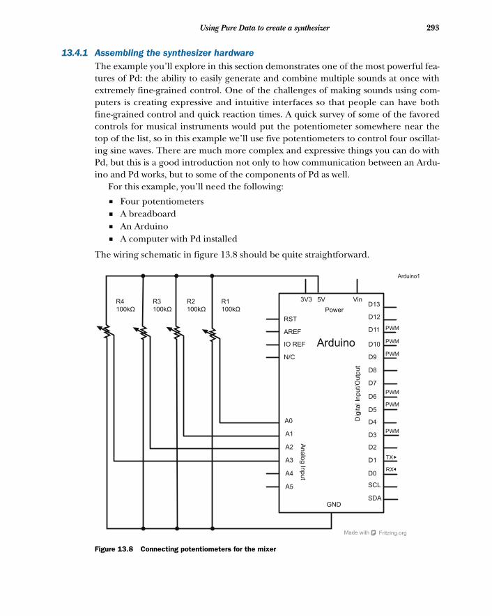
293Using Pure Data to create a synthesizer
13.4.1 Assembling the synthesizer hardwareThe example you’ll explore in this section demonstrates one of the most powerful fea-tures of Pd: the ability to easily generate and combine multiple sounds at once withextremely fine-grained control. One of the challenges of making sounds using com-puters is creating expressive and intuitive interfaces so that people can have bothfine-grained control and quick reaction times. A quick survey of some of the favoredcontrols for musical instruments would put the potentiometer somewhere near thetop of the list, so in this example we’ll use five potentiometers to control four oscillat-ing sine waves. There are much more complex and expressive things you can do withPd, but this is a good introduction not only to how communication between an Ardu-ino and Pd works, but to some of the components of Pd as well.
For this example, you’ll need the following:
■ Four potentiometers■ A breadboard■ An Arduino■ A computer with Pd installed
The wiring schematic in figure 13.8 should be quite straightforward.
Vin
Power
3V3 5V
RST
AREF
Arduino
D13
D12
D11
D10
D9
D8
D7
D6
D5
D4
D3
D2
D1
D0
GND
A0
A1
A2
A3
A4
A5
An
alo
g In
pu
t
Dig
ita
l In
pu
t/O
utp
ut
PWM
PWM
PWM
PWM
PWM
PWM
TX
RX
IO REF
N/C
SCL
SDA
Fritzing.orgMade with
Arduino1
R1
100kΩ
R3
100kΩ
R2
100kΩ
R4
100kΩ
Figure 13.8 Connecting potentiometers for the mixer
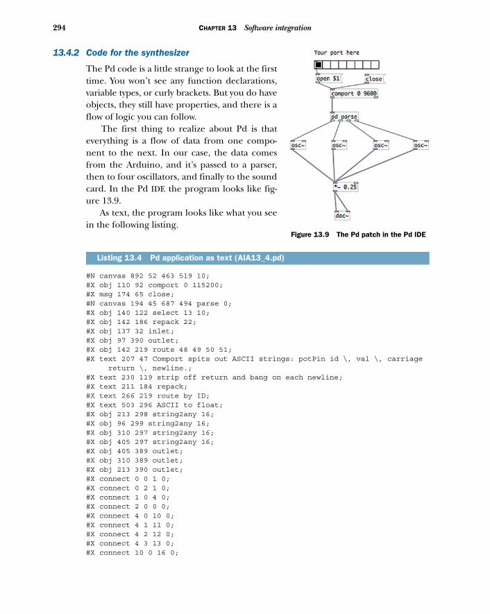
294 CHAPTER 13 Software integration
13.4.2 Code for the synthesizer
The Pd code is a little strange to look at the firsttime. You won’t see any function declarations,variable types, or curly brackets. But you do haveobjects, they still have properties, and there is aflow of logic you can follow.
The first thing to realize about Pd is thateverything is a flow of data from one compo-nent to the next. In our case, the data comesfrom the Arduino, and it’s passed to a parser,then to four oscillators, and finally to the soundcard. In the Pd IDE the program looks like fig-ure 13.9.
As text, the program looks like what you seein the following listing.
#N canvas 892 52 463 519 10;#X obj 110 92 comport 0 115200;#X msg 174 65 close;#N canvas 194 45 687 494 parse 0;#X obj 140 122 select 13 10;#X obj 142 186 repack 22;#X obj 137 32 inlet;#X obj 97 390 outlet;#X obj 142 219 route 48 49 50 51;#X text 207 47 Comport spits out ASCII strings: potPin id \, val \, carriage
return \, newline.;#X text 230 119 strip off return and bang on each newline;#X text 211 184 repack;#X text 266 219 route by ID;#X text 503 296 ASCII to float;#X obj 213 298 string2any 16;#X obj 96 299 string2any 16;#X obj 310 297 string2any 16;#X obj 405 297 string2any 16;#X obj 405 389 outlet;#X obj 310 389 outlet;#X obj 213 390 outlet;#X connect 0 0 1 0;#X connect 0 2 1 0;#X connect 1 0 4 0;#X connect 2 0 0 0;#X connect 4 0 10 0;#X connect 4 1 11 0;#X connect 4 2 12 0;#X connect 4 3 13 0;#X connect 10 0 16 0;
Listing 13.4 Pd application as text (AIA13_4.pd)
Figure 13.9 The Pd patch in the Pd IDE
295Using Pure Data to create a synthesizer
#X connect 11 0 3 0;#X connect 12 0 15 0;#X connect 13 0 14 0;#X restore 110 135 pd parse;#X text 78 16 Your port here;#X msg 83 64 open \$1;#X obj 80 40 hradio 15 1 0 8 empty empty empty 0 -8 0 10 -262144 -1-1 1;#X obj 118 319 dac~;#X obj 112 188 osc~;#X obj 36 188 osc~;#X obj 190 188 osc~;#X obj 264 188 osc~;#X obj 115 266 *~ 0.25;#X connect 0 0 2 0;#X connect 1 0 0 0;#X connect 2 0 8 0;#X connect 2 1 7 0;#X connect 2 2 9 0;#X connect 2 3 10 0;#X connect 4 0 0 0;#X connect 5 0 4 0;#X connect 7 0 11 0;#X connect 8 0 11 0;#X connect 9 0 11 0;#X connect 10 0 11 0;#X connect 11 0 6 0;#X connect 11 0 6 1;
On the Arduino side we’ll attach four potentiometers to control each of the oscilla-tors on the Pd side, and then we’ll read the values from each of them, as shown in thenext listing.
float val1,val2,val3,val4;
int potPin1 = 0; int potPin2 = 1;int potPin3 = 3; int potPin4 = 4;
void setup(){
Serial.begin(115200);}
void loop(){
val1 = analogRead(potPin1); Serial.print(potPin1); Serial.println(map(val1, 0, 1024, 200, 1000),DEC);
val2 = analogRead(potPin2); Serial.print(potPin2); Serial.println(map(val2, 0, 1024, 200, 1000),DEC);
Listing 13.5 Application to communicate with Pd
296 CHAPTER 13 Software integration
val3 = analogRead(potPin3); Serial.print(potPin3); Serial.println(map(val3, 0, 1024, 200, 1000),DEC);
val4 = analogRead(potPin4); Serial.print(potPin4); Serial.println(map(val4, 0, 1024, 200, 1000), DEC);
}
There’s not much to the Arduino side, but combined with the Pd application it allowsyou to create a rich range of sounds that can be closely tuned by the Arduino. Note thatthe data sent over the serial port is mapped between 200 and 1000, which ensuresthat the frequency of the sine wave is a little more palatable.
Using the Arduino with Pd is powerful because it allows musicians and DJs to cre-ate their own tangible interfaces to Pd and to their music. This means that you cannot only recreate interfaces that you may be familiar with, but also experiment withnew ways of physically inputting data and creating music.
To learn more about Pd I recommend that you look at the Pd tutorial site atwww.pd-tutorial.com.
13.5 Using Python to monitor temperaturesPython is one of the most popular programming languages—it’s flexible, powerful,and accessible. It has a remarkable number of libraries for doing everything fromgame development to applied mathematics to website development. It’s been underconstant development since 2001 and has steadily grown in popularity and capabilityover the years.
The example we’ll explore in this section revolves around a simple idea: what isthe temperature in discrete parts of a home at any given time? You could walk aroundwith a thermometer and figure this out, but it might be more fun and more practicalto place several thermometers around the house and send the temperature data asemail messages to your own email account. This example has the Arduino sleep untilit’s time to wake up (to save on power or battery), and upon waking, send a message tothe Python program. Once the Python application has received a message it parses itby room and then emails it off.
One thing to note is that this example assumes for the sake of brevity that you’reconnecting to an external SMTP server. You can get an SMTP server running on yourcomputer fairly easily, but the steps to do so are a little beyond the scope of this book,so we’ll leave it as an exercise for you to complete. Try searching around for “postfix”if you’re on OS X or Linux, or “enable smtp iis 7” if you’re on Windows.
13.5.1 The Serial library in Python
The Python library for serial communication is called pySerial, and you may need toexplicitly install it on your computer before beginning to work with serial communica-tion in a Python application. The library, along with installation instructions for youroperating system, can be found at http://pyserial.sourceforge.net.
297Using Python to monitor temperatures
Once you’ve installed the library you can load it into your program by putting thefollowing line at the beginning of your program:
import serial
Now it’s a matter of creating a serial instance:
arduino = serial.Serial( port='/dev/ttyUSB1', baudrate=9600,)
If you’re familiar with Python, the preceding line should look quite familiar. If you’renot, you might be wondering where the declaration of the Arduino variable is hidden.The answer is that there isn’t one. In Python you don’t need to give variables a typebefore starting to work with them, so the preceding line works fine.
Once you’ve made a Serial instance, given it a port to communicate on and abaud rate, and stored it in the arduino variable, the arduino variable is now aninstance of Serial. This is the long way of saying that a variable is only typed after ithas been constructed, not before. That might seem a bit bizarre, but it’s actually oneof the key affordances of Python. If you’re interested in learning more about Pythonand how it works check out http://python.org/. Now we’ll discuss more about how tointerface Python and the Arduino.
To start the serial communication you issue the following call:
arduino.open()
Note that this call to open() isn’t necessary if you haven’t closed the connection orreconnected a device.
To read from the serial port call read():
message = arduino.read(1)
The read() method takes an integer that dictates how many bytes you want to readfrom the serial port. The preceding example reads 1 byte.
You might wonder how you can read everything that’s in the serial channel.There’s a handy method to determine whether the Arduino has sent anything to theserial port: inWaiting(). To get all the data in the serial port, do something likethe following:
while arduino.inWaiting() > 0: message = arduino.read(1)print message
That’s all there is to it. To send a message to the Arduino over the serial channel usewrite():
arduino.write('x')
Clearing the serial buffer is as easy as calling flush():
arduino.flush()
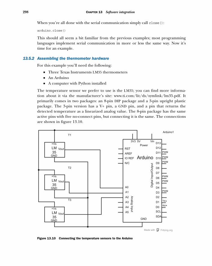
298 CHAPTER 13 Software integration
When you’re all done with the serial communication simply call close():
arduino.close()
This should all seem a bit familiar from the previous examples; most programminglanguages implement serial communication in more or less the same way. Now it’stime for an example.
13.5.2 Assembling the thermometer hardware
For this example you’ll need the following:
■ Three Texas Instruments LM35 thermometers■ An Arduino■ A computer with Python installed
The temperature sensor we prefer to use is the LM35; you can find more informa-tion about it via the manufacturer’s site: www.ti.com/lit/ds/symlink/lm35.pdf. Itprimarily comes in two packages: an 8-pin DIP package and a 3-pin upright plasticpackage. The 3-pin version has a V+ pin, a GND pin, and a pin that returns thedetected temperature as a linearized analog value. The 8-pin package has the sameactive pins with five no-connect pins, but connecting it is the same. The connectionsare shown in figure 13.10.
Vin
Power
3V3 5V
RST
AREF
Arduino
Arduino1
D13
D12
D11
D10
D9
D8
D7
D6
D5
D4
D3
D2
D1
D0
GND
A0
A1
A2
A3
A4
A5
Analo
g In
put
Dig
ital In
put/O
utp
ut
PWM
PWM
PWM
PWM
PWM
PWM
TX
RX
IO REF
N/C
SCL
SDA
Fritzing.orgMade with
+Vs
LM
35GND
Vout
+Vs
LM
35GND
Vout
+Vs
LM
35GND
Vout
T1
T2
T3
Figure 13.10 Connecting the temperature sensors to the Arduino
299Using Python to monitor temperatures
13.5.3 Code for monitoring temperatures
The Arduino code contains no big surprises, though you do need to convert the volt-age returned from the analogIn() method to correctly get the temperature in Cel-sius. That’s done in the convertToCelsius() method at the end of the followinglisting. (To convert to Fahrenheit, simply add 32 and multiply by 1.8.)
const int LIVING_ROOM = 1;const int BEDROOM = 2;const int KITCHEN = 3;
void setup(){ Serial.begin(57600);}
void loop(){ if(Serial.available() > 0) { Serial.print(LIVING_ROOM); Serial.print(','); Serial.print(convertToCelsius (LIVING_ROOM)); Serial.print(';'); Serial.print(BEDROOM); Serial.print(','); Serial.print(convertToCelsius (BEDROOM)); Serial.print(';'); Serial.print(KITCHEN); Serial.print(','); Serial.print(convertToCelsius (KITCHEN)); Serial.print(';'); }}
int convertToCelsius(int pin){ return (5.0 * analogRead(pin) * 100.0)/1024.0;}
The Python application sleeps for 15 minutes and then sends a message to tell theArduino to query its LM35 sensors and return their values (see the following listing).Once all of the data is read in from the Arduino, an email detailing the detected tem-peratures is sent to the user’s address using the user’s mail server to connect to theSMTP server.
import smtplibimport timeimport serial
SERVER = "smtp.somemail.com:587"
Listing 13.6 Arduino application to send temperature data to Python
Listing 13.7 Python application to receive temperature data
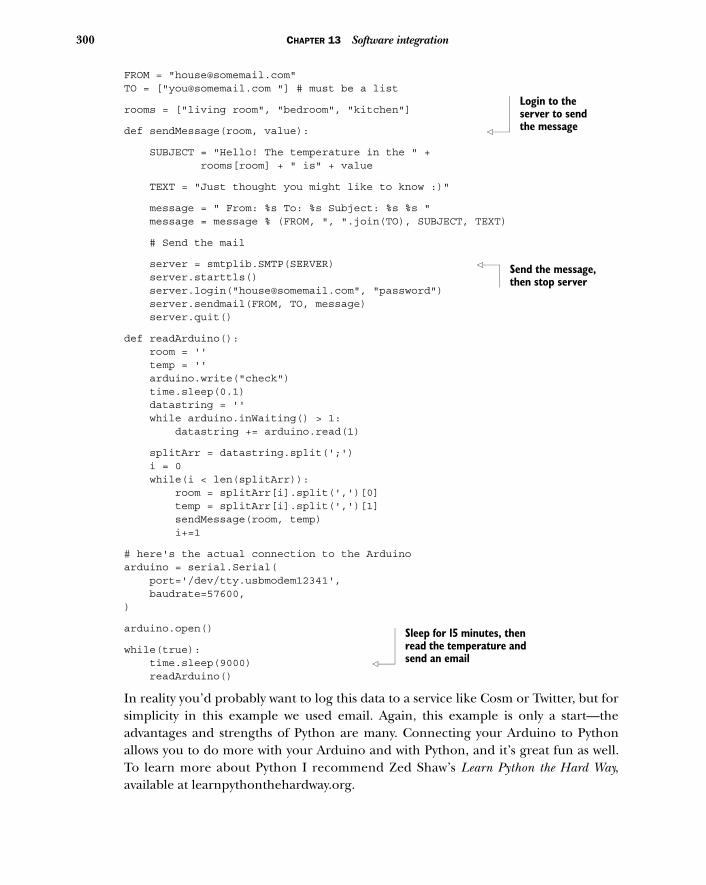
300 CHAPTER 13 Software integration
FROM = "[email protected]"TO = ["[email protected] "] # must be a list
rooms = ["living room", "bedroom", "kitchen"]
def sendMessage(room, value):
SUBJECT = "Hello! The temperature in the " + rooms[room] + " is" + value
TEXT = "Just thought you might like to know :)"
message = " From: %s To: %s Subject: %s %s " message = message % (FROM, ", ".join(TO), SUBJECT, TEXT)
# Send the mail
server = smtplib.SMTP(SERVER) server.starttls() server.login("[email protected]", "password") server.sendmail(FROM, TO, message) server.quit()
def readArduino(): room = '' temp = '' arduino.write("check") time.sleep(0.1) datastring = '' while arduino.inWaiting() > 1: datastring += arduino.read(1)
splitArr = datastring.split(';') i = 0 while(i < len(splitArr)): room = splitArr[i].split(',')[0] temp = splitArr[i].split(',')[1] sendMessage(room, temp) i+=1
# here's the actual connection to the Arduinoarduino = serial.Serial( port='/dev/tty.usbmodem12341', baudrate=57600,)
arduino.open()
while(true): time.sleep(9000) readArduino()
In reality you’d probably want to log this data to a service like Cosm or Twitter, but forsimplicity in this example we used email. Again, this example is only a start—theadvantages and strengths of Python are many. Connecting your Arduino to Pythonallows you to do more with your Arduino and with Python, and it’s great fun as well.To learn more about Python I recommend Zed Shaw’s Learn Python the Hard Way,available at learnpythonthehardway.org.
Login to the server to send the message
Send the message, then stop server
Sleep for 15 minutes, then read the temperature and send an email

301Summary
13.6 SummaryIntegrating your Arduino with software allows you to easily create physical input andfeedback for an application running on a larger computer, like a desktop or a laptopcomputer. This means you can extend the functionality of an application into tangibleand physical interaction easily, as well as vastly extending the capacity of the Arduinoto perform image or audio processing, networked communication, or graphics.
appendix AInstalling
the Arduino IDE
This appendix details how to install the Arduino IDE on the Windows, Mac OS X,and Linux platforms. The Arduino IDE for all platforms is available from the Ardu-ino website (http://arduino.cc/en/Main/Software). Download the IDE packagefor your platform and continue with the appropriate installation section for youroperating system.
A.1 WindowsArduino for Windows comes packaged as a zip file, so once it’s downloaded youmust first extract its contents. Browse to where you downloaded the file (typicallyyour User/Downloads folder) and double-click the zip file. As shown in figure A.1,extract or drag the containing folder to somewhere accessible on your hard drive,such as C:\Program Files.
A.1.1 Installing drivers for your board
Now that you have the Arduino package copied to your computer, you’re ready toinstall the drivers for your board. Follow the instructions in the appropriate subsec-tion for the board and version of Windows that you’re using.
DRIVER INSTALLATION FOR THE ARDUINO UNO
To begin the driver installation process, connect your Arduino Uno to the com-puter using a USB cable. The Uno board is USB-powered, so the green ON LED willlight up. Once connected, Windows will attempt to install the board’s drivers, but itwill fail. This is OK!
In the Windows Start menu, select Control Panel > System and Security > System> Device Manager. Next, click and expand Ports (COM & LPT). Your Uno should
302
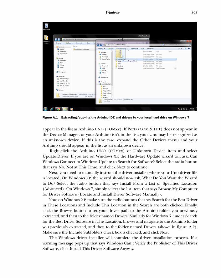
303Windows
appear in the list as Arduino UNO (COMxx). If Ports (COM & LPT) does not appear inthe Device Manager, or your Arduino isn’t in the list, your Uno may be recognized asan unknown device. If this is the case, expand the Other Devices menu and yourArduino should appear in the list as an unknown device.
Right-click the Arduino UNO (COMxx) or Unknown Device item and selectUpdate Driver. If you are on Windows XP, the Hardware Update wizard will ask, CanWindows Connect to Windows Update to Search for Software? Select the radio buttonthat says No, Not at This Time, and click Next to continue.
Next, you need to manually instruct the driver installer where your Uno driver fileis located. On Windows XP, the wizard should now ask, What Do You Want the Wizardto Do? Select the radio button that says Install From a List or Specified Location(Advanced). On Windows 7, simply select the list item that says Browse My Computerfor Driver Software (Locate and Install Driver Software Manually).
Now, on Windows XP, make sure the radio buttons that say Search for the Best Driverin These Locations and Include This Location in the Search are both clicked. Finally,click the Browse button to set your driver path to the Arduino folder you previouslyextracted, and then to the folder named Drivers. Similarly for Windows 7, under Searchfor the Best Driver Software in This Location, browse and navigate to the Arduino folderyou previously extracted, and then to the folder named Drivers (shown in figure A.2).Make sure the Include Subfolders check box is checked, and click Next.
The Windows driver installer will complete the driver installation process. If awarning message pops up that says Windows Can’t Verify the Publisher of This DriverSoftware, click Install This Driver Software Anyway.
Figure A.1 Extracting/copying the Arduino IDE and drivers to your local hard drive on Windows 7
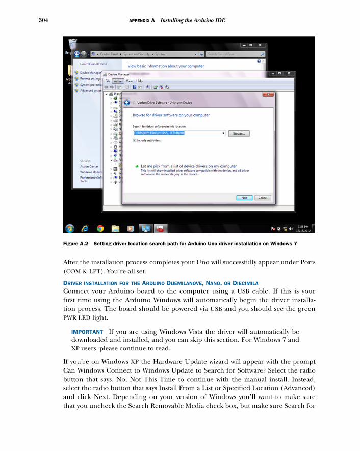
304 APPENDIX A Installing the Arduino IDE
After the installation process completes your Uno will successfully appear under Ports(COM & LPT). You’re all set.
DRIVER INSTALLATION FOR THE ARDUINO DUEMILANOVE, NANO, OR DIECIMILA
Connect your Arduino board to the computer using a USB cable. If this is yourfirst time using the Arduino Windows will automatically begin the driver installa-tion process. The board should be powered via USB and you should see the greenPWR LED light.
IMPORTANT If you are using Windows Vista the driver will automatically bedownloaded and installed, and you can skip this section. For Windows 7 andXP users, please continue to read.
If you’re on Windows XP the Hardware Update wizard will appear with the promptCan Windows Connect to Windows Update to Search for Software? Select the radiobutton that says, No, Not This Time to continue with the manual install. Instead,select the radio button that says Install From a List or Specified Location (Advanced)and click Next. Depending on your version of Windows you’ll want to make surethat you uncheck the Search Removable Media check box, but make sure Search for
Figure A.2 Setting driver location search path for Arduino Uno driver installation on Windows 7
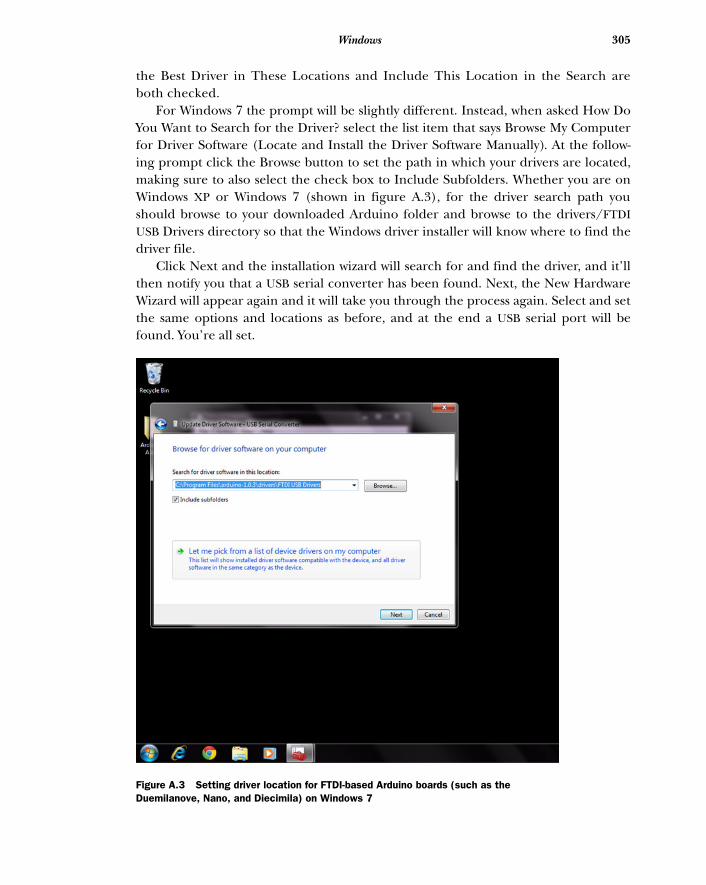
305Windows
the Best Driver in These Locations and Include This Location in the Search areboth checked.
For Windows 7 the prompt will be slightly different. Instead, when asked How DoYou Want to Search for the Driver? select the list item that says Browse My Computerfor Driver Software (Locate and Install the Driver Software Manually). At the follow-ing prompt click the Browse button to set the path in which your drivers are located,making sure to also select the check box to Include Subfolders. Whether you are onWindows XP or Windows 7 (shown in figure A.3), for the driver search path youshould browse to your downloaded Arduino folder and browse to the drivers/FTDIUSB Drivers directory so that the Windows driver installer will know where to find thedriver file.
Click Next and the installation wizard will search for and find the driver, and it’llthen notify you that a USB serial converter has been found. Next, the New HardwareWizard will appear again and it will take you through the process again. Select and setthe same options and locations as before, and at the end a USB serial port will befound. You’re all set.
Figure A.3 Setting driver location for FTDI-based Arduino boards (such as the Duemilanove, Nano, and Diecimila) on Windows 7
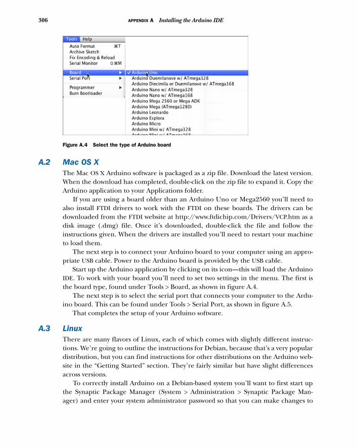
306 APPENDIX A Installing the Arduino IDE
A.2 Mac OS XThe Mac OS X Arduino software is packaged as a zip file. Download the latest version.When the download has completed, double-click on the zip file to expand it. Copy theArduino application to your Applications folder.
If you are using a board older than an Arduino Uno or Mega2560 you’ll need toalso install FTDI drivers to work with the FTDI on these boards. The drivers can bedownloaded from the FTDI website at http://www.ftdichip.com/Drivers/VCP.htm as adisk image (.dmg) file. Once it’s downloaded, double-click the file and follow theinstructions given. When the drivers are installed you’ll need to restart your machineto load them.
The next step is to connect your Arduino board to your computer using an appro-priate USB cable. Power to the Arduino board is provided by the USB cable.
Start up the Arduino application by clicking on its icon—this will load the ArduinoIDE. To work with your board you’ll need to set two settings in the menu. The first isthe board type, found under Tools > Board, as shown in figure A.4.
The next step is to select the serial port that connects your computer to the Ardu-ino board. This can be found under Tools > Serial Port, as shown in figure A.5.
That completes the setup of your Arduino software.
A.3 LinuxThere are many flavors of Linux, each of which comes with slightly different instruc-tions. We’re going to outline the instructions for Debian, because that’s a very populardistribution, but you can find instructions for other distributions on the Arduino web-site in the “Getting Started” section. They’re fairly similar but have slight differencesacross versions.
To correctly install Arduino on a Debian-based system you’ll want to first start upthe Synaptic Package Manager (System > Administration > Synaptic Package Man-ager) and enter your system administrator password so that you can make changes to
Figure A.4 Select the type of Arduino board
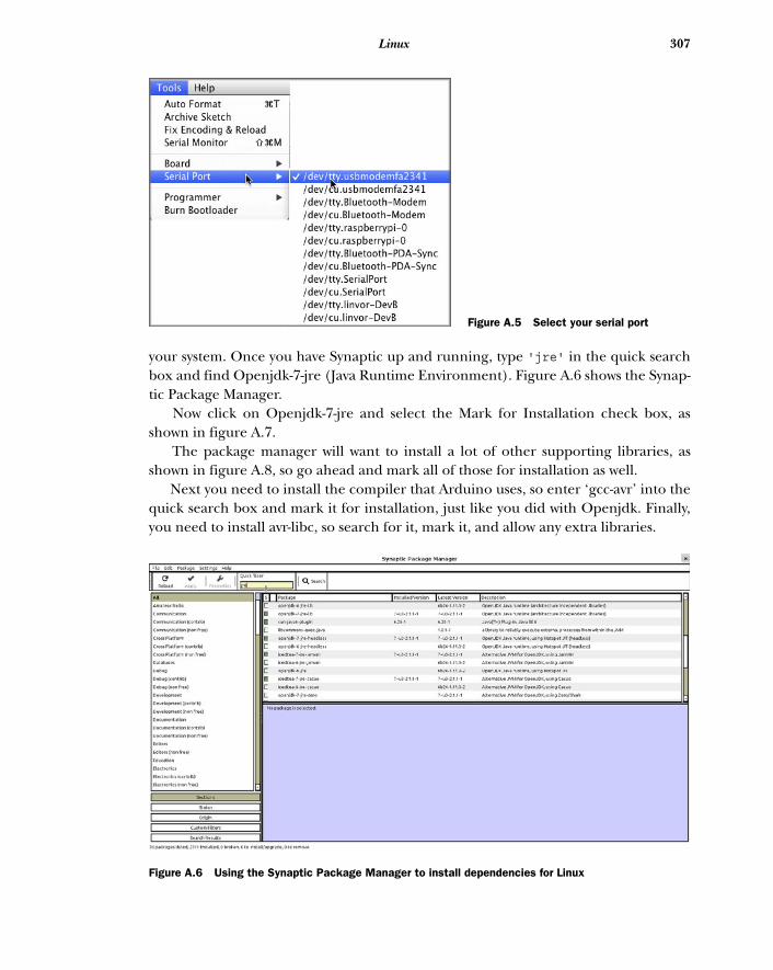
307Linux
your system. Once you have Synaptic up and running, type 'jre' in the quick searchbox and find Openjdk-7-jre (Java Runtime Environment). Figure A.6 shows the Synap-tic Package Manager.
Now click on Openjdk-7-jre and select the Mark for Installation check box, asshown in figure A.7.
The package manager will want to install a lot of other supporting libraries, asshown in figure A.8, so go ahead and mark all of those for installation as well.
Next you need to install the compiler that Arduino uses, so enter ‘gcc-avr’ into thequick search box and mark it for installation, just like you did with Openjdk. Finally,you need to install avr-libc, so search for it, mark it, and allow any extra libraries.
Figure A.5 Select your serial port
Figure A.6 Using the Synaptic Package Manager to install dependencies for Linux
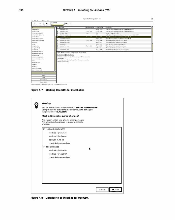
308 APPENDIX A Installing the Arduino IDE
Figure A.7 Marking OpenJDK for installation
Figure A.8 Libraries to be installed for OpenJDK
309Linux
Now you’re done with Synaptic, so you can close it down. You might also need torestart your computer, particularly if you’re on Ubuntu, to make sure all the changesyou’ve made have percolated through your system. Even if you’re not on Ubunturestarting is a good idea to ensure that the new libraries you’ve added can be found.
Now you can go ahead and download the Arduino IDE from the website and unzipit to a friendly location on your computer. You should now be able to run the ArduinoIDE and use it to program and communicate with your Arduino boards in the sameway as the other operating systems in this appendix.
appendix BCoding primer
This coding primer is a basic guide to the Arduino language and how it’s used tocreate sketches that can be run on an Arduino. We’ll cover the following topics:
■ History of the Arduino language■ Using variables■ Using control statements■ Using loops■ Using functions
B.1 The Arduino languageThe Arduino language is based on C/C++, and anyone who has previously studiedC or C++ will readily be able to read the written code. If you haven’t studied C orC++ before, don’t worry. The Arduino language was designed to make coding aspainless as possible, allowing you to concentrate on what can be done rather thanhow it’s done.
History of the Arduino languageStudents at the Interactive Design Institute, Ivrea, the original home of Arduino,were taught to program using a language called Processing. The Processing designphilosophy is to teach the fundamentals of programming within a visual context,and the Arduino team, realizing they needed to develop a language that made theprototyping of ideas as simple as possible, adopted a similar philosophy.
The decision was made to use the Processing IDE as the model for the ArduinoIDE, because the original Arduino system was aimed at art and design studentswho were already familiar with Processing. The close links to Processing are stillevident today, and any improvements made to the Processing IDE can be directlyimported into the Arduino system.
310
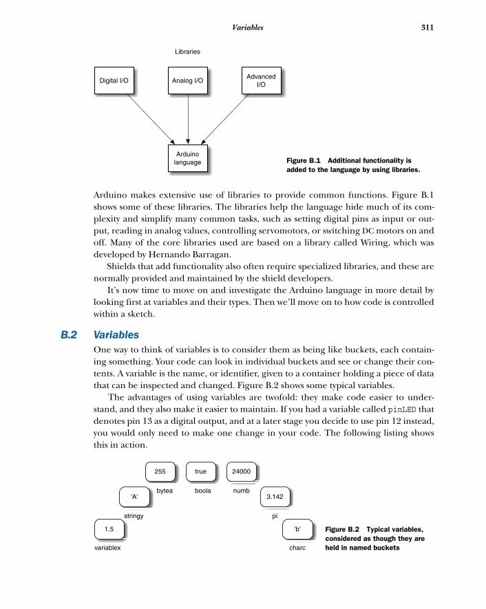
311Variables
Arduino makes extensive use of libraries to provide common functions. Figure B.1shows some of these libraries. The libraries help the language hide much of its com-plexity and simplify many common tasks, such as setting digital pins as input or out-put, reading in analog values, controlling servomotors, or switching DC motors on andoff. Many of the core libraries used are based on a library called Wiring, which wasdeveloped by Hernando Barragan.
Shields that add functionality also often require specialized libraries, and these arenormally provided and maintained by the shield developers.
It’s now time to move on and investigate the Arduino language in more detail bylooking first at variables and their types. Then we’ll move on to how code is controlledwithin a sketch.
B.2 VariablesOne way to think of variables is to consider them as being like buckets, each contain-ing something. Your code can look in individual buckets and see or change their con-tents. A variable is the name, or identifier, given to a container holding a piece of datathat can be inspected and changed. Figure B.2 shows some typical variables.
The advantages of using variables are twofold: they make code easier to under-stand, and they also make it easier to maintain. If you had a variable called pinLED thatdenotes pin 13 as a digital output, and at a later stage you decide to use pin 12 instead,you would only need to make one change in your code. The following listing showsthis in action.
Arduinolanguage
Digital I/O Analog I/OAdvanced
I/O
Libraries
Figure B.1 Additional functionality is added to the language by using libraries.
1.5
'A'
255
'b'
24000
3.142
true
variablex
stringy
bytea boola numb
pi
charc
Figure B.2 Typical variables, considered as though they are held in named buckets
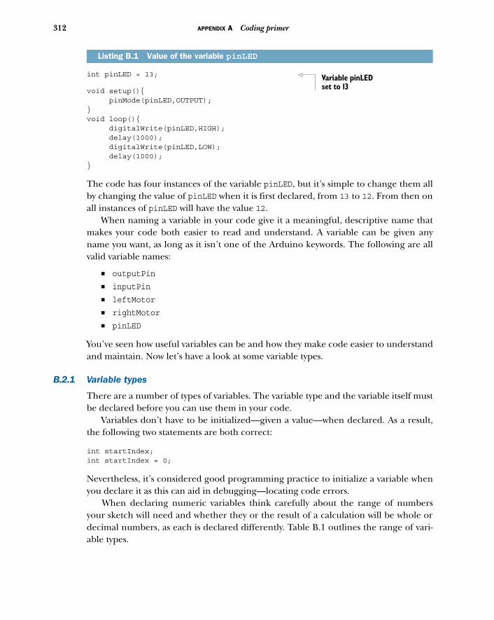
312 APPENDIX A Coding primer
int pinLED = 13;
void setup(){ pinMode(pinLED,OUTPUT);}void loop(){ digitalWrite(pinLED,HIGH); delay(1000); digitalWrite(pinLED,LOW); delay(1000);}
The code has four instances of the variable pinLED, but it’s simple to change them allby changing the value of pinLED when it is first declared, from 13 to 12. From then onall instances of pinLED will have the value 12.
When naming a variable in your code give it a meaningful, descriptive name thatmakes your code both easier to read and understand. A variable can be given anyname you want, as long as it isn’t one of the Arduino keywords. The following are allvalid variable names:
■ outputPin
■ inputPin
■ leftMotor
■ rightMotor
■ pinLED
You’ve seen how useful variables can be and how they make code easier to understandand maintain. Now let’s have a look at some variable types.
B.2.1 Variable types
There are a number of types of variables. The variable type and the variable itself mustbe declared before you can use them in your code.
Variables don’t have to be initialized—given a value—when declared. As a result,the following two statements are both correct:
int startIndex;int startIndex = 0;
Nevertheless, it’s considered good programming practice to initialize a variable whenyou declare it as this can aid in debugging—locating code errors.
When declaring numeric variables think carefully about the range of numbersyour sketch will need and whether they or the result of a calculation will be whole ordecimal numbers, as each is declared differently. Table B.1 outlines the range of vari-able types.
Listing B.1 Value of the variable pinLED
Variable pinLED set to 13
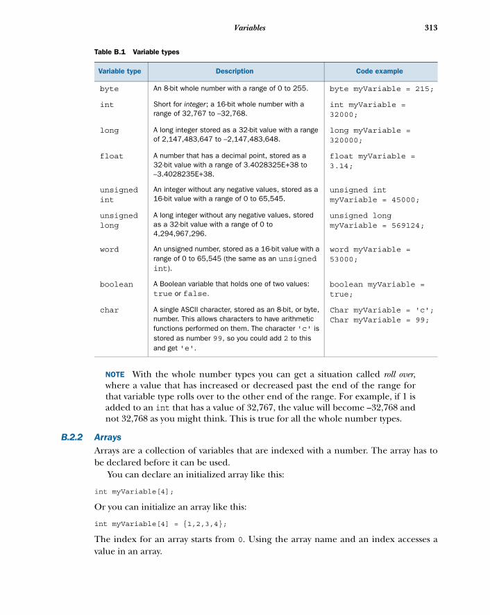
313Variables
NOTE With the whole number types you can get a situation called roll over,where a value that has increased or decreased past the end of the range forthat variable type rolls over to the other end of the range. For example, if 1 isadded to an int that has a value of 32,767, the value will become –32,768 andnot 32,768 as you might think. This is true for all the whole number types.
B.2.2 ArraysArrays are a collection of variables that are indexed with a number. The array has tobe declared before it can be used.
You can declare an initialized array like this:
int myVariable[4];
Or you can initialize an array like this:
int myVariable[4] = {1,2,3,4};
The index for an array starts from 0. Using the array name and an index accesses avalue in an array.
Table B.1 Variable types
Variable type Description Code example
byte An 8-bit whole number with a range of 0 to 255. byte myVariable = 215;
int Short for integer; a 16-bit whole number with a range of 32,767 to –32,768.
int myVariable = 32000;
long A long integer stored as a 32-bit value with a range of 2,147,483,647 to –2,147,483,648.
long myVariable = 320000;
float A number that has a decimal point, stored as a 32-bit value with a range of 3.4028325E+38 to –3.4028235E+38.
float myVariable = 3.14;
unsigned int
An integer without any negative values, stored as a 16-bit value with a range of 0 to 65,545.
unsigned int myVariable = 45000;
unsigned long
A long integer without any negative values, stored as a 32-bit value with a range of 0 to 4,294,967,296.
unsigned long myVariable = 569124;
word An unsigned number, stored as a 16-bit value with a range of 0 to 65,545 (the same as an unsigned int).
word myVariable = 53000;
boolean A Boolean variable that holds one of two values: true or false.
boolean myVariable = true;
char A single ASCII character, stored as an 8-bit, or byte, number. This allows characters to have arithmetic functions performed on them. The character 'c' is stored as number 99, so you could add 2 to this and get 'e'.
Char myVariable = 'c';Char myVariable = 99;
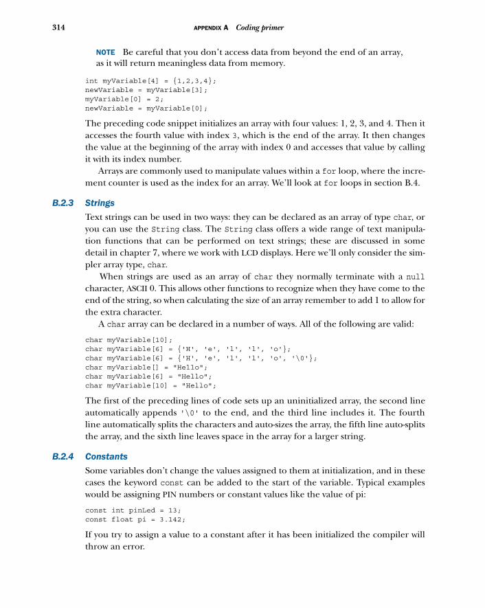
314 APPENDIX A Coding primer
NOTE Be careful that you don’t access data from beyond the end of an array,as it will return meaningless data from memory.
int myVariable[4] = {1,2,3,4}; newVariable = myVariable[3]; myVariable[0] = 2; newVariable = myVariable[0];
The preceding code snippet initializes an array with four values: 1, 2, 3, and 4. Then itaccesses the fourth value with index 3, which is the end of the array. It then changesthe value at the beginning of the array with index 0 and accesses that value by callingit with its index number.
Arrays are commonly used to manipulate values within a for loop, where the incre-ment counter is used as the index for an array. We’ll look at for loops in section B.4.
B.2.3 Strings
Text strings can be used in two ways: they can be declared as an array of type char, oryou can use the String class. The String class offers a wide range of text manipula-tion functions that can be performed on text strings; these are discussed in somedetail in chapter 7, where we work with LCD displays. Here we’ll only consider the sim-pler array type, char.
When strings are used as an array of char they normally terminate with a nullcharacter, ASCII 0. This allows other functions to recognize when they have come to theend of the string, so when calculating the size of an array remember to add 1 to allow forthe extra character.
A char array can be declared in a number of ways. All of the following are valid:
char myVariable[10]; char myVariable[6] = {'H', 'e', 'l', 'l', 'o'}; char myVariable[6] = {'H', 'e', 'l', 'l', 'o', '\0'}; char myVariable[] = "Hello"; char myVariable[6] = "Hello"; char myVariable[10] = "Hello";
The first of the preceding lines of code sets up an uninitialized array, the second lineautomatically appends '\0' to the end, and the third line includes it. The fourthline automatically splits the characters and auto-sizes the array, the fifth line auto-splitsthe array, and the sixth line leaves space in the array for a larger string.
B.2.4 Constants
Some variables don’t change the values assigned to them at initialization, and in thesecases the keyword const can be added to the start of the variable. Typical exampleswould be assigning PIN numbers or constant values like the value of pi:
const int pinLed = 13;const float pi = 3.142;
If you try to assign a value to a constant after it has been initialized the compiler willthrow an error.
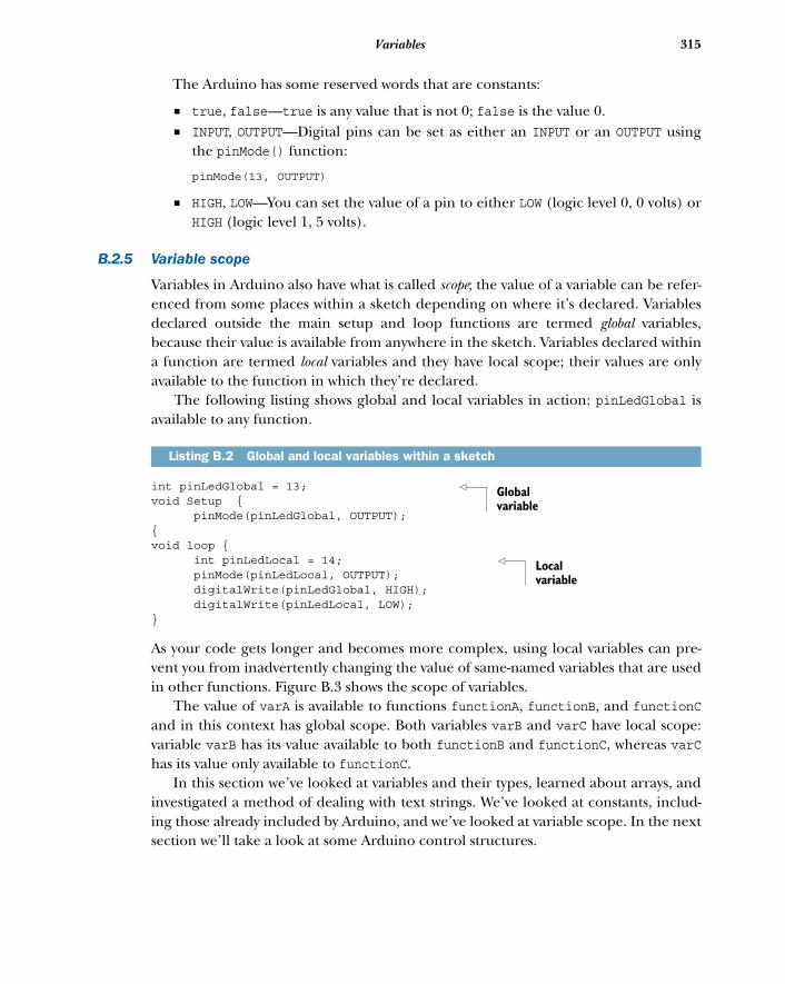
315Variables
The Arduino has some reserved words that are constants:
■ true, false—true is any value that is not 0; false is the value 0.■ INPUT, OUTPUT—Digital pins can be set as either an INPUT or an OUTPUT using
the pinMode() function:
pinMode(13, OUTPUT)
■ HIGH, LOW—You can set the value of a pin to either LOW (logic level 0, 0 volts) orHIGH (logic level 1, 5 volts).
B.2.5 Variable scope
Variables in Arduino also have what is called scope; the value of a variable can be refer-enced from some places within a sketch depending on where it’s declared. Variablesdeclared outside the main setup and loop functions are termed global variables,because their value is available from anywhere in the sketch. Variables declared withina function are termed local variables and they have local scope; their values are onlyavailable to the function in which they’re declared.
The following listing shows global and local variables in action: pinLedGlobal isavailable to any function.
int pinLedGlobal = 13; void Setup { pinMode(pinLedGlobal, OUTPUT);{void loop { int pinLedLocal = 14; pinMode(pinLedLocal, OUTPUT); digitalWrite(pinLedGlobal, HIGH); digitalWrite(pinLedLocal, LOW);}
As your code gets longer and becomes more complex, using local variables can pre-vent you from inadvertently changing the value of same-named variables that are usedin other functions. Figure B.3 shows the scope of variables.
The value of varA is available to functions functionA, functionB, and functionCand in this context has global scope. Both variables varB and varC have local scope:variable varB has its value available to both functionB and functionC, whereas varChas its value only available to functionC.
In this section we’ve looked at variables and their types, learned about arrays, andinvestigated a method of dealing with text strings. We’ve looked at constants, includ-ing those already included by Arduino, and we’ve looked at variable scope. In the nextsection we’ll take a look at some Arduino control structures.
Listing B.2 Global and local variables within a sketch
Global variable
Local variable
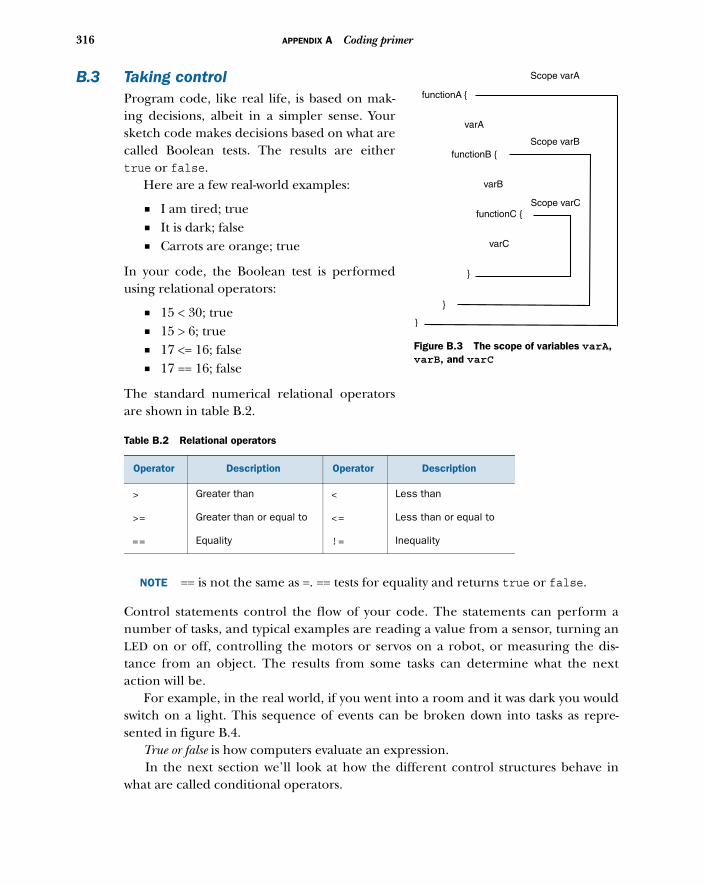
316 APPENDIX A Coding primer
B.3 Taking controlProgram code, like real life, is based on mak-ing decisions, albeit in a simpler sense. Yoursketch code makes decisions based on what arecalled Boolean tests. The results are eithertrue or false.
Here are a few real-world examples:
■ I am tired; true■ It is dark; false■ Carrots are orange; true
In your code, the Boolean test is performedusing relational operators:
■ 15 < 30; true■ 15 > 6; true■ 17 <= 16; false■ 17 == 16; false
The standard numerical relational operatorsare shown in table B.2.
NOTE == is not the same as =. == tests for equality and returns true or false.
Control statements control the flow of your code. The statements can perform anumber of tasks, and typical examples are reading a value from a sensor, turning anLED on or off, controlling the motors or servos on a robot, or measuring the dis-tance from an object. The results from some tasks can determine what the nextaction will be.
For example, in the real world, if you went into a room and it was dark you wouldswitch on a light. This sequence of events can be broken down into tasks as repre-sented in figure B.4.
True or false is how computers evaluate an expression. In the next section we’ll look at how the different control structures behave in
what are called conditional operators.
Table B.2 Relational operators
Operator Description Operator Description
> Greater than < Less than
>= Greater than or equal to <= Less than or equal to
== Equality != Inequality
functionA {
functionB {
functionC {
}
}
}
varA
varB
varC
Scope varA
Scope varB
Scope varC
Figure B.3 The scope of variables varA, varB, and varC
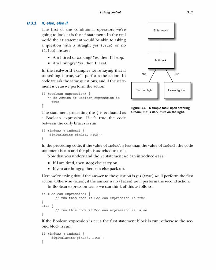
317Taking control
B.3.1 If, else, else if
The first of the conditional operators we’regoing to look at is the if statement. In the realworld the if statement would be akin to askinga question with a straight yes (true) or no(false) answer:
■ Am I tired of walking? Yes, then I’ll stop.■ Am I hungry? Yes, then I’ll eat.
In the real-world examples we’re saying that ifsomething is true, we’ll perform the action. Incode we ask the same questions, and if the state-ment is true we perform the action:
if (Boolean expression) { // do Action if Boolean expression is
true}
The statement preceding the { is evaluated asa Boolean expression. If it’s true the codebetween the curly braces is run:
if (indexA < indexB) { digitalWrite(pinLed, HIGH);{
In the preceding code, if the value of indexA is less than the value of indexB, the codestatement is run and the pin is switched to HIGH.
Now that you understand the if statement we can introduce else:
■ If I am tired, then stop; else carry on.■ If you are hungry, then eat; else pack up.
Here we’re saying that if the answer to the question is yes (true) we’ll perform the firstaction. Otherwise (else), if the answer is no (false) we’ll perform the second action.
In Boolean expression terms we can think of this as follows:
if (Boolean expression) { // run this code if Boolean expression is true{else { // run this code if Boolean expression is false}
If the Boolean expression is true the first statement block is run; otherwise the sec-ond block is run:
if (indexA < indexB) { digitalWrite(pinLed, HIGH);}
Enter room
Is it dark
Turn on light Leave light off
Yes No
Figure B.4 A simple task: upon entering a room, if it is dark, turn on the light.
318 APPENDIX A Coding primer
else { digitalWrite(pinLed, LOW);}
In the preceding code, if the value of indexA is less than the value of indexB the firststatement block is run, switching the pin to HIGH; otherwise the second code block isrun, switching the pin to LOW.
We’ll now add the last part of the puzzle, else if, where we can ask one ormore questions:
■ If I am tired, then stop; else, if you are tired, then stop; else let’s carry on.■ If you are hungry, then eat; else, if you are thirsty, then drink; else pack up.
In Boolean expression terms, it looks like this:
if (Boolean expression A) {// run this code if Boolean expression A is true{else if (Boolean expression B) { // run this code if Boolean expression B is true}else { // run this code if both Boolean expressions are false
Here’s a code example:
if (indexA < indexB) { digitalWrite(pinLedA, HIGH);}else if (indexA == index B) { digitalWrite(pinLedB, High);}else { digitalWrite(pinLedA, High);}
}
In this case, if the value of indexA is less than the value of indexB the first codeblock is run; otherwise, if the value of indexA is equivalent to the value indexB thesecond code block is run; otherwise, if none of the preceding are true the thirdblock is run.
We’ve now covered the if, else, and else if conditional operators, but if you findyou’re using a series of else if statements in your code it’s worth considering theswitch-case statement. We’ll look at this next.
B.3.2 Switch case
Switch-case statements are a great way of simplifying complicated if, else if state-ments, and we find them much easier to understand and read. The following listingshows the typical layout for a switch-case statement.
319Taking control
switch (value){ case 1: // code statements when value == 1 break; case 2: // code statements when value == 2 break; case 3: //code statements value == 3 break; case 4: case 5: case 6: // code statement when value == 4 or 5 or 6 break; default: // code statements run for any other value break;}
The switch-case statement computes a series of comparisons and the computedvalue is compared with each case. If it’s found equivalent the statements are run forthat case.
The break; statement shown in the listing is optional, but if it’s included it ceasesfurther comparisons, which is generally more efficient.
The default statement is also optional, but it can be used like the final else in acomplicated if, else if series of statements.
This completes our look at switch-case statements. We’re now going to move onand look at logical operators. These will give us more tools for comparing expressionsand will expand our coding abilities.
B.3.3 Logical operators
The conditional operator examples we’ve looked at so far have just considered simpleexpressions like “if I am tired, then stop.” Adding the logical operators AND, OR, andNOT gives us more scope to ask slightly more developed questions:
■ If I am tired AND you are tried, then we will stop.■ If I am tired OR you are tired, then we will stop.■ If you are NOT tired, we will carry on.
In code, we don’t use the words AND, OR, and NOT but instead represent them in thefollowing manner:
■ AND becomes &&■ OR becomes ||■ NOT becomes !
Let’s look at each in turn.
Listing B.3 The switch-case statement
320 APPENDIX A Coding primer
ANDif (indexA > indexB && indexC > indexD) { digitalWrite(pinLedA, HIGH);}
If the value of indexA is greater than the value of indexB AND the value of indexC isgreater than the value of indexD, then run the code block and switch the pin to HIGH.
ORif (indexA > indexB || indexC > indexD) { digitalWrite(pinLedB, HIGH);}
If the value of indexA is greater than the value of indexB OR the value of indexC isgreater than the value of indexD, then run the code block and switch the pin to HIGH.
NOTif (!buttonPressed) { digitalWrite(pinLedA, HIGH);}
If NOT variable buttonPressed, run the code block and switch the pin to HIGH.
B.4 Going loopyAs we’ve already discussed, the main part of a sketch typically takes part in the controlloop which continues to loop until the Arduino is powered off. But there are othertypes of loops that can occur within the main loop, designed to be used with repetitivecode. These are set so that they loop until a certain condition is met, and if that condi-tion isn’t met the loop will continue indefinitely.
We’re going to look at three types of loops: for, while, and do while.
B.4.1 The for loop
For loops are used to loop through a block of code a certain number of times. They’renormally used with some form of incremental counter that increments until a certainvalue is reached, which terminates the loop.
The following listing shows a typical for loop that prints the value of i, from 0 to99, repeatedly until the Arduino is powered off.
void setup(){ Serial.begin(9600);}
void loop { for (int i = 0; i < 100; i++){ Serial.println(i); }}
Listing B.4 A for loop printing the value of i, from 0 to 99
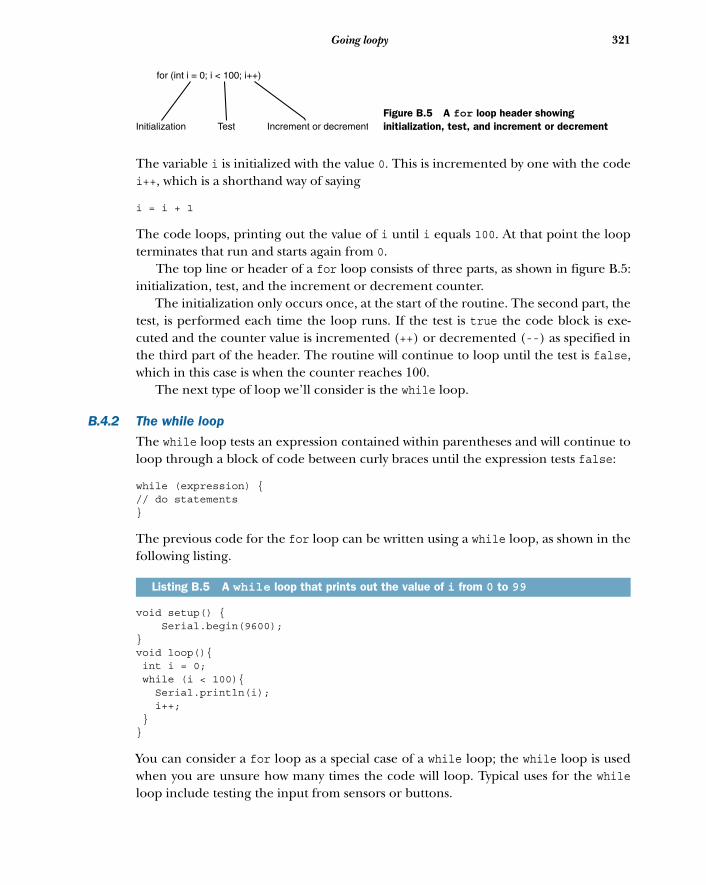
321Going loopy
The variable i is initialized with the value 0. This is incremented by one with the codei++, which is a shorthand way of saying
i = i + 1
The code loops, printing out the value of i until i equals 100. At that point the loopterminates that run and starts again from 0.
The top line or header of a for loop consists of three parts, as shown in figure B.5:initialization, test, and the increment or decrement counter.
The initialization only occurs once, at the start of the routine. The second part, thetest, is performed each time the loop runs. If the test is true the code block is exe-cuted and the counter value is incremented (++) or decremented (--) as specified inthe third part of the header. The routine will continue to loop until the test is false,which in this case is when the counter reaches 100.
The next type of loop we’ll consider is the while loop.
B.4.2 The while loop
The while loop tests an expression contained within parentheses and will continue toloop through a block of code between curly braces until the expression tests false:
while (expression) {// do statements}
The previous code for the for loop can be written using a while loop, as shown in thefollowing listing.
void setup() { Serial.begin(9600);}void loop(){ int i = 0; while (i < 100){ Serial.println(i); i++; }}
You can consider a for loop as a special case of a while loop; the while loop is usedwhen you are unsure how many times the code will loop. Typical uses for the whileloop include testing the input from sensors or buttons.
Listing B.5 A while loop that prints out the value of i from 0 to 99
for (int i = 0; i < 100; i++)
Initialization Test Increment or decrementFigure B.5 A for loop header showing initialization, test, and increment or decrement
322 APPENDIX A Coding primer
The following snippet tests the value of a sensor:
int sensorValue = 0;while (sensorValue < 2000 { sensorValue = analogRead(analogPin);}
This code will continue to loop while the value of sensorValue is less than 2000.
NOTE Make sure the code does change the value of the variable being testedin the expression, or the code will loop indefinitely.
The third and last type of loop is the do while loop, and we’ll look at that next.
B.4.3 The do while loop
The do while loop is not used as often as the while loop. The difference between itand the while loop is that it tests the expression at the end of the code block, so thecode block will always run at least once. The do while loop is typically used for readingdata from files:
do { // code block} while (expression);
Like a while loop, this code block will continue to run until the expression tests false.
B.5 FunctionsWe’ve already looked at the two main functions or routines that are needed in asketch: setup() and loop(). Both are declared as type void, which means theydon’t return a value. Arduino simplifies many tasks by using readily accessible func-tions to control digital and analog input and output of data, as well as mathematics,trigonometry, and time functions, but we discuss these in the chapters as we comeacross them.
You can also write your own functions. They are normally used to help with repeti-tive tasks or calculations. You first need to declare the function type, as you do with avariable, and give it a name—something memorable that indicates what the functiondoes. In parentheses, you place any parameters that you want to pass to the function.Code statements are then contained within curly braces:
type functionName(parameters){// code statements here}
Remember, if the function doesn’t return a value you should give it a type of void.Functions of type void can use a return; statement to exit or return from the func-tion; functions that return a value use the keyword return followed by the returnvalue and then a semicolon (;). The following code snippet shows a function thatconverts a temperature in Fahrenheit to Celsius and returns the Celsius value:
323Summary
float calcTemp(float fahrenheit){ float celcius; celcius = (fahrenheit – 32)/ 1.8; return celcius;}
The function is declared as type float and it’s passed a value for fahrenheit. Sub-tracting 32 from fahrenheit and then dividing by 1.8 produces the celsius value.The return statement returns the value of celsius. This function could be used aspart of a system for logging temperature data.
As you can see, functions are an ideal way to simplify code and take care of repeti-tive tasks.
B.6 SummaryIn this appendix we looked at some parts of the Arduino language. Variables are agood way to help with our code, and choosing good names for them helps indicatehow a code sketch works. We started to come to grips with language constructs such asif, else, and else if, and the switch-case statement. We also looked at the logicaloperators AND, OR and NOT. Finally, we ran through the different loop types, con-cluding with a look at functions. As you’ve seen, even if you’re completely new to cod-ing these techniques are quick to pick up and master.
appendix CLibraries
In chapter 4 we covered software libraries and how they’re used to extend the basicfunctionality of the Arduino. Other chapters have provided examples of how usinglibraries in your own projects can easily extend their functionality.
When you’ve gained some experience in writing your own sketches there willcome a time when you develop a sketch that you could reuse in future projects orthat may be useful to the Arduino community. You can either keep the developedcode in a sketch or split it out into a library. Splitting the sketch out into a librarywill probably make it more useful to other users.
This appendix will guide you through the anatomy of a library so that you cansee what’s involved in writing your own.
C.1 Anatomy of a libraryArduino sketches are coded using C++ (see appendix B for more detail), and muchof the complexity and functionality of Arduino programming is hidden from usersby the extensive use of software libraries.
A software library is made up of at least one C++ class and maybe many more.A class consists of two files: a header file with a .h extension and a file with a.cpp extension.
The .h (header) file acts as a blueprint for the library, describing the functionsof the library and what the class does. The .cpp file contains the fine detail of thelibrary, detailing the functions and variables declared by the header.
Let’s start by looking at the makeup of a header file.
C.1.1 The .h (header) file
The header is the blueprint for a library of classes. Imagine that we have a sensorcalled a Sabre that detects the presence of fossils in a patch of ground and countsthem. You need to think what functions the library is going to provide. In this
324
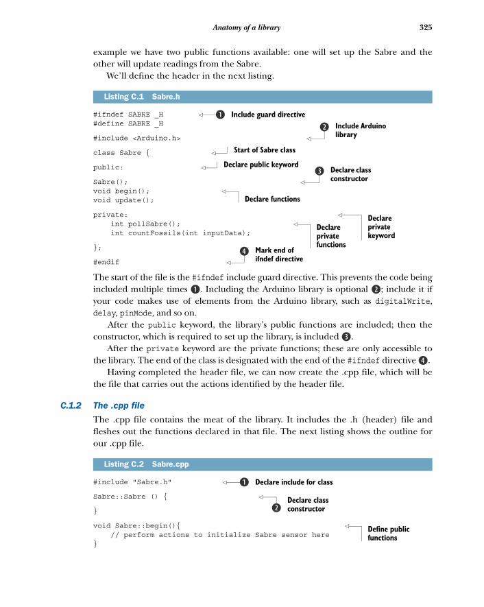
325Anatomy of a library
example we have two public functions available: one will set up the Sabre and theother will update readings from the Sabre.
We’ll define the header in the next listing.
#ifndef SABRE _H #define SABRE _H
#include <Arduino.h>
class Sabre {
public:
Sabre(); void begin(); void update();
private: int pollSabre(); int countFossils(int inputData);
};
#endif
The start of the file is the #ifndef include guard directive. This prevents the code beingincluded multiple times B. Including the Arduino library is optional c; include it ifyour code makes use of elements from the Arduino library, such as digitalWrite,delay, pinMode, and so on.
After the public keyword, the library’s public functions are included; then theconstructor, which is required to set up the library, is included d.
After the private keyword are the private functions; these are only accessible tothe library. The end of the class is designated with the end of the #ifndef directive e.
Having completed the header file, we can now create the .cpp file, which will bethe file that carries out the actions identified by the header file.
C.1.2 The .cpp file
The .cpp file contains the meat of the library. It includes the .h (header) file andfleshes out the functions declared in that file. The next listing shows the outline forour .cpp file.
#include "Sabre.h"
Sabre::Sabre () {
}
void Sabre::begin(){ // perform actions to initialize Sabre sensor here}
Listing C.1 Sabre.h
Listing C.2 Sabre.cpp
Include guard directivebInclude Arduino library
c
Start of Sabre class
Declare public keywordDeclare class constructor
d
Declare functions
Declare private keyword
Declare private functions
Mark end of ifndef directive
e
Declare include for classb
Declare class constructorc
Define public functions
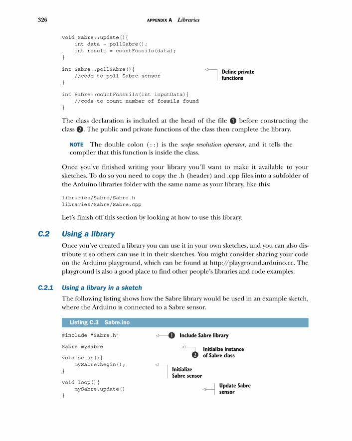
326 APPENDIX A Libraries
void Sabre::update(){ int data = pollSabre(); int result = countFossils(data);}
int Sabre::pollSAbre(){ //code to poll Sabre sensor}
int Sabre::countFosssils(int inputData){ //code to count number of fossils found}
The class declaration is included at the head of the file B before constructing theclass c. The public and private functions of the class then complete the library.
NOTE The double colon (::) is the scope resolution operator, and it tells thecompiler that this function is inside the class.
Once you’ve finished writing your library you’ll want to make it available to yoursketches. To do so you need to copy the .h (header) and .cpp files into a subfolder ofthe Arduino libraries folder with the same name as your library, like this:
libraries/Sabre/Sabre.h libraries/Sabre/Sabre.cpp
Let’s finish off this section by looking at how to use this library.
C.2 Using a libraryOnce you’ve created a library you can use it in your own sketches, and you can also dis-tribute it so others can use it in their sketches. You might consider sharing your codeon the Arduino playground, which can be found at http://playground.arduino.cc. Theplayground is also a good place to find other people’s libraries and code examples.
C.2.1 Using a library in a sketch
The following listing shows how the Sabre library would be used in an example sketch,where the Arduino is connected to a Sabre sensor.
#include "Sabre.h"
Sabre mySabre
void setup(){ mySabre.begin(); }
void loop(){ mySabre.update() }
Listing C.3 Sabre.ino
Define private functions
Include Sabre libraryb
Initialize instance of Sabre classc
Initialize Sabre sensor
Update Sabre sensor
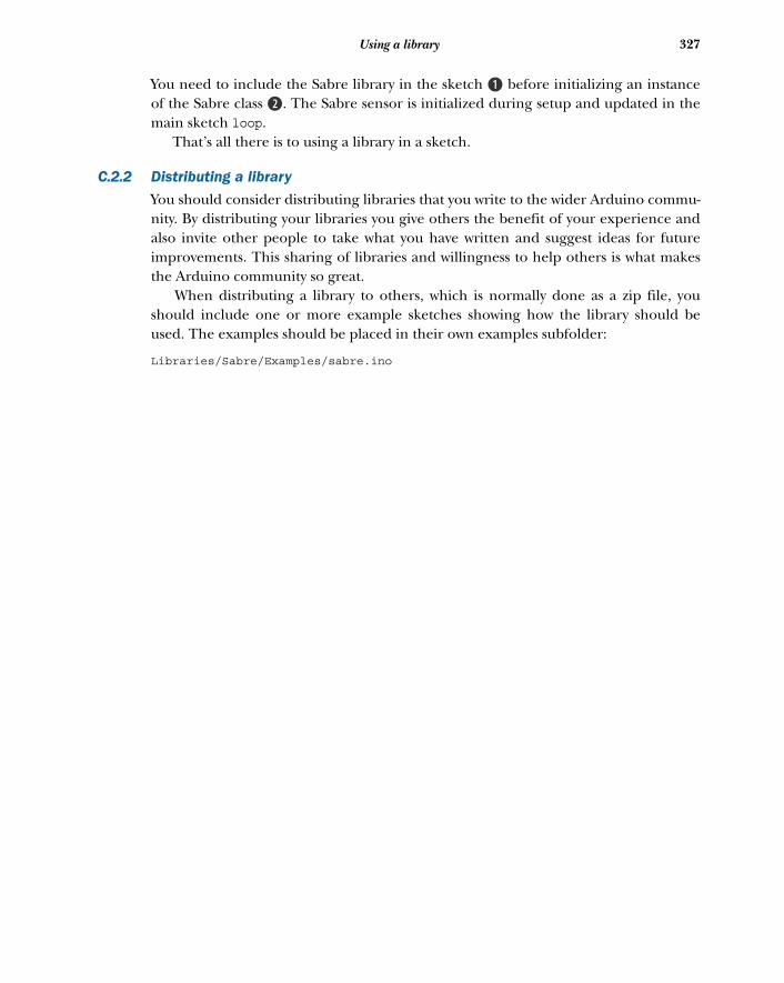
327Using a library
You need to include the Sabre library in the sketch B before initializing an instanceof the Sabre class c. The Sabre sensor is initialized during setup and updated in themain sketch loop.
That’s all there is to using a library in a sketch.
C.2.2 Distributing a library
You should consider distributing libraries that you write to the wider Arduino commu-nity. By distributing your libraries you give others the benefit of your experience andalso invite other people to take what you have written and suggest ideas for futureimprovements. This sharing of libraries and willingness to help others is what makesthe Arduino community so great.
When distributing a library to others, which is normally done as a zip file, youshould include one or more example sketches showing how the library should beused. The examples should be placed in their own examples subfolder:
Libraries/Sabre/Examples/sabre.ino

appendix DComponents list
This appendix lists the components used in the projects for each chapter.
Chapter 1An Arduino boardOne LED
Chapter 2An Arduino boardA breadboard and a selection of jumpersSix red LEDsOne green LEDSeven resistors, 180 ohmOne resistor, 10k ohmA momentary-contact push button
Chapter 3An Arduino boardA breadboard and a selection of jumpersA small potentiometer (a trimpot is ideal, as it can easily plug into a breadboard)Five zener diodes, 0.5 watt 5V1 (we used a BZX55C5V)Five resistors, 1M ohmOne resistor, 1k ohmA small speaker, 8 ohm
Chapter 4Not applicable
328
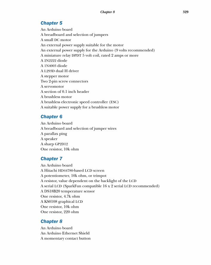
329Chapter 8
Chapter 5An Arduino boardA breadboard and selection of jumpersA small DC motorAn external power supply suitable for the motorAn external power supply for the Arduino (9 volts recommended)A miniature relay DPDT 5 volt coil, rated 2 amps or moreA 2N2222 diodeA 1N4003 diodeA L293D dual H driverA stepper motorTwo 2-pin screw connectorsA servomotorA section of 0.1 inch headerA brushless motorA brushless electronic speed controller (ESC)A suitable power supply for a brushless motor
Chapter 6An Arduino boardA breadboard and selection of jumper wiresA parallax pingA speakerA sharp GP2D12One resistor, 10k ohm
Chapter 7An Arduino board A Hitachi HD44780-based LCD screenA potentiometer, 10k ohm, or trimpotA resistor, value dependent on the backlight of the LCDA serial LCD (SparkFun compatible 16 x 2 serial LCD recommended)A DS18B20 temperature sensorOne resistor, 4.7k ohmA KS0108 graphical LCDOne resistor, 10k ohm One resistor, 220 ohm
Chapter 8An Arduino boardAn Arduino Ethernet ShieldA momentary contact button
330 APPENDIX A Components list
One resistor, 10k ohmAn Arduino Wifi ShieldAn accelerometer, such as the ADXL335A Bluetooth module, such as the SparkFun BlueSMiRF SilverA AD5206 digital potentiometer from Analog DevicesFour LEDsFour resistors, 220 ohmA potentiometer
Chapter 9An Arduino boardA Wii NunchukOptionally a WiiChuck or NunChuckyAn Xbox 360 game controllerA USB Host Shield, version 2.0
Chapter 10An Arduino boardAn iOS deviceA breadboard and selection of jumpersA Mac desktop or laptop computer with Xcode 4.0 or greaterA Redpark serial cableA RS232-to-TTL adapterA colored LEDOne resistor, 200 ohmA Sharp GP2D12 IR distance sensor
Chapter 11Two flex sensorsAn Arduino LilyPadFour LEDsThree meters of conductive threadAn Arduino Pro MiniAn HMC5883 three-axis digital compassA 7-segment serial displayThree more meters of conductive threadA pair of headphonesAn Arduino Pro MiniA QRE1113 reflectance sensorA 0.25 watt speakerTen thin pieces of copperFive thin pieces of rubber foamA spool of thread
331Chapter 13
Chapter 12An Arduino boardAn Adafruit Motor ShieldA 5V stepper motorTwo AA batteriesTwo buttonsA small DC motorA servomotorA potentiometerOne perfboard (preferably double-sided)Four female header strips (long pin) or three female header strips and one Arduinooffset headerAn SD card holderAn SD cardA 74HC4050 level shifterOne resistor, 5k ohm An SD card shield
Chapter 13An Arduino boardTwo servomotors A breadboard and selection of jumper wiresA desktop or laptop computer with Processing, Pure Data, and Python installedA USB webcamFive LEDsFive resistors, 4.7k ohm Four potentiometersFour resistors, 10k ohmThree LM35 temperature sensors
appendix EUseful links
This appendix lists a variety of useful Arduino-related links.
Additional Arduino articles■ A Tour of Arduino (http://manning.com/free/green_mevans.html)—An over-
view and general information about the Arduino, where it comes from, andthe development IDE.
■ Adafruit Motor Shield (http://manning.com/free/excerpt_mevans.html)—Using various motors with the handy Motor Shield by AdaFruit.
■ Introducing the LilyPad (http://manning.com/free/excerpt_mevans_b.html)—Introducing the Arduino LilyPad, an Arduino designed for use with wear-ables and textiles.
■ Wi-Fi Communication and Arduino (http://www.manning.com/free/excerpt_mevans_c.html)—Using the WiFly module for Wi-Fi on your Arduino.
Other useful links and materials■ Arduino home page (www.arduino.cc)—Arduino’s main home on the web.■ Arduino foundations (http://arduino.cc/en/Tutorial/Foundations)—Core
hardware and software concepts explained by Arduino.■ Arduino examples (http://arduino.cc/en/Tutorial/HomePage)—Additional
examples from blinking an LED to other libraries.■ Arduino language reference (http://arduino.cc/en/Reference/HomePage)—
The bible for writing Arduino code.■ SparkFun (www.sparkfun.com/)—A popular USA supplier for Arduinos,
shields, electronic components, and all things DIY. Lots of informationcan also be gleaned from the SparkFun message board forum and theproduct comments.
332
333Other useful links and materials
■ Adafruit (www.adafruit.com/)—Another popular USA supplier for Arduinosand DIY electronics. Like SparkFun, Adafruit also has great tutorials and onlineforums. Highly recommended!
■ SK Pang Electronics (www.skpang.co.uk)—UK supplier for Arduinos and DIYelectronics.
■ Cool Components (www.coolcomponents.co.uk)—UK supplier for Arduinosand DIY electronics. Subscribe to their newsletter for updates.
■ Bitsbox (www.bitsbox.co.uk)—UK supplier of a range of electronic components.■ Proto-PIC (www.proto-pic.co.uk)—UK supplier for Arduinos and DIY electronics. ■ oomlout (www.oomlout.co.uk)—UK supplier of Arduinos, electronic components,
and kits.

index
Symbols
!= (inequality) operator 316&= ~ operator 196#ifndef 325+5V pin 137<= (less than or equal to)
operator 316< (less than) operator 316== (equality) operator 316> (greater than) operator 316>= (greater than or equal to)
operator 316| operator 196|= operator 196
Numerics
1A pins 922A pins 922N2222 NPN transistor 82–844-bit configuration, vs. 8-bit
configuration 1335V pin 1438-bit configuration, vs. 4-bit
configuration 133
A
AAA Battery Holder 247accelerometers
client 169wireless 167
accessories, for LilyPad 247Adafruit Industries 9–10,
112
Adafruit motor shield 262–269AFMotor library 263–264assembled vs.
unassembled 269using with DC motor 265–
268using with stepper motor 264
Adafruit Wave shield 11ADC (analog-to-digital
converter) 42, 58, 87AF_DCMotor class 263, 265AF_Stepper instance 263AFMotor library 262–264analog input/output 42–46
digital vs. 42pentatonic keyboard
project 54–57circuit diagram for 54connecting hardware 54–
55sketch for 56–57uploading and testing 57
piezoelectric transducerscircuit diagram with 47–48connecting to Arduino 48–
49overview 46–47sketch to read from 49–50uploading and testing 51
potentiometersconnecting to Arduino 43–
44overview 43sketch to read from 44–45uploading and testing 45–
46
speakerscircuit diagram with 51connecting to Arduino 51sketch for 53uploading and testing 53–
54analogIn() method 299analogRead() method 42, 45,
287analog-to-digital converter. See
ADCanalogWrite() method 87–88,
103, 289AND operator 319angle brackets 63API key, for Cosm feeds 182–
183Arduino accelerometer
client 169Arduino Diecimila 304–305Arduino Duemilanove 5–6,
304–305Arduino Ethernet 6Arduino Ethernet Shield 156Arduino IDE, installing
on Linux 306–309on Mac OS X 306on Windows 302–305
Arduino language 310–311flow control 316–320
if, else, else if statements 317–318
logical operators 319–320switch-case statements 318–
319functions 322–323
334

INDEX 335
Arduino language (continued)loops 320–322
do while loop 322for loop 320–321while loop 321–322
variables 311–315arrays 313–314constants 314–315scope of 315strings 314types of 312
Arduino Mega 6–7Arduino Nano 8, 304–305Arduino Pro Mini, wearables
using 254Arduino Uno 5, 302–304Arduino, history of 4ArduinoBT board 172ArduinoTestSuite library 63–64arrays 313–314ASCII table 16assembled shields, vs. unassem-
bled shields 269assembling circuits 22ATMega1280
microcontroller 64ATMega168 microcontroller 64ATMega168 microprocessor 5–
6, 9ATMega2560
microcontroller 64ATMega2560 microprocessor 7ATMega328 microcontroller 64ATMega328 microprocessor
5–6, 8–9ATMega328 processor 6, 8ATMega8 microcontroller 64ATMega8U2 microcontroller 5ATMegachips 172ATS_begin test 64ATS_end test 64ATS_GetFreeMemory test 64ATS_Test_AnalogInput test 64ATS_Test_DigitalPin test 64ATS_Test_EEPROM test 64ATS_Test_PWM test 64ATS_TestSerialLoopBack test 64attach() method 69–70, 104attached() method 70, 104attachInterrupt(interrupt, func-
tion, mode) function 31audio, analyzing in
Processing 287–288autoscroll() method 134autoscrolling 134
available() method 69, 75, 154–155, 158, 166–167, 185
B
Banzi, Massimo 4Battery Holder 247battery packs 107, 109begin command 174begin method 170begin() method 66–67, 72–74,
154–155, 194begin(chipSelect) method 181begin(int column, int row)
method 134beginPacket() method 155beginTransmission function 73Beyond Logic website 204Bianconi, Gabrial 193big-endian 208BIN option 45bipolar stepper motors 95–98bit value. See BVBitsbox 333blink() method 134, 141blinking LEDs
code for 12connecting to board 12–13overview 11uploading and testing 13–14
BlueSMiRF line 172–173Bluetooth Mate Silver 256Bluetooth wireless 171–175
adding Bluetooth module 172–173
establishing connections 173sketch for 174–175using ArduinoBT board 172
Boarduino 9boolean variable type 313bounce, defined 31breadboards
connecting hardware to 24–25
connecting push buttons to 28–29
overview 22break command 32break statements, in
sketches 32–33breakout board 246brightness of LEDs, controlling
sketch for 236testing sketch 236–237Xcode for 230–235
brightnessLED action 230brushless DC motors 106–111
connecting to Arduino 109–110
controlling 107–108controlling direction of 110overview 106–107sketch for 108–111uploading and testing 110–
111BSSID() method 166Buechley, Leah 245, 249buf buffer 210Build Phases tab 223buttons, on Wii nunchuk 190–
191BV (bit value) 196_BV macro 195–196byte data, Nunchuk 193byte variable type 313
C
cableConnected method 228CAD (computer-aided design)
files 8cards 65cathode, defined 24char data type 130–133, 313charAt() method 131checkStatus() method 160circuit diagrams 22–24
for pentatonic keyboard project 54
for reactometer project 33circuits, assembling 22Circuits@Home 203clear() method 69, 134, 140, 144clearLine() method 140ClearScreen() method 146,
150–151Client class 68, 154–156Client function 68Client.available() method 155Client.connect() method 154Client.connected()
method 154, 158, 169, 185Client.flush() method 155Client.print() method 154–155Client.println() method 155,
158, 185Client.read() method 155, 158,
185Client.stop() method 155, 159,
185–186
INDEX336
Client.write() method 154Client() method 154clock phase 72clock polarity 72clones of Arduino hardware 8–9
Boarduino 9found on eBay 9Seeeduino 9Seeeduino Film 9Sippino 9
close() method 66, 181–182, 298
closing braces 27CNC (computer numerical
control) 94color parameter 147COM (common) pins 86commenting, in sketches 18–19communication port 292communications 152–187
Arduino web server 156–159overview 156–157sketch for 158–159troubleshooting 159uploading and testing 159
Bluetooth wireless 171–175adding Bluetooth
module 172–173establishing
connections 173sketch for 174–175using ArduinoBT
board 172Cosm feeds 182–186
API key for 182–183creating data feed 183–184sensor logging to 184–186uploading and testing 186
data logging 179–182SD card sensor logger
project 181–182SD cards 180SD library functions 180types of memory 180
Ethernet library functions 154–155
Ethernet shield 155–156SPI 175–179
circuit diagram for 177–178
digital LED dimmer project 178–179
digital potentiometers 176–177
SPI library functions 176
Twitter integration 159–163circuit diagram for 161sketch for 161–162tokens for 160Twitter library
functions 160uploading and testing 163
Wi-Fi 163–171connecting to Arduino 168sketch for 168–171uploading and testing 171WiFi library functions 165Wifi Shield 164–165wireless accelerometers 167
compareTo() method 131compatibility, for shields 80components, list of for all
projects 328–331computer numerical control. See
CNCcomputer-aided design files. See
CADCOMxx 303concat() method 131conductive thread and fabric,
for LilyPad 247–249connect() method 68, 167connected() method 68, 167connections, establishing
Bluetooth 173connectToNetwork()
method 169–170constants 314–315contributed libraries 75–76control statements 316convertToCelsius() method 299Cool Components 333Copy Items into Destination
Group’s Folder (if Needed) option 223
core library 62Cosm feeds 182–186
API key for 182–183creating data feed 183–184sensor logging to 184–186uploading and testing 186
.cpp file, in libraries 325–326createChar() method 141Cuartielles, David 4curly braces 15cursor() method 134, 141CursorTo() method 146custom shields
connecting to Arduino 273–276
level shifters 270memory considerations 269–
270SD cards
connecting to Arduino 271–272
holders for 270–271testing 276–277
D
D1 diode 86D2 pin 137D3 pin 137D4 pin 137D5 pin 137D10 pin 137D11 pin 137D12 pin 137, 143DallasTemperature library 141–
142, 144–145data logging 179–182
SD cardslogging data to 181–182overview 180SD library functions 180
types of memory 180DB4 (bit 4) pin 137DB5 (bit 5) pin 137DB6 (bit 6) pin 137DB6 (bit 7) pin 137DC (direct current) motors 263
connecting to Arduino 84–86controlling speed and direc-
tion ofconnecting hardware 91L293D dual H driver 90sketch for 92–94uploading and testing 93–
94using H-bridge 89–90using PWM 87–89
sketch for 84stopping and starting 83–84uploading and testing 86–87using Adafruit motor shield
with 265–268DDR register 195debounce 31default boot configurations, and
Xbox 208default statement 319delay() method 116delayMicroseconds()
method 116, 122
INDEX 337
detach() method 69–70, 104Devantech SRF05
additional pins on 116sketch for 117–118
devices object 292DHCP (Dynamic Host Configu-
ration Protocol) 157digital input/output, analog
vs. 42digital LED dimmer
project 178–179digital potentiometers 176–177digitalRead() method 62, 270,
287digitalWrite() method 12, 27,
62, 286Dingley, John 189diodes 49direct current motors. See DCdirection
controlling for brushless DC motors 110
controlling for DC motorsconnecting hardware 91L293D dual H driver 90sketch for 92–94uploading and testing 93–
94using H-bridge 89–90using PWM 87–89
Directory Name Service. See DNSdisconnect() method 166display() method 134, 141distance outlet 238distance, calculating 121distributing, libraries 327DNS (Directory Name
Service) 153dnsServerIP function 67do while loop 322DOUBLE option 264double pole double throw relay.
See DPDTdouble slash (//) character 19Download as tar.gz button 204DPDT (double pole double
throw) relay 83draw() method 171, 280DrawBitmap() method 146DrawCircle() method 147DrawHoriLine() method 147DrawLine() method 147DrawRect() method 147DrawRoundedRect()
method 147
DrawVertLine() method 147drivers, Windows
for Arduino Diecimila 304–305
for Arduino Duemilanove 304–305
for Arduino Nano 304–305for Arduino uno 302–304
DS18B20 temperature sensor 141, 143
duration parameter 53Dynamic Host Configuration
Protocol. See DHCP
E
E (Enable) pin 137eBay 9echolocation 115EEPROM library 63–65electronic speed controllers. See
ESCselse/else if statements 317–318enablePin 93encryptionType() method 166end connector, Nunchuk 192end() method 72, 74, 176endPacket() method 155endpoint attribute 206endsWith() method 131endTransmission() method 73,
197, 258environment 10–11
hardware 10software 10tools 11
equalizers 286–291assembling equalizer
hardware 288audio analysis in
Processing 287–288code for equalizer 288–291using Firmata in
application 286–287equals() method 131equalsIgnoreCase()
method 131errorHalt() method 277ESCs (electronic speed
controllers) 107Ethernet class 67Ethernet library
functions for 154–155overview 67–68
Ethernet Shield, Arduino 156
exists() method 66, 181extending Arduino 61–80
contributed libraries 75–76core library 62libraries, defined 62shields 76–80
compatibility for 80Ethernet shields 77motor shields 77prototyping shields 79Wi-Fi shields 78–79
standard libraries 63–75ArduinoTestSuite
library 63–64EEPROM library 64–65Ethernet library 67–68Firmata library 68–69LiquidCrystal library 69SD library 65–67Servo library 70SoftwareSerial library 74–
75SPI library 71–72Stepper library 70–71Wire library 72–73
F
fabric, conductive 247–249face tracking 280, 283, 285–286
assembling hardware for 281–282
code for face-tracking 282–286
serial communication in Processing application280–281
Facebook 160fast Fourier transform. See FFTFAT16 file system 270FAT32 file system 270FFT (fast Fourier
transform) 287File class 66, 180–181FillRect() method 147Firmata library 63, 68Firmata project 286–291
assembling equalizer hardware 288
audio analysis in Processing 287–288
code for equalizer 288–291using in application 286–287
fixed resistors 43flex sensor 249, 253

INDEX338
float variable type 313flow control 316–320
if, else, else if statements 317–318
logical operators 319–320switch-case statements 318–
319flush() method 68, 167, 181,
297for loop 26–27, 32, 94, 111, 314,
320–321forward() method 289four-wire bus 71frames 153freqout() method 123frequency 53FTDI cable 246, 254–255FTDI chipset 5–7functions 322–323
G
gaming 188–215Nintendo Wii
communicating with 193–201
overview 188–190testing connection 201–202Wii nunchuk 190–193
Xbox 202–214communicating with 204–
206connecting to Arduino 203default boot
configurations 208input report for
interface 206–208sketch for 210–213testing connection 213–214USB Host Shield library
for 203–204Xboxhidboot library
files 208–210gatewayIP() method 166getBytes() method 131getSocket() method 166ghost echoes 119GitHub 264GLCDks0108 library
functions 146–147GLCDs (Graphic LCDs) 146–
151circuit diagram for 147–148connecting to Arduino 148–
149
GLCDks0108 library functions 146–147
sketch for drawing to 150uploading and testing 151
global variables 315GND pin 137, 143gndpin bit 195GotoXY() method 146Graphic LCDs. See GLCDsGravitech 8
H
.h (header) file, in libraries 324–325
H&D Wireless 164Haar Cascade 284Half-H driver 90hardware
Arduino Duemilanove 5–6Arduino Ethernet 6Arduino Mega 6–7Arduino Nano 8Arduino Uno 5clones 8–9
Boarduino 9found on eBay 9Seeeduino 9Seeeduino Film 9Sippino 9
connecting to breadboard 24–25
for working environment 10LilyPad Arduino 7–8obtaining 9–10
Hardware Update wizard 303–304
H-bridge, controlling DC motors 89–90
header pins 273headers 254HEX option 45HID (human interface
device) 206hidboot.cpp file 208hidboot.h file 208HIGH signal 86, 115history of Arduino 4Hitachi HD44780 chip 69Hitachi HD44780 LCD 133–139
4-bit vs. 8-bit configurations 133
circuit diagram for 134–135connecting to Arduino 135–
137
LiquidCrystal library functions 133
sketch for writing to 137–138uploading and testing 138–
139HMC5883L magnetic
compass 257holders, for SD cards 270–271home() method 134, 140human interface device. See HID
I
i variable 321I/O pins 164I2C pins 272I2C protocol 270ICSP (in-circuit serial
programming) 5IDE (integrated development
environment)main editor
errors in 16overview 14–15
overview 16–17serial monitor 15–16
if statements 253, 317–318import statement 288inc folder 223in-circuit serial programming.
See ICSPinclude statement 63Include Subfolders check
box 303indexOf() method 131infrared 119–124
connecting hardware 123nonlinear algorithm for calcu-
lating distance 121passive infrared 124–128
connecting hardware 127–128
Parallax PIR sensor 125sketch for 125–126uploading and testing 128
Sharp GP2D12 range finder 121
sketch for 122–123uploading and testing 123–124using with ultrasound 120
Init() method 146input report for interface, for
Xbox 206–208input/output, for Nintendo
Wii 193

INDEX 339
inputPin variable 312inrunner motor 106, 111installing
Arduino IDEon Linux 306–309on Mac OS X 306on Windows 302–305
contributed libraries 76Windows drivers
for Arduino Diecimila 304–305
for Arduino Duemilanove 304–305
for Arduino Nano 304–305for Arduino uno 302–304
int variable type 313integrated development envi-
ronment. See IDEINTERLEAVE option 264Internet Protocol. See IPinternet service provider. See
ISPinterrupts, in reactometer
project 29InvertRect() method 147inWaiting() method 297iOS integration 216–243
connecting device to Arduino 218–220connecting RS232 adapter
to Arduino 220using Redpark serial
cable 218–219controlling LED brightness
with Slider controlsketch for 236testing sketch 236–237Xcode for 230–235
controlling LED with toggle switchsketch for 229testing sketch 229–230Xcode for 225–228
creating single-view applications 221–223
displaying sensor dataGP2D12 IR distance
sensor 241–242testing sketch 243Xcode for 237–241
IOSArduino-Info.plist 228IP (Internet Protocol) 153ip() method 171IPAddress object 157isListening function 74
ISP (internet service provider) 157
iTunes 255–256
J
jacket with compass project 257–260
joystick, on Wii nunchuk 190jumper wires 51, 276
K
Keys page 183knee voltage 49knock sensor 47Kurt, Tod 192Kv value 106
L
L293D chip 98–99, 102L293D dual H driver 89–90, 98L293D H-bridge 93lastIndexOf() method 131lastMillis variable 31LCD class 138LCD interface 65LCDs (liquid crystal
displays) 129–151and char data type 130–133and String data type 130–133graphic Samsung KS0108
GLCD 146–151circuit diagram for 147–148connecting to
Arduino 148–149GLCDks0108 library
functions 146–147sketch for drawing to 150uploading and testing 151
overview 130parallel Hitachi HD44780
LCD 133–1394-bit vs. 8-bit
configurations 133circuit diagram for 134–135connecting to
Arduino 135–137LiquidCrystal library
functions 133sketch for writing to 137–
138uploading and testing 138–
139
serial LCD weather station project 139–145circuit diagram for 142connecting to Arduino 143DallasTemperature
library 141–142Maxim IC DS18B20 temper-
ature sensor 141OneWire library 141–142SerLCD library
functions 139–141sketch for writing to 144–
145uploading and testing 145
serial vs. parallel 139Leah Buechley 7least significant bits. See LSBsLED- pin 137LED+ pin 137ledArray array 27ledOnOff() method 30, 32, 35,
38ledPin 236LEDs (light-emitting diodes)
controlling brightness from iOS devicesketch for 236testing sketch 236–237Xcode for 230–235
dimmer for 178–179making blink
code for 12connecting to board 12–13overview 11uploading and testing 13–
14overview 24turning on and off from iOS
devicesketch for 229testing sketch 229–230Xcode for 225–228
leftMotor variable 312leftToRight() method 134, 140length() method 131level shifters, for custom
shields 270lib folder 223libraries 324–327
.cpp file 325–326defined 62distributing 327.h (header) file 324–325overview 324using in sketch 326–327

INDEX340
light-emitting diodes. See LEDs
LilyPad 7–8accessories for 247conductive thread and
fabric 247–249wearables using 245–249
Link Binary With section 223Linux, installing Arduino IDE
on 306–309LiPo (lithium polymore) battery
pack 107LiPo batteries 247liquid crystal displays. See ICDsLiquidCrystal library 62–63
functions for 133overview 69
LiquidCrystial class 138list() method 280listen() method 74–75lithium polymore battery pack.
See LiPolittle-endian 208LM35 sensors 299localIP() method 67, 166, 170logging data 179–182
SD cardslogging data to 181–182overview 180SD library functions 180
types of memory 180logical operators 319–320long variable type 313loop function 18, 197loop routine 17loops 320–322
do while loop 322for loop 320–321while loop 321–322
LSBs (least significant bits) 72, 194, 196
Lynx Pan 281–282
M
mA (milliamperes) 24MAC (Media Access Control)
address 153Mac OS X, installing Arduino
IDE on 306macAddress() method 166magnetic compass 257main editor
errors in 16overview 14–15
MainStoryboard_iPhone.story-board 221
Maker Shed 10Mark for Installation check
box 307Martino, Gianluca 4master input, slave output. See
MISOmaster output, slave input. See
MOSIMate Silver, Bluetooth 256Maxim IC DS18B20 temperature
sensor 141Media Access Control address.
See MACMedTex 180 248Mellis, David 4memory
custom shields and 269–270types of 180
memory cards 65, 270microSD card 270microSD shield 67MICROSTEP option 264milliamperes. See mAmillis() method 30–32, 35, 37–
38, 185–186Minim library 288MISO (master input, slave
output) 175mkdir function 66monitoring, temperatures 296–
300assembling thermometer
hardware 298code for monitoring
temperatures 299–300serial library in Python 296–
298MOSI (master output, slave
input) 175Most Significant Bit. See MSBmotor brakes 89motor control shield kit 112motor shields 11, 262
Adafruit 262overview 77
motor terminals 89MotorDriving.pde 264motors 81–113
brushless DC motors 106–111advantages of 106–107connecting to
Arduino 109–110controlling 107–108
overview 106–107reverse 110sketch for 108–111uploading and testing 110–
111DC motors
connecting to Arduino 84–86
controlling speed and direc-tion of 87–94
sketch for 84stopping and starting 83–
84uploading and testing 86–
87motor control shield 112servomotors 102–105
connecting to Arduino 105controlling 102–103library functions for 103(Servo) library functions
for 103sketch for 104–105uploading and testing 105
stepper motors 94–102connecting to Arduino 98–
99library functions for 99–101sketch for 101unipolar vs. bipolar 95–98uploading and testing 101–
102moveSlider outlet 230MSB (Most Significant Bit) 72multicolor backlighting 133multimeters 96–97musical cards 46
N
NC (normally closed) pins 86New function 14New Hardware Wizard 305New Referencing Outlet
option 221, 230newMillis variable 31NiCd battery pack 107Nickel mesh 248NiMH battery pack 107Nintendo Wii
communicating with 193–201code to set up and power
nunchuk 194–199complete sketch 199–201input/output for 193

INDEX 341
Nintendo Wii (continued)overview 188–190testing connection 201–202Wii nunchuk
buttons on 190–191connecting to
Arduino 191–193joystick on 190three-axis accelerometer
in 190NO (normally open)
connection 86noAutoscroll() method 134noBlink() method 134, 141noCursor() method 134, 141noDisplay() method 134, 141nonlinear algorithm for calculat-
ing distance 121normally closed pins. See NCnormally open connection. See
NONOT operator 319noTone command 53null character 132, 314number one wire 97number_steps variable 100nunchuck_send_request()
function 199NunChucky 194nunchuk_init() method 194,
196nunchuk_setpowerpins()
function 194–195nunchuk, Wii
buttons on 190–191connecting to Arduino 191–
193joystick on 190three-axis accelerometer
in 190NXP Semiconductors 270
O
object detection 114–128with infrared 119–124
connecting hardware 123nonlinear algorithm for cal-
culating distance 121Sharp GP2D12 range
finder 121sketch for 122–123uploading and testing 123–
124using with ultrasound 120
with passive infrared 124–128connecting hardware 127–
128Parallax PIR sensor 125sketch for 125–126uploading and testing 128
with ultrasound 115–118additional pins on Devan-
tech SRF05 116connecting hardware 118sketch for Devantech
SRF05 117–118sketch for Parallax
Ping 116–117ultrasonic sensors for 115–
116uploading and testing 118
OCT option 45OneWire library 141–142onReceive function 73onRequest function 73oomlout 10, 333open() method 14, 66, 297OpenCV library 282, 284Openjdk-7-jre 307operating voltage 24OR operator 319outbuf array 193, 197–198outputPin variable 312outrunner motor 106–107
P
P4B TTL to RS232 adapter 219–220
Pachube 182packets 153Parallax Ping, sketch for 116–
117Parallax PIR sensor 125parallel LCDs
Hitachi HD44780 LCD 133–1394-bit vs. 8-bit
configurations 133circuit diagram for 134–135connecting to
Arduino 135–137LiquidCrystal library
functions 133sketch for writing to 137–
138uploading and testing 138–
139vs. serial LCDs 139
parsePacket() method 155passive infrared 124–128
connecting hardware 127–128
Parallax PIR sensor 125sketch for 125–126uploading and testing 128
passive infrared sensors. See PIRPCBs (printed circuit
boards) 77Pd patch 292, 294pentatonic keyboard
project 54–57circuit diagram for 54connecting hardware 54–55sketch for 56–57uploading and testing 57
pentatonic scales 54perfboard 269, 273–275Piezo buzzer 11piezo transducer 41piezoelectric transducers
circuit diagram with 47–48connecting to Arduino 48–49overview 46–47sketch to read from 49–50uploading and testing 51
Pin 1 143Pin 2 143Pin 3 143Pin 8 143PIN register 195ping sound 47pinLED variable 311–312pinLedGlobal 315pinMode() function 315PIR (passive infrared) sensors
124port manipulation 195PORT register 195position function 66post() method 160pot trimmer tool 44potentiometers 293, 295
connecting to Arduino 43–44overview 43sketch to read from 44–45uploading and testing 45–46
potentiometers, digital 176–177PotToMotors.pde 267Power over Ethernet (POE)
module 6premounted headers 254prevState buffer 210print command 174
INDEX342
print function 68print() method 139–140, 166–
167, 181, 197, 199, 279printCustomChar()
method 141printData() method 170–171printed circuit boards. See PCBsprintln() method 45, 66, 68–69,
154, 167, 181, 185PrintNumber() method 146printVersion method 68printWifiStatus() method 169–
170private keyword 325Processing project 280–286
assembling hardware for face tracking 281–282
audio analysis in 287–288code for face-tracking 282–
286serial communication in 280–
281processInput method 69project boards 269protection diode 86Proto-PIC 333prototyping shields 79public keyword 325pull-down resistors 28pull-up resistors 28pulse 115pulse width modulation. See PWMpulseIn() method 116–117Pure Data (Pd)
environment 292–296assembling synthesizer
hardware 293code for synthesizer 294–296
Pure Data environment. See Pdpush buttons, connecting to
breadboard 28–29pushbutton switches 249PUT command 185–186PutChar() method 146Puts() method 147PWM (pulse width modulation)
42, 87–89, 99, 254pwrpin bit 195pySerial library 296Python 296–300
assembling thermometer hardware 298
code for monitoring temperatures 299–300
serial library in 296–298
Q
QRE1113 IR-reflectance sensor 254
R
randMax argument 35randMin argument 35random function 35randomSeed function 36reactometer project
circuit diagram for 27, 33completed connections for 33connecting push button to
breadboard 28–29interrupts in 29sketch for 25–27, 30–31, 33–38uploading and testing 27, 32–
33, 36, 38–39read function 65–66, 68, 70, 74read_gp2d12 function 242read() method 75, 104, 155,
167, 181, 281Read/Write pin. See RWreadBytesAvailable method 238,
240readMicroseconds()
method 104readString() method 171receive function 73Redpark Product
Development 218Redpark SDK 217–218, 220Redpark serial cable 217–219reduced instruction set com-
puter microprocessor. SeeRISC
Register Select pin. See RSremove function 66replace() method 131requestFrom function 73resistor values, calculating 24resources 332–333return keyword 322revolutions per minute. See RPMrightMotor variable 312rightToLeft() method 134, 140RISC (reduced instruction set
computer) micro-processor 5
rmdir function 66rotary volume control 43RPM (revolutions per
minute) 100
RS (Register Select) pin 136RS232 adapter 220RS232 DB-9 connector 219RS232 to TTL adapter 229RSSI() method 166, 170run() method 263RW (Read/Write) pin 137RX pin 143
S
Sabre.cpp file 325Sabre.h file 325Sabre.ino file 326Samsung KS0108 GLCD 146–
151circuit diagram for 147–148connecting to Arduino 148–
149GLCDks0108 library
functions 146–147sketch for drawing to 150uploading and testing 151
Save function 14scales, pentatonic 54scanNetworks() method 166schematic, defined 22SCK (serial clock) 175scope resolution operator 326scope, of variables 315scrollDisplayLeft() method 134scrollDisplayRight()
method 134SD cards 65, 270
for custom shieldsconnecting to
Arduino 271–272holders for 270–271
logging data to 181–182overview 180
SD class 66, 180–181SD library 63, 66
functions for 180overview 65–67
SdFat library 65–66SDHC memory cards 65SDShieldWriter.pde 276Search Removable Media check
box 304Seeeduino Film 9seek function 66SelectFont() method 146selectLine() method 140semicolon (;) character 12, 16send function 73

INDEX 343
send_zero() method 197, 199sendAnalog method 69sendData() method 186sendDigitalPortPair method 69sendString method 69sendsysex method 69sendTweet function 162sensorPin 45, 55sensors, logging data from
to Cosm feed 184–186to SD card 179–182
sensors.begin() method 144sensors.requestTemperatures()
method 145sensorValue variable 45serial cables 217serial channel, software integra-
tion using 279–280Serial class 280serial commands 139serial communication
in Processing project 280–281
in Python 296–298with Firmata library 68–69
Serial function 62serial LCD weather station
project 139–145circuit diagram for 142connecting to Arduino 143DallasTemperature
library 141–142Maxim IC DS18B20 tempera-
ture sensor 141OneWire library 141–142SerLCD library
functions 139–141sketch for writing to 144–145uploading and testing 145
serial LCDs, vs. parallel LCDs 139
serial monitor 15–16, 45, 50–51
serial peripheral interface. See SPI
SerLCD library, functions for 139–141
serLCD object 144–145SerLCD.h file 141serLCD() method 140Server class 67, 156Server function 67Servo library 63, 70, 266
functions for 103overview 70
servo motors, face tracking with 280–286
assembling hardware for 281–282
code for face-tracking 282–286
serial communication in Pro-cessing application 280–281
servo object 104–105servomotors 102–105, 267
connecting to Arduino 105controlling 102–103library functions for 103sketch for 104–105uploading and testing 105
setBitOrder() method 72, 176setBrightness() method 140setCharAt() method 131setClockDivider() method 72,
176setCursor method 69, 138setCursor() method 134, 141setDataMode() method 72, 176SetDot() method 147setFirmwareVersion method 68setLed() method 179setSpeed function 71, 100–101setSplash() method 140setup function 17–18, 171, 174sewing thread, Shieldex 248Sharp GP2D12 range finder 121Shieldex sewing thread 248shields 76–80
Adafruit motor shield 262–269AFMotor library 263–264assembled vs.
unassembled 269using with DC motor 265–
268using with stepper
motor 264compatibility for 80creating custom
connecting to Arduino 273–276
level shifters 270memory
considerations 269–270SD cards on 270–272testing 276–277
Ethernet shields 77motor shields 77overview 261–262
prototyping shields 79Wi-Fi shields 78–79
single backlighting 133SINGLE option 264single pole double throw relay.
See SPDTSingle View Application
option 221single-view applications, for
iOS 221–223SiP (system in package) 164Sippino 9size function 66SK Pang Electronics 10, 333sketches
break statements in 32–33commenting in 18–19for pentatonic keyboard
project 56–57for reactometer project 37–38loop function 18setup function 17–18using library in 326–327
slave select pin. See SSslave select wire 71Slider control, iOS devices
controlling LED brightness usingsketch for 236testing sketch 236–237Xcode for 230–235
smart headphone project 254–257
software integrationFirmata project 286–291
assembling equalizer hardware 288
audio analysis in Processing 287–288
code for equalizer 288–291using in application 286–
287Processing project 280–286
assembling hardware for face tracking 281–282
code for face-tracking 282–286
serial communication in 280–281
Pure Data environment 292–296assembling synthesizer
hardware 293code for synthesizer 294–
296
INDEX344
software integration (continued)Python 296–300
assembling thermometer hardware 298
code for monitoring temperatures 299–300
serial library in 296–298serial channel 279–280
software, for working environment 10
SoftwareSerial library 63, 74–75, 140, 143–145
SparkFun Electronics 139–143
SPDT (single pole double throw) relay 83
speakerPin variable 53, 56speakers
circuit diagram with 51connecting to Arduino 51sketch for 53uploading and testing 53–
54speed, controlling for DC
motorsconnecting hardware 91L293D dual H driver 90sketch for 92–94uploading and testing 93–
94using H-bridge 89–90using PWM 87–89
SPI (serial peripheral interface) 175–179
circuit diagram for 177–178
digital LED dimmer project 178–179
digital potentiometers 176–177
SPI library functions 176SPI interface 156, 164SPI library 63, 71SS (slave select) pin 175SSID() method 166, 170standard libraries 63–75
ArduinoTestSuite library 63–64
EEPROM library 64–65Ethernet library 67–68Firmata library 68–69LiquidCrystal library 69SD library 65–67Servo library 70SoftwareSerial library 74–75
SPI library 71–72Stepper library 70–71Wire library 72–73
StandardFirmata program 288, 290
starting, DC motors 83–84start-stop display 30startsWith() method 131state variable 30status() method 160step() method 71, 264stepCount function 101Stepper function 71Stepper library 63, 70–71
overview 70–71setSpeed function 100Stepper function 100steps function 100–101
stepper motors 94–102connecting to Arduino
98–99library functions for 99–
101setSpeed function 100Stepper function 100steps function 100–101
sketch for 101unipolar vs. bipolar 95–98uploading and testing 101–
102using Adafruit motor shield
with 264stepper_oneStepAtATime
sketch 101stop() method 68, 167stopping DC motors 83–84storing data, SD library 65–67String class 130–132, 314String data type 130–133subnetMask() method 166substring() method 131Supported External Accessory
Protocols option 228Supporting Files group 228sweep sketch 104switch statement 32switch variable 226switch-case statements 318–
319Synaptic Package Manager 306–
307synthesizer
assembling hardware for 293code for 294–296
system in package. See SiP
T
Tag value 231TButton 191TCP (Transmission Control
Protocol) 153TCP/IP stack 67, 77TDD (test-driven
development) 63–64Temperature Sensor 247temperatures, monitoring 296–
300assembling thermometer
hardware 298code for monitoring
temperatures 299–300serial library in Python 296–
298test-driven development. See
TDDtesting
custom shields 276–277sketches 13–14
thermometer, assembling hard-ware for 298
thread, conductive, for LilyPad 247–249
three-axis accelerometer, in Wii nunchuk 190
threshold sketch 50Tilt kit 281–282toCharArray() method 131toggleLED action 224toggleSplash() method 140toggleSwitch outlet 224tokens, for Twitter
integration 160toLowerCase() method 131toneDuration variable 53, 56toneFrequency variable 53–
54tones array 56–57Tools menu 138tools, for working
environment 11torque 95toUpperCase() method 131transfer function 72transfer() method 176, 179transistor-transistor logic. See
TTLTransmission Control Protocol.
See TCPtri-color backlight 145Trim() method 131

INDEX 345
trimpots 43, 134, 136troubleshooting, web server on
Arduino 159truth tables 92, 96TTL (transistor-transistor
logic) 139, 219–220turn-signal jacket project 249–
251TWI (two-wire interface) 72,
191Twitter integration 159–163
circuit diagram for 161sketch for 161–162tokens for 160Twitter library functions 160uploading and testing 163
Twitter() method 160two-wire interface. See TWI
U
UDP class 155ultrasonic sensors, for
ultrasound 115–116ultrasound 115–118
additional pins on Devantech SRF05 116
connecting hardware 118sketch for Devantech
SRF05 117–118sketch for Parallax Ping 116–
117ultrasonic sensors for 115–
116uploading and testing 118using with infrared 120
unassembled shields, vs. assem-bled shields 269
unipolar stepper motors 95–98unsigned int variable type 313unsigned long variable type 313Upload button 13Upload function 14Upload icon 138uploading to Arduino 13–14USB Host Shield library, for
Xbox 203–204USB-to-serial driver 6
V
V0 pin 137varA variable 315varB variable 315varC variable 315
variable resistance 87variables 311–315
arrays 313–314constants 314–315scope of 315strings 314types of 312
Vcc pin 136–137Vdd pin 143Verify function 14Vibe Board 247ViewController.h 221, 238ViewController.m 226, 233volatile keyword 30voltage output 121volume control 43Vss pin 136–137
W
wait() method 160wearable piano project 251–253wearables 244–260
jacket with compass project 257–260
smart headphone project 254–257
turn-signal jacket project 249–251
using Arduino Pro Mini 254using LilyPad 245–249
accessories for 247conductive thread and
fabric 247–249wearable piano project 251–
253web server on Arduino 156–159
overview 156–157sketch for 158–159troubleshooting 159uploading and testing 159
while loop 321–322Wi-Fi 163–171
connecting to Arduino 168sketch for 168–171uploading and testing 171WiFi library functions 165Wifi Shield 164–165wireless accelerometers 167
Wi-Fi shields 78–79, 164–165WiFiClient() method 167Wii, Nintendo
communicating with 193–201code to set up and power
nunchuk 194–199
complete sketch 199–201input/output for 193
overview 188–190testing connection 201–202Wii nunchuk
buttons on 190–191connecting to
Arduino 191–193joystick on 190three-axis accelerometer
in 190WiiChuck 194Windows
installing Arduino drivers for 302–305
installing Arduino IDE on 302–305
wiper connection 43wire designations 71Wire library 63, 73, 258wireless accelerometers 167wires, color designations for
191Wiring library 311WMW (pulse width
modulation) 5word variable type 313write() method 104, 134, 154–
155, 167, 181, 297writemem() method 258writeMicroseconds function 70,
104
X
X-axis acceleration 193X-axis joystick 193x-axis servo 281Xbox 202–214
communicating with 204–206
connecting to Arduino 203default boot
configurations 208input report for
interface 206–208sketch for 210–213testing connection 213–214USB Host Shield library
for 203–204Xboxhidboot library
files 208–210Xboxhidboot.cpp file 209–
210Xboxhidboot.h file 209

INDEX346
Xboxhid.ino sketch 214Xboxhidboot library files 208–
210Xboxhidboot.cpp file 209–210Xboxhidboot.h file 209
Y
Y-axis acceleration 193Y-axis joystick 193y-axis servo 281
Z
Z-axis acceleration 194zener diode 47–50, 54

Evans ● Noble ● Hochenbaum
Arduino is an open source do-it-yourself electronics platform that supports a mind-boggling collection of sensors and actuators you can use to build anything you can imagine.
Even if you’ve never attempted a hardware project, this easy-to-follow book will guide you from your fi rst blinking LED through connecting Arduino to your iPhone.
Arduino in Action is a hands-on guide to prototyping and build-ing DIY electronics. You’ll start with the basics—unpacking your board and using a simple program to make something happen. Th en, you’ll attempt progressively more complex projects as you connect Arduino to motors, LCD displays, Wi-Fi, GPS, and Bluetooth. You’ll explore input/output sensors, including ultrasound, infrared, and light, and then use them for tasks like robotic obstacle avoidance.
What’s Inside● Getting started with Arduino—no experience required!● Writing programs for Arduino● Sensing and responding to events● Robots, fl ying vehicles, Twitter machines, LCD displays, and more!
Arduino programs look a lot like C or C++, so some program-ming skill is helpful.
Martin Evans is a professional developer, a lifelong electronics en-thusiast, and the creator of an Arduino-based underwater ROV. Joshua Noble is an author and creative technologist who works with smart spaces. Jordan Hochenbaum uses Arduino to explore musical expression and creative interaction.
To download their free eBook in PDF, ePub, and Kindle formats, owners of this book should visit manning.com/ArduinoinAction
$39.99 / Can $41.99 [INCLUDING eBOOK]
Arduino IN ACTION
ARDUINO/ELECTRONICS
M A N N I N G
“Well-written with many helpful examples.
Not just for practice!”—Matt Scarpinoauthor of OpenCL in Action
“Merges soft ware hacking with hardware tinkering.”—Philipp K. Janert
author of Gnuplot in Action
“A comprehensive introduction to Arduino.”—Steve Prior, geekster.com
“Takes us to a brand new world—planet Arduino.”
—Nikander & Margriet Bruggeman Lois & Clark IT Services
“A solid, applications- oriented approach.”—Andrew Davidson, Human-
Centered Design & Engineering
SEE INSERT
Copyright © 2022 FDOKUMEN