N N N N FCA = 833.33 N N N N N N FCD = 333.33 N N N
45
446 © 2010 Pearson Education, Inc., Upper Saddle River, NJ. All rights reserved. This material is protected under all copyright laws as they currently exist. No portion of this material may be reproduced, in any form or by any means, without permission in writing from the publisher. •6–49. Determine the force in members KJ, KC, and BC of the Howe truss, and state if the members are in tension or compression. 2 kN 3 kN 4 kN 5 kN 4 kN 6 kN 5 kN B A C D E F G H I J K L 2 m 4 m 2 m 2 m 2 m 2 m 2 m 06b Ch06b 446-490.indd 446 06b Ch06b 446-490.indd 446 6/12/09 8:51:41 AM 6/12/09 8:51:41 AM
-
Upload
independent -
Category
Documents
-
view
1 -
download
0
Transcript of N N N N FCA = 833.33 N N N N N N FCD = 333.33 N N N
446
© 2010 Pearson Education, Inc., Upper Saddle River, NJ. All rights reserved. This material is protected under all copyright laws as they currentlyexist. No portion of this material may be reproduced, in any form or by any means, without permission in writing from the publisher.
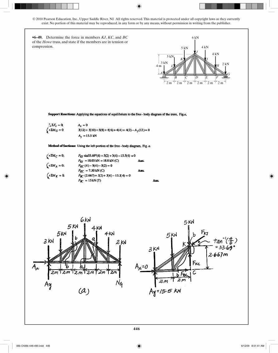
•6–49. Determine the force in members KJ, KC, and BCof the Howe truss, and state if the members are in tension orcompression.
2 kN3 kN
4 kN5 kN
4 kN
6 kN
5 kN
BA
C D E FG
H
I
J
K
L
2 m
4 m
2 m 2 m 2 m 2 m 2 m
06b Ch06b 446-490.indd 44606b Ch06b 446-490.indd 446 6/12/09 8:51:41 AM6/12/09 8:51:41 AM
447
© 2010 Pearson Education, Inc., Upper Saddle River, NJ. All rights reserved. This material is protected under all copyright laws as they currentlyexist. No portion of this material may be reproduced, in any form or by any means, without permission in writing from the publisher.
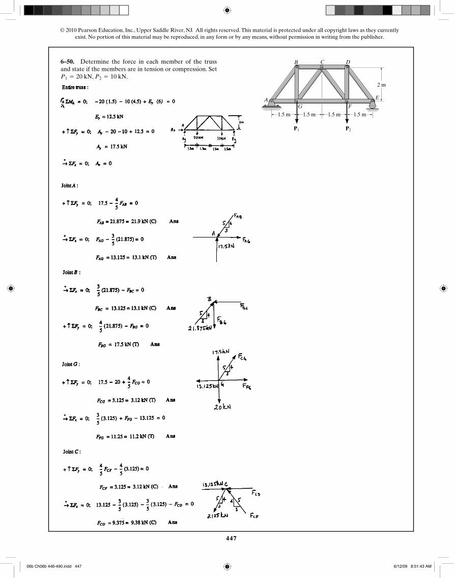
6–50. Determine the force in each member of the trussand state if the members are in tension or compression. Set
, .P2 = 10 kNP1 = 20 kN
AG F
E
DCB
P2P1
1.5 m 1.5 m 1.5 m 1.5 m
2 m
06b Ch06b 446-490.indd 44706b Ch06b 446-490.indd 447 6/12/09 8:51:43 AM6/12/09 8:51:43 AM
448
© 2010 Pearson Education, Inc., Upper Saddle River, NJ. All rights reserved. This material is protected under all copyright laws as they currentlyexist. No portion of this material may be reproduced, in any form or by any means, without permission in writing from the publisher.
06b Ch06b 446-490.indd 44806b Ch06b 446-490.indd 448 6/12/09 8:51:44 AM6/12/09 8:51:44 AM
449
© 2010 Pearson Education, Inc., Upper Saddle River, NJ. All rights reserved. This material is protected under all copyright laws as they currentlyexist. No portion of this material may be reproduced, in any form or by any means, without permission in writing from the publisher.
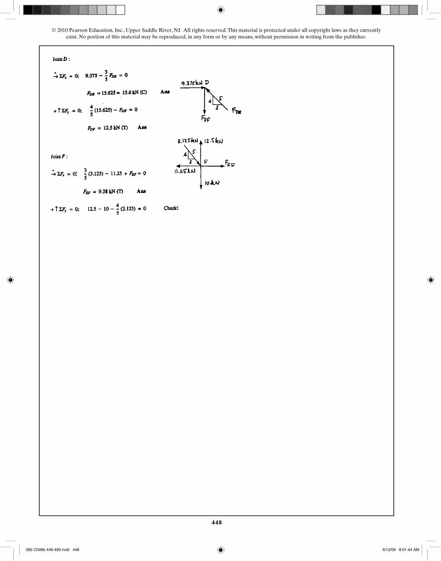
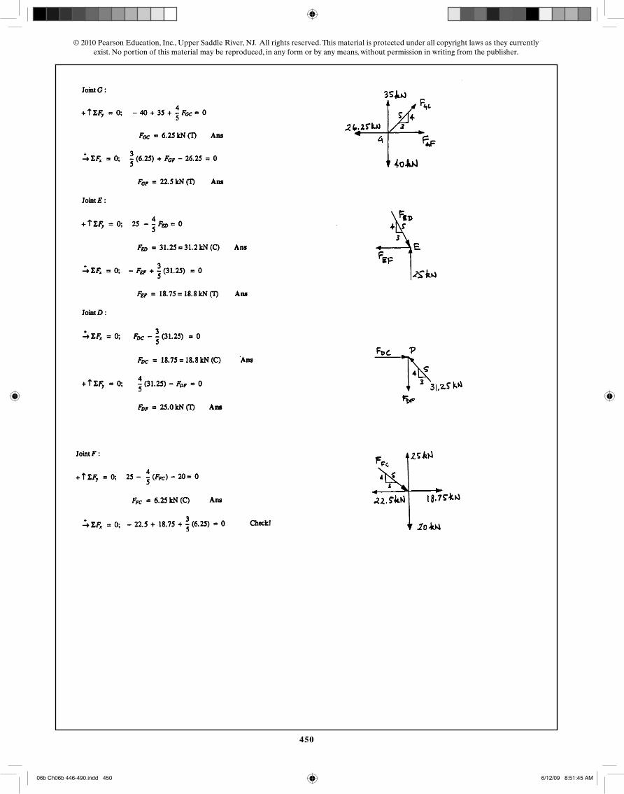
6–51. Determine the force in each member of the trussand state if the members are in tension or compression. Set
, .P2 = 20 kNP1 = 40 kN
AG F
E
DCB
P2P1
1.5 m 1.5 m 1.5 m 1.5 m
2 m
06b Ch06b 446-490.indd 44906b Ch06b 446-490.indd 449 6/12/09 8:51:45 AM6/12/09 8:51:45 AM
450
© 2010 Pearson Education, Inc., Upper Saddle River, NJ. All rights reserved. This material is protected under all copyright laws as they currentlyexist. No portion of this material may be reproduced, in any form or by any means, without permission in writing from the publisher.
06b Ch06b 446-490.indd 45006b Ch06b 446-490.indd 450 6/12/09 8:51:45 AM6/12/09 8:51:45 AM
451
© 2010 Pearson Education, Inc., Upper Saddle River, NJ. All rights reserved. This material is protected under all copyright laws as they currentlyexist. No portion of this material may be reproduced, in any form or by any means, without permission in writing from the publisher.
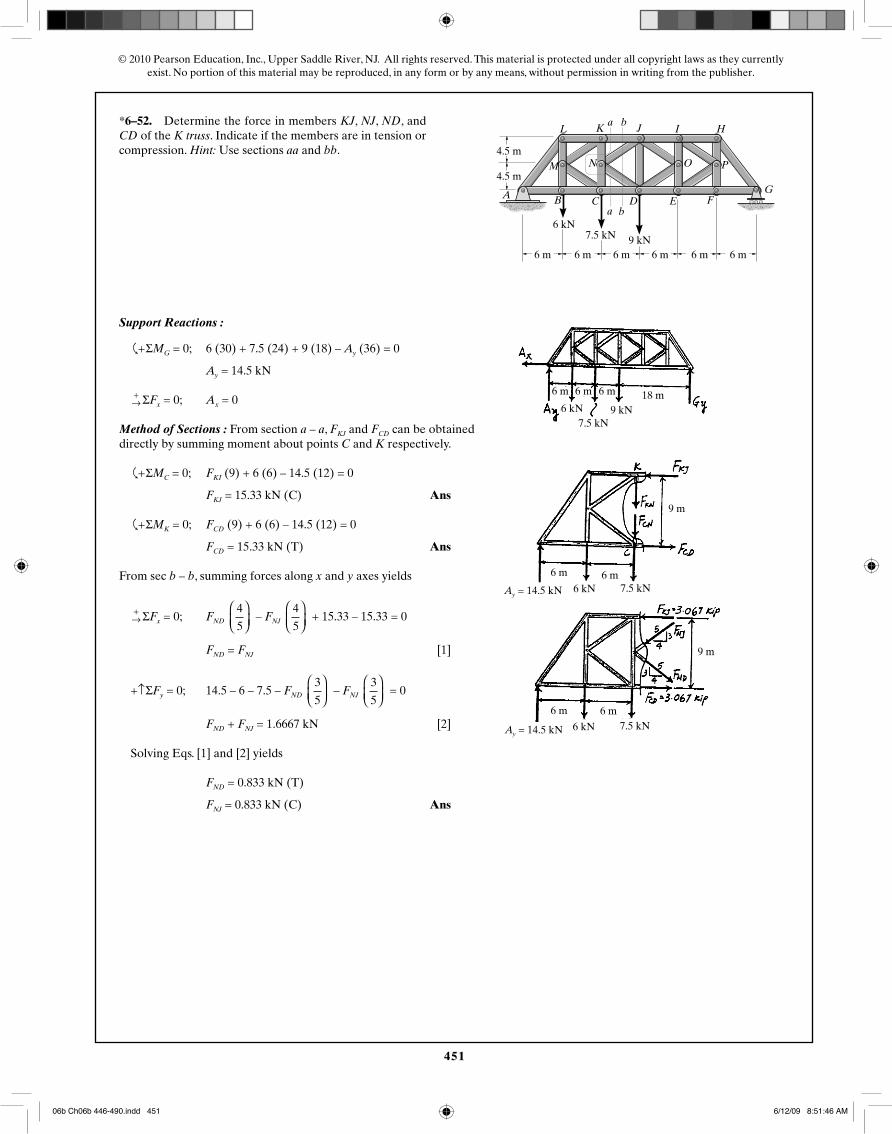
*6–52. Determine the force in members KJ, NJ, ND, andCD of the K truss. Indicate if the members are in tension orcompression. Hint: Use sections aa and bb.
1800 lb
15 ft
15 ft
20 ft 20 ft 20 ft 20 ft 20 ft
A B
I H
20 ft
L
M N O P
GFEDC
1500 lb1200 lb
a b
JKa b
6 kN7.5 kN 9 kN
4.5 m
4.5 m
6 m 6 m 6 m 6 m 6 m 6 m
6 m 6 m 6 m 18 m
9 m
6 m 6 m
9 m
6 m 6 m
7.5 kN
7.5 kN
7.5 kN
6 kN 9 kN
6 kN
6 kN
Ay = 14.5 kN
Ay = 14.5 kN
Support Reactions :
�
+ ΣMG = 0; 6 (30) + 7.5 (24) + 9 (18) – Ay (36) = 0
Ay = 14.5 kN
+→ ΣFx = 0; Ax = 0
Method of Sections : From section a – a, FKJ and FCD can be obtained directly by summing moment about points C and K respectively.
�
+ ΣMC = 0; FKI (9) + 6 (6) – 14.5 (12) = 0
FKJ = 15.33 kN (C) Ans
�
+ ΣMK = 0; FCD (9) + 6 (6) – 14.5 (12) = 0
FCD = 15.33 kN (T) Ans
From sec b – b, summing forces along x and y axes yields
+→ ΣFx = 0; FND
4
5
⎛⎝⎜
⎞⎠⎟
– FNJ 4
5
⎛⎝⎜
⎞⎠⎟
+ 15.33 – 15.33 = 0
FND = FNJ [1]
+↑ΣFy = 0; 14.5 – 6 – 7.5 – FND 3
5
⎛⎝⎜
⎞⎠⎟
– FNJ 3
5
⎛⎝⎜
⎞⎠⎟
= 0
FND + FNJ = 1.6667 kN [2]
Solving Eqs. [1] and [2] yields
FND = 0.833 kN (T)
FNJ = 0.833 kN (C) Ans
06b Ch06b 446-490.indd 45106b Ch06b 446-490.indd 451 6/12/09 8:51:46 AM6/12/09 8:51:46 AM
452
© 2010 Pearson Education, Inc., Upper Saddle River, NJ. All rights reserved. This material is protected under all copyright laws as they currentlyexist. No portion of this material may be reproduced, in any form or by any means, without permission in writing from the publisher.
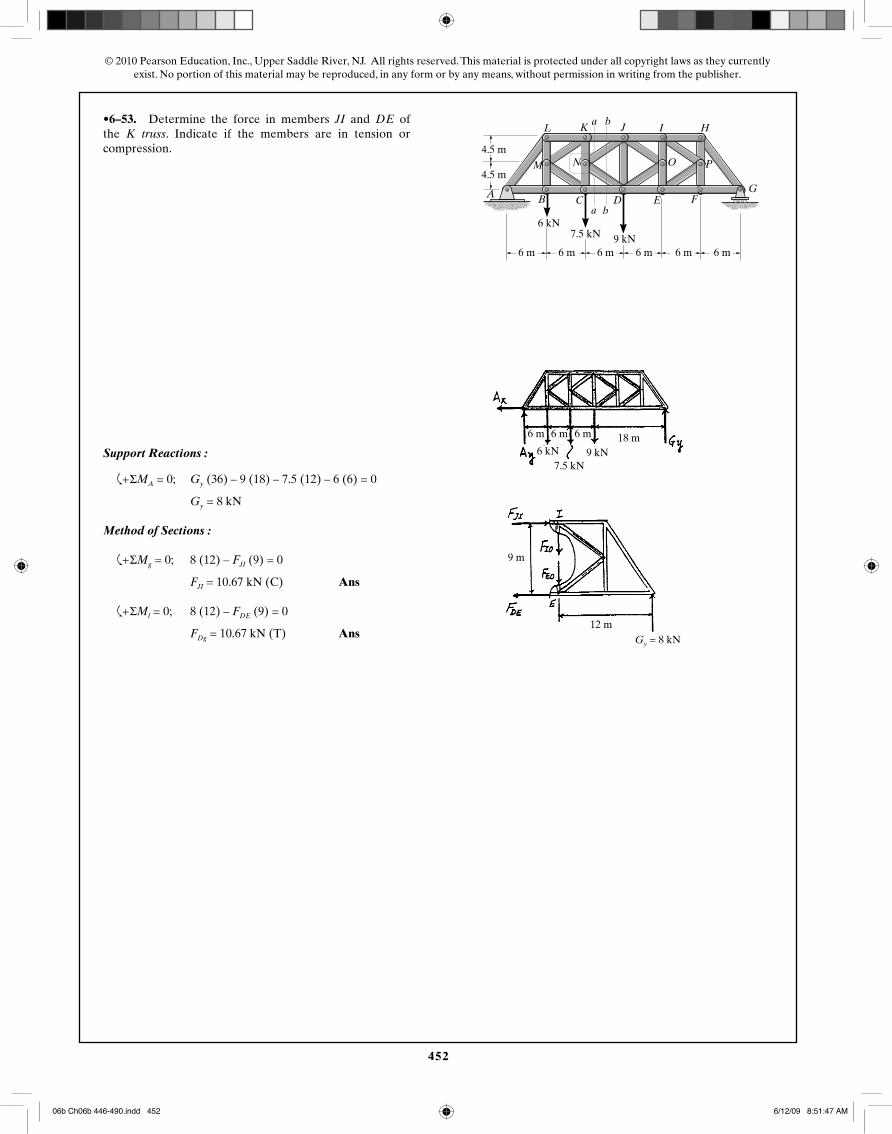
•6–53. Determine the force in members JI and DE ofthe K truss. Indicate if the members are in tension orcompression.
1800 lb
15 ft
15 ft
20 ft 20 ft 20 ft 20 ft 20 ft
A B
I H
20 ft
L
M N O P
GFEDC
1500 lb1200 lb
a b
JKa b
6 kN7.5 kN 9 kN
4.5 m
4.5 m
6 m 6 m 6 m 6 m 6 m 6 m
6 m 6 m 6 m 18 m
7.5 kN6 kN 9 kN
12 m
9 m
Gy = 8 kN
Support Reactions :
�
+ ΣMA = 0; Gy (36) – 9 (18) – 7.5 (12) – 6 (6) = 0
Gy = 8 kN
Method of Sections :
�
+ ΣMg = 0; 8 (12) – FJI (9) = 0
FJI = 10.67 kN (C) Ans
�
+ ΣMl = 0; 8 (12) – FDE (9) = 0
FDg = 10.67 kN (T) Ans
06b Ch06b 446-490.indd 45206b Ch06b 446-490.indd 452 6/12/09 8:51:47 AM6/12/09 8:51:47 AM
453
© 2010 Pearson Education, Inc., Upper Saddle River, NJ. All rights reserved. This material is protected under all copyright laws as they currentlyexist. No portion of this material may be reproduced, in any form or by any means, without permission in writing from the publisher.
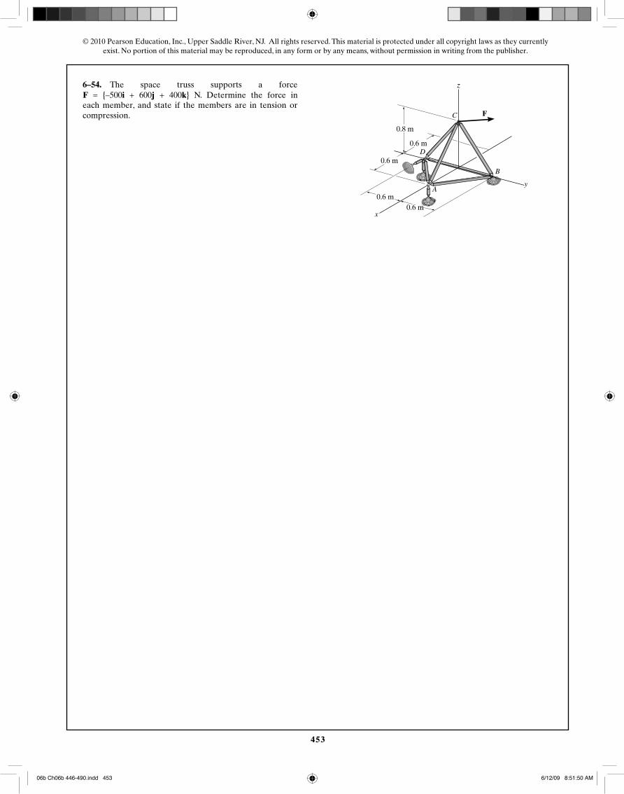
6–54. The space truss supports a force. Determine the force in
each member, and state if the members are in tension orcompression.
F = 5-500i + 600j + 400k6 lb
A
B
C
D
x
y
z
F
8 ft
6 ft
6 ft
6 ft
6 ft
0.8 m
0.6 m
0.6 m
0.6 m0.6 m
F = {–500i + 600j + 400k} N. Determine the force in
06b Ch06b 446-490.indd 45306b Ch06b 446-490.indd 453 6/12/09 8:51:50 AM6/12/09 8:51:50 AM

454
© 2010 Pearson Education, Inc., Upper Saddle River, NJ. All rights reserved. This material is protected under all copyright laws as they currentlyexist. No portion of this material may be reproduced, in any form or by any means, without permission in writing from the publisher.
400 N
500 N
600 N
FCA = 833.33 N
FCD = 333.33 N
FAD = 353.55 N
N N
NN
N
N
N N
N
N
N
06b Ch06b 446-490.indd 45406b Ch06b 446-490.indd 454 6/12/09 8:51:51 AM6/12/09 8:51:51 AM
455
© 2010 Pearson Education, Inc., Upper Saddle River, NJ. All rights reserved. This material is protected under all copyright laws as they currentlyexist. No portion of this material may be reproduced, in any form or by any means, without permission in writing from the publisher.
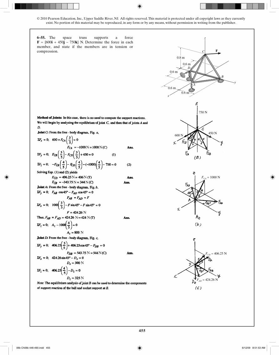
6–55. The space truss supports a force. Determine the force in each
member, and state if the members are in tension orcompression.
F = 5600i + 450j - 750k6 lb
A
B
C
D
x
y
z
F
8 ft
6 ft
6 ft
6 ft
6 ft
FCD = 406.25 N
FCA = 1000 N
FAD = 424.26 N
750 N
450 N600 N
0.8 m
0.6 m
0.6 m
0.6 m0.6 m
F = {600i + 450j – 750k} N. Determine the force in each
N N
N NN N
N N
N N
N
N
N
N
06b Ch06b 446-490.indd 45506b Ch06b 446-490.indd 455 6/12/09 8:51:53 AM6/12/09 8:51:53 AM
456
© 2010 Pearson Education, Inc., Upper Saddle River, NJ. All rights reserved. This material is protected under all copyright laws as they currentlyexist. No portion of this material may be reproduced, in any form or by any means, without permission in writing from the publisher.
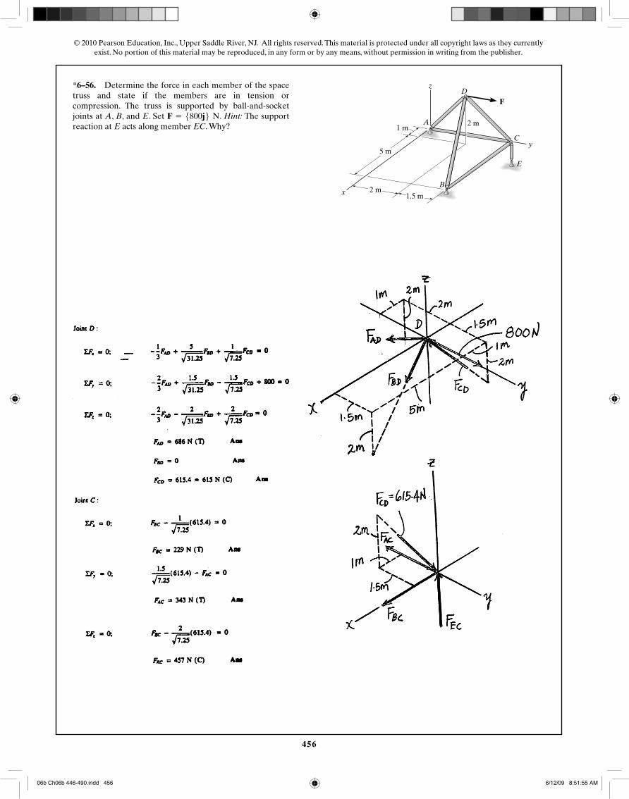
*6–56. Determine the force in each member of the spacetruss and state if the members are in tension orcompression. The truss is supported by ball-and-socketjoints at A, B, and E. Set . Hint: The supportreaction at E acts along member EC. Why?
F = 5800j6 N
FD
A
z
2 m
x
y
B
C
E
5 m
1 m
2 m1.5 m
06b Ch06b 446-490.indd 45606b Ch06b 446-490.indd 456 6/12/09 8:51:55 AM6/12/09 8:51:55 AM
457
© 2010 Pearson Education, Inc., Upper Saddle River, NJ. All rights reserved. This material is protected under all copyright laws as they currentlyexist. No portion of this material may be reproduced, in any form or by any means, without permission in writing from the publisher.
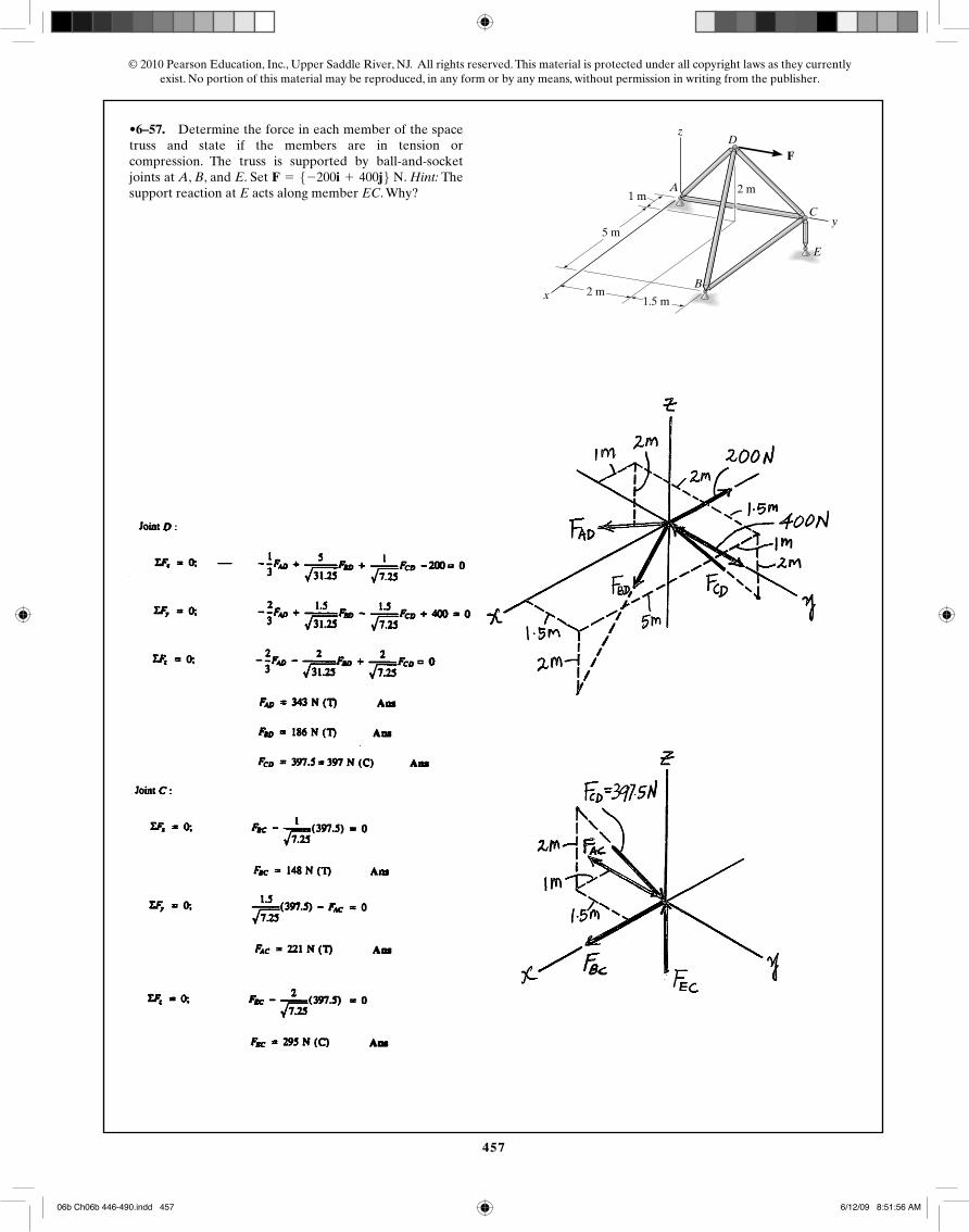
•6–57. Determine the force in each member of the spacetruss and state if the members are in tension orcompression. The truss is supported by ball-and-socketjoints at A, B, and E. Set . Hint: Thesupport reaction at E acts along member EC. Why?
F = 5-200i + 400j6 N
FD
A
z
2 m
x
y
B
C
E
5 m
1 m
2 m1.5 m
06b Ch06b 446-490.indd 45706b Ch06b 446-490.indd 457 6/12/09 8:51:56 AM6/12/09 8:51:56 AM
458
© 2010 Pearson Education, Inc., Upper Saddle River, NJ. All rights reserved. This material is protected under all copyright laws as they currentlyexist. No portion of this material may be reproduced, in any form or by any means, without permission in writing from the publisher.
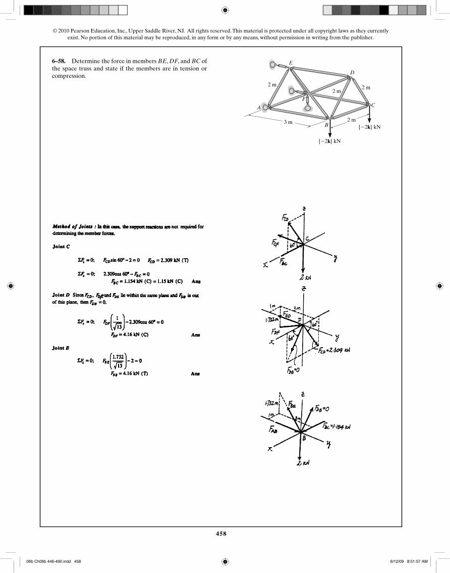
6–58. Determine the force in members BE, DF, and BC ofthe space truss and state if the members are in tension orcompression.
2 m
2 m
2 m
E
A
3 m
F
D
C
B
{�2k} kN
{�2k} kN
2 m
06b Ch06b 446-490.indd 45806b Ch06b 446-490.indd 458 6/12/09 8:51:57 AM6/12/09 8:51:57 AM
459
© 2010 Pearson Education, Inc., Upper Saddle River, NJ. All rights reserved. This material is protected under all copyright laws as they currentlyexist. No portion of this material may be reproduced, in any form or by any means, without permission in writing from the publisher.
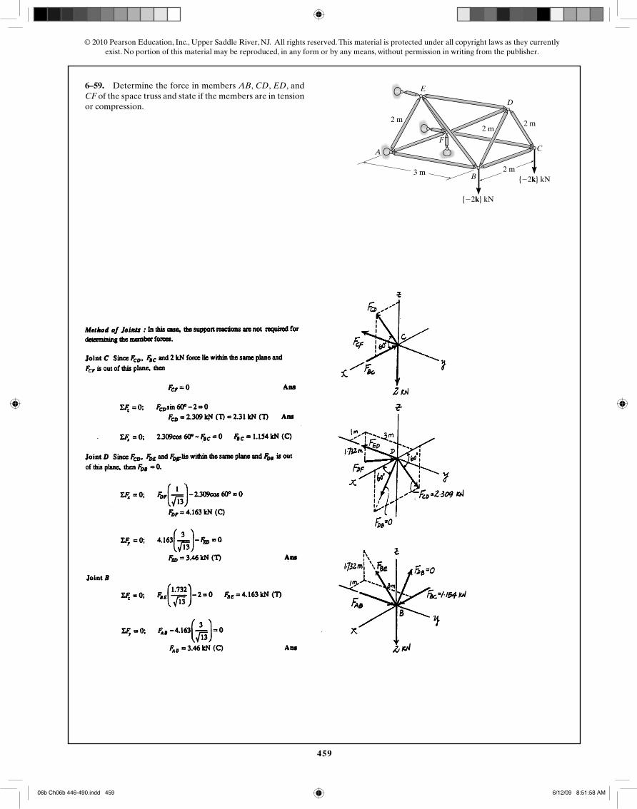
6–59. Determine the force in members AB, CD, ED, andCF of the space truss and state if the members are in tensionor compression.
2 m
2 m
2 m
E
A
3 m
F
D
C
B
{�2k} kN
{�2k} kN
2 m
06b Ch06b 446-490.indd 45906b Ch06b 446-490.indd 459 6/12/09 8:51:58 AM6/12/09 8:51:58 AM
460
© 2010 Pearson Education, Inc., Upper Saddle River, NJ. All rights reserved. This material is protected under all copyright laws as they currentlyexist. No portion of this material may be reproduced, in any form or by any means, without permission in writing from the publisher.
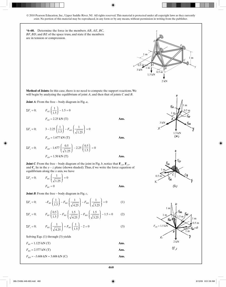
*6–60. Determine the force in the members AB, AE, BC,BF, BD, and BE of the space truss, and state if the membersare in tension or compression.
F
E
D
x
z
y
C
BA
4 ft
4 ft2 ft
2 ft300 lb
600 lb
400 lb
4 ft1 m
0.5 m1 m
0.5 m
1 m
2 kN
1.5 kN
3 kN
1.5 kN
3 kN
1 m
1 m
0.5 m
1 m
0.5 m
1 m
1 m
0.5 m
1 m
1 m
2 kN
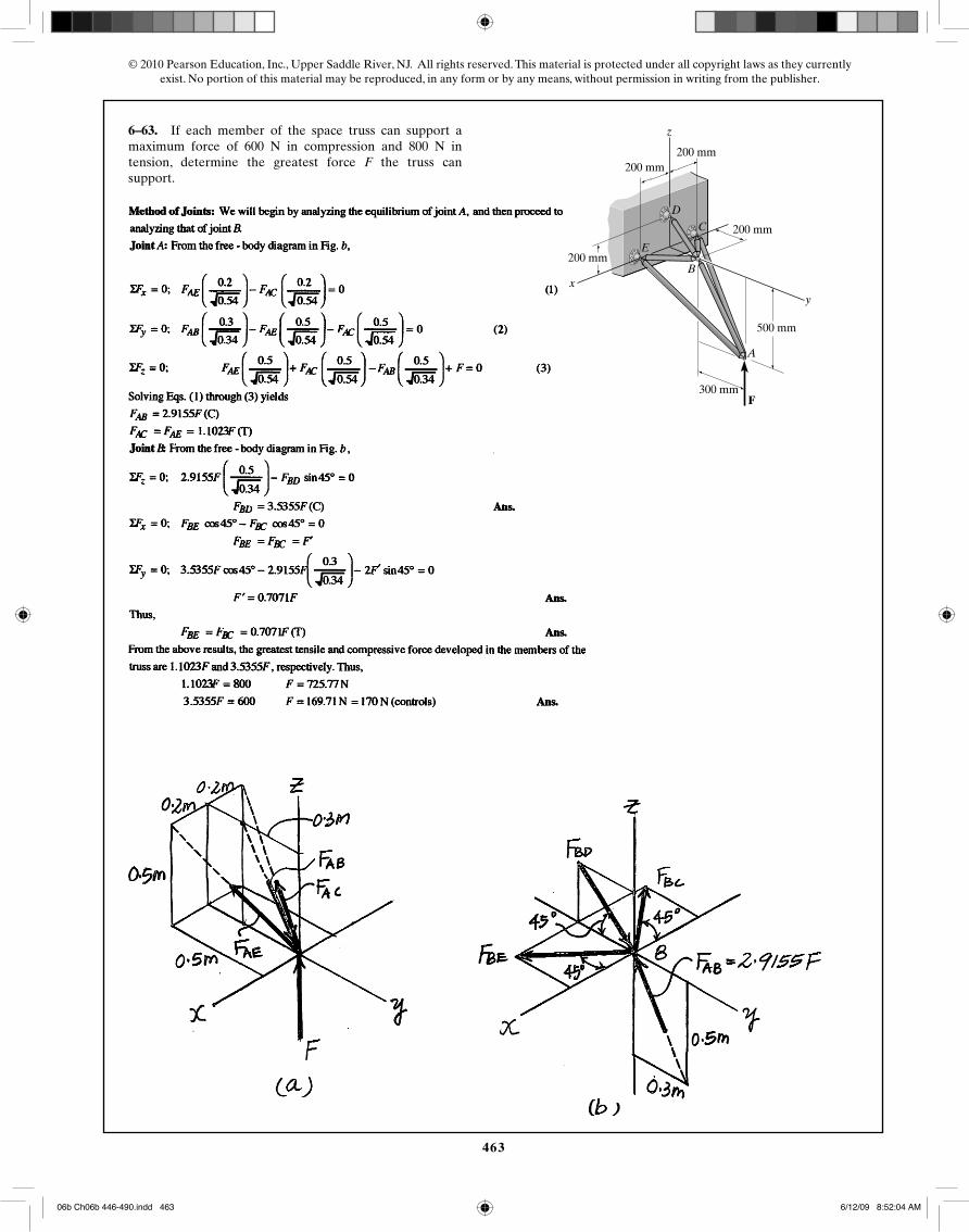
FAB = 1.5 kN
1.5 m
Method of Joints: In this case, there is no need to compute the support reactions. We will begin by analyzing the equilibrium of joint A, and then that of joints C and B.
Joint A: From the free – body diagram in Fig. a,
ΣFz = 0; FAE 1
1.5
⎛⎝⎜
⎞⎠⎟
– 1.5 = 0
FAE = 2.25 kN (T) Ans.
ΣFx = 0; 3 – 2.25 1
1.5
⎛⎝⎜
⎞⎠⎟
– FAD 1
1.25
⎛
⎝⎜
⎞
⎠⎟ = 0
FAD = 1.677 kN (T) Ans.
ΣFy = 0; FAB – 1.677 0.5
1.25
⎛
⎝⎜
⎞
⎠⎟ – 2.25
0.5
1.5
⎛⎝⎜
⎞⎠⎟
= 0
FAB = 1.50 kN (T) Ans.
Joint C: From the free – body diagram of the joint in Fig. b, notice that FCD, FCF, and Cy lie in the y – z plane (shown shaded). Thus, if we write the force equation of equilibrium along the x axis, we have
ΣFx = 0; FBC 1
1.25
⎛
⎝⎜
⎞
⎠⎟ = 0
FBC = 0 Ans.
Joint B: From the free – body diagram in Fig. c,
ΣFx = 0; –FBF 1
1.5
⎛⎝⎜
⎞⎠⎟
– FBE 1
4.25
⎛
⎝⎜
⎞
⎠⎟ – FBD
1
3.25
⎛
⎝⎜
⎞
⎠⎟ = 0 (1)
ΣFy = 0; FBF 0.5
1.5
⎛⎝⎜
⎞⎠⎟
– FBE 1.5
4.25
⎛
⎝⎜
⎞
⎠⎟ – FBD
1.5
3.25
⎛
⎝⎜
⎞
⎠⎟ – 1.5 = 0 (2)
ΣFz = 0; FBE 1
4.25
⎛
⎝⎜
⎞
⎠⎟ + FBF
1
1.5
⎛⎝⎜
⎞⎠⎟
– 2 = 0 (3)
Solving Eqs. (1) through (3) yields
FBF = 1.125 kN (T) Ans.
FBE = 2.577 kN (T) Ans.
FBD = –3.606 kN = 3.606 kN (C) Ans.
06b Ch06b 446-490.indd 46006b Ch06b 446-490.indd 460 6/12/09 8:51:59 AM6/12/09 8:51:59 AM
461
© 2010 Pearson Education, Inc., Upper Saddle River, NJ. All rights reserved. This material is protected under all copyright laws as they currentlyexist. No portion of this material may be reproduced, in any form or by any means, without permission in writing from the publisher.
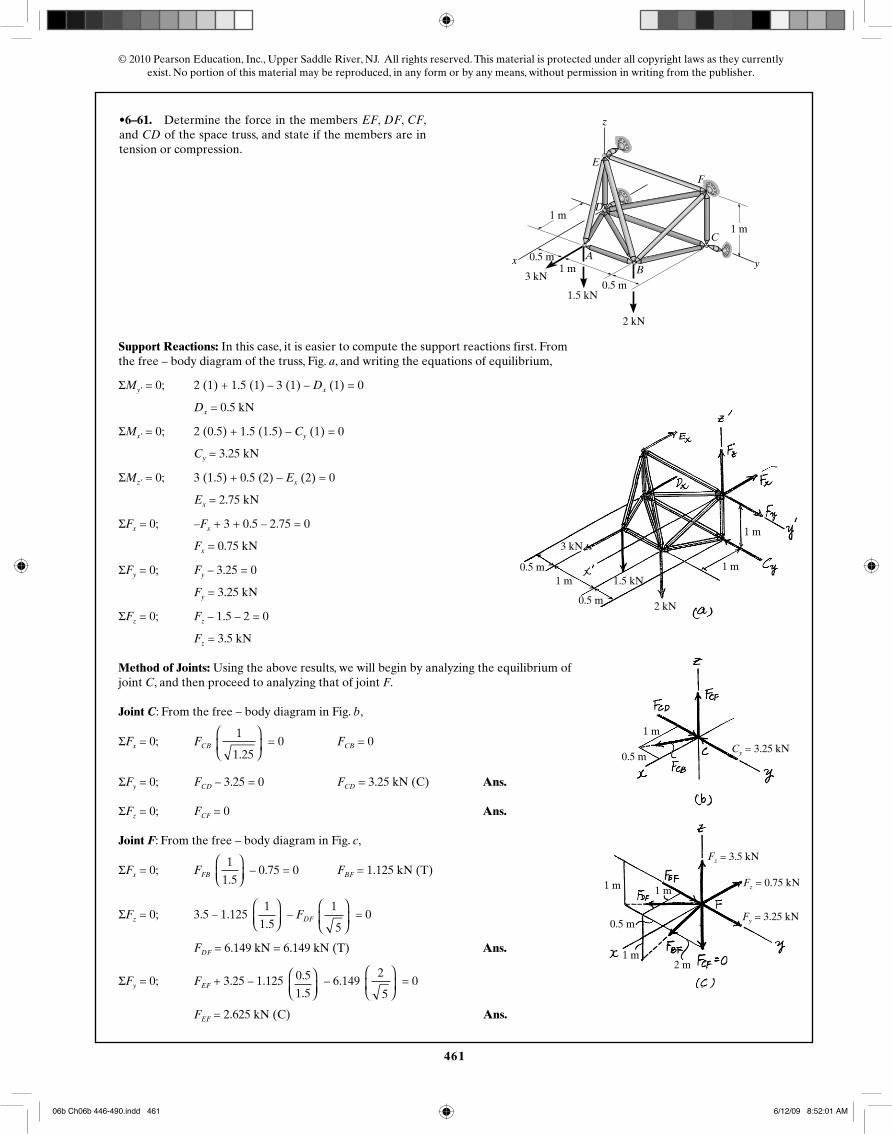
•6–61. Determine the force in the members EF, DF, CF,and CD of the space truss, and state if the members are intension or compression.
F
E
D
x
z
y
C
BA
4 ft
4 ft2 ft
2 ft300 lb
600 lb
400 lb
4 ft1 m
0.5 m1 m
0.5 m
1 m
2 kN
1.5 kN
3 kN
1 m
0.5 m
1 m
0.5 m
1 m2 m
1 m
Cy = 3.25 kN
Fz = 3.5 kN
Fz = 0.75 kN
Fy = 3.25 kN
0.5 m
0.5 m
1 m1 m
1 m3 kN
1.5 kN
2 kN
Support Reactions: In this case, it is easier to compute the support reactions first. From the free – body diagram of the truss, Fig. a, and writing the equations of equilibrium,
ΣMy′ = 0; 2 (1) + 1.5 (1) – 3 (1) – Dx (1) = 0
Dx = 0.5 kN
ΣMx′ = 0; 2 (0.5) + 1.5 (1.5) – Cy (1) = 0
Cy = 3.25 kN
ΣMz′ = 0; 3 (1.5) + 0.5 (2) – Ex (2) = 0
Ex = 2.75 kN
ΣFx = 0; –Fx + 3 + 0.5 – 2.75 = 0
Fx = 0.75 kN
ΣFy = 0; Fy – 3.25 = 0
Fy = 3.25 kN
ΣFz = 0; Fz – 1.5 – 2 = 0
Fz = 3.5 kN
Method of Joints: Using the above results, we will begin by analyzing the equilibrium of joint C, and then proceed to analyzing that of joint F.
Joint C: From the free – body diagram in Fig. b,
ΣFx = 0; FCB 1
1.25
⎛
⎝⎜
⎞
⎠⎟ = 0 FCB = 0
ΣFy = 0; FCD – 3.25 = 0 FCD = 3.25 kN (C) Ans.
ΣFz = 0; FCF = 0 Ans.
Joint F: From the free – body diagram in Fig. c,
ΣFx = 0; FFB 1
1.5
⎛⎝⎜
⎞⎠⎟
– 0.75 = 0 FBF = 1.125 kN (T)
ΣFz = 0; 3.5 – 1.125 1
1.5
⎛⎝⎜
⎞⎠⎟
– FDF 1
5
⎛
⎝⎜
⎞
⎠⎟ = 0
FDF = 6.149 kN = 6.149 kN (T) Ans.
ΣFy = 0; FEF + 3.25 – 1.125 0.5
1.5
⎛⎝⎜
⎞⎠⎟
– 6.149 2
5
⎛
⎝⎜
⎞
⎠⎟ = 0
FEF = 2.625 kN (C) Ans.
06b Ch06b 446-490.indd 46106b Ch06b 446-490.indd 461 6/12/09 8:52:01 AM6/12/09 8:52:01 AM
462
© 2010 Pearson Education, Inc., Upper Saddle River, NJ. All rights reserved. This material is protected under all copyright laws as they currentlyexist. No portion of this material may be reproduced, in any form or by any means, without permission in writing from the publisher.
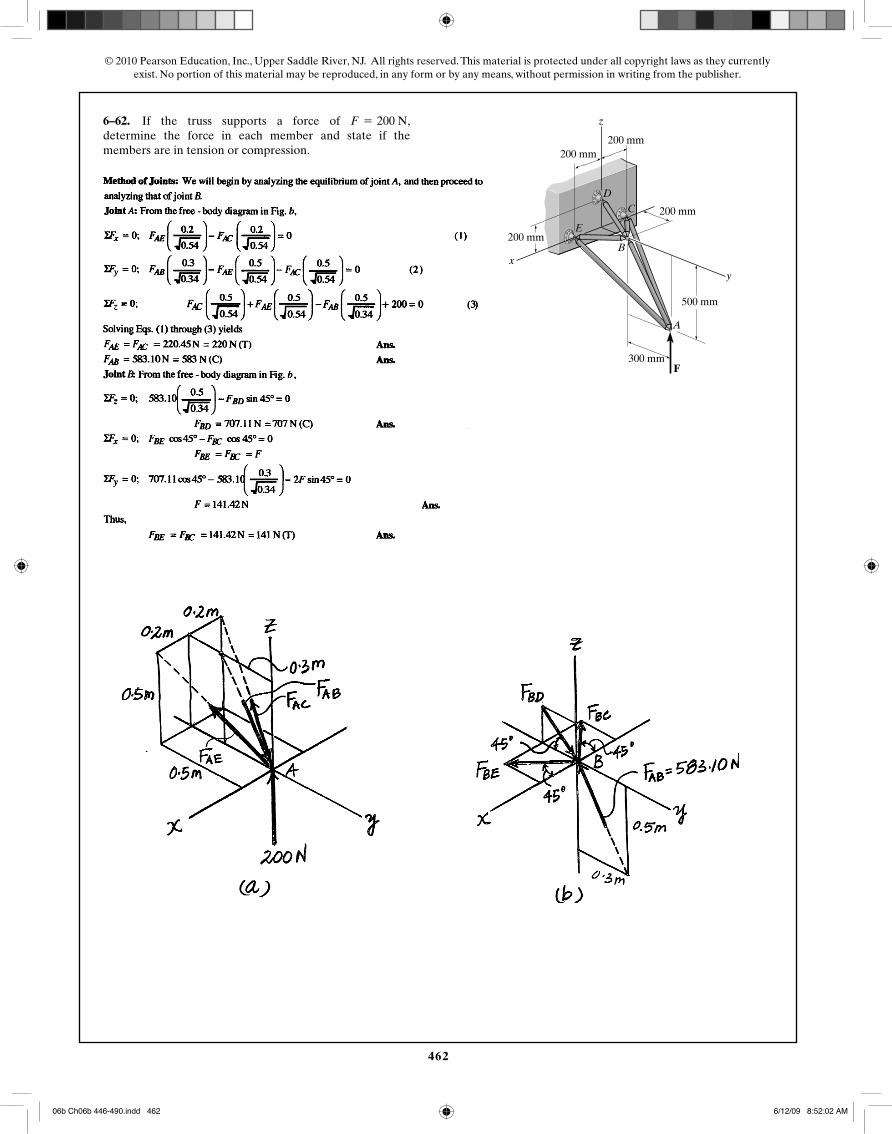
6–62. If the truss supports a force of ,determine the force in each member and state if themembers are in tension or compression.
F = 200 N
y
D
E
F
x
z
C
B
A
200 mm
200 mm
200 mm
200 mm
500 mm
300 mm
06b Ch06b 446-490.indd 46206b Ch06b 446-490.indd 462 6/12/09 8:52:02 AM6/12/09 8:52:02 AM
463
© 2010 Pearson Education, Inc., Upper Saddle River, NJ. All rights reserved. This material is protected under all copyright laws as they currentlyexist. No portion of this material may be reproduced, in any form or by any means, without permission in writing from the publisher.
6–63. If each member of the space truss can support amaximum force of 600 N in compression and 800 N intension, determine the greatest force F the truss cansupport.
y
D
E
F
x
z
C
B
A
200 mm
200 mm
200 mm
200 mm
500 mm
300 mm
06b Ch06b 446-490.indd 46306b Ch06b 446-490.indd 463 6/12/09 8:52:04 AM6/12/09 8:52:04 AM
464
© 2010 Pearson Education, Inc., Upper Saddle River, NJ. All rights reserved. This material is protected under all copyright laws as they currentlyexist. No portion of this material may be reproduced, in any form or by any means, without permission in writing from the publisher.
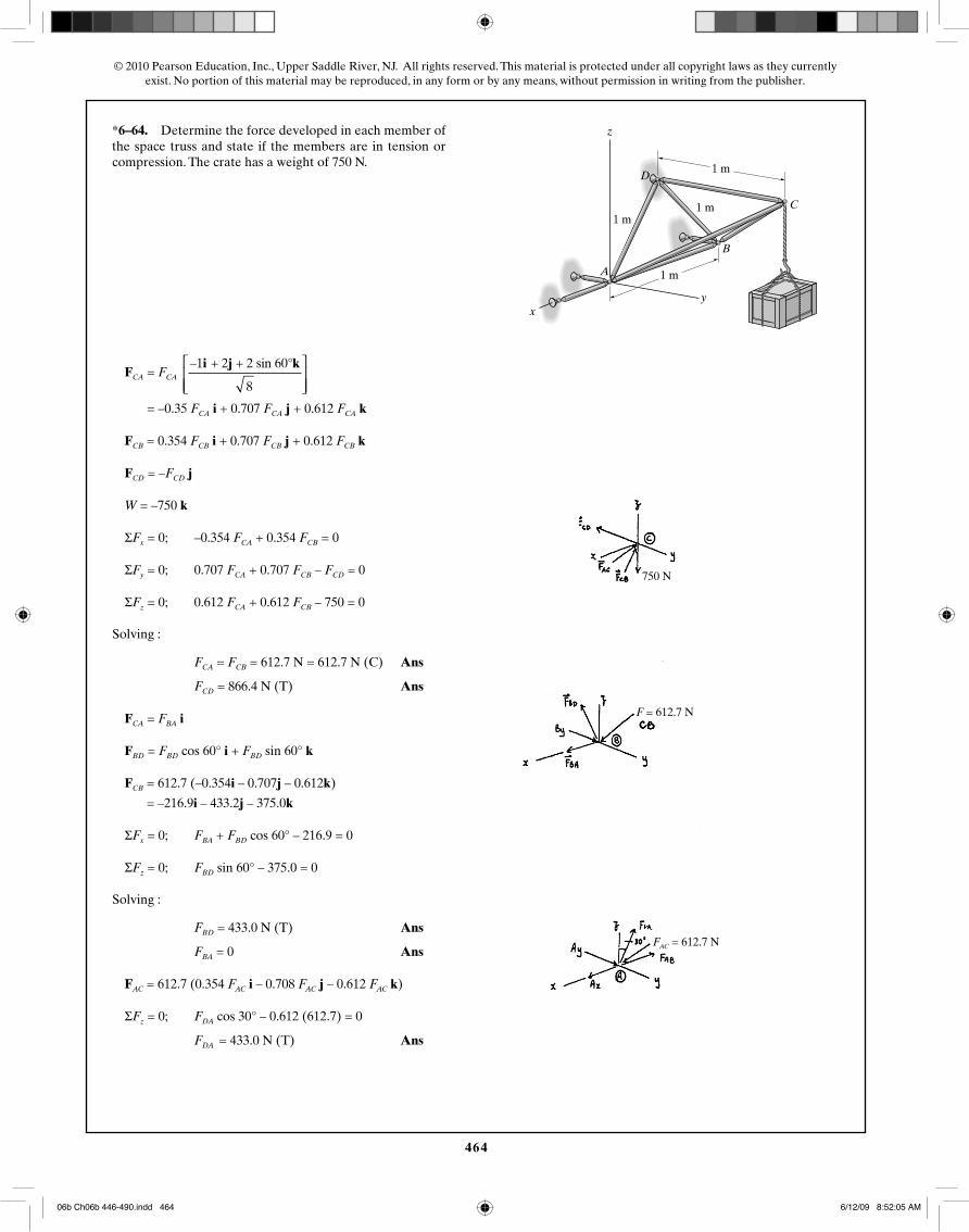
*6–64. Determine the force developed in each member ofthe space truss and state if the members are in tension orcompression. The crate has a weight of 150 lb.
xy
z
A
B
C
D
6 ft
6 ft6 ft
6 ft1 m
1 m
1 m1 m
compression. The crate has a weight of 750 N.
750 N
F = 612.7 N
FAC = 612.7 N
FCA = FCA –1 + 2 + 2 sin 60°
8
i j k⎡
⎣⎢⎢
⎤
⎦⎥⎥
= –0.35 FCA i + 0.707 FCA j + 0.612 FCA k
FCB = 0.354 FCB i + 0.707 FCB j + 0.612 FCB k
FCD = –FCD j
W = –750 k
ΣFx = 0; –0.354 FCA + 0.354 FCB = 0
ΣFy = 0; 0.707 FCA + 0.707 FCB – FCD = 0
ΣFz = 0; 0.612 FCA + 0.612 FCB – 750 = 0
Solving :
FCA = FCB = 612.7 N = 612.7 N (C) Ans
FCD = 866.4 N (T) Ans
FCA = FBA i
FBD = FBD cos 60° i + FBD sin 60° k
FCB = 612.7 (–0.354i – 0.707j – 0.612k)
= –216.9i – 433.2j – 375.0k
ΣFx = 0; FBA + FBD cos 60° – 216.9 = 0
ΣFz = 0; FBD sin 60° – 375.0 = 0
Solving :
FBD = 433.0 N (T) Ans
FBA = 0 Ans
FAC = 612.7 (0.354 FAC i – 0.708 FAC j – 0.612 FAC k)
ΣFz = 0; FDA cos 30° – 0.612 (612.7) = 0
FDA = 433.0 N (T) Ans
06b Ch06b 446-490.indd 46406b Ch06b 446-490.indd 464 6/12/09 8:52:05 AM6/12/09 8:52:05 AM
465
© 2010 Pearson Education, Inc., Upper Saddle River, NJ. All rights reserved. This material is protected under all copyright laws as they currentlyexist. No portion of this material may be reproduced, in any form or by any means, without permission in writing from the publisher.
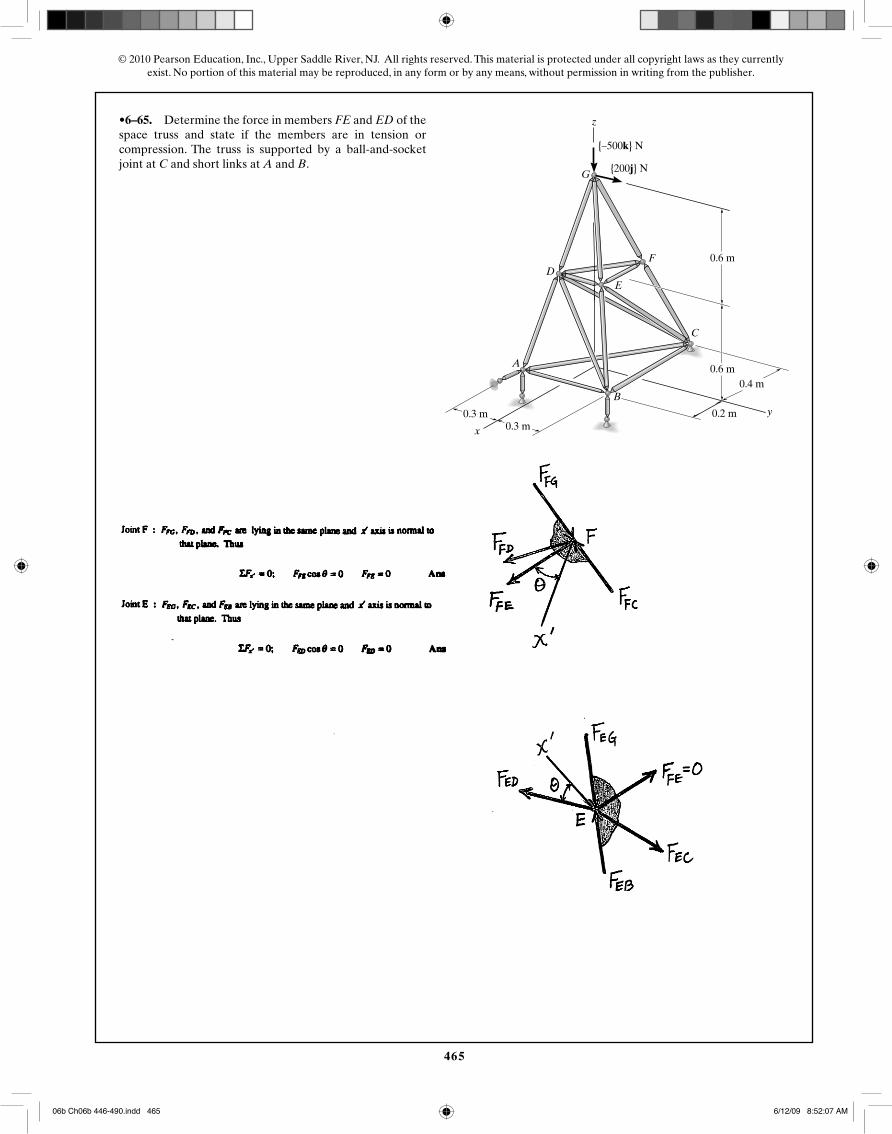
•6–65. Determine the force in members FE and ED of thespace truss and state if the members are in tension orcompression. The truss is supported by a ball-and-socketjoint at C and short links at A and B.
z
x
y
{�500k} lb
G {200j} lb
6 ft
6 ft
F
ED
C
4 ft
2 ft3 ft3 ft
A
B
{–500k} N
{200j} N
0.6 m
0.6 m0.4 m
0.2 m0.3 m
0.3 m
06b Ch06b 446-490.indd 46506b Ch06b 446-490.indd 465 6/12/09 8:52:07 AM6/12/09 8:52:07 AM
466
© 2010 Pearson Education, Inc., Upper Saddle River, NJ. All rights reserved. This material is protected under all copyright laws as they currentlyexist. No portion of this material may be reproduced, in any form or by any means, without permission in writing from the publisher.
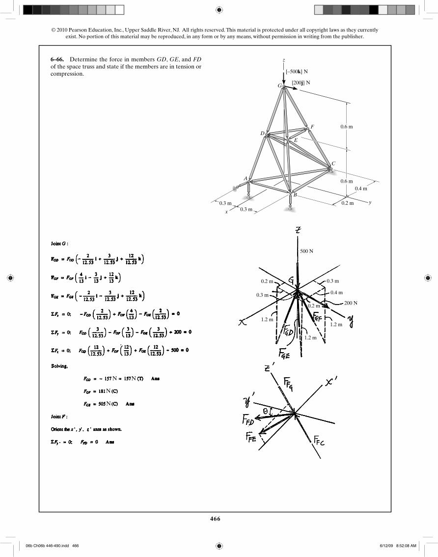
6–66. Determine the force in members GD, GE, and FDof the space truss and state if the members are in tension orcompression.
z
x
y
{�500k} lb
G {200j} lb
6 ft
6 ft
F
ED
C
4 ft
2 ft3 ft3 ft
A
B
{–500k} N
{200j} N
0.6 m
0.6 m0.4 m
0.2 m0.3 m
0.3 m
0.3 m
0.2 m 0.3 m
0.4 m
0.2 m
1.2 m
1.2 m
1.2 m
500 N
200 N
N N
N
N
06b Ch06b 446-490.indd 46606b Ch06b 446-490.indd 466 6/12/09 8:52:08 AM6/12/09 8:52:08 AM

467
© 2010 Pearson Education, Inc., Upper Saddle River, NJ. All rights reserved. This material is protected under all copyright laws as they currentlyexist. No portion of this material may be reproduced, in any form or by any means, without permission in writing from the publisher.
6–67. Determine the force required to hold the 100-lb weight in equilibrium.
P
PA
B
C
D
100 (9.81) N
TA = 490.5 NTB = 245.25 N
100-kg weight in equilibrium.
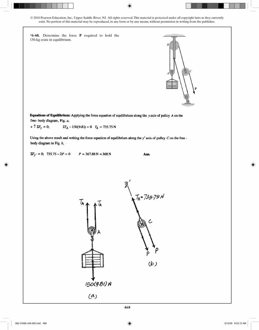
Equations of Equilibrium: Applying the force equation of equilibrium along the y axis of pulley A on the free – body diagram, Fig. a,
+↑ΣFy = 0; 2TA – 100 (9.81) = 0 TA = 490.5 N
Applying ΣFy = 0 to the free – body diagram of pulley B, Fig. b,
+↑ΣFy = 0; 2TB – 490.5 = 0 TB = 245.25 N
From the free – body diagram of pulley C, Fig. c,
+↑ΣFy = 0; 2P – 245.25 = 0 P = 122.625 N Ans.
06b Ch06b 446-490.indd 46706b Ch06b 446-490.indd 467 6/12/09 8:52:11 AM6/12/09 8:52:11 AM
468
© 2010 Pearson Education, Inc., Upper Saddle River, NJ. All rights reserved. This material is protected under all copyright laws as they currentlyexist. No portion of this material may be reproduced, in any form or by any means, without permission in writing from the publisher.
*6–68. Determine the force required to hold the 150-kg crate in equilibrium.
P
P
A
B
C
06b Ch06b 446-490.indd 46806b Ch06b 446-490.indd 468 6/12/09 8:52:15 AM6/12/09 8:52:15 AM
469
© 2010 Pearson Education, Inc., Upper Saddle River, NJ. All rights reserved. This material is protected under all copyright laws as they currentlyexist. No portion of this material may be reproduced, in any form or by any means, without permission in writing from the publisher.
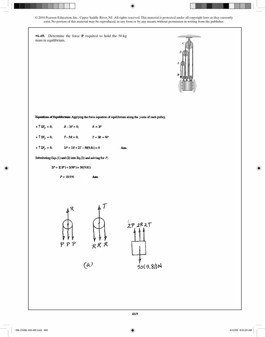
•6–69. Determine the force required to hold the 50-kgmass in equilibrium.
P
P
A
B
C
06b Ch06b 446-490.indd 46906b Ch06b 446-490.indd 469 6/12/09 8:52:20 AM6/12/09 8:52:20 AM
470
© 2010 Pearson Education, Inc., Upper Saddle River, NJ. All rights reserved. This material is protected under all copyright laws as they currentlyexist. No portion of this material may be reproduced, in any form or by any means, without permission in writing from the publisher.
6–70. Determine the force needed to hold the 20-lb blockin equilibrium.
P
C
B
A
P
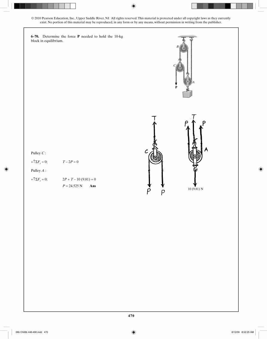
6–70. Determine the force P needed to hold the 10-kg block in equilibrium.
Pulley C :
+↑ΣFy = 0; T – 2P = 0
Pulley A :
+↑ΣFy = 0; 2P + T – 10 (9.81) = 0
P = 24.525 N Ans10 (9.81) N
06b Ch06b 446-490.indd 47006b Ch06b 446-490.indd 470 6/12/09 8:52:25 AM6/12/09 8:52:25 AM
471
© 2010 Pearson Education, Inc., Upper Saddle River, NJ. All rights reserved. This material is protected under all copyright laws as they currentlyexist. No portion of this material may be reproduced, in any form or by any means, without permission in writing from the publisher.
6–71. Determine the force needed to support the 100-lbweight. Each pulley has a weight of 10 lb. Also, what are thecord reactions at A and B?
P
P
2 in.
2 in.
2 in.
CA
B
50 (9.81) N
50 N50 N
50 mm
50 mm
50 mm
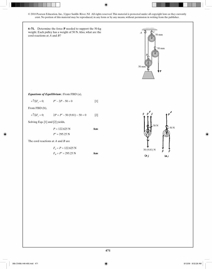
6–71. Determine the force P needed to support the 50-kg weight. Each pulley has a weight of 50 N. Also, what are the cord reactions at A and B?
Equations of Equilibrium : From FBD (a),
+↑ΣFy = 0; P′ – 2P – 50 = 0 [1]
From FBD (b),
+↑ΣFy = 0; 2P + P′ – 50 (9.81) – 50 = 0 [2]
Solving Eqs. [1] and [2] yields,
P = 122.625 N Ans
P′ = 295.25 N
The cord reactions at A and B are
FA = P = 122.625 N
FB = P′ = 295.25 N Ans
06b Ch06b 446-490.indd 47106b Ch06b 446-490.indd 471 6/12/09 8:52:26 AM6/12/09 8:52:26 AM
472
© 2010 Pearson Education, Inc., Upper Saddle River, NJ. All rights reserved. This material is protected under all copyright laws as they currentlyexist. No portion of this material may be reproduced, in any form or by any means, without permission in writing from the publisher.
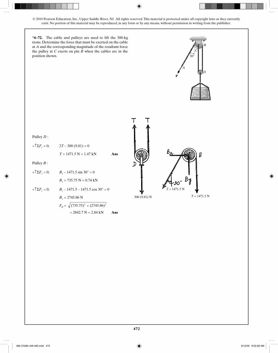
*6–72. The cable and pulleys are used to lift the 600-lbstone. Determine the force that must be exerted on the cableat A and the corresponding magnitude of the resultant forcethe pulley at C exerts on pin B when the cables are in theposition shown.
P
A
C
B
D
30�
300 (9.81) N
T = 1471.5 N
T = 1471.5 N
*6–72. The cable and pulleys are used to lift the 300-kg
Pulley D :
+↑ΣFy = 0; 2T – 300 (9.81) = 0
T = 1471.5 N = 1.47 kN Ans
Pulley B :
+↑ΣFx = 0; Bx – 1471.5 sin 30° = 0
Bx = 735.75 N = 0.74 kN
+↑ΣFy = 0; By – 1471.5 – 1471.5 cos 30° = 0
By = 2745.86 N
FB = (735.75) + (2745.86)2 2
= 2842.7 N = 2.84 kN Ans
06b Ch06b 446-490.indd 47206b Ch06b 446-490.indd 472 6/12/09 8:52:28 AM6/12/09 8:52:28 AM
473
© 2010 Pearson Education, Inc., Upper Saddle River, NJ. All rights reserved. This material is protected under all copyright laws as they currentlyexist. No portion of this material may be reproduced, in any form or by any means, without permission in writing from the publisher.
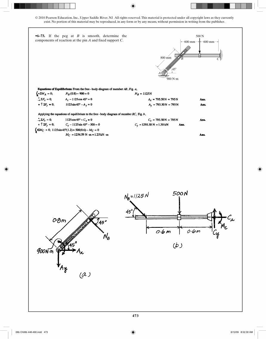
•6–73. If the peg at B is smooth, determine thecomponents of reaction at the pin A and fixed support C.
A
B C
600 mm
800 mm
900 N�m
600 mm
500 N
45�
06b Ch06b 446-490.indd 47306b Ch06b 446-490.indd 473 6/12/09 8:52:30 AM6/12/09 8:52:30 AM
474
© 2010 Pearson Education, Inc., Upper Saddle River, NJ. All rights reserved. This material is protected under all copyright laws as they currentlyexist. No portion of this material may be reproduced, in any form or by any means, without permission in writing from the publisher.
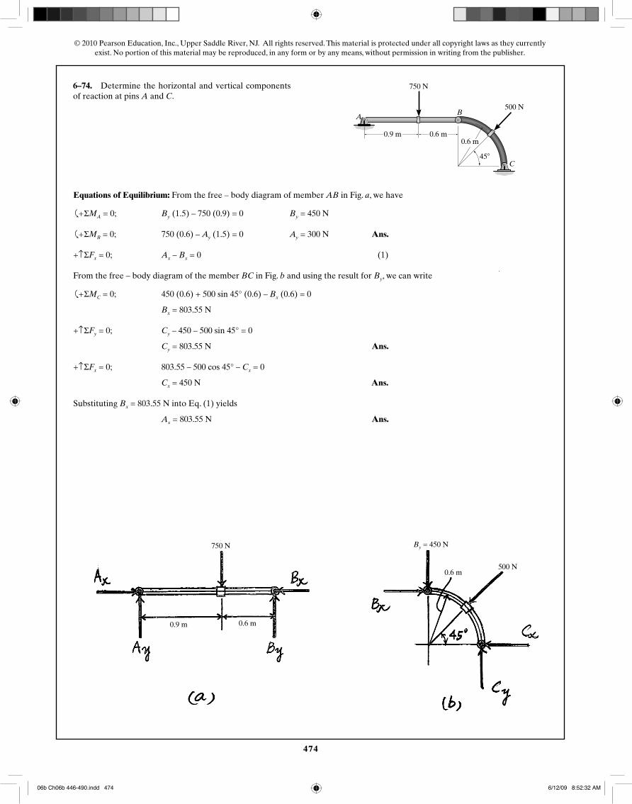
6–74. Determine the horizontal and vertical componentsof reaction at pins A and C.
BA
C
2 ft3 ft
150 lb
100 lb
2 ft
45�
By = 450 N
500 N0.6 m
0.6 m0.9 m
750 N
0.6 m0.9 m
750 N
500 N
0.6 m
Equations of Equilibrium: From the free – body diagram of member AB in Fig. a, we have
�
+ ΣMA = 0; By (1.5) – 750 (0.9) = 0 By = 450 N
�
+ ΣMB = 0; 750 (0.6) – Ay (1.5) = 0 Ay = 300 N Ans.
+↑ΣFx = 0; Ax – Bx = 0 (1)
From the free – body diagram of the member BC in Fig. b and using the result for By, we can write
�
+ ΣMC = 0; 450 (0.6) + 500 sin 45° (0.6) – Bx (0.6) = 0
Bx = 803.55 N
+↑ΣFy = 0; Cy – 450 – 500 sin 45° = 0
Cy = 803.55 N Ans.
+↑ΣFx = 0; 803.55 – 500 cos 45° – Cx = 0
Cx = 450 N Ans.
Substituting Bx = 803.55 N into Eq. (1) yields
Ax = 803.55 N Ans.
06b Ch06b 446-490.indd 47406b Ch06b 446-490.indd 474 6/12/09 8:52:32 AM6/12/09 8:52:32 AM
475
© 2010 Pearson Education, Inc., Upper Saddle River, NJ. All rights reserved. This material is protected under all copyright laws as they currentlyexist. No portion of this material may be reproduced, in any form or by any means, without permission in writing from the publisher.
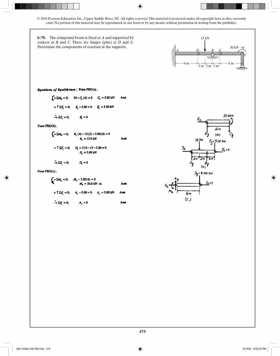
6–75. The compound beam is fixed at A and supported byrockers at B and C. There are hinges (pins) at D and E.Determine the components of reaction at the supports.
6 m2 m
6 m
30 kN � m
2 m 2 m
15 kN
A D B EC
06b Ch06b 446-490.indd 47506b Ch06b 446-490.indd 475 6/12/09 8:52:33 AM6/12/09 8:52:33 AM
476
© 2010 Pearson Education, Inc., Upper Saddle River, NJ. All rights reserved. This material is protected under all copyright laws as they currentlyexist. No portion of this material may be reproduced, in any form or by any means, without permission in writing from the publisher.
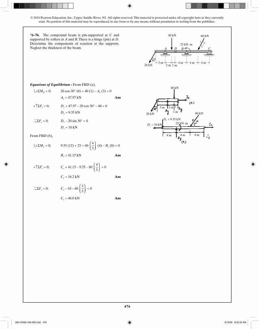
*6–76. The compound beam is pin-supported at C andsupported by rollers at A and B. There is a hinge (pin) at D.Determine the components of reaction at the supports.Neglect the thickness of the beam. A D B C
8 ft
3
45
8 ft
12 kip
15 kip � ft
4 kip30�
8 kip
8 ft4 ft 2 ft
6 ft3 m 4 m 4 m 4 m2 m 1 m
40 kN 60 kN
25 kN · m
4 m 4 m 4 m
Dy = 9.35 kN
60 kN
25 kN · mDx = 10 kN
40 kN
20 kN
3 m 2 m1 m
20 kN
Equations of Equilibrium : From FBD (a),
�
+ ΣMD = 0; 20 cos 30° (6) + 40 (1) – Ay (3) = 0
Ay = 47.97 kN Ans
+↑ΣFy = 0; Dy + 47.97 – 20 cos 30° – 40 = 0
Dy = 9.35 kN
+→ ΣFx = 0; Dx – 20 sin 30° = 0
Dx = 10 kN
From FBD (b),
�
+ ΣMC = 0; 9.35 (12) + 25 + 60 4
5
⎛⎝⎜
⎞⎠⎟
(4) – By (8) = 0
By = 41.15 kN Ans
+↑ΣFy = 0; Cy + 41.15 – 9.35 – 60 4
5
⎛⎝⎜
⎞⎠⎟
= 0
Cy = 16.2 kN Ans
+→ ΣFx = 0; Cx – 10 – 60
3
5
⎛⎝⎜
⎞⎠⎟
= 0
Cx = 46.0 kN Ans
06b Ch06b 446-490.indd 47606b Ch06b 446-490.indd 476 6/12/09 8:52:34 AM6/12/09 8:52:34 AM
477
© 2010 Pearson Education, Inc., Upper Saddle River, NJ. All rights reserved. This material is protected under all copyright laws as they currentlyexist. No portion of this material may be reproduced, in any form or by any means, without permission in writing from the publisher.
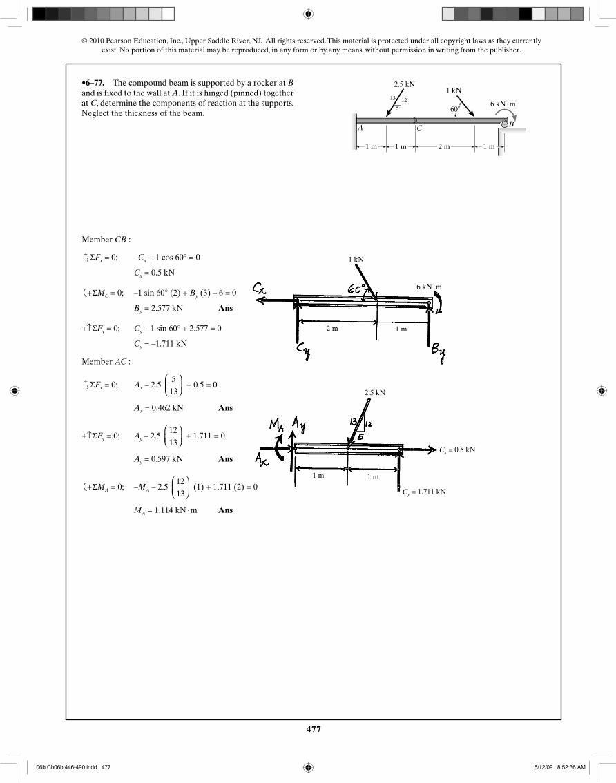
•6–77. The compound beam is supported by a rocker at Band is fixed to the wall at A. If it is hinged (pinned) togetherat C, determine the components of reaction at the supports.Neglect the thickness of the beam.
4 ft 4 ft
500 lb200 lb
4000 lb � ft
4 ft8 ft
A C B
1213
5 60�
1 m
2.5 kN1 kN
6 kN · m
1 m 2 m 1 m
1 kN
6 kN · m
2 m 1 m
1 m 1 m
Cx = 0.5 kN
Cy = 1.711 kN
2.5 kN
Member CB :
+→ ΣFx = 0; –Cx + 1 cos 60° = 0
Cx = 0.5 kN
�
+ ΣMC = 0; –1 sin 60° (2) + By (3) – 6 = 0
By = 2.577 kN Ans
+↑ΣFy = 0; Cy – 1 sin 60° + 2.577 = 0
Cy = –1.711 kN
Member AC :
+→ ΣFx = 0; Ax – 2.5
5
13
⎛⎝⎜
⎞⎠⎟
+ 0.5 = 0
Ax = 0.462 kN Ans
+↑ΣFy = 0; Ay – 2.5 12
13
⎛⎝⎜
⎞⎠⎟
+ 1.711 = 0
Ay = 0.597 kN Ans
�
+ ΣMA = 0; –MA – 2.5 12
13
⎛⎝⎜
⎞⎠⎟
(1) + 1.711 (2) = 0
MA = 1.114 kN · m Ans
06b Ch06b 446-490.indd 47706b Ch06b 446-490.indd 477 6/12/09 8:52:36 AM6/12/09 8:52:36 AM
478
© 2010 Pearson Education, Inc., Upper Saddle River, NJ. All rights reserved. This material is protected under all copyright laws as they currentlyexist. No portion of this material may be reproduced, in any form or by any means, without permission in writing from the publisher.
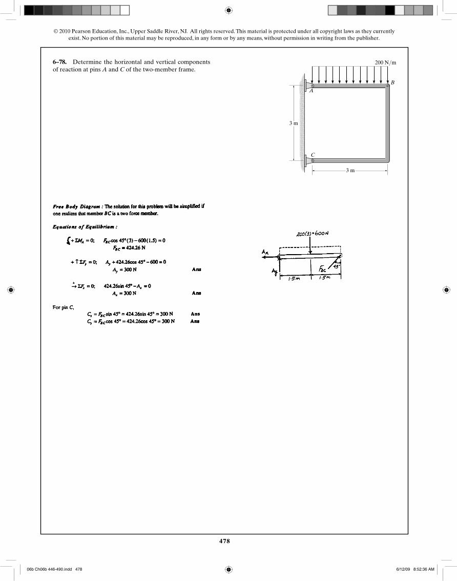
6–78. Determine the horizontal and vertical componentsof reaction at pins A and C of the two-member frame.
3 m
3 m
200 N/m
A
B
C
06b Ch06b 446-490.indd 47806b Ch06b 446-490.indd 478 6/12/09 8:52:36 AM6/12/09 8:52:36 AM
479
© 2010 Pearson Education, Inc., Upper Saddle River, NJ. All rights reserved. This material is protected under all copyright laws as they currentlyexist. No portion of this material may be reproduced, in any form or by any means, without permission in writing from the publisher.
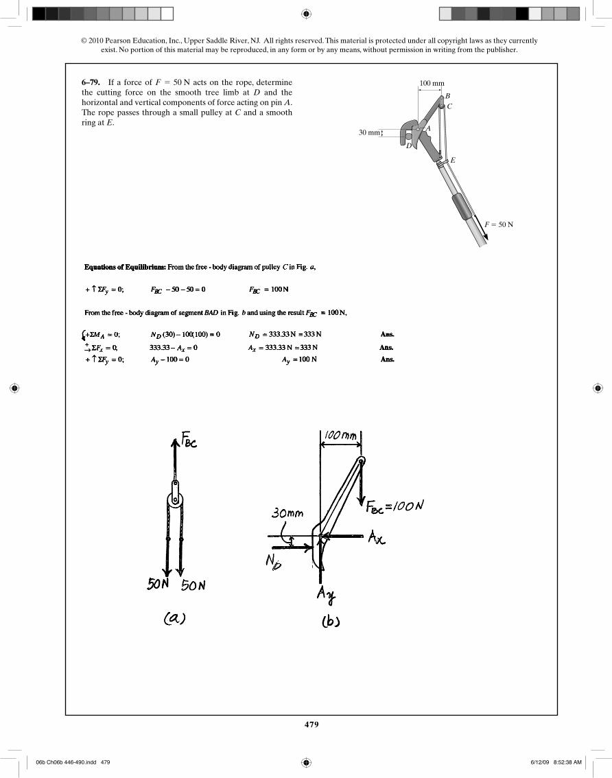
6–79. If a force of acts on the rope, determinethe cutting force on the smooth tree limb at D and thehorizontal and vertical components of force acting on pin A.The rope passes through a small pulley at C and a smoothring at E.
F = 50 N
F � 50 N
BC
E
30 mm
100 mm
A
D
06b Ch06b 446-490.indd 47906b Ch06b 446-490.indd 479 6/12/09 8:52:38 AM6/12/09 8:52:38 AM
480
© 2010 Pearson Education, Inc., Upper Saddle River, NJ. All rights reserved. This material is protected under all copyright laws as they currentlyexist. No portion of this material may be reproduced, in any form or by any means, without permission in writing from the publisher.
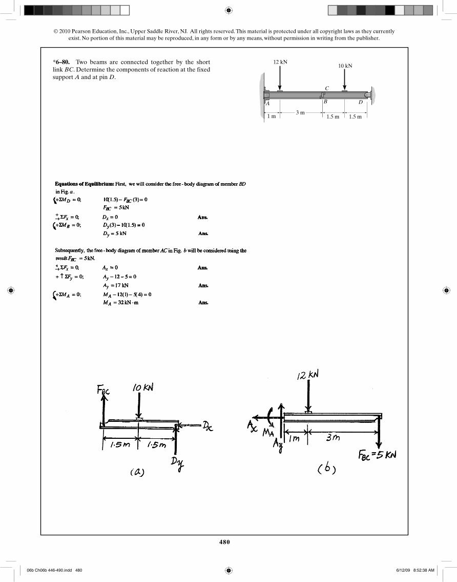
*6–80. Two beams are connected together by the shortlink BC. Determine the components of reaction at the fixedsupport A and at pin D.
A B
C
D
10 kN12 kN
3 m1.5 m1 m 1.5 m
06b Ch06b 446-490.indd 48006b Ch06b 446-490.indd 480 6/12/09 8:52:38 AM6/12/09 8:52:38 AM
481
© 2010 Pearson Education, Inc., Upper Saddle River, NJ. All rights reserved. This material is protected under all copyright laws as they currentlyexist. No portion of this material may be reproduced, in any form or by any means, without permission in writing from the publisher.
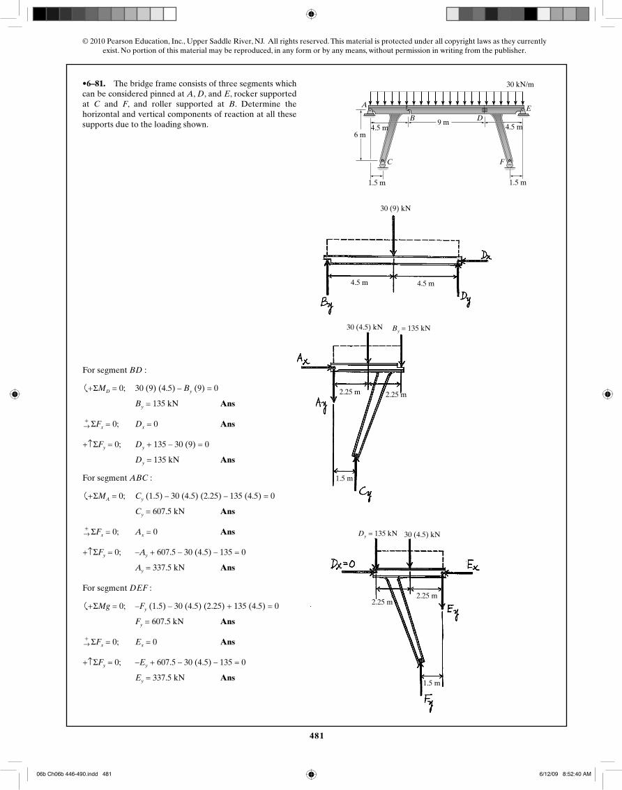
•6–81. The bridge frame consists of three segments whichcan be considered pinned at A, D, and E, rocker supportedat C and F, and roller supported at B. Determine thehorizontal and vertical components of reaction at all thesesupports due to the loading shown. 15 ft
20 ft
5 ft 5 ft
15 ft
2 kip/ft
30 ft
A
B
C F
DE
30 kN/m
9 m
6 m4.5 m
1.5 m 1.5 m
4.5 m
4.5 m4.5 m
1.5 m
2.25 m 2.25 m
1.5 m
2.25 m2.25 m
30 (4.5) kN
30 (4.5) kN By = 135 kN
Dy = 135 kN
30 (9) kN
For segment BD :
�
+ ΣMD = 0; 30 (9) (4.5) – By (9) = 0
By = 135 kN Ans
+→ ΣFx = 0; Dx = 0 Ans
+↑ΣFy = 0; Dy + 135 – 30 (9) = 0
Dy = 135 kN Ans
For segment ABC :
�
+ ΣMA = 0; Cy (1.5) – 30 (4.5) (2.25) – 135 (4.5) = 0
Cy = 607.5 kN Ans
+→ ΣFx = 0; Ax = 0 Ans
+↑ΣFy = 0; –Ay + 607.5 – 30 (4.5) – 135 = 0
Ay = 337.5 kN Ans
For segment DEF :
�
+ ΣMg = 0; –Fy (1.5) – 30 (4.5) (2.25) + 135 (4.5) = 0
Fy = 607.5 kN Ans
+→ ΣFx = 0; Ex = 0 Ans
+↑ΣFy = 0; –Ey + 607.5 – 30 (4.5) – 135 = 0
Ey = 337.5 kN Ans
06b Ch06b 446-490.indd 48106b Ch06b 446-490.indd 481 6/12/09 8:52:40 AM6/12/09 8:52:40 AM
482
© 2010 Pearson Education, Inc., Upper Saddle River, NJ. All rights reserved. This material is protected under all copyright laws as they currentlyexist. No portion of this material may be reproduced, in any form or by any means, without permission in writing from the publisher.
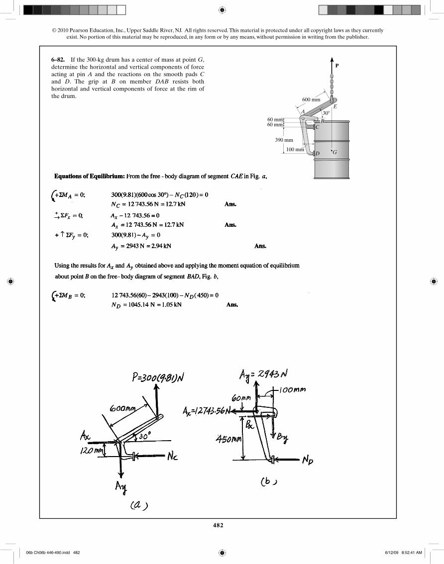
6–82. If the 300-kg drum has a center of mass at point G,determine the horizontal and vertical components of forceacting at pin A and the reactions on the smooth pads Cand D. The grip at B on member DAB resists bothhorizontal and vertical components of force at the rim ofthe drum.
P
390 mm
100 mm
60 mm60 mm
600 mm
30�
B
A
C
D G
E
06b Ch06b 446-490.indd 48206b Ch06b 446-490.indd 482 6/12/09 8:52:41 AM6/12/09 8:52:41 AM
483
© 2010 Pearson Education, Inc., Upper Saddle River, NJ. All rights reserved. This material is protected under all copyright laws as they currentlyexist. No portion of this material may be reproduced, in any form or by any means, without permission in writing from the publisher.
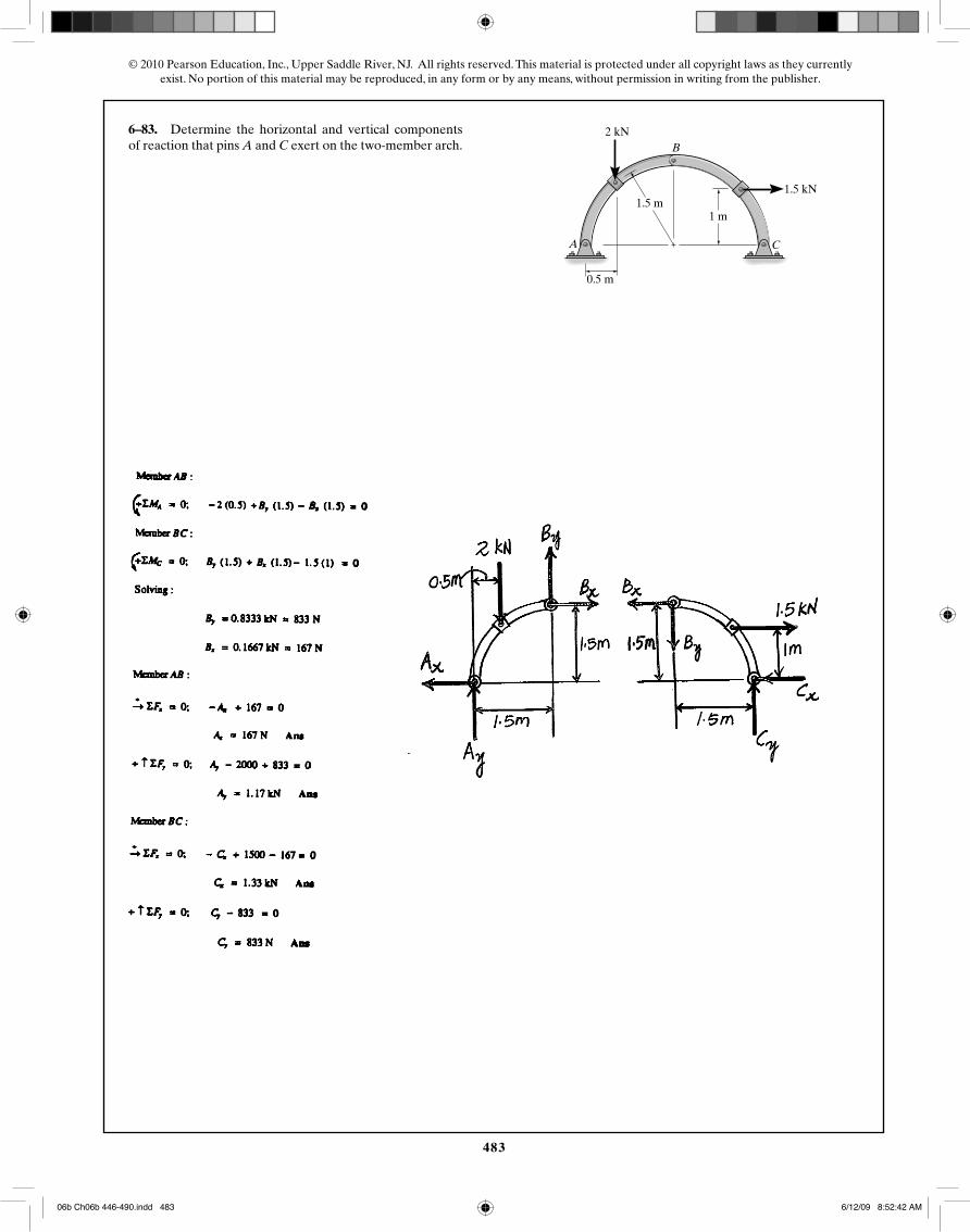
6–83. Determine the horizontal and vertical componentsof reaction that pins A and C exert on the two-member arch.
1 m1.5 m
2 kN
1.5 kN
0.5 m
A
B
C
06b Ch06b 446-490.indd 48306b Ch06b 446-490.indd 483 6/12/09 8:52:42 AM6/12/09 8:52:42 AM
484
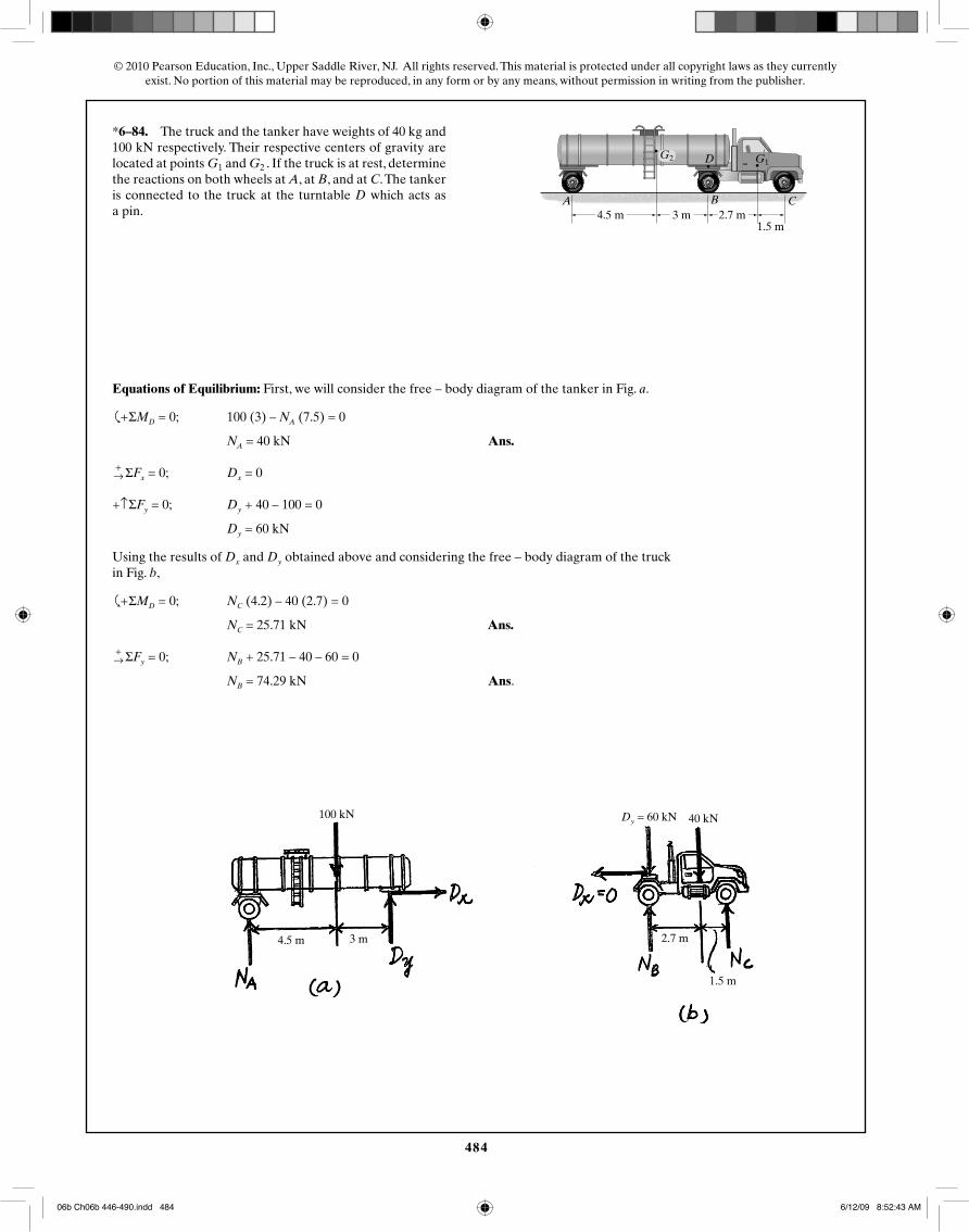
© 2010 Pearson Education, Inc., Upper Saddle River, NJ. All rights reserved. This material is protected under all copyright laws as they currentlyexist. No portion of this material may be reproduced, in any form or by any means, without permission in writing from the publisher.
*6–84. The truck and the tanker have weights of 8000 lband 20 000 lb respectively. Their respective centers ofgravity are located at points and . If the truck is atrest, determine the reactions on both wheels at A, at B, andat C. The tanker is connected to the truck at the turntableD which acts as a pin.
G2G1G1
15 ft 10 ft 9 ft5 ft
A B
D
C
G2
Dy = 60 kN100 kN 40 kN
1.5 m
2.7 m4.5 m 3 m
4.5 m 3 m 2.7 m1.5 m
*6–84. The truck and the tanker have weights of 40 kg and 100 kN respectively. Their respective centers of gravity are located at points G1 and G2 . If the truck is at rest, determine the reactions on both wheels at A, at B, and at C. The tanker is connected to the truck at the turntable D which acts as a pin.
Equations of Equilibrium: First, we will consider the free – body diagram of the tanker in Fig. a.
�
+ ΣMD = 0; 100 (3) – NA (7.5) = 0
NA = 40 kN Ans.
+→ ΣFx = 0; Dx = 0
+↑ΣFy = 0; Dy + 40 – 100 = 0
Dy = 60 kN
Using the results of Dx and Dy obtained above and considering the free – body diagram of the truck in Fig. b,
�
+ ΣMD = 0; NC (4.2) – 40 (2.7) = 0
NC = 25.71 kN Ans.
+→ ΣFy = 0; NB + 25.71 – 40 – 60 = 0
NB = 74.29 kN Ans.
06b Ch06b 446-490.indd 48406b Ch06b 446-490.indd 484 6/12/09 8:52:43 AM6/12/09 8:52:43 AM
485
© 2010 Pearson Education, Inc., Upper Saddle River, NJ. All rights reserved. This material is protected under all copyright laws as they currentlyexist. No portion of this material may be reproduced, in any form or by any means, without permission in writing from the publisher.
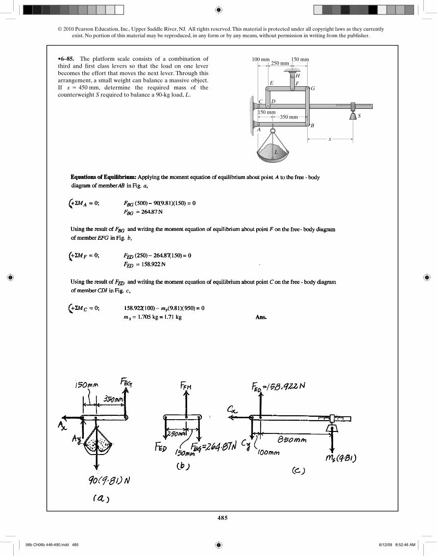
•6–85. The platform scale consists of a combination ofthird and first class levers so that the load on one leverbecomes the effort that moves the next lever. Through thisarrangement, a small weight can balance a massive object.If , determine the required mass of thecounterweight S required to balance a 90-kg load, L.x = 450 mm
350 mm150 mm
150 mm100 mm250 mm
BA
C D
E F
H
G
x
L
S
06b Ch06b 446-490.indd 48506b Ch06b 446-490.indd 485 6/12/09 8:52:46 AM6/12/09 8:52:46 AM
486
© 2010 Pearson Education, Inc., Upper Saddle River, NJ. All rights reserved. This material is protected under all copyright laws as they currentlyexist. No portion of this material may be reproduced, in any form or by any means, without permission in writing from the publisher.
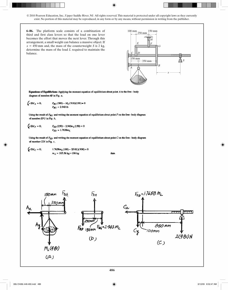
6–86. The platform scale consists of a combination ofthird and first class levers so that the load on one leverbecomes the effort that moves the next lever. Through thisarrangement, a small weight can balance a massive object. If
and, the mass of the counterweight S is 2 kg,determine the mass of the load L required to maintain thebalance.
x = 450 mm
350 mm150 mm
150 mm100 mm250 mm
BA
C D
E F
H
G
x
L
S
06b Ch06b 446-490.indd 48606b Ch06b 446-490.indd 486 6/12/09 8:52:47 AM6/12/09 8:52:47 AM
487
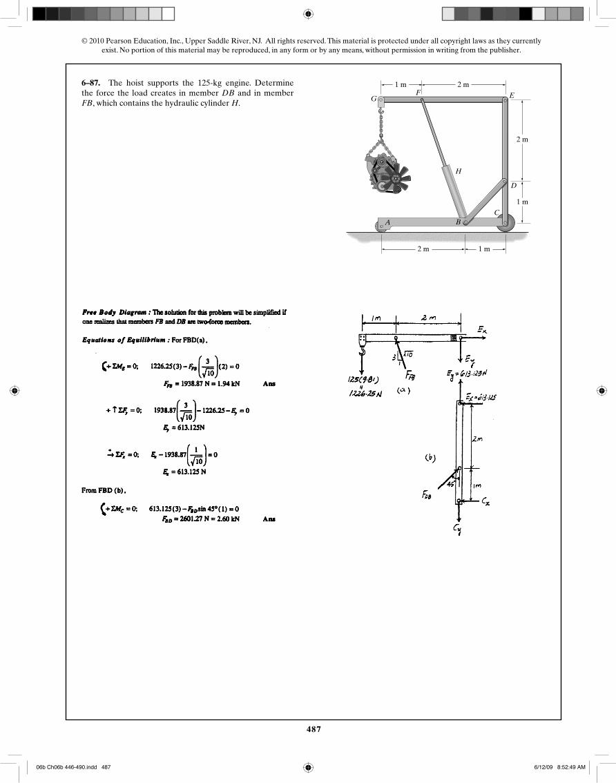
© 2010 Pearson Education, Inc., Upper Saddle River, NJ. All rights reserved. This material is protected under all copyright laws as they currentlyexist. No portion of this material may be reproduced, in any form or by any means, without permission in writing from the publisher.
6–87. The hoist supports the 125-kg engine. Determinethe force the load creates in member DB and in memberFB, which contains the hydraulic cylinder H.
C
D
EFG
H
2 m
1 m
1 m
2 m1 m
2 m
A B
06b Ch06b 446-490.indd 48706b Ch06b 446-490.indd 487 6/12/09 8:52:49 AM6/12/09 8:52:49 AM
488
© 2010 Pearson Education, Inc., Upper Saddle River, NJ. All rights reserved. This material is protected under all copyright laws as they currentlyexist. No portion of this material may be reproduced, in any form or by any means, without permission in writing from the publisher.
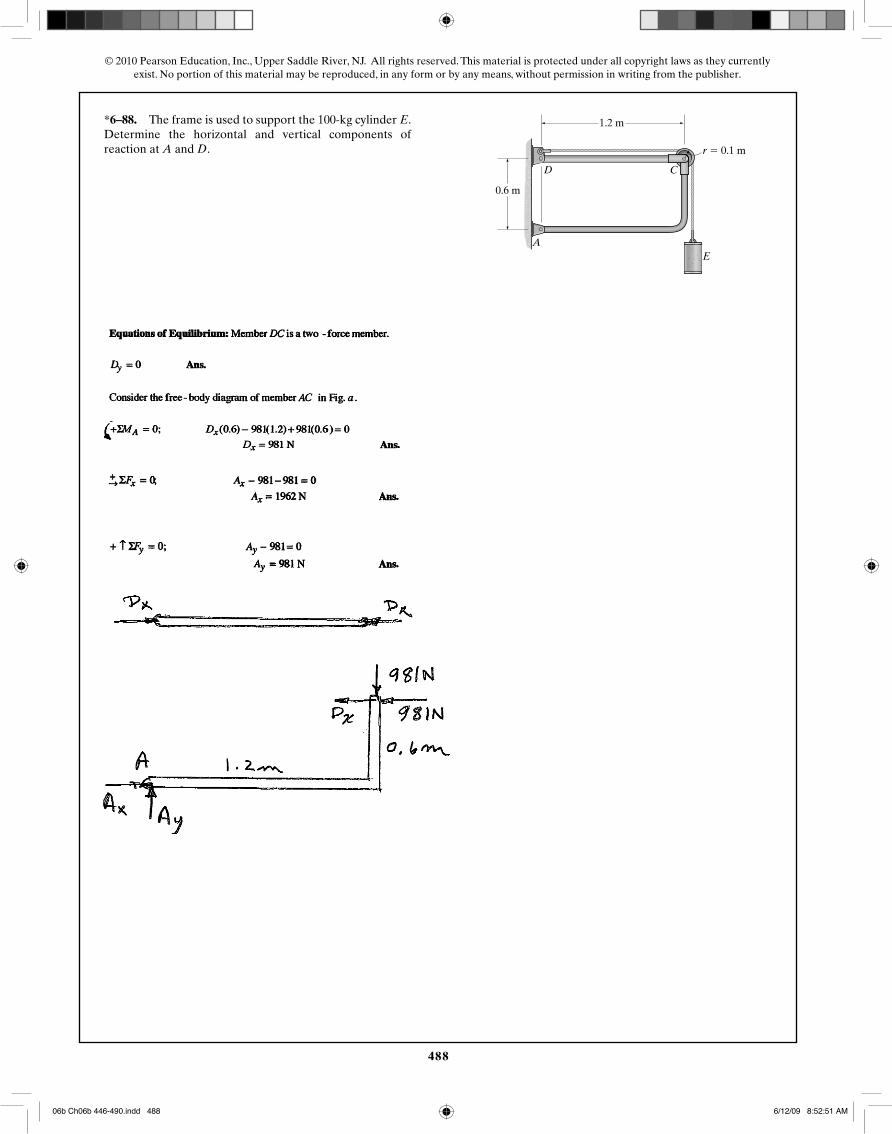
*6–88. The frame is used to support the 100-kg cylinder E.Determine the horizontal and vertical components ofreaction at A and D.
A
CD
E
0.6 m
1.2 m
r � 0.1 m
06b Ch06b 446-490.indd 48806b Ch06b 446-490.indd 488 6/12/09 8:52:51 AM6/12/09 8:52:51 AM
489
© 2010 Pearson Education, Inc., Upper Saddle River, NJ. All rights reserved. This material is protected under all copyright laws as they currentlyexist. No portion of this material may be reproduced, in any form or by any means, without permission in writing from the publisher.
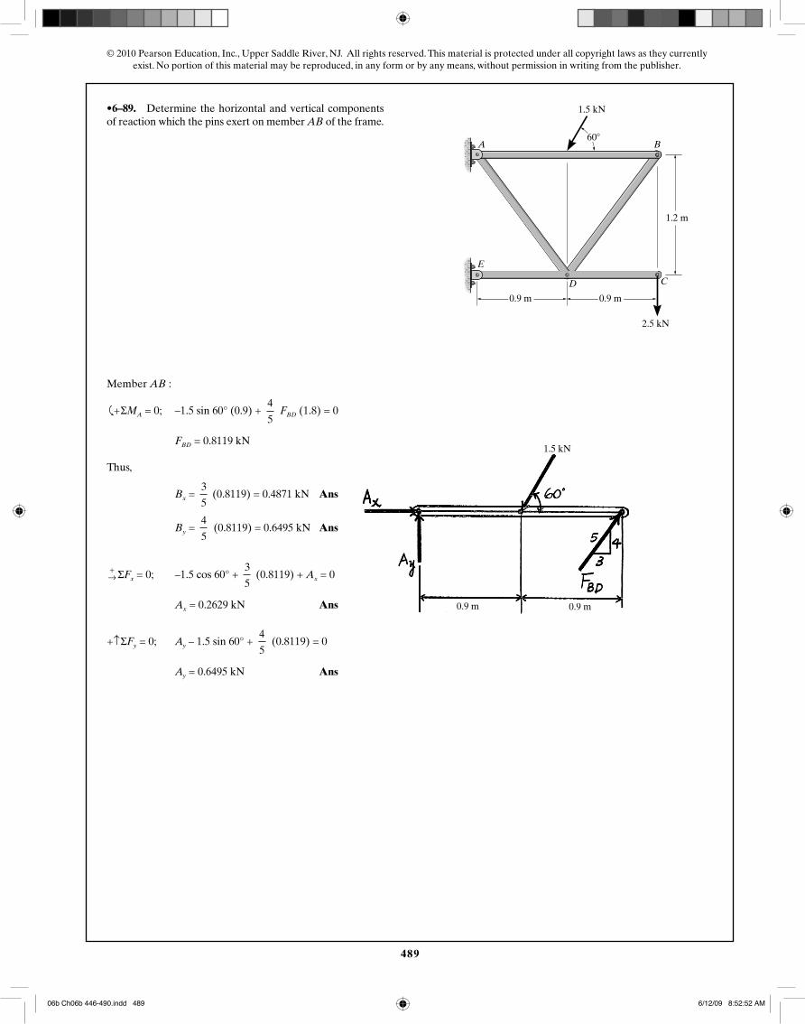
•6–89. Determine the horizontal and vertical componentsof reaction which the pins exert on member AB of the frame.
A
E
B
CD
500 lb
300 lb
3 ft 3 ft
4 ft
60�
1.5 kN
0.9 m0.9 m
0.9 m 0.9 m
2.5 kN
1.5 kN
1.2 m
Member AB :
�
+ ΣMA = 0; –1.5 sin 60° (0.9) + 4
5 FBD (1.8) = 0
FBD = 0.8119 kN
Thus,
Bx = 3
5 (0.8119) = 0.4871 kN Ans
By = 4
5 (0.8119) = 0.6495 kN Ans
+→ ΣFx = 0; –1.5 cos 60° +
3
5 (0.8119) + Ax = 0
Ax = 0.2629 kN Ans
+↑ΣFy = 0; Ay – 1.5 sin 60° + 4
5 (0.8119) = 0
Ay = 0.6495 kN Ans
06b Ch06b 446-490.indd 48906b Ch06b 446-490.indd 489 6/12/09 8:52:52 AM6/12/09 8:52:52 AM
490
© 2010 Pearson Education, Inc., Upper Saddle River, NJ. All rights reserved. This material is protected under all copyright laws as they currentlyexist. No portion of this material may be reproduced, in any form or by any means, without permission in writing from the publisher.
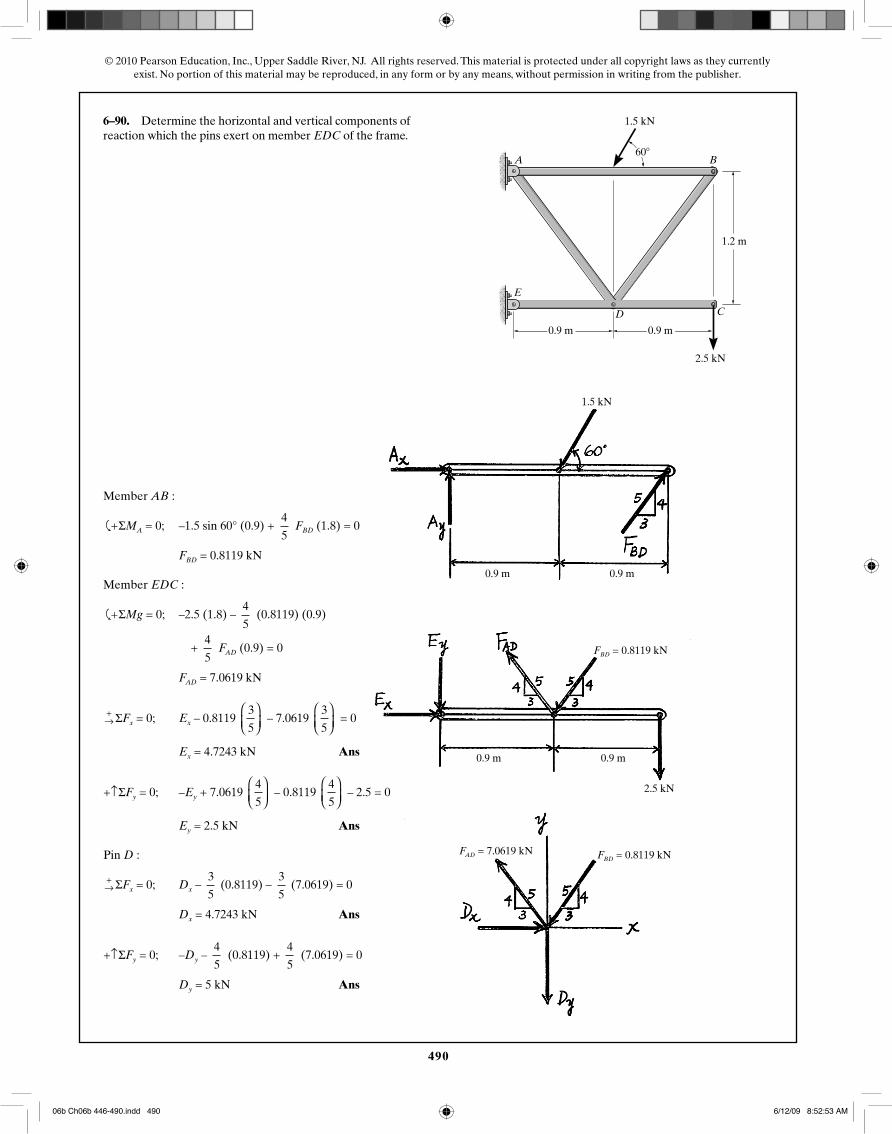
6–90. Determine the horizontal and vertical components ofreaction which the pins exert on member EDC of the frame.
A
E
B
CD
500 lb
300 lb
3 ft 3 ft
4 ft
60�
1.5 kN
0.9 m0.9 m
2.5 kN
1.2 m
0.9 m 0.9 m
1.5 kN
0.9 m 0.9 m
2.5 kN
FBD = 0.8119 kN
FBD = 0.8119 kNFAD = 7.0619 kN
Member AB :
�
+ ΣMA = 0; –1.5 sin 60° (0.9) + 4
5 FBD (1.8) = 0
FBD = 0.8119 kN
Member EDC :
�
+ ΣMg = 0; –2.5 (1.8) – 4
5 (0.8119) (0.9)
+ 4
5 FAD (0.9) = 0
FAD = 7.0619 kN
+→ ΣFx = 0; Ex – 0.8119
3
5
⎛⎝⎜
⎞⎠⎟
– 7.0619 3
5
⎛⎝⎜
⎞⎠⎟
= 0
Ex = 4.7243 kN Ans
+↑ΣFy = 0; –Ey + 7.0619 4
5
⎛⎝⎜
⎞⎠⎟
– 0.8119 4
5
⎛⎝⎜
⎞⎠⎟
– 2.5 = 0
Ey = 2.5 kN Ans
Pin D :
+→ ΣFx = 0; Dx –
3
5 (0.8119) –
3
5 (7.0619) = 0
Dx = 4.7243 kN Ans
+↑ΣFy = 0; –Dy – 4
5 (0.8119) +
4
5 (7.0619) = 0
Dy = 5 kN Ans
06b Ch06b 446-490.indd 49006b Ch06b 446-490.indd 490 6/12/09 8:52:53 AM6/12/09 8:52:53 AM