MTM800 Enhanced TETRA Mobile Terminal Product ...
308
MTM800 With Enhanced Control Head TETRA Mobile Terminals Product Information Manual When printed by Motorola Publication Number 6866535D14-C
-
Upload
khangminh22 -
Category
Documents
-
view
0 -
download
0
Transcript of MTM800 Enhanced TETRA Mobile Terminal Product ...
MTM800 With Enhanced Control HeadTETRA Mobile TerminalsProduct Information ManualWhen printed by Motorola
Publication Number
6866535D14-C
Motorola TETRA Terminal Product information Manual
September 2008 6866535D14-C
Copyright Information
The Motorola products described in this manual may include copyrighted Motorola computer programs stored in semiconductor memories
or other mediums. Laws in the United States and other countries preserve for Motorola certain exclusive rights for copyrighted computer
programs, including the exclusive right to copy or reproduce in any form the copyrighted computer program. Accordingly, any copyrighted
Motorola computer programs contained in the Motorola products described in this manual may not be copied or reproduced in any manner
without the express written permission of Motorola. Furthermore, the purchase of Motorola products shall not be deemed to grant either
directly or by implication, estoppel, or otherwise, any licence under the copyrights, patents, or patent applications of Motorola, except for
the normal non-exclusive royalty-free licence to use that arises by operation of the law in the sale of a product.
MOTOROLA and the stylized M Logo are registered in the U.S. Patent and Trademark Office. All other product or service names are the
property of their respective.
© Motorola Inc., 2008

DOCUMENT HISTORY
The following major changes have been implemented in this manual:
Edition Description Chapter, Paragraph Date
6866535D14-A Initial edition Oct 2007
6866535D14-B MR5.7 feature update Chapter 1-3 Jul 2008
6866535D14-C Correction of DGNA Auto-Attach description Chapter 3 Sep 2008
September 2008 6866535D14-CDocument History - MTM800 Enhanced Product Information Manual

ii
6866535D14-C Document History - MTM800 Enhanced Product Information Manual September 2008

TABLE OF CONTENTS
Chapter 1: Product Overview
1 Introduction .................................................................................................................................. 1-1
1.1 Using this manual ..................................................................................................................... 1-1
2 The TETRA-Terminal ................................................................................................................... 1-2
2.1 Terminal Software Upgrades.................................................................................................... 1-2
2.2 Quality Assurance .................................................................................................................... 1-2
2.2.1 Accelerated Life Testing ...................................................................................................... 1-2
2.2.2 Environmental Protection .................................................................................................... 1-2
2.2.3 IP54 & ETS300 019 - 1-7 Class 7.3 (Standard Control Head) ............................................ 1-2
2.2.4 Military Standards MIL 810 C - F ......................................................................................... 1-2
2.2.5 European Specifications ...................................................................................................... 1-3
3 MTM800 Enhanced - Standard & Motorcycle Control Head .................................................... 1-4
3.1 LED Indications ........................................................................................................................ 1-5
3.2 Audio Signal Tones .................................................................................................................. 1-5
3.3 Display Icons ............................................................................................................................ 1-7
3.4 Supported Languages .............................................................................................................. 1-9
4 Technical Specifications ........................................................................................................... 1-10
4.1 General Specifications ........................................................................................................... 1-10
4.2 RF Specifications ................................................................................................................... 1-10
4.3 GPS Specifications ................................................................................................................ 1-11
5 Ordering the MTM800 Enhanced & Accessories .................................................................... 1-12
5.1 Remote Mount - version for flexible vehicle installation.......................................................... 1-12
5.2 Dash Mount - version for compact installation........................................................................ 1-13
5.3 Desk Mount - version for use in the office .............................................................................. 1-13
5.4 Motorcycle - version for motorcycle installation...................................................................... 1-14
5.5 Data / Expansion Head........................................................................................................... 1-14
6 Ordering the Software Enablement Kits .................................................................................. 1-32
6.1 Software Selling - Tools and Mechanisms ............................................................................. 1-32
6.2 How to Place an Order for a Software Enablement Kit .......................................................... 1-33
6.3 Example Order ....................................................................................................................... 1-33
Chapter 2: Services and Feature Description
1 Introduction .................................................................................................................................. 2-1
1.1 Features Overview ................................................................................................................... 2-1
1.1.1 Trunk Mode Operation (TMO) ............................................................................................. 2-1
1.1.2 Direct Mode Operation (DMO) ............................................................................................. 2-2
1.1.3 MTM800 Enhanced Platform Features: ............................................................................... 2-2
1.1.4 MMI Features ...................................................................................................................... 2-2
1.1.5 General Features: ................................................................................................................ 2-2
1.1.6 IOP features: ....................................................................................................................... 2-3
1.2 References ............................................................................................................................... 2-3
1.2.1 TETRA Standard Documents .............................................................................................. 2-3
1.2.2 MoU TIP Documents ........................................................................................................... 2-3
1.2.3 Other Standards .................................................................................................................. 2-4
September 2008 Contents - MTM800 Enhanced Product Information Manual 6866535D14-C
ii
1.2.4 Miscellaneous ...................................................................................................................... 2-4
1.3 System Support ........................................................................................................................ 2-4
1.4 Definitions and Acronyms......................................................................................................... 2-5
2 Group Call (TMO) ......................................................................................................................... 2-6
2.1 Terminal Ergonomic Features .................................................................................................. 2-7
2.1.1 Group Mode ........................................................................................................................ 2-7
2.1.2 Programmable Talkgroups .................................................................................................. 2-7
2.1.3 Talkgroup Ranges ............................................................................................................... 2-7
2.1.4 My Favourite Groups ........................................................................................................... 2-7
2.1.5 Talkgroup Selection ............................................................................................................. 2-7
2.1.6 Receive-only Talkgroups ..................................................................................................... 2-7
2.1.7 Non Selectable Talkgroups (Hidden Talkgroups) ................................................................ 2-8
2.1.8 Audio Input and Output ....................................................................................................... 2-8
2.1.9 Talk Time Limit .................................................................................................................... 2-8
2.1.10 Receiving a Group Call ....................................................................................................... 2-8
2.1.11 Emergency Group Call ........................................................................................................ 2-8
2.1.12 Talkgroup Scanning ............................................................................................................ 2-8
2.1.13 Priority Monitor .................................................................................................................... 2-9
2.1.14 Broadcast Call (Also known as ‘Site Wide Call’) ................................................................. 2-9
2.2 Air Interface - Network Supported Features ............................................................................. 2-9
2.2.1 Group Call Setup ................................................................................................................. 2-9
2.2.2 Talking Party Identification (TPI) ....................................................................................... 2-10
2.2.3 Call Restoration ................................................................................................................. 2-10
2.2.4 Announcement Talk Group (ATG - also called Multi Group) ............................................. 2-10
2.2.5 Temporary Group Address ................................................................................................ 2-11
2.2.6 Group Attachment ............................................................................................................. 2-11
2.2.7 Late Entry .......................................................................................................................... 2-11
2.2.8 Call Ownership .................................................................................................................. 2-11
2.2.9 Transmit Request Queueing ............................................................................................. 2-11
2.2.10 Transmission during the Group Call .................................................................................. 2-12
2.2.11 Call Restoration in Group Call ........................................................................................... 2-12
2.2.12 Temporary Group Address ................................................................................................ 2-12
2.2.13 Late Entry .......................................................................................................................... 2-12
2.2.14 User initiated Group Attachment ....................................................................................... 2-12
2.2.15 SwMI Initiated Group Attach/Detach ................................................................................. 2-13
3 Private Call (TMO) ...................................................................................................................... 2-13
3.1 Terminal Ergonomic Features ................................................................................................ 2-13
3.1.1 Terminal ID ........................................................................................................................ 2-13
3.1.2 Dialing Methods ................................................................................................................. 2-13
3.1.3 Initiating a Private Call from the Contact Book .................................................................. 2-14
3.1.4 Short Number Dial ............................................................................................................. 2-14
3.1.5 Receiving a Private Call .................................................................................................... 2-14
3.1.6 Talk Time limit ................................................................................................................... 2-14
3.1.7 Terminating a Private Call ................................................................................................. 2-14
3.2 Air Interface - Network Supported Features ........................................................................... 2-15
3.2.1 Call Restoration in Private Call .......................................................................................... 2-15
3.2.2 Caller Line Identity Presentation CLIP .............................................................................. 2-15
4 Phone Call (TMO) ....................................................................................................................... 2-15
4.1 Phone Modes ......................................................................................................................... 2-15
4.2 Terminal Ergonomic Features ................................................................................................ 2-15
4.2.1 Dialing Methods ................................................................................................................. 2-15
4.2.2 Ring Styles ........................................................................................................................ 2-16
6866535D14-C Contents - MTM800 Enhanced Product Information Manual September 2008

iii
4.3 System Interaction.................................................................................................................. 2-16
4.3.1 Initiating a Telephone Call ................................................................................................. 2-16
4.3.2 Receiving a Telephone Call ............................................................................................... 2-16
4.3.3 Call Restoration ................................................................................................................. 2-16
4.3.4 DTMF (One Press) Over Dialing ....................................................................................... 2-17
4.3.5 Calling Line Identification Presentation (CLIP) .................................................................. 2-17
4.3.6 112/110/999 Dialing (pending on the infrastructure/SwMI) ............................................... 2-17
4.4 Address Book ......................................................................................................................... 2-17
5 Emergency Operation (TMO) .................................................................................................... 2-17
5.1 Emergency Group Operation.................................................................................................. 2-17
5.1.1 Emergency Group Mode ................................................................................................... 2-17
5.1.2 Emergency Alarm .............................................................................................................. 2-18
5.1.3 Emergency Alarm .............................................................................................................. 2-18
5.1.4 Emergency Group Call ...................................................................................................... 2-18
5.1.5 Hot Microphone ................................................................................................................. 2-18
5.2 Emergency Private Call .......................................................................................................... 2-19
6 Direct Mode Operation (DMO) .................................................................................................. 2-19
6.1 DMO Mode ............................................................................................................................. 2-19
6.2 DMO Group Call ..................................................................................................................... 2-19
6.3 DMO Private Call.................................................................................................................... 2-20
6.4 DMO Emergency .................................................................................................................... 2-20
6.4.1 DMO Emergency Alarm ..................................................................................................... 2-20
6.5 DMO Inter-MNI Calls .............................................................................................................. 2-20
6.6 DMO Gateway/Repeater ........................................................................................................ 2-20
7 SDS - Short Data Services ........................................................................................................ 2-21
7.1 Short Data Bearer Service...................................................................................................... 2-22
7.1.1 Transport Layer Services .................................................................................................. 2-22
7.1.2 External SDS Application Support ..................................................................................... 2-22
7.1.3 Downlink SDS Routing ...................................................................................................... 2-22
7.2 SDS Addressing. .................................................................................................................... 2-22
7.3 Status Messaging (Pre-defined) ............................................................................................. 2-22
7.3.1 Sending Status Messages (System Dependent) ............................................................... 2-22
7.3.2 Receiving Status Messages (System Dependent) ............................................................ 2-23
7.3.3 PEI Access to Status Messaging. ...................................................................................... 2-23
7.4 Text Message Service ............................................................................................................ 2-23
7.4.1 Sending a Text Message ................................................................................................... 2-23
7.4.2 Receiving a Text Message ................................................................................................ 2-23
7.4.3 Saving Text Messages ...................................................................................................... 2-24
7.4.4 Time Stamp ....................................................................................................................... 2-24
7.4.5 Text Coding Scheme ......................................................................................................... 2-24
7.4.6 Dialing Numbers Received in Text Messages ................................................................... 2-24
7.5 SDS Type 4 (Non Text Message)........................................................................................... 2-24
7.5.1 Home Mode Display .......................................................................................................... 2-24
7.5.2 ATS Entry Prompt (Predefined Templates) ....................................................................... 2-24
7.5.3 Remote Listening RL ......................................................................................................... 2-24
7.5.4 Busy User Pre-emption BUP ............................................................................................. 2-25
7.6 Terminal Features not Supported on Dimetra IP.................................................................... 2-25
7.6.1 SDS - TL Short Form Report ............................................................................................. 2-25
7.6.2 Text Message Addressing ................................................................................................. 2-25
7.6.3 Text Message Coding ........................................................................................................ 2-25
7.6.4 Service Center ................................................................................................................... 2-25
7.6.5 User Defined Data Types 1, 2 and 3. ................................................................................ 2-26
7.6.6 Sending SDS Status Messages ........................................................................................ 2-26
September 2008 Contents - MTM800 Enhanced Product Information Manual 6866535D14-C
iv
7.6.7 Call Me Back Feature ........................................................................................................ 2-26
7.7 Store & Forward ..................................................................................................................... 2-26
7.7.1 Addressing of Store and Forward Message ...................................................................... 2-26
7.7.2 Outbox ............................................................................................................................... 2-26
7.7.3 Outbox Capacity ................................................................................................................ 2-27
7.8 Concatenation ........................................................................................................................ 2-27
7.8.1 Buffer Full, Overwrite Policy .............................................................................................. 2-27
7.8.2 Timestamp for Received Text and Status Message .......................................................... 2-27
7.8.3 Process of Receiving Long Text Message ........................................................................ 2-27
7.8.4 Addressing of Long Text Message .................................................................................... 2-27
7.8.5 SDS Interacitons ............................................................................................................... 2-27
8 Packet Data (TMO) ..................................................................................................................... 2-27
8.1 General................................................................................................................................... 2-28
8.2 Connectivity ............................................................................................................................ 2-28
8.3 Packet Data Terminal Interface .............................................................................................. 2-28
8.4 Voice + Data Support ............................................................................................................. 2-28
8.4.1 Voice Only Mode ............................................................................................................... 2-28
8.4.2 Data Only Mode ................................................................................................................ 2-28
8.4.3 Voice Priority Mode ........................................................................................................... 2-28
8.5 Packet Data MMI Operation ................................................................................................... 2-29
8.6 Priority of Packet Data............................................................................................................ 2-29
8.7 Terminal Generated ICMP Messages .................................................................................... 2-29
8.8 IP Addressing ......................................................................................................................... 2-29
8.8.1 Wide IP Address ................................................................................................................ 2-29
8.8.2 Local IP Address ............................................................................................................... 2-29
8.9 Advanced Link........................................................................................................................ 2-29
8.10 IP Compression ...................................................................................................................... 2-29
8.11 Roaming of Terminals ............................................................................................................ 2-30
8.12 PD User Authentication .......................................................................................................... 2-30
8.13 Voice + Data Service and Feature Interaction........................................................................ 2-30
8.13.1 Voice Service Interaction ................................................................................................... 2-30
8.13.2 SDS Interaction ................................................................................................................. 2-30
9 Mobility Services ....................................................................................................................... 2-30
9.1 Main Control Channel Frequencies ........................................................................................ 2-30
9.2 Multi-System Operation .......................................................................................................... 2-31
9.2.1 List of Allowed Networks ................................................................................................... 2-31
9.2.2 Home Only Mode .............................................................................................................. 2-31
9.2.3 Selected Network Mode .................................................................................................... 2-31
9.2.4 Switching Between Network Modes .................................................................................. 2-31
9.2.5 Services ............................................................................................................................. 2-31
9.2.6 MMI Operation ................................................................................................................... 2-32
9.3 Registration ............................................................................................................................ 2-32
9.4 Roaming ................................................................................................................................. 2-32
9.5 Subscriber Class .................................................................................................................... 2-33
9.6 Local Site Trunking (LST)....................................................................................................... 2-33
10 TETRA Network Protocol 1 (TMO) ........................................................................................... 2-34
10.1 General................................................................................................................................... 2-34
10.2 Connectivity ............................................................................................................................ 2-34
10.2.1 IP Addressing .................................................................................................................... 2-34
10.2.2 Port Addressing ................................................................................................................. 2-34
10.3 Service and Feature Interactions............................................................................................ 2-34
10.3.1 TXI Mode ........................................................................................................................... 2-34
6866535D14-C Contents - MTM800 Enhanced Product Information Manual September 2008

v
10.3.2 DMO Mode ........................................................................................................................ 2-35
10.3.3 SDS and Packet Data ........................................................................................................ 2-35
10.3.4 AT commands ................................................................................................................... 2-35
11 Security Services ....................................................................................................................... 2-35
11.1 Terminal Equipment Identifier (TEI)........................................................................................ 2-35
11.2 User Authentication ................................................................................................................ 2-36
11.3 Air Interface Encryption (AIE) ................................................................................................. 2-38
11.3.1 Clear Terminals (Class 1) .................................................................................................. 2-38
11.3.2 Static Cipher Key SCK (Class 2) ....................................................................................... 2-38
11.3.3 Derived Cipher Key Encryption DCK, Common Cipher Keys CCK and Group Cipher Keys GCK
(Class 3) 2-38
11.3.4 Encryption Mobility ............................................................................................................ 2-40
11.3.5 Encryption MMI .................................................................................................................. 2-40
11.3.6 AIE Key Storage ................................................................................................................ 2-40
11.3.7 User Key Deletion .............................................................................................................. 2-41
11.3.8 Interaction Network/Terminal - Encrypted/Clear ................................................................ 2-41
11.4 End-to-End Encryption ........................................................................................................... 2-42
11.4.1 E2E Key Storage ............................................................................................................... 2-42
11.5 Terminal Disable/Enable ........................................................................................................ 2-42
11.6 Terminal Permanent Disable .................................................................................................. 2-43
11.7 PIN & PUK Numbers .............................................................................................................. 2-43
11.8 High Assurance Boot (HAB) ................................................................................................... 2-44
11.9 Terminal Disable/Enable on Non-Dimetra Infrastructures ...................................................... 2-44
11.10 Tamper Protection Labels ...................................................................................................... 2-44
12 Numbering and Addressing ...................................................................................................... 2-44
12.1 Short Addressing Schemes .................................................................................................... 2-44
12.1.1 Short Number Dialing Using ISSI ...................................................................................... 2-44
12.2 Direct TETRA ID Addressing.................................................................................................. 2-45
12.2.1 ISSI .................................................................................................................................... 2-45
13 PEI Characteristics .................................................................................................................... 2-45
13.1 Physical Layer ........................................................................................................................ 2-45
13.1.1 Baud Rate .......................................................................................................................... 2-46
13.1.2 PEI Flow Control ................................................................................................................ 2-46
13.2 PEI Link Layer ........................................................................................................................ 2-46
13.3 AT Commands........................................................................................................................ 2-47
13.3.1 General AT Commands ..................................................................................................... 2-47
13.3.2 Packet Data AT Commands .............................................................................................. 2-47
13.3.3 Status and Short Data Service in TMO & DMO AT Commands ........................................ 2-47
13.3.4 TNP1 AT Commands ........................................................................................................ 2-47
13.3.5 TETRA Modes AT Commands .......................................................................................... 2-48
13.3.6 Group Management AT Commands .................................................................................. 2-48
13.3.7 DMO AT Commands ......................................................................................................... 2-48
13.3.8 USB support ...................................................................................................................... 2-48
13.3.9 Network and Mobility Management AT Commands .......................................................... 2-48
13.3.10 Identity Management AT Commands ................................................................................ 2-48
13.3.11 Service Profiles & Capabilities AT Commands .................................................................. 2-48
13.3.12 Call Control in TMO AT Commands .................................................................................. 2-48
13.3.13 Audio Control AT Commands ............................................................................................ 2-49
13.3.14 Accessory Control AT Commands .................................................................................... 2-49
13.3.15 Emergency Mode AT Commands ..................................................................................... 2-49
14 Supplementary Services ........................................................................................................... 2-50
14.1 Dynamic Group Number Assignment (DGNA) ....................................................................... 2-50
September 2008 Contents - MTM800 Enhanced Product Information Manual 6866535D14-C
vi
14.1.1 Adding a Talkgroup ........................................................................................................... 2-50
14.1.2 Removing a Talkgroup. ..................................................................................................... 2-50
14.1.3 DGNA Notification to the User ........................................................................................... 2-50
14.1.4 Selection of DGNA Groups ............................................................................................... 2-50
14.1.5 Group Addressed DGNA ................................................................................................... 2-50
14.1.6 DGNA Limitations .............................................................................................................. 2-51
14.2 Ambience Listening (AL) ........................................................................................................ 2-51
14.2.1 Call Maintenance ............................................................................................................... 2-51
14.2.2 User Actions ...................................................................................................................... 2-51
14.2.3 Pseudo Power Down ......................................................................................................... 2-51
14.2.4 Call Termination ................................................................................................................ 2-51
14.3 Pre-emptive Priority Call (PPC) .............................................................................................. 2-52
14.4 RF Sensitive Area Mode (Transmit Inhibit Mode TXI) ............................................................ 2-52
14.5 Other Supplementary Services............................................................................................... 2-53
14.5.1 Calling Line Identification Presentation (CLIP) .................................................................. 2-53
14.5.2 Late Entry (LE) .................................................................................................................. 2-53
14.5.3 Talking Party Identification (TPI) ....................................................................................... 2-53
14.5.4 Calling Line Identification Restriction (CLIR) ..................................................................... 2-53
15 GPS Support .............................................................................................................................. 2-54
16 MMI Features .............................................................................................................................. 2-54
16.1 Dialing Modes......................................................................................................................... 2-54
16.2 Programmable Buttons........................................................................................................... 2-55
16.3 Backlight for Display ............................................................................................................... 2-55
16.4 Covert Mode........................................................................................................................... 2-55
16.5 Dialing Scheme ...................................................................................................................... 2-56
16.6 Languages.............................................................................................................................. 2-56
16.7 Scanning................................................................................................................................. 2-57
16.8 Non Tactical Emergency to Emergency ................................................................................. 2-57
16.9 DGNA Enhancement .............................................................................................................. 2-57
16.10 DGNA Auto Attach.................................................................................................................. 2-57
16.11 Favourite Talk Groups ............................................................................................................ 2-57
16.12 Receiving Audio during Text Message Editing ....................................................................... 2-58
16.13 Talk Group Index Entry via the Keypad.................................................................................. 2-58
16.14 Universal Time Display........................................................................................................... 2-58
16.15 Test Page / Test Mode ........................................................................................................... 2-59
16.15.1 Ver info .............................................................................................................................. 2-59
16.15.2 Addresses ......................................................................................................................... 2-59
16.15.3 Error logs ........................................................................................................................... 2-60
16.15.4 Cell Info ............................................................................................................................. 2-60
16.15.5 Cell lists ............................................................................................................................. 2-60
16.15.6 Data Services .................................................................................................................... 2-60
16.15.7 Key Information ................................................................................................................. 2-61
16.15.8 Memory (if enabled in codeplug) ....................................................................................... 2-61
17 Call-Out ....................................................................................................................................... 2-63
17.1 Feature Overview ................................................................................................................... 2-63
17.1.1 Addressing Call-Out .......................................................................................................... 2-63
17.1.2 CO Box (Call-Out Box) ...................................................................................................... 2-63
17.1.3 New Call-Out ..................................................................................................................... 2-63
17.2 Phases.................................................................................................................................... 2-63
17.3 Exception Handling................................................................................................................. 2-64
17.3.1 Emergency mode .............................................................................................................. 2-64
17.3.2 Transmit Inhibit Mode (TXI) ............................................................................................... 2-64
6866535D14-C Contents - MTM800 Enhanced Product Information Manual September 2008

vii
17.3.3 Direct Mode Operation (DMO) ........................................................................................... 2-64
17.3.4 Fallback Mode ................................................................................................................... 2-64
17.3.5 Call-Out test ....................................................................................................................... 2-64
17.3.6 Storm Plan alert ................................................................................................................. 2-64
18 Tool Interface Support .............................................................................................................. 2-64
18.1 Software and Codeplug Flashing Tool Support...................................................................... 2-64
18.2 Key Variable Loader (KVL)..................................................................................................... 2-64
Chapter 3: Customer Programming Software (CPS)
1 Introduction .................................................................................................................................. 3-1
2 Loading the CPS .......................................................................................................................... 3-1
3 Starting the CPS Application ...................................................................................................... 3-1
3.1 Administrator Opening Window ................................................................................................ 3-3
3.2 File Menu - with no codeplug displayed ................................................................................... 3-3
3.2.1 Open .................................................................................................................................... 3-4
3.2.2 Read Phone ......................................................................................................................... 3-4
3.2.3 Print Setup ........................................................................................................................... 3-5
3.2.4 Exit ....................................................................................................................................... 3-6
3.3 Tools Menu - with no codeplug displayed ................................................................................ 3-6
3.3.1 Enable Features .................................................................................................................. 3-6
3.4 Displayed Codeplug File........................................................................................................... 3-8
4 File Menu ...................................................................................................................................... 3-9
4.1 Open......................................................................................................................................... 3-9
4.2 Close ........................................................................................................................................ 3-9
4.3 Save ....................................................................................................................................... 3-10
4.4 Save As .................................................................................................................................. 3-10
4.5 Read Phone............................................................................................................................ 3-10
4.6 Write Phone............................................................................................................................ 3-11
4.7 Copy Phone............................................................................................................................ 3-11
4.8 Copy Wizard ........................................................................................................................... 3-11
4.9 Import Menu ........................................................................................................................... 3-13
4.9.1 Import User Data ............................................................................................................... 3-13
4.9.2 Screen Saver ..................................................................................................................... 3-13
4.10 Export Menu ........................................................................................................................... 3-13
4.10.1 User Data .......................................................................................................................... 3-14
4.10.2 User Report ....................................................................................................................... 3-14
4.10.3 Screen Saver ..................................................................................................................... 3-14
4.11 Change Codeplug Password.................................................................................................. 3-14
4.12 Print ........................................................................................................................................ 3-15
4.13 Print Preview .......................................................................................................................... 3-16
4.14 Print Setup.............................................................................................................................. 3-16
4.15 Send ....................................................................................................................................... 3-16
4.16 Exit.......................................................................................................................................... 3-17
5 Edit Menu .................................................................................................................................... 3-17
5.1 Find A Field ............................................................................................................................ 3-18
6 View Menu .................................................................................................................................. 3-18
6.1 Tool Bars ................................................................................................................................ 3-19
September 2008 Contents - MTM800 Enhanced Product Information Manual 6866535D14-C

viii
6.1.1 Main ................................................................................................................................... 3-19
6.1.2 Phone ................................................................................................................................ 3-19
6.1.3 Find ................................................................................................................................... 3-19
6.1.4 Bookmarks ........................................................................................................................ 3-20
6.1.5 Navigation ......................................................................................................................... 3-20
6.2 Work Book.............................................................................................................................. 3-20
6.2.1 View Mode ......................................................................................................................... 3-20
6.2.2 Toggle Icons ...................................................................................................................... 3-20
6.3 Zoom ...................................................................................................................................... 3-21
6.4 Full Screen ............................................................................................................................. 3-21
6.5 Navigation............................................................................................................................... 3-22
6.6 Hide Tree View ....................................................................................................................... 3-22
6.7 Status Bar............................................................................................................................... 3-22
7 Tools Menu (Administrator Login) ........................................................................................... 3-22
7.1 Power Off................................................................................................................................ 3-23
7.2 Upgrade Phone ...................................................................................................................... 3-23
7.3 Downgrade Phone.................................................................................................................. 3-24
7.4 Write Software ........................................................................................................................ 3-24
7.5 Erase Software ....................................................................................................................... 3-24
7.6 Restore Radio......................................................................................................................... 3-25
7.7 Languages.............................................................................................................................. 3-25
7.8 Configure ................................................................................................................................ 3-26
7.8.1 Profile ................................................................................................................................ 3-26
7.8.2 Customize ......................................................................................................................... 3-27
7.8.3 Short Cut ........................................................................................................................... 3-27
7.8.4 Options .............................................................................................................................. 3-28
8 Window Menu ............................................................................................................................ 3-34
8.1 Cascade ................................................................................................................................. 3-35
8.2 Tile.......................................................................................................................................... 3-35
8.3 Arrange Icons ......................................................................................................................... 3-35
8.4 Close All ................................................................................................................................. 3-35
8.5 Switch Panes.......................................................................................................................... 3-35
8.6 Adjust Splitter ......................................................................................................................... 3-35
8.7 1, 2, 3, 4 etc. (List of Open Codeplug Windows) .................................................................... 3-35
9 Help Menu .................................................................................................................................. 3-36
9.1 What’s This............................................................................................................................. 3-36
9.2 CPS Help Index ...................................................................................................................... 3-36
10 Reading/Opening a Codeplug .................................................................................................. 3-36
11 Phone Bar Icons ........................................................................................................................ 3-37
12 Codeplug .................................................................................................................................... 3-38
13 Subscriber Unit Parameters ..................................................................................................... 3-40
14 Feature Flags ............................................................................................................................. 3-42
14.1 Group...................................................................................................................................... 3-43
14.2 Status ..................................................................................................................................... 3-43
14.3 Targeted Status ...................................................................................................................... 3-43
14.4 Semi-duplex Private Call ........................................................................................................ 3-43
14.5 Private Duplex ........................................................................................................................ 3-43
14.6 Direct Mode (DMO) ................................................................................................................ 3-44
14.7 Direct Mode (DMO) Reservation ............................................................................................ 3-44
14.8 Telephone Interconnect.......................................................................................................... 3-44
6866535D14-C Contents - MTM800 Enhanced Product Information Manual September 2008
ix
14.9 MS User Application Support Pre-defined Template.............................................................. 3-44
14.10 Mail In ..................................................................................................................................... 3-45
14.11 Mail Out .................................................................................................................................. 3-45
14.12 External Device ...................................................................................................................... 3-45
14.13 Test Page ............................................................................................................................... 3-45
14.14 Horn & Light............................................................................................................................ 3-45
14.15 PABX...................................................................................................................................... 3-45
14.16 Talkgroup Scan ...................................................................................................................... 3-45
14.17 Packet Data ............................................................................................................................ 3-46
14.18 Home Mode Display ............................................................................................................... 3-46
14.19 Group Hot Mic ........................................................................................................................ 3-46
14.20 DMO Gateway ........................................................................................................................ 3-48
14.21 One-Touch Feature ................................................................................................................ 3-48
14.22 My Favorite Groups ................................................................................................................ 3-48
14.23 Speed Dialing ......................................................................................................................... 3-48
14.24 GPS ........................................................................................................................................ 3-48
14.25 Tx Audio Hi Pass Filter ........................................................................................................... 3-49
14.26 TNP1 Support......................................................................................................................... 3-49
14.27 Selected Network Enabled ..................................................................................................... 3-49
14.28 Address Book Restriction ....................................................................................................... 3-49
14.29 TG Dialing by Index ................................................................................................................ 3-49
14.30 WAP (Wireless Application Protocol) ..................................................................................... 3-50
14.31 Mail out to Group .................................................................................................................... 3-50
14.32 Direct Mode (DMO) Semi-Duplex Private Call ....................................................................... 3-50
14.33 Packet Data Page Enable ...................................................................................................... 3-50
14.34 Multislot Packet Data.............................................................................................................. 3-50
14.35 DMO Repeater ....................................................................................................................... 3-50
14.36 Clear LA Blacklist on Talk Group Change .............................................................................. 3-50
14.37 Remote Programming ............................................................................................................ 3-51
14.38 Call-Out .................................................................................................................................. 3-51
15 Security ....................................................................................................................................... 3-51
15.1 MS Authentication .................................................................................................................. 3-51
15.2 MS Mutual Authentication....................................................................................................... 3-52
15.3 Mandatory Mutual Authentication ........................................................................................... 3-52
15.4 SCK Air If Encryption.............................................................................................................. 3-52
15.5 DMO SCK............................................................................................................................... 3-52
15.6 DMO SCK OTAR.................................................................................................................... 3-53
15.7 DCK Air If Encryption.............................................................................................................. 3-53
15.8 GCK Air If Encryption and OTAR ........................................................................................... 3-53
15.9 Permanent Disable ................................................................................................................. 3-53
15.10 Permanent Disable V2............................................................................................................ 3-53
15.11 Permanent Disable Policy ...................................................................................................... 3-53
15.12 Temporary Enable/Disable Policy .......................................................................................... 3-54
15.13 Non Secured Call Indication ................................................................................................... 3-54
15.14 Encrypted Only ....................................................................................................................... 3-54
15.15 Class 3 Cell Ranks Higher than Class 2 Cell ......................................................................... 3-54
15.16 Key Erasure Mode.................................................................................................................. 3-55
15.17 Key Erasure Occurred ............................................................................................................ 3-55
15.18 Maximum Retries Due Time Out T351- 354........................................................................... 3-56
15.19 Max Password Attempts......................................................................................................... 3-56
15.20 PIN Flag.................................................................................................................................. 3-56
15.21 MS change PIN Number......................................................................................................... 3-56
15.22 PIN Number............................................................................................................................ 3-57
15.23 MS change PIN Options ......................................................................................................... 3-57
September 2008 Contents - MTM800 Enhanced Product Information Manual 6866535D14-C
x
15.24 PIN Unblocking Key................................................................................................................ 3-57
15.25 Disable Display....................................................................................................................... 3-57
15.26 Activate Always Encryption .................................................................................................... 3-57
15.27 Covert Mode........................................................................................................................... 3-57
15.28 Enter Pinlock-Menu Tone ....................................................................................................... 3-57
16 End to End Encryption .............................................................................................................. 3-58
16.1 Periodic End-To-End Key Failure Notice................................................................................ 3-58
16.2 Clear Reception Alert Tone .................................................................................................... 3-58
16.3 Clear Transmit Alert Tone ...................................................................................................... 3-58
16.4 End-To-End Key Erasure Enabled ......................................................................................... 3-58
16.5 Rx Clear Tone Association ..................................................................................................... 3-59
16.6 Muted Reception Alert Tone................................................................................................... 3-59
16.7 End-To-End Re-key Enable.................................................................................................... 3-59
16.8 User Prompt on Checksum Failure ........................................................................................ 3-59
16.9 Checksum Failure Indication .................................................................................................. 3-59
16.10 End-To-End Index Set Change Enabled ................................................................................ 3-59
16.11 Key Fail Indication Timer ........................................................................................................ 3-59
16.12 Re-Key Ongoing Timer........................................................................................................... 3-59
16.13 Re-Key Completion Timer ...................................................................................................... 3-60
16.14 Mandatory On Relaxation....................................................................................................... 3-60
16.15 Infinit End-To-End Key Retention ........................................................................................... 3-60
16.16 End-To-End Encryption in Class of MS .................................................................................. 3-60
17 Remote Programming ............................................................................................................... 3-60
17.1 Communication Timeout Timer .............................................................................................. 3-60
18 NGHC Interface .......................................................................................................................... 3-60
18.1 Physical Layer ........................................................................................................................ 3-61
19 Clock System Broadcast Information ...................................................................................... 3-61
19.1 Time Displayed....................................................................................................................... 3-61
19.2 Date Displayed ....................................................................................................................... 3-61
19.3 Time Format ........................................................................................................................... 3-62
19.4 Date Format............................................................................................................................ 3-62
19.5 Time Display by MMI .............................................................................................................. 3-62
19.6 Setting Time by User .............................................................................................................. 3-62
19.7 Local Time Synchronized to Network Time ............................................................................ 3-62
19.8 Local Time Offset ................................................................................................................... 3-63
19.9 RTC Update User Intervention ............................................................................................... 3-63
20 TMO Voice Services .................................................................................................................. 3-63
20.1 Pre-emptive Priority Call (PPC) .............................................................................................. 3-63
20.1.1 Originating PPC Private Call ............................................................................................. 3-64
20.1.2 Call Priority for Outgoing Private PPC PTPC .................................................................... 3-64
20.1.3 PPC PTPC Priority 12 13 .................................................................................................. 3-64
20.1.4 Scan Group Priority Behaviour .......................................................................................... 3-65
20.1.5 Audio Shock Delay Timer .................................................................................................. 3-65
20.2 Emergency Options ................................................................................................................ 3-66
20.2.1 Emergency Alarm .............................................................................................................. 3-66
20.2.2 Emergency Call ................................................................................................................. 3-66
20.2.3 TMO Emergency Services ................................................................................................ 3-67
20.2.4 Emergency Alarm Address ................................................................................................ 3-67
20.2.5 Emergency Call Address ................................................................................................... 3-67
20.2.6 Emergency Console Acknowledge .................................................................................... 3-67
20.2.7 Emergency Switch Power Up ............................................................................................ 3-67
6866535D14-C Contents - MTM800 Enhanced Product Information Manual September 2008

xi
20.2.8 Emergency Started Timer .................................................................................................. 3-67
20.2.9 Emergency Cancel Timer .................................................................................................. 3-68
20.2.10 Emergency Wait Ack Timer ............................................................................................... 3-68
20.2.11 Emergency Alarm Retries .................................................................................................. 3-68
20.2.12 Emergency Private Call Type ............................................................................................ 3-68
20.2.13 Emergency SDS Status Destination .................................................................................. 3-68
20.2.14 Emergency SDS Status Value ........................................................................................... 3-68
20.2.15 Emergency SDS Alias ....................................................................................................... 3-68
20.2.16 Disable Visible and Audible Indication ............................................................................... 3-68
20.2.17 Colored Emergency ........................................................................................................... 3-69
20.2.18 Emergency DMO to TMO .................................................................................................. 3-69
20.2.19 Emergency Alarm on Service Recovery ............................................................................ 3-69
20.2.20 Enter HotMic on Service Recovery .................................................................................... 3-69
20.3 Address List 1 and 2............................................................................................................... 3-69
20.3.1 Emergency Address Type ................................................................................................. 3-69
20.3.2 Emergency Group Type .................................................................................................... 3-69
20.3.3 Non-Tactical Alias .............................................................................................................. 3-70
20.3.4 Emergency ISSI/GSSI ....................................................................................................... 3-70
20.4 Scanning Parameters ............................................................................................................. 3-70
20.4.1 Active List .......................................................................................................................... 3-70
20.4.2 Scan Status ....................................................................................................................... 3-70
20.4.3 User List Editing ................................................................................................................ 3-70
20.4.4 Priority Editing Enabled ..................................................................................................... 3-70
20.4.5 PTT Operation ................................................................................................................... 3-71
20.4.6 Presentation Mode ............................................................................................................ 3-71
20.4.7 On/Off Via MMI .................................................................................................................. 3-71
20.4.8 Block Group Enabled ......................................................................................................... 3-71
20.4.9 Priority Presentation Timer ................................................................................................ 3-71
20.4.10 Scan Hold Timer ................................................................................................................ 3-71
20.4.11 Rx Hold Timer .................................................................................................................... 3-72
20.4.12 Scan List On/Off Over the Air ............................................................................................ 3-72
20.5 Voice Services Options .......................................................................................................... 3-72
20.5.1 Default Call Priority ............................................................................................................ 3-72
20.5.2 Transmit Demand Priority .................................................................................................. 3-72
20.5.3 Transmit Demand Private Priority ...................................................................................... 3-73
20.5.4 PSTN Gateway ID ............................................................................................................. 3-73
20.5.5 PABX Gateway ID ............................................................................................................. 3-73
20.5.6 PTT ID ............................................................................................................................... 3-73
20.5.7 Busy Override .................................................................................................................... 3-74
20.5.8 Announcement Talkgroup Enable ..................................................................................... 3-74
20.5.9 PTT Calls Back Displayed Party ........................................................................................ 3-74
20.5.10 Transmission Timeout Timer ............................................................................................. 3-74
20.5.11 Transmission Timeout Warning Timer ............................................................................... 3-74
20.5.12 PTT Call Back Timer ......................................................................................................... 3-74
20.5.13 PTT Call Back Timer Enabled ........................................................................................... 3-74
20.5.14 PTT during received Group Call ........................................................................................ 3-75
21 NGCH Parameters ...................................................................................................................... 3-75
21.1 User Test Enabled.................................................................................................................. 3-75
21.2 Connected Radio.................................................................................................................... 3-75
21.2.1 Available ............................................................................................................................ 3-75
21.2.2 Address ............................................................................................................................. 3-75
21.2.3 Class .................................................................................................................................. 3-75
22 DMO Parameters ........................................................................................................................ 3-76
September 2008 Contents - MTM800 Enhanced Product Information Manual 6866535D14-C

xii
22.1 DMO Emergency Options....................................................................................................... 3-76
22.2 DMO Short Data Service ........................................................................................................ 3-76
22.2.1 DT314 ................................................................................................................................ 3-76
22.2.2 DN314 ............................................................................................................................... 3-76
22.2.3 Pre-emption Timer ............................................................................................................. 3-76
22.2.4 DMO Voice Priority over SDS ........................................................................................... 3-77
22.3 DMO Gateway Timers ............................................................................................................ 3-77
22.3.1 DT301 ................................................................................................................................ 3-77
22.3.2 DT302 ................................................................................................................................ 3-77
22.3.3 DT309 ................................................................................................................................ 3-77
22.3.4 DT308, Pre-emption via Gateway Timer ........................................................................... 3-78
22.4 DMO Address Extension ........................................................................................................ 3-78
22.4.1 MCC .................................................................................................................................. 3-78
22.4.2 MNC .................................................................................................................................. 3-78
22.5 DMO MNI Partnership List...................................................................................................... 3-78
22.6 DMO Security ......................................................................................................................... 3-79
22.6.1 Key Grouping Method ....................................................................................................... 3-79
22.6.2 Default Key Group ............................................................................................................. 3-79
22.6.3 Default Incoming Minimum Security Class ........................................................................ 3-80
22.6.4 Default Outgoing Security Class ....................................................................................... 3-80
22.6.5 Gateway Capabilities Class 2A - 2C ................................................................................. 3-80
22.6.6 Repeater Capabilities Class 2A - 2C ................................................................................. 3-80
22.6.7 Permit Clear Preemption in 2A / 2B .................................................................................. 3-80
22.6.8 Active SCK Subset Number flag with OTAR ..................................................................... 3-80
22.6.9 Open MNI Security settings ............................................................................................... 3-81
22.6.10 Present Keys ..................................................................................................................... 3-81
23 Ergonomic Parameters ............................................................................................................. 3-81
23.1 General................................................................................................................................... 3-82
23.1.1 Control Head Dim .............................................................................................................. 3-82
23.1.2 Ring Style .......................................................................................................................... 3-82
23.1.3 Speaker Phone .................................................................................................................. 3-82
23.1.4 Range Scroll Type ............................................................................................................. 3-83
23.2 Tones...................................................................................................................................... 3-83
23.2.1 Clear to Send Tone ........................................................................................................... 3-83
23.2.2 Periodic Tone .................................................................................................................... 3-83
23.2.3 DTMF ................................................................................................................................ 3-83
23.2.4 Group Call Received Tone ................................................................................................ 3-84
23.2.5 Group Call Audio via MMI ................................................................................................. 3-84
23.2.6 Talk Permit Tone Option ................................................................................................... 3-84
23.2.7 Audio Toggle ..................................................................................................................... 3-85
23.3 Timers..................................................................................................................................... 3-85
23.3.1 Out of Service Timer, sec .................................................................................................. 3-85
23.3.2 Long Key Inactivity Timer .................................................................................................. 3-85
23.3.3 Channel Acquisition Timer ................................................................................................ 3-85
23.3.4 Call Delay on User Activity ................................................................................................ 3-86
23.4 Signal/Quality Indication Scale ............................................................................................... 3-86
23.4.1 Signal Strength Max Nobars ............................................................................................. 3-86
23.4.2 Signal Strength Min. Maxbars ........................................................................................... 3-86
23.5 Dialing Methods...................................................................................................................... 3-86
23.5.1 Dialing Scheme Option ...................................................................................................... 3-87
23.5.2 Default Call Type ............................................................................................................... 3-87
23.5.3 Type Order ........................................................................................................................ 3-87
24 Language Parameters ............................................................................................................... 3-87
6866535D14-C Contents - MTM800 Enhanced Product Information Manual September 2008

xiii
24.1 Language Settings.................................................................................................................. 3-88
24.2 Character Editor ..................................................................................................................... 3-88
24.2.1 Editor Types ...................................................................................................................... 3-89
25 Audio Parameters ...................................................................................................................... 3-89
25.1 Hot Mic ................................................................................................................................... 3-90
25.1.1 Hot Mic Pending Timer ...................................................................................................... 3-90
25.1.2 Hot Mic Duration Timer ...................................................................................................... 3-90
25.1.3 Hot Mic Gain Delta ............................................................................................................ 3-90
25.2 AGC (Automatic Gain Control) ............................................................................................... 3-90
25.3 Ambience Listening ................................................................................................................ 3-91
25.3.1 SS-AL IGM Gain ................................................................................................................ 3-91
25.3.2 SS-AL EMG Gain .............................................................................................................. 3-91
25.3.3 SS-AL VMG Gain .............................................................................................................. 3-91
25.3.4 Control Head AL Status ..................................................................................................... 3-92
25.4 Volume Settings ..................................................................................................................... 3-92
25.5 Mic Settings ............................................................................................................................ 3-93
25.5.1 Standard Mic / Handset Gain ............................................................................................ 3-93
25.5.2 External Mic Input Gain ..................................................................................................... 3-93
25.5.3 Accessory Connector Ext Mic Source ............................................................................... 3-93
26 Display Parameters ................................................................................................................... 3-94
26.1 Display Options ...................................................................................................................... 3-94
26.1.1 Font Size ........................................................................................................................... 3-94
26.1.2 Wallpaper On/Off ............................................................................................................... 3-94
26.1.3 Backlight Toggling ............................................................................................................. 3-94
26.1.4 Backlight Timer .................................................................................................................. 3-95
26.2 Screen Saver.......................................................................................................................... 3-95
26.2.1 Screen Saver Text ............................................................................................................. 3-95
26.2.2 Time Screen Saver Activation ........................................................................................... 3-95
26.2.3 Screen Saver Enabled ....................................................................................................... 3-95
26.2.4 Screen Saver Text User Editable ...................................................................................... 3-96
26.2.5 Auto Screen Saver ............................................................................................................ 3-96
26.3 Home Mode Display ............................................................................................................... 3-96
26.3.1 Home Mode Display Text .................................................................................................. 3-96
26.3.2 Home Mode Display Protocol Identifier ............................................................................. 3-96
26.3.3 Welcome Screen ............................................................................................................... 3-96
27 TalkGroups ................................................................................................................................. 3-96
27.1 TMO (Trunked Mode Operation) ............................................................................................ 3-97
27.1.1 TMO Folders List ............................................................................................................... 3-97
27.1.2 TMO Talkgroup List ........................................................................................................... 3-98
27.1.3 TMO Scan Lists ................................................................................................................. 3-99
27.1.4 Dynamic Group Number Assignment .............................................................................. 3-101
27.2 DMO (Direct Mode Operation).............................................................................................. 3-102
27.2.1 DMO Folders List ............................................................................................................. 3-103
27.2.2 DMO Talkgroup List ......................................................................................................... 3-103
27.3 My Favorite Groups .............................................................................................................. 3-106
27.3.1 List Options ...................................................................................................................... 3-106
27.3.2 Favorite Talkgroups List .................................................................................................. 3-106
28 Contact Book ........................................................................................................................... 3-108
28.1 Dialing Scheme .................................................................................................................... 3-108
28.2 Contacts List......................................................................................................................... 3-109
29 Data Services ........................................................................................................................... 3-110
29.1 Outgoing Mail Parameters.................................................................................................... 3-110
September 2008 Contents - MTM800 Enhanced Product Information Manual 6866535D14-C

xiv
29.1.1 Outgoing Mail Options ..................................................................................................... 3-110
29.1.2 Outgoing Mail List ............................................................................................................ 3-111
29.2 Status ID List ........................................................................................................................ 3-113
29.2.1 Name ............................................................................................................................... 3-113
29.2.2 ID ..................................................................................................................................... 3-113
29.2.3 Status .............................................................................................................................. 3-113
29.2.4 Indexed ............................................................................................................................ 3-113
29.3 Packet Data Parameters ...................................................................................................... 3-113
29.3.1 User Authentication ......................................................................................................... 3-114
29.3.2 Authenticator Name ......................................................................................................... 3-114
29.3.3 Data Only ........................................................................................................................ 3-114
29.3.4 Voice & Data ................................................................................................................... 3-114
29.3.5 Voice Only ....................................................................................................................... 3-114
29.3.6 Default Packet Data Mode .............................................................................................. 3-114
29.3.7 PD Page Period Updates ................................................................................................ 3-115
29.4 Short Data Service (SDS)..................................................................................................... 3-116
29.4.1 Individual SDS L3 Status ACK ........................................................................................ 3-116
29.4.2 Group SDS L3 Status ACK ............................................................................................. 3-116
29.4.3 SDS Status Number of Retry .......................................................................................... 3-116
29.4.4 Status Max ...................................................................................................................... 3-117
29.4.5 Status Min ....................................................................................................................... 3-117
29.4.6 Send Short Form Report ................................................................................................. 3-117
29.4.7 Access Priority ................................................................................................................. 3-117
29.4.8 AT Commands SDS-TL Access Priority .......................................................................... 3-117
29.4.9 AT Commands SDS-TL Traffic Stealing .......................................................................... 3-117
29.4.10 Buffer Full, Overwrite Policy ............................................................................................ 3-117
29.4.11 DTR Link Down Indication Time, sec .............................................................................. 3-118
29.4.12 PI Concatenated Messages ............................................................................................ 3-118
29.4.13 Support of Concatenated Text Messages ....................................................................... 3-118
29.4.14 Segmented Receive Timer, sec ...................................................................................... 3-118
29.4.15 The Long Text Message Sent Timer, sec ....................................................................... 3-118
29.4.16 Long Text Message Length ............................................................................................. 3-118
29.4.17 Number Of Service Center .............................................................................................. 3-119
29.4.18 Traffic Stealing ................................................................................................................ 3-119
29.4.19 Status During Group Call ................................................................................................ 3-119
29.4.20 Mail Out During Group Call ............................................................................................. 3-119
29.4.21 Filter Successive Duplicate Text Messages Timer, sec .................................................. 3-119
29.4.22 Default Data Russian Encoding Scheme ........................................................................ 3-119
29.4.23 Default Targeted SDS Status Destination Address ......................................................... 3-120
29.4.24 Support of Concatenated Text Messages Sending ......................................................... 3-120
29.5 Store and Forward Options .................................................................................................. 3-120
29.5.1 Support of Store and Forward ......................................................................................... 3-120
29.5.2 Default Validity Period ..................................................................................................... 3-120
29.5.3 Delivery Report Request ................................................................................................. 3-120
29.5.4 Received Delivery Status Notification ............................................................................. 3-121
29.5.5 Store and Forward Server Address ................................................................................. 3-121
29.6 PEI Parameter ...................................................................................................................... 3-121
29.6.1 Baud Rate ....................................................................................................................... 3-121
29.6.2 Parity Bit .......................................................................................................................... 3-121
29.6.3 ETSI AT SDS/Status Format ........................................................................................... 3-122
30 TNP1 Support ........................................................................................................................... 3-122
30.1 Default Service Profile .......................................................................................................... 3-122
30.2 Default Service Profile .......................................................................................................... 3-123
6866535D14-C Contents - MTM800 Enhanced Product Information Manual September 2008

xv
30.3 TNP1 Options ....................................................................................................................... 3-123
30.3.1 TNP1 Support .................................................................................................................. 3-123
30.3.2 NO TE TEMTA-REPORT IND Counter Limit ................................................................... 3-123
30.3.3 TE TEMTA-REPORT IND Timer ..................................................................................... 3-123
31 Buttons, Keys and Accessories ............................................................................................. 3-124
31.1 Accessory ............................................................................................................................. 3-124
31.1.1 Accessory Selection ........................................................................................................ 3-124
31.1.2 Ring Source ..................................................................................................................... 3-124
31.1.3 Tones Path Selection for PHF Accessory in Idle Mode ................................................... 3-125
31.1.4 Telephone Handset Enable External Speaker on Hook for Group Mode ........................ 3-125
31.2 Menu Shortcuts .................................................................................................................... 3-125
31.3 One-Touch Options .............................................................................................................. 3-126
31.3.1 One Touch Keypad Keypress Timer ............................................................................... 3-126
31.4 One Touch Buttons............................................................................................................... 3-126
31.4.1 Covert Mode .................................................................................................................... 3-127
31.4.2 PABX Call ........................................................................................................................ 3-127
31.4.3 Phone Call ....................................................................................................................... 3-127
31.4.4 Private Call ...................................................................................................................... 3-128
31.4.5 TXI (Transmit Inhibit) ....................................................................................................... 3-128
31.4.6 Sending Predefined Message ......................................................................................... 3-129
31.4.7 Sending User Defined Message ...................................................................................... 3-129
31.4.8 Hi/Lo Audio ...................................................................................................................... 3-130
31.4.9 Change Talkgroup ........................................................................................................... 3-130
31.4.10 Change Talkgroup to Latest Previously Selected ............................................................ 3-130
31.4.11 Sending Status ................................................................................................................ 3-130
31.4.12 TMO <-> DMO Switch ..................................................................................................... 3-131
31.4.13 TMO Talkgroup Scan ...................................................................................................... 3-131
31.4.14 Home Revert ................................................................................................................... 3-131
32 Inputs, Outputs, GPIOs ........................................................................................................... 3-131
32.1 GPIO Options ....................................................................................................................... 3-132
32.2 NGCH GPIOs ....................................................................................................................... 3-132
32.2.1 GPIO1 .............................................................................................................................. 3-132
32.2.2 GPIO2 .............................................................................................................................. 3-133
32.2.3 Sending Predefined Messages using PIN 14 and 3 ........................................................ 3-133
33 Mobility and System Parameters ........................................................................................... 3-133
33.1 Frequency List ...................................................................................................................... 3-134
33.1.1 Frequency List 1 .............................................................................................................. 3-134
33.1.2 Frequency List 2 .............................................................................................................. 3-134
33.1.3 Frequency List 3 .............................................................................................................. 3-134
33.1.4 Frequency List 4 .............................................................................................................. 3-135
33.2 Home Location Areas ........................................................................................................... 3-135
33.2.1 Number of Home Location Areas .................................................................................... 3-135
33.2.2 Home Location Area ........................................................................................................ 3-135
33.3 Address Extension................................................................................................................ 3-136
33.3.1 Country Code (MCC) ....................................................................................................... 3-136
33.3.2 Network Code (MNC) ...................................................................................................... 3-136
33.3.3 Alias ................................................................................................................................. 3-136
33.4 Mobility Parameters.............................................................................................................. 3-136
33.4.1 Min RSSI Threshold Data ................................................................................................ 3-136
33.4.2 Start Monitoring Threshold Delta ..................................................................................... 3-137
33.4.3 Stop Monitoring Delta ...................................................................................................... 3-137
33.4.4 Subscriber Class ............................................................................................................. 3-137
33.4.5 SC Acquisition Timer ....................................................................................................... 3-137
September 2008 Contents - MTM800 Enhanced Product Information Manual 6866535D14-C

xvi
33.4.6 MLE Sleep Timer ............................................................................................................. 3-137
33.4.7 Type 2 Reselection Enabled ........................................................................................... 3-137
33.5 TXI Parameters (Transmit Inhibit) ........................................................................................ 3-138
33.5.1 Activate ............................................................................................................................ 3-138
33.5.2 Deactivate ....................................................................................................................... 3-138
33.5.3 TXI Activation Timer ........................................................................................................ 3-138
33.5.4 TXI Mode Started Timer .................................................................................................. 3-138
33.5.5 TXI Mode Cancel Timer .................................................................................................. 3-139
34 GPS ........................................................................................................................................... 3-139
34.1 GPS Settings ........................................................................................................................ 3-140
34.1.1 Current GPS Cycle .......................................................................................................... 3-140
34.1.2 Leap Seconds ................................................................................................................. 3-140
34.1.3 Enable GPS via MMI ....................................................................................................... 3-140
34.1.4 Test Page on the MMI Enable ......................................................................................... 3-141
34.1.5 Beep for GPS Coverage .................................................................................................. 3-141
34.1.6 Notification for GPS Coverage ........................................................................................ 3-141
34.1.7 GPS Authorised ISSI Base .............................................................................................. 3-141
34.1.8 GPS Authorised ISSI Range ........................................................................................... 3-141
34.1.9 GPS Coverage Poll Period .............................................................................................. 3-141
34.1.10 GPS Location Protocol .................................................................................................... 3-141
34.2 LIP Configuration.................................................................................................................. 3-141
34.2.1 Send Initialization Request .............................................................................................. 3-141
34.2.2 Destination ISSI ............................................................................................................... 3-141
34.2.3 Min Reporting Interval ..................................................................................................... 3-142
34.2.4 LIP Max Data Age ........................................................................................................... 3-142
34.2.5 Max Respond Time ......................................................................................................... 3-142
34.2.6 Delete All OTA LIP Location Report Requests ................................................................ 3-142
34.3 LRRP Configuration.............................................................................................................. 3-143
34.3.1 GPS SDS TL Disable ...................................................................................................... 3-143
34.3.2 Delete All OTA LRRP Report Requests .......................................................................... 3-143
34.4 LIP Triggers .......................................................................................................................... 3-143
34.5 LRRP Profiles ....................................................................................................................... 3-146
34.5.1 GPS Event Location Enable ............................................................................................ 3-146
34.5.2 GPS Event Timestamp Enable ........................................................................................ 3-146
34.5.3 GPS LRRP Destination ISSI ........................................................................................... 3-146
34.5.4 GPS LRRP Unsolicited Shape ........................................................................................ 3-147
34.5.5 GPS LRRP Unsolicited Velocity Type ............................................................................. 3-147
34.5.6 GPS Unsolicited Uncertainty, m ...................................................................................... 3-147
34.5.7 GPS Max Data Age, sec ................................................................................................. 3-148
34.5.8 GPS Max Acquisition Delay, sec ..................................................................................... 3-148
34.5.9 GPS Idle Report Period, sec ........................................................................................... 3-148
34.5.10 GPS Emergency Report Period, sec ............................................................................... 3-148
34.5.11 GPS Report Distance , m ................................................................................................ 3-148
34.5.12 Distance Check Interval .................................................................................................. 3-148
34.5.13 GPS Low Battery Level ................................................................................................... 3-148
34.6 Status Value List................................................................................................................... 3-148
34.6.1 ID ..................................................................................................................................... 3-148
34.6.2 Enable Send Location Report ......................................................................................... 3-148
34.6.3 High Accuracy Mode ....................................................................................................... 3-149
34.6.4 High Accuracy Mode Timeout (sec) ................................................................................ 3-149
35 Call-Out ..................................................................................................................................... 3-150
35.1 Call-Out - General ................................................................................................................ 3-150
35.1.1 Call-Out Fallback TG ....................................................................................................... 3-150
6866535D14-C Contents - MTM800 Enhanced Product Information Manual September 2008

xvii
35.1.2 Enable CO Fallback TG ................................................................................................... 3-150
35.1.3 CO initiating in LST .......................................................................................................... 3-150
35.1.4 Response retries number ................................................................................................ 3-151
35.1.5 Protocol Identifier ............................................................................................................. 3-151
35.1.6 Fallback PTT blocked duration, sec ................................................................................ 3-151
35.1.7 Call-Out Fallback Validity, min ......................................................................................... 3-151
35.1.8 Call-Out Response Retries, sec ...................................................................................... 3-151
35.1.9 Call-Out Tone Duration, min ............................................................................................ 3-151
35.1.10 Call-Out Validity, min ....................................................................................................... 3-151
35.1.11 Ignore Call-Out, min ........................................................................................................ 3-151
35.2 Call-Out Tones ..................................................................................................................... 3-152
35.2.1 Call-Out Modes and Severities ........................................................................................ 3-152
35.2.2 Tone Code ....................................................................................................................... 3-152
35.2.3 Volume ............................................................................................................................ 3-152
35.2.4 Remarks .......................................................................................................................... 3-152
35.3 Call-Out Templates............................................................................................................... 3-152
Chapter 4: Data Connection
1 Introduction .................................................................................................................................. 4-1
2 Status Message ............................................................................................................................ 4-1
3 Mail Message (SMS) .................................................................................................................... 4-1
4 Short Data Service (SDS/PEI) ..................................................................................................... 4-2
4.1 SDS/PEI Setup Procedure ....................................................................................................... 4-2
4.1.1 Introduction .......................................................................................................................... 4-2
4.1.2 Setting up a new Modem (Windows 2000®) ....................................................................... 4-2
4.1.3 Setting up a new Network Connection (Windows 2000®) ................................................... 4-7
4.1.4 Dial Up Connection Settings .............................................................................................. 4-12
4.2 Registering on the System for Packet Data............................................................................ 4-24
4.2.1 FTP Server ........................................................................................................................ 4-26
5 Hyper Terminal ........................................................................................................................... 4-30
6 AT Commands ........................................................................................................................... 4-33
6.1 Examples of DTE Commands to the Terminal ....................................................................... 4-33
6.2 Examples of Terminal to DTE Unsolicited Messages............................................................. 4-34
September 2008 Contents - MTM800 Enhanced Product Information Manual 6866535D14-C

xviii
6866535D14-C Contents - MTM800 Enhanced Product Information Manual September 2008

Chapter 1
PRODUCT OVERVIEW
1 Introduction
This Product Information Manual explains all the features, and functionality of the MTM800
Enhanced TETRA Terminal and the Customer Programming Software (CPS) used for programming
the terminal.
It describes the following:
• Available features
• The user interface
• Accessories
• Product ordering
• The Customer Programming Software (CPS)
• Connection to a PC for data operation
This manual complements the available TETRA product sales and technical training and should be
used in conjunction with the terminals on a live system. The hands on experience provides valuable
practical knowledge that can be used to help explain the benefits and use of the TETRA-Terminals
to potential end users.
1.1 Using this manual
The Customer Information Manual is divided into four chapters that cover the following topics:
Chapter 1 This chapter is a review of the Motorola TETRA-Terminal showing the user interface
and detailing the specifications of the terminal. It also provides a list of the available
accessories, model numbers and how to order the products.
Chapter 2 This chapter describes the features of the product.
Chapter 3 It is a step by step guide of the ‘Customer Programming Software’ (CPS) and explains
the available options, the settings’ range and defaults where applicable.
Chapter 4 This chapter describes the method for connecting a computer to the terminal for data
transfer.
September 2008 Chapter 1 - MTM800 Enhanced Product Information Manual 6866535D14-C
1-2 Product Overview
2 The TETRA-Terminal
The MTM800 Enhanced has been developed for the Public Safety, industry and transport users. It is
a versatile product that can be installed in remote mount, desk, dash mount or on a motorcycle.
The introduction of the MTM800 Enhanced has been developed with the latest platform, common
with the TETRA portable terminals MTH800 and MTP850.
The main new features are:
• latest powerful chipset
• enabling features such as Multi Slot Packed Data (MSPD) or GPS
• greater memory capacity, ready for future software upgrades and increase use of data
• Integrated GPS receiver as an optional module
• End-to-End Encryption (E2E) as an optional module
2.1 Terminal Software Upgrades
As customer communication requirements evolve, they plan to make their existing platform evolve
through software upgrades.
To facilitate these upgrades, the Customer Programming Software (CPS) is common to all Motorola
TETRA terminals.
New features are developed on all platforms to facilitate user experience.
2.2 Quality Assurance
2.2.1 Accelerated Life Testing
Motorola Accelerated Life Test (ALT), this testing simulates 5 years hard use in the field and all
Motorola terminal products must pass this rigorous testing prior to shipping.
2.2.2 Environmental Protection
The Terminal has been designed and tested by Motorola to meet the required European and
American Standards specifications.
2.2.3 IP54 & ETS300 019 - 1-7 Class 7.3 (Standard Control Head)
These standards demonstrate the terminal's ability to withstand rain and dust.
2.2.4 Military Standards MIL 810 C - F
These Military standards ensure efficient terminal operation in rough environments.
6866535D14-C Chapter 1 - MTM800 Enhanced Product Information Manual September 2008
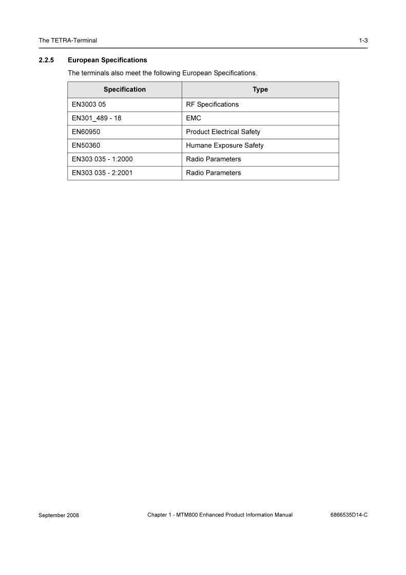
The TETRA-Terminal 1-3
2.2.5 European Specifications
The terminals also meet the following European Specifications.
Specification Type
EN3003 05 RF Specifications
EN301_489 - 18 EMC
EN60950 Product Electrical Safety
EN50360 Humane Exposure Safety
EN303 035 - 1:2000 Radio Parameters
EN303 035 - 2:2001 Radio Parameters
September 2008 Chapter 1 - MTM800 Enhanced Product Information Manual 6866535D14-C

1-4 Product Overview
3 MTM800 Enhanced - Standard & Motorcycle Control Head
Figure 1-1 MTM800 Enhanced - Standard and Motorcycle Control Head
Microphone/
Connector
Handset
LEDAlphanumeric
Display Alphanumeric
Keypad
Emergency
Button
Soft Keys
Menu Key
Navigation Key
Send Key
Rotary Knob /
On Push Button
Programmable
On-Off/End/Home
Key
Keys
6866535D14-C Chapter 1 - MTM800 Enhanced Product Information Manual September 2008

MTM800 Enhanced - Standard & Motorcycle Control Head 1-5
3.1 LED Indications
These are a visual indication of the operational state of the terminal.
3.2 Audio Signal Tones
Indication Terminal Status
Green - Solid In Use
Green - Blinking In Service
Red - Solid Out of Service
Red - Blinking Connecting to Network / Entering DMO
Amber - Solid Transmit Inhibit Active (TXI) / Channel Busy in DMO
Amber - Blinking Incoming Call
No Indication Terminal Powered Down
= High Tone; = Low Tone;
Description Type Repeated
Idle
• Back to Home display
• Back to rotary volume use when rota-
ry scroll timer expires
• Back to coverage
• Back to full service
Once
Clear-to-send Once
Bad key press Once
• Good key press
• MTM800 Enhanced self-test fails at
power up
• From out-of-service to in-service
Once
In Call
Call clear warning Once
Call waiting tone while Phone or
Private Call are pending.
Every 6 seconds, until a call is
terminated.
Data connected or
Data disconnected
Once
Talk permit sounds upon pressing the
PTT.
Once (Normal Tone)
Once (Short Tone)
Talk permit without gateway sounds
upon pressing PTT. The tone indicates
the gateway is no longer available.
Twice
Once
September 2008 Chapter 1 - MTM800 Enhanced Product Information Manual 6866535D14-C

1-6 Product Overview
• Talk prohibit
• System busy
• Time-out timer expire
• Called MTM800 Enhanced not avail-
able or busy
Until you release the PTT.
• Call disconnected or failed due to
network
• Wrong number dialed
Once
DMO (Direct Mode) Entering
Once
DMO Exiting Once
Local site trunking —entering/exiting Once
Phone ring back (sending) Every three seconds, until the
called user answers or call is
rejected.
Phone busy Every 0.5 seconds
Status message sent to the dispatcher
or failed.
Twice
Incoming Calls
Status message acknowledged by the
dispatcher.
Four times
Your MTM800 Enhanced received a
Group Call without gateway (setup
only).
Once
High-priority Group Call received Once
Emergency Alarm sent or received Twice
Emergency Alarm failed Four times
Emergency Call received Once
Phone ring, full-duplex Private Call
(reception)
According to the Ring Style sub-
menu setting.
Until you answer or the call is
rejected.
Private Call received Until the call is answered.
Private Call ringing to the caller Until the call is answered.
Half-duplex Private
Pre-emptive Priority Call (PPC) ring
Every 4 seconds, until the call
is answered or rejected.
Full-duplex Private PPC ring Every 4 seconds, until the call
is answered or rejected.
Limited service Once, upon entering limited
service.
New mail received Once
New Group Call Once
Battery/General
Volume setting (earpiece, keypad,
speaker)
Continuous
Volume setting (ringer) While setting the volume.
Transmit Inhibit (TXI)
Once
Rotary knob tone Once, when toggling from list
control to volume control.
Low battery alert Repeated
= High Tone; = Low Tone;
Description Type Repeated
6866535D14-C Chapter 1 - MTM800 Enhanced Product Information Manual September 2008
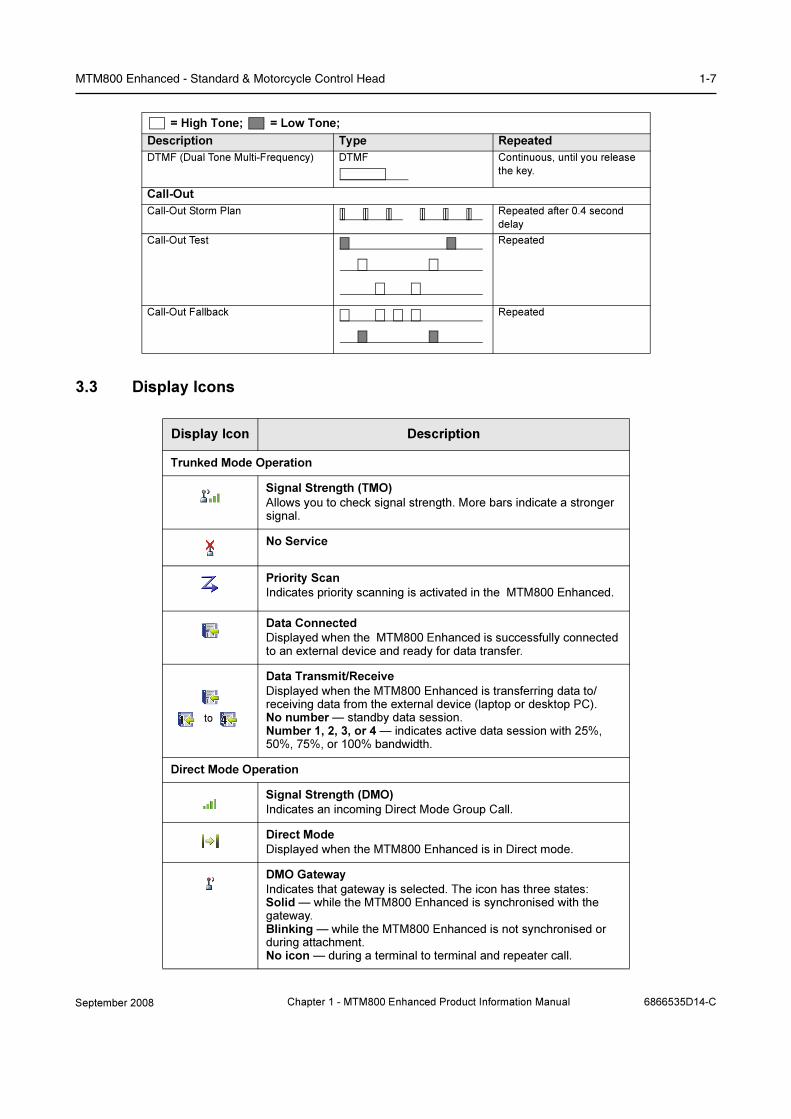
MTM800 Enhanced - Standard & Motorcycle Control Head 1-7
3.3 Display Icons
DTMF (Dual Tone Multi-Frequency) DTMF Continuous, until you release
the key.
Call-Out
Call-Out Storm Plan Repeated after 0.4 second
delay
Call-Out Test Repeated
Call-Out Fallback Repeated
Display Icon Description
Trunked Mode Operation
Signal Strength (TMO)
Allows you to check signal strength. More bars indicate a stronger signal.
No Service
Priority Scan
Indicates priority scanning is activated in the MTM800 Enhanced.
Data Connected
Displayed when the MTM800 Enhanced is successfully connected to an external device and ready for data transfer.
Data Transmit/Receive
Displayed when the MTM800 Enhanced is transferring data to/receiving data from the external device (laptop or desktop PC).No number — standby data session.Number 1, 2, 3, or 4 — indicates active data session with 25%, 50%, 75%, or 100% bandwidth.
Direct Mode Operation
Signal Strength (DMO)
Indicates an incoming Direct Mode Group Call.
Direct Mode
Displayed when the MTM800 Enhanced is in Direct mode.
DMO Gateway
Indicates that gateway is selected. The icon has three states:Solid — while the MTM800 Enhanced is synchronised with the gateway. Blinking — while the MTM800 Enhanced is not synchronised or during attachment.No icon — during a terminal to terminal and repeater call.
= High Tone; = Low Tone;
Description Type Repeated
to
September 2008 Chapter 1 - MTM800 Enhanced Product Information Manual 6866535D14-C
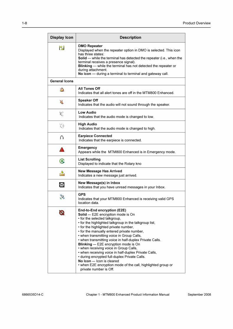
1-8 Product Overview
DMO Repeater
Displayed when the repeater option in DMO is selected. This icon has three states:Solid — while the terminal has detected the repeater (i.e., when the terminal receives a presence signal).Blinking — while the terminal has not detected the repeater or during attachment.No icon — during a terminal to terminal and gateway call.
General Icons
All Tones Off
Indicates that all alert tones are off in the MTM800 Enhanced.
Speaker Off
Indicates that the audio will not sound through the speaker.
Low Audio
Indicates that the audio mode is changed to low.
High Audio
Indicates that the audio mode is changed to high.
Earpiece Connected
Indicates that the earpiece is connected.
Emergency
Appears while the MTM800 Enhanced is in Emergency mode.
List Scrolling
Displayed to indicate that the Rotary kno
New Message Has Arrived
Indicates a new message just arrived.
New Message(s) in Inbox
Indicates that you have unread messages in your Inbox.
GPS
Indicates that your MTM800 Enhanced is receiving valid GPS location data.
End-to-End encryption (E2E)
Solid — E2E encryption mode is On • for the selected talkgroup,
• for the highlighted talkgroup in the talkgroup list,
• for the highlighted private number,
• for the manually entered private number,
• when transmitting voice in Group Calls,
• when transmitting voice in half-duplex Private Calls.
Blinking — E2E encryption mode is On• when receiving voice in Group Calls,
• when receiving voice in half-duplex Private Calls,
• during encrypted full-duplex Private Calls.
No Icon — Icon is cleared • when E2E encryption mode of the call, highlighted group or
private number is Off.
Display Icon Description
6866535D14-C Chapter 1 - MTM800 Enhanced Product Information Manual September 2008

MTM800 Enhanced - Standard & Motorcycle Control Head 1-9
3.4 Supported Languages
The following languages are supported by the terminal:
• English
• German
• French
• Spanish
• Dutch
• Greek
• Italian
• Swedish
• Arabic
• Lithuanian
• Hungarian
• Russian (cyrillic)
• Chinese (simplified)
• Chinese (traditional)
• Korean
• Croatian
• Danish
• Greek
• Hungarian
• Macedonian
• Norwegian
• User definable display languages
It is also possible for the terminal text messages to be changed to some another language,
supported by ISO 8859-1 characters, during programming.
September 2008 Chapter 1 - MTM800 Enhanced Product Information Manual 6866535D14-C

1-10 Product Overview
4 Technical Specifications
4.1 General Specifications
4.2 RF Specifications
Title Specifications
Dimensions H x W x D 49 x 170 x 155 mm Terminal Only
60 x 185 x 175 mm with Next Generation Control
Head
Weight 1350 g Terminal Only
1470 g Terminal with Next Generation Control Head
Talk Groups - TMO 2048
Talk Groups - DMO 1024
Phone Book Entries 225
Text Message List - (Outbox and Inbox) 200 Entries (short messages), 40 (long messages)
Text Message List - outgoing max. 100 Entries depending on mail’s length
Status List 100
Country Code/Network Code List 100
Scan Lists 40 Lists of 20 Groups
Operating Temperature -30 to +60 0C
Storage Temperature -40 to +85 0C
Humidity ETS 300 019-1-5 Class 5.1 and 5.2,
up to 95% R.H.@50 0C
EIA/TIA 603 (95%)
MIL810 95% RH 50 deg.
Dust & Water - Standard Control Head IP54 (dust - cat. 1) for Next Gen. Control Head
Dust & Water - Motorcycle Control Head (M/C) IP67 (dust - cat. 1) for M/C Next Gen. Control Head
Shock, Drop & Vibration ETS 300019-1-5 class 5M2 and class 5M3
MIL 810 C - F
Thermal Shock -40 °C to +80 0C
SB9600 Support No
Title Specifications
Frequency Bands 350 - 390 MHz, or
380 - 430 MHz, or
410 - 470 MHz, or
806 - 870 MHz
6866535D14-C Chapter 1 - MTM800 Enhanced Product Information Manual September 2008
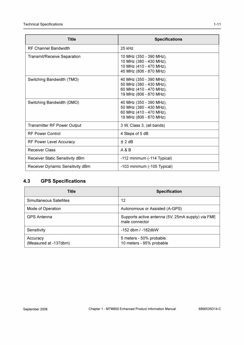
Technical Specifications 1-11
4.3 GPS Specifications
RF Channel Bandwidth 25 kHz
Transmit/Receive Separation 10 MHz (350 - 390 MHz),
10 MHz (380 - 430 MHz),
10 MHz (410 - 470 MHz),
45 MHz (806 - 870 MHz)
Switching Bandwidth (TMO) 40 MHz (350 - 390 MHz),
50 MHz (380 - 430 MHz),
60 MHz (410 - 470 MHz),
19 MHz (806 - 870 MHz)
Switching Bandwidth (DMO) 40 MHz (350 - 390 MHz),
50 MHz (380 - 430 MHz),
60 MHz (410 - 470 MHz),
19 MHz (806 - 870 MHz)
Transmitter RF Power Output 3 W, Class 3, (all bands)
RF Power Control 4 Steps of 5 dB
RF Power Level Accuracy ± 2 dB
Receiver Class A & B
Receiver Static Sensitivity dBm -112 minimum (-114 Typical)
Receiver Dynamic Sensitivity dBm -103 minimum (-105 Typical)
Title Specification
Simultaneous Satellites 12
Mode of Operation Autonomous or Assisted (A-GPS)
GPS Antenna Supports active antenna (5V, 25mA supply) via FME
male connector
Sensitivity -152 dbm / -182dbW
Accuracy
(Measured at -137dbm)
5 meters - 50% probable.
10 meters - 95% probable
Title Specifications
September 2008 Chapter 1 - MTM800 Enhanced Product Information Manual 6866535D14-C
1-12 Product Overview
5 Ordering the MTM800 Enhanced & Accessories
TETRA Subscribers are only available to Accredited Channel Partners.
The MTM800 Enhanced is Motorola's latest advanced digital mobile TETRA with optional integrated
GPS module and UCM. This terminal is based on a new digital platform technology, which ensures
high performance, excellent audio quality as well as wide band RF (Radio Frequency) operation. A
wide range of accessories and the flexible MTM800 design ensures that most applications are
covered by ordering the appropriate model, options and accessories. MTM800 Enhanced is
currently available in 350 - 390 MHz, 380 - 430 MHz, 410 - 470 MHz or 806 - 870 MHz. All terminals
are fully TETRA compliant.
The below Remote Mount models feature a control head with full keypad and display and ships with
the options ordered. If the model is ordered with the expansion control head (found under “remote
mount accessories”) an RS232 interface is available on the expansion control head.
If the model is ordered without the expansion control head (Remote Mount Kit Option), the Active
Data Cable GMKN1022 allows Short and Packet Data connectivity at the 20-pin Accessory
Connector on the rear of the terminal. You need to order GMKN1022 as a separate line accessory
item.
Additionally the transceiver MTM800 Enhanced can be supplied in the following configurations:
MTM800 Enhanced with Next Gen. motorcycle control head or MTM800 Enhanced as Dash / Desk
Mount.
Each Model configuration has unique ordering rules and careful attention to these will ensure that
the correct options and or accessories are ordered.
5.1 Remote Mount - version for flexible vehicle installation
1. Order the main model (includes remote standard control head).
2. One option from each of the following categories is mandatory
• Either clear or encryption software option,
• GPS option. Please note that terminals without the GPS option ordered up front cannot
be retrofitted later to have the GPS feature.
• UCM option
❏ Order remote mounting kit option (only one selection per model)
❏ Order remote mount speaker (only one selection per model)
❏ Order language of user guide (only one selection per model)
3. Add additional hardware accessories as needed. Note: Antenna is now a default Option for
General Information
Ordering Requirements
Ordering Information
6866535D14-C Chapter 1 - MTM800 Enhanced Product Information Manual September 2008

Ordering the MTM800 Enhanced & Accessories 1-13
inclusion in basic package, use Delete Option if No Antenna required
4. Customers can select from the Antenna Options shown or contact your Systems Engineer to
discuss requirements. The range of Antennas outside of these options is extensive. Note
there are two Antenna Option modes, GPS /Tetra combined or GPS with separate Tetra
Antenna.
5. Please note that the GMKN1022 is not required and should not be used with model ordered
with an expansion control head. Use the built-in 9 pin D connector instead for short and
packet data connectivity.
6. Note: Export controls apply when ordering encryption
5.2 Dash Mount - version for compact installation
1. Order the main model (includes standard control head).
2. One option from each of the following categories is mandatory
❏ Order the options:
• either clear or encryption software option,
• GPS option. Please note that terminals without the GPS option ordered up front cannot
be retrofitted later to have the GPS feature.
• UCM option
❏ Select dash mount accessory configuration (only one selection per model)
❏ Order an 'add: trunnion' option from Mounting options (only one selection per model)
❏ Order language of user guide (only one selection per model)
3. Add additional hardware accessories as needed. Note: Antenna is now a default Option for
inclusion in basic package, use Delete Option if No Antenna required
4. Customers can select from the Antenna Options shown or contact your Systems Engineer to
discuss requirements. The range of Antennas outside of these options is extensive. Note
there are two Antenna Option modes, GPS /Tetra combined or GPS with separate Tetra
Antenna.
5. Note: Export controls apply when ordering air-encryption & UCM.
5.3 Desk Mount - version for use in the office
1. Order the main model (includes standard control head).
2. One option from each of the following categories is mandatory
❏ Select Control Head option.
❏ Order either clear or encryption software option (only one selection per model)
❏ Please note that terminals without the GPS option ordered up front cannot be retrofitted
later to have the GPS feature.
❏ Order desktop accessory configuration (only one selection per model)
❏ Order 'del: trunnion' option from Mounting options (only one selection per model)
❏ Order language of user guide (only one selection per model)
❏ A Power Cable option must be ordered (only one selection per model)
❏ A line cord option must be ordered from Power Cord(s).
3. Add additional hardware accessories as needed. Note: Antenna is now a default Option for
September 2008 Chapter 1 - MTM800 Enhanced Product Information Manual 6866535D14-C

1-14 Product Overview
inclusion in basic package, use Delete Option if No Antenna required
4. Customers can select from the Antenna Options shown or contact your Systems Engineer to
discuss requirements. The range of Antennas outside of these options is extensive. Note
there are two Antenna Option modes, GPS /Tetra combined or GPS with separate Tetra
Antenna.
5. Note: Export controls apply when ordering air-encryption & UCM.
5.4 Motorcycle - version for motorcycle installation
1. Order the main model (includes the motorcycle control head).
2. One option from each of the following categories is mandatory
❏ Order the options:
• either clear or encryption software option,
• GPS option. Please note that terminals without the GPS option ordered up front cannot
be retrofitted later to have the GPS feature.
• UCM option
❏ Order microphone and speaker configuration (only one selection per model)
❏ Order mounting options (only one selection per model)
❏ Order language of Motorcycle user guide (only one selection per model)
3. Add additional hardware accessories as needed. Note: Antenna is now a default Option for
inclusion in basic package, use Delete Option if No Antenna required
4. Customers can select from the Antenna Options shown or contact your Systems Engineer to
discuss requirements. The range of Antennas outside of these options is extensive. Note
there are two Antenna Option modes, GPS /Tetra combined or GPS with separate Tetra
Antenna.
5. Note: Export controls apply when ordering air-encryption & UCM.
5.5 Data / Expansion Head
1. Order the main model
2. One option from each of the following categories is mandatory
❏ Order the options:
• either clear or encryption software option,
• GPS option. Please note that terminals without the GPS option ordered up front cannot
be retrofitted later to have the GPS feature.
• UCM option
❏ Order language of user guide (only one selection per model)
3. Add additional hardware accessories as needed. Note: Antenna is now a default Option for
inclusion in basic package, use Delete Option if No Antenna required
4. Antenna are not included in the basic package, Customers can select from the Antenna
Options shown or contact your Systems Engineer to discuss requirements. The range of
Antennas outside of these options is extensive.
5. Note: Export controls apply when ordering encryption
6866535D14-C Chapter 1 - MTM800 Enhanced Product Information Manual September 2008

Ordering the MTM800 Enhanced & Accessories 1-15
MTM800 Enhanced - Standard & Motorcycle Control Heads
MTM800 Enhanced Model Number
MTM800 ENH 380 - 430MHz DASH MT912M M80PCS6TZ5_N
MTM800 ENH 380 - 430MHz DESK MT912M M80PCS6TZ4_N
MTM800 ENH 380 - 430MHz REMOTE MT912M M80PCS6TZ6_N
MTM800 ENH 380 - 430MHz MOTORCYCLE MT912M M80PCS6TZ2_N
MTM800 ENH 410 - 470MHz DASH MT512M M80RCS6TZ5_N
MTM800 ENH 410 - 470MHz DESK MT512M M80RCS6TZ4_N
MTM800 ENH 410 - 470MHz REMOTE MT512M M80RCS6TZ6_N
MTM800 ENH 410 - 470MHz MOTORCYCLE MT512M M80RCS6TZ2_N
MTM800 ENH 806 - 870 Dash MT712M M80UCS6TZ5_N
MTM800 ENH 806 - 870 Desk MT712M M80UCS6TZ4_N
MTM800 ENH 806 - 870 Remote MT712M M80UCS6TZ6_N
MTM800 ENH 806 - 870 MOTORCYCLE MT712M M80UCS6TZ2_N
MTM800 ENH 350 - 390MHz DASH MT812M M80NCS6TZ5_N
MTM800 ENH 350 - 390MHz DESK MT812M M80NCS6TZ4_N
MTM800 ENH 350 - 390MHz REMOTE MT812M M80NCS6TZ6_N
MTM800 ENH 350 - 390MHz MOTORCYCLE MT812M M80NCS6TZ2_N
Description Nomenclature
ADD: STD ENH CTRL HD ROMAN
(keypad: Roman)
GA00095AA
ADD: STD ENH CTRL HD CHINESE
(Keypad: Chinese)
GA00096AA
ADD: STD ENH CTRL HD KOREAN
(Keypad: Korean)
GA00097AA
ADD: STD ENH CTRL HD ARABIC
(Keypad: Arabic)
GA00098AA
ADD: STD ENH CTRL HD BOPOMOFO
(Keypad: BoPoMoFo)
GA00099AA
ADD: STD ENH CTRL HD CYRILLIC
(Keypad: Russian Cyrillic)
GA00100AA
September 2008 Chapter 1 - MTM800 Enhanced Product Information Manual 6866535D14-C

1-16 Product Overview
MTM800 Enhanced - Software 350 - 390 MHz
ADD: REM ENH CTRL HD ROMAN GA00101AA
ADD: REM ENH CTRL HD CHINESE GA00102AA
ADD: REM ENH CTRL HD KOREAN GA00103AA
ADD: REM ENH CTRL HD ARABIC GA00104AA
ADD: REM ENH CTRL HD BOPOMOFO GA00105AA
ADD: REM ENH CTRL HD CYRILLIC GA00106AA
ADD: M/C ENH CTRL HD ROMAN GA00107AA
ADD: M/C ENH CTRL HD CHINESE GA00108AA
ADD: M/C ENH CTRL HD KOREAN GA00109AA
ADD: M/C ENH CTRL HD ARABIC GA00110AA
ADD: M/C ENH CTRL HD BOPOMOFO GA00111AA
ADD: M/C ENH CTRL HD CYRILLIC GA00112AA
DEL: DELETE ENH CTRL HD GA00113AA
ADD: STD ENH CTR HD HUNGARIAN GA00180AA
ADD: M/C ENH CTR HD HUNGARIAN GA00182AA
Description Nomenclature
ADD: ENH TX/RX 350-390 CLEAR GA00080AA
ADD: ENH TX/RX 350-390 TEA1 GA00081AA
ADD: ENH TX/RX 350-390 TEA3 GA00082AA
ADD: ENH TX/RX 350-390 GPS CLEAR GA00083AA
ADD: ENH TX/RX 350-390 GPS TEA1 GA00084AA
ADD: ENH TX/RX 350-390 GPS TEA3 GA00085AA
ADD: ENH TX/RX 350 UCM AES128 GA00086AA
ADD: ENH TX/RX 350 UCM TEA1 AES128 GA00087AA
ADD: ENH TX/RX 350 UCM TEA3 AES128 GA00088AA
ADD: ENH TX/RX 350 UCM/GPS AES128 GA00089AA
ADD: ENH TX/RX 350 UCM/GPS TEA1 AES128 GA00090AA
ADD: ENH TX/RX 350 UCM/GPS TEA3 AES128 GA00091AA
Description Nomenclature
6866535D14-C Chapter 1 - MTM800 Enhanced Product Information Manual September 2008
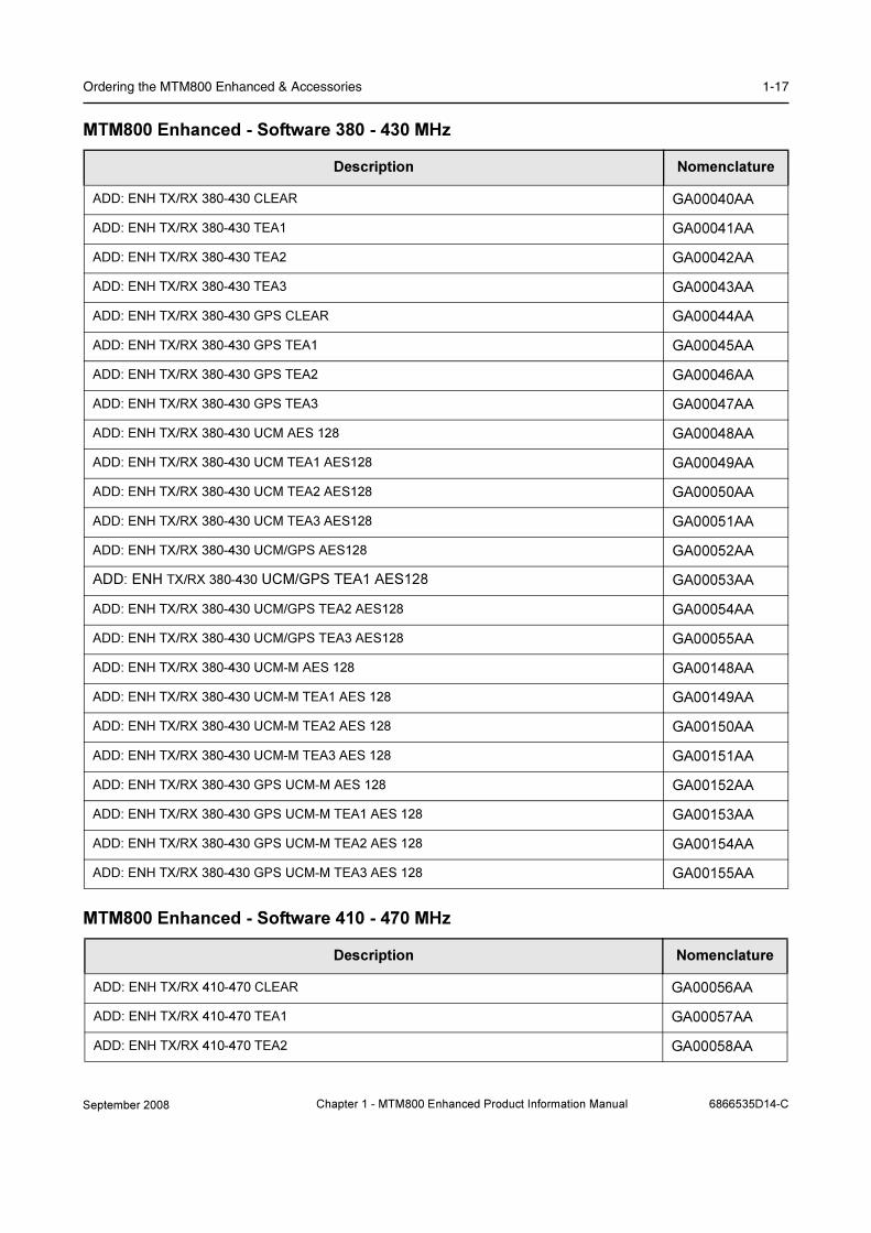
Ordering the MTM800 Enhanced & Accessories 1-17
MTM800 Enhanced - Software 380 - 430 MHz
MTM800 Enhanced - Software 410 - 470 MHz
Description Nomenclature
ADD: ENH TX/RX 380-430 CLEAR GA00040AA
ADD: ENH TX/RX 380-430 TEA1 GA00041AA
ADD: ENH TX/RX 380-430 TEA2 GA00042AA
ADD: ENH TX/RX 380-430 TEA3 GA00043AA
ADD: ENH TX/RX 380-430 GPS CLEAR GA00044AA
ADD: ENH TX/RX 380-430 GPS TEA1 GA00045AA
ADD: ENH TX/RX 380-430 GPS TEA2 GA00046AA
ADD: ENH TX/RX 380-430 GPS TEA3 GA00047AA
ADD: ENH TX/RX 380-430 UCM AES 128 GA00048AA
ADD: ENH TX/RX 380-430 UCM TEA1 AES128 GA00049AA
ADD: ENH TX/RX 380-430 UCM TEA2 AES128 GA00050AA
ADD: ENH TX/RX 380-430 UCM TEA3 AES128 GA00051AA
ADD: ENH TX/RX 380-430 UCM/GPS AES128 GA00052AA
ADD: ENH TX/RX 380-430 UCM/GPS TEA1 AES128 GA00053AA
ADD: ENH TX/RX 380-430 UCM/GPS TEA2 AES128 GA00054AA
ADD: ENH TX/RX 380-430 UCM/GPS TEA3 AES128 GA00055AA
ADD: ENH TX/RX 380-430 UCM-M AES 128 GA00148AA
ADD: ENH TX/RX 380-430 UCM-M TEA1 AES 128 GA00149AA
ADD: ENH TX/RX 380-430 UCM-M TEA2 AES 128 GA00150AA
ADD: ENH TX/RX 380-430 UCM-M TEA3 AES 128 GA00151AA
ADD: ENH TX/RX 380-430 GPS UCM-M AES 128 GA00152AA
ADD: ENH TX/RX 380-430 GPS UCM-M TEA1 AES 128 GA00153AA
ADD: ENH TX/RX 380-430 GPS UCM-M TEA2 AES 128 GA00154AA
ADD: ENH TX/RX 380-430 GPS UCM-M TEA3 AES 128 GA00155AA
Description Nomenclature
ADD: ENH TX/RX 410-470 CLEAR GA00056AA
ADD: ENH TX/RX 410-470 TEA1 GA00057AA
ADD: ENH TX/RX 410-470 TEA2 GA00058AA
September 2008 Chapter 1 - MTM800 Enhanced Product Information Manual 6866535D14-C

1-18 Product Overview
MTM800 Enhanced - Software 806 - 870 MHz
MTM800 Enhanced - Dash Mount
ADD: ENH TX/RX 410-470 GPS CLEAR GA00059AA
ADD: ENH TX/RX 410-470 GPS TEA1 GA00060AA
ADD: ENH TX/RX 410-470 GPS TEA2 GA00061AA
ADD: ENH TX/RX 410-470 UCM AES 128 GA00062AA
ADD: ENH TX/RX 410-470 UCM TEA1 AES128 GA00063AA
ADD: ENH TX/RX 410-470 UCM TEA2 AES128 GA00064AA
ADD: ENH TX/RX 410-470 UCM/GPS AES128 GA00065AA
ADD: ENH TX/RX 410-470 UCM/GPS TEA1 AES128 GA00066AA
ADD: ENH TX/RX 410-470 UCM/GPS TEA2 AES128 GA00067AA
Description Nomenclature
ADD: ENH TX/RX 806-870 CLEAR GA00068AA
ADD: ENH TX/RX 806-870 TEA1 GA00069AA
ADD: ENH TX/RX 806-870 TEA3 GA00070AA
ADD: ENH TX/RX 806-870 GPS CLEAR GA00071AA
ADD: ENH TX/RX 806-870 GPS TEA1 GA00072AA
ADD: ENH TX/RX 806-870 GPS TEA3 GA00073AA
ADD: ENH TX/RX 806-870 UCM AES 128 GA00074AA
ADD: ENH TX/RX 806-870 UCM TEA1 AES128 GA00075AA
ADD: ENH TX/RX 806-870 UCM TEA1 AES128 GA00076AA
ADD: ENH TX/RX 806-870 UCM/GPS AES128 GA00077AA
ADD: ENH TX/RX 806-870 UCM/GPS TEA1 AES128 GA00078AA
ADD: ENH TX/RX 806-870 UCM/GPS TEA3 AES128 GA00079AA
Description Nomenclature
ADD: COMP FIST MIC GCAI GA00134AA
ADD: HEAVy DUTY MIC GCAI GA00135AA
ADD: VISOR MIC GA00139AA
DEL Mic GA00140AA
Description Nomenclature
6866535D14-C Chapter 1 - MTM800 Enhanced Product Information Manual September 2008

Ordering the MTM800 Enhanced & Accessories 1-19
MTM800 Enhanced - Remote Mount
MTM800 Enhanced - Desktop Configuration
MTM800 Enhanced - Mounting
Description Nomenclature
ADD: REM HEAD FOR ENH CTRL HD
(to be connected to the MTM800)GA00122AA
ADD: REM ENH CTR HD HUNGARIAN GA00181AA
ADD: EXP HEAD FOR ENH CTRL HD
(to be connected to the MTM800)GA00123AA
ADD: Remote mount cable (radio to C/H) - 3m GA00124AA
ADD: Remote mount cable (radio to C/H) - 5m GA00125AA
ADD: Remote mount cable (radio to C/H) - 7m GA00126AA
ADD: REMote mount cable (radio to C/H) - 10 m GA00127AA
Add: acc expansion cable gcai (radio to M/C control head9 ga00116aa
ADD: ENH CTRL HD TRUNNION GA00128AA
ADD: M/C ENH CTRL HD TRUNNION GA00129AA
ADD: DIN MOUNT frame GA00130AA
ADD : ENH CTRL HD DIN TRUNNION GA00131AA
ADD: POWER SUPPLY GA00132AA
DEL: POWER SUPPLY GA00133AA
DEL: TAMPER EVIDENT LABEL G00147AA
ADD: COMP FIST MIC GCAI (REMOTE/MC) GA00222AA
Description Nomenclature
ADD: DESK MIC GCAI GA00138AA
ADD: DESKTOP TRAY W SPK GA00114AA
ADD: DESKTOP TRAY W/O SPK GA00115AA
ADD: ACC EXPANSION CABLE GCAI GA00116AA
Description Nomenclature
ADD: KEY LOCK MOUNT
(Adds key lock mount RLN4779)
B81BH
ADD: TRUNION LOW PROFILE
(Adds low profile trunnion GLN7324)
G844AA
ADD: TRUNION HIGH PROFILE
(Adds high profile trunnion GLN7317)
G845AA
September 2008 Chapter 1 - MTM800 Enhanced Product Information Manual 6866535D14-C

1-20 Product Overview
Power Cords
ADD: DIN MOUNT KIT G929AA
DEL: TRUNNION H857AA
Description Nomenclature
ADD: LINE CORD UK
(Adds UK line cord NTN7375)
G721AA
ADD: LINE CORD EURO
(Adds EURO line cord NTN7374)
G722AA
ADD: LINE CORD US
(Adds US line cord NTN7373)
G723AA
ADD: BATTERY POWER CABLE 3M G320AH
ADD: BATTERY POWER CABLE 6M G102AD
Description Nomenclature
6866535D14-C Chapter 1 - MTM800 Enhanced Product Information Manual September 2008

Ordering the MTM800 Enhanced & Accessories 1-21
AntennasFollowing Antenna range is suitable but NOT confined to the following configurations:
• Remote Mount
• Dash Mount
• Data / Expansion
Combined TETRA & GPS Antennas
GPS Antennas
TETRA Antennas
Description Frequency Range Nomenclature
ADD: Ant Combined Tetra/GPS 350MHz 350 - 390 MHz G981AA
ADD: ANTENNA Combined Tetra and GPS Tetra, Whip,
GPS 26dB LNA.
Panorama GPSK-Tet Accessory Kit GMAE4248A
380 - 430 MHz G893AA
ADD: ANTENNA Combined Tetra and GPS Tetra, Whip,
GPS 26dB LNA.
Panorama GPSK Tet S1 Accessory Kit GMAE4249A
380 - 400 MHz G894AA
ADD: ANTENNA Combined Tetra and GPS Tetra, Whip,
GPS 26dB LNA.
Panorama GPSK Tet S2 Accessory Kit GMAE4250A
410 - 430 MHz G895AA
ADD: ANTENNA COMBINED UHF/GPS 430 - 470 MHz G911AA
DEL: ANTENNA GPS G957AA
Description Frequency Range Nomenclature
ADD: ANTENNA GPS Only, Panel Mount
Panorama GPSF- P Accessory Kit GMAG4251A
GPS G896AA
ADD: ANTENNA GPS Only, Magnetic Mount
Panorama GPSM Accessory Kit GMAG4252A
GPS G897AA
DEL: ANTENNA GPS GPS G957AA
Description Frequency Range Nomenclature
ADD: Antenna Tetra Glass Mount 350MHz 350 - 390 MHz G984AA
ADD: ANTENNA Tetra Glass Mount
Panorama GM390 Accessory Kit GMAE4253A
380 - 400 MHz G898AA
ADD: ANTENNA Tetra Glass Mount
Panorama GM420 Accessory Kit GMAE4254A
410 - 430 MHz G899AA
ADD: AntENNA UHF Glass Mount 450 - 470 MHz G912AA
ADD: Antenna Tetra Panel/Roof Mount 350 - 390 MHz G985AA
September 2008 Chapter 1 - MTM800 Enhanced Product Information Manual 6866535D14-C

1-22 Product Overview
Desk Mount AntennasFollowing antennas are suitable for Desk Mount configurations. Antennas are general purpose
coverage including internal buildings such as shopping complexes, Airport complexes etc. GPS is
included for completeness. A suitable mounting bracket is Motorola Part No. MNT62312B1.
ADD: ANTENNA Tetra Panel Mount
Panorama EBF-Tet Accessory Kit GMAE4255A
380 - 430 MHz G900AA
ADD: AntENNA UHF Panel Mount 430 - 470 MHz G913AA
ADD: Antenna Tetra Magnetic Mount 350 - 390 MHz G986AA
ADD: ANTENNA Tetra Magnetic Mount
Panorama MD390-5 Accessory Kit GMAE4256A
380 - 400 MHz G901AA
ADD: ANTENNA Tetra Magnetic Mount
Panorama MD420-5 Accessory Kit GMAE4257A
410 - 430 MHz G902AA
ADD: AntENNA UHF Magnetic Mount 430 - 470 MHz G914AA
ADD: Antenna Tetra Covert 350 - 390 MHz G987AA
ADD: ANTENNA Tetra Covert, Strip Antenna, Glass,
Panorama EFS13F Accessory Kit GMAE4258A
380 - 400 MHz G903AA
ADD: ANTENNA Tetra Covert, Strip Antenna, Glass,
Panorama EFS23F Accessory Kit GMAE4259A
410 - 430 MHz G904AA
ADD: AntENNA UHF Covert Strip 420 - 465 MHz G915AA
ADD: Antenna Tetra Low Profile 350 - 390 MHz G988AA
ADD: ANTENNA Tetra Low Profile,
Panorama LP390 Accessory Kit GMAE4260A
380 - 400 MHz G905AA
ADD: ANTENNA Tetra Low Profile,
Panorama LP420 Accessory Kit GMAE4261A
410 - 430 MHz G906AA
ADD: AntENNA UHF Low Profile 450 - 470 MHz G916AA
DEL: ANTENNA TETRA G115AC
DEL: ANTENNA GPS G957AA
Description Frequency Range Nomenclature
ADD: Antenna Tetra Wall Mount 350 – 390MHz G989AA
ADD: ANTENNA Tetra Wall Mount
Panorama ODP390 Accessory Kit GMAE4262A
380 – 400 MHz G907AA
ADD: ANTENNA Tetra Wall Mount 430 - 470 MHz G917AA
ADD: ANTENNA Tetra Wall Mount
Panorama ODP420 Accessory Kit GMAE4263A
410 – 430 MHz G908AA
DEL: ANTENNA TETRA G115AC
Description Frequency Range Nomenclature
6866535D14-C Chapter 1 - MTM800 Enhanced Product Information Manual September 2008
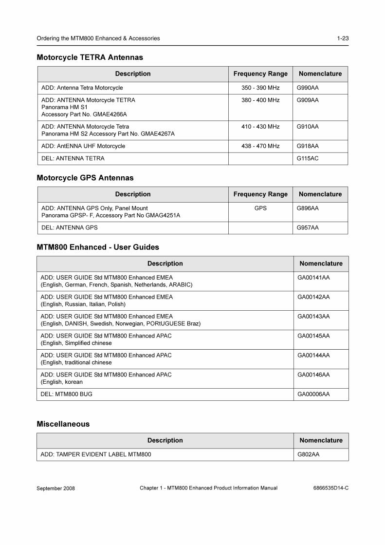
Ordering the MTM800 Enhanced & Accessories 1-23
Motorcycle TETRA Antennas
Motorcycle GPS Antennas
MTM800 Enhanced - User Guides
Miscellaneous
Description Frequency Range Nomenclature
ADD: Antenna Tetra Motorcycle 350 - 390 MHz G990AA
ADD: ANTENNA Motorcycle TETRA
Panorama HM S1
Accessory Part No. GMAE4266A
380 - 400 MHz G909AA
ADD: ANTENNA Motorcycle Tetra
Panorama HM S2 Accessory Part No. GMAE4267A
410 - 430 MHz G910AA
ADD: AntENNA UHF Motorcycle 438 - 470 MHz G918AA
DEL: ANTENNA TETRA G115AC
Description Frequency Range Nomenclature
ADD: ANTENNA GPS Only, Panel Mount
Panorama GPSP- F, Accessory Part No GMAG4251A
GPS G896AA
DEL: ANTENNA GPS G957AA
Description Nomenclature
ADD: USER GUIDE Std MTM800 Enhanced EMEA
(English, German, French, Spanish, Netherlands, ARABIC)
GA00141AA
ADD: USER GUIDE Std MTM800 Enhanced EMEA
(English, Russian, Italian, Polish)
GA00142AA
ADD: USER GUIDE Std MTM800 Enhanced EMEA
(English, DANISH, Swedish, Norwegian, PORtUGUESE Braz)
GA00143AA
ADD: USER GUIDE Std MTM800 Enhanced APAC
(English, Simplified chinese
GA00145AA
ADD: USER GUIDE Std MTM800 Enhanced APAC
(English, traditional chinese
GA00144AA
ADD: USER GUIDE Std MTM800 Enhanced APAC
(English, korean
GA00146AA
DEL: MTM800 BUG GA00006AA
Description Nomenclature
ADD: TAMPER EVIDENT LABEL MTM800 G802AA
September 2008 Chapter 1 - MTM800 Enhanced Product Information Manual 6866535D14-C
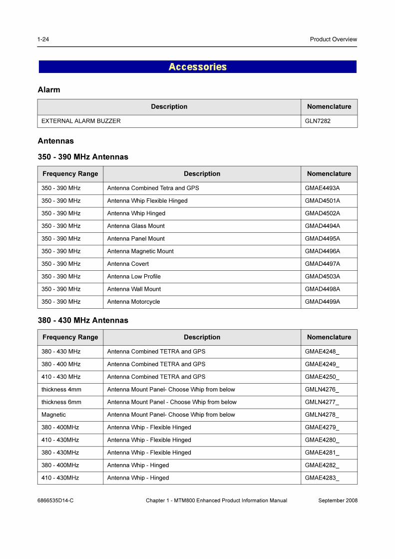
1-24 Product Overview
Alarm
Antennas
350 - 390 MHz Antennas
380 - 430 MHz Antennas
Description Nomenclature
EXTERNAL ALARM BUZZER GLN7282
Frequency Range Description Nomenclature
350 - 390 MHz Antenna Combined Tetra and GPS GMAE4493A
350 - 390 MHz Antenna Whip Flexible Hinged GMAD4501A
350 - 390 MHz Antenna Whip Hinged GMAD4502A
350 - 390 MHz Antenna Glass Mount GMAD4494A
350 - 390 MHz Antenna Panel Mount GMAD4495A
350 - 390 MHz Antenna Magnetic Mount GMAD4496A
350 - 390 MHz Antenna Covert GMAD4497A
350 - 390 MHz Antenna Low Profile GMAD4503A
350 - 390 MHz Antenna Wall Mount GMAD4498A
350 - 390 MHz Antenna Motorcycle GMAD4499A
Frequency Range Description Nomenclature
380 - 430 MHz Antenna Combined TETRA and GPS GMAE4248_
380 - 400 MHz Antenna Combined TETRA and GPS GMAE4249_
410 - 430 MHz Antenna Combined TETRA and GPS GMAE4250_
thickness 4mm Antenna Mount Panel- Choose Whip from below GMLN4276_
thickness 6mm Antenna Mount Panel - Choose Whip from below GMLN4277_
Magnetic Antenna Mount Panel- Choose Whip from below GMLN4278_
380 - 400MHz Antenna Whip - Flexible Hinged GMAE4279_
410 - 430MHz Antenna Whip - Flexible Hinged GMAE4280_
380 - 430MHz Antenna Whip - Flexible Hinged GMAE4281_
380 - 400MHz Antenna Whip - Hinged GMAE4282_
410 - 430MHz Antenna Whip - Hinged GMAE4283_
6866535D14-C Chapter 1 - MTM800 Enhanced Product Information Manual September 2008

Ordering the MTM800 Enhanced & Accessories 1-25
380 - 430MHz Antenna Whip - Hinged GMAE4284_
GPS Antenna GPS Panel Roof Mount 26db lna GMAG4251_
GPS Antenna GPS panel Magnetic Mount 26db lna GMAG4252_
380 - 400MHz Antenna Glass Mount GMAE4253_
410 - 430MHz Antenna Glass Mount GMAE4254_
380 - 430MHz Antenna Panel Mount GMAE4255_
380 - 400MHz Antenna Magnetic Mount GMAE4256_
410 - 430MHz Antenna Magnetic Mount GMAE4257_
380 - 400MHz Antenna Covert GMAE4258_
410 - 430MHz Antenna Covert GMAE4259_
380 - 400MHz Antenna Low Profile GMAE4260_
380 - 400MHz Antenna Low Profile GMAE4261_
380 - 400MHz Antenna Wall Mount GMAE4262_
410 - 430MHz Antenna Wall Mount GMAE4263_
380 - 400MHz Antenna Motorcycle GMAE4266_
410 - 430MHz Antenna Motorcycle GMAE4267_
Frequency Range Description Nomenclature
September 2008 Chapter 1 - MTM800 Enhanced Product Information Manual 6866535D14-C

1-26 Product Overview
450 - 470 MHz Antennas
806 - 870 MHz Antennas
Frequency range Description Nomenclature
430 - 470 MHz Antenna Combined TETRA and GPS GMAE4269_
Antenna Mount Panel
Choose Whip from below
GMAE4276_
Antenna Mount Panel
Choose Whip from below
GMAE4277_
Antenna Mount Magnetic
Choose Whip from below
GMLN4278_
430 - 470 MHz Antenna Whip - Flexible Hinged GMAE4285_
430 - 470 MHz Antenna Whip - Hinged GMAE4286_
GPS Antenna GPS Panel Mount GMAE4251_
GPS Antenna GPS Magnetic Mount GMAE4252_
450 - 470 MHz Antenna Glass Mount GMAE4270_
430 - 470 MHz Antenna Panel Mount GMAE4271_
430 - 470 MHz Antenna Magnetic Mount GMAE4272_
430 - 470 MHz Antenna Covert GMAE4273_
450 - 470 MHz Antenna Low Profile GMAG4274_
430 - 470 MHz Antenna Wall Mount GMAG4275_
430 - 470 MHz Antenna Motorcycle GMAE4268_
Frequency range Description Antennas
800 MHz Antenna Combined TETRA and GPS GMAF4408_
GPS Antenna GPS Panel Mount GMAG4251_
GPS Antenna GPS Magnetic Mount GMAG4252_
800 MHz Antenna Glass Mount GMAF4409_
800 MHz Antenna Glass Mount 3dB GMAF4410_
800 MHz Antenna Eurobase GMAF4411_
800 MHz Antenna MAG Mount GMAF4412_
800 MHz Antenna Magnetic Mount 3dB GMAF4413_
800 MHz Antenna Covert GMAF4414_
800 MHz Antenna Low Profile GMAF4415_
800 MHz Antenna Wall Mount GMAF4416_
800 MHz Antenna Motorcycle GMAF4417_
6866535D14-C Chapter 1 - MTM800 Enhanced Product Information Manual September 2008
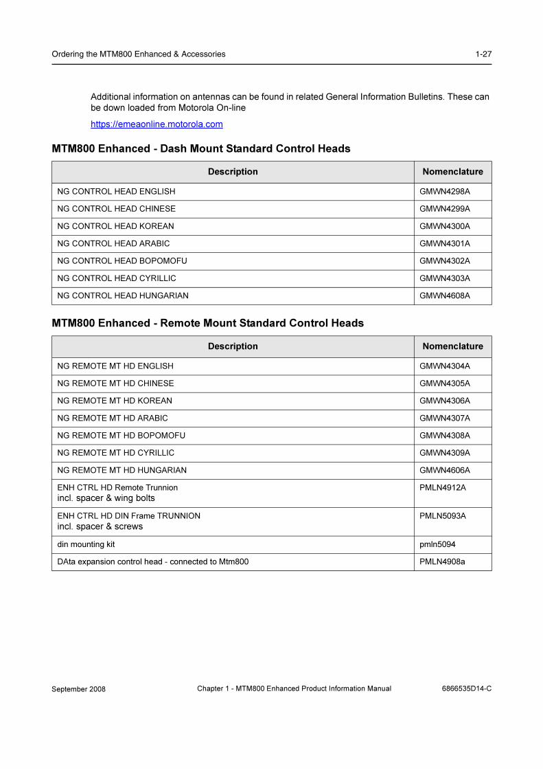
Ordering the MTM800 Enhanced & Accessories 1-27
Additional information on antennas can be found in related General Information Bulletins. These can
be down loaded from Motorola On-line
https://emeaonline.motorola.com
MTM800 Enhanced - Dash Mount Standard Control Heads
MTM800 Enhanced - Remote Mount Standard Control Heads
Description Nomenclature
NG CONTROL HEAD ENGLISH GMWN4298A
NG CONTROL HEAD CHINESE GMWN4299A
NG CONTROL HEAD KOREAN GMWN4300A
NG CONTROL HEAD ARABIC GMWN4301A
NG CONTROL HEAD BOPOMOFU GMWN4302A
NG CONTROL HEAD CYRILLIC GMWN4303A
NG CONTROL HEAD HUNGARIAN GMWN4608A
Description Nomenclature
NG REMOTE MT HD ENGLISH GMWN4304A
NG REMOTE MT HD CHINESE GMWN4305A
NG REMOTE MT HD KOREAN GMWN4306A
NG REMOTE MT HD ARABIC GMWN4307A
NG REMOTE MT HD BOPOMOFU GMWN4308A
NG REMOTE MT HD CYRILLIC GMWN4309A
NG REMOTE MT HD HUNGARIAN GMWN4606A
ENH CTRL HD Remote Trunnion
incl. spacer & wing boltsPMLN4912A
ENH CTRL HD DIN Frame TRUNNION
incl. spacer & screwsPMLN5093A
din mounting kit pmln5094
DAta expansion control head - connected to Mtm800 PMLN4908a
September 2008 Chapter 1 - MTM800 Enhanced Product Information Manual 6866535D14-C
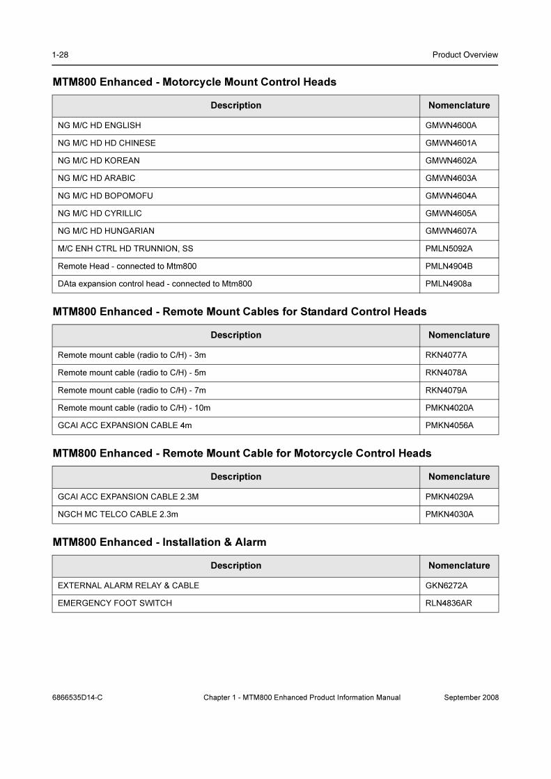
1-28 Product Overview
MTM800 Enhanced - Motorcycle Mount Control Heads
MTM800 Enhanced - Remote Mount Cables for Standard Control Heads
MTM800 Enhanced - Remote Mount Cable for Motorcycle Control Heads
MTM800 Enhanced - Installation & Alarm
Description Nomenclature
NG M/C HD ENGLISH GMWN4600A
NG M/C HD HD CHINESE GMWN4601A
NG M/C HD KOREAN GMWN4602A
NG M/C HD ARABIC GMWN4603A
NG M/C HD BOPOMOFU GMWN4604A
NG M/C HD CYRILLIC GMWN4605A
NG M/C HD HUNGARIAN GMWN4607A
M/C ENH CTRL HD TRUNNION, SS PMLN5092A
Remote Head - connected to Mtm800 PMLN4904B
DAta expansion control head - connected to Mtm800 PMLN4908a
Description Nomenclature
Remote mount cable (radio to C/H) - 3m RKN4077A
Remote mount cable (radio to C/H) - 5m RKN4078A
Remote mount cable (radio to C/H) - 7m RKN4079A
Remote mount cable (radio to C/H) - 10m PMKN4020A
GCAI ACC EXPANSION CABLE 4m PMKN4056A
Description Nomenclature
GCAI ACC EXPANSION CABLE 2.3M PMKN4029A
NGCH MC TELCO CABLE 2.3m PMKN4030A
Description Nomenclature
EXTERNAL ALARM RELAY & CABLE GKN6272A
EMERGENCY FOOT SWITCH RLN4836AR
6866535D14-C Chapter 1 - MTM800 Enhanced Product Information Manual September 2008
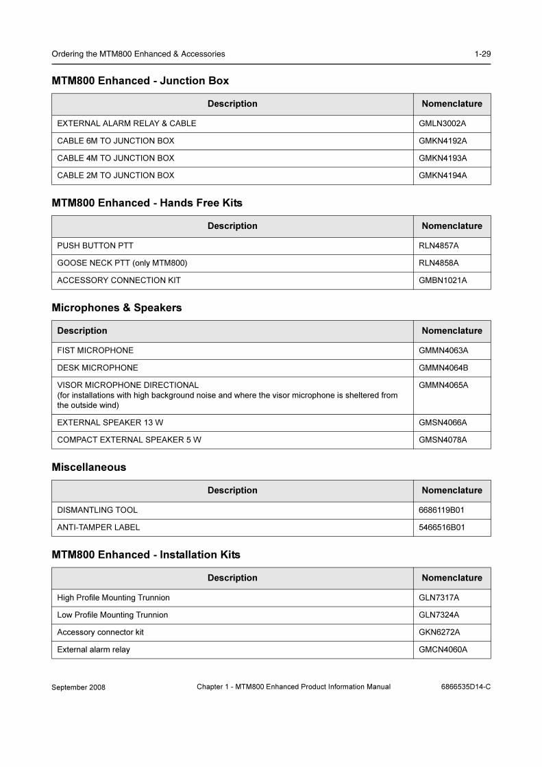
Ordering the MTM800 Enhanced & Accessories 1-29
MTM800 Enhanced - Junction Box
MTM800 Enhanced - Hands Free Kits
Microphones & Speakers
Miscellaneous
MTM800 Enhanced - Installation Kits
Description Nomenclature
EXTERNAL ALARM RELAY & CABLE GMLN3002A
CABLE 6M TO JUNCTION BOX GMKN4192A
CABLE 4M TO JUNCTION BOX GMKN4193A
CABLE 2M TO JUNCTION BOX GMKN4194A
Description Nomenclature
PUSH BUTTON PTT RLN4857A
GOOSE NECK PTT (only MTM800) RLN4858A
ACCESSORY CONNECTION KIT GMBN1021A
Description Nomenclature
FIST MICROPHONE GMMN4063A
DESK MICROPHONE GMMN4064B
VISOR MICROPHONE DIRECTIONAL
(for installations with high background noise and where the visor microphone is sheltered from
the outside wind)
GMMN4065A
EXTERNAL SPEAKER 13 W GMSN4066A
COMPACT EXTERNAL SPEAKER 5 W GMSN4078A
Description Nomenclature
DISMANTLING TOOL 6686119B01
ANTI-TAMPER LABEL 5466516B01
Description Nomenclature
High Profile Mounting Trunnion GLN7317A
Low Profile Mounting Trunnion GLN7324A
Accessory connector kit GKN6272A
External alarm relay GMCN4060A
September 2008 Chapter 1 - MTM800 Enhanced Product Information Manual 6866535D14-C
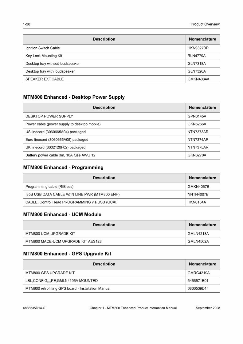
1-30 Product Overview
MTM800 Enhanced - Desktop Power Supply
MTM800 Enhanced - Programming
MTM800 Enhanced - UCM Module
MTM800 Enhanced - GPS Upgrade Kit
Ignition Switch Cable HKN9327BR
Key Lock Mounting Kit RLN4779A
Desktop tray without loudspeaker GLN7318A
Desktop tray with loudspeaker GLN7326A
SPEAKER EXT.CABLE GMKN4084A
Description Nomenclature
DESKTOP POWER SUPPLY GPN6145A
Power cable (power supply to desktop mobile) GKN6266A
US linecord (3060665A04) packaged NTN7373AR
Euro linecord (3060665A05) packaged NTN7374AR
UK linecord (3002120F02) packaged NTN7375AR
Battery power cable 3m, 10A fuse AWG 12 GKN6270A
Description Nomenclature
Programming cable (RIBless) GMKN4067B
I85S USB DATA CABLE W/IN LINE PWR (MTM800 ENH) NNTN4007B
CABLE, Control Head PROGRAMMING via USB (GCAI) HKN6184A
Description Nomenclature
MTM800 UCM UPGRADE KIT GMLN4218A
MTM800 MACE-UCM UPGRADE KIT AES128 GMLN4562A
Description Nomenclature
MTM800 GPS UPGRADE KIT GMRG4219A
LBL,CONFIG,,,,PE,GMLN4195A MOUNTED 5466571B01
MTM800 retrofitting GPS board - Installation Manual 6866539D14
Description Nomenclature
6866535D14-C Chapter 1 - MTM800 Enhanced Product Information Manual September 2008

Ordering the MTM800 Enhanced & Accessories 1-31
MTM800 Enhanced - Publications
Description Nomenclature
MTM800 ENH BASIC USER GUIDE EMEA
(English, German, French, Spanish, DUTCH, ARABIC)
6866539D24
MTM800 ENH BASIC USER GUIDE EMEA
(English, Russian, Italian, Polish)
6866539D34
MTM800 ENH BASIC USER GUIDE EMEA
(English, DANISH, Swedish, Norwegian, PORtUGUESE BRAZ)
6866539D35
MTM800 ENH BASIC USER GUIDE EMEA
(English, HUNGARIAN)
6866539D48
MTM800 ENH FEATURE USER GUIDE, ENGLISH
Available on Motorola Online (MOL)
6866539D25
MTM800 ENH BASIC SERVICE MANUAL, ENGLISH
Available on MOL
6866539D28
MTM800 ENH 350-390 MHz Detailed SERVICE MANUAL, APAC REGION
Available on MOL
6866539D33
MTM800 ENH 380-430 MHz DETAILED SERVICE MANUAL, ENGLISH
NOT Available on MOL - FOR INTERNAL USE ONLY
6866539D29
MTM800 ENH 410-470 MHz DETAILED SERVICE MANUAL, ENGLISH
NOT Available on MOL - FOR INTERNAL USE ONLY
6866539D31
MTM800 ENH 806-870 MHz DETAILED SERVICE MANUAL, ENGLISH
NOT Available on MOL - FOR INTERNAL USE ONLY
6866539D32
MTM800/MTM800 ENH PRODUCT INFORMATION MANUAL
Available on MOL
6866537D87
MTM800 ENH DATA TERMINAL USER GUIDE, ENGLISH
September 2008 Chapter 1 - MTM800 Enhanced Product Information Manual 6866535D14-C

1-32 Product Overview
6 Ordering the Software Enablement Kits
Each kit number ordered will provide one dongle for the customer with a certain number of counters
set according to the number of software option ordered.
This kit number is applicable to both new orders or existing fielded terminals which required
software enablement.
The WAP Software Enablement Kit is not applicable to the MTM800 Enhanced Mobile Terminal.
Note: The following features will be sold in MR5.7.
• GPS
• Multislot Packet Data (MSPD)
• WAP
• Enhanced Security (enclosing: GCK, GCK OTAR, DMO SCK, SCK OTAR)
• Permanent Disable (KILL\UNKILL)
• Call-out
6.1 Software Selling - Tools and Mechanisms
For MR5.7 the chosen approach is a dongle with counters for each one of the features. The features
are enabled at the same time the customer programs the radio. This will happen in one operation.
• A dongle is connected to the PC which is used to configure the TETRA terminal.
• The dongle has a counter for each of the features.
• The dongle counters are “charged” as per what the customer has ordered/purchased
(e.g. MSPD in 100 TETRA terminals.
• Every time a feature is enabled in a terminal the dongle counter is decreased for the
feature in question.
Note: For activating the appropriate features please refer to chapter “Customer Programming Software”,
paragraph “Enable Features” or refer to the CPS Start-Up Manual ((P/N 6802974C10_) on the CPS
CD for more information on how to implement the supplied software.
General Information
6866535D14-C Chapter 1 - MTM800 Enhanced Product Information Manual September 2008

Ordering the Software Enablement Kits 1-33
6.2 How to Place an Order for a Software Enablement Kit
1. Order the Main Kit GM0127
2. Select the software feature option from the following. You can select more than 1 feature for
each Main Kit:
• QA00176_ - Option to enable Multislot Packet Data (MSPD) feature. Order quantity
equaling number of models requiring MSPD enablement.
• QA00175_ - Option to enable WAP feature. Order quantity equaling number of models
requiring WAP enablement.
• QA00771_ - Option to enable Enhanced Security feature. Order quantity equaling
number of models requiring Enhanced Security enablement.
• QA01003AA- Option to enable Permanent Disable feature. Order quantity equaling
number of models requiring Permanent Disable enablement.
• QA01089AA - Option to enable Call-Out feature. Order quantity equaling number of
models requiring Call-Out enablement.
6.3 Example Order
The following order is required:
• 20 radios
• 10 MSPD Software enables
To accompany the 20 radios (ordered according to relevant price page) the following Software
Enhancement Kit should be ordered:
• 1 dongle (1 x GM0127_)
• 10 MSPD (10 x QA00176_)
Note: The CPS will not allow additional radios to be enabled with GPS or MSPD (unless further Software
options are ordered).
Ordering Requirements
September 2008 Chapter 1 - MTM800 Enhanced Product Information Manual 6866535D14-C

1-34 Product Overview
6866535D14-C Chapter 1 - MTM800 Enhanced Product Information Manual September 2008
Chapter 2
SERVICES AND FEATURE DESCRIPTION
1 Introduction
This chapter covers the services and functionality of the Motorola MTM800 Enhanced Terminals
based on the MR5.7 software release.
The functionality is described in enough detail to ensure that both the customer and developer are
clear what is being delivered, taking into account customer need as well as implementation
considerations and constraints.
This chapter contains a high level description of the agreed services and functionality of the
MTM800 Enhanced terminals for MR5.7, including those features that were supported in previous
releases.
The Man-Machine Interface (MMI) requirements are specified in this document in general terms.
The document will specify the functionality required to operate on the Dimetra IP SwMI, as well as
the functionality required to operate on other TETRA SwMI’s that comply with the MoU
interoperability documents [Ref 11] through [Ref 17].
1.1 Features Overview
1.1.1 Trunk Mode Operation (TMO)
• Group call
• Talkgroup Scanning & Priority monitor
• DGNA (Individually addressed + group addressed)
• Emergency group call (and Hot Microphone)
• Half-duplex private call
• Full-duplex private call
• Telephone call (PSTN /PABX)
• SwMI Authentication of MS, and made mutual by MS
• Air Interface Encryption - Static Cipher Key
• Temporary/Permanently Enable/Disable
• AT commands (SDS only)
• Short Data Services (Status, Text Message)
• Targeted SDS Status (to SSI) - (for IOP)
• SDA Remote Listening & Busy User Preemption (Clear builds only)
• Multi-Network Operation (Selected network only)
• Packet Data (Multi Slot)
• TNP1
• Call-Out
• SDS - Store & Forward
• Transmit Inhibit (RF Sensitive Area Mode)
• Support for Dimetra - IP Release 5.2
September 2008 Chapter 2 - MTM800 Enhanced Product Information Manual 6866535D14-C

2-2 Services and Feature Description
• Ambience Listening
• BUP & RL
• Pre-emptive Priority Call
• Mobility Enhancements
• Dynamic Key Encryption
• Broadcast Call
• On Hook Mode for Group Calls using external speaker.
• Horn & Light
1.1.2 Direct Mode Operation (DMO)
• DMO Group Call
• DMO Private Call
• DMO Gateway - Cleartone Gateway
• DMO Repeater Compatibility
• DMO Group Emergency Call
• DMO Static Key Encryption (DMO SCK)
• Short Data Services (Status, Text Message)
• AT commands (SDS only)
• DMO/TMO Emergency Switching
• DMO Inter - Networking - gateway functionality including open group and open network calls.
Also covered are mobility, security, group management and the user interfaces that both support
and enhance the user services.
1.1.3 MTM800 Enhanced Platform Features:
• Built-in GPS receiver
• UCM capable
• End-to-End Encryption (E2E)
1.1.4 MMI Features
• High/Low Audio Toggle Switch
• Individual Call Dialing Scheme
• Alphabetic Search
1.1.5 General Features:
• High Assurance Boot (HAB) memory access protection (see Paragraph 11.8 "High
Assurance Boot (HAB)")
• GPS location reports and display (see Paragraph 15 "GPS Support")
• Favorite talkgroups (see Paragraph 2.1.4 "My Favourite Groups")
• 2048 TMO talkgroups; 1024 DMO talkgroups
• 225 address book entries
• Super groups of scan groups (see Paragraph 14.1.5 "Group Addressed DGNA")
• Covert Mode
6866535D14-C Chapter 2 - MTM800 Enhanced Product Information Manual September 2008

Introduction 2-3
1.1.6 IOP features:
• DCK Forwarding (see Paragraph 11.3.3 "Derived Cipher Key Encryption DCK, Common
Cipher Keys CCK and Group Cipher Keys GCK (Class 3)")
• CCK per LA (see Paragraph 11.3.3 "Derived Cipher Key Encryption DCK, Common Cipher
Keys CCK and Group Cipher Keys GCK (Class 3)")
• Background scanning (see Paragraph 9.4 "Roaming")
• Announced Type 2 handover (see Paragraph 9.4 "Roaming")
• Emergency Private call (see Paragraph 5.2 "Emergency Private Call")
• Call modifications (see Paragraph 5.2 "Emergency Private Call")
• SwMI Initiated attachments (see Paragraph 2.2.15 "SwMI Initiated Group Attach/Detach")
• SwMI controlled groups (see Paragraph 2.2.15 "SwMI Initiated Group Attach/Detach" and
Paragraph 14.1.1 "Adding a Talkgroup")
1.2 References
The following documents may be referred to in this document:
1.2.1 TETRA Standard Documents
[Ref 1] TETRA: AI
ETSI EN 300 392-2 TETRA V+D; Part 2 Air Interface, Edition 2, V2.4.2 (2004-02)
[Ref 2] SDSTL draft 0.13
[Ref 3] TETRA: Security
ETS 300 392-7, TETRA V+D Part 7: Security, Version 2.1.26 (2004-06)
[Ref 4] PEI
ETS 300 392-5 TETRA V&D; Part 5: PEI, Version 1.2.1 (2003-11)
[Ref 5] SS-DGNA S3
ETS EN 300 392-12-22 TETRA V+D; Part 12 SS Stage 3; Subpart 22: DGNA,
Version 1.2.1 (2004-02)
[Ref 6] SS-AL S3
ETS EN 300 392-12-21 TETRA V+D; Part 12: SS Stage 3; Sub-part 21: AL, Version
1.2.0 (2004-06)
[Ref 7] SS-PPC S3
ETS EN 300 392-12-16 TETRA V+D; Part 12: SS Stage 3; Sub-part 16: PPC,
Version 1.2.0 (2004-05)
[Ref 8] TETRA-Address-guide
TETRA 300-5 Designers Guide Part 5; Dialing addressing (first edition, July 1998)
[Ref 9] DMO P1
TETRA Technical Requirements for DMO; Part 1: General Network Design, ETS
300396-1, March 1998
[Ref 10] DMO P3
ETS EN 300 392-6 TETRA Technical Requirements for DMO; Part 3: terminal to
terminal Air Interface Protocol, Version 1.1.21 (2004-06)
1.2.2 MoU TIP Documents
[Ref 11] TIP-Core
TTR 001, TETRA Interoperability Profile - Part 1 (Core), ver 4.8.1, Feb 2003
September 2008 Chapter 2 - MTM800 Enhanced Product Information Manual 6866535D14-C

2-4 Services and Feature Description
[Ref 12] TIP SDS
TTR 001-2, TETRA Interoperability Profile - Part 2: Short Data Service, ver 1.0.1,
Aug 2001
[Ref 13] TIP Auth
TTR 001-04 TIP - Part 4 - Authentication, Version 2.0.0 (April 2003)
[Ref 14] TIP PD
TTR 001-5 TETRA Interoperability Profile Version 3 - Part 5: Packet Data, ver 1.3.0
[Ref 15] TIP-SS-AL
prTTR 001-09 TIP Version 5 - Part 9 - Ambience Listening Ver 1.0.3, Jan 2002
[Ref 16] TIP AIE
TTR 001-11 TIP Version 5 - Part 11 - Air Interface Encryption Ver 1.0.0, Dec 2001
[Ref 17] TIP Disable
TTR 001-13 TIP Version 5 - Part 13 - Enable/Disable Ver 1.0.0, Jan 2002
1.2.3 Other Standards
[Ref 18] RFC: IP
Internet STD 5, RFC 791, Internet working Protocol (IP)
see http://www.isi.edu/in-notes/rfc791.txt
[Ref 19] RFC: PPP
Internet RFC 1661, Point-to-Point Protocol (PPP)
see http://www.isi.edu/in-notes/rfc1661.txt
[Ref 20] RFC: HDLC
Internet RFC 1662, PPP in HDLC-like Framing”
see http://www.isi.edu/in-notes/rfc1662.txt
[Ref 21] RFC: UDP
Internet RFC 768 User Datagram Protocol. J. Postel. Aug-28-1980
see http://www.isi.edu/in-notes/rfc768.txt
[Ref 22] RFC: PAP/CHAP
Internet RFC 1334 "PPP Authentication Protocols"
see http://www.isi.edu/in-notes/rfc1334.txt
[Ref 23] RS 232 Standard - "EIA232E - Interface Between Data Terminal Equipment and
Data Circuit-Terminating Equipment Employing Serial Binary Data Interchange"
published by the Electronic Industries Association,
see http://www.eia.org
1.2.4 Miscellaneous
[Ref 24] Cleartone GW Spec
Call protocol/procedure for DM-GATEWAY and DM-REPEATER by Cleartone
Telecoms; Issue 1.1 Jan-2001
1.3 System Support
The terminal operates on the Dimetra IP 5.x and 6.x releases and and Compact TETRA release 2
and release 3. It will also operate on previous versions of Dimetra-P - from Release 3.1 and on.
The terminal is designed to operate optimally on the Dimetra IP system, but will also operate
properly on Nokia systems, and all SwMIs that comply with IOP TIP documents [Ref 11] through
[Ref 17].
6866535D14-C Chapter 2 - MTM800 Enhanced Product Information Manual September 2008

Introduction 2-5
1.4 Definitions and Acronyms
AL Ambience Listening
ASSI Alias Short Subscriber Identity
AT ATtention; this two-character abbreviation is always used to start a command line to be sent from DTE to terminal
ATG Announcement TalkGroup
CCK Common Cipher Keys
CHAP Challenge-Handshake Authentication Protocol
CLIP Calling Line Identification Presentation
CLIR Calling/connected Line Identification Restriction
CPS Customer Programming Software (terminal Provisioning tool)
DCK Derived Cipher Key
DGNA Dynamic Group Number Assignment
DMO Direct Mode Operation
DTE Data Terminal Equipment (External device attached to radio)
ESN External Subscriber Number
GCK Group Cipher Keys
GCKN GCK Number
GCVK-VN GCK Version Number
GSM Global System for Mobile communications
GSSI Group Short Subscriber Identity
GTSI Group TETRA Subscriber Identity
GPS Global Positioning System
ICMP Internet Control Message Protocol
IP Internet Protocol
IPv4 Internet Protocol version 4
IPv6 Internet Protocol version 6
ISDN Integrated Services Digital Network
ISSI Individual Short Subscriber Identity
ITSI Individual TETRA Subscriber Identity
IMSI International Mobile Subscriber Identity
LIP Location Information Protocol (ETSI standard)
LMN Land Mobile Network
LRRP Location Request Response Protocol (non ETSI standard)
MCC Mobile Country Code
MM Mobility Management
MMI Man Machine Interface
MNC Mobile Network Code
MNI Mobile Network Identity
MO Mobile Originated calls
MS Mobile Station
MSPD Multi Slot Packed Data
MT Mobile Terminal
MT2 Mobile Termination Type 2 (Providing TETRA stack)
MTU Maximum Transmit Unit
PABX Private Automatic Branch eXchange
PAP Password Authentication Protocol
September 2008 Chapter 2 - MTM800 Enhanced Product Information Manual 6866535D14-C
2-6 Services and Feature Description
2 Group Call (TMO)
The group call is defined, in the TETRA Standard, as the normal operating mode and is a point to
multi-point operation. The terminals involved are only able to use half duplex call procedure which
means the user has to press and hold the Push-to-Talk Button during transmitting.
PD Packet Data
PDP Packet Data Protocol
PDCH Packet Data Channel
PDU Protocol Data Unit
PEI Peripheral Equipment Interface
PPC Pre-Emptive Priority Call
PPP Point to Point Protocol
PSTN Public Switched Telephone Network
PTT Push-To-Talk
PUK PIN Unblocking Key
RF SA Radio Frequency Sensitive Area
RFC Request For Comment (Internet ’standard’)
SCK Static Cipher Key
SCKN SCK Number
SCVK-VN SCK Version Number
SDMO Secure DMO
SDS Short Data Service (this includes SDS-Status, and SDS user-defined-data 1,2,3 and 4)
SDTS Short Data Transport Service
SFD Service and Feature Description
SMS Short Message Service
SNDCP Sub-Network Dependent Protocol
SS Supplementary Service
SwMI Switching and Management Infrastructure
TE2 Terminal Equipment Type 2 (Connected via serial link to MT2)
TEA TETRA Encryption Algorithm
TEI TETRA Equipment Identity
TETRA TErrestrial Trunked RAdio
TNP1 TETRA Network Protocol 1, radio control protocol on the PEI
TIP TETRA Interoperability Profile (an agreement between TETRA manufacturers that specifies TETRA signaling options to be used)
TNP1 TETRA Network Protocol 1, radio control protocol on the PEI
TXI Transmit Inhibit
UDP User Datagram Protocol
USSI Un-exchanged Short Subscriber Identity
(V)ASSI (Visitor) Alias Short Subscriber Alias Identity
GSSI Group Short Subscriber Identity
VGSSI Visitor GSSI
6866535D14-C Chapter 2 - MTM800 Enhanced Product Information Manual September 2008

Group Call (TMO) 2-7
2.1 Terminal Ergonomic Features
2.1.1 Group Mode
Before a terminal is able to send and receive Group Calls it will automatically switch to the group
mode of operation when dialing for call setup and alert the user to the incoming group call.
Group Calls are only cleared down by the call originator or if the call timer expires.
Benefits:
❏ Instant access – push PTT and talk, release to listen
❏ ”No fuss” easy & fast to use
2.1.2 Programmable Talkgroups
The terminal is capable of storing 2048 Talkgroup numbers (GSSI - Group Short Subscriber Identity)
in 128 ranges or lists. In Group Mode a single range is always active, offering the user up to 16
Talkgroups. Talkgroups may be repeated in different ranges. Both the Ranges and Talkgroups can
have names/aliases to ease recognition for selection when being scrolled by the user.
Benefits:
❏ Whatever the application and size of the system enough talk groups are available
2.1.3 Talkgroup Ranges
It is possible to provision the terminal to organize the talkgroups into ‘“ranges“. A talkgroup can then
be chosen by first choosing a range and then a talkgroup within the range. Up to 128 ranges can be
provisioned, with up to 16 talkgroups in each range.
Benefits:
❏ Allows ease of use -arrangement of important talk groups - otherwise up to 2048 Talkgroups
must be scrolled through.
❏ Logical arrangement for splitting up into departments or functional teams provides an easier
overview
Note: Via a CPS, a flag can be set to automatically scroll range1 to range2 ... or cycle existing range
only. The range definitions cannot be altered by the terminal user via the MMI.
Note: A new feature enables talkgroup search via keypad digit entry.
2.1.4 My Favourite Groups
This user friendly feature enables a user to create a ‘Personal Range’ of own talkgroups from pre-
programmed talk groups within the terminal and is saved in the terminal during power down.
It is a shared feature for both TMO & DMO operating modes and has a capacity of 128 talkgroups
for the MTM800 Enhanced.
2.1.5 Talkgroup Selection
Selection of a Talkgroup is done via up/down navigation buttons
2.1.6 Receive-only Talkgroups
It is possible to provision a group to be receive-only. The group can be selected, but the terminal will
not allow the user to initiate a call to this group.
September 2008 Chapter 2 - MTM800 Enhanced Product Information Manual 6866535D14-C

2-8 Services and Feature Description
2.1.7 Non Selectable Talkgroups (Hidden Talkgroups)
It is possible to programme non selectable talkgroups, these Talkgroups are not seen by the user
during scrolling, are non-selectable, are programmed as receive only and are only seen during a
received call.
Benefits:
❏ Non Selectable Talkgroups can help to shorten confusingly long Talkgroup Lists in the
terminal and therefore ease operation
❏ Groups where the user is not allowed to initiate a call (e.g. announcement TGs) are hidden
and do not confuse the user
2.1.8 Audio Input and Output
Incoming group call audio will be routed to an external accessory/speaker or Telephone Style
Handset.
2.1.9 Talk Time Limit
The terminal can limit the amount of time the user can continue to talk in a group call according to a
provisioned value defined in the CPS. The user will be warned a short time before the talk time
expires.
2.1.10 Receiving a Group Call
When the terminal is in group mode, it is able to receive group calls without any user intervention.
When the terminal receives an incoming group call, it may be signalled by a short alert tone from the
loudspeaker. This will be followed by the speech.
No user action is needed to clear the call which is cleared by the call owner (normally the SwMI).
2.1.11 Emergency Group Call
Emergency Group call is described in Section 5 "Emergency Operation (TMO)".
2.1.12 Talkgroup Scanning
This is a user selectable option that enables 1 of 20 scan lists to be selected. Each scan list may
contain up to 20 talkgroups that will be monitored for activity. If any activity is detected the terminal
will ‘land on’ the talkgroup and the terminal will join the call, upon call completion the terminal
resumes scan operation.
Features and Benefits:
❏ Ability to monitor more than one group at a time
❏ Allows the user to be in contact with a number of talk groups – calls are not missed
❏ Number of talkgroups in a scan list has been enhanced to 20 specifically for transport
applications
❏ CPS programming allows users to create/modify scan lists.
❏ Scan On/Off is user selectable.
❏ User can ‘cancel’ a scan call if not important to focus on other activities
❏ As Emergency Mode has highest priority, TG Scanning is disabled when emergency mode is
entered - this enhances security.
6866535D14-C Chapter 2 - MTM800 Enhanced Product Information Manual September 2008
Group Call (TMO) 2-9
❏ Talkback function selection - this determines whether or not a user is allowed to Tx on a scan
call.
2.1.13 Priority Monitor
Whilst active in a call, a terminal may receive a ‘call setup’ from a different group and based on call
priority, it will decide whether to ignore the new call or accept it . If the new call is of higher priority
the terminal will drop the active call and select the new call.
The terminal can be programmed to not immediately join the new higher priority call, in which case it
will display the new call to the user who then makes the descission either to accept or reject it.
Benefits:
❏ Priority monitor adds a 3 level priority to the scanned groups – even when engaged in a call a
higher priority call is not missed.
❏ Any TalkGroup/Announcement Talk Group can be provisioned as Priority Group.
2.1.14 Broadcast Call (Also known as ‘Site Wide Call’)
When a Broadcast Call is setup, it takes precedence over any call that has the same or lower
priority. It allows a console to communicate with all Terminal Users located at one or more sites. A
terminal will join the call, no matter what group ID it has selected and ‘Broadcast’ is displayed as the
group alias. As this type of call is receive only, the terminal prevents the user from transmitting
during the call.
Benefits:
❏ Ensures that in a crisis you can mobilise everybody on those sites in an instant.
❏ A wide range of groups and organizations are reachable via Site Wide Call
❏ Can be set up as an Emergency call or Group Call with Late Entry
❏ Easy management via SWTG (Site Wide Talk Groups)
❏ Important that communication is confined to the target area, only the specific critical area
needs to be made aware
❏ Important feature for Transit segment, e.g. if one or more stations need to be evacuated due
to a fire or a bomb threat
2.2 Air Interface - Network Supported Features
The following features are supported by Motorola Dimetra Networks and may not be supported by
other networks.
2.2.1 Group Call Setup
The terminal is able to make and receive group calls to and from other TETRA terminals with half-
duplex speech capability. This call type uses TETRA group call signalling with direct set-up for
incoming and outgoing calls. Group calls are owned and cleared down by the infrastructure.
Direct Setup – User requests call setup (selects address and presses PTT), gets grant by the
infrastructure (grant tone when enabled) and presses PTT to talk.
Benefits:
❏ Instant access to selected group - within <200ms (when resources available and not queuing)
❏ Just pressing PTT when starting communication with current selected Talk Group
September 2008 Chapter 2 - MTM800 Enhanced Product Information Manual 6866535D14-C

2-10 Services and Feature Description
2.2.2 Talking Party Identification (TPI)
This feature enables the identity of the calling terminal to be displayed on the called terminals.
Benefits:
❏ The user always knows who’s talking before answering the call - this enables preparation or
decision to accept or reject the call
2.2.3 Call Restoration
Dependent on available traffic channels, this feature enables a terminal to rejoin a group call as it
moves from one cell coverage area into another cell coverage area, this operation is seamless.
2.2.4 Announcement Talk Group (ATG - also called Multi Group)
This is a special type of group that is logically a group in its own right, but also may contain
subgroups. When selected, the terminal monitors the traffic received for the Announcement Group
and subgroups, but if a subgroup has been selected, the terminal will monitor traffic received for the
announcement group as well as the traffic received for any of the associated subgroups.
The terminal does not monitor the active scan list groups when an announcement group is selected.
When the user selects one of the subgroups of the announcement group, the traffic for the subgroup
is monitored as well as the traffic for its announcement group (but not other subgroups).
The terminal can be programmed to prevent user call initiation or talk back on announcement talk
groups.
This is a Motorola Dimetra ONLY feature (not in Standard or TIP)
Announcement Talk Group compared to Talkgroup Scanning:
• Similar to Scanning in some ways (from MS perspective)
• Rx hold applies to ATG operation
• Scanning mode (Presentation/Forced) applies to ATG operation
• Priority Monitor applies to ATG calls - Announcement group has the highest group
priority
• Unlike scanning in other ways
• Flag in the terminal indicates if user is allowed to start ATG call
• But ‘Talkback flag’ does not apply to ATG calls (always enabled)
• ATG operation applies even in Emergency mode
• ATG association set by CPS and cannot be changed by MS user
• Interaction
• Scan list is disabled when ATG is selected
• ATG cannot be a member of a scan list
Features and Benefits:
• Scanning of a second Talkgroup over the whole network. ATG is a form of active scanning as
opposed to passive scanning where another user on the scanned talkgroup has to be present
on the same site for the user to be offered the scanned talkgroup.
• Establishes a group hierarchy to better manage monitoring of groups
• Announcement group (ATG) ‘contains’ associated groups
• When ATG is selected
6866535D14-C Chapter 2 - MTM800 Enhanced Product Information Manual September 2008

Group Call (TMO) 2-11
• All associated groups are also monitored (‘scanned’)
• Normal TG scan list is disabled
• When group associated with ATG is selected
• ATG also monitored (‘scanned’)
• Normal TG scan list remains active
2.2.5 Temporary Group Address
When a terminal initiates a group call, the system may assign the call to a temporary group, for the
call duration only, and terminals will monitor all signalling addressed to this temporary group.
Similarly terminals support assignment of an incoming call to a temporary group address.
The terminal can support a temporary group address assigned by the SwMI which is only valid for
the lifetime of the call. Thus, if the terminal initiates a group call on the selected group, and the SwMI
assigns the call to a temporary group, the terminal can monitor all signalling addressed to this
temporary group as long as the call is active.
The terminal can support assignment of an incoming group call to a temporary group address.
2.2.6 Group Attachment
Whenever a user selects a new Talkgroup the terminal sends an ‘amendment’ attachment message
to the system. This tells the system what Talkgroup the terminal is now actively monitoring and
should now receive all call setup procedures for this group.
If a scan list has been selected and Talkgroup scanning is enabled by user action, this message will
be sent for all Talkgroups in the active scan list.
2.2.7 Late Entry
Terminals may miss the initial group call setup for various reasons and the system, by repeatedly
sending the group call set up as a ‘Late entry Broadcast’ on the control channel for the call duration,
enables the terminals to join the call at a later time.
The terminal will join a group call setup which contains a notification element indicating Late Entry
Broadcast. During Tx (Not hang time) SwMI sends periodic D-SETUPs on MCCH. However, it will
not differentiate between this and a regular call setup in any way.
Benefits:
❏ When used was out of range or just has finished another call then the terminal does not miss
an ongoing call of the selected Talk Group
2.2.8 Call Ownership
The terminal accepts call ownership of a group call. When the terminal is the call owner it will send
U-DISCONNECT when leaving the call.
2.2.9 Transmit Request Queueing
Whilst another user is talking during an ongoing group call and “PTT during received Group Call”
codeplug is enabled, a user may request to transmit by pressing and holding the PTT button. The
system will see this action and inform the user that the request has been queued.
While the MS is in Emergency Mode the transmission request is not ignored and the queuing is
ignored.
September 2008 Chapter 2 - MTM800 Enhanced Product Information Manual 6866535D14-C

2-12 Services and Feature Description
If the user releases the PTT button, the terminal sends a message to the system withdrawing the
request.
2.2.10 Transmission during the Group Call
Whilst another user is talking during an ongoing group call and “PTT during received Group Call”
codeplug is disabled, a user cannot transmit by pressing and holding the PTT button.
The MS ignores the request to transmit without any indication. The user has to release and then
press again the PTT button to re-initiate a transmission request.
While the MS is in Emergency Mode the transmission request is not ignored.
2.2.11 Call Restoration in Group Call
If the terminal roams to a new cell during a group call, it will attempt to continue the call on the new
cell, using TETRA cell reselection and call restoration procedures.
If the terminal roams while the user is the transmitting party in the group call, and it is possible to
perform announced cell reselection, announced cell reselection will be employed as described in
Paragraph 9.4 "Roaming" and call restoration procedures will be performed in the new cell.
If the user is not the transmitting party, Unannounced cell reselection will be employed, followed by
call restoration procedures.
2.2.12 Temporary Group Address
The terminal supports a temporary group address assigned by the SwMI which is only valid for the
lifetime of the call. Thus, if the terminal initiates a group call on the selected group, and the SwMI
assigns the call to a temporary group, the terminal will monitor all signalling addressed to this
temporary group as long as the call is active.
The terminal supports assignment of an incoming group call to a temporary group address.
2.2.13 Late Entry
The terminal assumes that the SwMI sends repeated setup messages (’late entry’) on the main
control channel. Thus, in certain circumstances (such as when receiving a priority monitor call if
provisioned as “Presented” - See Paragraph 2.1.13 "Priority Monitor") it will ignore a group call D-
SETUP PDU on the assumption that it can join the call at a later time.
The terminal will join a group call setup which contains an SS-LE notification element indicating Late
Entry Broadcast. However, it will not differentiate between this and a regular call setup in any way.
Note: Acknowledged Late Entry, and Late Entry Paging is not supported.
2.2.14 User initiated Group Attachment
When the user changes the selected talkgroup, the terminal will initiate an attachment to the SwMI,
detaching the old group and attaching the new Talkgroup.
All group attachments sent by the terminal are sent with “attachment mode” of “amendment” or
“detach all...” on a case-to-case basis depending on which form will cause less bits to be sent over
the air interface.
When the user selects a scan list and turns scanning on, the terminal will send a group attachment
request to attach the scan groups in addition to the selected group. Similarly, when the user selects
an ATG, the terminal will send an attachment of the ATG as the selected group along with the
attachment of the associated groups as scan groups. If a group associated with an ATG is selected,
6866535D14-C Chapter 2 - MTM800 Enhanced Product Information Manual September 2008

Private Call (TMO) 2-13
the terminal will send an attachment of the associated group as the selected group along with the
attachment of the ATG as a scan group in addition to other scan groups it is scanning.
The TETRA TIP provides a facility by which the terminal can send a status message to the SwMI to
turn scanning off and on rather than detaching and reattaching the groups in order to save air
interface signalling.
If the terminal is provisioned with this option, when the user turns scanning off the terminal sends U-
MM-STATUS (Status Uplink set to 0x20, and Scanning On/Off set to OFF (1)). In this state the
terminal does not monitor any groups other than the selected group (this includes user scan groups,
super groups of scan groups, SwMI scan groups, ATG when an associated group is selected and
associated groups when an ATG is selected). If the user subsequently turns scanning on, the
terminal will send U-MM-STATUS (Status Uplink set to 0x20, and Scanning On/ Off set to ON (0)).
and the terminal will begin again monitoring all attached groups.
If the terminal is not provisioned with this option, the user will only have an option to deselect the
active user scan list, but will not be able to turn (all) scanning off. Deselection of the user scan list
will cause a group detachment of the user scan list groups to be sent to the SwMI; but the terminal
will continue to scan all other groups (such as ATG associations).
2.2.15 SwMI Initiated Group Attach/Detach
If the terminal receives a SwMI initiated attachment for the group which is already currently selected
the terminal will accept the attachment and keep the group selected. If the Class of Usage (CoU)
received is not “selected”, that CoU will be applied when the group is deselected.
If the terminal receives a SwMI initiated attachment for a group in the currently active user scan list,
the attachment will be accepted. If it is for a group that is not in the currently the active scan list, the
attachment will be rejected. If it is for a group that is not in the currently active user scan list, the
attachment will be rejected.accepted and added to a separate scan list that will hold up to 10 such
groups.
SwMI initiated detachment is always accepted by the terminal. If the detachment is for the selected
group, the display will indicate to the user that no group is currently selected. If the detachment is for
a group that is in the user scan list, the group will remain in the list, but will not be monitored. If the
detachment is for a group that is in the “SwMI controlled” list, it will be removed from that list.
3 Private Call (TMO)
This is a call between two terminals and may use either full duplex or half duplex call procedures
dependent on call setup by the calling terminal user.
3.1 Terminal Ergonomic Features
3.1.1 Terminal ID
It is possible for the terminal user to view the terminal’s ID (ISSI - Individual Short Subscriber
Identity) via the menu functionality.
3.1.2 Dialing Methods
The terminal supports the following methods for Private Call setup:
• Direct Dial
September 2008 Chapter 2 - MTM800 Enhanced Product Information Manual 6866535D14-C

2-14 Services and Feature Description
• Scrolling the address book
• Alpha Recall
• Last Number Dialled
Direct Dial
The number of the called terminal is directly entered via the keypad.
Scroll Method
The terminal scroll buttons are used to scroll backwards and forwards through the address book.
Alpha Recall
Phone numbers can be found in the address book using the Alphabetic search feature.
Last Number Called
When entering private mode, the last number called is display, press PTT to redial the number.
3.1.3 Initiating a Private Call from the Contact Book
After defining the target address, the user can initiate the call in 1 of 2 ways:
1. Pressing the PTT button will initiate a half duplex call.
2. Pressing the <send/end> button will initiate a full duplex call. This button is also used to clear
down both types of call.
3.1.4 Short Number Dial
This enables a user to enter only part of a number for private call setup.
3.1.5 Receiving a Private Call
Incoming private calls can be either half-duplex or full-duplex. On receipt of a direct call setup (half
duplex), the terminal will immediately join the call and sound the received audio. Receiving a full-
duplex call setup will cause the terminal to ring using the selected phone ring style or will cause the
terminal to vibrate. Once the user takes the call by pressing <send/end>, the full-duplex call is
established.
3.1.6 Talk Time limit
In a half-duplex call, the terminal will limit the amount of time the user can continue to talk (=
transmit) according to a provisioned value. The user will be warned a short time before the talk time
expires.
Benefits:
❏ Prevents blocking of a Talkgroup when the Push to Talk button hangs on a terminal by
accident or if a user intentional tries to block this group.
3.1.7 Terminating a Private Call
The user will be given the ability to terminate a half-duplex or full-duplex private call by pressing the
<send/end> key.
6866535D14-C Chapter 2 - MTM800 Enhanced Product Information Manual September 2008
Phone Call (TMO) 2-15
3.2 Air Interface - Network Supported Features
3.2.1 Call Restoration in Private Call
This feature enables a terminal to rejoin the call as it moves from one cell coverage area into
another cell coverage area and dependent on available traffic channels, this operation is seamless.
3.2.2 Caller Line Identity Presentation CLIP
The calling party TETRA identity may be transported as part of the incoming individual call set-up
signalling. If the identity can be interpreted as a short number, the short number will be displayed to
the user. In addition, if the number is programmed in the terminal address book, the name
associated with that number will be displayed as well. If the calling party identity is not present in the
call set-up signalling, the terminal will display a blank line in place of the missing identity.
Benefits:
❏ The user always knows who’s calling
❏ If caller is programmed in terminal’s list the alias is displayed
4 Phone Call (TMO)
This is a system feature that enables terminal users to dial telephone numbers and have a full
duplex, one to one call with the called party.
To achieve this the system must have connectivity to PSTN/PABX networks.
4.1 Phone Modes
There are 2 types of Phone Mode, user selectable via the Mode Selection button.
• Phone, which is connectivity to a (public) PSTN network and the user dials a full telephone
number.
• PABX, which is connectivity to a local (private) telephone network, i.e. an office, where the
numbers dialled will be addressed to the defined PABX gateway address.
One PSTN and one PABX Gateway ID (access to a telephone network) can be stored in a terminal.
4.2 Terminal Ergonomic Features
4.2.1 Dialing Methods
Supported by the terminal the following ways can be used to enter/recall a PSTN/PABX number for
call setup (pending on the programming of the terminals):
• Direct Dial
• Scrolling
• One Touch Dial
• Last Number Redial
The number of the called terminal is directly entered via the keypad.
Benefits:
September 2008 Chapter 2 - MTM800 Enhanced Product Information Manual 6866535D14-C

2-16 Services and Feature Description
❏ Also unexperienced user are able to operate the TETRA terminal very similar to a GSM
phone
4.2.1.1 Scroll Method
The terminal scroll buttons are used to scroll backwards and forwards through the address book.
Benefits:
❏ Usage similar to a GSM phones address book - Aliases make it easy to find the wanted
destination
4.2.1.2 One Touch Dial
Keypad numbers 0 to 9 and function buttons can be programmed with an associated dial number
and holding the button pressed for more than a pre programmed time will initiate the call. This
feature is de-activated during Private, Phone and PABX calls.
Benefits:
❏ This is the fasted way to dial most wanted numbers
4.2.1.3 Last Number Redial
When entering phone mode, the last number called is display, press PTT to redial the number.
4.2.2 Ring Styles
The ring style and volume for incoming phone calls is pre-programmed in the terminal and can be
modified by the user via the menu.
Benefits:
❏ The user can setup the tones and volumes in a way that it fits to the circumstances and
environment the terminal is operating so that call will not be missed.
4.3 System Interaction
The terminal supports the following telephone related functions:
4.3.1 Initiating a Telephone Call
The terminal is only able to initiate calls to a PSTN/PABX using full duplex speech capability.
Telephone calls can also be made between terminals using the Terminal - ISDN number as the
called party number.
Half-duplex calls are not supported, if attempted, the system will try and update the call to full-
duplex, but if the terminal is not programmed for ful-duplex calls, the call will be dropped.
4.3.2 Receiving a Telephone Call
Incoming telephone calls use on/off hook signalling. The terminal extracts the Gateway ID from the
call set up signalling to determine which phone mode to enter, PABX or PSTN.
4.3.3 Call Restoration
This feature enables a terminal to rejoin the call as it moves from one cell coverage area into
another cell coverage area and dependent on available traffic channels, this operation is seamless.
6866535D14-C Chapter 2 - MTM800 Enhanced Product Information Manual September 2008

Emergency Operation (TMO) 2-17
4.3.4 DTMF (One Press) Over Dialing
DTMF Overloading enables the user to send out DTMF/MFV tones and is only available when the
terminal is active in a phone call. The DTMF feedback tone to the user is generated by the terminal.
DTMF tones are used to control e.g. an answering machine or a voice mail box.
4.3.5 Calling Line Identification Presentation (CLIP)
The calling party number is transported as part of the call set up signalling and is displayed on the
terminal screen. If the number is held in the terminal’s Address Book, then the name/alias
associated with the entry will be displayed.
4.3.6 112/110/999 Dialing (pending on the infrastructure/SwMI)
If the user initiates a call to a phone number programmed as the emergency call number, the call is
made with Call Priority 15 (Pre-emptive emergency priority) and the terminal display will not show
anything special to indicate that it is in emergency mode.
4.4 Address Book
This contains the following 3 lists:
• Private Call list - this can have to 100 entries.
• Phone List - this can have to 100 entries.
• PABX List - this can have to 25 entries.
These contain stored numbers for user dialing.
5 Emergency Operation (TMO)
5.1 Emergency Group Operation
5.1.1 Emergency Group Mode
Emergency mode is entered when the user presses and holds the dedicated emergency button for a
defined period of time.
On entry into the emergency mode any existing call or service other than the packet data service will
either be aborted or cleared down.
In emergency mode, the terminal automatically rejects PSTN, PABX and private calls and does not
monitor groups in the user selected scan list, but if an Announcement Talk Group (ATG) is the
selected group, then the terminal monitors the groups associated with the ATG.
The terminal remains in emergency mode until user action exits the emergency mode and restores
normal operation.
Benefits:
❏ Instant high priority access to the group
❏ Dispatcher is notified via emergency status
❏ The emergency group is notified of the emergency situation via a tone and the display
❏ ”Hot mic” enables the user to call for help without touching the terminal
September 2008 Chapter 2 - MTM800 Enhanced Product Information Manual 6866535D14-C
2-18 Services and Feature Description
5.1.2 Emergency Alarm
5.1.3 Emergency Alarm
If the terminal is provisioned with the emergency alarm feature, upon entry into emergency mode,
the terminal will send an emergency alarm. This alarm is sent by sending a specially designated
SDS status message to the address of the selected group. In addition, once the terminal is in
emergency mode (and the terminal is provisioned with the emergency alarm feature), whenever the
user presses the designated emergency button, an additional emergency alarm will be sent. The
message can be dispatched both in TMO and DMO.
If Emergency Alarm is disabled, initiation of a new call by pressing emergency button during
initiated Emergency Private call is disallowed. The radio shall notify the user by posting ‘Service
Restricted’.
If Emergency Alarm is enabled:
• Emergency Address Type is Group and HotMic is disabled - emergency alarm is sent
again
Emergency Address Type is Private - emergency alarm is sent again.
5.1.4 Emergency Group Call
The user is able to initiate an emergency group call in emergency mode and can participate in an
emergency group call (initiated by others) in emergency mode or in regular group mode.
If a terminal receives an incoming group call with emergency priority, the display will show that an
Emergency call has been received, and a special audio alert will be sounded.
The audio for an emergency group call will always sound through the speaker (high audio), even if
the low audio is selected.
An Emergency Group Call is configured as non-tactical or tactical:
• A non-tactical call initiates on a talkgroup designated by the codeplug setting. After exiting
from non-tactical emergency mode the terminal will be attached to the group that was
selected before initiating the non-tactical call. When in non-tactical emergency mode, the
user will not be able to switch talkgroups.
DGNA messages have no impact during non-tactical emergency mode but only after exiting
the non-tactical emergency mode.
• A tactical call initiates on the currently selected talkgroup.
5.1.5 Hot Microphone
This is a programmable option in the terminal. If enabled and the terminal enters emergency mode
and sets up an Emergency Group Call, the microphone will automatically open and allow the user to
talk without having to press the PTT button. Transmission is allowed for a pre-programmed period of
time, after which the user must press the emergency button to restore the Hot Mic. functionality.
Pressing the PTT during the Hot Mic operational period will end the Hot Mic functionality and the
terminal will revert to normal PTT voice operation.
If during an ongoing emergency call another terminal activates emergency within the same group
the first emergency call will be interrupted after a pre programmed time. The hotmike function
toggles between the first terminal and the second one in emergency stage triggered by the pending
timers until the duration timers are expired. All timers are set by CPS.
During the hot microphone phase the gain of the microphone can be altered automatically.
6866535D14-C Chapter 2 - MTM800 Enhanced Product Information Manual September 2008

Direct Mode Operation (DMO) 2-19
Benefits:
❏ Instant high priority access to the group - no emergency call gets lost
❏ Dispatcher is notified via emergency status - can react immediately
❏ The emergency group is notified of the emergency situation via a tone and the display - the
are immediately aware of it and can start to investigate for help
❏ ”Hot mic” enables the user to call for help without touching the terminal
❏ Increased microphone gain during emergency phase enables the user to talk without being
close to the terminal
❏ Also members of the Talk Group can gain more information about the situation by listen of
background noises
5.2 Emergency Private Call
Emergency Call can be provisioned to be a Half-Duplex or Full-Duplex private call. If Emergency
Call is provisioned as private call, when the user presses the emergency button/key, the terminal will
initiate a private call with emergency call priority to the provisioned address. No emergency alarm is
sent and there is no emergency mode; the emergency state (all user indication and rejection of other
services) ends as soon as the call ends.
6 Direct Mode Operation (DMO)
DMO enables a terminal to use the group call functionality to talk to other terminals without using a
network. The terminals must all be in DMO prior to the call set up and communication is possible
using DMO Supported Features.
6.1 DMO Mode
The user is able to switch between DMO and TMO via a predefined button on the terminal.
There is only the Group mode of operation available to the user.
All menu items are displayed, but some menu functionality are not be selectable.
The RSSI level is displayed when the terminal is receiving a call.
6.2 DMO Group Call
The user is able to initiate a DMO group call and participate as a listener of a DMO group call.
Up to 1024 DMO talkgroups can be programmed into the terminal, each of which has an associated
DMO frequency. It is possible to map groups between DMO and TMO such that when moving from
TMO to DMO or vice-versa the appropriate group is selected.
Calls initiated by the terminal will be to the selected group and only incoming calls to the selected
group and the open group (DMO Inter-MNI calls), on the selected frequency, will be joined by the
terminal.
Note: Talkgroup Scanning in DMO is not supported.
The terminal supports call initiation and acceptance of call change over, thus enabling the talking
user (DMO master) to change within the DMO group call.
September 2008 Chapter 2 - MTM800 Enhanced Product Information Manual 6866535D14-C

2-20 Services and Feature Description
The terminals support talking party ID and when received from the transmitting terminal in an
incoming group call transaction the ID will be displayed on receiving terminals.
A transmitting terminal will periodically send ‘late entry’ signals to enable other terminals to join the
group call.
6.3 DMO Private Call
Private Call in DMO (a.n.a. Direct Mode Individual Call) allows the user to dial a selected TETRA
terminal rather than currently selected talkgroup. Only MS to MS communication is supported.
Repeater and Gateway are not supported. When a DMO Private Call takes place, terminals not
involved in this call receive the channel busy indication.
Current implementation does not support the presence check. This implies that the calling party
does not know if the called party is available when the call is originating.
The Terminals are identified by Short Subscriber Identities. DMO Private Call is a half-duplex call.
6.4 DMO Emergency
The terminal supports initiation and acceptance of DMO Emergency group calls, this includes
support of call preemption. Emergency calls via gateway will also be supported. If Emergency Call
is provisioned in the terminal, upon pressing the Emergency key/button in DMO, the terminal will go
into Emergency Mode and allow the user to initiate an emergency call.
6.4.1 DMO Emergency Alarm
If the terminal is provisioned with the emergency alarm feature, upon entry into emergency mode,
the terminal sends an emergency alarm. This alarm is sent by sending a specially designated SDS
status message to the address of the selected group. The alarm status is received by all the radios
attached to the same talkgroup.
6.5 DMO Inter-MNI Calls
Terminals support receipt of DMO group calls addressed to the ‘Open MNI’ (MNI and SSI all 1s),
and those addressed to the Open Group (SSI is all 1s) with the home MNI or the MNI of the
currently selected group.
Terminals can have a list of partnership DMO (Gateway) networks and if a call is received to the
selected group and an MNI that is in the partnership list, a terminal will join the call if the selected
group has been programmed to enable partnership.
The terminals also support call set up of a DMO group call to any provisioned GTSI and the MNI
does not have to be in the partnership list.
6.6 DMO Gateway/Repeater
The terminal provides the capability of communicating in DMO mode with a TMO group via the
Cleartone TETRA DMO gateway as defined in [Ref 24].
A DMO repeater re-transmits information received from one DM-MS to other DM-MS(s) over the
DMO air interface.
The terminal allows the user to operate for each DMO talkgroup in one of 6 modes. The user can
choose which mode to operate in:
6866535D14-C Chapter 2 - MTM800 Enhanced Product Information Manual September 2008

SDS - Short Data Services 2-21
• DM-MS to DM-MS only: In this mode, the terminal will only initiate calls on this talkgroup
directly - not via a gateway or repeater.
• Specific gateway: In this mode, the terminal can initiate calls on this group directly DM-MS to
DM-MS or via a specific gateway address that is specified for this specific talkgroup. This
gateway address will be editable by the user.
• Automatic gateway: In this mode, the terminal can initiate calls on the selected group
directly with another terminal or via any usable gateway that is detected as present.
• Repeater: In this mode, the talkgroup should link to a repeater and by that to enhanced it’s
coverage area.
• Specific gateway and repeater: In this mode, the terminal will use only the gateway with the
specified gateway address for that talkgroup and/or a DMO repeater.
• Automatic gateway and repeater: In this mode, the terminal will use the first available
gateway for that talkgroup or a DMO repeater.
If either “specific gateway” or “automatic gateway” mode is chosen, and a suitable gateway is found,
all outgoing calls will be made via the gateway. If a suitable gateway is not found, or a call setup via
the gateway fails, the terminal will attempt to set up the call directly DM-MS to DM-MS.
If the terminal is idle (not involved in a call), it will follow incoming calls from either MS-MS or from a
suitable gateway no matter which gateway mode is chosen.
When the user is operating on a gateway or repeater, the terminal indicates this to the user.
Here is a typical situation where a DMO Gateway enlarges the system coverage:
Benefits:
❏ Increases coverage of a communication system, allowing terminals to operate outside the
normal TETRA system coverage.
❏ In building communication with the Talkgroup when the building is not in the coverage area of
the TETRA system.
7 SDS - Short Data Services
Terminals support Short Data Service (SDS) status and SDS User Defined Data Types 1, 2, 3 and 4
as well as the old SDS-TL standard.
The terminal in DMO supports Short Data Service (SDS) status and SDS User Defined Data Type 4,
both with and without SDS-TL.
September 2008 Chapter 2 - MTM800 Enhanced Product Information Manual 6866535D14-C

2-22 Services and Feature Description
7.1 Short Data Bearer Service
The terminal provides a short data bearer service for both internal and external applications.
7.1.1 Transport Layer Services
Terminal supports SDS Transport Layer services that provide end to end acknowledgments,
delivery report requests, message numbering etc. for SDS User Defined Data Type 4 messages.
The Transport Layer (TL) also provides SDS access for applications that do not request these
services, but use a Protocol Identifier.
The terminal can be programmed to always send the delivery report by using SDSTL-Report, even
if the originator requested a short report. It can also be programmed to support the old SDS-TL
standard for operation on both Dimetra - P and other SwMIs.
7.1.2 External SDS Application Support
An externally device connected via the terminal‘s PEI interface may access the terminals SDS
services, using the AT commands, to send and receive SDS status and SDS User Defined Data
Types 1, 2, 3 and 4.
7.1.3 Downlink SDS Routing
Downlink SDS messages Type 4 are presumed to contain a Protocol Identifier in order to identify
the target application, so if an external application has registered with the terminal for that PI, the
terminal will deliver the message to the target application. If the terminal receives the same
message with the same PI more than once due to successive retransmissions and it has already
been acknowledged by the terminal it will neither store or re-send the messages to the target
application.
7.2 SDS Addressing.
The terminal can accept SDS messages that are sent to any of the following addresses being used
by the terminal:
• The terminal’s TETRA individual address (ISSI)
• Any group address (GSSI) that the terminal is monitoring
• The TETRA Broadcast address
A terminal user is able to send SDS messages to any TETRA address.
7.3 Status Messaging (Pre-defined)
7.3.1 Sending Status Messages (System Dependent)
The terminal is able to store up to 100 status messages, each of up to 12 alphanumeric digits, in the
Status List.
Each entry in the list must have an associated unique number in the range 32768 to 61439. When a
status message is selected by the user, it is the associated unique number that is transmitted and
the called terminal looks up the received number in its status list and displays the message. The
sender is notified of delivery status.
In TMO if no status ack or negative ack is received, the terminal will retry sending the message. The
number of retries and amount of time to wait before retrying are provisioned parameters. The user
will be notified regarding the delivery status.
6866535D14-C Chapter 2 - MTM800 Enhanced Product Information Manual September 2008
SDS - Short Data Services 2-23
As there is no ack for DMO status messages, the user will be notified only of sending the status
message.
The status message can be sent between terminal and dispatcher or between terminals.
Benefits:
❏ Fast and reliable non-verbal communication with the dispatcher
❏ Provides access to all valid status values from the keypad
❏ Suitable for applications where each digit of a status has a specific meaning e.g. digit one:
location, digit 2: importance...
7.3.2 Receiving Status Messages (System Dependent)
The terminal is capable of receiving status messages on any address that it is monitoring and during
calls.
The user is alerted to the arrival of new messages and the terminal will display the mail message
screen, allowing the user to instantly read the message. It is possible to store the message in the
terminal’s text message buffer.
7.3.3 PEI Access to Status Messaging.
The PEI enables external applications to send and receive status messages.
7.4 Text Message Service
Terminals support an internal text messaging application that uses the TETRA SDS Transport Layer.
The terminals are able to send and receive up to 140 bytes of data per text message, which can be
up to 160 characters if 7-bit encoding is used, normally its 140 characters with 8 bit coding.
Benefits:
❏ Users can read, edit, create, store, delete and send text messages (140 characters) via the
terminal keypad/display
❏ Receipt of message is acknowledged to ensure delivery
❏ ”Consumed message” report indicates whether the message was read
❏ ”Prompt” feature allows customized prompts for built-in database inquiries (e.g. "Enter social
security number”)
❏ Each prompt has a destination address, protocol identifier and editor associated for ease of
use
❏ Predictive text editor (iTAP) ensures that only one button press is required per character input
7.4.1 Sending a Text Message
It is possible to compose or edit previously saved text messages prior to their transmission to a
TETRA address. The message is sent with a request for a received delivery report.
7.4.2 Receiving a Text Message
On reception of a text message, the terminal places the text into a circular buffer, the user is notified
of the new message and the message will be displayed in the mail message screen.
If a delivery report is requested, the terminal sends the report upon receipt of the message.
September 2008 Chapter 2 - MTM800 Enhanced Product Information Manual 6866535D14-C

2-24 Services and Feature Description
If a consumed report is requested, it will only be sent when the user reads the message. It is
possible for the user to read the message when out of service (not in the system coverage area)
and a report will not be sent.
7.4.3 Saving Text Messages
The user has the capability of saving received or composed/edited out going messages, these
saved messages can be edited and sent as required and can only be erased by explicit user action.
7.4.4 Time Stamp
Each message is time stamped by the system and displayed on the receiving terminal.
7.4.5 Text Coding Scheme
The terminals support the ISO/IEC 8859 - 1 Latin 1 (8 bit) alphabet coding scheme for both Uplink
and Downlink messages.
7.4.6 Dialing Numbers Received in Text Messages
A user is able to dial numbers from received text messages and if a message contains multiple
numbers, they are then user selectable.
7.5 SDS Type 4 (Non Text Message)
7.5.1 Home Mode Display
This is a Dimetra IP proprietary Feature that enables configured ‘over the air’ text to be shown by
default on a terminal’s display.
If this feature has been enabled, the terminal displays the text string to the user after the terminal
has been idle (not in a call or receiving user inputs) for a several seconds
On reception of an SDS User Defined Type 4 message with a predefined Protocol Identifier (PI) for
Home Mode Display, the terminal replaces the previous text with the new text received in the SDS
message. This text will then be used until power down or until replaced. If an ‘empty’ text is
received, the terminal will revert to its pre-programmed text.
The PI and message are programmed into the terminal’s code plug via CPS programming software.
7.5.2 ATS Entry Prompt (Predefined Templates)
This is a Dimetra IP proprietary feature that assists the terminal to send correctly formatted
messages intended for computer applications.
The terminal user is able to select a predefined entry prompt that defines a message format to
assist in the construction of the SDS message and it defines the areas that are read only and the
areas that can be edited. Included in the definition is an entry field for the ‘send to’ address.
The message is sent via the SDS-TL with the PI and a received report request.
7.5.3 Remote Listening RL
This is a Motorola proprietary feature that uses specially encoded SDS messages that request a
terminal to initiate a private call to a defined user and begin transmitting.
6866535D14-C Chapter 2 - MTM800 Enhanced Product Information Manual September 2008

SDS - Short Data Services 2-25
The terminals support this feature and will set up a private half duplex call to the defined TETRA
address and begin transmission, the terminal will transmit any audio picked up by its microphone,
the gain of which can be set higher for this operating mode.
This feature can be set up to operate in silent mode and users will not be aware of their involvement
in the call.
This is similar to Ambience Listening.
7.5.4 Busy User Pre-emption BUP
Again this is a Motorola proprietary feature and uses specially encoded SDS messages that request
a terminal, that is already involved in a private call, to clear the call so that it is ready to receive a
high priority call.
The terminals support this feature and will wait on the main control channel (MCCH) for the
message defined time period to await the call.
7.6 Terminal Features not Supported on Dimetra IP
These are terminal features that may be available on other systems, there is no commitment to
support these requirements and there is no guarantee that they will be supported.
Note: Some of the features have limited testing only.
7.6.1 SDS - TL Short Form Report
The terminal can be programmed to send a ‘Short Form’ SDS - TL received report when the
message originator enables Short Form Report. Short Form Reporting uses specially designated
SDS status values instead of the SDS Report.
7.6.2 Text Message Addressing
In addition to supporting targeting messages to TETRA individual address, the terminal is also
capable of sending messages to TETRA group and telephone addresses. The terminal does not
display its own messages sent to its group Address.
7.6.3 Text Message Coding
In addition to the 8 bit coding scheme it also supports the 7 bit alphabet for GSM compatibility.
When sending a message to a PSTN number 7 bit encoding is always used and when sending a
message to an ISSI or FSSN, 8 bit coding is used.
7.6.4 Service Center
The terminals support systems that employ store and forward service as indicated as part of the
cell’s broadcast information.
If a Service Center address is programmed in the terminal, the terminal will support the store and
forward operation.
The terminal will only notify users when messages are sent and not wait for the report from the
Service Center, this is due to deficiencies in the air interface that do not account for the long life time
of messages.
September 2008 Chapter 2 - MTM800 Enhanced Product Information Manual 6866535D14-C
2-26 Services and Feature Description
7.6.5 User Defined Data Types 1, 2 and 3.
Downlink SDS messages Types 1, 2 and 3 will always be routed to the PEI when an AT application
is registered.
If no external application is registered, the message will be discarded.
Note: Type 1,2, and 3 user defined short messages are not supported by DMO SDS.
7.6.6 Sending SDS Status Messages
By default status messages will be sent to the address of the previous message if the user does not
specify a new address.
7.6.7 Call Me Back Feature
This feature allows a user to page another terminal by sending a Call Me Back request. This request
is implemented using a predefined status message
A certain time after initiating a private call to another terminal where the user has not answered, the
calling terminal displays the Call Me Back request screen option to its user, who is then able to send
the page.
Additionally a user is able to send a call back request to any terminal via menu functionality.
Call Me Back requests are received as normal status messages and like any other status message,
the user is able to respond when viewing the message.
7.7 Store & Forward
This feature enables users to communicate with each other without being available at the same
time. If the destination is not online, the message will be stored until it is available or the expiration
time was exceeded.
7.7.1 Addressing of Store and Forward Message
User is able to send the Store and Forward message to an individual address. If the user chooses to
send it to the group, the message status is swithced from Store and Forward to Immediate.
7.7.2 Outbox
Only Store & Forward messages are stored in Outbox. Seven options are given to the user that are
described below:
• Store - to save the message as a template.
• Delete - to remove the message from the list.
• Delete All - to remove all the messages from the list.
• Resend - to send it again to the same recipients with the option to edit the text.
• Forward - to send it to the other person with the option to edit the text
• Refresh - to re-order the messages list and see the newest at the top
• Status Msg - to check the time and the date of Msg Sent, Msg Delivered, Msg Read,
Msg Expired or was not delivered. Everytime there is a status change the user is going
to receive a new message regarding it.
Delivery report is saved in Inbox and in the associated message in Outbox. However it is deleted
from Inbox after viewing it.
6866535D14-C Chapter 2 - MTM800 Enhanced Product Information Manual September 2008

Packet Data (TMO) 2-27
7.7.3 Outbox Capacity
Outbox is able to store 100 short messages at one time or up to 20 long message.
When the user enters Message submenu, the number on the right side of Inbox and Outbox is
indicating how many message are in.
If the Outbox is empty, the radio will display “No Messages” notification.
7.8 Concatenation
This feature enables users to send a long text message up to 1000 characters. All the messages
that are longer then 140 characters are going to be divided and sent separately one after another.
When the user receives all the parts of the message it will be displayed as one on the screen.
7.8.1 Buffer Full, Overwrite Policy
When the radio receives SDS message and the Inbox/Outbox is full it will act according to the
settings in the CPS. Please see Chapter 3, Paragraph 29.4.10 "Buffer Full, Overwrite Policy" for
more information.
7.8.2 Timestamp for Received Text and Status Message
When the text or status message is received and accepted, the radio retrieves actual time
information from its internal clock.
7.8.3 Process of Receiving Long Text Message
Radio is able to reconstruct a Long Text Message consisting of up to 10 short messages. The
maximum length of the message is 141-1000 and it can be defined in the CPS. It recombines the
text segments independently of the order they have been received to the correct order of the original
message. The message can be combined only if all the Message Reference Number are correct
and Segmented Receiver Timer is still valid.
7.8.4 Addressing of Long Text Message
User is able to send the Long Text Message to Group and Individual destination.
7.8.5 SDS Interacitons
• DMO Mode - this feature is not supported.
• Receiving the Message during Group/Broadcast Call - radio allows receipt of the text
message during ongoing group call and broadcast call. Group/Broadcast call is
displayed with the “new mail arrived’ icon and tone ‘Mail Rcdv’ is played.
• Emergency Mode - user is not able to receive and send SDS messages.
8 Packet Data (TMO)
In TMO the terminals provide a TETRA bearer service for applications that use the IP protocol.
External applications are able to use this service by connecting via the PEI interface.
External applications will be able to use this service by connecting via the PEI interface, as
described in Paragraph 13 "PEI Characteristics".
September 2008 Chapter 2 - MTM800 Enhanced Product Information Manual 6866535D14-C

2-28 Services and Feature Description
8.1 General
The terminal supports TETRA standard multi slot packet data using the IP network layer protocol.
Packet data applications will reside internally, over UDP, or in an external device connected to the 8
wire RS232 data port on the terminal. Communication to the external device is initialized using AT
commands and once connected the external device may request PPP mode and will then operate in
PPP mode until the data connection is terminated.
8.2 Connectivity
The system provides point to point IP connectivity allowing the following datagram exchanges:
• Terminal <-> External Equipment (TE2) - PC etc.
• External Equipment (TE2) <-> Network (via Terminal)
8.3 Packet Data Terminal Interface
The terminal:
• Supports only IP version 4 packets
• Routes datagrams independent of the protocol sitting on top of IP
• Supports an MTU of 1500 bytes
• Provides a best effort delivery service, but if delivery fails, the originating user application will
be informed, if possible, by sending back to TE2 an ICMP message
8.4 Voice + Data Support
The terminals are able to alternate between voice and the packet data service, but do not support
simultaneous voice and packet data transmissions.
8.4.1 Voice Only Mode
This is a user menu selectable option that is remembered at power up and if selected, packet data
functionality is disabled. If the packet data service is active when voice mode is selected, then the
packet data service will be disabled and the PEI will operate in local mode only. This will allow TNP1
operation which does not require PDP context activation.
8.4.2 Data Only Mode
This is a user menu selectable option that is remembered at power up and if selected, normal voice
calls are not permitted and all non emergency calls will be rejected.
Both set up and reception of emergency calls is still permitted.
8.4.3 Voice Priority Mode
If any voice call activity occurs during a data session, it will have priority over packet data. The
packet data session will be suspended until voice call completion, after which the packet data
session will be resumed.
Voice priority is the default mode if the user has never explicitly selected an interaction mode.
6866535D14-C Chapter 2 - MTM800 Enhanced Product Information Manual September 2008

Packet Data (TMO) 2-29
8.5 Packet Data MMI Operation
The terminal shows an indication to the user whenever the PDP context is active and it shows the
amount of used slots. The terminal has a separate indication to the user to indicate when data
transfer is in progress.
8.6 Priority of Packet Data
The packet data service access signalling for a packet data channel (PDCH) have the same priority
as that for normal call set up.
8.7 Terminal Generated ICMP Messages
In the case of non delivery due to the terminal’s environment, the terminal will generate ICMP
messages and address them to the TE2. The available messages include:
• No radio coverage
• Failed transmission
• Service interaction
8.8 IP Addressing
8.8.1 Wide IP Address
An IP address may be assigned to the MS by the system when the terminal registers for data mode
operation. When assigned, the address is used by both the terminal and the connected external
application as the source address in the IP packets delivered to the infrastructure and received as
the destination address from the infrastructure.
8.8.2 Local IP Address
By default both TE and MT have their own IP addresses: “10.0.0.100” and “10.0.0.101” respectively
as specified in [Ref 4] clause 4.10.2. These addresses are used by TE2 and MT2 for local datagram
transmissions between TE2 and MT2 only and are not passed to the SwMI.
8.9 Advanced Link
Dimetra IP does not support Advanced Link Flow Control, but Advanced Link Flow Control is
supported by the terminals.
The MS will discard received packets when its buffer is full and the system is expected to retransmit
these discarded packets.
Advanced Link Roaming, when the Advanced Link is not disconnected between cells, is supported
by the terminal.
8.10 IP Compression
The terminals do not support data compression and if an application attempts to negotiate data
compression during connection to the terminal and set up, it will be rejected. If a compressed data
IP packet is received from the system it will be ‘silently’ discarded.
September 2008 Chapter 2 - MTM800 Enhanced Product Information Manual 6866535D14-C

2-30 Services and Feature Description
The terminal does support IP header compression negotiation by an application during connection
to the terminal and set up and will transparently transfer IP packets with header compression
between the application and system.
8.11 Roaming of Terminals
The packet data service employs the TETRA standard cell selection and re-selection, i.e.
“undeclared” both when the terminal is not involved in packet data transfers and when the terminal
is on the PDCH. The packet data service is suspended (in “break” state) while the reselection is
occurring, and resumes when the cell reelection procedure is complete.
Note: The cell re-selection is “undeclared” in a strict TETRA sense. However, the SNDCP protocol
defines a procedure for reconnecting the packet data service on the new cell. In this sense, the cell
re-selection procedure resembles the “unannounced” cell re-selection procedure.
8.12 PD User Authentication
PD User authentication is a method of authenticating the TE2 user before allowing activation of the
packet data link. The actual authentication is preformed by an authentication center connected to
the SwMI. The terminal only relays the messages between the TE2 and the SwMI.
In “wide mode”, the terminal will offer PPP user authentication between MT2 and TE2 using PAP or
CHAP (as described in [Ref 22]) before the IP link is established. The terminal will always attempt to
negotiate usage of the CHAP method, but will agree to PAP if the TE2 application insists. If the
terminal is provisioned to not require PD user authentication, it will operate without any user
authentication if the TE2 application refuses to accept CHAP or PAP. However, if the terminal is
provisioned to require PD user authentication, it will reject the PDP context activation.
Note: If the SwMI does not agree to the authentication method (e.g.: PAP), the SwMI can reject it.
8.13 Voice + Data Service and Feature Interaction
8.13.1 Voice Service Interaction
During voice priority mode, a voice service will cause the terminal to move to a traffic channel. The
MS will terminate all active packet data transmission and reception and suspend the packet data
service. The packet data service will be resumed on the completion of the voice service.
8.13.2 SDS Interaction
A terminal will accept any downlink SDS message received on the PDCH.
A terminal is capable of sending uplink SDS messages on the PDCH.
9 Mobility Services
9.1 Main Control Channel Frequencies
The terminal is capable of finding a wide range of main control channels and this is done by
maintaining 4 different lists that are scanned in order.
• List 1. This is a dynamic list of up to 32 discrete frequencies that is maintained by the
terminal.
6866535D14-C Chapter 2 - MTM800 Enhanced Product Information Manual September 2008

Mobility Services 2-31
• List 2. This is a static list of up to 32 discrete frequencies specified by the system operator
and entered during terminal programming via the CPS.
• Lists 3. A frequency range specification, using a specific offset, that can be preprogrammed
in the factory. The system operator can modify this range via the programming tool. The
terminal will scan all frequencies in 25kHz intervals in the specified range.
• Lists 4. An additional frequency range specification as above. Having 2 separate range
specifications allows for 2 non-contiguous blocks of frequencies or 2 different offsets.
9.2 Multi-System Operation
9.2.1 List of Allowed Networks
A terminal can hold a list of up to 32 ‘allowed’ network identities (MMCC/MNC) and registration on
any of these networks is performed using the terminal’s ISSI without migration signalling. The same
ISSI must be used on all networks.
The first entry of the network list must be the terminal’s Home Network and each entry can have an
associated name for identification purposes.
The terminal user has menu option functionality to limit the terminal’s registration to the Home
Network only, or to a selected network only and in either case the terminal will ignore the other
‘allowed’ networks.
9.2.2 Home Only Mode
If this option is selected, the terminal will only use the first entry in the list of allowed networks. All
other allowed networks if found first during power up, or during cell reselection will be ignored even
if they offer stronger or better signalling conditions.
9.2.3 Selected Network Mode
If this option is enabled, the user selects the required operational network from the allowed list of
networks. The terminal will then only register and operate on this network. All other allowed
networks if found first during power up, or during cell reselection will be ignored even if they offer
stronger or better signalling conditions.
9.2.4 Switching Between Network Modes
Using the menu feature, the user is able to switch between the following network modes:
• Home Only
• Selected Network - when selected, the terminal displays the list of allowed networks for user
selection.
9.2.5 Services
The terminal will operate on all networks as it does on its home network, all calls will be made using
SSI addressing and it is the systems responsibility to reject calls to subscribers or groups that
cannot be reached.
Note: It is assumed that telephone numbers with the local country code will be understood by the
telephone gateway and dialed to the local number as a local with the country code deleted and any
front digit re-inserted as required. I.e. +44-1256-358-211, in the UK this will be amended to 01256-
358-211 and dialed.
September 2008 Chapter 2 - MTM800 Enhanced Product Information Manual 6866535D14-C

2-32 Services and Feature Description
9.2.6 MMI Operation
The user can change the network mode via the menu system. A top level menu item called ‘Net
Select’ is provided which when selected will give the user a choice between “Home Only” or
“Selected Network”. When the user chooses a new mode, if initial cell selection is needed (as
described above in 9.2.4 ) the terminal will leave the current cell and begin scanning from the
beginning of its frequency lists.
In the selected network option, the user is shown a list of network names where each network name
corresponds to one of the MNIs in the list. The network names are provisioned in the terminal as
part of provisioning of the MNI list.
The network alias or MNI of the current network is displayed on the first line of the idle display.
9.3 Registration
Note: Security aspects of registration is covered in Paragraph 11 "Security Services".
Upon camping on a cell, the terminal will send a registration request PDU to the SwMI, which
includes a request to attach to the terminal’s selected group. If the registration and attachment
succeeded, the terminal will begin normal operation on the cell.
If the registration attempt times out, or the registration is rejected by the SwMI for a temporary
reason, another registration attempt should be made. If this fails as well, the terminal will attempt to
camp on a different cell.
If the registration is rejected by the SwMI with a rejection cause that indicates that the terminal
cannot operate in this system, and there are other systems in the terminals MNI list, the terminal will
attempt to find a cell that has a different MNI than the rejected system.
If the registration request is denied by the SwMI due to Location Area Rejection, the terminal will not
attempt to register again at that cell until the next power on.
The terminal supports the modification of its subscriber class upon receipt of a new subscriber class
from the SwMI in the registration acknowledgement PDU. This subscriber class will be used until
power down or next ITSI attach, it is not saved in non-volatile memory.
9.4 Roaming
The terminal will continually monitor neighbour cells and will background scan the highest ranked
neighbour cell. When the state of the highest ranked neighbour cell is sufficiently better than the
serving cell, or when the terminal has totally lost the serving cell, the terminal will employ cell
reselection procedures employing the following methods as described in [Ref 1] clause 18.3.4.7.1
1. If not in a call:
• Undeclared Cell reselection
2. If in a call and not transmitting or link failure occurs:
• Unannounced Cell-reselection
3. If transmitting in a call, and a neighbor has been scanned, and the cells are synchronized:
• Announced Type-2 cell reselection
4. If transmitting in a call and no neighbor has been scanned or the cells are not synchronized:
• Announced Type-3 cell reselection
6866535D14-C Chapter 2 - MTM800 Enhanced Product Information Manual September 2008
Mobility Services 2-33
For compatibility with systems that do not support U-PREPARE containing a cell ID parameter, the
terminal can be provisioned to never perform Type 2 cell reselection.
The terminal will decide the need for cell reselection, based on comparison of the signal strength
and the service level between the serving cell and neighbour cells. The service level criteria shall be
based on the following criteria which are listed in priority order:
• System Wide Services available (Local/Wide Trunking)
• Security Class
• Subscriber Class
• Location Area (Home Location area)
• Cell Load
The terminal will always prefer a cell that has a higher service level to one with a lower service level.
If the terminal is operating on a serving cell that has a lower service level than a neighbour cell, the
terminal will roam to the neighbour, even during a call.
9.5 Subscriber Class
When the terminal registers on a cell that does not support any of its subscriber classes, it will only
participate in services that have emergency priority.
9.6 Local Site Trunking (LST)
This that allows a base station to operate as stand alone when the link to the zone controller has
gone down. The terminal will limit functionality when the cell is in this mode.
If system wide broadcasts indicate that system wide services are not available (LST) on a cell, a
terminal will only register on the cell if there are no system wide cells available.
When the terminal is operating in LST it goes into DMO and will prevent the user from invoking the
following services:
• Private Call
• Phone Call
• PABX Call
• Packet Data
Whilst operating in LST, the terminal is always searching for a cell with system wide capability and
will switch to such a cell as soon as possible.
September 2008 Chapter 2 - MTM800 Enhanced Product Information Manual 6866535D14-C

2-34 Services and Feature Description
10 TETRA Network Protocol 1 (TMO)
TETRA Network Protocol type 1 (TNP1) is a bridge protocol based on the TETRA layer 3 over the
air protocol and is therefore capable of supporting all TETRA dispatch functionality.
In TMO the TNP1 specifies a protocol to be used over the PEI that allows Terminal Equipment (TE2)
to have control over the TETRA services: mobility management, call control, short data service and
supplementary services. In addition there are commands to access the radio configuration and
storage parameters.
10.1 General
The terminal supports TETRA standard multi slot packet data using the IP network layer protocol.
Packet data applications will reside internally, over UDP, or in an external device connected to the 8
wire RS232 data port on the terminal. Communication to the external device is initialized using AT
commands.
10.2 Connectivity
The system provides point to point IP connectivity allowing the following datagram exchanges:
• Terminal <-> External Equipment (TE2) - PC etc.
• External Equipment (TE2) <-> Network (via Terminal)
The terminal supports IP version 4 and IP version 6 packets.
TNP1 services can use one of two PPP methods to connect from the TE to the MT, local mode, and
wide mode. TNP1 should be used in wide-mode wherever possible, so as to allow the parallel
operation of TNP1-SDS services and Packet date services over a common PPP link.
10.2.1 IP Addressing
10.2.1.1 Wide Mode
In this mode, all TNP1 services are available including packet data transfer towards the SwMI.
The address used is the dynamic address MS IP.
10.2.1.2 Local Mode
In this mode, all TNP1 services are available except packet data transfer. The address used are the
two static addresses TE IP: “10.0.0.100” and MT IP: “10.0.0.101”.
10.2.2 Port Addressing
The terminal uses a fixed port address for reception and transmission of TNP1 packets. The port
number is 4024.
10.3 Service and Feature Interactions
10.3.1 TXI Mode
TNP1 is available in local mode when TXI is enabled although all SDS messages will be blocked.
The terminal will drop the wide mode connection if TXI is entered, thus the PEI would go back to AT
mode. It is then up to the TNP1 client to detect this and reinitiate the PPP session in local mode
(This is the choice of the TNP1 client).
6866535D14-C Chapter 2 - MTM800 Enhanced Product Information Manual September 2008

Security Services 2-35
10.3.2 DMO Mode
The terminal disables the TNP1 session while in DMO.
10.3.3 SDS and Packet Data
TNP1 implementation allows SDS and Packet Data transmission simultaneously.
10.3.4 AT commands
AT commands are used to initiate the PPP service in order for TNP1 to operate. Once the PPP
session is running all AT commands are blocked. When the PPP session is closed then AT
commands are available to the programmer.
11 Security Services
The terminals are able to provide TETRA security features as required in TMO.
TETRA provides the following 4 Levels of Protection:
11.1 Terminal Equipment Identifier (TEI)
This is a unique identity programmed into the terminal at the factory and cannot be subsequently
modified. It is write on the terminal‘s label and can be displayed in the CPS after reading the
terminal. The Terminal Equipment Identifier TEI will be used for the Authentication and Encryption
features.
Benefits:
❏ As TEI is unique for each terminal and is not editable, it prevents duplication of terminals in
the system.
September 2008 Chapter 2 - MTM800 Enhanced Product Information Manual 6866535D14-C

2-36 Services and Feature Description
11.2 User Authentication
Background:
Authentication is used to prevent an attacker with an unauthorized terminal communicating with an
official infrastructure.
Also to prevent an attacker with a fake infrastructure communicating with an official terminal.
Functionality:
When authentication is used the infrastructure as well as the terminals have to contain an electronic
key string (K) that is provisioned ‘In Country’ and consists of 12,000,000,000,000,000,000,000,000
possible key combinations.
When the terminal registers on a system both the TEI and the Key are sent to the system, this is
then followed by the terminal’s ISSI and the Key. The system will then do a cross check on the
received information with that held in its security centre and if the information is correct it will allow
registry.
Each time the terminal starts a session it will also use a new over the air encryption key and
because of this, it is not possible to work backwards to discover the terminal’s electronic key. If
terminals are returned for repair their key have to be removed and to replaced with a new key after
repair.
The ‘In Country’ Key is replaced on a regular basis.
The terminal supports system initiated user authentication, but not terminal initiated authentication
of the system.
If the terminal is programmed for Mutual Authentication, then whenever the terminal is
authenticated by the system, it will authenticate the system.
Feature description – 2 types of Authentication:
1. 1. Authentication ensures that the official infrastructure “validates” a terminal (initiated by Sys-
tem).
2. 2. Terminals “validate” the infrastructure after an authentication request (initiated by System
made mutual by Terminal) before any voice / data communications can take place.
6866535D14-C Chapter 2 - MTM800 Enhanced Product Information Manual September 2008

Security Services 2-37
Agenda to the picture above:
• ITSI: Individual TETRA Subscriber Identity
• K: Authentication key – unique for each terminal unit
• GTSI: Group TETRA Subscriber Identity
Benefits:
❏ Major enhancement of overall system security & integrity
❏ Prevents eavesdropping / ensures airtime is not stolen
❏ Allows user safety in the knowledge that only authorized users are using the network
❏ Prove that an MS is not a Different Terminal, not a “Clone” or not a “Hacker”
September 2008 Chapter 2 - MTM800 Enhanced Product Information Manual 6866535D14-C

2-38 Services and Feature Description
11.3 Air Interface Encryption (AIE)
The terminals support TETRA Air Interface Encryption AIE using the standard TETRA Public
Encryption algorithms - TEA1, TEA2 and TEA3 in AsiaPac.
The Focus of Cryptography in TETRA is the Encryption Key:
TETRA AIE provides 12,000,000,000,000,000,000,000,000 key combinations
Benefits:
❏ Which will take a long time and cost a lot of money to attack, even with tomorrows computer
power!
TETRA has 3 Classes of Encryption:
• Class 1 - Clear (None)
• Class 2 - Static Key Encryption
• Class 3 - Derived Key Encryption (sometimes called Dynamic key), Common Cipher Key and
Group Cipher Key
In Direct Mode only the Static Cipher Key (SCK) type is defined.
11.3.1 Clear Terminals (Class 1)
A terminal can be configured as a “clear” terminal, in which case it will identify itself in registration as
a “Security Class 1” terminal and not support encryption. A Security Class 1 terminal will not contain
any encryption algorithms in its software.
11.3.2 Static Cipher Key SCK (Class 2)
The terminals support static air interface encryption and authorized terminals share up to 32 static
cipher keys (SCK) with the system.
The terminal determines which static cipher key to use based on the SCK Number (SCKN) and the
SCK version number (SCK_VN) broadcast by the system on the control channel.
Terminals can be either ‘Clear’ or ‘Encrypted’ and a Clear terminal will identify itself to the system
during registry as a Class 1 terminal. An encrypted terminal identifies itself as a Class 2 terminal
during registry.
In Direct Mode the SCK can be chosen by the system manager and may be distributed from the
TMO SwMI using the OTAR mechanism or it can be entered manually.
11.3.3 Derived Cipher Key Encryption DCK, Common Cipher Keys CCK and Group Cipher Keys
GCK (Class 3)
Background:
DCK/CCK/GCK required to prevent over-exposure of key material.
Existing encryption systems use Static Cipher Keys (SCK), one key is used for all terminals and all
calls:
Key material is often exposed
SCK logistics of changing keys = reprogram all terminals & Base Stations
Feature description:
DCK is used for both uplink and downlink for private calls
6866535D14-C Chapter 2 - MTM800 Enhanced Product Information Manual September 2008

Security Services 2-39
DCK/CCK/GCK encryption provides DCK (Derived Cipher Key) for “uplink” (from terminal to EBTS)
communication and CCK (Common Cipher Key) or GCK (Group Cipher Key) for “downlink” (from
EBTS to terminals) group communication
Functionality:
The terminals supporting Dynamic Key Encryption identify themselves to the system as Class 3
terminals during registry and attempt to negotiate Class 3 encryption.
A Class 3 terminal supports group addressed signalling and group call traffic encryption using
Common Cipher Keys (CCK) as well as encryption of uplink and down link individually addressed
signalling messages and individual call traffic (private or phone) using its derived cipher key (DCK).
Additionally Class 3 supports dedicated group addressed signalling and dedicated group call traffic
encryption using Group Cipher Keys (GCK) to cryptographically isolate talk groups.
The DCK is derived from either the one way or mutual authentication process and the CCK is
received during registry. GCK is received through OTAR mechanism only.
The terminals support ‘Over the Air Rekeying’ (OTAR) of the CCK and GCK by the system.
A ‘Clear’ terminal is able set up calls to and receive calls from encrypted terminals. The system
informs the encrypted terminals that the call is with a Clear Terminal and they switch to clear
operation. Class 2 & 3 terminals can only do this if they are allowed to operate in a lower class.
September 2008 Chapter 2 - MTM800 Enhanced Product Information Manual 6866535D14-C
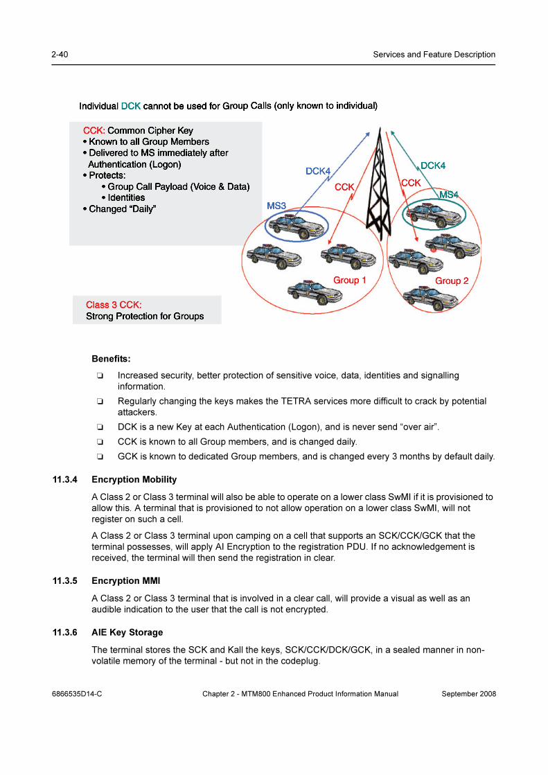
2-40 Services and Feature Description
Benefits:
❏ Increased security, better protection of sensitive voice, data, identities and signalling
information.
❏ Regularly changing the keys makes the TETRA services more difficult to crack by potential
attackers.
❏ DCK is a new Key at each Authentication (Logon), and is never send “over air”.
❏ CCK is known to all Group members, and is changed daily.
❏ GCK is known to dedicated Group members, and is changed every 3 months by default daily.
11.3.4 Encryption Mobility
A Class 2 or Class 3 terminal will also be able to operate on a lower class SwMI if it is provisioned to
allow this. A terminal that is provisioned to not allow operation on a lower class SwMI, will not
register on such a cell.
A Class 2 or Class 3 terminal upon camping on a cell that supports an SCK/CCK/GCK that the
terminal possesses, will apply AI Encryption to the registration PDU. If no acknowledgement is
received, the terminal will then send the registration in clear.
11.3.5 Encryption MMI
A Class 2 or Class 3 terminal that is involved in a clear call, will provide a visual as well as an
audible indication to the user that the call is not encrypted.
11.3.6 AIE Key Storage
The terminal stores the SCK and Kall the keys, SCK/CCK/DCK/GCK, in a sealed manner in non-
volatile memory of the terminal - but not in the codeplug.
6866535D14-C Chapter 2 - MTM800 Enhanced Product Information Manual September 2008

Security Services 2-41
The terminal supports loading of the keys via a Key Variable Loader (KVL) tool.
By using a special secret key combination it is possible for a user to delete the cipher keys in the
terminal. This can be provisioned to erase either all keys or only the long-term keys.
11.3.7 User Key Deletion
User can delete Encryption & / or Authentication keys by a special sequence from the keypad.
Benefits:
❏ This allows user to clear the keys e.g. for transit.
11.3.8 Interaction Network/Terminal - Encrypted/Clear
MR3.0 -Will begin in encrypted
mode, operating correctly. When
the radio detects from the system
broadcast that Encrypted Mode is
not supported, the radio will display
"Registration Failure" and thus
cannot operate.
MR2.1 and MR3.0 : Radio switches to
clear after detection of updated system
broadcast.
MR2.1 : same situation exists as in
"Constant Clear mode" in that once
registered, terminal will fail during
handover to other cells.
MR2.1 and MR3.0 : invalid scenario since
the radios only have Clear software - they
will never be in encrypted mode.
If however this scenario did occur,
typically the radios would have been in
"Registration Failure" so once system has
moved to Clear, terminals could be reset
and they would succesfully register in Clear mode.
Switch from
Encryted to
clear
MR3.0 Radio will register as normal
when switched to encryption - full
operation
MR2,1 : radio will succesfully move to
Encrypted mode if it is still in operation in
Clear mode. If however the radio has
failed handover etc, the radio is "locked
out" and will need to be reset to regain
operation on the encrypted network
MR3,0 : will succesfully switch to
encrypted mode after detection of the
secure network broadcast info.
MR2.1 and MR3.0 : Radio will not be able
to register (as Encrypted) on system as it
only has Clear software. Radio will display
Registration Failure
Switch from
clear to
Encryted
MR3.0 Radio will register as normal
- full operation
MR2.1 and MR3.0 : Radio works normallyMR2.1 and MR3.0 : Radio will not be able
to register on system as it only has Clear
software. Radio will display Registration
Failure
Constant
Encrypted
mode
MR3.0 - the radio will detect from
the system broadcast that
Encrypted Mode is not supported
and thus cannot register.
Radio Display : tbc
Invalid Scenario. If the MR3.0
Encrypted Only flag is set then the
terminal CANNOT enter Clear mode
in any circumstance. Thus, the
radio is always in Encrypted mode -
which is not possible with Clear
software - refer to the comments in
the next column
MR2.1 : when registering, terminal
detects system is in Clear mode and thus
will register in Clear mode. Radio will
operate normally within the cell which
registration took place but will drop out
of service during handover. Radio will
typically display No Group. Recovery is
only achieved by turning radio On/Off.
MR3.0 : when registering, radio will detect system is in Clear mode and will register
in Clear mode. All calls and operation
possible.
MR2.1 & MR3.0 : when registering, radio
will detect system is in Clear mode and
will register in Clear mode. All calls and
operation possible.
Constant Clear
Mode
Encrypted Only Flag: set
(only applies to MR3.0)
Encrypted Only Flag: set
(only applies to MR3.0)
Encrypted Only Flag: not set
(only applies to MR3.0)
Encrypted Only Flag: not set
(only applies to MR3.0)Network
Encrypted mode
(i.e. radio loaded with TEA2 SW)
Clear Mode
(i.e. radio loaded with Clear SW)
Encrypted mode
(i.e. radio loaded with TEA2 SW)
Clear Mode
(i.e. radio loaded with Clear SW)
Radio
vs.
September 2008 Chapter 2 - MTM800 Enhanced Product Information Manual 6866535D14-C
2-42 Services and Feature Description
11.4 End-to-End Encryption
The TETRA standard supports encryption over the air. Air Interface Security is defined and specified
for TMO and for DMO, see Paragraph 11.3 "Air Interface Encryption (AIE)". The terminal creates the
PDU (Packet Data Unit) and the PDU is encrypted before transmission. The base station receives
this PDU and needs to decrypt it, to know what to do with it and where to send it. Thus, if a PDU
contains voice information, the voice part of the message has been decrypted and is now
unprotected, until it is transmitted out to the caller.
The End-to-End Encryption feature (E2E encryption) resolves this by encrypting the voice
information before it is packed into the PDU. The voice encryption is carried out by a Universal
Crypto Module (UCM), which takes the voice stream and encrypts this stream using a set of keys.
Likewise, the UCM takes encrypted voice stream and using the same keys decrypts back into clear
voice.
You are capable to make or receive E2E encrypted calls:
• TMO Group Call (selected group, scanned group, announcement group, console patch
groups - if the console is capable to patch groups, priority monitor and emergency group call)
• DMO Group Call (direct, via DMO gateway, via DMO repeater)
• Private Call (half-duplex, full-duplex)
Note: Phone Calls and PABX Calls will be always clear and E2E related alert tones will not be play.
11.4.1 E2E Key Storage
The terminal stores the E2E keys:
Key encryption key (KEK) - This is the encryption key used to seal other encryption keys for
secure storage or transmission.
Traffic encryption key (TEK) - This is the encryption key used for the EtE.
The terminal supports loading of the encryption keys via the KVL/KMF solution.
11.5 Terminal Disable/Enable
Terminal disable is possible using TETRA Temporary Disable. The Dimetra IP system disables and
re-enables the terminal’s ’subscription’ (ITSI) and this is supported by the terminal.
Upon receipt of a D-DISABLE with ’Subscription Disable’, the correct SSI and MNI of the MS, the
terminal will be disabled and the terminal will remember this during power down.
Whilst disabled, the terminal continues to perform Mobility Management functions to facilitate
subsequent enabling of the terminal.
The terminal must receive the D - Enable message with its SSI and MNI before being restored to
normal service.
Benefits:
❏ Immediate disabling of the subscriber by the dispatcher via the air interface if the terminal is
compromised/stolen.
❏ Reversible, the terminal can be enabled again once found.
Note: If the encryption keys are erased, the MS puts itself in the disabled state. Permanent Disable
is not supported
6866535D14-C Chapter 2 - MTM800 Enhanced Product Information Manual September 2008
Security Services 2-43
11.6 Terminal Permanent Disable
Permanent disabling is intended to protect a network from attack from a compromised or faulty MS.
It can be used when the MS is known to have been compromised, or has been suspected of
compromise for a long time.
It is a one way function, there is no equivalent enable. The MS would need to be recovered and
reprogrammed before it could be used again.
When the MS is permanently disabled, it becomes inoperable:
❏ All its security key material, that is GCK, GSKO, DMO SCKs, Ks, DCK, CCK, TMO SCKs and
End-to-End key material are deleted.
❏ All its Codeplug is deleted.
❏ All its Software is deleted.
❏ All its MMI interfaces on the MS are disabled.
The Permanent Disable is recommended to be invoked when it has been determined that a MS is
absolutely unrecoverable. When a MS has been lost or stolen, the first step always is to stun
(Temporary Disable) the MS, followed by a disabling of the user in the Radio User Record of the
UCM.
Permanent Disable is recommended to be used in conjunction with the deletion of the user’s Radio
Record in the UCS and the deletion of the K-Ref association of the disabled MS in the PrC and the
AuC that lies within the cluster where the MS’s home zone is located. This ensures that subscriber
information is not downloaded into the HLR if a restore of the UCS is performed.
The system operator has to also ensure that the MS’s K-Ref association is also removed from the
other AuCs in the network, in cases where the K-Ref pairs are duplicated across the network. Note
that if this is not performed, the MS could be assigned a new home zone that lies in a cluster where
the K-Ref association has not been deleted.
Benefits:
❏ Immediate and complete disabling of the subscriber by the dispatcher via the air interface if
the terminal is not expected to be recovered.
11.7 PIN & PUK Numbers
The terminal is capable of requiring a Personal Identification Number (PIN) for authentication from
the user before it performs any network operation. The PIN is a 4-digit number.
The terminal user can use the menu functionality to enable or disable PIN lock, and to change the
PIN code. However, the user is not able to disable PIN lock or change the PIN code when the
terminal is PIN locked.
The ability to enter a PIN will be blocked after a number of unsuccessful attempts to enter the PIN.
The blocking can be released only by using an 8-digit PIN Unblocking Key (PUK). The terminal will
require the user to define a new PIN once the PUK has been successfully entered. The number of
maximum unsuccessful PIN attempts can be programmed via CPS programming (default is 3).
The PIN and PUK are stored in the code plug. There is also a parameter that indicates if the PIN is
enabled or disabled and if it is enabled, the user must enter the PIN on power up.
Benefits:
❏ 4 digit PIN code required to access terminal (if PIN is enabled) provides an extra level of
security
❏ After 3 failed attempts the PUK code is required (programmable)
September 2008 Chapter 2 - MTM800 Enhanced Product Information Manual 6866535D14-C

2-44 Services and Feature Description
11.8 High Assurance Boot (HAB)
The terminal has a facility that ensures that the code and data flashed in the terminal is authentic
and has not been altered. The HAB module is forced by hardware to run at boot time and check that
all software comes from a trusted source by checking the signature of the code and data segments
present in the terminal using a public/private key mechanism. The keys are downloaded using the
provisioning tool.
If HAB authentication of the flashed software fails, it will not allow the terminal software to run.
11.9 Terminal Disable/Enable on Non-Dimetra Infrastructures
In addition to ’subscription disable’, some Non-Dimetra Infrastructures can disable the terminal (TEI)
and it can disable either the ’subscription’, or ’equipment’ or both.
Upon receipt of a D-DISABLE with ’Equipment Disable’ with the correct TEI, the terminal will be
disabled.
If the terminal is in the equipment disabled state and receives a D-Enable with the correct TEI (in the
case of equipment disable), the terminal will be restored to its normal operative state (provided that
the subscription is also in the enabled state).
11.10 Tamper Protection Labels
This a special label which needs to be ordered with the terminal optionally. It automatically
destroyed if attempted to open up the terminal.
Benefits:
❏ Any attempt of manipulating the terminal or reading the key inside the terminal is obvious and
visible
12 Numbering and Addressing
Each terminal has an Individual TETRA Subscriber Identity ITSI which is used for addressing it over
the air interface and as these number can be long and it is time consuming to enter such a number
when dialing, a number of short number dialing schemes can be used to limit the SSI digit entry.
12.1 Short Addressing Schemes
Alternatively, the terminal can be programmed to treat a short number as an Short Subscriber
Identity SSI. This scheme can be refined to allow short dialing within a fleet by combining the ID
entered with the terminal’s own SSI.
12.1.1 Short Number Dialing Using ISSI
If the terminal has been programmed to treat a short number as a TETRA Short Subscriber Identity,
and the number entered is less than 7 digits, the terminal’s own identity will be combined with the
number entered by the user to produce the actual ISSI. Using this scheme, an Individual Short
Subscriber Identity ISSI can be comprised of a fleet number part and a member part.
The terminal’s own ISSI will be used as ‘leading digits’ for the digits omitted by the user. Thus, if for
instance:
Terminal’s own ID: 1234567
6866535D14-C Chapter 2 - MTM800 Enhanced Product Information Manual September 2008
PEI Characteristics 2-45
User Enters: 890
SSI sent will be: 1234890
The following call types can use SSI for identifying users:
• Full-duplex Private Call: called party and calling party identification
• Half-duplex Private Call: called party and calling party identification
• Group Call: calling party identification and talking party identification
• Mobile Status: called party and calling party identification
• Short Data Bearer Service: called party and calling party identification
• Text Message Service: called party and calling party identification
Benefits:
❏ Quick and easy setup of calls: User do not have to dial and remind on the full subscriber
numbers
12.2 Direct TETRA ID Addressing
12.2.1 ISSI
Regardless of the short addressing scheme used, if the user is provisioned with the capability of
entering a real TETRA ISSI, and the user enters an ID of 7 digits, the number will be interpreted as
a real TETRA ISSI.
13 PEI Characteristics
The terminal supports a eight-wire serial RS232 / V.24 interface via the optional data cable, and a
pre-defined set of the AT commands.
Note: The set of AT commands is not compliant with the TETRA PEI standard [Ref 4].
The terminal also supports 4-wire applications.
13.1 Physical Layer
The terminal PEI physical layer is the EIA-232 E Interface (RS232/V.24) and supports the following
circuits as specified in [Ref 23]:
• Transmit Data (TD)
• Receive Data (RD)
• Request To Send (RTS)
• Clear To Send (CTS)
• DCE Ready (DSR)
• DTE Ready (DTR)
• Carrier Detect (CD) (Received Line Signal Detector)
• Ring Indicator (RI) (Never Asserted)
The connection with the data device and opening of the PEI port is done when the user turns the
external device option on from the menu.
September 2008 Chapter 2 - MTM800 Enhanced Product Information Manual 6866535D14-C
2-46 Services and Feature Description
13.1.1 Baud Rate
The terminal supports the standard PEI baud rates specified in [Ref 23] from 300 bps to 115200
57,600 bps.
The auto baud rate detection mechanism is not supported.
13.1.2 PEI Flow Control
The terminal provides hardware flow control when the data traffic flows in the direction TE2 to MT2.
The flow control will use the RS232 request to send (RTS) and clear to send (CTS) lines.
13.2 PEI Link Layer
The terminal supports AT commands and PPP [Ref 19] as a link layer between the TE2 and MT2.
PPP negotiation will use unnumbered mode only.
The AT phase is compatible with the MS-Windows standard modem type.
6866535D14-C Chapter 2 - MTM800 Enhanced Product Information Manual September 2008

PEI Characteristics 2-47
13.3 AT Commands
13.3.1 General AT Commands
The terminal supports the following general AT Commands:
• DTR Behavior (&D)
• Local Command Mode Echo (E)
• DTE-DCE character framing (+ICF)
• DTE-DCE data rate control (+IPR) (Baud Rate)
• Control flow control (+IFC)
• Restore Factory Default Configuration (&F)
• Restore Default Configuration (Z)
• Terminal Success Reply (OK)
• Terminal Error Reply (+CME_ERROR)
• Reboot the Terminal (R)
13.3.2 Packet Data AT Commands
The terminal supports the following AT Commands for support of Packet Data:
• DCD Behavior (&C)
• Setup a PPP link for Packet Data and/or TNP1 session (D)
• Select DTE-side stack (+WS45)
• Select WDS-side stack (+WS46)
13.3.3 Status and Short Data Service in TMO & DMO AT Commands
The terminal supports the following AT Command for support of Status and Short Data Service in
TMO & DMO:
• Defining SDS Parameters (+CTSDS)
• Sending SDS, Status, Alarm and layer2 acknowledgement (+CMGS)
• Receive SDS, Status and Alarm (+CTSDSR)
• PID registration/deregistration, Send SDS, Status, Alarm (+CMGS)
• Receive SDS, Status and Alarm(+CMT)
• Message mode (+CNMI)
• Supported SDS types (+CSDS)
Note: Depending on Codeplug setting "ETSI AT SDS/Status Format" defined in section 29.6.3, the
radio supports an ETSI compliant format or a Motorola Proprietary format. DMO SDS AT commands
are only supported in the Motorola Proprietary format.
13.3.4 TNP1 AT Commands
The terminal supports the following AT Commands for support of TNP1:
• Setup a PPP link for Packet Data and/or TNP1 session (D)
• Set the UDP/IP Link to Local Mode (+WS46=252)
• Set the UDP/IP Link to Wide Mode (+WS46=14)
September 2008 Chapter 2 - MTM800 Enhanced Product Information Manual 6866535D14-C

2-48 Services and Feature Description
13.3.5 TETRA Modes AT Commands
The terminal supports the following AT Command for support of TETRA Modes:
• TMO/DMO Operating mode (+CTOM)
13.3.6 Group Management AT Commands
The terminal supports the following AT Command for support of Group Management:
• Talkgroup selection (+CTGS)
13.3.7 DMO AT Commands
The terminal supports the following AT Command for support of DMO:
• Visible DMO Gateway or Repeater (+CTDGR)
13.3.8 USB support
The terminal supports flashing of the software, codeplug and encryption material via USB interface.
13.3.9 Network and Mobility Management AT Commands
The terminal supports the following AT Command for support of Network and Mobility Management:
• Network Registration (+CREG)
• TETRA Cell Broadcast Information (+CTBCT)
• Cell Signal Quality (+CSQ)
• Neighbour Cell Information (+GCLI)
• Radio User Assignment (+CTRUA)
13.3.10 Identity Management AT Commands
The terminal supports the following AT Command for support of Identity Management:
• MT Manufacturer Identification (+GMI)
• MT Revision (+GMR)
• MT Serial Number (+GSN)
• MT Hardware Model (+GMM)
• Fixed TETRA Identities (+CNUMF)
• Talkgroup List by Folder and DGNA Notification (+CTGL)
13.3.11 Service Profiles & Capabilities AT Commands
The terminal supports the following AT Command for support of Service Profiles & Capabilities:
• Service Profiles (+CTSP)
• MT Capabilities (+GCAP)
13.3.12 Call Control in TMO AT Commands
The terminal supports the following AT Command for support of Call Control in TMO:
• Defining Call Parameters (+CTSDC)
• Call Transmit Demand (+CTXD)
6866535D14-C Chapter 2 - MTM800 Enhanced Product Information Manual September 2008

PEI Characteristics 2-49
• Call Transmit Cease (+CUTXC)
• Call Connect Notification (+CTCC)
• Call Transmission Grant (+CTXG)
• Call Release Notification (+CTCR)
• Incoming Call Notification (+CTICN)
• Call Progress Notification (+CTOCP)
• Call Transmit Cease Notification (+CDTXC)
• Call Transmission Interrupted Notification (+CTXI)
• Call Transmission Wait Notification (+CTXW)
• Terminate/Hangup call (H)
• Initiate a Call (D)
• Answer Hook Call (A)
13.3.13 Audio Control AT Commands
The terminal supports the following AT Command for support of Audio Control:
• Speaker Volume Control (+CLVL)
13.3.14 Accessory Control AT Commands
The terminal supports the following AT Command for support of Accessory Control:
• Handset on/off hook detection (+HHD)
13.3.15 Emergency Mode AT Commands
The terminal supports the following AT Command for support of Emergency Mode:
• Emergency Mode enter/exit (+EMER)
September 2008 Chapter 2 - MTM800 Enhanced Product Information Manual 6866535D14-C
2-50 Services and Feature Description
14 Supplementary Services
Following is the description of the TETRA Supplementary Services (SS) that the terminal supports
in TMO Mode.
14.1 Dynamic Group Number Assignment (DGNA)
The terminal supports the dynamic addition and removal of talkgroups in its talkgroup list via TETRA
Dynamic Group Number Assignment and De-assignment signalling (SS-DGNA). The terminal
responds to the DGNA directed to it, or to the DGNA directed to the group to which it is attached.
14.1.1 Adding a Talkgroup
When a dynamic group number assignment adding a new talkgroup is received, the terminal adds
the group to the end of the talkgroup list in its code plug. The user is then able to scroll to the
talkgroup, select it and attach to the group.
If the dynamic talkgroup list is full when adding a new group, the operation will be rejected by the
terminal.
14.1.2 Removing a Talkgroup.
When a dynamic group number de-assignment is received, the talkgroup will be removed from the
talkgroup list in the terminal’s code plug. When the selected talkgroup is de-assigned, the terminal
will show ‘No Group’.
14.1.3 DGNA Notification to the User
When the DGNA operation is successful, the user will be notified about the operation (e.g. group
added, group deleted). The notification to the user will be displayed until it is acknowledged by the
user and the message will still be displayed during call reception until it is acknowledged. (The
motivation is to make sure that user could see the notification).
Upon viewing an assigned talkgroup notification, the terminal will provide the ability for the user to
make that group the active group.
14.1.4 Selection of DGNA Groups
When viewing a list of new received DGNA groups the user can select any new group right away by
pressing the select button. Previously it could be time consuming to add newly received DGNA
groups.
Benefits:
❏ Ease of use, must faster selection of DGNA groups when initially received
14.1.5 Group Addressed DGNA
The terminal will support Group Addressed DGNA for the purpose of supporting the Dimetra-P
Console Multi Select (MSEL) and Group Patch mechanisms.
The terminal will support the reception of a DGNA Assignment that is addressed to its selected
group as a Super Group of the selected group. All signalling addressed to the Super Group will be
monitored in addition to signalling addressed to the selected group, any announcement or
associated groups and groups in the active scan list.
When the selected group is unselected, the terminal will cease processing signalling to the Super
Group that was associated with that selected group.
6866535D14-C Chapter 2 - MTM800 Enhanced Product Information Manual September 2008

Supplementary Services 2-51
The lifetime of the Super Group is received by the terminal as part of the assignment signalling. If a
subsequent assignment to the same group is not received within that lifetime, the terminal will cease
monitoring that super group.
The terminal will also support Super Groups of scanned groups, such that a group addressed DGNA
assignment, received on one of the scan group addresses, will cause the terminal to monitor all
signalling addressed to that super group as long as the scan group is being scanned and as long as
the Super Group lifetime lasts.
14.1.6 DGNA Limitations
The following DGNA functionality will not be supported
• Call-related DGNA will not be supported.
• The terminal will not support functionality of the “authorized user”
• The terminal will not perform any network authentication before accepting DGNA.
14.2 Ambience Listening (AL)
This provides an authorized user (a dispatcher etc.) with the ability to cause a terminal to transmit
without giving any indication to the user and monitor the audio activity picked up by the terminal’s
hot microphone. In scenarios where Ambience Listening is activated, a higher mic gain can be
automatically selected to increase pick-up of “ambient” conversation.
AL is a special Individual Call to a user‘s terminal.
14.2.1 Call Maintenance
The terminal does not restrict the duration of the call.
14.2.2 User Actions
If the user requests a call set up, the AL (Ambience Listening) call is immediately dropped and the
user’s call will be initiated.
The terminal allows the user to perform other interface functionality that and will not release the call,
including access to most menu items, changing modes, changing talkgroups and the activation/de-
activation of scan lists. During talkgroup change, the terminal will appear to be performing the
attachment, but the signalling will only happen after the Ambience Listening call has been
terminated and no indication will be given to the user, unless attachment fails.
14.2.3 Pseudo Power Down
If the user powers down the terminal, all indications will be extinguished and the terminal will appear
to have powered down. In reality the terminal is still active in transmit mode for the Ambience
listening call and the will only shut down on call completion.
If the user again powers up the terminal from its pseudo powered down state, it will go through all
the power up indications as though powering up.
14.2.4 Call Termination
The AL call is disconnected when the Emergency Button is pressed, Transmit Inhibit engaged, or
DMO entered. Also the initiator can close the AL call.
Benefits:
❏ User Safety especially in Lone Worker scenario or at scene of incident to keep dispatcher
operator informed
September 2008 Chapter 2 - MTM800 Enhanced Product Information Manual 6866535D14-C

2-52 Services and Feature Description
❏ All AL actions are controlled & logged appropriately in the infrastructure
14.3 Pre-emptive Priority Call (PPC)
If during a call, a call set up is received for a call that has a higher priority than the present call and
the new call is Pre-emptive Priority 3 or Pre-emptive Priority 4 (Emergency), the terminal will release
the present call and join the new high priority call.
If the call priority of the new call is either Pre-emptive Priority 1 or 2, the terminal will either accept or
reject the call based on a pre-programmed setting. If the new call is accepted, an alert tone is
sounded and a high priority call indication will be displayed to alert the user to the new call.
If the terminal has been programmed for pre-emptive call priority and the user initiates a private/
phone call which is rejected, the terminal will display the option to initiate the call again but this time
with pre-emptive call priority. The pre-emptive priority level is set during terminal programming via
the CPS interface.
Benefits:
❏ Allows dispatcher / key personnel to interrupt users engaged in private or telephone calls
without delay
❏ Dispatcher can always get through to critical users: Previously when a dispatcher has an
urgent or emergency situation and needs to immediately co-ordinate people, some users in a
private or telephone call cannot be contacted {send a text message only}
14.4 RF Sensitive Area Mode (Transmit Inhibit Mode TXI)
RF Sensitive Area Mode, also known as Transmit Inhibit (TXI) Mode, is a user selectable mode that
enables the terminal enter areas where radio transmissions are forbidden, e.g. hospitals, airplanes,
etc., where safety can be jeopardized due to the terminal uplink radiation. Once in TXI mode, the
terminal will not transmit under any circumstance and the user will be prevented from initiating any
non-emergency calls or service.
TXI mode is deactivated explicitly by the user, or is implicitly deactivated when the user initiates an
for Emergency call.
The user will be able to enter TXI mode and exit TXI mode via a menu sequence or one-touch
button and upon entry into or exit from the TXI mode and provided that the terminal is ‘camped’ on a
cell, it will send a specially designated SDS Status message to indicate to the system that it is
entering or exiting TXI mode.
The terminal provides user indications when it is in TXI mode.
Mobility procedures that do not require the terminal to send an uplink transmission are performed,
but cell reselection will not be performed even if no registration is required.
In TXI mode the terminal will join group calls for any monitored group(s), but prevents the user from
transmitting on that call. The terminal will also display any incoming SDS messages to the user.
To allow the user to know what calls have been missed, The missed call feature is active in TXI
mode and the terminal will attempt to prevent call setup retransmission from being recorded as
separate calls.
If the user initiates an Emergency call, the terminal will immediately leave TXI mode and start the
Emergency Call.
On power up, after powering down in TXI mode, the terminal offers the user the choice of
continuing in TXI mode.
6866535D14-C Chapter 2 - MTM800 Enhanced Product Information Manual September 2008

Supplementary Services 2-53
Benefits:
❏ Emergency calls still supported: If a user encounters a threat, the Emergency button will still
operate.
❏ Status when entering / exiting Tx-I mode: Alerts dispatcher that user is “out of comms”. Also
provides vital evidence that user is in TxI if required for later use.
❏ User alerted to incoming calls – Group calls still received: Even though terminals cannot
acknowledge calls, the user is still alerted if someone if trying to reach them. Group calls still
received. Private or Telephone calls stored in “Call History”
❏ Incoming mail messages received and accessible: Intelligently processes repeated Mail
messages - allow user to receive SDS messages
14.5 Other Supplementary Services
14.5.1 Calling Line Identification Presentation (CLIP)
This feature will display the number of the calling telephone on the called terminal’s display, the
terminal will attempt an ID look up in its Phone/PABX lists for a match, if a match is found, the
terminal will display the name/alias of the caller.
The PDUs and facility elements for this subscriber signalling will not be supported, but Identification
Presentation functionality is supported in most cases using the information found in the call setup
messages.
Benefits:
❏ This can enable the user to decide on acceptance of a call based on the callers identity prior
of the call
❏ Focus on important communication: Unwanted or low priority calls can be prevented on
demand
14.5.2 Late Entry (LE)
This is a Group Call feature only and it enables group members to join a call when it is in progress.
The system periodically sends out the group call set up information, thus allowing terminals that
have been involved in other calls or have just moved into the coverage area to join the call.
Benefits:
❏ No communication of selected Talkgroup will be missed: User who have finished a private or
telephone call will automatically connected to a current call of the selected Talkgroup
14.5.3 Talking Party Identification (TPI)
This feature will display the ID of the calling terminal on the called terminal’s display, the terminal will
attempt an ID look up in its Private Call list for a match, if a match is found, the terminal will display
the name/alias of the caller.
The PDUs and facility elements for this subscriber signalling will not be supported, but Identification
Presentation functionality is supported in most cases using the information found in the call setup
messages.
14.5.4 Calling Line Identification Restriction (CLIR)
CLIR is currently not supported in the terminal.
September 2008 Chapter 2 - MTM800 Enhanced Product Information Manual 6866535D14-C

2-54 Services and Feature Description
15 GPS Support
The terminal is equipped with a GPS receiver with which enables it to ascertain its own location.
The terminal provides Location Reports in various circumstances:
• On request;
• Triggered by specific events (e.g. status transmissions, emergency, power on/off);
• At specified time intervals;
• At specified distance intervals.
The reports are sent using a protocol which is based on existing standards, using SDS as a
transport layer. SDS User Defined Data Type 4 and the customer can provision the terminal to either
use SDS-TL (for added reliability) or no SDS-TL (for saving air interface resources). The TETRA
standard Protocol Identifiers for GPS will be used - 3 for simple GPS (no SDS-TL) or 131 if SDS-TL
is used.
The location data are stored in the non-volatile memory of the terminal, for later retrieval.
If the terminal is provisioned to provide user indications, the user is notified of the feature’s
operational status.
If the terminal is provisioned with to provide the terminal user with position information, the user will
be able to view the terminal’s position and the status of the satellites that are in view.
The GPS feature can be enabled or disabled as a whole by the CPS. Also, the parameters of the
feature can be configured by the CPS, or over the air. CPS configuration provides a default profile,
which can be overridden by commands received over the air. The profile assigned to the terminal
will determine when to send location data, what data to send with what accuracy and to what
address to send the data.
All data requests and configuration commands received over the air are checked to confirm they
have come from a trusted source. Only ISSIs in a specified range may send location commands.
Note: Both the terminal and application receiving location messages from the terminal have to be
configured with the same protocol ID otherwise the terminal will report a failure when requested to
send an Immediate Location Report for example.
16 MMI Features
16.1 Dialing Modes
The terminals have a separate dialing mode for each type of call. In order to make a call, the user
switches to the appropriate mode, and makes the call. The dialing modes are:
• Group Mode
• Private Mode
• Phone Mode
• PABX Mode
If the terminal is provisioned as auto-mode-switch operation, when an incoming call is received the
terminal will automatically switch to the appropriate mode. If the terminal is not provisioned for auto-
mode-switch, when an incoming call is received, the terminal will alert the user, and the user must
manually switch to the appropriate mode to answer the call.
6866535D14-C Chapter 2 - MTM800 Enhanced Product Information Manual September 2008

MMI Features 2-55
16.2 Programmable Buttons
It is possible to program keypad buttons and other option buttons with the followingh 11 options:
• Start a call to a designated private ID, phone or PABX number
• Enter/exit TXI mode
• Hi/Low Audio selectable when terminal is held close to or away from the face
• Select a designated talkgroup and go to group mode
• Select Latest Previously Selected Talkgroup
• Send a Status Message to a designated ID
• Switch between TMO & DMO operation
• Talkgroup Scan enable/disable
• Home Revert
• Enable/disable scanning
• Unassigned
16.3 Backlight for Display
A flexible backlight setting is provided by the terminals which are pre-programmed via CPS and
editable via the terminals menu:
Disabled: No backlight (for covert type operation)
Manual: On/off
Semi-automatic: Turns on for a programmable timer period when activated
Automatic: Turns on for a programmable timer period when buttons are pressed or calls received
Benefits:
❏ Appropriate setting to fit most customers needs
❏ Automatic Backlight saves energy without intervention of the user
16.4 Covert Mode
The Covert Mode feature is designed to give to the user ability to switch the audio to earpiece and
to:
1. dimmed (21%) display
2. grayscale colors on the display.
When Covert Mode is turned on the terminal
• sets all tones to Off (corresponding to All Tones menu entry)
• sets group audio to Speaker Controlled (corresponding to Group Audio menu entry)
• sets private speaker to Off (this will cause all calls to be routed via Earpiece)
• sets backlight to grayscaled and dimmed
• switch off LED
The terminal powers up in the mode it was before power down, therefore the terminal powers up in
Covert Mode if it was set before power down.
September 2008 Chapter 2 - MTM800 Enhanced Product Information Manual 6866535D14-C
2-56 Services and Feature Description
16.5 Dialing Scheme
The private ID number is a number with up to 16 digits. If the user enters less then 16 digits it is
padded to full ITSI with leading zeros. It is composed with MCC (Mobile Country Code), MNC
(Mobile Network Code) and ISSI (Individual Short Subscriber Identity).
Two options are given to the user:
• Fixed - user may provide up to 16 digits which include the MCC, MNC and ISSI numbers or if less
than 16 digits are entered, it will be filled with the digits that are set by the service provider.
• Automatic - you need to provide up to 8 digits. If the user provides more it will switch to fixed mode.
If the user provides less then 8 digits, the radio fills the rest of the number with its own ISSI. The rest
of the 16 digit number is automatically given by the radio.
If you select more then 16 digits the display will give you a warning about an incorrect input.
16.6 Languages
The terminal is capable to provide support for the following languages using ISO/IEC 8859-1 Latin 1
(8 bits) alphabet:
• English
• German
• French
• Spanish
• Dutch
• Swedish
• Croatian
• Danish
• Dutch
• Hungarian
• Italian
• Korean
• Lithuanian
• Macedonian
• Norwegian
• Russian
• Simplified Chinese
• Traditional Chinese
• Swedish
• Russian (Cyrillic) (Standard Control Head only)
• User Defined Language *)
*) In addition to these languages, the terminal will provide an option to use a "Local Language"
where each text string used by the terminal is defined in the code plug
MCC MNC ISSI
16-14 13-9 8-1
6866535D14-C Chapter 2 - MTM800 Enhanced Product Information Manual September 2008

MMI Features 2-57
Benefits:
❏ Easy to train user speaking different languages to operate and understand the terminal and
menu
❏ Prevents user errors and irritations due to unknown languages of terminal messages
❏ Flexible: Can support any other language which is based on the character set mentioned
above
16.7 Scanning
The passive scan functionality has been replaced with active scanning. Whenever scanning is
enabled/disabled, a status message is sent.
Scanning of only the Group Area (cell to Cell) is supported.
16.8 Non Tactical Emergency to Emergency
This feature allows users to set up an emergency call to a designated talk group (a pre-defined talk
group). This feature is an alternative to the normal emergency group call operation where the call is
set up to the selected Tactical Emergency talk group.
The Tactical and Non-Tactical operational mode and Non-Tactical talk group GSSI are selectable via
the CPS during terminal programming.
The Hot Microphone feature operates normally, when enabled via the CPS.
Note: This feature is not supported on all systems.
16.9 DGNA Enhancement
DGNA now has scan functionality. The terminal also supports SwMI (system) intitiated attachment/
detachment to a group and SwMI initiated scan functionality during attachment/detachment to these
groups. This is a supported system feature that may not be available on all systems.
16.10 DGNA Auto Attach
DGNA enables a network operator or authorised user to dynamically (over the air) allocate talk
groups to selected terminals.
Using Supplimentary Service Messages (SS-DGNA), the terminal can becommanded to add talk
groups to its existing list of talk groups, to attach or select these talk groups from the list, or modify
parameters of existing talk groups.
DGNA Auto Attach or ‘Forced Attach’ enables a dispatcher to send a talk group to a user group that
will then automatically join(affiliate to) the new talk group. No user actions are required as this is a
dispatcher controlled operation.
This feature ensures that a dispatcher can quickly mobilise a team of terminal users as and when
required to meet a current situation.
16.11 Favourite Talk Groups
This user friendly feature enables a user to create a ‘Personal Range’ of own talk groups from pre-
programmed talk groups within the terminal and is saved in the terminal during power down.
September 2008 Chapter 2 - MTM800 Enhanced Product Information Manual 6866535D14-C

2-58 Services and Feature Description
It is a shared feature for both TMO & DMO operating modes and has a capacity of 16 talk groups for
the End Stop MTM800 Enhanced model and 128 talk groups for all other terminal models.
16.12 Receiving Audio during Text Message Editing
When in a group call, the audio is no longer lost when composing a text message. It is now possible
to hear the group call audio, but audio will be lost for a very short period of time as a result of the
message transmission.
16.13 Talk Group Index Entry via the Keypad
The Talk Group (TG) Index feature can be entered via the keypad when only in either TMO or DMO
talk group mode, in idle or receiving but nor transmitting.
In this mode the terminal does not look at the Talk Groups per range, but as consequtive numbers
from the first talk group of range 1 to the last talk group in the last enabled range. i.e. 4 ranges of 16
talkgroups is equal to a list of 64 continuous talk groups, where a keypad entry of 17 equates to the
first talk group of range 2.
To enable this functionality, the required keypad presses are of a shorter duration than that required
when using the one touch button functionality.
Once the first digit has been entered a ‘Find’ soft menu appears and on completion of the talkgroup
digit entry, pressing the associated soft button will cause the talk group to be displayed. Once the
talk group is displayed, the user is then presented with the ‘Cancel’, ‘OK’ selectable soft button
options.
Selecting ‘OK’ will attach the terminal to the group, or pressing the PTT will attach the terminal to the
group and set up a call to that selected group.
The terminal will actively remain on the last selected talk group during the search process and calls
can be heard and answered via the PTT while the search screen is still displayed, thus allowing the
user to complete the talk group selection process.
Incorrect keypad entries are cleared using the ‘Clear’ option of a soft button.
It is also possible to enter a known talk group GSSI via the keypad and press the PTT to set up a
call without using the search functionality above.
16.14 Universal Time Display
The terminal is capable of presenting time information to the user. The time is derived from an
internal clock. The terminal maintains the clock both when the terminal is powered on and powered
off.
Note: In case of power loss (e.g. flat battery) the internal clock will not be maintained.
The time is received from the SwMI and is updated if the maximal deviation between time on the
internal clock and the time received is less than a value set during terminal programming via the
CPS interface and if the System Update is not set to Off via MMI.
The feature is enabled or disabled and the default configuration set for the terminal via the CPS
interface and in the MMI.
The terminal display supports:
• Twenty-four-hour and twelve-hour formats
6866535D14-C Chapter 2 - MTM800 Enhanced Product Information Manual September 2008

MMI Features 2-59
• YY/MM/DD, DD/MM/YY, MM/DD/YY and DD-MON-YY date formats
• Adjustable time offset
The time information can be changed by the user via MMI, if enabled in codeplug.
System broadcast information has higher priority than data entered manually. Hence time, date and
offset information entered via MMI is overwritten, when data is received from the SwMI. This
happens only if the System Update via the MMI is set to Time & Offset.
System broadcast information can be set via MMI. the radio gives you three options:
• Off - radio will not use the system broadcast update
• Time only - radio will update only the time from the system broadcast update
• Time & Offset - both are going to be updated from the system broadcast update
The terminal provides user indications upon crossing to another time zone, when new MCC
broadcast received.
Benefits:
❏ Time displayed can be synchronized for a number of terminals.
16.15 Test Page / Test Mode
Note: The Test Mode option must be enabled in the terminal via CPS programming and selecting
the “Test Page” option. The Test Mode is only for use by authorized persons, and not by users.
Use the following terminal key sequence, by pressing each button in turn, to access “Test Mode”:
• Cursor right , 1 , Menu, 2 , Menu, 3.
Note: If the Test Mode option is not enabled via CPS programming you have only access to the KVL
Mode options KVL On or KVL Off.
The following are the services offered by test page:
16.15.1 Ver info
Displays software/hardware version information:
• Build Date
• CodePlug Version
• DSP Software version
• Host Software version
• Hardware ID
• Equip ID
• LLS version
• UCM Ver
16.15.2 Addresses
Displays the following:
• Home MNI
• Group ID
September 2008 Chapter 2 - MTM800 Enhanced Product Information Manual 6866535D14-C

2-60 Services and Feature Description
• Own ISSI
• ASSI
16.15.3 Error logs
Displays information about software errors:
• Error log
• Fatal
• Reset
• UCM
16.15.4 Cell Info
This option displays information about the foreground and Background cells. This menu will display
the RSSI levels of the cells.
16.15.5 Cell lists
Displays frequency lists:
• Frequency list 1 (32 variable frequencies)
• Frequency list 2 (32 fixed frequencies)
• Frequency list 3
• Frequency list 4
16.15.6 Data Services
This allows access to Airtracer enable, Conformance tests, KVL Mode and E2E Key deletion:
• Airtracer
• Conf Test
• KVL mode (for Air Interface Encryption - AIE)
Note: The terminal software was changed for MR5.3 to have a new display content in the
KVL mode for distributing AIE keys.
The KVL mode for AIE keys is entered as before. The new behavior is that the display is
immediately dark and empty, but the green LED is ON.
During data exchange with the AIE KVL the orange LED will be ON. On successful key
exchange the green LED will be ON again.
In any error situation the red LED will be ON. You can leave the KVL mode by pressing the
power button.
The communication via the serial interface to the AIE KVL is as before.
Terminal Software Upgrade: (refer to Chapter 3 of the Product Information Manual,
Paragraph "Upgrade Phone")
• E2E Key Del (depending on UCM configuration)
Deleting E2E Traffic Keys
6866535D14-C Chapter 2 - MTM800 Enhanced Product Information Manual September 2008

MMI Features 2-61
The traffic keys (all keys except the KEK) can be deleted from customer and engineering test
page. If customer test page is enabled then this option will be accessible from main test page.
If engineering test page is enabled this option will be accessible under Data Svc menu option.
After deleting the keys all groups will have encryption mode set to off and the encryption icon
will be cleared. For private numbers the icon will be still displayed (contacts list) since the
encryption mode for private numbers is taken from codeplug.
Deletion of all keys
The key deletion key sequence " **00## " includes deletion of all the UCM key sets (including
the KEK, GEK and SEK).
Displaying UCM Version Information
UCM version number can be accessed from Ver Info menu item. After selecting UCM version
option the UCM Version and Algorithm IDs will be listed. If the number of algorithms is more
than what can be displayed on the screen then the user can cycle through them by using the
navigation keys.
Displaying UCM Error Log Information
UCM Error Log option can be accessed from Err Logs menu item. After selecting UCM Error
Log option the UCM error logs will be listed. The user can cycle through the error logs by
using the navigation keys. Every log will have a number (Log[n] and a Log value). The user is
able to clear the logs by selecting the left soft key (Clear). If no logs are available a notice with
’List Empty’ string and the right soft key (Back) will be shown.
16.15.7 Key Information
This option allows displaying the security information for the following conditions.
• For Serving Cell:
• Security class of the serving cell, i.e. Security Class 1, Security Class 2,
Security Class 3, Security Class 3 with GCK
• For Group OTAR:
• CMG GTSI
• For SDMO and TM-SCK OTAR:
• SDMO SCK Subset Grouping Type
• Current SDMO SCK Subset Number and SCK-VN
• Current Fallback TMO SCK, i.e. SCKN and SCK-VN attributes
• List all SCKs stored in the MS, i.e. SCKN and SCK-VN attributes
• For GCK:
• Current Full GCK-VN
• List all GCKs stored in the MS, i.e. GCKN and GCK-VN attributes
16.15.8 Memory (if enabled in codeplug)
Contains the following options:
• Host Memory
• DSP P-Memory
September 2008 Chapter 2 - MTM800 Enhanced Product Information Manual 6866535D14-C
2-62 Services and Feature Description
• DSP X-Memory
• DSP Y-Memory
6866535D14-C Chapter 2 - MTM800 Enhanced Product Information Manual September 2008

Call-Out 2-63
17 Call-Out
17.1 Feature Overview
It is alert that is sent to one or many users when the incdident requires immediate attention. Only the
Emergency Mode has higher priority then Call-out. When the user receives the alert, three
responses are availabele:
1. Accept - additional information from the dispatcher will be displayed
2. Stand by - voice and message communication will be the same as in Accept
3. Reject - display will return to the home display and the talkgroup will be selected to the one
before the Call-out.
17.1.1 Addressing Call-Out
Call-out alert can be addressed to:
• ISSI - individual
• ISSI - to a group via serial individual messages
• GSSI - group of users.
17.1.2 CO Box (Call-Out Box)
All incoming and outgoing Call-out messages are stored in CO Box and can be managed by the
user. There is a two- level structure for the alerts. First level is the main alert list, as the second one
are all the messages associated with the alerts. Both lists are displayed chronologically with the
newest on top. The capacity of the CO Box is 10 call-out alerts and 100 messages (incoming/
outgoing). It has also the overwrite policy which will delete the oldest one upon receipt of an
additional Call-Out message.
In normal mode, the user can browse the CO Box and read all the Call-Out messages.
In Call-Out mode, user can only read the ongoing Call-Out messages.
17.1.3 New Call-Out
When the new Call-Out is received by the radio, the old Cal-Out (even if has not been responded)
will override the old one. An ongoing Call-Out overrides the old one in any phase of the Call-Out
alert.
17.2 Phases
Call-Out service has 2 main phases:
1. Alert Phase
User receives the alert with the associated messages and he/she is able to respond to it.
Special tone is played by the radio when the alert is coming. All the messages provide the
user with all important information about the incident.
2. Information Phase
User is in Call-Out mode and is able to receive more messages about the incident with the
text or voice. User can also query for more information using voice group call or Call-Out text
function which enables to send a text message to the dispatcher host application. Voice
message can be sent with the high priority as a group call. Users can answer back to the
group or to the dispatcher using voice group call.
September 2008 Chapter 2 - MTM800 Enhanced Product Information Manual 6866535D14-C

2-64 Services and Feature Description
17.3 Exception Handling
17.3.1 Emergency mode
When user received Call-out alert while in Emergency Mode, message will be ignored.
17.3.2 Transmit Inhibit Mode (TXI)
The user is able to receive the message but it is not able to respond to it until TXI mode is
deactivated. When the user decides to leave the TXI mode after viewing the message, the radio will
prompt to accept, standby ot reject the call-out.
17.3.3 Direct Mode Operation (DMO)
Call-Out feature is not supported in DMO.
17.3.4 Fallback Mode
This mode is available when the user is in Local Side Trunking. The user who receives the Call-Out
Call, enters Fallback mode, which includes only voice communication. The user can clear Fallback
Mode only manually.
17.3.5 Call-Out test
Dispatcher is able to test this feature by using Call-out test. Radio will display ‘Call-Out Test’ and
generate the alert tone. Only one soft key is available for the user with the label Test OK. After
responding the display will return to its previous mode.
17.3.6 Storm Plan alert
This is special case of Call-Out because:
• it is sent out to the larger group of people
• user is able to respond with any key stroke and after that will be moved to information
phase
It is sent several times to raise realiability.
18 Tool Interface Support
The terminal supports interfaces with external diagnostic and testing software.
18.1 Software and Codeplug Flashing Tool Support
Equipment specific parameters, and other data that is required to be retained through power cycling
will be stored in non-volatile memory - known as the ’codeplug’. The terminal will support an
interface with an external tool (such as CPS) that is capable of reading from and writing to the
codeplug and flashing the terminal software via serial and USB interface.
18.2 Key Variable Loader (KVL)
The terminal supports provisioning of K, KEK and SCK via the KVL application. The terminal will
store the K in sealed format using TA51.
6866535D14-C Chapter 2 - MTM800 Enhanced Product Information Manual September 2008

Tool Interface Support 2-65
Features and Benefits:
❏ Simultaneous K+SCK loading: Simplifies provisioning process, optimizing security
❏ Secure Key (SCK & K) provisioning in the field: Key loading can be done at user’s premises,
rather than centralized facility – the customer is in control of security
❏ K provisioning tools available to Service Provider/End Users: No need to return unit to
manufacturer if key’s erased
❏ Dial-up connection for Key provisioning tools: Fast, efficient and secure transport of data
between field and central database
A KVL tool enables loading of encryption traffic keys (Static Cipher Key - SCK) as well as
authentication key (K) into terminal in a secure manner.These keys (for AIE) can be loaded into the
TETRA terminal when the KVL is connected to the terminal and the KVL mode in the terminal is
enabled. Refer to Paragraph 16.15 "Test Page / Test Mode".
September 2008 Chapter 2 - MTM800 Enhanced Product Information Manual 6866535D14-C

2-66 Services and Feature Description
6866535D14-C Chapter 2 - MTM800 Enhanced Product Information Manual September 2008

Chapter 3
CUSTOMER PROGRAMMING SOFTWARE (CPS)
1 Introduction
The TETRA CPS (R6x.490.02, July 23 2007, part no PMVN4152A - for MR5.7) is a Motorola
software tool that runs on PCs, Laptop and Desktop computers from Dell and Hewlett Packard that
use either Windows 2000® Professional or Windows XP® Professional. It is used for programming
TETRA terminals.
Existing users will be familiar with the structure and layout of this CPS.
The structure of the CPS has been designed so that PC users who are familiar with Windows® will
be more comfortable when first using the CPS.
The available menus and the editable option fields will vary by terminal type and how the CPS was
opened. There are 2 ways of opening the software, as a User or as an Administrator.
The CPS work screen contains a reset column and if there is a reset button against a Field Value
box, the user is able to reset the entered value to the factory default.
Note: The terminal (Mobile Subscriber - MS) is designed to work on all available TETRA systems
and all the features explained in this chapter may either not be available in this software release, or
not work on every system.
Note: Use only Dell or Hewlett Packard PCs, Laptop or Desktop computers.
Note: Before starting the CPS close all other open software applications.
Note: Do not try to load a codeplug into a terminal which is not compatible. Use the Copy Wizard
which allows to copy codeplug data from one terminal (or from a codeplug or call list data file) into
another compatible terminal.
2 Loading the CPS
This is a straight forward task, place the CD into the PC and follow the instructions.
If there is an earlier version of CPS, it may be over written.
If it is necessary to keep the earlier version go to C:\Program Files\Motorola and add a new folder
with the title version of the new software. When loading the new software, the person installing the
software will be prompted for the location in which to store the CPS and one of two things will
happen, either the installation program will have found the new folder and its path will be displayed
on the prompt screen, or the person installing the software will have to select the ‘Browse’ option
and manually find the new folder, after which the path will be displayed on the prompt screen. Select
‘Next’ to continue with the installation.
3 Starting the CPS Application
To start the CPS using the mouse, either double click on the Desktop CPS icon or select it via the
Start\ Programs feature.
As the program starts, the Password Prompt is displayed. This has 2 login options:
September 2008 Chapter 3 - MTM800 Enhanced Product Information Manual 6866535D14-C
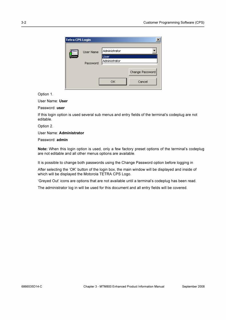
3-2 Customer Programming Software (CPS)
Option 1.
User Name: User
Password: user
If this login option is used several sub menus and entry fields of the terminal’s codeplug are not
editable.
Option 2.
User Name: Administrator
Password: admin
Note: When this login option is used, only a few factory preset options of the terminal’s codeplug
are not editable and all other menus options are available.
It is possible to change both passwords using the Change Password option before logging in
After selecting the ‘OK’ button of the login box, the main window will be displayed and inside of
which will be displayed the Motorola TETRA CPS Logo.
‘Greyed Out’ icons are options that are not available until a terminal’s codeplug has been read.
The administrator log in will be used for this document and all entry fields will be covered.
6866535D14-C Chapter 3 - MTM800 Enhanced Product Information Manual September 2008

Starting the CPS Application 3-3
3.1 Administrator Opening Window
This window shows the title bar with the minimise, restore and close icons at the top. Below this is
the File, View, Tools and Help bar, each of which when selected will open to display option menus.
Below this are displayed two icon bars on the same line.
The Main and Phone icon bars are displayed on this line and are selectable, deselectable via the
View option menu. Placing the cursor over an icon will cause the icon description to be display
directly below the icon.
The dark and larger portion of the screen is the main work area and at the bottom of the window is
the Status bar, which again is also selectable, deselectable via the View option menu.
3.2 File Menu - with no codeplug displayed
September 2008 Chapter 3 - MTM800 Enhanced Product Information Manual 6866535D14-C

3-4 Customer Programming Software (CPS)
There are 2 sub menus associated with the File Menu. The first is shown above and is displayed
when no terminal codeplug has been read, or loaded from archive. The options are:
3.2.1 Open
This option allows the user to select a previously archived codeplug.
1. In the File Open dialogue box, navigate to the drive and folder (or directory) where the code-
plug file is located.
2. Then double-click the desired file name, or highlight the file name and click OK to complete
the task. The codeplug contents will then be displayed in the CPS.
3. If the codeplug file is password protected, the CPS will display the password prompt to allow
the correct password to be entered and the file to be opened.
3.2.2 Read Phone
Selecting this option will cause the CPS to read the codeplug of the connected terminal.
6866535D14-C Chapter 3 - MTM800 Enhanced Product Information Manual September 2008
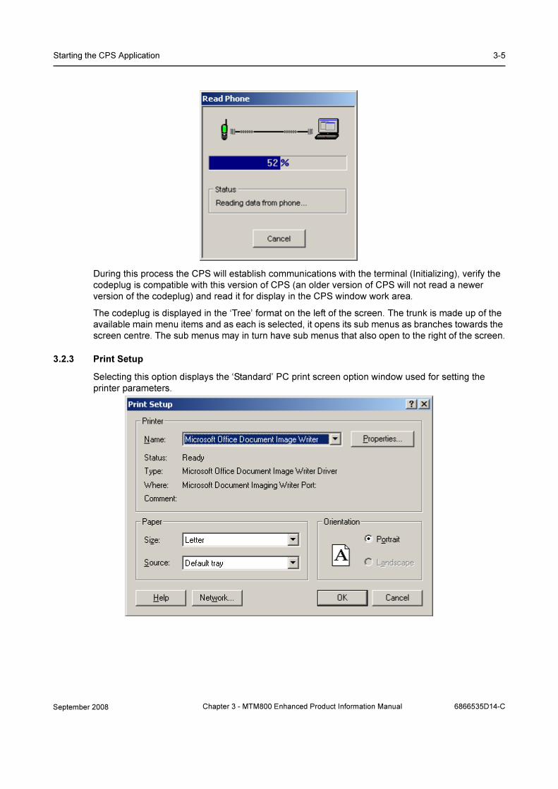
Starting the CPS Application 3-5
During this process the CPS will establish communications with the terminal (Initializing), verify the
codeplug is compatible with this version of CPS (an older version of CPS will not read a newer
version of the codeplug) and read it for display in the CPS window work area.
The codeplug is displayed in the ‘Tree’ format on the left of the screen. The trunk is made up of the
available main menu items and as each is selected, it opens its sub menus as branches towards the
screen centre. The sub menus may in turn have sub menus that also open to the right of the screen.
3.2.3 Print Setup
Selecting this option displays the ‘Standard’ PC print screen option window used for setting the
printer parameters.
September 2008 Chapter 3 - MTM800 Enhanced Product Information Manual 6866535D14-C

3-6 Customer Programming Software (CPS)
3.2.4 Exit
Selecting this option will close the CPS. if a codeplug is displayed in the work box and has been
edited, the user is given three options about saving it.
3.3 Tools Menu - with no codeplug displayed
There is one sub-menu which is only visible with no codeplug displayed:
3.3.1 Enable Features
Whenever a feature paid flag is disabled, the CPS disables access to the fields belonging to
separately priced features.
Some TETRA features (MSPD for MTM800 Enhanced) are separately priced in terminals from
release MR5.3 on, apart from MSPD from MR5.4 on. The customer who has paid either for a single
feature or for a number of features receives the Feature Enable kit, i.e. the Customer CPS and an
6866535D14-C Chapter 3 - MTM800 Enhanced Product Information Manual September 2008

Starting the CPS Application 3-7
USB dongle ("Feature Enable Dongle") that contains information about the total number of enables
per feature.
Feature enabling can be performed on one or more terminals simultaneously – all in one operation.
Proceed as follows:
1. Connect the terminal to the PC as described in the terminal’s hardware set-up. The terminal’s
codeplug contains special block for keeping the list of feature paid flags, each of which corre-
sponds to a separately paid feature.
2. Connect the Feature Enable dongle to the PC.
3. Run the CPS.
4. Enter the Administrator password.
5. Note: Do not read the terminal now!
Select Tools/Enable Feature. The Enable Feature dialogue opens up and displays information
related to the dongle and the terminal attached to the currently active port.
6. Enable the check box next to the feature you have paid.
7. Click Burn. Each counter will be decreased each time you enable one of the features you
have ordered.
8. The CPS scans communication ports and detects the terminal that is connected to the port.
The Operation Results message appears and displays the result of operations per each port.
Click Continue button.
9. The CPS will display the operation result for each terminal.
Note: If all paid features are enabled in a dongle and several terminals are connected for simultane-
ous feature enabling. Some features may not have been paid for some of the terminals or may
already have been enabled. The Customer CPS will automatically detect which features were paid
or enabled for each terminal and will not decrease the counter.
September 2008 Chapter 3 - MTM800 Enhanced Product Information Manual 6866535D14-C

3-8 Customer Programming Software (CPS)
3.4 Displayed Codeplug File
A new icon is now displayed with the codeplug and if the codeplug is maximised in the work screen,
the icon will move to the left of the File option.
This icon, when selected, gives the following options:
The Restore, Move, Size Minimise and Maximise options are used to position or alter the size of the
viewed code plug screen. I.e. if the screen has been maximised, selecting restore will return it to the
size it was when first opened.
If two or more code plugs are displayed on the work screen, selecting the ‘Next’ option will high light
the next code plug and make it the current active (for editing) code plug.
6866535D14-C Chapter 3 - MTM800 Enhanced Product Information Manual September 2008

File Menu 3-9
4 File Menu
All the available options with displayed codeplug are displayed below and only additions will be
explained.
4.1 Open
This option allows the user to select a previously archived codeplug.
1. In the File Open dialogue box, navigate to the drive and folder (or directory) where the code-
plug file is located.
2. Then double-click the desired file name, or highlight the file name and click OK to complete
the task. The codeplug contents will then be displayed in the CPS.
3. If the codeplug file is password protected, the CPS will display the password prompt to allow
the correct password to be entered and the file to be opened.
4.2 Close
Selecting this option will close the active codeplug and the user is given the option to save any
changes made.
September 2008 Chapter 3 - MTM800 Enhanced Product Information Manual 6866535D14-C

3-10 Customer Programming Software (CPS)
4.3 Save
If the code plug is already stored in the data folder, then selecting the save option will save changes
that are made to the code plug file on the work screen in the stored file. The CPS will then offer
password protection for the stored file.
4.4 Save As
This option is used for storing files for the first, or for keeping a record of successive changes made
to a code plug. Selecting one of the five icons on the left of the screen will change the heading in the
‘Save in’ line to that of the selected icon, selecting the down arrow at the end of the ‘Save in’ line will
give all available computer options. The three icons to the right of the ‘Save in’ line are standard
Windows® options, go up one level, create new folder and view menu options.
4.5 Read Phone
Selecting this option will cause the CPS to read the code plug of the connected terminal.
During this process the CPS will establish communications with the terminal (Initializing), verify the
codeplug is compatible and read it for display in the CPS window work area.
6866535D14-C Chapter 3 - MTM800 Enhanced Product Information Manual September 2008

File Menu 3-11
The codeplug is displayed in the ‘Tree’ format on the left of the screen. The trunk is made up of the
available main menu items and as each is selected, it opens its sub menus as branches towards the
screen centre. The sub menus may in turn have sub menus that also open to the right of the screen.
4.6 Write Phone
This option is used to Write codeplug data to (program) the phone while preserving the sensitivity
field values, i.e. tuning data. Use this function only to write a codeplug that was originally read or
loaded from the same phone, the source and target phones must be one and the same.
The CPS will display a progress bar and status messages as necessary.
CAUTION: Do not disconnect the programming cable from the phone during the write operation. This will
destroy the terminal.
4.7 Copy Phone
This option will copy the displayed codeplug to a connected terminal of the same model.
4.8 Copy Wizard
This is a 2 step feature that enables cloning of codeplug data from a master codeplug to one or
more terminals of the same model.
Select the codeplug blocks (up to 55) to be copied and write the codeplug data to one or more
terminals - all in one operation.
This function is used only for compatible terminal models - i.e.terminals belonging to the same
frequency range and operating in the same network.
TIP: Use Copy Wizard to clone multiple terminals with the same set of codeplug data. The master
codeplug is read from the master terminals and activated in the CPS window. Connect the next
terminal(s) and click the Write button.
September 2008 Chapter 3 - MTM800 Enhanced Product Information Manual 6866535D14-C
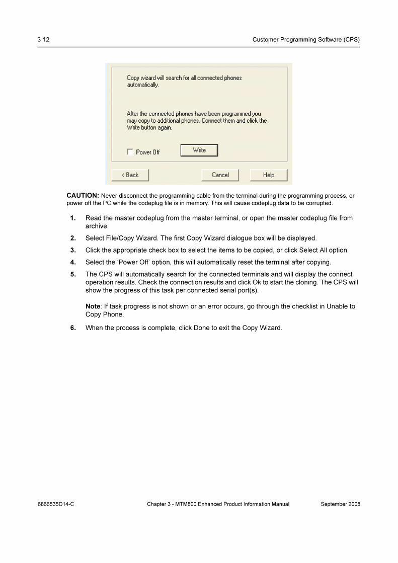
3-12 Customer Programming Software (CPS)
CAUTION: Never disconnect the programming cable from the terminal during the programming process, or
power off the PC while the codeplug file is in memory. This will cause codeplug data to be corrupted.
1. Read the master codeplug from the master terminal, or open the master codeplug file from
archive.
2. Select File/Copy Wizard. The first Copy Wizard dialogue box will be displayed.
3. Click the appropriate check box to select the items to be copied, or click Select All option.
4. Select the ‘Power Off’ option, this will automatically reset the terminal after copying.
5. The CPS will automatically search for the connected terminals and will display the connect
operation results. Check the connection results and click Ok to start the cloning. The CPS will
show the progress of this task per connected serial port(s).
Note: If task progress is not shown or an error occurs, go through the checklist in Unable to
Copy Phone.
6. When the process is complete, click Done to exit the Copy Wizard.
6866535D14-C Chapter 3 - MTM800 Enhanced Product Information Manual September 2008

File Menu 3-13
4.9 Import Menu
Note: This option is only available if the ‘Administrator’ password has been used to open the CPS
and has the following two options:
4.9.1 Import User Data
This option is used to import data from a user data file into the active or current codeplug file and
importing user data into a codeplug will REPLACE the existing entries.
In the Open User Data dialogue box, select the desired file name and click OK. The application will
place the user data in the appropriate fields (for example, phone list entries will appear in the Phone
List table).
When reading a user data file, the application will ignore entries and lists that are not valid for the
active phone mode.
To prevent a CPS crash, Do Not use question marks in the alias/name fields of any file.
Note: To create a user data file, open the codeplug file from which to copy the desired data. Then
use the Export User Data function to create the file.
Note: Use the Export and Import User Data functions to download data to several phones i.e. call
list data.
4.9.2 Screen Saver
This feature is not supported for the terminal model MTM800 Enhanced.
4.10 Export Menu
Note: These 3 options are only available if the ‘Administrator’ password has been used to open the
CPS:
September 2008 Chapter 3 - MTM800 Enhanced Product Information Manual 6866535D14-C
3-14 Customer Programming Software (CPS)
4.10.1 User Data
This option is used to save user data to a file by bringing up the Save dialogue box.
Select the types of data to be saved and click the Save button. If no types are selected, the save
button is disabled and the file will not be saved, otherwise specify the desired file name, hard drive
and directory location and click OK.
Notes:
• Make sure the call lists have entries in them before exporting the data. Otherwise, the user
data file will be empty.
• If a user extension is not provide to the file name, the application will automatically add this
file name extension when it saves the file.
• Use the Export and Import User Data functions when several terminals are required to have
the same Call List data.
4.10.2 User Report
This is used to generate a customised user report of codeplug data. The customised report is saved
as an *.html file.
4.10.3 Screen Saver
This feature is not supported for the terminal model MTM800 Enhanced.
4.11 Change Codeplug Password
If the codeplug is protected by a password, this menu enables the codeplug password to be
changed.
To prevent an unauthorised user from viewing or editing the codeplug file, it can be protected with a
password.
To set a codeplug file password:
1. If there is more than one open codeplug file, make the required codeplug file active by click-
ing on its title bar.
2. Select File/Change Codeplug Password. The following screen will pop up. Enter the pass-
6866535D14-C Chapter 3 - MTM800 Enhanced Product Information Manual September 2008

File Menu 3-15
word (case sensitive), re-confirm, and click OK. Keep the codeplug password in a safe place.
Follow the same procedure to change a password.
To remove the codeplug password, click Reset. All settings will be saved during write/save
operations.
If the codeplug is not password protected, but “Protect Codeplug Saving” check box is enabled in
Tools/Options/General, the CPS will ask the user to protect the codeplug for Save, Save As, and
Write codeplug tasks.
4.12 Print
Selecting this option will display the standard Windows® print screen and is used for making a paper
copy of the code plug.
September 2008 Chapter 3 - MTM800 Enhanced Product Information Manual 6866535D14-C

3-16 Customer Programming Software (CPS)
4.13 Print Preview
This displays the options of the selected menu that will be printed.
4.14 Print Setup
Selecting this option displays the ‘Standard’ PC print screen option window used for setting the
printer parameters.
4.15 Send
Microsoft Outlook® must be installed in the user’s computer.
This option allows the user to send an E-mail containing, as an attachment, the Codeplug from the
current window.
The standard Microsoft Outlook® message screen will appear. The message title and the Subject
field will display the name of the Codeplug file from the active window. The Codeplug file itself will
be attached to the message. Type the name of the message recipient in the ‘To Field’ and press the
Send button. The message will be sent to the recipient and the message screen will disappear.
Un-Named Option. Between the Print Setup and Exit options is a further option that may not
contain any information. It will display all the code plug identities of the code plugs that have been
opened/read during the current CPS session.
If these code plugs have been stored and closed, selecting a displayed code plug identity will re-
open the code plug.
6866535D14-C Chapter 3 - MTM800 Enhanced Product Information Manual September 2008

Edit Menu 3-17
4.16 Exit
Selecting this option will close the CPS. if a codeplug is displayed in the work box and has been
edited, the user is given the following three options:
5 Edit Menu
This menu is only available after a codeplug has been read.
September 2008 Chapter 3 - MTM800 Enhanced Product Information Manual 6866535D14-C

3-18 Customer Programming Software (CPS)
The available sub menu options are self explanatory and most will remain ‘greyed out’ until a
codeplug has been opened and a sub menu or an option of a sub menu has been opened.
5.1 Find A Field
This option is used to find a field in the application.
Its selection brings up the Find a Field dialogue box where the user is prompted to type a search
keyword. The application will display a list of fields whose names contain the search keyword.
Select the required field name and the code plug will open at the correct menu with the selected
field displayed in the right hand editing window.
6 View Menu
This contains several options for customisation of the layout of the displayed CPS windows.
The available sub menus are:
• Tool Bars
• Work Book
6866535D14-C Chapter 3 - MTM800 Enhanced Product Information Manual September 2008

View Menu 3-19
• Zoom
• Full Screen
• Navigation
• Hide Tree View
• Status Bar
• Columns
6.1 Tool Bars
This is used to toggle the displayed toolbars on or off. The toolbars are located below the menu bar.
They provide easy access to frequently used functions such as opening and saving codeplug files,
editing call list data, and copying data the phone.
The available options are:
• Main
• Phone
• Find
• Bookmarks
• Navigation
6.1.1 Main
This is used to toggle the Main toolbar display on or off. This toolbar provides easy access, by icon
selection, to standard functions such as save file, open file, print file, cut, copy, and paste.
6.1.2 Phone
This is used to toggle the Phone toolbar display on or off. This toolbar provides easy access by icon
selection to phone-related functions such as Read Phone and Copy Phone.
6.1.3 Find
This is used to find specific text within the application.
September 2008 Chapter 3 - MTM800 Enhanced Product Information Manual 6866535D14-C

3-20 Customer Programming Software (CPS)
The binocular icons are used for selection purposes. To display an icon’s function, place the pointer
over the icon.
6.1.4 Bookmarks
This is used to display the Book Mark icon options on the tool bar.
6.1.5 Navigation
This is used to display the Forward, Previous, Next and Back navigation buttons on the tool bar.
6.2 Work Book
The workbook is located at the bottom of the document window and displays the name of the open
codeplug file and can be toggled on/off.
The Work Book menu has the following 2 options:
• View Mode
• Toggle Icons
6.2.1 View Mode
Selecting this option will display a terminal’s serial number at the bottom left of the window and is
used in conjunction with the Toggle Icons option.
6.2.2 Toggle Icons
This option is used with the View Mode option. If multiple codeplugs are on the work screen the user
is able to toggle between codeplugs by simply selecting the required codeplug from the bottom of
the screen.
6866535D14-C Chapter 3 - MTM800 Enhanced Product Information Manual September 2008

View Menu 3-21
6.3 Zoom
It is possible to change the magnification level of a codeplug file page and the minimum and
maximum zoom levels depend on the open page size.
Choosing the 100% option will make the codeplug file fill the work screen
6.4 Full Screen
Selecting this option will fill the PC screen with the CPS work area. Select either the Esc key to
return to the normal view, or select the icon option displayed in the top left corner of the screen.
September 2008 Chapter 3 - MTM800 Enhanced Product Information Manual 6866535D14-C

3-22 Customer Programming Software (CPS)
6.5 Navigation
.
It is possible to navigate through the codeplug tree using Forward, Previous, Next and Back options.
6.6 Hide Tree View
This option is used to toggle the tree view on or off.
6.7 Status Bar
This option is used to toggle the status bar display on or off. The status bar is located at the bottom
of the work window and displays information about a command, toolbar button or an operation in
progress.
7 Tools Menu (Administrator Login)
The following options/sub menus are available when the CPS is opened using the administrative
login.
These options enable a terminal to be updated with the latest software release and code and also
may enable a terminal to be recovered if a codeplug is inadvertently upgraded when the terminal is
read using a later edition of CPS.
6866535D14-C Chapter 3 - MTM800 Enhanced Product Information Manual September 2008

Tools Menu (Administrator Login) 3-23
7.1 Power Off
After upgrading the terminal’s codeplug operation, select this option to power down the terminal and
take it out of the programming ‘Flash Mode’.
It is also possible to restore the terminal’s to its normal mode of operation by disconnecting the
terminal from the programming cable, removing and then replacing the battery.
Either way will take the terminal out of the ‘Flash Mode’ that is required for CPS programming.
The Power Off option is recommended when programming as the terminal will be restored to normal
operation without having to remove the battery.
7.2 Upgrade Phone
This option is used to upgrade one, or several terminals simultaneously (up to 8 per computer).
It is possible to activate this operation by selecting either the “Upgrade Phone” option in the Tools
menu, or use the shortcut Ctrl+U.
CAUTION: Do not disconnect the programming cable from the phone during the write operation. This will
destroy your terminal.
In the Options dialogue box, make sure the default software path is set to the directory that contains
the subscriber software files. Connect the phone(s) you need to upgrade.
1. Select Tools/Upgrade Phone. The Upgrade Phone function will search for the connected phone(s)
automatically and will display the connect operation results. Check the connection results and click
Continue to enter the Upgrade Phone dialogue.
September 2008 Chapter 3 - MTM800 Enhanced Product Information Manual 6866535D14-C

3-24 Customer Programming Software (CPS)
2. In the Upgrade dialogue check the Power Off box to turn off the phone automatically after the
upgrade operation. Check the subscriber version and the data codeplug to write in the Upgrade
Data area for each port’s page. To start the upgrade operation, click Write. The CPS will show the
progress of this task.
3. Operation results for each detected phone will be displayed in Upgrade Result area of the
Upgrade Phone dialogue.
4. If the upgrade operation fails at the Write Data To Terminal stage, click Retry to retry writing the
same data to the same terminal. (The Retry button appears in the Upgrade Phone dialogue in case
of failed upgrade.) If multiple upgrade is performed and failure occurs only for some of the upgraded
terminals, the Retry operation will be performed only on these terminals. If the terminal was
disconnected and reconnected again during upgrade, the Retry operation will not be performed and
you will be warned that the communication session id does not match.
5. If you have chosen to turn off the phone manually after upgrading, select Tools/Power Off to
return the phone to normal mode of operation. Another way of returning the phone to normal mode
of operation is to disconnect it from the programming cable, and remove and then reinstall the
battery.
7.3 Downgrade Phone
You can decline the downgrade of some attached terminal(s) that are presented in the dialog box in
the appropriate tab(s). The header of each tab includes a check box. If a check box is unselected,
the CPS does not downgrade the radio connected to the appropriate port.
The CPS determines software type of the attached terminal via Application Image field located in
the Subscriber Unit Parameters feature of the radio codeplug. This field indicates which software -
clear or TEA1/TEA2/TEA3 encrypted - is written in the radio. The downgrade dialog box displays
the list of software versions, which the radio can be downgraded to.
A downgrade matrix is used to restrict the software that can be used to downgrade radio which has
a higher version SW and codeplug:
CAUTION: Do not disconnect the programming cable from the terminal during the write operation. This will
destroy your radio.
7.4 Write Software
This option is used to write (or flash) software to the phone.
CAUTION: Do not disconnect the programming cable from the phone during the write operation. This will
destroy your terminal.
Note: The CPS will display only those fields that are applicable to the CPS programming level.
7.5 Erase Software
This option is used Erase Software.
6866535D14-C Chapter 3 - MTM800 Enhanced Product Information Manual September 2008

Tools Menu (Administrator Login) 3-25
1. Open the Tools menu and click on the Erase Software function.
2. The CPS starts reading the codeplug file from the phone. (Click the Cancel button here to
interrupt the Read and Erase Software operations.)
3. The CPS continues the Erase Software operation till successful completion.
7.6 Restore Radio
The CPS is able to restore the attached terminal if its codeplug has been saved as backup file if the
Write Software function or Upgrade by Software operation failed.
Required inputs are:
• Attached terminal
• Backup codeplug file.
Processing
1. Launch this function either from the Menu bar, or by using the keyboard shortcut (Ctrl+D).
2. The CPS will read the codeplug from the attached terminal and determine its Serial Number.
3. The reading in progress will be displayed. It is possible to cancelling the read operation.
4. The CPS will look for the backup codeplug file according to the Radio Serial Number, at the
path indicated in the Default Backup Path field in the Directories Options dialogue box.
5. When the backup codeplug file is found, the CPS will read the name of the Software file from
the Application Image<Application_Image>fieldhlp field of the codeplug, and the user prompt
will ask for confirmation to write the codeplug and software to the terminal, or cancel the oper-
ation.
6. If confirmed, the Restore Radio function will proceed in the following order:
• The software application will be written
• Then the codeplug is written.
The writing progress for both the software and codeplug will be displayed on screen.
7. An appropriate message will be displayed, notifying the success or failure of this operation.
Note: If the backup file does not exist in the Backup directory, or if the software application file has
not been found in the SW directory, then an error message will be displayed to indicate the problem
and the operation will be aborted. The operation will also be impossible if the ‘Application Image’
field of the codeplug is empty.
Outputs
Restored terminal.
7.7 Languages
Determines which languages are enabled in the terminal.
September 2008 Chapter 3 - MTM800 Enhanced Product Information Manual 6866535D14-C

3-26 Customer Programming Software (CPS)
Note: The CPS will display only those codeplug blocks and programming options that are applica-
ble to the active phone model.
The Default Software Path must point to a folder containing the z19 files containing language
information. Refer to Paragraph 7.8.4.4 "Directories"
One of 2 options can be selected:
• English, European Koran Greek Arabic
• English, Chinese
Press Write button. Selected software will be flashed to terminal. All software packs that existed on
the terminal before will be over written, except for local language pack. This pack will remain in
terminal.
7.8 Configure
This menu enables the computer preferences to be set.
7.8.1 Profile
This is a customer application for the customisation of the tool bars and is only cosmetic.
6866535D14-C Chapter 3 - MTM800 Enhanced Product Information Manual September 2008

Tools Menu (Administrator Login) 3-27
7.8.2 Customize
This option is used to set the default appearance of the CPS tool so that it will always open to the
user requirements.
It has the following two options:
7.8.2.1 Toolbars
This sets the viewed Icons and Tool Bars for display. .
7.8.2.2 Commands
Choose a category to show its available buttons, select the required button and drag it onto a
toolbar.
7.8.3 Short Cut
This option is used to create computer keypad short cuts for the CPS.
September 2008 Chapter 3 - MTM800 Enhanced Product Information Manual 6866535D14-C

3-28 Customer Programming Software (CPS)
I.e. Ctrl + P = Print.
Selecting this option will display the above box
From the “Select a macro” list chose the desired operation for shortcut creation, click the Create
Shortcut button and the Assigned Shortcuts message box appears. Then assign new shortcuts,
using such functional keys as Ctrl and Alt, plus any other key, including a numeric one. A warning
prompt will appear if the shortcut already exists for that operation.
7.8.4 Options
This menu is used to define the appearance, communication port and speed, the default directories
and logging of the CPS.
It has the following sub-menus:
6866535D14-C Chapter 3 - MTM800 Enhanced Product Information Manual September 2008
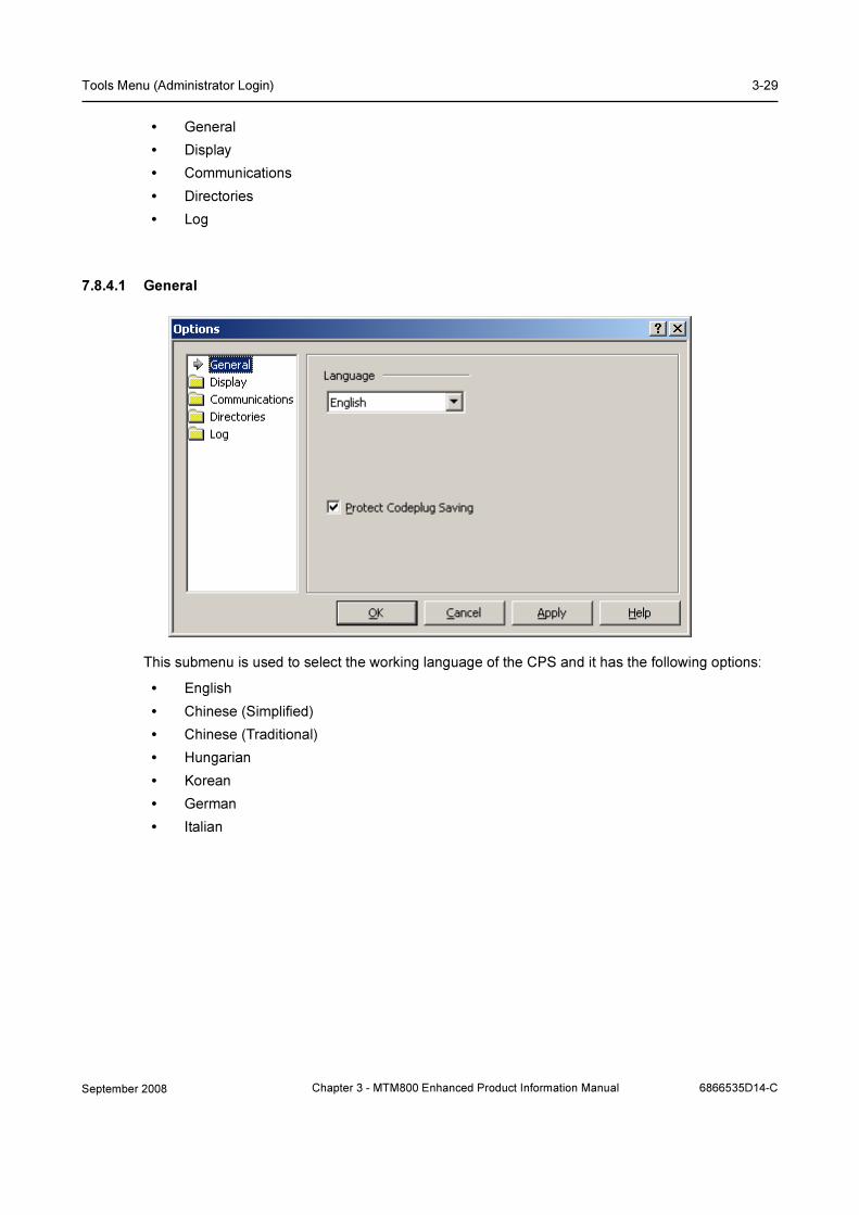
Tools Menu (Administrator Login) 3-29
• General
• Display
• Communications
• Directories
• Log
7.8.4.1 General
This submenu is used to select the working language of the CPS and it has the following options:
• English
• Chinese (Simplified)
• Chinese (Traditional)
• Hungarian
• Korean
• German
• Italian
September 2008 Chapter 3 - MTM800 Enhanced Product Information Manual 6866535D14-C

3-30 Customer Programming Software (CPS)
7.8.4.2 Display
These options allow:
1. Switching between “Cool” interface and “Traditional” interface as well as offering some addi-
tional options for each one:
• Cool interface: the toolbar buttons are flat and pop into an etched state as you move the
cursor over them. It contains grippers to facilitate moving and docking.
• Traditional interface: the toolbar buttons are raised.
2. Setting the toolbar size.
Selecting one of the available four language options.
7.8.4.3 Communication
6866535D14-C Chapter 3 - MTM800 Enhanced Product Information Manual September 2008
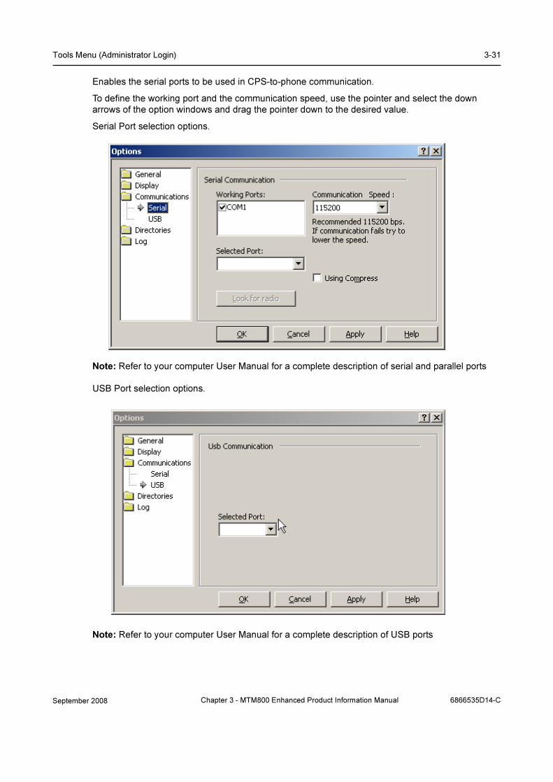
Tools Menu (Administrator Login) 3-31
Enables the serial ports to be used in CPS-to-phone communication.
To define the working port and the communication speed, use the pointer and select the down
arrows of the option windows and drag the pointer down to the desired value.
Serial Port selection options.
Note: Refer to your computer User Manual for a complete description of serial and parallel ports
USB Port selection options.
Note: Refer to your computer User Manual for a complete description of USB ports
September 2008 Chapter 3 - MTM800 Enhanced Product Information Manual 6866535D14-C

3-32 Customer Programming Software (CPS)
7.8.4.4 Directories
This is used to specify the default paths of the directories for codeplug, software and backup files.
Note: If there are several versions of Tetra CPS installed on the PC, these paths MUST be
configured as soon as the CPS is first launched, as the paths may default to existing directories.
This page lists three fields displaying the last selected path:
• Default Data Path — specifies the default path to the drive and folder (or directory) where the
codeplug file is located.
• Default Software Path — specifies the default path to the drive and folder (or directory)
where the subscriber (flashing) software is located.
• Default Backup Path — specifies the default path to the drive and folder (or directory) where
the codeplug backup files are located.
• Default Flash Packs Path — specifies the default path to the drive and folder (or directory)
where the Flash Packs files are located.
Each field has its accompanying Browse button.
Click any Browse button to bring up the Browse dialogue box, open the drivers/folders and select
the path to the directory where the desired file(s) will be stored/located.
To confirm the selection press OK. The path will be displayed in the relevant field of the Directories
page.
6866535D14-C Chapter 3 - MTM800 Enhanced Product Information Manual September 2008

Tools Menu (Administrator Login) 3-33
7.8.4.5 Log
Logging Options
Allows the logging feature to be enable/disable and to set up options for the Log file.
To enable the logging, from Logging Mode drop down list select Normal or TEI & ITSI, SFPG and
Normal. To disable the logging, from Logging Mode drop down list select Off.
Enable logging:
If logging is enabled, the CPS will write to the log file basic statistical information such as data, time,
operation name, operation data and operation result for main CPS functions activated by user
during CPS sessions.
When launched, the CPS will check whether the Log file exists or not in the directory, which is
specified in the Log file path field.
If the file does not exist, the CPS will automatically create it with the name cps_user.log.
An already existing log file will be appended to the newly recorded information.
Logging Mode:
Position the cursor into the combo box, then drag it to the required mode for the log file:
• TEI & ITSI, SFPG and Normal
• Normal
• Off
If the Normal or TEI & ITSI, SFPG and Normal modes are selected, the CPS checks whether or
not the log file exists in the directory specified in the Log File Path field. If the file does not exist, the
CPS creates it with the name cps_user.log. If the log file exists, new information will be recorded into
it.
If the Off mode is selected, the logging of all operations will be disabled. If the log file already exists,
no operation will be recorded into it.
Normal. If the Normal mode is selected for communication operations through one port only, then
the recording of all log operations through the default port will be written into the cps_user.log file.
September 2008 Chapter 3 - MTM800 Enhanced Product Information Manual 6866535D14-C

3-34 Customer Programming Software (CPS)
The logging of all operations will be enabled and performed according to the other logging page
settings.
TEI & ITSI, SFPG and Normal. If the ISSI & TEI Only mode is selected, then logging is similar to
the one in Normal mode and the CPS will also log any operation (through all ports related to the TEI,
ITSI and SFPG codeplug fields). The logging of all operations will be enabled and performed
according to the other logging page settings.
Log Options:
The following two options will be enabled if the user turns on the proper check boxes:
• Write Time To Log
• Write Operation Result To Log file
If these options are enabled, the time of the function start and the operation result (pass or fail) will
be appended to the new information recorded in the Log file.
Max log size:
This entry defines the maximum log file size. Click the slider to change the setting.The maximum
size is 200 MB.
Over write Log Info as Needed: The "enabled" setting means that all new events will be written to
the log, even when the log is full. When the log is full, each new event replaces the oldest one. The
“disabled” setting means that existing events will be retained when the log is full. If the maximum log
file size is reached, new events are discarded. This setting requires you to clear the log manually.
Select this setting only if you must retain all events.
Log File Path:
The CPS allows a directory to be set up for the Log file location through the Browse dialogue box,
which appears when clicking the Browse button. When the desired directory has been selected,
click the OK button and the path to the directory will be written to the Log file path field in the
Logging page. However, this path setting will be applied only in the next CPS session. Re-start the
CPS if the Log file path has been changed in the current session.
See Paragraph 7.8.4.4 "Directories".
8 Window Menu
This menu is similar to that in other Windows® applications. From this menu, it is possible to access
the following functions:
Note: This menu will be visible only if a file is already open in the application.
Note: The CPS will display only those functions that are applicable to the active phone model.
6866535D14-C Chapter 3 - MTM800 Enhanced Product Information Manual September 2008

Window Menu 3-35
8.1 Cascade
Is used to arrange open applications so that they overlap and each title bar is seen. This option does
not affect applications reduced to icons.
8.2 Tile
This option is used to arrange open applications into windows that do not overlap. It does not affect
applications reduced to icons.
8.3 Arrange Icons
This is used to arrange the icons of all minimised applications across the bottom of the screen.
8.4 Close All
Selecting this option can be used to close all open file windows. This function is only available if two
or more file windows are open in the application.
8.5 Switch Panes
This is used to switch the cursor from tree view to content view and vice-versa.
8.6 Adjust Splitter
This is used to adjust the width of tree view and content view areas or the width of columns in the
content view using the arrow keys on the keyboard.
Tip: This feature is useful when a mouse cannot be used (for example while programming a phone
in the field).
8.7 1, 2, 3, 4 etc. (List of Open Codeplug Windows)
This is an alphabetical listing of all open documents which appears at the bottom of the Window
menu. When selecting a document name, it will become the active document.
September 2008 Chapter 3 - MTM800 Enhanced Product Information Manual 6866535D14-C
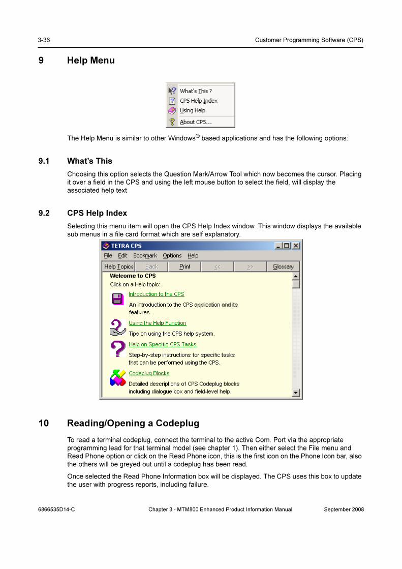
3-36 Customer Programming Software (CPS)
9 Help Menu
The Help Menu is similar to other Windows® based applications and has the following options:
9.1 What’s This
Choosing this option selects the Question Mark/Arrow Tool which now becomes the cursor. Placing
it over a field in the CPS and using the left mouse button to select the field, will display the
associated help text
9.2 CPS Help Index
Selecting this menu item will open the CPS Help Index window. This window displays the available
sub menus in a file card format which are self explanatory.
10 Reading/Opening a Codeplug
To read a terminal codeplug, connect the terminal to the active Com. Port via the appropriate
programming lead for that terminal model (see chapter 1). Then either select the File menu and
Read Phone option or click on the Read Phone icon, this is the first icon on the Phone Icon bar, also
the others will be greyed out until a codeplug has been read.
Once selected the Read Phone Information box will be displayed. The CPS uses this box to update
the user with progress reports, including failure.
6866535D14-C Chapter 3 - MTM800 Enhanced Product Information Manual September 2008

Phone Bar Icons 3-37
If a file is to be opened from archive, either select the File Menu and the ‘Open Option’ or click on
the open icon to display the Open Window dialogue box to select the file. Once selected the CPS
will display a wait prompt as it loads the file into the Work Screen
Once read, the codeplug will be displayed in the work screen for editing.
11 Phone Bar Icons
This bar, when selected, is displayed next to and on the same line as the main tool bar icons.
Placing the cursor over each icon will display its function, an explanation of which has previously
been given. These icons are a short cut to the option they represent.
September 2008 Chapter 3 - MTM800 Enhanced Product Information Manual 6866535D14-C

3-38 Customer Programming Software (CPS)
12 Codeplug
The top of the work screen will display terminal’s identity, i.e. Codeplug5_6204.cpd
The main body of the work screen is divided into 2 parts, on the left are the main menus of the
codeplug and on the right is the ‘Select a Category’ option. Once a menu has been selected the
‘Select a Category’ screen may change into 3 or more columns and may have the following options,
Field Name, Field Value and Reset.
Note: Right clicking on the Field Value entry fields may display a ‘Down Arrow’ in the box. Select the
arrow to display hidden options.
6866535D14-C Chapter 3 - MTM800 Enhanced Product Information Manual September 2008

Codeplug 3-39
The following main menu options are available:
• Subscriber Unit Parameters
• Feature Flags
• Security
• End to End Encryption
• Remote Programming
• NGCH Interface
• Clock System Broadcast Information
• TMO Voice Services
• NGCH Parameters
• DMO Parameters
• Ergonomic Parameters
• Language Parameters
• Audio Parameters
• Display Parameters
• TalkGroups
• Contact Book
• Data Services
• TNP1 Support
• Buttons, Keys and Accessories
• Input, Output, GPIOs
• Mobility and System Parameters
• GPS
• User Applications
• Call-Out
Note: When programming a terminal the minimum requirements to enable a terminal to log onto a
system are:
• A valid identity (ISSI) for the terminal
• A valid Group identity (GSSI)
• Valid Country and System codes
• Valid frequencies
Everything else programmed into the terminal will make the terminal operation more flexible and
friendly to the user.
September 2008 Chapter 3 - MTM800 Enhanced Product Information Manual 6866535D14-C

3-40 Customer Programming Software (CPS)
13 Subscriber Unit Parameters
Selecting this menu option will display its information in the right side of the screen. Not all fields are
editable, some being information fields only.
The first 6 fields provide information about the terminal’s codeplug, software and application image
versions, its model type, number and hardware ID.
Field 7 is a copyright notice.
Equipment Temporary Disabled is non-editable.
Subscription Temporary Disabled, is editable. When a terminal has been disabled over the air
(stunned), this field will be ‘checked’. It can be unchecked over the air or via the CPS. If the terminal
is stunned it will no longer be usable on the system (TMO) or off the system (DMO).
Equipment Permanently Disabled and Subscription Permanently Disabled, are non editable
Serial Number show the terminal’s serial number
Radio TEI show the terminal’s Terminal Equipment Identity (TEI)
Radio ISSI.This is where the terminal’s own Individual Short Subscriber Identity (ISSI) is entered. It
is the terminal’s unique system ID and it acts like a normal telephone number. The ISSI can contain
numbers in the range 1 - 13999999. Without a valid ISSI the terminal will not log on to a system.
Organization. The name of the organisation where the terminal was programmed can be entered
here for reference.
6866535D14-C Chapter 3 - MTM800 Enhanced Product Information Manual September 2008

Subscriber Unit Parameters 3-41
Person. The name of the person programming the terminal can be entered in this field.
This terminal Phone Number. Dependent upon the system telephone interconnect, it may be
necessary for a subscriber terminal to have a separate telephone number and not use its ISSI. This
field displays the subscriber phone number, it is also possible to view this number via the menu
functionality. The subscriber can change the number without modifying the phone number in the
system. Up to 24 digits can be entered.
This Radio Private Number. Displays the subscriber private number. This is an 8 digit number that
can be changed by the subscriber without modifying the phone number held in the system.
Last Modification Date. This non-editable field displays the date and time that the active Codeplug
was last programmed. The CPS automatically updates this data every time the Codeplug is saved,
or programmed into the terminal.
Programming Source. This non-editable field displays the source that was last used to program
the active Codeplug. This may be: Factory, CPS, OTAP, or Other. The CPS automatically updates
this data every time the Codeplug is saved or programmed into the terminal.
Comment. Comments can be entered about the last programming session and will be stored in the
Codeplug. Enter the information, up to 59 characters, before writing the Codeplug to the terminal.
September 2008 Chapter 3 - MTM800 Enhanced Product Information Manual 6866535D14-C

3-42 Customer Programming Software (CPS)
14 Feature Flags
When the CPS is opened with the ‘Admin Login’ option, this menu has 37 options. These options
are used to enable/disable terminal features.
6866535D14-C Chapter 3 - MTM800 Enhanced Product Information Manual September 2008

Feature Flags 3-43
14.1 Group
This refers to group call and is the main communication tool of TETRA and is a factory preset.
14.2 Status
This messaging feature enables the user to send and receive status. A status is a number
corresponding to a pre-programmed message in the terminal’s programmable status list. On
reception of the status number, the terminal will look the number up in its status list and display the
text associated with the number..
Related fields are:
Paragraph 29.2 "Status ID List"
Paragraph 29.4 "Short Data Service (SDS)"
Paragraph 31.4 "One Touch Buttons"
Paragraph 31.4.11 "Sending Status"
14.3 Targeted Status
This option is used to enable/disable the Targeted Status feature in the terminal. If enabled, the user
is able to send a predefined Status Message to an individual (ISSI) via a button programmed with
this feature.
See the following:
Paragraph 29.2 "Status ID List"
Paragraph 29.4 "Short Data Service (SDS)"
Paragraph 31.4 "One Touch Buttons"
Paragraph 31.4.11 "Sending Status"
14.4 Semi-duplex Private Call
This option is used to enable/disable the Semi-duplex Private Call feature in the terminal. Also
called Private Call or Express Connect Call. In this type of one-way call, the user presses and holds
the PTT while talking, and releases the PTT while listening.
Note: This is the only method of keying the terminal for call set up of Group Calls and keying during
the call.
14.5 Private Duplex
This option is used to enable/disable the Private Duplex feature in the terminal. Also called Private
Net Phone Call. If this method is used for Private Call set up, the terminals involved in the call will
behave as normal telephones with 2-way conversation - users will not have to press the PTT button.
Received calls are accepted by pressing the button with the red & green telephone handset icon.
Press the button to clear the call.
September 2008 Chapter 3 - MTM800 Enhanced Product Information Manual 6866535D14-C

3-44 Customer Programming Software (CPS)
14.6 Direct Mode (DMO)
This option is used to enable/disable the Direct Mode (DMO) feature is in the terminal. This feature
enables the terminal to work as a 2-way terminal and communicate directly with another
subscriber(s) of the talkgroup without the need for system infrastructure. Particularly useful when
the phone is out of coverage. In this mode the subscriber can not receive or make system - Group
calls, Private Calls, Telephone Interconnect Calls and Status Messages. The phone will not receive
system error and maintenance messages.
Note: DMO Emergency Calls are supported by the terminal.
See the following:
Paragraph 22 "DMO Parameters"
Paragraph 27.2.2 "DMO Talkgroup List"
Paragraph 31.3 "One-Touch Options"
Paragraph 31.4 "One Touch Buttons"
14.7 Direct Mode (DMO) Reservation
This is a form of ‘Hang Timer’ and is used to keep the channel open for the group. The entry in this
field specifies the duration of channel reservation time for DMO calls initiated by the terminal. During
the reservation time, other terminals that wish to talk, do not have to set up a new reservation;
instead, the current channel reservation may be used until the end of the time-out.
14.8 Telephone Interconnect
This option is used to enable/disable the terminal’s Phone Mode of operation, selectable via the
terminal’s mode selection button.
See related fields:
Paragraph 28 "Contact Book"
Paragraph 31.3 "One-Touch Options"
Paragraph 31.4 "One Touch Buttons"
14.9 MS User Application Support Pre-defined Template
The terminal’s Predefined Templates feature can be enabled or disabled by clicking in the check
box.
If enabled, the feature allows mail templates to be programmed into the phone. The user is allowed
to perform limited editing operations on a predefined template and send it, but is not allowed to store
the edited predefined template or erase it from the Templates List.
Related fields:
Paragraph 29.1.1 "Outgoing Mail Options"
Paragraph 29.1.2 "Outgoing Mail List"
Paragraph 31.3 "One-Touch Options"
Paragraph 31.4 "One Touch Buttons"
6866535D14-C Chapter 3 - MTM800 Enhanced Product Information Manual September 2008
Feature Flags 3-45
14.10 Mail In
This is a factory preset feature indicating that the Mail In feature (text messaging) is enabled in the
phone. The Mail In feature enables Reception, Reading and Deletion of Messages.
14.11 Mail Out
This option is used to enable/disable the Mail Out feature (text messaging) in the terminal. The Mail
Out features allows the user to Create, Store, Send, Reply, and Delete Messages.
Related Fields:
Paragraph 29.1.1 "Outgoing Mail Options"
Paragraph 29.1.2 "Outgoing Mail List"
Paragraph 31.3 "One-Touch Options"
Paragraph 31.4 "One Touch Buttons"
14.12 External Device
Selecting this feature enables the user to connect an external device (also called peripheral
equipment) to the phone, such as a laptop or desktop PC. The phone then operates then as a
wireless modem, sending or receiving data from another subscriber.
14.13 Test Page
Selecting this option enables field engineers to access various internal data via the test page sub
menu.
14.14 Horn & Light
If this feature is enabled, the vehicle’s horn will sound and the lights will flash to announce an
incoming private/phone call. This feature requires the installation of a kit.
Check box to enable this option.
14.15 PABX
This option is used to enable/disable the terminal’s PABX Mode of operation.
See related fields:
Paragraph 28 "Contact Book"
Paragraph 31.3 "One-Touch Options"
Paragraph 31.4 "One Touch Buttons"
14.16 Talkgroup Scan
Specifies whether the phone's Talkgroup Scan feature is enabled or disabled.
If this field is enabled, the phone, instead of just monitoring its selected talkgroup will monitor (scan)
more than one talkgroup sequentially.
September 2008 Chapter 3 - MTM800 Enhanced Product Information Manual 6866535D14-C
3-46 Customer Programming Software (CPS)
The talkgroups are organized into scan lists that are user selectable. Only one scan list can be
active and the terminal continuously monitors the talkgroups of the scan list for activity. The terminal
will also monitor the group on which scan was started, this may be an ‘Announcement Talkgroup’
(ATG).
By assigning priorities to the talkgroups defined in the scan list, the handset is capable of accepting
calls that have higher priority than the on-going call.
Enable or Disable the feature by clicking in the check box.
Related fields are:
Paragraph 20.4 "Scanning Parameters"
Paragraph 27.1.3 "TMO Scan Lists"
Paragraph 31.3 "One-Touch Options"
Paragraph 31.4 "One Touch Buttons"
14.17 Packet Data
If connected to an external device (such as a laptop or desktop PC), the terminal acts a terminal
modem and allows the transfer of data packets.
This feature has three programmable settings that when enabled are user selectable options via the
terminal’s menu functionality. The settings are: Data Only Enable, Voice & Data Enable, and Voice
Only Enable.
Related field: Data Services\Packet Data Parameters, paragraph 23.3
14.18 Home Mode Display
Enabling this feature will allow the terminal to display pre-programmed information when the
terminal is inactive.
14.19 Group Hot Mic
If enabled and the terminal enters emergency mode to set up an Emergency Group Call, the
microphone will automatically open and allow the user to talk without having to press the PTT
button. Transmission is allowed for a pre-programmed period of time, after which the user must
press the emergency button to restore the Hot Mic functionality.
If the emergency alarm button, switch or key is pressed during Hot Mic transmission, the emergency
alarm will not be sent, but the Hot Mic Duration Timer will be restarted from the beginning and the
voice transmission can continue.
If the PTT is pressed during Hot Mic transmission, Hot Mic transmission state will end, but the
terminal will continue to transmit in the normal Emergency PTT operation. The Hot Mic Duration
Timer will be cancelled, the normal mic gain will be restored and transmission will be as per normal
emergency group call PTT operation.
Hot Mic transmission will end when:
• the user exits emergency mode.
• the Hot Mic Duration Timer expires.
• the user presses an ’end’ key.
In the case where the user exits emergency mode, the terminal will leave the call.
6866535D14-C Chapter 3 - MTM800 Enhanced Product Information Manual September 2008
Feature Flags 3-47
In the cases where the timer expires or the user presses the end key, the terminal will send a U-TX-
CEASED message to the system and remain in the call.
In all cases, the mic gain will be restored to its normal value, the Hot Mic Duration Timer and Hot Mic
Pending Timer will be cancelled.
If during the call, the terminal receives a D-RELEASE from the SwMI (system), it will stop Hot Mic
transmission if is transmitting, cancel the Hot Mic Duration Timer and Hot Mic Pending Time (if they
are active) and restore the mic gain to its normal operational value.
If, upon requesting a hot-mic call, the terminal receives a response that transmission was granted to
another, it will sound an emergency received tone and enter the call.
If the Transmission Request Permission is set to ’allowed to request for transmission’, the terminal
will then start a ’Hot Mic Pending Timer’. If the transmission request is not allowed, or if the Hot Mic
Pending Timer is disabled, it will go into the Hot Mic Tx Pending state and not start the timer.
In this case the Hot Mic Pending state will end only when the other party stops transmitting.
The terminal will be in a Hot Mic Tx Pending state if the user takes no action and will remain in this
state until either the Hot Mic Pending Timer expires, or until the other terminal stops transmitting.
The Hot Mic Duration Timer will not be started until the first ’Tx Granted’ message is received.
If, in the Hot Mic Tx Pending state, the transmitting terminal stops transmitting, or the Hot Mic
Pending Timer expires, then the terminal will send a transmission request with Tx Demand Priority
set to ‘Emergency Pre-emptive Priority’. If transmission is granted, the terminal will start Hot Mic
transmission, but will not restart the Hot Mic Duration Timer.
If during Hot Mic transmission, it receives a signal that tx permission was granted to another user, it
will stop transmitting and sound the incoming voice alert. If the Transmission Request Permission is
set to ‘allowed to request for transmission’, the terminal will start the Hot Mic Pending Timer. If
transmission request is not allowed, it will enter the Hot Mic Tx Pending state, but not start the timer.
When the other terminal ceases transmission or the Hot Mic Pending Timer expires, it will re-request
transmission.
If the PTT is pressed in the Hot Mic Tx Pending state, the terminal will send a request to transmit
and cancel Hot Mic operation; normal mic gain will be restored, the Hot Mic Duration Timer and Hot
Mic Pending Timer will be cancelled and transmission will follow PTT operation as for normal
emergency group calls.
If the emergency button/key is pressed when in Emergency Mode Idle (i.e. the terminal is in
Emergency Mode, but there is no active call), an emergency alarm will be sent and the Hot Mic
operation will be initiated.
In Emergency Mode the Terminal also accepts normal group calls. If it is in Emergency Mode
listening to a normal group call and if the emergency button/key is pressed in the receive state (i.e.
listening to another user talking) or in the hang-time state (i.e. there is no talker), the terminal will
leave the call, send an emergency alarm and setup a new hot-mic emergency call to the current
group.
If the emergency button/switch/key is pressed when the terminal is in Emergency mode in an
emergency group call in the receive state (i.e. another user is talking) or in the hang-time state (i.e.
there is no talker), the terminal will initiate Hot Mic transmission by sending a U-TX-DEMAND with
request to transmit with Tx Demand Priority set to ‘Emergency Pre-emptive Priority level’.
Note: The Emergency alarm is not sent in this case as it would prevent the terminal from interrupting
the current talker since the terminal would have to leave the call and try to setup a new call after the
alarm is completed. In this case the Dimetra IP system will not grant tx permission.
September 2008 Chapter 3 - MTM800 Enhanced Product Information Manual 6866535D14-C

3-48 Customer Programming Software (CPS)
If the terminal is involved in an announcement group call or is still within the Rx-timer period of an
announcement group call when the hot-mic transmission is initiated, the Hot Mic group call will be
made to the Announcement Group.
Note: In normal circumstances there will not be a case of Rx-hold timer in an emergency call, since
the hang timer on the call is very long and the Rx-hold Timer starts when Tx-ceased is received.
Note: Hot Mic functionality does not work when the terminal is in the DMO operational mode.
Related field is:
Paragraph 25.1 "Hot Mic"
14.20 DMO Gateway
This feature allows the terminal to work with DMO Gateway(s).
The DMO Gateway is a device that provides gateway connectivity between terminal and the TETRA
Voice and Data (V+D) network. The gateway provides the interface between the TETRA DMO and
TETRA V+D modes. A gateway may provide only the gateway function (DM-GATE) or may provide
the functions of both a DM repeater and a DM gateway during a call (DM-REP/GATE).
This feature can be Enable/Disable by clicking in the check box.
14.21 One-Touch Feature
This feature enables often used functions to be assigned to a singe button press on the numeric
keypad button.
Related fields are:
Paragraph 31.3 "One-Touch Options"
Paragraph 31.4 "One Touch Buttons"
14.22 My Favorite Groups
Enabling this feature allows the user to create a ‘Personal’ range of groups from those held in both
the TMO and DMO Talkgroup lists of the terminals memory.
Related field:
Paragraph 27.3 "My Favorite Groups"
14.23 Speed Dialing
Selecting this option will enable the speed dialing functionality of the terminal.
If this feature is enabled, a speed dial number is added to numbers in the contacts list.
Turn the check box on (Enable) or off (Disable) by clicking in the check box.
14.24 GPS
Select this option to enable the GPS (Global Positioning System) feature of the terminal.
Paragraph 34 "GPS"
6866535D14-C Chapter 3 - MTM800 Enhanced Product Information Manual September 2008

Feature Flags 3-49
14.25 Tx Audio Hi Pass Filter
The terminal has a High-pass Filter module for all microphone connections. When enabled, the
High-pass Filter module reduces the frequencies at the lower end of the frequency
This feature is used to ensure audio clarity in a noisy environment. (This filter is used for certain
terminal models. Please consult with your Service Provider.)
This is applicable in TMO and DMO.
Check box to enable this feature.
14.26 TNP1 Support
The TNP1 feature will operate only if Packet Data or External Device is enabled in the codeplug
(i.e.: a PPP session with MT2 can be established).
Turn the check box on (Enable) or off (Disable) by clicking in the check box.
14.27 Selected Network Enabled
If enabled, the Selected Network Enabled option will be displayed on the terminal screen. The
option allows the terminal user to register to a network of choice from an allowed Network List.
Check box to enable this feature.
14.28 Address Book Restriction
When the Address Book Restriction feature is enabled, the user will be allowed to initiate a private/
phone/PABX call if a number stored in the list of received calls exists in the address book.
Turn the check box on (Enable) or off (Disable) by clicking in the check box.
14.29 TG Dialing by Index
The Talk Group (TG) Index feature can be entered via the keypad when only in either TMO or DMO
talk group mode, in idle or receiving but nor transmitting.
In this mode the terminal does not look at the Talk Groups per range, but as consecutive numbers
from the first talk group of range 1 to the last talk group in the last enabled range. i.e. 4 ranges of 16
talkgroups is equal to a list of 64 continuous talk groups, where a keypad entry of 17 equates to the
first talk group of range 2.
To enable this functionality, the required keypad presses are of a shorter duration than that required
when using the one touch button functionality.
Once the first digit has been entered a ‘Find’ soft menu appears and on completion of the talkgroup
digit entry, pressing the associated soft button will cause the talk group to be displayed. Once the
talk group is displayed, the user is then presented with the ‘Cancel’, ‘OK’ selectable soft button
options.
Selecting ‘OK’ will attach the terminal to the group, or pressing the PTT will attach the terminal to the
group and set up a call to that selected group.
The terminal will actively remain on the last selected talk group during the search process and calls
can be heard and answered via the PTT while the search screen is still displayed, thus allowing the
user to complete the talk group selection process.
Incorrect keypad entries are cleared using the ‘Clear’ option of a soft button.
September 2008 Chapter 3 - MTM800 Enhanced Product Information Manual 6866535D14-C

3-50 Customer Programming Software (CPS)
It is also possible to enter a known talk group GSSI via the keypad and press the PTT to set up a
call without using the search functionality above.
14.30 WAP (Wireless Application Protocol)
If enabled, allows the terminal to access the internet.
Turn the check box on (Enable) or off (Disable) by clicking in the check box.
14.31 Mail out to Group
If enabled, allows the user to send a mail to a group.
Turn the check box on (Enable) or off (Disable) by clicking in the check box.
14.32 Direct Mode (DMO) Semi-Duplex Private Call
Indicates whether the Direct Mode (DMO) Semi-duplex Private Call feature is enabled or disabled in
the phone. Also called DMO Private Call.
In this type of one-way call, the user presses and holds the PTT while talking, and releases the PTT
while listening.
Turn the check box on (Enable) or off (Disable) by clicking in the check box.
14.33 Packet Data Page Enable
Enabling this feature will allow the terminal to display the packet data page.
14.34 Multislot Packet Data
Specifies whether the Multislot Packet Data is supported or not.
When enabled on the terminal and the network, the Multislot Packet Data allows for faster Packet
Data transfer.
Turn the check box on (Enable) or off (Disable) by clicking in the check box.
14.35 DMO Repeater
Indicates whether the terminal supports the repeater feature or not.
The repeater enables to support Direct Mode communications over an enhanced coverage area as
compared to that typically achieved in direct MS-MS operation. Note that an MS will not join a call
initiated via a DMO repeater if it was received directly from the calling Direct Mode MS.
Turn the check box on (Enable) or off (Disable) by clicking in the check box.
14.36 Clear LA Blacklist on Talk Group Change
The Blacklist list stores sites that rejected the Mobile Station (MS) previously. If this feature is
enabled, the list will be cleared each time a new talkgroup is selected.
Turn the check box on (Enable) or off (Disable) by clicking in the check box.
6866535D14-C Chapter 3 - MTM800 Enhanced Product Information Manual September 2008

Security 3-51
14.37 Remote Programming
If enabled, allows programming a mobile terminal via a network without the need of bringing it
manually into programming mode.
Turn the check box on (Enable) or off (Disable) by clicking in the check box.
14.38 Call-Out
If enabled, allows Call-Out alerts to be sent and received.
Turn the check box on (Enable) or off (Disable) by clicking in the check box.
15 Security
15.1 MS Authentication
This feature may be required for several different reasons, see Chapter 2 Paragraph 9.2.
Checking the box enables/disables the MS Authentication Feature.
During normal operation the Switching and Management Infrastructure (SwMi) of the system may
require the terminal (mobile subscriber - MS) to authenticate, to allow access to the system
September 2008 Chapter 3 - MTM800 Enhanced Product Information Manual 6866535D14-C

3-52 Customer Programming Software (CPS)
services. The terminal may also require SwMi to authenticate, thus making the authentication
mutual
The authentication centre (AuC) manages the assignment, control and distribution of encryption key
information to the (SwMI), and manages keys for Air Interface Encryption and Authentication
services for the Dimetra infrastructure entities.
Note: Authentication and encryption require key storage/provisioning to be functional, to make
these features operational.
Note: The terminal, and SwMi encryption and authentication support are classified into 3 classes:
• Class 1 – no encryption, may use authentication;
• Class 2 – SCK encryption, ESI with SCK, may use authentication;
• Class 3 – DCK encryption, ESI with CCK, authentication.
15.2 MS Mutual Authentication
Enables/disables authentication initiated by SwMi and made mutual by terminal.
The SwMi initiates the process by challenging the terminal to prove its authenticity (“authentication
of the MS…”). The terminal responds with its proof of authenticity and a challenge of its own to the
SwMI (“…made mutual by the MS”).
The authentication centre (AuC) manages the assignment, control and distribution of encryption key
information to the Switching and Management Infrastructure (SwMI), and manages keys for Air
Interface Encryption and Authentication services for the Dimetra infrastructure entities.
Note: Authentication and encryption require key storage/provisioning to be functional, to make
these features operational.
Note: The terminal, and SwMi encryption and authentication support are classified into 3 classes:
• Class 1 – no encryption, may use authentication;
• Class 2 – SCK encryption, ESI with SCK, may use authentication;
• Class 3 – DCK encryption, ESI with CCK, authentication.
15.3 Mandatory Mutual Authentication
If this feature is enabled, it indicates that SwMI authentication is mandatory.
15.4 SCK Air If Encryption
This field contains the Class of MS and the all MS information elements to indicate the infrastructure
the characteristics of the MS terminal support (Authentication-flag, SCK-AI).
15.5 DMO SCK
Indicates if the MS supports DMO SCK feature. DMO SCK is to represent SCKs designated for
secure DMO.
Turn the check box on (Enable) or off (Disable) by clicking in the check box.
6866535D14-C Chapter 3 - MTM800 Enhanced Product Information Manual September 2008

Security 3-53
15.6 DMO SCK OTAR
Indicates whether DMO SCK Keys can be delivered to the MS by OTAR.
Turn the check box on (Enable) or off (Disable) by clicking in the check box.
WARNING: The DMO SCK OTAR feature flag shall only be enabled on the MS in one of the following 2 conditions: - The
current System supports SCK OTAR (e.g. SR6.1) and the MS belongs to a CMG
- The current System does not support SCK OTAR (e.g. SR5.2), the current System operates with TMO SCKs 31 and 32
only, DMO SCK is not being used, and the customer plans to upgrade his System to an SCK OTAR System and add the
MS to a CMG.
Enabling the DMO SCK OTAR feature for an MS operating on a System not supporting DMO SCK OTAR will result in the
deletion of SCKs provisioned by KVL except SCKs 31 and 32. Therefore, unless the System only uses SCKs 31 and 32
for TMO operations in Security Class 2, the MS will not be able to operate in TMO Security Class 2 on such a System and
DMO SCK will not operate because the DMO SCKs would have been deleted. To recover from such a configuration mis-
take, the DMO SCK OTAR flag needs to be disabled and SCKs need to be reloaded via KVL.
15.7 DCK Air If Encryption
This field contains the Class of MS and the all MS information elements to indicate the infrastructure
the characteristics of the MS terminal support.
15.8 GCK Air If Encryption and OTAR
Indicates if MS shall support GCK AIE and OTAR feature.
Turn the check box on (Enable) or off (Disable) by clicking in the check box.
15.9 Permanent Disable
When enabled, the radio will be permanently killed, when it receives the Permanent Disable
command. The radio’s software, codeplugs and security key material are deleted. Any of those
information cannot be recovered over the air but needs to be reprogrammed by the Service
Provider.
15.10 Permanent Disable V2
If enabled, the radio will appear dead to the user when it receives the Permanent Disable command.
The radio’s security key material is deleted and the radio cannot be recovered over the air.
Unlike Permanent Disable, for Permanent Disabled V2 the radio can be re-enabled by the customer
provider.
Turn the check box on (Enable) or off Disable) by clicking on the check box.
15.11 Permanent Disable Policy
This feature is used to accept or reject Permanent Disable commands sent by the Switching and
Management Infrastructure (SwMi) of the system when the command had not been implicitly
authenticated using AI (Air Interface) encryption.
The options are:
• No Security - no security is checked when radio is processing the Permanent Disable
command.
• Encryption Required - the command must be encrypted for it to be processed
September 2008 Chapter 3 - MTM800 Enhanced Product Information Manual 6866535D14-C

3-54 Customer Programming Software (CPS)
• Authentication Required - the command must contain an Authentication Challenge flag,
otherwise it will be rejected. For this, a valid K key must be loaded into the terminal
• Mutual Authentication Required - the command must contain an Authentication Challenge
flag, otherwise it will be rejected. In addition the radio will initiate mutual authentication prior
to processing the command. For this, a valid K key must be loaded into the terminal.
• Encryption and Authentication Required - the command must be encrypted and contain an
Authentication Challenge flag, otherwise it will be rejected. For this, a valid K key must be
loaded into the terminal
• Encryption and Mutual Authentication Required - the command must be encrypted and
contain an Authentication Challenge flag, otherwise it will be rejected. In addition the radio will
initiate mutual authentication prior to processing the command. For this, a valid K key must
be loaded into the terminal
15.12 Temporary Enable/Disable Policy
This feature is used to accept or reject Temporary Enable / Disable commands sent by the
Switching and Management Infrastructure (SwMi) of the system when the command had not been
implicitly authenticated using AI (Air Interface) encryption.
The options are:
• No Security
• Encryption Required
• Authentication Required
• Mutual Authentication Required
• Encryption and Authentication Required
• Encryption and Mutual Authentication Required
15.13 Non Secured Call Indication
Specifies whether or not the Non Secured Call Indication feature is enabled in the phone. When
enabled, this feature warns the user about unencrypted incoming calls.
Turn the check box on (Enable) or off (Disable) by clicking in the check box.
15.14 Encrypted Only
Enabling this option will cause the terminal to only search for cells supporting encryption at power
on or each cell reselection. The terminal will not register in any cell using ciphering off, in case the
flag is set to encrypted-only.
The options are:
• Encrypted Only.
• May Be Clear.
15.15 Class 3 Cell Ranks Higher than Class 2 Cell
If this feature is set to "Cell 3 is better", it means that a cell operating in Security Class 3 will be
ranked higher than a cell operating in Class 2
If this feature is set to "Cell 3 is equal", it means that a cell operating in Security Class 3 will be
ranked equal to a cell operating in Class 2.
6866535D14-C Chapter 3 - MTM800 Enhanced Product Information Manual September 2008
Security 3-55
It is only relevant to terminals supporting Static Cypher Key (SCK) and Dynamic Cypher Key (DCK).
The options are:
• Cell 3 is Better.
• Cell 3 is Equal.
15.16 Key Erasure Mode
This option is used to erase the encryption keys prior to the terminal going for service, or when the
vehicle in which a (mobile) terminal is mounted is sent for service. This mode may also be used to
remove all key material from a terminal in emergency situations.
An terminal that supports air interface encryption will initiate erasure of cipher keys (SCK) stored in
the terminal on detection of a unique terminal front panel key sequence. This sequence will only be
processed when the terminal is in the idle or emergency states.
On detection of an emergency key-erase operation, the terminal operational state will be Temporary
MS Disable (Equipment). The terminal will send an unsolicited PDU to the SwMi (if the terminal is
currently registered), to indicate that it has gone into this state. As this PDU must be sent encrypted,
it will be sent prior to performing the key erasure (if terminal is registered).
Select one of the following options:
• Erase All Keys Except K – when the key erase key sequence is entered on the terminal it
will erase only SCKs, not Authentication Ks.
• Delete All Keys – when the key erase key sequence is entered on the terminal it will erase
SCKs and K.
Provisioning of K and the SCK into the terminal will be done using the KVL.
To select the option, put the pointer into the field value, click on the arrow, and drag the pointer to the
desired option.
Note: Authentication and encryption require key storage/provisioning to be functional, to make
these features operational.
Note: The terminal, and SwMI encryption and authentication support are classified into 3 classes:
• Class 1 – no encryption, may use authentication;
• Class 2 – SCK encryption, ESI with SCK, may use authentication;
• Class 3 – DCK encryption, ESI with CCK, authentication.
Related Field is:
Paragraph 15.17 "Key Erasure Occurred"
15.17 Key Erasure Occurred
If enabled the terminal will store an indication in the codeplug that key Erasure occurred. This flag
will only be set on successful erasure of the encryption keys.
This flag can only be cleared by re-provisioning a new codeplug into the terminal, using the depot
CPS, or re-enabling the terminal over air (where possible).
This feature is Enabled/Disabled by clicking in the check box.
Related Field is:
September 2008 Chapter 3 - MTM800 Enhanced Product Information Manual 6866535D14-C

3-56 Customer Programming Software (CPS)
Paragraph 15.16 "Key Erasure Mode"
15.18 Maximum Retries Due Time Out T351- 354
The number in the editable field indicates the maximum number of times the terminal is allowed to
send U-LOCATION UPDATE DEMANDs due to time out of the timers T351-354.
Where authentication occurs embedded within a registration procedure, timer T351 (registration
timer) shall be treated as T354 (authentication timer) and as such only one timer needs to be
invoked. The terminal uses the registration timer T351 value for the terminal authentication timer
during explicit authentication.
The terminal starts the T351_354 timer on receiving the D-AUTHENTICATION DEMAND from the
SwMI.
The terminal will terminate T351_354 under the following conditions:
• Terminal Link Loss
• On receipt of D-AUTHENTICATION UPDATE ACCEPT containing the type-3 element
“Authentication downlink”
• On receipt of D-LOCATION REJECT
• On sending U-AUTHENTICATION RESULT for authentication initiated by the SwMI and
made mutual by terminal
If the authentication timer T351_354 expires, the terminal will again attempt to send the location
update demand before reverting to its previous mobility management state, prior to the
authentication attempt. The range of the timer is 1 - 255 seconds and the default setting is 1
second.
15.19 Max Password Attempts
This field defines the number of attempts that can be made to unlock the terminal, after which the
phone will not allow any more attempts. Only entry of the longer PIN Unlock Key (PUK) code can
unlock the phone.
The range for this option is 1 - 255. Default setting is 3.
15.20 PIN Flag
This feature is used to enable/disable the PIN facility and the default value of this option is
“enabled”. Upon power on, the terminal prompts the user to enter the valid 4 digits PIN1 value
before allowing access to any of the services available from the network or features of the terminal.
Following three consecutive failed attempts the terminal is temporarily blocked and will remain in
this state even through a power reset. PIN1 can be changed via CPS and the terminal’s user menu
functionality.
Once blocked only entry of the longer PIN Unlock Key (PUK) code can unlock the phone.
15.21 MS change PIN Number
If enabled, this field allows the user to change the pin number (unlock code) of the terminal.
Do Not use any spaces when entering the Pin Number.
6866535D14-C Chapter 3 - MTM800 Enhanced Product Information Manual September 2008

Security 3-57
15.22 PIN Number
This field is used to define the passcode required to unlock the phone after it has been locked.
During pin number entry, asterisks are displayed instead of the number.
15.23 MS change PIN Options
If enabled, this field allows the user to change the available pin options, i.e. the number of allowed
password attempts.
15.24 PIN Unblocking Key
This field is used to define the 8 digit code used to unlock the phone when passcode entry has been
blocked.
15.25 Disable Display
If this option is not selected, no visual indication will be displayed when the phone is disabled.
Check the box to enable this feature and display the disabled indication when the terminal is
disabled.
15.26 Activate Always Encryption
If enabled, the terminal will block any unexpected clear outgoing PDUs.
Use carefully as this feature, if enabled, will prevent the terminal from operating on any clear
system.
Turn the check box on (Enable) or off (Disable) by clicking in the check box.
15.27 Covert Mode
Indicates whether the Covert Mode is On or Off.
To select the option, put the pointer into the field value, click on the arrow, and drag the pointer to the
desired option.
Turn the check box on or off by clicking in the check box.
15.28 Enter Pinlock-Menu Tone
This feature is Enabled/Disabled by clicking in the check box.
September 2008 Chapter 3 - MTM800 Enhanced Product Information Manual 6866535D14-C
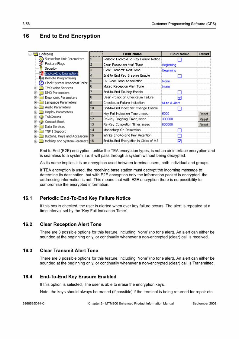
3-58 Customer Programming Software (CPS)
16 End to End Encryption
End to End (E2E) encryption, unlike the TEA encryption types, is not an air interface encryption and
is seamless to a system, i.e. it will pass through a system without being decrypted.
As its name implies it is an encryption used between terminal users, both individual and groups.
If TEA encryption is used, the receiving base station must decrypt the incoming message to
determine its destination, but with E2E encryption only the information packet is encrypted, the
addressing information is not. This means that with E2E encryption there is no possibility to
compromise the encrypted information.
16.1 Periodic End-To-End Key Failure Notice
If this box is checked, the user is alerted when ever key failure occurs. The alert is repeated at a
time interval set by the ‘Key Fail Indication Timer’.
16.2 Clear Reception Alert Tone
There are 3 possible options for this feature, including ‘None’ (no tone alert). An alert can either be
sounded at the beginning only, or continually whenever a non-encrypted (clear) call is received.
16.3 Clear Transmit Alert Tone
There are 3 possible options for this feature, including ‘None’ (no tone alert). An alert can either be
sounded at the beginning only, or continually whenever a non-encrypted (clear) call is Transmitted.
16.4 End-To-End Key Erasure Enabled
If this option is selected, The user is able to erase the encryption keys.
Note: the keys should always be erased (if possible) if the terminal is being returned for repair etc.
6866535D14-C Chapter 3 - MTM800 Enhanced Product Information Manual September 2008
End to End Encryption 3-59
16.5 Rx Clear Tone Association
This field defines the condition for sounding a clear reception alert tone. the three options are none,
always or by association.
16.6 Muted Reception Alert Tone
There are 3 possible options for this feature, including ‘None’ (no tone alert). A muted alert can
either be sounded at the beginning, or continually whenever a non-encrypted (clear) call is received
16.7 End-To-End Re-key Enable
This option defines whether or not the key request option is active.
16.8 User Prompt on Checksum Failure
Specifies whether a user prompt is displayed on an End-to-End synchronization frame checksum
failure. The message prompt indicates that a checksum failure has occurred.
Turn the check box on (Enable) or off (Disable) by clicking in the check box.
Note: The user may attempt to resynchronize the real time clock (RTC) manually or over the air (by
switching to TMO if in DMO) on the CCSUM failure indication. This may not clear the error
depending on the cause of the checksum failure.
16.9 Checksum Failure Indication
This option defines how the terminal will behave if a checksum failure occurs. the options are:
• Mute
• Mute & Alert
• Unmute & Alert
• Unmute & Overtone
• Unmute
16.10 End-To-End Index Set Change Enabled
Selecting this check box option will allow the user to change the active index set.
16.11 Key Fail Indication Timer
This option is used to set the periodic time interval for the Key Fail Alert.
See Paragraph 16.1 "Periodic End-To-End Key Failure Notice" above.
16.12 Re-Key Ongoing Timer
This option is used to set the response time interval after which the user will be alerted that no
response has been received from the KMF to a re-key request.
September 2008 Chapter 3 - MTM800 Enhanced Product Information Manual 6866535D14-C
3-60 Customer Programming Software (CPS)
16.13 Re-Key Completion Timer
The entry in this field defines the time after which the user is alerted when a re-key request has not
been completed.
16.14 Mandatory On Relaxation
This check box determines whether or not a received clear call is Accepted/Unmuted or Rejected/
Muted when the default mode of the accosiation is Mandatory On.
16.15 Infinit End-To-End Key Retention
Selecting this option enables the terminal to permanently store encryption keys even when the
battery is removed.
16.16 End-To-End Encryption in Class of MS
This field indicates whether the terminal is E2E capable or not. This is a sub-element of Class of
terminal Information element.
This field is set to Enabled in power-up if the terminal is equipped with the UCM.
Turn the check box on (Enable/Encrypted) or off (Disable/Clear) by clicking in the check box.
17 Remote Programming
Allows programming of a MS from a remote server connected via a local network to the handset
cradle. Benefits of this feature include:
• MS can be programmed without needing the user to manually bring it into programming
mode. This is especially useful for large systems having thousands of terminals.
• MS can be put into programming mode while it is charging.
• It is possible to support management of different software and codeplug versions of MS within
the system.
• This feature also offers a standard API for accessing parameters of each MS. It is then
possible to directly connect a fleet mapping or system configuration tool in order to do full
system and terminal management using a single tool. Previously, a file comma separated
value (CSV) formatted has to be generated and imported into CPS.
17.1 Communication Timeout Timer
Defines the timeout duration until a loss of a communication between MS and PC or beetween
control head and transceiver is notified to the user on the display of MS.
18 NGHC Interface
This menu option lists the NGCH interface parameters which are necessary to configure the control
head. This includes the definition of interface to the radio as well as accessory interfaces and
General Programmable Input Output pins (GPIO).
6866535D14-C Chapter 3 - MTM800 Enhanced Product Information Manual September 2008
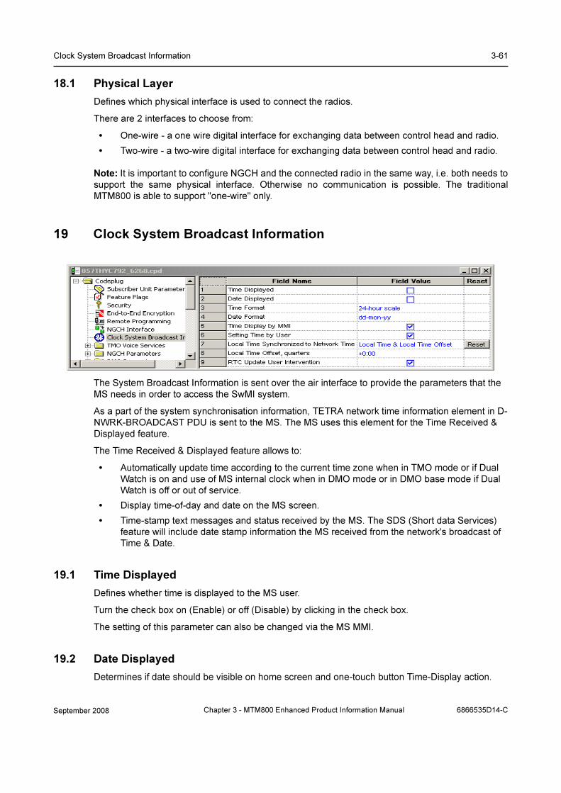
Clock System Broadcast Information 3-61
18.1 Physical Layer
Defines which physical interface is used to connect the radios.
There are 2 interfaces to choose from:
• One-wire - a one wire digital interface for exchanging data between control head and radio.
• Two-wire - a two-wire digital interface for exchanging data between control head and radio.
Note: It is important to configure NGCH and the connected radio in the same way, i.e. both needs to
support the same physical interface. Otherwise no communication is possible. The traditional
MTM800 is able to support "one-wire" only.
19 Clock System Broadcast Information
The System Broadcast Information is sent over the air interface to provide the parameters that the
MS needs in order to access the SwMI system.
As a part of the system synchronisation information, TETRA network time information element in D-
NWRK-BROADCAST PDU is sent to the MS. The MS uses this element for the Time Received &
Displayed feature.
The Time Received & Displayed feature allows to:
• Automatically update time according to the current time zone when in TMO mode or if Dual
Watch is on and use of MS internal clock when in DMO mode or in DMO base mode if Dual
Watch is off or out of service.
• Display time-of-day and date on the MS screen.
• Time-stamp text messages and status received by the MS. The SDS (Short data Services)
feature will include date stamp information the MS received from the network's broadcast of
Time & Date.
19.1 Time Displayed
Defines whether time is displayed to the MS user.
Turn the check box on (Enable) or off (Disable) by clicking in the check box.
The setting of this parameter can also be changed via the MS MMI.
19.2 Date Displayed
Determines if date should be visible on home screen and one-touch button Time-Display action.
September 2008 Chapter 3 - MTM800 Enhanced Product Information Manual 6866535D14-C
3-62 Customer Programming Software (CPS)
Turn the check box on (Enable) or off (Disable) by clicking in the check box.
The setting of this parameter can also be changed via the MS MMI.
19.3 Time Format
Defines the time format to be displayed to the MS user.
The possible values are "24-h clock" or "12-h clock".
To change the setting, select the field value, and select desired setting.
The setting of this parameter can also be changed via MS MMI.
19.4 Date Format
Sets the date format (DD - day number, MM - month number, MON - month abbreviation, YY - year
number).
The options are:
• dd/mm/yy
• mm/dd/yy
• dd-mon-yy
• yy-mm-dd
To select the option, put the pointer into the field value, click on the arrow, and drag the pointer to
the desired option.
The setting of this parameter can also be changed via the MS MMI.
19.5 Time Display by MMI
The field defines whether the user is given the possibility to enable/disable displaying time and date
information in the MS and changing the displayed time and date format.
Turn the check box on (Enable) or off (Disable) by clicking in the check box.
19.6 Setting Time by User
The field defines whether the user is given the possibility to set time and date.
Turn the check box on (Enable) or off (Disable) by clicking in the check box.
19.7 Local Time Synchronized to Network Time
Defines if the radio Local Time is going to be updated with the:
• None - Local Time of the radio wil not be updated with the network time
• Local Time - just the Local Time is going to be updated with the network time
• Local Time & Local Time Offset - both are going to be updated with the network
settings.
6866535D14-C Chapter 3 - MTM800 Enhanced Product Information Manual September 2008

TMO Voice Services 3-63
19.8 Local Time Offset
Determines how many quarters the local time is shifted in comparison to UTC time. The range is
from -14:00 to +14:00.
To select the option, put the pointer into the field value, click on the arrow, and drag the pointer to the
desired option.
19.9 RTC Update User Intervention
For the E2E radios the parameter determines if the user should be asked to accept changing the
radio internal clock.
Turn the check box on (Enable) or off (Disable) by clicking in the check box.
20 TMO Voice Services
This menu has the following 5 sub menus
• Pre-emptive Private Call
• Emergency Options
• Scanning Parameters
• Voices Services Options
20.1 Pre-emptive Priority Call (PPC)
There are five editable options in this menu.
A Pre-emptive Call is not a call that enables a user to go to the top of a queue. If two people, A & B,
are in a call and a user C, with pre-emption wishes to talk to B, then the call set up for user C will
interrupt (drop) the A/B call to set the call up with B.
September 2008 Chapter 3 - MTM800 Enhanced Product Information Manual 6866535D14-C

3-64 Customer Programming Software (CPS)
User A has been pre-empted.
20.1.1 Originating PPC Private Call
Selecting this check box allows PPC Private Calls to be made using this terminal.
20.1.2 Call Priority for Outgoing Private PPC PTPC
This option is used to define the PPC priority used when initiating a PPC PTPC.
PPC - Pre-emptive Priority Call.
PTPC - Point to Point Call.
The range is 12-15. Priority 15 is also the emergency call priority, but pre-emption will not interrupt
an emergency call.
Note:
• If the call priority of the incoming PPC call is set to 12 or 13, the terminal will either allow the
call or reject it without any intervention by the user.
• If the call priority of the incoming PPC call is 14 or 15, the active non-emergency call will be
pre-empted.
• In Data mode, the terminal will only accept a PPC call with Emergency priority 15.
The following fields below must be enabled for this feature to work:
• Semi-duplex Private Call
• Private Duplex
Related fields are:
• PPC PTPC Priority 12 13 - paragraph 16.1.3
20.1.3 PPC PTPC Priority 12 13
Indicates whether or not a PPC with call priority 12, 13 is accepted during a normal call.
PPC - Pre-emptive Priority Call.
PTPC - Point to Point Call.
There are two options:
• Accept – the PPC call will interrupt the ongoing call.
• Reject – the PPC call will not interrupt the ongoing call.
The option is selected by clicking on the down arrow in the field value box and drag the pointer to
the required option.
Requirements for the terminal to accept a PPC PTPC call during a non-emergency call are:
1. The active call is one of the following:
• PTPC
• Selected/ATG/Broadcast Group Call
• Scan Group Call, and the terminal is configured to Scan Group Equal Priority.
The terminal will accept the PPC PTPC call during a non-emergency call:
• If the incoming PPC PTPC priority is 14 or 15 and higher than the priority of the active
call.
6866535D14-C Chapter 3 - MTM800 Enhanced Product Information Manual September 2008

TMO Voice Services 3-65
• If the incoming call priority is 12 or 13 and higher than the priority of the active call, and
“Accept/Reject PPC PTPC priority 12,13 is set to “Accept”.
2. The active call is a Scan Group Call and the terminal is configured to Scan Group with lower
Priority.
The terminal will accept the PPC PTPC call during a non-emergency call:
• If the call priority of the incoming PPC PTPC is 14 or 15.
• If the call priority of the incoming PPC PTPC is 12 or 13 and “Accept/Reject PPC PTPC
priority 12,13 is set to “Accept”.
20.1.4 Scan Group Priority Behaviour
This field has 2 options and defines whether or not the terminals active scan group priority is less
than or equal to that of an incoming PPC group call
Indicates whether or not a PPC with call priority 12, 13 is accepted during normal call.
The two options are:
• Inferior Priority – the PPC group call will interrupt an on going group call.
• Equal Priority – if this option is chosen, the user will be given the choice of dropping the on
going call and accepting the new PPC group call, or rejecting the new PPC group call and
continuing with the on going group call.
The option is selected by clicking on the down arrow in the field value box and drag the pointer to
the required option.
20.1.5 Audio Shock Delay Timer
Period of time in milliseconds. Defines time delay required to eliminate audio shock.
Audio shock occurs when the user receives the audio of the old call in the earpiece and the audio of
the new call is sent immediately to the speaker that may be very close to the user’s ear.
September 2008 Chapter 3 - MTM800 Enhanced Product Information Manual 6866535D14-C

3-66 Customer Programming Software (CPS)
20.2 Emergency Options
Related fields are:
Paragraph 14.19 "Group Hot Mic"
Paragraph 25.1 "Hot Mic"
20.2.1 Emergency Alarm
If Emergency Alarm is enabled in the terminal and upon entry into emergency mode, the terminal
will send an emergency alarm. Any subsequent pressing of the emergency button will resend the
alarm.
To initiate an emergency alarm, the user presses the emergency key for a period of time determined
by the Emergency Started Timer, the phone will emit an Emergency Start tone to indicate that the
terminal has successfully entered Emergency mode and has sent an Emergency Alarm.
Related fields are:
Paragraph 20.2.2 "Emergency Call"
Note: The terminal is able to enter emergency mode directly from the powered off state by pressing
and holding down the emergency button if set up in the CPS, refer to Paragraph 20.2.7 "Emergency
Switch Power Up"
20.2.2 Emergency Call
This option is used to enable/disable the emergency call feature in the terminal.
Also called PPC Group Call, which is an outgoing group call with emergency call priority made from
Emergency mode only.
6866535D14-C Chapter 3 - MTM800 Enhanced Product Information Manual September 2008
TMO Voice Services 3-67
To send an emergency call, the user enters Emergency mode to initiate an Emergency Call and
presses the PTT, unless the Hot Mic feature is enabled.
See related fields:
Paragraph 25.1 "Hot Mic"
20.2.3 TMO Emergency Services
There are two TMO Emergency Services options:
• Emergency SDS (Short Data Service) Status
• Emergency Call/Emergency Alarm
To change the setting, select the field value, then select desired setting.
The following occurs:
• If you select Emergency SDS Status, Emergency Call and Emergency Alarm fields will be
"greyed out".
• If you select Emergency Call/Emergency Alarm, Emergency SDS Status Destination,
Emergency SDS Status Value, and Emergency SDS Alias will be "greyed out".
20.2.4 Emergency Alarm Address
Indicates whether “Address List 1” or “Address List 2” is used at the destination address in the event
of an Emergency Alarm.
To change the address list, put the pointer into the field value, click on the arrow, and drag the
pointer to the desired selection.
20.2.5 Emergency Call Address
Indicates whether “Address List 1” or “Address List 2” is used at the destination address in the event
of an Emergency Call.
To change the address list, put the pointer into the field value, click on the arrow, and drag the
pointer to the desired selection.
20.2.6 Emergency Console Acknowledge
This feature determines whether or not the terminal should expect an acknowledgement to an
Emergency Alarm or Priority Dialing (Priority Dispatch Number) from the RCM (Radio Control
Manager)/Dispatcher.
The feature is Enable/Disable by clicking in the check box.
20.2.7 Emergency Switch Power Up
This feature enables the terminal to be powered up and enter emergency mode by an external
source that provides the necessary emergency input.
20.2.8 Emergency Started Timer
This defines the period of time in milliseconds that the user must keep the emergency button
pressed for the terminal to enter emergency mode.
The programmable range is 1 - 5000 msecs.
The default is 500 msecs
Related field is:
September 2008 Chapter 3 - MTM800 Enhanced Product Information Manual 6866535D14-C
3-68 Customer Programming Software (CPS)
Paragraph 20.2.1 "Emergency Alarm"
20.2.9 Emergency Cancel Timer
This defines the period of time in milliseconds that the user must keep the relevant button pressed
for the terminal to exit emergency mode.
Note: Ensure that Emergency Alarm or Emergency Call is enabled to activate this timer.
The range for this option is 250 - 3750 msecs. The default is 2000 msecs.
20.2.10 Emergency Wait Ack Timer
This entry defines the period of time in seconds that the terminal will wait for an acknowledgment,
between retries, after sending an emergency alarm.
Note: The number of retries is dependent on the Emergency Alarm Retries parameter.
The range for this option is 2 - 60 seconds and the default is 5 seconds.
20.2.11 Emergency Alarm Retries
The entry in this field defines the number of times that the terminal will transmit the emergency
alarm in an attempt to receive an acknowledgement to the emergency call.
The range for this option is 0 - 255 and the default is 7.
20.2.12 Emergency Private Call Type
This (non-editable) field shows the call type of the terminal-initiated Emergency Private Call:
Full-Duplex.
20.2.13 Emergency SDS Status Destination
This field defines the destination address for the SDS status. The address is either GSSI or ISSI.
Type in the required value.
Applicable if TMO Emergency Services is set to Emergency SDS Status.
20.2.14 Emergency SDS Status Value
This field defines the SDS status value to be sent upon pressing the emergency button/footswitch.
Applicable if TMO Emergency Services is set to Emergency SDS Status.
20.2.15 Emergency SDS Alias
This field defines the SDS status alias displayed on the user’s terminal upon pressing the
emergency button/footswitch.
Applicable if TMO Emergency Services is set to Emergency SDS Status.
20.2.16 Disable Visible and Audible Indication
This field is for enabling or disabling audible and visible indication upon pressing the emergency
button/footswitch. This field is not applicable for an outgoing Emergency Private call.
Turn the check box on (Enable) or off (Disable) by clicking in the check box.
6866535D14-C Chapter 3 - MTM800 Enhanced Product Information Manual September 2008

TMO Voice Services 3-69
20.2.17 Colored Emergency
When an Emergency Call is initiated, the red color screen provides an extra emphasis to alert the
initiating user that the call has been initiated and the receiving users that an Emergency Call is in
progress. The feature can be disabled for a more discreet form of emergency where the display will
be in normal color.
20.2.18 Emergency DMO to TMO
Sets the behaviour of the MS when user enters Emergency Mode in DMO:
• The MS will stay in DMO Emergency.
• The MS will go into TMO Emergency after attaching to preselected TMO group: "Default TMO
TG Index Emergency DMO to TMO".
Turn the check box on (Enable) or off (Disable) by clicking in the check box.
20.2.19 Emergency Alarm on Service Recovery
Defines the number of times the radio sends emergency alarm when the radio returns to RF
coverage; for cases where the emergency button was pressed when the radio was out of coverage
and the emergency alarm could not be sent.
• ·Once - Upon the radio returning to RF coverage, an emergency alarm is sent once. On
subsequent loss and recovery of service, no emergency alarm will be sent.
• ·Always - Emergency alarm is sent every time the service is recovered.
To change the setting, select the field value, and select the desired setting.
20.2.20 Enter HotMic on Service Recovery
Indicates whether the radio enters into hotmic once or never when the radio returns to RF coverage;
for cases where the emergency button was pressed when the radio was out of coverage.
To change the setting, select the field value, and select the desired setting.
20.3 Address List 1 and 2
20.3.1 Emergency Address Type
Defines the type of destination address for the Emergency Call or Alarm initiated by the radio.
The options are:
• Group – If Group Address Type is ‘Tactical’, the MS will send emergency call/alarm to
attached talkgroup. If Group Address Type is ‘Non-Tactical’, the MS will send
emergency call/alarm to predefined group address.
• Private – The MS will send emergency call/alarm to a predefined individual address.
To change the type of destination address, put the pointer into the field value, click on the arrow, and
drag the pointer to the desired selection.
20.3.2 Emergency Group Type
Defines if Emergency Group Call is initiated on the selected Group (Tactical) or on a predefined
Group (Non-Tactical).
An Emergency Group Call can be configured as non-tactical or tactical:
September 2008 Chapter 3 - MTM800 Enhanced Product Information Manual 6866535D14-C
3-70 Customer Programming Software (CPS)
• ·A non-tactical call initiates on the configured talkgroup. The group might be different
than the one displayed on the terminal screen when the user starts the call. When in
non-tactical, the user will not be able to switch talkgroups.
• ·A tactical (normal) call allows the user to initiate the call on the currently selected
talkgroup.
To select an option, put the pointer into the field value, click on the arrow, and drag the pointer to the
desired option.
20.3.3 Non-Tactical Alias
Alias of the Non-Tactical Group.
Note: This parameter will only be used in emergency group call.
20.3.4 Emergency ISSI/GSSI
For Group: Configures predefined Emergency GSSI of Non-tactical Group as destination for
outgoing Emergency Group Call. If is enabled, the GSSI has to belong to the TMO Talkgroup List.
For Individual: Configures predefined Emergency ISSI as destination for outgoing Emergency
Private calls
20.4 Scanning Parameters
This menu has 12 options some of which are dependent on other programmable fields.
Related fields are:
Paragraph 14.16 "Talkgroup Scan"
Paragraph 27.1.3 "TMO Scan Lists"
Paragraph 31.3 "One-Touch Options"
Paragraph 31.4.13 "TMO Talkgroup Scan"
20.4.1 Active List
This option is dependent upon the scan list(s) being populated, otherwise the down arrow in the
Field Value box will not display. If a scan list is displayed in this field, the user is able to enable/
disable scanning via the terminal’s menu functionality.
20.4.2 Scan Status
Selecting this option will enable Talkgroup Scanning and is dependent on there being an entry in the
Active List.
20.4.3 User List Editing
If this option is enabled, the user is able to add or delete talkgroups from scan lists via the terminal’s
menu functionality.
20.4.4 Priority Editing Enabled
If this feature is enabled, the user is able to edit the priorities of the talkgroups in the scan lists.
6866535D14-C Chapter 3 - MTM800 Enhanced Product Information Manual September 2008

TMO Voice Services 3-71
20.4.5 PTT Operation
There are 2 options for this field value and are selected by clicking the pointer in the field value box
and selecting an option. The options defines the PTT operational functionality during scan.
If Talkback has been selected and the terminal ‘lands on’ a talkgroup in the scan list, the user is able
to take an active part (PTT).
If the Selected Only option is chosen and the terminal ‘lands on’ a talkgroup in the scan list, the user
is only able to listen. PTT is only available on the talkgroup selected via the Talkgroup Select button/
terminal menu functionality.
20.4.6 Presentation Mode
There are 2 options for this field value and are selected by clicking the pointer in the field value box
and selecting an option. These options define how received calls, from the selected talkgroup or
from the associated ATG, will be presented to the user during an on going call.
Force: If this option is chosen the received call is forced upon the user and interrupts the on-going
call (if the incoming call has higher priority than the on-going call).
Presented: This option ‘presents’ the incoming call to the user who is then able to accept or reject
the new call.
20.4.7 On/Off Via MMI
If selected, this features enables the terminal’s menu option that allows the user to turn scan on or
off.
20.4.8 Block Group Enabled
When enabled, this allows the user to temporarily block the terminal from scanning a particular
talkgroup. When the terminal lands on a channel, a soft button option is displayed to the user. Once
a talkgroup has been blocked, it will no longer be scanned for activity until the user:
• Stops and restarts the scan.
• Selects another scan list.
• Cycles the terminal’s power.
This feature is Enable/Disable by clicking in the check box.
20.4.9 Priority Presentation Timer
The entry in this field determines how long the priority call should be presented to the user, if the
user receives this call in presentation mode. See Presentation Mode above. To activate this timer,
the following options must be selected:
• The Talkgroup Scan flag is enabled
• The Presentation Mode flag is set to “Presented”.
The default is 8000 msecs
20.4.10 Scan Hold Timer
This entry determines the time period, in msecs, for how long the scan is disabled while the user
sets up a call to a selected group.
The default is 5000 msecs
September 2008 Chapter 3 - MTM800 Enhanced Product Information Manual 6866535D14-C
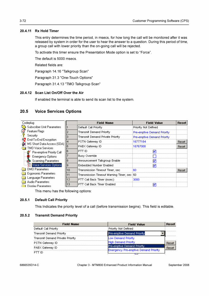
3-72 Customer Programming Software (CPS)
20.4.11 Rx Hold Timer
This entry determines the time period, in msecs, for how long the call will be monitored after it was
released by system in order for the user to hear the answer to a question. During this period of time,
a group call with lower priority than the on-going call will be rejected.
To activate this timer ensure the Presentation Mode option is set to “Force”.
The default is 5000 msecs.
Related fields are:
Paragraph 14.16 "Talkgroup Scan"
Paragraph 31.3 "One-Touch Options"
Paragraph 31.4.13 "TMO Talkgroup Scan"
20.4.12 Scan List On/Off Over the Air
If enabled the terminal is able to send its scan list to the system.
20.5 Voice Services Options
This menu has the following options:
20.5.1 Default Call Priority
This Indicates the priority level of a call (before transmission begins). This field is editable.
20.5.2 Transmit Demand Priority
6866535D14-C Chapter 3 - MTM800 Enhanced Product Information Manual September 2008

TMO Voice Services 3-73
There are 4 options associated with this field entry and are selected by clicking the pointer in the
field value box and selecting an option using the down arrow.
The selected entry defines the level of priority used by the terminal to send transmit requests (Group
Call or Express Group Call only).
Note: This parameter may be ignored by the system.
The available levels are:
• Low Demand Priority.
• High Demand Priority.
• Pre-emptive Demand Priority.
• Emergency Pre-emptive Demand Priority (This is priority 15 and will not interrupt emergency
calls).
Selecting “Pre-emptive Demand Priority” enables the pre-emption (interrupt) of a user on another
call that has a lower priority.
20.5.3 Transmit Demand Private Priority
This entry determines the level of priority that the terminal will use for call set up of Semi-duplex
Private Calls.
There are 3 options associated with this field entry and are selected by clicking the pointer in the
field value box and selecting an option using the down arrow.
The available levels are:
• Low Demand Priority
• High Demand Priority
• Pre-emptive Demand Priority
Selecting “Pre-emptive Demand Priority” enables the pre-emption (interrupt) of a user on another
call.
Note: This parameter may be ignored by the system.
20.5.4 PSTN Gateway ID
This field displays the System Identity (ISSI) of the PSTN Gateway that is used to access the
telephone interface for telephone call set up to a PSTN. Selecting the reset option will display the
TETRA Standard ISSI.
20.5.5 PABX Gateway ID
This field displays the System Identity (ISSI) of the PABX Gateway that is used to access the
telephone interface for telephone call set up to a PABX. Selecting the reset option will display the
TETRA Standard ISSI.
20.5.6 PTT ID
Selecting this feature allows the ID of the terminal to be displayed at receiving terminals during
Group Calls (Express Group Call) and Private Calls (Express Connect Call).
September 2008 Chapter 3 - MTM800 Enhanced Product Information Manual 6866535D14-C

3-74 Customer Programming Software (CPS)
20.5.7 Busy Override
During group call set up, the user may receive a busy indication from the system and although the
critical sites are busy and cannot support the Group Call, the user is allowed to request to transmit
the Group Call in the available sites.
To enable this option check the box.
20.5.8 Announcement Talkgroup Enable
An announcement call (also called multi-group call) is a special type of group call. It provides the
capability for the dispatcher or a terminal user to communicate with more than one talkgroup at the
same time.
A number of talkgroups are associated with an announcement talkgroup (ATG) so that when a call is
initiated to the ATG, all members of the associated talkgroups can receive the call. Each talkgroup
may have one associated ATG that it monitors (in addition to the selected talkgroup and the scan list
if activated).
An ATG has the highest priority level, thus enabling broadcast of the call to all these talkgroups.
Activation and deactivation of talkgroup scanning has no effect on the ATG scan list. The phone will
always monitor the ATG scan list.
This feature is Enabled/Disabled by clicking in the check box.
20.5.9 PTT Calls Back Displayed Party
If enabled, the user is able of return a voice call to the sender of a message or to any number that is
embedded in the message text.
Check box to enable this feature.
20.5.10 Transmission Timeout Timer
The entry in this field defines the period of time in seconds, that the user can PTT and talk during a
Private call. After this time the terminal will stop transmitting even though the PTT button is still
pressed.
The range for this option is 1 - 300 seconds and the default is 60 seconds.
20.5.11 Transmission Timeout Warning Timer
This field is a none editable and is related to the value set in the Transmission Time Out Timer field.
It defines the time in seconds, after which the terminal will alert the user prior to the expiry of the
Transmission Time Out Timer.
20.5.12 PTT Call Back Timer
Upon initiating a call, if the terminal’s user is not holding down the PTT when the network grants
transmit permission, the user shall be given this much time to begin transmitting before transmit
permission is rescinded.
The range for this option is 100 - 3000 seconds and the default is 3000 seconds.
20.5.13 PTT Call Back Timer Enabled
This feature is Enabled/Disabled by clicking in the check box.
6866535D14-C Chapter 3 - MTM800 Enhanced Product Information Manual September 2008
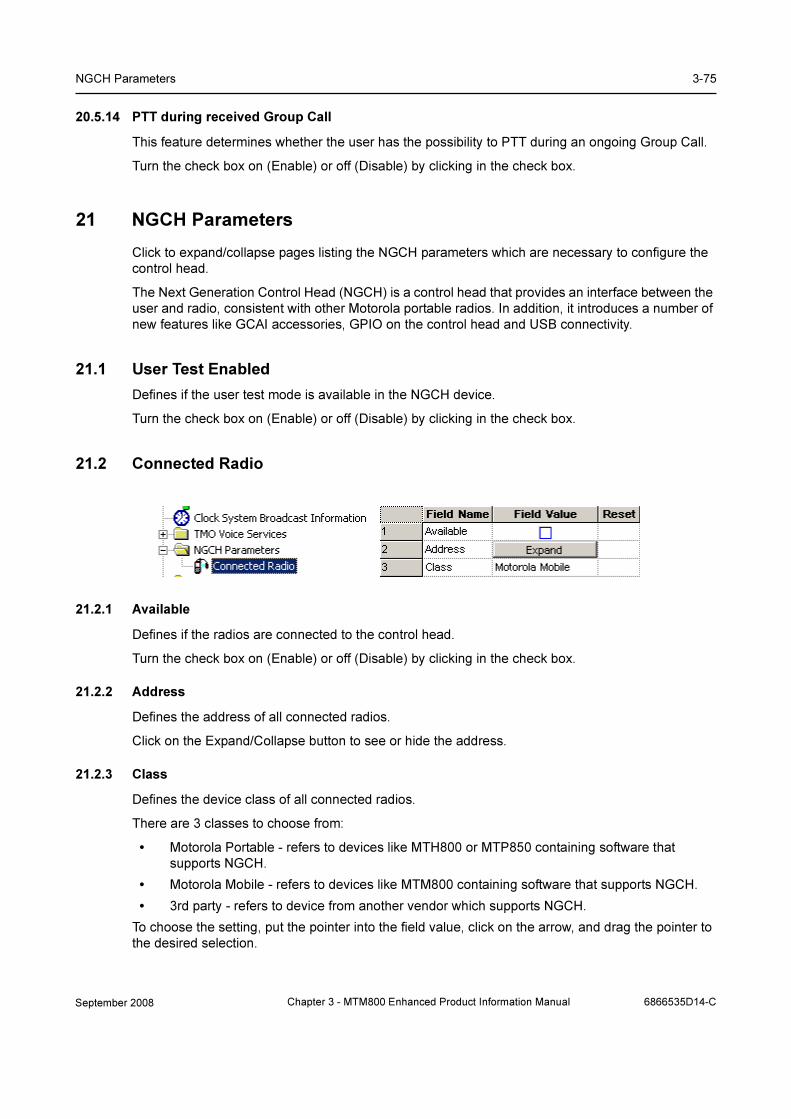
NGCH Parameters 3-75
20.5.14 PTT during received Group Call
This feature determines whether the user has the possibility to PTT during an ongoing Group Call.
Turn the check box on (Enable) or off (Disable) by clicking in the check box.
21 NGCH Parameters
Click to expand/collapse pages listing the NGCH parameters which are necessary to configure the
control head.
The Next Generation Control Head (NGCH) is a control head that provides an interface between the
user and radio, consistent with other Motorola portable radios. In addition, it introduces a number of
new features like GCAI accessories, GPIO on the control head and USB connectivity.
21.1 User Test Enabled
Defines if the user test mode is available in the NGCH device.
Turn the check box on (Enable) or off (Disable) by clicking in the check box.
21.2 Connected Radio
21.2.1 Available
Defines if the radios are connected to the control head.
Turn the check box on (Enable) or off (Disable) by clicking in the check box.
21.2.2 Address
Defines the address of all connected radios.
Click on the Expand/Collapse button to see or hide the address.
21.2.3 Class
Defines the device class of all connected radios.
There are 3 classes to choose from:
• Motorola Portable - refers to devices like MTH800 or MTP850 containing software that
supports NGCH.
• Motorola Mobile - refers to devices like MTM800 containing software that supports NGCH.
• 3rd party - refers to device from another vendor which supports NGCH.
To choose the setting, put the pointer into the field value, click on the arrow, and drag the pointer to
the desired selection.
September 2008 Chapter 3 - MTM800 Enhanced Product Information Manual 6866535D14-C

3-76 Customer Programming Software (CPS)
22 DMO Parameters
Related field is:
Paragraph 14.6 "Direct Mode (DMO)"
Paragraph 14.7 "Direct Mode (DMO) Reservation"
Paragraph 31.3 "One-Touch Options"
Paragraph 31.4 "One Touch Buttons"
This menu is used to set the parameters for Direct Mode Operation (DMO). When in DMO, the
terminal acts like a normal 2 way terminal and is not logged on to the system.
22.1 DMO Emergency Options
Emergency Alarm parameter indicates whether the emergency alarm feature is enabled or disabled
in DMO.
Turn the check box on (Enable) or off (Disable) by clicking in the check box.
22.2 DMO Short Data Service
This sub menu lists all the parameters related to the DMO Short Data Service feature.
It has the following options:
22.2.1 DT314
This entry defines time-out in miliseconds for reporting SDS failure after sending DM-PRE ACCEPT.
22.2.2 DN314
The entry in this field is a number of transmissions of unacknowledged DM-SDS UDATA packet
data unit (PDU).
22.2.3 Pre-emption Timer
This is the maximum time to wait for pre-emption response (DM-PRE ACCEPT or DM-REJECT).
Type in the required value.
6866535D14-C Chapter 3 - MTM800 Enhanced Product Information Manual September 2008

DMO Parameters 3-77
22.2.4 DMO Voice Priority over SDS
Determines if DMO Voice has more or equal priority compared to DMO SDS and Status.
The options are:
• Voice has more priority than SDS
• Voice has equal priority as SDS.
To select the option, put the pointer into the field value, click on the arrow, and drag the pointer to the
desired option.
22.3 DMO Gateway Timers
A DMO Gateway is equipment that can fulfill two rolls:
1. It acts as a repeater allowing calls between terminals from both the same and different sys-
tems.
2. It also enables system access to terminals in DMO.
A gateway may be installed at a site outside of a cell coverage area to provide extended coverage
for that cell in a particular direction.
This sub menu has the following options:
22.3.1 DT301
This entry defines the time that the terminal will wait for a response from a DMO Gateway to a DMO
Gateway set up (BM-GSETUP) request message before timing out.
The range for this timer is 0 - 30 seconds.
The default is 1second.
22.3.2 DT302
The entry in this field defines the time in seconds that the terminal will wait to be connected after
receiving a Gateway acknowledgement (DM-GACK) to a call set up request before timing out.
The range for this timer is 10 - 60 seconds. The default is 10 seconds.
22.3.3 DT309
The entry in this field defines the time in seconds that the terminal will wait, after receiving a
DM_GACK, for a Gateway Transmit Accept (DM-GTXACCEPT) message before timing out.
The range for this timer is 5- 30 seconds. The default is 5 seconds.
September 2008 Chapter 3 - MTM800 Enhanced Product Information Manual 6866535D14-C

3-78 Customer Programming Software (CPS)
22.3.4 DT308, Pre-emption via Gateway Timer
The entry in this field defines the time in seconds that the terminal will wait, after receiving a
DM_GACK, for a Gateway Pre-emption Accept message (DM-GPRE ACCEPT) before timing out.
Pre-requisite for this option is that “Initiate pre-emption in ongoing call” is supported by the terminal.
The range for this timer is 10 - 60 seconds.
The default is 30 seconds.
Note: Selecting the reset option for each of the above timers will enter the factory default setting in
the Field Value box.
22.4 DMO Address Extension
The 2 entries in this sub menu are used to identify the DMO Gateway on which the terminal can
operate. As an example, adjacent regional police forces have their own separate Tetra systems and
are using Gateways. By having the same entries for these fields in all the gateways, subscribers
from both systems are then able to communicate with each other.
22.4.1 MCC
The entry in this field defines the country code for the country in which the gateway is operating.
22.4.2 MNC
The entry in this field defines the system operating (licence number) number obtained from the in
country licensing authority.
22.5 DMO MNI Partnership List
This is basically an inter-operability table that provides backward compatibility allowing generation
one terminals to talk to generation two (and upwards) terminals. Without this table, call would be
receive only.
6866535D14-C Chapter 3 - MTM800 Enhanced Product Information Manual September 2008
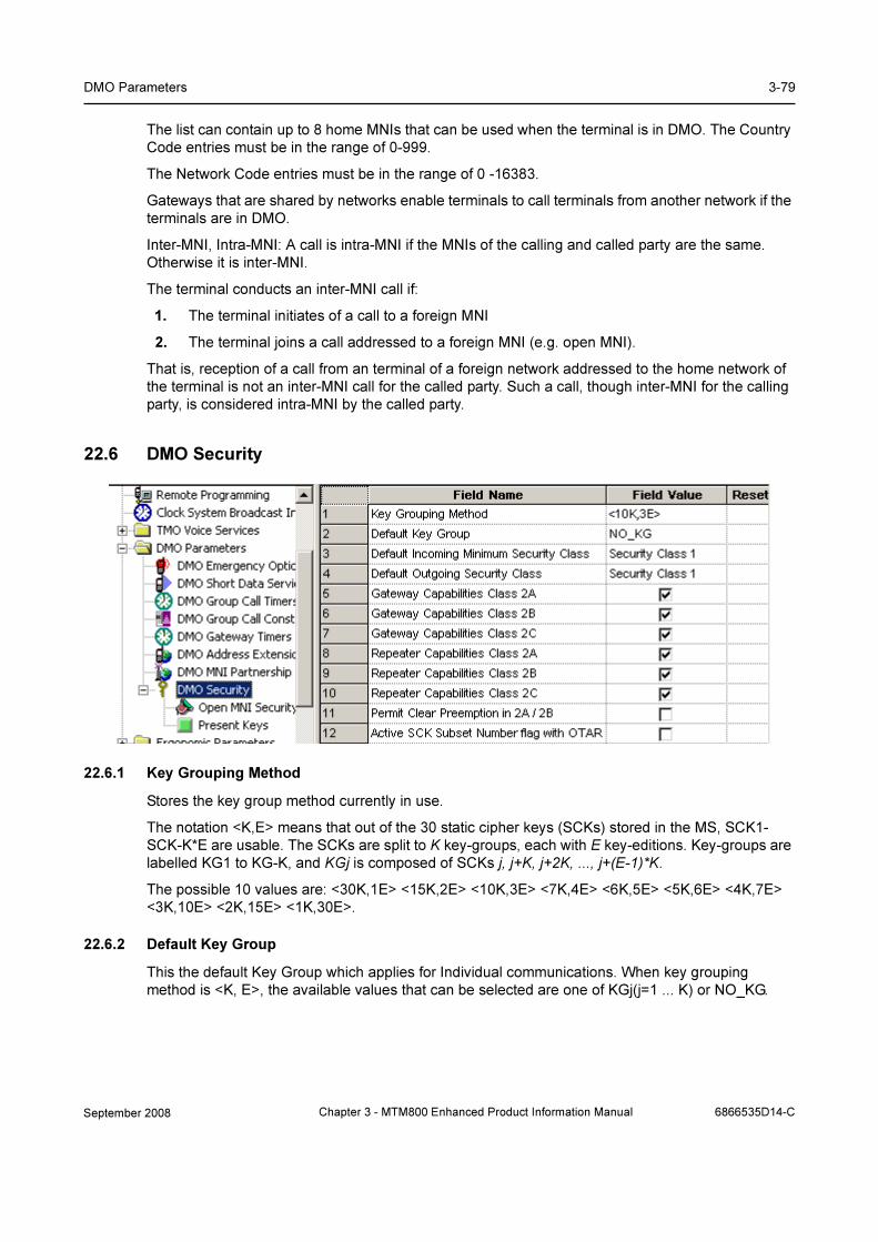
DMO Parameters 3-79
The list can contain up to 8 home MNIs that can be used when the terminal is in DMO. The Country
Code entries must be in the range of 0-999.
The Network Code entries must be in the range of 0 -16383.
Gateways that are shared by networks enable terminals to call terminals from another network if the
terminals are in DMO.
Inter-MNI, Intra-MNI: A call is intra-MNI if the MNIs of the calling and called party are the same.
Otherwise it is inter-MNI.
The terminal conducts an inter-MNI call if:
1. The terminal initiates of a call to a foreign MNI
2. The terminal joins a call addressed to a foreign MNI (e.g. open MNI).
That is, reception of a call from an terminal of a foreign network addressed to the home network of
the terminal is not an inter-MNI call for the called party. Such a call, though inter-MNI for the calling
party, is considered intra-MNI by the called party.
22.6 DMO Security
22.6.1 Key Grouping Method
Stores the key group method currently in use.
The notation <K,E> means that out of the 30 static cipher keys (SCKs) stored in the MS, SCK1-
SCK-K*E are usable. The SCKs are split to K key-groups, each with E key-editions. Key-groups are
labelled KG1 to KG-K, and KGj is composed of SCKs j, j+K, j+2K, ..., j+(E-1)*K.
The possible 10 values are: <30K,1E> <15K,2E> <10K,3E> <7K,4E> <6K,5E> <5K,6E> <4K,7E>
<3K,10E> <2K,15E> <1K,30E>.
22.6.2 Default Key Group
This the default Key Group which applies for Individual communications. When key grouping
method is <K, E>, the available values that can be selected are one of KGj(j=1 ... K) or NO_KG.
September 2008 Chapter 3 - MTM800 Enhanced Product Information Manual 6866535D14-C
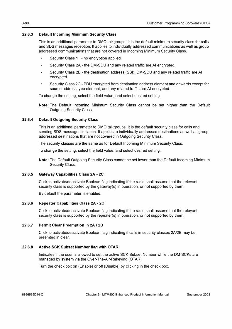
3-80 Customer Programming Software (CPS)
22.6.3 Default Incoming Minimum Security Class
This is an additional parameter to DMO talkgroups. It is the default minimum security class for calls
and SDS messages reception. It applies to individually addressed communications as well as group
addressed communications that are not covered in Incoming Minimum Security Class.
• Security Class 1 - no encryption applied.
• Security Class 2A - the DM-SDU and any related traffic are AI encrypted.
• Security Class 2B - the destination address (SSI), DM-SDU and any related traffic are AI
encrypted.
• Security Class 2C - PDU encrypted from destination address element and onwards except for
source address type element, and any related traffic are AI encrypted.
To change the setting, select the field value, and select desired setting.
Note: The Default Incoming Minimum Security Class cannot be set higher than the Default
Outgoing Security Class.
22.6.4 Default Outgoing Security Class
This is an additional parameter to DMO talkgroups. It is the default security class for calls and
sending SDS messages initiation. It applies to individually addressed destinations as well as group
addressed destinations that are not covered in Outgoing Security Class.
The security classes are the same as for Default Incoming Minimum Security Class.
To change the setting, select the field value, and select desired setting.
Note: The Default Outgoing Security Class cannot be set lower than the Default Incoming Minimum
Security Class.
22.6.5 Gateway Capabilities Class 2A - 2C
Click to activate/deactivate Boolean flag indicating if the radio shall assume that the relevant
security class is supported by the gateway(s) in operation, or not supported by them.
By default the parameter is enabled.
22.6.6 Repeater Capabilities Class 2A - 2C
Click to activate/deactivate Boolean flag indicating if the radio shall assume that the relevant
security class is supported by the repeater(s) in operation, or not supported by them.
22.6.7 Permit Clear Preemption in 2A / 2B
Click to activate/deactivate Boolean flag indicating if calls in security classes 2A/2B may be
preemted in clear.
22.6.8 Active SCK Subset Number flag with OTAR
Indicates if the user is allowed to set the active SCK Subset Number while the DM-SCKs are
managed by system via the Over-The-Air-Rekeying (OTAR).
Turn the check box on (Enable) or off (Disable) by clicking in the check box.
6866535D14-C Chapter 3 - MTM800 Enhanced Product Information Manual September 2008

Ergonomic Parameters 3-81
22.6.9 Open MNI Security settings
Click to display a table that provides security settings for open group calls which are identified by the
MNI value.
22.6.10 Present Keys
Click to display a table that stores for every key-group one SCKN which is the present key edition of
that key group.
When key grouping methods is <K,E> (except for <30K,1E>) the table shall contain exactly K
entries and each entry represents a key-group KGj j=1…K. For each key-group KGj (j=1…K) one of
the E SCKNs of this key group can be selected. The list of SCKNs for each key-group is preset (i.e.
the SCKN number cannot be typed). Each key-group is composed of SCKs j, j+K, j+2K, …, j+(E –
1)*K.
When the current pattern is <30K, 1E> every key group KGj has a single edition SCKj which is the
present edition. Therefore the table may not exist (or shall not be editable).
For example - when the current pattern is <10K,3E>, the present key of KG7 can be one of SCK7,
SCK17 or SCK27, and similarly for all key groups KG1 KG2 … KG10.
23 Ergonomic Parameters
September 2008 Chapter 3 - MTM800 Enhanced Product Information Manual 6866535D14-C
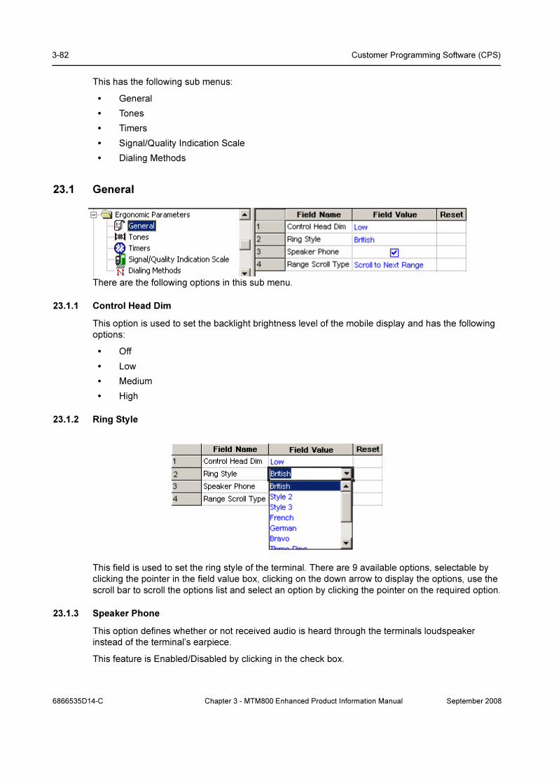
3-82 Customer Programming Software (CPS)
This has the following sub menus:
• General
• Tones
• Timers
• Signal/Quality Indication Scale
• Dialing Methods
23.1 General
There are the following options in this sub menu.
23.1.1 Control Head Dim
This option is used to set the backlight brightness level of the mobile display and has the following
options:
• Off
• Low
• Medium
• High
23.1.2 Ring Style
This field is used to set the ring style of the terminal. There are 9 available options, selectable by
clicking the pointer in the field value box, clicking on the down arrow to display the options, use the
scroll bar to scroll the options list and select an option by clicking the pointer on the required option.
23.1.3 Speaker Phone
This option defines whether or not received audio is heard through the terminals loudspeaker
instead of the terminal’s earpiece.
This feature is Enabled/Disabled by clicking in the check box.
6866535D14-C Chapter 3 - MTM800 Enhanced Product Information Manual September 2008
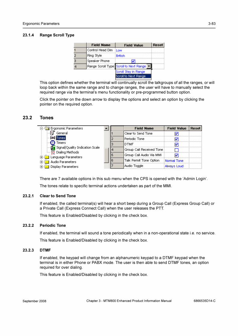
Ergonomic Parameters 3-83
23.1.4 Range Scroll Type
This option defines whether the terminal will continually scroll the talkgroups of all the ranges, or will
loop back within the same range and to change ranges, the user will have to manually select the
required range via the terminal’s menu functionality or pre-programmed button option.
Click the pointer on the down arrow to display the options and select an option by clicking the
pointer on the required option.
23.2 Tones
There are 7 available options in this sub menu when the CPS is opened with the ‘Admin Login’.
The tones relate to specific terminal actions undertaken as part of the MMI.
23.2.1 Clear to Send Tone
If enabled, the called terminal(s) will hear a short beep during a Group Call (Express Group Call) or
a Private Call (Express Connect Call) when the user releases the PTT.
This feature is Enabled/Disabled by clicking in the check box.
23.2.2 Periodic Tone
If enabled, the terminal will sound a tone periodically when in a non-operational state i.e. no service.
This feature is Enabled/Disabled by clicking in the check box.
23.2.3 DTMF
If enabled, the keypad will change from an alphanumeric keypad to a DTMF keypad when the
terminal is in either Phone or PABX mode. The user is then able to send DTMF tones, an option
required for over dialing.
This feature is Enabled/Disabled by clicking in the check box.
September 2008 Chapter 3 - MTM800 Enhanced Product Information Manual 6866535D14-C
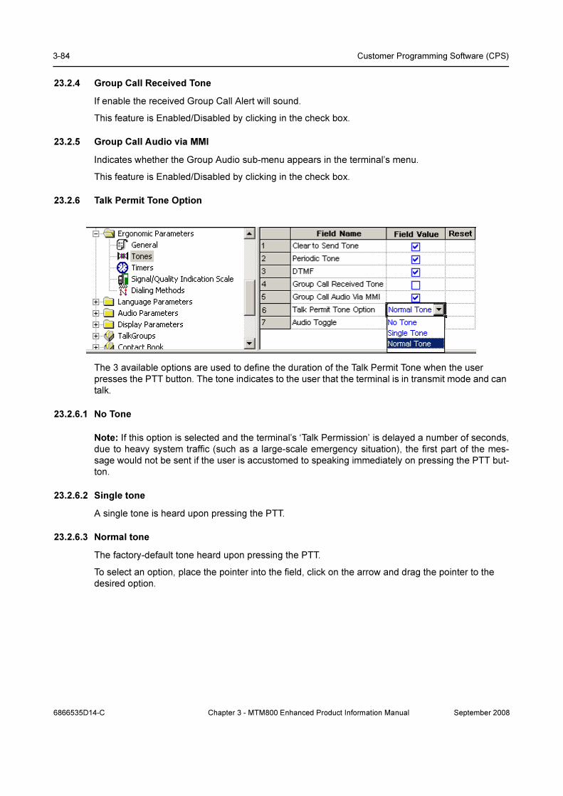
3-84 Customer Programming Software (CPS)
23.2.4 Group Call Received Tone
If enable the received Group Call Alert will sound.
This feature is Enabled/Disabled by clicking in the check box.
23.2.5 Group Call Audio via MMI
Indicates whether the Group Audio sub-menu appears in the terminal’s menu.
This feature is Enabled/Disabled by clicking in the check box.
23.2.6 Talk Permit Tone Option
The 3 available options are used to define the duration of the Talk Permit Tone when the user
presses the PTT button. The tone indicates to the user that the terminal is in transmit mode and can
talk.
23.2.6.1 No Tone
Note: If this option is selected and the terminal’s ‘Talk Permission’ is delayed a number of seconds,
due to heavy system traffic (such as a large-scale emergency situation), the first part of the mes-
sage would not be sent if the user is accustomed to speaking immediately on pressing the PTT but-
ton.
23.2.6.2 Single tone
A single tone is heard upon pressing the PTT.
23.2.6.3 Normal tone
The factory-default tone heard upon pressing the PTT.
To select an option, place the pointer into the field, click on the arrow and drag the pointer to the
desired option.
6866535D14-C Chapter 3 - MTM800 Enhanced Product Information Manual September 2008

Ergonomic Parameters 3-85
23.2.7 Audio Toggle
This field defines whether or not the “Loud/Low” audio soft key is displayed on the terminal screen
during an active group call.
Selecting ‘Always Loud’ will direct the audio to the speaker for the call duration and the soft key will
not be visible.
Selecting ‘Spkr Cntrl’ will display the soft key for user control, allowing the user to direct the audio to
either the earpiece or the main speaker for the duration of call.
23.3 Timers
There are four available options in this sub menu. the timers can be set to the factory default by
selecting ‘Reset’ or the user can enter a time in seconds.
23.3.1 Out of Service Timer, sec
This entry defines the period of time in seconds after which the phone will alert the user that it is out
of service. The alert is repeated at this time interval until it regains service.
The range of this time period is 0 - 900 seconds, the default setting is 120 seconds.
The timer is disabled when set to zero.
23.3.2 Long Key Inactivity Timer
This timer defines the time duration of no user input/activity, i.e. a button press, after which the
terminal will return to its default mode.
The range setting for this timer is from 0 - 60 seconds and is disabled when the field entry is set to 0
(zero). The default setting is 30 seconds,
23.3.3 Channel Acquisition Timer
This is the period of time the phone waits before it advises the user it is out of service, not attached,
or is in local area service.
September 2008 Chapter 3 - MTM800 Enhanced Product Information Manual 6866535D14-C

3-86 Customer Programming Software (CPS)
The range for this timer is 0 - 300 seconds, the default setting is 30 seconds.
23.3.4 Call Delay on User Activity
This field defines the amount of time after a user action during which all incoming (non-emergency)
group calls are ignored (not joined).
23.4 Signal/Quality Indication Scale
These two fields are used for setting the number of bars that will be displayed to represent received
signal strength.
23.4.1 Signal Strength Max Nobars
TMO/DMO dependent.
This field defines the maximum number of bars that will be displayed to indicate the QUALITY of the
received signal in TMO, the bars are displayed to the left of the ‘mast’ icon and if the terminal looses
coverage a warning is displayed and an alert sounded.
This field also defines the number of bars that will be displayed to indicate the STRENGTH of the
received signal in DMO, the bars are displayed without the mast icon.
The range is from 0 - 127, the default being 9.
23.4.2 Signal Strength Min. Maxbars
This field defines the minimum number of bars that will be displayed to indicate the quality/strength
of the received signal. These bars are displayed to the right of the ‘mast’ received signal strength
icon.
The range is from 0 - 127, the default being 35.
This option defines the first call type that will appear on the idle display when the user starts dialing.
The call type is one of the following: Private/Phone/PABX.
23.5 Dialing Methods
6866535D14-C Chapter 3 - MTM800 Enhanced Product Information Manual September 2008
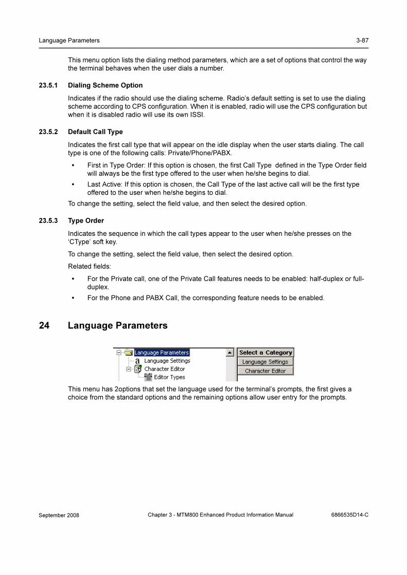
Language Parameters 3-87
This menu option lists the dialing method parameters, which are a set of options that control the way
the terminal behaves when the user dials a number.
23.5.1 Dialing Scheme Option
Indicates if the radio should use the dialing scheme. Radio’s default setting is set to use the dialing
scheme according to CPS configuration. When it is enabled, radio will use the CPS configuration but
when it is disabled radio will use its own ISSI.
23.5.2 Default Call Type
Indicates the first call type that will appear on the idle display when the user starts dialing. The call
type is one of the following calls: Private/Phone/PABX.
• First in Type Order: If this option is chosen, the first Call Type defined in the Type Order field
will always be the first type offered to the user when he/she begins to dial.
• Last Active: If this option is chosen, the Call Type of the last active call will be the first type
offered to the user when he/she begins to dial.
To change the setting, select the field value, and then select the desired option.
23.5.3 Type Order
Indicates the sequence in which the call types appear to the user when he/she presses on the
‘CType’ soft key.
To change the setting, select the field value, then select the desired option.
Related fields:
• For the Private call, one of the Private Call features needs to be enabled: half-duplex or full-
duplex.
• For the Phone and PABX Call, the corresponding feature needs to be enabled.
24 Language Parameters
This menu has 2options that set the language used for the terminal’s prompts, the first gives a
choice from the standard options and the remaining options allow user entry for the prompts.
September 2008 Chapter 3 - MTM800 Enhanced Product Information Manual 6866535D14-C
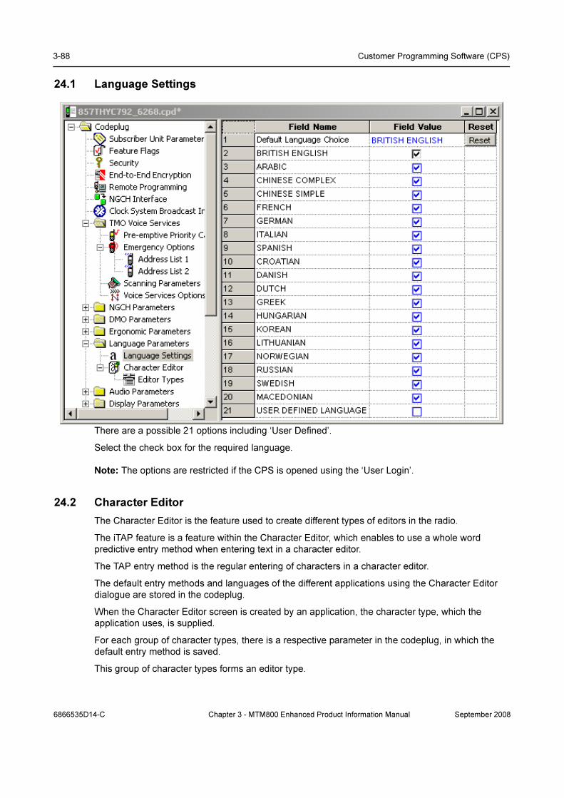
3-88 Customer Programming Software (CPS)
24.1 Language Settings
There are a possible 21 options including ‘User Defined’.
Select the check box for the required language.
Note: The options are restricted if the CPS is opened using the ‘User Login’.
24.2 Character Editor
The Character Editor is the feature used to create different types of editors in the radio.
The iTAP feature is a feature within the Character Editor, which enables to use a whole word
predictive entry method when entering text in a character editor.
The TAP entry method is the regular entering of characters in a character editor.
The default entry methods and languages of the different applications using the Character Editor
dialogue are stored in the codeplug.
When the Character Editor screen is created by an application, the character type, which the
application uses, is supplied.
For each group of character types, there is a respective parameter in the codeplug, in which the
default entry method is saved.
This group of character types forms an editor type.
6866535D14-C Chapter 3 - MTM800 Enhanced Product Information Manual September 2008

Audio Parameters 3-89
The terminal supports default primary and secondary entry methods via the codeplug for the
different features, which use the Character Editor dialogue.
24.2.1 Editor Types
The default primary and secondary entry methods and languages for the Message Editor are stored
in the primary message method and secondary message method.
When the primary and/or secondary entry methods are changed for a specific editor type, the new
values are saved in the codeplug. These values are now the default values for this editor type.
Upon entering the character editor via a certain feature, the initial values of the primary and
secondary entry methods will be taken by the terminal from the corresponding default parameters in
the codeplug.
The default primary and secondary entry methods and languages for the Name Editor will be stored
in primary name method and secondary name method.
When the primary and/or secondary entry methods are changed for a specific editor type, the new
values are saved in the codeplug. These values are now the default values for this editor type.
Upon entering the character editor via a certain feature, the initial values of the primary and
secondary entry methods will be taken by the terminal from the corresponding default parameters in
the codeplug.
25 Audio Parameters
The following sub menus are available:
• Hot Mic
• AGC
• Ambience Listening
• Volume Settings
• Mic Settings
September 2008 Chapter 3 - MTM800 Enhanced Product Information Manual 6866535D14-C
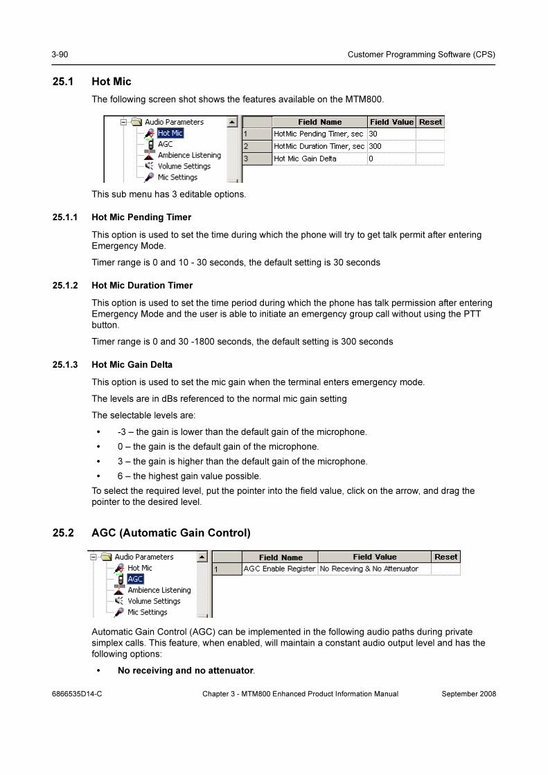
3-90 Customer Programming Software (CPS)
25.1 Hot Mic
The following screen shot shows the features available on the MTM800.
This sub menu has 3 editable options.
25.1.1 Hot Mic Pending Timer
This option is used to set the time during which the phone will try to get talk permit after entering
Emergency Mode.
Timer range is 0 and 10 - 30 seconds, the default setting is 30 seconds
25.1.2 Hot Mic Duration Timer
This option is used to set the time period during which the phone has talk permission after entering
Emergency Mode and the user is able to initiate an emergency group call without using the PTT
button.
Timer range is 0 and 30 -1800 seconds, the default setting is 300 seconds
25.1.3 Hot Mic Gain Delta
This option is used to set the mic gain when the terminal enters emergency mode.
The levels are in dBs referenced to the normal mic gain setting
The selectable levels are:
• -3 – the gain is lower than the default gain of the microphone.
• 0 – the gain is the default gain of the microphone.
• 3 – the gain is higher than the default gain of the microphone.
• 6 – the highest gain value possible.
To select the required level, put the pointer into the field value, click on the arrow, and drag the
pointer to the desired level.
25.2 AGC (Automatic Gain Control)
Automatic Gain Control (AGC) can be implemented in the following audio paths during private
simplex calls. This feature, when enabled, will maintain a constant audio output level and has the
following options:
• No receiving and no attenuator.
6866535D14-C Chapter 3 - MTM800 Enhanced Product Information Manual September 2008

Audio Parameters 3-91
• External Microphone 12 dB attenuator - When this feature is enabled (only during private
simplex calls), an Automatic Gain Control (AGC) is implemented in the microphone path in
order to keep the active speech level at a certain reference power level.
• Digital receiving AGC - When this feature is enabled (only during private simplex calls), an
Automatic Gain Control (AGC) is implemented in the receiver path in order to keep the active
speech level at a certain reference power level.
• Receiving and attenuator.
25.3 Ambience Listening
This provides an authorised user (a dispatcher etc.) with the ability to cause a terminal to transmit,
without giving any indication to the user, allowing any audio activity picked up by the terminal’s
microphone to be transmitted and monitored.
25.3.1 SS-AL IGM Gain
(Supplementary Services-Ambience Listening Internal Microphone Group).
This entry sets the gain of the terminal’s internal microphone between -3 and 24 in steps of 3. The
default is 24.
25.3.2 SS-AL EMG Gain
(Supplementary Services-Ambience Listening External Microphone Group)
This entry sets the gain of a microphone connected to the terminals accessory connector between -
3 and 24 in steps of 3. The default is 24.
25.3.3 SS-AL VMG Gain
(Supplementary Services-Ambience Listening Vehicle Microphone Group)
This entry sets the gain of the microphone used with a vehicle mounting kit between -3 and 24 in
steps of 3. The default is 12.
Note: All levels are in dBs relative to the microphone gain and may be different for each microphone
type.
September 2008 Chapter 3 - MTM800 Enhanced Product Information Manual 6866535D14-C

3-92 Customer Programming Software (CPS)
25.3.4 Control Head AL Status
The Control Head is able to receive Ambience Listening Status notification (i.e.: uses SB9600
commands for AL call status notification) and has the following options:
• Never - the terminal will not send notifications to the control head.
• Entering/Leaving AL Call - the terminal will notify the control head when entering/leaving
AL.
• Entering/Leaving Pseudo power Off - the terminal will notify the control head when
entering/leaving Pseudo Power On/Off state.
• Every AL Status Change - the terminal will notify the control head at every AL status
change.
To choose the level, put the pointer into the field value, click on the arrow, and drag the pointer to
the desired level.
25.4 Volume Settings
These options control of the volume range for the 2 speakers and various kinds of audio.
There are 2 speakers - the handset speaker and the external loudspeaker.
The levels can be set in the range of 0 to 31 and the defaults are as shown above.
6866535D14-C Chapter 3 - MTM800 Enhanced Product Information Manual September 2008
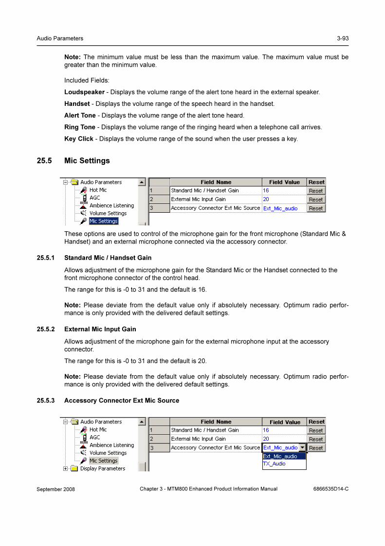
Audio Parameters 3-93
Note: The minimum value must be less than the maximum value. The maximum value must be
greater than the minimum value.
Included Fields:
Loudspeaker - Displays the volume range of the alert tone heard in the external speaker.
Handset - Displays the volume range of the speech heard in the handset.
Alert Tone - Displays the volume range of the alert tone heard.
Ring Tone - Displays the volume range of the ringing heard when a telephone call arrives.
Key Click - Displays the volume range of the sound when the user presses a key.
25.5 Mic Settings
These options are used to control of the microphone gain for the front microphone (Standard Mic &
Handset) and an external microphone connected via the accessory connector.
25.5.1 Standard Mic / Handset Gain
Allows adjustment of the microphone gain for the Standard Mic or the Handset connected to the
front microphone connector of the control head.
The range for this is -0 to 31 and the default is 16.
Note: Please deviate from the default value only if absolutely necessary. Optimum radio perfor-
mance is only provided with the delivered default settings.
25.5.2 External Mic Input Gain
Allows adjustment of the microphone gain for the external microphone input at the accessory
connector.
The range for this is -0 to 31 and the default is 20.
Note: Please deviate from the default value only if absolutely necessary. Optimum radio perfor-
mance is only provided with the delivered default settings.
25.5.3 Accessory Connector Ext Mic Source
September 2008 Chapter 3 - MTM800 Enhanced Product Information Manual 6866535D14-C
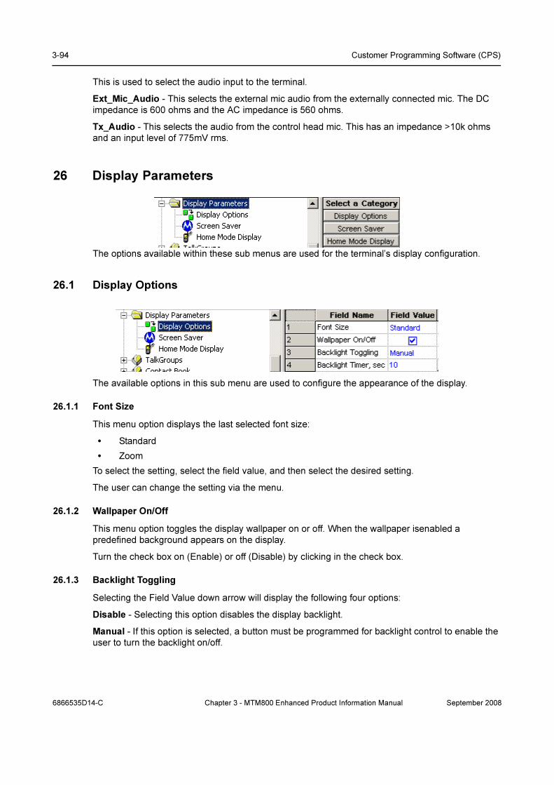
3-94 Customer Programming Software (CPS)
This is used to select the audio input to the terminal.
Ext_Mic_Audio - This selects the external mic audio from the externally connected mic. The DC
impedance is 600 ohms and the AC impedance is 560 ohms.
Tx_Audio - This selects the audio from the control head mic. This has an impedance >10k ohms
and an input level of 775mV rms.
26 Display Parameters
The options available within these sub menus are used for the terminal’s display configuration.
26.1 Display Options
The available options in this sub menu are used to configure the appearance of the display.
26.1.1 Font Size
This menu option displays the last selected font size:
• Standard
• Zoom
To select the setting, select the field value, and then select the desired setting.
The user can change the setting via the menu.
26.1.2 Wallpaper On/Off
This menu option toggles the display wallpaper on or off. When the wallpaper isenabled a
predefined background appears on the display.
Turn the check box on (Enable) or off (Disable) by clicking in the check box.
26.1.3 Backlight Toggling
Selecting the Field Value down arrow will display the following four options:
Disable - Selecting this option disables the display backlight.
Manual - If this option is selected, a button must be programmed for backlight control to enable the
user to turn the backlight on/off.
6866535D14-C Chapter 3 - MTM800 Enhanced Product Information Manual September 2008

Display Parameters 3-95
Semi-Auto - If this feature is enabled, the backlight works both manually and automatically. A button
must be programmed for backlight control. The user is able to turn the backlight on or off and if
turned on manually the terminal will turn the backlight off after the backlight timer expires.
Auto - If this option is selected, the terminal will automatically turn the backlight on for button press
and call reception and turn it off when the backlight timer expires.
26.1.4 Backlight Timer
This is the ‘Auto’ option timer and it defines how long the backlight will remain on, when the terminal
has gone back to its normal standby state.
The range setting is from 1 to 30 seconds, the default setting is 10 seconds.
26.2 Screen Saver
Some models have ‘screen saver’ functionality. If enabled, it will consist of 2 elements, for example:
• A Police Force Logo, or similar graphics.
• An identifier
This enhances:
• Security by hiding sensitive information when the terminal is worn high on the chest at the
lapel.
• Ease of identification by screen saver ID.
If configured, the user is able to edit the screen saver text.
Refer to the CPS help text on screen saver conversion.
26.2.1 Screen Saver Text
An alphanumeric text string of up to 12 characters can be entered in this field and will be displayed
when the terminal is in its idle state.
26.2.2 Time Screen Saver Activation
This field is used to set the time, in msecs, after which the screen saver text message will be
displayed. The range is 1000 - 216,000,000 msecs and the default is 35,000 msecs.
26.2.3 Screen Saver Enabled
This is a simple check box entry field that defines whether or not the screen saver is enabled. Use
the mouse pointer and select the check box by pressing the left mouse button to enable/disable this
option.
September 2008 Chapter 3 - MTM800 Enhanced Product Information Manual 6866535D14-C

3-96 Customer Programming Software (CPS)
26.2.4 Screen Saver Text User Editable
This is a simple check box entry field that defines whether or not the user is able to edit the screen
saver text message. Use the mouse pointer and select the check box by pressing the left mouse
button to enable/disable this option.
26.2.5 Auto Screen Saver
If enabled, the screen saver will automatically be displayed after a default period of terminal
inactivity.
26.3 Home Mode Display
This sub menu has the following four options that define the text displayed during the various stages
of the terminal’s power up and idle state.
26.3.1 Home Mode Display Text
An alphanumeric text string of up to 24 characters can be entered in this field and will be displayed
when ever the terminal is in Home Mode.
26.3.2 Home Mode Display Protocol Identifier
The number in this field defines the message protocol used by the terminal to transmit and receive
messages on the control channel when in Home Mode and enables the phone to identify the type of
received message as a Home Mode Display message and take any necessary action.
Note: Protocol Identifiers. These define the action a terminal must take when a message is
received. Some messages are displayed and others are actioned by the terminal, i.e. DGNA
updates.
The range is from 0 to 255, the default is 220.
For more information see: ETSI EN300 392 - 2 Paragraph 29.4.3.9 Table 439.
26.3.3 Welcome Screen
An alphanumeric text string of up to 28 characters can be entered in this field and will be displayed
as the terminal powers up.
27 TalkGroups
6866535D14-C Chapter 3 - MTM800 Enhanced Product Information Manual September 2008

TalkGroups 3-97
This menu contains the TMO, DMO and My Favorite Groups sub menus that have the following
options:
27.1 TMO (Trunked Mode Operation)
TMO now has the following sub menu options:
• TMO Folders List
• TMO Talkgroup List
• TMO Scan Lists
• Dynamic Group Number Assignment
27.1.1 TMO Folders List
The TMO Folder List contains up to 128 entries.
27.1.1.1 Name
This field can be programmed with up to 12 alphanumeric digits for the name/alias of the range.
27.1.1.2 Status
Select the check box to make an entry active. If an entry is not checked, it will not be displayed. A list
can either be created manually or imported.
27.1.1.3 Transmission Time Out Timer
The entry in this field is the per range allowed call talk time. The time range is from 0 to 300
seconds.
27.1.1.4 Transmission time Out Warning Timer
Parameter controlling, per range, the time for generating <TOT Warning Tone> prior to <TOT>
expires. The <TOT warning tone timer> shall be less than <TOT> setting.
The radio can continuously transmit until the <TOT Warning Tone timer> expired, then the phone will
generate <TOT Warning Tone> to alert the user that transmission will soon be stopped.
The time can be set between 0 - 299 seconds.
September 2008 Chapter 3 - MTM800 Enhanced Product Information Manual 6866535D14-C

3-98 Customer Programming Software (CPS)
27.1.1.5 Number of Talkgroups in the Range
The parameter indicates the maximum number of Talkgroups that can be programmed in the folder/
range.
The number of talkgroups can be set between 0-1024.
27.1.1.6 Receive Only
This is a per range setting and if the check box is selected, the user will be able to hear the calls, but
will not able to set up group calls to any of the talkgroups in the range, or PTT during a call.
27.1.2 TMO Talkgroup List
Note: At least one entry field must remain empty if DGNA is to be used, see paragraph 12.1.5.
Note: Call-Out talkgroup is recommended to be set as Invisible.
27.1.2.1 Name
This field can be programmed with up to 12 alphanumeric digits for the name/alias of the group.
Up to 16 entries can be added to each range, giving a total of 2048 group entries.
27.1.2.2 ID
This is a Group Short Subscriber Identity (GSSI) of up to 8 digits and in the range 0 to 15,999,999
can be entered in this field to define the identity of the group.
Note: The same group(s) can be added to several/all ranges as required.
27.1.2.3 Status
Select a box to display the down arrow and choose from the available options. An entry can be
enabled by selecting the ‘Programmed’ option, disabled and not seen by the user when the ‘Not
Programmed option’ is selected, or if the ‘Invisible’ option is selected it will not be seen or be
selectable by the user, but it can be added to a scan list via CPS programming.
27.1.2.4 Folders List
This field is an automatically filled read-only list. It lists the number of talkgroups in the range (done
in TMO Folders List page).
27.1.2.5 Announce Group
An announcement call (also called multi-group call) is a special case of group call. It provides the
capability for the dispatcher or the phone to communicate with more than one talkgroup at the same
time.
Select the check box to enable this option
27.1.2.6 Start Announce Call
Select the check box to make an entry active. If an entry is not checked, the user is not allowed to
initiate an announce call.
6866535D14-C Chapter 3 - MTM800 Enhanced Product Information Manual September 2008

TalkGroups 3-99
27.1.2.7 Associated Announce Group
If the talkgroup is not an ATG (announce talkgroup), this field indicates to which ATG the talkgroup is
assigned.
27.1.2.8 Group Priority
The entry in this field determines the scanning priority of the talkgroup. If landed on a group, the
terminal will discard this group call if, during background scanning, it lands on group with a higher
priority. The four available options are:
• Low
• Medium
• High
• Always Scanned
27.1.2.9 GCK Number
Stores the association between a TMO talkgroup and a GCK. This parameter is repeated for every
TMO talkgroup entry in the codeplug.
The range is from 0-65536131071.
27.1.2.10DMO Mapping
The mapped DMO talkgroup is selectable and derived from the Talkgroup list.
You can associate a DMO talkgroup configuration to a TMO talkgroup configuration. This means
that if you are on TMO talkgroup 3, for example, then you are not bound to use DMO talkgroup 3
should the user switch to DMO. In your DMO fleetmap, it’s possible to associate any TMO talkgroup
to ANY DMO talkgroup, so in this example you could make DMO talkgroup number 23 the relevant
DMO talkgroup for TMO talkgroup number 3.
When copying DMO or TMO talkgroup list to another new codeplug, mapping will be lost. Use
cloning to keep values.
You cannot map a DMO talkgroup to an unprogrammed TMO talkgroup.
To select the correspondent DMO talkgroup, put the pointer into the field value, click on the arrow,
and drag the pointer to the desired talkgroup.
27.1.2.11 Index
This column is non editable. Whenever a talkgroup is assigned as a one touch button option, the
keypad number to which it is assigned will be displayed in this box.
27.1.3 TMO Scan Lists
This sub menu contains 40 scan lists and each list may contain up to 20 entries. The lists can have
identical entries if required.
September 2008 Chapter 3 - MTM800 Enhanced Product Information Manual 6866535D14-C
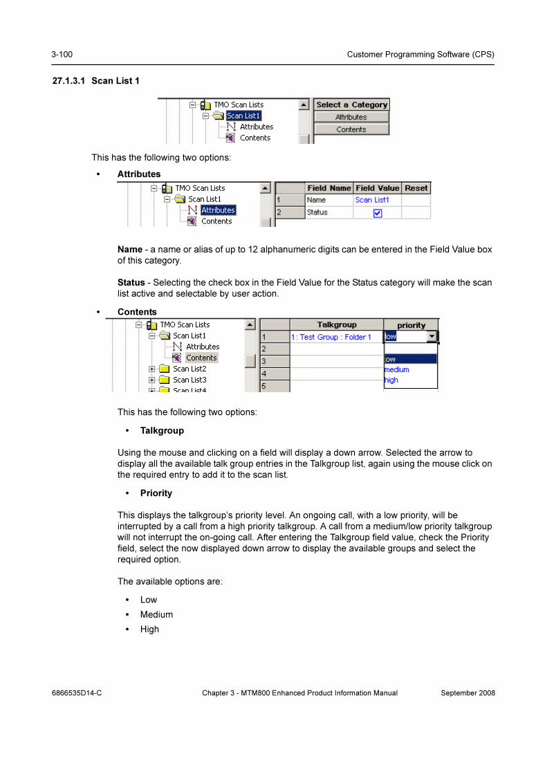
3-100 Customer Programming Software (CPS)
27.1.3.1 Scan List 1
This has the following two options:
• Attributes
Name - a name or alias of up to 12 alphanumeric digits can be entered in the Field Value box
of this category.
Status - Selecting the check box in the Field Value for the Status category will make the scan
list active and selectable by user action.
• Contents
This has the following two options:
• Talkgroup
Using the mouse and clicking on a field will display a down arrow. Selected the arrow to
display all the available talk group entries in the Talkgroup list, again using the mouse click on
the required entry to add it to the scan list.
• Priority
This displays the talkgroup’s priority level. An ongoing call, with a low priority, will be
interrupted by a call from a high priority talkgroup. A call from a medium/low priority talkgroup
will not interrupt the on-going call. After entering the Talkgroup field value, check the Priority
field, select the now displayed down arrow to display the available groups and select the
required option.
The available options are:
• Low
• Medium
• High
6866535D14-C Chapter 3 - MTM800 Enhanced Product Information Manual September 2008

TalkGroups 3-101
27.1.4 Dynamic Group Number Assignment
This has the following two options:
27.1.4.1 DGNA Notification
If this option is enabled by selecting the check box, the user will be alerted when the terminal
receives an ‘Over the Air’ update to its talk group list.
27.1.4.2 Super Group of Scanned Groups Enabled
If enabled by checking the box, the terminal will scan the super group.
A super group has one GSSI, but is made up of several other groups. A call setup sequence
addressed to the super group will also set the call up to the other groups within the super group.
Super groups are setup by system dispatchers/administrators and are part of the DGNA feature.
See Chapter 2 of the Product Information Manual, Paragraph "Group Addressed DGNA" for more
information.
27.1.4.3 Auto Select Single Assigned Group
Indicates whether or not the terminal should automatically select a single assigned DGNA group.
Check the check box to Enable/Disable this option.
Using SS-DGNA, the SwMI may send a group assignment:
• to add a group or a number of groups to the terminal’s data base.
• to change the parameters or the attachment state of an existing group or groups in the
terminal.
The assignment may require the terminal to immediately attach the group, change its Alias or Class
of Usage or to just add it to the talkgroup list allowing it to be attached later.
The following requirements apply to each group element in the SS-DGNA Assign PDU. If there are
multiple groups in the PDU, the acknowledge for all groups is sent together in one PDU.
For each assigned group, there is an assignment that is a command to add the group to the
terminal’s group list, and may contain instructions to attach the group. The terminal can accept or
reject the assignment. On accepting the assignment the terminal can either accept or reject the
attachment.
Assignment with Auto-select
If Auto-Select Single Assigned Group is enabled, upon receipt of an individually addressed D-
FACILITY PDU containing a DGNA assignment which contains a single group assignment without
an attachment (that is, the Attachment Mode is set to Not Attached, MS user allowed to request
attachment), the terminal processes the assignment as described above, and then automatically
makes that group the selected group (that is ’auto-select’). Specifically, if this group had not already
been the selected group before the assignment was received, the terminal shall send the group
attachment for this group as if the user had manually chosen this group to be the selected group.
The group shall remain the selected group until the user or the SwMI subsequently change the
selected group.
September 2008 Chapter 3 - MTM800 Enhanced Product Information Manual 6866535D14-C

3-102 Customer Programming Software (CPS)
Auto Reselect of Previous Group
When a group is auto-selected, and is then subsequently de-assigned or detached by the SwMI
while the auto-select group is the currently selected group, the terminal automatically reselects the
group previously selected by the user. However, if the user manually changed the selected group
after auto-select and then subsequently reselected the auto-select group, or if there was never a
user-selected group, the behaviour on de-assign of the group will be as the behaviour with any
other group.
No Auto-select with Multiple Groups
If the terminal receives a D-FACILITY PDU containing DGNA assignments for more than one group,
it will be treated as a normal DGNA assignment, and the auto-select parameter will have no effect
on any of the groups.
No Select of Non-selectable
If the single assigned group already exists in the talkgroup list and is defined as non-selectable the
terminal will not auto-select the group.
Assign Non-tactical Emergency Group
If an assignment for the group that is already defined in the codeplug as the non-tactical Emergency
group is received, the terminal will update the name of the non-tactical group with the group name
received in the assignment. The terminal will also treat this as a normal assignment and add the
group to the talkgroup list or modify the parameters of the group if already in that list.
De-assign Non-tactical Emergency Group
If a de-assignment for the group that is defined as the non-tactical Emergency group is received, the
terminal will remove it from the talkgroup list if it is also defined there, but it will remain as valid for
use for non-tactical Emergency group calls.
Auto-select in Non-tactical Emergency Mode
If an assignment is received with Auto-Select Single Assigned Group (enabled) in Non-tactical
Emergency Mode, the assignment will be accepted as normal, but auto-select will not be performed.
Upon exiting from Emergency Mode, the terminal will select (and attach to) the last auto-select
group received.
Auto-select Display
There will be a visible and audible notification to the user when auto select group is assigned or de-
assigned, even if DGNA is disabled.
27.1.4.4 DGNA Folder Size
This defines how many entries can be placed into the folder. It can contain from 1 to 2048 entries.
27.1.4.5 DGNA Folder Prefix
This can contain up to 8 digits as a prefix (name) for the folder.
27.2 DMO (Direct Mode Operation)
6866535D14-C Chapter 3 - MTM800 Enhanced Product Information Manual September 2008

TalkGroups 3-103
Direct Mode Operation (DMO): When the terminal enters DMO it is no longer attached to a system
and cannot receive calls (private, group, phone, Emergency or status and text messages) via the
system.
The terminal is now acting as a 2 way terminal, emergency and group calls can be made to other
terminals that are also in DMO mode, on the same group and within range.
This has the following two sub menus:
27.2.1 DMO Folders List
The DMO range list and the TMO range list have the same functionality.
The DMO Range List can have up to 64 entries.
27.2.2 DMO Talkgroup List
The list can contain up to 1024 entries and each entry has up to 12 configurable options.
Note: Do Not duplicate DMO talkgroups in the terminal.
The columns Name, ID, Status, DMO Range List and TMO Mapping are similar to those in the TMO
Talkgroup List, see Paragraph 27.1.2 "TMO Talkgroup List" for more information.
The other column options are:
27.2.2.1 Communication Type
This has four options, selectable by first clicking in the field to display the down arrow and then
selecting the down arrow to display the following options:
• Direct - this enables the user to communicate with other terminals operating in Direct Mode
that are on the same frequency and talkgroup as the user.
• Repeater - this enables to support Direct Mode communications over a repeater.
• Gateway - the terminal is able to communicate with its trunking system (and vice-versa) if this
option has been enabled, the system has Gateway connectivity and the terminal is able to
communicate with the Gateway. A Gateway is used to extend the coverage of a cell by
September 2008 Chapter 3 - MTM800 Enhanced Product Information Manual 6866535D14-C
3-104 Customer Programming Software (CPS)
allowing users to move out of the system’s cell coverage area and use the gateway to remain
in contact. Gateways are only used with terminals in DMO.
• Repeater & Gateway - depending on signal received the terminal uses the first available
gateway or a DMO repeater.
27.2.2.2 Gateway Selection
This defaults to ‘None’ unless the Feature Flags/DMO Gateway option is selected, see Paragraph
14.20 "DMO Gateway" and Paragraph 27.2.2.1 "Communication Type"
It has the following 3 options:
• None - The terminal cannot use a Gateway
• Specific - the terminal will use a Gateway with the Gateway Address specified for this
Talkgroup.
• Automatic - the terminal will use any Gateway it can find and to which it can connect.
27.2.2.3 Gateway Address
This is the specific address of the Gateway that the terminal will use, the MNI (Mobile Network
Identity). The Gateways now have standard MCC & MNC codes and to prevent terminals accessing
a different system, a specific address used for an own system gateway is entered in this field.
Note: Generation 1 terminals are not able to set up calls on a gateway, but if called by a terminal of
at least Generation 2 build, the Generation 1 terminals are able to take an active part in the call, i.e.
Tx & Rx.
27.2.2.4 Frequency Channel
This field specifies the frequency to be used for this DMO group, if no frequency is specified, the
group will not be enabled.
27.2.2.5 Receive Call to DMO Partnership Networks
It is possible that different network providers will share Gateway access, thus allowing terminals of
one system to access terminals of another system via a Gateway. These calls are referred to as
Inter-MNI or Intra-MNI calls and are dependent upon the direction of the call.
• Inter-MNI (Mobile Network Identity - made up of the Country Code & ISSI) calls are calls
between own system terminals via own system Gateway, or received calls, on own system
Gateway, from a terminal of another system.
• Intra-MNI calls are calls to another system terminal via the other system Gateway.
Note: A terminal on its own Gateway is making Inter-MNI calls, a terminal using another system’s
gateway is making Intra-MNI calls.
An incoming group call addressed to MNIRCVD and SSIRCVD will be accepted by the terminal if:
• SSIRCVD (Short Subscriber Identity Received) equals the selected GSSI, and:
i. SSIRCVD equals the group MNI, or
ii. If SIM is not supported, the received call to partnership networks is YES and MNIRCVD
exists in the DMO Partnership List.
• SSIRCVD = 11..112 and:
i. MNIRCVD = 11..112, or
ii. MNIRCVD = the Home MNI, or
6866535D14-C Chapter 3 - MTM800 Enhanced Product Information Manual September 2008
TalkGroups 3-105
iii. MNIRCVD = selected group MNI, or
iv. If SIM is not supported, the received call to partnership networks is YES and MNIRCVD
exists in the DMO Partnership List.
27.2.2.6 Network MCC
This field defines the country code of the DMO Gateway.
27.2.2.7 Network MNC
This field defines the network code of the DMO Gateway.
27.2.2.8 TMO Mapping
Mapping between DMO and TMO talkgroups. The mapped TMO talkgroup is selectable and derived
from the Talkgroup list.
It’s possible to associate a DMO talkgroup configuration to a TMO talkgroup configuration. This
means that if you are on TMO talkgroup 3, for example, then you are not bound to use DMO
talkgroup 3 should the user switch to DMO. In your DMO fleetmap, it’s possible to associate any
TMO talkgroup to ANY DMO talkgroup, so in this example you could make DMO talkgroup number
23 the relevant DMO talkgroup for TMO talkgroup number 3.
When copying DMO or TMO talkgroup list to another new codeplug, mapping will be lost. Use
cloning to keep values.
You cannot map a DMO talkgroup to an unprogrammed TMO talkgroup.
To select the correspondent TMO talkgroup, put the pointer into the field value, click on the arrow,
and drag the pointer to the desired talk group.
27.2.2.9 Key Group
This is an additional parameter to DMO talkgroups. It specifies the key group associated with the
destination address.
For each DMO group, when key grouping method is <K, E>, the available values that can be
selected are one of KGj (j=1…K) or NO_KG.
27.2.2.10Incoming Call Minimum Security Class
Specifies the minimum security class for call reception.
• Security Class 1 - no encryption applied.
• Security Class 2A - the DM-SDU and any related traffic are AI encrypted.
• Security Class 2B - the destination address (SSI), DM-SDU and any related traffic are AI
encrypted.
• Security Class 2C - PDU encrypted from destination address element and onwards except for
source address type element, and any related traffic are AI encrypted.
To change the setting, select the field value, and select desired setting.
27.2.2.11 Incoming Call Minimum Security Class
Specifies the minimum security class for call initiation.
See “Incoming Call Minimum Security Class” on page 105.
September 2008 Chapter 3 - MTM800 Enhanced Product Information Manual 6866535D14-C

3-106 Customer Programming Software (CPS)
27.3 My Favorite Groups
This menu has the following two sub-menus:
27.3.1 List Options
This has the following options:
27.3.1.1 Name of List of Favorite Groups
A name or alias of up to 11 characters, used to identify this group range, is entered in the ‘Field
Value’ window.
27.3.1.2 Maximum Number of Talkgroups in “My Favorite Groups”
This option defines the number of entries allowed in this list, up to 128 entries can be specified.
27.3.1.3 “My Favorite Groups” Edit
Selecting this option allows user to ADD groups to the list.
27.3.1.4 “My Favorite Groups” Erase All
Selecting this option allows the user to remove groups from the list.
27.3.2 Favorite Talkgroups List
This list can have up to 128 entries with the following three options:
6866535D14-C Chapter 3 - MTM800 Enhanced Product Information Manual September 2008

TalkGroups 3-107
27.3.2.1 Mode
This field defines from which talk group list the entry is taken, the options are either TMO or DMO.
27.3.2.2 Talkgroup Index
This option is used to define the talk group for this entry by clicking on its window, selecting the
down arrow and choosing the entry from the displayed list of talk groups.
The displayed list is dependent upon the previously selected option for the Mode entry, it will be
either the TMO or DMO talk group list.
27.3.2.3 Not Erasable by MS User
Checking the box in this field prevents the user from erasing the entry.
September 2008 Chapter 3 - MTM800 Enhanced Product Information Manual 6866535D14-C

3-108 Customer Programming Software (CPS)
28 Contact Book
This has the following sub-menus:
• Dialing Scheme.
• Contacts List.
28.1 Dialing Scheme
This option is important for the successful entry of ISSIs into the Private Call list.
Note: The Dialing Scheme is only associated with Private Call.
This option specifies how the user enters the TETRA Identity:
• Base MCC - Enters an up to 3-digit number representing the (home) country of the phone.
• Base MNC - Enters an up to 5-digit number representing the (home) network operator within
that country.
• Base ISSI - Enter the TETRA Identity.
• Mode - Enables or disables the Base ISSI field. To choose the mode, put the pointer into the
field, click on the arrow, and drag the pointer to the desired setting: Enable or Disable.
Base ISSI in this context is the base address of individual addresses displayed to the user. When
the user enters an individual address, the base address is added to the individual address before
sending it over the air interface.
Similarly, when an individual address is received over the air interface, the base address is
subtracted before displaying it to the user.
The service provider is given the flexibility to establish a different base address for a different
number of digits entered by the user.
6866535D14-C Chapter 3 - MTM800 Enhanced Product Information Manual September 2008

Contact Book 3-109
Examples:
If there are less than 1,000 phones in your fleet, the service provider may allow phones to address
each other using only 3 digits, and their real address will use a 'fleet address' as a base address
only if 3 digits or less are entered by the user.
If you want the user to enter exactly n digits, then set the Mode field of the nth entry to Enable. Enter
in the Base ISSI field the first digits of the terminal ISSI, followed by zeros.
Say, your terminal ISSI is 4282123. You prefer to call the engineers outside your group by dialing 3
digits (i.e.: dialing 456 to call 4282456). Therefore, set the Mode field of Entry 3 to Enable. Enter
4282000 in the Base ISSI field.
The engineers inside your group have the following numbers: 4282100 - 4282199. You wish to call
your group by dialing 2 digits. Therefore, set the Mode field of Entry 2 to Enable, and enter 4282100
in the Base ISSI field.
Thus:
dialing 89 will call 4282189
dialing 089 will call 4282089
dialing 389 will call 4282389
dialing 9 will call 4282389 (possible if the value of the Mode field of Entry 1 is Enabled)
Base ISSI 0 in the 7 entries and Mode field Enable mean that the user can enter the real TETRA
Identity, i.e. what the user types is sent over the air.
28.2 Contacts List
The Contacts List is a storage of information about the people the user wants to communicate with.
It allows the user to store frequently used contact information. The list comprises a number of
records identified by names. Each record contains the person’s contact information, person’s name
and one or several contact entries of different types. Each contact entry contains the number type
(home, work, private, etc.), the number itself, and may include the speed dial number. The user can
edit or delete any record or contact entry, or define a new contact entry.
September 2008 Chapter 3 - MTM800 Enhanced Product Information Manual 6866535D14-C
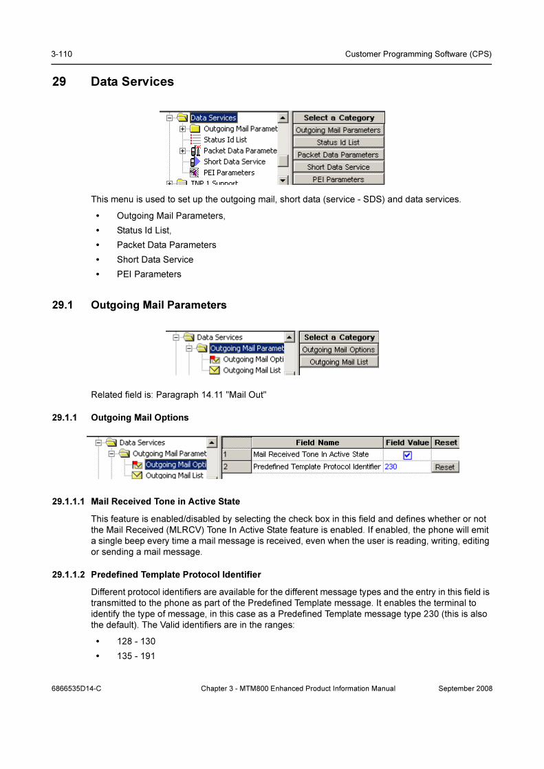
3-110 Customer Programming Software (CPS)
29 Data Services
This menu is used to set up the outgoing mail, short data (service - SDS) and data services.
• Outgoing Mail Parameters,
• Status Id List,
• Packet Data Parameters
• Short Data Service
• PEI Parameters
29.1 Outgoing Mail Parameters
Related field is: Paragraph 14.11 "Mail Out"
29.1.1 Outgoing Mail Options
29.1.1.1 Mail Received Tone in Active State
This feature is enabled/disabled by selecting the check box in this field and defines whether or not
the Mail Received (MLRCV) Tone In Active State feature is enabled. If enabled, the phone will emit
a single beep every time a mail message is received, even when the user is reading, writing, editing
or sending a mail message.
29.1.1.2 Predefined Template Protocol Identifier
Different protocol identifiers are available for the different message types and the entry in this field is
transmitted to the phone as part of the Predefined Template message. It enables the terminal to
identify the type of message, in this case as a Predefined Template message type 230 (this is also
the default). The Valid identifiers are in the ranges:
• 128 - 130
• 135 - 191
6866535D14-C Chapter 3 - MTM800 Enhanced Product Information Manual September 2008
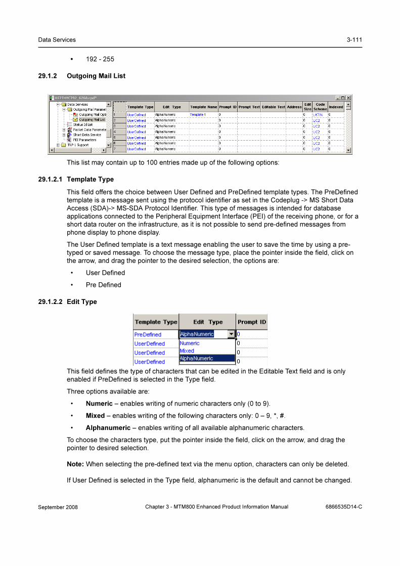
Data Services 3-111
• 192 - 255
29.1.2 Outgoing Mail List
This list may contain up to 100 entries made up of the following options:
29.1.2.1 Template Type
This field offers the choice between User Defined and PreDefined template types. The PreDefined
template is a message sent using the protocol identifier as set in the Codeplug -> MS Short Data
Access (SDA)-> MS-SDA Protocol Identifier. This type of messages is intended for database
applications connected to the Peripheral Equipment Interface (PEI) of the receiving phone, or for a
short data router on the infrastructure, as it is not possible to send pre-defined messages from
phone display to phone display.
The User Defined template is a text message enabling the user to save the time by using a pre-
typed or saved message. To choose the message type, place the pointer inside the field, click on
the arrow, and drag the pointer to the desired selection, the options are:
• User Defined
• Pre Defined
29.1.2.2 Edit Type
This field defines the type of characters that can be edited in the Editable Text field and is only
enabled if PreDefined is selected in the Type field.
Three options available are:
• Numeric – enables writing of numeric characters only (0 to 9).
• Mixed – enables writing of the following characters only: 0 – 9, *, #.
• Alphanumeric – enables writing of all available alphanumeric characters.
To choose the characters type, put the pointer inside the field, click on the arrow, and drag the
pointer to desired selection.
Note: When selecting the pre-defined text via the menu option, characters can only be deleted.
If User Defined is selected in the Type field, alphanumeric is the default and cannot be changed.
September 2008 Chapter 3 - MTM800 Enhanced Product Information Manual 6866535D14-C

3-112 Customer Programming Software (CPS)
29.1.2.3 Template Name
This field allows user to to edit the template for the User Defined templates or Predefined
Templates.
29.1.2.4 Prompt ID
This is a reference number, allowing multiple messages to be sent to the same address. The remote
application works out what to do with each message as it is received (i.e. route it to some other
destination). The field is enabled only if PreDefined is selected in the Type field.
29.1.2.5 Prompt Text
This field contains non-editable prompt text of up to 12 characters that will appear on the phone
screen, e.g. “Arrived At”, the user is then able to add further text to the message. The field is
enabled when PreDefined is the selected option in the Type field.
29.1.2.6 Editable Text
This field contains the actual text message (PreDefined or User Defined) and is editable. Edit
capability as a PreDefined message is limited to deleting characters. Maximum message size is up
to 124 characters for a PreDefined message (according to the Edit Type field selection) and up to
140 alphanumeric characters for User Defined message.
Note: Messages can be created by user action via the menu message option and as well as any
received message, they can be stored in this list as a template by selecting the ‘Add to Template’
option while in message mode.
29.1.2.7 Address
This field is only enabled by selecting the ‘PreDefined’ option in the Type field and it contains the
address to which the message will be sent, usually to an ISSI.
29.1.2.8 Edit Size
This field defines how much of the text message is editable. If User Defined is selected in the Type
field, the Edit Size field content is calculated according to actual message size + 1 up to a maximum
of 140 characters. When PreDefined is selected in the Type field, the Edit Size value must be
entered manually (up to 124 characters) before writing in the Editable Text field.
29.1.2.9 Code Scheme
There are two available options:
ASCII coding (LATIN1_8_BITS) scheme which is used by most western european languages.
UNICODE standard (UC2) which defines a consistent method of encoding/decoding multilingual
text such as Chinese and Korean characters.
6866535D14-C Chapter 3 - MTM800 Enhanced Product Information Manual September 2008

Data Services 3-113
29.1.2.10Indexed
This field indicates whether or not this entry is mapped to a button in the ‘One Touch Buttons’ menu
options. If it is, the user is able to quickly recall the text message and send it.
29.2 Status ID List
The Status List is used for sending and receiving short data messages via the control channel.
These are short cryptic messages of up to 12 alphanumeric characters.
The list can have a maximum of 100 entries and each entry is associated with the following four
column entry fields:
29.2.1 Name
This field contains the alphanumeric message.
29.2.2 ID
The entries in this column contain the ID’s of the messages in the range 32768 - 61439. All numbers
prior to 32768 are used by the system for internal addressing. When a short data message is sent, it
is the ID and not the message that is transmitted, the received ID is then ‘looked up’ in the list and
the corresponding text is displayed.
29.2.3 Status
Selecting the check box in this field will validate the message, allowing the user to see it when
scrolling the list and send it.
29.2.4 Indexed
This field indicates whether or not this entry is mapped to a button in the ‘One Touch Buttons’ menu
options. If it is, the user is able to quickly recall the text message and send it.
29.3 Packet Data Parameters
The following entries define the operation of the terminal’s packet data feature.
September 2008 Chapter 3 - MTM800 Enhanced Product Information Manual 6866535D14-C
3-114 Customer Programming Software (CPS)
29.3.1 User Authentication
This is a method for authenticating the application user prior to allowing activation of the packet data
link and indicates whether or not the customer is configured with mandatory User Authentication.
Select the check box in this field to enable this option.
See Chapter 2 of the Product Information Manual, Paragraph "PD User Authentication"
29.3.2 Authenticator Name
Authenticator name is a 15 digit alphanumeric name/alias that has been set up on the system, for
the Mobile Terminal, that will allow the system to authenticate the user. According to this name, the
data Terminal Equipment user application defines which pair "user-name/password" is suitable for
this authenticator. The system must support user authentication, otherwise this feature if enabled in
the terminal will be ignored by the system.
29.3.3 Data Only
Specifies whether or not the Data Only feature will be enabled as part of the Packet Data features
that allows connection to an external device (such as a laptop PC). When set to Data Only Enable
and except for emergency calls, the phone will reject incoming and outgoing voice calls, status and
text messages. The phone will transmit and receive data via the external device. Select the check
box in this field to enable this option.
29.3.4 Voice & Data
Specifies whether or not Voice & Data feature will be enabled as part of the Packet Data features
that allows connection to an external device (such as a laptop PC). When set to Voice & Data
Enable, the phone will transmit and receive data using the external device. As voice calls have
priority over data calls, any received voice call will interrupt an on going data call. Select the check
box in this field to enable this option.
29.3.5 Voice Only
Specifies whether or not the Voice Only feature will be enabled as part of the Packet Data features
that allows connection to an external device (such as a laptop PC). When set to Voice Only Enable,
the phone will only transmit and receive voice calls. Select the check box in this field to enable this
option.
29.3.6 Default Packet Data Mode
This field defines the default Packet Data mode after power up and can be
• Data Only,
• Voice & Data, or
• Voice Only.
These options are only available if enabled in 3, 4 & 5 above.
Place the mouse arrow in the entry field and press the left mouse button to display the ‘Down
Arrow’. Select the down arrow to display the available options, using the left mouse button select
the required option.
Related field is:
Paragraph 14.17 "Packet Data"
6866535D14-C Chapter 3 - MTM800 Enhanced Product Information Manual September 2008
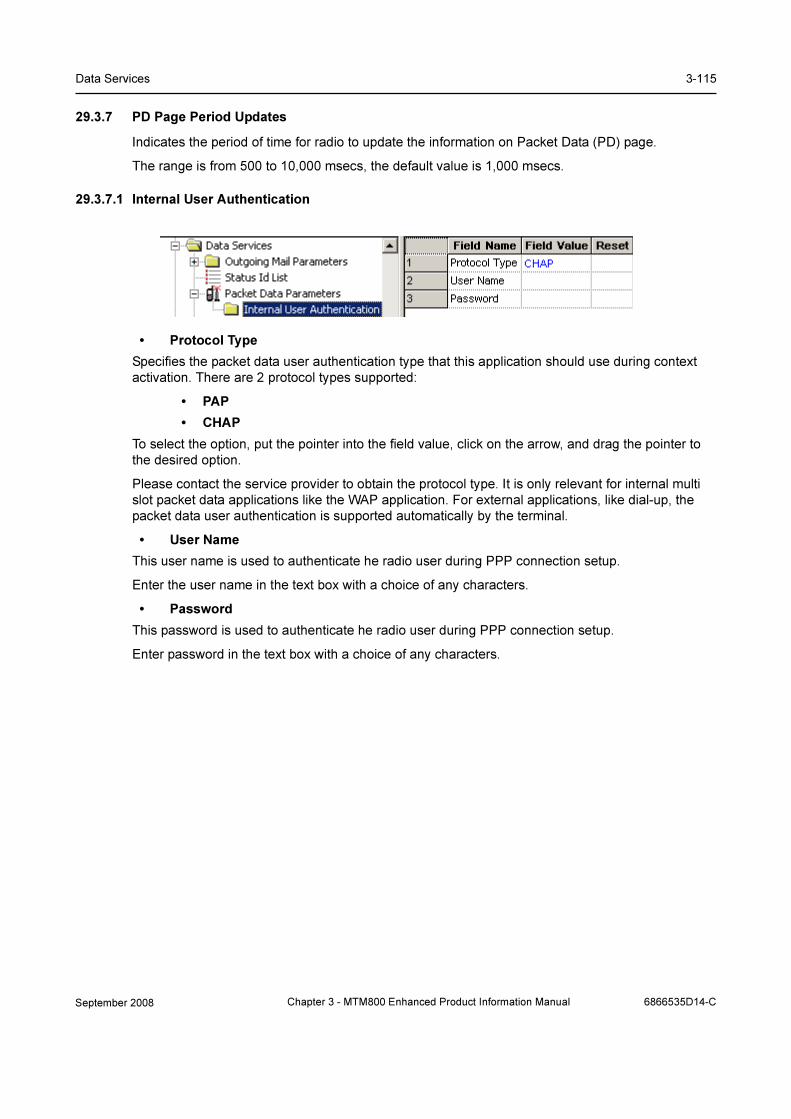
Data Services 3-115
29.3.7 PD Page Period Updates
Indicates the period of time for radio to update the information on Packet Data (PD) page.
The range is from 500 to 10,000 msecs, the default value is 1,000 msecs.
29.3.7.1 Internal User Authentication
• Protocol Type
Specifies the packet data user authentication type that this application should use during context
activation. There are 2 protocol types supported:
• PAP
• CHAP
To select the option, put the pointer into the field value, click on the arrow, and drag the pointer to
the desired option.
Please contact the service provider to obtain the protocol type. It is only relevant for internal multi
slot packet data applications like the WAP application. For external applications, like dial-up, the
packet data user authentication is supported automatically by the terminal.
• User Name
This user name is used to authenticate he radio user during PPP connection setup.
Enter the user name in the text box with a choice of any characters.
• Password
This password is used to authenticate he radio user during PPP connection setup.
Enter password in the text box with a choice of any characters.
September 2008 Chapter 3 - MTM800 Enhanced Product Information Manual 6866535D14-C
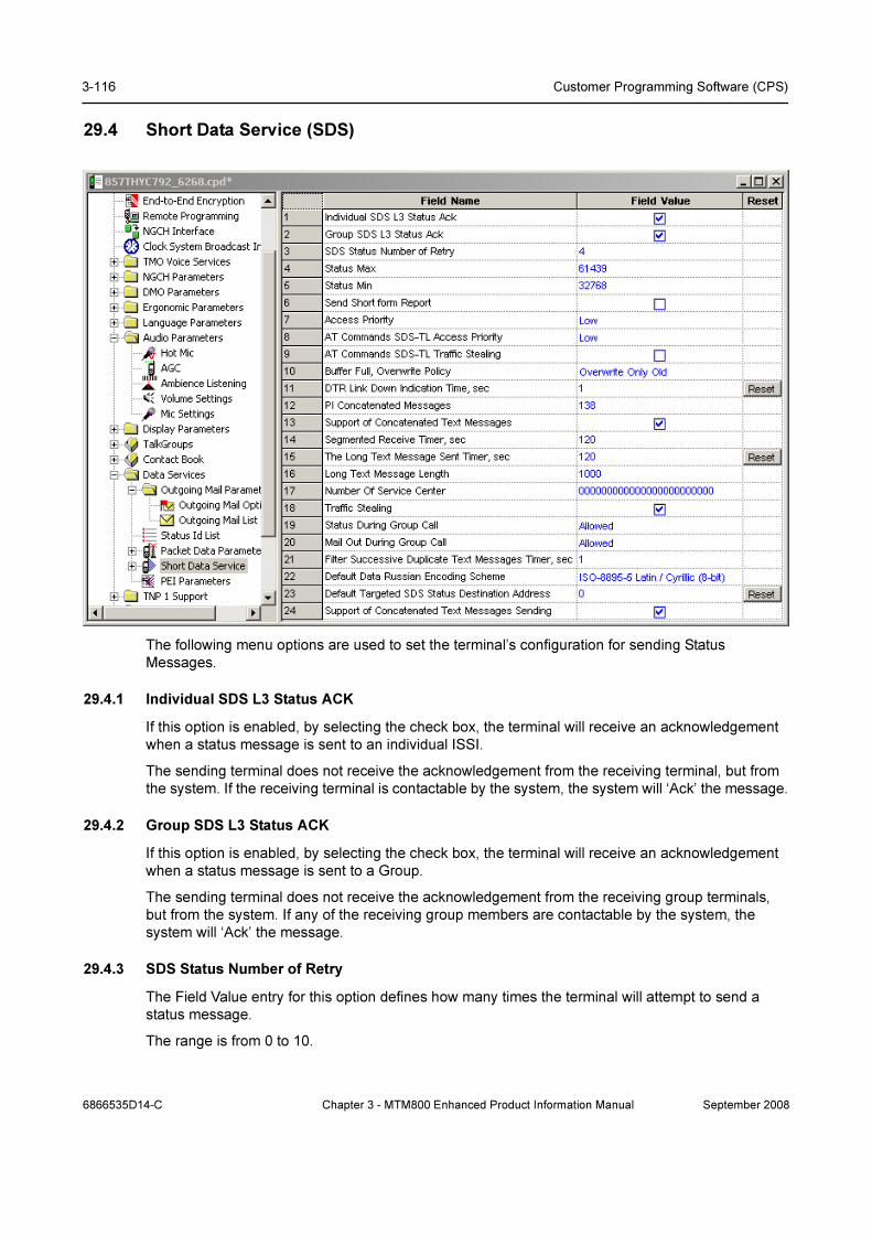
3-116 Customer Programming Software (CPS)
29.4 Short Data Service (SDS)
The following menu options are used to set the terminal’s configuration for sending Status
Messages.
29.4.1 Individual SDS L3 Status ACK
If this option is enabled, by selecting the check box, the terminal will receive an acknowledgement
when a status message is sent to an individual ISSI.
The sending terminal does not receive the acknowledgement from the receiving terminal, but from
the system. If the receiving terminal is contactable by the system, the system will ‘Ack’ the message.
29.4.2 Group SDS L3 Status ACK
If this option is enabled, by selecting the check box, the terminal will receive an acknowledgement
when a status message is sent to a Group.
The sending terminal does not receive the acknowledgement from the receiving group terminals,
but from the system. If any of the receiving group members are contactable by the system, the
system will ‘Ack’ the message.
29.4.3 SDS Status Number of Retry
The Field Value entry for this option defines how many times the terminal will attempt to send a
status message.
The range is from 0 to 10.
6866535D14-C Chapter 3 - MTM800 Enhanced Product Information Manual September 2008

Data Services 3-117
29.4.4 Status Max
The TETRA standard defines the number range of status messages as 32768 to 61439.
The number entered in this field will be the highest number that the terminal user can see and send.
The default is 61439.
29.4.5 Status Min
The TETRA standard defines the number range of status messages as 32768 to 61439.
The number entered in this field will be the lowest number that the terminal user can see and send.
The default is 32768.
29.4.6 Send Short Form Report
This Feature is a requirement for Nokia Systems.
When this feature is enabled, the terminal will automatically request an acknowledgement or send
an acknowledgement, whenever it sends or receives a status message.
29.4.7 Access Priority
This field is used to set the access priority of the SDS-TL reject report when no application is
registered to service.
Select the Field Value window to display the down arrow and the following available options:
• Low
• High
The default value is Low.
29.4.8 AT Commands SDS-TL Access Priority
This field is used to set the access priority for call set up using this data connection method.
When a computer is connected to a terminal and is being used as a ‘Hyper Terminal’, the user is
able to use the ‘AT’ command set for data communication.
Select the Field Value window to display the down arrow and the following available options:
• Low
• High
The default value is Low.
See Chapter 4 of the Product Information Manual.
29.4.9 AT Commands SDS-TL Traffic Stealing
It is possible, using AT Commands, to temporarily steal part of a traffic channels signalling capacity
to pass the message when this option is set to ‘High’.
29.4.10 Buffer Full, Overwrite Policy
As the terminal receives status messages, its buffer will eventually fill if messages are not deleted.
This feature has the following options:
• None - If this option is selected, the terminal will not buffer any more received status
messages once it is full.
September 2008 Chapter 3 - MTM800 Enhanced Product Information Manual 6866535D14-C
3-118 Customer Programming Software (CPS)
Note: Incoming messages - display will notify the user with the text “Inbox Full Msg Lost”
Note: Outgoing messages - display will notify the user with the text “Outbox Full Can Not Send”
• Overwrite Old + New - Selecting this option allows the terminal to overwrite any buffered
status message when the buffer is full.
• Overwrite only Old - Selecting this option allows the terminal to overwrite only the oldest
buffered status message, when the buffer is full.
29.4.11 DTR Link Down Indication Time, sec
When the terminal is in data mode, this is the time after which it will indicate, to the user, that the
down link has been lost.
The range of this timer is 0 to 255 seconds.
29.4.12 PI Concatenated Messages
The Protocol Identifier (PI) is the information element the MS uses when receiving text messages.
The MS will only accept concatenated text messages with the Protocol Identifier set to the indicated
value.
The concatenated text messages function enables the MS to receive text messages longer than
140 bytes using a special protocol called UDH (User Data Header).
Type the required value in the field.
29.4.13 Support of Concatenated Text Messages
Defines whether there is a support of concatenated messaging (receiving long SDS messages
greater than 140 bytes).
A concatenated text message is a chunk of a segmented Long Text Message.
Turn the check box on (Enable) or off (Disable) by clicking in the check box.
29.4.14 Segmented Receive Timer, sec
At the indicated time, the segmented receiver timer shall expire when not all concatenated text
messages belonging to the same long text message (same Message Reference Number) have
been received.
The operating value depends on the load profile of the customer.
Type the required value in the field.
29.4.15 The Long Text Message Sent Timer, sec
At the indicated time, the Long Text Message Sent Timer will expire, when not all delivery status
belonging to the same Long Text Message (same Message Reference Number) have been
received.
Type the required value in the field.
29.4.16 Long Text Message Length
Defines the maximum length of long text messages in characters.
LTM are short data messages with at least 500 characters 8-bit coded or 250 characters 16-bit
Unicode coded. This length refers to message text only without Protocol Identifier (PI) information.
6866535D14-C Chapter 3 - MTM800 Enhanced Product Information Manual September 2008

Data Services 3-119
Type the required value in the field.
29.4.17 Number Of Service Center
Enter the number (address) of the Message Service Centre that will be responsible for storing and
forwarding the subscriber's outgoing messages.
29.4.18 Traffic Stealing
When this field is enabled and a terminal is transmitting party in a circuit mode call, the SDS
message will be sent on the traffic channel by stealing frames from the audio if the message is short
enough to be sent this way.
Turn the check box on or off by clicking on it.
29.4.19 Status During Group Call
Defines option for sending a status during active group or broadcast call.
The options are:
• ·Not Allowed - Not allowed to send Status while there is an active group call.
• ·Leave Call to send Status - The call will be disconnected and the Status will be sent.
• ·Allowed - Status will be sent without disconnect the call.
To select the option, put the pointer into the field value, click on the arrow.
29.4.20 Mail Out During Group Call
Defines option for sending a text message during active group or broadcast call.
The options are:
• Not Allowed - Not allowed to send text message while there is an active group call.
• Leave Call to send Mail - The call will be disconnected and the text message will be sent.
• Allowed - Text message will be sent without disconnect the call.
The default is set to ’Allowed’.
To select the option, put the pointer into the field value, click on the arrow.
29.4.21 Filter Successive Duplicate Text Messages Timer, sec
Service Provider can send SDS message more then once. Duplicated messages (that are full y
equal), received one after the other during a pre-defined period of time, will be filtered.
Type in the required value in seconds.
29.4.22 Default Data Russian Encoding Scheme
Indicates which Russian SDS encoding scheme will be used.
There are 2 encoding schemes available to encode the SDS message:
• ISO-8895-5 Latin / Cyrillic (8-bit)
• Unicode (16-bit)
To select the option, put the pointer into the field value, click on the arrow, and drag the pointer to
the desired option.
September 2008 Chapter 3 - MTM800 Enhanced Product Information Manual 6866535D14-C

3-120 Customer Programming Software (CPS)
When the flag is set to ISO/IEC 8859-5 (0x05), the radio will transmit a SDS message at most 140
characters long. When the flag is set to Unicode (0x1A), the radio will transmit a SDS message at
most 70 characters long.
29.4.23 Default Targeted SDS Status Destination Address
Indicates the default Targeted Short Data Services (SDS) Status Destination Address.
To change the address, type in the value between 0-15999999, 16777215.
29.4.24 Support of Concatenated Text Messages Sending
Defines whether there is a support of concatenated messaging (sending long SDS messages
greater than 140 bytes).
A concatenated text message is a chunk of a segmented Long Text Message.
Turn the check box on (Enable) or off (Disable) by clicking in the check box.
29.5 Store and Forward Options
29.5.1 Support of Store and Forward
If the check box is enabled this feature will be available to the users.
29.5.2 Default Validity Period
It indicates how long the outgoing message should be held.
To choose the period click on the arrow, and drag the pointer to the desired period (range: 0-10
days)
Note: Selecting "No validity" means that the Message Service Centre will not hold the undelivered
message.
29.5.3 Delivery Report Request
Specifies the circumstances/condition in which the radio will send a Delivery Report Reply.
The options are:
• ·None - no message delivery report is sent to the sender when a message is received
by the recipient.
• ·Received - message delivery report is sent automatically to the sender when a
message is received by the recipient.
• ·Consumed - message delivery report is sent automatically to the sender when a
message is read by the recipient.
• ·Received and Consumed – message delivery report is sent automatically to the sender
when a message is received and read by the recipient.
6866535D14-C Chapter 3 - MTM800 Enhanced Product Information Manual September 2008

Data Services 3-121
Note: The radio shall not send a report when the received destination address is Group or Broad-
cast:
To select the option, put the pointer into the field value, click on the arrow, and drag the pointer to
the desired option.
29.5.4 Received Delivery Status Notification
This option indicates if the Store and Forward Delivery Status Notification is enabled or disabled. If
this is unchecked, user will not be notified when the Delivery Status is received.
29.5.5 Store and Forward Server Address
It defines the Server Address in the SDS-layer. It is expressed in the hexadecimal (range: 000001 -
FFFFFFE).
29.6 PEI Parameter
Lists the parameters related to the Peripheral Equipment Interface (PEI) feature.
29.6.1 Baud Rate
Selects the transmission rate at which data flows between DTE (e.g. computer) and DCE (i.e. this
TETRA terminal). Baud rate is the number of bits of information, including "control" bits that are
transmitted per second.
The possible values are 300, 1200, 2400, 4800, 9600, 19200, 38400, 57600 and 115200 bps. The
value chosen here will be the default value at radio power-up. The default value is 9600 bps.
To select the option, put the pointer into the field value, click on the arrow, and drag the pointer to
the desired option.
29.6.2 Parity Bit
Determines whether an optional Parity Bit is used on serial communication between DTE (e.g.
computer) and DCE (i.e. this TETRA terminal).
The parity bit indicates whether the number of 1 bits in the preceding data was even or odd. If a
single bit is changed in transmission, the message will change parity and error can be detected at
this point. This bit is meant for simple error checking.
There are 4 parity schemes available:
• PARITY_ODD - asserts or un-asserts a parity bit to set the total number of 1 bits to be odd in
the data.
• PARITY_EVEN - asserts or un-asserts a parity bit to set the total number of 1 bits to be even
in the data.
• PARITY_MARK - asserts a parity bit in the data. The parity scheme is programmed to odd.
• PARITY_SPACE - un-asserts the parity bit in the data.
September 2008 Chapter 3 - MTM800 Enhanced Product Information Manual 6866535D14-C
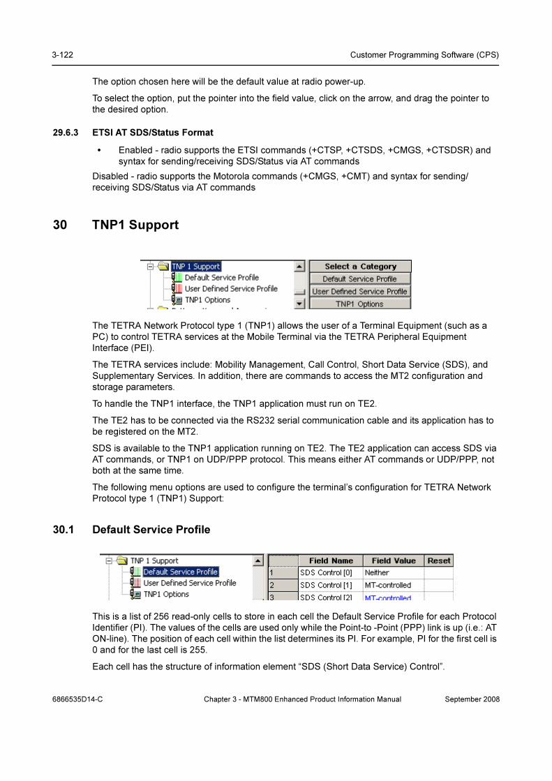
3-122 Customer Programming Software (CPS)
The option chosen here will be the default value at radio power-up.
To select the option, put the pointer into the field value, click on the arrow, and drag the pointer to
the desired option.
29.6.3 ETSI AT SDS/Status Format
• Enabled - radio supports the ETSI commands (+CTSP, +CTSDS, +CMGS, +CTSDSR) and
syntax for sending/receiving SDS/Status via AT commands
Disabled - radio supports the Motorola commands (+CMGS, +CMT) and syntax for sending/
receiving SDS/Status via AT commands
30 TNP1 Support
The TETRA Network Protocol type 1 (TNP1) allows the user of a Terminal Equipment (such as a
PC) to control TETRA services at the Mobile Terminal via the TETRA Peripheral Equipment
Interface (PEI).
The TETRA services include: Mobility Management, Call Control, Short Data Service (SDS), and
Supplementary Services. In addition, there are commands to access the MT2 configuration and
storage parameters.
To handle the TNP1 interface, the TNP1 application must run on TE2.
The TE2 has to be connected via the RS232 serial communication cable and its application has to
be registered on the MT2.
SDS is available to the TNP1 application running on TE2. The TE2 application can access SDS via
AT commands, or TNP1 on UDP/PPP protocol. This means either AT commands or UDP/PPP, not
both at the same time.
The following menu options are used to configure the terminal’s configuration for TETRA Network
Protocol type 1 (TNP1) Support:
30.1 Default Service Profile
This is a list of 256 read-only cells to store in each cell the Default Service Profile for each Protocol
Identifier (PI). The values of the cells are used only while the Point-to -Point (PPP) link is up (i.e.: AT
ON-line). The position of each cell within the list determines its PI. For example, PI for the first cell is
0 and for the last cell is 255.
Each cell has the structure of information element “SDS (Short Data Service) Control”.
6866535D14-C Chapter 3 - MTM800 Enhanced Product Information Manual September 2008

TNP1 Support 3-123
The field values may be as follows:
• MT-controlled - only the application in MT will transmit requests or receive responses when it
controls the services.
• TE-controlled - only the application in TE will transmit requests or receive responses when it
controls the services.
• Neither
Values of some PIs cannot be changed, as they are reserved for the future use or restricted by
internal MT application.
30.2 Default Service Profile
This is a list of 256 read-only cells to store in each cell the User-Defined Service Profile for each PI.
The values of the cells are used only while the PPP link is up. The position of each cell within the list
determines its PI.
Each cell has the structure of information element “SDS (Short Data Service) Control”.
30.3 TNP1 Options
This menu is used to set the button/key functionality and it has the following options:
30.3.1 TNP1 Support
The TNP1 feature operates only when Packet Data or External Device is enabled in the codeplug
(i.e.: a PPP session with MT2 can be estabilished).
Turn the check box (Enable) or off (Disable) by clicking in the check box.
30.3.2 NO TE TEMTA-REPORT IND Counter Limit
This is a Service Profile timer. MT2 terminates its PPP link with TE2 and resets to zero he NO
TEMTA-REPORT IND counter when the counter reaches its maximum value.
The range of this timer is 1 to 100.
30.3.3 TE TEMTA-REPORT IND Timer
This is a Service Profile timer. MT2 uses TE TEMTA-REPORT IND timer in combination with
NO TEMTA-REPORT IND counter over limit to decide when to terminate the PPP link
The range of this timer is 1 to 300.
September 2008 Chapter 3 - MTM800 Enhanced Product Information Manual 6866535D14-C

3-124 Customer Programming Software (CPS)
31 Buttons, Keys and Accessories
This menu defines:
• The type of accessory that can be used with the terminal.
• The one touch functionality of any button/key programmed with this feature.
The available options are:
31.1 Accessory
This menu has the following features:
31.1.1 Accessory Selection
Enables the selection of the accessory type that will be connected to the phone.
Depending on the terminals’ models, the available accessory types are:
• Speaker Mic
• Headset/Covert
• Earpiece
• Handset
• Standard Mic
• Handset
• External Mic
To select the accessory, put the pointer into the field value, click on the arrow, and drag the pointer
to the desired accessory type.
31.1.2 Ring Source
The available options with this feature defines where the ring tones will be heard, either from the
accessory or from the terminal’s internal loudspeaker:
• In Radio
• In Accessory
6866535D14-C Chapter 3 - MTM800 Enhanced Product Information Manual September 2008
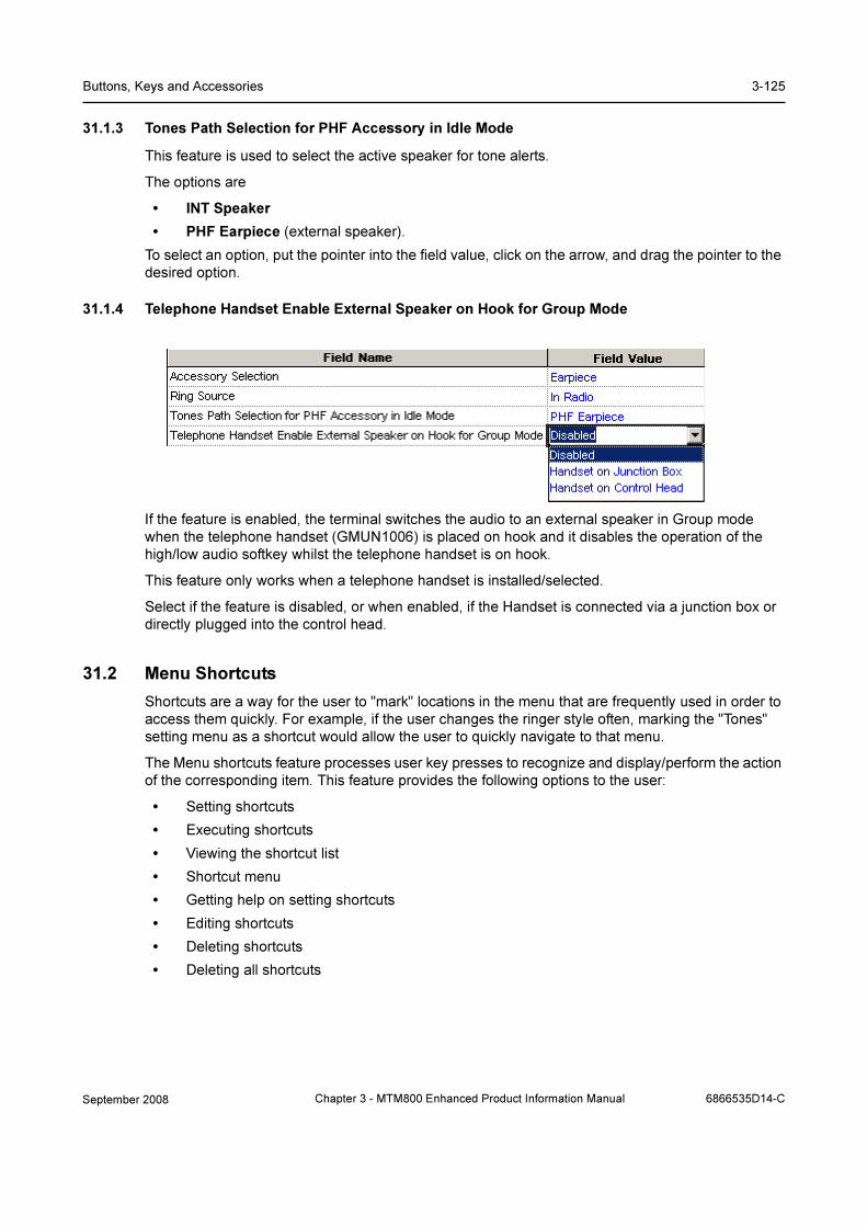
Buttons, Keys and Accessories 3-125
31.1.3 Tones Path Selection for PHF Accessory in Idle Mode
This feature is used to select the active speaker for tone alerts.
The options are
• INT Speaker
• PHF Earpiece (external speaker).
To select an option, put the pointer into the field value, click on the arrow, and drag the pointer to the
desired option.
31.1.4 Telephone Handset Enable External Speaker on Hook for Group Mode
If the feature is enabled, the terminal switches the audio to an external speaker in Group mode
when the telephone handset (GMUN1006) is placed on hook and it disables the operation of the
high/low audio softkey whilst the telephone handset is on hook.
This feature only works when a telephone handset is installed/selected.
Select if the feature is disabled, or when enabled, if the Handset is connected via a junction box or
directly plugged into the control head.
31.2 Menu Shortcuts
Shortcuts are a way for the user to "mark" locations in the menu that are frequently used in order to
access them quickly. For example, if the user changes the ringer style often, marking the "Tones"
setting menu as a shortcut would allow the user to quickly navigate to that menu.
The Menu shortcuts feature processes user key presses to recognize and display/perform the action
of the corresponding item. This feature provides the following options to the user:
• Setting shortcuts
• Executing shortcuts
• Viewing the shortcut list
• Shortcut menu
• Getting help on setting shortcuts
• Editing shortcuts
• Deleting shortcuts
• Deleting all shortcuts
September 2008 Chapter 3 - MTM800 Enhanced Product Information Manual 6866535D14-C
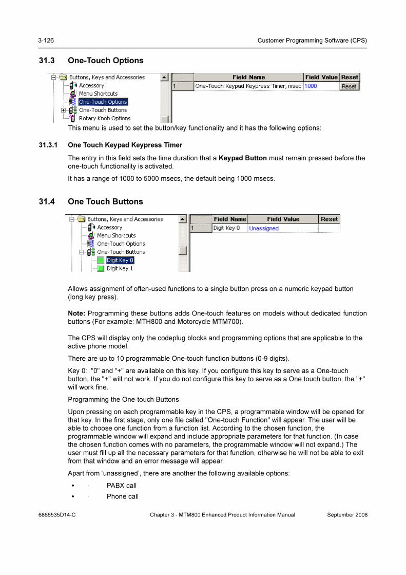
3-126 Customer Programming Software (CPS)
31.3 One-Touch Options
This menu is used to set the button/key functionality and it has the following options:
31.3.1 One Touch Keypad Keypress Timer
The entry in this field sets the time duration that a Keypad Button must remain pressed before the
one-touch functionality is activated.
It has a range of 1000 to 5000 msecs, the default being 1000 msecs.
31.4 One Touch Buttons
Allows assignment of often-used functions to a single button press on a numeric keypad button
(long key press).
Note: Programming these buttons adds One-touch features on models without dedicated function
buttons (For example: MTH800 and Motorcycle MTM700).
The CPS will display only the codeplug blocks and programming options that are applicable to the
active phone model.
There are up to 10 programmable One-touch function buttons (0-9 digits).
Key 0: "0" and "+" are available on this key. If you configure this key to serve as a One-touch
button, the "+" will not work. If you do not configure this key to serve as a One touch button, the "+"
will work fine.
Programming the One-touch Buttons
Upon pressing on each programmable key in the CPS, a programmable window will be opened for
that key. In the first stage, only one file called "One-touch Function" will appear. The user will be
able to choose one function from a function list. According to the chosen function, the
programmable window will expand and include appropriate parameters for that function. (In case
the chosen function comes with no parameters, the programmable window will not expand.) The
user must fill up all the necessary parameters for that function, otherwise he will not be able to exit
from that window and an error message will appear.
Apart from ‘unassigned’, there are another the following available options:
• · PABX call
• · Phone call
6866535D14-C Chapter 3 - MTM800 Enhanced Product Information Manual September 2008
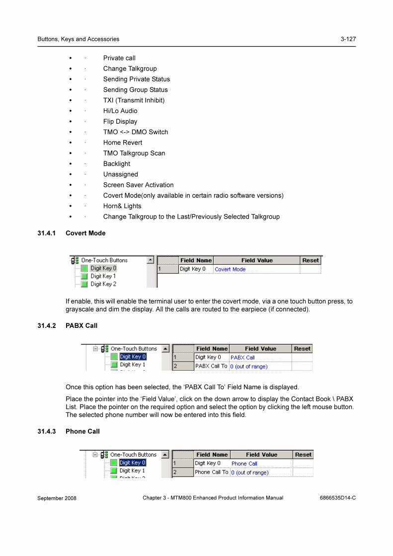
Buttons, Keys and Accessories 3-127
• · Private call
• · Change Talkgroup
• · Sending Private Status
• · Sending Group Status
• · TXI (Transmit Inhibit)
• · Hi/Lo Audio
• · Flip Display
• · TMO <-> DMO Switch
• · Home Revert
• · TMO Talkgroup Scan
• · Backlight
• · Unassigned
• · Screen Saver Activation
• · Covert Mode(only available in certain radio software versions)
• · Horn& Lights
• · Change Talkgroup to the Last/Previously Selected Talkgroup
31.4.1 Covert Mode
If enable, this will enable the terminal user to enter the covert mode, via a one touch button press, to
grayscale and dim the display. All the calls are routed to the earpiece (if connected).
31.4.2 PABX Call
Once this option has been selected, the ‘PABX Call To’ Field Name is displayed.
Place the pointer into the ‘Field Value’, click on the down arrow to display the Contact Book \ PABX
List. Place the pointer on the required option and select the option by clicking the left mouse button.
The selected phone number will now be entered into this field.
31.4.3 Phone Call
September 2008 Chapter 3 - MTM800 Enhanced Product Information Manual 6866535D14-C
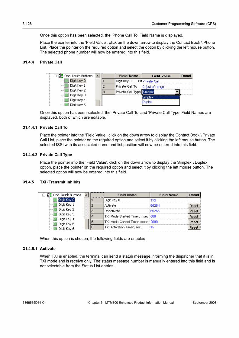
3-128 Customer Programming Software (CPS)
Once this option has been selected, the ‘Phone Call To’ Field Name is displayed.
Place the pointer into the ‘Field Value’, click on the down arrow to display the Contact Book \ Phone
List. Place the pointer on the required option and select the option by clicking the left mouse button.
The selected phone number will now be entered into this field.
31.4.4 Private Call
Once this option has been selected, the ‘Private Call To’ and ‘Private Call Type’ Field Names are
displayed, both of which are editable.
31.4.4.1 Private Call To
Place the pointer into the ‘Field Value’, click on the down arrow to display the Contact Book \ Private
Call List, place the pointer on the required option and select it by clicking the left mouse button. The
selected ISSI with its associated name and list position will now be entered into this field.
31.4.4.2 Private Call Type
Place the pointer into the ‘Field Value’, click on the down arrow to display the Simplex \ Duplex
option, place the pointer on the required option and select it by clicking the left mouse button. The
selected option will now be entered into this field.
31.4.5 TXI (Transmit Inhibit)
When this option is chosen, the following fields are enabled:
31.4.5.1 Activate
When TXI is enabled, the terminal can send a status message informing the dispatcher that it is in
TXI mode and is receive only. The status message number is manually entered into this field and is
not selectable from the Status List entries.
6866535D14-C Chapter 3 - MTM800 Enhanced Product Information Manual September 2008

Buttons, Keys and Accessories 3-129
31.4.5.2 Deactivate
When TXI is disabled, the terminal can send a status message informing the dispatcher that it is in
now in normal operating mode. The status message number is manually entered into this field and
is not selectable from the Status List entries.
31.4.5.3 TXI Mode Started Timer
The entry in this field sets the time that the button must remain pressed before the TXI mode is
started.
The range is from 1 to 5000 msecs and the default is 500 msecs.
31.4.5.4 TXI Mode Cancel Timer
The entry in this field sets the time that the button must remain pressed before the TXI mode is
cancelled and the terminal reverts to normal operation.
The range is from 1000 to 5000 msecs and the default is 2000 msecs.
31.4.5.5 TXI Activation Timer
This is the time delay between TXI being selected and TXI actually starting, it allows time for all on
going procedures to be completed before transmission is actually blocked.
The range is from 1 to 30 seconds and the default is 15 seconds.
31.4.6 Sending Predefined Message
This function sends a predefined message to the address that is already stored in the codeplug.
Related field:
Paragraph 29.1.2 "Outgoing Mail List"
Note: Sending Predefined Message is only available if the appropriate values are set in the Outgo-
ing Mail List.
31.4.7 Sending User Defined Message
September 2008 Chapter 3 - MTM800 Enhanced Product Information Manual 6866535D14-C

3-130 Customer Programming Software (CPS)
This function sends a user defined message to the address that is already stored in the codeplug.
The user will be asked for a target selection if Send To is set to 0.
Related field:
Paragraph 29.1.2 "Outgoing Mail List"
Note: Sending User Defined Message is only available if the appropriate values are set in the Out-
going Mail List.
31.4.8 Hi/Lo Audio
This function changes the speaker between Speaker: On/Speaker: Off.
31.4.9 Change Talkgroup
This option enables fast selection of a predefined talkgroup and different talkgroups may be
assigned to different buttons.
31.4.10 Change Talkgroup to Latest Previously Selected
This option enables fast selection of the talkgroup that was selected previously.
That is when TG-1 is current user talkgroup and the previous one is TG-2. In this case to go back to
TG-2 user needs to press the one-touch button that is set in CPS to select previous talkground.
Only one last talkgroup is stored.
31.4.11 Sending Status
This option allows the user to send a specific status message to a specific talkgroup.
Related field:
Paragraph 14.2 "Status"
6866535D14-C Chapter 3 - MTM800 Enhanced Product Information Manual September 2008
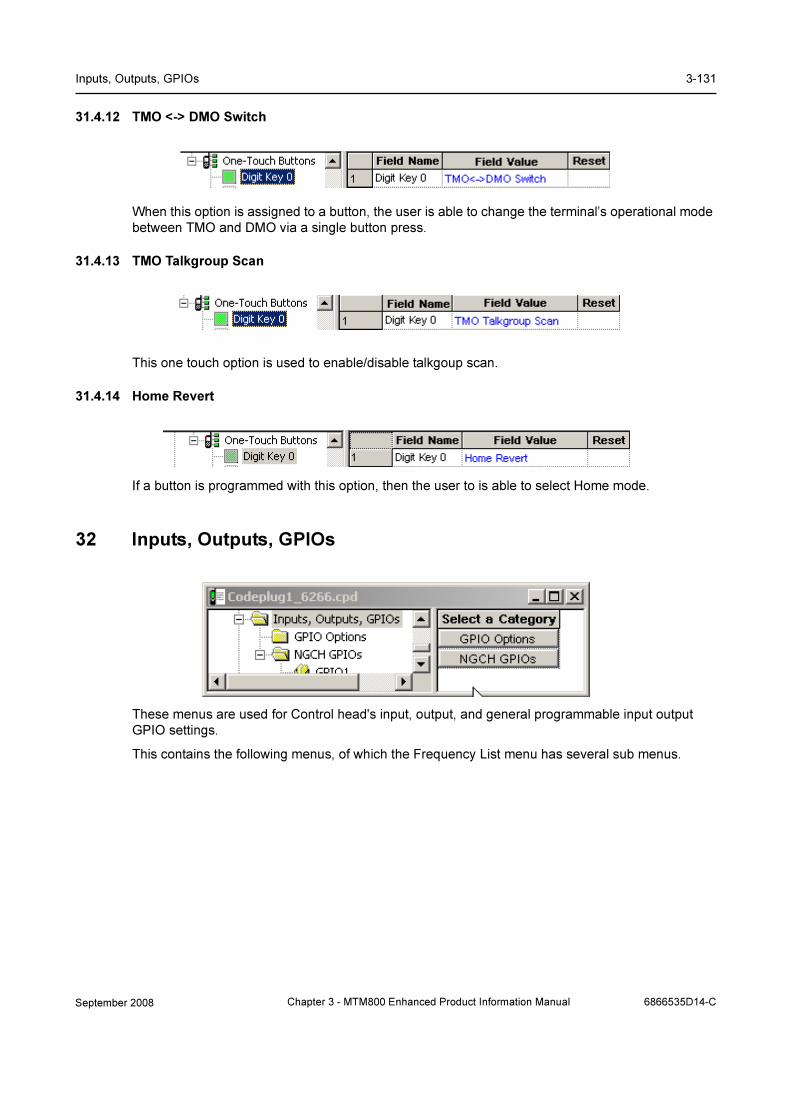
Inputs, Outputs, GPIOs 3-131
31.4.12 TMO <-> DMO Switch
When this option is assigned to a button, the user is able to change the terminal’s operational mode
between TMO and DMO via a single button press.
31.4.13 TMO Talkgroup Scan
This one touch option is used to enable/disable talkgoup scan.
31.4.14 Home Revert
If a button is programmed with this option, then the user to is able to select Home mode.
32 Inputs, Outputs, GPIOs
These menus are used for Control head's input, output, and general programmable input output
GPIO settings.
This contains the following menus, of which the Frequency List menu has several sub menus.
September 2008 Chapter 3 - MTM800 Enhanced Product Information Manual 6866535D14-C
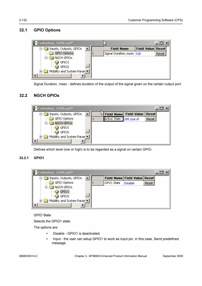
3-132 Customer Programming Software (CPS)
32.1 GPIO Options
Signal Duration, msec - defines duration of the output of the signal given on the certain output port.
32.2 NGCH GPIOs
Defines which level (low or high) is to be regarded as a signal on certain GPIO.
32.2.1 GPIO1
GPIO State
Selects the GPIO1 state.
The options are:
• ·Disable - GPIO1 is deactivated.
• · Input - the user can setup GPIO1 to work as input pin, in this case, Send predefined
message.
6866535D14-C Chapter 3 - MTM800 Enhanced Product Information Manual September 2008

Mobility and System Parameters 3-133
• ·Output – the user can setup GPIO1 to work as output pin, in this case, Send specific
message indication.
32.2.2 GPIO2
GPIO State
Selects the GPIO2 state.
The options are:
• ·Disable - GPIO2 is deactivated.
• · Input - the user can setup GPIO2 to work as input pin, in this case, Send predefined
message.
·Output – the user can setup GPIO2 to work as output pin, in this case, Send specific message
indication.
32.2.3 Sending Predefined Messages using PIN 14 and 3
Two requirements are need to be checked:
• Input of PIN 14 and 3 needs to be set as: GPIO State = Input, and GPIO Function = Send
Predefined Message (this function is invisible until you set GPIO State)
• PIN 14 or 3 needs to be connected to PIN 13 which is grounded
33 Mobility and System Parameters
These menus are used for programming the terminal with the necessary system parameters that will
enable the terminal to work on the system.
This contains the following menus, of which the Frequency List menu has several sub menus.
September 2008 Chapter 3 - MTM800 Enhanced Product Information Manual 6866535D14-C

3-134 Customer Programming Software (CPS)
33.1 Frequency List
This contains the following four frequency lists:
33.1.1 Frequency List 1
Displays a dynamic list of discrete frequencies that the terminal scans to find a valid TETRA system.
This list is maintained internally by the unit's embedded software only.
33.1.2 Frequency List 2
This list contains up to 32 valid cell frequencies for the system(s) to which the terminal has access.
Frequencies must be entered here to enable first time rapid access to a system. If no frequencies
were entered, the terminal would use the comprehensive hunt feature of lists 3 & 4 if enabled.
33.1.3 Frequency List 3
Lists 3 & 4 allow flexibility in the comprehensive hunt, both have the same options but the field
values should be different to allow for the different system frequencies.
33.1.3.1 First Frequency to Scan
This might appear to be a straight forward entry of the base frequency of the system(s), but the
terminal checks frequencies in 25kHz steps and systems may be using 25kHz, 12.5kHz or 6.25kHz
offsets. In the above picture the base frequency has a 12.5kHz offset.
33.1.3.2 Number of Frequencies
The entry in this field defines how many frequencies, upwards from the base frequency, the terminal
will check.
As shown above, the terminal will check 399 frequencies and as there is a step size of 25kHz, all
frequencies from 420.01250MHz to 429.975MHz inclusive will be checked.
6866535D14-C Chapter 3 - MTM800 Enhanced Product Information Manual September 2008

Mobility and System Parameters 3-135
33.1.4 Frequency List 4
It may not be necessary to use this list, in which case ensure there are no entries in the field values.
Using both tables adds flexibility to the comprehensive hunt if it is required for multiple system
access that use different frequencies offsets. In the above picture the base frequency has a 6.25kHz
offset and the frequencies scanned will be from 420.00625MHz to 429.98125MHz inclusive.
Note: It is more likely that lists 3 & 4 will have 25kHz and 12.5kHz offsets.
Comprehensive Hunt - is used when the terminal cannot log on to a system using the frequencies
in lists 1 & 2. The terminal will search a predefined number (block) of frequencies in List 3, then
check the frequencies in lists 1 & 2 before returning to List 3 and searching the next block of
frequencies. This procedure is repeated until the frequencies of both lists 3 & 4 have been checked.
The terminal will repeat this procedure until a system is found on which it can register.
33.2 Home Location Areas
These two has two options that define the system cells to which the terminal may roam and operate.
33.2.1 Number of Home Location Areas
The number in this field is automatically entered by the CPS after the Home Location Areas have
been defined.
33.2.2 Home Location Area
This is a collapsible table that can have up to 34 entries and contains the cell numbers of the cells
which are the preferred cells on which the terminal should work.
Select the ‘Expand’ option to open the table and enter the cells to which the terminal can register.
Afterwards ‘Collapse’ the table and the number of cells to which the terminal can roam will be
displayed on line 1.
September 2008 Chapter 3 - MTM800 Enhanced Product Information Manual 6866535D14-C
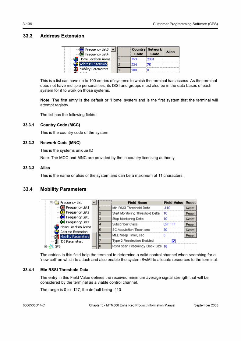
3-136 Customer Programming Software (CPS)
33.3 Address Extension
This is a list can have up to 100 entries of systems to which the terminal has access. As the terminal
does not have multiple personalities, its ISSI and groups must also be in the data bases of each
system for it to work on those systems.
Note: The first entry is the default or ‘Home’ system and is the first system that the terminal will
attempt registry.
The list has the following fields:
33.3.1 Country Code (MCC)
This is the country code of the system
33.3.2 Network Code (MNC)
This is the systems unique ID
Note: The MCC and MNC are provided by the in country licensing authority.
33.3.3 Alias
This is the name or alias of the system and can be a maximum of 11 characters.
33.4 Mobility Parameters
The entries in this field help the terminal to determine a valid control channel when searching for a
‘new cell’ on which to attach and also enable the system SwMI to allocate resources to the terminal.
33.4.1 Min RSSI Threshold Data
The entry in this Field Value defines the received minimum average signal strength that will be
considered by the terminal as a viable control channel.
The range is 0 to -127, the default being -110.
6866535D14-C Chapter 3 - MTM800 Enhanced Product Information Manual September 2008

Mobility and System Parameters 3-137
33.4.2 Start Monitoring Threshold Delta
This Field Value is used to set the tolerance threshold above the Slow Reselect Threshold.
The Slow reselect Threshold parameter is one of several system parameters settings used to set for
setting a cells coverage area and the defined RSSI of these parameters is used by the terminal to
determine cell reselection.
If the RSSI of a cell is above this Field Value setting, the signal strength of the cell’s control channel
is considered strong enough so that the terminal will not normally scan other neighbour cells,
33.4.3 Stop Monitoring Delta
The entry in this Field Value defines the value of the received signal above that set in the Start
Monitoring Threshold Delta Field Value after which the terminal will stop monitoring the received
control channel RSSI.
33.4.4 Subscriber Class
Systems may be able to divide their subscriber population into different ‘Classes’ and allocate
certain resources to specific ‘Classes’.
If set to ‘0’, the terminal will not work normally on any system, set this field accordingly, the default is
displayed above. i.e. 0xFFFF.
33.4.5 SC Acquisition Timer
If the Subscriber Class (SC) of the terminal has been set, the terminal will always attempt to log onto
a cell that supports this class.
The Field Value determines the period of time that the terminal will search for a cell that support this
class, after which it will register on the best cell even though there is no SC match.
The range is 0 to 300 seconds, the default is 30 seconds.
33.4.6 MLE Sleep Timer
The Field Value entry for the Mobile Link Entity (MLE) defines the period of time the terminal waits
between iterations of frequency list scanning.
Upon power up, or whenever the terminal is not attached to any cell and there are no known suitable
neighbour cells, the terminal begins to scan the frequencies.
After having exhausted all the lists, the terminal waits a provisioned amount of time before beginning
the process again from the first list. This time needs to be carefully balanced between the need to
save battery life and the need to find a system quickly after having lost coverage.
The range is 0 to 60 seconds, the default being 5 seconds.
33.4.7 Type 2 Reselection Enabled
This field needs to always be enabled except for terminals that are working on legacy Dimetra-P
releases.
Turn the check box on (Enable) or off (Disable) by clicking in the check box.
September 2008 Chapter 3 - MTM800 Enhanced Product Information Manual 6866535D14-C

3-138 Customer Programming Software (CPS)
33.5 TXI Parameters (Transmit Inhibit)
Allows setting up parameters of TXI status messages the terminal will send to the dispatcher upon
activation/de-activation of the TXI (Transmit Inhibit) mode.
TXI mode, also called terminal RF (Radio Frequency) SA (Sensitive Area) Mode, is a special
terminal mode where uplink transmission of any type is forbidden except an Emergency call.
The TXI mode is activated by the terminal user in RF sensitive areas, (e.g. hospitals, airplanes,
etc.), where safety can be jeopardized due to terminal uplink high radiation. When no danger to
safety exists anymore (for instance if user leaves RF sensitive area), the user can de-activate TXI
mode and return back to normal operation.
Note: If an emergency call caused TXI mode de-activation, no status message will be sent about
TXI deactivation.
These are the same options available for the TXI One Touch Button option, see paragraph 14.3.5.
Both menus are linked and if a field value is changed in either menu, it will automatically be changed
at the other. It has the following options:
33.5.1 Activate
When TXI is enabled, the terminal can send a status message informing the dispatcher that it is in
TXI mode and is receive only. The status message number is manually entered into this field and is
not selectable from the Status List entries.
33.5.2 Deactivate
When TXI is disabled, the terminal can send a status message informing the dispatcher that it is in
now in normal operating mode. The status message number is manually entered into this field and
is not selectable from the Status List entries.
33.5.3 TXI Activation Timer
This is the time delay between TXI being selected and TXI actually starting, it allows time for all on
going procedures to be completed before transmission is actually blocked.
The range is from 1 to 30 seconds and the default is 15 seconds.
33.5.4 TXI Mode Started Timer
The entry in this field sets the time that the button must remain pressed before the TXI mode is
started.
The range is from 1 to 5000 msecs and the default is 500 msecs.
6866535D14-C Chapter 3 - MTM800 Enhanced Product Information Manual September 2008

GPS 3-139
33.5.5 TXI Mode Cancel Timer
The entry in this field sets the time that the button must remain pressed before the TXI mode is
cancelled and the terminal reverts to normal operation.
The range is from 1000 to 5000 msecs and the default is 2000 msecs.
34 GPS
This autonomous GPS feature enables the terminal to send location reports.
Not only can the reports be sent to meet customer requirements, but they can also be triggered by
events occurring through terminal us, such as emergency call initiation and power on/off etc.
The ‘Profile Menus’ define the parameters that are used by and when these events (such as
selecting DMO) are triggered.
Other situations are:
• On Request.
• Specific events.
• Triggered after a time interval.
• Triggered at specific distance intervals.
The reports are sent using a proprietary protocol, via the SDS transport layer, that also flags error
conditions.
The user’s involvement with the operation of this feature is minimal, although the terminal does
provide indications of the operational status of the GPS feature.
The GPS feature can be enabled/disabled via the CPS and its event times/responses can be
configured in the GPS menu options. Configuration can also be done ‘Over the Air’ and this new
information will overwrite the CPS configuration.
All data requests and configuration commands received over the air are authenticated by checking
the ISSI of the sender of the source file, if the ISSI is wrong, the file will be rejected.
Note: Under the worst possible scenario of non emergency use, this feature will drain the battery by
up to 10%.
September 2008 Chapter 3 - MTM800 Enhanced Product Information Manual 6866535D14-C

3-140 Customer Programming Software (CPS)
This menu has 6 sub menus, made up of a GPS Settings sub menu. The Profile sub menus have
the same 1 to 8 Field Name options, but 4 have 9 or 10 options, these 4 sub menus are:
• Normal Periodic Profile.
• Emergency Periodic Profile.
• MS Moved Profile.
• Low Battery Profile (not relevant for the mobile terminal).
Note: This section will cover in detail the GPS Settings and the Emergency 1 Profile sub menus and
only the different Field Name options of the above 4 Profiles.
34.1 GPS Settings
This menu is used for setting the common GPS functionality and has the following options:
34.1.1 Current GPS Cycle
At the end of 1,024 weeks (every 19.75 years approx.) the GPS ‘Week Cycle’ starts again at zero.
Zero, also used to identify the first cycle, was from the 6th January 1980 until the 22nd August 1999.
We are now in the 2nd period or cycle 1 and this runs until 2019.
The entry for this field is 1.
34.1.2 Leap Seconds
Specifies the difference between GPS time and UTC time. This parameter is used to synchronize
both time systems in the radio.
The range is 0 to 65.553 seconds, the default is 14 seconds.
34.1.3 Enable GPS via MMI
If this option is enabled, it is then possible for the user to enable/disable the GPS feature.
6866535D14-C Chapter 3 - MTM800 Enhanced Product Information Manual September 2008

GPS 3-141
34.1.4 Test Page on the MMI Enable
Note: Not editable via Customer CPS.
34.1.5 Beep for GPS Coverage
This option enables/disables the terminal’s audio indications for GPS coverage.
34.1.6 Notification for GPS Coverage
Enable/disable the visual notification for loss of GPS coverage.
Turn the check box on (Enable) or off (Disable) by clicking in the check box.
34.1.7 GPS Authorised ISSI Base
This ISSI is the first in the range of valid ISSIs that the terminal will recognise when checking for
authorisation after receiving a location service request. The terminal checks the calling party ISSI.
34.1.8 GPS Authorised ISSI Range
The number entered in this Field Value defines the range of valid consecutive ISSIs from the GPS
Authorised ISSI Base.
34.1.9 GPS Coverage Poll Period
This option displays the time period in seconds after which the GPS coverage is checked and the
display icon updated accordingly.
The range for this setting is 0 - 2147483, the default is 180.
34.1.10 GPS Location Protocol
Selects the over-the air location protocol used for location requests and location reports.
There are 2 possible choices:
• LIP - Location Information Protocol (ETSI standard)
• LRRP - Location Request Response Protocol (non ETSI standard)
To select the option, put the pointer into the field value, click on the arrow, and drag the pointer to
the desired option.
34.2 LIP Configuration
34.2.1 Send Initialization Request
If enabled, the radio sends an Initialization Request after it is powered up and registered in the
network.
34.2.2 Destination ISSI
This is the destination Individual Short Subscriber Identity (ISSI) for Location Information Protocol
(LIP) reports. Usually this is the address of the LIP Location Server.
September 2008 Chapter 3 - MTM800 Enhanced Product Information Manual 6866535D14-C

3-142 Customer Programming Software (CPS)
34.2.3 Min Reporting Interval
Note: The GPS Location Protocol must be set to LIP to make this field editable.
Duration in seconds which is not underrun between 2 successive LIP location reports.
The range is from 10 to 5280 seconds and the default is 10 seconds.
Related fields:
The GPS Profiles
34.2.4 LIP Max Data Age
Note: The GPS Location Protocol must be set to LIP to make this field editable.
Specifies the acceptable maximum age of location data in seconds.
The range is from 0 to 254 seconds and the default is 60 seconds.
Related fields:
The GPS Profiles
34.2.5 Max Respond Time
Note: The GPS Location Protocol must be set to LIP to make this field editable.
Specifies the maximum duration in seconds the GPS system has to acquire location data.
The range is from 0 to 3780 seconds and the default is 0 seconds.
Related fields:
The GPS Profiles
34.2.6 Delete All OTA LIP Location Report Requests
Removes all Over-the-Air (OTA) Location Information Protocol (LIP) report requests (triggered
requests) received over the air. This is clean up measure to delete orphaned requests that are no
longer useful.
6866535D14-C Chapter 3 - MTM800 Enhanced Product Information Manual September 2008
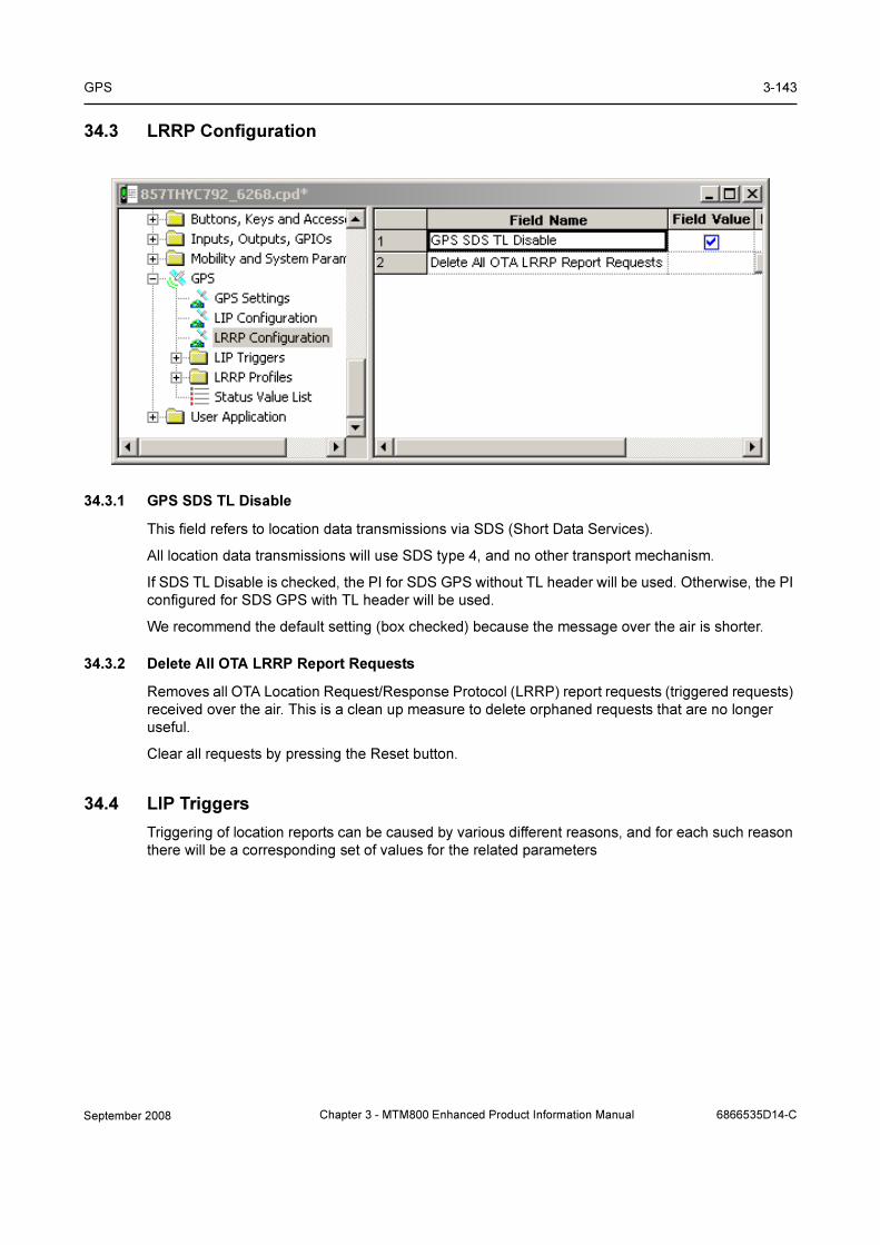
GPS 3-143
34.3 LRRP Configuration
34.3.1 GPS SDS TL Disable
This field refers to location data transmissions via SDS (Short Data Services).
All location data transmissions will use SDS type 4, and no other transport mechanism.
If SDS TL Disable is checked, the PI for SDS GPS without TL header will be used. Otherwise, the PI
configured for SDS GPS with TL header will be used.
We recommend the default setting (box checked) because the message over the air is shorter.
34.3.2 Delete All OTA LRRP Report Requests
Removes all OTA Location Request/Response Protocol (LRRP) report requests (triggered requests)
received over the air. This is a clean up measure to delete orphaned requests that are no longer
useful.
Clear all requests by pressing the Reset button.
34.4 LIP Triggers
Triggering of location reports can be caused by various different reasons, and for each such reason
there will be a corresponding set of values for the related parameters
September 2008 Chapter 3 - MTM800 Enhanced Product Information Manual 6866535D14-C
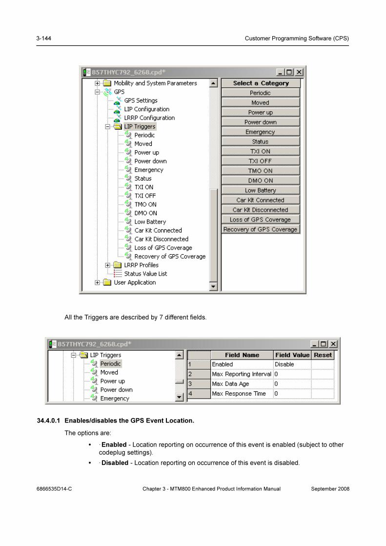
3-144 Customer Programming Software (CPS)
All the Triggers are described by 7 different fields.
34.4.0.1 Enables/disables the GPS Event Location.
The options are:
• ·Enabled - Location reporting on occurrence of this event is enabled (subject to other
codeplug settings).
• ·Disabled - Location reporting on occurrence of this event is disabled.
6866535D14-C Chapter 3 - MTM800 Enhanced Product Information Manual September 2008

GPS 3-145
To assign a setting, put the pointer into the field value, click on the arrow, and drag the pointer to the
desired setting.
This field is specified the same way for all the LIP Triggers.
34.4.0.2 Max Reporting Interval
This is the interval at which periodic Location Reports are sent.
34.4.0.3 Max Data Age
Indicates the default maximum age allowed for data in Location Report message for triggered
reports.
34.4.0.4 Max Response Time
Specifies maximum duration the GPS system has to acquire location data.
34.4.0.5 Max Reporting Distance
Defines the distance interval at which distanced based Location Reports are sent when not inserted
in a DIgital Car Kit.
34.4.0.6 Distance Check Interval
Maximum interval (in seconds) at which radio check its position for possition based Location
Reports when not inserted when is not inserted in a Digital Car Kit.
34.4.0.7 Low Battery Level
Indicates the percentage of battery level triggering the "Low Battery" condition.
September 2008 Chapter 3 - MTM800 Enhanced Product Information Manual 6866535D14-C

3-146 Customer Programming Software (CPS)
34.5 LRRP Profiles
34.5.1 GPS Event Location Enable
Enables/disables the GPS Event Location.
• · If Enabled, the Unsolicited Location Report on occurrence of this event is enabled
(subject to other codeplug settings).
• · If Disabled, the Unsolicited Location Report on occurrence of this event is disabled.
Turn the check box on (Enable) or off (Disable) by clicking in the check box.
This field is an element in the codeplug structure for the Unsolicited Report Profiles. The actual
value depends on the particular Profile.
34.5.2 GPS Event Timestamp Enable
Enables/disables the GPS Event Timestamp.
• · If Enabled, Unsolicited Location Reports on occurrence of this event shall have
timestamps.
• · If Disabled, Unsolicited Location Reports on occurrence of this event shall NOT have
timestamps.
This field is an element in the codeplug structure for Unsolicited Report Profiles; the actual value
depends on the particular Profile.
Turn the check box on (Enable) or off (Disable) by clicking in the check box.
34.5.3 GPS LRRP Destination ISSI
This is the destination ISSI for Unsolicited Location Reports.
6866535D14-C Chapter 3 - MTM800 Enhanced Product Information Manual September 2008

GPS 3-147
This field is an element in the codeplug structure for Unsolicited Report Profiles; the actual value
depends on the particular Profile.
The range is any valid ISSI or NO_ISSI. (NO_ISSI is a reserved value outside the range of possible
ISSIs, and only used to indicate that no ISSI has been assigned to the field in question.)
Type in the required value.
34.5.4 GPS LRRP Unsolicited Shape
This is the Shape to use for Unsolicited Location Reports:
• ·SHAPE_2d: a two-dimensional (latitude and longitude) position.
• ·SHAPE_3d: a three-dimensional (latitude, longitude and height) position.
This field is an element in the codeplug structure for Unsolicited Report Profiles; the actual value
depends on the particular Profile.
To assign a setting, put the pointer into the field value, click on the arrow, and drag the pointer to the
desired setting.
34.5.5 GPS LRRP Unsolicited Velocity Type
This is the Velocity Type to use for Unsolicited Location Reports:
• ·No speed reported
• ·Horizontal speed: gives the magnitude of the horizontal component of the velocity of a
target entity.
• ·Horizontal speed with high accuracy
• ·Vertical speed: gives the magnitude of the vertical component of the velocity of a target
entity.
• ·Vertical speed with high accuracy
• ·Horizontal and vertical speed
• ·Horizontal and vertical speed with high accuracy
To assign a setting, put the pointer into the field value, click on the arrow, and drag the pointer to the
desired setting.
This field is an element in the codeplug structure for Unsolicited Report Profiles; the actual value
depends on the particular Profile.
34.5.6 GPS Unsolicited Uncertainty, m
This is the requested horizontal uncertainty to use for Unsolicited Location Reports. The value is a
measure for the accuracy of the location determination.
This field is an element in the codeplug structure for Unsolicited Report Profiles; the actual value
depends on the particular Profile. Type in the required value in meters.
If the requested uncertainty/accuracy is achieved from the GPS system, the report will be sent with
the requested uncertainty/accuracy. If the requested uncertainty/accuracy is not achieved, the
uncertainty/accuracy, which has been achieved is reported after expiration of the GPS Max
Acquisition Delay.
If an uncertainty value of 0 is defined, then no accuracy information is requested and the unsolicited
location report will not contain any accuracy information (shape type is point_2d or point_3d). If an
uncertainty value not equals to 0 is defined, then an accuracy information is provided within the
unsolicited location report (shape type is ellipse_2d or ellipse_3d).
September 2008 Chapter 3 - MTM800 Enhanced Product Information Manual 6866535D14-C

3-148 Customer Programming Software (CPS)
34.5.7 GPS Max Data Age, sec
Indicate the default maximum age (in seconds) allowed for data Location Report message for
triggered reports.
34.5.8 GPS Max Acquisition Delay, sec
Indicates the default maximum time (in seconds) allowed for the acquisition of the current location.
Type in the value. This value will be mapped to an actual value as shown in the second column of
the mapping table.
At the end of the specified acquisition period, the following will happen:
• · If the terminal has a signal, the terminal will get the LRRP report with Location Data.
• · If the terminal has not acquired a fix to the requested accuracy, the terminal will get the
LRRP report without location data and with an error indication plus the reason.
34.5.9 GPS Idle Report Period, sec
This is the interval (in seconds) at which periodic Locarion Reports are sent outside Emergency
Mode.
34.5.10 GPS Emergency Report Period, sec
This is the interval at which periodic Location Reports are sent in Emergency Mode.
34.5.11 GPS Report Distance , m
Defines the distance interval at which distance-based Location Reports are sent when not inserted
in Digital Car Kit.
34.5.12 Distance Check Interval
Maximum interval seconds at which radio its position for position-based Location Reports when not
inserted in Digital Car Kit.
34.5.13 GPS Low Battery Level
Indicates the percentage of battery level triggering the "Low Battery" condition.
34.6 Status Value List
34.6.1 ID
This is the ID of pre-configured Status value.
34.6.2 Enable Send Location Report
If enabled, a location report will be sent when the status value is sent.
6866535D14-C Chapter 3 - MTM800 Enhanced Product Information Manual September 2008
GPS 3-149
34.6.3 High Accuracy Mode
Specifies the behavior of the radio for the GPS accuracy mode in case of sending an outgoing
Status message via the user menu.
There are 3 possible choices:
• ·No Change - Radio keeps the current GPS accuracy mode
• ·Enter - Radio enters the GPS high accuracy mode (high power consumption)
• ·Leave - Radio leaves the GPS high accuracy mode and enters the normal accuracy
mode (low power consumption)
To select the option, put the pointer into the field value, click on the arrow, and drag the pointer to
the desired option.
34.6.4 High Accuracy Mode Timeout (sec)
Duration when High Accuracy Mode should be left after it has been entered due to a Status
message.
September 2008 Chapter 3 - MTM800 Enhanced Product Information Manual 6866535D14-C

3-150 Customer Programming Software (CPS)
35 Call-Out
The purpose of a Call-Out message is to alert one or many users when an important incident
requires their immediate attention. This feature has second highest priority after Emergency Call so
all other calls are going to be ignored by the terminal.
The alert message can be sent either to addressed by an (Individual Short Subscriber Identity) ISSI
or sent to a group addressed by a Group Short Subscriber Identity (GSSI).
When the user receives a Call-Out alert, this means that the Call-Out has started and the radio will
interrupt current services to attend to the Call-Out alert without any further delay.
We can list four types of the Call-Out alerts:
• Normal call-out
• Storm plan - it is sent to a group several time to raise reliability. User can only accept the Call-
Out by pressing any button and is moved to information phase (soft keys are not labelled).
• Fallback Mode - it includes only voice communication. It can be cleared manually
• Test Call-Out - dispatcher has the ability to test this feature. Radio is generating the tone with
“Call-Out Test” on the display. Only one softkey is enabled “Test OK” to confirm and to clear
the test.Call
35.1 Call-Out - General
35.1.1 Call-Out Fallback TG
Choose the Talkgroup for the Call-Out in Fallback Mode.
To select the option, put the pointer into the field value, click on the arrow, and drag the pointer to
the desired option.
35.1.2 Enable CO Fallback TG
If enabled, Talkgroup can be choose for the Fallback Mode. If this field is disabled, the associated
talkgroup will be selected.
Turn the check box on (Enable) or off (Disable) by clicking in the check box.
35.1.3 CO initiating in LST
If enabled, user can send Call-Out alerts in Local Site Trunking.
Turn the check box on (Enable) or off (Disable) by clicking in the check box.
6866535D14-C Chapter 3 - MTM800 Enhanced Product Information Manual September 2008
Call-Out 3-151
35.1.4 Response retries number
Defines how many times radio is going to redeliver a failed Alert Response Message.
Type the number in the textbox (range 0-4).
35.1.5 Protocol Identifier
This is unique ID that specifies Call-Out service. It is the same for all the alerts.
Type the number in the textbox (range 195-254).
35.1.6 Fallback PTT blocked duration, sec
It defines time which the user is not allowed to use PTT after initiating the Call-Out Mode.
Type the desired number in the textbox. Default value for this option is 3 (range 0-30).
35.1.7 Call-Out Fallback Validity, min
Defines the period of time within which an ongoing Call-Out alert will be automatically cleared. Timer
will restand upon transmitting or receiving voice.
Type the desired number in the textbox. Default vaule is 5 minutes (range 0-10).
35.1.8 Call-Out Response Retries, sec
Defines the time between each sending attempt upon Alert Response Message failed delivery.
Type the desired number in the textbox. Default vaule is 5 minutes (range 0-16).
35.1.9 Call-Out Tone Duration, min
Defines how long the tone is on for the Call-Out alerts. After this period even if the tone is off the
visual display is still on.
Type the desired number in the textbox.
35.1.10 Call-Out Validity, min
Defines the time period of time that the Call-Out alert is valid. When the time is out Call-Out alert is
cleared automatically. Timer will restart upon transmitting or receiving voice.
Type the desired number in the textbox. Default vaule is 5 minutes (range 0-10).
35.1.11 Ignore Call-Out, min
Defines the period of time when the will ignore the messages rataled to the alert that was rejected or
exited before.
Type the desired number in the textbox. Default vaule is 5 minutes (range 0-30).
September 2008 Chapter 3 - MTM800 Enhanced Product Information Manual 6866535D14-C

3-152 Customer Programming Software (CPS)
35.2 Call-Out Tones
As for every massege or call, Call-Out has its own defined tones.
35.2.1 Call-Out Modes and Severities
Indicates the number of tone that can be assigned to any Call-Out Alert. There are three alerts that
are already named. 15 of the tones are editable by the Service Provider.
35.2.2 Tone Code
Tone code that is assigned to the Severity number. It can be changed by the Service Provider.
35.2.3 Volume
Indicates how loud the tone is going to be played.
35.2.4 Remarks
Describes what will be played.
35.3 Call-Out Templates
Describes 4 responds that are given to the user when he receives the Call-Out alert.
6866535D14-C Chapter 3 - MTM800 Enhanced Product Information Manual September 2008

Chapter 4
DATA CONNECTION
1 Introduction
This chapter will give a guideline on how to connect a PC or desktop computer, running either
Windows 2000® or Windows XP®, to a terminal to enable the transfer of packet data.
Note: When the computer is being connected to the terminal, the terminal must be powered off.
Powering up the terminal after connection will initiate the ‘Handshake’ procedure between the com-
puter and terminal.
2 Status Message
Status messaging is a ‘Point to Point’ short data service terminal application that enables a user to
transmit predefined status messages to either a default location such as a dispatcher, or to a
targeted user (Target Status).
The status message sent is actually a number (the status message ID) that is associated with the
message. The message and its ID must be preprogrammed in both the sender and receiver
equipment for the transfer to work correctly.
To be able to use this feature, it must first be enabled via the CPS - see Chapter 3, Paragraph 14.2
"Status".
3 Mail Message (SMS)
Mail messageing is an application that enables the terminal to send and receive text messages.
To be able to use this feature, it must first be enabled via the CPS - see Chapter 3, Paragraph 14.9
"MS User Application Support Pre-defined Template", Paragraph 14.10 "Mail In", & Paragraph 14.11
"Mail Out".
September 2008 Chapter 4 - MTM800 Enhanced Product Information Manual 6866535D14-C

4-2 Data Connection
4 Short Data Service (SDS/PEI)
The Short Data Service (SDS) and the Periferal Equipment Interface (PEI) is another feature of the
terminal’s data service. Instead of using the MMI (Man Machine Interface), this uses AT commands
to pass data via the terminal’s RS232 port.
4.1 SDS/PEI Setup Procedure
4.1.1 Introduction
To use this service, a terminal must be connected to a standard computer via its RS232 port and the
appropriate data cable/box. See Chapter 1 for the data accessories associated with the terminal
type being used.
Note: Ensure no other application is using the computer port.
The computer may be configured to work on the company’s LAN and must now be re-configured to
work with the terminal on the radio network.
As the computer is normally working on the company LAN it contains security software that:
• Restricts access
• Is anti virus
• Is a fire wall
If the computer is running something like ’BlackICE’, the computer will never work with the terminal.
This application must be stopped for the duration that the computer is being used with the terminal.
It may also be necessary to stop other applications, or change their default settings.
To stop applications follow the path:
Start/Settings/Control Panel/Administrive Tools/Services.
This window displays the applications running on the computer and from which they can be
stopped.
4.1.2 Setting up a new Modem (Windows 2000®)
At the terminal do the following:
1. Connect the data cable to the terminal’s data port.
2. Connect the other end of the data cable to the computer.
3. Power up the terminal
4. Via the menu, select either ‘Voice and Data’ or ‘Data’ mode option.
6866535D14-C Chapter 4 - MTM800 Enhanced Product Information Manual September 2008
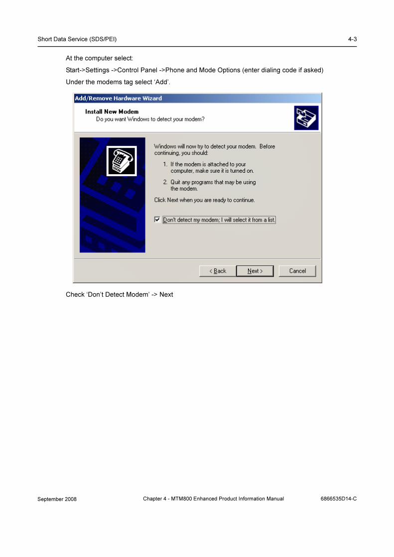
Short Data Service (SDS/PEI) 4-3
At the computer select:
Start->Settings ->Control Panel ->Phone and Mode Options (enter dialing code if asked)
Under the modems tag select ‘Add’.
Check ‘Don’t Detect Modem’ -> Next
September 2008 Chapter 4 - MTM800 Enhanced Product Information Manual 6866535D14-C
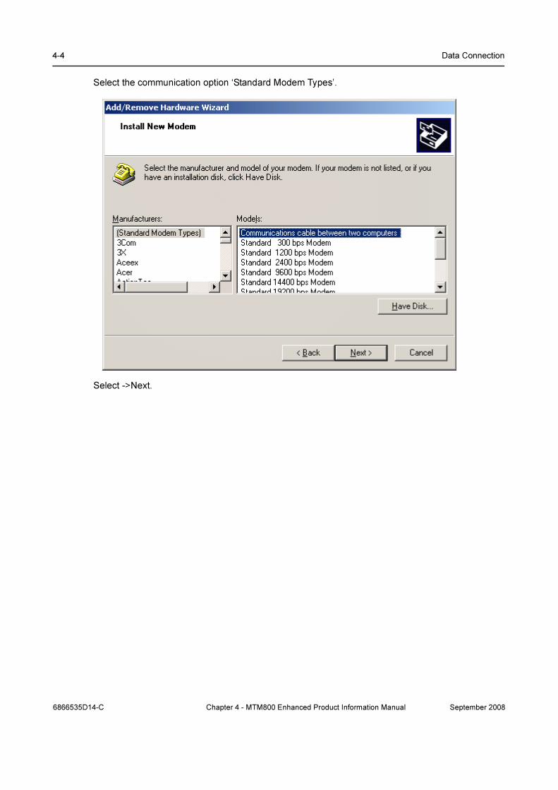
4-4 Data Connection
Select the communication option ‘Standard Modem Types’.
Select ->Next.
6866535D14-C Chapter 4 - MTM800 Enhanced Product Information Manual September 2008

Short Data Service (SDS/PEI) 4-5
Select the communication port that will be used.
Select ->Next
September 2008 Chapter 4 - MTM800 Enhanced Product Information Manual 6866535D14-C
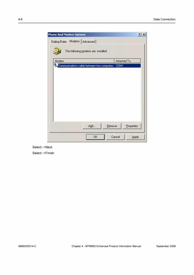
4-6 Data Connection
Select ->Next.
Select ->Finish.
6866535D14-C Chapter 4 - MTM800 Enhanced Product Information Manual September 2008

Short Data Service (SDS/PEI) 4-7
After this returns, select the newly added ‘Communictions Between Two Computers’.
Select ‘Properties’ and change the ‘Maximum Port Speed’ to 9600.
Select ->OK.
4.1.3 Setting up a new Network Connection (Windows 2000®)
At the computer select:
Start->Settings ->Control Panel ->Network and Dial-up Connections
September 2008 Chapter 4 - MTM800 Enhanced Product Information Manual 6866535D14-C
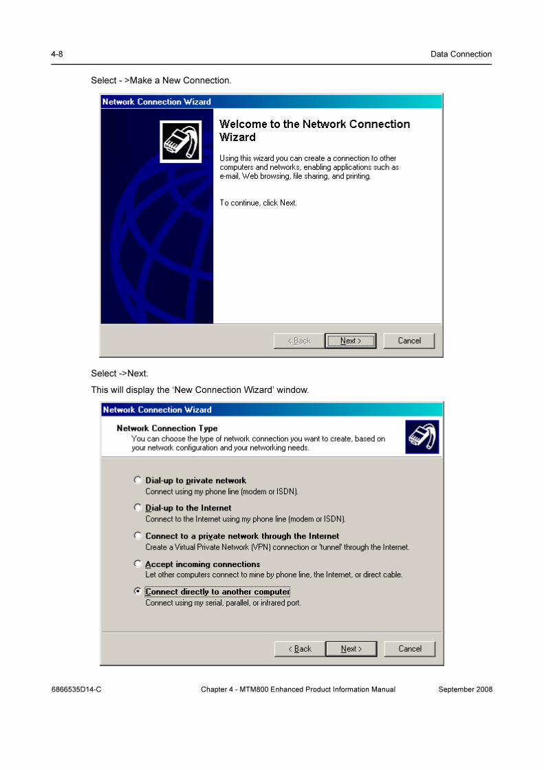
4-8 Data Connection
Select - >Make a New Connection.
Select ->Next.
This will display the ‘New Connection Wizard’ window.
6866535D14-C Chapter 4 - MTM800 Enhanced Product Information Manual September 2008
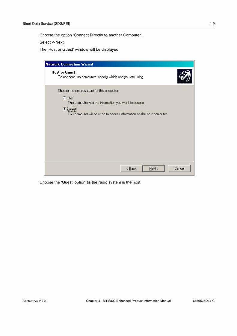
Short Data Service (SDS/PEI) 4-9
Choose the option ‘Connect Directly to another Computer’.
Select ->Next.
The ‘Host or Guest’ window will be displayed.
Choose the ‘Guest’ option as the radio system is the host.
September 2008 Chapter 4 - MTM800 Enhanced Product Information Manual 6866535D14-C
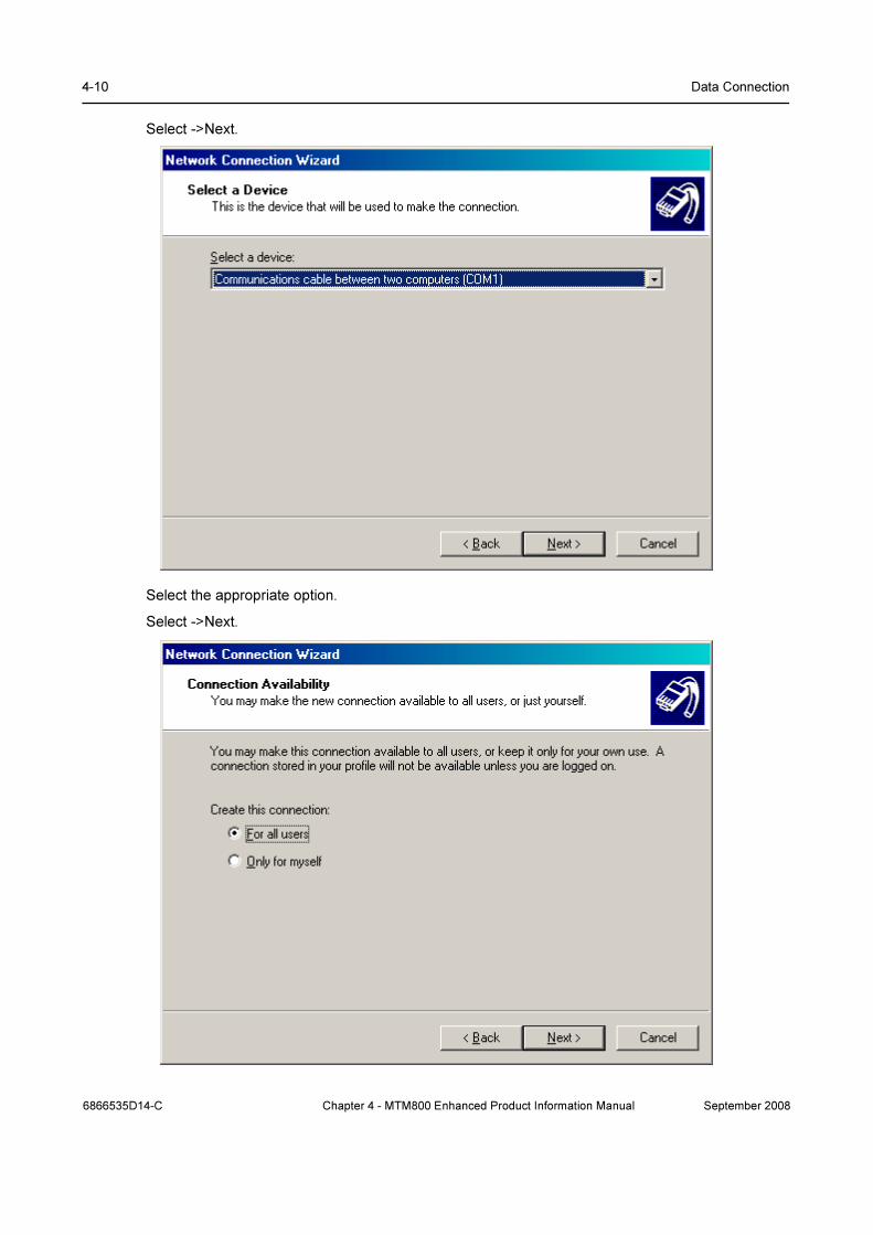
4-10 Data Connection
Select ->Next.
Select the appropriate option.
Select ->Next.
6866535D14-C Chapter 4 - MTM800 Enhanced Product Information Manual September 2008

Short Data Service (SDS/PEI) 4-11
Select ->Next
Enter a name or alias for the connection.
Select ->Finish.
September 2008 Chapter 4 - MTM800 Enhanced Product Information Manual 6866535D14-C

4-12 Data Connection
4.1.4 Dial Up Connection Settings
An easy method of doing this is to select the desktop icon to open the connection.
Select ->Properties.
6866535D14-C Chapter 4 - MTM800 Enhanced Product Information Manual September 2008
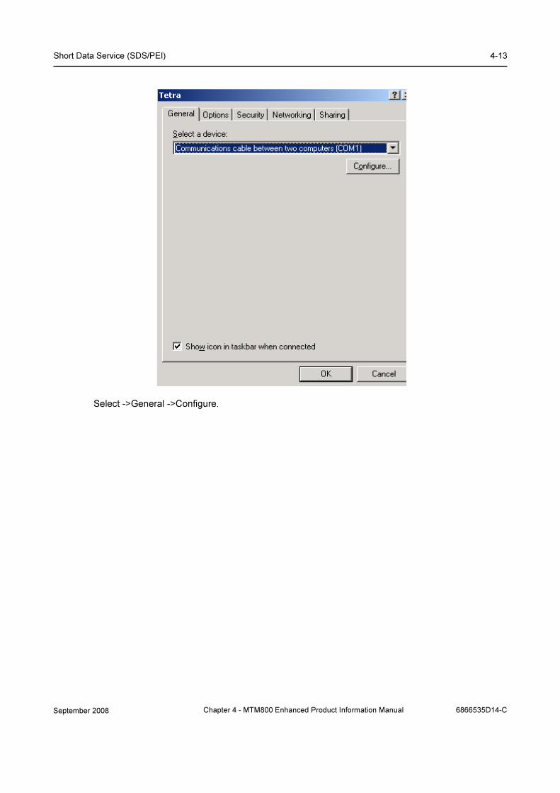
Short Data Service (SDS/PEI) 4-13
Select ->General ->Configure.
September 2008 Chapter 4 - MTM800 Enhanced Product Information Manual 6866535D14-C

4-14 Data Connection
Select the ‘Enable Hardware Flow Control’ an ‘Show Terminal Window’ options.
Select->OK.
Select ->Options.
This will display the ‘Options’ window.
6866535D14-C Chapter 4 - MTM800 Enhanced Product Information Manual September 2008

Short Data Service (SDS/PEI) 4-15
Set the displayed options.
Select ->Security
September 2008 Chapter 4 - MTM800 Enhanced Product Information Manual 6866535D14-C
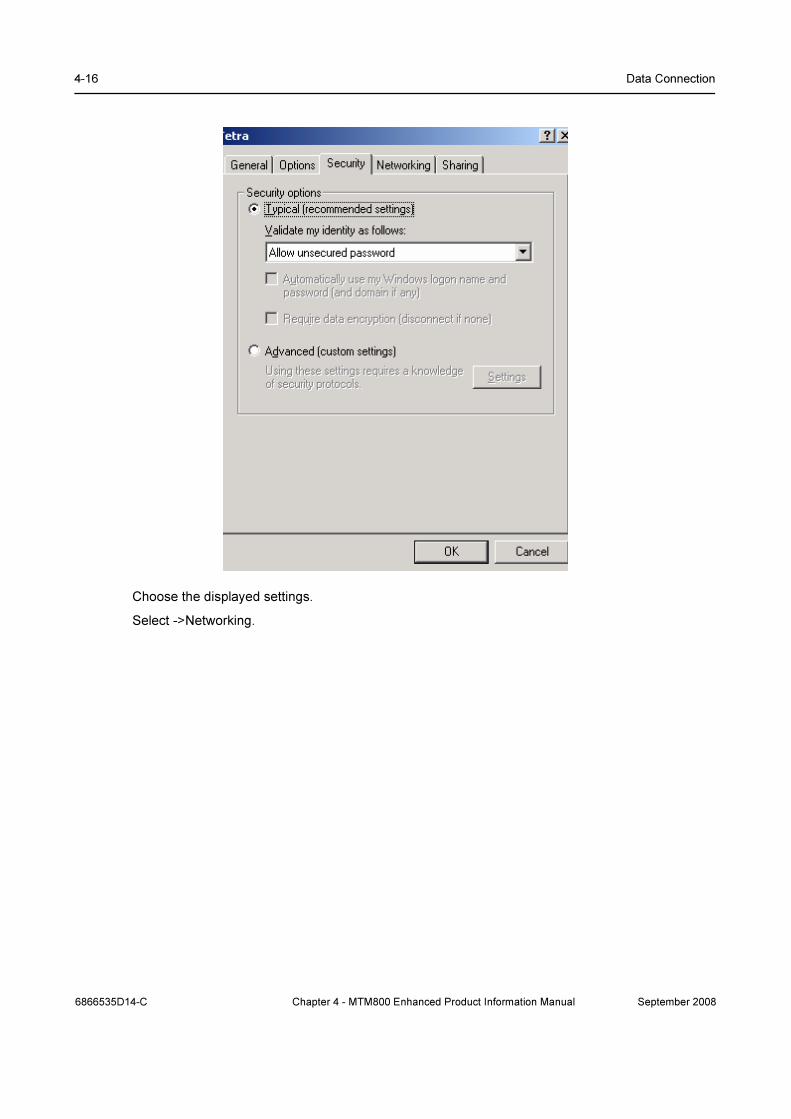
4-16 Data Connection
Choose the displayed settings.
Select ->Networking.
6866535D14-C Chapter 4 - MTM800 Enhanced Product Information Manual September 2008

Short Data Service (SDS/PEI) 4-17
Ensure PPP: Windows® 95/98/NT4/2000, Internet is displayed.
Select ->Settings.
Ensure non of the PPP options are selected.
Select ->OK.
On the main window ensure that the Internet Protocol (TCP/IP) option is selected.
Select->Properties.
September 2008 Chapter 4 - MTM800 Enhanced Product Information Manual 6866535D14-C

4-18 Data Connection
Ensure the above options are selected.
Select ->Advanced
6866535D14-C Chapter 4 - MTM800 Enhanced Product Information Manual September 2008

Short Data Service (SDS/PEI) 4-19
Select ->Use Default Gateway on Remote Network.
Select ->DNS
September 2008 Chapter 4 - MTM800 Enhanced Product Information Manual 6866535D14-C

4-20 Data Connection
Ensure the above options are selected.
Select ->WINS
6866535D14-C Chapter 4 - MTM800 Enhanced Product Information Manual September 2008

Short Data Service (SDS/PEI) 4-21
Ensure nothing is selected in this window.
Select ->Options.
September 2008 Chapter 4 - MTM800 Enhanced Product Information Manual 6866535D14-C

4-22 Data Connection
Select ->Properties.
6866535D14-C Chapter 4 - MTM800 Enhanced Product Information Manual September 2008

Short Data Service (SDS/PEI) 4-23
Ensure the above option is selected.
Select ->OK
Select ->OK.
Select ->OK
At the main window select ->Sharing.
Ensure either othing is selected or is ‘Greyed’ out in this window.
Select ->OK
Close the application if it is not going to be used.
September 2008 Chapter 4 - MTM800 Enhanced Product Information Manual 6866535D14-C

4-24 Data Connection
4.2 Registering on the System for Packet Data
If the application is not running, select the desk top icon.
Select ->Connect
This will open the ‘Pre-Dial Terminal screen.
Enter the following AT commands:
At the prompt type <at><select the enter key>
6866535D14-C Chapter 4 - MTM800 Enhanced Product Information Manual September 2008

Short Data Service (SDS/PEI) 4-25
At the prompt type<ato><select the enter key>
The screen will now display the following:
Select ->Continue.
The following message sequencies should now be displayed:
Enter “at” here
Enter “ato” here
Enter “at” here
Enter “ato” here
September 2008 Chapter 4 - MTM800 Enhanced Product Information Manual 6866535D14-C

4-26 Data Connection
The Terminal/Computer combination is now working on the system and packet data can now be
transmitted and received.
4.2.1 FTP Server
Due to issues with running FTP from Windows®, it is recommended to use the Internet Explorer®
FTP option when transferring files greater than 10K.
Open Internet Explorer.
Select ->Tools ->Internet Options.
6866535D14-C Chapter 4 - MTM800 Enhanced Product Information Manual September 2008
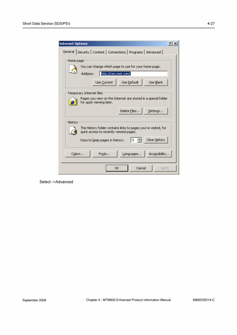
Short Data Service (SDS/PEI) 4-27
Select ->Advanced
September 2008 Chapter 4 - MTM800 Enhanced Product Information Manual 6866535D14-C
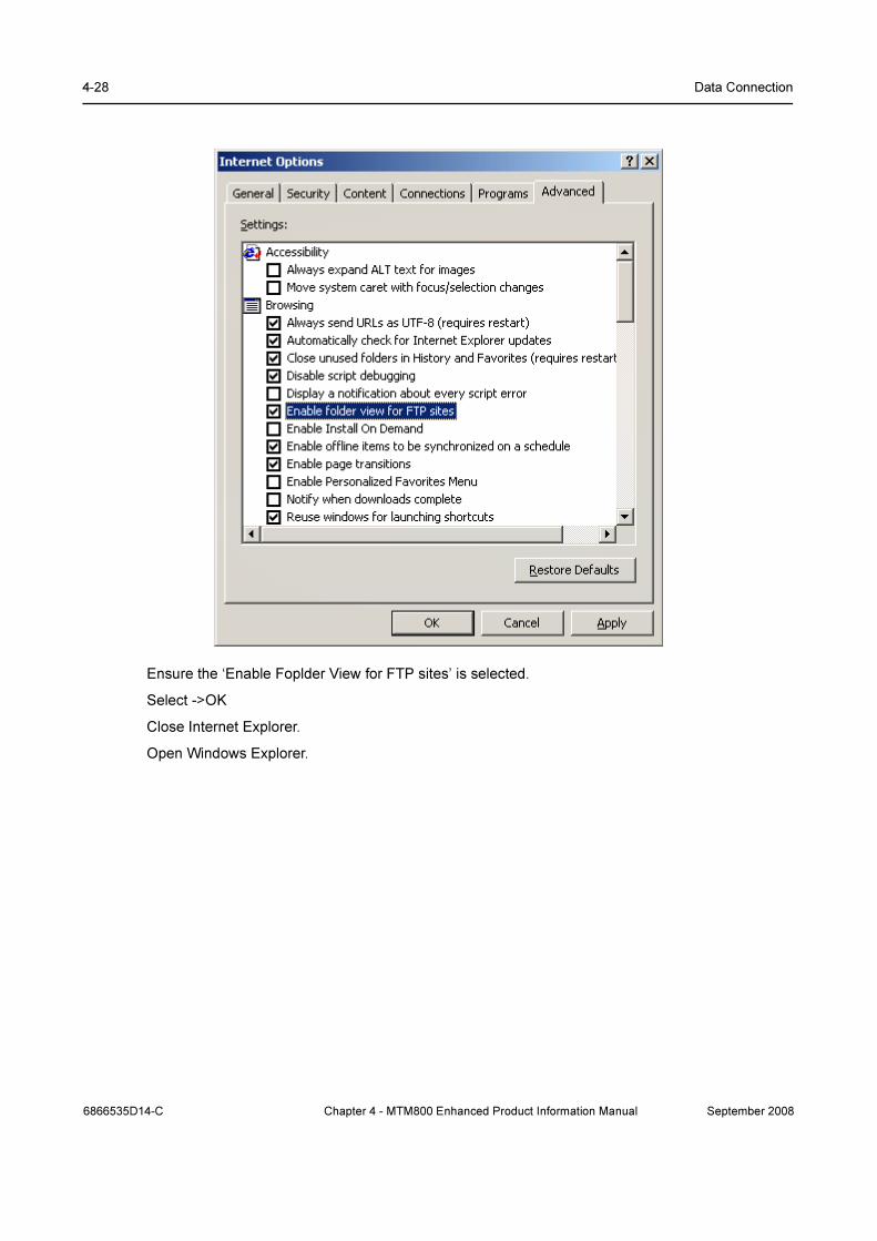
4-28 Data Connection
Ensure the ‘Enable Foplder View for FTP sites’ is selected.
Select ->OK
Close Internet Explorer.
Open Windows Explorer.
6866535D14-C Chapter 4 - MTM800 Enhanced Product Information Manual September 2008

Short Data Service (SDS/PEI) 4-29
In the ‘Address’ box, type in the following: e.g.
ftp://145.13.150.51/
Change the IP address 145.13.150.51 to that of the terminal connected to the computer.
An folder icon will be created as shown above and you will now be logged in as an ‘anonymous’
user.
Files can now be transferred.
September 2008 Chapter 4 - MTM800 Enhanced Product Information Manual 6866535D14-C

4-30 Data Connection
5 Hyper Terminal
It is also possible to use the ‘Hyper Terminal’ feature of the computer.
To run Hyper Terminal once the terminal and computer have been connected, at the computer
select
the following path to open the application:
Start ->Programs ->Accessories ->Communications ->Hyper Terminal.
Select:- File ->Properties
This will display the Packet Data Properties screen.
6866535D14-C Chapter 4 - MTM800 Enhanced Product Information Manual September 2008
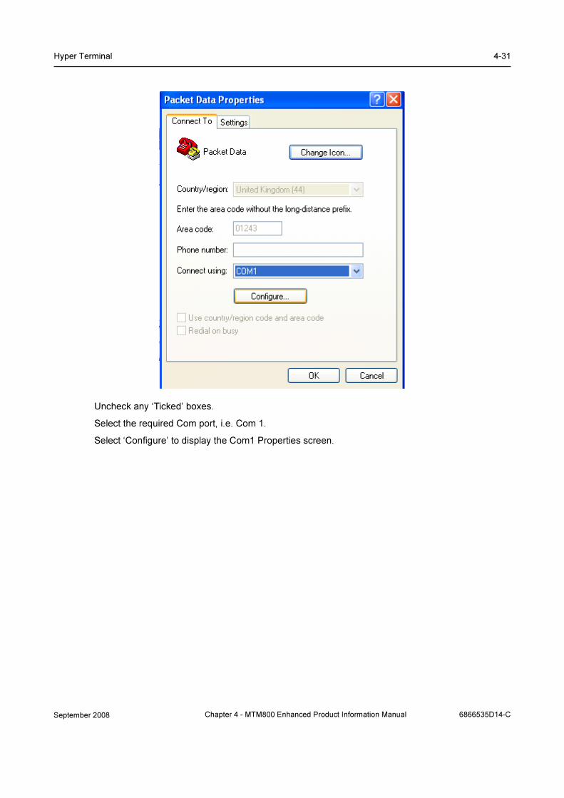
Hyper Terminal 4-31
Uncheck any ‘Ticked’ boxes.
Select the required Com port, i.e. Com 1.
Select ‘Configure’ to display the Com1 Properties screen.
September 2008 Chapter 4 - MTM800 Enhanced Product Information Manual 6866535D14-C

4-32 Data Connection
Configure the properties with the above settings.
It is now possible to use AT commands via the Hyper Terminal.
6866535D14-C Chapter 4 - MTM800 Enhanced Product Information Manual September 2008

AT Commands 4-33
6 AT Commands
The AT Commands supported by the terminal is a subset of the available AT Commands.
Note:
1. Each response from the terminal is followed by a <CR><LF><OK><CR><LF>
2. Each DTE command is terminated with a <CR>
The Motorola Proprietary format for SDS is selected in CPS.
6.1 Examples of DTE Commands to the Terminal
Table 4-1
DTE Command Possible Terminal Responses
AT+CTOM=<AI mode> +CTOM:_<AI mode>
AT+CTOM? +CTOM:_<AI mode>
AT+CTOM=? +CTOM:_(0,1)
AT+CTGS=1,<selected GSSI> +CTGS:_<group type>,
<selected GSSI>
AT+CTGS? +CTGS:_<group type>,
<selected GSSI>
AT+CTGS=? +CTGS:_(1,2),(0-16777215)
AT+CTDGR=<GR unsolic> OK
AT+CTDGR? +CTDGR:_[<DM communication type>,
<address>,<MNI>,<presence information>
<CR><LF>
[,_<DM communication type>,
<address>,<MNI>,<presence information>]]
AT+CMGS=<da>,1,0,<length> +CMGS:_0
AT+CMGS=?
AT+CMGS=[<da>],[<toa>],[<area>
],<length>[,<data-type>]
[,<mcc>,<mnc>]<CR>
<data><ctrl>-Z/ESC>
+CME_ERROR:_<err>
All other +CME_ERROR:_<err>
September 2008 Chapter 4 - MTM800 Enhanced Product Information Manual 6866535D14-C
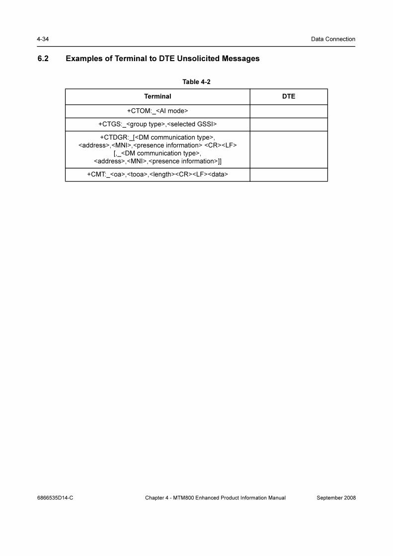
4-34 Data Connection
6.2 Examples of Terminal to DTE Unsolicited Messages
Table 4-2
Terminal DTE
+CTOM:_<AI mode>
+CTGS:_<group type>,<selected GSSI>
+CTDGR:_[<DM communication type>,
<address>,<MNI>,<presence information> <CR><LF>
[,_<DM communication type>,
<address>,<MNI>,<presence information>]]
+CMT:_<oa>,<tooa>,<length><CR><LF><data>
6866535D14-C Chapter 4 - MTM800 Enhanced Product Information Manual September 2008