
Kinetic modelling of the esterification of rosin and glycerol: Application to industrial operation
Upload
khangminh22Category
view
1download
0
Modelling and simulation of industrial systems
Citation for published version (APA):Wortmann, A. M. (1991). Modelling and simulation of industrial systems. [Phd Thesis 1 (Research TU/e /Graduation TU/e), Mechanical Engineering]. Academisch Boeken Centrum. https://doi.org/10.6100/IR360528
DOI:10.6100/IR360528
Document status and date:Published: 01/01/1991
Document Version:Publisher’s PDF, also known as Version of Record (includes final page, issue and volume numbers)
Please check the document version of this publication:
• A submitted manuscript is the version of the article upon submission and before peer-review. There can beimportant differences between the submitted version and the official published version of record. Peopleinterested in the research are advised to contact the author for the final version of the publication, or visit theDOI to the publisher's website.• The final author version and the galley proof are versions of the publication after peer review.• The final published version features the final layout of the paper including the volume, issue and pagenumbers.Link to publication
General rightsCopyright and moral rights for the publications made accessible in the public portal are retained by the authors and/or other copyright ownersand it is a condition of accessing publications that users recognise and abide by the legal requirements associated with these rights.
• Users may download and print one copy of any publication from the public portal for the purpose of private study or research. • You may not further distribute the material or use it for any profit-making activity or commercial gain • You may freely distribute the URL identifying the publication in the public portal.
If the publication is distributed under the terms of Article 25fa of the Dutch Copyright Act, indicated by the “Taverne” license above, pleasefollow below link for the End User Agreement:www.tue.nl/taverne
Take down policyIf you believe that this document breaches copyright please contact us at:[email protected] details and we will investigate your claim.
Download date: 28. Jul. 2022

Modelling and Sitnulation
of In dustrial Systetns
Alexander Michael Wortmann

Modelling and Simulation of lndustrial Systems

Copyright C by A.M. Wortmann, Eindhoven, The Netherlands.
No part of this hook may be reproduced in any form: by print, photoprint, mièrofilm, or any other means without permission of the copyright owner.
Druk: Wibro, Helmond
CIP-GEGEVBNS KONINKLDKE BmLIOTHEEK, DEN HAAG
, Wortmann, Alexander Michael
ModeDing and Simulation of lndustrial Systems I A.M. Worttnann. - De Lier : Academisch· Boeken Centrum Proefschrift Eindhoven, 1991. -Met lit. opg. -Met samenvatting in het Nederlands. ISBN 90-72015-91-6 Trefw.: industriële systemen ; modellering I industriële systemen ; computersimulatie.

Modelling and Simulation of lndustrial Systems
PROEFSCHRIFf
ter verkrijging van de graad van doctor aan de Technische Universiteit Eindhoven,
op gezag van de Rector Magnificus, prof. dr. J.H. van Lint, voor een conunissie aangewezen door het College
van Dekanen in het openbaar te verdedigen op dinsdagS november 1991 om 16.00 uur
door
ALEXANDER MICHAEL WORTMANN
geboren te Groningen

Dit proefschrift is goedgekeurd door de promotoren prof. dr. ir. I.E. Rooda en prof. dr. M. Rem.
Copromotor: dr. ir. I.H.A. Arentsen

to Diederik, Gertine
and my parents
PREFACE
The Power of an Appropriate Language
Let us focus our attentionfora moment on teievisions. When a teievision is broken, the engineer uses an eiectrical circuit diagram of the teievision to investigate the probiem. Also, when a design team thinks about inventing a new generation of teievisions, circuit diagrams are used to fonnulate the ideas. These diagrams are also used as a specificadon of the teievision, and as a communication tooi between peopie invoived in for instanee the design, evaluation or production of the television.
A circuitdiagram can be read by aneiectrical engineer, because heknows something about teievisions, and he understands the language of the diagram. The diagram is a symbolic Ianguage, it contains language elements like resistors, capacitors and operational amplifiers. An electrical engineer can read the diagram: he reads, for instance, that the highfrequency unit is designed to minimize noise, but is not completely stabie to temperature changes. The electrical engineer gets a good ideaabout the strong points and the weak points of the design, and can use the diagram when searching for a defect.
Now suppose that we give these engineersnota circuit diagram, but a set offonnulas descrihing the television. lt is possible to describe exactly the same infonnation that the schematic contains by means of a set of mathematica! fonnulas. Although the two representations contain the same infonnation, they are not of the same use to the electrical engineer. Stronger, he will not be able to do anything with the set of fonnulas; he may even not be able to see that it represents a television.
This observationleads to.the idea that it is not the infonnation as such that delermines whether something appears complex or not, but it is the language that is used to represent it. The circuit diagram has Ianguage

vili ModeUing and Simulation of lndustrial Sy~R~ms
elements that are appropriate abstractions for an electrical engineer, whereas the fonnulas do not.
After making this observatîon, the following question arises: "Which language should be used to describe industrial systems?" Whichlanguage gives designers of industrial systems a power such as the electtic diagram gives to electrical engineers? Suppose that we are completely :free to invent a language to describe industrial systems, what language would result, and why?
This study addresses these questions, and presents a language that is suitable for the description of industrial systems.
The language that bas been developed· bas been used further in the construction of a computertooi forthe design and simulatîon of industrial systems. The tooi and its use are also described.

Summary
This study focuses on the design of industrial systems, like machines, production lines and factories. The design of industrial systems is not a tri.vial tas.k, they can be complex and large, and a variety of disciplines may be involved.
The Process Interaction Approach is a metbod that supports designers in their tasks. It is an approach to the rnadelling of industrial systems with the following key ideas: make a functional and formal specificadon (a model) of the system before realizing it; use the abstractions process and interaction as basic rnadelling elements; use simulation to evaluate the specification; and be able to use the model of a software control system as the actual controL
The core of this study is the development of a new rnadelling language and a software tool for the specification and simulation of industrial systems according to the Process Interaction Approach.
In the past, different languages and different tools have been used, in the design, simulation and implementation phase of industrial systems. This diversity in languages resulted in gaps in the design process. Furthennore, these languages were in fact programming languages, which express abstractions that do not match the abstractions that modellers of industrial systems need. Therefore, programmers were needed to specify systems, instead of modellers.
In this study, one language will be developed that is suited for the specification of systems, and which can be simulated too. In order to do so, the semantic elements that are needed for such a description will be investigated. Then, a syntax is proposed that is able to express these abstractions. This results in the new language ProcessTalk: a language that can be used to make formal and functional specifications of industrial systems.

x Modelling and Simulation of Jndustrial Systems
Furthermore, a tooi is developed that supports the design activity of industrial systems. This tooi is called the ProcessTool; it is an interactive graphical software environment for the modelling and simwation of industrial systems.
ProcessTalk: and the ProcessTool enable designers of industrial systems to get a good impression about the behaviour of the system in an eariy phase of the design process. Designers think in such terms as: What will the throughput be of this production line? What happens when that machine breaks down? Where is the bottleneck of this system? One of the major benefits of the language and tooi is that modellers do nothave to transiate' their ideas in order to ask these questions, the tooi is approachable at exactly this level of abstraction.
The language and the tooi have been used in a large number of cases,, showing their usage in a diversity of areas, and illustrating their use in practice.
We will conclude that specifying industrial systems has become more modelling and less programming. The language ProcessTalk: enables the functional description of systems in an elegant, systematic and modular way. The ProcessTool has eliminaled the gaps between the specification, simulation and utilization phases. The large experience with the language and the tooi enabies us to affinn that they have a beneficial in.fluence on the generation of ideas of modellers.
The language ProcessTalk and the ProcessTool enable the full exploitation of the Process Interaction Approach, confirming its power in the design of industrial systems.

Samenvatting
- Deze studie richt zich op het ontwerpen van industriële systemen zoals machines, produktielijnen en fabrieken. Het ontwerpen van zulke systemen is geen eenvoudige taak, ze kunnen complex en groot zijn, en er kunnen verschillende disciplines bij betrokken zijn.
De Proces Interactie Benadering is een methode die ontwerpers ondersteunt bij deze ontwerptaak. Het is een benadering tot het modelleren van industriële systemen en bevat de volgende basisideeën: maak een functionele en formele specificatie (een model) van het systeem alvorens het te realiseren; gebruik de abstracties proces en interactie als basis modelleer-elementen; gebruik simulatie om het ontwerp te evalueren; .en maak· het mogelijk de specificatie van de besturingssoftware te gebruiken als de eigenlijke besturing;
De kern van deze studie vormt het ontwerp van een modelleertaal en een software-hulpmiddel voor de specificatie en simulatie van industriële systemen, volgens de uitgangspunten van de Proces Interactie Benadering.
In het verleden werden versèhillende talen en verschillende softwareomgevingen gebruikt tijdens ·de specificatie-, simulatie- en implementatiefase van een systeem. Deze diversiteit in talen resulteerde in mis-aanpassingen in het ontwerpproèes. Bovendien waren deze talen in feite programmeertalen, die abstracties uitdrukken die niet geschikt zijn voor het beschrijven van industriële systemen. Daardoor waren programmeurs nodig om systemen te specificeren, in plaats van modelleurs.
In deze studie wordt een taal ontwikkeld die geschikt is voor het beschrijven van industriële systemen, en bovendien gesimuleerd kan worden en, onder omstandigheden, als werkelijke besturing gebruikt kan worden. De taal wordt ontworpen door een inventarisatie te maken van de semantische elementen die nodig zijn voor het beschrijven van

xii Modelling and Simwation of lndustrial Systems
industriële systemen. Vervolgens wordt een syntaxis voorgesteld die deze elementen uit kan drukken. Dit resulteert in de taal 'ProcessTalk': een taal voor het formeel en functioneel beschrijven van industriële systemen.
Bovendien wordt een software-hulpmiddel ontwotpen dat een ontweiper kan ondersteunen. Deze applicatie heet 'ProcessTool ', het is een interactieve, grafische model~erings- en simulatieomgeving voor industriële systemen.
ProcessTalken ProcessTool geven ontwerpers de mogelijkheid om in een vroeg stadium van het ontwetpproces een goede indruk te krijgen over het toekomstig gedrag van het ontwetp. Ontwerpers denken in termen als: Wat zal) de doorzet van deze produktielijn zijn? Wat gebeurt er als deze machine uitvalt? Waar zit de bottleneck van dit systeem? Het feit dat zulke vragen gesteld kunnen worden zonder·dat de modelleurs hun gedachten moeten vertalen is een van de belangrijkste voordelen van de taal en de applicatie: ze zijn aanspreekbaar op het juiste abstractieniveau.
ProcessTalken ProcessTool zijn toegepast in een groot aantal cases, deze laten de diversiteit van het toepassingsgebied zien, alsmede hun functioneren in de praktijk.
Concluderend wordt gesteld dat het specificeren van industriële systemen meer modelleren is geworden en minder programmeren. De taal ProcessTalk is geschikt voor het beschrijven van systemen op een elegante, systematische en modulaire wijze. Het ProcessTool gereedschap laat de specificatie-, simulatie- en implementatiefase naadloos op elkaar aansluiten. De ruime ervaring met de taal maakt het mogelijk te stellen dat deze taal een positieve invloed op de ideeën van ontwerpers heeft.
De taal ProcessTalk en het ProcessTool hulpmiddellaten de Proces Interactie Benadering volledig tot haar recht komen, daarbij de kracht ervan bevestigend in het ontwetpen van industriële systemen.
Summary
Samenvatting
1. Introduetion
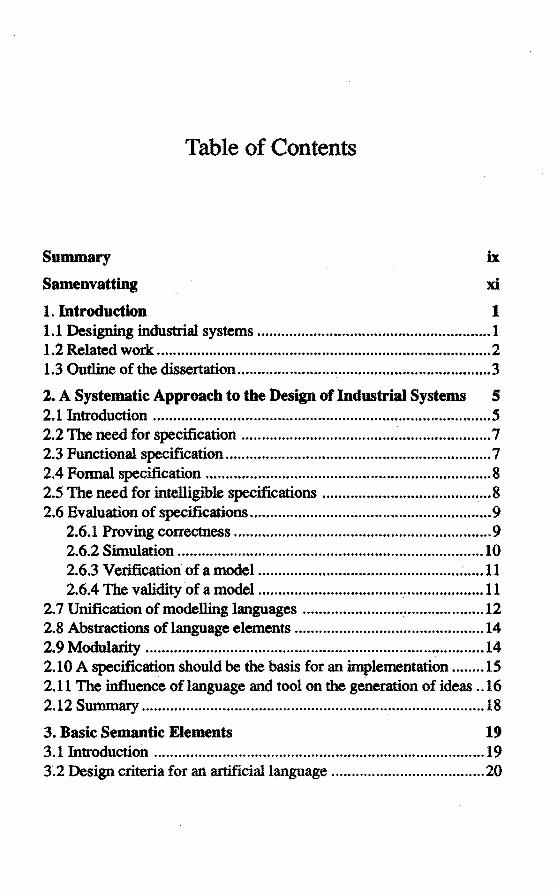
Table of Contents
ix
xi
1 1.1 Designing industrial systems .......................................................... 1 1.2 Related work ................................................................................... 2 1.3 Outline of the dissertation ............................................................... 3
2. A Systematic Approach to the Design of lndustrial Systems S 2.1 Introduetion .................................................................................... 5 2.2 The need for specification .............................................................. 7 2.3 Funetional specification .................................................................. 7 2.4 Formal. specification ......................................................................... 8 2.5 The need for intelligible specifications .......................................... 8 2.6 Evaluation of specifications ............................................................ 9
2.6.1 Proving correctness ................................................................ 9 2.6.2 Sirnularlon ............................................................................ 10 2.6.3 Verification of a model ........................................................ 11 2.6.4 The validity of a model ........................................................ 11
2. 7 Unification of modelling languages .............................................. 12 2.8 Abstractions of language elements ............................................... 14 2. 9 Mod:u1.ari.ty" .................................................................................... 14 2.10 A specification should be the basis for an implementation ........ 15 2.11 The influence oflanguage and tooi on the generation of ideas .. 16 2.12 Summary ..................................................................................... 18
3. Basic Semantic Elements 19 3.1 Introduetion ................................................................. ~ ................ 19 3.2 Design criteria for an artificiallanguage ...................................... 20

Modelling and Simulation of Jndustrial Systems
3.3 Modelling the stmcture of an industrial system ........................... 21 3.3 .1 Processors .............................................................................. 22 3.3.2 Interaction paths .................................................................... 24 3.3.3 Ports ....................................................................................... 25 3.3.4 Static stmcture ...................................................................... 26
3.4 Modelling the tasks of processors ................................................ 27 3.4.1 Passive el.ements .................................................................. 27 3.4.2 Duplicates and the concept of class ..................................... 28 3 .4.3 State ...................................................................................... 28 3.4.4 Discrete and continuous models .......................................... 29 3 .4.5 Action md activity" ............................................................... 30 3.4.6 lrlteractions ................................................................ -............ 31 3.4.7 Control stmctures or conditionat actions and loops ............. 39 3.4.8 Aggregation and decomposition .......................................... 39 3.4.9 Procedure abstraction ........................................................... 39 3.4.10 Commonness, specialization and generalization .............. .40 3.4.11 Nondetenninism ................................................................. 40
3 .S Sum.rnaiy' •...•.....•••.••...•..•••••....•.......••..•..•..•.•...••.........•••••....••....••.... 41
4. ProcessTalk: a Language for the Descripdon of Industrial Systems 43
4.1 futroducûon .................................................................................. 43 4.2 The strll.cture lmgu.age .................................................................. 43 4.3 The task language ......................................................................... 47
4.3.1 The choice fora textual task language ................................. 47 4.3.2 The choice for a computer language .................................... 47 4.3.3 The choice for an object oriented language ........................ .48 4. 3 .4 The choice for Smalltalk .................................................•.... 48 4.3.5 The modèlling of duplicates and the notion of class ........... .49 4.3.6 Modelling leafprocessors .................................................... 51 4.3.7 Modellmg activity ................................................................ 52 4.3.8 Send and receive actions ...................................................... 52 4.3.9 The modelling ofpassive elements ...................................... 53 4.3.10 The modelling of control stmctures ................................... 56 4.3.11 The modelling of aggregation and decomposition ............. 58 4.3.12 The modelling of procedure abstractions ........................... 62
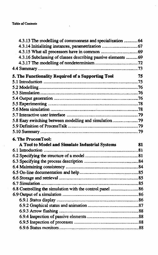
Table of Contents
4.3.13 The rnadelling of commonness and specialization ............ 64 4.3.14 Initializing înstances, parametrization ............................... 67 4.3.15 What all processors have in common ................................. 69 4.3.16 Subclassing of classes descrihing passive elements .......... 69 4.3.17 The modelling of nondetenninism ..................................... 72
4.4 Summ.ary ....................................................................................... 73
5. The Functionality Required of a Supporting Tooi 75 5.1 Introduetion .................................................................................. 75 S .2 Modelling ...................................................................................... 76 5.3 Siln.ulation ..................................................................................... 76 5.4 Output generation ......................................................................... 76 5.5 Experimenting .............................................................................. 78 S.6 Meta sinlulation ............................................................................ 78 5. 7 Interactive user interface .............................................................. 79 5.8 Easy switchîng between modelling and siln.ulation ...................... 79 5.9 Definition of ProcessTalk: .............................................................. 79 5.10 Summ.ary ..................................................................................... 79
6. The ProcessTool: A Tooi to Model and Simulate lndustrial Systems 81
6.1 Introduetion .................................................................................. 81 6.2 Specifying the structure of a mode1 .............................................. 81 6.3 Specifying the process description ............................................... 84 6.4 Maintainirlg consistency ............................................................... 84 6.5 On-line documentation and help ................................................... 85 6.6 Storage and retrieval ..................................................................... 85 6. 7 Siln.ulation ..................................................................................... 85 6.8 Controlling the siln.ulation with the control panel ........................ 86 6.9 Output of a siln.ulation .................................................................. 86
6.9.1 Status display ....................................................................... 86 6.9.2 Graphical status and aniln.ation ............................................ 87 6.9.3 Arrow flashîng ..................................................................... 88 6.9.4 Inspeetion of passive elements ............................................. 88 6.9.5 Inspeetion of processes ........................................................ 88 6.9.6 Status monitors ..................................................................... 88

Modelling and Simulation of Industrial Systems
6.9.7 Observers ............................................................................. 89 6.9.8 Reportmg ................•.........•................................................... 90 6.9.9 Independenee between the model and output generation .... 90
6.10 Some inlplementation details ...................................................... 91 6.11 Summary ..................................................................................... 92
7. Using ProcessTalk and the ProcessTool 95 7.1 Introduetion ................................................................................... 95 7. 2 Some cases ...................................................................................... 9S 7.3 A case: the design of a complex production cell .......................... 98 7.4 Implementing software control systems ....................................... 99
7.4 .1 futroduction .......................................................................... 99 7.4.2 Th.e concept: use the specificadon as an implementation .. 100 7.4.3 Realizing the concept ......................................................... 101 7 .4.4 Real-time control systems .................................................. 102 7 .4.5 Qmusions aboot impltmenting software conttol systlmS .......... 1 03
7.5 Summary ..................................................................................... 103
8. Open Issues and Conclusions lOS 8.1 Open issues ................................................................................. 105
8.1.1 A new syntax for the specificadon of interactions ............. 105 8.1.2 Th.e possibility to specify busy waiting .............................. 1 06 8.1.3 Enhancing the tooi ............................................................. 107 8.1.4 Imptementing control systems ........................................... 107
8.,2 A reflection and conclusions ...................................................... 108
Relerences ··················~·····································································111 APPENDIX A. An Introduetion to tbe Conceptsof OOP ................ 121
APPENDIX B. An Introduetion to tbe Syntax of Smalltalk ............ 127
APPENDIX C. Basic Task Language Methods ................................. 131
APPENDIX D. Glossary ...................................................................... 139
CHAPTER 1
Introduetion
1.1 Designing industrial systems
Industrial systems are systems like machines, production lines and factories. Such systems are intended to transport, handle or transform material. Their design is often a difficult task: such systems can be large and complex, and it can be difficult for a designer to keep an overview of the total system. Furthermore, a variety of disciplines are involved in their design, such as construction, logistics, control (possibly in the form of reai-time software), user-interfacing, and electronics; furthermore, disciplines like marketing and sales can make their influence feit. The influence of design decisions is often difficult to predict: it may be impossible, dangerous or costly to perform experiments. During the design stage, strong constraints on costs or available time can be in effect.
This explains the need for support for the design of industrial systems. A method that would help designers or design teams in performing their task, one which reduces at least some of the problems with which they are confronted, would seem to be useful.
The basis for the considerations that will be developed forther in this work was laid down by Overwater in [ Overwater 1987]. He developed the first attempts at a systematic description of an industrial system, independently of its magnitude, nature or degree of complexity. In doing so he laid the foundations for what has become to be known as the Process Interaction Approach. I became interested in this work in 1989, and it soon became apparent to me that the potential existed for the development of a new modelling language, a language created with the explicit purpose of

2 Modelling and Simwation of Industrial Systems
descrihing industrial systems. Such a language would be a very powerlul modelling language because it would contain exactly those abstractions that modellers needinorder to describe industrial systems. Furthermore, if th.e language were a formal one, it should be possible to create a software tooi to assist a designer in specifying and simulating the systems.
1.2 Related work
In [Overwater 1987] a metbod called the Process Interaction Approach is introdueed, including a language that uses the abstracri ons Process and Interaction as important modelling elements.
A set of tools were also available at that time, a design tooi named 086 [Munneke 1986], a set of Pascal procedures and functions that enable the construction of simwation models: S84 [Rooda et al. 1984], and a reaitime operating system kemel, Roskit [Rossingh et al. 1984].
Overwater showed that there were gaps between these tools. The different tools use different languages, for instanee in thesemantics of inter-process communication. Although they all use the process and interaction abstractions as basic building blocks for modelling, the communication primitives of the interactions differ significantly. This study shows how these gaps can be eliminated. Furthermore, the study places the approach on a fmner scientific footing by giving a stronger defmition of terms, showing design decisions, investigating altematives, and justifying the choiee of the terms selected. Attention is also focused on the problem of designing a suitable lariguage for the description of industrial systems, rather than using an existing programming language.
[Hoare 1985] is an important instanee of related work with a mathematica! viewpoint. He describes a formalism to speci:fy communicating sequentia! processes, including mathematica! analysis techniques to derive the properties of specifications in an analytica! way. This work is related because we use communicating processes for the description of industrial systems. Other mathematica! approaches include for instanee Petri nets [Peterson 1977]. Mathematica! approaches have our interest because they

Chapter 1. Introduetion 3
might enable us to prove certain properties of industrial systems, by analytically studying tbeir models.
[Birthwistle 1979] represents tbe approach oftbe simwation world. This is related work because simwation is important in our approach to tbe design of systems. He reveals the foundations of discrete event simwation techniques. [Zeigler 1976] introduces a formalism for discrete event simwation. [Law et al. 1982] address the topics of starlstics and validation in simwation.
Another class of related work is that of the software engineering community, which is related to tbe present work because our metbod is also suitable for tbe design of control software. An important memher of this class is [Y ourdon et al. 1979], who developed metbods for software design. [Meyer 1988] presents a metbod for object oriented software construction.
1.3 Outline of the dissertation
Chapter 2 describes tbe key concepts of tbe approach. The need for a functional specification will be shown. This specification is a formal and functional model of tbe system. The evaluation of specifications will be addressed, as well as tbe benefits of a unification of modelling languages. The concepts of abstraction and modwarity will be considered. This discussion reswts in tbe realisation tbat tbere is a need for a language to model industrial systems, and a tool tbat can assist modellers in the performance of tbeir task.
Chapter 3 describes tbe basic semantic elements tbat a language showd have in order to be suitable for use as a modelling language for industrial systems.
Chapter 4 gives a detailed proposal for such a language, it is called ProcessTalk and is based on tbe object oriented programming language Smalltalk.

4 Modelling and Simulation of lndustrial Systems
Chapter 5 investigates the functionality that is required of a software tooi that will be helpful in using the approach. The tooi itself is an enlviromnent in which it is possible to model and simulate industrial systems.
Chapter 6 describes an implementation of such a tooi.
Chapter 7 presents an overview of how the language and tool have been used in practice. It also includes a description of a case where the tooi was used to explore many of the problems faced in the design of a real system. One section is about the implementation of software control systems, descrihing a remarkable property of fomtal functional specificadons of software systems: they are also implementations of these specifications.
Chapter 8 mentions a number of open issues, reflects on this study, and presents the conclusions.
CHAPTER 2
A Systematic Approach to the Design of Industrial Systems
2.1 Introduetion
In thîs chapter, the Process Interaction Approach (recently also the name "ProcessCalculus" bas been introduced) will be described. It is an approach for the design of industrial systerns. We will fust focus on the act of designing, and describe the requirements for the specification technique. The following sections address the key concepts of specifying techniques, evaluation of specifications, and the properties of specification languages. During thîs description it will become apparent that, in order to be able to use the method, a modelling language is needed. The metbod makes high demands upon thîs language, and the basic semantic elementsof a language that meets these demands is described in the next chapter.
In Chapter 4 a detailed description of a language that can express these semantic elements is proposed. Furthennore, the need fora tool that helps in using the metbod and implements a number of conceptsof the metbod will be shown. The required functionality and an implementation of such a tooi is described in Chapters 5 and 6.
The design process
The act of designing an industrial system can be regarded as consisting of two activities of which one is the specification part. The designer starts by mak:ing a number of design choices, including hitting upon the right
6 Modelling and Simulation of Industrial Systems
ideas, comingup with anumber of altematives, inventing, thinking, using experi.ence and being creative (soinetimes maybe even artistic ) .. The design as it is in the mind of a designer is called a conceptual model [Garzia 1990].
In the second phase, the design must be represented. Giving expression to the ideas is called the act of specification, and it results in a representation of a system: a model, called the specification.
Specifying is modelling
A model of a system is an abstraction of that system built with a certain objective in mind. A specification is a model, and specifying is modelling, we will use these terms as synonyms. (See also Appendix D: the glossary, for the definitions of tenns.)
The purpose of a model
Before starring to model it is very important to have a good idea about the purpose ( or objective) of the model. For example, is it a model to examine the logistics of a given system, or to play a number of what-if scenari.os, or to study the reai-time timing requirements of the control, or to specify the control that eventually will be used for the real system? It is not possible to build, to judge the quality or to use a model when its purpose is not defined.
Assumptions: the experimental frame
The model will describe certain aspects of the system under certain circumstances. The modeller will make a number of assumptions, and only under these circumstances is the model intended to be the model of its system. It is important to descri.be which assumptions the modeller has used while modelling. These assumptions cannot in general be derived from the model and must be specified separately. It is not possible to describe these exhaustively (see also Section 2.6.4 on validation). Nevertheless, the modeller should specify as many relevant assumptions

Chapter 2. A Systematic Approach to the Design of lndustrial Systems 7
as possible, preventing users of the model from using it under inappropriate circumstances.
2.2 The need for specification
When building complex systems, it is wise first to make a specification of the system, instead of starting to construct it right away. Creating a specification helps one to think about the system before actually building it, it enables one to communicate with others about the design, and often prevents the building of a system that does not fulfil its objective. The informal goal of a specification of a system can be considered as the production of a description of all the essential properties of that system. A specification is the basis for the implementation.
2.3 Functional specification
When designing a system, the designer thinks in the first place about the function that the system should perform. The need fora system is expressed in terms of its functionality. The objective of the system is to perform this function. Usually there are many concrete systems imaginable that would perform the function well. This class of systems with the same functionality contains systems that differ in implementation. When designing the system, the matter of primary concern is thinking about the functionality, refraining from choosing between implementations. As long as the desired functionality is still under consideration, if it is unclear or not well described, then it is a waste of time to think about implementation aspects. This is the reason why there is a need for a technique for the functional specification of industrial systems. A functional specification is a description of the functionality of the system: what the system should do, and not how the system should do it. The functional level is sometimes called the system level; the word architecture is also used to emphasize that the topic of concern is closer to style and philosophy than to the actual, concrete realization.

8 Modelling and Simulation of Jndustrial Systems
2.4 Formal specitication '
A specification should have a unique interpretation. Ambiguity would introduce communication errors and eventually the construction of a system that does not conform to the specification as intended by the specifier. The meaning of a specification should therefore allow exactly one interpretation. A specification in a fonnallanguage is called a forma! model.
Modelling languages
A fonnal model is expressed in a language. A language is a systematic means of communication using conventionalized signs, sounds, gestures, ormarks. A fonnallanguage associates a meaning with a model, by means of a convention. A model expressed in a formallanguage can be called asemantic model: it has a meaning. See also [Brinksma 1988] for more details on formal specification.
2.5 The need for intelligible specitications
The requirements for the specification metbod inentioned thus far do not imply that it can be understood by humans. The requirement for a formallanguage might point in the direction of a mathematicallanguage or a computer programming language. Without rejecting these immediately, it is also important that humans will be able to use and understand the language, since industrial systems are designed by humans. A natoral language can certainly be understood by human beings, but it is not forma!, and therefore not appropriate. The use of a (partly) naturallanguage to start with, foliowed by the conversion of this so-called pseudo-code or structured English to a fonnallanguage introduces translation errors, and can therefore be rejected; the use of such techniques rather indicates a poor understandability of the formallanguage in question.ln any case, the requirement of a formal as well as an intelligible specification technique is, of course, challenging.

Chapter.2. A Systematic Approach to the Design of lndustri.al Systems 9
Given a specificadon of a system, it is often not easy to judge whether a system that is built according to this specification does indeed impiement the desired functionality. Maybe the specification was wrong, but it was not possible to detect the error before actually building or using the system. Systems can be so complex that specifying them completely correcdy at the first attempt is not possible. An iteration process is therefore started: during an evaluadon errors can be detected, and a respecification can be performed. Iterating through the realization phase or even the utilizadon phase can be very inconvenient, cosdy or even dangerous, however. Therefore it would be very desirabie to be able to evaluate a specification, by examining the specificadon, without building or using the actual system.
In the next subsecdons we wiJllook at two methods for the evaluation of specificadons: analytica! evaluation and evaluation by means of simulation. We will then look at the verification and validation of models. To summarize: we want to evaluate a model to judge whether it is a good design, whether it fulfils its industrial task; we need to verify and validate the model as a prerequisite to its use in an analytica! or simulation analysis.
2.6.1 Proving correctness
The most powerfut way to evaluate a specificadon is to prove its correctness using an analytica! technique. With the use of a mathematica! theory it might be possible to prove that a system will perform its task when it is built according to a certain specification. There are two important problems that make this kind of evaluadon difficult. First, the development of a fonnal theory about (discrete) systems has only just begun; there is no theory available that is comparable with those in the continuous field. Although quite successful in eertam applications, queuing theory, for instance, places many constraints on the models that can be developed and the results that can be obtained from such models [Garzia 1990]. Neither are the theories currently under development for
10 Modelling and Simulation of Jndustrlal Systems
proving properties of parallel architectures (such as CSP [Hoare 1985]) applicable to complex industrial systems. Among tbe reasons why analytical theories are not (yet) applicable to complex industrial systems are: the functional complexity; tbe parallelism; tbe large set of system states; and tbe' nondeterministic appearance of such systems.
The second problem witb proving tbe correctness of a specification is that of tbe validity of tbe model, which wil1 be explained inSection 2.6.4.
2.6.2 Simulation
There is another metbod to evaluate the specification of a system and tbat is by building a computational model of a system and running tbe model on tbe computer, tbus simulating tbe system. The model is given toa computing engine (tbe simulator), so tbe model becomes a kind of computer program. Running this program imitates tbe relevant behaviour of the system. By observing tbe behaviour of tbe model under simulation, it is possible tö get an idea of how tbe system would behave. This often pennits two kinds of evaluation. The flfSt is judging whetber tbe specification indeed speeffies tbe relevant parts of tbe system. Observing tbe simwation usually gives a better onderstanding of tbe model than just observing the model. Second, simulation'helps to judge whether tbe system will fu1fil its purpose.
Since an evaluation of tbe specification is desired, and analytical techniques fail, simwation will be tbe main metbod for tbe evaluation of a specification of complex industrial systems. Since iteration is a normal process in tbe design of industrial systems, any possible support for this iteration process is a requirement for tbe design metbod. Some kind of (software) tooitbat enables tbe specification of a system and which is able to execute tbe specification by means of a simwation is such a support. The tooi should produce output that is suitable for tbe interprelation and evaluation of tbe model, and should pennit an easy switch to be made between modelling and simwation activities.

Chapter 2. A Systematic Approach to the Design of lndustrial Systems 11
2.6.3 Veriracation of a model
The verification of a model is the action of detennining whether a model does indeed describe the system as intended by the modeller [Law et al. 1982]. Verification should detect the differences between how the modeller wanted to model the system, and how it has actually been modelled. These differences can be regarded as a class of modelling errors. These errors are different in nature from validation errors, which cause a mismatch between the model and the real system (set the next section). Any support that helpsin the verification of a model is desirable. Simwation support with the right output generation, inspection, and possibly animation, can help the modeller gain a good idea about what is happening in the model, and in that way it helps to verify a system.
2.6.4 The validity of a model
An important property of a model is its validity. The validity of a model is a measure of how well the behaviour of the model compares with the system 's behaviour. The validity of a model must be considered with respect to the objective of the model. The objective should detennine what behaviour ofthe system and the model is relevant, under what conditions the model is intended to be a representation of the system, and how these behaviours should be compared.
In [Zeigler 1976] three types of validity are described: replicative, structural and predictive. A model is replicatively valid if it matches data already acquired from the real system. Second, a model is structurally valid if it not only reproduces the observed system behaviour, but truly reflects the way in which the real system operates to produce this behaviour. (This point is a gradual criterion rather than a sharp distinction.) Third, a model is predictively valid when it can match data before data are acquired from the system (or at least "seen" by the model). [Law et al. 1982] give a related def'mition of validity: a model is valid if the same conclusions would be drawn from observing the model as would have been drawn from observing the system. For our purpose, the notion of predielive validity is crucial. The objective of a simulation is to know

12 Modelling and Simwation of Jndustrial Systems
the relevant behaviour of the system by observing the model. H the model is not predictively valid, wrong conclusions can be drawn from observing the model. So how is it possible to detennine whether a model is predictively valid? The standpoint can be defended that the predictive validity of roodels of real systems can never be proved. The reason is that it is never possible to prove that those aspects of the system that are relevant, given the objective, are indeed represented in the model; nor is it possibie to specify all assumptions under which the model bas been created. H the system exists, it is sometimes possible to measure replicative validity and to assume predictive validity on the basis of these measurements ( under certain well described conditions ). Usually it is possible to perform some simplified analytica! analysis, and compare the results. Often it is possible to simplify the model temporarily, in order to compare this simple case with analytica! results. Sometimes the same system can be modelled by another modeller; oomparing the behaviour of the different models gives further confidence in the predictive validity of the models. Sometimes important and valid parts of the model are reused from earlier models. Often it is possible to observe an (animated) simulation of the model which gives forther confidence. These are methods that give more and more confidence and probability that a model is predictively valid. Although no proof can be given for predictive validity of a model, it is usually possible to gain enough confidence in the model in order to use it in a simulation.
2.7 Unification of modelling languages
It is not only the designerwhomakes a model of the system; otherpeople involved in the project of creating, realizing and using the system also have an idea about how the system should appear. Customers, managers and potential users of the system, they all have their own model of the system. Different people involved in realizing the system, perhaps roeehanical engineers, electrical engineers and programmers, also all use their own representation of the system.

Chapter 2. A Systematic Approach to the Design of lndustrial Systema 13
Because all these languages differ, a lot of translations have to be made, which introduces communication problems between these people. Customers have difficulties in explaining what kind of system they want. Realizers build a system that does not match with what the designers had in mind, users are not well informed about how to use the system, and so on. Sometimes two parts of a system are designed rather independently of each other, where the parts themselves are not independent. A typical example is the separate design of a system and its control. When the system, without its control (the physical system), is designed without thinking about how it should be controlled, a lot of problems can arise in making the total system function as intended. The difficulty of designing the controlfora system can depend to an enormous degree on minor choices made in the design of the physical system.
Another instanee of this class of problems is the use of simuiadon languages to model and simulate a system in order to evaluate a specificadon. When the simwation language differs from the specificadon language (which is usually the case), a translation has to bemadebetween these languages, and simuiadon results have to be translated back to the specificadon viewpoint. Arentsen, in [Arentsen 1989], reveals the gap between the automation of production and the administrative automation, which is another example of a gap between disciplines.
A concept that reduces these problems is the unification of modelling languages. When all participants use the same language, they will all be able to understand each other' s models, and communication or translation problems are minimized.
A unification between specification language and simwation language is a special case of the concept mentioned above. This unification means that the specification itself can be given to a simulator, which "runs" the specification. In that case the specification is the simwation program; no translations have to be made between the specification and the simulation model. This eliminates possible translation errors. It also enables an interpretation of simuiadon results to be made in terms of the specification, thus permitring an easier adaptation to the specification in the iteration cycle.

14 Modelling and Simwation of Industrial Systems
2.8 Abstractions of language elements
One of the key characteristics of a language is wllat kind of abstractions can be represented by the language. As described in the preface, the complexity of a system and its model depends on the language that is used to represent it. When modelling industrial systems, a language should be used that is suitable for the description of abstractions in that domain. Furthermore, the concept unification stated above results in the requirement that this language should contain abstractions suitable to describe all the disciplines involved in the design (for instance, real-time control as wellas administrative automation).
2.9 Modularity
When designing large systems, a problem can arise as a result of the sheer size of the system. When systems grow large, their models will become large, and ,it is often the case that humans working with these models will not be able to maintain an overview and retain their understanding of these models. This is caused by a lack of modularity of the language that is used to express the models. Poor modularity means, in general, that it is necessary, in order to understand a small part of a model, to have a knowledge of a large part of it. Modularity not only favours the modelling of large systems by one person, it also greatly enhances the possibilities of performing a modeHing activity using a team of modeHers. The modelling technique and modeHing language determine the level of modularity of the resulting models. Therefore, one of the requirements of the design method is that it satisfies modularity criteria. [Meyer 1988] mentions the following modularity criteria: modular decomposability, modular composability and modular understandability.
The modular decomposability criterion is met by a design method if the method helps in the decomposition of a new problem into several subproblems, whose solution may then be pursued separately.
Chapter 2. A Systematic Approach to the Design of lndustrial Systems 15
A method satisfies the modular composability criterion if it favours the production of elements which may he freely combined with each other to produce new systems.
A method favours modular understandability if it helps to produce modules that can he separately understood by a human reader.
2.10 A specification should be the basis for an implemeotation
A specification has two main usages. First it helps to evaluate a design as described inSection 2.6. Second, it is the basis for an implementation. When implementing a system, the specificadon is the starring point. There are a number of requirements that have to be imposed on specifications if they are to be suitable for use as a basis for an implementation, see [Brinksma 1988]. We will mention two ofthem here. A specificadon is complete if every memher of its class of implementations is in the class of desired implementations. A specification is precise when it is possible to build a good implementation by consulting the specification alone. Such criteria are valuable from a theoretica! point of view, but unfortunately it is not possible to prove that a certain method for the design of industrial systems fulflls them. Nevertheless, we believe that our forma! and functional specifications are precise enough to use as the basis for an implementation. Implementors consider the functional specification to he very valuable infonnation. The specifications are certainly not complete; a lot of implementations, for instance, will be too expensive, although they imptement the required functionality. It is the common sense, experience and skill of the implementor that complete the specification.
For one type of sub-system there is an exception to the lack of precision of the specification, and this is for the category of software (control) systems. An industrial system can often be divided into two parts: a primary system and a control system. The primary system is the physical appearance of the system; the control system exercises a restraining or directing influence over the physical system. The primary system is
16 Modelling and Simulatiori. of Industrial Systems
usually the part that handles, transfonns or moves material, the physical appearance of the system. The control system is responsible for things like planning, scheduling, taking decisions, communicating and synchronizing. ( Control is not necessarily the execution of computer software, the decision making of a human is also regarded as control.) Control can exist at alllevels of an industrial system. For instance, the machine level control will be responsible for the exact timing of certain motor and cylinder movements, whereas the cell level control might execute a work-plan, reducing setup times of the machines in the cell.
A formal functional specification of a software control system bas a remarkable property. Since such a control system only implements functionality, the executable specification is itself an instanee of its class of implementations. In other words, it is possible to build a computing engine that is able to run the specification. A simulator is in fact such a computing engine. This means that such a specificadon can be executed and can thus be used as the control of the system. Thus the specificadon of a software system is precise. This is a very interesting property, because it completely eliminates any translations between specification, simwation and use of the control system. It also eliminates the realization phase: an (evaluated) specification can be used immediately. We will return to this topic in Section 7.4 "Implementing software control systems".
2.11 The inftuence of language and tooi on the generation of ideas
As mentioned before, the design process consists of two phases: an ideageneration phase, and a modelling phase. It is our opinion that the language that is used in the modelling phase heàvily influences the design decisions in the f'trst phase. (For instance: a BASIC programmer and a Smalltalk pregrammer create quite different algorithmic solutions when the same problem is given to them, although both algorithms can be implemented in both languages.) The language that will be used to represent the ideas have an influence on the ideas themselves. This makes
Chapter 2. A Systematic Approach to the Design of InduBtrial Systems 17
the following question interesting: which Ianguage exerts such an influence on the idea-generating process that good ideas result?
In Chapter 5 a tooi will be introduced that heips a user to specify industrial systems. The use of such a tooi is accompanied by a similar influence as with the use ofthe Ianguage. The tooi has an influence on the ideas of the modeller. Again, the question arises: what kind of tooi has the most positive influence?
The answer to these questions is difficult to give. On the one hand, it seems good to match the thinking of the modeller. The modeller should not have to translate his ideas when he wants to represent them. The Ianguage and tooi should fit with his thought processes in such a way that he does not experience them as a burden or restriction. Furthermore, modelling industrial systems is not an obvious, well known discipline; the Ianguage ( and tooi) should not be too "editorializing'', it should leave a rich power of expression to the modeller.
On the other hand, since the language has an influence on how the modeller thinks, why not offer him a language that pushes him in the rightdirection?
These two facets do not necessarily exciude each other: we hope that, once the language and tooi are familiar toa modeller, he will regard them as cioseiy matching hls thought, following his ideas, and not restricting his thoughts; helpful, and also stimulating and powerful. Because an appropriate language and tooi can have such a positive influence on the design process, it is justifiabie to try to develop a language and a tooi with the right properties. Chapters 3, 4, 5 and 6 will address these topics.
18 Modellins and Simulation of lndustrial Systems
2.12 Summary
In this chapter a systematic approach to the design of industrial. systems has been presented, which is called "the Process Interaction Approach". The following key ideas have been elucidated:
1. It is important to specify a system before realizing it.
2. The resulting model should be a functional specification.
3. The model should be fonnal.
4. The model should be understandable to a human.
5. It is important to eval.uate the specification.
6. The most appropriate eval.uation technique is simulation.
7. Models should be verified and val.idated.
8. A unified modelling language should be used.
9. The modelling language should contain the right abstractions.
10. The modelling language should favour modularity criteria.
11. Specifications should enable the construction of a desired implementation.
The modelling language and any supporting tooi can have a very positive influence on the way a designer thinks, therefore it is worthwhile to search for a suitable language and tool. The next chapters will address these topics.
CHAPTER3
Basic Semantic Elements
3.1 Introduetion
We have seen in the previous chapter that a specification bas to be written in a suitable language, and that great benefits can be obtained if the language used is common to all parties whohave to do with the system. Furthennore, if the language is fonnal, it can be presented to a computer in such a way that the computer and language system can assist the designers in their modelling tasks. It was with these thoughts in mind that it was decided to investigate in greater detail the general properties of a language that can be used to model industrial systems. This chapter describes the basic semantic elements of a language to model industrial systems. While designing the language, the requirements for such a language that were illustrated in the previous chapter will be bom in mind. To recapitulate briefly, the language should: be able to express the functionality of industrial systems; be fonnal; be understandable to humans; enable evaluation by means of simulation; be able to express models within a wide range of disciplines; meet modularity criteria.
Here I confme myself only to the basic semantic elements, and do not consider any syntax, thus drawing a clear distinction between the desired properties of the language and a choice of the representation of such properties. The complete description, including the syntax, of a language that is able to express the semantic elements of this chapter can be found in the next chapter.

20 ModeDing and Simulation of lndustrial Systems
3.2 Design criteria for an artiticiallanguage
When designing a fonnal. artificial. language there are a number of design criteria to keep in mind. One of them is that the language should contaio the right abstractions: it should be easy to express concepts of the domain for which the language is intended. This leads to the ioclusion of language elements that are specific to the domaio of application, a specialized language. A second criterion is simplicity of concept. A simple language is preferabie to a complex language. There should therefore be a smal.l set of language elements that are orthogonal., such that it is possible to combine them to form more complex expressions. This leads to rather general.language elements. These two criteria must be weighed against each other when designing a language.
Some language elements are primitives, which means that they cannot be constructed from other language elements. The simplicity of concept criterion, together with the notion of primitives, suggest that the language def'mition should only contaio primitives. However, the need for appropriate abstractions sometimes requires the introduetion of language elements that are not primitives. This is another bal.ancing design choiee to bemade.
The language should have semantic elements that express the right abstractions for the modelling of industrial systems. This is not a trivia! requirement, since it is simply not known what these abstractions are. It is not possible to follow a eertaio construction method to build tlJ,e language. It cannot be proved that a eertaio set of abstractions is the set that is best suited to the modelling of industrial systems. Neither is it easy to judge the qual.ity of a given set. What we have done is to start by observing in what terms people think about industrial systems, and then to define language elements that describe these abstractions. A lot of choiees were experimented with by building models and comparing them with modelsof the same system using a different set of abstractions (a different language). The evaluation criteria contain aspects like: how elegant is the model? How sure do we feelabout the correctness ofthe model? How simple do we consider the model to be?

Chapter 3. Basic Semantic Blernents 21
The abstractions that we currently use will be presented bere. They are not considered to be the fmal solution; it is quite possible that new ideas will replace the existing choices. Nevertheless, the language that is presented here is the most appropriate one for the description of industrial systems that we can imagine at the present time.
3.3 Modelling the structure of an industrial system
The choice of language elements will be introduced by modelling an imaginary industrial system: a small shoe factory. We want to build a model of this factory with the purpose of examining whether it could produce more shoes per hour than it does at present. A model is therefore needed that contains the logistic properties ofthe factory. Using that model we will be able to determine such properties as throughput, bottlenecks and the intluence of modifications to the factory.
A fmt look at the factory reveals two machines: one machine produces the shoes, the other is a packing machine that puts shoes in boxes. The fact that most people will make this observation (there are two machines in this factory) and consider it to be an important or relevant property of this factory, gives rise to the idea that a machine might be an interesting abstraction. If the language contains elements that represent machines, the description that this factory contains two machines will be easy to invent, to express, and to read. (This might seem trivial, but it is not the common approach. Jnstead of using languages that were not invented to describe industrial systems, we try to invent a language that is most suitable to describe industrial systems.) So "machine" seems to be an interesting language element. Using the same reasoning we can conclude that "transport system" is an element. If we were looking at a harbour instead of a factory, we w0uld have recognized elements like "distribution centres" and "ships". One approach is to create language elements for every such element. This will result in quite a lot of different types. The problem with this solution is that sooner or later a new kind of system will be encountered that doesnotmatch any element. Another approach is to try to generalize these elements, resulting in fewer types of elements,

22 Modelling and Simulation of Industrial Systems
more general building blocks, and a simpler language. In fact it is a compromise; on one side, generality is desirable. This makes the language simple, and gives it a great expressive power. On the other side there are specialized language elements that enable us to fonnulate expressions that are clear, compact and at a high level of abstraction.
3.3.1 Processors
Wetook the concept of"processor" to be a Ianguage element. Factories, machines, transport systems, all will be described as processors. A processor is an active element, descrihing an industrial system, and thus it is a model of an industrial system. We use the word "processor" or "active element" because it describes the fact that the. elements perfonn some kind of actions. An action is defined as a change in the state of the model. (See the glossary for fu11 details of the definitions.) Different processors execute "in parallel": they proceed with the performance of actions rather independently of each other: different processors are "active" at the same moment in time. Y ou could call this point of view a "parallel world-view". In this context it seems quite natural, but since most computers are sequential machines, they have imposed a sequential world-view for years on all kinds of computer related problem sol ving.
The abstraction "processor'' favours the modularity criteria. The fact that different processors are considered quite independently of each other makes it possible to think of them, to describe them, to use tb.em, or to design them, without knowing much about the rest of the system.
The two machines in the shoe factory are two processors. We will call them Producer and PackingMachine.
Expanded processors
Since systems contain other systems, processors must contain other processors. This seems quite natural; our shoe factory is one processor, containing two other processors: the Producerand the PackingMachine. We call the shoe factory expanded. An expanded processor is described by a number of sub-processors. There are also processors that are not

Otapter 3. Basic: Semantic Blements 23
expanded, and these are called leaf processors. We will call a processor that contains sub-processors the parent of these sub-processors. A subprocessor will be called a child of the parent that contains it. Children of the sameparent are said to be on the same level. The level of a parent is called to be higher than the level of its children.
Leaf processors
A leaf processor is a processor that is regarded as one that does not contain any other processors (the word leaf is used in the computer scieneè sense of "not branching any more"). This means that a leaf processor does not contain parallel actions. H we could "sense" parallel actions in the processor, we would regard it as a number of processors (and the processor would be expanded). Let us consider the producerand the packing machine of the shoe factory as leaf processors.
Choosing the processors
A majormodelling decision is detennining which processors should build the model. Usually, this rnadelling phase is one of the first in the modelling process. Usually the modeHer starts by determining high level processors. An environment processor is chosen: the outer boundaries of the model take shape. Then, this environment process is filled with a number of processors. The modeHer thinks of the system in tenns of which "rather independent active elements" compose the system. These active elements, the processors, are given a name, and the modellerthinks of them as a number of abstractions, the exact detailed activities of the processors are not yet under consideration. These abstractions can be functional: the modefier distinguishes a number of separate elements that each have a function in the whole. Such functions are performed in parallel (at the same time). However, other abstractions, too, such as the topological situation, might be a guideline. A further rule of thumb to use when determining the topology of processors, is the following: processors at a certain level may have knowledge of other processors at that level or below, but not of processors at higher levels. This rule gives
24 Modellingand Simulation of Jndustrial Systems
powerful assistance in building modular models with reusable components.
In a later phase each processor in turn is considered in more detail. 1bis is a recursive situation, the same considerations apply to these processors as to the root of the processor tree. Some processors will come into the picture that do not seem to be built out of others. These processors possibly have a single function that can be described sequentially. They must be modelled as a leaf processor. 1bis guideline is that of parallelism: whenever the modefier "feels" parallelism in a processor it is expanded; when a sequentiàl process should be modelled, a process description is specified. However, this is not a strong law, other criteria such as "there are two very independent activities in this process" might very well force the decision to model it as two processors, although the synchronization forces the two never to run at the same time.
ModeDing top down or bottorn up
Until now we have described a rather top-down design method. 1bis is often the approach followed at first sight. However, when a certain processor is modelled, the modefier often has ideas about details in deeper levels of that processor. Sometimes vague or even unconscious, but a truly top-down rule is usually not followed.
3.3.2 Interaction paths
We want to describe more aspects of the system than how it is decomposed into other systems. Por instance, the fact that shoes can be passed from the frrst machine to the second one. 1bis passing of material from one processor to the other is also regarded as a property of industrial systems that is relevant (the same holds for the passing of information). It is a basic and important phenomenon that happens in industrial systems. Therefore, it is interesting to have the language support this property. In our language we model the fact that objects can flow from one processor toanother by interaction pathways, or, more briefly: interaction paths. These objects can be physical (like shoes) or informa-
Chapter 3. Basic Semantic mements 25
tion objects (like orders). The example shoe factory will have an interaction path from the producer to the paclcing machine. Note that the existence of an interaction path does not mean that objects are actually transferred between the processors; it only indicates the possibility that they may be transferred. This fact, and its negation (if there is no path, there can be no interaction) is so important, in our view, that it is modelled separately from the actual interactions. Interaction paths describe dependencies between processors. This dependency structure is an important property of most systems, and therefore it is modelled by a dedicated language element.
The concept of interaction paths helps us to consider the processors as independent of each other. Processors that are not connected by an interaction path cannot influence each other directly. Therefore the concept of interaction paths favours the modularity criteria.
3.3.3 Ports
The producer intheshoe factory will be connected by an interaction path to the packing machine. The packing machine will perform some kind of receive action to obtain a shoe via the interaction path. There are different approaches to specifying that this path should be used in the receive action. First, the action could specify the processor with which it should communicate. Second, the interaction path could have a name that is used in the specification of the receive action. Third, the interaction path could be connected toa port that has a name, and this port name is used to specify the receive action. A port has nocapacity to store objects, it is just a name serving as a conneetion point. (There are yet other possibilities to specify partners in a communication that all have a more global character and will not be considered here.) We chose the third approach (the ports ), which has the best modularlty properties. When a description is made of a processor, for instanee the packing machine, the specification of a receive action has to be made somewhere. When ports are used in this speciftcation, there is no need to know anything about the environment of this processor. Using ports enables us to consider a processor as a black box; the ports are the interface to the pro-

26 Modelling and Simwation of lndustrial Systems
cessors. This favours the modular understandability criterion mentioned in Chapter 2. Suppose that, instead of the port, the processor were to be specified. This would mean that, when descrihing the pacldng machine, a knowledge of other processors is needed, in this case the producer. Specification ~f the named interaction path also requires knowledge outside of the processor that is currently being specified. The use of ports also favours the modular composability criterion. A packing machine is more general when its description does not specify that it should be connected to a certain processor or path. When using ports this packing machine could also be "plugged" into another factory.
3.3.4 Static strodure
The colleerion of processors, the way in which they are hierarchically organized, the interaction paths and ports of a model will be called the structure of a model. The structure describes the most basic arrangement and relations of the parts in the model. There are interesting properties of a system that can be derived from the structure of the model alone. That is one ofthe reasons why this definition of structure is an interesting concept.
An important design decision is whether the language should be able to describe changing structures, or whether we should consider the strocture of a model to be statie, not changing in time. We have chosen the last situation: models have a static structure. This implies that the number and hierarchical ordering of processors and the layout of the intemction paths do not change in time. Processors are not created dynamically, they all exist during the entire lifetime of the system (but may be in a kind of dormant state for as long as is appropriate). The most important reason for doing this is that we have not yet encountered industrial systems where there is a great need to use a dynamic structure, where the system is most naturally modelled using a dynamic structure. Limiting ourselves to models with a static structure has the advantage of simplicity of concept. It is much harder to describe dynamically changing structures, compared to static structures.

Chapter 3. Basic Semantic Elements 27
3.4 Modelling the tasks of processors
Up to this point we have proposed language elements that enable the description of the structure of an industrial system. The structure describes which processors make up the system, how they are hierarchically structured, which ports they have, and how these are interconnected by interaction paths. In this section (3.4) we willlook at the part of the language that will describe the tasks of the processors, the functionality of each separate leaf processor.
Process
InSection 3.3.1 a processor was called an active element. Often, we do not want to speak of the element itself, but we want to address ourselves to the actions. There is a need to speak: about the phenomenon that occurs when a processor is "active". This phenomenon is called a process. It is defined as a sequence of actions performed by a processor. A process is a phenomenon. A process is not the same as a process description; the latter is a representation in a forma! task language of how a processor should behave. A process description is a property of a (leaf) processor. The process is what happens when the processor executes its process description.
3.4.1 Passive elements
Stilllooking at our shoe factory, we notice the shoes themselves, and the boxes. These objects are also important for the description of this industrial system. Therefore it is necessary to model these elements as well. The modelsof these objects will be called passive elements (in contrast to the active elements: the processors). These passive elements can have properties like colour and size, and can be passed from one processor to another. One passive element can contain others, they can be put together to fonn a new passive element, or they can be split to obtain several others. A passive element is always inside one leaf
28 Modelling and Simwation of Jndustrial Systems
processor. Our language should have capabilities to describe passive elements, together with their properties.
3.4.2 Duplicates and the concept of class
Suppose for a moment that there is not a single paclcing machine, but that there are two of them. In that case it would be inconvenient to repeat the description of the first one in order to describe the second one. lnstead, it is natura! to introduce the concept of type, also called class. The modeDer thinks in terms of a type of processor, of which more than one instanee may exist.
The same reasoning holds for passive elements: it is very likely that more than one instanee of a certain type of passive element needs to be described. The language should support this notion of type or class.
3.4.3 State
The shoes and boxes are important for the state of the system. Wben we make an inventory of the shoe factory, by noting the place, number and types of shoes and boxes, we have a description of the state of the factory. The state fully describes the system at a certain moment in time. To be complete, we will also include the properties and their values of the active elements in the definition of state. The fact that a motor is switched on or off is part of the state, just as the fact that a machine is waiting for material. With the concept state, we can ta1k about a filled or an empty factory, we can say that a machine is in the same state as 21 seconds ago, and it is possible to detennine that the system is producing a brown shoe right now, but that the paclcing machine is awaiting a box.
To be precise, the system has a state, and the model has a state. The state of the model can be expressed formally, but the state of the system cannot (it does not seem to be possible to describe every atom of the system or something like that ). Therefore the state of the system can not be equal to the state of the model. The state of the model is a model of the state of the system. Thus the state of the model describes certain aspects of the state of the system that are considered to be relevant (given a certain

Otapter 3. Basic Semantic Blements 29
purpose of the model). Once the processors and passive elements are modelled, the state of the model is modelled too, since the state is a kind of inventory of them. (This does not mean that the modeHer always models active and passive elements fust, and then discovers that the model can be in certain states. Very often the modeller has ideas about the kind of states the model should be able to reach, and these states are guidelines when choosing how to model the system.)
The state of a system is an important concept, the language should be able to express state and state changes.
3.4.4 Discrete and continuous models
In the shoe factory there are state changes that appear at every moment in time. We can observe movementsof certain partsof the machines and movements ofpassive elements continuously. Butnotall these state changes are important in our model. In the model we want to describe that a certain shoe is in the producer or in the packing machine. Other details - about where exactly the shoe is in three dimensional space, and that it changes place slightly inside the producer while being produced- might not be relevant for our purpose. The fact that the shoes are taken from the producer by a robot arm that is part of the packing machine, and that during this transport the shoes change position at every moment intimeisnot relevant in every detail: what we want to model is that at a certain moment in time the shoe is inside the producer, and a certain time later the shoe is ready to be packed (at least, these could be the relevant aspects of the transport). This means that in our model the state changes do not happen continuously, but at discrete moments in time. Such a model is called a discrete model. A continuous model is a model in which the state changes at every moment in time. Whether the system is discrete or continuous is not of great importance to us; depending on the purpose, a discrete or a continuous model will be the right abstraction to describe the system. Those aspects that make the system appear continuous are often not relevant, given the purpose of the model. The fact that a discrete model results is very typical of discrete production systems, and very common for all kinds of other industrial systems, but

30 Modelling and Simulation of Jndustrial Systems
there are also industrial systems that have a characteristic property that is best modelled using a continuons model (for some modelling. purpose ). For instanee in the chemica! industry, a lot of continuous or hybrid moelels are encountered. (Models that have discrete as well as continuous state changes are called hybrid moelels ).
The difference between continuons and discrete moelels is important for us, because they might require quite different modelling languages, control architectures and simulation techniques. Otte of the requirements of our language could he that it should he capable of descrihing continuons as well as discrete models. However, we will drop that requirement and limit this study to systems with discrete models. The reason is not that we think: that the metbod described in this study is not appropriate for the description of systems having continuons models, but that we want to focus primarily on the discrete part.
3.4.5 Action and activity
An active element is able to change the state of a system. When a shoe is placed in a box, the shoe changes position, and the property "filled" of the box changes from false to true. Also, when a shoe is transported from the producer to the packing machine a state change occurs. We will define an action as a state change. Between two actions an active element is performing an activity.
Let us concentrate on the activity of the packing machine: the actual packing of the shoe. Suppose that it is obvious that the packing of a shoe takes much less time than the construction of the shoe, in other words, the actual packing is certainly not the bottleneck of the system. Therefore, for the purpose of this model (getting an idea of whether it is possibie to increase the throughput of the factory) itis unimportant to describe the packing activity in great detail. An appropriate level of detail is obtained by descrihing two things: f'rrst, it takes 12 seconds to move the shoe in the box, and second, the shoe is placed in the box. The ÏliSt activity. moving the shoe, could he described in great detail (for instanee that the shoe is gripped, motors get activated and hydraulic cylinders are

Chapter 3. Basic Semant:ic Elements 31
extended), but this detail is unirnportant. Therefore. the language should provide the possibility to describe an activity in no more detail than that it takes a certain amount of time. Often the activity can be given a name. like moving the shoe in our case, so it is quite convenient if the language could associate this name with the activity.
3.4.6 lnteractions
In the shoe factory, the transfer of shoes can be viewed as a fonn of transport between the two machines. But it will also be a fonn of syn:.. chronization since the pacldng machine waits for a shoe before it is able to put it in a box. Also, the producing machine might have to wait until the packing machine bas taken the shoe before being able to produce the next one. In this way. the interaction paths describe how processors can synchronize each other. The purpose of interactions is either transportation, communication (when infonnation is transported), or synchronization, or a mixture of all ofthem. (Sometimes the word communication is used as a generalization of these three.)
Since transport of material or infonnation, communication, and synchronization are important aspects of an industrial system. there is a need for the language to support descriptions of these concepts. The interaction path bas been introduced earlier in this chapter; an interaction path models the fact that it is possible to transfer objects between the connected processors. Now we will describe the actual occurrence of such a transfer, which is called an interaction.
In our example shoe factory, the producer will have finished producing a shoe at a certain moment in time. This machine will offer the shoe to the packing machine, for instanee by holding it at a certain position and releasing the clamps that hold the shoe. The packing machine has a little arm that can take the shoe out of the producer at this offering position, and lift the shoe over into the box. It will do so only if it bas fmished packing the previous shoe, and is ready to take the next one. Note that both processors must explicitly invoke the transportation, and that both processors must wait for the other when they reach the state at which

32 Modelling and Simulation of lodustrial Systems
they have to petfonn the transport. Only if they reach that situation exactly at the same moment will neither of them have to wait for the other. The fact that both processors have to invoke the transportation explicitly is modelled appropriately by specifying a send and a receive action intheir process descriptions (a send action in the producer, a receive action in the packing machine). We will define send and receive actionsin more detail later; for the moment it should be clear that a processor that wants to invoke a transport action should perfonn a send or a receive action.
The rest of this section (3.4.6) will investigate the exact semantics of interactions, in other words, the design of the communication and synchronization mechanism.
A synchronous or an asynchronous interaction mechanism?
The interaction mechanism described here is called synchronous. This means that the object that is transferred from one processor to the other is not buffered in between. If the sending processor is ready to send the object, but the receiving processor is not ready, the sending processor will be blocked until the receiving processor is also willing to perform the interaction. The other way around, a receiver will be blocked until the sender is ready to send. An asynchronous interaction mechanism would have stored the object in a buffer if no receiver were available. In the case of an unbounded buffer, a sender can never block (the sender will not synchronize, this explains the name asynchronous ). The difference between these two mechanism lies on the side of the sender, for the receiver the behaviour is the same. 1hese mechanisms are called primitive mechanisms because it is not possible to express the behaviour in terms of other mechanisms. For instance, it is not possible to express an interaction in terms of a process, but it is possible to express more complex interaction mechanisms in termsof a synchronous interaction mechanism and processes. When a synchronous mechanism is chosen as a primitive, the asynchronous mechanism can be built, so the latter is not a primitive in that situation. In order to achieve simplicity of concept, a small orthogonal set of primitives is favourable. It should be possible to build all required language constrocts by using the primitives. The reasons for

Chapter 3. Basic Semantic Elements 33
choosing a synchronous rather than an asynchronous primitive interaction mechanism are the following. (See also [Wortmann, 1988].)
First, when modelling a situation like our shoe factory where no buffer exists in the transport, it is elegant to use a synchronous interaction, as it has exactly the right semantics. lt is possible to model this situation using asynchronous interactions, but only by introducing a second interaction path, from receiver to sender, and implementing a kind ofhand-shaking. This introduces a second buffer and a send and receive action that cannot be considered as a model of something in the system. Therefore, they pollute the model. Using a synchronous interaction mechanism, the existence of an interaction, and the existence of a buffer can be modelled independently of each other.
Second, a processor can contain passive elements, and processors can therefore beregardedas buffers. When using asynchronous communication, there are two different types of buffers: those impHeit in the interactions, and the processors. This difference does notseem to be based on a difference in the system. Therefore it violates the criterion of simpHcity of concept. A buffer can quite naturally be expressed in terms of synchronous interactions and processors.
A third reason for choosing synchronous rather than asynchronous communication is the freedom of location of the buffers. When using asynchronous communication, the buffers are always located in the interaction paths, even when the buffers are more naturally modelled inside a processor. The gripper of a robot arm, for instance, is part of the robot and is therefore most elegantly modelled inside that processor, instead of in the interaction path between a station and the robot.
Fourth, a first-in-f'rrst-out buffer with unlimited capacity is not always a good representation of the buffer system. There might be buffers that sort their elements in a certain way, that are limited in capacity, or have another deviant behaviour. In the case of asynchronous communication it would be consistent to see all these forms as communication mechanisms. However, these properties are not easy to parameterize and therefore the need arises to have a lot of different primitive communica-

34 Modelling and Simulation of Industrial Systems
tion mechanisms. In the case of a synchronous mechanism, the different kind of buffers would be expressed by different process descriptions of the buffer processors. There would be only one prirnitive mechanism.
Fifth, a synchronous mechanism feels more simple than an asynchronous one. On account of the existence of the buffer, the asynchronous mechanism seems to be more complex. Not that the most simple concept would always be favourable (in that case, even more primitive mechanisms, such as semaphores, should be considered, but these are too primitive to be suitable as good abstractions for modelling communication in industrial systems ), but when other criteria do not favour one of them, the most simple mechanism is preferred.
Interacüons occur in zero time
When an interaction actually occurs, the transfer of the object is defmed as taking place instantaneously, in zero time. The reasons for choosing this simple semantic construct, rather than one in which one can defme that certain interactions can take time is comparable with the reasons mentioned above in the discussion of synchronous versus asynchronous interactions. The simple (zero time) case is chosen as the primitive behaviour. When a system contains transportations that take a certain amount of time, this is easily modelled using processors and synchronous interactions.
Because there are no buffers in the interaction paths and the transfer takes no time, a passive element is always in exactly one leaf processor.
Connecting multiple interaction paths to one port
Suppose that the packing machine is considered to be too slow compared to the producer. The shoe factory could produce more shoes by adding a second packing machine. A natural way to model this new situation is by adding a packing machine processor to our model. The question is now, how do we conneet this second packing machine to the producer, and what other changes are necessary to the model? In our case, the producer does not change, and the two packing machines will altemately

35
take a shoe from the producer. The packing machine that is first in the state of wanting a shoe gets served first. This principle of faimess or "firstcome-fmt-served" is a general case. Therefore the language allows the conneetion of one or more interaction paths to one port, resulting in a fmt-come-fmt-served behaviour. When two (or more) leaf processors are connected to one sending leaf processor, the receiver that fmt tries to receive will be served, the other(s) must wait for the next send action of the sender. When the receivers start trying to receive at the same moment in time, it is left undefmed which one will be served first.
This design choice-more paths may be connected toa port with a firstcome-first-served communication behaviour- results in a good modularity. No change had to be made to the producer, nor to the packing machine; only the structure of the shoe factory model bas changed. The producer did not change, because the producer doesn't even know how many packing machines are connected to it, it does noteven know what kind ofprocessor(s) are connected to its port.
The fmt-come-first-served mechanism is often an appropriate default, for two different reasons. Bither because the system behaves in a fl.rstcome-fmt-served manner or because otherproperties of the model mean that there is always just one candidate for the communication ( this happens quite often). However, there are of course many situations in which the system does not behave like this default mechanism. One packing machine might have a higher priority in such a way that it must be served, even if the other is waiting longer. Or the choice of which packing machine to use depends on the kind of shoe. Maybe a kind of control process will take the decision about which packing machine the shoe bas to go to. In all such cases the default behaviour is not the correct one. The solution is to model the correct behaviour explicitly. The language should provide elements that make it easy to model such aspects of the system.
Communication through one of a set of ports
Connecting more than one path to a port, and performing a receive action on this port, behaves like a receive from processorA or from

36 Modelling and Simulation of Jndustrial Systems
processorB etc. Within the receiving processor it is not known that there are different sending processors. Insome cases, however, it is kn,own that there are different senders and the behaviour of the receiver depends on which sender was actually involved in the communication. For instance, the pac1ring machine might wait at a certain momentfora box as well as for a shoe to put in the box. When it receives a box, it should fold the box open; when it receives the shoe, it must move the shoe to the right position; when both are present, it can put the shoe in the box. So the actions to be taken are different depending on whether the box is received or the shoe. In such a case multiple paths to one port with a single receive action on that port is not appropriate because it cannot be detected from which sending process the received object came. (In this concrete case it might be possible to distinguish the box and the shoe by looking at the type of the received object. In general, however, the type (and otherproperties) can be the same.) The main reason for not wanting to use the multiple path on one port model. is that it doesn't represent the properties of the system very well. In fact the system does not "receive" at one "position", it doesn't look at one place for incoming objects, it "looks" at two quite different places, ready to react differently depending on the place where the incoming èvent occurs. Therefore this seems to be modelled most natural.ly by a receive action on more than one port. One might argue that there is in fact paral.lelism, the processor is awaiting objects from souree a and at the same time from souree b, and should therefore be modelled by two sub-processors. The problem with this approach is that the two receive actions in the two sub-processors are extremely interdependent. As soon as one succeeds, the other should be aborted (that is, the process should stop trying to receive and proceed withits next action). This would introduce the need for aborting a receive action in another process. When using sub-processors the model contains two receive actions, but the system in fact performs just one. Therefore it should be modelled as one receive action on more than one port.
Tomeet this requirement the language has a specification of a receive action with more than one port, and the possibility to know, after a successful receive, which port participated in the communication.

Chapt~ 3. Basic Semantic Blements 37
Equivalent to this receive action, the language bas the possibility to specify a send action to more than one port.
There is also the possibility to express a combinéd send and receive action, each on a different port.
Time-restricted interactions (immediate, before and within)
Suppose that a processor wants to receive an object under the condition that this receive action succeeds within one second.lf nothing is received within that interval, then no receive is wanted any more, but some other action should take place. This could not be modelled with a normal receive action, since that would block the process until something is received. Therefore the language contains special send and receive actions that can time out at a eertaio moment in time or aftera certain time interval. These statementscan specify eertaio actions that must be performed when no communication occurs within the specified time, and on the other hand, those actions that should only be performed when the communication bas succeeded.
A special case of such actionsis the send-immediate and receive- immediate. These actions try to communicate at the exact moment in time that they are invoked; if no communication is possible, they time out.
All such receive and send actions can be seen as communication prinûtives that can be aborted. The criterion for aborting is a time criterion. The question might arise as to why time is the only criterion that aborts them, or why there are no other communication primitives that allow abortion caused by other events. The answer is that the time is the only change possible in a process that is waiting to communicate. All processors can only change their own properties when running. There are no global properties shared with other processes ( except, in a eertaio sense, the time) that might change the state of the process. Therefore there is only a need to abort a process that is blocked in a send or receive as a condition of the time.
Of course, a process might very well want to abort a communication activity as a consequence of a state change in another process. This can

38 Modolling and Simulation of Indultrial Systems
be easily and naturally modelled by an interaction between the two processes. The process should simply try to communicate through two ports: the original pÓrt through which it wants to communicate and a port through which the message comes that the fitst communication is not needed any more. A receive-or action or similar construct is appropriate to model this system (sometimes even a shared port might suffice ). This approach does not model an abortion of the communication, but a successful communication from another source.
The conditional rec:eive
Suppose now that we have two packing machines, one forshoes smaller than a certain size, the other for shoes larger than that size. Suppose further that it is not a property of the producer to distribute the shoes to the packing machines, but that each packing machine detects what size of shoe is presented, and the appropriate one takes it. Each packing machine only wants to receive if the shoe is intended for it. More generally, we can say that sometimes processes want to receive an object only if that objects satisfies a certain criterion. Since it is quite complex to model this abstraction by first receiving the object, then determining whether it is appropriate and, if not, sending it back to the sender for a retry, it is a sensible abstraction to provide by the language. Therefore, the language provides receive actions that have the possibility to specify a criterion, called conditional receive actions. Every time a connected sender offers an object, the criterion is evaluated with the object as an argument; only when this evaluates to true is the receive action performed. Otherwise the receiver waits for a subsequent candidate.
The question might arise of whether there is a need for conditional send actions. The answer is that there is no such need, since the sender can evaluate any condition prior to a possible send action and then conclude whether to perform the send action or not. Similarly, a receiver can evaluate any condition to determine whether to start a receive action or not. The only exception is the case that the condition depends on the candidate object ( which the receiver normally is unable to see ), this case is handled by the conditional receive.
Chapter 3. Basic Semantic Elements 39
3.4. 7 Control structures or conditionat actions and loops
Since the behaviour of a processor can depend on certain conditions, the language should be able to express such conditions and alternative behaviour. The same holds for control structures like loops. It should, for instance, be easy to specify that certain actions should be repeated, until some condition holds.
3.4.8 Aggregation and decomposition
It often happens in industrial systems that passive elements are aggregated into larger passive elements (all kind of assembly processes, packing processes like shoes in boxes and boxes on pallets, but infonnation objects, too, often contain a number of smaller components: an order aggregates type, amount, due date, customer etc.). The inverse also happens frequently: think of batches of material that are processed as a batch by some machines in the production line, whereas other machines take all parts individually for processing. This aggregation and disaggregation (decomposition) is such a common concept in industrial systems that the language needs matching descriptive capabilities.
3.4.9 Procedure abstraction
It often happens that, while creating a process description, a certain activity has to be described that contains too much detail to be relevant at that moment. In such cases the modeller thinks of a certain activity or procedure perfonned by the processor, instead of the details of how to perfoon the procedure.
The details of the procedure will be modelled at a later stage of the design. This does not change the way the modeHer thinks of body. The details of the procedure are not replaced by the line in body, but a separate description is specified descrihing it. This mechanism is called procedure abstraction. A procedure associates a name with a piece of task description. Procedure abstraction favours the modularity criteria: dif-

40 Modelling and Simulation oflndustrial Systems
ferent, smaller, named procedures are more easily understood than one large description.
3.4.10 Commonness, specialization and generalization
Our shoe factory is doing wefi, we have to add capacity tomeet the increasing demand of the market for our quality shoes. To increase the production capacity we need a number of producers instead of a single one. One possibility is to install a number of producers that are all dedicated to building a certain type of shoe. One for brogues, another for sandals and so on. This also reduces the set up times, the time to make adjustments toa machine to produceshoes of another type than the current one. Before actually installing these machines we will make a model of the proposed factory to examine whether the number of new machines that we plan to buy does indeed result in the required capacity.
All the new producers have a lot in common. Leather is supplied to all of them, they all build one shoe at a time, all the shoes get painted inside these producers, and the machinesneed periodic maintenance. However, they all have their special way of producing a shoe. It would be very suitable if our language could describe the general behaviour only once, for all producers, and the special behaviour for each different kind of producer.
Again, there is a comparable need for the description of these concepts for passive elements.
3.4.11 Nondeterminism
Deterministic models are models that have no random behaviour. Often, it is not possible to find a pattem in (a part of) the behaviour of the system, the behaviour seems to be random. Whether the system is detenninistic or nondeterministic is a philosophical question, but for the modefier it is important to remark that an exact pattem is not available. Therefore the modefier has to find a way to describe this (possibly only apparent) random behaviour. A powerful way to describe random behaviour is to make use of pseudo-random generators that have a similar behaviour to

Chapter 3. Basic Semantic Blements 41
the observed system, where the similarity is measured in tenns of statistical equivalence. Often it is possible to construct a valid model by modelling statistica! equivalent behaviour insteadof the real behaviour. Usually a random generator is constructed that has the same probability distribution as the data in the system. Therefore, the language should contain elements to describe random nuber sequences with different probability distributions.
A model that uses at least one pseudo-random generator is called nondetenninistic or, more correctly, probabilistic or stochastic.
3.5 Summary
Our analysis of the design process has allowed us to formulate a number of basic semantic elements that a language must possess if it is to be successful in descrihing industrial systems. The concepts of processor, interaction path and port permit the representation of a static structure which, of itself, can offer interesting information. Adding elements to describe communications, passive elements, control structures, aggregation and decomposition, procedure abstraction, specialization and the ability to deal with nondeterminism gives us a powerfullanguage which will be able to model industrial systems in an effective way. The syntax of the language based on these elements will be described in the next chapter.

42 ModeDing and Simwation of Industrial Systems

CHAPTER4
ProcessTalle a Language for the Description of Industrial Systems
4.1 Introduetion
In the previous chapter the basic semantic element& havè been described that a language should be able to express when the purpose is the functional description of industrial systems. In this chapter the language ProcessTalk will be introduced which is a language that is able to express the semantic elements given in the previous chapter.
This chapter has a structure that roughly matches the previous one. A section descrihing some semantic element matches with a section descrihing the syntax and other details of the language.
4.2 The structure language
The structure of a processor, that is the collection of processors it consists of, the way in which they are hierarchically organized, the interaction paths and ports, will be described by a part of ProcessTalk that is called the structure language.
When thinking and talking about a system, people almost automatically start drawing simple schematics of it (in their heads or on paper). The shoe factory might be drawn as two shapes, boxes, circles, or whatever. When talkingabout the transport of shoes between the machines, an arrow will be drawn between them. The port narnes can easily be indicated by writing the name near the place where the arrow enters or leaves

44 Modelling and Simwation of lndustrial Systems
the bubble. As soon as the factory as a whole becomes a unit, for instance when the s"Qppliers and customers come into the picture, a big box or circle will be drawn around the two machines. This graphical representation of the structure of a model is therefore very suitable to formalize and to use as a graphicallanguage to specify the structure of a (model of a) system. (Were the structure to change dynamically, things would be different, however.) We have chosen to describe the structure of a model graphically. Processors are drawn as bubbles (circles), interaction paths are represented as arrows. Every expanded processor has its own drawing descrihing its structure.
The structure is described only by a very limited number of concepts, so this simple schematic language is appropriate.
Moetelling expanded processors
The graphical description of the structure of an expanded processor consists of a drawing with a number of circles representing the subprocessors. Inside every circle the name of the sub-processor is written. When the expanded processor itself has ports they are visible as a textual name in the drawing. Such a port name may occur more than once. A port has a direction, it is either a send port or a receive port. A send port is a port through which objects leave the processor, a receive port is a port through which objects enter the processor. Arrows are lines with an arrowhead, indicating the direction of the arrow, which is the direction of the objects when an interaction occurs. An arrow is connected from a send port to a receive port. These ports may be ports of the expanded processor itself, or ports of the sub-processors. At least one arrow must be connected to every port, so more than one arrow may be connected to a port. Figure 1 shows the structure of the shoe factory.
The ports of the expanded processor itself (indicated by the narnes in the drawing) are visible again in the drawing of the parent processor, in the form of arrows connected to the processor. There is no relation between the number of arrows connected to a port on the two levels. For instance, a single arrow attached to the port at the parent level, can be split
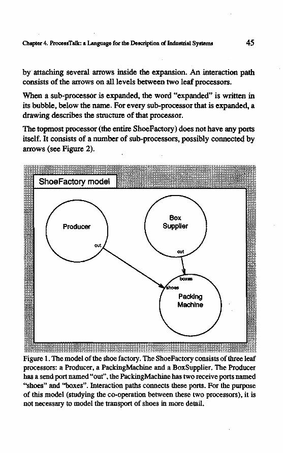
Chapter 4. ProcessTalk: a Language for the Description of lndustrial Systems 45
by attaching several arrows inside the expansion. An interaction path consists of the arrows on alllevels between two leaf processors.
When a sub-processor is expanded, the word "expanded" is written in its bubble, below the name. For every sub-processor that is expanded, a drawing describes the structure ofthatprocessor.
The topmost processor (the entire ShoeFactory) does nothave any ports itself. lt consists of a number of sub-processors, possibly connected by arrows (see Figure 2).
Producer Box
Supplier
Figure 1. The model of the shoe factory. The ShoeFactory consistsof three leaf processors: a Producer, a PackingMachine and a BoxSupplier. The Producer bas a send port named "out", the PackingMachine bas two receive ports named ''shoes" and "boxes". Interaction paths connects these ports. Por the purpose of this model (studying the co-operation between these two processors), it is not necessary to model the transport of shoes in more detail.
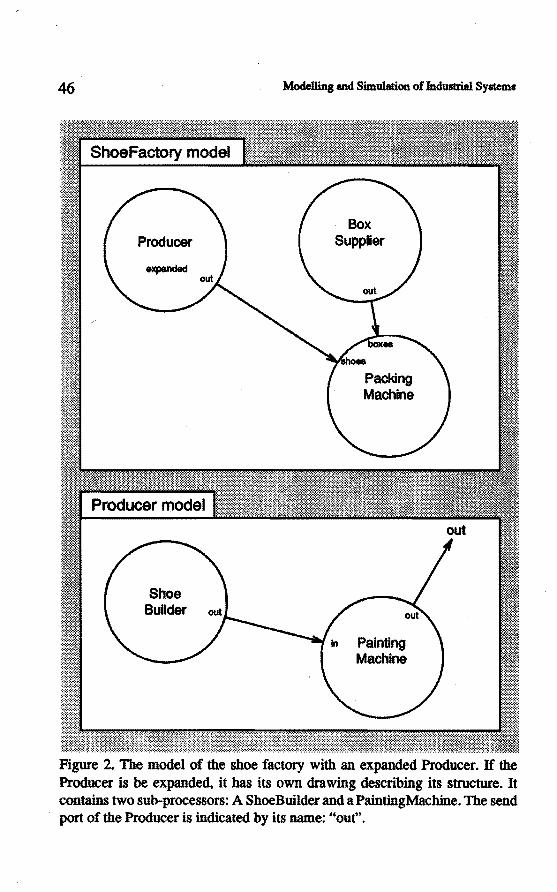
46
Producer
expanded
Shoe Builder
Modelling and Simulation of lndus1ri.al Systems
Box Supplier
Painting Machine
Figure 2. The model of the shoe factory with an expanded Producer. If the Producer is be expanded, it has its own drawing describing its structure. It contains two sub-processors: A ShoeBuilder and a PaintingMachine. The send port of the Producer is indicated by its name: "out".
Chapter 4. ProcessTalk: a Language for the Description of InduBtrial Systems 47
4.3 The task language
4.3.1 The choice for a textual task language
The task language is used to describe the process description of the leaf processors. (The task language and the structure language tagether fonn the language ProcessTalk:.) We have chosen a textuallanguage to specify the behaviour of leaf processors because of the power of textuallanguages. Other possibilities, such as schematic diagrams, seem less appropriate because the diversity of language elements should be large. We want to describe alllevels of processors, from bit-manipulating machine control up to abstract levels where strategies, schedules and orders must be described. Furthennore, the requirement of availability of procedure abstractions (Section 3.4.9) points strongly in the direction of a textual language. In textuallanguages there is a clear notion of procedure abstractions, that is the association of a name with a piece of text, where the name has a meaning indicating the meaning of the whole text. Since mad.eliers should be able to build procedure abstractions, their number and diversity can be large. This demands a rich language, so textual languages are most appropriate.
(lt might be possible to use a graphicallanguage for specialized process descriptions, for instanee processors that only perfonn a rather primitive control of hardware bit - 10. In that case a smalllanguage is appropriate and a graphical representation could have benefits. This approach also has disadvantages, as it introduces another language resulting in less conceptual simplicity. In this study, no research has been done into specialized graphicallanguages: we emphasize the benefits of using one generallanguage.)
4.3.2 The choice for a computer language
Since a requirement for the language is that it should be executable (in order to simulate a specification, see Section 2.6.2), a computer language is a good starting point. Unfortunately, there are no existing

48 Modelling and Simwation of Jndustrial Systems
computer languages that implement all the semantic elements of the previous chapter. Those languages that have the concept of parallelism (needed for the implementation of processors) do not incorporate interprocess communication in the way that we need for interactions. (In particular a send action to more than one port, combined with a receive action from more than one port cannot be expressed easily in languages such as Modula n, Ada and Occam.) However, languages do exist that imptement part of the semantics. Furthennore, languages exist that are extendable: in which it is possible to add new syntactic and semantic elements. Using such a language avoids developing and implementing a whole execution system (a compiler or intetpreter).
4.3.3 The choice for an object oriented language
Object oriented computer languages are languages that take objects ( or data) as a starting point, rather than procedures (like most other language para.digms). Object oriented languages emphasize primarily the modelling of the endties on which the procedures work:, instead of the computational aspects. Therefore, object oriented languages have a powerful expressive capacity for the description of objects. Second, object oriented languages possess very good modularity. The concept of "data hiding" strongly favours the different modularity criteria as mentioned in Chapter 2. These are the reasoos why object oriented languages are very well suited to our purpose. See Appendix A for an introduetion about the concepts of object oriented programming.
4.3A The choice for Smalltalk
Smalltalk is one of the existing object oriented programming languages [Goldberg et al. 1983]. We have chosen this language as the basis for ProcessTalk for the following reasons:
1) Smalltalk fits well with a number of design criteria mentioned in Chapter 2;
2) Smalltalk implements a number ofthe semantic elements presented in the previous chapter;

Otapter 4. ProcessTalk: a Language for the Description of lndustrial Systems 49
3) · It is possible to extend Smalltalk in order to add the remaining semantic elements to the language;
4) Smalltalk bas a powerful interactive programmingenvironment which makes Smalltalk an ideallanguage in which to construct a tooi to model and simulate industrial systems.
It is beyond the scope ofthis thesis to describe the language Smalltalk in much detail. However, in order to understand the remaining part of this chapter the reader should have some knowledge about Smalltalk. Appendix A gives a conceptual overview for readers who are familiar with Pascal-li.k:e languages. Appendix B describes the syntax of Smalltalk. For more detailed information please refer to [ Goldberg 1985].
4.3.5 The modelling of duplieates and the notion of elass
InSection 3.4.2 the need for the notion of a type bas been shown. The language should support a way to describe the fact that certain objects are all similar. Smalltalk, li.k:e other object oriented languages, bas a concept that matches this need exactly. In Smalltalk, a type is represented by a class. A class describes what members, also called instances of that class, look li.k:e, and what functionality these instances have. In other words, the class describes the properties that all instances of that class have in common.
By mapping a certain processor type onto a class, that is by creating a new class for every type of processor, a very natura! implementation of processor types results. When the process description is implemenled in methods of the corresponding class, it immediately matches with the required fu.nctionality: every type of processor shares the process description with the other class members.
It is a trivia! matter, too, to model the passive elements in classes and instances. For every type of passive element, a class will describe the properties of such elements.
In our example the class PackingMachine describes a type of processor; two instances ofPackingMachine will be included in our model. A class has a name, and instances of processor classes also have their own name.
50 Modelling and Simulation of Jndustri.al Systems
The default name of an instanee is the name of the class, possibly folIowed by a numerical count (like PackingMachinel and PackingMachine2), but the name of a processor is arbitrary, it is independent of its class (so the modeller might just as well call two instances of PackingMachine FastPackingMachine and SlowPackingMachine ).
All instances of a processor class share their process description. The process description is a property of the class. 1bis does not cause all these processors to behave in exactly the same way. Processors that have the same process description do not necessarily perform the same state changes. The sequence of state changes { also called the trace of a process) and the times at which the state changes occur depend in general on other processes. When the processors perform send and receive actions, they can get blocked fora timedepending on a process with which they want to communicate. Also, a process description can contain conditional statements, with conditions that depend on the property of a passive object that has been received. ·
We have def'med the condition that processors are of the sametype {the same class) if they have the same process description, and we have shown that processes with the same process description nevertheless can execute different traces, where this difference is caused by extemal factors. Sametimes processors are likely to share a process description, but are slightly different for intemal reasons. Por instance, two packing machines may behave exactly the same, except fortheir speed. One of them can pack a shoe in 30 seconds, the other needs 45 seconds. It is possible to model these as two classes with different constant values for these times (in which case they arenotprocessors ofthe same type). However, it seems to be more appropriate to model a kind of parametrization, a way to describe the fact that certain variables have values that are different for different instances. This parametrization is possible without the need for more than one class and will bedescribed inSection 4.3.14.
A related topic is the modelling of a number of processors that have a lot in common through the description of a general behaviour, and the way that different processors differ from the general behaviour. This is described in Sections 3.4.10 and 4.3.13.
Chapter 4. ProcessTalk: a Language for the Description of Industrial Systems 51
The functionality of instances of a class is described by a number of methods associated with the class. A metbod is a procedure abstraction or function abstraction, a number of actions (statements, expressions) associated with a name.
lnvoking a metbod is done by sending a message to an object. Unfortunately, although this function invocation is named "sending a message", it has nothing to do with our interactions.
4.3.6 Moetelling leaf processors
A leaf processor will be described by a piece of code written in the task language. The most natural place to implement a number of basic task language methods (such as send, receive and workOuring actions, described below) is in the processor class itself. These methods of the task language are understood by all processors. Therefore the messages by which they are invoked mustbesend to "self'. Here "self' refers to the processor itself. At this moment we will accept this intuitive explanation.ln Section 4.3.15 this topic will be explained in greater detail.
In the examples below we will use variables. Variables are place bolders for objects. A variabie can acquire a value by executing an assignment statement. For the moment we shall consider all variables to be instanee variables of the processor in whose description they are used. Instanee variables are variables that are private to the object (in this case the processor), we can say that an instanee variabie models the fact that the processor is capable of holding the objects that are stored in the variable.
The vast majority of processes willloop through a sequence of actions. They will repeat these actions over and over again. Therefore the language contains a default looping behaviour. The process description of a process is usually specified in terms of a metbod called body. The default behaviour is to repeat this body over and over. Often some initialization is needed before entering the loop. The language contains initialization methods that can be used to describe these actions. Of

52 ModeDing and Simulalion of Indust:rial Sysmns
course, there are ways to describe the fact that the repeating of the body should stop or not occur at all, or stop under certain conditions.
4.3.7 Modelling ac:tivity
InSection 3 .4.5 we have shown that there is a need to be able to describe "<
an activity in no more detail than that it takes a certain amount of time. Often the activity can be given a name, like moving the shoe in our case, so it is quite convenient if the language could associate this name with the activity. ProcessTalk contains the following statements to express these concepts.
work:Durlng: tlmeDelay The process wil/ be busy for tlmeDelay time units. The status associ
" ated with this actlvity Is 'busy'. work:Durlng: tlmeDelay forReason: work:Status
The process wil/ be busy tor tlmeDelay time units. The status associated with this activity is workStatus.
4.3.8 Send and receive ac:tions
Recalling, from Section 3.4.6, the fact that both processors involved in a communication have to invoke the communication explicitly is modelled appropriately by specifying a send and a receive action in their process descriptions.
ProcessTalk contains the following basic send and receive actions
send: object to: portName The most basic send action. Sends object synchronously to the port specified by portName. The process blocks until a matching recelve Is performed by snother processor.
recelvefrom: portName Recelve from the specified port. Block until some sender Is avallable tor communlcation. Retum the Item recelved.
Returning something from a method (like the receiveFrom: method above) means that execution of the statement delivers an object (in this

Chapter 4. ProcessTalk: a Language for the Descripti.on of Indultrial Systems 53
case tbe object that has been received), which can for instanee be assigned to a variable. See tbe examples below.
An example of tbe use of tbe send, receive and workDuring actions is given by a simple model of tbe producerand packing machine. Refer to Figure 1 for the structure of this model.
(The header Producer > body means that a description follows of the metbod called body for instances of tbe class witb name Producer.)
Producer> body self workOu ring: 12 minutes forReason: 'producing'. self send: 'shoe' to: 'out'.
BoxSuppller > body
PacklngMachlne > body box :- self receiveFrom: 'boxes'. shoe :• self receiveFrom: 'in'. box addShoe: shoe.
Thelast statement in the body of tbe PacldngMachine: box addShoe: shoe is nota language primitive. The metbod addShoe: must be defmed when modelling tbe boxes, it is a procedure abstraction. We will return to the concept of procedure abstraction later.
All otber send and receive actions, tbe time restricted variants, tbe multiple-port variants and the conditionat receives are described in AppendixB.
4.3.9 The moetelling of passive elements
We will also need to model tbe passive elements of our shoe factory. Things like shoes and boxes are important for understanding tbe logistics of tbe system. We shall see tbat our language is very suitable to model, i.e. to specify passive elements. No matter whetber they are shoes, containers, pallets, raw material parts, crates, orders, schedules, plans or due dates, all such elements can be elegantly described by this language.

54 Modelling and Simwation of Industrial Sy.rems
All passive elements will be objects in the programming language Smalltalk. An object is described by its class. A class describes what all objects of a certain type look like, and to what messages they respond. What they look like is described by their instanee variables. Every object has a number of instanee variables, descrihing its basic properties. The class Shoe might specify that all shoes have two instanee variables: size and colour. This means that a shoe is completely described by these aspects. The class might further describe a number of methods. There are basically two kind of methods: those that return an abstraction of the object, and those that change the object. In the fust category we might find forshoes the methods: size, colour, isColoured, islarge, isSmall, and in the second category: paint:, setSize:. The latter have an argument specifying the colour and size that the shoe should have. An object of a ~rtain class ( called an instanee of that class) is constructed by sending the message new to the class. (Note that sending means a message send to an object, which is completely different from a send action resulting in an interaction. A message send can be regarded as a function call.) The producer of the shoe factory might build a shoe and then send it away:
Producer> body shoe :- Shoe new. shoe setSize: 43. shoe paint: 'brown'. self send: shoe to: 'out'
If the packing machine needs to determine whether to take a small or a large box for the shoe it can evaluate shoe islarge, which will retum true or false:
PacklngMachlne > body shoe :- self receiveFrom: 'shoes'. shoe islarge
ifTrue: [box ; .. self receiveFrom: 'largeBoxes1 iffalse: [box : .. self receivefrom: 'smaiiBoxes1.
box addShoe: shoe.
BoxSuppller > body

Cbapter 4. ProcessTalk: a Language for the Descrip1ion of Industrlal Systems 55
Producer Box
Supplier
Figure 3. The ShoeFactory model. The shoes are modelled using the class Shoe, tb.e pacldng machine receives two kind of boxes.
Here is an example implementation of the class Shoe. We will use expressions like: class ivars: name1 name2 to specify that allinstances of that class have the instanee variables (ivars) named narnel and name2.
Shoe lvas: slze colour Shoe> slze
"si ze
Shoe > colour "colour
Shoe > lsCOioured "colour ....... nil
Shoe > lsLarge "seH size > 42
56
Shoe > leSmali "self lslarge not
Shoe > eetSize: aNumber slze :• aNumber
Shoe > palnt: aColour colour :- aColour
Modelling and Simulation of lndustrial Systems
4.3.10 The modelling of control structures
Often, the behaviour of a processor is dependent on certain conditions (see Section 3.4.7). For example, the PackingMachine described above bas to take a large or a small box depending on the kind of shoe it has to pack. To modelsuch behaviour it is useful if statements are used in that process description, such as lfTrue: ifFalse:. These are standard Smalltalk constrocts. They behave just like any message: the receiver is a boolean, either troe or false, that object is sent the message lfTrue:ifFalse: with two arguments. These arguments are blocks. The appropriate blockis evaluated. Smalltalk knows a lot of conditional evaluating constroctions (and the user can build more of them). A brief summary of those that we use in the examples is given here:
aBoolean IITrue: [ ... 1 aBoolean ifFalse: [ ... 1 aBoolean lfTrue: [ ... ] ifFalse: [ .•. ] [ ... ] whileTrue: [ ... ] [ ... 1 whlleFalse: [ ••• 1
An example of the usage of the last expression can be found in a PackingMachine that puts shoes in a box as long as there is room in it:
PacklngMachlne > body box := self receiveFrom: 'boxes'. [box isFull] whileFalse: [box addShoe: (self receiveFrom: 'shoes')]
Now suppose that the PackingMachine not only puts the shoes in the boxes, but also puts three boxes on a pallet. When the pallet is loaded, it is sent to the shipping department. The following description looks somewhat clumsy:

Chaptcr 4. ProcessTalk: a Language for the Description of Industrial Systems 57
PacklngMachlne > body pallet:- self receiveFrom: 'pallets'. box:. self receiveFrom: 'boxes'. box addShoe: (self receiveFrom: 'shoes'). pallet addBox: box. box :- self recelveFrom: 'boxes'. box addShoe: (self receiveFrom: 'shoes'). pallet addBox: box. box:- self receiveFrom: 'boxes'. box addShoe: (self recelveFrom: 'shoes'). pallet addBox: box. self send: pallet to: 'shipping'
Indeed this can be described more appropriately as follows:
PacklngMachlne > body pallet :. self recelveFrom: 'pallets'. 3 timesRepeat:
[box :• self receiveFrom: 'boxes'. box addShoe: (self.receiveFrom: 'shoes'). pallet addBox: box].
self send: pallet to: 'shipping'
Shlpplng > body
Such constrocts as anlnteger timesRepeat: [ ... ] are called looping constrocts or iterations.
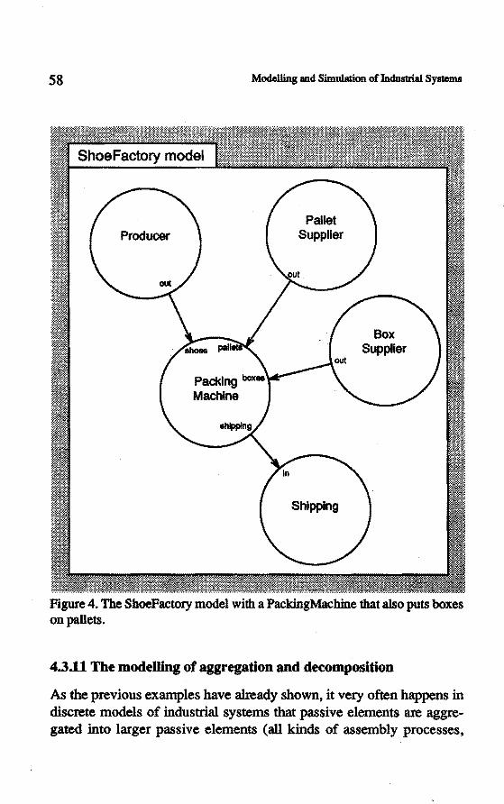
58
Producer
Modelling and Simulation of Industrial Systems
Pallet Suppller
Shlpping
Box Supplier
Figure 4. The ShoeFactory model with a PackingMachine that a1so puts boxes on pallets.
4.3.11 Tbe moetelling of aggregation and decomposition
As the previous examples have already shown, it very often happens in discrete models of industrial systems that passive element& are aggregated into larger passive elements (all kinds of assembly processes,

Chapter 4. ProcessTalk: a Language for the Description of Industrial Systems 59
pacldng processes like shoes in boxes and boxes on pallets, but also infonnation objects often contain a number of smaller components: an order aggregates type, amount, due date, customer etc.). The converse also happens frequently, think of batches of material that are processed as a batch by some machines in the production line, whereas other machines take all parts individually for processing. This aggregation and disaggregation (decomposition) is such a common concept in industrial systems that the language needs matching descriptive capabilities. Fortunately Smalltalk happens to implement powerlul constrocts to describe these concepts. Theref01-e we did not need to build them and add them explicitly to the language. Two aspects of Smalltalk are of importance here. First, the fact that every object consist of a number of instanee variables which makes it an aggregation of these components. Second, the powerlul Collection classes, a class hierarchy that comes with the language and implements all kind of coneetion abstractions. As an example we willlook at the class OrderedCollection, which is a class that implements collections that p..-eseiVe the order in which elements are added to it. It can often be used as a fU'St implementation of some passive element that stores other elements, for instanee the boxes or pallets of our example. Lik:e most collections OrderedCollections understand the following messages:
acceS8Ing methods aCollectlon add: anEiement
add the argument to the col/eetion aCollectlon remove: anEiement
remave the argument from the collection aCollectlon removeflrst
remove the first object in the collection, answer it aeoneetion slze
answer the number of objects In th8 collectlon anOrderedCollectlon at: Index
answer the element at position Index of the collection anOrderedCollectlon at: Index put: object
store the object at the speelfled posltlon

60 Modelling and Simulation of lildustrial Systema
teatlng methoela aCollectlon lncludes: anEiement
answer true or fa/se, depending if th6 argument is contained in th6 col/eetion
enumeratlng methode
aCollectlon do: [ :element I ... ] For every eiBment in the coll6ction, assign th6 616m6nt to the block variable, and evaluste the block.
The BoxSupplier might simply make an instanee of OrderedCollection and send it to the packing machine:
BoxSuppller > body box :- OrderedCollection new. self send: box to: 'out'
The PackingMachine uses the add: message to put shoes in the box:
PacklngMachlne > body box :. self receiveFrom: 'boxes'. shoe :- self recelveFrom: 'shoes'. box add: shoe.
This is an appropriate, correct and working implementation. In a later phase of the modelling, the modeller might add the class Box to provide more sophisticated methods. For instance, the class Box can imptement the message addShoe: which gives a more readable process description of the PackingMachine. Or the class Box might need an extra instanee variabie describing a label that is attached to the box with information about the order for which it bas been produced.
The next example assumes that pallets and boxes are Collections and shows a PaintingMachine that receives a box with shoes, unpacks them by tums, paints the shoes, putstheshoes on a platform called dryingShoes, and finally, when they are dry, putstheshoes back in the box. dryingShoes is also implemented using an OrderedCollection.

Chapter 4. ProcessTalk: a Language for the Description of lndustdal Systems 61
Producer
Painting Machine
Packlng Machine
Box Supplier
Figure 5. The ShoeFactory with a PaintingMachine.

62 · Modelli.ng and Simulation of Jndusb:ial System11
PalntlngMachlne > body dryingShoes := OrderedCollection new. box:- self receiveFrom: 'In'. [box isEmpty] whlleFalse:
[self workDuring: 3 seoonds forReason: 'taklng shoe from box'. shoe :• box removeFirst
self workOuring: 12 seconds forReason: 'paintlng shoe'. shoe palnt: #brown. drylngShoes add: shoe].
self workDuring: 10 minutes forReason: 'drying'. [dryingShoes isEmpty] whlleFalse:
[self workDuring: 4 seoonds forReason: 'putting shoe in box'. box add: dryingShoes removeFirst].
self send: box to: 'out'
This is a rather detailed description which might in certain cases be the right solution, that depends on the exact purpose of the model. In some cases it is notrelevant to actually remove the (modelled) shoes from the box whilepainting them, since.the only important aspect ofthe model might be the time it takes to process them. The next model shows such an implementation, which has the same behaviour as the preceding description as far as the timing is concemed. It also shows a usage of the enumeration message do:.
PalntlngMachlne > body box :- self recelveFrom: 'in'. box do:
· [ :shoe I self workDuring: 3 seconds forReason: 'taking shoe from box'. self workDuring: 12 seoonds forReason: 'palntlng shoe'. shoe palnt: #brown].
self workDuring: 10 minutes forReason: 'drying'. self workDuring: box size * 4 seconds forReason: 'putting shoes in box'. self send: box to: 'out'
4.3.12 The modelling of procedure abstractions
Often, it happens that while making a process description, a certain activity has to be described that contains too much detail to be relevant at

Cb.apter 4. ProcessTalk: a Language for the Descripû.on of lndustrlal Systems 63
the moment that body is specified. In such cases the modeDer thinks of a certain activity ór procedure perfonned by the processor. instead of the details of how to. perform the procedure. {See also Section 3.4.9.) Por instance, a PaintingMachine that has a rather complicated painting procedure can be modelled like this:
PalntlngMachlne > body box : .. self receiveFrom: 'in'. box do:
[ :shoe I self workDurlng: 3 seconds forReason: 'taking shoe from box'. "the procedure of painting the shoe" ].
self workDuring: 1 0 mlnutes forReason: 'drying'. self workDurlng: box slze "'4 seconds
forReason: 'putting shoes in box'. self send: box to: 'out'
The details of the procedure will be modelled in a later phase of the · design. This does not change the way the modeller thinks of body. The details of the procedure are not replaced by the line in body. but a separate description is specifred describing it. This mechanism is called procedure abstraction { or function abstraction when there is an emphasis on the value retumed by the procedure). In Smalltalk, procedure abstraction is implemented by methods and message sends. Using a messagesend insteadof the comment, the example becomes:
PalntlngMachlne > body box : .. self receiveFrom: 'in'. box do:
[ :shoe I self workDuring: 3 seconds forReason: 'taking shoe from box'. self paint: shoe].
self workDurlng: 10 minutes forReason: 'drying'. self workDurlng: box size " 4 seconds
forReason: 'putting shoes in box'. self send: box to: 'out'

64 Modelling and Simwation of Induslrial Systems
PalntlngMachlne > palnt: aShoe selfworkDuring: 2 mlnutes forReason: 'preparlng paint'. self workOuring: 3 minutes forReason: 'painting'. aShoe palnt: #brown. paintArnountAvailable :- palntAmountAvallable - 1. paintAmountAvallable • 0
ifTrue: [self workDuring: 30 seconds
forReason: 'supplylng paint. palntAmountAvailable :- 50]
The metbod paint: is a metbod ofthe class PaintingMachine. In the body this metbod is called by sending the message palnt: shoe toself ( self is an instanee of PaintingMachine ). The object stored in the variabie shoe in body is passed as an argwnent to the metbod paint:. The (fonnal) argument aShoe has the value ofthe (actual) argument, that is the shoe that the PaintingMachine has just taken out of the box.
In the metbod paint: ofPaintingMachine, the message paint: is sent to the shoe. This is another example of a procedure abstraction. The message palnt: for the class Shoe has been described in Section 4.3.9: "The modelling of passive elements". This example also shows that two classes can imptement methods using the same selector, in this case palnt: (this is called polymorphism, see also Appendix A). Which metbod will be invoked depends on the class of the receiver.
4.3.13 Thè modeDing of commonness, specialization and generatization
Our shoe factory is doing well, we have to add capacity to meet the increasing demand of the market for our quality shoes (the customers also appreciate the fact that both shoes are separately boxed). To increase the production capacity we need a number of producers instead of a single one. One possibility is to install a number of producers that are all dedicated tobuilding a certain type of shoe. One for brogues, another for sandals and so on. This also reduces the set up times, the time required to make adjustments to a machine to produce shoes of another type than the current one. Before actually installing these machines we

Cllapter 4. ProcessTalk: a Language for tbe Descriplion of Indusllial Systems 65
will make a model ofthe proposed factory to examine whetherthe number of new machines that we plan to buy does indeed result in the required capacity.
All the new producers have a lot in common. Leather is supplied to all of them, they all build one shoe at a time, they all get painted inside these producers, and they all need periodic maintenance. Ho wever, they all have their own special way of producing a shoe. It would be very suitable if ProcessTalk could describe the general behaviour only once, for all producers, and the special behaviour for each different kind of producer.
This modeDing of commonness, specialization and generalization is really straightforward in an object oriented language: it is, in fact, one of the basic concepts of object oriented programming. The idea is that a class can have one or more subclasses. Every subclass is a specialization of its (single) superclass. To be precise: instances ofthe subclass are special versions of instances of the superclass. The effect of specialization is reached by the concept of inheritance. This means that instances of a subclass can understand all methods of their superclass ( and of the superclass of the superclass, in short: the superclass chain). (There is one class in the system, named Object, which is the most general class, it has no superclass, everything in Smalltalk is an instanee of a descendant of Object.)
AB an example, let' s model the general Producer:
Producer ,. body leather :- self receiveFrom: 'in'. shoe := self produceShoeFrom: leather. self paint: shoe. self send: shoe to: 'ouf
Producer > palnt: aShoe self workDurlng: 2 minutes forReason: 'preparing paint'. self workOu ring: 3 minutes forReason: 'painting'. aShoe palnt: #brown.

66 Modelling and Simwation of IndUBtrial Syfiems
Th.e metbod produceShoeFrom: is not implemented in this class. The idea .is that this class has a number of subclasses, one for every type of producer. In every subclass the metbod produceShoeFrom: will be implemented:
BrogueProducer Is a subclass of Producer · BrogueProducer > produceShoeFrom: anAmountOfLeather
self workDuring: 2 minutes forReason: 'cutting leather'. self workDuring: 1 minutes forReason: 'drilling holes'. self workDuring: 2 minutes forReason: 'assembling', · "Shoe new type: #brogue.
SendalProducer Is a subcl888 of Producer SendalProducer > produceShoeFrom: anAmountOfLeather
self workDuring: 2 minutes forReason: 'cutting leather'. self workDuring: 30 seconds forReason: 'making buckle'. self workDuring: 3 minutes forReason: 'assembling'. "Shoe new type: lsandal.
New shoes are created by sending tbe message new to the class Shoe (this is tbe general way to make instances of a class). We make tbe assumption that shoes respond to tbe message type:. This metbod could set an instanee variabie of tbe shoes.
This example illustrates that, by using a common superclass (Producer), tbe general behaviour of all types of (shoe)producers can be described, and by subclassing the general class, and descrihing tbe specific behaviour in these subclasses, specialization can be modelled.
Note tbat in the example no instances of Producer will be made (Produceris tberefore called an abstract superclass). However, in other situations it might very well be appropriate to make subclasses of a class that has instances. For instance, recalling the PaintingMachine of Section 4.3 .11, a new type of painting machine m.ight be introduced that behaves tbe same as tbe existing one, except for tbe details of painting. A subclass will be made of PaintingMachine, and tbe metbod palnt: wm be redefined. Now instances of the subclass will use the metbod implemented in tbeir class, while instances of the superclass, PaintingMachine wm execute the metbod in that class. The general rule todetermine what method
Chapter 4. ProoessTalk: a Language for the DeiK:liplion of InduBtrial Systems 67
is used is tbe following: if tbe metbod is defined in tbe class of tbe receiver, that metbod is used; if it is not, tbe superclass is searched, and so on.
It is also pennitted to make a subclass and redefine the metbod body ( assuming that otber criteria will justify subclassing inslead of making a new normal processor class).
It is not only the protocol ( tbe metbods) of tbe superclass tbat are inherited by a subclass, but also tbe structure of its instances: the number and narnes of the instanee variables. An instanee of a subclass bas all tbe instances of the superclass chain, in addition to the instanee variables that the subclass itself defmes.
4.3.14 Initializing instances, parametrization
When two or more processors are of tbe sameprocessor class tbey have tbe same process description. This situation is appropriate if tbe processors behave in the same way. Often, a number of processors behave in almost tbe same way. There are two basic ways to describe processors tbat differ to some degree: subclassing and parametrization. The solution using subclassing is to describe tbe common behaviour in one class, and describe tbe special behaviour in subclasses as described in Section 4.3 .13. There are situations where subclassing feels like overldll. Consider for instanee a number of packing machines which only differ in tbe time they need to do the packing activity. It seems to be a bit too much of a good thing to model this situation by building a new subclass for every different packing time, altbough this solution is correct. A more appropriate way to model this is to use parametrization. We use tbe term parametrization to make different processors of the same class behave slightly differently. Usually the difference can be expressed by a different value for one or more instanee variables. Parametrization will assign a value to these variables tbat depends on which instanee of tbe processor it is. We need a way to specify which processor should get which values. ProcessTalk basically supports two ways to identify a processor: by name or by structure. Processors know tbeir name which

68 · Modelling and Simulation of Jndustrial Systems
is ( or at least can be) unique to them, since the modefier can specify the name of a processor freely. The name is independent of the class name, although the class name is used in the default generation of the name. The behaviour of a processor can be made dependent on the name:
PacklngMachlne lvars: packlng11me PacklngMachlne > lnltlallzeTasks
self name • 'FastPackingMachine' ifTrue: [packingTime :- 2 minutes]. self name • 'SiowPackingMachine' ifTrue: [packingTime :- 3 mlnutes].
PacklngMachlne > body box:- self receiveFrom: 'boxes'. shoe :- self recelveFrom: 'shoes'. self workDuring: packingTime forReason: 'packing'. box add: shoe. self send: box to: 'shipping'
The second way to identify a single processor is by structure. Every processor has a different position in the structure of the whole model. The language supports a way todetermine this location, and the behaviour can be made dependent on that. Suppose the paclcing machines are part of different PackingDepartments. The PackingDepartment processors are expanded and each contain a number of PackingMachines. All PackingMachirtes inside one department have the same speed, but the departments differ. The following lnltializeTasks will set the ivar packingTime depending on the location of the PackingMachine, and independently of their name.
PacklngMachlne > lnltlallzeTasks self isPartOfProcessorNamed: 'FastPackingDepartment'
ifTrue: [packingTime :- 2 minutes]. self isPartOfProcessorNamed: 'SiowPackingDepartment'
ifTrue: [packingTime :- 3 minutes].
There are a number of other methods that give access to the structure of the model, most notably processors can return their parent and their children. Using these messages, more complex parametrization criteria can be specified.
Chapter 4. ProcessTalt: a Language for the DeiiCri.ption of Indust:rial Systems 69
Note that it is possible to make the behaviour of processors of the same class completely different using the parametrization technique; it is possibie to use just one type of processor and execute different body methods depending on the name. The language cannot prevent a modeller from doing this, it is a màtter of style: The modeller should determine whether to use completely different classes, classes with a shared superclass or just one class with parametrization. The last option is typically used when only the valnes of instanee variables are different for the processors. Subclassing is typically done when a number of methods differ, but the body ( and the general behaviour) is shared.
4.3.15 What all processors have in common
An important property that all processors have in common is that their process description is specified in a certain language. This language, the task language, contains expressions like send, receive and workOuring statements. It seems natura! to define a common superclass for all processors where these methods are defined. This is the way we have defined that part of ProcessTalk. All processors are subclasses ( or further descendants) of one class that defines all methods that are typically understood by processors. This class is called Bubble. This is the reason why all such messages as send, receive and workOuring are sent to self. These messages are understood by the processors themselves, because they are defined ih the superclass chain.
4.3.16 Subclassing of classes descrihing passive elements
The concept of subclassing and inheritance is also applicable to the classes descrihing passive elements. In one of the previous examples we introduced different types of shoes, such as brogues and sandals. In that example the difference was modelled by adding an instanee variabie descrihing what type of shoe it is. However, when the different types of shoes have some common properties and some special properties, a class tree of different shoes seems the right way to model these types. For instance, one class Shoe descrihing what all shoes have in common,

70 Modellins and Simwation of Industrial Systems
with a number of subclasses such as Brogue and Sandal. Let's show an example implementation:
Shoe Is a subclaas of ObJect Shoe lvars: slze colour
Shoe> slze Asize
Shoe > colour Acolour
Shoe > ISColoured Acolour -- nil
Shoe > lsLarge AseH size > 42
Shoe > laSmali AseH isLarge not
Shoe > setSize: aNumber size :. aNumber
Shoe > palnt: aColour colour :. aColour
Shoe > amountOfLeatherNeeded AseH size * seH unitleatherArnountNeeded
Shoe > unltLeatherAmountNeeded seH subclassResponsibility
Brogue Is a subclass of Shoe Brogue lvars Brogue> unltLeatherAmountNeeded
A34
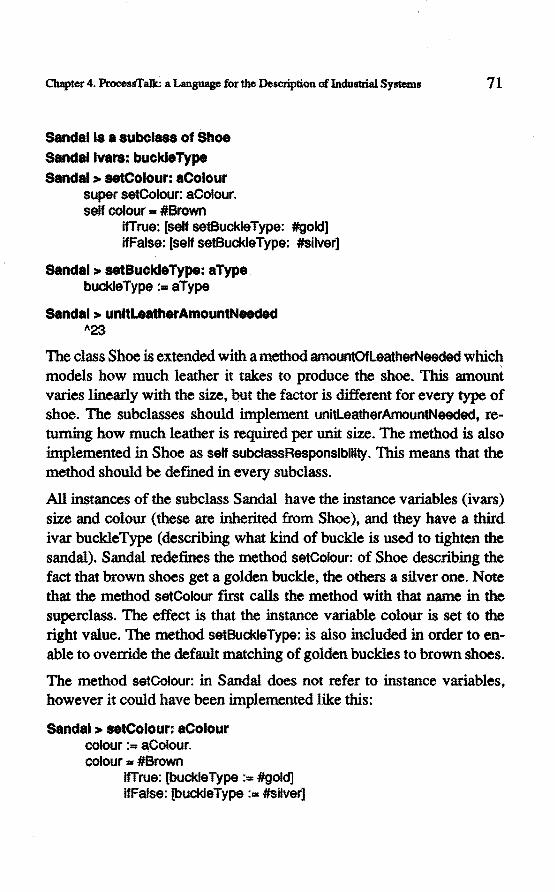
Chapter 4. ProcessTalk: a Language for the Descripti.on of lndustrial Systems 71
Sandalls a subclass of Shoe Sandallvara: buckleType Sandal > seteolour: aColour
super setColour: aColour. self colour == #Brown
lfTrue: [self setBuckleType: #gold] ifFalse: [sèlf setBuckleType: #silver]
Sandal > setBuckleType: aType buckleType :• aType
Sandal > unltLeatherAmountNeeded "23
The class Shoe is extended with a metbod amountOfleatherNeeded which roodels how much teather it takes to produce the shoe. This amount varles linearly with the size, but the factor is different for every type of shoe. The subclasses should imptement unitleatherAmountNeeded, retuming how much leather is required per unit size. The metbod is also implemented in Shoe as self subclassResponsibility. This means that the metbod should be defmed in every subclass.
Allinstances of the subclass Sandal have the instanee variables (ivars) size and colour (these are inherited from Shoe), and they have a third ivar buckleType (describing what kind of buckle is used to tighten the sandal). Sandal redefines the metbod setColour: of Shoe descrihing the fact that brown shoes get a golden buckle, the others a silver one. Note that the method setColour fust calls the method with that name in the superclass. The effect is that the instanee variabie colour is set to the right value. The metbod setBuckleType: is also included in order to enable to override the default matching of golden buck:les to brown shoes.
The metbod setColour: in Sandal does not refer to instanee variables, however it could have been implemented like this:
Sendal > seteolour: aColour colour := aColour. colour ... #Brown
lfTrue: [buckleType : ... #gold] ifFalse: [buckleType := #silver]
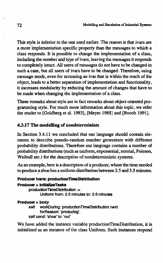
72 Modelling and Simulation of lndusbial Systems
This style is inferior to the one used earlier. The reason is that ivars are ~more implementation specific property than the messages to which a class responds. It is possible to change the implementation of a class, including the number and type of iv~, leaving the messages it responds to completely intact. All users of messages do nothave to be changed in such a case, but all users of ivars have to be changed. Therefore, using message sends, even for accessing an ivar that is within the reach of the object, leads to a better separation of implementation and functionality, it increases modularity by reducing the amount of changes that have to be made when changing the implementation of a class.
These remarks about style are in fact remarks about object oriented programming style. Por much more information about this topic, we refer the reader to [Ooldberg et al. 1983], [Meyer 1988] and [Booch 1991].
4.3.17 The modeDing of nondeterminism
InSection 3.4.11 we concluded that our lan~e should contain elements to describe pseudo-randurn number generators with different probability distributions. Therefore our language contains a number of probability distributions (such as uniform, exponential, normal, Poisson, Weibull etc.) for the description of nondetenninistic systems.
As an example, hereis a description of a producer, where the time needed to produce !1 shoe has a uniform distribution between 2.5 and 3.5 minutes.
Producer lvars: productlonllmeDistrlbutlon Producer > lnltlallzeTasks
productionTimeDistribution : ... Uniform trom: 2.5 mlnutes to: 3.5 mlnutes
Producer> body self workDuring: productionTimeDistribution next
forReason: 'produclng'. self send: 'shoe' to: 'out'
We have added the instanee variabie productionTimeDistribution, it is initialized as an instanee of the class Uniform. Such instances respond
Chapter 4. ProcessTalk: a Language for the Description of Indulllrial Systems 73
· to the message next by retuming a next sample. A large enough coneetion of these samples has the specified probability distribution.
4.4Summary
In this chapter we have introduced a language to express the semantic elements described in Chapter 3 . This language is called ProcessTalle and it consists of two · parts: the structure language and the task language. The structure language is a graphical language descrihing the processor topology, the pons, and the interaction paths. 1be task language is a textuallanguage, basedon the object oriented programming language Smalltalk. The task language is able to express such elements as: activity, send and receive actions, control structures, aggregation, passive elements, and nondeterminism.
It was always the intention to write a computer tooi to support the designer using the language. The computer tooi would also represent a verification of the analysis that lead to the establishment of the language. The following chapters deal with computer tools. Chapter 5 describes the functionality required of any tool for modelling and simwation of industrial systems using our approach. Chapter 6 presents the tool that bas been written as part of this study.

74 Modelling and Simwation of lndust:rial Systems

CHAPTER5
The Functionality Required of a Supporting Tool
5.1 Introduetion
Chapter 2 presented a systematic approach to the design of industrial systems. It became apparent, from the work presented in that chapter, that there is a need forsome tooi that can help a designer with his task. It has been shown that it is important to evaluate a specification using simulation, so the main task of the tooi will be to enabie a designer to model an industrial system, using the design language ProcessTalk, which has been developed for this pwpose, and to simulate it. The functionality that such a tooi should possess will be investigated in this chapter. A description of a tooi that impiements this functionality, and which has been developed as part of this study, is presented in the next chapter.
This work has been influenced by the previous generation of modelling and simulation tools, especially 584, a Pascal-type simulation language basedon the Process-Interaction Approach [Rooda et al. 1984] that matches with the ideas in [Overwater 1987].
The use of these tools has taught us the importance of simulating modeis of industrial systems, and how a tooi can support designers in performing their task. As [ Overwater 1987] signals, there is a gap between the toois: they do not use the same language. A major design goal of the new tooi is to eliminate these gaps.

76 Modelling and Simwation oflndul1rial Systems
5.2 Modelling
The tool should allow a modeller to build a model; by letting the modelter draw the structure of a model, for instance, with a typewritten text of the process descriptions. The tool should be able to handle the'inconsistent models that naturally arise during the construction of a model (for instanee a structure in which not all arrows are connected at both ends}.
It is desirabie that the toolaffords as much assistance possible to modefiers as they performtheir work. Such assistance should include: relieving the modefier of the necessity of perfonning repetitive tasks (for instanee by providing a powerfut copy and paste protocol}; helping the modefier to keep the model consistent (for instanee by ensuring that two processors of the same class cannot have different process descriptions, and preventing the inclusion of a processor as child of itself); and all kinds of more general support, such as an appropriate text input interface for the task language.
5.3 Simulation
The tool should be able to execute a model, simulating the behaviour of the system and must therefore implement ProcessTalk, i.e. the structure language and the task language described in Chapter 4. Since the models are disc;rete, the tool should be able to perform discrete-event simulation.
The tool should also provide support to maximize the benefits of simulation. In this respect it should supply debuggers and inspeetors that enable the detection and repair of errors in the model, and generate output in order to allow interpretation of the behaviour of the model.
5.4 Output generation
Simulation is only useful when it generates some sort of output which describes some aspects of the state of the model. The tool should therefore be able to generate such output. Por instance, it should be possible to

Chapter 5. The Functionality Required of a Supporting Tool 77
detennine the value of variables in the model, and to detennine up to which point a process has proceeded in its process description; some form of animation that shows status changes graphically also frequently increases the ease with which the results can be intetpreted. In our view, an important point that has to be made about output generation is that, when there is a need for output generation, in the form of animation, say, or the coneetion of certain data, it is important that there should be no need to change the model in order to generate the desired output. We want the modener to describe the model, and not how it should be displayed or how data coneetion should occur. Output should thus either be generated completely automatically by the tool itself, or, if that is not possible, the modener should be able to specify, without changing the process descriptions- i.e. independently of the model- what kind of output should be generated.
Often, the model will not contain exactly the data that the modener is interested in. The data in the model could need further processing before an intetpretation can be made. For instance, when the model is probabilistic, the data will need statistica! processing before it can be interpreted correctly. The tool should provide a functionality that helps the user in this processing.
ldea of output
The idea is that the tool should make it as easy as possible to give the user an idea about what is happening in the model. When the information gives a good idea about what is happening in the model, the user more quickly gets an idea about the correctness of the model. When it is easy to coneet such information, the user is more inclined to do so, and will detect important facts that would otherwise not be found ( or only in a much later phase). The amount of information that is derivable from a simwation run is usually immense. The tool is not able to know in advance what information the user is interested in. Therefore the approach adopted should be that the tool provides some information that is likely to be generally interesting. This information should always be available automatically. However, the tool should also provide mechanisms that make
78 Modelling and Sûnulation of Industrial Systems
it very easy for the user to specify what infonnation is important. Once the user has. specified that, the tool can also provide that infonnation automatically. It showd not be necessary to change the model in order to specify what infonnation showd be collected.
5.5 Experimenting
Usually, a simwation will not be run only one single time; rather it will be repeated a number of times while certain parameters are varied. Some of these parameters will be model parameters (properties ofthe model), while some will be simwation parameters. Examples of simwation parameters are: the stop time or other stop condition specifying when the simwation run showd end; the detail and kind of output generated and displayed; or the number of replicadons of a simwation run (for varianee reduction or confidence interval measurement). Determining and changing such parameters and running the simwating is called experimenting. In our view, it is important to keep the modeland the experiment description independent of each other. Again, the model should be a description of the system, and nothing more. The tool should provide support for the description and processing of experiments in such a way that the model is not touched.
5.6 Meta.simulation
A slightly more sophisticated procedure, compared to experimenting, is the case when experiments are perfonned over and over again in an automatic manner. An example of this is the determination of optimal model parameters by running the simwation, observing some output data, adapting the parameters, andre-running the simwation. This process will be repeated in a loop until the optima! parameters are found. When such a process is automated, we call it meta simwation (since one simwation drives the other). For the same reasons as stated earlier, the model should not be affected by meta simulation, and the tool should provide the necessary support.

Chapter S. The Functionality Required of a Supporting Tool 79
5. 7 Interactive user interface
Maybe this is not a requirement in its strict sense, but an interactive user interface will increase the power of the tooi enonnously, because it matches the experimentational character of modelling and simulation.
5.8 Easy switching between modelling and simulation
The fact that one model and one language is used during specification and simwation does not guarantee that switching between these activities is easy. However, the tooi should allow an easy change between these activities in order to support the iterative nature of this process.
5.9 Detinition of ProcessTalk
Since the part of the tooi that is able to execute a model (the simulator) is implemented in a fonnal computer language, this implementation in fact dermes the modelling language in a fonnal way. The implementation of the simulator dermes exactly what the meaning of every possible statement of ProcessTalk is. This definition has no ambiguity and is complete, in contrast to the description in the previous chapter.
5.10 Summary
In order to support the language and to support the modeller using that language, it is not only necessary that the tooi should imptement all the semantic and syntactic considerations explained earlier, it should also offer the modeller some specific support in the particular way that he thinks about the modeDing and experimenting task. Any support to the modeller should be given at the right level of abstraction. To that end it should be graphical in its representation, it should take care of repetitive tasks, it should offer the facillty for simulation, and it should generate meaningful output against which the model can be tested. Finally, there should be a clear distinction between the model itself and the experiments

80 · Modelli.ng and Sünulation of Jndustrial Systems
that are perfonned on it. In the next chapter we shall see how, and to what extent, this functionality bas been implemenled in the modelling and simwation tooi that bas been written as part of this work.

ÛIAPTER6
The ProcessTool: A Tooi to Model and Simu1ate
lndustrial Systems
6.1 Introduetion
The foregoing chapters have shown how a careful and thorough analysis of the design process and the requirements fora design language have allowed the creation of a language that is suitable for the description, and thus the modelling, of industrial systems. This chapter is a description of the ProcessTool: a tooi that has been implemented as part of this study (in the past, the name 'Process Interaction Environment' has been used for the tooi). The tooi has a functionality according to the requirements of the previous chapter. This chapter is not a user manual, nor is it a tutorial. The reader is referred to the complete manual [W ortmannet al. 1990] for details of how to use the tooi. The idea is rather to show the clear line that can be foliowed ftom the ideas presented earlier and the way in which they can be implemented in the computerised tooi.
Since the language of Chapter 4 is an extension to Smalltalk, and since Smalltalk is extremely suitable for building graphical interactive applications, the tooi has been implemented in Smalltalk.
6.2 Specifying the structure of a model
One of the functions of this tooi is to enable the user to specify a model. The model will be made using ProcessTalk., the tooi should offer ways
82 Modelling and Simulation of Jnd.ustrial Systems
to specify its language elements. Often, when modelling, a modeller starts tothink about the root level processor, the environment processor. Soon, that processor is thought of as consisting of a number of (sub )processors. In fact, the modefier thinks in tenns of the graphical representation that we introduced earlier. The tooi matches this.thinking process by offering a graphical user interface wîth which the modefier can draw the structure of a processor, when that processor is expanded (when it consistsof subprocessors). An expanded processor is modelled in a window and amouse and keyboard are used to interact wîth the system. Por instance, when the user wants to add a certain processor as a child to an expanded processor, he pushes a mouse button inside the window, a pop-up menu appears, the item "add processor" is selected, the tooi asks for the name of the new processor and draws a bubble at the indicated position. Similarly, the modeller can add interaction patlts between processors and can move processors, arrows and ports around in the picture. It is also possible to delete existing processors and to rename them. In this way, the structure and appearance of an expanded processor is specified. The appearance ( the exact position and form of processors, ports and arrows) has no influence on the semantics of the model; however, the user can determine ît and it can certainly help him to understand the meaning of the model (for instance, the position of the processors might reflect the physical positions of the cortesponding parts of the system).
While the modefier draws such a processor structure, the tooi not only represents the drawing but creates a data structure that describes the processors, the ports and the interaction paths. The modefier is notaware of this creation, the data structure is used in a later phase when simulating themodel.
Figure 6 gives an impression of the appearance of the tooi on the screen of a computer monitor.

Chapter 6. The ProcessTool: A tooi to Model and Simulate Jndustrial Systems 83
bod)'
I box shoa I box + salf recelveFrom: 'boxes'. shoa + self recelveFrom: 'shoes'. self workOuring: 10 minutes forReason: 'packing'. box add: shoe
Figure 6. An impression of some windows on the screen of the ProcessToot The topmost window is the simu1ation control panel, then there is a model window, a status monitor and an observer. The last window is a process description browser.

84 Modelling and Simulation of Industrial Systems
6.3 Specifying the process description
When a process description bas to be specified, a menu item is selected that opens a process description browser, a textual window in which the process description can be typed.
Standard Smalltalk Browsers can also be used to enter process descriptions and to model passive elements. All utilities of such browsers can be used, such as explaining and searching for implementors or senders of a certain method.
6.4 Maintaining consistency
When the modeller adds two or more processors with the same name, tliey will regarded as being of the same type ( they are instances of the sarne class ). The tool guarantees the consistency of the model, the modeller cannot mistakenly make them differ. When the process description of one of them is changed, it is changed for all of them. When one of them is expanded, they will all become expanded, when a port and interaction path is added to one of them, they all get the same port and arrow attached. When processOrs of the same name are expanded, their intemal structure is the same. When one of them bas a child of a certain type at a particwar position in the structure, they all will have a child of that type at that position. When a processor is added with the same type as an existing one, the new processor will be a consistent copy of the existing processor; if the existing processor was expanded the new processor will have the same structure. All this avoids the necessity for the modeller to have to perfonn repetitive tasks. Just before a simwation starts, the tooi automatically perfonns a stronger consistency check. The tooi checks amongst other things whether all arrows are connected at both ends, and whether allleaf processors have a process description.

Chapter 6. The ProcessTool: A tooi to Model and Simulate lndustrial Systems 85
6.5 On-line documentation and help
The tooi helps modellers by giving them the possibility to browse easily throu~ the commented task language statements. The process description browser shows a list of all ports that the processor has, and has a menu that helps a modeller to fonn the ri~t syntax for statements in the task language, andreduces tpe need for typing.
6.6 Storage and retrieval
Modelscan be saved toa ftle, for backup or fortransport toanother ProcessTool (possibly on another platform). Furthennore, parts of a model can be saved to file and read from ftle.
6.7 Simwation
After the modelling phase, the tooi enables the modeller to start a simulation of the model. This is the second main property of the tooi: it implements the language as described in the previous chapter.
The idea is that switching between specification and simulation is very easy and has an interactive character. The user does not have to take certain actions when he wants to simulate his model ( except, perhaps, pressing a button or selecting from a menu). The model as created in the specification phase is used during the simulation.
It is a discrete event simulation: at a certain moment in (simulation) time, the tooi investigates which events should occur and it performs these events. When no events remain for that moment, the time is incremented to the next moment at which an event is scheduled, for instanee the termination of a workDuring statement. The modeller is not explicitly aware of the events, the events are created by the simulator while performing the processes. An event is the change ofthe state of a processor; simulating is in fact stepping throu~ the state changes of the model.

86 Modelling and Sbnulation of lildustrial Sy.tems
6.8 Controlling the simulation with the control panel
To allow the user to control the simulation, the tooi opens a Simulation Control Panel at the user's request (the top-right window in fJ.gUre 6). This is a window for cantrolling the progress of the simulation. The window shows the current simulation time. It bas four buttons. After pressing the start button, the user is prompted for a stop time. The simulation wm then run until that point in time. The stop button enables the user to stop a simulation before the stop time bas been reached. Pushing the step button will allow the simulation to proceed for one step. Allevents scheduled at the next point in time will be processed. The reset button brings the simulation back to its initia! state.
6.9 Output of a simulation
A simulation run is perfonned to obtain some kind of infonnation from the model, and indirectly from the system. Therefore the simulation should provide output data. Depending on the situation different kind of output data wm be appropriate.
6.9.1 Status display
First, it might be interesting to observe the state of one of more processors as a function of time. Usually it is neither necessary nor feasible to observe every minor state change of every processor, but it is interesting to see how some abstraction of the state changes in time. The tooi automatically provides an animated display of such an abstraction of the state of every processor. While the simulation runs, a text is displayed in every processor descrihing its status. While a processor is blocked in a communication, this text shows on what ports it is waiting, and whether send or receive actions are to be perfonned. During a workOuring the status is equal to the reason as specified in the workOuring :forReason: statement. The PackingMachine might show statuses like (assuming it bas to wait for all interactions from time to time):

Chapter 6. The ProcessTool: A tooi to Model and Simulate InduBtrial Systema 87
>boxes "awaiting an incoming object from the port boxes"
>Shoe "awalting an lncomlng object trom the port shoe"
packing "the packing activlty•
shipping> "trying to send an object to the port shipplng"
Often this status display, together with the simwation time as displayed in the simwation control panel, gives a good first impression of what is happening in the model.
In most cases the status that is generated automatically is a good representation of what is happening in the processor. Sometimes, however, it is not. For instanee a buffer process has a status like:
<in out>
which means that the buffer is awaiting an incoming object from the port named in, or sending an object to out. 'Ibis is not the most interesting status for a buffer process, it would be more appropriate, for instance, to display the number of objects currently stored in the buffer. The user is therefore free to specify what he wants as the status. A metbod with the name status may be implemented in every processor class, and should return the status. For the buffer we could implement:
Buffer > status Abuffer size
(Assuming that buffer is an instanee variable, some collection storing the buffered elements.)
6.9.2 Graphical status and animation
Another way to change the default status messages is to specify that graphical images should be displayed instead of texts. This enables a (primitive but general) animation of the behaviour of the model.
88 Modelling and Simwation of Industrial. Systems
6.9.3 Arrow Oashing
When an object is passed through an arrow during an interaction, the simulator can automatically make the arrow flash. This is another way to give insight in what is happening in the model.
6.9.4 Inspeetion of passive elements
It might be important to know the state of the model (in more detail than provided by the automatic status display) at a certain moment during a simwation nm or at the end of it. The tooi provides mechanisms such as inspeetors to investigate the state of a model at any time. An inspeetor is a graphical interface on the structure and value of objects. A typical inspector shows the narnes of all instanee variables of an object and their values. Recursively, inspeetors can beopenedon these values. Inspeetors also allow the evaluation of ex.pressions within the scope of the object.
6.9.5 Inspeetion of processes
It can be interesting, in order to gain insight into the behaviour of a model, to investigate the position in the process description that has been reached by the different processes. A facility is provided to open a process inspector on processes of a simulation, which allows the user to see which statement is currently being executed. The process description is shown as specified by the modeller, with the current statement being highlighted. Furthermore, the stack of the process is shown, as well as all variables in its scope.
6.9.6 Status monitors
A status monitor is a window that allows the monitoring of the valnes of expressionsin the scope of a processor. The user only has to specify one or more expressions (in the form of methods in the processor class ). The tooi will automatically display the value of these expressions in the monitor, and updatethem when the value changes. Often, these ex-

Chapter 6. The ProcessTool: A tooi to Model and Simulate Jndustrial Systems 89
pressions will simply return the value of an instanee variable, but any expression is allowed.
The values are associáted with a key. The key is a description of the value (like the name of a variabie ). The name of the method of the expression is used as the key in the monitor.
As an example, the producer might have an instanee variabie that contains the size of the shoes for which the machine is set up currently. This value is changed from time to time through an order received from some orderController:
Producer lvars: slze amount Producer> body
I order I order== self receiveFrom: 'orders'. amount := order amount. size :=order slze. amountTirnesRepeat: [self produceShoeOfSize: slze]
Suppose that, while simulating, we want to keep track of the value of size. The following method (in the protocol category named 'monitor') wi11 arrange that the value of size will be displayed in the monitor with 'currentSize' as key.
Producer > currentSize "si ze
6.9.7 Observers
An observer is an information presentation window which is attached to a key of a monitor. Whenever the value of the key changes, this is reported to the observer. There are different kinds of observers.
Distribution observers show a distribution of the observed values over time. All occurring values are listed, followed by a numerical and graphical indication of the percentage of time that the given value has occurred. Figure 6 contains a distribution observer on the status of the PackingMachine.

90 Modelling and Simulation of Induslrial Systems
MinMax observers keep track of the minimum and maximum values of observations.
Staristics observers show the minimum, maximum, mean and varianee of the observed values.
Trace observers wri~ every observation toa console window (including a time stamp and the name of the processor). This trace infonnation can also be directed to a füe.
Graph observers draw a graph of the observed numerical values. The horizontal axis is the time axis.
6.9.8 Reporting
T.Jte tooi includes a reporting facility that generates a description of the status of the model, including all values of instanee varlab les, and reports of the infonnation of monitors and observers. These reports can be sent to a window, to a flle or to a printer.
6.9.9 Independenee between the model and output generation
We want to emphasize the fact that no change to the model is needed when the generation of a eertain output is desired. The use of the status display, the animation, the flashing of arrows, the monitors and the observers, does not mean thai any changes have to be made to the process descriptions. The importanee of this is not only that it is easy to use these facilities, but that the model is independent of the generation of this infonnation. It means that the modeller only has tothink of the model. We want modellers to model systems, insteadof programmers programming how a systems behaves plus how the system should be displayed, plus how the system should be animated, plushow data collection should take place on the system.
Of course, the modeller has to add methods to the processor classes to obtain the desired information in the monitors. But these methods can beseen as totally independent of the proeess description methoos (the metbod body and the methods called from there ). It is guaranteed that

Cbapter 6. The ProcessTool: A tooi to Model and Simulate Industrial Systems 91
adding, changing or removing the monitor methods does not affect the simulated behaviour.
In some cases the information that is required for data collection is not available. It is not possibie to formulate an expression that returns the desired data because there is no information that can be used to generate it. In such cases a change to the model has to be made, a processor might need an extra instanee variabie that is updated in body, for instance. Another example is the addition of an extra instanee variabie in the passive elements to store time stamps, in order to determine how much time is spent between two milestones intheir processing.
Suppose we want to monitortbc running average number of shoes packed per hour by the packingMachine. An instanee variabie is needed to store the total number of shoes that is processed, in order to be abie to generate the desired value in the monitor for averageThroughput:
PacklngMachlne lvars: totaiNrPacked PacklngMachlne > body
shoe := self receiveFrom: 'In'. box :- self receiveFrom: 'boxes' box add: shoe. totaiNrPacked := totaiNrPacked + 1. self send: box to: 'out'.
PacklngMachlne > lnltlallzeTasks totaiNrPacked :- 0.
The next metbod should remsin in the protocol 'monitor':
PacklngMachlne > averageThroughput "totaiNrPacked I slmulatlon time
6.10 Some implementation details
The tooi is entirely written in Smalltalk [ParcPlace Systems 1991]. It consistsof about 75 classes and 1200 methods, added to the standard image of roughly 300 classes and 5000 methods. No user defined primitives have been used. The main algorithm of the simulator is an

92 Modelling and Simwation of Industrial Systems
event queue manager. All scheelwedevents are placed in the sorted queue, the simwation time is advanced to the time of the next event, and this event is processed by resuming its associated process. A standard Smalltalk Process is associated with every leaf processor. Semaphores are used to control their progress. The standard Smalltalk process schedwer is used.
A lot of effort has been made to avoid an enonnous overhead of monitor and observer usage. A straightforward implementation wowd be expensive, because of the fact that users do not need to specify when a monitor value changes. This approach guarantees correctness and prevents changes to the models, but charges the tooi with the task of determining the changing of values. The implementation avoids enumerating over all leaf processes every time step, by keeping track of which processes have been active in a certain time step. Furthennore, monitors cache their values, preventing the propagation of needless updates. When they are not used, monitors and observers give no overhead. The user interface is programmed according to the Model-View-Controller paradigm [ParcPlace 1990], and represents more than half of the code of the entire application.
The application as described is highly portable, due to the portability of ParePiace Smalltalk images and souree code. Currently the tooi is running on Macintosh, MSDos, Atari, and Unix platforms.
6.11 Summary
The ProcessTool is a software tooi for the modelling and simwation of industrial systems, · according to the Process Interaction Approach. The tooi implements ProcessTalk, assists a modeller to specify a system and is able to simwate its behaviour. There are at present about 100 copies in use at the university and in industry. In use it has been proved to be reliable and robust. One of the major benefits of the tooi is its extreme interactivity: a modeller can adapt a model, perfonn a simwation run, and extract infonnation about its behaviour in such a way that he is virtually not slowed down by the tooi. This is not to emphasise the exe-

Chapter 6. The ProcessTool: A tooi to Model and Simulate lndustrial Systems 93
cution speed of the tooi, but rather the fact that the tooi provides a functionality that matches with the thinking process of the user.
The modeller thinks in such terms as: What happens when I change the speed of that machine? What happens when I add a second PackingMachine? Is my model still consistent? How does the value of this expression change in time? Are these two processors ever active at the same time? What happens when that machine breaks down? Why is that processor still awaiting a communication? These and numerous other questions arise naturally during the design process, and the tool enables the modeller to drive the experiments ( often in seconds or minutes) without the need to amend or adapt his ideas: the language and the tooi are approachable at the right degree of abstraction.
Some of the design work and studies that have been perfonned using ProcessTalk and the ProcessTool will be presented in the next Chapter, with a view to illustrating the use of the tool in practice.

94 Modelling and Simulation of Irtdustrial Systems

CH.APTER 7
Using ProcessTalk and the ProcessTool
7.1 Introduetion
Tiûs chapter gives an impression ofhow ProcessTalk and the ProcessTool function in use. Section 7.2 presents a fairly summary description of the use in a variety of different areas, and Section 7.3 goes into greater depth about a case in which the use ofthe language and the tooi made a material contribution to the solution of a problem of major industrial importance.
InSection 7.4 we present some considerations related to reai-time control since, as has been mentioned in Chapter 2, Section 2.1 0, a specification of a (software) control system is itself an instanee of its class of implementations. Section 7.5 is a summary of the material presented in this chapter.
7.2 Some cases
In this section a number of studies will be described in which the ProcessTalk language of Chapter 4 and the tooi of Chapter 6 have been used.
Theoretica( investigations of control architectures
[ Arentsen 1989] models factory control systems. Different kind of control architectures like post-order ( the reaction of the factory comes after the entrance of an order), ante-order (the control anticipates on orders that have not yet arrived) and kanban systems are developed, investigated and classified by studying the models.

96 ModeDing and Simulation of Indultrial Syatems
These rather abstract models have been modelled and simwated in a concrete way in the following studies:
[Berkers 1991] forthe solt-ordercontrol strategy, and [Elzen 1991] for the ante-order control strategy.
Other theoretica! investigations of control strategies include:
[Steijns 1991] describes a control strategy that uses simwation to investigate different alternatives when the control bas to make a schedwing choice.
[Vincenten 1991] is a study on the use of the kanban control principle in job-$hop situations.
[Mommers 1990] investigates the possibility to use control systems for the continuons world (like PID controllers) and their theory, for discrete production systems.
[V aes 1989b] reports on different scheduling strategies, developed using a model of a wafer processing cell with a job-shop character.
[Jonge 1991] concentrates on the hierarchical decomposition of control systems within a factory including the communication protocols between these controllers. Furthermore, a number of simwation studies of a fu11 scale chip-factory are described.
[Rooda 1990] contains a number of modelling examples, mustrating for instanee the difference between models with only material flow versus models with information and material flow. Another example shows two approaches for the control of a flow-shop factory, and a comparison betweenthem by using simulation.
models of real-world existing systems
In [Denekamp et al. 1990] models are described of wafer processing facilities (for IC manufacturing) on factory level, on shop level and on celllevel. The main purpose of thesemodelsis to study logistic properties of such systems such as throughput, and bottleneck location.
Chapter 7. Using ProcessTalk and the ProcessTool 97
[Meeusen 1990] investigates the influenee on logistic parameters behaviour of a wafer etching eetl.
[Penning 1991] models a number of automatic transport systems in a wafer etch cell, and compares their properties.
[Brandts et al. 1991.] is a studyin which a hospital has been modelled during its design phase. The purpose of the model was to investigate the transport system, responsible forthe transport ofbeds, patients, food and medicines. The main questions that were answered were: How much elevators are needed in the hospital building? How many transporterpersons are needed, and how is this figure distributed over time? What are appropriate values for buffer capacities (for instanee the number of clean beds on store)?
[K.ools 1990] models a production system of hydrodynamic sealings. He varles the structure of the production system and all kind of parameters in search for an optimal response time of the system.
[Uppelschoten 1991] is a study on the design of an assemblage system for the production of central heating systems.
[Melick 1991] designs and evaluates a large distribution centre for pharmaeeutic products. The design is simulated in order to determine under what conditions the distribution centre will be able to deliver the ordered goods within the maximum delivery time.
software control systems
(see also Section 7.4)
[Vaes 1989a] showshow to use a specification of a control system as the real control in the utilization phase.
[Aarts 1990] investigates a protocol for specifying interactions to sensors and actuators of the physical system.
[Brugman 1989] describes a model for a wafer processing cell including a software control system for the cell.

98 Modelling and Simulation of lndustrial Systems
[Klaassen 1990] is a study to the conneetion of the tool to a real-time network of Bitbus podes.
7.3 A case: the design of a complex production cell
This section describes how modelling and simulation has been used during the design of a complex production cell [Denekamp et al. 1990]. The cell is a wafer processing machine used for the manufacture of integrated circuits. During the manufacturing the silicon wafers have to undergo a large number of chemical and physical processes. A number of these can be performed by this cell, which incorporates up to four reactor chambers for such processes. A remarkable, novel design idea is to make use of a transport system for the transfer of wafers between the reactor chambers in vacuum. Transporting the wafers within the vacuum system has the advantage that the chemical processes can be much more closely controlled ( eliminating the undesired oxidation that takes place when transporting hot wafers through the normal air, for instance).
After a large number of design decisions, the design looked like a central, single wafer, robotic wafer hand.ler, with six chambers grouped around it, two of which are input/output ports (allowing the introduetion and withdrawal of cassettes containing 25 wafers), the remaining four being reactor chambers. At that moment it became apparent that this design was logistically complex since, at a certain moment in time during the operation of the machine, one wafer could need transporting from chamber one tochamber two, and (for instance) another wafer would need to be transported from chamber five to chamber six. A choice had to be made, since the wafer handler can ex ecu te only one transport action at a time. One of the two possibilities is better than the other in tenns of performance. The throughput (the number of wafers processed per hour) is an important performance issue for this machine and is affected by the order in which the wafers are transported. Such choices have to be made every few seconds, the tasks is too difficult for an operator, and therefore some form of software control system (a scheduler) would be required to take these decisions.

Chapter 7. Using ProcessTalk and the ProcessTool 99
ModeHing and simulation were used in the search for an optima! scheduling strategy. How should scheduling decisions be made in such a way that the throughput of the machine is optimal? Different types of schedulers have been analysed by modelling them and examine their behaviour by means of simulation.
But an optima! schedule is not the only result of the use of modelling and simulation of this cell. From the moment that the model was available, all kinds of what-if scenarios have been played on it. For instance: How important is it to speed up the robotic wafer handler? Where is the bottleneck of this system? How long may a certain process take before it becomes the bottleneck? What are optimum moments for the performance of preventive maintenance? Under what circumstances will a certain reactor chamber be unnecessary? These questions could all be answered by using the ProcessTool before the frrst machine was built, while changes in the design were still "cheap".
The model was also used for quite different purposes. Since an animated simulation of the machine under development gives a rapid insight into the main functionality of the machine, it has been used as a means of communication with potential customers. In certain cases customer specific modification to the system, as requested by the customer, have been modelled to explore the behaviour of the machine in the required configuration, as a service to the customers.
7.4 Imptementing software control systems
7 .4.1 Introduetion
In the previous chapters we addressed the modelling and simulation of discrete industrial systems. Sometimes a study stops after the modelling or simulation phase; the original problem can be solved. On other occasions the goal is to build the control of the system in software. As described in Chapter 2, our approach is very appropriate for doing so, since the specification (the model) of the control part of the system can be
100 Modelling and Simulation of Industrial Systems
used as the control part of the system. The idea is that we have modelled the (software) contrpl part and the primary part of the system, and at the moment that we want to use the control, we disregard the model of the primary part, and conneet the control part to the real system. In this way exactly the samemodel that has been used as a specificadon and has then been simulated is used as control software in the utilization phase. The potentlal for this concept had already been mentioned by [Boot 1983] and by [ Overwater 1987], but could not be realized at that time. In this section we willlook at the possibilities of the new language and tooi for bringing these ideas to fruition.
7 .4.2 The concept: use the specification as an implementation
The idea is to use the control part of the model without any modification as the real time control software. Instead of simulating the model, the model is executed.
Reeall from Section 2.10 that the specificadon of a software system can describe the functionality in a precise way. Therefore, the specification be used as amember of its class of implementations, given an appropriate computing engine.
The modeller should determine what parts of the model is control (the control part) and what part models the primary system. When the purpose of the model is to achleve real time control, the model will reflect this separation quite clearly. A number of processors belong to the control, and the rest to the primary system. There will be a number of interaction paths between them. These are the communication lines between the control and the primary system. These interaction paths are cut from the model of the primary system, and reconnected to the real system. Depending on the situation, an interface may be needed between them. The complexity of this interface depends on how well the real system understands the messages that the control sends. Of course, while modelling the system, the modeller can already focus on this communication requirement. In a simple case, the interface may consist, for instance, of a

Ctapter 7. Using ProcessTalk and the ProcessTool 101
description of which interaction path is connected to which hardware bit.
At the time Overwater foreshadowed this concept it was not possible to put it into practical implementation: the design, simulation and imple~mentation tools available at that time did not use the same language. One ofthe gaps that would have had to be bridged was a major difference in communication protocol between the simulation tooi S84 [Rooda et al. 1984] and the implementation tooi Roskit [Rossingh et al. 1984]. S84 uses an asynchronous interaction mechanism that is able to transfer objects, whereas Roskit uses semaphores which are unable to transfer objects.
This meant that a simulation model needed considerable adaptation before it could be used as a control system.
7 .4.3 Realizing the concept
Using ProcessTalk together withits tooi, we were able to realize the concept described above. An interface has been added to the kemel of the tooi that enables the performance of send and receive actions on external ports, such as serlal and Ethernet ports. From the point of view of the process descriptions there is no difference between communiearing with another process or with an extemal port. The extemal ports behave just like normal ports, and can be used in any send or receive action. The physical system that has to be controlled is connected to the external port, using sensors, actuators and a certain amount of interfacing hardware.
Using this setup it is possible to control the system; no changes have to be made to the process descriptions of the control part of the model. More details on theseexperimentscan be found in [Vaes 1989a] and [Aarts 1990] where the tooi is used to control a small elevator. A larger project is the control of a clustered production cell with a central robot that transports material between the production stations [Brugman 1989].

102 Modelling and Simulation of Industrial Systems
7 .4.4 Reai-time control systems
A note showd be inserted here about real-time systems. A control sys· tem controls a physical system, "listens" to sensors attached to the system, and responds by triggering actuators. Often, the control system must guarantee a response within a certain time after an incoming interaction from a sensor. Por instance, when an elevator reaches a floor where it has to stop, a sensor is used to detect whether the elevator is exactly levelled. The control must react within a certain time in order to make the motor stop at the right position. In such cases the control system must be a real-time, which is a system that guarantees that a response wil1 occur within a specified maximum time interval after the incoming interaction. This (in the present writer's own words) is a generally accepted defmition of the real-time concept; there are variations, see [Burns et al. 1989] for an overview. Note that real-time has nothing to do with speed as such, it has to do with guaranteed response times.
Whether a physical system needs real-time control or not is a property of the system itself. If real-time control is required, then it is also a property of that physical system what the maximum delay ofthe response maybe.
While simwating, a new state is computed out of the current state. This computation may take any amount of time; when it is finished, the simwation time is advanced to the time of the next event. Therefore there is no real-time requirement during simwation.
The current implementation of the tooi is not areal-time system. We are currently not able to guarantee any response time. The consequence is that we are only able to control systems that do not require areal-time control system. (This situation will probably change in the future, with the availability of areal-time Smalltalk kemel, or with the implementation of ProcessTalk on another real-time kemel.)
There are some other aspects that make centrolling systems in real-time different from simwating them. Por instanee the fact that in discrete event simwation differentevents can occur at the samemoment in time, and if they differ it is always possible to detennine in which order they occurred.

<llapter 7. Using ProcesSfalk: and the ProcessTool 103
While simulating faimess in cornmunication can be guaranteed, in reaitime control it is certainly not trivia! to implement an absolute level of faimess: it can be very difficult or impossible to detennine which of two events occurred first.
7 .4.5 Conclusions about imptementing software control systems
We have shown that it is possible to use a specification of a control system as an implementation of that system. Using ProcessTalk and the tooi, control systems have been implemented by using the specification.
Currently we are only able to control systems that do not require a reaitime controller. But even when a reai-time system is needed, the usage of this approach, ProcessTalk and the ProcessTool can be very valuable. After modelling and evaluating the specification, a precise description of the software results. In this case, it bas to be implemented in some other environment (some reai-time kemel), but since the model is a precise description of the software that bas to be implemented, it is merely a taskof translating rather than re-inventing the wheel (the complexity of the translation depends on how much the target language differs from ProcessTalk).
7.5 Summary
Although the present thesis is intended primarily to present the ideas underlying the construction of a language suitable for the description of industrial systems, the language itself, and a supporting tooi, the present chapter bas been included to show how the ideas presented bere have worked out in practice.
ProcessTalk and the ProcessTool have proved to be surprisingly effective in use, allowing the designer to construct models, and to experiment with them, with great ease.
While there are some open problems that still require attention (which will bedealt with in the next chapter), the current implementation bas

104 Modelling and Simulation of lndustrial Systems
already been of use to designers engaged in real, industrially interesting work, thus reinforcing our confidence in the underlying ideas.

CHAPTER 8
Open Issues and Conclusions
8.1 Open issues
We have described the requirements of a language and the requirements of a tool in Chapters 3 and 5. The language and the tool, as currently implemented, are appropriate choices (as can be concluded from Chapter 7), however they can be enhanced yet further to fulftl their requirements. Some proposals wiJl be described here.
8.1.1 A new syntax for the specification of interactions
An example of an enhancement to the language would be the reduction of the large number of communication expressions. In fact, there is a lack of orthogonality that leads to an explosion of communication primitives. When making an inventory of the send and receive actions in the language, we can count quite a large number of them. We have the basic send and receive, the actions specifying more than one port, the actions specifying a timeout time and the conditionat receive. But these aspects can be combined, they are in fact quite orthogonal. It might quite possibly be required to describe a receive action from more than one port and a condition. Therefore the number of different specifications to describe a communication tends to explode. In our current language we have a moderate set of actions; not all possible combinations are implemented, but the most general ones are. This makes it possible to specify any action, although some specifications might include a trivia! parameter. (lt is for instanee sometimes necessary to specify a dummy condition because the statement without the condition does not exist.) A future
106 Modelling and Simulation of Jndustrial Systems
implementation of the language might very well include a kind of syn~ chronization object that can be combined before the actual conununication is specifi.ed.ln this way the language would become more concise and orthogonal. See [Reppy 1988].
8.1.2 The possibility to spec:ify busy waiting
There are situations where the modeller is not able to model the system in a way that inunediately matches the way he thinks about it. From time to time, a translation is necessary from the conceptual model to the model as it can be expressed by the language that we use. An example of this situation will be given here: the modeller is notallowed to model a "busy waiting" state. The vast majority of computers have only one hardware processor that must execute all the modelled processes.ln most cases an operating system or programming language will supply the necessary abstractions, like "process" to implement them. The consequence of this architecture is that the processing power of the single processor is shared by all processes, it is distributed over the different processes by the operating system, for instance. This means that no single process will be allocated all the available processing power.ln most cases the processing power may be considered to be a scarce commodity. This leads to the requirement that, if a certain behaviour can be achieved in two ways that only differ in execution power requirements, the solution using the least power is favoured. This means that "busy waiting" should be avoided. As an example consider a process that wants to receive from either porti or port2. This could be specified by two receivelmmediate actions and looping over them:
[self recelvelmmedlateFrom: 'port1' then: [ ... ]. self receivelmmedlateFrom: 'port2' then: [ ... ]] torever
This solution implements busy waiting. Even if nothing gets received, the processis running and consuming processor power. Anotherproblem that occurs during simulation is the progress of time: since the time is controlled by the occurrence of events (as longasevents are possible the time stands still) the simulation will be unable to proceed. An alternative approach is:
Chapter 8. Open Issues and Conclusions 107
self recelveFrom: 'port1' then: [ ... ] orReceiveFrom: 'port2' tben: [ ..• ]
In this case, the language can implement the desired behaviour without busy waiting. In fact, this is one of the raisons d'être for the receive-or statement. Of course, one could argue that the first solution models the system more naturally than the second (in a certain sense ), and that the underlying simulation or real- time environment ( or operating system or hardware) should take care of the busy waiting problem; it should be of no concern to a modeller. This is a very valid statement, but until now we have not found an acceptable solution to the problem. lf the specification is to be executable, it should not contain busy waiting; fortunately the language provides an easy and natural means to make a specificadon without busy waiting states.
8.1.3 Enhancing the tooi
An example of an enhancement to the tool would be the addition of more features for automatic output generation and analysis, for instance: monitors and observers on ports and arrows, monitors with spreadsheet functionality, experimenting and meta-simulation support.
8.1.4 Imptementing control systems
This study is called "Modelling and Simwation of Industrial Systems", we haveleftout the "implementation'' part because more study is needed on this topic. Although it is possible to use ProcessTalk specificadons of software control systems as an implementation using the tooi, this must still be regarded as a preliminary solution. The most important reason is that the tool is currently not suitable for use as areal-time system. Deeper investigations into the field of descrihing real-time control systems might also reveal the need for language elements that are currently not supported by ProcessTalk (for instance, exception handling functionality).
108 Modelling and Simulation of Jndustrial Syatems
8.2 A reftection and conclusions
The design of industrial systems is a complex task, and modelling and simwation are an important part of that activity. It is important to build a specification (a model) of a system before actually building the system itself. The model showd be a functional and forma! specification of the system. Since designing complex systems is an iterative process (it is not possible to make a perfect design at the fl18t attempt) and since iterating through construction and utilization phases is often costly, dangerous or impossible, it is important to be able to evaluate a specification. The most powerful tec:hnique for doing so is simwation.
These considerations (together with the others described in Chapter 2), taken together, specify a way ofworking, a method, or an approach to the modelling of industrial systems (the Process Interaction Approach). Since modelling occupies an important place in the design of systems, and since the modelling language that is used, together with the tools available, have an influence on the quality of the ideas that the modeller bas, it bas been worthwhile analysing the requirements of a language that is best suited to the modeDing of industrial systems. The basic semantic elements that such a language showd have, have been investigated, and a possible syntax to express these bas been proposed, reswting in the language ProcessTalk. We have shown that a suitable tooi further assists a modeller in specifying and evaluating systems. The required functionality of such a tooi bas been described, and a tooi with such a functionality, called the ProcessTool, bas been implemented as part of this study. It is a graphical, interactive software environment that assists the modeller in building the model, and perfonning simwation studies with it, while providing powerful facilities for obtaining infonnation about the behaviour of the model.
The work of Overwater [ Overwater 1987] bas been a good basis for this study. In using the previous generation of language and tools we have gained confidence in the choice of using processes and interactions as basic modeDing elements to describe industrial systems. This experience also led to new ideas about modelling and simwating industrial systems,

Chapter 8. Open Issues and Conclusions 109
and implemenring control systems. One problem, asOveiWater signalled, was the gaps between the tools, due to language differences (the languages used to specify, to simulate, and to imptement are all different). For instance, the simwation language was not ideally suited for the specification of industrial systems. The Pascal-type programming language of the simwation tooi S84 [Rooda et al. 1984] required programmers to build a model instead of modellers. Another problem is the fact that a number of design decisions concerning the language and the tools were biased as a consequence of the Pascal-type language used at that time. The research team was conscious of that fact: they ask.ed me explicitly to reexamine every design choice, paying special attention to the possibility that the previous choice was made not on the basis of scientific arguments but because the implementation of the consequences (in that programming language) moved them in a certain direction. Of course, since I used Smalltalk to imptement and investigate the ideas, the same argument can be used now. However, an experienced Smalltalk programmer certainly feels much more freedom in implemenring ideas, compared to an experienced Pascal programmer. Due to the power of Smalltalk, the choices are much less biased. To put it rather strongly: you think: freely, because you can implement anything you think:.
These considerations led us to use the basis of the Process Interaction Approach, although reconsidering and adapting its design choices, giving it a stronger scientific basis. We then focused our attention on the design of a new language and tooi to model and simwate industrial systems. Insteadof trying to use an exisring computer language, we started thinking about how a language for the modelling of industrial systems should look like. The result is the language ProcessTalk and a software tooi, the ProcessTool, that indeed differ strongly from their predecessors. New language elements better match the abstractions that modeHers like to use. Specifying systems bas become less of a programming activity and more of a modeHing one. The modularity of the language bas increased significantly; largerand more complex systems can now be handled. The gaps between the specification and simwation tools have been removed completely; specification and simwation have been integrated in one tooi.

110 Modelling and Simulation of Indus1rial Systems
Also, the gap towards the implementation of software control systems bas been closed, although important problems remain to be solved.
As shown in Chapter 7, a large amount of experience has been gained with ProcessTalk: and the tooi. From this experience we can observe that the models are elegant and expressive, and that the purpose of the models can usually be fulfilled, which indicates that the combination oflanguage and tooi do have a beneficia! effect on the idea generation process, which was a stated goal of the research.
The language ProcessTalk: and the ProcessTool enable the full exploitation of the Process Interaction Approach, confmning its power in the design of industrial systems.

References
[Aarts 1990] Aarts A.A.M., Machinebesturing met de Smalltalk proces-Interactie omgeving, Masters thesis, Fac. of Mechanica! Engineering, Eindhoven University of T echnology (1990).
[Abelson et al. 1985] Abelson H., Sussman G.J., Structure and Interpretat/on of Computer Programs, The MIT Press, McGraw-Hill (1985).
[Akslt 1989] Aksit M., On the Design of the Object Oriented Language Slna, Dlssertation, Twente University, Enschede (1989).
[Arentsen 1989] Arentsen J.H.A. Factory Control Architecture, A Systems Approach, Dissertatlon, Eindhoven Unlversity of Technology (1989).
[Berkers 1991] Berkers J.M.H.P., Het ontwerpen van een produktielijnen met de Sort-Order Control strategie, Master's thesis, Fac. of Mechanica! Engineering, Eindhoven Universlty ofTechnology (1991).
[Birthwistle 1979] Blrthwlstle G.M., Discrete Event Modelling on Simula, McMillan Press Ltd, London (1979).

112 Modelling and Simulation of InduBtrial Systems
[Booch 1991] BoochG., Object oriented design with spplicatlons, Benjamin/Cummlngs, Redwood City, Ca, (1991).
[Boot 1983] BootW.C., Control of Logistlcs Systems, Master's thesis, Fac. of Mechanica! Engineering, Twente Universlty, Enschede (1983).
[Brandts et al. 1991] Brandts L.E.M.W., Kooten G.J.R.A. van, Renders P.J.J., RoodaJ.E., Bq Intern transport ochtendspits vmmqden, Het Ziekehuis, jaargang 21 (1 ), January (1991 ).
[Brinksma 1988] Brinksma E., On the d88ign of extended Lotos, Dissertatlon, Twente Unlversity, Enschede (1988).
[Brugman 1989] Brugman T.R.A.M., 888turlng van Hn VERTEX Sp8Ciflcati8, validatie en impl8mMtatie van oot transport In een waferb8WBrklngssyst8flm, Master's th8Sis, Fac. of Mechanica! Engineering, Eindhoven Universlty of Technology (1989).
[Bums et al. 1989] BumsA., Wellings A., Real Time Systems and their Programming Languag88, Addlson-Wesley Pub. Co. (1989).
[Denekamp et al. 1990] Denekamp B.R., Rooda J.E., Wortmann A.M., Smit H., How to modeland Simulate a Water PfOC8sslng Facility, Semiconductor International, September 1990.

References
[Elzen 1991] Elzen M.J.H.M. van den, Ante-Order Control model een simulatie-model voor het ontwerpen van fabrleksbesturlngssystemen, Master's thesis, Fac. of Mechanica! Engineering, Eindhoven Universlty ofTechnology (1991).
[Garzia 1990] Garzia M.R., Discrete Event Slmu/ation Methodologles and Formalisms, Slmulation Dlgest, ACM SIGSIM 21 (1) (&IEEE TCSIM 33) 3-13, Summer (1990).
[Goldberg et al. 1983] Goldberg A., Robson D., Smalltalk-80: The Language and lts lmplementation, Addison-Wesley Pub. Co. (1983).
[Goldberg 1984] Goldberg A., Smalltalk-80: The lnteractlve Programming Environment, Addison-Wesley Pub. Co. (1984).
[Green 1990] Green, O.G., Syntactlc modellng and simulation, Simulation 54 (6) 281-286 June (1990).
[Hoare 1985] Hoare C.A.R., Communlcating Sequentia/ Processes, Prentice-Hall, Englewood Cllffs, NJ (1985).
[IEC8481988] IEC848, Preparation of Functlon Charts for Control Systems, lnetnational Electrotechnical Commislon, Geneve (1988).
113

114 Modelli.ng and Simulation of Industrial Systems
[Jonge 1991] Jonge M.A.C. de, Modellen voor hikarchische fabrieksbesturingssystemen, Master's thesis, Fac. of Mechanica! Engineering, Eindhoven University of Technology (1991).
[Kelton 1986] Keiton W.O., Statistica/ Analysls Methoeis Enhance Usefulness, Rellabillty Of · Simu/ation Models, IE (lndustrlal Engineering), 74-84, September (1986).
[Kiaassen 1990] Klaassen R.J.L.W., Realisatie van besturingen met de proces-Interactie omgeving gekoppeld aan een Bitbusnetwerk, Masters thesis, Fac. of Computlng Science, Eindhoven Unlversity ofTechnology (1990).
[Kools 1990] Kools R.J.E., DoorlooptUdverkorting bQ PL Automotlve, Masters thesis, Fac. of Mechanical Engineering, Eindhoven University of Technology (1990).
[Law et al. 1982] Law M.D., Keiton W.O., Slmu/ation Modellng and Ana/ysls, McGraw-Hill, New Vork (1982).
[Meeusen 1990] Meeusen O.G., Waterimplantatie bij Phlllps Nijmegen: een onderzoek naar de invloed van logistieke parameters met behulp van de proces-interactie benadering, Master's thesis, Fac. of Mechanica! Engineering, Eindhoven Univarsity of Technology (1990).

Refe~nces
[Melick 1991] Meilek E.J.A. van, Ontwerp van een distributiecentrum voor een farmaceutische groothandel, Master's thesis, Fae. of Machanical Engineering, Eindhoven Univarsity ofTechnology (1991).
[Meyer 1988] MeyerB., Object-Oriented Software Construct/on, Prentice Hall, London {1988).
[Mommars 1990] Mommars E.P.M., Een regelaar voor het besturen van discrete produktiesystemen, Master's thesis, Fae. of Machanical Engineering, Eindhoven Univarsity of Technology (1990).
[Munneke et al. 1986] Munneke B., Overwater R., Design '86, Manual, Fae. of Mechanica! Engineering, Twente University, Enschede (1986).
[Nauta 197 4] Nauta D., Logica en model, Wetenschappelijke Uitgeverij B.V., Amsterdam (1974).
[Overwater 1987] Overwater R., Processas and lnteractions, An Approach to the Modelllng of lndustrlal Systems, Dissertatlon, Eindhoven Univarsity of Technology (1987).
[ParePiace 1988] ParePiace Systerns, Georg Heeg, The Smalltalk-80 Programming System, Version 2.3, Version 2.5 ParePiace Systems, Mountain View, Ca. (1988).
115

116 Modelling and Simwation of Industrial Systems
[ParcPiace 1990] ParePiace Systems, Objectworks\Smalltalk User Gulde Release4. ParePiace Systems, Mountain View, Ca. (1990).
[Penning 1991] PennlngW., Vergelijkend onderzoek naar de invloed van een automatisch transportsysteem op het logistieke gedrag van Hn ets-cel, Master's thesis, Fae. of Machanical Engineering, Eindhoven ~:Jniversity of Technology (1991).
[Peterson 1977] Peterson J.L., Petri Nets, Computlng Surveys, Vol9, No 3, September 1977.
[Pollacia 1989] Pollacia L.F., A Survey of Discrete Event Simu/ation and State-of-the-art Discrete Event Languages, Simulation Digest, SIGSIM 20 (3) (& IEEE TCSIM 31) 8-25 Fall (1989).
[Reppy 1988] ReppyJ.H., Synchronous operations as First-Ciass Values, SIGPLAN Notlees 23 (7) 250-259 July (1988).
[Rooda et al. 1984] Rooda J.E., Joosten S.M.M., Rossingh T.J., Smedlnga R., Simu/ation In S84, Manual, Fae. of Machanical Engineering, Twente Univarsity of Technology (1984).
[Rooda 1987] RoodaJ.E., De kunst van het automatiseren, Inaugurele rede, Eindhoven Univarsity of Teehnology (1987).

Relerences
[Rooda 1990] RoodaJ.E., The modelling of lndustrlal Systems, Eindhoven Universlty of Technology (1990).
[Rossingh et al. 1984] Rossingh T.J., Rooda J.E., Reai-time Operating System Kit, Manual, Fac. of Mechanica! Engineering, Twente Universlty, Enschede (1984).
[Steijns 1991] Steijns E.M.H.,
117
Besturing van Hn hiiirsrchische job-shop met behulp van slmulstieschedullng, Master's thesis, Fac. of Mechanicat Engineering, Eindhoven Unlverslty of Technology (1991).
[Smedinga 1989] Smedinga R., Control of Discrete Events, Dissertation, Rijksuniversiteit Groningen (1989).
[Uppelschoten 1991] Uppelschoten C.E.M., Het ontwikkelen van een assemblagelijn voor de viking met behulp van een nieuwe methode, Master's thesis, Fac. of Mechanlcat Engineering, Eindhoven Universlty of Technology (1991).
[Vaes 1989a] Vaes H.J., Machinebesturing vanuit Smalltalk, Memorandum nr. WPA 0649, Fac. of Mechanica! Engineering, Eindhoven Universlty of Technology (1989).
(Vaes 1989b] Vaes H.J., Vertex en schedullng, Master's thesis, WPA 0649, Fac. of Mechanica! Engineering, Eindhoven Universlty of Technology (1989).
118 Moetelling and Simulation of IndUBtrial Systems
[Vincenten 1991] VIncenten J.F.P.M., Besturing van een job-shop fabriek met behulp van van een op het Kanban-principe gebaseerd besturingssysteem, Master's thesis, Fac. of Machanical Engineering, Eindhoven Univarsity of Technology (1991 ).
[Wortrnann 1987] Wortmann A.M., Discrete Simulatie in Smalltalk, Memorandum nr. WPA 0498, Fac. of Machanical Engineering, Eindhoven Univarsity of Technology (1987).
[Wortrnann et al. 1989a] Wortmann A.M., Rooda J.E., Boot W.C., Basisbegrippen van de Proces-Interactie Benadering, Memorandum nr. WPA 0658, Fac. of Machanical Engineering, Eindhoven Univarsity of Tachnology (1989).
[Wortrnann 1989b] Wortmann A.M., Beknopte handleiding voor de Proces-Interactie Omgeving, Memorandum nr. WPA 0663, Fac. of Machanical Engineering, Eindhoven Univarsity of Tachnology (1989).
[Wortrnann 1989c] Wortmann A.M., De aard van primitieve interacties in de Proces-Interactie Benadering, Memorandum nr. WPA 0657, Fac. of Machanical Engineering, Eindhoven Univarsity of Tachnology (1989).
[Wortrnann 1990] Wortmann A.M., Rooda J.E., Process-lnteraction Environment User Manual, Memorandum nr. WPA 0841, Fac. of Machanical Engineering, Eindhoven Univarsity of Technology (1990).
[Yourdon et al. 1979] Yourdon E., Constantine L, Structured Design, Prentlee Hall, Englewood Cliffs, NJ (1979).
Refe:nmces
(Zeigler 1976] Zeigier B.P., Theory of Modelllng and Simu/st/on Wiley & Sons, New York (1976).
119

120 Modelling and Simwation of Industrial Systems

APPENDIX A
An Introduetion to the Concepts of Object Oriented Programming
This is a very short introduetion to object oriented programming (oop). Part of the contents is general to all object oriented programming languages, part of it is Smalltalk specific. It is eertainly not mend to be used as a tutorlal for ftrst time users of object oriented programming. Readers with a solid knowledge of programming in another language (such as Pascal or C), can use this as an introduetion to oop, and understand the basic concepts. Please refer to [ Goldberg et al. 1983] and [Meyer 1988] for a fu1l explanation.
Class and instanee
A class describes how objects of a eertain type look like (so far comparable with a type defmition in Pascal), and which messages these objects understand. The class describes that allobjectsof that class, called instonces of the class, consist of a number of instanee variables ( comparable with a record definition in Pascal). The class Point for instanee, declares that all points have two instanee variables, named x and y. Instance variables can be regarded as private data. Only the objects themselves can reach their instanee variables. A Oass also implements a number of methods. The class Point might include methoos like x (return the x value of this point), x: (set the x value of this point, dlstanceTo: (return the distance between this point and the argument). Every instanee of the class understands the methods defmed in its class. The coneetion of methods of a class is called its protocol.
122 Modelling and Simwation of Industrial Systems
Metbod
A method is a procedure abstraction (comparable toa function in Pascal). A metbod is defined in a class. It consistsof a message se lector, zero or more (formal) arguments and a number of statements. A metbod is invoked by sending an object a message (calling the function in Pascal). Arguments are passed by reference. A metbod can have a return statement, specifying what value the metbod should return. When no return statement is executed, a metbod returns tbe receiver (typical for functions tbat are called to invoke tbeir side effect). A return statement is an expression preceded by a A character.
Inheritance
A class can have subclasses. Every class (except Object) has one superclass. Therefore tbe classes are arranged in a tree, witb tbe class Object as tbe root. Instances of a subclass inherit structure and behaviour of their superclass. Structure is inherited because they have all the instanee variables defined in tbeir superclass chain, in addition to tbose in tbeir own class. Behaviour is inherited because they understand all metbods defmed in their superclass chain, in addition to tbose in their own class. Subclassing is typically done to build a specialization from an existing class. It is possible (and often appropriate) toredefine metbodsin the subclass to specify tbe specialization. Redefinition means specifying a metbod tbat also exists in the superclass chain.
When a message is send to an object, tbe search for the metbod starts in its class. When a metbod witb tbe right selector is found it is invoked. When it is not found, tbe superclass is searched. This continues until tbe metbod is found (an error occurs if tbe metbod is not defined in tbe superclass chain). Methods witb tbe same name (the same selector) may tbus be defined in several classes, not only in classes of tbe same chain.
Appendix A. An Introduetion to the Conceptsof Object Oriented Programming 123
Polymorphism and late binding
A variabie may refer to objects of different classes, which is called polymorphism. The selection of tbe metbod occurs at run-time, since it is dependent of the class of the receiver. This is called late ( or dynarnic) binding.
Variables
There are four types of variables in Smalltalk: Olobals, instance, argument, and temporary. Oiobal variables are accessible from every expression. Oiobals are capitalized. All classes are accessible through global variables. The second type are instanee variables. Every object consists of a number of instanee variables. They are private to tbe object. Third, arguments are variables that only exist during the invocation of a metbod. They make an object in tbe sender (calling method) available in tbe receivers metbod. Arguments are passed in a call by reierenee mechanism (a pointer is passed). It is not possible to store into arguments using an assignment statement, although it is possible to change the passed object by sending it appropriate messages (that have a side effect of changing the receiver). Blocks, which are a kind of in line anonymous function, also can have arguments, their scope is the block in which they are defined. The fourth type of variabie is the temporary variable. They are declared inside a metbod and exist only during the invocation of the metbod. They can be used to store intermediate computation results.
Pseudo variables
Smalltalk bas a few pseudo variables: narnes that behave like a variabie because tbey can be used in an expression, however, it is not possible to store into tbem with an assignment statement.
The name nil refers to an object that is used as a value for variables that have not yet been assigned.

124 Modelling and Simulation' of Jndustrial Sysfemll
The pseudo variables true and false refer to objects that are instances of the Boolean subclasses True and False. They exist for syntax convenienee reasons.
The pseudo variabie seH refers to the receiver of a message. When, inside a metbod, tbe receiver needs to address itself, tbe name self can be used.
The name super refers to tbe receiver, but invokes tbe searching of a metbod in tbe superclass of the class of tbe receiver. This can be used to invoke a metbod in the superclass chain but omitting invocation of the metbod in the class of tbe receiver ( often to prevent endless recursion but to use tbe metbod in the superclass after doing some subclass specific actions).
Example
This is an imaginary and simplified exam.ple to demonstrate some of tbe concepts of object oriented programming.
Suppose tbat tbe class hierarchy contains tbe class Window. Instances of Window are rectangular surface on tbe computer monitor. The class Window bas tbe following instanee variables:
area: an instanee of the class Rectangle descrlbing where the window Is positioned on the screen.
borderwidth: an Integer specifylng how thlck the border should be drawn (In number of pixels).
contents: an object (posslbly a collection of displaysbie objects} that should be dlsplayed In the window.
The class Window will deime tbe following metbods:
openOn: contents (asks the user for an area and opens the window on the screen, the argument is the contents to be dlsplayed)
close (removes the window from the screen)
resize (ask the user fora new area and redlsplays it there) display (does the actual displaylng)
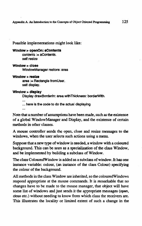
Appendix A. An Introduetion to the Concepts of Object Oriented Programming 125
Possible implementations might look like:
Wlndow > openOn: aContents contents :== aContents. self resize
Wlndow > close WindowManager restore: area
Wlndow > reslze area :- Rectangle fromUser. seH display.
Wlndow > display Display drawBorderln: area withThickness: borderWrth .
... here Is the code to do the actual displaying
Note that a number of assumptions have been made, such as the existence of agiobal WindowManager and Display, and the existence of certain methods in other classes.
A mouse controller sends the open, close and resize messages to the windows, when the user selects such actions using a menu.
Suppose that a new type ofwindow is needed, a window with a coloured background. This can beseen as a speciaJization ofthe class Window, and be implemented by building a subclass of Window.
The class ColouredWindow is added as a subclass of window. It has one instanee variable: colour, (an instanee of the class Colour) specifying the colour of the background.
All methods in the class Window are inherited, so the colouredWindows respond appropriate at the mouse commands.It is remarkable that no changes have to be made to the mouse manager, that object will have some list of windows and just sends it the appropriate messages (open, close etc.) without needing to know from which class the receivers are. This illustrates the locality or limited extent of such a change in the

126 Modelling and Simulation of Jndustrial Systema
application, as a result of late binding and polymorphism. (Of course, a mechanism should be implemented to create the the colouredWindows and include them in the mouse manager.)
To make the windows really coloured only the metbod display needs to be redefined to implcment the desi.red behaviour. The metbod display in the superclass can efficiently be called after doing the. colour specific action.
ColouredWindow > display Display paint: area wlthColour: colour. super display
This example illustrates how a given class (Window) is used to build a specialized version (ColouredWindow) by programming the difference between the existing and the required behaviour, and it illustrates the small changes that such an addition requi.res in the rest of the software.

APPENDIXB
An Introduetion to the Syntax of Smalltalk
For readers who are not familiar with the syntax of Smalltalk, a short description is given here. Por more details we refer to [ Goldberg et al 1983].
Basically there are four types of expressions: literal expressions, variabie names, message expressions and block expressions.
Literal expressions
Literal expressions are expressions that denote a constant value. Tb.ere are five types of literal expressions: number, string, symbol, array and character.
Anumberliteralexpressionsuchas 12,13.4and 12.6e4denoteanumber such as an integers or a float.
String literal expressions are sequences of characters enclosed by single quotes: 'abc', 'Bongo', 'A string with spaces'.
Symbolliteral expressions are formed by the character # followed by a sequence of characters: #abc, #green. Symbols are unique objects in the system, strings are not.
Array literal expressions are formed by the character # foliowed by a sequence of other literal expressions between parenthesis: #(1 2 3), #('string' #symbol12.3), #('abc' #{1 2 3)).
Character literal expressions are formed by the dollar sign followed by the character: $4, $A.

128 Modelling and Simwation of Indultrial Systems
Variables and assignment
A variabie associates a name with a value. The name of variables are simple identifiers, a sequence ofletters and digits, beginning with a letter. A variabie name is an expression.
An assignment statement changes the value of a variable. The syntax is: <variable name> <becomes symbol> <expression>
examples:
name :- 'John'.
length := 'abc' size.
amount := (3 + 4) factoriaL amount :- amount + 1.
Message expressions
The third type of expressions are message expressions. They have the syntax: <receiver> <m.essage>. Where <receiver> is any expression, and <message> is either a unary message, a keyword message or a binary message. A message consists of a selector and zero,or more arguments. The selector is specified literally, the arguments are expressions.
A unary message has no arguments, the selector is a keyword, some examples are:
12 factorial.
12 is the receiver (an expression), factorlal is the unary message, it is also the selector.
'a string' size.
•a string' is the receiver, slze is the selector.
A keyword message has one or more arguments, the selector consistsof a number of keywords each with a trailing colon. The selector is interwoven with the arguments as in:
12 ralsedTo: 13.

Appendix B. An Introduetion to lhe Syntax of Smalltalk 129
12 is the receiver, raisedTo: is the selector, 13 is the argument.
'AbC' at: 2 put: $8.
'AbC' is the receiver, at:put: is the selector, 2 and $8 are the arguments.
A binary message bas one single argument and a selector consisting of one or two nonalphanumeric characters.
3+4.
3 is the receiver,+ is the selector, 4 is the argument.
Block expressions
A block expression is an in-line tunetion specification. It is a sequence of statements enclosed by square brackets. When a block expression is evaluated, the containing expressions are not evaluated, instead the value is an object that can be sent a message to evaluate the expressions in the block. In this way blocks can be used to defer execution. Blocks are often used in control structures:
I :. an Integer.
p =· 1.
p • 0] whileFalse: [p :• p "I. i := 1- 1].
In this example the metbod whlleFalse evaluates the fust block, if it returns false it evaluates the second block, then it re-evaluates the fust block, and so on, until the value of the fust block returns true.
Preeedenee rules
The preeedenee rules for evaluating an expression determine in which order sub-expressions are evaluated.
The preeedenee rules in Smalltalk are as follows:
- Binary expressions take preeedenee over keyword expressions
1 + 2 raisedTo: 3
evaluates as: (1 + 2) raisedTo: 3

130 Modelling and Simulation of Industrial Systems
- Unary expressions take preeedenee over binary expressions
1 + 2 factorial
evaluates as: 1 + (2 factorlal)
- Otherwise, evaluation is done from left to right
1 +2* 3
evaluates as: (1 + 2) * 3
3 factorlal sin
evaluates as: (3 factorial) sin

APPENDIXC
Basic Task Language Methods
This appendix lists the most important methods of the task language.
Dubbie > task frame
lnltlallzeTasks This method is called befare any processor executes initia/Actions or body. 1t should not contain any send or receive actions, as the processes are notrunning yet. lt is malnly lntended to Initiai/ze Instanee varlab les. lt is also called tor expanded processors. lt is guaranteed that parents have executed this method befare it Is called for thelr chlldren. The order in which the different chlldren execute initializeTasks Is random.
lniUaiActlons
body
Thls method Is called once befare the first execution of body.
This methad is called repeatedly durlng simulation. 1t must be recJe.. fined by all subclasses. Calllng stopProcess prevents further ca/Is of this method.
ha HSlmulation Stop the present simulatlon. The effect is analogous to pushing the stop-button on the control panel.
stopProcess Prevent thls bubble trom executlng any further act/ons durlng the present simulatlon. This methad can be called in initlaiActions or body. lt can be used tor processors that do not loop, or stop looping aftera while.

132 Modei.Hng and Simwation of Jnclustrial Systems
Bobbie > activity
These methods are used to simulate an activity in no more detail than the fact that it takes a certain amount of time.
workDurlng: tlmeDelay The process wl/1 bB busy for timeDelay time units. The status assoclated with this actlvity Is 'busy'.
workDurlng: tlmeDelay forReaaon: workStatua The process wil/ bB busy for tlmeDelay time units. Th6 status assoclated with this actlvity Is workStatus.
workDurlng: tlmeDelay forReaaon: workStatua lnterruptFrom: portName
The process wf/1 bB busy for timeDelay time units, uniBss an Item is f6C8iv6d trom portName befort!J tlmeDe/ay Is expired. The status associated with th6 activity is provlded by workStatus. Return whether the actlvity terrnlnated without intenvpt The behavloris comparab/6 to rt!JCBiveFrom: portName before: time then: thenBioclc ifTimedOut: tim60ut8/ock.
workDurlng: tlmeDelay forReaaon: work9tatua lntarruptFrom: portName lf: condmon
The process w/11 bB busy for timeDBiay time units, uniBSs an item that satlsfiBs condition Is rt!JCBived from portName before tlmeDBiay is explred. condition is a block that w/11 bB evaluated with candidate Items as th6 slng/6 argument. 1t should have no sid8-Bff6cts. The status associat6d with the actlvlty is provlded by workStatus. Return whether the actlvlty termlnated without Interrupt.

~ C. Basic Taks Language Methode 133
Bubble > sending objects
send: object to: portName The most basic send act/on. Sends object synchronously to the port specified by portNarne. The process blocks until a matching recelve is pertormed by another processor.
send: object lmmedlateTo: portName B8haves exactly like a normalsend when sending at thls moment is possible. lf it blocks, which Is detected a little later, an error message appears in th8 console. This method does not have the problems related to causality that the other immediate methods have. That Is: it behaves the same as a normalsend that succeeds immedlate.
send: object lmmedlateTo: portName then: thenBiock else: elseBiock Try to send object to portName at this moment. lf that succeeds, evaluate the thenBiock, if it does not succeed, evaluate e/seB/ock.. Thus thls send cannot block.
send: object before: anme to: portName then: thenBiock else: elseBiock
Try tosend object toportName before a Time. lf that succeeds, evaluate the thenBiock., lf lt does not succeed, evaluate elseBiock.
send: object to: portName1 then: block1 o.rTo: portName2 then: block2 Try to send object toportName 1 or portName2. 8/ock. untll sending to one of the ports succeeds. lf sending to both portnarnes would be possible, use the one that has the longest waiting receiver. Evatuate th8 corresponding block when sending has succeeded.
send: ob] toOneOf: portNarnes portNarnes is a collectlon of send port names. Try to send to one of these. When there are waiting receivers, the longest walting Is used, otherwise the first receiver that bBcomes avallable wil/ be used. Aftera succestul send the method returns, the processor wil/ not try to send to the other ports as wel/. Return th8 portName that was used for the send. Performance Is best if portNarnes class == Array.

134 Modelling and Simulation of Industrial Systems
eend: obJ toOneOt: portNarnes then: actlonBiock actlonBiock is a one argument block, the argument speelfles the portName to wh/eh the send succeeded. Performance Is best lf portNarnes class -Array.
eend: object contlnuousTo: portName send object to portName. lt wil/ be avallable for an unlimited number of receivers until it Is replaced by a new cal/ to thfs method. Ooes never block.
eend: object asynchronousTo: portName send object to portName. object wil/ be buffered until a receiver Is avallable. So thls processor wi/1 not block. The size of the buffer is unllmited. This methad should be used with care; in many cases the buffer should be modelled explicitly using a processor.
Dubbie > receiving objects
recelveFrom: portName Recelve from the specified port. Block untll some sender is avallable for communicatlon. Retum the item recelved.
recelvefrom: portName lt: condltlonBiock condltlonBiock is a ons-argument block. lt Is evaluated with the candldate Item as argument. Evalustion should have no slde effects and must return a Boolean. The condition must not lnvolve values whlch change on thelr own, such as the slmu/ation time. Return the Item recelved.
recelvelmmedlatefrom: portName lt: condltlonBiock Behaves exactly llke a normal receive when recelvlng at thls moment Is posslble. ff lt blocks, this blocking is on/y detected a llttle later, then an error message appears in the console. This methad has not the probieros related to causality that the other immediate methods have. That Is: it behaves the same as a normal receive that succeeds lmmediate.
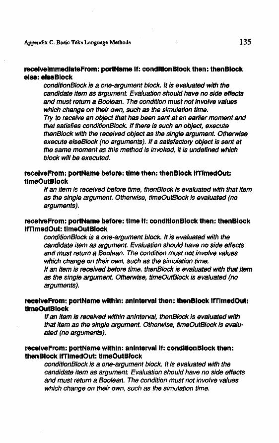
Appendix C. Basic Taks Language Methods 135
recelvelmmedlatefrom: portName H: condltlonBiock then: thenBiock else: elseBiock
condltionBiock is a one-argument block. 1t Is evaluatBd wlth the candldatB item as argument Evalustion shoukl have no sid8 flffects and must tetum a Boolean. The condition must not Jnvolve va/ues which change on thBir own, such as thB simu/ation time. Try to rBCBive an ob}Bct that has bBBn sent at an earl/er moment and that satisfles conditionBiock. lf there is such an object, execute thenBiock wlth the recelvBd ob}Bct as the single argument Otherw/se execute elseBiock (no arguments). lf a satisfactory object is sent at thB same moment as thls method is invoked, 1t is undeflnBd wh/eh block w//1 be BXBcutBd.
recelveFrom: portName before: ume then: thenBJock lfTimedOut: tlmeOutBiock
lf an item is rBCBived beforB time, thenBiock is evaluatBd wlth that item as thB single argument. Otherwlse, timeOutSloek is evaluatBd (no arguments).
recelveFrom: portName before: time lf: condltlonBiock then: thenBiock lfTimedOut: UmeOutBiock
conditionBiock Is a one-argument b/ock. lt is evaluatBd wlth the candidate item as argument. Evalustion should have no side effects and must return a Boo/ean. The condition must not /nvo/VB va/ues wh/eh change on their own, such as the simu/at/on time. lf an Item is receivBd before time, thenB/ock is evaluatBd wlth that Item as thB single argument. Otherwlse, timeOutSloek is evaluatBd (no arguments).
recelveFrom: portName wtthln: aninierval then: thenBiock trrtmedOut: tlmeOutBiock
lf an Item is f'BCfJivBd wlthln anlnterval, thenBiock Is evaluatBd w/th that Item as the single argument. Otherwlse, timeOutSloek is eva/uatBd (no arguments).
recelveFrom: portName wlthln: anlntervallf: condltlonBiock then: thenBiock lfTimedOut: ttmeOutBiock
conditionB/ock is a one-argument block. lt Is evaluatBd wlth the candidateltem as argument. Evalustion should have no sid8 effects and must return a Boolean. The condition must not lnvolve va/ues which change on their own, such as the slmu/ation time.

136 Modelling and Simulation of Indusbial Systems
lf an item Is received within anlnterval, thenB/ock Is evs/uated with that Item as the single argument. Otherwise, tfmeOutBiock Is evs/uated (no arguments).
recelveFrom: portName1 then: block1 or: portName2 then: block2 Receive an item from elfher one of two ports. Evaluate the corresponding block with the received item as the single argument.
recelvefromOneOf: portNames portNarnes Is a col/eetion of recelve port names. Try to receive from one of these. When there are ws/tlng senders, Ihslongest waltfng Is used, otherwlse the flrst sender that becomes avs/lable wilt be used. After the sUCC8Sful receive the method retums, the processor wil/ not try to recelve from the other ports as wel/. retum the item received. Performance is best lf portNarnes c/ass -Array.
recelveFromOneOf: portNames do: actlonBiock actionB/ock is a two-argument block. When an item is avallable, actlonB/ock Is evs/uated with the name of the port lnvolved as the first argument and the item as the second argument Performance is best ffportNames~s--Arra~
recelvefromOneOf: portNames lf: condltlonBiock do: actlonBiock condltionB/ock is a one-argument block. lt Is evaluated wlth the candldate Item as argument. Evs/uatlon should have no side effects and must retum a Boolean. The condition must not involve vs/ues wh/eh change on thelr own, sueh as the simu/ation time. actlonBiock is a two-argument block. When an spproprlate Item Is avallable, actlonBiock Is evs/uated wlth the name of the port lnvolved as the flrst argument and the item as the second argument Performance Is best if portNarnes class --Array.
Dubbie > special communications
send: Item to: sendPort then: sendBiock orRecelveFrom: recelvePort lf: cond then: recelveBiock
Send the item to the sendPort, or receive an item from the receivePort that satisfies cond, depending on wh/eh communication succeeds flrst. The condition is either n/1 {no condltlon) or a one argument bloei<.

Appendix C. Basic Taks Language Methods 137
send: Item to: eendPort then: sendBiock orRecelveFrom: recelvePort lt: cond then: recelveBiock wlthln: tlmelntervallfTimec:IOUt: tlmeOutBiock
Send the item to the sendPort, or receive an item from the recelvePort that satisfies cond, dependlng on whieh comrnunication succeeds flrst. The condition Is elther nll (no condition) or a one argument block. lf communieat/on does not succeed within tlmelnterval, evaluate tlmeOutBiock.
send: Item toOneOf: sendPorts do: sendBiock orRecelveFromOneOf: recelvePorts lt: cond do: recelveBiock
Send the Item to one of the sendPorts, or recelve an Item that satisfles cond from one of the receivePorts, depending on whlch communle&tion succeeds flrst. The condition is either nil (no condition) or a one argument block. sendB/ock is a one argument block; the argument specifies the portname at wh/eh sending succeeded. recelveBiock Is a two argument block; the arguments are the portname and the recelved object.
send: Item toOneOt: sendPorts do: sendBiock orRecelveFromOneOt: recelvePorts H: cond do: recelveBiock wlthln: tlmelntervallfTimedOut: tlmeOutBiock
Send the item to one of the sendPorts, or recelve an item that satisfles cond from one of the recelvePorts, depending on which communieation succeeds first The condition Is either nll (no condition) or a one argument block. lf communleation does not succeed withln timelnterval, evaluate tlmeOutBiock. sendBiock is a one argument block; the argument specifies the portname at wh/eh sending succeeded. receiveB/ock is a two argument block; the arguments are the portname and the received object.
Bobbie > accessing
The following messages do not implement an action but provide control or access to the model.
eh lidren Return a collection wlth all the processors of my expansion

138 Modelling and Simwation of Industrial Systems
name Return my name, a String
newName: string Set the name of the receiver to the argument.
parent Return the parent processor of the receiver.
Bubble > testing
lsPartOfCiass: class Answer whether the receiver is a child (ot a child of a child etc.) of a processor of the class specified by the argument. lntended to use in pararnetrisation of processors.
lsPartOfProcessorNamed: aName Answer whether the receiver is a child (or a child of a child etc.) of a processornamedas the argument. lntended to use in parametrisation of processors.

APPENDIXD
Glossary
This glossary is an alphabetic list of important tenns used in this thesis, with a short definition or explanation. The definitions are not always the most general defmitions, but reflect the way that the tenns are used in this study. Unless otherwise specified, they are formulated by the author.
Section numbers refer to sections in this dissertation where the term is used
abstraction An abstraction is a representation of something, strippeel of its concerete manifestations. Abstractions help people to · think about a single object instead of the complexity of a concrete manifestation. Abstractions suppress unnecessary detail.
A language is capable of expressing certain abstractions. For instance, our modelling language has a language abstraction to express interactions. This means that the modeller can easily think in terms of this communication mechanism, the modellar thinks of an interaction, instead of the whole complex mechanism that it represents. 2.8, 3.2

140 Modelling and Simulation of lndusbial Systems
procedure abstraction
A procedure abstraction is a piece of code associated with a name. lt enables a modellar tothink of the procedure without considering all details of the concrete implementation. 3.4.9, 4.3.12
action An action is a change of the state of a processor. 3.4.5
body body is the name of the method that describes a leaf processor. This method is assumed to be called in a loop. From within body other methods will be called. 4.3.6
busy waltlng Busy waiting is the phenomenon that a process waits for some (external) event, while consuming computing power. lt is usually implemented as a loop in which a condition is tested over and over again.ln our approach, busy waiting should be avoided, instead, the process wil perfarm a receive action walting for theevent (assuming that the occurrence of the event eausas an appropriate send action). A blocking receive ( or send) does not consume any computing power. 8.1.2
class A class is a description of a type of object. lt describes how lts objects are composed of instanee variables, and what functionality these objects have (which methods they have, or to which messages they respond). 4.3.5, 4.3.13, 4.3.15, 4.3.16, Appendix A
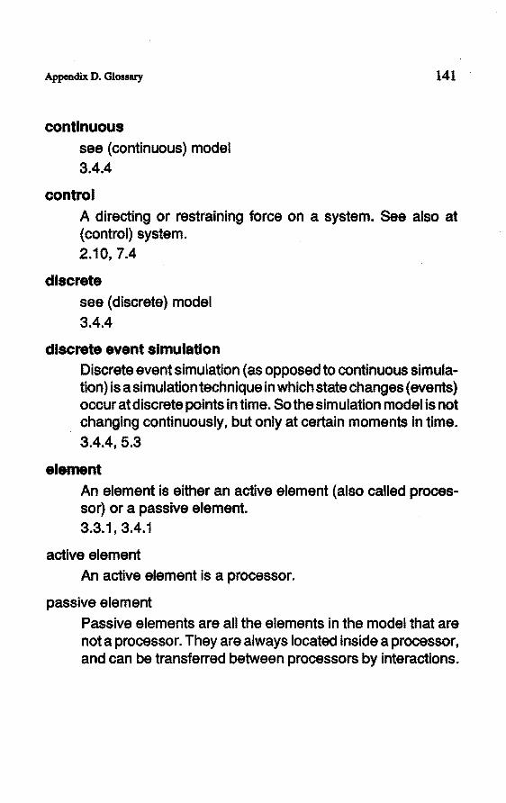
Appendix D. Gloasary
contlnuous see {continuous) model 3.4.4
control
141
A directing or rastraining force on a system. See also at { control) system. 2.10, 7.4
discrete see (discrete) model 3.4.4
discrete avant slmulatlon Discrete event si mulation (as opposed to continuous simulation) is a simulation technique in which state changes ( events) occur at discrete points in time. So the sim u lation model is not changing continuously, but only at certain momentsin time. 3.4.4, 5.3
alemant An element is alther an activa element ( also called processor) or a passiva element. 3.3,1 1 3.4.1
activa element An activa element is a processor.
passiva element Passiva elements are all the elements in the model that are nota processor. They are always located inside a processor, and can be transferred between processors by interactions.

142 Modelling and Simwation of lndustrial Systems
evaluaUon of speclflcatlons Evalustion of a specification is determining the quallty of a specification (of a design). This study emphasises on the ability to evaluate a specification without actually building the system. Simulation is used as the main method for evaluation. 2.6
event A change in the state. 3.4.3, 3.4.4
expanded processor see(expanded)processor 3.3.1
falrness Fairness is a messure that describes how different competing communication partners get involved in actual communications. The guarantee that processas will communicate in a first-come-firts-served order indicates a high faimess. 3.4.6
forma I see (formal) language see (formal) model

Appendix D. Glossary 143
functlonal speclflcatlon of an lndustrlal system In this study funotional specification is defined as a model of a system that describes the behaviour (the funotionality) of the system. A funotional specification does not describe the, systems appearanee orthe way it is construoted. A funotional specification of a discrete system describes which events will take place, and at what moment in time. This study presents a modelling technique that uses process descriptions as the basis for a funotional specification. 2.3
g lobal variabie A global variabie is a variabie that is accessible to more than one (or all) processors. The modelling technique that is used in this study avoids the use of global variables. lnstead, interaotions are used to communicate between processors. 3.4.6
implementatlon The term implementation is used as a synonym for realization. During the implementation, a system is construoted, based on the specification. 2.10
Instanee An instanee is a membar of a class. Every object in an object oriented programming language is an instanee of a eertain class. Examples: 'abc' is an instanee of the class String. 12 is an instanee of the class Integer. Appendix A, 4.3.5, 4.3.9

144 Modelling and Simulation of lndustrial Systems
Instanee variabie Instanee variables are variables that form the private data of an object. Every object consists of a nurnber of instanee variables. They are oomparabie wlth the record membars of a record in Pascal. For example, an instanee of the class Point has two instanee variables named x and y. This means that every Point has its own two variables x and y. We could say that an object is a number of instanee variables plus its notion to which class it belongs. Appendix A, 4.3.6, 4.3.9
Interaction An interaction is the transfer of an object from one processor to another processor. An interaction is performed in zero time. 3.4.6, 4.3.8
Interaction path
I var
An interaction path models the possibility that passiva elements are transferred trom one processor to another processor. An interaction path is directed, it has a to and trom side, describing the direction of the possible transfer. 3.3.2
See instanee variable. Appendix A, 4.3.6, 4.3.9

Appendix D. Glossary 145
language A language is a systematic means of communicating using conventionalized signs, sounds, gestures, ormarks [Longman Coneisa English Dictionary, 1985]. Therefore a language can. be used to express the model. Stronger: every model is expressed (or built) using a language. Not only natura! and artificial languages (like computer program specifications) are considered as languages, but also the formalisms behind drawings, maquettes and formulas. 2.11, 3.2
formal language A formallanguage is a language in which it is not possible to form ambiguous expressions. Every expression has exactly one meaning. Computer languages are examples of formal languages. ProcessTalkis also a formallanguage.
. 2.4
structure language see (structure) language 4.2
task language see (task) language 4.3
leaf processor see (leaf) processor 3.3.1
object orlented language see oop

146 Modelling and Simulation of Industrial. SysàmllJ
message A message is a description of which method to invoke with whlch arguments in an object oriented language. A message send to an object eausas the .specified method to be executed. Such an object oriented message send has nothing to do with the interactlons of the Process Interaction Approach. Appendix A
method A method is a tunetion abstraction in an object oriented programming language. lt associates a nametoa a piece of program code. See also (procedure) abstraction. 3.4.9, 4.3.12, Appendix A
model A model is an abstraction of a system that describes certain aspectsof the system; it describes those aspects that are relevant given a certain objective; the description is made using a language. When thinking about a system, when talking about a system, when describing a system, when specifying a system, when building a maquette of a system, when drawinga schematic of a system, in all these cases a model of the system results. A model is the result of a projection, it Is a representation of asystem. A model raferstoa system. And a model is built with a certain objective in mind. In this study models are used as specifications of systems. 2.1 , 2.2, 2.3, 2.4
conceptual model A model in the mind of a person. 2.1

Appendix D. Glossary
tormal model A model specified in a formallanguage. 2.4
continuous model
147
A model in which state changes happen at every moment in time. 3.4.4
discrete model A model in which state changes happen at discrete moments in time. 3.4.4
modularlty Modularity is a maasure for how related different parts of a system are. A high modularity means that it is possible to design or understand one part of the system without knowing much of the other parts. 2.9
mutex, mutual excluslon Mutual exclusion is the mechanism that prevents two or more processors to access some resource at the same time.
nondetermlnlsm A system is nondeterministic when its behaviour is not obeying causal rules, and is therefore not predictable. In this study we use the word for systems that do not have a known causal behaviour. For common modelling purposes, such systems can be modelled using pseudo random number generators. 3.4.11 ' 4.3.16
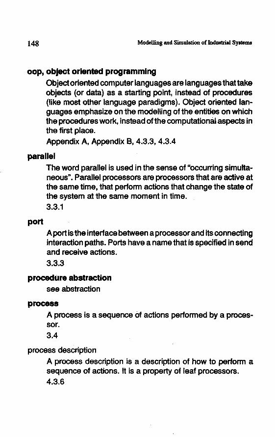
148 Modelling and Simulation of lndustrial Systems
oop, object orlented programmlng Objectoriented computer languages are languages thattake objects (or data) as a starting point, insteadof procedures (like mostother language paradigms). Object oriented languages emphasize on the modelling of the antities on which the procedures work, insteadof the computationàl aspectsin the first place. Appendix A, Appendix B, 4.3.3, 4.3.4
parallel
port
The word parallel is used in the sense of "occurring simultaneous". Paratiel processors are processors that are activa at the same time, that perform actions that change the state of the system at the same moment in time. 3.3.1
A port is the interface between a processor and its connecting interaction paths. Ports have a name that is speelfled insend and receive actions. 3.3.3
procedure abstraction see abstraction
process A process is a sequence of actions performed by a processor. 3.4
process description A process description is a description of how to perform a sequence of actions. lt is a proparty of leaf processors. 4.3.6

Appendix D. Glossary 149
blocked process A processis said to be blocked when it is not performing actions forsome time. For instance, a process that executes a receive action, but no other process is sending an object, will be blocked in the receive action until such a send occurs. 3.4.6
processor A processor is an active element modelling an industrial system. There are two types of processors: expanded processors and leaf processors. 3.3.1
expanded processor An expanded processor is a processor that is modelled by a number of sub-processors.
laaf processor · A laaf processor is a processor that is modelled by a process
description; a leaf processor has no children.
parent processor The processor that contains another processor is called the parent processor of the latter.
child processor A sub-processor is called the child of its parent.
level of a processor Processors that have the same parent are located in the same level. The level of a parent is called higherthan the level of its children.

150 Modellins and Simulation of Industrial. Systems
ProcessTalk ProcessTalkis thelanguage- introduced in this study -for the specification of industrial systems. The language consists of two parts: the structure language and the task language. ProcessTalk enables the modelling of the functionality of an industrial system in a tormal way. Thelanguage is based on the object oriented programming language Smalltalk. Chapter4
ProcessTool The ProcessTool is an interactiva graphical software environment for the rnadelling and simulation of industrial systems. The ProcessTool is implemented as part of this study. Chapter 6
race condition A race condition is the (undesired) phenomenon that the rasuit ofthe execution oftwo processas depends on the order in which statements in the different processas are executed, without an explicit synchronization betweenthem. The use of interactions, and refraining from the use of global variables, avoids the introduetion of race conditions. 3.4.6
reai-time system A reai-time system is a system of which can be guaranteed that it will raspond within a certain speelfled maximum time interval. 7.4

Appendix D. Glossary 151
schedullng Scheduling is the ordering of tasks in time. lt is the deelsion taking of which actions should occur at which moment. A typical scheduler in a factory datermlnes when which products should be produced, given a set of orders, material stock, set-up times etc. 7.3
semantlc elements With the term semantic elements of a language we emphasise on the meaning of the language elements (while not considering how they are written as speelfled by the syntax). 3.1' 3.2
al mulation Simulation is the technique of imitating certain aspects of a system. In this study discrete event simulation is used to evaluate the design of industrial systems. 2.6.2, 3.4.4, 5.3
Smalltalk Smalltalk is an object oriented programming language pur sang. lt is also a graphical interactiva programming environment. Our modelling language ProcessTalk is based on Smalltalk and the ProcessTool is implemenled in Smalltalk. Appendix A, Appendix B, 4.3.4
speclflcatlon see: functional specification of an industrial system

152 Modelling and Simulation of Jndustrial Systems
state The state of a model is a model of the state of lts system. The state of a processor (which Is a model) is an inventory of: its structure; all the values of the variables in its scope; the point in the process description to where execution has proceeded; and the state of its sub-processors. 3.4.3
statement A statement is an expression in a language.
structure The structure of an expanded processor is a description of its topology. lt describes the colledion of processors, the way that they are hierarchically organized, the ports and the interaction paths. 3.3
structure language The language to describe the structure of an expanded processor. The structure language is oneofthetwo partsof ProcessTalk, the other part is the task language. 4.2
system A system is a group of interrelated and interdependent units that serves a common purpose. In this study the word system will mainly be used for things in the real world. A certain factory is for instanee an (industrial) system. 1.1
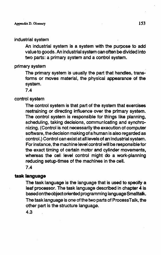
Appendix D. Glossary 153
lndustrial system An industrial system is a system with the purpose to add value to goods. An industrial system can often be divided into two parts: a primary system and a control system.
primary system The primary system is usually the part that handles, transforms or moves material, the physical appearance of the system. 7.4
control system The control system is that part of the system that exercises rastraining or directing influence over the primary system. The control system is responsible for things like planning, scheduling, taking decisions, communicating and synchronizing. ( Control is not necessarily the execution of computer software, the deelsion making of a hu man is also reg~rded as control.) Control can exist at alllevels of an industrial system. For instance, the machine level control will be responsible for the exact timing of certain motor and cylinder movements, whereas the cell level control might do a work-planning reducing setup-times of the machines in the cell. 7.4
task language The task language is the language that is used to specify a leaf processor. The task language described in chapter 4 is based ontheobjectoriented programming language Smalltalk. The task language is one of the two partsof ProcessTalk, the other part is the structure language. 4.3

154 Modelling and Simulation of lndustrial Systems
unlflcatlon of modelllng languages Unification Qf modelling languages is the concept to use only one modelling language in the design phase of a system. In our approach one language is used for the functional specification of industrial systems, from the logistic level to the reai-time control, for simulation, for communication within the design team, and so on. 2.7
valldatlon, valldlty An important proparty of a model is its validity. The validity of a model is a measure for how well the behaviour ofthe model compares to the systems behaviour. The validity of a model must be considered with respect to the purpose of the model. The objective should determine what behaviour of the system and the model is relevant, under what conditions the model is intended to be a representation of the system, and how these behaviours should be compared. 2.6.4
verlflcatlon Verification is the checking whether a model expressed In the modelling language conforms to the mental model. In other words, it is the determination whether a model indeed describes the system as intended by the modeller. Verification does not consider the validity of a model, it is rather the correction of "programming" errors. 2.6.3

Curriculum Vitae
Alexander Michael Wortmam
geboren op 28 April 1961 te Groningen
1973 tot 1979 Europese School Brussel, België
1979 tot 1987 Universiteit Twente, Doctoraal ·Elektrotechniek. De laatste jaren van deze studie is er veel aandacht besteed aan infonnatica, met name op het gebied van redeneer-systemen en de eigenschappen van de programmeertalen Lisp en Prolog.
1987 tot 1991 Technische Universiteit Eindhoven Aangesteld als universitair docent bij de vakgroep WP A (Werktuigbouwkundige Produktietechnologie en -Automatisering) van de faculteit Werktuigbouwkunde. Naast het onderwijskundige werk is er promotieonderzoek verricht op het gebeid van modellering en simulatie van industriële systemen.

Stellingen
behorende bij het proefschrift
ModeHing and Simulation of lndustrial Systems

1 . Het is onmogelijk om de voorspellende validiteit van een model van een industrieel systeem te bewijzen.
2. Het is niet zinvol om industriële systemen in te delen in discrete en continue.
3. De tijd die nodig is om een industrieel systeem te ontwerpen en te realiseren wordt bekort door het gebruik van simulatie, ondanks het feit dat simulatie enige tijd kost.
4. De kracht van het declaratieve karakter van de programmeertaal Prolog geldt vooral voor lezers van Prolog progranuna;s; schrijvers ervan dienen de taal helaas meestal als een imperatieve taal te beschouwen.
5 . De tijdsduur om met de progranuneertaal Smalltalk een probleem op te lossen is vaak korter dan met andere progranuneertalen, ook indien de executiesnelheid van Smalltalk lager is dan die van deze andere talen.
6 . Informatie over de ligging van hoge en lage drukgebieden, straalstromen en fronten; die tijdens weersverwachtingen vaak wordt ver:strekt; is irrelevant voor het publiek.
7. Het inkorten van een as in een grafiek tussen de oorsprong en de minimale waarde, werkt vaak misleidend in plaats van verhelderend.
8 . De moeite die veel mensen hebben met het maken van een beschrijving in een ééndimensionale representatie, zoals een geschrift, ligt gedeeltelijk daaraan dat de informatie niet ééndimensionaal gestrucmreerd is.
9. Eén gezamenlijke wachtrij voor een aantal loketten, in plaats van één rij per loket, verlaagt zowel de gemiddelde wachttijd, als de variantie daarvan, en is daarenboven eerlijker en rustiger voor de wachtenden.
10. In het informatica-onderwijs wordt het ontwerpen van datastrucmren onderbelicht ten opzichte van het ontwerpen van algoritmen.
11. In tegenstelling tot hetgeen in de natuur gebruikelijk is, gaat het vermenigvuldigen bij computers doorgaans niet met delen gepaard.
AJexanderVVonrnann Eindhoven, 5 november 1991
Copyright © 2022 FDOKUMEN