Minimally invasive silicon probe for electrical impedance measurements in small animals
9
Minimally invasive silicon probe for electrical impedance measurements in small animals A. Ivorra a , R. Go ´mez a , N. Noguera a , R. Villa a , A. Sola b , L. Palacios c , G. Hotter b , J. Aguilo ´ a, * a Centro Nacional de Microelecto ´nica (IMB-CSIC), Campus UAB, E-08193 Bellaterra, Barcelona, Spain b Department of Medical Bioanalysis, Instituto de Investigaciones Biome ´dicas, IIBB-CSIC, IDIBAPS, Barcelona, Spain c Department of Physiology, Faculty of Biology, University of Barcelona, Barcelona, Spain Received 11 July 2002; received in revised form 4 June 2003; accepted 25 June 2003 Abstract It is commonly accepted that electrical impedance provides relevant information about the physiological condition of living tissues. Currently, impedance measurements are performed with relatively large electrodes not suitable for studies in small animals due to their poor spatial resolution and to the damage that they cause to the tissue. A minimally invasive needle shaped probe for electrical impedance measurements of living tissues is presented in this paper. This micro-probe consists of four square platinum electrodes (300 mm /300 mm) on a silicon substrate (9 mm /0.6 mm /0.5 mm) and has been fabricated by using standard Si microelectronic techniques. The electrodes are not equally spaced in order to optimise the signal strength and the spatial resolution. Characterisation data obtained indicate that these probes provide high spatial resolution (measurement radius B/4 mm) with a useful wide frequency band going from 100 Hz to 100 kHz. A series of in vivo experiments in rat kidneys subjected to ischemia was performed to demonstrate the feasibility of the probes and the measurement system. The impedance modulus and phase were measured at 1 kHz since this frequency is sufficiently low to permit the study of the extracellular medium. The extracellular pH and K were also simultaneously measured by using commercial miniaturised Ion Selective Electrodes. The induced ischemia period (45 min) resulted in significant changes of all measured parameters (DjZj /65%; DpH /0.8; DK /30 mM). # 2003 Elsevier B.V. All rights reserved. Keywords: Bio-impedance; Micro-probe; Silicon needle; Rat kidney; Induced ischemia 1. Introduction It has been demonstrated that electrical impedance is a useful parameter to determine the physiological condition of living tissues (Grimnes and Martinsen, 2000; Rigaud et al., 1996). Some pathologies induce changes in essential tissue parameters, such as the extra- intracellular volume ratio or the ionic composition, which are reflected as changes in the passive electrical properties (electrical bio-impedance). One of these pathologies is ischemia (lack of blood supply and consequently lack of oxygen). Animal cells regulate their volume by a Na pump-mediated mechanism. In the case of a decrease in the metabolic energy caused by ischemia, this mechanism fails to regulate the Na equilibrium and an osmotic pressure imbalance is created between the intracellular and the extracellular media. As a result, the extracellular water penetrates into the cell with a subsequent cell swelling (Flores et al., 1972) and an extracellular medium shrinkage which is manifested as a decrease in the electrical conductivity of the tissue at low frequencies. Ischemia is induced during certain surgical practices or during the cold storage of grafts for transplantation. Its influence on the cells determines the further viability of the tissue and, therefore, any parameter able to monitor its evolution, such as bio-impedance, could become in medical practice a useful tool to follow the changes induced by the therapeutic management. More- over, the use of bio-impedance measurements could be * Corresponding author. Tel.: /34-93-594-7700; fax: /34-93-580- 1496. E-mail address: [email protected] (J. Aguilo ´). Biosensors and Bioelectronics xxx (2003) 1 /9 www.elsevier.com/locate/bios 0956-5663/03/$ - see front matter # 2003 Elsevier B.V. All rights reserved. doi:10.1016/S0956-5663(03)00204-5 ARTICLE IN PRESS
-
Upload
independent -
Category
Documents
-
view
1 -
download
0
Transcript of Minimally invasive silicon probe for electrical impedance measurements in small animals
Minimally invasive silicon probe for electrical impedancemeasurements in small animals
A. Ivorra a, R. Gomez a, N. Noguera a, R. Villa a, A. Sola b, L. Palacios c, G. Hotter b,J. Aguilo a,*
a Centro Nacional de Microelectonica (IMB-CSIC), Campus UAB, E-08193 Bellaterra, Barcelona, Spainb Department of Medical Bioanalysis, Instituto de Investigaciones Biomedicas, IIBB-CSIC, IDIBAPS, Barcelona, Spain
c Department of Physiology, Faculty of Biology, University of Barcelona, Barcelona, Spain
Received 11 July 2002; received in revised form 4 June 2003; accepted 25 June 2003
Biosensors and Bioelectronics xxx (2003) 1�/9
www.elsevier.com/locate/bios
ARTICLE IN PRESS
Abstract
It is commonly accepted that electrical impedance provides relevant information about the physiological condition of living
tissues. Currently, impedance measurements are performed with relatively large electrodes not suitable for studies in small animals
due to their poor spatial resolution and to the damage that they cause to the tissue. A minimally invasive needle shaped probe for
electrical impedance measurements of living tissues is presented in this paper. This micro-probe consists of four square platinum
electrodes (300 mm�/300 mm) on a silicon substrate (9 mm�/0.6 mm�/0.5 mm) and has been fabricated by using standard Si
microelectronic techniques. The electrodes are not equally spaced in order to optimise the signal strength and the spatial resolution.
Characterisation data obtained indicate that these probes provide high spatial resolution (measurement radius B/4 mm) with a
useful wide frequency band going from 100 Hz to 100 kHz. A series of in vivo experiments in rat kidneys subjected to ischemia was
performed to demonstrate the feasibility of the probes and the measurement system. The impedance modulus and phase were
measured at 1 kHz since this frequency is sufficiently low to permit the study of the extracellular medium. The extracellular pH and
K� were also simultaneously measured by using commercial miniaturised Ion Selective Electrodes. The induced ischemia period (45
min) resulted in significant changes of all measured parameters (DjZj�/65%; DpH�/0.8; DK��/30 mM).
# 2003 Elsevier B.V. All rights reserved.
Keywords: Bio-impedance; Micro-probe; Silicon needle; Rat kidney; Induced ischemia
1. Introduction
It has been demonstrated that electrical impedance is
a useful parameter to determine the physiological
condition of living tissues (Grimnes and Martinsen,
2000; Rigaud et al., 1996). Some pathologies induce
changes in essential tissue parameters, such as the extra-
intracellular volume ratio or the ionic composition,
which are reflected as changes in the passive electrical
properties (electrical bio-impedance). One of these
pathologies is ischemia (lack of blood supply and
consequently lack of oxygen). Animal cells regulate
their volume by a Na� pump-mediated mechanism. In
the case of a decrease in the metabolic energy caused by
ischemia, this mechanism fails to regulate the Na�
equilibrium and an osmotic pressure imbalance is
created between the intracellular and the extracellular
media. As a result, the extracellular water penetrates
into the cell with a subsequent cell swelling (Flores et al.,
1972) and an extracellular medium shrinkage which is
manifested as a decrease in the electrical conductivity of
the tissue at low frequencies.Ischemia is induced during certain surgical practices
or during the cold storage of grafts for transplantation.
Its influence on the cells determines the further viability
of the tissue and, therefore, any parameter able to
monitor its evolution, such as bio-impedance, could
become in medical practice a useful tool to follow the
changes induced by the therapeutic management. More-
over, the use of bio-impedance measurements could be
* Corresponding author. Tel.: �/34-93-594-7700; fax: �/34-93-580-
1496.
E-mail address: [email protected] (J. Aguilo).
0956-5663/03/$ - see front matter # 2003 Elsevier B.V. All rights reserved.
doi:10.1016/S0956-5663(03)00204-5
useful for biomedical researchers and, in this sense, the
possibility to experiment with small animals is very
attractive.
The impedance probe used in most past in vivo
studies consists of a linear array of four metallic needle
electrodes placed at a constant inter-electrode separa-
tion distance. The outer electrodes are employed to
inject an AC current into the tissue while the resulting
potential is differentially measured across the inner
electrodes (Rush et al., 1963). Although the feasibility
of this kind of probe has been widely demonstrated, it
implies some important practical drawbacks that restrict
its use: (a) the fabrication process results in large
tolerances because of the critical positioning and align-
ment of the electrodes, (b) the damage caused to the
tissue is considerable since each probe causes four
punctures, (c) the presence of a conductive layer (e.g.
blood) on top of the tissue under study shunts the
electrodes and seriously disturbs the measurements
(Steedijk et al., 1993) and (d) the strong dependence of
apparent resistance on insertion depth (Tsai et al., 2000)
makes crucial the probe fixation to the tissue. Because of
these facts, bio-impedance in vivo studies have been
mostly limited to moderate size animals and the few
studies that have been carried out with small animals
made use of different impedance probes with important
practical limitations (Jossinet et al., 2001; Raicu et al.,
1998).
In this paper, a needle shaped probe with four aligned
platinum electrodes on its surface is presented (Fig. 1).
This configuration not only lessens the limitations of the
classical plunge probe but provides another interesting
advantage: the probe can be easily fabricated by using
standard microelectronic technologies which implies
high reliability, low costs and the possibility to integrate
other sensors and electronics on the same probe. That
kind of geometry has been employed previously for
neural activity recording or stimulation (Blum and
Charles, 1988; Drake et al., 1988; Yoon et al., 2000),
but, as far as the authors know, it has not been applied
yet for impedance measurements. Thus, new design
strategies had to be considered in order to optimisethe probe performance for bio-impedance measure-
ments.
As it has been pointed out, ischemia induces tissue
changes that can be sensed by bio-impedance measure-
ments. Here, in order to demonstrate the feasibility of
these novel impedance probes to carry out in vivo
studies with small animals, a series of in vivo experi-
ments in rat kidneys subjected to ischemia was per-formed. Other two parameters known to be influenced
by the ischemia: the extracellular pH (Dmochowski and
Couch, 1966; Moller et al., 2000) and the extracellular
potassium concentration (Mayevsky et al., 2001; Reeves
and Shah, 1994) were also monitored and their results
and practical constraints were compared with those
obtained with the impedance measurements.
2. Materials and methods
2.1. Bio-impedance probes
2.1.1. Probe design
The starting point for the probe design was the four-
electrode structure with constant inter-electrode separa-tion distance (IESD). For this structure, the voltage
drop at the inner electrodes is inversely related with the
IESD (Steedijk et al., 1993) and, therefore, it is desirable
to make the probe as long as possible to enhance signal-
to-noise ratio. However, since the needle shaft length
was restricted in order to minimise the tissue damage
and to obtain high spatial resolution, a modification was
investigated: to bring the inner electrodes near to theouter electrodes (Ivorra et al., 2001). It can be deduced
intuitively that this strategy increases the voltage drop
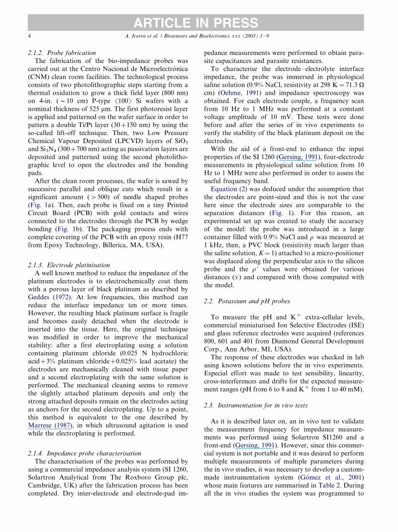
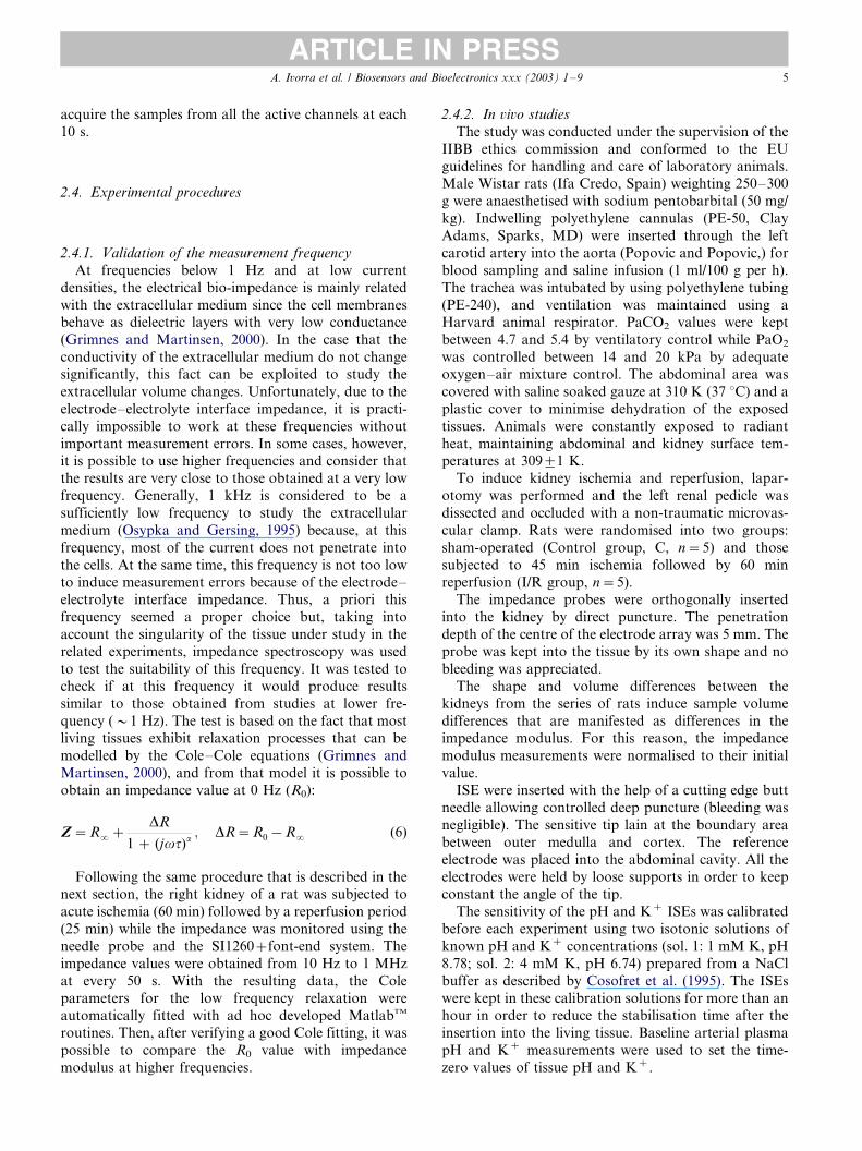
Fig. 1. (a) Impedance probe after wafer sawing. The platinum electrodes are placed at non-constant inter-electrode separation distance to optimise
the probe performance. (b) The packaging covers the bonding pads and reduces the needle shaft to 9 mm.
A. Ivorra et al. / Biosensors and Bioelectronics xxx (2003) 1�/92
ARTICLE IN PRESS

for a given current and resistivity. Fortunately, it is also
beneficial in terms of spatial resolution.
By applying the same methods used by Suesserman
and Spelman (1993) the signal strength (voltage drop,V ) is easily related with the injected current (I), the
sample resistivity (r ), the separation distance between
the outer and the inner electrodes (a ) and the separation
distance between the inner electrodes (b ) for an isotropic
and uniform infinite medium:
V �1
4pr
b
a(a � b)I (1)
This expression shows what was expected intuitively:
it is possible to improve the voltage signal withoutincreasing the length occupied by the electrodes (2a�/b).
Concerning the spatial resolution, it is possible to
analytically derive, by using the image method (Robil-
lard et al., 1979), an expression that relates the apparent
resistivity (measured resistivity, r ?) with the infinite
extent medium resistivity (r ) when there exists a
medium transition at a distance x from the non-
constant IESD electrode array (see Fig. 2):
r?�r
�1�K
G?
G
�(2)
G��
1
a�
1
a � b
�(3)
G?��
1ffiffiffiffiffiffiffiffiffiffiffiffiffiffiffiffiffiffi4x2 � a2
p �1ffiffiffiffiffiffiffiffiffiffiffiffiffiffiffiffiffiffiffiffiffiffiffiffiffiffiffiffiffiffiffi
4x2 � (a � b)2
q�
(4)
K�r2 � r1
r2 � r1
(5)
where K (‘‘reflection coefficient’’) depends on the
sample resistivity (r1) and the resistivity of the boundary
medium (r2).
The r ?/r ratio versus the transition distance with a
non-conductive medium (K�/1) is represented in Fig. 2
for different electrode distances and a constant array
length. It can be observed that effective measurement
volume is reduced when a is reduced. Thus, bringing the
inner electrodes closer to the outer electrodes also
enhances the spatial resolution of the probe.
From what has been said above, it could be deduced
that the best situation would be to place the inner and
the outer electrodes at the minimum possible separation
distance. However, it must be taken into account that
the most sensitive volume of the probe will be the
volume surrounding the separation between an inner
and an outer electrode. In the case that this distance is
reduced too much, the impedance measurements will
depend on the relative position of these electrodes in the
cellular structure of the tissue and not on the homo-
geneous properties of the tissue surrounding the probe.
Hence, a separation distance quite larger than the cell
size is recommended in order to avoid the heterogeneity
of the living tissue at cellular level. In the designed
probe, the minimum separation distance between elec-
trodes is 300 mm.
The electrode�/tissue, or electrode�/electrolyte, inter-
face impedance determines the performance of any
tissue impedance measuring system, even if the four-
electrode method is applied (Pallas-Areny and Webster,
1993). This undesired impedance causes measurement
errors, especially at low frequencies, that could be
understood as noise or signal distortion. In order to
minimise these errors, the electrode�/tissue impedances
should be reduced and matched as much as possible.
Since the conductance of these interfaces is directly
related to the area, the most evident way to reduce their
impedance is to enlarge the electrode surface. In this
sense, the square shape is a good choice because it
makes good use of the shaft length given for each
electrode. In the vicinity of the square corners the
current density will not be uniform and non-linear tissue
electrical properties could become manifested, however,
since the tissue impedance measurement covers
a greater volume and the injected current is very low
(B/10 mA), this effect will unlikely influence the
measurements.
About the probe materials it must be said that the
technological process was a decisive factor in regard to
the substrate material (Si) and the isolating materials
(SiO2 and Si3N4). The chosen material for the electrodes
was platinum because of its biocompatibility and low
electrode�/electrolyte interface impedance compared
with other materials such as stainless steel or silver.
Furthermore, the Pt electrodes can be coated with a
porous layer of ‘‘black platinum’’ which largely reduces
the impedance (Geddes, 1972).
Fig. 2. Estimated r ?/r (apparent resistivity/infinite extent medium
resistivity) of a conductive medium bounded by a non-conductive
medium located at x .
A. Ivorra et al. / Biosensors and Bioelectronics xxx (2003) 1�/9 3
ARTICLE IN PRESS
2.1.2. Probe fabrication
The fabrication of the bio-impedance probes was
carried out at the Centro Nacional de Microelectronica
(CNM) clean room facilities. The technological processconsists of two photolithographic steps starting from a
thermal oxidation to grow a thick field layer (800 nm)
on 4-in. (�/10 cm) P-type �100� Si wafers with a
nominal thickness of 525 mm. The first photoresist layer
is applied and patterned on the wafer surface in order to
pattern a double Ti/Pt layer (30�/150 nm) by using the
so-called lift-off technique. Then, two Low Pressure
Chemical Vapour Deposited (LPCVD) layers of SiO2
and Si3N4 (300�/700 nm) acting as passivation layers are
deposited and patterned using the second photolitho-
graphic level to open the electrodes and the bonding
pads.
After the clean room processes, the wafer is sawed by
successive parallel and oblique cuts which result in a
significant amount (�/500) of needle shaped probes
(Fig. 1a). Then, each probe is fixed on a tiny PrintedCircuit Board (PCB) with gold contacts and wires
connected to the electrodes through the PCB by wedge
bonding (Fig. 1b). The packaging process ends with
complete covering of the PCB with an epoxy resin (H77
from Epoxy Technology, Billerica, MA, USA).
2.1.3. Electrode platinisation
A well known method to reduce the impedance of the
platinum electrodes is to electrochemically coat them
with a porous layer of black platinum as described by
Geddes (1972). At low frequencies, this method can
reduce the interface impedance ten or more times.However, the resulting black platinum surface is fragile
and becomes easily detached when the electrode is
inserted into the tissue. Here, the original technique
was modified in order to improve the mechanical
stability: after a first electroplating using a solution
containing platinum chloride (0.025 N hydrochloric
acid�/3% platinum chloride�/0.025% lead acetate) the
electrodes are mechanically cleaned with tissue paperand a second electroplating with the same solution is
performed. The mechanical cleaning seems to remove
the slightly attached platinum deposits and only the
strong attached deposits remain on the electrodes acting
as anchors for the second electroplating. Up to a point,
this method is equivalent to the one described by
Marrese (1987), in which ultrasound agitation is used
while the electroplating is performed.
2.1.4. Impedance probe characterisation
The characterisation of the probes was performed by
using a commercial impedance analysis system (SI 1260,Solartron Analytical from The Roxboro Group plc,
Cambridge, UK) after the fabrication process has been
completed. Dry inter-electrode and electrode-pad im-
pedance measurements were performed to obtain para-
site capacitances and parasite resistances.
To characterise the electrode�/electrolyte interface
impedance, the probe was immersed in physiologicalsaline solution (0.9% NaCl, resistivity at 298 K�/71.3 Vcm) (Oehme, 1991) and impedance spectroscopy was
obtained. For each electrode couple, a frequency scan
from 10 Hz to 1 MHz was performed at a constant
voltage amplitude of 10 mV. These tests were done
before and after the series of in vivo experiments to
verify the stability of the black platinum deposit on the
electrodes.With the aid of a front-end to enhance the input
properties of the SI 1260 (Gersing, 1991), four-electrode
measurements in physiological saline solution from 10
Hz to 1 MHz were also performed in order to assess the
useful frequency band.
Equation (2) was deduced under the assumption that
the electrodes are point-sized and this is not the case
here since the electrode sizes are comparable to theseparation distances (Fig. 1). For this reason, an
experimental set up was created to study the accuracy
of the model: the probe was introduced in a large
container filled with 0.9% NaCl and r was measured at
1 kHz, then, a PVC block (resistivity much larger than
the saline solution, K�/1) attached to a micro-positioner
was displaced along the perpendicular axis to the silicon
probe and the r ? values were obtained for variousdistances (x ) and compared with those computed with
the model.
2.2. Potassium and pH probes
To measure the pH and K� extra-cellular levels,
commercial miniaturised Ion Selective Electrodes (ISE)
and glass reference electrodes were acquired (references
800, 601 and 401 from Diamond General DevelopmentCorp., Ann Arbor, MI, USA).
The response of these electrodes was checked in lab
using known solutions before the in vivo experiments.
Especial effort was made to test sensibility, linearity,
cross-interferences and drifts for the expected measure-
ment ranges (pH from 6 to 8 and K� from 1 to 40 mM).
2.3. Instrumentation for in vivo tests
As it is described later on, an in vivo test to validate
the measurement frequency for impedance measure-
ments was performed using Solartron SI1260 and a
front-end (Gersing, 1991). However, since this commer-
cial system is not portable and it was desired to perform
multiple measurements of multiple parameters during
the in vivo studies, it was necessary to develop a custom-made instrumentation system (Gomez et al., 2001)
whose main features are summarised in Table 2. During
all the in vivo studies the system was programmed to
A. Ivorra et al. / Biosensors and Bioelectronics xxx (2003) 1�/94
ARTICLE IN PRESS
acquire the samples from all the active channels at each
10 s.
2.4. Experimental procedures
2.4.1. Validation of the measurement frequency
At frequencies below 1 Hz and at low current
densities, the electrical bio-impedance is mainly related
with the extracellular medium since the cell membranesbehave as dielectric layers with very low conductance
(Grimnes and Martinsen, 2000). In the case that the
conductivity of the extracellular medium do not change
significantly, this fact can be exploited to study the
extracellular volume changes. Unfortunately, due to the
electrode�/electrolyte interface impedance, it is practi-
cally impossible to work at these frequencies without
important measurement errors. In some cases, however,it is possible to use higher frequencies and consider that
the results are very close to those obtained at a very low
frequency. Generally, 1 kHz is considered to be a
sufficiently low frequency to study the extracellular
medium (Osypka and Gersing, 1995) because, at this
frequency, most of the current does not penetrate into
the cells. At the same time, this frequency is not too low
to induce measurement errors because of the electrode�/
electrolyte interface impedance. Thus, a priori this
frequency seemed a proper choice but, taking into
account the singularity of the tissue under study in the
related experiments, impedance spectroscopy was used
to test the suitability of this frequency. It was tested to
check if at this frequency it would produce results
similar to those obtained from studies at lower fre-
quency (�/1 Hz). The test is based on the fact that mostliving tissues exhibit relaxation processes that can be
modelled by the Cole�/Cole equations (Grimnes and
Martinsen, 2000), and from that model it is possible to
obtain an impedance value at 0 Hz (R0):
Z�R��DR
1 � (jvt)a; DR�R0�R� (6)
Following the same procedure that is described in thenext section, the right kidney of a rat was subjected to
acute ischemia (60 min) followed by a reperfusion period
(25 min) while the impedance was monitored using the
needle probe and the SI1260�/font-end system. The
impedance values were obtained from 10 Hz to 1 MHz
at every 50 s. With the resulting data, the Cole
parameters for the low frequency relaxation were
automatically fitted with ad hoc developed MatlabTM
routines. Then, after verifying a good Cole fitting, it was
possible to compare the R0 value with impedance
modulus at higher frequencies.
2.4.2. In vivo studies
The study was conducted under the supervision of the
IIBB ethics commission and conformed to the EU
guidelines for handling and care of laboratory animals.Male Wistar rats (Ifa Credo, Spain) weighting 250�/300
g were anaesthetised with sodium pentobarbital (50 mg/
kg). Indwelling polyethylene cannulas (PE-50, Clay
Adams, Sparks, MD) were inserted through the left
carotid artery into the aorta (Popovic and Popovic,) for
blood sampling and saline infusion (1 ml/100 g per h).
The trachea was intubated by using polyethylene tubing
(PE-240), and ventilation was maintained using aHarvard animal respirator. PaCO2 values were kept
between 4.7 and 5.4 by ventilatory control while PaO2
was controlled between 14 and 20 kPa by adequate
oxygen�/air mixture control. The abdominal area was
covered with saline soaked gauze at 310 K (37 8C) and a
plastic cover to minimise dehydration of the exposed
tissues. Animals were constantly exposed to radiant
heat, maintaining abdominal and kidney surface tem-peratures at 3099/1 K.
To induce kidney ischemia and reperfusion, lapar-
otomy was performed and the left renal pedicle was
dissected and occluded with a non-traumatic microvas-
cular clamp. Rats were randomised into two groups:
sham-operated (Control group, C, n�/5) and those
subjected to 45 min ischemia followed by 60 min
reperfusion (I/R group, n�/5).The impedance probes were orthogonally inserted
into the kidney by direct puncture. The penetration
depth of the centre of the electrode array was 5 mm. The
probe was kept into the tissue by its own shape and no
bleeding was appreciated.
The shape and volume differences between the
kidneys from the series of rats induce sample volume
differences that are manifested as differences in theimpedance modulus. For this reason, the impedance
modulus measurements were normalised to their initial
value.
ISE were inserted with the help of a cutting edge butt
needle allowing controlled deep puncture (bleeding was
negligible). The sensitive tip lain at the boundary area
between outer medulla and cortex. The reference
electrode was placed into the abdominal cavity. All theelectrodes were held by loose supports in order to keep
constant the angle of the tip.
The sensitivity of the pH and K� ISEs was calibrated
before each experiment using two isotonic solutions of
known pH and K� concentrations (sol. 1: 1 mM K, pH
8.78; sol. 2: 4 mM K, pH 6.74) prepared from a NaCl
buffer as described by Cosofret et al. (1995). The ISEs
were kept in these calibration solutions for more than anhour in order to reduce the stabilisation time after the
insertion into the living tissue. Baseline arterial plasma
pH and K� measurements were used to set the time-
zero values of tissue pH and K�.
A. Ivorra et al. / Biosensors and Bioelectronics xxx (2003) 1�/9 5
ARTICLE IN PRESS

3. Results and discussion
3.1. Bio-impedance probes characterisation
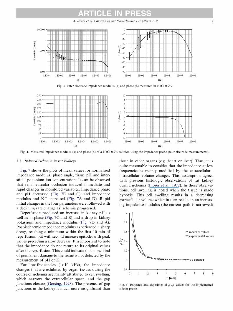
The results from the impedance probe characterisa-
tion after the manufacturing are summarised in Table 1.The electrode�/electrolyte interface impedance (Fig. 3)
becomes very high at frequencies below 100 Hz and that
can involve important tissue impedance measurement
errors, especially in a heterogeneous tissue where each
electrode can have completely different interface im-
pedances. On the other hand, at frequencies beyond 100
kHz, the capacitive coupling of the wires (including the
coaxial wires from the probes to the instrumentation) isstrongly manifested (Fig. 4). Thus, it can be considered
that the useful frequency band goes from 100 Hz to 100
kHz.
The interface impedance test after the series of in vivo
experiments resulted in minor changes (impedance
modulus increase at 100 Hz B/20%) confirming the
stability of the black platinum deposit.
The results from the spatial resolution characterisa-tion are shown in Fig. 5. It can be observed that the
experimental measurements follow the predicted values
by using the model. Therefore, the model works
properly although the electrodes cannot be considered
as point electrodes. From these results it is possible to
provide a value for the spatial resolution: 4 mm. That is,
any medium disruption beyond 4 mm from the centre of
the probe will cause measurement errors below 1%.The use of microelectronic materials and fabrication
processes reduces production costs and offers the
possibility to integrate signal conditioning electronics
or additional sensors. This could be used, for instance,
to expand the useful frequency band by integrating
voltage buffers on the silicon. Furthermore, a tempera-
ture sensor could be integrated on the same substrate to
isolate changes caused by physiological reasons from
those caused by temperature changes.
3.2. Validation of the measurement frequency
After inducing ischemia by arterial clamping, the R0
increased from 1.7 to 12.5 kV in 60 min. The impedance
modulus at 1 kHz followed this evolution with a reducedsensitivity resulting in a 25% of maximum relative
difference. This fact could suggest the use of lower
frequencies to reduce this difference, however, it must be
taken into account that measurement errors are ob-
served for frequencies below 300 Hz and that the range
of possible interface impedances is amazingly wide.
Therefore, in order to ensure quality for all the
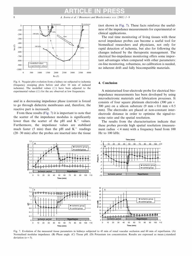
measurements it seems that 1 kHz is a proper choice.Fig. 6 shows the results obtained from this experi-
mental test before and after 10 min of induced ischemia
and the superimposed Cole fittings. The Cole models
were adjusted for low frequencies (B/10 kHz) since the
relaxation arc presented distortion for higher frequen-
cies due to other tissue relaxation constants and because
of the needle parasitic capacitances.
Table 1
Summarised results from the probes characterisation
Parameter Conditions Minimum Typical Maximum
Electrode-pad resistance: (connection resistance) TA�/298 K
I�/ 1050 V 1200 V 1300 VV�/ 900 V 1000 V 1100 VV�/ 850 V 1000 V 1050 VI�/ 600 V 700 V 800 VInter-electrode capacitance TA�/298 K 5 pF 6 pF
Inter-electrode impedance modulus in saline solution TA�/298 K, 0.9% NaCl, VOSC�/100 mVp
10 Hz 5 kV 8 kV 25 kV100 Hz 3.5 kV 5 kV 7 kV1 kHz 3.6 kV 3.8 kV 4 kV10 kHz 3.4 kV 3.5 kV 3.6 kV100 kHz 3.2 kV 3.3 kV 3.4 kV
Cell constant (k�/r /R ). R , measured resistance; r , resistivity TA�/298 K, 0.9% NaCl, VOSC�/100 mVp 0.32 cm
Spatial resolution ErrorB/1% 4 mm
Table 2
Instrumentation system main features
Bio-impedance meter
Number of channels 10
Ground isolation impedance 50 pF
Oscillator frequency 100 Hz to 125 kHz
Injected current amplitude B/5 mA
CMRR at 1 kHz 88 dB
Input common impedance �/50 MV//7pF
Input differential impedance �/50 MV//2pF
Ion meter (voltmeter )
Number of channels 16
Ground isolation impedance 50 pF
Input impedance �/10 TV
A. Ivorra et al. / Biosensors and Bioelectronics xxx (2003) 1�/96
ARTICLE IN PRESS
3.3. Induced ischemia in rat kidneys
Fig. 7 shows the plots of mean values for normalised
impedance modulus, phase angle, tissue pH and inter-
stitial potassium ion concentration. It can be observed
that renal vascular occlusion induced immediate and
rapid changes in monitored variables. Impedance phase
and pH decreased (Fig. 7B and C), and impedance
modulus and K� increased (Fig. 7A and D). Rapid
initial changes in the four parameters were followed with
a declining rate change as ischemia progressed.
Reperfusion produced an increase in kidney pH as
well as in phase (Fig. 7C and B) and a drop in kidney
potassium and impedance modulus (Fig. 7D and A).
Post-ischaemic impedance modulus experienced a sharp
decay, reaching a minimum within the first 10 min of
reperfusion, but with second increase episode, with peak
values preceding a slow decrease. It is important to note
that the impedance do not return to its original values
after the reperfusion. This could indicate that some kind
of permanent damage to the tissue is not detected by the
measurement of pH or K�.
For low-frequencies (B/10 kHz), the impedance
changes that are exhibited by organ tissues during the
course of ischemia are mainly attributed to cell swelling,
which narrows the extracellular space, and the gap
junctions closure (Gersing, 1998). The presence of gap
junctions in the kidney is much more insignificant than
those in other organs (e.g. heart or liver). Thus, it is
quite reasonable to consider that the impedance at low
frequencies is mainly modified by the extracellular�/
intracellular volume changes. This assumption agrees
with previous histologic observations of rat kidney
during ischemia (Flores et al., 1972). In those observa-
tions, cell swelling is noted when the tissue is made
hypoxic. This cell swelling results in a decreasing
extracellular volume which in turn results in an increas-
ing impedance modulus (the current path is narrowed)
Fig. 3. Inter-electrode impedance modulus (a) and phase (b) measured in NaCl 0.9%.
Fig. 4. Measured impedance modulus (a) and phase (b) of a NaCl 0.9% solution using the impedance probe (four-electrode measurements).
Fig. 5. Expected and experimental r ?/r values for the implemented
silicon probe.
A. Ivorra et al. / Biosensors and Bioelectronics xxx (2003) 1�/9 7
ARTICLE IN PRESS
and in a decreasing impedance phase (current is forced
to go through dielectric membranes and, therefore, the
reactive part is increased).
From these results (Fig. 7) it is important to note that
the scatter of the impedance modulus is significantly
lower than the scatter of the pH and K� values.
Furthermore, the impedance values are stabilised
much faster (5 min) than the pH and K� readings
(20�/30 min) after the probes are inserted into the tissue
(not shown in Fig. 7). These facts reinforce the useful-
ness of the impedance measurements for experimental or
clinical applications.
The real time monitoring of living tissues with thesenovel impedance probes can become a useful tool for
biomedical researchers and physicians, not only for
rapid detection of ischemia, but also for following the
changes induced by the therapeutic management. The
electrical bio-impedance monitoring offers some impor-
tant advantages when compared with other parameters:
on-line monitoring, robustness, no calibration is needed,
no inherent drift and fully biocompatible materials.
4. Conclusion
A miniaturised four-electrode probe for electrical bio-
impedance measurements has been developed by usingmicroelectronic materials and fabrication processes. It
consists of four square platinum electrodes (300 mm�/
300 mm) on a silicon substrate (9 mm�/0.6 mm�/0.5
mm). The electrodes are placed at non-constant inter-
electrode distance in order to optimise the signal-to-
noise ratio and the spatial resolution.
The results from the characterisation indicate that
these probes provide high spatial resolution (measure-ment radius B/4 mm) with a frequency band from 100
Hz to 100 kHz.
Fig. 6. Nyquist plot evolution from a kidney rat subjected to ischemia
(frequency sweeping plots before and after 10 min of induced
ischemia). The modelled values (k) have been adjusted to the
experimental values (I) for the arc observed at low frequencies.
Fig. 7. Evolution of the measured tissue parameters in kidneys subjected to 45 min of renal vascular occlusion and 60 min of reperfusion. (A)
Normalised modulus impedance. (B) Phase angle. (C) Tissue pH. (D) Potassium ion concentration. Results are expressed as mean9/standard
deviation (n�/5).
A. Ivorra et al. / Biosensors and Bioelectronics xxx (2003) 1�/98
ARTICLE IN PRESS
The capability of the probe to measure bio-impedance
in small animals has been demonstrated. Furthermore,
the obtained in vivo results reinforce the usefulness of
the bio-impedance as a marker of the tissue condition.
Acknowledgements
This work has been supported by the European
Commission through projects ESPPRIT-LTR-23485,
IST-1999-13047 and QLK6-CT-2000-00064 and by the
Spanish government through projects TIC98-1634-CE,TIC2000-2486-CE, FISS 01/1691 and SAF 2000-3090-
CE.
References
Blum, N.A., Charles Jr, K.K., 1988. Multi-microlectrode probe for
neurophysiologial experiments. In: Proceedings of the Fourteenth
Annual Northeast Bioengineering Conference, Durham, NH,
USA, pp. 15�/18.
Cosofret, V.V., Erdosy, M., Timothy, A.J., Buck, R.P., 1995.
Microfabricated sensor arrays sensitive to pH and K� for ionic
distribution measurements in the beating heart. Analytical Chem-
istry 67 (10), 1647�/1653.
Dmochowski, J.R., Couch, N.P., 1966. Electrometric surface pH of the
ischemic kidney and the effect of hypothermia. Journal of Surgical
Research 6 (1), 45�/48.
Drake, K.L., Wise, K.D., Farraye, J., Anderson, D.J., BeMent, S.L.,
1988. Performance of planar multisite microprobes in recording
extracellular single-unit intracortical activity. IEEE Transactions
on Biomedical Engineering 35 (9), 719�/731.
Flores, J., DiBona, D.R., Beck, C.H., Leaf, A., 1972. The role of cell
swelling in ischemic renal damage and the protective effect of
hypertonic solute. The Journal of Clinical Investigation 51, 118�/
126.
Geddes, L.A., 1972. Electrodes and the Measurement of Bioelectric
Events. Wiley-Interscience/Wiley, New York, pp. 32�/35.
Gersing, E., 1991. Measurement of electrical impedance in organs-
measuring equipment for research and clinical applications.
Biomedizinische Technik 36 (1-2), 6�/11.
Gersing, E., 1998. Impedance spectroscopy on living tissue for
determination of the state of organs. Bioelectrochemistry and
Bioenergetics 45, 145�/149.
Gomez, R., Noguera, N., Ivorra, A., Villa, R., Aguilo, J., Millan, J.,
Lopez, J., Palacios, L., Sola, A., Hotter, G., 2001. Instrumentation
system for in vivo organ studies. In: Proceedings of 24th Interna-
tional Semiconductor Conference, Sinaia (Romany), 9�/13 Octo-
ber, vol. 1, pp. 261�/264.
Grimnes, S., Martinsen, O.G., 2000. Bioimpedance and Bioelectricity
Basics. Academic Press.
Ivorra, A., Aguilo, J., Millan, J., 2001. Design considerations for
optimum impedance probes with planar electrodes for bioimpe-
dance measurements. In: Proceedings of 24th International Semi-
conductor Conference, Sinaia (Romany), 9�/13 October, vol. 1, pp.
269�/272.
Jossinet, J., Moulin, V., Matias, A., McAdams, E.T., 2001. In vivo
spectrometry of dunning prostate tumours. In: Proceedings of the
XII Conference on Electrical Bio-Impedance, Oslo (Norway), 17�/
21 June, pp. 285�/288.
Marrese, C.A., 1987. Preparation of strongly adherent platinum black
coatings. Analytical Chemistry 59 (1), 217�/218.
Mayevsky, A., Nakache, R., Luger-Hamer, M., Amran, D., Sonn, J.,
2001. Assessment of transplanted kidney vitality by a multipara-
metric monitoring system. Transplantation Proceedings 33, 2933�/
2934.
Moller, H.E., Gaupp, A., Dietl, K.-H., Buchholz, B., Vestring, T.,
2000. Tissue pH in human kidney transplants during hypothermic
ischaemia. Magnetic Resonance Imaging 18, 743�/751.
Oehme, F., 1991. In: Gopel, W., Jones, T.A., Kleitz, M., Lundstrom,
J., Seiyama, T. (Eds.), Sensors, A Comprehensive Survey, Chemical
and Biochemical Sensors, Part I, vol. 2. VCH Verlagsgesellschaft
mbH, Weinheim, pp. 314�/332.
Osypka, M., Gersing, E., 1995. Tissue impedance spectra and the
appropriate frequencies for EIT. Physiological Measurement 16,
A49�/A55.
Pallas-Areny, R., Webster, J.G., 1993. AC instrumentation amplifier
for bioimpedance measurements. IEEE Transactions on Biomedi-
cal Engineering 40 (8), 830�/833.
Raicu, V., Saibara, T., Irimajiri, A., 1998. Dielectric properties of rat
liver in vivo: a noninvasive approach using an open-ended coaxial
probe at audio/radio frequencies. Bioelectrochemistry and Bioe-
nergetics 47, 325�/332.
Reeves, W.B., Shah, S.V., 1994. Activation of potassium channels
contributes to hypoxic injury in proximal tubules. Journal of
Clinical Investment 94 (6), 2289�/2294.
Rigaud, B., Morucci, J.-P., Chauveau, N., 1996. Examples of
applications. Critical Reviews in Biomedical Engineering 24 (4-6),
323�/351.
Robillard, P.N., Poussart, D., 1979. Spatial resolution of four
electrode array. IEEE Transactions on Biomedical Engineering
BME-26 (8), 465�/470.
Rush, S., Abildskov, J.A., McFee, R., 1963. Resistivity of body tissues
at low frequencies. Circulation Research XII, 40�/50.
Steedijk, P., Mir, G., Van Del Velde, E.T., Baan, J., 1993. The four-
electrode resistivity technique in anisotropic media: theoretical
analysis and application on myocardial tissue in vivo. IEEE
Transactions on Biomedical Engineering 40 (11), 1138�/1148.
Suesserman, M.F., Spelman, F.A., 1993. Quantitative in vivo mea-
surements of inner ear tissue resistivities: I. In vitro characteriza-
tion. IEEE Transactions on Biomedical Engineering 40 (10), 1032�/
1046.
Tsai, J.-Z., Cao, H., Tungjitkusolmun, S., Woo, E.J., Vorperian, V.R.,
Webster, J.G., 2000. Dependence of apparent resistance of four-
electrode probes on insertion depth. IEEE Transactions on
Biomedical Engineering 47 (1), 41�/48.
Yoon, T.H., Hwang, E.J., Shin, D.Y., Park, S.I., Oh, S.J., Jung, S.C.,
Shinn, H.C., Kim, S.J., 2000. A micromachined silicon depth probe
for multichannel neural recording. IEEE Transactions on Biome-
dical Engineering 47 (8), 1082�/1087.
A. Ivorra et al. / Biosensors and Bioelectronics xxx (2003) 1�/9 9
ARTICLE IN PRESS