Micro end-milling of channels using ultrafine-grained low-carbon steel
11
ORIGINAL ARTICLE Micro end-milling of channels using ultrafine-grained low-carbon steel Cleiton L. F. de Assis & Renato G. Jasinevicius & Alessandro R. Rodrigues Received: 17 October 2013 /Accepted: 14 October 2014 # Springer-Verlag London 2014 Abstract During micromachining, the interaction between the cutting tool and the workpiece material may cause dam- ages on the machined surface related to material deformation. It would be interesting that the workpiece microstructure suits the scale of the cutting parameters. Very little has been inves- tigated on how a metallurgically modified material responds to microcutting. This research evaluated the effect of an ultrafine-grained material in the micromilling of grooves. Dual-phase low-carbon steel (ferrite-pearlite) was submitted to warm rolling for grain refinement (from 11- to 0.7-μm size of ferrite grains). The effect of tool cutting edge radius (r e ), feed per tooth (f t ), tool diameter, and speed cutting upon surface roughness and burr formation during end-milling of the original material and the modified one was evaluated. The ultrafine-grained material showed better results of surface finishing and presence of burrs when compared to the original dual-phase material. The metallurgical modification of low- carbon steels by grain refinement favored for micromachining of grooves, making it possible to extend applications of this class of steels. Keywords Micro end-milling . Channels . Ultrafine-grained low-carbon steel . Surface finishing . Burrs 1 Introduction The grain refinement in metals is considered an alternative to increase the mechanical strength of steels with relative tough- ness associated [1]. The microstructure refinement can be obtained by accelerated cooling after warm rolling. The ma- terial temperature control during deformation is important to produce a uniform ultrafine ferrite microstructure [ 2]. Furthermore, e.g., low-carbon steels submitted to the grain refinement can be applied for advanced structure products [3]. Macromilling studies showed satisfactory results, such as improved surface finishing, reduction of grain deformation, and a significant reduction in the microhardness variation along the part subsurface [4]. Also, less burr formation was reported in the micromachining of stainless steel with ultrafine grains [5]. Regarding the reduction of the machining scale, unwanted effects such as a change in the chip formation and defects in the workpiece surface can occur due to the increase of the effective tool rake angle, caused by the cutting edge radius of the tool interaction with cut material [6]. When the nominal thickness of cut is of the same magnitude of the cutting edge radius, shear deformation is yielded by the round portion of the cutting edge where the effective rake angle turns to be more and more negative. Under high negative rake angle, extrusion deformation of the part material occurs resulting in the increase of burr formation and surface defects [7]. According to literature, it is possible to generate chips with a -75° rake angle [8]. The investigation on the effect of microstructure modifica- tion upon micromachining performance may be considered of great relevance, e.g., when cutting multiphase materials, the tool cuts a ferrite grain at a moment and after that may cut a pearlite grain, causing variations on surface formation, with worse surface finishing [9]. The crystallographic structure (grain size and grain orientation) has a significant influence on the variation of the machined surface finish and burr C. L. F. de Assis (*) Department of Production Engineering, University of São Paulo, São Paulo, Brazil e-mail: [email protected] R. G. Jasinevicius : A. R. Rodrigues Department of Mechanical Engineering, University of São Paulo, 400 Trabalhador São Carlense Av, São Carlos, SP 13.566-590, Brazil Int J Adv Manuf Technol DOI 10.1007/s00170-014-6503-2
-
Upload
independent -
Category
Documents
-
view
1 -
download
0
Transcript of Micro end-milling of channels using ultrafine-grained low-carbon steel

ORIGINAL ARTICLE
Micro end-milling of channels using ultrafine-grainedlow-carbon steel
Cleiton L. F. de Assis & Renato G. Jasinevicius &Alessandro R. Rodrigues
Received: 17 October 2013 /Accepted: 14 October 2014# Springer-Verlag London 2014
Abstract During micromachining, the interaction betweenthe cutting tool and the workpiece material may cause dam-ages on the machined surface related to material deformation.It would be interesting that the workpiece microstructure suitsthe scale of the cutting parameters. Very little has been inves-tigated on how a metallurgically modified material respondsto microcutting. This research evaluated the effect of anultrafine-grained material in the micromilling of grooves.Dual-phase low-carbon steel (ferrite-pearlite) was submittedto warm rolling for grain refinement (from 11- to 0.7-μm sizeof ferrite grains). The effect of tool cutting edge radius (re),feed per tooth (ft), tool diameter, and speed cutting uponsurface roughness and burr formation during end-milling ofthe original material and the modified one was evaluated. Theultrafine-grained material showed better results of surfacefinishing and presence of burrs when compared to the originaldual-phase material. The metallurgical modification of low-carbon steels by grain refinement favored for micromachiningof grooves, making it possible to extend applications of thisclass of steels.
Keywords Micro end-milling . Channels .
Ultrafine-grained low-carbon steel . Surface finishing .
Burrs
1 Introduction
The grain refinement in metals is considered an alternative toincrease the mechanical strength of steels with relative tough-ness associated [1]. The microstructure refinement can beobtained by accelerated cooling after warm rolling. The ma-terial temperature control during deformation is important toproduce a uniform ultrafine ferrite microstructure [2].Furthermore, e.g., low-carbon steels submitted to the grainrefinement can be applied for advanced structure products [3].
Macromilling studies showed satisfactory results, such asimproved surface finishing, reduction of grain deformation, anda significant reduction in the microhardness variation along thepart subsurface [4]. Also, less burr formation was reported inthe micromachining of stainless steel with ultrafine grains [5].
Regarding the reduction of the machining scale, unwantedeffects such as a change in the chip formation and defects inthe workpiece surface can occur due to the increase of theeffective tool rake angle, caused by the cutting edge radius ofthe tool interaction with cut material [6]. When the nominalthickness of cut is of the same magnitude of the cutting edgeradius, shear deformation is yielded by the round portion ofthe cutting edge where the effective rake angle turns to bemore and more negative. Under high negative rake angle,extrusion deformation of the part material occurs resulting inthe increase of burr formation and surface defects [7].According to literature, it is possible to generate chips with a−75° rake angle [8].
The investigation on the effect of microstructure modifica-tion upon micromachining performance may be considered ofgreat relevance, e.g., when cutting multiphase materials, thetool cuts a ferrite grain at a moment and after that may cut apearlite grain, causing variations on surface formation, withworse surface finishing [9]. The crystallographic structure(grain size and grain orientation) has a significant influenceon the variation of the machined surface finish and burr
C. L. F. de Assis (*)Department of Production Engineering, University of São Paulo,São Paulo, Brazile-mail: [email protected]
R. G. Jasinevicius :A. R. RodriguesDepartment of Mechanical Engineering, University of São Paulo,400 Trabalhador São Carlense Av, São Carlos,SP 13.566-590, Brazil
Int J Adv Manuf TechnolDOI 10.1007/s00170-014-6503-2

formation [10]. Moreover, it has to be considered that at smallscale, the anisotropy effect caused by polycrystalline metals atthe interaction between the cutting edge and different grainorientation may generate chatter which affect surface forma-tion. Considering these effects, micromachining, therefore,could be favored by the presence of a homogeneous micro-structure and grain size as much as by the tool edge radius. Inthis way, homogeneous microstructure with ultrafine ferritecould be a solution to applications that need controlledfinishing, less burrs, and less surface defects.
This paper aims at studying the effects of workpiece mate-rial modified by grain refinement and tool edge radius (withtwo micromills diameter) in the micromilling of grooves.Surface texture of the machined part (average and maximum3D roughness) and burr formation were analyzed.
2 Experimental details
2.1 Cutting parameters
Microchannels were milled on a CNC machining center. Thecutting parameters were spindle rotation, micromill diameter,depth of cut, feed per tooth, and tool edge radius. Dry opera-tion was applied. Table 1 presents the cutting parameters. Thetests were replicated to confirm the effects of the variables and
material’s microstructure on surface finishing and burr forma-tion. All averages were calculated considering statistical reli-ability of 95 %.
Feeds per tooth were chosen to be smaller and bigger thantool edge radius values. Two materials with equivalent chem-ical properties but different metallurgical conditions wereused, dual-phase material (ferritic-pearlitic) and a homoge-neous ultrafine-grained material (ferrite ultrafine grain) namedDP and UFG materials, respectively.
For the 200-μm diameter end mill, the spindle speed waskept at 10,000 rpm, and for the 800-μm diameter end mill, thespindle speeds were 10,000 and 54,000 rpm.
2.2 Experimental apparatus and machining procedure
Figure 1 presents the experimental apparatus and machiningprocedure. The micromilling tests were carried out on a CNCMikrotools MPM4020L, and the spindle rotations were10,000 and 54,000 rpm. Two-flute carbide flat end micromillsMITSUBISHI MS2MS with diameter of 200 and 800 μm,respectively, and both with 30° helix angle were used.
The cutting edge radius (re) was measured by 3D LaserMicroscope Olympus OLS4000. Five edge radius measure-ments were made on each cutting edge used. The averagemeasured and standard values of the cutting edge radii were1.06±0.2 and 4.47±0.3 μm for the micromills with diameterof 200 and 800 μm, respectively (Fig. 2).
Surface images of the channels’ base and burrs were madeby scanning electron microscope (SEM) Philips XL30-TMP,and optical profiler (OP) Veeco Wyko NT1100. Average (Sa)and maximum (Sz) Roughness were evaluated over the com-plete 3D surface area.
2.3 Workpiece material
Table 2 shows the chemical composition of the workpiecematerial. Some samples were cut and drawn as a plate ofdimensions of 25×25×100 mm. Following cutting, they weresubjected to thermomechanical processing of warm rolling for
Table 1 Cutting conditions to the micromilling
Group Parameter Values
Micromilling process Spindle rotation [rpm] 10,000 and 54,000
Feed per tooth [μm/tooth] 0.5; 3 and 10
Length of cut [mm] 2
Depth of cut [μm] 32
Width of cut [mm] 200 and 800
Cutting tool End mill diameter [μm] 200 and 800
Cutting edge radius [μm] 1.06 and 4.47
Workpiece material Grain size [μm] 0.7 and 11
Fig. 1 Experimental setup formicromilling of channels in DPand UFG materials
Int J Adv Manuf Technol

Fig. 2 Procedure for measuring the tool edge radii by using laser microscopy
Table 2 Chemical compositionof the workpiece materials C Mn P S Si Al Cu Cr Ni Nb V Ti
0.15 1.49 0.027 0.009 0.27 0.046 0.005 0.276 0.008 0.048 0.044 0.016
Fig. 3 Microstructures of the workpiece materials
Table 3 Main mechanicalproperties of the workpiecematerials
Metallurgical condition Grain size [μm] Hardness [HV] Yield strength [MPa] Charpy energy [J]
Dual-phase material 11 192 474 176
Ultrafine-grained material 0.7 216 510 285
Int J Adv Manuf Technol

grain refinement. Instructions for material grain refining used inmachining tests can be found in the Brazilian patent registrationnumber PI11072474 granted on September 25, 2012 [11].
Figure 3 shows the UFG material microstructure obtainedby optical microscopy and transmission electron microscopy.The DPmaterial has a microstructure with ferrite grains (gray)
Fig. 4 Geometry of theworkpieces
Fig. 5 SEM images of thechannel bottom for 200-μmdiameter microtool and10,000 rpm. The arrows indicatethe tool direction and rotation
Int J Adv Manuf Technol

and pearlite colonies (black) by carbon’s banding due to theoriginal rolling processing. Due to the very small grain size ofthe UFG material, transmission electron microscope (TEM)Philips CM-120 was used. The contrast variation is due tochanges on crystallographic direction among the grains.
Table 3 presents main mechanical properties of the work-piece materials. The difference in hardness between the ma-terials is only 24 HV. This is due to the fact that dual-phasematerial process did not undergo a stress relief treatment afterrolling. Figure 4 shows the workpiece design to the machiningtests.
3 Results and discussion
Figure 5 presents surface SEM images of the channel’s basecut with the 200-μm end mill at 10,000 rpm. For all
conditions, the dual-phase material showed more flaws inthe machined surface than the ultrafine-grained material,mainly when ft>re. Also, for ft>re, it is observed that shapeof the tooth path is an elongated cycloid or trochoid [12]. Thiseffect occurs because of the tool eccentricity, spindle tilt, toothrun-out, and elastic deflections of the machine-tool-workpiecesystem [13]. In this paper, this effect was accentuated forincreasing feeds per tooth during micromachining with thesmaller tool diameter.
Figure 6 shows SEM images of the channels’ base cut withend mill with diameter of 800 μm at 10,000 rpm. For allconditions, the dual-phase material showed more flaws inthe machined surface than the ultrafine-grained material. Theflaws to the machined surface increased with increasing offeed per tooth.
Figure 7 shows SEM images of the channel’s base cut withthe end mill with diameter of 800 μm at 54,000 rpm. For ft>re,the dual-phase material showed more flaws than the ultrafine-
Fig. 6 SEM images of thechannel bottom for 800-μmdiameter microtool and10,000 rpm. The arrows indicatethe tool direction and rotation
Int J Adv Manuf Technol

grained material. The flaws in the machined surfaceincreased with the feed per tooth, but for ft=0.5 μm/tooth, both are similar. Compared to the spindle rotationof 10,000 rpm (Fig. 6), the dual-phase material showedbetter surface finishing for all conditions, particularlyfor the smallest feed per tooth, where no apparentdamage is seen at 54,000 rpm.
Measurements of Sa and Sz roughness were carried out toquantify the effect of feed per tooth and edge radius. Figure 8presents the roughness analysis of the workpieces. Figure 8ashows the Sa roughness. For both tool diameters, the ultrafine-grained material had smaller roughness than the dual-phasematerial, mainly for ft<re, where the edge radius is moreinfluent. Moreover, smaller surface roughness was achievedfor the ultrafine-grainedmaterial for bothmicromills diameter,i.e., 200 and 800 μm. The results suggest that the microstruc-ture refinement shows direct influence upon surface rough-ness formation.
When the surface of a part is modified by differentmanufacturing processes, Sz shows a change in thecharacteristic of the surface faster than Sa. Figure 8bshows the Sz roughness for 200-μm micromill; the dual-phase material shows larger Sz than the ultrafine-grainedmaterial for feed per tooth smaller and equal to 3 μm.This result may be attributed to damages and flawsfound in the surface such as voids and material sideflow which contributed to the increase of the roughnessvalues. However, for the highest feed per tooth valueused, the ultrafine-grained material generated a larger Szroughness value. When the surface finished is comparedby using Fig. 5, it is possible to observe that the cutridges generated for ft=10 μm/tooth in the DP sampleare crushed to the side whereas the cut ridges for theultrafine grain sample seem to be prominent. Moreover,for the DP material, the kurtosis value is smaller than3.0 and larger than 3.0 for the ultrafine grain material
Fig. 7 SEM images of thechannel bottom for 800-μmdiameter microtool and54,000 rpm. The arrows indicatethe tool direction and rotation
Int J Adv Manuf Technol

for this cutting condition. This may indicate the pres-ence of high peaks for the latter material and lackthereof making up the texture for the former.
Figure 8c presents the roughness as function of the spindlespeed and feed per tooth for both materials and the micromillwith diameter of 800 μm. The ultrafine-grained materialshowed better roughness than the dual-phase material, evenwhen comparing the machining of ultrafine-grained materialduring lower spindle rotation with the machining of the dual-phase material during higher spindle rotation. However, whencomparing the roughness of ultrafine-grained material in bothspindle rotations, the machining with 10,000 rpm showedlower roughness.
Sz parameter in Fig. 8d shows that the spindle speedvariation is more significant when considering the effect ofthe edge radius (ft<re) in the machining of ultrafine-grainedmaterial. For the dual-phase material, less damage occurred athigher spindle speed causing roughness to be lower. Thisbehavior may be validated by comparing Figs. 6 and 7.
Figure 9 presents the SEM images of burrs for 200-μmmicromill and 10,000 rpm. A qualitative analysis shows theburr formation more intense at the tool disengagement for theultrafine-grained material and for the dual-phase material. Theincrease in the burr size is maximized at the tool disengage-ment [14]. The burr size is inversely related to feed per tooth inthe machining of the ultrafine-grained material, and there wasno significant variation of burr volume in the machining of the
dual-phase material. It is possible to assert that the increase ofburr size or volume is directly related to the feed per tooth andcutting edge radius ratio. This is more clearly observed inFig. 9 for smaller feed per tooth when machining the UFGmaterial.
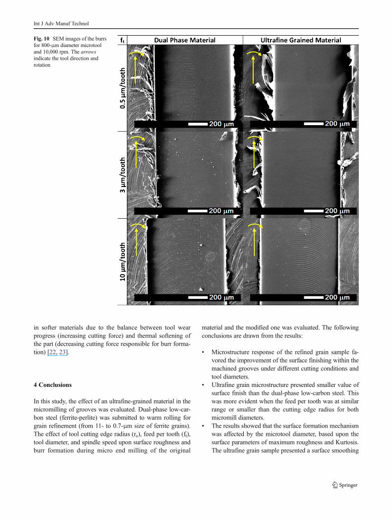
Figure 10 presents the SEM images of burrs for the800-μm micromill and 10,000 rpm. A qualitative analysisshows that burr formation is more intensive at the tool en-gagement for the dual-phasematerial, while burr volume is thesame at both engagement and disengagement of the tool forthe ultrafine-grained material. The burr volume decreased asfeed per tooth increased in the machining of both materials.The dual-phase burrs are thinner than ultrafine-grained burrs.
Figure 11 presents the SEM images of burrs in surfacesmachined with the 800-μm micromill and 54,000 rpm. Thequalitative analysis shows that burr formation is more inten-sive at the tool engagement for both materials. As shownbefore (Fig. 10), the burr volume is inversely proportional tofeed per tooth, and both materials showed thinner burrs thanwhen machining at 10,000 rpm.
At the tool engagement, the chip thickness is zero andraises until it reaches a minimum cutting thickness. To reachthat point, the material is pressed and pushed toward the topside of the channel [15]. After this stage, the shear happens.Conversely, at the tool disengagement, the material shearcontinues until again it reaches a minimum cutting thicknesspoint from which the material is pushed into a direction of
Fig. 8 Roughness behavior: a, b different tool diameters and 10,000 rpm, c, d different spindle rotations and 800-μm tool diameter
Int J Adv Manuf Technol

least resistance [16]. For condition ft>re, the minimum cuttingthickness decreases with the feed per tooth, reducing burrs atthe tool disengagement [17]. This phenomenon was moresignificant when micromilling UFG material with 800-μmmicromill at 54,000-rpm spindle speed.
The burr formation decreases when increasing positivelythe tool rake angle in micromilling [18, 19]. However, reduc-ing the diameter of micromill, this phenomenon was notobserved. Regardless of the value of the feed per tooth beingsmaller, equal to or larger than the edge radius (differenteffective rake angles), the burrs continued to form at the sameratio for both materials, mainly at the tool disengagement.
The cutting thickness is very small, even for feed per toothof 10 μm, leading to the assumption of friction increase andhigh plastic deformation of the material close to the cuttingedge. The friction increase and plastic deformation as function
of cutting thickness reduction have been studied by otherresearchers [19, 20].
For a better understanding, Fig. 12 shows schematically theformation of burrs in micromachining with 200-μm diametertools. In this condition, the tool penetrates the workpiece by astrain hardening mechanism taking place ahead of the tool in aand causing fracture, as seen in b. At this moment, the toolremoves material in front of the tool by plastic deformation inc and pushes the material to the side at the top of the channelwall (d) [21]. The material that should be removed in the formof chips is mostly or fully converted into burrs.
Burrs were minimized as spindle rotation or cutting speedincreased. At higher cutting speeds, the strength against plas-tic deformation becomes greater favoring shear and reducingburr formation [16]. However, burrs in harder workpiecesmachined at higher cutting speed may be higher than those
Fig. 9 SEM images of the burrsfor 200-μm diameter microtooland 10,000 rpm. The arrowsindicate the tool direction androtation
Int J Adv Manuf Technol
in softer materials due to the balance between tool wearprogress (increasing cutting force) and thermal softening ofthe part (decreasing cutting force responsible for burr forma-tion) [22, 23].
4 Conclusions
In this study, the effect of an ultrafine-grained material in themicromilling of grooves was evaluated. Dual-phase low-car-bon steel (ferrite-perlite) was submitted to warm rolling forgrain refinement (from 11- to 0.7-μm size of ferrite grains).The effect of tool cutting edge radius (re), feed per tooth (ft),tool diameter, and spindle speed upon surface roughness andburr formation during micro end milling of the original
material and the modified one was evaluated. The followingconclusions are drawn from the results:
& Microstructure response of the refined grain sample fa-vored the improvement of the surface finishing within themachined grooves under different cutting conditions andtool diameters.
& Ultrafine grain microstructure presented smaller value ofsurface finish than the dual-phase low-carbon steel. Thiswas more evident when the feed per tooth was at similarrange or smaller than the cutting edge radius for bothmicromill diameters.
& The results showed that the surface formation mechanismwas affected by the microtool diameter, based upon thesurface parameters of maximum roughness and Kurtosis.The ultrafine grain sample presented a surface smoothing
Fig. 10 SEM images of the burrsfor 800-μm diameter microtooland 10,000 rpm. The arrowsindicate the tool direction androtation
Int J Adv Manuf Technol

when the feed per tooth was reduced, while the dual-phasematerial presented the formation of flaws such as voids inthe machined surface.
& When the cutting speed was increased, the surface flawswere attenuated in the dual-phase steel as well as the burrformation in both materials.
Fig. 12 Burr formation duringmicromilling with 200-μmdiameter tool. a Deformation, bfracture, cmaterial pushing, and dburrs on the top of the channel
Fig. 11 SEM images of the burrsfor 800-μm diameter microtooland 54,000 rpm. The arrowsindicate the tool direction androtation
Int J Adv Manuf Technol

Acknowledgments We acknowledge São Paulo Research Foundationfor grants 2010/06140-0, 2011/10659-4, and 2012/13363-1.
Conflict of interest The authors declare that they have no conflict ofinterest.
References
1. Weng Y (2009) Ultra-fine grained steels. China Iron & SteelResearch Institute Group, Beijing
2. Eghbali B, Abdollah-Zadeh A (2005) The influence ofthermomechanical parameters in ferrite grain refinement in a lowcarbon Nb-microalloyed steel. Scrip Mat 51:41–45. doi:10.1016/j.scriptamat.2005.03.014
3. Rodriguez-Bacaraldo R, Tejedor R, Benito JA, Cabrera JM, PradoJM (2008) Microstructural evolution and mechanical response ofnanocrystalline and ultrafine-grained steel obtained by mechanicalmilling. Mat Sci Eng A 493:215–220. doi:10.1016/j.msea.2007.08.087
4. Rodrigues AR, Balancin O, Gallego J et al (2012) Surface integrityanalysis when milling ultrafine-grained steels. Mat Res 15:125–130.doi:10.1590/S1516-14392011005000094
5. Komatsu T, Yoshino T, Matsumura T, Torizuka S (2012) Effect ofcrystal grain size in stainless steel on cutting process in micromilling.5th CIRP 1:150–155. doi:10.1016/j.procir.2012.04.026
6. Simoneau A, Ng E, Elbestawi MA (2006) Surface defects duringmicrocutting. Int J Mach Tool Manuf 46:1378–1387. doi:10.1016/j.ijmachtools.2005.10.001
7. Li G, Xu Z, Fang F et al (2013)Micro cutting of V-shaped cylindricalgrating template for roller nano-imprint. J Mat Proc Tech 213:895–904. doi:10.1016/j.jmatprotec.2012.12.010
8. Komanduri R (1971) Some aspects of machining with negative raketools simulating grinding. Int J Mach Tool Des Res 11:223–233
9. Liu X, DeVor RE, Kapoor SG (2004) The mechanics of machining atthe microscale: assessment of the current state of the science. J ManufSci Eng 126:666–679. doi:10.1115/1.1813469
10. Ding X, Rahman M (2012) A study of the performance ofcutting polycrystalline Al 6061 T6 with single crystalline
diamond micro-tools. Prec Eng 36:593–603. doi:10.1016/j.precisioneng.2012.04.009
11. Rodrigues AR, Assis CLF, Balancin O, Silva OV (2012) Processotermomecânico para obtenção de aços ferríticos com grãos ultrafinos.Brazil patent PI11072474
12. Kaczmarek J (1976) Principles of machining by cutting, abrasion anderosion. Peter Peregrinus Limited, Stevenage
13. Li HZ, Liu K, Li XP (2001) A new method for determining theundeformed chip thickness in milling. J Mat Proc Tech 113:378–385.doi:10.1016/S0924-0136(01)00586-6
14. Li K, Chou S (2010) Experimental evaluation of minimum quantitylubrication in near micro-milling. J Mat Proc Tech 210:2163–2170.doi:10.1016/j.jmatprotec.2010.07.031
15. Lekkala R, Bajpai V, Singh RK, Joshi SS (2011) Characterization andmodeling of burr formation in micro-end milling. Prec Eng 35:625–637. doi:10.1016/j.precisioneng.2011.04.007
16. Biermann D, Steiner M (2012) Analysis of micro burr formation inaustenitic stainless steel X5CrNi18-10. 45th CIRP 3:97–102. doi:10.1016/j.procir.2012.07.018
17. Jin C, Kang I, Park J, Jang S, Kim J (2009) The characteristics ofcutting forces in the micro-milling of AISI D2 steel. J Mech Sci Tech23:2823–2829. doi:10.1007/s12206-009-0804-7
18. Aramcharoen A, Mativenga PT, Yang S, Cooke KE, Teer DG (2008)Evaluation and selection of hard coatings for micro milling of hard-ened tool steel. Int J Mach Tools Manuf 48:1578–1584. doi:10.1016/j.ijmachtools.2008.05.011
19. Saptaji K, Subbiah S, Dhupia JS (2012) Effect of side angle andeffective rake angle on top burrs in micro-milling. Prec Eng 36:444–450. doi:10.1016/j.precisioneng.2012.01.008
20. Madhavan V, Chandrasekar S, Farris TN (2002) Direct observationsof the chip-tool interface in the low speed cutting of pure metals. JTrib 124:617–626. doi:10.1115/1.1398546
21. Chern G, Wu YE, Cheng J, Yao J (2007) Study on burr formation inmicro-machining using micro-tools fabricated by micro-EDM. PrecEng 31:122–129. doi:10.1016/j.precisioneng.2006.04.001
22. Schaller T, Bohn L, Mayer J, Schubert K (1999) Microstructuregrooves with a width of less than 50 μm cut with ground hard metalmicro endmills. Prec Eng 23:229–235. doi:10.1016/S0141-6359(99)00011-2
23. Schmidt J, Tristschler H (2004) Micro cutting of steel. Micro Tech10:167–174. doi:10.1007/s00542-003-0346-3
Int J Adv Manuf Technol