
Indexable Milling ADVANCES 2017 Metric
338
Indexable Milling ADVANCES 2017 Metric
-
Upload
khangminh22 -
Category
Documents
-
view
0 -
download
0
Transcript of Indexable Milling ADVANCES 2017 Metric

Language Version: IndexableMilling_FPO_Cover August 17, 2015 9:08 AM
Indexable Milling ADVANCES 2017
Metric


WWW.WIDIA.COM G1
Indexable Milling
Indexable Milling Introduction ..............................................................................................................................G2–G19
Face Mills ...............................................................................................................................................................H1–H74
Chamfer Mills ............................................................................................................................................................ I1–I10
90° Shoulder Mills ................................................................................................................................................... J1–J51
Helical Mills ..............................................................................................................................................................K1–K9
Slotting Mills ...........................................................................................................................................................L1–L33
Copy Mills ............................................................................................................................................................M1–M130

WWW.WIDIA.COM G2
Our latest Metalcutting Innovations are designed to deliver higher
productivity, longer tool life, and increased application versatility.
For more information about the latest products and services from
WIDIA™, please contact your WIDIA Representative or Authorised
WIDIA Distributor, or visit www.widia.com.
• WP40PM™ — New Best-in-Class Victory Milling
Grade for machining steel materials in ISO
material group P40 in rough milling applications.
• WK15CM™ — New Milling Grade for cast irons
for higher tool life and increased productivity.
• WS30PM™ — A New High-Performance
Milling Grade for machining titanium
and stainless steels.
New Products
Victory™ Milling Grades VSM490™
• Step down capabilities.
• Effective internal coolant supply for screw-on,
end mill, and shell mill cutters.
• The max ramp angle for VSM11 is 10°.
• Four cutting edges on a double-sided strong insert.
• Lower cutting forces; high-positive geometry.
• Excellent wall and surface finish capabilities.
• When using multiple steps, this is a “stepless” solution.
VSM11™

WWW.WIDIA.COM G3
VSM17™
SuperFeed™
• Depth-of-cut capabilities up to 16,3mm.
• Step down capabilities.
• Effective internal coolant supply for screw-on,
end mill, and shell mill cutters.
• Protective cutter body.
• Increased flexibility with five PCD cartridge options.
• User-friendly axial adjustment.
• Reconditioning options reduce overall cost.

WWW.WIDIA.COM G4
The Most Advanced Milling Solutions in the Industry
Indexable Milling
Choosing the Correct Cutter
For unsurpassed quality, value, and performance, you can trust WIDIA™ to provide the most comprehensive line of reliable metalcutting tools. Whatever your indexable milling product requirements, be assured that you will fi nd the appropriate solution in this all-inclusive, easy-to-use guide.
For every milling application, workpiece, or equipment need, we offer the best tools on the market, designed to reduce your machining time, provide superior surface fi nishes, and outperform the competition.
1. Choose your application:
• Face Mills
• Shoulder Mills
• Helical Mills
• Slotting Mills
• Copy Mills
• Chamfer Mills
2. Identify material to be machined:
Each tool has a material
grid marked with a letter
indicating the materials
that can be machined.
3. Select tool based on maximum depth of cut and diameter required:
Information is given in this area
to provide specifi c detail as a
quick reference.
Location of introduction detail, tool bodies, inserts, and cutting data
Face Mills
Tool name
Product photo
Informational icons(Connection type
and possible
operations)
P Steel
M Stainless Steel
K Cast Iron
N Non-Ferrous
S High-Temp Alloys
H Hardened Materials
Victory™ M1200 45°
Max depth of cut: 4,5mm
Lead angle: 45°
Indexes per insert: 12
Diameter: 40–315mm
Pages: H30–H37
P
M
K
N
S
H
You can also use our NOVO app to guide you to the correct choice!
For more information, please visit www.widia.com/novo.

WWW.WIDIA.COM G5
Selecting Tool Body, Insert, and Cutting Data
4. Choose the tool body:
Choose diameter (D1) and pitch (Z)
of tool body.
NOTE: Make sure you select the
correct shank style for your
toolholder. For toolholders,
visit www.widia.com.
A Determine light machining,
general purpose, or heavy
machining according to
workpiece material. See the
Material Overview at the end
of the catalogue for material
descriptions.
B Select the grade given in the
insert selection guide. Use the
six digit order number to easily
place your order.
5. Choose the inserts with the WIDIA™ insert selection guide:
6. Determine cutting data — with the WIDIA Recommended Speeds and Feeds tables:
A Choose the recommended
speed value according to the
workpiece material and grade.
B Choose the recommended
starting feed rate according to
the insert geometry and % of
radial engagement ae.
Starting values are given in bold.
Indexable Milling
Determining Cutting Data
Recommended Starting Speeds [SFM]
n Insert Selection Guide
MaterialGroup
LightMachining
GeneralPurpose
HeavyMachining
Geometry Grade Geometry Grade Geometry Grade
P1–P2 .E..LD WP40PM .S..GD WP40PM .S..HD WP40PM
P3–P4 .E..LD WP25PM .S..GD WP35CM .S..HD WP35CM
P5–P6 .E..LD WP25PM .S..GD WP35CM .S..HD WP35CM
5A
� fi rst choice
� alternate choice HNPJ-GD HNGJ-GD
P � � � � � �
M � � � � � � �
K � � � � � �
N
S � � � � �
H �
n HNGJ-HD
catalogue numbercutting edges D L10 S BS Rε hm TN
6520
TN65
25TN
6540
TN75
35W
K15
CM
WP
25P
MW
S30P
MW
P35
CM
WP
40P
M
HNGJ090543ANSNHD 12 16 8,50 5,44 — 4,35 0,20
3564
083
3564
084
3564
085
— — — — — —
5B
MaterialGroup WP25PM WP35CM WS30PM WP40PM TN6501 THM-U
P
1 395 340 325 545 475 445 – – – 355 310 295 – – – – – –
2 330 290 240 335 305 275 – – – 300 260 215 – – – – – –
3 305 260 210 305 275 245 – – – 275 235 190 – – – – – –
4 270 220 180 230 210 190 – – – 245 205 160 – – – – – –
5 220 205 180 310 275 250 – – – 205 185 160 – – – – – –
6 200 150 120 190 160 130 – – – 180 140 110 – – – – – –
M
1 245 215 200 245 220 185 270 240 220 235 205 185 – – – – – –
2 220 190 155 220 190 170 245 215 175 210 180 150 – – – – – –
3 170 145 115 175 155 140 185 160 125 155 140 110 – – – – – –
K
1 275 245 220 355 320 290 – – – – – – – – – – – –
2 215 190 180 280 250 230 – – – – – – – – – – – –
3 180 160 145 235 210 190 – – – – – – – – – – – –
n Recommended Starting Feeds [mm]
NOTE: Use “Light Machining” value as starting feed rate.
LightMachining
GeneralPurpose
HeavyMachining
InsertGeometry
Programmed Feed per Tooth (fz)as a % of Radial Depth of Cut (ae)
InsertGeometry5% 10% 20% 30% 40–100%
.F..LDJ 0,17 0,32 0,65 0,13 0,23 0,47 0,09 0,17 0,35 0,08 0,15 0,31 0,08 0,14 0,28 .F..LDJ
.E..LD 0,17 0,50 1,00 0,13 0,36 0,72 0,09 0,27 0,54 0,08 0,23 0,47 0,08 0,21 0,43 .E..LD
.S..GD 0,33 0,84 1,35 0,24 0,60 0,97 0,18 0,45 0,72 0,16 0,39 0,63 0,14 0,36 0,57 .S..GD
.S..HD 0,33 0,84 1,35 0,24 0,60 0,97 0,18 0,45 0,72 0,16 0,39 0,63 0,14 0,36 0,57 .S..HD
6A6A
6A
6B
6B
6B

WWW.WIDIA.COM G6
Indexable Milling
Application Guide • Face Mills
Face Mills
Victory™ M1200 Mini HD 60°
Max depth of cut: 4,7mm
Lead angle: 60°
Indexes per insert: 12
Diameter: 40–125mm
Pages: H20–H23
P
M
K
N
S
P
M
K
N
S
H
Victory™ M1200 Mini 45°
Max depth of cut: 3,5mm
Lead angle: 45°
Indexes per insert: 12
Diameter: 25–125mm
Pages: H12–H19
Victory™ M1200 45°
Max depth of cut: 4,5mm
Lead angle: 45°
Indexes per insert: 12
Diameter: 40–315mm
Pages: H30–H37
P
M
K
N
S
H
(continued)
P
M
K
N
S
Victory™ M1200 HF 15°
Max depth of cut: 2,2mm
Lead angle: 15°
Indexes per insert: 12
Diameter: 50–160mm
Pages: H26–H29
Pages: H5–H11
Victory™ M1200 Mini HF 15°
Max depth of cut: 1,7mm
Lead angle: 15°
Indexes per insert: 12
Diameter: 25–80mm
P
M
K
N
S
Victory™ M1200 HD 60°
Max depth of cut: 6mm
Lead angle: 60°
Indexes per insert: 12
Diameter: 50–160mm
Pages: H38–H41
P
M
K
N
S

WWW.WIDIA.COM G7
Face Mills
Indexable Milling
Application Guide • Face Mills
P
M
K
N
S
H
M4000 Cartridge Milling System
All front line insert styles available.
Diameter: 125–315mm
(continued)
Pages: H72–H74
M660 SN1205..
Max depth of cut: 6,4mm
Lead angle: 45°
Indexes per insert: 4
Diameter: 20–160mm
Pages: H52–H57
P
M
K
N
S
H
P
M
K
M660 SN1505..
Max depth of cut: 8,4mm
Lead angle: 45°
Indexes per insert: 4
Diameter: 100mm
Pages: H58–H60
M640
Max depth of cut: 4,8mm
Lead angle: 58°
Indexes per insert: 6
Diameter: 32–125mm
Pages: H44–H49
P
M
K
N
S
H
N
SuperFeed™
Max depth of cut: 6,35mm(can be less depending on the cartridge)
Lead angle: 90°
Indexes per insert: 1 edge per PCD cartridge
Diameter: Standard Platform 63–200mm
Pages: H64–H68

WWW.WIDIA.COM G8
Indexable Milling
Application Guide • Chamfer Mills
Chamfer Mills M25™ SD0903..
Max depth of cut: 6,4mm
Lead angle: 45°
Indexes per insert: 4
Diameter: 25–40mm
Pages: I4–I6, I8, I10
P
M
K
N
S
H
M25 SP1204..
Max depth of cut: 8,3mm
Lead angle: 45°
Indexes per insert: 4
Diameter: 50–63mm
Pages: I7, I9–I10
P
M
K
N
S
H

WWW.WIDIA.COM G9
Indexable Milling
Application Guide • 90° Shoulder Mills
90° Shoulder Mills
VSM17™
Max depth of cut: 16,33mm
Lead angle: 90°
Indexes per insert: 2
Diameter: 25–160mm
VSM490™-15
M690 SD1506..
Max depth of cut: 15mm
Max depth of cut: 12mm
Lead angle: 90°
Indexes per insert: 4
Diameter: 25–160mm
Lead angle: 90°
Indexes per insert: 4
Diameter: 50–125mm
P
M
K
S
Pages: J32–J40
Pages: J48–J51
P
M
K
N
S
Pages: J20–J29
P
M
K
S
H
P
M
K
N
S
H
VSM11™
Max depth of cut: 11,7mm
Lead angle: 90°
Indexes per insert: 2
Diameter: 16–125mm
Pages: J4–J16
P
M
K
S
H
M690 SD1204..
Max depth of cut: 10mm
Lead angle: 90°
Indexes per insert: 4
Diameter: 50–160mm
Pages: J44–J47

WWW.WIDIA.COM G10
Helical Mills
Slotting Mills
M390 SD1204...
Max depth of cut: 17mm
Lead angle: 90°
Indexes per insert: 4
Diameter: 50–80mm
Pages: K4–K9
Pages: L10–L14
Pages: L24–L30, L32–L33
Pages: L18–L21
Indexable Milling
Application Guide • Helical Mills • Slotting Mills
P
M
K
S
H
P
M
K
M16
M95
M94
M900™
Slot Width Range:
11–21,9mm
Slot Width Range:
4–10mm
Slot Width Range:
1,93–5,23mm
Slot Width Range:
12–22mm
Indexes per insert: 2
Diameter: 25–50mm
Indexes per insert: 4
Diameter: 100–200mm
Indexes per insert: 3
Diameter: 25–80mm
Indexes per insert: 2
Diameter: 100–315mm
Pages: L4–L7
P
M
K
P
M
K
P
M
K
S

WWW.WIDIA.COM G11
M370™
M170™
M200™
M100™
Max depth of cut: up to 2mm
Max depth of cut: 8mm
Max depth of cut: up to 5mm
Max depth of cut: 6mm
Indexes per insert: 6
Diameter: 25–125mm
Diameter: 12–125mm
Indexes per insert: up to 12
Diameter: 25–125mm
Diameter: 24–125mm
Pages: M4–M16
Pages: M42–M70
Pages: M102–M117
Pages: M20–M39
Pages: M74–M99
Pages: M118–M123
M270™ Ball Nose
M270 High Feed
M270 Toroidal
Max depth of cut: 5–16mm
Max depth of cut:0,6–1,1mm
Max depth of cut: 0,3–4mm
Diameter: 10–32mm
Diameter: 10–20mm
Diameter: 10–20mm
Pages: M124–M130
Copy Mills
Indexable Milling
Application Guide • Copy Mills
P
M
K
S
H
P
M
K
S
H
P
M
K
S
H
P
M
K
S
H
P
M
K
S
H
P
M
K
S
H
P
M
K
S
H

WWW.WIDIA.COM G12
Face Mills • Victory™ M1200 Mini Series
Inserts
n HNPJ-GD
catalogue numbercutting edges D L10 S BS Rε hm TN
6510
TN65
20TN
6525
TN65
40TN
7535
WK
15C
MW
P25
PM
WP
35C
MW
S30P
MW
P40
PM
HNPJ0704ANSNGD 12 13 6,80 4,45 1,27 1,20 0,10
3954
432
3954
473
–39
5447
439
5447
554
2737
458
9529
358
9529
455
2897
655
5090
6
� fi rst choice
� alternate choice
n HNPJ-HD
HNPJ-GD HNPJ-HD
Face
Mill
s
P � � � � � �
M � � � � � � �
K � � � � � � �
N
S � � � � �
H �
nn
WIDIA™ Milling Inserts
Catalogue Numbering System
indexable inserts with corner radii insert thickness indexable inserts with
facets/wipers
Each character in our catalogue number signifi es a specifi c trait of
that product. Use the following key columns and corresponding
images to easily identify which attributes apply.
How Do Catalogue Numbers Work?
Special
Design
*See table above for tolerances according to insert size and class.
**WIDIA standard only.
iC (+/–) M (+/–) T (+/–) iC (+/–) M (+/–) T (+/–)
A 0,025 0,005 0,025 J 0,05–0,15* 0,005 0,025
B 0,025 0,005 0,013 K 0,05–0,15* 0,013 0,025
C 0,025 0,013 0,025 L 0,05–0,15* 0,025 0,025
D 0,025 0,013 0,013 M 0,05–0,15* 0,08–0,20* 0,013
E 0,025 0,025 0,025 N 0,05–0,15* 0,08–0,20* 0,025
F 0,013 0,005 0,025 P** 0,038 0,038 0,038
G 0,025 0,025 0,013U 0,08–0,25* 0,13–0,30* 0,013
H 0,013 0,013 0,025
iC
tolerances on “iC” tolerances on “M”
classes J, K, L, M, N (+/–) class U (+/–) classes M & N (+/–) class U (+/–)
4,76–10,00 0,051 0,076 0,076 0,127
11,11–14,29 0,076 0,127 0,127 0,203
15,00–20,64 0,102 0,178 0,152 0,279
22,00–31,16 0,127 0,254 0,178 0,381
31,75–35,00 0,152 0,254 0,2 0,381
H N P J
Insert Shape Insert Clearance Angle
Tolerance Class
Geometry and Clamping Type
A
B
C
E
H
L
O
R
S
T
W
X
A
B
C
D
E
F
G
N
P
symbol hole shape of hole chipbreakershape of
insert’s section
N
without
without
R single-sided
F double-sided
A
with cylindrical hole
without
M single-sided
G double-sided
Wwith
partly cylindrical hole, 40–60º countersink
without
T single-sided
Qwith
partly cylindrical hole, 40–60º
double countersink
without
U double-sided
Bwith
partly cylindrical hole, 70–90º countersink
without
H single-sided
Cwith
partly cylindrical hole, 70–90º
double countersink
without
J double-sided
X special design
HNPJ0704ANSNGD

WWW.WIDIA.COM G13
Face Mills • Victory™ M1200 Mini Series
Inserts
n HNPJ-GD
catalogue numbercutting edges D L10 S BS Rε hm TN
6510
TN65
20TN
6525
TN65
40TN
7535
WK
15C
MW
P25
PM
WP
35C
MW
S30P
MW
P40
PM
HNPJ0704ANSNGD 12 13 6,80 4,45 1,27 1,20 0,10
3954
432
3954
473
–39
5447
439
5447
554
2737
458
9529
358
9529
455
2897
655
5090
6
� fi rst choice
� alternate choice
n HNPJ-HD
HNPJ-GD HNPJ-HD
Face
Mill
s
P � � � � � �
M � � � � � � �
K � � � � � � �
N
S � � � � �
H �
nnn
WIDIA™ Milling Inserts
Catalogue Numbering System
By referencing this easy-to-use guide,
you can identify the correct product to
meet your needs.
inscribed circle “iC” versus
cutting edge length “L”
For shapes A, L, and X, see position #1;
use length of leading cutting edge.
direction of cutter
rotation
leading or
major cutting
edge
facet or
wiper
edge
assumed
direction of
feed motion
07 04 AN S N GDSize
(Cutting Edge Length)Insert Thickness Corner
Confi gurationCutting Edge
FormInsert Hand Edge
Geometry
symbol thickness
T1 1,98
02 2,38
03 3,18
T3 3,97
04 4,76
05 5,56
06 6,35
07 7,94
iC
“L” for shapes
S T R O C H E
6,00 – – 06 – – – –
6,35 06 11 06 02 06 03 06
8,00 – – 08 – – – –
9,52 09 16 09 04 09 05 09
10,00 – – 10 – – – –
12,00 – – 12 – – – –
12,70 12 22 12 05 12 07 13
15,88 15 27 15 06 16 09 16
16,00 – – 16 – – – –
19,05 19 33 19 07 19 11 19
20,00 – – 20 – – – –
25,00 – – 25 – – – –
25,40 25 4
radius
M0
MO round insert
If letter is replaced by number(s), refer to table for radius “r.”
wiper edge clearance P
01 0,1mm
02 0,2mm
04 0,4mm A 3º
05 0,5mm B 5º
08 0,8mm C 7º
10 1,0mm D 15º
12 1,2mm lead angle K E 20º
15 1,5mm A 45º F 25º
16 1,6mm D 60º G 30º
24 2,4mm E 75º N 0º
32 3,2mm P 90º P 11º
HNPJ0704ANSNGD
F sharp
E honed
T T-land
S honed + T-land

WWW.WIDIA.COM G14
n Shell Mills
order number catalogue number D1 D1 max D D6 L L2 Ap1 max Z max RPMcoolant supply kg
3957995 M1200D040Z04HN07 40 48,7 22 38 40 40 3,5 4 15800 Yes 0,26
3957996 M1200D040Z05HN07 40 48,7 22 38 40 40 3,5 5 15800 Yes 0,26
3957997 M1200D050Z04HN07 50 58,7 22 38 40 40 3,5 4 12700 Yes 0,35
Face
Mill
s
• Twelve cutting edges.
• First choice for low depth-of-cut face milling.
• Maximum number of teeth per diameter.
WIDIA™ Milling Tool Bodies
Catalogue Numbering System
M1200 D 100 Z 03 C
Series Cutting Diameter Number of Flutes Shank Form
M2300 M690 Z = Number of effective fl utes
C = Cylindrical
M1200HF M680+ W = Weldon®
M640 M680 M = Modular
M660 M270BS = Shell Mill
M6800S M270T
M6800M M100
M6800LX
Each character in our catalogue number signifi es a specifi c trait of
that product. Use the following key columns and corresponding
images to easily identify which attributes apply.
M1200D100Z03C100HN07L800
How Do Catalogue Numbers Work?
Indexable Milling Tool Bodies

WWW.WIDIA.COM G15
n Shell Mills
order number catalogue number D1 D1 max D D6 L L2 Ap1 max Z max RPMcoolant supply kg
3957995 M1200D040Z04HN07 40 48,7 22 38 40 40 3,5 4 15800 Yes 0,26
3957996 M1200D040Z05HN07 40 48,7 22 38 40 40 3,5 5 15800 Yes 0,26
3957997 M1200D050Z04HN07 50 58,7 22 38 40 40 3,5 4 12700 Yes 0,35
Face
Mill
s
• Twelve cutting edges.
• First choice for low depth-of-cut face milling.
• Maximum number of teeth per diameter.
Indexable Milling Tool Bodies
WIDIA™ Milling Tool Bodies
Catalogue Numbering System
Special Design
A
B
C
C
D
D
E
E
H
K
L
M
O
P
P
R
S
T
V
W
X
F
G
N
By referencing this easy-to-use guide,
you can identify the correct product to
meet your needs.
Optional uses as required
Heavy Metal Shank
JIS Standard
LH
C
HM
J
Left Hand
Carbide Shank
100 H N 07 L 800
Shank/PilotDiameter
Insert ShapeInsert
Clearance AngleInsert Size
(Cutting Edge Length)
Overall Length of ToolUsed for all cylindrical shank and long version
Weldon® if required (standard Weldon without)
M1200D100Z03C100HN07L800

WWW.WIDIA.COM G16
Technical Information
P Steel
M Stainless Steel
K Cast Iron
N Non-Ferrous
S High-Temp Alloys
H Hardened Materials
Grades and Grade Descriptions
primary use alternate use
Light (fi nishing) Light (fi nishing)
Medium Medium
Heavy (roughing) Heavy (roughing)
Modern coating technologies provide higher speed capabilities, greater productivity, and longer tool life.
Each insert has a material grid indicating primary and alternate uses for that tool, as well as whether it can be operated dry or with coolant.
Grade P M K N S H dry withcoolant
TN2505•
HC-H05 • PVD-TiAlN
TN2525•
HC-H20 • PVD-TiAlN
TN2510
•HC-H10 • MT-CVD/CVD-TiN-TiCN- (ZrO2-Al2O3-TiOx)
TN6501• •
HC-N03 • PVD-TiB2
TN6510•
HC-K10 • PVD-TiAlN Nanolayer
TN6520• •
HC-K20 • PVD-TiAlN Nanolayer

WWW.WIDIA.COM G17
Grade P M K N S H dry withcoolant
Technical Information
Grades and Grade Descriptions
TN6525•
HC-P25 • PVD-TiAlN Nanolayer
TN6540• •
HC-P40 • PVD-TiAlN Nanolayer
TN7525•
HC-P25 • MT-CVD/CVD-TiN-TiCN-Al2O3-TiN
TN7535•
HC-P35 • MT-CVD/CVD-TiN-TiCN-Al2O3
TTI25• •
HT-P15 • Cermet
THM• •
HW-K15 • Uncoated
P Steel
M Stainless Steel
K Cast Iron
N Non-Ferrous
S High-Temp Alloys
H Hardened Materials
Modern coating technologies provide higher speed capabilities, greater productivity, and longer tool life.
Each insert has a material grid indicating primary and alternate uses for that tool, as well as whether it can be operated dry or with coolant.
primary use alternate use
Light (fi nishing) Light (fi nishing)
Medium Medium
Heavy (roughing) Heavy (roughing)

WWW.WIDIA.COM G18
P Steel
M Stainless Steel
K Cast Iron
N Non-Ferrous
S High-Temp Alloys
H Hardened Materials
Modern coating technologies provide higher speed capabilities, greater productivity, and longer tool life.
Each insert has a material grid indicating primary and alternate uses for that tool, as well as whether it can be operated dry or with coolant.
Grade P M K N S H dry withcoolant
Technical Information
Grades and Grade Descriptions
THM-U• •
HF-N05 • Uncoated
TTM/TTM08• •
HW-P25 • Uncoated
WK15PM• •
PVD-TiAlN Nanolayer
WK15CM™•
MT-CVD/TiN-TiCN-Al2O3
WP20CM
MT-CVD/TiN-TiCN-Al2O3
WP25PM• •
PVD-AlTiN Multilayer
primary use alternate use
Light (fi nishing) Light (fi nishing)
Medium Medium
Heavy (roughing) Heavy (roughing)

WWW.WIDIA.COM G19
Grade P M K N S H dry withcoolant
P Steel
M Stainless Steel
K Cast Iron
N Non-Ferrous
S High-Temp Alloys
H Hardened Materials
Modern coating technologies provide higher speed capabilities, greater productivity, and longer tool life.
Each insert has a material grid indicating primary and alternate uses for that tool, as well as whether it can be operated dry or with coolant.
Technical Information
Grades and Grade Descriptions
WU35PM• •
PVD-AlTiN Multilayer
WP35CM•
MT-CVD/TiN-TiCN-Al2O3
WP40PM™• •
PVD TiAlN-AlCrN Multilayer
WK25YM•
Silicon Nitride
WS30PM™• •
PVD-AlTiN Multilayer
WDN00U™•
Ultra-fi ne grain PCD
primary use alternate use
Light (fi nishing) Light (fi nishing)
Medium Medium
Heavy (roughing) Heavy (roughing)


WWW.WIDIA.COM H1
M1200 Mini • First Choice for Taper 40 Spindle Machines ..............................................................................H2–H23
M1200 • First Choice for Taper 50 Spindle Machines .....................................................................................H24–H41
M640 • High Positive Geometries for Low Power Machines .........................................................................H42–H49
M660 • Heavy-Duty Applications ......................................................................................................................H50–H60
SuperFeed • PCD Face Milling & End Milling Platform ...................................................................................H62–H68
M4000 • Flexible Cartridge Milling System ......................................................................................................H70–H74
Indexable Milling • Face Mills

WWW.WIDIA.COM H2
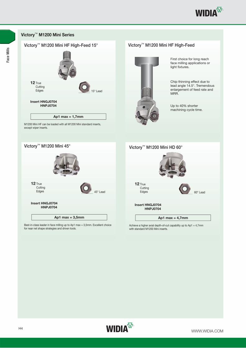
One Series Meets Every Face Milling Need •
WIDIA™ Victory™ M1200 Mini
M1200 Mini
For consistent performance, look no further than the WIDIA Victory™
M1200 Mini. This easy-to-use product ensures great tool life, reduced
machining time, and maximum productivity.
• Low cost per edge and high productivity.
• Reduced cutting forces due to soft cutting action.
• Significantly increased Metal Removal Rates (MRR).
• Victory™ M1200 Mini available in 15°, 45°, and 60° lead.
• WIDIA premium milling grades.
• Excellent tool life in light to heavy machining.
• Shorter machining cycle times.
Best-in-class face milling platform to boost productivity
on taper 40 spindle milling machines and driven tools.
Comprehensive standard offering for
coarse, medium, and fine pitch cutter
bodies to match all shop floor needs.
12 True
Cutting
Edges.
Latest soft cutting edge insert design for all material groups
Through tool
coolant.
Easy-to-use — one
screw enables fast,
accurate indexing.
-FNLDJ
N
Machining Aluminium
-SNHD
P M K S
Heavy Machining
-ENLD
P M K S
Light Machining
-SNGD
P M K S
General Purpose

WWW.WIDIA.COM H3
Face Mills
Victory™ M1200 Mini HD 60°
Max depth of cut: 4,7mm
Lead angle: 60°
Indexes per insert: 12
Diameter: 40–125mm
Pages: H20–H23
P
M
K
N
S
P
M
K
N
S
H
Victory™ M1200 Mini 45°
Max depth of cut: 3,5mm
Lead angle: 45°
Indexes per insert: 12
Diameter: 25–125mm
Pages: H12–H19 Pages: H5–H11
Victory™ M1200 Mini HF 15°
Max depth of cut: 1,7mm
Lead angle: 15°
Indexes per insert: 12
Diameter: 25–80mm
P
M
K
N
S
• Wiper inserts only applied with 45° lead angle
cutter bodies.
• Easy to use. Regular and wiper inserts are loaded
into fi xed pockets. No adjustment required.
• Please have D1 max wiper in mind in case of limited
working area.
• Use wiper inserts only in combination with
periphery ground regular inserts HNGJ07.
• Up to cutting diameter D1=100mm load one
wiper insert.
• For cutting diameter D1=125mm and above
load two wiper inserts.
• Each wiper insert XNGJ07 can be applied with three
right hand R and three left hand L cutting edges.
Regular Insert HNGJ07
Wiper Insert XNGJ07
D1 max wiper = D1 max + 2,44mm
Wiper insert overlapping vs. regular insert
1,22mm [D1]
[D1 max]
Easy-to-use wiper insert setup to achieve excellent surface fl oor fi nish
WWW.WIDIA.COM H4
Victory™ M1200 Mini HF High-Feed 15°
12 True
Cutting
Edges 15° Lead
Insert HNGJ0704HNPJ0704
Ap1 max = 1,7mm
M1200 Mini HF can be loaded with all M1200 Mini standard inserts,
except wiper inserts.
First choice for long reach
face milling applications or
light fi xtures.
Chip thinning effect due to
lead angle 14.5°. Tremendous
enlargement of feed rate and
MRR.
Up to 40% shorter
machining cycle time.
Victory™ M1200 Mini HF High-Feed
Victory™ M1200 Mini Series
Face
Mill
s
60° Lead
Victory™ M1200 Mini HD 60°
12 True
Cutting
Edges
Insert HNGJ0704HNPJ0704
Ap1 max = 4,7mm
Achieve a higher axial depth-of-cut capability up to Ap1 = 4,7mm
with standard M1200 Mini inserts.
12 True
Cutting
Edges 45° Lead
Victory™ M1200 Mini 45°
Insert HNGJ0704HNPJ0704
Ap1 max = 3,5mm
Best-in-class leader in face milling up to Ap1 max = 3,5mm. Excellent choice
for near net shape strategies and driven tools.
WWW.WIDIA.COM H5
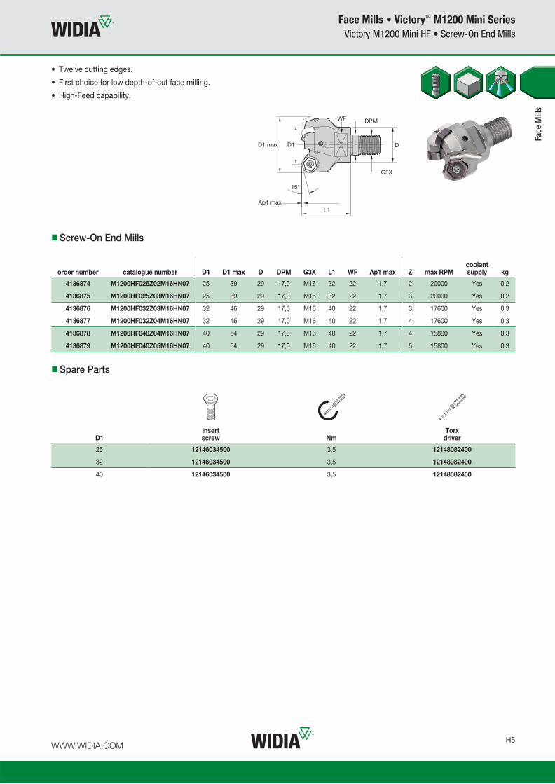
Face Mills • Victory™ M1200 Mini Series
Victory M1200 Mini HF • Screw-On End Mills
D1insert screw Nm
Torx driver
25 12146034500 3,5 12148082400
32 12146034500 3,5 12148082400
40 12146034500 3,5 12148082400
Spare Parts
Screw-On End Mills
order number catalogue number D1 D1 max D DPM G3X L1 WF Ap1 max Z max RPMcoolant supply kg
4136874 M1200HF025Z02M16HN07 25 39 29 17,0 M16 32 22 1,7 2 20000 Yes 0,2
4136875 M1200HF025Z03M16HN07 25 39 29 17,0 M16 32 22 1,7 3 20000 Yes 0,2
4136876 M1200HF032Z03M16HN07 32 46 29 17,0 M16 40 22 1,7 3 17600 Yes 0,3
4136877 M1200HF032Z04M16HN07 32 46 29 17,0 M16 40 22 1,7 4 17600 Yes 0,3
4136878 M1200HF040Z04M16HN07 40 54 29 17,0 M16 40 22 1,7 4 15800 Yes 0,3
4136879 M1200HF040Z05M16HN07 40 54 29 17,0 M16 40 22 1,7 5 15800 Yes 0,3
• Twelve cutting edges.
• First choice for low depth-of-cut face milling.
• High-Feed capability.
Face
Mill
s

WWW.WIDIA.COM H6
Face Mills • Victory™ M1200 Mini Series
Victory M1200 Mini HF • Cylindrical Shanks
D1insert screw Nm
Torx driver
25 12146034500 3,5 12148082400
32 12146034500 3,5 12148082400
Spare Parts
Cylindrical Shanks
order number catalogue number D1 D1 max D L LBX Ap1 max Z max RPMcoolant supply kg
4136880 M1200HF025Z02A20HN07L120 25 39,1 20 120 32 1,7 2 20000 Yes 0,33
4136881 M1200HF025Z03A20HN07L120 25 39,1 20 120 32 1,7 3 20000 Yes 0,31
4136882 M1200HF032Z03A25HN07L130 32 46,1 25 130 40 1,7 3 17600 Yes 0,52
4136883 M1200HF032Z04A25HN07L130 32 46,1 25 130 40 1,7 4 17600 Yes 0,53
• Twelve cutting edges.
• First choice for low depth-of-cut face milling.
• High-Feed capability.
Face
Mill
s

WWW.WIDIA.COM H7
Face Mills • Victory™ M1200 Mini Series
Victory M1200 Mini HF • Shell Mills
D1insert screw Nm
Torx driver
socket-headcap screw
40 12146034500 3,5 12148082400 12146120500
50 12146034500 3,5 12148082400 12146120500
63 12146034500 3,5 12148082400 12146120500
80 12146034500 3,5 12148082400 12748701000
Spare Parts
Shell Mills
order number catalogue number D1 D1 max D D6 L Ap1 max Z max RPMcoolant supply kg
4136884 M1200HF040Z05HN07 40 54,1 22 38 40 1,7 5 15800 Yes 0,29
4136885 M1200HF050Z05HN07 50 64,1 22 38 40 1,7 5 12700 Yes 0,40
4136886 M1200HF063Z06HN07 63 77,1 22 50 40 1,7 6 10100 Yes 0,67
4136887 M1200HF080Z08HN07 80 94,1 27 60 50 1,7 8 7900 Yes 1,26
• Twelve cutting edges.
• First choice for low depth-of-cut face milling.
• High-Feed capability.
Face
Mill
s

WWW.WIDIA.COM H8
HNGJ-LDJ
catalogue numbercutting edges D L10 S BS R hm TN
6501
THM
-U
HNGJ0704ANFNLDJ 12 13 6,80 4,48 1,60 1,20 0,08
3954
414
3954
332
� first choice
� alternate choice
P � � � � � �
M � � � � � � �
K � � � � � � �
N
S � � � � �
H �
HNGJ-LD
catalogue numbercutting edges D L10 S BS R hm TN
6510
TN65
20TN
6525
TN65
40TN
7535
WK
15C
MW
P25
PM
WP
35C
MW
S30P
MW
P40
PM
HNGJ0704ANENLD 12 13 6,80 4,48 1,60 1,20 0,08
3954
419
3954
420
3954
421
3954
422
– –58
9529
158
9529
255
2897
555
5090
5
HNGJ070432ANENLD 12 13 6,80 4,48 — 3,20 0,08
3954
428
–39
5442
939
5443
0– – – – – –
� first choice
� alternate choice
Face Mills • Victory™ M1200 Mini Series
Inserts
Insert Selection Guide
MaterialGroup
Light Machining
General Purpose
Heavy Machining
Geometry Grade Geometry Grade Geometry Grade
P1–P2 .E..LD WP40PM .S..GD WP40PM .S..HD WP40PM
P3–P4 .E..LD WP25PM .S..GD WP35CM .S..HD WP35CM
P5–P6 .E..LD WP25PM .S..GD WP35CM .S..HD WP35CM
M1–M2 .E..LD WP25PM .S..GD WP25PM .S..HD WP25PM
M3 .E..LD WP35CM .S..GD WP35CM .S..HD WP35CM
K1–K2 .E..LD TN6510 .S..GD WK15CM .S..HD WK15CM
K3 .E..LD WP35CM .S..GD WP35CM .S..HD WP35CM
N1–N2 .F..LDJ TN6501 .F..LDJ TN6501 .F..LDJ TN6501
N3 .F..LDJ TN6501 .F..LDJ TN6501 .F..LDJ TN6501
S1–S2 .E..LD WS30PM .S..GD WS30PM .S..HD WP25PM
S3 .E..LD WS30PM .S..GD WS30PM .S..GD WS30PM
S4 .E..LD WS30PM .S..GD WS30PM .S..HD WP40PM
H1 – – – – – –
HNGJ-LDJ
HNGJ-LD
Face
Mill
s
P
M
K
N � �
S
H

WWW.WIDIA.COM H9
Face Mills • Victory™ M1200 Mini Series
Inserts
HNPJ-GD
catalogue numbercutting edges D L10 S BS R hm TN
6510
TN65
20TN
6525
TN65
40TN
7535
WK
15C
MW
P25
PM
WP
35C
MW
S30P
MW
P40
PM
HNPJ0704ANSNGD 12 13 6,80 4,45 1,27 1,20 0,10
3954
432
3954
473
–39
5447
439
5447
554
2737
458
9529
358
9529
455
2897
655
5090
6
� first choice
� alternate choice
HNPJ-HD
catalogue numbercutting edges D L10 S BS R hm TN
6510
TN65
20TN
6525
TN65
40TN
7535
WK
15C
MW
P25
PM
WP
35C
MW
S30P
MW
P40
PM
HNPJ0704ANSNHD 12 13 6,80 4,41 1,25 1,20 0,14
3954
477
3954
478
–39
5447
939
5448
054
2737
558
9529
558
9529
6–
5550
907
HNPJ070432ANSNHD 12 13 6,80 4,42 — 3,20 0,14
3954
481
3954
482
–39
5448
339
5448
4– – – –
5895
297
HNPJ-GD HNPJ-HD
Face
Mill
s
P � � � � � �
M � � � � � � �
K � � � � � � �
N
S � � � � �
H �

WWW.WIDIA.COM H10
Face Mills • Victory™ M1200 Mini Series
Recommended Starting Speeds
Recommended Starting Speeds [m/min]
MaterialGroup TN6510 TN6520 TN6525 TN6540 TN7535 WK15CM
P
1 – – – – – – 410 320 280 360 280 240 545 475 445 – – –
2 – – – – – – 320 250 215 250 190 170 335 305 275 – – –
3 – – – – – – 280 215 185 215 170 140 305 275 245 – – –
4 – – – – – – 235 170 145 180 130 110 230 210 190 – – –
5 – – – – – – 310 235 200 240 180 150 310 275 250 – – –
6 – – – – – – 205 160 130 160 120 100 190 160 130 – – –
M
1 – – – – – – 190 120 80 130 80 60 245 220 185 – – –
2 – – – – – – 120 80 50 80 50 40 220 190 170 – – –
3 – – – – – – 125 80 55 85 50 40 175 155 140 – – –
K
1 480 350 260 450 320 230 275 245 220 220 205 180 355 320 290 505 460 410
2 420 280 205 390 250 190 215 190 180 175 155 140 280 250 230 400 355 330
3 335 260 200 300 230 160 180 160 145 155 145 125 235 210 190 335 300 275
N
1 – – – – – – – – – – – – – – – – – –
2 – – – – – – – – – – – – – – – – – –
3 – – – – – – – – – – – – – – – – – –
S
1 – – – – – – – – – 50 35 30 – – – – – –
2 – – – – – – – – – 25 20 10 – – – – – –
3 – – – – – – – – – 70 40 30 – – – – – –
4 – – – – – – – – – 60 30 25 – – – – – –
H
1 – – – – – – – – – – – – – – – – – –
2 – – – – – – – – – – – – – – – – – –
3 – – – – – – – – – – – – – – – – – –
Face
Mill
s
(continued)

WWW.WIDIA.COM H11
Face Mills • Victory™ M1200 Mini Series
Recommended Starting Speeds
Recommended Starting Feeds [mm]
NOTE: Use “Light Machining” value as starting feed rate.
LightMachining
GeneralPurpose
HeavyMachining
InsertGeometry
Programmed Feed per Tooth (fz)as a % of Radial Depth of Cut (ae)
InsertGeometry5% 10% 20% 30% 40–100%
.F..LDJ 0,48 0,89 1,81 0,34 0,64 1,29 0,26 0,48 0,96 0,22 0,42 0,83 0,21 0,38 0,76 .F..LDJ
.E..LD 0,48 1,38 2,85 0,34 0,99 2,00 0,26 0,74 1,48 0,22 0,64 1,28 0,21 0,59 1,17 .E..LD
.S..GD 0,92 2,35 3,89 0,66 1,67 2,70 0,49 1,23 1,98 0,43 1,07 1,72 0,39 0,98 1,57 .S..GD
.S..HD 0,92 2,35 3,89 0,66 1,67 2,70 0,49 1,23 1,98 0,43 1,07 1,72 0,39 0,98 1,57 .S..HD
NOTE: FIRST choice starting speeds are in bold type.As the average chip thickness increases, the speed should be decreased.
MaterialGroup WP25PM WP35CM WS30PM WP40PM TN6501 THM-U
P
1 395 340 325 545 475 445 – – – 355 310 295 – – – – – –
2 330 290 240 335 305 275 – – – 300 260 215 – – – – – –
3 305 260 210 305 275 245 – – – 275 235 190 – – – – – –
4 270 220 180 230 210 190 – – – 245 205 160 – – – – – –
5 220 205 180 310 275 250 – – – 205 185 160 – – – – – –
6 200 150 120 190 160 130 – – – 180 140 110 – – – – – –
M
1 245 215 200 245 220 185 270 240 220 235 205 185 – – – – – –
2 220 190 155 220 190 170 245 215 175 210 180 150 – – – – – –
3 170 145 115 175 155 140 185 160 125 155 140 110 – – – – – –
K
1 275 245 220 355 320 290 – – – – – – – – – – – –
2 215 190 180 280 250 230 – – – – – – – – – – – –
3 180 160 145 235 210 190 – – – – – – – – – – – –
N
1 – – – – – – – – – – – – 2400 1440 1200 2400 1440 1200
2 – – – – – – – – – – – – 1640 980 800 1640 980 800
3 – – – – – – – – – – – – 960 600 480 960 600 480
S
1 50 40 30 – – – 55 50 35 50 40 35 – – – – – –
2 50 40 30 – – – 55 50 35 50 40 35 – – – – – –
3 60 50 30 – – – 65 55 35 60 50 35 – – – – – –
4 85 60 40 80 60 40 100 70 50 80 60 40 – – – – – –
H
1 145 110 85 – – – – – – – – – – – – – – –
2 – – – – – – – – – – – – – – – – – –
3 – – – – – – – – – – – – – – – – – –
Face
Mill
s
Recommended Starting Feeds
(Recommended Starting Speeds [m/min] — continued)

WWW.WIDIA.COM H12
Face Mills • Victory™ M1200 Mini Series
Victory M1200 Mini • Screw-On End Mills
D1insert screw Nm
Torx driver
25 12146034500 3,5 12148082400
32 12146034500 3,5 12148082400
40 12146034500 3,5 12148082400
Spare Parts
Screw-On End Mills
order number catalogue number D1 D1 max D DPM G3X L1 WF Ap1 max Z max RPMcoolant supply kg
3957839 M1200D025Z02M16HN07 25 33,7 29 17,0 M16 32 22 3,5 2 20000 Yes 0,13
3957840 M1200D025Z03M16HN07 25 33,7 29 17,0 M16 32 22 3,5 3 20000 Yes 0,13
3957841 M1200D032Z03M16HN07 32 40,7 29 17,0 M16 40 22 3,5 3 17600 Yes 0,20
3957842 M1200D032Z04M16HN07 32 40,7 29 17,0 M16 40 22 3,5 4 17600 Yes 0,20
3957963 M1200D040Z04M16HN07 40 48,7 29 17,0 M16 40 22 3,5 4 15800 Yes 0,24
3957964 M1200D040Z05M16HN07 40 48,7 29 17,0 M16 40 22 3,5 5 15800 Yes 0,25
Face
Mill
s
• Twelve cutting edges.
• First choice for low depth-of-cut face milling.
• Maximum number of teeth per diameter.

WWW.WIDIA.COM H13
Face Mills • Victory™ M1200 Mini Series
Victory M1200 Mini • Weldon® Shanks
D1insert screw Nm
Torx driver
25 12146034500 3,5 12148082400
32 12146034500 3,5 12148082400
Spare Parts
Weldon Shanks
order number catalogue number D1 D1 max D L L2 Ap1 max Z max RPMcoolant supply kg
3958011 M1200D025Z02B20HN07 25 33,7 20 82 32 3,5 2 20000 Yes 0,22
3958012 M1200D025Z03B20HN07 25 33,7 20 82 32 3,5 3 20000 Yes 0,21
3958023 M1200D032Z03B25HN07 32 40,7 25 97 40 3,5 3 17600 Yes 0,39
3958024 M1200D032Z04B25HN07 32 40,7 25 97 40 3,5 4 17600 Yes 0,40
Face
Mill
s
L
• Twelve cutting edges.
• First choice for low depth-of-cut face milling.
• Maximum number of teeth per diameter.

WWW.WIDIA.COM H14
Face Mills • Victory™ M1200 Mini Series
Victory M1200 Mini • Cylindrical Shanks
D1insert screw Nm
Torx driver
25 12146034500 3,5 12148082400
32 12146034500 3,5 12148082400
Spare Parts
Cylindrical Shanks
order number catalogue number D1 D1 max D L LBX Ap1 max Z max RPMcoolant supply kg
3958025 M1200D025Z02A20HN07L120 25 33,7 20 120 32 3,5 2 20000 Yes 0,29
3958026 M1200D025Z03A20HN07L120 25 33,7 20 120 32 3,5 3 20000 Yes 0,28
3958029 M1200D025Z02A25HN07L200 25 33,7 25 200 32 3,5 2 20000 Yes 0,72
3958030 M1200D025Z03A25HN07L200 25 33,7 25 200 32 3,5 3 20000 Yes 0,71
3958027 M1200D032Z03A25HN07L130 32 40,7 25 130 40 3,5 3 17600 Yes 0,49
3958028 M1200D032Z04A25HN07L130 32 40,7 25 130 40 3,5 4 17600 Yes 0,50
Face
Mill
s
• Twelve cutting edges.
• First choice for low depth-of-cut face milling.
• Maximum number of teeth per diameter.

WWW.WIDIA.COM H15
Face Mills • Victory™ M1200 Mini Series
Victory M1200 Mini • Shell Mills
Spare Parts
Shell Mills
order number catalogue number D1 D1 max D D6 L L2 Ap1 max Z max RPMcoolant supply kg
3957995 M1200D040Z04HN07 40 48,7 22 38 40 40 3,5 4 15800 Yes 0,26
3957996 M1200D040Z05HN07 40 48,7 22 38 40 40 3,5 5 15800 Yes 0,26
3957997 M1200D050Z04HN07 50 58,7 22 38 40 40 3,5 4 12700 Yes 0,35
3957998 M1200D050Z05HN07 50 58,7 22 38 40 40 3,5 5 12700 Yes 0,36
3957999 M1200D050Z06HN07 50 58,7 22 38 40 40 3,5 6 12700 Yes 0,35
3958000 M1200D063Z04HN07 63 71,7 22 50 40 40 3,5 4 10100 Yes 0,58
3958001 M1200D063Z06HN07 63 71,7 22 50 40 40 3,5 6 10100 Yes 0,65
3958002 M1200D063Z08HN07 63 71,7 22 50 40 40 3,5 8 10100 Yes 0,62
3958003 M1200D080Z05HN07 80 88,7 27 60 50 50 3,5 5 7900 Yes 1,11
3958004 M1200D080Z08HN07 80 88,7 27 60 50 50 3,5 8 7900 Yes 1,24
3958005 M1200D080Z10HN07 80 88,7 27 60 50 50 3,5 10 7900 Yes 1,17
3958006 M1200D100Z06HN07 100 108,7 32 80 50 50 3,5 6 6300 Yes 1,71
3958007 M1200D100Z09HN07 100 108,7 32 80 50 50 3,5 9 6300 Yes 1,82
3958008 M1200D100Z12HN07 100 108,7 32 80 50 50 3,5 12 6300 Yes 1,82
4138470 M1200D125Z08HN07 125 133,7 40 90 63 — 3,5 8 5050 Yes 2,84
4138471 M1200D125Z12HN07 125 133,7 40 90 63 — 3,5 12 5050 Yes 2,96
4138472 M1200D125Z16HN07 125 133,7 40 90 63 — 3,5 16 5050 Yes 3,02
Face
Mill
s
• Twelve cutting edges.
• First choice for low depth-of-cut face milling.
• Maximum number of teeth per diameter.
D1insert screw Nm
Torx driver
socket-headcap screw
mounting screw with coolant grooves
coolant screw assembly
coolant lock screw
coolant cap
40 12146034500 3,5 12148082400 — 12146109200 — — —
50 12146034500 3,5 12148082400 12146120500 — — — —
63 12146034500 3,5 12148082400 12146120500 — — — —
80 12146034500 3,5 12148082400 12748701000 — — — —
100 12146034500 3,5 12148082400 — — 12146109400 — —
125 12146034500 3,5 12148082400 — — — 12146107000 12146111000
NOTE: Mounting screw with coolant groove, coolant screw assembly, coolant lock screw, and coolant cap must be ordered separately.

WWW.WIDIA.COM H16
Face Mills • Victory™ M1200 Mini Series
Inserts
Insert Selection Guide
MaterialGroup
Light Machining
General Purpose
Heavy Machining
Geometry Grade Geometry Grade Geometry Grade
P1–P2 .E..LD WP40PM .S..GD WP40PM .S..HD WP40PM
P3–P4 .E..LD WP25PM .S..GD WP35CM .S..HD WP35CM
P5–P6 .E..LD WP25PM .S..GD WP35CM .S..HD WP35CM
M1–M2 .E..LD WP25PM .S..GD WP25PM .S..HD WP25PM
M3 .E..LD WP35CM .S..GD WP35CM .S..HD WP35CM
K1–K2 .E..LD TN6510 .S..GD WK15CM .S..HD WK15CM
K3 .E..LD WP35CM .S..GD WP35CM .S..HD WP35CM
N1–N2 .F..LDJ TN6501 .F..LDJ TN6501 .F..LDJ TN6501
N3 .F..LDJ TN6501 .F..LDJ TN6501 .F..LDJ TN6501
S1–S2 .E..LD WS30PM .S..GD WS30PM .S..HD WP25PM
S3 .E..LD WS30PM .S..GD WS30PM .S..GD WS30PM
S4 .E..LD WS30PM .S..GD WS30PM .S..HD WP40PM
H1 – – – – – –
P
M
K
N � �
S
H
HNGJ-LDJ
catalogue numbercutting edges D L10 S BS R hm TN
6501
THM
-U
HNGJ0704ANFNLDJ 12 13 6,80 4,48 1,60 1,20 0,08
3954
414
3954
332
� first choice
� alternate choice
P � � � � � �
M � � � � � � �
K � � � � � � �
N
S � � � � �
H �
� first choice
� alternate choice
HNGJ-LD
catalogue numbercutting edges D L10 S BS R hm TN
6510
TN65
20TN
6525
TN65
40TN
7535
WK
15C
MW
P25
PM
WP
35C
MW
S30P
MW
P40
PM
HNGJ0704ANENLD 12 13 6,80 4,48 1,60 1,20 0,08
3954
419
3954
420
3954
421
3954
422
– –58
9529
158
9529
255
2897
555
5090
5
HNGJ070432ANENLD 12 13 6,80 4,48 — 3,20 0,08
3954
428
–39
5442
939
5443
0– – – – – –
HNGJ-LDJ
HNGJ-LD
Face
Mill
s

WWW.WIDIA.COM H17
Face Mills • Victory™ M1200 Mini Series
Inserts
HNPJ-GD
catalogue numbercutting edges D L10 S BS R hm TN
6510
TN65
20TN
6525
TN65
40TN
7535
WK
15C
MW
P25
PM
WP
35C
MW
S30P
MW
P40
PM
HNPJ0704ANSNGD 12 13 6,80 4,45 1,27 1,20 0,10
3954
432
3954
473
–39
5447
439
5447
554
2737
458
9529
358
9529
455
2897
655
5090
6
� first choice
� alternate choice
HNPJ-HD
catalogue numbercutting edges D L10 S BS R hm TN
6510
TN65
20TN
6525
TN65
40TN
7535
WK
15C
MW
P25
PM
WP
35C
MW
S30P
MW
P40
PM
HNPJ0704ANSNHD 12 13 6,80 4,41 1,25 1,20 0,14
3954
477
3954
478
–39
5447
939
5448
054
2737
558
9529
558
9529
6–
5550
907
HNPJ070432ANSNHD 12 13 6,80 4,42 — 3,20 0,14
3954
481
3954
482
–39
5448
339
5448
4– – – –
5895
297
P
M
K
N � �
S
H
XNGJ-LDJ-3 Wiper
catalogue numbercutting edges D L10 S BS R hm TN
6501
THM
-UXNGJ0704ANFNLDJ3W 3 13 6,78 4,47 6,78 1,30 0,08
3954
416
3954
433
NOTE: Inserts have 3 right-hand and 3 left-hand cutting edges.
P � � � � � �
M � � � � � � �
K � � � � � � �
N
S � � � � �
H �
XNGJ-LD3 Wiper
catalogue numbercutting edges D L10 S BS R hm TN
6510
TN65
20TN
6525
TN65
40TN
7535
WK
15C
MW
P25
PM
WP
35C
MW
S30P
MW
P40
PM
XNGJ0704ANENLD3W 3 13 6,78 4,47 6,78 1,30 0,08
3954
424
3954
425
3954
426
3954
427
–54
2737
358
9529
8– –
5895
299
NOTE: Inserts have 3 right-hand and 3 left-hand cutting edges.
� first choice
� alternate choice
� first choice
� alternate choice
XNGJ-LDJ-3
Wiper
XNGJ-LD3
Wiper
HNPJ-GD HNPJ-HD
Face
Mill
s
P � � � � � �
M � � � � � � �
K � � � � � � �
N
S � � � � �
H �

WWW.WIDIA.COM H18
Face Mills • Victory™ M1200 Mini Series
Recommended Starting Speeds
Recommended Starting Speeds [m/min]
MaterialGroup TN6510 TN6520 TN6525 TN6540 TN7535 WK15CM
P
1 – – – – – – 410 320 280 360 280 240 545 475 445 – – –
2 – – – – – – 320 250 215 250 190 170 335 305 275 – – –
3 – – – – – – 280 215 185 215 170 140 305 275 245 – – –
4 – – – – – – 235 170 145 180 130 110 230 210 190 – – –
5 – – – – – – 310 235 200 240 180 150 310 275 250 – – –
6 – – – – – – 205 160 130 160 120 100 190 160 130 – – –
M
1 – – – – – – 190 120 80 130 80 60 245 220 185 – – –
2 – – – – – – 120 80 50 80 50 40 220 190 170 – – –
3 – – – – – – 125 80 55 85 50 40 175 155 140 – – –
K
1 480 350 260 450 320 230 275 245 220 220 205 180 355 320 290 505 460 410
2 420 280 205 390 250 190 215 190 180 175 155 140 280 250 230 400 355 330
3 335 260 200 300 230 160 180 160 145 155 145 125 235 210 190 335 300 275
N
1 – – – – – – – – – – – – – – – – – –
2 – – – – – – – – – – – – – – – – – –
3 – – – – – – – – – – – – – – – – – –
S
1 – – – – – – – – – 50 35 30 – – – – – –
2 – – – – – – – – – 25 20 10 – – – – – –
3 – – – – – – – – – 70 40 30 – – – – – –
4 – – – – – – – – – 60 30 25 – – – – – –
H
1 – – – – – – – – – – – – – – – – – –
2 – – – – – – – – – – – – – – – – – –
3 – – – – – – – – – – – – – – – – – –
Face
Mill
s
(continued)

WWW.WIDIA.COM H19
Face Mills • Victory™ M1200 Mini Series
Recommended Starting Speeds
NOTE: FIRST choice starting speeds are in bold type.As the average chip thickness increases, the speed should be decreased.
MaterialGroup WP25PM WP35CM WS30PM WP40PM TN6501 THM-U
P
1 395 340 325 545 475 445 – – – 355 310 295 – – – – – –
2 330 290 240 335 305 275 – – – 300 260 215 – – – – – –
3 305 260 210 305 275 245 – – – 275 235 190 – – – – – –
4 270 220 180 230 210 190 – – – 245 205 160 – – – – – –
5 220 205 180 310 275 250 – – – 205 185 160 – – – – – –
6 200 150 120 190 160 130 – – – 180 140 110 – – – – – –
M
1 245 215 200 245 220 185 270 240 220 235 205 185 – – – – – –
2 220 190 155 220 190 170 245 215 175 210 180 150 – – – – – –
3 170 145 115 175 155 140 185 160 125 155 140 110 – – – – – –
K
1 275 245 220 355 320 290 – – – – – – – – – – – –
2 215 190 180 280 250 230 – – – – – – – – – – – –
3 180 160 145 235 210 190 – – – – – – – – – – – –
N
1 – – – – – – – – – – – – 2400 1440 1200 2400 1440 1200
2 – – – – – – – – – – – – 1640 980 800 1640 980 800
3 – – – – – – – – – – – – 960 600 480 960 600 480
S
1 50 40 30 – – – 55 50 35 50 40 35 – – – – – –
2 50 40 30 – – – 55 50 35 50 40 35 – – – – – –
3 60 50 30 – – – 65 55 35 60 50 35 – – – – – –
4 85 60 40 80 60 40 100 70 50 80 60 40 – – – – – –
H
1 145 110 85 – – – – – – – – – – – – – – –
2 – – – – – – – – – – – – – – – – – –
3 – – – – – – – – – – – – – – – – – –
Recommended Starting Feeds [mm]
NOTE: Use “Light Machining” value as starting feed rate.
LightMachining
GeneralPurpose
HeavyMachining
InsertGeometry
Programmed Feed per Tooth (fz)as a % of Radial Depth of Cut (ae)
InsertGeometry5% 10% 20% 30% 40–100%
.F..LDJ 0,17 0,32 0,65 0,13 0,23 0,47 0,09 0,17 0,35 0,08 0,15 0,31 0,08 0,14 0,28 .F..LDJ
.E..LD 0,17 0,50 1,00 0,13 0,36 0,72 0,09 0,27 0,54 0,08 0,23 0,47 0,08 0,21 0,43 .E..LD
.S..GD 0,33 0,84 1,35 0,24 0,60 0,97 0,18 0,45 0,72 0,16 0,39 0,63 0,14 0,36 0,57 .S..GD
.S..HD 0,33 0,84 1,35 0,24 0,60 0,97 0,18 0,45 0,72 0,16 0,39 0,63 0,14 0,36 0,57 .S..HD
Face
Mill
s
(Recommended Starting Speeds [m/min] — continued)
Recommended Starting Feeds

WWW.WIDIA.COM H20
Face
Mill
sFace Mills • Victory™ M1200 Mini Series
Victory M1200 Mini • HD • Shell Mills
Spare Parts
Shell Mills
order number catalogue number D1 D1 max D D6 L Ap1 max Z max RPMcoolant supply kg
4136482 M1200HD040Z04HN07 40 46,8 22 38 40 4,7 4 15800 Yes 0,22
4136863 M1200HD040Z05HN07 40 46,8 22 38 40 4,7 5 15800 Yes 0,22
4136864 M1200HD050Z04HN07 50 56,8 22 38 40 4,7 4 12700 Yes 0,34
4136865 M1200HD050Z05HN07 50 56,8 22 38 40 4,7 5 12700 Yes 0,34
4136866 M1200HD063Z04HN07 63 69,8 22 50 40 4,7 4 10100 Yes 0,58
4136867 M1200HD063Z06HN07 63 69,8 22 50 40 4,7 6 10100 Yes 0,60
4136868 M1200HD080Z05HN07 80 86,8 27 60 50 4,7 5 7900 Yes 1,11
4136869 M1200HD080Z08HN07 80 86,8 27 60 50 4,7 8 7900 Yes 1,17
4136870 M1200HD100Z06HN07 100 106,7 32 80 50 4,7 6 6300 Yes 1,74
4136871 M1200HD100Z09HN07 100 106,7 32 80 50 4,7 9 6300 Yes 1,74
4136872 M1200HD125Z08HN07 125 131,7 40 90 63 4,7 8 5050 Yes 2,86
4136873 M1200HD125Z12HN07 125 131,7 40 90 63 4,7 12 5050 Yes 2,90
• Twelve cutting edges.
• Higher axial depth-of-cut capability
with 59° lead angle.
D1insert screw Nm
Torx driver
socket-headcap screw
mounting screw with coolant grooves
coolant screw assembly
coolant lock screw
coolant cap
40 12146034500 3,5 12148082400 — 12146109200 — — —
50 12146034500 3,5 12148082400 12146120500 — — — —
63 12146034500 3,5 12148082400 12146120500 — — — —
80 12146034500 3,5 12148082400 12748701000 — — — —
100 12146034500 3,5 12148082400 — — 12146109400 — —
125 12146034500 3,5 12148082400 — — — 12146107000 12146111000
NOTE: Mounting screw with coolant groove, coolant screw assembly, coolant lock screw, and coolant cap must be ordered separately.

WWW.WIDIA.COM H21
Face Mills • Victory™ M1200 Mini Series
Inserts
Insert Selection Guide
Face
Mill
sMaterialGroup
Light Machining
General Purpose
Heavy Machining
Geometry Grade Geometry Grade Geometry Grade
P1–P2 .E..LD WP40PM .S..GD WP40PM .S..HD WP40PM
P3–P4 .E..LD WP25PM .S..GD WP35CM .S..HD WP35CM
P5–P6 .E..LD WP25PM .S..GD WP35CM .S..HD WP35CM
M1–M2 .E..LD WP25PM .S..GD WP25PM .S..HD WP25PM
M3 .E..LD WP35CM .S..GD WP35CM .S..HD WP35CM
K1–K2 .E..LD TN6510 .S..GD WK15CM .S..HD WK15CM
K3 .E..LD WP35CM .S..GD WP35CM .S..HD WP35CM
N1–N2 .F..LDJ TN6501 .F..LDJ TN6501 .F..LDJ TN6501
N3 .F..LDJ TN6501 .F..LDJ TN6501 .F..LDJ TN6501
S1–S2 .E..LD WS30PM .S..GD WS30PM .S..HD WP25PM
S3 .E..LD WS30PM .S..GD WS30PM .S..GD WS30PM
S4 .E..LD WS30PM .S..GD WS30PM .S..HD WP40PM
H1 – – – – – –
P
M
K
N � �
S
H
HNGJ-LDJ
catalogue numbercutting edges D L10 S BS R hm TN
6501
THM
-U
HNGJ0704ANFNLDJ 12 13 6,80 4,48 1,60 1,20 0,08
3954
414
3954
332
� first choice
� alternate choice
P � � � � � �
M � � � � � � �
K � � � � � � �
N
S � � � � �
H �
� first choice
� alternate choice
HNGJ-LD
catalogue numbercutting edges D L10 S BS R hm TN
6510
TN65
20TN
6525
TN65
40TN
7535
WK
15C
MW
P25
PM
WP
35C
MW
S30P
MW
P40
PM
HNGJ0704ANENLD 12 13 6,80 4,48 1,60 1,20 0,08
3954
419
3954
420
3954
421
3954
422
– –58
9529
158
9529
255
2897
555
5090
5
HNGJ070432ANENLD 12 13 6,80 4,48 — 3,20 0,08
3954
428
–39
5442
939
5443
0– – – – – –
HNGJ-LDJ
HNGJ-LD

WWW.WIDIA.COM H22
Face Mills • Victory™ M1200 Mini Series
Inserts
HNPJ-GD
catalogue numbercutting edges D L10 S BS R hm TN
6510
TN65
20TN
6525
TN65
40TN
7535
WK
15C
MW
P25
PM
WP
35C
MW
S30P
MW
P40
PM
HNPJ0704ANSNGD 12 13 6,80 4,45 1,27 1,20 0,10
3954
432
3954
473
–39
5447
439
5447
554
2737
458
9529
358
9529
455
2897
655
5090
6
� fi rst choice
� alternate choice
HNPJ-HD
catalogue numbercutting edges D L10 S BS R hm TN
6510
TN65
20TN
6525
TN65
40TN
7535
WK
15C
MW
P25
PM
WP
35C
MW
S30P
MW
P40
PM
HNPJ0704ANSNHD 12 13 6,80 4,41 1,25 1,20 0,14
3954
477
3954
478
–39
5447
939
5448
054
2737
558
9529
558
9529
6–
5550
907
HNPJ070432ANSNHD 12 13 6,80 4,42 — 3,20 0,14
3954
481
3954
482
–39
5448
339
5448
4– – – –
5895
297
Recommended Starting Speeds [m/min]
MaterialGroup TN6510 TN6520 TN6525 TN6540 TN7535 WK15CM
P
1 – – – – – – 410 320 280 360 280 240 545 475 445 – – –
2 – – – – – – 320 250 215 250 190 170 335 305 275 – – –
3 – – – – – – 280 215 185 215 170 140 305 275 245 – – –
4 – – – – – – 235 170 145 180 130 110 230 210 190 – – –
5 – – – – – – 310 235 200 240 180 150 310 275 250 – – –
6 – – – – – – 205 160 130 160 120 100 190 160 130 – – –
M
1 – – – – – – 190 120 80 130 80 60 245 220 185 – – –
2 – – – – – – 120 80 50 80 50 40 220 190 170 – – –
3 – – – – – – 125 80 55 85 50 40 175 155 140 – – –
K
1 480 350 260 450 320 230 275 245 220 220 205 180 355 320 290 505 460 410
2 420 280 205 390 250 190 215 190 180 175 155 140 280 250 230 400 355 330
3 335 260 200 300 230 160 180 160 145 155 145 125 235 210 190 335 300 275
N
1 – – – – – – – – – – – – – – – – – –
2 – – – – – – – – – – – – – – – – – –
3 – – – – – – – – – – – – – – – – – –
S
1 – – – – – – – – – 50 35 30 – – – – – –
2 – – – – – – – – – 25 20 10 – – – – – –
3 – – – – – – – – – 70 40 30 – – – – – –
4 – – – – – – – – – 60 30 25 – – – – – –
H
1 – – – – – – – – – – – – – – – – – –
2 – – – – – – – – – – – – – – – – – –
3 – – – – – – – – – – – – – – – – – –
Face
Mill
s HNPJ-GD HNPJ-HD
P � � � � � �
M � � � � � � �
K � � � � � � �
N
S � � � � �
H �
Recommended Starting Speeds
(continued)

WWW.WIDIA.COM H23
Face Mills • Victory™ M1200 Mini Series
Face
Mill
s
NOTE: FIRST choice starting speeds are in bold type.As the average chip thickness increases, the speed should be decreased.
MaterialGroup WP25PM WP35CM WS30PM WP40PM TN6501 THM-U
P
1 395 340 325 545 475 445 – – – 355 310 295 – – – – – –
2 330 290 240 335 305 275 – – – 300 260 215 – – – – – –
3 305 260 210 305 275 245 – – – 275 235 190 – – – – – –
4 270 220 180 230 210 190 – – – 245 205 160 – – – – – –
5 220 205 180 310 275 250 – – – 205 185 160 – – – – – –
6 200 150 120 190 160 130 – – – 180 140 110 – – – – – –
M
1 245 215 200 245 220 185 270 240 220 235 205 185 – – – – – –
2 220 190 155 220 190 170 245 215 175 210 180 150 – – – – – –
3 170 145 115 175 155 140 185 160 125 155 140 110 – – – – – –
K
1 275 245 220 355 320 290 – – – – – – – – – – – –
2 215 190 180 280 250 230 – – – – – – – – – – – –
3 180 160 145 235 210 190 – – – – – – – – – – – –
N
1 – – – – – – – – – – – – 2400 1440 1200 2400 1440 1200
2 – – – – – – – – – – – – 1640 980 800 1640 980 800
3 – – – – – – – – – – – – 960 600 480 960 600 480
S
1 50 40 30 – – – 55 50 35 50 40 35 – – – – – –
2 50 40 30 – – – 55 50 35 50 40 35 – – – – – –
3 60 50 30 – – – 65 55 35 60 50 35 – – – – – –
4 85 60 40 80 60 40 100 70 50 80 60 40 – – – – – –
H
1 145 110 85 – – – – – – – – – – – – – – –
2 – – – – – – – – – – – – – – – – – –
3 – – – – – – – – – – – – – – – – – –
Recommended Starting Speeds
(Recommended Starting Speeds [m/min] — continued)
Recommended Starting Feeds [mm]
NOTE: Use “Light Machining” value as starting feed rate.
LightMachining
GeneralPurpose
HeavyMachining
InsertGeometry
Programmed Feed per Tooth (fz)as a % of Radial Depth of Cut (ae)
InsertGeometry5% 10% 20% 30% 40–100%
.F..LDJ 0,14 0,26 0,53 0,10 0,19 0,38 0,08 0,14 0,29 0,07 0,12 0,25 0,06 0,11 0,23 .F..LDJ
.E..LD 0,14 0,41 0,82 0,10 0,29 0,59 0,08 0,22 0,44 0,07 0,19 0,38 0,06 0,18 0,35 .E..LD
.S..GD 0,27 0,68 1,10 0,20 0,49 0,79 0,15 0,37 0,59 0,13 0,32 0,51 0,12 0,29 0,47 .S..GD
.S..HD 0,27 0,68 1,10 0,20 0,49 0,79 0,15 0,37 0,59 0,13 0,32 0,51 0,12 0,29 0,47 .S..HD
Recommended Starting Feeds

WWW.WIDIA.COM H24
One Series Meets Every Face Milling Need •
WIDIA™ Victory™ M1200 Series
M1200
• Low cost per edge; high productivity.
• 15–60° lead angles.
• One series meets every face milling need.
• Available in WIDIA premium milling grades.
• Better tool life in light to heavy machining.
Through tool coolant.
Easy-to-use — one screw enables fast,
accurate indexing.
The latest technology with twelve true
cutting edges and high-precision pressed
and ground inserts.
Best-in-class face milling platform to boost productivity
on taper 50 spindle milling machines.
Comprehensive standard offering for
coarse, medium, and fine pitch cutter
bodies to match all shop floor needs.

WWW.WIDIA.COM H25
Face Mills Victory™ M1200 45°
Max depth of cut: 4,5mm
Lead angle: 45°
Indexes per insert: 12
Diameter: 40–315mm
Pages: H30–H37
P
M
K
N
S
H
P
M
K
N
S
Victory™ M1200 HF 15°
Max depth of cut: 2,2mm
Lead angle: 15°
Indexes per insert: 12
Diameter: 50–160mm
Pages: H26–H29
Victory™ M1200 HD 60°
Max depth of cut: 6mm
Lead angle: 60°
Indexes per insert: 12
Diameter: 50–160mm
Pages: H38–H41
P
M
K
N
S
• Wiper inserts only applied with 45° lead angle
cutter bodies .
• Easy to use. Regular and wiper inserts are loaded
into fi xed pockets. No adjustment required.
• Please have D1 max wiper in mind in case
of limited working area.
• Use wiper inserts only in combination with
periphery ground regular inserts HNGJ09.
• Up to cutting diameter D1=100mm load one
wiper insert.
• For cutting diameter D1=125mm and above
load two wiper inserts.
• Each wiper insert XNGJ09 can be applied with three
right hand R and three left hand L cutting edges.
Regular Insert HNGJ09
Wiper Insert XNGJ09
D1 max Wiper = D1 max + 3,00mm
Wiper insert overlapping vs. regular insert
1,50mm [D1]
[D1 max]
Easy-to-use wiper insert setup to achieve excellent surface fl oor fi nish

WWW.WIDIA.COM H26
Face Mills • Victory™ M1200 Series
Victory M1200 HF • Shell Mills
D1insert screw Nm
Torx driver
socket-headcap screw
socket-head cap screwwith coolant groove
coolant lock screw assembly
coolant lock screw
coolant cap
50 12146034500 3,5 12148082400 12146120500 12146101000 — — —
63 12146034500 3,5 12148082400 12146120500 12146101000 — — —
80 12146034500 3,5 12148082400 12748701000 12146101800 — — —
100 12146034500 3,5 12148082400 — — 12146109400 — —
125 12146034500 3,5 12148082400 — — — 12146107000 12146111000
160 12146034500 3,5 12148082400 — — — 12146107000 12146111100
Spare Parts
Shell Mills
order number catalogue number D1 D1 max D D6 L Ap1 max Z max RPMcoolant supply kg
3750370 M1200HF050Z04HN09 50 67,9 22 38 40 2,2 4 11400 Yes 0,65
3750372 M1200HF063Z05HN09 63 80,9 22 50 40 2,2 5 8950 Yes 0,65
3750434 M1200HF080Z06HN09 80 97,9 27 60 50 2,2 6 7300 Yes 1,24
3750435 M1200HF100Z08HN09 100 117,9 32 80 50 2,2 8 5900 Yes 1,89
3750436 M1200HF125Z09HN09 125 142,9 40 90 63 2,2 9 4800 Yes 3,23
3957969 M1200HF160Z12HN09 160 177,9 40 110 63 2,2 12 3900 Yes 5,14
• Twelve cutting edges.
• High feed rates for rough face milling.
• Use standard M1200 inserts.
• Do not load wiper inserts.
Face
Mill
s
NOTE: Socket-head cap screw with coolant groove, coolant lock screw assembly, coolant lock screw, and coolant cap must be ordered separately.

WWW.WIDIA.COM H27
P
M
K
N � �
S
H
catalogue numbercutting edges D L10 S BS R hm TN
6501
THM
-U
HNGJ0905ANFNLDJ 12 16 8,58 5,56 1,80 1,20 0,02
3865
373
3606
383
� first choice
� alternate choice
HNGJ-LDJ
P � � � � � �
M � � � � � � �
K � � � � � �
N
S � � � � �
H �
HNPJ-GD
HNPJ-GD
� first choice
� alternate choice
Face Mills • Victory™ M1200 Series
Inserts
Insert Selection Guide
MaterialGroup
Light Machining
General Purpose
Heavy Machining
Geometry Grade Geometry Grade Geometry Grade
P1–P2 .E..LD WP40PM .S..GD WP40PM .S..HD WP40PM
P3–P4 .E..LD WP25PM .S..GD WP35CM .S..HD WP35CM
P5–P6 .E..LD WP25PM .S..GD WP35CM .S..HD WP35CM
M1–M2 .E..LD WP25PM .S..GD WP25PM .S..HD WP25PM
M3 .E..LD WP35CM .S..GD WP35CM .S..HD WP35CM
K1–K2 .E..LD TN6520 .S..GD WK15CM .S..HD WK15CM
K3 .E..LD WP35CM .S..GD WP35CM .S..HD WP35CM
N1–N2 .F..LDJ TN6501 .F..LDJ TN6501 .F..LDJ TN6501
N3 .F..LDJ TN6501 .F..LDJ TN6501 .F..LDJ TN6501
S1–S2 .E..LD WS30PM .S..GD WS30PM .S..HD WP25PM
S3 .E..LD WS30PM .S..GD WS30PM .S..HD WP40PM
S4 .E..LD WS30PM .S..GD WS30PM .S..HD WP40PM
H1 – – – – – –
catalogue numbercutting edges D L10 S BS R hm TN
6520
TN65
25TN
6540
TN75
35W
K15
CM
WP
25P
MW
S30P
MW
P35
CM
WP
40P
M
HNPJ0905ANSNGD 12 16 8,58 5,56 1,80 1,20 0,10
3761
185
—37
6118
737
6118
854
2737
258
9537
4—
5895
375
5550
908
Face
Mill
sHNPJ-GD

WWW.WIDIA.COM H28
Face Mills • Victory™ M1200 Series
Inserts
� first choice
� alternate choice
HNPJ-HD
catalogue numbercutting edges D L10 S BS R hm TN
6520
TN65
25TN
6540
TN75
35W
K15
CM
WP
25P
MW
S30P
MW
P35
CM
WP
40P
M
HNPJ090543ANSNHD 12 16 8,50 5,44 — 4,34 0,13
3670
866
—36
7086
5— —
5895
378
—58
9537
958
9538
0
HNPJ0905ANSNHD 12 16 8,59 5,46 1,66 1,20 0,18
3670
864
—36
7084
2—
5427
371
5895
376
—58
9537
755
5090
9
HNGJ-HD
catalogue numbercutting edges D L10 S BS R hm TN
6520
TN65
25TN
6540
TN75
35W
K15
CM
WP
25P
MW
S30P
MW
P35
CM
WP
40P
M
HNGJ090543ANSNHD 12 16 8,50 5,44 — 4,35 0,20
3564
083
3564
084
3564
085
— — — — — —
HNGJ0905ANSNHD 12 16 8,59 5,46 1,66 1,20 0,17
3563
900
3563
901
3563
902
— —58
9537
1—
5895
372
5895
373
HNGJ-GD
catalogue numbercutting edges D L10 S BS R hm TN
6520
TN65
25TN
6540
TN75
35W
K15
CM
WP
25P
MW
S30P
MW
P35
CM
WP
40P
M
HNGJ0905ANSNGD 12 16 8,58 5,56 1,80 1,20 0,10
3119
541
3614
650
3037
596
3093
721
5427
370
—55
2897
458
9534
958
9535
0
Face
Mill
s HNGJ-GD HNPJ-HD HNGJ-HD
P � � � � � �
M � � � � � � �
K � � � � � �
N
S � � � � �
H �

WWW.WIDIA.COM H29
Face
Mill
s
Face Mills • Victory™ M1200 Series
Recommended Starting Speeds
Recommended Starting Speeds [m/min]
MaterialGroup TN6520 TN6525 TN6540 TN7535 WK15CM WP25PM
P
1 – – – 410 320 280 360 280 240 545 475 445 – – – 395 340 325
2 – – – 320 250 215 250 190 170 335 305 275 – – – 330 290 240
3 – – – 280 215 185 215 170 140 305 275 245 – – – 305 260 210
4 – – – 235 170 145 180 130 110 230 210 190 – – – 270 220 180
5 – – – 310 235 200 240 180 150 310 275 250 – – – 220 205 180
6 – – – 205 160 130 160 120 100 190 160 130 – – – 200 150 120
M1 – – – 190 120 80 130 80 60 245 220 185 – – – 245 215 200
2 – – – 120 80 50 80 50 40 220 190 170 – – – 220 190 155
3 – – – 125 80 55 85 50 40 175 155 140 – – – 170 145 115
K1 450 320 230 275 245 220 220 205 180 355 320 290 505 460 410 275 245 220
2 390 250 190 215 190 180 175 155 140 280 250 230 400 355 330 215 190 180
3 300 230 160 180 160 145 155 145 125 235 210 190 335 300 275 180 160 145
N1 – – – – – – – – – – – – – – – – – –
2 – – – – – – – – – – – – – – – – – –
3 – – – – – – – – – – – – – – – – – –
S
1 – – – – – – 50 35 30 – – – – – – 50 40 30
2 – – – – – – 25 20 10 – – – – – – 50 40 30
3 – – – – – – 70 40 30 – – – – – – 60 50 30
4 – – – – – – 60 30 25 – – – – – – 85 60 40
H1 – – – – – – – – – – – – – – – 145 110 85
2 – – – – – – – – – – – – – – – – – –
3 – – – – – – – – – – – – – – – – – –
NOTE: FIRST choice starting speeds are in bold type.As the average chip thickness increases, the speed should be decreased.
MaterialGroup WS30PM WP35CM WP40PM TN6501 THM-U
P
1 – – – 545 475 445 355 310 295 – – – – – –
2 – – – 335 305 275 300 260 215 – – – – – –
3 – – – 305 275 245 275 235 190 – – – – – –
4 – – – 230 210 190 245 205 160 – – – – – –
5 – – – 310 275 250 205 185 160 – – – – – –
6 – – – 190 160 130 180 140 110 – – – – – –
M1 270 240 220 245 220 185 235 205 185 – – – – – –
2 245 215 175 220 190 170 210 180 150 – – – – – –
3 185 160 125 175 155 140 155 140 110 – – – – – –
K1 – – – 355 320 290 – – – – – – – – –
2 – – – 280 250 230 – – – – – – – – –
3 – – – 235 210 190 – – – – – – – – –
N1 – – – – – – – – – 2400 1440 1200 2400 1440 1200
2 – – – – – – – – – 1640 980 800 1640 980 800
3 – – – – – – – – – 960 600 480 960 600 480
S
1 55 50 35 – – – 50 40 35 – – – – – –
2 55 50 35 – – – 50 40 35 – – – – – –
3 65 55 35 – – – 60 50 35 – – – – – –
4 100 70 50 80 60 40 80 60 40 – – – – – –
H1 – – – – – – – – – – – – – – –
2 – – – – – – – – – – – – – – –
3 – – – – – – – – – – – – – – –
Recommended Starting Feeds [mm]
NOTE: Use “Light Machining” value as starting feed rate.
LightMachining
GeneralPurpose
HeavyMachining
InsertGeometry
Programmed Feed per Tooth (fz)as a % of Radial Depth of Cut (ae)
InsertGeometry5% 10% 20% 30% 40–100%
.F..LDJ 0,45 0,90 1,84 0,33 0,65 1,31 0,25 0,48 0,97 0,21 0,42 0,84 0,20 0,39 0,77 .F..LDJ
.E..LD 0,45 1,36 2,81 0,33 0,98 1,97 0,25 0,73 1,46 0,21 0,63 1,27 0,20 0,58 1,16 .E..LD
.S..GD 0,72 2,35 3,89 0,52 1,67 2,70 0,39 1,23 1,98 0,34 1,07 1,72 0,31 0,98 1,57 .S..GD
.S..HD 0,92 2,35 3,89 0,66 1,67 2,70 0,49 1,23 1,98 0,43 1,07 1,72 0,39 0,98 1,57 .S..HD
Recommended Starting Feeds

WWW.WIDIA.COM H30
Face Mills • Victory™ M1200 Series
Victory M1200 • Weldon® Shanks
D1insert screw Nm
Torx driver
40 12146034500 3,5 12148082400
Spare Parts
Weldon Shanks
order number catalogue number D1 D1 max D L L2 Ap1 max Z max RPMcoolant supply kg
3325311 M1200D040Z04B25HN09 40 51,0 25 107 50 4,5 4 15800 Yes 0,52
3325310 M1200D040Z03B25HN09 40 51,0 25 107 50 4,5 3 15800 Yes 0,53
Face
Mill
s
• Twelve cutting edges.
• First choice for general face milling.
• Low cutting forces for maximum productivity.

WWW.WIDIA.COM H31
Face Mills • Victory™ M1200 Series
Victory M1200 • Shell Mills
Shell Mills
order number catalogue number D1 D1 max D D4 D6 L Ap1 max Z max RPMcoolant supply kg
3957970 M1200D040Z03HN09 40 51,0 22 — 39 40 4,4 3 15800 Yes 0,26
3957971 M1200D040Z04HN09 40 51,0 22 — 39 40 4,4 4 15800 Yes 0,25
3325312 M1200D050Z04HN09 50 61,0 22 — 38 40 4,5 4 12700 Yes 0,32
3325693 M1200D050Z05HN09 50 61,0 22 — 38 40 4,5 5 12700 Yes 0,33
3650535 M1200D063Z04HN09 63 74,0 22 — 50 40 4,5 4 10100 Yes 0,59
3093594 M1200D063Z06HN09 63 74,0 22 — 50 40 4,5 6 10100 Yes 0,56
3025376 M1200D063Z07HN09 63 74,0 22 — 50 40 4,5 7 10100 Yes 0,57
3650536 M1200D080Z05HN09 80 91,0 27 — 60 50 4,5 5 7900 Yes 1,12
3081507 M1200D080Z06HN09 80 91,0 27 — 60 50 4,5 6 7900 Yes 1,07
3025377 M1200D080Z09HN09 80 91,0 27 — 60 50 4,5 9 7900 Yes 1,11
3650537 M1200D100Z06HN09 100 111,0 32 — 80 50 4,5 6 6300 Yes 1,73
3325694 M1200D100Z08HN09 100 111,0 32 — 80 50 4,5 8 6300 Yes 1,68
3025378 M1200D100Z11HN09 100 111,0 32 — 80 50 4,5 11 6300 Yes 1,73
3650538 M1200D125Z08HN09 125 135,9 40 — 90 63 4,5 8 5050 Yes 2,84
3081508 M1200D125Z10HN09 125 135,9 40 — 90 63 4,5 10 5050 Yes 2,77
3093593 M1200D125Z14HN09 125 136,0 40 — 90 63 4,5 14 5050 Yes 2,86
3066118 M1200D160Z12HN09 160 171,0 40 66,7 110 63 4,5 12 3900 Yes 4,56
3066119 M1200D160Z16HN09 160 171,0 40 66,7 110 63 4,5 16 3900 Yes 4,70
3957972 M1200D200Z16HN09 200 211,0 60 101,6 130 63 4,5 16 3180 Yes 6,43
3957993 M1200D250Z20HN09 250 261,0 60 101,6 130 63 4,5 20 2550 Yes 9,93
3957994 M1200D315Z24HN09 315 326,0 60 101,6 230 80 4,5 24 2020 Yes 22,90
• Twelve cutting edges.
• First choice for general face milling.
• Low cutting forces for maximum productivity.
Face
Mill
s(continued)

WWW.WIDIA.COM H32
D1insert screw Nm
Torx driver
socket-headcap screw
socket-head cap screwwith coolant groove
coolant screw assembly
coolant lock screw
coolant cap
40 12146034500 3,5 12148082400 — 12146109200 — — —
50 12146034500 3,5 12148082400 — — — — —
63 12146034500 3,5 12148082400 — — — — —
80 12146034500 3,5 12148082400 12748701000 — — — —
100 12146034500 3,5 12148082400 — — 12146109400 — —
125 12146034500 3,5 12148082400 — — — 12146107000 12146111000
160 12146034500 3,5 12148082400 — — — 12146107000 12146111100
200 12146034500 3,5 12148082400 — — — — 12146111200
250 12146034500 3,5 12148082400 — — — — 12146111300
315 12146034500 3,5 12148082400 — — — — 12146111400
Spare Parts
Face Mills • Victory™ M1200 Series
Victory M1200 • Shell Mills
Face
Mill
s
(Shell Mills — continued)
NOTE: Socket-head cap screw with coolant groove, coolant screw assembly, coolant lock screw, and coolant cap must be ordered separately.

WWW.WIDIA.COM H33
Face Mills • Victory™ M1200 Series
Inserts
Insert Selection Guide
MaterialGroup
Light Machining
General Purpose
Heavy Machining
Geometry Grade Geometry Grade Geometry Grade
P1–P2 .E..LD WP40PM .S..GD WP40PM .S..HD WP40PM
P3–P4 .E..LD WP25PM .S..GD WP35CM .S..HD WP35CM
P5–P6 .E..LD WP25PM .S..GD WP35CM .S..HD WP35CM
M1–M2 .E..LD WP25PM .S..GD WP25PM .S..HD WP25PM
M3 .E..LD WP35CM .S..GD WP35CM .S..HD WP35CM
K1–K2 .E..LD TN6520 .S..GD WK15CM .S..HD WK15CM
K3 .E..LD WP35CM .S..GD WP35CM .S..HD WP35CM
N1–N2 .F..LDJ TN6501 .F..LDJ TN6501 .F..LDJ TN6501
N3 .F..LDJ TN6501 .F..LDJ TN6501 .F..LDJ TN6501
S1–S2 .E..LD WS30PM .S..GD WS30PM .S..HD WP25PM
S3 .E..LD WS30PM .S..GD WS30PM .S..HD WP40PM
S4 .E..LD WS30PM .S..GD WS30PM .S..HD WP40PM
H1 – – – – – –
P
M
K
N � �
S
H
HNGJ-LDJ
catalogue numbercutting edges D L10 S BS R hm TN
6501
THM
-U
HNGJ0905ANFNLDJ 12 16 8,58 5,56 1,80 1,20 0,02
3865
373
3606
383
� first choice
� alternate choiceHNGJ-LDJ
P � � � � � �
M � � � � � � �
K � � � � � �
N
S � � � � �
H �
HNGJ-LD
catalogue numbercutting edges D L10 S BS R hm TN
6520
TN65
25TN
6540
TN75
35W
K15
CM
WP
25P
MW
S30P
MW
P35
CM
WP
40P
M
HNGJ0905ANENLD 12 16 8,58 5,56 1,80 1,20 0,05
3093
559
3330
950
3030
034
3030
017
—58
9534
655
2897
358
9534
758
9534
8
� first choice
� alternate choiceHNGJ-LDFa
ce M
ills

WWW.WIDIA.COM H34
Face Mills • Victory™ M1200 Series
Inserts
HNPJ-GD
catalogue numbercutting edges D L10 S BS R hm TN
6520
TN65
25TN
6540
TN75
35W
K15
CM
WP
25P
MW
S30P
MW
P35
CM
WP
40P
M
HNPJ0905ANSNGD 12 16 8,58 5,56 1,80 1,20 0,10
3761
185
—37
6118
737
6118
854
2737
258
9537
4—
5895
375
5550
908
� first choice
� alternate choiceHNPJ-GD
HNGJ-GD
catalogue numbercutting edges D L10 S BS R hm TN
6520
TN65
25TN
6540
TN75
35W
K15
CM
WP
25P
MW
S30P
MW
P35
CM
WP
40P
M
HNGJ0905ANSNGD 12 16 8,58 5,56 1,80 1,20 0,10
3119
541
3614
650
3037
596
3093
721
5427
370
—55
2897
458
9534
958
9535
0
HNGJ-GD
HNPJ-HD
catalogue numbercutting edges D L10 S BS R hm TN
6520
TN65
25TN
6540
TN75
35W
K15
CM
WP
25P
MW
S30P
MW
P35
CM
WP
40P
M
HNPJ090543ANSNHD 12 16 8,50 5,44 — 4,34 0,13
3670
866
—36
7086
5— —
5895
378
—58
9537
958
9538
0HNPJ0905ANSNHD 12 16 8,59 5,46 1,66 1,20 0,18
3670
864
—36
7084
2—
5427
371
5895
376
—58
9537
755
5090
9
HNPJ-HD
HNGJ-HD
catalogue numbercutting edges D L10 S BS R hm TN
6520
TN65
25TN
6540
TN75
35W
K15
CM
WP
25P
MW
S30P
MW
P35
CM
WP
40P
M
HNGJ090543ANSNHD 12 16 8,50 5,44 — 4,35 0,20
3564
083
3564
084
3564
085
— — — — — —
HNGJ0905ANSNHD 12 16 8,59 5,46 1,66 1,20 0,17
3563
900
3563
901
3563
902
— —58
9537
1—
5895
372
5895
373
HNGJ-HD
Face
Mill
s
P � � � � � �
M � � � � � � �
K � � � � � �
N
S � � � � �
H �

WWW.WIDIA.COM H35
Face Mills • Victory™ M1200 Series
Inserts
XNGJ-LDJ3
Wiper
catalogue numbercutting edges D L10 S BS R hm W
K25
YM
HNEC0905ANSN 12 16 9,17 5,56 1,95 1,20 0,19
5910
033
HNEC535ANSN Ceramic
HNEC535ANSN
Ceramic
P
M
K
N � �
S
H
XNGJ-LDJ3 Wiper
catalogue numbercutting edges D L10 S BS R hm TN
6501
THM
-U
XNGJ0905ANFNLDJ3W 3 16 9,60 5,51 6,00 1,60 0,02
3865
375
3865
358
NOTE: Inserts have 3 right-hand and 3 left-hand cutting edges.
� first choice
� alternate choice
P � � � � � �
M � � � � � � �
K � � � � � �
N
S � � � � �
H �
XNGJ-GD3 Wiper
catalogue numbercutting edges D L10 S BS R hm TN
6520
TN65
25TN
6540
TN75
35W
K15
CM
WP
25P
MW
S30P
MW
P35
CM
WP
40P
M
XNGJ0905ANSNGD3W 3 16 9,60 5,51 6,00 1,60 0,09
3524
707
3523
620
3066
479
—56
2262
258
9538
1— —
5895
382
NOTE: Inserts have 3 right-hand and 3 left-hand cutting edges.
� first choice
� alternate choiceXNGJ-GD3
Wiper
P �
M
K
N
S
H
� first choice
� alternate choice
Face
Mill
s

WWW.WIDIA.COM H36
Face Mills • Victory™ M1200 Series
Recommended Starting Speeds
Recommended Starting Speeds [m/min]
MaterialGroup TN6520 TN6525 TN6540 TN7535 WK15CM WP25PM
P
1 – – – 410 320 280 360 280 240 545 475 445 – – – 395 340 325
2 – – – 320 250 215 250 190 170 335 305 275 – – – 330 290 240
3 – – – 280 215 185 215 170 140 305 275 245 – – – 305 260 210
4 – – – 235 170 145 180 130 110 230 210 190 – – – 270 220 180
5 – – – 310 235 200 240 180 150 310 275 250 – – – 220 205 180
6 – – – 205 160 130 160 120 100 190 160 130 – – – 200 150 120
M
1 – – – 190 120 80 130 80 60 245 220 185 – – – 245 215 200
2 – – – 120 80 50 80 50 40 220 190 170 – – – 220 190 155
3 – – – 125 80 55 85 50 40 175 155 140 – – – 170 145 115
K
1 450 320 230 275 245 220 220 205 180 355 320 290 505 460 410 275 245 220
2 390 250 190 215 190 180 175 155 140 280 250 230 400 355 330 215 190 180
3 300 230 160 180 160 145 155 145 125 235 210 190 335 300 275 180 160 145
N
1 – – – – – – – – – – – – – – – – – –
2 – – – – – – – – – – – – – – – – – –
3 – – – – – – – – – – – – – – – – – –
S
1 – – – – – – 50 35 30 – – – – – – 50 40 30
2 – – – – – – 25 20 10 – – – – – – 50 40 30
3 – – – – – – 70 40 30 – – – – – – 60 50 30
4 – – – – – – 60 30 25 – – – – – – 85 60 40
H
1 – – – – – – – – – – – – – – – 145 110 85
2 – – – – – – – – – – – – – – – – – –
3 – – – – – – – – – – – – – – – – – –
Face
Mill
s
(continued)

WWW.WIDIA.COM H37
Face Mills • Victory™ M1200 Series
Recommended Starting Speeds
Face
Mill
s
NOTE: FIRST choice starting speeds are in bold type.As the average chip thickness increases, the speed should be decreased.
MaterialGroup WS30PM WP35CM WP40PM WK25YM TN6501 THM-U
P
1 – – – 545 475 445 355 310 295 – – – – – – – – –
2 – – – 335 305 275 300 260 215 – – – – – – – – –
3 – – – 305 275 245 275 235 190 – – – – – – – – –
4 – – – 230 210 190 245 205 160 – – – – – – – – –
5 – – – 310 275 250 205 185 160 – – – – – – – – –
6 – – – 190 160 130 180 140 110 – – – – – – – – –
M
1 270 240 220 245 220 185 235 205 185 – – – – – – – – –
2 245 215 175 220 190 170 210 180 150 – – – – – – – – –
3 185 160 125 175 155 140 155 140 110 – – – – – – – – –
K
1 – – – 355 320 290 – – – 965 880 780 – – – – – –
2 – – – 280 250 230 – – – 765 685 635 – – – – – –
3 – – – 235 210 190 – – – 645 570 525 – – – – – –
N
1 – – – – – – – – – – – – 2400 1440 1200 2400 1440 1200
2 – – – – – – – – – – – – 1640 980 800 1640 980 800
3 – – – – – – – – – – – – 960 600 480 960 600 480
S
1 55 50 35 – – – 50 40 35 – – – – – – – – –
2 55 50 35 – – – 50 40 35 – – – – – – – – –
3 65 55 35 – – – 60 50 35 – – – – – – – – –
4 100 70 50 80 60 40 80 60 40 – – – – – – – – –
H
1 – – – – – – – – – – – – – – – – – –
2 – – – – – – – – – – – – – – – – – –
3 – – – – – – – – – – – – – – – – – –
(Recommended Starting Speeds [m/min] — continued)
Recommended Starting Feeds [mm]
NOTE: Use “Light Machining” value as starting feed rate.
LightMachining
GeneralPurpose
HeavyMachining
InsertGeometry
Programmed Feed per Tooth (fz)as a % of Radial Depth of Cut (ae)
InsertGeometry5% 10% 20% 30% 40–100%
.F..LDJ 0,17 0,33 0,66 0,12 0,24 0,47 0,09 0,18 0,35 0,08 0,15 0,31 0,07 0,14 0,28 .F..LDJ
.E..LD 0,17 0,49 0,99 0,12 0,35 0,71 0,09 0,27 0,53 0,08 0,23 0,46 0,07 0,21 0,42 .E..LD
.S..GD 0,26 0,84 1,35 0,19 0,60 0,97 0,14 0,45 0,72 0,12 0,39 0,63 0,11 0,36 0,57 .S..GD
.S..HD 0,33 0,84 1,35 0,24 0,60 0,97 0,18 0,45 0,72 0,16 0,39 0,63 0,14 0,36 0,57 .S..HD
.S..Ceramic 0,17 0,33 0,49 0,12 0,24 0,35 0,09 0,18 0,27 0,08 0,15 0,23 0,07 0,14 0,21 .S..Ceramic
Recommended Starting Feeds

WWW.WIDIA.COM H38
Face Mills • Victory™ M1200 Series
Victory M1200 HD • Shell Mills
D1insert screw Nm
Torx driver
socket-headcap screw
coolant screw assembly
coolant lock screw
coolant cap
50 12146034500 3,5 12148082400 12146120500 — — —
63 12146034500 3,5 12148082400 12146120500 — — —
80 12146034500 3,5 12148082400 12748701000 — — —
100 12146034500 3,5 12148082400 — 12146109400 — —
125 12146034500 3,5 12148082400 — — 12146107000 12146111000
160 12146034500 3,5 12148082400 — — 12146107000 12146111100
Spare Parts
Shell Mills
order number catalogue number D1 D1 max D D4 D6 L Ap1 max Z max RPMcoolant supply kg
4152113 M1200HD050Z04HN09 50 58,6 22 — 38 40 6,0 4 12700 Yes 0,29
4152114 M1200HD050Z05HN09 50 58,6 22 — 38 40 6,0 5 12700 Yes 0,28
4152115 M1200HD063Z04HN09 63 71,5 22 — 50 40 6,0 4 10100 Yes 0,54
4152116 M1200HD063Z06HN09 63 71,5 22 — 50 40 6,0 6 10100 Yes 0,55
4152117 M1200HD080Z05HN09 80 88,5 27 — 60 50 6,0 5 7900 Yes 1,05
4152118 M1200HD080Z08HN09 80 88,5 27 — 60 50 6,0 8 7900 Yes 1,10
4152119 M1200HD100Z06HN09 100 108,5 32 — 80 50 6,0 6 6300 Yes 1,61
4152120 M1200HD100Z08HN09 100 108,5 32 — 80 50 6,0 8 6300 Yes 1,63
4152121 M1200HD125Z08HN09 125 133,5 40 — 90 63 6,0 8 5050 Yes 2,88
4152122 M1200HD125Z10HN09 125 133,5 40 — 90 63 6,0 10 5050 Yes 2,85
4152123 M1200HD160Z09HN09 160 168,5 40 66,7 110 63 6,0 9 3900 Yes 4,62
4152124 M1200HD160Z12HN09 160 168,5 40 66,7 110 63 6,0 12 3900 Yes 4,75
Face
Mill
s
• Twelve cutting edges.
• Higher Ap1 max with standard insert.
NOTE: Coolant screw assembly, coolant lock screw, and coolant cap must be ordered separately.

WWW.WIDIA.COM H39
Face Mills • Victory™ M1200 Series
Inserts
Insert Selection Guide
Face
Mill
sMaterialGroup
Light Machining
General Purpose
Heavy Machining
Geometry Grade Geometry Grade Geometry Grade
P1–P2 .E..LD WP40PM .S..GD WP40PM .S..HD WP40PM
P3–P4 .E..LD WP25PM .S..GD WP35CM .S..HD WP35CM
P5–P6 .E..LD WP25PM .S..GD WP35CM .S..HD WP35CM
M1–M2 .E..LD WP25PM .S..GD WP25PM .S..HD WP25PM
M3 .E..LD WP35CM .S..GD WP35CM .S..HD WP35CM
K1–K2 .E..LD TN6520 .S..GD WK15CM .S..HD WK15CM
K3 .E..LD WP35CM .S..GD WP35CM .S..HD WP35CM
N1–N2 .F..LDJ TN6501 .F..LDJ TN6501 .F..LDJ TN6501
N3 .F..LDJ TN6501 .F..LDJ TN6501 .F..LDJ TN6501
S1–S2 .E..LD WS30PM .S..GD WS30PM .S..HD WP25PM
S3 .E..LD WS30PM .S..GD WS30PM .S..HD WP40PM
S4 .E..LD WS30PM .S..GD WS30PM .S..HD WP40PM
H1 – – – – – –
HNGJ-LDJ
P
M
K
N � �
S
H
� first choice
� alternate choice
P � � � � � �
M � � � � � � �
K � � � � � �
N
S � � � � �
H �
HNGJ-LD
catalogue numbercutting edges D L10 S BS R hm TN
6520
TN65
25TN
6540
TN75
35W
P25
PM
WK
15C
MW
S30P
MW
P35
CM
WP
40P
M
HNGJ0905ANENLD 12 16 8,58 5,56 1,80 1,20 0,05
3093
559
3330
950
3030
034
3030
017
5895
346
—55
2897
358
9534
758
9534
8� first choice
� alternate choiceHNGJ-LD
HNGJ-LDJ
catalogue numbercutting edges D L10 S BS R hm TN
6501
THM
-U
HNGJ0905ANFNLDJ 12 16 8,58 5,56 1,80 1,20 0,02
3865
373
3606
383

WWW.WIDIA.COM H40
Face Mills • Victory™ M1200 Series
Inserts
HNPJ-GD
catalogue numbercutting edges D L10 S BS R hm TN
6520
TN65
25TN
6540
TN75
35W
P25
PM
WK
15C
MW
S30P
MW
P35
CM
WP
40P
M
HNPJ0905ANSNGD 12 16 8,58 5,56 1,80 1,20 0,10
3761
185
—37
6118
737
6118
858
9537
454
2737
2—
5895
375
5550
908
� first choice
� alternate choiceHNPJ-GD
Face
Mill
s
HNGJ-GD
catalogue numbercutting edges D L10 S BS R hm TN
6520
TN65
25TN
6540
TN75
35W
P25
PM
WK
15C
MW
S30P
MW
P35
CM
WP
40P
M
HNGJ0905ANSNGD 12 16 8,58 5,56 1,80 1,20 0,10
3119
541
3614
650
3037
596
3093
721
—54
2737
055
2897
458
9534
958
9535
0
HNGJ-GD
HNPJ-HD
catalogue numbercutting edges D L10 S BS R hm TN
6520
TN65
25TN
6540
TN75
35W
P25
PM
WK
15C
MW
S30P
MW
P35
CM
WP
40P
M
HNPJ090543ANSNHD 12 16 8,50 5,44 — 4,34 0,13
3670
866
—36
7086
5—
5895
378
— —58
9537
958
9538
0
HNPJ0905ANSNHD 12 16 8,59 5,46 1,66 1,20 0,18
3670
864
—36
7084
2—
5895
376
5427
371
—58
9537
755
5090
9
HNPJ-HD
HNGJ-HD
catalogue numbercutting edges D L10 S BS R hm TN
6520
TN65
25TN
6540
TN75
35W
P25
PM
WK
15C
MW
S30P
MW
P35
CM
WP
40P
M
HNGJ090543ANSNHD 12 16 8,50 5,44 — 4,35 0,20
3564
083
3564
084
3564
085
— — — — — —
HNGJ0905ANSNHD 12 16 8,59 5,46 1,66 1,20 0,17
3563
900
3563
901
3563
902
—58
9537
1— —
5895
372
5895
373
HNGJ-HD
P � � � � � �
M � � � � � � �
K � � � � � �
N
S � � � � �
H �

WWW.WIDIA.COM H41
Face Mills • Victory™ M1200 Series
Recommended Starting Speeds
Recommended Starting Speeds [m/min]
NOTE: FIRST choice starting speeds are in bold type.As the average chip thickness increases, the speed should be decreased.
MaterialGroup WK15CM WS30PM WP35CM WP40PM TN6501 THM-U
P
1 – – – – – – 545 475 445 355 310 295 – – – – – –
2 – – – – – – 335 305 275 300 260 215 – – – – – –
3 – – – – – – 305 275 245 275 235 190 – – – – – –
4 – – – – – – 230 210 190 245 205 160 – – – – – –
5 – – – – – – 310 275 250 205 185 160 – – – – – –
6 – – – – – – 190 160 130 180 140 110 – – – – – –
M1 – – – 270 240 220 245 220 185 235 205 185 – – – – – –
2 – – – 245 215 175 220 190 170 210 180 150 – – – – – –
3 – – – 185 160 125 175 155 140 155 140 110 – – – – – –
K1 505 460 410 – – – 355 320 290 – – – – – – – – –
2 400 355 330 – – – 280 250 230 – – – – – – – – –
3 335 300 275 – – – 235 210 190 – – – – – – – – –
N1 – – – – – – – – – – – – 2400 1440 1200 2400 1440 1200
2 – – – – – – – – – – – – 1640 980 800 1640 980 800
3 – – – – – – – – – – – – 960 600 480 960 600 480
S
1 – – – 55 50 35 – – – 50 40 35 – – – – – –
2 – – – 55 50 35 – – – 50 40 35 – – – – – –
3 – – – 65 55 35 – – – 60 50 35 – – – – – –
4 – – – 100 70 50 80 60 40 80 60 40 – – – – – –
H1 – – – – – – – – – – – – – – – – – –
2 – – – – – – – – – – – – – – – – – –
3 – – – – – – – – – – – – – – – – – –
MaterialGroup TN6501 TN6520 TN6525 TN6540 TN7535 WP25PM
P
1 – – – – – – 410 320 280 360 280 240 545 475 445 1295 1120 1060
2 – – – – – – 320 250 215 250 190 170 335 305 275 1080 940 785
3 – – – – – – 280 215 185 215 170 140 305 275 245 1000 845 690
4 – – – – – – 235 170 145 180 130 110 230 210 190 890 725 590
5 – – – – – – 310 235 200 240 180 150 310 275 250 725 670 590
6 – – – – – – 205 160 130 160 120 100 190 160 130 650 490 395
M1 – – – – – – 190 120 80 130 80 60 245 220 185 805 710 650
2 – – – – – – 120 80 50 80 50 40 220 190 170 725 630 510
3 – – – – – – 125 80 55 85 50 40 175 155 140 550 475 370
K1 – – – 450 320 230 275 245 220 220 205 180 355 320 290 905 805 725
2 – – – 390 250 190 215 190 180 175 155 140 280 250 230 710 630 590
3 – – – 300 230 160 180 160 145 155 145 125 235 210 190 590 535 475
N1 2400 1440 1200 – – – – – – – – – – – – – – –
2 1640 980 800 – – – – – – – – – – – – – – –
3 960 600 480 – – – – – – – – – – – – – – –
S
1 – – – – – – – – – 50 35 30 – – – 155 140 95
2 – – – – – – – – – 25 20 10 – – – 155 140 95
3 – – – – – – – – – 70 40 30 – – – 200 155 95
4 – – – – – – – – – 60 30 25 – – – 275 200 140
H1 – – – – – – – – – – – – – – – 475 355 275
2 – – – – – – – – – – – – – – – – – –
3 – – – – – – – – – – – – – – – – – –
Face
Mill
s
Recommended Starting Feeds [mm]
NOTE: Use “Light Machining” value as starting feed rate.
LightMachining
GeneralPurpose
HeavyMachining
InsertGeometry
Programmed Feed per Tooth (fz)as a % of Radial Depth of Cut (ae)
InsertGeometry5% 10% 20% 30% 40–100%
.F..LDJ 0,13 0,27 0,54 0,10 0,19 0,39 0,07 0,14 0,29 0,06 0,13 0,25 0,06 0,12 0,23 .F..LDJ
.E..LD 0,13 0,40 0,81 0,10 0,29 0,58 0,07 0,22 0,43 0,06 0,19 0,38 0,06 0,17 0,35 .E..LD
.S..GD 0,21 0,68 1,10 0,15 0,49 0,79 0,12 0,37 0,59 0,10 0,32 0,51 0,09 0,29 0,47 .S..GD
.S..HD 0,27 0,68 1,10 0,20 0,49 0,79 0,15 0,37 0,59 0,13 0,32 0,51 0,12 0,29 0,47 .S..HD
Recommended Starting Feeds

WWW.WIDIA.COM H42
All pockets are machined into preheated material
for excellent runout and pocket strength.
When Low Cutting Forces Are Required •
M640 Series
M640
The M640 platform is the first choice when high productivity, superior
finish operations, and soft cutting performance are a priority. With six
effective cutting edges and a streamlined body design, this easy-to-use
tool is ideal, even for low-power machines.
• Highly positive rake angle means extremely low cutting forces.
• Available in geometries and grades for all applications.
• Easy-to-use for fast, accurate indexing.
Through tool coolant
up to 80mm diameter.
One screw enables
fast, accurate
indexing.Optimum tool body design
using latest technology.

WWW.WIDIA.COM H43
Face Mills M640
Max depth of cut: 4,8mm
Lead angle: 58°
Indexes per insert: 6
Diameter: 32–125mm
Pages: H44–H49
P
M
K
N
S
H
Insert Offering
Low cutting force wiper inserts:
Special wiper design for very soft
cutting in fi nishing operations
with high productivity.
Six effective cutting edges.
Highly positive rake:
• Extremely low cutting forces.
• For low-power machines, driven units,
and light fi xtures.
• Chipbreaker and grades for all applications.
• Through tool coolant up to 80mm diameter.

WWW.WIDIA.COM H44
Face Mills • M640 Series
Weldon® Shanks
D1insert screw Nm
Torx driver
32 12148038800 4,0 12148000600
Spare Parts
Weldon Shanks
order number catalogue number D1 D1 max D L L2 Ap1 max Z max RPMcoolant supply kg
2263165 12395405200 32 38,4 32 100 40 4,8 4 29500 Yes 0,35
• Six cutting edges.
• Highly positive rake for low-power machines
or light fixtures.
• Geometries and grades for all applications.
Face
Mill
s

WWW.WIDIA.COM H45
Face Mills • M640 Series
Shell Mills
D1insert screw Nm
Torx driver
50 12148038800 4,0 12148000600
63 12148038800 4,0 12148000600
80 12148038800 4,0 12148000600
100 12148038800 4,0 12148000600
125 12148038800 4,0 12148000600
Spare Parts
Shell Mills
order number catalogue number D1 D1 max D D6 L Ap1 max Z max RPMcoolant supply kg
2263132 12395410200 50 56,4 22 47 40 4,8 4 19000 Yes 0,40
2263154 12395410400 63 69,4 22 50 40 4,8 5 15000 Yes 0,55
2263156 12395410600 80 86,4 27 60 50 4,8 6 11500 Yes 1,05
2263158 12395410800 100 106,4 32 78 50 4,8 7 9500 No 1,50
2263159 12395415800 100 106,4 32 78 50 4,8 10 9500 No 1,65
2263160 12395411000 125 131,4 40 89 63 4,8 8 7500 No 2,90
• Six cutting edges.
• Highly positive rake for low-power machines
or light fixtures.
• Geometries and grades for all applications.
Face
Mill
s

WWW.WIDIA.COM H46
Face Mills • M640 Series
Inserts
Insert Selection Guide
MaterialGroup
Light Machining
General Purpose
Heavy Machining
Geometry Grade Geometry Grade Geometry Grade
P1–P2 .E..LD WP40PM .E..GD WP40PM .E..GD WP40PM
P3–P4 .E..LD WP25PM .E..GD WP35CM .E..GD WP35CM
P5–P6 .E..LD WP25PM .E..GD WP35CM .E..GD WP35CM
M1–M2 .E..LD WP25PM .E..GD WP25PM .E..GD WP25PM
M3 .E..LD WP40PM .E..GD WP35CM .E..GD WP35CM
K1–K2 .E..LD TN6510 .E..GD WK15CM .E..GD WK15CM
K3 .E..LD TN6520 .E..GD WP35CM .E..GD WP35CM
N1–N2 .F..LDAL TN6501 .F..LDAL TN6501 .F..LDAL TN6501
N3 .F..LDAL TN6501 .F..LDAL TN6501 .F..LDAL TN6501
S1–S2 .E..LD WP25PM .E..GD WP25PM .E..GD WP25PM
S3 .E..GD WS30PM .E..GD WS30PM .E..GD WP40PM
S4 .E..GD WS30PM .E..GD WS30PM .E..GD WP40PM
H1 .E..LD TN2510 .E..GD TN2510 – –
P
M
K �
N � � �
S �
H
HPGT-LDAL
catalogue numbercutting edges D S R hm TN
6501
THM
-UTH
M
HPGT06T3DZFRLDAL 6 11 4,00 0,90 0,08
2957
548
2288
107
2288
106
NOTE: Ap1 max = 3,2mm with this geometry.
� first choice
� alternate choice
1
2
3
4
5
6
HPGT-LDAL
P � � � � � � � �
M � � � � � � � �
K � � � � � � � �
N
S � � � � �
H � �
HPGT-LD
catalogue numbercutting edges D S R hm TN
2510
TN65
10TN
6520
TN65
25TN
6540
TN75
25TN
7535
WK
15C
MW
P25
PM
WS3
0PM
WP
35C
MW
P40
PM
HPGT06T3DZERLD 6 11 3,99 0,98 0,08
2288
072
—29
5758
529
5754
729
5758
722
8807
0— —
5895
784
— —58
9578
5
NOTE: Ap1 max = 3mm with this geometry.
� first choice
� alternate choice
1
2
3
4
5
6
HPGT-LD
Face
Mill
s

WWW.WIDIA.COM H47
Face Mills • M640 Series
Inserts
HPPT-GD
catalogue numbercutting edges D S R hm TN
2510
TN65
10TN
6520
TN65
25TN
6540
TN75
25TN
7535
WK
15C
MW
P25
PM
WS3
0PM
WP
35C
MW
P40
PM
HPPT06T3DZENGD 6 11 3,97 0,98 0,10 — —29
5758
329
5758
629
5755
222
7176
022
7175
9—
5895
788
—58
9579
058
9578
9
� first choice
� alternate choice
12
3
4
5
6
HPPT-GD
HPGT-GD
catalogue numbercutting edges D S R hm TN
2510
TN65
10TN
6520
TN65
25TN
6540
TN75
25TN
7535
WK
15C
MW
P25
PM
WS3
0PM
WP
35C
MW
P40
PM
HPGT06T3DZENGD 6 11 3,97 0,98 0,10
2288
069
2957
589
—29
5758
829
5754
622
8806
722
8806
654
2738
758
9578
255
2897
8—
5895
783
HPGT-GD Wiper
catalogue numbercutting edges D S BS R hm TN
2510
TN65
10TN
6520
TN65
25TN
6540
TN75
25TN
7535
WK
15C
MW
P25
PM
WS3
0PM
WP
35C
MW
P40
PM
HPGT06T3DZERGD3W 3 11 4,00 2,88 0,98 0,10 —29
5754
9—
2957
584
—22
8810
3—
5427
388
5895
786
— —58
9578
7
� first choice
� alternate choice
1
3
2
HPGT-GD
Wiper
P � � � � � � � �
M � � � � � � � �
K � � � � � � � �
N
S � � � � �
H � �
Face
Mill
sHPGT-GD
P � � � � � � � �
M � � � � � � � �
K � � � � � � � �
N
S � � � � �
H � �

WWW.WIDIA.COM H48
MaterialGroup TN7535 WK15CM WP25PM WS30PM WP35CM WP40PM
P
1 545 475 445 – – – 395 340 325 – – – 545 475 445 355 310 295
2 335 305 275 – – – 330 290 240 – – – 335 305 275 300 260 215
3 305 275 245 – – – 305 260 210 – – – 305 275 245 275 235 190
4 230 210 190 – – – 270 220 180 – – – 230 210 190 245 205 160
5 310 275 250 – – – 220 205 180 – – – 310 275 250 205 185 160
6 190 160 130 – – – 200 150 120 – – – 190 160 130 180 140 110
M
1 245 220 185 – – – 245 215 200 270 240 220 245 220 185 235 205 185
2 220 190 170 – – – 220 190 155 245 215 175 220 190 170 210 180 150
3 175 155 140 – – – 170 145 115 185 160 125 175 155 140 155 140 110
K
1 355 320 290 505 460 410 275 245 220 – – – 355 320 290 – – –
2 280 250 230 400 355 330 215 190 180 – – – 280 250 230 – – –
3 235 210 190 335 300 275 180 160 145 – – – 235 210 190 – – –
N
1 – – – – – – – – – – – – – – – – – –
2 – – – – – – – – – – – – – – – – – –
3 – – – – – – – – – – – – – – – – – –
S
1 – – – – – – 50 40 30 55 50 35 – – – 50 40 35
2 – – – – – – 50 40 30 55 50 35 – – – 50 40 35
3 – – – – – – 60 50 30 65 55 35 – – – 60 50 35
4 – – – – – – 85 60 40 100 70 50 80 60 40 80 60 40
H
1 – – – – – – – – – – – – – – – – – –
2 – – – – – – – – – – – – – – – – – –
3 – – – – – – – – – – – – – – – – – –
MaterialGroup TN2510 TN6510 TN6520 TN6525 TN6540 TN7525
P
1 660 580 540 – – – – – – 410 320 280 360 280 240 410 310 280
2 410 370 330 – – – – – – 320 250 215 250 190 170 310 250 215
3 370 330 305 – – – – – – 280 215 185 215 170 140 280 215 185
4 275 260 230 – – – – – – 235 170 145 180 130 110 235 170 145
5 330 300 275 – – – – – – 310 235 200 240 180 150 310 235 200
6 230 205 175 – – – – – – 205 160 130 160 120 100 205 160 130
M
1 270 240 210 – – – – – – 190 120 80 130 80 60 245 220 185
2 245 210 190 – – – – – – 120 80 50 80 50 40 220 190 170
3 190 175 150 – – – – – – 125 80 55 85 50 40 175 155 140
K
1 420 360 300 480 350 260 450 320 230 275 245 220 220 205 180 380 280 240
2 360 300 250 420 280 205 390 250 190 215 190 180 175 155 140 325 240 200
3 300 250 200 335 260 200 300 230 160 180 160 145 155 145 125 240 200 170
N
1 – – – – – – – – – – – – – – – – – –
2 – – – – – – – – – – – – – – – – – –
3 – – – – – – – – – – – – – – – – – –
S
1 – – – – – – – – – – – – 50 35 30 – – –
2 – – – – – – – – – – – – 25 20 10 – – –
3 – – – – – – – – – – – – 70 40 30 – – –
4 – – – – – – – – – – – – 60 30 25 – – –
H
1 145 110 70 – – – – – – – – – – – – – – –
2 145 110 70 – – – – – – – – – – – – – – –
3 115 80 45 – – – – – – – – – – – – – – –
Face Mills • M640 Series
Recommended Starting Speeds
Recommended Starting Speeds [m/min]
Face
Mill
s
(continued)

WWW.WIDIA.COM H49
MaterialGroup TN6501 THM-U THM
P
1 – – – – – – – – –
2 – – – – – – – – –
3 – – – – – – – – –
4 – – – – – – – – –
5 – – – – – – – – –
6 – – – – – – – – –
M
1 – – – – – – – – –
2 – – – – – – – – –
3 – – – – – – – – –
K
1 – – – 230 205 180 145 110 90
2 – – – – – – 150 120 85
3 – – – – – – 155 115 70
N
1 2400 1440 1200 2400 1440 1200 1080 720 600
2 1640 980 800 1640 980 800 820 560 460
3 960 600 480 960 600 480 540 335 240
S
1 – – – – – – – – –
2 – – – – – – – – –
3 – – – – – – – – –
4 – – – – – – – – –
H
1 – – – – – – – – –
2 – – – – – – – – –
3 – – – – – – – – –
Recommended Starting Feeds
Recommended Starting Feeds [mm]
NOTE: Use “Light Machining” value as starting feed rate.
LightMachining
GeneralPurpose
HeavyMachining
InsertGeometry
Programmed Feed per Tooth (fz)as a % of Radial Depth of Cut (ae)
InsertGeometry5% 10% 20% 30% 40–100%
.F..LDAL 0,13 0,34 0,47 0,10 0,25 0,34 0,07 0,18 0,25 0,06 0,16 0,22 0,06 0,15 0,20 .F..LDAL
.E..LD 0,13 0,34 0,47 0,10 0,25 0,34 0,07 0,18 0,25 0,06 0,16 0,22 0,06 0,15 0,20 .E..LD
.E..GD 0,13 0,48 0,54 0,10 0,35 0,39 0,07 0,26 0,29 0,06 0,23 0,25 0,06 0,21 0,23 .E..GD
Face Mills • M640 Series
Recommended Starting Speeds
NOTE: FIRST choice starting speeds are in bold type.As the average chip thickness increases, the speed should be decreased.
Face
Mill
s
(Recommended Starting Speeds [m/min] — continued)

WWW.WIDIA.COM H50
The Ideal Heavy-Duty Face Milling Platform •
M660 Series
M660
The M660 Series Heavy-Duty Face Milling platform, with its strong
tool body design and perfect axial and radial runout, is the
ultimate high-performance booster in the heavy machining
of steel and cast iron.
• Three tailor-made chipbreakers with large
chip gash ensures excellent chip evacuation.
• Easy, safe, and stable clamping ensures
accurate indexing.
• Thick inserts for reliability and high MRR capability.
Strong tool body design for
high Metal Removal Rates
(MRR).
Large chip gash for
excellent chip evacuation.
Low axial and
radial runout.
Easy-to-use, safe clamping:
One insert screw enables
fast, accurate indexing.

WWW.WIDIA.COM H51
Face Mills M660 SN1205..
Max depth of cut: 6,4mm
Lead angle: 45°
Indexes per insert: 4
Diameter: 20–160mm
Pages: H52–H57
P
M
K
N
S
H
P
M
K
M660 SN1505..
Max depth of cut: 8,4mm
Lead angle: 45°
Indexes per insert: 4
Diameter: 100mm
Pages: H58–H60
Three tailor-made chipbreakers (-20, -21, -31)
for all heavy-duty applications in steel and
cast iron.
Positive rake angle:
• Soft cutting action.
• Less spindle power requirement.
• Less chipping on workpiece in
cast iron.
• Less burs on workpiece in steel.
• High feed rate capability.
Integrated wiper facet: Good surface fi nish
in heavy roughing applications.
Thick inserts for reliability and high MRR
capability.
Insert Offering

WWW.WIDIA.COM H52
Face Mills • M660 Series
Weldon® Shanks • SN1205..
D1insert screw Nm
Torx driver
20 12148007200 3,5 12148007500
25 12148007200 3,5 12148007500
Spare Parts
Weldon Shanks
order number catalogue number D1 D1 max D L L2 Ap1 max Z max RPMcoolant supply kg
2002367 12396202200 20 33,8 25 86 30 6,4 2 17000 Yes 0,30
2002370 12396202600 25 38,7 25 91 35 6,4 2 15000 Yes 0,35
D
L
L2
D1D1 max
Ap1 max
• Four cutting edges.
• Strong tool body design.
• Excellent chip evacuation.
Face
Mill
s

WWW.WIDIA.COM H53
Face Mills • M660 Series
Shell Mills • SN1205..
D1insert screw Nm
Torx driver
50 12148007200 3,5 12148007500
63 12148007200 3,5 12148007500
80 12148007200 3,5 12148007500
100 12148007200 3,5 12148007500
125 12148007200 3,5 12148007500
160 12148007200 3,5 12148007500
Spare Parts
Shell Mills
order number catalogue number D1 D1 max D D4 D6 L Ap1 max Z max RPMcoolant supply kg
2003541 12396203800 50 63,5 22 — 50 40 6,4 4 12500 Yes 0,45
2003558 12396204200 63 76,5 22 — 50 40 6,4 5 11000 Yes 0,60
2003575 12396204600 80 94,3 27 — 60 50 6,4 6 9900 Yes 1,15
2003582 12396205000 100 113,4 32 — 78 50 6,4 7 8900 No 1,60
2003679 12396205400 125 138,3 40 — 89 63 6,4 8 7900 No 2,80
2003780 12396205800 160 173,3 40 66,7 90 63 6,4 10 7000 No 4,10
• Four cutting edges.
• Strong tool body design.
• Excellent chip evacuation.
Face
Mill
s

WWW.WIDIA.COM H54
Face Mills • M660 Series
Inserts
Insert Selection Guide
MaterialGroup
LightMachining
GeneralPurpose
HeavyMachining
Geometry Grade Geometry Grade Geometry Grade
P1–P2 …20 TN6540 …31 WP40PM …31 WP40PM
P3–P4 …20 TN7535 …31 WP35CM …31 WP35CM
P5–P6 …20 TN7535 …31 WP35CM …31 WP35CM
M1–M2 …20 TN6540 …31 WP25PM …31 WP25PM
M3 ...20 TN7535 …31 WP35CM …31 WP35CM
K1–K2 ...21 WK15CM …31 WK15CM …31 WK15CM
K3 ...21 WK15CM …31 WP35CM …31 WP35CM
N1–N2 – – – – – –
N3 – – – – – –
S1–S2 ...20 TN6540 …31 WP25PM …31 WP25PM
S3 – – – – – –
S4 ...20 TN6540 …31 WP40PM …31 WP40PM
H1 – – – – – –
� fi rst choice
� alternate choice SNKT-20
SNKT-20
catalogue numbercutting edges D L10 S BS hm TN
6540
TN75
25TN
7535
WK
15C
MW
P40
PM
TTI2
5TH
M
SNKT1205AZER20 4 12,70 12,70 5,51 2,00 0,10
2964
201
2022
370
2020
691
– –20
2237
1–
SNKT-21
catalogue numbercutting edges D L10 S BS hm TN
6540
TN75
25TN
7535
WK
15C
MW
P40
PM
TTI2
5TH
M
SNKT1205AZR21 4 12,70 12,70 5,56 1,54 0,15 –20
2237
3–
5427
383
–20
2237
420
2237
5
Inserts • SN1205..
Face
Mill
s
SNKT-21
P � � � � �
M � � � � �
K � � � �
N �
S � � �
H

WWW.WIDIA.COM H55
Face Mills • M660 Series
Inserts • SN1205..
SNMT-31
catalogue numbercutting edges D L10 S BS hm TN
6525
TN65
40TN
7525
TN75
35W
K15
CM
WP
25P
MW
P35
CM
WP
40P
MTT
I25
THM
SNMT1205AZR31 4 12,70 12,70 5,56 1,54 0,16
2964
206
2964
204
2020
673
2020
663
5427
382
5895
536
5895
537
5551
088
– –
Face
Mill
s
catalogue numbercutting edges D L10 S BS hm TN
6525
TN65
40TN
7525
TN75
35W
K15
CM
WP
40P
MTT
I25
THM
SNKT1205AZR31 4 12,70 12,70 5,56 1,54 0,16
2964
208
2964
205
2020
683
2020
677
5427
384
– – –XNKT-12 Wiper
� first choice
� alternate choiceXNKT-12 Wiper
XNKT-11 Wiper
catalogue numbercutting edges D L10 S BS hm TN
6540
TN75
25TN
7535
WK
15C
MW
P40
PM
TTI2
5TH
M
XNKT1205AZER11 1 12,70 12,70 5,15 8,00 0,04 –20
1524
2–
5427
381
–20
1524
420
1524
6
SNKT-31
P � � � � � �
M � � � � � �
K � � � � �
N �
S � � �
H
SNKT-31
� first choice
� alternate choice
P � � � � �
M � � � � �
K � � � �
N �
S � � �
H
XNKT-11 Wiper
catalogue numbercutting edges D L10 S BS hm TN
6540
TN75
25TN
7535
WK
15C
MW
P40
PM
TTI2
5TH
M
XNKT1205AZTR12 1 12,70 12,70 5,15 8,00 0,04 –20
1526
4– – –
2015
266
–
P � � � � � � � �
M � � � � � � � �
K � � � � � �
N � �
S � � � �
H �
� first choice
� alternate choiceSNMT-31

WWW.WIDIA.COM H56
MaterialGroup TN6525 TN6540 TN7525 TN7535
P
1 410 320 280 360 280 240 410 310 280 545 475 445
2 320 250 215 250 190 170 310 250 215 335 305 275
3 280 215 185 215 170 140 280 215 185 305 275 245
4 235 170 145 180 130 110 235 170 145 230 210 190
5 310 235 200 240 180 150 310 235 200 310 275 250
6 205 160 130 160 120 100 205 160 130 190 160 130
M
1 190 120 80 130 80 60 245 220 185 245 220 185
2 120 80 50 80 50 40 220 190 170 220 190 170
3 125 80 55 85 50 40 175 155 140 175 155 140
K
1 275 245 220 220 205 180 380 280 240 355 320 290
2 215 190 180 175 155 140 325 240 200 280 250 230
3 180 160 145 155 145 125 240 200 170 235 210 190
N
1 – – – – – – – – – – – –
2 – – – – – – – – – – – –
3 – – – – – – – – – – – –
S
1 – – – 50 35 30 – – – – – –
2 – – – 25 20 10 – – – – – –
3 – – – 70 40 30 – – – – – –
4 – – – 60 30 25 – – – – – –
H
1 – – – – – – – – – – – –
2 – – – – – – – – – – – –
3 – – – – – – – – – – – –
Recommended Starting Speeds [m/min]
Face Mills • M660 Series
Recommended Starting Speeds
Face
Mill
s
(continued)

WWW.WIDIA.COM H57
MaterialGroup WK15CM WP40PM TTI25 THM
P
1 – – – 355 310 295 430 360 300 – – –
2 – – – 300 260 215 310 250 215 – – –
3 – – – 275 235 190 310 250 215 – – –
4 – – – 245 205 160 265 215 180 – – –
5 – – – 205 185 160 320 235 200 – – –
6 – – – 180 140 110 145 110 90 – – –
M
1 – – – 235 205 185 480 310 215 – – –
2 – – – 210 180 150 325 205 145 – – –
3 – – – 155 140 110 320 210 145 – – –
K
1 505 460 410 – – – 220 185 155 145 110 90
2 400 355 330 – – – 180 145 125 150 120 85
3 335 300 275 – – – 145 125 100 155 115 70
N
1 – – – – – – – – – 1080 720 600
2 – – – – – – – – – 820 560 460
3 – – – – – – – – – 540 335 240
S
1 – – – 50 40 35 – – – – – –
2 – – – 50 40 35 – – – – – –
3 – – – 60 50 35 – – – – – –
4 – – – 80 60 40 – – – – – –
H
1 – – – – – – – – – – – –
2 – – – – – – – – – – – –
3 – – – – – – – – – – – –
NOTE: FIRST choice starting speeds are in bold type.As the average chip thickness increases, the speed should be decreased.
Recommended Starting Feeds [mm]
NOTE: Use “Light Machining” value as starting feed rate.
LightMachining
GeneralPurpose
HeavyMachining
InsertGeometry
Programmed Feed per Tooth (fz)as a % of Radial Depth of Cut (ae)
InsertGeometry5% 10% 20% 30% 40–100%
...20 0,17 0,66 1,19 0,12 0,47 0,86 0,09 0,35 0,64 0,08 0,31 0,56 0,07 0,28 0,51 ...20
…21 0,24 0,74 1,25 0,18 0,53 0,89 0,13 0,40 0,66 0,12 0,35 0,58 0,11 0,32 0,53 …21
…31 0,26 0,76 1,28 0,19 0,55 0,91 0,14 0,41 0,68 0,12 0,36 0,59 0,11 0,33 0,54 …31
Face Mills • M660 Series
Recommended Starting Speeds
Face
Mill
s
(Recommended Starting Speeds [m/min] — continued)
Recommended Starting Feeds

WWW.WIDIA.COM H58
Face Mills • M660 Series
Shell Mills • SN1505..
D1insert screw Nm
Torx driver
100 12148007200 3,5 12148007500
Spare Parts
Shell Mills
order number catalogue number D1 D1 max D D6 L Ap1 max Z max RPMcoolant supply kg
2003593 12396215000 100 116,9 32 78 50 8,0 7 8900 No 1,60
• Four cutting edges.
• Strong tool body design.
• Thick inserts for reliability.
Face
Mill
s

WWW.WIDIA.COM H59
Face Mills • M660 Series
Inserts
Insert Selection Guide
MaterialGroup
LightMachining
GeneralPurpose
HeavyMachining
Geometry Grade Geometry Grade Geometry Grade
P1–P2 ...31 WP40PM ...31 WP40PM ...31 WP40PM
P3–P4 ...31 WP25PM ...31 WP35CM ...31 WP35CM
P5–P6 ...31 WP25PM ...31 WP35CM ...31 WP35CM
M1–M2 ...31 WP25PM ...31 WP25PM ...31 WP25PM
M3 ...31 WP35CM ...31 WP35CM ...31 WP35CM
K1–K2 ...31 WK15CM ...31 WK15CM ...31 WK15CM
K3 ...31 WK15CM ...31 WK35CM ...31 WK15CM
N1–N2 – – – – – –
N3 – – – – – –
S1–S2 ...31 WP25PM ...31 WP25PM ...31 WP25PM
S3 – – – – – –
S4 ...31 WP40PM ...31 WP40PM ...31 WP40PM
H1 – – – – – –
SNKT-31
catalogue numbercutting edges D L10 S BS hm TN
7525
TN75
35W
K15
CM
WP
25P
MW
P35
CM
WP
40P
M
SNKT1505AZR31 4 16 15,88 5,56 2,00 0,16
2020
711
2020
705
5427
385
5895
538
5895
539
5895
540
SNMT-31
catalogue numbercutting edges D L10 S BS hm TN
7525
TN75
35W
K15
CM
SNMT1505AZR31 4 16 15,88 5,56 2,00 0,16
2020
701
2020
695
5427
386
Inserts • SN1505..
� fi rst choice
� alternate choice SNMT-31
Face
Mill
s
P � �
M � �
K � �
N
S
H
SNKT-31 � fi rst choice
� alternate choice
P � � � � �
M � � � � �
K � � �
N �
S � �
H �

WWW.WIDIA.COM H60
Face Mills • M660 Series
Recommended Starting Speeds
Recommended Starting Speeds [m/min]
MaterialGroup TN6525 TN7525 TN7535 WK15CM
P
1 410 320 280 410 310 280 545 475 445 – – –
2 320 250 215 310 250 215 335 305 275 – – –
3 280 215 185 280 215 185 305 275 245 – – –
4 235 170 145 235 170 145 230 210 190 – – –
5 310 235 200 310 235 200 310 275 250 – – –
6 205 160 130 205 160 130 190 160 130 – – –
M
1 190 120 80 245 220 185 245 220 185 – – –
2 120 80 50 220 190 170 220 190 170 – – –
3 125 80 55 175 155 140 175 155 140 – – –
K
1 275 245 220 380 280 240 355 320 290 505 460 410
2 215 190 180 325 240 200 280 250 230 400 355 330
3 180 160 145 240 200 170 235 210 190 335 300 275
N
1 – – – – – – – – – – – –
2 – – – – – – – – – – – –
3 – – – – – – – – – – – –
S
1 – – – – – – – – – – – –
2 – – – – – – – – – – – –
3 – – – – – – – – – – – –
4 – – – – – – – – – – – –
H
1 – – – – – – – – – – – –
2 – – – – – – – – – – – –
3 – – – – – – – – – – – –
NOTE: Use “Light Machining” value as starting feed rate.
LightMachining
GeneralPurpose
HeavyMachining
InsertGeometry
Programmed Feed per Tooth (fz)as a % of Radial Depth of Cut (ae)
InsertGeometry5% 10% 20% 30% 40–100%
...21 0,24 0,74 1,25 0,18 0,53 0,89 0,13 0,40 0,66 0,12 0,35 0,58 0,11 0,32 0,53 ...21
...31 0,33 0,84 1,35 0,24 0,60 0,97 0,18 0,45 0,72 0,16 0,39 0,63 0,14 0,36 0,57 ...31
Recommended Starting Feeds [mm]
Recommended Starting Feeds
Face
Mill
s
NOTE: FIRST choice starting speeds are in bold type.As the average chip thickness increases, the speed should be decreased.

Notes

WWW.WIDIA.COM H62
Indexable Milling • SuperFeed™
p SuperFeed
The new SuperFeed face mills and end mills are the fi rst choice platform
for machining aluminium in the transportation and general engineering industries.
Our unique insert design delivers exceptional stability and performance. Reduced
complexity with exceptional fi nishing capabilities make SuperFeed the go-to platform
in aluminium and non-ferrous face and end milling applications.
• Durable cutter body protection.
• Five PCD cartridge options for increased fl exibility.
• User-friendly axial adjustment 0,3–0,8mm.
• Reduce overall tooling costs with reconditioning options.
Features Benefi ts
• Anodized aluminium cutter bodies. • Durable and lightweight.
• Easy axial adjustment range 0,3–0,8mm. • Simple and very user friendly.
• DovLok™ PCD cartridge design.• Proven in demanding automotive
applications.
• Fine pitch cutters.• Shorter cycle times, higher MRR
and productivity.

WWW.WIDIA.COM H63
Face Mills
Insert Offering
N
SuperFeed™
Max depth of cut: 6,35mm(can be less depending on the cartridge)
Pages: H64–H68
SDR/EDR
Lead angle: 90°
Indexes per insert: 1 edge per PCD cartridge
Diameter: Standard Platform 63–200mm
Corner Radii:SDR — 0,8mm and 2,36mm
EDR — 0,8mm
WIDIA™ Grade WDN00U™: • Ultra fi ne grain PCD.
• Long tool life, consistent results,
excellent surface qualities.
Axial DOC: SDR — 6,35mm max
EDR — 6,35mm max

WWW.WIDIA.COM H64
• Through coolant capability.
• +/- 3 micron axial adjustment range.
• Balanced design.
• Easy setup in a simple system design.
• Modified standards available.
Spare Parts
D1wedge screw
wrench size wedge screw
adjusting screw
wrench size- adjusting screw
coolant cap
coolant shower plate wedge
63 LS103 3 mm SWSM515 4 mm SALS063 — HDWM5EU4DD
80 LS103 3 mm SWSM515 4 mm SALS080 — HDWM5EU4DD
100 LS103 3 mm SWSM515 4 mm SALS100 — HDWM5EU4DD
125 LS103 3 mm SWSM515 4 mm SALS125 — HDWM5EU4DD
160 LS103 3 mm SWSM515 4 mm SALS160 — HDWM5EU4DD
200 LS103 3 mm SWSM515 4 mm — SSP8 HDWM5EU4DD
Face Mills • Metric
order number catalogue number D1 D D4 D6 L Ap1 max Z Z ADJ kg max RPM
5363208 SF06306RH 63 22 — 60 40 6 6 6 0,45 20000
5363209 SF08008RH 80 27 — 77 50 6 8 8 0,63 20000
5363220 SF10012RH 100 32 — 97 50 6 12 12 1,13 17320
5363221 SF12515RH 125 40 — 122 63 6 15 15 2,30 15500
5363222 SF16018RH 160 40 — 157 63 6 18 18 3,20 14150
5363223 SF20024RH 200 60 102 197 63 6 24 24 4,21 12240
NOTE: Z = Number of cartridges. Z ADJ = Number of adjustable cartridges.
NOTE: Coolant cap or coolant shower plate must be ordered separately.
Face Mills • SuperFeed™ Series
Tool Bodies • Face Mills
Face
Mill
s

WWW.WIDIA.COM H65
Face Mills • SuperFeed™ Series
Tool Bodies • End Mills
Spare Parts
D1wedge screw
wrench size wedge screw wedge
adjusting screw
wrench size- adjusting screw
25 DSM550 3 mm HDWM5S SWSM5155 4 mm
32 DSM550 3 mm HDWM5S SWSM5155 4 mm
40 DSM550 3 mm HDWM5S SWSM5155 4 mm
50 DSM550 3 mm HDWM5S SWSM5155 4 mm
End Mills • Metric
order number catalogue number D1 D L2 L Ap1 max Z Z ADJ kg max RPM
5363252 WSSEM02502RH 25 20 40 100 6,4 2 2 0,22 35800
5363253 WSSEM03203RH 32 32 42 100 6,4 3 3 0,54 31600
5363254 WSSEM04004RH 40 32 42 100 6,4 4 4 0,49 28300
5363255 WSSEM05005RH 50 32 42 100 6,4 5 5 0,79 25300
NOTE: Z = Number of cartridges. Z ADJ = Number of adjustable cartridges.
• Through coolant capability.
• +/- 3 micron axial adjustment range.
• Easy setup in a simple system design.
• Modified standards available.
Face
Mill
sNOTE: For setting procedure, see page H68.

WWW.WIDIA.COM H66
P
M
K
N �
S
H
Insert Selection Guide
MaterialGroup
Light Machining
General Purpose
Heavy Machining
Geometry Grade Geometry Grade Geometry Grade
P1–P2 – – – – – –
P3–P4 – – – – – –
P5–P6 – – – – – –
M1–M2 – – – – – –
M3 – – – – – –
K1–K2 – – – – – –
K3 – – – – – –
N1–N2 SDR…/EDR… WDN00U SDR…/EDR… WDN00U SDR…/EDR… WDN00U
N3 SDR…/EDR… WDN00U SDR…/EDR… WDN00U SDR…/EDR… WDN00U
S1–S2 – – – – – –
S3 – – – – – –
S4 – – – – – –
H1 – – – – – –
� first choice
� alternate choice
PCD Inserts • Face Mills • SDR
catalogue numbercutting edges L1 BS W R hm W
DN
00U
SDR100031E0NW 1 22,23 — 9,53 0,79 0,02
5358
450
SDR100031E0W4 1 22,23 1,52 9,53 0,79 0,0253
5840
7
SDR100031E1W4 1 22,23 1,52 9,53 0,79 0,02
5358
408
SDR100093E1W4 1 22,23 1,52 9,53 2,36 0,02
5358
409
SDR102 1 22,22 — 9,52 3,17 0,02
5358
451
PCD Inserts • End Mills • EDR
catalogue numbercutting edges L1 BS W R hm W
DN
00U
EDR100031E1W4 1 22,23 1,52 6,36 0,79 0,02
5358
452
NOTE: hm = Average chip thickness; BS = Wiper facet length; E0 = 2,5 ap1 max; E1 = 6,3 ap1 max.
Face Mills • SuperFeed™ Series
Inserts
Face
Mill
s

WWW.WIDIA.COM H67
Recommended Starting Speeds [m/min]
MaterialGroup WDN00U
P
1 – – –
2 – – –
3 – – –
4 – – –
5 – – –
6 – – –
M
1 – – –
2 – – –
3 – – –
K
1 – – –
2 – – –
3 – – –
N1–2 910 1980 4880
3 460 610 760
S
1 – – –
2 – – –
3 – – –
4 – – –
H 1 – – –
Face Mills • SuperFeed™ Series
Recommended Starting Speeds
Recommended Starting Feeds [mm]
InsertGeometry
Programmed Feed per Tooth (fz)as a % of Radial Depth of Cut (ae)
InsertGeometry10% 20% 30% 40% 50–100%
SDR… 0,08 0,17 0,33 0,06 0,13 0,25 0,06 0,11 0,22 0,05 0,10 0,20 0,05 0,10 0,20 SDR…
EDR… 0,08 0,17 0,33 0,06 0,13 0,25 0,06 0,11 0,22 0,05 0,10 0,20 0,05 0,10 0,20 EDR…
Recommended Starting Feeds
LightMachining
GeneralPurpose
HeavyMachining
NOTE: First choice starting feed (fz) is in bold type.Use corresponding speed (vc).fz and vc are valid for ae 0,4 D1.For smaller ae, fz and vc should be multiplied by the factor given below:
ae/D1 = 0,2 0,3 0,4
fz-Factor 1,5 1,3 1,0
vc-Factor 1,3 1,2 1,1
Face
Mill
s

WWW.WIDIA.COM H68
Face Mills • SuperFeed™ Series
Insert Setting and Fine Adjustment Procedure
General
Face Mills
End Mills
• Non-contact gages are preferred.
• Contact gages can be used with the following precautions:
— Indicator must be fl at and parallel to the base.
— Always approach the PCD cartridge from the relief angle under the PCD segment.
— Do NOT let the indicator drop on the PCD segment.
• Remove all worn PCD cartridges.
• Clean the pockets of the cutter completely.
• Apply a small amount of lubricant to the following areas:
— Pocket area where the wedge slides.
— Threads of the cartridge locking screw.
— Threads of the axial adjustment screw.
• Install cartridges applying light torque to the wedge assembly locking screw.
• Turn axial adjustment screw until the cartridge is 0,01–0,015mm below the fi nal set height.
• Tighten the wedge assembly locking screw to 4 Nm.
• Turn the axial adjustment screw moving the PCD cartridge 0,005mm to the fi nal set height position.
• Set all cartridges as above.
• Apply a small amount of lubricant to the following areas:
— Threads of the cartridge locking screw.
— Threads of the axial adjustment screw.
• Install cartridges applying light torque to the locking screws.
• Turn axial adjustment screw until the cartridge is 0,01–0,015mm below the fi nal set height.
• Tighten the locking screw (left-hand threads) to 8 Nm leaving 0,005mm below the fi nal set height.
• Turn the axial adjustment screw moving the PCD cartridge 0,005mm to the fi nal set height position.
• Set all cartridges as above.
Face
Mill
s

Notes

WWW.WIDIA.COM H70
Roughing and Finishing with a Single Tool
• Roughing and finishing solution with a single tool.
• Adjustable pockets and cartridge stop feature.
• Easily change cartridges with different insert styles and lead angles.
• Best-in-class flexibility lowers cost per tool.
• Easy runout adjustment.
• Perfect floor surface for finishing operations.
Roughing and Finishing with a Single Tool •
WIDIA™ M4000
M4000
Cartridges with different insert styles and lead angles can be easily changed.
Axial adjustment
wedge.
Quick cartridge stop ready to go
in a minute with no adjustment
for roughing.
Standard Offering
D1 = 125–315mm

WWW.WIDIA.COM H71
Face Mills P
M
K
N
S
H
M4000 Cartridge Milling System
All front line insert styles available.
Diameter: 125–315mm
Pages: H72–H74

WWW.WIDIA.COM H72
Face Mills • M4000 Series
Tool Bodies • Cartridge Milling System
Spare Parts
D1cartridge
screw Nm wedgeadjusting
screw
125 MS1294 20,0 12748308500 12748600900
160 MS1294 20,0 12748308500 12748600900
200 MS1294 20,0 12748308500 12748600900
250 MS1294 20,0 12748308500 12748600900
315 MS1294 20,0 12748308500 12748600900
Cartridge Milling System
order number catalogue number D1 D D4 D6 Lnumber of cartridges kg
4136343 M4000D125Z06ADJ 125 40 — 108 68,0 6 3,34
4136344 M4000D125Z08ADJ 125 40 — 108 68,0 8 3,51
4136345 M4000D160Z08ADJ 160 40 66,7 137 63,0 8 5,19
4136346 M4000D160Z12ADJ 160 40 66,7 137 63,0 12 5,20
4136347 M4000D200Z10ADJ 200 60 101,6 178 63,0 10 8,02
4136348 M4000D200Z14ADJ 200 60 101,6 178 80,0 14 12,57
4136349 M4000D250Z12ADJ 250 60 101,6 228 63,0 12 13,53
4136350 M4000D250Z18ADJ 250 60 101,6 228 63,0 18 13,90
4136351 M4000D315Z16ADJ 315 60 101,6 293 80,0 16 25,08
4136352 M4000D315Z22ADJ 315 60 101,6 293 80,0 22 25,42
• Roughing and finishing with a single tool.
• Quick cartridge stop feature.
• Easy runout adjustment.
• Easy change of cartridges with different
insert styles and lead angles.
Face
Mill
s

WWW.WIDIA.COM H73
* For all details regarding insert offering and cutting conditions, please refer to the master platforms.
Face Mills • M4000 Series
Tool Bodies • Cartridge Milling System
Cartridge
order number catalogue numberinsert style
masterplatform * Ap max
4159022 M4000CA-AD1505 AD.T1505 CIP 14,0
4159020 M4000CA-AP1003 AP.T1003 CIP 10,2
4159021 M4000CA-AP1604 AP.T1604 CIP 16,2
3968124 M4000CA-HN07 HN.J0704/XNGJ0704 M1200 Mini 3,5
4159018 M4000CA-HN07HD HN.J0704 M1200 Mini 4,7
4159017 M4000CA-HN07HF HN.J0704 M1200 Mini 1,0
3126691 M4000CA-HN09 HN.J0905/XNGJ0905 M1200 4,4
4159019 M4000CA-HN09HD HN.J0905 M1200 6,0
3954792 M4000CA-HN09HF HN.J0905 M1200 2,2
2511344 M4000CA-HP06 HP.T06T3 M640 4,8
2006361 M4000CA-MDHX10 MDHX1004 M76 1,0
2006346 M4000CA-RC1606 RC.T1606 M100 8,0
2067492 M4000CA-SD1204 SDM.1204 M690 11,7
2006359 M4000CA-SD1506 SDM.1506 M690 14,9
2006374 M4000CA-SE1203 SE.N1203/SE.R1203 M68 6,0
2033495 M4000CA-SE1204 SE.N1204/SE.R1204 M68 6,0
2006377 M4000CA-SE1504 SE.N1504/SE.R1504 M68 8,0
2006348 M4000CA-SN12 SN.T1205/XNKT1205 M660 6,4
2006360 M4000CA-SN15 SN.T1505 M660 8,0
2006362 M4000CA-SP12 121358680 M40Wiper 9,0
2006373 M4000CA-SP1203 SP.N1203/SP.R1203 M40 9,0
2006376 M4000CA-SP1504 SP.N1504 M40 12,0
2033496 M4000CA-TP1603 TP.N1603/TP.R1603 M40 12,0
2006379 M4000CA-TP2204 TP.N2204/TP.R2204 M40 18,0
2006347 M4000CA-XP16 XP.T1604 M680 14,0
Face
Mill
s

WWW.WIDIA.COM H74
Face Mills • M4000 Series
Cartridges
M4000CA-SN12
M4000CA-SN12RC
M4000CA-SN15
M4000CA-XP16
M4000CA-AP1003
M4000CA-AD1505
M4000CA-AP1604
M4000CA-SD1204
M4000CA-SD1506
order number order number order number order number order number order number order number order number order number
2006348 2006357 2006360 2006347 4159020 4159022 4159021 2067492 2006359
D1 D1 max D1 max D1 max D1 max D1 max D1 max D1 max D1 max D1 max
125 139,3 139,3 143 125 125 125 125 125 125
160 174,3 174,3 178 160 160 160 160 160 160
200 214,3 214,3 218 200 200 200 200 200 200
250 264,3 264,3 268 250 250 250 250 250 250
315 329,3 329,3 333 315 315 315 315 315 315
M4000CA-MDHX10CA
M4000CA-HN07HF
M4000CA-HN07
M4000CA-HN07HD
M4000CA-HN09HF
M4000CA-HN09
M4000CA-HN09HD
M4000CA-HP06
order number order number order number order number order number order number order number order number
2006361 4159017 3968124 4159018 3954792 3126691 4159019 2511344
D1 D1 max D1 max D1 max D1 max D1 max D1 max D1 max D1 max
125 125 139 134 132 143 136 133 131,4
160 160 174 169 167 178 171 168 166,4
200 200 214 209 207 218 211 208 206,4
250 250 264 259 257 268 261 258 256,4
315 315 329 324 322 333 326 323 321,4
M4000CA-RC1606
M4000CA-SE1203
M4000CA-SE1204
M4000CA-SE1504
M4000CA-SP1203
M4000CA-SP12 Wiper
M4000CA-SP1504
M4000CA-TP1603
M4000CA-TP2204
order number order number order number order number order number order number order number order number order number
2006346 2006374 2033495 2006377 2006373 2006362 2006376 2033496 2006379
D1 D1 max D1 max D1 max D1 max D1 max D1 max D1 max D1 max D1 max
125 125 139 139 143 130,6 132,2 132,2 125 125
160 160 174 174 178 165,6 167,2 167,2 160 160
200 200 214 214 218 205,6 207,2 207,2 200 200
250 250 264 264 268 255,6 257,2 257,2 250 250
315 315 329 329 333 320,6 322,2 322,2 315 315
Face
Mill
s

Notes


WWW.WIDIA.COM I1
M25 ........................................................................................................................................................................... I2–I10
Indexable Milling • Chamfer Mills

WWW.WIDIA.COM I2
For Chamfering and Countersinking Applications •
M25™ Series Chamfer Mills
M25
M25 Series Chamfer Mills are the ideal tool of choice for milling all steel,
stainless steel, and cast iron materials. With clearance for back-chamfer
operations, the M25 Series will help streamline your most challenging
milling operations.
45° lead angle for most
chamfering applications.
Strong tool design for
optimum insert support.
Clearance for back-chamfer
operations.
• Strong tool design for optimum insert support.
• 45˚ lead angle for most chamfering applications.

WWW.WIDIA.COM I3
Chamfer Mills M25™ SD0903..
Max depth of cut: 6,4mm
Lead angle: 45°
Indexes per insert: 4
Diameter: 25–40mm
Pages: I4–I6, I8, I10
P
M
K
N
S
H
M25 SP1204..
Max depth of cut: 8,3mm
Lead angle: 45°
Indexes per insert: 4
Diameter: 50–63mm
Pages: I7, I9–I10
P
M
K
N
S
H

WWW.WIDIA.COM I4
Chamfer Mills • M25™ Series
Weldon® Shanks
insert screw Nm
Torx wrench
12148095100 3,0 12148000600
Spare Parts
Weldon Shanks
order number catalogue number D D1 D1 max L L2 Ap1 max Z insert 1coolant supply kg
2022628 12292510400 16 16 28,8 75 27 6,4 2 SD..0903.. No 0,10
2022629 12292510800 25 25 37,8 96 40 6,4 2 SD..0903.. No 0,30
2022630 12292511000 32 32 44,8 100 40 6,4 3 SD..0903.. No 0,50
Cham
fer
Mill
s
• Chamfer milling in steel, stainless steel,
and cast iron.

WWW.WIDIA.COM I5
Cylindrical Shanks
Spare Parts
Cylindrical Shanks
order number catalogue number D1 D1 max D L L2 Ap1 max Z insert 1coolant supply kg
2022634 12292550400 16 28,8 16 200 27 6,4 2 SD..0903.. No 0,40
2022635 12292550800 25 37,8 25 200 40 6,4 2 SD..0903.. No 0,70
2022636 12292551000 32 44,8 32 200 40 6,4 3 SD..0903.. No 1,20
• Chamfer milling in steel, stainless steel,
and cast Iron.
insert screw Nm
Torx driver
12148095100 3,0 12148000600
Cham
fer
Mill
s
Chamfer Mills • M25™ Series

WWW.WIDIA.COM I6
Chamfer Mills • M25™ Series
Shell Mills
insert screw Nm
Torx driver
12148095100 3,0 12148000600
Spare Parts
Shell Mills
NOTE: Standard milling cutters will accept insert nose radii up to 2mm without modification.
order number catalogue number D1 D1 max D L Ap1 max Z insert 1coolant supply kg
2022631 12292511200 40 52,3 22 40 6,1 4 SD..0903.. No 0,80
Cham
fer
Mill
s
• Chamfer milling in steel, stainless steel,
and cast iron.

WWW.WIDIA.COM I7
Chamfer Mills • M25™ Series
Shell Mills
Cham
fer
Mill
s
Spare Parts
Shell Mills
order number catalogue number D1 D1 max D L Ap1 max Z insert 1coolant supply kg
2022632 12292511400 50 66,7 22 40 8,3 4 SP..1204.. No 0,90
2022633 12292511600 63 79,7 22 40 8,3 5 SP..1204.. No 1,10
• Chamfer milling in steel, stainless steel,
and cast Iron.
insert screw Nm
Torx driver
12148007200 4,0 12148007500

WWW.WIDIA.COM I8
Chamfer Mills • M25™ Series
Inserts
Insert Selection Guide for Insert Style SD09
Cham
fer
Mill
s
MaterialGroup
Light Machining
General Purpose
Heavy Machining
Geometry Grade Geometry Grade Geometry Grade
P1–P2 . .. TN7525 . .. TN7525 . .. TN7525
P3–P4 . .. TN7525 . .. TN7535 . .. TN7535
P5–P6 . .. TN7525 . .. TN7535 . .. TN7535
M1–M2 . .. TN7525 . .. TN7525 . .. TN7525
M3 . .. TN7535 . .. TN7535 . .. TN7535
K1–K2 – – – – – –
K3 . .. TN7535 . .. TN7535 . .. TN7535
N1–N2 – – – – – –
N3 – – – – – –
S1–S2 – – – – – –
S3 – – – – – –
S4 – – – – – –
H1 . .. TN2510 – – – –
P � � �
M � �
K � �
N
S
H �
SDNT
catalogue numbercutting edges D L10 M S hm TN
2510
TN75
25TN
7535
SDNT090308 4 9,53 9,53 1,64 3,18 0,10 –20
3020
020
3019
8
SDNT090308T 4 9,53 9,53 1,64 3,18 0,1020
2833
6– –
� first choice
� alternate choiceSDNT
P �
M �
K �
N �
S �
H
SDMW
� first choice
� alternate choiceSDMW
catalogue numbercutting edges D L10 M S hm TN
7525
THM
SDMW090308 4 9,53 9,53 1,64 3,18 0,10
2105
263
2028
332

WWW.WIDIA.COM I9
Chamfer Mills • M25™ Series
Inserts
Cham
fer
Mill
s
P � �
M � �
K �
N
S
H
SPNT
catalogue numbercutting edges D L10 M S hm TN
7525
TN75
35
SPNT120408 4 12,70 12,70 2,30 4,76 0,10
2029
794
2029
792
� first choice
� alternate choice
P
M
K � �
N �
S �
H
� first choice
� alternate choiceSPMW
SPMW
catalogue numbercutting edges D L10 M S hm TH
MW
K15
CM
SPMW120408 4 12,70 12,70 2,30 4,76 0,14
2014
066
5427
380
SPNT
Insert Selection Guide for Insert Style SP12
MaterialGroup
Light Machining
General Purpose
Heavy Machining
Geometry Grade Geometry Grade Geometry Grade
P1–P2 . .. TN7525 . .. TN7525 . .. TN7525
P3–P4 . .. TN7525 . .. TN7535 . .. TN7535
P5–P6 . .. TN7525 . .. TN7535 . .. TN7535
M1–M2 . .. TN7525 . .. TN7525 . .. TN7525
M3 . .. TN7535 . .. TN7535 . .. TN7535
K1–K2 . .. WK15CM . .. WK15CM . .. WK15CM
K3 . .. TN7535 . .. WK15CM . .. WK15CM
N1–N2 – – – – – –
N3 – – – – – –
S1–S2 – – – – – –
S3 – – – – – –
S4 – – – – – –
H1 – – – – – –

WWW.WIDIA.COM I10
Chamfer Mills • M25™ Series
Recommended Starting Speeds
Recommended Starting Speeds [m/min]
NOTE: FIRST choice starting speeds are in bold type.As the average chip thickness increases, the speed should be decreased.
MaterialGroup TN2510 TN7525 TN7535 WK15CM THM
P
1 660 580 540 410 310 280 545 475 445 – – – – – –
2 410 370 330 310 250 215 335 305 275 – – – – – –
3 370 330 305 280 215 185 305 275 245 – – – – – –
4 275 260 230 235 170 145 230 210 190 – – – – – –
5 330 300 275 310 235 200 310 275 250 – – – – – –
6 230 205 175 205 160 130 190 160 130 – – – – – –
M
1 270 240 210 245 220 185 245 220 185 – – – – – –
2 245 210 190 220 190 170 220 190 170 – – – – – –
3 190 175 150 175 155 140 175 155 140 – – – – – –
K
1 420 360 300 380 280 240 355 320 290 505 460 410 145 110 90
2 360 300 250 325 240 200 280 250 230 400 355 330 150 120 85
3 300 250 200 240 200 170 235 210 190 335 300 275 155 115 70
N
1 – – – – – – – – – – – – 1080 720 600
2 – – – – – – – – – – – – 820 560 460
3 – – – – – – – – – – – – 540 335 240
S
1 – – – – – – – – – – – – – – –
2 – – – – – – – – – – – – – – –
3 – – – – – – – – – – – – – – –
4 – – – – – – – – – – – – – – –
H
1 145 110 70 – – – – – – – – – – – –
2 145 110 70 – – – – – – – – – – – –
3 115 80 45 – – – – – – – – – – – –
Recommended Starting Feeds [mm] LightMachining
GeneralPurpose
HeavyMachining
Recommended Starting Feeds
Cham
fer
Mill
s
NOTE: Use “Light Machining” value as starting feed rate.
InsertGeometry Programmed Feed per Tooth (fz)
InsertGeometry
SD09 0,10 0,15 0,30 SD09
SP12 0,10 0,15 0,35 SP12

Notes


WWW.WIDIA.COM J1
VSM11 • Versatile — Single-Sided 90° Shoulder Mill Platform .......................................................................J2–J16
VSM17 • Versatile — Single-Sided 90° Shoulder Mill Platform .....................................................................J18–J29
VSM490-15 • Double-Sided Shoulder Milling Platform with Four Cutting Edges .......................................J30–J40
M690 • Square Insert Shoulder Mill Platform .................................................................................................J42–J51
Indexable Milling • 90° Shoulder Mills

WWW.WIDIA.COM J2
VSM11
WIDIA™ Victory™ Shoulder Mill 11™ • VSM11™
Victory™ Shoulder Mill 11™ is a high-performance, versatile, robust, 90° square shoulder milling platform.
VSM11 is designed for versatility, low horsepower consumption, and easy cutting action. Cutters can be
used for profiling, face milling, slotting, ramping, helical interpolation, circular interpolation, and other milling
applications. Inserts are specially designed with innovative geometries and features like variable rake angles,
negative T-land, small hone, and the latest Victory grades enhancing tool performance and versatility.
Take advantage of the high-performance, advanced carbide substrates, coatings, and surface treatment
technologies of the available 6 Victory grades, 5 geometries, and broad range of cutter body product
portfolio. This platform works with multiple material types and applications.
Features• Insert geometries and grades for all workpiece
materials.
• Insert corner radius from 0,4–3,1mm
(.016–.122")
Benefits• Achieve 90° wall finish.
• Longer tool life.
• Latest WIDIA Victory milling grades
for all workpiece materials.
• Soft cutting action, reduced cycle times,
and low horsepower consumption.
• Stability and reliability.
• State-of-the-art step down capability.
• Screw-on, end mill, and shell mill cutters with
effective internal coolant supply.
To learn more about the WIDIA VSM11, use your smartphone or tablet to scan the QR code here.
Multiple corner
nose radii
available.
Optimised cutting edge
and positive rake face
for reduced cutting
forces and softer
cutting action.
Innovative cutting
geometry provides
superior wall and
surface finish.

WWW.WIDIA.COM J3
90° Shoulder Mills
P
M
K
N
S
H
VSM11™
Max depth of cut: 11,7mm
Lead angle: 90°
Indexes per insert: 2
Diameter: 16–125mm
Pages: J4–J16
Insert Offering
XDPT-MH
P M K S
First choice for heavy-duty machining.
Steel and cast iron materials.
Precision pressed to size.
XDPT-MM
P M K S H
Medium to heavy machining.
First choice for general purpose.
Precision pressed to size.
XDCW-PCD
N
Roughing and fi nishing
of aluminium alloys.
Abrasive non-ferrous materials.
High precision.
Periphery ground.
XDCT-ALP
N
Roughing and fi nishing
of aluminium alloys.
High precision.
Periphery ground.
XDCT-ML
P M S H
Light to medium machining.
First choice for stainless steel
and titanium.
Periphery ground.

WWW.WIDIA.COM J4
Victory™ Shoulder Mills • VSM11™ Series
Tool Bodies
Spare Parts
insert screw Nm wrench
192.432 1,0 170.028
NOTE: Standard milling cutters will accept insert nose radii up to 1,6mm without modification. For tool body modification instructions, see page J16.
Screw-On End Mills
order number catalogue number D1 D DPM G3X L2 WF Ap1 max Zmax
ramp anglecoolant supply max RPM kg
5417011 VSM11D016Z02M08XD11 16 13 8,5 M8 25 10 11,5 2 10.0° Yes 41400 0,02
5417013 VSM11D020Z03M10XD11 20 18 10,5 M10 28 15 11,6 3 7.8° Yes 35100 0,05
5417015 VSM11D025Z04M12XD11 25 21 12,5 M12 32 17 11,5 4 5.3° Yes 30200 0,08
5417017 VSM11D032Z04M16XD11 32 29 17,0 M16 40 24 11,4 4 3.6° Yes 25800 0,18
5417019 VSM11D040Z06M16XD11 40 29 17,0 M16 40 24 11,4 6 2.6° Yes 22600 0,24
Shou
lder
Mill
s
• True 90° capability.
• Increased ramping capability.
• Superior wall and surface finish.
• Effective internal coolant feature,
precisely reaching the cutting edge.

WWW.WIDIA.COM J5
Victory™ Shoulder Mills • VSM11™ Series
Weldon® Shanks
Spare Parts
insert screw Nm wrench
192.432 1,0 170.028
NOTE: Standard milling cutters will accept insert nose radii up to 1,6mm without modification. For tool body modification instructions, see page J16.
Weldon Shanks
order number catalogue number D1 D L L2 Ap1 max Zmax
ramp anglecoolant supply max RPM kg
5416454 VSM11D012Z01B16XD11 12 16 70 21 11,7 1 3.7° Yes 53100 0,08
5416455 VSM11D016Z02B16XD11 16 16 70 21 11,5 2 10.0° Yes 41400 0,09
5416457 VSM11D020Z02B20XD11 20 20 81 30 11,6 2 7.8° Yes 35100 0,15
5416458 VSM11D020Z03B20XD11 20 20 81 30 11,6 3 7.8° Yes 35100 0,16
5416459 VSM11D025Z03B25XD11 25 25 88 31 11,5 3 5.3° Yes 30200 0,27
5416480 VSM11D025Z04B25XD11 25 25 88 31 11,5 4 5.3° Yes 30200 0,28
5416481 VSM11D030Z04B25XD11 30 25 88 31 11,5 4 3.2° Yes 26900 0,30
5416482 VSM11D032Z04B32XD11 32 32 100 39 11,4 4 3.6° Yes 25800 0,51
5416483 VSM11D032Z05B32XD11 32 32 100 39 11,4 5 3.6° Yes 25800 0,52
• True 90° capability.
• Increased ramping capability.
• Superior wall and surface finish.
• Effective internal coolant feature,
precisely reaching the cutting edge.
Shou
lder
Mill
s

WWW.WIDIA.COM J6
Victory™ Shoulder Mills • VSM11™ Series
Cylindrical End Mills
Spare Parts
insert screw Nm wrench
192.432 1,0 170.028
NOTE: Standard milling cutters will accept insert nose radii up to 1,6mm without modification. For tool body modification instructions, see page J16.
Cylindrical End Mills
order number catalogue number D1 D L L2 Ap1 max Zmax
ramp anglecoolant supply max RPM kg
5416632 VSM11D012Z01A16XD11L100 12 16 100 25 11,7 1 3.7° Yes 53100 0,13
5416633 VSM11D016Z02A16XD11L100 16 16 100 31 11,5 2 10.0° Yes 41400 0,12
5416634 VSM11D020Z02A20XD11L110 20 20 110 31 11,6 2 7.8° Yes 35100 0,22
5416635 VSM11D020Z03A20XD11L110 20 20 110 31 11,6 3 7.8° Yes 35100 0,23
5416636 VSM11D025Z03A25XD11L120 25 25 120 33 11,5 3 5.3° Yes 30200 0,39
5416637 VSM11D025Z04A25XD11L120 25 25 120 33 11,5 4 5.3° Yes 30200 0,40
5416638 VSM11D032Z03A32XD11L130 32 32 130 41 11,4 3 3.6° Yes 25800 0,70
5416639 VSM11D032Z05A32XD11L130 32 32 130 41 11,4 5 3.6° Yes 25800 0,71
Shou
lder
Mill
s
• True 90° capability.
• Increased ramping capability.
• Superior wall and surface finish.
• Effective internal coolant feature,
precisely reaching the cutting edge.

WWW.WIDIA.COM J7
Victory™ Shoulder Mills • VSM11™ Series
Cylindrical End Mills • Long Shanks
Spare Parts
insert screw Nm wrench
192.432 1,0 170.028
NOTE: Standard milling cutters will accept insert nose radii up to 1,6mm without modification. For tool body modification instructions, see page J16.
Cylindrical End Mills • Long Shanks
order number catalogue number D1 D L L2 Ap1 max Zmax
ramp anglecoolant supply max RPM kg
5416700 VSM11D016Z02A16XD11L170 16 16 170 25 11,5 2 10.0° Yes 41400 0,23
5416701 VSM11D018Z02A16XD11L170 18 16 170 25 11,6 2 9.7° Yes 37900 0,23
5416702 VSM11D020Z02A20XD11L170 20 20 170 41 11,6 2 7.8° Yes 35100 0,35
5416703 VSM11D020Z03A20XD11L170 20 20 170 41 11,6 3 7.8° Yes 35100 0,36
5416704 VSM11D022Z03A20XD11L170 22 20 170 30 11,5 3 6.6° Yes 32900 0,37
5416705 VSM11D025Z03A25XD11L210 25 25 210 50 11,5 3 5.3° Yes 30200 0,70
5416706 VSM11D025Z04A25XD11L210 25 25 210 50 11,5 4 5.3° Yes 30200 0,72
5416707 VSM11D032Z03A32XD11L250 32 32 250 65 11,4 3 3.6° Yes 25800 1,39
• True 90° capability.
• Increased ramping capability.
• Superior wall and surface finish.
• Effective internal coolant feature,
precisely reaching the cutting edge.
Shou
lder
Mill
s

WWW.WIDIA.COM J8
Victory™ Shoulder Mills • VSM11™ Series
Shell Mills
Spare Parts
D1insert screw Nm wrench
socket-headcap screw
socket-head cap screwwith coolant groove
coolant lock screw assembly
40,0 192.432 1,0 170.028 MS1294 MS1294CG –
50,0 192.432 1,0 170.028 12146120500 MS1234CG –
63,0 192.432 1,0 170.028 12146120500 MS1234CG –
80,0 192.432 1,0 170.028 125.230 MS2038CG –
100,0 192.432 1,0 170.028 – – MS2195C
125,0 192.432 1,0 170.028 – – MS2187C
NOTE: Socket-head cap screw and coolant lock screw assembly must be ordered separately.
Shell Mills
order number catalogue number D1 D D6 L Ap1 max Zmax
ramp anglecoolant supply max RPM kg
5416316 VSM11D040Z04S016XD11 40 16 37 40 11,4 4 2.6° Yes 22600 0,22
5416317 VSM11D040Z06S016XD11 40 16 37 40 11,4 6 2.6° Yes 22600 0,22
5416318 VSM11D050Z05S022XD11 50 22 44 40 11,3 5 1.9° Yes 19900 0,33
5416319 VSM11D050Z08S022XD11 50 22 44 40 11,3 8 1.9° Yes 19900 0,33
5416340 VSM11D063Z06S022XD11 63 22 44 40 11,3 6 1.5° Yes 17500 0,50
5416341 VSM11D063Z09S022XD11 63 22 44 40 11,3 9 1.5° Yes 17500 0,52
5416342 VSM11D080Z08S027XD11 80 27 60 50 11,3 8 1.1° Yes 15300 1,14
5416345 VSM11D100Z09S032XD11 100 32 80 50 11,3 9 0.9° Yes 13600 1,79
5416347 VSM11D125Z011S040XD11 125 40 80 63 11,3 11 0.7° Yes 12100 3,01
Shou
lder
Mill
s
• True 90° capability.
• Increased ramping capability.
• Superior wall and surface finish.
• Effective internal coolant feature,
precisely reaching the cutting edge.

WWW.WIDIA.COM J9
Insert Selection Guide
MaterialGroup
Light Machining
General Purpose
Heavy Machining
Geometry Grade Geometry Grade Geometry Grade
P1–P2 .E..ML WP40PM .E..MM WP40PM .S..MH WP40PM
P3–P4 .E..ML WP35CM .E..MM WP35CM .S..MH WP35CM
P5–P6 .E..MM WP25PM .S..MH WP35CM .S..MH WP35CM
M1–M2 .E..ML WU35PM .E..MM WU35PM .S..MH WU35PM
M3 .E..ML WU35PM .E..MM WU35PM .S..MH WU35PM
K1–K2 .E..ML WK15CM .E..MM WK15CM .S..MH WK15CM
K3 .E..ML WP25PM .E..MM WP25PM .S..MH WP25PM
N1–N2 .F..ALP WN25PM .F..ALP WN25PM .E..ML WP25PM
N3 .F..ALP WN25PM .F..ALP WN25PM .E..ML WP25PM
S1–S2 .E..ML WP25PM .E..MM WU35PM .S..MH WU35PM
S3 .E..ML WP25PM .E..MM WU35PM .S..MH WU35PM
S4 .E..MM WU35PM .S..MH WU35PM – –
H1 .E..MM WP25PM .E..MM WP25PM – –
Victory™ Shoulder Mills • VSM11™ Series
Inserts
Shou
lder
Mill
s
XDCT-ML
catalogue numbercutting edges L1 BS S W R hm W
DN
10U
WK
15C
MW
N25
PM
WP
25P
MW
P35
CM
WP
40P
MW
S30P
MW
U35
PM
XDCT110404PDERML 2 13,43 2,09 4,00 6,90 0,40 0,04 – – –55
3667
155
3667
056
4223
0– –
XDCT110408PDERML 2 13,44 1,69 4,00 6,90 0,80 0,04 –54
1554
9–
5415
548
5415
547
5545
065
5517
826
5415
546
� first choice
� alternate choice
P � � � �
M � � � �
K � � �
N � �
S � � � �
H
XDCT-ML
• -ML is a light- to medium-machining geometry and is the
first choice for stainless steel and titanium materials.

WWW.WIDIA.COM J10
Victory™ Shoulder Mills • VSM11™ Series
XDPT-MM
catalogue numbercutting edges L1 BS S W R hm W
DN
10U
WK
15C
MW
N25
PM
WP
25P
MW
P35
CM
WP
40P
MW
S30P
MW
U35
PM
XDPT110431PDSRMM 2 12,91 — 4,00 6,89 3,10 0,06 –54
1542
2–
5415
426
5415
425
5642
234
5517
827
–
XDPT110424PDSRMM 2 13,37 — 4,01 6,94 2,40 0,06 – – –59
0135
5–
5901
354
– –
XDPT110404PDSRMM 2 13,43 2,06 4,00 6,90 0,40 0,06 –54
1542
8–
5642
237
5415
450
5642
231
– –
XDPT110412PDSRMM 2 13,44 1,29 4,00 6,90 1,20 0,06 –54
1531
0–
5415
314
5415
313
5642
232
–54
1531
2
XDPT110408PDSRMM 2 13,44 1,68 4,00 6,90 0,79 0,06 –54
1531
5–
5415
319
5415
318
5545
063
5519
921
5415
317
XDPT110420PDSRMM 2 13,51 0,45 4,13 6,95 2,00 0,06 – – –59
8039
959
8040
059
8039
8– –
XDPT110416PDSRMM 2 13,51 0,85 4,13 6,95 1,60 0,06 –54
1525
0–
5415
254
5415
253
5642
233
– –
� first choice
� alternate choice
Inserts
Shou
lder
Mill
s
XDPT-MM
• -MM is a medium- to heavy-machining geometry and is the
first choice for general purpose and universal applications.
XDPT-MH
catalogue numbercutting edges L1 BS S W R hm W
DN
10U
WK
15C
MW
N25
PM
WP
25P
MW
P35
CM
WP
40P
MW
S30P
MW
U35
PM
XDPT110416PDSRMH 2 13,44 0,90 4,00 6,90 1,59 0,13 –54
1536
4– –
5415
366
5642
236
– –
XDPT110412PDSRMH 2 13,44 1,29 4,00 6,90 1,20 0,13 –54
1536
0– –
5415
362
5642
235
– –
XDPT110408PDSRMH 2 13,44 1,68 4,00 6,90 0,79 0,13 –54
1525
5– –
5415
257
5545
064
–54
1525
6
XDPT-MH
• -MH is a heavy-duty machining geometry and is the
first choice for steel and cast iron materials.
P � � � �
M � � � �
K � � �
N � �
S � � � �
H

WWW.WIDIA.COM J11
Victory™ Shoulder Mills • VSM11™ Series
XDCW-PCD
catalogue numbercutting edges L1 BS S W R hm W
DN
10U
XDCW110404PDFRPCD 1 13,43 2,10 4,00 6,90 0,40 0,02
5415
420
XDCW110408PDFRPCD 1 13,44 1,70 4,00 6,90 0,80 0,02
5415
421
� first choice
� alternate choice
Inserts
P
M
K
N �
S
H
Shou
lder
Mill
s
XDCW-PCD
• -PCD is the first choice for roughing and finishing of
abrasive non-ferrous materials and aluminium alloys.
� first choice
� alternate choice
P
M
K
N � �
S
H
XDCT-ALP
• -ALP is the first choice for roughing and finishing
of aluminium alloys.
XDCT-ALP
catalogue numbercutting edges L1 BS S W R hm W
N10
HM
WN
25P
MXDCT110404PDFRALP 2 13,43 2,09 4,00 6,90 0,40 0,02
5933
940
5417
054
XDCT110408PDFRALP 2 13,44 1,69 4,00 6,90 0,80 0,02
5936
171
5417
053

WWW.WIDIA.COM J12
Recommended Starting Speeds [m/min]
MaterialGroup WP25PM WU35PM WP40PM WK15CM
P
1 330 285 270 260 230 215 300 260 250 – – –
2 275 240 200 220 190 160 250 220 180 – – –
3 255 215 175 200 170 140 230 200 160 – – –
4 225 185 150 180 150 120 210 170 140 – – –
5 185 170 150 150 135 120 170 160 140 – – –
6 165 125 100 130 100 80 150 120 90 – – –
M
1 205 180 165 170 150 135 200 170 160 – – –
2 185 160 130 155 130 110 180 150 130 – – –
3 140 120 95 115 100 80 130 120 90 – – –
K
1 230 205 185 – – – – – – 420 385 340
2 180 160 150 – – – – – – 335 295 275
3 150 135 120 – – – – – – 280 250 230
N1–2 – – – – – – – – – – – –
3 – – – – – – – – – – – –
S
1 40 35 25 35 30 25 40 40 30 – – –
2 40 35 25 35 30 25 40 40 30 – – –
3 50 40 25 45 35 25 50 40 30 – – –
4 70 50 35 60 45 30 70 50 40 – – –
H 1 120 90 70 – – – – – – – – –
Victory™ Shoulder Mills • VSM11™ Series
Recommended Starting Speeds
Shou
lder
Mill
s
(continued)

WWW.WIDIA.COM J13
Recommended Starting Feeds [mm] LightMachining
GeneralPurpose
HeavyMachining
InsertGeometry
Programmed Feed per Tooth (fz)as a % of Radial Depth of Cut (ae)
InsertGeometry10% 20% 30% 40% 50–100%
.F..-PCD 0,08 0,17 0,23 0,06 0,13 0,18 0,06 0,11 0,15 0,05 0,10 0,14 0,05 0,10 0,14 .F..-PCD
.F..ALP 0,08 0,10 0,16 0,06 0,07 0,12 0,06 0,06 0,10 0,05 0,06 0,10 0,05 0,06 0,10 .F..ALP
.E..ML 0,09 0,18 0,30 0,07 0,14 0,23 0,06 0,12 0,20 0,05 0,11 0,19 0,05 0,11 0,18 .E..ML
.S..MM 0,17 0,20 0,34 0,13 0,15 0,25 0,11 0,13 0,22 0,10 0,12 0,21 0,10 0,12 0,20 .S..MM
.S..MH 0,17 0,25 0,40 0,13 0,19 0,30 0,11 0,17 0,26 0,10 0,15 0,24 0,10 0,15 0,24 .S..MH
NOTE: Use “Light Machining” values as starting feed rate.
MaterialGroup WS30PM WP35CM WN25PM WDN10U
P
1 – – – 455 395 370 – – – – – –
2 – – – 280 255 230 – – – – – –
3 – – – 255 230 205 – – – – – –
4 – – – 190 175 160 – – – – – –
5 – – – 260 230 210 – – – – – –
6 – – – 160 135 110 – – – – – –
M
1 225 200 185 205 185 155 – – – – – –
2 205 180 145 185 160 140 – – – – – –
3 155 135 105 145 130 115 – – – – – –
K
1 – – – 295 265 240 – – – – – –
2 – – – 235 210 190 – – – – – –
3 – – – 195 175 160 – – – – – –
N1–2 – – – – – – 1075 945 875 2755 2450 2255
3 – – – – – – 945 875 760 2285 1670 1355
S
1 45 40 30 – – – – – – – – –
2 45 40 30 – – – – – – – – –
3 55 45 30 – – – – – – – – –
4 85 60 40 66 50 33 – – – – – –
H 1 – – – – – – – – – – – –
NOTE: FIRST choice starting speeds are in bold type.As the average chip thickness increases, the speed should be decreased.
(Recommended Starting Speeds [m/min] — continued)
Victory™ Shoulder Mills • VSM11™ Series
Recommended Starting Speeds
Shou
lder
Mill
s
Recommended Starting Feeds

WWW.WIDIA.COM J14
VSM11 Starter Kits • Metric
Victory™ Shoulder Mill 11™ Starter Kits
Achieve True 90° Shoulder Milling with the New
High-Performance WIDIA™ VSM11 Starter Kits.
Order one of our starter kits and test the performance of our new VSM11 platform.
The kits are set up to serve the majority of shoulder milling applications,
delivered with a cutter body and the latest WIDIA Victory™ grades.
Detailed order information can be found in the table below.
Victory™ Shoulder Mills • VSM11™ Series
VSM11 Starter Kits
*Starter Kit to be delivered in regular WIDIA™ corrugated box.
order number catalogue number
diameter D1 (mm)
cutter body type
material group
content
cutter qty inserts gradeZ (pocket
seats)
5527101 VSM11KITWD016Z02WP40PM 16 Weldon P VSM11D016Z02B16XD11 10 XDPT110408PDSRMM WP40PM 2
5527102 VSM11KITWD020Z03WP40PM 20 Weldon P VSM11D020Z03B20XD11 10 XDPT110408PDSRMM WP40PM 3
5527106 VSM11KITSD050Z05WP40PM 50 Shell P VSM11D050Z05S022XD11 10 XDPT110408PDSRMM WP40PM 5
5719051 VSM11KITSD040Z06WP40PM 40 Shell P VSM11D040Z06S016XD11 10 XDPT110408PDSRMM WP40PM 6
5719052 VSM11KITCD016Z02WP40PM 16 Cylindrical P VSM11D016Z02A16XD11L100 10 XDPT110408PDSRMM WP40PM 2
5719053 VSM11KITCD020Z03WP40PM 20 Cylindrical P VSM11D020Z03A20XD11L110 10 XDPT110408PDSRMM WP40PM 3
5719054 VSM11KITCD025Z04WP40PM 25 Cylindrical P VSM11D025Z04A25XD11L120 10 XDPT110408PDSRMM WP40PM 4
5719055 VSM11KITCD032Z03WP40PM 32 Cylindrical P VSM11D032Z03A32XD11L130 10 XDPT110408PDSRMM WP40PM 3
5886219 VSM11KITCD025Z03L120WP40PM 25 Cylindrical P VSM11D025Z03A25XD11L120 10 XDPT110408PDSRMM WP40PM 3
5886220* VSM11KITCD025Z03L210WP40PM 25 Cylindrical P VSM11D025Z03A25XD11L210 10 XDPT110408PDSRMM WP40PM 3
5886251* VSM11KITCD032Z03L250WP40PM 32 Cylindrical P VSM11D032Z03A32XD11L250 10 XDPT110408PDSRMM WP40PM 3

WWW.WIDIA.COM J15
Victory™ Shoulder Mills • VSM11™ Series
Application Data
shoulder cut
Ø DH/DH1DH min = Minimum blind hole diameter with helical interpolation
DH1 max = Maximum blind hole diameter with flat bottom
ramp angle
helical
interpolationramping
NOTE: For DH1 max, subtract the insert corner radius from the max hole diameter.
Application Examples
order number catalogue numbernumber
of insertsmax RPM
max ramp angle tosteel body interference
max flat-bottomhole diameter
(DH1 max)
min holediameter (DH min)
5417011 VSM11D016Z02M08XD11 2 41400 10.00° 32,00 19,00
5417013 VSM11D020Z03M10XD11 3 35100 7.80° 40,00 27,00
5417015 VSM11D025Z04M12XD11 4 30200 5.30° 50,00 37,00
5417017 VSM11D032Z04M16XD11 4 25800 3.60° 64,00 51,00
5417019 VSM11D040Z06M16XD11 6 22600 2.60° 80,00 67,00
5416454 VSM11D012Z01B16XD11 1 53100 3.70° 24,00 11,00
5416455 VSM11D016Z02B16XD11 2 41400 10.00° 32,00 19,00
5416457 VSM11D020Z02B20XD11 2 35100 7.80° 40,00 27,00
5416458 VSM11D020Z03B20XD11 3 35100 7.80° 40,00 27,00
5416459 VSM11D025Z03B25XD11 3 30200 5.30° 50,00 37,00
5416480 VSM11D025Z04B25XD11 4 30200 5.30° 50,00 37,00
5416481 VSM11D030Z04B25XD11 4 26900 3.20° 60,00 47,00
5416482 VSM11D032Z04B32XD11 4 25800 3.60° 64,00 51,00
5416483 VSM11D032Z05B32XD11 5 25800 3.60° 64,00 51,00
5416632 VSM11D012Z01A16XD11L100 1 53100 4.00° 24,00 11,00
5416633 VSM11D016Z02A16XD11L100 2 41400 10.00° 32,00 19,00
5416634 VSM11D020Z02A20XD11L110 2 35100 8.00° 40,00 27,00
5416635 VSM11D020Z03A20XD11L110 3 35100 8.00° 40,00 27,00
5416637 VSM11D025Z04A25XD11L120 4 30200 5.00° 50,00 37,00
5416636 VSM11D025Z03A25XD11L120 3 30200 5.00° 50,00 37,00
5416638 VSM11D032Z03A32XD11L130 3 25800 4.00° 64,00 51,00
5416639 VSM11D032Z05A32XD11L130 5 25800 4.00° 64,00 51,00
5416700 VSM11D016Z02A16XD11L170 2 41400 10.00° 32,00 19,00
5416701 VSM11D018Z02A16XD11L170 2 37900 10.00° 36,00 23,00
5416703 VSM11D020Z03A20XD11L170 3 35100 8.00° 40,00 27,00
5416702 VSM11D020Z02A20XD11L170 2 35100 8.00° 40,00 27,00
5416704 VSM11D022Z03A20XD11L170 3 32900 7.00° 44,00 31,00
5416705 VSM11D025Z03A25XD11L210 3 30200 5.00° 50,00 37,00
5416706 VSM11D025Z04A25XD11L210 4 30200 5.00° 50,00 37,00
5416707 VSM11D032Z03A32XD11L250 3 25800 4.00° 64,00 51,00
5416316 VSM11D040Z04S016XD11 4 22600 3.00° 80,00 67,00
5416317 VSM11D040Z06S016XD11 6 22600 3.00° 80,00 67,00
5416318 VSM11D050Z05S022XD11 5 19900 2.00° 100,00 87,00
5416319 VSM11D050Z08S022XD11 8 19900 2.00° 100,00 87,00
5416340 VSM11D063Z06S022XD11 6 17500 2.00° 126,00 113,00
5416341 VSM11D063Z09S022XD11 9 17500 2.00° 126,00 113,00
5416342 VSM11D080Z08S027XD11 8 15300 1.00° 160,00 147,00
5416345 VSM11D100Z09S032XD11 9 13600 0.90° 200,00 187,00
5416347 VSM11D125Z011S040XD11 11 12100 0.70° 250,00 237,00
Shou
lder
Mill
s

WWW.WIDIA.COM J16
Modifi cation Instructions for Use of Larger Radii Inserts
(Shoulder Mills and Helical Mills)
b
a
30º
material to remove
insert corner radius a b
3,1mm 0,2mm 1,8mm
Victory™ Shoulder Mills • VSM11™ Series
Application Example
Shou
lder
Mill
s

Notes

WWW.WIDIA.COM J18
VSM17
WIDIA™ Victory™ Shoulder Mill 17™ • VSM17™
WIDIA™ Victory Shoulder Mill 17 is a high-performance, versatile, robust, 90° square shoulder milling
platform. VSM17 is designed for versatility, low horsepower consumption, and easy cutting action. Cutters
can be used for shoulder milling, profiling, face milling, slotting, ramping, helical interpolation, and circular
interpolation milling applications. Inserts are specially designed with innovative geometries and features like
variable rake angles, negative T-land, small hone, and the latest Victory grades enhancing tool performance
and versatility.
Take advantage of the high-performance, advanced carbide substrates, coatings, and surface treatment
technologies of the available 7 Victory grades, 4 geometries, and a broad-range cutter body product
portfolio. This platform works with multiple material types and applications.
Features• Insert geometries and grades for all workpiece
materials.
• Insert corner radius from 0,4–4mm
(.015–.157").
• Max axial depth of cut 16,3mm (0.65").
Benefits• Achieve true 90° wall finish.
• High performance and longer tool life.
• Latest WIDIA Victory milling grades for
all workpiece materials.
• High positive geometry, soft cutting action,
reduced cycle times, and low horsepower
consumption.
• Stability and reliability.
• Up to 16,33mm (.65") depth-of-cut capabilities.
• State-of-the-art step down capability.
• Screw-on, end mill, and shell mill cutters with
effective internal coolant supply.
Multiple corner
nose radii
available.
Optimised cutting edge
and positive rake face
for reduced cutting
forces and softer
cutting action.
Innovative cutting
geometry provides
superior wall and
surface finish.

WWW.WIDIA.COM J19
90° Shoulder Mills
Insert Offering
XDCT-ALP
N
Roughing and fi nishing
of aluminium alloys.
High precision.
Periphery ground.
XDCT-ML
P M S H
Light to medium machining.
First choice for stainless steel
and titanium.
Periphery ground.
XDPT-MH
P M K S
First choice for heavy-duty machining.
Steel and cast iron materials.
Precision pressed to size.
XDPT-MM
P M K S H
Medium to heavy machining.
First choice for general purpose.
Precision pressed to size.
VSM17™
Max depth of cut: 16,33mm
Lead angle: 90°
Indexes per insert: 2
Diameter: 25–160mm
P
M
K
N
S
Pages: J20–J29
New product available in 2016!

WWW.WIDIA.COM J20
Victory™ Shoulder Mills • VSM17™ Series
Screw-On End Mills
Spare Parts
insert screw Nm wrench
191.725 3,5 170.025
NOTE: Standard milling cutters will accept insert nose radii up to 1,6mm without modifi cation. For tool body modifi cation instructions, see page J16.
Screw-On End Mills
order number catalogue number D1 D DPM G3X L2 WF Ap1 max Z
max ramp angle
coolant supply max RPM kg
5988091 VSM17D025Z02M12XD17 25 21 12,5 M12 35 17 16,3 2 8.8 Yes 41800 0,08
5988092 VSM17D032Z03M16XD17 32 29 17,0 M16 40 24 16,3 3 5.7 Yes 34700 0,17
5988132 VSM17D32Z02M016XD17 32 29 17,0 M16 40 24 16,3 2 5.7 Yes 34700 0,18
5988093 VSM17D040Z04M16XD17 40 29 17,0 M16 40 24 16,2 4 4.0 Yes 29800 0,20
5988131 VSM17D40Z03M016XD17 40 29 17,0 M16 40 24 16,2 3 4.0 Yes 29800 0,20
Shou
lder
Mill
s
New product available in 2016!

WWW.WIDIA.COM J21
Victory™ Shoulder Mills • VSM17™ Series
Weldon® Shanks
Spare Parts
insert screw Nm wrench
191.725 3,5 170.025
NOTE: Standard milling cutters will accept insert nose radii up to 1,6mm without modifi cation. For tool body modifi cation instructions, see page J16.
Weldon Shanks
order number catalogue number D1 D L L2 Ap1 max Z
max ramp angle
coolant supply max RPM kg
5988102 VSM17D025Z02B25XD17 25 25 90 33 16,3 2 8.8 Yes 41800 0,26
5988136 VSM17D032Z02B32XD17 32 32 100 39 16,3 2 5.7 Yes 34700 0,49
5988103 VSM17D032Z03B32XD17 32 32 100 39 16,3 3 5.7 Yes 34700 0,48
5988137 VSM17D040Z03B40XD17 40 40 110 39 16,2 3 4.0 Yes 29800 0,88
5988104 VSM17D040Z04B40XD17 40 40 110 39 16,2 4 4.0 Yes 29800 0,87
Shou
lder
Mill
s
New product available in 2016!

WWW.WIDIA.COM J22
Victory™ Shoulder Mills • VSM17™ Series
Cylindrical End Mills
Spare Parts
insert screw Nm wrench
191.725 3,5 170.025
NOTE: Standard milling cutters will accept insert nose radii up to 1,6mm without modifi cation. For tool body modifi cation instructions, see page J16.
Cylindrical End Mills
order number catalogue number D1 D L L2 Ap1 max Z
max ramp angle
coolant supply max RPM kg
5988055 VSM17D025Z02A25XD17L110 25 25 110 44 16,3 2 8.8 Yes 41800 0,32
5988056 VSM17D025Z02A25XD17L170 25 25 170 44 16,3 2 8.8 Yes 41800 0,54
5988107 VSM17D032Z02A32XD17L120 32 32 120 50 16,3 2 5.7 Yes 34700 0,60
5988057 VSM17D032Z03A32XD17L120 32 32 120 50 16,3 3 5.7 Yes 34700 0,60
5988109 VSM17D040Z03A32XD17L130 40 32 130 50 16,2 3 4.0 Yes 29800 0,77
5988059 VSM17D040Z04A32XD17L130 40 32 130 50 16,2 4 4.0 Yes 29800 0,77
Shou
lder
Mill
s
New product available in 2016!

WWW.WIDIA.COM J23
Victory™ Shoulder Mills • VSM17™ Series
Cylindrical End Mills • Long Shank
Spare Parts
insert screw Nm wrench
191.725 3,5 170.025
NOTE: Standard milling cutters will accept insert nose radii up to 1,6mm without modifi cation. For tool body modifi cation instructions, see page J16.
Cylindrical End Mills • Long Shank
order number catalogue number D1 D L L2 Ap1 max Z
max ramp angle
coolant supply max RPM kg
5988108 VSM17D032Z02A32XD17L210 32 32 210 50 16,3 2 5.7 Yes 34700 1,14
5988058 VSM17D032Z03A32XD17L210 32 32 210 50 16,3 3 5.7 Yes 34700 1,13
5988110 VSM17D040Z03A32XD17L250 40 32 250 50 16,2 3 4.0 Yes 29800 1,49
5988060 VSM17D040Z04A32XD17L250 40 32 250 50 16,2 4 4.0 Yes 29800 1,49
Shou
lder
Mill
s
New product available in 2016!

WWW.WIDIA.COM J24
Victory™ Shoulder Mills • VSM17™ Series
Shell Mills
Spare Parts
D1insert screw Nm wrench
socket-headcap screw
socket-head cap screwwith coolant groove
coolant lock screw assembly
coolant lock screw
coolantcap
40,0 191.725 3,5 170.025 MS1294 MS1294CG – – –
50,0 191.725 3,5 170.025 MS1234 MS1294CG – – –
50,0 191.725 3,5 170.025 MS1234 MS1234CG – – –
63,0 191.725 3,5 170.025 MS1234 MS1234CG – – –
80,0 191.725 3,5 170.025 MS2038 MS2038CG – – –
100,0 191.725 3,5 170.025 – – MS2195C – –
125,0 191.725 3,5 170.025 – – MS2187C – –
160,0 191.725 3,5 170.025 – – – 12146107000 12146111100
NOTE: Standard milling cutters will accept insert nose radii up to 1,6mm without modifi cation. For tool body modifi cation instructions, see page J16.
Shell Mills
order number catalogue number D1 D D6 L Ap1 max Z
max ramp angle
coolant supply max RPM kg
5988094 VSM17D040Z04S16XD17 40 16 37 40 16,2 4 4.0 Yes 29800 0,19
5988095 VSM17D050Z04S22XD17 50 22 45 40 16,1 4 3.0 Yes 25800 0,28
5988096 VSM17D050Z05S22XD17 50 22 45 40 16,1 5 3.0 Yes 25800 0,29
5988134 VSM17D050Z06S22XD17 50 22 45 40 16,1 6 3.0 Yes 25800 0,28
5988097 VSM17D063Z05S22XD17 63 22 50 40 16,0 5 2.1 Yes 22400 0,45
5988135 VSM17D063Z06S22XD17 63 22 50 40 16,0 6 2.1 Yes 22400 0,45
5988098 VSM17D080Z06S27XD17 80 27 60 50 15,9 6 1.6 Yes 19500 0,98
5988133 VSM17D080Z07S27XD17 80 27 60 50 15,9 7 1.6 Yes 19500 0,96
5988099 VSM17D100Z08S32XD17 100 32 80 50 15,8 8 1.2 Yes 17200 1,63
5988100 VSM17D125Z09S40XD17 125 40 90 63 15,7 9 0.9 Yes 15200 2,94
5988101 VSM17D160Z12S40XD17 160 40 100 63 15,6 12 0.7 Yes 13300 3,66
Shou
lder
Mill
s
New product available in 2016!

WWW.WIDIA.COM J25
Victory™ Shoulder Mills • VSM17™ Series
Inserts
Insert Selection Guide
MaterialGroup
LightMachining
GeneralPurpose
HeavyMachining
Geometry Grade Geometry Grade Geometry Grade
P1–P2 .E..ML WP40PM .S..MM WP40PM .S..MH WP40PM
P3–P4 .E..ML WP35CM .S..MM WP35CM .S..MH WP35CM
P5–P6 .E..ML WP35CM .S..MM WU35PM .S..MH WP35CM
M1–M2 .E..ML WP25PM .S..MM WP25PM .S..MM WU35PM
M3 .E..ML WP35CM .S..MM WP35CM .S..MH WP35CM
K1–K2 .S..MM WK15CM .S..MM WK15CM .S..MH WK15CM
K3 .E..ML WP35CM .S..MM WP35CM .S..MH WP35CM
N1–N2 .F..ALP WN10HM .F..ALP WN25PM .F..ALP WN25PM
N3 – – – – – –
S1–S2 .E..ML WP25PM .E..ML WU35PM .S..MM WU35PM
S3 .E..ML WU35PM .E..ML WU35PM .S..MM WU35PM
S4 .E..ML WP25PM .E..ML WU35PM .S..MM WU35PM
H1 – – – – – –
Shou
lder
Mill
s
P � � � �
M � � � �
K � � �
N �
S � � �
H � �
� fi rst choice
� alternate choice XDCT-ML
XDCT-ML
catalogue numbercutting edges L1 BS S W R W
K15
CM
WN
25P
MW
P25
PM
WP
35C
MW
P40
PM
WU
35P
M
XDCT170440PEERML 2 18,20 — 4,87 9,59 4,00 – –60
0123
9– – –
XDCT170432PEERML 2 18,71 — 4,88 9,59 3,20 – –60
0125
1– – –
XDCT170404PEERML 2 19,00 2,57 4,90 9,60 0,40 – –59
8901
0– – –
XDCT170412PEERML 2 19,01 1,76 4,90 9,60 1,20 – –59
8898
859
8898
759
8898
6–
XDCT170408PEERML 2 19,01 2,19 4,90 9,60 0,80 – –59
8898
359
8898
259
8898
1–
XDCT170416PEERML 2 19,02 1,38 4,90 9,60 1,60 – –60
0125
7– – –
XDCT170424PEERML 2 19,03 0,62 4,90 9,60 2,40 – –60
0125
3– – –
XDCT170420PEERML 2 19,03 1,00 4,90 9,60 2,00 – –60
0125
5– – –
New product available in 2016!

WWW.WIDIA.COM J26
Victory™ Shoulder Mills • VSM17™ Series
P
M
K
N � �
S
H
Inserts
XDCT-ALP
catalogue numbercutting edges L1 BS S W R W
N10
HM
WN
25P
M
XDCT170440PEFRALP 2 18,20 — 4,87 9,59 4,00 –60
0123
8
XDCT170432PEFRALP 2 18,71 — 4,88 9,59 3,20 –60
0124
0
XDCT170404PEFRALP 2 19,00 2,57 4,90 9,60 0,40
6007
341
6007
220
XDCT170412PEFRALP 2 19,01 1,76 4,90 9,60 1,20
6007
342
6001
537
XDCT170408PEFRALP 2 19,01 2,19 4,90 9,60 0,80
6007
345
6007
344
XDCT170416PEFRALP 2 19,02 1,38 4,90 9,60 1,60 –60
0125
6
XDCT170424PEFRALP 2 19,03 0,62 4,90 9,60 2,40 –60
0125
2
XDCT170420PEFRALP 2 19,03 1,00 4,90 9,60 2,00 –60
0125
4
Shou
lder
Mill
s
� fi rst choice
� alternate choice XDCT-ALP
New product available in 2016!

WWW.WIDIA.COM J27
Victory™ Shoulder Mills • VSM17™ Series
Inserts
XDPT-MM
catalogue numbercutting edges L1 BS S W R W
K15
CM
WN
25P
MW
P25
PM
WP
35C
MW
P40
PM
WU
35P
M
XDPT170440PESRMM 2 18,20 — 4,87 9,59 4,00 – –59
8897
0–
5988
969
–
XDPT170432PESRMM 2 18,71 — 4,89 9,59 3,20 – –59
8820
659
8820
459
8820
5–
XDPT170412PESRMM 2 19,01 1,76 4,90 9,60 1,20
5988
138
–59
8815
159
8814
059
8813
959
8815
2
XDPT170408PESRMM 2 19,01 2,15 4,90 9,60 0,80
5987
948
–59
8794
959
8794
759
8794
659
8795
0
XDPT170404PESRMM 2 19,01 2,52 4,91 9,60 0,40 – – – –59
8768
959
8769
0
XDPT170420PESRMM 2 19,02 0,99 4,90 9,60 2,00 – –59
8815
859
8816
059
8815
9–
XDPT170416PESRMM 2 19,02 1,38 4,90 9,60 1,60
5988
153
–59
8815
559
8815
659
8815
4–
XDPT170424PESRMM 2 19,03 0,62 4,90 9,60 2,40 – –59
8820
3–
5988
202
–
� fi rst choice
� alternate choice XDPT-MM
Shou
lder
Mill
s
XDPT-MH
XDPT-MH
catalogue numbercutting edges L1 BS S W R W
K15
CM
WN
25P
MW
P25
PM
WP
35C
MW
P40
PM
WU
35P
M
XDPT170412PESRMH 2 19,01 1,72 4,91 9,60 1,20
5991
817
– –59
9181
659
9181
5–
XDPT170408PESRMH 2 19,01 2,10 4,91 9,60 0,80
5989
053
– –59
8905
459
8905
2–
P � � � �
M � � � �
K � � �
N �
S � � �
H � �
New product available in 2016!

WWW.WIDIA.COM J28
Victory™ Shoulder Mills • VSM17™ Series
Recommended Starting Speeds
NOTE: FIRST choice starting speeds are in bold type.As the average chip thickness increases, the speed should be decreased.
Shou
lder
Mill
s
Recommended Starting Speeds [m/min]
MaterialGroup WK15CM WN25PM WP25PM WP35CM WP40PM WN10HM
P
1 – – – – – – 330 285 270 455 395 370 295 260 245 – – –
2 – – – – – – 275 240 200 280 255 230 250 215 180 – – –
3 – – – – – – 255 215 175 255 230 205 230 195 160 – – –
4 – – – – – – 225 185 150 190 175 160 205 170 135 – – –
5 – – – – – – 185 170 150 260 230 210 170 155 135 – – –
6 – – – – – – 165 125 100 160 135 110 150 115 90 – – –
M
1 – – – – – – 205 180 165 205 185 155 195 170 155 – – –
2 – – – – – – 185 160 130 185 160 140 175 150 125 – – –
3 – – – – – – 140 120 95 145 130 115 130 115 90 – – –
K
1 420 385 340 – – – 230 205 185 295 265 240 – – – 190 170 150
2 335 295 275 – – – 180 160 150 235 210 190 – – – – – –
3 280 250 230 – – – 150 135 120 195 175 160 – – – – – –
N
1 – – – 1075 945 875 – – – – – – – – – 2000 1200 1000
2 – – – 945 875 760 – – – – – – – – – 1365 815 665
3 – – – 945 875 760 – – – – – – – – – 800 500 400
S
1 – – – – – – 40 35 25 – – – 40 35 30 – – –
2 – – – – – – 40 35 25 – – – 40 35 30 – – –
3 – – – – – – 50 40 25 – – – 50 40 30 – – –
4 – – – – – – 70 50 35 66 50 33 65 50 35 – – –
H
1 – – – – – – 120 90 70 – – – – – – – – –
2 – – – – – – – – – – – – – – – – – –
3 – – – – – – – – – – – – – – – – – –
Recommended Starting Feeds
NOTE: Use “Light Machining” value as starting feed rate.
Recommended Starting Feeds [mm] LightMachining
GeneralPurpose
HeavyMachining
InsertGeometry
Programmed Feed per Tooth (fz)as a % of Radial Depth of Cut (ae)
InsertGeometry5% 10% 20% 30% 40–100%
.F..ALP 0,12 0,23 0,58 0,08 0,17 0,42 0,06 0,13 0,31 0,06 0,11 0,27 0,05 0,10 0,25 .F..ALP
.E..ML 0,16 0,35 0,70 0,12 0,25 0,50 0,09 0,19 0,38 0,08 0,16 0,33 0,07 0,15 0,30 .E..ML
.S..MM 0,16 0,46 0,87 0,12 0,33 0,63 0,09 0,25 0,47 0,08 0,22 0,41 0,07 0,20 0,38 .S..MM
.S..MH 0,23 0,58 0,93 0,17 0,42 0,67 0,13 0,31 0,50 0,11 0,27 0,44 0,10 0,25 0,40 .S..MH

WWW.WIDIA.COM J29
VSM17 Starter Kits • Metric
Victory™ Shoulder Mill 17™ Starter Kits
Order a VSM17 Kit to achieve true 90°
high-performance shoulder milling!
Victory™ Shoulder Milling • VSM17 Series
Victory™ Shoulder Mill 17™ Starter Kits
Order one of our starter kits and test the performance of our new VSM17 platform.
The kits are set up to serve the majority of shoulder milling applications, delivered
with a cutter body and the latest WIDIA Victory™ grades. Detailed order information
can be found in the table below.
order number catalogue number
diameter D1 (mm)
cutter body type
material group
content
cutter qty inserts qty grade
Z (Pocket Seats)
6049187 VSM17KITCD025Z2WP40PM 25 CYLINDRICAL P VSM17D025Z02A25XD17L110 1 XDPT170408PESRMM 10 WP40PM 2
6049185 VSM17KITSW025Z2WP40PM 25 SCREW ON P VSM17D025Z02M12XD17 1 XDPT170408PESRMM 10 WP40PM 2
6049186 VSM17KITWD025Z2WP40PM 25 CYLINDRICAL P VSM17D025Z02B25XD17 1 XDPT170408PESRMM 10 WP40PM 2
6049190 VSM17KITCD032Z3WP40PM 32 CYLINDRICAL P VSM17D032Z03A32XD17L120 1 XDPT170408PESRMM 10 WP40PM 3
6049188 VSM17KITSW032Z3WP40PM 32 SCREW ON P VSM17D032Z03M16XD17 1 XDPT170408PESRMM 10 WP40PM 3
6049189 VSM17KITWD032Z3WP40PM 32 WELDON P VSM17D032Z03B32XD17 1 XDPT170408PESRMM 10 WP40PM 3
6049311 VSM17KITCD032Z2WP40PM 32 WELDON P VSM17D032Z02A32XD17L120 1 XDPT170408PESRMM 10 WP40PM 2
6049313 VSM17KITCD040Z4WP40PM 40 CYLINDRICAL P VSM17D040Z04A32XD17L130 1 XDPT170408PESRMM 10 WP40PM 4
6049312 VSM17KITSD040Z4WP40PM 40 SHELL MILL P VSM17D040Z04S16XD17 1 XDPT170408PESRMM 10 WP40PM 4
6049314 VSM17KITSD050Z4WP40PM 50 SHELL MILL P VSM17D050Z04S22XD17 1 XDPT170408PESRMM 10 WP40PM 4
6049315 VSM17KITSD050Z5WP40PM 50 SHELL MILL P VSM17D050Z05S22XD17 1 XDPT170408PESRMM 10 WP40PM 5
6049316 VSM17KITSD063Z5WP40PM 63 SHELL MILL P VSM17D063Z05S22XD17 1 XDPT170408PESRMM 10 WP40PM 5
6049317 VSM17KITSD080Z6WP40PM 80 SHELL MILL P VSM17D080Z06S27XD17 1 XDPT170408PESRMM 10 WP40PM 6
6049318 VSM17KITSD100Z8WP40PM 100 SHELL MILL P VSM17D100Z08S32XD17 1 XDPT170408PESRMM 10 WP40PM 8
6049321 VSM17KITCD025Z2WK15CM 25 CYLINDRICAL K VSM17D025Z02A25XD17L110 1 XDPT170408PESRMM 10 WK15CM 2
6049319 VSM17KITSW025Z2WK15CM 25 SCREW ON K VSM17D025Z02M12XD17 1 XDPT170408PESRMM 10 WK15CM 2
6049320 VSM17KITWD025Z2WK15CM 25 CYLINDRICAL K VSM17D025Z02B25XD17 1 XDPT170408PESRMM 10 WK15CM 2
6049324 VSM17KITCD032Z3WK15CM 32 CYLINDRICAL K VSM17D032Z03A32XD17L120 1 XDPT170408PESRMM 10 WK15CM 3
6049322 VSM17KITSW032Z3WK15CM 32 SCREW ON K VSM17D032Z03M16XD17 1 XDPT170408PESRMM 10 WK15CM 3
6049323 VSM17KITWD032Z3WK15CM 32 WELDON K VSM17D032Z03B32XD17 1 XDPT170408PESRMM 10 WK15CM 3
6049325 VSM17KITCD032Z2WK15CM 32 WELDON K VSM17D032Z02A32XD17L120 1 XDPT170408PESRMM 10 WK15CM 2
6049327 VSM17KITCD040Z4WK15CM 40 CYLINDRICAL K VSM17D040Z04A32XD17L130 1 XDPT170408PESRMM 10 WK15CM 4
6049326 VSM17KITSD040Z4WK15CM 40 SHELL MILL K VSM17D040Z04S16XD17 1 XDPT170408PESRMM 10 WK15CM 4
6049328 VSM17KITSD050Z4WK15CM 50 SHELL MILL K VSM17D050Z04S22XD17 1 XDPT170408PESRMM 10 WK15CM 4
6049329 VSM17KITSD050Z5WK15CM 50 SHELL MILL K VSM17D050Z05S22XD17 1 XDPT170408PESRMM 10 WK15CM 5
6049330 VSM17KITSD063Z5WK15CM 63 SHELL MILL K VSM17D063Z05S22XD17 1 XDPT170408PESRMM 10 WK15CM 5
6049331 VSM17KITSD080Z6WK15CM 80 SHELL MILL K VSM17D080Z06S27XD17 1 XDPT170408PESRMM 10 WK15CM 6
6049332 VSM17KITSD100Z8WK15CM 100 SHELL MILL K VSM17D100Z08S32XD17 1 XDPT170408PESRMM 10 WK15CM 8
New product available in 2016!

WWW.WIDIA.COM J30
-ML
P M S
First choice forstainless steel.
Lower cutting forces.
State-of-the-art stepping down
capabilities due to its ultimate
design concept.
Multiple corner
nose radii available.
Up to 15mm (0.59")
depth-of-cut
capabilities.
Double-Sided Shoulder Mill • VSM490™-15
WIDIA™ Victory™ Shoulder Milling Series (VSM series) is specially engineered to achieve excellent surface
quality as well as higher material removal rates in shoulder milling applications. The VSM490 series, with its
unique design, enables the tool to be applied in multiple passes (stepping down) with outstanding results.
VSM490-15 is applicable in a wide range of workpiece materials: steel, cast iron, stainless steel, and
titanium, from roughing to fi nishing applications.
• Double-sided strong insert with 4 cutting edges.
• High positive geometry for lower cutting forces.
• Superior wall and surface fi nish capabilities.
VSM490-15
Geometry Strengthening
Finishing Capabilities/Reduced Cutting Force
Cutter bodies with
effective internal
coolant supply.
-MM
P M K S
First choiceespecially when
machining steels.
Three geometriesfor all material groups
in shoulder milling applications.
-MH
P K
First choice for cast iron, also recommended for
heavy applications.

WWW.WIDIA.COM J31
90° Shoulder Mills
VSM490™-15 • Unbeatable Performance in Shoulder Milling
• “Stepless” solution.
• No mismatch when machining walls in different steps.
VSM490-15 minimises the marks left. By increasing wall quality and avoiding a second tool, productivity increases signifi cantly.
VSM490-15 • Wall Quality
Traditional tools are designed to achieve a 90° wall, but exhibit poor performance when machining walls in multiple passes.
Competitor Tool • Wall Quality
Innovative cutting geometry
provides superior wall
and surface fi nish.
Integrated wiper facet for
excellent fl oor fi nishing.
VSM490™-15
Max depth of cut: 15mm
Lead angle: 90°
Indexes per insert: 4
Diameter: 25–160mm
P
M
K
S
Pages: J32–J40

WWW.WIDIA.COM J32
Victory™ Shoulder Mills • VSM490™-15 Series
Screw-On End Mills
Spare Parts
insert screw Nm
Torx Plus driver
MS-2071 3,5 DT15IP
Screw-On End Mills
order number catalogue number D1 D DPM G3X L2 WF Ap1 max Z kg max RPM
5873211 VSM490D025Z02M12XN15 25 21 13 M12 32 17 15,0 2 0,18 26700
5873212 VSM490D032Z03M16XN15 32 29 17 M16 40 24 15,0 3 0,18 22000
5873213 VSM490D032Z04M16XN15 32 29 17 M16 40 24 15,0 4 0,18 22000
5873214 VSM490D035Z04M16XN15 35 29 17 M16 40 24 15,0 4 0,19 20600
Shou
lder
Mill
s
DPMWF
G3X D
L2
D1
90º
Ap1 max
• Superior wall and surface finish capabilities.
• “Stepless” solution. True 90° to run precise
applications in multiple axial passes.
• Strong concept to run up to 15mm (.590") depth of cut.
• Effective internal coolant feature, reaching the cutting
edge precisely.

WWW.WIDIA.COM J33
Victory™ Shoulder Mills • VSM490™-15 Series
Weldon® Shanks
Spare Parts
insert screw Nm
Torx Plus driver
MS-2071 3,5 DT15IP
Weldon Shanks
NOTE: Weldon type not recommended for finishing operations.
order number catalogue number D1 D L L2 Ap1 max Z kg max RPM
5710285 VSM490D025Z02B25XN15 25 25 89 32 15,0 2 0,28 26700
5710286 VSM490D032Z03B32XN15 32 32 111 50 15,0 3 0,58 22000
5873215 VSM490D040Z03B32XN15 40 32 111 50 15,0 3 0,65 18800
Shou
lder
Mill
s
• Superior wall and surface finish capabilities.
• “Stepless” solution. True 90° to run precise
applications in multiple axial passes.
• Strong concept to run up to 15mm (.590") depth of cut.
• Effective internal coolant feature, reaching the cutting
edge precisely.

WWW.WIDIA.COM J34
Victory™ Shoulder Mills • VSM490™-15 Series
Cylindrical End Mills
Spare Parts
insert screw Nm
Torx Plus driver
MS-2071 3,5 DT15IP
Cylindrical End Mills
order number catalogue number D1 D L L2 Ap1 max Z kg max RPM
5873216 VSM490D025Z02A25XN15L100 25 25 100 43 15,0 2 0,32 26700
5710287 VSM490D025Z02A25XN15L170 25 25 170 43 15,0 2 0,59 26700
5873217 VSM490D032Z03A32XN15L110 32 32 110 49 15,0 3 0,59 22000
5710288 VSM490D032Z03A32XN15L200 32 32 200 50 15,0 3 1,14 22000
5873218 VSM490D032Z04A32XN15L110 32 32 110 49 15,0 4 0,58 22000
5873219 VSM490D032Z04A32XN15L200 32 32 200 50 15,0 4 1,14 22000
Shou
lder
Mill
s
• Superior wall and surface finish capabilities.
• “Stepless” solution. True 90° to run precise
applications in multiple axial passes.
• Strong concept to run up to 15mm (.590") depth of cut.
• Effective internal coolant feature, reaching the cutting
edge precisely.

WWW.WIDIA.COM J35
Victory™ Shoulder Mills • VSM490™-15 Series
Shell Mills
Spare Parts
D1insert screw Nm
Torx Plus driver
socket-headcap screw
socket-head cap screwwith coolant groove
coolant lock screw assembly
coolant lock screw
coolant shower plate
40 MS-2071 3,5 DT15IP 125.825 MS1294CG — — —
50 MS-2071 3,5 DT15IP 125.025 MS1234CG — — —
63 MS-2071 3,5 DT15IP 125.025 MS1234CG — — —
80 MS-2071 3,5 DT15IP 125.230 MS2038CG — — —
100 MS-2071 3,5 DT15IP — — MS2189C — —
125 MS-2071 3,5 DT15IP — — MS2187C — —
160 MS-2071 3,5 DT15IP — — — 420.200 470.233
Shell Mills
order number catalogue number D1 D D6 L Ap1 max Z kg max RPM
5710289 VSM490D040Z04S16XN15 40 16 37 40 15,0 4 0,20 18800
5710520 VSM490D040Z05S16XN15 40 16 37 40 15,0 5 0,19 18800
5873221 VSM490D050Z04S22XN15 50 22 42 40 15,0 4 0,28 16300
5710521 VSM490D050Z05S22XN15 50 22 42 40 15,0 5 0,28 16300
5710522 VSM490D050Z06S22XN15 50 22 42 40 15,0 6 0,28 16300
5873222 VSM490D063Z05S22XN15 63 22 50 40 15,0 5 0,50 14200
5710523 VSM490D063Z06S22XN15 63 22 50 40 15,0 6 0,49 14200
5710524 VSM490D063Z07S22XN15 63 22 50 40 15,0 7 0,48 14200
5873223 VSM490D080Z05S27XN15 80 27 60 50 15,0 5 1,03 12300
5710525 VSM490D080Z07S27XN15 80 27 60 50 15,0 7 1,03 12300
5873224 VSM490D080Z09S27XN15 80 27 60 50 15,0 9 1,04 12300
5710526 VSM490D100Z08S32XN15 100 32 80 50 15,0 8 1,61 10900
5873225 VSM490D100Z11S32XN15 100 32 80 50 15,0 11 1,64 10900
5873226 VSM490D125Z09S40XN15 125 40 90 63 15,0 9 2,96 9600
5873227 VSM490D125Z12S40XN15 125 40 90 63 15,0 12 3,11 9600
5873228 VSM490D160Z12S40XN15 160 40 110 63 15,0 12 4,80 8400
• Superior wall and surface finish capabilities.
• “Stepless” solution. True 90° to run precise
applications in multiple axial passes.
• Strong concept to run up to 15mm (.590") depth of cut.
• Effective internal coolant feature, reaching the cutting
edge precisely.
Shou
lder
Mill
s
NOTE: Socket-head cap screw with coolant groove and coolant lock screw assembly must be ordered separately.

WWW.WIDIA.COM J36
Victory™ Shoulder Mills • VSM490™-15 Series
Inserts
Shou
lder
Mill
s
Insert Selection Guide
Material Group
Light Machining
General Purpose
Heavy Machining
Geometry Grade Geometry Grade Geometry Grade
P1–P2 XNGU-ML WP40PM XNPU-ML WP40PM XNPU-MM WP40PM
P3–P4 XNGU-ML WP25PM XNPU-MM WP35CM XNPU-MM WP40PM
P5–P6 XNGU-MM WP25PM XNPU-MM WP35CM XNPU-MM WP35CM
M1–M2 XNGU-ML WP25PM XNGU-ML WU35PM XNGU-MM WU35PM
M3 XNGU-ML WP25PM XNGU-ML WU35PM XNGU-MM WU35PM
K1–K2 XNGU-MH WK15CM XNGU-MH WK15CM XNGU-MH WP35CM
K3 XNGU-MH WK15PM XNGU-MH WK15PM XNGU-MH WP40PM
N1–N2 – – – – – –
N3 – – – – – –
S1–S2 XNGU-ML WP25PM XNGU-ML WU35PM XNGU-MM WU35PM
S3 XNGU-ML WP25PM XNGU-ML WU35PM XNGU-MM WU35PM
S4 XNGU-ML WU35PM XNGU-ML WU35PM XNPU-MM WU35PM
H1 – – – – – –
P � � � �
M � � � �
K � � � �
N
S � � �
H
• -ML geometry is the first choice for machining stainless
steel. With reduced cutting forces, this is recommended
for improved wall finishing capabilities in steels.
� first choice
� alternate choice
XNGU-MLXNGU-ML
XNGU-ML • Precision Finishing
catalogue numbercutting edges L1 S W BS R hm W
K15
PM
WP
25P
MW
U35
PM
WP
40P
MW
K15
CM
WP
35C
M
XNGU15T604ERML 4 16,20 6,88 10,00 2,20 0,40 0,08 –58
9082
158
9082
358
9082
2– –
XNGU15T608ERML 4 16,20 6,88 10,00 1,80 0,80 0,08 –58
7348
158
7348
358
7348
2– –
Back View

WWW.WIDIA.COM J37
Victory™ Shoulder Mills • VSM490™-15 Series
Indexable Inserts
XNGU-MM • Precision Finishing
catalogue numbercutting edges L1 S W BS R hm W
K15
PM
WP
25P
MW
U35
PM
WP
40P
MW
K15
CM
WP
35C
M
XNGU15T604SRMM 4 16,20 6,88 10,00 2,20 0,40 0,10 –59
4920
459
4920
659
4920
5– –
XNGU15T608SRMM 4 16,20 6,88 10,00 1,90 0,80 0,10 –57
1052
757
1052
957
1052
8– –
� first choice
� alternate choice
XNGU-MM
Shou
lder
Mill
s
XNPU-ML • Utility Roughing
catalogue numbercutting edges L1 S W BS R hm W
K15
PM
WP
25P
MW
U35
PM
WP
40P
MW
K15
CM
WP
35C
M
XNPU15T608ERML 4 16,10 6,88 10,00 1,90 0,80 0,08 –58
8309
758
8309
958
8309
8– –
XNPU-MM • Utility Roughing
catalogue numbercutting edges L1 S W BS R hm W
K15
PM
WP
25P
MW
U35
PM
WP
40P
MW
K15
CM
WP
35C
MXNPU15T608SRMM 4 16,10 6,88 10,00 1,90 0,80 0,10
5873
419
5873
415
5873
417
5873
416
5873
420
5873
418
XNPU15T612SRMM 4 16,10 6,88 10,00 1,50 1,20 0,10
5890
762
5890
728
5890
730
5890
729
5890
763
5890
761
XNPU15T616SRMM 4 16,10 6,88 10,00 1,10 1,60 0,10
5883
521
5883
447
5883
449
5883
448
5883
522
5883
450
• -ML geometry is the first choice for machining stainless
steel. With reduced cutting forces, this is recommended
for improved wall finishing capabilities in steels.
• -MM is the universal geometry for VSM490-15.
First choice when machining steel, as well as stainless
steel and high-temp alloys in heavy applications.
• -MH geometry is the first choice for cast iron machining
in the medium and heavy applications.
Back View
XNGU-MH • Utility Roughing
catalogue numbercutting edges L1 S W BS R W
K15
PM
WP
25P
MW
U35
PM
WP
40P
MW
K15
CM
WP
35C
M
XNGU15T608SRMH 4 16,20 6,88 10,00 1,80 0,80
6003
724
6003
570
6003
722
6003
721
6003
725
6003
723
XNGU15T616SRMH 4 16,20 6,88 10,00 1,00 1,60
6030
378
6030
376
– –60
3038
060
3037
7
P � � � �
M � � � �
K � � � �
N
S � � �
H
XNPU-MM XNPU-ML
XNGU-ML XNGU-MH

WWW.WIDIA.COM J38
Victory™ Shoulder Mills • VSM490™-15 Series
Recommended Starting Speeds
Shou
lder
Mill
s
Recommended Starting Speeds [m/min]
MaterialGroup WK15PM WP25PM WU35PM WP40PM WK15CM WP35CM
P
1 – – – 330 285 270 260 230 215 300 260 250 – – – 455 395 370
2 – – – 275 240 200 220 190 160 250 220 180 – – – 280 255 230
3 – – – 255 215 175 200 170 140 230 200 160 – – – 255 230 205
4 – – – 225 185 150 180 150 120 210 170 140 – – – 190 175 160
5 – – – 185 170 150 150 135 120 170 160 140 – – – 260 230 210
6 – – – 165 125 100 130 100 80 150 120 90 – – – 160 135 110
M
1 – – – 205 180 165 170 150 135 200 170 160 – – – 205 185 155
2 – – – 185 160 130 155 130 110 180 150 130 – – – 185 160 140
3 – – – 140 120 95 115 100 80 130 120 90 – – – 145 130 115
K
1 270 245 215 230 205 185 – – – – – – 420 385 340 295 265 240
2 210 190 175 180 160 150 – – – – – – 335 295 275 235 210 190
3 175 160 145 150 135 120 – – – – – – 280 250 230 195 175 160
N1–2 – – – – – – – – – – – – – – – – – –
3 – – – – – – – – – – – – – – – – – –
S
1 – – – 40 35 25 35 30 25 40 40 30 – – – – – –
2 – – – 40 35 25 35 30 25 40 40 30 – – – – – –
3 – – – 50 40 25 45 35 25 50 40 30 – – – – – –
4 – – – 70 50 35 60 45 30 70 50 40 – – – – – –
H 1 – – – – – – – – – – – – – – – – – –
NOTE: FIRST choice starting speeds are in bold type.As the average chip thickness increases, the speed should be decreased.
Recommended Starting Feeds [mm]
NOTE: Use “Light Machining” values as starting feed rate.
LightMachining
GeneralPurpose
HeavyMachining
InsertGeometry
Programmed Feed per Tooth (fz)as a % of Radial Depth of Cut (ae)
InsertGeometry5% 10% 20% 30% 40–100%
XN.U-ML 0,17 0,29 0,46 0,13 0,21 0,33 0,09 0,16 0,25 0,08 0,14 0,22 0,08 0,13 0,20 XN.U-ML
XN.U-MM 0,21 0,39 0,58 0,15 0,28 0,42 0,11 0,21 0,31 0,10 0,19 0,27 0,09 0,17 0,25 XN.U-MM
XNGU-MH 0,23 0,45 0,70 0,17 0,33 0,50 0,13 0,24 0,38 0,11 0,21 0,33 0,10 0,20 0,30 XNGU-MH
Recommended Starting Feeds

WWW.WIDIA.COM J39
VSM490-15 Starter Kits • Metric
VSM490-15 Starter Kits
Order a VSM490 Kit and experience
the next level of shoulder milling!
Order one of our starter kits and test the performance of our new VSM490-15 platform. The
kits are set up to serve the majority of shoulder milling applications and workpiece materials,
delivered with a cutter body as well as 20 inserts from a premium WIDIA™ grade.
Detailed order information can be found in the table below.
Victory™ Shoulder Milling • VSM490™-15 Series
VSM490-15 Starter Kits
order number
cataloguenumber
cutter diameter/
flutescutter
body typematerial group
application range
content
cutter qty inserts grade qty
5966234 VSM490KITC-D25Z02WP40PM 25z2 CYLINDRICAL P VSM490D025Z02A25XN15L170 1 XNPU15T608SRMM WP40PM 20
5966235 VSM490KITC-D32Z03WP40PM 32z3 CYLINDRICAL P VSM490D032Z03A32XN15L200 1 XNPU15T608SRMM WP40PM 20
5966236 VSM490KITS-D40Z04WP40PM 40z4 SHELL MILL P VSM490D040Z04S16XN15 1 XNPU15T608SRMM WP40PM 20
5966237 VSM490KITS-D50Z05WP40PM 50z5 SHELL MILL P VSM490D050Z05S22XN15 1 XNPU15T608SRMM WP40PM 20
5966238 VSM490KITS-D50Z06WP40PM 50z6 SHELL MILL P VSM490D050Z06S22XN15 1 XNPU15T608SRMM WP40PM 20
5966239 VSM490KITS-D63Z06WP40PM 63z6 SHELL MILL P VSM490D063Z06S22XN15 1 XNPU15T608SRMM WP40PM 20
5966240 VSM490KITS-D80Z07WP40PM 80z7 SHELL MILL P VSM490D080Z07S27XN15 1 XNPU15T608SRMM WP40PM 20
5966251 VSM490KITS-D100Z08WP40PM 100z8 SHELL MILL P VSM490D100Z08S32XN15 1 XNPU15T608SRMM WP40PM 20
Heavy/Roughing
Medium
Light Machining/Finishing
(continued)

WWW.WIDIA.COM J40
Victory™ Shoulder Milling • VSM490™-15 Series
VSM490-15 Starter Kits
order number
cataloguenumber
cutter diameter/
flutescutter
body typematerial group
application range
content
cutter qty inserts grade qty
5966252 VSM490KITC-D25Z02WU35PM 25z2 CYLINDRICAL M+S VSM490D025Z02A25XN15L170 1 XNGU15T608ERML WU35PM 20
5966253 VSM490KITC-D32Z03WU35PM 32z3 CYLINDRICAL M+S VSM490D032Z03A32XN15L200 1 XNGU15T608ERML WU35PM 20
5966255 VSM490KITS-D40Z04WU35PM 40z4 SHELL MILL M+S VSM490D040Z04S16XN15 1 XNGU15T608ERML WU35PM 20
5966256 VSM490KITS-D50Z05WU35PM 50z5 SHELL MILL M+S VSM490D050Z05S22XN15 1 XNGU15T608ERML WU35PM 20
5966257 VSM490KITS-D50Z06WU35PM 50z6 SHELL MILL M+S VSM490D050Z06S22XN15 1 XNGU15T608ERML WU35PM 20
5966258 VSM490KITS-D63Z06WU35PM 63z6 SHELL MILL M+S VSM490D063Z06S22XN15 1 XNGU15T608ERML WU35PM 20
5966259 VSM490KITS-D80Z07WU35PM 80z7 SHELL MILL M+S VSM490D080Z07S27XN15 1 XNGU15T608ERML WU35PM 20
5966260 VSM490KITC-D25Z02WK15PM 25z2 CYLINDRICAL K VSM490D025Z02A25XN15L170 1 XNPU15T608SRMM WK15PM 20
5966261 VSM490KITC-D32Z03WK15PM 32z3 CYLINDRICAL K VSM490D032Z03A32XN15L200 1 XNPU15T608SRMM WK15PM 20
5966262 VSM490KITS-D40Z04WK15PM 40z4 SHELL MILL K VSM490D040Z04S16XN15 1 XNPU15T608SRMM WK15PM 20
5966263 VSM490KITS-D50Z05WK15PM 50z5 SHELL MILL K VSM490D050Z05S22XN15 1 XNPU15T608SRMM WK15PM 20
5966264 VSM490KITS-D50Z06WK15PM 50z6 SHELL MILL K VSM490D050Z06S22XN15 1 XNPU15T608SRMM WK15PM 20
5966265 VSM490KITS-D63Z07WK15PM 63z7 SHELL MILL K VSM490D063Z07S22XN15 1 XNPU15T608SRMM WK15PM 20
5966266 VSM490KITS-D80Z09WK15PM 80z9 SHELL MILL K VSM490D080Z09S27XN15 1 XNPU15T608SRMM WK15PM 20
5966267 VSM490KITS-D100Z11WK15PM 100z11 SHELL MILL K VSM490D100Z11S32XN15 1 XNPU15T608SRMM WK15PM 20
(VSM490-15 Starter Kits • Metric — continued)
Heavy/Roughing
Medium
Light Machining/Finishing

Notes

WWW.WIDIA.COM J42
First Choice for Economical Shoulder Milling •
M690 Series 90° Shoulder Mills
M690
Designed to streamline even your most challenging milling operations,
the M690 Series provides optimal chip evacuation, excellent shoulder finish,
free cutting action, and solid tool design for optimal insert support.
• New SDMX inserts — helical cutting edges for smooth cutting.
• Strong insert and tool design for maximum productivity.
• Four cutting edges enable excellent machining economy.
Positive pockets and
geometry for free cutting action.
Strong tool design for
optimum insert support.
Accurate PSTS inserts offer
excellent shoulder finish.
Designed for optimal
chip evacuation.

WWW.WIDIA.COM J43
90° Shoulder Mills
Insert Offering
P
M
K
S
H
M690 SD1204..
Max depth of cut: 10mm
Lead angle: 90°
Indexes per insert: 4
Diameter: 50–160mm
Pages: J44–J47
M690 SD1506..
Max depth of cut: 12mm
Lead angle: 90°
Indexes per insert: 4
Diameter: 50–125mm
Pages: J48–J51
P
M
K
S
H
12mm iC insert 15mm iC insert

WWW.WIDIA.COM J44
Shoulder Mills • M690 Series
Shell Mills • SD1204..
insert screw Nm
Torx driver
12148037700 4,0 12148000600
Spare Parts
Shell Mills
NOTE: Standard milling cutters will accept insert nose radius up to 2mm without modification. For tool body modification instructions, see page J16.
order number catalogue number D1 D D4 D6 L Ap1 max Z max RPMcoolant supply kg
2003556 12396953800 50 22 — 47 40 10,0 4 22400 Yes 0,3
2003557 12396954000 50 22 — 47 40 10,0 5 22400 Yes 0,3
2003573 12396954200 63 22 — 50 40 10,0 5 20000 Yes 0,5
2003574 12396954400 63 22 — 50 40 10,0 6 20000 Yes 0,5
2003580 12396954600 80 27 — 60 50 10,0 6 17700 Yes 1,0
2003581 12396954800 80 27 — 60 50 10,0 8 17700 Yes 1,1
2003596 12396955000 100 32 — 78 50 10,0 8 15800 No 1,5
2003597 12396955200 100 32 — 78 50 10,0 10 15800 No 1,6
2003693 12396955400 125 40 — 89 63 10,0 9 14200 No 3,0
2003694 12396955600 125 40 — 89 63 10,0 12 14200 No 3,0
2003793 12396955800 160 40 66,7 90 63 10,0 12 12500 No 3,6
2003794 12396956000 160 40 66,7 90 63 10,0 15 12500 No 3,6
Shou
lder
Mill
s
• Four cutting edges.
• 90° shoulders.
• Excellent for slot and profile milling.

WWW.WIDIA.COM J45
Shoulder Mills • M690 Series
Inserts
Shou
lder
Mill
s
Insert Selection Guide
MaterialGroup
LightMachining
GeneralPurpose
HeavyMachining
Geometry Grade Geometry Grade Geometry Grade
P1–P2 .E..ML TN6540 .S..MM TN6540 .S..MH TN6540
P3–P4 .E..ML TN7535 .S..MM TN6540 .S..MH TN6540
P5–P6 .E..ML TN7535 .S..MM TN6540 .S..MH TN6540
M1–M2 .E..ML TN6540 .S..MM TN6540 .S..MH TN6540
M3 .E..ML TN7535 .S..MM TN7535 .S..MH TN7535
K1–K2 .E..ML WK15CM .E..ML WK15CM .S..MH WK15CM
K3 .E..ML WK15CM .S..MM TN6525 .S..MH TN6525
N1–N2 .ALP THM-U .E..ML THM-U .S..ML THM-U
N3 .ALP THM-U .E..ML THM-U .S..ML THM-U
S1–S2 .E..ML TN6540 .S..MM TN6540 .S..MM TN6540
S3 .E..ML TN6540 .S..MM WS30PM .S..MM TN6540
S4 .E..ML TN6540 .S..MM WS30PM .S..MM TN6540
H1 .S..MM WS30PM .S..MM WS30PM .S..MM WS30PM
� fi rst choice
� alternate choice SDMT-ML
SDMT-ML
catalogue numbercutting edges D L10 S BS R hm TN
2510
TN65
20TN
6525
TN65
40TN
7525
TN75
35W
K15
CM
WS3
0PM
SDMT1204PDRML 4 12,70 12,70 4,77 1,10 1,20 0,08 –30
9466
7–
3020
185
2030
439
2030
437
5427
423
–
Inserts • SD1204..
P � � � � �
M � � � � �
K � � � � � �
N
S � �
H �
SDMX-MM
SDMX-MM
catalogue numbercutting edges D L10 S BS R hm TN
2510
TN65
20TN
6525
TN65
40TN
7525
TN75
35W
K15
CM
WS3
0PM
SDMX120408RMM 4 12,70 12,70 4,76 1,93 0,80 0,10 – –39
5058
839
5058
939
5059
039
5059
1–
5522
490
SDMX120412RMM 4 12,70 12,70 4,76 1,50 1,20 0,10 – –39
5059
639
5059
739
5059
939
5060
0–
5519
572
SDMX120416RMM 4 12,70 12,70 4,76 1,50 1,60 0,10 –41
4506
341
4506
441
4506
5– – – –
SDMX120424RMM 4 12,70 12,70 4,76 0,60 2,40 0,10 – – –41
4507
2–
4145
093
– –
SDMX120432RMM 4 12,70 12,70 4,76 — 3,20 0,10 – – –41
4509
4–
4145
095
– –
SDMX-MMSDMT-ML

WWW.WIDIA.COM J46
Shoulder Mills • M690 Series
Inserts • SD1204..
SDMX-MH
catalogue numbercutting edges D L10 S BS R hm TN
2510
TN65
20TN
6525
TN65
40TN
7525
TN75
35W
K15
CM
WS3
0PM
SDMX120408RMH 4 12,70 12,70 4,76 1,93 0,80 0,14 – – –39
5059
239
5059
439
5059
554
2742
7–
SDMX120412RMH 4 12,70 12,70 4,76 1,54 1,20 0,14 –39
5061
439
5060
139
5060
339
5060
539
5060
654
2742
8–
SDMX120416RMH 4 12,70 12,70 4,76 1,50 1,60 0,14 – – –39
5060
7–
3950
609
– –
Shou
lder
Mill
s
� first choice
� alternate choice
SDMT-MH
catalogue numbercutting edges D L10 S BS R hm TN
2510
TN65
20TN
6525
TN65
40TN
7525
TN75
35W
K15
CM
WS3
0PM
SDMT1204PDRMH 4 12,70 12,70 4,81 1,10 1,20 0,14
2028
314
3094
669
3325
040
3326
330
2030
419
2030
417
5427
422
–
SDMT-MH
P
M
K
N �
S
HSDEX-ALP
catalogue numbercutting edges D L10 S BS R hm TH
M-U
SDEX120408FRALP 4 12,70 12,70 4,76 1,52 0,80 0,02
5281
790
SDEX-ALP
P � � � � �
M � � � � �
K � � � � � �
N
S � �
H �
� first choice
� alternate choice
SDMX-MH

WWW.WIDIA.COM J47
Shoulder Mills • M690 Series
Recommended Starting Speeds
NOTE: FIRST choice starting speeds are in bold type.As the average chip thickness increases, the speed should be decreased.
Recommended Starting Speeds [m/min]
MaterialGroup TN7535 WK15CM WS30PM TTI25 THM-U
P
0 455 395 370 – – – – – – 360 300 250 – – –
1 455 395 370 – – – – – – 360 300 250 – – –
2 280 255 230 – – – – – – 260 210 180 – – –
3 255 230 205 – – – – – – 260 210 180 – – –
4 190 175 160 – – – – – – 220 180 150 – – –
5 260 230 210 – – – – – – 265 195 165 – – –
6 160 135 110 – – – – – – 120 90 75 – – –
M1 205 185 155 – – – 225 200 185 400 260 180 – – –
2 185 160 140 – – – 205 180 145 270 170 120 – – –
3 145 130 115 – – – 155 135 105 265 175 120 – – –
K1 295 265 240 420 385 340 – – – 185 155 130 190 170 150
2 235 210 190 335 295 275 – – – 150 120 105 – – –
3 195 175 160 280 250 230 – – – 120 105 85 – – –
N1 – – – – – – – – – – – – 2000 1200 1000
2 – – – – – – – – – – – – 1365 815 665
3 – – – – – – – – – – – – 800 500 400
S
1 – – – – – – 45 40 30 – – – – – –
2 – – – – – – 45 40 30 – – – – – –
3 – – – – – – 55 45 30 – – – – – –
4 – – – – – – 85 60 40 – – – – – –
H1 – – – – – – – – – – – – – – –
2 – – – – – – – – – – – – – – –
3 – – – – – – – – – – – – – – –
MaterialGroup TN2510 TN6520 TN6525 TN6540 TN7525
P
0 – – – – – – 340 265 235 300 235 200 340 260 235
1 550 485 450 – – – 340 265 235 300 235 200 340 260 235
2 340 310 275 – – – 265 210 180 210 160 140 260 210 180
3 310 275 255 – – – 235 180 155 180 140 115 235 180 155
4 230 215 190 – – – 195 140 120 150 110 90 195 140 120
5 275 250 230 – – – 260 195 165 200 150 125 260 195 165
6 190 170 145 – – – 170 135 110 135 100 85 170 135 110
M1 225 200 175 – – – 160 100 65 110 65 50 205 185 155
2 205 175 160 – – – 100 65 40 65 40 35 185 160 140
3 160 145 125 – – – 105 65 45 70 40 35 145 130 115
K1 350 300 250 375 265 190 230 205 185 185 170 150 315 235 200
2 300 250 210 325 210 160 180 160 150 145 130 115 270 200 165
3 250 210 165 250 190 135 150 135 120 130 120 105 200 165 140
N1 – – – – – – – – – – – – – – –
2 – – – – – – – – – – – – – – –
3 – – – – – – – – – – – – – – –
S
1 – – – – – – – – – 40 30 25 – – –
2 – – – – – – – – – 20 15 10 – – –
3 – – – – – – – – – 60 35 25 – – –
4 – – – – – – – – – 50 25 20 – – –
H1 115 90 60 – – – – – – – – – – – –
2 115 90 60 – – – – – – – – – – – –
3 85 65 45 – – – – – – – – – – – –
Shou
lder
Mill
s
NOTE: Use “Light Machining” value as starting feed rate.
Recommended Starting Feeds [mm] LightMachining
GeneralPurpose
HeavyMachining
InsertGeometry
Programmed Feed per Tooth (fz)as a % of Radial Depth of Cut (ae) Insert
Geometry5% 10% 20% 30% 40–100%.F..ALP 0,12 0,23 0,46 0,08 0,17 0,33 0,06 0,13 0,25 0,06 0,11 0,22 0,05 0,10 0,20 .F..ALP
.E..ML 0,12 0,35 0,58 0,08 0,25 0,42 0,06 0,19 0,31 0,06 0,17 0,27 0,05 0,15 0,25 .E..ML
.S..MM 0,12 0,42 0,70 0,08 0,30 0,50 0,06 0,23 0,38 0,06 0,20 0,33 0,05 0,18 0,30 .S..MM
.S..MH 0,23 0,54 0,85 0,17 0,39 0,61 0,13 0,29 0,46 0,11 0,25 0,40 0,10 0,23 0,36 .S..MH
Recommended Starting Feeds

WWW.WIDIA.COM J48
Shoulder Mills • M690 Series
Shell Mills • SD1506..
Spare Parts
Shell Mills
order number catalogue number D1 D D6 L Ap1 max Z max RPMcoolant supply kg
2003555 12396943800 50 22 47 40 12,0 4 18500 Yes 0,3
2003562 12396944200 63 22 50 40 12,0 5 16100 Yes 0,4
2003579 12396944600 80 27 60 50 12,0 6 14000 Yes 0,9
2003595 12396945000 100 32 78 50 12,0 8 12300 No 1,3
2003682 12396945400 125 40 89 63 12,0 9 10800 No 2,7
• Four cutting edges.
• 90° shoulders.
• Excellent for slot and profile milling.
insert screw Nm
Torx driver
MS2260 6,0 12148007500
Shou
lder
Mill
s

WWW.WIDIA.COM J49
Shoulder Mills • M690 Series
Inserts
Shou
lder
Mill
s
Insert Selection Guide
MaterialGroup
LightMachining
GeneralPurpose
HeavyMachining
Geometry Grade Geometry Grade Geometry Grade
P1–P2 .E..ML TN6540 .S..MM TN6540 .S..MH TN6540
P3–P4 .E..ML TN7535 .S..MM TN6540 .S..MH TN6540
P5–P6 .E..ML TN7535 .S..MM TN6540 .S..MH TN6540
M1–M2 .E..ML TN6540 .S..MM TN6540 .S..MH TN6540
M3 .E..ML TN7535 .S..MM TN7535 .S..MH TN7535
K1–K2 .E..ML WK15CM .E..ML WK15CM .S..MH WK15CM
K3 .E..ML WK15CM .S..MM WK15CM .S..MH WK15CM
N1–N2 – – – – – –
N3 – – – – – –
S1–S2 .E..ML TN6540 .S..MM TN6540 .S..MM TN6540
S3 .E..ML TN6540 .S..MM TN6540 .S..MM TN6540
S4 .E..ML TN6540 .S..MM TN6540 .S..MM TN6540
H1 .S..MM TN6540 .S..MM TN6540 .S..MM TN6540
SDMT-ML
catalogue numbercutting edges D L10 S BS R hm TN
2510
TN65
40TN
7525
TN75
35W
K15
CM
SDMT1506PDRML 4 15,88 15,88 6,32 1,10 1,20 0,08 –33
7867
720
3043
420
3042
054
2742
5
� fi rst choice
� alternate choice SDMT-ML
SDMX-MM
catalogue numbercutting edges D L10 S BS R hm TN
2510
TN65
40TN
7525
TN75
35W
K15
CM
SDMX150612RMM 4 15,88 15,88 6,35 1,45 1,20 0,14 –39
4980
739
4980
9– –
SDMX-MM
P � � � �
M � � �
K � � � �
N
S �
H �
Inserts • SD1506..

WWW.WIDIA.COM J50
Shoulder Mills • M690 Series
Inserts • SD1506..
SDMX-MH
catalogue numbercutting edges D L10 S BS R hm TN
2510
TN65
40TN
7525
TN75
35W
K15
CM
SDMX150612RMH 4 15,88 15,88 6,35 1,45 1,20 0,20 –39
4981
139
5058
339
5058
454
2742
6
SDMX150616RMH 4 15,88 15,88 6,35 1,51 1,60 0,20 –39
5058
5–
3950
587
–
Shou
lder
Mill
s
� first choice
� alternate choice
SDMT-MH
catalogue numbercutting edges D L10 S BS R hm TN
2510
TN65
40TN
7525
TN75
35W
K15
CM
SDMT1506PDRMH 4 15,88 15,88 6,35 1,10 1,20 0,20
2028
325
3378
676
2030
414
2030
400
5427
424
SDMT-MH
P � � � �
M � � �
K � � � �
N
S �
H �
SDMX-MH

WWW.WIDIA.COM J51
Recommended Starting Feeds
NOTE: Use “Light Machining” value as starting feed rate.
Recommended Starting Feeds [mm] LightMachining
GeneralPurpose
HeavyMachining
InsertGeometry
Programmed Feed per Tooth (fz)as a % of Radial Depth of Cut (ae) Insert
Geometry5% 10% 20% 30% 40–100%.F..ALP 0,12 0,23 0,46 0,08 0,17 0,33 0,06 0,13 0,25 0,06 0,11 0,22 0,05 0,10 0,20 .F..ALP
.E..ML 0,12 0,35 0,58 0,08 0,25 0,42 0,06 0,19 0,31 0,06 0,17 0,27 0,05 0,15 0,25 .E..ML
.S..MM 0,12 0,42 0,70 0,08 0,30 0,50 0,06 0,23 0,38 0,06 0,20 0,33 0,05 0,18 0,30 .S..MM
.S..MH 0,23 0,54 0,85 0,17 0,39 0,61 0,13 0,29 0,46 0,11 0,25 0,40 0,10 0,23 0,36 .S..MH
Shoulder Mills • M690 Series
Recommended Starting Speeds
Recommended Starting Speeds [m/min]
MaterialGroup TN2510 TN6540 TN7525 TN7535 WK15CM
P
0 – – – 300 235 200 340 260 235 455 395 370 – – –
1 550 485 450 300 235 200 340 260 235 455 395 370 – – –
2 340 310 275 210 160 140 260 210 180 280 255 230 – – –
3 310 275 255 180 140 115 235 180 155 255 230 205 – – –
4 230 215 190 150 110 90 195 140 120 190 175 160 – – –
5 275 250 230 200 150 125 260 195 165 260 230 210 – – –
6 190 170 145 135 100 85 170 135 110 160 135 110 – – –
M
1 225 200 175 110 65 50 205 185 155 205 185 155 – – –
2 205 175 160 65 40 35 185 160 140 185 160 140 – – –
3 160 145 125 70 40 35 145 130 115 145 130 115 – – –
K
1 350 300 250 185 170 150 315 235 200 295 265 240 420 385 340
2 300 250 210 145 130 115 270 200 165 235 210 190 335 295 275
3 250 210 165 130 120 105 200 165 140 195 175 160 280 250 230
N
1 – – – – – – – – – – – – – – –
2 – – – – – – – – – – – – – – –
3 – – – – – – – – – – – – – – –
S
1 – – – 40 30 25 – – – – – – – – –
2 – – – 20 15 10 – – – – – – – – –
3 – – – 60 35 25 – – – – – – – – –
4 – – – 50 25 20 – – – – – – – – –
H
1 115 90 60 – – – – – – – – – – – –
2 115 90 60 – – – – – – – – – – – –
3 85 65 45 – – – – – – – – – – – –
NOTE: FIRST choice starting speeds are in bold type.As the average chip thickness increases, the speed should be decreased.
Shou
lder
Mill
s


WWW.WIDIA.COM K1
M390 • Square Insert Helical Mill Platform ....................................................................................................... K2–K9
Indexable Milling • Helical Mills

WWW.WIDIA.COM K2
First Choice for High Productivity Helical Milling •
M390 Series
M390Positive pockets and geometry for free cutting action.
Designed for optimal
chip evacuation.
Replaceable
end cap for lower
maintenance costs.
Strong tool design for optimum insert support.
With a replaceable nose collar and positive helix for increased productivity,
the M390 Series Helical Mills provide optimal chip evacuation and performance
with lower maintenance costs.
• Strong insert and tool design for maximum productivity.
• New SDMX inserts — helical cutting edge for smooth cutting.
• Long edge shoulder ensures stable insert support.

WWW.WIDIA.COM K3
Helical Mills
Maximum cutting depth (Ap1) and contact width (ae) ratios based on application type
Slot Milling Contouring Profi ling
ae = 1 x D1
Ap1 max = 0,6 x D1
*Not recommended in ISO “H” materials. *Not recommended in ISO “H” materials.
ae = 0,25–0,4 x D1
Ap1 max = 1 x D1
ae = >0,4 x D1
Ap1 max = 0,6 x D1
ae = <0,25 x D1
Ap1 max = Ap1 max
M390 SD1204...
Max depth of cut: 17mm
Lead angle: 90°
Indexes per insert: 4
Diameter: 50–80mm
Pages: K4–K9
P
M
K
S
H

WWW.WIDIA.COM K4
Helical Mills • M390 Series
Integral • SD1204..
D1insert screw Nm
Torx wrench
end cap
socket-headcap screw
50 12148037700 4,0 12148000600 12393051200 12147625400
63 12148037700 4,0 12148000600 12393051400 12148783700
80 12148037700 4,0 12148000600 12393051800 12148783700
Spare Parts
Integral
order number catalogue number D1 L L1 L2 Ap1 max Z Z UCSMS
system size max RPMcoolant supply kg
2021422 12393041200 50 207 105 82 64,0 18 3 DV50 14000 Yes 3,4
2021423 12393041400 63 232 130 107 85,0 32 4 DV50 12000 Yes 4,3
2021424 12393041800 80 262 160 137 117,0 55 5 DV50 10500 Yes 6,3
Helic
al M
ills
• Four cutting edges per insert.
• Replaceable end cap.
• Positive helix for high productivity.
NOTE: Z = number of pocket seats. ZU = number of effective teeth.

WWW.WIDIA.COM K5
Helical Mills • M390 Series
End Cap
End Cap
order number catalogue number D1 L1 Z U Z kg
2021428 12393051200 50 21 3 6 0,2
2021429 12393051400 63 21 4 8 0,3
2021430 12393051800 80 21 5 10 0,5
Helic
al M
ills
• Four cutting edges per insert.
• Replaceable end cap.
• Positive helix for high productivity.
NOTE: Z = number of pocket seats. ZU = number of effective teeth.

WWW.WIDIA.COM K6
Helical Millls • M390 Series
Inserts
Helic
al M
ills
Insert Selection Guide
MaterialGroup
LightMachining
GeneralPurpose
HeavyMachining
Geometry Grade Geometry Grade Geometry Grade
P1–P2 .E..ML TN6540 .S..MM TN6540 .S..MH TN6540
P3–P4 .E..ML TN7535 .S..MM TN6540 .S..MH TN6540
P5–P6 .E..ML TN7535 .S..MM TN6540 .S..MH TN6540
M1–M2 .E..ML TN6540 .S..MM TN6540 .S..MH TN6540
M3 .E..ML TN7535 .S..MM TN7535 .S..MH TN7535
K1–K2 .E..ML WK15CM .E..ML WK15CM .S..MH WK15CM
K3 .E..ML WK15CM .S..MM TN6525 .S..MH TN6525
N1–N2 – – – – – –
N3 – – – – – –
S1–S2 .E..ML TN6540 .S..MM TN6540 .S..MM TN6540
S3 .E..ML TN6540 .S..MM WS30PM .S..MM TN6540
S4 .E..ML TN6540 .S..MM WS30PM .S..MM TN6540
H1 .S..MM WS30PM .S..MM WS30PM .S..MM WS30PM
SDMT-ML
catalogue numbercutting edges D L10 S BS R hm TN
6520
TN65
25TN
6540
TN75
25TN
7535
WK
15C
MW
S30P
M
SDMT1204PDRML 4 12,70 12,70 4,77 1,10 1,20 0,08
3094
667
–30
2018
520
3043
920
3043
754
2742
3–
� fi rst choice
� alternate choice SDMT-ML
Inserts • SD1204..
SDMX-MM
catalogue numbercutting edges D L10 S BS R hm TN
6520
TN65
25TN
6540
TN75
25TN
7535
WK
15C
MW
S30P
M
SDMX120408RMM 4 12,70 12,70 4,76 1,93 0,80 0,10 –39
5058
839
5058
939
5059
039
5059
1–
5522
490
SDMX120412RMM 4 12,70 12,70 4,76 1,50 1,20 0,10 –39
5059
639
5059
739
5059
939
5060
0–
5519
572
SDMX120416RMM 4 12,70 12,70 4,76 1,50 1,60 0,10
4145
063
4145
064
4145
065
– – – –
SDMX120424RMM 4 12,70 12,70 4,76 0,60 2,40 0,10 – –41
4507
2–
4145
093
– –
SDMX120432RMM 4 12,70 12,70 4,76 — 3,20 0,10 – –41
4509
4–
4145
095
– –
SDMX-MM
P � � � �
M � � � � �
K � � � � �
N
S � �
H

WWW.WIDIA.COM K7
Helical Mills • M390 Series
Inserts • SD1204..
� first choice
� alternate choiceSDMX-MH
SDMX-MH
catalogue numbercutting edges D L10 S BS R hm TN
6520
TN65
25TN
6540
TN75
25TN
7535
WK
15C
MW
S30P
M
SDMX120408RMH 4 12,70 12,70 4,76 1,93 0,80 0,14 – –39
5059
239
5059
439
5059
554
2742
7–
SDMX120412RMH 4 12,70 12,70 4,76 1,54 1,20 0,14
3950
614
3950
601
3950
603
3950
605
3950
606
5427
428
–
SDMX120416RMH 4 12,70 12,70 4,76 1,50 1,60 0,14 – –39
5060
7–
3950
609
– –
Helic
al M
ills
SDMT-MH
catalogue numbercutting edges D L10 S BS R hm TN
6520
TN65
25TN
6540
TN75
25TN
7535
WK
15C
MW
S30P
M
SDMT1204PDRMH 4 12,70 12,70 4,81 1,10 1,20 0,14
3094
669
3325
040
3326
330
2030
419
2030
417
5427
422
–
SDMT-MH
P � � � �
M � � � � �
K � � � � �
N
S � �
H

WWW.WIDIA.COM K8
Helical Millls • M390 Series
Recommended Starting Speeds
Helic
al M
ills
Recommended Starting Speeds [m/min]
MaterialGroup TN6520 TN6525 TN6540 TN7525
P
0 – – – 340 265 235 300 235 200 340 260 235
1 – – – 340 265 235 300 235 200 340 260 235
2 – – – 265 210 180 210 160 140 260 210 180
3 – – – 235 180 155 180 140 115 235 180 155
4 – – – 195 140 120 150 110 90 195 140 120
5 – – – 260 195 165 200 150 125 260 195 165
6 – – – 170 135 110 135 100 85 170 135 110
M
1 – – – 160 100 65 110 65 50 205 185 155
2 – – – 100 65 40 65 40 35 185 160 140
3 – – – 105 65 45 70 40 35 145 130 115
K
1 375 265 190 230 205 185 185 170 150 315 235 200
2 325 210 160 180 160 150 145 130 115 270 200 165
3 250 190 135 150 135 120 130 120 105 200 165 140
N
1 – – – – – – – – – – – –
2 – – – – – – – – – – – –
3 – – – – – – – – – – – –
S
1 – – – – – – 40 30 25 – – –
2 – – – – – – 20 15 10 – – –
3 – – – – – – 60 35 25 – – –
4 – – – – – – 50 25 20 – – –
H
1 – – – – – – – – – – – –
2 – – – – – – – – – – – –
3 – – – – – – – – – – – –
(continued)

WWW.WIDIA.COM K9
Helical Millls • M390 Series
Recommended Starting Speeds
NOTE: FIRST choice starting speeds are in bold type.As the average chip thickness increases, the speed should be decreased.
Helic
al M
ills
MaterialGroup TN7535 WK15CM WS30PM
P
0 455 395 370 – – – – – –
1 455 395 370 – – – – – –
2 280 255 230 – – – – – –
3 255 230 205 – – – – – –
4 190 175 160 – – – – – –
5 260 230 210 – – – – – –
6 160 135 110 – – – – – –
M
1 205 185 155 – – – 225 200 185
2 185 160 140 – – – 205 180 145
3 145 130 115 – – – 155 135 105
K
1 295 265 240 420 385 340 – – –
2 235 210 190 335 295 275 – – –
3 195 175 160 280 250 230 – – –
N
1 – – – – – – – – –
2 – – – – – – – – –
3 – – – – – – – – –
S
1 – – – – – – 45 40 30
2 – – – – – – 45 40 30
3 – – – – – – 55 45 30
4 – – – – – – 85 60 40
H
1 – – – – – – – – –
2 – – – – – – – – –
3 – – – – – – – – –
NOTE: Use “Light Machining” value as starting feed rate.
Recommended Starting Feeds [mm] LightMachining
GeneralPurpose
HeavyMachining
InsertGeometry
Programmed Feed per Tooth (fz)as a % of Radial Depth of Cut (ae)
InsertGeometry5% 10% 20% 30% 40–100%
.F..ALP 0,12 0,23 0,46 0,08 0,17 0,33 0,06 0,13 0,25 0,06 0,11 0,22 0,05 0,10 0,20 .F..ALP
.E..ML 0,12 0,35 0,58 0,08 0,25 0,42 0,06 0,19 0,31 0,06 0,17 0,27 0,05 0,15 0,25 .E..ML
.S..MM 0,12 0,42 0,70 0,08 0,30 0,50 0,06 0,23 0,38 0,06 0,20 0,33 0,05 0,18 0,30 .S..MM
.S..MH 0,23 0,54 0,85 0,17 0,39 0,61 0,13 0,29 0,46 0,11 0,25 0,40 0,10 0,23 0,36 .S..MH
(Recommended Starting Speeds [m/min] — continued)
Recommended Starting Feeds


WWW.WIDIA.COM L1
M16 • T-Slotting Platform .................................................................................................................................... L2–L7
M94 • Precise Slotting and Grooving ............................................................................................................... L8–L14
M95 • Square Style Insert Slotting Platform .................................................................................................. L16–L21
M900 • Adjustable Slotting Platform .............................................................................................. L22–L30, L32–L33
Indexable Milling • Slotting Mills

WWW.WIDIA.COM L2
Designed for maximum chip evacuation and optimum security, the M16
Series Slotting Mills are an excellent choice for T-slot milling of steel
and cast iron.
Reliable, Powerful, and Durable Milling Tools •
M16 Series T-Slotting Mills
M16
• Strong and sturdy tool design ensures reliable steel
and cast iron machining, time after time.
• Maximum chip evacuation streamlines your most
challenging milling operations.
Strong tool design for
optimum security.
Designed for maximum
chip evacuation.
Excellent T-slot mill for
steel and cast iron.

WWW.WIDIA.COM L3
Slotting Mills
T-Slotting
Steel
NOTE: Air blast is recommended to disperse the chips.
• If machining a vertical slot, minimise depth; reference
Figure 1. If the depth is greater than Figure 1, chip
evacuation problems could occur.
• Vibrations could occur when the T-slot cutter diameter
increases; use Figure 1 as the starting point. If vibrations
are a concern, adopt the Figure 2 solution.
Cast Iron • Fewer problems with chip evacuation and reduced
cutting forces enable deeper vertical slots as shown
in Figures 2 and 3.
Figure 3
C/2
C
Figure 2
1–3mm
Figure 1
Insert Offering
Inserts with positive
chipbreaker providing
low cutting forces.
P
M
K
M16
Slot Width Range:
11–21,9mm
Indexes per insert: 2
Diameter: 25–50mm
Pages: L4–L7

WWW.WIDIA.COM L4
Slotting Mills • M16 Series
Weldon® Shanks
D1insert screw Nm
Torx driver
Torx wrench
25 12148068700 1,0 12148086600 —
32 12148067200 2,0 12148086600 —
40 12148038800 3,0 — 12148000600
50 12148007200 4,0 12148007500 —
Spare Parts
Weldon Shanks
order number catalogue number D1 D D3 L L3 Ap1 max Z Z U insert 1coolant supply kg
2021380 12391602600M 25 16 13 80 32 11,0 4 2 CPNT60204T Yes 0,1
2021381 12391603000 32 16 15 90 42 13,9 4 2 CPNT80308T Yes 0,2
2021382 12391603400 40 25 19 105 49 17,9 4 2 CPNT9T308T Yes 0,4
2021383 12391603800 50 32 25 120 60 21,9 4 2 CPNT120408T Yes 0,7
Slot
ting
Mill
s
• T-slot mill.
• Ideal for steel and
cast iron machining.
NOTE: Z = number of pocket seats. ZU = number of effective teeth.

WWW.WIDIA.COM L5
Slotting Mills • M16 Series
Inserts
Slot
ting
Mill
s
Insert Selection Guide
MaterialGroup
Light Machining
General Purpose
Heavy Machining
Geometry Grade Geometry Grade Geometry Grade
P1–P2 CPNT WP40PM CPNT WP40PM CPNT WP40PM
P3–P4 CPNT WP35CM CPNT WP35CM CPNT WP35CM
P5–P6 CPNT WP35CM CPNT WP40PM CPNT WP40PM
M1–M2 CPNT WP40PM CPNT WP40PM CPNT WP40PM
M3 CPNT TN7535 CPNT WP35CM CPNT WP35CM
K1–K2 CPNT WK15CM CPNT WK15CM CPNT WK15CM
K3 CPNT WK15CM CPNT WP35CM CPNT WP35CM
N1–N2 – – – – – –
N3 – – – – – –
S1–S2 – – – – – –
S3 – – – – – –
S4 – – – – – –
H1 – – – – – –
� first choice
� alternate choiceCPNT
CPNT • CP0602..
catalogue numbercutting edges D L10 M S R hm W
K15
CM
WP
35C
MW
P40
PM
CPNT060204T 2 6,35 6,45 1,54 2,38 0,40 0,03
5903
680
5903
676
5578
222
CPNT • CP0803..
catalogue numbercutting edges D L10 M S R hm W
K15
CM
WP
35C
MW
P40
PM
CPNT080308T 2 7,94 8,06 1,76 3,18 0,80 0,09
5903
701
5903
677
–
P � �
M � �
K � �
N
S �
H

WWW.WIDIA.COM L6
Slotting Mills • M16 Series
Inserts
CPNT • CP09T3..
catalogue numbercutting edges D L10 M S R hm W
K15
CM
WP
35C
MW
P40
PM
CPNT09T308T 2 9,52 9,67 2,20 3,97 0,80 0,04
5903
702
5903
678
–
Slot
ting
Mill
s
� first choice
� alternate choiceCPNT
CPNT • CP1204..
catalogue numbercutting edges D L10 M S R hm W
K15
CM
WP
35C
MW
P40
PM
CPNT120408T 2 12,70 12,90 3,08 4,76 0,80 0,03
5903
703
5903
679
–
P � �
M � �
K � �
N
S �
H

WWW.WIDIA.COM L7
Slotting Mills • M16 Series
Recommended Starting Speeds
NOTE: FIRST choice starting speeds are in bold type.As the average chip thickness increases, the speed should be decreased.
Slot
ting
Mill
s
Recommended Starting Speeds [m/min]
MaterialGroup WK15CM WP35CM WP40PM
P
0 – – – 455 395 370 295 260 245
1 – – – 455 395 370 295 260 245
2 – – – 280 255 230 250 215 180
3 – – – 255 230 205 230 195 160
4 – – – 190 175 160 205 170 135
5 – – – 260 230 210 170 155 135
6 – – – 160 135 110 150 115 90
M
1 – – – 205 185 155 195 170 155
2 – – – 185 160 140 175 150 125
3 – – – 145 130 115 130 115 90
K
1 420 385 340 295 265 240 – – –
2 335 295 275 235 210 190 – – –
3 280 250 230 195 175 160 – – –
N
1 – – – – – – – – –
2 – – – – – – – – –
3 – – – – – – – – –
S
1 – – – – – – 40 35 30
2 – – – – – – 40 35 30
3 – – – – – – 50 40 30
4 – – – 66 50 33 65 50 35
H
1 – – – – – – – – –
2 – – – – – – – – –
3 – – – – – – – – –
NOTE: Use “Light Machining” value as starting feed rate.
Recommended Starting Feeds [mm] LightMachining
GeneralPurpose
HeavyMachining
InsertGeometry
Programmed Feed per Tooth (fz)as a % of Radial Depth of Cut (ae)
InsertGeometry5% 10% 20% 30% 40–100%
CPNT 0,12 0,29 0,46 0,09 0,21 0,33 0,07 0,16 0,25 0,06 0,14 0,22 0,05 0,13 0,20 CPNT
CPNT 0,12 0,29 0,46 0,09 0,21 0,33 0,07 0,16 0,25 0,06 0,14 0,22 0,05 0,13 0,20 CPNT
CPNT 0,12 0,29 0,46 0,08 0,21 0,33 0,06 0,16 0,25 0,06 0,14 0,22 0,05 0,13 0,20 CPNT
CPNT 0,12 0,35 0,58 0,08 0,25 0,42 0,06 0,19 0,32 0,06 0,16 0,28 0,05 0,15 0,25 CPNT
Recommended Starting Feeds

WWW.WIDIA.COM L8
• Coolant grooves provide accurate and consistent
cooling performance.
• Perfect choice when shallow grooving and slotting
are required.
• Tangential mounted inserts ensure maximum
strength and stability.
For Precise Slotting and Grooving Applications •
M94 Series Slotting Mills
M94
Three cutting
edges per insert.
The M94 Series Slotting Mills are equipped with three cutting edges
per insert and precise cooling capabilities for the most demanding
small width slotting and grooving operations.
Excellent for thin slotting
and grooving.
Cooling grooves for
precise cooling.

WWW.WIDIA.COM L9
Slotting Mills
Pages: L10–L14
M94
Slot Width Range:
1,93–5,23mm
Indexes per insert: 3
Diameter: 25–80mm
P
M
K
Insert Offering
Inserts with free-cutting
geometry providing
low cutting forces.

WWW.WIDIA.COM L10
Slotting Mills • M94 Series
Weldon® Shanks
D1insert screw Nm
Torx driver
25 12148080000 1,0 12148086600
40 12148067200 3,5 12148086600
Spare Parts
Weldon Shanks
NOTE: D min = minimum internal hole diameter required for clearance.
order number catalogue number D1 D D3 D min L L2 W min W max Z insert 1coolant supply kg
2022619 12290900800 25 25 21 34 100 44 1,93 2,73 3 TCAX1103ZZ.. No 0,4
2022620 12290901200 40 32 32 65 110 50 2,73 4,26 3 TNAX1604ZZ.. No 0,7
Slot
ting
Mill
s
• Three cutting edges per insert.
• Tangential mounted inserts.
• Shallow grooving and slotting.

WWW.WIDIA.COM L11
Slotting Mills • M94 Series
Shell Mills
Spare Parts
Shell Mills
NOTE: D min = minimum internal hole diameter required for clearance.
order number catalogue number D1 D D min D6 L W min W max Z insert 1coolant supply kg
2022621 12290911600 63 22 85 55 40 2,73 4,26 6 TNAX1604ZZ.. No 0,7
2022622 12290911800 80 27 102 68 50 4,26 5,23 6 TNAX2206ZZ.. No 1,3
W maxW min
• Three cutting edges per insert.
• Tangential mounted inserts.
• Shallow grooving and slotting.
D1insert screw Nm
Torx driver
63 12148067200 3,5 12148086600
80 12148007200 6,0 12148007500
Slot
ting
Mill
s

WWW.WIDIA.COM L12
Slotting Mills • M94 Series
Inserts
Slot
ting
Mill
s
Insert Selection Guide
MaterialGroup
Light Machining
General Purpose
Heavy Machining
Geometry Grade Geometry Grade Geometry Grade
P1–P2 TCAX/TNAX TTM/TTM08 TCAX/TNAX TTM/TTM08 TCAX/TNAX TTM/TTM08
P3–P4 TCAX/TNAX TTM/TTM08 TCAX/TNAX TTM/TTM08 TCAX/TNAX TTM/TTM08
P5–P6 TCAX/TNAX TTM/TTM08 TCAX/TNAX TTM/TTM08 TCAX/TNAX TTM/TTM08
M1–M2 TCAX/TNAX TTM/TTM08 TCAX/TNAX TTM/TTM08 TCAX/TNAX TTM/TTM08
M3 TCAX/TNAX TTM/TTM08 TCAX/TNAX TTM/TTM08 TCAX/TNAX TTM/TTM08
K1–K2 TCAX/TNAX TTM/TTM08 TCAX/TNAX TTM/TTM08 TCAX/TNAX TTM/TTM08
K3 TCAX/TNAX THM TCAX/TNAX THM TCAX/TNAX THM
N1–N2 TCAX/TNAX THM TCAX/TNAX THM TCAX/TNAX THM
N3 TCAX/TNAX THM TCAX/TNAX THM TCAX/TNAX THM
S1–S2 TCAX/TNAX THM TCAX/TNAX THM TCAX/TNAX THM
S3 TCAX/TNAX THM TCAX/TNAX THM TCAX/TNAX THM
S4 TCAX/TNAX THM TCAX/TNAX THM TCAX/TNAX THM
H1 – – – – – –
P � �
M � �
K � � �
N �
S �
HTCAX • 1103..
catalogue numbercutting edges D LI W T S hm TH
MTT
MTT
M08
TCAX1103ZZ18 3 6,35 11,00 1,93 2,10 3,20 0,07 – –20
1404
1
TCAX1103ZZ21 3 6,35 11,00 2,23 2,25 3,20 0,0720
2601
7–
2026
018
TCAX1103ZZ26 3 6,35 11,00 2,73 2,35 3,20 0,07
2014
054
2014
056
–
� first choice
� alternate choiceTCAX
TNAX • 1604..
catalogue numbercutting edges D LI W T S hm TH
MTT
MTT
M08
TNAX1604ZZ26 3 9,52 16,49 2,73 3,08 4,76 0,07
2014
152
–20
1416
4
TNAX1604ZZ31 3 9,52 16,49 3,26 3,04 4,76 0,07
2014
166
–20
1416
8
TNAX1604ZZ41 3 9,52 16,49 4,26 3,32 4,76 0,07
2014
170
2014
172
–
TNAX

WWW.WIDIA.COM L13
Slotting Mills • M94 Series
P � �
M � �
K � � �
N �
S �
H
Inserts
TNAX • 2206..
catalogue numbercutting edges D LI W T S hm TH
MTT
MTT
M08
TNAX2206ZZ41 3 12,70 22,00 4,26 4,02 6,40 0,07 –20
1417
6–
TNAX2206ZZ51 3 12,70 22,00 5,23 4,43 6,40 0,07 –20
2602
2–
Slot
ting
Mill
s
� first choice
� alternate choiceTNAX

WWW.WIDIA.COM L14
Slotting Mills • M94 Series
Recommended Starting Speeds
NOTE: FIRST choice starting speeds are in bold type.As the average chip thickness increases, the speed should be decreased.
Slot
ting
Mill
s
Recommended Starting Speeds [m/min]
MaterialGroup THM TTM/TTM08
P
1 – – – 560 490 460
2 – – – 345 280 245
3 – – – 345 280 245
4 – – – 280 195 180
5 – – – 360 280 260
6 – – – 165 130 115
M
1 – – – 330 195 130
2 – – – 195 115 80
3 – – – 215 130 100
K
1 395 295 245 – – –
2 410 330 230 – – –
3 425 310 195 – – –
N
1 2950 1970 1640 – – –
2 2245 1525 1265 – – –
3 1475 920 655 – – –
S
1 – – – – – –
2 – – – – – –
3 – – – – – –
4 – – – – – –
H
1 – – – – – –
2 – – – – – –
3 – – – – – –
NOTE: Use “Light Machining” value as starting feed rate.
Recommended Starting Feeds [mm] LightMachining
GeneralPurpose
HeavyMachining
InsertGeometry
Programmed Feed per Tooth (fz)as a % of Radial Depth of Cut (ae)
InsertGeometry5% 10% 20% 30% 40–100%
TCAX/TNAX 0,12 0,29 0,45 0,08 0,21 0,33 0,06 0,16 0,25 0,06 0,14 0,21 0,05 0,13 0,20 TCAX/TNAX
Recommended Starting Feeds

Notes

WWW.WIDIA.COM L16
M95 slotting cutters are ideal for deeper applications that require the cutting load to be shared
from one insert to the other. They provide groove widths from 4–10mm and cutter diameters from
100–200mm as well as an economical way to achieve balanced cutting.
• Cutters available in arbour mount.
• Inserts with four indexes.
• Staggered key ways in mounting bore,
used for multiple ganged cutters.
• Slot width 4–10mm.
• Three insert geometries available;
SNHX in 11 and 12mm iC.
• Requires only one spare part.
• Economical to use.
• Available in Latest WIDIA™ Victory™ Grade.
M95 Series Slotting Mills
M95
Features and Benefits

WWW.WIDIA.COM L17
Slotting Mills
Pages: L18–L21
M95
Slot Width Range:
4–10mm
Indexes per insert: 4
Diameter: 100–200mm
P
M
K
Insert Offering
Inserts with free-cutting
geometry providing
low cutting forces.
SNHX

WWW.WIDIA.COM L18
Language Version: WID_Master16_IndexableMilling_SlottingCutters_L018_L019_Metric August 11, 2015 4:39 PM
Slotting Mills • M95 Series Arbour Mount
nnSpare Parts
D1insert screw Nm wrench bushing
100 12147548500 1,2 170.023 —
100 12147562300 1,2 170.023 12147676800
100 12147548600 5,0 170.025 12147676900
125 12147548500 1,2 170.023 —
125 12147562300 1,2 170.023 12147676800
125 12147548600 5,0 170.025 12147676900
125 12147572400 5,0 170.025 12147677000
160 12147548500 1,2 170.023 —
160 12147562300 1,2 170.023 12147676800
160 12147548600 5,0 170.025 12147676900
160 12147572400 5,0 170.025 12147677000
200 12147548600 5,0 170.025 12147676900
200 12147572400 5,0 170.025 12147677000
nnM95
order number catalogue number D1 D D6 B min CDX THUB Z Z Scoolant supply kg
2016502 12299510400 100 27 48 4 26,0 12,0 12 6 No 0,3
2016514 12299515500 100 27 48 5 26,0 12,0 12 6 No 0,3
2016516 12299515600 100 27 48 6 26,0 12,0 10 5 No 0,3
2016518 12299515700 100 27 48 7 26,0 12,0 9 3 No 0,3
2016520 12299515800 100 27 48 8 26,0 12,0 9 3 No 0,4
2016524 12299520400 125 40 58 4 91,5 12,0 14 7 No 0,4
2016526 12299525500 125 40 58 5 91,5 12,0 14 7 No 0,4
2016528 12299525600 125 40 58 6 91,5 12,0 12 6 No 0,5
2016530 12299525700 125 40 58 7 91,5 12,0 12 4 No 0,5
2016532 12299525800 125 40 58 8 91,5 12,0 12 4 No 0,6
2016544 12299526000 125 40 58 10 91,5 12,0 12 6 No 0,6
2016547 12299530400 160 40 68 4 114,0 12,0 18 9 No 0,7
2022648 12299535500 160 40 68 5 114,0 12,0 18 9 No 0,7
2016551 12299535600 160 40 68 6 114,0 12,0 16 8 No 1,0
2016555 12299535800 160 40 68 8 114,0 12,0 15 5 No 1,1
2022650 12299536000 160 40 68 10 114,0 12,0 16 8 No 1,2
2016562 12299546000 200 22 72 10 136,0 12,0 18 9 No 1,9
2022652 12299545800 200 50 72 8 136,0 12,0 18 6 No 1,6
Slot
ting
Mill
s

WWW.WIDIA.COM L19
Slotting Mills • M95 Series
Inserts
Slot
ting
Mill
s
Insert Selection Guide
MaterialGroup
Light Machining
General Purpose
Heavy Machining
Geometry Grade Geometry Grade Geometry Grade
P1–P2 SNHX WP40PM SNHX WP40PM SNHX WP40PM
P3–P4 SNHX WP35CM SNHX WP35CM SNHX WP35CM
P5–P6 SNHX WP35CM SNHX WP35CM SNHX WP35CM
M1–M2 SNHX WP40PM SNHX WP40PM SNHX WP40PM
M3 SNHX WP35CM SNHX WP35CM SNHX WP35CM
K1–K2 SNHX WK15CM SNHX WK15CM SNHX WK15CM
K3 SNHX WP35CM SNHX WP35CM SNHX WP35CM
N1–N2 – – – – – –
N3 – – – – – –
S1–S2 – – – – – –
S3 – – – – – –
S4 – – – – – –
H1 – – – – – –
SNHX
SNHX • 12,7mm iC
catalogue numbercutting edges D L10 S hm W
K15
CM
WP
35C
MW
P40
PM
123506601 4 12,70 12,70 3,18 0,08
5903
650
5903
674
5903
646
� first choice
� alternate choice
SNHX • 11mm iC
catalogue numbercutting edges D L10 S hm W
K15
CM
WP
35C
MW
P40
PM
123506599 4 11,00 11,00 2,38 0,08
5903
648
5903
672
5903
644
P � �
M � �
K � �
N
S �
H

WWW.WIDIA.COM L20
Slotting Mills • M95 Series
Inserts
SNHX • 11mm iC
catalogue numbercutting edges D L10 S hm W
K15
CM
WP
35C
MW
P40
PM
123506600 4 11,00 11,00 2,70 0,08
5903
649
5903
673
5903
645
Slot
ting
Mill
s
SNHX
SNHX • 12,7mm iC
catalogue numbercutting edges D L10 S hm W
K15
CM
WP
35C
MW
P40
PM
123506602 4 12,70 12,70 5,40 0,08
5903
671
5903
675
5903
647
� first choice
� alternate choice
P � �
M � �
K � �
N
S �
H

WWW.WIDIA.COM L21
Slotting Mills • M95 Series
Recommended Starting Speeds
NOTE: FIRST choice starting speeds are in bold type.As the average chip thickness increases, the speed should be decreased.
Slot
ting
Mill
s
Recommended Starting Speeds [m/min]
MaterialGroup WK15CM WP35CM WP40PM
P
0 – – – 455 395 370 295 260 245
1 – – – 455 395 370 295 260 245
2 – – – 280 255 230 250 215 180
3 – – – 255 230 205 230 195 160
4 – – – 190 175 160 205 170 135
5 – – – 260 230 210 170 155 135
6 – – – 160 135 110 150 115 90
M
1 – – – 205 185 155 195 170 155
2 – – – 185 160 140 175 150 125
3 – – – 145 130 115 130 115 90
K
1 420 385 340 295 265 240 – – –
2 335 295 275 235 210 190 – – –
3 280 250 230 195 175 160 – – –
N
1 – – – – – – – – –
2 – – – – – – – – –
3 – – – – – – – – –
S
1 – – – – – – – – –
2 – – – – – – – – –
3 – – – – – – – – –
4 – – – 66 50 33 – – –
H
1 – – – – – – – – –
2 – – – – – – – – –
3 – – – – – – – – –
NOTE: Use “Light Machining” value as starting feed rate.
Recommended Starting Feeds [mm] LightMachining
GeneralPurpose
HeavyMachining
InsertGeometry
Programmed Feed per Tooth (fz)as a % of Radial Depth of Cut (ae)
InsertGeometry5% 10% 20% 30% 40–100%
SNHX 0,12 0,28 0,71 0,08 0,20 0,51 0,06 0,15 0,38 0,06 0,13 0,33 0,05 0,12 0,30 SNHX
Recommended Starting Feeds

WWW.WIDIA.COM L22
Adjustable cartridge
Width range: 12–22mm
Four cutting
edges per insert
The WIDIA M900 Series is a multipurpose slotting cutter with high-precision capability
for numerous operations. The cutter is one of the most productive of its kind for slotting
and for cut-off operations. Two keyways in the cutter provide wide slot options by
mounting several cutters together in a gang-slotting style operation.
Features
Application
Benefits
• Insert geometries and grades for various
workpiece materials.
• Easy setting for desired width.
• Superior cartridge sliding mechanism.
• Available in arbour and shell mount.
• Two keyways for staggered slotting.
• Strong, reliable pocket seat.
• Full slotting.
• Half slotting (left and right styles).
• Gang slotting.
• Shoulder milling.
• Face milling.
• Back face milling.
• Wide range of slot width options.
• High accuracy of slots.
• Security/stability of cartridge cutter.
• Wide range of mounting options.
• Multiple slots by gang slotting.
WIDIA™ M900™ Series • Adjustable Slotting Cutters
M900
Inserts:
MDHX09T3: 09mm iC
MDHW1204: 12mm iC

WWW.WIDIA.COM L23
Slotting Mills
Pages: L24–L30, L32–L33
M900™
Slot Width Range:
12–22mm
Indexes per insert: 2
Diameter: 100–315mm
P
M
K
S
Insert Offering
MDHX Geometry iC 09mm
MDHW Geometry iC 12mm

WWW.WIDIA.COM L24
Slotting Mills • M900™ Series
Arbour Mount • 9mm
D1insert screw
Torx driver
STCscrew
T-handlehex wrench
clampwedge
cartridgeleft-hand
cartridgeright-hand
adjusting wedge left-hand
adjusting wedge right-hand
100 12148067200 12749726100 12148574100 12148050000 12748307600 12748210100 12748210200 12748551100 12748551200
100 12148067200 12749726100 12148574100 12148050000 12748307600 12748210300 12748210400 12748551100 12748551200
125 12148067200 12749726100 12148574100 12148050000 12748307600 12748210100 12748210200 12748551100 12748551200
125 12148067200 12749726100 12148574100 12148050000 12748307600 12748210300 12748210400 12748551100 12748551200
125 12148067200 12749726100 12148574100 12148050000 12748307700 12748210500 12748210600 12748551100 12748551200
160 12148067200 12749726100 12148574100 12148050000 12748307600 12748210300 12748210400 12748551100 12748551200
160 12148067200 12749726100 12148574100 12148050000 12748307700 12748210500 12748210600 12748551100 12748551200
200 12148067200 12749726100 12148574100 12148050000 12748307600 12748210100 12748210200 12748551100 12748551200
200 12148067200 12749726100 12148574100 12148050000 12748307600 12748210300 12748210400 12748551100 12748551200
200 12148067200 12749726100 12148574100 12148050000 12748307700 12748210500 12748210600 12748551100 12748551200
250 12148067200 12749726100 12148574100 12148050000 12748307700 12748210500 12748210600 12748551100 12748551200
315 12148067200 12749726100 12148574100 12148050000 12748307700 12748210500 12748210600 12748551100 12748551200
Spare Parts
Arbour Mount • 9mm
order number catalogue number D1 D D6 B min B max THUB Z max RPMcoolant supply kg
2003598 12399010200 100 32 48 12 14 16,0 6 7070 No 0,5
2067540 12399011400 100 32 48 14 16 16,0 6 7070 No 0,8
2003695 12399010400 125 40 58 12 14 16,0 8 6370 No 0,8
2003696 12399011600 125 40 58 14 16 16,0 8 6370 No 0,9
2003697 12399012800 125 40 58 16 18 20,0 8 6370 No 1,1
2003796 12399011800 160 40 58 14 16 16,0 10 5600 No 1,6
2003797 12399013000 160 40 58 16 18 20,0 10 5600 No 1,9
2065591 12399010800 200 50 72 12 14 16,0 12 5040 No 2,1
2003879 12399012000 200 50 72 14 16 16,0 12 5040 No 2,6
2003880 12399013200 200 50 72 16 18 20,0 12 5040 No 2,9
2067541 12399013400 250 50 72 16 18 20,0 16 4480 No 7,0
2116241 12399013600 315 60 84 16 18 20,0 20 3990 No 7,6
Slot
ting
Mill
s

WWW.WIDIA.COM L25
Slotting Mills • M900™ Series
Shell Mount • 9mm
Spare Parts
Shell Mount • 9mm
order number catalogue number D1 D D4 D6 B min B max L1 Z max RPMcoolant supply kg
2003602 12399111400 100 27 — 48 14 16 33,0 6 7070 No 0,8
2003700 12399110400 125 32 — 58 12 14 37,0 8 6370 No 1,1
2003701 12399111600 125 32 — 58 14 16 37,0 8 6370 No 1,2
2003702 12399112800 125 32 — 58 16 18 37,0 8 6370 No 1,4
2003800 12399110600 160 40 — 70 12 14 42,0 10 5600 No 1,8
2003801 12399111800 160 40 — 70 14 16 42,0 10 5600 No 2,1
2003802 12399113000 160 40 — 70 16 18 42,0 10 5600 No 2,3
2003897 12399110800 200 40 67 90 12 14 44,0 12 5040 No 3,0
2003898 12399112000 200 40 67 90 14 16 44,0 12 5040 No 3,3
2003899 12399113200 200 40 67 90 16 18 44,0 12 5040 No 3,7
2003997 12399113400 250 60 102 130 16 18 50,0 16 4480 No 7,0
2004095 12399113600 315 60 102 130 16 18 50,0 20 3990 No 9,7
D1insert screw
Torx driver
STCscrew
T-handlehex wrench
clampwedge
cartridgeleft-hand
cartridgeright-hand
adjusting wedge left-hand
adjusting wedge right-hand
125 12148067200 12749726100 12148574100 12148050000 12748307600 12748210100 12748210200 12748551100 12748551200
100 12148067200 12749726100 12148574100 12148050000 12748307600 12748210300 12748210400 12748551100 12748551200
125 12148067200 12749726100 12148574100 12148050000 12748307600 12748210100 12748210200 12748551100 12748551200
125 12148067200 12749726100 12148574100 12148050000 12748307700 12748210500 12748210600 12748551100 12748551200
160 12148067200 12749726100 12148574100 12148050000 12748307600 12748210100 12748210200 12748551100 12748551200
160 12148067200 12749726100 12148574100 12148050000 12748307600 12748210300 12748210400 12748551100 12748551200
160 12148067200 12749726100 12148574100 12148050000 12748307700 12748210500 12748210600 12748551100 12748551200
200 12148067200 12749726100 12148574100 12148050000 12748307600 12748210100 12748210200 12748551100 12748551200
200 12148067200 12749726100 12148574100 12148050000 12748307600 12748210300 12748210400 12748551100 12748551200
200 12148067200 12749726100 12148574100 12148050000 12748307700 12748210500 12748210600 12748551100 12748551200
250 12148067200 12749726100 12148574100 12148050000 12748307700 12748210500 12748210600 12748551100 12748551200
315 12148067200 12749726100 12148574100 12148050000 12748307700 12748210500 12748210600 12748551100 12748551200
Slot
ting
Mill
s

WWW.WIDIA.COM L26
Slotting Mills • M900™ Series
Inserts
Slot
ting
Mill
s
Insert Selection Guide
P � � � �
M � � � �
K � � �
N
S � � �
H �
MDHX
catalogue numbercutting edges D D1 L10 M S R W
K15
CM
WP
25P
MW
U35
PM
WP
35C
MW
P40
PM
MDHX09T308 2 9,53 3,40 9,55 1,85 3,97 0,80
5903
706
5903
722
5903
710
5903
708
5903
704
� fi rst choice
� alternate choice
MDHX MDHX
Inserts • MDH..
MaterialGroup
LightMachining
GeneralPurpose
HeavyMachining
Geometry Grade Geometry Grade Geometry Grade
P1–P2 MDHX WP40PM MDHX WP40PM MDHX WP40PM
P3–P4 MDHX WP35CM MDHX WP35CM MDHX WP35CM
P5–P6 MDHX WP35CM MDHX WP40PM MDHX WU35PM
M1–M2 MDHX WP25PM MDHX WP25PM MDHX WU35PM
M3 MDHX WP35CM MDHX WP40PM MDHX WU35PM
K1–K2 MDHX WK15CM MDHX WK15CM MDHX WK15CM
K3 MDHX WK15CM MDHX WP35CM MDHX WP35CM
N1–N2 – – – – – –
N3 – – – – – –
S1–S2 MDHX WP25PM MDHX WU35PM MDHX WU35PM
S3 MDHX WU35PM MDHX WU35PM MDHX WU35PM
S4 MDHX WP25PM MDHX WU35PM MDHX WU35PM
H1 – – – – – –
Recommended Starting Feeds
NOTE: Use “Light Machining” value as starting feed rate.
Recommended Starting Feeds [mm] LightMachining
GeneralPurpose
HeavyMachining
InsertGeometry
Programmed Feed per Tooth (fz)as a % of Radial Depth of Cut (ae)
InsertGeometry5% 10% 20% 30% 40–100%
MDHX 0,12 0,23 0,46 0,08 0,17 0,33 0,06 0,13 0,25 0,06 0,11 0,22 0,05 0,10 0,20 MDHX
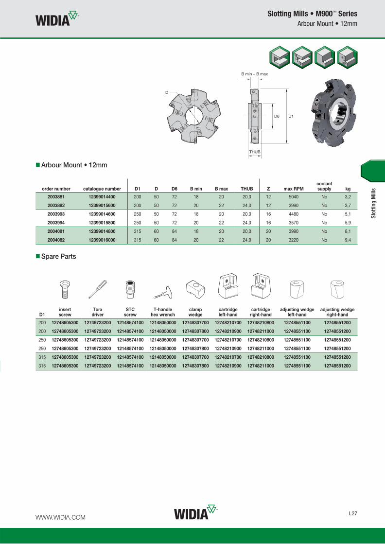
WWW.WIDIA.COM L27
Slotting Mills • M900™ Series
Arbour Mount • 12mm
Spare Parts
Arbour Mount • 12mm
order number catalogue number D1 D D6 B min B max THUB Z max RPMcoolant supply kg
2003881 12399014400 200 50 72 18 20 20,0 12 5040 No 3,2
2003882 12399015600 200 50 72 20 22 24,0 12 3990 No 3,7
2003993 12399014600 250 50 72 18 20 20,0 16 4480 No 5,1
2003994 12399015800 250 50 72 20 22 24,0 16 3570 No 5,9
2004081 12399014800 315 60 84 18 20 20,0 20 3990 No 8,1
2004082 12399016000 315 60 84 20 22 24,0 20 3220 No 9,4
D1insert screw
Torx driver
STCscrew
T-handlehex wrench
clampwedge
cartridgeleft-hand
cartridgeright-hand
adjusting wedge left-hand
adjusting wedge right-hand
200 12748605300 12749723200 12148574100 12148050000 12748307700 12748210700 12748210800 12748551100 12748551200
200 12748605300 12749723200 12148574100 12148050000 12748307800 12748210900 12748211000 12748551100 12748551200
250 12748605300 12749723200 12148574100 12148050000 12748307700 12748210700 12748210800 12748551100 12748551200
250 12748605300 12749723200 12148574100 12148050000 12748307800 12748210900 12748211000 12748551100 12748551200
315 12748605300 12749723200 12148574100 12148050000 12748307700 12748210700 12748210800 12748551100 12748551200
315 12748605300 12749723200 12148574100 12148050000 12748307800 12748210900 12748211000 12748551100 12748551200
Slot
ting
Mill
s

WWW.WIDIA.COM L28
Slotting Mills • M900™ Series
Arbour Mount • 12mm
D1insert screw
Torx driver
STCscrew
T-handlehex wrench
clampwedge
cartridgeleft-hand
cartridgeright-hand
adjusting wedge left-hand
adjusting wedge right-hand
200 12748605300 12749723200 12148574100 12148050000 12748307700 12748210700 12748210800 12748551100 12748551200
200 12748605300 12749723200 12148574100 12148050000 12748307800 12748210900 12748211000 12748551100 12748551200
250 12748605300 12749723200 12148574100 12148050000 12748307700 12748210700 12748210800 12748551100 12748551200
250 12748605300 12749723200 12148574100 12148050000 12748307800 12748210900 12748211000 12748551100 12748551200
315 12748605300 12749723200 12148574100 12148050000 12748307700 12748210700 12748210800 12748551100 12748551200
315 12748605300 12749723200 12148574100 12148050000 12748307800 12748210900 12748211000 12748551100 12748551200
Spare Parts
Shell Mount • 12mm
order number catalogue number D1 D D4 D6 B min B max L1 Z max RPMcoolant supply kg
2003900 12399114400 200 40 67 90 18 20 44,8 12 5040 No 3,8
2003901 12399115600 200 40 67 90 20 22 46,0 12 3990 No 4,3
2003998 12399114600 250 60 102 130 18 20 51,8 16 4480 No 7,2
2003999 12399115800 250 60 102 130 20 22 53,0 16 3570 No 7,9
2004096 12399114800 315 60 102 130 18 20 51,8 20 3990 No 10,2
2004097 12399116000 315 60 102 130 20 22 53,0 20 3220 No 11,3
Slot
ting
Mill
s

WWW.WIDIA.COM L29
Slotting Mills • M900™ Series
Inserts
Slot
ting
Mill
s
Insert Selection Guide
MaterialGroup
LightMachining
GeneralPurpose
HeavyMachining
Geometry Grade Geometry Grade Geometry Grade
P1–P2 MDHW WP40PM MDHW WP40PM MDHW WP40PM
P3–P4 MDHW WP35CM MDHW WP35CM MDHW WP35CM
P5–P6 MDHW WP35CM MDHW WP40PM MDHW WU35PM
M1–M2 MDHW WP25PM MDHW WP25PM MDHW WU35PM
M3 MDHW WP35CM MDHW WP40PM MDHW WU35PM
K1–K2 MDHW WK15CM MDHW WK15CM MDHW WK15CM
K3 MDHW WK15CM MDHW WP35CM MDHW WP35CM
N1–N2 – – – – – –
N3 – – – – – –
S1–S2 MDHW WP25PM MDHW WU35PM MDHW WU35PM
S3 MDHW WU35PM MDHW WU35PM MDHW WU35PM
S4 MDHW WP25PM MDHW WU35PM MDHW WU35PM
H1 – – – – – –
P � � � �
M � � � �
K � � �
N
S � � �
H �
Inserts • MDH..
MDHW
� fi rst choice
� alternate choice
MDHW MDHW
catalogue numbercutting edges D D1 L10 M S R W
K15
CM
WP
25P
MW
U35
PM
WP
35C
MW
P40
PM
MDHW120408 2 12,70 5,50 12,73 2,58 4,76 0,80
5903
707
5903
723
5903
721
5903
709
5903
705

WWW.WIDIA.COM L30
Slotting Mills • M900™ Series
Recommended Starting Speeds
NOTE: FIRST choice starting speeds are in bold type.As the average chip thickness increases, the speed should be decreased.
Slot
ting
Mill
s
Recommended Starting Speeds [m/min]
MaterialGroup WK15CM WP25PM WU35PM WP35CM WP40PM
P
0 – – – 330 285 270 260 230 215 455 395 370 295 260 245
1 – – – 330 285 270 260 230 215 455 395 370 295 260 245
2 – – – 275 240 200 220 190 160 280 255 230 250 215 180
3 – – – 255 215 175 200 170 140 255 230 205 230 195 160
4 – – – 225 185 150 180 150 120 190 175 160 205 170 135
5 – – – 185 170 150 150 135 120 260 230 210 170 155 135
6 – – – 165 125 100 130 100 80 160 135 110 150 115 90
M
1 – – – 205 180 165 170 150 135 205 185 155 195 170 155
2 – – – 185 160 130 155 130 110 185 160 140 175 150 125
3 – – – 140 120 95 115 100 80 145 130 115 130 115 90
K
1 420 385 340 230 205 185 – – – 295 265 240 – – –
2 335 295 275 180 160 150 – – – 235 210 190 – – –
3 280 250 230 150 135 120 – – – 195 175 160 – – –
N
1 – – – – – – – – – – – – – – –
2 – – – – – – – – – – – – – – –
3 – – – – – – – – – – – – – – –
S
1 – – – 40 35 25 35 30 25 – – – 40 35 30
2 – – – 40 35 25 35 30 25 – – – 40 35 30
3 – – – 50 40 25 45 35 25 – – – 50 40 30
4 – – – 70 50 35 60 45 30 66 50 33 65 50 35
H
1 – – – – – – – – – – – – – – –
2 – – – – – – – – – – – – – – –
3 – – – – – – – – – – – – – – –
NOTE: Use “Light Machining” value as starting feed rate.
Recommended Starting Feeds [mm] LightMachining
GeneralPurpose
HeavyMachining
InsertGeometry
Programmed Feed per Tooth (fz)as a % of Radial Depth of Cut (ae)
InsertGeometry5% 10% 20% 30% 40–100%
MDHW 0,12 0,23 0,46 0,08 0,17 0,33 0,06 0,13 0,25 0,06 0,11 0,22 0,05 0,10 0,20 MDHW
Recommended Starting Feeds

Notes

WWW.WIDIA.COM L32
1. General
Assembly and Operating Instructions
2. Exploded Diagram of Spare Parts
3. Mounting the Cartridges in the Mill Body
The runout tolerance of the milling cutter has a decisive effect on the quality of workpieces and the life cycle of tools. Proper tool fi tting and the precise axial setting of the milling insert are essential for a successful application and optimum results. One key requirement for assembly and setting work is that all components are clean. Bearing surfaces must be free from grease, and only the threads of indexable insert clamping screws and double threaded screws of clamping and adjusting wedges should be lubricated with copper grease. The indexable inserts should be inserted in the cleaned insert seats so that they are positioned correctly on the bearing surfaces. The indexable insert clamping screws should be tightened with the specifi ed torque.
3.1 Turn double threaded screw one turn clockwise in the adjusting wedge. Then insert both parts in the slot in the mill body and turn the double threaded screw clockwise until the adjusting wedge is fl ush with the milling cutter.
3.2 Turn double threaded screw three turns clockwise in the mill body. Then mount the clamping wedge on the double threaded screw and screw both parts together until the lower edge of the clamping wedge is at the same height as the chip space runout.
3.3 Push the top of the fully assembled cartridge into the mill body using the rear bearing surface of the milling cutter so that the cartridge slot makes contact with the adjusting wedge spring. Ensure a perfect axial/radial surface.
3.4 Secure the correctly positioned cartridge by tightening the clamping wedge with a preset torque of MApre = 1 Nm to set the runout or cutting width.
Slotting Mills • M900™ Series
Assembly and Operating Instructions
Double threaded screws
Right-hand adjusting wedge
Right-hand cartridge, complete
Clamping wedge
Mill body
Clamping screw
Indexable insert
Left-hand cartridge
Left-hand adjusting wedge
3.4 3.3 3.2 3.1

WWW.WIDIA.COM L33
Slotting Mills • M900™ Series
Assembly and Operating Instructions
ATTENTION:
4. Setting the Runout for Milling Cutters with 2–3 Cutting Edges
5. Setting the Runout for Milling Cutters with 3 Cutting Edges
4.1 Possible interpretations of the measuring dimension C.
4.2 Set gage to desired measurement C using gage blocks set to 0.
4.3 Set cartridge to ~0,1mm before fi nal measurement. Clamping wedge is tightened with torque MApre = 1 Nm. Then briefl y loosen clamping wedge and tighten again.
4.4 Set cartridge to 0,02mm before fi nal measurement. Then briefl y loosen clamping wedge so that the contact surfaces can level out. Tighten clamping.
4.4 Wedge again with torque MApre = 1 Nm.
4.5 Adjust cartridge to fi nal measurement. Tighten clamping wedge with torque MA = 4 Nm. Check runout of the fully adjusted milling cutter.
The cutting widths for milling cutters with three cutting edges are set using purpose-designed optical tool presetting equipment. Note that the projection of the cartridges from the mill body must be almost exactly the same on both sides. The sequence of steps required for setting the cartridge is identical to those for tools with two cutting edges.
At each tool adjustment, the body, cartridges, indexable inserts, and spare parts must be checked and replaced if necessary. Before each tool use, the clamping and double threaded screws must be tightened with the specifi ed torque. The tools must only be used in accordance with their function. We accept no liability for their improper use. Changes of any kind and/or printing errors are not valid grounds for claims.
4.5 4.4 4.3 4.2 4.1


WWW.WIDIA.COM M1
M370 • High-Feed Double-Sided Platform ..................................................................................................... M2–M16
M200 • Double-Sided Round Inserts ............................................................................................................ M18–M39
M170 • Round Inserts, Ideal for Die and Mould Applications .................................................................... M40–M70
M100 • Positive Round Inserts ...................................................................................................................... M72–M99
M270 • Indexable Ball Nose and Toroidal Inserts for Complex Parts ................................................... M100–M130
Indexable Milling • Copy Mills

WWW.WIDIA.COM M2
High-Feed Applications • M370™ Series
M370
Designed for high feed rate productivity, M370 Series provides the latest insert technology
with outstanding performance and reliability. Its double-sided concept and six cutting edges
provide security and optimal metal removal with an efficient cost per edge.
• Double-sided design offers six cutting edges per insert.
• Extremely high metal removal rates.
• First choice for high-feed roughing applications.
Profiled tool for
maximum chip
evacuation.
Through tool
coolant.
Six cutting edges
per insert.
High-strength tool
body design.

WWW.WIDIA.COM M3
Copy Mills M370 ™
Max depth of cut: up to 2mm
Indexes per insert: 6
Diameter: 25–125mm
Pages: M4–M16
P
M
K
S
H
Insert Offering
8mm iC Insert WOEJ0804Up to 1,3mm Ap max
Diameter range 25–80mm
12mm iC Insert WOEJ1207Up to 2mm Ap max
Diameter range 42–125mm

WWW.WIDIA.COM M4
Copy Mills • M370™ Series
iC08 • Screw-On End Mills
D1 maxinsert screw Nm
Torx driver
25 MS2219 1,8 DT9IP
32 MS2219 1,8 DT9IP
42 MS2219 1,8 DT9IP
Spare Parts
Screw-On End Mills
order number catalogue number D1 max D1 D DPM G3X L2 WF Ap1 max Z
max ramp angle max RPM
coolant supply kg
4056186 M370D025Z02M12WO08 25 11 21 12,5 M12 35 17 1,3 2 2.1° 46000 Yes 0,09
4170918 M370D025Z03M12WO08 25 11 21 12,5 M12 35 17 1,3 3 2.1° 46000 Yes 0,09
4056187 M370D032Z04M16WO08 32 18 29 17,0 M16 43 24 1,3 4 1.4° 38700 Yes 0,21
4056188 M370D042Z05M16WO08 42 28 29 17,0 M16 43 24 1,3 5 1.0° 32500 Yes 0,57
Copy
Mill
s
• Double-sided, six cutting edges.
• Highest metal removal rates.
• First choice for roughing applications.

WWW.WIDIA.COM M5
Copy Mills • M370™ Series
iC08 • Cylindrical End Mills
Spare Parts
Cylindrical End Mills
order number catalogue number D1 max D1 D L LBX Ap1 max Z max RPMcoolant supply kg
4056189 M370D025Z03A25WO08L150 25 11 25 150 40 1,3 3 46000 Yes 0,50
4008281 M370D025Z02A25WO08L200 25 11 25 200 50 1,3 2 46000 Yes 0,68
4170919 M370D025Z03A25WO08L200 25 11 25 200 40 1,3 3 46000 Yes 0,69
4170920 M370D025Z02A25WO08L300 25 11 25 300 40 1,3 2 46000 Yes 1,08
4056190 M370D028Z03A25WO08L200 28 14 25 200 40 1,3 3 42400 Yes 0,70
4056192 M370D032Z04A32WO08L200 32 18 32 200 50 1,3 4 38700 Yes 1,14
4056191 M370D032Z04A32WO08L150 32 18 32 150 40 1,3 4 38700 Yes 0,84
4170921 M370D032Z03A32WO08L300 32 18 32 300 40 1,3 3 38700 Yes 0,84
• Double-sided, six cutting edges.
• Highest metal removal rates.
• First choice for roughing applications.
Copy
Mill
s
D1 maxinsert screw Nm wrench
25 MS2219 1,8 DT9IP
28 MS2219 1,8 DT9IP
32 MS2219 1,8 DT9IP

WWW.WIDIA.COM M6
Copy Mills • M370™ Series
iC08 • Shell Mills
D1 maxinsert screw Nm
Torx Plus driver
socket-headcap screw
socket-head cap screwwith coolant groove
40 MS2219 1,8 DT9IP 125.825 MS1294CG
50 MS2219 1,8 DT9IP 12146120500 MS1234CG
52 MS2219 1,8 DT9IP 12146120500 MS1234CG
63 MS2219 1,8 DT9IP 12146120500 MS1234CG
66 MS2219 1,8 DT9IP MS2038 MS2038CG
80 MS2219 1,8 DT9IP MS2038 MS2038CG
Spare Parts
Shell Mills
order number catalogue number D1 max D1 D D6 L Ap1 max Z max RPMcoolant supply kg
4056193 M370D040Z04WO08 40 26 16 37 40 1,3 4 33500 Yes 0,19
4170922 M370D040Z05WO08 40 26 16 37 40 1,3 5 33500 Yes 0,19
4008276 M370D050Z05WO08 50 36 22 44 40 1,3 5 29200 Yes 0,29
4171223 M370D050Z06WO08 50 36 22 44 40 1,3 6 29200 Yes 0,29
4171224 M370D052Z06WO08 52 38 22 44 50 1,3 6 28600 Yes 0,40
4056194 M370D052Z05WO08 52 38 22 44 50 1,3 5 28600 Yes 0,41
4056195 M370D063Z06WO08 63 49 22 60 50 1,3 6 25500 Yes 0,74
4008277 M370D066Z06WO08 66 52 27 60 50 1,3 6 24900 Yes 0,77
4171225 M370D080Z07WO08 80 66 27 60 50 1,3 7 24900 Yes 2,36
Copy
Mill
s
D6
D
L
Ap1 max
D1 max
D1
• Double-sided, six cutting edges.
• Highest metal removal rates.
• First choice for roughing applications.
NOTE: Socket-head cap screw with coolant groove must be ordered separately.

WWW.WIDIA.COM M7
Copy Mills • M370™ Series
Inserts
Copy
Mill
s
Insert Selection Guide
MaterialGroup
LightMachining
GeneralPurpose
HeavyMachining
Geometry Grade Geometry Grade Geometry Grade
P1–P2 ..MM WP40PM ..MM WP40PM ..MM WP40PM
P3–P4 ..MM WP25PM ..MM WP40PM ..MH WP40PM
P5–P6 ..MM WP25PM ..MH WP25PM ..MH WP40PM
M1–M2 ..MM WP25PM ..MM WS30PM ..MM WP40PM
M3 ..MM WP25PM ..MM WP25PM ..MM WP40PM
K1–K2 ..MH WK15CM ..MH WK15CM ..MH WK15CM
K3 ..MH TN6520 ..MH TN6520 ..MH WK15CM
N1–N2 – – – – – –
N3 – – – – – –
S1–S2 ..MM WP25PM ..MM WS30PM ..MM WP40PM
S3 ..MM WS30PM ..MM WS30PM ..MM WP40PM
S4 ..MM WS30PM ..MM WP40PM ..MM WP40PM
H1 ..MH WP25PM – – – –
• -MM geometry provides lower cutting forces. First choice for steel,
stainless steel, and high-temp alloys. � fi rst choice
� alternate choice
WOEJ-MM
WOEJ-MM
catalogue numbercutting edges D S R TN
6520
TN65
25TN
7535
WK
15C
MW
P25
PM
WS3
0PM
WP
40P
MWOEJ080412SRMM 6 7,79 4,70 1,22 –
4113
892
4113
916
–55
6459
755
2024
855
4475
3
• -MH geometry is the fi rst choice for high-strength steel and cast iron.
WOEJ-MH
catalogue numbercutting edges D S R TN
6520
TN65
25TN
7535
WK
15C
MW
P25
PM
WS3
0PM
WP
40P
M
WOEJ080412SRMH 6 7,79 4,75 1,22
4136
480
4052
411
4068
517
5427
443
5564
596
–55
4475
2
WOEJ-MH
iC08 • Inserts • WO.J0804...
P � � � � �
M � � � � �
K � � � � �
N
S � � �
H � �

WWW.WIDIA.COM M8
Copy Mills • M370™ Series
Recommended Starting Speeds
Copy
Mill
s
Recommended Starting Speeds [m/min]
MaterialGroup TN6520 TN6525 TN7535 WK15CM
P
1 – – – 410 320 280 545 475 445 – – –
2 – – – 320 250 215 335 305 275 – – –
3 – – – 280 215 185 305 275 245 – – –
4 – – – 235 170 145 230 210 190 – – –
5 – – – 310 235 200 310 275 250 – – –
6 – – – 205 160 130 190 160 130 – – –
M
1 – – – 190 120 80 245 220 185 – – –
2 – – – 120 80 50 220 190 170 – – –
3 – – – 125 80 55 175 155 140 – – –
K
1 450 320 230 275 245 220 355 320 290 505 460 410
2 390 250 190 215 190 180 280 250 230 400 355 330
3 300 230 160 180 160 145 235 210 190 335 300 275
N
1 – – – – – – – – – – – –
2 – – – – – – – – – – – –
3 – – – – – – – – – – – –
S
1 – – – – – – – – – – – –
2 – – – – – – – – – – – –
3 – – – – – – – – – – – –
4 – – – – – – – – – – – –
H
1 – – – – – – – – – – – –
2 – – – – – – – – – – – –
3 – – – – – – – – – – – –
(continued)

WWW.WIDIA.COM M9
Copy Mills • M370™ Series
Recommended Starting Speeds
NOTE: FIRST choice starting speeds are in bold type.As the average chip thickness increases, the speed should be decreased.
Copy
Mill
s
MaterialGroup WP25PM WS30PM WP40PM
P
1 395 340 325 – – – 355 310 295
2 330 290 240 – – – 300 260 215
3 305 260 210 – – – 275 235 190
4 270 220 180 – – – 245 205 160
5 220 205 180 – – – 205 185 160
6 200 150 120 – – – 180 140 110
M
1 245 215 200 270 240 220 235 205 185
2 220 190 155 245 215 175 210 180 150
3 170 145 115 185 160 125 155 140 110
K
1 275 245 220 – – – – – –
2 215 190 180 – – – – – –
3 180 160 145 – – – – – –
N
1 – – – – – – – – –
2 – – – – – – – – –
3 – – – – – – – – –
S
1 50 40 30 55 50 35 50 40 35
2 50 40 30 55 50 35 50 40 35
3 60 50 30 65 55 35 60 50 35
4 85 60 40 100 70 50 80 60 40
H
1 145 110 85 – – – – – –
2 – – – – – – – – –
3 – – – – – – – – –
NOTE: Use “Light Machining” value as starting feed rate.
Recommended Starting Feeds [mm] LightMachining
GeneralPurpose
HeavyMachining
InsertGeometry
Programmed Feed per Tooth (fz)as a % of Radial Depth of Cut (ae)
InsertGeometry5% 10% 20% 30% 40–100%
..MM 0,90 1,67 4,09 0,65 1,19 2,83 0,48 0,88 2,08 0,42 0,77 1,80 0,38 0,70 1,64 ..MM
..MH 0,90 2,34 5,00 0,65 1,66 3,41 0,48 1,23 2,49 0,42 1,07 2,16 0,38 0,98 1,97 ..MH
For Plunging Applications
Recommended Starting Feeds
(Recommended Starting Speeds [m/min] — continued)

WWW.WIDIA.COM M10
The high-feed concept bases its strategy on small depth of cut
and higher fz values, which results in a higher MRR and productivity
with low radial forces.
Small Ap1 values and higher feed
rates generate lower cutting forces
versus traditional milling strategies.
For CAM programming, the tools
can be programmed as a toroidal
tool type by using the Rt value as
the insert radius.
Recommended when long
overhang is necessary due to
lower radial forces. Maximum
L/D ratio of 10 x D.
Cutter
Diameter
General Programming Information for Applying M370
Applying High-Feed Tools
Maximum Linear Ramping and Helical Interpolation from Solid • Metric
Rt
tWtWt
Hole
Diameter
Ap1 max
Copy Mills • M370™ Series
Additional Application Advice • WO.J0804...
L/D ratio starting Ap1 starting fz range
<3 0,9mm 1–1,3mm
>3–<5 0,6mm 1–1,3mm
>5–<7 0,4mm 0,6–1mm
cutter diametermax linear ramp angle
(straight line)min holediameter
max holediameter
Ap1 max per revolution
25 3,1° 30,2 49,5 1,25
28 2,6° 36,1 55,5 1,25
32 2,9° 44,1 63,5 1,25
40 1,6° 60 79,5 1,25
42 1,5° 64 83,5 1,25
50 1,3° 80 99,5 1,25
52 1,2° 84 103,5 1,25
63 1° 106 125,5 1,25
66 1° 112 131,5 1,25
80 0,8° 140 155,5 1,25
Rt t Wt
2,5mm 1mm 7,5mm

WWW.WIDIA.COM M11
Copy Mills • M370™ Series
iC12 • Screw-On End Mills
Spare Parts
Screw-On End Mills
order number catalogue number D1 max D1 D DPM G3X L2 WF Ap1 max Z
max ramp angle max RPM
coolant supply kg
5338912 M370D42Z03M16WO12 42 25 29 17,0 M16 40 24 2,0 3 5.1° 21310 Yes 0,22
• Double-sided, six cutting edges.
• Highest metal removal rates.
• First choice for roughing applications.
D1 maxinsert screw Nm
Torx driver
42 MS2085 4,0 DT15IP
Copy
Mill
s

WWW.WIDIA.COM M12
Copy Mills • M370™ Series
iC12 • Shell Mills
D1 maxinsert screw Nm
Torx Plus driver
socket-headcap screw
socket-head cap screwwith coolant groove
coolant lock screw
coolant lock screw assembly
50 MS2085 4,0 DT15IP 12146120500 MS1234CG — —
52 MS2085 4,0 DT15IP 12146120500 MS1234CG — —
63 MS2085 4,0 DT15IP 125.025 MS1234CG — —
66 MS2085 4,0 DT15IP 125.230 MS2038CG — —
80 MS2085 4,0 DT15IP 125.230 MS2038CG — —
100 MS2085 4,0 DT15IP — — KLS32M MS2195C
125 MS2085 4,0 DT15IP — — KLS40M MS2187C
Spare Parts
Shell Mills
order number catalogue number D1 max D1 D D6 L Ap1 max Z max RPMcoolant supply kg
5338913 M370D50Z04WO12 50,0 33 22 42 50 2,0 4 19530 Yes 0,38
5338914 M370D52Z04WO12 52,0 35 22 49 50 2,0 4 19160 Yes 0,47
5338915 M370D63Z04WO12 63,0 46 22 49 50 2,0 4 17400 Yes 0,57
5338916 M370D63Z05WO12 63,0 46 22 49 50 2,0 5 17400 Yes 0,57
5338917 M370D66Z05WO12 66,0 49 27 60 50 2,0 5 17000 Yes 0,79
5338918 M370D80Z05WO12 80,0 63 27 60 50 2,0 5 15440 Yes 0,94
5338919 M370D80Z06WO12 80,0 63 27 60 50 2,0 6 15440 Yes 0,94
5338920 M370D100Z06WO12 100,0 83 32 78 50 2,0 6 13810 Yes 1,56
5338921 M370D100Z07WO12 100,0 83 32 78 50 2,0 7 13810 Yes 1,57
5338922 M370D125Z07WO12 125,0 108 40 90 63 2,0 7 12350 Yes 2,92
5338923 M370D125Z09WO12 125,0 108 40 90 63 2,0 9 12350 Yes 2,94
Copy
Mill
s
• Double-sided, six cutting edges.
• Highest metal removal rates.
• First choice for roughing applications.
NOTE: Socket-head cap screw with coolant groove and coolant lock screw assembly must be ordered separately.

WWW.WIDIA.COM M13
Copy Mills • M370™ Series
Inserts
Copy
Mill
s
Insert Selection Guide
MaterialGroup
LightMachining
GeneralPurpose
HeavyMachining
Geometry Grade Geometry Grade Geometry Grade
P1–P2 .S..MM WU35PM .S..MM WP40PM .S..MM WP40PM
P3–P4 .S..MM WP25PM .S..MM WP25PM .S..MH WP40PM
P5–P6 .S..MM WP25PM .S..MM WP35CM .S..MH WP35CM
M1–M2 .S..MM WS30PM .S..MM WU35PM .S..MM WP40PM
M3 .S..MM WP25PM .S..MM WP35CM .S..MM WP40PM
K1–K2 .S..MH WK15CM .S..MH WK15CM .S..MH WP20CM
K3 .S..MH WK15CM .S..MH WK15CM .S..MH WP20CM
N1–N2 – – – – – –
N3 – – – – – –
S1–S2 .S..MM WS30PM .S..MM WU35PM .S..MM WP40PM
S3 .S..MM WS30PM .S..MM WU35PM .S..MM WP40PM
S4 .S..MM WS30PM .S..MM WU35PM .S..MM WP40PM
H1 .S..MH WP35CM .S..MR WP25PM – –
• -MM geometry provides lower cutting forces. First choice for steel,
stainless steel, and high-temp alloys.
� fi rst choice
� alternate choice
WOEJ-MM
WOEJ-MM
catalogue numbercutting edges D S R W
K15
CM
WP
20C
MW
P25
PM
WU
35P
MW
P35
CM
WS3
0PM
WP
40P
M
WOEJ120712SRMM 6 12,00 7,30 1,27 –54
1979
054
1964
854
1964
954
1979
155
2024
955
4234
6
WOEJ-MH
catalogue numbercutting edges D S R W
K15
CM
WP
20C
MW
P25
PM
WU
35P
MW
P35
CM
WS3
0PM
WP
40P
M
WOEJ120712SRMH 6 12,00 7,30 1,27
5338
860
5338
861
5338
818
5338
819
5338
862
–55
4234
7
• -MH geometry is the fi rst choice for high-strength steel and cast iron.
WOEJ-MH
iC12 • Inserts • WO.J1207…
P � � � � �
M � � � � � �
K � � � �
N
S � � � �
H � �
• -MR geometry is designed for heavy-duty steel and cast iron applications.

WWW.WIDIA.COM M14
Copy Mills • M370™ Series
P � � � � �
M � � � � � �
K � � � �
N
S � � � �
H � �
iC12 • Indexable Inserts • WO.J1207…
WOEJ-MR
catalogue numbercutting edges D S R W
K15
CM
WP
20C
MW
P25
PM
WU
35P
MW
P35
CM
WS3
0PM
WP
40P
M
WOEJ120712SRMR 6 12,00 7,30 1,27 – –56
9834
3– – –
5698
342
Copy
Mill
s
D S
5ºRε
� fi rst choice
� alternate choice
WOEJ-MR
Recommended Starting Speeds
Recommended Starting Speeds [m/min]
MaterialGroup WK15CM WP20CM WP25PM WU35PM
P
1 – – – 660 580 540 395 340 325 310 275 260
2 – – – 410 370 330 330 290 240 265 230 190
3 – – – 370 330 305 305 260 210 240 205 170
4 – – – 275 260 230 270 220 180 215 180 145
5 – – – 330 300 275 220 205 180 180 160 145
6 – – – 230 205 175 200 150 120 155 120 95
M
1 – – – 270 240 210 245 215 200 205 180 160
2 – – – 245 210 190 220 190 155 185 155 130
3 – – – 190 175 150 170 145 115 140 120 95
K
1 505 460 410 430 390 355 275 245 220 – – –
2 400 355 330 340 305 280 215 190 180 – – –
3 335 300 275 290 260 240 180 160 145 – – –
N
1 – – – – – – – – – – – –
2 – – – – – – – – – – – –
3 – – – – – – – – – – – –
S
1 – – – – – – 50 40 30 40 35 30
2 – – – – – – 50 40 30 40 35 30
3 – – – – – – 60 50 30 55 40 30
4 – – – – – – 85 60 40 70 55 35
H
1 – – – 170 140 115 145 110 85 – – –
2 – – – – – – – – – – – –
3 – – – – – – – – – – – –
(continued)

WWW.WIDIA.COM M15
Copy Mills • M370™ Series
Recommended Starting Speeds
NOTE: FIRST choice starting speeds are in bold type.As the average chip thickness increases, the speed should be decreased.
MaterialGroup WP35CM WS30PM WP40PM
P
1 545 475 445 – – – 355 310 295
2 335 305 275 – – – 300 260 215
3 305 275 245 – – – 275 235 190
4 230 210 190 – – – 245 205 160
5 310 275 250 – – – 205 185 160
6 190 160 130 – – – 180 140 110
M
1 245 220 185 270 240 220 235 205 185
2 220 190 170 245 215 175 210 180 150
3 175 155 140 185 160 125 155 140 110
K
1 355 320 290 – – – – – –
2 280 250 230 – – – – – –
3 235 210 190 – – – – – –
N
1 – – – – – – – – –
2 – – – – – – – – –
3 – – – – – – – – –
S
1 – – – 55 50 35 50 40 35
2 – – – 55 50 35 50 40 35
3 – – – 65 55 35 60 50 35
4 80 60 40 100 70 50 80 60 40
H
1 – – – – – – – – –
2 – – – – – – – – –
3 – – – – – – – – –
Copy
Mill
s
(Recommended Starting Speeds [m/min] — continued)
NOTE: Use “Light Machining” value as starting feed rate.
Recommended Starting Feeds [mm] LightMachining
GeneralPurpose
HeavyMachining
InsertGeometry
Programmed Feed per Tooth (fz)as a % of Radial Depth of Cut (ae)
InsertGeometry5% 10% 20% 30% 40–100%
..MM 0,90 1,87 3,62 0,65 1,33 2,52 0,48 0,99 1,86 0,42 0,86 1,61 0,39 0,79 1,47 ..MM
..MH 0,90 2,35 4,97 0,65 1,67 3,40 0,48 1,23 2,48 0,42 1,07 2,15 0,39 0,98 1,96 ..MH
..MR 0,90 2,81 5,44 0,65 1,97 3,69 0,48 1,46 2,69 0,42 1,27 2,33 0,39 1,16 2,13 ..MR
For All Other Applications
Recommended Starting Feeds

WWW.WIDIA.COM M16
Copy Mills • M370™ Series
Additional Application Advice • WO.J1207...
The high-feed concept bases its strategy on small depth of cut
and higher fz values, which results in a higher MRR and productivity
with low radial forces.
Small Ap1 values and higher feed
rates generate lower cutting forces
versus traditional milling strategies.
For CAM programming, the tools
can be programmed as a toroidal
tool type by using the Rt value as
the insert radius.
Recommended when long
overhang is necessary due to
lower radial forces. Maximum
L/D ratio of 10 x D.
General Programming Information for Applying M370
Applying High-Feed Tools
Maximum Linear Ramping and Helical Interpolation from Solid • Metric
Wt
Rt
tWt
Ap1 max
diametermax
ramp angle
max ramp angle for 360°
helical interpolationmax
plunge depth
min holediameter (DH min)
max fl at-bottomhole diameter
(DH1 max)max diameter
(no fl at bottom)
42 5,1° 1,44° 1,66 57,36 65,29 84
50 3,7° 1,09° 1,66 73,07 81,24 100
52 3,5° 1,03° 1,66 77,03 85,24 104
63 2,6° 0,78° 1,66 98,88 107,20 126
66 2,4° 0,74° 1,66 104,85 113,20 132
80 1,8° 0,57° 1,66 132,77 141,18 160
100 1,3° 0,43° 1,66 172,70 181,16 200
125 1,0° 0,33° 1,66 222,66 231,15 250
CAM programming information
Rt Wt t
mm value 3,2 9 1,4

Notes

WWW.WIDIA.COM M18
Double-Sided Round Insert • M200™ Series
M200
Revolutionary double-sided round insert, capable of running in multiple types
of milling operations and workpiece materials, increases customer’s productivity
with the most efficient cost per edge.
• Up to 12 cutting edges per insert.
• Effective anti-rotation feature.
• Able to apply in all type of materials
and milling applications.
• Latest WIDIA™ Victory™ grades offered.
Higher clearance
in bodies to permit
pocketing, profiling,
and 5-axis machining.
Screw-on, end mill,
and shell mill cutters
with internal coolant.
Easy-to-use and unique
anti-rotation feature for
excellent stability for higher
feed rates and cutting forces.
Three different insert sizes and three insert
topography styles with the new WIDIA™ Victory™
milling grades cover any type of component
and application.

WWW.WIDIA.COM M19
Copy Mills M200 ™
Max depth of cut: up to 5mm
Indexes per insert: up to 12
Diameter: 25–125mm
Pages: M20–M39
P
M
K
S
H
Insert Offering
M200 iC 1616mm iC insert
12 cutting edges
M200 iC 1212mm iC insert
12 cutting edges
M200 iC 1010mm iC insert
8 cutting edges

WWW.WIDIA.COM M20
Copy Mills • M200™ Series
iC10 • Screw-On End Mills
insert screw Nm
Torx driver
191.848 2,0 170.025
Spare Parts
Screw-On End Mills
order number catalogue number D1 max D1 D DPM G3X L2 WF Ap1 max Z max RPMcoolant supply kg
5210273 M200D25Z03M12RN10 25 15 21 12,5 M12 32 17 5,0 3 54700 Yes 0,08
5210274 M200D32Z04M16RN10 32 22 29 17,0 M16 40 24 5,0 4 48300 Yes 0,18
5210275 M200D35Z05M16RN10 35 24 29 17,0 M16 40 24 5,0 5 46200 Yes 0,20
5210276 M200D42Z06M16RN10 42 32 29 17,0 M16 40 24 5,0 6 42200 Yes 0,24
Copy
Mill
s
• Double-sided, eight cutting edges.
• Anti-rotation feature for better stability
and higher feed rates.
• Pocketing and profiling capabilities.

WWW.WIDIA.COM M21
Copy Mills • M200™ Series
iC10 • Weldon® Shanks
Spare Parts
Weldon Shanks
order number catalogue number D1 max D1 D L LBX Ap1 max Z max RPMcoolant supply kg
5210277 M200D25Z03B25RN10 25 15 25 89 40 5,0 3 54700 Yes 0,27
5210278 M200D32Z04B32RN10 32 22 32 101 40 5,0 4 48300 Yes 0,52
• Double-sided, eight cutting edges.
• Anti-rotation feature for better stability
and higher feed rates.
• Pocketing and profiling capabilities.
insert screw Nm
Torx driver
191.848 2,0 170.025
Copy
Mill
s

WWW.WIDIA.COM M22
Copy Mills • M200™ Series
iC10 • Cylindrical End Mills
insert screw Nm
Torx driver
191.848 2,0 170.025
Spare Parts
Cylindrical End Mills
order number catalogue number D1 max D1 D L LBX L2 Ap1 max Z max RPMcoolant supply kg
5210279 M200D25Z03A25RN10L150 25 15 25 150 32 32 5,0 3 54700 Yes 0,50
5210300 M200D25Z03A25RN10L200 25 15 25 200 32 32 5,0 3 54700 Yes 0,69
5210301 M200D25Z03A32RN10L250 25 15 32 250 32 32 5,0 3 54700 Yes 1,41
5210302 M200D28Z03A25RN10L200 28 18 25 200 40 40 5,0 3 51600 Yes 0,70
5210303 M200D32Z04A32RN10L150 32 22 32 150 40 40 5,0 4 48300 Yes 0,83
5210304 M200D32Z03A32RN10L200 32 22 32 200 40 40 5,0 3 48300 Yes 1,14
Copy
Mill
s
• Double-sided, eight cutting edges.
• Anti-rotation feature for better stability
and higher feed rates.
• Pocketing and profiling capabilities.

WWW.WIDIA.COM M23
Copy Mills • M200™ Series
iC10 • Shell Mills
Spare Parts
Shell Mills
order number catalogue number D1 max D1 D D6 L Ap1 max Z max RPMcoolant supply kg
5210305 M200D40Z04RN10 40 30 16 38 40 5,0 4 43200 Yes 0,23
5210306 M200D40Z06RN10 40 30 16 38 40 5,0 6 43200 Yes 0,24
5210307 M200D50Z05RN10 50 40 22 42 40 5,0 5 38600 Yes 0,32
5210308 M200D50Z06RN10 50 40 22 42 40 5,0 6 38600 Yes 0,32
5210309 M200D52Z06RN10 52 42 22 49 50 5,0 6 37900 Yes 0,52
• Double-sided, eight cutting edges.
• Anti-rotation feature for better stability
and higher feed rates.
• Pocketing and profiling capabilities.
D1 maxinsert screw Nm wrench
socket-headcap screw
socket-head cap screwwith coolant groove
40 191.848 2,0 170.025 MS1294 MS1294CG
50 191.848 2,0 170.025 MS1234 MS1234CG
52 191.848 2,0 170.025 MS1242 MS1242CG
Copy
Mill
s
NOTE: Socket-head cap screw and socket-head cap screw with coolant groove must be ordered separately.

WWW.WIDIA.COM M24
Copy Mills • M200™ Series
Inserts
Copy
Mill
s
Insert Selection Guide
MaterialGroup
LightMachining
GeneralPurpose
HeavyMachining
Geometry Grade Geometry Grade Geometry Grade
P1–P2 ML WP25PM MM WP40PM MM WP40PM
P3–P4 ML WP25PM MM WP25PM MH WP40PM
P5–P6 ML WP35CM MM WP35CM MH WP35CM
M1–M2 ML WP25PM ML WU35PM MM WU35PM
M3 ML WP25PM MM WU35PM MM WU35PM
K1–K2 MH WK15CM MH WK15CM MH WP20CM
K3 MH WK15CM MH WK15CM MH WP25PM
N1–N2 – – – – – –
N3 – – – – – –
S1–S2 ML WS30PM MM WS30PM MM WU35PM
S3 ML WS30PM MM WU35PM MM WU35PM
S4 ML WS30PM MM WU35PM MM WU35PM
H1 MH WP25PM MH WP20CM – –
RNGJ-ML
catalogue numbernumber
of indexes D S WK
15C
MW
P20
CM
WP
25P
MW
S30P
MW
U35
PM
WP
35C
MW
P40
PM
RNGJ10T3M0EML 8 10,00 4,76 – –52
7445
655
2035
252
7445
752
7445
5–
• -ML geometry is the fi rst choice for stainless steel and high-temp alloys.
• -MM geometry is for general purpose, especially for steel.
� fi rst choice
� alternate choice
RNGJ-ML
RNGJ-MM
catalogue numbernumber
of indexes D S WK
15C
MW
P20
CM
WP
25P
MW
S30P
MW
U35
PM
WP
35C
MW
P40
PM
RNGJ10T3M0SMM 8 10,00 4,76 – –52
7451
155
2035
352
7451
2– –
RNGJ-MM
iC10 • Inserts • RN.J10…
P � � � � �
M � � � � � �
K � � � �
N
S � � � �
H � �

WWW.WIDIA.COM M25
Copy Mills • M200™ Series
iC10 • Inserts • RN.J10…
RNPJ-MM
catalogue numbernumber
of indexes D S WK
15C
MW
P20
CM
WP
25P
MW
S30P
MW
U35
PM
WP
35C
MW
P40
PM
RNPJ10T3M0SMM 8 10,00 4,76 –52
7619
852
7619
7– –
5276
196
5542
327
Copy
Mill
s
• -MM geometry is for general purpose, especially for steel.
• -MH geometry is the first choice for heavy applications,
cast iron, and high-strength steel. � first choice
� alternate choice
RNGJ-MM RNPJ-MH
RNPJ-MH
catalogue numbernumber
of indexes D S WK
15C
MW
P20
CM
WP
25P
MW
S30P
MW
U35
PM
WP
35C
MW
P40
PM
RNPJ10T3M0SMH 8 10,00 4,76
5276
243
5276
241
5276
240
–54
7663
352
7619
955
4232
8
P � � � � �
M � � � � � �
K � � � �
N
S � � � �
H � �

WWW.WIDIA.COM M26
Copy Mills • M200™ Series
Recommended Starting Speeds
NOTE: FIRST choice starting speeds are in bold type. As the average chip thickness increases, the speed should be decreased.
Copy
Mill
s
Recommended Starting Speeds [m/min]
MaterialGroup WU35PM WP35CM WP40PM
P
1 310 275 260 545 475 445 355 310 295
2 265 230 190 335 305 275 300 260 215
3 240 205 170 305 275 245 275 235 190
4 215 180 145 230 210 190 245 205 160
5 180 160 145 310 275 250 205 185 160
6 155 120 95 190 160 130 180 140 110
M
1 205 180 160 245 220 185 235 205 185
2 185 155 130 220 190 170 210 180 150
3 140 120 95 175 155 140 155 140 110
K
1 – – – 355 320 290 – – –
2 – – – 280 250 230 – – –
3 – – – 235 210 190 – – –
N
1 – – – – – – – – –
2 – – – – – – – – –
3 – – – – – – – – –
S
1 40 35 30 – – – 50 40 35
2 40 35 30 – – – 50 40 35
3 55 40 30 – – – 60 50 35
4 70 55 35 80 60 40 80 60 40
H
1 – – – – – – – – –
2 – – – – – – – – –
3 – – – – – – – – –
MaterialGroup WK15CM WP20CM WP25PM WS30PM
P
1 – – – 660 580 540 395 340 325 – – –
2 – – – 410 370 330 330 290 240 – – –
3 – – – 370 330 305 305 260 210 – – –
4 – – – 275 260 230 270 220 180 – – –
5 – – – 330 300 275 220 205 180 – – –
6 – – – 230 205 175 200 150 120 – – –
M
1 – – – 270 240 210 245 215 200 270 240 220
2 – – – 245 210 190 220 190 155 245 215 175
3 – – – 190 175 150 170 145 115 185 160 125
K
1 505 460 410 430 390 355 275 245 220 – – –
2 400 355 330 340 305 280 215 190 180 – – –
3 335 300 275 290 260 240 180 160 145 – – –
N
1 – – – – – – – – – – – –
2 – – – – – – – – – – – –
3 – – – – – – – – – – – –
S
1 – – – – – – 50 40 30 55 50 35
2 – – – – – – 50 40 30 55 50 35
3 – – – – – – 60 50 30 65 55 35
4 – – – – – – 85 60 40 100 70 50
H
1 – – – 170 140 115 145 110 85 – – –
2 – – – – – – – – – – – –
3 – – – – – – – – – – – –

WWW.WIDIA.COM M27
Copy Mills • M200™ Series
Recommended Starting Feeds
NOTE: Use “Light Machining” value as starting feed rate.
Copy
Mill
s
Recommended Starting Feeds [mm]
At 5,00 Axial Depth of Cut (ap)
At 2,50 Axial Depth of Cut (ap)
At 1,25 Axial Depth of Cut (ap)
Light Machining
General Purpose
Heavy Machining
InsertGeometry
Programmed Feed per Tooth (fz)as a % of Radial Depth of Cut (ae)
InsertGeometry5% 10% 20% 30% 40–100%
ML 0,20 0,67 1,21 0,14 0,48 0,87 0,11 0,36 0,65 0,09 0,31 0,56 0,09 0,29 0,52 ML
MM 0,43 0,77 1,39 0,31 0,55 1,00 0,23 0,41 0,74 0,20 0,36 0,65 0,18 0,33 0,59 MM
MH 0,70 0,88 1,46 0,51 0,63 1,04 0,38 0,47 0,78 0,33 0,41 0,68 0,30 0,38 0,62 MH
InsertGeometry
Programmed Feed per Tooth (fz)as a % of Radial Depth of Cut (ae)
InsertGeometry5% 10% 20% 30% 40–100%
ML 0,27 0,92 1,67 0,20 0,66 1,19 0,15 0,49 0,89 0,13 0,43 0,77 0,12 0,39 0,71 ML
MM 0,58 1,05 1,92 0,42 0,75 1,37 0,31 0,56 1,02 0,27 0,49 0,88 0,25 0,45 0,81 MM
MH 0,96 1,21 2,02 0,69 0,87 1,43 0,52 0,65 1,06 0,45 0,56 0,93 0,41 0,52 0,85 MH
InsertGeometry
Programmed Feed per Tooth (fz)as a % of Radial Depth of Cut (ae)
InsertGeometry5% 10% 20% 30% 40–100%
ML 0,15 0,51 0,92 0,11 0,37 0,66 0,08 0,27 0,49 0,07 0,24 0,43 0,07 0,22 0,39 ML
MM 0,32 0,58 1,06 0,23 0,42 0,76 0,18 0,31 0,57 0,15 0,27 0,49 0,14 0,25 0,45 MM
MH 0,54 0,67 1,11 0,39 0,48 0,80 0,29 0,36 0,59 0,25 0,32 0,52 0,23 0,29 0,47 MH
InsertGeometry
Programmed Feed per Tooth (fz)as a % of Radial Depth of Cut (ae)
InsertGeometry5% 10% 20% 30% 40–100%
ML 0,13 0,44 0,80 0,10 0,32 0,57 0,07 0,24 0,43 0,06 0,21 0,37 0,06 0,19 0,34 ML
MM 0,28 0,50 0,91 0,20 0,36 0,66 0,15 0,27 0,49 0,13 0,24 0,43 0,12 0,22 0,39 MM
MH 0,46 0,58 0,96 0,33 0,42 0,69 0,25 0,31 0,51 0,22 0,27 0,45 0,20 0,25 0,41 MH
At 0,63 Axial Depth of Cut (ap)

WWW.WIDIA.COM M28
Copy Mills • M200™ Series
iC12 • Screw-On End Mills
D1 maxinsert screw Nm
Torx driver
32 193.492 4,0 170.025
35 193.492 4,0 170.025
42 193.492 4,0 170.025
Spare Parts
Screw-On End Mills
order number catalogue number D1 max D1 D DPM G3X L2 WF Ap1 max Z max RPMcoolant supply kg
4147560 M200D32Z03M16RN12 32 20 29 17,0 M16 40 24 3,0 3 39160 Yes 0,18
4147561 M200D35Z03M16RN12 35 23 29 17,0 M16 40 24 3,0 3 37440 Yes 0,19
4147562 M200D42Z04M16RN12 42 30 29 17,0 M16 40 24 3,0 4 34180 Yes 0,24
Copy
Mill
s
• Double-sided, 12 cutting edges.
• Anti-rotation feature for better stability
and higher feed rates.
• Pocketing and profiling capabilities.

WWW.WIDIA.COM M29
Copy Mills • M200™ Series
iC12 • Weldon® Shanks
Spare Parts
Weldon Shanks
order number catalogue number D1 max D1 D L LBX Ap1 max Z max RPMcoolant supply kg
4147564 M200D32Z03B32RN12 32 20 32 125 40 3,0 3 39160 Yes 0,65
• Double-sided, 12 cutting edges.
• Anti-rotation feature for better stability
and higher feed rates.
• Pocketing and profiling capabilities.
D1 maxinsert screw Nm
Torx driver
32 193.492 4,0 170.025
Copy
Mill
s

WWW.WIDIA.COM M30
Copy Mills • M200™ Series
iC12 • Cylindrical End Mills
D1 maxinsert screw Nm
Torx driver
32 193.492 4,0 170.025
Spare Parts
Cylindrical End Mills
order number catalogue number D1 max D1 D L LBX Ap1 max Z max RPMcoolant supply kg
4147566 M200D32Z03A32RN12L200 32 20 32 200 40 3,0 3 39160 Yes 1,10
4147567 M200D32Z02A32RN12L250 32 20 32 250 40 3,0 2 39160 Yes 1,41
Copy
Mill
s
• Double-sided, 12 cutting edges.
• Anti-rotation feature for better stability
and higher feed rates.
• Pocketing and profiling capabilities.

WWW.WIDIA.COM M31
Copy Mills • M200™ Series
iC12 • Shell Mills
Spare Parts
Shell Mills
order number catalogue number D1 max D1 D D6 L Ap1 max Z max RPMcoolant supply kg
4147568 M200D40Z04RN12 40 28 16 38 40 3,0 4 35020 Yes 0,22
4147569 M200D50Z04RN12 50 38 22 42 40 3,0 4 31330 Yes 0,30
4147570 M200D50Z05RN12 50 38 22 42 40 3,0 5 31330 Yes 0,29
4147571 M200D52Z05RN12 52 40 22 49 50 3,0 5 30720 Yes 0,49
4147572 M200D63Z05RN12 63 51 22 49 50 3,0 5 27910 Yes 0,63
4147573 M200D63Z07RN12 63 51 22 49 50 3,0 7 27910 Yes 0,63
4147574 M200D66Z07RN12 66 54 27 60 50 3,0 7 27260 Yes 0,82
4147575 M200D80Z06RN12 80 68 27 60 50 3,0 6 24760 Yes 1,02
4147576 M200D80Z08RN12 80 68 27 60 50 3,0 8 24760 Yes 1,02
4147577 M200D100Z07RN12 100 88 32 78 50 3,0 7 22150 Yes 1,45
4147578 M200D100Z09RN12 100 88 32 78 50 3,0 9 22150 Yes 1,41
• Double-sided, 12 cutting edges.
• Anti-rotation feature for better stability
and higher feed rates.
• Pocketing and profiling capabilities.
D1 maxinsert screw Nm wrench
low-head cap screw
socket-headcap screw
socket-head cap screwwith coolant groove
coolant lock screw
coolant lock screw assembly
40 193.492 4,0 170.025 — MS1294 MS1294CG — —
50 193.492 4,0 170.025 MS1336 — MS2072CG — —
52 193.492 4,0 170.025 — MS1242 MS1242CG — —
63 193.492 4,0 170.025 — MS1242 MS1242CG — —
66 193.492 4,0 170.025 — MS2038 MS2038CG — —
80 193.492 4,0 170.025 — MS2038 MS2038CG — —
100 193.492 4,0 170.025 — — — KLS32M MS2195C
Copy
Mill
s
NOTE: Socket-head cap screw with coolant groove and coolant lock screw assembly must be ordered separately.

WWW.WIDIA.COM M32
Copy Mills • M200™ Series
Inserts
Copy
Mill
s
Insert Selection Guide
MaterialGroup
LightMachining
GeneralPurpose
HeavyMachining
Geometry Grade Geometry Grade Geometry Grade
P1–P2 ML WP25PM MM WP40PM MM WP40PM
P3–P4 ML WP25PM MM WP25PM MH WP40PM
P5–P6 ML WP35CM MM WP35CM MH WP35CM
M1–M2 ML WP25PM ML WU35PM MM WU35PM
M3 ML WP25PM MM WU35PM MM WU35PM
K1–K2 MH WK15CM MH WK15CM MH WP20CM
K3 MH WK15PM MH WK15PM MH WP25PM
N1–N2 – – – – – –
N3 – – – – – –
S1–S2 ML WS30PM MM WS30PM MM WU35PM
S3 ML WS30PM MM WU35PM MM WU35PM
S4 ML WS30PM MM WU35PM MM WU35PM
H1 MH WP25PM MH WP20CM – –
RNGJ-ML
catalogue numbercutting edges D S W
K15
PM
WK
15C
MW
P20
CM
WP
25P
MW
S30P
MW
U35
PM
WP
35C
MW
P40
PM
RNGJ1204M0EML 12 12,00 4,75 – – –51
2386
355
2035
051
2386
451
2386
5–
• -ML geometry is the fi rst choice for stainless steel and high-temp alloys.
• -MM geometry is for general purpose, especially for steel.
� fi rst choice
� alternate choice
RNGJ-ML
RNGJ-MM
catalogue numbercutting edges D S W
K15
PM
WK
15C
MW
P20
CM
WP
25P
MW
S30P
MW
U35
PM
WP
35C
MW
P40
PM
RNGJ1204M0SMM 12 12,00 4,75
5123
866
– –51
2386
755
2035
151
2386
851
2386
9–
RNGJ-MM
iC12 • Inserts • RN.J12..
P � � � � �
M � � � � � �
K � � � � �
N
S � � � �
H � �

WWW.WIDIA.COM M33
Copy
Mill
s
RNPJ-MM
RNPJ-MM
catalogue numbercutting edges D S W
K15
PM
WK
15C
MW
P20
CM
WP
25P
MW
S30P
MW
U35
PM
WP
35C
MW
P40
PM
RNPJ1204M0SMM 12 12,00 4,75 – –52
7636
252
7636
1–
5476
634
5276
360
5542
329
RNPJ-MH
RNPJ-MH
catalogue numbercutting edges D S W
K15
PM
WK
15C
MW
P20
CM
WP
25P
MW
S30P
MW
U35
PM
WP
35C
MW
P40
PM
RNPJ1204M0SMH 12 12,00 4,75 –52
7636
652
7636
552
7636
4–
5476
635
5276
363
5542
340
M200™ Series • Copy Mills
P � � � � �
M � � � � � �
K � � � � �
N
S � � � �
H � �
iC12 • Inserts • RN.J12..
RNGJ-MH
catalogue numbercutting edges D S W
K15
PM
WK
15C
MW
P20
CM
WP
25P
MW
S30P
MW
U35
PM
WP
35C
MW
P40
PM
RNGJ1204M0SMH 12 12,00 4,75
5123
900
– –51
2390
1–
5123
902
5123
903
–
RNGJ-MH
• -MM geometry is for general purpose, especially for steel.
• -MH geometry is the first choice for heavy applications,
cast iron, and high-strength steel. � first choice
� alternate choice

WWW.WIDIA.COM M34
Copy Mills • M200™ Series
Recommended Starting Speeds
NOTE: FIRST choice starting speeds are in bold type. As the average chip thickness increases, the speed should be decreased.
Copy
Mill
s
Recommended Starting Speeds [m/min]
MaterialGroup WS30PM WU35PM WP35CM WP40PM
P
1 – – – 310 275 260 545 475 445 355 310 295
2 – – – 265 230 190 335 305 275 300 260 215
3 – – – 240 205 170 305 275 245 275 235 190
4 – – – 215 180 145 230 210 190 245 205 160
5 – – – 180 160 145 310 275 250 205 185 160
6 – – – 155 120 95 190 160 130 180 140 110
M
1 270 240 220 205 180 160 245 220 185 235 205 185
2 245 215 175 185 155 130 220 190 170 210 180 150
3 185 160 125 140 120 95 175 155 140 155 140 110
K
1 – – – – – – 355 320 290 – – –
2 – – – – – – 280 250 230 – – –
3 – – – – – – 235 210 190 – – –
N
1 – – – – – – – – – – – –
2 – – – – – – – – – – – –
3 – – – – – – – – – – – –
S
1 55 50 35 40 35 30 – – – 50 40 35
2 55 50 35 40 35 30 – – – 50 40 35
3 65 55 35 55 40 30 – – – 60 50 35
4 100 70 50 70 55 35 80 60 40 80 60 40
H
1 – – – – – – – – – – – –
2 – – – – – – – – – – – –
3 – – – – – – – – – – – –
MaterialGroup WK15PM WK15CM WP20CM WP25PM
P
1 – – – – – – 660 580 540 395 340 325
2 – – – – – – 410 370 330 330 290 240
3 – – – – – – 370 330 305 305 260 210
4 – – – – – – 275 260 230 270 220 180
5 – – – – – – 330 300 275 220 205 180
6 – – – – – – 230 205 175 200 150 120
M
1 – – – – – – 270 240 210 245 215 200
2 – – – – – – 245 210 190 220 190 155
3 – – – – – – 190 175 150 170 145 115
K
1 325 295 260 505 460 410 430 390 355 275 245 220
2 250 230 210 400 355 330 340 305 280 215 190 180
3 210 190 175 335 300 275 290 260 240 180 160 145
N
1 – – – – – – – – – – – –
2 – – – – – – – – – – – –
3 – – – – – – – – – – – –
S
1 – – – – – – – – – 50 40 30
2 – – – – – – – – – 50 40 30
3 – – – – – – – – – 60 50 30
4 – – – – – – – – – 85 60 40
H
1 – – – – – – 170 140 115 145 110 85
2 – – – – – – – – – – – –
3 – – – – – – – – – – – –

WWW.WIDIA.COM M35
Copy Mills • M200™ Series
Recommended Starting Feeds
NOTE: Use “Light Machining” value as starting feed rate.
Copy
Mill
s
Recommended Starting Feeds [mm]
At 6,00 Axial Depth of Cut (ap)
At 3,00 Axial Depth of Cut (ap)
At 1,50 Axial Depth of Cut (ap)
Light Machining
General Purpose
Heavy Machining
InsertGeometry
Programmed Feed per Tooth (fz)as a % of Radial Depth of Cut (ae)
InsertGeometry5% 10% 20% 30% 40–100%
ML 0,18 0,27 0,49 0,13 0,19 0,35 0,10 0,15 0,26 0,09 0,13 0,23 0,08 0,12 0,21 ML
MM 0,43 0,77 1,28 0,31 0,56 0,92 0,23 0,42 0,68 0,20 0,36 0,60 0,19 0,33 0,55 MM
MH 0,70 1,06 1,56 0,51 0,76 1,12 0,38 0,57 0,83 0,33 0,50 0,72 0,30 0,45 0,66 MH
InsertGeometry
Programmed Feed per Tooth (fz)as a % of Radial Depth of Cut (ae)
InsertGeometry5% 10% 20% 30% 40–100%
ML 0,25 0,37 0,67 0,18 0,27 0,48 0,14 0,20 0,36 0,12 0,17 0,32 0,11 0,16 0,29 ML
MM 0,59 1,06 1,77 0,43 0,76 1,26 0,32 0,57 0,94 0,28 0,50 0,81 0,25 0,45 0,75 MM
MH 0,96 1,46 2,16 0,69 1,04 1,53 0,52 0,78 1,14 0,45 0,68 0,99 0,41 0,62 0,90 MH
InsertGeometry
Programmed Feed per Tooth (fz)as a % of Radial Depth of Cut (ae)
InsertGeometry5% 10% 20% 30% 40–100%
ML 0,14 0,20 0,37 0,10 0,15 0,27 0,08 0,11 0,20 0,07 0,10 0,18 0,06 0,09 0,16 ML
MM 0,33 0,59 0,97 0,24 0,43 0,70 0,18 0,32 0,52 0,16 0,28 0,45 0,14 0,25 0,42 MM
MH 0,54 0,81 1,18 0,39 0,58 0,85 0,29 0,43 0,63 0,25 0,38 0,55 0,23 0,35 0,51 MH
InsertGeometry
Programmed Feed per Tooth (fz)as a % of Radial Depth of Cut (ae)
InsertGeometry5% 10% 20% 30% 40–100%
ML 0,12 0,18 0,32 0,09 0,13 0,23 0,07 0,10 0,18 0,06 0,08 0,15 0,05 0,08 0,14 ML
MM 0,28 0,51 0,84 0,21 0,37 0,61 0,15 0,28 0,45 0,13 0,24 0,39 0,12 0,22 0,36 MM
MH 0,46 0,70 1,02 0,33 0,50 0,73 0,25 0,38 0,55 0,22 0,33 0,48 0,20 0,30 0,44 MH
At 0,75 Axial Depth of Cut (ap)

WWW.WIDIA.COM M36
Language Version: WID_Master16_IndexableMIlling_CopyMills_M036_M037_Metric August 11, 2015 4:41 PM
Copy Mills • M200™ SeriesiC16 • Shell Mills
D1 maxinsert screw Nm wrench
socket-headcap screw
socket-head cap screwwith coolant groove
coolant lock screw
coolant lock screw assembly
50 192.932 4,0 170.026 MS1242 MS1242CG — —
52 MS2260 4,0 170.026 MS1242 MS1242CG — —
63 MS2260 4,0 170.026 MS1242 MS1242CG — —
63 193.343 4,0 170.026 MS1242 MS1242CG — —
66 MS2260 4,0 170.026 MS2038 MS2038CG — —
80 MS2260 4,0 170.026 MS2038 MS2038CG — —
100 MS2260 4,0 170.026 — — KLS32M MS2195C
125 MS2260 4,0 170.026 — — KLS40M MS2187C
nnSpare Parts
nnShell Mills
order number catalogue number D1 max D1 D D6 L Ap1 max Z max RPMcoolant supply kg
5209989 M200D50Z04RN16 50 34 22 42 50 4,0 4 26700 Yes 0,36
5210210 M200D52Z04RN16 52 36 22 42 50 4,0 4 26000 Yes 0,39
5210212 M200D63Z06RN16 63 47 22 49 50 4,0 6 22700 Yes 0,56
5210211 M200D63Z04RN16 63 47 22 49 50 4,0 4 22700 Yes 0,58
5210213 M200D66Z05RN16 66 50 27 60 50 4,0 5 22000 Yes 0,69
5210214 M200D80Z05RN16 80 64 27 60 50 4,0 5 19500 Yes 0,88
5210215 M200D80Z07RN16 80 64 27 60 50 4,0 7 19500 Yes 0,89
5210216 M200D100Z06RN16 100 84 32 78 50 4,0 6 17000 Yes 1,36
5210217 M200D100Z08RN16 100 84 32 78 50 4,0 8 17000 Yes 1,37
5210218 M200D125Z08RN16 125 109 40 90 63 4,0 8 14900 Yes 2,50
Copy
Mill
s
• Double-sided, 12 cutting edges.
• Anti-rotation feature for better stability and higher feed rates.
• Pocketing and profiling capabilities.
NOTE: Socket-head cap screw with coolant groove and coolant lock screw assembly must be ordered separately.

WWW.WIDIA.COM M37
Language Version: WID_Master16_IndexableMIlling_CopyMills_M036_M037_Metric August 11, 2015 4:41 PM
Copy Mills • M200™ SeriesInserts
Copy
Mill
s
nn Insert Selection Guide
MaterialGroup
Light Machining
General Purpose
Heavy Machining
Geometry Grade Geometry Grade Geometry Grade
P1–P2 ML WP25PM MM WP40PM MM WP40PM
P3–P4 ML WP25PM MM WP25PM MH WP40PM
P5–P6 ML WP35CM MM WP35CM MH WP35CM
M1–M2 ML WP25PM ML WU35PM MM WU35PM
M3 ML WP25PM MM WU35PM MM WU35PM
K1–K2 MH WK15CM MH WK15CM MH WP20CM
K3 MH WK15CM MH WP20CM MH WP35CM
N1–N2 – – – – – –
N3 – – – – – –
S1–S2 ML WS30PM ML WS30PM ML WU35PM
S3 ML WS30PM ML WU35PM ML WU35PM
S4 ML WS30PM ML WU35PM ML WU35PM
H1 MH WP25PM MH WP20CM – –
P v v v v v
M j v j v j v
K v j j j
N
S v v v j
H j j
• -ML geometry is the first choice for stainless steel and high-temp alloys.
v first choicej alternate choice
RNGJ-ML
nnRNGJ-ML
catalogue numbercutting edges D S W
K15
CM
WP
20C
MW
P25
PM
WS3
0PM
WU
35P
MW
P35
CM
WP
40P
M
RNGJ1605M0EML 12 16,00 6,35 – –52
7456
155
2035
452
7456
252
7456
0–
iC16 • Inserts • RN.J16…

WWW.WIDIA.COM M38
Copy Mills • M200™ Series
iC16 • Inserts • RN.J16…
RNPJ-MM
catalogue numbercutting edges D S W
K15
CM
WP
20C
MW
P25
PM
WS3
0PM
WU
35P
MW
P35
CM
WP
40P
M
RNPJ1605M0SMM 12 16,00 6,35 –52
7647
252
7647
1–
5476
637
5276
470
5542
341
Copy
Mill
s
• -MM geometry is for general purpose, especially for steel.
• -MH geometry is the fi rst choice for heavy applications,
cast iron, and high-strength steels. � fi rst choice
� alternate choice
RNPJ-MM
RNPJ-MH
catalogue numbercutting edges D S W
K15
CM
WP
20C
MW
P25
PM
WS3
0PM
WU
35P
MW
P35
CM
WP
40P
M
RNPJ1605M0SMH 12 16,00 6,35
5276
476
5276
475
5276
474
–54
7663
652
7647
355
4234
2
RNPJ-MH
Recommended Starting Speeds
Recommended Starting Speeds [m/min] MaterialGroup WK15CM WP20CM WP25PM WS30PM
P
1 – – – 660 580 540 395 340 325 – – –
2 – – – 410 370 330 330 290 240 – – –
3 – – – 370 330 305 305 260 210 – – –
4 – – – 275 260 230 270 220 180 – – –
5 – – – 330 300 275 220 205 180 – – –
6 – – – 230 205 175 200 150 120 – – –
M
1 – – – 270 240 210 245 215 200 270 240 220
2 – – – 245 210 190 220 190 155 245 215 175
3 – – – 190 175 150 170 145 115 185 160 125
K1 505 460 410 430 390 355 275 245 220 – – –
2 400 355 330 340 305 280 215 190 180 – – –
3 335 300 275 290 260 240 180 160 145 – – –
N1 – – – – – – – – – – – –
2 – – – – – – – – – – – –
3 – – – – – – – – – – – –
S
1 – – – – – – 50 40 30 55 50 35
2 – – – – – – 50 40 30 55 50 35
3 – – – – – – 60 50 30 65 55 35
4 – – – – – – 85 60 40 100 70 50
H1 – – – 170 140 115 145 110 85 – – –
2 – – – – – – – – – – – –
3 – – – – – – – – – – – –
P � � � � �
M � � � � � �
K � � � �
N
S � � � �
H � �

WWW.WIDIA.COM M39
Copy Mills • M200™ Series
Recommended Starting Speeds
NOTE: FIRST choice starting speeds are in bold type.As the average chip thickness increases, the speed should be decreased.
MaterialGroup WU35PM WP35CM WP40PM
P
1 310 275 260 545 475 445 355 310 295
2 265 230 190 335 305 275 300 260 215
3 240 205 170 305 275 245 275 235 190
4 215 180 145 230 210 190 245 205 160
5 180 160 145 310 275 250 205 185 160
6 155 120 95 190 160 130 180 140 110
M1 205 180 160 245 220 185 235 205 185
2 185 155 130 220 190 170 210 180 150
3 140 120 95 175 155 140 155 140 110
K1 – – – 355 320 290 – – –
2 – – – 280 250 230 – – –
3 – – – 235 210 190 – – –
N1 – – – – – – – – –
2 – – – – – – – – –
3 – – – – – – – – –
S
1 40 35 30 – – – 50 40 35
2 40 35 30 – – – 50 40 35
3 55 40 30 – – – 60 50 35
4 70 55 35 80 60 40 80 60 40
H1 – – – – – – – – –
2 – – – – – – – – –
3 – – – – – – – – –
Copy
Mill
s
(Recommended Starting Speeds [m/min] — continued)
NOTE: Use “Light Machining” value as starting feed rate.
Recommended Starting Feeds [mm]
At 8,00 Axial Depth of Cut (ap)
At 4,00 Axial Depth of Cut (ap)
At 2,00 Axial Depth of Cut (ap)
LightMachining
GeneralPurpose
HeavyMachining
InsertGeometry
Programmed Feed per Tooth (fz)as a % of Radial Depth of Cut (ae)
InsertGeometry5% 10% 20% 30% 40–100%
ML 0,19 0,56 0,73 0,14 0,40 0,53 0,10 0,30 0,40 0,09 0,26 0,34 0,08 0,24 0,32 ML
MM 0,43 1,06 1,24 0,31 0,76 0,89 0,23 0,57 0,66 0,20 0,50 0,57 0,19 0,45 0,53 MM
MH 0,81 1,06 1,79 0,58 0,76 1,28 0,44 0,57 0,95 0,38 0,50 0,83 0,35 0,45 0,76 MH
InsertGeometry
Programmed Feed per Tooth (fz)as a % of Radial Depth of Cut (ae)
InsertGeometry5% 10% 20% 30% 40–100%
ML 0,26 0,77 1,01 0,19 0,55 0,73 0,14 0,41 0,54 0,12 0,36 0,47 0,11 0,33 0,43 ML
MM 0,59 1,46 1,70 0,43 1,04 1,21 0,32 0,78 0,90 0,28 0,68 0,79 0,25 0,62 0,72 MM
MH 1,11 1,46 2,48 0,80 1,04 1,75 0,60 0,78 1,30 0,52 0,68 1,13 0,48 0,62 1,03 MH
InsertGeometry
Programmed Feed per Tooth (fz)as a % of Radial Depth of Cut (ae)
InsertGeometry5% 10% 20% 30% 40–100%
ML 0,14 0,43 0,56 0,10 0,31 0,40 0,08 0,23 0,30 0,07 0,20 0,26 0,06 0,18 0,24 ML
MM 0,33 0,81 0,94 0,24 0,58 0,67 0,18 0,43 0,50 0,16 0,38 0,44 0,14 0,35 0,40 MM
MH 0,62 0,81 1,36 0,44 0,58 0,97 0,33 0,43 0,72 0,29 0,38 0,63 0,27 0,35 0,58 MH
InsertGeometry
Programmed Feed per Tooth (fz)as a % of Radial Depth of Cut (ae)
InsertGeometry5% 10% 20% 30% 40–100%
ML 0,12 0,37 0,48 0,09 0,27 0,35 0,07 0,20 0,26 0,06 0,17 0,23 0,05 0,16 0,21 ML
MM 0,28 0,70 0,81 0,21 0,50 0,58 0,15 0,38 0,44 0,13 0,33 0,38 0,12 0,30 0,35 MM
MH 0,53 0,70 1,17 0,38 0,50 0,84 0,29 0,38 0,63 0,25 0,33 0,55 0,23 0,30 0,50 MH
At 1,00 Axial Depth of Cut (ap)
Recommended Starting Feeds

WWW.WIDIA.COM M40
Ideal for Die and Mould Applications • M170™ Series
M170
Specially engineered with industry standard insert sizes, the M170 Series offers the highest performance
rates for best-in-class cost efficiency, high-strength steel, and hard machining capability, and a strong,
solid cutter body designed for maximum performance.
• Nickel-coated cutter bodies ensure improved tool life and chip flow.
• Screw-on end mills and shell mills.
• High teeth density for optimised HSM.
• High-accuracy PSTS inserts ideal for die and mould manufacturing.
Hard nickel-coated bodies.
Additional insert clamping
(select tool bodies).
High teeth density
for optimised HSM.Through tool coolant.
Superior ramping and
helical interpolation
capabilities.

WWW.WIDIA.COM M41
Copy Mills M170™
Max depth of cut: 8mm
Diameter: 12–125mm
Pages: M42–M70
P
M
K
S
H
Insert Offering
iC07 iC10 iC12 iC16
7mm iC insert RD.X
Up to 3,5mm Ap max.
Diameter range
12–35mm
10mm iC insert RDPX
Up to 5mm Ap max.
Diameter range
20–52mm
12mm iC insert RDPX
Up to 6mm Ap max.
Diameter range
24–100mm
16mm iC insert RDPX
Up to 8mm Ap max.
Diameter range
32–125mm

WWW.WIDIA.COM M42
Copy Mills • M170™ Series
Screw-On End Mills • RD07T1..
D1 maxinsert screw Nm
Torx driver
12 193.364 1,0 12147549000
15 193.364 1,0 12147549000
Spare Parts
Screw-On End Mills
order number catalogue number D1 max D1 D DPM G3X L2 WF Ap1 max Z
max ramp angle max RPM
coolant supply kg
3935336 M170D012Z02M06RD07T 12 5 10 6,5 M6 18 7 3,5 2 22.0° 26200 Yes 0,02
3935337 M170D012Z02M08RD07T 12 5 13 8,5 M8 23 10 3,5 2 22.0° 26200 Yes 0,02
3935338 M170D015Z03M08RD07T 15 8 13 8,5 M8 18 10 3,5 3 11.0° 21200 Yes 0,02
Copy
Mill
s
• Longer cutter tool life.
• Premium nickel-coated bodies.
• Designed for maximum performance.
• Ideally suited for die and mould manufacturing.
NOTE: All spare parts except the insert screws must be ordered separately.

WWW.WIDIA.COM M43
Copy Mills • M170™ Series
Cylindrical Shanks • RD07T1..
Spare Parts
Cylindrical Shanks
order number catalogue number D1 max D1 D L L2 BHTCA Ap1 max Z
max ramp angle max RPM
coolant supply kg
3935339 M170D012Z02A12RD07TL100 12 5 12 100 20 — 3,5 2 22.0° 26200 Yes 0,07
3935340 M170D012Z02A16RD07TL120 12 5 16 120 60 2.0° 3,5 2 22.0° 26200 Yes 0,14
3935341 M170D012Z02A16RD07TL140 12 5 16 140 80 1.5° 3,5 2 22.0° 26200 Yes 0,16
3935342 M170D015Z03A16RD07TL130 15 8 16 130 60 0.5° 3,5 3 11.0° 21200 Yes 0,13
• Longer cutter tool life.
• Premium nickel-coated bodies.
• Designed for maximum performance.
• Ideally suited for die and mould manufacturing.
D1 maxinsert screw Nm
Torx driver
12 193.364 1,0 12147549000
15 193.364 1,0 12147549000
Copy
Mill
s
NOTE: All spare parts except the insert screws must be ordered separately.

WWW.WIDIA.COM M44
Copy Mills • M170™ Series
Inserts
Copy
Mill
s
Insert Selection Guide
MaterialGroup
LightMachining
GeneralPurpose
HeavyMachining
Geometry Grade Geometry Grade Geometry Grade
P1–P2 – – – – – –
P3–P4 MH TN2505 MH TN6525 MH TN6540
P5–P6 MH TN2505 MH TN6525 MH TN6540
M1–M2 – – – – – –
M3 – – – – – –
K1–K2 MH TN2505 MH TN2505 MH TN6525
K3 MH TN2505 MH TN2505 MH TN6525
N1–N2 – – – – – –
N3 – – – – – –
S1–S2 – – – – – –
S3 – – – – – –
S4 – – – – – –
H1 MH TN2505 MH TN2505 – –
P � � �
M � �
K � � �
N
S �
H �
RDHX-MH
catalogue number D S hm TN25
05TN
6525
TN65
40
RDHX07T1M0SNMH 7,00 1,98 0,0839
6057
839
6057
339
6053
2
• -MH geometry is suitable for high-strength steels,
cast iron, and hard machining.
� fi rst choice
� alternate choice
iC07 • Inserts
RDHX-MH

WWW.WIDIA.COM M45
Copy Mills • M170™ Series
Recommended Starting Speeds
NOTE: FIRST choice starting speeds are in bold type.As the average chip thickness increases, the speed should be decreased.
Copy
Mill
s
Recommended Starting Speeds [m/min]
MaterialGroup TN2505 TN6525 TN6540
P
1 550 420 360 410 320 280 360 280 240
2 320 240 205 320 250 215 250 190 170
3 320 240 205 280 215 185 215 170 140
4 – – – 235 170 145 180 130 110
5 – – – 310 235 200 240 180 150
6 – – – 205 160 130 160 120 100
M
1 – – – 190 120 80 130 80 60
2 – – – 120 80 50 80 50 40
3 – – – 125 80 55 85 50 40
K
1 400 300 250 275 245 220 220 205 180
2 540 365 280 215 190 180 175 155 140
3 310 190 155 180 160 145 155 145 125
N
1 – – – – – – – – –
2 – – – – – – – – –
3 – – – – – – – – –
S
1 – – – – – – 50 35 30
2 – – – – – – 25 20 10
3 – – – – – – 70 40 30
4 – – – – – – 60 30 25
H
1 175 140 95 – – – – – –
2 175 140 95 – – – – – –
3 140 115 80 – – – – – –
NOTE: Use “Light Machining” value as starting feed rate.
Recommended Starting Feeds [mm]
At 3,50 Axial Depth of Cut (ap)
At 1,50 Axial Depth of Cut (ap)
At 0,75 Axial Depth of Cut (ap)
LightMachining
GeneralPurpose
HeavyMachining
InsertGeometry
Programmed Feed per Tooth (fz)as a % of Radial Depth of Cut (ae)
InsertGeometry5% 10% 20% 30% 40–100%
MH 0,37 0,75 1,21 0,27 0,54 0,87 0,20 0,40 0,65 0,18 0,35 0,56 0,16 0,32 0,52 MH
InsertGeometry
Programmed Feed per Tooth (fz)as a % of Radial Depth of Cut (ae)
InsertGeometry5% 10% 20% 30% 40–100%
MH 0,45 0,91 1,47 0,32 0,65 1,05 0,24 0,49 0,78 0,21 0,42 0,68 0,19 0,39 0,62 MH
InsertGeometry
Programmed Feed per Tooth (fz)as a % of Radial Depth of Cut (ae)
InsertGeometry5% 10% 20% 30% 40–100%
MH 0,28 0,56 0,91 0,20 0,41 0,65 0,15 0,31 0,49 0,13 0,27 0,43 0,12 0,24 0,39 MH
InsertGeometry
Programmed Feed per Tooth (fz)as a % of Radial Depth of Cut (ae)
InsertGeometry5% 10% 20% 30% 40–100%
MH 0,23 0,46 0,74 0,17 0,33 0,54 0,13 0,25 0,40 0,11 0,22 0,35 0,10 0,20 0,32 MH
At 0,50 Axial Depth of Cut (ap)
Recommended Starting Feeds

WWW.WIDIA.COM M46
Copy Mills • M170™ Series
Screw-On End Mills • RD0702..
Spare Parts
Screw-On End Mills
order number catalogue number D1 max D1 D DPM G3X L2 WF Ap1 max Z
max ramp angle max RPM
coolant supply kg
3926607 M170D015Z02M08RD07 15 8 13 8,5 M8 23 10 3,5 2 18.0° 21200 Yes 0,03
3926608 M170D016Z03M08RD07 16 9 13 8,5 M8 23 10 3,5 3 9.0° 21200 Yes 0,03
3926609 M170D020Z04M10RD07 20 13 18 10,5 M10 30 14 3,5 4 12.5° 19600 Yes 0,06
3926610 M170D025Z05M12RD07 25 18 21 12,5 M12 35 19 3,5 5 8.5° 12700 Yes 0,10
3926611 M170D030Z05M16RD07 30 23 29 17,0 M16 43 22 3,5 5 6.5° 10600 Yes 0,20
3926612 M170D035Z06M16RD07 35 28 29 17,0 M16 43 22 3,5 6 4.8° 9900 Yes 0,23
• Premium nickel-coated bodies.
• Designed for maximum performance.
• Ideally suited for die and mould manufacturing.
insert screw Nm Torx
193.341 1,0 12147549000
Copy
Mill
s
NOTE: All spare parts except the insert screws must be ordered separately.

WWW.WIDIA.COM M47
Copy Mills • M170™ Series
Weldon® Shanks • RD0702..
D1 maxinsert screw Nm
Torx driver
15 193.341 1,0 12147549000
Spare Parts
Weldon Shanks
order number catalogue number D1 max D1 D L L2 BHTCA Ap1 max Z
max ramp angle max RPM
coolant supply kg
3929403 M170D015Z02B16RD07 15 8 16 90 40 1.0° 3,5 2 18.0° 21200 Yes 0,11
• Premium nickel-coated bodies.
• Designed for maximum performance.
• Ideally suited for die and mould manufacturing.
NOTE: All spare parts except the insert screws must be ordered separately.
Copy
Mill
s

WWW.WIDIA.COM M48
Copy Mills • M170™ Series
Cylindrical Shanks • RD0702..
Spare Parts
Cylindrical Shanks
order number catalogue number D1 max D1 D L L2 BHTCA Ap1 max Z
max ramp angle max RPM
coolant supply kg
3929404 M170D015Z02A16RD07L110 15 8 16 110 60 0.5° 3,5 2 18.0° 21200 Yes 0,14
3929405 M170D015Z02A16RD07L150 15 8 16 150 60 0.5° 3,5 2 18.0° 21200 Yes 0,20
3929407 M170D016Z02A16RD07L150 16 9 16 150 30 — 3,5 2 9.0° 21200 Yes 0,21
3929406 M170D016Z03A16RD07L110 16 9 16 110 20 — 3,5 3 9.0° 21200 Yes 0,16
3929409 M170D020Z03A20RD07L140 20 13 20 140 40 — 3,5 3 12.0° 10600 Yes 0,29
3929408 M170D020Z04A20RD07L115 20 13 20 115 30 — 3,5 4 12.0° 10600 Yes 0,25
• Premium nickel-coated bodies.
• Designed for maximum performance.
• Ideally suited for die and mould manufacturing.
D1 maxinsert screw Nm
Torx driver
15 193.341 1,0 12147549000
16 193.341 1,0 12147549000
20 193.341 1,0 12147549000
Copy
Mill
s
NOTE: All spare parts except the insert screws must be ordered separately.

WWW.WIDIA.COM M49
Copy Mills • M170™ Series
Inserts
Insert Selection Guide
MaterialGroup
LightMachining
GeneralPurpose
HeavyMachining
Geometry Grade Geometry Grade Geometry Grade
P1–P2 – – – – – –
P3–P4 MH TN2505 MH TN6525 MH TN6540
P5–P6 MH TN2505 MH TN6525 MH TN6540
M1–M2 – – – – – –
M3 – – – – – –
K1–K2 MH TN2505 MH TN2505 MH TN6525
K3 MH TN2505 MH TN2505 MH TN6525
N1–N2 – – – – – –
N3 – – – – – –
S1–S2 – – – – – –
S3 – – – – – –
S4 – – – – – –
H1 MH TN2505 MH TN2505 – –
P � � �
M � �
K � � �
N
S �
H �
RDPX-MH
catalogue number D S hm TN25
05TN
6525
TN65
40
RDPX0702M0SNMH 7,00 2,38 0,08
3959
627
3959
626
3959
625
• -MH geometry is suitable for high-strength steels,
cast iron, and hard machining.
� fi rst choice
� alternate choice RDPX-MH
iC07 • Inserts
Copy
Mill
s

WWW.WIDIA.COM M50
Copy Mills • M170™ Series
Recommended Starting Speeds
NOTE: FIRST choice starting speeds are in bold type.As the average chip thickness increases, the speed should be decreased.
Copy
Mill
s
Recommended Starting Speeds [m/min]
MaterialGroup TN2505 TN6525 TN6540
P
1 550 420 360 410 320 280 360 280 240
2 320 240 205 320 250 215 250 190 170
3 320 240 205 280 215 185 215 170 140
4 – – – 235 170 145 180 130 110
5 – – – 310 235 200 240 180 150
6 – – – 205 160 130 160 120 100
M
1 – – – 190 120 80 130 80 60
2 – – – 120 80 50 80 50 40
3 – – – 125 80 55 85 50 40
K
1 400 300 250 275 245 220 220 205 180
2 540 365 280 215 190 180 175 155 140
3 310 190 155 180 160 145 155 145 125
N
1 – – – – – – – – –
2 – – – – – – – – –
3 – – – – – – – – –
S
1 – – – – – – 50 35 30
2 – – – – – – 25 20 10
3 – – – – – – 70 40 30
4 – – – – – – 60 30 25
H
1 175 140 95 – – – – – –
2 175 140 95 – – – – – –
3 140 115 80 – – – – – –
NOTE: Use “Light Machining” value as starting feed rate.
Recommended Starting Feeds [mm] LightMachining
GeneralPurpose
HeavyMachining
At 0,75 Axial Depth of Cut (ap)
InsertGeometry
Programmed Feed per Tooth (fz)as a % of Radial Depth of Cut (ae) Insert
Geometry5% 10% 20% 30% 40–100%MH 0,37 0,75 1,21 0,27 0,54 0,87 0,20 0,40 0,65 0,18 0,35 0,56 0,16 0,32 0,52 MH
At 1,50 Axial Depth of Cut (ap)
InsertGeometry
Programmed Feed per Tooth (fz)as a % of Radial Depth of Cut (ae) Insert
Geometry5% 10% 20% 30% 40–100%MH 0,28 0,56 0,91 0,20 0,41 0,65 0,15 0,31 0,49 0,13 0,27 0,43 0,12 0,24 0,39 MH
At 3,50 Axial Depth of Cut (ap)
InsertGeometry
Programmed Feed per Tooth (fz)as a % of Radial Depth of Cut (ae) Insert
Geometry5% 10% 20% 30% 40–100%MH 0,23 0,46 0,74 0,17 0,33 0,54 0,13 0,25 0,40 0,11 0,22 0,35 0,10 0,20 0,32 MH
InsertGeometry
Programmed Feed per Tooth (fz)as a % of Radial Depth of Cut (ae) Insert
Geometry5% 10% 20% 30% 40–100%MH 0,45 0,91 1,47 0,32 0,65 1,05 0,24 0,49 0,78 0,21 0,42 0,68 0,19 0,39 0,62 MH
At 0,50 Axial Depth of Cut (ap)
Recommended Starting Feeds

WWW.WIDIA.COM M51
Copy Mills • M170™ Series
Additional Application Advice • RD07..
1. fz depends on the Ap1 and ae values
2. Ap1 and vc corrections depend on L/D ratio
With round inserts, two factors can affect the hm: Ap1 and ae.
fz has to be adjusted accordingly.
With increasing L/D ratios, or overhang, vibrations can occur due to reduced
rigidity. To ensure successful application, it is recommended to adjust Ap1
and vc values according to the following table:
Example application highlighted.
Selecting the Correct Cutting Values
ae engagement 10% 20% 30% 40% 50% 100%
Ap1 = 0,5mm 0,59mm 0,42mm 0,34mm 0,30mm 0,26mm 0,19mm
Ap1 = 0,75mm 0,50mm 0,36mm 0,29mm 0,25mm 0,22mm 0,16mm
Ap1 = 1mm 0,42mm 0,30mm 0,24mm 0,21mm 0,19mm 0,13mm
Ap1 = 1,5mm 0,34mm 0,24mm 0,20mm 0,17mm 0,15mm 0,11mm
Ap1 = 3,5mm 0,22mm 0,16mm 0,13mm 0,11mm 0,10mm 0,08mm
Recommended Starting Feed Rate Values (fz) Related to the Ap1 and ae Values:
Example Cutting Conditions for RD..07... Insert in Pocketing, L/D ratio = 2 x D:
insert = RDPX0702M0SNMH
TN2505 TN6525 TN6540
feed per tooth fz (mm)/ae>50%
min med max min med max min med max
ae>50% Recommended starting Ap1 = 0,5mm 0,19mm 0,22mm 0,30mm 0,19mm 0,30mm 0,35mm 0,19mm 0,30mm 50,4mm
D
L
D
L
D
L
L/D ratio% of Ap1 max
to reduce% of vc
to reduce
<2 0% 0%
2<L/D<4 65–75% 10–15%
>4 80–95% 20–40%
Recommended Cutting Conditions • Helical Interpolation from Solid
cutter diametermin holediameter
max hole diameter(fl at bottom)
Ap1 max per revolution
max ramp angle
Ap1 max when plunging
12 17mm 17mm 3,5mm 22° 1mm
15 18mm 23mm 2,8mm 18° 2,2mm
16 20mm 25mm 1,9mm 9° 1,4mm
20 28mm 33mm 3,5mm 12° 1,5mm
25 36,5mm 43mm 3,5mm 8.5° 2,5mm
30 46,4mm 53mm 3,5mm 6.5° 2,5mm
Cutter
Diameter
Hole
Diameter

WWW.WIDIA.COM M52
Copy Mills • M170™ Series
Screw-On End Mills • RD1003..
insert screw Nm
Torx driver
193.342 3,5 12148082400
Spare Parts
Screw-On End Mills
order number catalogue number D1 max D1 D DPM G3X L2 WF Ap1 max Z
max ramp angle max RPM
coolant supply kg
3934647 M170D020Z02M10RD10 20 10 18 10,5 M10 30 15 5,0 2 20.0° 15900 Yes 0,06
3934648 M170D025Z02M12RD10 25 15 21 12,5 M12 35 19 5,0 2 8.0° 12800 Yes 0,10
3934649 M170D025Z03M12RD10 25 15 21 12,5 M12 35 19 5,0 3 8.0° 12800 Yes 0,10
3934650 M170D030Z04M16RD10 30 20 29 17,0 M16 43 22 5,0 4 10.0° 10600 Yes 0,24
3934651 M170D035Z05M16RD10 35 25 29 17,0 M16 45 22 5,0 5 8.5° 9100 Yes 0,23
3934652 M170D042Z06M16RD10 42 32 29 17,0 M16 45 22 5,0 6 6.0° 7800 Yes 0,28
Copy
Mill
s
• Premium nickel-coated bodies.
• Designed for maximum performance.
• Ideally suited for die and mould manufacturing.
NOTE: All spare parts except the insert screws must be ordered separately.

WWW.WIDIA.COM M53
Copy Mills • M170™ Series
Weldon® Shanks • RD1003..
Spare Parts
Weldon Shanks
order number catalogue number D1 max D1 D L L2 Ap1 max Z
max ramp angle max RPM
coolant supply kg
3940703 M170D020Z02B20RD10 20 10 20 110 40 5,0 2 20.0° 15900 Yes 0,24
3940708 M170D025Z03B25RD10 25 15 25 110 40 5,0 3 9.0° 12900 Yes 0,35
• Premium nickel-coated bodies.
• Designed for maximum performance.
• Ideally suited for die and mould manufacturing.
D1 maxinsert screw Nm
Torx driver
20 193.342 3,5 12148082400
25 193.342 3,5 12148082400
Copy
Mill
s
NOTE: All spare parts except the insert screws must be ordered separately.

WWW.WIDIA.COM M54
Copy Mills • M170™ Series
Cylindrical Shanks • RD1003..
insert screw Nm
Torx driver
193.342 3,5 12148082400
Spare Parts
Cylindrical Shanks
order number catalogue number D1 max D1 D L L2 BHTCA Ap1 max Z
max ramp angle max RPM
coolant supply kg
3940704 M170D020Z02A20RD10L140 20 10 20 140 60 — 5,0 2 20.0° 15900 Yes 0,30
3940705 M170D020Z02A25RD10L160 20 10 25 160 80 2.0° 5,0 2 20.0° 15900 Yes 0,48
3940706 M170D020Z02A25RD10L180 20 10 25 180 100 1.5° 5,0 2 20.0° 15900 Yes 0,53
3940707 M170D022Z02A20RD10L160 22 12 20 160 40 — 5,0 2 12.0° 14400 Yes 0,35
3940709 M170D025Z02A25RD10L180 25 15 25 180 70 — 5,0 2 9.0° 12800 Yes 0,61
3940710 M170D025Z02A25RD10L220 25 15 25 220 100 — 5,0 2 9.0° 12800 Yes 0,74
3940711 M170D028Z02A25RD10L200 28 18 25 200 40 — 5,0 2 15.0° 11300 Yes 0,74
Copy
Mill
s
• Premium nickel-coated bodies.
• Designed for maximum performance.
• Ideally suited for die and mould manufacturing.
NOTE: All spare parts except the insert screws must be ordered separately.

WWW.WIDIA.COM M55
Copy Mills • M170™ Series
Shell Mills • RD1003..
Spare Parts
Shell Mills
order number catalogue number D1 max D1 D D6 L Ap1 max Z
max ramp angle max RPM
coolant supply kg
3940712 M170D040Z05RD10 40 30 16 37 40 5,0 5 7.2° 9950 Yes 0,28
3940723 M170D042Z05RD10 42 32 16 37 40 5,0 5 5.8° 9500 Yes 0,28
3940724 M170D050Z06RD10 50 40 22 44 40 5,0 6 5.2° 7950 Yes 0,35
3940725 M170D052Z06RD10 52 42 22 44 50 5,0 6 3.0° 7650 Yes 0,51
• Premium nickel-coated bodies.
• Designed for maximum performance.
• Ideally suited for die and mould manufacturing.
D1 maxinsert screw Nm
Torx driver
socket-headcap screw
low-head cap screw
socket-head cap screwwith coolant groove
40 193.342 3,5 12148082400 MS1294 — MS1294CG
42 193.342 3,5 12148082400 MS1294 — MS1294CG
50 193.342 3,5 12148082400 — 129.025 MS2072CG
52 193.342 3,5 12148082400 — 129.025 MS2072CG
Copy
Mill
s
NOTE: All spare parts except the insert screws must be ordered separately.

WWW.WIDIA.COM M56
Copy Mills • M170™ Series
Inserts
Copy
Mill
s
Insert Selection Guide
MaterialGroup
LightMachining
GeneralPurpose
HeavyMachining
Geometry Grade Geometry Grade Geometry Grade
P1–P2 MM TN6525 MM TN6525 MM TN6540
P3–P4 MH TN2505 MH TN6525 MH TN6540
P5–P6 MH TN2505 MH TN6525 MH TN6540
M1–M2 – – MM TN6525 MM TN6540
M3 – – MM TN6525 MM TN6540
K1–K2 MH TN2505 MH TN2505 MH TN6525
K3 MH TN2505 MH TN2505 MH TN6525
N1–N2 – – – – – –
N3 – – – – – –
S1–S2 – – MM TN6540 – –
S3 – – MM TN6540 – –
S4 – – MM TN6540 – –
H1 MH TN2505 MH TN2505 – –
RDPX-MM
catalogue number D S hm TN25
05TN
6525
TN65
40
RDPX1003M0SNMM 10,00 3,18 0,11 –39
5963
339
5958
2
• -MM geometry is the best option for general-purpose use,
materials, and applications. Used for reduced cutting forces.
� fi rst choice
� alternate choice RDPX-MM
RDPX-MH
catalogue number D S hm TN25
05TN
6525
TN65
40
RDPX1003M0SNMH 10,00 3,18 0,12
3959
581
3959
580
3959
579
• -MH geometry is the fi rst choice for heavy machining.
• Suitable for high-strength steels, cast iron, and hard machining.
iC10 • Inserts
P � � �
M � �
K � � �
N
S �
H �
RDPX-MH

WWW.WIDIA.COM M57
Copy Mills • M170™ Series
Recommended Starting Speeds
NOTE: FIRST choice starting speeds are in bold type.As the average chip thickness increases, the speed should be decreased.
Copy
Mill
s
Recommended Starting Speeds [m/min]
MaterialGroup TN2505 TN6525 TN6540
P
1 550 420 360 410 320 280 360 280 240
2 320 240 205 320 250 215 250 190 170
3 320 240 205 280 215 185 215 170 140
4 – – – 235 170 145 180 130 110
5 – – – 310 235 200 240 180 150
6 – – – 205 160 130 160 120 100
M1 – – – 190 120 80 130 80 60
2 – – – 120 80 50 80 50 40
3 – – – 125 80 55 85 50 40
K1 400 300 250 275 245 220 220 205 180
2 540 365 280 215 190 180 175 155 140
3 310 190 155 180 160 145 155 145 125
N1 – – – – – – – – –
2 – – – – – – – – –
3 – – – – – – – – –
S
1 – – – – – – 50 35 30
2 – – – – – – 25 20 10
3 – – – – – – 70 40 30
4 – – – – – – 60 30 25
H1 175 140 95 – – – – – –
2 175 140 95 – – – – – –
3 140 115 80 – – – – – –
NOTE: Use “Light Machining” value as starting feed rate.
LightMachining
GeneralPurpose
HeavyMachining
At 1,00 Axial Depth of Cut (ap)
InsertGeometry
Programmed Feed per Tooth (fz)as a % of Radial Depth of Cut (ae) Insert
Geometry5% 10% 20% 30% 40–100%MM 0,47 0,68 1,25 0,34 0,49 0,89 0,25 0,37 0,67 0,22 0,32 0,58 0,20 0,29 0,53 MM
MH 0,56 0,98 1,66 0,40 0,71 1,18 0,30 0,53 0,88 0,26 0,46 0,76 0,24 0,42 0,70 MH
At 2,00 Axial Depth of Cut (ap)
InsertGeometry
Programmed Feed per Tooth (fz)as a % of Radial Depth of Cut (ae)
InsertGeometry5% 10% 20% 30% 40–100%
MM 0,35 0,51 0,93 0,25 0,37 0,67 0,19 0,28 0,50 0,17 0,24 0,44 0,15 0,22 0,40 MM
MH 0,42 0,73 1,23 0,30 0,53 0,88 0,23 0,39 0,66 0,20 0,34 0,57 0,18 0,32 0,53 MH
At 5,00 Axial Depth of Cut (ap)
InsertGeometry
Programmed Feed per Tooth (fz)as a % of Radial Depth of Cut (ae) Insert
Geometry5% 10% 20% 30% 40–100%MM 0,28 0,41 0,74 0,20 0,29 0,53 0,15 0,22 0,4 0,13 0,19 0,35 0,12 0,18 0,32 MM
MH 0,33 0,58 0,98 0,24 0,42 0,71 0,18 0,32 0,53 0,16 0,28 0,46 0,14 0,25 0,42 MH
InsertGeometry
Programmed Feed per Tooth (fz)as a % of Radial Depth of Cut (ae) Insert
Geometry5% 10% 20% 30% 40–100%MM 0,64 0,94 1,73 0,46 0,68 1,24 0,35 0,51 0,92 0,30 0,44 0,80 0,28 0,40 0,73 MM
MH 0,77 1,36 2,31 0,55 0,97 1,63 0,41 0,73 1,21 0,36 0,63 1,05 0,33 0,58 0,96 MH
At 0,50 Axial Depth of Cut (ap)
Recommended Starting Feeds [mm]
Recommended Starting Feeds

WWW.WIDIA.COM M58
Copy Mills • M170™ Series
Additional Application Advice • RD1003..
1. fz depends on the Ap1 and ae values
2. Ap1 and vc corrections depend on L/D ratio
With increasing L/D ratios, or overhang, vibrations can occur due to reduced
rigidity. To ensure successful application, it is recommended to adjust Ap1
and vc values according to the following table:
Example application highlighted.
Selecting the Correct Cutting Values
Recommended Starting Feed Rate Values (fz) Related to the Ap1 and ae Values:
Example Cutting Conditions for RD..10... Insert in Pocketing, L/D ratio = 2 x D:
D
L
D
L
D
L
Recommended Cutting Conditions • Helical Interpolation from Solid
Cutter
Diameter
Hole
Diameter
L/D ratio% of Ap1 max
to reduce% of vc
to reduce
<2 0% 0%
2<L/D<4 65–75% 10–15%
>4 80–95% 20–40%
cutter diametermin holediameter
max hole diameter(fl at bottom)
Ap1 max per revolution
max ramp angle
Ap1 max when plunging
20 22mm 30mm 2,1mm 20° 4mm
22 24mm 34mm 2,1mm 20° 2,4mm
25 33mm 40mm 3,2mm 8° 1,7mm
28 36mm 46mm 5mm 15° 3,8mm
30 40,6mm 50mm 5mm 10° 3,4mm
35 50,7mm 60mm 5mm 8,5° 3,4mm
40 60,5mm 70mm 5mm 7,2° 3,6mm
42 64,5mm 74mm 5mm 5,8° 3,6mm
50 80,3mm 90mm 5mm 5,2° 4mm
52 85,8mm 94mm 5mm 3° 2,2mm
insert = RDPX1003M0SN
TN2505 TN6525 TN6540
feed per tooth fz (mm)/ae>50%
min med max min med max min med max
Edge Geometry MM ae>50% Recommended starting Ap1 = 1mm – – – 0,25mm 0,30mm 0,40mm 0,25mm 0,32mm 0,45mm
Edge Geometry MH ae>50% Recommended starting Ap1 = 1mm 0,25mm 0,32mm 0,40mm 0,25mm 0,35mm 0,55mm 0,25mm 0,45mm 0,65mm
ae engagement 10% 20% 30% 40% 50% 100%
Ap1 = 0,5mm 1,18mm 0,70mm 0,63mm 0,56mm 0,50mm 0,35mm
Ap1 = 0,75mm 0,95mm 0,62mm 0,56mm 0,50mm 0,45mm 0,30mm
Ap1 = 1mm 0,80mm 0,57mm 0,46mm 0,40mm 0,36mm 0,25mm
Ap1 = 2mm 0,57mm 0,40mm 0,33mm 0,28mm 0,25mm 0,18mm
Ap1 = 3mm 0,46mm 0,33mm 0,27mm 0,23mm 0,21mm 0,15mm
Ap1 = 5mm 0,36mm 0,25mm 0,21mm 0,18mm 0,16mm 0,11mm
With round inserts, two factors can affect the hm: Ap1 and ae.
fz has to be adjusted accordingly.

WWW.WIDIA.COM M59
Copy Mills • M170™ Series
Screw-On End Mills • RD12T3..
D1 maxinsert screw Nm
clampscrew
Torx driver
24 193.342 3,5 193.338 12148082400
35 193.342 3,5 193.338 12148082400
42 193.342 3,5 193.338 12148082400
Spare Parts
Screw-On End Mills
order number catalogue number D1 max D1 D DPM G3X L2 WF Ap1 max Z
max ramp angle max RPM
coolant supply kg
3930950 M170D024Z02M12RD12 24 12 21 12,5 M12 35 19 6,0 2 15.0° 13200 Yes 0,08
3930954 M170D035Z03M16RD12 35 23 29 17,0 M16 43 22 6,0 3 11.0° 9900 Yes 0,22
3930956 M170D035Z04M16RD12 35 23 29 17,0 M16 43 22 6,0 4 10.5° 9900 Yes 0,21
3930958 M170D042Z05M16RD12 42 30 29 17,0 M16 43 22 6,0 5 7.2° 7500 Yes 0,26
Copy
Mill
s
• Premium nickel-coated bodies.
• Designed for maximum performance.
• Ideally suited for die and mould manufacturing.
NOTE: All spare parts except the insert screws must be ordered separately.

WWW.WIDIA.COM M60
Copy Mills • M170™ Series
Weldon® Shanks • RD12T3..
Spare Parts
Weldon Shanks
order number catalogue number D1 max D1 D L L2 Ap1 max Z
max ramp angle max RPM
coolant supply kg
3930960 M170D032Z03B32RD12 32 20 32 125 64 6,0 3 12.0° 9500 Yes 0,63
• Premium nickel-coated bodies.
• Designed for maximum performance.
• Ideally suited for die and mould manufacturing.
D1 maxinsert screw Nm
clampscrew
Torx driver
32 193.342 3,5 193.338 12148082400
Copy
Mill
s
NOTE: All spare parts except the insert screws must be ordered separately.

WWW.WIDIA.COM M61
Copy Mills • M170™ Series
Cylindrical Shanks • RD12T3..
D1 maxinsert screw Nm
clampscrew
Torx driver
32 193.342 3,5 193.338 12148082400
35 193.342 3,5 193.338 12148082400
Spare Parts
Cylindrical Shanks
order number catalogue number D1 max D1 D L L2 Ap1 max Z
max ramp angle max RPM
coolant supply kg
3930962 M170D032Z02A32RD12L200 32 20 32 200 65 6,0 2 12.0° 9500 Yes 1,12
3930964 M170D032Z02A32RD12L300 32 20 32 300 65 6,0 2 12.0° 9500 Yes 1,74
3930966 M170D035Z02A32RD12L300 35 23 32 300 40 6,0 2 11.0° 9100 Yes 1,79
• Premium nickel-coated bodies.
• Designed for maximum performance.
• Ideally suited for die and mould manufacturing.
NOTE: All spare parts except the insert screws must be ordered separately.
Copy
Mill
s

WWW.WIDIA.COM M62
Copy Mills • M170™ Series
Shell Mills • RD12T3..
Spare Parts
Shell Mills
order number catalogue number D1 max D1 D D6 L Ap1 max Z
max ramp angle max RPM
coolant supply kg
3930968 M170D040Z04RD12 40 28 16 37 40 6,0 4 9.3° 7000 Yes 0,22
3930970 M170D050Z05RD12 50 38 22 44 40 6,0 5 6.1° 7950 Yes 0,32
3930972 M170D052Z05RD12 52 40 22 44 50 6,0 5 4.5° 7600 Yes 0,44
3930975 M170D063Z06RD12 63 51 22 44 40 6,0 6 4.5° 6300 Yes 0,45
3930976 M170D066Z06RD12 66 54 27 60 50 6,0 6 4.5° 6030 Yes 0,81
3930979 M170D080Z07RD12 80 68 27 60 50 6,0 7 3.5° 4900 Yes 0,97
3930981 M170D100Z08RD12 100 88 32 80 55 6,0 8 2.2° 3900 Yes 1,95
• Premium nickel-coated bodies.
• Designed for maximum performance.
• Ideally suited for die and mould manufacturing.
D1 maxinsert screw Nm
clampscrew
Torx driver
low-head cap screw
low-head cap screw with coolant groove
socket-headcap screw
socket-head cap screwwith coolant groove
40 193.342 3,5 193.338 12148082400 — — MS1294 MS1294CG
50 193.342 3,5 193.338 12148082400 129.025 — — MS2072CG
52 193.342 3,5 193.338 12148082400 129.025 — — MS2072CG
63 193.342 3,5 193.338 12148082400 129.025 — — MS2072CG
66 193.342 3,5 193.338 12148082400 — — MS2038 MS2038CG
80 193.342 3,5 193.338 12148082400 — — MS2038 MS2038CG
100 193.342 3,5 193.338 12148082400 MS1254 MS1254CG — —
Copy
Mill
s
NOTE: Socket-head cap screw, socket-head cap screw with coolant groove, low-head cap screw with coolant groove, and Torx driver must be ordered separately.

WWW.WIDIA.COM M63
Copy Mills • M170™ Series
Inserts
Insert Selection Guide
MaterialGroup
LightMachining
GeneralPurpose
HeavyMachining
Geometry Grade Geometry Grade Geometry Grade
P1–P2 MM TN6525 MM TN6525 MM TN6540
P3–P4 MH TN2505 MH TN6525 MH TN6540
P5–P6 MH TN2505 MH TN6525 MH TN6540
M1–M2 – – MM TN6525 MM TN6540
M3 – – MM TN6525 MM TN6540
K1–K2 MH TN2505 MH TN2505 MH TN6525
K3 MH TN2505 MH TN2505 MH TN6525
N1–N2 – – – – – –
N3 – – – – – –
S1–S2 – – MM TN6540 – –
S3 – – MM TN6540 – –
S4 – – MM TN6540 – –
H1 MH TN2505 MH TN2505 – –
RDPX-MM
catalogue number D S hm TN25
05TN
6525
TN65
40
RDPX12T3M0SNMM 12,00 3,97 0,13 –39
5962
439
5962
3
• -MM geometry is the best option for general-purpose use,
materials, and applications. Used for reduced cutting forces. � fi rst choice
� alternate choice
RDPX-MM
RDPX-MH
catalogue number D S hm TN25
05TN
6525
TN65
40
RDPX12T3M0SNMH 12,00 3,97 0,17
3959
622
3959
621
3959
620
• -MH geometry is the fi rst choice for heavy machining.
• Suitable for high-strength steels, cast iron, and hard machining.
RDHX-MH
iC12 • Inserts
P � � �
M � �
K � � �
N
S �
H �
Copy
Mill
s

WWW.WIDIA.COM M64
Copy Mills • M170™ Series
Recommended Starting Speeds
NOTE: FIRST choice starting speeds are in bold type.As the average chip thickness increases, the speed should be decreased.
Copy
Mill
s
Recommended Starting Speeds [m/min]
MaterialGroup TN2505 TN6525 TN6540
P
1 550 420 360 410 320 280 360 280 240
2 320 240 205 320 250 215 250 190 170
3 320 240 205 280 215 185 215 170 140
4 – – – 235 170 145 180 130 110
5 – – – 310 235 200 240 180 150
6 – – – 205 160 130 160 120 100
M1 – – – 190 120 80 130 80 60
2 – – – 120 80 50 80 50 40
3 – – – 125 80 55 85 50 40
K1 400 300 250 275 245 220 220 205 180
2 540 365 280 215 190 180 175 155 140
3 310 190 155 180 160 145 155 145 125
N1 – – – – – – – – –
2 – – – – – – – – –
3 – – – – – – – – –
S
1 – – – – – – 50 35 30
2 – – – – – – 25 20 10
3 – – – – – – 70 40 30
4 – – – – – – 60 30 25
H1 175 140 95 – – – – – –
2 175 140 95 – – – – – –
3 140 115 80 – – – – – –
NOTE: Use “Light Machining” value as starting feed rate.
LightMachining
GeneralPurpose
HeavyMachining
At 2,00 Axial Depth of Cut (ap)
InsertGeometry
Programmed Feed per Tooth (fz)as a % of Radial Depth of Cut (ae) Insert
Geometry5% 10% 20% 30% 40–100%MM 0,44 0,65 1,02 0,32 0,47 0,73 0,24 0,35 0,55 0,21 0,30 0,48 0,19 0,28 0,44 MM
MH 0,47 0,94 1,59 0,34 0,68 1,13 0,25 0,50 0,84 0,22 0,44 0,73 0,20 0,40 0,67 MH
At 3,00 Axial Depth of Cut (ap)
InsertGeometry
Programmed Feed per Tooth (fz)as a % of Radial Depth of Cut (ae) Insert
Geometry5% 10% 20% 30% 40–100%MM 0,38 0,56 0,88 0,28 0,40 0,63 0,21 0,30 0,47 0,18 0,26 0,41 0,17 0,24 0,38 MM
MH 0,40 0,81 1,36 0,29 0,58 0,97 0,22 0,43 0,72 0,19 0,38 0,63 0,17 0,35 0,58 MH
At 6,00 Axial Depth of Cut (ap)
InsertGeometry
Programmed Feed per Tooth (fz)as a % of Radial Depth of Cut (ae) Insert
Geometry5% 10% 20% 30% 40–100%MM 0,33 0,48 0,76 0,24 0,35 0,54 0,18 0,26 0,41 0,16 0,23 0,35 0,14 0,21 0,33 MM
MH 0,35 0,70 1,17 0,25 0,50 0,84 0,19 0,38 0,63 0,16 0,33 0,55 0,15 0,30 0,50 MH
InsertGeometry
Programmed Feed per Tooth (fz)as a % of Radial Depth of Cut (ae) Insert
Geometry5% 10% 20% 30% 40–100%MM 0,60 0,88 1,38 0,43 0,63 0,99 0,32 0,47 0,74 0,28 0,41 0,64 0,26 0,38 0,59 MM
MH 0,63 1,28 2,16 0,45 0,91 1,53 0,34 0,68 1,14 0,30 0,59 0,99 0,27 0,54 0,90 MH
At 1,00 Axial Depth of Cut (ap)
Recommended Starting Feeds [mm]
Recommended Starting Feeds

WWW.WIDIA.COM M65
Copy Mills • M170™ Series
Additional Application Advice • RD12T3..
1. fz depends on the Ap1 and ae values
2. Ap1 and vc corrections depend on L/D ratio
Example application highlighted.
Selecting the Correct Cutting Values
Recommended Starting Feed Rate Values (fz) Related to the Ap1 and ae Values:
Example Cutting Conditions for RD..10... Insert in Pocketing, L/D ratio = 2 x D:
D
L
D
L
D
L
Recommended Cutting Conditions • Helical Interpolation from Solid
Cutter
Diameter
Hole
Diameter
With round inserts, two factors can affect the hm: Ap1 and ae.
fz has to be adjusted accordingly.
ae engagement 10% 20% 30% 40% 50% 100%
Ap1 = 1mm 1,01mm 0,77mm 0,63mm 0,55mm 0,49mm 0,35mm
Ap1 = 2mm 0,77mm 0,55mm 0,45mm 0,39mm 0,35mm 0,24mm
Ap1 = 3mm 0,63mm 0,45mm 0,37mm 0,32mm 0,28mm 0,20mm
Ap1 = 4mm 0,55mm 0,39mm 0,32mm 0,27mm 0,24mm 0,17mm
Ap1 = 5mm 0,49mm 0,35mm 0,28mm 0,24mm 0,22mm 0,15mm
Ap1 = 6mm 0,45mm 0,32mm 0,26mm 0,22mm 0,20mm 0,14mm
insert = RDPX12T3M0SN
TN2505 TN6525 TN6540
feed per tooth fz (mm)/ae>50%
min med max min med max min med max
Edge Geometry MM ae>50% Recommended starting Ap1 = 2mm – – – 0,24mm 0,30mm 0,50mm 0,24mm 0,40mm 0,60mm
Edge Geometry MH ae>50% Recommended starting Ap1 = 2mm 0,24mm 0,30mm 0,50mm 0,24mm 0,40mm 0,65mm 0,24mm 0,50mm 0,70mm
L/D ratio% of Ap1 max
to reduce% of vc
to reduce
<2 0% 0%
2<L/D<4 65–75% 10–15%
>4 80–95% 20–40%
With increasing L/D ratios, or overhang, vibrations can occur due to reduced
rigidity. To ensure successful application, it is recommended to adjust Ap1
and vc values according to the following table:
cutter diametermin holediameter
max hole diameter(fl at bottom)
Ap1 max per revolution
max ramp angle
Ap1 max when plunging
24 25,6mm 36mm 1,3mm 15° 3mm
32 40,6mm 52mm 5,3mm 12° 4,4mm
35 46,9mm 58mm 6mm 11° 3,9mm
40 57,4mm 68mm 6mm 9.3° 3,3mm
42 61,2mm 72mm 6mm 7.2° 3,5mm
50 77,4mm 88mm 6mm 6.1° 3,5mm
52 81,3mm 92mm 6mm 4.5° 3,2mm
63 102,4mm 114mm 6mm 4.5° 4,6mm
66 108,5mm 120mm 6mm 4.5° 4,4mm
80 136,5mm 148mm 6mm 3.5° 4,2mm
100 176,5mm 188mm 6mm 2.2° 4,2mm

WWW.WIDIA.COM M66
Copy Mills • M170™ Series
Screw-On End Mills • RD1604..
D1 maxinsert screw Nm
Torx driver
32 193.343 6,0 12148099400
Spare Parts
Screw-On End Mills
order number catalogue number D1 max D1 D DPM G3X L2 WF Ap1 max Z
max ramp angle max RPM
coolant supply kg
3926601 M170D032Z02M16RD16 32 16 29 17,0 M16 43 22 8,0 2 20.0° 9950 Yes 0,17
Copy
Mill
s
• Premium nickel-coated bodies.
• Designed for maximum performance.
• Ideally suited for die and mould manufacturing.
NOTE: All spare parts except the insert screws must be ordered separately.

WWW.WIDIA.COM M67
Copy Mills • M170™ Series
Shell Mills • RD1604..
Spare Parts
Shell Mills
order number catalogue number D1 max D1 D D6 L Ap1 max Z
max ramp angle max RPM
coolant supply kg
3926602 M170D050Z04RD16 50 34 22 44 40 8,0 4 8.5° 7900 Yes 0,28
3934623 M170D052Z04RD16 52 36 22 44 50 8,0 4 8.2° 7650 Yes 0,36
3934624 M170D063Z05RD16 63 47 22 44 40 8,0 5 5.5° 5300 Yes 0,39
3934625 M170D066Z05RD16 66 50 27 60 50 8,0 5 4.0° 6000 Yes 0,74
3934626 M170D080Z06RD16 80 64 27 60 50 8,0 6 3.0° 4900 Yes 1,06
3934628 M170D100Z07RD16 100 84 32 80 55 8,0 7 2.4° 3950 Yes 1,94
3934629 M170D125Z08RD16 125 109 40 90 60 8,0 8 2.2° 3200 Yes 2,90
• Premium nickel-coated bodies.
• Designed for maximum performance.
• Ideally suited for die and mould manufacturing.
D1 maxinsert screw Nm
clampscrew
Torx driver
low-head cap screw
low-head cap screw with coolant groove
socket-headcap screw
socket-head cap screwwith coolant groove
coolant lock screw
coolant cap
50 193.343 6,0 193.383 12148099400 129.025 — — MS2072CG — —
52 193.343 6,0 193.383 12148099400 129.025 — — MS2072CG — —
63 193.343 6,0 193.383 12148099400 129.025 — — MS2072CG — —
66 193.343 6,0 193.383 12148099400 — — MS2038 MS2038CG — —
80 193.343 6,0 193.383 12148099400 — — MS2038 MS2038CG — —
100 193.343 6,0 193.383 12148099400 MS1254 MS1254CG — — — —
125 193.343 6,0 193.383 12148099400 129.512 — — — 420.200 470.232
Copy
Mill
s
NOTE: All spare parts except the insert screws and clamp screws must be ordered separately.

WWW.WIDIA.COM M68
Copy Mills • M170™ Series
Inserts
Copy
Mill
s
Insert Selection Guide
MaterialGroup
LightMachining
GeneralPurpose
HeavyMachining
Geometry Grade Geometry Grade Geometry Grade
P1–P2 MM TN6525 MM TN6525 MM TN6540
P3–P4 MH TN2505 MH TN6525 MH TN6540
P5–P6 MH TN2505 MH TN6525 MH TN6540
M1–M2 – – MM TN6525 MM TN6540
M3 – – MM TN6525 MM TN6540
K1–K2 MH TN2505 MH TN2505 MH TN6525
K3 MH TN2505 MH TN2505 MH TN6525
N1–N2 – – – – – –
N3 – – – – – –
S1–S2 – – MM TN6540 – –
S3 – – MM TN6540 – –
S4 – – MM TN6540 – –
H1 MH TN2505 MH TN2505 – –
RDPX-MM
• -MM geometry is the best option for general-purpose use,
materials, and applications. Used for reduced cutting forces.
� fi rst choice
� alternate choice
RDPX-MM
RDPX-MH
catalogue number D S hm TN25
05TN
6525
TN65
40
RDPX1604M0SNMH 16,00 4,76 0,22
3960
514
3960
513
3960
462
• -MH geometry is the fi rst choice for heavy machining.
• Suitable for high-strength steels, cast iron, and hard machining.
RDPX-MH
iC16 • Inserts
catalogue number D S hm TN25
05TN
6525
TN65
40RDPX1604M0SNMM 16,00 4,76 0,14 –
3960
516
3960
515
P � � �
M � �
K � � �
N
S �
H �

WWW.WIDIA.COM M69
Copy Mills • M170™ Series
Recommended Starting Speeds
NOTE: FIRST choice starting speeds are in bold type.As the average chip thickness increases, the speed should be decreased.
Copy
Mill
s
Recommended Starting Speeds [m/min]
MaterialGroup TN2505 TN6525 TN6540
P
1 550 420 360 410 320 280 360 280 240
2 320 240 205 320 250 215 250 190 170
3 320 240 205 280 215 185 215 170 140
4 – – – 235 170 145 180 130 110
5 – – – 310 235 200 240 180 150
6 – – – 205 160 130 160 120 100
M1 – – – 190 120 80 130 80 60
2 – – – 120 80 50 80 50 40
3 – – – 125 80 55 85 50 40
K1 400 300 250 275 245 220 220 205 180
2 540 365 280 215 190 180 175 155 140
3 310 190 155 180 160 145 155 145 125
N1 – – – – – – – – –
2 – – – – – – – – –
3 – – – – – – – – –
S
1 – – – – – – 50 35 30
2 – – – – – – 25 20 10
3 – – – – – – 70 40 30
4 – – – – – – 60 30 25
H1 175 140 95 – – – – – –
2 175 140 95 – – – – – –
3 140 115 80 – – – – – –
NOTE: Use “Light Machining” value as starting feed rate.
Recommended Starting Feeds [mm] LightMachining
GeneralPurpose
HeavyMachining
At 2,00 Axial Depth of Cut (ap)
InsertGeometry
Programmed Feed per Tooth (fz)as a % of Radial Depth of Cut (ae) Insert
Geometry5% 10% 20% 30% 40–100%MM 0,59 0,79 1,24 0,43 0,57 0,89 0,32 0,42 0,66 0,28 0,37 0,58 0,25 0,34 0,53 MM
MH 0,77 1,06 1,79 0,56 0,76 1,28 0,42 0,57 0,95 0,36 0,50 0,83 0,33 0,45 0,76 MH
At 4,00 Axial Depth of Cut (ap)
InsertGeometry
Programmed Feed per Tooth (fz)as a % of Radial Depth of Cut (ae) Insert
Geometry5% 10% 20% 30% 40–100%MM 0,45 0,60 0,94 0,32 0,43 0,68 0,24 0,32 0,51 0,21 0,28 0,44 0,19 0,26 0,40 MM
MH 0,59 0,81 1,36 0,43 0,58 0,97 0,32 0,43 0,72 0,28 0,38 0,63 0,25 0,35 0,58 MH
At 8,00 Axial Depth of Cut (ap)
InsertGeometry
Programmed Feed per Tooth (fz)as a % of Radial Depth of Cut (ae) Insert
Geometry5% 10% 20% 30% 40–100%MM 0,39 0,52 0,82 0,28 0,37 0,59 0,21 0,28 0,44 0,18 0,24 0,38 0,17 0,22 0,35 MM
MH 0,51 0,70 1,17 0,37 0,50 0,84 0,28 0,38 0,63 0,24 0,33 0,55 0,22 0,30 0,50 MH
InsertGeometry
Programmed Feed per Tooth (fz)as a % of Radial Depth of Cut (ae) Insert
Geometry5% 10% 20% 30% 40–100%MM 0,81 1,08 1,71 0,58 0,78 1,22 0,43 0,58 0,91 0,38 0,51 0,79 0,35 0,46 0,72 MM
MH 1,06 1,46 2,48 0,76 1,04 1,75 0,57 0,78 1,30 0,50 0,68 1,13 0,45 0,62 1,03 MH
At 1,00 Axial Depth of Cut (ap)
Recommended Starting Feeds

WWW.WIDIA.COM M70
Copy Mills • M170™ Series
Additional Application Advice • RD1604..
1. fz depends on the Ap1 and ae values
2. Ap1 and vc corrections depend on L/D ratio
Example application highlighted.
Selecting the Correct Cutting Values
Recommended Starting Feed Rate Values (fz) Related to the Ap1 and ae Values:
D
L
D
L
D
L
Cutter
Diameter
Hole
Diameter
With round inserts, two factors can affect the hm: Ap1 and ae.
fz has to be adjusted accordingly.
With increasing L/D ratios, or overhang, vibrations can occur due to reduced
rigidity. To ensure successful application, it is recommended to adjust Ap1
and vc values according to the following table:
ae engagement 10% 20% 30% 40% 50% 100%
Ap1 = 1mm 1,52mm 1,07mm 0,88mm 0,76mm 0,68mm 0,48mm
Ap1 = 2mm 1,07mm 0,76mm 0,62mm 0,54mm 0,48mm 0,34mm
Ap1 = 3mm 0,88mm 0,62mm 0,51mm 0,44mm 0,39mm 0,28mm
Ap1 = 4mm 0,76mm 0,54mm 0,44mm 0,38mm 0,34mm 0,24mm
Ap1 = 5mm 0,62mm 0,44mm 0,36mm 0,31mm 0,26mm 0,20mm
Ap1 = 6mm 0,54mm 0,38mm 0,31mm 0,27mm 0,24mm 0,17mm
insert = RDPX1604M0SN
TN2505 TN6525 TN6540
feed per tooth fz (mm)/ae>50%
min med max min med max min med max
Edge Geometry MM ae>50% Recommended starting Ap1 = 3mm – – – 0,28mm 0,45mm 0,65mm 0,28mm 0,50mm 0,70mm
Edge Geometry MH ae>50% Recommended starting Ap1 = 3mm 0,28mm 0,35mm 0,50mm 0,28mm 0,50mm 0,75mm 0,28mm 0,60mm 0,80mm
Example Cutting Conditions for iC16mm... Insert in Pocketing, up to 3 L/D approximately:
L/D ratio% of Ap1 max
to reduce% of vc
to reduce
<2 0% 0%
2<L/D<4 65–75% 10–15%
>4 80–95% 20–40%
cutter diametermin holediameter
max hole diameter(fl at bottom)
Ap1 max per revolution
max ramp angle
Ap1 max when plunging
32 36mm 48mm 3mm 20° 3mm
50 69mm 84mm 8mm 9,5° 4,8mm
52 73mm 88mm 8mm 8,2° 5mm
63 95mm 110mm 8mm 5,5° 4,7mm
66 101mm 120mm 8mm 4° 4,2mm
80 129mm 144mm 8mm 3° 4,1mm
100 169mm 184mm 8mm 2,4° 4,6mm
125 219mm 234mm 8mm 2,2° 4,4mm
Recommended Cutting Conditions • Helical Interpolation from Solid

Notes

WWW.WIDIA.COM M72
Versatile Platform for All Materials and Applications •
M100™ Series Copy Mills
M100
A trusted multipurpose solution for profiling and copy applications, the M100 Series ensures
a reliable platform for all of your copy milling, face milling, helical interpolation, and roughing needs.
The strong and rigid body design ensures superior results in even the most demanding operations.
• Thick inserts ensure reliability and consistent results.
• Anti-rotation systems in larger iC inserts provide
higher MRR capabilities.
• Increased chip evacuation and through tool coolant
for enhanced performance.
Through tool coolant.
Large area for
chip evacuation.
Thick inserts for reliability and higher MRR
capabilities with anti-rotation system in the
larger iC inserts.
Strong and rigid tool body design for
the most demanding operations.

WWW.WIDIA.COM M73
Copy Mills M100™
Max depth of cut: 6mm
Diameter: 24–125mm
Pages: M74–M99
P
M
K
S
H
Insert Offering
08mm iC RD Insert Type
Ground and PSTS
10mm iC RD Insert Type
Ground and PSTS
12mm iC RD Insert Type
Anti-rotation Feature
Ground and PSTS
16mm iCRD Insert Type
Anti-rotation Feature
Ground and PSTS
16mm iCRC Insert Type
Anti-rotation Feature
Ground and PSTS

WWW.WIDIA.COM M74
Copy Mills • M100™ Series
Weldon® Shanks • RD0802..
D1 maxinsert screw Nm
Torx driver
12 12148001300 3,0 12148086600
16 12148001300 3,0 12148086600
Spare Parts
Weldon Shanks
order number catalogue number D1 max D1 D L L2 Ap1 max Z
max ramp angle max RPM
coolant supply kg
2021331 12391010000 12 4 16 90 42 4,0 1 2.0° 33000 Yes 0,10
2021332 12391010400 12 4 16 130 82 4,0 1 2.0° 33000 Yes 0,10
2021333 12391010600 16 8 16 90 42 4,0 2 7.5° 28000 Yes 0,10
2021334 12391011000 16 8 20 132 82 4,0 2 7.5° 28000 Yes 0,20
2021335 12391011400 16 8 25 183 127 4,0 2 7.5° 28000 Yes 0,40Copy
Mill
s
• General purpose face and copy milling.
NOTE: All spare parts except the insert screws must be ordered separately.

WWW.WIDIA.COM M75
Copy Mills • M100™ Series
Inserts
Copy
Mill
s
Insert Selection Guide
MaterialGroup
LightMachining
GeneralPurpose
HeavyMachining
Geometry Grade Geometry Grade Geometry Grade
P1–P2 RDMT-T TN7525 RDMT-T TN7525 RDMT-T TN7535
P3–P4 RDMT-T TN7525 RDMW-T TN6540 RDMW-T TN6540
P5–P6 RDMT-T TN7525 RDMT-T TN7535 RDMT-T TN7535
M1–M2 RDHT-T TN7525 RDHT-T TN7525 RDMT-T TN7535
M3 RDHT-T TN7525 RDHT-T TN7525 RDMT-T TN7535
K1–K2 – – RDMW-T TN7535 RDMW-T TN7535
K3 – – RDMW-T TN7535 RDMW-T TN7535
N1–N2 – – – – – –
N3 – – – – – –
S1–S2 – – – – – –
S3 – – – – – –
S4 – – – – – –
H1 – – – – – –
• Precision pressed insert; positive geometry for lower cutting forces.
• First choice for general machining, stainless steel, and high-temp alloys
in roughing operations.
• Precision ground insert; fi rst choice for light machining.
� fi rst choice
� alternate choice RDMT-T
RDMT-T
catalogue number D S hm TN25
10TN
6540
TN75
25TN
7535
RDMT0802M0T 8,00 2,38 0,09 – –20
1251
820
2075
7
RDHT-T
iC08 • Inserts
RDHT-T
catalogue number D S hm TN25
10TN
6540
TN75
25TN
7535
RDHT0802M0T 8,00 2,38 0,09 – –20
1242
6–
P � � � �
M � � �
K � � �
N
S �
H �

WWW.WIDIA.COM M76
Copy Mills • M100™ Series
P � � � �
M � � �
K � � �
N
S �
H �
iC08 • Inserts
RDMW/-T
catalogue number D S hm TN25
10TN
6540
TN75
25TN
7535
RDMW0802M0 8,00 2,38 0,09
2012
564
– – –
RDMW0802M0T 8,00 2,38 0,09 –33
5327
8–
2020
727
Copy
Mill
s
• Precision pressed insert.
• First choice for roughing operations,
especially for steel and cast iron.
� fi rst choice
� alternate choice
RDMW/-T
NOTE: FIRST choice starting speeds are in bold type.As the average chip thickness increases, the speed should be decreased.
Recommended Starting Speeds [m/min]
MaterialGroup TN2510 TN6540 TN7525 TN7535
P
1 660 580 540 360 280 240 410 310 280 545 475 445
2 410 370 330 250 190 170 310 250 215 335 305 275
3 370 330 305 215 170 140 280 215 185 305 275 245
4 275 260 230 180 130 110 235 170 145 230 210 190
5 330 300 275 240 180 150 310 235 200 310 275 250
6 230 205 175 160 120 100 205 160 130 190 160 130
M
1 270 240 210 130 80 60 245 220 185 245 220 185
2 245 210 190 80 50 40 220 190 170 220 190 170
3 190 175 150 85 50 40 175 155 140 175 155 140
K
1 420 360 300 220 205 180 380 280 240 355 320 290
2 360 300 250 175 155 140 325 240 200 280 250 230
3 300 250 200 155 145 125 240 200 170 235 210 190
N
1 – – – – – – – – – – – –
2 – – – – – – – – – – – –
3 – – – – – – – – – – – –
S
1 – – – 50 35 30 – – – – – –
2 – – – 25 20 10 – – – – – –
3 – – – 70 40 30 – – – – – –
4 – – – 60 30 25 – – – – – –
H
1 145 110 70 – – – – – – – – –
2 145 110 70 – – – – – – – – –
3 115 80 45 – – – – – – – – –
Recommended Starting Speeds

WWW.WIDIA.COM M77
Copy Mills • M100™ Series
Recommended Starting Feeds
NOTE: Use “Light Machining” value as starting feed rate.
Copy
Mill
s
Recommended Starting Feeds [mm]
At 4,00 Axial Depth of Cut (ap)
At 2,00 Axial Depth of Cut (ap)
At 1,00 Axial Depth of Cut (ap)
Light Machining
General Purpose
Heavy Machining
InsertGeometry
Programmed Feed per Tooth (fz)as a % of Radial Depth of Cut (ae)
InsertGeometry5% 10% 20% 30% 40–100%
RDMW- 0,28 0,44 0,63 0,20 0,32 0,46 0,15 0,24 0,34 0,13 0,21 0,30 0,12 0,19 0,27 RDMW-
RDHT-T 0,35 0,47 0,95 0,25 0,34 0,69 0,19 0,26 0,51 0,17 0,22 0,45 0,15 0,20 0,41 RDHT-T
RDMT-T 0,35 0,47 0,95 0,25 0,34 0,69 0,19 0,26 0,51 0,17 0,22 0,45 0,15 0,20 0,41 RDMT-T
RDMW-T 0,35 0,63 1,12 0,25 0,46 0,80 0,19 0,34 0,60 0,17 0,30 0,52 0,15 0,27 0,48 RDMW-T
InsertGeometry
Programmed Feed per Tooth (fz)as a % of Radial Depth of Cut (ae)
InsertGeometry5% 10% 20% 30% 40–100%
RDMW- 0,39 0,60 0,87 0,28 0,44 0,62 0,21 0,33 0,47 0,18 0,28 0,41 0,17 0,26 0,37 RDMW-
RDHT-T 0,48 0,65 1,31 0,35 0,47 0,94 0,26 0,35 0,70 0,23 0,30 0,61 0,21 0,28 0,56 RDHT-T
RDMT-T 0,48 0,65 1,31 0,35 0,47 0,94 0,26 0,35 0,70 0,23 0,30 0,61 0,21 0,28 0,56 RDMT-T
RDMW-T 0,48 0,87 1,54 0,35 0,62 1,10 0,26 0,47 0,82 0,23 0,41 0,71 0,21 0,37 0,65 RDMW-T
InsertGeometry
Programmed Feed per Tooth (fz)as a % of Radial Depth of Cut (ae)
InsertGeometry5% 10% 20% 30% 40–100%
RDMW- 0,22 0,34 0,48 0,16 0,24 0,35 0,12 0,18 0,26 0,10 0,16 0,23 0,09 0,15 0,21 RDMW-
RDHT-T 0,27 0,36 0,72 0,19 0,26 0,52 0,14 0,20 0,39 0,13 0,17 0,34 0,12 0,16 0,31 RDHT-T
RDMT-T 0,27 0,36 0,72 0,19 0,26 0,52 0,14 0,20 0,39 0,13 0,17 0,34 0,12 0,16 0,31 RDMT-T
RDMW-T 0,27 0,48 0,85 0,19 0,35 0,61 0,14 0,26 0,46 0,13 0,23 0,40 0,12 0,21 0,36 RDMW-T
InsertGeometry
Programmed Feed per Tooth (fz)as a % of Radial Depth of Cut (ae)
InsertGeometry5% 10% 20% 30% 40–100%
RDMW- 0,19 0,29 0,42 0,14 0,21 0,30 0,10 0,16 0,23 0,09 0,14 0,20 0,08 0,13 0,18 RDMW-
RDHT-T 0,23 0,31 0,63 0,17 0,23 0,45 0,13 0,17 0,34 0,11 0,15 0,29 0,10 0,14 0,27 RDHT-T
RDMT-T 0,23 0,31 0,63 0,17 0,23 0,45 0,13 0,17 0,34 0,11 0,15 0,29 0,10 0,14 0,27 RDMT-T
RDMW-T 0,23 0,42 0,73 0,17 0,30 0,53 0,13 0,23 0,39 0,11 0,20 0,34 0,10 0,18 0,32 RDMW-T
At 0,50 Axial Depth of Cut (ap)

WWW.WIDIA.COM M78
Copy Mills • M100™ Series
Screw-On End Mills • RD1003..
Spare Parts
Screw-On End Mills
order number catalogue number D1 max D1 D DPM G3X L L2 WF Ap1 max Z
max ramp angle max RPM
coolant supply kg
2021375 12391050400 25 15 22 12,5 M12 52 30 19 5,0 2 15.8° 22000 Yes 0,10
2021376 12391050600 30 20 28 17,0 M16 63 40 22 5,0 3 10.3° 20000 Yes 0,20
• General purpose face and copy milling.
insert screw Nm
Torx wrench
12148036700 3,0 12148000600
Copy
Mill
s
NOTE: All spare parts except the insert screws must be ordered separately.

WWW.WIDIA.COM M79
Copy Mills • M100™ Series
Weldon® Shanks • RD1003..
insert screw Nm
Torx driver
12148036700 3,0 12148000600
Spare Parts
Weldon Shanks
order number catalogue number D1 max D1 D L L2 Ap1 max Z
max ramp angle max RPM
coolant supply kg
2021336 12391011600 20 10 20 92 42 5,0 2 7.8° 25000 Yes 0,20
2021337 12391012000 20 10 25 138 82 5,0 2 8.8° 25000 Yes 0,40
2021338 12391012400 20 10 25 183 127 5,0 2 7.5° 25000 Yes 0,50
2021339 12391012800 26 16 32 142 82 5,0 2 13.5° 22000 Yes 0,60
2021340 12391013200 26 16 32 187 127 5,0 2 14.3° 22000 Yes 0,90 Copy
Mill
s
• General purpose face and copy milling.
NOTE: All spare parts except the insert screws must be ordered separately.

WWW.WIDIA.COM M80
Copy Mills • M100™ Series
Inserts
Copy
Mill
s
Insert Selection Guide
MaterialGroup
LightMachining
GeneralPurpose
HeavyMachining
Geometry Grade Geometry Grade Geometry Grade
P1–P2 RDMT-T TN6525 RDMT-T TN6540 RDMT-T TN6540
P3–P4 RDMT-T TN6525 RDMW-T TN6540 RDMW-T TN6540
P5–P6 RDMT-T TN7525 RDMT-T TN7535 RDMW-T TN7535
M1–M2 RDHT-T TN7525 RDHT-T TN7525 RDMT-T TN6540
M3 RDHT-T TN7525 RDMT-T TN6540 RDMT-T TN6540
K1–K2 RDHW-MH TN2510 RDHW-MH TN2510 RDMW-T TN7535
K3 RDHW-MH TN2510 RDHW-MH TN2510 RDMW-T TN7535
N1–N2 – – – – – –
N3 – – – – – –
S1–S2 – – RDMT-T TN6540 – –
S3 – – RDMT-T TN6540 – –
S4 – – RDMT-T TN6540 RDMT-T TN6540
H1 RDHW-MH TN2510 RDHW-MH TN2510 – –
P � � � � � �
M � � � � �
K � � � �
N
S �
H �
RDHT-T
catalogue number D S hm TN25
10TN
6525
TN65
40TN
7525
TN75
35TT
I25
RDHT1003M0T 10,00 3,18 0,14 – – –20
1244
6– –
• Precision ground insert; fi rst choice for light machining.
� fi rst choice
� alternate choice
RDHT-T
iC10 • Inserts
RDHW-MH
catalogue number D S hm TN25
10TN
6525
TN65
40TN
7525
TN75
35TT
I25
RDHW1003M0MH 10,00 3,18 0,14
2012
480
– – – – –
• Precision ground fl at top geometry.
RDHW-MH

WWW.WIDIA.COM M81
Copy
Mill
s
Copy Mills • M100™ Series
P � � � � � �
M � � � � �
K � � � �
N
S �
H �
iC10 • Inserts
RDMT-T
catalogue number D S hm TN25
10TN
6525
TN65
40TN
7525
TN75
35TT
I25
RDMT1003M0T 10,00 3,18 0,14 –29
5742
929
5742
820
1253
422
7661
8–
• Precision pressed insert; positive geometry for lower cutting forces.
• First choice for general machining, stainless steel, and high-temp alloys
in roughing operations.
� first choice
� alternate choice
RDMT-T
RDMW/-T
catalogue number D S hm TN25
10TN
6525
TN65
40TN
7525
TN75
35TT
I25
RDMW1003M0 10,00 3,18 0,09
2012
572
– – – – –
RDMW1003M0T 10,00 3,18 0,14 – –33
5327
921
0938
120
2073
520
1257
8
• Precision pressed insert with flat top geometry.
• First choice for cast iron and high-strength steel.
RDMW/-T

WWW.WIDIA.COM M82
Copy Mills • M100™ Series
Recommended Starting Speeds
NOTE: FIRST choice starting speeds are in bold type. As the average chip thickness increases, the speed should be decreased.
Copy
Mill
s
Recommended Starting Speeds [m/min]
MaterialGroup TN2510 TN6525 TN6540 TN7525 TN7535 TTI25
P
1 660 580 540 410 320 280 360 280 240 410 310 280 545 475 445 430 360 300
2 410 370 330 320 250 215 250 190 170 310 250 215 335 305 275 310 250 215
3 370 330 305 280 215 185 215 170 140 280 215 185 305 275 245 310 250 215
4 275 260 230 235 170 145 180 130 110 235 170 145 230 210 190 265 215 180
5 330 300 275 310 235 200 240 180 150 310 235 200 310 275 250 320 235 200
6 230 205 175 205 160 130 160 120 100 205 160 130 190 160 130 145 110 90
M
1 270 240 210 190 120 80 130 80 60 245 220 185 245 220 185 480 310 215
2 245 210 190 120 80 50 80 50 40 220 190 170 220 190 170 325 205 145
3 190 175 150 125 80 55 85 50 40 175 155 140 175 155 140 320 210 145
K
1 420 360 300 275 245 220 220 205 180 380 280 240 355 320 290 220 185 155
2 360 300 250 215 190 180 175 155 140 325 240 200 280 250 230 180 145 125
3 300 250 200 180 160 145 155 145 125 240 200 170 235 210 190 145 125 100
N
1 – – – – – – – – – – – – – – – – – –
2 – – – – – – – – – – – – – – – – – –
3 – – – – – – – – – – – – – – – – – –
S
1 – – – – – – 50 35 30 – – – – – – – – –
2 – – – – – – 25 20 10 – – – – – – – – –
3 – – – – – – 70 40 30 – – – – – – – – –
4 – – – – – – 60 30 25 – – – – – – – – –
H
1 145 110 70 – – – – – – – – – – – – – – –
2 145 110 70 – – – – – – – – – – – – – – –
3 115 80 45 – – – – – – – – – – – – – – –

WWW.WIDIA.COM M83
Copy Mills • M100™ Series
Recommended Starting Feeds
NOTE: Use “Light Machining” value as starting feed rate.
Copy
Mill
s
Recommended Starting Feeds [mm]
At 5,00 Axial Depth of Cut (ap)
At 2,00 Axial Depth of Cut (ap)
At 1,00 Axial Depth of Cut (ap)
Light Machining
General Purpose
Heavy Machining
InsertGeometry
Programmed Feed per Tooth (fz)as a % of Radial Depth of Cut (ae)
InsertGeometry5% 10% 20% 30% 40–100%
RDHT-T 0,39 0,65 1,09 0,28 0,47 0,78 0,21 0,35 0,58 0,18 0,31 0,51 0,17 0,28 0,47 RDHT-T
RDHW-MH 0,39 0,71 1,49 0,28 0,51 1,06 0,21 0,38 0,79 0,18 0,33 0,69 0,17 0,30 0,63 RDHW-MH
RDMT-T 0,39 0,65 1,09 0,28 0,47 0,78 0,21 0,35 0,58 0,18 0,31 0,51 0,17 0,28 0,47 RDMT-T
RDMW 0,39 0,35 1,02 0,28 0,25 0,73 0,21 0,19 0,55 0,18 0,16 0,48 0,17 0,15 0,44 RDMW
RDMW-T 0,39 0,95 1,49 0,28 0,69 1,06 0,21 0,51 0,79 0,18 0,45 0,69 0,17 0,41 0,63 RDMW-T
InsertGeometry
Programmed Feed per Tooth (fz)as a % of Radial Depth of Cut (ae)
InsertGeometry5% 10% 20% 30% 40–100%
RDHT-T 0,53 0,90 1,52 0,38 0,65 1,08 0,29 0,48 0,81 0,25 0,42 0,70 0,23 0,39 0,64 RDHT-T
RDHW-MH 0,53 0,98 2,07 0,38 0,70 1,47 0,29 0,52 1,09 0,25 0,46 0,95 0,23 0,42 0,87 RDHW-MH
RDMT-T 0,53 0,90 1,52 0,38 0,65 1,08 0,29 0,48 0,81 0,25 0,42 0,70 0,23 0,39 0,64 RDMT-T
RDMW 0,53 0,48 1,41 0,38 0,35 1,01 0,29 0,26 0,75 0,25 0,23 0,65 0,23 0,21 0,60 RDMW
RDMW-T 0,53 1,32 2,07 0,38 0,95 1,47 0,29 0,70 1,09 0,25 0,61 0,95 0,23 0,56 0,87 RDMW-T
InsertGeometry
Programmed Feed per Tooth (fz)as a % of Radial Depth of Cut (ae)
InsertGeometry5% 10% 20% 30% 40–100%
RDHT-T 0,29 0,49 0,82 0,21 0,35 0,59 0,16 0,26 0,44 0,14 0,23 0,38 0,13 0,21 0,35 RDHT-T
RDHW-MH 0,29 0,53 1,11 0,21 0,38 0,79 0,16 0,28 0,59 0,14 0,25 0,52 0,13 0,23 0,47 RDHW-MH
RDMT-T 0,29 0,49 0,82 0,21 0,35 0,59 0,16 0,26 0,44 0,14 0,23 0,38 0,13 0,21 0,35 RDMT-T
RDMW 0,29 0,26 0,76 0,21 0,19 0,55 0,16 0,14 0,41 0,14 0,12 0,36 0,13 0,11 0,33 RDMW
RDMW-T 0,29 0,71 1,11 0,21 0,51 0,79 0,16 0,38 0,59 0,14 0,33 0,52 0,13 0,31 0,47 RDMW-T
InsertGeometry
Programmed Feed per Tooth (fz)as a % of Radial Depth of Cut (ae)
InsertGeometry5% 10% 20% 30% 40–100%
RDHT-T 0,23 0,39 0,65 0,17 0,28 0,47 0,13 0,21 0,35 0,11 0,18 0,31 0,10 0,17 0,28 RDHT-T
RDHW-MH 0,23 0,42 0,88 0,17 0,30 0,63 0,13 0,23 0,47 0,11 0,20 0,41 0,10 0,18 0,38 RDHW-MH
RDMT-T 0,23 0,39 0,65 0,17 0,28 0,47 0,13 0,21 0,35 0,11 0,18 0,31 0,10 0,17 0,28 RDMT-T
RDMW 0,23 0,21 0,61 0,17 0,15 0,44 0,13 0,11 0,33 0,11 0,10 0,28 0,10 0,09 0,26 RDMW
RDMW-T 0,23 0,57 0,88 0,17 0,41 0,63 0,13 0,31 0,47 0,11 0,27 0,41 0,10 0,25 0,38 RDMW-T
At 0,50 Axial Depth of Cut (ap)

WWW.WIDIA.COM M84
Copy Mills • M100™ Series
iC12 • Screw-On End Mills
Spare Parts
Screw-On End Mills
order number catalogue number D1 max D1 D DPM G3X L L2 WF Ap1 max Z
max ramp angle max RPM
coolant supply kg
2021374 12391050200 24 12 22 12,5 M12 52 30 19 6,0 2 10.0° 23000 Yes 0,10
2021378 12391051000 35 23 28 17,0 M16 63 40 22 6,0 3 10.8° 19000 Yes 0,20
2021379 12391051200 40 28 28 17,0 M16 63 40 22 6,0 4 8.3° 17000 Yes 0,30
• General purpose face and copy milling.
• Anti-rotation feature for top security.
D1 maxinsert screw Nm
Torx wrench
24 12148038800 3,0 12148000600
35 12148038800 3,0 12148000600
40 12148038800 3,0 12148000600
Copy
Mill
s
NOTE: All spare parts except the insert screws must be ordered separately.

WWW.WIDIA.COM M85
Copy Mills • M100™ Series
iC12 • Shell Mills
D1 maxinsert screw Nm
Torx driver
socket-headcap screw
socket-head cap screwwith coolant groove
50 12148038800 3,0 12148000600 125.025 MS1234CG
52 12148038800 3,0 12148000600 125.025 MS1234CG
63 12148038800 3,0 12148000600 125.230 MS2038CG
80 12148038800 3,0 12148000600 125.230 MS2038CG
100 12148038800 3,0 12148000600 — —
125 12148038800 3,0 12148000600 — —
Spare Parts
Shell Mills
order number catalogue number D1 max D1 D D6 L Ap1 max Z
max ramp angle max RPM
coolant supply kg
2021342 12391020000 50 38 22 40 40 6,0 4 6.8° 15000 Yes 0,20
2021361 12391024000 52 40 22 40 40 6,0 4 6.5° 15000 Yes 0,20
2021343 12391020200 63 51 27 48 40 6,0 5 4.5° 14000 Yes 0,30
2021344 12391020400 80 68 27 60 50 6,0 6 3.5° 12000 Yes 0,90
2021345 12391020600 100 88 32 78 50 6,0 6 2.5° 11000 No 1,20
2021346 12391020800 125 113 40 89 50 6,0 7 2.0° 10000 No 1,70
Copy
Mill
s
• General purpose face and copy milling.
• Anti-rotation feature for top security.
NOTE: All spare parts except the insert screws must be ordered separately.

WWW.WIDIA.COM M86
Copy Mills • M100™ Series
Inserts
Copy
Mill
s
Insert Selection Guide
MaterialGroup
LightMachining
GeneralPurpose
HeavyMachining
Geometry Grade Geometry Grade Geometry Grade
P1–P2 RDMT-TX TN7525 RDMT-TX TN6540 RDMT-TX TN6540
P3–P4 RDMT-TX TN7525 RDMW-TX TN6540 RDMW-TX TN6540
P5–P6 RDMT-TX TN7525 RDPT-MMX TN7535 RDPT-MMX TN7535
M1–M2 RDHT-TX TN7525 RDMT-TX TN6540 RDPT-MMX TN6540
M3 RDHT-TX TN7525 RDMT-TX TN6540 RDPT-MMX TN6540
K1–K2 RDMW-TX WK15CM RDMW-TX WK15CM RDMW-TX TN7535
K3 RDHW-MH TN2510 RDMW-TX WK15CM RDMW-TX WK15CM
N1–N2 – – – – – –
N3 – – – – – –
S1–S2 – – RDMT-TX TN6540 – –
S3 – – RDMT-TX TN6540 – –
S4 – – RDMT-TX TN6540 RDPT-MMX TN6540
H1 RDHW-MH TN2510 RDHW-MH TN2510 – –
• Precision ground positive geometry for lower cutting forces.
• First choice for general machining, stainless steel,
and high-temp alloys.
� fi rst choice
� alternate choice
RDHT-TX
RDHT-TX
catalogue numbernumber
of indexes D S hm TN25
10TN
6525
TN65
40TN
7525
TN75
35W
K15
CM
WS3
0PM
RDHT1204M0TX 6 12,00 4,76 0,12 – – –20
2077
5– – –
RDHW-MH
catalogue numbernumber
of indexes D S hm TN25
10TN
6525
TN65
40TN
7525
TN75
35W
K15
CM
WS3
0PM
RDHW1204M0MH 6 12,00 4,76 0,14
2012
484
– – – – – –
RDHW-MH
• Precision ground fl at top insert.
• Alternative choice for stable milling operations
in high-strength steel and hardened materials.
iC12 • Inserts
P � � � � �
M � � � � �
K � � � � �
N
S � �
H �

WWW.WIDIA.COM M87
Copy Mills • M100™ Series
iC12 • Inserts
RDPT-MMX
catalogue numbernumber
of indexes D S hm TN25
10TN
6525
TN65
40TN
7525
TN75
35W
K15
CM
WS3
0PM
RDPT1204M0SMMX 6 12,00 4,76 0,18 – –51
7697
4–
5176
975
– –
Copy
Mill
s
• Precision pressed insert.
• Improved performance in stainless steel and
high-temp alloys.
� fi rst choice
� alternate choice RDPT-MMX
RDMT-TX
catalogue numbernumber
of indexes D S hm TN25
10TN
6525
TN65
40TN
7525
TN75
35W
K15
CM
WS3
0PM
RDMT1204M0TX 6 12,00 4,76 0,15
2109
552
2957
430
2957
432
2020
763
2109
542
–55
2024
7
• Precision pressed positive geometry
for lower cutting forces.
• First choice for general machining, stainless steel,
and high-temp alloys in roughing operations.
RDMT-TX
RDMW-TX
catalogue numbernumber
of indexes D S hm TN25
10TN
6525
TN65
40TN
7525
TN75
35W
K15
CM
WS3
0PM
RDMW1204M0TX 6 12,00 4,76 0,15
2012
594
–33
5328
121
0944
020
2074
154
2744
1–
• Precision pressed insert.
• First choice for roughing operations,
especially for steel and cast iron.
RDMW-TX
P � � � � �
M � � � � �
K � � � � �
N
S � �
H �

WWW.WIDIA.COM M88
Copy Mills • M100™ Series
Recommended Starting Speeds
Recommended Starting Speeds [m/min]
MaterialGroup TN2510 TN6525 TN6540 TN7525
P
1 660 580 540 410 320 280 360 280 240 410 310 280
2 410 370 330 320 250 215 250 190 170 310 250 215
3 370 330 305 280 215 185 215 170 140 280 215 185
4 275 260 230 235 170 145 180 130 110 235 170 145
5 330 300 275 310 235 200 240 180 150 310 235 200
6 230 205 175 205 160 130 160 120 100 205 160 130
M
1 270 240 210 190 120 80 130 80 60 245 220 185
2 245 210 190 120 80 50 80 50 40 220 190 170
3 190 175 150 125 80 55 85 50 40 175 155 140
K
1 420 360 300 275 245 220 220 205 180 380 280 240
2 360 300 250 215 190 180 175 155 140 325 240 200
3 300 250 200 180 160 145 155 145 125 240 200 170
N
1 – – – – – – – – – – – –
2 – – – – – – – – – – – –
3 – – – – – – – – – – – –
S
1 – – – – – – 50 35 30 – – –
2 – – – – – – 25 20 10 – – –
3 – – – – – – 70 40 30 – – –
4 – – – – – – 60 30 25 – – –
H
1 145 110 70 – – – – – – – – –
2 145 110 70 – – – – – – – – –
3 115 80 45 – – – – – – – – –
NOTE: FIRST choice starting speeds are in bold type. As the average chip thickness increases, the speed should be decreased.
MaterialGroup TN7535 WK15CM WS30PM TTI25
P
1 545 475 445 – – – – – – 430 360 300
2 335 305 275 – – – – – – 310 250 215
3 305 275 245 – – – – – – 310 250 215
4 230 210 190 – – – – – – 265 215 180
5 310 275 250 – – – – – – 320 235 200
6 190 160 130 – – – – – – 145 110 90
M
1 245 220 185 – – – 270 240 220 480 310 215
2 220 190 170 – – – 245 215 175 325 205 145
3 175 155 140 – – – 185 160 125 320 210 145
K
1 355 320 290 505 460 410 – – – 220 185 155
2 280 250 230 400 355 330 – – – 180 145 125
3 235 210 190 335 300 275 – – – 145 125 100
N
1 – – – – – – – – – – – –
2 – – – – – – – – – – – –
3 – – – – – – – – – – – –
S
1 – – – – – – 55 50 35 – – –
2 – – – – – – 55 50 35 – – –
3 – – – – – – 65 55 35 – – –
4 – – – – – – 100 70 50 – – –
H
1 – – – – – – – – – – – –
2 – – – – – – – – – – – –
3 – – – – – – – – – – – –
Copy
Mill
s

WWW.WIDIA.COM M89
Copy Mills • M100™ Series
Recommended Starting Feeds
NOTE: Use “Light Machining” value as starting feed rate.
Copy
Mill
s
Recommended Starting Feeds [mm]
At 6,00 Axial Depth of Cut (ap)
At 3,00 Axial Depth of Cut (ap)
At 1,50 Axial Depth of Cut (ap)
Light Machining
General Purpose
Heavy Machining
InsertGeometry
Programmed Feed per Tooth (fz)as a % of Radial Depth of Cut (ae)
InsertGeometry5% 10% 20% 30% 40–100%
RDHT-TX 0,53 0,50 0,85 0,38 0,36 0,61 0,28 0,27 0,45 0,25 0,24 0,40 0,23 0,22 0,36 RDHT-TX
RDMT-TX 0,53 0,63 1,06 0,38 0,46 0,76 0,28 0,34 0,57 0,25 0,30 0,50 0,23 0,27 0,45 RDMT-TX
RDPT-MMX 0,53 0,87 1,42 0,38 0,63 1,01 0,28 0,47 0,76 0,25 0,41 0,66 0,23 0,37 0,60 RDPT-MMX
RDHW-MH 0,53 1,06 1,65 0,38 0,76 1,18 0,28 0,57 0,88 0,25 0,50 0,76 0,23 0,45 0,70 RDHW-MH
RDMW-TX 0,53 1,06 1,78 0,38 0,76 1,26 0,28 0,57 0,94 0,25 0,50 0,82 0,23 0,45 0,75 RDMW-TX
InsertGeometry
Programmed Feed per Tooth (fz)as a % of Radial Depth of Cut (ae)
InsertGeometry5% 10% 20% 30% 40–100%
RDHT-TX 0,72 0,69 1,16 0,52 0,50 0,83 0,39 0,37 0,62 0,34 0,32 0,54 0,31 0,30 0,50 RDHT-TX
RDMT-TX 0,72 0,87 1,46 0,52 0,62 1,04 0,39 0,47 0,78 0,34 0,41 0,68 0,31 0,37 0,62 RDMT-TX
RDPT-MMX 0,72 1,20 1,96 0,52 0,86 1,39 0,39 0,64 1,03 0,34 0,56 0,90 0,31 0,51 0,82 RDPT-MMX
RDHW-MH 0,72 1,46 2,29 0,52 1,04 1,62 0,39 0,78 1,20 0,34 0,68 1,04 0,31 0,62 0,95 RDHW-MH
RDMW-TX 0,72 1,46 2,46 0,52 1,04 1,74 0,39 0,78 1,29 0,34 0,68 1,12 0,31 0,62 1,02 RDMW-TX
InsertGeometry
Programmed Feed per Tooth (fz)as a % of Radial Depth of Cut (ae)
InsertGeometry5% 10% 20% 30% 40–100%
RDHT-TX 0,40 0,38 0,64 0,29 0,28 0,46 0,22 0,21 0,35 0,19 0,18 0,30 0,17 0,17 0,28 RDHT-TX
RDMT-TX 0,40 0,48 0,81 0,29 0,35 0,58 0,22 0,26 0,43 0,19 0,23 0,38 0,17 0,21 0,35 RDMT-TX
RDPT-MMX 0,40 0,66 1,08 0,29 0,48 0,77 0,22 0,36 0,58 0,19 0,31 0,50 0,17 0,29 0,46 RDPT-MMX
RDHW-MH 0,40 0,81 1,25 0,29 0,58 0,90 0,22 0,43 0,67 0,19 0,38 0,58 0,17 0,35 0,53 RDHW-MH
RDMW-TX 0,40 0,81 1,34 0,29 0,58 0,96 0,22 0,43 0,72 0,19 0,38 0,62 0,17 0,35 0,57 RDMW-TX
InsertGeometry
Programmed Feed per Tooth (fz)as a % of Radial Depth of Cut (ae)
InsertGeometry5% 10% 20% 30% 40–100%
RDHT-TX 0,35 0,33 0,56 0,25 0,24 0,40 0,19 0,18 0,30 0,16 0,16 0,26 0,15 0,14 0,24 RDHT-TX
RDMT-TX 0,35 0,42 0,70 0,25 0,30 0,50 0,19 0,23 0,38 0,16 0,20 0,33 0,15 0,18 0,30 RDMT-TX
RDPT-MMX 0,35 0,57 0,93 0,25 0,41 0,67 0,19 0,31 0,50 0,16 0,27 0,43 0,15 0,25 0,40 RDPT-MMX
RDHW-MH 0,35 0,70 1,08 0,25 0,50 0,78 0,19 0,38 0,58 0,16 0,33 0,50 0,15 0,30 0,46 RDHW-MH
RDMW-TX 0,35 0,70 1,16 0,25 0,50 0,83 0,19 0,38 0,62 0,16 0,33 0,54 0,15 0,30 0,50 RDMW-TX
At 0,75 Axial Depth of Cut (ap)

WWW.WIDIA.COM M90
Copy Mills • M100™ Series
Weldon® Shanks • RD1605..
Spare Parts
Weldon Shanks
order number catalogue number D1 max D1 D L L2 Ap1 max Z
max ramp angle max RPM
coolant supply kg
2021341 12391013800 32 16 32 142 82 8,0 2 7.8° 19000 Yes 1,10
• General purpose face and copy milling.
• Anti-rotation feature for top security.
D1 maxinsert screw Nm
Torx driver
32 12148007200 4,0 12148007500
Copy
Mill
s
NOTE: All spare parts except the insert screws must be ordered separately.

WWW.WIDIA.COM M91
Copy Mills • M100™ Series
Shell Mills • RD1605..
D1 maxinsert screw Nm
Torx driver
socket-headcap screw
socket-head cap screwwith coolant groove
50 12148007200 4,0 12148007500 125.025 MS1234CG
63 12148007200 4,0 12148007500 125.230 MS2038CG
80 12148007200 4,0 12148007500 125.230 MS2038CG
100 12148007200 4,0 12148007500 — —
125 12148007200 4,0 12148007500 — —
Spare Parts
Shell Mills
order number catalogue number D1 max D1 D D6 L Ap1 max Z
max ramp angle max RPM
coolant supply kg
2021347 12391021000 50 34 22 40 40 8,0 4 10.3° 13000 Yes 0,20
2021348 12391021200 63 47 27 48 40 8,0 4 7.0° 12000 Yes 0,30
2021349 12391021400 80 64 27 60 50 8,0 5 4.8° 10000 Yes 0,90
2021350 12391021600 100 84 32 78 50 8,0 6 3.8° 9000 No 1,20
2021351 12391021800 125 109 40 89 50 8,0 7 2.8° 8000 No 1,70 Copy
Mill
s
• General purpose face and copy milling.
• Anti-rotation feature for top security.
NOTE: All spare parts except the insert screws must be ordered separately.

WWW.WIDIA.COM M92
Copy Mills • M100™ Series
Inserts
Copy
Mill
s
Insert Selection Guide
MaterialGroup
LightMachining
GeneralPurpose
HeavyMachining
Geometry Grade Geometry Grade Geometry Grade
P1–P2 RDMT-TX TN6525 RDMT-TX TN6540 RDMT-TX TN6540
P3–P4 RDMT-TX TN6525 RDMW-TX TN6540 RDMW-TX TN6540
P5–P6 RDMT-TX TN7525 RDMT-TX TN7535 RDMT-TX TN7535
M1–M2 RDMT-TX TN6525 RDMT-TX TN6540 RDMT-TX TN6540
M3 RDMT-TX TN6525 RDMT-TX TN6540 RDMT-TX TN6540
K1–K2 RDMW-TX TN2510 RDMW-TX TN7535 RDMW-TX TN7535
K3 RDMW-TX TN2510 RDMW-TX TN7535 RDMW-TX TN7535
N1–N2 – – – – – –
N3 – – – – – –
S1–S2 – – RDMT-TX TN6540 – –
S3 – – RDMT-TX TN6540 – –
S4 – – RDMT-TX TN6540 RDMT-TX TN6540
H1 RDMW-TX TN2510 RDMW-TX TN2510 – –
• Precision pressed positive geometry for lower cutting forces.
• First choice for general machining, stainless steel, and
high-temp alloys in roughing operations.
• Precision ground positive geometry for lower cutting forces
• First choice for general machining, stainless steel, and high-temp alloys.
RDMT-TX
RDHT-TX
catalogue number D S hm TN25
10TN
6525
TN65
40TN
7525
TN75
35TT
I25
RDHT1605M0TX 16,00 5,56 0,12 – – – – –20
1246
2
RDHT-TX
iC16 • Inserts
� fi rst choice
� alternate choice
P � � � � � �
M � � � � �
K � � � �
N
S �
H �
RDMT-TX
catalogue number D S hm TN25
10TN
6525
TN65
40TN
7525
TN75
35TT
I25
RDMT1605M0TX 16,00 5,56 0,18 –29
5753
629
5753
320
2076
722
0764
5–

WWW.WIDIA.COM M93
Copy Mills • M100™ Series
P � � � � � �
M � � � � �
K � � � �
N
S �
H �
iC16 • Inserts
RDMW-TX
catalogue number D S hm TN25
10TN
6525
TN65
40TN
7525
TN75
35TT
I25
RDMW1605M0TX 16,00 5,56 0,15 – –35
2308
321
0947
620
2074
9–
Copy
Mill
s
• Precision pressed insert.
• First choice for roughing operations,
especially for steel and cast iron.
� first choice
� alternate choice
RDMW-TX

WWW.WIDIA.COM M94
Copy Mills • M100™ Series
Recommended Starting Speeds
Recommended Starting Speeds [m/min]
MaterialGroup TN2510 TN6525 TN6540 TN7525 TN7535 TTI25
P
1 660 580 540 410 320 280 360 280 240 410 310 280 545 475 445 430 360 300
2 410 370 330 320 250 215 250 190 170 310 250 215 335 305 275 310 250 215
3 370 330 305 280 215 185 215 170 140 280 215 185 305 275 245 310 250 215
4 275 260 230 235 170 145 180 130 110 235 170 145 230 210 190 265 215 180
5 330 300 275 310 235 200 240 180 150 310 235 200 310 275 250 320 235 200
6 230 205 175 205 160 130 160 120 100 205 160 130 190 160 130 145 110 90
M
1 270 240 210 190 120 80 130 80 60 245 220 185 245 220 185 480 310 215
2 245 210 190 120 80 50 80 50 40 220 190 170 220 190 170 325 205 145
3 190 175 150 125 80 55 85 50 40 175 155 140 175 155 140 320 210 145
K
1 420 360 300 275 245 220 220 205 180 380 280 240 355 320 290 220 185 155
2 360 300 250 215 190 180 175 155 140 325 240 200 280 250 230 180 145 125
3 300 250 200 180 160 145 155 145 125 240 200 170 235 210 190 145 125 100
N
1 – – – – – – – – – – – – – – – – – –
2 – – – – – – – – – – – – – – – – – –
3 – – – – – – – – – – – – – – – – – –
S
1 – – – – – – 50 35 30 – – – – – – – – –
2 – – – – – – 25 20 10 – – – – – – – – –
3 – – – – – – 70 40 30 – – – – – – – – –
4 – – – – – – 60 30 25 – – – – – – – – –
H
1 145 110 70 – – – – – – – – – – – – – – –
2 145 110 70 – – – – – – – – – – – – – – –
3 115 80 45 – – – – – – – – – – – – – – –
NOTE: FIRST choice starting speeds are in bold type. As the average chip thickness increases, the speed should be decreased.
Copy
Mill
s

WWW.WIDIA.COM M95
Copy Mills • M100™ Series
Recommended Starting Feeds
NOTE: Use “Light Machining” value as starting feed rate.
Copy
Mill
s
Recommended Starting Feeds [mm]
At 8,00 Axial Depth of Cut (ap)
At 4,00 Axial Depth of Cut (ap)
At 2,00 Axial Depth of Cut (ap)
Light Machining
General Purpose
Heavy Machining
InsertGeometry
Programmed Feed per Tooth (fz)as a % of Radial Depth of Cut (ae)
InsertGeometry5% 10% 20% 30% 40–100%
RDHX-TX 0,17 0,53 1,06 0,13 0,38 0,76 0,09 0,28 0,57 0,08 0,25 0,50 0,08 0,23 0,45 RDHX-TX
RDMT-TX 0,35 0,63 1,28 0,25 0,46 0,92 0,19 0,34 0,68 0,17 0,30 0,59 0,15 0,27 0,54 RDMT-TX
RDMW-TX 0,35 0,79 1,61 0,25 0,57 1,15 0,19 0,43 0,85 0,17 0,37 0,74 0,15 0,34 0,68 RDMW-TX
InsertGeometry
Programmed Feed per Tooth (fz)as a % of Radial Depth of Cut (ae)
InsertGeometry5% 10% 20% 30% 40–100%
RDHX-TX 0,24 0,72 1,46 0,17 0,52 1,04 0,13 0,39 0,78 0,11 0,34 0,68 0,10 0,31 0,62 RDHX-TX
RDMT-TX 0,48 0,87 1,76 0,35 0,62 1,26 0,26 0,47 0,93 0,23 0,41 0,81 0,21 0,37 0,74 RDMT-TX
RDMW-TX 0,48 1,09 2,22 0,35 0,78 1,58 0,26 0,58 1,17 0,23 0,51 1,02 0,21 0,46 0,93 RDMW-TX
InsertGeometry
Programmed Feed per Tooth (fz)as a % of Radial Depth of Cut (ae)
InsertGeometry5% 10% 20% 30% 40–100%
RDHX-TX 0,13 0,40 0,81 0,10 0,29 0,58 0,07 0,22 0,43 0,06 0,19 0,38 0,06 0,17 0,35 RDHX-TX
RDMT-TX 0,27 0,48 0,97 0,19 0,35 0,70 0,14 0,26 0,52 0,13 0,23 0,45 0,12 0,21 0,42 RDMT-TX
RDMW-TX 0,27 0,60 1,22 0,19 0,44 0,87 0,14 0,33 0,65 0,13 0,28 0,57 0,12 0,26 0,52 RDMW-TX
InsertGeometry
Programmed Feed per Tooth (fz)as a % of Radial Depth of Cut (ae)
InsertGeometry5% 10% 20% 30% 40–100%
RDHX-TX 0,11 0,35 0,70 0,08 0,25 0,50 0,06 0,19 0,38 0,05 0,16 0,33 0,05 0,15 0,30 RDHX-TX
RDMT-TX 0,23 0,42 0,84 0,17 0,30 0,60 0,13 0,23 0,45 0,11 0,20 0,39 0,10 0,18 0,36 RDMT-TX
RDMW-TX 0,23 0,52 1,05 0,17 0,38 0,76 0,13 0,28 0,56 0,11 0,25 0,49 0,10 0,23 0,45 RDMW-TX
At 1,00 Axial Depth of Cut (ap)

WWW.WIDIA.COM M96
Copy Mills • M100™ Series
Shell Mills • RC1606..
Spare Parts
Shell Mills
order number catalogue number D1 max D1 D D4 D6 L Ap1 max Z
max ramp angle max RPM
coolant supply kg
2021358 12391023400 50 34 22 — 40 40 8,0 4 6.0° 13000 Yes 0,20
2021359 12391023600 52 36 22 — 40 40 8,0 4 5.8° 13000 Yes 0,30
2021357 12391023200 63 47 27 — 48 40 8,0 5 4.0° 12000 Yes 0,20
2021360 12391023800 66 50 27 — 48 40 8,0 5 3.8° 12000 Yes 0,30
2021352 12391022000 80 64 27 — 60 50 8,0 6 2.8° 10000 Yes 0,90
2021353 12391022200 100 84 32 — 78 50 8,0 7 2.3° 9000 No 1,20
2021354 12391022400 125 109 40 — 89 50 8,0 8 1.8° 8000 No 1,80
2021355 12391022600 160 144 40 67 90 63 8,0 9 1.3° 7000 No 2,90
2021356 12391022800 200 184 60 102 130 63 8,0 11 0.8° 6000 No 0,30
• General purpose face and copy milling.
• Anti-rotation feature for top security.
D1 maxinsert screw Nm
Torx driver
socket-headcap screw
socket-head cap screwwith coolant groove
50 12148007200 4,0 12148007500 125.025 MS1234CG
52 12148007200 4,0 12148007500 125.025 MS1234CG
63 12148007200 4,0 12148007500 125.230 MS2038CG
66 12148007200 4,0 12148007500 125.230 MS2038CG
80 12148007200 4,0 12148007500 125.230 MS2038CG
100 12148007200 4,0 12148007500 — —
125 12148007200 4,0 12148007500 — —
160 12148007200 4,0 12148007500 — —
200 12148007200 4,0 12148007500 — —
Copy
Mill
s
NOTE: All spare parts except the insert screws must be ordered separately.

WWW.WIDIA.COM M97
Copy
Mill
s
Copy Mills • M100™ Series
Inserts
Insert Selection Guide
MaterialGroup
LightMachining
GeneralPurpose
HeavyMachining
Geometry Grade Geometry Grade Geometry Grade
P1–P2 ...TX TN6525 ...43 TN6540 ...43 TN6540
P3–P4 ...TX TN6525 ...TX TN6540 ...43 TN6540
P5–P6 ...TX TN6525 ...TX TN7535 ...TX TN7535
M1–M2 ...TX TN6525 ...TX TN6540 ...TX TN6540
M3 ...TX TN6525 ...TX TN6540 ...TX TN6540
K1–K2 ...43 TN2510 ...TX WK15CM ...TX WK15CM
K3 ...TX TN6525 ...TX WK15CM ...TX WK15CM
N1–N2 – – – – – –
N3 – – – – – –
S1–S2 – – – – – –
S3 – – – – – –
S4 ...43 TN6540 ...TX TN6540 ...TX TN6540
H1 – – ...TX TN2510 – –
RCMT-43
catalogue number D S hm TN25
10TN
6525
TN65
40TN
7525
TN75
35
RCMT1606M043M 16,00 6,35 0,20 – –29
5753
720
2077
120
6714
0
• Optimised geometry providing excellent chip control,
even at lower depth of cut.
� fi rst choice
� alternate choice
RCMT-43
RCMT-TX
catalogue number D S hm TN25
10TN
6525
TN65
40TN
7525
TN75
35
RCMT1606M0TX 16,00 6,35 0,24
2012
416
2957
535
2957
427
2012
418
2020
781
• Precision pressed positive geometry for lower cutting forces.
• First choice for general machining, stainless steel,
and high-temp alloys in roughing operations.
RCMT-TX
iC16 • Inserts
P � � � � �
M � � � �
K � � � �
N
S �
H �

WWW.WIDIA.COM M98
Copy Mills • M100™ Series
Recommended Starting Speeds
Recommended Starting Speeds [m/min]
MaterialGroup TN2510 TN6525 TN6540 TN7525 TN7535 WK15CM
P
1 660 580 540 410 320 280 360 280 240 410 310 280 545 475 445 – – –
2 410 370 330 320 250 215 250 190 170 310 250 215 335 305 275 – – –
3 370 330 305 280 215 185 215 170 140 280 215 185 305 275 245 – – –
4 275 260 230 235 170 145 180 130 110 235 170 145 230 210 190 – – –
5 330 300 275 310 235 200 240 180 150 310 235 200 310 275 250 – – –
6 230 205 175 205 160 130 160 120 100 205 160 130 190 160 130 – – –
M
1 270 240 210 190 120 80 130 80 60 245 220 185 245 220 185 – – –
2 245 210 190 120 80 50 80 50 40 220 190 170 220 190 170 – – –
3 190 175 150 125 80 55 85 50 40 175 155 140 175 155 140 – – –
K
1 420 360 300 275 245 220 220 205 180 380 280 240 355 320 290 505 460 410
2 360 300 250 215 190 180 175 155 140 325 240 200 280 250 230 400 355 330
3 300 250 200 180 160 145 155 145 125 240 200 170 235 210 190 335 300 275
N
1 – – – – – – – – – – – – – – – – – –
2 – – – – – – – – – – – – – – – – – –
3 – – – – – – – – – – – – – – – – – –
S
1 – – – – – – 50 35 30 – – – – – – – – –
2 – – – – – – 25 20 10 – – – – – – – – –
3 – – – – – – 70 40 30 – – – – – – – – –
4 – – – – – – 60 30 25 – – – – – – – – –
H
1 145 110 70 – – – – – – – – – – – – – – –
2 145 110 70 – – – – – – – – – – – – – – –
3 115 80 45 – – – – – – – – – – – – – – –
NOTE: FIRST choice starting speeds are in bold type. As the average chip thickness increases, the speed should be decreased.
Copy
Mill
s

WWW.WIDIA.COM M99
Copy Mills • M100™ Series
Recommended Starting Feeds
NOTE: Use “Light Machining” value as starting feed rate.
Copy
Mill
s
Recommended Starting Feeds [mm]
At 8,00 Axial Depth of Cut (ap)
At 4,00 Axial Depth of Cut (ap)
At 2,00 Axial Depth of Cut (ap)
Light Machining
General Purpose
Heavy Machining
InsertGeometry
Programmed Feed per Tooth (fz)as a % of Radial Depth of Cut (ae)
InsertGeometry5% 10% 20% 30% 40–100%
...43 0,70 0,92 1,42 0,51 0,66 1,02 0,38 0,49 0,76 0,33 0,43 0,66 0,30 0,39 0,60 ...43
...TX 0,70 1,06 1,72 0,51 0,76 1,23 0,38 0,57 0,91 0,33 0,50 0,79 0,30 0,45 0,73 ...TX
InsertGeometry
Programmed Feed per Tooth (fz)as a % of Radial Depth of Cut (ae)
InsertGeometry5% 10% 20% 30% 40–100%
...43 0,96 1,26 1,97 0,69 0,90 1,40 0,52 0,67 1,04 0,45 0,59 0,90 0,41 0,54 0,83 ...43
...TX 0,96 1,46 2,38 0,69 1,04 1,68 0,52 0,78 1,25 0,45 0,68 1,08 0,41 0,62 0,99 ...TX
InsertGeometry
Programmed Feed per Tooth (fz)as a % of Radial Depth of Cut (ae)
InsertGeometry5% 10% 20% 30% 40–100%
...43 0,54 0,70 1,08 0,39 0,50 0,78 0,29 0,38 0,58 0,25 0,33 0,50 0,23 0,30 0,46 ...43
...TX 0,54 0,81 1,30 0,39 0,58 0,93 0,29 0,43 0,69 0,25 0,38 0,61 0,23 0,35 0,55 ...TX
InsertGeometry
Programmed Feed per Tooth (fz)as a % of Radial Depth of Cut (ae)
InsertGeometry5% 10% 20% 30% 40–100%
...43 0,46 0,60 0,93 0,33 0,44 0,67 0,25 0,33 0,50 0,22 0,28 0,44 0,20 0,26 0,40 ...43
...TX 0,46 0,70 1,12 0,33 0,50 0,81 0,25 0,38 0,60 0,22 0,33 0,52 0,20 0,30 0,48 ...TX
At 1,00 Axial Depth of Cut (ap)

WWW.WIDIA.COM M100
For Secure and Rigid Insert Clamping • M270™ Series
With precision-engineered ball nose, toroidal, and new high-feed inserts,
the M270 Series provides the highest accuracy and insert stability
for exceptional reliability and performance.
• Ball nose and toroidal tools for semi-finishing through finishing.
• Performance-boosting High-Feed (HF) inserts offered standard.
• V-shaped contact faces enable maximum stability and accuracy.
Two contact faces in V-shape provide
more insert rigidity and accuracy.
Secure and rigid
insert clamping.
Steel and carbide shanks offered.
Highly accurate
insert positioning.
Toroidal and high-feed inserts
use the same holder.
Through tool coolant
versions available.
Steel and carbide shanks offered.
Highly accurate
insert positioning.
M270

WWW.WIDIA.COM M101
Copy Mills
Pages: M102–M117 Pages: M118–M123
M270™ Ball Nose
M270 High Feed
M270 Toroidal
Max depth of cut: 5–16mm
Max depth of cut: 0,6–1,1mm
Max depth of cut: 0,3–4mm
Diameter: 10–32mm
Diameter: 10–20mm
Diameter: 10–20mm
Pages: M124–M130
P
M
K
S
H
P
M
K
S
H
P
M
K
S
H
Insert Offering
Ball nose inserts BF/BR
Toroidal insertsTF
High-Feed inserts HF

WWW.WIDIA.COM M102
Copy Mills • M270™ Series
Ball Nose Tool Bodies
D1insert screw Nm
Torx driver
10 12748610500 2,0 12148788900
12 12748610600 2,0 12148788900
16 12748610700 5,0 12148099300
20 12748610800 5,0 12148099300
25 12748610900 7,0 12148086800
32 12748611000 7,0 12146006300
Spare Parts
Ball Nose • Screw-On End Mills
NOTE: ZU = Effective teeth. Z = number of pocket seats.
order number catalogue number D1 DPM G3X L L2 WF Z Z U inserts max RPMcoolant supply kg
2243624 M270BD010M08 10 8,5 M8 42 25 10,0 1 2 M270B.10 57000 Yes 0,05
2243625 M270BD012M08 12 8,5 M8 42 25 10,0 1 2 M270B.12 55000 Yes 0,05
2243626 M270BD016M08 16 8,5 M8 47 30 10,0 1 2 M270B.16 53000 Yes 0,05
2243627 M270BD020M10 20 10,5 M10 59 40 14,0 1 2 M270B.20 52000 Yes 0,10
2243628 M270BD025M12 25 12,5 M12 72 50 19,0 1 2 M270B.25 50000 Yes 0,10
2243629 M270BD032M16 32 17,0 M16 73 50 22,0 1 2 M270B.32 46000 Yes 0,20Copy
Mill
s
• Rough, semi-finishing, and finishing with one system.
• Through tool coolant.
• Secure and rigid insert clamping.
NOTE: All spare parts except the insert screws must be ordered separately.

WWW.WIDIA.COM M103
Copy Mills • M270™ Series
Ball Nose Tool Bodies
Spare Parts
Ball Nose • Weldon® Shanks
order number catalogue number D1 D L L2 Z Z U inserts max RPMcoolant supply kg
2243618 M270BD010B12L90 10 12 90 45 1 2 M270B.10 57000 No 0,10
2243619 M270BD012B12L95 12 12 95 50 1 2 M270B.12 55000 No 0,10
2243620 M270BD016B16L105 16 16 105 57 1 2 M270B.16 53000 No 0,10
2243621 M270BD020B20L120 20 20 120 70 1 2 M270B.20 52000 No 0,20
2243622 M270BD025B25L145 25 25 145 89 1 2 M270B.25 50000 No 0,40
2243623 M270BD032B32L155 32 32 155 95 1 2 M270B.32 46000 No 0,80
• Rough, semi-finishing, and finishing with one system.
• Secure and rigid insert clamping.
D1insert screw Nm
Torx driver
10 12748610500 2,0 12148788900
12 12748610600 2,0 12148788900
16 12748610700 5,0 12148099300
20 12748610800 5,0 12148099300
25 12748610900 7,0 12148086800
32 12748611000 7,0 12146006300
Copy
Mill
sNOTE: All spare parts except the insert screws must be ordered separately.
NOTE: ZU = Effective teeth. Z = number of pocket seats.

WWW.WIDIA.COM M104
Copy Mills • M270™ Series
Ball Nose Tool Bodies
D1insert screw Nm
Torx driver
10 12748610500 2,0 12148788900
12 12748610600 2,0 12148788900
16 12748610700 5,0 12148099300
20 12748610800 5,0 12148099300
25 12748610900 7,0 12148086800
32 12748611000 7,0 12146006300
Spare Parts
Ball Nose • Cylindrical Shanks
order number catalogue number D1 D L L2 Z Z U inserts max RPMcoolant supply kg
2243613 M270BD010A12L140 10 12 140 45 1 2 M270B.10 57000 No 0,10
2243614 M270BD012A12L145 12 12 145 50 1 2 M270B.12 55000 No 0,10
2067470 M270BD016A16L155 16 16 155 57 1 2 M270B.16 53000 No 0,20
2243615 M270BD020A20L170 20 20 170 70 1 2 M270B.20 52000 No 0,40
2243616 M270BD025A25L195 25 25 195 89 1 2 M270B.25 50000 No 0,60
2243617 M270BD032A32L205 32 32 205 95 1 2 M270B.32 46000 No 1,10Copy
Mill
s
• Rough, semi-finishing, and finishing with one system.
• Secure and rigid insert clamping.
NOTE: All spare parts except the insert screws must be ordered separately.
NOTE: ZU = Effective teeth. Z = number of pocket seats.

WWW.WIDIA.COM M105
Copy Mills • M270™ Series
Ball Nose Tool Bodies
Spare Parts
Ball Nose • Carbide Cylindrical Shanks
order number catalogue number D1 D L L2 Z Z U inserts max RPMcoolant supply kg
2424550 M270BD010A12L140C 10 12 140 45 1 2 M270B.10 57000 Yes 0,20
2424587 M270BD012A12L145C 12 12 145 50 1 2 M270B.12 55000 Yes 0,20
2424634 M270BD016A16L155C 16 16 155 57 1 2 M270B.16 53000 Yes 0,40
2639257 M270BD020A20L170C 20 20 170 70 1 2 M270B.20 52000 Yes 0,65
• Rough, semi-finishing, and finishing with one system.
• Through tool coolant.
• Carbide shank to improve rigidity.
D1insert screw Nm
Torx driver
10 12748610500 2,0 12148788900
12 12748610600 2,0 12148788900
16 12748610700 5,0 12148099300
20 12748610800 5,0 12148099300
Copy
Mill
s
NOTE: All spare parts except the insert screws must be ordered separately.
NOTE: ZU = Effective teeth. Z = number of pocket seats.

WWW.WIDIA.COM M106
Copy Mills • M270™ Series
Inserts
Copy
Mill
s
Insert Selection Guide • .B..10
MaterialGroup
Light Machining
General Purpose
Heavy Machining
Geometry Grade Geometry Grade Geometry Grade
P1–P2 BF TN2505 BR TN7535 BR TN7535
P3–P4 BF TN2505 BR TN7535 BR TN7535
P5–P6 BF TN2505 BR TN7535 BR TN7535
M1–M2 BR TN7535 BR TN7535 BR TN7535
M3 BR TN7535 BR TN7535 BR TN7535
K1–K2 BF TN2505 BR TN7535 BR TN7535
K3 BF TN2505 BR TN7535 BR TN7535
N1–N2 – – – – – –
N3 – – – – – –
S1–S2 – – – – – –
S3 – – – – – –
S4 – – – – – –
H1 BF TN2505 BF TN2505 – TN2510
Insert Selection Guide • .B..12
MaterialGroup
Light Machining
General Purpose
Heavy Machining
Geometry Grade Geometry Grade Geometry Grade
P1–P2 BF TN2505 BR TN7535 BR TN7535
P3–P4 BF TN2505 BR TN7535 BR TN7535
P5–P6 BF TN2505 BR TN7535 BR TN7535
M1–M2 BR TN7535 BR TN7535 BR TN7535
M3 BR TN7535 BR TN7535 BR TN7535
K1–K2 BF TN2505 BR TN2510 BR TN7535
K3 BF TN2505 BR TN2510 BR TN7535
N1–N2 – – – – – –
N3 – – – – – –
S1–S2 – – – – – –
S3 – – – – – –
S4 – – – – – –
H1 BF TN2505 BF TN2505 BR TN2510
Insert Selection Guide • .B..16
MaterialGroup
Light Machining
General Purpose
Heavy Machining
Geometry Grade Geometry Grade Geometry Grade
P1–P2 BF TN6525 BR TN7535 BR TN7535
P3–P4 BF TN6525 BR TN7535 BR TN7535
P5–P6 BF TN6525 BR TN7535 BR TN7535
M1–M2 BF TN6525 BF TN6525 BR TN7535
M3 BF TN6525 BF TN6525 BR TN7535
K1–K2 BF TN2505 BR TN7535 BR TN7535
K3 BF TN2505 BR TN7535 BR TN7535
N1–N2 – – – – – –
N3 – – – – – –
S1–S2 – – – – – –
S3 – – – – – –
S4 BF TN2505 – – – –
H1 BF TN2505 BF TN2505 BR TN2510

WWW.WIDIA.COM M107
Copy Mills • M270™ Series
Inserts
Copy
Mill
s
Insert Selection Guide • .B..20
MaterialGroup
Light Machining
General Purpose
Heavy Machining
Geometry Grade Geometry Grade Geometry Grade
P1–P2 BF TN6540 BF TN6540 BF TN6540
P3–P4 BF TN6540 BF TN6540 BF TN7535
P5–P6 BF TN6540 BF TN7535 BF TN7535
M1–M2 BF TN6540 BF TN6540 BF TN7535
M3 BF TN6540 BF TN6540 BF TN7535
K1–K2 BR TN2505 BR TN2505 – –
K3 BR TN2505 BR TN2505 – –
N1–N2 – – – – – –
N3 – – – – – –
S1–S2 – – BF TN6540 – –
S3 – – BF TN6540 – –
S4 – – BF TN6540 – –
H1 – – BR TN2505 – TN2510
Insert Selection Guide • .B..25
MaterialGroup
Light Machining
General Purpose
Heavy Machining
Geometry Grade Geometry Grade Geometry Grade
P1–P2 BF TN2510 BR TN7525 BR TN7535
P3–P4 BF TN2510 BR TN7525 BR TN7535
P5–P6 BF TN2510 BR TN7525 BR TN7535
M1–M2 BF TN2510 BF TN2510 BR TN7535
M3 BF TN2510 BF TN2510 BR TN7535
K1–K2 BF TN2510 BF TN2510 BR TN7535
K3 BF TN2505 BF TN2510 BR TN7535
N1–N2 – – – – – –
N3 – – – – – –
S1–S2 BF TN2510 – – – –
S3 BF TN2510 – – – –
S4 BF TN2505 BR TN7535 – –
H1 BF TN2505 BF TN2510 BR TN2510
Insert Selection Guide • .B..32
MaterialGroup
Light Machining
General Purpose
Heavy Machining
Geometry Grade Geometry Grade Geometry Grade
P1–P2 BF TN2510 BR TN7525 BR TN7535
P3–P4 BF TN2510 BR TN7525 BR TN7535
P5–P6 BF TN2510 BR TN7525 BR TN7535
M1–M2 BF TN2510 BF TN2510 BR TN7535
M3 BF TN2510 BF TN2510 BR TN7535
K1–K2 BF TN2510 BF TN2510 BR TN7535
K3 BF TN2505 BF TN2510 BR TN7535
N1–N2 – – – – – –
N3 – – – – – –
S1–S2 BF TN2510 – – – –
S3 BF TN2510 – – – –
S4 BF TN2505 BR TN7535 – –
H1 BF TN2505 BF TN2510 BR TN2510

WWW.WIDIA.COM M108
M270 BF
catalogue number W S RC hm TN25
05TN
2510
TN65
25TN
6540
TN75
25TN
7535
M270BF10 10,00 2,38 5,00 0,08
2012
698
2012
700
– – – –
M270BF12 12,00 3,18 6,00 0,08
2012
718
2012
720
2957
538
– – –
M270BF16 16,00 4,76 8,00 0,08
2012
728
2012
730
2957
541
– – –
M270BF20 20,00 4,76 10,00 0,10
2012
748
2012
750
2957
542
– – –
M270BF25 25,00 4,76 12,50 0,10
2012
758
2012
760
– – – –
M270BF32 32,00 4,76 16,00 0,10
2012
778
2012
780
– – – –
• -BF geometry is the first choice for all finishing
and light operations.
� first choice
� alternate choice
M270-BF
P � � � � � �
M � � � �
K � � � � �
N
S �
H � �
Copy
Mill
sCopy Mills • M270™ Series
Ball Nose Inserts

WWW.WIDIA.COM M109
Copy Mills • M270™ Series
Ball Nose Inserts
M270 BR
catalogue number W S RC hm TN25
05TN
2510
TN65
25TN
6540
TN75
25TN
7535
M270BR10 10,00 2,38 5,00 0,08 –20
1261
0– –
2012
612
2012
624
M270BR12 12,00 3,18 6,00 0,08 –20
1263
0–
2957
539
2012
632
2012
634
M270BR16 16,00 4,76 8,00 0,08 –20
1264
0–
2957
540
2012
642
2113
506
M270BR20 20,00 4,76 10,00 0,10 –20
1265
8–
2957
543
2012
660
2012
662
M270BR25 25,00 4,76 12,50 0,10 –20
1266
8– –
2012
670
2012
672
M270BR32 32,00 4,76 16,00 0,10 –20
1268
8– –
2012
690
2012
692
• -BR geometry is the first choice for all semi-finishing
and medium-duty applications.
Copy
Mill
s
� first choice
� alternate choice
P � � � � � �
M � � � �
K � � � � �
N
S �
H � �
M270-BR

WWW.WIDIA.COM M110
Copy Mills • M270™ Series
Recommended Starting Speeds
NOTE: FIRST choice starting speeds are in bold type. As the average chip thickness increases, the speed should be decreased.
Copy
Mill
s
Recommended Starting Speeds [m/min]
MaterialGroup TN7525 TN7535 TTI25
P
1 410 310 280 545 475 445 430 360 300
2 310 250 215 335 305 275 310 250 215
3 280 215 185 305 275 245 310 250 215
4 235 170 145 230 210 190 265 215 180
5 310 235 200 310 275 250 320 235 200
6 205 160 130 190 160 130 145 110 90
M
1 245 220 185 245 220 185 480 310 215
2 220 190 170 220 190 170 325 205 145
3 175 155 140 175 155 140 320 210 145
K
1 380 280 240 355 320 290 220 185 155
2 325 240 200 280 250 230 180 145 125
3 240 200 170 235 210 190 145 125 100
N
1 – – – – – – – – –
2 – – – – – – – – –
3 – – – – – – – – –
S
1 – – – – – – – – –
2 – – – – – – – – –
3 – – – – – – – – –
4 – – – – – – – – –
H
1 – – – – – – – – –
2 – – – – – – – – –
3 – – – – – – – – –
MaterialGroup TN2505 TN2510 TN6525 TN6540
P
1 550 420 360 660 580 540 410 320 280 360 280 240
2 320 240 205 410 370 330 320 250 215 250 190 170
3 320 240 205 370 330 305 280 215 185 215 170 140
4 – – – 275 260 230 235 170 145 180 130 110
5 – – – 330 300 275 310 235 200 240 180 150
6 – – – 230 205 175 205 160 130 160 120 100
M
1 – – – 270 240 210 190 120 80 130 80 60
2 – – – 245 210 190 120 80 50 80 50 40
3 – – – 190 175 150 125 80 55 85 50 40
K
1 400 300 250 420 360 300 275 245 220 220 205 180
2 540 365 280 360 300 250 215 190 180 175 155 140
3 310 190 155 300 250 200 180 160 145 155 145 125
N
1 – – – – – – – – – – – –
2 – – – – – – – – – – – –
3 – – – – – – – – – – – –
S
1 – – – – – – – – – 50 35 30
2 – – – – – – – – – 25 20 10
3 – – – – – – – – – 70 40 30
4 – – – – – – – – – 60 30 25
H
1 175 140 95 145 110 70 – – – – – –
2 175 140 95 145 110 70 – – – – – –
3 140 115 80 115 80 45 – – – – – –

WWW.WIDIA.COM M111
Copy Mills • M270™ Series
Recommended Starting Feeds
NOTE: Use “Light Machining” value as starting feed rate.
Copy
Mill
s
Recommended Starting Feeds [mm] • .B..10
At 4,76 Axial Depth of Cut (ap)
At 2,38 Axial Depth of Cut (ap)
At 1,19 Axial Depth of Cut (ap)
Light Machining
General Purpose
Heavy Machining
InsertGeometry
Programmed Feed per Tooth (fz)as a % of Radial Depth of Cut (ae)
InsertGeometry5% 10% 20% 30% 40–100%
BF 0,18 0,36 0,68 0,13 0,25 0,45 0,09 0,18 0,32 0,08 0,16 0,28 0,08 0,15 0,25 BF
BR 0,29 0,46 0,84 0,21 0,31 0,54 0,15 0,23 0,39 0,13 0,20 0,33 0,12 0,18 0,30 BR
InsertGeometry
Programmed Feed per Tooth (fz)as a % of Radial Depth of Cut (ae)
InsertGeometry5% 10% 20% 30% 40–100%
BF 0,25 0,51 1,02 0,18 0,34 0,63 0,13 0,25 0,44 0,11 0,22 0,38 0,10 0,20 0,35 BF
BR 0,41 0,66 1,34 0,28 0,44 0,76 0,21 0,31 0,53 0,18 0,27 0,45 0,17 0,25 0,41 BR
InsertGeometry
Programmed Feed per Tooth (fz)as a % of Radial Depth of Cut (ae)
InsertGeometry5% 10% 20% 30% 40–100%
BF 0,14 0,27 0,49 0,10 0,19 0,34 0,07 0,14 0,25 0,06 0,12 0,21 0,06 0,11 0,19 BF
BR 0,22 0,34 0,61 0,16 0,24 0,40 0,12 0,17 0,29 0,10 0,15 0,25 0,09 0,14 0,23 BR
InsertGeometry
Programmed Feed per Tooth (fz)as a % of Radial Depth of Cut (ae)
InsertGeometry5% 10% 20% 30% 40–100%
BF 0,12 0,23 0,42 0,08 0,16 0,29 0,06 0,12 0,21 0,05 0,10 0,18 0,05 0,10 0,17 BF
BR 0,19 0,29 0,51 0,14 0,20 0,35 0,10 0,15 0,25 0,09 0,13 0,22 0,08 0,12 0,20 BR
At 0,60 Axial Depth of Cut (ap)

WWW.WIDIA.COM M112
NOTE: Use “Light Machining” value as starting feed rate.
Recommended Starting Feeds [mm] • .B..12
At 5,00 Axial Depth of Cut (ap)
At 2,50 Axial Depth of Cut (ap)
At 1,25 Axial Depth of Cut (ap)
Light Machining
General Purpose
Heavy Machining
InsertGeometry
Programmed Feed per Tooth (fz)as a % of Radial Depth of Cut (ae)
InsertGeometry5% 10% 20% 30% 40–100%
BR 0,20 0,45 0,68 0,14 0,31 0,46 0,11 0,23 0,34 0,09 0,20 0,29 0,08 0,18 0,27 BR
BF 0,32 0,61 0,94 0,23 0,42 0,62 0,17 0,31 0,45 0,15 0,26 0,38 0,13 0,24 0,35 BF
InsertGeometry
Programmed Feed per Tooth (fz)as a % of Radial Depth of Cut (ae)
InsertGeometry5% 10% 20% 30% 40–100%
BR 0,28 0,63 0,99 0,20 0,43 0,64 0,15 0,31 0,46 0,13 0,27 0,40 0,12 0,25 0,36 BR
BF 0,45 0,89 1,42 0,31 0,58 0,87 0,23 0,42 0,61 0,20 0,36 0,53 0,18 0,33 0,48 BF
InsertGeometry
Programmed Feed per Tooth (fz)as a % of Radial Depth of Cut (ae)
InsertGeometry5% 10% 20% 30% 40–100%
BR 0,15 0,33 0,50 0,11 0,24 0,35 0,08 0,17 0,26 0,07 0,15 0,22 0,06 0,14 0,20 BR
BF 0,24 0,46 0,69 0,17 0,32 0,47 0,13 0,23 0,34 0,11 0,20 0,29 0,10 0,18 0,27 BF
InsertGeometry
Programmed Feed per Tooth (fz)as a % of Radial Depth of Cut (ae)
InsertGeometry5% 10% 20% 30% 40–100%
BR 0,13 0,29 0,43 0,09 0,20 0,30 0,07 0,15 0,22 0,06 0,13 0,19 0,06 0,12 0,18 BR
BF 0,21 0,39 0,58 0,15 0,27 0,40 0,11 0,20 0,29 0,10 0,18 0,25 0,09 0,16 0,23 BF
At 0,63 Axial Depth of Cut (ap)
Copy
Mill
sCopy Mills • M270™ Series
Recommended Starting Feeds

WWW.WIDIA.COM M113
Copy Mills • M270™ Series
Recommended Starting Feeds
NOTE: Use “Light Machining” value as starting feed rate.
Recommended Starting Feeds [mm] • .B..16
At 8,00 Axial Depth of Cut (ap)
At 4,00 Axial Depth of Cut (ap)
At 2,00 Axial Depth of Cut (ap)
Light Machining
General Purpose
Heavy Machining
InsertGeometry
Programmed Feed per Tooth (fz)as a % of Radial Depth of Cut (ae)
InsertGeometry5% 10% 20% 30% 40–100%
BF 0,21 0,44 0,70 0,15 0,31 0,48 0,11 0,23 0,35 0,10 0,20 0,30 0,09 0,18 0,28 BF
BR 0,32 0,60 0,94 0,23 0,42 0,63 0,17 0,31 0,46 0,15 0,26 0,40 0,13 0,24 0,36 BR
InsertGeometry
Programmed Feed per Tooth (fz)as a % of Radial Depth of Cut (ae)
InsertGeometry5% 10% 20% 30% 40–100%
BF 0,29 0,61 0,99 0,21 0,43 0,66 0,16 0,31 0,48 0,14 0,27 0,42 0,12 0,25 0,38 BF
BR 0,44 0,85 1,38 0,31 0,57 0,88 0,23 0,42 0,63 0,20 0,36 0,54 0,18 0,33 0,50 BR
InsertGeometry
Programmed Feed per Tooth (fz)as a % of Radial Depth of Cut (ae)
InsertGeometry5% 10% 20% 30% 40–100%
BF 0,16 0,33 0,52 0,12 0,23 0,36 0,09 0,17 0,27 0,08 0,15 0,23 0,07 0,14 0,21 BF
BR 0,24 0,45 0,69 0,17 0,31 0,48 0,13 0,23 0,35 0,11 0,20 0,30 0,10 0,18 0,28 BR
InsertGeometry
Programmed Feed per Tooth (fz)as a % of Radial Depth of Cut (ae)
InsertGeometry5% 10% 20% 30% 40–100%
BF 0,14 0,28 0,45 0,10 0,20 0,31 0,08 0,15 0,23 0,07 0,13 0,20 0,06 0,12 0,18 BF
BR 0,21 0,38 0,59 0,15 0,27 0,41 0,11 0,20 0,30 0,10 0,17 0,26 0,09 0,16 0,24 BR
At 1,00 Axial Depth of Cut (ap)
Copy
Mill
s

WWW.WIDIA.COM M114
Copy Mills • M270™ Series
Recommended Starting Feeds
NOTE: Use “Light Machining” value as starting feed rate.
Recommended Starting Feeds [mm] • .B..20
At 10,00 Axial Depth of Cut (ap)
At 5,00 Axial Depth of Cut (ap)
At 2,50 Axial Depth of Cut (ap)
Light Machining
General Purpose
Heavy Machining
InsertGeometry
Programmed Feed per Tooth (fz)as a % of Radial Depth of Cut (ae)
InsertGeometry5% 10% 20% 30% 40–100%
BF 0,28 0,37 0,61 0,20 0,27 0,43 0,15 0,20 0,32 0,13 0,17 0,28 0,12 0,16 0,25 BF
BR 0,36 0,58 1,01 0,26 0,41 0,70 0,19 0,30 0,52 0,17 0,26 0,45 0,15 0,24 0,41 BR
InsertGeometry
Programmed Feed per Tooth (fz)as a % of Radial Depth of Cut (ae)
InsertGeometry5% 10% 20% 30% 40–100%
BF 0,39 0,51 0,85 0,28 0,36 0,59 0,21 0,27 0,44 0,18 0,23 0,38 0,17 0,21 0,35 BF
BR 0,50 0,81 1,44 0,36 0,56 0,97 0,26 0,42 0,71 0,23 0,36 0,61 0,21 0,33 0,56 BR
InsertGeometry
Programmed Feed per Tooth (fz)as a % of Radial Depth of Cut (ae)
InsertGeometry5% 10% 20% 30% 40–100%
BF 0,22 0,28 0,46 0,15 0,20 0,33 0,12 0,15 0,24 0,10 0,13 0,21 0,09 0,12 0,19 BF
BR 0,27 0,44 0,76 0,20 0,31 0,53 0,15 0,23 0,39 0,13 0,20 0,34 0,12 0,18 0,31 BR
InsertGeometry
Programmed Feed per Tooth (fz)as a % of Radial Depth of Cut (ae)
InsertGeometry5% 10% 20% 30% 40–100%
BF 0,19 0,24 0,40 0,13 0,17 0,28 0,10 0,13 0,21 0,09 0,11 0,18 0,08 0,10 0,17 BF
BR 0,24 0,38 0,65 0,17 0,27 0,46 0,13 0,20 0,34 0,11 0,17 0,30 0,10 0,16 0,27 BR
At 1,25 Axial Depth of Cut (ap)
Copy
Mill
s

WWW.WIDIA.COM M115
Copy Mills • M270™ Series
Recommended Starting Feeds
NOTE: Use “Light Machining” value as starting feed rate.
Copy
Mill
s
Recommended Starting Feeds [mm] • .B..25
At 12,50 Axial Depth of Cut (ap)
At 6,25 Axial Depth of Cut (ap)
At 3,13 Axial Depth of Cut (ap)
Light Machining
General Purpose
Heavy Machining
InsertGeometry
Programmed Feed per Tooth (fz)as a % of Radial Depth of Cut (ae)
InsertGeometry5% 10% 20% 30% 40–100%
BF 0,27 0,47 0,77 0,19 0,33 0,54 0,14 0,25 0,40 0,12 0,21 0,35 0,11 0,20 0,32 BF
BR 0,36 0,58 1,02 0,26 0,41 0,70 0,19 0,30 0,52 0,17 0,26 0,45 0,15 0,24 0,41 BR
InsertGeometry
Programmed Feed per Tooth (fz)as a % of Radial Depth of Cut (ae)
InsertGeometry5% 10% 20% 30% 40–100%
BF 0,37 0,65 1,09 0,26 0,46 0,75 0,19 0,34 0,55 0,17 0,29 0,47 0,15 0,27 0,43 BF
BR 0,50 0,81 1,44 0,36 0,56 0,97 0,26 0,42 0,71 0,23 0,36 0,61 0,21 0,33 0,56 BR
InsertGeometry
Programmed Feed per Tooth (fz)as a % of Radial Depth of Cut (ae)
InsertGeometry5% 10% 20% 30% 40–100%
BF 0,20 0,35 0,58 0,15 0,25 0,41 0,11 0,19 0,30 0,09 0,16 0,27 0,09 0,15 0,24 BF
BR 0,27 0,44 0,76 0,20 0,31 0,53 0,15 0,23 0,39 0,13 0,20 0,34 0,12 0,18 0,31 BR
InsertGeometry
Programmed Feed per Tooth (fz)as a % of Radial Depth of Cut (ae)
InsertGeometry5% 10% 20% 30% 40–100%
BF 0,17 0,31 0,50 0,13 0,22 0,36 0,09 0,16 0,26 0,08 0,14 0,23 0,08 0,13 0,21 BF
BR 0,24 0,38 0,65 0,17 0,27 0,46 0,13 0,20 0,34 0,11 0,17 0,30 0,10 0,16 0,27 BR
At 1,56 Axial Depth of Cut (ap)

WWW.WIDIA.COM M116
Copy Mills • M270™ Series
Recommended Starting Feeds
NOTE: Use “Light Machining” value as starting feed rate.
Copy
Mill
s
Recommended Starting Feeds [mm] • .B..32
At 16,00 Axial Depth of Cut (ap)
At 8,00 Axial Depth of Cut (ap)
At 4,00 Axial Depth of Cut (ap)
Light Machining
General Purpose
Heavy Machining
InsertGeometry
Programmed Feed per Tooth (fz)as a % of Radial Depth of Cut (ae)
InsertGeometry5% 10% 20% 30% 40–100%
BF 0,26 0,46 0,72 0,19 0,33 0,51 0,14 0,25 0,38 0,12 0,21 0,33 0,11 0,20 0,30 BF
BR 0,35 0,57 0,92 0,25 0,41 0,64 0,19 0,30 0,48 0,17 0,26 0,41 0,15 0,24 0,38 BR
InsertGeometry
Programmed Feed per Tooth (fz)as a % of Radial Depth of Cut (ae)
InsertGeometry5% 10% 20% 30% 40–100%
BF 0,36 0,64 1,01 0,26 0,45 0,71 0,19 0,34 0,52 0,17 0,29 0,45 0,15 0,27 0,41 BF
BR 0,49 0,80 1,28 0,35 0,56 0,89 0,26 0,42 0,65 0,23 0,36 0,57 0,21 0,33 0,52 BR
InsertGeometry
Programmed Feed per Tooth (fz)as a % of Radial Depth of Cut (ae)
InsertGeometry5% 10% 20% 30% 40–100%
BF 0,20 0,35 0,55 0,15 0,25 0,39 0,11 0,19 0,29 0,09 0,16 0,25 0,09 0,15 0,23 BF
BR 0,27 0,43 0,69 0,19 0,31 0,49 0,14 0,23 0,36 0,13 0,20 0,32 0,12 0,18 0,29 BR
InsertGeometry
Programmed Feed per Tooth (fz)as a % of Radial Depth of Cut (ae)
InsertGeometry5% 10% 20% 30% 40–100%
BF 0,17 0,30 0,47 0,13 0,22 0,34 0,09 0,16 0,25 0,08 0,14 0,22 0,08 0,13 0,20 BF
BR 0,23 0,38 0,59 0,17 0,27 0,42 0,13 0,20 0,31 0,11 0,17 0,27 0,10 0,16 0,25 BR
At 2,00 Axial Depth of Cut (ap)

WWW.WIDIA.COM M117
Copy Mills • M270™ Series
Additional Application Advice • M270 Ball Nose
1. Insert Style: Considerations for Selecting the Correct Insert
Starting Values for Semi-Finishing in Common Material Types (L/D ratio <3 x D1)
Selecting the Correct Insert and Cutting Conditions for Your Application
2. Calculating effective diameter and resulting surface speed
When machining inclinations between 11° and 55°, further modifi cation of vc is required. Apply factor “k” from the given formula to calculate the correct vc (vceff). This corrected value is then used to calculate the proper RPM for the tool.
It is important to consider the effective diameter (Deff) when using light depths of cut in order to properly calculate RPM values. Use the following formula when machining fl at surfaces or inclinations of 10° or less to fi nd the Deff value, and then use this for RPM calculations as opposed to using the overall insert diameter (D1).
Deff
D1
Ap1
Deff
D1
α
2-(D1-2Ap1)2
1sin [α + arcCos (1-(2 (Ap1/D1)))]
vceff = vc X k
k = Deff
M270 is usually applied for semi-fi nishing and fi nishing operations; Ap1/ae conditions depend on the operation. As a general rule: Ap1/ae 0,05D.
Material
Tool Diameter
Ø10 Ø12 Ø16 Ø20 Ø25 Ø32
max rec. (mm) fz
(mm/tooth)
max rec. (mm) fz
(mm/tooth)
max rec. (mm) fz
(mm/tooth)
max rec. (mm) fz
(mm/tooth)
max rec. (mm) fz
(mm/tooth)
max rec. (mm) fz
(mm/tooth)Ap1 ae Ap1 ae Ap1 ae Ap1 ae Ap1 ae Ap1 ae
Soft Steel <250 HB 0,7 0,7 0,2 0,8 0,8 0,2 1,1 1,1 0,27 1,3 1,3 0,27 1,7 1,7 0,3 2,1 2,1 0,3
High-Strength Steel 33–44 HRC
0,5 0,5 0,15 0,6 0,6 0,2 0,8 0,8 0,25 1 1 0,25 1,3 1,3 0,25 1,6 1,6 0,25
Hardened Steel 44–55 HRC
0,3 0,3 0,15 0,4 0,4 0,2 0,5 0,5 0,22 0,7 0,7 0,22 0,8 0,8 0,25 1,1 1,1 0,25
Grey Cast Iron GG25… 1 1 0,2 1,2 1,2 0,25 1,6 1,6 0,25 2 2 0,25 2,5 2,5 0,3 3,2 3,2 0,3
Nodular Cast Iron GGG60…
0,7 0,7 0,2 0,8 0,8 0,25 1,1 1,1 0,25 1,3 1,3 0,25 1,7 1,7 0,3 2,1 2,1 0,3
Best Choices for Insert and Grade Selection
BR Geometry BF Geometry
� First choice� Alternate choice
Grade TN7535 TN2510 TN2505
Roughing Operation � �
Finishing Operation � �
Low RPM Machine � �
Flat Areas or Face Milling (≤10° inclination) � �
Hard Machining � �
Unstable and/or Long Overhangs � �
HSM or 5-Axis Machining (smaller ap/ae values) � �

WWW.WIDIA.COM M118
Copy Mills • M270™ Series
Toroidal Tool Bodies
D1insert screw Nm
Torx driver
12 12748610600 2,0 12148788900
16 12748610700 5,0 12148099300
20 12748610800 5,0 12148099300
Spare Parts
Toroidal • Screw-On End Mills
NOTE: ZU = Effective teeth. Z = number of pocket seats.
order number catalogue number D1 D DPM G3X L L2 WF Z Z U inserts max RPMcoolant supply kg
3926546 M270TD012M08 12 13 8,5 M8 42 25 10 1 2 M270TF12R.. 55000 Yes 0,02
3926547 M270TD016M08 16 13 8,5 M8 47 30 10 1 2 M270TF16R.. 53000 Yes 0,09
3926548 M270TD020M10 20 18 10,5 M10 59 40 14 1 2 M270TF20R.. 52000 Yes 0,07
Copy
Mill
s
• Semi-finishing and finishing applications.
• Through tool coolant.
• Secure and rigid insert clamping.
NOTE: All spare parts except the insert screws must be ordered separately.

WWW.WIDIA.COM M119
Copy Mills • M270™ Series
Toroidal Tool Bodies
D1insert screw Nm
Torx driver
10 12748610500 2,0 12148788900
12 12748610600 2,0 12148788900
16 12748610700 5,0 12148099300
20 12748610800 5,0 12148099300
Spare Parts
Toroidal • Cylindrical Shanks
NOTE: ZU = Effective teeth. Z = number of pocket seats.
order number catalogue number D1 D D3 L L2 Z Z U inserts max RPMcoolant supply kg
3926514 M270TD010A10L120 10 10 9 120 45 1 2 M270TF10R.. 57000 Yes 0,06
3926515 M270TD012A12L140 12 12 11 140 50 1 2 M270TF12R.. 55000 Yes 0,09
3926516 M270TD016A16L160 16 16 14 160 57 1 2 M270TF16R.. 53000 Yes 0,19
3926517 M270TD020A20L180 20 20 18 180 70 1 2 M270TF20R.. 52000 Yes 0,35
• Semi-finishing and finishing applications.
• Through tool coolant.
• Secure and rigid insert clamping.
NOTE: All spare parts except the insert screws must be ordered separately.
Copy
Mill
s

WWW.WIDIA.COM M120
Copy Mills • M270™ Series
Toroidal Tool Bodies
Spare Parts
Toroidal • Carbide Cylindrical Shanks
NOTE: ZU = Effective teeth. Z = number of pocket seats.
order number catalogue number D1 D D3 L L2 Z Z U inserts max RPMcoolant supply kg
3926518 M270TD010A10L120C 10 10 9 120 45 1 2 M270TF10R.. 57000 Yes 0,11
3926519 M270TD010A10L150C 10 10 9 150 45 1 2 M270TF10R.. 57000 Yes 0,14
3926520 M270TD012A12L120C 12 12 11 120 50 1 2 M270TF12R.. 55000 Yes 0,15
3926521 M270TD012A12L160C 12 12 11 160 50 1 2 M270TF12R.. 55000 Yes 0,22
3926522 M270TD016A16L140C 16 16 14 140 57 1 2 M270TF16R.. 53000 Yes 0,32
3926543 M270TD016A16L180C 16 16 14 180 57 1 2 M270TF16R.. 53000 Yes 0,44
3926544 M270TD020A20L150C 20 20 18 150 70 1 2 M270TF20R.. 52000 Yes 0,52
3926545 M270TD020A20L200C 20 20 18 200 70 1 2 M270TF20R.. 52000 Yes 0,74
• Semi-finishing and finishing applications.
• Through tool coolant.
• Carbide shank for higher rigidity.
D1insert screw Nm
Torx driver
10 12748610500 2,0 12148788900
12 12748610600 2,0 12148788900
16 12748610700 5,0 12148099300
20 12748610800 5,0 12148099300
Copy
Mill
s
NOTE: All spare parts except the insert screws must be ordered separately.

WWW.WIDIA.COM M121
Copy Mills • M270™ Series
Inserts
Copy
Mill
s
Insert Selection Guide
MaterialGroup
Light Machining
General Purpose
Heavy Machining
Geometry Grade Geometry Grade Geometry Grade
P1–P2 TF TN2510 TF TN2525 TF TN2525
P3–P4 TF TN2510 TF TN2525 TF TN2525
P5–P6 TF TN2510 TF TN2525 – –
M1–M2 TF TN2510 – – – –
M3 TF TN2510 – – – –
K1–K2 TF TN2510 TF TN2525 – –
K3 TF TN2510 TF TN2525 – –
N1–N2 – – – – – –
N3 – – – – – –
S1–S2 TF TN2510 – – – –
S3 TF TN2510 – – – –
S4 TF TN2510 – – – –
H1 TF TN2505 TF TN2510 – –

WWW.WIDIA.COM M122
Copy Mills • M270™ Series
P � � �
M
K � � �
N
S
H � � �
Toroidal Inserts
M270 Toroidal
catalogue number W S RR hm TN25
05TN
2510
TN25
25
M270TF10R05 10,00 2,38 0,50 0,08 –33
7438
533
8442
4
M270TF10R1 10,00 2,38 1,00 0,08
2095
682
–26
3876
0
M270TF12R05 12,00 3,18 0,50 0,08 –33
7438
733
8442
6
M270TF12R1 12,00 3,18 1,01 0,08 –33
7438
833
8442
7
M270TF12R2 12,00 3,18 2,01 0,08
2095
640
–26
3876
1
M270TF16R03 16,00 4,76 0,30 0,08 –33
7438
933
8442
8
M270TF16R05 16,00 4,76 0,50 0,08 –33
7439
033
8442
9
M270TF16R1 16,00 4,76 1,01 0,08 –33
7439
133
8443
0M270TF16R2 16,00 4,76 2,02 0,08 –
3374
392
3384
431
M270TF16R3 16,00 4,76 3,04 0,08 – –26
3876
2
M270TF20R03 20,00 4,76 0,30 0,08 –33
7571
3–
M270TF20R05 20,00 4,76 0,50 0,08 –33
7571
433
8445
3
M270TF20R1 20,00 4,76 1,01 0,08 – –33
8445
4
M270TF20R2 20,00 4,76 2,01 0,08 –33
7571
633
8445
5
M270TF20R4 20,00 4,76 4,02 0,08 – –26
3902
3
• Precision insert for finishing and semi-finishing applications.
• Back draft design to minimise vibration and improve surface finishes.
� first choice
� alternate choice
M270-TF
NOTE: Ap1 max is equal to RR.
Copy
Mill
s

WWW.WIDIA.COM M123
Copy Mills • M270™ Series
Recommended Starting Speeds
NOTE: FIRST choice starting speeds are in bold type.As the average chip thickness increases, the speed should be decreased.
Copy
Mill
s
Recommended Starting Speeds [m/min]
MaterialGroup TN2505 TN2510 TN2525
P
1 550 420 360 660 580 540 550 420 360
2 320 240 205 410 370 330 320 240 205
3 320 240 205 370 330 305 320 240 205
4 – – – 275 260 230 – – –
5 – – – 330 300 275 – – –
6 – – – 230 205 175 – – –
M
1 – – – 270 240 210 – – –
2 – – – 245 210 190 – – –
3 – – – 190 175 150 – – –
K
1 400 300 250 420 360 300 – – –
2 540 365 280 360 300 250 – – –
3 310 190 155 300 250 200 – – –
N
1 – – – – – – – – –
2 – – – – – – – – –
3 – – – – – – – – –
S
1 – – – – – – – – –
2 – – – – – – – – –
3 – – – – – – – – –
4 – – – – – – – – –
H
1 175 140 95 145 110 70 130 90 60
2 175 140 95 145 110 70 130 90 60
3 140 115 80 115 80 45 – – –
NOTE: Use “Light Machining” value as starting feed rate.
Recommended Starting Feeds [mm] LightMachining
GeneralPurpose
HeavyMachining
InsertGeometry
Programmed Feed per Tooth (fz)as a % of Radial Depth of Cut (ae)
InsertGeometry5% 10% 20% 30% 40–100%
TF 0,12 0,37 0,62 0,09 0,26 0,43 0,06 0,19 0,31 0,06 0,17 0,27 0,05 0,15 0,25 TF
Recommended Starting Feeds

WWW.WIDIA.COM M124
Copy Mills • M270™ Series
High-Feed Tool Bodies
D1insert screw Nm
Torx driver
12 12748610600 2 12148788900
16 12748610700 5 12148099300
20 12748610800 5 12148099300
Spare Parts
High-Feed • Screw-On End Mills
NOTE: ZU = Effective teeth. Z = number of pocket seats. *D1 = 13mm when using M270HF13; D1 = 17mm when using M270HF17.
order number catalogue number D1 D DPM G3X L L2 WF Ap1 max Z Z U insert 1 insert 2* max RPMcoolant supply kg
3926546 M270TD012M08 12 13 8,5 M8 42 25 10 0,6 1 2 M270HF12 M270HF13 55000 Yes 0,02
3926547 M270TD016M08 16 13 8,5 M8 47 30 10 0,9 1 2 M270HF16 M270HF17 53000 Yes 0,09
3926548 M270TD020M10 20 18 10,5 M10 59 40 14 1,1 1 2 M270HF20 — 52000 Yes 0,07
Copy
Mill
s
• High metal removal rates.
• Excellent in long reach applications.
• Rough and semi-finishing applications.
NOTE: All spare parts except the insert screws must be ordered separately.
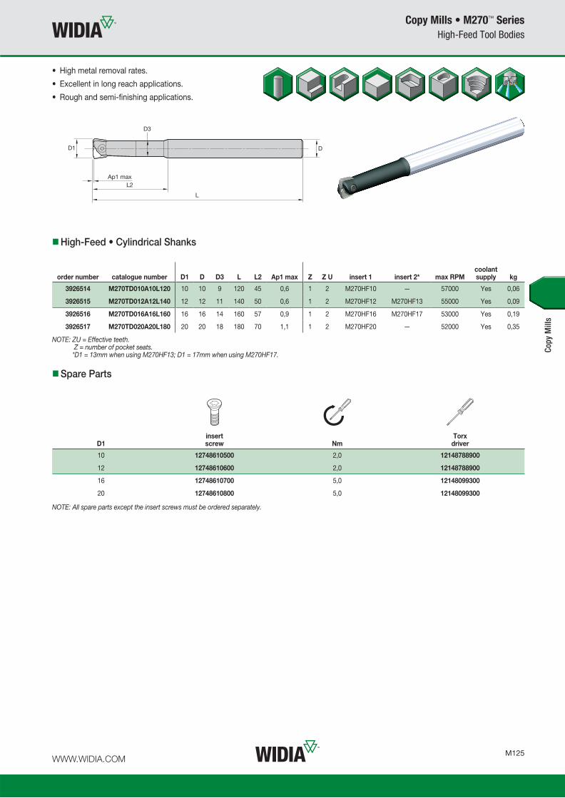
WWW.WIDIA.COM M125
Copy Mills • M270™ Series
High-Feed Tool Bodies
Spare Parts
High-Feed • Cylindrical Shanks
NOTE: ZU = Effective teeth. Z = number of pocket seats. *D1 = 13mm when using M270HF13; D1 = 17mm when using M270HF17.
order number catalogue number D1 D D3 L L2 Ap1 max Z Z U insert 1 insert 2* max RPMcoolant supply kg
3926514 M270TD010A10L120 10 10 9 120 45 0,6 1 2 M270HF10 — 57000 Yes 0,06
3926515 M270TD012A12L140 12 12 11 140 50 0,6 1 2 M270HF12 M270HF13 55000 Yes 0,09
3926516 M270TD016A16L160 16 16 14 160 57 0,9 1 2 M270HF16 M270HF17 53000 Yes 0,19
3926517 M270TD020A20L180 20 20 18 180 70 1,1 1 2 M270HF20 — 52000 Yes 0,35
• High metal removal rates.
• Excellent in long reach applications.
• Rough and semi-finishing applications.
D1insert screw Nm
Torx driver
10 12748610500 2,0 12148788900
12 12748610600 2,0 12148788900
16 12748610700 5,0 12148099300
20 12748610800 5,0 12148099300
Copy
Mill
s
NOTE: All spare parts except the insert screws must be ordered separately.

WWW.WIDIA.COM M126
Copy Mills • M270™ Series
High-Feed Tool Bodies
D1insert screw Nm
Torx driver
10 12748610500 2,0 12148788900
12 12748610600 2,0 12148788900
16 12748610700 5,0 12148099300
20 12748610800 5,0 12148099300
Spare Parts
High-Feed • Carbide Cylindrical Shanks
NOTE: ZU = Effective teeth. Z = number of pocket seats. *D1 = 13mm when using M270HF13; D1 = 17mm when using M270HF17.
order number catalogue number D1 D D3 L L2 Ap1 max Z Z U insert 1 insert 2* max RPMcoolant supply kg
3926518 M270TD010A10L120C 10 10 9 120 45 0,6 1 2 M270HF10 — 57000 Yes 0,11
3926519 M270TD010A10L150C 10 10 9 150 45 0,6 1 2 M270HF10 — 57000 Yes 0,14
3926520 M270TD012A12L120C 12 12 11 120 50 0,6 1 2 M270HF12 M270HF13 55000 Yes 0,15
3926521 M270TD012A12L160C 12 12 11 160 50 0,6 1 2 M270HF12 M270HF13 55000 Yes 0,22
3926522 M270TD016A16L140C 16 16 14 140 57 0,9 1 2 M270HF16 M270HF17 53000 Yes 0,32
3926543 M270TD016A16L180C 16 16 14 180 57 0,9 1 2 M270HF16 M270HF17 53000 Yes 0,44
3926544 M270TD020A20L150C 20 20 18 150 70 1,1 1 2 M270HF20 — 52000 Yes 0,52
3926545 M270TD020A20L200C 20 20 18 200 70 1,1 1 2 M270HF20 — 52000 Yes 0,74
Copy
Mill
s
• High metal removal rates.
• Excellent in long reach applications.
• Carbide shank for higher rigidity.
NOTE: All spare parts except the insert screws must be ordered separately.

WWW.WIDIA.COM M127
Copy Mills • M270™ Series
Inserts
Copy
Mill
s
Insert Selection Guide
MaterialGroup
LightMachining
GeneralPurpose
HeavyMachining
Geometry Grade Geometry Grade Geometry Grade
P1–P2 HF TN6525 HF TN6540 HF TN6540
P3–P4 HF TN6525 HF TN6540 HF TN6540
P5–P6 HF TN6525 HF TN6540 HF TN6540
M1–M2 HF TN6525 HF TN6540 HF TN6540
M3 HF TN6525 HF TN6540 HF TN6540
K1–K2 HF TN2505 HF TN6525 – –
K3 HF TN2505 HF TN6525 – –
N1–N2 – – – – – –
N3 – – – – – –
S1–S2 HF TN6525 HF TN6540 – –
S3 HF TN6525 HF TN6540 – –
S4 HF TN6525 HF TN6540 HF TN6540
H1 HF TN2505 HF TN2505 HF TN6525
P � � �
M � �
K � � �
N
S �
H � �
High-Feed
catalogue number W LI S RR RT hm TN25
05TN
6525
TN65
40
M270HF10 10,00 10,50 2,38 0,63 1,15 0,08
3903
944
4145
110
3903
943
M270HF12 12,00 12,40 3,18 0,75 1,40 0,08
3903
946
4145
111
3903
945
M270HF13 13,00 12,40 3,18 0,75 1,40 0,08
3903
948
4145
112
3903
947
M270HF16 16,00 16,70 4,76 1,00 1,90 0,08
3903
950
4145
123
3903
949
M270HF20 20,00 20,70 4,76 1,25 2,30 0,08
3903
954
4145
125
3903
953
NOTE: RT = Programming radius.
• High-Feed geometry for roughing and semi-fi nishing
applications at maximum feed rates.
• Exceptional stability, even when long overhang is required.
� fi rst choice
� alternate choice
M270-HF
High-Feed Inserts

WWW.WIDIA.COM M128
Copy Mills • M270™ Series
Recommended Starting Speeds
NOTE: FIRST choice starting speeds are in bold type.As the average chip thickness increases, the speed should be decreased.
Copy
Mill
s
Recommended Starting Speeds [m/min]
MaterialGroup TN2505 TN6525 TN6540
P
1 550 420 360 410 320 280 360 280 240
2 320 240 205 320 250 215 250 190 170
3 320 240 205 280 215 185 215 170 140
4 – – – 235 170 145 180 130 110
5 – – – 310 235 200 240 180 150
6 – – – 205 160 130 160 120 100
M
1 – – – 190 120 80 130 80 60
2 – – – 120 80 50 80 50 40
3 – – – 125 80 55 85 50 40
K
1 400 300 250 275 245 220 220 205 180
2 540 365 280 215 190 180 175 155 140
3 310 190 155 180 160 145 155 145 125
N
1 – – – – – – – – –
2 – – – – – – – – –
3 – – – – – – – – –
S
1 – – – – – – 50 35 30
2 – – – – – – 25 20 10
3 – – – – – – 70 40 30
4 – – – – – – 60 30 25
H
1 175 140 95 – – – – – –
2 175 140 95 – – – – – –
3 140 115 80 – – – – – –
Recommended Starting Feeds [mm]
At 0,60 Axial Depth of Cut (ap) • HF10
LightMachining
GeneralPurpose
HeavyMachining
InsertGeometry
Programmed Feed per Tooth (fz)as a % of Radial Depth of Cut (ae)
InsertGeometry5% 10% 20% 30% 40–100%
HF 1,01 1,57 – 0,67 0,97 1,41 0,48 0,69 0,97 0,42 0,59 0,83 0,38 0,54 0,75 HF
At 0,60 Axial Depth of Cut (ap) • HF12
InsertGeometry
Programmed Feed per Tooth (fz)as a % of Radial Depth of Cut (ae)
InsertGeometry5% 10% 20% 30% 40–100%
HF 0,91 1,53 2,81 0,61 0,96 1,43 0,45 0,69 0,99 0,39 0,59 0,85 0,35 0,54 0,77 HF
NOTE: Use “Light Machining” value as starting feed rate.
At 0,60 Axial Depth of Cut (ap) • HF13
InsertGeometry
Programmed Feed per Tooth (fz)as a % of Radial Depth of Cut (ae)
InsertGeometry5% 10% 20% 30% 40–100%
HF 0,94 1,58 2,82 0,64 1,00 1,49 0,46 0,71 1,03 0,40 0,61 0,88 0,37 0,56 0,80 HF
Recommended Starting Feeds

WWW.WIDIA.COM M129
Copy Mills • M270™ Series
Recommended Starting Feeds
Copy
Mill
s
Recommended Starting Feeds [mm]
At 0,90 Axial Depth of Cut (ap) • HF16
Light Machining
General Purpose
Heavy Machining
InsertGeometry
Programmed Feed per Tooth (fz)as a % of Radial Depth of Cut (ae)
InsertGeometry5% 10% 20% 30% 40–100%
HF 1,03 1,60 3,34 0,69 1,00 1,50 0,50 0,71 1,03 0,43 0,61 0,88 0,39 0,56 0,80 HF
At 0,90 Axial Depth of Cut (ap) • HF17
InsertGeometry
Programmed Feed per Tooth (fz)as a % of Radial Depth of Cut (ae)
InsertGeometry5% 10% 20% 30% 40–100%
HF 1,06 1,63 3,00 0,71 1,03 1,52 0,51 0,73 1,05 0,44 0,63 0,90 0,40 0,57 0,82 HF
NOTE: Use “Light Machining” value as starting feed rate.
At 1,10 Axial Depth of Cut (ap) • HF20
InsertGeometry
Programmed Feed per Tooth (fz)as a % of Radial Depth of Cut (ae)
InsertGeometry5% 10% 20% 30% 40–100%
HF 1,01 1,69 2,74 0,69 1,09 1,57 0,50 0,78 1,10 0,44 0,67 0,94 0,40 0,61 0,86 HF

WWW.WIDIA.COM M130
Copy Mills • M270™ Series
Additional Application Advice • M270 High-Feed
Applying High-Feed Tools
General Programming Information for Applying M270 High-Feed
Ap1 max
Rt
Recommended when long overhang is
necessary due to lower radial forces.
Maximum L/D ratio of 10 x D.
Small Ap1 values and higher
feed rate generate lower cutting
forces versus traditional milling
strategies.
For CAM programming, the tools
can be programmed as a toroidal
tool type by using the Rt value as
the insert radius.
NOTE: Use two effective teeth for feed calculations.For materials above 45 HRC, we recommend adjusting the ae max to 55% of cutting diameter and using no more than 50% of Ap1 max.While centre cutting is possible, we recommend using a ramp angle of 0.5°–1.0° to ensure smooth operation.
tool diameter Ø10 Ø12 Ø13 Ø16 Ø17 Ø20
recommended starting Ap1 (mm) 0,40 0,40 0,40 0,60 0,60 0,75
Rt CAM programming
1,15 1,40 1,40 1,90 1,90 2,30
fz recommended for general purpose
0,45 0,55 0,55 0,60 0,60 0,70
fz recommended for 45 HRC (approx.)
0,40 0,45 0,45 0,55 0,55 0,65
fz recommended for 55 HRC (approx.)
0,30 0,35 0,35 0,45 0,45 0,50
L/D ratio% of Ap1 max
to reduce% of vc
to reduce
<4 0% 0%
4<L/D<7 55–65% 10–15%
>8 65–75% 20–30%
The high-feed concept bases its strategy in small depth of cut and high fz
values, which results in a higher MRR and productivity with low radial forces.

Notes

Language Version: IndexableMilling_FPO_Cover August 17, 2015 9:08 AM
Indexable Milling ADVANCES 2017
World and Corporate HeadquartersKennametal Inc.WIDIA Products Group1600 Technology WayLatrobe, PA 15650 USAPhone: 800 446 7738 (United States and Canada) E-mail: [email protected]
European HeadquartersKennametal Europe GmbHWIDIA Products GroupRheingoldstrasse 50CH 8212 Neuhausen am RheinfallSwitzerlandPhone: +41 52 6750 100E-mail: [email protected]
Asia-Pacific HeadquartersKennametal Singapore Pte. Ltd.WIDIA Products Group3A International Business ParkUnit #01-02/03/05, ICON@IBPSingapore 609935Phone: +65 6265 9222E-mail: [email protected]
India Headquarters Kennametal India LimitedWIDIA Products GroupCIN: L27109KA1964PLC0015468/9th Mile, Tumkur RoadBangalore - 560 073Phone: +91 080 22198444 or +91 080 43281444E-mail: [email protected]
WWW.WIDIA.COM
©2015 Kennametal Inc. All rights reserved. A-15-04580EN_me