Milling Machine - IES IPS Academy
87
Milling Machine • It is a machine tool in which metal is removed by means of a revolving cutter with many teeth , each tooth having a cutting edge which removes metal from a work piece. • Cutting can be Horizontal Transversely or Vertically
-
Upload
khangminh22 -
Category
Documents
-
view
0 -
download
0
Transcript of Milling Machine - IES IPS Academy
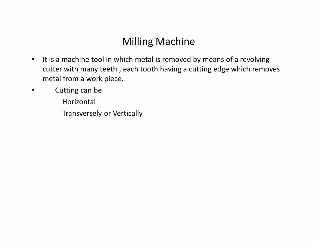
Milling Machine
• It is a machine tool in which metal is removed by means of a revolving
cutter with many teeth , each tooth having a cutting edge which removes
metal from a work piece.
• Cutting can be
Horizontal
Transversely or Vertically

Vertical


Horizontal


Classification of milling machine
• Column and knee type
• Fixed bed type
• Planer type
• Production type
• Special purpose

Classification of milling machine
1 Column and knee type
• Horizontal
• Vertical -- Vertical position of cutter spindle
• Universal -------Swivel
• Ram type Universal --- arm which slide forward and back word .cutter can be
angled

Planer type

Production type
• Rotary table
• Drum type
• Pantograph, profiling & tracer controlled
milling machine

Special purpose
• Thread type milling m/c
• Gear milling
• Planetary type

2 Manufacturing or fixed bed type :- in this vertical motion is impart to spindle or arbor instead of
table
• Simplex Spindle
• Duplex Spindle
• Triples Spindle
Rotary table milling machine:- This machine construction is a modification to
a vertical milling machine.The face milling cutters are mounted on two or
more vertical spindles and a number of workpieces are clamped on the
horizontal surface of a circular table which rotates about vertical axis.The
cutters may be set at different heights relative to the work so that when
one of the cutter is roughing the pieces the other is finishing them.


Rotary table milling machine

• Drum milling Drum milling machine
• The drum milling machine is similar to a rotary table milling machine in that work-supporting table which
is called drum and it rotates in a horizontal axis. The face milling cutters mounted on three or four spindle
heads rotate in a horizontal axis and removal metal from workpieces supported on both the faces of drum.
The finished machined parts are removed after on complete turn of the drum, and then the new ones are
clamped to it.
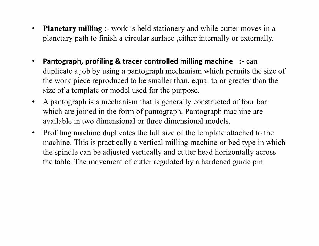
• Planetary milling :- work is held stationery and while cutter moves in a
planetary path to finish a circular surface ,either internally or externally.
• Pantograph, profiling & tracer controlled milling machine :- can
duplicate a job by using a pantograph mechanism which permits the size of
the work piece reproduced to be smaller than, equal to or greater than the
size of a template or model used for the purpose.
• A pantograph is a mechanism that is generally constructed of four bar
which are joined in the form of pantograph. Pantograph machine are
available in two dimensional or three dimensional models.
• Profiling machine duplicates the full size of the template attached to the
machine. This is practically a vertical milling machine or bed type in which
the spindle can be adjusted vertically and cutter head horizontally across
the table. The movement of cutter regulated by a hardened guide pin

Milling operation• Plain or slab milling
• Face milling
• Angular milling
• Form milling
• Straddle milling
• Gang milling
• End milling
• T slot milling
• Dove tail milling
• Saw milling
• Involutes gear cutting

Plain or slab milling It is used to machine flat and horizontal
surface

Face milling for m/c a flat surface which is at right angle to the
axis of rotation of the rotating cutter

Angular milling Angle milling cutter is used

Form milling :- the milling cutter is used has the shape of the cutting teeth
conforming to the profile of surface to be produce

Straddle milling in which a pair o side milling cutters is used for
milling two // vertical surface
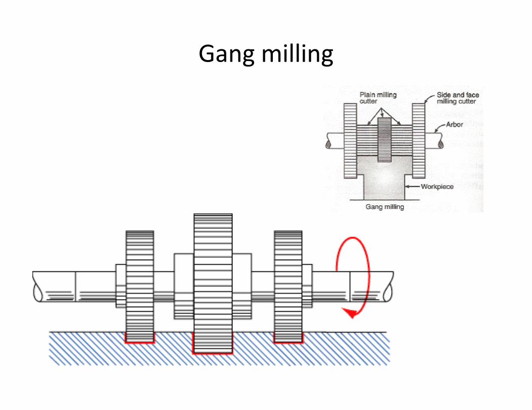
Gang milling

End milling for producing narrow slots, grooves and keyways
using end mill cutter

T slot milling

Dove tail milling

Saw milling

Involutes gear cutting end milling cutter is used which carries the profile on
its cutting teeth corresponding to the required profile of the gap between
gear teeth

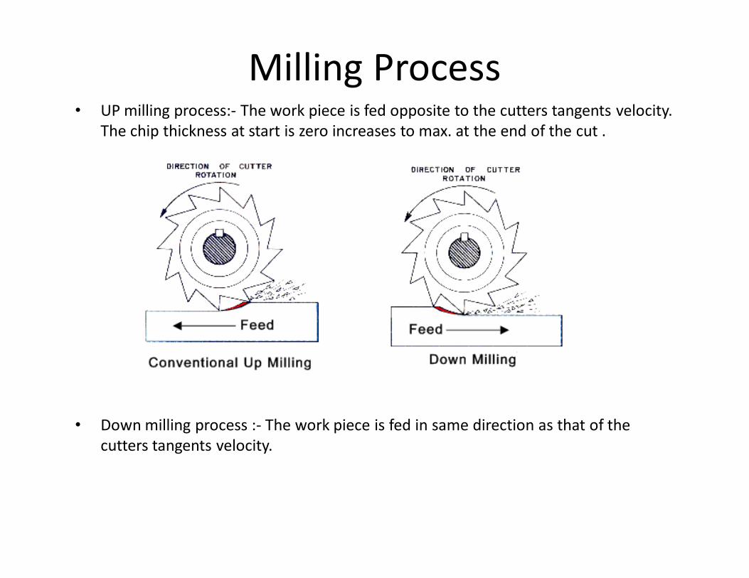
Milling Process• UP milling process:- The work piece is fed opposite to the cutters tangents velocity.
The chip thickness at start is zero increases to max. at the end of the cut .
• Down milling process :- The work piece is fed in same direction as that of the
cutters tangents velocity.

Machine size
• Dim of table in cm
• HP of driving motor
• Spindle speed
• Feed

Indexing
• Indexing is the method of dividing the periphery of a piece of work into any
number of equal parts. The attachment used for performing indexing is known as
indexing head. The indexing operation can be adapted for cutting gears, ratchet
wheels, keyways, fluted drills, taps and reamers. The indexing head serves as an
attachment for holding and indexing the work in doing the above tasks.
• There are three different types of indexing heads namely:
• 1. Plain or simple dividing head :- IT is hand operated and used for simple indexing
• 2. Universal dividing head :- IT can be done by hand or gear drive depending on
the operation
• 3. Optical dividing head.:- It is the most precision attachment and is therefore ,used
for very precision indexing .


Type of indexing
• Rapid or direct indexing :- work on small no. of division like sq.
hexagonal etc.
• Simple indexing
• Compound indexing :- when the number of division require is outside the
range that can be obtained by simple indexing use two circle of index plate
• Differential indexing :- use gear train
• Angular indexing : - it is used when to cut grooves or slot at the
centre of the circle upon which they are spaced

Compound indexing
• n1/N1 ± n2/N2
• n is no. of hole in N hole circle
• n1/N1 ± n2/N2 = 40/Ndiv.
Factor of division required X factors of difference of hole circles
------------------------------------------------------------------------------------------
Factor of 40 X factor of first hole circle N1 X factor of second hole N2
• If numerator is cancelled out therefore selection of N1 and N2 is correct


Differential indexing


Cutting speed
• Vc = Π DN/1000 m/min
• D = dia of cutter mm
• N = cutting speed in rpm
Feed f = ft .Z.N
ft feed rate per tooth
Z is number of cutting teeth of the cutter periphery


• MRR = W d f , mm3/min
W is width of cut
d = depth of cut
f = Rate of feed
• Machining timing is the time require for one
pass of width of cut for milling or machining a
surface
tm = Length of cut / Feed rate = L/f
L0 = √ (d(D-d)
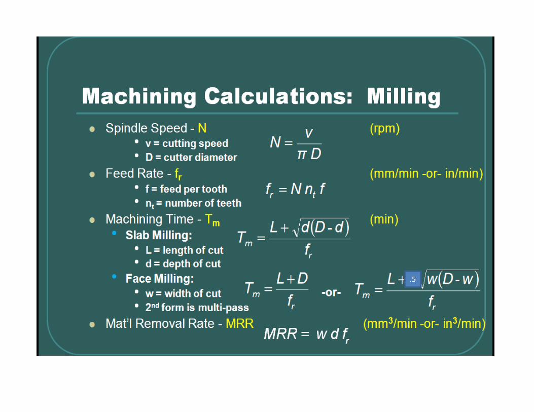
.5

Drilling • Drilling is a process of making hole or enlarge a hole in an object by facing
a rotating tool called “Drill”.
Drill is generally called ‘twisted drill’
Material used for drill Carbon steel , HSS , Carbide tipped
• Drill Machine :- A power operated machine tool which hold the drill in its
spindle rotating at high speed and when manually actuated to move linearly
simultaneously against the work piece produce a hole.
• Specification of a drill Machine
• Size of drill m/c table
• Largest bit the m/c can hold
• Max size of the work piece that can be held.
• Power of the motor, spindle speed

Various type of drill machine
• Portable drilling machine – max diameter of drill
• Sensitive or bench drilling - machine are specified by the
diameter of the diameter of largest work piece that can be
drilled
• Radial drill machine is specified by the length of arm and
column diameter.
• Multiple spindle drill machine is specified by the drill area, the
size and the number of hole a machine can drill
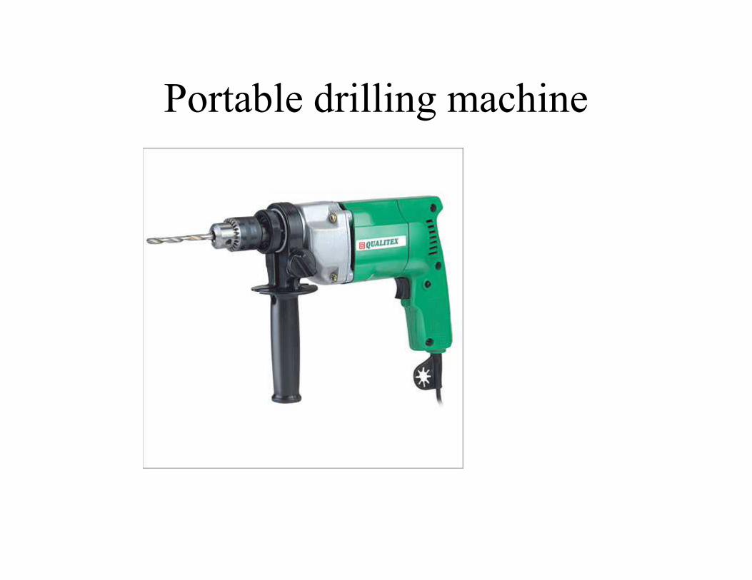
Portable drilling machine

Sensitive or bench drilling Machine light duty machine they
are usually mounted on work bench

Radial drill machine

Multiple spindle drill machine

Gang drill machine when several drill spindles
are mounted on a single table

Turret Drill machine

Deep hole drilling machine


• Axis: The imaginary straight line which forms the longitudinal center line of the drill
• Body: The portion of the drill extending from the shank or neck to the outer corners of the
cutting lips
• Body Diameter Clearance: That portion of the land that has been cut away so it will not rub
against the walls of the hole
• Chip Breaker: Nicks or Grooves designed to reduce the size of chips; they may be steps or
grooves in the cutting lip or in the leading face of the land
• Chisel Edge: The edge at the end of the web that connects the cutting lips
• Chisel Edge Angle: The angle included between the chisel edge and the cutting lip, as viewed
from the end of the drill
• Clearance: The space provided to eliminate undesirable contact between the drill and the
workpiece
• Clearance Diameter: The diameter over the the cut away portion of the drill lands
• Heel: The trailing edge of the land
• Helix Angle: The angle made by the leading edge of the land with a plane containing the axis
of the drill
• Land: The peripheral portion of the body between adjacent flutes
• Land Width: The distance between the leading edge and the heel of the land measured at a
right angle to the leading edge
• Neck: The section of reduced diameter between the body and the shank of a drill Oil Grooves:
Longitudinal straight or helical grooves in the shank, or grooves in the lands of a drill to carry
cutting fluid to the cutting lips Oil Holes

• Point angle
• 60o for wood
• 100o for soft and medium cast iron
• 118o for soft and medium hard brass and copper
• 125 o – 135 o for heat treated steel ,drop forging alloy steels, SS
• 150o for steel rails , armor plate
• Helix angle :- Large for soft material and small for hard material
• High helix drills: This drill has a high helix angle, which improves cutting
efficiency but weakens the drill body. It is used for cutting softer metals
and other low strength materials.
• Low helix drills: A lower than normal helix angle is sometimes useful to
prevent the tool from "running ahead" or "grabbing" when drilling brass
and similar materials.
•

• Crankshaft or Deep Hole Drills: Drills designed for drilling oil holes in crankshafts, connecting rods and similar deep holes; they are generally made with heavy webs and higher helix angles than normal


Spade Drill: A drill whose flutes are produced by two parallel or
tapered flats

Half-Round Drill: A drill with a transverse cross-section of approximately half a
circle and having one cutting lip

Step drill these have two or more steps (dia ) of sq or angular cutting edges
produce by grinding various steps on the dia of conventional drill. use fro
operation like counter boring ,counter sinking and chamfering
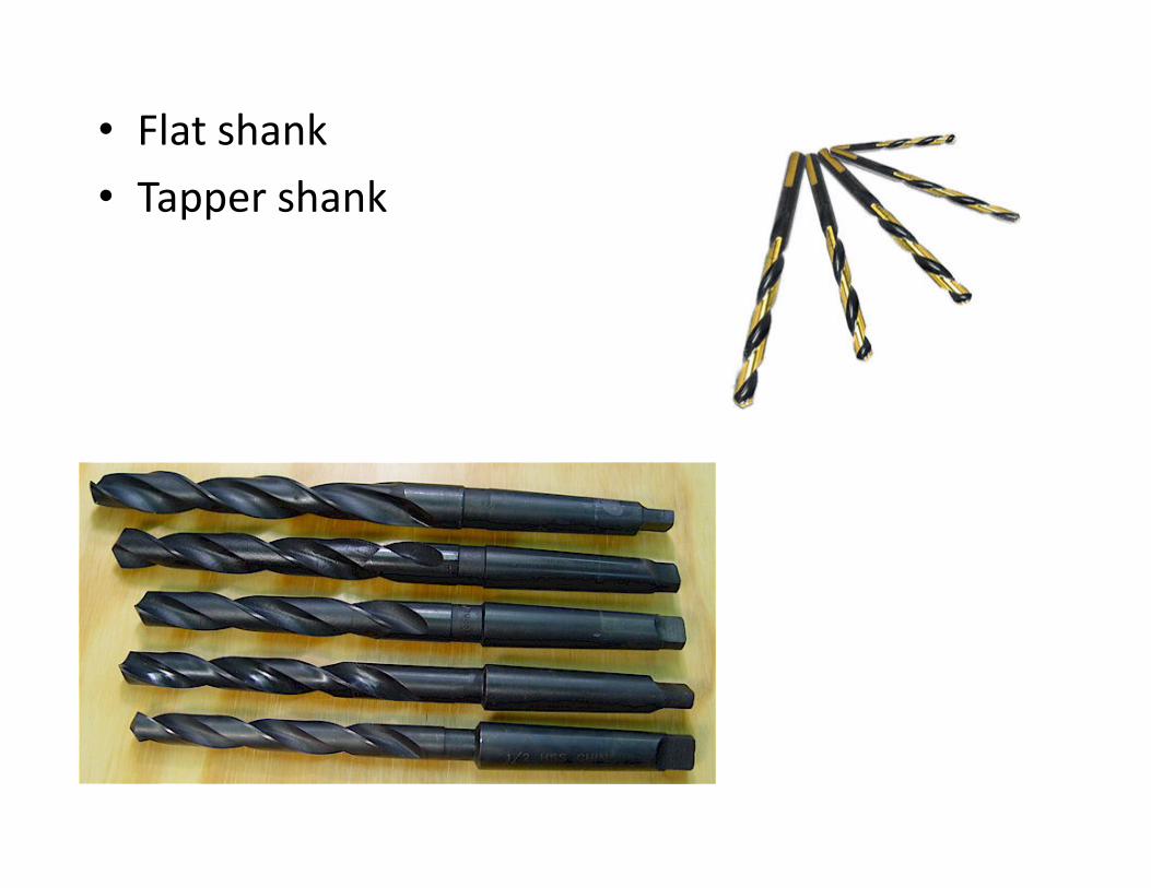
• Flat shank
• Tapper shank


Chip brakers

Drilling machine operation• Reaming :- Finishing an existing hole
• Boring :- enlarging hole
• Counter boring :- It is an operation of enlarging a drill hole partially for specific length
• Counter sinking :- it is an operation of forming a conical shape at the end of a drill hole
• Tapping :-forming thread on hole
• Trepanning :- producing hole by removing the metal along the circumference of hollow cutting tool

Reaming


Classification of drill • According to type of shank
• Parallel shank
• Taper Shank
• According to Flutes
• Flat
• Twist drill
• According to length
• Short series drill
• Stub series drill
• Long series drill
• According to application
• Core drilling A core drill is a drill specifically designed to remove a cylinder of material, much like a hole saw
• Drills for long hole
• Centre drill were originally designed to create the countersink required to locate a tailstock centre
when turning between centres.
• Masonry drill :- bits are designed for drilling into tough materials such as stone, block or concrete

Core drill

Centre drill, Flat Flutes , Short series drill


Drill holding devise

Job holding device


• SPEED V = (╥ D N ) / 1000 m/min
• Where D is in mm, N is in rev/min.
• f = FEED expressed as mm/rev.
• DEPTH OF CUT = (Drill diameter)/ 2 mm
MRR IN DRILLING OPERATION
• MRR = (╥ D^2 / 4) f N mm^3/min
MACHINING TIME IS GIVEN BY
t = L / fN min
• Where L is in mm
• f is in mm/rev
• N is in rpm

• Drilling formulas The material removal rate (MRR) in drilling is the volume
of material removed by the drill per unit time.
• For a drill with a diameter D, the cross-sectional area of the drilled hole is
πD 2 /4.
• The velocity of the drill perpendicular to the work piece f is the product of
the feed fr and the rotational speed N where N = V /π D.
• Thus, MRR = (πD 2 / 4) (f) mm3 /min
• Conversion of feedrate fr (mm/rev) to feedrate f (mm/min)
• f = N fr (mm/min)
• Power = MRR x unit power

Broaching • It is a method of removing metal by a tool that has successively higher cutting
edge in a fixed path .
Each tooth remove pre determine amount of material
Job is completed in one stroke of machine , the last tooth of cutting tool
conforming to the desired shape.
Component make by broaching are pliers , wrenches ,clutch pressure plates , gear
spline , gear sectors, rocker arm , spider spline hole key way etc

Advantage and limitation
• Both roughening and finishing operation are completed in one pass of the tool, giving a high
rate of production
• Rate of production is high
• Internal or external surface can be machined within close tolerances needed for
interchangeable mass production the accuracy of surface finish is of the order of 0.1 micron
• Broaching have exceptionally long life since each tooth of a broach passes through or over
the work only once per pass.
Limitation
• The tooling coast is very high and hence broaching process is adopted only in those place
were mass production is required.
• The broach tool is made for a particular job only and cannot be easily adopted to a range of
application
• Work piece to be broach should be rigid and strong to withstand heavy tool forces
• All the elements of the broaching surface must be parallel to the axis of the travel .


• Rake angle or face angle of the tooth depends on the material to be cut and its hardness,
toughness and ductility .
• The land of the tooth determines its strength .
• The pitch determines the length of the cut and chip thickness which a broach can handles

• Pull Broaching Workpiece is clamped to the broaching machine in stationary position and the
broach is pulled through the work. Broaches are usually long and are held in a special head.
Pull broaching is mostly used for internal broaching.
• Push Broaching Workpiece is held in the broaching machine in stationary position and
broach is pushed through the portion of workpiece to the machined. Normally push
broaching is done by hand and arbor presses (hydraulic press). This method is also
recommended for internal broaching like for sizing and finishing the holes, cavities, and key
ways
• Surface Broaching Any one of two, either workpiece or the broach (tool) is kept moving and
other is kept stationary. The method is widely used as surface finishing operation. In case of
surface broaching, the broaching tool is specifically designed for the shape to be finished.
• Continuous Broaching In continuous broaching the broach is held stationary in the broaching
machine and workpiece is moved continuously. The teeth of movement of the workpiece
may be either straight, horizontal or circular. This is generally used for broaching a large
number of similar workpieces at a time

• Working principle can be criteria of classification of broaching machine as
described below :
(a) Hydraulic broaching machine
(b) Mechanical broaching machine
(C) Pneumatic broaching machine
• Construction of a broaching machine can also be another criteria of classification
like :
(a) Vertical broaching machine
(b) Horizontal broaching machine
• Application of a broaching machine can also be criteria of classification of a
broaching machine :
(a) internal broaching machine
(b) external broaching machine