Stress and Strain - IES Academy
39
1. Stress and Strain Theory at a Glance (for IES, GATE, PSU) 1.1 Stress (σ) When a material is subjected to an external force, a resisting force is set up within the component. The internal resistance force per unit area acting on a material or intensity of the forces distributed over a given section is called the stress at a point. It uses original cross section area of the specimen and also known as engineering stress or conventional stress. Therefore, s = P A P is expressed in Newton (N) and A, original area, in square meters (m 2 ), the stress σ will be expresses in N/ m 2 . This unit is called Pascal (Pa). As Pascal is a small quantity, in practice, multiples of this unit is used. 1 kPa = 10 3 Pa = 10 3 N/ m 2 (kPa = Kilo Pascal) 1 MPa = 10 6 Pa = 10 6 N/ m 2 = 1 N/mm 2 (MPa = Mega Pascal) 1 GPa = 10 9 Pa = 10 9 N/ m 2 (GPa = Giga Pascal) Let us take an example: A rod 10 mm ´ 10 mm cross-section is carrying an axial tensile load 10 kN. In this rod the tensile stress developed is given by () ( ) s ´ = = = = = ´ 3 2 2 10 kN 10 10 N 100 N/mm 100 MPa 10mm 10mm 100 mm t P A The resultant of the internal forces for an axially loaded member is normal to a section cut perpendicular to the member axis. The force intensity on the shown section is defined as the normal stress. s s D ® D = = D 0 lim and avg A F P A A Tensile stress (σt) If σ > 0 the stress is tensile. i.e. The fibres of the component tend to elongate due to the external force. A member subjected to an external force tensile P and tensile stress distribution due to the force is shown in the given figure.
-
Upload
khangminh22 -
Category
Documents
-
view
1 -
download
0
Transcript of Stress and Strain - IES Academy

1. Stress and Strain
Theory at a Glance (for IES, GATE, PSU)
1.1 Stress (σ) When a material is subjected to an external force, a resisting force is set up within the component.
The internal resistance force per unit area acting on a material or intensity of the forces distributed
over a given section is called the stress at a point.
It uses original cross section area of the specimen and also known as engineering stress or
conventional stress.
Therefore, s =P
A
P is expressed in Newton (N) and A, original area, in square meters (m2), the stress σ will be
expresses in N/ m2. This unit is called Pascal (Pa).
As Pascal is a small quantity, in practice, multiples of this unit is used.
1 kPa = 103 Pa = 103 N/ m2 (kPa = Kilo Pascal)
1 MPa = 106 Pa = 106 N/ m2 = 1 N/mm2 (MPa = Mega Pascal)
1 GPa = 109 Pa = 109 N/ m2 (GPa = Giga Pascal)
Let us take an example: A rod 10 mm ´ 10 mm cross-section is carrying an axial tensile load 10
kN. In this rod the tensile stress developed is given by
( )( )
s´
= = = = =´
32
2
10 kN 10 10 N100 N/mm 100 MPa
10mm 10mm 100 mmt
P
A
The resultant of the internal forces for an axially loaded member is
normal to a section cut perpendicular to the member axis.
The force intensity on the shown section is defined as the normal stress.
s sD ®
D= =
D0lim and
avgA
F P
A A
Tensile stress (σt)
If σ > 0 the stress is tensile. i.e. The fibres of the component
tend to elongate due to the external force. A member
subjected to an external force tensile P and tensile stress
distribution due to the force is shown in the given figure.

India’s No. 1 Stress and Strain
IES Academy Chapter 1
www.iesacademy.com Email: [email protected] Page-2
28-B/7, 2nd, Jia Sarai, Near IIT. New Delhi-16 Ph: 011-26537570, 9810958290
Compressive stress (σc)
If σ < 0 the stress is compressive. i.e. The fibres of the
component tend to shorten due to the external force. A
member subjected to an external compressive force P and
compressive stress distribution due to the force is shown in
the given figure.
Shear stress ( t )
When forces are transmitted from one part of a body to other, the stresses
developed in a plane parallel to the applied force are the shear stress. Shear
stress acts parallel to plane of interest. Forces P is applied
transversely to the member AB as shown. The corresponding
internal forces act in the plane of section C and are called shearing
forces. The corresponding average shear stress ( )t =Area
P
1.2 Strain (ε)
The displacement per unit length (dimensionless) is
known as strain.
Tensile strain (εt)
The elongation per unit length as shown in the
figure is known as tensile strain.
εt = ΔL/ Lo
It is engineering strain or conventional strain.
Here we divide the elongation to original length
not actual length (Lo + D L)
Let us take an example: A rod 100 mm in original length. When we apply an axial tensile load 10
kN the final length of the rod after application of the load is 100.1 mm. So in this rod tensile strain is
developed and is given by
( )e-D -
= = = = =100.1mm 100mm 0.1mm
0.001 (Dimensionless)Tensile100mm 100mm
o
t
o o
L LL
L L

India’s No. 1 Stress and Strain
IES Academy Chapter 1
www.iesacademy.com Email: [email protected] Page-3
28-B/7, 2nd, Jia Sarai, Near IIT. New Delhi-16 Ph: 011-26537570, 9810958290
Compressive strain (εc)
If the applied force is compressive then the reduction of length per unit length is known as
compressive strain. It is negative. Then εc = (–ΔL)/ Lo
Let us take an example: A rod 100 mm in original length. When we apply an axial compressive
load 10 kN the final length of the rod after application of the load is 99 mm. So in this rod a
compressive strain is developed and is given by
( )e-D - -
= = = = = -99mm 100mm 1mm
0.01 (Dimensionless)compressive100mm 100mm
o
c
o o
L LL
L L
Shear Strain ( g ): When a force P is
applied tangentially to the element
shown. Its edge displaced to dotted
l i n e . W h e r e d i s t h e l a t e r a l
displacement of the upper face of the
element relative to the lower face and L is the distance between these faces. Then the shear
strain is d
g =( )L
Let us take an example: A block 100 mm × 100 mm base and 10 mm height. When we apply a
tangential force 10 kN to the upper edge it is displaced 1 mm relative to lower face.
Then the direct shear stress in the element
t´
= = = =´ ´
3210kN 10 10 N
( ) 1 N/mm 1 MPa100mm 100mm 100mm 100mm
And shear strain in the element ( g ) = = =1mm
0.110mm
Dimensionless
1.3 True stress and True Strain
The true stress is defined as the ratio of the load to the cross section area at any instant.
( ) ( )s s e= = +load
1Instantaneous area
T
Where and is the engineering stress and engineering strain respectively.
True strain
s e

India’s No. 1 Stress and Strain
IES Academy Chapter 1
www.iesacademy.com Email: [email protected] Page-4
28-B/7, 2nd, Jia Sarai, Near IIT. New Delhi-16 Ph: 011-26537570, 9810958290
( ) ( )e eæ ö æ ö æ ö÷ç ÷ ÷ç ç÷ ÷ ÷= = = + = =ç ç ç÷ ÷ ÷ç ç ç÷ ÷ç ç÷ç è ø è øè ø
ò ln ln 1 ln 2ln
o
L
o o
T
oL
A ddl L
l L A d
or engineering strain ( ) = Tee-1
The volume of the specimen is assumed to be constant during plastic deformation. [
=Q ]o o
A L AL It is valid till the neck formation.
Comparison of engineering and the true stress-strain curves shown below:
The true stress-strain curve is also known as
the flow curve.
True stress-strain curve gives a true indication
of deformation characteristics because it is
based on the instantaneous dimension of
the specimen.
In engineering stress-strain curve, stress drops
down after necking since it is based on the
original area.
In true stress-strain curve, the stress however increases after necking since the cross-
sectional area of the specimen decreases rapidly after necking.
Let us take two examples:
(I.) Only elongation no neck formation
In the tension test of a rod shown initially it was Ao
= 50 mm2 and Lo = 100 mm. After the application of
load it’s A = 40 mm2 and L = 125 mm.
Determine the true strain using changes in both
length and area.
Answer: First of all we have to check that does the
member forms neck or not? For that check
o oA L AL or not?
Here 50 × 100 = 40 × 125 so no neck formation is
there. Therefore true strain
(If no neck formation
occurs both area and
gauge length can be used
for a strain calculation.)
e

India’s No. 1 Stress and Strain
IES Academy Chapter 1
www.iesacademy.com Email: [email protected] Page-5
28-B/7, 2nd, Jia Sarai, Near IIT. New Delhi-16 Ph: 011-26537570, 9810958290
( )eæ ö÷ç= = =÷ç ÷÷çè øò125
ln 0.223100
o
L
T
L
dl
l
( )eæ ö æ ö÷ ÷ç ç÷= = =÷ç ç÷ ÷ç ÷ç÷ç è øè ø
50ln ln 0.223
40
o
T
A
A
(II.) Elongation with neck formation
A ductile material is tested such and necking
occurs then the final gauge length is L = 140 mm
and the final minimum cross sectional area is A =
35 mm2. Though the rod shown initially it was Ao =
50 mm2 and Lo = 100 mm. Determine the true
strain using changes in both length and area.
Answer: First of all we have to check that does the
member forms neck or not? For that check
=o oA L AL or not?
Here AoLo = 50 × 100 = 5000 mm3 and AL=35 × 140
= 4200 mm3. So neck formation is there. Note here
AoLo > AL.
Therefore true strain
( )eæ ö æ ö÷ ÷ç ç÷= = =÷ç ç÷ ÷ç ÷ç÷ç è øè ø
50ln ln 0.357
35
o
T
A
A
But not ( )eæ ö÷ç= = =÷ç ÷÷çè øò140
ln 0.336100
o
L
T
L
dl
l (it is wrong)
(After necking, gauge
length gives error but
area and diameter can be
used for the calculation of
true strain at fracture
and before fracture also.)
1.4 Hook’s law
According to Hook’s law the stress is directly proportional to strain i.e. normal stress (σ) a normal
strain (ε) and shearing stress ( t ) a shearing strain ( g ).
σ = Eε and t g= G
The co-efficient E is called the modulus of elasticity i.e. its resistance to elastic strain. The co-
efficient G is called the shear modulus of elasticity or modulus of rigidity.

India’s No. 1 Stress and Strain
IES Academy Chapter 1
www.iesacademy.com Email: [email protected] Page-6
28-B/7, 2nd, Jia Sarai, Near IIT. New Delhi-16 Ph: 011-26537570, 9810958290
1.5 Volumetric strain (εv)
A relationship similar to that for length changes holds for three-dimensional (volume) change. For
volumetric strain ( )ev
, the relationship is ( )ev
= (V-V0)/V0 or ( )e = D =0
/v
PV V
K
Where V is the final volume, V0 is the original volume, and ΔV is the volume change.
Volumetric strain is a ratio of values with the same units, so it also is a dimensionless
quantity.
ΔV/V= volumetric strain = εx +εy + εz = ε1 +ε2 + ε3
Dilation: The hydrostatic component of the total stress contributes to deformation by
changing the area (or volume, in three dimensions) of an object. Area or volume change is
called dilation and is positive or negative, as the volume increases or decreases,
respectively. =p
eK
where p is pressure.
1.6 Young’s modulus or Modulus of elasticity (E) = Î
PL σ=
Aδ
1.7 Modulus of rigidity or Shear modulus of elasticity (G) =t
g=
TL
Jq
1.8 Bulk Modulus or Volume modulus of elasticity (K) =D D
- =D D
p p
v R
v R
1.10 Relationship between the elastic constants E, G, K, µ
( ) ( )m m= + = - =+
92 1 3 1 2
3
KGE G K
K G [VIMP]
Where K = Bulk Modulus, m= Poisson’s Ratio, E= Young’s modulus, G= Modulus of rigidity
For a linearly elastic, isotropic and homogeneous material, the number of elastic constants
required to relate stress and strain is two. i.e. any two of the four must be known.
If the material is non-isotropic (i.e. anisotropic), then the elastic moduli will vary with
additional stresses appearing since there is a coupling between shear stresses and normal
stresses for an anisotropic material.

India’s No. 1 Stress and Strain
IES Academy Chapter 1
www.iesacademy.com Email: [email protected] Page-7
28-B/7, 2nd, Jia Sarai, Near IIT. New Delhi-16 Ph: 011-26537570, 9810958290
Let us take an example: The modulus of elasticity and rigidity of a material are 200 GPa and 80
GPa, respectively. Find all other elastic modulus.
Answer: Using the relation ( ) ( )m m= + = - =+
92 1 3 1 2
3
KGE G K
K G we may find all other elastic
modulus easily
Poisson’s Ratio m m m+ = Þ = - = - =´
200( ) : 1 1 1 0.25
2 2 2 80
E E
G G
Bulk Modulus (K) : ( ) ( )m m
= Þ = = =- - - ´
2003 133.33GPa
1 2 3 1 2 3 1 2 0.25
E EK K
1.11 Poisson’s Ratio (µ)
- Î
= =Î
y
x
Transverse strainor lateral strain
Longitudinal strain
(Under unidirectional stress in x-direction)
The theory of isotropic elasticity allows Poisson's ratios in the range from –1 to 1/2.
Poisson's ratio in various materials
Material Poisson's ratio Material Poisson's ratio
Steel 0.25 – 0.33 Rubber 0.48 – 0.5
C.I 0.23 – 0.27 Cork Nearly zero
Concrete 0.2 Novel foam negative
We use cork in a bottle as the cork easily inserted and removed, yet it also withstand the
pressure from within the bottle. Cork with a Poisson's ratio of nearly zero, is ideal in this
application.
1.12 Elongation
A prismatic bar loaded in tension by an axial force P
For a prismatic bar loaded in tension by
an axial force P. The elongation of the bar
can be determined as

India’s No. 1 Stress and Strain
IES Academy Chapter 1
www.iesacademy.com Email: [email protected] Page-8
28-B/7, 2nd, Jia Sarai, Near IIT. New Delhi-16 Ph: 011-26537570, 9810958290
d =PL
AE
Let us take an example: A Mild Steel wire 5 mm in diameter and 1 m long. If the wire is subjected
to an axial tensile load 10 kN find its extension of the rod. (E = 200 GPa)
Answer: ( )d =We know that PL
AE
( )pp -
= = ´
=
´= = = ´
22
2 5 2
Here given, Force(P) 10 10 1000N
Length(L) 1 m
0.005Area(A) m 1.963 10 m
4 4
kN
d
( )
( ) ( )
9 2
3
5 9
Modulous of Elasticity ( ) 200 200 10 N/m
10 1000 1Therefore Elongation( ) m 2.55 10 m 2.55 mm
1.963 10 200 10
E GPa
PL
AEd -
-
= = ´
´ ´= = = ´ =
´ ´ ´
Elongation of composite body
Elongation of a bar of varying cross section A1, A2,----------,An of lengths l1, l2,--------ln respectively.
dé ùê ú= + + - - - - - - - +ê úë û
31 2 n
1 2 3 n
ll l lP
E A A A A
Let us take an example: A composite rod is 1000 mm long, its two ends are 40 mm2 and 30 mm2 in
area and length are 300 mm and 200 mm respectively. The middle portion of the rod is 20 mm2 in
area and 500 mm long. If the rod is subjected to an axial tensile load of 1000 N, find its total
elongation. (E = 200 GPa).
Answer: Consider the following figure
Given, Load (P) =1000 N
Area; (A1) = 40 mm2, A2 = 20 mm2, A3 = 30 mm2
Length; (l1) = 300 mm, l2 = 500 mm, l3 = 200 mm
E = 200 GPa = 200 109 N/m2 = 200 103 N/mm2
Therefore Total extension of the rod
India’s No. 1 Stress and Strain
IES Academy Chapter 1
www.iesacademy.com Email: [email protected] Page-9
28-B/7, 2nd, Jia Sarai, Near IIT. New Delhi-16 Ph: 011-26537570, 9810958290
dé ù é ùê ú ê ú= + + = ´ + + =ê ú ê ú´ ë ûë û
31 2
3 2 2 2 2
1 2 3
1000 300mm 500mm 200mm0.196mm
200 10 N/mm 40mm 20mm 30mm
ll lP N
E A A A
Elongation of a tapered body
Elongation of a tapering rod of length ‘L’ due to load ‘P’ at the end
1 2
4PL
Ed d (d1 and d2 are the diameters of smaller & larger ends)
You may remember this in this way, dp
=æ ö÷ç ÷ç ÷÷çè ø
1 2
. .
4eq
PL PLi e
EAE d d
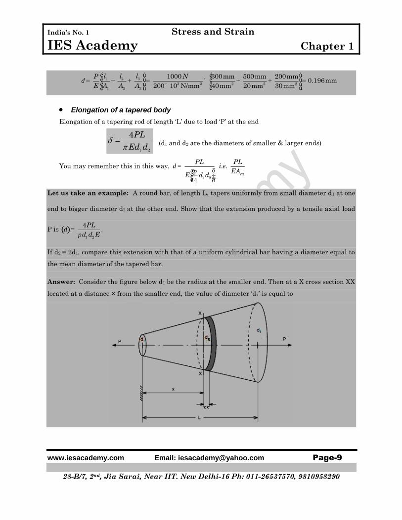
Let us take an example: A round bar, of length L, tapers uniformly from small diameter d1 at one
end to bigger diameter d2 at the other end. Show that the extension produced by a tensile axial load
P is ( )dp
=1 2
4.
PL
d d E
If d2 = 2d1, compare this extension with that of a uniform cylindrical bar having a diameter equal to
the mean diameter of the tapered bar.
Answer: Consider the figure below d1 be the radius at the smaller end. Then at a X cross section XX
located at a distance × from the smaller end, the value of diameter ‘dx’ is equal to

India’s No. 1 Stress and Strain
IES Academy Chapter 1
www.iesacademy.com Email: [email protected] Page-10
28-B/7, 2nd, Jia Sarai, Near IIT. New Delhi-16 Ph: 011-26537570, 9810958290
( ) ( )
æ ö÷ç= + - ÷ç ÷ç ÷è ø
-= + - = + = ´
1 2 1
2 1
1 2 1 1
1
2 2 2 2
1or 1 where
x
x
d d d dx
L
d dxd d d d d kx k
L L d
( )( ){ }
dp p
= = =æ ö +÷ç ÷́ç ÷ç ÷çè ø
22
1
We now taking a small strip of diameter ' 'and length ' 'at section .
Elongation of this section ' ' length
. 4 .
. 1
4
x x
x
x
d d XX
d
PL P dx P dxd
AE d d kx EE
( )( )
d dpp
=
=
= = =+
ò ò 221 20 1
Therefore total elongation of the taper bar
4 4
1
x L
x
P dx PLd
E d dEd kx
Comparison: Case-I: Where d2 = 2d1
Elongation 2
1 1 1
4 2
2I
PL PL
Ed d Ed
Case –II: Where we use Mean diameter
1 2 1 1
1
2 3
2 2 2m
d d d dd d
+ += = =
( )2 2
1
1
. 16Elongation of such bar
93.
4 2
Extension of taper bar 2 9
16Extension of uniform bar 8
9
II
PL P L PL
AE Edd E
dpp
= = =æ ö÷ç ÷ç ÷÷çè ø
= =
Elongation of a body due to its self weight
(i) Elongation of a uniform rod of length ‘L’ due to its own weight ‘W’
2
WL
AE
The deformation of a bar under its own weight as compared to that when subjected to
a direct axial load equal to its own weight will be half.
(ii) Total extension produced in rod of length ‘L’ due to its own weight ‘ w ’ per with

India’s No. 1 Stress and Strain
IES Academy Chapter 1
www.iesacademy.com Email: [email protected] Page-11
28-B/7, 2nd, Jia Sarai, Near IIT. New Delhi-16 Ph: 011-26537570, 9810958290
length w
d =2
2
L
EA
(iii) Elongation of a conical bar due to its self weight
r
d = =2
max6 2
gL WL
E A E
1.13 Thermal or Temperature stress and strain
When a material undergoes a change in temperature, it either elongates or contracts
depending upon whether temperature is increased or decreased of the material.
If the elongation or contraction is not restricted, i. e. free then the material does not
experience any stress despite the fact that it undergoes a strain.
The strain due to temperature change is called thermal strain and is expressed as,
T
Where α is co-efficient of thermal expansion, a material property, and ΔT is the change in
temperature.
The free expansion or contraction of materials, when restrained induces stress in the
material and it is referred to as thermal stress.
t E T Where, E = Modulus of elasticity
Thermal stress produces the same effect in the material similar to that of mechanical
stress. A compressive stress will produce in the material with increase in temperature
and the stress developed is tensile stress with decrease in temperature.
Let us take an example: A rod consists of two parts that are made of steel and copper as shown in
figure below. The elastic modulus and coefficient of thermal expansion for steel are 200 GPa and 11.7
× 10-6 per °C respectively and for copper 70 GPa and 21.6 × 10⁻⁶ per °C respectively. If the
temperature of the rod is raised by 50°C, determine the forces and stresses acting on the rod.

India’s No. 1 Stress and Strain
IES Academy Chapter 1
www.iesacademy.com Email: [email protected] Page-12
28-B/7, 2nd, Jia Sarai, Near IIT. New Delhi-16 Ph: 011-26537570, 9810958290
Answer: If we allow this rod to freely expand then free expansion
( )
( ) ( )
( )
d a
- -
= D
= ´ ´ ´ + ´ ´ ´
=
6 611.7 10 50 500 21.6 10 50 750
1.1025 mm Compressive
TT L
But according to diagram only free expansion is 0.4 mm.
Therefore restrained deflection of rod =1.1025 mm – 0.4 mm = 0.7025 mm
Let us assume the force required to make their elongation vanish be P which is the reaction force at
the ends.
( ) ( ) ( ) ( )
d
p p
æ ö æ ö÷ ÷ç ç= +÷ ÷ç ç÷ ÷÷ ÷ç çè ø è ø
´ ´= +ì ü ì üï ï ï ïï ï ï ï´ ´ ´ ´ ´ ´í ý í ýï ï ï ïï ï ï ïî þ î þ
=
2 29 9
500 750or 0.7025
0.075 200 10 0.050 70 104 4
or 116.6 kN
Steel Cu
PL PL
AE AE
P P
P
Therefore, compressive stress on steel rod
( )s
p
´= = =
´
32
2
116.6 10N/m 26.39 MPa
0.0754
Steel
Steel
P
A
And compressive stress on copper rod
( )s
p
´= = =
´
32
2
116.6 10N/m 59.38 MPa
0.0504
Cu
Cu
P
A
1.14 Thermal stress on Brass and Mild steel combination
A brass rod placed within a steel tube of exactly same length. The assembly is making in such a
way that elongation of the combination will be same. To calculate the stress induced in the brass
rod, steel tube when the combination is raised by t°C then the following analogy have to do.

India’s No. 1 Stress and Strain
IES Academy Chapter 1
www.iesacademy.com Email: [email protected] Page-13
28-B/7, 2nd, Jia Sarai, Near IIT. New Delhi-16 Ph: 011-26537570, 9810958290
(a) Original bar before heating.
(b) Expanded position if the members are allowed to
expand freely and independently after heating.
(c) Expanded position of the compound bar i.e. final
position after heating.
Compatibility Equation:
d d d d d= + = -st sf Bt Bf
Equilibrium Equation:
s s=s s B BA A
Assumption:
a a
=
>
-
-
s1. L = L
2.
3. Steel Tension
Brass Compression
B
b s
L
Where, = Expansion of the compound bar = AD in the above figure.
dst
= Free expansion of the steel tube due to temperature rise toC = s L t
= AB in the above figure.
sfd = Expansion of the steel tube due to internal force developed by the unequal expansion.
= BD in the above figure.
dBt
= Free expansion of the brass rod due to temperature rise t°C = ab
L t
= AC in the above figure.
Bfd = Compression of the brass rod due to internal force developed by the unequal expansion.
= BD in the above figure.
And in the equilibrium equation
Tensile force in the steel tube = Compressive force in the brass rod
Where, s = Tensile stress developed in the steel tube.
B = Compressive stress developed in the brass rod.
sA = Cross section area of the steel tube.
BA = Cross section area of the brass rod.

India’s No. 1 Stress and Strain
IES Academy Chapter 1
www.iesacademy.com Email: [email protected] Page-14
28-B/7, 2nd, Jia Sarai, Near IIT. New Delhi-16 Ph: 011-26537570, 9810958290
Let us take an example: See the Conventional Question Answer section of this chapter and the
question is “Conventional Question IES-2008” and it’s answer.
1.15 Creep
When a member is subjected to a constant load over a long period of time it undergoes a slow
permanent deformation and this is termed as “creep”. This is dependent on temperature. Usually at
elevated temperatures creep is high.
The materials have its own different melting point; each will creep when the homologous
temperature > 0.5. Homologous temp = Testing temperature
Melting temperature > 0.5
A typical creep curve shows three distinct stages
with different creep rates. After an initial rapid
elongation εo, the creep rate decrease with time
until reaching the steady state.
1) Primary creep is a period of transient creep.
The creep resistance of the material increases
due to material deformation.
2) Secondary creep provides a nearly constant
creep rate. The average value of the creep rate
during this period is called the minimum creep
rate. A stage of balance between competing.
Strain hardening and recovery (softening) of the material.
3) Tertiary creep shows a rapid increase in the creep rate due to effectively reduced cross-
sectional area of the specimen leading to creep rupture or failure. In this stage intergranular
cracking and/or formation of voids and cavities occur.
1.16 If a load P is applied suddenly to a bar then the stress & strain induced will be double
than those obtained by an equal load applied gradually.

India’s No. 1 Stress and Strain
IES Academy Chapter 1
www.iesacademy.com Email: [email protected] Page-15
28-B/7, 2nd, Jia Sarai, Near IIT. New Delhi-16 Ph: 011-26537570, 9810958290
Impact Stresses:
1.17 Stress produced by a load P in falling from height ’h’
s s
üé ùïïïê ú= + + ýê úïÎê úïë ûïþ
Î
21 1 σ,
being stress & strain produced by static load P & L=length of bar.
d
h
L
é ùê ú= + +ê úê úë û
21 1
A AEh
P PL
1.18 Loads shared by the materials of a compound bar made of bars x & y due to load W,
. and .y yx x
x y
x x y y x x y y
A EA EP W P W
A E A E A E A E= =
+ +
1.19 Elongation of a compound bar, x x y y
PL
A E A E
1.20 Tension Test
i) True elastic limit: based on micro-strain measurement at strains on order of 2 × 10⁻⁶. Very low
value and is related to the motion of a few hundred dislocations.
ii) Proportional limit: the highest stress at which stress is directly proportional to strain.
iii) Elastic limit: is the greatest stress the material can withstand without any measurable
permanent strain after unloading. Elastic limit > proportional limit.

India’s No. 1 Stress and Strain
IES Academy Chapter 1
www.iesacademy.com Email: [email protected] Page-16
28-B/7, 2nd, Jia Sarai, Near IIT. New Delhi-16 Ph: 011-26537570, 9810958290
iv) Yield strength is the stress required to produce a small specific amount of
deformation. The offset yield strength can be determined by the stress
corresponding to the intersection of the stress-strain curve and a line
parallel to the elastic line offset by a strain of 0.2 or 0.1%. ( = 0.002 or
0.001).
The offset yield stress is referred to proof stress either at 0.1 or 0.5% strain used for design
and specification purposes to avoid the practical difficulties of measuring the elastic limit or
proportional limit.
v) Tensile strength or ultimate tensile strength (UTS) u
is the maximum load Pmax divided
by the original cross-sectional area Ao of the specimen.
vi) % Elongation, ,f o
o
L L
L
is chiefly influenced by uniform elongation, which is dependent on the
strain-hardening capacity of the material.
vii) Reduction of Area: o f
o
A Aq
A
Reduction of area is more a measure of the deformation required to produce failure and
its chief contribution results from the necking process.
Because of the complicated state of stress state in the neck, values of reduction of area
are dependent on specimen geometry, and deformation behaviour, and they should not be
taken as true material properties.
RA is the most structure-sensitive ductility parameter and is useful in detecting quality
changes in the materials.
viii) Stress-strain response

India’s No. 1 Stress and Strain
IES Academy Chapter 1
www.iesacademy.com Email: [email protected] Page-17
28-B/7, 2nd, Jia Sarai, Near IIT. New Delhi-16 Ph: 011-26537570, 9810958290
1.21 Elastic strain and Plastic strain
The strain present in the material after unloading is called the residual strain or plastic strain
and the strain disappears during unloading is termed as recoverable or elastic strain.
Equation of the straight line CB is given by
total Plastic ElasticE E E
Carefully observe the following figures and understand which one is Elastic strain and which one is
Plastic strain
Let us take an example: A 10 mm diameter tensile specimen has a 50 mm gauge length. The load
corresponding to the 0.2% offset is 55 kN and the maximum load is 70 kN. Fracture occurs at 60 kN.
The diameter after fracture is 8 mm and the gauge length at fracture is 65 mm. Calculate the
following properties of the material from the tension test.
(i) % Elongation
(ii) Reduction of Area (RA) %
(iii) Tensile strength or ultimate tensile strength (UTS)
(iv) Yield strength
(v) Fracture strength
(vi) If E = 200 GPa, the elastic recoverable strain at maximum load
(vii) If the elongation at maximum load (the uniform elongation) is 20%, what is the plastic strain
at maximum load?
India’s No. 1 Stress and Strain
IES Academy Chapter 1
www.iesacademy.com Email: [email protected] Page-18
28-B/7, 2nd, Jia Sarai, Near IIT. New Delhi-16 Ph: 011-26537570, 9810958290
Answer: Given, Original area 2 2 5 2
00.010 m 7.854 10 m
4A
Area at fracture 2 2 5 20.008 m 5.027 10 m
4f
A
Original gauge length (L0) = 50 mm
Gauge length at fracture (L) = 65 mm
Therefore
(i) % Elongation 0
0
65 50100% 100 30%
50
L L
L
(ii) Reduction of area (RA) = 0
0
7.854 5.027100% 100% 36%
7.854
fA A
qA
(iii) Tensile strength or Ultimate tensile strength (UTS), 3
2
5
70 10N/m 891 MPa
7.854 10
max
u
o
P
A
(iv) Yield strength 3
2
5
55 10N/m 700 MPa
7.854 10
y
y
o
P
A
(v) Fracture strength 3
2
5
60 10N/m 764 MPa
7.854 10
Fracture
F
o
P
A
(vi) Elastic recoverable strain at maximum load 6
max
9
/ 891 100.0045
200 10
o
E
P A
E
(vii) Plastic strain 0.2000 0.0045 0.1955P total E
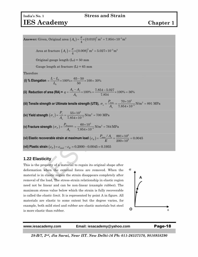
1.22 Elasticity
This is the property of a material to regain its original shape after
deformation when the external forces are removed. When the
material is in elastic region the strain disappears completely after
removal of the load, The stress-strain relationship in elastic region
need not be linear and can be non-linear (example rubber). The
maximum stress value below which the strain is fully recoverable
is called the elastic limit. It is represented by point A in figure. All
materials are elastic to some extent but the degree varies, for
example, both mild steel and rubber are elastic materials but steel
is more elastic than rubber.

India’s No. 1 Stress and Strain
IES Academy Chapter 1
www.iesacademy.com Email: [email protected] Page-19
28-B/7, 2nd, Jia Sarai, Near IIT. New Delhi-16 Ph: 011-26537570, 9810958290
1.23 Plasticity
When the stress in the material exceeds the elastic limit, the
material enters into plastic phase where the strain can no longer
be completely removed. Under plastic conditions materials ideally
deform without any increase in stress. A typical stress strain
diagram for an elastic-perfectly plastic material is shown in the
figure. Mises-Henky criterion gives a good starting point for
plasticity analysis.
1.24 Strain hardening
If the material is reloaded from point C, it will follow the previous
unloading path and line CB becomes its new elastic region with
elastic limit defined by point B. Though the new elastic region CB
resembles that of the initial elastic region OA, the internal
structure of the material in the new state has changed. The
change in the microstructure of the material is clear from the fact
that the ductility of the material has come down due to strain
hardening. When the material is reloaded, it follows the same path
as that of a virgin material and fails on reaching the ultimate
strength which remains unaltered due to the intermediate loading
and unloading process.
1.25 Stress reversal and stress-strain hysteresis loop

India’s No. 1 Stress and Strain
IES Academy Chapter 1
www.iesacademy.com Email: [email protected] Page-20
28-B/7, 2nd, Jia Sarai, Near IIT. New Delhi-16 Ph: 011-26537570, 9810958290
We know that fatigue failure begins at a local
discontinuity and when the stress at the
discontinuity exceeds elastic limit there is plastic
strain. The cyclic plastic strain results crack
propagation and fracture.
When we plot the experimental data with reversed
loading and the true stress strain hysteresis loops is
found as shown figure.
Due to cyclic strain the elastic limit increases for
annealed steel and decreases for cold drawn steel.
Here the stress range is Δσ. Δεp and Δεe are the
plastic and elastic strain ranges, the total strain
range being Δε. Considering that the total strain
amplitude can be given as
Δε = Δεp+ Δεe
True stress-strain plot with a number of
stress reversals

India’s No. 1 Stress and Strain
IES Academy Chapter 1
www.iesacademy.com Email: [email protected] Page-21
28-B/7, 2nd, Jia Sarai, Near IIT. New Delhi-16 Ph: 011-26537570, 9810958290
OBJECTIVE QUESTIONS (GATE & IES)
Previous 10-Years GATE Questions
GATE-1. A steel bar of 40 mm × 40 mm square cross-section is subjected to an axial
compressive load of 200 kN. If the length of the bar is 2 m and E = 200 GPa, the
elongation of the bar will be: [GATE-2006]
(a) 1.25 mm (b) 2.70 mm (c) 4.05 mm (d) 5.40 mm
GATE-2. The ultimate tensile strength of a material is 400 MPa and the elongation up to
maximum load is 35%. If the material obeys power law of hardening, then the
true stress-true strain relation (stress in MPa) in the plastic deformation range
is: [GATE-2006]
(a) 0.30540 (b) 0.30775 (c) 0.35540 (d) 0.35775
GATE-3. An axial residual compressive stress due to a manufacturing process is present
on the outer surface of a rotating shaft subjected to bending. Under a given
bending load, the fatigue life of the shaft in the presence of the residual
compressive stress is: [GATE-2008]
(a) Decreased
(b) Increased or decreased, depending on the external bending load
(c) Neither decreased nor increased (d) Increased
GATE-6. A rod of length L and diameter D is subjected to a tensile load P. Which of the
following is sufficient to calculate the resulting change in diameter?
(a) Young's modulus (b) Shear modulus [GATE-2008]
(c) Poisson's ratio (d) Both Young's modulus and shear modulus
GATE-10. A bar having a cross-sectional area of 700mm2 is subjected to axial loads at the
positions indicated. The value of stress in the segment QR is: [GATE-2006]
P Q R S
(a) 40 MPa (b) 50 MPa (c) 70 MPa (d) 120 MPa

India’s No. 1 Stress and Strain
IES Academy Chapter 1
www.iesacademy.com Email: [email protected] Page-22
28-B/7, 2nd, Jia Sarai, Near IIT. New Delhi-16 Ph: 011-26537570, 9810958290
GATE-14. A rod of length L having uniform cross-section area A is subjected to a tensile
force
D as shown in fig. If the young’s modulus of the material varies linearly from 1E
to
2Ealong the length of the rod, the normal stress developed at the section 5.5 is
[GATE:2013]
(a)
P
A (b)
1 2
1 2
P E E
A E E
(c)
2
1
PE
AE (d)
1
2
PE
AE
GATE-15. A solid steel cube constrained on all six fucos is heated so that the temperature
rises uniformly by T . If the thermal coefficient of the material is . Young’s
modules is E & the Poison’s ratio is V, the thermal stress developed in the cube
due to heating is [GATE:2012]
(a)
TE
1 2
(b)
2 ( T)E
1 2
(c) 3 TE
1 2
(d)
TE
3 1 2
Previous 10-Years IES Questions
IES-2. Which one of the following statements is correct? [IES 2007]
A beam is said to be of uniform strength, if
(a) The bending moment is the same throughout the beam
(b) The shear stress is the same throughout the beam
(c) The deflection is the same throughout the beam
(d) The bending stress is the same at every section along its longitudinal axis
IES-3. Which one of the following statements is correct? [IES-2006]
Beams of uniform strength vary in section such that
(a) Bending moment remains constant (b) Deflection remains constant
(c) Maximum bending stress remains constant (d) Shear force remains constant

India’s No. 1 Stress and Strain
IES Academy Chapter 1
www.iesacademy.com Email: [email protected] Page-23
28-B/7, 2nd, Jia Sarai, Near IIT. New Delhi-16 Ph: 011-26537570, 9810958290
IES-4. Two tapering bars of the same material are subjected to a tensile load P. The
lengths of both the bars are the same. The larger diameter of each of the bars is
D. The diameter of the bar A at its smaller end is D/2 and that of the bar B is
D/3. What is the ratio of elongation of the bar A to that of the bar B? [IES-2006]
(a) 3 : 2 (b) 2: 3 (c) 4 : 9 (d) 1: 3
IES-7. If a piece of material neither expands nor contracts in volume when
subjected to stresses, then the Poisson's ratio must be: [IES-2011]
(a) Zero (b) 0.25 (c) 0.33 (d) 0.5
IES-8. What is the phenomenon of progressive extension of the material i.e., strain
increasing with the time at a constant load, called? [IES 2007]
(a) Plasticity (b) Yielding (c) Creeping (d) Breaking
IES-9. E, G, K and μ represent the elastic modulus, shear modulus, bulk modulus and
Poisson's ratio respectively of a linearly elastic, isotropic and homogeneous
material. To express the stress-strain relations completely for this material, at
least [IES-2006]
(a) E, G and μ must be known (b) E, K and μ must be known
(c) Any two of the four must be known (d) All the four must be known
IES-10. What are the materials which show direction dependent properties, called?
(a) Homogeneous materials (b) Viscoelastic materials [IES 2007]
(c) Isotropic materials (d) Anisotropic materials
IES-11. An orthotropic material, under plane stress condition will have: [IES-2006]
(a) 15 independent elastic constants (b) 4 independent elastic constants
(c) 5 independent elastic constants (d) 9 independent elastic constants
IES-12. Young's modulus of elasticity and Poisson's ratio of a material are 1.25 × 10⁵
MPa and 0.34 respectively. The modulus of rigidity of the material is:
[IAS 1994, IES-1995, 2001, 2002, 2007]
(a) 0.4025 ×10⁵ Mpa (b) 0.4664 × 10⁵ Mpa
(c) 0.8375 × 10⁵ MPa (d) 0.9469 × 10⁵ MPa
IES-13. What is the relationship between the linear elastic properties Young's modulus
(E), rigidity modulus (G) and bulk modulus (K)? [IES-2008]
1 9 3 3 9 1 9 3 1 9 1 3
(a) (b) (c) (d)E K G E K G E K G E K G

India’s No. 1 Stress and Strain
IES Academy Chapter 1
www.iesacademy.com Email: [email protected] Page-24
28-B/7, 2nd, Jia Sarai, Near IIT. New Delhi-16 Ph: 011-26537570, 9810958290
IES-14. What is the relationship between the liner elastic properties Young’s modulus
(E), rigidity modulus (G) and bulk modulus (K)? [IES-2009]
(a) 9
KGE
K G
(b)
9KGE
K G
(c)
9
3
KGE
K G
(d)
9
3
KGE
K G
IES-16. The modulus of elasticity for a material is 200 GN/m2 and Poisson's ratio is 0.25.
What is the modulus of rigidity? [IES-2004]
(a) 80 GN/m2 (b) 125 GN/m2 (c) 250 GN/m2 (d) 320 GN/m2
IES-17. Consider the following statements: [IES-2009]
1. Two-dimensional stresses applied to a thin plate in its own plane
represent the plane stress condition.
2. Under plane stress condition, the strain in the direction perpendicular to
the plane is zero.
3. Normal and shear stresses may occur simultaneously on a plane.
Which of the above statements is/are correct?
(a) 1 only (b) 1 and 2 (c) 2 and 3 (d) 1 and 3
IES-18. Materials which show direction dependent properties are called :
(a) Homogeneous (b) Viscoelastic [IES-2011]
(c) Isotropic (d) Anisotropic
IES-19. Eight bolts are to be selected for fixing the cover plate of a cylinder subjected
to a maximum load of 980·175 kN. If the design stress for the bolt material is
315 N/mm2, what is the diameter of each bolt? [IES-2008]
(a) 10 mm (b) 22 mm (c) 30 mm (d) 36 mm
IES-22. Which one of the following is correct? [IES-2008]
When a nut is tightened by placing a washer below it, the bolt will be subjected
to:
(a) Compression only (b) Tension
(c) Shear only (d) Compression and shear
IES-23. A 100 mm × 5 mm × 5 mm steel bar free to expand is heated from 15°C to 40°C.
What shall be developed? [IES-2008]
(a) Tensile stress (b) Compressive stress (c) Shear stress (d) No stress
IES-24. Which one of the following statements is correct? [GATE-1995; IES 2007]
If a material expands freely due to heating, it will develop
(a) Thermal stress (b) Tensile stress (c) Compressive stress (d) No stress

India’s No. 1 Stress and Strain
IES Academy Chapter 1
www.iesacademy.com Email: [email protected] Page-25
28-B/7, 2nd, Jia Sarai, Near IIT. New Delhi-16 Ph: 011-26537570, 9810958290
IES-25. A steel rod 10 mm in diameter and 1m long is heated from 20°C to 120°C, E = 200
GPa and α = 12 × 10-6 per °C. If the rod is not free to expand, the thermal stress
developed is: [IAS-2003, IES-1997, 2000, 2006]
(a) 120 MPa (tensile) (b) 240 MPa (tensile)
(c) 120 MPa (compressive) (d) 240 MPa (compressive)
IES-28. If a rod expands freely due to heating, it will develop: [IES-2011]
(a) Bending stress (b) Thermal stress
(c) No stress (d) Compressive stress
IES-30. Resilience of a material becomes important when it is subjected to:
(a) Fatigue (b) Thermal stresses [IES-2011]
(c) Shock loading (d) Pure static loading
IES-31. In a tensile test, near the elastic limit zone [IES-2006]
(a) Tensile stress increases at a faster rate
(b) Tensile stress decreases at a faster rate
(c) Tensile stress increases in linear proportion to the stress
(d) Tensile stress decreases in linear proportion to the stress
IES-34. Assertion (A): A cast iron specimen shall fail due to shear when subjected to a
compressive load.
Reason (R): Shear strength of cast iron in compression is more than half its
compressive strength. [IES-2010]
IES-35. Assertion (A): A plane state of stress always results in a plane state of strain.
Reason (R): A uniaxial state of stress results in a three-dimensional state of
strain.
[IES-2010]
IES-36. Match List-I with List-II and select the correct answer using the code
given below the lists: [IES-2011]
List-I List-II
A. Elasticity l. Deform non elastically without fracture
B. Malleability 2. Undergo plastic deformation under tensile load
C. Ductility 3. Undergo plastic deformation under compressive load
D. Plasticity 4. Return to its original shape on unloading
Code :
A B C D A B C D
(a) 1 2 3 4 (b) 4 2 3 1

India’s No. 1 Stress and Strain
IES Academy Chapter 1
www.iesacademy.com Email: [email protected] Page-26
28-B/7, 2nd, Jia Sarai, Near IIT. New Delhi-16 Ph: 011-26537570, 9810958290
(c) 1 3 2 4 (d) 4 3 2 1
IES-37. A road of length 1 tapers uniformly form a diameters D at one end to a
diameter ‘d’ at the other. The young’s modulus of the material is E. The
extension caused by an axial load P is
[IES:2012]
(a) 2 2
Pl
D d E
(b)
2 2
Pl
D d E
(c) Pl
DdE
(d)
2Pl
DdE
IES-38. Consider the following statements [IES:2013]
1. State of plane stress occurs at the surface
2. State of plane strain occurs at the surface
3. State of plane stress occurs in the interior part of the plate
4. State of plane strain occurs in the interior part of the plate
Which of these statements are correct?
(a) 1 and 3 (b) 2 and 4
(c) 1 and 4 (d) 2 and 3

India’s No. 1 Stress and Strain
IES Academy Chapter 1
www.iesacademy.com Email: [email protected] Page-27
28-B/7, 2nd, Jia Sarai, Near IIT. New Delhi-16 Ph: 011-26537570, 9810958290
IES39. In the arrangement as shown in the figure the stepped steel bar ABC is loaded
by a load P. The material has young’s modulus E=200 GPa and the two portions
AB and BC have area of cross section 21cm
and 22cm
respectively. The
magnitude of load P required to fill up the gap of 0.75 mm is
[IES:2013]
(a) 10KN (b) 15KN
(c) 20KN (d) 25KN
IES-40. The modulus of rigidity and the bulk modules of a material are found as 10
GPA and 150 GPa respectively [IES:2014]
Then
1. Elasticity modulus is 200 GPa
2. Poison’s ratio is 0.22
3. Elasticity modules is 182 GPa
4. Poison’s ratio is 0.3
Which of the above statements are correct ?
(a) 1 & 2 (b) 1& 4
(c) 2 & 3 (d) 3&4
IES-41. A steel rod, 2m long, is held between two walls and heated form 20 C to 60 C .
Young’s modulus and coefficient of liner expansion of the rod material are 3200 10 MPa and
610 10 respectively. The stress induced in the rod, if walls
field by 2mm, is [IES:2014]
(a) 60 MPa tensile
(b) 80 MPa tensile
(c) 80 MPa compressive
(d) 60 MPa compressive
IES-42. An Al bar of 8m length & a steel bar of 5m long are kept at 30 C . If the ambient
temperature is raised gradually, at what temperature the Al bar
10 6st 12 10 & Al 23 10 / C [IES:2014]
(a) 50.7 C
(b) 69.0 C
(c) 143.7 C
(d) 33.7 C
A
B
P
C
1m 1m 0.75mm

India’s No. 1 Stress and Strain
IES Academy Chapter 1
www.iesacademy.com Email: [email protected] Page-28
28-B/7, 2nd, Jia Sarai, Near IIT. New Delhi-16 Ph: 011-26537570, 9810958290
IES-43. A copper rod of 2 cm diameter is completely encased in a steel tube of inner
diameter 2 cm and outer diameter 4cm. Under an axial load, the stress in the
steel tube is 2100 N / mm . If Es=2Ec, then the stress in the copper rod is.
[IES:2015]
(a) 250 N / mm
(b) 233.33N / mm
(c) 2100 N / mm
(d) 2300 N / mm
IES-44. The fig shows a steel piece of diameter 20mm at A and C, and 10mm at B. The
length of three section A,B & C are each equal to 20mm. The piece is held
between two rigid surfaces X and Y . The coefficient of linear expansions 51.2 10 / C &
5E 2 10 MPa for steel [IES:2015]
When the temp of this piece increases by 50 C the stresses in section A and B
are
(a) 120 MPa & 480 MPa
(b) 60 MPa & 240 MPa
(c) 120 MPa & 120 MPa
(d) 60 MPa & 120 MPa
IES-45. For a material following hooker’s law, the values of elastic & shear moduli are
53 10 MPa &
51.2 10 MPa suspectively. The value of bulk modulus is
[IES: 2015]
(a) 51.5 10 MPa
(b) 52 10 MPa
(c) 52.5 10 MPa
(d) 53 10 MPa
10f
A B C
20f20f
20 20 20
x y

India’s No. 1 Stress and Strain
IES Academy Chapter 1
www.iesacademy.com Email: [email protected] Page-29
28-B/7, 2nd, Jia Sarai, Near IIT. New Delhi-16 Ph: 011-26537570, 9810958290
Answers with Explanation (Objective)
Previous 10-Years GATE Answers
GATE-2. Ans. (a) ( )
( )d
´ ´= = =
´ ´ ´ 9
200 1000 2m 1.25mm
0.04 0.04 200 10
PLL
AE
GATE-3. Ans. (c) A true stress – true strain curve in tension s e= nk
k = Strength co-efficient = 400 × (1.35) = 540 MPa
n = Strain – hardening exponent = 0.35
GATE-5. Ans. (d)
GATE-6. Ans. (d) For longitudinal strain we need Young's modulus and for calculating transverse
strain we need Poisson's ratio. We may calculate Poisson's ratio from
m= +2 (1 )E G for that we need Shear modulus.
GATE-10. Ans. (a)
F.B.D
s = = =28000
MPa 40 MPa700
QR
P
A
´ ´
´ = ´ = = =50 10000 50
50 100 or 5000N100 100
y
y
FF F F
GATE-14. Ans. (a)

India’s No. 1 Stress and Strain
IES Academy Chapter 1
www.iesacademy.com Email: [email protected] Page-30
28-B/7, 2nd, Jia Sarai, Near IIT. New Delhi-16 Ph: 011-26537570, 9810958290
GATE-15. Ans. (a)
Strain in x direction,
x y z( T)
E E E
x y z
TE E E
T E
1 2

India’s No. 1 Stress and Strain
IES Academy Chapter 1
www.iesacademy.com Email: [email protected] Page-31
28-B/7, 2nd, Jia Sarai, Near IIT. New Delhi-16 Ph: 011-26537570, 9810958290
Previous 10-Years IES Answers
IES-2. Ans. (d)
IES-3. Ans. (c)
IES-4. Ans. (c)
IES-4. Ans. (c) ( )dp p
= =æ ö æ ö÷ ÷ç ç ´ ´÷ ÷ç ç÷ ÷÷ ÷ç çè ø è ø
1 2
Actual elongation of the bar
1.1 0.94 4
act
PL PLl
d d E D D E
2Cal
2
act cal
cal
PLCalculated elongation of the bar l
DE
4
l l DError % 100 1 100% 1%
l 1.1D 0.9D
IES-7. Ans. (c)
IES-8. Ans. (b)
IES-9. Ans. (c)
IES-10. Ans. (d)
IES-11. Ans. (d)
IES-12. Ans. (b) m= +2 (1 )E G or 1.25 × 105 = 2G(1 + 0.34) or G = 0.4664 × 10⁵ MPa
IES-13. Ans. (d) ( ) ( )m m= + = - =+
92 1 3 1 2
3
KGE G K
K G
IES-14. Ans. (d) ( ) ( )m m= + = - =+
92 1 3 1 2
3
KGE G K
K G
IES-16. Ans. (a) ( )( ) ( )
mm
= + = = =+ ´ +
22002 1 or 80 GN/m
2 1 2 1 0.25
EE G G
IES-17. Ans. (d) Under plane stress condition, the strain in the direction perpendicular to the
plane is not zero. It has been found experimentally that when a body is stressed
within elastic limit, the lateral strain bears a constant ratio to the linear strain.
IES-18. Ans. (d)
IES-19. Ans. (b) ( )p
sps p
= ´ ´ = = =´
2 980175Total load 8 or 22.25mm
4 2 2 315
d PP d
0.5
B
10R
3

India’s No. 1 Stress and Strain
IES Academy Chapter 1
www.iesacademy.com Email: [email protected] Page-32
28-B/7, 2nd, Jia Sarai, Near IIT. New Delhi-16 Ph: 011-26537570, 9810958290
IES-22. Ans. (b)
IES-23. Ans. (d) If we resist to expand then only stress will develop.
IES-24. Ans. (d)
IES-25. Ans. (d) ( ) ( ) ( )a -D = ´ ´ ´ ´ - =6 312 10 200 10 120 20 240E t MPa
It will be compressive as elongation restricted.
IES-28. Ans.(c)
IES-30. Ans.(c)
IES-31. Ans. (b)
IES-34. Ans. (c) Shear strength of cast iron is half of its compressive strength
IES-35. Ans. (d)
IES-36. Ans. (d) IES-37. Ans. (c)
IES-38. Ans. (c)
IES-39. Ans. (a)
5P P1000 1000 2 10 0.75
200 100
P 10000N 10KN
IES-40. Ans. (d)
IES-41. Ans. (d)
6 3
9
thermal.LTL 2
E
thermal 2010 10 40 20 2 10
200 10
therm 60MPa(Compressive)
IES-42. Ans. (b)
IES-43. Ans. (a)
IES-44. Ans. (b)
IES-45. Ans. (b)

India’s No. 1 Stress and Strain
IES Academy Chapter 1
www.iesacademy.com Email: [email protected] Page-33
28-B/7, 2nd, Jia Sarai, Near IIT. New Delhi-16 Ph: 011-26537570, 9810958290
Previous Conventional Questions with Answers
Conventional Question IES-2008
Question: What different stresses set-up in a bolt due to initial tightening, while used as
a fastener? Name all the stresses in detail.
Answer: (i) When the nut is initially tightened there will be some elongation in the bolt so
tensile stress will develop.
(ii) While it is tightening a torque across some shear stress. But when tightening will
be completed there should be no shear stress.
Conventional Question IES-2008 Question: A Copper rod 6 cm in diameter is placed within a steel tube, 8 cm external
diameter and 6 cm internal diameter, of exactly the same length. The two
pieces are rigidly fixed together by two transverse pins 20 mm in diameter,
one at each end passing through both rod and the tube.
Calculated the stresses induced in the copper rod, steel tube and the pins if
the temperature of the combination is raised by 50oC.
[Take ES=210 GPa, 0.0000115 /o
s Ca = ; Ec=105 GPa, 0.000017 /o
c Ca = ]
Answer:
( )s s
a a+ = D -c sc s
c s
tE E
222 3 2
c
6Area of copper rod(A ) = 2.8274 10
4 4 100
p p -æ ö
÷ç= = ´÷ç ÷çè ø
dm m
2 222 3 28 6
Area of steel tube (A ) = 2.1991 104 4 100 100
p p -é ùæ ö æ öê ú÷ ÷ç ç= - = ´÷ ÷ç çê ú÷ ÷ç çè ø è øê úë û
s
dm m
in temperature, 50D = oRise t C
cFree expansion of copper bar= L ta V
Free expansion of steel tube = sL ta V
( )Difference in free expansion = c s L ta a- V

India’s No. 1 Stress and Strain
IES Academy Chapter 1
www.iesacademy.com Email: [email protected] Page-34
28-B/7, 2nd, Jia Sarai, Near IIT. New Delhi-16 Ph: 011-26537570, 9810958290
( ) 6 -4= 17-11.5 ×10 50=2.75×10L Lm- ´ ´
A compressive force (P) exerted by the steel tube on the copper rod opposed the extra
expansion of the copper rod and the copper rod exerts an equal tensile force P to pull
the steel tube. In this combined effect reduction in copper rod and increase in length of
steel tube equalize the difference in free expansions of the combined system.
Reduction in the length of copper rod due to force P Newton=
( )( )( )3 9
m2.8275 10 105 10C
c c
PL PLL
A EV
-= =
´ ´
Increase in length of steel tube due to force P
( )( )( )3 9
.
2.1991 10 210 10Ss s
PL P LL m
A EV
-= =
´ ´
Difference in length is equated
( ) ( ) 42.75 10c s
L L L-+ = ´V V
( )( ) ( )( )
4
3 9 3 9
.2.75 10
2.8275 10 105 10 2.1991 10 210 10
PL P LL-
- -+ = ´
´ ´ ´ ´
Or P = 49.695 kN
c 3
49695Stress in copper rod, MPa=17.58MPa
2.8275 10c
P
As
-= =
´
3
49695 in steel tube, MPa 22.6MPa
2.1991 10s
s
PStress
As
-= = =
´
Since each of the pin is in double shear, shear stress in pins ( pint )
=
( )2
49695=79 MPa
2 2 0.024
p=
´ ´pin
P
A
Conventional Question IES-2007
Question: Explain the following in brief:
(i) Effect of size on the tensile strength
(ii) Effect of surface finish on endurance limit.
Answer: (i) When size of the specimen increases tensile strength decrease. It is due to the
reason that if size increases there should be more change of defects (voids) into
the material which reduces the strength appreciably.
(ii) If the surface finish is poor, the endurance strength is reduced because of
scratches present in the specimen. From the scratch crack propagation will start.
Conventional Question IES-2004
India’s No. 1 Stress and Strain
IES Academy Chapter 1
www.iesacademy.com Email: [email protected] Page-35
28-B/7, 2nd, Jia Sarai, Near IIT. New Delhi-16 Ph: 011-26537570, 9810958290
Question: Mention the relationship between three elastic constants i.e. elastic modulus
(E), rigidity modulus (G), and bulk modulus (K) for any Elastic material. How
is the Poisson's ratio (μ ) related to these modulli?
Answer: 9
3
KGE
K G
9
3 (1 2 ) 2 (1 )3
KGE K µ G µ
K G
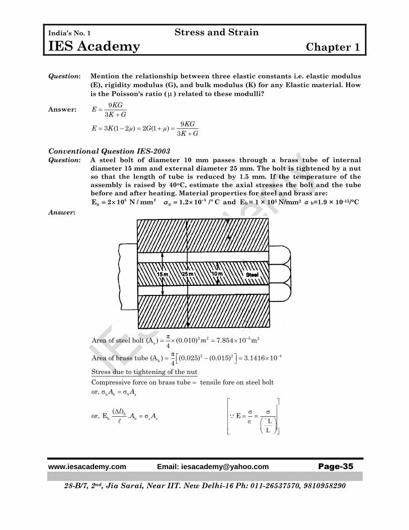
Conventional Question IES-2003 Question: A steel bolt of diameter 10 mm passes through a brass tube of internal
diameter 15 mm and external diameter 25 mm. The bolt is tightened by a nut
so that the length of tube is reduced by 1.5 mm. If the temperature of the
assembly is raised by 40oC, estimate the axial stresses the bolt and the tube
before and after heating. Material properties for steel and brass are:
5 2 5 o
SE 2 10 N / mm 1.2 10 / CS and Eb = 1 × 10⁵ N/mm2 b=1.9 × 10⁻¹⁵/°C
Answer:
π
π
2 2 5 2
s
2 2 4
b
Area of steel bolt (A ) (0.010) 7.854 10 m4
Area of brass tube (A ) (0.025) (0.015) 3.1416 104
m
S
σ σ
σ σσ
L
L
b
b. b
Stress due to tightening of the nut
Compressive force on brass tube tensile fore on steel bolt
or,
( )or, E . E
b s
b
s s
A A
lA A

India’s No. 1 Stress and Strain
IES Academy Chapter 1
www.iesacademy.com Email: [email protected] Page-36
28-B/7, 2nd, Jia Sarai, Near IIT. New Delhi-16 Ph: 011-26537570, 9810958290
35 6 4 -5
35
b.
Let assume total length ( ) 1m
(1.5 10 )Therefore (1×10 10 ) 3.1416 10 7.854 × 10
1
or 600MPa (tensile)
( ) (1.5 10 )and =E (1×10 ) MPa 150 MPa (Compressive)
1
s
s
b
b
l
σ
σ
b
s
So before heating
Stress in brass tube ( ) 150 MPa(compressive)
Stress in steel bolt( ) 600 MPa(tensile)
Stress due to rise of temperature
Let stress '
bσ σ'&
s are due to brass tube and steel bolt.
If the two members had been free to expand,
Free expansion of steel = s
1t
Free expansion of brass tube = 1b
t
Since sσ
b free expansion of copper is greater than the free expansion of steel. But
they are rigidly fixed so final expansion of each members will be same. Let us assume
this final expansion is ' δ ', The free expansion of brass tube is grater than δ , while the
free expansion of steel is less than δ . Hence the steel rod will be subjected to a tensile
stress while the brass tube will be subjected to a compressive stress.
For the equilibrium of the whole system,
Total tension (Pull) in steel = Total compression (Push) in brass tube.
'
bσ σ σ σ σ σ
5' ' ' ' '
b s 4
7.854 10, 0.25
3.14 10
s
b s s S S
b
AA A or
A
'
s
s
σ
E
σ σ
'
b
s
b
' '
5 5
5 6 5 6
Final expansion of steel final expansion of brass tube
( ).1 1 ( ) 1 1E
, 1.2 10 40 1 (1.9 10 ) 40 1 ( )2 10 10 1 10 10
b
s b
t t
or ii
'
sσ
σ
4
11 11
'
From(i) & (ii) we get
1 0.252.8 10
2 10 10
or, 37.33 MPa (Tensile stress)
s
'
bor, σ = 9.33MPa (compressive)
'
b b
'
s s
Therefore, the final stresses due to tightening and temperature rise
Stress in brass tube σ +σ 150 9.33MPa 159.33 MPa
Stress in steel bolt σ +σ = 600 + 37.33 637.33MPa.

India’s No. 1 Stress and Strain
IES Academy Chapter 1
www.iesacademy.com Email: [email protected] Page-37
28-B/7, 2nd, Jia Sarai, Near IIT. New Delhi-16 Ph: 011-26537570, 9810958290
Conventional Question IES-2004
Question: Which one of the three shafts listed hare has the highest ultimate tensile
strength? Which is the approximate carbon content in each steel?
(i) Mild Steel (ii) cast iron (iii) spring steel
Answer: Among three steel given, spring steel has the highest ultimate tensile strength.
Approximate carbon content in
(i) Mild steel is (0.3% to 0.8%)
(ii) Cost iron (2% to 4%)
(iii) Spring steel (0.4% to 1.1%)
Conventional Question IES-2003
Question: If a rod of brittle material is subjected to pure torsion, show with help of a
sketch, the plane along which it will fail and state the reason for its failure.
Answer: Brittle materials fail in tension. In a torsion test the maximum tensile test Occurs at
45° to the axis of the shaft. So failure will occurs along a 45o to the axis of the shaft. So
failure will occurs along a 45° helix
X
X
So failures will occurs according to 45° plane.
Conventional Question IES-2014
Question: A steel tube 2.5 cm external dia & 1.8 cm internal dia encloses a copper rod
16cm dia to which it is rigidly joind at each end. If at a temp. of 20 C t 20 Cthere is no longitudral stress calculate the stresses in the rod and tube when
the temp. is raised to 210 C
6
6
ES 210GPa & s 12 10 / C
EC 100GPa c 20 10 / C
Answer:
st cu
RL RLTL cu TL
ASES AcuEcu
6
2 2 4 9
6
2 4 9
R12 10 210 20
2.5 1.8 10 100 104
R20 10 210 20
1.6 10 210 104
816N

India’s No. 1 Stress and Strain
IES Academy Chapter 1
www.iesacademy.com Email: [email protected] Page-38
28-B/7, 2nd, Jia Sarai, Near IIT. New Delhi-16 Ph: 011-26537570, 9810958290
2 2 4
2 4
R 816s 3.453MPa
As2.5 1.8 10
4
R 816cu 4.06MPa
Ac1.6 10
4

Students Notes