Electronics Projects for DUMm IES(1)
430
Electronics Projects FOR DUMmIES ‰ by Earl Boysen and Nancy Muir
-
Upload
independent -
Category
Documents
-
view
0 -
download
0
Transcript of Electronics Projects for DUMm IES(1)

ElectronicsProjects
FOR
DUMmIES‰
by Earl Boysen and Nancy Muir
01_009683 ffirs.qxp 6/22/06 9:39 PM Page iii

Electronics Projects For Dummies®
Published byWiley Publishing, Inc.111 River StreetHoboken, NJ 07030-5774
www.wiley.com
Copyright © 2006 by Wiley Publishing, Inc., Indianapolis, Indiana
Published by Wiley Publishing, Inc., Indianapolis, Indiana
Published simultaneously in Canada
No part of this publication may be reproduced, stored in a retrieval system or transmitted in any form orby any means, electronic, mechanical, photocopying, recording, scanning or otherwise, except as permit-ted under Sections 107 or 108 of the 1976 United States Copyright Act, without either the prior writtenpermission of the Publisher, or authorization through payment of the appropriate per-copy fee to theCopyright Clearance Center, 222 Rosewood Drive, Danvers, MA 01923, (978) 750-8400, fax (978) 646-8600.Requests to the Publisher for permission should be addressed to the Legal Department, Wiley Publishing,Inc., 10475 Crosspoint Blvd., Indianapolis, IN 46256, (317) 572-3447, fax (317) 572-4355, or online athttp://www.wiley.com/go/permissions.
Trademarks: Wiley, the Wiley Publishing logo, For Dummies, the Dummies Man logo, A Reference for theRest of Us!, The Dummies Way, Dummies Daily, The Fun and Easy Way, Dummies.com, and related tradedress are trademarks or registered trademarks of John Wiley & Sons, Inc. and/or its affiliates in the UnitedStates and other countries, and may not be used without written permission. All other trademarks are theproperty of their respective owners. Wiley Publishing, Inc., is not associated with any product or vendormentioned in this book.
LIMIT OF LIABILITY/DISCLAIMER OF WARRANTY: THE PUBLISHER AND THE AUTHOR MAKE NO REP-RESENTATIONS OR WARRANTIES WITH RESPECT TO THE ACCURACY OR COMPLETENESS OF THE CON-TENTS OF THIS WORK AND SPECIFICALLY DISCLAIM ALL WARRANTIES, INCLUDING WITHOUTLIMITATION WARRANTIES OF FITNESS FOR A PARTICULAR PURPOSE. NO WARRANTY MAY BE CRE-ATED OR EXTENDED BY SALES OR PROMOTIONAL MATERIALS. THE ADVICE AND STRATEGIES CON-TAINED HEREIN MAY NOT BE SUITABLE FOR EVERY SITUATION. THIS WORK IS SOLD WITH THEUNDERSTANDING THAT THE PUBLISHER IS NOT ENGAGED IN RENDERING LEGAL, ACCOUNTING, OROTHER PROFESSIONAL SERVICES. IF PROFESSIONAL ASSISTANCE IS REQUIRED, THE SERVICES OF ACOMPETENT PROFESSIONAL PERSON SHOULD BE SOUGHT. NEITHER THE PUBLISHER NOR THEAUTHOR SHALL BE LIABLE FOR DAMAGES ARISING HEREFROM. THE FACT THAT AN ORGANIZATIONOR WEBSITE IS REFERRED TO IN THIS WORK AS A CITATION AND/OR A POTENTIAL SOURCE OF FUR-THER INFORMATION DOES NOT MEAN THAT THE AUTHOR OR THE PUBLISHER ENDORSES THE INFOR-MATION THE ORGANIZATION OR WEBSITE MAY PROVIDE OR RECOMMENDATIONS IT MAY MAKE.FURTHER, READERS SHOULD BE AWARE THAT INTERNET WEBSITES LISTED IN THIS WORK MAY HAVECHANGED OR DISAPPEARED BETWEEN WHEN THIS WORK WAS WRITTEN AND WHEN IT IS READ.
For general information on our other products and services, please contact our Customer CareDepartment within the U.S. at 800-762-2974, outside the U.S. at 317-572-3993, or fax 317-572-4002.
For technical support, please visit www.wiley.com/techsupport.
Wiley also publishes its books in a variety of electronic formats. Some content that appears in print maynot be available in electronic books.
Library of Congress Control Number: 2006926111
ISBN-13: 978-0-470-00968-0
ISBN-10: 0-470-00968-3
Manufactured in the United States of America
10 9 8 7 6 5 4 3 2 1
1B/RT/QX/QW/IN
01_009683 ffirs.qxp 6/22/06 9:39 PM Page iv

About the AuthorsEarl Boysen is an engineer who after 20 years in the computer chip industry,decided to slow down and move to a quiet town in Washington state. Earl isthe co-author of Electronics For Dummies and Nanotechnology For Dummies.He lives with his wife, Nancy, in a house he built himself and finds himself asbusy as ever with teaching, writing, house building, and acting. Visit Earl athis Web site to get reviews and information about the latest components andtechniques for building projects: www.buildinggadgets.com.
Nancy Muir is the author of over 50 books on topics ranging from desktopcomputer applications to distance learning and electronics. She has a certifi-cate in distance learning design and has taught technical writing at the uni-versity level. Prior to her freelance writing career, she held managementpositions in the publishing and software industries. She lives with her hus-band Earl and their benevolent owners — their dog and cat. Nancy’s com-pany, The Publishing Studio, has its Web site at www.pubstudio.com.
01_009683 ffirs.qxp 6/22/06 9:39 PM Page v

DedicationNancy and Earl dedicate this book to their uncle, Ted Stier, with thanks forbeing such a great guy and giving Nancy away with such style and grace!
Authors’ AcknowledgmentsThe authors wish to thank Katie Feltman for continuing to hire them to workon interesting book projects and to Chris Morris for managing the editingprocess and the authors so successfully. Thanks also to technical editor KirkKleinschmidt and copy editor Teresa Artman for making sure that what wewrote ended up being accurate and grammatically correct.
We also received help during this project from the following people, and theyhave our sincere gratitude: Bruce Reynolds of Reynolds Electronics (www.renton.com); the helpful folks at Magnevation (www.magnevation.com);and the following helpful members of our local ham radio club: Clint Hurd,Andy Andersen, Jack West and Owen Mulkey; and Gordon McComb of BudgetRobotics (www.budgetrobotics.com).
01_009683 ffirs.qxp 6/22/06 9:39 PM Page vii

Publisher’s AcknowledgmentsWe’re proud of this book; please send us your comments through our online registration formlocated at www.dummies.com/register/.
Some of the people who helped bring this book to market include the following:
Acquisitions, Editorial, and Media Development
Project Editor: Christopher Morris
Acquisitions Editor: Katie Feltman
Senior Copy Editor: Teresa Artman
Technical Editor: Kirk Kleinschmidt
Editorial Manager: Kevin Kirschner
Media Development Specialists: Angela Denny,Kate Jenkins, Steven Kudirka, Kit Malone
Media Development Manager:Laura VanWinkle
Editorial Assistant: Amanda Foxworth
Sr. Editorial Assistant: Cherie Case
Cartoons: Rich Tennant(www.the5thwave.com)
Composition Services
Project Coordinator: Patrick Redmond
Layout and Graphics: Claudia Bell, Carl Byers, Joyce Haughey, Barbara Moore, Barry Offringa, Alicia South
Proofreaders: Leeann Harney, Joe Niesen, Christy Pingleton
Indexer: Techbooks
Special Help: Virginia Sanders
Publishing and Editorial for Technology Dummies
Richard Swadley, Vice President and Executive Group Publisher
Andy Cummings, Vice President and Publisher
Mary Bednarek, Executive Acquisitions Director
Mary C. Corder, Editorial Director
Publishing for Consumer Dummies
Diane Graves Steele, Vice President and Publisher
Joyce Pepple, Acquisitions Director
Composition Services
Gerry Fahey, Vice President of Production Services
Debbie Stailey, Director of Composition Services
01_009683 ffirs.qxp 6/22/06 9:39 PM Page viii

Contents at a GlanceIntroduction .................................................................1
Part I: Project Prep.......................................................5Chapter 1: Exploring the World of Electronics Projects................................................7Chapter 2: Safety First......................................................................................................17Chapter 3: Assembling Your Electronics Arsenal.........................................................31Chapter 4: Running Down the Skills You Need .............................................................59
Part II: Sounding Off! .................................................85Chapter 5: Making Light Dance to the Music................................................................87Chapter 6: Focusing Sound with a Parabolic Microphone........................................115Chapter 7: Murmuring Merlin .......................................................................................139Chapter 8: Surfing the Airwaves...................................................................................165
Part III: Let There Be Light .......................................185Chapter 9: Scary Pumpkins...........................................................................................187Chapter 10: Dancing Dolphins ......................................................................................215Chapter 11: Controlling a Go-Kart Infrared Style........................................................239
Part IV: Good Vibrations............................................279Chapter 12: A Handy-Dandy Metal Detector ...............................................................281Chapter 13: Sensitive Sam Walks the Line...................................................................301Chapter 14: Couch Pet-ato.............................................................................................343
Part V: The Part of Tens ............................................361Chapter 15: Ten Great Parts Suppliers ........................................................................363Chapter 16: Ten Great Electronics Resources ............................................................369Chapter 17: Ten Specialized Electronics Resources ..................................................375
Glossary...................................................................381
Index .......................................................................391
02_009683 ftoc.qxp 6/22/06 9:37 PM Page ix

Table of ContentsIntroduction..................................................................1
Why Buy This Book?........................................................................................1Foolish Assumptions .......................................................................................1Safety, Safety, Safety!........................................................................................2How This Book Is Organized...........................................................................2
Part I: Project Prep .................................................................................2Part II: Sounding Off! ..............................................................................3Part III: Let There Be Light ....................................................................3Part IV: Good Vibrations........................................................................3Part V: The Part of Tens.........................................................................3
Icons Used in This Book..................................................................................3
Part I: Project Prep .......................................................5
Chapter 1: Exploring the World of Electronics Projects . . . . . . . . . . . .7What Is an Electronics Project, Anyway?......................................................7
Electronics, mechanics, robotics: Huh? ..............................................8Programmable versus nonprogrammable...........................................8
Mixing and Matching Effects...........................................................................9What Can You Do with Electronics Projects? .............................................10
Just for the fun of it ..............................................................................10Building things you can actually use .................................................12Picking up lots of cool stuff along the way .......................................12
What You Need to Get Started......................................................................13How much will it cost?.........................................................................13Space . . . the final frontier ..................................................................14
Chapter 2: Safety First . . . . . . . . . . . . . . . . . . . . . . . . . . . . . . . . . . . . . . . . .17Avoiding Shocks Like the Plague..................................................................17
How voltage and current can get you................................................18How much is too much? ......................................................................18Common sense: Protecting yourself from getting shocked ............20
Protecting Electronic Components from Dreaded Static Discharge........21What static discharge can do .............................................................21How to guard against ESD ...................................................................22
Working with the Tools of the Trade ...........................................................23Safe soldering........................................................................................24Running with sharp objects: Cutting, sawing, and drilling .............25
02_009683 ftoc.qxp 6/22/06 9:37 PM Page xi

A Safe Workspace Is a Happy Workspace ...................................................26Dressing for safety................................................................................26Clean up your stuff! ..............................................................................29Keeping kids and pets out of your space ..........................................29
Chapter 3: Assembling Your Electronics Arsenal . . . . . . . . . . . . . . . . .31Tool Time ........................................................................................................31
Soldering prerequisites........................................................................32Drills that come in handy ....................................................................33Hacking away with saws......................................................................34Garden variety tools: Pliers, screwdrivers,
wire strippers, and more .................................................................35Multimeter.......................................................................................................37Components Primer.......................................................................................38
Running down discrete components: Resistors, capacitors, and transistors .............................................................39
ICs...........................................................................................................42The switch is on ...................................................................................45Sensors ..................................................................................................48Microphones .........................................................................................48Let there be light: Light emitting diodes ...........................................50Speaking up about speakers ...............................................................50Buzzers ..................................................................................................51
The Nuts and Bolts of Building Materials ...................................................52Plastic.....................................................................................................52Wood ......................................................................................................52Build it yourself ....................................................................................53Holding it all together ..........................................................................53Holding down wires..............................................................................54
Breadboard Basics .........................................................................................54Wires pull it all together ......................................................................56Connectors ............................................................................................58
Chapter 4: Running Down the Skills You Need . . . . . . . . . . . . . . . . . . .59It’s Symbolic: Reading a Schematic..............................................................59
Perusing a simple schematic ..............................................................60Switching gears with switches............................................................62Schematic variables .............................................................................63Pulling it all together............................................................................64
Breadboarding ................................................................................................65The anatomy of a breadboard ............................................................66Figuring and finessing the layout .......................................................67Inserting wires and components ........................................................68
Soldering Your Circuit Board........................................................................70Using a soldering iron ..........................................................................71Working with solder .............................................................................72Soldering extras....................................................................................75
Electronics Projects For Dummies xii
02_009683 ftoc.qxp 6/22/06 9:37 PM Page xii

Measuring Stuff with a Multimeter...............................................................76How a multimeter works .....................................................................76Reading resistance ...............................................................................77Measuring voltage ................................................................................77
Working with the Boxes that Contain Your Projects .................................78Working with boxes..............................................................................78Mounting your project in a box ..........................................................79
Part II: Sounding Off!..................................................85
Chapter 5: Making Light Dance to the Music . . . . . . . . . . . . . . . . . . . . .87The Big Picture: Project Overview...............................................................87Scoping Out the Schematic...........................................................................89Fancy Footwork: Exploring the Dance to the Music Circuit .....................90Building Alert: Construction Issues .............................................................92Perusing the Parts List ..................................................................................92Taking Things Step by Step...........................................................................94
Building a circuit ..................................................................................94Let there be lights ..............................................................................101Adding the rest of the doohickeys ...................................................108
Trying It Out..................................................................................................111Taking It Further...........................................................................................113
Chapter 6: Focusing Sound with a Parabolic Microphone . . . . . . . .115What a Dish! The Project Overview...........................................................115Scoping Out the Schematic.........................................................................117Building Alert: Construction Issues ...........................................................118Perusing the Parts List ................................................................................119Taking Things Step by Step.........................................................................122
Building an amplifier circuit..............................................................123Mounting everything on the dish.....................................................126Mounting the microphone.................................................................138Mounting switches and more on the box........................................132Putting everything together..............................................................134
Trying It Out..................................................................................................137Taking It Further...........................................................................................137
Chapter 7: Murmuring Merlin . . . . . . . . . . . . . . . . . . . . . . . . . . . . . . . . .139The Big Picture: Project Overview.............................................................139Scoping Out the Schematic.........................................................................141Building Alert: Construction Issues ...........................................................143Perusing the Parts List ................................................................................144Taking Things Step by Step.........................................................................147
Creating Merlin’s circuit ....................................................................147Making the box puppet-friendly .......................................................152
xiiiTable of Contents
02_009683 ftoc.qxp 6/22/06 9:37 PM Page xiii

Programming sounds.........................................................................159Hooking up the puppet ......................................................................162
Trying It Out..................................................................................................163Taking It Further...........................................................................................164
Chapter 8: Surfing the Airwaves . . . . . . . . . . . . . . . . . . . . . . . . . . . . . . .165The Big Picture: Project Overview.............................................................165Scoping Out the Schematic.........................................................................166Building Alert: Construction Issues ...........................................................169Perusing the Parts List ................................................................................169Taking Things Step by Step.........................................................................172
Building a radio circuit ......................................................................172Making a box into a radio..................................................................174Coaxing the coil ..................................................................................179Putting it all together .........................................................................180
Trying It Out..................................................................................................183Taking It Further...........................................................................................183
Part III: Let There Be Light ........................................185
Chapter 9: Scary Pumpkins . . . . . . . . . . . . . . . . . . . . . . . . . . . . . . . . . . .187The Big Picture: Project Overview.............................................................187
Scoping out the schematic................................................................189Building alert: Construction issues..................................................193Perusing the parts list........................................................................194
Taking Things Step by Step.........................................................................197Making a silent pumpkin ...................................................................197Making a talking pumpkin .................................................................205
Trying It Out..................................................................................................211Taking It Further...........................................................................................214
Chapter 10: Dancing Dolphins . . . . . . . . . . . . . . . . . . . . . . . . . . . . . . . . .215The Big Picture: Project Overview.............................................................215Scoping Out the Schematic.........................................................................216
Getting in the swim: Exploring the dolphin circuit ........................218Setting up the light show...................................................................219
Building Alert: Construction Issues ...........................................................221Perusing the Parts List ................................................................................221
A circuit with a porpoise ...................................................................221Making your dolphins boogie ...........................................................222
Taking Things Step by Step.........................................................................223Making the circuit...............................................................................224Making dolphins .................................................................................229
Trying It Out..................................................................................................237Taking It Further...........................................................................................238
Electronics Projects For Dummies xiv
02_009683 ftoc.qxp 6/22/06 9:37 PM Page xiv

Chapter 11: Controlling a Go-Kart, Infrared Style . . . . . . . . . . . . . . . .239The Big Picture: Project Overview.............................................................239Scoping Out the Schematic.........................................................................241
Transmitting at the speed of light ....................................................241Receiving what the transmitter sends.............................................242Controlling motor behavior ..............................................................243
Building Alert: Construction Issues ...........................................................245Perusing the Parts List ................................................................................245
Go-kart transmitter parts list............................................................246Go-kart receiver/chassis parts list ...................................................247
Taking Things Step by Step.........................................................................249Making the transmitter ......................................................................249Making the receiver circuit board....................................................260Building the go-kart............................................................................268
Trying It Out..................................................................................................276Taking It Further...........................................................................................277
Part IV: Good Vibrations ............................................279
Chapter 12: A Handy-Dandy Metal Detector . . . . . . . . . . . . . . . . . . . . .281The Big Picture: Project Overview.............................................................281Scoping Out the Schematic.........................................................................282Building Alert: Construction Issues ...........................................................284Perusing the Parts List ................................................................................284Taking Things Step by Step.........................................................................286
Building a metal detector circuit......................................................286Building the box to house the circuit ..............................................291Putting it all together .........................................................................293Handling the handle ...........................................................................294
Trying It Out..................................................................................................299Taking It Further...........................................................................................300
Chapter 13: Sensitive Sam Walks the Line . . . . . . . . . . . . . . . . . . . . . .301The Big Picture: Project Overview.............................................................301Scoping Out the Schematic.........................................................................303
Transmitting Sam’s commands ........................................................303Helping Sam receive his commands ................................................305
Building Alert: Construction Issues ...........................................................309Perusing the Parts List ................................................................................309
Tallying up transmitter bits and pieces...........................................309Running down receiver and container parts ..................................311
Taking Things Step by Step.........................................................................313Making the transmitter circuit and remote control box................313Making the receiver circuit ...............................................................321Building Sensitive Sam’s chassis ......................................................332
xvTable of Contents
02_009683 ftoc.qxp 6/22/06 9:37 PM Page xv

Trying It Out..................................................................................................340Taking It Further...........................................................................................341
Chapter 14: Couch Pet-ato . . . . . . . . . . . . . . . . . . . . . . . . . . . . . . . . . . . .343The Big Picture: Project Overview.............................................................344Scoping Out the Schematic.........................................................................344Building Alert: Construction Issues ...........................................................346Perusing the Parts List ................................................................................346Taking Things Step by Step.........................................................................348Trying It Out..................................................................................................359Taking It Further...........................................................................................360
Part V: The Part of Tens .............................................361
Chapter 15: Ten Great Parts Suppliers . . . . . . . . . . . . . . . . . . . . . . . . . .363When Is a Supplier Right for You?..............................................................363Reynolds Electronics ...................................................................................364Hobby Engineering.......................................................................................365Jameco...........................................................................................................365Digi-Key..........................................................................................................365Mouser Electronics ......................................................................................366RadioShack....................................................................................................366Fry’s Electronics...........................................................................................366Electronic Goldmine ....................................................................................367Furturlec........................................................................................................367Maplin............................................................................................................367
Chapter 16: Ten Great Electronics Resources . . . . . . . . . . . . . . . . . . .369Electronics Magazines .................................................................................369
Nuts & Volts magazine .......................................................................370Everyday Practical Electronics magazine .......................................370Silicon Chip magazine........................................................................370
Jumpstart Your Project Creativity with Circuits ......................................371Electronics Lab ...................................................................................371Circuits for the Hobbyist ...................................................................371Discover Circuits ................................................................................371Bowden’s Hobby Circuits ..................................................................372FC’s Electronic Circuits......................................................................372
Web Sites That Teach You the Ropes ........................................................372Electronics Teacher Web site............................................................373The Electronics Club Web site..........................................................373Electronics Tutorials Web site ..........................................................373All About Circuits discussion forum................................................373
Writing the Book on Electronics ................................................................374
Electronics Projects For Dummies xvi
02_009683 ftoc.qxp 6/22/06 9:37 PM Page xvi

Chapter 17: Ten Specialized Electronics Resources . . . . . . . . . . . . .375Radio..............................................................................................................375
Ian Purdie’s electronics tutorial radio design pages......................376QRP Quarterly.....................................................................................376Australian Radio Resource Page ......................................................376QRP/SWL HomeBuilder .....................................................................376IK3OIL...................................................................................................377
Audio and Music...........................................................................................377The Guitar Effects Oriented (GEO) Web Page.................................377Bob’s Vacuum Tube Audio Projects Page........................................378Effectronics .........................................................................................378
Robotics ........................................................................................................378The BEAM Reference Library............................................................378Robot magazine ..................................................................................379
Glossary...................................................................381
Index .......................................................................391
xviiTable of Contents
02_009683 ftoc.qxp 6/22/06 9:37 PM Page xvii

Electronics Projects For Dummies xviii
02_009683 ftoc.qxp 6/22/06 9:37 PM Page xviii

Introduction
If you’ve caught the electronics bug, you’re ready to try all kinds of pro-jects that will help you develop your skills while creating weird and won-
derful gadgets. That’s what this book is about: providing projects that are funand interesting as well as helping you find out about all kinds of electroniccircuits and components.
Electronics Projects For Dummies is a great way to break into electronics orexpand your electronics horizons. Here, we provide projects that allow youto dabble in using sound chips, motion detectors, light effects, and more. Andall the projects are low voltage, so if you follow our safety advice, no elec-tronics folks will be hurt in the process.
Why Buy This Book?Electronics projects not only help you build useful and fun gadgets, but youpick up a lot of knowledge along the way about how various electronic partswork, how to read a circuit diagram, and how to use tools such as solderingirons and multimeters. So by using this book, you have fun and get someknowledge at the same time.
This book provides you with just what you need to get going in the fun worldof electronics. It offers projects that you can build in a reasonable amount oftime — and in most cases, for under $100 each (some well under!).
Foolish AssumptionsThis book assumes that you have an interest in electronics and that you’veprobably explored the world of electricity and electronics a bit. You’ve proba-bly scanned a few electronics circuit Web sites and maybe a magazine or twoand have picked up some of the jargon. Other than that, you don’t need any-thing but a minimal budget to buy parts and tools, a small space in yourhouse or apartment that you can set aside for a workbench, and a little time.
If you feel like you want more information about terms and concepts in elec-tronics to help you out, we recommend Electronics For Dummies, by GordonMcComb and Earl Boysen (Wiley).
03_009683 intro.qxp 6/22/06 9:37 PM Page 1
You don’t need to be an electrical engineer or have worked on electronic pro-jects in the past. We provide some initial chapters that help you stock up onessential parts and tools, understand what each one does, set yourself up forsafety, and master a few simple skills. Then you’re all set to tackle any one ofthe projects in this book.
Safety, Safety, Safety!We can’t say this enough: Electronics, especially lower-voltage projects likethe ones in this book, can be a painless pastime but only if you follow somebasic safety procedures from the get-go.
Even low voltages can harm you, soldering irons can burn you, and smallpieces of plastic or wire that you snip could fly into your face.
We recommend that everybody — even those with electronics experience —read the chapter on safety (Chapter 2). And because we can’t cover everypotential danger in a single chapter, be sure to read each manufacturer’swarnings about how to use parts, power sources, and tools. Finally, usecommon sense when working on projects. If in doubt whether a safety pre-caution is necessary, just do it. Better safe than sorry is one of our mantras.
How This Book Is OrganizedElectronics Projects For Dummies is organized into several parts, starting offwith some general information about safety and stocking your electronicsworkshop. Then we offer several parts with different types of projects, andfinally conclude with the Part of Tens chapters with additional resources youmight want to explore. This book also has a spiffy full-color photo spread ofsome of the circuits and finished products of several of the projects.
Here’s the rundown of how this book is organized.
Part I: Project PrepIf you’re new to electronics, read through this part first. Even if you’re sea-soned, humor us and read Chapter 2 about safety. Then use Chapters 3 and 4to gather the parts and tools you’ll need and also bone up on some essentialelectronics skills, such as soldering and reading schematics.
2 Electronics Projects For Dummies
03_009683 intro.qxp 6/22/06 9:37 PM Page 2

Part II: Sounding Off!This part contains the first set of projects, all involving sound in some fash-ion. Here you work on projects to make lights dance to music, create a para-bolic microphone to pick up sounds at a distance, make a wizard that talkswhen you push his buttons, and create your own AM radio.
Part III: Let There Be LightElectricity can produce light (as Thomas Edison could have told you), sohere we show you how to work with light in a variety of ways. These projectsuse light to amuse or even make gadgets run. In this part, you light up apumpkin by using a motion detector, create a light display that will makeyour next party rock, and build a go-kart that you direct by using an infraredremote control device.
Part IV: Good VibrationsSome electronic gadgets do their thing when they sense vibrations. All theprojects in this part depend on vibrations, including electrical, mechanical,or radio waves. Work through these projects to create a metal detector, aradio controlled vehicle that senses light and runs around a track, and adevice that sits on your couch and raises a ruckus if your pet jumps on thecushion.
Part V: The Part of TensThe chapters in this part provide the ever-popular For Dummies top-ten lists.Use the recommendations here to explore some interesting suppliers of elec-tronic parts and tools; get information or swap ideas about general electron-ics topics online or in print; or look into resources for more specializedinterests, such as audio effects and robotics.
Icons Used in This BookWe live in a visual world, so this book uses little icons to point out usefulinformation of various types.
3Introduction
03_009683 intro.qxp 6/22/06 9:37 PM Page 3

The Tip icon points you to information that is interesting and can save youtime or headaches. These icons generally add a bit of spice to your electronicproject education.
Oops. If you don’t heed these little icons, you might regret it. Warnings alertyou to potential danger or problems that you want to avoid.
Remember icons remind you of an important idea or fact that you shouldkeep in mind as you explore electronics. They might even point you toanother chapter for more in-depth information about a topic.
If you’re gonna build an electronics project, you’re gonna spend some money.To save you time and help you keep your costs down, we give you shoppingtips wherever you see this icon.
4 Electronics Projects For Dummies
03_009683 intro.qxp 6/22/06 9:37 PM Page 4

Part IProject Prep
04_009683 pt01.qxp 6/22/06 9:37 PM Page 5

In this part . . .
Before you can jump in and tackle projects, you mightwant to brush up on (or discover for the first time)
the basics. Chapter 1 answers such urgent questions as“What is an electronics project, anyway?,” and Chapter 2provides our best advice about safety procedures thatkeep you intact while you play with gadgets. Chapter 3runs down the parts and equipment you work with in atypical project, and Chapter 4 reviews some basic skillsthat you need to build all kinds of electronic toys.
04_009683 pt01.qxp 6/22/06 9:37 PM Page 6
Chapter 1
Exploring the World of Electronics Projects
In This Chapter Understanding exactly what an electronics project is
Exploring the effects you can achieve
Considering what’s in it for you
Determining what you need to invest to get started
You probably picked up this book because you love tinkering with gad-gets, from that train set you got as a kid to the motion-activated dancing
monsters on display in the store aisles at Halloween. Not only are youintrigued by them, but you wonder whether you can build something likethem yourself. Now that you own this book, yes, you can!
In this chapter, we take a look at exactly what getting into building electron-ics projects involves, the kinds of great gadgets you can build yourself, whatyou’ll get from spending your time with electronics, and what you need tocommit to take the plunge.
What Is an Electronics Project, Anyway?Obviously, an electronics project involves electronics, meaning that you useelectricity to make something happen. However, overlaps exist among elec-tronics, mechanics, and even programmable devices such as robots. Here’swhat we mean when we say electronics projects.
05_009683 ch01.qxp 6/22/06 9:37 PM Page 7

Electronics, mechanics, robotics: Huh?Do you dream of building elaborate Erector Set-types of mechanical structures — perhaps a model of the Golden Gate Bridge with pulleys andlevers moving objects around? Is your goal to create a robot butler with aprogrammed brain that enables it to serve your every whim? Well, thosearen’t exactly what we categorize as electronics projects.
Certainly, electronics projects are often combined with mechanical struc-tures that use motors, and a robot has electronic components driven bymicrocontrollers and computer programs. In this book, though, we focus onprojects that use simple electronics components to form a circuit that directsvoltage to produce effects such as motion, sound, or light. By keeping to thissimple approach, you can pick up all the basic skills and discover all thecommon components and tools that you need to work on a wide variety ofprojects for years to come. For these projects, you don’t have to become amechanical or programming whiz.
An electronic circuit might run a motor, light an LED display, or set off soundsthrough a speaker. It uses various components to regulate the voltage, suchas capacitors and resistors. A circuit can also use integrated circuits (ICs),which are teeny, tiny circuits that provide a portion of your circuit in a verycompact way. This saves you time micromanaging pieces of the projectbecause somebody else has already done that job for you, such as building atimer chip that sets off a light intermittently.
Programmable versus nonprogrammableICs are preprogrammed or programmable. And that brings us to our next distinction.
Although we do use ICs in many of our projects — for example, in the form of asound chip that’s preprogrammed with beeps and music — for the most part,we keep away from programmable electronics. In order to work with program-mable electronics, you have to get your hands dirty with programming codeand microcontrollers, and that’s not what we’re about here. Instead, we focuson building electronics gadgets that teach you about how electricity works andget your mind stirring with ideas about what you can do by using electronics,rather than computers.
Don’t get us wrong: Microcontroller projects can be a lot of fun. After you getyour hands dirty and pick up lots of basic skills doing the projects in thisbook, you might just go out and buy Microcontroller Projects For Dummies (ifsuch a book existed).
8 Part I: Project Prep
05_009683 ch01.qxp 6/22/06 9:37 PM Page 8

Mixing and Matching EffectsThe possibilities of what electronics projects can do are probably endless; ona basic level, the projects in this book use electricity to do a variety of things,from running a small cart around the room to setting off a sequence of lightsor sounds.
Generally, most electronics projects consist of four types of elements:
Input: This sets off the effect, such as a remote control device or aswitch that you push. An event and a sensor, such as a motion or lightdetector, can also be used to activate an effect.
Power source: We typically use batteries in these projects.
Circuit: Components that control the voltage — such as transistors,capacitors, amplifiers, and resistors — are connected to each other andto the power source by wires and make up the circuit.
Output: This is what is powered by the circuit to produce an effect, suchas speaker emitting sound, LED lights going off, or a motor that setsattached wheels spinning.
9Chapter 1: Exploring the World of Electronics Projects
Battery-powered versus 120 volts+One other thing that we made a conscious decision about when writing this book was thatwe didn’t want you tinkering with high-voltageprojects. Electricity can be dangerous! Keepingto about 6 volts keeps you reasonably safewhereas working with something that uses 120volts — like the juice that comes out of yourwall socket — can kill you. While you’re dis-covering the basics of electronics, our advice is that it’s better to be safe than sorry.
When you get more comfortable and moreknowledgeable about tools and skills and safetymeasures (which we put a lot of emphasis on,especially in Chapter 2), you might explorehigher-voltage projects such as high-poweredaudio or ham radio projects. In this book, weshow you how to work with low-voltage batter-ies and still have fun in the process.
05_009683 ch01.qxp 6/22/06 9:37 PM Page 9

What Can You Do with Electronics Projects?
You get to explore a number of variations in the projects in this book. Andsure, this stuff sounds like it might be cool, but what’s in it for you?Electronics projects offer three benefits (at least):
Fun
The thrill of making something work all by yourself
A boatload of useful knowledge
Just for the fun of itOne obvious benefit of tinkering with gadgets is that it’s just plain fun. Ifyou’re the type who’s intrigued by how things work and what’s under thehood, you probably already know this.
In fact, we have lost ourselves for hours figuring out circuits (this is the elec-tronics equivalent of a jigsaw puzzle, which starts as a drawing, like the oneshown in Figure 1-1), wiring the components, and refining the results. You canalso, quite literally, amaze your friends with the things you build. And if yougo in for electronic gizmos that you can race, scare people with, or use toentertain crowds at parties, you can share the fun with others.
Don’t forget the social aspect: Electronics projects devotees comprise afriendly bunch of folks who like to help each other. You can get into discus-sion groups online or join a local electronics club and find both interestingideas and friendships at the same time. Chapter 16 provides ten great Websites about electronics where you’ll find such online groups.
10 Part I: Project Prep
05_009683 ch01.qxp 6/22/06 9:37 PM Page 10

82
1
4
- +
R 16
V+ -
+ -
3 2
1
48
3
86
7
4
- +
+ -
5 6
7
48
5
S1
+6VC1
R2 R3
R4
R5
R6
½ IC
1
C2
C3
R7
R8
R9R1
0
½ IC
2
R11
R11
R13
R14
R15
R16
R17
R18
LED1
LED2
LED3
LED4
Q1Q2
Q4Q3
Q5Q6
Q7Q8
LED9
LED1
0LE
D11
LED1
2
LED
13LE
D 14
LED
15LE
D16
½ IC
2
½ IC
1
+6V
C4R1
9
+6V
R20 R2
1
R22 R2
3R2
4
C5
R25
C6
R26
R27
R32
R33
R28
R29
R30
R31
R34
R35
LED5
LED6
LED7
LED8
+ +
Figure 1-1:The
schematicfor the
Dance tothe Musicproject in
Chapter 5.
11Chapter 1: Exploring the World of Electronics Projects
05_009683 ch01.qxp 6/22/06 9:37 PM Page 11

Building things you can actually useSo why, when you can buy an AM radio for $7.95, would you decide to build oneyourself with parts that cost $30? That’s a good question. The truth is just abouteverything you build in the projects included in this book — and most of the cir-cuits floating around on the Internet — is something that you could probablybuy in some form somewhere. But where would the challenge be in that?
Here’s why hundreds of thousands of electronics junkies build instead ofbuying: Because they can. They can make something that grabs music out ofthe airwaves or sets off a light display or sends a little cart wheeling aroundthe room themselves. We guess this is why people knit sweaters instead ofbuying them or work on old cars instead of taking them to mechanics. It justfeels good to master something on your own.
Parts II, III, and IV of this book are where you can find all these cool projects,divided into categories by what the projects do, such as producing light,sound, or motion.
Some of the things that you build in this book are just for fun, like the danc-ing dolphin light display (Chapter 10). Other things have a practical use: theCouch Pet-ato (Chapter 14) keeps your cat off the furniture when you leavethe house, for example.
Besides building gadgets that have a use, in some cases, you can build itemsmore cheaply than you can buy them in the store. You could just end up withprojects you can put to work and save a few bucks in the process.
Picking up lots of cool stuff along the wayOne of the great things about electronics is that it teaches you about all kindsof things you can use in your life. For example, you discover
How electricity works and how to stay safe when working with it
How to read an electronic circuit and build it on a breadboard like theone shown in Figure 1-2
How to use a variety of tools to solder, build, and customize casings tohold your gadgets
How to work with integrated circuits
A bit about wiring (which can give you a head start when you decide tolearn how to add an outlet to your kitchen someday)
12 Part I: Project Prep
05_009683 ch01.qxp 6/22/06 9:37 PM Page 12

This book is full of lots of School of Hard Knocks information that might takeyou years to acquire doing electronics projects on your own; you’ll also pick uplots of wisdom as you work through the projects and try things out for yourself.
What You Need to Get StartedNow that you’re all excited about the benefits of working on electronics projects, you’re probably wondering what this will cost you in dollars andworkspace.
How much will it cost?We tried to keep the cost of the projects in this book to under $100; in manycases, the materials and parts will cost you under $50 or so.
Depending on what you have lying around the house already, you might nothave to invest in some of the basic tools, such as pliers or a screwdriver. Youwill probably have to spend $50 or so for electronics-specific tools and mate-rials such as a soldering iron, solder, and a multimeter like the one shown inFigure 1-3.
Figure 1-2:Here’s
what thebreadboard
for Dance tothe Music in
Chapter 5looks like.
13Chapter 1: Exploring the World of Electronics Projects
05_009683 ch01.qxp 6/22/06 9:37 PM Page 13

If you want to get really fancy, you could spend a couple hundred dollars onfancy testing equipment such an oscilloscope, but you don’t have to havethat equipment to get through these projects, by any means.
Of course, in the world outside this book, projects can cost you hundreds ofdollars. Like any hobby, you can spend a few bucks to dabble or mortgageyour house to get into it in a big way. To get your feet wet in electronics,though, the investment is not that great.
Keep in mind that you can reuse some of the parts of one project (such as abreadboard) in another and cut your electronics budget further.
See Chapter 3 for information about the parts and tools that we recommendyou get to build your basic electronics workshop.
Space . . . the final frontierOne thing you do need to leap into the world of electronics projects is space.That doesn’t mean you have to take over your living room and build a fancyworkbench. In most cases, a corner of your garage or laundry room stocked
Figure 1-3:A multi-
meter is ameasuringdevice that
you’ll useoften.
14 Part I: Project Prep
05_009683 ch01.qxp 6/22/06 9:37 PM Page 14

with a shelf where you can keep parts and a card table works just fine. We doadvise that you find a specific space for your projects.
In short order, your workspace will be filled with tools and parts and all kindsof (useful) junk (see Figure 1-4). See Chapter 2 for advice about safety whenworking with all this stuff. For example, stock your workspace with safetyglasses that protect you whenever bits of wire go flying, and find a place whereyou can keep your soldering iron in a stand so it doesn’t roll into your lap.
We also recommend finding a spot that you can close off if there are others in your household — especially small children or pets — who could toppleyour work surface or eat tiny electrical parts and do themselves damage.Electronic projects don’t happen in a day, and you might work on a singleproject over a matter of weeks. If you have a small room with a door to keepothers out, great. If not, use your common sense about what you leave out onyour work surface overnight.
Figure 1-4:A typical
assortmentof electron-
ics para-phernalia.
15Chapter 1: Exploring the World of Electronics Projects
05_009683 ch01.qxp 6/22/06 9:37 PM Page 15

16 Part I: Project Prep
05_009683 ch01.qxp 6/22/06 9:37 PM Page 16

Chapter 2
Safety FirstIn This Chapter Avoiding those nasty shocks
Keeping your electric components safe from static discharge
Working safely with tools
Keeping yourself and your workspace neat and tidy (and safe)
We won’t kid you: Electricity deserves your respect. It can shock you,burn you, and even kill you. In this book, we stick with projects that
work with AA batteries to limit the potential for serious damage.
Still, anytime you work with electronics, there is potential for danger. If theseprojects get you excited about electronics so that you move on to projectsthat use bigger jolts of electricity, now is the time to learn the proper respectfor electricity and the proper safety precautions when working with electron-ics projects.
In this chapter, you discover what electricity is capable of — and how to keepyourself, electrical components, tools, and those near and dear to you safe.
This is the one must-read chapter in this book. Humor us, and read it fromtop to bottom, okay?
Avoiding Shocks Like the PlagueYour body is a delicate machine. Electric shocks, depending on certain condi-tions, can be fatal, even at relatively low voltages. What comes out of yourwall outlet is deadly if you play around with it. Even electrical gadgets work-ing off batteries can cause you serious damage.
06_009683 ch02.qxp 6/22/06 9:41 PM Page 17

How voltage and current can get youYour body is like a big resistor. Usually, your body’s resistance is high enoughto prevent damage when you’re exposed to low voltages. However, certainconditions can lower your body’s resistance, lowering the amount of voltageneeded to cause you serious damage, such as giving you a nasty burn. Thoseconditions might include handling electronics with sweaty palms or trying tochange your 12 volt (V) car battery on a rainy day — either can turn a slighttingle into a fatal event.
Both AC (alternating current, such as the power from your wall outlet) andDC (direct current, such as from a battery) voltage can damage you in differ-ent ways:
AC voltage: This type of voltage regularly reverses direction. This cancause your heart to shift its regular beating pattern in a condition knownas ventricular fibrillation. If this happens, your heart muscles go out ofwhack in a way that causes blood to stop pumping. In this situation,even if you cut the current, your heart might not be able to find itsproper rhythm, and you could die.
DC voltage: This type of voltage is on constantly and causes your mus-cles to contract and seize up quickly (including your heart muscle). Ifyou grab an electrical device in conditions that cause your body to con-duct DC voltage, your hands could become frozen (unable to let go of thedevice), and your heart could stop. If someone cuts the current quickly,though, your heart might begin to beat again (and you’ll be able toattend that Rotary luncheon next week).
Short of killing you, electric shock can cause burns as the current dissipatesacross your body’s natural resistance (that is, your skin).
How much is too much?Most resistance in your body is in your skin. If your skin is wet or damp, thatresistance is lowered. If you handle an electrical device with damp hands,even voltages under 20V or so (not enough to even light a low-wattage lamp)might be sufficient to do you serious damage. The 120V coming out of yourelectrical outlet has a lot of punch: more than enough to kill you.
Four AA batteries in series — which is what we use in the projects in thisbook — generate only about 6V. We did that on purpose to keep you rela-tively safe.
18 Part I: Project Prep
06_009683 ch02.qxp 6/22/06 9:41 PM Page 18

Just because AA batteries don’t have a high voltage output, don’t think thatthey can’t hurt you. If you short them out, all the electrons will flow quicklyfrom the negative to the positive poles and generate a lot of heat — enoughheat, in some cases, to destroy the battery and possibly burn you. If you feelheat coming from your circuit or the batteries, you might have a short-circuitor a component inserted the wrong way. Turn it off and let things cool down;then check to see what’s causing the problem.
The resistance in your body can vary greatly. For example, if you have sweatyhands and touch a live wire with one hand while the other hand rests on ametal table, this is a very dangerous situation. Because you have moisture onyour hands — which lowers your contact resistance — a higher current willflow through your body for a given voltage. If you have dry hands — onehand touching a live wire, the other hand in your pocket — and your feet on a dry, rubber mat, there’s far less danger from the same amount of voltagebecause your resistance is higher. However, if a higher voltage comes yourway, even with the higher resistance, you could die. Bottom line: There is noiron clad rule as to what level of voltage will kill or seriously injure a personbecause of all the variables.
Regardless of how much voltage you work with, develop safe work habits now.
19Chapter 2: Safety First
Is it the voltage or the current — or both?Electricity is the movement of electrons (cur-rent) through a conductor when a voltage isapplied across the conductor. Electric current iswhat burns your skin, stops your muscles cold,and causes your heart to go into fibrillation. Ifyou touch a live wire (that is, any conductor atsome voltage), current can flow through yourbody because it is a conductor. The amount ofcurrent that flows through your body dependsupon your body’s resistance to the flow of elec-tric current and how much voltage is applied.
Ohm’s Law deals with the relationship betweenvoltage, current, and resistance. Here’s the law,for those among you who appreciate equations:
Current = Voltage ÷ Resistance
The calculation for what’s dangerous involvesthe current, the voltage, and your body’s resis-tance. The current passing through your body isequal to the difference in the voltage that’sbeing applied to two spots on your body (forexample, your hand touching an electric cir-cuit and your feet touching the floor, or one handtouching a live conductor and another hand rest-ing on a chair), divided by your body’s resistance.
06_009683 ch02.qxp 6/22/06 9:41 PM Page 19

Common sense: Protecting yourself from getting shockedAlthough you should always use care working with electricity, we want to letyou know some common situations to avoid that could turn your body into asuper conductor. You know you shouldn’t stick your finger into an electricaloutlet (we hope!), but you should also get into some other good habits. Read on.
Rings are outMetal is a dandy conductor. Wearing rings or other metal jewelry around electricity is a lousy idea. For example, when the skin on your finger is sur-rounded by a ring (a terrific contact point) and you touch a voltage source,your body’s resistance can be very low. In that state, even a lower voltage joltcould do you serious damage. Leave jewelry somewhere else. (Tell yourspouse or fiancée that we said it’s okay for you to take off your wedding ringwhen working with electricity.)
Another good reason to avoid jewelry is that it can snag on things. Imagineworking on a breadboard filled with wires and tiny components, only to haveyour ring or necklace catch on something and yank it out. At the least, youhave to put the component back in place; at the worst, you could damage thecomponent and have to replace it.
Beware of water!Don’t work in a wet environment (say, outdoors on a rainy day, or whilestanding on a damp garage floor). This prevention might seem obvious, butconsider that cup of coffee on your workbench. What would happen if youknocked it over while working with electricity? You need to become supercareful about anything wet or moist in or near your work area. This includesyou: If you just came in out of the rain or from a run, dry off before workingon electrical equipment.
Respect electricityHere’s one simple rule that you should memorize right now: Never touch acomponent in a circuit that has power (an energized circuit). Turn off all powersources or remove the source from the circuit entirely before touching it.
One trick that electricians use is to keep their left hands in their pockets whenworking with electrical equipment. If a zap occurs, it will flow from their righthands to the ground — not from hand to hand, passing right through the heart.You shouldn’t be working with live electricity — ever! — but this trick of tradeused by more advanced users shows how important it is to understand howelectricity works and respect its authority.
20 Part I: Project Prep
06_009683 ch02.qxp 6/22/06 9:41 PM Page 20

Even when the source is removed, some electricity might remain. To beabsolutely sure, before you touch anything, test the circuit with your multi-meter. (We talk about how to use a multimeter in Chapter 4.) And don’t takesomebody else’s word that the power is off; always check and double-checkthis yourself!
Don’t work with AC-operated circuits unless you absolutely have to. And ifyou do, it might not be a bad idea to have a friend nearby who is trained inCPR. Visit www.redcross.org for more information about CPR training.
Protecting Electronic Components from Dreaded Static Discharge
You’re not the only thing in your work area that could suffer from shocks. Staticdischarge (also referred to as electrostatic discharge; ESD) can do damage toyour delicate electrical components. Static discharge is so named because it’scaused by the discharge of electrons from a static charge that hang around inan insulating body, even after the source of those electrons goes away.
Static charge is typically caused by friction. You might trap some electrons inyour body as you walk across a carpet, for example. When a static charge isbuilt up on your body, a corresponding voltage difference is built up betweenyour body and a grounded object, such as a doorknob. The zap when youthen touch a doorknob is the static discharge: that is, the electrons flowingfrom you to the doorknob.
What static discharge can doMetal oxide semiconductor (MOS) devices are cool because they allow inte-grated components to use less power. MOS devices improve circuit designand operation, but that improvement comes at a price. These little guys areVERY sensitive to ESD. One little zap, and they are likely to be history.
When you walk across a carpet, you can produce a static charge in the rangeof 2,000–4,000V. Because the number of electrons trapped on your body islow, you feel only a little shock. However, MOS devices contain a very thinlayer of insulating glass that can become toast when exposed to as little as50V of discharge or less. When you work with a MOS device, your body, clothes,and tools have to be free of static discharge. (You find out how to do that in thenext section.)
21Chapter 2: Safety First
06_009683 ch02.qxp 6/22/06 9:41 PM Page 21

MOS devices are found in many integrated circuits (ICs) and transistors. ICsand transistors that use bipolar devices do not have the very thin layers ofinsulating glass found in MOS devices, so they are less susceptible to damagefrom static discharge. Resistors, capacitors, diodes, transformers, and coils,on the other hand, aren’t in too much danger from static discharge. Keepstatic discharge away from your projects just to be safe.
How to guard against ESDTo get rid of static discharge in your electronics workshop, you can do several things, such as wearing anti-static devices and clothing, using static-dissipative floor mats, and grounding your tools.
First, wear an anti-static wrist strap. An anti-static wrist strap is one of thebest ways to get rid of ESD. This strap, like the one shown in Figure 2-1, fitssnugly on your wrist. You then attach the wire on the strap to earth ground —which is just what it sounds like: namely, the earth beneath your feet.
The cold water pipe on a water heater or under a sink is a good option forearth ground — if the water pipes are metal, that is. Plastic water pipes thatyou find in some newer construction won’t work. Because the cold waterpipe comes up out of the ground, it is therefore grounded (logical, huh?),which works where the hot water pipe usually won’t. Use a clamp to attach awire to the pipe (earth ground) and run it to your worktable, being sure to
Figure 2-1:An anti-
static wriststrap is
ESD’s worstenemy.
22 Part I: Project Prep
06_009683 ch02.qxp 6/22/06 9:41 PM Page 22

run the wire along the wall so you don’t trip over it. Set a loop of the wire atthe edge of your worktable where it’s handy to attach the alligator clip on theend of it to your wrist strap.
If you don’t happen to have a metal cold water pipe nearby, the best methodis to use a metal rod that you insert into the ground. The standard rule is tosink it three feet deep.
Second, wear clothing that is less likely to accumulate static charge. Forexample, polyester, acetate, and wool fabrics easily accumulate static chargeswhereas as cotton is less likely to accumulate the static charges necessaryfor ESD.
Using an anti-static wrist strap and wearing cotton clothing will usually besufficient.
Third, if you plan to do electronics projects long-term, consider buying astatic-dissipative mat for your work surface. You connect the mat to a ground,as you do with the wrist strap, and the mat dissipates charges from compo-nents you’re working on as you lay them on the mat. However, the mat has ahigh enough resistance that it won’t short together the pins of components.
There are also static-dissipative floor mats; however, these are more likely tobe used in a manufacturing setting when a worker needs to move betweenworkstations.
Anti-static wrist straps and static-dissipative workbench mats can be pur-chased at most electronics distributors. See Chapter 15 for a list of electron-ics distributors. The prices for wrist straps vary widely but start at just over$6; prices for workbench mats start at about $10.
Don’t try rigging up a homemade anti-static wrist strap. The ones you buy havea high resistance that slowly dissipates current. If you use a material withoutthat resistance, the current would rush to ground — which could cause youserious injury — instead of slowly dissipating. For $6, why take a chance?
Finally, don’t forget to ground your tools. Some tools, like the better solderingirons, have a three-prong plug that provides a ground connection. (Cheaptools might use only two-prong plugs, so avoid them at all cost.) Other than agrounded soldering iron, however, most metal tools (such as a screwdriver)dissipate static through you when you wear your handy anti-static wrist strap.
Working with the Tools of the TradeIn addition to keeping yourself safe from electricity, you will find a few other dangers with working with electronics projects. Using a variety of
23Chapter 2: Safety First
06_009683 ch02.qxp 6/22/06 9:41 PM Page 23

tools — from a hot soldering iron to a sharp hacksaw — mandates that youadopt some wise safety habits.
Safe solderingSoldering poses a few different dangers. (You might use solder to attach various pieces of your electronics project, such as soldering wires onto aspeaker, microphone, or switch.) The soldering iron itself (you can see one inFigure 2-2) gets mighty hot. The solder (the material you heat with the iron)gets hot. Occasionally, you even get an air pocket or impurity in solder thatcan pop as you heat it, splattering a little solder toward your face or ontoyour arm. To top that off, hot solder produces some nasty fumes.
Soldering itself takes experience to get right. Your best bet is to have some-body who is good at it teach you.
Here are some soldering safety guidelines you should always follow:
Always wear safety glasses when soldering.
Never solder a live circuit (one that is energized).
Soldering irons come in models that use different wattages. Use the rightsize soldering iron for your projects, as we discuss in Chapter 3; toomuch heat could ruin your board or components.
Figure 2-2:Always treat
a solderingiron withrespect!
24 Part I: Project Prep
06_009683 ch02.qxp 6/22/06 9:41 PM Page 24

Solder in a well-ventilated space to prevent the mildly caustic and toxicfumes from building up and causing eye or throat irritation.
Always put your soldering iron back in its stand when not in use. Too, besure that the stand is weighted enough or attached to your worktable sothat it doesn’t topple over if you should brush against the cord.
NEVER place a hot soldering iron on your work surface. You could starta fire.
Give any soldered surface a minute or two to cool down before youtouch it.
Never, ever try to catch a hot soldering iron if you drop it. No matterhow hard you try, you are very likely to grab the hot end in a freefall. Letit fall; buy a new one if you have to — just don’t grab!
Never leave flammable items (like paper) near your soldering iron.
Be sure to unplug your soldering iron when you’re not around.
Don’t put your face too close to the soldering site because of the danger ofstray hot solder and those horrible fumes. Instead, use a magnifying deviceto see when soldering teeny-tiny components to a board. You can buy clamp-on magnifiers that keep your hands free for soldering.
Running with sharp objects: Cutting,sawing, and drillingAs you work with electronics projects, you will find yourself spending a cer-tain amount of time doing construction tasks: building enclosures of variousshapes and sizes, cutting holes for switches, drilling a board to attach wheels,and so on. These tasks involve using tools such as knives, saws, and drills.
Anything that cuts can cut you, too. Here are a few tips for safe cutting:
Take a moment before you cut. Know where you want to cut, what thebest tool for the cut is, and how best to hold onto the thing you’re cut-ting to avoid cutting your fingers. (Clamps or a vise are useful for secur-ing whatever you are cutting.)
Get experience. If you’re new to sawing and drilling, get an experiencedhand to fill you in or take a shop class.
If you don’t know how to run power equipment, don’t use it. A small,unpowered hand tool can often perform the job without as much poten-tial danger to you if something goes wrong.
Keep distractions to a minimum. If you’re likely to have a visitor wanderin while you’re running a power saw, put a Do Not Disturb sign on thedoor. That momentary distraction could cause an accident.
25Chapter 2: Safety First
06_009683 ch02.qxp 6/22/06 9:41 PM Page 25

Don’t hurry. When you’re rushed, you make mistakes and accidentshappen.
Never force things. If the drill is meeting resistance or the saw isn’tbiting into the material, stop and check out the situation. Forcing a toolat these times can cause it to kick back on you or worse.
Wear leather work gloves to avoid cutting your hands when handlingmaterials with sharp edges or a rough surface that could have splinters.
Watch what you wear. Always wear safety glasses when cutting withany tool to avoid flying bits landing in your eyes. If a power tool is noisy,protect your ears with ear muffs or ear plugs. (See the last section ofthis chapter for more about this.)
Your safety rules apply to anyone in your work area. A flying objectcould hit a friend in the eye several feet away, and a noisy tool coulddamage his hearing.
Keep a first aid kit handy, just in case. Taking a first aid class wouldalso be a good thing.
Have a phone handy for emergencies.
Follow directions! Power tools often have safety devices and usuallycome with instructions for their use. Always engage the safety devicesand follow the manufacturer’s recommendations for safe use of the tool.
In the hopes that you’ll rush right over to the tool aisle and buy a lot of tools,many home improvement stores offer free classes on using power tools andother procedures that might help you get started.
A Safe Workspace Is a Happy WorkspaceThe environment that you work in can be as important to electronic projectsafety as how you deal with electricity or sharp tools. Paying attention todetails, such as the kind of clothing you wear — as well as how neat and tidyyou keep your work space — pays off by reducing mistakes and accidents.
Dressing for safetyWe put things you wear around your workshop into two categories: the cloth-ing you come in with and the safety devices you should put on as you work.
The clothes make the man (or woman) safeHere are two important considerations for safety in the clothing that you puton before going into your workshop. We touch on each of these elsewhere inthe chapter, but they bear repeating:
26 Part I: Project Prep
06_009683 ch02.qxp 6/22/06 9:41 PM Page 26

Don’t wear loose-fitting clothing. Loose-fitting clothing and items likescarves or ties can get caught on tools or other items. This could causeyou to get a burn, have a fall, or knock a sharp object off your work-bench. Wear comfortable clothing — just not clothing that flaps around.In fact, humor us and tuck in that shirttail right now, okay?
Wear the right fabric. Fabrics made of cotton don’t hold static chargesas easily as man-made fibers do. Static discharge can zap electroniccomponents into oblivion. Leave the polyester leisure suit in yourcloset, and opt for the cotton jeans and shirt instead.
Arming yourself for safetyYou should put on certain safety devices — such as ear protection, safetyglasses, and leather work gloves — depending on the kind of work you’re doing.
Ear protection makes sense if you’re working with loud noises, such as whenrunning a very loud power tool. With small electronics projects, like the onesin this book, you probably won’t use a very loud piece of equipment. But ifyou graduate to working on life-size robots, consider your hearing when work-ing with power tools. You can purchase ear muffs, like the ones shown inFigure 2-3, to protect yourself.
As Mom used to say, when they were handing out eyes, you get only two, sotake care of them. Safety glasses, like those shown in Figure 2-4, are practicallya religion with us. In fact, we’d almost go so far as to say when you enter your
Figure 2-3:Safety ear
muffs toprotect your
hearing.
27Chapter 2: Safety First
06_009683 ch02.qxp 6/22/06 9:41 PM Page 27

workspace, put on safety glasses. That could be going too far, but there aremany, many instances when you should wear them: when cutting anything,soldering, clipping wires, and so on. Consider whether safety glasses wouldn’tbe a good idea before you do any procedure.
Don’t delude yourself that regular prescription glasses will protect you. Theyaren’t necessarily made of shatterproof material. Too, they have no protec-tion along the sides.
Direct things that you’re cutting down — toward your workbench — insteadof up toward your face. As long as you can make the cut without looking, thiscan guarantee that flying pieces go away from you and not toward you.
If you’re working a lot with something that generates fumes (anything frompaint to solder), consider taking a cue from Zorro and wearing a mask calleda respirator (but wear yours over your mouth and nose) that can be found atany hardware store. Respirators are rated for different types of protection, somake sure you get the appropriate one. For example, one type might keepsmall particles like sawdust out of your mouth, and another might bedesigned to keep fumes at bay.
Figure 2-4:Our veryfavorite
electronicsproject
prop.
28 Part I: Project Prep
06_009683 ch02.qxp 6/22/06 9:41 PM Page 28

Clean up your stuff!Keeping your workspace neat, including minimizing strung-out cords thatcould trip you up, is important in preventing accidents.
A cluttered work surface makes it hard to see what you’re reaching for. Youmight reach over to grab a plastic box, only to come up with a mini hacksawin your palm (ouch!).
Pick up small pieces of cut wire or loose screws and nails. Not only could youstep on one and cut yourself if you decide to work barefoot someday (notsomething we recommend), but a pet or child could pick up such small itemsand decide they would be tasty.
Keeping kids and pets out of your spaceBesides keeping your space neat, you should also keep your space off-limitsto the smaller members of your household: namely, kids and pets. Even if youput away all sharp tools religiously and make sure that any power source isdisconnected from breadboards, small hands (or paws) are made for mischief.
If you can, lock your workspace when you’re not in it. If you can’t (maybebecause your workspace is a corner of your den), lock up your electronicproject tools, components, and works in progress in a box or cabinet.
29Chapter 2: Safety First
Electronics and alcohol don’t mixOkay, this probably goes without saying, butdon’t work around electronics if you’ve had adrink (or two or three). Alcohol slows your brain
and has an impact on your judgment. Bad judg-ment around electricity or sharp power toolscould be fatal. ’Nuff said?
06_009683 ch02.qxp 6/22/06 9:41 PM Page 29

30 Part I: Project Prep
06_009683 ch02.qxp 6/22/06 9:41 PM Page 30

Chapter 3
Assembling Your ElectronicsArsenal
In This Chapter Gathering the right tools for the job
Collecting electronic components to make projects run
Finding what you need to build what surrounds your project
Building circuits on breadboards
When you meet somebody who has had a hobby for a few years, he orshe usually has a well-stocked arsenal of materials and tools for the
task at hand. Knitters have drawers full of wool; stamp collectors have tweez-ers and scrapbooks; and electronics people have drawers full of switches,resistors, capacitors, integrated circuits, and transistors.
In this chapter, we walk you through the typical items that you need to workwith for electronics projects. We introduce you to just about all the tools andcomponents and building blocks that you use in the projects in this book.Whether you buy some now or wait until you need them, by the time youfinish this chapter, you will be familiar with the most common tools of theelectronics trade.
Tool TimeMany of the tools we want to first address are those that you find in the toolaisle of your hardware or home improvement store — everything from thesomewhat specialized soldering iron to the ubiquitous screwdriver.
07_009683 ch03.qxp 6/22/06 9:38 PM Page 31

Soldering prerequisitesIf you’ve ever used wax to seal an envelope, you understand the basic premiseof soldering. Take a material (in this case, solder; pronounced sod-der) andheat it so that it melts onto items, such as two wires you have twistedtogether to make a physical connection. When the solder cools, you have aseal or joint that makes an electrical connection between the items.
Soldering requires that you get your hands on a few basic items:
Soldering iron: See an example of one in Figure 3-1.
Get one rated at about 30 watts, preferably one for which you can buy dif-ferent size tips so you can work on different types of projects. And makesure to get an iron with a three-prong plug so that it will be grounded.
Tips: Large tips can be chisel-shaped and about 1⁄8" wide; small tips canhave a cone shape with a radius at the tip of only 1⁄64". Most solderingirons don’t specify the tip sizes that are supplied with the iron. For mostelectronics work, we suggest you just find one described as a fine tip ata electronics supplier. If you’re ordering a replacement tip, a 3⁄64" coneshape is a good size for general use. If you’re soldering circuit boards,you might try a 1⁄64" cone-shaped tip. Figure 3-1 shows a soldering ironwith a collection of different tip sizes and shapes.
Figure 3-1:A collection
of tips, asolderingiron, and a stand.
32 Part I: Project Prep
07_009683 ch03.qxp 6/22/06 9:38 PM Page 32

If you end up doing a lot of projects soldering components on circuitboards, you might decide to spend extra — sometimes quite a lot extra —to get a soldering iron with controls that allow you to change the wattage,or even one that senses the temperature of at the tip of the solderingiron and adjusts the power to keep the temperature stable.
Stand: You need a device to hold the soldering iron. To ensure that itdoesn’t tip over with a hot soldering iron in it, make sure that the stand’sbase is heavy enough or that you can clamp it to your worktable.
Damp sponge: You will use this constantly to clean the soldering tipbetween soldering jobs.
Solder wick: This piece of flat, woven copper wire — also called a solderbraid — soaks up solder when you need to rework a connection andneed to remove a dab or two from a joint. Some folks use a desolderingpump to suck up solder, but we find that a wick is easier to use.
Solder: Solder is a material that when heated and then cooled, holdswires and other metallic connectors together. The standard type usedfor electronics is referred to as 60/40 rosin core solder, which is 60 per-cent tin and 40 percent lead with flux at its core. This flux in the solderhelps to clean the items you’re putting together as you solder. We sug-gest you use a 0.032" diameter solder, which is small enough to help youkeep the solder where you want it to go.
Tip cleaner paste: This paste is an option for keeping your solderingiron tip neat. Although using a damp sponge (see its earlier bullet) willkeep the tip clean for a while, a good cleaning with tip cleaner paste nowand then is a good idea.
You can read about soldering safety in Chapter 2.
Drills that come in handyYou will use drills for all kinds of tasks, from attaching wheels to the body ofan electronically controlled kart to drilling holes in boxes to fit switches,lights, and much more.
Drills commonly come in 3⁄8" or 1⁄2" chuck sizes. (The chuck is the opening inthe drill where you insert the drill bit.) This measurement tells you how largeof a drill bit (its diameter) will fit in the chuck. For the projects in this book, a3⁄8" drill is just fine. Drills come in cordless versions as well as the type youplug into a wall outlet. We prefer cordless drills such as the one you can seein Figure 3-2, along with an assortment of drill bits.
33Chapter 3: Assembling Your Electronics Arsenal
07_009683 ch03.qxp 6/22/06 9:38 PM Page 33

For the projects in this book, an assortment of drill bits that includes bits upto 1⁄2" in diameter (the shank of the 1⁄2" bit should be 3⁄8") and a cordless 3⁄8" drillare probably your best bet.
Hacking away with sawsFrom the magician who saws his assistant in half to the saw you use to cut offa dead tree branch, these tools are handy to trim off excess bits.
Here are the kinds of saws you might need when building electronics projects,especially to build the boxes or boards that contain the electronics brains ortrim off little bits of plastic. See Figure 3-3 to view an assortment of saws:
A coping saw allows you to cut openings in a sheet or box of plastic orwood. For example, you might use this saw to cut a hole in a box toinsert a speaker.
A hacksaw or a conventional hand saw can be used to make straightcuts in sheets of plastic or wood or to cut plastic pipes or woodenboards to the desired length.
A mini hacksaw is useful when you don’t have enough room to workwith a full-sized saw. This can be common with electronics projects.
Figure 3-2:A 3⁄8" drill
and anassortmentof drill bits.
34 Part I: Project Prep
07_009683 ch03.qxp 6/22/06 9:38 PM Page 34

Hacksaws and coping saws have replaceable blades; you can find new bladesat hardware stores. When you buy a new blade, check the package to seewhat material it is intended to cut. Manufactures make blades with differentpitches (that is, spacing of the teeth) for cutting different materials, such asmetal versus wood or plastic.
Power saws go by names such as circular saws, chop saws, jigsaws, tablesaws, and band saws. You don’t need to go out and buy this type of equip-ment for the type of projects included in this book. However, if you’re dyingto work with one of these higher-powered saws and someone offers to loanyou one, please make sure you know how to operate it safely. It’s best to haveall your fingers and toes accounted for to work on electronics!
Garden variety tools: Pliers, screwdrivers,wire strippers, and moreThis is the category of tools that you’re most likely to have floating aroundyour garage or household toolkit. Take an inventory of your toolkit. (We’ll
Hacksaw
Coping sawMini hacksaw
Figure 3-3:Various
hand saws.
35Chapter 3: Assembling Your Electronics Arsenal
07_009683 ch03.qxp 6/22/06 9:38 PM Page 35

wait.) If you’re missing any of the tools in this list, it’s probably worth goingto your hardware store and picking them up.
Precision screwdrivers: This includes both straight and Phillips head(the one with the cross shape at the tip).
Mini or hobby needlenose pliers: These are useful for bending wires tovarious shapes for breadboarding; you also use them to insert wires andcomponents in the holes of the boards.
Standard sized needlenose pliers: These are useful for tasks where youneed to apply more strength than mini needlenose pliers can handle.You can see both standard-sized needlenose pliers and the smaller ver-sion in Figure 3-4.
A small pair of wire cutters: These are useful for clipping wires in closequarters, such as above a solder joint. The standard size of wire clippersyou find at hardware stores is so large that you might have trouble clip-ping the wire with enough precision. You can see the smaller version inFigure 3-4.
Precision screwdriverWire strippers
Mini needlenose pliers
6" needlenose pliers
Small wire cutters
Figure 3-4:Handy hand
tools.
36 Part I: Project Prep
07_009683 ch03.qxp 6/22/06 9:38 PM Page 36

Although you should be able to find small wire cutters and smallneedlenose pliers at electronics stores such as RadioShack, you mightalso check out the tools available at hobby supply stores or jewelry-making/bead supply stores. Our local bead supply store carries a niceassortment of tools that work perfectly with small wire.
Wire strippers: You use these to cut plastic insulation from the outsideof a wire without harming the copper wire inside. The stripped wire canthen be inserted into a breadboard or get soldered to a component tokeep electricity flowing.
A vise: Use this to hold components still while you drill, saw, sand, orwhatever.
A 3X magnifying glass: This helps you read part numbers on compo-nents and check your soldering joints to make sure they’re good. Youcan get handheld or table-mounted magnifying glasses.
Safety glasses: Your eyes are one of your most important tools, so besure to have a pair of safety glasses on hand to protect them. When usingthe tools in your workshop to drill, saw, clip wires, solder, and performmany other tasks, you need these special glasses to avoid injury fromsmall pieces that could go flying.
MultimeterA multimeter is essentially an electronics troubleshooting tool that you can’tdo without. You could use it to hunt down the defective part of a circuit —for example, where the voltage is too low to get your circuit going. A multime-ter is a combo type of testing tool in that it combines the functions of a fewothers meters (a voltmeter, an ammeter, and an ohmmeter) in one package.
By using a multimeter, you can take certain electrical measurements, such as
Current: The flow of electrons through your circuit
Voltage: The force your battery uses to push the electrons through yourcircuit
Resistance: The amount of fight your circuit puts up when voltagepushes the electrons through your circuit
To use a multimeter to test these various measurements, you set a multi-posi-tion switch on the meter to have it measure the appropriate range of volts,amperage, or resistance.
Check out Chapter 4, where we tell you exactly how to use a multimeter formore about the various test types it offers and how it works.
37Chapter 3: Assembling Your Electronics Arsenal
07_009683 ch03.qxp 6/22/06 9:38 PM Page 37

Test leads that typically come with multimeters use simple cone-shaped tips.You can buy test clips that slip onto the cone-shaped tips to make it easier toclip them onto the leads of a component. This makes testing much easier,trust us.
Components PrimerYou use many of the tools discussed in the previous section to work withoften teeny, tiny parts called components. These range from electricaldoohickeys such as resistors and transistors to integrated circuits (chips),switches, and sensors.
Our projects tell you exactly the type and value of component to use (as domost published projects in books and on the Web), so don’t worry too muchabout calculating these values. If you decide to strike off on your own tobuild your own circuits, we recommend that you get another book, such asElectronics For Dummies, by Gordon McComb and Earl Boysen (Wiley) to findout all about understanding component values.
One important terminology point to make is that the terms pin and lead arealmost always interchangeable. They essentially refer to a wire or stamped-out metal bar coming off a component used to connect it to a breadboard orother types of circuit boards. The only exception is pinout, which refers tothe function of each lead; you never refer to that as a lead-out!
38 Part I: Project Prep
Analog or digital multimeters?Multimeters come in two main types: analogand digital. Think of the difference between awristwatch that has hands that go around andone that has a numerical readout. For ourmoney (and yours), a digital multimeter is theway to go because you have a smaller chanceof making an error when reading the result;even the cheapest is just fine for testing simpleprojects.
All digital meters have a battery that powers thedisplay. Because they use virtually no powerfrom the circuit you’re testing, they’re not likelyto affect the results.
Auto-ranging is another handy feature to lookfor in your multimeter if you’re willing to spenda little extra money. This sets the test range (seemore about this in Chapter 4) automatically.
07_009683 ch03.qxp 6/22/06 9:38 PM Page 38

Running down discrete components:Resistors, capacitors, and transistorsWhereas discreet components should be good at keeping secrets, discretecomponents are so-named because they are one single, solitary thing, ratherthan a collection of components like those contained in an integrated chip(IC). (Read more about ICs later in this chapter.) Discrete components aresingle electrical items, typically resistors, capacitors, and transistors.
Diodes are also discrete components, but the only kind we use in this bookare light emitting diodes (LEDs). See the later section, “Let there be light:Light emitting diodes,” for more about these.
ResistorsThe job of a resistor is to restrict the flow of current, which is essentially theflow of electrons. The more electrons, the higher the current. For example,you might want to stop LEDs (which love to eat current) from burning them-selves out, and so you would add a resistor to your circuit. You’ll find theselittle guys used all the time in electronics circuits. We measure resistance inohms, which are so tiny that the measurement of them is usually given inthousands (kohms) or millions (megohms) of ohms. The value of a resistor isindicated by colored bands, with each band representing a number. However,rather than counting colored bands, just read the packaging your resistorcomes in or test it with a multimeter.
One variation on a resistor is a variable resistor, also called a potentiometer. Avariable resistor allows you to constantly adjust from 0 (zero) ohms to a max-imum value. These can be mounted on the face of a gadget, where you adjustthem with a knob; or, you can mount them on a circuit board, where you haveto adjust them by using a screwdriver. A typical use of a potentiometer is tocontrol the volume of an amplifier in a sound circuit.
CapacitorsA capacitor stores an electric charge. Quite often, you’ll see capacitors usedhand in hand with a resistor — for example, in a circuit whose job is to settiming. Because it takes time for a capacitor to fill with a charge, you can setyour watch by them (so to speak) if you use a resistor to control how fast thecharge (that is, current) flows in. Also, they make good filters for DC signalsbecause although AC passes through a capacitor with ease, DC signals arestopped in their tracks.
Capacitance is a measurement of a capacitor’s ability to store a charge. Thelarger the capacitance, the more charge is stored. You measure capacitance
39Chapter 3: Assembling Your Electronics Arsenal
07_009683 ch03.qxp 6/22/06 9:38 PM Page 39

in farads (F). An F is pretty darn big, so you have to use prefixes to show lesservalues. The prefixes used are micro- (millionth), nano- (thousand-millionth),and pico- (the ever-popular million-millionth).
Although you can find several kinds of capacitors — based on what materialthey are made of — three common types of capacitors you’ll run across inelectronics projects are electrolytic, tantalum bead, and ceramic. Here’s arethe basic characteristics of each:
Electrolytic capacitors are typically made of some kind of foil material,and you’ll find them with values of 1 microfarad and up. The two types are
• Axial: These have leads stuck on both ends.
• Radial: These have all the leads attached to the same end.
We use the axial type for the projects in this book because they take lessroom on a breadboard. The value of this type of capacitor is printed onit along with a voltage rating and its capacitance.
Be careful to check the voltage rating required by your project andchoose a capacitor accordingly.
Tantalum (a metallic material) bead capacitors are available with valuesof 0.1 microfarad and higher. They cost more than the electrolytic capac-itors but are useful if you have a circuit that requires more accuracybecause tantalum capacitors have less variation in value than elec-trolytic capacitors.
Ceramic capacitors are nonpolarized (see the sidebar, “Polarized counts”),and you can find them with values from 1 picofarad to 0.47 microfarad.Reading the value on these tiny components can be difficult. And to add tothe confusion, because many of these capacitors are too small to write thevalue on in words and numbers, folks use a code. Table 3-1 helps you spotcommon capacitor values based on their markings.
40 Part I: Project Prep
Polarized countsMost electrolytic and tantalum capacitors arepolarized, so you will see a polarity symbol onthem. Typically, only one end is marked witheither a plus or minus sign, so you can concludethat the other end is the opposite. With both typesof capacitor, the longer lead is the positive one,which is probably the easiest way to identify it.
What’s important about being polarized? If acapacitor is polarized, you have to be absolutely
sure to install it the right way around in your cir-cuit. If you don’t, you will be left with one deadcapacitor and possible damage to other com-ponents in the circuit.
Small-value capacitors, typically made ofceramic or mica, are nonpolarized so you canconnect them any way you want.
07_009683 ch03.qxp 6/22/06 9:38 PM Page 40

Table 3-1 Capacitor ValuesMarking Value
101 0.0001 µF
102 0.001 µF
103 0.01 µF
471 0.00047 µF
472 0.0047 µF
473 0.047 µF
474 0.47 µF
For much more detail about various types of capacitors and how to readcapacitor values, we recommend that you go out and buy Electronics ForDummies, by Gordon McComb and our own Earl Boysen (Wiley).
A final capacitor distinction that we have to make is variable versus fixed. Allthe capacitors we talked about so far are fixed, meaning they have a set valueyou can’t adjust. However, variable capacitors can by adjusted by various meth-ods. We use a variable capacitor, for example, in Chapter 8 for tuning a radio.
TransistorsTransistors are the darlings of the electronics world. Transistors amplify asignal or voltage, or switch voltage on or off. The really amazing thing abouttransistors is how tiny they are: Before the advent of transistors, people usedvacuum tubes to perform the same function, and a vacuum tube is huge incomparison. Transistors also use a lot less power.
When you shop for transistors, be sure to check the package type. You can usepackages starting with TO, such as TO-92, TO-39, and TO-220 (as shown inFigure 3-5) in breadboards or manually soldered circuit boards. Packages start-ing with SOT or SOIC are meant to be used on huge assembly lines and don’thave the types of leads that you can use easily in hobbyist electronics projects.
41Chapter 3: Assembling Your Electronics Arsenal
07_009683 ch03.qxp 6/22/06 9:38 PM Page 41

Transistors come in
NPN (negative/positive/negative): You turn on NPN transistors by apply-ing positive voltage; they start to turn on when you apply about 0.7 volts.
We use NPN transistors throughout this book because it’s more straight-forward to apply a positive voltage to get things working.
PNP (positive/negative/positive): You turn off PNP transistors by apply-ing positive voltage; they turn on when you apply negative voltages orvoltages near ground.
Transistors have three leads: the emitter, base, and collector. In Chapter 4,we show you how to read schematics so you can figure out where to connecteach pin. For each transistor you use, check the datasheet (which contains adrawing, called a pinout) to determine which pin is which.
ICsIntegrated circuits — commonly known as ICs — are like social directors for components: They gather lots of other components in a single location
TO-92 TO-39 T0-220
Figure 3-5:Common
transistorpackages.
42 Part I: Project Prep
07_009683 ch03.qxp 6/22/06 9:38 PM Page 42

(shuffleboard optional). ICs typically contain a number of transistors, resis-tors, and capacitors connected on a silicon chip to make a functional circuitin one small package.
ICs, as well as some other electrical components, can be susceptible to elec-trostatic discharge (in other words, zapping). For that reason, be sure to alsoget yourself an anti-static wrist strap (as we discuss in Chapter 2) for yourelectronics workshop.
ICs come in many packagesManufacturers make ICs in many types of packages or containers. (A wholevalley in California is dedicated to this type of thing.) The type of packagethat you use either in a breadboard or a circuit board is a dual inline package(DIP). A DIP is made up of plastic that encapsulates a silicon chip, with a rowof metal leads running on either side of the plastic. You insert these leadsinto the contact holes in a breadboard and connect components on thebreadboard with the circuitry on the silicon chip. (See the later section,“Breadboard Basics,” for more about this process.)
DIP ICs are identified by the number of leads they have, such as 8-pin DIP, 14-pin DIP, 16-pin DIP, 18-pin DIP, and so on. Figure 3-6 shows a few commonDIP ICs.
Figure 3-6:An assort-
ment of DIPICs (8-pin,
14-pin, and28-pin).
43Chapter 3: Assembling Your Electronics Arsenal
07_009683 ch03.qxp 6/22/06 9:38 PM Page 43

When you order ICs, be careful to order an IC in a DIP package. If you obtain anIC in a non-DIP package, such as an SOIC (see the earlier section, “Transistors”),you can try forever, but you will never be able to insert the leads into a board.High-volume manufacturers use these other ICs with a technique called sur-face mounting. In this technique, the leads are soldered onto a contact on thesurface of a circuit board, not inserted into a hole. If you really need to use anIC that comes only in a surface mount-type package, look for adapters to whichyou can solder the surface-mount IC and then insert the adapter into yourboard.
Because ICs are simply a collection of components (such as transistors, resis-tors, and capacitors) stuffed in miniature onto a silicon chip, each type of ICcan perform a different function. That function depends on how many of eachcomponent is placed on the chip and how they are wired together. The nexttwo sections provide an overview of two common ICs: operational amplifiersand audio amplifiers.
Opting for op ampsOperational amplifiers (affectionately known as op amps) are a type of IC thatcontains a series of transistors; each transistor amplifies the voltage of thesignal just a bit more. You could build a multistage transistor amplifier thatcould do a similar job by using several transistors, capacitors, and resistors,but why bother? This setup would use about 50 times more space on yourbreadboard than a single 8-pin DIP op amp.
If you look in a catalog for op amps, you’ll probably see pages and pages ofthem — they’re that popular. The fact that we’re using 6 volt batteries to powerour circuits narrows down the list considerably. Many op amps are designed towork with a positive supply voltage and a negative supply voltage, such as +6volts and –6 volts. We use op amps in our projects that are designed to workwith a 6 volt, or less, single-sided supply. An op amp that is designed to workwith a single-sided supply needs only a positive supply voltage and ground.
Op amp ICs usually come in 8-pin DIPs; some of these have one op amp cir-cuit, and some have two op amps (dual op amps). In a dual op amp, the pinsthat give access to one op amp are on the left side of the DIP, and the pinsthat give access to the other op amp are on the right side of the DIP. As youcan see in the project in Chapter 7, this allows you to build one portion ofyour project circuit along the left side of the breadboard and a second por-tion along the right side of the breadboard, which can come in handy if thingsget overcrowded. Op amp ICs also come in 14-pin DIPs. These contain fourseparate op amps and are therefore called quad op amps.
Here are some common op amps used in electronics projects using low-volt-age batteries:
LM358: A dual op amp
LM324: A quad op amp
44 Part I: Project Prep
07_009683 ch03.qxp 6/22/06 9:38 PM Page 44

MC33171: A single op amp
MC33172: A dual op amp
MC33174: A quad op amp
Amplifying soundAudio amplifiers are similar to op amps except that they are designed to pro-vide more power; logically, being audio amps, they provide enough power todrive speakers.
The LM386 is a widely used audio amplifier. Different versions of the LM386 aredesigned to work with different supply voltages. For example, the LM386N-1,which we use in projects in Chapters 6 and 7, is designed to work with a 6 voltsupply and can work with a supply voltage as low as 4 volts. The MC34119 is anaudio amplifier that can work with a supply voltage as low as 2 volts.
ICs are available for many specialized uses; you can see some of them inaction in the projects that we include in this book. The projects in Chapters 11and 15, for example, use encoder/decoders ICs paired with motor driver ICs.The project in Chapter 10 uses a timer IC paired with a decade counter IC, andthe project in Chapter 7 uses a speech synthesizer IC paired with an audioamplifier IC. The projects in Chapters 9 and 14 both use a voice recorder IC.
The switch is onA switch seems simple enough: You flick it one way to go on and the otherway to go off. However, understanding what’s happening behind that switchrequires that we give you a bit of background.
Open: A switch is in an open state when there is no electrical connec-tion. When switch is open, there is very high resistance between a wirecoming into a switch and the wire going out of the switch.
Closed: A switch is closed when there is an electrical connection. Whena switch is closed, there is very low resistance between a wire cominginto a switch and the wire going out of the switch.
There are different kinds of switches, referred to as SPST, SPDT, and DPDT, asshown in Figure 3-7. Here’s what these catchy acronyms mean:
SPST (single-pole, single-throw): This kind of switch has two lugs towhich you can solder wires. When the switch is on, the two wires areconnected; when the switch is off, the two wires are disconnected. Welike SPST switches so much that we use them as on/off switches in everyproject in this book.
SPDT (single-pole, double-throw): This kind of switch has three lugs to which you can solder wires: one for an incoming wire and two for
45Chapter 3: Assembling Your Electronics Arsenal
07_009683 ch03.qxp 6/22/06 9:38 PM Page 45

outgoing wires. When the switch is in one position, the incoming wire isconnected to the first of the outgoing wires. When the switch is in theother position, the incoming wire is connected to the second of the out-going wires. (If you have a different need and this is the type of switchyou happen to have in your parts bin, you can use just two lugs to makeit work as an SPST.)
DPDT (double-pole, double-throw): This kind of switch has six lugs towhich you can solder wires. These lugs can be attached to two incomingwires and four outgoing wires. When you flip this switch, you simplyswitch each incoming wire between two of the outgoing wires. We usethis type of switch in a relay in Chapter 13 to switch control of themotors from one type of sensor to another.
As if switches didn’t have enough names, they are also referred to by themethod used to change their state from open to closed. See Figure 3-8 to seethe different types.
Toggle switch: This switch gets its name from the fact that you flip alever to turn it on and flip it back to turn it off.
Pushbutton on/off switch: Every time you push this button, it changesfrom on to off or vice versa.
Figure 3-7:Three typesof switchesfrom left to
right: SPST,SPDT, and
DPDT.
46 Part I: Project Prep
07_009683 ch03.qxp 6/22/06 9:38 PM Page 46

Momentary pushbutton switch: Pushing this switch is what changes itsstate, but only for the moment! These are also classified by whether theyare normally open (NO) or normally closed (NC). For example, a momen-tary normally open switch is closed only while you hold the pushbuttondown. When you release the button, it goes back to its normal — open —state.
Tactile switch: This is a type of momentary pushbutton switch. Tactileswitches are rated by the amount of force that is needed to push thebutton and are often flat so that they can be easily inserted somewherewithout protruding (like how we insert them into the hands of a puppetin Chapter 7).
Slide switch: Logically, this switch operates when you slide a knob tochange it from on to off or vice versa.
Relays: These switches are operated by a voltage rather than by pushinga switch. This makes them very useful for turning on or off a component,such as a light or motor, through a remote control or by voltage gener-ated by a sensor. We control relays with both methods in Chapter 13.
Toggle switch Pushbutton switch Tactile switch
Slide switch Relay switch
Figure 3-8:A plethoraof ways to
flip a switch.
47Chapter 3: Assembling Your Electronics Arsenal
07_009683 ch03.qxp 6/22/06 9:38 PM Page 47

SensorsSensors take energy in forms such as sound or light and transform thatenergy into a signal. By using a sensor, you can detect heat, light, and sound,for example. When a signal is sensed, to the sensor produces an electricalsignal that is used by your circuit to control some activity. For example, aninfrared detector can work in conjunction with an infrared remote controldevice to stop or start a little go-kart.
Here are a few types of sensors that we use in the projects in this book:
IR detector: This converts infrared (IR) light into an electric signal. Theversion that we use in Chapters 11 and 9 contains a photodiode thatdetects infrared light and an integrated circuit that produces either +Vor 0 volts on its output pin. In order to reduce noise from ambient IRlight, this detector is designed to only respond to IR light that is pulsedat 38 kHz.
Tilt/vibration sensor: This type of sensor (which we use in Chapter 14)detects motion or vibrations when the switch is mounted with the bodyof the sensor horizontal. When the sensor detects motion, it closes aswitch, just like a toggle switch works.
MicrophonesTechnically speaking, a microphone is a kind of sensor. However, there’s a lotto say about these sound-sensing devices, so we give microphones their ownsection (because we’re the authors, and we can!).
How condenser (capacitor) microphones workCapacitors are kind of like a voltage sandwich in that they have two plates,with a slab of voltage between them. A so-called condenser mike (also called acapacitor microphone) contains one plate made of a very light material thatacts as a diaphragm. This plate vibrates when sound waves hit it. This movesthe two plates apart, which changes capacitance (the ability to store elec-trons). Moving the plates farther apart decreases capacitance (dischargingcurrent), and moving them together increases capacitance (charging current).
Condenser microphones aren’t cheap, but they give high-quality sound, sothey are often the best choice for an audio-intensive project.
A better mousetrap: Electret capacitor microphonesToday, the most popular type of condenser microphone is the electret micro-phone (which gets its name from the combination of electrostatic and magnet),
48 Part I: Project Prep
07_009683 ch03.qxp 6/22/06 9:38 PM Page 48

invented in 1962. The electret material used in this type of microphone is madeby embedding a permanent charge in a material called a dielectric. A charge isembedded in a dielectric by aligning the charges in the material — sort of likehow you make a magnet by aligning the atoms in a piece of iron.
There is a preamplifier in an electret microphone, to which you provide asupply voltage. That’s why the projects in this book that use electret micro-phones have a connection through a resistor running between the plus (+)lead of the microphone and the +V bus to power the preamplifier. (The resis-tor reduces the voltage at the + lead of the microphone to the desired supplyvoltage.)
Size countsWhen you order electret microphones, pay attention to the diameter andthickness because some can be hard to handle and solder. For most of ourprojects in this book, we use microphones with a diameter of about 3⁄8" and athickness of about 2⁄10". A microphone cartridge with a diameter of about 1⁄4"and a thickness of about 1⁄10" turns out to be much harder to handle and solderto than a microphone cartridge of about 3⁄8" and a thickness of about 2⁄10". (Checkout Chapter 6, where we bit the bullet and used a small microphone cartridgebecause that project needed some of the capabilities we couldn’t find in alarger microphone cartridge.)
Many microphone cartridge sizes are specified in millimeters. To help youtranslate this, typical diameters of microphone casings are 6 mm (about 1⁄4")and 9.7 mm (about 3⁄8").
Measuring sensitivitySensitivity is another issue that you should pay attention to with microphonecartridges. Sensitivity is measured in decibels (dB) — and just to confuseyou, this measurement is given as a negative number. A microphone cartridgewith a sensitivity of –40 dB, for example, is more sensitive (provides highervoltage at a given level of sound) than a microphone cartridge with a sensitiv-ity of –60.
For example, for the project in Chapter 6 (which has to pick up very faintsounds as part of a parabolic microphone), you need a highly sensitivemicrophone cartridge. We use one with a sensitivity of –35 dB. In Chapter 14,in which you talk directly into the microphone to record a message, we use aless-sensitive microphone cartridge, rated at –64 dB.
Connecting your microphone cartridge to your projectTo connect electret microphone cartridges to your project, you can get elec-tret microphone cartridges with solder pads or with leads that you can insertinto a breadboard. We use both in our projects.
49Chapter 3: Assembling Your Electronics Arsenal
07_009683 ch03.qxp 6/22/06 9:38 PM Page 49

Let there be light: Light emitting diodesA diode sends out light when you pass an electric current through it. LEDs,which we use quite a bit in the projects in this book, are similar to the tiny,twinkly lights you use to decorate a Christmas tree, and they come in a vari-ety of colors, such as red, orange, yellow, green, blue, and white. Blue andwhite LEDs are a lot more expensive, so you don’t see them used that often inthis book. (We’re thrifty!)
LED color isn’t controlled by the plastic that surrounds the light. Rather, thesemiconductor material used in the LED determines the color. The plasticsurrounding the semiconductor material can be clear or treated so that it dif-fuses the light.
In addition, you can get LEDs in several sizes and shapes. The standard LED,which is a cylinder with a diameter of 5mm, is referred to as T-1 3⁄4.
If you don’t connect LEDs the right way, you could wait forever to see thelight. Connect the longer of the two leads to the positive voltage and theshorter of the two leads to ground or the more negative voltage.
Speaking up about speakersEverybody knows what a speaker is: There’s one on your DVD player, yourcomputer, your iPod — you name it! Most speakers contain a permanentmagnet, an electromagnet, and a cone-shaped device from which the soundsemerge (see Figure 3-9).
Permanent magnet
Electromagnet
Cone
Figure 3-9:The partsthat make
up aspeaker.
50 Part I: Project Prep
07_009683 ch03.qxp 6/22/06 9:38 PM Page 50

When current moves through the electromagnet, which is attached to thecone, it gets pushed toward or pulled away from the permanent magnet. Thisdepends on which way the electric current is moving. This movement of theelectromagnet is what makes the cone vibrate, and that produces sound waves.
Speakers come with a rated impedance (the degree to which a componentresists electrical current): for example, 4 ohm, 8 ohm, 16 ohm, or 32 ohm. Aspeaker is often referred to by its impedance: for example, “I’m going out tobuy an 8 ohm speaker.” When you use a speaker in a circuit, it should have animpedance rating that matches the minimum impedance rating that the ampli-fier hooked up to the speaker can drive. If you use a speaker with higherimpedance than the amplifier can drive, you won’t get the maximum amountof sound; conversely, if you use a speaker with lower impedance than theamplifier can drive, you might overheat the amplifier. You can find this ratingin the datasheet on your supplier’s Web site.
For example, in Chapter 8, we use an 8 ohm speaker because the LM386amplifier can drive a speaker with impedance as low as 8 ohms. And inChapter 14, we use a 16 ohm speaker because the ISD1110 voice record/playback chip can drive a speaker with impedance as low as 16 ohms.
Speakers also come with a power rating, such as 0.2 watt, 1 watt, or 2 watt.Choose a speaker with at least as high of a power rating as the maximumoutput of the amplifier. Again, you can find this maximum output in the ampli-fier datasheet.
When you buy a speaker for electronics projects, buy one that comes withconvenient holes in the corners of metal or plastic flanges that you can slipscrews through. These help you to easily attach the speaker to the boxyou’re putting the circuit in. See Chapter 4 for more about building andassembling projects.
BuzzersIf you have an annoying friend who plays practical jokes, you’ve probablybeen on the receiving end of the buzzer and handshake joke. A buzzer essen-tially generates a sound, which you can use in projects in a variety of ways.For example, a buzzer could be the horn on a remote controlled car or analarm that goes off when a sensor detects motion.
In a buzzer, you apply voltage to a crystal (a piezoelectric crystal), which thenexpands or contracts. By attaching a diaphragm to the crystal, you cause thediaphragm to vibrate when you change the voltage. This vibration causes thatbzzz sound. There are electromagnet buzzers, but the piezo buzzer works justfine for electronic projects, so we stick to using them in this book.
51Chapter 3: Assembling Your Electronics Arsenal
07_009683 ch03.qxp 6/22/06 9:38 PM Page 51

Most buzzers give off sound in the 2–4 kHz range. Buzzers aren’t very dis-criminating when it comes to voltage: Their ratings are approximate, meaningthat a 12V buzzer is absolutely happy to work with a 9V power supply.
Buzzers have two leads, and you have to connect a buzzers the right wayround. The red lead is always positive (+).
The Nuts and Bolts of Building MaterialsA pure electronics project might just consist of a breadboard containing com-ponents and wires. In most cases, though, you’ll also want to create somesort of container or chassis to hold the project. For example, if you build asimple radio, you might put the guts of it in a box and drill holes to place thedials and speaker.
You can buy ready-made boxes or other containers and make them work foryour project. You can also build your own out of various materials.
PlasticABS (please don’t ask what this acronym means; we could tell you, but youcouldn’t pronounce it) plastic boxes are available from most electronics sup-pliers. These are lightweight, sturdy, waterproof, and handy for housing yourgadgets. We use a plastic box in Chapter 11 to house a remote control.
The plus with plastic boxes is that components such as switches aredesigned to be mounted on boxes or panels with thin walls. Therefore,mounting these components on these plastic boxes is often easier than onwooden boxes.
The downside is that cutting clean openings in plastic is harder than in wood —for example, to insert speakers.
WoodWe like to use wooden boxes to house many of our projects because, well,they look nice. We found simple, unfinished wooden boxes at a national craftsupply superstore (Michaels), but any craft store probably stocks them.
52 Part I: Project Prep
07_009683 ch03.qxp 6/22/06 9:38 PM Page 52

Wood is also easier to drill and cut than plastic; however, you’ll often findthat the wall of the box is 1⁄4" thick, which makes mounting components suchas switches more complicated. In Chapter 4, we provide some advice on howto handle mounting components on wood.
Build it yourselfIf you don’t like to buy ready-made containers, you can make your own boxesfrom wood or plastic. You can easily find lots of books that tell you how tomake all sorts of things from wood, so we don’t get into that. To start, youmight check out the Woodbox.com Web site and click the Wooden BoxMaking link for a good overview.
If you want to make your own boxes or build fancier shapes out of plastic,such as a model car, to mount your electronics, check out
www.talkingelectronics.com/Projects/Boxes/BJones-BoxArticle.html
This article is a nice introduction to making custom plastic boxes for elec-tronics projects.
For some projects, you will mount boxes on a base or sandwich thembetween two sheets of materials. We used sheets of PVC and plywood in ourprojects. Quarter-inch or 6 mm thickness is a good bet for a strong base. Youcan use thinner sheets — for example, 1⁄8" or 3 mm — when you don’t needstructural strength. Rigid, expanded PVC is often used instead of other plas-tics because it resists the buildup of electric charges, which might cause elec-trostatic discharge, which can zap your electronics components.
Robot supply houses, such as Solarbotics (www.solarbotics.com) orBudget Robotics (www.budgetrobotics.com), carry PVC sheeting. AtSolarbotics, this material is sold under the product name Sintra. You can findplastics suppliers that sell rigid expanded PVC in 4' x 8' sheets, which is eco-nomical if you plan to use a lot of it.
Holding it all togetherSticking materials together to form boxes or whatever can be done in a fewdifferent ways.
You can attach many different types of materials together with glue. Look fora glue called contact cement. This can bind a wealth of materials, includingmetal, plastic, rubber, and wood.
53Chapter 3: Assembling Your Electronics Arsenal
07_009683 ch03.qxp 6/22/06 9:38 PM Page 53
To mount components such as speakers, you need screws and nuts. The partslists in our project chapters tell you what size screws and nuts to get; we’rebetting you have some of these in that leftover cake tin in your garage gather-ing dust, but you can buy what you need for pennies in any hardware store.
We find that 6-32 screws fit many mounting holes.
Holding down wiresWire clips are very useful for organizing wires that you affix to your projectcontainer. These generally have an adhesive backing on the base that you useto attach them to a surface. Then you slip the wires into the clip, and they arenicely held in place. (We use RadioShack part #287-1668.)
Cable ties can also be useful when you want to run wires along somethingwithout a flat surface, like a wooden dowel.
Breadboard BasicsA breadboard is a rectangular plastic box filled with holes, which have contactsin which you can insert electronic components and wires. A breadboard is whatyou use to string together a temporary version of your circuit. You don’t have tosolder wires or anything else; instead, you poke your components and wires intothe little contact holes arranged in rows and connected by lines of metal; thenyou can connect your components together with wires to form your circuit.
The nice thing about breadboards is that you can change your mind andreplace or rearrange components as you like. You typically create an elec-tronics project on a breadboard to make sure that everything works. If it’s aproject you wish to save, you can create a more permanent version. We usebreadboarded versions of circuits exclusively in this book.
If you want to create a permanent version of your circuit, you need to createa soldered or printed circuit board; see the sidebar, “Printed circuit boards,”to find out how to go about that.
There are a few different sizes of breadboards, some of which are shown in Figure 3-10. You can link breadboards to make a larger circuit, like the one shown in Figure 3-11. See Chapter 4 for more about how to build a breadboard.
54 Part I: Project Prep
07_009683 ch03.qxp 6/22/06 9:38 PM Page 54

Figure 3-11:A large
circuit builton multiple
breadboardshooked
together.
Figure 3-10:Two bread-boards, one
with 830contact
holes andone with
400 contactholes.
55Chapter 3: Assembling Your Electronics Arsenal
07_009683 ch03.qxp 6/22/06 9:38 PM Page 55

Wires pull it all togetherWhen you place components in a breadboard, you don’t get much action untilyou connect those components with wire. Wire used in electronics is copper
56 Part I: Project Prep
Printed circuit boardsIf you create a circuit on a breadboard anddecide that it’s worthy of immortality, you canmake it permanent by soldering components inplace on a printed circuit board. To do this, youhave to get your hands on a universal printedcircuit board. This is much like a breadboardexcept that you can solder all the connectionsyou’ve made to keep them around.
A universal printed circuit board has rows ofindividual holes throughout the board withcopper pads around each hole and metal linesconnecting the holes in each row, like in abreadboard. You mount parts on the face of theboard and then pass leads through holes to the
components. You can solder the leads to thecopper pads on the bottom of the board.Universal printed circuit boards are available in a variety of patterns of contact holes andmetal lines. The figure here shows one we likebecause there are rows on either side thataccommodate discrete components handily.This circuit board is made by One Pass, Inc.(www.onepassinc.com).
You can get custom printed circuit boards madefor your circuit; this is typically done by submit-ting a drawing of your circuit to a printed circuitboard company. These boards eliminate the needto solder jumper wires between components.
07_009683 ch03.qxp 6/22/06 9:38 PM Page 56

surrounded by a plastic insulator, usually called hookup wire. Hookup wirecomes in various diameters referred to as a gauge. The standard gauge mea-surement used in the U.S. is American Wire Gauge, also referred to as AWG.We generally use 22 gauge or 20 gauge wire.
Someone decided at some point that the smaller the gauge, the larger thediameter of wire. For example, 20 gauge wire is 0.032" in diameter, and 22gauge wire is 0.025" in diameter. Don’t ask us why — just memorize this fact!
We use 22 gauge solid wire for most of the projects in this book. (Okay, in twochapters, we use 20 gauge; and in one, we use 26 gauge, but you’ll find outwhy when you get to those projects.)
Use solid wire — never stranded wire — between components within abreadboard because stranded tends to separate when you try to insert it intothe holes of a breadboard.
You can buy hookup wire in spools; we generally get spools containing 100feet of wire. If you are starting with only a few projects, you can get smallerspools containing as little as 30 feet of wire.
The insulating plastic that surrounds wire is made in different colors. Pick upa spool of red and a spool of black. Using different colors helps you to iden-tify the purpose of different wires in your project.
You might also consider buying an assortment of different lengths of pre-stripped and prebent 22 gauge wire jumpers. Jumper wires — which are usedto connect components in a breadboard — save you a lot of time you mightotherwise spend cutting small wires to length, stripping them, and bendingthe stripped wire when you’re building a breadboard.
57Chapter 3: Assembling Your Electronics Arsenal
Insulating those naked wiresYou will also use various materials to insulatebare wires. You can use electrical tape, forexample, to insulate solder joints that mighttouch each other and cause a short.
Heat shrink tubing is a tidy way to insulate thepoint where wires connect in a solder joint.Heat shrink tubing is simply a plastic tube.When you slip a short length of this tubing overa solder joint and apply heat, the plastic tube
shrinks, providing an insulating layer around thewire. When working with 22 gauge wire, we use3⁄32" heat shrink tubing.
Liquid electrical tape is also handy to insulatebare wire in situations where heat shrink tubingor conventional electrical tape doesn’t workvery well. We use liquid electrical tape inChapters 5 and 10, for example.
07_009683 ch03.qxp 6/22/06 9:38 PM Page 57

ConnectorsFinally, terminal blocks are used to connect wires from components such asspeakers, motors, and microphones to the breadboard. A terminal block is asmall block of plastic that you mount on a breadboard. You insert the wiresinto the terminal block through a hole in the block and then tighten screws tohold the wire securely.
When choosing terminal blocks, the diameter of the pin that inserts into thebreadboard or circuit board is important. Some terminal blocks that workfine in circuit boards where the components are soldered in do not stay inplace on breadboards. We have had the most success with RadioShack part#276-1388.
58 Part I: Project Prep
07_009683 ch03.qxp 6/22/06 9:38 PM Page 58

Chapter 4
Running Down the Skills You Need
In This Chapter Discovering schematics
Assembling little bits and pieces on breadboards
Spiffing up your soldering skills
Troubleshooting problems with a multimeter
Working with the boxes that enclose your projects
You need three key things to build an electronics project: materials, aworkspace, and certain skills that help you assemble the materials into
something that moves, beeps, lights up, or otherwise makes itself electronicallyknown to the world. (You also need time, but we’ll leave that to you to find.)
In Chapter 3, we talk about organizing your materials and workspace. In thischapter, we address the third element — the skills that you need to read cir-cuit designs, build, and test electronics projects. This chapter provides anoverview of these skills; for more comprehensive explanations, check outElectronics For Dummies, by Gordon McComb and Earl Boysen (Wiley).
It’s Symbolic: Reading a SchematicA schematic is your blueprint for building an electronics project. A blueprintfor building a house uses various symbols to represent elements, such asdoors, and lines to show walls. Instead of doors and walls, the symbols andlines in a schematic represent components such as transistors, integrated cir-cuits (ICs), and resistors as well as the wires that connect them.
Be sure to check out the Cheat Sheet (the yellow page at the front of thisbook) for a table of commonly used schematic symbols.
08_009683 ch04.qxp 6/22/06 9:41 PM Page 59
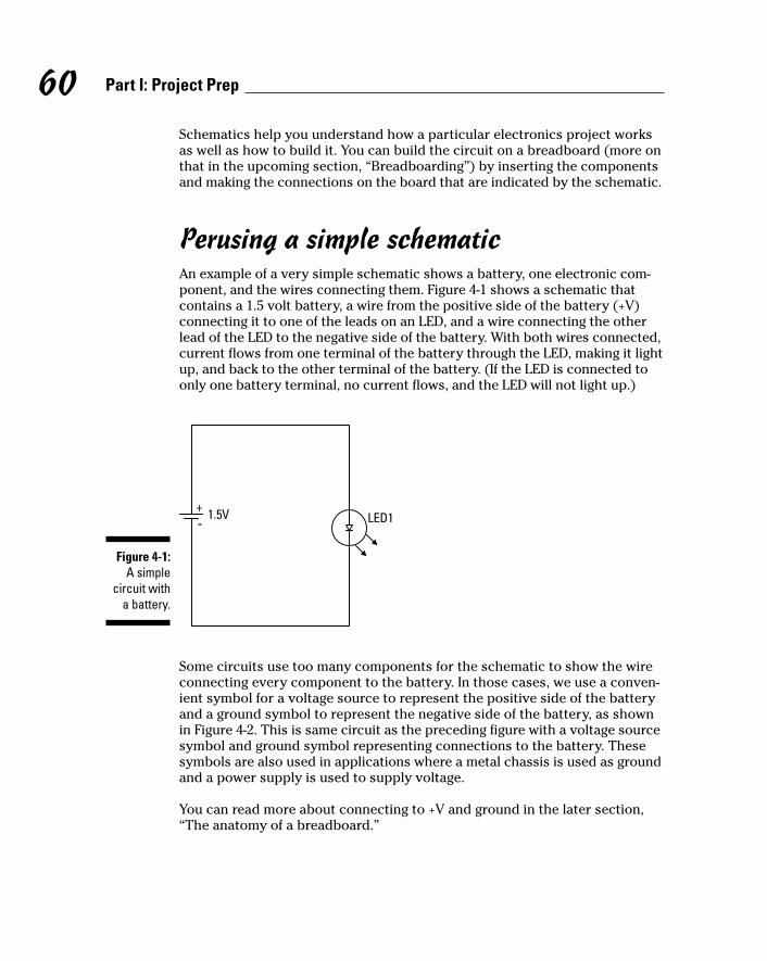
Schematics help you understand how a particular electronics project worksas well as how to build it. You can build the circuit on a breadboard (more onthat in the upcoming section, “Breadboarding”) by inserting the componentsand making the connections on the board that are indicated by the schematic.
Perusing a simple schematicAn example of a very simple schematic shows a battery, one electronic com-ponent, and the wires connecting them. Figure 4-1 shows a schematic thatcontains a 1.5 volt battery, a wire from the positive side of the battery (+V)connecting it to one of the leads on an LED, and a wire connecting the otherlead of the LED to the negative side of the battery. With both wires connected,current flows from one terminal of the battery through the LED, making it lightup, and back to the other terminal of the battery. (If the LED is connected toonly one battery terminal, no current flows, and the LED will not light up.)
Some circuits use too many components for the schematic to show the wireconnecting every component to the battery. In those cases, we use a conven-ient symbol for a voltage source to represent the positive side of the batteryand a ground symbol to represent the negative side of the battery, as shownin Figure 4-2. This is same circuit as the preceding figure with a voltage sourcesymbol and ground symbol representing connections to the battery. Thesesymbols are also used in applications where a metal chassis is used as groundand a power supply is used to supply voltage.
You can read more about connecting to +V and ground in the later section,“The anatomy of a breadboard.”
+-
1.5V LED1
Figure 4-1:A simple
circuit witha battery.
60 Part I: Project Prep
08_009683 ch04.qxp 6/22/06 9:41 PM Page 60
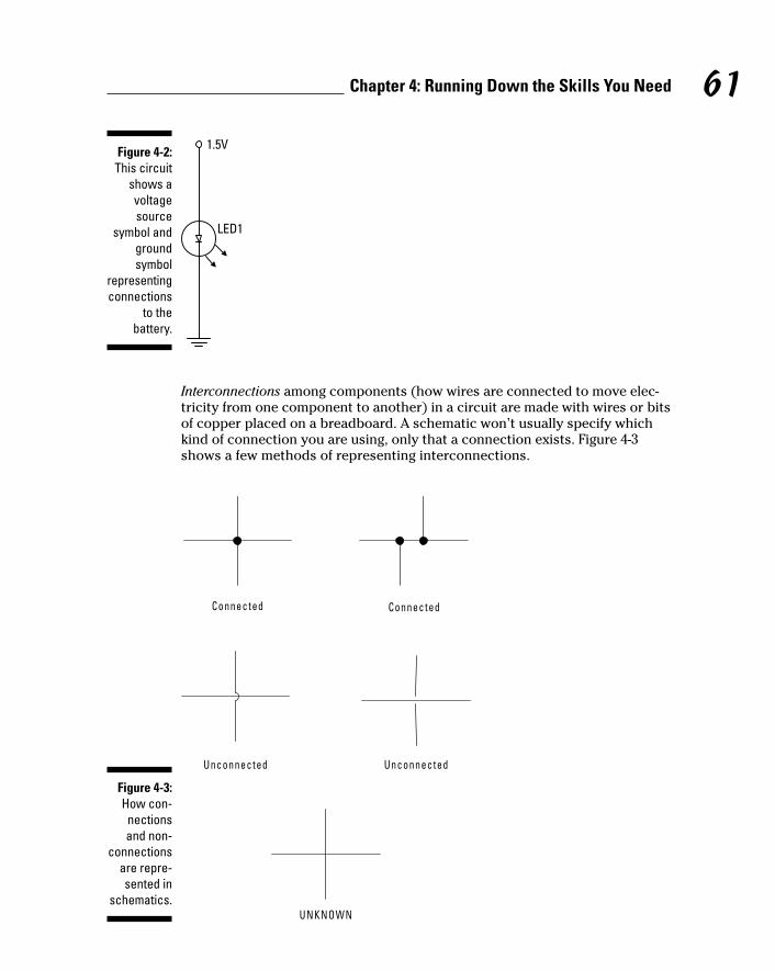
Interconnections among components (how wires are connected to move elec-tricity from one component to another) in a circuit are made with wires or bitsof copper placed on a breadboard. A schematic won’t usually specify whichkind of connection you are using, only that a connection exists. Figure 4-3shows a few methods of representing interconnections.
UNKNOWN
Unconnected Unconnected
Connected Connected
Figure 4-3:How con-nectionsand non-
connectionsare repre-sented in
schematics.
1.5V
LED1
Figure 4-2:This circuit
shows avoltagesource
symbol andgroundsymbol
representingconnections
to thebattery.
61Chapter 4: Running Down the Skills You Need
08_009683 ch04.qxp 6/22/06 9:41 PM Page 61

You’ll also find symbols for commonly used components, such as resistors,diodes, capacitors, and transistors, in schematics (see Figure 4-4). Chapter 3explains what most of these components do in a circuit.
Switching gears with switchesYou use switches to turn power to a circuit on or off or to connect/disconnecta pin on a component to +V or ground. However, switches don’t use just asingle symbol. Rather, they come in several varieties, indicating
How many wires they control
Whether they stay in the position you set them at or return to a normalposition after you release them
An SPST (single-pole, single-throw) switch has one incoming wire and one out-going wire that you use to open or close a connection in a circuit. For exam-ple, if a wire runs from the negative pole of a battery to an SPST switch andanother wire runs from the SPST switch to a circuit, current can flow throughthe circuit when you have the switch in the closed position. When you flipthe switch to the open position, no current can flow through the circuit.
SPST switches also come in the momentary switch variety; these can be nor-mally open (NO) or normally closed (NC) and are generally controlled bypushbuttons or relays. A normally open switch conducts current only whenthe button is pressed and returns to its open position when it’s released. Anormally closed switch won’t conduct current when you press the button butreturns to its normal position and conducts current when you release it.
An SPDT (single-pole double-throw) switch has one incoming wire and two out-going wires that you use to control which of two components is connected.Suppose that the incoming wire is connected to power, one outgoing wire isconnected to a green LED, and the other outgoing wire is connected to a redLED. When you have the switch in one position, the green LED lights up; whenyou flip the switch, the green LED goes dark, and the red LED lights up.
Resisto r
Capac i to r
Diode
Transisto r
Figure 4-4:Common
componentsymbols.
62 Part I: Project Prep
08_009683 ch04.qxp 6/22/06 9:41 PM Page 62

You can think of a DPDT (double-pole double-throw) switch as containing twoSPDT switches that switch in tandem. To see an example of this in action,visit Chapter 13, where we use DPDT relays to simplify the wiring of ourbreadboard.
Schematic variablesSome components are polarized, which means that you have to put them inthe circuit in a particular way. Schematics can identify the polarity of compo-nents (see Figure 4-5).
AND gate
In Out
OP amp
+ Out
+ Supply
Supply
Batte ryRelay
++
Diode
Negat ivete rminal
Negat ivete rminal
Posi t ivete rminal
Posi t ivete rminal
+
Capac i to r
PNP t ransisto rNPN t ransisto r
Figure 4-5:Common
polaritysymbols.
63Chapter 4: Running Down the Skills You Need
08_009683 ch04.qxp 6/22/06 9:41 PM Page 63

Identifying the + lead on polarized capacitors and LEDs is easy because the +lead is longer than the ground lead. For transistors and integrated circuits(ICs), you have to take a look at the datasheet to find out which pin to connectto +V and which pin to connect to ground. A datasheet is the manufacturer’sspecifications for the component. You can read about pins in Chapter 3.
Some components are variable, meaning that they don’t just operate at onevalue; instead, you can adjust their values. Variable resistors (also calledpotentiometers), variable capacitors, and variable coils are all examples ofadjustable components. You can use these adjustable items to controlvolume or tune in a radio station, for example.
Pulling it all togetherAfter you understand some of the elements that go into a schematic, wethought you’d like to have us rundown how to read a simple schematicsample. The schematic used in Chapter 6 is shown in Figure 4-6. This is a cir-cuit that includes a microphone and an IC that amplify noises; the circuitworks together with a parabolic (curved) metal dish that helps pick upsounds.
First, some general rules: A line between two symbols indicates that the twocomponents are connected by a wire. A connection is also indicated when a symbol is shown connected by one line to another line with a dot at thejunction.
3
2
6
5
4
IC1
C3
C5
R2 +
-
+
+C4
R3
7SPEAKER
+
81
C2
R1
+-
S1
6V
MICC1
Figure 4-6:The
schematicused for the
parabolicmicrophone.
64 Part I: Project Prep
08_009683 ch04.qxp 6/22/06 9:41 PM Page 64

Here’s what this schematic is saying:
A battery is used to supply 6 volts to the circuit.
S1 is an SPST switch that turns the power to the circuit on or off.
An electret microphone (MIC) transforms sound waves into electricalsignals.
A resistor (R1) connects the microphone to the positive battery termi-nal and supplies the 3 volts required to make the microphone function.Note the dots above and below R1 that indicate connections.
C1 is a capacitor connected between R1 and R2.
R2 is a potentiometer with one lead connected to C1, one lead con-nected to the negative battery terminal, and the variable contact con-nected to Pin 3 of R2.
IC1 is an audio amplifier (op amp) connected at Pin 3 to R2.
Pins 2 and 4 of IC1 are connected to the negative battery terminal.
Pin 6 of IC1 is connected to the positive battery terminal.
Capacitor C2 is connected between Pins 1 and 8 of IC1. The positive sideof the capacitor is connected to Pin 1.
Capacitor C3 is connected between Pin 7 of IC1and the negative batteryterminal.
Capacitor C4 is connected between Pin 5 of IC1 and the speaker (orheadphones).
Capacitor C5 is connected between Pin 5 of IC1 and resistor R3.
Resistor R3 is connected between capacitor C5 and the negative batteryterminal.
The speaker (in this case, headphones) is connected between capacitorC4 and the negative battery terminal.
BreadboardingA breadboard is a temporary place to build and test a circuit for an electron-ics project. You don’t have to solder the circuit; just insert components andthe wires, connecting them into handy little holes.
When you’re sure you have your circuit right, you can create permanentboards by soldering or by ordering printed circuit boards. See Electronics ForDummies, by Gordon McComb and Earl Boysen (Wiley), for some detaileddescriptions of these processes.
65Chapter 4: Running Down the Skills You Need
08_009683 ch04.qxp 6/22/06 9:41 PM Page 65

The anatomy of a breadboardThe breadboard itself is a plastic board with strips of metal running under-neath and holes in the top. You slot the little wire legs that sprout from com-ponents and also the connecting wires into these holes, which contain metalchannels called contacts. The metal strips that run underneath connect theitems you plug into the holes to each other and the battery.
Breadboards come in various sizes; however, no matter what the size, the topand bottom rows of contacts on the breadboard (see Figure 4-7) are linkedhorizontally, and you’ll typically use them to connect to your battery.
How to figure out what size breadboard to get? Some have as many as 3,200contact points! But don’t overdo. For the projects in this book, we usedboards with 400 contact points for small circuits and 830 contact points formedium circuits; for our large circuits, we hooked two boards together withthe handy ridges and notches on the sides of the boards.
Notice the + and – (negative) signs on the breadboard. The positive batteryterminal is connected to the rows with the + sign; these rows are often referredto as the +V bus. The negative battery terminal is connected to the rows withthe – sign; these rows are often referred to as the ground bus. Because the +Vbus and the ground bus run the entire length of the board on both sides, youneed to use only a short piece of wire to reach a +V or ground bus from any-where on the breadboard.
Figure 4-7:Your basicsolderless
breadboardin our two
favoritesizes.
66 Part I: Project Prep
08_009683 ch04.qxp 6/22/06 9:41 PM Page 66

Other contacts on the breadboard are linked vertically in rows of five; the fivepoints are connected electrically by metal strips. Most folks place chips inthe middle of the circuit, straddling the little aisle with each pin of the IC in acontact hole. That way, each pin of the IC is electrically connected to fourother contacts, making it easy to connect other components to IC pins.
Don’t fry your board! These things are very susceptible to heat. Shorted com-ponents can melt them. Check the components with power on to make surethat nothing overheats. Also, they are designed only for low-voltage DC pro-jects, so don’t apply too much juice.
Figuring and finessing the layoutHow you arrange items on a breadboard won’t look exactly like how you’vearranged items in a schematic. You have to pay attention to a few issueswhen laying out components on your breadboard. The schematic shows theelements of a circuit and connections, but a breadboard is arranged to makethe most efficient connections possible using the holes and connectors avail-able. Here are some tips to keep in mind.
Pin numbering: ICs have pins that are numbered counterclockwise, startingat a little notch or dot indicator (see Figure 4-8). You should place all ICs point-ing in the same direction. This helps you avoid inserting an IC backwards andalso helps you keep track of the pin numbers. Use various pins, as specifiedon the IC datasheet, to connect to +V, ground, and other components.
1
2
3
4
5
6
7 8
9
14
13
12
11
10
Clocking mark
Pin numbers Pin numbers
Figure 4-8:The IC pin
numberingschematic.
67Chapter 4: Running Down the Skills You Need
08_009683 ch04.qxp 6/22/06 9:41 PM Page 67

Neatness counts: Take your time to make your board neat and tidy. Thishelps you to avoid mistakes and also helps you to troubleshoot if thingsaren’t working quite right.
Spacing: Leave yourself room to place items, allowing a little space betweenthem. It’s better to leave a little more space between elements and use abigger or expanded breadboard than to crowd yourself too much. This givesyou the space to modify and refine your circuit.
Jumps: Minimize the jumps that you make between connections. (Typically,this involves using a jumper wire.) For example, if you can insert one lead ofa component in the same row as the lead of another component you’re con-necting to, you don’t have to use a jumper wire to connect them. The lesswiring you have, the less messy things get.
Using color-coded wiring helps you to keep track of your layout. For example,many people use black wire for ground and red wire for power. Put wires at90° angles, not on the diagonal, because diagonal wires will get in the way ofother components to be placed on the board.
Also keep wires to a practical length: that is, long enough so you can routethem around ICs but short enough so you don’t have lots of extra wire clut-tering up your breadboard. (Routing wires around ICs means that if you haveto remove or replace an IC, you don’t have to remove all the wires as well!)
Assorted lengths of prestripped wires are available that save you time in cut-ting, stripping, and bending wires to length. You just pick one that’s alreadycut to the right length. However, each length of these wires is a differentcolor; thus, if you use prestripped wires, you can’t color-code your circuit.Because most of the photos in this book are black and white, we went for theconvenience of using prestripped wires rather than color-coding the wires onthe breadboard.
Inserting wires and componentsIn a nutshell, here’s how to wire a breadboard:
1. Use 22 gauge solid wire to make connections (see Figure 4-9).
Don’t use stranded wire because it can get smushed when you push itinto a hole and could even cause shorts in your circuit if a piece of wirebreaks off.
See the sidebar, “When stranded wire works,” for times when usingstranded wires is more appropriate.
68 Part I: Project Prep
08_009683 ch04.qxp 6/22/06 9:41 PM Page 68

2. Measure how long of a wire you need to make each connection.
3. Strip off 1⁄4" of insulation from each end.
Better yet, buy prestripped wires.
4. Bend the bare wire at a right angle.
5. Insert the wire into a hole in the board.
The schematic shown earlier in Figure 4-6 is shown translated onto a bread-board in Figure 4-10. You don’t see the potentiometer, microphone, battery,switch, or speaker on the breadboard because these are connected throughwires attached to the five terminal blocks (TB). The sole purpose of a termi-nal block is to provide a place where you can attach wires to your circuitboard by inserting them into holes and using a screw to clamp them down.
Notice that we inserted a lead from C2 into a contact in the same row as Pin 1of IC1, thereby making electrical contact. We ran a wire from the same row asthe other lead of C2 around IC1 to Pin 8 of IC1. This produces a lot neaterboard than you get when you loop wires over the IC.
Notice also how all the wires are flat on the breadboard. We cut them all tothe length required so they didn’t have excess wire poking up in the air.
We measured the resistor leads so that we had enough length to cross thedistance between the contacts and still have about 1⁄4" more on either side tobend down and insert in the breadboard holes.
St randed wi re
Sol id wi re
Insulat ion Single wire
Insulat ion Seve ral f ine wi res
Figure 4-9:Stranded
versus solidwire.
69Chapter 4: Running Down the Skills You Need
08_009683 ch04.qxp 6/22/06 9:41 PM Page 69

We bent the wires on the ceramic capacitors at a 45° angle so that the face ofthe capacitor is visible. That way, you can easily read the value of the capaci-tor on the board.
We cut the leads of the electrolytic capacitors to about 3⁄4" to minimize howfar they stick up in the air.
When you use a breadboard, you can use and reuse components for differentprojects. However, be aware that the little contact wires on components canbreak off easily. If you remove ICs, use an IC extractor or the flat end of asmall screwdriver to pry the IC up at both ends, or you will damage it andprobably end up tossing it. The leads on ICs aren’t designed to be bent morethan once or twice, or they will break off.
Soldering Your Circuit BoardElectronics projects involve a lot of little bits called components (think tran-sistors and capacitors, for example) and wire, and items like microphonesand light bulbs and such. In many instances, you have to solder some of
Battery and S1 TBC3
C4 IC1 R1C2
Headphone/speaker TB Potentiometer TB Microphone TB
C1C5 R3
Figure 4-10:A bread-boarded
parabolicmicrophone
circuit.
70 Part I: Project Prep
08_009683 ch04.qxp 6/22/06 9:41 PM Page 70

these things together to provide an electrical connection between them.Solder is a metal material that you melt and apply to two items; when it cools,it forms a joint that holds items together and forms an electrical connection.
So why do you need to solder if you use solderless breadboards? Althoughwe chose to not have you make circuits permanent by soldering them for the purpose of the projects in this book, we do ask you to solder wires toswitches and microphones and such, so this is definitely something you needto be able to do.
Soldering perfect joints is an acquired skill — one that you just get better atwith practice. Here are some valuable tips for getting started.
Please, please read the several safety precautions about soldering in Chapter 2.You’re playing around with 700°F temperatures here, and we don’t want youto get hurt!
Using a soldering ironA soldering iron (sometimes called a soldering pencil) is like a wand that getsvery, very hot so that when you touch it to the solder, it melts it. You can finda variety of soldering iron models (see an example in Figure 4-11), which willvary in price based on features, such as those we discuss in Chapter 3.
Figure 4-11:A soldering
iron.
71Chapter 4: Running Down the Skills You Need
08_009683 ch04.qxp 6/22/06 9:41 PM Page 71

When you’re ready to solder, make sure you attach the best tip for the job; asmaller conical or chiseled tip is your best bet. Then, make sure that the sol-dering iron is firmly seated in its holder. Finally, wait for it to reach the righttemperature, somewhere around 700°F. Just touch the end of your solder tothe tip, if the solder quickly melts, the iron is hot enough.
Before using a new solder iron — and periodically, as you use your iron —you should tin it (coat the tip with solder):
1. Heat up the iron.
2. Clean the tip by wiping it on a moist sponge.
3. Apply a little bit of solder to the tip.
4. Wipe off any extra solder with a moist sponge.
Working with solderSolder is a rather soft metal, and the most common type for electronics pro-jects is a 60/40 rosin core. The rosin core contains flux, which cleans the sur-face of the wires being soldered. This helps the solder stick to the wire surface.
Solder also comes in different diameters. You don’t need super-thick solder forelectronics projects. We use 0.032" diameter solder on the projects in this book.
Molten solder sends out fumes that you wouldn’t want your worst enemy tobreathe. Lead-free solder helps you avoid toxic lead fumes. Keep your work-space well ventilated no matter what kind of solder you use.
When you solder, you press the cold (solid) solder to a part and then applyheat to a part you want to join, not to the solder itself (see Figure 4-12).
SolderSolder ing
penc i l
Wi re betweensolder and
solder ing penc i lFigure 4-12:In this
example,apply the
iron to thewire, not
the solder.
72 Part I: Project Prep
08_009683 ch04.qxp 6/22/06 9:41 PM Page 72

When you solder, hold the soldering iron just as you would a pencil (near thebase) and be careful to avoid touching the very hot tip. Touch the iron to theelements that will be joined to heat them and then feed solder onto them.The solder should flow like how water flows around your finger when youhold it under a running faucet.
When you’re done soldering, pull the solder and the iron away, and let thesolder cool that you applied. Take a look at the joint you made; it should beshiny and shaped like a little mountain (not a deflated soccer ball).
Here are some tips for good soldering:
Keep it clean. Make sure the parts that you solder are clean and thatyour soldering iron has a clean, tinned tip.
See the preceding section for the skinny on tinning.
Watch the heat. Be sure to get the soldering iron hot enough and heatany parts you are soldering before you apply the solder.
Easy does it. You should need to hold the soldering iron on a joint only afew seconds.
If you heat a component for longer than a few seconds, you mightdamage it.
The eyes have it. Always wear safety glasses when soldering.
Pockets in solder could pop when heat is applied. Your eyes are not theplace for hot solder to settle.
Keep it clean, Part 2. Keep a damp (not dripping wet) sponge handy towipe away excess solder on the tip and to wipe the tip clean before sol-dering each component.
Bend before you solder. Before soldering a wire onto a component,bend the end of the wire in a U shape and insert the U through the holein the lug you want to solder to. Use a pair of needlenose pliers to clampthe wire to the lug. Then you can solder without having to hold the wire,the solder, and the soldering iron, which is nigh impossible (assumingyou have only two hands).
Read about third-hand clamps in the upcoming section, “Solderingextras.”
Figure 4-13 shows a switch and two potentiometers with wires solderedto the component lugs.
73Chapter 4: Running Down the Skills You Need
08_009683 ch04.qxp 6/22/06 9:41 PM Page 73

Bend before you solder, Part 2. Before soldering a wire to a componentthat has presoldered flat contact pads, do the following:
1. Bend the end of the wire at a 45° angle.
2. Heat the end of the wire.
3. Apply a light solder coating to the wire.
4. Press the wire onto the contact pad with the soldering iron.
5. Hold down the wire with the soldering iron until the solder on the padmelts.
6. Remove the iron and hold the wire on the pad with your other handuntil the solder cools. (You should hold the wire several inches fromthe solder joint so your fingers don’t get hot.)
Make sure that the component you’re soldering is kept steady. (Readabout third-hand clamps in the next section for help with this.)
Figure 4-14 shows a microphone cartridge wire soldered with this technique.
Figure 4-13:Soldering
wires tocomponent
lugs.
74 Part I: Project Prep
08_009683 ch04.qxp 6/22/06 9:41 PM Page 74

Soldering extrasYour soldering iron and solder are the main tools you need to make solderedjoints. However, a few accessories will make your soldering life easier. Theseinclude
Sponge: You use a damp (not dripping) sponge to wipe the tip of yoursoldering iron clean before soldering each component.
Tip cleaner: If you don’t keep the iron’s tip clean, it might actually repelsolder — making it bead up and staying away from where you want it togo. When the tip is too grungy to be cleaned by simply wiping it on thedamp sponge, use a tip cleaner paste to chemically clean it.
Solder wick: Sometimes you have to desolder a bad joint and then resol-der it. To help remove the bad solder, you can use a solder wick, which isa flat, braided piece of copper that soaks up solder.
Third-hand clamp: There are fancy clamps you can buy called third-handclamps to hold components while you solder them. Personally, we justuse a vice and an alligator clip; they do just fine!
Figure 4-14:Soldering toflat contact
pads.
75Chapter 4: Running Down the Skills You Need
08_009683 ch04.qxp 6/22/06 9:41 PM Page 75

Measuring Stuff with a MultimeterA multimeter (see Figure 4-15) is a testing device that, um, tests multiplethings, including resistance, voltage, and current. Using certain multimetermodels, you can test to be sure that components — such as diodes, capaci-tors, and transistors — function properly. You can also troubleshoot your cir-cuit to see where current is failing and pinpoint the problem spot.
You don’t have to break into your piggy bank to buy a multimeter. You canfind them for about $10; if you want fancy features, you can spend over $100.Find a model whose price you like and then splurge on the next higher-pricedmodel. You will use a multimeter all the time. Trust us: It’s worth a few extrabucks for a better model. See Chapter 3 for more information about multi-meter features.
How a multimeter worksA multimeter has a set of leads: a black one and a red one. You attach theseleads to the component or portion of the circuit that you’re testing, and a dig-ital readout provides the results. You adjust a knob to set the test you wish toperform such as resistance, voltage, or current as well as the range to test.Note: Some multimeters have an auto-ranging feature that saves you the trou-ble of setting the range.
Figure 4-15:The multi-
functionmultimeter.
76 Part I: Project Prep
08_009683 ch04.qxp 6/22/06 9:41 PM Page 76

Test leads that typically come with multimeters use simple cone-shaped tips.You can buy test clips that slip onto the cone-shaped tips to make it easier toclip them onto the leads of a component. This makes testing much easier,trust us.
The two things we test most often with our multimeter are resistance andvoltage.
Reading resistanceThe problem with resistors is that manufacturers seem to expect you to mem-orize the color code that identifies the resistance rating. Here is an easier way:
1. Clip your test leads onto the resistor leads.
2. Dial your multimeter to the resistance range you think the resistor fits in.
3. Read the value.
If your multimeter reads 1, you guessed too low of a value. Move the dialto the next range up until you get a valid reading. If your multimeter readsat close to 0 (zero), you guessed too high of a value. Dial to the next rangedown until you get a valid reading; if you get to the lowest range and thevalue is still 0, whatever you’re testing has zero resistance.
Testing switches or relays is another common use of the resistance-testingfeature of your multimeter. You can clip your test leads onto the lugs of anSPST switch to verify that it’s working. (Hint: Occasionally, they don’t work.)When the switch is open, you should get a value of 1, meaning that the resis-tance is higher than your meter can measure. When the switch is closed, youshould get a low resistance — close to 0 (zero) ohms. You can also test SPDTor DPDT switches or relays, like those we use in Chapter 13, to make surewhich lugs are connected in which switch position.
Measuring voltageTo run a test to measure voltage, you connect the red multimeter lead to thepositive side of the battery or circuit that you’re testing and the black lead tothe negative or ground side and set the dial to the voltage range you expect.
We often check the voltage at the contacts of a battery pack. To do this, touchthe red lead to one of the battery pack outputs and the black test lead to theother. With a 4-battery pack loaded with fresh batteries, you should get a read-ing of about 6 volts. (If you get a reading of –6 volts, don’t worry: Just reversewhich lead you are touching to which battery pack output.) When batteries
77Chapter 4: Running Down the Skills You Need
08_009683 ch04.qxp 6/22/06 9:41 PM Page 77

get old, the voltage drops. If you get less than 5 volts from a 4-battery pack, it’stime to get new batteries.
When a circuit doesn’t work, one of the first things to check is the voltagebetween the +V bus and the ground bus of the breadboard. Here’s how:
1. Strip both ends of a 3" piece of 22 gauge wire.
2. Clip one end of each wire to one of your test leads.
3. Slip the free end of the wire attached to your red test lead into anycontact on the +V bus.
4. Slip the free end of the wire attached to your black test lead into anycontact on the ground bus.
Although you might not get a reading of the full 6 volts because of drainon the battery from the circuit, you should get a reading above 3.5 volts.
If you get a reading close to 0 (zero) volts, check to make sure that yourbattery pack and the wires from the battery pack terminal block are con-nected properly.
Working with the Boxes that Contain Your Projects
In most cases, you’ll want to put the breadboard on which you build your cir-cuit into some kind of container. A container can make toting around yourbreadboard easier, help prevent little bits from falling off, and make your pro-ject look better. You might also want to add mechanisms for controlling yourcircuit in a box. For example, you might operate a remote control device bydisconnecting and connecting wires on a breadboard, but wouldn’t it be easierto put the breadboard in a box and then add switches and buttons you canuse to make it work?
In this section, we give you some advice about basic skills you need to workwith these containers for your projects.
Working with boxesEssentially, using a box involves finding the right type of box and then drillingor cutting holes in it to poke wires and items such as switches or speakersthrough.
78 Part I: Project Prep
08_009683 ch04.qxp 6/22/06 9:41 PM Page 78

@Spy
Choosing plastic or woodYou could build your own boxes, but you can find a large variety of contain-ers that you can simply buy cheaply and put right to work, including plasticand wooden boxes in various shapes. We typically put remote control circuitsin plastic boxes to make the control light and compact for handling. And wetypically use wooden boxes to house other circuits because we can makethem look a little more stylish than the plastic boxes.
Drilling and cutting holesWe use a drill to make holes up to 1⁄2" diameter in boxes. There’s nothing com-plicated about using an electric drill, but if you’re new to this tool, havesomeone at your local home improvement center walk you through it.
Here’s an easy way to decide what size drill bit to use. Try slipping drill bitsthrough the nut used to secure the screws or electrical component you’redrilling the hole for. Choose a drill bit that’s too big to fit through the hole inthe nut and smaller than the outside of the nut.
Drill bits sometimes bind in the material you’re drilling. When a drill bitbinds, the box gets kind of edgy and begins to spin with the drill. That’s whyit’s important that you clamp the box you’re drilling to your worktable orsecure it in a vise. We’ve found that drill bits bind more often in plastic boxesthan in wooden ones.
Mounting your project in a boxAfter you build your circuit and drill or cut holes in your box to accommo-date anything you want to feed through from inside to outside, actuallymounting things in the box has a few ins and outs, too.
Working with switches, potentiometers, and other panel-mount componentsMany switches, potentiometers, and other components have a threadedshaft, a nut, and possibly washers that are meant to be mounted through ahole in a panel. Here’s the drill (pun intended):
1. Drill a hole in your box where you want to mount the component.
2. Clean up any debris around the hole from the drilling.
3. Slide the threaded shaft through the hole and tighten a nut on thethreads.
If the hole turns out to be a little too big, slip a washer under the nut.
79Chapter 4: Running Down the Skills You Need
08_009683 ch04.qxp 6/22/06 9:41 PM Page 79

@Spy
Some components, such as speakers or buzzers, have holes in flanges thatyou can use to secure the component to the wall of the box with screws. Usethe flange holes as a template to mark the locations to drill holes.
Some components are meant to be panel-mounted but don’t have threads.For example, in Chapter 11, we use a two-piece, LED panel-mount socket inwhich one part of the socket slides through the hole and onto the other halfand snaps in place, securing the LED.
In some cases, you have to mount microphone cartridges that don’t comewith threads or snap sockets in the walls of boxes. Simply drill a hole that’sjust big enough in diameter to slip the cartridge in with a snug fit. If you’reusing a wooden box, the wall of the box should be thick enough to secure themicrophone cartridge. If you’re using a plastic box, you’ll probably need tosecure the microphone cartridge with glue.
Sticking things on the boxIf you use screws to attach a component to a wooden box and you want toput something else over the screw head, use a flathead screw, as shown inFigure 4-16. When you don’t need to keep the surface flush, panhead screwsare just fine.
Figure 4-16:Keep the
surfaceflush with
flatheadscrews.
80 Part I: Project Prep
08_009683 ch04.qxp 6/22/06 9:41 PM Page 80

@Spy
For items with flat surfaces such as breadboards or battery packs, Velcro orsimilar materials are useful to secure them in your box. However, if youremove breadboards that you have secured in a box with Velcro, be careful.Breadboards have a thin sheet of plastic or paper on the back that can peeloff if you’re not careful.
You can make custom mounts out of metal bars, screws, and nuts, as shownin Figure 4-17, which shows also how we mount the motors in Chapter 13.
Figure 4-17:Make acustom
mount witha metal bar
and screws.
81Chapter 4: Running Down the Skills You Need
When stranded wire worksIf you’re connecting a component in the lid ofyour box to a terminal block on the breadboardin the bottom of the box, that wire will be bentback into the box when you close the lid. In thiscase, it’s best to use stranded wire, which ismore flexible than solid wire. (Refer to Figure 4-9for a comparison.)
Be sure to leave enough length of wire for thebox to open and lightly solder the strands at theend of the wire together before inserting theminto the terminal block so none of them poke outand short the circuit.
08_009683 ch04.qxp 6/22/06 9:41 PM Page 81

@Spy
You can also use wooden dowels and cable ties as we did to mount the micro-phone in Chapter 6 (see Figures 4-18 and 4-19).
Figure 4-19:With the
microphonecartridge in place.
Figure 4-18:Make acustom
mount withwooden
dowels andcable ties.
82 Part I: Project Prep
08_009683 ch04.qxp 6/22/06 9:41 PM Page 82

@Spy
You can use wire clips to secure wires to the side of boxes so they are out ofthe way as you work, as shown in Figure 4-20.
Figure 4-20:Use wire
clips tosecure the
wires.
83Chapter 4: Running Down the Skills You Need
08_009683 ch04.qxp 6/22/06 9:41 PM Page 83

@Spy
84 Part I: Project Prep
08_009683 ch04.qxp 6/22/06 9:41 PM Page 84

@Spy
Part IISounding Off!
09_009683 pt02.qxp 6/22/06 9:41 PM Page 85

@Spy
In this part . . .
We thought we’d start you working on projects thatprovide a bang, so this first set of projects is all
about making noise. The chapters in this part set lightsdancing to music and help you pick up sounds at a dis-tance with a parabolic microphone. You also get to buildyour own AM radio.
Along the way, you’ll also pick some information aboutworking with sound synthesizer chips as well as usingcomponents to detect various audio frequencies, micro-phone sensitivity, and more.
09_009683 pt02.qxp 6/22/06 9:41 PM Page 86

@Spy
Chapter 5
Making Light Dance to the MusicIn This Chapter Taking a peek at the schematic
Checking off the parts list
Breadboarding the circuit
Calibrating your frequencies
Lighting up to music
Music hath charms to soothe the savage breast, as the saying goes.Whether you feel particularly savage or not, if you enjoy listening to
all kinds of music, you’ll enjoy this project. Here, we combine light and soundin an interesting way: We show you how to set up two rows of lights that illu-minate to different frequencies of sound. When you put on a rowdy piece ofmusic — say, swing or reggae — the lights dance all around. Every piece ofmusic has its own, unique effect.
We chose to arrange our lights like notes on a music staff, but you could putthem in any arrangement you like. By working through this fun project, youget to know more about frequency filters, operational amplifiers, and howmusic can make things light up and get your toes tapping.
The Big Picture: Project OverviewAfter you complete this project, you’ll have a display of LEDs that light up inresponse to high- or low-frequency sounds. You can see our LED musicalnotes arrangement in the finished display in Figure 5-1.
10_009683 ch05.qxp 6/22/06 9:39 PM Page 87

@Spy
Here’s the overview of what you’ll be up to in the Dance to the Music project.You will
Put together an electronic circuit to turn on the LEDs in response tosounds.
Half of the LEDs will flash to high-frequency sounds, and the other halfwill flash to low-frequency sounds.
Create a template for the musical notes; then place the template onthe box and drill holes in the top of a wooden box for the LEDs.
Wire two groups of LEDs and resistors.
Turn on the juice (that is, pop in the batteries and flip the switch), andthen turn on some music.
The circuit sends current to each group of LEDs in response to themusic.
Get dancing yourself.
This one’s infectious!
Figure 5-1:The finalproduct.
Dance tothe music!
88 Part II: Sounding Off!
10_009683 ch05.qxp 6/22/06 9:39 PM Page 88

@Spy
Scoping Out the SchematicMusic and light don’t just happen: You have to start with a plan — or in thiscase, a schematic. You get to put together one large breadboard and two LEDarrays for this project.
Take a look at the schematic for the breadboard shown in Figure 5-2.8
21
4
- +
R16
V+ -
+ -
3 2
1
48
3
86
7
4
- +
+ -
5 6
7
48
5
S1
MIC
+6VC1
R2 R3
R4
R5
R6
½ IC
1
C2
C3
R7
R8
R9R1
0
½ IC
2
R11
R12
R13
R14
R15
R16
R17
R18
LED1
LED2
LED3
LED4
Q1Q2
Q4Q3
Q5Q6
Q7Q8
LED9
LED1
0LE
D11
LED1
2
LED
13LE
D 14
LED
15LE
D16
½ IC
2
½ IC
1
+6V
C4R1
9
+6V
R20 R2
1
R22 R2
3R2
4
C5
R25
C6
R26
R27
R32
R33
R28
R29
R30
R31
R34
R35
LED5
LED6
LED7
LED8
+ +
Figure 5-2:The
schematicfor your
Dance tothe Music
project.
89Chapter 5: Making Light Dance to the Music
10_009683 ch05.qxp 6/22/06 9:39 PM Page 89
The following sections explore the schematic elements in detail.
Fancy Footwork: Exploring the Dance to the Music Circuit
To make your musical score light up in response to the music, you need tomake a circuit that uses a microphone, as well as two operational amplifierICs in combination with some resistors, capacitors, and transistors. Workingtogether, these control which group of LEDs lights up to a particular frequencyof music.
Here’s the overview of the schematic elements that you use to control yourproject:
The circuit starts with an electret microphone, which transforms soundinto electrical signals.
R1 connects the microphone to positive voltage and supplies about 4.5volts required by the microphone to function.
C1 and C2 are capacitors that block the DC voltage on the input signaland allow the AC signal to pass.
At this point, the circuit splits: The signal processed by the upper half of the circuit powers the LEDs blinking in response to high-frequencysound; the signal flowing through the lower half of the circuit powers the LEDs blinking in response to low-frequency sound.
IC1 is an operational amplifier (op amp) that amplifies the signal fromthe microphone. The IC contains two op amps; one half of IC1 is used inthe upper circuit, and one half of IC1 is used in the lower circuit.
R2 and R5 in the upper circuit and R19 and R22 in the lower circuit setthe gain for each side of IC1. Because R5 is 50 times R2, a signal processedby the op amp is amplified approximately 50 times.
Gain is the amplitude of the voltage out divided by the amplitude of thevoltage in: in other words, how much more juice goes out than comes in.
R3, R4, and R6 in the upper circuit and R20, R21, and R23 in the lowercircuit provide a DC bias to the op amp that allows the full AC signal to beamplified. If these resistors were not there, the portion of the AC signalcoming into the op amp with voltage less than 0 volts would be lost.
90 Part II: Sounding Off!
10_009683 ch05.qxp 6/22/06 9:39 PM Page 90

Bias involves applying voltage that is above ground to a portion of thecircuit to amplify both the positive and negative sides of a signal. WithoutDC bias, you would lose part of the signal.
C2 and C5 remove any DC bias from the signal coming out of the op amps.
R7 and R24 are potentiometers that allow you to adjust the sensitivityof the circuit in relation to how loud the music is.
C3 and R8 function as a high pass filter, and R25 and C6 function as alow pass filter. These filters are what make higher-frequency soundslight up LEDs 1–8 and lower-frequency sounds light up LEDs 9–16.
IC2 is an op amp that is used to amplify the signal that passes throughthe filter. The IC contains two op amps; one half of IC1 is used in theupper circuit, and one half of IC1 is used in the lower circuit.
R9 and R10 in the upper circuit and R26 and R27 in the lower circuit setthe gain of the op amp. Because R10 is 200 times R9, a signal processedby the op amp is amplified approximately 200 times.
Q1, Q2, Q3, and Q4 in the upper circuit and Q5, Q6, Q7, and Q8 in the lower circuit are 2N3904 transistors whose bases are connected to the output of the op amps in IC2. When the output of the op ampreaches about 0.7 volts, the transistors turn on, and current flowsthrough the LEDs.
91Chapter 5: Making Light Dance to the Music
FiltersThe portion of the circuit made up of C3 and R8is an RC high pass filter. This pass has nothingto do with a tricky move in football. Rather, withthis filter, signals above a certain frequency —determined by the value of C3 and R8 — passthrough more easily than signals below that fre-quency. The strength of signals below this keyfrequency is therefore reduced. This type offilter is made up of the capacitor in line with thesignal path and the resistor between the outputof the signal and ground.
Correspondingly, the portion of the circuit madeup of R25 and C6 is an RC low pass filter. Here,
signals below a certain frequency — determinedby the value of R25 and C6 — pass through moreeasily than signals above that frequency. Thestrength of signals above this key frequency arereduced. This type of filter has the resistor in linewith the signal path and the capacitor betweenthe output of the resistor and ground.
For both types of filters, increasing the value ofeither or both the resistor or capacitor lowersthe value of the key frequency. Lowering thevalue of either or both the resistor or capacitorincreases the value of the key frequency.
10_009683 ch05.qxp 6/22/06 9:39 PM Page 91

The circuit won’t mean a thing if you don’t set up the lights for it to con-trol. That’s where the two groups of LEDs and resistors come in. Theyinclude
• LED1–LED8 to light the display for the high-frequency circuit andLED9–LED18 to light the display for the low-frequency circuit.
• R11–R18 in the upper circuit and R28–R35 in the lower circuit areresistors, that in series with LEDs, limit the current runningthrough the LEDs to approximately 10 milliamps.
Building Alert: Construction IssuesBehind the musical score, we drew on the box that holds the circuit, and allthe resistors and LED leads are soldered together. To make sure that leadsthat get bent and touch don’t cause a short, they need to be protected.Rather than using electrical tape, we use liquid electrical tape to coat theexposed leads.
Wires run between the circuit board resting on the bottom of the box and the LEDs that you insert in the top of the box. Be sure to cut your wires longenough so that when you open the box (which moves the LEDs in the top far-ther away from the circuit in the bottom of the box) that you don’t rip out thewires. Also be careful that you leave room to tuck those long wires inside thebox when closed so they don’t poke out the sides or get caught in the hinges.This is one case when stranded wires work better than solid wires becausethey are more flexible.
Perusing the Parts ListIt’s off to your nearest electronics store or online vendor for those electronicparts you use to build the circuit and assemble the box that contains allthose LEDs.
The circuit that transforms music into your dancing light show involves thefollowing parts, several of which are shown in Figure 5-3:
2.2 kohm resistor (R1)
Eight 220 ohm resistors (R11–R14, R28–R31)
92 Part II: Sounding Off!
10_009683 ch05.qxp 6/22/06 9:39 PM Page 92

Eight 100 ohm resistors (R15–R18, R32–R35)
Two 10 kohm potentiometers (R7, R24)
Four 47 kohm resistors (R3, R4, R20, R21)
Two 100 kohm resistors (R5, R22)
Two 2 kohm resistors (R2, R19)
Two 5 kohm resistors (R6, R23)
Two 1 kohm resistors (R9, R26)
Two 220 kohm resistors (R10, R27)
0.001 microfarad ceramic capacitor (C3)
Two 0.1 microfarad ceramic capacitors (C1, C4)
Two 10 microfarad electrolytic capacitors (C2, C5)
Eight green size T-1 3⁄4 LEDs (LED1–LED8)
Eight red or orange size T-1 3⁄4 LEDs (LED9–LED16)
Two LM358 op amps (IC1 and IC2)
Electret microphone
We use the Horn part #EM9745-38 electret microphone for two reasons:high sensitivity and a reasonable size that makes it easy to handle. Youcan use other electret microphones; see Chapter 3 for the criteria tohelp you choose one.
Two 830-contact breadboards
One 4 AA battery pack with snap connector
Eleven 2-pin terminal blocks
Two knobs (for the potentiometer)
Eight 2N3904 transistors (Q1–Q8)
A wooden box
We found one at a local craft supply store that was just the right size tohold the electronics for this project.
An assortment of different lengths of prestripped, short 22 AWG wire
Several feet of black 20 AWG wire
Several feet of red 20 AWG wire
93Chapter 5: Making Light Dance to the Music
10_009683 ch05.qxp 6/22/06 9:39 PM Page 93

Taking Things Step by StepTo make the lights dance to the music, you have a few tasks to perform:
1. Build the circuit that makes it all run.
2. Assemble the lights on the surface of the wooden box that you place thecircuit in.
3. Attach knobs, an on/off switch, a microphone, potentiometers, and aspeaker to the box; then insert the breadboard containing the circuit inthe box and connect everything.
And that’s what we cover in this section.
Building a circuitTime to go one-on-one with your breadboard. Grab your schematic, tape it tothe wall, and get going.
Electrolytic capacitor Potentiometer Ceramic capacitor
Transistors
Terminal block
Electret microphone
Op amp
On/off switch
ResistorLED
Figure 5-3:Importantpieces of
the Danceto the Music
project
.
94 Part II: Sounding Off!
10_009683 ch05.qxp 6/22/06 9:39 PM Page 94

Here are the steps involved in building the circuit:
1. Place the two LM385 ICs (IC1 and IC2) and 11 terminal blocks on thebreadboard, as shown in Figure 5-4.
As you can see in this figure, each terminal block has connections for twowires. Here’s what the wires get from each block will be connected to:
• Wires from one of the terminal blocks on the right side of the figurego to the battery pack.
• Wires from the other terminal block on the right go to the microphone.
• Wires from the terminal blocks in the center go to the potentiometers.
• Wires from the terminal blocks on the left side of the breadboardgo to the LEDs.
2. Place the eight 2N3904 (Q1–Q8) transistors on the breadboard, asshown in Figure 5-4.
IC2 IC1
Q5 Q6 Q7 Q8
Q1 Q2 Q3 Q4
Figure 5-4:Place the
LM385 ICs,2N3904
transistors,and terminal
blocks.
95Chapter 5: Making Light Dance to the Music
10_009683 ch05.qxp 6/22/06 9:39 PM Page 95
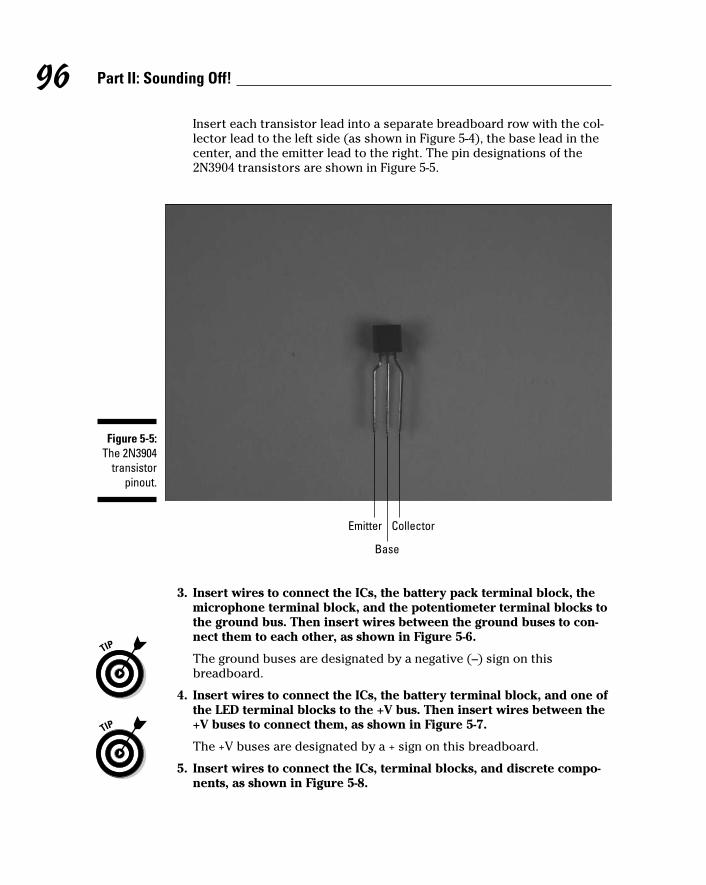
Insert each transistor lead into a separate breadboard row with the col-lector lead to the left side (as shown in Figure 5-4), the base lead in thecenter, and the emitter lead to the right. The pin designations of the2N3904 transistors are shown in Figure 5-5.
3. Insert wires to connect the ICs, the battery pack terminal block, themicrophone terminal block, and the potentiometer terminal blocks tothe ground bus. Then insert wires between the ground buses to con-nect them to each other, as shown in Figure 5-6.
The ground buses are designated by a negative (–) sign on this breadboard.
4. Insert wires to connect the ICs, the battery terminal block, and one ofthe LED terminal blocks to the +V bus. Then insert wires between the+V buses to connect them, as shown in Figure 5-7.
The +V buses are designated by a + sign on this breadboard.
5. Insert wires to connect the ICs, terminal blocks, and discrete compo-nents, as shown in Figure 5-8.
Base
Emitter Collector
Figure 5-5:The 2N3904
transistorpinout.
96 Part II: Sounding Off!
10_009683 ch05.qxp 6/22/06 9:39 PM Page 96

LED terminal block to +V
Pin 8 of IC2 to +V Pin 8 of IC1 to +V
Battery terminal block to +V
Figure 5-7:Connect
componentsto the +V
bus.
Figure 5-6:Shorter
wiresconnect
componentsto ground
bus; the twolong wires
on the rightconnect the
groundbuses.
97Chapter 5: Making Light Dance to the Music
10_009683 ch05.qxp 6/22/06 9:39 PM Page 97

6. Insert wires to connect IC2 to the transistors and the base pins of thetransistors to each other, as shown in Figure 5-9.
7. Insert three 0.1 microfarad capacitors (C1, C4, and C6), two 10 micro-farad capacitors (C2 and C5), and one 0.001 microfarad capacitor (C3)on the breadboard, as shown in Figure 5-10.
Use both the schematic and the photo to place each component. Forexample, the schematic shows that the + side of C2 is connected to Pin 1of IC1 and that the other side of C2 is connected to potentiometer R7, soinsert the long lead of C2 in the same row as the wire connected to pin 1of IC1 and the short lead in the same row as the wire connected to theterminal block for potentiometer R7.
Pin 6 of IC2 to open region
Pin 5 of IC2 to open region
Potentiometer R24 terminal block to open region Pin 7 of IC1 to open region
Pin 6 of IC1 to open region
Connecting two rows
Pin 2 of IC2 to open region
Pin 3 of IC2 to open region
Potentiometer R7 terminal block to open region
Pin 1 of IC1 to open region
Pin 2 of IC1 to open region
Microphone terminal block to open region
Figure 5-8:Hook up theIC, terminalblocks, and
discretecomponents.
98 Part II: Sounding Off!
10_009683 ch05.qxp 6/22/06 9:39 PM Page 98

8. Insert eight 1 kohm resistors (R15–R18, R32–R35) from the emitterpins of each transistor to the ground bus, as shown in Figure 5-11.
9. Insert one 2.2 kohm resistor (R1), one 2 kohm resistor (R2), two 47kohm resistors (R3 and R4), one 100 kohm resistor (R5), two 5 kohmresistors (R6 and R8), one 1 kohm resistor (R9), one 5 kohm resistor(R6), and one 220 kohm resistor (R10) on the breadboard, as shown inFigure 5-12.
Pin 7 of IC2 to base of Q5
Pin 1 of IC2 to base of Q1
Base of Q1 to base of Q2
Base of Q2 to base of Q3
Base of Q3 to base of Q4
Base of Q5 to base of Q6
Base of Q6 to base of Q7
Base of Q7 to base of Q8
Figure 5-9:Connect
IC2 totransistors.
99Chapter 5: Making Light Dance to the Music
10_009683 ch05.qxp 6/22/06 9:39 PM Page 99

10. Insert one 2 kohm resistor (R19), two 47 kohm resistors (R20 andR21), one 100 kohm resistor (R22), one 5 kohm resistors (R21), two 1kohm resistors (R25 and R26), and one 220 kohm resistor (R27) on thebreadboard, as shown in Figure 5-13.
11. Insert wires to connect the collector pins of the transistors to the ter-minal blocks, as shown in Figure 5-14.
C6 from IC2 Pin 5 to ground bus
C4 from microphone TB to open region
C5 from IC1 Pin 7 to R24 TB
C3 from R7 TB to IC2 Pin 3
C2 from IC1 Pin 1 to R7 TB
C1 from microphone TB to open region
Figure 5-10:Insert
capacitorsinto the
breadboard.
100 Part II: Sounding Off!
10_009683 ch05.qxp 6/22/06 9:39 PM Page 100

Let there be lightsAll the brains of the circuit assembled in the previous section are there tomake the Dance to the Music light display work. Here’s the part where youassemble those lights.
Follow these steps to create your Dance to the Music display:
1. Select a series of musical notes, with eight high notes and eight lownotes.
2. Draw a musical staff on the top of the wooden box in pencil and thendraw a dot for the spot where each LED will go.
3. Drill test holes in a piece of scrap wood to determine the size of drillbit that you should use to give a press fit for the LEDs.
We used a 13⁄64" drill bit.
R15 R16 R17 R18
R32 R33 R34 R35
Figure 5-11:Insert
resistorsonto the
breadboard.
101Chapter 5: Making Light Dance to the Music
10_009683 ch05.qxp 6/22/06 9:39 PM Page 101

4. Drill holes for the LEDs at the locations you marked in Step 3.
5. With a permanent marker or paint brush, draw the musical notes andstaff on the wooden box.
6. Insert LEDs in the drilled holes.
The box at this stage is shown in Figure 5-15.
See Figure 5-15 for help with this if you’re not musical!
R10 from Pin 1 of IC2 to Pin 2 of IC2
R5 from Pin 1 of IC1 to Pin 2 of IC1
R2 from C1 to Pin 2 of IC1
R1 from C1 to +V bus
R9 from Pin 2 of IC2 to ground bus
R8 from C3 to ground bus
R6 from Pin 1 of IC1 to ground bus
R3 from Pin 3 of IC1 to +V bus
R4 from Pin 3 of IC1 to ground bus
Figure 5-12:Insert more
resistorsonto the
breadboard.
102 Part II: Sounding Off!
10_009683 ch05.qxp 6/22/06 9:39 PM Page 102

7. Attach resistors between the pairs of LEDs, as shown in Figure 5-16.
Attach the resistors to the short lead on one LED of each pair (four pairof each color) and to the long lead on the other LED of the pair.
8. Solder the resistors to the leads and clip the leads just above thesolder joint.
Clip only the leads to which you have soldered resistors. Figure 5-16shows how the LEDs and resistors should look at this point. Figure 5-17shows a close up to help you see the soldering more clearly.
R27 from Pin 7 of IC2 to Pin 2 of IC2
R26 from Pin 6 of IC2 to ground bus
R23 from Pin 7 of IC1 to ground bus
R20 from Pin 5 of IC1 to +V bus
R21 from Pin 5 of IC1 to ground bus
R19 from C4 to Pin 6 of IC1
R22 from Pin 7 of IC1 to Pin 6 of IC1
R25 from R24 TB to C6
Figure 5-13:Insert theremaining
resistorsonto the
breadboard.
103Chapter 5: Making Light Dance to the Music
10_009683 ch05.qxp 6/22/06 9:39 PM Page 103

Figure 5-15:A bit of our
favoritesong
createdfrom marker
and LEDs.
Wires connecting transistor collector pins to terminal blocks
Figure 5-14:Connect the
collectorpins of the
transistor toterminalblocks.
104 Part II: Sounding Off!
10_009683 ch05.qxp 6/22/06 9:39 PM Page 104

Figure 5-17:A close-up
of thesoldering
job.
Figure 5-16:Resistorssoldered
and leadsclipped.
105Chapter 5: Making Light Dance to the Music
10_009683 ch05.qxp 6/22/06 9:39 PM Page 105

Be sure to heed all the safety precautions about soldering that we pro-vide in Chapter 2. For example, don’t leave your soldering iron on if youhave to step away to let the pizza delivery guy in. And just in case a bitof solder has an air pocket that could cause it to pop, wear your safetyglasses whenever you solder or clip leads and wires.
9. Connect and solder short lengths of 20 gauge red wire between theremaining long LED leads. Then attach a 12" 20 gauge red wire to theremaining long lead of the first LED pair, as shown in Figure 5-18.
These wires are the +V bus for the LED arrays; you attach the 12" wire toa terminal block to supply voltage to the bus.
10. Clip the LED leads just above the solder joint.
Clip only the leads to which you have soldered the red wires; you needthe remaining leads in the next step.
11. Connect and solder a 12" 20 gauge black wire to the remaining shortLED lead on each pair of LEDs, as shown in Figure 5-19.
Figure 5-18:Red wires
forming the+V bus for
the LEDarrays.
106 Part II: Sounding Off!
10_009683 ch05.qxp 6/22/06 9:39 PM Page 106

You will connect each of these eight wires to a terminal block. Theupcoming Figure 5-20 shows these connections close up.
Figure 5-20:A close-up
of all theconnections.
Figure 5-19:Black wiresto connect
each pair ofLEDs to
terminalblocks.
107Chapter 5: Making Light Dance to the Music
10_009683 ch05.qxp 6/22/06 9:39 PM Page 107

12. Clip the LED leads just above the solder joint.
Make sure that the LED leads and solder joints don’t touch each other.Coat them with liquid electrical tape to help prevent any shorts thatcould occur if you bend or push the wires together.
Adding the rest of the doohickeysAfter the circuit and LEDs are pretty much taken care of, you have a lot ofother things still sitting on your workbench, like the microphone, poten-tiometers, a switch, and one or two more things. You have to take care ofassembling these before your project will work.
Follow these steps to take care of all the rest of the parts that make the musicdance:
1. Solder a 12" black wire to the microphone ground contact and a 12"red wire to the microphone +V contact.
Figure 5-21 identifies the microphone contacts.
Ground contact
+V contact
Black wire
Red wire
Figure 5-21:Solder wires
to themicrophone.
108 Part II: Sounding Off!
10_009683 ch05.qxp 6/22/06 9:39 PM Page 108

2. Drill holes in the box where you will insert the microphone and on/offswitch.
We put both the potentiometers and on/off switch on one side of the boxand the microphone on another side, but the placement is really up toyou. Chose a drill bit size for the microphone hole so that the micro-phone has a slip fit. The upcoming Figure 5-22 shows where we placethese components.
See Chapter 4 for more information about choosing drill bit sizes for par-ticular components and other pieces of wisdom on how to customize abox for your projects. Make sure you use safety glasses when drilling,and clamp the box to your worktable!
3. Slip the shaft of the on/off switch through the drilled hole and securewith the nut provided.
4. Slip the shaft of the potentiometers through the drilled holes andsecure with the nuts provided.
5. Slip a knob over the shaft of each potentiometer and tighten the knobwith the set screw provided.
The tread on potentiometers is about 1⁄4" long, so if the wall of yourwooden box is 1⁄4" thick, you won’t be able to use the nut to secure thepotentiometer. Instead, check to make sure that the potentiometer shaftextends far enough beyond the box to allow the knob set screw to tightenon the shaft. If the shaft extends far enough, glue the face of the poten-tiometer to the box, making sure that you don’t get any glue on the rotat-ing shaft of the potentiometer. If the shaft doesn’t protrude quite enough,use a small chisel to remove some wood on the inside of the box to letthe potentiometer shaft extend a little farther before you glue.
6. Slip the microphone into its drilled hole with a press fit.
Figure 5-22 shows the on/off switch, potentiometers, and microphone inplace in the box.
7. Solder 12" black wires to each of the three potentiometer lugs, asshown Figure 5-23.
8. Solder the black wire from the battery pack to one lug of the on/offswitch and solder a 12" black wire to the remaining lug of the on/offswitch.
Figure 5-23 shows the switch after the wires are soldered.
9. Attach Velcro to the breadboard and the box and then secure thebreadboard in the box.
10. Attach Velcro to the battery pack and the box and then secure the bat-tery pack in the box.
109Chapter 5: Making Light Dance to the Music
10_009683 ch05.qxp 6/22/06 9:39 PM Page 109

11. Insert the wires from the LEDs, battery pack, and the on/off switch tothe terminal blocks on the breadboard, as shown in Figure 5-24.
Use the following as a key to the numbered callouts in Figure 5-24.
1. Red wire from LED +V bus
2–5. Wires from pair of red LEDs
6–9. Wires from pair of green LEDs
10. Red wire from battery pack
11. Black wire from on/off switch
12. Red wire from microphone
13. Black wire from microphone
14 and 17. Wires from right potentiometer lug
15 and 18. Wires from center potentiometer lug
16 and 19. Wires from left potentiometer lug
On/off switch Microphone
Potentiometers
Figure 5-22:Box with on/
off switch,potentio-
meters, andmicrophone
in place.
110 Part II: Sounding Off!
10_009683 ch05.qxp 6/22/06 9:39 PM Page 110

12. As you insert the wires, cut each of them to the length needed toreach the assigned terminal block and strip the insulation from theend of the wire.
13. Secure the wires with wire clips.
Trying It OutOkay, you’ve been taking it on faith that this is going to be a cool project, andwe appreciate it. But now it’s time to get the thing going and see whether youthink it’s as much fun as we do.
Black wire from battery pack to on/off switch
Black wire to on/off switch
Wires to potentiometers
Figure 5-23:Wires
soldered tothe on/off
switch andthe potenti-
ometers.
111Chapter 5: Making Light Dance to the Music
10_009683 ch05.qxp 6/22/06 9:39 PM Page 111

You can use any music you like to get the effect going, but we found thatmusic with lots of instruments — like a swing band with lots of brass —works best. Also, music with an upbeat tempo moves along and gets thelights switching on and off faster, which makes the effect better. Our favoritenumber for dance to the music? Ella Fitzgerald singing Take the A Train, byBilly Strayhorn. (Ask your parents; they might have heard of it.)
Here are the simple steps to get this project going:
1. Pop the batteries into the battery pack.
2. Flip the on/off switch to on.
10
11
15
16
61
78
9
1418
32
1719
54
12
13
Figure 5-24:LEDs,
batterypack, and
on/offswitch
connectedto the
breadboard.
112 Part II: Sounding Off!
10_009683 ch05.qxp 6/22/06 9:39 PM Page 112
3. Put on some music.
That’s it! Watch the lights go on an off in response to the high and lowfrequencies in the music. You can adjust the sensitivity of the LEDs byturning the potentiometers.
Here are the obvious things to check out if you’re having a problem:
Check that all the batteries are fresh and tight in the battery pack andthat all face the right direction.
If one or two LEDs aren’t working, replace them.
If two LEDs in series with each other aren’t functioning, you might havereversed the long and short leads of the LEDs; if so, just replace that pairof LEDs.
You are playing Brahm’s Lullaby. Brahm’s Lullaby will not light up a singleLED. Switch to Snoop Doggy Dogg or Motörhead.
Taking It FurtherBy now, you’re probably jumping and jiving to this cool light show, playingevery CD you have to see what they do, and still, you want more? Here are afew different ways to take this project further:
Obviously, you can change from a musical staff and notes to any kind ofshape you might want to define with your LEDs. You can have two starsor a sun and moon, for example.
You can use a band pass filter to add more layers of frequency. For exam-ple, between your high pass filter and low pass filter, you could add twomore band pass filters to hit intermediate frequencies and have four setsof LEDs going off in response to music.
You could miniaturize your circuit so you can pin it on your shirt or takeit with you to parties. A few steps would help you to get a smaller cir-cuit. First, you could use smaller LEDs. (This project uses T-1 3⁄4 LEDs,but you could use T1 LEDs.) You could also use a different method ofbuilding the circuit called a dead bug circuit. Imagine an IC turned on itsback with its little prongs sticking up on the air, and you get an idea ofwhat we mean. This method doesn’t involve a breadboard but makesconnection directly to the LED. Check out www.arrl.org (AmericanRadio Relay League online) for some ideas about using the dead bugapproach to building circuits.
113Chapter 5: Making Light Dance to the Music
10_009683 ch05.qxp 6/22/06 9:39 PM Page 113

114 Part II: Sounding Off!
10_009683 ch05.qxp 6/22/06 9:39 PM Page 114

Chapter 6
Focusing Sound with a Parabolic Microphone
In This Chapter Looking over the circuit
Organizing the parts list
Putting the microphone circuit on a breadboard
Assembling the dish
Picking up sounds all over the place
When’s the last time you stepped outside your door and really listenedto all that noise out there? There are birds, traffic noises, maybe a cat
slinking through the tall grass. Of course, some of these sounds you can pickup with your own two ears, but others aren’t so clear. A microphone thatcould help you pick up those softer sounds — whether made by your buddywhispering to you 100 feet away or birds in the trees — might come in handy.
In this project, we show you how to put together a microphone and an IC toamplify noises that it picks up. Then you can put the whole circuit togetherwith a parabolic (curved) metal dish that picks up sounds, just like how cup-ping your hand behind your ear helps you pick up sounds.
What a Dish! The Project OverviewA parabolic microphone kind of looks like a TV satellite dish. Instead of pick-ing up electromagnetic broadcast waves, though, this kind of microphonepicks up sound waves. Sound waves are simply vibrating molecules thatdeliver all kinds of sounds, like birds chirping and your neighbors’ latestargument. (Disclaimer: Of course, we’re NOT recommending that you usethis project to eavesdrop on anybody!) You use the microphone, the curveddish, and headphones to gather and deliver the amplified sound to your ears.
11_009683 ch06.qxp 6/27/06 5:28 PM Page 115

You can see the finished parabolic microphone (and our own author, Earl,lurking behind it) in Figure 6-1.
Figure 6-1:Parabolic
microphoneand ace
operator.
116 Part II: Sounding Off!
11_009683 ch06.qxp 6/27/06 5:28 PM Page 116

Here are the types of activities that you’ll be doing to create your own para-bolic microphone. You will
1. Put together
• An electronic circuit containing an electret microphone cartridgethat can pick up faint sounds
• An IC that amplifies the sounds enough to power your headphones
2. Install the microphone in a parabolic dish that gathers sound like a giant ear.
We use a parabolic dish because the shape gathers sound and focuses iton a point — in this case, on the spot where we put the microphone car-tridge. When you point the parabolic dish at a bird a hundred feet away,for example, the dish gathers sound only from the exact direction youpoint toward and focuses the sound on the microphone cartridge.
3. Add a handle made of pieces of plastic pipe so you can hold the dish upeasily and aim it at the feathered or non-feathered friend of your choosing.
Scoping Out the SchematicBy now, your mind is likely a-flutter with ideas for sounds floating aroundyour neighborhood that you’re dying to pick up, so it’s time to get going onthe schematic for the board, which you can see in Figure 6-2.
3
2
6
5
4
IC1
C3
C5
R2 +
-
+
+C4
R3
7SPEAKER
+
81
C2
R1
+-
S1
6V
MICC1
Figure 6-2:The
schematicof the
parabolicmicrophone
circuit.
117Chapter 6: Focusing Sound with a Parabolic Microphone
11_009683 ch06.qxp 6/27/06 5:28 PM Page 117

The following is a list of the schematic elements for your parabolic microphone:
The circuit starts with the electret microphone, which transforms soundwaves into electrical signals.
R1 connects the microphone to positive voltage and supplies the 3 voltsrequired to make the microphone function.
C1 is a capacitor that blocks the DC voltage on the input signal andallows the AC signal to pass.
IC1, an LM386N-1 audio amplifier, takes the electrical signal generatedby the electret microphone and amplifies it to provide sufficient powerto generate sound through the headphones.
R2 is a potentiometer you use to control the sound volume.
C2 sets the voltage gain of IC1 to 200. Therefore the voltage out is 200times the voltage in.
C3 improves the stability of the LM386 amplifier to prevent problems,such as oscillation. Oscillation can turn that nice little birdcall into ahodgepodge of unintelligible sounds.
C4 removes any DC offset from the output of the LM386 amplifier.
C5 acts as a current bank for the output. This capacitor drains whensudden surges of current occur and refills with electrons when thedemand for current is low.
Building Alert: Construction IssuesThe electret microphone cartridge used in this project is about 1⁄4" in diame-ter. Therefore, the contact pads on the cartridge to which you solder wiresare very small. Review the methods for soldering to contact pads that wecover in Chapter 4. And don’t forget to use your magnifying glass after solder-ing to check for solder bridging (a clump of solder that could short out theconnection) between the two pads.
If you find bridging solder, try using a utility knife to gently clean it out. Also,you might subscribe to the better-safe-than-sorry theory and consider order-ing two of these microphone cartridges. That way, if you ruin one while learn-ing how to solder to these small contact pads, you have a second one at theready, saving you time and shipping fees for a second order.
The parabolic dish comes with a reflective finish. We recommend spray paint-ing it to avoid blinding yourself or others with the sun’s reflection from the
118 Part II: Sounding Off!
11_009683 ch06.qxp 6/27/06 5:28 PM Page 118

dish’s original finish. Note: Before painting, be sure to wipe off the dish to getrid of dust or smudges because spray painting makes any smudges on thesmooth surface really stand out.
Feel free to get creative when choosing a color for the dish; if you’re planningto listen to wildlife, you might want to paint the dish a color that will blendin, such as green or brown. We painted ours black because, well, we had theblack paint.
Use a special glue — PVC cement to connect the PVC fittings that form themicrophone handle. You can get this type of glue at any building supplystore. This glue provides a very strong joint, which you need because thedish is somewhat heavy and you don’t want the handle to fall apart, causingyou to drop the dish on the ground. (This happened to us with a prototypewe hadn’t yet glued together. Nancy’s ears are still ringing from the resultingamplified crash.)
Be sure to wear some form of work gloves when using this glue because itmelts plastic — you definitely don’t want this stuff on your hands! Also readthe label for advice on safety, such as using the glue in a well-ventilated areaas well as what to do if it does come into contact with your skin.
Perusing the Parts ListHere comes our favorite part — shopping for parts! The upcoming Figures 6-3and 6-4 show many of the parts used in this project.
Here’s what you’ll need:
Electret microphone cartridge
Trust us. We tried a lot of microphones to get this working just right(and save you the trouble). We finally decided on the Panasonic part#WM61A because of its very high sensitivity that allows it to pick upfaint sounds. We found the WM61 at Digikey (www.digikey.com).
10 kohm potentiometer (R2)
10 ohm resistor (R3)
5.6 kohm resistor (R1)
0.1 microfarad ceramic capacitor (C1)
0.047 microfarad ceramic capacitor (C5)
10 microfarad electrolytic capacitors (C2, C3)
119Chapter 6: Focusing Sound with a Parabolic Microphone
11_009683 ch06.qxp 6/27/06 5:28 PM Page 119

100 microfarad electrolytic capacitor (C4)
LM386N-1 amplifier IC1
Of the many versions of the LM386 amplifier, we chose the LM386N-1because it is designed to work with the supply voltage of 6 voltsrequired by this circuit.
Battery pack for 4 AA batteries
Edmund Scientific’s (www.edsci.com) 24"-diameter parabolic reflec-tor, part #3053876
SPST toggle switch, used as the on/off switch
830-pin breadboard
Five 2-pin terminal blocks
Knobs for the potentiometer
Two phono jacks
Two right-angle phone plugs
We use right-angle plugs to avoid having a loop of wire coming out of thebox. (You can also use something called a banana plug and jack.)
Headphones
We used a set of Philips HP170, but you can use any headphone youhave available. Obviously, the better quality headphone you use, thebetter the sound quality.
Headphone jack
We used a 1⁄4" jack. If your headphone plug is a different size, use theappropriate size jack or get an adaptor.
Enclosure to protect the circuit
We used a plastic box, RadioShack part #2701807.
An assortment of different lengths of prestripped, short 22 AWG wire
PVC adaptor with 3⁄4" female slip fitting on one end and a 1" thread fit-ting on the other end
PVC 90° joint with a 1" slip fitting on both ends (one male and onefemale)
PVC adaptor 1" female slip fitting to a 1" female thread
PVC 1" end cap with a 1" female slip fitting
5⁄16"-diameter wooden dowel
120 Part II: Sounding Off!
11_009683 ch06.qxp 6/27/06 5:28 PM Page 120

Washer with a 1⁄4" inner diameter (ID) and 11⁄2" outer diameter (OD)
3⁄16" ID rubber 0-ring
1⁄4" thick rubber gasket material
1" diameter schedule 40 PVC pipe, 16" long
1" clamp
Four 1⁄2" 8-32 panhead screws
Four 8-32 nuts
You should be able to find the last 12 parts on this list at your local buildingsupply or hardware store. Take this book with you: The photos should helpyou pick out the right parts, and everybody who sees you with it will realizejust how smart you are.
Microphonecartridge
Right-anglephono plug
SPST toggle switch Phono jack
Electrolyticcapacitor
Potentiometer
Headphone jackCeramic capacitor IC
Figure 6-3:Key
components.
121Chapter 6: Focusing Sound with a Parabolic Microphone
11_009683 ch06.qxp 6/27/06 5:28 PM Page 121

Taking Things Step by StepWe’ve taken a lot of the pain out of this project for you by finding just theright microphone, the right dish size, headphones, and so on so that you caneasily pick up distant sounds. This took many mornings of standing on eitherend of our street shouting, “Say that again; I couldn’t hear you!” Our neigh-bors still wonder about us, but it was worth it.
We further simplify your life by breaking down the process into a few easysteps.
PVC adaptor fitting3/4" slip fit to 1" thread 3/16" ID rubber O-ring
PVC adaptor fitting1" slip fit to 1" thread
PVC 90° fitting ¼" ID,1½" OD washer
1" clamp
Figure 6-4:More key
components.
122 Part II: Sounding Off!
11_009683 ch06.qxp 6/27/06 5:28 PM Page 122

Building an amplifier circuitThe first step in building a parabolic microphone is to tackle the circuit thatforms its electronic brains. Here are the steps involved:
1. Place LM386N-1 (IC2) and five terminal blocks (TB) on the bread-board, as shown in Figure 6-5.
The five terminal blocks shown in this figure will be used to connect twowires each to various components in the circuit. The wires from thesefive terminal blocks will go to the battery pack, the on/off switch, themicrophone, the speaker, and the potentiometer.
2. Insert wires to connect the IC and the terminal blocks to the groundbus and insert a wire between the two ground buses to connect them,as shown in Figure 6-6.
Six shorter wires connect components to ground bus; the long wire onthe right connects the two ground buses.
Figure 6-5:Place the ICand terminal
blocks on the
breadboard.
123Chapter 6: Focusing Sound with a Parabolic Microphone
11_009683 ch06.qxp 6/27/06 5:28 PM Page 123
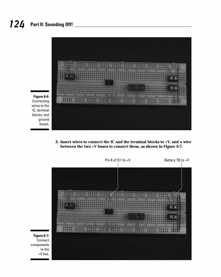
3. Insert wires to connect the IC and the terminal blocks to +V, and a wirebetween the two +V buses to connect them, as shown in Figure 6-7.
Battery TB to +VPin 6 of IC1 to +V
Figure 6-7:Connect
componentsto the
+V bus.
Figure 6-6:Connectingwires to theIC, terminalblocks, and
groundbuses.
124 Part II: Sounding Off!
11_009683 ch06.qxp 6/27/06 5:28 PM Page 124

4. Insert wires to connect the ICs, terminal block for the microphone car-tridge, terminal blocks for the potentiometer (R2), terminal block forthe headphone jack, and discrete components, as shown in Figure 6-8.
5. Insert the 0.047 microfarad capacitor (C5), two 10 microfarad capaci-tors (C2 and C3), one 100 microfarad capacitor (C4), one 0.1 micro-farad capacitor (C1), one 5.6 kohm resistor (R1), and one 10 ohmresistor (R3) on the breadboard, as shown in Figure 6-9.
When inserting electrolytic capacitors, be sure to check the schematicfor where to insert the longer + lead.
We discuss in Chapter 4 how you can determine how short to clip theleads of many of these components to make them fit neatly on the bread-board. And you knew we were going to say it: Make sure you wear yoursafety glasses when clipping leads!
Open regionto headphone jack TB
Pin 5 of IC1to open region
Microphone TBto open region
Open regionto R2 TB
Pin 8 of IC1to open region
R2 TBto Pin 3 of IC1
Figure 6-8:Hook up theICs, terminalblocks, and
discretecomponents.
125Chapter 6: Focusing Sound with a Parabolic Microphone
11_009683 ch06.qxp 6/27/06 5:28 PM Page 125

Mounting everything on the dishTime to assemble the handle that allows you to hold the parabolic micro-phone. Figure 6-10 shows how the pieces (minus the parabolic dish itself) go together. When these fittings are assembled on the parabolic dish, thethreads go through the hole in the center of the dish with one gasket insidethe dish and one gasket outside the dish.
R3from C5
to ground
C5 from Pin 5of IC1
to open region
C1 frommicrophone TB
to R2 TB
C3 from Pin 7of IC1
to ground
R1 from C1to +V
C4 from Pin 5 of IC1to headphone jack TB
C2 from Pin 1 of IC1to Pin 8 of IC1
Figure 6-9:Insert
resistorsand
capacitorson the
breadboard.
126 Part II: Sounding Off!
11_009683 ch06.qxp 6/27/06 5:28 PM Page 126

1. In the sheet of gasket material, cut a hole (using your utility knife or X-ACTO knife) large enough to slip over the 1" threads.
Use one of the PVC fittings as a template.
2. Use scissors to cut the outer diameter of the gasket about 3⁄8" largerthan the inner diameter.
3. Repeat Steps 1 and 2 to create a second gasket.
Whenever you cut with a utility knife or an X-ACTO knife, wear leatherwork gloves to reduce the chance of cutting yourself if the knife slips.
4. Glue a 16", 1"-diameter PVC pipe into the female end of the 90° fitting.
5. Glue the male end of the 90° fitting into the slip fit end of the 1" x 1"fitting.
1" thread x 1" slip fittingGaskets
1" x 1" 90° slip fitting 1" PVC pipe1" thread x ¾" slip fitting
Figure 6-10:Put thefittings
together like this.
127Chapter 6: Focusing Sound with a Parabolic Microphone
11_009683 ch06.qxp 6/27/06 5:28 PM Page 127

6. Drill a 3⁄8" hole about eight inches from the end in the side of the PVC pipe that will be to your left when you’re holding the parabolicmicrophone.
You use this hole to feed the wires from the microphone cartridge to thebox containing your circuit.
7. Slip one of the gaskets over the threads on the 1" x 3⁄4" fitting. Then slipthe threads from the inside through the hole in the dish.
8. Slip the other gasket over the threads and then screw the 1" x 1" fit-ting onto the threads.
9. Tighten the fitting by hand so that the gaskets are compressed a littleand the dish is held securely between the gaskets.
Figure 6-11 shows the handle assembled on the dish.
Mounting the microphoneThe microphone is what makes this project work. The first step here is tomake the microphone mounting. Follow these steps:
Figure 6-11:Fittings
assembledon the
parabolicdish.
128 Part II: Sounding Off!
11_009683 ch06.qxp 6/27/06 5:28 PM Page 128

1. Cut four 6" pieces of wooden dowel.
2. Cut a slot about one-third of the way through each dowel, 1⁄4" from an end.
The slot has to be wide enough for the washer to slip into.
3. Assemble the dowels and washer in the parabolic dish, as shown inFigure 6-12.
Use cable ties to hold the dowels in place. If you are doing this by your-self, it can be kind of a struggle, but it is doable. Getting another personto hold the dowels in place while you put the cable ties on it will simplifyyour life.
4. Solder an 18" black wire to the ground pad of the microphone car-tridge and an 18" red wire to the +V pad.
Figure 6-13 shows a cartridge before and after soldering.
Figure 6-12:Put together
the micro-phone
mounting.
129Chapter 6: Focusing Sound with a Parabolic Microphone
11_009683 ch06.qxp 6/27/06 5:28 PM Page 129

5. Twist the free ends of the wires from the microphone cartridgetogether and feed the microphone wires through the PVC fittings frominside the parabolic dish until the end of the wire reaches the 3⁄8" hole.
If you have trouble pushing the wires around the 90° turn, take a stiffwire with a hook shape in the end (we used some 10 gauge wire; manybuilding supply stores will sell you a few feet of this) and pull the wiresthrough the PVC fittings and pipe.
6. Use a piece of 20 or 22 gauge wire with a hook shape on the end topull the wires from the microphone cartridge through the 3⁄8" hole.
7. Pull the wires through the 3⁄8" hole, leaving enough wire inside theparabolic dish for the microphone cartridge to reach the 11⁄2" washerwith about two inches of slack left over.
8. Cut the wires to allow three inches to extend from the 3⁄8" hole in thepipe and attach each wire to a right-angle phono plug, as shown inFigure 6-14.
You can use either a plug that requires soldering to the wire or one thatuses a screw to secure the wire, as we did here.
Red wireBlack wire
Ground pad +V pad
Figure 6-13:Solder wires
to themicrophone
cartridge.
130 Part II: Sounding Off!
11_009683 ch06.qxp 6/27/06 5:28 PM Page 130

9. From the inside of the dish, put the 3⁄8" inner diameter O-ring over themicrophone cartridge and glue the O-ring to the washer, as shown inFigure 6-15.
Figure 6-15:Microphone
cartridge in place.
Figure 6-14:Thread
wires fromthe micro-
phonecartridge
through thePVC fittings
and pipe.
131Chapter 6: Focusing Sound with a Parabolic Microphone
11_009683 ch06.qxp 6/27/06 5:28 PM Page 131

Make sure you don’t get glue on the front side of the microphone car-tridge, or it could interfere with any sound coming through.
10. Use another cable tie to secure the wires from the microphone to oneof the dowels.
Mounting switches and more on the boxIt’s time to drill all kinds of holes and pop various components into the box.Follow these steps to do so:
1. Drill holes in the box where you will mount the potentiometer, audio jacks, headphone jack, clamp, and on/off switch, as shown inFigure 6-16.
We put the on/off switch and potentiometer on one side of the box, theheadphone jack on the opposite side of the box, and the phono jacks onthe bottom of the box.
We kept the headphone jack to one side to keep the output signal fromfeeding into the input of the circuit (for example, by being near themicrophone wires), which could cause feedback.
Screws and nutssecuring the clampAudio jack
Headphone jackPotentiometerOn/Off switch
Figure 6-16:Box with
on/offswitch,poten-
tiometer,headphone
jack, clamp,and audio
jacks.
132 Part II: Sounding Off!
11_009683 ch06.qxp 6/27/06 5:28 PM Page 132

See Chapter 4 for more information about choosing drill bit sizes for par-ticular components and other advice on how to customize a box foryour projects. Make sure you use safety glasses when drilling and clampthe box to your worktable!
2. Slip the shaft of the on/off switch through the drilled hole and securewith the nut provided.
3. Slip the shaft of the potentiometer through the drilled hole and securewith the nut provided.
4. Slip the knob on the potentiometer shaft and secure with the set screw.
5. Slip the threads of the headphone jack through the drilled hole andsecure with the nut provided.
6. Slip the threads of the audio jacks through the drilled holes andsecure with the (you guessed it) nuts provided.
7. Slip 8-32 screws through holes in the clamp and the holes you drilledin the box and secure with nuts from the inside of the box.
8. Solder the black wire from the battery pack to one lug of the on/offswitch and solder an 8" black wire to the remaining lug of the on/offswitch, as shown in Figure 6-17.
9. Solder one 8" black wire to the lug on one of the audio jacks andsolder one 8" red wire to the lug on the other audio jack, as shownFigure 6-17.
10. Solder 8" wires to each of the three potentiometer lugs, as shown inFigure 6-17.
11. Solder one 8" black wire and one 8" red wire to the lugs of the head-phone jack, as shown Figure 6-17.
The red wire should go to the contact that touches the tip of the head-phone plug.
Okay, we’ll say it again: Heed all the safety precautions about soldering that wegive you in Chapter 2. Don’t ever leave your soldering iron on and unattended.And to avoid damage from flying pieces of solder, wear your safety glasses!
133Chapter 6: Focusing Sound with a Parabolic Microphone
11_009683 ch06.qxp 6/27/06 5:28 PM Page 133
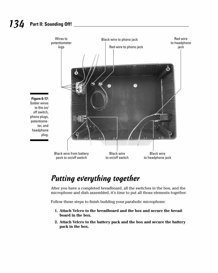
Putting everything togetherAfter you have a completed breadboard, all the switches in the box, and themicrophone and dish assembled, it’s time to put all those elements together.
Follow these steps to finish building your parabolic microphone:
1. Attach Velcro to the breadboard and the box and secure the bread-board in the box.
2. Attach Velcro to the battery pack and the box and secure the batterypack in the box.
Red wireto headphone
jack
Wires topotentiometer
lugs Red wire to phono jack
Black wireto on/off switch
Black wire from batterypack to on/off switch
Black wireto headphone jack
Black wire to phono jack
Figure 6-17:Solder wires
to the on/off switch,
phono plugs,potentiome-
ter, andheadphone
plug.
134 Part II: Sounding Off!
11_009683 ch06.qxp 6/27/06 5:28 PM Page 134

3. Insert the wires from the headphone jack, potentiometer, phono jacks,battery pack, and the on/off switch to the terminal blocks on thebreadboard, as shown in Figure 6-18.
4. As you insert the wires, cut each of them to the length you need toreach the assigned terminal block and strip the insulation from theend of each wire.
Keep the wires from the headphone jack as far as possible away fromthe wires from the potentiometer and the wires from the microphonecartridge. Remember how a microphone put too close to a speaker canproduce an awful screech? The same screech can assault your ears ifthese wires get too close together.
Black wirefrom on/off
switch
Red wirefrom
battery pack
Black wirefrom headphone
jack
Red wirefrom headphone
jack
Black wirefrom
phonojack
Red wirefrom
phonojackWire from left lug of potentiometer
Wire from right lug of potentiometer
Wire from center lug of potentiometer
Figure 6-18:Connect theheadphonejack, poten-
tiometer,on/off
switch, andbattery pack
to thebreadboard.
135Chapter 6: Focusing Sound with a Parabolic Microphone
11_009683 ch06.qxp 6/27/06 5:28 PM Page 135

5. Secure the wires with wire clips where needed.
The way that parts are laid out in this box as well as the distance betweensome of the components — such as from the phono jacks to the terminalblocks — are both short enough that you won’t need wire clips.
6. Slip the box onto the PVC pipe and tighten the clamp screws.
Don’t tighten them too much; you still need to slide the box into its finalposition.
7. Put batteries in the battery pack and put the lid on the box, securingit with the screws provided with the box.
8. Slide the box into its final position just below the hole where thephono jacks come out of the PVC pipe. Then insert the phono plugsand headphone plug into the jacks in the box, as shown in Figure 6-19.
9. Glue the 1" PVC end cap on the end of the PVC pipe.
You can see the finished product at the beginning of the chapter inFigure 6-1.
Figure 6-19:The
electronicsin place.
136 Part II: Sounding Off!
11_009683 ch06.qxp 6/27/06 5:28 PM Page 136

Trying It OutAt this point, the microphone is ready to go, but here are a few tips to help yoube kind to your ears — you can get some really loud noises out of this thing.
Before putting on the headphones, flip the switch on and adjust thevolume control.
You’ll be able to hear enough to make sure you don’t have the volume sohigh that it hurts your ears.
Avoid knocking the parabolic dish against anything like a tree trunkor your cat while you have the headphones on. The resultant ringing inyour ears is not a desirable thing.
Avoid having any “friends” shout into the parabolic dish, or anywherenear it, while you have the headphone on.
Time to get this thing in gear. Here goes:
With the headphones on your head, flip the On switch, point the thing atsomething you want to listen to (such as a neighborhood bird or your bestfriend), and listen.
If you don’t get the results we got, here are some options to check out:
Check that all the batteries are fresh, tightly inserted in the batterypack, and face the right direction.
Check that no wires or components have come loose.
Compare your breadboard with the photos to make sure all the wiresand components are connected correctly.
Taking It FurtherAfter you wander around your neighborhood with your parabolic micro-phone (and explain to curious passersby what that thing is), you might wantto try some variations. Here are our suggestions:
Instead of headphones, hook up a tape recorder to the circuit and recordsounds. (Once again, do not record your neighbors because there is prob-ably some kind of law against this — and if there isn’t, there should be.)
137Chapter 6: Focusing Sound with a Parabolic Microphone
11_009683 ch06.qxp 6/27/06 5:28 PM Page 137

Get a bigger dish and set it up outside, hooked into speakers you set upin a permanent wildlife listening station either outdoors or in yourhouse. (We say permanent because a dish much bigger than 24 inchesneeds a wheelbarrow to cart it around.)
If you replace the microphone with a speaker, you could turn this thing on its head and make it a loudspeaker instead of a long-distancemicrophone. Look up any noise ordinances on the books before tryingthis one!
138 Part II: Sounding Off!
11_009683 ch06.qxp 6/27/06 5:28 PM Page 138

Chapter 7
Murmuring MerlinIn This Chapter Scoping out the schematic
Running down the parts list
Breadboarding the wizard’s circuit
Programming a sound synthesizer chip
Placing the board in the puppet
Getting sounds from Merlin
A picture can be worth a thousand words, but sometimes a word — orsound — is just what’s needed. In this project, you work with a sound
synthesizer chip, an amplifier, and a speaker. With this setup, you can pro-duce almost any sound you can imagine.
You can place a sound chip in just about anything and use switches to acti-vate sounds. For this project, we chose a hand puppet (ours happens to be awizard because we’re into fantasy fiction); a hollow puppet lets you easilyinsert the project breadboard and switches. However, you can use anythingyou like for your talking pal.
As you work through this project, you discover how to work with programma-ble sound synthesizer chips as well as a bit about how amplification works.
The Big Picture: Project OverviewWhen you complete this project, you’ll have a talking hand puppet. You canprogram the synthesizer chip inside the puppet with any messages you like.For example, we programmed ours to say, “The check’s in the mail,” “Youcan’t have more money,” and “Where’s the darn chapter?!” — and then wegave it to our editor.
12_009683 ch07.qxp 6/22/06 9:38 PM Page 139

These messages (or sounds) are activated when you shake either of thepuppet’s hands or press the puppet’s nose. Alas, adding the electronics tothe puppet makes it unsuitable for use on your hand, but you can’t haveeverything.
You can see the finished talking puppet (okay, you have to imagine the soundpart) in Figure 7-1.
Here are the types of activities that you’ll do to create your own talking toy:
1. Put together an electronic circuit containing a sound synthesizer chip,an amplifier, and a speaker.
2. Hook up the circuit to your computer to program the sound synthesizerwith sentences, music, or whatever strange sounds you’d like to playaround with.
3. Place the box containing the circuit in the puppet and connect switchesin the puppet to the circuit.
Figure 7-1:We affec-
tionatelycall ourtalkingpuppet
MurmuringMerlin.
140 Part II: Sounding Off!
12_009683 ch07.qxp 6/22/06 9:38 PM Page 140

After these steps, when someone presses either of the puppet’s hands orpresses its nose, it plays whatever you programmed in the sound synthesizerfor that particular switch.
Although the hand puppet we work with in this chapter might seem like a toy,it’s not intended for small children. The wires and small electronic compo-nents could be swallowed, and you don’t certainly want small kids playingwith batteries.
Scoping Out the SchematicYou have only one breadboard to put together for this project. You can seethe schematic for the board in Figure 7-2.
The following is a list of the schematic elements for our Murmuring Merlin.
IC1 is a SpeakJet sound synthesizer model. You can connect this IC toyour computer and program it to generate electrical signals by usingsoftware supplied by the manufacturer. These signals correspond towords that form sentences, sounds that create music, or various coolsound effects. The software allows you to program eight sounds; eachsound is controlled by one of the Pins 1–4 and 6–9 of the IC.
C1 is a capacitor that filters noise from the +4.5V supply to IC2.
Switches S1, S2, and S3 control the voltage on Pins 2, 4, and 7. Theswitches are normally open, which means each pin is normally con-nected to ground. When you push one of the switches, the voltage onthe corresponding pin raises to +4.5 volts. When you release the switch,the voltage on the pin returns to ground. Because we programmed theSpeakJet to trigger when the voltage on a pin changes from high (+4.5volts) to low (ground), the sound which that pin controls is triggeredwhen you press and release the corresponding switch. We used threeswitches to control three sounds because the puppet we used has threehandy spots where we could place switches. (If you’re lucky enough tofind an octopus puppet, you can have up to eight switches, controllingup to eight sounds.)
IC2, a MAX232 driver/receiver chip, converts the signals from your com-puter. These signals aren’t generated with the correct voltage for thiscircuit, so signals have to be converted so that they can be used by theSpeakJet chip. This chip also converts signals from the SpeakJet into sig-nals that your computer can use.
141Chapter 7: Murmuring Merlin
12_009683 ch07.qxp 6/22/06 9:38 PM Page 141

Resistors R1, R2, and R3 limit the current running to ground when youpress switches S1, S2, or S3.
C2, C3, C4, and C5 are capacitors that fill a function that the Max232designers call charge pump capacitors. These are required to make theIC2 function properly.
3
2
6
5
4
IC3
C8
C9
C10
R8 +
-
+
+4.5 V
15
2
7
4
1 10
2
1
3
615
5
4
16
R7R6
18
14
11
12
13
5
3
6
8
9
14
13
8
3
+
+
11
12
+
+
+ 4.5 V
S1 S2 S3
R1
R2
R3
R4
R5
+
C1
C2
C3
C4
C5
5
C6 C7
IC1IC2
+
+C11
R9
7
Figure 7-2:The
schematicof the
talkingpuppetcircuit.
142 Part II: Sounding Off!
12_009683 ch07.qxp 6/22/06 9:38 PM Page 142

R6 and R7, C6 and C7 are two resistors and two capacitors, respec-tively, that form a filter (a low pass filter) that eliminates high-frequencynoise prior to the signal reaching the amplifier.
C8 is a capacitor that removes any DC offset from the output of IC1.
R8 is a potentiometer that controls the sound volume.
IC3, an LM386N-1 audio amplifier, takes the electrical signal generatedby the SpeakJet when you push and release one of the switches in thepuppet and then amplifies the electrical signal to create enough powerto drive the speaker.
C9 is a capacitor that improves the stability of the LM386 amplifier toprevent problems such as oscillation.
Capacitor C10 acts as a current bank for the output. This capacitordrains when sudden surges of current occur and refills with electronswhen the demand for current is low.
C11 is a capacitor that removes any DC offset from the output of theLM386 amplifier.
Building Alert: Construction IssuesThe tactile switches that we use in this project have very tiny leads that aremeant to be surface mounted in an assembly line. Given that we (and you)don’t have an assembly line handy, we used needlenose pliers to crimp wirearound the tiny leads to hold the wires in place while we soldered them.
The DB9 connector has a small metal tube or cup to which you can soldereach wire connection. We found that the easiest way to solder a wire to oneof these tubes is to melt some solder into the tube, reheat the tube, and theninsert the bare wire end into the melted solder.
When inserting electrolytic or tantalum capacitors into the breadboard, pay attention to the polarity. Inserting the capacitors the wrong way coulddamage the capacitors and possibly other components in your circuit. Thelonger lead of the capacitor is the + side. The schematic shows you whichdirection to insert the capacitor. For example, the + lead of capacitor C2 goestoward Pin 1 of IC2, and the other lead goes toward Pin 3 of IC2.
In order to feed wires from the tactile switches to a location where they couldbe connected to the electronics box by the shortest path, we had to cut a fewholes in the fabric of the puppet. Don’t worry; he won’t feel a thing.
143Chapter 7: Murmuring Merlin
12_009683 ch07.qxp 6/22/06 9:39 PM Page 143

Perusing the Parts ListYour biggest shopping decision for this project is what to place the project in.The hand puppet idea is nice because it’s hollow and has a personality, asopposed to using just a plain wooden box. However, you could technicallyput the insides of the project into anything. For example, you could cut opena stuffed toy, take out the stuffing, and put the project inside.
Assuming you take our route and go with a hand puppet, though, pick outone that you like with enough room to fit the electronics enclosure and withopenings that allow you to place switches in the hands, face, or other areas.We found one at a local toy store made by Sunny and Co. Toys, Inc., theiritem #GL1902.
After you choose your housing unit, shop for the parts for the project itself,several of which are shown in the upcoming Figures 7-3 and 7-4:
Electrolytic capacitor
Ceramic capacitor
Tantalum capacitor Resistor
LM386 IC SpeakJet IC MAX232 IC
Figure 7-3:Many of the
keycomponents
for theproject.
144 Part II: Sounding Off!
12_009683 ch07.qxp 6/22/06 9:39 PM Page 144

10 kohm potentiometer (R8)
Two 33 kohm resistors (R6 and R7)
Five 1 kohm resistors (R1, R2, R3, R4, R5)
10 ohm resistor (R9)
0.01 microfarad ceramic capacitor (C6 and C7)
Five 1 microfarad tantalum or electrolytic capacitor (C1, C2, C3, C4, C5)
0.047 microfarad ceramic capacitor (C10)
Three 10 microfarad electrolytic capacitors (C8 and C9)
100 microfarad electrolytic capacitor (C11)
Battery pack for three AAA batteries
Potentiometer
Speaker
On/off switch
DB9 connectorTactile switch
Battery pack
Phono jack Phono plug Terminal block
Figure 7-4:Key
components,part 2!
145Chapter 7: Murmuring Merlin
12_009683 ch07.qxp 6/22/06 9:39 PM Page 145

We use three AAA batteries in this project to supply 4.5 volts. If we useda four-battery pack as we do in other chapters, the supply voltage wouldbe about 6 volts, above the maximum supply voltage allowed for theSpeakJet IC.
SpeakJet sound synthesizer IC1
You can find a list of distributors on the manufacturer’s Web site, www.speakjet.com.
LM386N-1 amplifier IC3
Of the many versions of the LM386 amplifier, we chose the LM386N-1because it works with the supply voltage of 4.5 volts used by this circuit.
MAX232 driver/receiver IC2
SPST (single-pole, single-throw) slide switch, used as the on/off switch
830-contact breadboard
Eight 2-pin terminal blocks
Knob (for potentiometer)
8 ohm, 1 watt speaker
Three tactile switches (S1, S2, S3)
Many of these tactical switches are very small; for example, a 6 mm × 6mm switch is less than 1⁄4" square. We bought 12 mm × 12 mm switches(part #TS6424T2602AC) made by Mountain Switch at Mouser (www.mouser.com).
Enclosure
We used Radio Shack part #270-10807.
Six phono plugs
Six phono jacks
DB9 female connector
There are about as many DB9 connecters out there as there are fish inthe sea. We used RadioShack part #276-1538.
DB9 serial port cable
Four 1⁄2" 6-32 flathead screws
Four 6-32 nuts
An assortment of different lengths of prestripped, short 22 AWG wire
146 Part II: Sounding Off!
12_009683 ch07.qxp 6/22/06 9:39 PM Page 146

Taking Things Step by StepIf we were wizards like Merlin, we could probably snap our fingers, say “Abra-cadabra,” and produce a talking puppet. Being simple electronic project geeks,though, we (and you) have to do things the old-fashioned way. Building a talk-ing puppet requires that you
1. Create the circuit.
2. Drill various holes in a box.
3. Place the circuit in the box.
4. Program the sound synthesizer.
5. Insert the box and switches into the puppet.
Creating Merlin’s circuitGet your breadboard and other little parts ready to build the circuit that willhelp Merlin murmur. Here are the steps involved:
1. Place the SpeakJet IC (IC1), the MAX232 IC (IC2), the LM386 IC (IC3),and eight terminal blocks on a breadboard, as shown in Figure 7-5.
IC3 IC2 IC1
Figure 7-5:Place the
ICs andterminal
blocks on the
breadboard.
147Chapter 7: Murmuring Merlin
12_009683 ch07.qxp 6/22/06 9:39 PM Page 147

The eight terminal blocks shown in this figure will be used to connecttwo wires each to various components in the circuit. The wires fromthese terminal blocks go to the battery pack, the DB9 connector, theon/off switch, tactile switches in the puppet, the speaker, and the poten-tiometer, respectively.
2. Insert wires to connect the ICs and the terminal blocks to the groundbus and then insert a wire between the two ground buses to connectthem to each other, as shown in Figure 7-6.
Fourteen shorter wires connect components to ground bus; the longwire on the left connects the two ground buses.
3. Insert wires to connect the ICs and the terminal blocks for the batterypack and the three tactile switches (S1, S2, S3) to the +V bus, as shownin Figure 7-7.
4. Insert wires to connect the ICs; terminal blocks for the potentiometer(R8) and tactile switches (S1, S2, S3); and discrete components, asshown in Figure 7-8.
5. Insert discrete components on the breadboard, as shown in Figure 7-9.
When inserting electrolytic or tantalum capacitors, be sure to check theschematic to see where to insert the longer, positive (+) lead. The com-ponents shown in this figure, indicated by numbered callout, include
Figure 7-6:Connect the
ICs andterminal
blocks toground; thenconnect the
groundbuses.
148 Part II: Sounding Off!
12_009683 ch07.qxp 6/22/06 9:39 PM Page 148

1. 1 kohm resistor R1 from IC1 Pin 2 to ground
2. 1 kohm resistor R2 from IC1 Pin 4 to ground
3. 1 kohm resistor R3 from IC1 Pin 7 to ground
4. 1 kohm resistor R4 from IC1 Pin 11 to +V
5. 1 kohm resistor R5 from IC1 Pin 12 to +V
6. 1 microfarad capacitor C2 from IC2 Pin 1 to Pin 3
7. 1 microfarad capacitor C3 from IC2 Pin 4 to Pin 5
8. 1 microfarad capacitor C4 from IC2 Pin 2 to ground
9. 1 microfarad capacitor C5 from IC2 Pin 6 to ground
10. 1 microfarad capacitor C1 from +V to ground
11. 33 kohm resistor R6 from wire to IC1 Pin 18 to an open region
12. 33 kohm resistor R7 from R6 to an open region
13. 10 microfarad capacitor C8 from R7 to wire to R8 terminal block
Battery terminal block to +V
Pin 6 of IC3 to +V
Pin 16 of IC2 to +V
Pin 14 of IC1 to +V
Tactile switch terminal blocks to +V
Figure 7-7:Connect
componentsto the +V
bus.
149Chapter 7: Murmuring Merlin
12_009683 ch07.qxp 6/22/06 9:39 PM Page 149

14. 0.01 microfarad capacitor C6 from R6 to ground
15. 0.01 microfarad capacitor C7 from R7 to ground
16. 10 microfarad capacitor C9 from IC3 Pin 7 to ground
17. 0.047 microfarad capacitor C10 from IC3 Pin 5 to open region
18. 10 ohm resistor R9 from C10 to ground
19. 100 microfarad capacitor C11 from wire to IC3 Pin5 to wire tospeaker terminal block
We discuss in Chapter 4 how you can determine how short to clip the leads of many of these components to make them fit neatly on thebreadboard.
Open region to speaker TB
IC3 Pin 5 to open region
IC3 Pin 3 to R8 TB IC2 Pin 14 to DB9 TB
IC1 Pin 15 to IC2 Pin 11
IC1 Pin 10 to IC2 Pin 12
IC1 Pin 18 to open region
Open region to R8 TB
IC1 Pin 4 to S2 TB
IC1 Pin 2 to S1 TB
IC1 Pin 7 to S3 TB IC2 Pin 13 to DB9 TB
Figure 7-8:Hook up theICs, terminalblocks (TB),
and discretecomponents.
150 Part II: Sounding Off!
12_009683 ch07.qxp 6/22/06 9:39 PM Page 150

Make sure you wear your safety glasses when clipping leads!
6. Solder 12" wires to the solder cups for Pins 3, 5, and 8 of the DB9 connector.
The location of these pins is shown in Figure 7-10. Although the manu-facturer prints the pin numbers next to the solder cups, you might needa magnifying glass to read the pin numbers on the connector.
Be sure to heed all the safety precautions about soldering that we list inChapter 2. For example, don’t leave your soldering iron on and unattended.And just in case a bit of solder has an air pocket and pops, wear yoursafety glasses!
19 18 12 11 10 5
4
16
17 13 15 14 9 1
2
3786
Figure 7-9:Insert
resistorsand
capacitorson the
breadboard.
151Chapter 7: Murmuring Merlin
12_009683 ch07.qxp 6/22/06 9:39 PM Page 151

7. Slip a 1" length of heat shrink tubing along each wire until it coversthe soldered joints. Then heat the tubing with a hair dryer to secure itand protect the joints.
Making the box puppet-friendlyIt’s time to prepare the box so that you can insert the guts of the project intoit and string wires to the puppet. This involves some drilling, some cutting,and some assembling.
Follow these steps to get the project box wired up:
1. Drill holes in the box for the phono jacks, potentiometer, speaker, DB9 connecter, and on/off switch in locations as shown in upcomingFigure 7-11.
Pin 3
Pin 5
Pin 8
Figure 7-10:Solder cups
on back ofthe DB9
connector.
152 Part II: Sounding Off!
12_009683 ch07.qxp 6/22/06 9:39 PM Page 152
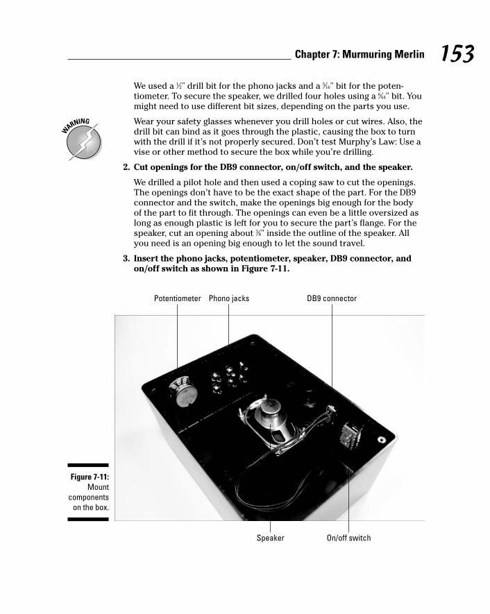
We used a 1⁄2" drill bit for the phono jacks and a 5⁄16" bit for the poten-tiometer. To secure the speaker, we drilled four holes using a 6⁄64" bit. Youmight need to use different bit sizes, depending on the parts you use.
Wear your safety glasses whenever you drill holes or cut wires. Also, thedrill bit can bind as it goes through the plastic, causing the box to turnwith the drill if it’s not properly secured. Don’t test Murphy’s Law: Use avise or other method to secure the box while you’re drilling.
2. Cut openings for the DB9 connector, on/off switch, and the speaker.
We drilled a pilot hole and then used a coping saw to cut the openings.The openings don’t have to be the exact shape of the part. For the DB9connector and the switch, make the openings big enough for the body of the part to fit through. The openings can even be a little oversized aslong as enough plastic is left for you to secure the part’s flange. For thespeaker, cut an opening about 3⁄8" inside the outline of the speaker. Allyou need is an opening big enough to let the sound travel.
3. Insert the phono jacks, potentiometer, speaker, DB9 connector, andon/off switch as shown in Figure 7-11.
Potentiometer Phono jacks DB9 connector
Speaker On/off switch
Figure 7-11:Mount
componentson the box.
153Chapter 7: Murmuring Merlin
12_009683 ch07.qxp 6/22/06 9:39 PM Page 153

4. Secure the phono jacks and potentiometer with the nuts providedwith each part.
The outside of the box is shown in Figure 7-12.
You can secure the speaker with four 1⁄2" 6-32 flathead screws and four6-32 nuts. Use glue on the flanges of the DB9 connector and on the on/offswitch to attach them to the box.
5. Solder the black wire from the battery pack to one lug of the on/offswitch and solder an 8" black wire to the other lug of the on/offswitch, as shown in Figure 7-13.
6. Solder a 6" black wire to each of the two solder lugs on the speaker, asshown in Figure 7-13.
7. Solder an 8" wire to each of the three potentiometer lugs, as shownFigure 7-14.
8. Connect 8" wires to each of the audio jacks and solder them, as shownin Figure 7-14.
9. Use Velcro to attach the breadboard and the battery pack to the box.
Figure 7-12:A view fromthe outside.
154 Part II: Sounding Off!
12_009683 ch07.qxp 6/22/06 9:39 PM Page 154

10. Cut the wires from the phono jacks, potentiometer, on/off switch, bat-tery pack, and DB9 connector to a length that allows you to arrangewires neatly in the enclosure.
11. Strip insulation from the ends of cut the wires, insert them in the ter-minal blocks, and secure with wire clips, as shown in Figure 7-15.
The components shown in this figure, indicated by numbered callout,include
1. Wires from left phono jack
2. Wires from center phono jack
3. Wires from right phono jack
4. Wire from left potentiometer lug
5. Wire from center potentiometer lug
Black wire from battery pack to on/off switch
Black wire to on/off switch
Wires to speaker
Figure 7-13:Wires
soldered tothe on/off
switch andspeaker.
155Chapter 7: Murmuring Merlin
12_009683 ch07.qxp 6/22/06 9:39 PM Page 155

6. Wire from right potentiometer lug
7. Wire from Pin 3 of DB9 connector
8. Wire from Pin 5 of DB9 connector
9. Wire from Pin 8 of DB9 connector
10. Red wire from battery pack
11. Black wire from on/off switch
12. Speaker wires
12. Place the on/off switch in the off position, insert batteries in the battery pack, and secure the lid on the enclosure with the screws provided.
Wire soldered to center potentiometer lug
Wire soldered to right potentiometer lug
Wire soldered to left potentiometer lug
Wires soldered to audio jacks
Figure 7-14:Solder wires
to connectexternal
componentsto the
breadboard.
156 Part II: Sounding Off!
12_009683 ch07.qxp 6/22/06 9:39 PM Page 156

13. Use your multimeter to find two contact pins on the tactile switchesthat are normally open (infinite resistance between the contact pins)and closed (nearly zero resistance between the two pins) when theswitch is pressed.
14. Solder a 12" wire to each of the two pins on each tactile switch, asshown in Figure 7-16.
15. Cut the wires from the tactile switches to the length you need to reachthe jacks on the electronics enclosure after both the switches and thebox are in place.
Leave about three extra inches of length to allow for some shifting asyou stuff the box in the puppet.
16. Unscrew the top from each phono plug, slip the top over the wire, andsolder each wire from the tactile switches to the center lug of a plug,as shown in Figure 7-17.
11 5 6
4
8
9 7
10
12
1 2 3
Figure 7-15:Insert wiresinto terminal
blocks.
157Chapter 7: Murmuring Merlin
12_009683 ch07.qxp 6/22/06 9:39 PM Page 157

Figure 7-17:Solder wires
to phonoplugs.
Figure 7-16:Solder wires
to tactileswitches.
158 Part II: Sounding Off!
12_009683 ch07.qxp 6/22/06 9:39 PM Page 158

17. Screw the covers of the phono plugs back in place and feed each tac-tile switch to the proper location.
We placed one switch in each hand and a switch under the puppet’s nose.
18. Feed the phono jacks behind the puppet, as shown in Figure 7-18.
You might want to secure the switches in place in some fashion. We useda strip of adhesive-backed Velcro (somewhat wider than the switch) forthe switch behind the nose. We stuck this to the back of the switch, putthe switch in place, and pressed the adhesive back to the fabric, rightunder the puppet’s nose. Another idea is to use a few stitches of threadto stop the switch from moving.
Programming soundsEven with your picture-perfect puppet and circuit, Merlin won’t murmur athing without sounds programmed into the sound synthesizer chip. For thispart, you have to study a bit on the software provided by the manufacturer.SpeakJet doesn’t provide a lot of documentation for using the software, butwe felt that the chip was the best bet for our puppet because it offers somany cool options for creating sounds.
Figure 7-18:Place tactileswitches inthe puppet.
159Chapter 7: Murmuring Merlin
12_009683 ch07.qxp 6/22/06 9:39 PM Page 159

The steps that we provide here are just an introduction to programming theSpeakJet. The SpeakJet user guide is available at www.speakjet.com, underthe Documentation heading.
If you need more information, we suggest you try the SpeakJet discussionforum at
http://groups.yahoo.com/group/speakjet
You can get the PhraseALator software that you use to program the chip at
http://magnevation.com/software/PhraseALator.zip
The manufacturer assures us that it is creating a manual for the PhraseALator.Go to www.speakjet.com and check under Documentation to see whetherit’s been posted.
By using this chip and software to program it, you can get some pretty neatfunctionality. For example, at your disposal is a built-in set of 72 speech ele-ments, 43 sound effects, 3 octaves of musical notes, and 12 touch tones. Bymixing and matching these and controlling the pitch, rate, bend, and volumesettings, you can produce just about any sound, phrase, or musical tones you want.
After you install the software on your computer, you can simply assign pre-loaded sounds to the circuit of this project, which we cover in the next set ofsteps. Or, you can get fancy and start programming sounds or even words ofyour choosing. If you want to get fancy, it will take some playing around tolearn the software (which is beyond the scope of this book). As we said, notmuch extensive documentation is available for it at this point, but with a littletrial and error, you can get the hang of it.
For our purposes, we used the sounds that the manufacturer preloaded. Hereare the steps involved in this procedure:
1. Open the PhraseALator software and click the Event Configurationbutton.
The upcoming Figure 7-19 shows the SpeakJet Event Configuration thatwe loaded onto our chip. The items in the Phrase# to Play column in thisfigure indicate phrases that the manufacturer has preloaded.
2. Select the check boxes in the Play Phrase column only for inputevents listed as Goes Low.
160 Part II: Sounding Off!
12_009683 ch07.qxp 6/22/06 9:39 PM Page 160

You do this so that the SpeakJet activates when you first press and thenrelease the switch. See the note and table after these steps for help inchoosing which check boxes you must select. (The simple route is tojust select all the Goes Low inputs, as shown in Figure 7-19.)
3. Connect the box to your computer by using a serial port cable to pro-gram the SpeakJet.
Check over your circuit to make sure that no wires are loose or touchanother wire — which could cause a short — before hooking them up toyour computer.
4. With the box connected to your computer, simply click the Write Datato SpeakJet button in the Event Configuration screen of the SpeakJetprogram (as shown in Figure 7-19).
5. After you finish programming the chip, disconnect the box with theelectronics from the computer.
The event number in the SpeakJet software Event Configuration windowdoesn’t always match the pin number in the SpeakJet IC — that would be too easy. Here’s a list of event numbers and corresponding pin numbers. We wired switches to Pins 2, 4, and 7, so we use Events 6, 4, and 2.
Figure 7-19:The EventConfigur-
ation screen
of thePhraseA-
Latorsoftwareprogram.
161Chapter 7: Murmuring Merlin
12_009683 ch07.qxp 6/22/06 9:39 PM Page 161

Event Pin
0 9
1 8
2 7
3 6
4 4
5 3
6 2
7 1
Hooking up the puppetMerlin is just bursting to have his say at this point, so it’s time to take thefinal steps to activate the newly loquacious puppet.
162 Part II: Sounding Off!
Making soundsWe know you’re the inquiring kind who willwant to program custom phrases before long,so here’s an overview of the process to get youstarted:
1. Open the EEPROM Editor screen.
2. Select the check box for the Phrase# thatyou wish to use for a custom sound.
3. In the Phrase Editor screen that opens,select the sounds that you wish to includein a phrase.
Be sure to check out words available fromthe library.
4. After you make a custom phrase, clickDone in the bottom right of the screen.
This takes you back to the EEPROM Editorscreen, where you can see that the selectedsounds have been added to the phrase.
5. Close the EEPROM Editor screen and openthe Event Configuration screen.
6. Enter the phrase number that you createdin the Phrase# to Play box for one of theinput #s.
See the nearby table to see how input num-bers correspond to pin numbers.
7. Connect the serial cable and then click theWrite Data to SpeakJet button to programthe chip.
12_009683 ch07.qxp 6/22/06 9:39 PM Page 162

Follow these steps to hook up and operate the puppet:
1. Plug the phono plugs from one of the tactile switches into the box andpress the switch.
If the sound is too soft or too loud, adjust the potentiometer to get thesound level right.
2. Unplug the phono plugs and insert the electronics box in the puppet,taking care not to move the tactile switches out of position.
3. Insert each phono plug in a phono jack and tuck the wires out of site,as shown in Figure 7-20.
Trying It OutAt this point, the puppet is ready to go. Press a hand or the little guy’s nose,and listen to what he has to say.
Figure 7-20:The
electronicsconcealed
in thepuppet.
163Chapter 7: Murmuring Merlin
12_009683 ch07.qxp 6/22/06 9:39 PM Page 163

If something doesn’t work, here are the obvious things to check out:
Check that all the batteries are fresh, tightly inserted in the batterypack, and all face the right direction.
Check to see that no wires or components have come loose.
Taking It FurtherAdding sound to objects has endless potential, as manufacturers of stuffedtoys and dolls have discovered. If you like this project, here are some ways tovary it or take it further:
You can use a different puppet or stuffed animal or plastic toy inwhich to put the project.
Create a music box that plays when you press a switch.
Add more switches for people to push.
You can use up to eight of the event pins for sound.
Add light to sound.
For example, you might want to put a light on Merlin’s head that lightsup every time he speaks. See Chapter 5 for some ideas about workingwith LEDs.
If you want to program the SpeakJet only once, you don’t need to keep theMAX232 with your project. Instead, you can move the SpeakJet to a smallerbreadboard. That way, you can fit the board into a smaller puppet or toy.
164 Part II: Sounding Off!
12_009683 ch07.qxp 6/22/06 9:39 PM Page 164

Chapter 8
Surfing the AirwavesIn This Chapter Taking a close look at the radio’s circuit
Checking off the parts list
Putting the radio circuit on a breadboard
Assembling the radio box
Tuning in!
For years, people attracted to electronics have been drawn to radios. In olden days, radios had big tubes and were the size of a bookcase;
today, you can create a small radio yourself by using common electronicscomponents.
The radio in this project involves a simple circuit, speaker, and a coil andvariable capacitor combo that you use to tune into your favorite station.
By working on this project, you discover how to work with radio frequencyand amplification to grab radio signals out of the air.
The Big Picture: Project OverviewAfter you complete this project, you’ll have an AM radio. We know, ourfavorite stations are on FM, too, but AM (amplitude modulation) was the firstmethod of modulating frequencies used in radio. Building an AM radio is a biteasier to do, so that’s where we start you off.
If you’re dying to discover more about creating an FM (frequency modulation)radio, check out Basic Radio: Understanding the Key Building Blocks, by JoelHallas, published by the American Radio Relay League (www.arrl.org).
You can see the finished radio in Figure 8-1.
13_009683 ch08.qxp 6/22/06 9:40 PM Page 165

Here are the types of activities you’ll be doing to create your own radio. You will
1. Put together an electronic circuit containing a coil and variable capaci-tor that you use to tune to your favorite stations, an IC that separatesthe voice signal from the radio frequency carrier and an IC that amplifiesthe voice signal enough to power a speaker.
2. Install the circuit, speaker, on/off switch, volume control, and tuner in ahandy box.
Scoping Out the SchematicImagine all that music and talk floating around out there in the air. Time toget to work on a circuit that lets you capture those sounds and pump themthrough a speaker. There is only one breadboard to put together for this pro-ject. You can see the schematic for the board in Figure 8-2.
Figure 8-1:Painted a
shiny silver,we think our
radio iscool.
166 Part II: Sounding Off!
13_009683 ch08.qxp 6/22/06 9:40 PM Page 166

The following is a list of the schematic elements for your radio:
L1 is a coil, or inductor. You make this by wrapping wire around a ferriterod. This coil is both the antenna and half the tuning circuit needed totune the radio to a particular station. The value of the inductor, given inHenrys, is determined by the number of coils of wire you wrap aroundthe rod.
C2 is a variable capacitor that forms a tuning circuit along with L1. Whenyou have a capacitor and inductor in parallel, the value of the capacitorand inductor determine the resonance frequency, which is the frequencyof the radio station you tune in on your radio. As you change the valueof C2 by turning the knob connected to the capacitor, you change theresonance frequency, therefore tuning in to a different radio station.
IC1 is a ZN416E integrated circuit that is designed to separate the voicesignal from the radio frequency carrier and amplify the signal to a levelsufficient to power headphones.
C1 is a capacitor that allows nonresonant radio frequency signals toconduct to ground.
C3, C4, and C5 are suggested by the manufacturer of IC1; they shunthigh-frequency signals to ground, preventing them from causing noise incertain parts of the circuit inside of IC1.
IC2, an audio amplifier named LM386N-1, takes the audio frequency elec-trical signal generated by IC1 and amplifies it to provide sufficient powerto drive the speaker.
3
2
6
5
4
IC2
C7
C9
R1 +
-
+6 V
+
+C8
R2
7
8
1
5
6
4 7
3
2
+1.5 V
C1
C2
C3 C5
C4
IC1
SPEAKER
+
81
C6
L1
Figure 8-2:The
schematicof the radio
circuit.
167Chapter 8: Surfing the Airwaves
13_009683 ch08.qxp 6/22/06 9:40 PM Page 167
R1 is a potentiometer that controls the sound volume.
C6 sets the voltage gain of IC2 to 200. (Therefore, the voltage out will be200 times the voltage in.)
C7 improves the stability of the LM386 amplifier to prevent problemssuch as oscillation, which can turn your signal into an unintelligiblegarble of sound.
C8 removes any DC offset from the output of the LM386 amplifier.
C9 acts as a current bank for the output. This capacitor drains whensudden surges of current occur and refills with electrons when thedemand for current is low.
168 Part II: Sounding Off!
Picking up the right signalFerrite, used for the coil core in this project, iscomposed of crystalline iron oxide and is typi-cally used at radio frequencies. For coils usedat low frequencies, such as in power trans-formers, you can use iron as the core; however,at high frequencies, the high conductivity ofiron allows eddy currents to be created in thecore. These eddy currents can decrease thelevel of signal induced to the coil, thus weak-ening the signal. Because these eddy currentsdon’t occur in the lower conductivity ferritecore, you get a much more efficient coil at radiofrequencies.
When a radio signal comes across a ferrite rod,the radio signal creates a magnetic field in therod. When you wrap a coil of wire around theferrite rod, this magnetic field — which ischanging direction at high frequency (the fre-quency of the radio signal) — induces (hencethe name inductor) an electric current in thewire coil. A magnetic or electric field can causeelectrons to flow in a wire; if the field is chang-ing direction frequently, like one created by aradio signal does, the direction of the electronschanges with the magnetic field. Voilà! You now
have a radio frequency signal traveling throughyour wire coil.
Because the inductor and capacitor are con-nected, this radio frequency signal also travelsthrough the capacitor. When you have aninductor and capacitor in parallel, like in ourAM radio circuit, the values of the inductor andcapacitor determine a resonance frequency. Asignal at the resonance frequency is thenblocked from moving through the inductor/capacitor circuit. This resonance frequency isthe frequency of the radio station that you tuneinto when you change the value of the variablecapacitor by turning the knob on your radio.
Signals from other radio stations that aren’t atthe resonance frequency flow through theinductor/capacitor circuit and through C1 toground; basically, these signals are thrownaway.
Only the signal at the resonance frequencydoesn’t go to ground through C1; rather, thatsignal is available to your circuit to beprocessed back into the music your radio sta-tion sends out.
13_009683 ch08.qxp 6/22/06 9:40 PM Page 168

Building Alert: Construction IssuesThe ferrite rod that you wrap wires around to make a coil is brittle. If youdrop it or knock it against something, it could easily break, so be careful!
If you place your radio in a wooden box (as we did), check the thickness ofthe wall of the box against the length of the threads on the potentiometer.Because the wall on our box was 1⁄4" thick (the same thickness as the threadson the potentiometer), we just put some glue between the body of the poten-tiometer and the wall of the box (making sure not to get glue on the rotatingshaft). You might want to use a chisel to reduce the thickness of the wall sothat the rotating shaft sticks out a little farther; that way, the knob doesn’tend up too close to the face of the box.
The variable capacitor has very small holes in its metal body that you canuse to mount it on small pins. Again, we found it easiest to glue this to thewall of the box after chamfering (cutting a furrow in) the edge of the hole to fitthe metal knuckle around the shaft. In this way, the wall of the capacitor fitsflush against the wall of the box.
Perusing the Parts ListGet ready to turn on your computer or head to the electronics supply storeto shop for the parts for your radio project (several of which are shown inFigures 8-3 and 8-4). Here’s what you’ll need:
10 kohm potentiometer (R1)
10 ohm resistor (R2)
Two 0.01 microfarad ceramic capacitors (C1, C3)
One 0.1 microfarad ceramic capacitor (C5)
Two 0.047 microfarad ceramic capacitor (C4, C9)
10 microfarad electrolytic capacitors (C7, C6)
100 microfarad electrolytic capacitor (C8)
LM386N-1 amplifier IC2
You’ll find many versions of the LM386 amplifier. We chose the LM386N-1because it works with the supply voltage of 6 volts used by this circuit.
Battery pack for 1 AA battery
169Chapter 8: Surfing the Airwaves
13_009683 ch08.qxp 6/22/06 9:40 PM Page 169

This supplies 1.5 volts to IC1 because the maximum supply voltage forthe ZN416 is 1.6 volts.
Battery pack for 4 AA batteries to supply 6 volts to IC2
ZN416E AM radio receiver IC1
14–365 picofarad variable air capacitor (C2)
You could also use a variable capacitor that goes up to 500 picofarad.
3⁄8"-diameter × 31⁄2" ferrite rod
You can also use a ferrite rod with a 1⁄2" diameter and longer lengths ofeither 3⁄8" or 1⁄2" diameter as long as they fit in the box that you’re usingfor the radio. Longer ferrite rods should give you higher sensitivity toweak radio signals than shorter ferrite rods.
We found the preceding three radio-specific items above at Ocean StateElectronics (www.oselectronics.com). We noticed that it was lessexpensive to buy this vendor’s part #LA-540 — a ferrite rod alreadywrapped with a wire coil — slip off the coil, and then wrap wire to thenumber of turns we needed on that rod. Buying a ferrite rod by itself was about three times as expensive!
Battery pack for IC1 Resistor
Electrolytic capacitor
Ferrite rod
Battery pack for IC2 Ceramic capacitor Terminal block IC
Figure 8-3:Key
components.
170 Part II: Sounding Off!
13_009683 ch08.qxp 6/22/06 9:40 PM Page 170

SPST toggle switch, used as the on/off switch
830-pin breadboard
Seven 2-pin terminal blocks
Two knobs (for the potentiometer and variable capacitor)
8 ohm, 1 watt speaker
Enclosure
We used a wooden box that we found at a national craft supply store(Michael’s). You can use plastic or wood but do not use metal becauseit will block the radio signal from the ferrite antenna.
Four 1⁄2" long 6-32 flathead screws
Four 6-32 nuts
An assortment of different lengths of prestripped, short 22 AWG wire
A few feet of 26 gauge enamel-coated wire (used to make the coil)
On/off switch Speaker
Variable capacitor Potentiometer
Figure 8-4:More key
components.
171Chapter 8: Surfing the Airwaves
13_009683 ch08.qxp 6/22/06 9:40 PM Page 171

Taking Things Step by StepIf you have one, now’s the time to put on your official Marconi Was Here T-shirt so you can set out to build your AM radio in style. Building a radioinvolves creating the circuit; drilling various holes in a box; placing the cir-cuit, speaker, and knobs in the box; and tuning to find available frequencies.
Building a radio circuitThe first step in building a radio is to tackle the circuit that forms its elec-tronic brains. Here are the steps involved:
1. Place ZN416E (IC1), LM386N-1 (IC2), and seven terminal blocks on thebreadboard, as shown in Figure 8-5.
The seven terminal blocks shown in this figure will be used to connecttwo wires each to various components in the circuit. The wires fromthese terminal blocks go to the battery pack for IC1, the battery pack forIC2, the on/off switch, the coil, the variable capacitor, the speaker, andthe potentiometer.
IC2 IC1
Figure 8-5:Place the
ICs andterminal
blocks on the
breadboard.
172 Part II: Sounding Off!
13_009683 ch08.qxp 6/22/06 9:40 PM Page 172

2. Insert wires to connect the ICs and the terminal blocks to the groundbus and insert a wire between the two ground buses to connect themto each other, as shown in Figure 8-6.
3. Insert wires to connect IC2 and the terminal block for IC2’s batterypack to the +V bus, and a wire between the two +V buses to connectthem to each other, as shown in Figure 8-7.
Do not connect IC1 to the +V bus. If you do, you will probably fry thepoor IC because it isn’t designed to take 6 volts.
4. Insert wires to connect the ICs, terminal blocks for the coil (L1), vari-able capacitor (C2) and terminal blocks for the potentiometer (R1),and terminal block for the speaker and discrete components, asshown in Figure 8-8.
5. Insert two 0.047 microfarad capacitors (C4 and C9), two 10 microfaradcapacitors (C6 and C7), one 100 microfarad capacitor (C8), two 0.001microfarad capacitors (C1 and C3), one 0.1 microfarad capacitor (C5),and one 10 ohm resistor (R2) on the breadboard, as shown in Figure 8-9.
When inserting electrolytic capacitors, be sure to check the schematicto see where to insert the longer, positive (+) lead.
Figure 8-6:Six shorter
wiresconnect
componentsto ground
bus; thelong wire on
the rightconnects
the twogroundbuses.
173Chapter 8: Surfing the Airwaves
13_009683 ch08.qxp 6/22/06 9:40 PM Page 173

We discuss in Chapter 4 how you can determine how short to clip theleads of many of these components to make them fit neatly on the bread-board. Not to sound like your mother, but make sure you wear yoursafety glasses when clipping leads!
Making a box into a radioAfter you build the circuit, it needs a home, so the next step in the process isto work with the box you purchased for your radio enclosure.
Follow these steps to get the box radio ready:
1. Drill holes in the box where you will mount the variable capacitor,potentiometer, and on/off switch.
We put both the on/off switch on one side of the box and the speaker,potentiometer and variable capacitor on another side, but the place-ment is really up to you. Figure 8-10 shows where we placed these com-ponents.
Pin 6 of IC2 to +V Battery terminal block to +V
Figure 8-7:Connect
componentsto the +V
bus.
174 Part II: Sounding Off!
13_009683 ch08.qxp 6/22/06 9:40 PM Page 174

2. Place the speaker against the face of the box where you want tomount it and mark positions for the four screws you’ll use to securethe speaker.
3. Drill holes to allow clearance for 6-32 screws.
We used a 9⁄64" drill bit.
4. Draw an outline about 1⁄4" smaller than the speaker shape for the open-ing to let sound from the speaker out.
Use a coping saw to cut the opening.
Pin 5 of IC2 to open region
Pin 5 of IC1 to R1 TB
L1/C2 TB to Pin 8 of IC1
Battery pack TB to Pin 6 of IC1
Open region to speaker TB
Pin 8 of IC2 to open region
R1 TB to Pin 3 of IC2 L1/C2 TB to Pin 1 of IC1
Connecting pins of L1/C2 terminal block
Figure 8-8:Hook up theICs, terminalblocks (TB),
and discretecomponents.
175Chapter 8: Surfing the Airwaves
13_009683 ch08.qxp 6/22/06 9:40 PM Page 175

See Chapter 4 for more information about choosing drill bit sizes for par-ticular components and other pieces of wisdom on how to customize abox for your projects. Make sure you use safety glasses when drillingand clamp the box to your worktable!
5. Slip the shaft of the on/off switch through the drilled hole and securewith the nut provided.
6. Slip the shaft of the potentiometer through the drilled hole and securewith the nut provided.
C8 from IC2 Pin 5 to speaker TB
C7 from Pin 7 of IC2 to ground
C9 from Pin 5 of IC2 to open region
R2 from C9 to ground
C1 from IC1 Pin 8 to ground
C3 from IC1 Pin 7 to ground
C6 from Pin 1 of IC2 to Pin 8 of IC2
C4 from Pin 2 of IC1 to Pin 3 of IC1
C5 from Pin 2 of IC1 to ground
Figure 8-9:Insert
resistorsand
capacitorson the
breadboard.
176 Part II: Sounding Off!
13_009683 ch08.qxp 6/22/06 9:40 PM Page 176

7. Slip the knob on the potentiometer shaft and secure with the setscrew provided.
The tread on potentiometers is about 1⁄4" long, so if the wall of yourwooden box is 1⁄4" thick, you won’t be able to use the nut to secure thepotentiometer. Instead, glue the face of the potentiometer to the box,making sure that you don’t get any glue on the rotating shaft of thepotentiometer.
8. Slip the shaft of the variable capacitor through the drilled hole andglue the metal body of the capacitor to the wooden box.
Make sure you don’t get any glue on the shaft or other moving parts ofthe capacitor.
9. Slip the knob on the variable capacitor shaft and secure with the setscrew provided.
10. Secure the speaker with four 6-32 flathead screws and four 6-32 nuts.
Variable capacitor
Potentiometer
Speaker
On/off switch
Figure 8-10:Box with on/
off switch,potenti-ometer,
variablecapacitor,
and speakerin place.
177Chapter 8: Surfing the Airwaves
13_009683 ch08.qxp 6/22/06 9:40 PM Page 177

11. Solder the black wire from each of the battery packs to one lug of theon/off switch and solder an 8" black wire to the remaining lug of theon/off switch, as shown in Figure 8-11.
12. Solder one 8" wire to a variable capacitor lug and solder one 8" wireto the metal body of the variable capacitor, as shown Figure 8-11.
The lugs are electrically connected to the stationary plates of the capaci-tor, and the metal body is electrically connected to the rotating plates.
13. Solder 8" wires to each of the three potentiometer lugs, as shownFigure 8-12.
14. Solder 8" wires to each of the two speaker lugs, as shown Figure 8-12.
Black wire to on/off switch Wire to capacitor body
Black wire from IC1 battery pack to on/off switch
Black wire from IC2 battery pack to on/off switch
Wire to capacitor lug
Figure 8-11:Wires
soldered tothe on/off
switch andvariable
capacitor.
.
178 Part II: Sounding Off!
13_009683 ch08.qxp 6/22/06 9:40 PM Page 178

Be sure to heed all the safety precautions about soldering that we giveyou in Chapter 2. For example, don’t leave your soldering iron on andunattended. And just in case a bit of solder has an air pocket and pops,wear your safety glasses!
Coaxing the coilTake your ferrite rod, 26 gauge enamel-coated wire, some electrical tape, andglue and get ready to make the coil by following these steps:
1. Wrap electrical tape around the ferrite rod.
This protects the enamel coating on the wire from the ridges that runalong the rod.
2. Cut two small pieces of electrical tape, about 1⁄4" wide, and place themin a handy spot.
Wires to potentiometer
Wires to speaker
Figure 8-12:Wires
soldered topotenti-
ometer andspeaker.
179Chapter 8: Surfing the Airwaves
13_009683 ch08.qxp 6/22/06 9:40 PM Page 179

3. Leaving about 8 inches of wire loose, start winding the enamel-coatedwire around the rod, starting about 11⁄4" from one end.
4. When you have about 20 turns of wire on the rod, secure that endwith one of the pieces of electrical tape so that it doesn’t loosen whileyou are finishing the coil.
5. Wind a total of 50 turns of wire around the rod, leaving another 8-inch length of wire loose at the other end.
6. Secure the wire at that end with the other piece of electrical tape.
7. At each end of the coil, use some glue to hold down the wires.
We had you cut the electrical tape 1⁄4" wide so there is enough exposedwire to glue. When the glue is dry, your coil is finished. The finished coilis shown in Figure 8-13.
Putting it all togetherNow it’s time to assemble your radio and see whether you can pick up asignal. Follow these steps to complete the project:
1. Attach Velcro to the breadboard and the box and then secure thebreadboard in the box.
Figure 8-13:Your coil, all
ready touse.
180 Part II: Sounding Off!
13_009683 ch08.qxp 6/22/06 9:40 PM Page 180
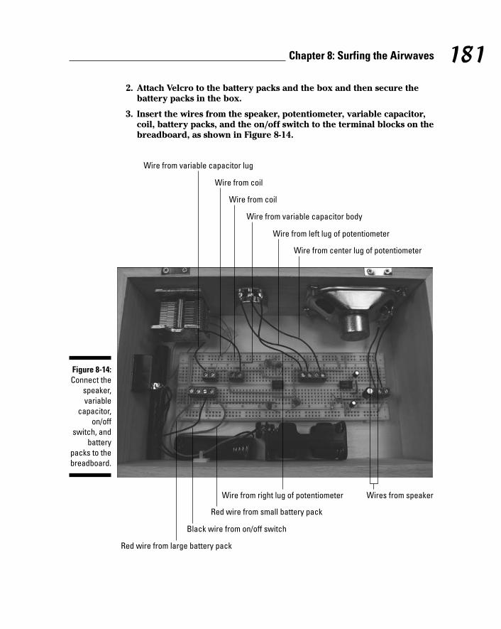
2. Attach Velcro to the battery packs and the box and then secure thebattery packs in the box.
3. Insert the wires from the speaker, potentiometer, variable capacitor,coil, battery packs, and the on/off switch to the terminal blocks on thebreadboard, as shown in Figure 8-14.
Wire from coil
Wire from variable capacitor lug
Wire from coil
Wire from variable capacitor body
Wire from left lug of potentiometer
Wire from center lug of potentiometer
Black wire from on/off switch
Red wire from large battery pack
Red wire from small battery pack
Wire from right lug of potentiometer Wires from speaker
Figure 8-14:Connect the
speaker,variable
capacitor,on/off
switch, andbattery
packs to thebreadboard.
181Chapter 8: Surfing the Airwaves
13_009683 ch08.qxp 6/22/06 9:40 PM Page 181

4. As you insert the wires, cut each of them to the length needed toreach the assigned terminal block and strip the insulation from theend of the wire.
Keep the wires from the potentiometer as far away as possible from thewires from the speaker or the wires from the variable capacitor/coil.You’ve no doubt experienced how having a microphone too close to aspeaker can produce an awful screech; the same screech can occur ifthese wires get too close together.
5. Secure the wires with wire clips where needed.
The way parts are laid out in this box and the distance between some ofthe components (such as the speaker, potentiometer, and variablecapacitor to the terminal blocks) is short enough that you won’t needwire clips.
6. Close the lid on the box and admire your finished radio, as shown inFigure 8-15.
Figure 8-15:The finished
radio.
182 Part II: Sounding Off!
13_009683 ch08.qxp 6/22/06 9:40 PM Page 182

Trying It OutAt this point, the radio is ready to go. Insert batteries and turn it on. Adjustthe tuner (the knob on the variable capacitor) and the volume (the knob onthe potentiometer) to find listen to your favorite radio stations.
When you tune into a station that you want to find again, mark the position ofthe tuning knob on the face of the radio.
If you’re not getting the signal you thought you would, here are the obviousthings to check out:
Check that all the batteries are fresh and tightly inserted in the bat-tery pack, all facing the right direction.
Check to see that no wires or components have come loose.
Rotate the radio.
When one end of the antenna points at the radio station’s transmittingantenna, the signal from that radio station will be stronger.
Taking It FurtherMany people get bitten by the radio bug and want to get into ham radio in abig way. If you’re one of these, here are some variations on this project tokeep you going:
You can build an FM radio to get those high-frequency stations. TheTEA5710N IC can be used to build a radio that can receive both AM andFM signals.
Build a radio that will receive signals from ham radio operators.
Go to QRP/SWL HomeBuilder (www.qrp.pops.net/default.htm) forsome ideas for ham radio projects, or visit www.arrl.org.
Mount an external antenna connected to the ferrite rod to boost thepower of the signal if you live in the boondocks where signals are hardto come by.
183Chapter 8: Surfing the Airwaves
13_009683 ch08.qxp 6/22/06 9:40 PM Page 183

184 Part II: Sounding Off!
13_009683 ch08.qxp 6/22/06 9:40 PM Page 184

Part IIILet There Be Light
14_009683 pt03.qxp 6/22/06 9:36 PM Page 185

In this part . . .
Thomas Edison discovered what fun light can be inelectronics projects when he invented the light bulb.
In the projects in this part, you use light in several forms.For example, you work with tiny LED lights that danceacross a display of dolphins; use infrared light to signal ago cart when to go and when to stop; and use an infraredbeam to detect motion to set off lights and sound in asnazzy Halloween display.
14_009683 pt03.qxp 6/22/06 9:36 PM Page 186

Chapter 9
Scary PumpkinsIn This Chapter Eyeing the schematic
Checking off the parts list
Breadboarding the pumpkin circuits
Placing the works in the pumpkins
Turning on your pumpkins
Around the end of October, many of us carve faces in pumpkins and thenput candles in those pumpkins to create an eerie effect. Why not elec-
trify pumpkins to do the same thing — and add a spooky sound effect or mes-sage to the mix?
In this chapter, we use two plastic pumpkins and activate sound and light byusing an infrared beam. When those trick-or-treaters come up to your door-way, won’t they be surprised?
Of course, if it’s February and plastic pumpkins are scarce, use these sametechniques with some other plastic container shape to create talking dinosaurs,heart-shaped candy boxes, or whatever!
The Big Picture: Project OverviewWhen you complete this project, you’ll have two pumpkins:
One that transmits an infrared beam
A second one that lights up and plays back a recorded sound or mes-sage when something or somebody interrupts the infrared beam bywalking between the two pumpkins
15_009683 ch09.qxp 6/22/06 9:40 PM Page 187

You can see the finished pumpkin in Figure 9-1.
Here’s the big picture of this pumpkin project:
1. Put together two electronic circuits and fit them into plastic pumpkinswith switches, a microphone, and a speaker.
2. Use a microphone to record a sound or message.
We like, “Welcome to Sleepy Hollow. We hope you have a good time,” fol-lowed by a spooky laugh.
3. One pumpkin transmits an infrared beam to the other. When someonewalks between the pumpkins, the recorded message is triggered, alongwith a flickering red light.
4. To reduce the chance of this IR noise interfering with your gadget, usean IR detector tuned to detect infrared that turns on and off at 38 kHzand ignores infrared not switched at that frequency. The transmitter cir-cuit then sends out infrared that is switched on and off at 38 kHz, andthe noise problem is solved.
One complication you’ll deal with along the way is lots of infrared noisefloating around. IR is given off by heaters, people, pets, and pretty muchany living creature or equipment that gives off heat.
Figure 9-1:The final
product: atalking
pumpkin.
188 Part III: Let There Be Light
15_009683 ch09.qxp 6/22/06 9:40 PM Page 188

Should you be lucky enough to have an oscilloscope perched on yourworkbench, you can see that a 38 kHz square wave looks something likethe one shown in Figure 9-2. But don’t worry: You don’t have to have anoscilloscope to tune your IR transmitter. We tell you how to tune it in theupcoming section, “Trying It Out.”
Scoping out the schematicYou put together two breadboards for this project: one that transmits andone that receives and sounds off.
First, you can see the schematic for the board that goes in what we call thesilent pumpkin (the one with the transmitter in it) in Figure 9-3.
Here’s the nitty-gritty of the schematic elements for the silent pumpkin:
The IR LED (LED2) is one of the key components of this circuit; the pur-pose of the rest of the circuit is to send an electrical current, whichturns on and off at a frequency of 38 kHz, through this LED. This currentcauses the LED to transmit IR light that turns on and off at a frequencyof 38 kHz (38,000 times a second: so fast you can’t even see a flicker).
Figure 9-2:A square
wave on anoscilloscope
screenlooks like
this.
189Chapter 9: Scary Pumpkins
15_009683 ch09.qxp 6/22/06 9:40 PM Page 189

IC1 is the other key component of this circuit. This is an LM555 timerchip that you use to generate a square wave at its output on Pin 3.
R2, R3, R4, and C1 are three resistors and a capacitor, respectively, thatform the RC circuit that determines the frequency of the square wavegenerated by the LM555 timer chip.
S1 is an SPST (single-pole, single-throw; see Chapter 4) toggle switchconnected between the negative pole of the battery pack and the bread-board ground bus. When this switch is open, no current can flow, and sothe circuit turns off. When this switch is closed, the circuit turns on.
LED2 provides a light (we use a yellow light) to simulate a candle’s glowin the pumpkin. This LED is on whenever S1 is closed.
R1 is a resistor that limits the current running through LED1 to approxi-mately 20 milliamps (mA).
R5 is a resistor that limits the current running through LED2 to approxi-mately 30 milliamps (mA).
C2 is a capacitor that reduces the occurrence of noise on Pin 5, whichcould cause false triggering of the IC. This might occur if Pin 5 were leftunconnected.
Now it’s time to run down the elements of the receiver schematic that goesinto the talking pumpkin. Take a look at the schematic in Figure 9-4.
1
6
78 4
5
2
R2
R3
C2
C1
IC1
3
R5
+-
R4
LED2
S1
6V
R1
LED1Figure 9-3:The silent
pumpkincircuit
schematic.
190 Part III: Let There Be Light
15_009683 ch09.qxp 6/22/06 9:40 PM Page 190

The IR detector is the key component of this circuit. It contains a photo-diode that detects infrared light and an integrated circuit that produceseither +V or 0 volts on its output pin. Exactly what volts the IR detectorproduces depends on whether it detects a 38 kHz infrared signal (result-ing in 0 volts output) or not (resulting in +V output).
IC1 is the other key component of this circuit. This is a chip that youcan use to record a sound or voice message and play it back. We con-nect the output of the IR detector to Pin 23 of IC1. Voltage on Pin 23starts a playback when the voltage changes from +V to 0 volts. Here’show this works: When a person walks between the pumpkins, the volt-age from the IR detector changes from 0 volts to +V. When the personleaves the beam field, it drops back down to 0 volts. The jump back to 0volts is the point when your recording starts to play.
The speaker is connected to Pins 14 and 15 of IC1. The speaker playsmessages that you recorded on IC1.
You connect LED1 between Pin 14 of IC1 and ground. When your mes-sage plays, this LED generates a flickering light. (We used a red LED toget a red light.)
191Chapter 9: Scary Pumpkins
Time, time, timersWhen you connect a 555 timer IC to resistors and capacitors in the arrangement shown in theschematic, the timer IC generates a digital waveform from its output. The frequency of the wave-form is determined by how fast the capacitor fills and drains. You calculate how fast the capaci-tor fills to two-thirds of its capacity or drains to one-third of its capacity by using the RC timeconstant equation. (This involves math, so it’s not for the faint of heart.)
The RC time constant for filling the capacitor is
T1 = (R2 + R3 + R4) × C
The RC time constant for draining the capacitor is
T2 = (R3 + R4) × C
In this circuit, R2, R3, and R4 determine how fast the capacitor charges and discharges. The extentto which the capacitor is filled determines the voltage on Pins 2 and 6 and the voltage applied tothe circuit inside the IC. When the voltage reaches two-thirds of +V, the circuitry connected to Pin6 turns on and causes the output to change from +V to 0 (zero) volts. It also causes the charge onthe capacitor to drain through Pin 7 to ground. As the capacitor drains, the voltage to Pins 2 and6 drops. When the voltage gets to one-third of the +V, the circuitry connected to Pin 2 turns on andcauses the output of the IC to shift from 0 (zero) to +V and disconnects Pin 7 from ground, whichallows the capacitor to charge back up to two-thirds of +V. At this point, the cycle starts again.
15_009683 ch09.qxp 6/22/06 9:40 PM Page 191
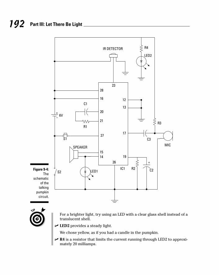
For a brighter light, try using an LED with a clear glass shell instead of atranslucent shell.
LED2 provides a steady light.
We chose yellow, as if you had a candle in the pumpkin.
R4 is a resistor that limits the current running through LED2 to approxi-mately 20 milliamps.
20
21
1415
28
12
27
1926
13
17
16
+-
MIC
S1
6V
SPEAKER
C1
R1
R2 C2
C3
R3
IC1
+
S2
23
IR DETECTOR
LED1
R4
LED2
Figure 9-4:The
schematicof the
talkingpumpkin
circuit.
192 Part III: Let There Be Light
15_009683 ch09.qxp 6/22/06 9:40 PM Page 192

S1 is a normally open (NO) pushbutton switch that when depressed,connects Pin 27 of IC1 to ground. This is how you record sounds to IC1 through the microphone. Recording stops when you release the S1 pushbutton.
R3 is a resistor that connects the microphone to +V, supplying the 4.5volts that the microphone needs to function.
C3 is a capacitor that removes the DC voltage from the AC signal that’sflowing from the microphone to Pin 17 of IC1.
S2 is the on/off switch between the negative terminal of the battery packand the ground bus of the circuit board.
R1 and C1 filter out that pesky electrical noise.
R2 and C2 connect the automatic gain control circuit inside IC1 toground. The values of R2 and C2 determine how fast the automatic gaincontrol responds to changes in volume when you’re recording a message.
Building alert: Construction issuesPlastic pumpkins present unique building challenges, as everybody (whobothers to think about it) knows. The curved shape of the pumpkin makes itdifficult to stick your hands inside to attach wires to terminal blocks. There-fore, we attached the wires from most components — like switches andspeakers — to terminal blocks on the breadboard before placing them in the pumpkin or attaching the components to the side of the pumpkin.
Wrap each lead of the IR detector and microphone in electrical tape afterthey have cooled from soldering to make sure that the bare soldered leadsdon’t touch each other. Leads co-mingling in this fashion can cause minorelectrical disasters.
We used a utility knife and small wire cutters to cut the holes in the plasticpumpkins. Make sure that the plastic is not too brittle, and be sure to wearsafety goggles to protect your eyes against flying pumpkin pieces and leatherwork gloves to protect your hands.
We placed some foam in the bottom of the pumpkins on which to rest thebreadboards. The type of foam used for flower arrangements is easy to cut,but it’s so fine that particles go everywhere. The foam that you find in pack-ing boxes will also shred, but the pieces are bigger and a little easier to cleanup. In either case, plan to spend some time cleaning up your cutting surfaceafterward and don’t cut on your electronics bench — you don’t want thosefoam pieces to get into the electronics bits and pieces.
193Chapter 9: Scary Pumpkins
15_009683 ch09.qxp 6/22/06 9:40 PM Page 193

Perusing the parts listIn addition to buying the two plastic pumpkins, you have to find the elec-tronic parts to build the circuits and assemble everything. Here are the partslists for the silent pumpkin and the talking pumpkin.
Silent pumpkin parts listIt’s time to go shopping for the bits and pieces used to build the silent pumpkin.This involves the following parts (several of which are shown in Figure 9-5):
330 ohm resistor (R1, R2)
10 kohm resistor (R3)
10 kohm potentiometer (R4)
150 ohm resistor (R5)
0.001 microfarad ceramic capacitor (C1)
0.1 microfarad ceramic capacitor (C2)
Yellow size T-1 3⁄4 LED (LED1)
IR LED, TSAL7200 (LED2)
Various other IR LEDs will work. The one we used is advertised to work atlonger distances than standard IR LEDs. We used this one along with theIR detector specified in the next section because it was easier to get thegadget to work at a distance up to about 15 feet than with other combina-tions we tried. See www.rentron.com for a nice listing of similar IR LEDs.
LM555 (IC1)
SPST toggle switch (S1), used as the on/off switch
400-contact breadboard
LED socket, sized for T-1 3⁄4 LEDs
Four AA battery pack with snap connector
Three 2-pin terminal blocks
Knob (for potentiometer)
Foam (Styrofoam or similar), about 21⁄2" thick, 12" wide, 12" long
An assortment of different lengths of prestripped short 22 gauge (AWG) wire
194 Part III: Let There Be Light
15_009683 ch09.qxp 6/22/06 9:40 PM Page 194

Talking pumpkin parts listHere’s your shopping list for building your talking pumpkin. This projectinvolves the following parts, several of which are shown in Figure 9-6:
Panasonic PNA4602 IR detector
16 ohm, 0.2 watt speaker
Electret microphone part #EM-99
We found this one at Jameco (www.jameco.com). You can use otherelectret microphones; see Chapter 3 for the criteria to help you chooseone. If you use another model of microphone, you might have to adjustR3 to set the supply voltage to the correct level.
Winbond Electronics ISD1110 voice record/playback chip (IC1)
0.01 microfarad capacitor (C1)
0.1 microfarad capacitors (C3)
On/off switch LM555 (IC1) Battery pack Resistor
Potentiometer Capacitor
LED socket
LED
Terminal block
Knob
Figure 9-5:Key
componentsfor the silent
pumpkin.
195Chapter 9: Scary Pumpkins
15_009683 ch09.qxp 6/22/06 9:40 PM Page 195

4.7 microfarad electrolytic capacitor (C2)
Four 5⁄8" 6-32 screws
Four 6-32 nuts
5.1 kohm resistor (R1)
470 kohm resistor (R2)
2.2 kohm resistor (R3)
330 ohm resistor (R4)
Yellow T-1 3⁄4 LED (LED1)
Red T-1 3⁄4 LED (LED2)
830-contact breadboard
Normally open (NO) momentary contact pushbutton switch, alsoreferred to as record switch (S1)
Voice chip Terminal block
Battery packRecord switch Speaker
On/off switch Ceramic capacitor
IR detector Microphone LED Electrolytic capacitor
Figure 9-6:Key
componentsof the
talkingpumpkin.
196 Part III: Let There Be Light
15_009683 ch09.qxp 6/22/06 9:40 PM Page 196

SPST toggle switch, also referred to as on/off switch (S2)
Four AA battery pack with snap connector
Six 2-pin terminal blocks
An assortment of different lengths of prestripped short 22 AWG wire
Taking Things Step by StepScary things don’t just happen by themselves (things that go bump in thenight notwithstanding). Building a scary pumpkin project requires that youdo two things:
1. Create the silent pumpkin.
2. Create the talking pumpkin.
Making a silent pumpkinTackle the silent partner of this pumpkin duo first. Here are the stepsinvolved:
1. Place the LM555 IC and three terminal blocks on a breadboard, asshown in Figure 9-7.
Figure 9-7:Place theLM555 IC
and terminalblocks on
thebreadboard.
197Chapter 9: Scary Pumpkins
15_009683 ch09.qxp 6/22/06 9:40 PM Page 197

The three terminal blocks shown in this figure will be used to connecttwo wires each to various components in the circuit. The wires fromthese terminal blocks go to the battery pack, IR LED, and potentiometer,respectively.
2. Insert wires to connect the IC and the terminal blocks to the groundbus (marked with a – sign on this breadboard) and insert a wirebetween the two ground buses to connect them to each other, asshown in Figure 9-8.
Three shorter wires connect components to the ground bus; the longwire on the right connects the two ground buses.
3. Insert wires to connect the IC and the terminal block for the batteryto the +V bus, as shown in Figure 9-9.
4. Insert wires to connect the IC, terminal blocks, and discrete compo-nents, as shown in Figure 9-10.
5. Insert discrete components on the breadboard, as shown in Figure 9-11.
Note that the shorter of the LED leads is inserted in the ground bus.
Figure 9-8:Connect
componentsto the
ground bus.
198 Part III: Let There Be Light
15_009683 ch09.qxp 6/22/06 9:40 PM Page 198

6. Solder the black wire from a battery snap to one lug of the on/offswitch and solder a 5" black wire to the other lug of the on/off switch.
7. Solder two 5" wires to the potentiometer, as shown Figure 9-12.
Be sure to heed all the safety precautions about soldering that we giveyou in Chapter 2. For example, don’t leave your soldering iron on andunattended. And just in case a bit of solder has an air pocket and pops,wear your safety glasses!
8. Cut the leads of the IR LED to 1⁄4", keeping track of which is the long(+V) lead.
Wear your safety glasses any time you cut wires!
9. Insert the IR LED in the LED socket, making sure that the +V lead islined up with the white wire from the socket.
Figure 9-13 shows the LED inserted into the socket.
Pin 4 of IC1 to +V
Pin 8 of IC1 to +V Battery terminal block to +V
Figure 9-9:Connect
componentsto the +V
bus.
199Chapter 9: Scary Pumpkins
15_009683 ch09.qxp 6/22/06 9:40 PM Page 199

10. Attach wires from the LED, battery pack snap, on/off switch, andpotentiometer to the terminal blocks, as shown in Figure 9-14.
11. Use a mini hacksaw or a utility knife to shape foam blocks so that theyfit inside the bottom of the pumpkin, as shown in Figure 9-15.
We used the type of foam used to hold dried flower arrangements. Youcould also use packing foam.
12. On the side of the plastic pumpkin that will face the talking pumpkin,cut a hole just large enough to allow the LED socket to fit.
13. On the side of the plastic pumpkin that will face away from visitors,cut holes just large enough to allow the shaft of the on/off switch andpotentiometer to pass through.
Be sure to wear safety glasses in case a piece of plastic flies off in thewrong direction!
IC Pin 2 to IC Pin 6
LED terminal block to an open region
IC Pin 6 to potentiometer terminal block
Potentiometer terminal block to an open region
Figure 9-10:Hook up theIC, terminalblocks, and
discretecomponents.
200 Part III: Let There Be Light
15_009683 ch09.qxp 6/22/06 9:40 PM Page 200

14. Attach the battery snap connector to the battery pack and place thebreadboard in the pumpkin.
Because this pumpkin probably won’t move around much, we just choseto lay the breadboard on the foam, as shown in Figure 9-15.
15. Slip the on/off switch and the potentiometer through the holes you cut for them and use the nuts supplied with them to secure them, asshown in Figure 9-16.
16. Slip the LED socket through the hole you cut for it.
Figure 9-17 shows the LED socket installed in the pumpkin.
LED1 from R1 to ground
R1 from +V to an open region
R5 from Pin 3 of IC1 to LED terminal block
C1 from Pin 2 of IC1 to ground
C2 from Pin 5 of IC1 to ground
R2 from +V to Pin 7 of IC1
R3 from Pin 7 of IC1 to potentiometer terminal block
Figure 9-11:Insert
resistors,capacitors,and an LED
on thebreadboard.
201Chapter 9: Scary Pumpkins
15_009683 ch09.qxp 6/22/06 9:40 PM Page 201

If the hole for the LED socket is small enough that the socket fits tightly,this “press fit” will hold it in place; if the socket is a little loose, use alittle glue to secure it to the pumpkin. Read about what kind of glue touse in Chapter 3.
17. Make sure that the on/off switch is in the off position and then attachthe battery snap connector to a filled battery pack.
18. Place the battery pack in the pumpkin.
Figure 9-13:An LED
socket anda socketwith LEDinserted.
Figure 9-12:Solder wiresto the on/off
switch and thepotenti-ometer.
202 Part III: Let There Be Light
15_009683 ch09.qxp 6/22/06 9:40 PM Page 202

Figure 9-15:The silent
pumpkinwith the
electronicsinstalled.
Ground LED lead Red battery lead
On/off switch lead
+V LED lead Potentiometer leads
Figure 9-14:Connect
wires to theterminalblocks.
203Chapter 9: Scary Pumpkins
15_009683 ch09.qxp 6/22/06 9:40 PM Page 203

Figure 9-17:Silent
pumpkinwith LED
socketinstalled.
Figure 9-16:Silent
pumpkinwith switchand potenti-
ometerinstalled.
204 Part III: Let There Be Light
15_009683 ch09.qxp 6/22/06 9:40 PM Page 204

Making a talking pumpkinThis is the mouthpiece of the pumpkin organization: the one that receives theIR beam and plays back whatever you record.
Follow these steps to build your talking pumpkin:
1. Place the voice chip IC and six terminal blocks on the breadboard, asshown in Figure 9-18.
As you can see in this figure, you connect two wires to each terminalblock. The wires from these six terminal blocks (TBs) go to the batterypack, on/off switch, record switch, IR detector, speaker, and microphone,respectively.
2. Insert wires to connect each component and terminal to the groundbus and insert a wire between the two ground buses to connect them,as shown in Figure 9-19.
Figure 9-19:Connect
componentsto the
ground bus.
Figure 9-18:Place the
voice chipIC and six
TBs on thebreadboard.
205Chapter 9: Scary Pumpkins
15_009683 ch09.qxp 6/22/06 9:40 PM Page 205

In this figure, seven shorter wires connect components to ground bus(marked with a – on this breadboard); the long wire on the right con-nects the two ground buses together.
3. Insert wires to connect each component and terminal to the +V busand insert a wire between the two +V buses to connect them, asshown in Figure 9-20.
In this figure, five wires have been added: four shorter wires connectcomponents to the +V bus (marked with a + on this breadboard); thelong wire on the right connects the two +V buses.
4. Insert wires to connect the voice chip IC to the terminal blocks and tothe open regions of the breadboard where discrete components willbe inserted, as shown in Figure 9-21.
5. Insert discrete components on the breadboard, as shown in Figure 9-22.
The short lead of the LEDs and C2 go to the ground bus.
6. Connect 6" wires (any color will work just fine) to the speaker andsolder them, as shown in Figure 9-23.
7. Connect the black wire from the battery pack snap and another 6"black wire to the on/off switch and solder them together, as shown inFigure 9-23.
8. Connect a 6" red wire and a 6" black wire to the microphone pins, asindicated in Figure 9-24. Then solder them, as shown in upcomingFigure 9-25.
9. Connect a 6" red wire and two 6" black wires to the IR detector pins,as indicated in Figure 9-24; then solder them, as shown in upcomingFigure 9-25.
Figure 9-20:Connect
componentsto the +V
bus.
206 Part III: Let There Be Light
15_009683 ch09.qxp 6/22/06 9:40 PM Page 206

10. Connect two 10" wires (any color works) to the record switch andsolder them, as shown in Figure 9-25.
11. Attach the wires from the battery pack snap connector, on/off switch,IR detector, microphone, and speaker to the terminal blocks, asshown in Figure 9-26.
When attaching the wires to the terminal blocks, cut the wires to thelength you need and strip the ends.
IC Pin 14 to terminal block for speaker
IC Pin 15 to terminal block for speaker
IC Pin 23 to terminal block for IR detector
IC Pin 21 to open region of breadboard
Open region of breadboard to terminal block for microphone
IC Pin 17 to open region of breadboard
IC Pin 20 to open region of breadboard
IC Pin 27 to terminal block for record switch
Figure 9-21:Connect the
IC to theTBs and
availablelocations for
discretecomponents.
207Chapter 9: Scary Pumpkins
15_009683 ch09.qxp 6/22/06 9:40 PM Page 207

12. Use your handy mini hacksaw or a utility knife to shape foam blocksto fit inside the bottom of the pumpkin.
13. On the side of the plastic pumpkin that will be out of sight, cut holesjust large enough to allow the shaft of the on/off switch, microphone,and record switch to pass through.
14. On the side of the talking pumpkin that will face the silent pumpkin,cut a slot just large enough to allow the IR detector to fit through.
LED1 between IC Pin 14 and ground
Resistor R2 between IC Pin 19 and ground
LED2 between resistor R4 and ground
Resistor R4 between +V and an open region of the breadboard
Capacitor C1 and resistor R1 in series between wires to IC Pins 20 and 21
Resistor R3 between capacitor C3 and +V
Capacitor C3 between microphone terminal block and IC Pin 17
Capacitor C2 between IC Pin 19 and ground
Figure 9-22:Insert
discretecomponents
on thebreadboard.
208 Part III: Let There Be Light
15_009683 ch09.qxp 6/22/06 9:40 PM Page 208

15. Place the breadboard and speaker on the foam. Then slip the on/offswitch, microphone, and IR detector through the holes you cut, asshown in Figure 9-27.
Figure 9-28 shows the IR detector protruding from the side of the pumpkin.
16. Tuck the wires off to the side; refer to Figure 9-27.
You can secure the on/off switch with the nut supplied and use either apress fit or a bit of glue to hold the microphone and IR detector in place.
17. Slip the record switch through the hole you cut for it and secure itwith the supplied nut; refer to Figure 9-27.
The direction of the threads on the body of the switch determines whichway you insert it. The one we used had threads positioned such that thenut would be attached from inside the pumpkin, as shown from the out-side in Figure 9-29.
18. Insert the wires from the record switch to the remaining terminalblock on the breadboard.
19. Make sure that the on/off switch is in the off position and attach thebattery snap connector to a filled battery pack.
20. Place the battery pack in the pumpkin.
Your pumpkins are all ready to scare the pants off of your Halloween vis-itors. The completed talking pumpkin is shown in Figure 9-30.
Figure 9-23:Wires
soldered tospeaker and
on/offswitch.
209Chapter 9: Scary Pumpkins
15_009683 ch09.qxp 6/22/06 9:40 PM Page 209

Figure 9-25:Wires
soldered tothe
microphone,IR detector,and record
switch.
+V pin, use red wire
Ground pin, use black wire
+V pin, use red wire
Ground pin, use black wire
Vout pin, use black wire
Figure 9-24:Microphone
and IRdetector pin
identifi-cation.
210 Part III: Let There Be Light
15_009683 ch09.qxp 6/22/06 9:40 PM Page 210

Trying It OutThose trick-or-treaters are probably lumbering up your street as we speak, soget your pumpkins set up and working to give them a proper scare.
Follow these steps to operate the scary pumpkins:
1. Press the on/off switch of the talking pumpkin to turn it on.
2. Press and hold down the record switch and speak your greeting.
Black wire from microphone
Red wire from microphone
Black wire from ground pin of IR detector
Red wire from IR detector
Black wire from Vout pin of IR detector
Wire from on/off switch
Wires from speaker
Red wire from battery pack
Figure 9-26:Attach
wires toterminalblocks.
211Chapter 9: Scary Pumpkins
15_009683 ch09.qxp 6/22/06 9:40 PM Page 211

3. Place the talking pumpkin on one side of your entryway (just inside, orsafely out of the rain because these are not waterproof) and place thesilent pumpkin on the other, with the IR LED facing the IR detector.
4. Flip the on/off switch of the silent pumpkin to On and adjust thepotentiometer until the talking pumpkin starts talking.
5. Wait for your guests to walk between the pumpkins, and watch themscatter in fear (or laugh in delight) when the pumpkins sound off.
Figure 9-28:The IR
detectormounted inthe side of
thepumpkin.
Figure 9-27:Talking
pumpkinwith
electronicsin place.
212 Part III: Let There Be Light
15_009683 ch09.qxp 6/22/06 9:40 PM Page 212

Figure 9-30:The talking
pumpkin, allput
together.
Figure 9-29:Switches
andmicrophonemounted on
pumpkin.
213Chapter 9: Scary Pumpkins
15_009683 ch09.qxp 6/22/06 9:40 PM Page 213

Here the obvious things to check out if you’re having a problem:
All the batteries are fresh, are tight in the battery pack, and face theright direction.
No bare wires near the microphone or IR detector touch each other.
If you need to troubleshoot your circuit beyond the obvious, here are someoptions:
See whether the LEDs are inserted backward or are burned out.
If the sound isn’t loud enough, go with a 4 ohm, 1 watt or greater,speaker.
If nothing’s shaking, make sure the IR detector wires are connected tothe correct terminal block pins.
Make sure that the IC isn’t backward.
To test that the circuit in the silent pumpkin works, place a standard LED intothe circuit instead of an IR LED. If you get a light, try a different IR LED orcheck the connection to the IR LED.
Taking It FurtherAren’t talking pumpkins just so cool? (Sounds like a rap group, now that wethink of it!) You can morph these guys into something else or expand theirfunctionality in a few different ways:
Obviously, you can change the containers for this light and sound eventto whatever your heart desires. Plastic Santas, scarecrows, or firecrack-ers come to mind.
You could have a one-two punch scenario for your pumpkins: One soundgoes off when somebody steps into the beam, and another sound hitswhen somebody steps out of it. You need a receiver and transmitter ineach pumpkin. Then connect the signal output of the IR detector to Pin23 of the voice chip in a receiver circuit in one pumpkin, and Pin 24 ofthe voice chip in the receiver circuit of the other pumpkin.
Try using a voice synthesizer chip. Instead of recording your own mes-sage, buy a voice synthesizer chip, such as the one we use in Chapter 7.This allows you to put together custom sound effects such as a rocketblasting off, a bit of Beethoven’s Ninth Symphony, or a red alert alarmwhen somebody interrupts your IR beam.
214 Part III: Let There Be Light
15_009683 ch09.qxp 6/22/06 9:40 PM Page 214

Chapter 10
Dancing DolphinsIn This Chapter Taking a peek at the schematic
Checking off the parts list
Breadboarding the dolphin circuit
Making dolphins out of lights
Lighting up your dolphins
We all know that lighting effects make for a good time at movie pre-mieres and parties. Building a design from lights and making the lights
move in sequence can give you a great effect.
In this project, we show you how to create a series of dolphins dancingacross the water (well, the plywood). You could just as easily create a seriesof spaceships in sequential stages of taking off, birds flying through the sky,or just about anything you can imagine.
Along the way, you can pick up some tips about timer chips, decade coun-ters, and the artistic opportunity of stringing lots (and we do mean lots) ofLEDs in sequence.
The Big Picture: Project OverviewWhen you complete this project, you’ll have a wall display sporting five dol-phins, outlined in LEDs, that light up one after the other, making them seemto dance across the wall. You can see the little guys jumping and jiving in thefinished display shown in Figure 10-1.
16_009683 ch10.qxp 6/22/06 9:38 PM Page 215

Here’s the big picture of the dancing dolphin project:
1. Put together an electronic circuit to control the timing of the light display.
2. Create a template for the dolphins and drill holes in a plywood sheet forfive dolphin outlines by using the template.
3. Wire five arrays of LEDs and resistors onto the plywood sheet.
4. Mount the circuit on the plywood, connect the arrays of LEDs to the cir-cuit, and add a plywood board to the back of the project.
5. Turn on the juice (that is, pop in the batteries).
The circuit sends current to each group of LEDs for about two seconds,lighting up and then dimming the dolphins in sequence.
Scoping Out the SchematicYou have but one breadboard to put together for this project, but we makeup for that by making you string 5 LED/resistor arrays, each containing 38LEDs and 19 resistors.
Take a look at the schematic for the board, as shown in Figure 10-2.
Figure 10-1:The finalproduct:dancing
dolphins.
216 Part III: Let There Be Light
16_009683 ch10.qxp 6/22/06 9:38 PM Page 216

1
2
7
8
4
31
6
7
8 4
5
2
R1
6V
C2
C1 IC1IC2
15
13
14
16
3
10
TO LED ARRAY 5
TO LED ARRAY 4
TO LED ARRAY 3
TO LED ARRAY 2
TO LED ARRAY 1
+-
TO LED ARRAYS 1 TO 5
Q5
Q4
Q3
Q2
Q1
R2
+
Figure 10-2:The
schematicof the
dancingdolphincircuit.
217Chapter 10: Dancing Dolphins
16_009683 ch10.qxp 6/22/06 9:38 PM Page 217

Getting in the swim: Exploring the dolphin circuitTo make your dolphin shapes light up in sequence, you need to make a cir-cuit that uses a timer chip and a decade counter chip in combination withsome resistors and a capacitor plus some transistors. Together, these controlhow often each of the five dolphins lights up and how long each stays lit.
A decade counter essentially takes a square wave and breaks it up into tenpulses. For those of you who took Latin, you’ll recognize decade as related tothe magic number ten. Read more about this counter in the following list.
Here’s the overview of the schematic elements that you use to control yourterpsichorean dolphins:
IC1 is a key component of this circuit; it’s an LM555 timer chip that youuse to generate a square wave at its output on Pin 3.
IC2 is the other key component of this circuit. This is a 4017 decadecounter that takes a square wave and generates ten sequential pulseoutputs. A 4017 decade counter does this by placing +V on one of itsoutput pins at a time, one after the other. The 4017 decade counterswitches to the next output pin at the start of each cycle of the squarewave generated by the timer, as shown in Figure 10-3. This allows you tocontrol the rate at which the 4017 decade counter switches +V to eachoutput pin; this is done by controlling the frequency of the square wavegenerated by the LM555 timer chip. Because we didn’t want ten dolphins,we connected the sixth output pin (Pin 1) to the reset pin (Pin 15). Thisapplies +V to the reset pin after five dolphins dance across the wall andalso resets the counter to the first output pin, skipping the last fouroutput pins altogether.
R1, R2, and C1 are, respectively, two resistors and a capacitor that formthe RC circuit that determines the frequency of the square wave gener-ated by the LM555 timer chip.
Q1, Q2, Q3, Q4, and Q5 are 2N3053 transistors that turn on when theoutput pin of the 4017 decade counter they’re connected to is switchedto +V. You use these transistors to supply the necessary current —about 190 milliamps — to light the 38 LEDs in each group.
The 555 timer IC generates a square wave from its output. The frequencyof the square wave that is generated is determined by how fast the capaci-tor fills and drains. You calculate how fast the capacitor fills to two-thirdsof its capacity or drains to one-third of its capacity by using the RC timeconstant equation. You can read more about this equation in Chapter 9.
C2 is a capacitor that reduces the occurrence of noise on Pin 5 of theLM555, which could cause false triggering of the IC. This noise can occurif Pin 5 is left unconnected (also called floating).
218 Part III: Let There Be Light
16_009683 ch10.qxp 6/22/06 9:38 PM Page 218

Setting up the light showThe circuit won’t mean a thing if you don’t set up the lights for it to control.That’s where the elements of the LED/resistor arrays come in. An array, inthis case, equals the lights that define one whole dolphin.
These five arrays each include
38 LEDs, which light up when a river of current runs through them
19 resistors, which are resistors that limit the current running throughthe LEDs in series with each resistor to approximately 10 milliamps
Take a look at the schematic for these in Figure 10-4. Notice that we have notassigned a number to each LED and resistor. That is because we have 190LEDs and 95 resistors among the 5 dolphins — and we don’t have time.
These LEDs and resistors are wired together such that two LEDs and oneresistor are in series. When +V is applied, current runs through each compo-nent sequentially. Each group of two LEDs and one resistor are connectedparallel with the other groups of LEDs and resistor. Because 19 LED/resistorgroups are in each array, the total current running through an array isapproximately 190 milliamps.
Square Wave
Pin 3
Pin 2
Pin 4
Pin 7
Pin 10
Figure 10-3:You put in
one squarewave to getout multiple
sequentiallittle pulses.
219Chapter 10: Dancing Dolphins
16_009683 ch10.qxp 6/22/06 9:38 PM Page 219

TO +v TO COLLECTOR PIN OF
TRANSISTOR
Figure 10-4:The
schematicof a LED/
resistorarray.
220 Part III: Let There Be Light
16_009683 ch10.qxp 6/22/06 9:38 PM Page 220

Building Alert: Construction IssuesThe back of the dolphins — where all the resistors and LED leads are sol-dered together — gets kind of hectic. Make sure that if a lead gets bent in thecourse of putting it on the plywood that it doesn’t short. Rather than usingelectrical tape, we used liquid electrical tape to coat the exposed leads.
For a mounting surface, we used 1⁄4" sheet plywood as the best bet. We triedusing PVC (a kind of plastic) sheets, but they weren’t rigid enough to supportthe display.
We won’t kid you: Stringing the LED and resistor arrays takes some time andpatience. There is no real shortcut to offer you here! We recommend that yousolder the resistors to the LED leads first and then attach and solder eitherthe red or black wires. If you try to attach all the wires before you solder,some will get in the way of your soldering iron.
You can use any artwork you like to create the images of your choice. Wefound a simple clip art drawing of a dolphin, printed it, copied and enlargedit, and used that as our stencil. We tipped the stencil at different anglesacross the plywood, creating a feeling of movement. However, you can useany graphic for your template as long as you avoid using anything so com-plex that people can’t make it out by looking at a simple outline of lights.
Perusing the Parts ListIt’s time to go shopping for those electronic parts you use to build the cir-cuits and assemble all those LEDs into dancing dolphins. This is where wegive you the parts lists for the circuit and the LED arrays.
A circuit with a porpoiseThe circuit that controls the timing of your light show involves the followingparts, several of which are shown in Figure 10-5:
47 kohm resistor (R1)
470 kohm resistor (R2)
LM555 timer (IC1)
4017 decade counter (IC2)
1 microfarad electrolytic capacitor (C1)
221Chapter 10: Dancing Dolphins
16_009683 ch10.qxp 6/22/06 9:38 PM Page 221

0.1 microfarad ceramic capacitor (C2)
Five 2N3053 transistors (Q1, Q2, Q3, Q4, Q5)
Breadboard (830 contacts)
Six 2-pin terminal blocks
An assortment of different lengths of prestripped short 22 AWG wire
Making your dolphins boogieHere’s your shopping list for building your dancing dolphin light display. Thispart of the project involves the following parts, several of which are shown inFigure 10-6:
190 orange T-1 3⁄4 LEDs
95 220 ohm resistors
Six 5⁄8" 6-32 flathead screws
Electrolytic capacitor
Terminal block Ceramic capacitor LM555
Decade counter Resistor
Transistor
Figure 10-5:Key circuit
components.
222 Part III: Let There Be Light
16_009683 ch10.qxp 6/22/06 9:38 PM Page 222

Six 2" standoffs with 6-32 threads
Several feet of black 20 AWG wire
Several feet of red 20 AWG wire
A four pack of AA batteries with an on/off switch
An assortment of different lengths of prestripped short 22 AWG wire
Seven wire clips
Two sheets of 1⁄4" plywood measuring 2' high x 4' wide
Liquid electrical tape
Taking Things Step by StepTo make a dolphin dance a two-step, you have to do a few things. First, youhave to build the circuit that makes it all run. Then you have to assemble thelights that outline the dolphins on a surface, such as plywood. That’s whatwe cover in this section.
Battery pack Standoffs
LED
Resistor
Figure 10-6:Key
componentsof the LED
arrays.
223Chapter 10: Dancing Dolphins
16_009683 ch10.qxp 6/22/06 9:38 PM Page 223

Making the circuitTime to go one-on-one with your breadboard. Here are the steps involved:
1. Place the LM555 IC, the LM4017 IC, and six terminal blocks on thebreadboard, as shown in Figure 10-7.
The six terminal blocks in this figure will be used to connect two wireseach to various components in the circuit. The wires from one terminalblock go to the battery pack, and the wires from each of the other termi-nal blocks go to one of the LED/resistor arrays.
2. Insert discrete components on the breadboard, as shown in Figure 10-8.
Figure 10-7:Place theLM555 IC,
4017 IC, andsix terminal
blocks.
224 Part III: Let There Be Light
16_009683 ch10.qxp 6/22/06 9:38 PM Page 224

Figure 10-9 identifies the pins of the 2N3053 transistors.
You insert each transistor pin into a separate breadboard row, placingthe collector pin nearest to the terminal block, and then insert C1 withthe shorter of the two pins of C1 in the ground bus and the longer pin in the same breadboard row as Pin 5 of IC1.
C2 from Pin 5 of IC1 to ground
R1 from an open region to +V
C1 from Pin 2 of IC1 to ground
R2 from Pin 6 of IC1 to R1
Figure 10-8:Insert
resistors,capacitors,
andtransistors
on thebreadboard.
225Chapter 10: Dancing Dolphins
16_009683 ch10.qxp 6/22/06 9:38 PM Page 225

3. Insert wires to connect the ICs, the battery pack terminal block, andthe emitter pin of the transistors to the ground bus. Then insert a wire between the two ground buses to connect them, as shown inFigure 10-10.
Emitter
Base
Collector
Figure 10-9:The 2N3053
transistorpinout.
226 Part III: Let There Be Light
16_009683 ch10.qxp 6/22/06 9:38 PM Page 226

4. Insert wires to connect the ICs and the terminal blocks to the +V bus,as shown in Figure 10-11.
Terminal blocks to +V Pin 16 of IC2 to +V
Pin 8 of IC1 to +V
Pin 4 of IC1 to +VTerminal blocks to +V
Figure 10-11:Connect
componentsto the
+V bus.
Figure 10-10:Nine shorter
wiresconnect
componentsto ground
bus; thelong wire on
the leftconnects
the twogroundbuses.
227Chapter 10: Dancing Dolphins
16_009683 ch10.qxp 6/22/06 9:38 PM Page 227

5. Insert wires to connect the collector pin of the transistors to the termi-nal blocks, as shown in Figure 10-12.
6. Insert wires to connect the ICs, terminal blocks, and discrete compo-nents, as shown in Figure 10-13.
Figure 10-12:Connect the
collector pin of the
transistor toterminalblocks.
228 Part III: Let There Be Light
16_009683 ch10.qxp 6/22/06 9:38 PM Page 228

Making dolphinsAll the brains of the circuit assembled in the previous section are there tomake the dolphin light display work.
Follow these steps to create your dancing dolphin display:
1. Make five dolphin (or another figure) stencils, each about 11" high.
You can create a template by printing a piece of clip art or other simpledrawing and enlarging it with a copier.
2. Decide where you want to place the dolphins on the plywood and usedouble-sided tape to affix the templates.
Pin 4 of IC2 to base pin of Q3
Pin 10 of IC2 to base pin of Q5
Pin 1 of IC2 to Pin 15 of IC2
Pin 7 of IC1 to R1
Pin 2 of IC1 to Pin 6 of IC1
Pin 3 of IC2 to base pin of Q1
Pin 2 of IC2 to base pin of Q2
Pin 7 of IC2 to base pin of Q4
Pin 3 of IC1 to Pin 14 of IC2
Figure 10-13:Hook up theIC, terminalblocks, and
discretecomponents.
229Chapter 10: Dancing Dolphins
16_009683 ch10.qxp 6/22/06 9:38 PM Page 229

3. Use a marking pen to mark where you want to place the LEDs on theplywood to show the outline of the dolphins.
We used 38 LEDs per dolphin. We spaced the marks about 11⁄2" apart inthe parts of the dolphin where there was little change in shape. Wherethe dolphin’s shape was a bit more complex (for example, the nose andtail), we spaced them more closely.
4. Drill test holes in a piece of scrap wood to determine the size of drillbit that you should use to give a press fit for the LEDs.
We used a 13⁄64" drill bit.
5. Drill holes for the LEDs at the locations that you marked in Step 3.
The plywood after drilling is shown in Figures 10-14 and 10-15.
Figure 10-15:A closer
look at thedolphin
templateswith all
holesdrilled.
Figure 10-14:The
plywoodafter drilling
holes.
230 Part III: Let There Be Light
16_009683 ch10.qxp 6/22/06 9:38 PM Page 230

6. Pick a dolphin and start inserting LEDs in the drilled holes.
We suggest starting at either end of the plywood sheet so the LED leadsof a finished dolphin aren’t in your way while you work.
7. Attach resistors between every other LED, as shown in Figure 10-16.
Attach the resistors to the short lead on the first LED of each pair and tothe long lead on the second LED of each pair. At this point, leave thelong lead on the first LED and the short lead on second LED alone.
8. Solder the resistors to the leads and clip the leads just above thesolder joint.
Clip only the leads to which you have soldered resistors. Figure 10-17shows how the dolphin board should look at this point.
Figure 10-16:Attach
resistors to LEDs.
231Chapter 10: Dancing Dolphins
16_009683 ch10.qxp 6/22/06 9:38 PM Page 231

Be sure to heed all the safety precautions about soldering that we pro-vide in Chapter 2. For example, don’t leave your soldering iron on if youhave to step away. And just in case a bit of solder has an air pocket thatcould cause it to pop, wear your safety glasses whenever you solder.
9. Connect the short leads on every other LED to short lengths of 20gauge black wire, as shown in Figures 10-18 and 10-19.
Figure 10-18 shows a gap without a black wire across the tail of the dol-phin. One of the LEDs at the tail with a short lead has only one blackwire attached, and the other has a 2' 20 gauge black wire attached; youconnect this wire to a terminal block on the breadboard in Step 20.
Figure 10-17:Resistorssoldered
and leadsclipped.
232 Part III: Let There Be Light
16_009683 ch10.qxp 6/22/06 9:38 PM Page 232

10. Solder the black wires to the leads, as shown in Figure 10-19.
Figure 10-19:A close-up
of blackwires
connectingshort leads
of LEDs.
Gap
Figure 10-18:Black wiresconnectingshort leads
of LEDs.
233Chapter 10: Dancing Dolphins
16_009683 ch10.qxp 6/22/06 9:38 PM Page 233

11. Connect the long leads on every other LED to short lengths of 20gauge red wire, as shown in Figures 10-20 and 10-21.
Figure 10-20 shows a gap where no red wire is strung across the tail ofthe dolphin. One of the LEDs at the tail with a long lead has only one redwire attached; the other has a 2' 20 gauge red wire attached, which youconnect to a terminal block on the breadboard in upcoming Step 20.
12. Solder the red wires to the leads, as shown in Figure 10-21.
13. Clip the LED leads just above the solder joint.
14. Make sure that the LED leads and solder joints don’t touch each otherand then coat them with liquid electrical tape to help prevent anyshorts if wires are bent or pushed together.
15. Repeat Steps 6–11 for each dolphin until you install and wire the LEDsfor all five.
16. Chose a location on the plywood sheet to place the battery pack sothat you can reach the on/off switch.
Gap
Figure 10-20:Red wires
connectlong leads
of LEDs.
234 Part III: Let There Be Light
16_009683 ch10.qxp 6/22/06 9:38 PM Page 234

17. Attach Velcro to the battery pack and the plywood so that you canattach the battery pack to the plywood, as shown in Figure 10-22.
Figure 10-22:The battery
pack inplace.
Figure 10-21:A close-up
of red wiresconnectinglong leads
of LEDs.
235Chapter 10: Dancing Dolphins
16_009683 ch10.qxp 6/22/06 9:38 PM Page 235
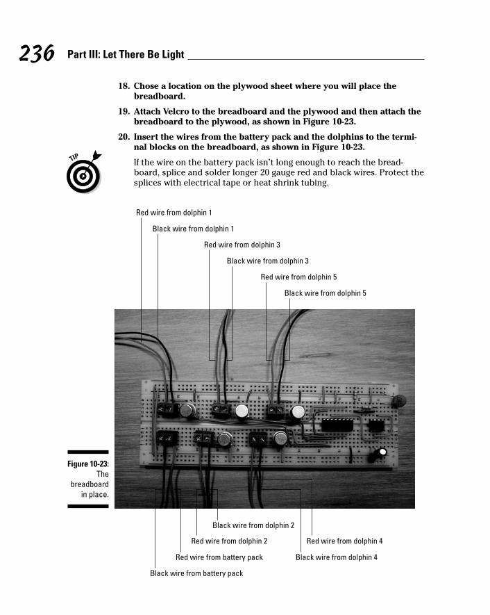
18. Chose a location on the plywood sheet where you will place thebreadboard.
19. Attach Velcro to the breadboard and the plywood and then attach thebreadboard to the plywood, as shown in Figure 10-23.
20. Insert the wires from the battery pack and the dolphins to the termi-nal blocks on the breadboard, as shown in Figure 10-23.
If the wire on the battery pack isn’t long enough to reach the bread-board, splice and solder longer 20 gauge red and black wires. Protect thesplices with electrical tape or heat shrink tubing.
Red wire from dolphin 1
Black wire from dolphin 1
Red wire from dolphin 3
Black wire from dolphin 3
Red wire from dolphin 5
Black wire from dolphin 5
Black wire from battery pack
Red wire from dolphin 2 Red wire from dolphin 4
Black wire from dolphin 4
Black wire from dolphin 2
Red wire from battery pack
Figure 10-23:The
breadboardin place.
236 Part III: Let There Be Light
16_009683 ch10.qxp 6/22/06 9:38 PM Page 236

21. Secure the wires with wire clips.
22. Add the protective backing by performing the following steps:
a. Drill holes for 6-32 screws in six locations on each plywood sheet toattach the standoffs between the two plywood sheets.
b. Secure the six standoffs to the plywood sheet on which you’ve placedthe LEDs, using 6-32 screws.
c. To finish off the project, secure the second plywood sheet to the sixstandoffs using 6-32 screws, as shown Figure 10-24.
Trying It OutWe’re sure that after spending hours stringing LEDs, you’re eager to see thefruits of your labors. (We were!) Whether you followed our lead and createddolphins or got creative with some other shape, it’s time to turn on yourlighting display.
You can either lean the display against a wall or hang it as you would a largepicture; then enjoy the show at your next dance party.
Figure 10-24:The finished
dancingdolphin
product.
237Chapter 10: Dancing Dolphins
16_009683 ch10.qxp 6/22/06 9:38 PM Page 237

There aren’t many steps to getting this project going:
1. Pop the batteries into the battery pack.
2. Flip the switch to On.
That’s it! Your dolphins will begin dancing across the wall in timed sequence.
Here are the obvious things to check out if you’re having a problem:
All the batteries are fresh and tight in the battery pack and also face theright direction.
If one dolphin in the group doesn’t function, check its wiring.
If one or two LEDs aren’t working, replace them.
If two LEDs in series with each other aren’t functioning, you might havereversed the long and short leads of the LEDs. If so, it’s easiest to justreplace that pair.
Taking It FurtherAren’t dancing dolphins just so cool? You can morph these guys into some-thing else or expand their functionality in a few different ways:
Change the stencils to create whatever your heart desires.
Santa and his reindeer, or swans, or leaping lizards come to mind.
You can create larger figures or make up to ten figures.
However, we wouldn’t suggest using more LEDs than we used here tooutline them because that would drain the batteries too quickly or pos-sibly cause the 2N3053 transistors to overheat.
Get your dolphins chattering in sequence.
You could add sound by using a sound chip, as we show you in Chapter 14.
Use a SpeakJet sound synthesizer chip (like we show you in Chapter 7)to have each dolphin make a unique sound, giving each a distinctivepersonality.
Tie an output pin of the decade counter to an event pin on the SpeakJetsound synthesizer chip in parallel with the transistor for the LEDs.Program the SpeakJet to trigger an event when it goes from low to high.When a dolphin lights up, it triggers the sound for that pin.
238 Part III: Let There Be Light
16_009683 ch10.qxp 6/22/06 9:38 PM Page 238

Chapter 11
Controlling a Go-Kart, Infrared Style
In This Chapter Looking over the go-kart schematic
Laying down the parts list
Breadboarding the transmitter and receiver
Building the go-kart body
Making the go-kart go!
Remote-controlled vehicles are very cool things. You can cause them tozip around your living room, tease your cat, and race with your friends.
Building your own go-kart from scratch and using the power of infrared tocontrol its every move are what this project is all about. How far you go inmaking a cool-looking car is up to you; here we’ve designed what we call aninfrared go-kart — sort of like a VW Bug but just a little bit smaller.
In this chapter, you get to explore creating a go-kart that can go forward andbackward and even turn left and right on a dime. Along the way, you pick upall kinds of tips about infrared transmitters and receivers as well as control-ling motors.
The Big Picture: Project OverviewAfter you complete this project, you’ll have a little three-wheeled go-kart thatyou can control with an infrared transmitter, as shown in Figure 11-1. Here’sthe rundown on the key features of this vehicle:
We use three wheels. Why three wheels? No kart you ever saw hadthree wheels, right? Well, the world of electronic projects isn’t Detroit,so we use three wheels because it’s simpler and it works. As soon as youuse four wheels, you have to add a suspension system to ensure that allthe wheels stay in contact with the ground, especially when that ground
17_009683 ch11.qxp 6/27/06 5:34 PM Page 239

gets uneven. For a simple electronics project, where the focus is on theelectronics and not the mechanics, you don’t want to deal with a sus-pension system.
The infrared remote control works along the same lines as your televi-sion remote control. You supply an electric current that causes the LEDto generate infrared light. The IC in the transmitter modulates the elec-tric current running through the LED according to which button youpush on the transmitter: on/off, motor right (we’ll call this motor R), ormotor left (motor L). If you aim the transmitter at the infrared detectoron the kart, the detector turns the infrared light back into electric cur-rent. That current is then interpreted by the receiver circuit on the kartto turn the motors on or off, reverse motor R, or reverse motor L (basedon which button you push).
So what, exactly, will you be doing in this project? The project involves
1. Putting together the electronic circuit for the IR transmitter and fitting itinto a plastic box with buttons that you use to control the movement ofthe go-kart
2. Putting together the electronic circuit for the IR receiver/motor driver
3. Building the base for the go-kart itself and attaching the various bits to it
Figure 11-1:The final
product: athree-
wheeled,infrared-
controlledgo-kart.
240 Part III: Let There Be Light
17_009683 ch11.qxp 6/27/06 5:34 PM Page 240

Scoping Out the SchematicThere are actually two breadboards to assemble in this project: a transmittercircuit and a receiver circuit. Take a look at the schematics for these two inthe following sections, along with helpful tips for reading them.
Transmitting at the speed of lightThe transmitter is what you use to operate the go-kart. The transmitter cir-cuit is shown in Figure 11-2.
Here’s the gist of what’s going on:
VR1 is a voltage regulator that takes the 6 volts supplied by the batterypack and converts it to 5 volts, the maximum voltage specified for thedecoder (IC1).
The capacitor (C1) that’s placed between the output pin and the groundpin of the voltage regulator prevents any oscillation (wiggling around) inthe output voltage of the regulator.
6
2
1 8
45
3
B1
B3
B2
IC1
7
LED 1
R1
X1
+- VR1V-
VIN
VOUT
C1
+
Figure 11-2:The
schematicof the
transmittercircuit.
241Chapter 11: Controlling a Go-Kart, Infrared Style
17_009683 ch11.qxp 6/27/06 5:34 PM Page 241

IC1 is an encoder whose job it is to send out a signal that tells a decoderon the receiver what to do. Pins 4, 6, and 7 are inputs to the encoder(inputs 3, 2, and 1, respectively). When a normally open (NO) pushbuttonswitch (B1, B2, B3) tied to one of these pins is closed, the encoder modu-lates the 38 kHz carrier wave that tells the decoder IC in the receiverexactly which button has been pressed. This signal goes out through Pin5 and then through a 150 ohm resistor (R1). The resistor limits the cur-rent to about 22 milliamps; that’s so you don’t burn out the LED. Thesignal then goes through the IR LED, which generates an infrared signal.
X1 is a 4 MHz ceramic resonator. This works with components withinthe encoder to generate timing signals that help generate the 38 kHz car-rier wave and runs an internal clock used to generate a signal that identi-fies which pushbutton switch has been closed.
Receiving what the transmitter sendsJust like your TV receives the signal from a remote control telling it to flipover to MTV, something has to receive the transmitter signal to make the kartgo. The receiver circuit is shown in Figure 11-3.
Note what’s going on in this schematic:
The IR detector contains a photodiode; when the infrared signal reachesthe photodiode, it produces an electrical signal. This electrical signalgoes into Pin 4 of the decoder (IC1).
IC1 then decodes the electrical signal sent by the transmitter. Pressingand releasing a pushbutton on the transmitter causes the decoder toswitch around the state of the corresponding output; Pin 7 is output 1,Pin 6 is output 2, and Pin 5 is output 3. So, if the output pin is high, (5volts), it will be changed to ground; if the output pin is low (ground), itwill be changed to high (5 volts). The output stays at that voltage untilanother signal appears to change it.
The resonator (X1) drives an oscillator within the decoder to generateinternal clock signals used to decode the signal sent out by the encoder.
Like with the transmitter circuit, a voltage regulator (VR1) limits thesupply voltage to the ICs to 5 volts.
S1 is the power switch for the receiver.
You place a 10 microfarad capacitor (C2, C4, C6) and 0.1 microfaradcapacitor (C1, C3, C5) between the +V and ground buses at the +V inputof each of the ICs. These are used to filter electrical noise from the DCmotors; that noise can prevent the ICs from operating correctly becausethey won’t consistently have the correct supply voltage. If you don’t addthese capacitors to the circuit, the motors could occasionally stop run-ning or stop responding when you press the transmitter button.
242 Part III: Let There Be Light
17_009683 ch11.qxp 6/27/06 5:34 PM Page 242

Controlling motor behaviorTo control the movement of the kart, you need to be able to control the direc-tion of both DC motors. Here’s what will happen, depending on what themotors are doing:
62
1 8
4
53
IC1
7
X12
10
7
15
1 213 12
3 6
11 14
13
12
5
4
9
1
8
16
+-
ML
IC3
IC2
MR
IR
+
DETECTOR
14
7
VIN
VOUT
6V
6V
VR1
+-
C1 C2
+
C3 C4
+
C5 C6
+
S1
Figure 11-3:The
schematicof the
receivercircuit.
243Chapter 11: Controlling a Go-Kart, Infrared Style
17_009683 ch11.qxp 6/27/06 5:34 PM Page 243

Both motors are rotating forward: The kart will move forward.
Both motors are rotating backward: The kart will move backward.
If motor L is moving backward and motor R is moving forward: Thekart will make a left turn.
If motor L is moving forward and motor R is moving backward: Thekart will make a right turn.
In order to change the direction of the motors, you need to change the direc-tion of the current flowing through the motor windings. A circuit called an H-bridge flips the direction of the current through the motors. In the receiverschematic (refer to Figure 11-3), IC3 contains two H-bridges. (You can’t seethe H-bridges in the schematic, but trust us: They’re in there. You’ll seewhere they go when you get to the steps for assembling the go-kart.)
To control the motors, the H-bridge needs the following inputs, as shown inFigure 11-3:
Pin 16: +V to power the IC.
Pin 8: A separate +V to power the DC motors.
This is why you need to use a second battery pack; it helps isolate theICs from electrical noise generated by the DC motors that can cause thecircuit to stop functioning intermittently. Read about this in the upcom-ing parts list section for this project.
Pins 1 and 9: The signal, supplied from Pin 7 of the decoder (IC1), goesto Pins 1 and 9 of the H-bridge in IC3. If Pin 7 (IC1) is at +V, both DCmotors turn on. If Pin 7 of IC1 is at ground, both DC motors turn off.
Pins 2 and 7: Pins 2 and 7 of the H-bridge determine in what directionmotor L rotates. To rotate motor L, the H-bridge requires +V at Pin 2 andground at Pin 7 in order to go in one direction, or the opposite to go inthe other direction. In order to establish the +V and ground connectionsfor motor L, you connect Pin 6 of the decoder to Pin 2 of the H-bridgeand also connect Pin 6 to IC3. IC2 inverts the signal so that +V becomesground or ground becomes +V. You then connect the inverted signal toPin 7 of the H-bridge; this gives you both the +V and ground you need tocontrol the direction of motor L.
Pins 10 and 15: These control the direction of motor R in the same waythat Pins 2 and 7 control motor L. To rotate motor R, the H-bridge requires+V at Pin 10 and ground at Pin 15, or the opposite to go the other way.Connect Pin 5 of IC1 to Pin 10 of the H-bridge and also connect Pin 5 of IC1to IC2. IC2 then inverts the signal so that +V becomes ground or groundbecomes +V. That signal now goes to Pin 15 of the H-bridge.
244 Part III: Let There Be Light
17_009683 ch11.qxp 6/27/06 5:34 PM Page 244

Building Alert: Construction IssuesWe thought and thought about what to use to place over the kart’s works togive our kart a top. In a stroke of genius (well, we couldn’t think of anythingelse, to be honest, and we were grocery shopping at the time), we used aplastic food storage container to create a bubble-like dome. It’s cheap, easyto work with, and clear so you can see what makes the kart go, which is kindof cool. Make sure you get a container made of flexible plastic. Flexible plas-tic is easier to use because you have to make two cuts in this container: anopening in the back that lets the IR signal from your transmitter reach the IRdetector in the back of the kart and an opening in the side so you can reachthe power switch.
You can build the base of the kart out of 1⁄4" thick plywood or 1⁄4" rigid expandedPVC (plastic). The PVC provides a better finished look than the plywood, buteither will work. You should be able to locate 1⁄4" thick plywood at any lumberor homebuilding store.
A couple of robot supply houses, such as Budget Robotics and Solarbotics(here the material is called Sintra), sell small sheets of rigid expanded PVC. A Google search for “rigid expanded PVC” will also turn up plastic supplycompanies that sell larger sheets. Find more at these Web sites: www.budgetrobotics.com and www.solarbotics.com.
If you don’t feel ambitious, you can leave off the bubble top and let the go-kart be a convertible model. If you plan to reuse the components after tryingout the kart, that might be the way to go. However, if you plan to keep thekart intact, we suggest that you use a top to keep out dirt and avoid the pos-sibility of wires or components being knocked off (in case your kart gets intoa traffic accident in your living room).
The motor lugs used in this project are made of thin metal and will break offif you put too much stress on them. By using stranded wire, rather than solidwire, you can minimize the stress on the lugs.
Perusing the Parts ListWe broke the parts list for this project into two very logical sections: one forthe transmitter, and one for the receiver and the kart body on which thereceiver is mounted.
245Chapter 11: Controlling a Go-Kart, Infrared Style
17_009683 ch11.qxp 6/27/06 5:34 PM Page 245
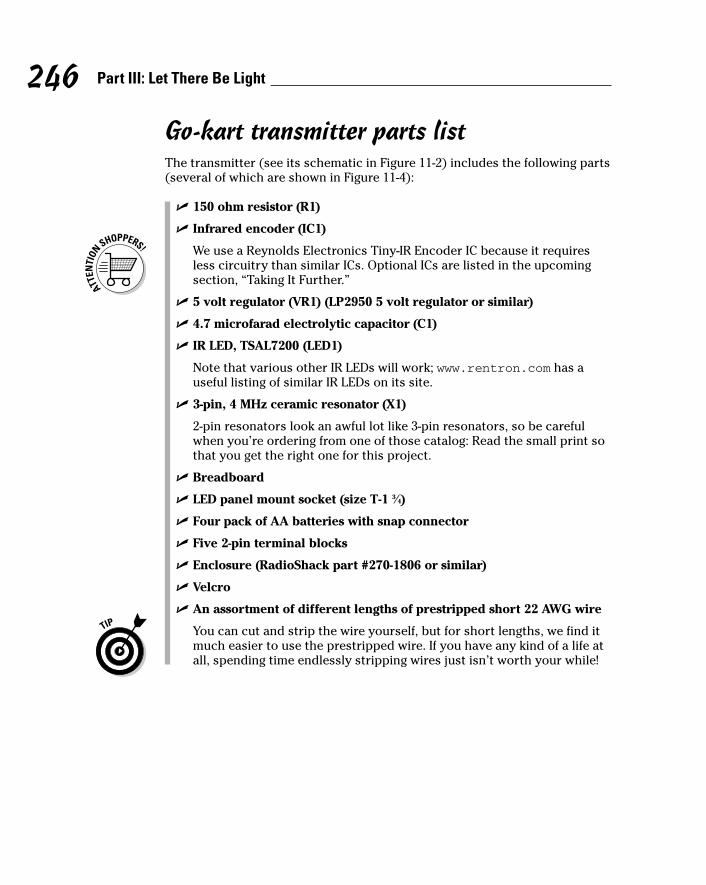
Go-kart transmitter parts listThe transmitter (see its schematic in Figure 11-2) includes the following parts(several of which are shown in Figure 11-4):
150 ohm resistor (R1)
Infrared encoder (IC1)
We use a Reynolds Electronics Tiny-IR Encoder IC because it requiresless circuitry than similar ICs. Optional ICs are listed in the upcomingsection, “Taking It Further.”
5 volt regulator (VR1) (LP2950 5 volt regulator or similar)
4.7 microfarad electrolytic capacitor (C1)
IR LED, TSAL7200 (LED1)
Note that various other IR LEDs will work; www.rentron.com has auseful listing of similar IR LEDs on its site.
3-pin, 4 MHz ceramic resonator (X1)
2-pin resonators look an awful lot like 3-pin resonators, so be carefulwhen you’re ordering from one of those catalog: Read the small print sothat you get the right one for this project.
Breadboard
LED panel mount socket (size T-1 3⁄4)
Four pack of AA batteries with snap connector
Five 2-pin terminal blocks
Enclosure (RadioShack part #270-1806 or similar)
Velcro
An assortment of different lengths of prestripped short 22 AWG wire
You can cut and strip the wire yourself, but for short lengths, we find itmuch easier to use the prestripped wire. If you have any kind of a life atall, spending time endlessly stripping wires just isn’t worth your while!
246 Part III: Let There Be Light
17_009683 ch11.qxp 6/27/06 5:34 PM Page 246

Go-kart receiver/chassis parts listThe receiver and go-kart chassis (see the schematic in Figure 11-3) use thefollowing parts (several of which are shown in Figures 11-5 and 11-6):
IR detector PNA4602M
Various other IR detectors will work. If you want to try another, you canfind a listing of IR detectors at www.rentron.com.
Decoder (IC1) (Reynolds Tiny-IR Decoder)
5 volt regulator (VR1) (LM7805 5 volt regulator or similar)
Inverter (IC2) (SN74F04 or similar)
H-bridge (IC3) (L293D or similar)
3 pin, 4 MHz ceramic resonator (X1)
Three 10 microfarad electrolytic capacitors (C1, C3, C5)
Voltage regulator Capacitor
IR LED
Terminal block
2-piece LED socket
SwitchResonator Resistor Battery packEncoder IC
Figure 11-4:Key
transmittercomponents.
247Chapter 11: Controlling a Go-Kart, Infrared Style
17_009683 ch11.qxp 6/27/06 5:34 PM Page 247

Three 0.1 microfarad ceramic capacitors (C2, C4, C6)
Four 2 pin terminal blocks
Two 4 packs of AA batteries
Two DC gear motors (MR, ML) (GM2 with 25⁄8" wheels or equivalent)
We use the GM2 model gear motors because the suppliers (HobbyEngineering, www.hobbyengineering.com; and Solarbotics) carrywheels just made to fit them, and they cost a bit less than servomotors, akind of motor often used in robots because it offers more control ofquick changes in motion.
2" swiveling castor
SPST (single-pole, single-throw) switch (S1)
Two wire clips
Use RadioShack part #278-1668 or something similar; essentially, youcan use anything that will secure the wires without damaging them.
1⁄4" thick expanded PVC, 9" x 61⁄2".
You could also use 1⁄4" thick plywood.
6" x 9" plastic food container
Velcro
Inverter ICH-bridge ICTerminal blockVoltage regulator 0.1 microfarad capacitor
10 microfarad capacitor Decoder ICResonatorIR detector
Figure 11-5:Key receivercomponents.
248 Part III: Let There Be Light
17_009683 ch11.qxp 6/27/06 5:34 PM Page 248

Taking Things Step by StepCreating your go-kart involves building the transmitter, building the receiver,and then assembling the go-kart body with its motors and three wheels. Thereceiver circuit gets mounted on the body as well, and then you top thewhole thing off with the plastic bubble cover.
Making the transmitterThe transmitter — the thing that you hold in your hand like a TV remote control — is what you aim at the go-kart to control it.
Follow these steps to build the transmitter circuit:
1. Place the encoder IC, resonator, voltage regulator, resistor, and capacitor on the breadboard, as shown in Figure 11-7.
Make sure you put the negative lead of the capacitor in the same bread-board row as the center pin of the voltage regulator and the positive leadin the same breadboard row as the +5 volt output pin of the regulator.
WheelBattery pack Power switch
DC motorCastor
Figure 11-6:Key go-kart
chassiscomponents.
249Chapter 11: Controlling a Go-Kart, Infrared Style
17_009683 ch11.qxp 6/27/06 5:34 PM Page 249

Figure 11-8 shows the uses of each pin of the voltage regulator, capaci-tor, and LED.
+5 volt output+V
+V GroundGround+V Ground
Figure 11-8:Pinout of the
capacitor,LED, and
voltageregulator.
CapacitorResonator
Voltage regulatorEncoder ICResistor
Figure 11-7:Place the
encoder ICand
associatedcomponents
on thebreadboard.
250 Part III: Let There Be Light
17_009683 ch11.qxp 6/27/06 5:34 PM Page 250

2. Place five terminal blocks on the breadboard, as shown in Figure 11-9.
The five terminal bocks shown in this figure will be used to connect twowires each to various components in the circuit. The wires go to the bat-tery pack, IR LED, on/off switch, motor R switch, and motor L switch,respectively.
3. Insert wires to connect each component and terminal to the groundbus and insert a wire between the two ground buses to connect them,as shown in Figure 11-10.
On the resonator, the center of the three leads is the ground lead.
Eight shorter wires connect components to ground bus; the long wire onthe left connects the two ground buses.
Figure 11-9:Add
terminalblocks to the
breadboard.
251Chapter 11: Controlling a Go-Kart, Infrared Style
17_009683 ch11.qxp 6/27/06 5:34 PM Page 251

4. Insert wires to connect the input pin of the voltage regulator and the ter-minal block for the battery to the + voltage bus, as shown in Figure 11-11.
Batteryterminal block
connectionto +V
Voltageregulator
connectionto +V
Figure 11-11:Connect theinput pin ofthe voltageregulator tothe battery.
Figure 11-10:Short wires
connectcomponents
to groundbus; a long
wireconnects
the twogroundbuses.
252 Part III: Let There Be Light
17_009683 ch11.qxp 6/27/06 5:34 PM Page 252

5. Insert wires to connect the encoder IC, voltage regulator, and res-onator, as shown in Figure 11-12.
6. Insert wires to connect the terminal blocks to the IC1 encoder andresistor, as shown in Figure 11-13.
IC Pin 3 to the other outer resonator pin
Voltage regulatorto IC Pin 1
IC Pin 2 to one outerresonator pin
Figure 11-12:Connect the
IC, voltageregulator,
andresonator.
253Chapter 11: Controlling a Go-Kart, Infrared Style
17_009683 ch11.qxp 6/27/06 5:34 PM Page 253

7. Drill holes in the transmitter box for the LED and switches.
Figure 11-14 shows holes drilled in the front of the box for the LED and inthe top of the box for the switches. The size of drill bit that you usedepends upon the diameter of the switches and LED socket you use. Weused a 1⁄4" drill bit to drill the hole for the LED and a 5⁄16" drill bit to drillthe holes for the switches.
Resistor to LED terminal blockPin 7 of IC1 encoder to on/off terminal block
Pin 6 of IC1 encoder to motor R terminal blockPin 4 of IC1 encoder to motor L terminal block
Figure 11-13:Connectterminal
blocks tothe IC1
encoderand resistor.
254 Part III: Let There Be Light
17_009683 ch11.qxp 6/27/06 5:34 PM Page 254

8. Place adhesive-backed Velcro in the box and on the battery pack, asshown in Figure 11-15.
Figure 11-15:Stick Velcro
to attach the battery
pack.
Figure 11-14:Drill holes
for the LED and
switches.
255Chapter 11: Controlling a Go-Kart, Infrared Style
17_009683 ch11.qxp 6/27/06 5:34 PM Page 255

9. Place the three switches through the holes, as shown in Figure 11-16,and secure them to the box with the nuts included with the switches.
10. Feed the LED socket through the hole in the front of the box. Slip theLED into the socket from the inside of the box, and then slip thebottom half of the socket over the leads and tighten to secure the LED.
11. Connect one black and one red 6" wire to the LED and solder them.
The secured and soldered LED is shown in Figure 11-17.
The red wire must be connected to the longer of the LED leads. After thewires have cooled, wrap them in electrical tape to prevent the leadsfrom shorting.
Heed all the safety precautions about soldering that we talk about inChapter 2. For example, don’t leave your soldering iron on and unat-tended. And for heaven sakes — don’t drop it in your lap when it’s hot!
Figure 11-16:Transmitter
box withswitchesinstalled.
256 Part III: Let There Be Light
17_009683 ch11.qxp 6/27/06 5:34 PM Page 256

12. Connect 6" wires (any color is okay) to the switches and solder them,as shown in Figure 11-18.
To connect wires to the switches, feed the wire through the lug and twistto secure it.
Figure 11-18:Attach
wires to theswitches.
Figure 11-17:Transmitter
box withLED inplace.
257Chapter 11: Controlling a Go-Kart, Infrared Style
17_009683 ch11.qxp 6/27/06 5:34 PM Page 257

13. Secure the breadboard in the box with Velcro. Or, if the breadboardalready has adhesive tape on the back like the one we used, just usethe tape.
14. Attach the wires from the battery pack snap connector and the LED tothe terminal blocks, as shown in Figure 11-19.
15. Attach the wires from the switches to the terminal blocks, as shown inFigure 11-20.
Blackbattery
lead
Redbattery
lead
+V LED lead Ground LED lead
Figure 11-19:Transmitter
box withbreadboard
installed.
258 Part III: Let There Be Light
17_009683 ch11.qxp 6/27/06 5:34 PM Page 258

16. Place batteries in the battery holder, connect the snap, and secure theholder in the box with Velcro, as shown in Figure 11-21.
Figure 11-21:The inside
of thecompletedtransmitter
box.
Leads to motor R switchLeads to on/off switch
Leads to motor L switch
Figure 11-20:Attaching
wires toterminalblocks.
259Chapter 11: Controlling a Go-Kart, Infrared Style
17_009683 ch11.qxp 6/27/06 5:34 PM Page 259

17. Attach the cover to the box with the included screws.
The completed box is shown in Figure 11-22.
Making the receiver circuit boardThe receiver, quite logically, receives the signal sent by the transmitter. Youwill eventually affix the receiver circuit to the body of the go-kart, but don’tput the kart before the horse (so to speak): Before you affix the receiver, youhave to build it.
To build the receiver circuit, follow these steps:
1. Insert the ICs on the breadboard, as shown in Figure 11-23.
Be sure to leave room between each IC to place wires (as shown in thefinal figure in this section, the upcoming Figure 11-32). Also, leave roomat the end of the board near the decoder to insert the IR detector andthe resonator. Finally, leave room at the end of the board near the H-bridge to add terminal blocks.
Figure 11-22:The
transmitterall put
together.
260 Part III: Let There Be Light
17_009683 ch11.qxp 6/27/06 5:34 PM Page 260

2. Insert the voltage regulator, resonator, and IR detector on the bread-board, as shown in Figure 11-24.
Resonator IR detectorVoltage regulator
Figure 11-24:Insert the
discretecomponents.
H-bridge IC3 Inverter IC2 Decoder IC1
Figure 11-23:Insert theICs on the
breadboard.
261Chapter 11: Controlling a Go-Kart, Infrared Style
17_009683 ch11.qxp 6/27/06 5:34 PM Page 261

Figure 11-25 shows how the circuit uses each pin of the voltage regulatorand IR detector (referred to as discrete components).
3. Insert four terminal blocks a few rows in from the end of the bread-board, as shown in Figure 11-26.
Inputvoltage
+5 voltoutput Output +V +V
GroundGround Ground
Figure 11-25:Pinouts for
the discretecomponents.
262 Part III: Let There Be Light
17_009683 ch11.qxp 6/27/06 5:34 PM Page 262

4. Insert wires to connect each component to the + voltage bus and awire to connect the two + voltage buses, as shown in Figure 11-27.
Note that you connect the +5 volt output of the voltage regulator to the +voltage bus because the voltage regulator takes the approximately +6volts from the battery and changes it to +5 volts. It then supplies those +5volts to the + voltage bus so that it can be used by the other components.
Figure 11-27:Connect
componentsto the
+V bus.
Figure 11-26:Insert
terminalblocks on the
breadboard.
263Chapter 11: Controlling a Go-Kart, Infrared Style
17_009683 ch11.qxp 6/27/06 5:34 PM Page 263

5. Insert a set of one 10 microfarad and one 0.1 microfarad capacitorbetween the + voltage bus and the ground bus next to the V+ input forthe decoder IC. Do the same for the inverter IC and the H-bridge IC, asshown in Figure 11-28.
These capacitors filter out electrical noise introduced to the + voltagesupply for each IC by the DC motors.
6. Insert wires to connect each component and terminal to the groundbus (marked with a – on this breadboard) and insert a wire to connectthe two ground buses, as shown in Figure 11-29.
The resonator in the center of the three leads is the ground lead.
0.1 microfarad capacitors
10 microfarad capacitors
Figure 11-28:Insert
capacitorson the
breadboard.
264 Part III: Let There Be Light
17_009683 ch11.qxp 6/27/06 5:34 PM Page 264

7. Insert wires to connect the decoder IC, resonator, and IR detector, asshown in Figure 11-30.
IR detectorto ground bus
Decoderto ground bus
H-bridgeto ground bus
Voltage regulatorto ground bus
Terminal blockto ground bus
Wire connecting2 ground buses
Resonator to ground busTerminal blockto ground bus
H-bridgeto ground bus
Figure 11-29:Connect
componentsto the
ground bus.
265Chapter 11: Controlling a Go-Kart, Infrared Style
17_009683 ch11.qxp 6/27/06 5:34 PM Page 265

8. Insert wires to connect the decoder, inverter, and H-bridge, as shownin Figure 11-31.
Pin 4 of thedecoder
to output pinof the
IR detector
Pin 3 of the decoderto the other outer pin
of the resonator
Pin 2 of the decoderto the outer pinof the resonator
Figure 11-30:Insert wires
betweenpins on the
decoder,resonator,
and IRdetector.
266 Part III: Let There Be Light
17_009683 ch11.qxp 6/27/06 5:34 PM Page 266

9. Insert wires to connect the terminal blocks to the H-bridge and volt-age regulator, as shown in Figure 11-32.
Pin 12 of theinverterto Pin 15
of the H-bridge
Pin 13 of theinverterto Pin 10
of the H-bridge
Pin 5 of thedecoderto Pin 13
of the inverter
Pin 7 of thedecoderto Pin 9
of the H-bridge
Pin 1 of theinverterto Pin 2
of the H-bridge
Pin 6 of thedecoderto Pin 1
of the inverter
Pin 9 of theH-bridgeto Pin 1
of the H-bridge
Pin 2 of theinverterto Pin 7
of the H-bridge
Figure 11-31:Inserting
wiresbetween
pins on thedecoder,
inverter, andH-bridge.
267Chapter 11: Controlling a Go-Kart, Infrared Style
17_009683 ch11.qxp 6/27/06 5:34 PM Page 267
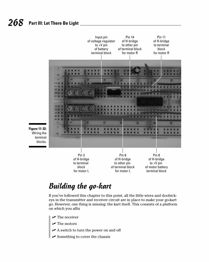
Building the go-kartIf you’ve followed this chapter to this point, all the little wires and doohick-eys in the transmitter and receiver circuit are in place to make your go-kartgo. However, one thing is missing: the kart itself. This consists of a platformon which you affix
The receiver
The motors
A switch to turn the power on and off
Something to cover the chassis
Pin 14of H-bridgeto other pin
of terminal blockfor motor R
Pin 11of H-bridgeto terminal
blockfor motor R
Input pinof voltage regulator
to +V pinof battery
terminal block
Pin 8of H-bridgeto +V pin
of motor batteryterminal block
Pin 6of H-bridgeto other pin
of terminal blockfor motor L
Pin 3of H-bridgeto terminal
blockfor motor L
Figure 11-32:Wiring the
terminalblocks.
268 Part III: Let There Be Light
17_009683 ch11.qxp 6/27/06 5:34 PM Page 268

Although the covering is optional, it makes the kart look cooler. More impor-tantly, a covering prevents your kids or pets from poking a finger or pawwhere they shouldn’t and pulling wires loose.
To build the kart itself, follow these steps:
1. Place the breadboard, battery packs, caster, and power switch on the1⁄2" PVC or plywood sheet, as shown in Figure 11-33.
This will help you to determine how large to make the base of the kart.
We chose a 1⁄2" PVC sheet, 61⁄2" wide and 9" long, which can hold all thecomponents and still leave enough room to rest the top of the kart onthe base. You can use a pencil to mark where to cut the 1⁄2" PVC sheet.
2. Mark a location between the breadboard and the bumper switchwhere you will drill a hole to feed the wires to the motors.
3. Use the base of the castor as a template to mark the four holes youwill drill to mount it to the body.
Figure 11-34 shows the marked PVC sheet.
Figure 11-33:Determine
the shape ofthe kart
base.
269Chapter 11: Controlling a Go-Kart, Infrared Style
17_009683 ch11.qxp 6/27/06 5:34 PM Page 269

4. Cut the sheet along the lines you drew (a hacksaw or any fine-toothedsaw should do the job), and then use a 1⁄4" bit to drill a hole where youmarked the feed-through hole in Step 2.
5. Use a 1⁄8" bit to drill the holes used to attach the castor.
Use sandpaper or a file to smooth any rough edges. Figure 11-35 showsthe base after it’s been cut and drilled.
Figure 11-35:The base for
the kart, allsawed,
drilled, andsanded.
Figure 11-34:Mark thebase for
cutting anddrilling.
270 Part III: Let There Be Light
17_009683 ch11.qxp 6/27/06 5:34 PM Page 270

6. Attach Velcro to the battery packs, motors, and switch, as shown inFigure 11-36.
7. Solder 12" wires to the motors, as shown in Figure 11-37.
By using different wire colors (we used red and black), it’s easier to iden-tify which goes to each pin in the terminal blocks on the breadboard soyou can control which direction the motors turn.
Figure 11-36:Attach
Velcro tothe various
components.
271Chapter 11: Controlling a Go-Kart, Infrared Style
17_009683 ch11.qxp 6/27/06 5:34 PM Page 271

8. Stick some Velcro to the base of the kart where the motors will beattached and then attach the motors; see Figure 11-38.
Figure 11-38:Attach the
motors andcastor.
Black wire Red wire
Figure 11-37:Solder wires
to themotors.
272 Part III: Let There Be Light
17_009683 ch11.qxp 6/27/06 5:34 PM Page 272

9. Attach the castor, using 5⁄8" 6-32 screws and nuts, also shown in Figure 11-38.
10. Feed the wires through the 1⁄4" hole and secure the wires with the wireclips (as shown in Figure 11-38); then slip the wheels on the motorshafts and secure the wheels with the screw provided.
11. Stick Velcro to the base of the kart and attach the battery packs,switches, and breadboard to the top of the base, as shown in Figure11-39.
12. Attach wires from the motors to the terminal blocks, as shown inFigure 11-40.
Figure 11-39:Attach
variousparts to the kart.
273Chapter 11: Controlling a Go-Kart, Infrared Style
17_009683 ch11.qxp 6/27/06 5:34 PM Page 273

13. Attach wires from the battery packs to the terminal blocks and powerswitch, as shown in Figure 11-41, and solder the wires attached to thepower switch lugs.
Red wire from motor R Red wire from motor L
Black wire from motor R Black wire from motor L
Figure 11-40:Wire the
motors onto the
breadboard.
274 Part III: Let There Be Light
17_009683 ch11.qxp 6/27/06 5:34 PM Page 274

14. With a mini hacksaw, cut openings in the back of the plastic kart top.
One opening will allow the IR detector to peek out and detect a signal;the other opening is for the power switch in the side.
Make sure you’re using a top made of flexible plastic so it cuts easily.Wear safety glasses in case a piece flies off while you’re cutting.
15. Rest the bubble on the kart, as shown in Figure 11-42.
Red wirefrom battery pack
Black wirefrom battery packto power switch
Red wirefrom battery pack
Black wirefrom power switch
Black wirefrom battery pack
Figure 11-41:Wire
the poweronto the
breadboard.
275Chapter 11: Controlling a Go-Kart, Infrared Style
17_009683 ch11.qxp 6/27/06 5:34 PM Page 275

Trying It OutHere’s the payoff to all your hard work: You finally get to see the little kartzoom around your living room. Remove any obstacles before you start!
Follow these steps to operate your go-kart:
1. Slip in the batteries.
2. Turn on the power switch on the kart.
3. Point the transmitter at the kart and press and release the on/off button.
4. Watch it go!
If nothing happens, here are a few things to check out:
All the batteries are fresh, are tight in the battery pack, and face theright direction.
See whether any wires or parts have come loose.
Compare your circuit with the photos in this chapter to make sure yougot all the connections right.
Figure 11-42:The finalproduct:
an infraredgo-kart!
276 Part III: Let There Be Light
17_009683 ch11.qxp 6/27/06 5:34 PM Page 276

To turn left, press and release the motor L button; to turn right, press andrelease the motor R button. After the kart has turned far enough, press andrelease the same button again, and the kart will go forward. If you want thekart to go backward, just press and release motor button L and quickly pressand release motor button R (or vise versa); ditto if the kart is moving back-ward and you want it to move forward.
If these buttons work opposite to the way you expect, swap the wires fromthe motors at the terminal blocks on the receiver.
Just like your car on a cold winter morning, the kart could take a fewmoments to warm up. Wait a few beats after you turn on both on/offswitches, and then go for it!
If you plan on keeping the kart working long-term (rather than using the partson another project), we suggest that you remove the Velcro from the motorsand from the base (where you mounted the motors) and glue the motors to thekart base at the same spot. This will make the kart a little more stable. You canalso glue the wheels onto the motor shaft to make your kart more permanent.
Taking It FurtherAre you so wowed by the go-kart you want to add to it? Here are some ideasto explore:
Other encoder/decoder ICs are available that have more than the threeinput/output pins used here. One option is the Holtek HT12A encoderand HT12D decoder; another is Reynolds Electronics IR-DX8 encoder/decoder. Building a kart by using one of these lets you add other thingsto the kart that you can control: for example, LED headlights or a buzzerto use just like a car horn.
If you want to race go-karts with a friend, you can build multiple kartswith one of the other encoder/decoder pairs just mentioned. Theseallow you to pick an address for each kart by tying different pins toground or +V on each of the encoder/decoder pairs. However, you stillhave to be careful not to activate your transmitters at the same time orpoint your transmitter at your buddy’s car lest you confuse the receivers.The only way around this is to use radio control instead of infrared con-trol, and use different frequencies for each transmitter. See Chapter 18for information about using radio control.
Spiff up the go-kart base and top any way your artistic whim dictates:Paint it, add racing stripes, use a different shape, add decals, or gluefuzzy fur and cute little ears on it.
277Chapter 11: Controlling a Go-Kart, Infrared Style
17_009683 ch11.qxp 6/27/06 5:34 PM Page 277

278 Part III: Let There Be Light
17_009683 ch11.qxp 6/27/06 5:34 PM Page 278

Part IVGood Vibrations
18_009683 pt04.qxp 6/22/06 9:36 PM Page 279

In this part . . .
The chapters in this part all deal with things thatvibrate in some fashion, from sound waves in the air
to a furniture cushion. Intrigued? Here’s what’s covered:
Radio waves form the basis of the remote control unit that you use to manage a character we call Sensitive Sam(Chapter 13). Oscillating signals sent by a metal detector(Chapter 12) produce a corresponding oscillating signal in metal, helping you identify when you’ve hit gold (ormore likely, iron). Finally, our Couch Pet-ato (Chapter 14)responds to the vibration that occurs when your cutekitty jumps up on your couch in your absence, producinga sound to scare off the little dear.
18_009683 pt04.qxp 6/22/06 9:36 PM Page 280

Chapter 12
A Handy-Dandy Metal DetectorIn This Chapter Exploring the detector circuit
Checking off the parts list
Assembling the handle
Mounting the circuit to the handle
Finding metal!
Finding little bits of metal is a time-honored task, right up there with find-ing free music to download off the Internet. With a metal detector, you
can scout out coins in your couch, nails in your walls, keys in somebody’spocket — face it, the applications are endless.
In this project, we show you how to build a small, handheld metal detectorthat can detect certain kinds of metal — especially ferrous (iron-containing)metals — even if that metal is under a half-inch or so of drywall, sand, or soil(but never water!).
The Big Picture: Project OverviewIn this project, you use an IC that generates an AC signal that goes through acoil. Because metal objects conduct electricity, you can induce a current inthose objects. When the coil in the metal detector comes near a metal object,the electromagnetic field in the coil induces currents in the metal object. Theelectromagnetic field generated by the metal changes the current in the coil.When the signal changes, IC turns on an LED, alerting you to the presence ofmetal.
You can see the finished metal detector in Figure 12-1.
19_009683 ch12.qxp 6/22/06 9:39 PM Page 281

Here are the types of activities you’ll be doing to build the metal detector.You will
1. Build a pretty simple electronic circuit containing a coil, a proximitydetector IC, a transistor, a couple of resistors, and an LED.
2. Install the circuit in a box with batteries and an on/off switch.
3. Mount the box on a handle made from plastic pipe.
Scoping Out the SchematicThis project is really easy. You have only one breadboard to put together forthis project. You can see the schematic for the board in Figure 12-2.
Figure 12-1:Our
handheldmetal
detector.
282 Part IV: Good Vibrations
19_009683 ch12.qxp 6/22/06 9:39 PM Page 282

Here’s a list of the schematic elements:
L1 is a coil (also called an inductor) wired in parallel to capacitor C1; thecombination of this dynamic duo is a parallel LC (inductor/capacitor)circuit. When a signal that oscillates at several kHz passes through thiscircuit, the signal creates an electric field around the coil. When youbring the coil near a metallic object, that electric field induces an oscil-lating signal in the object. Turnabout is fair play, so when the oscillatingsignal has been induced in the metallic object, the signal in the objectcreates an electric field that induces current in the coil. This currentchanges the oscillating signal running through the LC parallel circuit.
IC1 is a TDA0161 proximity detector. This IC is designed to supply theoscillating signal that’s sent through the LC parallel circuit. The IC alsoresponds to any changes in the signal: the IC has an output of 1 milliamp(mA) or less if the coil is far from a metallic object and an output of 10mA or higher if the coil is near a metallic object.
R1 is a resistor, and R2 is a variable resistor. These resistors are used tocalibrate the circuit in IC1 to the LC circuit. You calibrate the circuit by
R1
1
5
6
4
7
3 2
C1
C2
IC1
L1
+-
R2
Q1
R3
LED1
R4
R5
6V
S1
Figure 12-2:The
schematicof the metal
detector.
283Chapter 12: A Handy-Dandy Metal Detector
19_009683 ch12.qxp 6/22/06 9:39 PM Page 283

adjusting the value of the variable resistor when the coil is not near anymetal objects.
R5 is a resistor connected between the output of IC1 and ground. Whenthe output of IC1 is on, current flows through this resistor and providesa positive voltage to the base of Q1.
Q1 is a 2N3904 transistor that you connect to the output of IC1. Whenthe output of IC1 is high, Q1 turns on and allows current to flow throughLED1.
LED1 is the indicator light used to indicate that the device has detectedmetal in the vicinity.
R3 is a resistor that limits the amount of current flowing through LED1,which prevents it from burning out.
S1 is the on/off switch.
Building Alert: Construction IssuesYou use PVC cement (a glue) to connect the PVC fittings that form the micro-phone handle. You can get this glue at any building supply store.
This glue creates a very strong joint. However, be sure to wear some form of work gloves when using this glue because it melts plastic — and you defi-nitely don’t want it on your hands. Also read the label for safety tips, such asusing the glue in a well-ventilated area and what to do if some comes in con-tact with your skin.
Perusing the Parts ListEven though this project doesn’t require many parts, you still have to go outand buy or assemble them. Several of the parts are shown in Figure 12-3.Here’s what you need:
Two 1 kohm resistors (R1, R4)
10 kohm potentiometer (R2)
330 ohm resistor (R3)
284 Part IV: Good Vibrations
19_009683 ch12.qxp 6/22/06 9:39 PM Page 284

120 ohm resistor (R5)
Two 0.0047 microfarad ceramic capacitors (C1, C3)
One 2N3904 transistor (Q1)
One T-1 3⁄4 LED (LED1)
LED panel-mount socket, T-1 3⁄4
TDA0161 proximity detector (IC1)
Battery pack for 4 AA batteries
680 picofarad bobbin-type inductor (L1)
We used C&D Technologies part #1468420C that we picked up at Mouser(www.mouser.com).
SPST (single-pole, single-throw) toggle switch, used as the on/offswitch
400-pin breadboard
Four 2-pin terminal blocks
Knob (for the potentiometer)
Two phono jacks
Two right-angle phono plugs
We used right-angle plugs to avoid having a loop of wire coming out ofthe box. You can also use banana plugs and jacks.
Enclosure
We used a plastic box, RadioShack part #270-1806.
An assortment of different lengths of prestripped, short 22 AWG wire
Two PVC 45° joints with 1" slip fitting on both ends (one male and onefemale)
PVC 1" end cap with 1" female slip fitting
1" diameter PVC pipe (referred to as schedule 40 pipe), 1' in length
1" clamp to attach the enclosure to the pipe
Two 1⁄2" 8-32 panhead screws
Two 8-32 nuts
285Chapter 12: A Handy-Dandy Metal Detector
19_009683 ch12.qxp 6/22/06 9:39 PM Page 285

Taking Things Step by StepAlthough the circuit is simple, there are a few steps you need to do to assem-ble it and then put the whole shooting match together, including building thehandle and attaching the circuit to it. As usual, we start with the circuit.
Building a metal detector circuitThe circuit in this project controls sending a detector signal and processingthe signal that comes back to light up the LED. Here are the steps involved:
1. Place TDA0161 (IC1), 2N3904 (Q1), and four terminal blocks (TB) onthe breadboard, as shown in Figure 12-4.
The transistor pinout is shown in Figure 12-5.
IC InductorRight-anglephono pug LED
PVC45° joint
SPSTswitch
Potentiometer Phonojack
Two-pieceLED socket
Figure 12-3:Key
componentsof the metal
detector.
286 Part IV: Good Vibrations
19_009683 ch12.qxp 6/22/06 9:39 PM Page 286

Base pin
Collector pinEmitter pin
Figure 12-5:The 2N3904
pinout.
Coil TB IC1 Potentiometer TB Battery TB
Q1 LED TB
Figure 12-4:Place the IC,
transistor,and terminal
blocks on the
breadboard.
287Chapter 12: A Handy-Dandy Metal Detector
19_009683 ch12.qxp 6/22/06 9:39 PM Page 287

2. Insert wires to connect the battery terminal block and the transistoremitter pin to the ground bus. Then insert a wire between the twoground buses to connect them, as shown in Figure 12-6.
Two shorter wires connect components to ground bus; the long wire onthe right connects the two ground buses.
3. Insert wires to connect IC1 and the battery terminal block to the +Vbus. Then insert a wire between the two +V buses to connect them, asshown in Figure 12-7.
Figure 12-6:Connect
componentsto groundbus; then
connect thetwo ground
buses.
288 Part IV: Good Vibrations
19_009683 ch12.qxp 6/22/06 9:39 PM Page 288

4. Insert wires to connect the IC and discrete components, terminalblock for the coil (L1), terminal block for the potentiometer (R2), andterminal block for the LED, as shown in Figure 12-8.
Pin 1 of IC1 to +V Battery terminal block to +V
Figure 12-7:Connect
componentsto the
+V bus.
289Chapter 12: A Handy-Dandy Metal Detector
19_009683 ch12.qxp 6/22/06 9:39 PM Page 289

5. Insert two 0.0047 microfarad capacitors (C1 and C2), two 247 ohmresistors (R3 and R5), one 1 kohm resistor (R1), and one 120 ohmresistor (R5) on the breadboard, as shown in Figure 12-9.
We discuss in Chapter 4 how to determine how short to clip the leads ofmany of these components to make them fit neatly on the breadboard.Make sure you wear your safety glasses when clipping leads!
L1 TBto Pin 3 of IC1
R2 TBto Pin 4 of IC1
L1 TBto Pin 7 of IC1
Pin 6 of IC1to open region
LED TBto collector pin of Q1
Figure 12-8:Hook up theICs, terminalblocks (TB),
and discretecomponents.
290 Part IV: Good Vibrations
19_009683 ch12.qxp 6/22/06 9:39 PM Page 290

Building the box to house the circuitThe box that houses the circuit needs holes so that you can place the LED,the potentiometer dial you use to adjust resistance on the IC, and the on/offswitch as well as various wire connections.
Follow these steps to get the metal detector circuit enclosure ready:
1. Drill holes in the box where you will mount the LED, potentiometer,audio jacks, on/off switch, and clamp.
We put the on/off switch and the potentiometer on one side of the box,the LED on one end, and the audio jacks on the bottom. However, theplacement is really up to you. Figure 12-10 shows where we placed thesecomponents.
C1 between pinsof L1 TB
R1 from Pin 2of IC1 to R2 TB
R4 from base pin of Q1to Pin 6 of IC1
C2 from Pin 5 of IC1to Pin 7 of IC1
R5 from R4to ground
R3 from LED TBto +V
Figure 12-9:Insert
resistorsand
capacitorson the
breadboard.
291Chapter 12: A Handy-Dandy Metal Detector
19_009683 ch12.qxp 6/22/06 9:39 PM Page 291

See Chapter 4 for more information about choosing drill bit sizes for par-ticular components and other advice about how to customize a box foryour projects. And guess what? We always advise that you use safetyglasses when drilling.
2. Slip the threads of the phono jacks through the drilled holes andsecure with the nuts provided.
3. Slip the shaft of the on/off switch through the drilled hole and securewith the nut provided.
4. Slip the shaft of the potentiometer through the drilled hole and securewith the nut provided.
5. Slip the knob on the potentiometer shaft and secure with the set screw.
6. Feed the top half of the LED socket through the drilled hole from out-side the box and insert the LED into the top half of the socket frominside the box.
7. Slip the bottom half of the socket over the leads and snap onto the tophalf of the socket to secure the LED.
8. Solder the black wire from the battery pack to one lug of the on/offswitch and solder an 8" black wire to the remaining lug of the on/offswitch, as shown in Figure 12-11.
LED On/off switch
Screws and nuts securing the clamp Phono jacks Potentiometer
Figure 12-10:Box with
on/offswitch,
phono jacks,potentiome-ter, and LED
in place.
292 Part IV: Good Vibrations
19_009683 ch12.qxp 6/22/06 9:39 PM Page 292

9. Solder an 8" wire to the center potentiometer lug and another 8" wireto the left potentiometer lug, as shown in Figure 12-11.
10. Solder a red 8" wire to the long lead of the LED and a black 8" wire tothe short lead of the LED, as shown in Figure 12-11.
11. Slip a 1" piece of heat shrink tubing over each solder joint and use ahair dryer to secure them in place.
12. Solder an 8" wire to the lug on each of the phono jacks, as shown inFigure 12-11.
See Chapter 2 for advice about safe soldering if you’re not very experiencedin this art.
Putting it all togetherAfter you have a box and a circuit, it’s time to introduce them to each other.Follow these steps to do so:
1. Attach Velcro to the breadboard and the box and secure the bread-board in the box.
2. Attach Velcro to the battery pack and the box and secure the batterypack in the box.
Figure 12-11:Wires
soldered tothe on/off
switch,potentio-
meter,phone jacks,
and LED.
293Chapter 12: A Handy-Dandy Metal Detector
19_009683 ch12.qxp 6/22/06 9:39 PM Page 293
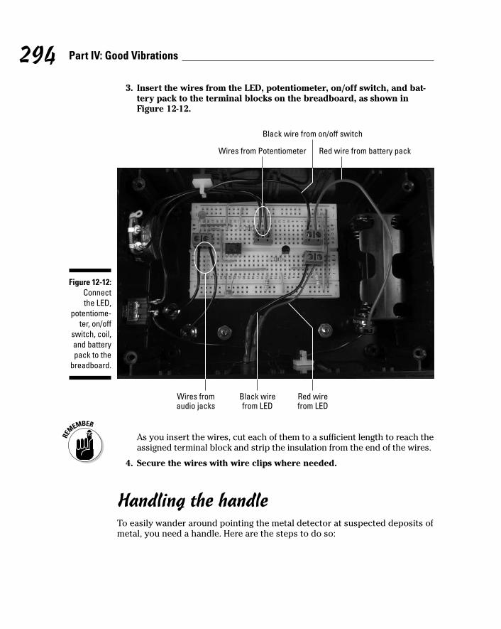
3. Insert the wires from the LED, potentiometer, on/off switch, and bat-tery pack to the terminal blocks on the breadboard, as shown inFigure 12-12.
As you insert the wires, cut each of them to a sufficient length to reach theassigned terminal block and strip the insulation from the end of the wires.
4. Secure the wires with wire clips where needed.
Handling the handleTo easily wander around pointing the metal detector at suspected deposits ofmetal, you need a handle. Here are the steps to do so:
Wires from Potentiometer Red wire from battery pack
Black wire from on/off switch
Wires fromaudio jacks
Red wirefrom LED
Black wirefrom LED
Figure 12-12:Connect the LED,
potentiome-ter, on/off
switch, coil,and batterypack to the
breadboard.
294 Part IV: Good Vibrations
19_009683 ch12.qxp 6/22/06 9:39 PM Page 294

1. Glue an 8", 1"-diameter PVC pipe into one end of a 45°-angle PVC pipefitting, facing up. (See the upcoming Figure 12-13.)
2. Glue the other 45° PVC pipe fitting onto the other end of the PVC pipe,facing down. (See the upcoming Figure 12-13.)
3. Glue a 3", 1"-diameter PVC pipe into the open end of one of the 45°pipe fittings to form the coil end of the metal detector.
4. Glue a 6", 1" PVC pipe into the open end of the other 45° fitting.
This becomes the handle end of the metal detector.
5. Glue the 1" PVC cap on the open end of the 6" PVC pipe.
6. Drill a 3⁄8" hole in the middle of the long section of PVC pipe on theside that will be to your left when you’re holding the metal detector.
You use this hole to feed the wires from the microphone cartridge to thebox containing your circuit. Note: If you’re left handed, consider placingthis hole on the side that will be to your right when you’re holding thedetector so that you hold the handle in your left hand and operate theswitches with your right hand.
Figure 12-13 shows the PVC pipe and fittings made into a handle for themetal detector.
Figure 12-13:Metal
detectorhandle.
295Chapter 12: A Handy-Dandy Metal Detector
19_009683 ch12.qxp 6/22/06 9:39 PM Page 295

7. Solder 12" wires to each of the two inductor leads, as shown in Figure12-14. Slip a 1" segment of heat shrink tubing over each solder jointand use a hair dryer to secure the tubing in place.
8. Twist together the free ends of the wires from the inductor and feedthem through the PVC pipe from the coil end until the end of the wirestrand reaches the 3⁄8" hole.
9. Form a hook shape with a piece of 20 or 22 gauge wire and pull thewires through the 3⁄8" hole.
10. Insert the inductor in the end of the 1" PVC pipe, as shown in Figure12-15, and use some glue to secure the inductor in the pipe.
Figure 12-14:Wires
attached toinductor.
296 Part IV: Good Vibrations
19_009683 ch12.qxp 6/22/06 9:39 PM Page 296

11. Cut the wires to allow three inches to extend from the 3⁄8" hole in thepipe and attach each wire to a right-angle phono plug, as shown inFigure 12-16.
Figure 12-16:Phono plugsattached towires frominductors.
Figure 12-15:Inductor inthe end of
the PVCpipe.
297Chapter 12: A Handy-Dandy Metal Detector
19_009683 ch12.qxp 6/22/06 9:39 PM Page 297

You can use either a plug that requires soldering to the wire or one thatuses a screw to secure the wire, as we have here.
12. Press the clamp onto the 1" PVC pipe and attach the box to the clampwith the 8-32 screws and nuts.
Figure 12-17 shows the box attached to the handle.
13. Plug the right-angle phono plugs into the phono jacks, as shown inFigure 12-17.
The finished metal detector is shown in Figure 12-18.
Figure 12-17:Box
attached tothe handleand phono
plugs inplace.
298 Part IV: Good Vibrations
19_009683 ch12.qxp 6/22/06 9:39 PM Page 298

Trying It OutYou probably have a fortune in coins just waiting to be found at the bottom ofyour furniture cushions, so it’s time you got this metal detector thing on thetrail of all those nickels and dimes! Here’s how to make this gadget work:
1. Insert the batteries.
2. Secure the lid on the box with the screws provided and flip the on/offswitch to On.
3. Holding the coil away from any metal, turn the potentiometer knob sothat the LED is on, and then turn the potentiometer knob slightly inthe other direction till the LED turns off.
This calibrates the IC so that it is triggered by small changes in the oscil-lating signal that runs through the coil.
4. Try out your detector by holding it near different items containingmetal.
We were able to detect coins and keys in pants pockets as well as vari-ous types of tools and nails at a distance of about 1⁄2". You should be ableto detect larger metal objects (such as a space shuttle) at a distance ofabout an inch.
Figure 12-18:The finished
metaldetector.
299Chapter 12: A Handy-Dandy Metal Detector
19_009683 ch12.qxp 6/22/06 9:39 PM Page 299

If you don’t get the results we got, here are some options to check out:
Check that all the batteries are fresh, tightly inserted in the batterypack, and all face the right direction.
Check that no wires or components have come loose.
Compare your breadboard against the photos to make sure all the wiresand components are connected correctly.
Taking It FurtherAren’t metal detectors just the most addictive thing? (Well, maybe not, butthey are kind of fun to play around with.) Here are some other things you cando to have fun with detectors:
Have your detector activate a buzzer instead of an LED by simplyreplacing the LED in the circuit with a buzzer.
Make a more powerful detector that could find coins a few inchesunder the sand on the beach.
Check online for other metal detector circuits that have more oomph.www.thunting.com specializes in metal detectors you can use forhunting treasure, for example.
300 Part IV: Good Vibrations
19_009683 ch12.qxp 6/22/06 9:39 PM Page 300

Chapter 13
Sensitive Sam Walks the LineIn This Chapter Getting the overview of all Sam can do
Looking over the very cool (and somewhat complex!) schematic
Arming yourself to deal with building issues
Getting your shopping list in order
Walking through the steps to make the circuit and assemble the cart
Trying out Sam and taking things further
Okay, we have to admit this right upfront: This project is Earl’s absolutefavorite in this whole book. Sensitive Sam is a motorized cart. You stick
black electrical tape on the floor to create a little path or track for Sam, andSam uses his sensors to follow the tape around corners and in interestingloops you devise for hours of fun. He also has a little horn you can blow (towarn the cat that he’s coming). What’s not to love?
In this chapter, you discover how to give Sam the “eyes” he needs to sensewhere he’s going and also how to build a radio remote control device to tellhim what you want him to do. Although you’ll find lots of little componentsand connections going on here, don’t be intimidated; after you get going, wethink you’ll find it’s a pretty fun project. (Earl did!)
The Big Picture: Project OverviewYou’re probably wondering what this Sam guy looks like and what he’s capa-ble of. Glad you asked. Here’s the low down on Sam, who
Has three wheels: This design makes the cart stable. If you use fourwheels, you need to include a suspension mechanism to ensure that all wheels stay in contact with the floor at all times. We use one unpow-ered wheel in front and two independently powered wheels in back. Thisway, if the motor for one of the wheels in back is shut off, the cart turnsin the direction of the motor that was shut off (left or right).
20_009683 ch13.qxp 6/27/06 5:38 PM Page 301

Sports two eyes: These eyes help Sam figure out where to go. Sam’s eyes — phototransistors pointed at the floor — sense infrared (IR) lightthat is sent out by IR LEDs and then reflected by the floor. By layingdown a track of black electrical tape on the floor, you create an area thatreflects less of the IR light.
We set up the circuit so that when Sam’s eyes hover over reflective floor,the motors turn. If one eye is over the black tape or other nonreflectivesurface — for example, where a bend comes in the tape track — themotor connected to that eye shuts off, causing the cart to turn andfollow the tape. When the eye is back over the reflective floor, the motorturns back on, and the cart goes in a straight line again.
Responds to a remote control: This remote uses radio waves to send itscommands to Sensitive Sam. (This is the same technology that a keychain remote control device uses to open the doors on a car.) You canset the switches on the remote control to tell Sam to turn on/off, slowdown or speed up, or honk the horn. When you flip a switch and pressthe transmit button, that effect kicks in.
Sensitive Sam is shown in Figure 13-1 in all his glory.
Figure 13-1:Our very
ownSensitive
Sam and hisfeline friend,Willoughby.
302 Part IV: Good Vibrations
20_009683 ch13.qxp 6/27/06 5:38 PM Page 302

Here are the types of activities you’ll do in this project:
1. Put together the electronic circuit for the remote control transmitter andthen fit the breadboard into a plastic box with switches.
2. Put together the electronic circuit that decodes the radio signal and con-trols the movement of Sam in response to his sensor eyes.
3. Mount the circuit onto a chassis along with DC motors, wheels, and afew switches.
In the end, you create a cart that follows a track all by itself and responds toyour every command. It also has a cute little horn that you can toot.
Scoping Out the SchematicYou need to get your arms around two schematics to master this project. Thefirst is the transmitter circuit that you use to send Sam his commands. Thesecond is the receiver circuit that helps him understand what the heck you’resaying!
Transmitting Sam’s commandsYou use the transmitter circuit to send signals to Sam to start, change speeds,and sound his horn. Here’s an explanation of what’s going on in this circuit:
VR1 is a voltage regulator that takes the 6 volts supplied by the batterypack and supplies a steady 5 volts instead. We added this becausealthough the IC specs say it should work with 6 volts, it blew out thefirst time we tried using 6 volts. Better safe than sorry!
The transmitter module sends out a radio signal at 433.9 MHz that’smodulated with the code provided by the encoder.
IC1 is an encoder. The radio signal that the remote control sends out ismodulated, depending upon how you have the switches set, by thisencoding IC (see Figure 13-2). In this figure, the top line shows the codethat tells Sam to speed up, and the bottom shows the code that tellsSam to slow down, based in the width of the fourth pulse from the right.The radio receiver in Sam sends this code to a decoding IC to turn Samon/off, honk the horn, or change the speed.
303Chapter 13: Sensitive Sam Walks the Line
20_009683 ch13.qxp 6/27/06 5:38 PM Page 303

Pin 14 is a transmit enable pin. When you press the normally open (NO)pushbutton switch between Pin 14 and ground, the encoder sends asignal to the transmitter module. This signal contains information thattells the decoding module whether the toggle switches (S1–S4) betweenPins 10, 11, 12, and 13 and ground are open or closed.
R1 is a resistor that sets the frequency of an oscillator that’s internal tothe encoder. The signal from this oscillator is required to generate theencoded signal.
S5 is the on/off switch.
Figure 13-3 shows what’s going on in the transmitter circuit.
Figure 13-2:The top
line speedsSam up;
the bottomslows him
down.
304 Part IV: Good Vibrations
20_009683 ch13.qxp 6/27/06 5:38 PM Page 304

Helping Sam receive his commandsThe receiver circuit that Sam uses to make sense of all your transmitted com-mands is shown in Figure 13-4. Here’s how this one works:
The receiver module separates the coded signal sent by the transmitterfrom the 433.9 MHz carrier wave. The output of the receiver module atPin 2 is the decoded signal, as shown in Figure 13-2.
VR1 is a voltage regulator that takes the 6 volts supplied by the batterypack and supplies a steady 5 volts because the transmitter module has amaximum voltage of 5.5 volts. We provided a separate battery pack forthis section of the circuit to provide a stable supply for the radio receiver.We found this setup gives much more consistent reception than setting upthe receiver to share a battery pack with the rest of the circuit.
S1 is the on/off switch for the circuit.
15
2
1 17
414
3
S4
IC1
16
+- VR1
VOUTVIN
S5
6V6
5
8
7
9
18
10
13
12
S1
S2
S3
3
2
4
1
TRANSMITTERMODULE
ANTENNA
R1
Figure 13-3:Sam’s
transmittercircuit.
305Chapter 13: Sensitive Sam Walks the Line
20_009683 ch13.qxp 6/27/06 5:38 PM Page 305

IC1 decodes the signal sent by the transmitter. Pins 10, 11, 12, and 13 areoutputs of the decoder that are at 0 volts if the corresponding toggleswitch on the encoder is closed (connected to ground). The outputs areat about 5 volts if the corresponding toggle switch on the encoder isopen (not connected to ground). These outputs stay at one voltage untilthey receive another signal to change.
The 10 microfarad and 0.1 microfarad capacitors (C1–C4 and C7–C12)placed between the +V and ground buses at the +V input of each of theICs are used to filter electrical noise from the DC motors. That noise canprevent the ICs from getting the correct supply voltage.
IC2 is an LM555 timer that generates a square wave at Pin 3. This squarewave alternates between 5 volts and 0 (zero) volts. The frequency of thesquare wave is determined by the values of R2, R3, and C5; we discussthis process in Chapter 9. When you tell Sensitive Sam to slow down,this square wave causes the voltage to the motor to switch on and offrapidly, with 6 volts to the motor half the time and 0 volts to the motorhalf the time. When you ask Sam to speed up, 6 volts are sent to themotor constantly. This is a simple form of pulse width modulation, whichis commonly used to control the speed of DC motors.
C6 is a capacitor that reduces the occurrence of noise on Pin 5 of IC2,which could cause false triggering of the LM555. This might occur if Pin5 were left unconnected.
Q1 turns the horn on and off. Q1 is a transistor that turns on whendecoder Pin 12 is at 5 volts. Turning on Q1 allows a current to flowthrough the buzzer. To turn on the buzzer, you put the toggle switch con-nected to the encoder Pin 12 on the transmitter in the open position andpush the transmit button. To turn off the buzzer, you put the toggleswitch connected to encoder Pin 12 on the transmitter in the closedposition and push the transmit button.
Q2 and Relay 1 control Sam’s speed. Q2 is a transistor that turns onwhen decoder Pin 10 is at 5 volts. Pin 4 and Pin 6 are normally con-nected (NC), and Pin 4 and Pin 8 are normally open (NO). Turning on Q2allows current to flow through the coil in Relay 1 and connects Pin 4 toPin 8. Pin 4 is the output of Relay 1, and Pin 8 is where you input thesquare wave from IC2 into Relay 1. When Q2 is off, no current flowsthrough the coil in Relay 1, and Pin 4 is connected to Pin 6. This makesthe output of Relay 1 approximately 5 volts. To ask Sam to go full speed
306 Part IV: Good Vibrations
20_009683 ch13.qxp 6/27/06 5:38 PM Page 306

ahead, you put the toggle switch connected to the encoder Pin 10 in theclosed position and push the transmit button. To ask Sam to slow down,you put the toggle switch connected to the encoder Pin 10 in the openposition and push the transmit button.
Use Q3 and Relay 2 to tell Sam to start or stop. Q3 is a transistor thatturns on when decoder Pin 13 is at 5 volts. Turning on Q3 by having thestart/stop transmitter toggle switch closed allows current to flowthrough the coil in Relay 2 and connects Pin 4 (the output of Relay 2) toPin 8. This tells Sam to run his engines. When the start/stop transmittertoggle switch is open and Q3 is off, no current flows through the coil inRelay 2, and Pin 4 is connected to Pin 6; this makes the output of Relay 2zero (0) volts.
IC3 is an H-bridge motor controller. Although this controller is capableof controlling more functions than just going straight ahead (as you canread about in Chapter 11), all we need it to do here is supply the voltageto drive each motor forward. The battery pack attached to Pin 8 of IC3supplies power for the motors. You connect the output of Relay 2 to theenable pins (1 and 9) of IC3. When 5 volts is provided by Relay 2 to theenable pins, IC3 supplies power to the motors. When 0 volts is connectedto the enable pins, IC3 doesn’t supply power, so Sam just sits there.
The left and right sensors allow Sensitive Sam to take control of himself.When the track curves or Sam drifts so that one of the sensors is overthe black electrical tape, power is cut to the motor on that side. Thiscauses Sam to move away from the tape. When the sensor again hoversover a reflective floor, power is restored to that motor, and Sam straight-ens out.
On the schematic, the orange (O) and green (G) wires connect to anLED, with R4 and R6 limiting the current to protect the LED fromdamage. The blue (B) and white (W) wires connect to a phototransistor.When the sensor moves over a reflective surface, such as hardwoodfloor, the phototransistor is on, and the base of Q5 or Q4 is connected toground. This turns off Q5 or Q4, which leaves the output of Relay 3 orRelay 4 connected to Pin 11, allowing the motor to run. When the sensoris over a nonreflective surface, such as black electrical tape, the photo-transistor is off, and the base of Q5 or Q4 is connected to a positive volt-age through R7 or R5, turning on Q5 or Q4. This disconnects the outputof the relay from Pin 11 and also shuts off the motor.
307Chapter 13: Sensitive Sam Walks the Line
20_009683 ch13.qxp 6/27/06 5:38 PM Page 307

152
1
14
4
3
IC1
16
+-
6
5
8
7
9
18
10
13
12
R1
8
1
RECEIVER
MODULE
VR1
VOUTVIN
+-
4
56 7 2
6V
6V
2 10
7
15
6
14
13
125
4
9
1
8
16
IC3
+-
C9
1
6
7
84
5
2
316
14
6
8
16
4
68
1
1613
11
S1
BUZZER
6 V
6V
6V
C1 C2
C3 C4
Q3
Q2
Q1
S1
RELAY1
RELAY2
S1
6V
6V
11
3
1
G
O
BW
16
13
11
1
GO
BW
RIGHTMOTOR
6V
6V
RIGHTSENSOR
ANTENNA
LEFTSENSOR
LEFT MOTOR
6V
Q5
C10
Q4
RELAY4
RELAY 3
IC2
C8C7
R4
C5
R2
R3
6V
R5
R6
+
+
+
+
C11 C12
+
C6+
R7
Figure 13-4:The receiver
schematicrevealed.
308 Part IV: Good Vibrations
20_009683 ch13.qxp 6/27/06 5:38 PM Page 308
Building Alert: Construction IssuesSam is sensitive, and so are some of the issues you’ll encounter when build-ing him. For example, the motor lugs used in this project are made of thinmetal and will break off if you put too much stress on them. By usingstranded wire, rather than solid wire, you can minimize the stress on thelugs. Throughout the construction instructions that follow, we indicate whento use stranded wire.
Another construction issue to be aware of is the antenna. You solder antennawire to one lead on both the transmitter and receiver modules. A 12" 20 gaugewire makes a dandy antenna; unlike 22 gauge wire, 20 gauge wire is stiffenough to stay upright. The only complication is in soldering the wire to theleads on the modules, so here are a few tips:
Keep the soldering time to a few seconds to avoid damaging some of thesolder joints in the module.
Leave 1⁄4" of lead below the solder joint to allow you to insert the adja-cent leads fully into the breadboard.
Soldering the 20 gauge solid wire directly to the lead is acceptable; how-ever, soldering a few inches of stranded wire to the end of the antenna,covering that joint with heat shrink tubing, and soldering the strandedwire to the module lead prevents the leads from being twisted while youwork with them.
Twisting can put too much stress on the lead and break it off, which ismore likely to happen if you solder solid wire directly to the lead.
Perusing the Parts ListWe broke down the parts shopping list into two . . . um . . . parts: a list for thetransmitter circuit parts and a list for the receiver circuit and container parts.
Tallying up transmitter bits and piecesThe circuit that sends signals to Sam telling him what to do involves the fol-lowing parts, several of which are shown in Figure 13-5:
LM7805 5 volt voltage regulator (VR1)
Four SPST toggle switches (S1, S2, S3, S4)
309Chapter 13: Sensitive Sam Walks the Line
20_009683 ch13.qxp 6/27/06 5:38 PM Page 309

SPST normally open (NO) momentary push button switch (S4)
Holtek HT12E encoder (IC1)
1 megohm resistor (R1)
TWS-434 RF transmitter module
We bought this at Reynolds Electronics (www.rentron.com); HobbyEngineering (www.hobbyengineering.com) carries a similar module.
400-contact breadboard
One 4 AA battery pack with snap connector
Five 2-pin terminal blocks
Plastic box
We use Radio Shack part #270-1806.
An assortment of different lengths of prestripped short 22 AWG wire
BatterypackIC
Toggleswitch
Voltageregulator
Transmitter module (to whichyou’ve soldered the antenna)
Terminalblock
Push buttonswitch
Figure 13-5:Key com-
ponents of your
transmitter.
310 Part IV: Good Vibrations
20_009683 ch13.qxp 6/27/06 5:38 PM Page 310

Running down receiver and container partsThe circuit that takes transmitted signals and explains to Sam what’s expectedof him involves the following parts, several of which are shown in Figure 13-6:
Holtek HT12D decoder (IC1)
L293D H-bridge (IC3)
LM555N-1 timer (IC2)
Five 2N3904 transistors (Q1–Q5)
6 volt buzzer
RWS-434 RF receiver module
We bought this at Reynolds Electronics; Hobby Engineering carries asimilar module.
Four 1 amp or greater solid state relays, DPDT (double-pole, double-throw) or SPDT (single-pole, double-throw)
We used the Shinmei RSB-5-S DPDT that we found at Jameco (www.jameco.com). A SPDT would also work, but we used the DPDT becauseit allows for more flexibility for which side of the relay we could runwires to. Make sure that the relay you buy has a pinout pattern that fits abreadboard; many of them do not.
Two DC gear motors GM2 each with a 25⁄8" wheel or equivalent
We use these because the suppliers (Hobby Engineering (www.hobbyengineering.com) or Solarbotics Ltd. (www.solarbotics.com)carry wheels made to fit them.
Two metal brackets used as motor mounts
We found 3" x 5⁄8" mending braces made by National ManufacturingCompany at our local hardware store. These worked great.
One 11⁄2" inch swiveling castor
Six 0.1 microfarad ceramic capacitors (C1, C3, C6, C7, C9, C11)
Six 10 microfarad electrolytic capacitors (C2, C4, C5, C8, C10, C12)
51 kohm resistor (R1)
Three 10 kohm resistors (R3, R5, R7)
Two 150 ohm resistors (R4, R6)
330 ohm resistor (R2)
Two 830-contact breadboards
Two Fairchild QRB1134 sensors
311Chapter 13: Sensitive Sam Walks the Line
20_009683 ch13.qxp 6/27/06 5:38 PM Page 311

Three 4 AA battery packs with snap connectors
Ten 2-pin terminal blocks
Four 8-32 11⁄2" panhead screws
Four 8-32 nuts
Four 6-32 1⁄2" panhead screws
Four 6-32 nuts
Four 4-40 3⁄4" panhead screws
Four 4-40 nuts
Two wooden boxes
• 2" wide x 5" tall x 11⁄4" deep
• 51⁄2" wide x 81⁄2" long x 21⁄2" deep
We found one at a local craft supply store that was just the right size tohold the electronics for this project and a smaller wooden box to glue onthe front of the bigger box to mount the sensors.
An assortment of different lengths of prestripped, short 22 AWG wire
IC On/off switchBuzzerMending brace
Receiver module(with antenna soldered)
RelaySensor
Figure 13-6:Importantpieces ofthe Samproject.
312 Part IV: Good Vibrations
20_009683 ch13.qxp 6/27/06 5:38 PM Page 312

Taking Things Step by StepThe steps involved in making Sensitive Sam sensitive are
1. Making the transmitter circuit and fitting it into your remote control box
2. Making the receiver circuit that goes into Sam
3. Putting together the chassis that contains the receiver circuit (Sam’s body)
Making the transmitter circuit and remote control boxThe transmitter circuit fits into a remote control box and allows you to turnSam on and off, speed him up or slow him down, and sound his horn. Here’swhat’s involved in making this circuit:
1. Place HT12E (IC1) and five terminal blocks on the breadboard, asshown in Figure 13-7.
The five terminal blocks shows in this figure will be used to connect twowires each to various components in the circuit. The wires from these ter-minal blocks will go to the battery pack, the on/off switch, the transmitswitch, and the three toggle switches.
Figure 13-7:Place the ICand terminal
blocks on the
breadboard.
313Chapter 13: Sensitive Sam Walks the Line
20_009683 ch13.qxp 6/27/06 5:38 PM Page 313

2. Solder an antenna wire to Pin 4 of the transmitter module, as shownin Figure 13-8.
See the earlier “Building Alert: Construction Issues” section of this chap-ter for some tips on how to do this.
3. Insert the voltage regulator (VR1), a 1 megohm resistor (R1), and thetransmitter module on the breadboard, as shown in Figure 13-9.
VR1input
VR1 5 volt output
VR1 ground pin Transmitter ground
Transmitter data input Transmitter +V
Transmitter antenna
Figure 13-8:Transmitterand voltage
regulator(VR1)
pinouts.
314 Part IV: Good Vibrations
20_009683 ch13.qxp 6/27/06 5:38 PM Page 314

4. Insert wires to connect the IC, voltage regulator, transmitter, and theterminal blocks to the ground bus. Then insert a wire between thetwo ground buses to connect them, as shown in Figure 13-10.
Sixteen shorter wires connect components to ground bus; the long wireon the right connects the two ground buses.
Voltage regulator
R1 from Pin 16 of IC1to Pin 17 of IC1
Transmitter
Figure 13-9:Insert aresistor,voltage
regulator,and the
transmitteron the
breadboard.
315Chapter 13: Sensitive Sam Walks the Line
20_009683 ch13.qxp 6/27/06 5:38 PM Page 315

5. Insert wires to connect the IC, voltage regulator, and transmitter to+V; then insert a wire between the two +V buses to connect them, asshown in Figure 13-11.
Output pin of voltage regulator to +V
Pin 3 of transmitterto +V
Pin 18 of IC1to +V
Figure 13-11:Connect
componentsto the
+V bus.
Figure 13-10:Make
ground busconnections.
316 Part IV: Good Vibrations
20_009683 ch13.qxp 6/27/06 5:38 PM Page 316

6. Insert wires to connect the IC, voltage regulator, transmitter, and ter-minal blocks, as shown in Figure 13-12.
The next step is to drill all kinds of holes into which you can pop variouscomponents to create the remote control box. Follow these steps to do so:
1. Drill holes in the box where you will mount the on/off switch, speedswitch, horn switch, start/stop switch, transmit switch, and antenna,as shown in Figures 13-13 and 13-14.
You can rearrange the switches. Just be careful not to put a switchwhere it will be in the way of the battery pack when you mount it insidethe box.
Pin 17 of IC1 to transmitter data input pinBattery TB to VR1 input pin
S1 TB to Pin 10 of IC1
S2 TB to Pin 12 of IC1S4 TB to Pin 14 of IC1
S3 TB to Pin 13 of IC1
Figure 13-12:Hook up theICs, terminal
blocks(TBs),
transmitter,and voltage
regulator.
317Chapter 13: Sensitive Sam Walks the Line
20_009683 ch13.qxp 6/27/06 5:38 PM Page 317

On the end of the right side of the box, you can see the hole used to feedantenna out of box.
Figure 13-14:Use this
hole to feedthe antenna
out of the box.
Start/stop switch
Horn switchSpeed switchTransmit
pushbuttonOn/off switch
Figure 13-13:Box with
all theswitches
and buttonsin place.
318 Part IV: Good Vibrations
20_009683 ch13.qxp 6/27/06 5:38 PM Page 318
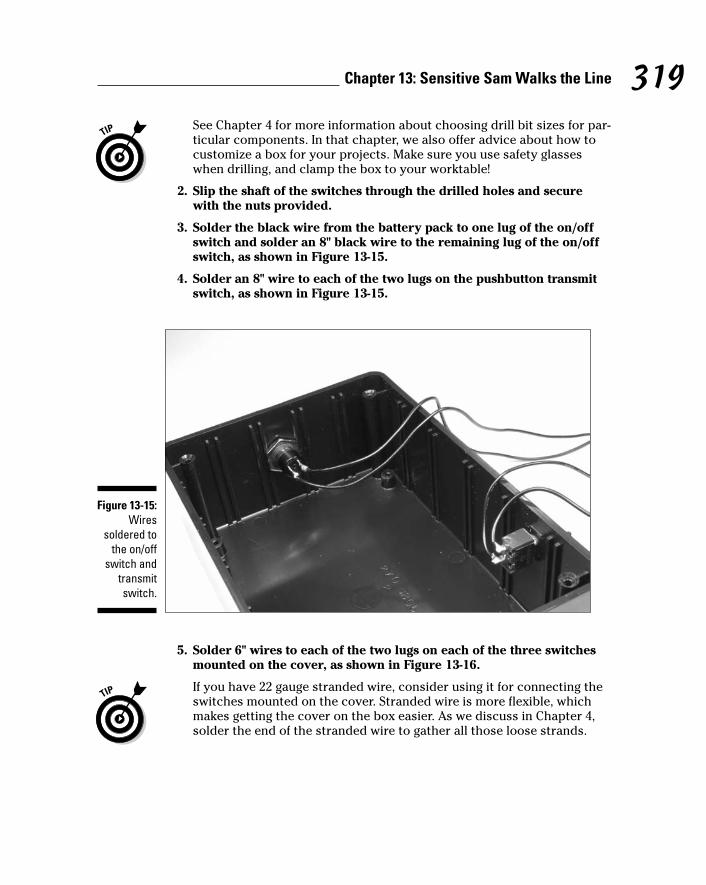
See Chapter 4 for more information about choosing drill bit sizes for par-ticular components. In that chapter, we also offer advice about how tocustomize a box for your projects. Make sure you use safety glasseswhen drilling, and clamp the box to your worktable!
2. Slip the shaft of the switches through the drilled holes and securewith the nuts provided.
3. Solder the black wire from the battery pack to one lug of the on/offswitch and solder an 8" black wire to the remaining lug of the on/offswitch, as shown in Figure 13-15.
4. Solder an 8" wire to each of the two lugs on the pushbutton transmitswitch, as shown in Figure 13-15.
5. Solder 6" wires to each of the two lugs on each of the three switchesmounted on the cover, as shown in Figure 13-16.
If you have 22 gauge stranded wire, consider using it for connecting theswitches mounted on the cover. Stranded wire is more flexible, whichmakes getting the cover on the box easier. As we discuss in Chapter 4,solder the end of the stranded wire to gather all those loose strands.
Figure 13-15:Wires
soldered tothe on/off
switch andtransmitswitch.
319Chapter 13: Sensitive Sam Walks the Line
20_009683 ch13.qxp 6/27/06 5:38 PM Page 319

Repeat after us: Heed all the safety precautions about soldering that wegive you in Chapter 2. Use adequate ventilation when soldering to avoidinhaling fumes, and be sure to get a soldering iron with a stable stand sothere’s no danger of it falling off your work surface.
6. Secure the breadboard and battery pack in the box with Velcro, asshown in Figure 13-17.
As you place the breadboard in the box, carefully feed the antenna wire outof the box through its hole and secure the antenna wire with a wire clip.
7. Attach the wires from the battery pack, on/off, transmit, speed, horn, and start/stop switches to the terminal blocks, as shown inFigure 13-17.
Figure 13-16:Wires
soldered tothe speed,horn, andstart/stopswitches.
320 Part IV: Good Vibrations
20_009683 ch13.qxp 6/27/06 5:38 PM Page 320

Making the receiver circuitThe receiver circuit will eventually reside in Sam’s body, taking the signalsthat your remote control unit sends telling Sam how to behave. Here are thesteps to build the receiver circuit:
1. Take two 830-contact breadboards and join them by inserting the tabsinto the slots along the sides to make one large breadboard.
2. Place the HT12D (IC1), the LM555 (IC2), the L293D (IC3), the receivermodule, and ten terminal blocks on the breadboard, as shown inFigure 13-18.
Wires from horn switch Wires from transmit switch
Wires from start/stop switch
Antenna
Wiresfrom
speedswitch
Black wirefrom
on/offswitch
Red wirefrom
batterypack
Figure 13-17:Transmitter
circuit inplace.
321Chapter 13: Sensitive Sam Walks the Line
20_009683 ch13.qxp 6/27/06 5:38 PM Page 321

3. Place the four RB5-5-S relays (Relay 1–Relay 4) and five 2N3904(Q1–Q5) transistors on the breadboard, as shown in Figure 13-19.
Insert each transistor lead into a separate breadboard row with the
• Collector lead to the left side, as shown in Figure 13-19
• Base lead in the center
• Emitter lead to the right
The collector pin of Q2 goes in the same breadboard row as Pin 16 ofRelay 1. The collector pin of Q3 goes in the same breadboard row as Pin16 of Relay 2. The pin designations of the 2N3904 transistors and theLM7805 voltage regulator are shown in Figure 13-20.
IC1
Receiver battery TB
Main battery TB Receiver module
Rightsensor
TB
IC2
Buzzer TB Motor battery TB Left motor TB
Left sensor TB
IC3 Rightmotor
TB
Figure 13-18:Place the
ICs andterminal
blocks on the
breadboard.
322 Part IV: Good Vibrations
20_009683 ch13.qxp 6/27/06 5:38 PM Page 322

VR1
Relay 1
Q1 Relay 4 Q5
Relay 2
Q2
Relay 3
Q4Q3
Figure 13-19:Place the
RB5-5-Srelays,
LM7805voltage
regulator,and 2N3904transistors
on thebreadboard.
323Chapter 13: Sensitive Sam Walks the Line
20_009683 ch13.qxp 6/27/06 5:38 PM Page 323

4. Insert wires to connect the ICs, voltage regulator, transistors, relays,and terminal blocks to the ground bus. Then insert wires between theground buses to connect them, as shown in Figure 13-21.
The ground buses are designated by a negative (–) sign on this breadboard.
Thirty-one shorter wires connect components to ground bus; the twolong and one short wires on the left connect the ground buses.
Pin 9(right NO)
Pin 4 (left common)
Pin 1 (coil +V)
Base
CollectorEmitter
Pin 11(right NC)
Pin 13(right
common)
Pin 16(coil ground)
Pin 8 (left NO)
Pin 6 (left NC) Ground
Voltageoutput
Input
Figure 13-20:The 2N3904
transistor,LM7805voltage
regulator,and RB5-5-S
relayspinout.
324 Part IV: Good Vibrations
20_009683 ch13.qxp 6/27/06 5:38 PM Page 324

5. Insert wires to connect the ICs, the terminal blocks, relays, and thevoltage regulator to the +V bus. Then insert wires between the +Vbuses to connect them, as shown in Figure 13-22.
The +V buses are designated by a + sign on this breadboard.
Figure 13-21:Connect
componentsto ground
buses.
325Chapter 13: Sensitive Sam Walks the Line
20_009683 ch13.qxp 6/27/06 5:38 PM Page 325
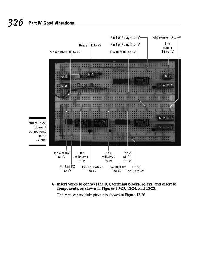
6. Insert wires to connect the ICs, terminal blocks, relays, and discretecomponents, as shown in Figures 13-23, 13-24, and 13-25.
The receiver module pinout is shown in Figure 13-26.
Main battery TB to +V
Pin 16of IC3 to +V
Pin 4 of IC2to +V
Pin 18 of IC1 to +V
Pin 1 of Relay 3 to +V
Right sensor TB to +V
Buzzer TB to +V
Pin 1 of Relay 4 to +V
Leftsensor
TB to +V
Pin 1 of Relay 1to +V
Pin 6 of Relay 1
to +V
Pin 1 of Relay 2
to +V
Pin 2of IC3to +V
Pin 8 of IC2to +V
Pin 10 of IC3to +V
Figure 13-22:Connect
componentsto the
+V bus.
326 Part IV: Good Vibrations
20_009683 ch13.qxp 6/27/06 5:38 PM Page 326

Receiver battery TBto input pin of VR1
Buzzer TBto collector pin of Q1
Pin 16 of Relay 4to collector pin of Q5
Left sensor TBto base of Q5
Pin 16 of Relay 3to collector pin of Q4
Right sensor TB to base of Q4
Pin 4of Relay 1
to Pin 8of Relay 2
Pin 4of Relay 2
to Pin 1of IC3
Pin 3 of IC2to Pin 8
of Relay 1
Figure 13-23:Hook up theIC, terminal
blocks,relays, and
discretecomponents.
327Chapter 13: Sensitive Sam Walks the Line
20_009683 ch13.qxp 6/27/06 5:38 PM Page 327

Pin 5 of receiver module to Pin 4 of receiver module
Pin 13 of Relay 4to left motor TB
Voltage output pin of VR1to Pin 5 of receiver module
Pin 7 of IC2to open region
Pin 4 of Relay 2to Pin 9 of IC3
Pin 2 of IC2to Pin 6 of IC2
Pin 2 of receiver moduleto Pin 14 of IC1
Pin 13 of Relay 3to right motor TB
Pin 8 of IC3to motor battery TB
Figure 13-24:Hooking up
yet morewires.
328 Part IV: Good Vibrations
20_009683 ch13.qxp 6/27/06 5:38 PM Page 328
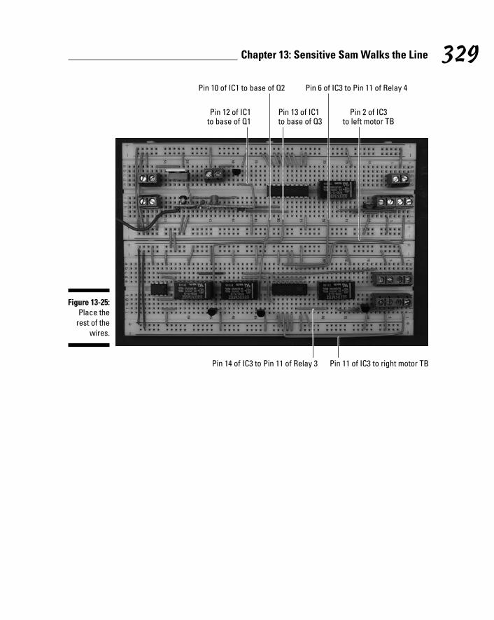
Pin 12 of IC1to base of Q1
Pin 14 of IC3 to Pin 11 of Relay 3 Pin 11 of IC3 to right motor TB
Pin 13 of IC1to base of Q3
Pin 10 of IC1 to base of Q2 Pin 6 of IC3 to Pin 11 of Relay 4
Pin 2 of IC3to left motor TB
Figure 13-25:Place the
rest of thewires.
329Chapter 13: Sensitive Sam Walks the Line
20_009683 ch13.qxp 6/27/06 5:38 PM Page 329

7. Insert the following, as shown in Figure 13-27:
• Six 0.1 microfarad ceramic capacitors (C1, C3, C6, C7, C9, C11)
• Six 10 microfarad electrolytic capacitors (C2, C4, C5, C8, C10, C12)
• 51 kohm resistor (R1)
• Three 10 kohm resistors (R3, R5, R7)
• Two 150 ohm resistors (R4, R6)
• 330 ohm resistor (R2)
Use both the schematic and the photo to help you place each compo-nent. For example, the schematic shows that the + side of C5 is con-nected to Pin 2 of IC2 and the other side of C2 is connected to ground, soinsert the long lead of C2 in the same row as Pin 2 of IC2 and the shortlead in the ground bus.
Pin 1
Pin 2 Pin 3
Pin 4 Pin 5
Pin 6 Pin 7
Pin 8
Figure 13-26:Receiver
modulepinout.
330 Part IV: Good Vibrations
20_009683 ch13.qxp 6/27/06 5:38 PM Page 330

Use the following key for the callouts in Figure 13-27.
1. C1 from +V bus to ground bus
2. C2 from +V bus to ground bus
3. C3 from +V bus to ground bus
4. C4 from +V bus to ground bus
5. C7 from +V bus to ground bus
6. C8 from +V bus to ground bus
7. C9 from +V bus to ground bus
8. C10 from +V bus to ground bus
9. C5 from Pin 2 of IC2 to ground bus
10. C6 from Pin 5 of IC2 to ground bus
10 8
11
12 13
1415
16
17
18 199 76 5
432 1
Figure 13-27:Insert
capacitorsand
resistorsonto the
breadboard.
331Chapter 13: Sensitive Sam Walks the Line
20_009683 ch13.qxp 6/27/06 5:38 PM Page 331

11. R1 from Pin 15 of IC1 to Pin 16 of IC1
12. R2 from Pin 6 of IC2 to Pin 7 of IC2
13. R3 from Pin 7 of IC2 to +V
14. R4 from right sensor TB to ground
15. R6 from left sensor TB to ground
16. R5 from right sensor TB to +V
17. R7 from left sensor TB to +V
18. C11 from +V bus to ground bus
19. C12 from +V bus to ground bus
Building Sensitive Sam’s chassisIf you’re a sensitive guy like Sam, how your body looks is very important toyou. Here are the steps to build Sam a serviceable little chassis to hold thereceiver circuit:
1. Solder 12" stranded wires to the motor lugs, as shown in Figure 13-28.
Figure 13-28:Wires
soldered to the
motor lugs.
332 Part IV: Good Vibrations
20_009683 ch13.qxp 6/27/06 5:38 PM Page 332

2. Drill holes for the 6-32 screws used to mount the castor, as shown inFigure 13-29.
Use the base of the castor to guide you when marking the four holes youwill drill in the chassis box to mount the castor.
3. Mark a location about an inch to each side of the castor and drillholes with a 1/4" bit to feed the wires to the motors and sensors, asshown in Figure 13-29.
4. Using a mending brace to mark the four holes you will drill in the box to mount the motors, drill holes for 8-32 screws, as shown inFigure 13-29.
5. Attach the castor to the box with four 6-32 screws and nuts, as shownin Figure 13-30.
6. Attach the motors to the box with two 8-32 screws and nuts and onemending brace for each motor, as shown in Figures 13-30 and 13-31.
Screws for castorHoles for feeding wires Screws for motor mounts
Figure 13-29:The insideof the box
after holeshave beendrilled andthe motorsand castor
aremounted.
333Chapter 13: Sensitive Sam Walks the Line
20_009683 ch13.qxp 6/27/06 5:38 PM Page 333

7. Drill a hole for 4-40 screws in each side of the small box to mount thesensors, as shown in Figure 13-32.
Figure 13-31:A closer
look at howto mount the
motors.
Figure 13-30:The bottomof the cart
with castorsand motors
mounted.
334 Part IV: Good Vibrations
20_009683 ch13.qxp 6/27/06 5:38 PM Page 334

8. Mount the sensors in the small box with one 4-40 screw and nut persensor.
9. Feed the wires for the sensors and the motors through the holes youdrilled to each side of the castor.
10. Glue the small box to the cart, as shown in Figures 13-32 and 13-33.
The face of the sensors should be a quarter-inch above the floor.
Figure 13-32:Keeping thesensors justoff the floorallows Sam
to spot the tape.
335Chapter 13: Sensitive Sam Walks the Line
20_009683 ch13.qxp 6/27/06 5:38 PM Page 335

11. Drill two holes for 6-32 screws to mount the buzzer, as shown inFigure 13-34.
Figure 13-34:The buzzer
and theon/off
switchmounted on Sam.
Figure 13-33:A look athow we
attachedthe sensorsfrom below.
336 Part IV: Good Vibrations
20_009683 ch13.qxp 6/27/06 5:38 PM Page 336

12. Mount the buzzer by using two 6-32 screws and nuts.
13. Drill a hole in the box where you will insert the on/off switch, asshown in Figure 13-34.
14. Slip the threaded shaft of the on/off switch through the hole youdrilled and secure it with the nut provided.
If the wall of the box is too thick to allow the threads on the switch toreach the nut, use a small chisel to remove enough wood from the insidewall of the box so that the nut can engage the threads.
15. Solder the black wires from the three battery snaps to one lug of theon/off switch and solder three 12" black wires to the other lug of theon/off switch.
Figure 13-35 shows the switch after soldering.
16. Attach Velcro to the breadboard and the box and secure the bread-board in the box.
17. Attach Velcro to the battery packs and the box and secure the batterypacks in the box.
18. Insert the wires from the sensors, motors, battery packs, buzzer, andthe on/off switch to the terminal blocks on the breadboard, as shownin Figures 13-36 and 13-37.
Figure 13-35:Wires
soldered to on/offswitch.
337Chapter 13: Sensitive Sam Walks the Line
20_009683 ch13.qxp 6/27/06 5:38 PM Page 337

As you insert the wires, cut each of them to the length you need forthem to reach the corresponding terminal block. Also, strip the insula-tion from the end of the wire.
Figure 13-36:Connect the
sensors,motors,batterypacks,
buzzer, andon/off
switch to the
breadboard.
338 Part IV: Good Vibrations
20_009683 ch13.qxp 6/27/06 5:38 PM Page 338

Use the following key for the callouts in Figure 13-37.
1. Red wire from buzzer
2. Black wire from buzzer
3. Red wire from receiver battery pack
4. Black wire from receiver battery pack
5. Red wire from main battery pack
6. Black wire from main battery pack
7. Red wire from motor battery pack
8. Black wire from motor battery pack
9. Wires from left motor
10. White wire from left sensor
10
1211 13
16 1714 15 18
8
7
9
6 5
4 3 21
Figure 13-37:A closer
look.
339Chapter 13: Sensitive Sam Walks the Line
20_009683 ch13.qxp 6/27/06 5:38 PM Page 339

11. Blue wire from left sensor
12. Green wire from left sensor
13. Orange wire from left sensor
14. White wire from right sensor
15. Blue wire from right sensor
16. Green wire from right sensor
17. Orange wire from right sensor
18. Wires from right motor
19. Secure the wires with wire clips where needed.
Sensitive Sam is shown roaring around our living room floor in all his glory inFigure 13-38.
Trying It OutNow that you have a remote control unit and Sam’s body all assembled, takehim out for a spin. Follow these steps to play with your new sensitive buddy:
Figure 13-38:Sam chugsaround the
track till youtell him to stop.
340 Part IV: Good Vibrations
20_009683 ch13.qxp 6/27/06 5:38 PM Page 340

1. Place black electrician’s tape on a reflective floor (hardwood orlinoleum, for example).
You don’t have to create a straight line; you can use several pieces todesign a circular or oval track.
2. Place Sam on the track with the sensors on either side of the tape.
3. Put batteries in Sam and the remote control flip the on/off switches onboth to On.
4. Flip the start/stop switch to start and press the transmit button on theremote control to get Sam moving.
5. Flip either the speed or horn switch on the remote control and thenpress the transmit button to activate either effect.
6. To stop Sam, flip the start/stop switch to stop and press the transmitbutton.
If nothing happens, here are a few things to check out:
All the batteries are fresh, are tight in the battery pack, and face theright direction.
See whether any wires or parts have come loose.
Compare your circuit with the photos in this chapter to make sure yougot all the connections right.
If Sam gets going but doesn’t follow the track as you expect, you can adjustthe sensors by loosening the screws and sliding the sensors up or down.
If Sam stalls, try these steps:
1. Put the start/stop switch in the start position.
2. Push the transmit button once more.
Taking It FurtherWe’re sure you can see why this neat little guy is Earl’s favorite project. Youcan create huge tracks and have him follow around the room. He confusesrecalcitrant cats (refer to Figure 13-1), and you can put notes in his cart andsend them to someone else on the other side of the room.
341Chapter 13: Sensitive Sam Walks the Line
20_009683 ch13.qxp 6/27/06 5:38 PM Page 341

When you’re ready to take Sam further, try these suggestions:
Build a Sensitive Samantha using a different radio frequency module for the remote control to give Sam a girlfriend he can race with aroundthe track.
Add lights by using the fourth pin on the encoder/decoder to control them.
Read up on other radio control project ideas at sites such as www.renton.com.
If you build Sam’s chassis to be strong enough, you can put him to workcarrying things around your house — a can of soda, the TV remote, orwhatever you want to send off to the couch potato lounging in yourliving room.
342 Part IV: Good Vibrations
20_009683 ch13.qxp 6/27/06 5:38 PM Page 342

Chapter 14
Couch Pet-atoIn This Chapter Looking over the schematic
Laying down the parts list
Breadboarding the Couch Pet-ato circuit
Installing the breadboard and components in the case
Sounding off!
You arrive home from a fast-paced game of racquetball, eager to grab abag of chips and a cold can of soda, and then just veg out on your
couch. As you walk in the front door, though, what do you find but your 30-pound cat, Reggie, spread out on the couch. Adding insult to injury, he’spurring loudly — and shedding to beat the band.
Want to be saved from this annoying scenario forever after? That’s what thischapter is all about: using a vibration/tilt switch sensor in a gadget that willsound off if Reggie (or Fluffy or Rover) so much as lays his paws on your furniture.
21_009683 ch14.qxp 6/22/06 9:40 PM Page 343

The Big Picture: Project OverviewWhen you complete this project, you’ll have what we like to call a Couch Pet-ato. This device is a box rigged with a vibration sensor and recording/playback setup. You can record your voice, shouting something like, “Get the&!@!#@ off the couch!” or a shrill noise of your choosing. When your petjumps onto the couch, the vibration sets off the playback.
You can see the finished Couch Pet-ato in Figure 14-1.
So what, exactly, will you be doing in this chapter? The project involves
1. Putting together the electronic circuit
2. Fitting the circuit into a wooden box
3. Attaching switches, a microphone, and a speaker
Scoping Out the SchematicYou have but one breadboard to pull together for this project. Take a look atthe schematic for the board in Figure 14-2.
Figure 14-1:The finalproduct: a CouchPet-ato.
344 Part IV: Good Vibrations
21_009683 ch14.qxp 6/22/06 9:40 PM Page 344
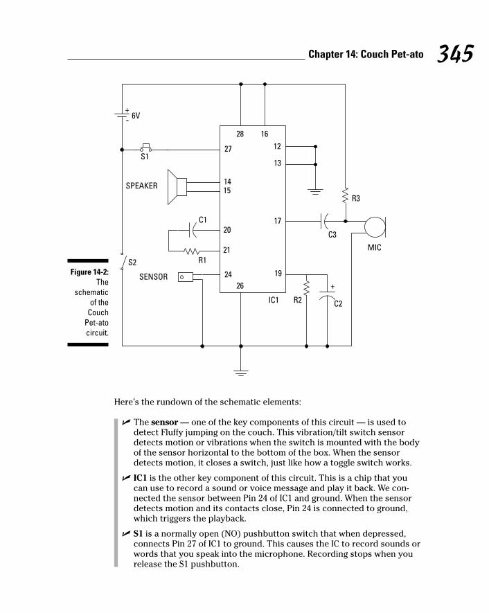
Here’s the rundown of the schematic elements:
The sensor — one of the key components of this circuit — is used todetect Fluffy jumping on the couch. This vibration/tilt switch sensordetects motion or vibrations when the switch is mounted with the bodyof the sensor horizontal to the bottom of the box. When the sensordetects motion, it closes a switch, just like how a toggle switch works.
IC1 is the other key component of this circuit. This is a chip that youcan use to record a sound or voice message and play it back. We con-nected the sensor between Pin 24 of IC1 and ground. When the sensordetects motion and its contacts close, Pin 24 is connected to ground,which triggers the playback.
S1 is a normally open (NO) pushbutton switch that when depressed,connects Pin 27 of IC1 to ground. This causes the IC to record sounds orwords that you speak into the microphone. Recording stops when yourelease the S1 pushbutton.
20
21
1415
2812
24
27
1926
13
17
16
+-
MIC
SENSOR
S1
6V
SPEAKER
C1
R1
R2 C2
C3
R3
IC1
+
S2Figure 14-2:
Theschematic
of theCouch
Pet-atocircuit.
345Chapter 14: Couch Pet-ato
21_009683 ch14.qxp 6/22/06 9:40 PM Page 345

R3 is a resistor that connects the microphone to the +V, supplying the4.5 volts that the microphone needs to function.
C3 is a capacitor that removes the DC voltage from the AC signal that’sflowing from the microphone to Pin 17 of IC1.
The speaker is connected to Pins 14 and 15 of IC1. The speaker is usedto play messages that you recorded on IC1 when the sensor connectsPin 24 to ground.
S2 is the on/off switch between the negative terminal of the battery packand the ground bus of the circuit board.
R1 and C1 filter out electrical noise.
R2 and C2 connect the automatic gain control circuit inside IC1 to ground.The values of R2 and C2 determine how fast the automatic gain controlresponds to changes in volume when you’re recording a message.
Building Alert: Construction IssuesBecause the Couch Pet-ato is likely to sit in your living room and we knowthat you like a neat-looking home, we placed all the works in a wooden box tomake it look tidy.
We went strolling down the aisle of a local craft store to find our wooden box,but you might also find one in an office supply store — designed to hold indexcards, for example. Just make sure that it’s big enough to hold the breadboard.
Because the walls of this box are thicker than the plastic boxes often used for electronic gadgets, the threads on switches might not be long enough tosecure them to the side of the box. If this happens to you, just drill the holeso that it’s large enough to slip only the shaft of the switch through; then useglue to secure the switch.
The size of drill bit that you use to drill holes for the switches, speaker, andmicrophone depends upon the diameter of the components you’re using. Weused a 1⁄2" drill bit to drill the hole for the switches and a 3⁄8" bit to drill a holefor the microphone. For the speaker, we used a 5⁄32" bit to drill the holes towhich we attached screws for the speaker flange, and then we used a copingsaw to cut the center hole for the speaker.
Perusing the Parts ListHere’s your shopping list for building your Couch Pet-ato. This projectinvolves the following parts, several of which are shown in Figure 14-3:
346 Part IV: Good Vibrations
21_009683 ch14.qxp 6/22/06 9:40 PM Page 346

Signal Systems 3004 tilt/motion sensor
Many vibration (also called tilt or motion) sensors are available; we usedcost and pin type as our criteria. We found this sensor at Jameco (www.jameco.com), and Mouser (www.mouser.com) carries a similar low-cost sensor. We chose this one because it doesn’t use a surface-mountpackage, which is harder to work with.
16 ohm, 0.2 watt speaker
Electret microphone part #EM-99
We found this one at Jameco. You can use other electret microphones;see Chapter 3 for the criteria to help you choose one. If you use anothermodel of microphone, you might have to adjust R3 to get the supplyvoltage to the correct level.
Winbond Electronics ISD1110 voice record/playback chip (IC1)
0.01 microfarad capacitor (C1)
0.1 microfarad capacitor (C3)
4.7 microfarad electrolytic capacitor (C2)
Four 5⁄8" 6-32 screws
Four 6-32 nuts
Three wire clips
5.1 kohm resistor (R1)
470 kohm resistor (R2)
2.2 kohm resistor (R3)
NO (normally open) momentary pushbutton switch (S1)
Breadboard (830 contacts)
SPST toggle switch (S2)
Four pack of AA batteries with snap connector
Four 2-pin terminal blocks
Enclosure
We use a wooden box 8" x 51⁄4" x 31⁄4", with latches and clasp.
Velcro
An assortment of different lengths of prestripped short 22 AWG wire
347Chapter 14: Couch Pet-ato
21_009683 ch14.qxp 6/22/06 9:40 PM Page 347

Taking Things Step by StepCreating your Couch Pet-ato involves wiring the circuit; installing the speaker,microphone, battery, switches, and circuit board in the box; and then con-necting the whole shebang.
Start at the beginning — by wiring the circuit. Follow these steps to build yourCouch Pet-ato circuit (but be sure not to let Rover know what you’re up to).
1. Place the voice chip IC and four terminal blocks on the breadboard,as shown in Figure 14-4.
The four terminal blocks shown in this figure will be used to connecttwo wires each to various components in the circuit. The wires fromthese four terminal blocks go to the battery pack, on/off switch, recordswitch, and microphone, respectively.
ResistorSpeaker
Record switchBattery pack
Electrolytic capacitor Microphone Tilt switch
Ceramic capacitor On/off switch Terminal block Voice chip
Figure 14-3:Key
components.
348 Part IV: Good Vibrations
21_009683 ch14.qxp 6/22/06 9:40 PM Page 348

2. Insert wires to connect each component and terminal to the groundbus and insert a wire between the two ground buses to connect them,as shown in Figure 14-5.
In this figure, six shorter wires connect components to the ground bus(marked with a – on this breadboard); the long wire on the left connectsthe two ground buses.
Figure 14-5:Connect
componentsto the
ground bus.
Figure 14-4:Place the
voice chipIC and four
terminalblocks on the
breadboard.
349Chapter 14: Couch Pet-ato
21_009683 ch14.qxp 6/22/06 9:40 PM Page 349

3. Insert wires to connect each component and terminal to the +V busand insert a wire between the two +V buses to connect them, asshown in Figure 14-6.
In this figure, four wires have been added:
• Three shorter wires connect components to +V bus (marked with a+ on this breadboard).
• The long wire on the left connects the two +V buses.
4. Insert wires to connect the voice chip IC to the terminal blocks and tothe open regions of the breadboard where discrete components willbe inserted, as shown in Figure 14-7.
Figure 14-6:Connect
componentsto the
+V bus.
350 Part IV: Good Vibrations
21_009683 ch14.qxp 6/22/06 9:40 PM Page 350

5. Insert discrete components and the tilt sensor in the breadboard, asshown in Figure 14-8.
IC pin 27 to terminal block for record switch
IC Pin 21 to open region of breadboard
IC Pin 17 to open region of breadboard
open region of breadboard to terminal block for microphone
IC Pin 14 to terminal block for speaker
IC Pin 20 to open region of breadboard
IC Pin 15 to terminal block for speaker
Figure 14-7:Connect the
IC to theterminal
blocks andavailable
locations fordiscrete
components.
351Chapter 14: Couch Pet-ato
21_009683 ch14.qxp 6/22/06 9:40 PM Page 351

6. Drill holes in the Couch Pet-ato box for inserting the switches, micro-phone, and speaker.
Figure 14-9 shows holes drilled in the front of the box for the switchesand microphone and the side of the box for the speaker, but the place-ment is really up to you.
Whenever you drill holes or do any procedure where bits can fly, such asclipping wires, wear safety glasses to protect your eyes.
Capacitor C3 between wire connected to microphone terminal block and wire connected to IC Pin 17
Capacitor C1 and resistor R1 in series between wires connected to IC Pin 20 and IC Pin 21
Resistor R3 between capacitor C3 and +V
Resistor R2 between IC Pin 19 and ground
Capacitor C2 between IC Pin 19 and ground
Tilt sensor between IC Pin 24 and ground
Figure 14-8:Insert
discretecomponents
on thebreadboard.
352 Part IV: Good Vibrations
21_009683 ch14.qxp 6/22/06 9:40 PM Page 352
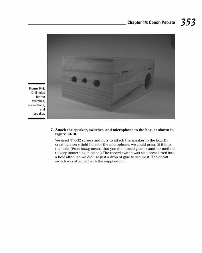
7. Attach the speaker, switches, and microphone to the box, as shown inFigure 14-10.
We used 5⁄8" 6-32 screws and nuts to attach the speaker to the box. Bycreating a very tight hole for the microphone, we could press-fit it intothe hole. (Press-fitting means that you don’t need glue or another methodto keep something in place.) The record switch was also press-fitted intoa hole although we did use just a drop of glue to secure it. The on/offswitch was attached with the supplied nut.
Figure 14-9:Drill holes
for theswitches,
microphone,and
speaker.
353Chapter 14: Couch Pet-ato
21_009683 ch14.qxp 6/22/06 9:40 PM Page 353

8. Connect 6" wires (any color will work just fine) to the speaker and therecord switch and solder them, as shown in Figure 14-11.
On/Off switch
Microphone
Speaker Record switch
Figure 14-10:Attach the
speaker,switches,
andmicrophone
to the box.
354 Part IV: Good Vibrations
21_009683 ch14.qxp 6/22/06 9:40 PM Page 354

9. Connect the black wire from the battery pack snap and another 6"black wire to the on/off switch and solder them together, as shown inFigure 14-11.
10. Connect a 12" red wire and a 12" black wire to the microphone andsolder them, as shown in Figure 14-11.
Figure 14-12 shows which lead of the microphone you should solder thered and black wires to.
11. After the wires cool, wrap the solder joints with electrical tape to pre-vent them from touching each other.
Black wire to microphone
Wires to on/off switchWires to speaker
Red wire to microphone
Wires to record switch
Figure 14-11:Couch
Pet-ato boxwith wires
soldered toswitches,
microphone,and the
speaker.
355Chapter 14: Couch Pet-ato
21_009683 ch14.qxp 6/22/06 9:40 PM Page 355

Don’t get sloppy now! Heed all the safety precautions about solderingthat we provide in Chapter 2. For example, don’t leave your solderingiron on if you’re not around. And for heaven sakes, don’t drop it in yourlap when it’s hot!
12. Attach Velcro to the battery pack, breadboard, and box. Attach thebattery pack and breadboard to the box, as shown in Figure 14-13.
Note that we used three wire ties in the box to secure the wires and keepthem out of the way.
Lead that red wire is attached to
Lead that black wire is attached to
Figure 14-12:Identifyingthe micro-
phone leadsto whichyou will
solderwires.
356 Part IV: Good Vibrations
21_009683 ch14.qxp 6/22/06 9:40 PM Page 356

13. Attach the wires from the battery pack snap connector, on/off switch,record switch, microphone, and speaker to the terminal blocks, asshown in Figure 14-14.
When attaching the wires to the terminal blocks, cut the wires to thelength you need and strip the ends.
Figure 14-13:Couch
Pet-ato withbattery
pack,breadboard,
and wireties
attached.
357Chapter 14: Couch Pet-ato
21_009683 ch14.qxp 6/22/06 9:40 PM Page 357

14. Close and latch the lid.
That’s it! The completed box is shown in Figure 14-15.
Wires from speakerRed wire from battery pack
Wire from on/off switch
Black wire from microphone
Red wire from microphoneWires from record switch
Figure 14-14:Attach
wires toterminalblocks.
358 Part IV: Good Vibrations
21_009683 ch14.qxp 6/22/06 9:40 PM Page 358

Trying It OutOkay, it’s time for Fluffy or Rover to meet his or her newest adversary in thefight over couch real estate.
Follow these steps to operate your Couch Pet-ato:
1. Slip in the batteries.
2. Flip on the on/off switch.
3. Press the recording button and hold it down while you speak yourmessage or create a pet-annoying noise into the microphone.
4. Place the Couch Pet-ato on your furniture.
5. Drop your animal on the furniture (gently) and watch the fur fly!
Be sure that the Couch Pet-ato box is securely closed and latched. Youdon’t want Fluffy to get into the works and chew up the wires or a resis-tor and choke.
Figure 14-15:The Couch
Pet-ato, all put
together.
359Chapter 14: Couch Pet-ato
21_009683 ch14.qxp 6/22/06 9:40 PM Page 359

If nothing happens, here is the usual list of a few things to check out.
Check that all the batteries are fresh, are tight in the battery pack, andface the right direction.
Check whether any wires or parts have come lose.
Compare your circuit with the photos in this chapter to make sure thatyou got all the connections right.
If the phrase or sound that you recorded doesn’t scare your pet, experimentwith different phrases or louder noises. Cats hate hissing type sounds, anddogs respond better to verbal commands. Good luck!
Taking It FurtherOur Couch Pet-ato (patent pending) is so cool that you might want to trysome variations:
If the sound isn’t loud enough, add an amplifier between IC1 and thespeaker. You can find out how that’s done in an application note at themanufacturer’s Web site at
www.winbond-usa.com/products/isd_products/chipcorder/applicationbriefs/apbr06.pdf
We did something similar in the circuit for Murmuring Merlin in Chapter 7.By adding the amplifier, the sound should be sufficiently dynamic toimpress all but the most hard-of-hearing pets.
Feel free to spiff up the Couch Pet-ato box by applying potato (or other)decals, painting it, or sticking glitter all over it.
Try other uses for the Couch Pet-ato:
• Place it on top of your refrigerator and record a message like,“Remember your diet!” When somebody (who shouldn’t) opens therefrigerator door headed for the leftover cheesecake, the brand-new Pot Belly-tato takes over.
• If you’re a teen who fears that your parents might invade your bed-room space, add a strap to the Couch Pet-ato and hang it on yourdoorknob. When somebody opens your door without your permis-sion, you can give him a piece of your mind. The verbal or otherwarning that you use in this Back Off-tato is entirely up to you!
360 Part IV: Good Vibrations
21_009683 ch14.qxp 6/22/06 9:40 PM Page 360

Part VThe Part of Tens
22_009683 pt05.qxp 6/22/06 9:38 PM Page 361

In this part . . .
Every For Dummies book has gotta have a few Part ofTens chapters! The chapters in this part use the ever-
popular top-ten list format to give you a quick rundown of some useful information. Chapter 15 lists some of thebetter parts suppliers. Chapter 16 offers an assortment ofgreat sources of information about electronics, from mag-azines to electronics clubs. And finally, Chapter 17 runsdown ten great Web sites dedicated to electronics.
22_009683 pt05.qxp 6/22/06 9:38 PM Page 362

Chapter 15
Ten Great Parts SuppliersIn This Chapter Understanding what you need in a supplier
Finding suppliers who offer the world
Discovering suppliers who save you money
Trading convenience for cost
When you enter the world of electronics projects, you begin a long-termrelationship with electronics suppliers — the companies from which
you buy resistors, transistors, sound chips, breadboards, and more.
All suppliers are not made equal. Some give better service, some offer betterprices, and still others stock unique or hard-to-find items. In this chapter, wegive some advice about what to look for in a supplier, listing ten or so suppli-ers we think are worth looking into.
It’s probably worth ordering catalogs from all the suppliers listed here. Thecatalogs are free, and you can order them online. They come in handy forbrowsing because they organize things into categories that can help you findwhat you need. If you buy anything from a supplier’s catalog, that firm usu-ally sends you updates automatically. (And if nothing else, the hefty catalogsmake great doorstops.)
When Is a Supplier Right for You?If you’re like us, sometimes you go to a large discount store for bargain bulkgroceries; other times, you’re off to a corner store because it’s convenient orto a gourmet shop for a special (but expensive) treat. So how do you choosewhat electronics supplier to go to? What makes one electronics supplierbetter than another? Just like with food shopping, that might depend on yourneed of the moment.
23_009683 ch15.qxp 6/22/06 9:37 PM Page 363

Ordering online: If you like to order online, look for handy Web site features,such as being able to save your order and add to or modify it during multiplevisits to the site. Many suppliers’ Web sites offer this feature, but most offer itonly after you register with their sites.
Delivery time: Shipping times can vary based on where an online supplierships from. For example, a supplier in a neighboring state might get you partsin a day or so, whereas one across the country might make you wait four orfive days for your order, depending on the shipping method you choose.
Labels: Suppliers typically send parts separated into many little bags, but dif-ferent suppliers have different methods of labeling parts. Some don’t labelparts all that well, so if you aren’t yet confident enough to identify one com-ponent from another, you might want to look for a supplier who is meticulousabout labeling. After ordering from a few suppliers, you can determine whatstyle of labeling works for you.
Cost: Cost is an obvious differentiator. Some companies offer price guaran-tees that ensure that if you find a better price, they will match it. Othersimpress you with all their specialty items, but they offer them at less-impres-sive prices. If you’re ordering a lot of electronic parts, you might want to finda lower-cost resource to save a lot over time.
Part version: Be careful to check out which version of a part you’re ordering.Many parts are manufactured for use on an automated assembly line with amethod called surface mounting. These do not have pins that allow you toinsert them in a breadboard.
Dimensions: Pay attention to dimensions. Some parts are so small that youcan’t easily handle them. Because the sizes are often listed in millimeters (whichyou might not be used to deciphering), you might get a component that’s 1⁄8" x 1⁄8"instead of getting a component that you assumed was about 1⁄2" x 1⁄2".
Help: Need some help using the parts you buy? Some suppliers specialize incertain special interest areas and offer articles or tutorials on their Web sites.Other suppliers give you easy access to the manufacturer’s datasheet, whichprovides useful information to help you see how to apply the part in a circuit.
Reynolds Electronicshttp://rentron.com
Reynolds Electronics is a good supplier of remote control components, micro-controllers, and robot kits and parts. One feature that stands out on Reynolds
364 Part V: The Part of Tens
23_009683 ch15.qxp 6/22/06 9:37 PM Page 364

Web site is the clear and helpful project/circuit tutorials. You can also findlinks for educational books on topics such as robotics and microcontrollers.
Hobby Engineeringwww.hobbyengineering.com
As its name suggests, Hobby Engineering is slanted toward the hobbyist. Thisfirm carries some useful items that can prove hard to find from suppliers whocater toward the corporate customer.
Hobby Engineering offers a good supply of microcontrollers, robot kits andparts, and miscellaneous components and tools.
Jamecowww.jameco.com
We like Jameco’s catalog. It’s not so big that you suspect a forest was sacri-ficed in its making, and it has great color photos with relatively easy-to-findcomponents.
This is one of those suppliers that offers a low price guarantee, which meansthat if you can show a part offered for less, the lesser price is honored.
Jameco offers lower-priced generic products as well as name brands.
Digi-Keywww.digikey.com
Digi-Key is a large distributor of components from various manufacturers,offering a huge catalog (we’re talking about 1,600 pages) with lots of choices.However, the trade-off is that the catalog uses such small print that it can behard to read. The catalog includes line drawings but no part photos.However, Digi-Key does a good job of clearly labeling parts.
Bottom line: Digi-Key might give you more choices than a smaller supplier,so you might be able to find a part you couldn’t find at other suppliersalthough it might take some looking to find the right part.
365Chapter 15: Ten Great Parts Suppliers
23_009683 ch15.qxp 6/22/06 9:37 PM Page 365

Mouser Electronicswww.mouser.com
Another large distributor of components from various manufacturers isMouser. We like how the Mouser Web site allows you to compile separateorders for different projects. You can come back as many times as you like tocomplete your order and make your purchase. We also like how Mouserlabels parts because the labels are easy to read and provide a lot of informa-tion about the parts.
Like Digi-Key, Mouser offers a large catalog (about 1,300 pages) with lots ofchoices, but it can take some looking (and eye strain) to find the right part.
RadioShackwww.radioshack.com
Everybody knows RadioShack because there’s one on every corner (almost).This electronics convenience store is pretty much like any food conveniencestore: convenient but expensive. If you’re stuck at 4:30 on a Sunday afternoonneeding a small part or two to keep working on your project, the conveniencemight be worth it to you.
Be aware that not all RadioShacks are equal. Some carry a much better selec-tion of electronics parts than others.
Fry’s Electronicswww.frys.comwww.outpost.com
Fry’s has stores in nine states, and if you’re lucky enough to live near one,you can browse its aisles in person. Fry’s stocks all kinds of electronics,including a good selection of ICs.
If you live in one of the other 41 states, try Fry’s online electronics store:Outpost.com. It doesn’t seem to stock as many parts as in Fry’s stores, butyou might find some things you need there.
366 Part V: The Part of Tens
23_009683 ch15.qxp 6/22/06 9:37 PM Page 366

Electronic Goldminewww.goldmine-elec.com
If you’re in the market for bargains, try Electronic Goldmine. This online storeoften offers specials that can save you money. Based in Scottsdale, Arizona,Electronic Goldmine offers great help with international orders and alsooffers wholesale items on auction at eBay. Make a bid, and save a few bucks!
Try clicking the Electronic Goldmine Treasure Ball for the best product dealof the day.
Furturlecwww.futurlec.com
Furturlec offers a nicely done Web site with color photos of parts that makesfor easy browsing. Furturlec offers semiconductor news links and also linksto recently added parts to help you keep on top of the latest and greatest aswell as PCB design and manufacturing services.
With headquarters in Asia, Furturlec ships throughout the world, and itsshipping times aren’t that much longer than U.S. counterparts.
Maplinwww.maplin.co.uk
The British supplier Maplin has stores scattered around the U.K. and alsooffers an online store.
Unlike electronic gadgets and appliances that operate on different voltages inEuropean countries, electronic components are pretty standard. AlthoughMaplin will ship overseas, it will cost you, so unless you live in the U.K.,check out U.S. suppliers first.
367Chapter 15: Ten Great Parts Suppliers
23_009683 ch15.qxp 6/22/06 9:37 PM Page 367

368 Part V: The Part of Tens
23_009683 ch15.qxp 6/22/06 9:37 PM Page 368

Chapter 16
Ten Great Electronics ResourcesIn This Chapter Getting publications for the electronics enthusiast
Scoping out sources for circuits
Browsing electronics Web sites and discussion groups
Reading books on electronics
If you have the electronics bug, you’ll probably never get enough. That’swhy we include this chapter, which outlines some great general electron-
ics resources.
Here we list ten — okay, a few more than ten — useful sources where you canfind general information on how electronics work and also where you can getsome ideas for circuits and projects. You can even chat with others whoshare your interests in online discussion forums.
Note that many of the projects described on these sites use much higher volt-age and current levels than the projects in this book. Make sure that youhave sufficient training and knowledge before tackling such projects.
Electronics MagazinesThe world might live on the Internet today, but sometimes there’s nothinglike having a colorful magazine in hand that you can flip through while ridingon the bus or eating a pastrami sandwich at the local deli. Here are somegood ones to explore:
24_009683 ch16.qxp 6/22/06 9:36 PM Page 369

Nuts & Volts magazinewww.nutsvolts.com
This monthly magazine, which you can subscribe to for about $25 a year,uses the tagline Everything for Electronics. Although that might be an exagger-ation, it is a good electronics hobbyist magazine with articles on a variety oftypes of projects, many of them microcontroller- or microprocessor-based.You’re likely to find some interesting suppliers among the advertisers here aswell as info on the latest technology advances and electronics products.
Everyday Practical Electronics magazinewww.epemag.wimborne.co.uk
(online version) www.epemag.com
This monthly electronics hobbyist magazine, published in the U.K., is a goodchoice to browse for projects using reasonably simple electronics circuits.Each issue includes lots of projects as well as reader-contributed ideas, ahelp desk feature, and new technology update.
You can subscribe to either a paper publication or online version. Online, youcan buy back issues, subscribe to the full year for $15.99 as of this writing, orjust buy a single online issue. You can also subscribe to the print magazine;prices vary depending on whether you are in the U.K. or another country.
Silicon Chip magazinehttp://www.siliconchip.com.au
Here’s an electronics hobbyist magazine published monthly Down Under. Youcan get the online version for about $59 U.S. for a year’s subscription. You canget a printed version, but you’ll have to fork over extra money for the interna-tional postage if you live Up Under. This Australian publication offers articlesthat can range from salvaging parts from your VCR to advice on wirelessdevices or building a vintage style radio. The Ask Silicon Chip feature advisesreaders on how to solve their particular problem or project challenge.
Want to get the latest reviews of hot new components from somebody youknow and trust? Although we were too humble to put our own author Earl’sWeb site, www.buildinggadgets.com, as one of the top ten in this chapter,we hope you’ll visit to get advice and tips about cool new chips and more.
370 Part V: The Part of Tens
24_009683 ch16.qxp 6/22/06 9:36 PM Page 370

Jumpstart Your Project Creativity with Circuits
A circuit is where most electronic projects start, so being able to find coolcircuits is essential. Here are several online sources for circuits that offerstimulating project ideas.
Electronics Labwww.electronics-lab.com/projects/index.html
This site is an electronic hobbyist’s dream, offering schematics and explana-tions for several hundred electronics projects. Projects are neatly dividedinto categories such as Audio, Radio Frequency, Science Related, andTelephone Related.
Check out the download page for free, downloadable calculators.
Circuits for the Hobbyistwww.uoguelph.ca/~antoon/circ/circuits.htm
Run by hobbyist Tony van Roon, this site is kept up to date with over 100schematics and very active discussion forums on topics ranging from radioprojects to remote control and microcontroller-related projects.
Post your own message to get a dialog going with other people who shareyour interests. One nice feature of this site is an absence of advertising: It’shosted from pure enthusiasm, not greed. However, Tony can’t handle non-English messages, so those are deleted.
Tony van Roon also runs a site that features tutorials on electronics plus sev-eral high-voltage projects for the adventurous (and safety minded). Go towww.uoguelph.ca/~antoon/index.htm to access this site.
Discover Circuitswww.discovercircuits.com/list.htm
This site is run by electronic engineer Dave Johnson, who states, “Electronicsis my vocation, hobby and passion.”
371Chapter 16: Ten Great Electronics Resources
24_009683 ch16.qxp 6/22/06 9:36 PM Page 371

This site boasts over 11,000 electronic circuits cross-referenced into 500+ cat-egories. Check out the featured circuit of the week for inspiration and alsoexplore the Hot Links! to go to other sites of interest.
Links to some of Dave’s other Web sites, such as Imagineering On-LineMagazine and Discover Solar Energy.com, can lead you into some other inter-esting materials.
Bowden’s Hobby Circuitshttp://ourworld.compuserve.com/homepages/Bill_Bowden/homepage.htm
This small collection of electronic circuits for the hobbyist provides over 100circuit diagrams, links to related sites, and commercial kits and projects. Inaddition, you can follow links to related newsgroups and educational areas.
The JavaScript calculators collection on this site is very impressive. Here youcan find calculators to help with calculating resistor color codes, RC timeconstants (discussed in Chapter 9), Ohm’s Law, and more.
FC’s Electronic Circuitswww.solorb.com/elect
This rather simply designed Web site offers interesting collection of circuits(including schematics and descriptions). What you’ll find here are somerather unusual circuits that put the emphasis on practicality rather thanmerely electronic toys.
Most circuits are designed with discrete components that you can easily find.This site also includes an extensive list of links to other electronics sites.
Web Sites That Teach You the RopesWhether you need a tutorial on soldering techniques or a primer to help youunderstand just how electricity works, you can likely find that info on theInternet somewhere. Here are some good ties to get you started with bothtutorials and discussions.
372 Part V: The Part of Tens
24_009683 ch16.qxp 6/22/06 9:36 PM Page 372

Electronics Teacher Web sitewww.electronicsteacher.com
This Web site provides you with a wide range of tutorials on electronics androbotics. One nice feature is that the tutorials are ranked as beginner, interme-diate, and advanced, so you can easily find the ones that meet your needs.This site also offers electronic calculators and converters as well as the abilityto send an e-mail to Ask an Expert; your response will be posted in its forum.
Click the Components link to be taken to a list of suppliers and online cata-logs from around the world.
The Electronics Club Web sitewww.kpsec.freeuk.com
If you feel like you’re a beginner in electronics, check out this site. It offersbasic explanations of a range of electronics topics, from components to pro-jects. You can also find a good table of electronics symbols, constructionadvice, and a good, basic soldering guide. Follow the Studying Electronicslinks to give yourself a good basic online electronics education.
Electronics Tutorials Web sitewww.electronics-tutorials.com
Go to this site for over 120 online explanations of a variety of electronicstopics. The directory of topics here makes finding what you need easy. Andthe Links page offers a lot of links from parts suppliers to electronics in edu-cation sites, with good explanations of what you can find there.
If English isn’t your native language, you can use the translator links at thetop of the home page here to view the contents in several other languages.
All About Circuits discussion forumhttp://forum.allaboutcircuits.com
This is a very active discussion forum with over 5,000 members. Here youcan post questions on general electronics questions, electronics textbook
373Chapter 16: Ten Great Electronics Resources
24_009683 ch16.qxp 6/22/06 9:36 PM Page 373
problems that you’re stuck on, or programming for microcontrollers. If youneed a break from electronics, check out the Off Topic Lounge to help you getaway from it all with electronically minded colleagues.
The Electronics Lab Forum Web site (www.electronics-lab.com/forum)mentioned in the previous section also has a very active electronic discus-sion forum where you can post questions on circuits you are working on orquestions in electronics theory.
Writing the Book on ElectronicsBecause we get royalties, we’re big believers in books. Here are two that wethink you should have in your library, in addition to Electronics Projects ForDummies.
The Art of Electronics (Cambridge University Press, 2001) is a classicelectronics reference book by Paul Horiwitz and Winfield Hill. Whatmakes it a classic is the thorough coverage of analog and digital circuitdesign topics. In addition, it is well written and gives a foundation fordesigning your own circuits.
Electronics For Dummies (Wiley, 2005) was written by Gordon McComband Earl Boysen. (Yes, you saw that name on the cover of this book.) Wehappen to think that For Dummies books, with their easy-to-understandstyle, are great. We recommend this one for a good introduction to elec-tronics theory as well as some good general information about topics suchas setting up your electronics workshop and how PCB boards are made.
374 Part V: The Part of Tens
24_009683 ch16.qxp 6/22/06 9:36 PM Page 374

Chapter 17
Ten Specialized ElectronicsResources
In This Chapter Sounding out resources for radio-related projects
Scoping out audio resources
Exploring the world of robotics
In Chapter 16, we provide several good resources for general electronicstopics. As you work in the world of electronics, though, you might find
yourself drawn to certain specialty areas, such as ham radio or robotics.Consequently, we picked a few such specialties and compiled this list ofuseful publications and Web sites worth looking into.
Many of the projects described on these sites use much higher voltage andcurrent levels than the projects in this book. Make sure that you have suffi-cient training and knowledge before tackling such projects.
RadioHam radio is very much alive and well. (The original term ham came from earlytelegraphy and radio operators who were often frustrated by amateurs —called hams — who could jam up the system. Radio hobbyists adopted thephrase to describe themselves.) If the radio branch of electronics is yourinterest, check out these sites.
25_009683 ch17.qxp 6/22/06 9:42 PM Page 375

Ian Purdie’s electronics tutorial radio design pageshttp://my.integritynet.com.au/purdic
This site, designed for amateur ham radio and electronic project enthusiasts,includes tutorials and information about project kits as well as links to sup-pliers of ham radio equipment. You can find information on radio terminologyif you’re new to ham and want to sound cool. Here you can find links tobooks, software, and more.
QRP Quarterlywww.qrparci.org
This journal of the non-profit QRP Amateur Radio Club International is pub-lished (logically enough) four times a year by a group of hardworking volun-teers. Every issue is packed with often interesting articles by some big namesin the amateur radio world. QRP Quarterly provides a wealth of circuits, elec-tronic projects, and schematics in a very professional format.
Australian Radio Resource Pagewww.alphalink.com.au/~parkerp/project.htm
Admittedly “home-brewed,” the projects offered here sometimes contain articles and supporting information, but many offer only a schematic andsome notes, so you might have to figure out some things on your own. Projectsrange from broadcast and shortwave to marine and scanning devices. Ifyou’re a radio history buff, you can get in a time machine by visiting thearchives here to read articles written way back in the 1990s.
QRP/SWL HomeBuilderwww.qrp.pops.net/default.htm
The QRP/SWL HomeBuilder site is great for short wave radio buffs, featuringmany projects with clearly drawn schematics and often helpful pictures. The Junk Box feature is where the site owner posts ideas and experiments in progress, so it’s an interesting way to study how a fellow ham radio devo-tee thinks.
376 Part V: The Part of Tens
25_009683 ch17.qxp 6/22/06 9:42 PM Page 376

IK3OILhttp://digilander.libero.it/ik3oil/menu_eng.htm
This site proclaims that it’s devoted to amateur radio home-brewing, whichtranslates into some interesting experimentation and idea swapping. Withgood color photos of projects and schematics and notes in linked PDF files,you’ll get some good ideas and even contribute some of your own.
Browse through the Projects page of this site to find a really good idea ofwhat radio enthusiasts can build when they set their minds to it.
Audio and MusicIf you need music or sound effects for your projects, here are three sites thatare worth a look. They range from a site devoted to guitar effects to a site onamplifier designs.
The Guitar Effects Oriented (GEO) Web Pagehttp://www.geofex.com
Offering a variety of guitar-related projects, the FX Projects page on this siteis a good place to get started with guitar special effects.
377Chapter 17: Ten Specialized Electronics Resources
There’s no place like homeYou also might be able to find knowledgeablepeople right in your own backyard:
Check out your local ham radio club. Lookfor people with a range of knowledge andexperience, from retired electronics engi-neers to “Elmers” skilled in building gadgetsfrom what is available.
Wander into a local hobby shop. For exam-ple, one such shop near us has several
hobbyists gather around the model traintracks every Saturday. Folks like this —even though they might not have the elec-tronics circuit knowledge you seek — willhave something to share about how to build the mechanical/structural aspects of yourprojects.
25_009683 ch17.qxp 6/22/06 9:42 PM Page 377

Look at the Guitar Effects FAQ for the section Finding Guitar Effects Schematics.Check this out for a list of several other Web sites that offer information onguitar special effects.
Bob’s Vacuum Tube Audio Projects Pagewww.geocities.com/TimesSquare/1965/projects.html
Here you can find a collection of audio amplifier designs of various descrip-tions. If it’s amp designs you need, you’re likely to find a good one here. Thesite is a little out of date, but it’s worth a visit if this is your area of interest.
Effectronicswww.j.philpott.com/effectronics
If you need still more do-it-yourself guitar electronic effects, head over toEffectronics. Unlike Bob’s Vacuum Tube site (see the preceding section), thissite is pretty much all about guitar effects. You can find design advice andschematics here as well as often lengthy and comprehensive PDF tutorials. Ifyou’ve been looking for books on electronic effects for musicians, visit theSponsors page, where you can click on a link to purchase featured booksfrom Amazon.com.
RoboticsWhether your idea of a robot is a clanking, walking tin can from a 1950s spacemovie or a modern day robotic vacuum cleaner, you might be interested inbuilding your own robots. Here are a couple of resources that can help youget started.
The BEAM Reference Librarywww.solarbotics.net/library.html
BEAM is an approach to robotics started by a former researcher at the LosAlamos National Laboratory who now runs research and development at atoy company. BEAM robots start with simple reflexes and build on those to
378 Part V: The Part of Tens
25_009683 ch17.qxp 6/22/06 9:42 PM Page 378

create mostly noncomputerized robots. Unlike processor-based robots,BEAM robots are cheap and simple, and you can build them with only themost basic skills in a matter of hours. Working with BEAM robotics can be aninteresting way to quickly get down the basics of robots.
Robot magazinewww.botmag.com
Even if you’re not (yet) into robots, this magazine is worth looking throughfor electronics ideas. If you have caught the robotics bug, this magazine willhave you in robot heaven. You’ll find lots of color pictures of projects as wellas information about robot competitions and technology advances. Want thelatest robot kits? You’ll find them reviewed or advertised here.
379Chapter 17: Ten Specialized Electronics Resources
25_009683 ch17.qxp 6/22/06 9:42 PM Page 379

380 Part V: The Part of Tens
25_009683 ch17.qxp 6/22/06 9:42 PM Page 380

Glossary
Electronics has its own jargon, just like every other discipline. Some ofthese terms have to do with electricity itself, such as voltage or electron.
Other terms are the names of various components or tools that you work with.
Use this handy glossary if you run into an unfamiliar word or phrase.
60/40 rosin core: Solder used in working with electronics that contains 60percent tin and 40 percent lead (within a few percentage points) with a coreof rosin flux.
alternating current (AC): Current in which there is a change in the directionin which electrons flow. See also direct current (DC).
amplitude: How much voltage is in an electrical signal.
anode: Positive terminal of a diode. See also cathode.
auto-ranging: A feature that some multimeters offer that automatically sets atest range. See also multimeter.
AWG (American Wire Gauge): See wire gauge.
bandwidth: With an oscilloscope, the highest frequency signal that you cantest with any reliability, measured in megahertz (MHz).
battery: A power source that uses electrochemical reaction to create a posi-tive voltage at one terminal and a negative voltage at another. Two differenttypes of metal are placed in a type of chemical to produce the power.
biasing: Applying a small amount of voltage to the base of a transistor. Thispartially turns on the transistor.
bipolar: A common IC type. See also integrated circuit.
breadboard: Also referred to as a prototyping board or solderless breadboard.Plastic boards in a variety of shapes, styles, and sizes that have columns ofholes. A line of metal connects these holes electrically. By plugging compo-nents into these holes and connecting them with wire, you can build a circuit.See also soldered breadboard.
26_009683 gl.qxp 6/22/06 9:38 PM Page 381

bus: A connection point.
cable: Sets of two or more wires that are protected by an outer insulationlayer. The common power cord is an example of a cable.
capacitance: The ability to store electrons. You measure capacitance infarads.
capacitor: A component in a circuit providing the property of capacitance.See also electrolytic capacitor, ceramic capacitor, tantalum capacitor.
cathode: The negative terminal of a diode. See also anode.
ceramic capacitor: One of the most common types of capacitor. This type isused for smaller values of capacitance. See also capacitor.
circuit: Wires that connect components in such a way that a current flowsthrough the components and returns to the source.
closed circuit: A circuit with connected wires, so that current is able to flow.See also open circuit.
closed position: The position of a switch in which current can flow. See alsoopen position.
CMOS: A type of IC that is very sensitive to ESD. See also integrated circuit,static electricity.
cold solder joints: A bad joint. These happen when solder doesn’t flow prop-erly around metal parts.
commutator: A device that changes the direction of electric current in amotor or generator.
components: The parts you use in electronics projects, such as a capacitoror resistor.
conductor: A material through which electricity moves freely.
connector: Metal or plastic receptacles on equipment into which you can fitcable ends.
continuity: A multimeter test of whether a circuit is intact between twopoints. See also multimeter.
current: The flow of an electrical charge.
382 Electronics Projects For Dummies
26_009683 gl.qxp 6/22/06 9:38 PM Page 382

cycle: That portion of an AC waveform where the voltage goes from its lowestpoint to the highest point and back again. This cycle repeats again and againuntil you turn off the signal.
decoder: An IC that takes information transmitted by either infrared or radioremote signal and translates it into output signals. See also encoder, inte-grated circuit.
desolder pump: A piece of equipment that sucks up excess solder by using avacuum.
diode: A device that limits the flow of current to one direction, thereby con-verting alternating current to direct current.
direct current (DC): A type of current in which the electrons move only fromthe negative terminal through the wires to the positive terminal in one direc-tion. A battery generates direct current.
double-pole, double-throw switch (DPDT): A type of switch with two inputconnections and four output connections.
double-pole, single-throw switch (DPST): A type of switch with two inputconnections and two output connections.
double-pole switches: A type of switch with two input connections.
DPDT: See double-pole, double-throw switch.
DPST: See double-pole, single-throw switch.
dual inline package (DIP): A commonly used integrated circuit plastic pack-age; used in breadboards and circuit boards used by hobbyists.
electricity: The movement of electrons through a conductor.
electrolytic capacitor: One of the most common types of capacitor. This typeis used for larger values of capacitance. See also capacitor.
electromagnet: A type of wire coiled around a piece of metal (usually an ironbar). When current runs through the wire, the metal is magnetized. Shut offthe current, and the metal loses its magnetic quality.
electromotive force: An attractive force which you measure in volts. Thisforce exists between positive and negative charges.
electron: A negatively charged particle. See also proton.
383Glossary
26_009683 gl.qxp 6/22/06 9:38 PM Page 383

encoder: An IC that codes information to be transmitted by either infrared orradio remote signal. See also decoder, integrated curcuit.
ESD (electrostatic discharge): See static electricity.
farad: The unit of measurement for capacitance. (A microfarad is one mil-lionth of a farad.) See also capacitor.
flathead: A type of screw with a flat head and single slot; the screwdriverused with a flathead screw.
flux: A waxy substance used to make molten solder flow around componentsand wire, assuring a good joint.
frequency: A way to measure how often an AC signal repeats. The symbol forfrequency is f.
gain: The amount that a signal is amplified. To calculate this, divide the volt-age of the signal coming out by the voltage of the incoming signal.
gauge: See wire gauge.
ground: A connection in a circuit used as a reference for 0 (zero) volts.
H-bridge: A circuit or IC used to control the power to DC motors. See alsointergrated circuit.
heat sink: A piece of metal used to protect components. The sink is attachedto the component and draws off heat to prevent destroying the component.
hertz (Hz): The measurement used for the number of cycles per second thatoccur in alternating current.
high pass filter: A circuit that allows signals above a certain frequency topass through. See also low pass filter.
high signal: In digital electronics, a signal at a value of higher than 0 (zero) volts.
I: The symbol used for current.
IC: See integrated circuit.
impedence: In an electrical current, a measurement of opposition to the flowof alternating current.
384 Electronics Projects For Dummies
26_009683 gl.qxp 6/22/06 9:38 PM Page 384

inductance: Ability to store energy in a magnetic field (measured in Henries).
inductors: Components that provide the ability to store energy in a magneticfield for a circuit.
infrared temperature sensor: A type of sensor that measures temperatureelectrically.
insulator: A substance that electrons are unable to move through freely.
integrated circuit (IC): A component (in the form of a chip) that contains sev-eral smaller components, such as resistors, capacitors, and transistors.
inverter: A type of logic gate with a single input. See also logic gate.
inverting mode: What happens when an op amp flips an input signal to pro-duce an output signal. See also operational amplifier.
jack: A type of connector. See also connector.
kohm: 1000 ohms. See also ohm.
live circuit: A circuit with voltage applied.
logic gate: An integrated circuit that uses input values to determine outputvalue based on certain rules.
low pass filter: A circuit that allows signals below a certain frequency to passthrough. See also high pass filter.
low signal: In digital electronics, a signal at or near 0 (zero) volts.
lug: A metal protrusion, usually with a hole in the center, into which you canfeed wire and solder it to various components.
microcontroller: A programmable circuit.
multimeter: A testing device that measures things such as voltage, resis-tance, and amperage.
n-type semiconductor: A semiconductor to which contaminants are added.This causes it to have more electrons than a pure semiconductor.
ohm: A unit of resistance. The symbol for ohm is Ω. See also resistance.
385Glossary
26_009683 gl.qxp 6/22/06 9:38 PM Page 385

Ohm’s Law: The equation that you use to calculate voltage, current, resis-tance, or power.
open circuit: A circuit in which a wire is disconnected. Therefore, no currentis able to flow. See also closed circuit.
open position: A switch position that stops current from flowing. See alsoclosed position.
operational amplifier: Also called op amp. An integrated circuit that containstransistors and other components. An op amp provides uniform amplificationover a wider range of frequencies than a single-transistor amplifier.
oscillator: A circuit that generates waveforms. See also waveform.
oscilloscope: An electronic device used to measure voltage, frequency, andother parameters for waveforms.
p-type semiconductor: A semiconductor to which contaminants are addedthat cause it to contain fewer electrons than a pure semiconductor.
pad: Contact points on a circuit board used to connect components.
Phillips: Both a screw with a plus-shaped (+) slot in its head and the screw-driver that you use with that type of screw.
pn junction: The interface of two regions that contain boron and phosphorusadjacent in a semiconductor. Transistors and diodes contain pn junctions.See also transistor, diode.
potentiometer: A variable resistor that allows for continual adjustment ofresistance. This adjustment can range from virtually 0 (zero) ohms to a maxi-mum value.
power: The measure in watts of the amount of work that electric currentdoes while running through an electrical component.
proton: A positively charged particle. See also electron.
prototyping board: See breadboard.
pulse: A signal that rapidly alternates between high and low.
pulse width modulation: A way to control the speed of a motor by turningvoltage on and off in quick pulses. When the on intervals are longer, themotor goes faster.
386 Electronics Projects For Dummies
26_009683 gl.qxp 6/22/06 9:38 PM Page 386

R: The symbol for resistance.
RC (resistance/capacitance) time constant: A formula to calculate the timerequired to charge a capacitor to two-thirds or discharge it to one-third of itscapacity.
relay: A device that performs like a switch. It closes or opens a circuit,depending on the voltage that you supply.
resistance: The measurement of the ability of electrons to move through anymaterial.
resistor: A component of a circuit that reduces the amount of electrons thatflow through the circuit.
rosin flux remover: An after-soldering cleaner that removes any remainingflux so that it doesn’t oxidize your circuit.
schematic: A drawing that shows how components in a circuit are connected.
semiconductor: A material, such as silicon, that has some of the propertiesof both conductors and insulators.
semiconductor temperature sensors: A type of sensor that measures temper-ature electrically.
sensors: Electronic components that sense a particular condition, such asheat or light.
series circuit: A circuit in which current runs through each component insequence.
short circuit: What happens when two wires are connected and current goesthrough them, resulting in the circuit not being completed.
sine wave: An signal that switches from a high voltage to a low voltage, backto the high voltage, and then repeats this cycle with a smooth sinesoidal(curvy) waveform until it’s shut off.
single-pole, double-throw switch (SPDT): A type of switch in which one wiregoes into the switch and two wires leave the switch.
single-pole switches: A type of switch with one input wire.
slide switch: A switch that you slide forward or backward to turn an elec-tronic device on or off.
387Glossary
26_009683 gl.qxp 6/22/06 9:38 PM Page 387
solar cell: A semiconductor that generates a current when exposed to light.
solder sucker: A tool used to remove excess solder. The sucker uses a spring-loaded vacuum.
solder wick: Also called solder braid. A device that you use to remove diffi-cult-to-reach solder. The solder wick is a copper braid that absorbs soldermore easily than the tin plating on most components and printed circuitboards.
soldered breadboard: A breadboard on which you solder components. Seealso breadboard.
soldering: The method that uses small globs of molten metal — solder — tohold components together.
soldering iron: See soldering pencil.
soldering pencil: A wand-like tool used to apply solder.
solderless breadboard: See breadboard.
solid wire: A single-strand wire. See also stranded wire.
SPDT: See single-pole, double-throw switch.
spike: See voltage spike.
square wave: An signal that switches from a high voltage to a low voltage,back to the high voltage, and then repeats this cycle with a square-shapedwaveform until it’s shut off.
static electricity: A form of current that remains within an insulating body afteryou remove the power source. Lightning is an example of static electricity.
stranded wire: Two or three small bundles of very fine wires wrapped withininsulation. See also solid wire.
stray capacitance: What happens when electric fields occur between wires orleads in a circuit because they are placed too close together. In this condi-tion, energy is stored unintentionally.
tantalum capacitor: A type of capacitor used when the circuit can’t accom-modate a large range of capacitance value variation. See also capacitor.
388 Electronics Projects For Dummies
26_009683 gl.qxp 6/22/06 9:38 PM Page 388

terminal: A piece of metal to which you hook up wires (for example, a bat-tery terminal).
thermistor: A resistor that changes its resistance value when the tempera-ture changes.
thermocouple: A sensor that measures temperature electrically.
tinning: The process of heating a soldering tool to full temperature and apply-ing a small amount of solder to the tip. This prevents solder from sticking tothe tip.
tolerance: The variation in the value of a component due to the manufactur-ing process that is allowable, typically expressed as a range.
traces: On a circuit board, the wires that run between pads to electricallyconnect components.
transistor: A semiconductor that controls the flow of electric current.
V: The symbol for voltage. Also can represented by E.
variable capacitor: A capacitor that includes two or more metal plates thatare separated by air. If you turn the knob, you change the capacitance of adevice. See also capacitor.
variable coil: A coil of wire that surrounds a movable metal slug. When youturn the slug, you change or vary the inductance of the coil.
variable resistor: See potentiometer.
voltage: Attractive force between positive and negative charges.
voltage divider: The voltage drops in a circuit that produce voltage lowerthan the supply voltage at certain points in the circuit.
voltage drop: The lowering of voltage that occurs when voltage pulls elec-trons through resistors (or any other component) and the component usesup a portion of the voltage.
voltage spike: A brief increase in voltage.
watt hour: A unit of measure for energy; the ability of a device or circuit to do work.
389Glossary
26_009683 gl.qxp 6/22/06 9:38 PM Page 389

waveform: Voltage fluctuations such as those that appear in a sine wave orsquare wave. See also oscilloscope, sine wave, square wave.
wire: A long strand of metal, usually made of copper, used to make connec-tions in electronics projects. Electrons travel through the wire, conductingelectricity.
wire clips: An adhesive-backed piece of plastic with a clip used to securewires.
wire gauge: A system used to measure the diameter of wire.
390 Electronics Projects For Dummies
26_009683 gl.qxp 6/22/06 9:38 PM Page 390

• Numerics •6 volt battery, 960/40 rosin core solder, 33, 381120 volt power, 9, 18555 timer IC, 191, 306
• A •AC voltage
capacitor, passing through, 39shock from, 18
alcohol, 29All About Circuits discussion forum,
373–374alternating current (AC), 381AM (amplitude modulation), 165American Radio Relay League (ARRL),
113, 165American Wire Gauge (AWG), 57, 381amplifier, audio
description, 45radio project, 167schematic symbol, 65
amplifier circuit, in parabolic microphoneproject, 123–126
amplifier, operational (op amp)Dance to the Music project, 90–91description, 44, 386dual, 44–45polarity symbol, 63quad, 44–45schematic symbol, 65
amplitude, 381AND gate, polarity symbol for, 63anode, 381antenna
coil as, 167external radio, 183ferrite, 171Sensitive Sam project, 314, 318
anti-static devices and clothing, 22–23array, resistor, 219–220ARRL (American Radio Relay League),
113, 165The Art of Electronics (Horiwitz and
Hill), 374audio amplifier
description, 45radio project, 167schematic symbol, 65
audio jacksmetal detector project, 291parabolic microphone project, 132–134
audio, resources, 377–378Australian Radio Resource Page (Web
site), 376auto-ranging, 381AWG (American Wire Gauge), 57, 381axial, electrolytic capacitor, 40
• B •band pass filter, 113bandwidth, 381base pin, 287Basic Radio: Understanding the Key Building
Blocks (Hallas), 165battery
definition, 381polarity symbol, 63schematic symbol, 60, 65terminals, 66voltage, 77–78
battery packCouch Pet-ato project, 356–357Dance to the Music project, 109–111Dancing Dolphins project, 224–229,
234–236go-kart project, 244, 255, 258, 269, 271,
273–275metal detector project, 292–294
Index
27_009683 bindex.qxp 6/22/06 9:40 PM Page 391

battery pack (continued)Murmuring Merlin project, 154–156parabolic microphone project, 134–136pumpkin project, 201–202, 209radio project, 181Sensitive Sam project, 319–321, 337–339
bead capacitor, tantalum, 40bead supply store, 37BEAM Reference Library (Web site),
378–379biasing, 91, 381bipolar, 381bits, drill, 33–34Bob’s Vacuum Tube Audio Projects Page
(Web site), 378books
The Art of Electronics (Horiwitz and Hill), 374
Basic Radio: Understanding the KeyBuilding Blocks (Hallas), 165
Electronics For Dummies (McComb andBoysen), 1, 38, 41, 65, 374
botmag.com (Web site), 379Bowden’s Hobby Circuits (Web site), 372box
building, 53–54Couch Pet-ato project, 352–359drilling and cutting holes, 79metal detector project, 291–294mounting project in, 79–83Murmuring Merlin project, 152–159parabolic microphone project, 132–134plastic, 52, 79pumpkins, 193radio project, 174–179wood, 52–53, 79
Boysen, Earl (Electronics For Dummies),1, 38, 41, 65, 374
brace, mending, 311braid, solder, 33breadboard
anatomy, 66–67color-coded wires, 68contact holes, 55, 66contacts, 66–67Couch Pet-ato project, 348–352Dance to the Music project, 94–101Dancing Dolphins project, 224–229description, 54–57, 65, 381
go-kart project receiver circuit, 260–268go-kart project transmitter circuit,
249–260jumper wire use, 68layout, 67–68metal detector project, 286–291mounting in box, 81multiple, 55Murmuring Merlin project, 147–151neatness, 68parabolic microphone project, 123–126,
134–135pumpkin project, 197–211radio project, 172–174Sensitive Sam project, 313–317, 321–332size, 66spacing, 68wiring components, 56–57, 68–70
bridge (H-bridge), 244, 261, 266–268, 307, 384
bridging solder, 118Budget Robotics (supply house), 53, 245buildinggadgets.com (Web site), 370bumper switch, 269bus, 382buzzer
description, 51–52electromagnet, 51leads, 52mounting in box, 80piezoelectric, 51Sensitive Sam project, 336–339
• C •cable, 382. See also wirecable ties, 54, 82, 129calculator, JavaScript, 372capacitance, 39–41, 48, 382capacitor
axial, 40capacitance values, 39–41ceramic, 40, 70, 382charge pump, 142condenser microphone, 48Couch Pet-ato project, 346Dance to the Music project, 90–91, 98Dancing Dolphins project, 218
392 Electronics Projects For Dummies
27_009683 bindex.qxp 6/22/06 9:40 PM Page 392

definition, 382draining time, 191electrolytic, 40, 70, 383filling time, 191fixed, 41function, 39go-kart project, 241–242, 249–250, 264markings, 41metal detector project, 290–291mica, 40Murmuring Merlin project, 141–143parabolic microphone project,
118, 125–126polarity symbol, 63polarized, 40–41pumpkin project, 190, 193radial, 40radio project, 167–168, 173–178, 181–183RC filter, 91schematic symbol, 62, 65Sensitive Sam project, 306, 330–332tantalum, 40variable, 41, 167, 173–178, 181–183, 389
capacitor microphone, 48–49castor
go-kart project, 269–270, 272–273Sensitive Sam project, 333–334
cathode, 382cement, contact, 53ceramic capacitor, 40, 70, 382chamfering, 169charge pump capacitors, 142charge, storage by capacitors, 39chassis
go-kart, 247–249, 268–275Sensitive Sam project, 332–340
chuck, drill, 33circuit
Couch Pet-ato project, 348–352Dance to the Music project, 94–101Dancing Dolphins project, 218–219,
224–229dead bug, 113definition, 382energized, 20go-kart project, 241–244, 249–268H-bridge, 244, 261, 266–268metal detector project, 286–291
miniaturizing, 113Murmuring Merlin project, 147–152online sources for, 371–372parabolic microphone project, 123–126radio project, 172–174receiver, 242–243, 260–268safety precautions, 20Sensitive Sam project receiver, 305–308,
321–332Sensitive Sam project transmitter,
303–305, 313–317, 321silent pumpkin, 197–204talking pumpkin, 205–211transmitter, 241–242, 249–260
circuit boardprinted, 56soldering, 70–75
circuit, integrated (IC)audio amplifier, 45breadboard placement, 67contents of, 43Couch Pet-ato project, 345, 348–352Dance to the Music project, 90, 96–98Dancing Dolphins project, 218, 224–229description, 42–43, 384, 385DIP (dual inline package), 43–44electrostatic discharge susceptibility, 43functions, 44go-kart project, 242, 246, 249–250,
253–254, 260–261, 264–265metal detector project, 283, 286–290MOS (metal oxide semiconductor)
devices in, 22in Murmuring Merlin project, 141, 143,
147–150op amp (operational amplifier), 44–45parabolic microphone project,
118, 123–126pin numbering, 67preprogrammed or programmable, 8pumpkin project, 190–191, 197–200,
205–207radio project, 167, 172–173removing from breadboard, 70Sensitive Sam project, 303, 306–307,
313–317, 321–330surface mounting, 44timer, 191
393Index
27_009683 bindex.qxp 6/22/06 9:40 PM Page 393

circuit resourcesBowden’s Hobby Circuits, 372Circuits for the Hobbyist, 371Discover Circuits, 371–372Electronics Lab, 371FC’s Electronic Circuits, 372
Circuits for the Hobbyist (Web site), 371clamp, third-hand, 75cleaner paste, tip, 33clips, wire, 54, 83, 136, 182, 390closed circuit, 382closed position, 45, 382clothing
cotton, anti-static properties of, 23, 27safety, 26–27
club, electronics, 10CMOS, 382coil
metal detector project, 283, 289, 296–297radio project, 167–168, 179–180variable, 64, 389
cold solder joints, 382collector pin, 287, 322commutator, 382components. See also specific components
breadboard, 54–57buzzers, 51–52capacitors, 39–41connectors, 58, 382containers, 52–54definition, 382discrete, 39–42inserting, 68–70integrated circuits (ICs), 42–45light emitting diodes (LEDs), 50microphones, 48–49panel-mount, 79–80polarity of, 63polarized, 63–64resistors, 39schematic symbol, 62sensors, 48speakers, 50–51switch, 45–47terminology, 38transistors, 41–42variable, 64
condenser microphone, 48conductor, 382connections, schematic, 61connector
DB9, 143, 146, 152, 153description, 58, 382
contact cement, 53contact pad, soldering to, 74–75contacts, breadboard, 66–67container
building, 53–54Couch Pet-ato project, 352–359drilling and cutting holes, 79metal detector project, 291–294mounting project in, 79–83Murmuring Merlin project, 152–159parabolic microphone project, 132–134plastic, 52, 79pumpkins, 193radio project, 174–179wood, 52–53, 79
continuity, 382coping saw, 34–35cost, of electronics projects, 13–14Couch Pet-ato
construction issues, 346construction steps, 348–359operating, 359–360overview, 344parts list, 346–348schematic, 344–346variations, 360
counter, decade, 218CPR training, 21crystal, piezoelectric, 51current
definition, 19, 382measuring with multimeter, 37Ohm’s Law, 19symbol, 384
cuttingplastic, 52safe, 25–26, 28wire, 57wood, 53
cycle, 383
394 Electronics Projects For Dummies
27_009683 bindex.qxp 6/22/06 9:40 PM Page 394

• D •Dance to the Music project
battery pack, 109–111circuit, building, 94–101construction issues, 92LEDs, adding, 101–108microphone, 108–110miniaturizing, 113operating, 111–113overview, 87–88parts list, 92–94potentiometer, 109–111schematic, 89–92switch, 109–111variations, 113
Dancing Dolphins projectcircuit, building, 224–229construction issues, 221dolphin light display, 229–237operating, 237–238overview, 215–216parts list, 221–223schematic, 216–220variations, 238
datasheet, 64DB9 connector, 143, 146, 152, 153DC (direct current), 383. See also DC
voltageDC motor
go-kart project, 243–244, 248, 271–274Sensitive Sam project, 303
DC voltagebias, 91capacitor as filter for, 39shock from, 18
dead bug circuit, 113decade counter chip, 218decoder
definition, 383go-kart project, 242, 260–261, 265, 277
desolder pump, 33, 383detector, infrared
description, 48go-kart project, 242, 247, 260–262, 265pumpkin project, 191, 206–212
detector, metalcircuit, building, 286–291construction issues, 284enclosure, 291–294handle, 294–299operating, 299–300overview, 281–282parts list, 284–286schematic, 282–284variations, 300
detector, proximity, 283dielectric, electret microphones and, 49Digi-Key (Web site), 119, 365diode
definition, 383photodiode, 191polarity symbol, 63schematic symbol, 62
diode, light emitting (LED)color, 50Dance to the Music project, 92, 101–108Dancing Dolphins project, 219–221,
231–235description, 50diameter of standard, 50go-kart project, 242, 246, 254–258IR, 189, 199, 212, 242, 246metal detector project, 284, 289,
291–294, 299mounting in box, 80panel-mount socket, 80pumpkin project, 189–192, 199–202,
204, 212schematic symbol, 60switches for, 62
DIP. See dual inline package (DIP)direct current (DC), 383. See also DC
voltageDiscover Circuits, 371–372Discover Solar Energy.com (Web site), 372discreet components. See componentsdolphins. See Dancing Dolphins projectdouble-pole, double-throw switch (DPDT),
46, 63, 383double-pole, single-throw switch
(DPST), 383
395Index
27_009683 bindex.qxp 6/22/06 9:40 PM Page 395

dowel, wooden, 82, 129drilling holes in boxes, 79drills, 33–34dual inline package (DIP)
definition, 383IC, 43–44
dual op amp, 44–45
• E •ear muffs, 27ear protection, 26, 27earth ground, 22eddy currents, 168educational resources
All About Circuits discussion forum,373–374
The Art of Electronics (Horiwitz and Hill), 374
Basic Radio: Understanding the KeyBuilding Blocks (Hallas), 165
Electronics Club (Web site), 373Electronics For Dummies (McComb and
Boysen), 1, 38, 41, 65, 374Electronics Lab Forum (Web site), 374Electronics Teacher (Web site), 373Electronics Tutorials (Web site), 373
EEPROM Editor, 162Effectronics (Web site), 378electret capacitor microphone, 48–49electret microphone, 65, 93, 119, 347electrical tape, 57, 193electricity
description, 19, 383respect for, 20–21static, 388
electrolytic capacitor, 40, 70, 383electromagnet, 50–51, 383electromotive force, 383electron, 383Electronic Goldmine (Web site), 367Electronics Club (Web site), 373Electronics For Dummies (McComb and
Boysen), 1, 38, 41, 65, 374Electronics Lab, 371Electronics Lab Forum (Web site), 374Electronics Teacher (Web site), 373Electronics Tutorials (Web site), 373
electrostatic discharge (ESD)definition, 384friction as cause of, 21guarding against, 22–23MOS device sensitivity to, 21–22
emitter pin, 287enclosure
building, 53–54Couch Pet-ato project, 352–359drilling and cutting holes, 79metal detector project, 291–294mounting project in, 79–83Murmuring Merlin project, 152–159parabolic microphone project, 132–134plastic, 52, 79pumpkins, 193radio project, 174–179wood, 52–53, 79
encoderdefinition, 384go-kart project, 242, 246, 249–250,
253–254, 277Sensitive Sam project, 303
energized circuit, 20epemag.com (Web sites), 370ESD. See electrostatic dischargeEvent Configuration, SpeakJet, 160–162Everyday Practical Electronics
(magazine), 370extractor, IC, 70eye protection, 26, 27–28, 73
• F •fabric, choice of, 27farad (F), 40, 384FC’s Electronic Circuits (Web site), 372ferrite rod, 167–171, 179–180fibrillation, ventricular, 18filter
band pass, 113Dance to the Music project, 91, 113high pass, 384low pass, 143, 385RC, 91
first aid kit, 26555 timer IC, 191, 306flathead, 36, 384floating, 218
396 Electronics Projects For Dummies
27_009683 bindex.qxp 6/22/06 9:40 PM Page 396

floor mat, static-dissipative, 23flux, 33, 72, 384FM (frequency modulation), 165frequency
definition, 384resonance, 167–168
friction, 21Fry’s Electronics (Web site), 366fumes, from soldering, 24–25, 72Furturlec (Web site), 367
• G •gain, 90, 384gaskets, 127–128gauge, wire, 57, 384, 390GEO (Guitar Effects Oriented) (Web site),
377–378glasses, safety, 26–28, 37, 73gloves, 26, 119go-kart project
construction issues, 245operating, 275–276overview, 239–240parts list, 245–249platform, constructing, 268–275receiver, building, 260–268schematic, 241–244transmitter, building, 249–260variations, 277
grounddescription, 384earth, 22pipes as, 22–23tools, 23
ground bus, breadboard, 66ground symbol, schematic, 60Guitar Effects Oriented (GEO) (Web site),
377–378
• H •hacksaw, mini, 34–35, 275Hallas, Joel (Basic Radio: Understanding the
Key Building Blocks), 165ham radio, 375–377hand puppet. See Murmuring Merlin
projecthand saw, 34
handlemetal detector project, 294–299parabolic microphone project, 126–128
H-bridge, 244, 261, 266–268, 307, 384headphone jack, in parabolic microphone
project, 132–134headphones, 120heart, shock effect on, 18heat shrink tubing, 57, 296heat sink, 384hertz (Hz), 384high pass filter, 384high signal, 384Hill, Winfield (The Art of Electronics), 374Hobby Engineering (vendor), 248, 365hookup wire, 57Horiwitz, Paul (The Art of Electronics), 374
• I •I (current symbol), 384Ian Purdie’s electronics tutorial radio
design pages (Web site), 376IC. See integrated circuit (IC)IC extractor, 70icons, used in text, 3–4IK3OIL (Web site), 377Imagineering On-Line Magazine (Web
site), 372impedance
definition, 384speaker, 51
inductance, 385inductor
bobbin-type, 285definition, 385metal detector project, 283, 289, 296–297in radio project, 167, 168, 179–180
inductor/capacitor (LC), 283infrared detector
description, 48go-kart project, 242, 247, 260–262, 265pumpkin project, 191, 206–212
infrared temperature sensor, 385input, 9insulation
color, 57with electric tape, 57with heat shrink tubing, 57
397Index
27_009683 bindex.qxp 6/22/06 9:40 PM Page 397

insulator, 57, 385integrated circuit (IC)
audio amplifier, 45breadboard placement, 67contents of, 43Couch Pet-ato project, 345, 348–352Dance to the Music project, 90, 96–98Dancing Dolphins project, 218, 224–229description, 42–43, 384–385DIP (dual inline package), 43–44electrostatic discharge susceptibility, 43functions, 44go-kart project, 242, 246, 249–250,
253–254, 260–261, 264–265metal detector project, 283, 286–290MOS (metal oxide semiconductor)
devices in, 22in Murmuring Merlin project, 141, 143,
147–150op amp (operational amplifier), 44–45parabolic microphone project,
118, 123–126pin numbering, 67preprogrammed or programmable, 8pumpkin project, 190–191, 197–200,
205–207radio project, 167, 172–173removing from breadboard, 70Sensitive Sam project, 303, 306–307,
313–317, 321–330surface mounting, 44timer, 191
interconnections, schematic, 61inverter, 247, 261, 385inverting mode, 385IR detector
description, 48go-kart project, 242, 247, 260–262, 265pumpkin project, 191, 206–212
IR noise, 188
• J •jack
definition, 385metal detector project, 291–293, 298Murmuring Merlin project, 153–155,
159, 163parabolic microphone project, 132–134
Jameco (vendor), 195, 365JavaScript calculator, 372jewelry, 20Johnson, Dave (electronic engineer), 371jumper wires, 57, 68
• K •kids, safety issues with, 29knife, X-ACTO, 127kohm, 39, 385
• L •layout, breadboard, 67–68LC (inductor/capacitor), 283lead (metal), 33leads
buzzer, 52defined, 38inserting, 69–70transistor, 42
light emitting diodes (LEDs)color, 50Dance to the Music project, 92, 101–108Dancing Dolphins project, 219–221,
231–235description, 50diameter of standard, 50go-kart project, 242, 246, 254–258IR, 189, 199, 212, 242, 246metal detector project, 284, 289,
291–294, 299mounting in box, 80panel-mount socket, 80pumpkin project, 189–192, 199–202,
204, 212schematic symbol, 60switches for, 62
liquid electrical tape, 57live circuit, 385LM386 audio amplifier, 45, 143logic gate, 385loudspeaker, 138low pass filter, 143, 385low signal, 385lug, 385
398 Electronics Projects For Dummies
27_009683 bindex.qxp 6/22/06 9:40 PM Page 398

• M •magazines
Everyday Practical Electronics, 370Imagineering On-Line Magazine (Web
site), 372Nuts & Volts, 370Robot, 379Silicon Chip, 370
magnet, 50–51magnevation.com (Web site), 160magnifying glass, 37Maplin (Web site), 367mask, 28mat, static-dissipative, 23MAX232 driver/receiver chip, 141McComb, Gordon (Electronics For
Dummies), 1, 38, 41, 65, 374Merlin. See Murmuring Merlin projectmetal detector project
circuit, building, 286–291construction issues, 284enclosure, 291–294handle, 294–299operating, 299–300overview, 281–282parts list, 284–286schematic, 282–284variations, 300
metal oxide semiconductor (MOS) devices, 21–22
mica capacitor, 40microcontroller, 8, 385microphone
condenser (capacitor), 48connecting cartridge to your project, 49Couch Pet-ato project, 347, 352–359Dance to the Music project, 108–110electret, 48–49, 93, 119, 347parabolic, 64–65, 115–138pumpkin project, 206–210, 213sensitivity, 49
microphone cartridgeconnecting to project, 49mounting in box, 80sizes, 49
microphone, parabolicamplifier circuit, building, 123–126audio jacks, 132–134construction issues, 118–119final assembly, 134–137handle, assembling, 126–128headphone jack, 132–134mounting the microphone, 128–132operating, 137overview, 115–117parts lists, 119–122potentiometer, 132–134schematic, 64–65, 117–118switch, 132–134variations, 137–138
mini hacksaw, 34–35, 275momentary pushbutton switch, 47MOS (metal oxide semiconductor) devices,
21–22motor
go-kart project, 243–244, 248, 271–274mounting in box, 81Sensitive Sam project, 333–335, 339–340servomotors, 248
Mountain Switch, 146Mouser Electronics (Web site), 366multimeter
analog, 38auto-ranging feature, 38, 76cost, 76description, 37–38, 385digital, 38how it works, 76–77resistance, reading, 77test clips, 38voltage, measuring, 77–78
Murmuring Merlin projectbox, constructing, 152–159circuit, building, 147–152construction issues, 143hooking up, 162–163operating, 162–164overview, 139–141parts list, 144–146programming sounds, 159–162schematic, 141–143variations, 164
music, resources, 377–378
399Index
27_009683 bindex.qxp 6/22/06 9:40 PM Page 399

• N •National Manufacturing Company, 311needlenose pliers, 36noise, IR, 188NPN (negative/positive/negative)
transistordescription, 42polarity symbol, 63
n-type semiconductor, 385Nuts & Volts (magazine), 370
• O •Ocean State Electronics (vendor), 170ohm, 39, 385Ohm’s Law, 19, 386One Pass, Inc. (circuit board maker), 56120 volt power, 9, 18open circuit, 386open position, 45, 386operational amplifier (op amp)
Dance to the Music project, 90–91description, 44, 386dual, 44–45polarity symbol, 63quad, 44–45schematic symbol, 65
O-ring, 131oscillation, 241oscillator
definition, 386setting frequency of, 304
oscilloscope, 14, 189, 386oselectronics.com (Web site), 170outpost.com (Web site), 366output, 9
• P •pad, 386parabolic dish, 118–119parabolic microphone project
amplifier circuit, building, 123–126audio jacks, 132–134construction issues, 118–119final assembly, 134–137handle, assembling, 126–128
headphone jack, 132–134mounting the microphone, 128–132operating, 137overview, 115–117parts lists, 119–122potentiometer, 132–134schematic, 64–65, 117–118switch, 132–134variations, 137–138
parts listCouch Pet-ato, 346–348Dance to the Music project, 92–94Dancing Dolphins project, 221–223go-kart project, 245–249metal detector project, 284–286Murmuring Merlin project, 144–146parabolic microphone project, 119–122pumpkin project, 194–197radio project, 169–171Sensitive Sam project, 309–312
parts supplierschoosing, 363–364cost, 364delivery time, 364Digi-Key, 365dimensions, 364Electronic Goldmine, 367Fry’s Electronics, 366Furturlec, 367help, 364Hobby Engineering, 365Jameco, 365labels, 364Maplin, 367Mouser Electronics, 366ordering online, 364parts version, 364RadioShack, 366Reynolds Electronics, 364–365
pencil, soldering, 38. See also solderingiron
petsCouch Pet-ato project, 343–360safety issues with, 29
Phillips head screwdriver, 36, 386phono jacks
metal detector project, 292–293, 298Murmuring Merlin project, 153–155,
159, 163
400 Electronics Projects For Dummies
27_009683 bindex.qxp 6/22/06 9:40 PM Page 400

phono plugsmetal detector project, 297–298Murmuring Merlin project, 157–159, 163
photodiode, 191phototransistor, 302PhraseALator software, 160–161piezoelectric crystal, 51pin, defined, 38pin numbering, IC, 67pinout, defined, 38pipes, as earth ground, 22–23pitch, blade, 35plastic boxes, 52, 79pliers, 36plug, cord, 23, 32pn junction, 386PNP (positive/negative/positive) transistor
description, 42polarity symbol, 63
polarity symbols, 63polarized components, 63–64potentiometer
as adjustable component, 64Dance to the Music project, 109–111description, 64, 386metal detector project, 289, 291–294, 299mounting in box, 79Murmuring Merlin project, 153–156, 163parabolic microphone project, 132–134pumpkin project, 199–201, 204, 212radio project, 168, 174, 176–179, 181–183schematic symbol, 65tread length, 109, 177uses of, 39
power, 386power saw, 35power tools, 25, 27, 35press-fitting, 353printed circuit boards, 56programmable electronics, 8programming sounds, 159–162projects. See also specific projects
battery powered versus 120 volts, 9benefits of, 10–13cost, 13–14educational value of, 12–13electronics, defined, 8
elements of, 9programmable versus
nonprogrammable, 8space requirements, 14–15
proton, 386prototyping board, 386p-type semiconductor, 386pulse, 386pulse width modulation, 306, 386pump, desolder, 33, 383pumpkin project
construction issues, 193operating, 211–214overview, 187–189parts list, 194–197schematic, 189–193silent pumpkin, 197–204talking pumpkin, 205–211variations, 214
puppet projectbox, constructing, 152–159circuit, building, 147–152construction issues, 143hooking up, 162–163operating, 162–164overview, 139–141parts list, 144–146programming sounds, 159–162schematic, 141–143variations, 164
pushbutton on/off switch, 46PVC
pipe, 127–128, 136, 295–299sheet, 245, 269
PVC cement, 119
• Q •QRP Quarterly (journal) (Web site), 376QRP/SWL HomeBuilder (Web site), 183, 376quad op amp, 44–45
• R •R (resistance symbol), 387radial, electrolytic capacitor, 40
401Index
27_009683 bindex.qxp 6/22/06 9:40 PM Page 401

radio projectassembly, 180–182box, adding to, 174–179circuit, building, 172–174coil, constructing, 179–180construction issues, 169operating, 183overview, 165–166parts list, 169–171schematic, 166–168variations, 183
radio, resources forAustralian Radio Resource Page (Web
site), 376ham, 375–377Ian Purdie’s electronics tutorial radio
design pages (Web site), 376IK3OIL (Web site), 377QRP Quarterly (journal) (Web site), 376QRP/SWL HomeBuilder (Web site), 183
RadioShack, 366RC filter, 91RC (resistance/capacitance) time constant,
191, 218, 387receiver circuit
go-kart project, 242–243, 260–268Sensitive Sam project, 305–308, 321–332
receiver, go-kart, 247–248redcross.org (Web site), 21reflective finish, parabolic dish, 118–119relay
description, 47, 387polarity symbol, 63Sensitive Sam project, 306–307, 322–327testing with multimeter, 77
Remember icon, 4remote control box, Sensitive Sam project,
317–321remote-controlled vehicles. See go-kart
projectrentron.com (Web site), 194, 246–247, 364resistance
body, 18, 19definition, 387measuring with multimeter, 37multimeter, reading with, 77Ohm’s Law, 19symbol, 387
resistance/capacitance (RC) time constant,191, 218, 387
resistorCouch Pet-ato project, 346Dance to the Music project, 90–92,
99–101, 103, 105Dancing Dolphins project, 218–221,
231–232definition, 387function, 39go-kart project, 242, 249–250metal detector project, 283–284, 290–291Murmuring Merlin project, 142–143parabolic microphone project, 118,
125–126pumpkin project, 190, 192–193radio project, 168, 173RC filter, 91schematic symbol, 62, 65Sensitive Sam project, 304, 306–307,
314–315, 330–332testing with multimeter, 77value, 39variable, 39, 64, 389
resonance frequency, 167, 168resonator, in go-kart project, 242, 246,
251–253, 260–261, 265resources
All About Circuits discussion forum,373–374
The Art of Electronics (Horiwitz and Hill), 374
audio and music, 377–378Australian Radio Resource Page (Web
site), 376Basic Radio: Understanding the Key
Building Blocks (Hallas), 165BEAM Reference Library (Web site),
378–379Bob’s Vacuum Tube Audio Projects Page
(Web site), 378Bowden’s Hobby Circuits, 372circuits, 371–372Circuits for the Hobbyist, 371Discover Circuits, 371–372Effectronics (Web site), 378Electronics Club (Web site), 373Electronics For Dummies (McComb and
Boysen), 1
402 Electronics Projects For Dummies
27_009683 bindex.qxp 6/22/06 9:40 PM Page 402

Electronics Lab, 371Electronics Lab Forum (Web site), 374Electronics Teacher (Web site), 373Electronics Tutorials (Web site), 373Everyday Practical Electronics
(magazine), 370FC’s Electronic Circuits, 372Guitar Effects Oriented (GEO) (Web site),
377–378ham radio, 375–377Ian Purdie’s electronics tutorial radio
design pages (Web site), 376IK3OIL (Web site), 377Nuts & Volts (magazine), 370QRP Quarterly (journal) (Web site), 376QRP/SWL HomeBuilder (Web site), 183radio, 375–377robotics, 378–379Silicon Chip (magazine), 370
respirator, 28Reynolds Electronics, 364–365RF receiver module, 311RF transmitter module, 310rings, 20Robot (magazine) (Web site), 379robotics
resources for, 378–379supply houses, 53
rosin core solder, 33, 381rosin flux remover, 387
• S •safety
alcohol, effect of, 29clothing, 26–27cutting, 25–26, 28ear protection, 27eye protection, 27–28first aid kit, 26kids and pets, 29masks, 28respirator, 28sharp edges, 26sharp objects, 25–26shocks, 17–21soldering, 24–25
static discharge, 21–23workspace, 25–26
safety glasses, 26–28, 37, 73saw
coping, 34–35hand, 34mini hacksaw, 34–35, 275pitch, blade, 35power, 35
schematicCouch Pet-ato project, 344–346Dance to the Music project, 89–92Dancing Dolphins project, 216–220description, 59–60, 387go-kart project, 241–244ground symbol, 60interconnections, 61metal detector project, 282–284Murmuring Merlin project, 141–143parabolic microphone project, 64–65,
117–118polarity symbols, 63pumpkin project, 189–193radio project, 166–168Sensitive Sam project, 303–308simple, example of, 60–62switches, 62–63variables, 63–64voltage source, 60
screwdrivers, 36screws, size of, 54semiconductor
definition, 387metal oxide semiconductor (MOS)
devices, 21–22n-type, 385p-type, 386
semiconductor temperature sensors, 387Sensitive Sam project
chassis, 332–340construction issues, 309operating, 340–341overview, 301–303parts list, 309–312receiver circuit, 321–332remote control box, 317–321schematic, 303–308transmitter circuit, 313–317, 321variations, 341–342
403Index
27_009683 bindex.qxp 6/22/06 9:40 PM Page 403

sensitivity, microphone, 49sensors
Couch Pet-ato project, 345, 351description, 48, 387infrared temperature, 385semiconductor temperature, 387Sensitive Sam project, 307, 333–335,
339–340types, 48vibration/tilt switch, 48, 345
serial port cable, 161series circuit, 387servomotors, 248sharp edges, 26shocks
AA batteries, 18–19AC voltage, 18damage from, 17–18DC voltage, 18electrostatic discharge, 21–23protection from, 20–21
short circuit, 387Silicon Chip (magazine), 370sine wave, 387single-pole, double-throw switch (SPDT),
45–46, 62, 387single-pole, single-throw switch (SPST),
45, 62–65single-pole switches, 3876 volt battery, 960/40 rosin core solder, 33, 381skills
boxes, working with, 78–83breadboarding, 65–70multimeter use, 76–78reading schematics, 59–65soldering, 70–75
slide switch, 47, 387SOIC transistor, 41solar cell, 388Solarbotics (supply house), 53, 245, 248solder
description, 24, 33, 71diameter, 7260/40 rosin core solder, 33, 381working with, 72–74
solder braid, 33solder bridging, 118solder sucker, 388
solder wick, 75, 388soldered breadboard, 388soldering
accessories, 75circuit board, 70–75definition, 388printed circuit boards, 56safety, 24–25tips, 73tools, 32–33
soldering irondefinition, 388safety, 24–25stand, 33tinning, 72tips, 32, 72types, 32–33using, 71–72wattage, 24, 32–33
soldering pencil, 388solderless breadboard, 388solid wire, 388solorb.com (Web site), 372SOT transistor, 41sound waves, 115sounds, programming Murmuring Merlin,
159–162space, requirement for electronics
projects, 14–15SPDT (single-pole, double-throw switch),
45–46, 62, 387speaker
Couch Pet-ato project, 346, 352–355,357–358
description, 50–51impedance, 51loudspeaker, 138mounting in box, 80Murmuring Merlin project, 153power rating, 51pumpkin project, 191, 206–207radio project, 174–175, 177–179, 181–182
SpeakJet, 141, 146–147, 159–162, 164, 238spike, 388SPST (single-pole, single-throw) switch,
45, 62–65square wave, 189, 219, 388static discharge. See electrostatic
discharge (ESD)
404 Electronics Projects For Dummies
27_009683 bindex.qxp 6/22/06 9:40 PM Page 404

static electricity, 388. See also electrostaticdischarge (ESD)
stranded wire, 388strap, anti-static wrist, 22–23stray capacitance, 388strippers, wire, 37Sunny and Co. Toys, Inc., 144suppliers
choosing, 363–364cost, 364delivery time, 364Digi-Key, 365dimensions, 364Electronic Goldmine, 367Fry’s Electronics, 366Furturlec, 367help, 364Hobby Engineering, 365Jameco, 365labels, 364Maplin, 367Mouser Electronics, 366ordering online, 364parts version, 364RadioShack, 366Reynolds Electronics, 364–365
surface mounting, 44, 364suspension, 301switch
bumper, 269closed, 45Couch Pet-ato project, 345–346, 352–355Dance to the Music project, 109–111description, 45double-pole, double-throw switch
(DPDT), 46, 63, 383double-pole, single-throw switch
(DPST), 383go-kart project, 242, 254–259, 269, 271,
273–275metal detector project, 284, 291–294, 299momentary pushbutton, 47mounting in box, 79Murmuring Merlin project, 141, 143,
153–159open, 45
parabolic microphone project, 132–134pumpkin project, 190, 193, 199–202, 204,
206–210, 212–213pushbutton on/off, 46radio project, 174, 176–178schematics, 62–63Sensitive Sam project, 304–305, 317–321,
336–338, 341single-pole, double-throw switch (SPDT),
45–46, 62, 387single-pole, single-throw switch (SPST),
45, 62–65slide, 47, 387tactile, 47, 143, 146, 157–159, 163testing with multimeter, 77toggle, 46uses of, 62
symbolspolarity, 63schematic, 65
• T •tactile switch
description, 47Murmuring Merlin project, 143, 146,
157–159, 163talking pumpkins. See pumpkin projecttalking puppet project
box, constructing, 152–159circuit, building, 147–152construction issues, 143hooking up, 162–163operating, 162–164overview, 139–141parts list, 144–146programming sounds, 159–162schematic, 141–143variations, 164
talkingelectronics.com (Web site), 53tantalum capacitor, 40, 143, 388tape, electrical, 57, 193tape recorder, 137terminal, 389terminal block, 58, 69, 81
405Index
27_009683 bindex.qxp 6/22/06 9:40 PM Page 405
test clips, 77thermistor, 389thermocouple, 389third-hand clamp, 75thunting.com (Web site), 300tilt/motion sensor, 347timer
Dancing Dolphins project, 218pumpkin project, 191RC time constant equation, 191
tinning, 389tip cleaner paste, 33, 75tip, soldering iron, 32TO transistor, 41toggle switch, 46tolerance, 389tools
cost, 13drills, 33–34grounding, 23magnifying glass, 37multimeter, 37–38pliers, 36power, 25, 27safety, 24–26, 37saws, 34–35screwdrivers, 36soldering, 32–33vise, 37wire cutters, 36–37wire strippers, 37
traces, 389transistor
Dance to the Music project, 91, 95–96, 100Dancing Dolphins project,
218, 225–226, 228definition, 389function, 41leads, 42metal detector project, 284, 286–288MOS (metal oxide semiconductor)
devices in, 22NPN (negative/positive/negative)
transistor, 42, 63in op amps, 44
packages, 41–42phototransistor, 302PNP (positive/negative/positive)
transistor, 42, 63schematic symbol, 62Sensitive Sam project, 306–307, 322–324SOIC, 41SOT, 41TO, 41vacuum tube compared, 41
transmitter circuitgo-kart project, 241–242Sensitive Sam project, 303–305,
313–317, 321transmitter, go-kart, 246–247, 249–260tubing, heat shrink, 57, 296
• U •utility knife, 127
• V •+V bus, breadboard, 66V (voltage symbol), 389vacuum tube, 41van Roon, Tony (hobbyist), 371variable capacitor
definition, 389fixed compared, 41radio project, 167, 173–178, 181–183
variable coil, 64, 389variable detector, in metal detector
project, 283–284variable resistor
as adjustable component, 64definition, 389uses of, 39
variables, schematic, 63–64Velcro, 81ventricular fibrillation, 18vibration/tilt sensor, 48, 345vise, 37voice chip IC, 348–350voice synthesizer chip, 214
406 Electronics Projects For Dummies
27_009683 bindex.qxp 6/22/06 9:40 PM Page 406
voltageAC, 18battery, 77–78bias, 91buzzer, 52dangerous, 18–19DC, 18definition, 389gain, 90measuring with multimeter, 37multimeter, measuring with, 77–78Ohm’s Law, 19
voltage divider, 389voltage drop, 389voltage regulator
go-kart project, 241–242, 249–250,252–253, 261–263, 267–268
Sensitive Sam project, 303, 305, 314–317,323–325
voltage source, schematic symbol, 60voltage spike, 389
• W •Warning icon, 4water, safety and, 20watt hour, 389wattage
soldering iron, 24, 32–33speaker, 51
waveform, 390Web sites
American Radio Relay League (ARRL),113, 165
Australian Radio Resource Page, 376BEAM Reference Library, 378–379Bob’s Vacuum Tube Audio Projects
Page, 378botmag.com, 379Bowden’s Hobby Circuits, 372Budget Robotics, 53, 245buildinggadgets.com, 370Circuits for the Hobbyist, 371Digi-Key, 119, 365Discover Circuits, 371–372
Discover Solar Energy.com, 372Effectronics, 378Electronic Goldmine, 367Electronics Club, 373Electronics Lab, 371Electronics Lab Forum, 374Electronics Teacher, 373Electronics Tutorials, 373epemag.com, 370Everyday Practical Electronics
(magazine), 370FC’s Electronic Circuits, 372Fry’s Electronics, 366Furturlec, 367Guitar Effects Oriented (GEO), 377–378Hobby Engineering, 248, 365Ian Purdie’s electronics tutorial radio
design pages, 376IK3OIL, 377Imagineering On-Line Magazine, 372Jameco, 195, 365magnevation.com, 160Maplin, 367Mouser Electronics, 146, 366Nuts & Volts (magazine), 370Ocean State Electronics, 170One Pass, Inc. (circuit board maker), 56oselectronics.com, 170outpost.com, 366QRP Quarterly (journal), 376QRP/SWL HomeBuilder, 183, 376RadioShack, 366redcross.org, 21rentron.com, 194, 246–247, 364Reynolds Electronics, 364Robot (magazine), 379Silicon Chip (magazine), 370Solarbotics, 53, 245solorb.com, 372SpeakJet, 146, 160talkingelectronics.com, 53thunting.com, 300winbond-usa.com, 360Woodbox.com, 53
wick, solder, 75, 388
407Index
27_009683 bindex.qxp 6/22/06 9:40 PM Page 407

winbond-usa.com (Web site), 360wire
breadboard, 68definition, 390gauge, 57, 384, 390hookup, 57inserting, 68–70insulation color, 57jumpers, 57length, 68prestripped, 68, 246soldering to component lugs, 73–74solid versus stranded, 57, 68–69, 81spools, 57
wire clips, 54, 83, 136, 182, 390wire cutters, 36–37wire gauge, 57, 384, 390wire strippers, 37
wiring, breadboard, 56–57, 68–70Woodbox.com (Web site), 53wooden boxes, 52–53, 79workspace
clean, 29requirements, 14–15safety, 26–29
wrist strap, anti-static, 22, 23
• X •X-ACTO knife, 127
• Z •zapping, 43. See also electrostatic
discharge (ESD)
408 Electronics Projects For Dummies
27_009683 bindex.qxp 6/22/06 9:40 PM Page 408

Her
e is
the
bre
adbo
ard,
wir
ing,
and
encl
osur
e fo
r th
eD
ance
to
the
Mus
ic p
roje
ct in
Cha
pter
5.T
his
proj
ect
show
s yo
u ho
w t
o se
para
te o
ut d
iffer
ent
soun
dsel
ectr
onic
ally
wit
h lo
w-p
ass
and
high
-pas
s fil
ters
.
009683 ci_f.qxd 6/1/06 3:58 PM Page 1

Here is Sam sensing his way around a track on thefloor. This guy can move along a track on his own orat your command, speed up, and sound a horn.
This is the circuit for Sensitive Sam, whom you meet inChapter 13. This maze of electronic gizmos can be controlledwith a radio remote control in combination with sensors thatallow Sam to follow a track using his own instincts.
009683 ci_f.qxd 6/1/06 3:58 PM Page 2
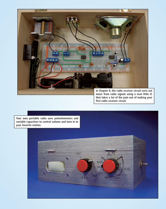
In Chapter 8, the radio receiver circuit sorts outmusic from radio signals using a neat little ICthat takes a lot of the pain out of making yourfirst radio receiver circuit.
Your own portable radio uses potentiometers andvariable capacitors to control volume and tune in toyour favorite station.
009683 ci_f.qxd 6/1/06 3:58 PM Page 3

This cute little guy has push buttonshidden here and there that you useto get him to talk.
Taking a closer look at Merlin’s insides (Chapter 7). Thisproject uses a neat speech synthesizer IC that can beprogrammed with musical tones, words, and more.
009683 ci_f.qxd 6/1/06 3:58 PM Page 4

The metal detector detectingthings! This handheld gadgetcan locate coins, lost keys, andeven nails in your wall.
The metal detector circuit from Chapter 12 uses a great IC thatkeeps the number of components you need to sense the changein the AC signal that indicates metal is in the area to a minimum.
009683 ci_f.qxd 6/1/06 3:58 PM Page 5

In Chapter 6, you build this circuit to drive the parabolic microphone thatpicks up sounds at a distance. Be careful with this circuit when placing thewires so that they don’t get too close and cause feedback.
Chapter 11 is where you go to create this little bubble cart thatyou control with infrared light. This is just like controlling yourTV, only you get to watch this guy dart around the room and gobackward, which is way more entertaining than most TV shows.
009683 ci_f.qxd 6/1/06 3:58 PM Page 6

The very cool dancing dolphin display you create inChapter 10 using many LEDs and a timer that sets thedolphins off in sequence.
The dancing dolphin circuit revealed. Each pair of wiresgoes to an array of LEDs that make up one dolphin. Wiringup the arrays is the time consuming part of this project!
009683 ci_f.qxd 6/1/06 3:58 PM Page 7

A receiver circuit is housedin one plastic pumpkin, andanother pumpkin houses thetransmitter (see Chapter 9).When somebody walksbetween the two, a beam ofinfrared light is disruptedand a recorded messageplays using a sound chip.
The Couch Petato circuit from Chapter 14 uses a vibration sensorto detect your pet when it jumps on a piece of furniture, and asound chip to tell your cat to scat.
009683 ci_f.qxd 6/1/06 3:58 PM Page 8