Development of an ultrafine grained ferrite in a low C–Mn and Nb–Ti microalloyed steels after...
11
Materials Science and Engineering A 402 (2005) 98–108 Development of an ultrafine grained ferrite in a low C–Mn and Nb–Ti microalloyed steels after warm torsion and intercritical annealing G. Azevedo a,∗ , R. Barbosa b , E.V. Pereloma c , D.B. Santos b a Technical College, Federal University of Minas Gerais, Av. Antonio Carlos, 6627-Pampulha 31270-901, Belo Horizonte, Minas Gerais, Brazil b Department of Metallurgical and Materials Engineering, Federal University of Minas Gerais, R. Esp´ ırito Santo 35-s206-Centro-30160-030, Belo Horizonte, Minas Gerais, Brazil c School of Physics and Materials Engineering, Building 69, Monash University, Vic. 3800, Australia Accepted 6 April 2005 Abstract In recent years, several studies on grain refinement of ferrite have been conducted by different methods (equal channel angular pressing (ECAP), high pressure torsion (HPT), accumulative roll bonding (ARB)) in order to optimize the relationship between mechanical properties and microstructure of steels. The present work deals with the strain-induced dynamic transformation of ferrite. Samples of low C–Mn and Nb–Ti microalloyed steels were intensively deformed in warm torsion. This resulted in the formation of ultrafine ferrite grains (∼1 m) thereby enhancing the mechanical properties compared to the ordinary hot rolled products without the necessity of implementing an extremely high strain accumulation. The following annealing has resulted in recrystallization and growth of ferrite grains accompanied by a homogenization of the final microstructure and a decrease in hardness. With increase in annealing time the volume fraction of martensite/austenite (MA) constituent increased. The results have shown that the effect of steel chemistry was insignificant in comparison with the effect of thermomechanical processing parameters. © 2005 Elsevier B.V. All rights reserved. Keywords: Ultrafine ferrite; Strain-induced transformation; Torsion testing 1. Introduction Ferrite grain refinement by various processing techniques has attracted a significant attention in the last decade. Intense plastic deformation, involving processes such as equal chan- nel angular pressing (ECAP), high pressure torsion (HPT) and accumulative roll bonding (ARB) are now currently in use in experimental setups throughout the world. ECAP was developed about 10 years ago [1] and has demonstrated the capability to produce a great refinement of the steel mi- crostructure. Alternative methods such as ARB and marten- sitic steel rolling, were presented later by Saito et al. [2] and Ueji et al. [3], respectively. Some of these processes, however, are disadvantageous either due to their complexity or to their inapplicability to large scale/volume production of materials. On the other hand, a controlled thermomechanical processing ∗ Corresponding author. Tel.: +55 31 34994948; fax: +55 31 34994969. E-mail address: [email protected] (G. Azevedo). that involved intense deformation, phase transformation and deformation induced ferrite transformation, if feasible, could be a suitable way to obtain a more refined microstructure at plant level, producing the superior results compared to the controlled rolling products [4–10]. The aim of this work was to study the microstructure evo- lution during a thermomechanical treatment to obtain ultra- fine grains. Samples of C–Mn and C–Mn–Nb–Ti were warm torsioned in the intercritical range cooled to room tempera- ture and subsequently annealed at 800 ◦ C. The results have shown that the effect of steel chemistry was insignificant in comparison with the effect of thermomechanical processing parameters. 2. Experimental procedure The nominal compositions of the steels investigated are given in Table 1. Tubular specimens (16 mm length, 6.35 mm 0921-5093/$ – see front matter © 2005 Elsevier B.V. All rights reserved. doi:10.1016/j.msea.2005.04.026
-
Upload
independent -
Category
Documents
-
view
0 -
download
0
Transcript of Development of an ultrafine grained ferrite in a low C–Mn and Nb–Ti microalloyed steels after...
Materials Science and Engineering A 402 (2005) 98–108
Development of an ultrafine grained ferrite in a low C–Mn and Nb–Timicroalloyed steels after warm torsion and intercritical annealing
G. Azevedoa,∗, R. Barbosab, E.V. Perelomac, D.B. Santosb
a Technical College, Federal University of Minas Gerais, Av. Antonio Carlos, 6627-Pampulha 31270-901, Belo Horizonte, Minas Gerais, Brazilb Department of Metallurgical and Materials Engineering, Federal University of Minas Gerais,
R. Esp´ırito Santo 35-s206-Centro-30160-030, Belo Horizonte, Minas Gerais, Brazilc School of Physics and Materials Engineering, Building 69, Monash University, Vic. 3800, Australia
Accepted 6 April 2005
Abstract
In recent years, several studies on grain refinement of ferrite have been conducted by different methods (equal channel angular pressing(ECAP), high pressure torsion (HPT), accumulative roll bonding (ARB)) in order to optimize the relationship between mechanical propertiesand microstructure of steels. The present work deals with the strain-induced dynamic transformation of ferrite. Samples of low C–Mn andNe emely highs nization oft ) constituenti echanicalp©
K
1
hpnaudccsUaiO
anduldre at
the
vo-ltra-armera-et insing
arem
0d
b–Ti microalloyed steels were intensively deformed in warm torsion. This resulted in the formation of ultrafine ferrite grains (∼1�m) therebynhancing the mechanical properties compared to the ordinary hot rolled products without the necessity of implementing an extrtrain accumulation. The following annealing has resulted in recrystallization and growth of ferrite grains accompanied by a homogehe final microstructure and a decrease in hardness. With increase in annealing time the volume fraction of martensite/austenite (MAncreased. The results have shown that the effect of steel chemistry was insignificant in comparison with the effect of thermomrocessing parameters.2005 Elsevier B.V. All rights reserved.
eywords:Ultrafine ferrite; Strain-induced transformation; Torsion testing
. Introduction
Ferrite grain refinement by various processing techniquesas attracted a significant attention in the last decade. Intenselastic deformation, involving processes such as equal chan-el angular pressing (ECAP), high pressure torsion (HPT)nd accumulative roll bonding (ARB) are now currently inse in experimental setups throughout the world. ECAP waseveloped about 10 years ago[1] and has demonstrated theapability to produce a great refinement of the steel mi-rostructure. Alternative methods such as ARB and marten-itic steel rolling, were presented later by Saito et al.[2] andeji et al.[3], respectively. Some of these processes, however,re disadvantageous either due to their complexity or to their
napplicability to large scale/volume production of materials.n the other hand, a controlled thermomechanical processing
∗ Corresponding author. Tel.: +55 31 34994948; fax: +55 31 34994969.E-mail address:[email protected] (G. Azevedo).
that involved intense deformation, phase transformationdeformation induced ferrite transformation, if feasible, cobe a suitable way to obtain a more refined microstructuplant level, producing the superior results compared tocontrolled rolling products[4–10].
The aim of this work was to study the microstructure elution during a thermomechanical treatment to obtain ufine grains. Samples of C–Mn and C–Mn–Nb–Ti were wtorsioned in the intercritical range cooled to room tempture and subsequently annealed at 800◦C. The results havshown that the effect of steel chemistry was insignificancomparison with the effect of thermomechanical procesparameters.
2. Experimental procedure
The nominal compositions of the steels investigatedgiven inTable 1. Tubular specimens (16 mm length, 6.35 m
921-5093/$ – see front matter © 2005 Elsevier B.V. All rights reserved.oi:10.1016/j.msea.2005.04.026
G. Azevedo et al. / Materials Science and Engineering A 402 (2005) 98–108 99
Table 1Nominal steel compositions
Steel Elements (wt.%)
C Mn Si Al P S N Nb Ti
C–Mn 0.15 1.39 0.39 0.039 0.016 0.009 0.0042 – –Nb–Ti 0.11 1.41 0.29 0.022 0.025 0.008 – 0.028 0.012
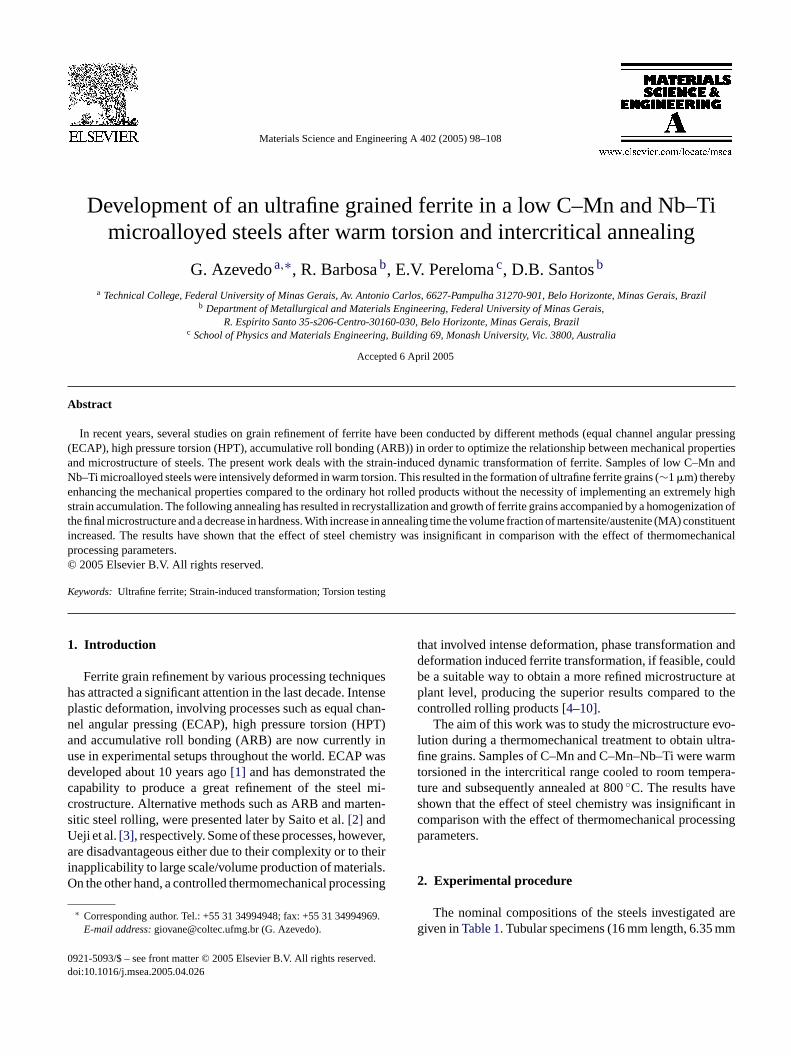
Fig. 1. Schematic diagram of the thermomechanical processing schedule.
outer diameter and 2 mm inner diameter) were machinedfrom industrial plates parallel to the rolling direction.
The thermomechanical treatment employed in this work(Fig. 1) consisted of three stages: (i) austenitization at 900◦C
for 300 s followed by ice brine quenching at a cooling rateof 300◦C/s; (ii) intercritical deformation after reheating upto 740◦C, where the samples were homogenized for 300 s.Ac1 and Ac3 temperatures for these steels were calculatedaccording to[11] to be 719 and 849◦C (for C–Mn steel), and716 and 800◦C (for Nb–Ti steel), respectively. Warm torsionwas conducted using seven passes of an approximately equaldeformation of 0.14 per pass at a strain rate of 2 s−1 resultingin a total equivalent true strain of∼1. It was carried out underargon atmosphere. Details of the torsion equipment employedin the experiments are given elsewhere[9]. All samples werethen air cooled to room temperature. (iii) Soaking for 60,600, 1800, 3600, 7200 and 10,800 s at 800◦C, followed byair cooling.
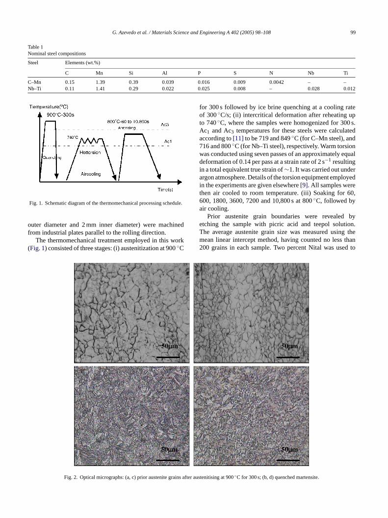
Prior austenite grain boundaries were revealed byetching the sample with picric acid and teepol solution.The average austenite grain size was measured using themean linear intercept method, having counted no less than200 grains in each sample. Two percent Nital was used to
Fig. 2. Optical micrographs: (a, c) prior austenite grains afte
r austenitising at 900◦C for 300 s; (b, d) quenched martensite.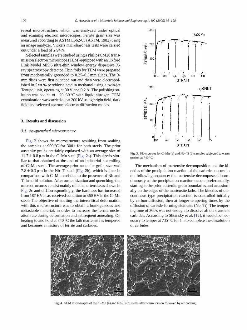
100 G. Azevedo et al. / Materials Science and Engineering A 402 (2005) 98–108
reveal microstructure, which was analyzed under opticaland scanning electron microscopes. Ferrite grain size wasmeasured according to ASTM E562-83 (ASTM, 1983) usingan image analyzer. Vickers microhardness tests were carriedout under a load of 2.94 N.
Selected samples were studied using a Philips CM20 trans-mission electron microscope (TEM) equipped with an OxfordLink Model MK 6 ultra-thin window energy dispersive X-ray spectroscopy detector. Thin foils for TEM were preparedfrom mechanically grounded to 0.25–0.3 mm slices. The 3-mm discs were first punched out and then were electropol-ished in 5 wt.% perchloric acid in methanol using a twin-jetTenupol unit, operating at 30 V and 0.2 A. The polishing so-lution was cooled to−20–30◦C with liquid nitrogen. TEMexamination was carried out at 200 kV using bright field, darkfield and selected aperture electron diffraction modes.
3. Results and discussion
3.1. As-quenched microstructure
Fig. 2 shows the microstructure resulting from soakingthe samples at 900◦C for 300 s for both steels. The prioraustenite grains are fairly equiaxed with an average size of1 -i lingo was7c andT them n inF asedf Mns tionw andm ucle-a g. Onh eda
Fig. 3. Flow curves for C–Mn (a) and Nb–Ti (b) samples subjected to warmtorsion at 740◦C.
The mechanism of martensite decomposition and the ki-netics of the precipitation reaction of the carbides occurs inthe following sequence: the martensite decomposes discon-tinuously as the precipitation reaction occurs preferentially,starting at the prior austenite grain boundaries and occasion-ally on the edges of the martensite laths. The kinetics of dis-continous type precipitation reaction is controlled initiallyby carbon diffusion, then at longer tempering times by thediffusion of carbide-forming elements (Nb, Ti). The temper-ing time of 300 s was not enough to dissolve all the transientcarbides. According to Shtansky et al.[12], it would be nec-essary to temper at 735◦C for 1 h to complete the dissolutionof carbides.
Nb–Ti
1.7± 0.8�m in the C–Mn steel (Fig. 2a). This size is simlar to that obtained at the end of an industrial hot rolf C–Mn steel. The average prior austenite grain size.8± 0.3�m in the Nb–Ti steel (Fig. 2b), which is finer inomparison with C–Mn steel due to the presence of Nbi in solid solution. After austenitization and quenching,icrostructures consist mainly of lath martensite as showig. 2c and d. Correspondingly, the hardness has incre
rom 187 HV in as-received condition to 360 HV in the C–teel. The objective of starting the intercritical deformaith this microstructure was to obtain a homogeneousetastable material, in order to increase the ferrite ntion rate during deformation and subsequent annealineating to and hold at 740◦C the lath martensite is tempernd becomes a mixture of ferrite and carbides.
Fig. 4. SEM micrographs of the C–Mn (a) and
(b) steels after warm torsion followed by air cooling.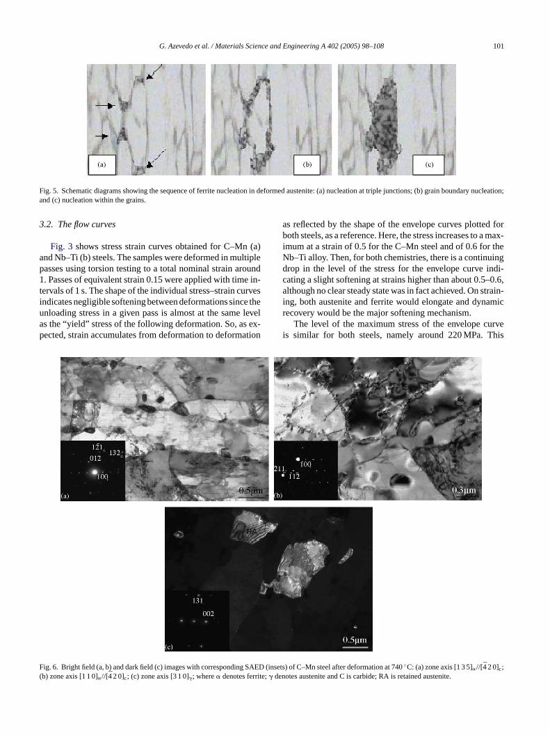
G. Azevedo et al. / Materials Science and Engineering A 402 (2005) 98–108 101
Fig. 5. Schematic diagrams showing the sequence of ferrite nucleation in deformed austenite: (a) nucleation at triple junctions; (b) grain boundarynucleation;and (c) nucleation within the grains.
3.2. The flow curves
Fig. 3 shows stress strain curves obtained for C–Mn (a)and Nb–Ti (b) steels. The samples were deformed in multiplepasses using torsion testing to a total nominal strain around1. Passes of equivalent strain 0.15 were applied with time in-tervals of 1 s. The shape of the individual stress–strain curvesindicates negligible softening between deformations since theunloading stress in a given pass is almost at the same levelas the “yield” stress of the following deformation. So, as ex-pected, strain accumulates from deformation to deformation
as reflected by the shape of the envelope curves plotted forboth steels, as a reference. Here, the stress increases to a max-imum at a strain of 0.5 for the C–Mn steel and of 0.6 for theNb–Ti alloy. Then, for both chemistries, there is a continuingdrop in the level of the stress for the envelope curve indi-cating a slight softening at strains higher than about 0.5–0.6,although no clear steady state was in fact achieved. On strain-ing, both austenite and ferrite would elongate and dynamicrecovery would be the major softening mechanism.
The level of the maximum stress of the envelope curveis similar for both steels, namely around 220 MPa. This
F(
ig. 6. Bright field (a, b) and dark field (c) images with corresponding SAED (b) zone axis [1 1 0]�//[4 2 0]c; (c) zone axis [3 1 0]�; where� denotes ferrite;� den
insets) of C–Mn steel after deformation at 740◦C: (a) zone axis [1 3 5]�//[4 2 0]c;otes austenite and C is carbide; RA is retained austenite.
102 G. Azevedo et al. / Materials Science and Engineering A 402 (2005) 98–108
indicates that the effect of microalloying elements in theform of fine dispersed precipitates on strength is virtually nonexistent. Hence, the only major factor affecting the value ofthe stress would be the relative volume fractions of austenite,ferrite and cementite present at the temperature of 740◦C,previous to straining. In the present case, a fully martensiticmicrostructure was heated up to test temperature. Martensitereverted back to a given fraction of austenite, ferrite andcementite. The results here obtained for maximum stresssuggest then that, beyond any second-order effect, the relativevolume fractions of austenite, ferrite and cementite presentprior to straining were roughly the same for both steels.
3.3. Development of the microstructure during torsion
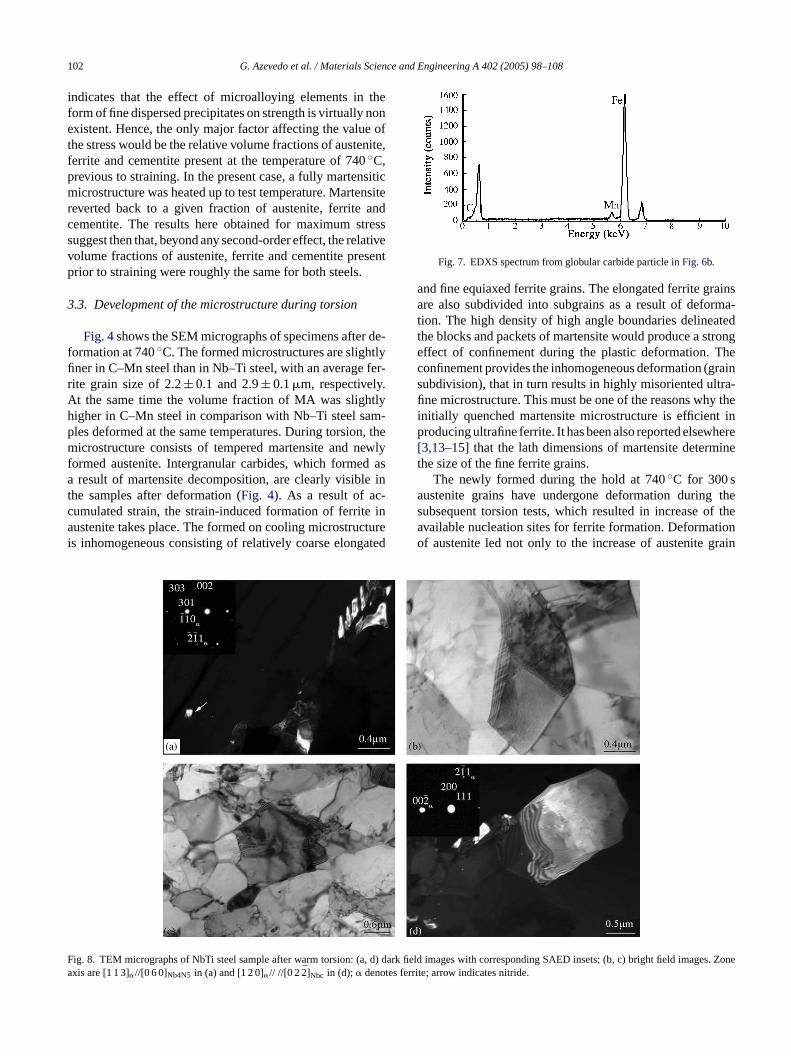
Fig. 4shows the SEM micrographs of specimens after de-formation at 740◦C. The formed microstructures are slightlyfiner in C–Mn steel than in Nb–Ti steel, with an average fer-rite grain size of 2.2± 0.1 and 2.9± 0.1�m, respectively.At the same time the volume fraction of MA was slightlyhigher in C–Mn steel in comparison with Nb–Ti steel sam-ples deformed at the same temperatures. During torsion, themicrostructure consists of tempered martensite and newlyformed austenite. Intergranular carbides, which formed asa result of martensite decomposition, are clearly visible inthe samples after deformation (Fig. 4). As a result of ac-c e ina cturei ated
Fig. 7. EDXS spectrum from globular carbide particle inFig. 6b.
and fine equiaxed ferrite grains. The elongated ferrite grainsare also subdivided into subgrains as a result of deforma-tion. The high density of high angle boundaries delineatedthe blocks and packets of martensite would produce a strongeffect of confinement during the plastic deformation. Theconfinement provides the inhomogeneous deformation (grainsubdivision), that in turn results in highly misoriented ultra-fine microstructure. This must be one of the reasons why theinitially quenched martensite microstructure is efficient inproducing ultrafine ferrite. It has been also reported elsewhere[3,13–15]that the lath dimensions of martensite determinethe size of the fine ferrite grains.
The newly formed during the hold at 740◦C for 300 saustenite grains have undergone deformation during thesubsequent torsion tests, which resulted in increase of theavailable nucleation sites for ferrite formation. Deformationof austenite led not only to the increase of austenite grain
Fa
umulated strain, the strain-induced formation of ferritustenite takes place. The formed on cooling microstru
s inhomogeneous consisting of relatively coarse elong
ig. 8. TEM micrographs of NbTi steel sample after warm torsion: (a, d) darxis are [1 1 3]�//[0 6 0]Nb4N5 in (a) and [1 2 0]�// //[0 22]Nbc in (d); � denotes ferr
k field images with corresponding SAED insets; (b, c) bright field images. Zoneite; arrow indicates nitride.
G. Azevedo et al. / Materials Science and Engineering A 402 (2005) 98–108 103
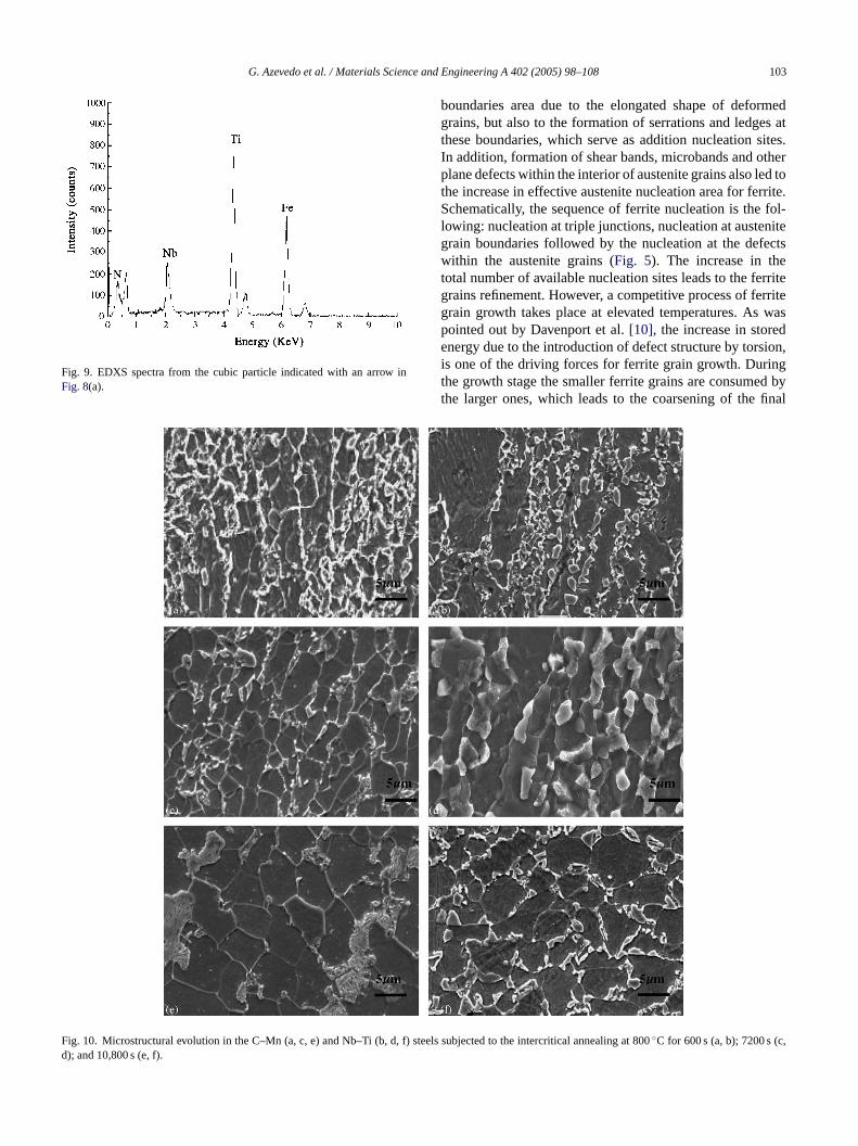
Fig. 9. EDXS spectra from the cubic particle indicated with an arrow inFig. 8(a).
boundaries area due to the elongated shape of deformedgrains, but also to the formation of serrations and ledges atthese boundaries, which serve as addition nucleation sites.In addition, formation of shear bands, microbands and otherplane defects within the interior of austenite grains also led tothe increase in effective austenite nucleation area for ferrite.Schematically, the sequence of ferrite nucleation is the fol-lowing: nucleation at triple junctions, nucleation at austenitegrain boundaries followed by the nucleation at the defectswithin the austenite grains (Fig. 5). The increase in thetotal number of available nucleation sites leads to the ferritegrains refinement. However, a competitive process of ferritegrain growth takes place at elevated temperatures. As waspointed out by Davenport et al.[10], the increase in storedenergy due to the introduction of defect structure by torsion,is one of the driving forces for ferrite grain growth. Duringthe growth stage the smaller ferrite grains are consumed bythe larger ones, which leads to the coarsening of the final
Fig. 10. Microstructural evolution in the C–Mn (a, c, e) and Nb–Ti (b, d, f) std); and 10,800 s (e, f).
eels subjected to the intercritical annealing at 800◦C for 600 s (a, b); 7200 s (c,
104 G. Azevedo et al. / Materials Science and Engineering A 402 (2005) 98–108
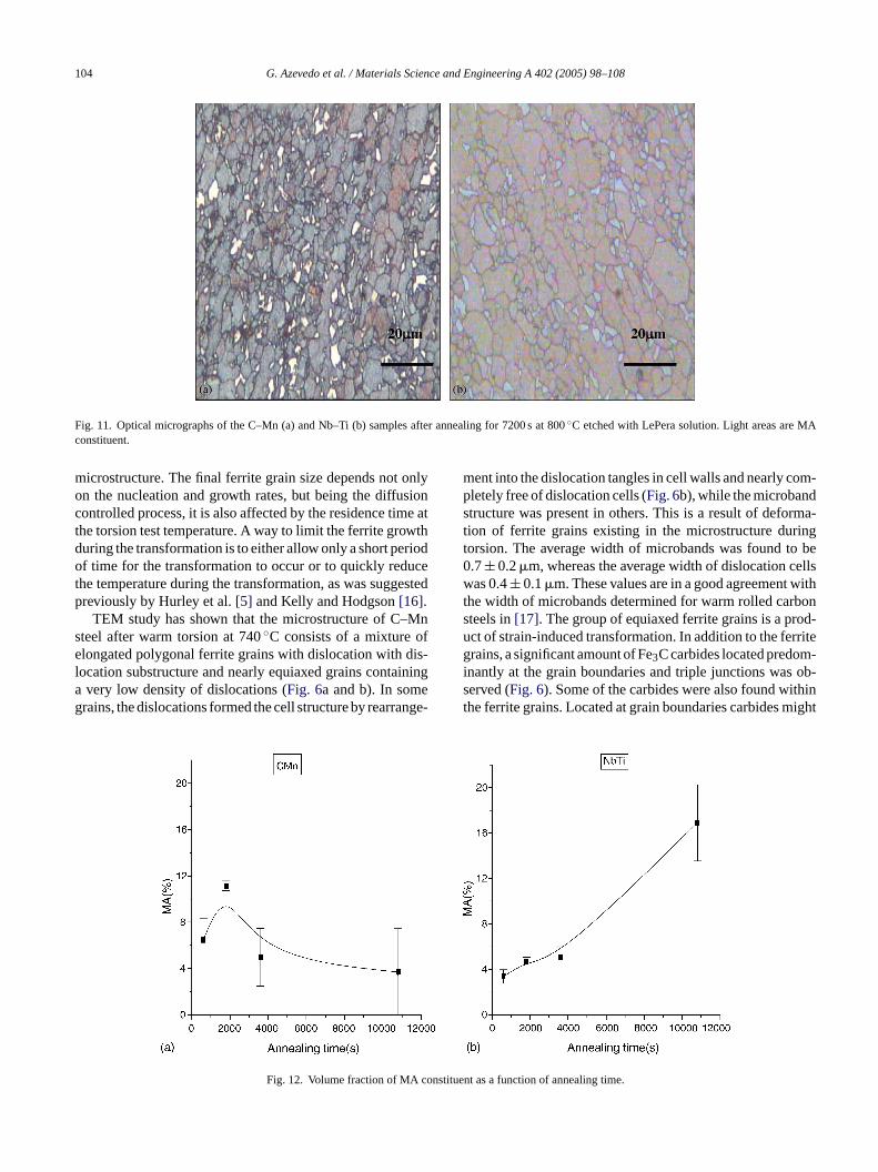
Fig. 11. Optical micrographs of the C–Mn (a) and Nb–Ti (b) samples after annealing for 7200 s at 800◦C etched with LePera solution. Light areas are MAconstituent.
microstructure. The final ferrite grain size depends not onlyon the nucleation and growth rates, but being the diffusioncontrolled process, it is also affected by the residence time atthe torsion test temperature. A way to limit the ferrite growthduring the transformation is to either allow only a short periodof time for the transformation to occur or to quickly reducethe temperature during the transformation, as was suggestedpreviously by Hurley et al.[5] and Kelly and Hodgson[16].
TEM study has shown that the microstructure of C–Mnsteel after warm torsion at 740◦C consists of a mixture ofelongated polygonal ferrite grains with dislocation with dis-location substructure and nearly equiaxed grains containinga very low density of dislocations (Fig. 6a and b). In somegrains, the dislocations formed the cell structure by rearrange-
ment into the dislocation tangles in cell walls and nearly com-pletely free of dislocation cells (Fig. 6b), while the microbandstructure was present in others. This is a result of deforma-tion of ferrite grains existing in the microstructure duringtorsion. The average width of microbands was found to be0.7± 0.2�m, whereas the average width of dislocation cellswas 0.4± 0.1�m. These values are in a good agreement withthe width of microbands determined for warm rolled carbonsteels in[17]. The group of equiaxed ferrite grains is a prod-uct of strain-induced transformation. In addition to the ferritegrains, a significant amount of Fe3C carbides located predom-inantly at the grain boundaries and triple junctions was ob-served (Fig. 6). Some of the carbides were also found withinthe ferrite grains. Located at grain boundaries carbides might
onstitu
Fig. 12. Volume fraction of MA c ent as a function of annealing time.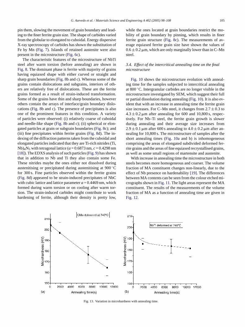
G. Azevedo et al. / Materials Science and Engineering A 402 (2005) 98–108 105
pin them, slowing the movement of grain boundary and lead-ing to the finer ferrite grain size. The shape of carbides variedfrom the globular to elongated to cuboidal. Energy dispersiveX-ray spectroscopy of carbides has shown the substitution ofFe by Mn (Fig. 7). Islands of retained austenite were alsopresent in the microstructure (Fig. 6c).
The characteristic features of the microstructure of NbTisteel after warm torsion (before annealing) are shown inFig. 8. The dominant phase is ferrite with majority of grainshaving equiaxed shape with either curved or straight andsharp grain boundaries (Fig. 8b and c). Whereas some of thegrains contain dislocations and subgrains, interiors of oth-ers are relatively free of dislocations. These are the ferritegrains formed as a result of strain-induced transformation.Some of the grains have thin and sharp boundaries, howeverothers contain the arrays of interface/grain boundary dislo-cations (Fig. 8b and c). The presence of precipitates is alsoone of the prominent features in this condition. A varietyof particles were observed: (i) relatively coarse of cuboidaland needle-like shape (Fig. 8b and c); (ii) spherical or elon-gated particles at grain or subgrain boundaries (Fig. 8c); and(iii) fine precipitates within ferrite grains (Fig. 8d). The in-dexing of the diffraction patterns taken from the cuboidal andelongated particles indicated that they are Ti-rich nitrides (Ti,Nb)4N5 with tetragonal lattice (a= 0.6873 nm,c= 0.4298 nm[18]). The EDXS analysis of such particles (Fig. 9) has shownt Fe.T uringa 0f ains( NbCwf tor-s orkh ow,
while the ones located at grain boundaries restrict the mo-bility of grain boundary by pinning, which results in finerferrite grain structure (Fig. 8c). The measurements of av-erage equiaxed ferrite grain size have shown the values of0.6± 0.2�m, which are only marginally lower than in C–Mnsteel.
3.4. Effect of the intercritical annealing time on the finalmicrostructure
Fig. 10shows the microstructure evolution with anneal-ing time for the samples subjected to intercritical annealingat 800◦C. Intergranular carbides are no longer visible in themicrostructure investigated by SEM, which suggest their fullor partial dissolution during annealing (Fig. 10). It is also ev-ident that with an increase in annealing time the ferrite grainsize increases. For C–Mn steel, it changes from 2.7± 0.3 to4.3± 0.2�m after annealing for 600 and 10,800 s, respec-tively. For Nb–Ti steel, the ferrite grain growth is slowerduring annealing and their average size increases from2.9± 0.1�m after 600 s annealing to 4.0± 0.2�m after an-nealing for 10,800 s. The microstructure of samples after theshort annealing times (Fig. 10a and b) is inhomogeneouscomprising the areas of elongated subdivided deformed fer-rite grains and the areas of fine equiaxed recrystallised grains,as well as some small regions of martensite and austenite.
oths olumef thee sb d mi-c Ac lumef inF
crohard
hat in addition to Nb and Ti they also contain somehese nitrides maybe the ones either not dissolved dustenitising or precipitated during austenitising at 90◦C
or 300 s. Fine particles observed within the ferrite grFig. 8d) appeared to be strain-induced precipitates ofith cubic lattice and lattice parametera= 0.4469 nm, which
ormed during warm torsion or on cooling after warmion. The strain-induced carbides might contribute to wardening of ferrite, although their density is pretty l
Fig. 13. Variation in mi
With increase in annealing time the microstructure in bteels becomes more homogeneous and coarser. The vraction of MA constituent changes non-linearly, due toffect of Nb presence on hardenability[19]. The differenceetween MA contents can be seen from the colour etcherographs shown inFig. 11. The light areas represent the Monstituent. The results of the measurements of the voraction of MA as a function of annealing time are givenig. 12.
ness with annealing time.
106 G. Azevedo et al. / Materials Science and Engineering A 402 (2005) 98–108
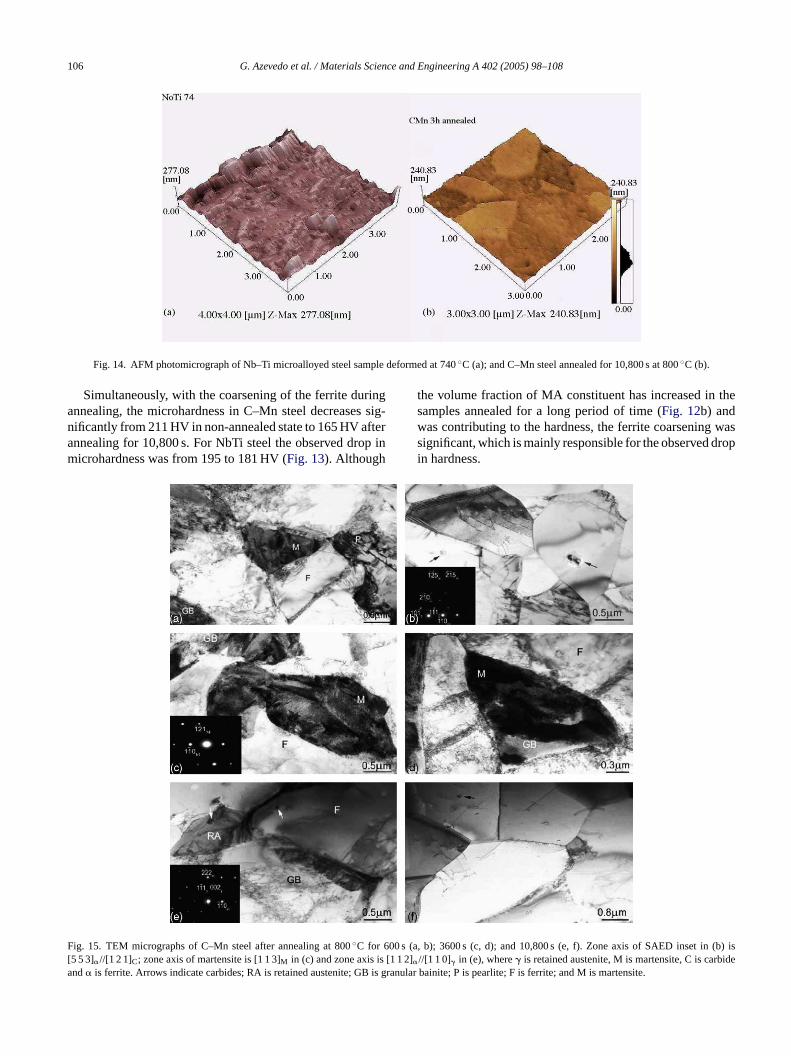
Fig. 14. AFM photomicrograph of Nb–Ti microalloyed steel sample deformed at 740◦C (a); and C–Mn steel annealed for 10,800 s at 800◦C (b).
Simultaneously, with the coarsening of the ferrite duringannealing, the microhardness in C–Mn steel decreases sig-nificantly from 211 HV in non-annealed state to 165 HV afterannealing for 10,800 s. For NbTi steel the observed drop inmicrohardness was from 195 to 181 HV (Fig. 13). Although
the volume fraction of MA constituent has increased in thesamples annealed for a long period of time (Fig. 12b) andwas contributing to the hardness, the ferrite coarsening wassignificant, which is mainly responsible for the observed dropin hardness.
F[a
ig. 15. TEM micrographs of C–Mn steel after annealing at 800◦C for 600 s (a5 5 3]�//[1 2 1]C; zone axis of martensite is [1 1 3]M in (c) and zone axis is [1 1 2�nd� is ferrite. Arrows indicate carbides; RA is retained austenite; GB is gra
, b); 3600 s (c, d); and 10,800 s (e, f). Zone axis of SAED inset in (b) is]//[1 1 0]� in (e), where� is retained austenite, M is martensite, C is carbidenular bainite; P is pearlite; F is ferrite; and M is martensite.
G. Azevedo et al. / Materials Science and Engineering A 402 (2005) 98–108 107
Application of atomic force microscopy (AFM) allows theidentification of phases utilising the topography of phases. Asdemonstrated inFig. 6 and in accordance with Ros-Yanez[20], ferrite, more susceptible to the attack by nital, alwayshas a lower height than other phases. Although in the non-annealed state the presence of ferrite grains (dark) is clearlyvisible (Fig. 14a), the lighter particles of presumably Nb, Ticarbides could be also identified. After long annealing time(10,800 s) of CMn sample the coarser both ferrite grains andsome MA particles were observed (Fig. 14b).
TEM studies also confirmed the observed trends in mi-crostructural evolution during annealing at 800◦C from 600to 3600 to 10,800 s (Figs. 15 and 16). With longer annealingtime the recrystallised ferrite grains became coarser, while thevolume fraction of other phases (martensite, retained austen-ite and granular bainite) also increased. In some small pock-ets the presence of fine pearlite was also noted (Fig. 15a).The carbides presence was only evident inside the ferrite and
retained austenite grains, while the grain boundaries werepredominantly free from any precipitation. The amount ofcarbides has significantly decreased in comparison with thedeformed state indicating their dissolution. Carbides werealso becoming finer with increase in annealing time, whichalso supported their dissolving. No pearlite was observed atlater stages of annealing in the Nb–Ti steel. As was demon-strated in[21], pearlite decomposes during annealing andthen carbides serve as additional nucleation sites for the re-crystallised nuclei.
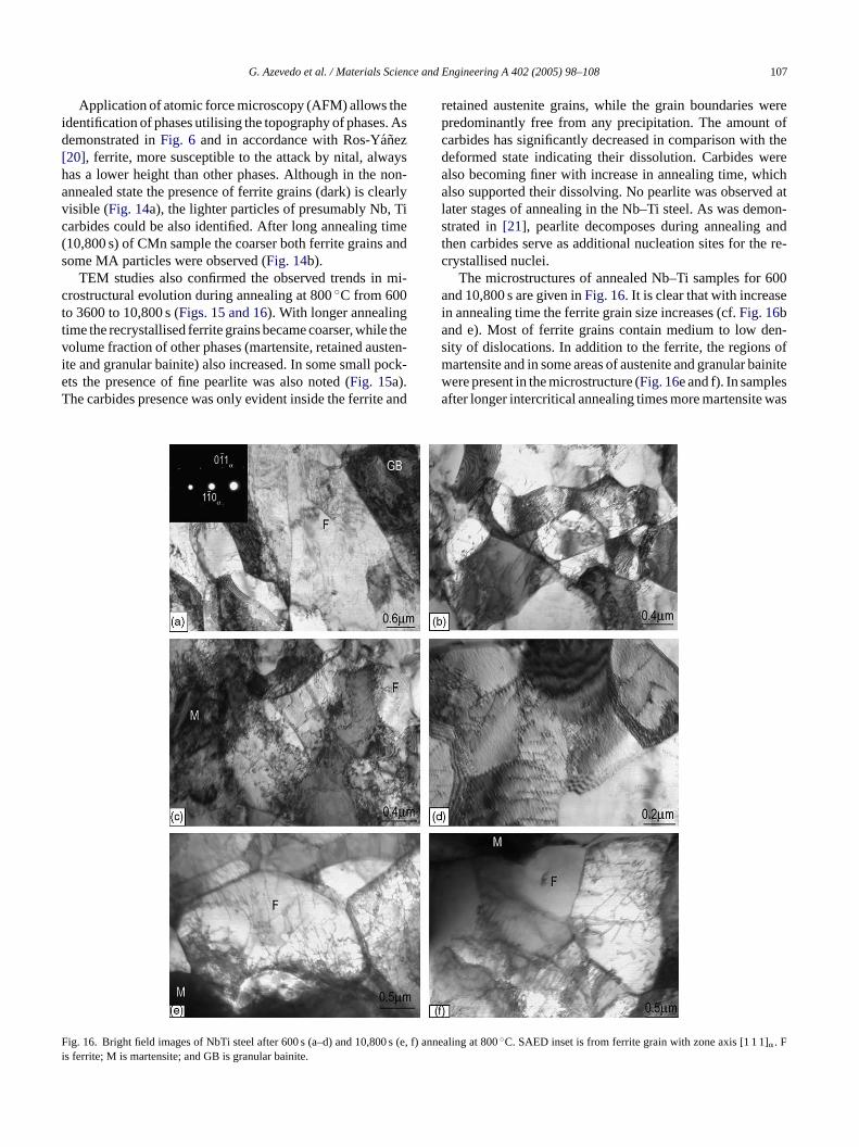
The microstructures of annealed Nb–Ti samples for 600and 10,800 s are given inFig. 16. It is clear that with increasein annealing time the ferrite grain size increases (cf.Fig. 16band e). Most of ferrite grains contain medium to low den-sity of dislocations. In addition to the ferrite, the regions ofmartensite and in some areas of austenite and granular bainitewere present in the microstructure (Fig. 16e and f). In samplesafter longer intercritical annealing times more martensite was
Fi
ig. 16. Bright field images of NbTi steel after 600 s (a–d) and 10,800 s (e, fs ferrite; M is martensite; and GB is granular bainite.
) annealing at 800◦C. SAED inset is from ferrite grain with zone axis [1 1 1]�. F
108 G. Azevedo et al. / Materials Science and Engineering A 402 (2005) 98–108
formed, which indicates that during hold at 800◦C more fer-rite transforms to austenite and then to martensite on cooling.The average ferrite grain size has increased to 4.0± 0.2�mafter 10,800 s annealing, but remained finer than in C–Mnsteel (4.3± 0.2�m). This might be due to the presence of Nband Ti carbides and nitrides in the matrix, which slow the re-arrangement of dislocation structure and migration of ferriteboundaries during annealing, as was shown for low carbonsteels in[21].
To sumarize, the employed thermomechanical processingschedule after short annealing times has produced a fine-grained but inhomogeneous microstructure. With the pro-longed annealing times the microstructure became coarsenedand more homogeneous, which was accompanied by the de-crease in hardness. However, even at these hardness values,which correspond to 555–660 MPa ultimate tensile strength,the produced steels exhibit higher strength (by approximately25%)[22] than the same steel grades traditionally processedby cold rolling and intercritical annealing. This processingroute could be considered to be an industrial viable one forthese steel grades.
4. Conclusions
Warm torsion testing with multipass deformation and in-t ther-m grainf re-c ingo armt nt off af-ts ed inmc s exh and1 siles
iffer-e hichi edulea mores lowad ndn i onr
Acknowledgment
The authors would like to thank Conselho Nacional de De-senvolvimento Cientıfico e Tecnologico, CNPq, for financialsupport to this work.
References
[1] R.Z. Valiev, A.V. Korznikov, R.R. Mulyukov, Mater. Sci. Eng. AA168 (2) (1993) 141–148.
[2] Y. Saito, H. Utsunomiya, N. Tsuji, T. Sakai, Acta Mater. 47 (2)(1999) 579–583.
[3] R. Ueji, N. Tsuji, Y. Saito, Y. Minamino, ISUGS 2001, Fukuoka,Japan, pp. 222–225.
[4] P.C.M Rodrigues, R.K. Brzuszek, D.B. Santos, ISUGS 2001,Fukuoka, Japan, pp. 138–141.
[5] P.J. Hurley, B.C. Muddle, P.D. Hodgson, Metall. Mater. Trans. A33A (9) (2002) 2985–2993.
[6] J.W. Bowden, F.H. Samuel, J.J. Jonas, Metall. Mater. Trans. A 22A(1991) 2947–2957.
[7] L.N. Pussegoda, J.J. Jonas, ISIJ Int. 31 (3) (1991) 278–288.[8] L.P. Karjalainen, T.M. Maccagno, J.J. Jonas, ISIJ Int. 35 (12) (1995)
1523–1531.[9] A.B. Cota, R. Barbosa, D.B. Santos, J. Mater. Process. Technol. 100
(1–3) (2000) 156–162.[10] S.B. Davenport, D.N. Hanlon, F. Van Der Zwaag, Scripta Mater. 46
(2002) 413–417.[11] K.W. Andrews, JISI 203 (1965) 721–727.[ 00)
[ 117
[ nalx’99).333–
[ (4)
[ nfer-
[ eed-ence,543–
[ tion
[ e onand
–10
[ 01)
[ 005)
[ long,
ercritical annealing was used to study the effects ofomechanical processing parameters on the ultrafine
errite formation by strain-induced transformation andrystallization in the C–Mn and Nb–Ti steels. The utilisf the martensite as a starting microstructure before the w
orsion has allowed to achieve the significant refinemeerrite grains after deformation with the final grain sizeer annealing for 10,800 s of approximately 4�m for bothteels studied. Short annealing times (60–600 s) resultuch finer ferrite grains (2.2± 0.1 to 2.9± 0.1�m), but mi-
rostructure was more inhomogeneous. These sampleibit the microhardness values of 212–175 HV (CMn)90–180 HV (NbTi), which translates into ultimate tentrength of aproximately 660–555 MPa.
The results have shown the absence of a significant dnce in the final microstructures of the studied steels, w
ndicates the predominant effect of the processing schnd not a steel composition. However, the absence of aignificant influence of microalloying might be due to theustenitising temperature used in this study (900◦C), whichid not allow the dissolution of existing Nb, Ti carbides aitrides and by this minimising the influence of Nb and Tecovery and recrystallisation.
-
12] D.V. Shtansky, K. Nakai, Y. Ohmori, Acta Mater. 48,4 (25) (20969–983.
13] S. Takaki, K. Kawasaki, Y. Kimura, J. Mater. Process. Technol.(3) (2001) 359–363.
14] T. Hayashi, M. Saito, K. Tsuzaki, K. Nagai, Fourth InternatioConference on Recrystallization and Related Phenomena (ReConference Proceedings, JIM, Tsukuba Japan, 1999, pp.338.
15] N. Tsuji, R. Ueji, Y. Minamino, Y. Saito, Scripta Mater. 46(2002) 305–310.
16] G.L. Kelly, P.D. Hodgson, Proceedings of the 42nd MWSP Coence, vol. 38, Toronto, Canada, 2000, pp. 515–522.
17] I.B. Timokhina, A. Nosenkov, J.J. Jonas, E.V. Pereloma, Procings of the Materials Science and Technology 2004 Confervol. 1, New Orleans, AIST/TMS, 26–29 September, 2004, pp.552.
18] International Centre for Powder Diffraction Data, Powder DiffracFiles, Inorganic Phases, JCPDS, Pennsylvania, 1981.
19] S. Okaguchi, T. Hashimoto, H. Ohtani, International ConferencPhysical Metallurgy of Thermomechanical Processing of Steelsother Metals (THERMEC), Keidanren Kaikan, Tokyo, Japan, 6June, 1988, pp. 330–336.
20] T. Ros-Yanez, Y. Houbaert, A. Mertens, Mater. Charact. 47 (2093–104.
21] I.B. Timokhina, J.J. Jonas, E.V. Pereloma, ISIJ Int. 45 (6) (2867–875.
22] D.B. Santos, G. Azevedo, Proceedings of the 2nd ISUGS, GeeVictoria, Australia, 11–13 November 2003, 8 pp.