DESIGN ANALYSIS OF FERRITE SHEET ATTACHMENT FOR SAR REDUCTION IN HUMAN HEAD
15
Progress In Electromagnetics Research, PIER 98, 191–205, 2009 DESIGN ANALYSIS OF FERRITE SHEET ATTACH- MENT FOR SAR REDUCTION IN HUMAN HEAD M. T. Islam Institute of Space Science (ANGKASA) Universiti Kebangsaan Malaysia UKM, Bangi Selangor 43600, Malaysia M. R. I. Faruque Department of Electrical, Electronic and Systems Engineering Faculty of Engineering and Built Environment Universiti Kebangsaan Malaysia UKM, Bangi Selangor 43600, Malaysia N. Misran Department of Electrical, Electronic and Systems Engineering Faculty of Engineering and Built Environment Institute of Space Science (ANGKASA) Universiti Kebangsaan Malaysia UKM, Bangi Selangor 43600, Malaysia Abstract—In this paper, reducing Specific Absorption Rate (SAR) with ferrite sheet attachment is investigated. The finite-difference time-domain method with Lossy-Drude model is adopted in this study. The methodology of SAR reduction is addressed and then the effects of attaching location, distance, size and material properties of ferrite sheet on the SAR reduction are investigated. Computational results show that the SAR averaging over 10gm was better than that for 1 gm and SAR reduction of 57.75% is achieved for SAR 10 gm. These results show the way to choose a ferrite sheet with the maximum SAR reducing effect for phone model. Corresponding author: M. T. Islam ([email protected]).
Transcript of DESIGN ANALYSIS OF FERRITE SHEET ATTACHMENT FOR SAR REDUCTION IN HUMAN HEAD

Progress In Electromagnetics Research, PIER 98, 191–205, 2009
DESIGN ANALYSIS OF FERRITE SHEET ATTACH-MENT FOR SAR REDUCTION IN HUMAN HEAD
M. T. Islam
Institute of Space Science (ANGKASA)Universiti Kebangsaan MalaysiaUKM, Bangi Selangor 43600, Malaysia
M. R. I. Faruque
Department of Electrical, Electronic and Systems EngineeringFaculty of Engineering and Built EnvironmentUniversiti Kebangsaan MalaysiaUKM, Bangi Selangor 43600, Malaysia
N. Misran
Department of Electrical, Electronic and Systems EngineeringFaculty of Engineering and Built EnvironmentInstitute of Space Science (ANGKASA)Universiti Kebangsaan MalaysiaUKM, Bangi Selangor 43600, Malaysia
Abstract—In this paper, reducing Specific Absorption Rate (SAR)with ferrite sheet attachment is investigated. The finite-differencetime-domain method with Lossy-Drude model is adopted in this study.The methodology of SAR reduction is addressed and then the effectsof attaching location, distance, size and material properties of ferritesheet on the SAR reduction are investigated. Computational resultsshow that the SAR averaging over 10 gm was better than that for1 gm and SAR reduction of 57.75% is achieved for SAR 10 gm. Theseresults show the way to choose a ferrite sheet with the maximum SARreducing effect for phone model.
Corresponding author: M. T. Islam ([email protected]).

192 Islam, Faruque, and Misran
1. INTRODUCTION
Cellular phone protection and the enforcement of pertinent exposurestandards are issues in the current media, and regulatory agenciesare motivated to assure that compliance testing is acceptable. IEEEStandard 1528 [1] and IEC 62209-1 specify protocols and process forthe measurement of the peak spatial-average specific absorption rate(SAR) induced inside a simplified model of the head of the usersof hand held radio transceivers (cellular phones). For example, theSAR limit specified in IEEE C95.1: 1999 is 1.6 W/kg in a SAR 1 gmaveraging mass while that specified in IEEE C95.1: 2005 has beenupdated to 2W/kg in a 10 gm averaging mass [2]. This new SAR limitspecified in IEEE C95.1: 2005 is comparable to the limit specified inthe International Commission on Non-Ionizing Radiation Protection(ICNIRP) guidelines [3].
The exposure limits are defined commonly in terms of thespatial peak SAR averaged either over any one gram or ten gramsof tissue. Especially, the U.S. Federal Communication Commission(FCC) requires the routine SAR evaluation of phone model prior todevice authorization or use since 1997. So there is a need to reducean effort for reducing the spatial peak SAR in the design stage ofphone model because the possibility of a spatial peak SAR exceedingthe recommended exposure limit cannot be completely ruled out [2, 3].The interaction of the cellular handset with the human head hasbeen investigated by many published papers with considering; first,the effect of the human head on the handset antenna performance,including the feed-point impedance, gain, and efficiency [4–8], second,the impact of the antenna EM radiation on the user’s head due to theabsorbed power, which is measured by predicting the induced SAR inthe head tissue [7–12].
The most used method to solve the electromagnetic problemdealt with this area is the finite-difference time-domain (FDTD)technique [10–13]. Although, in principle, the solution for generalgeometries does not require any additional effort with respect tothe standard method, the technique requires the definition of thediscretized space by assigning to each cell its own electromagneticproperties, which is not an easy process [12–15]. Specifically, theproblems to be solved in SAR reduction need to correct representationof the cellular phone; anatomical representation of the head; alignmentof the phone and the head and suitable design of ferrite sheet or othermaterial.
Human exposure to electromagnetic (EM) radiation, as well as thepertinent health effects, constitutes a matter of raised public concern,

Progress In Electromagnetics Research, PIER 98, 2009 193
undergoing continuous scientific investigation. Various studies on thissubject exist [8–20], most of which mainly delve into the consequencesof mobile-phone usage. Yet, devices and communication terminalsoperating in other frequency bands have also gained substantial interestin the last 15 years. In [13], a ferrite sheet was adopted as protectionattachment between the antenna and the human head. A reductionover 13% for the spatial peak SAR over 1 gm averaging was achieved.Study on the effects of attaching ferrite sheet for SAR reduction waspresented [16, 21] and it was concluded that the position of shieldingplayed an important role in the reduction effectiveness.
In [17, 22], for the SAR in human head, an effective approachis the use of a planar antenna integrated onto the back side (awayfrom the head) of a phone model, but it brings additional designdifficulties especially in achieving the required frequency bandwidthand radiation efficiency. Another approach is the use of a directionalor reflecting antenna [13–16]. Such an antenna structure sacrificesthe availability of signals received from all directions to the phonemodel. The mechanism of SAR reduction by ferrite sheet attachmentwas due to the suppression of surface currents on the front side ofphone model [16]. However, the relationship between the maximumSAR reducing effect and the parameters such as attaching location,size and material properties of ferrite sheet remains unknown.
In [9, 16], a perfect electric conductor (PEC) reflector was placedbetween a human head and the driver of a folded loop antenna. Theresult showed that the radiation efficiency can be enhanced and thepeak SAR value can be reduced. In [12], a study on the effects ofattaching conductive materials to cellular phone for SAR reductionhas been presented. It is shown that the position of the shieldingmaterial is an important factor for SAR reduction effectiveness. Thereis a necessity to make an effort for reducing the spatial peak SAR inthe design stage of ferrite sheet because the possibility of a spatialpeak SAR exceeding the recommended exposure limit cannot becompletely ruled out. Two important parameters electric permittivityand magnetic permeability, determine the response of the materials tothe electromagnetic propagation.
This paper is structured as follows. Section 2 describes thestatistical analysis of the handset together with the SAM phantomhead. FDTD method is used with positive meshing techniques forquick and correct analysis. Modeling and analyzing technique willbe described in Section 3. Simulation and comparing results will besummarized in Section 4 and finally in Section 5 concluded the paper.

194 Islam, Faruque, and Misran
2. SIMULATION MODEL AND NUMERICALTECHNIQUES
2.1. Model Description
The simulation model which includes the handset with helix type ofantenna and the SAM phantom head provided by CST MicrowaveStudio (CST MWS) is shown in Fig. 1. Complete handset modelcomposed of the circuit board, LCD display, keypad, battery andhousing was used for simulation. The relative permittivity andconductivity of individual components were set to comply withindustrial standards. In addition, definitions in [21–23] were adoptedfor material parameters involved in the SAM phantom head. Inorder to accurately characterize the performance over broad frequencyrange, dispersive models for all the dielectrics were adopted duringthe simulation [21]. Fig. 2 shows the dispersive permittivity of the
Figure 1. Complete model used for simulation including handset andSAM phantom head.
Eps'' Eps'
0 1 2 3 4 0 1 2 3 4Frequency/GHz Frequency/GHz
30
25
20
15
10
Electric Dispersion 2nd Order Model (Fit) Electric Dispersion 2nd Order Model (Fit)
43424140393837
Figure 2. Dispersive permittivity of the liquid in the SAM phantomhead used for simulation.

Progress In Electromagnetics Research, PIER 98, 2009 195
Table 1. Electrical properties of materials used for simulation.
Phone Materials εr σ (S/m)Circuit Board 4.4 0.05
Housing Plastic 2.5 0.005LCD Display 3.0 0.02
Rubber 2.5 0.005SAM Phantom Head
Shell 3.7 0.0016Liquid @ 900 MHz 40 1.42
liquid in SAM phantom head for simulation. The electrical propertiesof materials used for simulation are listed in Table 1. Helix typeantenna constructed in a helical sense operating at 900MHz for GSMapplication was used in the simulation model. In order to obtain high-quality geometry approximation for such helical structure, predictablemeshing scheme used in FDTD method usually requires large numberof hexahedrons which in turn makes it extremely challenging to getconvergent results within reasonable simulation time.
2.2. Numerical Technique
CST MWS, based on the finite integral time-domain technique (FITD)proposed by Weiland in 1976 [23], was used as the main simulationinstrument. In permutation of the perfect boundary approximation(PBA) and thin sheet technique (TST), significant development ingeometry approximation with computation speed is achieved squashyhighly accurate results. Non-uniform meshing scheme was adopted sothat major computation endeavor was dedicated to regions along theinhomogeneous boundaries for fast and perfect analysis. Fig. 3 showsthe mesh sight for two cut planes of the complete model indicatingthe area with denser meshing along the inhomogeneous boundaries.The minimum and maximum mesh sizes were 0.3mm and 1.0 mm,respectively. A total of 2,097,152 mesh cells were generated for thecomplete model, and the simulation time was 1163 seconds (includingmesh generation) for each run on an Intel CoreTM 2 Duo E8400 3.0 GHzCPU with 4GB RAM system.
The analysis workflow in progress from the design of antenna withcomplete handset model in free space. The antenna was designed suchthat the S11 response was less than −10 dB over the frequency band ofinterest. SAM phantom head was then included for SAR calculation

196 Islam, Faruque, and Misran
using the standard definition as
SAR =σ
2ρE2
where E is the induced electric field (V/m); ρ is the density of thetissue (kg/m3) and σ is the conductivity of the tissue (S/m). Theresultant SAR values averaged over 1 gm and 10 gm of tissue in thehead were denoted as SAR 1 gm and SAR 10 gm, respectively. Thesevalues were used as a benchmark to appraise the effectiveness in peakSAR reduction.
Figure 3. Mesh view for two cutplanes of the complete model showing thenonuniform meshing scheme adopted forsimulation.
Figure 4. Human headmodel for FDTD computa-tion.
Table 2. Dielectric tissue properties at 900 MHz and 1800MHz[23, 24].
900MHz 1800MHz
Material
Density,
ρ
(kg/m3)
Conductivity
σ
(S/m)
Relative
Permittivity
εr
Conductivity
σ
(S/m)
Relative
Permittivity
εr
Fat,
Bone1130 0.12 4.83 0.11 4.48
Muscle,
Skin1020 1.5 50.5 1.35 47.80
Brain 1050 1.11 41.7 1.09 39.50
Eyeball 1000 2.03 68.6 1.99 65.3

Progress In Electromagnetics Research, PIER 98, 2009 197
3. SAR REDUCTION BY FDTD METHOD WITH LOSSYDRUDE MODEL
3.1. Lossy-drude Model
The SAR reduction effectiveness and antenna performance withdifferent positions, sizes and material properties of ferrite sheet willbe analyzed. The head models used in this study was obtained fromMRI-based head model through the whole brain Atlas website. Sixtypes of tissues, i.e., bone, brain, muscle, eye ball, fat, and skinwere involved in this model [22–26]. Table 2 shows their dielectricproperties [23, 24]. Fig. 4 shows a horizontal cross-section throughthe eyes of this head model. The electrical properties of tissues weretaken from [11]. Numerical simulation of SAR value was performedby FDTD method. The parameters for FDTD computation wereas follows. In our Lossy-Drude simulation model, the domain were128 × 128 × 128 cells in FDTD method. The cell sizes were set as∆x = ∆y = ∆z = 1.0mm. The computational domain was terminatedwith 8 cells PML. A helix antenna was modeled for this paper bythin-wire approximation. Simulations of ferrite sheet are performedby FDTD method with Lossy-Drude Model [23–26]. The method isutilized to understand the wave propagation characteristics of ferritesheet.
Figure 5. Models of head and portable telephone with attached ferritesheet.

198 Islam, Faruque, and Misran
3.2. Analysis Method
Figure 5 shows a portable telephone model at 900 MHz for the presentstudy. It was considered to be a quarter wavelength helix antennamounted on a rectangular conducting box. The conducting box was10 cm tall, 4 cm wide and 3 cm thick. The helix antenna was locatedat the top surface of conducting box. A ferrite sheet with a height of90mm, a width of 40mm and a thickness of 3.5 mm was attached tothe conducting box as shown in Fig. 5.
The head model was an anatomically based one constructed by ourgroups on the basis of an anatomical chart of a child adult head. Itconsists of about 2,097,152 cubical cells with a resolution of 1 mm. TheFDTD method was employed in the numerical analysis. Its discretizedformulations were derived from the following Maxwell’s time-domainequations.
δH
δt= − 1
µ0µ′r(∇× E)− σ∗
µ0µ′rH (1)
δE
δt= − 1
ε0ε′r(∇×H)− σ∗
ε0ε′rE (2)
where σ∗ = ωµ0µ′′r and σ = ωε0ε
′′r . A space domain enclosing the
human head and the phone model is shown in Fig. 5. The time stepwas set to δ√
3c, where c is the speed of light, to guarantee the numerical
stability. The time-stepping was performed for about eight sinusoidalcycles in order to reach a steady state. To absorb outgoing scatteredwaves, the second order Mur absorbing boundaries acting on electricfields were used. An antenna excitation was introduced by specifyinga sinusoidal voltage across the one-cell gap between the helix and thetop surface of the conducting box.
The antenna output power is defined as
Pout = Pabs + Pferr + Prad
=12
∫
V hσ |E|2 dv+
12
∫
V f
(σ |E|2+σ∗ |H|2
)dv+
12Re
(∫
sE×H∗ ·~n·ds
)(3)
where Pabs is the power absorbed in the head with a volume ofVh, Pferr is the power dissipated in the ferrite sheet with a volumeof Vf , and Prad is the power radiated to the far-field, which can becalculated by integrating the normal component of the Pointing vectorE×H∗ over a surface S completely surrounding the head/phone modelconfiguration.

Progress In Electromagnetics Research, PIER 98, 2009 199
4. IMPACT ON SAR OF FERRITE SHEETATTACHMENT
In this section, ferrite sheet are placed between antenna and ahuman head then reducing the SAR value. In order to study SARreduction of antenna operated at the GSM 900 band [27–29]. Differentpositions, sizes, and different materials of ferrite sheet for SARreduction effectiveness are also analyzed by using the FDTD methodin conjunction with a detailed human head model.
Figure 6 shows the simulation model which includes the handsetwith monopole type of helix antenna and the SAM phantom head thatprovided by CST MWS.
The dispersive models for all the dielectrics were adopted duringthe simulation in order to accurately characterize the ferrite sheet. Theantenna was arranged in parallel to the head axis; the distance is variedfrom 5mm to 20 mm; and finally 20 mm was chosen for comparisonwith ferrite sheet. Besides that, the output power of the mobile phonemodel need to be set before SAR is simulated. In this paper, the outputpower of the cellular phone is 500 mW at the operating frequency of
Figure 6. The head and antenna models for SAR calculation.
Table 3. Comparisons of peak SAR with ferrite sheet.
Tissue SAR value (W/kg)SAR value for [11] 1.28SAR value for [19] 1.37
SAR value with ferrite sheet for 10 gm 0.676

200 Islam, Faruque, and Misran
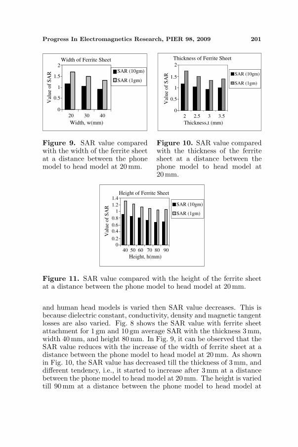
0.9GHz. In the real case, output power of the mobile phone will notexceed 250mW for normal use, while the maximum output power canreach till 1 W or 2 W when the base station is far away from themobile station (cellular phone). The SAR simulation is comparedwith the results in [11, 19] for validation, as shown in Table 3. Thecalculated peak SAR 1 gm value is 2.002 W/kg, and SAR 10 gm valueis 1.293W/kg when the phone model is placed 20 mm away from thehuman head model without ferrite sheet. This SAR value we achievedis better compared with the result reported in [23], which is 2.43 W/kgfor SAR 1 gm. The ferrite sheet material is utilized in between thephone and head models, and it is found that the simulated value of SAR1 gm and SAR 10 gm are 1.043W/kg and 0.676W/kg respectively. Thereduction about 57.75% was observed in this study when a ferrite sheetis attached between phone and human head models for SAR 10 gm.This SAR reduction is better than the result reported in [15], whichis 22% for SAR 10 gm. This is achieved due to the use of differentradiating powers and impedance factors. Figs. 7–11 show the SARvalue in the distance between phone and head models, width of ferritesheet between 20–40 mm, thickness of ferrite sheet between 2–3.5 mmand height between 40–90 mm respectively.
The reduction efficiency of the SAR depends on its width andheight. In order to definitely confirm this, 1 gm and 10 gm averageSARs versus distance, width, thickness and height are plotted in theFigs. 7–11. In Fig. 7, it is shown that if the distance between phone
Distance Between Phone Model
and Human Head Model Without
Ferrite Sheet
5 10 15 20
Distance, d(mm)
SAR (10gm)
SAR (1gm)
Val
ue
of
SA
R
012
3
4
56
Figure 7. SAR value versusthe distance between phone modeland human head model withoutferrite sheet.
Distance Between Phone Model
and Human Head Model With
Ferrite Sheet
5 10 15 20
Distance, d(mm)
SAR (10gm)
SAR (1gm)
Val
ue
of
SA
R
0
0.5
1
1.5
2
Figure 8. SAR value comparedwith the distance between phonemodel and human head modelwith ferrite sheet (Dimensions:Thickness 3 mm, Width 40 mm,and Height 80 mm).
Progress In Electromagnetics Research, PIER 98, 2009 201
Width of Ferrite Sheet
20 30 40
Width, w(mm)
SAR (10gm)
SAR (1gm)
Val
ue
of
SA
R
0
0.5
1
1.5
2
Figure 9. SAR value comparedwith the width of the ferrite sheetat a distance between the phonemodel to head model at 20 mm.
Thickness of Ferrite Sheet
2 2.5 3 3.5
Thickness,t (mm)
SAR (10gm)
SAR (1gm)
Val
ue
of
SA
R
0
0.5
1
1.5
2
Figure 10. SAR value comparedwith the thickness of the ferritesheet at a distance between thephone model to head model at20mm.
Height of Ferrite Sheet
40 50 60 70 80 90
Height, h(mm)
SAR (10gm)
SAR (1gm)
Val
ue
of
SA
R
0
0.2
0.4
0.6
0.8
1
1.2
1.4
Figure 11. SAR value compared with the height of the ferrite sheetat a distance between the phone model to head model at 20 mm.
and human head models is varied then SAR value decreases. This isbecause dielectric constant, conductivity, density and magnetic tangentlosses are also varied. Fig. 8 shows the SAR value with ferrite sheetattachment for 1 gm and 10 gm average SAR with the thickness 3 mm,width 40 mm, and height 80 mm. In Fig. 9, it can be observed that theSAR value reduces with the increase of the width of ferrite sheet at adistance between the phone model to head model at 20 mm. As shownin Fig. 10, the SAR value has decreased till the thickness of 3 mm, anddifferent tendency, i.e., it started to increase after 3 mm at a distancebetween the phone model to head model at 20mm. The height is variedtill 90mm at a distance between the phone model to head model at

202 Islam, Faruque, and Misran
20mm in Fig. 11. From this figure, it can be illustrated that if theheight of ferrite sheet increases SAR value also decreases up to heightof 80 mm, and it started to increase after 80mm. It can be observedthat with ferrite sheet attachment the SAR value has been decreasedfor the case of 1 gm and 10 gm average SAR. The result imply that onlysuppressing the maximum current on the front side of conducting boxcontributes significantly to the reduction of spatial peak SAR. This isbecause the decreased quantity of the power absorbed in the head isconsiderably larger than that dissipated in the ferrite sheet.
5. CONCLUSIONS
The SAR reduction in human head by attaching ferrite sheet has beendiscussed in this paper. The average SAR value is with ferrite sheet isachieved about 0.676 for SAR 10 gm. Based on the 3-D FDTD methodwith lossy-Drude model, it is found that the peak SAR 10 gm of thehead can be reduced by placing the ferrite sheet between the antennaand the human head.
ACKNOWLEDGMENT
The authors would like to thank Institute of Space Science(ANGKASA), Universiti Kebangsaan Malaysia (UKM) and theMOSTI Secretariat, Ministry of Science, Technology and Innovation ofMalaysia, e-Science fund: 01-01-02-SF0566, for sponsoring this work.
REFERENCES
1. Recommended Practice for Determining the Peak Spatial-averageSpecific Absorption Rate (SAR) in the Human Head fromWireless Communications Devices: Measurement Techniques,IEEE Standard 1528-2003, 2003.
2. IEEE C95.1-2005, “IEEE standards for safety levels with respectto human exposure to radio frequency electromagnetic fields,3 kHz to 300 GHz,” Institute of Electrical and ElectronicsEngineers, New York, NY, 2005.
3. International Non-ionizing Radiation Committee of the Interna-tional Radiation Protection Association, “Guidelines on limits onexposure to radio frequency electromagnetic fields in the frequencyrange from 100 kHz to 300 GHz,” Health Physics, Vol. 54, No. 1,115–123, 1988.
Progress In Electromagnetics Research, PIER 98, 2009 203
4. Christopoulou, M., S. Koulouridis, and K. S. Nikita, “Parametricstudy of power absorption patterns induced in adult andchild head models by small helical antennas,” Progress InElectromagnetics Research, PIER 94, 49–67, 2009.
5. Hirata, A., K. Shirai, and O. Fujiwara, “On averaging mass of SARcorrelating with temperature elevation due to a dipole antenna,”Progress In Electromagnetics Research, PIER 84, 221–237, 2008.
6. Mahmoud, K. R., M. El-Adawy, S. M. M. Ibrahem, R. Bansal,and S. H. Zainud-Deen, “Investigating the interaction between ahuman head and a smart handset for 4G mobile communicationsystems,” Progress In Electromagnetics Research C, Vol. 2, 169–188, 2008.
7. Kouveliotis, N. K. and C. N. Capsalis, “Prediction of the SARlevel induced in a dielectric sphere by a thin wire dipole antenna,”Progress In Electromagnetics Research, PIER 80, 321–336, 2008.
8. Ebrahimi-Ganjeh, M. A. and A. R. Attari, “Interaction of dualband Helical and PIFA handset antennas with human head andhand,” Progress In Electromagnetics Research, PIER 77, 225–242,2007.
9. Kuo, L. C., Y. C. Kan, and H.-R. Chuang, “Analysis of a900/1800-MHz dual-band gap loop antenna on a handset withproximate head and hand model,” Journal of ElectromagneticWaves and Applications, Vol. 21, No. 1, 107–122, 2007.
10. Kouveliotis, N. K., S. C. Panagiotou, P. K. Varlamos, andC. N. Capsalis, “Theoretical approach of the interaction betweena human head model and a mobile handset helical antennausing numerical methods,” Progress In Electromagnetics Research,PIER 65, 309–327, 2006.
11. Fung, L. C., S. W. Leung, and K. H. Chan, “An investigationof the SAR reduction methods in mobile phone application,”2002 IEEE International Symposium on EMC, Vol. 2, 656–660,Aug. 2002.
12. Habashy, T. M. and A. Abubakar, “A generalized materialaveraging formulation for modeling of the electromagnetic fields,”Journal of Electromagnetic Waves and Applications, Vol. 21,No. 9, 1145–1159, 2007.
13. Ali, M. and S. Sanyal, “A numerical investigation of finiteground planes and reflector effects on monopole antenna factorusing FDTD technique,” Journal of Electromagnetic Waves andApplications, Vol. 21, No. 10, 1379–1392, 2007.
14. Okoniewski, M. and M. Stuchly, “A study of handset antenna andhuman body interaction,” IEEE Trans. Microwave Theory Tech.,

204 Islam, Faruque, and Misran
Vol. 44, 1855–1864, Oct. 1996.15. Wang, J. and O. Fujiwara, “Reduction of electromagnetic
absorption in the human head for portable telephones by a ferritesheet attachment,” IEICE Trans. Commune., Vol. E80-B, No. 12,1810–1815, Dec. 1997.
16. Kiminami, K., A. Hirata, Y. Horii, and T. Shiozawa, “Astudy on human body modeling for the mobile terminal antennadesign at 400 MHz band,” Journal of Electromagnetic Waves andApplications, Vol. 19, 671–687, 2005.
17. Li, L. W., M. S. Leong, P. S. Kooi, and T. S. Yeo,“Specific absorption rates in human head due to handsetantennas: A comparative study using FDTD method,” Journalof Electromagnetic Waves and Applications, Vol. 14, 987–1000,2000.
18. Chan, K. H., K. M. Chow, L. C. Fung, and S. W. Leung,“Effects of using conductive materials for SAR reduction in mobilephones,” Microwave and Optical Technology Letters, Vol. 44,No. 2, 140–144, Jan. 2005.
19. Wang, J. and O. Fujiwara, “FDTD computation of temperaturerise in the human head for portable telephones,” IEEE Trans.Microwave Theory Tech., Vol. 47, No. 8, 1528–1534, Aug. 1999.
20. Kuo, L. C., Y. C. Kan, and H. R. Chuang, “Analysis of a900/1800MHz dual-band gap loop antenna on a handset withproximate head and hand model,” Journal of ElectromagneticWaves and Applications, Vol. 21, No. 1, 107–122, 2007.
21. Chou, H.-H., H. T. Hsu, H. T. Chou, K. H. Liu, and F. Y. Kuo,“Reduction of peak SAR in human head for handset applicationswith resistive sheets (R-cards),” Progress In ElectromagneticsResearch, PIER 94, 281–296, 2009.
22. Kuo, L. C., H. R. Chuang, Y. C. Kan, T. C. Huang, andC. H. Ko, “A study of planer printed dipole antennas for wirelesscommunication applications,” Journal of Electromagnetic Wavesand Applications, Vol. 21, No. 5, 637–652, 2007.
23. Weiland, T., “A discretization method for the solution ofMaxwell’s equations for six-component fields,” Electronics andCommunications (AEU), Vol. 31, 116, 1977.
24. Zygiridis, T. T. and T. D. Tsiboukis, “Assessment of humanhead exposure to wireless communication devices combinedelectromagnetic and thermal studies for diverse frequency bands,”Progress In Electromagnetics Research B, Vol. 9, 83–96, 2008.
25. Elkaramany, E. M. A. and F. G. A. El-Hadeed, “Circuit models

Progress In Electromagnetics Research, PIER 98, 2009 205
for 2-dimensional EM absorption by biological bodies,” ProgressIn Electromagnetics Research, PIER 66, 1–14, 2006.
26. Wu, B. I., F. C. A. I. Cox, and J. A. Kong, “Experimentalmethodology for non-thermal effects of electromagnetic radiationon biologics,” Journal of Electromagnetic Waves and Applications,Vol. 21, No. 4, 533–548, 2007.
27. Hawang, J. N. and F.-C. Chen, “Reduction of the peak SAR in thehuman head with metamaterials,” IEEE Transactions on Antennaand Propagation, Vol. 54, No. 12, 3763–3770, 2006.
28. Liu, Y., Z. Liang, and Z. Yang, “Computation of electromagneticdosimetry for human body using parallel FDTD algorithm com-bined with interpolation technique,” Progress In ElectromagneticsResearch, PIER 82, 95–107, 2008.
29. Ibrahiem, A., C. Dale, W. Tabbara, and J. Wiart, “Analysis of thetemperature increase linked to the power induced by RF source,”Progress In Electromagnetics Research, PIER 52, 23–46, 2005.