
List of Project Reports/Theses/Industrial Attachment (Soft copy)
REPORT OF THE STUDENTS INDUSTRIAL WORK EXPERIENCE SCHEME (SIWES)
MAY, 2014
TAJ-LIAD ADETUNJI ABDULMALIK
ENG0902822

UNVERSITY OF BENINDEPARTMENT OF PRODUCTION ENGINEERING
A TECHNICAL REPORT OF THESTUDENTS INDUSTRIAL WORKEXPERIENCE SCHEME (SIWES)
UNDERTAKEN AT:
SCIENCE AND TECHNOLOGYEDUCATION POST BASIC (STEP-
B) PROJECT WORKSHOP.FACULTY OF RNGINEERING,UNIVERSITY OF BENIN –BENIN/LAGOS EXPRESS
WAY UGBOWO , IBENIN CITY, EDO STATE.
PERIOD OF ATTACHMENT:JUNE 2013 TO APRIL 2014
TAJ-LIAD ADETUNJI ABDULMALIKENG0902822SUBMITTED TO:
THE DEPARTMENT OF PRODUCTION ENGINEERING, FACULTY OFENGINEERING,UNIVERSITY OF BENIN.
IN PARTIAL FULFILMENT FOR THE AWARD OF BACHELOR OFENGINEERING (B.ENG) DEGREE IN PRODUCTION ENGINEERING.

MAY 2014
ABSTRACT
The goal of the six month University of
Benin Industrial Training Scheme is to gain
industrial experience such as engineering,
commerce, technology and other relevant
knowledge needed. In a span of six month
knowledge transferred and learnt was at its
optimum as we were challenged to design and
build a fuel efficient car that will
participate in the 2014 Shell Eco Marathon
Competition, Europe. After series of design
and re-design of the urban concept car, a
design was selected and implementation
began. The goal was to make research
afterwards implement it by building a road
worthy urban concept car that would be the
first made in Nigeria car by Nigerian
Undergraduates and also serve as the first
urban concept car from Sub-Sahara Africa to
participate in the Shell Eco Marathon
Europe Competition. The design and building
process is well guided by the Shell Eco
Marathon rules and regulations, provided by
the organisers of the competition.
ACKNOWLEDGEMENT
I would like to express my deepest
appreciation to my project supervisor,
Professor A.O Akii Ibhadode, who has the
attitude and substance of a genius. Without
his guidance and persistent help this
project would not have been possible.
A special note of thanks to my team members
Adekola Adeyemi and Daniel Ejiro Okwoka for
the great team spirit displayed and the
high level of ingenuity that came from
working together with them to make this
project a big success.
At last, sincere regards goes to my parents
and friends who have directly or indirectly
helped me in the project.
I also express my profound gratitude to all
members of staff of STEP-B who gave me
training and provided a conducive
environment for the exercise.
SECTION ONE
1.0 INTRODUCTION
The STEP-B project is a World Bank/Federal
Ministry of Education grant to the Engine
Research and Development Unit of the
production Engineering Department,
University of Benin, to carry out work on
the project titled “Development of a skills
Acquisition Centre for internal Combustion
Engine Parts Manufacture”.
The aim of the STEP-B project is to acquire
the capacity, both human and equipment, to
empower local auto parts manufacturer to
venture into internal combustion engine
parts production and complete internal
combustion engine manufacture.
1.2 SKILLS AND PRACTICES ACQUIRED
As an engineering student in the
penultimate year, practical experience
ought to have constituted about thirty to
forty percentage of knowledge gotten from
the past four years in school.
Unfortunately, the level of practical
knowledge/experience needed to function
effectively in a research project workshop
is more than that, thus, the need for
training and retraining in various
machining processes and procedures.
A training program was organised where we
were trained on our to use the different
types of machines and machine tools that
will aid us throughout our attachment.

1.2.1 ANGLE GRINDER
A power tool use for cutting and grinding.
It is shown in Figure 1.1
1.2.2 ARC WELDING MACHINE
Used alongside electrode to join metals
together. Shown in figure1.2
Figure1.2 welding machine
1.2.3 HACKSAW
Use to cut metals. Shown in figure 1.3
Figure 1.3 hacksaw
1.2.4 HAND DRILL
Use to drill into metals or wood. Shown in
figure 1.4
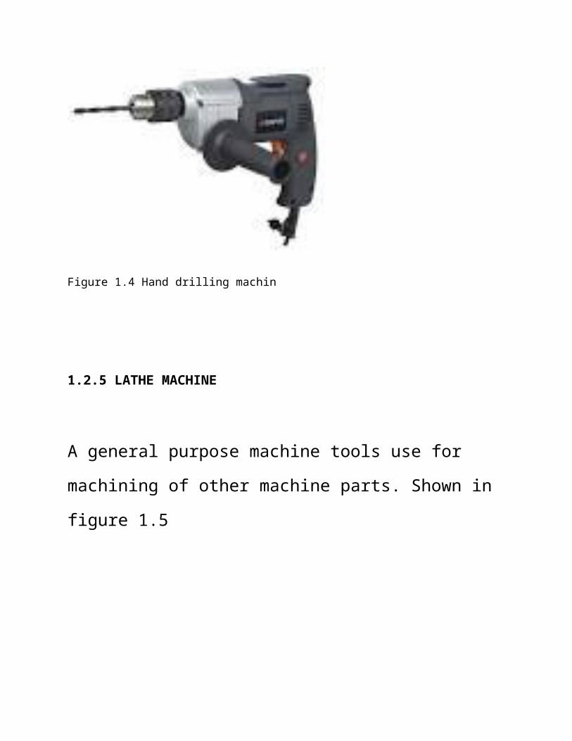
Figure 1.4 Hand drilling machin
1.2.5 LATHE MACHINE
A general purpose machine tools use for
machining of other machine parts. Shown in
figure 1.5
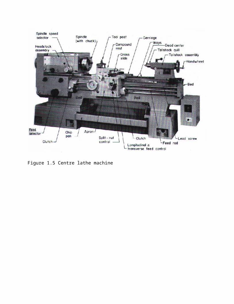
Figure 1.5 Centre lathe machine
1.3 ROLE(S) AND RESPONSIBILITY
With dearth machine tools and lack of
optimum usage of up-to-date machine tools
and equipment, the activities that has to
be carried out manually increased which led
to a proportional increase in
responsibility. Tasks were spelt out and I
was responsible for brakes, suspensions and
steering.
Having in mind a simple and effective
system, we were meant to proffer simple
solutions to problems faced. After sessions
of brainstorming, the solution was kart
steering system. As seen in fig.1 it’s a
simple but effective system that we could
employ in our design.
The suspensions was to be a light weight
system that provides a good balance to the
car. The first design that was implemented
was a big failure as it provided little
support to the car and caused the tyres to
tilt so badly that anybody could tell it
was a bad system. Fig. 2 shows the AutoCAD
drawing. Finally, we had to settle for the
Double wishbone mechanism suspension system
shown in Fig. 3. It worked perfectly and it
was adopted by all the team members.
As specified in the Shell Eco Marathon
rules, the recommended barking system was a
hydraulic braking system, of which the
braking fluid is hydraulic. The tricycle
braking system was adopted in our design

and fabrication as it satisfies all
conditions as specified in the rules.
2 DESIGNS ANALYSIS
Conceptual designs, static and dynamic
forces analysis and calculations were
carried out explicitly as the system we
were designing has to do with human lives.
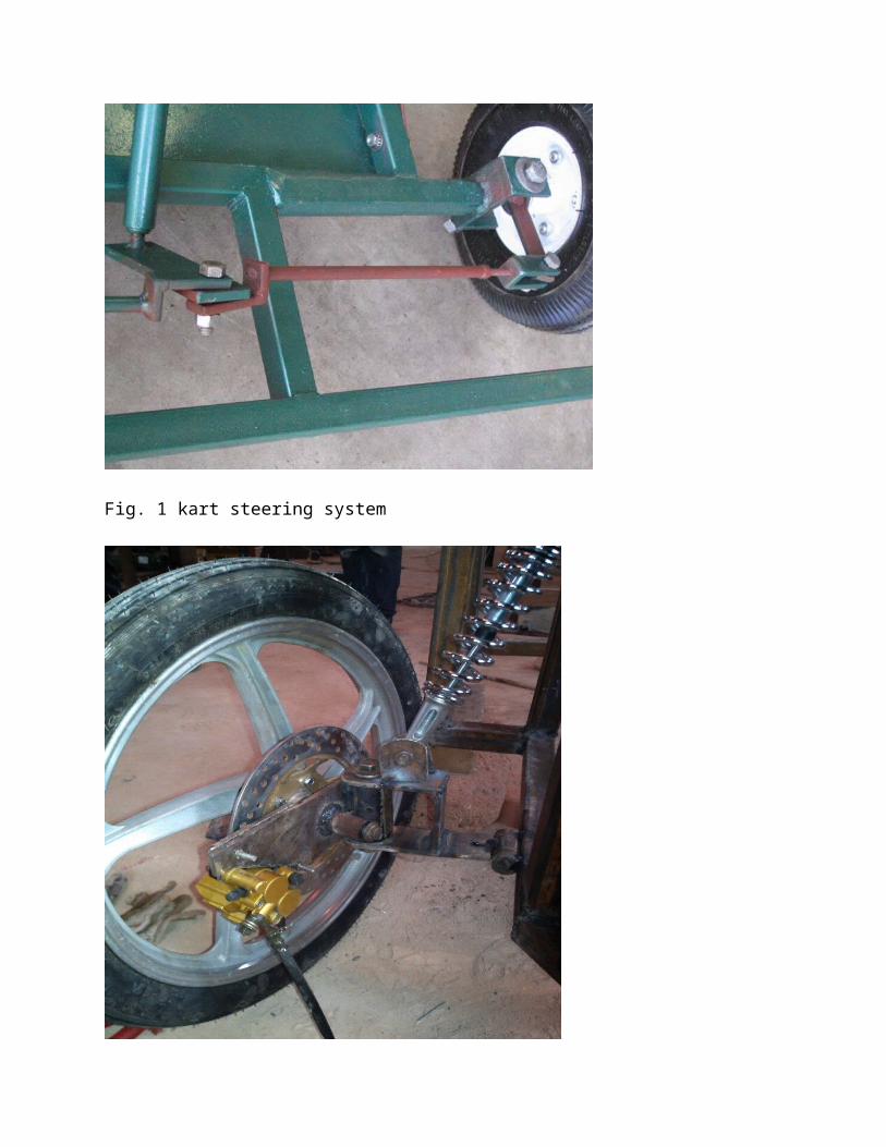
Fig. 1 kart steering system

Fig. 2 first suspension mechanism used
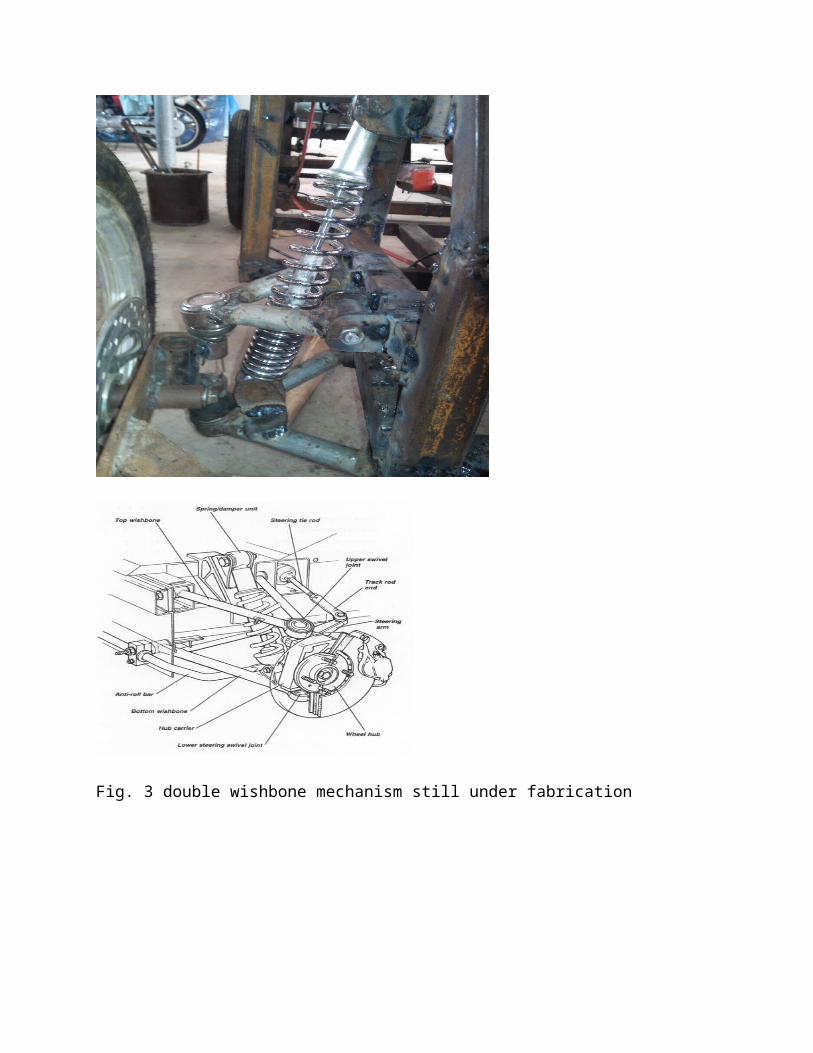
Fig. 3 double wishbone mechanism still under fabrication
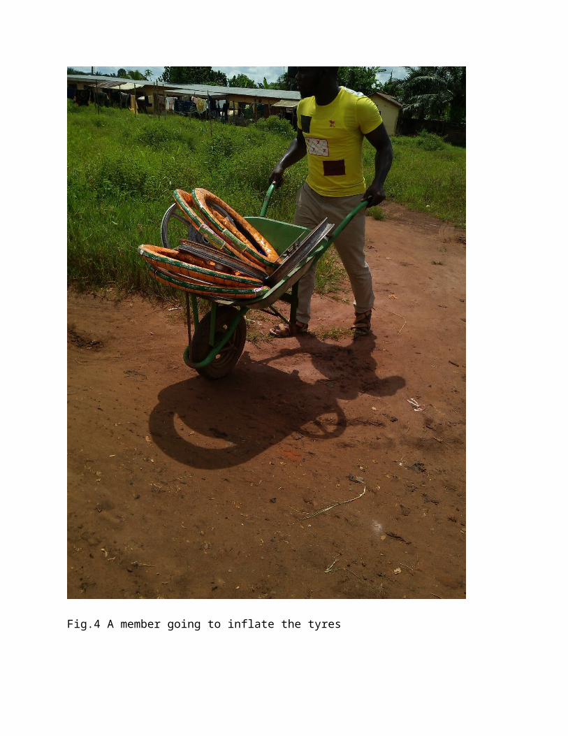
Fig.4 A member going to inflate the tyres
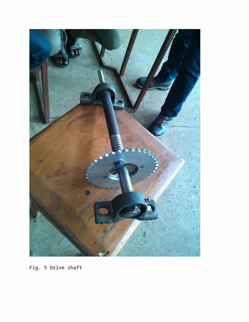
Fig. 5 Drive shaft
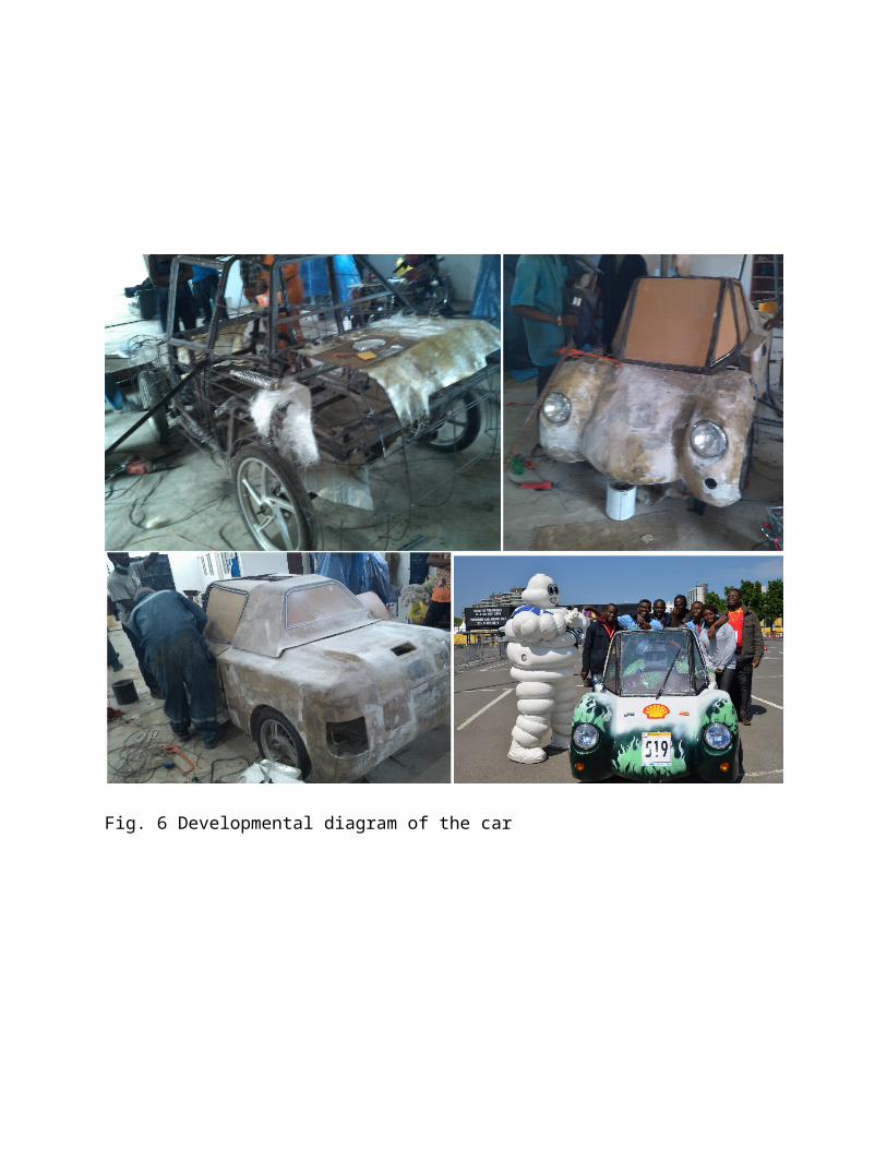
Fig. 6 Developmental diagram of the car

Fig. 7 at the event centre
Find attached in appendix detail analysis of the frame and
chassis.
CONCLUSION/RECOMMENDATION
In order to improve on the expected results of
the Student Industrial Work Experience Scheme
and for progress in subsequent programmes, I
want to offer the following recommendation to my
Student Industrial Work Experience Scheme site,
School, Industrial Training Funds and the
Government:

1. The management of STEP-B should try to
make maximum use of the up-to-date machine
tools.
2. The management of STEP-B should endeavour
to see to workers welfare in terms of
incentives to motivate them for best input.
3. The Industrial Liaison office and
Students’ Departmental Supervisor(s) should
endeavour to regularly visit students on site
to solve some relevant problems and for
adequate evaluation.
4. The University’s Departments-in-charge of
student Industrial Training programme can
acquaint themselves to various company and
establishment of Student Industrial Work
Experience Scheme. This will contribute to
the success of the program as students could
be offered placement from school instead of
them seeking for months before finding a
suitable organization.

5. Industrial Training Fund as a body
responsible to Federal Government should
create time to visit students on-site to
evaluate the success of the scheme.
6. The Federal Government should provide
industries and organizations with incentives
to encourage and solicit for their
cooperation and contribution to the
programme.

APPENDIX
1. The competition rules and regulations
URBANCONCEPT GROUP
DEFINITION
Under the name “UrbanConcept”, Shell offers an
opportunity to design and build fuel efficient
vehicles that are close in appearance to today’s
production type passenger cars. UrbanConcept
vehicles must comply with the specific rule of
the Shell Eco-marathon for this group. One
particular feature of this group is that
vehicles competing in this group will require
“stop & go” driving.
DIMENSIONS
a) The total vehicle height must be between 100
cm and 130 cm.
b) The total body width, excluding rear view
mirrors, must be between 120 cm and 130 cm.
c) The total vehicle length must be between 220
cm and 350 cm.
d) The track width must be at least 100 cm for
the front axle and 80 cm for the rear axle,
measured between the midpoints where the tyres
touch the ground.
e) The wheelbase must be at least 120 cm.
f) The Driver’s compartment must have a minimum
height of 88 cm and a minimum width of 70 cm at
the Driver’s shoulders.
g) The ground clearance must be at least
10 cm with the driver (and necessary
ballast) in the vehicle.
h) The maximum vehicle weight (excluding the
Driver) is 205 kg.
CHASSIS/MONOCOQUE SOLIDITY
a) Teams must ensure that the vehicle chassis
or monocoque is designed wide and long enough to
effectively protect the driver’s body in the
case of collisions or rollovers. The Organizers
will exclude any vehicle whose construction is
deemed to be dangerous.
A monocoque is a construction that supports structural load
by using an Object’s external skin as opposed to using a frame.
b) The vehicle chassis must be equipped
with an effective roll bar that extends 5
cm around the driver’s helmet when seated in
normal driving position with the safety belts
fastened.
If this position impairs the driver visibility
it will be deemed that the roll bar is not
adequate. The effectiveness of the roll bar and
driver’s visibility will be validated
simultaneously, i.e. the driver must not be in
such position that he or she must raise their
head or torso above the roll bar to pass the
visibility test.
c) This roll bar must extend in width beyond
the driver’s shoulders when seated in normal
driving position with the safety belts fastened.
It is permissible to either use a tubular or
panel type roll bar. If a ‘tubular roll bar’ is
used, it must be made of metal. A panel roll bar
is the rigid partition separating the cockpit
from the engine compartment. Such a panel roll
bar must be an integral part of the vehicle
chassis or integrated in a monocoque.

d) Any roll bar must be capable of
withstanding a static load of 700 N (~
70 kg) applied in a vertical, horizontal or
perpendicular direction, without deforming (i.e.
in any direction).
VISIBILITY
a) The Driver must have access to a direct arc
of visibility ahead and to 90° on each side of
the longitudinal axis of the vehicle. This field
of vision must be achieved without aid of any
optical (or electronic) devices such as mirrors,
prisms, periscopes, etc. Movement of the
Driver’s head within the confines of the vehicle
body to achieve a complete arc of vision is
allowed.
The driver’s helmet must be 5 cm below the roll
bar at all times.
b) The vehicle must be equipped with a rear-
view mirror on each side of the vehicle, each
with a minimum surface area of 25 cm² (e.g. 5 cm
x 5 cm). The visibility provided by these
mirrors, and their proper attachment, will be
subject to inspection. An electronic device must
not replace a rear-view mirror.
c) In technical inspection visibility will be
checked in order to assess on-track safety by
using 60 cm high poles spread out every 30° in a
half-circle, with a 4 m radius in front of the
vehicle.
d) For Urban Concept vehicles wet weather
visibility is also mandatory.
SAFETY BELTS
a) The Driver’s seat must be fitted with an
effective safety harness having at least five

mounting points to maintain the Driver securely
in his/her seat. The five independent belts must
be firmly attached to the vehicle's main
structure and be fitted into a single buckle,
specifically designed for this purpose. The
mounting points should fitted so that the belts
will self-align with the direction of the load.
b) The safety harness must prevent any upward
or forward motion of the driver’s torso. Any
slack in the harness must be adjusted by using
the seat belt length adjuster. The adjustor must
be located as close as possible to the
connection point. The crotch strap mounting
point should be behind
the chest line and the topmost straps
should be at an angle of at least10° below
the shoulder line.
c) The safety harness must be worn and fastened
at all times to prevent the driver from having
any free movement when the vehicle is in motion.
d) The fitness for purpose of the harness and
its fitting will be evaluated during technical
inspection.
For Prototype cars this will be done by
raising the vehicle with the Driver on
board using the
safety harness buckle as the lifting
point, this must be capable of
withstanding 1.5 times the
Driver’s weight.
e) The Urban Concept vehicle safety harness
must be specifically manufactured for motorsport
use (e.g. certified or compliant with FIA
standards).
HORN
a) Each vehicle must be equipped with an
electric horn mounted towards the front of the
vehicle, in such a manner that is effectively
audible to other vehicles and track marshals.
With the vehicle in
normal running condition, it must emit a
sound greater than 85 dB when measured 4
meters horizontally from the vehicle.
b) The horn must have a high tone (pitch) of
equal or greater than 420 Hz.
ON-BOARD FIRE EXTINGUISHER
a) Each vehicle must be fitted with a fire
extinguisher (ABC or BC type). All Drivers must
be trained in the use of said fire extinguisher.
This extinguisher must have a minimum
extinguishant capacity of 1 kg (2 lb. for US
application); equivalent size extinguishers are
not permitted. It must be full and have a
certificate of validity bearing the
manufacturer's number and the date of
manufacture or expiry.
b) Plumbed-in extinguishers may be located in
the engine compartment and must discharge into
the engine compartment. Triggering systems must
be located within the cockpit and be operable by
the Driver in his/her normal driving position.
c) Hand held extinguishers must be located
within the cockpit and be accessible to the
Driver once they have vacated the vehicle.
These should be securely mounted to prevent
movement while driving/braking. In the event
of a fire, Drivers should first exit the
vehicle and then if possible, remove the
extinguisher and attempt to extinguish the fire
if safe to do so.
d) The on-board fire extinguisher does not
replace the need for an adequate fire
extinguisher for the team’s garage area.
TURNING RADIUS AND STEERING
a) Vehicle steering must be achieved by
one system operated with both hands using
a turning motion. It must be precise, with no
excessive play.
b) Steering must be achieved using a steering
wheel or sections of a wheel.
c) Steering bars, tillers, joysticks, indirect
or electric systems are not permitted.
d) The turning radius must be less than 6 m.
The turning radius is the distance between the
centres of the circle and the external wheel of
the vehicle. The external wheel of the vehicle
must be able to follow a 90° arc of 6 m radius
in both directions.
e) A vehicle handling course may be set up in
order to verify the following when the vehicle
is in motion: driver skills, turning radius and
steering precision. In particular, Inspectors
will verify that steering is precise, with no
excessive play.
WHEELS
a) The rims must be between 13 to 17 inches in
diameter.
b) The wheels located inside the vehicle
body must be made inaccessible to the
Driver by a bulkhead. Any handling or
manipulation of the wheels is forbidden from the
moment the vehicle arrives at the starting line
until it crosses the finish line.
TYRES
The choice of tyres is free as long as they are
fitted on the type and size of rims recommended
by
their manufacturers and have a minimum
tread of 1.6 mm. The tyre/rim assembly must
have a minimum width of 80 mm, measured from
sidewall to sidewall. The width is measured with
the tyre fitted on its rim at its rated
pressure.
Caution: the manufacturer’s size indications
should not be taken as measure, as the width of
the rim directly impacts the width of the
rim/tyre assembly.
BRAKING
a) The vehicle must be equipped with a four-
disc hydraulic brake system, with a brake pedal,
which has a minimum surface area of 25 cm².
b) The brakes must operate independently on the
front and rear axles or in an X pattern (i.e.
right front wheel with left rear wheel, and left
front wheel with right rear wheel).
c) A single master cylinder may be used,
provided that it has a dual circuit (two pistons
and dual tank).
d) The effectiveness of the braking system will
be tested during vehicle inspection for both
Drivers.
The vehicle must remain immobile with the Driver
inside when it is placed on a 20 percent incline
with the main brake in place. Moreover, a

dynamic inspection may be performed on the
vehicle-handling course.
e) A parking brake function is required in
order to keep the car stationary during
technical inspections and fuel measurements. It
must provide a brake force of at least 50 N.
f) Wet weather capability is mandatory.
Copyright © 2022 FDOKUMEN