Mechanical properties and microstructure of laser sintered ...
73
Faculty of Technology and Science Materials Engineering DISSERTATION Karlstad University Studies 2008:13 Yu Wang Mechanical properties and microstructure of laser sintered and starch consolidated iron-based powders
-
Upload
khangminh22 -
Category
Documents
-
view
1 -
download
0
Transcript of Mechanical properties and microstructure of laser sintered ...

Faculty of Technology and ScienceMaterials Engineering
DISSERTATION
Karlstad University Studies2008:13
Yu Wang
Mechanical properties and microstructure of laser
sintered and starch consolidated iron-based powders

Karlstad University Studies
2008:13
Yu Wang
Mechanical properties and microstructure of laser
sintered and starch consolidated iron-based powders

Yu Wang. Mechanical properties and microstructure of laser sintered and starch consoli-dated iron-based powders
DISSERTATION
Karlstad University Studies 2008:13ISSN 1403-8099 ISBN 978-91-7063-171-9
© The author
Distribution:Faculty of Technology and Science Materials EngineeringSE-651 88 KarlstadSWEDEN+46 54-700 10 00
www.kau.se
Printed at: Universitetstryckeriet, Karlstad 2008

Abstract
In powder metallurgy research field, Direct Metal Laser Sintering (DMLS) andMetal Powder Starch Consolidation (MPSC) are relatively new rapid formingtechniques to fabricate complex and near net-shaped components. The work-ing principles of DMLS are to melt and fuse metal powder layer by layerin computer controlled systems to pile up components like three dimensionalprinting. It has been for instance extensively used for mould inserts, die parts,and functional metal prototypes. Another, less explored method, starch con-solidation is a pressureless direct casting method which consists principally ofmixing powder slurry, casting into molds, consolidation, drying, and sintering.With a strong focus on both methods, the study here combines several strongmaterial technology sectors; powder, rapid forming, mechanical property test-ing and surface technology. It covers the processing chain from green bodypreparation, optimization of sintering, nitriding, post sinter heat treatment,to modeling and assessment of material behaviour for end-user applications.An iron based powder and a high vanadium high speed steel powder withlow and high carbon contents were used in the DMLS and MPSC processes,respectively. The overall aim of the study is to synthesize near net-shapedpowder-based components, to characterize pores and microstructure, and toestablish a fundamental understanding of failure mechanisms of powder basedmaterials in bending fatigue, thermal fatigue and wear.The study showed the DMLS and MPSC technologies could produce shapedcomponents with a multi-phased structure, controllable nitriding depth andhigh relative densities in a range of 97 - 99.7 %. Materials’ heterogeneity andporosity have detrimental influence on mechanical properties, especially oncrack initiation and subsequent propagation.
Keywords: Powder metallurgy, Laser sintering, Starch consolidation, Rapidforming, Net shaping, Liquid phase sintering, Nitriding, High speed steels,Microstructure, Fatigue, Thermal fatigue, Wear.
i


Preface
As one of doctoral programs from the national graduate school in materialsscience, the research associated with this Ph.D thesis has been carried out atthe Department of Materials Engineering, Karlstad University. In completingthis thesis I am grateful to many people, who have inspired, encouraged, su-pervised, supported and helped me over the time of the research and duringthe writing of this thesis. First of all I am deeply grateful to my supervisorProf. Jens Bergstrom for his persistent help, skilful and excellent guidance andpositive encouragement. My sincerely gratitude also goes to my co-supervisorChrister Burman for his heuristic supervision, enduring technical support, andreminding me what is the most important in life. Furthermore, special thanksare given to Marianne Johansson for her kind help in many respects, and tomy colleagues at the Department of materials engineering in Karlstad univer-sity. Erasteel Kloster AB is gratefully acknowledged for supplying high speedsteel powder. Sincere gratitude is extended to Henrik Borgstrom for sinteringspecimens in Chalmers University of Technology. Finally, I want to expressmy heartfelt thanks to my family for their great support. I will cherish foreverthe experience of studying in Sweden.
Yu WangApril, 2008Karlstad, Sweden
iii


List of enclosed papers
Paper I
Yu Wang, Jens Bergstrom, Christer Burman, Characterization of an iron-based laser sintered material, Journal of Materials Processing Technol-ogy, pp 77-87, Vol.172, 2006.
Paper II
Yu Wang, Jens Bergstrom, Christer Burman, Four-point bending fatiguebehaviour of an iron-based laser sintered material, Int. Journal of Fa-tigue, pp 1705-1715, Vol.28, 2006.
Paper III
Yu Wang, Jens Bergstrom, Christer Burman, Thermal fatigue behaviourof an iron-based laser sintered material, Submitted to Materials scienceand Engineering A, 2008.
Paper IV
Yu Wang, Jens Bergstrom, Characterization and fatigue behaviour of astarch consolidated and sintered high speed steel, Proceeding of the 7thInternational Tooling Conference, 2-5 May 2006, Torino, Italy.
Paper V
Yu Wang, Jens Bergstrom, Henrik Borgstrom, Characterization andbending fatigue behaviour of a starch consolidated high speed steel: as-sintered, sintered and tempered, and sintered and nitrided, In manuscript.
Paper VI
Yu Wang, Jens Bergstrom, Julia Gerth, Sture Hogmark, Henrik Borgstrom,Peter Harlin, Microstructure, strength and wear of high speed steel inHIPed, HIPed + nitrided, and SC+nitrided conditions, In manuscript.
Paper VII
H. Borgstrom, P. Harlin, M. Olsson, T. Paiar, Y. Wang and L. Nyborg,Possibilities and constraints of implementing starch consolidated high
v

speed steel in prototyping, Materials Science and Engineering A, pp 34-38, Vol. 475, 2008.
vi

Other publications
Paper I
Yu Wang, Jens Bergstrom, Room temperature and thermal fatigue be-haviour of an iron-based laser sintered metal, Proceedings of the 9thInternational Fatigue Congress, 14-19 May 2006, Atlanta, USA.
Paper II
Yu Wang, Jens Bergstrom, Fatigue and microstructure of iron basedsintered alloys, Journal of iron and steel research, pp 137-141,Vol.14,Sep. 2007.
Paper III
Yu Wang, Lic thesis: Characterization and fatigue behaviour of lasersintered iron-based powder material, Karlstad University Studies, 2004.
Paper IV
Yu Wang, Microstructure and mechanical properties of powder metal-lurgy materials – A literature review, Karlstad University Studies, 2005.
vii


The author’s contribution to thepapers
Paper I
Major part of planning and writing, all evaluation and experimentalwork.
Paper II
Major part of planning and writing, all evaluation and experimentalwork.
Paper III
Major part of planning and writing, all evaluation and experimentalwork.
Paper IV
Major part of planning and writing, all evaluation and experimentalwork.
Paper V
Major part of planning, writing, evaluation, and experimental work.
Paper VI
Major part of planning, writing, evaluation, and experimental work.
Paper VII
Some part of evaluation and experimental work.
ix


Contents
Abstract i
Preface iii
List of enclosed papers v
Other publications vii
The author’s contribution to the papers ix
1 Introduction 11.1 Direct metal laser sintering . . . . . . . . . . . . . . . . . . . . . 11.2 Metal powder starch consolidation . . . . . . . . . . . . . . . . . 31.3 The aim and contents of this thesis . . . . . . . . . . . . . . . . 5
2 Materials 72.1 DMLS material . . . . . . . . . . . . . . . . . . . . . . . . . . . 72.2 MPSC material . . . . . . . . . . . . . . . . . . . . . . . . . . . 7
2.2.1 Ingredients for MPSC materials . . . . . . . . . . . . . . 72.2.2 Green body manufacture procedures . . . . . . . . . . . 82.2.3 Sintering and nitriding of MPSC material . . . . . . . . 9
3 Experimental methods 113.1 Material characterization (Paper I, IV, V, VI, and VII) . . . . . 11
3.1.1 Surface quality test . . . . . . . . . . . . . . . . . . . . . 113.1.2 Microstructure and porosity study . . . . . . . . . . . . . 11
3.2 Mechanical property test (Paper II, IV, V, and VI) . . . . . . . 123.2.1 Four-point bending fatigue test on DMLS material (Pa-
per II) . . . . . . . . . . . . . . . . . . . . . . . . . . . . 123.2.2 Four point bending fatigue on MPSC ASP 2053 (Paper
IV and V) . . . . . . . . . . . . . . . . . . . . . . . . . . 143.2.3 Three point bending test on MPSC KV 167 (Paper VI) . 14
3.3 Thermal fatigue (Paper III) . . . . . . . . . . . . . . . . . . . . 15
xi

3.4 Crater grinder test of MPSC KV 167 (Paper VI) . . . . . . . . . 16
4 Experimental results and discussions 174.1 Dimension accuracy and surface quality (Paper I, V, and VI) . . 174.2 Pore characterization (Paper I, IV, V, VI, and VII) . . . . . . . 184.3 Microstructure and sintering (Paper I, IV, V, and VI) . . . . . . 26
4.3.1 DMLS material . . . . . . . . . . . . . . . . . . . . . . . 264.3.2 MPSC material . . . . . . . . . . . . . . . . . . . . . . . 274.3.3 Microstructure and nitriding (Paper V and VI) . . . . . 31
4.4 Mechanical properties (Paper II, IV, V, and VI) . . . . . . . . . 324.4.1 Bending fatigue and monotonic bending behavior . . . . 324.4.2 Thermal fatigue of DMLS material . . . . . . . . . . . . 424.4.3 Wear resistance of MPSC KV 167 . . . . . . . . . . . . . 48
5 Conclusions 53
Bibliography 54
xii

Chapter 1
Introduction
Powder metallurgy (PM) has been called a lost art. It can be traced backto 4500 B.C., when ancient Indians used gold powder collected from riverbeds to make decorative objects [1]. But sintering of metal powder seemsto be completely forgotten during the succeeding centuries due to almost noremaining historical record on it. It is not until the end of the 18th century thatthe various sintering methods of platinum powder production were recorded [2],indicating the lost art revived. In the 19th century, the real development ofmodern powder metallurgy technology occurred.
Effective application of a variety of PM manufacturing methods requiresa general comparison of major design features; cost effectiveness and prod-uct properties. Up to present, cost-effectiveness and high-performance (goodproperties) seem to be a dilemma in PM processing. A PM approach requiringa low cost generally results in low mechanical properties. The one which leadsto products with enhanced mechanical properties and complex geometry gen-erally accompanies high cost. Therefore, it has become a common goal in thePM research area to seek a PM manufacturing process with both features ofbeing economical and high performance. Direct Metal Laser Sintering (DMLS)and Metal Powder Starch Consolidation (MPSC) are two kinds of relative newrapid forming technologies developed to achieve this goal. In the followingtext, these two methods are introduced in detail.
1.1 Direct metal laser sintering
The direct metal laser sintering process was developed as a rapid prototypingprocess which is based on a layered method [3]. As early as 1890, for mak-ing moulds for topographical relief maps, Blanther [3] put forward the layeredmethod. It produced both positive and negative three-dimensional surfacesby impressing topographical contour lines on a series of wax plates, cuttingthe wax plates on the contour lines, and then stacking and smoothing the
1

Chapter 1 Introduction
wax sections [3]. This method was further refined by Perrare, Zang, Gaskinand Matsubara as a layer manufacturing process to form casting moulds [4]in the succeeding century. In 1971, the layer manufacturing process was firstproposed by Ciraud [3] on powder materials. This process could be used tomanufacture objects from a variety of powder materials by heating particleslocally and fusing them together employing a laser, electron beam, or plasmabeam. With the development of computer aided design and manufacturingtechnologies, the layer manufacturing became a computer aided rapid manu-facturing process to make intricate and near net-shaped parts. The first pow-der laser sinter system emerged in 1992 [5], which fuses and solidifies powderedmaterials using heat from a laser. At the beginning, this technique was limitedto polymer and plastic powder with low melting points due to the limitationin the maximum power of the laser, electron, or plasma beam. In 1995 withthe development of laser technology, the first bronze-based metal powder wassuccessfully sintered with a layer thickness capability of 100 µm and a carbondioxide laser in a EOSINT M 250 machine by the company EOS GmbH, whoalso first introduced the terminology Direct Metal Laser Sintering process intheir company report indicating the birth of DMLS [6]. Two years later theminimum layer thickness of the EOSINT DMLS machine was reduced to 50µm improving the suitability of DMLS technology for prototyping and toolingapplications. In the late 1998, the first iron-based powder ‘Directsteel 50-V1’was introduced [7]. Soon, a modified vision of DirectSteel 50-V1 was put for-ward and named DirectSteel 20-V1, which built parts with a layer thickness of20 µm. In 2004, EOS GmbH presented their latest developments of the EOSlaser sintering machine named EOSINT M 270 and a new series of powdernamed DirectSteel H20. The company claims the resulting part of DirectSteelH20 could reach the properties of commonly-used tool steels [8].
The working principles of DMLS processing, Fig. 1.1, can be describedas the following sequence: (i) Generate the component model from 3D-CADsoftware and convert it to standard STL format. (ii) Slice the STL model intohorizontal layers with a certain thickness (usually 20-50 µm) in the computercontrol centre of the DMLS facility. (iii) Spread a layer of metal powder onthe top of the building platform. (iv) Melt and fuse the powder by a laserbeam, as it traces the geometry of the generated slice. (v) Lower the fusedlayer and spread a new layer of powder with the recoater. (vi) Laser scan thenew surface and fuse the metal particles to each other and to the lower layer.(vii) Repeat the process until the component is fully fabricated. (viii) Finally,remove the part from the machine and sieve back the unsintered powder tothe powder dispenser for reuse [4, 6, 9, 10].
DMLS has significant advantages such as geometrical complexity, near net-shape, low energy consumption, high raw material utilization and rapid manu-facturing integrated with CAD technique compared to conventional manufac-
2

1.2 Metal powder starch consolidation
Figure 1.1: Schematic illustration of DMLS process [11].
turing techniques [4,10]. It was evident that DMLS products can be used notonly as a prototype but also as a tool material. Nowadays, the DMLS tech-nique has successfully developed into the commercial realm and can producemould inserts, die-cast tools, and functional metal prototypes using bronze-based and iron-based powder by liquid-phase sintering [5, 12]. Nevertheless,the performance of DMLS manufactured parts is limited due to low mechanicalproperties and bad surface quality [13, 14], which makes it difficult to super-sede the traditional manufacturing methods. Therefore, microstructure andmechanical property characterization of DMLS materials helps to overcomethe weakness and extend its area of use.
1.2 Metal powder starch consolidation
Another powder metallurgy technology involved in this work is starch consol-idation technology. Starch consolidation (SC) was initially used in the man-ufacture of porous ceramics and biomedical materials proposed by Lychfeldt1998 [15]. Soon after the ceramics starch consolidation, Lyckfeldt researchgroup applied starch consolidation to shape metal powders, as a result, themetal powder starch consolidation (MPSC) technique was proved as a way toshape metallic powder green bodies with open porosity [16, 17].
Principally, MPSC processing is to shape components by transforminga powder suspension into a green body with sufficient strength to be de-molded, handled, dried and sintered. The consolidation process depends on thetemperature-induced water-absorption and swelling of starch granules. Whenstarch is heated with the presence of water, its native crystalline structure isdisrupted and swells to many times of its original size known as gelatiniza-tion [15]. The increase of volume fraction of the starch granules in the suspen-sion leads to an increased viscosity of the slurry and finally locks water causingthe solid particles to stick together and consolidate into a rigid body [15, 18],
3

Chapter 1 Introduction
Fig. 1.2. The disrupted crystalline regions of the starch granules adsorb at thesurface of the solid particles, acting as a binder, and improve the strength ofthe consolidated body [19]. The overall porosity and the pore size distributionin resulting materials can be controlled by variation of original suspension com-position regarding the total solids loading and the starch content [15,17,20]. Inthe starch consolidation process, thus, starch serves as not only a pore-formingagent but also as a body-forming agent.
Figure 1.2: Mechanism of starch consolidation [15].
But without debinding and sintering, shaped green bodies can not beenused due to the lack of appropriate mechanical properties to perform tasks.The debinding processing of MPSC green bodies occurs at 450 ◦C - 500 ◦Caccording to Lyckfeldt and Magalheas’s research [16, 20], to clean up the wa-ter, starch and other organic additives involved in the MPSC technique. It isfound that the organic additives give a carbon residue and the water process-ing causes a severe oxidation. Among three kinds of debinding atmospheresnitrogen, hydrogen, and vacuum, Lyckfeldt [15, 16] pointed out the debindingin nitrogen and vacuum gave a similar result with a carbon content increaseof 0.32 wt% after debinding. The hydrogen was more effective with a carboncontent increase of 0.22 wt% after debinding, but which gave unacceptablelow final carbon content after final sintering. Therefore, the debinding invacuum and nitrogen integrated with sintering cycles was recommended byLyckfeldt [16].
After debinding and pre-sintering, rigid and porous bodies would be pro-duced with open porosity. Due to its special porous structure, the materialhas a lot of unique advantages such as big surface reaction areas for nitridingbecause of the large gas penetration depth, providing spaces to hold lubricantsfor wear resistance and low weight. On the other hand, the spongy structuredeteriorates the mechanical properties as pores usually act as stress raisers.Therefore, after surface treatment such as nitriding as a mid-stage treatment,closing the pores is very important for final sintering of MPSC materials.
4

1.3 The aim and contents of this thesis
Sintering is a thermal process creating inter-particle welds, improving uponproperties observed in the green state [21]. The bonding of particles can occureither at temperature below the melting point by solid-state atomic transportevents or at temperature involving the formation of a liquid phase. In solidphase sintering, particles are sintered by atomic motions driven by the releaseof high surface energy associated with the particle surface area [21]. During thesintering progresses, the contact points between particles enlarge and mergeto form grain boundaries. The grain boundary grows to replace the solid va-por interface hence lowering the total free energy of the system. Prolongedsintering causes sintered particles to coalesce. Several variables influence therate of sintering, such as the initial density, material, particle size, particleshape, sintering atmosphere, temperature, time, and heating rate [21]. Thefinal coalescence of all the sintered particles is seldom reached. Hence, poresare hard to avoid, which to a great extent deteriorate the materials’ mechanicalproperties. To create materials equal to or better than wrought stock, densifi-cation must often be enhanced. Liquid phase sintering is one way to enhancedensification. In liquid phase sintering, one powder constituent, having lowermelting temperature, forms the liquid phase coexisting with a solid phase atthe sintering temperature. The liquid will flow along the interparticle chan-nels to wet the particle by a capillary force. The capillary force acts equivalentto high external pressures that pulls the solid particles together and inducesparticle rearrangement. With continued heating, the solid phase dissolves intothe liquid and the amount of liquid grows until it is saturated with the solidcomponent. In addition, the liquid gives rapid mass transport at the sinteringtemperature and enhance densification [15, 16, 20, 22, 23].
1.3 The aim and contents of this thesis
This thesis addresses the possibilities and limitations of applying DMLS andMPSC technologies for advanced applications. Development of laser sinteringand starch consolidation process and microstructure characterization of DMLSand MPSC materials was taken into consideration in the first part of the thesis(Paper I, IV, V, VI, and VII). With a focus on the relationships betweenmicrostructure and mechanical properties, four point bending fatigue, thermalfatigue and wear resistance of DMLS and MPSC materials were investigated asthe second part of this thesis. The experimental work provides a great deal ofinsight into the complicated fracture process of heterogeneous steels (Paper II,III, IV, V and VI). Applying a thermal fatigue test based on induction heatingand interior specimen oil cooling, thermal fatigue behavior such as thermalfatigue crack initiation and propagation was discussed in order to provide anunderstanding of thermal fatigue mechanisms of DMLS materials (Paper III).
5

Chapter 1 Introduction
Finally, the influence of a special high temperature nitriding treatment onstructure, mechanical strength and wear resistance of starch consolidated highspeed steels was studied in Paper V and Paper VI. The research approaches,experimental results and summary of conclusions are provided systematicallyin the proceeding part of this thesis.
6

Chapter 2
Materials
2.1 DMLS material
The studied DMLS material was processed using an iron-based powder blendnamed Directsteel 20-V1 in an EOSINT M250 machine. A carbon dioxide laser(wave length = 10.6 µm) with a maximum output of 200 W in continuous waveoperation was used as a power source. The diameter of the focused laser beamwas 0.4 mm. The chemical composition of the DMLS material was obtainedby energy dispersive X-ray spectrometer (EDS) analysis as in Table 2.1. Thetensile properties at room temperature along layer direction was 424 MPa in0.2% proof strength (σys), 505 MPa in ultimate tensile strength (σuts), and118 GPa in Young’s modulus (E) [13].
Table 2.1: Chemical composition of the iron-based laser sintered material.Element Fe Ni Cu Pwt% Bal. 29 8.3 1.35
2.2 MPSC material
2.2.1 Ingredients for MPSC materials
High speed steel ASP 2053 and Kv167 used in MPSC process are highly alloyedsteel powder manufactured by Erasteel Kloster AB. The chemical compositionof the steel ASP 2053 and KV 167 were given in Table 2.2 and Table 2.3. Thedensity of the ASP 2053 powder was 7.67 g/cm3 at 20 ◦C, 7.56 g/cm3 at 400◦C and 7.50 g/cm3 at 600 ◦C.
Chemically modified potato starch with granule size of 20 µm was appliedas consolidator due to its superior swelling ability at lower temperature than
7

Chapter 2 Materials
Table 2.2: Chemical composition of metal powder ASP 2053.Element C Cr Mo W Vwt% 2.45 4.2 3.1 4.2 8.0
Table 2.3: Chemical composition of metal powder KV 167.Element C Cr Mo W Vwt% 1.28 4.2 3.0 3.0 8.0
other commercial starches [15,24]. A commercial thickener (Rhodopol, RhonePoulence, France) based on xanthan gum was used to avoid settling of metalpowder particles. A dispersant, one type of polyacrylic acid, (Dispex A40, CibaSpecialty Chemicals, USA) was utilized to provide a combined electrostatic andelectrosteric repulsion between particles in water suspensions.
2.2.2 Green body manufacture procedures
The procedures to make MPSC materials were based on the previous researchesby Lyckfeldt [15,16], Romano [25] and Magalheas [20]. The recipe for preparingpowder slurry was optimized as in the Table 2.4. The manufacture parametersvaries with metal powder size. The bigger size, the more starch and thickenerare needed to avoid settling problems and compensate gaps between particles.An outline of the MPSC procedures can be summarized as follows:
1. Preparation of thickener solution adding 0.3 g thickener (Xanthan gum)to 100 g distilled water, by stirring with a propeller speed of 500 r/minfor three hours until the thickener is complectly dissolved in the water.
2. Take a clean beaker, add the ingredients in the following sequence: starch,dispersant and thickener solution.
3. Stir the solution for 30-45 mins with a speed of 500 r/min until dispersed.
4. Set the propeller to the speed 55-65 r/min, then add proper amount ofsteel powder slowly to the suspension spoon by spoon.
5. Stir the slurry with a speed 55-65 r/min in vacuum (50-100 mbar) for 10minutes to be homogenous.
6. Pour prepared slurry into the molds. In order to remove entrapped air-bubbles, a vacuum treatment is recommended.
7. Heat the filled-up mold to 70 ◦C for 60 minutes.
8

2.2 MPSC material
8. Cool it in the air and then put it in a common household freezer for60-120 minutes.
9. Demould the consolidated powder and dry it at room temperature to getgreen bodies. In order to accelerate the drying procedure, a drying boxwith a ventilation system may be used.
Table 2.4: The recipe for MPSC.Particle size of powder(µm) < 150Powder loading(wt.% of total) 55-63Amount of dispersant(wt.% of metal powder ) 0.15Amount of starch(vol.% of all liquid) 3Amount of thickener(wt.% of water) 0.3
2.2.3 Sintering and nitriding of MPSC material
There are several factors, such as temperature, dwell time, pressure, carboncontent, nitrogen uptake, and sintering atmosphere, influencing the extent ofdensification, surface layers and formation of eutectic carbides. The selectionof final sintering temperature and time was based on optimization of poros-ity and microstructure. The sintering parameters were theoretically simulatedand selected by using ThermoCalc with the nominal chemical composition asinput parameters and aiming to have about 10-20% liquid phase to facilitatepore closure. Too low sintering temperature can not close pores efficiently. Onthe other hand, too high sintering temperature would induce grain growth,carbide coarsening and eutectic carbide forming due to the formation of ex-cess liquid phase. Porosity and eutectic carbides have detrimental effect onmechanical properties; hence they are unfavorable and should be limited andavoided. There were two stages in planning and designing sintering cycles. Thefirst stage was to investigate the influence of sintering temperature and dwelltime on porosity and microstructure. In order to remove water and organicspecies, a slow heating rate 5 ◦C/min was employed from room temperatureto 500 ◦C. With a heating rate of 20 ◦C/min, a vacuum annealing at 900 ◦Cfor 15 minutes was introduced in order to reduce oxide, clean particle surfacesand create better contact between particles [26]. After debinding and vacuumannealing, green body densification was carried out by liquid phase sintering.Different sintering temperatures (1250-1265 ◦C) and dwell times (30-60 mins)were applied to sinter green bodies. Then vacuum cooling or argon gas cooling
9

Chapter 2 Materials
followed. The vacuum sintering experiments were done in a pilot high vac-uum furnace (10−5 mbar) fitted with Mo heating elements built by ParkburnControls Ltd according to Vacuatherm Sales specification.
The second stage was to introduce nitriding into sintering cycles, with asequence of debinding, annealing, pre-sintering, nitriding, and final sintering.By introducing gas nitriding as an mid-stage process after pre-sintering, openpores act as efficient channels for gas percolation and nitrogen uptake, whichwill result in thicker nitride layers than conventional nitriding of full densesteels. In extreme cases, it is possible to obtain a fully nitrided structure.In this study, all the above-mentioned processes were finally integrated intoone sintering cycle and performed in the pilot scale vacuum furnace. Afternitriding, the final sintering temperature was set to be 1260 ± 5 ◦C basedon experimental results from the first stage. The porosity of final sinteredparts was controlled to be smaller than 1%. After sintering, some groups weretempered three times at 560 ◦C for 1 hour.
10

Chapter 3
Experimental methods
DMLS and MPSC processing technologies are competitive processes due totheir merits mentioned above. But besides knowing these strengths, it is alsovery important to be aware of properties of the produced materials. Therefore,characterization of DMLS and MPSC materials appears very significant fromboth aspects of microstructure and mechanical properties.
3.1 Material characterization (Paper I, IV, V,
VI, and VII)
3.1.1 Surface quality test
Surface quality is a characteristic of particle packing and bridging, and assuch it is strongly related to the shape and size of the pre-sintered particles,particle packing direction, and packing density. The sintered surfaces of theDMLS material and the MPSC KV 167 were examined by scanning electronmicroscopy (SEM) and a 3D surface profilometry (Wyko NT 3300) applying avertical scanning interferometer technique where the surface roughness as wellas 3D-topography were obtained.
3.1.2 Microstructure and porosity study
Both microstructure and pore characterization can be carried out on properlypolished cross-sections. The metallographic preparation and interpretation ofthe porous structure were strongly influenced by porosities. In order to getclear polished cross-sections of a powder material, the samples were carefullypolished down to 1 or 3 µm diamond paste. During metallographic preparation,the pores can easily carry abrasives and be smeared. Proper polishing shouldopen the smeared pores, then reveal their true shapes and amounts [27]. When
11

Chapter 3 Experimental methods
the specimens are uniformly dense and properly prepared, the area fraction ofporosity will equal the volume fraction of porosity, which equals the porositycalculated from the measured and theoretical densities of the part as in Eq.(3.1) [27]:
Sp = Vp =ρt − ρm
ρt
(3.1)
where Sp is the area fraction porosity, Vp is the volume fraction porosity, ρt
is the theoretical density, and ρm is the measured density. In this study,an optical microscope (OM) aided with a Leica microsystems image analysissoftware was used to determine the area fraction of porosity and other poreparameters, such as area, length and width, and aspect ratio.
Samples for metallographic examination were etched using proper etchantsand examined in both OM and SEM. The compositional variation within dif-ferent sintered zones was analyzed by EDS mapping and point analysis. X-raydiffraction measurement (Cr-Kα radiation, Seifert XRD 3003 PTS X-ray gen-erator) was utilized to derive the microstructural phases. Macro and micro-Vickers hardness of sintered samples and hardness profiles of the nitrided ma-terials were tested.
3.2 Mechanical property test (Paper II, IV, V,
and VI)
Four-point bending fatigue tests and three point bending tests were conductedon rectangular beam specimens with and without notches to investigate fatiguebehavior and mechanical properties of the DMLS and MPSC materials.
3.2.1 Four-point bending fatigue test on DMLS mate-
rial (Paper II)
The size of DMLS specimens was 160×30×12 mm3 with a notch of 5 mmradius in the middle, Fig. 3.1. Two sets of specimens were used, horizontallylayered and vertically layered specimens, where the bending load was appliedperpendicularly and parallel, respectively, to the layer stacking direction asshown in Fig. 3.2. All the bending fatigue tests were conducted in loadcontrol mode using a load ratio of 0.01 and a 10 Hz sinusoidal waveform. Thebending load amplitude was chosen as 1.5 kN aiming to obtain fatigue livesaround 30,000 load cycles.
The edges of the notches were chamfered in order to avoid edge crackinitiation. All the notch surfaces were hand polished, using diamond pastefrom 9 µm finish to 3 µm finish. Thus, a smooth notch surface with a minimum
12

3.2 Mechanical property test (Paper II, IV, V, and VI)
R=5
L=150
d=50 d=50
F/2F/2
F/2F/2
t=12
w=30
2h
Figure 3.1: Geometry and loading of the DMLS specimen (mm).
(a)
(b)
Figure 3.2: Layer running directions of two kinds of DMLS specimens. (a)Horizontally layered structure. (b) Vertically layered structure.
13

Chapter 3 Experimental methods
of surface defects was obtained, enabling a convenient crack replication. Afterpolishing, the surface roughness (Ra) in the notches was measured to 0.4-0.5µm.
By tracking the process of crack growth by using a high resolution replica,the thorough study of crack initiation and small fatigue crack propagationbecomes practicable. Applying a cellulose acetate sheet of a 125 µm thickness,surface replication at the notch root was performed at certain intervals duringthe test. During replication, the specimens were slightly loaded to avoid closureof any fatigue cracks. The replicas were then examined using SEM and OM toidentify the main crack initiation, measure crack lengths and determine crackpaths.
After failure, fractographic analysis was performed using SEM in order toidentify the mechanisms of the fatigue process.
3.2.2 Four point bending fatigue on MPSC ASP 2053(Paper IV and V)
Four-point bending fatigue tests of MPSC ASP 2053 were performed on rect-angular beams (7.5 × 7.5 × 65 mm3) in an Instron Model 8500 Plus Dynamictesting machine. Edges of the beams were chamfered in order to avoid edgecrack initiation. The tensile sides of the specimens were ground and polishedto a surface roughness of 0.5µm. The bending fatigue tests were conducted inload control with a load ratio of R = 0.01 and a 5 Hz sinusoidal waveform.Different stress amplitudes were applied to study fatigue life of the sinteredsteels, and S-N curves were plotted. After failure, SEM fractographic analysiswas carried out.
3.2.3 Three point bending test on MPSC KV 167 (Pa-
per VI)
Totally three groups of KV 167 samples were investigated: 1) hot isostaticpressed (HIP), 2) hot isostatic pressed and then high temperature nitrided(HIPN), and 3) starch consolidated, high vacuum liquid phase sintered andthen high temperature nitrided (SCN). Three point bending tests with a fixeddisplacement were performed with 2 specimens per each condition to evaluatebend strength and damage mechanism of the KV 167 material. Microcracksdeveloped on tensile sides were observed using SEM. The surface damage andcrack initiation mechanisms of the nitrided and un-nitrided specimens werestudied and compared.
14

3.3 Thermal fatigue (Paper III)
3.3 Thermal fatigue (Paper III)
Thermal fatigue tests of DMLS material were performed on hollow cylinderspecimens with an inner diameter of 3 mm, an outer diameter of 10 mm anda length of 80 mm. The instrument was specially designed based on inductionheating and internal liquid cooling. In this study, the cooling agent was siliconoil of 60 ◦C going through the cooling channel continually. The external coolingwas performed by argon gas which also served as a protection atmosphere. Theinduction heating coil heated 20 mm of the middle part of test rods. A K-type Chromel-Alumel thermocouple was spot-welded to the surface to measureand record the temperature. Surface strain was recorded during the thermaltests by a laser speckle technique. A HeNe laser beam with diameter of 1.5mm was generated and directed at the surface of the specimens through asmall hole in the induction coil. A surface area illuminated by the laser beamdisplays a pattern of small visually observed dots, which varies with the surfacedistortion. The movement of the pattern was monitored and recorded by twopairs of CCD-array sensors, Fig. 3.3, a vertical pair and a horizontal pair. Fromthe displacement of pattern, the axial (from the vertical pair of sensors) andtangential surface strain (from the horizontal pair of sensors) were calculatedusing Equation 3.2 [28].
ε = −∆d
2L0tanθ0
(3.2)
where ε is the surface strain, ∆d is the displacement detected by CCD-arraysensors, L0 is the distance from the specimen surface to the CCD-array sensors(0.17m), θ0 is the angle between the incident beam and each CCD-array sensor(45◦). Totally, 6 thermal fatigue specimens were examined under three differentthermal cycling conditions as shown in Table 3.1. Two samples were testedunder each thermal condition.
Pyrometer
Cooling channel
HeNe-laser
CCD-array
CCD-array
CCD-array CCD-array
HF-generator
Coil
Specimen
90°
Figure 3.3: Test equipment for thermal fatigue testing [29].
15

Chapter 3 Experimental methods
Table 3.1: Thermal fatigue test parameters.Sample No. Max. Temp.(◦C) Min. Temp.(◦C) Cycle time(s) CyclesNo1, No2 700 200 18.8 1000No3, No4 700 200 18.8 10000No5, No6 600 200 16.1 10000
3.4 Crater grinder test of MPSC KV 167 (Pa-
per VI)
Crater grinder wear test is a quick, simple and reproducible method for charac-terization of intrinsic wear resistance of thin coating [30]. In this study, cratergrinder wear tests were performed in a commercial dimple grinder (GatanModel 656) on three block specimens 8 × 8 × 3 mm3 for each condition (HIP,HIPN, and SCN), Fig. 3.4. A stainless steel grinding wheel with a diameterof 20mm and a thickness of 2mm was used. Approximately 6 ml of commercialKemet liquid (diamond type K with particle size of 2.5 micron) was applied onthe specimen surface. The load was set to be 20g, and the rotational speed ofthe grinding wheel was 375 rpm, corresponding to a peripheral velocity of about0.3 m/s. The sliding distance was chosen from 314 to 628 meters. The wearcraters were evaluated by crater depths and volume loss by 3D-profilometry(Wyko NT 3300). Intrinsic wear rates of the three groups were calculatedbased on Archard’s classical wear equation [31]. The wear mechanisms werediscussed by means of SEM observations of the worn surface.
Figure 3.4: Test equipment for crater grinder test [30].
16

Chapter 4
Experimental results anddiscussions
The results could be classified into four parts. The first one was about surfacequalities and dimension accuracies such as surface roughness, sintering shrink-age and geometry distortion. Pore characterization constituted the secondpart, which included pore size, pore shape, porosity, pore dispersion and inter-connectivity. The third one was microstructural characteristics like the grainsize, the grain boundaries, phases, the dispersion of phases and inclusions. Themechanical properties, such as strength, bending and thermal fatigue proper-ties and wear resistance made up the fourth part, all of which were of greatimportance for industry components.
4.1 Dimension accuracy and surface quality
(Paper I, V, and VI)
Sintered MPSC materials underwent high volumetric shrinkage during liquidphase sintering, enabling them to reach near full density. The shrinkage ofMPSC was measured before and after sintering. It was showed that the shrink-age varies with powder loading and the final relative density (sintering parame-ters). For the fixed powder loading 59%, the sintering shrinkage was measuredin the rang of 11 ± 1%.
The surface roughness is a characteristic of particle packing and bridging,and as such it is highly related to the shape and size of the sintered particles,packing direction and packing density. In this study, the surfaces of MPSCand DMLS materials were measured by 3D surface profilometry.
For DMLS material, it showed that the surface qualities got influencedby the particle size and the building direction. The top-view had a coarsetopography (Ra 18.2 µm) containing a network of microcracks over the surface
17

Chapter 4 Experimental results and discussions
due to thermal shocks. On the other hand, the side-view surface parallel tothe building direction was finer (Ra 12.6 µm) with layers piling up as observedin Fig. 4.1. The thickness of layers was consistent with the thickness of thepowder layers. 3D topographies of DMLS materials (2.4×1.9 mm2), Fig. 4.2,showed the maximum height of profile peaks (Rp) and the valley depth (Rv)for the top-view and side-view, which were (79 and -197 µm) and (36 and -131µm) respectively. The side-view valleys had elongated shapes oriented alonglayer interfaces, while the top-view showed no obvious orientation. The spacingbetween the two adjacent valleys of the top-view was longer than that of theside-view, which was mainly because the sintering layer thickness of 20 µmwas much finer than the laser spot size of 0.4 mm and the hatching distance.For MPSC material, the 3D topographical image (2.4×1.9 mm2) showed themaximum height of profile peaks (Rp) was 54 µm and the valley depth (Rv)was -64 µm. The surface roughness Ra was measured to be 7 µm, Fig. 4.3.
(a) (b)
Figure 4.1: Surface morphology of the DMLS material, 500 ×, SEM. (a) Top-view normal to building direction with small cracks running over the surfacedue to thermal shock. (b) Side-view parallel to building direction with layerspiled up from the left to the right.
4.2 Pore characterization (Paper I, IV, V, VI,
and VII)
Pore size and morphology could been extensively studied by quantitative imageanalysis on a polished cross section. One should always keep in mind that theappearance of pores is two dimensional and depends on their orientation with
18

4.2 Pore characterization (Paper I, IV, V, VI, and VII)
(a) (b)
Figure 4.2: 3D topography of DMLS materials. (a) Top-view surface normalto building direction. (b) Side-view surface parallel to building direction.
Figure 4.3: 3D topography of MPSC materials.
19

Chapter 4 Experimental results and discussions
respect to the cross-sections. Various pore shapes can be identified roughly as1) spheroid pores with a uniform diameter despite of directions; 2) cylindricalpores with a length greater than a diameter; 3) disc-shaped pores. In our study,we found that pore size, porosity, morphology and dispersion were influenceby sintering methods, parameters and particle packing. The main results aresummarized as follows:
1. The DMLS material had a density of 7.73 gcm−3 and an average porosityof 2.6%. The porosities of sections parallel and normal to the buildingdirections were 2.1±0.2% and 3.1±0.2% respectively.
2. The location and morphology of pores in DMLS material were sensitiveto the laser building direction, i.e. particle packing, Fig. 4.4. Thepores on the top view had a bigger mean pore area (120 ± 280 µm2)and a smaller aspect ratio (1.6 ± 0.5) than the pores on the side viewwith a mean pore area of 57 ± 114 µm2 and a aspect ratio of 2.1 ± 0.9.The layer interfaces were mainly preferable sites for pores. To sum up,three sorts of pores were distinguished according to their location andshape: a) disc-shaped pores oriented along layer interfaces; b) larger andirregular pores regardless of layer interfaces; c) nearly perfectly sphericalsolidification pores gathered in clusters.
3. MPSC material showed porosity from 0.05 to 7.5% depending on powderloading, particle packing and sintering parameters. For porosity biggerthan 2%, pores were big and irregular, evenly distributed on the wholepolished cross-section, Fig. 4.5a, that results from too low sintering tem-perature or short dwell time. For porosity in the range of 0.3-2%, poreswere relatively small, spheroid, and gathered as pore clusters, Fig. 4.5b,which might result from particle packing defects. A three dimensionalmorphology of such pore clusters was viewed by SEM, Fig. 4.6, inter-preted as gaps among half-sintered particles. Sintered with the samesintering parameters, the MPSC material showed that the porosity de-creased with increase of the powder loading first, then increased whenthe powder loading exceeded a critical value, Fig. 4.7. The viscosity ofslurry varied with powder loading. When powder loading was low, thepourability of slurry was good and consequently the produced green den-sity was low with more packing defects. When powder loading exceeded acritical level, viscosity of the slurry became high. Consequently, the abil-ity to release entrapped air and the pourability of the slurry decreased.An example of air entrapment was shown in Fig. 4.8.
4. Both DMLS and MPSC process involved liquid phase sintering. Den-sification process occurring during liquid phase sintering is complexly
20

4.2 Pore characterization (Paper I, IV, V, VI, and VII)
related with amount of liquid phase. The difference in chemical compo-sition of sintered powder gives different solidus temperatures and amountof liquid phase. In the DMLS process, the working principle was to use alow melting compound, i.e., copper alloy, to merge iron powder particles.In this case, Cu particles had a lower melting point than the others andmelted first then flowed into the gaps between the particles acting as abinder. Then thermal conduction and elemental diffusion took place be-tween the liquid and solid phases, which lowered the melting points of Niand Fe particles and induced more liquid phase. During cooling, solidifi-cation of the Fe-Ni-Cu-P system was complicated. In particular for lasersintering, where the content of every component was very localized. Lasersintering only heated up a small volume of powder at a time, the diffu-sion region was small and the existence time of liquid phase was short.Hence the desification of the DMLS material was hindered and exhibitedhigh porosity (2.5%). For MPSC process, the amount and existence timeof liquid phase could be controlled by sintering temperature and dwelltime. A ThermoCalc simulation based on the nominal composition ofASP 2053, Fig. 4.9, showed how the content of liquid phase varied withsintering temperature. In order to have efficient dencification, the liquidphase was controlled to be around 20% theoretically. Hence the sinteringwindow of ASP 2053 was set to be 1260 ± 5 ◦C. Similarly, the sinteringwindow of KV 167 was set to be 1300 ± 5 ◦C. Based on our results, wefound it was hard to only use an average porosity to examine the ex-tent of densification, especially when differences of porosity were small,as in Fig. 4.10a. By using cumulative-count curves of pores, as in Fig.4.10b, the relation between densification and sintering parameters wasmore explicit. We could tell from the curves that increase of the sinteringtemperature from 1255 ◦C to 1260 ◦C significantly improved densifica-tion. Sintering at 1265 ◦C for 30 minutes produced densest structure,showing as the most left-up curve in Fig. 4.10b. Prolonging sinteringtime from 30 minutes to 60 minutes at 1260 ◦C did not show a significantreduction of porosity illustrating almost overlapped curves.
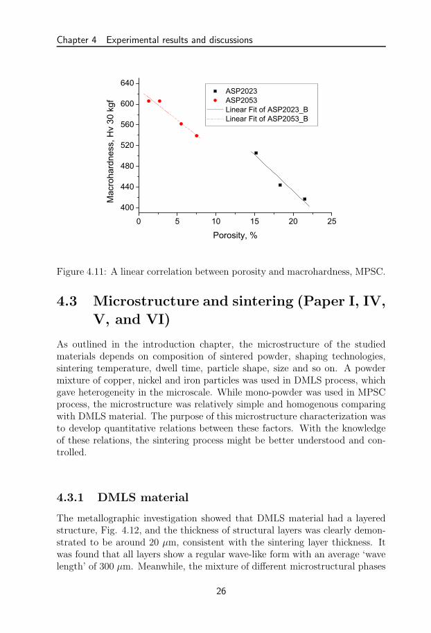
5. Having identical cooling rate and sintering parameters, a correlation be-tween porosity and macrohardness of MPSC materials, Fig. 4.11, revealsa linear relationship. This relation could help us to estimate porosity ofmaterials roughly based on a quick hardness measurement.
21

Chapter 4 Experimental results and discussions
(a) (b)
Figure 4.4: Pore morphology and locations on the polished cross sections of theDMLS material, OM. (a) Top-view normal to building direction. (b) Side-viewparallel to building direction.
(a) (b)
Figure 4.5: Pore mophology of MPSC material (ASP 2053, powder loading59%). (a) Porosity 4.4 ± 1.6% (b)Porosity 1.2 ± 0.6%.
22

4.2 Pore characterization (Paper I, IV, V, VI, and VII)
Figure 4.6: Pore cluster in the MPSC material showed as half-sintered parti-cles.
55 56 57 58 59 60 61 62 63 641.0
1.5
2.0
2.5
3.0
3.5
4.0
Por
osity
,%
Powder loading, wt%
Figure 4.7: Porosity varies with the powder loading, MPSC.
23

Chapter 4 Experimental results and discussions
Figure 4.8: Large and round pores in MPSC ASP 2053 due to entrapped air.
Figure 4.9: Thermo-Calc simulation for ASP 2053 [32].
24

4.2 Pore characterization (Paper I, IV, V, VI, and VII)
1255-30 1260-30 1260-60 1265-300
1
2
3
4
5
6
Por
osity
, %
Sintering temperature-time, oC-Min
(a)
0 50 100 150 200 250 300 350 4000
20
40
60
80
100
1255oC-30min-4.4% 1260oC-30min-1.2% 1265oC-30min-1.9% 1260oC-60min-1.6%
Cum
ulat
ive
coun
ts (%
)
Pore Length ( m)
(b)
Figure 4.10: Porosity varies with sintering parameters, MPSC. (a) Averageporosity vs. sintering parameters. (b) Cumulative counts of pores and sinteringparameters.
25
Chapter 4 Experimental results and discussions
0 5 10 15 20 25
400
440
480
520
560
600
640 ASP2023 ASP2053 Linear Fit of ASP2023_B Linear Fit of ASP2053_B
Mac
roha
rdne
ss, H
v 30
kgf
Porosity, %
Figure 4.11: A linear correlation between porosity and macrohardness, MPSC.
4.3 Microstructure and sintering (Paper I, IV,
V, and VI)
As outlined in the introduction chapter, the microstructure of the studiedmaterials depends on composition of sintered powder, shaping technologies,sintering temperature, dwell time, particle shape, size and so on. A powdermixture of copper, nickel and iron particles was used in DMLS process, whichgave heterogeneity in the microscale. While mono-powder was used in MPSCprocess, the microstructure was relatively simple and homogenous comparingwith DMLS material. The purpose of this microstructure characterization wasto develop quantitative relations between these factors. With the knowledgeof these relations, the sintering process might be better understood and con-trolled.
4.3.1 DMLS material
The metallographic investigation showed that DMLS material had a layeredstructure, Fig. 4.12, and the thickness of structural layers was clearly demon-strated to be around 20 µm, consistent with the sintering layer thickness. Itwas found that all layers show a regular wave-like form with an average ‘wavelength’ of 300 µm. Meanwhile, the mixture of different microstructural phases
26

4.3 Microstructure and sintering (Paper I, IV, V, and VI)
was clearly demonstrated. The phases, Fig. 4.13, as determined by EDSand X-ray diffraction analysis, were: i) Fe, Ni, Cu, P eutectic, ii) Fe, Ni, Cuaustenitic, iii) Cu-rich, iv) Fe-rich ferritic, and v) Ni-rich phases, respectively.The corresponding microhardness of different phases also shows its heterogene-ity with an average microhardness 381±30 HV 5gf of the dendritic regions and260±15 HV 5gf of the non-dendritic regions.No matter how evenly the powder is mixed, heterogeneity always exists inDMLS process. Comparing the laser spot size (0.4 mm) with the maximumparticle size (0.178 mm), it is recognized that both are of the same order. Aftera local fusion of particles, the heterogeneity could not be eliminated becausethat the diffusion region was too small and the existence time of liquid phasewas too short.
Figure 4.12: Side view of the DMLS material shows the wavy layers, thehatching width and the layer thickness.
4.3.2 MPSC material
The microstructure of MPSC ASP 2053 and KV 167 showed a martensite/ferritematrix with scattered carbides. Grain size, carbide size, nitrided layers andcontent of retained austenite differed from each groups due to different sinter-ing, nitriding parameters, and cooling rates, The main results can be pointedout as the following.
1. The cooling rate influenced the size of martensite laths and the content ofretained austenite. Having been sintered with the same temperature and
27

Chapter 4 Experimental results and discussions
(a) (b)
(c) (d)
(e)
Figure 4.13: Different phases of the DMLS material. (a) Top view image.(b) Dendritic structure and interdendritic segregation viewed by BSD on pol-ished specimen. (c) Copper-rich phase and α-Fe. (d) Unmelted iron particlemaintaining an irregular shape. (e) Partly melted nickel particle.
28

4.3 Microstructure and sintering (Paper I, IV, V, and VI)
dwell but with difference cooling rates, we found fast cooled ASP 2053specimen constituted much finer martensite structure than the vacuumcooled one, Fig. 4.14. The content of retained austenite was measuredto be 34 ± 3 vol. % and 42 ± 2 vol. % for the fast and slow cooled,respectively. Vickers hardnesses of fast cooled and slow cooled specimenswere also different and measured to be 772± 23 HV 30 kgf and 636± 27HV 30 kgf, respectively.
2. The content of carbide in MPSC ASP 2053 specimens was estimated at13.9 vol.% by image analysis. XRD analysis illustrated the existenceof primary MC carbide. Eutectic carbide, showing a feathery lamellarstructure, was found in small amounts, which was too little to be detectedby the current used XRD instrument, Fig. 4.15.
(a) (b)
Figure 4.14: The optical microscopy microstructure of MPSC ASP 2053. (a)Slow cooled with big martensitic needles. (b) Fast cooled with fine martensitelaths.
3. Tempering, as a post sinter heat treatment, was carried out at 560 ◦Cthree times for at least one hour each time and cooling to room tem-perature between temperings. Most of the retained austenite transferredinto martensite. The decrease of retained austenite after tempering wasindicated by decreased austenite peaks in the XRD spectrum, Fig. 4.16.An example of the microstructure change before and after tempering wasgive in Fig. 4.17 from the nitrided MPSC ASP 2053 material.
29

Chapter 4 Experimental results and discussions
(a) (b)
Figure 4.15: The carbides found in MPSC ASP 2053. (a) Primary and eutec-tic carbides found in an etched OM image. (b) Morphology of primary andeutectic carbides found in a SEM image (backscattered electron detector).
Figure 4.16: XRD spectrum of MPSC ASP 2053 in tempered and un-temperedconditions.
30

4.3 Microstructure and sintering (Paper I, IV, V, and VI)
(a) (b)
Figure 4.17: Most of retained austenite transfered into martensite by temper-ing. (a) Etched OM microstructure of MPSC 2053 before tempering showinga lot of retained austennite. (b) Etched OM microstructure after temperingshowing mainly martensite.
4.3.3 Microstructure and nitriding (Paper V and VI)
Nitriding was introduced into sintering cycles of MPSC ASP 2053 and KV167 in the end or the middle stage. Both two materials have high content ofvanadium, which is a strong nitride forming element. A lot of experimentalevidences have been collected and pointed out that high content of vanadiumcauses an increase of nitrogen consumption and diffusion rate by forming vana-dium nitride. The microstructure of nitrided layers of ASP 2053 and KV 167was shown in Figs. 4.18, 4.19 and 4.20. EDS mapping of the nitrided ASP2053 showed that the distribution of nitrogen was in connection with vanadiumcarbides, Fig. 4.21, implying a preferential nitrogen uptake in the carbide ascompared with the surrounding matrix. Carbide and nitride are normally iso-morphous with a high degree of mutual solubility, so carbonitrides could be ofvariable composition, i.e., M(CN). Nitriding the low carbon KV 167, a thickcompound layer was observed, Fig. 4.18b. While, compound layer was absentfor the nitrided ASP 2053 with a high carbon content, Fig. 4.19b. A highermagnification image of the compound layer in the nitrided KV 167 specimenrevealed whitish iron-nitride laths and dispersed grey carbide/carbonitride,Fig. 4.22. Hence, the compound layer was composed by alloy nitride (MCN)and iron nitride. As we know, both nitrogen and carbon can exist in fer-rite or austenite as interstitial elements. If the interstitial void was occupiedby carbon, nitrogen would be forced to overcome obstacles or diffuse to an-other unoccupied interstitial void resulting in a slow diffusion rate and a thin
31

Chapter 4 Experimental results and discussions
nitrided layer. Therefore, one of the possible reasons for the differences ofnitrided layers in KV 167 and ASP 2053 groups was because of differences incarbon content. Due to the low carbon content, nitriding of KV 167 was moreefficient than ASP 2053.
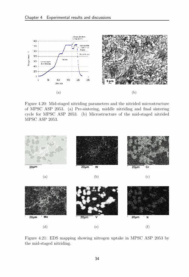
Introducing nitriding in the mid-stage would produce a structure fully ni-trided, Fig. 4.20. The sintering and nitriding cycle, Fig. 4.20a, was designedbased on the previous experimental work and ThermoCalc simulation. Presin-tering of the MPSC gree bodies was carried out at 1240 ◦C, which produced aporous structure with open porosity around 15%. In the subsequent nitridingat 1100 ◦C, the nitrogen infiltrated the whole open structure and reacted withhalf sintered particles at the gas-solid interfaces. The vanadium carbide causesnitrogen consumption by transforming its MC form to M(CN) carbonitrides.Having 1260 ◦C for 10 mins as the final sintering parameters, the final sinteredparts had a porosity smaller than 1% and a content of eutectic carbide about2.1%, which was four times higher than the group without nitriding. It clearlyrevealed that a shorter dwell at 1260 ◦ C can densify the nitrided specimens tothe same extent as un-nitrided ASP 2053. This was due to that the addition ofnitrogen decreased the solidus temperature and facilitated formation of liquidphase. A rough ThermoCalc simulation of ASP 2053 (with 2.3 wt. % C and0.4 wt. % N) was performed. The result, Fig. 4.23, confirmed that there wasa significant decrease of solidus temperature by introducing nitrogen. Alsothe eutectic formation started to occur with temperature below 1180 ◦C, Fig.4.23. Thus, it was consistent with the experimentally determined increase ofeutectic carbides after nitriding.
4.4 Mechanical properties (Paper II, IV, V,
and VI)
The main aim of this investigation is to evaluate the mechanical propertiesusing monotonic bending, four-point bending fatigue, and thermal fatigue teststo study failure mechanisms of DMLS and MPSC materials.
4.4.1 Bending fatigue and monotonic bending behavior
Like all other porous PM materials, the mechanical properties of DMLS andMPSC materials are governed by porosity and microstructural features, par-ticularly by local mechanical properties in the region of crack tips [33]. Herewe focused on the fatigue crack initiation and propagation mechanisms of thePM material especially with an emphasis on short fatigue crack range. The
32

4.4 Mechanical properties (Paper II, IV, V, and VI)
(a) (b)
Figure 4.18: Final-staged nitriding parameters and the nitrided microstructureof MPSC KV 167. (a) Sintering and final-staged nitriding cycle for MPSC KV167 (sintering: 1300 ◦C for 30 mins, nitriding: 1290 ◦C for 10 mins). (b) Thenitrided microstructure.
(a) (b)
Figure 4.19: Final-staged nitriding parameters and the nitrided microstructureof MPSC ASP 2053. (a) Sintering and final-staged nitriding cycle for MPSCASP 2053 (sintering: 1260 ◦C for 30 mins, nitriding: 1250 ◦C for 10 mins). (b)The nitrided layer of MPSC ASP 2053.
33
Chapter 4 Experimental results and discussions
(a) (b)
Figure 4.20: Mid-staged nitriding parameters and the nitrided microstructureof MPSC ASP 2053. (a) Pre-sintering, middle nitriding and final sinteringcycle for MPSC ASP 2053. (b) Microstructure of the mid-staged nitridedMPSC ASP 2053.
(a) (b) (c)
(d) (e) (f)
Figure 4.21: EDS mapping showing nitrogen uptake in MPSC ASP 2053 bythe mid-staged nitriding.
34

4.4 Mechanical properties (Paper II, IV, V, and VI)
Figure 4.22: Compound layer in the nitrided MPSC KV 167.
(a) (b)
Figure 4.23: The stable phase fraction with temperature [32]. (a) ASP 2053.(b) ASP 2053 with 0.4 wt. % nitrogen.
35

Chapter 4 Experimental results and discussions
microscopic damage mechanisms were identified and related to pores and mi-crostructure. The main results are summarized as the following:
1. S-N curves generated from four point bending fatigue test were shownin Fig. 4.24. It was readily seen that MPSC ASP 2053 material hadinferior fatigue properties compared to conventionally HIPed and forgedmaterial. The reason was mainly due to porosity and coarse microstruc-ture of MPSC materials. A comparison of the fatigue behaviour be-tween samples of the as-sintered and the tempered MPSC ASP 2053showed that the effect of tempering made the fatigue life longer at highstress level and shorter or similar at low stress level, suggesting someimprovement in ductility but not in fracture toughness due to temper-ing. This seemed reasonable since toughness and fatigue at longer liveswere clearly controlled by pore distribution. Being tested at one stresslevel, the DMLS material has similar fatigue strength as the MPSC ma-terial, which was promising for the MPSC, considering that the formermaterial already today is in commercial use. However, comparing to theconventionally manufactured ASP 2053, the MPSC 2053 had inferior me-chanical strength, underlining the importance of improving the MPSCprocess. The nitrided MPSC ASP 2053 group had the highest densitybut showed lowest fatigue strength indicating a decrease in toughnessdue to nitriding. The embrittlement was mainly because of deteriorationof microstructure by the eutectic carbide network, Fig. 4.20b.
2. For the DMLS material, the bending flexural rigidity was found to varywith the layer stacking direction, where the horizontal specimens were8% lower than the vertical one in flexural rigidity. One of the reasons forthe difference of flexural rigidity was due to the layer structure. In thehorizontal layered specimens, the layer interfaces had to accommodateshear stresses during bending. Since the layer interfaces contained alot of sinter defects (pores, etc), they were very easy to be sheared dueto stress concentration effects. For the vertical layered specimens, thelayer interfaces were not loaded by shear stress and the bending beamdeformed as one unit showing a higher bending rigidity.
3. SEM observation of the fatigue fracture surface indicated that the poresplayed very important roles in the crack initiation stage. The poresat or under the surface were preferable places for crack initiation forboth DMLS and MPSC materials, Fig. 4.25. Multiple initiations wereobserved with a distance between adjacent crack origins in the range ofseveral tens to several hundreds of micrometers in the DMLS material.For the MPSC ASP 2053, cracks initiated as well from pores, on ornearly below the surface. Initiations were single or a few only, leading
36

4.4 Mechanical properties (Paper II, IV, V, and VI)
1 10 100 1000 10000 100000 1000000 1E7100
200
300
400
1000
1100
1200
1300
1400
1500 As sintered MPSC ASP2053 Tempered MPSC ASP2053 Nitrided and tempered MPSC ASP2053 Conventional ASP2053 DMLS Horizontal DMLS Vertical Nitrided MPSC KV167
Stre
ss a
mpl
itude
, MP
a
Fatigue life, cycles
Figure 4.24: Fatigue life of the MPSC ASP 2053, DMLS and conventional ASP2053 (HIP+forged).
to a singular crack without linkage, growing to critical sizes before finalfailure occurred. The fatigue zone on the fracture surface was usuallyvery flat and smooth with a clear contour (boundary) between fatiguecrack growing zone and final fracture zone, Fig. 4.25 b, which differedfrom the DMLS material. Fatigue crack propagation in both materialswas transgranular. By image analysis, the fatigue crack zone had aradius of 300-700 µm in the MPSC materials, which was about 10 timesbigger than the one in the DMLS material. The explanation for thisphenomenon was based on how porosity and pore distribution influencecrack initiation, crack linkage, and growth.
4. From tracking the growth of cracks by surface replication, the relation be-tween fatigue crack and pores was studied. The DMLS materials showedtortuous crack paths, multiple crack nucleations and crack linkage, Fig.4.26. While, the MPSC materials frequently showed a single crack whichgrew to critical length and then caused failure.
5. The crack growth rate da/dN data versus stress intensity factor ∆K,for the DMLS material specimens, showed an oscillating behaviour, par-ticularly in the short crack region. The stress intensity factor of themeasured surface crack was calculated by Newman and Raju’s empirical
37

Chapter 4 Experimental results and discussions
(a) (b)
Figure 4.25: Multiple crack origins on the fracture surface. (a) DMLS speci-men. (b) MPSC specimen.
Figure 4.26: The crack paths (named V erticalII and V erticalIII) on the DMLSvertical specimen (after 31000 cycling) from the notch replica showing 90 ◦
jumps and small perpendicular cracks, the double headed arrow indicates theloading direction.
38

4.4 Mechanical properties (Paper II, IV, V, and VI)
equation [34].
∆KI = H(a
t,a
c)kt
3∆M
bt2
√
πa
Q(ac)F (
a
t,a
c,c
b, φ) (4.1)
where the functions Q, F and H are defined by systematic curve-fitting inRef. [34]. ∆KI is the stress intensity factor range, c and a are the semi-major (crack length) and the semi-minor (crack depth) axis of the semi-elliptical surface crack, respectively. kt is the stress concentration factorequal to 1.34 according to FEM analysis. ∆M is the bending momentrange. t and b are the thickness and the half width of the beam. Thecrack growth rates were treated by assuming a Paris relationship withthe stress intensity factor range,
da
dN= CA∆Km
A (4.2)
and,dc
dN= CB∆Km
B (4.3)
The coefficient CB was assumed to be CB = 0.9mCA according to Ref.[34] so that a small semicircular crack would retain its shape. Linearfitting of the Log(dc/dN) − Log(∆K) curve was used to deduct theParis parameters C and m. In order to define the influence of crackshape on the stress intensity factor, an iteration method was used tocalculate the convergent values of ∆K, C and m. At the beginningof iteration, a=c was used to derive ∆K, C and m. Then, the crackconfiguration (a/c and a/t ratio) was recalculated cycle by cycle usingthe Paris law and finally the successive approximation ∆K, C, and mwere obtained by applying the simple iteration. The parameters (C, m)were found to converge to (2.13× 10⁻¹¹, 2.94) and (2.31× 10⁻¹⁰, 2.0) forthe DMLS horizontal and vertical specimens, respectively. Comparingtwo linear fitting curves, the crack growth rate of vertical specimens washigher than that of horizontal ones when cracks were short. When cracksbecame long, dc
dN verticalbecame smaller than dc
dN horizontal.
6. The variation of crack growth rate with stress intensity depended on theinteraction between the crack tip and the different phases, crack linkageand crack deflection along layer interfaces or phase boundaries. Of thepresent microstructural constituents, the iron rich or nickel rich phaseshad a lower yield stress and therefore the size of the plastic zone of thecrack tip was larger than that in the dendritic phase. Hence, one mayassume that the crack propagation in iron or nickel rich phases is faster.It may be one of the reason for the variation in crack growth rate, as
39

Chapter 4 Experimental results and discussions
2 3 4 5 6 7 8 9 10 15 20 25 3010
−11
10−10
10−9
10−8
10−7
10−6
∆ K, MPa m1/2
dc/d
N, m
/cyc
le
HorizontalI
HorizontalII
HorizontalIII
HorizontalIV
HorizontalV
Linear fit
(a)
2 3 4 5 6 7 8 9 10 15 20 25 3010
−11
10−10
10−9
10−8
10−7
10−6
∆ K, MPa m1/2
dc/d
N, m
/cyc
le
VerticalI
VerticalII
VerticalIII
Linear fit
a
(b) (c)
Figure 4.27: Variation of the fatigue crack growth rate versus the stress in-tensity, DMLS. (a) Horizontal DMLS specimen. (b) Vertical DMLS specimen.(c) Crack tip corresponding to the point ‘a’ in (b).
40

4.4 Mechanical properties (Paper II, IV, V, and VI)
the crack makes its way through the different phases, Fig. 4.28. In theetched image, one could see the crack deflected at the phase interfaces Aand B.
Figure 4.28: One crack cross section in the DMLS vertical specimen afteretching.
7. The fracture morphology of the DMLS material was influenced by thelocal microstructure, showing a mixture of ductile dimple rupture andbrittle intergranular rupture. Based on the SEM observations, the inter-granular fractures favored the Fe-Ni-Cu-P eutectic. The dimple fractureswere related to the areas lacking phosphorus. The cleavage-like zone wasassumed as the transition zone between the dimple and intergranularfracture zone, Fig. 4.29. Final fracture of the MPSC material showeda mixture of quasi-cleavage, low ductile transgranular and pore clusterfracture. An overall low fracture toughness was observed for both kindsof materials. However, common to other powder metallurgical producedmaterials, the porosity controlled fatigue crack behaviour in both mate-rials studied.
8. A monotonic three point bending test of a nitrided MPSC KV 167 ma-terial was performed to study surface failure mechanisms. Without ni-triding, the microstructure of the material was composed of a soft ferritematrix and scattered MC carbides, which could theoretically lead to agood ductility. But as a result after nitriding, failure occurred when thematerial was loaded to 675 MPa. A brittle fracture surface with river
41

Chapter 4 Experimental results and discussions
Figure 4.29: Final fracture surface of a DMLS horizontal specimen.
marks and cleavage steps, Fig. 4.30, was observed by using SEM. Car-bide cracking and detachment were found through the whole fracturesurface. Further examination on the tensile stressed side of the MPSCKV 167 specimen revealed that carbide cracking was the main mecha-nism at the early stage of failure, Fig. 4.31. It would be expected thatthe embrittlement was connected with the increased nitrogen content inmetal and formation of brittle carbides.
4.4.2 Thermal fatigue of DMLS material
The main aim of this investigation was using the thermal fatigue test based oninduction heating and oil cooling to simulate the thermal loading conditionsencountered in real field applications and studying thermal fatigue crack ini-tiation and propagation mechanisms of the iron-based DMLS material. Therelationship between microstructure and thermal fatigue behaviours had beenrevealed. We found thermal fatigue behaviour to be more sensitive to local-ized microstructure than mechanical fatigue. This could be readily revealed bycomparing thermal and bending fatigue crack patterns. Similar with bendingfatigue cracks, thermal cracks prefer to initiate from pores as well as layer in-terfaces. The cracks preferentially propagated along phase boundaries and thininter-dendritic phases showing intergranular fracture. By using the fundamen-tal Fourier equation for heat conduction, the temperature cycle was modeledand calculated. A thermo elastic ideal plastic model was used to deduce the
42

4.4 Mechanical properties (Paper II, IV, V, and VI)
Figure 4.30: Final fracture surface of the nitrided MPSC KV 167 with rivermarks, cleavage steps, broken and detached carbides
Figure 4.31: Crack initiated from hard and big carbides, MPSC KV 167.
43

Chapter 4 Experimental results and discussions
thermal stress based on surface strain measured experimentally. Finally, thetemperature distribution, stress and mechanical strain was discussed with re-spect to thermal fatigue damage.
1. For each thermal cycling conditions, Fig. 4.32, the mean crack lengthof 15 longest cracks, the maximum crack length and the crack densitywere summarized in Table 4.1. Compared with the experimental data ofa hot-work tool steel, Premium H13 [35], the following main points canbe deducted: (a) The present DMLS material was susceptible to thermalfatigue showing considerably more damage than the hot work tool steelPremium H13. This difference was particularly clear when using themaximum crack length as measure, which meant a great risk for failurein applications of the laser sintered material. (b) The thermal damageincreased with increasing maximum temperature and thermal cycles.
0 5000 10000 15000 20000100
200
300
400
500
600
700
Slow cooling
Fast cooling
Temp.Max. 700oC
Temp.Max. 600oC
Tem
pera
ture
(o C)
Time(ms)
Figure 4.32: The two test thermal cycles (temperature vs. time).
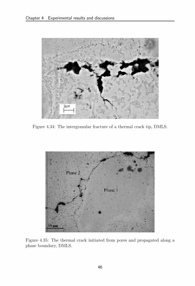
2. The SEM examination of the thermal fatigued specimens showed that thecracks preferred to initiate in porous layer interfaces and defects (suchas pores and inclusions), Fig. 4.33, due to stress concentration aroundgeometry discontinuities. The backscatter electron image of one cracktip showed an intergranular thermal fracture, Fig. 4.34. During heatingand cooling, a considerable internal stress might be introduced because ofdifferent thermal expansion and contraction of different phases. Finally,phase boundaries or thin inter-dendritic phases reached rapture, Fig.4.35. Element mapping images, Fig. 4.36, showed how the heterogeneityof material influenced the thermal crack propagation.
44

4.4 Mechanical properties (Paper II, IV, V, and VI)
Table 4.1: Mean crack length (L15), maximum crack length (Lmax) and crackdensity (ρ) of the DMLS material.Test condition L15±SD(µm) Lmax(µm) ρ(mm−1)700◦C,1000 cycles 84±24 138 3.2600◦C,10000 cycles 150±77 301 1.8700◦C,10000 cycles 543±224 1050 4.6600◦C,10000 cycles, Premium H13 [35] 125±80 240 1700◦C,10000 cycles, Premium H13 [35] 320±130 440 6.2
Figure 4.33: The thermal crack initiated from the porous layer interface,DMLS.
45
Chapter 4 Experimental results and discussions
Figure 4.34: The intergranular fracture of a thermal crack tip, DMLS.
Figure 4.35: The thermal crack initiated from pores and propagated along aphase boundary, DMLS.
46

4.4 Mechanical properties (Paper II, IV, V, and VI)
(a) (b)
(c) (d)
(e)
Figure 4.36: The element mapping of a thermal crack tip, DMLS. (a) Crackimage. (b) Cu mapping. (c) Fe mapping. (d) Ni mapping. (e) P mapping.
47

Chapter 4 Experimental results and discussions
3. The surface strain of the first and the stabilized thermal cycles wereshown in Fig. 4.37. Since it is difficult to quantify the deteriorationof the speckle pattern due to speckle decorrelation, the scatter in thedata was fairly big. In the first cycle, Fig. 4.37a and c, the testedmaterial underwent severe plastic deformation showing open loops. Theabsolute value of plastic deformation was calculated. After a few cycles,the thermal loop was stabilized resulting in a closed surface strain loopshown in Fig. 4.37b and d with a maximum measured strain of 0.2% and0.3% at the maximum cycle temperature 600 ◦C and 700 ◦C, respectively.The loops of the axial strain εz (along LSD) and the tangential strain εφ
(normal to LSD) were more or less identical.
4. According to the fundamental Fourier equation for heat conduction in acylinder coordinate system, the relation between temperature and timewere calculated and showed that the temperature of the internal materialfluctuated periodically as the same as the surface temperature during theperiodic heating and cooling, but with a delayed phase and a reducedamplitude. During heating the surface temperature always kept higherthan in the bulk material. Hence, the surface expansion was constrainedby the cool core to undergo a compressive stress. At the beginning ofcooling, the internal material continued absorbing heat and expanding sothat the total surface strain was kept constant even though the surfacetemperature dropped down very fast.
5. The thermal stress was estimated by using the thermo elastic ideal plasticmodel. The result implies that compressive plastic deformation occursin the first thermal cycle. Tensile stress which developed in the stablethermal cycles was responsible for initiation and propagation of thermalcracks, Fig. 4.38.
4.4.3 Wear resistance of MPSC KV 167
In this study, the wear resistances of specimens with and without nitridingtreatment were compared. The intrinsic abrasive resistance of some extremerough and thick layers were studied. The depths of all craters were in the rangeof case depth. The results were analyzed by calculating true worn volume andvolume difference between sliding distance of 314 m and 628 m in order tominimize the influence of surface irregularity. Fig. 4.39 shows the relationshipbetween volume difference and microhardness of top surfaces. It was observedthat the HIP specimens without nitriding had highest volume loss, while thenitrided HIPed and MPSC specimens had comparable volume loss. The resultswere in good correlation with top surface microhardess, because it seemednatural that decrease of hardness would increase wear rate in two body abrasive
48

4.4 Mechanical properties (Paper II, IV, V, and VI)
0 100 200 300 400 500 6000
0.5
1
1.5
2
2.5
3
3.5
4x 10
−3
Temperature, °C
Str
ain
εφ total
εztotal
Heating
Cooling
(a)
100 200 300 400 500 600 700 800−500
0
500
1000
1500
2000
2500
3000
3500
Temperature(oC)S
trai
n (x
10−
6 )
εφ total
εz total
Cooling
Heating
(b)
0 100 200 300 400 500 600 700 800−1
0
1
2
3
4
5x 10
−3
Temperature, °C
Str
ain
εφ total
εztotal
Cooling
Heating
(c)
100 200 300 400 500 600 700 800−500
0
500
1000
1500
2000
2500
3000
3500
Temperature (oC)
Str
ain
(x10
−6 )
εφφ total
εzz tatal
Heating
Cooling
(d)
Figure 4.37: The surface strain of the first cycle and the stabilized thermalcycles recorded by the speckle technique, DMLS. (a)The first cycle with themaximum temperature 600 ◦C. (b) The stabilized thermal cycle with the max-imum temperature 600 ◦C. (c) The first cycle with the maximum temperature700 ◦C. (d)The stabilized thermal cycle with the maximum temperature 700◦C.
49

Chapter 4 Experimental results and discussions
−4.5 −4 −3.5 −3 −2.5 −2 −1.5 −1 −0.5 0
x 10−3
−4
−3
−2
−1
0
1
2
3
4x 10
8
Mechanical Strain
Str
ess,
Pa
Cycle 1
Cycle 6
Heating
Yield
CoolingT
max=700°C
Figure 4.38: Thermal stress versus mechanical strain of the first and the sta-bilized cycle with a maximum temperature 700 ◦C, DMLS.
wear. SEM analysis showed that the predominant wear mechanism was micro-cutting and chipping. For the ductile as-HIPed group, fine grooves, detachmentof some carbides and some signs of chipping were observed, Fig. 4.40a. It alsoshowed that the diamond particles removed and pushed materials into ridgesalong the sides of the grooves. Hence, the wear of the HIPed material can beconcluded to occur by micro cutting. For the hard and brittle nitrided groups(HIPN and SCN), chipping was the predominant wear mechanisms showingmuch more debris than the HIPed group, Fig. 4.40b.
50

4.4 Mechanical properties (Paper II, IV, V, and VI)
0
100
200
300
400
500
600
700
800Max
Min
Max
Min
Max
Min
HIP SCN HIPN
3x10⁷
4x10⁷
5x10⁷
6x10⁷ V
V,m
3
Microhardness
Mic
roha
rdne
ss, H
V0.005
kg
Figure 4.39: Variation of volume loss with microhardness for nitrided andun-nitrided KV 167.
51

Chapter 4 Experimental results and discussions
(a)
(b)
Figure 4.40: SEM images of worn scars showing wear mechanism. (a) Ductilegrooves, HIP KV 167. (b) Debris, Nitrided MPSC KV 167, SCN.
52

Chapter 5
Conclusions
The thesis was an overview of the two rapid forming technologies, i.e., DMLSand MPSC, and proved that the applied rapid forming technologies could pro-duce near net shaped components with fairly good mechanical properties. Thekey processing issues related to final sintered microstructure were addressedand further discussed with relation to the resulting mechanical properties. Thefollowing major conclusions can be drawn from this thesis:
1. It demonstrates that it is possible to obtain a nearly full dense materialwith desired shaped and surface layer by controlling the MPSC sinteringand nitriding parameters.
2. The sintered DMLS materials is porous and heterogeneous multi-phasedmaterial.
3. The pores have a detrimental effect on both the four-point bending fa-tigue and thermal fatigue properties.
4. The microstructural heterogeneity influences the path of fatigue cracksfor both thermal fatigue and four-point bending fatigue.
5. The thermal fatigue test revealed that the tested DMLS material wasnot ready to be used in severe thermal applications, but may be used inapplications with limited usage.
6. The present materials had inferior properties compared to the conven-tionally manufactured. But with the competitive merits of rapid forming,net shaping, and cost saving, they may be suitable for applications inlimited usage. The knowledge of the materials’ properties could be usefulfor further development and material selection.
53

Chapter 5 Conclusions
54

Bibliography
[1] R. K. Dube, Further literary and documentary evidence for powder tech-nology in ancient and medieval india, Powder Metallurgy 36 (2) (1993)113–121.
[2] ASM Handbook: Powder Metal Technologies and Applications, Vol. 7,ASM International, Materials Park, Ohio, 1998.
[3] J. J. Beaman, Historical Perspective, Chapter 3 in JTEC/WTEC PanelReport on Rapid Prototyping in Europe and Japan, Tech. rep., WTECHyper-Librarian (1997).
[4] D. T. Pham, S. S. Dimov, Rapid manufacturing: the technologies andapplications of rapid prototyping and rapid tooling, Springer-VerlagUK, London, 2001.
[5] T. Wohlers, Rapid Prototyping and Tooling -State of the industry,Wohlers Associates, Inc., Colorado, USA, 1999.
[6] EOS takes fine approach to laser sintering, Metal Powder Report 56 (2001)18.
[7] Eos newsletter 2000/2: Direct metal laser-sintering with eosint m gainsworldwide recognition, Tech. Rep. 2, EOS (2000).
[8] Eos newsletter 2004/1: Directsteel h20 the new material for higher (tool)hardness, Tech. Rep. 1, EOS (2004).
[9] J. Hanninen, Direct metal laser sintering, Advanced Materials and Pro-cesses 160 (2002) 33–36.
[10] F. Abe, K. Osakada, M. Shiomi, K. Uematsu, M. Matsumoto, The manu-facturing of hard tools from metallic powders by selective laser melting,Journal of Materials Processing Technology 111 (2001) 210–213.
[11] I. Sarady, H. Engstrom, Rapid Tooling: en forundersoking, Lulea univer-sity of technology, Lulea, 2000.
[12] Laser sintering ushers in new route to PM parts, Metal Powder Report52 (1997) 24–30.
55

BIBLIOGRAPHY
[13] M. Skoog, Microstructure and mechanical properties of laser sinteredmetal powders, Master’s thesis, Department of Materials Engineering,Karlstad University, Karlstad, Sweden (2003).
[14] A. Simchi, F. Petzoldt, H. Pohl, H. Loffler, A new steel powder mixturefor direct laser sintering, Rapid Prototyping & Tooling Newsletter (4)(2000) 4–5.
[15] O. Lyckfeldt, J. M. F. Ferreira, Processing of porous ceramics by ‘starchconsolidation’, Journal of the European Ceramic Society 18 (1998)131–140.
[16] O. Lyckfeldt, L. O. Nordberg, L. Nyborg, Processing of high-speed steel bystarch consolidation, in: Proceeding of 2000 powder metallurgy worldcongress, Japan Society of Powder and Powder Metallurgy, Kyoto,2000, pp. 810–813.
[17] S. Magalhaes, L. Nyborg, O. Lyckfeldt, E. Carlstrm, Pressureless netshape manufacture of P/M parts, in: Proceedings of the 1998 PowderMetallurgy World Congress & Exhibition, Vol. 2, European PowderMetallurgy Association, Shewsbury, 1998, pp. 308–313.
[18] E. Tynova, W. Pabst, J. Mikac, Starch swelling and its role in mod-ern ceramic shaping technology, Macromolecular Symposia 203 (2003)295–300.
[19] H. M. Alves, G. Tari, A. T. Fonseca, J. M. F. Ferreira, Processing ofporous cordierite bodies by starch consolidation, Materials ResearchBulletin 33 (10) (1998) 1439–1448.
[20] S. Magalhaes, Surface composition and microstructure control duringpressureless forming and sintering of ferrous powder metallurgy mate-rials, Ph.D. thesis, Department of Materials Science and Engineering,Chalmers university and technology, Goteborg, Sweden (2003).
[21] R. M. German, Poweder Metallurgy Science, 2nd Edition, Metal PowderIndustries Federation, Princeton, New Jersey, USA, 1994.
[22] R. M. German, Sintering Theory and Practice, John Wiley, New York,1996.
[23] P. R. Triguero, Development of a new method for the production of pow-der metallurgy high-speed steels by means of starch consolidation,Ph.D. thesis, Spain (2003).
[24] E. Gregorova, W. Pabst, I. Bohacenko, Characterization of different starchtypes for their application in ceramic processing, Journal of the Euro-pean Ceramic Society 26 (2006) 1301–1309.
56

BIBLIOGRAPHY
[25] P. Romano, O. Lyckfeldt, N. Candela, F. Velasco, Water-based processingof high-speed steel utilising starch consolidation, Journal of MaterialsProcessing Technology 143-144 (1) (2003) 752–757.
[26] H. Borgstrom, L. Nyborg, Effect of vacuum annealing and nitrogen alloy-ing on gas atomized m4 high speed steel powder, Powder Metall. 49(2006) 48–56.
[27] ASM Handbook: Metallography and microstructures, Vol. 9, ASM Inter-national, Ohio, USA, 2000.
[28] I. Yamaguchi, Encoder and strain gauge using laser speckle, Optics andLasers in Engineering 11 (4) (1989) 223–232.
[29] A. Persson, S. Hogmark, J. Bergstrom, Thermal fatigue cracking of surfaceengineered hot work tool steels, Surface and Coatings Technology 191(2005) 216–227.
[30] R. Gahlin, M. Larsson, P. Hedenqvist, S. Jacobson, S. Hogmark, Thecrater grinder method as a means for coating wear evaluation - anupdate, Surface and Coatings Technology 90 (1-2) (1997) 107–114.
[31] I. Hutchings, Tribology-friction and wear of engineering materials,Butterworth-Heinemann Ltd., 1992.
[32] H. Borgstrom, Group Report: Optimizing sintering cycles of ASP 2053,Chalmers University of Technology, 2005-2008.
[33] S. Suresh, Fatigue of materials, Cambride university press, 1998.
[34] J. C. Newman, I. S. Raju, An empirical stress-intensity factor equationfor the surface crack, Engineering Fracture Mechanics 15 (1-2) (1981)185–192.
[35] J. Sjostrom, J. Bergstrom, On the influence of austenitizing treatment onisothermal and thermal fatigue lives of hot-work tool steels, in: NorthAmerican Die Casting Conference, 2003, pp. 429–437.
57

Karlstad University StudiesISSN 1403-8099
ISBN 978-91-7063-171-9
Mechanical properties and
microstructure of laser sintered and starch
consolidated iron-based powders
In powder metallurgy research field, Direct Metal Laser Sintering (DMLS) and Metal Powder Starch Consolidation (MPSC) are relatively new rapid forming techniques to fabricate complex and near net-shaped components. The working principles of DMLS are to melt and fuse metal powder layer by layer in computer controlled systems to pile up components like three dimensional printing. It has been for instance extensively used for mould inserts, die parts, and functional metal prototypes. Another, less explored method, starch consolidation is a pressureless direct casting method which consists principally of mixing powder slurry, casting into moulds, consolidation, drying, and sintering. With a strong focus on both methods, the study here combines several strong material technology sectors; powder, rapid forming, mechanical property testing and surface technology. It covers the processing chain from green body preparation, optimization of sintering, nitriding, post sinter heat treatment, to modeling and assessment of material behaviour for end-user applications. An iron based powder and a high vanadium high speed steel powder with low and high carbon contents were used in the DMLS and MPSC processes, respectively. The overall aim of the study is to synthesize near net-shaped powder-based components, to characterize pores and microstructure, and to establish a fundamental understanding of failure mechanisms of powder based materials in bending fatigue, thermal fatigue and wear.
The study showed the DMLS and MPSC technologies could produce shaped components with a multi-phased structure, controllable nitriding depth and high relative densities in a range of 97 - 99.7 %. Materials' heterogeneity and porosity have detrimental influence on mechanical properties, especially on crack initiation and subsequent propagation.