Structural and magnetic properties of sputter deposited cobalt���silica nanocomposite thin films
Upload
demokritosCategory
view
1download
0
JOURNAL OF APPLIED PHYSICS 100, 053913 �2006�
Microstructure and magnetic properties of SmCo5 thin films depositedon Cu and Pt underlayers
Y. K. Takahashi,a� T. Ohkubo, and K. HonoNational Institute for Materials Science (NIMS), Tsukuba 305-0047, Japan
�Received 21 January 2006; accepted 3 June 2006; published online 11 September 2006�
The microstructure of the SmCo5 thin films sputter deposited on Cu underlayers was investigated toexplain the high coercivity Hc. Energy filtered elemental map and energy dispersive x-rayspectroscopy line analysis showed that Cu diffused into the SmCo5 layer to form a Sm�Co,Cu�5
solid solution. Composition fluctuations with a scale length of 40 nm were found within theSm�Co,Cu�5 layer, which would cause the local changes in the magnetocrystalline anisotropy. Thehigh coercivity that was observed in the continuous Sm�Co,Cu�5 layer may be attributed to thepinning force for the magnetic domain wall motion due to the fluctuation of the magnetocrystallineanisotropy. The structure and magnetic properties of the SmCo5 thin film deposited on a Ptunderlayer were also examined for comparison. © 2006 American Institute of Physics.�DOI: 10.1063/1.2266247�
I. INTRODUCTION
To attain a high signal to noise ratio �SNR� in thegranular-type ultrahigh density magnetic recording media,ferromagnetic particles of less than 10 nm must be uniformlydispersed in a nonmagnetic matrix. Since the magnetic mo-ments of such fine particles become thermally unstable, highmagnetocrystalline anisotropy material such as L10-FePtmust be employed for future ultrahigh density recording me-dia. SmCo5 is another potential material for ultrahigh densitymagnetic recording media due to its high magnetocrystallineanisotropy of about 108 erg/cm3. As a writable high magne-tocrystalline anisotropy medium, Suzuki recently demon-strated the possibility of a pinning-type magnetic recordingmedium using L10-FePt continuous films.1 Due to the narrowmagnetic domain wall width of high magnetocrystalline an-isotropy materials, the transition area is expected to be sharp.If magnetic domain walls are effectively pinned by pinningcenters in the films, they may be used as perpendicular re-cording media without granular-type morphology. For suchpinning-type media, the perpendicular anisotropy film of theSmCo5 phase is expected to be more suitable than L10-FePt because of its narrower magnetic domain wall widthdue to the higher magnetocrystalline anisotropy.
Recent studies by Sayama et al.2 and Takei et al.3 re-ported that perpendicular anisotropy can be obtained whenSmCo5 films are deposited on the Cu underlayer. AlthoughSmCo5 has not been seriously considered for potential mediaapplications due to its poor corrosion resistance, a recentstudy by Sayama et al. reported a substantially improvedcorrosion resistance by the addition of Cu.4 Furthermore,Sayama et al. reported that the SmCo5 film on the Cu under-layer with a Ti buffer layer showed strong perpendicular an-isotropy and high coercivity �Hc� of 12 kOe even though thefilm morphology was continuous.5 As demonstrated from theepitaxially grown continuous FePt thin films, coercivity will
a�Author to whom correspondence should be addressed; FAX: 81-29-859-
2701; electronic mail: [email protected]0021-8979/2006/100�5�/053913/6/$23.00 100, 0539
Downloaded 20 Sep 2006 to 144.213.253.16. Redistribution subject to
be very low if the film is composed of magnetically coupledgrains with the same orientation unless there are strong pin-ning centers within the film.6 In this study, we have investi-gated the relationship between the microstructure and themagnetic properties of the SmCo5 film deposited on threetypes of underlayers, Cu, Cu with Ti, and Pt, to discuss thecoercivity mechanism.
II. EXPERIMENT
Films were deposited on thermally oxidized Si substratesby the dc magnetron sputtering method. The base pressure ofthe system was less than 1�10−7 Pa, and the high purityargon of �0.1 Pa was flown during sputtering. First, a100 nm thick Cu or Pt underlayer was deposited at roomtemperature �RT�. In some of the films, a 1 nm thick Ti layerwas deposited on the thermally oxidized Si substrates beforedepositing the Cu underlayer for texture control. Then 25 nmthick SmCo5 films were deposited on the underlayers at350 °C by cosputtering Sm and Co targets. Finally, a 10 nmthick Cr was deposited on the SmCo5 layer as a protectivelayer against oxidation at RT.
Magnetic properties were measured by a superconduct-ing quantum interference device �SQUID� magnetometerwith a maximum magnetic field of 55 kOe. The microstruc-ture of the films was investigated by x-ray diffraction �XRD�with Cu K� radiation �wavelength of 0.154 nm� and trans-mission electron microscopy �TEM�. The compositions ofthe Sm–Co films were estimated to be close to SmCo5 byenergy dispersive x-ray spectroscopy �EDS�.
III. RESULTS
A. SmCo5 film with Cu underlayer
Figure 1 shows an XRD pattern of the SmCo5 film witha Cu underlayer. Diffraction peaks from �0001� and �0002� ofSmCo5 are clearly observed at around 22.3° and 45.6° for2�, respectively. No peaks from the other planes of the
SmCo5 are seen because of the strong �0001� texture. The© 2006 American Institute of Physics13-1
AIP license or copyright, see http://jap.aip.org/jap/copyright.jsp
053913-2 Takahashi, Ohkubo, and Hono J. Appl. Phys. 100, 053913 �2006�
diffraction peak from Cu�111� is also clearly observed ataround 43.3° for 2�. In addition, the diffraction peak fromCu�200� is observed at around 50.5° for 2�. The intensity ofCu �111� is stronger than the intensity that is expected fromthe randomly oriented fine grain microstructure, which indi-cates that the Cu underlayer is weakly textured on �111�.
Figure 2 shows perpendicular and in-plane magnetiza-tion curves of the film with a Cu underlayer. The film showsstrong perpendicular anisotropy although it is not perfect. Itis consistent with the XRD result which showed that most ofthe SmCo5 grains had their c axis normal to the plane. The
SmCo5 grains with the �112̄1� orientation will exist because
the 2� position of SmCo5�112̄1� overlaps with that ofCu�111�. The Hc is about 12 kOe. The saturation magnetiza-tion of the film is about 600 emu/cm3 which is smaller thanthat of the bulk sample of about 800 emu/cm3. The decreaseof the saturation magnetization is due to the Cu diffusionfrom the underlayer and will be discussed later.
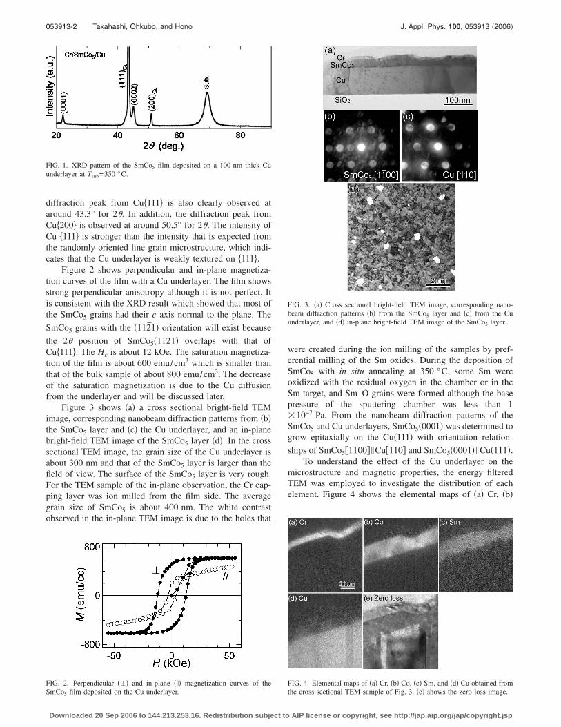
Figure 3 shows �a� a cross sectional bright-field TEMimage, corresponding nanobeam diffraction patterns from �b�the SmCo5 layer and �c� the Cu underlayer, and an in-planebright-field TEM image of the SmCo5 layer �d�. In the crosssectional TEM image, the grain size of the Cu underlayer isabout 300 nm and that of the SmCo5 layer is larger than thefield of view. The surface of the SmCo5 layer is very rough.For the TEM sample of the in-plane observation, the Cr cap-ping layer was ion milled from the film side. The averagegrain size of SmCo5 is about 400 nm. The white contrastobserved in the in-plane TEM image is due to the holes that
FIG. 1. XRD pattern of the SmCo5 film deposited on a 100 nm thick Cuunderlayer at Tsub=350 °C.
FIG. 2. Perpendicular ��� and in-plane ��� magnetization curves of the
SmCo5 film deposited on the Cu underlayer.Downloaded 20 Sep 2006 to 144.213.253.16. Redistribution subject to
were created during the ion milling of the samples by pref-erential milling of the Sm oxides. During the deposition ofSmCo5 with in situ annealing at 350 °C, some Sm wereoxidized with the residual oxygen in the chamber or in theSm target, and Sm–O grains were formed although the basepressure of the sputtering chamber was less than 1�10−7 Pa. From the nanobeam diffraction patterns of theSmCo5 and Cu underlayers, SmCo5�0001� was determined togrow epitaxially on the Cu�111� with orientation relation-
ships of SmCo5�11̄00� �Cu�110� and SmCo5�0001� �Cu�111�.To understand the effect of the Cu underlayer on the
microstructure and magnetic properties, the energy filteredTEM was employed to investigate the distribution of eachelement. Figure 4 shows the elemental maps of �a� Cr, �b�
FIG. 3. �a� Cross sectional bright-field TEM image, corresponding nano-beam diffraction patterns �b� from the SmCo5 layer and �c� from the Cuunderlayer, and �d� in-plane bright-field TEM image of the SmCo5 layer.
FIG. 4. Elemental maps of �a� Cr, �b� Co, �c� Sm, and �d� Cu obtained from
the cross sectional TEM sample of Fig. 3. �e� shows the zero loss image.AIP license or copyright, see http://jap.aip.org/jap/copyright.jsp

053913-3 Takahashi, Ohkubo, and Hono J. Appl. Phys. 100, 053913 �2006�
Co, �c� Sm, and �d� Cu. Figure 4�e� shows a zero loss image.The intensity contrast can be seen clearly from the Co map,indicating that the concentration in Co fluctuates locally. Al-though the contrast is very weak, the intensity fluctuation isalso observed in the Cu map. Because the contrast of theenergy filtered image is affected by the diffraction contrast aswell as the difference in the thickness, relative compositionalchanges of each element were also analyzed by EDS. Figure5 shows the intensity profiles of each element. �a� and �b� inthe Co map correspond to the two orthogonal scanning di-rections. The intensity profile of �b� shows that Cu diffusedinto the SmCo5 layer, forming Sm�Co,Cu�5 which was ob-served in the �SmCo6/Cu/Fe� multilayer film.7 The intensityprofile of �a� shows that there are fluctuations of Co and Cuconcentrations by the substitution of Cu for Co.
B. SmCo5 film with Cu/Ti underlayer
Figure 6 shows the XRD pattern of the SmCo5 film witha Cu/Ti underlayer. The diffraction peak from Cu�200� be-comes invisible in the XRD pattern when a very thin Ti layeris deposited on a Si substrate before the deposition of the Cuunderlayer. The Cu underlayer shows a strong preferred ori-entation with �111�. Diffraction peaks from �0001� and�0002� of SmCo5 are clearly observed at around 22.3° and45.6° for 2�, respectively. No peaks from the other planes ofthe SmCo5 are seen because of the strong �0001� texture.
FIG. 5. Energy filtered Co map obtained from the cross sectional image ofthe SmCo5 layer deposited on the Cu underlayer and EDS intensity profilesof Cr, Co, and Cu along two orthogonal analysis directions shown as �a� and�b�.
FIG. 6. XRD pattern of the SmCo5 film deposited on the Cu/Ti underlayer.
Downloaded 20 Sep 2006 to 144.213.253.16. Redistribution subject to
Figure 7 shows the perpendicular and in-plane magneti-zation curves of the SmCo5 film with the Cu/Ti underlayer.Ratio of the residual magnetization at zero field of in-planemagnetization curve to that of perpendicular curve decreasesfrom 0.39 to 0.33 by depositing Ti layer under Cu layer.Although the film does not show a perfect perpendicular an-isotropy, it shows strong perpendicular anisotropy which isstronger than that of the SmCo5 film with a Cu underlayer.
The presence of the SmCo5 grains with the �112̄1� orienta-tion cannot be ruled out because the 2� position of
SmCo5�112̄1� overlaps with that of Cu�111�. The squarenessof the perpendicular magnetization curve is about 0.86, andHc is about 10 kOe. The saturation magnetization of the filmis about 600 emu/cm3.
Figure 8 shows the cross sectional TEM image of theSmCo5 film on the Cu/Ti underlayer. The grain size of theCu underlayer is about 200 nm and that of the SmCo5 is alsovery large ��200 nm�. The rough surface of the SmCo5 canalso be seen in this figure.
A qualitative chemical analysis was carried out to under-stand the effect of the Cu underlayer on the microstructureand the magnetic properties of SmCo5. Figure 9 shows theenergy filtered elemental maps of �a� Cr, �b� Co, �c� Sm, �d�Cu, and �e� Ti that were obtained from the film shown in Fig.8. Figure 9�f� shows a zero loss image. The Ti mappingshows that the Ti layer is continuous and remains very sharp.The composition fluctuation of Co and Cu can be observedin the SmCo5 layer. An EDS line analysis was carried out toinvestigate the compositional change in the SmCo5 layer indetail. Figure 10 shows the intensity profiles of each element.�a� and �b� in the Co map correspond to the two orthogonalscanning directions. The intensity profiles show that Cu sub-stitutes for Co and diffuses into the SmCo5 layer. There arefluctuations of Cu concentrations in the Sm�Co,Cu�5 layer.
FIG. 7. Perpendicular ��� and in-plane ��� magnetization curves of theSmCo5 film deposited on the Cu/Ti underlayer.
FIG. 8. Cross sectional TEM image of the SmCo5 film deposited on the
Cu/Ti underlayer.AIP license or copyright, see http://jap.aip.org/jap/copyright.jsp

053913-4 Takahashi, Ohkubo, and Hono J. Appl. Phys. 100, 053913 �2006�
C. SmCo5 film with Pt underlayer
Figure 11 shows the XRD pattern of the SmCo5 filmdeposited on a Pt underlayer. The diffraction peaks from
SmCo5 �11̄00� and �0002� are clearly observed at around20.5° and 45.6° for 2�, respectively. Compared to the pow-
der diffraction pattern data of SmCo5 and Pt, �11̄00� SmCo5
and �111� Pt are stronger, suggesting the development of in-plane and �111� textures for SmCo5 and Pt, respectively.
Figure 12 shows the perpendicular and the in-plane mag-netization curves of the SmCo5 film with the Pt underlayer.The film shows strong in-plane anisotropy which is consis-tent with the XRD result. The in-plane coercivity is less than1 kOe, which is substantially lower than the perpendicularcoercivity of Sm�Co,Cu�5 films. The saturation magnetiza-tion of the film is about 700 emu/cm3, which is still smallerthan that of the bulk sample, but is larger than that of theSm�Co,Cu�5 films.
Figure 13 shows the cross sectional TEM image of theSmCo5 film on the Pt underlayer. The Pt underlayer shows acolumnar structure which is typical for sputtered films. TheSmCo5 film consists of two different layers, and the surfaceof the SmCo5 layer is smooth. A high resolution TEM
FIG. 9. Energy filtered elemental maps of �a� Cr, �b� Co, �c� Sm, �d� Cu, and�e� Ti obtained from the cross sectional TEM specimen shown in Fig. 8. �f�shows the zero loss image.
FIG. 10. Energy filtered Co map obtained from the cross sectional image ofthe SmCo5 layer deposited on the Cu/Ti underlayer and EDS intensity pro-files of Cr, Co, and Cu along two orthogonal analysis directions shown as �a�
and �b�.Downloaded 20 Sep 2006 to 144.213.253.16. Redistribution subject to
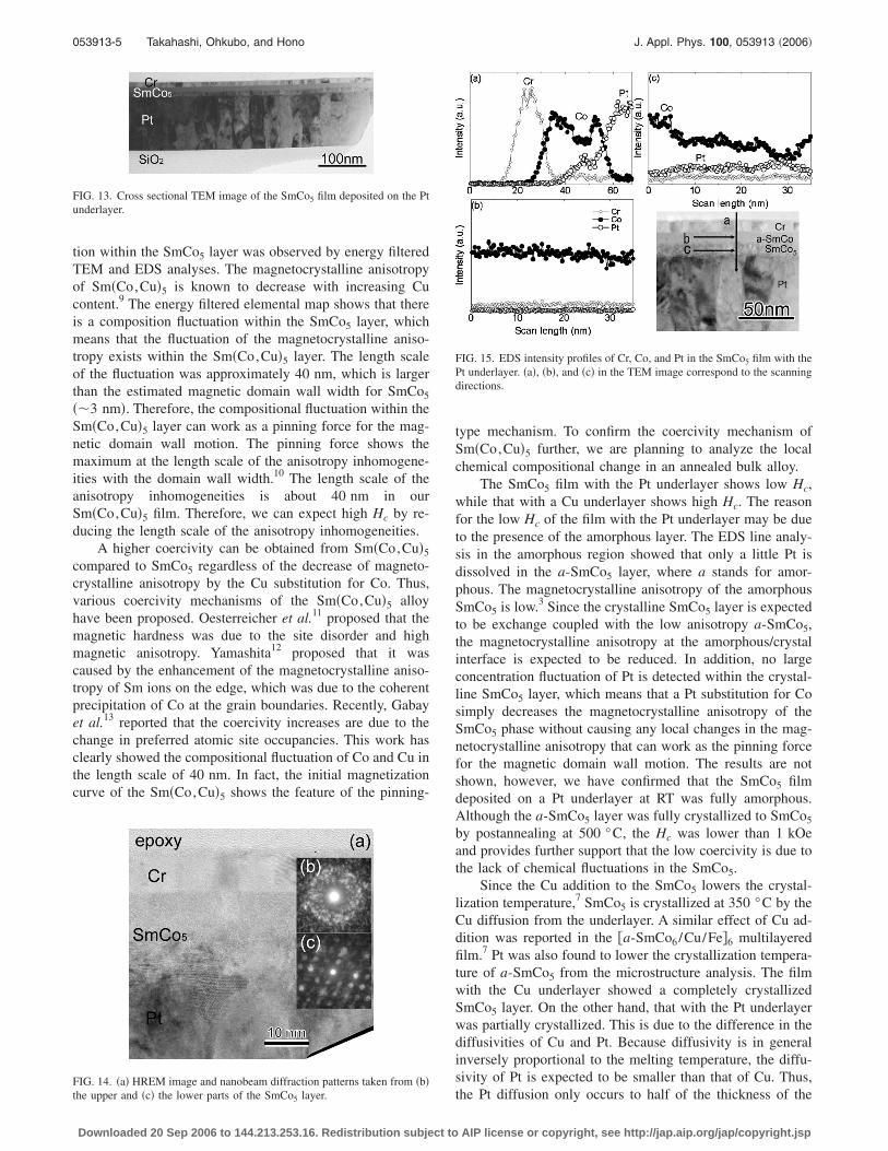
�HREM� observation was carried out to understand the twodifferent layers in the SmCo5 film. Figure 14 shows �a� theHREM image and nanobeam diffraction patterns taken from�b� the upper and �c� the lower regions of the SmCo5 layer.The nanobeam diffraction patterns show that the upper re-gion of the SmCo5 layer is amorphous, while the lower re-gion of the SmCo5 layer is crystalline. An EDS line analysiswas carried out to investigate the compositional change inthe SmCo5 layer in detail. Figure 15 shows the intensityprofiles of each element. �a�, �b�, and �c� in the TEM imagecorrespond to the two orthogonal scanning directions. Theintensity profile of �a� shows that Pt diffuses into the bottompart of the SmCo5 layer. The intensity profile of �b� showsthat Pt and Cr concentrations are lower than the detectablelevel within the amorphous SmCo5 layer, which indicatesthat Pt does not diffuse into the amorphous region of theSmCo5 layer. The intensity profile of �c� shows some Pt,which means that Pt diffuses in the crystalline SmCo5 layerbut their dissolution appears to be uniform.
IV. DISCUSSION
The SmCo5 film with the Cu underlayer showed a highHc of about 10 kOe, although the film was completely con-tinuous. In general, a strongly textured continuous filmshows low Hc,
6 because the pinning sites for the magneticdomain wall motion cannot be expected. However, Fullertonet al. reported that the Sm–Co film epitaxially grown onMgO�110� single crystal substrate shows high Hc such as4 T.8 Because the microstructure observation has not beendone yet, the coercivity mechanism is under question. In theSmCo5 film with the Cu underlayer, the composition fluctua-
FIG. 11. XRD pattern of the SmCo5 film deposited on the Pt underlayer.
FIG. 12. Perpendicular ��� and in-plane ��� magnetization curves of the
SmCo film deposited on the Pt underlayer. 5AIP license or copyright, see http://jap.aip.org/jap/copyright.jsp
053913-5 Takahashi, Ohkubo, and Hono J. Appl. Phys. 100, 053913 �2006�
tion within the SmCo5 layer was observed by energy filteredTEM and EDS analyses. The magnetocrystalline anisotropyof Sm�Co,Cu�5 is known to decrease with increasing Cucontent.9 The energy filtered elemental map shows that thereis a composition fluctuation within the SmCo5 layer, whichmeans that the fluctuation of the magnetocrystalline aniso-tropy exists within the Sm�Co,Cu�5 layer. The length scaleof the fluctuation was approximately 40 nm, which is largerthan the estimated magnetic domain wall width for SmCo5
��3 nm�. Therefore, the compositional fluctuation within theSm�Co,Cu�5 layer can work as a pinning force for the mag-netic domain wall motion. The pinning force shows themaximum at the length scale of the anisotropy inhomogene-ities with the domain wall width.10 The length scale of theanisotropy inhomogeneities is about 40 nm in ourSm�Co,Cu�5 film. Therefore, we can expect high Hc by re-ducing the length scale of the anisotropy inhomogeneities.
A higher coercivity can be obtained from Sm�Co,Cu�5
compared to SmCo5 regardless of the decrease of magneto-crystalline anisotropy by the Cu substitution for Co. Thus,various coercivity mechanisms of the Sm�Co,Cu�5 alloyhave been proposed. Oesterreicher et al.11 proposed that themagnetic hardness was due to the site disorder and highmagnetic anisotropy. Yamashita12 proposed that it wascaused by the enhancement of the magnetocrystalline aniso-tropy of Sm ions on the edge, which was due to the coherentprecipitation of Co at the grain boundaries. Recently, Gabayet al.13 reported that the coercivity increases are due to thechange in preferred atomic site occupancies. This work hasclearly showed the compositional fluctuation of Co and Cu inthe length scale of 40 nm. In fact, the initial magnetizationcurve of the Sm�Co,Cu�5 shows the feature of the pinning-
FIG. 13. Cross sectional TEM image of the SmCo5 film deposited on the Ptunderlayer.
FIG. 14. �a� HREM image and nanobeam diffraction patterns taken from �b�
the upper and �c� the lower parts of the SmCo5 layer.Downloaded 20 Sep 2006 to 144.213.253.16. Redistribution subject to
type mechanism. To confirm the coercivity mechanism ofSm�Co,Cu�5 further, we are planning to analyze the localchemical compositional change in an annealed bulk alloy.
The SmCo5 film with the Pt underlayer shows low Hc,while that with a Cu underlayer shows high Hc. The reasonfor the low Hc of the film with the Pt underlayer may be dueto the presence of the amorphous layer. The EDS line analy-sis in the amorphous region showed that only a little Pt isdissolved in the a-SmCo5 layer, where a stands for amor-phous. The magnetocrystalline anisotropy of the amorphousSmCo5 is low.3 Since the crystalline SmCo5 layer is expectedto be exchange coupled with the low anisotropy a-SmCo5,the magnetocrystalline anisotropy at the amorphous/crystalinterface is expected to be reduced. In addition, no largeconcentration fluctuation of Pt is detected within the crystal-line SmCo5 layer, which means that a Pt substitution for Cosimply decreases the magnetocrystalline anisotropy of theSmCo5 phase without causing any local changes in the mag-netocrystalline anisotropy that can work as the pinning forcefor the magnetic domain wall motion. The results are notshown, however, we have confirmed that the SmCo5 filmdeposited on a Pt underlayer at RT was fully amorphous.Although the a-SmCo5 layer was fully crystallized to SmCo5
by postannealing at 500 °C, the Hc was lower than 1 kOeand provides further support that the low coercivity is due tothe lack of chemical fluctuations in the SmCo5.
Since the Cu addition to the SmCo5 lowers the crystal-lization temperature,7 SmCo5 is crystallized at 350 °C by theCu diffusion from the underlayer. A similar effect of Cu ad-dition was reported in the �a-SmCo6/Cu/Fe�6 multilayeredfilm.7 Pt was also found to lower the crystallization tempera-ture of a-SmCo5 from the microstructure analysis. The filmwith the Cu underlayer showed a completely crystallizedSmCo5 layer. On the other hand, that with the Pt underlayerwas partially crystallized. This is due to the difference in thediffusivities of Cu and Pt. Because diffusivity is in generalinversely proportional to the melting temperature, the diffu-sivity of Pt is expected to be smaller than that of Cu. Thus,
FIG. 15. EDS intensity profiles of Cr, Co, and Pt in the SmCo5 film with thePt underlayer. �a�, �b�, and �c� in the TEM image correspond to the scanningdirections.
the Pt diffusion only occurs to half of the thickness of the
AIP license or copyright, see http://jap.aip.org/jap/copyright.jsp

053913-6 Takahashi, Ohkubo, and Hono J. Appl. Phys. 100, 053913 �2006�
SmCo5 layer, which was crystallized during the depositionprocess. A higher substrate temperature is necessary to crys-tallize the SmCo5 layer with a Pt underlayer.
Although the thicknesses of the Cu and Pt underlayerswere the same �about 100 nm�, the grain size of the Cu un-derlayer was larger than that of the Pt underlayer which hadthe columnar structure. This is due to the difference in thediffusivities of Cu and Pt. Since the diffusivity of Cu on thesubstrate is larger than that of Pt due to the lower meltingtemperature of Cu, Cu grains tend to grow faster than Ptgrains.
This work has confirmed that the perpendicular aniso-tropy of the film was improved by depositing a thin Ti bufferlayer between the thermally oxidized Si substrate and the Cuunderlayer as was reported by Sayama et al.4 The XRD pat-tern showed that the Cu underlayer had a stronger �111� tex-ture by the presence of a Ti buffer layer, hence a higher�0001� alignment of the SmCo5 layer. Although the XRDpeaks from the Ti layer were not observed because of thethinness of the film, Ti is expected to show a �0001� texturebecause it is the closest packed plane of the hcp structure.The lattice parameter a of Ti is 0.295 nm and the latticemisfit between Ti�0001� and Cu�111� is about 13%. Despitethe relatively large misfit, the Cu orientation is controlled bythe Ti buffer layer. The film with a perfectly perpendicularanisotropy is expected if we use a buffer layer of a hcp phasewith a smaller misfit with the Cu underlayer.
V. CONCLUSIONS
Cross sectional TEM observations of the SmCo5 filmsgrown on Cu, Cu/Ti, and Pt underlayers were investigated toexplain the high coercivity of the films that were grown onthe Cu underlayers. The following conclusions were ob-tained.
�1� SmCo5 films developed a strong �0001� texture on theCu underlayers and a �100� texture on the Pt underlayer.
Downloaded 20 Sep 2006 to 144.213.253.16. Redistribution subject to
�2� Cu diffused into the SmCo5 layer to form a Sm�Co,Cu�5
phase, while Pt diffused into only half of the thicknessof the SmCo5 film.
�3� Imaging filter and EDS analyses showed nanoscale com-positional fluctuations within the Sm�Co,Cu�5 layer,which are believed to cause local changes in the magne-tocrystalline anisotropy. This gives rise to the pinningforce for the magnetic domain wall motion, which canexplain the high coercivity of the SmCo5 film grown onthe Cu underlayer. On the other hand, no compositionalfluctuations were observed in the SmCo5 film that con-tained Pt.
�4� The upper part of the SmCo5 layer remained amorphousbecause of the insufficient dissolution of Pt.
ACKNOWLEDGMENT
This work was in part supported by the Ministry of Edu-cation, Science, Sports and Culture of Japan, Grant-in-Aidfor Scientific Research �B�, 17360346, 2005.
1T. Suzuki, Mater. Trans., JIM 44, 1535 �2003�.2J. Sayama, T. Asahi, K. Mizutani, and T. Osaka, J. Phys. D 37, L1 �2004�.3S. Takei, A. Morisako, and M. Matsumoto, J. Magn. Magn. Mater. 272–276, 1703 �2004�.
4J. Sayama, K. Mizutani, T. Asahi, J. Ariake, K. Ouchi, S. Matsunuma, andT. Osaka, J. Magn. Magn. Mater. 287, 239 �2005�.
5J. Sayama, K. Mizutani, T. Asahi, and T. Osaka, Appl. Phys. Lett. 85,5640 �2004�.
6Y. K. Takahashi, T. O. Seki, K. Hono, T. Shima, and K. Takanashi, J. Appl.Phys. 96, 475 �2004�.
7J. Zhang, Y. K. Takahashi, R. Gopalan, and K. Hono, Appl. Phys. Lett. 86,122509 �2005�.
8E. E. Fullerton, J. S. Jiang, C. Rehm, C. H. Sowers, and S. D. Bader, Appl.Phys. Lett. 71, 1579 �1997�.
9E. Lectard, C. H. Allibert, and R. Ballou, J. Appl. Phys. 75, 6277 �1994�.10H. Kronmuller and K. D. Durst, J. Magn. Magn. Mater. 74, 291 �1988�.11H. Oesterreicher, F. T. Parker, and M. Misroch, J. Appl. Phys. 50, 4273
�1979�.12O. Yamashita, J. Phys. Chem. Solids 65, 907 �2004�.13A. M. Gabay, P. Larson, I. I. Mazin, and G. C. Hadjipanayis, J. Phys. D
38, 1337 �2005�.
AIP license or copyright, see http://jap.aip.org/jap/copyright.jsp
Copyright © 2022 FDOKUMEN


![The formation, transport properties and microstructure of 45° [001] grain boundaries induced by epitaxy modification in YBa 2Cu 3O 7− x thin films](https://static.fdokumen.com/doc/165x107/6315b7dbc32ab5e46f0d6fce/the-formation-transport-properties-and-microstructure-of-45-001-grain-boundaries.jpg)