Origin of damages in OLED from Al top electrode deposition by DC magnetron sputtering
Upload
independentCategory
view
2download
0
Thin Solid Films 518 (2010) 5762–5768
Contents lists available at ScienceDirect
Thin Solid Films
j ourna l homepage: www.e lsev ie r.com/ locate / ts f
Influence of sputtering parameters and nitrogen on the microstructure of chromiumnitride thin films deposited on steel substrate by direct-current reactivemagnetron sputtering
Hetal N. Shah a, R. Jayaganthan a,⁎, Davinder Kaur b, Ramesh Chandra c
a Department of Metallurgical and Materials Engineering & Centre of Nanotechnology, Indian Institute of Technology Roorkee, Roorkee-247667, Indiab Department of Physics & Centre of Nanotechnology, Indian Institute of Technology Roorkee, Roorkee-247667, Indiac Institute Instrumentation Centre, Indian Institute of Technology Roorkee, Roorkee-247667, India
⁎ Corresponding author.E-mail address: [email protected] (R. Jayagantha
0040-6090/$ – see front matter © 2010 Elsevier B.V. Adoi:10.1016/j.tsf.2010.05.095
a b s t r a c t
a r t i c l e i n f oAvailable online 31 May 2010
Keywords:CoatingsSputteringX-ray diffractionScanning electron microscopySurface morphologyHardness
Chromium nitride thin films were deposited on SA-304 stainless steel substrates by using direct-currentreactive magnetron sputtering. The influence of process conditions such as nitrogen content in the fed gas,substrate temperature, and different sputtering gases on microstructural characteristics of the films wasinvestigated. The films showed (200) preferred orientation at low nitrogen content (b30%) in the fed gas.The formation of Cr2N and CrN phases was observed when 30% and 40% N2 were used, with a balance of Ar,respectively. Field emission scanning electron microscopy and atomic force microscopy were used tocharacterize the morphology and surface topography of the thin films, respectively. Microhardness testsshowed a maximum hardness of 16.95 GPa for the 30% nitrogen content.
n).
ll rights reserved.
© 2010 Elsevier B.V. All rights reserved.
1. Introduction
Transition metal nitride coatings are widely used in tribological andprotective applications such as in cutting tools, components subjected towear and corrosion in automobile and biomedical industries [1]. Thesputter deposited nitride films with high residual stresses affect thefilm–substrate interface adhesion and film thickness, while it improvestheerosion resistanceof thebrittlematerials as reported in the literature[2,3]. The transition metal nitrides exhibit high hardness, high wearresistance, and corrosion resistance, useful for providing protections tothe materials on which they are coated [4,5]. Safi et al. [6] investigatedthe hysteresis effect of reactive gas partial pressure, and differentialpoisoning of target during DC-reactive magnetron sputtering of thinfilms. The sputtering process was monitored effectively by controllingthe process parameters such as pumping speed, target to substratedistance, reactive gasflow, and voltage. Physical vapor deposition is oneof the preferred techniques for the development of hard coatings due toadvantages such as better control of the process parameters andstoichiometry of the deposited coatings than evaporation [5]. It is alsocost-effective as compared to RF sputtering, plasma enhanced chemicalvapor deposition and low pressure chemical vapor deposition [5,6].
Amongvarious nitrides, chromiumnitride coatingsfind extensive use incutting and forming tools, bearing and machine parts, dies, and mouldsdue to its superior strength, hardness, and wear resistance properties[7–11]. CrxNy coatings exhibit low coefficient of friction, high surfacehardness and high toughness when compared to TiN as reported in theliterature [12–15]. It has been found that themicrohardness of sputteredCrNfilms is insensitive to variations in the deposition parameters due toshallow transitions in different phases during growth. Due to theseshallow transitions, CrN coating is a potential substitute for TiN [11].Pure Cr and [Cr+N]–[Cr+CrNx]–[Cr+CrN] phase sequences wereobserved at nitrogen contents, in the reactive fed gas, of ≤2% and 40%,respectively in theDC-reactivemagnetron sputtered CrN thin films [16].vanEssenet al. [17] investigated reactivemagnetron sputteredCrNfilmsdeposited on high-speed steel (HSS) and hot work tool steel (HWTS)under various N2 flows and observed a high hardness of 30 GPa for theN2 flow from 60% to 100%. The CrN films deposited by unbalancedmagnetron sputtering showed a high hardness value of 16 GPa for filmswith (200) preferred orientation [18]. The influence of processparameters such as partial pressure of reactive gases and substratebias on the structural, mechanical, electronic and optical properties oftransition metal nitrides (i.e. CrN, TiN, etc) has been investigated [19].Wu et al. [20] have investigated the hardness and modulus behavior ofthe CrN coated mild steel with the addition of electroless nickelinterlayer and observed a significant increase in hardness and modulusof the coating, 24.5 GPa and 340–380 GPa, respectively, as compared to

Table 1Compositional analysis of SA 304 stainless steel substrate (as per ASME Section 2).
Element C Mn Si Cr Ni P S
Weight % 0.08 2.0 1.0 18.0–20.0 8.0–10.5 0.045 0.03
Table 2Sputtering deposition conditions.
Deposition parameters Values
Target Pure Cr (99.995%)Substrate Stainless steel (Grade: SA-304)Base pressure b5.3×10−4 PaWorking pressure 1.33 PaTarget power/density 75 W (3.82 W/cm2)Distance between target and substrate 50 mmTemperature 573 KSubstrate biasing NoDeposition time 60 min
5763H.N. Shah et al. / Thin Solid Films 518 (2010) 5762–5768
the films deposited without the incorporation of an electroless nickelinterlayer. Sputter deposited CrN thin films showed the formation of Crand Cr2N phases (dual phase structure) and CrN phase for nitrogen flowratesof 25%andN50%, respectively, as reportedbyTuet al. [7]. Zhao et al.[21] have deposited chromium nitride films, by reactive DC magnetronsputtering, ontomultiplemoving substrates andobserveddistinct phasestructure, stress state and growthmorphology in thefilmsdependingonnitrogen flow rate. The films deposited at very low nitrogen flow(2.8 sccm) exhibited a refinedmicrostructure, followed by a decrease insurface roughness with an increase in nitrogen flow.
Nam et al. [22] studied the influence of high deposition rate inmagnetron sputtering for controlling the microstructure of CrN thinfilms. They reported that the formation of CrN compound occurredpredominantly compared to pure Cr due to the increase in ionizationefficiency caused by negative pulsed DC bias. The studies on the effectof residual stress and deposition parameters on the microstructuraland mechanical properties of CrN films deposited on SA 316 substrateby magnetron sputtering have shown that that the films exhibit anaverage density varying between 55 and 85% of the bulk density,which in turn affect the hardness of the coatings [23,24]. Barshilia etal. [14] have investigated CrN hard coatings deposited by unbalancedmagnetron pulsed DC sputtering and reported that their hardness isaffected by several factors such as packing factor, residual stress,stoichiometry, preferred orientation, and grain size. They have alsostudied the effect of high temperature on CrN and CrAlN coatings [25]and observed that at around 873 K, the former has oxidized, while inthe latter no detectable oxides were formed even at 1073 K. Forniés etal. [16] reported that the application of bias does not affect the phaseformation but it leads to the formation of the preferred crystalorientation and the residual stress in CrN thin films deposited by DCmagnetron sputtering. The residual stresses in thin films are due todeposition temperature, working gas entrapment, and surface tensionforces at the film/substrate interface [26].
The effect of N2 gas on microstructure and tribological propertiesof CrN thin films developed by DC-reactive magnetron sputtering hasbeen well studied in the literature as discussed above [1,4,17–21,27].However, a detailed investigation on the formation of differentphases, orientation and growth mechanisms of grains in the films,which are affected by reactive as well as sputtering gases besidesother parameters, is very much essential to develop CrN thin filmswith superior mechanical properties. Therefore, the present work hasbeen focused to investigate the relationship between microstructuraland microhardness of the CrN thin films, deposited by DC-reactivemagnetron sputtering, as a function of sputtering conditions such assputtering gas, different concentrations of reactive gas, and substratetemperature. X-ray diffraction (XRD), atomic forcemicroscopy (AFM),and field emission scanning electron microscopy (FESEM) were usedto reveal the effects of process parameters on the microstructuralcharacteristics of the CrN thin films such as phase formation, grainmorphology, textures, and surface roughness. The hardness of the CrNfilms prepared under different processing conditions has beenmeasured by using microhardness tester and correlated with theobserved microstructural morphology. The smallest applied load wasset to 15g during hardness test.
2. Experimental details
2.1. Film deposition
CrN films were deposited on stainless steel (Grade: SA-304)substrate by using reactive magnetron sputtering (Model: DCSS - 12,manufactured by Excel Industries, Mumbai) equipped with BaratronCapacitance Manometer and Vacuum Gauge using DC power source.The chemical compositions of the substrate are given in Table 1. Thestainless steel (Grade: SA-304) substrate with a dimension of15 mm×15mm×0.9 mm was prepared and mechanically polished to
a surface roughness (Ra) of less than 0.1 µm using Fe2O3 powder inwater. Subsequently, the samples were ultrasonically cleaned in waterbath for 10 min followed by rinsing in acetone solution before thedeposition of CrN thin films. The samples are mounted on holder cumheater using silver paste and clips. The heater was fitted with a verticalrod fixed perpendicular to the flange. The heat transfer takes placethrough a conducting surface, which was controlled by a PID controllerand the temperature was measured by a thermocouple. The sputteringchamber was evacuated to a pressure of less than 5.3×10⁻⁴ Pa by aturbomolecular pump. The environment in the sputtering chamberwasamixture of Ar+N2 gases or Ar+He gases. A Cr (99.995% purity) targetof 50 mm in diameter was used during the sputter deposition. Theproportions of Ar–N2 andHe–N2were varied during deposition. The gasflow was controlled by a mass flow controller. During all experiments,the deposition temperature used was 573 K except for the filmsdeposited in pure N2 environment in which the temperature was473 K, 573 K, and 673 K. The main deposition parameters aresummarized in Table 2.
2.2. Film characterization
In the present study, a reactive magnetron sputtering was used toproduce chromium nitride films, with a controlled microstructure, onstainless steel substrate. The deposition conditions for tailoring themicrostructure were achieved by altering the proportion of sputteringgases (Ar, He) and reactive gases (N2) in the chamber. Themicrostruc-ture and phases of the films were analyzed by field emission scanningelectron microscopy (Model: 200F, FEI-Quanta), atomic force micros-copy (NT-MDT), and X-ray diffraction (Model: D8 Advance, Brucker),respectively. The AFMwas operated at tappingmodewith tip height, tipangle and tip curvature of 10–15 µm,≤22o and 10 nm, respectively. Thecantilever length, width, and thickness are 100 µm, 35 µm, and 1.7 to2.3 µm, respectively. The FESEM was operated at 20 kV to captureimages of the films at differentmagnifications. The surface roughness ofthe films was measured by using analysis software attached with AFM,adopting root mean square and average roughness statistics. Thechemical analysis of CrN thin films was performed using EDS, whilemechanical characterization was carried out by a microhardness testerusing a diamond indenter tip with pyramid shape (Model: Miniload-II,Mfg: Leitz, Germany). The smallest applied load value was 15g duringhardness test. The diamond indenter tip with pyramid shape, its squaresides with opposite faces, edges, and face angles are at an angle of 136°,148°, and 68°, respectively, has been used for indenting the samples.Vicker's diamond hardness (VDH) is calculated by using a standardequation with the input of indenter load and the actual surface area ofthe impression. An average of hardness measured on five differentpoints in each CrN/SS sample was estimated. The phases and preferred

5764 H.N. Shah et al. / Thin Solid Films 518 (2010) 5762–5768
orientation of CrN thin films in the as deposited condition werecharacterized by X-ray diffraction (θ–2θ configuration) with CuKαradiation (λ=1.54 ) and Ni filter. The excitation voltage and currentwere set to 40 kV and 30 mA respectively, in the diffractometer. Thescan range used was 30o to 90° to find out the possible changes in thetexture of films. The scan rate used was 1o/min with a step size of 0.05o.The grain size of filmswas calculated by two different approaches: i) byusing Scherrer formula [28], and ii) by using AFM images of surfacemorphology of the films.
Fig. 2. Dependence of nitrogen content, in gas flow, on film thickness and grain size ofCrN films.
3. Results and discussion
3.1. Effect of N2 content
It is observed that the high amount of nitrogen (N50%) is required toform the CrN and other stoichiometric phases, but the deposition ratedecreases during deposition. Normally, the sputtering yield is higher, inAr environment, during sputtering of any material [6]. The effect ofdifferent proportions of reactive gas (N2) and the sputtering gas (Ar) onthe formation of CrN thinfilms is shown in Fig. 1. It clearly shows that thefilmorientation changes from(200) to (111)withan increase innitrogencontent in the sputtering chamber. The films deposited using low N2
content (up to 30%) gas exhibit a dual structure, a mixture of CrN andCr2N, in which the most dominating peak orientation is (200) with arelatively weak (111) peak orientation, showing a textured films. Also,the peakwith (200) orientation is broad and its intensity is reducedwithincreasing nitrogen content in the fed reactive gas from 30% to 40%. Onthe other hand, the peak intensity of (111) increases with an increase innitrogen content in the chamber,which is similar to results reportedbyC.Meunier et al. [29]. The preferred orientation of (111) plane is due to itslowest strain energy as compared to (200) plane. The result of preferredorientation is in tandem with Forniés's [16] work on CrN thin films, inwhich the preferred (200) orientation was observed up to 30% N2
content. The dependence of nitrogen content in gas flow on depositionrate and its influence on the film thickness and grain size of CrN film,during deposition, is plotted in Fig. 2. The deposition rate decreases withan increase in nitrogen content fed in the chamber and is in agreementwith the reported data in literature [16,17,28,29]. As soon as pressurizedN2, 1.33 Pa, is introduced into the chamber, the deposition rate hasdecreased rapidlywith increasing pressure. It is because of the formationof nitride layer at the outer surface of the target due to the reactionbetween reactive gas (N2) and Cr target. Hence, it leads to a lowsputtering rate and low sputtering yield and subsequently the filmthickness has reduced from 4370 nm to 2080 nmwith an increase in N2
Fig. 1. XRD pattern of CrN films deposited at 573 K with different Ar:N2 gas mixtureratios.
content in the sputtering chamber (Table 3), as evident from the crosssectional FESEM images shown in Fig. 3. However, the film density isincreasing with N2 content as observed in this figure. Also, initially, thegrain size increaseswith increasing nitrogen content in the gasflow(20%to 30%) as shown in Fig. 2. It is due to the higher adatommobility, whichfacilitates the atomicmigration to the grain boundaries followedby graingrowth. The adatom mobility is influenced predominantly by substratetemperature than the nitrogen contents during deposition of thefilms atsubstrate temperature and nitrogen content of, 573 K and 30%,respectively. However, the effect of nitrogen is more pronounced whenit is above 30% for the same deposition temperature, causing a reductionin the grain size of the films. It is because of a lower atomic diameter ofnitrogen compared to argon, which results in a higher MFP, causing lessnumber of collisions with gas particles in the chamber. The sputtered Cratoms also undergo less collisions leading to a low probability ofagglomeration and growth even before arriving at the substrate [30].Hence, a reduction in the grain size occurs with low atomic mass of thesputtering gas. The detailed XRD analysis shows that the deposited filmsundergo phase changes from a mixture of Cr2N+CrN phases to single-phase CrN with increasing nitrogen content of fed gas (above 40%). Thevariation in nitrogen content is responsible for the formation of differentphases such as Cr, Cr2N and CrN in the films.
3.2. Effect of different sputtering gases
The chromium nitride films were deposited on stainless steel withdifferentproportionsof gases suchas80%Ar+20%N2, 100%N2, and80%He+20%N2 referred to as Ar+N2, pure N2, andHe+N2 respectively. Inthe sputteringdeposition system,mainly two types of depositionmodeswere observed during deposition of nitride compound: metallic modeand nitride mode [31]. In the nitride mode, the deposition rate is smallfor a N2/Ar ratio ofmore than 50%.WhenN2/Ar ratio is less than50%, the
Table 3Effect of N2+Ar gas environment on physical properties of CrN films.
% N2 in thechamber
Grain size(in nm) XRD
Surface roughness(in nm)
Film thickness(in nm)
Microhardness(in GPa)
D111 D200 DAve
20 14 28 21 13 4370 9.1230 28 35 32 11 4150 16.9540 34 14 24 9 3240 10.5050 17 14 16 14 2080 9.90
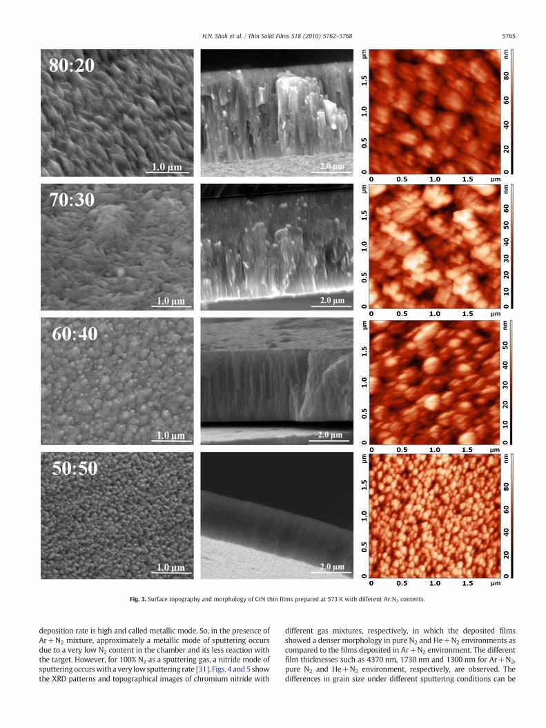
Fig. 3. Surface topography and morphology of CrN thin films prepared at 573 K with different Ar:N2 contents.
5765H.N. Shah et al. / Thin Solid Films 518 (2010) 5762–5768
deposition rate is high and called metallic mode. So, in the presence ofAr+N2 mixture, approximately a metallic mode of sputtering occursdue to a very low N2 content in the chamber and its less reaction withthe target. However, for 100% N2 as a sputtering gas, a nitride mode ofsputteringoccurswith a very lowsputtering rate [31]. Figs. 4 and5 showthe XRD patterns and topographical images of chromium nitride with
different gas mixtures, respectively, in which the deposited filmsshowed a denser morphology in pure N2 and He+N2 environments ascompared to the films deposited in Ar+N2 environment. The differentfilm thicknesses such as 4370 nm, 1730 nm and 1300 nm for Ar+N2,pure N2 and He+N2 environment, respectively, are observed. Thedifferences in grain size under different sputtering conditions can be
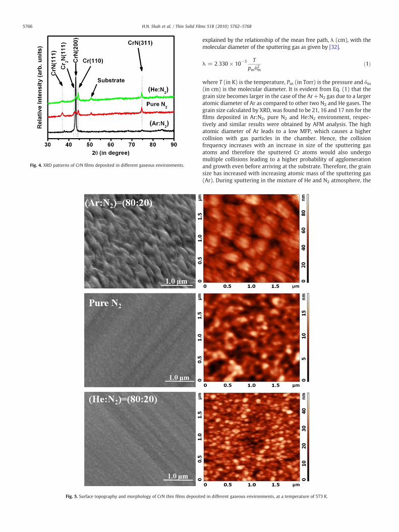
Fig. 4. XRD patterns of CrN films deposited in different gaseous environments.
Fig. 5. Surface topography and morphology of CrN thin films deposit
5766 H.N. Shah et al. / Thin Solid Films 518 (2010) 5762–5768
explained by the relationship of the mean free path, λ (cm), with themolecular diameter of the sputtering gas as given by [32].
λ = 2:330 × 10−3 Tpmδ
2m
ð1Þ
where T (in K) is the temperature, Pm (in Torr) is the pressure and δm(in cm) is the molecular diameter. It is evident from Eq. (1) that thegrain size becomes larger in the case of the Ar+N2 gas due to a largeratomic diameter of Ar as compared to other two N2 and He gases. Thegrain size calculated by XRD, was found to be 21, 16 and 17 nm for thefilms deposited in Ar:N2, pure N2 and He:N2 environment, respec-tively and similar results were obtained by AFM analysis. The highatomic diameter of Ar leads to a low MFP, which causes a highercollision with gas particles in the chamber. Hence, the collisionfrequency increases with an increase in size of the sputtering gasatoms and therefore the sputtered Cr atoms would also undergomultiple collisions leading to a higher probability of agglomerationand growth even before arriving at the substrate. Therefore, the grainsize has increased with increasing atomic mass of the sputtering gas(Ar). During sputtering in the mixture of He and N2 atmosphere, the
ed in different gaseous environments, at a temperature of 573 K.

Fig. 6. XRD patterns of CrN films deposited at different temperatures in pure N2
environment.
Fig. 7. Surface topography and morphology of CrN thin films de
5767H.N. Shah et al. / Thin Solid Films 518 (2010) 5762–5768
ionized He atoms bombarding the target might have backscatteredand implanted into the films. In the sputter deposition system, thedeposition rate is limited by sputtering gas ionization and itssputtering yield, sputtered atom diffusion from the target to thesubstrate. The sputtering yield of Cr element, in He and Ar gasenvironment, is 0.17 and 1.18, respectively, at 500 eV [33]. However,the use of helium gas as the sputtering gas may be advantageous forionization of elements as it eliminates some of the commonpolyatomic interferences associatedwith conventional argon plasmas.
3.3. Effect of substrate temperature
The CrN films deposited in pure N2 environment, at differenttemperatures, were analyzed and the influence of substrate temper-ature on the microstructure of the films is explained using a structurezone diagram. The columnar structure is observed in CrN films whenthe ratio of substrate temperature (Ts) and its melting temperature(Tm), (Ts/Tm)≤0.3, with voids in the grain boundaries due to very lowmobility of adatoms on the surface. When Ts/Tm≥0.3 and ≤0.45, thestructure has changed to a columnar structure with a dense grainboundary array, due to the changes in plasma state occurring betweenthe target and substrate with the increasing substrate temperature. At
posited in pure N2 environment at different temperatures.

5768 H.N. Shah et al. / Thin Solid Films 518 (2010) 5762–5768
high substrate temperature, above 773 K, the temperature of thetarget surface also increases due to thermal radiation. It causes thechanges in plasma volume, and affects the ion density and electrondensity [26]. The film thickness decreases to 1810 nm, 1730 nm and1550 nm for the substrate temperature 473 K, 573 K and 673 Krespectively, during deposition of CrN films as shown in Figs. 6 and 7.Also, the film density increases with an increase in temperature. Asexplained above, the deposition in pure nitrogen environment leadsto a low deposition rate owing to nitride mode. The observed lowdeposition rate at high substrate temperature, 673 K, despite the highadatom mobility during the nitride mode of deposition, is probablydue to more collision between sputtered particle and gas atom, whichcauses less number of atoms to arrive on the substrate.
3.4. Microhardness
The microhardness of magnetron sputtered CrN films depends onthe nitrogen content used in the deposition chamber [13]. At a low N2
content up to 30%, the dual phase CrN+Cr2N films are observed in thefilms, which showed a high hardness of 16.95 GPa. It is due to thehexagonal crystal structure and strong covalent bonding exhibited bythe Cr2N phase present in the films. The lower hardness of CrN films ascompared to Cr2N films may be due to its higher degree of ionicity ofthe bonding [3].
It is observed that the microhardness of CrN films depends oncomposition, morphology, crystal structure and its orientation. Thegrowing film is bombarded by low density ions and therefore, theratio of the number of ions to the number of neutral chromium atomsis low for magnetron sputtering. The formation of ions and release ofCr atoms from the target depends on the current density anddeposition rate, respectively, which in turn affect the morphology ofthe deposited films. Also, during film deposition in the magnetronsputtering with pure N2 environment, the grain growth becomesinevitable with increasing Ts as it leads to the formation of columnarmorphology of the grains in the films. The microhardness of CrN thinfilms decreases due to the grain growth facilitating the formation ofcolumnar grains as observed in the present work. The columnargrowth of the film is suppressed by using a comparatively highernitrogen content in the chamber, 50%, which facilitates re-nucleationkinetics for the formation of fine grains.
4. Conclusion
TheCrNfilmshavebeendepositedon stainless steel (Grade: SA-304)substrates using reactive magnetron sputtering. The influence ofsubstrate temperature and varying contents of N2 and Ar gases on themorphological and microhardness of the CrN thin films has beeninvestigated by using XRD, SEM, AFM, and microhardness tester. It hasbeen observed that the grain size of CrN thin films decreases with anincrease in nitrogen content in the sputtering chamber. The filmsbecome denser at high nitrogen percentage in the gas mixture. Thesurface roughness of CrN films decreases with increasing nitrogencontent and substrate temperature. The films deposited in He+N2
atmosphere exhibits lower film thickness and grain size as compared to
films deposited in Ar+N2 atmosphere. This may be due to lowersputtering yield of helium ions than argon ions. A mixture of differentgases affects the surface morphology, grain size and microhardness ofCrN thin films. The formation of amixture of CrN+Cr2N phase occurredup to 30% nitrogen content in the chamber; while at very high N2
content, single-phase CrNhas been observed in the films. The filmswithCrN+Cr2N phase exhibit higher hardness (16.95 GPa) than that of thefilms with CrN (10.50 GPa).
Acknowledgements
One of the authors, Hetal N Shah, would like to thank themanagement of Charotar University of Science and Technology, Changafor their sponsorship in the research work and Quality ImprovingProgram of AICTE, New Delhi, in India for their partial financial support.
References
[1] Y. Shi, S. Long, L. Fang, F. Pan, H. Liao, Appl. Surf. Sci. 255 (2009) 6515.[2] Y. Gachon, A.B. Vannes, G. Farges, M.C. Sainte Catherine, I. Caron, G. Inglebert,
Wear 233–235 (1999) 263.[3] M. Bielawski, D. Seo, Surf. Coat. Technol. 200 (2005) 1476.[4] P. Hones, R. Sanjines, F. Levy, Surf. Coat. Technol. 94/95 (1997) 398.[5] J. Musil, P. Baroch, J. Vlcek, K.H. Nam, J.G. Han, Thin Solid Films 475 (2005) 208.[6] I. Safi, Surf. Coat. Technol. 127 (2000) 203.[7] J.N. Tu, J.G. Duh, S.Y. Tsai, Surf. Coat. Technol. 133/134 (2000) 181.[8] R. Gahlin, M. Bromark, P. Hedenqvist, S. Hogmark, G. Hakansson, Surf. Coat.
Technol. 76/77 (1995) 174.[9] A.P. Ehiasarian, P.Eh. Hovsepian, L. Hultman, U. Helmersson, Thin Solid Films 457
(2004) 270.[10] Y. Otani, S. Hofmann, Thin Solid Films 287 (1996) 188.[11] B. Gu¨nter, F. Christoph, B. Erhard, B. Christina, Surf. Coat. Technol. 86/87 (1996)
184.[12] D. Dubiel, Prakt. Met. 26 (1989) 68.[13] J.A. Sue, T.P. Chang, Surf. Coat. Technol. 76/77 (1995) 61.[14] H.C. Barshilia, N. Selvakumar, B. Deepthi, K.S. Rajam, Surf. Coat. Technol. 201
(2006) 2193.[15] Z. Han, J. Tian, Q. Lai, X. Yu, G. Li, Surf. Coat. Technol. 162 (2003) 189.[16] E. Fornies, R. Escobr Galindo, O. Sanchez, J.M. Albella, Surf. Coat. Technol. 200
(2006) 6047.[17] P. van Essen, R. Hoy, J.D. Kamminga, A.P. Ehiasarian, G.C.A.M. Janssen, Surf. Coat.
Technol. 200 (2006) 3496.[18] J.J. Olaya, S.E. Rodil, S. Muhl, E. Sanchez, Thin Solid Films 474 (2005) 119.[19] F. Levy, P. Hones, P.E. Schmid, R. Sanjines, M. Diserens, C. Wiemer, Surf. Coat.
Technol. 120/121 (1999) 284.[20] F.B. Wu, J.J. Li, J.G. Duh, Thin Solid Films 377/378 (2000) 354.[21] Z.B. Zhao, Z.U. Rek, S.M. Yalisove, J.C. Bilello, Thin Solid Films 472 (2005) 96.[22] K.H. Nam, M.J. Jung, J.G. Ham, Surf. Coat. Technol. 131 (2000) 222.[23] L. Cunha, M. Andritschky, Surf. Coat. Technol. 111 (1999) 158.[24] L. Cunha, M. Andritschky, K. Pischow, Z. Wang, Thin Solid Films 355/356 (1999)
465.[25] H.C. Barshilia, K.S. Rajam, Surf. Coat. Technol. 201 (2006) 1827.[26] M. Ohring, Material Science of Thin Films: Deposition and Structure, Academic
Press, California, 2002.[27] G.A. Zhang, P.X. Yan, P. Wang, Y.M. Chen, Y.J. Zhang, Mater. Sci. Eng., A 460/461
(2007) 301.[28] B.D. Cullity, Elements of X-Ray Diffraction, Addison Wesley California, 2001.[29] C. Meunier, S. Vives, G. Bertrand, Surf. Coat. Technol. 107 (1998) 149.[30] R. Chandra, A. Chawla, P. Ayyub, J. Nanosci. Nanotech. 6 (2006) 1119.[31] H. Sumi, H. Inoue, M. Taguchi, Y. Sugano, H. Masuya, N. Ito, S. Kishida, H. Tokutaka,
Jpn. J. Appl. Phys. 36 (1997) 595.[32] R. Chandra, A. Chawla, D. Kaur, P. Ayyub, Nanotechnology 16 (2005) 3053.[33] L.I. Maissel, R. Glang, Handbook of Thin Film Technology, New York, , 1970.
Copyright © 2022 FDOKUMEN