Understanding deposition rate loss in high power impulse magnetron sputtering: I. Ionization-driven...
17
Understanding deposition rate loss in high power impulse magnetron sputtering: I. Ionization-driven electric fields N Brenning, C Huo, Daniel Lundin, M A Raadu, C Vitelaru, G D Stancu, T Minea and Ulf Helmersson Linköping University Post Print N.B.: When citing this work, cite the original article. Original Publication: N Brenning, C Huo, Daniel Lundin, M A Raadu, C Vitelaru, G D Stancu, T Minea and Ulf Helmersson, Understanding deposition rate loss in high power impulse magnetron sputtering: I. Ionization-driven electric fields, 2012, Plasma sources science & technology (Print), (21), 2, 025005. http://dx.doi.org/10.1088/0963-0252/21/2/025005 Copyright: Institute of Physics http://www.iop.org/ Postprint available at: Linköping University Electronic Press http://urn.kb.se/resolve?urn=urn:nbn:se:liu:diva-77328
-
Upload
independent -
Category
Documents
-
view
0 -
download
0
Transcript of Understanding deposition rate loss in high power impulse magnetron sputtering: I. Ionization-driven...

Understanding deposition rate loss in high
power impulse magnetron sputtering: I.
Ionization-driven electric fields
N Brenning, C Huo, Daniel Lundin, M A Raadu, C Vitelaru, G D Stancu,
T Minea and Ulf Helmersson
Linköping University Post Print
N.B.: When citing this work, cite the original article.
Original Publication:
N Brenning, C Huo, Daniel Lundin, M A Raadu, C Vitelaru, G D Stancu, T Minea and Ulf
Helmersson, Understanding deposition rate loss in high power impulse magnetron sputtering:
I. Ionization-driven electric fields, 2012, Plasma sources science & technology (Print),
(21), 2, 025005.
http://dx.doi.org/10.1088/0963-0252/21/2/025005
Copyright: Institute of Physics
http://www.iop.org/
Postprint available at: Linköping University Electronic Press
http://urn.kb.se/resolve?urn=urn:nbn:se:liu:diva-77328

1
Understanding deposition rate loss in high power impulse magnetron sputtering
N. Brenning1, D. Lundin
2, M. A. Raadu
1, C. Huo
1, C. Vitelaru
3,4, G. D. Stancu
3,
T. Minea3 , and U. Helmersson
2
1 Division of Space and Plasma Physics, School of Electrical Engineering, Royal Institute of
Technology, SE-100 44 Stockholm, Sweden
2 Plasma & Coatings Physics Division, IFM-Materials Physics, Linköping University, SE-581 83
Linköping, Sweden
3 Laboratoire de Physique des Gaz et Plasmas, UMR 8578 CNRS, Université Paris Sud-XI, 91405
Orsay Cedex, France
4 Physics Department, Faculty of Physics Al I Cuza University, Bd. Carol No 11, Iasi, 700506,
Romania
E-mail: [email protected]
Abstract
The lower deposition rate for high power impulse magnetron sputtering (HiPIMS) compared
to direct current magnetron sputtering for the same average power is often reported as a
drawback. The often invoked reason is back-attraction of ionized sputtered material to the
target, due to a substantial negative potential profile from the location of ionization towards
the cathode. Emitting and swept Langmuir probes have yielded space- and time resolved
electric potential profiles and electron energy distributions, Rogowski coils have been used to
obtain current density distributions. Also, space- and time resolved, and fast imaging
techniques show how the time evolution of the discharge structure varies with gas pressure
and species. This combined data set is here used to benchmark two different types of plasma
models for different regions of the HiPIMS discharges, with special focus on the problem of
electric fields zE in the high density plasma region and their effect on the transport of ionized
sputtered material. We propose two different mechanisms to be dominating in different
regions: “ionization driven” ,z ionizE in a rather stable ionization region extending a few cm
from the target, and “transport driven” ,z transE in the highly dynamic surrounding bulk plasma.

2
1. Introduction
One of the main advantages with high power impulse magnetron sputtering (HiPIMS)
is the dramatic increase of the degree of ionization of the metallic vapor [1,2] which
opens a completely new perspective in the engineering and design of new thin film
materials [1]. However, a problem with using ions is that the electric potential applied
to the target and the resulting electrical field zE can reduce the deposition rate
seriously if they extend outside the cathode sheath, into the dense plasma. In Christie-
type models (see Figure 1a) [3,4] a key variable is the back-attraction parameter, β, of
ionized metal M+. An electric field Ez in the plasma (see Figure 1b) can turn such ions
around, increase β, and decrease the deposited fraction δ of the M+ ions. Recent probe
data [5,6] have shown that in HiPIMS there can be a potential uphill from the sheath
edge to the bulk of the plasma that can vary at least in the range 7-60 V, with stronger
Ez generally observed closer to the target, as well as for stronger magnetic field, for
stronger applied power, and during the early stage of the HiPIMS pulse.
For a discussion on Ez in HiPIMS discharges we divide the plasma into two
regions (see Figure 1c) in which different mechanisms for Ez are proposed to
dominate. In the ionization region (IR) extending a few cm from the target there are
“ionization driven” ,z ionizE , essentially forced by the energy and particle balance
conditions for a self-sustained discharge. In the surrounding bulk plasma (BP)
“transport driven” fields ,z transE are needed to close the discharge current ID by
electron transport across the magnetic field lines to the anode.

3
Figure 1. a), b) The role of zE for the M particle dynamics in magnetron sputtering. c) Cross-
sectional view of the magnetron describing two plasma regions: the ionization region (IR) and the
bulk plasma (BP) region, where different mechanisms are proposed to give rise to Ez.
2. Ionization driven electric fields Ez,ioniz
As a basic driving mechanism for generation of zE fields in the ionization region it is
here proposed the need to heat the electrons enough for a self sustained ion particle
balance as shown in Figure 2. We first pose the question: assuming that there are no
electric fields outside the plasma sheath region, under what conditions can the ion
losses from the ionization region be replaced by electron impact ionization? For
parameters where they cannot, we will have to return to the much more difficult
question of how Ez in the ionization region can help to alleviate the situation. We will
refer to such fields as “ionization driven” and denote them by ,z ionizE .
Consider in Figure 2 an Ar+ ion that hits the target and emits a secondary
electron with a probability 0.1se . For steady-state this has to, on average, set a
chain of events into motion that leads to another Ar+ ion hitting the target. This
condition is quantified as follows. Under the assumption ,z ionizE = 0, SH DU U , where
USH and UD are the sheath and discharge potentials, respectively, it is found that the
emitted electron is accelerated to the energy DeU across the sheath. With an effective

4
cost of ionization eUi,EFF , and a fraction Ar
of the Ar+ ions drawn to the target, we
can define a Townsend product as
Figure 2. Model of the ionization region showing the reactions involved in Ar+ ion particle
balance. The parentheses around Ez and the potential difference across the ionization region, UIR,
indicate that these quantities are assumed to be zero in Eq. 1 and in the runs of the ionization
region model (IRM I).
,
DTownsend se Ar
i EFF
U
U . (1)
In steady-state, 1Townsend , while 1Townsend corresponds to a discharge that will
be depleted of plasma and become extinguished. 1Townsend can be seen as a
breakdown condition: a discharge can ignite but will not be in steady-state. As a
numerical example we take the parameters 0.1se , 600DU V, , 35i EFFU eV*
(see also reference 7), and a rather efficient collection of ions to the target, 0.8Ar
.
This gives 1.37Townsend , i.e. the breakdown condition is satisfied. As this numerical
example demonstrates, it is in principle possible to have a discharge without
ionization driven ,z ionizE fields, but the physical picture is far too simplistic to prove
certain that there is a large enough margin above the steady-state value. Better
modeling is therefore needed including a physically motivated estimate of Ar
,
* The effective costs of ionization ,i EFFU used in this paper are estimated from three contributing
mechanisms, (1) the collisional energy loss including ionization which depends on electron energy [7],
(2) heating the new electron to the bulk electron temperature, and (3) the energy cost of electron flow
from the ionization region to the bulk plasma.

5
realistic cross-sections for all species present, density growth and decay during a
HiPIMS pulse, Penning ionization, time-varying UD(t), gas rarefaction, the transition
to self-sputtering, etc.
In order to more carefully study if a discharge can be sustained assuming
,z ionizE = 0 simulations of the ionization region have been run using IRM 1, which is a
global plasma model [8,9] that includes these effects and can flexibly be adjusted to
different discharges. As a model system, data has been taken from a “reference
discharge” in Ar with a 15 cm in diameter Al target mounted on a slightly unbalanced
magnetron. The discharge is driven by a Sinex I HiPIMS power supply from Chemfilt
Ionsputtering, delivering 100 μs long discharge pulses with a peak current of 105 A
and a peak voltage of 700 V, which decreases monotonically to 200 V as the pulse
decays. Typical ID(t) - UD(t) characteristics can be found in works by Bohlmark et al.
[10]. The reason for this choice is that this particular magnetron has been extensively
diagnosed [2,10,11,12,13].
In IRM I, ID(t) and UD(t) are input parameters. One key output parameter is
the “required power to the electrons” in form of the fraction FPWR of the electric input
power IDUD(t). FPWR is normally adjusted using a self-consistency condition
1i se DI I t , where 1i seI is the calculated sum of the ion current and
secondary electron current to the target. The secondary emission coefficient, γse varies
in time since it depends on the time-varying fraction of Ar+ to M
+ ions (γse ≈ 0.1 for
Ar+ while γse ≈ 0 for M
+).
In this work, the model is not run for these self consistent solutions, since the
artificial condition ,z ionizE = 0 has been imposed. When this is the case, the only
source of energy in the plasma are secondary emitted electrons accelerated across the
sheath, and FPWR is locked to the value /(1 )PWR se seF . An advantage with the

6
assumption ,z ionizE = 0 is that the fraction to the target Ar
can be modeled rather
realistically. No ion flux in the ionization region is electric field driven, and Ar
is
Figure 3. Results from the IRM I. a) Density plot of M
n versus Ar
n for the parameters
0.88, 0.1Ar se . The plots b – d show modeled ion current to target compared to measured
discharge current for the parameters b) 0.88, 0.1Ar se c) 0.88, 0.06
Ar se and d)
0.36, 0.06Ar se .
determined by the relative ion diffusion speeds to, and sizes of, the different
boundaries to the ionization region. Here, two cases has been studied, assuming the
diffusive ion flow to the target (at the sheath edge) to be at the ion acoustic speed
using the electron temperature calculated in the model (2.7 eV at current maximum)
for both cases. The speed at the boundary to the bulk plasma is taken as one of two
extremes: the thermal speed at 300 K filling gas temperature (corresponding to distant
substrate and walls, and probably most resembling the chosen reference discharge), or
the ion acoustic speed (corresponding to a hypothetical case with close-lying substrate
and walls). The model assumes a 2 cm thick and 5 cm wide ionization region centered
over the race track giving approximate values 0.88Ar
(for distant chamber walls)
and 0.36Ar
(for close-lying chamber walls). Figure 3 shows results from three
IRM I runs with different γse and Ar
. The first run (Figure 3a and 3b) has parameters
γse = 0.1 and 0.88Ar
. Figure 3b shows the calculated ion current to the target Ii

7
and the input current ID(t). A discharge with these γse and Ar
seems to be possible,
since Ii is quite close to ID. This is also consistent with Eq. (1) which, with these γse
and Ar
and at current maximum ( DU = 430 V), gives 1.1Townsend . However, a
look at the Ar+ and M
+ densities (Figure 3a) shows that during the pulse there is an
approximate average 60/40 Ar+/M
+ ratio. For M
+, γse ≈ 0 and the assumed constant γse
= 0.1 during the pulse is therefore unrealistic. Closer to reality is the run in Figure 3c,
where γse = 0.06. This discharge can probably not be sustained since Ii < ID. Finally,
Figure 3d shows the effect of γse = 0.06 combined with enhanced ion losses to close-
lying substrate and walls ( 0.36Ar
). Under these conditions a discharge with
0zE is clearly not possible.
These results from the IRM I are in good agreement with those obtained
from Eq. (1), using the same γse, Ar
,and taking DU at current maximum. This
indicates that the simple model in Figure 2 captures the key elements of the much
more complicated discharge physics. Let us therefore extend the Townsend product to
make a crude estimate of how large ,z ionizE fields would be needed in the ionization
region to sustain the Ar ion particle balance. With , 0z ionizE , more ions are
redirected towards the target and the value of Ar
increases, with 1Ar
as a
definite upper limit. Furthermore, there will be increased ionization because the bulk
electrons are heated directly. Assuming that in the ionization region on the average
50 % of the current is carried by electrons, the total power input to the electrons is
( ) 0.5e D se D IR D IRP I U U I U . Taking into account the different costs of ionization
of the secondary electrons (hot) and the bulk electrons (cold), the Townsend product
becomes

8
, , , ,
0.5D IR IRTownsend se Ar
i EFF h i EFF c
U U U
U U
. (2)
When 0IRU , the earlier Eq. (1) is recovered. For a numerical example we take
current maximum ( DU = 430 V), 1Townsend for steady-state, Ar
and γse as in
Figure 3c, , , 60i EFF cU eV and , , 35i EFF hU (see footnote *). This inserted in Eq. (2)
gives UIR ≈ 60 V, in the higher end of the observed range 7 – 60 V. The absolute
value of this estimate must be regarded as very uncertain, but it clearly indicates that
,z ionizE fields are likely for normal operating HiPIMS conditions.
3. Transport driven electric fields Ez,trans
In the bulk plasma, electrons have to move across the magnetic field lines in order to
arrive at the anode and close the current loop, as illustrated in Figure 1c. In this region
transport driven fields ,z transE will appear in order to make that possible. Cross-B
discharge current density and electric fields are related through the component along
E of the generalized Ohm’s law [14,15]
2
/1 ( )
ge EFFe
P ge EFF
n eJE J
B
(3)
Eq. 3 can be used to model the potential V(r,z), and the current density distribution
J(r,z), provided that ID, ne (electron density), ge EFF (electron angular gyration
frequency times the effective collision time), and B(r,z) are known [16]†. P is the
Pedersen conductivity across B(r,z).
Let us look at what is known regarding the needed input data ne and ge EFF .
Optical emission measurements by Hala et al. [17] show that the bulk plasma can
† In reference 16, it is also assumed that 0 E B .
9
expand with a speed in the range 1 - 3.5 km/s depending on species and pressure.
From Langmuir and magnetic probe measurements [10,11], the expansion speed in
our
Figure 4. Electron drift directions across B in the HiPIMS discharge at different times: a) 30 μs
(pulse rise) b) 50 μs (pulse peak) c) 85μs (pulse decay) (after Lundin [18]). The shaded area
schematically illustrates the expansion of plasma with a front speed of 1 km/s [10,11]. The dashed
line represents the plasma front.
reference magnetron is estimated to be about 1 km/s. Recent measurements of the
internal currents [18] have shown how these evolve in space and time. In Figure 4, the
temporal change of the cross-B electron transport during a HiPIMS pulse is proposed
based on these measurements. During the initial part of the pulse, when there is little
plasma in the bulk volume, most of the cross-B current flows radially close to the
target (Figure 4a). As the plasma expands into the bulk volume the current system
gradually changes, on a 50 – 100 μs time scale, towards a vertical current channel
(figure 4c) resembling that in direct current magnetron sputtering (DCMS).
Now let us turn to ge EFF . In the bulk plasma the current is carried mainly by
electrons, and the relation /ge EFF J J [13,19] can be used to obtain ge EFF
from /J J measurements. This has earlier been done in DCMS [20], in pulsed
DCMS [21], and in HiPIMS [10,12], but always built on some assumed distribution of
J . In view of the now known temporal redistribution shown in Figure 4 they must
therefore be regarded as uncertain. Still, the trend is clear. In DCMS, ge EFF lies

10
within a factor of two from the Bohm value [14] 16ge EFF , a result also reported
from recent particle in cell Monte Carlo simulations [22]. In pulsed DCMS and
HiPIMS the values are significantly lower, in the studies above uniformly reported as
Figure 5. Measured ge EFF
above the target race track for three different times during the
HiPIMS discharge (after Lundin [18]).
2ge EFF . This now has to be revised. The first space- and time resolved current
measurements [18] shows a more complicated picture, see Figure 5, with higher
ge EFF values closer to the target, and also with some time variation. We here only
note that around z = 4 cm a “best estimate” could be 8ge EFF , but with an
uncertainty by perhaps a factor of two.
In view of the uncertainties in both en and ge EFF , quantitative modeling of
transport driven ,z transE based on Eq. (3) is probably not feasible at the moment. It is
here only demonstrated that such fields are likely, and how sensitive they are to the
uncertainty in ge EFF . Figure 6 shows results from the bulk plasma model of
Brenning et al. [16]. Input parameters are the magnetic field B(r,z) of our reference

11
magnetron, the peak current ID = 105 A, and density estimates based on earlier probe
measurements [10,11] in the same device. ge EFF is assumed to be constant in the
volume. As can be seen in Figure 6, the earlier proposed value 2ge EFF (which
Figure 6. Calculated potential profiles above the target race track for different ge EFF using
the bulk plasma model. The dashed curve denotes 8ge EFF and the dashed bars denote a
range of ± 4 around that value. The results are adapted from Brenning et al. [16]
was believed to be correct at the time of the publication [16]), results in unrealistically
low Ez, with potential variations of only a few volts above the race track. The Bohm
value 16ge EFF would give ~ 50 V from sheath edge to bulk plasma, while the
“best estimate” 8ge EFF from Figure 5 results in ~ 10 V. This is large enough to
significantly increase the M back-attraction and also consistent (within a factor of
two) with probe measurements in the same device [5].

12
4. Summary and discussion
Recent measurements in two different HiPIMS devices [5,6] have shown electric
fields zE in the plasma that are strong enough to cause considerable back-attraction of
the ionized sputtered species M . The associated potential uphill extended a distance
of 5 – 6 cm from the sheath edge into the plasma, and had amplitudes in the range 6 –
70 V. HiPIMS discharges should be possible to optimize with respect to such electric
fields since they in these experiments varied with parameters that can be externally
controlled as the magnetic field strength [6], the gas pressure [5,6], and the applied
power [6]. It is also very likely that they can be influenced by varying the pulse shape
and length: the zE fields are generally stronger closer to the target, and during the
phases of breakdown and current rise [6].
Outside the sheath, on a larger scale length, there is a always a presheath [14]
in which the ions are accelerated to the Bohm speed by a potential drop
/(2 )B ek T e , in HiPIMS magnetrons at most a few volts. Let us call the associated
field ,z presheathE . We here propose that in addition to ,z presheathE , zE fields in the plasma
are driven mainly by two mechanisms, and that these dominate in different regions of
the discharge. Ionization driven fields ,z ionizE can be expected in an ionization region
extending a few cm from the target, approximately corresponding to the negative
glow in dc glow discharges. These ,z ionizE fields are forced by the energy and particle
balance conditions for a self sustained discharge. The other type of fields are transport
driven ,z transE , needed to carry the electrons across the magnetic field lines in the
surrounding bulk plasma. The limit between these two mechanisms should not be
expected to be sharp: there is a need to carry electrons across the magnetic field also
in the ionization region, and there is ionization also in the bulk plasma. Where
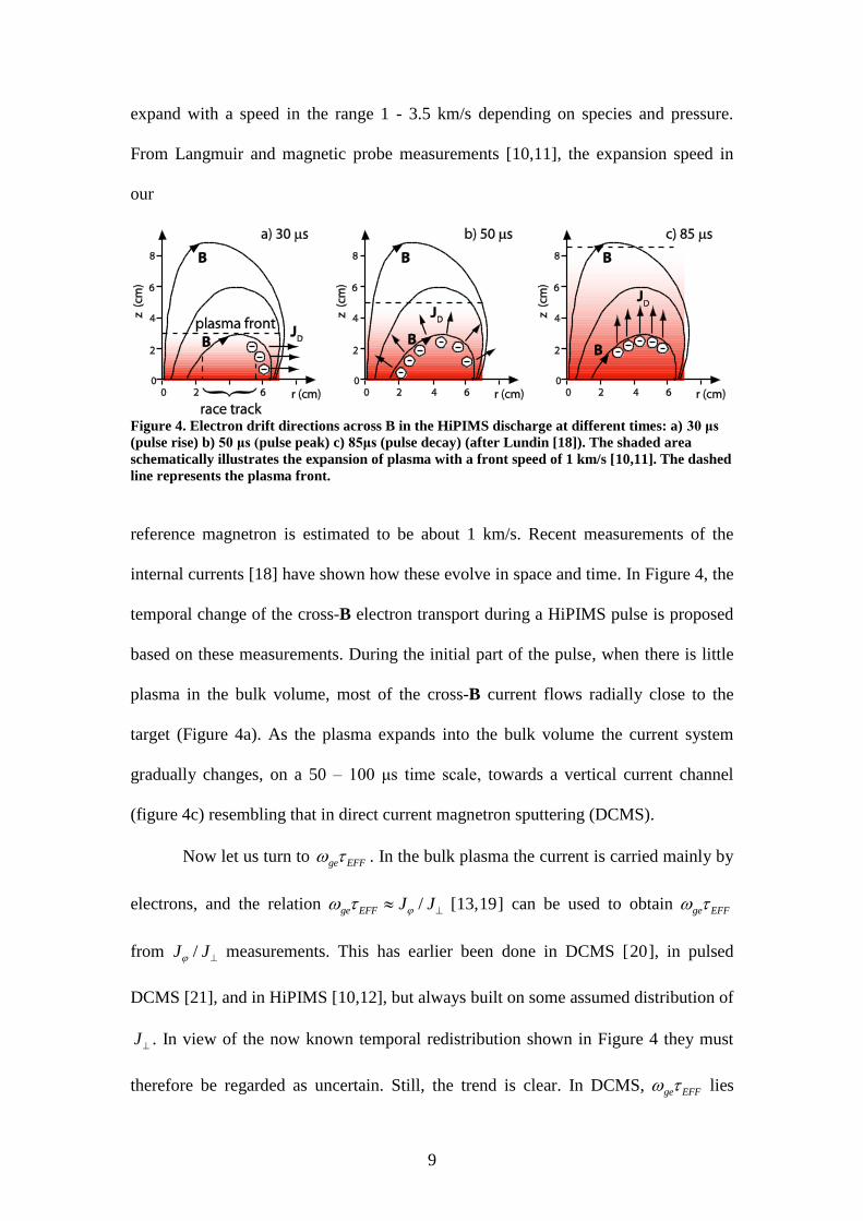
13
different mechanisms overlap, the strongest required field should result, i.e.
, , ,max( , , )z z presheath z ioniz z transE E E E .
Modeling of these two types of zE fields (see sections 2 and 3 above)
indicates that both are likely to arise under normal HiPIMS operating conditions, and
also that they are of the same order as those observed. Identified risk factors, leading
to high zE in the models, are: (1) close-lying substrates and walls that result in large
ion loss fluxes, and a high wall loss rate of electron energy, (2) fast rising currents
with the need of an ionization rate per electron that is far above that in steady-state, (3)
gas depletion caused by long and/or high energy pulses, which forces the discharge
towards the self-sputtering mode in which the low γse for M ions is an additional
problem, (4) a low density in the bulk plasma which forces electron transport to go
across the stronger magnetic fields closer to the target, and (5) strong magnetic fields
above the race track which gives higher transport driven ,z transE for a given current
density.
Even with a known potential profile ( , , )V r z t , the effective back-attraction is
a complicated function and depends also the plasma profile ( , , )en r z t . Out of the
sputtered energy distribution of neutrals emitted from the target, sputteredf E , the
components with higher velocity vz will on the average become ionized at larger
distances from the target, have a larger directed energy 2 / 2M zm v , and also a lower
remaining potential hill to climb. The combination of these effects leads to a high-
energy filtering of the M+ flux that can reach the substrate. A proper evaluation of the
back-attraction would require at least Monte Carlo simulations over sputteredf E
including collisions with the background gas.

14
Acknowledgements
This work was partly supported by the Swedish Research Council, the Swedish
Foundation for Strategic Research, the European Collaboration in Science and
Technology (COST Action: MP0804), the ANH HiPPoPP (French Government
Research Agency), and the Romanian ministry of Education, Research, Youth and
Sport, Grant IDEI 540/2009.
References
[1] Helmersson U, Lattemann M, Bohlmark J, Ehiasarian A P and Gudmundsson J T
2006 Thin Solid Films 513 1
[2] Bohlmark J, Lattemann M, Gudmundsson J T, Ehiasarian A P, Aranda Gonzalvo
Y, Brenning N and Helmersson U 2006 Thin Solid Films 515 1522
[3] Christie D J 2005 J. Vac. Sci. Technol. A 23 330
[4] Andersson J and Anders A 2009 Phys. Rev. Lett. 102 045003
[5] Sigurjonsson P 2008 Master’s Thesis: Spatial and temporal variation of the
plasma parameters in a high power impulse magnetron sputtering (HiPIMS)
discharge (Reykjavik: Faculty of Engineering, University of Iceland)
[6] Mishra A, Kelly P J and Bradley J W 2010 Plasma Sources Sci. Technol. 19
045014
[7] Lieberman M A and Lichtenberg A J 1994 Principles of Plasma Discharges and
Materials Processing (New York: John Wiley & Sons) p 81
[8] Samuelsson M, Lundin D, Jensen J, Raadu M A, Gudmundsson J T and
Helmersson U 2010 Surf. Coat. Technol. 205 591

15
[9] Raadu M A, Axnäs I, Gudmundsson J T and Brenning N 2010 manuscript in
preparation
[10] Bohlmark J, Helmersson U, VanZeeland M, Axnäs I, Alami J and Brenning N
2004 Plasma Sources Sci. Technol. 13 654
[11] Bohlmark J, Gudmundsson J T, Alami J, Lattemann M and Helmersson U 2005
IEEE Trans. Plasma Sci. 33 346
[12] Lundin D, Helmersson U, Kirkpatrick S, Rohde S and Brenning N 2008 Plasma
Sources Sci. Technol. 17 025007
[13] Lundin D, Larsson P, Wallin E, Lattemann M, Brenning N and Helmersson U
2008 Plasma Sources Sci. Technol. 17 035021
[14] Chen F F 1984 Introduction to Plasma Physics and Controlled Fusion Vol. I:
Plasma Physics (New York: Plenum)
[15] Spitzer L 1962 Physics of Fully Ionized Gases 2nd
ed. (New York: John Wiley &
Sons)
[16] Brenning N, Axnäs I, Raadu M A, Lundin D and Helmerson U 2008 Plasma
Sources Sci. Technol. 17 045009
[17] Hala M, Viau N, Zabeida O, Klemberg-Sapieha J W and Martinu L 2010 J. Appl.
Phys. 107 043305
[18] Lundin D 2010 Doctoral Thesis: The HiPIMS Process, (Linköping: Linköping
University)
[19] Rossnagel S M and Kaufman H R 1987 J. Vac. Sci. Technol. A 5 2276
[20] Bradley J W, Thompson S and Aranda Gonzalvo Y 2001 Plasma Sources Sci.
Technol. 10 490
[21] Vetushka A and Bradley J W 2007 J. Phys. D: Appl. Phys. 40 2037

16
[22] E. Bultinck E, Mahieu S, Depla D and Bogaerts A 2010 J. Phys. D: Appl. Phys.
43 292001