Microstructure and properties of hard and wear resistant MMC coatings deposited by laser cladding
7
Microstructure and properties of hard and wear resistant MMC coatings deposited by laser cladding Janne Nurminen a , Jonne Näkki a , Petri Vuoristo a,b, * a Technology Centre KETEK Oy, Korpintie 8, FI-67100 Kokkola, Finland b Tampere University of Technology, Department of Materials Science, Korkeakoulunkatu 6, FI-33720 Tampere, Finland article info Article history: Received 30 September 2008 Accepted 2 October 2008 Keywords: Laser coating Laser cladding MMC Carbides Wear Microstructure abstract Laser coating (laser cladding) is a useful method to produce metal matrix composite (MMC) coatings. The selection of the metallic matrix can be done on the base of the intended application and environment, whereas the additional wear resistance improvement is provided by mixing various carbides with the metallic matrix. In the present work, various types of MMC coatings were prepared by laser coating methods. The coatings consisted of vanadium, tungsten, titanium and chromium carbide hard phases mixed with metallic tool steel M2, Stellite 21, NiCrBSi-alloy and Inconel 625. Different levels of carbide contents were used. The abrasion resistance of the MMC coatings has been tested using a rubber-wheel abrasion apparatus. The wear surfaces were examined and the microstructures of MMC coatings were analysed in order to determine microstructures and carbide dissolution. The best abrasion results were achieved by the correct choice of carbide for each matrix material. Ó 2008 Elsevier Ltd. All rights reserved. 1. Introduction Metal matrix composites (MMC) are very common abrasion resistant materials. The basic structure contains a relatively soft matrix and a harder phase that provides high abrasion resistance. There are two basic metallurgical ways to achieve such a structure: the hard phase can be generated through segregation from molten metal or the hard phase can be introduced to the matrix as is. The best example of in situ hard phase generation is chromium carbide welding materials that are very commonly used in many industrial sectors. The best examples of the latter cases are HVOF-tungsten carbide coatings and sintered MMC-components. Laser cladding is still a rather unknown industrial coating meth- od that can be used for manufacturing metal matrix components. The basic method includes a laser beam that melts the powder material injected into a melt pool on the surface of the substrate. The result is a fully dense, metallurgically bonded coating, usually 0.5–3 mm thick. Metal matrix composites are built up by blowing metal powder simultaneously with hard powder, usually carbides, into a melt pool that the laser beam generates. The aim is to keep the carbides intact with minimal dissolution and melt only the ma- trix material. Because of the low heat input of laser cladding it can usually be achieved, providing that the difference of melting tem- peratures of matrix and the carbides is high enough. There are plenty of scientific papers containing information about MMC laser coatings. For instance: tungsten carbides [1–3], vanadium carbides [4] and titanium carbides [5,6]. However, com- parative abrasion data is often lacking for different metal matrixes and carbide types. This study tries to cover this lack of knowledge. 2. Experimental The samples for abrasion tests were manufactured by laser cladding with following equipment: Rofin-Sinar DY044 diode pumped Nd:YAG laser power source with 600 lm fiber connection, Medicoat dual powder feeder with gravimetric controls and Preci- tec cladding head. After cladding, the samples were ground before set on abrasion tests. The surfaces of the coatings were ground by using an industrial planar grinding machine and a diamond grind- ing tool. The coating thicknesses after grinding were of the order of 1.5 mm. 2.1. Materials All matrix materials were gas atomized metal powders with spherical shape. The carbide powders are presented in Fig. 1. All powders have a distinct look (morphology) which has some effect on abrasion results. The porous appearance of VC should increase dissolution during processing. On the other hand, the 0263-4368/$ - see front matter Ó 2008 Elsevier Ltd. All rights reserved. doi:10.1016/j.ijrmhm.2008.10.008 * Corresponding author. Address: Tampere University of Technology, Department of Materials Science, Korkeakoulunkatu 6, FI-33720 Tampere, Finland. Tel.: +358 40 849 0044; fax: +358 3 3115 2330. E-mail address: petri.vuoristo@tut.fi (P. Vuoristo). Int. Journal of Refractory Metals & Hard Materials 27 (2009) 472–478 Contents lists available at ScienceDirect Int. Journal of Refractory Metals & Hard Materials journal homepage: www.elsevier.com/locate/IJRMHM
Transcript of Microstructure and properties of hard and wear resistant MMC coatings deposited by laser cladding
Int. Journal of Refractory Metals & Hard Materials 27 (2009) 472–478
Contents lists available at ScienceDirect
Int. Journal of Refractory Metals & Hard Materials
journal homepage: www.elsevier .com/locate / IJRMHM
Microstructure and properties of hard and wear resistant MMC coatingsdeposited by laser cladding
Janne Nurminen a, Jonne Näkki a, Petri Vuoristo a,b,*
a Technology Centre KETEK Oy, Korpintie 8, FI-67100 Kokkola, Finlandb Tampere University of Technology, Department of Materials Science, Korkeakoulunkatu 6, FI-33720 Tampere, Finland
a r t i c l e i n f o
Article history:Received 30 September 2008Accepted 2 October 2008
Keywords:Laser coatingLaser claddingMMCCarbidesWearMicrostructure
0263-4368/$ - see front matter � 2008 Elsevier Ltd. Adoi:10.1016/j.ijrmhm.2008.10.008
* Corresponding author. Address: Tampere Universiof Materials Science, Korkeakoulunkatu 6, FI-33720 Ta849 0044; fax: +358 3 3115 2330.
E-mail address: [email protected] (P. Vuoristo).
a b s t r a c t
Laser coating (laser cladding) is a useful method to produce metal matrix composite (MMC) coatings. Theselection of the metallic matrix can be done on the base of the intended application and environment,whereas the additional wear resistance improvement is provided by mixing various carbides with themetallic matrix. In the present work, various types of MMC coatings were prepared by laser coatingmethods. The coatings consisted of vanadium, tungsten, titanium and chromium carbide hard phasesmixed with metallic tool steel M2, Stellite 21, NiCrBSi-alloy and Inconel 625. Different levels of carbidecontents were used. The abrasion resistance of the MMC coatings has been tested using a rubber-wheelabrasion apparatus. The wear surfaces were examined and the microstructures of MMC coatings wereanalysed in order to determine microstructures and carbide dissolution. The best abrasion results wereachieved by the correct choice of carbide for each matrix material.
� 2008 Elsevier Ltd. All rights reserved.
1. Introduction
Metal matrix composites (MMC) are very common abrasionresistant materials. The basic structure contains a relatively softmatrix and a harder phase that provides high abrasion resistance.There are two basic metallurgical ways to achieve such a structure:the hard phase can be generated through segregation from moltenmetal or the hard phase can be introduced to the matrix as is. Thebest example of in situ hard phase generation is chromium carbidewelding materials that are very commonly used in many industrialsectors. The best examples of the latter cases are HVOF-tungstencarbide coatings and sintered MMC-components.
Laser cladding is still a rather unknown industrial coating meth-od that can be used for manufacturing metal matrix components.The basic method includes a laser beam that melts the powdermaterial injected into a melt pool on the surface of the substrate.The result is a fully dense, metallurgically bonded coating, usually0.5–3 mm thick. Metal matrix composites are built up by blowingmetal powder simultaneously with hard powder, usually carbides,into a melt pool that the laser beam generates. The aim is to keepthe carbides intact with minimal dissolution and melt only the ma-trix material. Because of the low heat input of laser cladding it can
ll rights reserved.
ty of Technology, Departmentmpere, Finland. Tel.: +358 40
usually be achieved, providing that the difference of melting tem-peratures of matrix and the carbides is high enough.
There are plenty of scientific papers containing informationabout MMC laser coatings. For instance: tungsten carbides [1–3],vanadium carbides [4] and titanium carbides [5,6]. However, com-parative abrasion data is often lacking for different metal matrixesand carbide types. This study tries to cover this lack of knowledge.
2. Experimental
The samples for abrasion tests were manufactured by lasercladding with following equipment: Rofin-Sinar DY044 diodepumped Nd:YAG laser power source with 600 lm fiber connection,Medicoat dual powder feeder with gravimetric controls and Preci-tec cladding head. After cladding, the samples were ground beforeset on abrasion tests. The surfaces of the coatings were ground byusing an industrial planar grinding machine and a diamond grind-ing tool. The coating thicknesses after grinding were of the order of1.5 mm.
2.1. Materials
All matrix materials were gas atomized metal powders withspherical shape. The carbide powders are presented in Fig. 1.
All powders have a distinct look (morphology) which has someeffect on abrasion results. The porous appearance of VC shouldincrease dissolution during processing. On the other hand, the
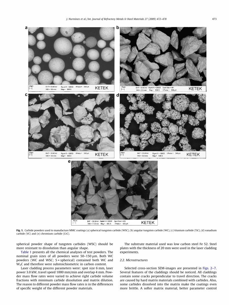
Fig. 1. Carbide powders used to manufacture MMC coatings (a) spherical tungsten carbide (WSC), (b) angular tungsten carbide (WC), (c) titanium carbide (TiC), (d) vanadiumcarbide (VC) and (e) chromium carbide (CrC).
J. Nurminen et al. / Int. Journal of Refractory Metals & Hard Materials 27 (2009) 472–478 473
spherical powder shape of tungsten carbides (WSC) should bemore resistant to dissolution than angular shape.
Table 1 presents all the chemical analyses of test powders. Thenominal grain sizes of all powders were 50–150 lm. Both WCpowders (WC and WSC; S = spherical) contained both WC andW2C and therefore were substoichiometric in carbon content.
Laser cladding process parameters were: spot size 6 mm, laserpower 3.0 kW, travel speed 1000 mm/min and overlap 4 mm. Pow-der mass flow rates were varied to achieve right carbide volumefractions with minimum carbide dissolution and matrix dilution.The reason to different powder mass flow rates is in the differencesof specific weight of the different powder materials.
The substrate material used was low carbon steel Fe 52. Steelplates with the thickness of 20 mm were used in the laser claddingexperiments.
2.2. Microstructures
Selected cross-section SEM-images are presented in Figs. 2–7.Several features of the claddings should be noticed. All claddingscontain some cracks perpendicular to travel direction. The cracksare caused by hard matrix materials combined with carbides. Also,some carbides dissolved into the matrix make the coatings evenmore brittle. A softer matrix material, better parameter control
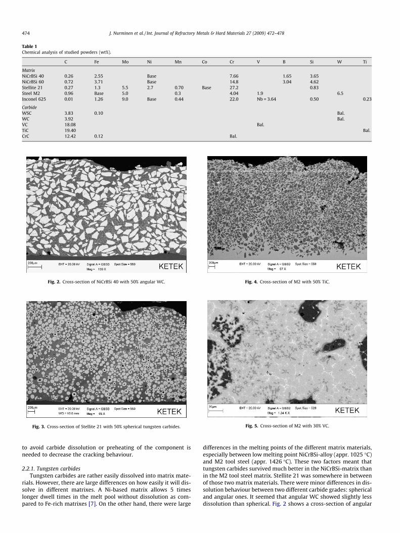
Table 1Chemical analysis of studied powders (wt%).
C Fe Mo Ni Mn Co Cr V B Si W Ti
MatrixNiCrBSi 40 0.26 2.55 Base 7.66 1.65 3.65NiCrBSi 60 0.72 3.71 Base 14.8 3.04 4.62Stellite 21 0.27 1.3 5.5 2.7 0.70 Base 27.2 0.83Steel M2 0.96 Base 5.0 0.3 4.04 1.9 6.5Inconel 625 0.01 1.26 9.0 Base 0.44 22.0 Nb = 3.64 0.50 0.23
CarbideWSC 3.83 0.10 Bal.WC 3.92 Bal.VC 18.08 Bal.TiC 19.40 Bal.CrC 12.42 0.12 Bal.
Fig. 2. Cross-section of NiCrBSi 40 with 50% angular WC.
Fig. 3. Cross-section of Stellite 21 with 50% spherical tungsten carbides.
Fig. 4. Cross-section of M2 with 50% TiC.
Fig. 5. Cross-section of M2 with 30% VC.
474 J. Nurminen et al. / Int. Journal of Refractory Metals & Hard Materials 27 (2009) 472–478
to avoid carbide dissolution or preheating of the component isneeded to decrease the cracking behaviour.
2.2.1. Tungsten carbidesTungsten carbides are rather easily dissolved into matrix mate-
rials. However, there are large differences on how easily it will dis-solve in different matrixes. A Ni-based matrix allows 5 timeslonger dwell times in the melt pool without dissolution as com-pared to Fe-rich matrixes [7]. On the other hand, there were large
differences in the melting points of the different matrix materials,especially between low melting point NiCrBSi-alloy (appr. 1025 �C)and M2 tool steel (appr. 1426 �C). These two factors meant thattungsten carbides survived much better in the NiCrBSi-matrix thanin the M2 tool steel matrix. Stellite 21 was somewhere in betweenof those two matrix materials. There were minor differences in dis-solution behaviour between two different carbide grades: sphericaland angular ones. It seemed that angular WC showed slightly lessdissolution than spherical. Fig. 2 shows a cross-section of angular

Fig. 6. Cross-section of M2 with 50% VC. (a) Cross-section of the whole depth of the coating (b) higher magnification showing high amount of secondary carbides between theoriginal ones.
Fig. 7. Inconel 625 with 50 vol.% of chromium carbides at two magnifications.
J. Nurminen et al. / Int. Journal of Refractory Metals & Hard Materials 27 (2009) 472–478 475
WC in NiCrBSi 40 matrix with rather low dissolution although onecan see some lighter spots between the original carbides indicatingdissolved tungsten in the back scattering image. A cross-section ofspherical carbides in Stellite 21 matrix is shown in Fig. 3.
Some indication of uneven carbide distribution was found par-ticularly with 50 vol.%. Sinking of the heavy WC-particles wasminimal in cases when the processing parameters were good butwith excessive laser power and, hence, larger melt pool, the surviv-ing carbides sank to the lower part of the coating.
2.2.2. Titanium carbideThe case with titanium carbides is a lot better from a process-
ability point of view than that of the WC’s. Dissolution was loweralthough some secondary carbides were formed. In general, theprocessability was much better than that of WC due to the highmelting point. Some cracks were visible inside the carbides buttheir contribution to the abrasion resistance results is unknown.Laser processing remained TiC almost intact in all matrixes. Fig. 4shows TiC in the M2-matrix. The surface of the coating shows uprather rough due to the cooling effect of unmelted carbides.
2.2.3. Vanadium carbideVanadium carbide coatings suffered rather high dissolution and
due to that, formed pores as can be seen in Fig. 6a. Secondary car-bides do form between the primary injected carbides that show
black in Fig 6b. The secondary carbides can be very favourable inabrasion resistance of MMC coating increasing the resistance be-tween primary carbides. This could not, however, be tested in thisstudy. With high carbide content there are lot of secondary car-bides between the original ones. With smaller carbide contentthere are only some reformed carbides between the original onesas can be seen in Fig. 5.
2.2.4. Chromium carbideChromium carbides are known to be easily dissolved and there-
fore they are rather seldom used in laser claddings. This fact canalso be seen in Fig. 7 as there are very few original carbides leftin the matrix. On the other hand, there is a high amount of re-formed carbides in the matrix. The microstructure is very similarto those encountered in chromium-iron welding consumablesand castings. Chromium–iron materials, e.g. white cast irons, areknown to have excellent wear properties.
2.3. Abrasion tests
The dry abrasion wear testing was performed with a rubber-wheel abrasion test equipment, which is a modified version ofthe ASTM G65 standard. The test apparatus has been presentedand described elsewhere [8]. In the test the steel block with acoated surface was pressed against a rubber-lined wheel at a

Fig. 10. Abrasion results of M2 tool steel with 30% carbides.
Fig. 9. Abrasion results of Stellite 21 with 30% carbides.
476 J. Nurminen et al. / Int. Journal of Refractory Metals & Hard Materials 27 (2009) 472–478
normal load of 23 N. The test duration was 1 h, which equals to atotal wear length of appr. 6 km. The abrasive was quartz sand withthe size of 0.1–0.6 mm. The particles are blocky and sharp in theirshape, due to preparation of the sand by crushing. The hardness ofquartz is 7 in the Mohs scale.
3. Results and discussion
3.1. Abrasion results
The results of abrasion tests are presented in Figs. 8–11. Foreach matrix material there was a different carbide that was bestsuited for it – resulting in the best abrasion resistance.
The results for NiCrBSi-matrix with different carbides are pre-sented in Fig. 8. One noticeable feature is the poor result of 30%TiC. Other than that, very good results of spherical tungsten car-bides were observed. This combination is a very widely used mate-rial for many applications and seems to compete rather well withthe less common MMC’s containing TiC and VC.
For the Stellite 21 matrix in Fig 9, the TiC and VC carbides wererather similar in abrasion resistance. WC was slightly worse, butthe result was only on order of 15% worse than the other two car-bide types. The partial reason can also be a result from a worse dis-tribution of WC in matrix as was noted in some coatings. Stellite 21with 50% WSC, however showed very good wear properties as canbe seen in Fig. 9.
M2 tool steel is not suitable to be reinforced with tungsten car-bides processed with laser cladding, Fig 10. The melting point ofM2 is rather high for WC to survive the processing without largedissolution. The low wetting angle between WC and iron furtherhelps dissolution [9].
M2 tool steel with VC achieved the best results of all the mate-rial combinations. The increase of carbide content did not enhanceabrasion resistance very much except in the case of Stellite 21. Thematrix material has a large effect on abrasion resistance. Iron basedmaterials are known to often offer better abrasion resistance thancobalt or nickel-based matrixes. If the case is something else thanpure abrasion then the results can be very much different, though.
Hard, wear resistant, cast Ni material (Ni-hard) was added toFig. 11 as a reference material for abrasion results to give someperspective to the overall results. The abrasion result of Inconel625 with 50 vol% added chromium carbide is also given. ThisMMC offered best abrasion resistance which was somewhat sur-prising since most of the original carbides were dissolved. The rea-son for its good result is probably due to the relatively small size of
Fig. 11. Best performed material combinations: abrasion test results after 60 minwear test.
Fig. 8. Abrasion results for NiCrBSi-matrix, different carbide types of 30 and 50%vol.
the reformed carbides. With high carbon content there is also apossibility that the carbide was actually the same Cr2C3-phase asthe original and, hence, the preferred and hardest chromium car-bide form. Alternatively, the carbides have some uniform and highdistribution that causes the abrasives to wear the coating only atvery low rates.
3.2. Wear surfaces
Wear surfaces were examined by electron microscope to revealsome reasons for different wear behavior. All matrix materials
J. Nurminen et al. / Int. Journal of Refractory Metals & Hard Materials 27 (2009) 472–478 477
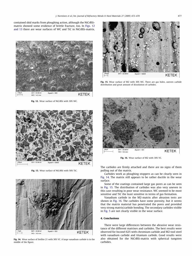
contained skid marks from ploughing action, although the NiCrBSi-matrix showed some evidence of brittle fracture, too. In Figs. 12and 13 there are wear surfaces of WC and TiC in NiCrBSi-matrix.
Fig. 12. Wear surface of NiCrBSi with 30% WC.
Fig. 13. Wear surface of NiCrBSi with 50% TiC.
Fig. 14. Wear surface of Stellite 21 with 30% VC. A large vanadium carbide is in themiddle of the figure.
Fig. 15. Wear surface of M2 with 30% WC. There are gas holes, uneven carbidedistribution and great amount of dissolution of carbides.
Fig. 16. Wear surface of M2 with 30% VC.
The carbides are firmly attached and there are no signs of thempulling out of the matrix.
Carbides work as ploughing stoppers as can be clearly seen inFig. 14. The matrix still appears to be rather ductile in the wearsurface.
Some of the coatings contained large gas pores as can be seenin Fig. 15. The distribution of carbides was also very uneven inthis case resulting in poor wear resistance. WC seemed to be mostsensitive and TiC the least sensitive in terms of gas formation.
Vanadium carbide in the M2-matrix after abrasion tests areshown in Fig. 16. The carbides have some porosity, but it seemsthat the matrix material has penetrated the pores and providedvery strong matrix/carbide bonding. The secondary carbides visiblein Fig. 5 are not clearly visible in the wear surface.
4. Conclusions
There were large differences between the abrasive wear resis-tance of the different matrixes and carbides. The best results wereobserved for Inconel 625 with chromium carbide and M2 tool steelwith vanadium carbide and titanium carbide. Good results werealso obtained for the NiCrBSi-matrix with spherical tungstencarbides.

478 J. Nurminen et al. / Int. Journal of Refractory Metals & Hard Materials 27 (2009) 472–478
The selection of the proper hard phase for the matrix material isimportant in laser cladding and all of the matrixes in this studyshowed the best results with different carbide types.
References
[1] Gassmann RC. Laser cladding with (WC + W2C)/Co–Cr–C and (WC + W2C)/Ni–B–Si composites for enhanced abrasive wear resistance. Mater Sci Technol1996;12:691–6.
[2] Grünewald B, Shen J, Dausinger F, Nowotny St. In: Mordike BL, editor. Lasercladding with a heterogeneous powder mixture of WC/Co and NiCrBSi:European conference on laser treatment of materials (ECLAT’92), 1992. p.411–6.
[3] Huang SW, Samadi M, Brandt M. Abrasive wear performance andmicrostructure of laser clad WC/Ni layers. Wear 2004;256:1095–105.
[4] Kathuria YP. Nd-YAG laser cladding of Cr3C2 and TiC cermets. Surf Coat Technol2001;140:195–9.
[5] Xu G, Kutsuna M. Cladding of Stellite 6 and VC powder on carbon steel using aYAG laser robot system, ICALEO 2003; 2003.
[6] Herrera Y, Staia MH, Grigorescu IC, Ramirez J, Rauso CDi. Microstructure andwear mode of vanadium carbide laser clad coatings, Surface ModificationTechnologies XII; 1998.
[7] Martukanitz RP. Modeling and characterization of hard particle retention duringlaser surface alloying: Appl. Research Lab., State College, PA, <http://mjndeweb.ms.ornl.gov/MPLUS/ARL/MC_00_37.pdf>.
[8] Niemi K, Rekola S, Vuoristo P, Laurila J, Vippola M, Mäntylä T. Advanced oxideceramic coatings for applications demanding high wear resistance, ThermalSpray 2003: Advancing the Science and Applying the Technology. In:Proceedings of the 2003 international thermal spray conference volume 1,Orlando, FL, USA; 5–8 May 2003. p. 233–6.
[9] Schüssler A. Microstructure and properties of laser processed composite layers.In: Mordike BL, editor. European conference on laser treatment of materials(ECLAT’92); 1992. p. 287–92.