Laser cladding of in situ TiB 2/Fe composite coating on steel
6
Laser cladding of in situ TiB 2 /Fe composite coating on steel Baoshuai Du, Zengda Zou, Xinhong Wang *, Shiyao Qu School of Materials Science and Engineering, Shandong University, Jinan 250061, China 1. Introduction Wear is one of the most frequently encountered failure modes for mechanical components, with the other two as corrosion and fatigue respectively. It attacks a component by removing material from the upper end, indicating that wear is often a surface related phenomenon. And it is well documented that materials with a high hardness and good toughness are expected to provide good wear resistance [1]. Particulate reinforced metal matrix composites (PMMCs) are desirable with respect to this property due to the synergetic effect caused by the combination of hard reinforce- ments and ductile metal matrix [2,3]. However, it is expensive, time-consuming and may even strategically unrealistic to produce bulk PMMCs. Thus, fabricating PMMC coating using surfacing technology comes as an alternative and more economic way to improve the wear resistance of components. Laser cladding is a unique process producing thick coating with metallurgical joint to the substrate that has found increasing application in the field of surface engineering. It utilizes laser beam with high energy density as the heat source to melt the cladding materials and a limited portion of the underlying substrate to form a coating. The cladding materials can be added either by preplacing powders on the substrate or by injecting them into the trailing edge of the molten pool. Compared with other surfacing technology, laser cladding possesses have many advanced features. These include metallurgical bond between the coating and substrate, highly refined microstructure, low dilution ratio and limited heat affected zone (HAZ) [4–6]. Furthermore, laser cladding is an effective way to produce PMMC composite coatings because the desired coating can be gained by coupling the design of the precursor with the tailoring of the laser processing parameters. According to the literature, considerable studies have been conducted on the fabrication of PMMC coatings by laser cladding [3–8]. Among various ceramic particulates, titanium diboride is expected to be one of the best reinforcements for steel matrix due to its high hardness (3400 HV), high melting temperature (3225 8C), outstanding tribological properties and good compat- ibility with the steel matrices [9,10]. Thus, it is attractive to fabricate TiB 2 reinforced Fe-based MMCs. Although some work [11–13] has been done to produce TiB 2 reinforced composite coatings, most of them focus on adding TiB 2 particles directly into the metal matrix. However, emphasis has been given to the in situ formation of reinforcing particles using laser-cladding technology recently for several important reasons. Compared with the ex situ route, this in situ process is more economical and has an intrinsic advantage that the surface of the particles is cleaner and hence the bond between the reinforcing particles and the matrix tends to be stronger [8]. Moreover, coating properties can be tailored to the application by varying the laser cladding process variables, such as laser traverse speed, power, beam size, overlapping ratio and composition of precursor. In the past, pure titanium and Applied Surface Science 254 (2008) 6489–6494 ARTICLE INFO Article history: Received 5 December 2007 Received in revised form 25 February 2008 Accepted 6 April 2008 Available online 22 April 2008 Keywords: In situ TiB 2 /Fe composite coating Laser cladding Ferrotitanium Ferroboron ABSTRACT To enhance the wear resistance of mechanical components, laser cladding has been applied to deposit in situ TiB 2 /Fe composite coating on steel using ferrotitanium and ferroboron as the coating precursor. The phase constituents and microstructure of the composite coating were investigated using X-ray diffraction (XRD), scanning electron micrograph (SEM) and electron probe microanalysis (EPMA). Microhardness tester and block-on-ring wear tester were employed to measure the microhardness and dry-sliding wear resistance of the composite coating. Results show that defect-free composite coating with metallurgical joint to the steel substrate can be obtained. Phases presented in the coating consist of TiB 2 and a-Fe. TiB 2 particles which are formed in situ via nucleation-growth mechanism are distributed uniformly in the a- Fe matrix with blocky morphology. The microhardness and wear properties of the composite coating improved significantly in comparison to the as-received steel substrate due to the presence of the hard reinforcement TiB 2 . ß 2008 Elsevier B.V. All rights reserved. * Corresponding author. Tel.: +86 531 88392208; fax: +86 531 82616431. E-mail address: [email protected] (X. Wang). Contents lists available at ScienceDirect Applied Surface Science journal homepage: www.elsevier.com/locate/apsusc 0169-4332/$ – see front matter ß 2008 Elsevier B.V. All rights reserved. doi:10.1016/j.apsusc.2008.04.051
-
Upload
independent -
Category
Documents
-
view
1 -
download
0
Transcript of Laser cladding of in situ TiB 2/Fe composite coating on steel
Laser cladding of in situ TiB2/Fe composite coating on steel
Baoshuai Du, Zengda Zou, Xinhong Wang *, Shiyao Qu
School of Materials Science and Engineering, Shandong University, Jinan 250061, China
Applied Surface Science 254 (2008) 6489–6494
A R T I C L E I N F O
Article history:
Received 5 December 2007
Received in revised form 25 February 2008
Accepted 6 April 2008
Available online 22 April 2008
Keywords:
In situ
TiB2/Fe composite coating
Laser cladding
Ferrotitanium
Ferroboron
A B S T R A C T
To enhance the wear resistance of mechanical components, laser cladding has been applied to deposit in
situ TiB2/Fe composite coating on steel using ferrotitanium and ferroboron as the coating precursor. The
phase constituents and microstructure of the composite coating were investigated using X-ray diffraction
(XRD), scanning electron micrograph (SEM) and electron probe microanalysis (EPMA). Microhardness
tester and block-on-ring wear tester were employed to measure the microhardness and dry-sliding wear
resistance of the composite coating. Results show that defect-free composite coating with metallurgical
joint to the steel substrate can be obtained. Phases presented in the coating consist of TiB2 and a-Fe. TiB2
particles which are formed in situ via nucleation-growth mechanism are distributed uniformly in the a-
Fe matrix with blocky morphology. The microhardness and wear properties of the composite coating
improved significantly in comparison to the as-received steel substrate due to the presence of the hard
reinforcement TiB2.
� 2008 Elsevier B.V. All rights reserved.
Contents lists available at ScienceDirect
Applied Surface Science
journal homepage: www.elsevier.com/locate/apsusc
1. Introduction
Wear is one of the most frequently encountered failure modesfor mechanical components, with the other two as corrosion andfatigue respectively. It attacks a component by removing materialfrom the upper end, indicating that wear is often a surface relatedphenomenon. And it is well documented that materials with a highhardness and good toughness are expected to provide good wearresistance [1]. Particulate reinforced metal matrix composites(PMMCs) are desirable with respect to this property due to thesynergetic effect caused by the combination of hard reinforce-ments and ductile metal matrix [2,3]. However, it is expensive,time-consuming and may even strategically unrealistic to producebulk PMMCs. Thus, fabricating PMMC coating using surfacingtechnology comes as an alternative and more economic way toimprove the wear resistance of components.
Laser cladding is a unique process producing thick coating withmetallurgical joint to the substrate that has found increasingapplication in the field of surface engineering. It utilizes laser beamwith high energy density as the heat source to melt the claddingmaterials and a limited portion of the underlying substrate to forma coating. The cladding materials can be added either by preplacingpowders on the substrate or by injecting them into the trailingedge of the molten pool. Compared with other surfacing
* Corresponding author. Tel.: +86 531 88392208; fax: +86 531 82616431.
E-mail address: [email protected] (X. Wang).
0169-4332/$ – see front matter � 2008 Elsevier B.V. All rights reserved.
doi:10.1016/j.apsusc.2008.04.051
technology, laser cladding possesses have many advanced features.These include metallurgical bond between the coating andsubstrate, highly refined microstructure, low dilution ratio andlimited heat affected zone (HAZ) [4–6]. Furthermore, laser claddingis an effective way to produce PMMC composite coatings becausethe desired coating can be gained by coupling the design of theprecursor with the tailoring of the laser processing parameters.According to the literature, considerable studies have beenconducted on the fabrication of PMMC coatings by laser cladding[3–8].
Among various ceramic particulates, titanium diboride isexpected to be one of the best reinforcements for steel matrixdue to its high hardness (3400 HV), high melting temperature(3225 8C), outstanding tribological properties and good compat-ibility with the steel matrices [9,10]. Thus, it is attractive tofabricate TiB2 reinforced Fe-based MMCs. Although some work[11–13] has been done to produce TiB2 reinforced compositecoatings, most of them focus on adding TiB2 particles directly intothe metal matrix. However, emphasis has been given to the in situformation of reinforcing particles using laser-cladding technologyrecently for several important reasons. Compared with the ex situroute, this in situ process is more economical and has an intrinsicadvantage that the surface of the particles is cleaner and hence thebond between the reinforcing particles and the matrix tends to bestronger [8]. Moreover, coating properties can be tailored to theapplication by varying the laser cladding process variables, such aslaser traverse speed, power, beam size, overlapping ratio andcomposition of precursor. In the past, pure titanium and
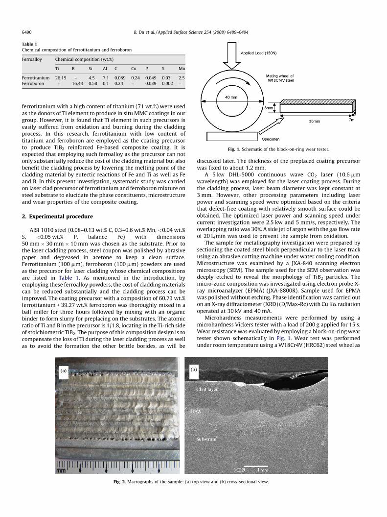
Table 1Chemical composition of ferrotitanium and ferroboron
Ferroalloy Chemical composition (wt.%)
Ti B Si Al C Cu P S Mn
Ferrotitanium 26.15 – 4.5 7.1 0.089 0.24 0.049 0.03 2.5
Ferroboron – 16.43 0.58 0.1 0.24 – 0.039 0.002 –
Fig. 1. Schematic of the block-on-ring wear tester.
B. Du et al. / Applied Surface Science 254 (2008) 6489–64946490
ferrotitanium with a high content of titanium (71 wt.%) were usedas the donors of Ti element to produce in situ MMC coatings in ourgroup. However, it is found that Ti element in such precursors iseasily suffered from oxidation and burning during the claddingprocess. In this research, ferrotitanium with low content oftitanium and ferroboron are employed as the coating precursorto produce TiB2 reinforced Fe-based composite coating. It isexpected that employing such ferroalloy as the precursor can notonly substantially reduce the cost of the cladding material but alsobenefit the cladding process by lowering the melting point of thecladding material by eutectic reactions of Fe and Ti as well as Feand B. In this present investigation, systematic study was carriedon laser clad precursor of ferrotitanium and ferroboron mixture onsteel substrate to elucidate the phase constituents, microstructureand wear properties of the composite coating.
2. Experimental procedure
AISI 1010 steel (0.08–0.13 wt.% C, 0.3–0.6 wt.% Mn, <0.04 wt.%S, <0.05 wt.% P, balance Fe) with dimensions50 mm � 30 mm � 10 mm was chosen as the substrate. Prior tothe laser cladding process, steel coupon was polished by abrasivepaper and degreased in acetone to keep a clean surface.Ferrotitanium (100 mm), ferroboron (100 mm) powders are usedas the precursor for laser cladding whose chemical compositionsare listed in Table 1. As mentioned in the introduction, byemploying these ferroalloy powders, the cost of cladding materialscan be reduced substantially and the cladding process can beimproved. The coating precursor with a composition of 60.73 wt.%ferrotitanium + 39.27 wt.% ferroboron was thoroughly mixed in aball miller for three hours followed by mixing with an organicbinder to form slurry for preplacing on the substrates. The atomicratio of Ti and B in the precursor is 1/1.8, locating in the Ti-rich sideof stoichiometric TiB2. The purpose of this composition design is tocompensate the loss of Ti during the laser cladding process as wellas to avoid the formation the other brittle borides, as will be
Fig. 2. Macrographs of the sample: (a) to
discussed later. The thickness of the preplaced coating precursorwas fixed to about 1.2 mm.
A 5 kw DHL-5000 continuous wave CO2 laser (10.6 mmwavelength) was employed for the laser coating process. Duringthe cladding process, laser beam diameter was kept constant at3 mm. However, other processing parameters including laserpower and scanning speed were optimized based on the criteriathat defect-free coating with relatively smooth surface could beobtained. The optimized laser power and scanning speed undercurrent investigation were 2.5 kw and 5 mm/s, respectively. Theoverlapping ratio was 30%. A side jet of argon with the gas flow rateof 20 L/min was used to prevent the sample from oxidation.
The sample for metallography investigation were prepared bysectioning the coated steel block perpendicular to the laser trackusing an abrasive cutting machine under water cooling condition.Microstructure was examined by a JXA-840 scanning electronmicroscopy (SEM). The sample used for the SEM observation wasdeeply etched to reveal the morphology of TiB2 particles. Themicro-zone composition was investigated using electron probe X-ray microanalyzer (EPMA) (JXA-8800R). Sample used for EPMAwas polished without etching. Phase identification was carried outon an X-ray diffractometer (XRD) (D/Max-Rc) with Cu Ka radiationoperated at 30 kV and 40 mA.
Microhardness measurements were performed by using amicrohardness Vickers tester with a load of 200 g applied for 15 s.Wear resistance was evaluated by employing a block-on-ring weartester shown schematically in Fig. 1. Wear test was performedunder room temperature using a W18Cr4V (HRC62) steel wheel as
p view and (b) cross-sectional view.
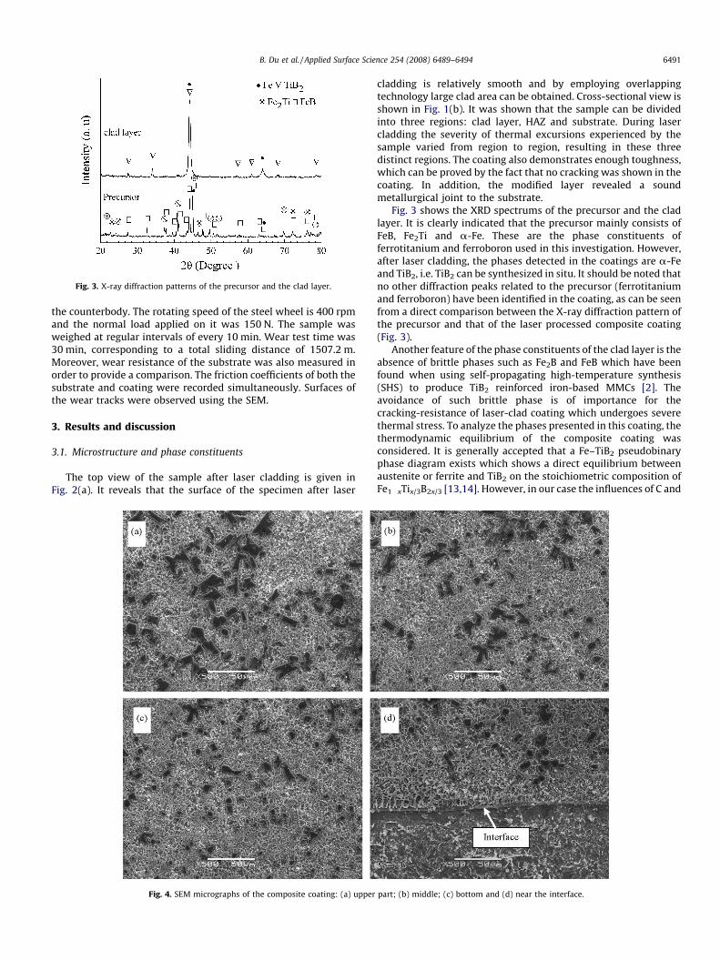
Fig. 3. X-ray diffraction patterns of the precursor and the clad layer.
B. Du et al. / Applied Surface Science 254 (2008) 6489–6494 6491
the counterbody. The rotating speed of the steel wheel is 400 rpmand the normal load applied on it was 150 N. The sample wasweighed at regular intervals of every 10 min. Wear test time was30 min, corresponding to a total sliding distance of 1507.2 m.Moreover, wear resistance of the substrate was also measured inorder to provide a comparison. The friction coefficients of both thesubstrate and coating were recorded simultaneously. Surfaces ofthe wear tracks were observed using the SEM.
3. Results and discussion
3.1. Microstructure and phase constituents
The top view of the sample after laser cladding is given inFig. 2(a). It reveals that the surface of the specimen after laser
Fig. 4. SEM micrographs of the composite coating: (a) upper
cladding is relatively smooth and by employing overlappingtechnology large clad area can be obtained. Cross-sectional view isshown in Fig. 1(b). It was shown that the sample can be dividedinto three regions: clad layer, HAZ and substrate. During lasercladding the severity of thermal excursions experienced by thesample varied from region to region, resulting in these threedistinct regions. The coating also demonstrates enough toughness,which can be proved by the fact that no cracking was shown in thecoating. In addition, the modified layer revealed a soundmetallurgical joint to the substrate.
Fig. 3 shows the XRD spectrums of the precursor and the cladlayer. It is clearly indicated that the precursor mainly consists ofFeB, Fe2Ti and a-Fe. These are the phase constituents offerrotitanium and ferroboron used in this investigation. However,after laser cladding, the phases detected in the coatings are a-Feand TiB2, i.e. TiB2 can be synthesized in situ. It should be noted thatno other diffraction peaks related to the precursor (ferrotitaniumand ferroboron) have been identified in the coating, as can be seenfrom a direct comparison between the X-ray diffraction pattern ofthe precursor and that of the laser processed composite coating(Fig. 3).
Another feature of the phase constituents of the clad layer is theabsence of brittle phases such as Fe2B and FeB which have beenfound when using self-propagating high-temperature synthesis(SHS) to produce TiB2 reinforced iron-based MMCs [2]. Theavoidance of such brittle phase is of importance for thecracking-resistance of laser-clad coating which undergoes severethermal stress. To analyze the phases presented in this coating, thethermodynamic equilibrium of the composite coating wasconsidered. It is generally accepted that a Fe–TiB2 pseudobinaryphase diagram exists which shows a direct equilibrium betweenaustenite or ferrite and TiB2 on the stoichiometric composition ofFe1�xTix/3B2x/3 [13,14]. However, in our case the influences of C and
part; (b) middle; (c) bottom and (d) near the interface.
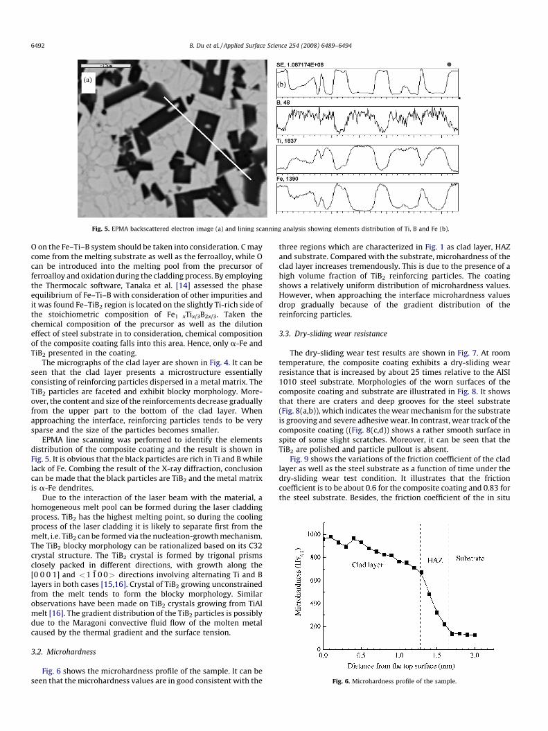
Fig. 5. EPMA backscattered electron image (a) and lining scanning analysis showing elements distribution of Ti, B and Fe (b).
Fig. 6. Microhardness profile of the sample.
B. Du et al. / Applied Surface Science 254 (2008) 6489–64946492
O on the Fe–Ti–B system should be taken into consideration. C maycome from the melting substrate as well as the ferroalloy, while Ocan be introduced into the melting pool from the precursor offerroalloy and oxidation during the cladding process. By employingthe Thermocalc software, Tanaka et al. [14] assessed the phaseequilibrium of Fe–Ti–B with consideration of other impurities andit was found Fe–TiB2 region is located on the slightly Ti-rich side ofthe stoichiometric composition of Fe1�xTix/3B2x/3. Taken thechemical composition of the precursor as well as the dilutioneffect of steel substrate in to consideration, chemical compositionof the composite coating falls into this area. Hence, only a-Fe andTiB2 presented in the coating.
The micrographs of the clad layer are shown in Fig. 4. It can beseen that the clad layer presents a microstructure essentiallyconsisting of reinforcing particles dispersed in a metal matrix. TheTiB2 particles are faceted and exhibit blocky morphology. More-over, the content and size of the reinforcements decrease graduallyfrom the upper part to the bottom of the clad layer. Whenapproaching the interface, reinforcing particles tends to be verysparse and the size of the particles becomes smaller.
EPMA line scanning was performed to identify the elementsdistribution of the composite coating and the result is shown inFig. 5. It is obvious that the black particles are rich in Ti and B whilelack of Fe. Combing the result of the X-ray diffraction, conclusioncan be made that the black particles are TiB2 and the metal matrixis a-Fe dendrites.
Due to the interaction of the laser beam with the material, ahomogeneous melt pool can be formed during the laser claddingprocess. TiB2 has the highest melting point, so during the coolingprocess of the laser cladding it is likely to separate first from themelt, i.e. TiB2 can be formed via the nucleation-growth mechanism.The TiB2 blocky morphology can be rationalized based on its C32crystal structure. The TiB2 crystal is formed by trigonal prismsclosely packed in different directions, with growth along the[0 0 0 1] and <1 1 0 0> directions involving alternating Ti and Blayers in both cases [15,16]. Crystal of TiB2 growing unconstrainedfrom the melt tends to form the blocky morphology. Similarobservations have been made on TiB2 crystals growing from TiAlmelt [16]. The gradient distribution of the TiB2 particles is possiblydue to the Maragoni convective fluid flow of the molten metalcaused by the thermal gradient and the surface tension.
3.2. Microhardness
Fig. 6 shows the microhardness profile of the sample. It can beseen that the microhardness values are in good consistent with the
three regions which are characterized in Fig. 1 as clad layer, HAZand substrate. Compared with the substrate, microhardness of theclad layer increases tremendously. This is due to the presence of ahigh volume fraction of TiB2 reinforcing particles. The coatingshows a relatively uniform distribution of microhardness values.However, when approaching the interface microhardness valuesdrop gradually because of the gradient distribution of thereinforcing particles.
3.3. Dry-sliding wear resistance
The dry-sliding wear test results are shown in Fig. 7. At roomtemperature, the composite coating exhibits a dry-sliding wearresistance that is increased by about 25 times relative to the AISI1010 steel substrate. Morphologies of the worn surfaces of thecomposite coating and substrate are illustrated in Fig. 8. It showsthat there are craters and deep grooves for the steel substrate(Fig. 8(a,b)), which indicates the wear mechanism for the substrateis grooving and severe adhesive wear. In contrast, wear track of thecomposite coating ((Fig. 8(c,d)) shows a rather smooth surface inspite of some slight scratches. Moreover, it can be seen that theTiB2 are polished and particle pullout is absent.
Fig. 9 shows the variations of the friction coefficient of the cladlayer as well as the steel substrate as a function of time under thedry-sliding wear test condition. It illustrates that the frictioncoefficient is to be about 0.6 for the composite coating and 0.83 forthe steel substrate. Besides, the friction coefficient of the in situ
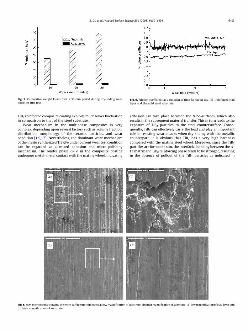
Fig. 7. Cumulative weight losses over a 30-min period during dry-sliding wear
block-on-ring test.Fig. 9. Friction coefficient as a function of time for the in situ TiB2 reinforced clad
layer and the mild steel substrate.
B. Du et al. / Applied Surface Science 254 (2008) 6489–6494 6493
TiB2 reinforced composite coating exhibits much lower fluctuationin comparison to that of the steel substrate.
Wear mechanism in the multiphase composites is verycomplex, depending upon several factors such as volume fraction,distribution, morphology of the ceramic particles, and wearcondition [1,9,17]. Nevertheless, the dominant wear mechanismof the in situ synthesized TiB2/Fe under current wear test conditioncan be regarded as a mixed adhesion and micro-polishingmechanism. The binder phase a-Fe in the composite coatingundergoes metal–metal contact with the mating wheel, indicating
Fig. 8. SEM micrographs showing the worn surface morphology: (a) low magnification of s
(d) high magnification of substrate.
adhesion can take place between the tribo-surfaces, which alsoresults in the subsequent material transfer. This in turn leads to theexposure of TiB2 particles to the steel countersurface. Conse-quently, TiB2 can effectively carry the load and play an importantrole in resisting wear attacks when dry-sliding with the metalliccounterpart. It is obvious that TiB2 has a very high hardnesscompared with the mating steel wheel. Moreover, since the TiB2
particles are formed in situ, the interfacial bonding between the a-Fe matrix and TiB2 reinforcing phase tends to be stronger, resultingin the absence of pullout of the TiB2 particles as indicated in
ubstrate; (b) high magnification of substrate; (c) low magnification of clad layer and

B. Du et al. / Applied Surface Science 254 (2008) 6489–64946494
Fig. 8(b). Hence, the TiB2 particles are worn via micro-polishingmechanism. Taken together, the dominating wear mechanismfor the composite coating is a mixed adhesive and micro-polishing mechanism. The severe adhesive wear experienced bythe steel substrate leads to a higher friction coefficient. However,the inherent strong atomic bonds of the TiB2 phases coupled withthe relative smooth surface of the composite coating prevent thecold-welding to the metallic asperities on the contacting surfaceof the W18Cr4V metallic counterpart, so the composite coatingdemonstrated a lower friction coefficient and slighter fluctuationdegree.
4. Conclusions
Using ferrotitanium and ferroboron as precursor, a laser cladTiB2 reinforced composite coating on mild steel substrate free fromcracks and pores has been obtained. Phase constituents of thecoating include a-Fe and TiB2. TiB2 are formed in situ via thenucleation-growth mechanism during the cooling of the lasercladding process. The microstructure of the composite coatingconsists of blocky TiB2 particles distributed uniformly in the a-Femetal matrix. Due to the synergetic effect of the in situ formed hardTiB2 particles with the ductile a-Fe matrix, microhardness andwear resistance of the composite coating improved dramaticallycompared with the steel substrate.
Acknowledgements
This research is supported by the Specialized Research Fund forthe Doctoral Program of Higher Education of China (project No.060422020) and the Natural Science Foundation of ShandongProvince (No. Z2006F07).
References
[1] A. Agarwal, N.B. Dahotre, Wear 240 (2000) 144.[2] A. Anal, T.K. Bandyopadhyay, K. Das, J. Mater. Process. Technol. 172 (2006) 70.[3] J. Xu, Z. Li, W.H. Li, Z.L. Liu, W.J. Liu, Mater. Sci. Eng. A 447 (2007) 307.[4] Y.T. Pei, T.C. Zuo, Mater. Sci. Eng. A 241 (1998) 259.[5] S. Yang, W.J. Liu, M.L. Zhong, Z.J. Wang, Mater. Lett. 58 (2004) 2958.[6] R. Anandkumar, A. Almeida, R. Colaco, R. Vilar, V. Ocelik, J.Th.M. De Hosson, Surf.
Coat. Technol. 201 (2007) 9497.[7] Q.W. Meng, L. Geng, B.Y. Zhang, Surf. Coat. Technol. 200 (2006) 4923.[8] A. Singh, N.B. Dahotre, J. Mater. Sci. 39 (2004) 4553.[9] C.C. Degnan, P.H. Shipway, Wear 252 (2002) 832.
[10] C.C. Degnan, P.H. Shipway, Metall. Mater. Trans. 33A (2002) 2973.[11] A. Agarwal, N.B. Dahotre, Int. J. Refract. Metals Hard Mater. 17 (1999) 283.[12] A. Agarwal, N.B. Dahotre, Mater. Character. 42 (1999) 31.[13] M. Darabara, G.D. Papadimitriou, L. Bourithis, Surf. Coat. Technol. 201 (2006)
3518.[14] K. Tanaka, T. Saito, J. Phase Equilib. 20 (3) (1998) 207.[15] A.A. Abdel-Hamid, S.T. Hamar, R. Hamar, J. Cryst. Growth. 71 (1985) 744.[16] M.E. Hyman, C. Mccullough, J.J. Valencia, C.G. Levi, R. Meherabian, Metall. Mater.
Tran. 20A (1989) 1847.[17] M. Darabara, G.D. Papadimitriou, L. Bourithis, Surf. Coat. Technol. 202 (2007) 246.