Magnetic pulse cladding of aluminum alloy on mild steel tube
10
Journal of Materials Processing Technology 214 (2014) 141–150 Contents lists available at ScienceDirect Journal of Materials Processing Technology jou rn al hom epage: www.elsevier.com/locate/jmatprotec Magnetic pulse cladding of aluminum alloy on mild steel tube Haiping Yu a,b,∗ , Zhisong Fan b , Chunfeng Li a,b a National Key Laboratory for Precision Hot Processing of Metals, Harbin 150001, China b School of Materials Science and Engineering, Harbin Institute of Technology, Harbin 150001, China a r t i c l e i n f o Article history: Received 22 April 2013 Received in revised form 18 July 2013 Accepted 26 August 2013 Available online 4 September 2013 Keywords: Bi-metal tubes Magnetic pulse cladding Compression-shear strength Profiled field shaper Magnetic pulse joining a b s t r a c t Bi-metal tubes, which combine the advantageous properties of two different metals, are desirable in industries where corrosion resistance is important. A new cladding method named magnetic pulse cladding (MPC) was used to form bi-metal tubes. A cladding of mild steel tube by aluminum alloy (AA3003) was achieved. The effect of the geometry of the field shaper on cladding quality was investigated as well as other main process parameters, such as, feeding size, radial gap and discharge voltage. The mechanical property was evaluated by compression-shear test and a maximum strength of 79.2 MPa and an aver- age of 29.7 MPa were attained to by the following process settings: profiled field shaper, feeding size of 12 mm, radial gap of 2.0 mm and discharge voltage of 15 kV. OM and SEM images show a smooth integral interface and a small wavy one. EDS mapping reveals the interfacial diffusion zone up to 50-m wide. The results show that the proposed MPC process is able to form sound cladding bonds and could be applicable to a tubular clad component with a high axial length. © 2013 Elsevier B.V. All rights reserved. 1. Introduction A bi-metal tube or clad tube is a tubular layered composite, com- posed of two or more metallic materials joined at their interface. It is desirable or necessary to combine in one tube the properties of two different metals for corrosion-resistant applications. For instance, in refrigerating apparatus, ammonia vapors are in contact with the outside of the tube and cooling water is circulated within the tube. Herein, bi-metal tubes can be employed consisting of an outer tube of aluminum or other corrosion-resistant materials to withstand the attack of corrosive vapors and a steel inner tube to provide nec- essary strength. Bi-metal tubes provide functionality as well as cost saving compared to the single metal. So far, several plastic processing methods have been studied for preparation of clad tubes, such as hot extrusion, rolling, explosive welding/cladding and even combinations thereof. Traditionally, rolling-clad metal plates are bent to form a seam pipe which then is longitudinally welded (Schulz et al., 1999). Hot extrusion is a conventional process for manufacturing seamless clad pipes, and now it has been improved to manufacture bimetal tubes. Chen et al. (2003) reported the fabrication of bimetallic pipes by multi- billet extrusion which is characterized by co-extruding several solid billets, joining them in welding chambers and finally obtaining a ∗ Corresponding author at: School of Materials Science and Engineering, Harbin Institute of Technology, Harbin 150001, China. Tel.: +86 451 86413970; fax: +86 451 86418753. E-mail addresses: [email protected], [email protected] (H. Yu). desired product by means of a die. Krishna et al. (2005) investigated co-axial extrusion process to produce bimetallic tubes by using sin- tered powder metallurgy performs. Madej et al. (2012) utilized a multi-billet extrusion technology to manufacture bi-layered alu- minum pipes using ultra fine-grain billets provided by the equal channel angular pressing process. Wang et al. (2005) introduced a method based on the hydro-forming technology to manufacture the CRA-lined pipe. Mohebbi and Akbarzadeh (2010) presented a spin-bonding process to form seamless thin-walled clad tubes. However, these methods only produce mechanically bonded bi- metal tubes which can barely withstand any thermal stress. In order to form a metallurgical bond, heating is often needed, but in the case of dissimilar-metal joints, a high heat input often leads to for- mation of brittle and continuous intermetallic phases that might deteriorate the mechanical properties of the bond. Magnetic pulse joining/welding (MPJ/MPW), along with the explosive welding and laser impact welding, is classified as high-velocity impact welding process. Zhang et al. (2011) inves- tigated high velocity impact welding at different length scales and concluded such solid state impact welding could minimize the for- mation of intermetallics. Explosive welding by expansion of the inner tubular component was analyzed by Sun et al. (2011) and the bonding characteristics of the Fe/Al clad tube were investigated. The state of the art of electromagnetic welding was reviewed in detail by Psyk et al. (2011) to discuss the dominating joining mech- anism of MPJ/MPW. As indicated by the authors, the MPJ/MPW process is a cost-effective and environmentally friendly method of joining dissimilar metals. No filler is used and almost no damage occurs on the surface of the workpiece due to the contact-free force 0924-0136/$ – see front matter © 2013 Elsevier B.V. All rights reserved. http://dx.doi.org/10.1016/j.jmatprotec.2013.08.013
Transcript of Magnetic pulse cladding of aluminum alloy on mild steel tube
M
Ha
b
a
ARRAA
KBMCPM
1
pddioHotes
pwricnebb
If
0h
Journal of Materials Processing Technology 214 (2014) 141– 150
Contents lists available at ScienceDirect
Journal of Materials Processing Technology
jou rn al hom epage: www.elsev ier .com/ locate / jmatprotec
agnetic pulse cladding of aluminum alloy on mild steel tube
aiping Yua,b,∗, Zhisong Fanb, Chunfeng Lia,b
National Key Laboratory for Precision Hot Processing of Metals, Harbin 150001, ChinaSchool of Materials Science and Engineering, Harbin Institute of Technology, Harbin 150001, China
r t i c l e i n f o
rticle history:eceived 22 April 2013eceived in revised form 18 July 2013ccepted 26 August 2013vailable online 4 September 2013
a b s t r a c t
Bi-metal tubes, which combine the advantageous properties of two different metals, are desirable inindustries where corrosion resistance is important. A new cladding method named magnetic pulsecladding (MPC) was used to form bi-metal tubes. A cladding of mild steel tube by aluminum alloy (AA3003)was achieved. The effect of the geometry of the field shaper on cladding quality was investigated as wellas other main process parameters, such as, feeding size, radial gap and discharge voltage. The mechanical
eywords:i-metal tubesagnetic pulse cladding
ompression-shear strengthrofiled field shaperagnetic pulse joining
property was evaluated by compression-shear test and a maximum strength of 79.2 MPa and an aver-age of 29.7 MPa were attained to by the following process settings: profiled field shaper, feeding size of12 mm, radial gap of 2.0 mm and discharge voltage of 15 kV. OM and SEM images show a smooth integralinterface and a small wavy one. EDS mapping reveals the interfacial diffusion zone up to 50-�m wide. Theresults show that the proposed MPC process is able to form sound cladding bonds and could be applicableto a tubular clad component with a high axial length.
. Introduction
A bi-metal tube or clad tube is a tubular layered composite, com-osed of two or more metallic materials joined at their interface. It isesirable or necessary to combine in one tube the properties of twoifferent metals for corrosion-resistant applications. For instance,
n refrigerating apparatus, ammonia vapors are in contact with theutside of the tube and cooling water is circulated within the tube.erein, bi-metal tubes can be employed consisting of an outer tubef aluminum or other corrosion-resistant materials to withstandhe attack of corrosive vapors and a steel inner tube to provide nec-ssary strength. Bi-metal tubes provide functionality as well as costaving compared to the single metal.
So far, several plastic processing methods have been studied forreparation of clad tubes, such as hot extrusion, rolling, explosiveelding/cladding and even combinations thereof. Traditionally,
olling-clad metal plates are bent to form a seam pipe which thens longitudinally welded (Schulz et al., 1999). Hot extrusion is aonventional process for manufacturing seamless clad pipes, andow it has been improved to manufacture bimetal tubes. Chen
t al. (2003) reported the fabrication of bimetallic pipes by multi-illet extrusion which is characterized by co-extruding several solidillets, joining them in welding chambers and finally obtaining a∗ Corresponding author at: School of Materials Science and Engineering, Harbinnstitute of Technology, Harbin 150001, China. Tel.: +86 451 86413970;ax: +86 451 86418753.
E-mail addresses: [email protected], [email protected] (H. Yu).
924-0136/$ – see front matter © 2013 Elsevier B.V. All rights reserved.ttp://dx.doi.org/10.1016/j.jmatprotec.2013.08.013
© 2013 Elsevier B.V. All rights reserved.
desired product by means of a die. Krishna et al. (2005) investigatedco-axial extrusion process to produce bimetallic tubes by using sin-tered powder metallurgy performs. Madej et al. (2012) utilized amulti-billet extrusion technology to manufacture bi-layered alu-minum pipes using ultra fine-grain billets provided by the equalchannel angular pressing process. Wang et al. (2005) introduced amethod based on the hydro-forming technology to manufacturethe CRA-lined pipe. Mohebbi and Akbarzadeh (2010) presenteda spin-bonding process to form seamless thin-walled clad tubes.However, these methods only produce mechanically bonded bi-metal tubes which can barely withstand any thermal stress. In orderto form a metallurgical bond, heating is often needed, but in thecase of dissimilar-metal joints, a high heat input often leads to for-mation of brittle and continuous intermetallic phases that mightdeteriorate the mechanical properties of the bond.
Magnetic pulse joining/welding (MPJ/MPW), along with theexplosive welding and laser impact welding, is classified ashigh-velocity impact welding process. Zhang et al. (2011) inves-tigated high velocity impact welding at different length scales andconcluded such solid state impact welding could minimize the for-mation of intermetallics. Explosive welding by expansion of theinner tubular component was analyzed by Sun et al. (2011) and thebonding characteristics of the Fe/Al clad tube were investigated.The state of the art of electromagnetic welding was reviewed indetail by Psyk et al. (2011) to discuss the dominating joining mech-
anism of MPJ/MPW. As indicated by the authors, the MPJ/MPWprocess is a cost-effective and environmentally friendly method ofjoining dissimilar metals. No filler is used and almost no damageoccurs on the surface of the workpiece due to the contact-free force
1 cessing Technology 214 (2014) 141– 150
aisaMmttitehbebtms2btonp
fccpMms
2
2
isncicisnFoaoyajt
pfec
t
h
Table 1Chemical compositions of aluminum alloys AA3003 (wt. %).
Alloys Analysis (wt. %)
42 H. Yu et al. / Journal of Materials Pro
pplication. It was noted by Marre et al. (2008) that joining by form-ng does not influence the material thermally and the achievablehear strength could exceed the tensile strength of one base tubet least. Faes et al. (2010) welded Copper tube to Brass tube by thePW process and investigated the optimal process parameters foraximum weld length. Ben-Artzy et al. (2010) welded magnesium
o aluminum and had an elaborate analysis of the mechanism ofhe welded interface. Raoelison et al. (2012) analyzed the mechan-cal behavior of aluminum 6060T6/copper welded joint and foundhat intermetallic phase at the interface undermines the joint. Yut al. (2013) welded aluminum tube to steel tube and observedigh-density dislocations and nanocrystals in base metals along theonding interfaces. Therefore, magnetic pulse joining/welding is anffective method of dissimilar materials joining and can potentiallye used to manufacture hybrid materials. However, the MPJ/MPWechnique is restricted to the narrow overlap joining of the tubes,
ostly due to the limitation in the amount of energy that can betored in the equipment and in the inductor strength (Psyk et al.,011). To the best of the authors’ current knowledge, no clad tubesy magnetic pulse joining/welding have been reported. Thus, forhe purpose of taking the advantage of the MPJ/MPW technol-gy, the authors have explored a novel plastic processing methodamed magnetic pulse cladding (MPC) to make a tubular clad com-onent with a large length scale in longitudinal direction.
In the present work, the MPC method was introduced and theabrication experiment of aluminum-clad steel tubes by MPC wasarried out. The effect of the geometry of the field shaper onladding quality was investigated as well as other main processarameters, such as feeding size, radial gap, and discharge voltage.icrostructure of the interface was observed and analyzed. Theechanical property of the bond was evaluated by compression-
hear test.
. Experimental details
.1. Cladding process principle and method
The principle of the magnetic pulse cladding process is shownn Fig. 1. A field shaper is disposed between the outer tube and theolenoid coil. Initially, a high-frequency primary current I1 with sig-ificant amplitude is generated by rapid discharging a high-voltageapacitor bank through a coil. This current generates a quickly vary-ng magnetic field around the coil and thus induces a secondaryurrent I2. The secondary current flows in a closed circuit along thenner and outer surfaces of the field shaper because of the radiallid in the field shaper body. Thus, a strong and transient mag-etic field is produced around the outer tube. According to thearaday’s law, an eddy current I3 is induced flowing through theuter surface of outer tube, which interacts with the magnetic fieldnd results in Lorentz Forces. The resulting repulsive force F actingn out tube causes a radial plastic deformation when the material’sield strength is exceeded. Then the outer tube deforms inwardlyt a high velocity into a sharp impact with the inner tube to obtainoining or welding (see Fig. 1(a) and (b)). Thus, the first portion ofhe clad joint is formed, and this is called a composite billet.
Next, the composite billet which is carried on a movable supportasses through the work zone of the field shaper with a definedeeding size (forward arrow in Fig. 1(c)). The coil is subsequentlynergized so as to drive the next region of the outer tube to form alad joint.
This process is then repeated until a desired length of the cladube is obtained (see Fig. 1(d) and (e)).
In the setup described above, the coil and the field shaper areeld in place while the tube is advanced step-by-step through the
Fe Si Cu Mn Al Mg Ti Zn
AA3003 0.70 0.60 0.20 1.0–1.6 Balance 0.05 0.15 0.10
center of the field shaper. An alternative setup would be to hold thetube in place and advance the coil and the field shaper.
The MPC method has two remarkable advantages. First, it iscapable of fabricating a long clad tube by sequential forming steps,and only a small amount of energy is necessary to be stored inthe equipment at one time. Second, the entire process can be eas-ily automated, including feeding and tube surface preparation bysandblasting or peening.
2.2. Materials
The examined materials were aluminum alloy AA3003 and mildsteel 1020. The nominal chemical compositions of the investigatedalloys were listed in Tables 1 and 2, respectively. And the mechan-ical properties of the tubes were listed in Table 3. The aluminumtube has an outside diameter of 20 mm with a wall thickness of1 mm and a length of 300 mm. The steel tube has an inside diam-eter of 8 mm with a wall thickness from 2.0 mm to 3.0 mm and alength of 400 mm. Although the high-speed oblique impact couldgenerate a jet to clean contaminants on the contact surface, thenon-uniformities along the surface would prevent the plastic flowof base metals and jet formation on the cladding surface along axialdirection. These are the key factors which determine the result-ing quality of the clad component. Therefore, the outer surface ofthe steel tube and the inner surface of the aluminum tube werecleaned prior to the assembly. The surfaces to be clad were polishedwith 800 grit silicon carbide waterproof paper to remove surfaceoxides. An alkaline detergent was applied to remove oil and anabsolute ethanol was used to thoroughly clean away any remainingimpurities. In order to assemble the tubes in the co-axially alignedposition, polyvinyl chloride insulator rings with a length of 20 mmwere inserted into the gap between the two tubes at both ends afterthe surface cleaning (see Fig. 1(a)). The rings’ thickness, which isequivalent to the radial spacing between the two tubes, could bechanged according to experimental requirement. In addition, fourholes were bored in the outer aluminum tube to allow air to escape.
2.3. Compression-shear test
The clad interface of the aluminum-clad steel tube was sub-jected to compression-shear test to evaluate the bond strength, asshown in Fig. 2. The clad tube was cut continuously by EDM inthe direction vertical to the symmetry axis for a single step length(see Fig. 2(a)). The test specimens’ thickness is 1 mm. Compression-shear test was performed using an Instron-type tester at a speedof 0.5 mm/s at room temperature. Generally, bond strength wasevaluated as:
�� = Fmax
A= Fmax
�dh(1)
where �� is the bonding strength (MPa), Fmax is the maximum com-pression force in the force–displacement curve and A is the claddingarea given by multiplying the outer circumference of the inner tube�d by the thickness of the sample h.
2.4. Experimental setup
The main part of magnetic pulse cladding setup was a capaci-tor with 100 �F capacitance which may be charged to a maximum
H. Yu et al. / Journal of Materials Processing Technology 214 (2014) 141– 150 143
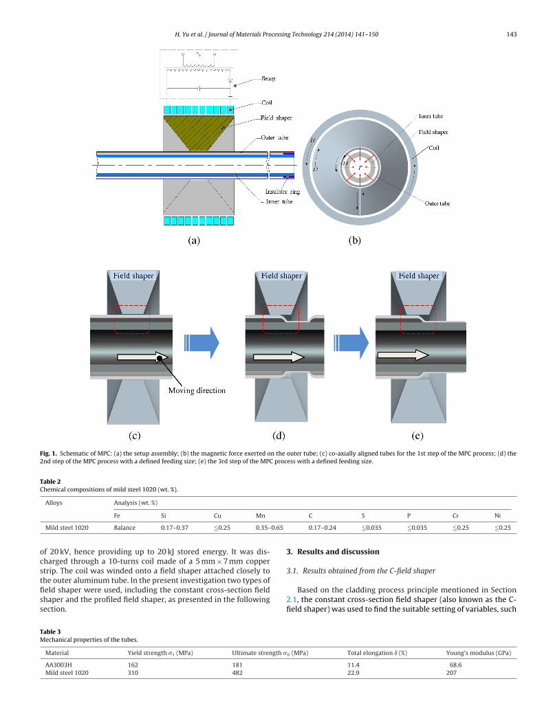
Fig. 1. Schematic of MPC: (a) the setup assembly; (b) the magnetic force exerted on the outer tube; (c) co-axially aligned tubes for the 1st step of the MPC process; (d) the2nd step of the MPC process with a defined feeding size; (e) the 3rd step of the MPC process with a defined feeding size.
Table 2Chemical compositions of mild steel 1020 (wt. %).
Alloys Analysis (wt. %)
0.65
ocstfiss
TM
Fe Si Cu Mn
Mild steel 1020 Balance 0.17–0.37 �0.25 0.35–
f 20 kV, hence providing up to 20 kJ stored energy. It was dis-harged through a 10-turns coil made of a 5 mm × 7 mm coppertrip. The coil was winded onto a field shaper attached closely to
he outer aluminum tube. In the present investigation two types ofeld shaper were used, including the constant cross-section fieldhaper and the profiled field shaper, as presented in the followingection.able 3echanical properties of the tubes.
Material Yield strength �s (MPa) Ultimate strength �
AA3003H 162 181
Mild steel 1020 310 482
C S P Cr Ni
0.17–0.24 �0.035 �0.035 �0.25 �0.25
3. Results and discussion
3.1. Results obtained from the C-field shaper
Based on the cladding process principle mentioned in Section2.1, the constant cross-section field shaper (also known as the C-field shaper) was used to find the suitable setting of variables, such
b (MPa) Total elongation ı (%) Young’s modulus (GPa)
11.4 68.622.9 207

144 H. Yu et al. / Journal of Materials Processing Technology 214 (2014) 141– 150
Fig. 2. (a) Sampling portions of the clad tube cut one after another in the directionvertical to the symmetry axis for a one step length; (b) schematic illustration of thect
aasit
Work zone
field. Thus, an uneven distribution of the magnetic field and con-
ompression-shear test; (c) indenter, holder and a sample for compression-shearest.
s feeding size, radial gap of the tubes, and discharge voltage forchieving a high quality clad tube. The cross-section of the C-field
haper is shown in Fig. 3. The cross section geometry keeps constantn the work zone. The length of the C-field shaper was 60 mm, andhe length of its work zone was 15 mm. Its outer diameter and innerFig. 4. The part formed by MPC with a list of feeding size: (a) finished p
Fig. 3. Cross-sections of the constant cross-section field shaper (C-field shaper).
diameter were 85 mm and 21 mm, respectively. The radial slit in theC-field shaper body was 0.3 mm in width.
The first experiment was performed to study the influence ofthe feeding size during the MPC process. In the condition of 10 kVdischarge voltage and 1.0 mm radial gap, the feeding size had alist of 6 mm -7 mm -9 mm -9 mm -9 mm -12 mm -15 mm -21 mmalong the axial direction as illustrated in Fig. 4. One feeding sizecorresponds to one MPC step. Fig. 4(a) shows the appearance of thebi-metal tube formed by MPC. It can be seen that the outer diam-eter of the cladding tube was not always uniform as feeding sizeincreased from 40% L to 140% L (L, the length of the work zone ofthe C-field shaper, shown in Fig. 3). Typical failure was observedas shown in Fig. 4(b). The surface of the clad tube was rippled andswelled when feeding size exceeds L (15 mm). An excessive feedingsize was thought to be responsible for the asperity failure. While,the inhomogeneous radial gap between the deformed outer tubeand C-field shaper was thought to be responsible for the rippleson the surface. Before the first step of the MPC process, the radialdistance between C-field shaper and the outer tube were kept con-stant. However, after the first step of the MPC process, the outertube was electromagnetically compressed into an “S” configurationwhich features the transition zone which is defined as the regionbetween two adjacent joints. As a result, there arose an inhomoge-neous radial gap between field shaper and the outer tube, as shownin Fig. 1(d). Therefore, the density of the magnetic flux lines throughthe gap is not uniform, as shown in Fig. 5(a). The local density ofmagnetic flux lines is proportional to the strength of the magnetic
sequently of the magnetic pressure in the transition zone occurs,which are schematically illustrated in Fig. 5(b) and (c). The inhomo-geneous magnetic force finally leads to an improper deformation:
art; (b) the typical asperity failure on the surface of the clad tube.
H. Yu et al. / Journal of Materials Processing Technology 214 (2014) 141– 150 145
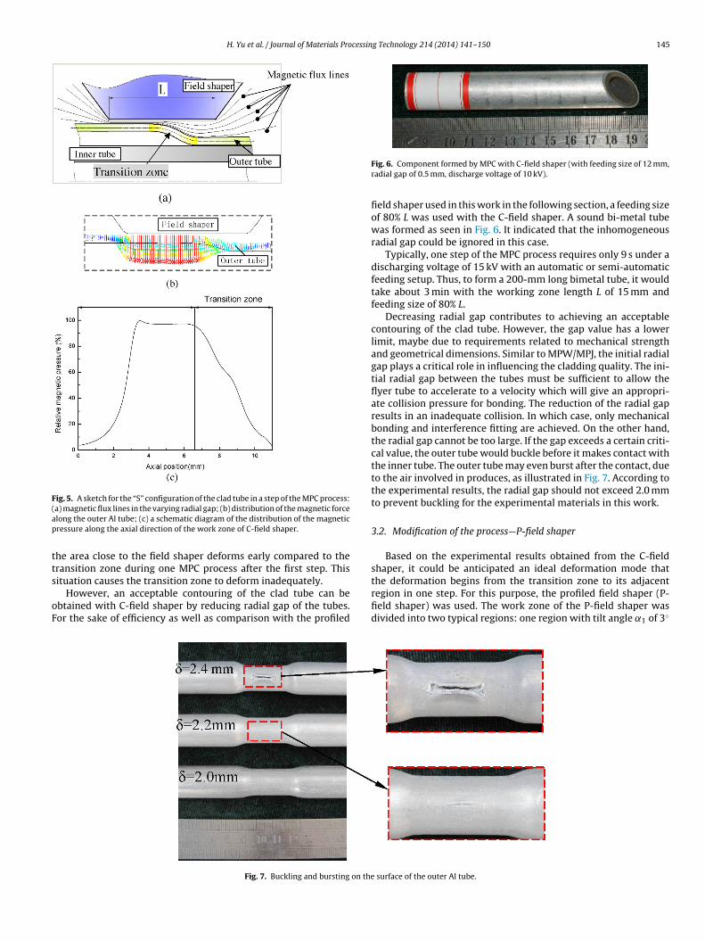
Fig. 5. A sketch for the “S” configuration of the clad tube in a step of the MPC process:(ap
tts
oF
a) magnetic flux lines in the varying radial gap; (b) distribution of the magnetic forcelong the outer Al tube; (c) a schematic diagram of the distribution of the magneticressure along the axial direction of the work zone of C-field shaper.
he area close to the field shaper deforms early compared to theransition zone during one MPC process after the first step. This
ituation causes the transition zone to deform inadequately.However, an acceptable contouring of the clad tube can bebtained with C-field shaper by reducing radial gap of the tubes.or the sake of efficiency as well as comparison with the profiled
Fig. 7. Buckling and bursting on the
Fig. 6. Component formed by MPC with C-field shaper (with feeding size of 12 mm,radial gap of 0.5 mm, discharge voltage of 10 kV).
field shaper used in this work in the following section, a feeding sizeof 80% L was used with the C-field shaper. A sound bi-metal tubewas formed as seen in Fig. 6. It indicated that the inhomogeneousradial gap could be ignored in this case.
Typically, one step of the MPC process requires only 9 s under adischarging voltage of 15 kV with an automatic or semi-automaticfeeding setup. Thus, to form a 200-mm long bimetal tube, it wouldtake about 3 min with the working zone length L of 15 mm andfeeding size of 80% L.
Decreasing radial gap contributes to achieving an acceptablecontouring of the clad tube. However, the gap value has a lowerlimit, maybe due to requirements related to mechanical strengthand geometrical dimensions. Similar to MPW/MPJ, the initial radialgap plays a critical role in influencing the cladding quality. The ini-tial radial gap between the tubes must be sufficient to allow theflyer tube to accelerate to a velocity which will give an appropri-ate collision pressure for bonding. The reduction of the radial gapresults in an inadequate collision. In which case, only mechanicalbonding and interference fitting are achieved. On the other hand,the radial gap cannot be too large. If the gap exceeds a certain criti-cal value, the outer tube would buckle before it makes contact withthe inner tube. The outer tube may even burst after the contact, dueto the air involved in produces, as illustrated in Fig. 7. According tothe experimental results, the radial gap should not exceed 2.0 mmto prevent buckling for the experimental materials in this work.
3.2. Modification of the process—P-field shaper
Based on the experimental results obtained from the C-fieldshaper, it could be anticipated an ideal deformation mode that
the deformation begins from the transition zone to its adjacentregion in one step. For this purpose, the profiled field shaper (P-field shaper) was used. The work zone of the P-field shaper wasdivided into two typical regions: one region with tilt angle ˛1 of 3◦surface of the outer Al tube.
146 H. Yu et al. / Journal of Materials Processin
a˛ts
Ftwfasm
3
gaiam
the wide diffusion zone with width of about 50 �m, the composi-
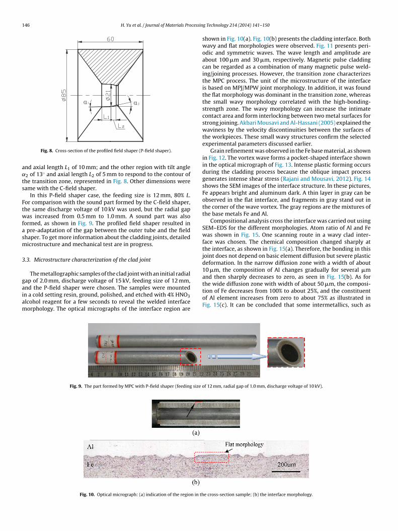
Fig. 8. Cross-section of the profiled field shaper (P-field shaper).
nd axial length L1 of 10 mm; and the other region with tilt angle2 of 13◦ and axial length L2 of 5 mm to respond to the contour of
he transition zone, represented in Fig. 8. Other dimensions wereame with the C-field shaper.
In this P-field shaper case, the feeding size is 12 mm, 80% L.or comparison with the sound part formed by the C-field shaper,he same discharge voltage of 10 kV was used, but the radial gapas increased from 0.5 mm to 1.0 mm. A sound part was also
ormed, as shown in Fig. 9. The profiled field shaper resulted in pre-adaptation of the gap between the outer tube and the fieldhaper. To get more information about the cladding joints, detailedicrostructure and mechanical test are in progress.
.3. Microstructure characterization of the clad joint
The metallographic samples of the clad joint with an initial radialap of 2.0 mm, discharge voltage of 15 kV, feeding size of 12 mm,
nd the P-field shaper were chosen. The samples were mountedn a cold setting resin, ground, polished, and etched with 4% HNO3lcohol reagent for a few seconds to reveal the welded interfaceorphology. The optical micrographs of the interface region areFig. 9. The part formed by MPC with P-field shaper (feeding size o
Fig. 10. Optical micrograph: (a) indication of the region in th
g Technology 214 (2014) 141– 150
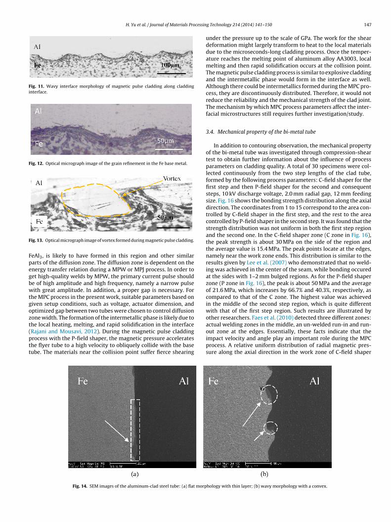
shown in Fig. 10(a). Fig. 10(b) presents the cladding interface. Bothwavy and flat morphologies were observed. Fig. 11 presents peri-odic and symmetric waves. The wave length and amplitude areabout 100 �m and 30 �m, respectively. Magnetic pulse claddingcan be regarded as a combination of many magnetic pulse weld-ing/joining processes. However, the transition zone characterizesthe MPC process. The unit of the microstructure of the interfaceis based on MPJ/MPW joint morphology. In addition, it was foundthe flat morphology was dominant in the transition zone, whereasthe small wavy morphology correlated with the high-bonding-strength zone. The wavy morphology can increase the intimatecontact area and form interlocking between two metal surfaces forstrong joining. Akbari Mousavi and Al-Hassani (2005) explained thewaviness by the velocity discontinuities between the surfaces ofthe workpieces. These small wavy structures confirm the selectedexperimental parameters discussed earlier.
Grain refinement was observed in the Fe base material, as shownin Fig. 12. The vortex wave forms a pocket-shaped interface shownin the optical micrograph of Fig. 13. Intense plastic forming occursduring the cladding process because the oblique impact processgenerates intense shear stress (Rajani and Mousavi, 2012). Fig. 14shows the SEM images of the interface structure. In these pictures,Fe appears bright and aluminum dark. A thin layer in gray can beobserved in the flat interface, and fragments in gray stand out inthe corner of the wave vortex. The gray regions are the mixtures ofthe base metals Fe and Al.
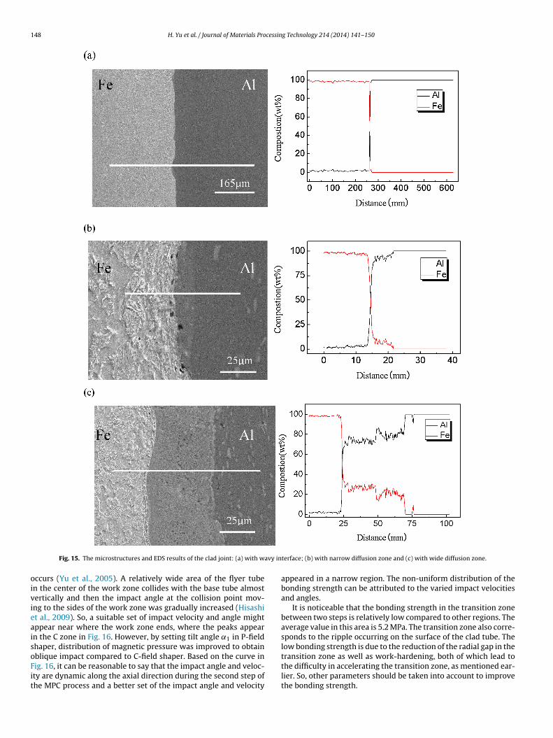
Compositional analysis cross the interface was carried out usingSEM–EDS for the different morphologies. Atom ratio of Al and Fewas shown in Fig. 15. One scanning route in a wavy clad inter-face was chosen. The chemical composition changed sharply atthe interface, as shown in Fig. 15(a). Therefore, the bonding in thisjoint does not depend on basic element diffusion but severe plasticdeformation. In the narrow diffusion zone with a width of about10 �m, the composition of Al changes gradually for several �mand then sharply decreases to zero, as seen in Fig. 15(b). As for
tion of Fe decreases from 100% to about 25%, and the constituentof Al element increases from zero to about 75% as illustrated inFig. 15(c). It can be concluded that some intermetallics, such as
f 12 mm, radial gap of 1.0 mm, discharge voltage of 10 kV).
e cross-section sample; (b) the interface morphology.
H. Yu et al. / Journal of Materials Processin
Fig. 11. Wavy interface morphology of magnetic pulse cladding along claddinginterface.
Fig. 12. Optical micrograph image of the grain refinement in the Fe base metal.
F
Fpegbwtgozt(ptt
ig. 13. Optical micrograph image of vortex formed during magnetic pulse cladding.
eAl3, is likely to have formed in this region and other similararts of the diffusion zone. The diffusion zone is dependent on thenergy transfer relation during a MPW or MPJ process. In order toet high-quality welds by MPW, the primary current pulse shoulde of high amplitude and high frequency, namely a narrow pulseith great amplitude. In addition, a proper gap is necessary. For
he MPC process in the present work, suitable parameters based oniven setup conditions, such as voltage, actuator dimension, andptimized gap between two tubes were chosen to control diffusionone width. The formation of the intermetallic phase is likely due tohe local heating, melting, and rapid solidification in the interface
Rajani and Mousavi, 2012). During the magnetic pulse claddingrocess with the P-field shaper, the magnetic pressure accelerateshe flyer tube to a high velocity to obliquely collide with the baseube. The materials near the collision point suffer fierce shearingFig. 14. SEM images of the aluminum-clad steel tube: (a) flat morp
g Technology 214 (2014) 141– 150 147
under the pressure up to the scale of GPa. The work for the sheardeformation might largely transform to heat to the local materialsdue to the microseconds-long cladding process. Once the temper-ature reaches the melting point of aluminum alloy AA3003, localmelting and then rapid solidification occurs at the collision point.The magnetic pulse cladding process is similar to explosive claddingand the intermetallic phase would form in the interface as well.Although there could be intermetallics formed during the MPC pro-cess, they are discontinuously distributed. Therefore, it would notreduce the reliability and the mechanical strength of the clad joint.The mechanism by which MPC process parameters affect the inter-facial microstructures still requires further investigation/study.
3.4. Mechanical property of the bi-metal tube
In addition to contouring observation, the mechanical propertyof the bi-metal tube was investigated through compression-sheartest to obtain further information about the influence of processparameters on cladding quality. A total of 30 specimens were col-lected continuously from the two step lengths of the clad tube,formed by the following process parameters: C-field shaper for thefirst step and then P-field shaper for the second and consequentsteps, 10 kV discharge voltage, 2.0 mm radial gap, 12 mm feedingsize. Fig. 16 shows the bonding strength distribution along the axialdirection. The coordinates from 1 to 15 correspond to the area con-trolled by C-field shaper in the first step, and the rest to the areacontrolled by P-field shaper in the second step. It was found that thestrength distribution was not uniform in both the first step regionand the second one. In the C-field shaper zone (C zone in Fig. 16),the peak strength is about 30 MPa on the side of the region andthe average value is 15.4 MPa. The peak points locate at the edges,namely near the work zone ends. This distribution is similar to theresults given by Lee et al. (2007) who demonstrated that no weld-ing was achieved in the center of the seam, while bonding occuredat the sides with 1–2 mm bulged regions. As for the P-field shaperzone (P zone in Fig. 16), the peak is about 50 MPa and the averageof 21.6 MPa, which increases by 66.7% and 40.3%, respectively, ascompared to that of the C zone. The highest value was achievedin the middle of the second step region, which is quite differentwith that of the first step region. Such results are illustrated byother researchers. Faes et al. (2010) detected three different zones:actual welding zones in the middle, an un-welded run-in and run-
out zone at the edges. Essentially, these facts indicate that theimpact velocity and angle play an important role during the MPCprocess. A relative uniform distribution of radial magnetic pres-sure along the axial direction in the work zone of C-field shaperhology with thin layer; (b) wavy morphology with a convex.
148 H. Yu et al. / Journal of Materials Processing Technology 214 (2014) 141– 150
avy in
oivieaisoFit
Fig. 15. The microstructures and EDS results of the clad joint: (a) with w
ccurs (Yu et al., 2005). A relatively wide area of the flyer tuben the center of the work zone collides with the base tube almostertically and then the impact angle at the collision point mov-ng to the sides of the work zone was gradually increased (Hisashit al., 2009). So, a suitable set of impact velocity and angle mightppear near where the work zone ends, where the peaks appearn the C zone in Fig. 16. However, by setting tilt angle ˛1 in P-fieldhaper, distribution of magnetic pressure was improved to obtain
blique impact compared to C-field shaper. Based on the curve inig. 16, it can be reasonable to say that the impact angle and veloc-ty are dynamic along the axial direction during the second step ofhe MPC process and a better set of the impact angle and velocityterface; (b) with narrow diffusion zone and (c) with wide diffusion zone.
appeared in a narrow region. The non-uniform distribution of thebonding strength can be attributed to the varied impact velocitiesand angles.
It is noticeable that the bonding strength in the transition zonebetween two steps is relatively low compared to other regions. Theaverage value in this area is 5.2 MPa. The transition zone also corre-sponds to the ripple occurring on the surface of the clad tube. Thelow bonding strength is due to the reduction of the radial gap in the
transition zone as well as work-hardening, both of which lead tothe difficulty in accelerating the transition zone, as mentioned ear-lier. So, other parameters should be taken into account to improvethe bonding strength.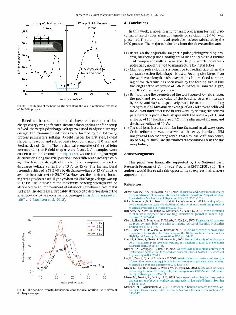
H. Yu et al. / Journal of Materials Processin
Fo
ciepsfccdadsaitasi1
Fd
ig. 16. Distribution of the bonding strength along the axial direction for two stepsf the MPC process.
Based on the results mentioned above, enhancement of dis-harge energy was performed. Because the capacitance of the setups fixed, the varying discharge voltage was used to adjust dischargenergy. The examined clad tubes were formed by the followingrocess parameters settings: C-field shaper for first step, P-fieldhaper for second and subsequent step, radial gap of 2.0 mm, andeeding size of 12 mm. The mechanical properties of the clad jointorresponding to P-field shaper were focused. All samples werehosen from the second step. Fig. 17 shows the bonding strengthistribution along the axial position under different discharge volt-ge. The bonding strength of the clad tube is improved when theischarge voltage varies from 10 kV to 15 kV. The highest bondtrength achieved is 79.2 MPa by discharge voltage of 15 kV, and theverage bond strength is 29.7 MPa. However, the maximum bond-ng strength decreased slightly when the discharge voltage was upo 16 kV. The increase of the maximum bonding strength can bettributed to an improvement of interlocking between two metalurfaces. The decrease is probably attributed to deterioration of thenterface due to the excessive input energy (Balasubramanian et al.,
997 and Raoelison et al., 2012).15 20 25 30 35
0
20
40
60
80
Bon
ding
str
engt
h (M
Pa)
Axial position (mm)
10 kV 13 kV 15 kV 16 kV
ig. 17. The bonding strength distribution along the axial position under differentischarge voltages.
g Technology 214 (2014) 141– 150 149
4. Conclusions
In this work, a novel plastic forming processing for manufac-turing bi-metal tubes, named magnetic pulse cladding (MPC), waspresented. The aluminum-clad steel tube has been fabricated by theMPC process. The major conclusions from the above studies are:
(1) Based on the sequential magnetic pulse joining/welding pro-cess, magnetic pulse cladding could be applicable to a tubularclad component with a large axial length, which indicates apotentially good method to manufacture bi-metal tubes.
(2) Magnetic pulse cladding is sensitive to feeding size when theconstant section field shaper is used. Feeding size larger thanthe work zone length leads to asperities failure. Good contour-ing of the clad tube has been made by the feeding size of 80%the length of the work zone of C-field shaper, 0.5 mm radial gap,and 10 kV discharging voltage.
(3) By modifying the geometry of the work zone of C-field shaper,the peak and average value of the bonding strength increaseby 66.7% and 40.3%, respectively. And the maximum bondingstrength of 79.2 MPa and an average of 29.7 MPa were achievedfor Al-clad mild steel tube in this work by setting the processparameters: a profile field shaper with tile angle ˛1 of 3◦ andangle ˛2 of 13◦, feeding size of 12 mm, radial gap of 2.0 mm, anddischarge voltage of 15 kV.
(4) The clad joint features both flat interfaces and small wavy ones.Grain refinement was observed at the wavy interface. SEMimages and EDS mapping reveal that a mutual diffusion zones,up to 50-�m thick, are distributed discontinuously in the flatmorphology.
Acknowledgments
This paper was financially supported by the National BasicResearch Program of China (973 Program) [2011CB012805]. Theauthors would like to take this opportunity to express their sincereappreciation.
References
Akbari Mousavi, A.A., Al-Hassani, S.T.S., 2005. Numerical and experimental studiesof the mechanism of the wavy interface formations in explosive/impact welding.Journal of the Mechanics and Physics of Solids 53, 2501–2528.
Balasubramanian, V., Rathinasabapathi, M., Raghukandan, K., 1997. Modeling of pro-cess parameters in explosive cladding of mild steel and aluminum. Journal ofMaterials Processing Technology 63, 83–88.
Ben-Artzy, A., Stern, A., Frage, N., Shribman, V., Sadot, O., 2010. Wave formationmechanism in magnetic pulse welding. International Journal of Impact Engi-neering 37, 397–404.
Chen, Z., Ikeda, K., Murakami, T., Takeda, T., Xie, J.X., 2003. Fabrication of compos-ite pipes by multi-billet extrusion technique. Journal of Materials ProcessingTechnology 137, 10–16.
Faes, K., Baaten, T., De Waele, W., Debroux, N., 2010. Joining of copper to brass usingmagnetic pulse welding. In: Proceedings of the 4th International Conference onHigh Speed Forming, Columbus-Ohio, USA, pp. 84–96.
Hisashi, S., Isao, S., Sherif, R., Hidekazu, M., 2009. Numerical study of joining pro-cess in magnetic pressure seam welding. Transactions of Joining and WeldingResearch Institute 38, 63–68.
Krishna, B.V., Venugopal, P., Rao, K.P., 2005. Co-extrusion of dissimilar sintered P/Mperforms-an explored route to produce bi-metallic tubes. Materials Science andEngineering A 407, 77–83.
Lee, K.J., Kumai, S.J., Arai, T., Aizawa, T., 2007. Interfacial microstructure and strengthof steel/aluminum alloy lap joint fabricated by magnetic pressure seam welding.Materials Science and Engineering A 471, 95–101.
Madej, L., Paul, H., Trebacz, L., Wajda, W., Pietrzyk, M., 2012. Multi billet extrusiontechnology for manufacturing bi-layered components. CIRP Annals – Manufac-turing Technology 61, 235–238.
Marre, M., Brosius, A., Tekkaya, A.E., 2008. New aspects of joining by compression
and expansion of tubular workpieces. International Journal of Material Forming1, 1295–1298.Mohebbi, M.S., Akbarzadeh, A., 2010. A novel spin-bonding process for manufac-turing multilayered clad tubes. Journal of Materials Processing Technology 210,510–517.

1 cessin
P
R
R
S
S
259–265.
50 H. Yu et al. / Journal of Materials Pro
syk, V., Risch, D., Kinsey, B.L., Tekkaya, A.E., Kleiner, M., 2011. Electromagneticforming-a review. Journal of Materials Processing Technology 211, 787–829.
ajani, H.R.Z., Mousavi, S.A.A., 2012. The effect of explosive welding parameters onmetallurgical and mechanical interfacial features of Inconel 625/plain carbonsteel bi-metal plate. Materials Science and Engineering A 556, 454–464.
aoelison, R., Rachik, M., Buiron, N., Haye, D., Morel, M., Dos Sanstos, B., Jouaffre, D.,Frantz, G., 2012. Assessment of gap and charging voltage influence on mechan-ical behaviour of joints obtained by magnetic pulse welding. In: Proceedings ofthe 5th International Conference on High Speed Forming, Dortmund, Germany,pp. 207–216.
chulz, W., Worringer, J., Osborn, D., 1999. Process for the manufacture of claddedmetal pipes, United States Patent: No. 5940951.
un, X.J., Tao, J., Guo, X.Z., 2011. Bonding properties of interface in Fe/Al clad tubeprepared by explosive welding. Transactions of Nonferrous Metals Society ofChina 21, 2175–2180.
g Technology 214 (2014) 141– 150
Wang, X.S., Li, P.N., Wang, R.Z., 2005. Study on hydro-forming technology of manu-facturing bi-metallic CRA-lined pipe. International Journal of Machine Tools andManufacture 45, 373–378.
Yu, H.P., Li, C.F., Zhao, Z.H., Li, Z., 2005. Effect of field shaper on magnetic pressurein electromagnetic forming. Journal of Materials Processing Technology 168,245–249.
Yu, H.P., Xu, Z.D., Fan, Z.S., Zhao, Z.X., Li, C.F., 2013. Mechanical prop-erty and microstructure of aluminum alloy–steel tubes joint bymagnetic pulse welding. Materials Science and Engineering A 561,
Zhang, Y., Badu, S.S., Prothe, C., Blakely, M., Kwasegroch, J., LaHa, M., Daehn,G.S., 2011. Application of high velocity impact welding at varied dif-ferent length scales. Journal of Materials Processing Technology 211,944–952.