Gun axis UA05 - Gema Powder Coating
54
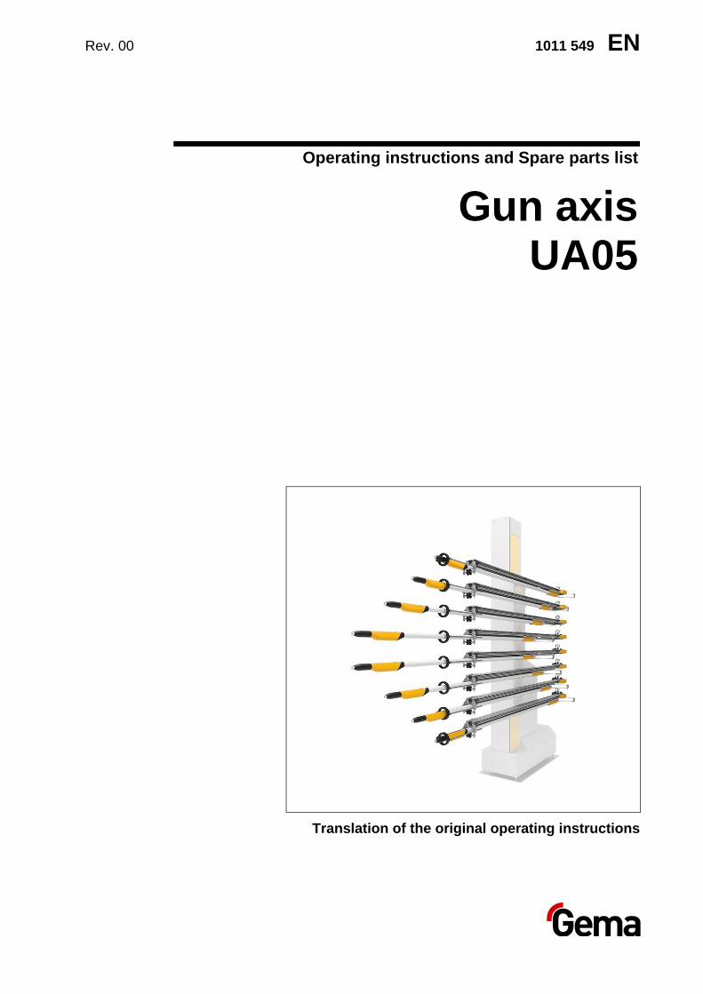
Rev. 00 1011 549 EN Operating instructions and Spare parts list Gun axis UA05 Translation of the original operating instructions
-
Upload
khangminh22 -
Category
Documents
-
view
0 -
download
0
Transcript of Gun axis UA05 - Gema Powder Coating
Rev. 00 1011 549 EN
Operating instructions and Spare parts list
Gun axis UA05
Translation of the original operating instructions
Rev. 00 05/21
Documentation UA05
© Copyright 2017 Gema Switzerland GmbH
All rights reserved.
This publication is protected by copyright. Unauthorized copying is prohibited by law. No part of this publication may be reproduced, photocopied, translated, stored on a retrieval system or transmitted in any form or by any means for any purpose, neither as a whole nor partially, without the express written consent of Gema Switzerland GmbH.
Gema, EquiFlow, MagicCompact, MagicCylinder, OptiCenter, OptiFlex, OptiGun, OptiSelect and OptiStar are registered trademarks of Gema Switzerland GmbH.
ClassicLine, ClassicStandard, ClassicOpen, DVC (Digital Valve Control), GemaConnect, MagicControl, MagicPlus, MonoCyclone, MRS, MultiColor, MultiStar, OptiAir, OptiControl, OptiColor, OptiFeed, OptiFlow, OptiHopper, OptiMove, OptiSieve, OptiSpeeder, OptiSpray, PCC (Precise Charge Control), RobotGun, SIT (Smart Inline Technology) und SuperCorona are trademarks of Gema Switzerland GmbH.
All other product names are trademarks or registered trademarks of their respective holders.
Reference is made in this manual to different trademarks or registered trademarks. Such references do not mean that the manufacturers concerned approve of or are bound in any form by this manual. We have endeavored to retain the preferred spelling of the trademarks, and registered trademarks of the copyright holders.
To the best of our knowledge and belief, the information contained in this publication was correct and valid on the date of publication. Gema Switzerland GmbH makes no representations or warranties with respect to the contents or use of this publication, and reserves the right to revise this publication and make changes to its content without prior notice.
For the latest information about Gema products, visit www.gemapowdercoating.com.
For patent information, see www.gemapowdercoating.com/patents or www.gemapowdercoating.us/patents.
Printed in Switzerland Gema Switzerland GmbH Mövenstrasse 17 9015 St.Gallen Switzerland
Phone: +41-71-313 83 00 Fax.: +41-71-313 83 83
E-mail: [email protected]
Rev. 00 05/21
UA05 Table of contents • 3
Table of contents
About these instructions 7
General information ................................................................................................ 7 Keeping the Manual ................................................................................................ 7 Safety symbols (pictograms) ................................................................................... 7
Structure of Safety Notes ........................................................................... 8 Presentation of the contents ................................................................................... 8
Figure references in the text ...................................................................... 8
Safety 9
Basic safety instructions ......................................................................................... 9 Product specific security regulations ...................................................................... 9
Special safety regulations ........................................................................ 10
Transport 13
Introduction ........................................................................................................... 13 Requirements on personnel carrying out the work .................................. 13
Packing material.................................................................................................... 13 Selection of packing material ................................................................... 13 Procedure when packing ......................................................................... 13
Transport ............................................................................................................... 13 Data concerning goods to be transported ................................................ 13 Loading, transferring the load, unloading ................................................ 13
Product description 15
Intended use ......................................................................................................... 15 Utilization .................................................................................................. 16
Reasonably foreseeable misuse ........................................................................... 16 Function ................................................................................................................ 16
Schematic presentation ........................................................................... 17 Special characteristics ............................................................................. 18 Combination with additional axes of motion ............................................ 18
Position regulator with CAN BUS (Power unit) ..................................................... 19 Technical Data ...................................................................................................... 20
Versions ................................................................................................... 20 Electrical data .......................................................................................... 20 Pneumatic data ........................................................................................ 20 Dimensions .............................................................................................. 21 Sound pressure level ............................................................................... 21 Rating plate .............................................................................................. 21 Controller cabinet ..................................................................................... 22
Assembly / Connection 23
Place of installation and operation ........................................................................ 24 Grounding of the axis ............................................................................................ 25 Electrical/pneumatic connections and cable connections .................................... 25
Rev. 00 05/21
4 • Table of contents UA05
Start-up 27
Preparation for start-up ......................................................................................... 27 General information ................................................................................. 27 Reference point ....................................................................................... 28 Setting values/parameters ....................................................................... 28
Reference point and mechanical stop .................................................................. 28 Setting of the mechanical stop ................................................................ 29
Operation 31
Decommissioning / Storage 33
Introduction ........................................................................................................... 33 Safety rules .............................................................................................. 33 Requirements on personnel carrying out the work .................................. 33
Storage conditions ................................................................................................ 33 Hazard notes ........................................................................................... 33 Type of storage ........................................................................................ 33 Storage duration ...................................................................................... 33 Space requirements ................................................................................ 33 Physical requirements ............................................................................. 34
Shut-down ............................................................................................................. 34 Putting out of service ............................................................................... 34 Cleaning................................................................................................... 34 Preservation ............................................................................................ 34
Maintenance during storage ................................................................................. 34 Maintenance schedule ............................................................................. 34 Maintenance works .................................................................................. 34
Maintenance / Repairs 35
General information .............................................................................................. 35 Maintenance schedule .......................................................................................... 36 Drive unit ............................................................................................................... 36
Replacing the drive unit ........................................................................... 37 Toothed belt .......................................................................................................... 38
Replacing the toothed belt ....................................................................... 38 Replacing the gliding elements............................................................................. 39 Setting the support roller ...................................................................................... 43 Maintenance of the position regulator .................................................................. 43 Replacing the position regulator ........................................................................... 44
Fault clearance 45
Disposal 47
Introduction ........................................................................................................... 47 Safety rules .............................................................................................. 47 Requirements on personnel carrying out the work .................................. 47 Disposal regulations ................................................................................ 47 Materials .................................................................................................. 48
Disposal of operating material .............................................................................. 48 Disassembly of component groups ...................................................................... 48
Preparation .............................................................................................. 48
Spare parts list 49
Ordering spare parts ............................................................................................. 49 UA05 – complete .................................................................................................. 50 Position regulator .................................................................................................. 51
Rev. 00 05/21
UA05 Table of contents • 5

Rev. 00 05/21
UA05 About these instructions • 7
About these instructions
General information This operating manual contains all the important information which you require for the working with the UA05. It will safely guide you through the start-up process and give you references and tips for the optimal use when working with your powder coating system.
Information about the functional mode of the individual system components should be referenced in the respective enclosed documents.
Keeping the Manual Please keep this Manual ready for later use or if there should be any queries.
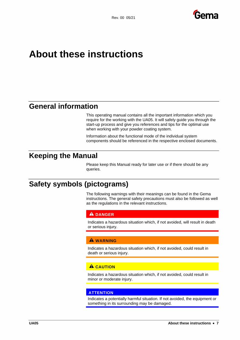
Safety symbols (pictograms)
The following warnings with their meanings can be found in the Gema instructions. The general safety precautions must also be followed as well as the regulations in the relevant instructions.
DANGER
Indicates a hazardous situation which, if not avoided, will result in death or serious injury.
WARNING
Indicates a hazardous situation which, if not avoided, could result in death or serious injury.
CAUTION
Indicates a hazardous situation which, if not avoided, could result in minor or moderate injury.
ATTENTION
Indicates a potentially harmful situation. If not avoided, the equipment or something in its surrounding may be damaged.
Rev. 00 05/21
8 • About these instructions UA05
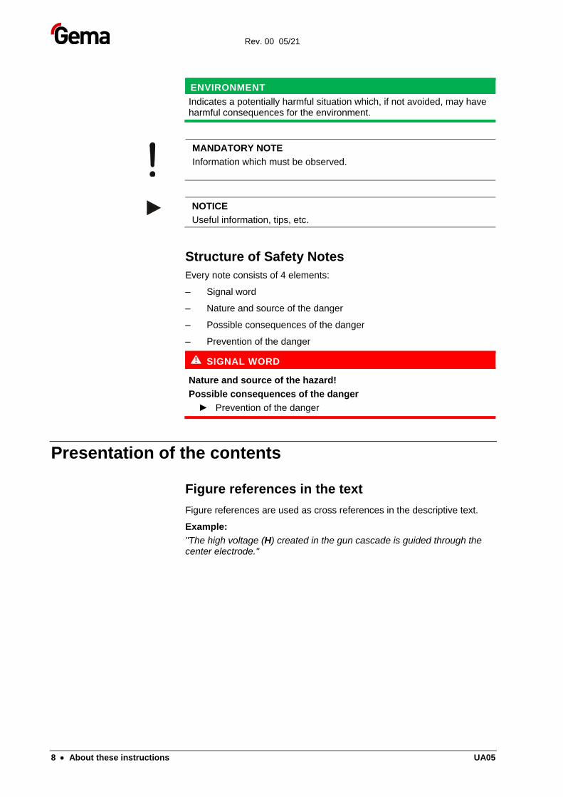
ENVIRONMENT
Indicates a potentially harmful situation which, if not avoided, may have harmful consequences for the environment.
MANDATORY NOTE
Information which must be observed.
NOTICE
Useful information, tips, etc.
Structure of Safety Notes
Every note consists of 4 elements:
– Signal word
– Nature and source of the danger
– Possible consequences of the danger
– Prevention of the danger
SIGNAL WORD
Nature and source of the hazard!
Possible consequences of the danger
► Prevention of the danger
Presentation of the contents
Figure references in the text
Figure references are used as cross references in the descriptive text.
Example:
"The high voltage (H) created in the gun cascade is guided through the center electrode."
Rev. 00 05/21
UA05 Safety • 9
Safety
Basic safety instructions
– This product is built to the latest specification and conforms to the recognized technical safety regulations and is designed for the normal application of powder coating.
– Any other use is considered non-compliant. The manufacturer shall not be liable for damage resulting from such use; the user bears sole responsibility for such actions. If this product is to be used for other purposes or other substances outside of our guidelines then Gema Switzerland GmbH should be consulted.
– Start-up (i.e. the execution of intended operational tasks) is forbidden until it has been established that this product has been set up and wired according to the guidelines for machinery. The standard "Machine safety" must also be observed.
– Unauthorized modifications to the product exempt the manufacturer from any liability from resulting damage.
– The relevant accident prevention regulations, as well as other generally recognized safety regulations, occupational health and structural regulations are to be observed.
– Furthermore, the country-specific safety regulations also must be observed.
Product specific security regulations
– This product is a constituent part of the equipment and is therefore integrated in the system's safety concept.
– If it is to be used in a manner outside the scope of the safety concept, then corresponding measures must be taken.
– The installation work to be done by the customer must be carried out according to local regulations.
– It must be ensured, that all components are earthed according to the local regulations before start-up.
For further security information, see the more detailed Gema safety regulations!
Rev. 00 05/21
10 • Safety UA05
Special safety regulations
– The axis may only be switched on and operated after careful reading of this manual. Incorrect operation of the axis control unit can lead to accidents, malfunctions or damage to the plant.
WARNING
The power of the axes is much stronger than that of a human being!
► All axes must be protected from access during operation (see local safety regulations).
► Never stand under the Z carriage when the vertical axis is not operating!
– The plugs and sockets of the axis control unit and the power unit of the axis should only be unplugged when the power supply is disconnected
– The connecting cables between the control unit and the axis must be laid in such a way, that they cannot be damaged during axes operation. Please observe the local safety regulations!
– The maximum upper stroke limit of the vertical axis must always be set with reference to the maximum height of the booth gun slots. If an incorrect (too high) stroke limit is set, this can lead to damage to the reciprocator and/or the booth!
ATTENTION
During a test run, it must be guaranteed that the unit is not damaged by the test!
► In particular, the limitations of the stroke range have to be observed (for further information, see chapter "Setting the mechanical stop")!
– When repairing the axis, both the axis control unit and the axis must be disconnected from the mains according to the local safety regulations!
– Repairs may be done only by authorized Gema service centers. Unauthorized conversions and modifications can lead to injuries and damage to the equipment. The Gema Switzerland GmbH guarantee would no longer be valid.
– Only original Gema spare parts should be used! The use of spare parts from other manufacturers will invalidate the Gema guarantee conditions!
– We point out that the customer himself is responsible for the safe operation of the equipment. Gema Switzerland GmbH is in no way responsible for any resulting damage.
For further security information, see the more detailed Gema safety regulations!
Rev. 00 05/21
UA05 Safety • 11
WARNING
Working without instructions
Working without instructions or with individual pages from the instructions may result in damage to property and personal injury if relevant safety information is not observed.
► Before working with the device, organize the required documents and read the section "Safety regulations".
► Work should only be carried out in accordance with the instructions of the relevant documents.
► Always work with the complete original document.
Rev. 00 05/21
12 • Safety UA05
Rev. 00 05/21
UA05 Transport • 13
Transport
Introduction This chapter describes special precautions that must be taken during internal transport of the product if:
– the customer himself must pack, transport and ship the product, such as to have renovations or service work carried out by the manufacturer
or
– the product must be shipped for disposal (recycling).
Requirements on personnel carrying out the work
All work must be carried out by personnel trained in packing machines.
Packing material
Selection of packing material
Suitably stable wood packing material must be used.
Procedure when packing
Transport the unit only in a horizontal position.
Axes must be supported in the center.
Transport
Data concerning goods to be transported
The space requirements correspond to the size of the axes of motion plus the packaging.
Loading, transferring the load, unloading
At least two people must be available.
Rev. 00 05/21
14 • Transport UA05
Rev. 00 05/21
UA05 Product description • 15
Product description
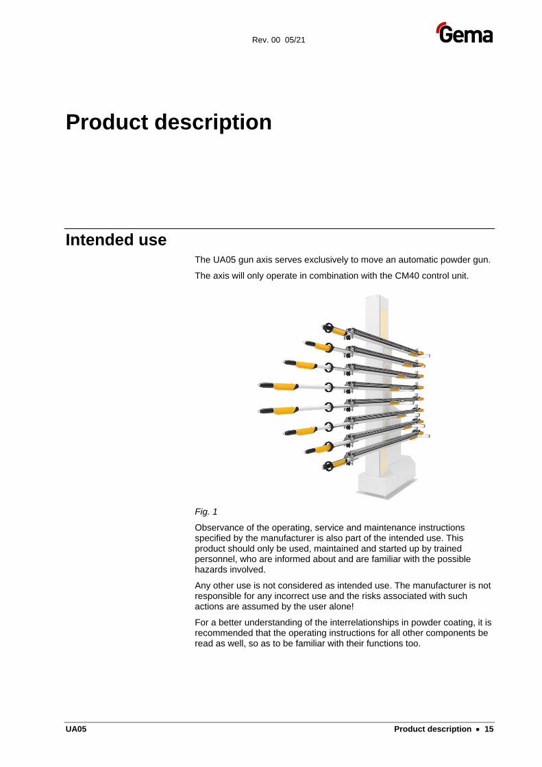
Intended use The UA05 gun axis serves exclusively to move an automatic powder gun.
The axis will only operate in combination with the CM40 control unit.
Fig. 1
Observance of the operating, service and maintenance instructions specified by the manufacturer is also part of the intended use. This product should only be used, maintained and started up by trained personnel, who are informed about and are familiar with the possible hazards involved.
Any other use is not considered as intended use. The manufacturer is not responsible for any incorrect use and the risks associated with such actions are assumed by the user alone!
For a better understanding of the interrelationships in powder coating, it is recommended that the operating instructions for all other components be read as well, so as to be familiar with their functions too.
Rev. 00 05/21
16 • Product description UA05
Utilization
The axis was designed for automatic coating with powder applicators. The axis can position the automatic powder gun in the corresponding position for the required coating condition to the object by the corresponding axis control unit. The gun axis is installed in a horizontal position, other positions after consultation with Gema Switzerland GmbH only. Depending on the design of the applicators, this unit may be used with all types of powder coating.
Reasonably foreseeable misuse – Operation in rooms with gases
– Incorrect setting of the mechanical travel distance limiters
– Incorrect programming of the front and rear turning points
– Use in connection with not permissible control units
– Loading the carriage with more weight than allowed (see "Technical Data")
– Operation without the proper training
– Operating the axis without the protective fence
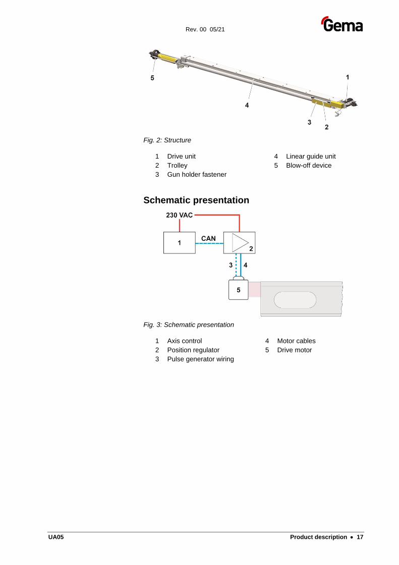
Function The gun axis is a feeding axis. The axis carries out a linear, oscillating backwards and forwards motion in the horizontal direction (called U motion), in order to adjust the gun position to the parts to be coated. The movement sequences (travel distance and travel speed) are controlled by the axis control unit.
During reverse motion, the gun is blown off using the integrated blow-off device (5).
The gun holders are pressed onto the carriage (2) with the fastener (3). The carriage (2) is moved backwards and forwards on the linear guide unit by a drive belt (4) inside the axis. The drive unit (1) and the electrical connection are installed in the axis rear part. A pulse generator, which is installed in the motor case, enables the exact positioning of the carriage.
The power supply is located in a separate control cabinet. One power unit is needed for each axis.
If the power is interrupted, the motion of the carriage is stopped momentarily.
To ensure that the gun axes cannot become a hazard during normal operation, the axes are shielded by a protective fence that is 2.3 m high. The fence has doors that are released by the control unit to allow authorized technical personnel access to the axes.
Rev. 00 05/21
UA05 Product description • 17
Fig. 2: Structure
1 Drive unit
2 Trolley
3 Gun holder fastener
4 Linear guide unit
5 Blow-off device
Schematic presentation
Fig. 3: Schematic presentation
1 Axis control
2 Position regulator
3 Pulse generator wiring
4 Motor cables
5 Drive motor
Rev. 00 05/21
18 • Product description UA05
Special characteristics
This axis is conspicuous because of its rugged, compact construction, a new drive system and an improved carriage design.
Further characteristics:
– Extremely smooth operation with toothed belt transmission
– High speed, maximum acceleration
– Precision point accuracy of the feed motion
– Safe operation and simple maintenance
– Simple assembly and disassembly
– A grid formation with separation of 110 mm between the automatic guns with the distance mechanically adjustable
– Robust, dirt-resistant and easily accessible components
– Integrated cleaning function (blow-off)
– Maximum stroke-length 1850 mm
– Free axis programming via MagicControl CM40
– Bus-/CAN bus technology integrated into the control unit
– Can be combined with Gema Laser scanner technologie
– IP54 protection type
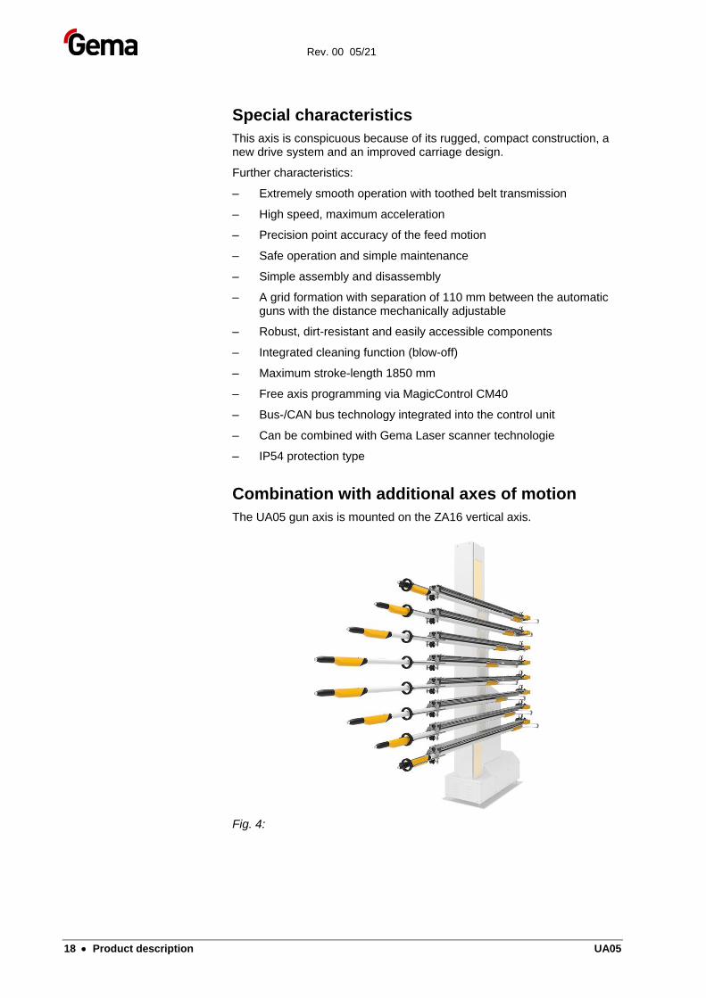
Combination with additional axes of motion
The UA05 gun axis is mounted on the ZA16 vertical axis.
Fig. 4:
Rev. 00 05/21
UA05 Product description • 19
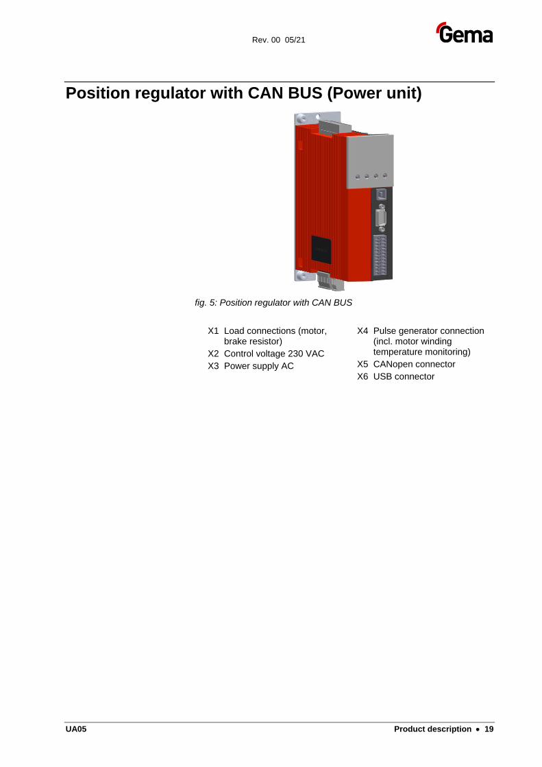
Position regulator with CAN BUS (Power unit)
fig. 5: Position regulator with CAN BUS
X1 Load connections (motor, brake resistor)
X2 Control voltage 230 VAC
X3 Power supply AC
X4 Pulse generator connection (incl. motor winding temperature monitoring)
X5 CANopen connector
X6 USB connector
Rev. 00 05/21
20 • Product description UA05
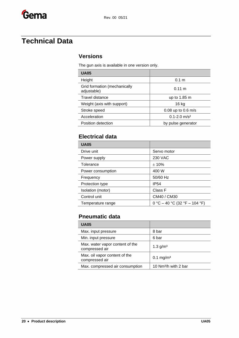
Technical Data
Versions
The gun axis is available in one version only.
UA05
Height 0.1 m
Grid formation (mechanically adjustable)
0.11 m
Travel distance up to 1.85 m
Weight (axis with support) 16 kg
Stroke speed 0.08 up to 0.6 m/s
Acceleration 0.1-2.0 m/s²
Position detection by pulse generator
Electrical data
UA05
Drive unit Servo motor
Power supply 230 VAC
Tolerance 10%
Power consumption 400 W
Frequency 50/60 Hz
Protection type IP54
Isolation (motor) Class F
Control unit CM40 / CM30
Temperature range 0 °C – 40 °C (32 °F – 104 °F)
Pneumatic data
UA05
Max. input pressure 8 bar
Min. input pressure 6 bar
Max. water vapor content of the compressed air
1.3 g/m³
Max. oil vapor content of the compressed air
0.1 mg/m³
Max. compressed air consumption 10 Nm³/h with 2 bar
Rev. 00 05/21
UA05 Product description • 21
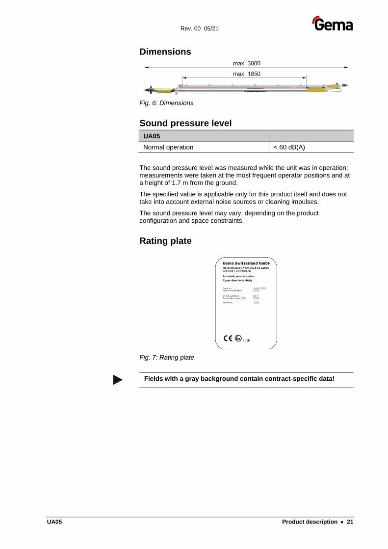
Dimensions
Fig. 6: Dimensions
Sound pressure level
UA05
Normal operation < 60 dB(A)
The sound pressure level was measured while the unit was in operation; measurements were taken at the most frequent operator positions and at a height of 1.7 m from the ground.
The specified value is applicable only for this product itself and does not take into account external noise sources or cleaning impulses.
The sound pressure level may vary, depending on the product configuration and space constraints.
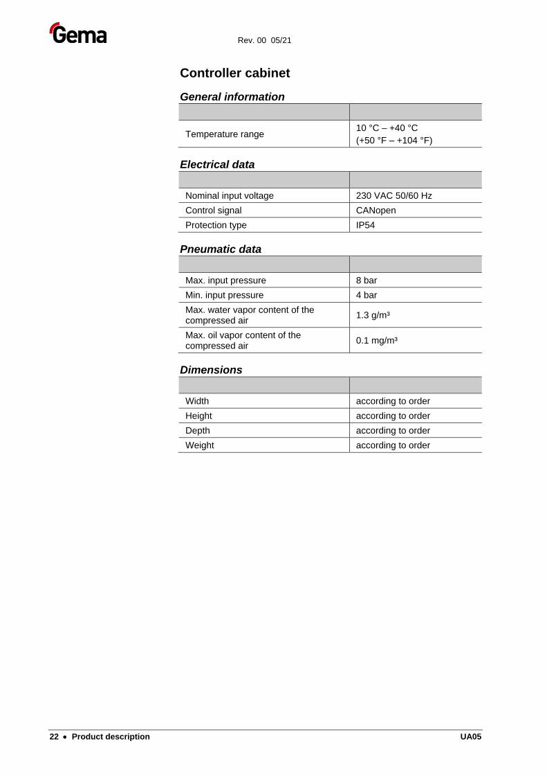
Rating plate
Fig. 7: Rating plate
Fields with a gray background contain contract-specific data!
Rev. 00 05/21
22 • Product description UA05
Controller cabinet
General information
Temperature range 10 °C – +40 °C
(+50 °F – +104 °F)
Electrical data
Nominal input voltage 230 VAC 50/60 Hz
Control signal CANopen
Protection type IP54
Pneumatic data
Max. input pressure 8 bar
Min. input pressure 4 bar
Max. water vapor content of the compressed air
1.3 g/m³
Max. oil vapor content of the compressed air
0.1 mg/m³
Dimensions
Width according to order
Height according to order
Depth according to order
Weight according to order
Rev. 00 05/21
UA05 Assembly / Connection • 23
Assembly / Connection
CAUTION
Uncontrolled gun axis movement
If a gun axis is not fixed firmly to the vertical axis, uncontrolled movement of the machine or insufficient fixing can cause injuries.
► Always fix gun axis firmly to the vertical axis!
CAUTION
The movement of the gun axis can cause injuries.
► Erect a protective fence around the reciprocator so that there is no danger of injury during normal operation.
CAUTION
Injuries can occur inside the protective fence due to the movement of the gun axis!
► In order to enter the inner area, the door interlocks must be released by the control unit. This release signal may only be activated by technical personnel.
► Except for normal operation, all other operating modes must be set up by an authorized technical representative.
Rev. 00 05/21
24 • Assembly / Connection UA05
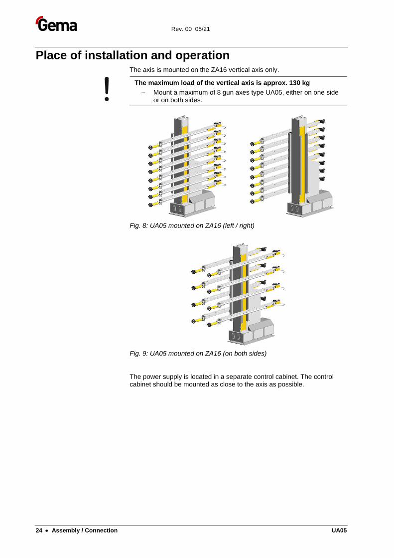
Place of installation and operation The axis is mounted on the ZA16 vertical axis only.
The maximum load of the vertical axis is approx. 130 kg
– Mount a maximum of 8 gun axes type UA05, either on one side or on both sides.
Fig. 8: UA05 mounted on ZA16 (left / right)
Fig. 9: UA05 mounted on ZA16 (on both sides)
The power supply is located in a separate control cabinet. The control cabinet should be mounted as close to the axis as possible.
Rev. 00 05/21
UA05 Assembly / Connection • 25
Grounding of the axis
DANGER
Missing or incorrect grounding
A bad or missing ground connection can be dangerous to the operator.
► Ground all metal parts of the axis according to the general, local safety regulations.
► Check regularly the grounding of the axis.
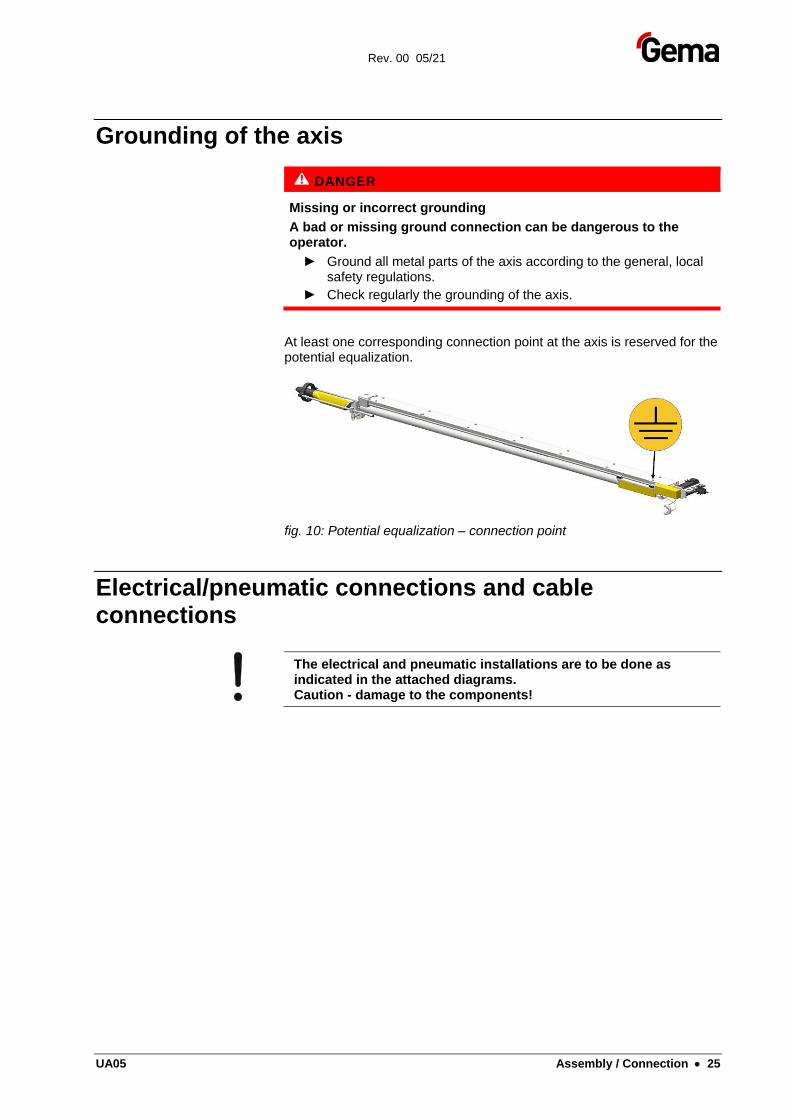
At least one corresponding connection point at the axis is reserved for the potential equalization.
fig. 10: Potential equalization – connection point
Electrical/pneumatic connections and cable connections
The electrical and pneumatic installations are to be done as indicated in the attached diagrams. Caution - damage to the components!
Rev. 00 05/21
26 • Assembly / Connection UA05
Rev. 00 05/21
UA05 Start-up • 27
Start-up
Preparation for start-up
ATTENTION
Incorrect setting of the stroke limit will cause damages to the axis, to the booth or to the applicators
► Before connecting or switching on the axis, read carefully these operating instructions!
► Before the axis is put into operation, the stroke limit must be set!
► See the user manual of the axis control unit!
General information
WARNING
Before start-up works are done, make certain that nobody can switch on the axis!
► Switch off and lock the mains switch!
Before starting up, check the following:
– Check the gun holder and hose holder if they are firmly fitted. Mount the gun holder in such a way that they do not hit the bottom of the booth slots on start-up and cause damage
– Lay out the cables and hoses in such a way that even at the highest stroke no strain can
– Check the grounding of the guns and hose carriers
– Check if the front and the rear reversing point of the carriage are set correctly. The stroke length of the axis must be in the range of the booth opening (collision danger!)
– Make sure that the automatic guns cannot collide with the work pieces (incorrectly adjusted stroke parameters on the axis control unit)
Rev. 00 05/21
28 • Start-up UA05
Reference point
At every start-up after the mains have been interrupted, the reference point of the axis must be referred again (see "Reference point and mechanical stops"). After the reference point is reached, the axis begins to carry out the movements set on the axis control unit.
Before the axis is put into operation, the front stroke limit must be set on the axis control unit (see therefore the corresponding axis control unit operating manual)!
ATTENTION
Incorrect setting of the stroke limit will cause damages to the axis, to the booth or to the applicators
► Before connecting or switching on the axis, read carefully these operating instructions!
► See the user manual of the axis control unit!
Setting values/parameters
The exact setting of parameters is performed with the Magic Control CM40/CM30 control unit (see therefore the corresponding operating manual).
The pressure for the blow-off device should be approximately 2 bar.
Reference point and mechanical stop The reference point serves as starting point for the reciprocator control unit for calculating the front and rear reversing point and the maximum stroke.
Each time the reciprocator is switched on, the control unit requests that the linear guide unit travels to the reference point (zero point). The linear guide unit travels to the mechanical stop, and remains in this end position.
The control unit notes this and gives the distance how far the unit must travel from this position. The standard value for the UA axis is 10, that means 10 mm away from the mechanical stop. For this reason, the Axis control unit must be programmed in such a way that the reference point is always 10 mm before the lowest mechanical stop (zero point).
ATTENTION
Damages to the booth, to the gun holders etc.
Reference point incorrectly set
► Check the reference point before the first start-up and if necessary, reset!
► Fit the mechanical stop to the gun slots!
Rev. 00 05/21
UA05 Start-up • 29
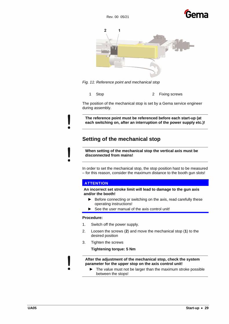
Fig. 11: Reference point and mechanical stop
1 Stop 2 Fixing screws
The position of the mechanical stop is set by a Gema service engineer during assembly.
The reference point must be referenced before each start-up (at each switching on, after an interruption of the power supply etc.)!
Setting of the mechanical stop
When setting of the mechanical stop the vertical axis must be disconnected from mains!
In order to set the mechanical stop, the stop position hast to be measured – for this reason, consider the maximum distance to the booth gun slots!
ATTENTION
An incorrect set stroke limit will lead to damage to the gun axis and/or the booth!
► Before connecting or switching on the axis, read carefully these operating instructions!
► See the user manual of the axis control unit!
Procedure:
1. Switch off the power supply.
2. Loosen the screws (2) and move the mechanical stop (1) to the desired position
3. Tighten the screws
Tightening torque: 5 Nm
After the adjustment of the mechanical stop, check the system parameter for the upper stop on the axis control unit!
► The value must not be larger than the maximum stroke possible between the stops!

Rev. 00 05/21
30 • Start-up UA05
Rev. 00 05/21
UA05 Operation • 31
Operation
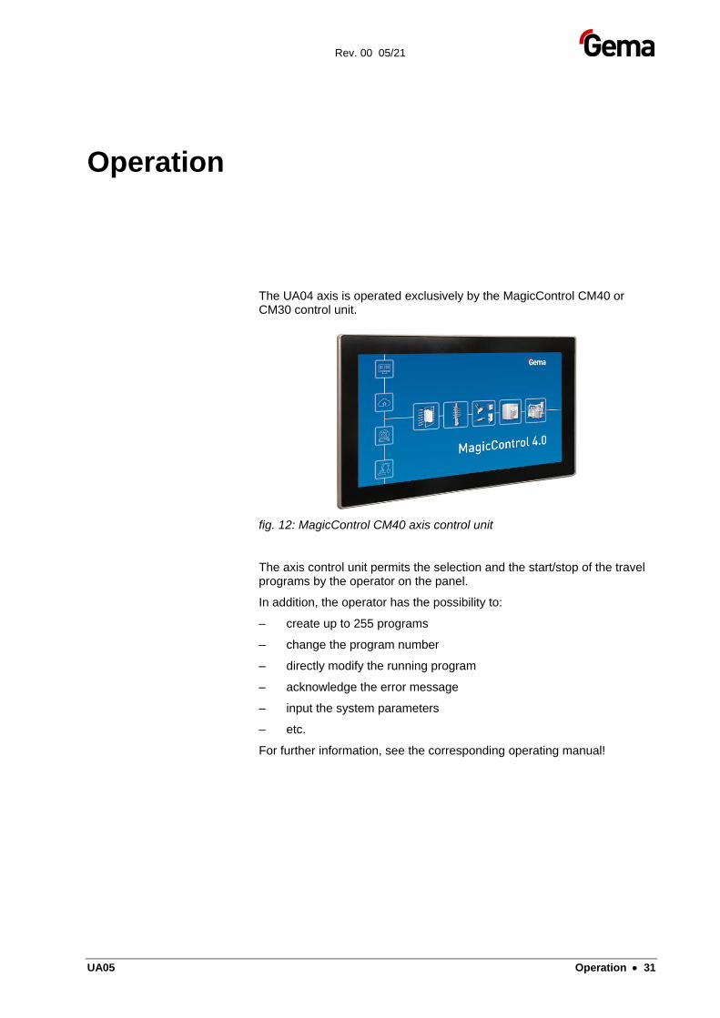
The UA04 axis is operated exclusively by the MagicControl CM40 or CM30 control unit.
fig. 12: MagicControl CM40 axis control unit
The axis control unit permits the selection and the start/stop of the travel programs by the operator on the panel.
In addition, the operator has the possibility to:
– create up to 255 programs
– change the program number
– directly modify the running program
– acknowledge the error message
– input the system parameters
– etc.
For further information, see the corresponding operating manual!

Rev. 00 05/21
32 • Operation UA05
Rev. 00 05/21
UA05 Decommissioning / Storage • 33
Decommissioning / Storage
Introduction
Safety rules
Before lifting a gun axis off of its vertical axis, the vertical axis must be secured from falling over.
Requirements on personnel carrying out the work
All work should be carried out only by authorized technical personnel.
Storage conditions
Hazard notes
There is no danger to personnel or the environment if the unit is stored properly.
Type of storage
For safety reasons, gun axes should only be stored in a horizontal position.
Storage duration
If the physical conditions are maintained, the unit can be stored indefinitely.
Space requirements
The space requirements correspond to the sizes of the axes of motion.
There are no special requirements concerning distance to neighboring equipment.
Rev. 00 05/21
34 • Decommissioning / Storage UA05
Physical requirements
Storage must be inside a dry building at a temperature between +5 - 50 °C.
Shut-down
Putting out of service
Before starting any kind of work, the axes of motion must be disconnected from the power supply:
– Unplug the power cable
– Unplug the ground cable
Cleaning
The linear guide unit running surface of the gun axis must be thoroughly cleaned.
Preservation
No preservation is necessary.
Maintenance during storage
Maintenance schedule
No maintenance schedule is necessary.
Maintenance works
During long-term storage, periodically perform a visual check.
Rev. 00 05/21
UA05 Maintenance / Repairs • 35
Maintenance / Repairs
General information
WARNING
Before start-up works are done, make certain that nobody can switch on the axis!
► Switch off and lock the mains switch!
WARNING
Injuries can occur inside the protective fence due to the movement of the gun axis!
► In order to enter the inner area, the door interlocks must be released by the control unit. This release signal may only be activated by technical personnel.
► Except for normal operation, all other operating modes must be set up by an authorized technical representative.
The axis was designed to operate with a minimum of maintenance. The motor is self-lubricating and maintenance-free.
Regular maintenance and inspection of the axis increases the working reliability and avoids damages, repair downtimes etc.!
Rev. 00 05/21
36 • Maintenance / Repairs UA05
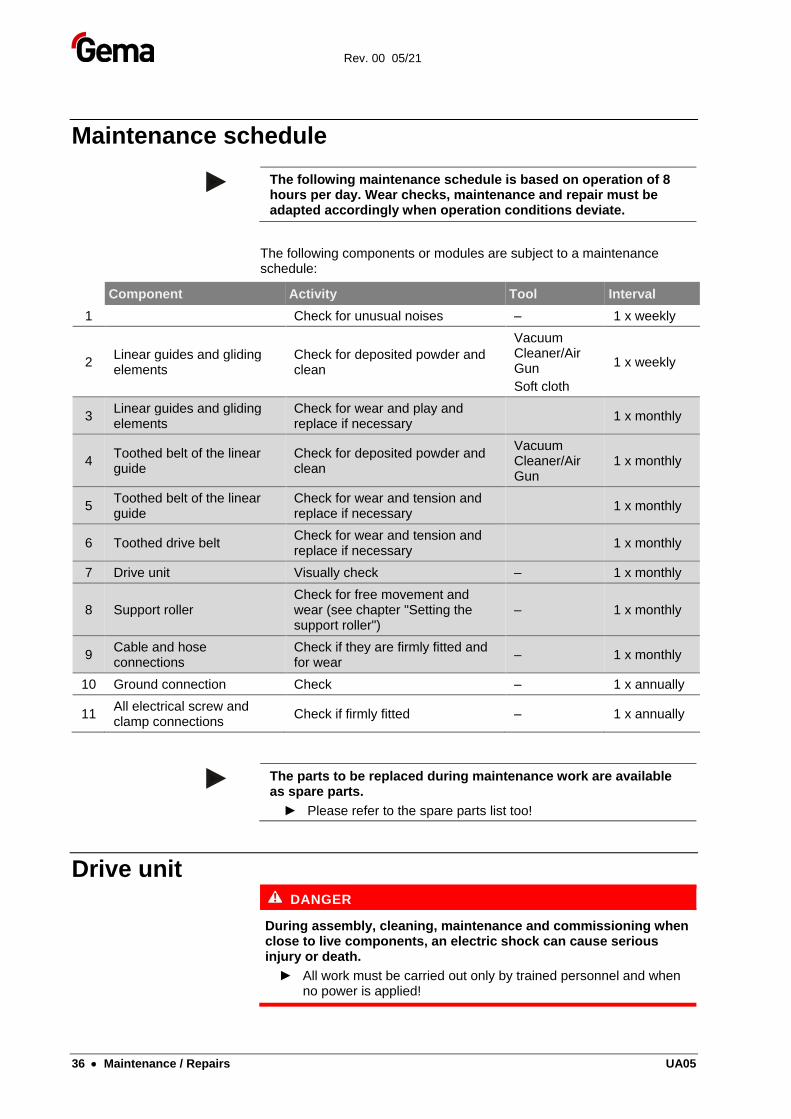
Maintenance schedule
The following maintenance schedule is based on operation of 8 hours per day. Wear checks, maintenance and repair must be adapted accordingly when operation conditions deviate.
The following components or modules are subject to a maintenance schedule:
Component Activity Tool Interval
1 Check for unusual noises – 1 x weekly
2 Linear guides and gliding elements
Check for deposited powder and clean
Vacuum Cleaner/Air Gun
Soft cloth
1 x weekly
3 Linear guides and gliding elements
Check for wear and play and replace if necessary
1 x monthly
4 Toothed belt of the linear guide
Check for deposited powder and clean
Vacuum Cleaner/Air Gun
1 x monthly
5 Toothed belt of the linear guide
Check for wear and tension and replace if necessary
1 x monthly
6 Toothed drive belt Check for wear and tension and replace if necessary
1 x monthly
7 Drive unit Visually check – 1 x monthly
8 Support roller Check for free movement and wear (see chapter "Setting the support roller")
– 1 x monthly
9 Cable and hose connections
Check if they are firmly fitted and for wear
– 1 x monthly
10 Ground connection Check – 1 x annually
11 All electrical screw and clamp connections
Check if firmly fitted – 1 x annually
The parts to be replaced during maintenance work are available as spare parts.
► Please refer to the spare parts list too!
Drive unit DANGER
During assembly, cleaning, maintenance and commissioning when close to live components, an electric shock can cause serious injury or death.
► All work must be carried out only by trained personnel and when no power is applied!
Rev. 00 05/21
UA05 Maintenance / Repairs • 37
The motor is maintenance-free.
Observe the contamination of the enclosure – strong contamination on the outside can increase the operating temperature of the drive unit!
Therefore, clean the drive unit from time to time (with a vacuum cleaner etc.).
Replacing the drive unit
CAUTION
Risk of burns
There is the risk of burns if contact is made with electrical components that have become overheated!
► All work must be carried out only by trained personnel and when no power is applied!
Procedure:
ATTENTION
Incorrectly assembled parts may cause malfunctions or defects
► Reassembly is in reverse order!
► Observe the tightening torques when assembling!
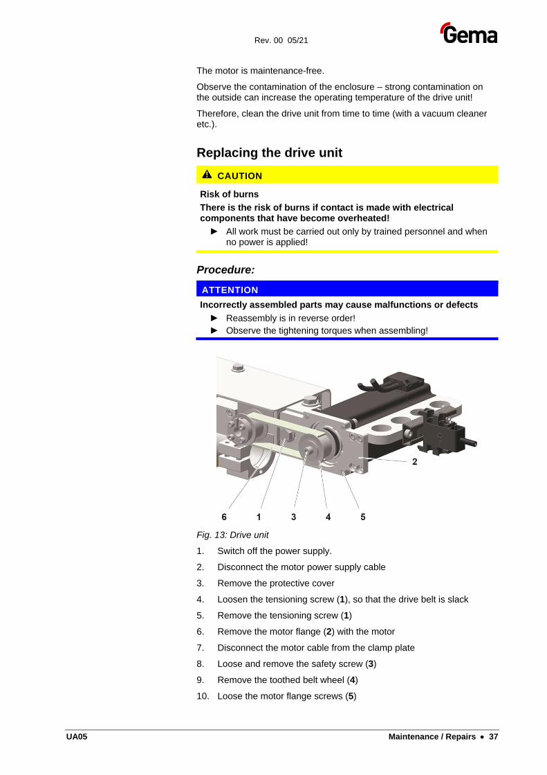
Fig. 13: Drive unit
1. Switch off the power supply.
2. Disconnect the motor power supply cable
3. Remove the protective cover
4. Loosen the tensioning screw (1), so that the drive belt is slack
5. Remove the tensioning screw (1)
6. Remove the motor flange (2) with the motor
7. Disconnect the motor cable from the clamp plate
8. Loose and remove the safety screw (3)
9. Remove the toothed belt wheel (4)
10. Loose the motor flange screws (5)
Rev. 00 05/21
38 • Maintenance / Repairs UA05
11. Remove the screws and remove the motor from the flange
The installation takes place exactly in the reverse order!
Tightening torque: 15 Nm
After installing, check whether the toothed belt is sufficiently tensioned!
Toothed belt
CAUTION
Injuries can arise if fingers, hair or articles of clothing get caught between the toothed belt and the drive wheel or toothed wheel.
► All work must be carried out only by trained personnel.
The toothed belt is exposed to high loads during operation and must therefore be checked regularly:
– Check the toothed belt every six months for wear and tension according to the maintenance schedule. Powder deposits should be preferably removed with a vacuum cleaner, because this can influence the quiet running and shorten the service life of the toothed belt
– Switch on the gun axis and check the carriage for quiet running. Check the toothed belt for elongation or wear (noisy running, or similar)
Replacing the toothed belt
Procedure:
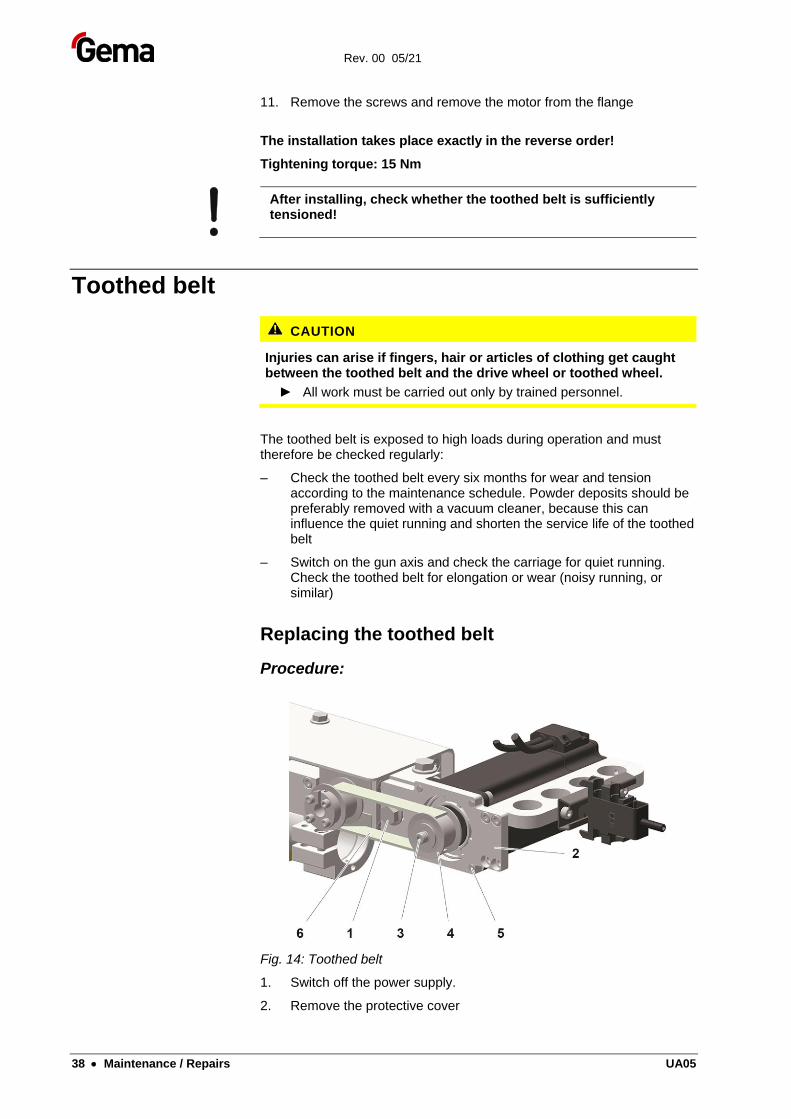
Fig. 14: Toothed belt
1. Switch off the power supply.
2. Remove the protective cover
Rev. 00 05/21
UA05 Maintenance / Repairs • 39
3. Loosen the tensioning screw (1), so that the drive belt (6) is slack
4. Remove the toothed belt.
5. Insert the new toothed belt
6. Pull on the motor with one hand to tension the toothed belt.
7. Tighten the tensioning screw (1)
8. Let the carriage slowly run backwards and forwards a few times, to see if the drive belt does not ride up on the toothed wheel
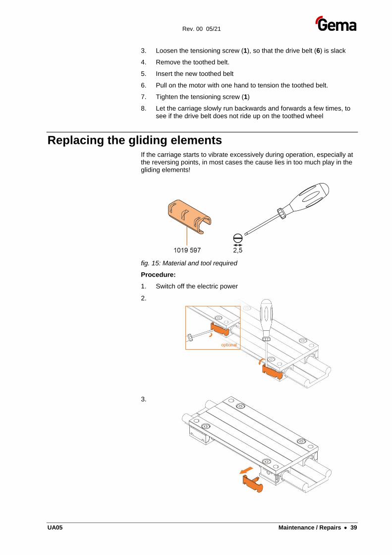
Replacing the gliding elements If the carriage starts to vibrate excessively during operation, especially at the reversing points, in most cases the cause lies in too much play in the gliding elements!
fig. 15: Material and tool required
Procedure:
1. Switch off the electric power
2.
3.
Rev. 00 05/21
40 • Maintenance / Repairs UA05
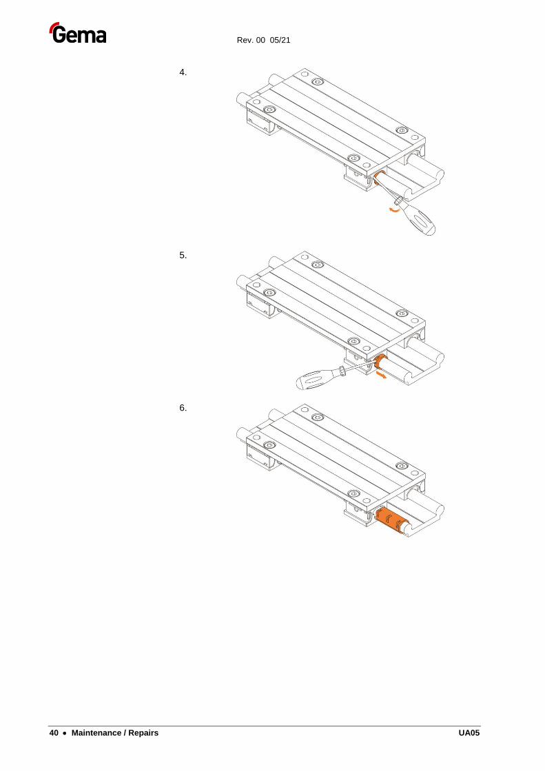
4.
5.
6.
Rev. 00 05/21
UA05 Maintenance / Repairs • 41
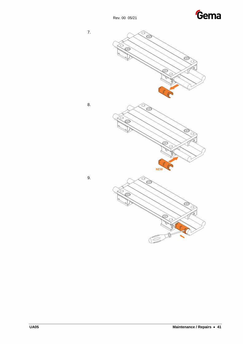
7.
8.
9.
Rev. 00 05/21
42 • Maintenance / Repairs UA05
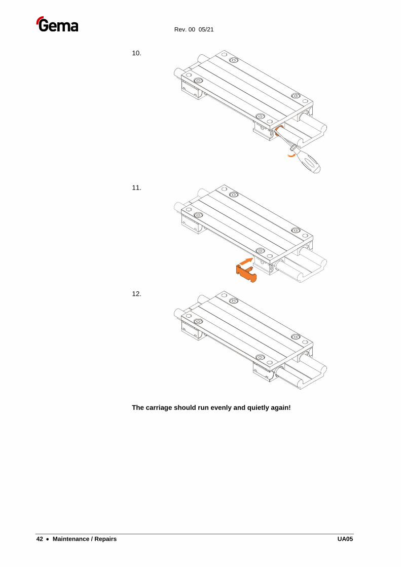
10.
11.
12.
The carriage should run evenly and quietly again!
Rev. 00 05/21
UA05 Maintenance / Repairs • 43
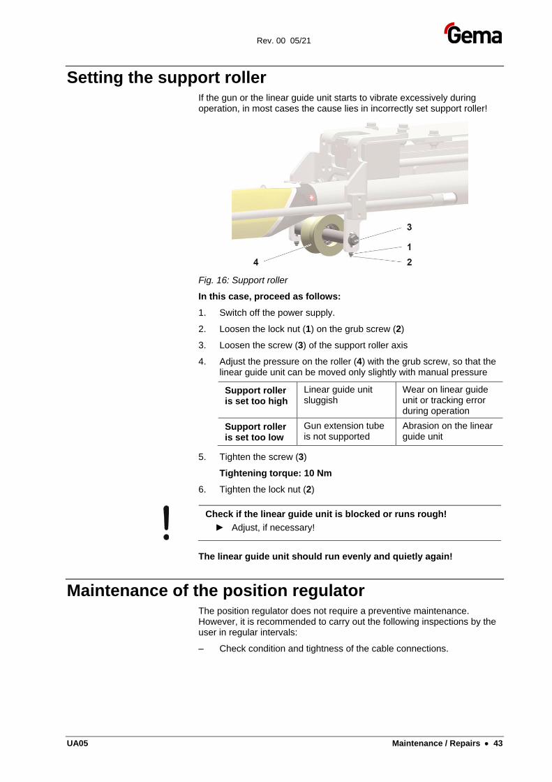
Setting the support roller If the gun or the linear guide unit starts to vibrate excessively during operation, in most cases the cause lies in incorrectly set support roller!
Fig. 16: Support roller
In this case, proceed as follows:
1. Switch off the power supply.
2. Loosen the lock nut (1) on the grub screw (2)
3. Loosen the screw (3) of the support roller axis
4. Adjust the pressure on the roller (4) with the grub screw, so that the linear guide unit can be moved only slightly with manual pressure
Support roller is set too high
Linear guide unit sluggish
Wear on linear guide unit or tracking error during operation
Support roller is set too low
Gun extension tube is not supported
Abrasion on the linear guide unit
5. Tighten the screw (3)
Tightening torque: 10 Nm
6. Tighten the lock nut (2)
Check if the linear guide unit is blocked or runs rough!
► Adjust, if necessary!
The linear guide unit should run evenly and quietly again!
Maintenance of the position regulator The position regulator does not require a preventive maintenance. However, it is recommended to carry out the following inspections by the user in regular intervals:
– Check condition and tightness of the cable connections.
Rev. 00 05/21
44 • Maintenance / Repairs UA05
Replacing the position regulator If a position regulator exchange was made, it is to be noted, that all shielded cables are properly attached again!
WARNING
Electric shock hazard in contact with energized components
Keep the cover plate of the position regulator closed at all times!
► Before interventions take place in the device, the power supply must be switched off!
► After switching off the power supply, wait at least 10 min. before working on the equipment, because the internal condensers need this time for discharging!
► Verify that the parts are deenergized by means of a voltmeter!
Rev. 00 05/21
UA05 Fault clearance • 45
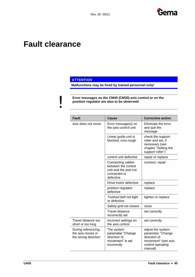
Fault clearance
ATTENTION
Malfunctions may be fixed by trained personnel only!
Error messages on the CM40 (CM30) axis control or on the position regulator are also to be observed!
Fault Cause Corrective action
Axis does not move Error message(s) on the axis control unit
Eliminate the error and quit the message
Linear guide unit is blocked, runs rough
check the support roller and set, if necessary (see chapter "Setting the support roller")
control unit defective repair or replace
Connecting cables between the control unit and the axis not connected or defective
connect, repair
Drive motor defective replace
position regulator defective
replace
Toothed belt not tight or defective
tighten or replace
Safety grid not closed close
Travel distance incorrectly set
set correctly
Travel distance too short or too long
incorrect settings on the axis control
set correctly
During referencing, the axis moves in the wrong direction
The system parameter “Change direction of movement” is set incorrectly
adjust the system parameter "Change direction of movement" (see axis control operating manual)
Rev. 00 05/21
46 • Fault clearance UA05
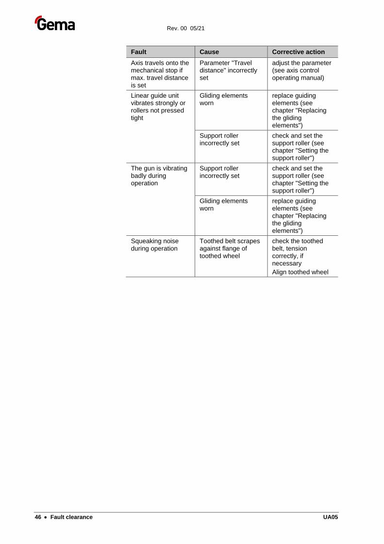
Fault Cause Corrective action
Axis travels onto the mechanical stop if max. travel distance is set
Parameter "Travel distance" incorrectly set
adjust the parameter (see axis control operating manual)
Linear guide unit vibrates strongly or rollers not pressed tight
Gliding elements worn
replace guiding elements (see chapter "Replacing the gliding elements")
Support roller incorrectly set
check and set the support roller (see chapter "Setting the support roller")
The gun is vibrating badly during operation
Support roller incorrectly set
check and set the support roller (see chapter "Setting the support roller")
Gliding elements worn
replace guiding elements (see chapter "Replacing the gliding elements")
Squeaking noise during operation
Toothed belt scrapes against flange of toothed wheel
check the toothed belt, tension correctly, if necessary
Align toothed wheel
Rev. 00 05/21
UA05 Disposal • 47
Disposal
Introduction
Safety rules
WARNING
Heavy components!
Falling components can lead to severe injuries
► Secure heavy components before and during disassembly
ENVIRONMENT
Improper disposal of operating material
Environmental hazard
► Drain the operating material into suitable containers
► Remove escaping operating material immediately
► Dispose of operating material in an environmentally friendly manner
Requirements on personnel carrying out the work
The disposal of the product is to be carried out by the owner or operator.
When disposing of components that are not manufactured by Gema, the instructions in the respective third-party manufacturer’s documentation must be observed.
Disposal regulations
The product must be disassembled and disposed of properly at the end of its service life.
► When disposing of the product, the applicable local and regional laws, directives and environmental regulations must be complied with!
Rev. 00 05/21
48 • Disposal UA05
Materials
The materials must be sorted according to material groups and taken to the appropriate collection points.
Disposal of operating material The operating material is very harmful to the environment if it is improperly disposed of. Therefore, the instructions and information contained in the safety data sheets must be adhered to when disposing of the operating material.
Disassembly of component groups
Preparation
WARNING
Live components!
Risk of fatal injury from electric shock if touched
► Only trained, authorized staff may open the electrical compartment
► Observe the safety symbols
1. Disconnect the mains supply, supply cables and additional units.
2. Remove all product covers.
3. Drain all existing lubricant supplies and dispose of accordingly.
The product is now prepared for disassembly.
The instructions in the third-party manufacturer’s documentation must be followed!
Rev. 00 05/21
UA05 Spare parts list • 49
Spare parts list
Ordering spare parts When ordering spare parts for your product, please indicate the following specifications:
– Type and serial number of your product
– Order number, quantity and description of each spare part
Example:
– Type Gun axis UA05
Serial number 1234 5678
– Order no. 203 386, 1 piece, Clamp – Ø 18/15 mm
When ordering cable or hose material, the required length must also be given. The spare part numbers of this bulk stock is always marked with an *.
The wearing parts are always marked with a #. marked.
All dimensions of plastic hoses are specified with the external and internal diameter:
Example:
Ø 8/6 mm, 8 mm outside diameter (o/d) / 6 mm inside diameter (i/d)
WARNING
Use of non-original Gema spare parts
When using the spare parts from other manufacturers the explosion protection is no longer guaranteed. If any damage is caused by this use all warrantee claims become invalid!
► Only original Gema spare parts should be used!
Rev. 00 05/21
50 • Spare parts list UA05
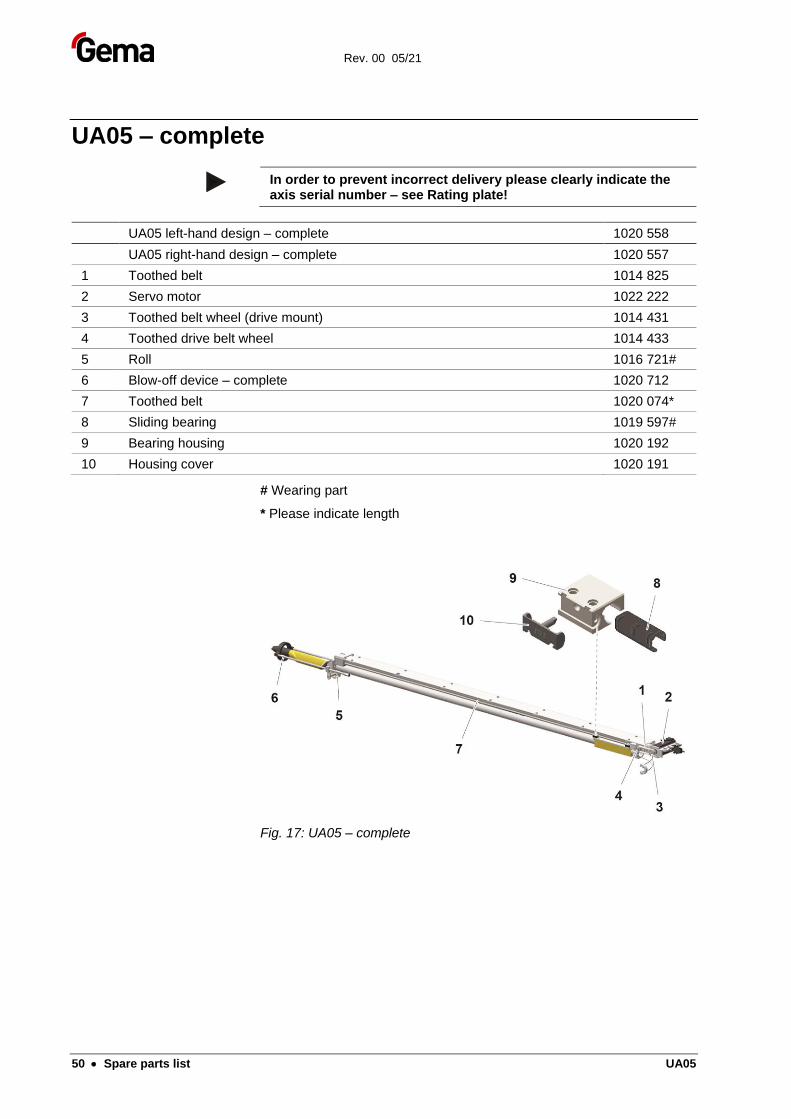
UA05 – complete
In order to prevent incorrect delivery please clearly indicate the axis serial number – see Rating plate!
UA05 left-hand design – complete 1020 558
UA05 right-hand design – complete 1020 557
1 Toothed belt 1014 825
2 Servo motor 1022 222
3 Toothed belt wheel (drive mount) 1014 431
4 Toothed drive belt wheel 1014 433
5 Roll 1016 721#
6 Blow-off device – complete 1020 712
7 Toothed belt 1020 074*
8 Sliding bearing 1019 597#
9 Bearing housing 1020 192
10 Housing cover 1020 191
# Wearing part
* Please indicate length
Fig. 17: UA05 – complete
Rev. 00 05/21
UA05 Spare parts list • 51
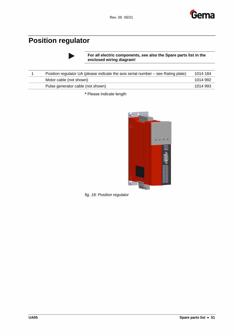
Position regulator
For all electric components, see also the Spare parts list in the enclosed wiring diagram!
1 Position regulator UA (please indicate the axis serial number – see Rating plate) 1014 184
Motor cable (not shown) 1014 992
Pulse generator cable (not shown) 1014 993
* Please indicate length
fig. 18: Position regulator

Rev. 00 05/21
UA05 Spare parts list • 53
Index
A
About these instructions ..................................... 7 Assembly .......................................................... 23
B
Basic safety instructions ..................................... 9
C
Connection ....................................................... 23
D
Decommissioning ............................................. 33 Dimensions ...................................................... 21 Disposal ............................................................ 47
E
Electrical data ................................................... 20
F
Fault clearance ................................................. 45 Figure references in the text .............................. 8
M
Maintenance ..................................................... 35 Maintenance during storage ............................ 34
O
Operation.......................................................... 31
P
Pictograms ......................................................... 7 Pneumatic data ................................................ 20 Presentation of the contents .............................. 8 Product description .......................................... 15 Product specific security regulations ................. 9
R
Rating plate ...................................................... 21 Repairs ............................................................ 35
S
Safety ................................................................. 9 Safety symbols .................................................. 7 Sound pressure level ....................................... 21 Spare parts list ................................................. 49 Start-up ............................................................ 27 Storage ............................................................ 33
T
Technical Data ................................................. 20 Transport ......................................................... 13
V
Versions ........................................................... 20

Rev. 00