MDOT Internet Proposal
313
MDOT Use Only Checked Loaded Keyed PROPOSAL AND CONTRACT DOCUMENTS SM No. CBR9385000171 Project Completion: 11/11/2021 16 Bridge Repair on SR 609 over Old Fort Bayou, Bridge No. 0.2, known as Federal Aid Project No. BR-9385-00(017) / 107705301 in Jackson County. FOR THE CONSTRUCTION OF 16 - (STATE DELEGATED) SECTION 900 OF THE CURRENT 2017 STANDARD SPECIFICATIONS FOR ROAD AND BRIDGE CONSTRUCTION JACKSON, MISSISSIPPI NOTICE BIDDERS MUST COMPLETE AN ONLINE REQUEST FOR PERMISSION TO BID THIS PROJECT. Electronic addendum updates will be posted on www.gomdot.com
-
Upload
khangminh22 -
Category
Documents
-
view
0 -
download
0
Transcript of MDOT Internet Proposal

MDOT Use Only
Checked
Loaded
Keyed
PROPOSAL AND CONTRACTDOCUMENTS
SM No. CBR9385000171
Project Completion: 11/11/2021
16Bridge Repair on SR 609 over Old Fort Bayou, Bridge No. 0.2, known as FederalAid Project No. BR-9385-00(017) / 107705301 in Jackson County.
FOR THE CONSTRUCTION OF
16 -
(STATE DELEGATED)
SECTION 900OF THE CURRENT
2017 STANDARD SPECIFICATIONSFOR ROAD AND BRIDGE CONSTRUCTION
JACKSON, MISSISSIPPI
NOTICE
BIDDERS MUST COMPLETE AN ONLINE REQUESTFOR PERMISSION TO BID THIS PROJECT.
Electronic addendum updates will be posted on www.gomdot.com

MISSISSIPPI DEPARTMENT OF TRANSPORTATION
TABLE OF CONTENTS
PROJECT: BR-9385-00(017)/107705301 - Jackson
Section 901 - Advertisement
Section 904 - Notice to Bidders#1 Governing Specification#2 Status of ROW, w/ Attachments#7 Disadvantaged Business Enterprise In Federal-Aid Highway Construction, w/
Supplement
#9 Federal Bridge Formula#296 Reduced Speed Limit Signs#445 Mississippi Agent and Qualified Nonresident Agent#480 Bridge Repair Permits (Nationwide Permit No. 3)#516 Errata and Modifications to the 2017 Standard Specifications#977 DUNS Requirement For Federal Funded Projects#1206 MASH Compliant Devices#1225 Early Notice to Proceed#1226 Material Storage Under Bridges#1241 Fuel and Material Adjustments#1841 Contract Time#1842 Specialty Items#1843 Lane Closure Restrictions
906 Required Federal Contract Provisions -- FHWA 1273, w/Supplements
Section 907 - Special Provisions907-102-2 Bidding Requirements and Conditions907-103-2 Award and Execution of Contract907-109-1 Measurement and Payment907-258-2 Building Amenities907-619-5 Traffic Control for Construction Zones907-624-1 Inverted Profile Thermoplastic Traffic Stripe907-701-1 Hydraulic Cement907-702-4 Bituminous Materials907-703-1 Gradation907-705-1 Stone Riprap907-707-2 Joint Material907-711-2 Plain Steel Wire907-720-2 Acceptance Procedure for Glass Beads907-804-6 Concrete Bridges and Structures907-808-1 Joint Repair907-823-6 Preformed Joint Seal907-850-1 Mechanical Construction for Movable Bridges907-851-1 Moveable Bridges907-852-1 Electrical Construction for Movable Bridges
Section 905 - Proposal, Proposal Bid Items, Combination Bid Proposal
1

PROJECT: BR-9385-00(017)/107705301 - Jackson
Certification of Performance - Prior Federal-Aid ContractsCertification Regarding Non-Collusion, Debarment and SuspensionSAM.GOV Registration and DUNS NumberSection 902 - Contract FormSection 903 - Contract Bond FormsForm -- OCR-485
(REVISIONS TO THE ABOVE WILL BE INDICATED ON THE SECOND SHEETOF SECTION 905 AS ADDENDA)
08/28/2019 11:04 AM
2

MISSISSIPPI DEPARTMENT OF TRANSPORTATION
SECTION 901 - ADVERTISEMENT
Electronic bids will be received by the Mississippi Transportation Commission at 10:00 o'clock A.M., Tuesday, September 24, 2019, from the Bid Express Service and shortly thereafter publicly read on the Sixth Floor for:
Bridge Repair on SR 609 over Old Fort Bayou, Bridge No. 0.2, known as Federal Aid Project No. BR-9385-00(017) / 107705301 in Jackson County.
The attention of bidders is directed to the Contract Provisions governing selection and employment of labor. Minimum wage rates have been predetermined by the Secretary of Labor and are subject to Public Law 87-581, Work Hours Act of 1962, as set forth in the Contract Provisions.
The Mississippi Department of Transportation hereby notifies all bidders that it will affirmatively insure that in any contract entered into pursuant to this advertisement, disadvantaged business enterprises will be afforded full opportunity to submit bids in response to this invitation and will not be discriminated against on the grounds of race, color, sex, age, disability, religion or national origin in consideration for an award.
The award of this contract will be contingent upon the Contractor satisfying the DBE requirements.
Contractors may request permission to bid online at http://shopmdot.ms.gov at no cost. Upon approval, Contractors shall be eligible to submit a bid using Bid Express at http://bidx.com. Specimen proposals may be viewed and downloaded online at no cost at http://mdot.ms.gov or purchased online at http://shopmdot.ms.gov at a cost of Ten Dollars ($10.00) per proposal plus a small convenience fee. Cash or checks will not be accepted as payment.
Plans must be purchased online at <https://shopmdot.ms.gov>. Costs of plans will be on a per sheet basis plus a small convenience fee. If you have any questions, you can contact the MDOT Plans Print Shop at (601) 359-7460, or e-mail at [email protected]. Plans will be shipped upon receipt of payment. Cash or checks will not be accepted as payment.
Bid bond, signed or countersigned by a Mississippi Agent or Qualified Nonresident Agent, with Power of Attorney attached, a Cashier's check or Certified Check for five (5%) percent of bid, payable to STATE OF MISSISSIPPI, must accompany each proposal.
The attention of bidders is directed to the provisions of Subsection 102.07 pertaining to irregular proposals and rejection of bids.
MELINDA L. MCGRATHEXECUTIVE DIRECTOR
3

MISSISSIPPI DEPARTMENT OF TRANSPORTATION SECTION 904 - NOTICE TO BIDDERS NO. 1 CODE: (IS) DATE: 03/01/2017 SUBJECT: Governing Specifications The current (2017) Edition of the Standard Specifications for Road and Bridge Construction adopted by the Mississippi Transportation Commission is made a part hereof fully and completely as if it were attached hereto, except where superseded by special provisions, or amended by revisions of the Specifications contained within this proposal. Copies of the specification book may be purchased from the MDOT Construction Division, or online at shopmdot/default.aspx?StoreIndex=1. A reference in any contract document to controlling requirements in another portion of the contract documents shall be understood to apply equally to any revision or amendment thereof included in the contract. In the event the plans or proposal contain references to the 2004 Edition of the Standard Specifications for Road and Bridge Construction, it is to be understood that such references shall mean the comparable provisions of the 2017 Edition of the Standard Specifications.
4

MISSISSIPPI DEPARTMENT OF TRANSPORTATION SECTION 904 - NOTICE TO BIDDERS NO. 2 CODE: (IS) DATE: 03/01/2017 SUBJECT: Status of Right-of-Way Although it is desirable to have acquired all rights-of-way and completed all railroad agreements, utility adjustments and work to be performed by others prior to receiving bids, sometimes it is not considered to be in the public interest to wait until each and every such clearance has been obtained. The bidder is hereby advised of possible unacquired rights-of-way, relocates, railroad agreements and utilities adjustments which have not been completed. The status of right-of-way acquisition, utility adjustments, encroachments, potentially contaminated sites, railroad facilities, improvements, and asbestos contamination are set forth in the following attachments. In the event right of entry is not available to ALL parcels of right-of-way and/or all work that is to be accomplished by others on the date set forth in the contract for the Notice to Proceed is not complete, the Department will issue a restricted Notice to Proceed.
5

-2- Notice To Bidders No. 2 -- Cont'd.
6

-3- Notice To Bidders No. 2 -- Cont'd.
7

-4- Notice To Bidders No. 2 -- Cont'd.
8

-5- Notice To Bidders No. 2 -- Cont'd.
9

-6- Notice To Bidders No. 2 -- Cont'd.
10

MISSISSIPPI DEPARTMENT OF TRANSPORTATION SUPPLEMENT TO NOTICE TO BIDDERS NO. 7 DATE: 01/17/2017 The goal is 0 percent for the Disadvantaged Business Enterprise. The low bidder is required to submit Form OCR-481 for all DBEs. Bidders are advised to check the bid tabulation link for this project on the MDOT website at: http://sp.gomdot.com/Contract%20Administration/BidSystems/Pages/letting%20calendar.aspx Bid tabulations are usually posted by 3:00 pm on Letting Day.
11

MISSISSIPPI DEPARTMENT OF TRANSPORTATION SECTION 904 - NOTICE TO BIDDERS NO. 7 CODE: (IS) DATE: 03/01/2017 SUBJECT: Disadvantaged Business Enterprises In Federal-Aid Highway Construction This contract is subject to the "Moving Ahead for Progress in the 21st Century Act (MAP-21)" and applicable requirements of "Part 26, Title 49, Code of Federal Regulations". Portions of the Act are set forth in this Notice as applicable to compliance by the Contractor and all of the Act, and the MDOT DBE Program, is incorporated by reference herein. The Department has developed a Disadvantaged Business Enterprise Program that is applicable to this contract and is made a part thereof by reference. Copies of the program may be obtained from: Office of Civil Rights Mississippi Department of Transportation P. O. Box 1850 Jackson, Mississippi 39215-1850 POLICY It is the policy of the Mississippi Department of Transportation to provide a level playing field, to foster equal opportunity in all federally assisted contracts, to improve the flexibility of the DBE Program, to reduce the burdens on small businesses, and to achieve that amount of participation that would be obtained in a non-discriminatory market place. In doing so, it is the policy of MDOT that there will be no discrimination in the award and performance of federally assisted contracts on the basis of race, color, sex, age, religion, national origin, or any handicap. ASSURANCES THAT CONTRACTORS MUST TAKE MDOT will require that each contract which MDOT signs with a sub-recipient or a Contractor, and each subcontract the Prime Contractor signs with a Subcontractor, includes the following assurances: “The Contractor, sub-recipient or Subcontractor shall not discriminate on the basis of race, color, national origin, or sex in the performance of this contract. The Contractor shall carry out applicable requirements of 49 CFR 26 in the award and administration of federally assisted contracts. Failure by the Contractor to carry out these requirements is a material breach of this contract, which may result in the termination of this contract or such other remedy as MDOT deems appropriate.” DEFINITIONS For purposes of this provision the following definitions will apply:
12

- 2 - Notice to Bidders No. 7 – Cont’d.
"Disadvantaged Business" means a small business concern: (a) which is at least 51 percent owned by one or more socially and economically disadvantaged individual(s) or in the case of any publicly owned business, at least 51 percent of the stock of which is owned by one or more socially and economically disadvantaged individual(s); and (b) whose management and daily business operations are controlled by one or more of the socially and economically disadvantaged individual(s) who own it. It is important to note that the business owners themselves must control the operations of the business. Absentee ownership or title ownership by an individual who does not take an active role in controlling the business is not consistent with eligibility as a DBE under CFR 49 Part 26.71. CONTRACTOR'S OBLIGATION The Contractor and all Subcontractors shall take all necessary and reasonable steps to ensure that DBE firms can compete for and participate in the performance of a portion of the work in this contract and shall not discriminate on the basis of race, color, national origin, religion or sex. Failure on the part of the Contractor to carry out the DBE requirements of this contract constitutes a breach of contract and after proper notification the Department may terminate the contract or take other appropriate action as determined by the Department. When a contract requires a zero percent (0%) DBE goal, the Contractor still has the responsibility to take all necessary and reasonable steps to ensure that DBE firms can compete for and participate in the performance of the work in the contract. In this case, all work performed by a certified DBE firm is considered to be a “race neutral” measure and the Department will receive DBE credit towards the overall State goals when the DBE firm is paid for their work. If the Prime Contractor is a certified DBE firm, the Department can receive DBE credit only for the work performed by the Prime Contractor’s work force or any work subcontracted to another DBE firm. Work performance by a non-DBE Subcontractor is not eligible for DBE credit. CONTRACT GOAL The goal for participation by DBEs is established for this contract in the attached Supplement. The Contractor shall exercise all necessary and reasonable steps to ensure that participation is equal to or exceeds the contract goal. If the percentage of the contract that is proposed for DBEs is 1% or greater, the Contractor shall agree to meet or exceed the contract goal on the last bid sheet of the proposal. The apparent lowest responsive bidder shall submit to the Office of Civil Rights Form OCR-481, signed by the Prime Contractor and the DBE Subcontractors, no later than the 3rd business day after opening of the bids. Form OCR-481 is available on the MDOT website at GoMDOT.com, then Divisions, Civil Rights, Forms, DBE, MDOT Projects, or by calling 601-359-7466. The OCR-481 Form must contain the following information:
The name and address of each certified DBE Contractor / Supplier;
13

- 3 - Notice to Bidders No. 7 – Cont’d.
The Reference Number, percent of work and the dollar amount of each item. If a portion of an item is subcontracted, a breakdown of that item including quantities and unit price must be attached, detailing what part of the item the DBE firm is to perform and who will perform the remainder of the item.
If the DBE Commitment shown on the last bid sheet of the proposal, does not equal or exceed the contract goal, the bidder must submit, to MDOT Contract Administration Division prior to bid opening, information to satisfy the Department that adequate good faith efforts have been made to meet the contract goal. Failure of the lowest bidder to furnish acceptable proof of good faith efforts, submitted to MDOT Contract Administration Division prior to bid opening, shall be just cause for rejection of the proposal. Award may then be made to the next lowest responsive bidder or the work may be re-advertised. The following factors are illustrative of matters the Department will consider in judging whether or not the bidder has made adequate good faith effort to satisfy the contract goal.
(1) Whether the bidder attended the pre-bid meeting that was scheduled by the Department to inform DBEs of subcontracting opportunities;
(2) Whether the bidder advertised in general circulation, trade association, and minority-focus
media concerning the subcontracting opportunities;
(3) Whether the bidder provided written notice to a reasonable number of specific DBEs that their interest in the contract is being solicited;
(4) Whether the bidder followed up initial solicitations of interest by contacting DBEs to
determine with certainty whether they were interested;
(5) Whether the bidder selected portions of the work to be performed by DBEs in order to increase the likelihood of meeting the contract goal;
(6) Whether the bidder provided interested DBEs with adequate information about the plans,
specifications and requirements of the contract;
(7) Whether the bidder negotiated in good faith with interested DBEs and did not reject them as unqualified without sound reasons based on a thorough investigation of their capabilities; and
(8) Whether the bidder made efforts to assist interested DBEs in obtaining any required bonding
or insurance.
(9) Whether the bidder has written notification to certified DBE Contractors soliciting subcontracting for items of work in the contract.
(10) Whether the bidder has a statement of why an agreement was not reached.
14

- 4 - Notice to Bidders No. 7 – Cont’d.
The bidder’s execution of the signature portion of the proposal shall constitute execution of the following assurance:
The bidder hereby gives assurance pursuant to the applicable requirements of "Moving Ahead for Progress in the 21st Century Act (MAP-21)" and applicable requirements of "Part 26, Title 49, Code of Federal Regulations" that the bidder has made a good faith effort to meet the contract goal for DBE participation for which this proposal is submitted.
DIRECTORY A list of “Certified DBE Contractors” which have been certified as such by the Mississippi Department of Transportation and other Unified Certification Partners (UPC) can be found on the Mississippi Department of Transportation website at www.gomdot.com. The list is in the top left corner of the current Letting Calendar under Contracts & Letting. The DBE firm must be certified at the time the project is let and approved by MDOT to count towards meeting the DBE goal. REPLACEMENT If a DBE Subcontractor cannot perform satisfactorily, and this causes the OCR-481 commitment to fall below the contract goal, the Contractor shall take all necessary reasonable steps to replace the DBE with another certified DBE Subcontractor or submit information to satisfy the Mississippi Department of Transportation that adequate good faith efforts have been made to replace the DBE. The replacement DBE must be a DBE who was on the Department's list of "Certified DBE Contractors" when the job was let, and who is still active. All DBE replacements must be approved by the Department. Under no circumstances shall the Prime or any Subcontractor perform the DBE's work (as shown on the OCR-481) without prior written approval from the Department. See "Sanctions" at the end of this document for penalties for performing DBE's work. When a Contractor proposes to substitute/replace/terminate a DBE that was originally named on the OCR-481, the Contractor must obtain a release, in writing, from the named DBE explaining why the DBE Subcontractor cannot perform the work. A copy of the original DBE's release must be attached to the Contractor's written request to substitute/replace/terminate along with appropriate Subcontract Forms for the substitute/replacement/terminated Subcontractor, all of which must be submitted to the DBE Coordinator and approved, in advance, by MDOT. GOOD FAITH EFFORTS To demonstrate good faith efforts to replace any DBE that is unable to perform successfully, the Contractor must document steps taken to subcontract with another certified DBE Contractor. Such documentation shall include no less than the following:
(1) Proof of written notification to certified DBE Contractors by certified mail that their interest is solicited in subcontracting the work defaulted by the previous DBE or in subcontracting other items of work in the contract.
15

- 5 - Notice to Bidders No. 7 – Cont’d.
(2) If the Prime Contractor is a certified DBE firm, only the value of the work actually performed by the DBE Prime can be counted towards the project goal, along with any work subcontracted to a certified DBE firm.
(3) If the Contractor is not a DBE, the work subcontracted to a certified DBE Contractor will be
counted toward the goal. (4) The Contractor may count toward the goal a portion of the total dollar value of a contract
with a joint venture eligible under the standards of this provision equal to the percentage of the DBE partner in the joint venture.
(5) Expenditures to DBEs that perform a commercially useful function may be counted toward
the goal. A business is considered to perform a commercially useful function when it is responsible for the execution of a distinct element of the work and carries out its responsibilities by actually performing, managing, and supervising the work involved.
(6) The Contractor may count 100% of the expenditures for materials and supplies obtained from
certified DBE suppliers and manufacturers that produce goods from raw materials or substantially alters them for resale provided the suppliers and manufacturers assume the actual and contractual responsibility for the provision of the materials and supplies. The Contractor may count sixty percent (60%) of the expenditures to suppliers that are not manufacturers, provided the supplier performs a commercially useful function in the supply process. Within 30 days after receipt of the materials, the Contractor shall furnish to the DBE Coordinator invoices from the certified supplier to verify the DBE goal.
(7) Any work that a certified DBE firm subcontracts or sub-subcontracts to a non-DBE firm will
not count towards the DBE goal. (8) Only the dollars actually paid to the DBE firm may be counted towards the DBE goal.
Failure of the Contractor to demonstrate good faith efforts to replace a DBE Subcontractor that cannot perform as intended with another DBE Subcontractor, when required, shall be a breach of contract and may be just cause to be disqualified from further bidding for a period of up to 12 months after notification by certified mail. PRE-BID MEETING A pre-bid meeting will be held in Amphitheater 1 & 2 of the Hilton Jackson located at I-55 and County Line Road, Jackson, Mississippi at 2:00 P.M. on the day preceding the date of the bid opening. This meeting is to inform DBE firms of subcontracting and material supply opportunities. Attendance at this meeting is considered of prime importance in demonstrating good faith effort to meet the contract goal. PARTICIPATION / DBE CREDIT Participation shall be counted toward meeting the goal in this contract as follows:
16

- 6 - Notice to Bidders No. 7 – Cont’d.
(1) If the Prime Contractor is a certified DBE firm, only the value of the work actually performed
by the DBE Prime can be counted towards the project goal, along with any work subcontracted to a certified DBE firm.
(2) If the Contractor is not a DBE, the work subcontracted to a certified DBE Contractor will be
counted toward the goal. (3) The Contractor may count toward the goal a portion of the total dollar value of a contract
with a joint venture eligible under the standards of this provision equal to the percentage of the DBE partner in the joint venture.
(4) Expenditures to DBEs that perform a commercially useful function may be counted toward
the goal. A business is considered to perform a commercially useful function when it is responsible for the execution of a distinct element of the work and carries out its responsibilities by actually performing, managing, and supervising the work involved.
(5) The Contractor may count 100% of the expenditures for materials and supplies obtained from
certified DBE suppliers and manufacturers that produce goods from raw materials or substantially alters them for resale provided the suppliers and manufacturers assume the actual and contractual responsibility for the provision of the materials and supplies. The Contractor may count sixty percent (60%) of the expenditures to suppliers that are not manufacturers, provided the supplier performs a commercially useful function in the supply process. Within 30 days after receipt of the materials, the Contractor shall furnish to the DBE Coordinator invoices from the certified supplier to verify the DBE goal.
(6) Any work that a certified DBE firm subcontracts or sub-subcontracts to a non-DBE firm will
not count towards the DBE goal. (7) Only the dollars actually paid to the DBE firm may be counted towards the DBE goal. The
participation of a DBE Firm cannot be counted towards the Prime Contractor’s DBE goal until the amount being counted towards the goal has been paid to the DBE.
AWARD Award of this contract to the low bidder will be contingent upon the following conditions:
(1) Concurrence from Federal Highway Administration, when applicable. (2) Bidder must submit to the Office of Civil Rights for approval, Form OCR-481 (DBE
Commitment) no later than the 3rd business day after opening of the bids to satisfy the Department and that adequate good faith efforts have been made to meet the contract goal. For answers to questions regarding Form OCR-481, contact the MDOT Office of Civil Rights at (601) 359-7466.
(3) Bidder must include OCR-485 information with their bid proposal listing all firms that
submitted quotes for material supplies or items to be subcontracted. OCR-485 information
17

- 7 - Notice to Bidders No. 7 – Cont’d.
must be included with the bid proposal. If the OCR-485 information is not included as part of bid proposal, your bid will be deemed irregular.
Prior to the start of any work, the bidder must notify the Project Engineer, in writing, of the name of the designated "DBE Liaison Officer" for this project. This notification must be posted on the bulletin board at the project site. DEFAULT If the contract goal established by MDOT in this proposal is 1% or greater, it must be met to fulfill the terms of the contract. The Contractor may list DBE Subcontractors and items that exceed MDOT's contract goal, but should unforeseen problems arise that would prevent a DBE from completing its total commitment percentage, the Contractor will meet the terms of the contract as long as it meets or exceeds MDOT's Contract Goal. For additional information, refer to "Replacement" section of this Notice. DBE REPORTS
(1) OCR-481: Refer to "CONTRACT GOAL" section of this Notice to Bidders for information regarding this form.
(2) OCR-482: OCR-482: At the conclusion of the project, before the final estimate is paid and
the project is closed out, the Prime Contractor will submit to the Project Engineer for verification of quantities and further handling Form OCR-482 whereby the Contractor certifies to the amounts of payments made to all Contractors / Suppliers over the life of the contract. The Project Engineer shall submit the completed Form OCR-482 to the DBE Coordinator (Office of Civil Rights). Final acceptance of the project is dependent upon Contract Administration Division's receipt of completed Form OCR-482 which they will receive from the Office of Civil Rights.
(3) OCR-483: The Project Engineer/Inspector will complete Form OCR-483, the
Commercially Useful Function (CUF) Performance Report, in accordance with MDOT S.O.P. No. OCR-03-09-01-483. Evaluations reported on this form are used to determine whether or not the DBE firm is performing a CUF. The Prime Contractor should take corrective action when the report contains any negative evaluations. DBE credit may be disallowed and/or other sanctions imposed if it is determined the DBE firm is not performing a CUF. This form should also be completed and returned to the DBE Coordinator (Office of Civil Rights).
(4) OCR-484: Each month, the Prime Contractor will submit to the Project Engineer OCR-
484 that certifies payments to all Subcontractors and shows all firms even if the Prime Contractor has paid no monies to the firm during that estimate period (negative report). The Project Engineer will attach the form to the monthly estimate before forwarding to the Contract Administration Division for further processing. Failure of the Contractor to submit the OCR-484 will result in the estimate not being processed and paid.
18

- 8 - Notice to Bidders No. 7 – Cont’d.
(5) OCR-485: ALL BIDDERS must submit signed form with bid proposal of all firms that submitted quotes for material supplies or items to be subcontracted. If the OCR-485 information is not included as part of bid proposal, the bid will be deemed irregular.
(6) OCR-487: Only used by Prime Contractors that are certified DBE firms. This form is used
in determining the exact percentage of DBE credit for the specified project. It should be returned to MDOT with the OCR-481 form, or can also be returned with the Permission to Subcontract Forms (CAD-720, CAD-725 and CAD-521).
DBE Forms, can be obtained from the Office of Civil Rights Division, MDOT Administration Building, 401 North West Street, Jackson, MS, or at www.gomdot.com under Divisions, Civil Rights, and Forms. SANCTIONS The Department has the option to enforce any of the following penalties for failure of the Prime Contractor to fulfill the DBE goal as stated on the OCR-481 form or any violations of the DBE program guidelines:
(1) Disallow credit towards the DBE goal (2) Withhold progress estimate payments (3) Deduct from the final estimate or recover an amount equal to the unmet portion of the DBE
goal which may include additional monetary penalties as outlined below based on the number of offenses and the severity of the violation as determined by MDOT.
1st Offense 10% of unmet or $5,000 lump or Both portion of goal sum payment 2nd Offense 20% of unmet or $10,000 lump or Both portion of goal sum payment 3rd Offense 40% of unmet or $20,000 lump or $20,000 lump sum portion of goal sum payment payment and debarment
(4) Debar the Contractor involved from bidding on MDOT federally funded projects.
19

MISSISSIPPI DEPARTMENT OF TRANSPORTATION SECTION 904 - NOTICE TO BIDDERS NO. 9 CODE: (IS) DATE: 03/01/2017 SUBJECT: Federal Bridge Formula Bidders are hereby advised that the latest revision of Federal Highway Administration Publication No. FHWA-HOP-06-105, BRIDGE FORMULA WEIGHTS, dated August 2006, is made a part of this contract when applicable. Prior to the preconstruction conference, the Contractor shall advise the Engineer, in writing, what materials, if any, will be delivered to the jobsite via Interstate route(s). Copies of the BRIDGE FORMULA WEIGHTS publication may be obtained by contacting: Federal Highway Administration 400 7th Street, SW Washington, DC 20590 (202) 366-2212 or http://www.ops.fhwa.dot.gov/Freight/publications/brdg_frm_wghts/bridge_formula_all_rev.pdf An on line BRIDGE FORMULA WEIGHTS CALCULATOR is available at http://ops.fhwa.dot.gov/freight/sw/brdgcalc/calc_page.htm
20

MISSISSIPPI DEPARTMENT OF TRANSPORTATION SECTION 904 - NOTICE TO BIDDERS NO. 296 CODE: (SP) DATE: 07/25/2017 SUBJECT: Reduced Speed Limit Signs Bidders are advised that when the plans or contract documents require the speed limit on a project to be reduced, the Contractor shall begin work within 48 hours of installing the reduced speed limit signs. Should the Contractor not start work or have no plans to start work within 48 hours of installing the signs, the reduced speed limit signs shall be covered and existing speed limit signs uncovered.
21

MISSISSIPPI DEPARTMENT OF TRANSPORTATION SECTION 904 - NOTICE TO BIDDERS NO. 445 CODE: (SP) DATE: 10/10/2017 SUBJECT: Mississippi Agent or Qualified Nonresident Agent Bidders are hereby advised of the requirements of Subsections 102.08, 103.05.2, and 107.14.2.1 of the 2017 Standard Specifications for Road and Bridge Construction as it refers to bonding agents. Proposal guaranties, bonds, and liability insurance policies must be signed by a Mississippi Agent or Qualified Nonresident Agent.
22

MISSISSIPPI DEPARTMENT OF TRANSPORTATION SECTION 904 - NOTICE TO BIDDERS NO. 480 CODE: (SP) DATE: 11/09/2017 SUBJECT: Bridge Repair Permits (Nationwide Permit No. 3) The Department has acquired Nationwide Permit General Conditions and Special Conditions, Nationwide Permit No. 3, for repair and maintenance of bridge(s). Copies of said permit(s) are available at the below referenced link for the appropriate letting date under the column titled “Permit Doc.” http://mdot.ms.gov/Applications/BidSystem/Home.aspx Securing a permit(s) for the filling of any other regulated site, the purpose of which is temporary construction for the convenience of the Contractor, shall be the responsibility of the Contractor.
23

MISSISSIPPI DEPARTMENT OF TRANSPORTATION SECTION 904 - NOTICE TO BIDDERS NO. 516 CODE: (IS) DATE: 11/28/2017 SUBJECT: Errata and Modifications to the 2017 Standard Specifications Page Subsection Change 16 102.06 In the seventh full paragraph, change “Engineer” to “Director.” 33 105.05.1 In the sixth sentence, change “Contract Administration Engineer” to
“Contract Administration Director.” 34 105.05.2.1 In subparagraph 2, change “SWPPP, ECP” to “SWPPP and the
ECP” 35 105.05.2.2 In subparagraphs 2, add “ and” to the end of the sentence. In
subparagraph 3, remove “, and” and add “.”. 90 109.04.2 In the last paragraph of subparagraph (a), place a period “.” at the
end of the sentence. 93 109.04.2 In the last paragraph of subparagraph (g), place a period “.” at the
end of the sentence. Also, in the first paragraph of subparagraph (h), place a period “.” at the end of the sentence.
97 109.07 Under ADJUSTMENT CODE, subparagraph (A1), change “HMA
mixture” to “Asphalt mixtures.” 98 109.11 In the third sentence, change “Engineer” to “Director.” 219 308.04 In the last sentence of the last paragraph, change “Contractor’s
decision” to “Engineer’s decision.” 300 405.02.5.9 In the first sentence of the second paragraph, change “Hot Mix
Asphalt” to “Asphalt Mixtures.” 502 630.01.1 In the first paragraph, change “AASHTO” to “AASHTO’s LRFD”. 636 646.05 Change “each” to “per each” for the pay item units of payment. 640 656.02.6.2 In item 7), change “down stream” to “downstream”. 688 630.03.2 Change the subsection number from “630.03.2” to “680.03.2.”
24

- 2 - Notice to Bidders No. 516 -- Cont’d.
725 702.08.3 In the second sentence of the first paragraph, change “hot-mix” to
“asphalt.” 954 804.02.13.1.6 In the definition for “M” in the % Reduction formulas, change
“paragraph 7.3” to “paragraph 5.3.”
25

MISSISSIPPI DEPARTMENT OF TRANSPORTATION SECTION 904 - NOTICE TO BIDDERS NO. 977 CODE: (IS) DATE: 07/25/2018 SUBJECT: DUNS Requirement for Federal Funded Projects Bidders are advised that the Prime Contractor must maintain a current registration in the System for Award Management ( http://www.sam.gov ) at all times during this project. A Dun and Bradstreet Data Universal Numbering System (DUNS) Number ( http://www.dnb.com ) is one of the requirements for registration in the System for Award Management. Bidders are also advised that prior to the award of this contract, they MUST be registered, active, and have no active exclusions in the System for Award Management.
26

MISSISSIPPI DEPARTMENT OF TRANSPORTATION SECTION 904 - NOTICE TO BIDDERS NO. 1206 CODE: (SP) DATE: 10/16/2018 SUBJECT: MASH Compliant Devices Bidders are hereby advised that the Standard Specifications may require certain traffic control and permanent safety hardware devices to meet the requirements of the Manual for Assessing Safety Hardware (MASH). However, devices meeting the requirements of NCHRP Report 350 will be allowed until the mandatory effective date for MASH compliance. The following table shows the effective dates for MASH compliant devices.
Device Effective Date for MASH
Compliance W-beam barriers, cast-in-place concrete barriers December 31, 2017 W-beam terminals - non-flared June 30, 2018 Crash cushions December 31, 2018 Cable barriers, cable barrier terminals, bridge rails, transitions, all other longitudinal barriers including portable barriers installed permanently, W-beam terminals - flared, all other terminals, sign supports, all other breakaway hardware
December 31, 2019
Temporary work zone devices, including portable barriers manufactured after December 31, 2019, must have been successfully tested to the 2016 Edition of MASH. Such devices manufactured on or before this date and successfully tested to NCHRP Report 350 or the 2009 Edition of MASH may continue to be used throughout their normal service lives.
27

MISSISSIPPI DEPARTMENT OF TRANSPORTATION SECTION 904 - NOTICE TO BIDDERS NO. 1225 CODE: (SP) DATE: 11/13/2018 SUBJECT: Early Notice to Proceed Bidders are advised that if an early notice to proceed is allowed by the Department and the Contractor experiences problems or delays between the early notice to proceed date and the original notice to proceed date, this shall not be justification for any monetary compensation or an extension of contract time.
28

MISSISSIPPI DEPARTMENT OF TRANSPORTATION
SECTION 904 - NOTICE TO BIDDERS NO. 1226 CODE: (SP) DATE: 11/16/2018 SUBJECT: Material Storage Under Bridges Bidders are advised that Subsection 106.08 of the Standard Specifications allows the Contractor to store materials and equipment on portions of the right-of-way. However, the Contractor will not be allowed to store or stockpile materials under bridges without written permission from the Project Engineer. The Contractor shall submit a detailed request of all proposed materials to be stored under bridges to the Engineer a minimum of 14 calendar days prior to anticipated storage. This detail shall include, but not limited to, bridge location, material type, material quantity, and duration of storage. The Project Engineer and any other needed Division will review this information and determine whether to grant approval. The Contractor shall not store any material under any bridge without written approval from the Project Engineer.
29

MISSISSIPPI DEPARTMENT OF TRANSPORTATION SECTION 904 - NOTICE TO BIDDERS NO. 1241 CODE: (SP) DATE: 11/27/2018 SUBJECT: Fuel and Material Adjustments Bidder’s attention is brought to the last paragraph of Subsection 109.07 of the Standard Specifications which states that no fuel or material adjustment will be made after the completion of contract time. Any fuels consumed or materials incorporated into the work during the monthly estimate period falling wholly after the expiration of contract time will not be subject a fuel or material adjustment.
30

MISSISSIPPI DEPARTMENT OF TRANSPORTATION SECTION 904 - NOTICE TO BIDDERS NO. 1841 CODE: (SP) DATE: 08/22/2019 SUBJECT: Contract Time PROJECT: BR-9385-00(017) / 107705301 – Jackson County The calendar date for completion of work to be performed by the Contractor for this project shall be November 11, 2021 which date or extended date as provided in Subsection 108.06 shall be the end of contract time. It is anticipated that the Notice of Award will be issued no later than October 7, 2019 and the effective date of the Notice to Proceed / Beginning of Contract Time will be November 7, 2019. Should the Contractor request a Notice to Proceed earlier than November 7, 2019 and it is agreeable with the Department for an early Notice to Proceed, the requested date will become the new Notice to Proceed date. All requests for an early Notice to Proceed shall be sent to the Project Engineer who will forward it to the Contract Administration Division.
31

MISSISSIPPI DEPARTMENT OF TRANSPORTATION
SECTION 904 - NOTICE TO BIDDERS NO.
DATE:
SUBJECT: Specialty Items
PROJECT:
Pursuant to the provisions of Section 108, the following work items are hereby designated as "Specialty Items" for this contract.Bidders are reminded that these items must be subcontracted in order to be considered as specialty items.
1842
08/22/2019
BR-9385-00(017)/107705301 - JACKSON
Line No DescriptionPay Item
CATEGORY: CURBING, SIDEWALKS, GUTTERS
0080 608-B001 Concrete Sidewalk, With Reinforcement
Line No DescriptionPay Item
CATEGORY: GUARDRAIL, GUIDERAIL
0050 606-B010 Guard Rail, Class A, Type 1, Thrie Beam
0060 606-D022 Guard Rail, Bridge End Section, Type I
0070 606-E005 Guard Rail, Terminal End Section, Flared
Line No DescriptionPay Item
CATEGORY: NON ROADWAY ITEMS
0290 907-258-A002 Building Amenities
Line No DescriptionPay Item
CATEGORY: PAVEMENT STRIPING AND MARKING
0270 627-K001 Red-Clear Reflective High Performance Raised Markers
0280 627-L001 Two-Way Yellow Reflective High Performance Raised Markers
0310 907-624-A002 6" Inverted Profile Thermoplastic Traffic Stripe, Skip White
0320 907-624-B002 6" Inverted Profile Thermoplastic Traffic Stripe, Continuous White
0330 907-624-D002 6" Inverted Profile Thermoplastic Traffic Stripe, Continuous Yellow
0340 907-624-E001 Inverted Profile Thermoplastic Detail Traffic Stripe, White
0350 628-G001 6" High Performance Cold Plastic Traffic Stripe, Skip White
0360 628-H001 6" High Performance Cold Plastic Traffic Stripe, Continuous White
0370 628-J001 6" High Performance Cold Plastic Traffic Stripe, Continuous Yellow
0380 628-K001 High Performance Cold Plastic Detail Stripe, White
Line No DescriptionPay Item
CATEGORY: TRAFFIC CONTROL - TEMPORARY
0110 619-A1007 Temporary Traffic Stripe, Continuous White, Type 1 or 2 Tape
0120 619-A2008 Temporary Traffic Stripe, Continuous Yellow, Type 1 or 2 Tape
0130 619-A3008 Temporary Traffic Stripe, Skip White, Type 1 or 2 Tape
0140 619-C6001 Red-Clear Reflective High Performance Raised Marker
32

Line No DescriptionPay Item
CATEGORY: TRAFFIC CONTROL - TEMPORARY
0150 619-C7001 Two-Way Yellow Reflective High Performance Raised Marker
0160 619-E1001 Flashing Arrow Panel, Type C
0170 619-F1001 Concrete Median Barrier, Precast
0180 619-F1002 Portable Median Barrier
0190 619-F2001 Remove and Reset Concrete Median Barrier, Precast
0200 619-F2002 Remove and Reset Portable Median Barrier
0210 619-G4005 Barricades, Type III, Single Faced
0220 619-G5001 Free Standing Plastic Drums
0230 619-G7001 Warning Lights, Type "B"
0240 619-J1001 Impact Attenuator, 40 MPH
0250 619-J3001 Remove and Reset Impact Attenuator
0300 907-619-E3001 Changeable Message Sign
33

MISSISSIPPI DEPARTMENT OF TRANSPORTATION SECTION 904 – NOTICE TO BIDDERS NO. 1843 CODE: (SP) DATE: 08/26/2019 SUBJECT: Lane Closure Restrictions PROJECT: BR-9385-00(017) / 107705301 - Jackson County Bidders are advised to pay special attention to general notes 18 and 19 and notes 5 under traffic gate configuration during northbound and southbound lane closure notes on GENERAL NOTES sheet GN-1.
34
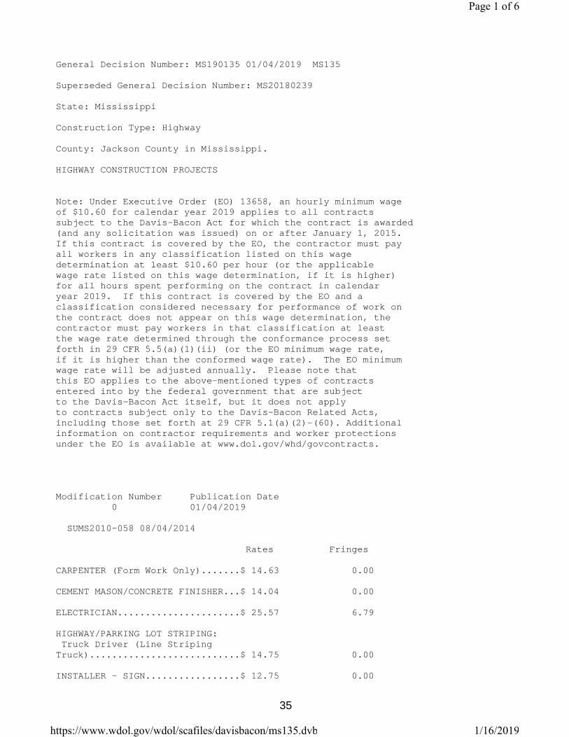
General Decision Number: MS190135 01/04/2019 MS135
Superseded General Decision Number: MS20180239
State: Mississippi
Construction Type: Highway
County: Jackson County in Mississippi.
HIGHWAY CONSTRUCTION PROJECTS
Note: Under Executive Order (EO) 13658, an hourly minimum wage of $10.60 for calendar year 2019 applies to all contracts subject to the Davis-Bacon Act for which the contract is awarded (and any solicitation was issued) on or after January 1, 2015. If this contract is covered by the EO, the contractor must pay all workers in any classification listed on this wage determination at least $10.60 per hour (or the applicable wage rate listed on this wage determination, if it is higher) for all hours spent performing on the contract in calendar year 2019. If this contract is covered by the EO and a classification considered necessary for performance of work on the contract does not appear on this wage determination, the contractor must pay workers in that classification at least the wage rate determined through the conformance process set forth in 29 CFR 5.5(a)(1)(ii) (or the EO minimum wage rate, if it is higher than the conformed wage rate). The EO minimum wage rate will be adjusted annually. Please note that this EO applies to the above-mentioned types of contracts entered into by the federal government that are subject to the Davis-Bacon Act itself, but it does not apply to contracts subject only to the Davis-Bacon Related Acts, including those set forth at 29 CFR 5.1(a)(2)-(60). Additional information on contractor requirements and worker protections under the EO is available at www.dol.gov/whd/govcontracts.
Modification Number Publication Date 0 01/04/2019
SUMS2010-058 08/04/2014
Rates Fringes
CARPENTER (Form Work Only).......$ 14.63 0.00
CEMENT MASON/CONCRETE FINISHER...$ 14.04 0.00
ELECTRICIAN......................$ 25.57 6.79
HIGHWAY/PARKING LOT STRIPING: Truck Driver (Line Striping Truck)...........................$ 14.75 0.00
INSTALLER - SIGN.................$ 12.75 0.00
Page 1 of 6
1/16/2019https://www.wdol.gov/wdol/scafiles/davisbacon/ms135.dvb
35

INSTALLER: Guardrail.............$ 11.81 0.00
IRONWORKER, REINFORCING..........$ 15.50 0.00
LABORER: Asphalt, Includes Raker, Shoveler, Spreader and Distributor......................$ 11.25 0.00
LABORER: Common or General......$ 10.90 0.00
LABORER: Flagger................$ 11.42 0.00
LABORER: Grade Checker..........$ 16.13 0.00
LABORER: Landscape..............$ 11.23 0.00
LABORER: Luteman................$ 12.88 0.00
LABORER: Mason Tender - Cement/Concrete..................$ 12.70 0.00
LABORER: Pipelayer..............$ 14.88 0.00
LABORER: Laborer-Cones/ Barricades/Barrels - Setter/Mover/Sweeper.............$ 13.19 0.00
OPERATOR: Asphalt Spreader......$ 14.71 0.00
OPERATOR: Backhoe/Excavator/Trackhoe.......$ 15.88 0.00
OPERATOR: Bobcat/Skid Steer/Skid Loader................$ 11.86 0.00
OPERATOR: Broom/Sweeper.........$ 13.62 0.00
OPERATOR: Bulldozer.............$ 15.94 0.00
OPERATOR: Concrete Saw..........$ 15.50 0.00
OPERATOR: Crane.................$ 15.89 0.00
OPERATOR: Distributor...........$ 14.47 0.00
OPERATOR: Grader/Blade..........$ 16.95 0.00
OPERATOR: Loader................$ 15.99 0.00
OPERATOR: Mechanic..............$ 18.44 0.00
OPERATOR: Milling Machine.......$ 16.04 0.00
OPERATOR: Oiler.................$ 12.22 0.00
OPERATOR: Paver (Asphalt, Aggregate, and Concrete).........$ 13.60 0.00
OPERATOR: Roller (All Types)....$ 14.32 0.00
Page 2 of 6
1/16/2019https://www.wdol.gov/wdol/scafiles/davisbacon/ms135.dvb
36

OPERATOR: Scraper...............$ 14.00 0.00
OPERATOR: Tractor...............$ 13.88 0.00
TRUCK DRIVER: Flatbed Truck.....$ 14.72 0.00
TRUCK DRIVER: Lowboy Truck......$ 13.01 0.00
TRUCK DRIVER: Mechanic..........$ 12.31 0.00
TRUCK DRIVER: Water Truck.......$ 17.08 0.00
TRUCK DRIVER: Dump Truck (All Types)...........................$ 13.68 0.00
TRUCK DRIVER: Semi/Trailer Truck............................$ 14.36 0.00 ----------------------------------------------------------------
WELDERS - Receive rate prescribed for craft performing operation to which welding is incidental.
================================================================
Note: Executive Order (EO) 13706, Establishing Paid Sick Leave for Federal Contractors applies to all contracts subject to the Davis-Bacon Act for which the contract is awarded (and any solicitation was issued) on or after January 1, 2017. If this contract is covered by the EO, the contractor must provide employees with 1 hour of paid sick leave for every 30 hours they work, up to 56 hours of paid sick leave each year. Employees must be permitted to use paid sick leave for their own illness, injury or other health-related needs, including preventive care; to assist a family member (or person who is like family to the employee) who is ill, injured, or has other health-related needs, including preventive care; or for reasons resulting from, or to assist a family member (or person who is like family to the employee) who is a victim of, domestic violence, sexual assault, or stalking. Additional information on contractor requirements and worker protections under the EO is available at www.dol.gov/whd/govcontracts.
Unlisted classifications needed for work not included within the scope of the classifications listed may be added after award only as provided in the labor standards contract clauses (29CFR 5.5 (a) (1) (ii)).
----------------------------------------------------------------
The body of each wage determination lists the classification and wage rates that have been found to be prevailing for the cited type(s) of construction in the area covered by the wage determination. The classifications are listed in alphabetical order of "identifiers" that indicate whether the particular rate is a union rate (current union negotiated rate for local), a survey rate (weighted average rate) or a union average rate (weighted union average rate).
Page 3 of 6
1/16/2019https://www.wdol.gov/wdol/scafiles/davisbacon/ms135.dvb
37

Union Rate Identifiers
A four letter classification abbreviation identifier enclosed in dotted lines beginning with characters other than "SU" or "UAVG" denotes that the union classification and rate were prevailing for that classification in the survey. Example: PLUM0198-005 07/01/2014. PLUM is an abbreviation identifier of the union which prevailed in the survey for this classification, which in this example would be Plumbers. 0198 indicates the local union number or district council number where applicable, i.e., Plumbers Local 0198. The next number, 005 in the example, is an internal number used in processing the wage determination. 07/01/2014 is the effective date of the most current negotiated rate, which in this example is July 1, 2014.
Union prevailing wage rates are updated to reflect all rate changes in the collective bargaining agreement (CBA) governing this classification and rate.
Survey Rate Identifiers
Classifications listed under the "SU" identifier indicate that no one rate prevailed for this classification in the survey and the published rate is derived by computing a weighted average rate based on all the rates reported in the survey for that classification. As this weighted average rate includes all rates reported in the survey, it may include both union and non-union rates. Example: SULA2012-007 5/13/2014. SU indicates the rates are survey rates based on a weighted average calculation of rates and are not majority rates. LA indicates the State of Louisiana. 2012 is the year of survey on which these classifications and rates are based. The next number, 007 in the example, is an internal number used in producing the wage determination. 5/13/2014 indicates the survey completion date for the classifications and rates under that identifier.
Survey wage rates are not updated and remain in effect until a new survey is conducted.
Union Average Rate Identifiers
Classification(s) listed under the UAVG identifier indicate that no single majority rate prevailed for those classifications; however, 100% of the data reported for the classifications was union data. EXAMPLE: UAVG-OH-0010 08/29/2014. UAVG indicates that the rate is a weighted union average rate. OH indicates the state. The next number, 0010 in the example, is an internal number used in producing the wage determination. 08/29/2014 indicates the survey completion date for the classifications and rates under that identifier.
A UAVG rate will be updated once a year, usually in January of each year, to reflect a weighted average of the current negotiated/CBA rate of the union locals from which the rate is based.
Page 4 of 6
1/16/2019https://www.wdol.gov/wdol/scafiles/davisbacon/ms135.dvb
38

----------------------------------------------------------------
WAGE DETERMINATION APPEALS PROCESS
1.) Has there been an initial decision in the matter? This can be:
* an existing published wage determination * a survey underlying a wage determination * a Wage and Hour Division letter setting forth a position on a wage determination matter * a conformance (additional classification and rate) ruling
On survey related matters, initial contact, including requests for summaries of surveys, should be with the Wage and Hour Regional Office for the area in which the survey was conducted because those Regional Offices have responsibility for the Davis-Bacon survey program. If the response from this initial contact is not satisfactory, then the process described in 2.) and 3.) should be followed.
With regard to any other matter not yet ripe for the formal process described here, initial contact should be with the Branch of Construction Wage Determinations. Write to:
Branch of Construction Wage Determinations Wage and Hour Division U.S. Department of Labor 200 Constitution Avenue, N.W. Washington, DC 20210
2.) If the answer to the question in 1.) is yes, then an interested party (those affected by the action) can request review and reconsideration from the Wage and Hour Administrator (See 29 CFR Part 1.8 and 29 CFR Part 7). Write to:
Wage and Hour Administrator U.S. Department of Labor 200 Constitution Avenue, N.W. Washington, DC 20210
The request should be accompanied by a full statement of the interested party's position and by any information (wage payment data, project description, area practice material, etc.) that the requestor considers relevant to the issue.
3.) If the decision of the Administrator is not favorable, an interested party may appeal directly to the Administrative Review Board (formerly the Wage Appeals Board). Write to:
Administrative Review Board U.S. Department of Labor 200 Constitution Avenue, N.W. Washington, DC 20210
4.) All decisions by the Administrative Review Board are final.
================================================================
END OF GENERAL DECISION
Page 5 of 6
1/16/2019https://www.wdol.gov/wdol/scafiles/davisbacon/ms135.dvb
39

Page 6 of 6
1/16/2019https://www.wdol.gov/wdol/scafiles/davisbacon/ms135.dvb
40

SUPPLEMENT TO FORM FHWA-1273 DATE: 12/17/2018 SUBJECT: Federal Contract Provisions for Subcontracts and Cargo Preference Act Federal Contract Provisions for Subcontracts All subcontracts shall be in writing and contain all pertinent provisions and requirements of the prime contract. Each “Request for Permission to Subcontract” (Mississippi Department of Transportation Form CAD-720) shall include a copy of the subcontract. The federal contract provisions (FHWA-1273, SUPPLEMENT TO FORM FHWA-1273, NOTICE OF REQUIREMENT FOR AFFIRMATIVE ACTION TO ENSURE EQUAL EMPLOYMENT OPPORTUNITY (EXECUTIVE ORDER 11246), DAVIS-BACON AND RELATED ACT PROVISIONS (WAGE RATES)) must be physically incorporated as part of the subcontract. A completed Mississippi Department of Transportation Form CAD-521 and Form CAD-725 must be attached to the CAD-720. Cargo Preference Act The Contractor is hereby advised of the requirements set forth in the following Attachment (Title 46 - Shipping) as it pertains to the implementation of Cargo Preference Act (CPA) requirements in the Federal-aid Highway Program. By signing this contract, the Contractor agrees to conform to the requirements of the CPA.
41

Attachment Title 46- Shipping Volume: 8 Date: 2014-10-01 Original Date: 2014-10-01 Title: Section 381.7 - Federal Grant, Guaranty, Loan and Advance at Funds Agreements. Context: Title 46- Shipping. CHAPTER II- MARITIME ADMINISTRATION, DEPARTMENT OF TRANSPORTATION. SUBCHAPTER J - MISCELLANEOUS. PART 381 - CARGO PREFERENCE-U.S.- FLAG VESSELS. § 381.7 Federal Grant, Guaranty, Loan and Advance of Funds Agreements. In order to insure a fair and reasonable participation by privately owned United States-flag commercial vessels in transporting cargoes which are subject to the Cargo Preference Act of 1954 and which are generated by U.S. Government Grant, Guaranty, Loan and/or Advance of Funds Programs, the head of each affected department or agency shall require appropriate clauses to be inserted in those Grant. Guaranty1 Loan and/or Advance of Funds Agreements and all third party contracts executed between the borrower/grantee and other parties, where the possibility exists for ocean transportation of items procured, contracted for or otherwise obtained by or on behalf of the grantee, borrower, or any of their contractors or subcontractors. The clauses required by this part shall provide that at least 50 percent of the freight revenue and tonnage of cargo generated by the U.S. Government Grant, Guaranty, Loan or Advance of Funds be transported on privately owned United States-flag commercial vessels. These clauses shall also require that all parties provide to the Maritime Administration the necessary shipment information as set forth in § 381.3. A copy of the appropriate clauses required by this part shall be submitted by each affected agency or department to the Secretary, Maritime Administration, for approval no later than 30 days after the effective date of this part. The following are suggested acceptable clauses with respect to the use of United States-flag vessels to be incorporated in the Grant, Guaranty, Loan and/or Advance of Funds Agreements as well as contracts and subcontracts resulting therefrom: (a) Agreement Clauses. "Use of United States-flag vessels: "(1) Pursuant to Pub. L 664 (43 U.S.C. 1241(b)) at least 50 percent of any equipment, materials or commodities procured, contracted for or otherwise obtained with funds granted, guaranteed, loaned, or advanced by the U.S. Government under this agreement, and which may be transported by ocean vessel, shall be transported on privately owned United States-flag commercial vessels, if available. "(2) Within 20 days following the date of loading for shipments originating within the United States or within 30 working days following the date of loading for shipments originating outside the United States, a legible copy of a rated, 'on-board' commercial ocean bill-of-lading in English for each shipment of cargo described in paragraph (a)(1) of this section shall be furnished to both the Contracting Officer (through the prime contractor in the case of subcontractor bills-of-lading) and to the Division of National Cargo, Office of Market Development, Maritime Administration, Washington, DC 20590." (b) Contractor and Subcontractor Clauses. "Use of United States-flag vessels: The contractor agrees -- "(1) To utilize privately owned United States-flag commercial vessels to ship at least 50 percent of the gross tonnage (computed separately for dry bulk carriers, dry cargo liners, and tankers) involved, whenever shipping any equipment, material, or commodities pursuant to this contract, to the extent such vessels are available at fair and reasonable rates for United States-flag commercial vessels. "(2) To furnish within 20 days following the date of loading for shipments originating within the United
42

States or within 30 working days following the date of loading for shipments originating outside the United States, a legible copy of a rated, 'on-board' commercial ocean bill-of-lading in English for each shipment of cargo described in paragraph (b) (1) of this section to both the Contracting Officer (through the prime contractor in the case of subcontractor bills-of-lading) and to the Division of National Cargo, Office of Market Development, Maritime Administration, Washington, DC 20590. "(3) To insert the substance of the provisions of this clause in all subcontracts issued pursuant to this contract." (Reorganization Plans No.21 of 1950(64 Stat. 1273) and No. 7 of 1961 (75 Stat. 840) as amended by Pub. L 91.469 (84 Stat 1036) and Department of Commerce Organization Order 10-8 (38 FR 19707, July 23, 1973)) (42 FR 57126, Nov. 1, 1977]
43

FHWA-1273-- Revised May 1, 2012
Page 1
REQUIRED CONTRACT PROVISIONS FEDERAL-AID CONSTRUCTION CONTRACTS
I. General II. NondiscriminationIII. Nonsegregated FacilitiesIV. Davis-Bacon and Related Act ProvisionsV. Contract Work Hours and Safety Standards Act
ProvisionsVI. Subletting or Assigning the Contract VII. Safety: Accident PreventionVIII. False Statements Concerning Highway ProjectsIX. Implementation of Clean Air Act and Federal Water
Pollution Control Act X. Compliance with Governmentwide Suspension and
Debarment Requirements XI. Certification Regarding Use of Contract Funds for
Lobbying
ATTACHMENTS
A. Employment and Materials Preference for Appalachian Development Highway System or Appalachian Local Access Road Contracts (included in Appalachian contracts only)
I. GENERAL
1. Form FHWA-1273 must be physically incorporated in eachconstruction contract funded under Title 23 (excluding emergency contracts solely intended for debris removal). The contractor (or subcontractor) must insert this form in each subcontract and further require its inclusion in all lower tier subcontracts (excluding purchase orders, rental agreements and other agreements for supplies or services).
The applicable requirements of Form FHWA-1273 are incorporated by reference for work done under any purchase order, rental agreement or agreement for other services. The prime contractor shall be responsible for compliance by any subcontractor, lower-tier subcontractor or service provider.
Form FHWA-1273 must be included in all Federal-aid design-build contracts, in all subcontracts and in lower tier subcontracts (excluding subcontracts for design services, purchase orders, rental agreements and other agreements for supplies or services). The design-builder shall be responsible for compliance by any subcontractor, lower-tier subcontractor or service provider.
Contracting agencies may reference Form FHWA-1273 in bid proposal or request for proposal documents, however, the Form FHWA-1273 must be physically incorporated (not referenced) in all contracts, subcontracts and lower-tier subcontracts (excluding purchase orders, rental agreements and other agreements for supplies or services related to a construction contract).
2. Subject to the applicability criteria noted in the following sections, these contract provisions shall apply to all work performed on the contract by the contractor's own organization and with the assistance of workers under the contractor's immediate superintendence and to all work performed on the contract by piecework, station work, or by subcontract.
3. A breach of any of the stipulations contained in these Required Contract Provisions may be sufficient grounds for withholding of progress payments, withholding of final payment, termination of the contract, suspension / debarment or any other action determined to be appropriate by the contracting agency and FHWA.
4. Selection of Labor: During the performance of this contract, the contractor shall not use convict labor for any purpose within the limits of a construction project on a Federal-aid highway unless it is labor performed by convicts who are on parole, supervised release, or probation. The term Federal-aid highway does not include roadways functionally classified as local roads or rural minor collectors.
II. NONDISCRIMINATION
The provisions of this section related to 23 CFR Part 230 are applicable to all Federal-aid construction contracts and to all related construction subcontracts of $10,000 or more. The provisions of 23 CFR Part 230 are not applicable to material supply, engineering, or architectural service contracts.
In addition, the contractor and all subcontractors must comply with the following policies: Executive Order 11246, 41 CFR 60, 29 CFR 1625-1627, Title 23 USC Section 140, the Rehabilitation Act of 1973, as amended (29 USC 794), Title VI of the Civil Rights Act of 1964, as amended, and related regulations including 49 CFR Parts 21, 26 and 27; and 23 CFR Parts 200, 230, and 633.
The contractor and all subcontractors must comply with: the requirements of the Equal Opportunity Clause in 41 CFR 60-1.4(b) and, for all construction contracts exceeding $10,000, the Standard Federal Equal Employment Opportunity Construction Contract Specifications in 41 CFR 60-4.3.
Note: The U.S. Department of Labor has exclusive authority to determine compliance with Executive Order 11246 and the policies of the Secretary of Labor including 41 CFR 60, and 29 CFR 1625-1627. The contracting agency and the FHWA have the authority and the responsibility to ensure compliance with Title 23 USC Section 140, the Rehabilitation Act of 1973, as amended (29 USC 794), and Title VI of the Civil Rights Act of 1964, as amended, and related regulations including 49 CFR Parts 21, 26 and 27; and 23 CFR Parts 200, 230, and 633.
The following provision is adopted from 23 CFR 230, Appendix A, with appropriate revisions to conform to the U.S. Department of Labor (US DOL) and FHWA requirements.
1. Equal Employment Opportunity: Equal employment opportunity (EEO) requirements not to discriminate and to take affirmative action to assure equal opportunity as set forth under laws, executive orders, rules, regulations (28 CFR 35, 29 CFR 1630, 29 CFR 1625-1627, 41 CFR 60 and 49 CFR 27) and orders of the Secretary of Labor as modified by the provisions prescribed herein, and imposed pursuant to 23 U.S.C. 140 shall constitute the EEO and specific affirmative action standards for the contractor's project activities under
44

FHWA-1273-- Revised May 1, 2012
Page 2
this contract. The provisions of the Americans with Disabilities Act of 1990 (42 U.S.C. 12101 et seq.) set forth under 28 CFR 35 and 29 CFR 1630 are incorporated by reference in this contract. In the execution of this contract, the contractor agrees to comply with the following minimum specific requirement activities of EEO:
a. The contractor will work with the contracting agency and the Federal Government to ensure that it has made every good faith effort to provide equal opportunity with respect to all of its terms and conditions of employment and in their review of activities under the contract.
b. The contractor will accept as its operating policy the following statement:
"It is the policy of this Company to assure that applicants are employed, and that employees are treated during employment, without regard to their race, religion, sex, color, national origin, age or disability. Such action shall include: employment, upgrading, demotion, or transfer; recruitment or recruitment advertising; layoff or termination; rates of pay or other forms of compensation; and selection for training, including apprenticeship, pre-apprenticeship, and/or on-the-job training."
2. EEO Officer: The contractor will designate and make known to the contracting officers an EEO Officer who will have the responsibility for and must be capable of effectively administering and promoting an active EEO program and who must be assigned adequate authority and responsibility to do so.
3. Dissemination of Policy: All members of the contractor's staff who are authorized to hire, supervise, promote, and discharge employees, or who recommend such action, or who are substantially involved in such action, will be made fully cognizant of, and will implement, the contractor's EEO policy and contractual responsibilities to provide EEO in each grade and classification of employment. To ensure that the above agreement will be met, the following actions will be taken as a minimum:
a. Periodic meetings of supervisory and personnel office employees will be conducted before the start of work and then not less often than once every six months, at which time the contractor's EEO policy and its implementation will be reviewed and explained. The meetings will be conducted by the EEO Officer.
b. All new supervisory or personnel office employees will be given a thorough indoctrination by the EEO Officer, covering all major aspects of the contractor's EEO obligations within thirty days following their reporting for duty with the contractor.
c. All personnel who are engaged in direct recruitment for the project will be instructed by the EEO Officer in the contractor's procedures for locating and hiring minorities and women.
d. Notices and posters setting forth the contractor's EEO policy will be placed in areas readily accessible to employees, applicants for employment and potential employees.
e. The contractor's EEO policy and the procedures to implement such policy will be brought to the attention of employees by means of meetings, employee handbooks, or other appropriate means.
4. Recruitment: When advertising for employees, the contractor will include in all advertisements for employees the notation: "An Equal Opportunity Employer." All such advertisements will be placed in publications having a large circulation among minorities and women in the area from which the project work force would normally be derived.
a. The contractor will, unless precluded by a valid bargaining agreement, conduct systematic and direct recruitment through public and private employee referral sources likely to yield qualified minorities and women. To meet this requirement, the contractor will identify sources of potential minority group employees, and establish with such identified sources procedures whereby minority and women applicants may be referred to the contractor for employment consideration.
b. In the event the contractor has a valid bargaining agreement providing for exclusive hiring hall referrals, the contractor is expected to observe the provisions of that agreement to the extent that the system meets the contractor's compliance with EEO contract provisions. Where implementation of such an agreement has the effect of discriminating against minorities or women, or obligates the contractor to do the same, such implementation violates Federal nondiscrimination provisions.
c. The contractor will encourage its present employees to refer minorities and women as applicants for employment. Information and procedures with regard to referring such applicants will be discussed with employees.
5. Personnel Actions: Wages, working conditions, and employee benefits shall be established and administered, and personnel actions of every type, including hiring, upgrading, promotion, transfer, demotion, layoff, and termination, shall be taken without regard to race, color, religion, sex, national origin, age or disability. The following procedures shall be followed:
a. The contractor will conduct periodic inspections of project sites to insure that working conditions and employee facilities do not indicate discriminatory treatment of project site personnel.
b. The contractor will periodically evaluate the spread of wages paid within each classification to determine any evidence of discriminatory wage practices.
c. The contractor will periodically review selected personnel actions in depth to determine whether there is evidence of discrimination. Where evidence is found, the contractor will promptly take corrective action. If the review indicates that the discrimination may extend beyond the actions reviewed, such corrective action shall include all affected persons.
d. The contractor will promptly investigate all complaints of alleged discrimination made to the contractor in connection with its obligations under this contract, will attempt to resolve such complaints, and will take appropriate corrective action within a reasonable time. If the investigation indicates that the discrimination may affect persons other than the complainant, such corrective action shall include such other persons. Upon completion of each investigation, the contractor will inform every complainant of all of their avenues of appeal.
6. Training and Promotion:
a. The contractor will assist in locating, qualifying, and increasing the skills of minorities and women who are
45

FHWA-1273-- Revised May 1, 2012
Page 3
applicants for employment or current employees. Such efforts should be aimed at developing full journey level status employees in the type of trade or job classification involved.
b. Consistent with the contractor's work force requirements and as permissible under Federal and State regulations, the contractor shall make full use of training programs, i.e., apprenticeship, and on-the-job training programs for the geographical area of contract performance. In the event a special provision for training is provided under this contract, this subparagraph will be superseded as indicated in the special provision. The contracting agency may reserve training positions for persons who receive welfare assistancein accordance with 23 U.S.C. 140(a).
c. The contractor will advise employees and applicants for employment of available training programs and entrance requirements for each.
d. The contractor will periodically review the training and promotion potential of employees who are minorities and women and will encourage eligible employees to apply for such training and promotion.
7. Unions: If the contractor relies in whole or in part upon unions as a source of employees, the contractor will use good faith efforts to obtain the cooperation of such unions to increase opportunities for minorities and women. Actions by the contractor, either directly or through a contractor's association acting as agent, will include the procedures set forth below:
a. The contractor will use good faith efforts to develop, in cooperation with the unions, joint training programs aimed toward qualifying more minorities and women for membership in the unions and increasing the skills of minorities and women so that they may qualify for higher paying employment.
b. The contractor will use good faith efforts to incorporate an EEO clause into each union agreement to the end that such union will be contractually bound to refer applicants without regard to their race, color, religion, sex, national origin, age or disability.
c. The contractor is to obtain information as to the referral practices and policies of the labor union except that to the extent such information is within the exclusive possession of the labor union and such labor union refuses to furnish such information to the contractor, the contractor shall so certify to the contracting agency and shall set forth what efforts have been made to obtain such information.
d. In the event the union is unable to provide the contractor with a reasonable flow of referrals within the time limit set forth in the collective bargaining agreement, the contractor will, through independent recruitment efforts, fill the employment vacancies without regard to race, color, religion, sex, national origin, age or disability; making full efforts to obtain qualified and/or qualifiable minorities and women. The failure of a union to provide sufficient referrals (even though it is obligated to provide exclusive referrals under the terms of a collective bargaining agreement) does not relieve the contractor from the requirements of this paragraph. In the event the union referral practice prevents the contractor from meeting the obligations pursuant to Executive Order 11246, as amended, and these special provisions, such contractor shall immediately notify the contracting agency.
8. Reasonable Accommodation for Applicants / Employees with Disabilities: The contractor must be familiar
with the requirements for and comply with the Americans with Disabilities Act and all rules and regulations established there under. Employers must provide reasonable accommodation in all employment activities unless to do so would cause an undue hardship.
9. Selection of Subcontractors, Procurement of Materials and Leasing of Equipment: The contractor shall not discriminate on the grounds of race, color, religion, sex, national origin, age or disability in the selection and retention of subcontractors, including procurement of materials and leases of equipment. The contractor shall take all necessary and reasonable steps to ensure nondiscrimination in the administration of this contract.
a. The contractor shall notify all potential subcontractors and suppliers and lessors of their EEO obligations under this contract.
b. The contractor will use good faith efforts to ensure subcontractor compliance with their EEO obligations.
10. Assurance Required by 49 CFR 26.13(b):
a. The requirements of 49 CFR Part 26 and the State DOT’s U.S. DOT-approved DBE program are incorporated by reference.
b. The contractor or subcontractor shall not discriminate on the basis of race, color, national origin, or sex in the performance of this contract. The contractor shall carry out applicable requirements of 49 CFR Part 26 in the award and administration of DOT-assisted contracts. Failure by the contractor to carry out these requirements is a material breach of this contract, which may result in the termination of this contract or such other remedy as the contracting agency deems appropriate.
11. Records and Reports: The contractor shall keep such records as necessary to document compliance with the EEO requirements. Such records shall be retained for a period of three years following the date of the final payment to the contractor for all contract work and shall be available at reasonable times and places for inspection by authorized representatives of the contracting agency and the FHWA.
a. The records kept by the contractor shall document the following:
(1) The number and work hours of minority and non-minority group members and women employed in each work classification on the project;
(2) The progress and efforts being made in cooperation
with unions, when applicable, to increase employment opportunities for minorities and women; and
(3) The progress and efforts being made in locating,
hiring, training, qualifying, and upgrading minorities and women;
b. The contractors and subcontractors will submit an annual report to the contracting agency each July for the duration of the project, indicating the number of minority, women, and non-minority group employees currently engaged in each work classification required by the contract work. This information is to be reported on Form FHWA-1391. The staffing data should represent the project work force on board in all or any part of the last payroll period preceding the end of July. If on-the-job training is being required by special provision, the contractor
46

FHWA-1273-- Revised May 1, 2012
Page 4
will be required to collect and report training data. The employment data should reflect the work force on board during all or any part of the last payroll period preceding the end of July.
III. NONSEGREGATED FACILITIES
This provision is applicable to all Federal-aid construction contracts and to all related construction subcontracts of $10,000 or more.
The contractor must ensure that facilities provided for employees are provided in such a manner that segregation on the basis of race, color, religion, sex, or national origin cannot result. The contractor may neither require such segregated use by written or oral policies nor tolerate such use by employee custom. The contractor's obligation extends further to ensure that its employees are not assigned to perform their services at any location, under the contractor's control, where the facilities are segregated. The term "facilities" includes waiting rooms, work areas, restaurants and other eating areas, time clocks, restrooms, washrooms, locker rooms, and other storage or dressing areas, parking lots, drinking fountains, recreation or entertainment areas, transportation, and housing provided for employees. The contractor shall provide separate or single-user restrooms and necessary dressing or sleeping areas to assure privacy between sexes.
IV. DAVIS-BACON AND RELATED ACT PROVISIONS
This section is applicable to all Federal-aid construction projects exceeding $2,000 and to all related subcontracts and lower-tier subcontracts (regardless of subcontract size). The requirements apply to all projects located within the right-of-way of a roadway that is functionally classified as Federal-aidhighway. This excludes roadways functionally classified as local roads or rural minor collectors, which are exempt. Contracting agencies may elect to apply these requirements to other projects.
The following provisions are from the U.S. Department of Labor regulations in 29 CFR 5.5 “Contract provisions and related matters” with minor revisions to conform to the FHWA-1273 format and FHWA program requirements.
1. Minimum wages
a. All laborers and mechanics employed or working upon the site of the work, will be paid unconditionally and not less often than once a week, and without subsequent deduction or rebate on any account (except such payroll deductions as are permitted by regulations issued by the Secretary of Labor under the Copeland Act (29 CFR part 3)), the full amount of wages and bona fide fringe benefits (or cash equivalents thereof) due at time of payment computed at rates not less than those contained in the wage determination of the Secretary of Labor which is attached hereto and made a part hereof, regardless of any contractual relationship which may be alleged to exist between the contractor and such laborers and mechanics.
Contributions made or costs reasonably anticipated for bona fide fringe benefits under section 1(b)(2) of the Davis-Bacon Act on behalf of laborers or mechanics are considered wages
paid to such laborers or mechanics, subject to the provisions of paragraph 1.d. of this section; also, regular contributions made or costs incurred for more than a weekly period (but not less often than quarterly) under plans, funds, or programs which cover the particular weekly period, are deemed to be constructively made or incurred during such weekly period. Such laborers and mechanics shall be paid the appropriate wage rate and fringe benefits on the wage determination for the classification of work actually performed, without regard to skill, except as provided in 29 CFR 5.5(a)(4). Laborers or mechanics performing work in more than one classification may be compensated at the rate specified for each classification for the time actually worked therein: Provided, That the employer's payroll records accurately set forth the time spent in each classification in which work is performed. The wage determination (including any additional classification and wage rates conformed under paragraph 1.b. of this section) and the Davis-Bacon poster (WH–1321) shall be posted at all times by the contractor and its subcontractors at the site of the work in a prominent and accessible place where it can be easily seen by the workers.
b. (1) The contracting officer shall require that any class of laborers or mechanics, including helpers, which is not listed in the wage determination and which is to be employed under the contract shall be classified in conformance with the wage determination. The contracting officer shall approve an additional classification and wage rate and fringe benefits therefore only when the following criteria have been met:
(i) The work to be performed by the classification requested is not performed by a classification in the wage determination; and
(ii) The classification is utilized in the area by the construction industry; and
(iii) The proposed wage rate, including any bona fide fringe benefits, bears a reasonable relationship to the wage rates contained in the wage determination.
(2) If the contractor and the laborers and mechanics to be employed in the classification (if known), or their representatives, and the contracting officer agree on the classification and wage rate (including the amount designated for fringe benefits where appropriate), a report of the action taken shall be sent by the contracting officer to the Administrator of the Wage and Hour Division, Employment Standards Administration, U.S. Department of Labor, Washington, DC 20210. The Administrator, or an authorized representative, will approve, modify, or disapprove every additional classification action within 30 days of receipt and so advise the contracting officer or will notify the contracting officer within the 30-day period that additional time is necessary.
(3) In the event the contractor, the laborers or mechanics to be employed in the classification or their representatives, and the contracting officer do not agree on the proposed classification and wage rate (including the amount designated for fringe benefits, where appropriate), the contracting officer shall refer the questions, including the views of all interested parties and the recommendation of the contracting officer, to the Wage and Hour Administrator for determination. The Wage and Hour Administrator, or an authorized representative, will issue a determination within 30 days of receipt and so advise
47

FHWA-1273-- Revised May 1, 2012
Page 5
the contracting officer or will notify the contracting officer within the 30-day period that additional time is necessary.
(4) The wage rate (including fringe benefits where appropriate) determined pursuant to paragraphs 1.b.(2) or 1.b.(3) of this section, shall be paid to all workers performing work in the classification under this contract from the first day on which work is performed in the classification.
c. Whenever the minimum wage rate prescribed in the contract for a class of laborers or mechanics includes a fringe benefit which is not expressed as an hourly rate, the contractor shall either pay the benefit as stated in the wage determination or shall pay another bona fide fringe benefit or an hourly cash equivalent thereof.
d. If the contractor does not make payments to a trustee or other third person, the contractor may consider as part of the wages of any laborer or mechanic the amount of any costs reasonably anticipated in providing bona fide fringe benefits under a plan or program, Provided, That the Secretary of Labor has found, upon the written request of the contractor, that the applicable standards of the Davis-Bacon Act have been met. The Secretary of Labor may require the contractor to set aside in a separate account assets for the meeting of obligations under the plan or program.
2. Withholding
The contracting agency shall upon its own action or upon written request of an authorized representative of the Department of Labor, withhold or cause to be withheld from the contractor under this contract, or any other Federal contract with the same prime contractor, or any other federally-assisted contract subject to Davis-Bacon prevailing wage requirements, which is held by the same prime contractor, so much of the accrued payments or advances as may be considered necessary to pay laborers and mechanics, including apprentices, trainees, and helpers, employed by the contractor or any subcontractor the full amount of wages required by the contract. In the event of failure to pay any laborer or mechanic, including any apprentice, trainee, or helper, employed or working on the site of the work, all or part of the wages required by the contract, the contracting agency may, after written notice to the contractor, take such action as may be necessary to cause the suspension of any further payment, advance, or guarantee of funds until such violations have ceased.
3. Payrolls and basic records
a. Payrolls and basic records relating thereto shall be maintained by the contractor during the course of the work and preserved for a period of three years thereafter for all laborers and mechanics working at the site of the work. Such records shall contain the name, address, and social security number of each such worker, his or her correct classification, hourly rates of wages paid (including rates of contributions or costs anticipated for bona fide fringe benefits or cash equivalents thereof of the types described in section 1(b)(2)(B) of the Davis-Bacon Act), daily and weekly number of hours worked, deductions made and actual wages paid. Whenever the Secretary of Labor has found under 29 CFR 5.5(a)(1)(iv) that the wages of any laborer or mechanic include the amount of any costs reasonably anticipated in providing benefits under a plan or program described in section 1(b)(2)(B) of the Davis-
Bacon Act, the contractor shall maintain records which show that the commitment to provide such benefits is enforceable, that the plan or program is financially responsible, and that the plan or program has been communicated in writing to the laborers or mechanics affected, and records which show the costs anticipated or the actual cost incurred in providing such benefits. Contractors employing apprentices or trainees under approved programs shall maintain written evidence of the registration of apprenticeship programs and certification of trainee programs, the registration of the apprentices and trainees, and the ratios and wage rates prescribed in the applicable programs.
b. (1) The contractor shall submit weekly for each week in which any contract work is performed a copy of all payrolls to the contracting agency. The payrolls submitted shall set out accurately and completely all of the information required to be maintained under 29 CFR 5.5(a)(3)(i), except that full social security numbers and home addresses shall not be included on weekly transmittals. Instead the payrolls shall only need to include an individually identifying number for each employee ( e.g. , the last four digits of the employee's social security number). The required weekly payroll information may be submitted in any form desired. Optional Form WH–347 is available for this purpose from the Wage and Hour Division Web site at http://www.dol.gov/esa/whd/forms/wh347instr.htm or its successor site. The prime contractor is responsible for the submission of copies of payrolls by all subcontractors. Contractors and subcontractors shall maintain the full social security number and current address of each covered worker, and shall provide them upon request to the contracting agency for transmission to the State DOT, the FHWA or the Wage and Hour Division of the Department of Labor for purposes of an investigation or audit of compliance with prevailing wage requirements. It is not a violation of this section for a prime contractor to require a subcontractor to provide addresses and social security numbers to the prime contractor for its own records, without weekly submission to the contracting agency..
(2) Each payroll submitted shall be accompanied by a “Statement of Compliance,” signed by the contractor or subcontractor or his or her agent who pays or supervises the payment of the persons employed under the contract and shall certify the following:
(i) That the payroll for the payroll period contains the information required to be provided under §5.5 (a)(3)(ii) of Regulations, 29 CFR part 5, the appropriate information is being maintained under §5.5 (a)(3)(i) of Regulations, 29 CFR part 5, and that such information is correct and complete;
(ii) That each laborer or mechanic (including each helper,
apprentice, and trainee) employed on the contract during the payroll period has been paid the full weekly wages earned, without rebate, either directly or indirectly, and that no deductions have been made either directly or indirectly from the full wages earned, other than permissible deductions as set forth in Regulations, 29 CFR part 3;
(iii) That each laborer or mechanic has been paid not less
than the applicable wage rates and fringe benefits or cash equivalents for the classification of work performed, as specified in the applicable wage determination incorporated into the contract.
48

FHWA-1273-- Revised May 1, 2012
Page 6
(3) The weekly submission of a properly executed certification set forth on the reverse side of Optional Form WH–347 shall satisfy the requirement for submission of the “Statement of Compliance” required by paragraph 3.b.(2) of this section.
(4) The falsification of any of the above certifications may subject the contractor or subcontractor to civil or criminal prosecution under section 1001 of title 18 and section 231 of title 31 of the United States Code.
c. The contractor or subcontractor shall make the records required under paragraph 3.a. of this section available for inspection, copying, or transcription by authorized representatives of the contracting agency, the State DOT, the FHWA, or the Department of Labor, and shall permit such representatives to interview employees during working hours on the job. If the contractor or subcontractor fails to submit the required records or to make them available, the FHWA may, after written notice to the contractor, the contracting agency or the State DOT, take such action as may be necessary to cause the suspension of any further payment, advance, or guarantee of funds. Furthermore, failure to submit the required records upon request or to make such records available may be grounds for debarment action pursuant to 29 CFR 5.12.
4. Apprentices and trainees
a. Apprentices (programs of the USDOL).
Apprentices will be permitted to work at less than the predetermined rate for the work they performed when they are employed pursuant to and individually registered in a bona fide apprenticeship program registered with the U.S. Department of Labor, Employment and Training Administration, Office of Apprenticeship Training, Employer and Labor Services, or with a State Apprenticeship Agency recognized by the Office, or if a person is employed in his or her first 90 days of probationary employment as an apprentice in such an apprenticeship program, who is not individually registered in the program, but who has been certified by the Office of Apprenticeship Training, Employer and Labor Services or a State Apprenticeship Agency (where appropriate) to be eligible for probationary employment as an apprentice.
The allowable ratio of apprentices to journeymen on the job site in any craft classification shall not be greater than the ratio permitted to the contractor as to the entire work force under the registered program. Any worker listed on a payroll at an apprentice wage rate, who is not registered or otherwise employed as stated above, shall be paid not less than the applicable wage rate on the wage determination for the classification of work actually performed. In addition, any apprentice performing work on the job site in excess of the ratio permitted under the registered program shall be paid not less than the applicable wage rate on the wage determination for the work actually performed. Where a contractor is performing construction on a project in a locality other than that in which its program is registered, the ratios and wage rates (expressed in percentages of the journeyman's hourly rate) specified in the contractor's or subcontractor's registered program shall be observed.
Every apprentice must be paid at not less than the rate specified in the registered program for the apprentice's level of progress, expressed as a percentage of the journeymen hourly
rate specified in the applicable wage determination. Apprentices shall be paid fringe benefits in accordance with the provisions of the apprenticeship program. If the apprenticeship program does not specify fringe benefits, apprentices must be paid the full amount of fringe benefits listed on the wage determination for the applicable classification. If the Administrator determines that a different practice prevails for the applicable apprentice classification, fringes shall be paid in accordance with that determination.
In the event the Office of Apprenticeship Training, Employer and Labor Services, or a State Apprenticeship Agency recognized by the Office, withdraws approval of an apprenticeship program, the contractor will no longer be permitted to utilize apprentices at less than the applicable predetermined rate for the work performed until an acceptable program is approved.
b. Trainees (programs of the USDOL).
Except as provided in 29 CFR 5.16, trainees will not be permitted to work at less than the predetermined rate for the work performed unless they are employed pursuant to and individually registered in a program which has received prior approval, evidenced by formal certification by the U.S. Department of Labor, Employment and Training Administration.
The ratio of trainees to journeymen on the job site shall not be greater than permitted under the plan approved by the Employment and Training Administration.
Every trainee must be paid at not less than the rate specified in the approved program for the trainee's level of progress, expressed as a percentage of the journeyman hourly rate specified in the applicable wage determination. Trainees shall be paid fringe benefits in accordance with the provisions of the trainee program. If the trainee program does not mention fringe benefits, trainees shall be paid the full amount of fringe benefits listed on the wage determination unless the Administrator of the Wage and Hour Division determines that there is an apprenticeship program associated with the corresponding journeyman wage rate on the wage determination which provides for less than full fringe benefits for apprentices. Any employee listed on the payroll at a trainee rate who is not registered and participating in a training plan approved by the Employment and Training Administration shall be paid not less than the applicable wage rate on the wage determination for the classification of work actually performed. In addition, any trainee performing work on the job site in excess of the ratio permitted under the registered program shall be paid not less than the applicable wage rate on the wage determination for the work actually performed.
In the event the Employment and Training Administration withdraws approval of a training program, the contractor will no longer be permitted to utilize trainees at less than the applicable predetermined rate for the work performed until an acceptable program is approved.
c. Equal employment opportunity. The utilization of apprentices, trainees and journeymen under this part shall be in conformity with the equal employment opportunity requirements of Executive Order 11246, as amended, and 29 CFR part 30.
49

FHWA-1273-- Revised May 1, 2012
Page 7
d. Apprentices and Trainees (programs of the U.S. DOT).
Apprentices and trainees working under apprenticeship and skill training programs which have been certified by the Secretary of Transportation as promoting EEO in connection with Federal-aid highway construction programs are not subject to the requirements of paragraph 4 of this Section IV. The straight time hourly wage rates for apprentices and trainees under such programs will be established by the particular programs. The ratio of apprentices and trainees to journeymen shall not be greater than permitted by the terms of the particular program.
5. Compliance with Copeland Act requirements. The contractor shall comply with the requirements of 29 CFR part 3, which are incorporated by reference in this contract.
6. Subcontracts. The contractor or subcontractor shall insert Form FHWA-1273 in any subcontracts and also require the subcontractors to include Form FHWA-1273 in any lower tier subcontracts. The prime contractor shall be responsible for the compliance by any subcontractor or lower tier subcontractor with all the contract clauses in 29 CFR 5.5.
7. Contract termination: debarment. A breach of the contract clauses in 29 CFR 5.5 may be grounds for termination of the contract, and for debarment as a contractor and a subcontractor as provided in 29 CFR 5.12.
8. Compliance with Davis-Bacon and Related Act requirements. All rulings and interpretations of the Davis-Bacon and Related Acts contained in 29 CFR parts 1, 3, and 5 are herein incorporated by reference in this contract.
9. Disputes concerning labor standards. Disputes arising out of the labor standards provisions of this contract shall not be subject to the general disputes clause of this contract. Such disputes shall be resolved in accordance with the procedures of the Department of Labor set forth in 29 CFR parts 5, 6, and 7. Disputes within the meaning of this clause include disputes between the contractor (or any of its subcontractors) and the contracting agency, the U.S. Department of Labor, or the employees or their representatives.
10. Certification of eligibility.
a. By entering into this contract, the contractor certifies that neither it (nor he or she) nor any person or firm who has an interest in the contractor's firm is a person or firm ineligible to be awarded Government contracts by virtue of section 3(a) of the Davis-Bacon Act or 29 CFR 5.12(a)(1).
b. No part of this contract shall be subcontracted to any person or firm ineligible for award of a Government contract by virtue of section 3(a) of the Davis-Bacon Act or 29 CFR 5.12(a)(1).
c. The penalty for making false statements is prescribed in the U.S. Criminal Code, 18 U.S.C. 1001.
V. CONTRACT WORK HOURS AND SAFETY STANDARDS ACT
The following clauses apply to any Federal-aid construction contract in an amount in excess of $100,000 and subject to the overtime provisions of the Contract Work Hours and Safety Standards Act. These clauses shall be inserted in addition to the clauses required by 29 CFR 5.5(a) or 29 CFR 4.6. As used in this paragraph, the terms laborers and mechanics include watchmen and guards.
1. Overtime requirements. No contractor or subcontractor contracting for any part of the contract work which may require or involve the employment of laborers or mechanics shall require or permit any such laborer or mechanic in anyworkweek in which he or she is employed on such work to work in excess of forty hours in such workweek unless such laborer or mechanic receives compensation at a rate not less than one and one-half times the basic rate of pay for all hours worked in excess of forty hours in such workweek.
2. Violation; liability for unpaid wages; liquidated damages. In the event of any violation of the clause set forth in paragraph (1.) of this section, the contractor and any subcontractor responsible therefor shall be liable for the unpaid wages. In addition, such contractor and subcontractor shall be liable to the United States (in the case of work done under contract for the District of Columbia or a territory, to such District or to such territory), for liquidated damages. Such liquidated damages shall be computed with respect to each individual laborer or mechanic, including watchmen and guards, employed in violation of the clause set forth in paragraph (1.) of this section, in the sum of $10 for each calendar day on which such individual was required or permitted to work in excess of the standard workweek of forty hours without payment of the overtime wages required by the clause set forth in paragraph (1.) of this section.
3. Withholding for unpaid wages and liquidated damages.The FHWA or the contacting agency shall upon its own action or upon written request of an authorized representative of the Department of Labor withhold or cause to be withheld, from any moneys payable on account of work performed by the contractor or subcontractor under any such contract or any other Federal contract with the same prime contractor, or any other federally-assisted contract subject to the Contract Work Hours and Safety Standards Act, which is held by the same prime contractor, such sums as may be determined to be necessary to satisfy any liabilities of such contractor or subcontractor for unpaid wages and liquidated damages as provided in the clause set forth in paragraph (2.) of this section.
4. Subcontracts. The contractor or subcontractor shall insert in any subcontracts the clauses set forth in paragraph (1.)through (4.) of this section and also a clause requiring the subcontractors to include these clauses in any lower tier subcontracts. The prime contractor shall be responsible for compliance by any subcontractor or lower tier subcontractor with the clauses set forth in paragraphs (1.) through (4.) of this section.
50
FHWA-1273-- Revised May 1, 2012
Page 8
VI. SUBLETTING OR ASSIGNING THE CONTRACT
This provision is applicable to all Federal-aid construction contracts on the National Highway System.
1. The contractor shall perform with its own organization contract work amounting to not less than 30 percent (or a greater percentage if specified elsewhere in the contract) of the total original contract price, excluding any specialty items designated by the contracting agency. Specialty items may be performed by subcontract and the amount of any such specialty items performed may be deducted from the total original contract price before computing the amount of work required to be performed by the contractor's own organization (23 CFR 635.116).
a. The term “perform work with its own organization” refers to workers employed or leased by the prime contractor, and equipment owned or rented by the prime contractor, with or without operators. Such term does not include employees or equipment of a subcontractor or lower tier subcontractor, agents of the prime contractor, or any other assignees. The term may include payments for the costs of hiring leased employees from an employee leasing firm meeting all relevant Federal and State regulatory requirements. Leased employees may only be included in this term if the prime contractor meets all of the following conditions:
(1) the prime contractor maintains control over the supervision of the day-to-day activities of the leased employees;
(2) the prime contractor remains responsible for the quality of the work of the leased employees;
(3) the prime contractor retains all power to accept or exclude individual employees from work on the project; and
(4) the prime contractor remains ultimately responsible for the payment of predetermined minimum wages, the submission of payrolls, statements of compliance and all other Federal regulatory requirements.
b. "Specialty Items" shall be construed to be limited to work that requires highly specialized knowledge, abilities, or equipment not ordinarily available in the type of contracting organizations qualified and expected to bid or propose on the contract as a whole and in general are to be limited to minor components of the overall contract.
2. The contract amount upon which the requirements set forth in paragraph (1) of Section VI is computed includes the cost of material and manufactured products which are to be purchased or produced by the contractor under the contract provisions.
3. The contractor shall furnish (a) a competent superintendent or supervisor who is employed by the firm, has full authority to direct performance of the work in accordance with the contract requirements, and is in charge of all construction operations (regardless of who performs the work) and (b) such other of its own organizational resources (supervision, management, and engineering services) as the contracting officer determines is necessary to assure the performance of the contract.
4. No portion of the contract shall be sublet, assigned or otherwise disposed of except with the written consent of the contracting officer, or authorized representative, and such consent when given shall not be construed to relieve the contractor of any responsibility for the fulfillment of the contract. Written consent will be given only after the
contracting agency has assured that each subcontract is evidenced in writing and that it contains all pertinent provisions and requirements of the prime contract.
5. The 30% self-performance requirement of paragraph (1) is not applicable to design-build contracts; however, contracting agencies may establish their own self-performance requirements.
VII. SAFETY: ACCIDENT PREVENTION
This provision is applicable to all Federal-aid construction contracts and to all related subcontracts.
1. In the performance of this contract the contractor shall comply with all applicable Federal, State, and local laws governing safety, health, and sanitation (23 CFR 635). The contractor shall provide all safeguards, safety devices and protective equipment and take any other needed actions as it determines, or as the contracting officer may determine, to be reasonably necessary to protect the life and health of employees on the job and the safety of the public and to protect property in connection with the performance of the work covered by the contract.
2. It is a condition of this contract, and shall be made a condition of each subcontract, which the contractor enters into pursuant to this contract, that the contractor and any subcontractor shall not permit any employee, in performance of the contract, to work in surroundings or under conditions which are unsanitary, hazardous or dangerous to his/her health or safety, as determined under construction safety and health standards (29 CFR 1926) promulgated by the Secretary of Labor, in accordance with Section 107 of the Contract Work Hours and Safety Standards Act (40 U.S.C. 3704).
3. Pursuant to 29 CFR 1926.3, it is a condition of this contract that the Secretary of Labor or authorized representative thereof, shall have right of entry to any site of contract performance to inspect or investigate the matter of compliance with the construction safety and health standards and to carry out the duties of the Secretary under Section 107 of the Contract Work Hours and Safety Standards Act (40 U.S.C.3704).
VIII. FALSE STATEMENTS CONCERNING HIGHWAY PROJECTS
This provision is applicable to all Federal-aid construction contracts and to all related subcontracts.
In order to assure high quality and durable construction in conformity with approved plans and specifications and a high degree of reliability on statements and representations made by engineers, contractors, suppliers, and workers on Federal-aid highway projects, it is essential that all persons concerned with the project perform their functions as carefully, thoroughly, and honestly as possible. Willful falsification, distortion, or misrepresentation with respect to any facts related to the project is a violation of Federal law. To prevent any misunderstanding regarding the seriousness of these and similar acts, Form FHWA-1022 shall be posted on each Federal-aid highway project (23 CFR 635) in one or more places where it is readily available to all persons concerned with the project:
18 U.S.C. 1020 reads as follows:
51

FHWA-1273-- Revised May 1, 2012
Page 9
"Whoever, being an officer, agent, or employee of the United States, or of any State or Territory, or whoever, whether a person, association, firm, or corporation, knowingly makes any false statement, false representation, or false report as to the character, quality, quantity, or cost of the material used or to be used, or the quantity or quality of the work performed or to be performed, or the cost thereof in connection with the submission of plans, maps, specifications, contracts, or costs of construction on any highway or related project submitted for approval to the Secretary of Transportation; or
Whoever knowingly makes any false statement, false representation, false report or false claim with respect to the character, quality, quantity, or cost of any work performed or to be performed, or materials furnished or to be furnished, in connection with the construction of any highway or related project approved by the Secretary of Transportation; or
Whoever knowingly makes any false statement or false representation as to material fact in any statement, certificate, or report submitted pursuant to provisions of the Federal-aid Roads Act approved July 1, 1916, (39 Stat. 355), as amended and supplemented;
Shall be fined under this title or imprisoned not more than 5 years or both."
IX. IMPLEMENTATION OF CLEAN AIR ACT AND FEDERAL WATER POLLUTION CONTROL ACT
This provision is applicable to all Federal-aid construction contracts and to all related subcontracts.
By submission of this bid/proposal or the execution of this contract, or subcontract, as appropriate, the bidder, proposer, Federal-aid construction contractor, or subcontractor, as appropriate, will be deemed to have stipulated as follows:
1. That any person who is or will be utilized in the performance of this contract is not prohibited from receiving an award due to a violation of Section 508 of the Clean Water Act or Section 306 of the Clean Air Act.
2. That the contractor agrees to include or cause to be included the requirements of paragraph (1) of this Section X in every subcontract, and further agrees to take such action as the contracting agency may direct as a means of enforcing such requirements.
X. CERTIFICATION REGARDING DEBARMENT, SUSPENSION, INELIGIBILITY AND VOLUNTARY EXCLUSION
This provision is applicable to all Federal-aid construction contracts, design-build contracts, subcontracts, lower-tier subcontracts, purchase orders, lease agreements, consultant contracts or any other covered transaction requiring FHWA approval or that is estimated to cost $25,000 or more – as defined in 2 CFR Parts 180 and 1200.
1. Instructions for Certification – First Tier Participants:
a. By signing and submitting this proposal, the prospective first tier participant is providing the certification set out below.
b. The inability of a person to provide the certification set out below will not necessarily result in denial of participation in this
covered transaction. The prospective first tier participant shall submit an explanation of why it cannot provide the certification set out below. The certification or explanation will be considered in connection with the department or agency's determination whether to enter into this transaction. However, failure of the prospective first tier participant to furnish a certification or an explanation shall disqualify such a person from participation in this transaction.
c. The certification in this clause is a material representation of fact upon which reliance was placed when the contracting agency determined to enter into this transaction. If it is later determined that the prospective participant knowingly rendered an erroneous certification, in addition to other remedies available to the Federal Government, the contracting agency may terminate this transaction for cause of default.
d. The prospective first tier participant shall provide immediate written notice to the contracting agency to whom this proposal is submitted if any time the prospective first tier participant learns that its certification was erroneous when submitted or has become erroneous by reason of changed circumstances.
e. The terms "covered transaction," "debarred," "suspended," "ineligible," "participant," "person," "principal," and "voluntarily excluded," as used in this clause, are defined in 2 CFR Parts 180 and 1200. “First Tier Covered Transactions” refers to any covered transaction between a grantee or subgrantee of Federal funds and a participant (such as the prime or general contract). “Lower Tier Covered Transactions” refers to any covered transaction under a First Tier Covered Transaction (such as subcontracts). “First Tier Participant” refers to the participant who has entered into a covered transaction with a grantee or subgrantee of Federal funds (such as the prime or general contractor). “Lower Tier Participant” refers any participant who has entered into a covered transaction with a First Tier Participant or other Lower Tier Participants (such as subcontractors and suppliers).
f. The prospective first tier participant agrees by submitting this proposal that, should the proposed covered transaction be entered into, it shall not knowingly enter into any lower tier covered transaction with a person who is debarred, suspended, declared ineligible, or voluntarily excluded from participation in this covered transaction, unless authorized by the department or agency entering into this transaction.
g. The prospective first tier participant further agrees by submitting this proposal that it will include the clause titled "Certification Regarding Debarment, Suspension, Ineligibility and Voluntary Exclusion-Lower Tier Covered Transactions," provided by the department or contracting agency, entering into this covered transaction, without modification, in all lower tier covered transactions and in all solicitations for lower tier covered transactions exceeding the $25,000 threshold.
h. A participant in a covered transaction may rely upon a certification of a prospective participant in a lower tier covered transaction that is not debarred, suspended, ineligible, or voluntarily excluded from the covered transaction, unless it knows that the certification is erroneous. A participant is responsible for ensuring that its principals are not suspended, debarred, or otherwise ineligible to participate in covered transactions. To verify the eligibility of its principals, as well as the eligibility of any lower tier prospective participants, each participant may, but is not required to, check the Excluded Parties List System website (https://www.epls.gov/), which is compiled by the General Services Administration.
52

FHWA-1273-- Revised May 1, 2012
Page 10
i. Nothing contained in the foregoing shall be construed to require the establishment of a system of records in order to render in good faith the certification required by this clause. The knowledge and information of the prospective participant is not required to exceed that which is normally possessed by a prudent person in the ordinary course of business dealings.
j. Except for transactions authorized under paragraph (f) of these instructions, if a participant in a covered transaction knowingly enters into a lower tier covered transaction with a person who is suspended, debarred, ineligible, or voluntarily excluded from participation in this transaction, in addition to other remedies available to the Federal Government, the department or agency may terminate this transaction for cause or default.
* * * * *
2. Certification Regarding Debarment, Suspension, Ineligibility and Voluntary Exclusion – First Tier Participants:
a. The prospective first tier participant certifies to the best of its knowledge and belief, that it and its principals:
(1) Are not presently debarred, suspended, proposed for debarment, declared ineligible, or voluntarily excluded fromparticipating in covered transactions by any Federal department or agency;
(2) Have not within a three-year period preceding this proposal been convicted of or had a civil judgment rendered against them for commission of fraud or a criminal offense in connection with obtaining, attempting to obtain, or performing a public (Federal, State or local) transaction or contract under a public transaction; violation of Federal or State antitrust statutes or commission of embezzlement, theft, forgery, bribery, falsification or destruction of records, making false statements, or receiving stolen property;
(3) Are not presently indicted for or otherwise criminally or civilly charged by a governmental entity (Federal, State or local) with commission of any of the offenses enumerated in paragraph (a)(2) of this certification; and
(4) Have not within a three-year period preceding this application/proposal had one or more public transactions (Federal, State or local) terminated for cause or default.
b. Where the prospective participant is unable to certify to any of the statements in this certification, such prospectiveparticipant shall attach an explanation to this proposal.
2. Instructions for Certification - Lower Tier Participants:
(Applicable to all subcontracts, purchase orders and other lower tier transactions requiring prior FHWA approval or estimated to cost $25,000 or more - 2 CFR Parts 180 and 1200)
a. By signing and submitting this proposal, the prospective lower tier is providing the certification set out below.
b. The certification in this clause is a material representation of fact upon which reliance was placed when this transaction was entered into. If it is later determined that the prospective lower tier participant knowingly rendered an erroneous certification, in addition to other remedies available to the Federal Government, the department, or agency with which
this transaction originated may pursue available remedies, including suspension and/or debarment.
c. The prospective lower tier participant shall provide immediate written notice to the person to which this proposal is submitted if at any time the prospective lower tier participant learns that its certification was erroneous by reason of changed circumstances.
d. The terms "covered transaction," "debarred," "suspended," "ineligible," "participant," "person," "principal," and "voluntarily excluded," as used in this clause, are defined in 2 CFR Parts 180 and 1200. You may contact the person to which this proposal is submitted for assistance in obtaining a copy of those regulations. “First Tier Covered Transactions” refers to any covered transaction between a grantee or subgrantee of Federal funds and a participant (such as the prime or general contract). “Lower Tier Covered Transactions” refers to any covered transaction under a First Tier Covered Transaction (such as subcontracts). “First Tier Participant” refers to the participant who has entered into a covered transaction with a grantee or subgrantee of Federal funds (such as the prime or general contractor). “Lower Tier Participant” refers any participant who has entered into a covered transaction with a First Tier Participant or other Lower Tier Participants (such as subcontractors and suppliers).
e. The prospective lower tier participant agrees by submitting this proposal that, should the proposed covered transaction be entered into, it shall not knowingly enter into any lower tier covered transaction with a person who is debarred, suspended, declared ineligible, or voluntarily excluded from participation in this covered transaction, unless authorized by the department or agency with which this transaction originated.
f. The prospective lower tier participant further agrees by submitting this proposal that it will include this clause titled "Certification Regarding Debarment, Suspension, Ineligibility and Voluntary Exclusion-Lower Tier Covered Transaction," without modification, in all lower tier covered transactions and in all solicitations for lower tier covered transactions exceeding the $25,000 threshold.
g. A participant in a covered transaction may rely upon a certification of a prospective participant in a lower tier covered transaction that is not debarred, suspended, ineligible, or voluntarily excluded from the covered transaction, unless it knows that the certification is erroneous. A participant is responsible for ensuring that its principals are not suspended, debarred, or otherwise ineligible to participate in covered transactions. To verify the eligibility of its principals, as well as the eligibility of any lower tier prospective participants, each participant may, but is not required to, check the Excluded Parties List System website (https://www.epls.gov/), which is compiled by the General Services Administration.
h. Nothing contained in the foregoing shall be construed to require establishment of a system of records in order to render in good faith the certification required by this clause. The knowledge and information of participant is not required to exceed that which is normally possessed by a prudent person in the ordinary course of business dealings.
i. Except for transactions authorized under paragraph e of these instructions, if a participant in a covered transaction knowingly enters into a lower tier covered transaction with a person who is suspended, debarred, ineligible, or voluntarily excluded from participation in this transaction, in addition to other remedies available to the Federal Government, the
53

FHWA-1273-- Revised May 1, 2012
Page 11
department or agency with which this transaction originated may pursue available remedies, including suspension and/or debarment.
* * * * *
Certification Regarding Debarment, Suspension, Ineligibility and Voluntary Exclusion--Lower Tier Participants:
1. The prospective lower tier participant certifies, by submission of this proposal, that neither it nor its principals is presently debarred, suspended, proposed for debarment, declared ineligible, or voluntarily excluded from participating in covered transactions by any Federal department or agency.
2. Where the prospective lower tier participant is unable to certify to any of the statements in this certification, such prospective participant shall attach an explanation to this proposal.
* * * * *
XI. CERTIFICATION REGARDING USE OF CONTRACT FUNDS FOR LOBBYING
This provision is applicable to all Federal-aid construction contracts and to all related subcontracts which exceed $100,000 (49 CFR 20).
1. The prospective participant certifies, by signing and submitting this bid or proposal, to the best of his or her knowledge and belief, that:
a. No Federal appropriated funds have been paid or will be paid, by or on behalf of the undersigned, to any person for influencing or attempting to influence an officer or employee of any Federal agency, a Member of Congress, an officer or employee of Congress, or an employee of a Member of Congress in connection with the awarding of any Federal contract, the making of any Federal grant, the making of any Federal loan, the entering into of any cooperative agreement, and the extension, continuation, renewal, amendment, or modification of any Federal contract, grant, loan, or cooperative agreement.
b. If any funds other than Federal appropriated funds have been paid or will be paid to any person for influencing or attempting to influence an officer or employee of any Federal agency, a Member of Congress, an officer or employee of Congress, or an employee of a Member of Congress in connection with this Federal contract, grant, loan, or cooperative agreement, the undersigned shall complete and submit Standard Form-LLL, "Disclosure Form to Report Lobbying," in accordance with its instructions.
2. This certification is a material representation of fact upon which reliance was placed when this transaction was made or entered into. Submission of this certification is a prerequisite for making or entering into this transaction imposed by 31 U.S.C. 1352. Any person who fails to file the required certification shall be subject to a civil penalty of not less than $10,000 and not more than $100,000 for each such failure.
3. The prospective participant also agrees by submitting its bid or proposal that the participant shall require that the language of this certification be included in all lower tier subcontracts, which exceed $100,000 and that all such recipients shall certify and disclose accordingly.
54

(12/04/2018)
NOTICE OF REQUIREMENTS FOR AFFIRMATIVE ACTION TO ENSURE EQUAL EMPLOYMENT OPPORTUNITY (EXECUTIVE ORDER 11246)
1. The Offeror’s or Bidder’s attention is called to the “Equal Opportunity Clause” and the “Standard Federal Equal Employment Opportunity Construction Contract Specifications” set forth herein. 2. The goal for female participation, expressed in percentage terms for the Contractor’s aggregate workforce in each trade on all construction work, is 6.9%. Until further notice Goals for minority participation for each trade (percent) SHSA Cities: Pascagoula - Moss Point ---------------------------------------------- 16.9 Biloxi - Gulfport ------------------------------------------------------- 19.2 Jackson ------------------------------------------------------------------ 30.3 SMSA Counties: Desoto ------------------------------------------------------------------- 32.3 Hancock, Harrison, Stone --------------------------------------------- 19.2 Hinds, Rankin ---------------------------------------------------------- 30.3 Jackson ------------------------------------------------------------------ 16.9 Non-SMSA Counties: George, Greene --------------------------------------------------------- 26.4
Alcorn, Benton, Bolivar, Calhoun, Carroll, Chickasaw, Clay, Coahoma, Grenada, Itawamba, Lafayette, Lee, Leflore, Marshall, Monroe, Montgomery, Panola, Pontotoc, Prentiss, Quitman, Sunflower, Tallahatchie, Tate, Tippah, Tishomingo, Tunica, Union, Washington, Webster, Yalobusha ----------------------------------- 26.5 Attala, Choctaw, Claiborne, Clarke, Copiah, Covington, Franklin, Holmes, Humphreys, Issaquena, Jasper, Jefferson, Jefferson Davis, Jones Kemper, Lauderdale, Lawrence, Leake, Lincoln, Lowndes, Madison, Neshoba, Newton, Noxubee, Oktibbeha, Scott, Sharkey, Simpson, Smith, Warren, Wayne, Winston, Yazoo ------------------------------------ 32.0 Forrest, Lamar, Marion, Pearl River, Perry, Pike, Walthall ------------------------------------------------------------------ 27.7 Adams, Amite, Wilkinson -------------------------------------------- 30.4
These goals are applicable to all the Contractor’s construction work (whether or not it is Federal or federally assisted) performed in the covered area. If the contractor performs construction work in a geographical area located outside of the covered area, it shall apply the goals established for such geographical area where the work is actually performed. With regard to this second area, the contractor also is subject to the goals for both its federally involved and nonfederally involved construction. The Contractor’s compliance with the Executive Order and the regulations in 41 CFR Part 60-4 shall be based on its implementation of the Equal Opportunity clause, specific affirmative action obligations required by the specifications set forth in 41 CFR 60-4.3(a), and its efforts to meet the goals. The hours of minority and female employment and training must be substantially uniform throughout the length of the contract, and in each trade, and the Contractor shall make a good faith effort to employ minorities and women evenly on each of its projects. The transfer of minority or female employees or trainees from Contractor to Contractor or from project to project for the sole purpose of meeting the Contractor’s goals shall be a violation of the contract, the Executive Order and the regulations in 41 CFR Part 60-4.2(d). Compliance with the goals will be measured against the total work hours performed. 3. The Contractor shall provide written notification to the Director of the Office of Federal Contract Compliance Programs within 10 working days of award of any construction subcontract in excess of $10,000 at any tier for construction work under the contract resulting from this solicitation. The notification shall list the name, address and telephone number of the subcontractor, employer identification number of the subcontractor, estimated dollar amount of the subcontract; estimated starting and completion dates of the subcontract; and the geographical area in which the subcontract is to be performed. 4. As used in this Notice, and in the contract resulting from this solicitation, the “covered area” is to the county and city (if any), stated in the advertisement. 5. The notification required in Paragraph 3 shall be addressed to the following: Contract Compliance Officer Mississippi Department of Transportation P.O. Box 1850 Jackson, Mississippi 39215-1850
55

MISSISSIPPI DEPARTMENT OF TRANSPORTATION SPECIAL PROVISION NO. 907-102-2 CODE: (IS) DATE: 11/22/2017 SUBJECT: Bidding Requirements and Conditions Section 102, Bidding Requirements and Conditions, of the 2017 Edition of the Mississippi Standard Specifications for Road and Bridge Construction is hereby amended as follows. 907-102.01--Prequalification of Bidders. Delete the last sentence of the third paragraph of Subsection 102.01 on page 13, and substitute the following. The Bidder’s Certificate of Responsibility number must be on file with the Department’s Contract Administration Division prior to request for permission to bid. 907-102.02--Contents of Proposal Forms. Delete the fourth paragraph in Subsection 102.02 on page 13, and substitute the following. Prospective bidders must complete an online request for permission to be eligible to bid a project. Upon approval, the bidder will be authorized to submit a bid electronically using Bid Express at http://bidx.com.
56

MISSISSIPPI DEPARTMENT OF TRANSPORTATION SPECIAL PROVISION NO. 907-103-2 CODE: (SP) DATE: 06/22/2017 SUBJECT: Award and Execution of Contract Section 103, Award and Execution of Contract, of the 2017 Edition of the Mississippi Standard Specifications for Road and Bridge Construction is hereby amended as follows. 907-103.01--Consideration of Proposal. Delete the second and third paragraphs of Subsection 103.01 on page 19, and substitute the following. 907-103.01.1--For Projects Constructed Without Federal Funds. Resident Contractors actually domiciled in Mississippi are to be granted preference over nonresidents in awarding of Contracts financed 100% with State funds. In consideration of proposals that are equal to or in excess of $50,000 and financed 100% with State funds, a nonresident bidder domiciled in a state having laws granting preference to local Contractors will be considered for such contracts on the same basis as the nonresident bidder's state awards contracts to Mississippi Contractors bidding under similar circumstances. When a nonresident Contractor submits a bid equal to or in excess of $50,000 on a contract financed 100% with State funds, a copy of the current laws from the state of domicile and an explanation thereof pertaining to treatment of nonresident Contractors shall be attached. If no preferential treatment is provided for Contractors in the state of domicile and contracts are awarded to the lowest responsible bidder, a statement to this effect shall be attached. Should the attachment not accompany the bid when submitted, the Contractor shall have 10 days following the opening of the bids to furnish the required information to the Contract Administration Director for attachment to the bid. Failure to provide the attachment within 10 days will result in the nonresident Contractor’s bid being rejected and not considered for award. As used herein, the term "resident Contractor" includes a nonresident person, firm or corporation that has been qualified to do business in this State and has maintained a permanent full-time office in the State of Mississippi for two years prior to the submission of the bid, and the subsidiaries and affiliates of such a person, firm or corporation.
57

MISSISSIPPI DEPARTMENT OF TRANSPORTATION SPECIAL PROVISION NO. 907-109-1 CODE: (SP) DATE: 05/08/2019 SUBJECT: Measurement and Payment Section 109, Measurement and Payment, of the 2017 Edition of the Mississippi Standard Specifications for Road and Bridge Construction is hereby amended as follows. 907-109.01--Measurement of Quantities. Delete the sixth full paragraph of Subsection 109.01 on page 88, and substitute the following. If appropriate based on the specific circumstances of the project, the Contractor may request that material specified to be measured by the cubic yard or ton be converted to the other measure. The Contractor must submit this request to the Engineer. The Engineer will provide an approval or denial in writing. The decision is in the sole discretion of the Engineer. If approved, factors for this conversion will be determined by the District Materials Engineer and agreed to by the Contractor. The conversion of the materials along with the conversion factor will be incorporated into the Contract by supplemental agreement. The supplemental agreement must be executed before such method of measurement is used.
58

MISSISSIPPI DEPARTMENT OF TRANSPORTATION SPECIAL PROVISION NO. 907-258-2 CODE: (SP) DATE: 08/07/2019 SUBJECT: Building Amenities PROJECT: BR-9385-00(017) / 107705301 -- Jackson County Section 907-258, Building Amenities, is hereby added to and made a part of the 2017 Edition of the Mississippi Standard Specifications for Road and Bridge Construction as follow.
SECTION 907-258 – BUILDING AMENITIES 907-258.01--Description. This work consists of the rehabilitation of the existing control house as shown in the Plans. 907-258.02--Compliance and Acceptance Requirements. The Contractor shall adhere to local building codes and inspection requirements. The Engineer will inspect in accordance with these codes. The Contractor shall comply with the following submittals:
a. Submit manufacturer's data on all materials and products. Submit shop drawings detailing the installation of new equipment, material and fixtures.
b. Submit catalog cuts of light fixtures with complete photometric data. c. Submit shop drawings establishing window and door identification and location, with full
size details showing all materials and method of installation. The dimensioning of all equipment and materials shall be the Contractor's responsibility. Neither the Department, the Engineer-of-Record, nor any representative thereof will be in any way responsible for the sizes shown. Approval of the shop drawings will be for concept and compliance to the specifications, not specific unit sizes.
When aluminum surfaces come in contact with metals other than stainless steel or zinc, the aluminum surface shall be kept from direct contact with incompatible metals by painting the dissimilar metal with a prime coat of zinc-chromate primer or other suitable primer approved by the Engineer, followed by one coat of aluminum paint or other suitable protective coating, excluding those containing lead pigmentation. 907-258.03--Materials and Construction Methods. 907-258.03.1--General. The Contractor shall meet the material and construction requirements specified in the Contract Plans and these Specifications for the various items that constitute rehabilitating the existing Control House.
59

- 2 - S. P. No. 907-258-2 -- Cont’d.
907-258.03.2--Quarry Tile. Quarry tile shall meet the following:
1. Surface Preparation - Surfaces to receive tile shall be cleaned by removing existing tile and sandblasting to a commercial blast finish and shall be dry and clean of all loose and foreign matter and any elements not compatible with the adhesive.
2. Laying of Tile - Maintain a temperature of not less than 70 degrees F on the surfaces and on the tile 48 hours before, during, and 48 hours after tile is laid. Lay tile square with tight joints and in a symmetrical pattern. Finish the pieces of uniform size and shape against walls, edge strips, and thresholds. Do not use stained or damaged tiles. Lay tile in adhesive of a type and in a manner recommended by the manufacturer of the tile.
3. Quarry tile shall be 12 by 12 by ½ inches, non-skid finished and with raven grout. Provide a rubber base with cove at all walls. Base cove shall be dark brown. Adhere to local building codes and inspection requirements for the above listed sub-tasks. The Engineer will inspect in accordance with these codes.
4. Cleaning - The finished floor covering shall be thoroughly cleaned and polished and at the time of acceptance shall be free of stained, damaged, loose, broken or curled tiles.
5. Extra tiles - Furnish a minimum of 24 tiles and leave in the Control Room for purposes of future maintenance.
907-258.03.3--Windows Features. Windows shall meet the following:
1. Window designs shall be as indicated on the Plans and are to comply with the furnishing of operable sash and fixed-removable sash, using the glass materials as indicated. The measurements stated in the Plans are approximate only. All window openings shall be measured as deemed necessary by the Contractor for the proper sizing of new windows.
2. Provide windows with a SHGC factor of 0.25 or better and a U factor of 0.4 BTU/(hr)(ft2)(F) or better.
3. Provide all ventilators with 4-bar friction hinges made of stainless steel with a nylon friction block in sliding brass shoes opening to approximately 45 degrees and cam locks made of white bronze. Provide all upper ventilators with an integral support arm hold open device for washing and tamper resistant custodial key locks with concealed pawl. The locks must be constructed of a high pressure zinc housing, zinc-plated steel pawl, and stainless steel spiral pin and keepers. The locks must hold securely up to 300 lbs. of force per lock for negative air pressure and forced entry resistance. Provide all lower ventilators with cam handle locks with concealed pawl. The locks must be constructed of high pressure zinc alloy die castings and a nickel plated steel pawl. The locks must hold securely up to 150 lbs. of force per lock for negative air pressure and forced entry resistance. Provide all fixed frame, operating vent, and receiver sections extruded from 6063-T5 aluminum alloy or equivalent, provided with a barrier chamber and bridges as one piece. A two-part chemically curing, high strength, polyurethane resin is to be poured into the barrier chamber and the aluminum bridge shall be removed, affording a continuous thermal break. Provide all frames and sashes of depths equal to or greater than on the existing windows. Provide all frames and sashes with a nominal wall thickness of 0.125 inches. All window sashes must tilt inward for ease of cleaning and close flush with the interior and exterior of frame sections. Provide all sashes with two rows of dual durometer compression type EPDM alloy weather-stripping.
4. Furnish all windows with hurricane resistant laminated insulated glass composed of two panes of clear float glass, separated by a ½ inch thick dehydrated, captive air space which is
60

- 3 - S. P. No. 907-258-2 -- Cont’d.
hermetically sealed with a metal-to-glass band and of the sizes required to fit the windows. Provide factory glazed insulating glass, as manufactured by Old Castle Glass Company, Pilkington, PPG Industries, or approved equal. Windows and glazing shall meet the requirements of the Florida Building Code’s Wind-Borne Debris Region, considering wind speeds of 162 mph. The system shall also meet the requirements of the “Large Missile Test”. Store, install, clean, etc. glass in accordance with the requirements of the Flat Glass Jobbers Association and with the recommendations of the window manufacturer.
5. Provide screens at all lower ventilators. Screens are to be furnished by the window manufacturer. Provide inside removable screen frames of extruded aluminum sections with corners mitered and mechanically attached. Match screen frame color to the windows. Corners of the frame are to be miter cut, reinforced with extruded aluminum corner keys mechanically staked to form a tight corner joint. The screen is to cover approximately the area of the normally vented sash fitting into the outer frame sash track at the head, resting on the frame sash rib at the sill, fitting to a weather-stripped adapter at the frame jamb and mesh screening fabric, colored black, and retained in screen frames with vinyl splines which permit easy replacement. Secure screen frames to window frames with aluminum lift off clips. The screen is to be fitted with twist-locks engaging with the screen adapter and meeting rail.
6. Submit to the Engineer four copies of the window manufacturer's maintenance manual describing proper job site storage, handling, post-installation cleaning, and care of aluminum windows and hardware.
Design Criteria. The Contractor shall comply with design criteria for heavy commercial windows as recommended by current ANSI, AAMA, AA, and ASTM publications for all window units and components. The Contractor shall substantiate actual compliance by tests on a window of similar type, size, and construction, and certify the testing results by an independent testing laboratory. The Contractor shall submit to the Engineer certified test reports for air infiltration, water penetration, structural failure and deflection, as described below:
a. Air Infiltration. When tested in accordance with ASTM E283, the allowable air infiltration shall not exceed 0.10 cubic feet per minute of fixed lite when subjected to a static pressure of 6.24 psf, (25 mph). When tested in accordance with ASTM E283, the allowable air infiltration of operating vents shall not exceed 0.10 cubic feet per minute per foot of crack length when subjected to a static pressure of 6.24 psf, (50 mph).
b. Water Penetration. When tested in accordance with ASTM E331, there shall be no uncontrolled water penetration at a static pressure of 10 psf, with a water spray of 5 gallons per square foot of exterior surface per hour.
c. Structural Failure. Furnish structural calculations for window member stress and provide test reports in accordance with ASTM E330 guidelines. Stress limits for aluminum and steel components shall be as set forth by the current AAMA and AISC guidelines, respectively. All window members shall be of proper aluminum alloy and temper to provide a minimum ultimate tensile strength of 28,000 psi; mitered corners of ventilators shall withstand a 2.5 kip load without permanent deformation. There shall be no over-stress of any window member, anchor, or other component when unit is subjected to a Structural Test Pressure equal to 1.5 times the design pressure.
d. Deflection. i. Wind Load. Furnish structural calculations for window member deflection and
61

- 4 - S. P. No. 907-258-2 -- Cont’d.
provide test reports in accordance with ASTM E330 guidelines. Determine deflections for members when subjected to a wind load of 30 psf. Limit deflection normal to wall plane of intermediate vertical and horizontal members to 1/175 of unsupported span, 0.75 inches maximum. Limit deflection of operating ventilator glass carrying members to manufacturer's limits, 0.062 inches maximum. Limit deflection at sealant joints occurring between window frame members and building elements to ½ of joint width. Limit deflection of anchors to 0.062 inches. Provide sufficient aluminum or steel reinforcing where required to meet the criteria. Reinforcement must not obstruct the function of the operating ventilator units.
ii. Glass Load. Limit fixed frame glass carrying members to a deflection parallel to wall plane of 1/300 of unsupported span without reducing glass bite more than 25 percent, 0.125 inches maximum. Limit operating vent glass carrying members to manufacturer's limits, 0.062 inches maximum, which do not obstruct the function of the operating unit. Provide aluminum or steel reinforcing when required.
Finish. The Contractor shall provide a finish by caustic etch and anodic treatment in accordance with Aluminum Association Standard Architectural Class 1 coating of 0.7 mils minimum thickness for all exposed aluminum surfaces. Provide a clear finish. Anchorage. Window units shall be secured to the existing building structure with allowances made for installation sequence, building movement, thermal movement of aluminum, and standard window opening construction tolerances. All material employed shall be aluminum or non-corrosive materials compatible with aluminum; fasteners shall be stainless steel or cadmium plated steel, all steel clips and/or steel anchors, if used, shall be zinc plated. All fasteners, expansion channels, clips and anchors, utilized as the project requires, must be of adequate alloy, size and spacing to assure the structural integrity of window units. Window Shades. Window shades shall meet the following:
1. Equip the windows in the operator's room with dual window shades. The outer shade (mounted nearest the glass) shall be a light filtering shade and the inner shade shall be a room darkening shade. Furnish seamless shades of a high quality commercial grade acceptable to the Engineer.
2. Furnish bottom weights of aluminum, 1 inch x 1/8 inch x width of shade, enclosed in a fabric hem pocket. Furnish 1 3/8-inch OD steel roller tubes, lock-seamed and coated with a protective enamel finish.
3. Provide a clutch of high strength fiberglass reinforced polyester with high carbon steel springs to transmit motion from driving to driven members of the clutch mechanism. Provide a crash proof clutch mechanism that prevents slippage and raises and lowers smoothly to any desired height. Provide a clutch that operates bi-directionally with the use of an endless beaded chain and that never needs adjustment. Provide an idler made of high strength fiberglass reinforced polyester consisting of an outside sleeve and center shaft. The sleeve shall provide a bearing surface for the roller tube and must rotate freely on the center shaft, providing smooth, quiet, and long wearing operation. The control loop shall be an endless plated steel ball chain or plastic bead chain with a plastic connector.
4. Provide installation brackets of at least 1/16 inch thick steel with black baked enamel finish. Brackets must accommodate overhead, side, or face mounting with the clutch at either end of
62

- 5 - S. P. No. 907-258-2 -- Cont’d.
roller tube. Light Filtering Shades. Light filtering shades shall be made of 3.5 mil minimum Mylar fabric with a sputtered metalized surface. The sputtered metalized surface shall be charcoal/silver-CS69 with the following characteristics:
Percent solar energy transmission .......... 15± Percent solar energy absorption ............. 35± Percent solar energy reflectance .............. 50± Percent UV transmission ........................... 2± Percent visible light transmission ............ 12±
Room Darkening Shades. Room darkening shades shall be made of fabric woven from extruded vinyl over a fiberglass or polyester core. Fabric must hang straight and flat, without buckling or distortion, and when trimmed, the fabric edge must remain straight and free of raveling. Fabric shall be closed weave to provide a room darkening capability. Fabric shall be flame retardant and shall be fade resistant to commercially accepted standards. Variations in fiber density and striations inherent in woven fabrics shall be within commercially accepted standards. Provide beige shades. Submittals. Shop drawings, including elevation views showing window unit types, sizes, and locations, shall be submitted for approval. Typical details shall be drawn at full scale depicting window member cross-sections, trim, anchorage, and glazing. Installation. Windows shall be installed as follows.
1. Fabricate and install all windows and related items as shown on the Plans, as directed by the Engineer, and as specified herein. The nominal window sizes shall be as shown on the plans. Field measure all rough openings to determine the exact sizes of windows to be furnished. Take all necessary measurements and verify all conditions at the building site wherever window work engages other work already in place.
2. Submit to the Engineer for approval complete construction drawings, shop details, erection drawings, catalog data, etc. for the Control House windows. Coordinate all window drawings with adjacent construction prior to submitting details to the Engineer for approval. Drawings must include elevations showing window unit types, sizes, and locations and shall include typical details drawn at full scale depicting window member cross-sections, trim, anchorage, and glazing.
3. Submit to the Engineer two sets of the window manufacturer's paint color samples. The Engineer will make a color selection from among all the samples. Acceptance of color samples will be at the discretion of the Engineer.
4. Secure window units to the building structure with allowances made for installation sequence, building movement, thermal movement of aluminum, and standard window opening construction tolerances. All material employed for securing the window units to the building structure must be aluminum or non-corrosive materials compatible with aluminum. Furnish and install all fasteners, expansion channels, clips, and anchors of adequate alloy, size, and spacing to assure the structural integrity of window units.
5. An experienced window installer must erect, anchor, and seal windows and related trim
63

- 6 - S. P. No. 907-258-2 -- Cont’d.
in accordance with the approved construction drawings and install the windows in a neat, workmanlike manner to provide a weather tight closure.
a. Provide all materials fully processed, pre-fit, pre-punched, etc. The unit, when
assembled, is to fit the openings so as not to require any cutting, ripping, or fitting on the job site other than trimming of the exterior panning to fit the masonry openings. The method of assembly and installation is to be a determining factor in the selection of the product.
b. Each opening is to be properly prepared and cleaned before installation of windows and trim. Remove all portions of window frame, sash members, transoms, fixed panels, or other existing materials, which are required to be removed or altered to permit the proper installation of the new materials. Preparation is to include scraping or removal of existing loose caulking which could interfere with the proper installation of the unit or interfere with the proper application or bonding of new caulking.
c. All new continuous liners, furring, blocking and shimming are to be completed as required. The panning is to make contact with the existing framing or new continuous liners or furring which is to further act as a backup for the new caulking. Suspended panning without proper backup or furring will not be permitted.
d. All assembled window materials are to be properly back sealed and fastened before erection. The Engineer reserves the right to determine whether the materials are satisfactorily sealed before installation.
e. The window units are to be installed so that the exposed surfaces are uniformly proportioned, both inside and out, for attractive appearance. Proper tolerances must be allowed to install the windows square and aligned. Any window not installed in accordance with the approved shop drawings will be rejected and must be reinstalled in the proper manner.
f. Protect all of work and materials and turn the finished installation over to the Department in a first class manner. All materials and workmanship must be approved. Any damage to adjoining surfaces, caused by removal of old materials, must be replaced or properly repaired by the Contractor at his expense. Clean up premises of any refuse or materials removed by him. Unless otherwise directed by the Engineer, all unnecessary materials removed from the window openings are to be disposed of by the Contractor. Working areas are to be left "broom clean."
g. The window manufacturer or his authorized representative is to inspect and adjust all window sash for proper operation after the installation is completed.
h. Product Warranty. The window manufacturer is to furnish a written warranty against defects in workmanship and materials, under normal use, for ten years from the date of acceptance of the installed product. The warranty is to state that the manufacturer will provide all materials and labor required at the job site to repair or replace defective materials or workmanship. The warranty is to further state that the parts used in the manufacture of the window, or suitable replacements, shall be available throughout the warranty period.
i. Installation Warranty. The Installation Contractor is to furnish a written warranty against defects in workmanship and materials for a period of one year from the date of completion of the work performed. This warranty is intended to insure that the installation meets the standards contained in these Special Provisions for the one year
64

- 7 - S. P. No. 907-258-2 -- Cont’d.
period, and any corrective work to maintain the performance in this accord is to be performed by the Installation Contractor at no cost to the Department.
907-258.03.4--Doors. Doors shall meet the following.
1. Metal Door Frames. Provide door frames fabricated from 16 gauge steel with a 2" face, 1/2" integral stops, and having depths as shown on the Plans. Provide frames that are set-up, with corners mitered and internally welded. Coat frames with an electrolytic zinc coating after corners are mitered and welded. Mortise hinge jambs for hinges and prepare lock jambs for lock strike as required for hardware specified below. Provide all door frames with adjustable floor anchors. Adjustments shall be in increments of 1/16" with a permanent locking feature. Furnish three rubber door silencers for strike jambs except where weather stripping eliminates this need. Provide adjustable anchors at each jamb suitable for the construction of abutting walls. Provide a 14 gauge bent reinforcing plate in head of all metal frames occurring in masonry walls. The exterior and interior of the frame for the door shall be provided with a metal trim at the head and jambs. The trim shall be securely fastened to the frame. Trim shall be flush with both sides of door.
2. Exterior Doors. Provide doors of flush panel design, 1-3/4" thick, as shown on the plans. Fabricate doors from electrolytic zinc coated 16 gauge steel face panels with a core of foamed-in-place polyurethane (2.0 to 2.5 pcf density). Provide doors with smooth hemmed edges, seamless face sheets, 16 gauge steel top and bottom channels positioned flush with face sheets, 14 gauge lock reinforcing, 12 gauge closer reinforcing, and 7 gauge steel hinge reinforcing. Drill any holes necessary at the time of door fabrication.
3. Interior Doors. Provide doors of full flush design, 1-3/4" thick with 18 gauge steel face panels with an electrolytic zinc coating. Furnish door with a one piece full honeycomb core securely bonded to both face sheets, mechanically interlocked door edges, and seamless face sheets. Provide doors with 16 gauge steel top and bottom channels positioned flush with face sheets and 10 gauge steel hinge reinforcing. Provide interior doors glazed with 1/4" polished wire glass.
4. Paint. Bonderize frames and doors if necessary to insure the proper adhesion of the shop prime coat to the substrate. Touch-up areas where the zinc coating has been damaged by the fabrication process with a zinc-rich paint before priming. Use a gray alkyd resin-iron oxide paint having high chromate content for the shop prime coat. It shall be oven dried and tested to ASTM Specifications D-714 and B-117 for humidity cabinet and salt spray tests. The paint should have good adhesion, high flexibility, the ability to resist scuffing and scratching during transit and installation. Ensure that the shop paint is compatible with the field applied intermediate and finish coats. Shop coat includes all surfaces, including those inaccessible after installation. Door and frame shall be pre-finished at the factory with an electrostatic, baked on finish. Provide color chart for selection of color by the Engineer.
5. Locks. Provide all door locks for the North Pier and South Pier keyed to the requirements of the Department.
6. Hardware. Provide hardware sets for doors as described below. Provide all hardware brushed stainless steel unless noted otherwise. a. Furnish the door and frame manufacturer with all templates and necessary information
relative to cutting out and reinforcing for the installation of locksets, butts, etc. Determine need and location of door stops, etc., subject to the approval of the Engineer.
65

- 8 - S. P. No. 907-258-2 -- Cont’d.
b. Provide all hinges of five knuckle, flush ball bearing design, with wide spaced bearings. Bearing assemblies are to be thoroughly lubricated. Ball bearings are to be of chrome alloy material, through hardened. All full mortise hinges are to have a hole in the bottom tip for easy pin removal except for non-removable pin.
c. Furnish and install mechanical mortise locks for the exterior doors. Provide locks with cases constructed of zinc dichromate plated wrought steel, ¾ inch throw latch bolts with stainless steel, two-piece anti-friction camming action, and solid steel, heat treated hubs. Locksets must have heavy cold forged, reinforced knobs and cold forged, reinforced roses. Locksets must be reversible for both right hand or left hand doors and be easily installed without the use of any special tools. Locksets must conform to ANSI A115.1, ANSI A115.11, and ANSI A156.13, Series 1000, Operational Grade 1. Provide a bronze knob and trim with Physical Vapor Deposition (PVD) finish for the exterior doors.
d. Furnish and install a cylindrical lockset for the interior doors. The lockset mechanism must be constructed of heavy-gauge, zinc dichromate plated, cold-rolled steel. Provide the lock and trim made entirely of stainless steel. The lockset must be reversible for both right hand or left hand doors and be easily installed without the use of any special tools. The knob and roses must be heavy cold forged reinforced.
e. Furnish and install door closers of a full rack-and-pinion type with cast aluminum alloy shell. Provide surface mounted closers projecting no more than 2 7/8 inches from the surface of the door. Provide non-handed closers to permit installation of doors of either hand. Closer fluid must contain lubricity and anti-oxidation agents and maintain stable viscosity to allow the door closer to perform in temperatures ranging from extremely high to low temperatures. Size closers for each door. Provide closers with two non-critical valves, hex key adjusted, to independently regulate sweep and latch speed. Provide closers with adjustable backcheck cushioning controlled by a hex key adjusted valve.
f. Furnish and install door closers with a built-in door stop and holder effective at a single point selected at installation, from 85° to 115° in 5° increments. The door stop must be cushioned by a shock-absorbing heavy-duty spring action effective at the soffit plate pivot. Provide closers for parallel arm installation using rigid steel main arm and secondary arm lengths proportional to the door width to hold-open mechanism incorporating an on/off hold-open selector and a hold-open tension adjustment.
g. Provide all weather stripping fabricated from durable, UV-resistant polyethylene cladding permanently bonded to a thermoset urethane open-cell foam core. Provide weatherproofing conforming to ISDSI-101 and ISDSI-104 for air and water infiltration. Provide a mortise type automatic door bottom seal. Provide weather- proof thresholds manufactured of bronze with an integral water-drainage system.
h. Provide all kick plates fabricated of 0.050 inch thick architectural stainless steel. Furnish kick plates meeting ANSI A156.6 requirements for 0.050 inch thickness. Provide #6 x 5/8” oval head, undercut sheet metal screws plated to match.
i. Provide heavy duty cast dome door stops constructed of brass. Provide door stops meeting ANSI/BHMA 156.6, L12141. Furnish matching risers where required for use with thresholds. Furnish fasteners sufficient for mounting in all types of floor construction, including ceramic tile and concrete.
66

- 9 - S. P. No. 907-258-2 -- Cont’d.
7. Sealant. Furnish and install caulking at all joints between dissimilar materials on the exterior and interior faces of openings between the concrete masonry and the door and window frames, and all other locations as shown on the plans and as directed by the Engineer.
a. Sealant: Exterior caulk shall be one part polyurethane sealant meeting the requirements
of ASTM C920, (Type M, Grade NS, Class 25 Type 2 Class A) and interior caulk that is acrylic latex sealant meeting the requirements of ASTM C834. Provide interior and exterior caulking of colors approved by the Engineer to match or complement colors of materials on either side of the joint.
b. Provide non staining sealant backer rods and/or bond breakers, as recommended by the sealant manufacturer, which are compatible with joint substrates, sealant, primers, and other joint fillers.
c. Joints shall be caulked with a pressure caulking gun. Surfaces shall be thoroughly cleaned and bone dry. No caulking shall be done when the temperature is 40 F and falling. Prior to caulking operation, Contractor shall submit for approval, literature showing product specifications and application methods that will be used.
8. Painting Doors and Door Frames. All doors and frames must be shop primed as
specified in subsection "Doors and Door Frames" above. Repair damaged shop prime coat in accordance with the manufacturer's recommendations. Obtain approval of repair of the shop prime coat from the Engineer before proceeding with field painting. Paint all exterior surfaces of exterior doors and door frames with one intermediate coat and two finish coats in the field. Paint all interior surfaces of doors and frames with one intermediate coat and one finish coat in the field. Use field paint as recommended by the the finish coats. Submit to the Engineer two sets of the door manufacturer's paint color samples. The Engineer will make a color selection from among all of the samples.
907-258.03.5--Roofing & Flashing. Roofing and flashing shall meet the following:
1. Roof systems shall be of approved hurricane-resistant construction in accordance with the Mississippi State Building Code.
2. Furnish and install metal roofing and related metal work, including metal flashing as indicated on the Contract Plans and as specified herein to provide a complete finished project.
3. The Contractor and roofing subcontractor shall examine the Plans and Specifications and shall thoroughly familiarize themselves with all provisions regarding the manufacture, detailing and installation of roofing panels, battens, and related flashing. Perform all roofing work in accordance with codes and standards, as well as all manufacturer’s published recommendations.
4. All roofing materials shall be from a company specializing in manufacturing of specified product for a minimum of five (5) years and installed by a company approved by the manufacturer.
5. Furnish and install metal system comprised of batten metal panels. Panels shall be roll-formed in continuous lengths. Seam spacing shall match existing roofing panels with single lock seams machine formed. Snap-on Battens shall be formed in continuous lengths and attached with clips spaced 36" on center. Panel assembly to bear Underwriter’s laboratory UL 90 label, pursuant to Construction no. 312, 333 and 335.Metal panels shall be 24 gauge
67

- 10 - S. P. No. 907-258-2 -- Cont’d.
structural quality aluminum-zinc alloy coated steel sheet, complying with ASTM A792 with class AZ-50 coating, Grade 40 with all mill oils, chemicals and residue removed.
a. Exterior of metal roofing system surfaces shall be a two-coat Fluorocarbon coating
system consisting of an epoxy based primer and a full strength 70 percent Kynar 500 fluorocarbon satin finish. Color of new roof shall be approved by the Engineer. Provide color sample for approval.
b. Integral flashing of the roofing system shall be of the same material and finish as the panel system.
c. Roof panels shall be Aeicor Roofing Products Co., AEP Span, Metal Building Components Inc. Berridge Manufacturing Co., or approved equal snap-on type batten standing seam panels.
6. Furnish and install Grace Ice and Water Shield Architectural Metal Roofing (self-adhesive)
Underlayment where indicated on Drawings as marketed by Berridge Manufacturing Co., Houston, Texas or approved equal.
a. Underlayment shall have the following performance properties: b. Thickness: 40 mils c. Tensile strength of 250 psi, complying with ASTM D 412 d. Elongation-ultimate failure of rubberized asphalt: 250 psi when tested in accordance with
ASTM D 412 (Die C) Mod. e. Adhesion to plywood: 3.0 lb. in width
7. Prior to roofing panel installation, ensure roofing manufacturer has inspected the job and has
accepted the installation and provided the necessary warranties. 8. Submittals:
a. Submit product data, flashing and accessories: manufacturer’s technical product data,
installation instructions and general recommendations for each specified sheet material and fabricated product.
b Submit 12-inch long samples of locally fabricated products of finished work, complete with factory finish.
c. Submit shop drawings showing layout, profiles, methods of joining, and anchorages details, including major counterflashing, trim/fascia units.
9. Installation: Except as otherwise indicated, complying with manufacturer’s installation
instructions and recommendations and with SMACNA Architectural Sheet Metal Manual. Anchor unit of work securely in place by methods indicated, providing for thermal expansion of metal units; conceal fasteners where possible, and set units true to line and level as indicated. Install work with laps, joints, and seams that will be permanently watertight and weatherproof.
10. Cleaning and Protection: Clean exposed metal surfaces, removing substances that might cause corrosion of metal or deterioration of finishes.
907-258.03.6--Piping and Fittings. Piping and fittings shall meet the following:
68

- 11 - S. P. No. 907-258-2 -- Cont’d.
1. Work Included:
a. Pipe and pipe fittings b. Valves c. Corporation Stops
2. Related Work: Plumbing Fixtures: a. ANSI/ASTM D2466 - Poly (Vinyl Chloride) (PVC) Plastic Pipe Fittings, Schedule 40. b. ASTM A120 - Pipe, Steel, Black and Hot-Dipped Zinc Coated (Galvanized), Welded
and Seamless, for Ordinary Uses. c. ASTM D1785 - Poly (Vinyl Chloride) (PVC) Plastic Pipe, Schedules 40, 80, and 120. d. ASTM D2241 - Poly (Vinyl Chloride) (PVC) Plastic Pipe (SDR-PR). e. ASTM D2683 – Socket-Type Polyethylene Fillings for Outside Diameter- Controlled
Polyethylene Pipe. f. ASTM D2729 - Poly (Vinyl Chloride) (PVC) Sewer Pipe and Fittings. g. ASTM D2855 - Making Solvent-Cemented Joints with Poly (Vinyl Chloride) (PVC)
Pipe and Fittings. h. ASTM D3033 - Type PSP Poly (Vinyl Chloride) (PVC) Sewer Pipe and Fittings. i. ASTM D3034 - Type PSM Poly (Vinyl Chloride) (PVC) Sewer Pipe and Fittings. j. ASTM F477 - Elastomeric Seals (Gaskets) for Joining Plastic Pipe. k. AWWA C601 - Standard Methods for the Examination of Water and Waste Water.
3. Quality Assurance: Valves: Manufacturer's name and pressure rating marked on valve body.
4. Submittals: Include data on pipe materials, pipefittings, valves and accessories.
5. Gravity Sewer Pipe and Fittings: PVC Pipe: ASTM D-3034 SDR 35 meeting requirements of ASTM D-3212 "Joints For Drain and Sewer Pipes Using Flexible Elastomer Seals."
6. Water Pipe, Outside Control House: a. PVC Pipe: ASTM D1785, Schedule 40, or ASTM D2241, SDR for not less than 160
psig pressure rating. b. Fittings: ANSI/ASTM D2466, PVC. c. Joints: ASTM D2855, solvent weld.
7. Water Pipe and Fittings, Inside Control House: a. Copper Tubing: ASTM B88, Type M, L, or hard drawn. b. Fittings: ANSI/ASME B16.23, cast brass, or ANSI/ASME B16.29, wrought copper. c. Joints: ANSI/ASTM B32, solder, Grade 95TA. d. Galvanized Steel Pipe: ASTM A53 or A120, Schedule 40.
i. Fittings: Cast iron. ii.. Joints: Grooved mechanical couplings.
8. Flanges, Unions, and Couplings: a. Pipe Size 2 Inches and Under: 150 psig malleable iron unions for threaded ferrous
piping; bronze unions for copper pipe, soldered joints. b. Pipe Size Over 2 Inches: 150 psig forged steel slip-on flanges for ferrous piping; bronze
flanges for copper piping; neoprene gaskets for gas service; 1/16 inch thick preformed neoprene bonded to asbestos.
c. Grooved and Shouldered Pipe End Couplings: Malleable iron housing clamps to engage and lock, designed to permit some angular deflection, contraction, and expansion; "C"
69

- 12 - S. P. No. 907-258-2 -- Cont’d.
shape composition sealing gasket; steel bolts, nuts, and washers; galvanized couplings for galvanized pipe.
d. Dielectric Connections: Union with galvanized or plated steel threaded end, copper solder end, water impervious isolation barrier.
9. Preparation: a. Ream pipe and tube ends. Remove burrs. b. Remove scale and dirt, on inside and outside, before assembly. c. Prepare piping connections to equipment with flanges or unions.
10. Valves: a. Gate Valves:
i. Up to 2 Inches: Bronze body, non-rising stem and handwheel, inside s crew, single wedge or disc, solder ends.
ii. Over 2 Inches: Iron body, bronze trim, rising stem and handwheel, OS&Y, single wedge, flanged ends.
b. Globe Valves: i. Up to 2 Inches: Bronze body, rising stem and handwheel, inside screw, renewable
composition disc, solder ends, with backseating capacity. ii. Over 2 Inches: Iron body, bronze trim, rising stem and handwheel, OS&Y, plug-
type disc, flanged ends. c. Ball Valves:
i. Up to 2 Inches: Bronze body, stainless steel ball, teflon seats and stuffing box ring, lever handle, solder ends.
ii. Over 2 Inches: Cast steel body, chrome plated steel ball, teflon seat and stuffing box seals, lever handle.
d. Butterfly Valves: Iron body, bronze disc, resilient replaceable seat for service to 180 degrees F, water or lug ends.
e. Swing Check Valves: i. Up to 2 Inches: Bronze 45 degree swing disc, solder ends. ii. Over 2 Inches: Iron body, bronze trim, 45 degree swing disc, renewable disc and
seat, flanged ends. f. Spring Loaded Check Valves:
Iron body, bronze trim, spring loaded, renewable composition disc, screwed, wafer, or flanged ends.
11. Installation: a. Provide non-conducting dielectric connections wherever jointing dissimilar metals. b. Route piping in orderly manner and maintain gradient. c. Group piping whenever practical at common elevations. d. Install piping to allow for expansion and contraction without stressing pipe, joints, or
connected equipment. e. Provide clearance for installation of insulation and access to valves and fittings. f. Provide access where valves and fittings are not exposed. g. Slope water piping and arrange to drain at low points. h. Where pipe support members are welded to structural building framing, scrape, brush
clean, and apply one coat of zinc rich primer to welding. i. Prepare pipe, fittings, supports, and accessories not prefinished, ready for finish
painting.
70

- 13 - S. P. No. 907-258-2 -- Cont’d.
j. Establish invert elevations, slopes for drainage to 1/8 inch per foot (one percent) minimum. Maintain gradients.
k. Install bell and spigot pipe with bell end upstream. l. Install valves with stems upright or horizontal, not inverted.
12. Application: a. Use grooved mechanical couplings and fasteners only in accessible locations. b. Install unions downstream of valves and at equipment or apparatus connections. c. Install brass male adapters each side of valves in copper piped system. Sweat solder
adapters to pipe. d. Install gate, ball or butterfly valves for shut-off and to isolate equipment, part of
systems, or vertical risers. e. Install globe, ball or butterfly valves for throttling, bypass, or manual flow control
services. f. Provide spring loaded check valves on discharge of water pumps.
13. Plumbing Fixtures: a. Section Includes:
a. water closet located in bathroom. b. Sink (lavatory) located in new bathroom. c. Utility Sink located on the lower level. c. Hose Bibb provide on roadway level exterior.
b. References: a. ANSI/ASSE 1012 - Backflow Preventers with Immediate Atmospheric Vent. b. ANSI/ASSE 1011 - Hose Connection Vacuum Breakers. c. ANSI/ASSE 1013 - Backflow Preventers, Reduced Pressure Principle. d. ANSI/ASSE 1019 - Wall Hydrants, Frost Proof Automatic Draining Anti- Backflow
Types. e. ANSI A112.18.1 - Finished and Rough Brass Plumbing Fixture Fittings. f. ANSI A112.19.1 - Enameled Cast Iron Plumbing Fixtures. g. ANSI A112.19.2 - Vitreous China Plumbing Fixtures. h. ANSI A112.19.5 - Trim for Water-Closet Bowls, Tanks, and Urinals.
c. Submittals: a. Product Data: Provide catalog illustrations of fixtures, sizes, rough in dimensions,
utility sizes, trim, and finishes. b. Manufacturer's installation instructions.
d. Operation and Maintenance Data: a. Maintenance Data: Include fixture trim exploded view and replacement parts lists.
e. Delivery, Storage and Handling: a. Accept fixtures on site in factory packaging. Inspect for damage. b. Protect installed fixtures from damage by securing areas and by leaving factory
packaging in place to protect fixtures and prevent use. f. Field Measurements:
a. Verify that field measurements are as indicated on drawings or as instructed by the manufacturer.
g. Warranty: a. Provide manufacturer's warranty.
h. Water Closets: a. Water Closet: Bowl: ANSI A112.19.2; elongated, floor mounted white vitreous
71

- 14 - S. P. No. 907-258-2 -- Cont’d.
china, china bolt caps and locking vandal resistant lid; bottom discharge. b. Seat: Solid white plastic, open front, extended back, brass bolts, without cover.
i. Lavatory Sink: a. Bowl: ANSI/ASME A112.19.1M; 32¾” by 22½” by 8¼” deep, acid resisting
enameled cast iron, self-rimming countertop sink with double bowl, and fitting ledge, basket strainers and 1½-inch cast brass "P" traps.
b. Faucet: ANSI A112.18.1 Single lever washer-less sink faucet with 9½-inch swing spout and aerator.
j. Utility Sink: One-Compartment Utility Sinks, Constructed of type 304 or 430 stainless steel with square corners, Euro-Style edging on front, and 8-inch backsplash. All partitions have 5/8˝ rolled top edge. Faucet holes punched on 8-inch centers. All outside corners to be bullnosed for clean, safe edges. 15/8˝ O.D. stainless steel tubular legs with adjustable bullet feet. Lever waste with overflow 12-gauge leg gussets welded to a die-cut heavy-gauge reinforcing plate underneath sink bowl. • Drain hole is 3½˝ diameter, recessed, and complete with 1½” IPS basket-type waste drain.
k. Pre-packaged Grinder Pump: i. Provide a pre-packaged grinder pump station including a basin and pump with
associated controls. ii. Basin is to be polyethylene with a full cover and a minimum of 30 gallon capacity. iii. Basin is to be fitted with a factory installed indoor alarm for high water level
conditions. iv. Inlet connection is to be 4” dia. PVC. v. Discharge is to be 2” dia. Schedule 80 PVC. vi. Pump is to be ½ HP single phase 115 Volt with a standard 16/3 grounded power
cord and three prong plug. vii. Pump is to be capable of 2” dia. solids. viii. Pump is to have a flow rate capability of 70 gpm and a head of 16 ft. ix. Pump is
to be capable of running dry without damage to components. x. A factory installed preset float switch is to be provided for the pump for automatic
operation. l. Examination:
Verify that walls and floor finishes are prepared and ready for installation of fixtures. m. Interface with Other Products:
Review millwork shop drawings. Confirm location and size of fixtures and openings before installation.
n. Adjusting: Adjust stops or valves for intended water flow rate to fixtures without splashing, noise, or overflow.
o. Cleaning: At completion, clean plumbing fixtures and equipment.
p. Protection of Finished Work: Protect finished work from damage and debris resulting from other trades.
907-258.03.7--Lighting Fixtures.
See Electrical Plans and Special Provisions Electrical Section for Control House and Bascule Pier
72

- 15 - S. P. No. 907-258-2 -- Cont’d.
Lighting requirements. 907-258.03.8--Air Conditioner/Heat Pump.
1. Furnish and install complete dual-zone package, inverter type, ductless air conditioning/heat pump system, suitable for wall mounting installation. System is to be capable of seasonal year-round operation. Unit is to include sleeve, electrical and operating controls. Unit is to be interfaced with the bridge electrical system as shown in the Electrical Plans and installed for complete operation.
2. Air Conditioning Unit: a. The outdoor condenser unit is to have capacity as per the Plans. b. The outdoor condenser is to utilize two separate rotary compressor and refrigerant
circuits. c. Each indoor air handler is to have a separate remote controller unit with 12-HR on/off,
night set-back and energy saver. d. Filter for compressor unit is to be washable and removable without tools. e. S.E.E.R is to be a minimum of 10. f. Mount outdoor air condenser unit to utility platform grating with stainless steel bolts and
backing plate. g. Provide electrical service to condenser and air handler as required and as shown in
electrical plans. Provide and install all coolant lines and penetrate concrete walls and floors as required in neat and workman like manner to provide a working system. Seal all penetrations with silicone caulk as required.
907-258.03.9--Smoke Detectors/Carbon Monoxide. The Contractor shall furnish and install smoke detectors/carbon monoxide detectors as shown in the Plans or required by NFPA. Use only smoke detectors with ionization chambers capable of detecting products of combustion with power requirements of 120 VAC. Provide internal alarms and auxiliary contracts for remote annunciation. Ensure that when one unit is activated, all horns will sound.
907-258.03.10--Bathroom. Bathrooms shall meet the following requirements:
1. Construct bathroom as shown in the Plans. Clean and paint walls with paint specified here in. Color shall be eggshell white.
2. Furnish and install the following equipment and appurtenances in the bathroom as shown in the Plans. Shop drawings and/or catalog cuts showing dimensions and details of the installation of the items listed herein including electrical wiring, support brackets, and anchorage or attachment hardware shall be submitted to the Engineer for review and approval. a. Paper Towel Dispenser: Dispenser shall be key locked wall mounted dispenser. Holds
600 multifold towels. Provide one case of 125 count packages of hand towels (Ultra Premium, sheet size of 9¼” x 9½”). Install as per manufacturer’s requirements.
b. Waterless type hand cleaner dispenser: Provide 7500 refill cartridges. Install as per manufacturer’s requirements.
c. Toilet tissue dispenser: The toilet tissue dispenser shall be wall mounted, two roll
73

- 16 - S. P. No. 907-258-2 -- Cont’d.
dispensers with key lock. Install as per manufacturer’s requirements. Provide one case (60 rolls- 420 sheets per roll) of ultra-premium two-ply toilet tissue.
d. Wastebaskets (3): Two wastebaskets shall be a 12-gallon step can (12”x12”x23”) rectangular wastebasket with foot petal and self-closing lid. White enamel finish with galvanized steel interior liner. Complies with OSHA and UL approved. One wastebasket shall be located adjacent to the desk in the Tender’s Room and one located in the bathroom. Machinery room wastebasket shall be Fire Marshall approved for safe disposal of solvent soaked rags. All plastic construction with pedal operated lid.
e. Exhaust Fan: Furnish and Install commercial grade electric bathroom exhaust fan (60 cfm) with exterior non-corrosive exhaust vent and fan (aluminum or stainless steel) for bathroom at location shown in the Plans. Core or form hole in concrete wall. Repair any damage as necessary to the wall, and seal with silicone the inside and outside interfaces.
f. Furnish and install Wall mounted mirror (24” x 20”) above lavatory sink. Attach to wall as per manufacturer’s instructions.
907-258.03.11--Interior Walls & Ceilings. Interior walls and ceilings shall meet the following:
1. Article Includes: a. Steel framing members b. Gypsum board c. Accessories d. Acoustical tape, sealant e. Ceiling tiles f. Interior Paint
2. References:
American Society for Testing and Standards (ASTM) a. C11-97 Terminology relating to gypsum and related building material and systems. b. C36-95b Specification for gypsum wallboard.
3. Submittals:
a. Submit properly identified product data including material specifications and printed installation directions for system.
b. Where fire rated partitions and ceilings are required, submit manufacturer's U.L. design for each item.
4. Environmental Conditions: Proceed with installation of gypsum board materials only after Control House is weather- tight.
Maintain Temperature in areas receiving gypsum board materials between 55 degrees and 90 degrees F during and subsequent to installation and provide adequate ventilation.
5. Quality Assurance:
a. Unless otherwise specified, comply with applicable requirements of governing codes and authorities and ASTM C754 and C840.
b. Comply with fire-resistance ratings as required by governing authorities and codes.
74

- 17 - S. P. No. 907-258-2 -- Cont’d.
Materials must be listed by Underwriters' Laboratories or tested in accord with ASTM E119.
c. All components of gypsum board systems shall be by one manufacturer or compatible.
6. Steel Framing Members: a. Metal Studs: ASTM C645; screw type, roll-formed galvanized steel, 25 gage and 20 gage
as required, depths as indicated. b. Floor And Ceiling Runners: 25 gage galvanized steel; width as required to suit screw
studs. Ceiling runners for partitions terminating at underside of structural deck shall be long leg type 1¼-inch flange depth minimum. Where indicated, provide custom fabricated floor runners of special height as indicated and of width as required to suit screw studs.
c. Standard Furring Channels: 25 gage hat-shaped galvanized steel channels; 7/8 inch depth x 1-3/8 face width.
d. "Z" Furring: 26 gage galvanized steel, 1-1/2 inch deep. e. Horizontal Stiffeners: 16 gage cold-rolled channels; galvanized; l/2 inch depth x 3/4 inch
face width. f. Channel Tie Wire: 16 gage galvanized soft annealed wire.
7. Gypsum Board Accessories:
a. Corner Beads: Heavy duty, electro-galvanized steel; 1-1/4 inch x 1-1/4 inch. b. Casing Beads: Roll formed electro-galvanized steel. c. Control Joints: Roll formed zinc with tape protected 1/4 inch wide x 7/16 inch deep
opening.
8. Gypsum Board: a. 48 inches wide unless otherwise indicated; thickness as indicated; lengths as great as
practicable to minimize joints; in accord with ASTM C1396. b. Regular Gypsum Board: Paper-faced surface suitable to receive decorative finish with
long edges tapered. c. Fire-Rated Gypsum Board: Specially formulated mineral core and treated paper face with
long edges tapered; Type X.
9. Gypsum Base Coat Plaster (For Filling Hollow Metal Door Frames): Gypsum base coat plaster shall comply with ASTM C28, regular wood fibered type.
10. Fasteners:
a. Gypsum Board Screws: No. 6 self-drilling, cross slot countersunk bugle head, zinc plated, l inch long for single gypsum board layer applied to metal studs, and metal furring and not less than 1-5/8 inch long for double layer gypsum board applied to metal studs. Provide l-l/4 inch screws for gypsum board applied to wood furring or blocking.
b. Runner And Metal Furring Fasteners: Zinc plated hardened steel stub nails. c. Stud And Door Frame Screws: No. 6 self-drilling, cross slot pan head, zinc plated, 3/8
inch or l/2 inch long, as required. d. Staples For Gypsum Board Accessories: Zinc plated; length as required. e. Twist Clips: Sizes as required to fit acoustical suspension system members.
75

- 18 - S. P. No. 907-258-2 -- Cont’d.
11. Joint Treatment Materials:
Tape and joint compound for embedding and fill coat application and finishing in accord with ASTM C475, ready mixed.
12. Sound Attenuation Blankets:
In accord with Fed. Spec. HH-I-521F, Type 1, Class A; thickness as indicated; mineral wool blankets or batts.
13. Butyl Acoustical Sealer Tape:
Butyl acoustical sealer tape shall be 1/16 inch by 2 inch. 14. Acoustical Sealant:
Acrylic or vinyl emulsion type. 15. Foam Tape:
Soft vinyl foam tape, self stick type off-white color; 1 inch wide by 1/8 inch thick. 16. General:
Install gypsum board systems in strict accord with manufacturer's published installation directions, and as specified herein.
17. Installation of Steel Framing for Gypsum Board Partitions:
a. Install floor and ceiling runners as required; do not miter at corners. b. Install steel framing member’s 16 inches o.c., plumb, level, true to line, and secured with
proper fasteners. c. Terminate partitions at heights indicated on the drawings. d. Where partitions terminate at underside of structural deck, install long leg type ceiling
runners leaving 1/2" space between top of stud and web of ceiling runner. e. Where partitions terminate at suspended acoustical ceilings provide twist clips 24 inches
o.c. maximum for attachment of ceiling runner to suspended tees. Attach casing beads to ceiling runner. Prior to attachment, seal gap between partition top and acoustical ceiling with two continuous strips of foam tape applied to top of ceiling runners.
f. Provide additional studs to support inside corners at partition intersections and corners, and to support outside corners, terminations of partitions and both sides of control joints. Provide not less than 3 studs at partition external corners and intersections.
g. Provide 20 gage metal studs at door jambs and at partitions supporting heavy loads such as shelving, wall cabinets, and plumbing fixtures. Provide 25 gage studs at other locations.
h. Coordinate frame openings with hollow metal frames. Provide 20 gage metal studs on each side of door frame openings extended to overhead structure. Framing across top of door frames shall be made of standard floor and ceiling runner with flanges cut and bent 90 degrees at each end.
i. Install short lengths of studs vertically 16 inches o.c. above door frames, with each flange of each stud secured to top and bottom runners. Provide diagonal stud braces in stud panels over openings over 4 feet wide. Fit diagonal stud braces between top and bottom runners and secure each flange at each end to runners.
76
- 19 - S. P. No. 907-258-2 -- Cont’d.
j. Provide all holes, cut outs and notches in framing members for proper installation of electrical and mechanical items. Provide stud framing fastened in partitions as required for support of electrical boxes, telephone boxes, lights, access doors, and other attached or recessed equipment.
k. Provide all stud and ceiling runner reinforcing or additional studs as required to provide straight, plumb and safe partitions, free from weakness. Where studs are cut for pipe, conduit, and other work, reinforce partitions in accord with manufacturer's directions and details.
l. Where chase walls are indicated thicker than nominal stud depth, provide two rows of metal studs. Studs to be spaced 16 inches o.c. to provide chase wall width desired or as required to accommodate pipes and recessed accessories indicated.
m. race each row of studs together with horizontal metal stud sections spaced 24 inches o.c. maximum, attached to each vertical stud. Form metal stud furred pilasters as required to conceal ducts, pipes, and conduits in finished areas.
n. Horizontal stiffeners: i. At single layer partitions over 8'-0" high with studs spaced 16 inches o.c. ii. Stiffener spacing as per manufacturer's recommendations.
18. Installation of Gypsum Board:
a. General: Cut and fit gypsum board by scoring and breaking, or by sawing, working from face side. Smooth cut edges and ends of gypsum board to achieve neat joining. Where gypsum board meets projecting surfaces, scribe and cut. Remove cracked, broken or otherwise damaged boards and replace with new materials.
b. Walls and Columns: Apply gypsum board with long dimension parallel to metal stud framing members or metal furring channels. Except for column edges, lay out gypsum board ends and edges to occur over studs or channels, horizontally and vertically. Use gypsum board of maximum practical length to minimize joints. Joints to be neatly fitted and staggered on opposite sides of studs. Cut gypsum board to fit tight to penetrations and abutting items. Allow l/4-inch clear space at floor to prevent wicking. Reduce wicking gap to 1/8 inch at sound-rated partitions. Extend gypsum board upward to structural soffit unless lower extent is indicated, but in no case less than six (6) inches above level of suspended ceiling. Cover gypsum board end joints at masonry walls with metal trim strip against a continuous bead of calking.
c. Accessories and Trim: Install accessories and trim as follows: d. Corner Beads: Install specified corner beads from floor to ceiling line on all external
gypsum board surfaces. e. Casing Beads: Where gypsum board is indicated to be inserted in hollow metal door
frames, sidelight frames, casing beads will not be required. Install specified casing beads in all other locations where gypsum board abuts another material and to exposed gypsum board edges.
f. Control Joints: Install control joints in all partitions, ceilings and soffits, spaced not more than 30 feet o.c. Locate control joints in partitions at internal corners or at door frame edges, extending from top of door frame to top of partition. Where no door occurs and control joints are required, install control joints from floor to top of partitions. Where control joints are required on one side of a partition, provide a matching control joint on opposite side of partition. Where a space has a gypsum board ceiling and partition
77

- 20 - S. P. No. 907-258-2 -- Cont’d.
requires a control joint, extend partition control joint through ceiling at same location. After removal of tape joint covers, seal control joints with silicone sealant.
g. Fasten above accessories and trim with staples or crimps in accord with manufacturer's recommendations. Cut end joints square and align for tight neat fit.
h. Flanges of corner beads and control joints shall be coated with not less than two coats of taping compound sanded smooth.
i. Where sound rated partitions are indicated, sound and fire seal behind control joints as recommended by gypsum board manufacturer.
19. Gypsum Board Attachment:
a. Space fasteners not less than 3/8 inch not more than 1/2 inch from edges and ends of gypsum board. While fasteners are being driven, hold the gypsum board in firm contact with underlying support. Proceed from the central portion of the gypsum board to the ends and edges. If the paper surfaces are broken by fasteners in attachment, drive another fastener approximately two (2) inches from the faulty fastener.
b. Drive screws with a mechanical tool, using a special bit to provide screw head penetration just below gypsum board surface, without breaking surface paper or stripping the framing member around the screw.
c. Spacing of Fasteners - Screw Method:
i. Walls: Space screws 16 inches o.c., maximum. ii. Ceilings: Space screws 12 inches o.c., maximum. iii. Fire rated construction: Space screws 12 inches o.c., maximum in field and 8 inches
o.c. at edges. iv. Fasten corner beads and trim with fasteners spaced 6" o.c., driven through gypsum
board into framing members.
20. Joint and Fastener Treatment: a. Mix and use joint finishing materials in accord with manufacturer's published directions.
Allow a minimum drying time of 24 hours between coats. Sand as necessary after each application without scuffing paper surface of gypsum board.
b. Reinforce wall and ceiling angles and inside vertical corner angles with tape folded to conform to the adjoining surfaces and to form a straight, true angle.
c. Embedment Coat: Apply a thin, uniform layer of joint compound (embedding type) approximately three inches (3”) wide over the joint to be reinforced. Center tape over the joint and seat into the compound, leaving sufficient compound under the tape to provide proper bond. Apply a skim coat of compound immediately after embedding tape.
d. Fill Coat: After drying, apply fill coat over embedding coat by evenly spreading compound over and slightly beyond the tapered edge area of the gypsum board; feather at the edges.
e. Topping: Cover fill coat with topping compound, spread evenly over and slightly beyond the edge of the proceeding coat; feather to a smooth, uniform finish.
f. Fastener Concealment: Treat fastener dimples and holes as described for joint treatment. g. Conceal flanges of corners beads, casing beads, trim members and control joints by a
minimum of two coats of compound applied in accord with manufacturer's published directions.
78

- 21 - S. P. No. 907-258-2 -- Cont’d.
h. Joints at Penetrations: Where pipes, conduits, ducts, electrical devices, and other items penetrate gypsum board, caulk as described in the Joint Sealers Article.21.
21. Insulation: Furnish and install 8-inch fiberglass or mineral wool batt insulation. Insulation
shall be provided in all exterior walls and above ceiling tiles as shown in the Plans. In accord with Fed. Spec. HH-I-521F, Type 1, Class A; thickness as indicated; mineral wool blankets or batts.
22. Ceiling Tiles:
a. Furnish and Install acoustical ceiling in locations shown in the Plans and specified herein. b. Provide completely designed system complying with Section 808 of CBC and specified
herein. c. Shop Drawings: Submit shop drawings showing suspension system details and reflected
ceiling plans indicating location of light fixtures, mechanical air supply and return outlets and other items affecting ceiling construction. Identify locations of types of suspension systems and types of panels or tile including access panels, where required.
d. Samples: Submit manufacturer's standard color range for acoustical board and suspension system.
e. Environmental Requirements: Maintain temperature approximating operational conditions, before, during and after installation; humidity not more than 70%.
f. Ceiling Suspension System: i. Exposed system of steel components; fire endurance rated where shown, complying
with DSA IR 47-4. ii. Manufactured by the Chicago Metallic Corp., USG Interiors, Inc. or equal. iii. Standard Sections: Heavy-duty (16 lb/ft) main and cross runner members, assembly
devices, wall moldings; other accessories as required; factory-painted in color selected by Representative.
iv. Hanger Wires: 12 gage when spaced at four feet (4’), or 10 gage when spaced at five feet (5’), galvanized, soft-annealed mild steel wire of gage certified by load test data as capable of carrying five (5) times design load.
v. Compression Struts: a. "Donn Compression Post" manufactured by the USG Interiors, Inc. Armstrong World Industries or equal.
g. Acoustical Sealant: As recommended by acoustical material manufacturer, for
application shown. h. Wall Molding:
i. Molding shall have a horizontal flange of at least 2”, unless otherwise required. The 2” wall angle is required at the attached and unattached perimeters.
ii. Armstrong 2” BERC Clip (BERC 2) or approved equal may be used in lieu of the 2” wall angle when 7/8” wall molding is used.
i. Installation: Conditions of work in place before beginning work; report defects. Surface Preparation: Comply with ASTM C636 Article 3, Interference of Ceiling Related Components; coordinate requirements with other trades. Verify that required work has been installed above ceiling and that perimeter wall work, where ceiling abuts, is completed and dry. Install in conformance with referenced standards, manufacturer's written directions, as shown, and as specified.
79

- 22 - S. P. No. 907-258-2 -- Cont’d.
j. Ceiling Suspension System: i. General: Conform to ASTM C636 and ASTM E580 and 4701(E) of CBC and
suspension system manufacturer's instructions, non-cumulatively; main runners at 4'-0" on center, with support wires at 4'-0" on center, maximum; exposed members parallel with one another, in grid layout as shown.
ii. Splices and Intersections: Install with interlocking device that draws members tightly together and prevents torsional deflection.
iii. Compression Struts: Install as shown. k. Perimeter Molding and Grid: Install intersections so fastenings are concealed, as shown. l. Tolerances: Erect ceiling system level within ⅛” in 12'-0" in any direction. m. The ceiling grid must be attached to the molding at two adjacent walls. Unattached ends
of the grid system must have ¾” clearance from the wall, and must rest upon and be free to slide on the molding.
n. Hanger wires must be plumb within 1 in 6 unless counter sloping wires are provided. o. Hanging and seismic bracing wires must be 6” minimum clear from unbraced conduits,
pipes, ducts, etc., and 1” minimum from braced conduits, pipes, ducts, etc. C. Acoustical Panels: Install in ceiling suspension system, as shown.
p. Acoustical Tile: i. Tile: Install smooth, level or plumb, as shown; with exposed tile joints true and
straight, and junctures neat, tight and properly trimmed. Unevenness, edge or corner offsets, cupping, scratches, broken tile or other imperfections, not acceptable.
ii. Adhesive: Place 1¼-inch diameter, minimum, spots of adhesive at corners. iii. Press and slide tile into place with face surface aligned and level. Install each panel
on perimeter bead of acoustical sealant and attach hold-down clips. q. Light Fixtures:
i. All fixtures must be positively attached to the suspension system. The attachment device must be able to withstand 100% of the weight of the fixture acting in any direction.
ii. Fixtures weighing 56 lbs. or less must have two 12-gage wires attached at diagonal corners. These wires may be slack tied.
iii. Fixtures weighing more than 56 lbs. must be independently supported from the building structure.
r. Mechanical Services: i. Mechanical services less than 20 lbs. must be positively attached to the suspension
system main beams or cross tees. ii. Terminals or services weighing 20 lbs. to 56 lbs. must have two 12-gage wires
connecting them to the ceiling system hangers or to the structure above. iii. Terminals or services weighing more than 56 lbs. must be independently supported.
s. Penetrations: Ceilings without a grid brace must have 2-inch oversize trim rings to allow one inch (1”) horizontal movement in all horizontal directions at penetrations.
t. Adjustments: i. General: Adjust sags or twists which develop in ceiling systems; replace improperly
installed or damaged suspension system components and acoustical panels, as directed by Engineer.
ii. Tolerances: Maximum Variation from Flat and Level Surface: ⅛” in 10'-0". Maximum Variation from Plumb of Grid Members Caused by Eccentric Loads: 2
80

- 23 - S. P. No. 907-258-2 -- Cont’d.
degrees. u. Cleaning: Upon completion, thoroughly clean exposed surfaces per manufacturer's
instructions. 23. Interior Paint: Interior paint shall meet the following:
1. Interior surfaces to be painted, including: a. Gypsum board b. Ferrous metals c. Galvanized metals
2 Submittals: a. Prior to initiating this work, submit for review, product data, including paint label
analysis and application instructions for each material proposed for each coat on each surface, including names and numbers of each product conforming to the "Acceptable Paint Manufacturers and Products" chart contained herein.
b. Prior to initiating this work, submit to Engineer for color selection and review, manufacturer's full range of standard color chips including deep tone color chips for each type of paint specified. Colors selected by Engineer may not necessarily be manufacturer's standard colors.
c. After color selection and review, submit samples of each type and color of paint selected, applied to specified wood, metal, plaster, gypsum board, concrete and unit masonry.
d. Accepted color and sheen samples shall serve as minimum standard for painting work throughout building.
3. Maintenance Paint: Provide two one-gallon containers of each type and color of paint clearly identified as to type, color and location, for the nucleus of the Company's maintenance use.
4. Quality Assurance: Use of lead containing paint shall be prohibited.
5. Products: Use only products manufactured by the same manufacturer for primer or first coat and finish coats.
6. Execution: a. Clean surface of all dirt, dust, or other contaminants, which adversely affect adhesion
of paint or appearance of finish. Moisture content of masonry, concrete and plaster surfaces shall not exceed 15 percent measured using a moisture meter. Thoroughly wash surfaces containing excess alkalinity as recommended by paint manufacturer.
b. Gypsum Board: Fill minor irregularities with spackling compound and sand to a smooth level surface exercising care to avoid raising nap of paper. Do not paint until compound has fully cured.
c. Woodwork: Sand surfaces to achieve smooth finish. Prime wood to be painted and after drying, patch surface imperfections, cracks, holes, nail holes, and joints with putty.
d. Metal: Wash metal surfaces with mineral spirits to remove grease, oil and dirt. Wire brush or sand surfaces to remove rust and scale. Touch-up factory-primed surfaces with compatible primer.
81

- 24 - S. P. No. 907-258-2 -- Cont’d.
7. Application and Workmanship: a. Perform work using experienced, skilled painters in accordance with manufacturer's
published directions. Mix and thin paint only as prescribed by the paint manufacturer. b. Before painting, remove or provide ample protection of hardware, accessories, plates,
lighting fixtures and similar items. Replace items when painting is completed. c. Apply paint using brush, rollers or airless spray equipment. Application methods used
shall provide complete coverage, uniform colors, specified thick nesses, desired sheen and accepted texture. Cut in edges by brush next to trim, abutting items and internal corners. Repaint any surfaces where differences occur in coverage, or where surfaces contain runs, sags, holidays, brush marks, air bubbles or stipple.
d. For each coat of paint use slightly different shade than preceding coat to distinguish various coats.
e. Sand wood surfaces between each coat, dust and apply succeeding coats. f. Apply succeeding coats only after paint is thoroughly dry in accord with manufacturer's published directions.
f. Finish paint tops, bottoms and side edges of exterior hollow metal doors same as faces of doors.
g. Back prime all interior woodwork prior to installation with material specified for prime coat.
h. Do not paint bright-plated metal/non-ferrous metal/glass. i. At completion of work, touch up and restore field painted finish where damaged prior
to occupancy. 8. Painting Schedule: Provide paint finishes, locations and type of coatings in accord with the
following schedule. Carefully examine the requirements of all Articles of the specifications for this project as to the location, extent and nature of painting work required, and include such items to be painted which are not specifically included in the schedules. Gypsum Board:
a. Coat – Latex Primer Sealer b. Coats - Flat Latex
Ferrous Metal: a. Touch-Up Shop Primed Surface b. Coat - Oil Alkyd Primer c. Coats - Eggshell Alkyd Enamel
Galvanized Metal: Use same type primer as specified in chart below for exterior metal areas. a. Coat - Oil Alkyd Primer for Galvanized Metal b. Coats - Eggshell Alkyd Enamel
Wood (Paint Finish): a. Coat - Enamel Undercoater b. Coats - Eggshell Enamel
Exposed Ferrous Piping, Valves and Hangers: a. Coat - Oil Alkyd Primer b. Coats - Eggshell Alkyd Enamel
Exposed Pipe Insulation: a. Coats - Glidden Insulcap Latex b. Coats - Eggshell Alkyd Enamel
82

- 25 - S. P. No. 907-258-2 -- Cont’d.
Exposed Ductwork, Galvanized Piping and Conduits: a. Coat - Oil Alkyd for Galvanized Metal b. Coats - Eggshell Alkyd Enamel
907-258.03.12--Stairs & Ship Ladders. Stairs and ship ladders shall meet the following:
1. Furnish and install pre-fabricated stair assemblies in the Control House as shown in the Plans. Fabricated stair assembly and its components (railings, hardware, connection attachments, etc.) shall comply with OSHA Standards.
2. Submit shop drawing for review and approval for compliance with intended design parameters.
3. Refer to the Contract Plans for location, and size. Confirm all field conditions prior to preparation of shop drawings and erection
4. Materials: a. Stair frame-structural steel sections complying with ASTM A36 or A992 as required. b. Treads and risers-14 gauge hot rolled checker plate, raised pattern, and slip resistant sheet
steel. c. Railing-shall be standard pipe rail with top, mid and bottom rail. Top rail to be 1¼-inch
round pipe, intermediate rail shall be 1¼-inch round pipe, and posts shall be 1¼- inch round pipe.
d. Header channels-shall be C6 x 8.2 minimum, complying with ASTM A36. e. One coat modified alkyd anticorrosive primer (lead and chromate free) meeting or
exceeding performance requirements of Federal Specification TT-P-636 shop applied with finish coat of high gloss acrylic enamel. Color to be selected by the Engineer. Provide samples for approval
f. Make required field adjustments in conformance with approved documents. Prime field welds, abrasions and other surfaces not shop primed, except surfaces in contact with concrete, and finish to the satisfaction of the Engineer.
907-258.03.13--Furniture. Furniture shall meet the following:
1. Furnish and install (1) Double Pedestal steel desk (60” x 30” x 29” high) with parchment enamel finish with walnut tone hard laminated plastic top. Edge covering is in matching laminated plastic. Chrome plate 1 inch square tubular steel legs with leveling glides adjustable to 1¼” to compensate for uneven floor. Drawers have steel chrome handles with self-lubricating glides.
2. Furnish and install (1) Desk Chair. Chair shall be swivel-tilt chair with high back. Upholstered seat with vinyl back and vinyl arm caps. Mechanical seat height adjustment with four-legged base with 2-inch hard plastic casters.
3. Submittals: Submit product data, physical dimensions, and operational features, color and finish details.
4. Furnish and install industrial grade 60” x 30” steel top work bench and 78” x 36” x 18” industrial grade steel five shelf cabinet in Gate House as shown in the Plans. Industrial steel five-shelf cabinet shall be 16-gauge frame, 24-gauge back panel and 20 gauge shelves. Rating per shelf is 150 lbs.
83

- 26 - S. P. No. 907-258-2 -- Cont’d.
5. Furnish and Install Workbench meeting the following requirements: a. Industrial duty bench legs- 16 gauge ribbed steel uprights, 14 gauge top support, foot
assembly and lower cross members. b. Height adjustments between 29” and33” for standing or seated job requirements. c. Steel top shall be gouge resistant, non-porous 12 gauge steel surface with 14 gauge end
channels with gray enamel finish. Load rating 200lbs/sqft. d. Work Bench shall also include 3-inch back stop, work bench riser shelf, lower shelf and
work bench drawer. e. Provide heavy-duty 5-inch machinists’ combination pipe and bench vise. The vise shall
have a precision slide bar, serrated swivel base (360 degrees) with dual lock-downs and a pipe jaw for clamping cylindrical objects. The vise shall be bolted to work bench top as recommended by manufacturer.
6. Furnish and Install Locker. Provide two, two compartment wide, double tier storage lockers, manufactured from 24-gage (minimum) steel and resting on 6-inch high legs. Compartments must be 12" wide x 18" (minimum) deep x 72" high and equipped with a shelf approximately nine inches (9") from the top, three double coat hooks or a coat rod, and three wooden hangers. Provide doors with rubber cushions and lockable tamper-proof chrome handles. A baked enamel finish is required on all surfaces.
7. Furnish and Install Cabinet. Provide three industrial quality steel storage cabinets manufactured from extra heavy duty, 16-gage steel frame with welded construction. Two cabinets must be 48" wide x 24" deep x 78" high. The third cabinet must be 36" wide x 24" deep x 72" high. All cabinets must have four 20-gage shelves, adjustable on 2-inch centers. The shelves must be double reinforced at the front and rear edges. Provide reinforced doors with three-point locking mechanisms and stainless steel or chrome plated door handles with a built-in key lock. Provide cabinets with leveling glides. A baked enamel finish is required on all surfaces, inside and out.
8. Submittals: Submit product data, physical dimensions, operational features, color and finish and anchorage details for bench and cabinet.
907-258.03.14--Appliances. The Control House shall include the following appliances (including user’s manuals):
1. 1.5-cu. ft. microwave. 2. 3-cu. ft. refrigerator. 3. Countertop-style 4-cup coffee maker. 4. Freestanding top-load water cooler with hot and cold dispensers. 5. Electric tankless water heater with 2 gpm minimum flow rate, plumbed to service the
countertop sink and restroom lavatory. 907-258.03.15--Fire Extinguishers. Furnish and install fire extinguishers at locations shown in the Plans. Conform to NFPA requirements for fire extinguishers. Fire extinguishers shall be multi-purpose dry chemical type- 20-LB unit with aluminum tank 850-psi operating pressure with 11-15 second discharge time. 907-258.04--Method of Measurement. Building amenities, complete in accordance with the
84

- 27 - S. P. No. 907-258-2 -- Cont’d.
requirements of the contract, will be measured as a lump sum unit. 907-258.05--Basis of Payment. Building amenities, measured as prescribed above, will be paid for at the contract unit lump sum price, which price shall be full compensation for all work, including all materials, equipment, tools, labor and incidentals necessary to complete the work necessary to construct New Gate House and renovate the existing Control House as shown in the Plans and Specifications. Payment will be made under: 907-258-A: Building Amenities - lump sum
85

MISSISSIPPI DEPARTMENT OF TRANSPORTATION SPECIAL PROVISION NO. 907-619-5 CODE: (IS) DATE: 01/17/2018 SUBJECT: Traffic Control for Construction Zones Section 619, Traffic Control for Construction Zones, of the 2017 Edition of the Mississippi Standard Specifications for Road and Bridge Construction is hereby amended as follows. 907-619.02--Materials. 907-619.02.8--Traffic Signals and Flashers. Delete Subsection 619.02.8.1 on pages 452 thru 455, and substitute the following. 907-619.02.8.1-Portable Traffic Signals. Portable traffic signals shall be trailer or pedestal mounted units that provide for easy, legal transportation and quick setup and deployment. Each unit shall be self-contained. The types of portable traffic signals are as follows. Type 1 portable traffic signal shall include two signal heads per trailer with one signal head
mounted on an overhead mast arm that can be extended over the travel lane, and the other signal head shall be mounted on the vertical upright of the trailer.
Type 2 portable traffic signal shall include one signal head that is mounted on the vertical
upright of the pedestal/cart or trailer. Pedestal/Cart mounted shall be designated as Type 2A and Trailer mounted shall be designated as Type 2B. Type 2 portable traffic signals shall be tested to MASH Standards or NCHRP Test Level 3 crash testing requirements by an accredited independent test facility, with supporting documentation available upon request.
Type 3 portable traffic signal shall be the same as Type 1 mentioned above but with enhanced
capabilities as mentioned in each applicable section below. The portable traffic signals shall be MUTCD Compliant and utilize standard ITE signal heads, and adhere to the ITE Specifications and Standards for Vehicle Traffic Control Signal Heads, Light Emitting Diode (LED) Circular Signal Supplement. The units shall be battery powered with a solar charging system, and be equipped with an onboard battery charger capable of being used with a 120V AC power source. Portable traffic signals shall be able to communicate with other portable signals via 900 MHz or other accepted wireless communications. If wireless connectivity is not feasible, hardwired connectivity shall be an acceptable alternative, as approved by the Engineer. Portable Traffic Signals shall include all the major components listed below or be able to perform the functions of these components. The major components of the unit shall include, but are not limited to, the trailer or pedestal/cart, telescoping mast arm (on Type 1 and 3), signal head(s) and back plates, traffic signal controller with operating software, solar charging system with batteries, input and output devices, vehicle detection, flasher units, conflict monitor, relays,
86

- 2 - S. P. No. 907-619-5 -- Cont’d.
communications system and other equipment required for the safe operation and installation of the unit. 907-619.02.8.1.1--Signal Heads. The signal heads and all applicable components of the portable traffic signal shall meet the physical display and operational requirements of conventional traffic signals as specific in the Manual on Uniform Traffic Control Devices (MUTCD). The signal heads shall be cast aluminum or polycarbonate and shall meet the requirements laid out in the Mississippi Standard Specification for traffic signal heads and associated MDOT material specifications for traffic signal heads. The signal heads shall accommodate standard 12-inch LED indications meeting the ITE Specification “Vehicle Traffic Control Signal Heads” and ITE Specifications and Standards for Vehicle Traffic Control Signal Heads, Light Emitting Diode (LED) Circular Signal Supplement. For Type 1, Type 2 and Type 3 portable traffic signals, the signal heads shall have the ability to be rotated 180 degrees to face in the opposite direction and shall have the ability to rotate and lock in approximately 10 degree increments to position the signal head for the optimum visibility to motorists. For Type 1 portable traffic signals, each unit shall contain two signal heads with one signal head mounted on an overhead mast arm that can be extended over the travel lane with a minimum clearance of 17 feet measured from the bottom of the signal head unit to the road surface. The lower signal head shall be mounted to the vertical upright of the trailer at a minimum height of eight feet (8’) from the bottom of the signal head unit to the road surface. For Type 2 portable traffic signals, the signal head shall be mounted to the vertical upright of the trailer at a minimum height of eight feet (8’) from the bottom of the signal head unit to the road surface. For Type 3 portable traffic signals, each unit shall be the same as Type 1 mentioned above but with enhanced capabilities as mentioned below. 907-619.02.8.1.2--Controller and Operating Requirements. The portable traffic signal (Types 1, 2, and 3) shall include a solid state Controller Unit (CU) that is in compliance with NEMA TS 5 Performance Standard. The CU shall have an easy to read front panel backlit display for viewing and programming the configuration settings and CU status. The CU shall be capable of operating the portable traffic signal system in a fixed time, traffic actuated or manual control mode. Multiple portable traffic signals shall have the capability to be interconnected to form a portable traffic signal system. Each portable traffic signal within a connected system shall have the capability to serve as either the master or remote signal. Each portable traffic signal shall include a Conflict Monitor Unit (CMU), or Malfunction Management Unit (MMU) to ensure phase conflicts do not exist during operation. For Type 1 and Type 2 portable traffic signals, a minimum of five (5) automatic time-of-day timing plans within a 24-hour period should be available in fixed time mode. The CU should have the ability to control a minimum of four (4) traffic phases with programmable cycle time adjustments and user adjustable red, amber, minimum green and maximum green times. The CU shall have
87

- 3 - S. P. No. 907-619-5 -- Cont’d.
the capability of programming green and red times from 1 to 999 seconds and yellow times up to 15 seconds in one-second increments. The CU shall also have the capability of facilitating standby modes of red, red flash and yellow flash. For Type 3 portable traffic signals, a minimum of ten (10) automatic time-of-day timing plans within a 24-hour period should be available in fixed time mode. The CU should have the ability to control a minimum of 16 traffic phases with programmable cycle time adjustments and user adjustable red, amber, minimum green and maximum green times. The CU shall have the capability of programming green and red times from 1 to 999 seconds and yellow times up to 15 seconds in one-second increments. The CU shall also have the capability of facilitating standby modes of red, red flash and yellow flash. The system shall also have the ability to operate in vehicle actuation mode when vehicle detection components are used. The operating system shall have the capability to allow the Portable Traffic Signal to be connected to and controlled by a standard NEMA controller. The system shall have the capability to be controlled remotely using a hardwired or wireless remote. The wireless radio remote shall be capable of communicating at a clear line of site distance up to ¼ mile from the master. The CU shall have the capability of interfacing with a Remote Monitoring System (RMS) capable of reporting signal location, battery voltage, and system faults. The RMS shall include a password-protected web site, viewable via an internet connection. In the event of a system fault, the RMS shall provide specific information concerning the cause of the system fault (example: “red lamp on signal number 1 out”). The RMS shall immediately contact previously designated individuals via SMS text messaging or email, upon a fault event. The active timing program operating the PTS system shall be available and viewable through the RMS website at all times. The RMS shall maintain a history of the operating system in each signal including total operating hours, alerts, and the location of the PTS trailer. 907-619.02.8.1.3--Wireless Communications. The portable traffic signals shall communicate with other portable traffic signals within the signal system via license-free wireless 900 MHZ radio link communications as specified in Subsection 662.02.2 of the radio Interconnect System specification. The radio units shall maintain communications at a minimum distance of one (1) mile. The radio system shall conform to the applicable Federal Communications Commission requirements and all applicable state and local requirements. The portable traffic signals shall be in direct communication at all times either by wireless or hardwire connection to provide for the required conflict monitoring / malfunction management system. 907-619.02.8.1.4--Power Requirements. Each Portable Traffic Signal shall be equipped with a power source consisting of a solar collection array, solar controller and/or charging unit and batteries sufficient to operate the signal system. The number and size of batteries shall be sufficient to operate the Type 1 and Type 3 signals for a minimum of 30 days and Type 2A signals for
88

- 4 - S. P. No. 907-619-5 -- Cont’d.
minimum of five (5) days, and Type 2B signals for minimum of 15 days without additional charging or assist from the solar array. An on-board battery charger shall be compatible with both the solar array and with a 120V AC power source. For Type 1 signals, the solar panel array shall provide for a minimum of 440 watts of solar collection capability. For Type 2A signals, the solar panel array shall provide for a minimum of 90 watts of solar collection capability. For Type 2B signals, the solar panel array shall provide for a minimum of 110 watts of solar collection capability. For Type 3 signals, the solar panel array shall provide for a minimum of 480 watts of solar collection capability and shall include a tilt and rotate system to optimally position the panels. All instrumentation for the electrical system and battery compartment shall be contained in a lockable weatherproof enclosure. Solar panels shall be secured to the mounting brackets for theft prevention. 907-619.02.8.1.5--Trailer and Lift System. The trailer or pedestal/cart and all mounted components shall conform to the wind loading requirements as follows: 100 mph minimum for Type 1 portable traffic signals, 55 mph minimum for Type 2A portable traffic signals, 75 mph minimum for Type 2B portable traffic signals, and 90 mph minimum for Type 3 portable traffic signals as described in the AASHTO Standard Specifications for Highway Signs, Luminaries and Traffic Signals, as specified in the plans including all interims and updates. At the request of the Engineer, proof of conformance to these wind load ratings shall be verified by a third-party. No additional loose ballast shall be used to meet these wind load requirements. The trailer shall be made of structural steel and shall include four (4) leveling/stabilizer jacks capable of lifting the trailer a minimum of six inches (6”). The trailer or pedestal shall be equipped with a mechanical, hydraulic or electric lift system sufficient for one person to be able to raise and lower the vertical upright and/or horizontal mast arm to and from the operating position. For Type 1, 2B, and Type 3 signals, the trailer shall be equipped to provide legal and safe transport on the public highway system at speeds up to 55 mph. All exterior metal surfaces, except signal heads and back plates, shall be powder-coat painted highway safety orange. 907-619.02.9--Impact Attenuators. Delete the sentence in the first paragraph of Subsection 619.02.9 on page 455, and substitute the following. Impact attenuators must be listed on the Department’s APL.
89

- 5 - S. P. No. 907-619-5 -- Cont’d.
907-619.02.11--Snap-Back Delineators. Delete the sentence in the paragraph of Subsection 619.02.11 on page 456, and substitute the following. Snap-back delineators shall be selected from the list of surface mounted flexible delineator posts as shown on the Department's APL. 907-619.02.14--Changeable Message Sign. 907-619.02.14.5--PCMS Controller and Storage Cabinets. Delete the fifth sentence in the first paragraph of Subsection 619.02.14.5 on pages 462 and 463, and substitute the following. The controller cabinet shall be illuminated. 907-619.05--Basis of Payment. Add the following to the list of pay items ending on page 480. 907-619-E3: Changeable Message Sign ***** - per each 907-619-H2: Traffic Signal, Portable, Type ___ - per each
90

MISSISSIPPI DEPARTMENT OF TRANSPORTATION SPECIAL PROVISION NO. 907-624-1 CODE: (SP) DATE: 01/17/2017 SUBJECT: Inverted Profile Thermoplastic Traffic Stripe Section 907-624, Inverted Profile Thermoplastic Traffic Stripe, is hereby added to and made part of the 2017 Edition of the Mississippi Standard Specifications for Road and Bridge Construction as follows. 907-624.01--Description. Inverted profile thermoplastic pavement markings consists of furnishing materials and placing inverted profile thermoplastic pavement markings in reasonably close conformity with these specifications and the details shown on the plans or established. Inverted profile thermoplastic pavement markings, high contract, shall consist of furnishing materials and placing inverted profile thermoplastic pavement markings over a black thermoplastic pavement marking in order to enhance the marking’s visibility. 907-624.02--Materials. 907-624.02.1--General. The inverted profile thermoplastic marking material shall consist of an alkyd/maleic or hydrocarbon based formulation. The material shall be so manufactured as to be applied to the pavement in a molten form, with internal and surface application of glass spheres, and upon cooling to normal pavement temperature, shall produce an adherent, reflectorized pavement marking of specified thickness and width, capable of resisting deformation. Materials shall be obtained from approved sources as listed on the Department’s “List of Approved Sources” for Inverted Profile Thermoplastic Pavement Marking Materials. The material shall not scorch, break down, discolor, or deteriorate when held at the application temperature for four hours or when reheated four times to the application temperature. Temperature-vs-viscosity characteristics of the plastic material shall remain constant when reheated four times, and shall be the same from batch to batch. The thermoplastic material shall be a product especially compounded for pavement markings. The pavement markings shall maintain their original dimension and shall not smear or spread under normal traffic at temperatures below 140ºF. The markings shall have a uniform cross section. Pigment shall be evenly dispersed throughout its thickness. The exposed surface shall be free from tack and shall not be slippery when wet. The material shall not lift from pavement in freezing weather. Cold ductility of the material shall be such as to permit normal movement with the pavement surface without chipping or cracking. Black thermoplastic compound for the placement of inverted profile thermoplastic pavement markings, high contract, shall consist of a hydrocarbon or alkyd/maleic based formulation.
91

- 2 - S. P. No. 907-624-1 –Cont’d.
The manufacturers of the thermoplastic compound, glass beads and epoxy primer sealer shall furnish to the Engineer three copies of certified test reports showing results of all tests specified herein and shall further certify that the materials meet all requirements. The Contractor shall provide the warranty as specified herein to the Engineer. 907-624.02.2--Inverted Profile Thermoplastic Material. The thermoplastic material shall consist of homogeneously mixed pigments, fillers, resins and glass beads, and shall be available in both white and yellow. The material shall be free from all skins, dirt, and foreign objects. Materials shall conform to AASHTO M 249 with the following modifications: 907-624.02.2.1--Intermixed Glass Beads. The thermoplastic material shall contain a minimum of 40 percent Class H glass beads by weight. Class H glass beads shall meet the requirements of ASTM D 1155, and shall be coated with an adhesion promoting coating which shall also provide moisture resistance as tested by AASHTO M 247, Section 4.4.2. Class H beads shall have a minimum of 70 percent true spheres and the +20 sieve shall be tested visually. The gradation of the Class H beads shall meet the following: U. S. Standard Sieve % Passing 12 100 14 95 - 100 16 80 - 100 18 30 - 100 20 15 - 100 30 10 - 100 50 0 - 50 100 0 - 5 907-624.02.2.2--Binder Content. The binder content of the thermoplastic material shall be 19 percent minimum. 907-624.02.2.3--Titanium Dioxide. The titanium dioxide shall meet ASTM D 476, Type II, Rutile grade - 10 percent minimum titanium content. 907-624.02.2.4--Yellow Pigment. The yellow pigment for the yellow thermoplastic material shall be five (5) percent minimum. 907-624.02.2.5--Specific Gravity. The specific gravity of the thermoplastic pavement marking material shall not exceed 2.35. 907-624.02.2.6--Flow Characteristics. 907-624.02.2.6.1--Flowability. After heating the thermoplastic material for four (4) hours ±5 minutes at 425 ±3ºF and testing flowability, the white thermoplastic shall have a maximum percent residue of 22 percent and the yellow thermoplastic shall have a maximum residue of 24 percent.
92

- 3 - S. P. No. 907-624-1 –Cont’d.
907-624.02.2.6.2--Flow Resistance. The material shall exhibit a maximum flow of 10%. The material’s ability to form ribs on the markings shall be evaluated by casting a disc of material approximately 3.5 inches wide by 1.0 inch long by and 0.60 inch deep. After the material is cooled to ambient temperature, measure the exact height. The material shall then be stored at 190ºF for four (4) hours. After the material is cooled to ambient temperature, re-measure the exact height and express the flow resistance as a flow percentage. 907-624.02.2.7--Reflectivity. The initial reflectance for the in-place marking shall have a minimum reflectance value of 450 mcd/fc/sq. ft. for white and 350 mcd/fc/sq. ft. for yellow, when measured with a Mirolux Ultra 30 retroreflectometer, or approved equal. 907-624.02.2.8--Wet Reflectivity. The initial reflectance for the in-place marking when wet shall have a minimum reflectance value of 200 mcd/fc/sq. ft. for white and 175 mcd/fc/sq. ft. for yellow, when measured with an approved retroreflectometer. The stripe shall be wetted utilizing a pump type sprayer for five (5) seconds. After 30 seconds, place the retroreflectometer on the stripe and measure the reflectance. 907-624.02.2.9--Inverted Profile. The thermoplastic pavement marking material shall be applied to have individual profiles having a minimum height of 0.140 inches with the recessed inverted profiles having a thickness of 0.025 to 0.050 inches. The profiles shall be well defined, spaced approximately one (1) inch apart, and not excessively run back together. 907-624.02.3--Black Pavement Marking Material for High Contrast Inverted Profile Pavement Markings. 907-624.02.3.1--General. In the molten state, the material shall not give off fumes that are toxic or otherwise injurious to persons or property. The manufacturer shall provide material safety data sheets for the product. The temperature versus viscosity characteristic of the plastic material shall remain constant and the material shall not deteriorate in any manner during three reheating processes. There shall be no obvious change in color of the material as a result of up to three reheatings, or in maintaining the material at application temperature up to an aggregate time of four (4) hours, or from batch to batch. The maximum elapsed time after application at which normal traffic will leave no impression or imprint on the new stripe shall be 30 seconds when the air and road surface temperature is approximately 68 ±5°F. The applied stripe shall remain free from tack and shall not lift from the pavement under normal traffic conditions within a road temperature range of -20°F to 150°F. The stripe shall maintain its original dimensions and placement. Cold ductility of the material shall be such as to permit normal dimensional distortion as a result of tire impact within the temperature range specified. The material shall provide a stripe that has a uniform thickness throughout its cross section. 907-624.02.3.2--Binder. The binder shall be hydrocarbon or alkyd/maleic based. The binder shall consist of a homogeneous mixture of pigment, fillers, resins, waxes and plasticizers. The total
93

- 4 - S. P. No. 907-624-1 –Cont’d.
binder content shall be well distributed throughout the compound. The binder shall be free from all foreign objects or ingredients that would cause bleeding, staining or discoloration. The binder shall be 19 percent minimum by weight of the thermoplastic compound. 907-624.02.3.3--Pigment. The pigment used for black pavement marking compound shall be as required and shall be uniformly distributed throughout the marking compound. 907-624.02.3.4--Filler. The filler to be incorporated with the resins shall be a white calcium carbonate, silica or any approved substitute. 907-624.02.3.5--Specific Gravity. The specific gravity of the marking compound shall not exceed 2.0. 907-624.02.3.6--Softening Point. After heating the marking compound for 4 hours ±5 minutes at 375 ±3°F and testing in accordance with ASTM E 28, the material shall have a minimum softening point of 180°F as measured by the ring and ball method. 907-624.02.3.7--Tensile Bond Strength. After heating the marking compound for 4 hours ±5 minutes at 375 ±3°F, the tensile bond strength shall exceed 180 psi when tested in accordance with ASTM D 4806. The material shall be applied to unprimed, sandblasted Portland cement concrete block at a thickness of 0.0625-inch and at a temperature of 375 ±3°F. The test shall be conducted at room temperature. 907-624.02.3.8--Impact Resistance. After heating the marking compound for 4 hours ±5 minutes at 375 ±3°F, the impact resistance shall be a minimum of 50 inch-pounds minimum when tested in accordance with ASTM D 2794. No cracks or bond loss shall occur when a 0.0625-inch thick film drawdown is made at 375 ±3°F on an unprimed sandblasted Portland cement concrete block. The sample is tested with a male indentor 5/8-inch and no female Die at room temperature. 907-624.02.3.9--Identification. Each package of material shall be stenciled with the manufacturer's name, the type of material and specification number, the month and year the material was packaged and lot number. The letters and numbers used in the stencils shall be a minimum of 1/2 inch in height. 907-624.02.3.10--Packaging. The material shall be packaged in suitable containers that will not adhere to the product during shipment and storage. The container of pavement marking material shall weigh approximately 50 lbs. Each container shall designate the color, type of resin, type of application and user information. The label shall warn the user that the material shall be heated in the range of 350° to 425°F. 907-624.02.3.11--Storage Life. The material shall meet the requirements of this specification for a period of one year. The material must also meet uniformly with no evidence of skins or unmelted particles for this one-year period. The manufacturer shall replace any material not meeting the above requirements.
94

- 5 - S. P. No. 907-624-1 –Cont’d.
907-624.02.3.12--Certifications. The material manufacturer shall furnish a certified copy of material test reports to the Engineer. 907-624.02.4--Drop-On Glass Beads. Drop-on glass beads shall be separated into two (2) classes, as follows: 907-624.02.4.1--Class G Glass Beads. Class G glass beads shall be coated with an adhesion promoting coating which shall also provide moisture resistance as tested by AASHTO M 247, Section 4.4.2 and shall exhibit the following characteristics: Color and Clarity: The glass beads shall be colorless and clear, and shall be free of carbon
residues. Index of Refraction: minimum 1.50 Roundness: The glass beads shall have a minimum of 80% true spheres per screen for the
two highest sieve quantities, determined visually, and a maximum of 3% angular particles per sieve, determined visually. The remaining sieves shall have a minimum of 75% true spheres, determined visually per aspect ratio using microfiche reader.
Air Inclusions: 10% maximum Specific Gravity: The specific gravity of the glass beads shall be a minimum of 2.50. Gradation: The gradation of Class G glass beads shall be as follows:
U. S. Standard Sieve % Passing 12 100 14 100 - 95 16 100 - 80 18 100 - 20 20 90 - 20 30 100 - 50 Pan 100 - 90 All Class G glass beads shall be coated with an adhesion promoting coating. 907-624.02.4.2--Class H Glass Beads. Class H glass beads shall meet the requirements of ASTM D 1155, and shall be coated with an adhesion promoting coating which shall also provide moisture resistance as tested by AASHTO M 247, Section 4.4.2. Class H beads shall have a minimum of 70 percent true spheres and the +20 sieve shall be tested visually. The gradation of the Class H beads shall meet the following: U. S. Standard Sieve % Passing 16 99 - 100 20 75 - 100 30 55 - 95 50 10 - 35 100 0 - 5
95

- 6 - S. P. No. 907-624-1 –Cont’d.
907-624.03--Construction Requirements. 907-624.03.1--Equipment. The application equipment shall be specifically designed for placing thermoplastic material in a hot molten state on the pavement surface utilizing a pressure type application method. The thermoplastic stripe shall be formed by a die that is allowed to drag along in proximity with the pavement surface. The die is pulled forward by a special linkage that will allow it to automatically level itself as to float and remain parallel with the pavement surface. The traffic stripe shall be formed by reason that the hot thermoplastic material is forced under pressure through four sides to the die onto the pavement surface. The top of the die shall be enclosed and provide entry means for the hot molten thermoplastic material to enter the die cavity. The bottom of the die shall contain a movable door that is remote controlled so as to start or stop the flow of thermoplastic material onto the pavement surface. When the movable door is open, thermoplastic material can flow through the die and will apply a thermoplastic stripe that will be formed rearward of the advancing die. The pavement surface shall be at the bottom of the die enclosure. Thermoplastic material shall be fed to the die under pressure through flexible oil-jacketed stainless steel hoses. The thermoplastic material must be either pumped or fed from a pressure vessel to the die under pressure in order to obtain the proper adhesion with the pavement surface. The system shall consist of a low pressure drop-on type glass bead gun, (bead coat #1). The thermoplastic die shall be oil-jacketed on four (4) sides and is formed from a single solid block of steel. The glass bead gun shall dispense glass beads onto the hot thermoplastic stripe from a height of approximately one (1) inch above the pavement surface. The point at which the glass beads strike the surface of the stripe shall be approximately three inches (3”) behind the strike point of the thermoplastic material itself. This reflective bead coat #1 shall utilize Class G glass beads as specified herein, and shall provide a surface coating of 50 percent of the thermoplastic stripe surface. Of this 50 percent stripe coverage, at least 50 percent of the beads shall be embedded to a depth of 60 percent of their diameter. A second curtain coater, low pressure drop-on type glass bead gun capable of applying a continuous sheet or ribbon of glass beads, shall follow at an interval of approximately 10 inches behind the first bead gun. This second glass bead gun shall apply bead coat #2 which will form a continuous drop-on coat of Class H glass beads immediately in front of the profiling device. This second curtain of glass beads shall have a low impact speed so that they are not forced into the stripe under pressure. A special rotatable wheel profiling device shall be located approximately eight (8) inches behind bead gun #2. This rotatable wheel device shall be approximately seven (7) inches in diameter and shall have a plurality of spaced projections located around its circumference. The profiling device shall be wider than the stripe being applied in order that the stripe shall be adequately covered. The projections on the rotatable profiling device shall have an angular profiling surface set at an angle to the pavement surface. The rotatable profile device shall be mounted with an automatic leveling device to the same carriage assembly as the thermoplastic gun. This is required so that a traffic stripe of accurate and uniform definition can be obtained. The inverted profile grooves shall be pressed into the hot molten thermoplastic stripe within one (1) second of the thermoplastic material application in order to insure proper bead adhesion to the stripe. Using rollers to place grooves in the traffic stripe utilizing a separate vehicle or grooves that are not pressed within one
96

- 7 - S. P. No. 907-624-1 –Cont’d.
(1) second of the thermoplastic material application will not be allowed. To insure that no thermoplastic material adheres to the wheel as it rotates and profiles the stripe, a small air atomizer water jet shall apply a thin mist coat of water to the rotatable profile wheel. It is the intent of this specification that a minimum amount of water be used and that no water puddles greater than ¼ inch in diameter be allowed to accumulate on the pavement surface in proximity to the freshly placed stripe. Excess water on the pavement surface can cause bond failure of the thermoplastic material. All parts of the thermoplastic holding tank including manifolds, hoses, pipes, dies, etc., shall be oil-jacketed to insure accurate temperature control. The thermoplastic material shall be preheated in kettles designed specifically for that purpose. Each kettle of preheated thermoplastic material shall be properly mixed and heated to the correct application temperature. The preheated material shall then be fed to the thermoplastic gun for application. The striping machine shall contain enough glass beads and water to apply one full kettle of thermoplastic material. 907-624.03.2--Cleaning of Pavement Surface. Immediately before application, the areas to receive markings shall be cleaned thoroughly using equipment capable of cleaning without damaging the pavement surface. This will include, but not be limited to, all vegetation, loose soil, oils, and other debris. On areas of pavement cured with compound, the membrane shall be removed completely by "shot" blasting, sand blasting or other approved method. Striping shall follow as closely as practical after the pavement surface has been cleaned. 907-624.03.3--Application Over Existing Striping. Where shown on the plans or directed by the Engineer, the existing traffic stripe shall be removed by grinding or sandblasting. When placing inverted profile thermoplastic pavement markings on existing pavement that has more than one light coat (pavement not showing through stripe) of striping material, the existing stripe shall be removed to the point that 80 percent of the pavement surface is visible. Removal of existing stripe will be paid for as a separate item of work. Where unsatisfactory striping performed by the Contractor must be removed and replaced in accordance with these specifications, the Contractor shall use the removal method described above. No payment will be made for removal or replacement of the Contractor’s unsatisfactory striping. 907-624.03.4--Surface Conditions. When placing inverted profile thermoplastic pavement markings, no striping shall be permitted when the pavement surface temperature is less than 60ºF. A non-contact infrared pyrometer shall be furnished by the Contractor for use by the Engineer for verification of the temperature. Striping shall not be performed when there is moisture on the pavement surface or when winds exceed 12 mph. When unseen moisture is suspected to be present, a moisture test shall be performed. The test shall be as follows:
1) Place a piece of roofing felt on the pavement surface. 2) Pour 0.5 gallon of thermoplastic material at application temperature onto the paper.
97

- 8 - S. P. No. 907-624-1 –Cont’d.
3) After two (2) minutes, lift the paper and inspect to see if moisture has been drawn from the pavement.
4) If moisture is present, striping is not to begin until the surface is moist free. Documentation of weather and pavement conditions shall be recorded as part of completing the MDOT Inverted Profile Thermoplastic Pavement Marking Inspectors Report. 907-624.03.5--Application. Prior to the placement of pavement markings, the Contractor shall furnish the Engineer three copies of the manufacturer's warranty stating that the manufacturer will guarantee the pavement marking to meet the requirements of this specification. The thermoplastic material shall be preheated and thoroughly mixed. The application temperature of the thermoplastic material shall be between 400ºF and 430ºF. A digital thermometer complete with a 24-inch probe shall be furnished by the Contractor for use by the Engineer for verification of the temperature. When measured at the highest point of the profile, the cold thickness of the in-place thermoplastic stripe shall be a minimum of 0.140 inch for Inverted Profile Thermoplastic Pavement Markings. The thickness of the thermoplastic material in the bottom of the profiles shall range from 0.025 to 0.050 inch. The individual profiles shall be located transversely across the stripe at intervals of approximately one (1) inch. The bottoms of these intervals shall be between 3/32 inch and 5/16 inch wide. In order to drain water and to reflect light, it is normal for the top surface of the inverted profiles to be irregular. The application rate of thermoplastic material for Inverted Profile Thermoplastic Pavement Markings shall be a minimum of 2700± pounds per mile for a continuous 6-inch stripe. The application rate for Class G glass beads (bead coat #1) shall be 300± pounds per mile for 6-inch continuous stripe. The application rate for Class H glass beads (bead coat #2) shall be 300± pounds per mile for 6-inch continuous stripe. The thickness of the striping materials shall be verified periodically (at least every 1320 feet) and any thickness more than five (5) percent under the designated thickness shall be reworked. A consistent, uncorrected under-run will not be allowed and the Contractor will be required to install the specified minimum thickness of 0.140 inch. A wet thickness gauge and cold thickness gauge shall be furnished by the Contractor for use by the Engineer for the verification of film thickness. When striping over existing painted stripe (one light coat), on old oxidized asphalt, on all concrete surfaces or on asphalt surfaces when ambient temperatures are below 70ºF, a two component epoxy primer sealer shall be used and installed as recommended in writing by the thermoplastic material manufacturer. The epoxy primer sealer shall be EX255/EX256 as manufactured by Crown Paint Company of Oklahoma City, Oklahoma, or approved equal. The Contractor shall furnish certification of compatibility of the epoxy primer sealer to be used with the thermoplastic material supplied. If an alternate epoxy primer sealer to the EX255/EX256 is used, the Contractor
98

- 9 - S. P. No. 907-624-1 –Cont’d.
shall furnish a mill analysis and proof of adequate performance of the alternate epoxy primer sealer when used with thermoplastic pavement markings. 907-624.03.6--Inverted Profile Thermoplastic Traffic Stripe, High Contrast. Before applying the black pavement marking material, the Contractor shall remove any dirt, glaze, grease or any other material that would reduce the adhesion of the thermoplastic to the pavement. The pavement marking material shall be installed in a molten state by the spray method at a minimum temperature of 350°F and a maximum temperature of 425°F. Scorching or discoloration of material shall be cause for rejection by the Engineer. The machinery shall be constructed so that all mixing and conveying parts, up to and including the thermoplastic gun, maintain the material in the molten state. The pavement marking materials shall not be applied when air and pavement surface temperatures are below 60°F or when the surface of the pavement contains any evidence of moisture. The pavement marking material shall be applied at a thickness of not less than 0.040-inch. The equipment used to install hot applied pavement marking material shall provide continuous mixing and agitation of the material while maintaining a minimum temperature exceeding 400°F. A strainer shall be in place between the main material reservoir and the gun to prevent accumulation and clogging. The equipment shall be constructed for easy accessibility to parts requiring cleaning and maintenance. After the black thermoplastic pavement markings are applied, inverted profile thermoplastic markings shall be placed over the black thermoplastic pavement markings in accordance with the specifications and to the dimensions and details shown on the plans or established. 907-624.03.7--Warranty. The manufacturer shall warrant that the inverted profile thermoplastic markings will meet the minimum performance level of 150 mcd/fc/sq. ft. dry and 75 mcd/fc/sq. ft. wet for a period of 48 months from the date of final inspection when exposed to normal roadway conditions regardless of the average daily traffic. Failure to meet this requirement will result in the total replacement of the portion of the stripe shown to be below these minimums. All costs of labor, material and other incidentals necessary for the replacement of unacceptable pavement markings shall be at no additional costs to the State. Compliance will be determined by an average brightness reading over a minimum zone marking length of 300 linear feet, using an approved reflectometer. The zone of measurement referred to includes centerline stripe, edge lines and skip lines. Performance Requirements: White Yellow Dry Wet Dry Wet Initial Reflectivity, mcd/fc/sq. ft. 450 200 350 175 48-Month Retained Reflectivity 150 75 150 75
99

- 10 - S. P. No. 907-624-1 –Cont’d.
The measurement procedure for this warranty will entail a visual night inspection by a manufacturer representative and a MDOT representative to identify areas of the installation, which appear to be below the specified minimum, warranted reflectance value. All reflectance measurements for dry conditions shall be made on a clean dry surface at a minimum temperature of 40°F. All reflectance measurements for wet conditions shall be made using the setting conditions of Subsection 907-624.02.2.8 at a minimum temperature of 40°F. Measurement intervals for installations with areas less than, or equal to, three (3) miles shall be at a minimum of three (3) check points for each zone. These check points should include the start point, approximate mid-point and the end point. Measurement intervals for installations with areas greater than three (3) miles shall be at a minimum of three (3) check points, one at the start point, one at the end point and additional measurements spaced at 3-mile intervals between the start and end points of the area in question. The number of measurements at each check point for each zone will be as follows:
(A) Skip Lines: Eighteen (18) measurements, distributed over six (6) skip lines, shall be made at each check point.
(B) Center Lines and/or Edge Lines: Eighteen (18) measurements shall be made over 300
linear feet of continuous stripe.
When taking reflectivity measurements, the value of the measurement shall be determined by averaging three measurements; one at the left edge of the stripe, one at the center of the stripe and one at the right edge of the stripe. In addition, the reflectance values measured at each check point shall be averaged by zone to determine conformance to the minimum warranted reflective values. 907-624.04--Method of Measurement. Inverted profile thermoplastic traffic stripe of the type specified will be measured by the mile or by the linear foot, as indicated, from end-to-end of individual stripes. In the case of skip lines the measurement will include skips. The length used to measure centerline and edge stripes will be the horizontal length computed along the stationed control line. Inverted profile thermoplastic detail traffic stripe will be measured by the linear foot from end-to-end of individual stripes. Measurements will be made along the surface of each stripe and will exclude skip intervals where skips are specified. Stripes more than six (6) inches in width will be converted to equivalent lengths of six-inch widths. 907-624.05--Basis of Payment. Inverted profile thermoplastic traffic stripe, measured as prescribed above, will be paid for at the contract unit price per mile or linear foot, as applicable, which shall be full compensation for completing the work.
100

- 11 - S. P. No. 907-624-1 –Cont’d.
Payment will be made under: 907-624-A: 6" Inverted Profile Thermoplastic Traffic Stripe, Skip White * - per linear foot or mile 907-624-B: 6" Inverted Profile Thermoplastic Traffic Stripe, Continuous White * - per linear foot or mile 907-624-C: 6" Inverted Profile Thermoplastic Traffic Stripe, Skip Yellow * - per linear foot or mile 907-624-D: 6" Inverted Profile Thermoplastic Traffic Stripe, Continuous Yellow * - per linear foot or mile 907-624-E: Inverted Profile Thermoplastic Detail Traffic Stripe, Color * - per linear foot * High Contrast may be specified
101

MISSISSIPPI DEPARTMENT OF TRANSPORTATION SPECIAL PROVISION NO. 907-701-1 CODE: (SP) DATE: 10/23/2018 SUBJECT: Hydraulic Cement Section 701, Hydraulic Cement, of the 2017 Edition of the Mississippi Standard Specifications for Road and Bridge Construction is hereby amended as follows. 907-701.01--General. In the first sentence of the third paragraph of Subsection 701.01 on page 718, change “mills” to “plants.” In the second sentence of the seventh paragraph of Subsection 701.01 on pages 718 and 719, change “shall” to “will.” 907-701.02--Portland Cement. 907-701.02.1-General. 907-701.02.1.2--Alkali Content. Delete the sentence in Subsection 701.02.1.2 on page 719, and substitute the following. The Equivalent alkali content for all cement types in this Subsection shall not exceed 0.60%. 907-701.02.2--Replacement by Other Cementitious Materials. Delete the paragraph in Subsection 701.02.2 on page 719, and substitute the following. The maximum replacement of cement by weight is 25% for fly ash or 50% for ground granulated blast furnace slag (GGBFS). Replacement contents below 20% for fly ash or 45% for GGBFS may be used, but will not be given any special considerations, such as the maximum acceptance temperature for portland cement concrete containing pozzolans in Subsection 804.02.13.1.5. Special considerations shall only apply for replacement of cement by fly ash or GGBFS. Delete Subsection 701.02.2.1 on pages 719 and 720, and substitute the following. 907-701.02.2.1--Portland Cement Concrete Exposed to Soluble Sulfate Conditions or Seawater. When portland cement concrete is exposed to moderate or severe soluble sulfate conditions, or to seawater, cement types and replacement of cement by Class F fly ash or GGBFS shall be as follows in Table 1. Class C fly ash shall not be used as a replacement for cement in any of the sulfate exposure conditions listed in Table 1.
102
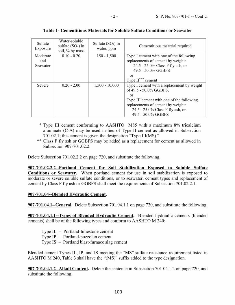
- 2 - S. P. No. 907-701-1 -- Cont’d.
Table 1- Cementitious Materials for Soluble Sulfate Conditions or Seawater
Sulfate Exposure
Water-soluble sulfate (SO4) in soil, % by mass
Sulfate (SO4) in water, ppm
Cementitious material required
Moderate and
Seawater
0.10 - 0.20 150 - 1,500 Type I cement with one of the following replacements of cement by weight:
24.5 - 25.0% Class F fly ash, or 49.5 - 50.0% GGBFS
or Type II*,** cement
Severe 0.20 - 2.00 1,500 - 10,000 Type I cement with a replacement by weight of 49.5 - 50.0% GGBFS,
or Type II* cement with one of the following replacements of cement by weight:
24.5 - 25.0% Class F fly ash, or 49.5 - 50.0% GGBFS
* Type III cement conforming to AASHTO M85 with a maximum 8% tricalcium
aluminate (C3A) may be used in lieu of Type II cement as allowed in Subsection 701.02.1; this cement is given the designation “Type III(MS).”
** Class F fly ash or GGBFS may be added as a replacement for cement as allowed in Subsection 907-701.02.2.
Delete Subsection 701.02.2.2 on page 720, and substitute the following. 907-701.02.2.2--Portland Cement for Soil Stabilization Exposed to Soluble Sulfate Conditions or Seawater. When portland cement for use in soil stabilization is exposed to moderate or severe soluble sulfate conditions, or to seawater, cement types and replacement of cement by Class F fly ash or GGBFS shall meet the requirements of Subsection 701.02.2.1. 907-701.04--Blended Hydraulic Cement. 907-701.04.1--General. Delete Subsection 701.04.1.1 on page 720, and substitute the following. 907-701.04.1.1--Types of Blended Hydraulic Cement. Blended hydraulic cements (blended cements) shall be of the following types and conform to AASHTO M 240:
Type IL – Portland-limestone cement Type IP – Portland-pozzolan cement Type IS – Portland blast-furnace slag cement
Blended cement Types IL, IP, and IS meeting the “MS” sulfate resistance requirement listed in AASHTO M 240, Table 3 shall have the “(MS)” suffix added to the type designation. 907-701.04.1.2--Alkali Content. Delete the sentence in Subsection 701.04.1.2 on page 720, and substitute the following.
103

- 3 - S. P. No. 907-701-1 -- Cont’d.
All blended cement types shall be made with clinker that would result in cement meeting the requirements of Subsection 701.02.1.2 when used in the production of AASHTO M 85, Type I or Type II cement. 907-701.04.2--Replacement by Other Cementitious Materials. Delete the paragraph in Subsection 701.04.2 on page 720, and substitute the following. The maximum replacement of blended cement Type IL by weight is 35% for fly ash or 50% for GGBFS. Replacement contents below 20% for fly ash or 45% for GGBFS may be used, but will not be given any special considerations, such as the maximum acceptance temperature for blended cement concrete containing pozzolans in Subsection 804.02.13.1.5. Special considerations shall only apply for replacement of blended cement by fly ash or GGBFS. No additional cementitious materials, such as portland cement, blended cement, fly ash, GGBFS, or others, shall be added to or as a replacement for blended cement Types IP and IS. Delete Subsection 701.04.2.1 on pages 720 and 721, and substitute the following. 907-701.04.2.1--Blended Cement Concrete Exposed to Soluble Sulfate Conditions or Seawater. When blended cement concrete is exposed to moderate or severe soluble sulfate conditions, or to seawater, cement types and replacement of cement by Class F fly ash or GGBFS shall be as follows in Table 2. Class C fly ash shall not be used as a replacement for cement in any of the sulfate exposure conditions listed in Table 2.
Table 2- Cementitious Materials for Soluble Sulfate Conditions or Seawater
Sulfate Exposure
Water-soluble sulfate (SO4) in soil, % by mass
Sulfate (SO4) in water, ppm
Cementitious material required
Moderate and
Seawater
0.10 - 0.20 150 - 1,500 Type IL (MS)* cement, Type IL cement with one of the following replacements of cement by weight:
24.5 - 35.0% Class F fly ash, or 49.5 - 50.0% GGBFS,
Type IP (MS) cement, or
Type IS (MS) cement Severe 0.20 - 2.00 1,500 - 10,000 Type IL cement with a replacement of
cement by weight of 49.5 - 50.0% GGBFS, or
Type IL (MS) cement with one of following replacements of cement by weight:
24.5 - 35.0% Class F fly ash, or 49.5 - 50.0% GGBFS
104

- 4 - S. P. No. 907-701-1 -- Cont’d.
* Class F fly ash or GGBFS may be added as a replacement for cement as allowed in Subsection 907-701.04.2.
Delete Subsection 701.04.2.2 on page 721, and substitute the following. 907-701.04.2.2--Blended Cement for Soil Stabilization Exposed to Soluble Sulfate Conditions or Seawater. When blended cement for use in soil stabilization is exposed to moderate or severe soluble sulfate conditions, or to seawater, cement types and replacement of cement by Class F fly ash or GGBFS shall meet the requirements of Subsection 701.04.2.1. Delete Subsection 701.04.3 on page 721.
105

MISSISSIPPI DEPARTMENT OF TRANSPORTATION SPECIAL PROVISION NO. 907-702-4 CODE: (IS) DATE: 09/11/2018 SUBJECT: Bituminous Materials Section 702, Bituminous Materials, of the 2017 Edition of the Mississippi Standard Specifications for Road and Bridge Construction is hereby amended as follows. 907-702.04--Sampling. Delete the sentence in Subsection 702.04 on page 722, and substitute the following. Sampling of bituminous materials shall be as set out in AASHTO R 66. 907-702.07--Emulsified Asphalt. Delete the last sentence in Subsection 702.07 on page 724, and substitute the following. Asphalt for fog seal shall conform to the requirements of Subsection 907-702.12, Table V. 907-702.12--Tables. Delete Table V in Subsection 702.12 on page 729, and substitute the following.
TABLE V SPECIFICATION FOR FOG SEAL
LD-7 CHPF-1
Test Requirements Min. Max. Min. Max. Test Method Viscosity, Saybolt Furol, @ 25°C, Sec. 10 100 - 100 AASHTO T 72 Storage Stability Test, 24 hr, % - 1 - 1 AASHTO T 59 Settlement, 5 day, % - 5 - - AASHTO T 59 Oil Distillate, % - 1 - - AASHTO T 59 Sieve Test, % * - 0.3 - 0.1 AASHTO T 59 Residue by Distillation, % 40 - 40 - AASHTO T 59 Test on Residue from Distillation
Penetration @ 25°C, 100g, 5 sec - 20 40 90 AASHTO T 49 Softening Point, °C 65 - - - ASTM D 36 Solubility in trichloroethylene, % 97.5 - - - AASHTO T 44 Elastic Recovery @ 25°C, % - - 40 - AASHTO T 301
Original DSR @ 82° (G*/Sinδ, 10 rad/sec) 1 - - - AASHTO T 111
* The Sieve Test result is tested for reporting purposes only and may be waived if no application problems are present in the field.
106

MISSISSIPPI DEPARTMENT OF TRANSPORTATION SPECIAL PROVISION NO. 907-703-1 CODE: (IS) DATE: 06/13/2018 SUBJECT: Gradation Section 703, Aggregates, of the 2017 Edition of the Mississippi Standard Specifications for Road and Bridge Construction is hereby amended as follows. 907-703.03--Course Aggregates for Hydraulic Cement Concrete. 907-703.03.2--Detail Requirements. 907-703.03.2.4--Gradation. In the table in Subsection 703.03.2.4 on page 734, add 100 for the percent passing by weight on the 1½-inch sieve for Size No. 67 aggregates.
107

MISSISSIPPI DEPARTMENT OF TRANSPORTATION SPECIAL PROVISION NO. 907-705-1 CODE: (IS) DATE: 06/13/2018 SUBJECT: Stone Riprap Section 705, Stone Blanket Protection and Filter Blanket Materials, of the 2017 Edition of the Mississippi Standard Specifications for Road and Bridge Construction is hereby amended as follows. 907-705.04--Stone Riprap. Delete the last sentence of the first paragraph of Subsection 705.04 on page 750, and substitute the following. Quality requirements for rock to be furnished under these specifications will come from a pre-approved source and be visually approved prior to use.
108

MISSISSIPPI DEPARTMENT OF TRANSPORTATION SPECIAL PROVISION NO. 907-707-2 CODE: (SP) DATE: 06/05/2019 SUBJECT: Joint Materials Section 707, Joint Materials, of the 2017 Edition of the Mississippi Standard Specifications for Road and Bridge Construction is hereby amended as follows. 907-707.02.3--Wood. Delete paragraph (b) of Subsection 707.02.3 on page 755, and substitute the following: (b) Dimensions shall be as shown on the plans Dimensions shown on the plans are “dressed”
sizes in accordance with Table 3 of the American Softwood Lumber Standard, SP-20. At the discretion of the Engineer, a 3/4-inch dressed board may be used in lieu of a 1-inch dressed board. A tolerance of plus or minus 1/16 inch thickness and plus or minus 1/8 inch width will be permitted. For slip-form paving a tolerance of minus 1/4 inch on each end in length will be permitted.
907-707.06--Flexible Plastic Gasket for Joining Conduit. Delete the third paragraph of Subsection 707.06 on page 756, and substitute the following. The Department may require the performance test described in ASTM C 990.
109

MISSISSIPPI DEPARTMENT OF TRANSPORTATION SPECIAL PROVISION NO. 907-711-2 CODE: (IS) DATE: 09/11/2018 SUBJECT: Plain Steel Wire Section 711, Reinforcement and Wire Rope, of the 2017 Edition of the Mississippi Standard Specifications for Road and Bridge Construction is hereby amended as follows. 907-711.02--Deformed and Plain Carbon-Steel Bars for Concrete Reinforcing. 907-711.02.3--Steel Welded and Non-Welded Wire Reinforcement, Plain and Deformed, for Concrete. 907-711.02.3.1--Plain Steel Wire. Delete the sentence in Subsection 711.02.3.1 on pages 780 and 781, and substitute the following. Plain steel wire and plain steel welded wire shall conform to the requirements of AASHTO M 336.
110

MISSISSIPPI DEPARTMENT OF TRANSPORTATION SPECIAL PROVISION NO. 907-720-2 CODE: (IS) DATE: 09/11/2018 SUBJECT: Acceptance Procedure for Glass Beads Section 720, Pavement Marking Materials, of the 2017 Edition of the Mississippi Standard Specifications for Road and Bridge Construction is hereby amended as follows. 907-720.01--Glass Beads. 907-720.01.4--Acceptance Procedures. Delete the last sentence of the paragraph in Subsection 720.01.4 on page 841, and substitute the following. Acceptance sampling and testing of glass beads will be in accordance with the Department’s Materials Division Inspection, Testing, and Certification Manual, Section 2.9.2 -- Glass Beads.
111

MISSISSIPPI DEPARTMENT OF TRANSPORTATION SPECIAL PROVISION NO. 907-804-6 CODE: (SP) DATE: 02/13/2019 SUBJECT: Concrete Bridges and Structures Section 804, Concrete Bridges and Structures, of the 2017 Edition of the Mississippi Standard Specifications for Road and Bridge Construction is hereby amended as follows. 907-804.02--Materials. 907-804.02.3—Non-Quality Control / Quality Assurance Concrete. Delete the third sentence of the first paragraph on page 936 and substitute the following. The Contractor is required to submit mixture designs to accomplish this work in accordance with Section 804 and perform normal Quality Control functions in accordance with Table 4, Items A and B. 907-804.02.6--Classification and Uses of Concrete. After the last class of concrete listed in Section 804.02.6 on page 938, add the following. 10) Class BDX - Concrete for bridge decks (4,500 psi) 907-804.02.10--Hydraulic Cement Concrete Mixture Design. Add the following to Table 3 in Subsection 804.02.10 on page 941.
BDX Bridge Deck 1 57 or 67 0.42-0.45 4500 5 [-2.5] 4.5±1.5 6.5±1.5
N/A
Delete footnote 1 of Table 3 in Subsection 804.02.10 on pages 941 & 942 and substitute the following.
1 An approved synthetic structural fiber meeting the requirements of Subsection 711.04 shall be incorporated into the mixture at 1.25 times the approved dosage rate. For each additional pound of fibers per cubic yard added in excess of the requirement stated above, an additional inch of slump will be allowed up to a maximum permitted slump of eight (8) inches. For Class BD, the maximum cementitious material content shall be 550 pounds per cubic yard For Class BDX, the maximum cementitious material content shall be 564 pounds per cubic yard.
Delete footnote 3 of Table 3 in Subsection 804.02.10 on page 942 and substitute the following:
3 The design slump selected by the Contractor for the mixture design approval is the maximum slump permitted.
112

-2- S.P. No. 907-804-6 –Cont’d.
Delete the last sentence of the first paragraph on page 942 and substitute the following. Other hydraulic cements may be used in accordance with the specifications listed in Section 701. Other small coarse aggregate sizes meeting the requirements of Subsection 703.03.2.4 may be used in conjunction with the coarse aggregate sizes listed in Table 3. 907-804.02.13.1.4--Yield. Delete the first sentence of Subsection 804.02.13.1.4 on page 953 and substitute the following. If the yield of the concrete mixture is more than plus or minus three percent (±3%) of the design volume, the mixture design shall be adjusted by a Class III Certified Technician representing the Contractor to yield the correct volume, plus or minus three percent (±3%). 907.804.02.13.1.7--Static Segregation. Delete the second sentence of Subsection 804.02.13.1.7 on page 954 and substitute the following. If the static segregation of the concrete mixture design exceeds this requirement, the mixture design shall be adjusted by a Class III Certified Technician representing the Contractor to ensure a static segregation in conformance with the requirement in Table 3. 907-804.03--Construction Requirements. Delete Subsection 804.03.16.1 on pages 970 & 971, and substitute the following. 907-804.03.16.1--Cold Weather Concreting. 907-804.03.16.1.1--Mixture Acceptance Temperature. For the purpose of job site acceptance temperature in accordance with Subsection 804.02.13.1.5, in cold weather, the acceptance temperature of the concrete when delivered to the job site shall conform to the temperature limitations of “Temperature Limitations on Concrete when Delivered to Job Site” listed in Table 8 below. For the purpose of job site acceptance temperature in accordance with Subsection 804.02.13.1.5, cold weather is defined as three consecutive days when there is a probability that the daily average of the highest and lowest ambient temperatures is expected to be less than 40°F. This three-day forecast shall be based on the latest information available from the National Weather Service.
TABLE 8 COLD WEATHER TEMPERATURE LIMITATIONS ON CONCRETE
WHEN DELIVERED TO JOB SITE Section thickness in the
least dimension inches
Jobsite Acceptance Temperature Range
°FLess than 12 55 to 75
12 to 36 50 to 7036 to 72 45 to 65
Greater than 72 40 to 60
113

-3- S.P. No. 907-804-6 –Cont’d.
When this definition of cold weather does not apply, there is no minimum job site acceptance temperature and the maximum job site acceptance temperature shall meet the requirements of Subsection 804.02.13.1.5. 907-804.03.16.1.2--Structural Protection. The Contractor shall assume all risk and added cost connected with the placing and protecting of concrete during cold weather. Permission given by the Engineer to place concrete during such time will in no way relieve the Contractor of responsibility for satisfactory results. Should it be determined at any time that the concrete placed under such conditions is unsatisfactory, it shall be removed and replaced with satisfactory concrete by the Contractor without extra compensation. When the Contractor proposes to place concrete during seasons when there is a probability of ambient temperatures lower than 40°F, the Contractor shall have available on the project the approved facilities necessary to enclose uncured concrete and to keep the temperature of the air inside the enclosure within the ranges and for the minimum periods specified herein. The Contractor shall assume all risk and added cost connected with the placing and protecting of concrete during cold weather. Permission given by the Engineer to place concrete during such time will in no way relieve the Contractor of responsibility for satisfactory results. Should it be determined at any time that the concrete placed under such conditions is unsatisfactory, it shall be removed and replaced with satisfactory concrete by the Contractor without extra compensation. When there are indications of temperatures of less than 40°F during the first four days after placement of the concrete, the concrete shall be protected from cold temperatures by maintaining a temperature between 50°F and 100°F for at least four days after placement and between 40°F and 100°F for at least three additional days. The Contractor shall use such heating equipment such as stoves, salamanders, or steam equipment as deemed necessary to protect the concrete. When dry heat is used, means of maintaining atmospheric moisture shall be provided. At the option of the Contractor with the approval of the Engineer, when concrete is placed during cold weather and there is a probability of ambient temperatures lower than 40°F, an approved maturity meter may be used to determine concrete strengths by inserting probes into concrete placed in a structure. The minimum number of maturity meter probes required for each structural component shall be in accordance with Table 7. An approved insulating blanketing material shall be used to protect the work when ambient temperatures are less than 40°F and shall remain in place until the required concrete strength in Table 6 is achieved. Procedures for using the maturity meter and developing the strength/maturity relationship shall follow the requirements of AASHTO T 325 and ASTM C 1074 specifications. Technicians using the maturity meter or calculating strength/maturity graphs shall be required to have at least two hours of training prior to using the maturity equipment. Before placing concrete, all ice or frost shall be removed from the forms and reinforcement. In the case of concrete placed directly on or in the ground, such as for footings or bottom slabs, protection and curing during cold weather may be provided as set for concrete pavement under Subsection 501.03.20.3. 907-804.03.16.1.3--Batching Considerations. One or more of the aggregates and/or mixing water may be heated. The aggregates may be heated by steam, dry heat, or by placing in the mixing
114

-4- S.P. No. 907-804-6 –Cont’d.
water that has been heated. Frozen aggregates shall not be used. When either aggregates or water are heated above 100°F, the aggregates and water shall be combined first in the mixer before the cement is added to avoid flash set. Cement shall not be mixed with water or with a mixture of water and aggregate having a temperature greater than 100°F. The use of salt or other chemical admixtures in lieu of heating will not be permitted. 907-804.03.17--Curing Concrete. 907-804.03.17.1--Water with Waterproof Cover. In the second sentence of the fourth paragraph of Subsection 804.03.17.1 on page 973, delete the word “due”. Delete the first sentence of the fifth paragraph of Subsection 804.03.17.1 on page 973, and substitute the following. The Contractor shall maintain the burlap in a fully wet condition using powered fogging equipment, such as a commercially available pressure washer, which is capable of producing a fog spray of atomized droplets of water (i.e., producing a very fine and gentle mist that looks like a foggy morning) until the concrete has gained sufficient strength to allow foot traffic without the foot traffic marring the surface of the concrete. In the second sentence of the eighth paragraph of Subsection 804.03.17.1 on page 973, replace the word “like” with “such as”. 907-804.03.17.1.2--Liquid Membrane. In the first sentence of the first paragraph of Subsection 804.03.17.1 on page 973, replace “polyethylene sheets” with “white polyethylene sheets.” 907-804.05--Basis of Payment. Delete the first and second pay items listed on page 999, and substitute the following. 907-804-A: Bridge Concrete, Class _____ - per cubic yard 907-804-B: Box Bridge Concrete, Class _____ - per cubic yard
115

MISSISSIPPI DEPARTMENT OF TRANSPORTATION SPECIAL PROVISION NO. 907-808-1 CODE: (SP) DATE: 11/01/2018 SUBJECT: Joint Repair Section 808, Joint Repair, of the 2017 Edition of the Mississippi Standard Specifications for Road and Bridge Construction is hereby amended as follows. 907-808.04--Method of Measurement. Delete the paragraph in Subsection 808.04 on page 1009, and substitute the following. When a pay item is included in the plans, joint repair will be measured by the linear foot and mortar mix will be measured by the gallon. The volume of measurement for the epoxy/sand mortar mix will be determined from the summation of the volumes of the epoxy components and the volume of sand will not be measured for payment. 907-808.05--Basis of Payment. Delete the paragraph in Subsection 808.05 on page 1009, and substitute the following. When a pay item is included in the plans, joint repair, measured as prescribed above, will be paid for at the contract unit price per linear foot, which price shall be full compensation for furnishing and placing all materials, labor, tools, equipment, and all incidentals necessary to complete the work. When a pay item is included in the plans, mortar mix, measured as prescribed above, will be paid for at the contract unit price per gallon, which price shall be full compensation for furnishing all materials including sand and forming materials, and all incidentals necessary to complete the work. No payment will be made for the sand used in the epoxy mortar mix. The price bid for each item of work shall include the cost of continuous maintenance of traffic and protective services as required by the Department's Traffic Control Plan. This shall include all required individual traffic control devices. Payment will be made under: 907-808-A: Joint Repair - per linear foot 907-808-B: Mortar Mix - per gallon
116

117
118

119

120

121

122

123
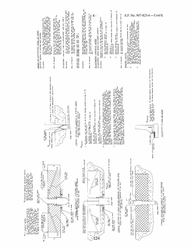
124

125

126

127

MISSISSIPPI DEPARTMENT OF TRANSPORTATION SPECIAL PROVISION NO. 907-850-1 CODE: (SP) DATE: 08/07/2019 SUBJECT: Mechanical Construction for Movable Bridges PROJECT: BR-9385-00(017) / 107705301 -- Jackson County Section 907-850, Mechanical Construction for Movable Bridges, is hereby added to and made a part of the 2017 Edition of the Mississippi Standard Specifications for Road and Bridge Construction as follow.
SECTION 907-850--MECHANICAL CONSTRUCTION FOR MOVABLE BRIDGES 907-850.01--Description. 907-850.01.1--General. The intent and purpose of this work is to cover apparatus, material and labor required to properly detail, manufacture, ship, install, adjust, test, paint and put into approved working order all Mechanical parts of the movable bridge. Dimensions given on the plans are nominal and intended for guidance. Note any variations from nominal dimensions on the Contract Plans. The definitions below only apply to this work.
A. Alignment Wire (see also Trunnion Reference Centerline): Usually piano wire used for checking trunnion alignment.
B. Bascule Span: All structural, mechanical and electrical elements of the movable span, including the Bascule Leafs, and all associated trunnion bearings, machinery, power and control systems.
C. Bascule Leaf: The movable portion of the roadway and sidewalk deck and its supporting elements, including the Bascule Girders, floor beams, brackets, barriers, hand rails, roadway deck, sidewalk deck, counterweight, trunnions, and appurtenances which rotate about the trunnion axis during operation.
D. Bascule Girder or Main Girder: The main longitudinal load carrying members of the Bascule Leaf (steel girders).
E. Counterweight: The weight provided to balance the leaf including the steel box, counterweight concrete and associated reinforcing steel.
F. AASHTO Movable Specifications: AASHTO LRFD Movable Highway Bridge Design Specification, 2nd Edition, (2007) with all Interim Revisions.
G. Blend: A smooth transition between surfaces with a slope less than or equal to 1:3. H. Centerline Trunnion (Trunnion Centerline): The theoretical axis of rotation of the Bascule
Leaf. I. Outboard Centerline Bore: The location of the axial centerline of the bore of the trunnion
shaft at the intersection of the centerline of the bore with the plane of the outboard face (at
128

- 2 - S. P. No. 907-850-1 -- Cont’d.
the bearing) of the trunnion shaft. J. Inboard Centerline Bore: The location of the axial centerline of the bore of the trunnion
shaft at the intersection of the centerline of the bore with the plane of the inboard face (at trunnion girder) of the trunnion shaft.
K. Trunnion Axis of Rotation: The datum axis that passes through the Outboard Centerline Bores of the two trunnion shafts for an assembled leaf in the field.
L. Established Axis of Rotation: The datum axis physically established as the correct axis of rotation in the field for each leaf; axis is physically established and maintained for the duration of the erection and alignment of the bascule leaf.
M. Stressing Weight: The weight hung vertically at the ends of alignment wire for physically establishing datum axes in the field; the Stressing Weight is a weight determined by the Millwright utilizing a specified calibration procedure.
N. Trunnion Reference Centerline: The physical reference line for the centerline trunnion established during fabrication and erection, also referred to as the alignment wire.
O. Tight Integration (Well Integrated): The methods, practices, techniques, standards, and procedures by which a seamless hardware, software, electrical, mechanical and structural interfacing of electrical sub-systems, hydraulic sub-systems, mechanical sub-systems and structural components is provided. Tight integration is determined (in part) by the Engineer through submittals, shop testing of complete systems and sub-systems, shop drawings, and incidental items as required by the Engineer. Provide a complete movable bridge system that is reliable, repeatable, and free of anomalies and intermittent operation as determined by the Engineer.
P. Balanced Leaf Condition: The condition where an individual leaf is within the acceptable limits required by the provisions of this Section for maintaining the balance state during the course of construction or the final balance state, as applicable.
Q. Unstable Leaf: 1. Condition No.1 - Tail Heavy: The condition where a leaf is not balanced and the leaf due
to the unbalanced condition will rotate to the open position (tail heavy). 2. Condition No. 2 - Tip Heavy: The condition where a leaf is not balanced and the leaf due
to the unbalanced condition will rotate to the closed position (tip heavy). R. Running Condition: Condition where the combination of span position (rotated position) and
an unstable leaf condition would result in the span running (rotating) if; 1. The ability of the hydraulic cylinders or mechanical drive to sustain load is
compromised by detached hydraulic cylinders, disconnected or inoperable fluid circuitry, or disconnected or inoperable brakes; and
2. The span is not externally anchored to prevent rotation (tied down). S. Tie-Down Device (see Special Provision 907-851):
1. External applied anchoring device that prevents rotation of the span. 2. Applied to resist turning moments as a result of:
a. Imbalance in counterweighing; b. Wind loads.
3. Structurally, a tension member, a compression member or combination as applicable to the position of the span and the type of turning moment.
T. Imbalance Moment: Imbalance moment is the moment caused by the eccentricity of the weight of the leaf about the center of rotation of the leaf, excluding trunnion friction.
907-850.01.2--Integration. Coordinate hydraulic, electrical and mechanical equipment, systems
129

- 3 - S. P. No. 907-850-1 -- Cont’d.
and sub-systems integration with structural components and disciplines. Variable Speed Drives (VSD), DC Drives, Hydraulic Power Units (HPU), Hydraulic Power Unit Control Panels (HPUCPs), Uninterrupted Power Supplies (UPSs), inclinometers, gearboxes, cylinders, and piping, become the basic critical motion and control system for each leaf. Provide tight integration between all elements of the critical systems as well as with non-critical systems such as CCTV systems. Quality Assurance. Supervisory and Technical Personnel
A. Provide Supervisory Erector, Supervisory Fabricator, Millwrights and Technical. Representatives in accordance with the provisions of this Special Provision.
B. Supervisory Mechanical System Engineer: 1. Include a Mechanical Systems Engineer, in accordance with MDOT Specifications as
part of the field crew. Their responsibilities include, but are not limited to, attending meetings related to mechanical issues, reviewing mechanical submittals, supervision of mechanical systems field installations, and coordination of mechanical aspects with the structural, electrical and architectural interfaces.
2. The Mechanical Systems Engineer must be a registered Professional Engineer licensed in the State of Mississippi, through examination taken in the mechanical engineering discipline.
C. Supervisory Erector: For field erection and alignment of structural steel for the bascule leafs and piers, utilize a competent supervisory erector with a minimum of twenty years of experience in the erection of structural steel for (1) movable bridges, or (2) of similar size, type and character. Supervisory erector is to be present for the full duration of all field assembly and erection operations; the individual approved by the Engineer as acceptable is designated as the Supervisory Erector. For alignment and installation procedures for structural steel, have Supervisory Erector initial all submittals.
D. Millwrights (General): For field installation and alignment of machinery components and other designated components required under the provisions of the Contract Documents, utilize millwright(s), with a minimum of ten years of experience in the assembly and alignment of large diameter trunnion shafts, and installation of large diameter bronze sleeve bearings and housings for (1) movable bridges, or (2) machinery of similar size, type and character. Millwright(s) to be present for the full duration of all field installations.
E. Supervisory Millwright: Utilize approved supervisory millwright for the supervision of field alignment and installation of the machinery and other designated work to be provided under the provisions of the Contract Documents: Individual who is a millwright by trade, who will supervise the alignment and installation of the machinery components to be field installed. Supervisory millwright is to have a minimum of ten years of the above stated General Millwright experience.
F. Millwrights: Utilize approved millwright(s) for field alignment and installation of the machinery and other designated work to be provided under the provisions of this Section and the Contract Documents. For alignment and installation procedures for machinery components, have Supervisory Millwright installation of the machinery components installed in the field, under the provisions of this Section.
G. Designated Machinery Manufacturer: Have an authorized technical representative of the designated machinery manufacturer:
130

- 4 - S. P. No. 907-850-1 -- Cont’d.
1. Verify and approve the acceptability of field assembly and installation procedures of
machinery components. 2. Verify and approve the acceptability of field assembly and installation of machinery
components. 3. Provide written report directly to Engineer listing observations, recommendations and
acceptability of installations.
Submittals for Supervisory and Technical Personnel. Submit qualifications for supervisory and technical personnel according to the requirements of MDOT Specification. 907-850.01.3--Working Plans and Shop Drawings. Provide Shop Drawings in accordance with MDOT Specifications, including but not limited to:
A. Submit detailed written installation procedures for all machinery components. The procedure shall include sequence of installation, alignment methods, bolt tightening methods and torque values for all bolts.
B. Detail and accurately dimension all parts, indicate limits of accuracy and tolerances required for machining, surface finishes and allowances for fits. Unless otherwise called for, provide the fits and finishes in accordance with ANSI B46.1 and ANSI B4.1.
C. Provide detail and assembly drawings, together with an outline drawing, for all operating machinery and parts. Ensure the drawing contains all information necessary for computing the strength of the machinery parts. Provide sufficiently detailed drawings to permit the duplication of the machinery parts by others, including assembly and disassembly instructions. Show the estimated weights of individual parts and total weights of all parts in the details for machinery and castings.
D. Submit machinery assembly shop drawings before submitting shop drawings for individual components. All assembly drawings shall contain both plan and elevation views of the assembly withdrawn and dimensioned references of machinery and structural components mating to and surrounding the assembly. Include dimensions from the assembly to the edges and centerlines of these references as necessary to display no interferences. Detail elevation marks on assembly drawings including but not limited to centerline of shafts and interfaces between machinery and structural members.
E. Include in submittals for each manufactured item manufacturer’s descriptive literature, drawings, diagrams, performance and characteristic curves, and catalog cuts, and include the manufacturer’s name, trade name, catalog model or number, nameplate data, size, certified layout dimensions, capacity, specification reference, including ASTM, ANSI, and any other applicable references, and all other information necessary to establish Contract compliance.
F. Provide complete shop bills of materials for all machinery parts. If the bills are not shown on the shop drawings, furnish prints of the bills in the same manner as specified for the drawings.
G. State the material and material specifications for each part. Where ASTM Specifications or any of the Standard Specifications are used, give the designating numbers of such specification.
H. Furnish complete assembly and erection drawings. Indicate identifying marks, match marks and essential dimensions for locating each part or assembled unit with respect to the bridge or equipment foundation. Cross-reference every part to the drawing sheet on which it
131

- 5 - S. P. No. 907-850-1 -- Cont’d.
is detailed. Clearly show and detail marks or indentations of any type on the drawings. In general, avoid die stamping or scoring unless otherwise called for on the Contract Documents. Detail all components and assemblies separately to assure correct fabrication, assembly, and erection. Do not use mirror image or opposite hand drawings.
I. Dimension fastener locations to the centerlines of machinery components. J. Clearly indicate and accurately detail minimum and maximum tolerances for all
dimensions requiring a fit. Verify the maximum and minimum clearance and interference between mating components for all fits do not exceed the specified standard limits.
K. Clearly differentiate any dimensions that are prior to machining from final dimensions. Provide a final dimension for any dimension that is prior to machining.
L. Give each shop drawing a suitable title to describe the parts detailed therein. M. Where equipment or materials are specified to conform to requirements of the standards of
an organization such as American Society of Mechanical Engineers (ASME), Underwriters Laboratories (UL), American Gas Association (AGA), and American Refrigeration Institute (ARI), which use a label or listing as method of indicating compliance, submit proof of such conformance for review. The label or listing of the specified organization will be acceptable evidence. In lieu of the label or listing, submit a certificate from an independent testing organization adequately equipped and competent to perform such services and approved by the Department, stating that the item was tested in accordance with the specified organization’s test methods and that the item conforms to the specified organization’s standard or code.
N. As used herein, certified test reports refer to reports of tests conducted on previously manufactured materials, or equipment identical to that proposed for use.
O. As used herein, factory tests refer to tests performed on the actual materials or equipment proposed for use. Submit results of the test in accordance with provisions of the Contract Documents for laboratory test results.
907-850.01.4--Contractor Responsibility for Accuracy and Coordination of Shop Drawings. Coordinate, schedule, and control all submittals, with a regard for the required priority, including those of the various subcontractors, suppliers, and engineers, to provide for an orderly and balanced distribution of the work. Coordinate, review, date, stamp, approve and sign all shop drawings prepared by the Contractor or agents (subcontractor, fabricator, supplier, etc.) prior to submitting them to the Engineer of Record for review. Submittal of the drawings confirms verification of the work requirements, units of measurement, field measurements, construction criteria, sequence of assembly and erection, access and clearances, catalog numbers, and other similar data. Indicate on each series of drawings the specification section and sheet or drawing number of the Contract Plans to which the submission applies. Indicate on the shop drawings all deviations from the Contract drawings and itemize all deviations in the letter of transmittal. Likewise, whenever a submittal does not deviate from the Contract Plans, clearly state so in the submittal. Schedule the submission of shop drawings to allow for a 45 day review period. The review period commences upon the Engineer of Record’s receipt of the valid submittal or valid re-submittal and terminates upon the transmittal of the submittal back to the Contractor. A valid submittal includes all the minimum requirements outlined in these Special Provisions.
132

- 6 - S. P. No. 907-850-1 -- Cont’d.
Submit shop drawings to facilitate expeditious review. The Contractor is discouraged from transmitting voluminous submittals of shop drawings at one time. For submittals transmitted in this manner, allow for the additional review time that may result. Only shop drawings distributed with the approval stamps are valid and all work that the Contractor performs in advance of approval will be at the Contractor’s risk. Do not take advantage of any apparent error or omission discovered in the Contract Documents, but immediately notify the Engineer in writing of such discovery. The Engineer will then make such corrections and interpretations as necessary to reflect the actual spirit and intent of the Contract Documents. 907-850.01.5--Construction Requirements. Construct in accordance with the Contract documents and the applicable provisions of the AASHTO Movable Bridge Specifications. Where a conflict exists between documents, the requirements of the Plans and this Special Provision governs over those of the AASHTO Movable Bridge Specifications. Ensure that, unless specified in the Plans or herein, dimensions between machined surfaces have a tolerance of 0.010-inch and machined surfaces have a flatness tolerance of 0.010-inch. Design and construct temporary members in accordance with the provisions of MDOT Specifications. 907-850.01.6--Notification of Shop Work. Comply with MDOT Specifications. 907-850.02--Material Requirements. 907-850.02.1--General. Comply with the following requirements: Material Compatibility. Provide products that are compatible with other products of the mechanical work, and with other work that requires interface with the mechanical work, including mechanical/electrical connections and control devices. Nameplates. Provide each piece of mechanical equipment and apparatus with a permanent, corrosion- resisting metal nameplate stamped with the name of the manufacturer’s name and address, the catalog or model number, serial number, and the rating or capacity of the equipment or apparatus securely affixed in a conspicuous place. Include a detail for all nameplates on the corresponding shop drawing with all available information clearly shown as text on the nameplate in the proper location. Shop Inspection and Testing. Comply with the requirements of MDOT Specifications. Use materials that conform to the current ASTM specifications. An alternative material may be requested in writing; the request must provide complete data justifying suitability of the alternate materials and must be approved by the Engineer prior to initiating fabrication or construction. 907-850.02.2--Shafting and Pins. Shafting and pins shall comply with the following:
A. Rolled material is acceptable for shafting and pins up to 4-inch diameter. Use forgings for
133

- 7 - S. P. No. 907-850-1 -- Cont’d.
larger diameter shafts and those having integral flanges or pinions. Homogeneity of forgings is required. Reduce shafts to size from a single bloom or ingot at no less than red heat. Ensure the blooms or ingots have a cross section area at least three times the required finish product. Ensure that the finished product is free of injurious flaws such as seams, pipes or cracks. Provide forged shafts over 8-inches in diameter with a hole bored lengthwise through the center, about 1/5 the diameter of the shaft.
B. Provide all shafts and pins with accurate finishes and ample radii at fillets. Ensure they are round, true, smooth and straight, and have round fillets at shoulders.
C. Test and certify that finished shafts are free of camber and run without vibration, noise or chatter at all speeds up to, and including, 120% of design speed.
D. Furnish shafts conforming to tolerances in ASTM A29 unless otherwise indicated. Ensure that turned, ground and polished shafting straightness tolerances do not exceed 0.002-inch per foot for shafts up to and including 1½-inch in diameter and 0.003-inch per foot for shafts over 1½-inch in diameter.
E. Provide each end of all shafts, when finished to the required lengths, with a 60 degree lathe center, with clearance hole, at the exact center of the shaft. Prepare the ends of shafts that are bored with an inspection hole for the attachment of a centering device equivalent to the lathe center. Furnish all such devices as part of the work.
F. Blend in stepped shafts fillets smoothly to adjacent surfaces without tool marks or scratches. Unless otherwise required herein or on the drawings to have a finer finish, ensure the surfaces have an ANSI maximum roughness of 16 micro inches.
G. Ensure all hubs mounted on the ends of cold-finished shafts have the fit specified herein or on the Plans. To obtain the required fit between hub and shaft, furnish the cold-finished shaft 0.006 inch larger than the nominal diameter specified and turn the ends to the required dimension for the hub. Furnishing any cold-finished shaft of one diameter end to end is permitted if the shaft has tolerances selected from the normal manufacturing range to provide the specified fit. Show the selected tolerances on the shop drawings.
H. Accurately machine and polish all journal-bearing areas on shafts and pins, with no trace of tool marks or scratches on the journal surface or adjoining shoulder fillets.
907-850.02.3--Castings. Castings shall comply with the following:
A. Provide castings that conform to AASHTO Requirements. B. Ensure all castings are free of cracks, cold shuts, shrink holes, blow holes, porosity, are free
of loose scale and sand, fins, seams, gates, risers and other irregularities. Cast unfinished edges of castings neatly with rounded corners with inside angles having ample fillets.
C. Perform in the manufacturer’s shop, for each casting:
1. Visual surface examinations per ASTM A802 with Level II as the Acceptance Criteria. Linear discontinuities, cracks and tears are not permitted. Castings with test records meeting Level III may be considered for weld repair. All other discontinuities are unacceptable.
2. Liquid Penetrant exams in accordance with ASTM E165 or Magnetic Particle exams (100%) in accordance with ASTM E709 with an acceptance criteria per ASTM E125. The Acceptance Criteria, as to the Type of Discontinuity and the Degree for acceptance, will be as follows:
134

- 8 - S. P. No. 907-850-1 -- Cont’d.
Type I Cracks/Hot tears 3/16” Maximum Type II Shrinkage Degree 3 Type III Inclusions Degree 3 Type IV Chaplets Degree 2 Type V Porosity Degree 1
Surface discontinuities may be considered for weld repair.
3. Ultrasonic exams in accordance with ASTM A609. All castings with solid sections of 4 inches thick or greater shall meet ASTM A609, Method A, Quality Level 3. Castings that do not pass this test will be rejected. Submit test results, whether positive or negative, to the Engineer.
4. Castings that do not pass each of the above tests against the respective acceptance criteria may be rejected. Submit all test results, whether positive or negative, to the Engineer, as Certified Test Reports. Test Reports showing Quality Levels and Degrees of Discontinuities higher than those that may be considered for weld repair shall be cause for rejection, and such castings will not be considered for weld repair.
D. Using ASTM Practice A802M, identify and remove unacceptable surface discontinuities. E. Cast phosphor bronze castings into ingots and allow to cool, pour the casting from the
re-melted ingots. Furnish the chemical analysis of each heat, and ensure no alloy contains any more than 0.08% sulphur. Perform physical tests in accordance with ASTM B22 Specification, and in addition, record the permanent set under a load of 350 psi for bearings. Cracks or other evidences of brittleness in compression test specimens after testing will be cause for rejection.
F. Suspend large castings and hammer all over. G. Repair steel castings that develop cracks, flaws or other defects during hammering or
from any other cause. The Engineer must approve Weld repair, after start of machining and/or assembly. Ensure all repairs conform to the required ASTM procedure.
H. If weld repair is approved by the Engineer following a review of the test results, submit detailed weld procedures, including a means to qualify the weld repair. Obtain approval from the Engineer before making any weld repairs. Perform weld repairs per ASTM A488 or equivalent, and radiographic examination of welds per ASTM E94.
907-850.02.4--Forgings. Provide forgings that conform to AASHTO Specifications for Movable Bridges. Perform, in the manufacturer’s shop, for each forging:
A. Liquid Penetrant exams in accordance with ASTM E165 or Magnetic Particle exams in accordance with ASTM A275 and ASTM E709. Acceptance criteria of ASTM A788, Supplementary Requirements S18 and S19, shall apply.
B. Ultrasonic exams in accordance with ASTM A388. Acceptance criteria of ASTM A788, Supplementary Requirement S20, Level BR and Level S, shall apply.
C. Radiographic exams in accordance with ASTM E94. Submit test results to Engineer. D. Stress relieve dimensionally critical components that have been rough machined.
907-850.02.5--Welding. Welding shall comply with the following:
135
- 9 - S. P. No. 907-850-1 -- Cont’d.
A. Ensure that welding required or designated in the Contract Documents conforms to the American Welding Society (AWS) Specifications. Inspect all weldments utilizing Ultrasonic Testing or Radiographical Testing as per ASTM E164 and AWS D1.5. Stress relieve all shop welds. Submit shop drawings that include procedures for field structural welding with inspection requirements stipulated in the Contract Documents for approval prior to start of welding. Do not machine components until after welding and stress relieving.
B. Include a certified copy of a test report showing the chemical composition of the specific steel piece(s) to be welded in any welding procedure involving attachment to existing steelwork. Consider this chemical composition in the welding procedure.
C. Ensure all welding required or designated in the Contract Documents conforms to the appropriate AASHTO and American Welding Society (AWS) Specifications for the material being welded.
D. Perform welding of steel in accordance with the ANSI/AASHTO/AWS D1.5 Bridge Welding Code. E. Groove welds to be complete joint penetration groove welds (CJP).
F. Ensure the fitting up and welding procedure is such that distortion of the work will be a minimum. If necessary to obtain this result, use suitable welding fixtures. Unless otherwise specifically stated, stress relieving is required for welded machinery parts prior to final machining.
G. Inspect all welds utilizing non-destructive tests (i.e., via dye penetrant checks) supported by Ultrasonic Testing or Radiographical Testing as required by the AASHTO/AWS D1.5 Bridge Welding Code or the Contract Documents. Unless otherwise noted, herein or in the Plans, perform 100% magnetic-particle inspection of fillet welds and partial penetration welds of machinery weldments.
H. Submit, in shop drawing form (i.e., with inspection requirements stipulated in the General Notes of the Drawing), procedures for structural welding to be permitted in the field, for approval, before welding is begun.
I. Do not paint welded components until welds are inspected and approved. 907-850.02.6--Shop Assembly Operations. Shop assemble machinery components to verify their correct fit prior to shipment. Give the operating machinery four hours test run, two hours in each direction. Furnish a motor to perform this test at normal operating speeds. The Engineer will witness this test. Disassemble components not mounted in a common base for shipment. Match mark any components requiring selective assembly for future assembly. 907-850.02.7--Fasteners. Fasteners shall comply with the following:
A. Provide all bolts for connecting machinery parts to each other and to supporting members as shown in the Contract Documents and conform to one of the following types, as specified in the Plans: 1. High-strength structural bolts. 2. High-strength turned bolts, turned cap screws, and turned studs.
B. High-strength Structural Bolts 1. Shall meet the requirements of ASTM F3125 Grade A325. Ensure hole for the structural
bolt is no larger than 1/16” over the nominal diameter of the bolt. 2. Use nuts that conform to ASTM A563 or A194, Grade DH or 2H, heavy hex series.
C. High-strength Turned bolts, cap screws, and studs. 1. Turned fastener shall meet the requirements of ASTM A449. 2. Use only high strength bolts with heavy hexagonal heads. Wherever possible, install
136

- 10 - S. P. No. 907-850-1 -- Cont’d.
high-strength bolts connecting machinery components to structural elements or to other machinery components comprised of different thicknesses so that the bolt head is adjacent to the connected element with the least thickness.
3. Furnish high-strength turned bolts, turned cap screws, and turned studs with turned shanks and cut threads. Ensure all finished shanks of turned fasteners are 0.060-inch larger in diameter than the diameter of the thread, which determines the head and nut dimensions.
4. Ensure the shanks of all turned fasteners have a LC6 fit in the finished holes in accordance with ANSI B4.1. Provide an LC1 fit with the pinion pillow block bearing mounting bolts and mating finished holes in the bearing feet and corresponding support plates.
5. Drill or ream-assemble all elements connected by bolts to assure accurate alignment of the hole and accurate clearance over the entire length of the bolt within the specified limits.
6. Use nuts that conform to ASTM A563 or A194, Grade DH or 2H, heavy hex series. Provide heavy series heads and nuts for turned bolts, screws, and studs.
7. Provide bolt heads, nuts, castle nuts, and hexagonal head cap screws dimensioned in accordance with ANSI B18.2.1, Hexagon Bolts and ANSI B18.2.2 Nuts.
8. Ensure the dimensions of socket-head cap screws, socket flathead cap screws, and socket- set screws conform to ANSI B18.3. Provide screws made of heat-treated alloy steel, cadmium-plated, and furnished with a self-locking nylon pellet embedded in the threaded section. Unless otherwise called for on the Contract Documents or specified herein, provide setscrews of the headless safety type with threads of coarse thread series and cup points. Do not use setscrews to transmit torsion nor as the fastening or stop for any equipment that contributes to the stability or operation of the bridge.
9. Unless otherwise called for, sub drill all bolt holes in machinery parts at least 1/16 inch smaller in diameter than the bolt diameter and ream assemble for the proper fit at final assembly or at erection with the steel work after the parts are correctly assembled and final aligned.
D. Provide cap screws with threads that conform to the coarse thread series and have a Class 2A tolerance. For bolts and nuts, ensure the bolts conform to the coarse thread series and have a Class 2A tolerance. Furnish Class 2B nuts in accordance with ANSI/ASME B1.1.
E. Spot face bolt holes square with the axis of the hole. F. Do not use different size bolts when connecting components (i.e., gearbox to pedestal,
bearing to pedestal). If a hole is over drilled requiring a bigger bolt, then furnish all bolts of the bigger size.
G. Provide cotters that conform to SAE standard dimensions and are made of half-round stainless- steel wire, ASTM A276, Type 316.
H. Dowel Pins: Unless otherwise specified or shown on the Plans, provide dowel pins in accordance with ANSI B 18.8.2. Provide unhardened dowel pins with minimum shear strength of 64 ksi. Dowel pins installed into enclosed part shall have a groove or a flat machined on the cylindrical surface for air release.
907-850.02.8--Undercut Anchors. Where specified in the Plans, anchor machinery bases to the machinery floor using undercut anchors. Provide undercut anchors of length and diameter as indicated in the Plans. No matter is if an embedment length is specified, calculate the required length based on the information provided and the site-specific conditions. Specify undercut anchor
137

- 11 - S. P. No. 907-850-1 -- Cont’d.
to resist applied loads through bearing on the surface of the conical portion of the drilled hole. Do not use wedge or sleeve anchors that rely on friction to resist applied loads at these locations. Design for maximum forces generated in starting or stopping the leaf plus 100% impact. Anchors must be capable of developing the tensile capacity of the bolt without slip or concrete failure. Design the conical undercut and the nut to transfer the bolt tension into direct bearing stress between the conical nut and expansion sleeve and the expansion sleeve and conical concrete surface. Unless otherwise specified, provide undercut anchors fabricated from the following materials:
Bolt ...................................ASTM A193 Grade B7 Sleeve ...............................ASTM A512 Type 5 Conical Nut ......................ASTM A193 Grade B7 Heavy Hex Nut ................ASTM A194 Grade 2H Washer ASTM F436
Provide zinc-plated components in accordance with ASTM B633 Type II. 907-850.02.9--Adhesive Anchors. Where specified in the Plans, anchor machinery bases to the machinery floor using adhesive anchors. Provide adhesive anchors of length and diameter as indicated in the Plans. When no length is specified, calculate the length based on the information provided and the site-specific conditions. Anchor steel rods should have a 45 deg chisel or cut point at end. Unless otherwise specified, provide adhesive anchors fabricated from the following materials:
All Threaded Steel Rod ............................. ASTM A193 Grade B7 Heavy Hex Nut ......................................... ASTM A194 Grade 2H Washer ...................................................... Stainless Steel Type 316 Adhesive Resin ......................................... Vinyl Urethane Methacrylate
907-850.02.10--Keys and Keyways. Conform the dimensions and tolerances for square and flat keys to ANSI B17.1, unless otherwise specified. Effectively hold in place all keys, preferably by setting them into closed-end keyways milled into the shaft. Round the ends of all such keys to a half circle of diameter equal to the width of the key. Round the inside corners. Do not extend keyways into any bearing. If two keys are used, locate them 120 degrees apart. Unless otherwise specified herein or in the drawings, machine keys from steel forgings, ASTM A668, Class N. Cold finished carbon steel meeting the requirements of ASTM A108 Grade 1045 may be used for small keys, carrying light loads, which connect electrical components. 907-850.02.11--Flexible Couplings. Flexible couples shall comply with the following:
A. Connect electric motors to machinery components using grid-type, self-aligning, fully flexible, torsionally flexible couplings unless otherwise indicated in the Contract Documents.
B. Other than for connecting electric motors to machinery components, provide all-metal, flexible, positive engagement gear type couplings, unless otherwise indicated in the Contract Documents, capable of accommodating misalignment between the shafts without
138

- 12 - S. P. No. 907-850-1 -- Cont’d.
introducing bending into the shafts, and with provisions for introducing lubricant to all contact surfaces.
C. Provide manufacturer-machined couplings that are finish-bored and with keyways cut to limits specified on the shop drawings. Install coupling halves on reducer shafts and other shafts as per the coupling manufacturer’s installation instructions. Provide coupling-shaft fits that conform to ANSI B4.1, preferred FN2 medium drive fit.
D. Use gear-type, self-aligning, full-flexible couplings or semi-flexible couplings with floating shafts to connect all machinery components, except where other types of couplings are called for on the drawings. Provide couplings with shrouded bolts.
E. Use gear-type couplings made of forged steel, with curved face teeth, and provision for at least a plus or minus 3/4 degree misalignment per gear mesh.
F. Use grid-type couplings, self-aligning, flexible (in bending and torsion) to connect electric motors to machinery components.
G. Provide grid-type couplings with steel hubs, alloy steel grids, and steel or aluminum covers. Provide shrouded cover bolts.
H. Provide couplings that are standard products of an established manufacturer. I. Indicate manufacturer maximum bore diameter for all coupling shop drawings. J. Provide machined coupling hub boring, including key ways, to the required size and
tolerances. K. Ship each hub to the proper location for installation on its shaft by the manufacturer of the
connected component. L. Provide special couplings as shown on the Plans.
907-850.02.12--Bushings. Provide split type bushings on machinery shafts, and mount to base and cap. Provide an ANSI B4.1 Class LC1 clearance location fit between bushing outside diameter and housing. Provide the same fit between flanges and the end faces of the base and cap of double flanged bushings. Fit bores with shaft journals to achieve an ANSI B4.1 Class RC6 running fit. Turn bushings with a predetermined gap between halves to suit the liner or shim thickness. Provide in the total thickness of liners in each bushing set at least 1/8-inch laminated construction, permitting adjustment in increments of 0.003-inch. Cut liners to fit shoulder fillets, square with bushing flanges, and with bolt holes drilled through them. Provide bushings with spiral grease grooves such that the grooves intersect at the center of each bushing half. Provide all grease lubricated bronze bushings 8-inch in diameter or less with grease grooves cut in a spiral pattern for the full length of half the bearing, unless otherwise shown on the contract documents. Machine cut all grease grooves smooth. Provide corners of all grooves 0.315-inch wide at the bearing surface and rounded to a 0.16-inch radius, unless otherwise shown on the Plans. Provide one-piece bronze sleeve solid bushings, where required in the Contract Documents, with spiral cut lubrication grooves. Provide a Class FN1 light drive fit or FN2 medium drive fit, ANSI B4.1, between the bushing OD and housing (as specified elsewhere). Fit bores with the shaft to achieve an RC6 fit. In cases of solid or split bushings required to support axial loads, provide the flanges with grease grooves connected to the grooves in the bushing bore. Provide lubricant fittings for both new and reconditioned parts.
139
- 13 - S. P. No. 907-850-1 -- Cont’d.
907-850.02.13--Pillow Blocks and Bearings. Select anti-friction bearings for L-10 life (as defined by the AFBMA) at which 90% of a group of bearings will survive the identical loading conditions) of 40,000 hours for the ratings shown in the Contract Documents. Provide adaptor mounting, self-aligning expansion and non-expansion type pillow block and flange- mounted roller bearings as indicated in the Contract Documents. Provide housings capable of withstanding the design radial load in any direction, including uplift. Cast bases without mounting holes. Drill mounting holes from the solid at assembly with the supporting steel work. Provide seals that will retain the lubricant and exclude water and debris. Provide high-strength steel cap bolts on pillow blocks. Provide cap and cap bolts capable of resisting the rated bearing load as an uplift force. Provide all new pillow blocks with a tapped hole and a lifting eyebolt of sufficient capacity to carry twice the estimated weight of the bearing assembly. Clearly indicate the load rating for all bearings on the bearing shop drawings. 907-850.02.13.1--Plain Spherical Bearings. Where required, provide plain spherical bearings of the self-aligning type that are sized to meet L-10 life (as defined by the AFBMA at which 90% of a group of bearings will survive the identical loading conditions) of 40,000 hours under the power requirements defined in AASHTO Movable Bridge Specifications or shown in the Plans. Machine all pins and attachments to the dimensions and tolerances specified by the Bearing Manufacturer. Unless otherwise indicated in the Contract Documents, provide all plain spherical bearings with a means for grease lubrication and lip seals to retain the lubrication and guard the spherical surfaces from contamination. 907-850.02.13.2--Spherical Roller Bearings. Where required, provide spherical roller bearings manufactured in accordance with AFBMA Roller Bearing Engineering Committee (RBEC). Provide bearings of the size, type and mounting configuration shown in the Plans. Bearing and bearing housing materials are determined by the Bearing Manufacturer in accordance with applicable specifications and the design loads shown in the Plans. Unless otherwise indicated, provide anti- friction bearings selected for L-10 life of 40,000 hours for the configuration shown on the Plans. Include in bearing submittals calculations verifying bearing capacity, L-10 life, cap bolt and bearing housing capacity, and recommended maintenance, installation, and lubrication procedures. Seal bearing lubrication cavities with labyrinth type seals around shaft. Provide pillow blocks manufactured by the same manufacturer as the roller bearing. 907-850.02.13.3--Dry Sliding Bearings. Where required, provide dry sliding bearings of the
140

- 14 - S. P. No. 907-850-1 -- Cont’d.
size, type and mounting configuration shown in the Plans. Provide Dry Sliding Bearings with a copper plated sheet steel backing with a sintered porous layer of tin bronze. Cover the layer of sintered tin bronze with a layer of acetal resin (polyoxymethylene). Plate the outer surface of the bearing with tin. 907-850.02.13.4--Pillow Blocks. Provide pillow blocks with bolts (or studs) for caps that meet or exceed the requirements of ASTM A449. Provide pillow blocks with a tapped hole with a lifting eye-bolt of sufficient capacity to carry twice the estimated weight of the bearing assembly. Provide housings and cap bolts capable of withstanding design radial and axial loads including uplift where specified. Provide keyed or dowel together split bearing housings to establish and maintain the bore for the bearing and to eliminate shear loads on the cap bolts. Provide bearing housings equipped with seals, end covers, bearing retainers, lube fillings, and vents. Use the following minimum materials with higher strength materials substituted as required by analysis:
A. Bearing Housings: Carbon Steel ASTM A36 or Cast Steel ASTM A148 Grade 80-40 B. Cap Bolts: High Strength Turned Bolts, ASTM A449 C. Hex Head Cap Screws: SAE Grade 8 D. Housing Cover: Structural Steel, ASTM A709 Grade 36 E. Bearing Retainer: Structural Steel, ASTM A709 Grade 50
907-850.02.14--Shaft Journals. Turn journal bearing areas on shafts and pins and polish with no trace of tool marks or scratches on the journal surface, and no step between the journal surface and fillet. Provide running fits between journals and bearings, in accordance with ANSI Class RC6. 907-850.02.15--Open Gears. Provide spur gears with 20 degree full-depth involute cut teeth, in accordance with the proportions of ANSI/AGMA 201.02, Tooth Proportions for Coarse-Pitch Involute Spur Gears, unless otherwise indicated in the Contract Documents. Cut gears from solid rims or blanks. Machine finish outside diameters and the sides of all gears, pinions and racks, accurately scribe pitch lines to a depth of not less than 0.030-inch on both sides. Ensure the working surfaces of all gear teeth are true to the proper outline, accurately spaced on the true pitch circle, smooth, and free from planing or milling cutter ridges. Remove cutter burrs from all edges of the teeth, and round the top edges of all teeth to a 0.030-inch radius. Except as otherwise provided herein or on the drawings, cut and mount all gears to meet the requirements for accuracy of AGMA 390.02, AGMA Gear Classification Manual. State the AGMA quality number on applicable shop drawings. Provide open gearing conforming to AGMA QUALITY No. 10 or higher, including the tolerance on runout, pitch and profile, unless otherwise noted. After installation, check the gears for proper alignment and intermittently operate for 10 cycles
141

- 15 - S. P. No. 907-850-1 -- Cont’d.
and examine gear teeth for contact patterns. Provide a tip relief for both flanks of all open gearing teeth. Tip relief shall be a smooth parabolic curve. Detail tip relief on the corresponding shop drawing as a dimension from a line tangent to the tip of the tooth relief to the initial tooth tip. On each shop drawing, provide a table with at least the following information on all open gearing shop drawings: number of teeth, circular pitch, diametrical pitch, pitch diameter, addendum, dedendum, whole depth, face width, backlash, tooth thickness, and minimum gear quality number. 907-850.02.16--Integral Rack Pinion Shafts. Furnish a forged steel rack pinion integral with the rack pinion shaft as shown on the Plans. Furnish rack pinions with a pitch diameter, circular pitch and number of teeth as shown in the Plans. Machine cut 20 degree involute teeth with a stub tooth detail matching that of the existing pinion and 0.010-inch tip relief on both sides of each tooth. Measure the existing pinion tooth dimensions to establish required stub tooth dimensions. Remove all cutter burrs from all edges of all teeth. Inscribe a “V” shaped with a 60 degree included angle and a depth of 0.030-inch pitch line on both ends of all pinion teeth. Ultrasonically examine the rack pinion shafts in accordance with this Special Provision. Any indications (loss of back reflection) using the straight beam method which cannot be readily explained by the geometry of the piece will be cause for rejection. Replace, at no cost to the Department, any rejected forgings. Ensure the fit and surface finish of the shaft at the bearing locations is in accordance with the bearing manufacturer’s recommendations. Submit certification of the recommended fits and surface finishes at the bearing locations. 907-850.02.17--Racks. Existing Rack material shall be tested to verify material properties. If the rack material properties does not match the material assumed by the Engineer of Record for design calculations, a new rack will be required to be fabricated with a stronger material. Material assumed to be Cast steel with an allowable stress of 16 ksi. Submit test results in a timely manner for review to allow for fabrication of new rack if required. 907-850.02.18--Hubs and Bores. Ensure the fit between bored holes and their mating parts is as indicated in the Contract Documents. Finish and polish both faces of the hubs of all gears, wheels, and couplings where the hub face performs the function of a collar to prevent shaft movement. Bore the hubs concentric with the rims of gears and wheels or with the outside of the couplings. Fit all hubs on shafts to provide an ANSI B4.1 Class FN2 medium drive fit, unless otherwise specified. Meet AASHTO LRFD Movable 6.7.9 for minimum hub thickness requirements especially at all keyways. 907-850.02.19--Shims. Provide type 304 or 316 stainless steel, full depth shim packs, drilled for all bolts that pass through, trim to the dimensions of the assembled unit. Thin brass precision thickness shims may be used for final adjustment.
142

- 16 - S. P. No. 907-850-1 -- Cont’d.
Unless otherwise indicated in the Plans, provide shim pack containing shims of decreasing thickness from full depth down to 0.010-inch, plus 2-0.005-inch shims. For example, a 0.5-inch shim pack would consist of the following shim thickness 0.500, 0.250, 0.125, 0.060, 0.040, 0.020, 0.010, 2-0.005-inch for a total of 9 shims. Show and fully dimension shims as details on the shop drawings. Do not use shims with open sided or U-shaped holes for bolts unless otherwise noted. Ensure no shims have less than two holes for bolts. Provide full tapered shims, if required to obtain the specified alignment tolerances, at no additional cost to the Department. Neatly assemble shims not installed after final alignment, tag with the part number from the approved shop drawings, and turn over to the Department for future use. Do not use resins in lieu of shims. 907-850.02.20--Non-Shrink Epoxy Leveling Grout. Use a Non-Shrink Epoxy Leveling Grout where required for chocking, leveling and supporting equipment. Use a Non-Shrink Epoxy Leveling Grout that is a two component, pourable, epoxy-based grouting compound manufactured for use in severe applications. Use Non-Shrink Epoxy Leveling Grout manufactured for use in a thickness range shown in the Plans or detailed in approved shop drawings for each application. Use Non-Shrink Epoxy Leveling Grout having the following minimum properties:
Minimum Compressive Strength: ........................10,000 PSI Maximum Linear Shrinkage: ...............................0.0004 in/in Minimum Tensile Strength: .................................2,000 PSI Fire Resistance: ....................................................Self Extinguishing
Store, mix, place, and finish Epoxy Leveling Grout in strict accordance with the Manufacturer’s recommendations. 907-850.02.21--Lubrication of Machinery. Lubrication of machinery shall comply with the following:
A. Provide standard grease fittings for a pressure system of lubrication for all bearings and surfaces requiring external lubrication. Do not use more than two sizes of fittings. Use the large size wherever possible and use the smaller size for motor bearings and other small devices. Provide pressure fittings rated at a minimum 10,000 psi. Provide fittings with a steel check valve that will receive grease and close against backpressure.
B. Furnish three permanent lubrication charts. On the charts, identify all points at which lubrication fittings are located and designate the kind and frequency of lubrication required at each point. Give the list to the Engineer prior to start-up and testing of the machinery. Include the charts in the instruction booklet referenced in Special Provision No. 907-850. Submit component manufacturer’s lubrication literature for every machinery component that
143

- 17 - S. P. No. 907-850-1 -- Cont’d.
requires lubrication. C. Submit the lubrication charts as drawings, for approval. Include:
1. A schematic diagram of all machinery showing the location of lubrication fittings and other points of mechanical and electrical equipment that require lubrication of any kind. Indicate the type of lubrication used at each point, the method of application at each point, and the frequency of lubrication at each point.
2. A table chart listing each machinery component that requires lubrication, the minimum frequency of inspection, the minimum lubrication frequency, the minimum lubrication change frequency instructions, standards, guidelines, and a history of most recent service.
3. Permanently mount each chart in the machinery room or as otherwise directed by the Engineer. Seal the schematic chart in permanent plastic covers. Furnish a second set of charts to the Engineer as a reference set.
D. Locate grease fittings in bearings or attached with 0.54-inch diameter schedule 80 minimum size extra strong, threaded steel pipe and forged threaded fittings so that grease is introduced directly into the grease grooves for distribution. Extend tubing from the bearings to convenient lubrication stations but keep lines as short as practical. In such cases, securely support and locate the tubing to protect it from damage and prohibit vibration during application of live load.
E. Supply one grease gun for each type fitting. F. Immediately after the completion of fabrication, plug all grease fittings until components are
installed and regular lubrication is started. G. Lubricants: Immediately after erection and before operation, lubricate all rotating and
sliding parts and fill all gear housings with the lubricants specified on lubrication charts. 1. Enclosed Gear Reducers: Meet the requirements of AGMA Standard 9005
“Lubrication of Industrial Gear Drives.” Provide lubricants manufactured by a reputable and knowledgeable supplier of lubrication and as recommended by the reducer manufacturer. The lubricant should contain oxidation inhibitors, rust inhibitors, anti-foaming agents, and anti-wear additives. Follow recommendations of both the reducer manufacturer and the lubricant manufacturer with respect to maintenance of the lubricant, method of application, and re-lubrication intervals.
2. Open Gears: Provide open gear lubricant that bonds strongly to gear teeth to maintain a continuous film on bearing surfaces despite high loading and high load repetition, contains an Extreme Pressure (EP) additive, repels water, resists throw-off and dripping, maintains consistency over wide temperature variations, and allows for ease in application and removal. Provide lubricant that has an operating range of 0 to 210°F and is considered a heavy bodied, adhesive type open gear lubricant by its reputable lubricant manufacturer. (Note: Some adhesive lubricants are available in a diluted form for ease of application. This type of lubricant is diluted with solvent that quickly evaporates after application leaving behind an adhesive tacky film. If such a lubricant is desired, the solvent must be non-flammable and the mixture must not pose any hazard to health). The detailed specifications for open gear lubricants that satisfy the above requirements vary. Lubricant to Use: Unleaded, non-diluent type, non- chlorinated open gear grease, SUS 7,000 at 100°F viscosity, water resistant, anti-wear/extreme pressure.
3. Roller Bearings: Provide roller bearing lubricant, the maintenance of the lubricant, method of application, and re-lubrication intervals as recommended or approved by the manufacturer.
4. Sleeve Bearings: Provide lubricant approved for use in sleeve bearings by the lubricant
144

- 18 - S. P. No. 907-850-1 -- Cont’d.
manufacturer. Recommended Lubricant: NLGI No. 2 grease with rust and oxidation inhibiting additives, 280 Worked Penetration at 77°F, 340°F (or higher) ASTM D2265 Drop Point, SUS 900 at 100°F, water resistant, anti- wear/extreme pressure.
5. Couplings: Provide coupling lubricant and its maintenance as approved for use in gear couplings by the manufacturer.
6. Proprietary units: Provide lubricants approved by the manufacturer. Other units: Provide the lubricants specified in the latest edition of the Bridge Maintenance Manual.
7. Keep maintenance and lubrication manuals for each machinery component in the machinery room in a heavy bound binder.
8. Furnish the bridge with an appropriate amount of proper lubricant. Store the lubricant in steel containers at room temperature. Store, at the site, the following amounts of additional lubricant (turn over to the Department any unused lubricant):
a. Gear Reducer Oil ........................10% of the total reducer fill volume b. Open Gear Grease .......................100 pounds c. Bearing Grease ............................100 pounds d. Grid Coupling Lubricant .............50 pounds e. Gear Coupling Lubricant ............50 pounds
9. Keep the lubricant for each type of machinery component separately in clearly marked
containers. Take all measures necessary to prevent lubricant contamination. 907-850.02.22--Machinery Guards. Provide machinery guards for all moving parts readily accessible to personnel including but not restricted to the following:
A. Couplings B. Unused shaft extensions C. Shafts at platform and roadway level D. Brakes E. Instrument drives and limit switches
Machinery guards are not required for the rack segments and rack pinions. Construct machinery guards to comply with the applicable requirements of ANSI B 15.1, Safety Standard for Mechanical Power Transmission Apparatus. Unless otherwise indicated or specified, construct all machinery guards of stainless steel having minimum thickness of No. 12 gage and with provision for removal without requiring disassembly of any machinery component. Provide machinery guards with removable hinged or bolted covers for access to lubrication fittings enclosed by the guard. Provide phenolic nameplates on these covers with lubrication instructions. 907-850.02.23--Painting of Machinery. Painting of machinery shall comply with the following:
A. Clean and paint all unfinished surfaces of machinery and equipment in accordance with MDOT Specifications and as shown in the Plans.
145

- 19 - S. P. No. 907-850-1 -- Cont’d.
B. Provide paint for the final field coat high-gloss enamel compatible with the intermediate coats and with colors meeting the OSHA safety colors.
C. Ensure nameplates on all proprietary elements are readable, clean, and free of all paint before acceptance of the machinery.
907-850.02.24--Protection for Shipment. Protection for shipment shall comply with the following:
A. Clean machinery parts of dirt, chips, grit, and all other injurious materials prior to shipping and coat with corrosion-inhibiting preservative.
B. Coat all finished metal surfaces, not to be painted, as soon as practical after machining with a temporary protective coating that prevents oxidation. Coat non-stainless shims with a temporary protective coating that prevents oxidation prior to shipment, wipe clean before installation. Completely protect machinery parts from weather, dirt and foreign materials during manufacture and store indoors while awaiting erection. Grease exposed shaft journals or coat with the oxidation preventative coating, wrap in oil-soaked burlap and securely timber lag for shipment. Any solvent used to clean a journal prior to assembly must be completely removed from the shaft and bearing prior to assembly. Assembled units - including bearings, lock bar operators and other devices having finished mounting surfaces will have those surfaces thoroughly coated with a temporary protective coating that prevents oxidation and skid or crate for protection during handling, shipment and storage.
C. Reapply any coating removed for the purpose of installation or erection of equipment as soon as practical until it is removed for the application of paint or installation into a lubricated assembly.
D. Coat, as soon as practical after finishing, all finished metal surfaces and unpainted metal surfaces that would be damaged by corrosion with a rust-inhibiting preservative. Except for unfinished metal surfaces inside of gear reducers, remove this coating from operation and from all surfaces prior to painting and after erection.
E. Coat any interface between stainless steel or aluminum and structural steel with zinc-chromate primer prior to assembly.
F. Coat shims with a rust-inhibiting preservative prior to shipment. Remove this coating, before erection, from the shims that are used.
G. Completely protect machinery parts from weather, dirt, and all other injurious conditions during manufacture, shipment, and while awaiting erection.
H. Protect shaft journals that are shipped disassembled from their bearings during shipment and before erection by a packing of oil-soaked waste secured in place by burlap and covered with heavy metal thimbles or heavy timber lagging securely attached. Take every precaution to ensure that the bearing surfaces are not damaged and that all parts arrive at their destination in satisfactory condition.
I. Mount assembled units on skids or otherwise crate for protection during handling and shipment.
J. Bag and crate mounting hardware and other small parts for shipment. Provide wire tags, indicating the part number, and attach to each part prior to shipment.
907-850.02.25--Spare Parts and Tools. Provide the following spare parts and tools to the Department, along with all spare parts required in this Special Provision.
146

- 20 - S. P. No. 907-850-1 -- Cont’d.
A. Two wrenches, drop forged steel, for all fasteners larger than 1-1/2-inch. B. Four sets of seals (two each set) and snap rings (two each set) for each size plain spherical
bearing provided. C. Two permanent storage cabinets. Provide heavy-duty storage cabinets of minimum 36 x
24 x 78 inch size steel frame with 16 gage minimum thickness and 22 gage minimum thickness sides, doors and shelves. Provide cabinets with inside surfaces of gear cases a minimum of four shelves, hinged doors and locking handle or heavy-duty padlocks and hasps. Install one cabinet in each bascule pier at a location determined by the engineer.
907-850.03--Construction Requirements. 907-850.03.1--General. 907-850.03.1.1--Description. Unless otherwise noted, construct structural steel fabrications in accordance with the provisions of MDOT Specifications. Where installation procedures or any part thereof are required to be in accordance with the recommendations of the manufacturer of the material being installed, furnish printed copies of these recommendations to the Engineer prior to installation. Do not install material until the recommendations are received. Failure to furnish these recommendations can be cause for rejection of the material. 907-850.03.1.2--Setting of Machinery on Concrete Structures. Utilize experienced millwrights, with qualifications described herein, to position, install, and make final adjustments to machinery and machinery pedestals installed on concrete structures. Use appropriate means and methods in setting machinery bases and pedestals, such as leveling screws or precision jacks such that the required positioning tolerances are obtained. If using steel shims between the concrete surface and the machinery or pedestal base, remove the shims prior to tightening anchor bolts. Where leveling grout is shown, remove all other temporary support devices, including leveling screws, jacks, and shims, prior to tightening anchor bolts. Unless otherwise indicated in the Plans, position all machinery pedestals that are installed prior to aligning the supported machinery to within the following tolerances:
A. Horizontal position: plus or minus 0.031-inch. B. Vertical Position: plus or minus 0.031-inch. C. Level (top of machined surface): plus or minus 0.005 inch/foot. D. Orientation (parallel to Plan centerline): plus or minus 0.20 degrees.
907-850.03.1.3--Erection and Testing. Erection and testing shall comply with the following:
A. Erect and assemble machinery in accordance with part numbers and match marks. Adjust all parts for precise alignment by means of shims and pull parts tightly against supporting members by use of clamps, temporary bolts, or other approved means before drilling and reaming holes for connecting bolts. Install all machinery within the specified tolerances and such that satisfactory operation is achieved. In general, the order of assembly and alignment of bridge machinery is to start at the final driven component and work back to the prime mover.
147

- 21 - S. P. No. 907-850-1 -- Cont’d.
B. Unless approved by the Engineer prior to construction, drill bolt holes in structural steel supports only after alignment of machinery. Fully grout and tension anchor bolts for pedestals prior to aligning machinery.
C. Prior to erection of the machinery components on their structural supports, make a complete survey of the actual relative horizontal and vertical position of the structural supports. Do not grout structural support bases and tighten anchor bolts prior to surveying. From this survey, prepare and submit a layout of machinery shim thicknesses for review by the Engineer. Upon concurrence by the Engineer that the layout is acceptable, mark the necessary centerlines on the structural supports if different from those placed during fabrication, install the required thickness of shims, and only then proceed to set the machinery.
D. Drill bolt holes in structural steel for connecting machinery, in general, from the solid after final alignment of the machinery. Sufficient erection holes, sub drilled 1/4-inch undersize, for temporary bolts, can be used for erection and alignment of the machinery. When the machinery is aligned in its final position, sub drill and ream full-size holes for the remaining bolts, the full-size bolts installed, and the temporary bolts removed.
E. Do not install machinery unless mounting surfaces are clean of dirt, paint and other foreign materials.
F. Securely tighten connecting screws, bolts and nuts to specified torque values after approval of field alignment by the Engineer.
G. Arrange for and have the machinery supplier or manufacturer inspect and approve the complete machinery installation prior to checkout operations for the bridge (i.e., compliance criteria and acceptance tests per this Special Provision or as specified in Shop Drawings). Also, have the machinery supplier observe the testing and trial runs of the equipment.
907-850.03.1.4--Alignment of Open Gearing - Rack and Pinion. Where practical, align open gearing by adjusting the location of pinion bearings prior to drilling holes in bearing feet and supports. During assembly, fine tune alignment by adjusting shims between the bearing and support. Align and adjust to satisfy the following criteria for tooth contact, backlash and center distance:
A. Tooth Contact - Align open gears so that the gear tooth makes contact with the mating pinion tooth over a minimum of 70% of the tooth width. Ensure that this criterion is satisfied by 80% of the gear and pinion teeth. Up to 20% of the gear teeth may have less than 70% contact but no less than 50% contact. Check gear contact under no-load conditions and verify during normal operation under full load.
B. Backlash - Ensure gear set backlash is within the tolerances established by AGMA for spur gears, based upon center-to-center distances and tooth pitch unless otherwise indicated in the Plans.
C. Center Distance - During alignment, set the center-to-center distance between gears and pinion to within the tolerances established by AGMA for spur gears.
907-850.03.1.5--Fasteners. Fasteners shall comply with the following:
A. Unless otherwise indicated in the Plans, drill bolt holes in machinery parts for connection to supporting steelwork in the shop a minimum of 1/16-inch diameter smaller than the finished bolt diameter or drill from solid at assembly. Drill and ream for the required
148
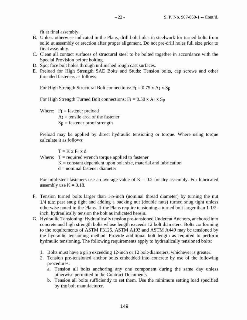
- 22 - S. P. No. 907-850-1 -- Cont’d.
fit at final assembly. B. Unless otherwise indicated in the Plans, drill bolt holes in steelwork for turned bolts from
solid at assembly or erection after proper alignment. Do not pre-drill holes full size prior to final assembly.
C. Clean all contact surfaces of structural steel to be bolted together in accordance with the Special Provision before bolting.
D. Spot face bolt holes through unfinished rough cast surfaces. E. Preload for High Strength SAE Bolts and Studs: Tension bolts, cap screws and other
threaded fasteners as follows:
For High Strength Structural Bolt connections: Ft = 0.75 x At x Sp For High Strength Turned Bolt connections: Ft = 0.50 x At x Sp Where: Ft = fastener preload At = tensile area of the fastener Sp = fastener proof strength Preload may be applied by direct hydraulic tensioning or torque. Where using torque calculate it as follows:
T = K x Ft x d Where: T = required wrench torque applied to fastener
K = constant dependent upon bolt size, material and lubrication d = nominal fastener diameter
For mild-steel fasteners use an average value of K = 0.2 for dry assembly. For lubricated assembly use K = 0.18.
F. Tension turned bolts larger than 1½-inch (nominal thread diameter) by turning the nut
1/4 turn past snug tight and adding a backing nut (double nuts) turned snug tight unless otherwise noted in the Plans. If the Plans require tensioning a turned bolt larger than 1-1/2-inch, hydraulically tension the bolt as indicated herein.
G. Hydraulic Tensioning: Hydraulically tension pre-tensioned Undercut Anchors, anchored into concrete and high strength bolts whose length exceeds 12 bolt diameters. Bolts conforming to the requirements of ASTM F3125, ASTM A193 and ASTM A449 may be tensioned by the hydraulic tensioning method. Provide additional bolt length as required to perform hydraulic tensioning. The following requirements apply to hydraulically tensioned bolts:
1. Bolts must have a grip exceeding 12-inch or 12 bolt-diameters, whichever is greater. 2. Tension pre-tensioned anchor bolts embedded into concrete by use of the following
procedures: a. Tension all bolts anchoring any one component during the same day unless
otherwise permitted in the Contract Documents. b. Tension all bolts sufficiently to set them. Use the minimum setting load specified
by the bolt manufacturer.
149

- 23 - S. P. No. 907-850-1 -- Cont’d.
c. Snug the nut down prior to releasing the hydraulic pressure to the ram. Perform final tensioning after all bolts are set and the machinery base aligned. Tension all bolts by the use of a center hole calibrated hydraulic ram. Mount the ram on a chair that permits access to the anchor bolt nut. If the Plans require a turned bolt larger than 1½-inch to be tensioned but do not specify a preload value, tension the bolt to 70% of the minimum tensile strength of the bolt, using the nominal area of the threaded section. Tension bolts to 70% of the specified minimum tensile strength of the bolt or the anchor bolt manufacturer’s recommendation, whichever is greater, unless otherwise indicated in the Contract documents.
d. Check the preload just after installation and again 60 days later. Apply hydraulic tension. Ensure the bolts have a tension equal to 60% of the minimum specified tensile load applied. Ensure there is no movement of the nut under this load.
e. If the preload test fails, re-tension the bolts to original tensioning values and retighten the nut.
H. Install primary nuts of Adhesive Anchors to 1/4 turn past snug tight condition and double
nut, unless otherwise noted in the Plans. 907-850.03.1.6--Undercut Anchors. For hydraulically tension undercut anchors, ensure all installation equipment including drills, drill bits, undercutting tools, tolerance gauges, and tensioning devices conform to the Manufacturer’s recommendations. Submit proposed equipment and installation methods to the Engineer for review. Install the undercut anchors in compliance with the Manufacturer’s recommendations. Employ at least one person with demonstrated experience in setting undercut anchors or arrange to have a representative of the anchor Manufacturer on site to supervise installation. The following provisions apply where the Contract documents call for the sleeve to extend into the base plate:
A. Drill holes for undercut anchors using the hole in the base plate as a template after the base plate has been set and grouted. Install such that the sleeve of the undercut anchor has an LC6 fit in the base or sole plate, and the bolt has adequate thread length for double nuts. Ensure bolt length is sufficient for hydraulic tensioning and double nuts. After final tightening, remove excess bolt length; provide enough length to allow the bolts to be re-tensioned. Do not torch cut bolts.
B. If the Contract documents do not require the sleeve to extend into the base, remove the sleeve after the anchor is set and grout the void around the bolt, including the hole in the base plate, with a non-shrink epoxy grout after setting the base and tensioning the anchor. Block out the areas around the anchors for installation of grout under base prior to tensioning anchors. Provide grout tubes and vent tubes as required to fill all voids with grout. Ensure that the material and grouting methods used are per the Anchor Manufacturer’s recommendations.
907-850.03.1.7--Keys and Keyways. Effectively hold in place all keys, preferably by setting them into closed-end keyways milled into the shaft.
150

- 24 - S. P. No. 907-850-1 -- Cont’d.
907-850.03.1.8--Flexible Couplings. Ensure finish boring and cutting of keyways in couplings is done by the coupling manufacturer to limits specified on the Shop Drawings. Ship finished couplings to the proper location for installation on shafts by the manufacturer of the connected component. Install coupling halves on reducer shafts and other shafts as per the coupling manufacturer’s installation instructions. Ensure coupling-shaft fits conform to FN2 fit, unless otherwise noted in the Contract Documents. 907-850.03.1.9--Bushings. For solid bushings provide fits between the bushing outside diameter and housing and between the bore and the shaft as indicated in the Plans. 907-850.03.1.10--Plain and Spherical Roller Bearings. Ensure bearings remain in their original packages until immediately before mounting so that they do not become contaminated. Do not wash with trichloroethylene, perchloroethylene, white spirit or any other solvent or cleanser. Any parts which have become soiled as a result of faulty handling should be wiped clean with a clean, lint-free, rag. Mount bearings with fractured or two-piece outer rings so that the main direction of the load is at 90 degrees to the plane of the fracture or joint. Bearing Installation: Finish shafts to the dimensions and tolerances recommended by the Bearing Manufacturer. Finish shafts for tapered bore bearings using the Bearing Manufacturer’s taper gauge (sine bar). Provide a representative of the Bearing Manufacturer to witness bearing installation, verify installation dimensions and tolerances, and certify acceptable installation. This representative will measure and record shaft and bearing dimensions prior to installation and verify acceptable conditions. This representative will also measure the bench clearance and takeout in the bearings upon installation and verify their acceptability. Following installation, the manufacturer’s representative will prepare and submit, per shop drawing procedures, a report containing the as-built dimensions and certifying that acceptable installation was witnessed. 907-850.03.1.11--Dry Sliding Bearings. Ensure that the mating surface and other components of the arrangement is carefully cleaned and deburred, and non-machined surfaces inside cast housings are free from molding sand before assembly. Mount plain and flanged bushings so that the butt joint is positioned at 90 degrees from the loaded zone. 907-850.03.1.12--Pillow Blocks. Provide one-piece base half of pillow blocks for trunnions and gear trains. Secure bearing caps to bases with turned bolts with square heads recessed in the base. As an alternative, secure caps to bases with turned studs tapped into the base and fitted with double hexagonal nuts. Install so that the nuts bear on finished bosses or spot-faced seats. Where using plain bushings, make provision for alignment of pillow blocks by means of shims, and for the caps by means of laminated liners. Provide adaptor mounting pillow block and flange-mounted roller bearings, self-aligning expansion and non-expansion types as called for on the Plans. Provide cast steel housings capable of withstanding the design radial load in any direction, including uplift. Provide cast bases without mounting holes. Drill mounting holes from the solid at assembly with the supporting steel work. Provide seals that retain the lubricant and exclude water and debris. All pillow block housings shall have provisions for purging grease.
151

- 25 - S. P. No. 907-850-1 -- Cont’d.
907-850.03.1.13--Shaft Journals. Turn and polish journal bearing areas on shafts and pins with no trace of tool marks or scratches on the journal surface, and no step between the journal surface and fillet. Provide and install journals and bearings to a RC6 fit unless otherwise noted in the Plans. 907-850.03.1.15--Hubs and Bores. Finish and polish the faces of all hubs on gears, wheels and couplings that serve as a surface carrying axial loads. Bore hubs concentric with the outside diameter of those parts. 907-850.03.1.15--Welding and Weldments. Welding and weldments shall meet the following:
A. Unless otherwise noted herein or in the plans, perform all welding and weld inspection of machinery in accordance with AASHTO/ANSI/AWS D1.5. Unless otherwise noted, herein or in the plans, treat all welded machinery and weldments that support machinery as main members, all welds as subject to tension or stress reversal, and all welds as joining primary components. Do not perform field welding on these elements unless specifically required in the Contract Documents.
B. Perform coupon testing and provide a certified copy of test reports prior to any welding procedure involving attachment to existing steelwork. Provide report showing the chemical composition of the specific steel piece(s) to be welded. Design a weld procedure specific to this chemical composition.
C. Unless otherwise shown in the Plans, connect elements of weldments by complete joint penetration welds. Do not use fillet welds where they would require machining to provide clearance for machinery, fasteners, or other attachments. Clip stiffeners to avoid overlapping stiffener welds with welds at the intersection of main plates.
D. Stress relieve weldments after welding and prior to final machining. Unless otherwise shown in the Plans, finish machined surfaces of weldments to flatness as required herein and finish machinery bearing surfaces parallel to each other and to the bottom of the base plate. Machine finish the height of the weldments supporting machinery, on shims, as measured from the bottom of the base plate to the top of the bearing surface, to Plan height plus or minus 1/8 inch. Grind all exposed edges of weldments to a chamfer or radius to eliminate sharp edges and burrs. Ensure that weldment base plates, placed against concrete or grout, have 3/4-inch minimum radii on the corners.
E. Thoroughly coat finished mounting surfaces with an approved temporary protective coating that prevents oxidation and are skidded or crated for protection during handling, shipment and storage. Unless the weldment is galvanized and after weldment is accepted by the Engineer, prime base surfaces which will have concrete or grout cast against them, but do not finish coat them.
F. Where galvanizing of weldments is required, hot dip galvanize in accordance with ASTM A123. Provide lifting lugs and vent holes as needed for the galvanizing process. Mask surfaces to be machined as required.
G. Provide a pair of lifting eye bolts either drilled and tapped into the weldment or through bolted in a weldment plate for lifting and handling. Provide lugs with a minimum working capacity of two (2) times the weight of the weldment.
H. Provide leveling screws drilled and tapped through the weldment base plate for field leveling. Use leveling screws with adequate capacity to support the weldment and any other
152

- 26 - S. P. No. 907-850-1 -- Cont’d.
construction loads anticipated to be applied prior to grouting under the base plate. After installation of grout and prior to tensioning anchor bolts, remove leveling screws. Grease the leveling screws and reinstall them in the taped holes to a snug tight condition.
907-850.03.1.16--Lubrication of Machinery. Connect grease fittings with tubing or fittings so that grease is introduced directly into the grease grooves for distribution. Tubing is to extend from the bearings to convenient lubrication stations. Install vibration absorbent braided stainless steel hose, 8-inch minimum length, between the pipe and the component lubricated on span lock components or other components subject to vibration or impact. Provide tubing supports at increments not to exceed 3-feet between supports. Immediately after erection and before operation, lubricate all rotating and sliding parts and fill all gear housings with the approved lubricants specified on lubrication charts. 907-850.03.1.17--Painting of Machinery. Prepare non-contact finished surfaces, such as the sides of rack and pinion teeth, trunnion shafts between shoulder and hub, coupling housings, shafts other than journals, hub rings and hubs for painting. Paint with a three-coat system consisting of two coats of aluminum epoxy mastic primer and a finish coat of aliphatic polyurethane. Apply the finish coat to weldments, bearing housings, enclosed gear boxes and other machinery as specified in this Special Provision in the shop. Apply field touch-up paint to shop applied coatings damaged during construction. After erection is complete, thoroughly clean with an approved solvent and give intermediate coats of paint to all machinery surfaces remaining exposed, except rubbing surfaces and mating surfaces of gear teeth. After completing the operating tests and acceptance of the machinery, wash with approved solvent all accumulated oil, grease, dirt, and other foreign matter from exposed machinery surfaces, except rubbing surfaces and mating surfaces of gear teeth. Give the exposed surfaces a final field coat. Paint machinery surfaces with the final field coat in the following colors:
A. Federal safety Blue - for all fixed parts of the machinery, such as reducers, weldments, housings, and motors.
B. Federal safety Red - except rubbing surfaces, for all moving parts of the machinery, such as shafting, couplings, brakes, machinery guards, hydraulic cylinders, live load shoes, and load shoe masonry plates.
C. Federal Safety Yellow - non-corrosion resistant hydraulic power unit manifolds and components.
Paint other supporting steel with the final field coat to match the structural steel. Do not paint stainless steel elements unless approved by the Engineer. 907-850.03.2--Trunnion Assemblies. 907-850.03.2.1--Description. The work consists of: Furnishing and installing new trunnion bushing assemblies. Machining trunnion journals. Measuring trunnion alignment and adjusting trunnion shaft and eccentrics and providing new eccentrics if required for re-alignment of trunnion.
153

- 27 - S. P. No. 907-850-1 -- Cont’d.
New trunnion hub turned bolts. 907-850.03.2.1.1--Work Included. Each Bascule Leaf has two complete trunnion assemblies. The work includes shop drawing preparation, detailing, fabrication, span jacking, installation, alignment, testing and adjustment as required to rehabilitate the movable span trunnions. Knocking holes into the concrete walls to allow for room for the machining lathe shall be required due to tight constraints in access room. Wall should be built back up after work is completed. Vertical, horizontal and angular orientation locations of the journal housings and bearings are to be determined relative to the Trunnion Reference Centerline. Determine orientation of the trunnion relative to the Trunnion Reference Centerline both in the leaf closed and leaf open positions. Also take at least two evenly spaced positions between closed and open. 907-850.03.2.1.2--Submittals. Submit complete fully detailed Shop Drawings of the trunnion assembly components and all parts and sub-assemblies. Indicate fits, finishes, sizes, connection attachments, size and type of fasteners, and accessories. Provide sub-assembly drawings for the machine shop and steel fabrication shop in addition to the final assembly drawing(s). Submit detailed systematic procedures for installation of trunnion bushings into the trunnion bearing housings, machining of the trunnion shaft journals, and installation of trunnion hub bolts. 907-850.03.2.1.3--Materials. Provide materials for trunnion assembly components as shown in the Plans. 907-850.03.2.2--Construction Requirements. 907-850.03.2.2.1--General. Provide all tools required for proper installation and alignment of the trunnion assemblies, including precision machinist levels. Utilize precision machinist level(s) for trunnion bearing setting and alignment accurate to the nearest 0.005-inch or less per foot. 907-850.03.2.2.2--Machining of Trunnion Shafts. Machining of trunnion shafts shall meet the following:
A. Field machine the trunnion journals to a uniform diameter and finish according to the Contract Plans and field measurements with the leaves jacked in the open position as outlined in SP 907-850B. All fillets, grease grooves, and shoulders shall be machined to a uniform finish and blended smoothly to the dimensions indicated on the Contract Plans. The reworked trunnion shafts, including fillets and shoulders are to have a surface finish as indicated on the Contract Plans. Both trunnions of the same leaf are to be machined simultaneously. Adjust shims at the existing trunnion bearing cap and trunnion bearing lower housing interface, as required to accommodate newly machined journal.
B. Measure the inside diameter of the Trunnion Bearing Base and machine OD of bushings such that the ANSI B4.1 fit is achieved over the entire length of the Trunnion Bearing Base. Submit to the Engineer for approval the method that will be used to verify that the ANSI fit as per the Contract Plans is achieved.
154

- 28 - S. P. No. 907-850-1 -- Cont’d.
C. Realign and reset the trunnions as part of this work item by using a qualified Millwright as per these Special Provisions using the existing or new eccentrics and wrench. The alignment of the trunnions is to be checked prior to the start of the any trunnion work and following the completion of the all trunnion work. Obtain trunnion alignment by utilizing a piano wire stretched through both trunnions, or by laser instrumentation. Submit the procedure and method for approval to the Engineer. The Department Maintenance Personnel may verify the results by using their own means. The method and calculations of trunnion alignment are to be submitted to the Engineer for approval. When the leafs are reset in the trunnion bearings, the criteria for the newly adjusted centerlines is that in the bridge closed position the newly adjusted centerlines are not to deviate more than 1/16” from the theoretical centerline. The Engineer is to verify that the newly adjusted trunnion centerline complies with the criteria above.
D. Submit fully detailed plans and calculations for the span jacking and temporary support for the duration of the trunnion work. The plans and calculations are to be signed and sealed by a Professional Engineer, registered in the State of Mississippi. Obtain all information and measurements necessary to accurately complete the work. Submit all survey information for review. In order to obtain the trunnion shaft alignment as directed above, several span jacking operations may be required.
E. Following the final alignment of the trunnion shafts, the leaves are to be jacked down such that the newly machined trunnion journals bear on the new trunnion bearing bushings. The alignment of the trunnion journal to the trunnion bearing base is to be achieved such that there is “zero” clearance between the journal and bushing at both the inboard and outboard sides of the bearing base in addition to achieving the ANSI B4.1 fit as directed on the Contract Plans. “Zero” clearance is to be achieved to within 0.00050” and verified, in the presence of the Engineer, by utilizing feeler gages (0.00050”) or other approved method. The procedure for achieving the alignment of the trunnion bearing base to the trunnion journal is to submitted to the Engineer for approval. Upon installing the trunnion bearing cap, the ANSI B4.1 journal/bushing fit is to be within 0.0010” at both the inboard and outboard sides of the trunnion bearing.
907-850.03.2.2.3--Setting of Trunnion Shaft and Bearing in Bearing Housings. Setting of trunnion shaft and bearing in bearing housings shall meet the following:
A. Clean all components of any dirt or foreign debris. B. Thoroughly clean inside and outside of bearing housings to receive the shaft assembly.
Thoroughly lubricate the bearings with approved lubricant. C. Carefully lower trunnion assemblies into the bearing housings. Install bearing caps as
soon as possible to prevent contamination. Fill with approved lubrication prior to any rotation of the bearings.
D. Install taught alignment wire through trunnion plugs and recheck alignment of trunnions. Adjust eccentric assemblies. Align the adjusted trunnion alignment such that the centerline of trunnion at the eccentric is 0.020 to 0.040-inch below the alignment wire per the trunnion alignment diagram with the leaf in either the full open or full closed position.
E. After the trunnion alignment is accepted by the Engineer, re-drill and ream the trunnion bearing housing bolts to install the permanent bolts. Perform this operation one bolt at a time to preserve the alignment.
155

- 29 - S. P. No. 907-850-1 -- Cont’d.
907-850.03.2.2.4--Trunnion Journal Alignment Inspection. Determine vertical, horizontal and angular orientation locations of the journal housings and bearings relative to a reference line. Determine orientation of the trunnion shaft relative to this reference line both in the span closed and span open positions, and at least two even spaced positions between closed and open. Establish eccentric positions. Remove the trunnion journal caps and inspect the condition of the journal. Clean grease passages or flush clear. 907-850.03.3--Main Span Machinery Drive Speed Reducer. 907-850.03.3.1--Description. This section applies to all speed reducers in the Leaf Operating Machinery gear train, beginning at the leaf motor(s) and continuing through to the rack and pinion. 907-850.03.3.1.1--Shipping and Handling. Coat, as soon as practical after machining, all finished metal surfaces with an anti-oxidant. Coat all internal parts of the reducer with a non-contaminating type rust inhibitor suitable for six months storage time. Completely fill the reducer with the proper oil and rotate the shaft until all surfaces are completely lubricated. Oil should be new and not oil used from shop testing. If the reducer is to be stored for a period longer than six months, rotate the shaft periodically to ensure all surfaces remain completely lubricated. 907-850.03.3.2--Materials. Materials shall meet the following:
A. Provide speed reducers from a single manufacturer with sizes, ratios and construction details as shown on the Plans, unless otherwise approved by the Engineer.
B. Provide speed reducers that meet the requirements of the latest edition of ANSI/AGMA 6010 Standard for Spur, Helical, Herringbone and Bevel Enclosed Drives. A minimum reverse bending factor of 0.8 is required in the strength rating.
C. Ensure that allowable contact stress numbers, Sac and Sat, conform to AGMA Grade 1 materials as defined in ANSI/AGMA 2001.
D. Design speed reducers to withstand a sustained overload equal to three times the rated full load torque of the driving motor(s) without any reducer component reaching 50% of its yield strength.
E. Provide helical or herringbone gear types. Do not use spur gears. Bevel gear types are required for the differential gearing. All gears are to conform to the specifications of AGMA Quality 9 or better. Furnish exact ratios where specified in the Plans.
F. Ensure the material for pinions and gears meets the requirements of ANSI 4140. The relative hardness of gears and driving pinions is to be such that the loading and testing requirements of these Special Provisions are met. Pinions are to have a minimum hardness of 320/360 Brinell. Gears are to have a minimum hardness of 265/305 Brinell. Pinions are to be proportioned so that the root diameter of the pinion is not smaller in diameter than the diameter of the journals for the pinion shaft.
G. Ensure shaft bearings are anti-friction type bearings with an L-10 life of 40,000 hours at the rated speed, horsepower, and service factor of the unit. Provide ANSI 4140 material for shafts.
156

- 30 - S. P. No. 907-850-1 -- Cont’d.
H. Construct housings of stress relieved welded steel plate or cast steel with removable inspection covers to facilitate viewing the gearing (except differential gears). The inside of the housings are to be sandblast cleaned prior to assembly and be protected from rusting. Equip the speed reducers with a means of filling and draining with drains having shut-off valves. Accessible devices for observing the lubricant level in the gear box must include both a dipstick and sight gauge of rugged construction and protected against breakage.
I. Extend the reducer bases sufficiently past the body of the reducers to allow for mounting bolt hole reaming and bolt installation from above the unit. Provide clearance for hydraulically tension testing of anchor bolts.
J. Manufacture reducers in accordance with the requirements of AASHTO, and given nameplates with the following additional information:
1. Size 2. Ratio 3. Service Power Rating 4. High Speed Shaft RPM 5. Service Factor 6. Lubrication Specification 7. AGMA symbol and Gear Quality Number
K. Lubrication of the gears and bearings is to be automatic when the unit is in operation.
Utilize a bath lubrication system. Partially submerge, in an oil bath, all components in the speed reducer which require lubrication. When the configuration of gears and bearings prevent bath lubrication, use a splash lubrication system. Splash lubrication systems are to continuously lubricate all gears and bearings properly. Oil feed troughs may be used to supply oil to bearings and gears, which are above the bath. Splash lubrication systems are to be designed such that equal lubrication is supplied to each internal component for both directions of operation. Ensure oil viscosity of lubricant is in accordance with ANSI/AGMA 9005, Industrial Gear Lubrication. Provide splash lubrication of the gears and bearings when the unit is in operation. Do not use pressurized lubrication systems for speed reducers unless specifically approved by the Engineer or specified in the Contract Documents. When a pressurized lubrication system is required for the reducer, provide a redundant lubrication system so that both systems operate concurrently. If a lubrication system malfunction can occur, provide a contact for remote alarm indication.
L. Inspection ports on reducers are to provide for inspection of all gears, bearings and other internal devices. Locate the ports above the oil level, if practicable, so that oil draining is not required for inspection. Size the port such that minor repairs could be made to reducers without requiring housing disassembly. Properly seal ports with seals that do not require replacement when ports are opened.
M. Inspection ports for planetary gearboxes should allow use of a borescope to inspect internal components.
N. Mount oil level indicators in locations that can be easily viewed by maintenance crews. Provide a graduated sight gauge on reducers in which the oil level varies by more than 1/2-inch per 50°F temperature change. Vent the indicator back to the case. Sight gauges are to be of rugged construction and protected against breakage.
O. Locate oil drains at the lowest point possible. Provide the drain with a hand-operated lever that can be locked in the closed position.
157

- 31 - S. P. No. 907-850-1 -- Cont’d.
P. Locate oil sampling cocks in accessible positions on the reducers. Provide two sampling cocks, one located at the lowest level of oil and one just below the upper oil level.
Q. Speed reducers are to have provisions for oil expansion due to churning and temperature change.
R. Furnish grease lubricated reducer bearings with grease fittings readily accessible after installation of reducer. Internal seals between the bearing housing and the gear oil are to prevent interaction between them.
S. On shaft extensions, bearing shaft ring seals are to be mechanical type dual lip spring loaded oil seals that compensate for wear.
907-850.03.3.3--Construction Requirements. 907-850.03.3.3.1--Construction. Construction shall meet the following:
A. Ensure a qualified installer performs the work described herein. The installer is to have had
at least ten years of experience in the design, fabrication, installation, and testing of major systems of comparable size and type. The Engineer will send an inspector to the shop for verification of compliance prior to shipment of any equipment to the field.
B. Submit shop drawings to the Engineer, showing interface with other equipment and including the following:
1. Main drive speed reducers with bill of materials 2. Gear ratios, dimensions, construction details, and AGMA ratings 3. Installation, Operation and Maintenance Manual sheets 4. Operational experience record for model supplied 5. Product data for all components 6. Certified test data for all factory tests and As-Built Plans 7. Calculations including AGMA ratings for gear sets, bearing ratings, and shaft sizing
C. The manufacturer is to submit for approval a certified print of each speed reducer showing
as a minimum the following: 1. All external mounting dimensions including shaft sizes, bores, and keyways where
required. 2. The ratings that will appear on the nameplate. 3. Location of all lubricant connections. 4. Lubrication recommendations. 5. Provide internal drawings showing each gearbox component with part numbers to the
Department. 6. Submit shop drawings showing steel designations, AWS welding symbols, and net weld
lengths. 7. Product data for all bearings. 8. Manufacturer’s installation instructions. 9. Operation and Maintenance data. 10. Duplicate copies of shop results for welds and full load testing of reducer(s). D. Shrink
fit gear couplings on the shafts in the shop.
158

- 32 - S. P. No. 907-850-1 -- Cont’d.
D. Shop/Factory Finish: Factory finish the speed reducer with 2 coats of red oxide primer, in conformity with SSPC 15, Type 1.
E. Provide the reducer design calculations and drawings to the Engineer for approval before construction of the unit.
907-850.03.3.3.2--Shop Testing and Inspection. Shop testing and inspection shall meet the following:
A. Provide two weeks of notice to the Engineer of the reducer testing schedule. B. Ensure the following information is provided:
1. NDT testing documentation for ultrasonically or radiographically testing all welds for all gearing components.
2. Test reports for materials used in the manufacture of the gears and pinions. 3. Heat treatment documentation, through hardening, induction hardening for the gears and
pinions. 4. Hardness quality control documentation. If through hardened teeth are not specified,
provide case depth measurements. 5. Lead, profile, spacing, and run-out measurements for gears and pinions. 6. Summary computer printout calculations of all gear/pinion sets. 7. The specific design criteria for the speed reducer; i.e., material requirements on the
housing, gears, pinions, shafts, bearings, seals, lubrication, factory finish, etc. C. Anchor the reducer to the floor using bolts through the base plate to a rigid frame. Provide
temporary couplings for the reducer testing that are capable of operation at 300% of the reducer shaft rated torque. Secure couplings to shafts using temporary keys and at least a FN1 shrink fit.
D. After assembly of the reducer, conduct a no load spin test at 115% of rated speed one hour in each direction. Sound level readings taken at 5-feet from the reducer surface cannot exceed 90 dB with the unit running at 115% of rated speed. Closely monitor the reducer during the spin test for oil leaks, excessive heating of bearings, excessive vibrations, and any other abnormalities.
E. Following the no load spin test, run speed reducers at rated speed at 50 and 100% of full load motor torque for thirty minutes in each direction, and 150% of full load motor torque for ninety minutes in each direction. Monitor for oil leaks, excessive heating of bearings, excessive vibration, and any other abnormalities.
F. At the end of these tests, dismantle the box and examine for excessive wear and damage. Examine gear teeth for contact patterns. A minimum of 85% tooth flank contact must be evident. Replace all out of tolerance parts and adjust as required. After correcting the discrepancies, retest the reducer until meeting all satisfactory conditions. Submit a report of the testing and any abnormal conditions to the Engineer for review and acceptance.
G. After reassembly of the speed reducer and acceptance by the Engineer, if no material modifications were required, run the unit at 100% full speed at no load for 30 minutes in each direction and monitor for abnormal changes in operating conditions. If material modifications were required following the initial load test, perform additional load tests up to and including the 150% load test as required by the Engineer at no additional cost to the Department.
H. Conduct any required NDT testing of the speed reducer(s) in the manufacturers’ shop and closely inspect the gearbox for any oil leaks and repair if necessary.
159
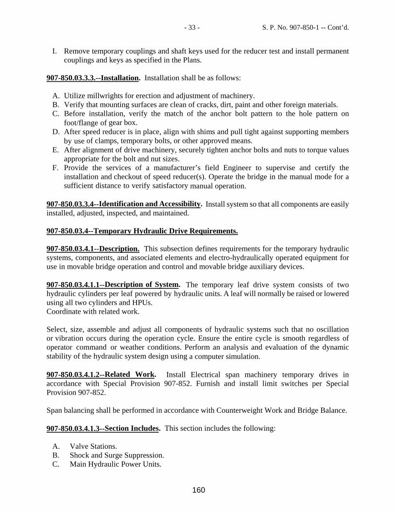
- 33 - S. P. No. 907-850-1 -- Cont’d.
I. Remove temporary couplings and shaft keys used for the reducer test and install permanent couplings and keys as specified in the Plans.
907-850.03.3.3.--Installation. Installation shall be as follows:
A. Utilize millwrights for erection and adjustment of machinery. B. Verify that mounting surfaces are clean of cracks, dirt, paint and other foreign materials. C. Before installation, verify the match of the anchor bolt pattern to the hole pattern on
foot/flange of gear box. D. After speed reducer is in place, align with shims and pull tight against supporting members
by use of clamps, temporary bolts, or other approved means. E. After alignment of drive machinery, securely tighten anchor bolts and nuts to torque values
appropriate for the bolt and nut sizes. F. Provide the services of a manufacturer’s field Engineer to supervise and certify the
installation and checkout of speed reducer(s). Operate the bridge in the manual mode for a sufficient distance to verify satisfactory manual operation.
907-850.03.3.4--Identification and Accessibility. Install system so that all components are easily installed, adjusted, inspected, and maintained. 907-850.03.4--Temporary Hydraulic Drive Requirements. 907-850.03.4.1--Description. This subsection defines requirements for the temporary hydraulic systems, components, and associated elements and electro-hydraulically operated equipment for use in movable bridge operation and control and movable bridge auxiliary devices. 907-850.03.4.1.1--Description of System. The temporary leaf drive system consists of two hydraulic cylinders per leaf powered by hydraulic units. A leaf will normally be raised or lowered using all two cylinders and HPUs. Coordinate with related work. Select, size, assemble and adjust all components of hydraulic systems such that no oscillation or vibration occurs during the operation cycle. Ensure the entire cycle is smooth regardless of operator command or weather conditions. Perform an analysis and evaluation of the dynamic stability of the hydraulic system design using a computer simulation. 907-850.03.4.1.2--Related Work. Install Electrical span machinery temporary drives in accordance with Special Provision 907-852. Furnish and install limit switches per Special Provision 907-852. Span balancing shall be performed in accordance with Counterweight Work and Bridge Balance. 907-850.03.4.1.3--Section Includes. This section includes the following:
A. Valve Stations. B. Shock and Surge Suppression. C. Main Hydraulic Power Units.
160

- 34 - S. P. No. 907-850-1 -- Cont’d.
D. Fluid Reservoirs. E. Valve Stands. F. Valves. G. Piping, Fittings and Manifolds. H. Cylinders. I. Motors. J. Filtration and Fluid Conditioning. K. Hydraulic Fluids. L. Pressure Gauges.
907-850.03.4.1.4--Qualifications. Use Certified Hydraulic Technician or Certified Industrial Hydraulic Mechanics certified by the Fluid Power Society. Use Certified Technician/Mechanics having prior experience on similar sized systems for installation, start-up, piping and flushing of hydraulic systems. Use Certified Technician/Mechanics with at least five years of experience in the design, fabrication, and installation of hydraulic systems of this size and type. Use only personnel with demonstrated skill in this type of work for installation and adjustment of hydraulic components. 907-850.03.4.1.5--Submittal Requirements. Submittals shall be as follows:
A. Submit all hydraulic equipment component data to the Engineer for approval prior to fabrication. Label each submittal package as noted below and include all the required items for that section. Provide these labels in addition to sequential submittal numbers.
B. Use a Certified Fluid Power Engineer or Certified Fluid Power Specialist to prepare or check all calculations required to be performed for detailing the hydraulic systems. Provide calculations signed by the responsible Certified Fluid Power Engineer or Certified Fluid Power Specialist.
C. Prepare and provide the following submittal packages as a minimum. Submit additional submittal packages as specified or as requested by the Engineer. 1. Main Drive Hydraulic Power Units (HPU’s):
a. Complete system schematic (including components in the cylinder manifolds) with component reference numbers matching reference numbers on the Plans.
b. Bill of Materials for all components of the main drive HPU and cylinder manifold, including a table of contents and manufacturer’s data cuts on all system components. Provide a Bill of Materials that includes, but is not limited to, all pumps, motors, motor adaptors, motor mounts, couplings, valves, heat transferring equipment, accumulators, filters, breathers, gauges, flow meters, hoses, pipe, reservoirs, drip trays, reservoir accessories, manifolds, hydraulic oil, all electrical devices located on the HPU, and details of all placards as required in the Contract Documents. Submit any HPU item proposed to be custom fabricated for approval with supporting detail drawings and specifications. Reference numbers for the Bill of Materials to the schematic numbering shown in the Plans. Provide working pressure ratings for all components.
c. Prepare pressure drop calculations based on proposed components, component efficiencies, flow rates, and line sizes. Format these calculations to provide clear and
161

- 35 - S. P. No. 907-850-1 -- Cont’d.
concise information regarding the system input power, power delivered to the hydraulic cylinders, and system losses. Provide supporting documentation for any assumptions made during the preparation of these calculations. Provide manufacturers supporting documentation for component efficiencies. Use pressure drop across cylinders shown as “average operating” pressure in the Plans.
d. Initial setting values for all adjustable components. Clearly indicate these values on the system schematics and define where and when the initial setting will be made (e.g. factory, shop, or field).
e. Hydraulic power unit layout indicating dimensions and placement of all system components (manifolds, reservoir, frame, electrical junction boxes, enclosure, etc.). Provide clearances between the HPU and adjacent structures, equipment, and walkways. Location of field piping connections. Detailed drawings of pressure gauge station, including labeling.
f. Weld procedures for power unit structural and piping welds. g. Paint material and painting procedures, including color identifications, surface
preparation procedures and product specifications. h. Detailed shop test procedures. i. Fabrication drawings for power unit structural framing, reservoirs, and supports. j. List of spare parts provided with manufacturer, model/part numbers and quantity
to be supplied. k. Sample placards and a list of placards to be provided, including the information
to be included on each placard. 2. Main Drive Cylinders and Attachment Components:
a. Bill of Materials for all internal and external cylinders components including manufacturer’s part numbers for ordering replacement seals.
b. Certified dimensional prints and assembly drawings of components with reference numbers matching the cylinder Bill of Materials. Assembly drawing of cylinders and attachments indicating clearances between the cylinders and adjacent structures, equipment, and walkways.
c. Cylinder cushion details. d. Cylinder calculations for cushion orifice sizing, rod buckling, tube burst, head bolt
design, weld design, and reserve stroke values at the fully closed and fully open bridge positions.
e. Cylinder manifold attachment details. f. Cylinder clevis details. g. Torque arm bearings, including snap rings and hardware, and clevis pins details. h. Cylinder rod seal leakage reservoir details. i. Cylinder shop test procedure including testing of cylinder cushions details. j. Detailed alignment and installation procedures. k. Paint material and painting procedures, including color identifications, surface
preparation procedures and product specifications. i. List of spare parts provided with manufacturer, model/part numbers and quantity to
be supplied. 3. Main Drive Hydraulic Power Unit Control Panels (HPUCP’s):
a. Complete electrical schematics with rung and component reference numbers as indicated in the Plans. Provide schematics that detail interfacing and tight integration with all field components, HPU components, and all other bridge electrical panels
162

- 36 - S. P. No. 907-850-1 -- Cont’d.
not directly related to hydraulic drive system (i.e., CP-1, CP-2, MCC, etc.). b. Bill of Materials for all components of the Control System including a table of
contents and manufacturer’s data cuts on all components. Each control system consists of an HPUCP, HPU, UPS, two Inclinometers, leaf limit switches, amplifier cards, sensors and valve & motor controls.
c. Software listings, PLC hardware and default configurations, theory of operations, testing plans, detailed block diagrams, auxiliary test equipment (e.g. laptops, chart recorders, etc.), default values listings, and timing diagrams.
d. Physical dimensioned panel layout detailing all operator interface devices on panel face and component layout of panel interior.
e. Any additional requirements as noted in the electrical equipment submittal procedure outlined in Special Provision 907-805C.
f. Paint material and painting procedures, including color identifications, surface preparation procedures and product specifications.
4. Main Drive Hydraulic Field Piping: a. Complete layout and material data cuts for all required field piping and support
devices including piping, tubing, flexible hoses, hose ends, fittings, pipe and tube support devices, fasteners, anchor bolts and all related hardware required for installation. Ensure layout details proposed routing and length of fluid conductors with relation to the Main Drive HPU and drive cylinders.
b. Factors of safety as required of this Special Provision for all hydraulic plumbing. c. List of hoses to be delivered including size, length, hose ends and quantity to deliver. d. Weld procedures for welded piping or piping connections.
5. Startup and Functional Testing: a. Detailed procedure for inspection, charging, flushing, and fluid sampling for all
hydraulic drive systems. b. Detailed procedure for initial startup of the Main Drive HPU’s, and the Span Lock
HPU’s. c. Detailed procedure for Hydraulic Static Field Testing. d. Detailed procedure for Hydraulic Unit Dynamic Field Testing. e. Detailed procedure for functional testing of the Main Hydraulic Drive System and
the Span Lock Hydraulic Drive System. 907-850.03.4.2--Materials. Design and assemble hydraulic equipment in accordance with standard JIC hydraulic practices. Completely pre-pipe, test, and paint hydraulic power units prior to arrival at the job site. Securely cap open ports for field piping with steel plugs. Do not make changes or modifications in the field. Should the power units require piping changes, remove them from the bridge, modify, and re-test in the manufacturer’s shop. 907-850.03.4.2.1--Hydraulic Fluid. Provide all hydraulic fluid required to test, store, clean, and install the hydraulic systems. Use fluid for the main hydraulic drive system that is of a premium grade, petroleum based, high performance, and anti-wear hydraulic oil with an ISO grade VG of 32. Use fluid for the span lock hydraulics that is of a premium grade, high- performance, biodegradable, non-toxic, anti-wear hydraulic oil with an ISO Grade VG of 32. Provide components, seals, etc. that are compatible with the approved fluid.
163

- 37 - S. P. No. 907-850-1 -- Cont’d.
907-850.03.4.2.2--Filtration. Provide each system with full flow pressure and return filtration. Provide independent pressure filters for each pump unless noted otherwise in the Plans. Use a tank top mounted return filter. Provide each filter with a local visual clogging indicator and an electrical clogging indicator. Provide filters with filter elements having a 10-micron rating of Beta 10 = 100 or better. Provide filters whose filter housings have low collapse elements and a suitable bypass valve built into the housing. Provide off line filtration through use of the fluid conditioning circuit. 907-850.03.4.2.3--Reservoirs. Fabricate hydraulic reservoirs and supporting structure of ASTM A276 Type 316 stainless steel. Use welds and connecting hardware of compatible stainless steel. Reservoirs of 5 gallons or less may be constructed of aluminum alloy. Provide removable clean out cover(s) on the front face of each reservoir. Provide reservoirs of the capacity as shown in the Plans. Provide a minimum of two removable clean out covers on the front face of the reservoir. Provide each reservoir with suitable baffles to assist in fluid conditioning. Provide a water barrier type breather installed on the sealed reservoir. Make provisions such that new fluid can only be added to the sealed reservoir by pumping it through the return filter or through similar filtration. Locate ports and baffles such that temperature switches are not located adjacent to fluid returning from the heat exchanger and return flow from the cylinders is buffered prior to circulating into the pump suction lines. In addition to details shown in the Plans, provide the following items incorporated into the hydraulic reservoir:
A. Fluid sampling port with shut-off valve B. Reservoir drain port with shutoff valves C. Sight level gauge with temperature indicator D. Support structure
907-850.03.4.2.4--Hydraulic Cylinders. Hydraulic cylinders shall meet the following:
A. Provide hydraulic cylinders for operation and holding of the Bascule Leafs that meet the following requirements. As a minimum, provide products that meet the material strength criteria and minimum material properties and grades specified. Provide higher strength materials as required to meet the design requirements depending on the cylinder manufacturer’s design, detailing and construction methods.
B. For hydraulic cylinders for Bascule Leaf operation provide heavy-duty mill-type, double-acting cylinders, of the mounting type shown in the Plans. Provide cylinders pressure rated for a minimum of 3,600 psi. Provide cylinders that have bore, stroke, and rod diameter as indicated. Use SAE Code 62 - 4 bolt flange ports. Provide cylinders with the cylinder head and end cap bolted to the body flange except as shown in the Plans.
C. Cylinder Mounts: Design and manufacture cylinders for mounting as shown in the Plans. Provide rod ends per Plan details, designed and fabricated for easy field removal of connecting pins to allow for disconnecting a cylinder from the Bascule Leaf to remove it from service. Ensure cylinder mounts attached to the cylinder and all associated bearings and hardware are supplied by the cylinder manufacturer, provide details in the cylinder
164

- 38 - S. P. No. 907-850-1 -- Cont’d.
Shop Drawings. D. Cylinder Tube: Fabricate the cylinder tube from ASTM A519, Grade 1026, heavy wall
seamless steel tubing, and finish the bore honed to a 16-micro-inch RMS surface finish or better. Alternate steel grades may be utilized as required to obtain the required strength. Provide certification of tube material strength and ductility. Chamfer or taper cylinder body ends to facilitate manufacturing. Weld body flanges to the tube.
E. Cylinder Heads: Fabricate cylinder heads and end caps from ASTM A576, Grade 1018, steel bar stock, heat treated as required for strength and toughness, and machine finish all surfaces. Equip the cylinder head with rod seals and external dirt wipers, and pilot rod bushings into the head to ensure concentricity. Machine cylinder heads to allow for multiple rod seals and a rod seal leakage area and port as shown on the Plans. Machine cylinder head contact surfaces where they mate with the cylinder tube. Except as otherwise noted in the Plans, bolt cylinder heads to the body tube with through bolts, or cap screws tapped directly into the cylinder tube. Provide SAE Grade 8 fasteners.
F. Pistons: Precision fit pistons to the cylinder body bore. Provide pistons made of a steel core with SAE 62 bronze coating 0.080 inch thick and equipped with multiple lip-type seals. Design and fabricate pistons such that piston seals are protected from blow-out and over squeeze. Positively secure pistons to the piston rod by threading onto the rod and securing with set screws. Finish piston bearing and packing seal surfaces to a 32-micro-inch RMS finish or better.
G. Piston Rods: Provide piston rods made of medium carbon steel of yield strengths of 45-KSI to 70- KSI high tensile strength using ASTM A108, Grade 1045 for rods 3-inch to 10-inch in diameter. Alternate steel grades may be utilized as required to obtain the required strength and buckling resistance. Provide certification of rod material strength and ductility. Provide rods that are case hardened, polished to 8 micro-inch RMS surface finish or better, and nickel-chrome plated in accordance with ASTM B456 (SC 5 extended severe service). Furnish rods with a final chrome thickness not less than 0.002-inch. Provide piston rods with a minimum Factor of Safety of 3.0 against buckling. Base Factors of Safety on a maximum working pressure equal to the maximum pressure protection setting at the cylinder relief valves.
H. As an alternative to nickel-chrome plating, rods may be protected by a ceramic coating. Use only ceramic homogeneous, non-conducting, and impermeable ceramic coatings. Do not use systems unless they have a minimum of f ive (5) years of demonstrated field experience in marine environments. Provide ceramic coating with the following characteristics:
1. Ceramic coating thickness of 0.008 to 0.015-inch. 2. Surface finish or 4 to 12 micro-inch rms. 3. Surface hardness or 67 to 72 HRC. 4. Ceramic coating impact resistance of 5 to 12 ft-lbs. 5. Retained modulus of elasticity of 52,000 KSI to 62,000 KSI.
6. Thermal expansion coefficient of approximately 13 x 10-6 per degree F. 7. Capable of withstanding a fracture force of 41-KSI to 72-KSI. 8. Corrosion resistance that meets or exceeds the requirements of ASTM G85 (minimum
of 1,000 hours).
I. Provide rods with spanner wrench lugs or other approved means to secure the piston rod in place while assembling or removing the rod end. Provide one spare wrench for each size
165

- 39 - S. P. No. 907-850-1 -- Cont’d.
of lugs used. Provide a positive means of securing rod ends to the rod, such as stainless steel wire locked set screws.
J. Cylinder Pressure Rating: Hydrostatically test each cylinder and provide certification that all dynamic seals are suitable for both frequent and infrequent operation and are capable of not less than 500,000 cycles of operation.
K. Rod Seals: For nickel-chrome plated rods provide rod seals of the chevron multi-lip type and of Viton material. For ceramic coated rods provide rod seals of ultra-high weight molecular polyethylene material. Provide hard polyester scrappers. Design rod seals and scrappers such that replacement can be performed in the field with minimal disassembling and without removal of the cylinder.
L. Cylinder Ports: Provide cylinders with SAE Code 62 - four bolt flange type main ports. Provide each cylinder with hydraulic pressure sensing ports at the upper and lower end of the cylinder for measurement of hydraulic pressure on each side of the hydraulic piston. For pressure sensing ports use SAE straight threaded connection with an O-ring sealed quick connect test port. Provide test connection ports of stainless steel construction with checked leak free seal and protective cover attached with a lanyard. Locate ports such that pressure transducers may be easily installed.
M. Cylinder Control Module (Cylinder Manifold): Provide each cylinder with a cylinder manifold rigidly plumbed to each main cylinder port. Detail, fabricate, and install cylinder manifolds such that they will positively lock the cylinder in any position even in the event of a hose failure. Incorporate cylinder relief valves into this manifold to provide relief function should wind loads exceed maximum design pressures. Provide steel manifold stands welded or otherwise rigidly secured to the cylinder tube to support the cylinder manifold. Do not attach manifolds to the cylinder with U-bolts or straps.
N. Cylinder Rod and Blind End Cushions: Design and provide each drive cylinder with cushions per the requirements indicated herein and in the Plans. Mark cylinder rod and tube with reference points, which can be measured to determine when cushions are engaged. Provide a detailed description on how to determine cushion location on a corrosion resistant placard permanently mounted to the cylinder body.
O. Cylinder Painting: Paint cylinders and cylinder manifolds with a shop applied epoxy enamel. Perform surface preparation in accordance with the paint manufacturer’s recommendations, including establishing an anchor pattern in the steel surfaces and removal of oil, grease and other debris immediately prior to paint application. Touch up paint in the field as required following installation. Use paint of a color as specified elsewhere.
907-850.03.4.2.5--Power Units. Power units shall meet the following.
A. Provide power units for Bascule Leaf operation that are of simple design and substantial construction. Arrange parts to permit easy erection, adjustment, and replacement of defective parts. Arrange parts to permit easy access for inspection, cleaning, lubrication, maintenance and repairs. Provide fasteners adequate to hold parts in place under all conditions of transport and service. Mount all parts, motors, pumps, etc., over a drip pan to contain oil spills when servicing or replacing the unit. Provide a drip pan with a minimum wall height of three inches (3”). Provide drip pans equipped with drain spigots.
B. Provide hydraulic pumps of the variable displacement axial piston type with swash plate design. Use pressure compensated open-loop type pumps with swash plate position feedback
166

- 40 - S. P. No. 907-850-1 -- Cont’d.
transducers. Provide pilot pressure related hydraulic controlled stroke with electronically controlled pilot pressure and swash plate position feedback transducer for infinitely variable flow independent of temperature and pressure. Provide pumps with the following:
1. Rated for continuous duty at 5,000 psi or higher 2. Pump efficiency at 1,200 psi pressure and full flow of 76% or better
C. Provide an electronic amplifier card for pump control capable of closed loop control by way
of the swash plate position feedback. Provide amplifier card with the following:
1. Internal adjustable ramps and setting for acceleration, full speed, deceleration, creep speed and seating
2. External ramp inputs 3. Internal PID controller for closed loop control of swash plate position. Ensure the input
amplifier control voltage is directly proportional to pump flow, and is reliable and repeatable.
D. Provide direct coupling of each pump to a standard TEFC/NEMA “C” faced electric motor
by use of a “C” faced adaptor bracket. Use electric motors that are in accordance with the requirements of Special Provision 907-852. Provide components in which pump stroke is controlled by an electrical input signal via controlling valves integral with the pump. Provide pumps that have a stroking function with a manual override pushbutton for manual stroking of the swash plate. Provide PID pump controller electronics that are compatible with the PLC control schemes, schematics and intent of the control theory as described.
E. Provide a placard for each pump that lists the final pump settings for pressure compensation, maximum stroke (flow), and minimum stroke (flow).
F. Connect pumps and electric motors using a suitable flexible coupling with less than 0.005-inch parallel or angular misalignment. Secure coupling set screws with Loctite or approved equal. Mount the entire pump/motor assembly on standard vibration isolation shock mounts.
G. Provide main power units with multiple pump/motor groups as shown in the Plans. The intent is that all pumps be operated simultaneously. Make provisions such that if one pump/motor group is inoperable the system automatically valves that unit off while the remaining pump(s) operate the Bascule Leaf at reduced speed.
H. Painting of Power Units: Do not paint stainless steel assemblies, including reservoirs, drip pans, supporting steel work, and connections. Perform surface preparation, and paint all corrosive surfaces, including manifolds, valve bodies, valve handles, and components of the power unit assemblies. Prepare manifold surfaces to be painted with the required anchor pattern to properly bond the paint to the surfaces. Remove all oil, grease, and other contaminants from surfaces to be painted immediately prior to painting. Paint manifolds and components with a shop applied epoxy enamel. Touch up paint in the field as required following installation.
I. Provide control output to the motor starters accordingly from the control systems. J. Provide spare parts at the bridge site prior to function acceptance testing. Furnish the
following spare parts:
167

- 41 - S. P. No. 907-850-1 -- Cont’d.
2 ------ Proportional Amplifier Cards for Pump Stroke 2 ------ Proportional Amplifier Cards for Pressure Control 2 ------ Amplifier Power Supply Unit 1 ------ PLC input block module 1 ------ PLC output block module 1 ------ PLC power supply card 1 ------ PLC Bus Controller card 1 ------ PLC CPU/Ethernet card 1 ------ Set of signal conditioner modules 1 ------ Each type and size of fuse 1 ------ Inclinometer sensor module and power supply 1 ------ Set of Plugs for actuator to seal off all ports 1 ------ Set of Plugs for each power unit to seal off check valves should pumps be
removed from service 1 ------ Complete set of flexible hoses with fittings for one hydraulic power unit
and four drive cylinders 1 ------ Pressure gauges with hose and fittings for reading pressure at pressure test
connection points 16 ----- High pressure filters 8 ------ Return Line Filters 1 ------ Complete Sets of Hydraulic Cylinder Seals 1 ------ Rod Seal Leakage Reservoir 8 ------ Felt Washers for Clevis Assembly
907-850.03.4.3--Hydraulic Valves. Hydraulic valves shall meet the following:
A. Provide main system valving rated for its intended flow and pressure and suitable for the intended use in the hydraulic system with regard to function and performance throughout the anticipated range of operating conditions. Use ANSI/ISO standard sub plate mounted or cartridge valves wherever possible for ease of servicing. Provide externally drained valves where required.
B. For the main relief valve, use a normally open proportional force solenoid with maximum relief protection and without spool position feedback. A manual override button on the valve is required such that manual operation of the valve can be accomplished. This valve will load and unload all pumps gradually. Provide a compatible amplifier card with each proportional relief valve.
C. For the main directional control valve use a solenoid type, pilot operated, 4-way, 3-position spring centered valve. Provide valve with a maximum shift time of 80-ms. Provide a valve with manual override buttons supplied on the valve.
D. Use proportional valve amplifier cards and power supply that are of the rack mounted plug in type design. Mount and pre-wire all the necessary cards in a standard card rack. Incorporate this rack into the Hydraulic Power Unit Control Panel. Make all necessary adjustments to the cards at the shop test and readjust at the time of start-up to achieve the required operational characteristics.
E. Provide pilot operated check valves that are lead free in the checked direction and equipped with external drain and decompression poppet.
F. Counterbalance Valves: Provide counterbalance valves to control the dynamically moving
168

- 42 - S. P. No. 907-850-1 -- Cont’d.
load of the bascule leaf. Provide counterbalance valves with the following: 1. Leak free holding 2. Changeable orifice in pilot line for damping adjustment 3. ISO standard sub plate or cartridge mounting 4. Pilot pressure controlled load lowering 5. Externally drained and unaffected by backpressure
G. Provide Counterbalance Valves for Creep Flow (CVCF) with a fixed pressure drop setting and a pilot pressure to begin opening the valve at 290 psi and achieve full open at 750 psi. Provide Counterbalance Valves for Full Flow (CVFF) with an adjustable pressure drop setting, initially set in the shop to the values specified in the Plans. Field adjust orifice sizes and pressure drop setting to optimize bridge performance (least power required for operation) and maximize stability (eliminate oscillations in all normal modes of operation).
907-850.4.3.1--Plumbing and Fittings. Plumbing and fittings shall meet the following:
A. Use mechanical connections that incorporate O-rings as the primary pressure sealing component.
B. Provide plumbing that conforms to current JIC hydraulic system standards. For rigid tubing use seamless, annealed ASTM A269 Type 304 stainless steel tube. For piping use seamless, ASTM A312 Type 316 stainless steel. For fittings for stainless tubing use SAE J518 four bolt welded O-ring flange, flat O-ring face seal fittings. Install long runs using SAE four bolt split flange unions to facilitate easy installation and disassembly. For threaded connections use SAE straight thread with O-ring. Provide all fittings of stainless steel. For fittings for steel piping use SAE four bolt welded O-ring flange or flat O-ring faced seal. For long runs, incorporate SAE four bolt split flange unions to facilitate easy installation and disassembly. Weld and pressure test all tubing and piping in the manufacturer’s shop before installation. No field welding of plumbing or fittings is permitted.
C. Use of hydraulic pipe clamps is mandatory. Clamp hydraulic tubing and piping using 1 5/8-inch Slotted Steel Channels and heavy-duty clamps. Provide sufficient clamps such that maximum pipe clamp spacing does not exceed 36 inch. Provide shop drawing for hydraulic piping layout. Follow clamp manufacturer’s specifications for installation. Use Type 316 stainless steel for all metallic clamp components, hardware, and channels.
D. Provide flexible hose of the proper SAE rating, consistent with working pressures noted on the Plans. As a minimum, use flexible hose for suction, drain, bypass and pressure lines connecting all pumps to the system. Connect all hydraulic cylinders to fixed plumbing with flexible hose. Assemble all hose assemblies with a suitable sealant. Provide Type 316 stainless steel hose ends and hardware for all hoses. Use JIC Code 61 or 62 four- bolt flange, O-ring sealed fittings for hose connections.
E. Size tubing, fittings and pipe to provide a minimum Factor of Safety of 4.0 against bursting (based on yield). Base Factors of Safety on the maximum working pressure as defined in the Plans.
F. Hydraulic Piping Insulation: Provide thermal insulation on the following piping runs: 1. From the reservoir to the fluid conditioning circuit pump. 2. From the in-line heater to the reservoir. 3. Raise, Lower, and Tank Return lines between the main manifold and the wall
penetrations leaving the HPU room. G. Pipe insulation need not cover valves and fittings. Provide a minimum of 1 inch thick
169

- 43 - S. P. No. 907-850-1 -- Cont’d.
fiber glass insulation with a thermal conductivity of no more than 0.24 Btu in/(hr
ft2·degree F) at 100°F per ASTM C335. Provide insulation meeting the requirements of ASTM C547 for mineral fiber pipe insulation and ASTM E84 fire hazard requirements. Provide insulation with a vapor sealing jacket.
H. In-Line Valving: Provide in line ball and needle valves with stainless steel housings. Provide in-line valves with ports at least as large as the adjoining plumbing and components.
907-850.03.4.3.2--Hardware and Fasteners. Use ASTM A193, Grade B8M, Type 316 or ASTM A276 Type 316 Stainless Steel for all fastener bolts, nuts, washers and all other mounting hardware used on all the hydraulic equipment and power units, and plumbing unless otherwise specified. Provide valves with manufacturer recommended stainless steel hardware. Provide non-stainless steel fasteners only under the following conditions:
A. Component fasteners subject to calculated forces due to hydraulic pressure and are not supplied in stainless steel by the component manufacturer, or;
B. Strength requires bolts to be heat treated alloy steel, SAE Grade 8. Paint non-stainless steel hardware in accordance with the requirements for the connected components. 907-850.03.4.3.3--Manifolds. Use manifolds to house valving and other components as specified in the Plans. Unless otherwise specified in the Plans, fabricate manifolds from steel or aluminum alloy as required for the specified working pressures. 907-850.03.4.3.4--Placards. Construct all hydraulic system placards required of the Contract Documents using grade 316 stainless steel plate with a minimum thickness of 1/16-inch or other material of equivalent durability as determined by the Engineer. Etch placard information and diagrams into plates using computerized engraving system. Ensure that placard details have a high contrast to the plate on which the information is etched and all information is legible from a minimum of two feet (2’) in normal light. Attach placards to components or mounting surfaces with stainless steel hardware or compatible epoxy adhesive. Provide Shop Drawings detailing all placards regardless of details provided in the Plans. Base placard information on as-built conditions of related equipment. Submit three samples of each type of placard material and mounting method for review. 907-850.03.4.4--Construction Requirements. At initial field startup, use the approved hydraulic fluid to flush the lines through the pressure and return filters to remove any foreign particles. Loop flexible hoses together at one actuator while the ones on the other side are plugged. This will allow all of the main pump flow to circulate through the plumbing on one side. Flush system in accordance with the requirements herein and in the Plans.
907-850.03.4.4.1--Hydraulic System General Construction Requirements. Hydraulic System General Construction Requirements shall be as follow:
A. Use an installation crew with at least one member that is a Certified Technician/Mechanic.
170

- 44 - S. P. No. 907-850-1 -- Cont’d.
Use only personnel with demonstrated skill in this type of work for installation and adjustment of hydraulic components.
B. Use a five micron filter with an efficiency rating of Beta 10 = 50 for initial system filling and flushing.
C. Perform charging and flushing only when atmospheric particles are at a minimum (no sandblasting or painting in progress). Check reservoir condition through cleanout covers prior to charging. All surfaces should be clean of dirt, rust or moisture. Once the reservoir has been cleaned, charge the reservoir with the fluid approved for final use in the system.
D. Piping Runs: Exclusive of hoses, terminal connectors and adaptors, make tubing runs integral and continuous from one device or component to another. Make tube or pipe branches only at terminal connectors or adaptors that are secured rigidly. Install pipe runs with a minimum number of fittings and bends.
E. Piping Runs Across Access Ways: Install piping runs across access ways for normal maintenance and inspection that do not interfere with passage. Rigidly support these runs and protect them from contact. For protection of piping mounted to a walkway floor, provide conduit protection with a non-skid surface, designed to support pedestrian loading. Provide a means for removal of conduit protection in the event service is required.
F. Hose Installation: Manufacture hose assemblies to the proper length to avoid flexing and straining of the hose during operation. Minimize torsional deflection of hoses. Locate and install hoses such that they do not rub against or contact rigid objects or other hoses.
G. After system flushing of the main drive hydraulic system, and after all piping and drive cylinders have been properly plumbed, operate each system for a minimum of 10 complete cycles to allow cylinder and reservoir oil to become sufficiently mixed. Using proper NFPA techniques, draw a fluid sample from each system and analyze per the ISO Solid Contaminant Code. Flush, filter, and test fluid as required to obtain the required cleanliness level. Prior to final acceptance of the bridge hydraulic system, provide certified test evidence of fluid cleanliness for all units following the ISO standard.
H. Fluid Condition: Provide fluid at functional acceptance and final acceptance that is clean and in acceptable condition. Ensure fluid cleanliness level for all units is ISO 17/14 or cleaner. Replace any fluid that has been heated beyond 160°F at any time during construction or testing. Replace any fluid contaminated with water or other foreign materials detrimental to the fluid or hydraulic system components.
I. Welding: Perform welding for steel HPU elements in accordance with the AWS D1.1 Structural Welding Code - Steel. Perform welding for stainless steel HPU and reservoir elements in accordance with the AWS D1.6 Structural Welding Code - Stainless Steel. Perform welding for hydraulic piping in accordance with the ASME B31.1 Code for Pressure Piping. Perform visual inspection and inspection documentation of all the above welds in accordance with the applicable welding code requirements.
907-850.03.4.4.2--Pump Set-Up and Testing. Set up and test pumps at the factory or shop. Set the pump controls and verify the performance curves for the pump such that the maximum flow is set at the value required for full speed operation; the pressure compensator is set to fully compensate the pump at the specified working setting shown in the Plans. Using a test stand, verify all pump settings and measure pump efficiencies at the seating pressure, maximum working pressure, and midpoint in between. Submit a report summarizing the test measurements to the Engineer.
171

- 45 - S. P. No. 907-850-1 -- Cont’d.
907-850.03.4.4.3--Valve Set-Up and Testing. Set up and test adjustable valves at the factory or shop. Set adjustable counterbalance valves to the initial requirements shown in the Plans. Using a test stand verify and record flow, pilot pressure, and pressure drop for the anticipated operating ranges. 907-850.03.4.4.4--Power Unit Testing. Power unit testing shall meet the following:
A. Requirements for Shop Testing of the power units are as follows: 1. Verify full flow of pump as required of Plans 2. Pressure test all system components to 1.5 times maximum specified working pressure
as required of the Contract Documents. During the test duration (five minutes, minimum), inspect for and correct all leaks. Provide alternate source of pressure generation if pump compensator or system relief valve limit testing of a component to below this test value.
3. Verify initial unit settings for the following components per the Contract Documents: a. Pump compensation pressure. b. Pump maximum flow limiter. c. System relief valve settings for idle, raise, lower and creep lower modes. d. Counterbalance valve back pressure at full flow (approximately 300-psi for initial
settings). e. Amplifier card output values and ramping rates for pump stroke and pressure control.
4. Run the hydraulic power unit, simulating cylinder load, and verify correct pump stroking, directional control, and pressure control.
5. Individually simulate activation of all sensors located on the hydraulic power units and verify proper response at the HPUCP’s.
6. Verify operation of temperature switches, valve limit switches, fluid level switches, pressure switches, and heat exchanger.
B. Prepare and submit as a complete shop drawing along with HPU and Level II system simulated shop test procedures. Include the following: 1. General arrangement of the test equipment. 2. Product data on the test equipment, including meters, hydraulic components, and data
acquisition system(s). 3. Detailed descriptions and plans of simulation methodologies used. 4. Detailed descriptions and schematic diagrams of HPU, HPUCP & I/O (input/output)
connections, Inclinometers, and UPS. Ensure descriptions include full integration of HPU/HPUCP/Inclinometers/UPS as required.
5. PLC software listings to include detailed theory of operation. Implement Level II control hardware and software as required.
6. Step by step procedures (including expected results and/or data) to be used to conduct the tests.
C. Perform HPU simulated shop testing of complete HPU and control systems, complete with all hydraulic equipment, hydraulic fluid, controls and simulation equipment. Provide verifiable Ethernet connected computer and software as required to simulate the control commands and status. Provide test stands (as required) that simulate bridge performance and measures (and records) performance data including the following: 1. Circulation test loop capable of passing the full rated flow of the HPU. 2. Calibrated flow meter accurate to the nearest gallon per minute and with visual and
172

- 46 - S. P. No. 907-850-1 -- Cont’d.
electronic indication (independent of the meters that are part of the HPU). 3. Calibrated pressure transducer accurate to the nearest 10-psi with visual display. 4. Proportional pressure relief valve or similar valve with electronic control that provides
the ability to program, repeat, and display a series of simulated loads on the circulation test loop.
5. Current and voltage meters to measure and display the power draw on all pump motors simultaneously during testing.
6. Test port connections, valve position feedback, or similar devices to measure and display status of counterbalance valves.
7. Pressure transducers at test port connections to measure and record pressure drop across the manifolds.
8. Simulation and visual displays of commands and I/O from bridge control system for raise and lower.
9. Simulation and visual displays of bridge motion using both electronic inclinometers attached to a simplified model that rotates proportional to flow in the test loop.
10. Data acquisition system capable of recording pressure, flow, functional sequences, and motor power data continuously during tests, including test stand data and HPU outputs for pump case drain flow, system pressure, and return flow.
11. Computers and printers capable of producing color delineated plots of recorded pressure, flow, functional sequences, and motor power recorded during tests.
D. For each HPU perform the following tests and record data: With all pumps operating: 1. Simulate bridge raise and lower operation against a fixed test loop pressure of 500 psi 2. Simulate bridge raise and lower operation against a fixed test loop pressure of 1,200 psi 3. Simulate bridge raise and lower operation against a variable test loop pressure that starts
at 800- psi and increases gradually over 2 seconds to 1500-psi with the increase occurring during the full flow stage of the sequence
4. Simulate bridge raise and lower operation against a variable test loop pressure that starts at 800-psi and increases gradually over 2 seconds to 1500-psi with the increase occurring during the ramp stage of the sequence
5. Simulate bridge raise and lower operation against a variable test loop pressure that starts at 800- psi and rapidly increases over 0.5 seconds to 1500-psi followed by a rapid decrease over 0.5 seconds to 800-psi with the fluctuation occurring during the full flow stage of the sequence
6. Re-run item 5 and simulate remote E-STOP from control system during rapid pressure increase and decrease procedure
7. Re-run item 5 and remove all power to HPU, HPUCP and UPS output during rapid decrease procedure.
E. Provide complete documentation of the HPU simulated testing for each HPU/control system. Assemble and bind in three ring binders, on 8½ x 11 inch paper, labeled color plots of each test. Include a copy of the approved test procedures, schematics, test setups, theory of operations, timing sequences, recorded data, and final PLC default values clearly marked to indicate any deviations approved by the Engineer during the tests in an appendix. Divide the booklet with labeled tabs clearly identified by HPU/control system and test. Submit three draft copies of the report to the Engineer for review. Incorporate the Engineer’s review comments and submit five copies of the final report to the Engineer.
F. Clearly mark each major component of the system (e.g. Far Adjacent, Near Opposite, etc.) before shipment of each HPU/control system to the control system staging site. Ensure the
173

- 47 - S. P. No. 907-850-1 -- Cont’d.
system contains, as a minimum, the completely tested HPU, HPUCP, inclinometer cabinets, and UPS for each leaf and all documentation required for control system integration.
G. Regardless of initial settings for each drive system, perform readjustment of all unit settings during field installation and startup as necessary to demonstrate the system’s ability to perform as required of the Contract Documents.
907-850.03.4.4.5--Cylinder Testing. Do not perform cylinder testing unless the cylinder manifolds and all associated valving are installed and adjusted. Shop test the main drive hydraulic cylinders as follows:
A. Pressure test each cylinder to 5,000 psi in each direction (five minutes minimum in each direction). Verify all welds and plumbing connections to be free of leaks. Verify oil leakage is not present at the return ports during testing. Provide temporary relief valves or port covers required to achieve the specified test pressure.
B. Demonstrate operation of cylinder manifold valves for emergency lowering functions. C. Demonstrate function of pilot operated check valve for holding.
D. Verify proper settings for the cylinder relief valves. E. Demonstrate proper operation and location of cylinder cushions. Demonstrate cushion
back pressure generated when engaged at full rod speed and at 10% of full speed. 907-850.03.4.4.6--Hydraulic System Computer Simulation. Hydraulic system computer simulation shall meet the following:
A. Perform an analysis and evaluation of the dynamic stability of the hydraulic system design using a computer simulation. Perform a simulation to model the interaction of the hydraulic drive system and bridge leaf. Summarize the results of the simulation and submit them for review by the Engineer prior to the development of the detailed hydraulic power unit and cylinder submittal. Include in the simulation a simplified geometric model of the bridge leaf and all critical components of the hydraulic system.
B. Model the hydraulic drive system to include: 1. One theoretical large cylinder to represent the total areas and volumes of the actual
cylinders. 2. The two counterbalance valves CVFF and CVCF including the effects of the directional
valve. 3. Oil volumes in both the piping and hoses with a distinction made between each. 4. Include the effects of the pressure drop within the system due to the pressure filter,
check valves, ball valve and pilot operated check valve. 5. For the E-stop condition, include the influence of accumulator, ball valve, and flow
control valve. C. Include the following in the model and analysis:
1. The natural frequency of the leaf. 2. Geometry: The center of gravity of both front and rear of leaf (each side of pivot
point) and distance between the cylinder attachment and pivot point. 3. Moment of inertia of the leaf. 4. Any influence mechanical dampening/friction. 5. Sequence of Operations/Ramp Times.
D. Perform the simulation and evaluate the following:
174

- 48 - S. P. No. 907-850-1 -- Cont’d.
1. Speed of opening and closing - confirm that operation is possible within allowable time specified.
2. Stability: No excessive oscillation throughout both raising and lowering cycles including transition of counterbalance valve for creep speed.
3. Effects of E-stop (maximum force exerted on leaf). 4. Effects of wind loads/gusts. 5. Confirm stable performance of pilot operated check valves.
E. Submit the results of the analysis in an 8½ x 11 inch report. Include in the report any recommended hydraulic system changes. Do not proceed with changes without the approval of the Engineer.
907-850.03.4.4.7--Field Hydraulic System Testing. Perform static and dynamic field tests of the hydraulic system as follows:
A. Hydraulic Static Field Testing 1. Complete charging and flushing of hydraulic system prior to testing. After all
components (tubing valves etc.) of the fluid system have been physically tightened and inspected, obtain power source for motor(s). Bleed all air from cylinders. Do not exceed creep speed velocity during these tests. Demonstrate that the current leaf condition is tip heavy within acceptable tolerances prior to initiating any tests or operations that require the cylinders to hold the load of the leaf. Submit balance calculations for review by the Engineer prior to testing.
2. Verify system directional control and cylinder manifold pilot operated check valve function (Suggested procedure: With the cylinders disconnected from the leaf, extend and retract the cylinders at creep speed or less).
3. Verify that rods do not drift unless actuated (Suggested procedure: extend cylinders and hold position).
4. Pressure test system to seating pressure level. Set the system pressure relief valves to the specified seating pressure. Set the flow control for creep speed. Perform this test with the leaf in the full open or full closed position. a. If the Bascule Leaf is in the full open position, block the leaf against the bumper
blocks. Provide leaf restraints to prevent accidental lowering. Manually controlling the HPU, shift the directional control to the raise position. Verify system and cylinder pressures, leak free piping and control functions. Shut down power unit and bleed pressure from cylinders.
b. If the leaf is in the full closed position, verify that all live load shoes are in full contact with the masonry plates or temporary blocking. Provide leaf restraints to prevent accidental raising. Manually controlling the HPU, shift the directional control to the lower position. Verify system and cylinder pressures, leak free piping and control functions. Shut down power unit and bleed pressure from cylinders.
5. Test load holding and manual bleed down valve functions. 6. If initial leaf operation is from the open position, perform the following test:
a. Manually lock the cylinders by closing all cylinder bleed down needle valves. b. Partially release the leaf restraints to produce slack of the equivalent of at least
1/2- inch and no more than 1-inch of cylinder stroke. Verify that the load is held by cylinders.
c. Open the cylinder rod end and blind end bleed down needle valves on both pull-
175

- 49 - S. P. No. 907-850-1 -- Cont’d.
to- open cylinders, verify that the push-to-open cylinders hold the load and that the leaf is tip heavy. If the leaf rotates further open discontinue the test until the span is rebalanced to a tip heavy condition.
d. Open the rod end bleed down needle valves on the push-to-open cylinders. e. Open the blind end valve on one of the two push-to-open cylinders. Verify that
the other cylinder holds the leaf in position. Slowly open the blind end valve on the other push-to-open cylinder until the leaf begins to drift down. Immediately shut the valve before transferring the load to the leaf restraints.
f. Using manual control of the power unit and a single pump set to creep speed, raise the leaf back to its original position.
g. Repeat the above steps to test the holding capacity of the other cylinder. 7. If initial leaf operation is from the closed position, perform the following test:
a. Using manual control of the power unit and a single pump set to creep speed, raise the leaf approximately 2 to 3 inch of cylinder stroke. Stop the bridge by de-stroking the pump.
b. Shut down the power unit and verify that the cylinders hold the load. c. Conduct steps 6.c through 6.g. above.
B. Hydraulic Unit Dynamic Field Testing and Adjustment 1. Hydraulic Unit Dynamic Field Testing: Do not initialize dynamic testing until
Hydraulic Static Field Testing and Initial Bridge Operation is completed and accepted by the Engineer.
2. If console is not available, use local manual Joystick control of movable spans to demonstrate the operation of the hydraulic leaf drive.
3. Install all limit switches and position indication devices to initial settings. 4. Raise and lower the leaf in creep speed as defined in Special Provision 907-852. Verify
motion control signals and indicators, including limit switches, normal stop, and Emergency Stop.
5. After several operations of step (2) check all areas for leaks, fluid temperature and motor current drain. Connect all control wiring for console system test.
907-850.03.5--Temporary Hydraulic Cylinder Supports. 907-850.03.5.1--Description. This subsection covers furnishing and installing hydraulic cylinder attachments where shown on the Plans. This work includes supplying all clevis bases, brackets, shims, pins, bearings, grout, fasteners, associated hardware, and anchor bolts. This work includes surface preparation, leveling, and installation. 907-850.03.5.1.1--Related Work. Drive System Hydraulic Components, including hydraulic cylinders are furnished and installed under the pay item for Movable Bridge Mechanical. Structural work, including preparation of the machinery platform and installation of supporting structural work for hydraulic cylinder support, is furnished and installed under separate pay items. 907-850.03.5.1.2--Coordination. Coordinate installation of supports with installation of the hydraulic cylinders and drive system. 907-850.03.5.1.3--Submittals. Submit Shop Drawings of all fabricated components of the
176

- 50 - S. P. No. 907-850-1 -- Cont’d.
hydraulic cylinder supports to the Engineer for review prior to fabrication. Submit Shop Drawings detailing the dimensions of the supporting structures and the procedure for the alignment of the cylinder supports and a full installation procedure. Submit for approval in shop drawing format the method to be used to locate the brackets. Submit all procedures to the Engineer for review prior to the start of the work. 907-850.03.5.2--Materials. Fabricate components of the cylinder support attachments using materials specified in the Plans. Anchor the clevis bases to the machinery platform as shown in the Plans. Use epoxy leveling grout to level the clevis bases. Use leveling screws as required. Detail leveling screws in shop drawings and include in shop fabrication. 907-850.03.5.3--Construction Requirements. Construction requirements shall be as follows:
A. Detail clevis pins to allow for field installation of the cylinders and for future field removal. Detail and fabricate the upper clevis pins for easy removal should a cylinder need to be disconnected from the cylinder mounting tube for service. Demonstrate this operation in the Functional Acceptance Test.
B. Place epoxy leveling grout pads for leveling the clevis bases per the manufacturer’s recommended procedures.
C. Perform final positioning of the clevis bases only after installing the leaf and torque arms. Install clevis bases such that the cylinders are located within the tolerances shown in the Plans regarding offset from the centerline trunnion in the direction along the centerline of bridge. Install such that the cylinders are plumb with the upper clevis in a plane normal to the Centerline Trunnions within plus or minus 1/16-inch.
D. Field verify all cylinder support component alignment prior to final mounting of cylinder support components.
E. Except for galvanized surfaces, paint cylinder supports in accordance with the requirements of Section 560, apply the finish coat in the shop. Touch-up paint in the field as required following installation.
907-850.03.6--Brakes. 907-850.03.6.1--Description. Furnish and install motor and machinery brakes as indicated in the Plans. 907-850.03.6.2--Materials. Materials shall be as follows:
A. Furnish brakes with the following features: 1. Adjustable time delay for setting the brake. 2. Chrome plated brake wheels; shoes to be provided with special high torque molded
linings that will rate the brake at 33% more torque than the relative catalog rating. 3. Stainless steel NEMA 3R enclosure. 4. Latching hand releases. 5. Limit switches as described in D. below.
177

- 51 - S. P. No. 907-850-1 -- Cont’d.
6. Stainless steel pins and related clips or other corrosion resistant materials approved by the Engineer.
7. Brake thruster unit suitable for the mounting arrangement shown in the Plans. 8. Adjustable centering of brake shoes that allows one brake pad to contact the brake
wheel when the brake is released. B. Coat all items with the manufacturer’s special paint and application process required
for corrosive atmospheres. C. Permanently affix to each brake actuating device stainless steel or brass nameplates
engraved with, but not limited to, the following information: Manufacturer; model number; braking torque (indicate both the recommended setting and the maximum torque), brake lining material, push capacity of the actuator; stroke of the actuator; volts, phase, Hz, watts; and type of fluid required in the reservoir.
D. Equip all brakes with three limit switches; one switch to indicate when the brake is fully set, one to indicate when the brake is fully released, and one to indicate when the brake is hand released. All torques given are continuous torque ratings. Mount brake wheels on the shafts with an FN2 fit and key. Provide brakes that do not require more than 50 pounds of force to manually release.
E. Equip brake covers with hinged lids that permit easy inspection of all brake components and easy operation of the hand release. Bolt each cover to the same support as the brake.
F. Special Provision 907-852 provides information regarding the electrical requirements for the brakes and the limit switches.
907-850.03.6.3 Construction Requirements. Set brakes at not more than 90% of their continuous rated capacity for normal operation. Sequence the four brakes on each leaf as follows:
A. Motor brakes to set in 0.5 to 1 second. B. Machinery brakes to set 2 to 3 seconds after the motor brakes.
907-850.03.7--Span Lock Assemblies. 907850.03.7.1--Description. 907-850.03.7.1.1--General Requirements. Remove existing span lock assemblies. Furnish and install new linear actuator operators for lock assemblies. Maintain the span locks in the fully engaged position (fully driven) whenever vehicle traffic is passing over the bridge. Utilize temporary span locks during construction as required. 907-850.03.7.1.2--Related Work. Coordinate work with adjacent structural, mechanical, electrical, and control system work. Reference specifications include movable bridge machinery, span lock assemblies, live load shoes, fasteners, and movable bridge temporary and permanent operating systems. 907-850.03.7.1.3--Submittals. Provide Shop Drawings in accordance with MDOT Specifications. Including but not limited to:
A. Indicate adjustment tolerances, fits, finishes, profiles, sizes, fasteners and accessories.
178

- 52 - S. P. No. 907-850-1 -- Cont’d.
Indicate connection attachments, reinforcing, anchorage, size and type of fasteners, and accessories. Include erection drawings, erection tolerances, elevations, span lock actuator layout with component configuration, and details where applicable.
B. Indicate welded connections using standard AWS welding symbols. C. Proposed procedure for the installation of span locks after alignment and adjustment of
Bascule Leaf live load shoes. D. Bill of Materials for all components of the span lock linear actuator, including a table
of contents and manufacturers data cuts on all system components. Provide a Bill of Materials that includes all required elements and components of the span lock hydraulic system and associated equipment. Submit supporting details for any HPU item proposed to be custom fabricated. Reference numbers for the Bill of Materials to match those shown in the schematics of the Plans.
E. Initial values for all adjustable components. Clearly indicate these values on the system schematic.
F. Detailed shop test procedure. G. Names and certification numbers (Certified Fluid Power Technician, Specialist, or Engineer)
of individuals proposed for hydraulic installation and startup. H. Paint material and painting procedures, including color identifications, surface
preparation procedures and product specifications. I. List of spare parts provided with manufacturer, model/part numbers and quantity to be
supplied. J. As-Built measurements of the clearance between lock bar and guide shoes of the receiving,
front and rear guides at the top and bottom of the lock bar. Submit the total shim thickness for each guide shoe after final alignment.
907-850.03.7.2--Materials. 907-850.03.7.2.1--Hydraulic Locks. Hydraulic locks shall meet the following:
A. Materials shall be as shown in the Plans and specified herein. B. Provide linear electric actuators meeting the requirements in the plans, particularly thrust
and speed. Do not exceed the specified maximum motor horsepower unless approved by the engineer. Provide linear actuators of a complete package, from a single OEM / manufacturer, to include all electrical motors, brakes, belts, pulleys, reducers, ball screws, rod ends, manual cranks with safety disconnect, trunnions, trunnion mounting brackets and accessories. The motor must have class “F” insulation minimum and thermal protection. Paint actuators and all mounted equipment with a factory finish intended for use in corrosive industrial applications. Provide storage compartment or clamp for the hand wheel at each actuator location if the wheel is not permanently attached to the actuator. Detail storage mechanism in the shop drawings. Refer to the plans for specific actuator requirements, including accessories. Coordinate details of the actuator hand wheel, manual electric drive and motor disconnect with the structural details for the access hand hole to make the hand wheel easily accessible to maintenance personnel.
C. Lock bar Guide and Receiver Bushings: Provide lock bar guide and receiver bushings as specified in the Contract Documents. Minimum deformation limit (compression) of 55,000 psi.
D. Provide an alignment coupler on the rod end of the span lock liner gear actuator. Coupler
179
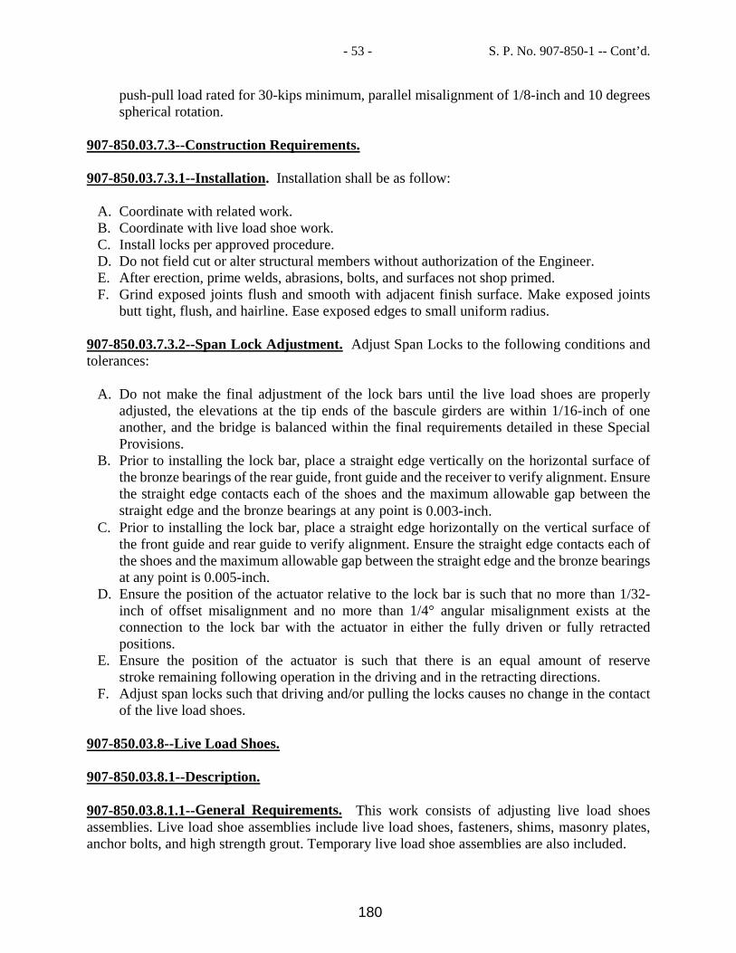
- 53 - S. P. No. 907-850-1 -- Cont’d.
push-pull load rated for 30-kips minimum, parallel misalignment of 1/8-inch and 10 degrees spherical rotation.
907-850.03.7.3--Construction Requirements. 907-850.03.7.3.1--Installation. Installation shall be as follow:
A. Coordinate with related work. B. Coordinate with live load shoe work. C. Install locks per approved procedure. D. Do not field cut or alter structural members without authorization of the Engineer. E. After erection, prime welds, abrasions, bolts, and surfaces not shop primed. F. Grind exposed joints flush and smooth with adjacent finish surface. Make exposed joints
butt tight, flush, and hairline. Ease exposed edges to small uniform radius. 907-850.03.7.3.2--Span Lock Adjustment. Adjust Span Locks to the following conditions and tolerances:
A. Do not make the final adjustment of the lock bars until the live load shoes are properly adjusted, the elevations at the tip ends of the bascule girders are within 1/16-inch of one another, and the bridge is balanced within the final requirements detailed in these Special Provisions.
B. Prior to installing the lock bar, place a straight edge vertically on the horizontal surface of the bronze bearings of the rear guide, front guide and the receiver to verify alignment. Ensure the straight edge contacts each of the shoes and the maximum allowable gap between the straight edge and the bronze bearings at any point is 0.003-inch.
C. Prior to installing the lock bar, place a straight edge horizontally on the vertical surface of the front guide and rear guide to verify alignment. Ensure the straight edge contacts each of the shoes and the maximum allowable gap between the straight edge and the bronze bearings at any point is 0.005-inch.
D. Ensure the position of the actuator relative to the lock bar is such that no more than 1/32-inch of offset misalignment and no more than 1/4° angular misalignment exists at the connection to the lock bar with the actuator in either the fully driven or fully retracted positions.
E. Ensure the position of the actuator is such that there is an equal amount of reserve stroke remaining following operation in the driving and in the retracting directions.
F. Adjust span locks such that driving and/or pulling the locks causes no change in the contact of the live load shoes.
907-850.03.8--Live Load Shoes. 907-850.03.8.1--Description. 907-850.03.8.1.1--General Requirements. This work consists of adjusting live load shoes assemblies. Live load shoe assemblies include live load shoes, fasteners, shims, masonry plates, anchor bolts, and high strength grout. Temporary live load shoe assemblies are also included.
180

- 54 - S. P. No. 907-850-1 -- Cont’d.
907-850.03.8.1.2--Related Work. Coordinate work with general machinery requirements described herein and in MDOT Specifications. 907-850.03.8.1.3--Submittals. Provide Shop Drawings in accordance with MDOT Specifications and these Special Provisions. Including but not limited to: Fully detailed drawings of live load shoe assembly components to be replaced, including
shims, fasteners and anchor bolt nuts as shown in the Contract documents. Manufacturer’s data sheets for Non-Shrink Epoxy Leveling Grout and sheet lead. Indicate fits, finishes, size and type of fasteners, and accessories. Indicate number and location of leveling screws, jacks, temporary live load shoe assemblies,
or other materials and equipment used to set and adjust the live load shoe assembly. Indicate anchor bolt tensioning or nut tightening as required.
Procedure for adjusting shims/grout pad and equalizing the loads on the live load shoe assemblies.
907-850.03.8.2--Materials. Ensure that shims less than 1/4-inch thick are stainless steel. Use Non-Shrink Epoxy Leveling Grout to grout between concrete pier and sole plate. Provide fasteners and anchor bolt nuts as required per the Plans. 907-850.03.8.3--Construction Requirements. 907-850.03.8.3.1--Load Equalizing. When all four of the live load supports have been installed with the nominal shims indicated, lower each leaf until there is approximately 1/2-inch of space below each live load shoe. Use the following procedure to obtain equal loading on the two live load shoes for each leaf:
A. Release all brakes on the span drives for the leaf in question to allow the span to settle down bringing at least one live load shoe into contact with its strike plate. Note that the span locks should not be installed at this time.
B. If both live load shoes contact their strike plates, raise the leaf and insert a temporary shim 1/2- inch thick under the adjacent shoe (Sa). Lower the leaf by releasing the brakes. Measure the clearance (Co) under the opposite shoe (So). Raise the leaf and remove the 1/2-inch temporary shim from under the adjacent shoe and insert it under the opposite shoe. Lower the leaf by releasing the brakes. Measure the clearance (Ca) under the adjacent shoe. If the clearances Ca and Co measured under the two live load shoes with the temporary shim in place are equal, no additional shim adjustment is required at this time. If Ca is greater than Co, additional shims must be installed under Sa with a thickness of T= (Ca-Co)/2. If Co is greater than Ca, additional shims must be installed under So with a thickness of T= (Co-Ca)/2.
C. If one of the live load shoes does not contact its strike plate, measure the clearance (C1) under that shoe (S1). Raise the leaf and install a temporary shim of thickness (C1+1/2-inch) at S1. Lower the leaf and measure the resulting clearance C2 at the other shoe (S2). Install permanent shims at S1. The thickness (T) of the permanent shims will be T= [C1 + (1/2-inch-C2)/2)].
907-850.03.8.3.3--Span Vertical Alignment. After the shimming described above to equalize
181

- 55 - S. P. No. 907-850-1 -- Cont’d.
the loads on the live load supports has been completed for both leafs, additional shim adjustments may be required to bring the tips of the two leafs to the proper elevation and to align the roadways at the tips of the two leafs. Use the following procedures to complete the shimming of the live load supports:
A. Lower both leafs to the fully closed position with all four live load shoes in firm contact with their strike plates.
B. Measure the elevation of the tips of the two leafs at the center of the waterway with respect
to the elevations of the roadways on the ends of the approach spans adjacent to the bascule spans.
C. Measure the differences in elevation between the roadways at the tips of the two leafs, at the center of the roadway, and at the point on the roadway two feet (2’) inboard of each curb.
D. Determine what adjustment in shim thickness is required at the live load supports to properly align the roadways at the tips of the two leafs and to position them at the proper elevation with respect to the approach span roadways. Ensure the difference in elevation from the span centerline to the rear joint between the fixed and bascule spans is as shown in the Contract documents ±1/8-inch.
E. Install additional shims (or remove shims) above the live load shoes as required to position the roadways at the tips of the leaves at the proper elevation with respect to the roadways on the approach spans and to properly align the roadways on the two leafs vertically with one another. An equal amount of shims must be added or removed from the two live load shoes on a given leaf.
F. After adjusting the thickness of the shims under each live load shoes, lower the leafs by releasing the brakes and check the tips of the bascule leafs to see it they are at the proper elevation and are properly aligned with one another. Readjust shims under the strike plate if necessary.
907-850.03.8.3.3--Alignment. The live load supports are properly aligned when the live load shoe is in full contact with the live load strike plate. Contact is full if a 0.002-inch feeler gage cannot be inserted between the shoe and the strike plate along the entire length of live load shoe. 907-850.04--Method of Measurement. Mechanical Work, complete in accordance with the requirements of the contract, will be measured as lump sum unit. 907-850.05--Basis of Payment. Mechanical Work, measured as prescribed above, will be paid for at the contract unit lump sum price, which price shall be full compensation for all work, including all materials, equipment, tools, labor and all incidentals necessary to complete the work. Payment will be made under: 907-850-A: Mechanical Work - lump sum
182

MISSISSIPPI DEPARTMENT OF TRANSPORTATION SPECIAL PROVISION NO. 907-851-1 CODE: (SP) DATE: 08/07/2019 SUBJECT: Moveable Bridges PROJECT: BR-9385-00(017) / 107705301 -- Jackson County Section 907-851, Moveable Bridges, is hereby added to and made a part of the 2017 Edition of the Mississippi Standard Specifications for Road and Bridge Construction as follow.
SECTION 907-851--MOVABLE BRIDGES 907-851.01--Description. The intent and purpose of this work is to properly detail, manufacture, ship, install, adjust, and put a movable bridge in operation. 907-851.02-- Materials. Materials requirements for this work is addressed in Subsection 907-851.03 under the appropriate item. 907-851.03--Construction Requirements. 907-851.03.1--General. 907-851.03.1.1--Description. Execute movable bridge work in accordance with the Contract Documents. 907-851.03.1.2--Standards. Portions or all of certain recognized industry or association standards or specifications referred to as a requirement in these Technical Special Provisions are to be considered as binding as though reproduced in full unless supplemented and modified by more stringent requirements of the Contract Documents. Unless otherwise stated the reference standard or specification, which is current at the time the Contract Documents are sent out for solicitation, will apply. The following abbreviations will be used throughout the Contract Documents to designate standard specifications for material and workmanship:
American Gas Association AGA American Refrigeration Institute ARI Anti-Friction Bearings Manufacturers Association AFBMA National Electrical Contractors Association NECA
907-851.03.1.3--Supervisory Personnel Qualifications. Meet the requirements of the MDOT Specifications. Bridge Operator(s) and Foreman:
A. Provide a qualified bridge operator for operation, testing, and adjusting of the bridge from the first chargeable workday through final acceptance.
183

- 2 - S. P. No. 907-851-1 -- Cont’d.
B. Provide a foreman, who is qualified to operate the bridge, to supervise its operation, and to make any minor adjustments that may be required to the electrical or mechanical equipment.
907-851.03.1.4--Field Measurements and Surveys. Conduct field surveys to verify existing dimensions shown on the plans, prior to development of submittals. Identify field verified dimensions on submittals. Conduct field measurements and surveys as required to supplement information provided in the plans and as necessary to provide a complete and satisfactory fitting and operational installation. 907-85103.1.5--Products. Provide materials and equipment meeting the requirements of this TSP. Where particular are called for, provide said products unless otherwise approved by the Engineer. 907-851.03.1.6--Bridge Operator, Preventive Maintenance, and Routine Repair. Assume responsibility for the operation and all maintenance on the movable bridge as directed by the Engineer. For Maintenance Requirements refer to the established Maintenance Procedures with the Department. 907-851.03.1.7--Coordination. Coordinate installation and testing of the bridge drive and control systems. Coordination of Shop Drawings: Provide Shop Drawings meeting the requirements of MDOT Specifications. 907-851.03.1.8--Quality Control. Perform all work under this Technical Special Provision in accordance with an approved Quality Control Plan meeting the requirements of MDOT Specifications. 907-851.03.1.9--Equipment Start-Up. Verify that utilities, connections, and controls are complete and equipment is in operable condition. Observe start-up and adjustment. Record date and time of start-up, and results. Observe equipment demonstrations to the Engineer. Record times and additional information required for operation and maintenance manuals. Provide the services of a factory authorized start-up representative at the time of energizing and for the Functional Checkout as required in this Special Provision. 907-851.03.1.10--Inspection and Acceptance of Equipment. Prior to inspection, verify that equipment is tested, operational, clean, and ready for operation. Assist Engineer with review. Prepare list of items to be completed and corrected. 907-851.03.1.11--Submittals.
184

- 3 - S. P. No. 907-851-1 -- Cont’d.
907-851.03.1.11.1--General. Shop drawing and samples shall be as follows: Shop Drawings:
A. Refer to MDOT Specifications. B. Before preparation of shop drawings for new components that must mate with the existing
structure, obtain all necessary field dimensions to provide proper fit of the new components. Where new components are to be attached to the existing structure where existing fasteners exist, take care that any fastener holes in the new components will mate with the bolts/holes in the existing material.
C. Mark standard drawings showing more than one model or size, to indicate the model or size proposed.
D. Submit shop drawings of cabinets containing electrical equipment and include outside dimensions, areas for conduit penetrations, one-line and three-line diagrams, wiring diagrams, schematic and interconnection diagrams, terminal block arrangements and numbers (if such terminal blocks are intended for connection in the field) and operating instructions.
E. Provide layout drawings and geographic diagrams for the complete electrical and hydraulic systems.
F. Submit shop drawings when installation and mounting details of switches, fixtures, and devices are different from or not specifically detailed on the Plans.
Samples:
A. Refer to MDOT Specifications. 907-851.03.1.11.2--Product Data. Submit products meeting the requirements of MDOT Specifications. As-Built Drawings. As a condition precedent to final acceptance under MDOT Specifications, submit for review and approval by the Engineer, complete as-built drawings meeting the requirements of MDOT Specifications. In addition, provide an electronic copy of all documents in a format acceptable to the Engineer. Draft as built drawings from the marked up working drawings. Provide the working drawings for checking purposes. Ensure that as-built drawings are essentially the same as the working plans and shop drawings submitted for approval but showing all the changes made during construction. 907-851.03.1.11.3--Operations and Maintenance Manuals. Operations and maintenance manuals will be comprised of a compilation of the manufacturers’ catalog data, installation, and maintenance instructions. Provide an electronic copy of all documents in a format acceptable to the Engineer. As a condition precedent to final acceptance under MDOT Specifications, submit for review and approval by the Engineer, complete as-built drawings as well as operations and maintenance
185

- 4 - S. P. No. 907-851-1 -- Cont’d.
instructions meeting the requirements of MDOT Specifications. Initially submit outlines of the booklets. Submit full copies of the final booklets, as complete as possible, prior to Phase A of Functional Testing. Provide final, complete copies prior to Phase C of Functional Testing. First Booklet: Include the following items in the first booklet:
A. Table of Contents. B. Operator’s Instructions, covering in full the step-by-step sequence of operation of the bridge
and its auxiliaries, and noting all precautions required for correct operation. Include complete instructions for the following: 1. Selection of the power supply (commercial or stand-by). 2. Normal operation of the bascule leaf drive electric motors on commercial power source. 3. Auxiliary operation of bascule leafs with either bascule leaf drive motor energized by the
stand-by generator. Include in this description the method of transfer to stand-by operation, the arrangement of the machinery, and the necessary controls.
4. Emergency Operation of bascule leafs by use of the emergency procedures. Include in this description the method of transfer, the arrangement of the machinery, the necessary controls, and a step-by-step sequence of operation under the conditions of a functioning Programmable Logic Controller and a nonfunctioning Programmable Logic Controller.
C. Detailed maintenance instructions for adjusting, calibrating and operating all of the electrical and instrumentation equipment, including the manufacturer’s recommended preventative maintenance lubrication schedule.
D. A set of descriptive leaflets, bulletins, and drawings covering all items of equipment and apparatus made a part of the completed bridge operation and control, the service lighting system, the heating system, the instrumentation system, the lightning protection system, and the grounding system.
E. The catalog number of each piece and, where applicable, a complete parts list, to be used in case it becomes necessary to order replacement parts from the manufacturer. Furnish this information for all equipment such as motors, switches, circuit breakers, relays, controllers, cables, hydraulic system, etc.
F. Copies of all warranties on equipment supplied to the project.
Second Booklet: Include, in the second booklet, legible reduced size photocopies of the following drawings, corrected to show the work as constructed:
A. The complete spare parts list. B. All schematic wiring diagrams and mechanical schematic diagrams. C. The control console and control panel layouts and wiring diagrams for all equipment. D. The schedule of electrical and mechanical apparatus. E. The complete speed-torque-current curves for main drive motors (i.e., factory test data). F. All conduit and piping layout and installation drawings. G. All approved electrical and mechanical shop drawings. H. Lubrication Charts:
1. Provide lubrication charts. 2. Note: In addition to providing lubricating charts in the instruction books, mount full size
wall charts as follows:
186

- 5 - S. P. No. 907-851-1 -- Cont’d.
Mount copies of the first chart in each pier area near each piece of main drive machinery. Mount a copy of the second chart in the Control House. Provide mounted charts of at least 22 by 36 inch in size, mounted in a permanent frame
behind transparent plastic. Furnish two (2) full size permanent type reproducible of these charts to the Department
for replacement purposes. 907-851.03.1.12--Training. Provide classroom and on-site training for operations and maintenance personnel. Provide a DVD of all classroom training sessions. 907-851.03.1.12.1--Maintenance Training. Provide a minimum of 24 hours classroom and on-site training for 10 persons. Distribution of time may be divided as required but with a minimum of 8 hours on-site. Coordinate the location and time of the training with the Department. Include the following topics:
A. Lubrication. B. Preventive maintenance for all machinery including drive system, locking devices and
barriers. C. Electrical equipment. D. Adjusting of control system parameters. E. Emergency generator operation. F. Control system troubleshooting.
Perform maintenance training prior to the end of the Operational Testing period. 907-851.03.1.12.2--Operations Training. Provide a minimum of 8 hours on-site training for 10 persons. Include the following in training:
A. Operation of bridge under all conditions. B. Interlock functions. C. Bypass functions. D. Emergency stops. E. Manual gate and locking device operation. F. Emergency generators and manual transfer switch operations. G. Interpretation of trouble alarms. H. Operation under different operating and redundancy modes.
Perform operations training within the first 10 working days of the Operational Testing period, following Functional Acceptance. 907-851.03.1.12.3--Hydraulic Systems Training. Hydraulic systems training shall be as follows:
A. Provide a minimum of 24 hours classroom instruction for 10 Department employees.
187

- 6 - S. P. No. 907-851-1 -- Cont’d.
B. Provide each attendee a notebook that includes a course outline and manuals and/or textbook pertaining to the subject matter to be covered in the course.
C. Include the following topics in the course: 1. Industrial Fluid Power Basics. 2. Fluid Power Control. 3. Preventive Maintenance Procedures. 4. Trouble shooting and minor repairs. 5. Operation of the Bridge.
D. Provide a minimum of 16 hours of on-site instruction related to the topics covered in the classroom. Faults will be introduced into the system that the students will diagnose and correct, which will include the most common failures that are likely to be encountered in this type of operation.
907-851.03.2--Counterweights and Bridge Balancing. 907-851.03.2.1--Description. 907-851.03.2.1.1--Terminology. The terms “counterweight tub girders”, “tub girders”, and “counterweight girders” are used interchangeably. The terms “tie down assembly”, “tie-down device”, “tie down”, “tie-down”, and “hold down assembly” are used interchangeably. The terms “counterweight adjusting blocks”, “counterweight balancing blocks”, “counterweight blocks”, “adjusting blocks”, and “balance blocks” are used interchangeably. The terms “balance state” and “balance condition” are used interchangeably. The terms “steel ballast (counterweight)”, “counterweight steel ballast”, “steel ballast”, “counterweight transition slabs”, and “transition slabs” are used interchangeably. 907-851.03.2.1.2--Requirements for Balance States. Properly balance the bridge for all angles of operation and ensure the Counterweight will adequately clear adjacent pier walls, slabs, railings, beams, columns, machinery, etc. Consider the properly balanced condition for the bascule leafs as follows:
A. Ensure the bascule leaves are unbalanced toward the channel (tip heavy) by a moment of 105 kip-ft plus or minus 20 kip-ft with the bridge in the lowered (closed) position.
B. Ensure the bascule leaves unbalanced moment during all angles of bascule leaf operation does not exceed 125 kip-ft.
C. Center of gravity of the leaf forward of the centerline of rotation (trunnion) of the leaf with an alpha angle between a 0 degrees and a plus 50 degrees. The alpha angle is defined as the angle of elevation of the center of gravity of the leaf above (minus being below) the horizontal axis through the centerline rotation of the leaf. Location of the center of gravity within this range will yield a closing imbalance moment for the full rotation of the leaf, with maximum imbalance being near the fully closed position and minimum imbalance at the fully
188

- 7 - S. P. No. 907-851-1 -- Cont’d.
open position of the leaf. Required Interim Balance State: During the course of construction and for conditions where the leaf is not secured with tie-down devices, the maximum permitted imbalance requirement is indicated in Paragraph A (above). The Engineer may consider an imbalance outside this range acceptable for specific operations. For such operations, submit detailed request along with calculations completed in accordance with Specifications to the Engineer for review and approval. 907-851.03.2.1.3--General Scope of Work. The general scope of work shall be as follows:
A. General: The work specified in this Section is required for each leaf of each bascule span; items are not necessarily listed in the order of occurrence.
B. Provide span tie-down devices for the specified conditions and for conditions determined as producing an unstable leaf.
C. Develop and submit counterweight computations and finalized counterweight configuration. D. Develop and submit Leaf Balancing and Stability Plan. E. Furnish and install steel ballast per approved counterweight computations and configuration. F. Furnish and place concrete or cast-iron counterweight adjusting blocks as required for
achieving balancing. G. Achieve and maintain acceptable interim balance states for the bascule leafs throughout the
course of the work. H. Achieve an acceptable final balance state for the bascule leafs upon completion of the work. I. Furnish and install Span Balancing Test Gage Assemblies. J. Field survey and document final dimensional configuration of counterweight concrete, steel
ballast and adjusting blocks. K. Assist the Department during the performance of Balance Verification Tests.
907-851.03.2.1.4--Work Restriction and Requirements. Work restriction and requirements shall be as follows:
A. Meet the requirements of MDOT Specifications. B. Machining of the trunnion journals will not be permitted prior to the completion of
counterweight computations and acceptable establishment of the vertical location of the trunnion centerline.
C. Maintain a Balanced Leaf Condition at all times, the exception being those periods where tie-down devices are erected and fully functional.
D. Ensure that a Balanced Leaf Condition is present prior to the removal of tie-down devices. E. Ensure the main drive system is fully secured and operable at the initiation of the removal of
tie- down devices. F. The use of span locks as a tie-down device or as a supplement to a tie-down device is not
permitted. G. Installation of a steel ballast piece is not permitted until the Department has received certified
dimensions and shipping weight for that individual piece to be installed in the leaf. 907-851.03.2.1.5--Tie Down Device Requirements. Tie down devices shall meet the following requirements:
189

- 8 - S. P. No. 907-851-1 -- Cont’d.
A. Tie-Down Devices: Provide tie-down devices on an individual leaf for an operation where
the leaf will become unstable as a result of that operation. B. Have tie-down devices in place prior to conducting the following operations:
1. Erection of the bascule leaf(s). 2. Condition where the unbalanced moment exceeds the permissible limits designated under
the provisions of this Technical Special Provision; and 3. All other operations which will result in an unstable leaf.
C. Structural Capacity: 1. Non-Movable Leaf Condition: For the condition where the leaf cannot be readily rotated
into the down position, provide tie-down devices capable of sustaining the sum of the maximum imbalance moment and a 110 mph wind in accordance with the MDOT Specifications.
2. Movable Leaf Condition: For the condition where the leaf can be readily rotated into the down position, provide tie-down devices capable of sustaining the sum of the maximum imbalance moment and a 20 psf wind load in accordance with the AASHTO Standard Specifications for Movable Highway Bridges.
D. Utilize tie-down devices in pairs, one located at each main girder, unless otherwise permitted by the Engineer.
E. Connection of tie-down device elements to the main girder by welding will not be permitted; connection will be by bolting utilizing approved hole patterns.
F. Hold-down brackets detailed in the plans are permanent components of the bridge and are to remain on the bridge; remove all other tie-down devices the pier and leaf at the completion of the work.
G. Fabricate tie-down devices in accordance with the provisions of the MDOT Specifications. 907-851.03.2.1.6--Counterweight Details. The configuration of steel ballast, counterweight concrete, and adjusting blocks depicted in the Plans is intended as a guide to establish the final dimensional configuration of the counterweight. 907-851.03.2.1.7--Coordination. Meet the requirements of MDOT Specifications. Coordinate the work of this Section to ensure:
A. Proper alignment of live load shoe assemblies. B. Proper installation and alignment of span lock receivers.
907-851.03.2.1.8--Quality Assurance. Counterweight Computations: Provide signed and sealed counterweight computations and shop drawings. Computations for Tie-Down Devices: Provide signed and sealed computations and shop drawings. 907-851.03.2.1.9--Shop Drawings. Shop drawings shall meet the following:
A. As a minimum, submit the following for review and approval: Shop drawings for concrete or cast iron counterweight adjusting blocks; provide weight of block; product data for coal tar epoxy coating for cast -iron blocks; and shop and erection drawings for steel ballast.
190

- 9 - S. P. No. 907-851-1 -- Cont’d.
B. Counterweight Computations: 1. Submit detailed counterweight computations and shop drawings for interim leaf
configurations and interim balance states. 2. Submit detailed counterweight computations and shop drawings for the final leaf
configuration and final balance state. 3. Provide all counterweight shop drawings and counterweight computations signed and
sealed by a Professional Engineer registered in the State of Mississippi. 4. Counterweight computations are to identify as a minimum, the center of gravity of the
following component assemblies: Leaf structural steel, leaf machinery, unfilled grid flooring, concrete for the filled grid flooring, steel ballast, counterweight concrete, and counterweight adjusting blocks.
5. The theoretical weight of the individual grid flooring panels is to be determined by the flooring manufacturer and noted in the bill of materials on the grid flooring shop drawings.
6. The shipping weight (actual weight) of the individual grid flooring panels is to be determined by the flooring manufacturer and utilized to finalize computations.
7. The shipping weight (actual weight) of the individual steel ballast plates is to be determined by the steel manufacturer and utilized to finalize computations.
8. For counterweight computational purposes, verify the unit weight of concrete used in filled grid flooring with preliminary test blocks.
9. Use weights from approved structural steel and machinery shop drawings for computations.
10. For counterweight computational purposes, verify the unit weight of concrete used in the counterweight from preliminary test blocks.
11. In determining the final production dimensions of the steel ballast plates, consider production tolerances.
12. Provide 100 additional adjusting blocks for future balancing 13. Shop and erection drawings for placement of counterweight blocks: in addition to
conventional drawings, provide isometric showing configuration of blocks to be utilized to achieve an acceptable final balance state.
14. After achieving an acceptable final balance state, submit revised drawings depicting the final as-built configuration of the counterweight concrete, steel ballast and adjusting blocks.
15. At the completion of the Department’s Balance Verification Testing, submit revised erection drawings documenting the final configuration of adjusting blocks in the counterweight pockets.
C. Tie-Down Devices: Submit design computations and shop drawings, design computations and shop drawings to be signed and sealed by a Professional Engineer registered in the State of Mississippi.
D. Span Balancing (Interim and Final): Submit description of proposed equipment to be utilized, proposed balancing procedures, and proposed reporting forms.
E. Leaf Balancing and Stability Plan: 1. Prepare and submit a Leaf Balancing and Stability Plan for each leaf. 2. Outline proposed leaf stability for the duration of the project. 3. Specifically address each element of the Work associated with the leaf and the machinery
of the leaf that will affect the balance and stability of the leaf and the proposed measures
191

- 10 - S. P. No. 907-851-1 -- Cont’d.
that will be taken to ensure balanced and stable leaf conditions throughout the duration of the Work.
4. Specifically address and identify the sequence for placement of counterweight concrete. 5. Submit supporting shop drawings and counterweight computations. 6. Balance State Report: a. Submit for final balance state after all work on the leaf is complete but prior to the
Department conducting Balance Verification Tests. b. As a minimum, the balance state reports must contain the following: Geometric
parameters for equating pressure/torque and imbalance moment, pressure/torque measurements with associated leaf positions, accompanying weather, wind, and temperature measurements, quantification of the location of the center of gravity of the leaf, summary and conclusions, and Signed and Sealed by Professional Engineer registered in the State of Mississippi.
F. Steel Ballast: Provide certified dimensions and shipping weights referenced to piece identification. Submit prior to installation in the leaf.
907-851.03.2.1.10--Balance Calculations.
A. Complete weight and center of gravity calculations from approved shop details of the Bascule Leaves and all parts attached thereto. Perform balance calculations for each Bascule Leaf (two total sets). Compute the balance calculations in two phases: Phase 1 - Preliminary Balance Calculations using computed weights and
Phase 2 (Final Balance Calculations) using measured weights for steel grid deck panels, counterweight concrete, and deck concrete. Ensure the calculations are prepared, signed and sealed by a Professional Engineer registered in the State of Mississippi. In order to permit detailed checking, prepare these calculations as detailed below.
B. Compute weights on the basis of the net finished dimensions of the parts as shown in the Shop Drawings deducting for copes, cuts, clips and all open holes, except bolt holes.
C. Base the weight of heads, nuts, single washers, and threaded stick-through of all high tensile strength bolts, both shop and field, on the following unit weights:
Diameter of Bolt (in) Weight per 100 Bolts (lb) 1/2 17 5/8 31 3/4 52 7/8 78 1 114 1 1/8 154 1 1/4 205
D. Base the weight of fillet welds as follows:
Size of Fillet Weld (in) Weight (lbs/ft) 1/4 0.11 5/16 0.17 3/8 0.24
192

- 11 - S. P. No. 907-851-1 -- Cont’d.
7/16 0.65
E. No allowance is required for the weight of paint. Compute the weight of galvanizing as 7.5% of the steel weight of the components to be galvanized.
F. Compute weights of individual components to the nearest 0.1 lb accuracy. Summarize weights of assemblies to the nearest 1.0 lb accuracy. Summarize Bascule Leaf weight to the nearest 0.1 kip accuracy.
G. Locate the Center of Gravity (C.G.) of each component or assembly of components both horizontally and vertically. 1. Reference the C.G.’s longitudinally to the center of rotation:
a. Positive (+) distances are recorded for elements forward of the trunnion (i.e., toward the channel).
b. Negative (-) distances are recorded for elements behind the trunnion. 2. Reference the C.G.’s vertically to the center of trunnions:
a. Positive (+) distances are recorded for elements above the trunnion. b. Negative (-) distances are recorded for elements below the trunnion.
3. Record distances to components or assemblies to the nearest 0.010 foot of accuracy.
H. Use unit weights of rolled shapes per AISC. Use a unit weight of steel of 490 lb/ft3. I. Properly account (deduct) for items embedded in the Counterweight concrete (e.g.,
reinforcing steel, Counterweight bracing, etc.). J. In computing the vertical distances to the C.G.’s of the components, account for the vertical
geometry of the Bascule Leaf (i.e., the roadway vertical curve profile) and the effects of camber and dead load deflection. Compute dimensions based on the deflected shape with the bridge in the lowered (closed) position.
K. Summarize the computations in tabular form with components and/or subassemblies grouped together.
L. Report the weight and C.G. of each component in Department terminology as follows: 1. Weight, W in kips (to the nearest 0.01 kip). 2. Distances from center of trunnions to C.G., X (horizontal) and Y (vertical) in feet (to the
nearest0.010 ft). 3. The component contribution to unbalance torque in kip-ft shown as the products W*X
and W*Y (to the nearest 0.1 kip-ft.). 4. Add the component weights and unbalanced torques to produce totals for each Bascule
Leaf. M. Report the weight and C.G. of the sum total of all components for each Bascule Leaf in
Department terminology as follows: 1. Weight, W in kips (to the nearest 1.0 kip). 2. Distances from center of trunnions to C.G., X (horizontal), Y (vertical) and L (radial) in
feet (to the nearest 0.010 ft). 3. Angle, α, between a horizontal line through the trunnion axis and a line from the trunnion
axis through the C.G. of the Bascule Leaf in degrees (accuracy to 0.010 degrees). The angle is measured positive (+) upwards from a horizontal line extending forward (toward the channel) of the trunnion axis.
4. The net Bascule Leaf unbalance torque as the products, W*X, W*Y, and W*L, and the leaf unbalance torque, T = W*L*cos(θ +α), shown at ten degree increments of leaf angle, θ.
193

- 12 - S. P. No. 907-851-1 -- Cont’d.
907-851.03.2.2--Materials. 907-851.03.2.2.1--Tie-Down Devices. Provide tie-downs for securing leaf when an unstable condition exists. Tie-Down Concept: Only tie-down concepts which anchor the main girder to the pier will be considered. Engineer. Utilize tie down devices in pairs, one located at each main girder, unless otherwise permitted by the Connection of tie-down device elements to the main girder by welding will not be permitted; connection will be by bolting utilizing approved hole patterns. Hold-down brackets detailed in the plans are permanent components of the bridge and are to remain on the bridge; remove all other tie-down devices the pier and leaf at the completion of the work. Fabricate tie-down devices in accordance with the provisions of MDOT Specifications. 907-851.03.2.2.2--Steel Ballast. Steel ballast shall meet the following:
A. Material: Steel Plates. B. Minimum Unit Weight: 490 pcf. C. Fabrication Tolerances:
1. Length: Plus or minus 1 inch. 2. Width: Plus or minus 1/2 inch. 3. Thickness: Plus or minus 1/8 inch. 4. Flatness: 1/4 inch per square meter.
D. Mill Preparation prior to Shipment: Mark, by die stamping, piece identification on the top surface where lifting lugs are to be attached such that the piece can be identified after placement in the leaf. Lifting lugs may be attached at the mill or at the Site.
E. Dimensions: Plan Dimensions are for conceptual purposes only. Production Dimensions: Per approved counterweight computations and shop drawings.
907-851.03.2.2.3--Counterweight Blocks (Cast Iron). Cast-iron blocks shall meet the following:
A. Material: ASTM A48 or equivalent. B. Unit Weight: Minimum 450 pcf. C. Protective Coating: Coat Tar Epoxy: Abrasive blast and apply one coat of coal tar epoxy
coating minimum 8 mils dry film thickness. Optional: Hot-dipped galvanized in accordance with ASTM A153.
907-851.03.2.3--Construction Requirements. 907-851.03.2.3.1--Notifications. Notify the Engineer a minimum of 28 days prior to the date that is anticipated that the Department’s Balance Verification Testing is going to be required.
194

- 13 - S. P. No. 907-851-1 -- Cont’d.
Submit final Balance Report and confirm with the Department the date for Balance Verification Testing a minimum of seven (7) days prior to the date; failure to submit the report or confirm the date may result in a delay of the Balance Verification Testing; delays caused as a result from the failure to confirm the date is not a basis for claim. 907-851.03.2.3.2--Counterweight Adjusting Blocks. Fabricate counterweight adjusting blocks only after approval by the Engineer of the appropriate counterweight computations as specified elsewhere in this Special Provision. Place and arrange blocks throughout the course of the Work as required for achieving or maintaining acceptable balance states. . 907-851.03.2.3.3--Span Balancing - General.
A. For the initial and final balance states, obtain, as a minimum, torque measurements as follows: At leaf angular positions of every 10 degrees from Fully Closed to Fully Open. For a minimum of three cycles of the leaf; the intent is to obtain three measurements at each angular position, the second and third measurement being made after the leaf is cycled back to the closed position.
B. For interim balance states (maintenance balancing), obtain, as minimum, torque measurements as follows: At leaf angular positions of one, 30 and 60 degrees. For a minimum of two cycles of the leaf, same intent as paragraph A above.
C. Given the numerous variables that may have an effect on the values of the torque measurements, schedule testing generally as follows in order that measurements taken on one day may be better correlated with measurements taken on another day: 1. In the morning at sunrise so as to minimize the differential in ambient temperature. 2. At a time with no wind; if wind exists, preferably the wind should not be in a direction
along centerline of the bridge (perpendicular to the bridge deck surface). 3. If hydraulic drive: At a time where the main hydraulic system has remained idle for a
period of time and the hydraulic oil is being maintained by the system at its lowest temperature.
D. For each torque measurement, obtain and record the following data: Ambient temperature, weather conditions, wind speed and direction at the roadway surface, and, if hydraulic drive, oil temperature in power unit reservoirs and surface temperature of blind end cylinder piping.
907-851.03.2.3.4--Initial Balance State. Establish the initial balance state of each leaf at the time that tie-downs are disengaged, and the leaf is moved for the first time utilizing the main drive system. If appropriate, revise Leaf Balancing and Stability Plan and submit for the record. 907-851.03.2.3.5--Maintenance Balance During the Course of Construction. Maintain balance in accordance with the Leaf Balancing and Stability Plan. Maintain the bascule leaf(s) in balance for those periods where the main drive system is operable
195

- 14 - S. P. No. 907-851-1 -- Cont’d.
and tie down devices are not in place. Verify the condition of balance at time intervals appropriate with the work being performed in order to ensure a Balanced Condition at all times. For periods where tie down devices are in place, maintain the balance of the leaf(s) as the work progresses based on computational work and in accordance with the Leaf Balancing and Span Stability Plan. 907-851.03.2.3.6--Final Balancing. Complete all work on the leaf, including application of protective coatings, except for the installation of the live load shoe assemblies and the adjustment of the span lock assemblies, prior to initiation of the final balancing program. Perform the final balancing of the leaf; achieve an acceptable final balance state. Achieve an acceptable final balance state prior to the Department conducting Balance Verification Tests. Submit Balance Report and arrangement of adjusting blocks; submit Balance Report a minimum of seven days prior to date that the project is ready for the Department to begin Balance Verification Testing. 907-851.03.2.3.7--Dynamic Strain Gauge Testing. Dynamic Strain Gauge Testing includes, at minimum, the following items:
A. Description of experimental procedure including type and method of installation of strain gauge rosettes, method of transmission of low level signals, data acquisition equipment and strip chart recorders.
B. Location plan of span drive equipment showing proposed location of strain gauges, amplifiers, cable or radio links, data acquisition equipment and all associated cabling.
C. Details of method of transmission of signals from shafting to data acquisition units. D. Elementary wiring diagrams of interconnection of strain gauges, amplifiers, data acquisition
equipment and strip chart recorders. E. Description of electrical and mechanical factors including sample calculations for obtaining
shaft torque from measured strains, span imbalance and curve fitting and basis for friction correction.
F. Mount adhesive bond foil strain gauge rosettes on the shafts of each rack pinion. Sufficiently clean the areas of the shafts where the gauges are to be mounted to remove all contaminants. Mount two rosettes on each main pinion shaft at 180° from each other. Connect the two gauges such that any direct shear forces in the shafts are neglected and true torsional shear is measured.
G. Connect the gauge leads on each shaft to a four arm amplifier securely mounted to the shaft. Transmit the signals from the shafts to the data acquisition equipment either through cable links wound on spring operated cable reels with sufficient capacity and torque or through wireless transmitters.
H. Connect the output loads from each channel of the amplifiers in each shaft to a strip chart
196

- 15 - S. P. No. 907-851-1 -- Cont’d.
recorder with at least ten inch wide chart paper. Provide the strip chart recorder with an event marker connected to sensors on the pinion shaft such that increments of pinion shaft revolutions are recorded. Interpret each increment as opening angle utilizing the gear ratios of the machinery. Provide a step-wise adjustable chart speed and include a setting of at least 10 inches per minute.
I. Record the strains in both main pinion shafts versus leaf angle simultaneously during opening and closing to a suitable scale. Ensure the readings for all main pinions are at the same strain scale and chart speed and recorded during the same span opening.
J. Numerically convert the strains induced in the rack pinion shafts to torque for at least 10 points at equal intervals along the strain plots for both opening and closing. Process this data to give a curve of torque for the full travel of the leaf versus opening angle, corrected for friction.
K. Submit ten copies of a full report documenting the results of the strain gauge tests. The reports shall contain as a minimum the following: 1. Description of experimental procedure and equipment used. 2. Span drive diagram showing location at which strain gauges and event markers were
attached and all applicable gear ratios. 3. Photocopies of original strip charts for both leaf opening and leaf closing for all rack
pinion shafts. 4. Description of relationships and sample calculations for obtaining rack pinion shaft
torque from strains, span imbalance moment from pinion shaft torque and curve fitting and basis for friction corr ection.
5. Fitted curves of torque versus opening angle during opening and closing for each rack pinion shaft.
6. Curve of shaft torque versus opening angle corrected for friction. 7. Discussion of probable error.
The reports will be bound in between heavy plastic covers. Include in the report an introductory section incorporating the name of the bridge, the shafts tested, the date of the test, weather conditions during testing, and any other information requested by the Engineer. 907-851.03.2.3.8--Balance Verification Tests and Final Balancing. Provide safe access to the bridge for the Department to conduct Balance Verification Tests. Place additional adjusting blocks, remove existing blocks, or change arrangement of adjusting blocks as required by the Department. Record changes for submittal of final adjusting block configuration. 907-851.03.2.3.9--Acceptance and Final Documentation. Testing by the Department that verifies that a leaf is in an acceptable final balance state is the basis that the leaf is acceptable with respect to balancing. Obtain test results from the Department and combine with revised drawings showing final adjusting block configurations; submit as final documentation of the final balance state.
197

- 16 - S. P. No. 907-851-1 -- Cont’d.
907-851.03.3--Movable Bridge Functional Checkout. 907-851.03.3.1--General Requirements. Thoroughly checkout and test the movable bridge operation as defined herein, to determine compliance with the requirements for construction, safety, maintenance, and operation of the facility as required in the contract documents. Include in the tests verification of all functions related to leaf operation, maintenance, and safety whether specifically defined herein or required of the contract. Collect and assemble full documentation of the test requirements and provide in booklet form meeting the requirements of MDOT Specifications. Detail and submit in shop drawing format, for approval, test procedures for specific tests to be performed and the acceptance criteria for each test. Each procedure will be reviewed before and after testing by the Engineer. Ensure this testing demonstrates the functionality of the bridge components as well as the complete operation of the constructed facility. Shop test individual systems prior to this procedure as required herein or under individual item specification. Verify all mechanical, electrical and structural systems integration requirements. 907-851.03.3.2--Material Requirements. Functional Acceptance Test Books: Integrate and assemble information required for Functional Test books meeting the requirements of MDOT Specifications. 907-851.03.3.3--Construction Requirements. 907-851.03.3.3.1--General. The following general requirements shall be met:
A. The Functional Acceptance Tests consists of three parts. 1. Preliminary Checkout. 2. Functional Tests (three phases, A, B, C). 3. Operational Testing Period
B. Engineer Notification: Provide adequate notice (20 working days minimum) prior to all tests so that the Engineer can witness and accept the method and result of the testing. Perform all testing after all required submittals are reviewed and approved by the Engineer.
C. Manufacturer Representatives: Arrange to have at the site, for each test, appropriate representatives of the bridge drive and electrical control equipment. These representatives must be prepared to make adjustments to the equipment, of locating faults or defects and correcting them, and of obtaining from the manufacturers, without delay, new parts or replacements of apparatus which, in the opinion of the Engineer, do not perform satisfactorily.
D. Field Tests: Arrange for and provide all necessary field tests, as indicated herein and as directed by the Engineer, to demonstrate that the entire modified or reworked area is in proper working order and is in accordance with the approved Plans and Special Provisions.
E. Phasing of Tests:
198

- 17 - S. P. No. 907-851-1 -- Cont’d.
1. Implement the construction of the bridge in phases as required by the Maintenance of Traffic Plan. In general, the phases will consist of installing replacement systems, first in one pair of bascule leafs (Phase A), second in the other pair of leafs (Phase B), and third completing the integrated system (Phase C). Conduct independent, functional acceptance testing for each phase. Two leaf bascules will only need to complete Phase C.
2. Once construction work begins, do not open that structure to traffic until the detailed requirements for preliminary and functional testing as described below, and approved by the Engineer, are completed to the satisfaction of the Engineer. Functions which have been completed to the extent required of the testing may be accepted in part, provided the deficiencies have been documented, an approved plan of corrective action has been submitted, and an approved method of providing a safe substitute function has been implemented (example, gate functions may be provided by temporary flagmen).
3. Acceptance of a structure for operation and receipt of all required records and documentation will constitute completion of a phase (A or B) of the Movable Bridge Functional Checkout. Completion of Phase C will be accepted only when the entire integrated system has been tested and accepted, all temporary functions have been removed, all required records and documentation have been provided, and the Operational Testing Period has been successfully completed.
907-851.03.3.3.2--Tests. The Functional Acceptance Tests: Present specific, step by step procedures to demonstrate and provide data for evaluation of each function of the movable bridge. Include for each test quantitative measurements including torque, amperage, watts, pressure, temperature, speed, RPM, and other parameters required by the Engineer to evaluate functionality. Include method of measurement, and their method of recording. Refer to the testing requirements of TSP Sections in Special Provisions 907-850 and 907-852. Acceptance Criteria: Present Functional Acceptance criteria that is concise and void of ambiguities. State specific performance of each component or function with regards to the requirements of the design and each unique condition of performance. Include all normal and emergency operating conditions as defined in the Contract documents and design specifications and all maintenance modes of operation. 907-851.03.3.3.3--Preliminary Checkout. The following shall be performed during preliminary checkout:
A. Prior to scheduling the Functional or Acceptance Test, perform preliminary checks and make adjustments on the new work, such that the system is in general working order. Ensure that all control wiring has been completed and properly labeled. Coordinate this work with the maintenance of traffic plan such that any failure of the system being tested would not interfere with the scheduled use of the bridge.
B. Perform drive system tests during periods in which the span (or leaf) being tested is normally closed (i.e., closed to marine traffic). Provide backup means of lowering the leaf(s) if vehicular traffic is scheduled to use the bridge.
C. Run the bridge continuously in normal mode (not manual mode) for at least five days before performing the Functional Checkout.
D. Record the following during the preliminary checkout (record using time as the base
199

- 18 - S. P. No. 907-851-1 -- Cont’d.
measurement): 1. Chart recorded wattmeter readings for each main drive motor and lock motor during their
full cycle of operation. 2. Chart recorded pressure readings for both ends of each cylinder during their full cycle of
operation. 907-851.03.3.3.4--Functional Tests. Upon approval of the Engineer to proceed, conduct the Functional Acceptance Tests. The tests include the following functional tests and Acceptance Criteria: 907-851.03.3.3.4.1--Control Functions. The following shall be followed when testing both manual and automatic operations.
A. Bridge Sequence: Demonstrate the correct operation of the bridge as described in these Technical Special Provisions and in the drawings.
B. Demonstrate EMERGENCY STOP of each leaf at or during each phase of opening and closing the bridge (phases include ramping up or down, full speed, and creep speed).
C. Interlocks: 1. Simulate the operation of each limit switch to demonstrate correct operation and
interlocking of systems. 2. Demonstrate BYPASS operation for each failure for each required bypass (as listed in
Technical Special Provision 907-805C). 3. Simulate each failure for which there is an alarm message to demonstrate correct message
displays. 4. Provide comprehensive testing of interlocks to demonstrate that unsafe or out of sequence
operations are prevented. D. Position Indicator: Observe readings with bridge closed and full open to assure correct
readings. E. Navigation Lights:
1. Demonstrate that all lamps are working. 2. Demonstrate proper change of channel lights from red to green. 3. Demonstrate Battery Backup by simulating a power outage.
F. Traffic Gates, Sidewalk Gates, and Traffic Barriers: 1. Demonstrate proper operation of each gate arm. 2. Demonstrate opening or closing times. Time should not exceed 15 seconds in either
direction. 3. Demonstrate door switch safety interlocks and manual operations using hand crank.
G. Span Locks: 1. Operate each span lock through one complete cycle and record, with chart recorder, motor
power (watts) throughout the operation, record lockbar-to-guide and lockbar-to-receiver, clearances.
2. Operate each lock with hand crank for one complete cycle. 3. Record time of operation, stroke, and maximum operating motor current for each lock
bar assembly. 4. Verify lock bar to guides and receiver clearances and parallelism. 5. Verify that there is no movement of the leafs caused by the operation of the span locks,
200

- 19 - S. P. No. 907-851-1 -- Cont’d.
when the locks are pulled and driven with the bridge fully seated. H. Bumper Blocks: Demonstrate bumper block contact points relative to leaf position and
contact face parallelism. Record clearances between bumper blocks with leaf open to normal full open position.
I. Bridge Machinery (also refer to the testing requirements of TSP Section 907-850A): 1. Demonstrate operation of all lubrication systems. 2. Demonstrate live load shoe contacts and alignment of the bascule leaf rear and center
span joints. 3. Operate each leaf through six continuous cycles at full speed, three cycles for each
electric motor. During this inspect the machinery for proper function. Correct any abnormal conditions to the satisfaction of the Engineer, and retest in entirety.
J. Span Brakes Control: 1. During the span raise and lower operations, verify and record the normal automatic set
and release operation of the brakes. 2. Demonstrate brake hand release, each brake, one at a time, and monitor the hand release
indication through the PLC. 3. With the Span in non-permissive operation mode (span locks driven, drives not
energized), manually activate the brake set and release switches and monitor their set/released indication in the control system.
K. Emergency Power: Have test results from the tests specified in Special Provision 907-852 available for inspection.
L. Automatic Transfer Switch: 1. Perform automatic transfer by simulating loss of normal power and return to normal
power. 2. Monitor and verify correct operation and timing of: normal voltage sensing relays, engine
start sequence, time delay upon transfer, alternate voltage sensing relays, automatic transfer operation, interlocks and limit switch function, timing delay and retransfer upon normal power restoration, and engine shut -down feature.
M. Programmable Controller Program: 1. Demonstrate the completed program’s capability prior to installation or connection of the
system to the bridge. Coordinate the arrangements and scheduling for the demonstration with the Engineer and the Engineer-of-Record.
2. Prepare a detailed field test procedure and provide to the Engineer-of-Record for approval. Provide for testing as listed below:
a. Exercise all remote limit switches to simulate faults (including locks, gates, traffic
lights etc.). Ensure proper readouts appear on the alphanumeric display. b. When the local testing of all individual remote components is completed, check all
individual manual override selections for proper operation at the console. When all override selections have checked out satisfactorily, exercise for a full raise and lower cycle. It should operate as diagrammed on the plan sheet for the sequence of events.
c. Exercise a sequence of operation interweaving the by-pass functions with the automatic functions for all remote equipment.
d. Remove the power from the input utility lines, at which time, the Automatic Transfer Switch should activate the engine-generator to supply power. Raise and lower the bridge again; the bascule leafs should operate in sequence (one side of the span at a
201

- 20 - S. P. No. 907-851-1 -- Cont’d.
time). Upon completion of test, reapply utility power to the ATS; load should switch over to utility for normal operation.
e. Include, in the testing, verification that all safety features are included in the control logic and that the system will not accept commands that are contrary to the basic sequence diagram. Include the failure mode testing in the written field test procedure submitted for approval.
N. Hydraulic Functions (temporary hydraulics only): 1. Main Power Unit: Operate main hydraulic power units of each of the leafs under the
following conditions; record flow and pressure, and angle of opening versus time during operation. a. Operation with both pumps and all cylinders on line. b. Operation with one pump and all cylinders on-line (one test per pump). c. Operation with both pumps and two cylinders; take two cylinders off line and
disconnect from the leaf. 2. Demonstrate operation of temperature and low level switches:
a. Lower fluid level to just above low-level point and attempt operation of the leaf. b. Heat hydraulic fluid to shutdown temperature with immersion heater.
3. Hydraulic Cylinders: Demonstrate manual release of fluid in cylinders back to tank under no power condition.
O. Submarine Cable Assembly (Submarine Cables) (if used): 1. Perform the following tests, using a 1,000 volt megger, on each cable of the installed
submarine cable assembly: a. Insulation Resistance (IR): Measure and record the IR of each conductor to the rest
of the conductors and to the cable armor. Measure and record the IR of each conductor to ground.
b. Calculate and record the Polarization Index (PI) for each conductor as discussed in IEEE 62-1995 Revision using the 60 second and 10 minute readings.
2. IR readings of less than 100 MΩ are unacceptable. PI readings of less than 1.0 are unacceptable.
3. If more than 10% of conductors of any cable fail the PI or the IR measurements then the cable is deemed to be defective and has to be replaced.
4. If, at any time during construction, or after the initial testing described above, the submarine cable assembly is damaged, then perform the IR and PI tests again except that the IEEE 62-1995 Revision 30 second and 60 second readings can be used to determine the PI.
P. Submarine Cable Assembly (HDPE Conduits) (if used): 1. Perform the following tests, using a 1,000 volt megger, on each conductor of the installed
submarine cable assembly: a. Insulation Resistance (IR): Measure and record the IR of each conductor to the rest
of the conductors in the conduit. Measure and record the IR of each conductor to ground.
b. Calculate and record the Polarization Index (PI) for each conductor as discussed in IEEE 62-1995 Revision using the 60 second and 10 minute readings.
2. IR readings of less than 100 MΩ are unacceptable. PI readings of less than 1.0 are unacceptable.
3. If more than 10% of conductors in any conduit fail the PI or the IR measurements then
202

- 21 - S. P. No. 907-851-1 -- Cont’d.
all the conductors are deemed to be defective and have to be replaced. 4. If, at any time during construction, or after the initial testing described above, any of the
conduits in the submarine cable assembly is damaged such as by kinking, impact, etc., perform the IR and PI tests again on the conductors in that conduit except that the IEEE 62-1995 Revision 30 second and 60 second readings can be used to determine the PI.
907-851.03.3.3.5--Bridge Operational Testing Period. Upon successful completion of the Functional Checkout and the repair of all items that were identified during the functional tests, open the bridge for vehicular and marine traffic, and start a 60 day bridge operational testing period. Provide all materials and labor to operate and maintain the bridge for the operational testing period. During this period, open the bridge a minimum of four (4) times per day. During this period, under observation by the Engineer, test all aspects of the movable bridge and its operation. Repair or replace any mechanical or electrical component of the bridge that becomes inoperative or defective during the 60 day period, at no additional compensation. If correction of inoperative or defective equipment requires installation of components from a different manufacturer, or reconfiguration of components, the changes will be subject to approval by the Engineer. Additional functional testing of the corrected systems may be required and the 60-day Operational Testing Period may be increased or restarted at the sole discretion of the Engineer. Perform the tests at no additional compensation. Train Department personnel in the maintenance and operation of the bridge during the latter 15 days of this 60-day period. 907-851.03.4--Movable Span Jacking. 907-851.03.4.1--Description of Work General. The trunnion shaft of the SR 609 bridge will be machined as part of the scope of work for this project. Machining of the trunnion shafts requires jacking of the bascule leaf. The leaf will be jacked to remove the load from the bearings and to provide clearance between the bearing and the pillow block base to allow removal of the existing bearings, machining of the shafts and reinstallation of the bearings. The work may require removal and reinstallation of the trunnion bearing bases. 907-851.03.4.2--Bascule Leaf Jacking Procedure General. The bascule leaf will be jacked and blocked in a partially raised position to unload the bearings and provide clearance for the removal and reinstallation of the trunnion bearings. Leaf jacking will be performed with hydraulic jacks set on the live load shoe bearing plates forward of the trunnion and set on jacking columns installed onto the pier, under the stiffener aligned with the bumper block to the rear of the trunnion. Redundant jacks will be used at each jacking location and locking collars will be used on the jacks to maintain the leaf in the raised position once jacking is complete. The jacks will be piped to a common power unit through a manifold that has a valve for each line where all jacks can be isolated
203

- 22 - S. P. No. 907-851-1 -- Cont’d.
for raising or lowering. 907-851.03.4.3--Bascule Leaf Jacking Order of Events. The general order of events required for jacking the bascule leaf, and impacts to bridge use are as follows:
1. Prepare the live load shoe areas. 2. Install the rear jacking columns (leaf becomes inoperable for marine traffic). 3. Begin detour of roadway traffic. 4. Partially raise the leaf, remove the live load shoes and set the jacks under the bottom flanges
of the bascule leaf main girders in the four jacking locations. 5. Position jacks at each jacking point and final position the leaf for jacking, if necessary,
preferably by drifting under releasing the brakes. 6. Disconnect the leaf drive electric motors and lock out. 7. Remove the trunnion bearing caps (Attempt this prior to jacking operation to ensure it can
be performed when needed). 8. Perform measurements and markings establishing the position of the leaf on the pier and
the bearings on the leaf. 9. Release the brakes on the drive machinery. Set them after the teeth are disengaged. 10. Jack the span incrementally, primarily utilizing the rear jacks on their support weldments
until the final jacked position is achieved and the locking collars are set on the jacks. 11. Remove the existing north bearing. Measure shaft and have adapter provided to the
appropriate size. 12. Remove the existing south bearing. 13. Machine both shafts and prepare for reinstallation of the bearings. 14. Reinstall the bearings with new bronze bushings on the trunnions. 15. Lower the span, while performing any required alignment steps, including aligning the
appropriate rack and pinion teeth with the brakes released as necessary. 16. Install the trunnion bearing caps. 17. Remove the leaf jacking system. 18. Restore power to the drive motors and test operate the leaf. 19. Remove roadway detour.
907-851.03.4.4--General Jacking Notes. The following jacking notes shall be followed.
• Limit jack height to less than two inches (2”) due to the proximity of the leaf steel to the cross girder of the bascule pier deck.
• Do not change rack and pinion teeth engagement. Mark teeth to ensure the correct teeth are re-meshed when the leaf is lowered back into position.
• Lockout electric motor during jacking. • Mark locations of bearings prior to removal to ensure alignment upon replacement. • Use separate pressure power unit for forward and rear jacks.
907-851.03.4.5--Technical Documents for Review. Submit the following documents signed and sealed by an engineer licensed in Mississippi:
• Leaf Jacking and Support Details
204

- 23 - S. P. No. 907-851-1 -- Cont’d.
• Leaf Jacking Supporting Calculations 907-851.04--Method of Measurement. Span Balancing, complete in accordance with the requirements of the contract, will be measured as a lump sum unit. Balance Plates, complete in accordance with the requirements of the contract, will be measured per each. 907-851.05--Basis of Payment. Span Balancing, measured as prescribed above, will be paid for at the contract unit lump sum price, which price shall be full compensation for all work, including all materials, equipment, tools, labor and all incidentals necessary to complete the work. Balance Plates, measured as prescribed above, will be paid for at the contract unit price per each, which price shall be full compensation for all work, including all materials, equipment, tools, labor and all incidentals necessary to complete the work. Payment will be made under: 907-851-A: Span Balancing - lump sum 907-851-B: Balance Plates - per each
205

MISSISSIPPI DEPARTMENT OF TRANSPORTATION SPECIAL PROVISION NO. 907-852-1 CODE: (SP) DATE: 08/07/2019 SUBJECT: Electrical Construction for Movable Bridges PROJECT: BR-9385-00(017) / 107705301 -- Jackson County Section 907-852, Electrical Construction for Movable Bridges, is hereby added to and made a part of the 2017 Edition of the Mississippi Standard Specifications for Road and Bridge Construction as follow.
SECTION 907-852-- ELECTRICAL CONSTRUCTION FOR MOVABLE BRIDGES 907-852.01--Description. 907-852.01.1--Basic Requirements. This work includes furnishing all labor and materials required to complete, make ready for operation, and make operational the installation of all items of work to provide a complete power, lighting, and control system for the bridge and control tower in accordance with this Special Provision and the accompanying Contract Documents. Items of work include but are not limited to the following:
1. Perform testing and verify that the completed electrical system’s installation and performance is satisfactory with respect to the requirements of this Special Provision.
2. Furnish and install all wire, cables, conduits, wiring devices, connections, terminations, motors, controllers, relays, control equipment traffic gates, safety switches, and all other apparatus and accessories required by the Contract Documents.
3. Furnish and install the connections to motors and to other equipment, which motors and equipment furnished and installed under other sections of the Contract Documents.
4. Furnish and install the lightning protection system; air terminals, bonding conductors, down conductors and accessories.
5. Furnish and install a standby generator and automatic transfer switch, a double walled, above ground fuel storage tank, day tank if needed.
6. Furnish and install a motor control center. 7. Furnish and install squirrel cage induction drive motors and matching vector controlled
variable speed motor drives. 8. Furnish and install an integrated control system including control desk, control panel, and
field limit switches. 9. Furnish and install traffic gates where shown in the Plans. 10. Furnish and install navigational lighting and signals. 11. Furnish and install submarine cable ducts, steel casing, termination cabinet, wiring, and
cables. 12. Furnish and install surge protective devices. 13. Provide shop drawings for all electrical and control equipment.
206

- 2 - S. P. No. 907-852-1 -- Cont’d.
14. Provide system conduit and conductor layout drawings. Perform final detail design of electrical systems. Wiring and conduit work includes: runs to all traffic and pedestrian gates; traffic signals; limit switches; span lock motors; panelboards; drives and drive motors; local disconnect switches; generator, transfer switches, fuel tank, and accessories; motor control center; control desk; control panel; air horn; navigation lights, intercom and PA system; lightning protection system and ground bonding scheme; submarine duct and cable system; Control House amenities and equipment (including, but not limited to, air conditioning, exhaust fans, and appliances); and any other component necessary for a complete electrical operating system.
907-852.01.1.1--Regulatory Requirements. Perform all work, and furnish and install all materials and equipment in accordance with the applicable sections of the latest edition, at time of Contract signing, of the following:
National Electrical Code - NFPA 70 (NEC). Electrical Safety in the Workplace - NFPA 70E. National Electrical Safety Code - IEEE-C2
(NESC). Life Safety Code (NFPA-101). Underwriters Laboratories (UL) - all applicable UL standards where established for electrical
materials, devices, and equipment. National Electrical Contractors Association (NECA-1). Electrical Standard for Industrial Machinery - NFPA 79 (ESIM). Standard for the Installation off
Lightning Protection Systems - NFPA-780. AASHTO LRFD Movable Highway Bridge Design Specifications (second edition 2007 and all
interim revisions), published by the American Association of State Highway and Transportation Officials, Inc.
American National Standards Institute (ANSI). National Electrical Manufacturers Association (NEMA) - NEMA- MG1, plus all NEMA
standards where established for electrical devices, and equipment. Institute of Electrical and Electronics Engineer (IEEE) - Ground Testing Standard 81. Insulated Cable Engineers Association (ICEA). International Electrical Testing Association (NETA) - ATS.
907-852.01.1.2--Protection of Electrical Equipment. Protect electrical equipment from water damage, rain, condensation, and water dripping or splashing on equipment and wiring, at all times during shipment, storage and construction (prior to Final Acceptance). Provide temporary electrical connections to equipment heaters, or provide temporary heaters, as required to prevent damage from moisture. Provide climate-controlled environment for the storage of control equipment and assemblies during construction. Maintain temperature and humidity within the manufacturer’s required parameters for the equipment. Thoroughly dry out and put through special dielectric tests any equipment subjected to possible injury by water or dampness (including the interiors of motor control equipment or any other electrical devices).
207

- 3 - S. P. No. 907-852-1 -- Cont’d.
Protect equipment from damage from mishandling, dropping, or impact. Do not install damaged equipment. Provide spare parts in sealed, uniform-sized cartons, with typed and clearly varnished labels to indicate their contents, and stored in a portioned lockable steel or fiberglass cabinet. Also, provide a directory of permanent type describing the parts including the name of each part, the manufacturers’ number, and the rating of the device for which the part is a spare. Mark the spare parts to correspond with their respective item numbers as indicated on the elementary wiring diagram. Ensure spare parts are available at time of Functional Checkout. Replace all spare parts used during Functional Checkout at no additional cost to the Department. 907-852.01.1.3--Field Verification. Dimensions shown on the Plans are diagrammatic and are based on the Existing Plans and design basis electrical equipment. Field verify all dimensions based on the existing structure prior to shop drawing submittal and provide field verified dimensions on the shop drawings. Equipment dimensions may vary according to the Contractor’s proposed materials. Perform the detail design of the system as necessary to accommodate the existing bridge structure and proposed electrical equipment. 907-852.01.1.4--Coordination of Electrical Work. The contract documents are diagrammatic in showing certain physical relationships within the electrical work and must interface with other work including utilities and mechanical work. 907-852.01.1.5--Materials and Equipment to Install. Use only new materials that conform to the standards of the UL in every case where such a standard has been established for the particular type of materials and its intended application. Furnish and install all new conduit, wiring, disconnect switches, smoke detectors, panelboards, controls and relays, wiring devices, transformers, boxes, terminal blocks, electrical identification, motor controls, and supporting devices for a complete electrical installation on the bridge. Ensure that the material s are UL listed for the application. Ensure all electrical equipment used outside of the conditioned spaces of the Control tower is suitable for use in a marine (salt atmosphere) environment. 907-852.01.1.6--Electrical Journeymen. Perform all electrical work either by, or under the immediate supervision of an electrical journeyman. For this project, “under the immediate supervision” means that the journeyman is in the immediate vicinity and physically involved in performing the electrical work. 907-852.01.1.7--Control Systems Engineer. Retain the services of a Professional Engineer licensed in the State of Mississippi to serve as the Control Systems Engineer. The Project’s Control Systems Engineer serves as sole representative for the detail design, development, coordination, and testing of the entire electrical system including lightning protection, grounding, power
208

- 4 - S. P. No. 907-852-1 -- Cont’d.
distribution, leaf drives and interface to the electrical control system, and the electrical control system including the Motor Control Center (MCC), the Programmable Logic Controller (PLC), the control console. The Control System Engineer’s responsibilities include directing all factory, shop and field-testing of electrical components including the motor control center (MCC), the main distribution panel, motor controllers, the control panel, the control desk, and PLC program. The Control System Engineer is responsible for the review of all electrical Shop Drawings and Shop Drawings with electrical components, prior to submission, to ensure that all components of the bridge operating system submitted for use are compatible in every respect and that all components meet or exceed the specific requirements and intent of the project. The Control Systems Engineer shall not forward submittals for Engineer of Record review until all known issues have been resolved. Ensure the Control Systems Engineer is on site directing all testing and commissioning of the bridge operating equipment and systems including the span locks, span motors, brakes, and traffic gates in conjunction with the manufacturers’ on-site field engineer representatives for the mechanical equipment. 907-852.01.2--Quality Control. Ensure the Quality Control Plan includes all work under this Special Provision. 907-852.01.2.1--Test Procedures. Submit procedures for shop testing and functional acceptance testing as required under other Special Provisions within this Specifications Package. 907-852.01.2.2--Tools and Procedures. Manufacturer Requirements: Install, apply, or adjust all electrical equipment and materials in accordance with the manufacturers’ recommendations including the usage of the manufacturer specified tooling. When such materials are UL, or other third party, listed or recognized, the tooling used for field installation must be the same as, or the manufacturers’ approved equivalent to, the tooling utilized in the approval testing. When applicable, the approved tooling will provide a suitable identification to the work to allow verification of the use of the appropriate tool to perform the work. For example, use of crimping dies that contain identification marks that emboss the crimps made with them with an identification embossment. Where possible, the requirement to provide a level of workmanship quality is transferred to the tooling rather than the skills of the worker. For example: Conductor Stripping: Depend upon the use of approved non-nicking strippers rather than the operator’s skill with knife edged stripping tools to prevent wire nicking. Crimp Tightness: Proper crimping will depend upon the exclusive use of controlled cycle crimping tools that require the proper degree of compression before releasing the work rather than upon the operator’s judgment in squeezing the tool handle.
209

- 5 - S. P. No. 907-852-1 -- Cont’d.
Tie Tightness: Determine proper tensioning of cable and wrap ties by the use of the manufacturers’ specified calibrated tensioning tool rather than the operator’s judgment of what is “tight enough.” Fastener Torque: Tighten fasteners with a recommended torque, where the proper tightness is important to the performance of the function (which includes all electrical terminals), with a calibrated torque (limiting) screwdriver or other torque-indicating tool. 907-852.01.2.3--Tool Verification. Whenever any other Article of this Section requires material submittals, when tooling is associated therewith, submit the manufacturers’ tooling requirements and procedures, including catalog and calibration information, on the tooling that is proposed. Document all tooling used as to the method of use and the calibration requirements and procedures. Provide calibrations that are traceable to the National Institute of Standards and Technology (NIST) or other recognized standards laboratory. Equipment that requires repetitive calibration (e.g., terminal crimpers often require daily verification by pull testing sample crimps) must be supported, on site, by the required calibration verification instruments. Ensure that operating manuals for all specialized tooling are available on the site for reference at any time. 907-852.01.2.4--Tool Application. The journeyman electrician intending to operate a specialized tool must demonstrate his knowledge of, and skill in using, the tool including the knowledge and ability to judge the results produced by the tool and to recognize failure of the tool to perform satisfactorily. 907-852.01.2.5--Test Equipment. Provide test and measurement instruments suitable to perform the required tests including ratings and measurement accuracy as specified by the manufacturer. Clearly indicate the exact make and model of instrument used and include manufacturers’ specification data indicating the suitability of the instrument’s specifications. Use only test instruments calibrated and certified by an independent certification laboratory, to the required accuracy, in accordance with the instrument manufacturers’ requirements within a maximum interval of the preceding 12 months. Certify all calibrations as traceable to the National Institute of Standards and Technology (NIST) or other recognized standardization authority. Test instrument operating manuals and certification certificates must be available on the project site for reference whenever the instrument is being used or evaluated. 907-852.01.2.6--Test Result Reporting. Include the forms to be used for recording and submitting the data, where test or inspection data submittal is required by this Special Provision, in the Quality Control Plan. For all electrical testing, record the weather conditions including temperature, rain/fair, and relative humidity, on the form twice daily or more frequently at appropriate intervals as determined by the changing meteorological conditions. Record wind velocity and direction for leaf related tests where the wind loading is a factor in the performance or results. Record test instrument identification, including traceable serial number, for each measurement
210

- 6 - S. P. No. 907-852-1 -- Cont’d.
group. Include a copy of the Certificate of Calibration for the particular instrument in the submittal. Have the Control Systems Engineer review and approve all test data submittals prior to submittal. 907-852.01.2.7--Test Performance. Perform all tests in accordance to the latest edition of the International Electrical Testing Association (NETA) Acceptance Testing Specifications. 907-852.01.3--Working Plans and Shop Drawings. 907-852.01.3.1--Description. Provide Shop Drawings including but not limited to the following: 907-852.01.3.1.1--Data Sheets. Label data sheets for individual components such as motors, limit switches, etc. with the identification numbers shown in the Contract Documents. 907-852.01.3.1.2--Spare Parts. List of all manufacturers’ recommended spare parts. 907-852.01.3.1.3--Conduit Layout Drawings. Conduit layout drawings for conduit and wiring, including details of all conduit penetrations through structural elements, and each type of conduit and fitting. Include details of reinforcement in the penetration area on conduit penetration shop drawings. Show all conduit runs between all pieces of equipment in the drawings. Outline and support point dimensions, voltage, main bus ampacity, integrated short-circuit ampere rating, circuit breaker arrangement and sizes. Provide manufacturers installation instructions, which indicate application conditions and limitations of use, stipulated by the product-testing agency. Include instructions for storage, handling, protection, examination, preparation, installation and starting of all products. Record actual locations of all products and indicate actual branch circuit arrangement. 907-852.01.3.1.4--New Power and Telephone Service. Power service detailing routing with dimensions, pull box locations, expansion joint fitting type and locations, and conduit support assembly details. Show electric meter detail and location. Include documentation showing coordination with the electrical utility company. Include documentation showing coordination with the telephone utility company. 907-852.01.3.1.5--Electrical Shop Drawings. Prepare detailed electrical and control system designs as required to fabricate and furnish the control equipment, define the installation and interconnection of the electrical equipment including all required interconnections with equipment furnished under other sections of the Special Provisions for Movable Bridge Construction. 907-852.01.3.1.6--Fused Disconnect Switches. For fused disconnect switches include outline drawings with dimensions, equipment ratings for voltage, capacity, horsepower, and short-circuit. Provide manufacturers fuse and circuit breaker curves (time/current on log/log graph) for each rating of fuse and circuit breaker supplied. 907-852.01.3.1.7--Disconnect Switches. Voltage and ampere ratings, construction material, NEMA classification, and dimensioned outline drawing for each type switch.
211

- 7 - S. P. No. 907-852-1 -- Cont’d.
907-852.01.3.1.8--Electrical Equipment. Catalog data sheets for conduit and fittings, wire, wiring devices, outlet boxes, fasteners, terminal blocks, mounting hardware, junction and pull boxes, grounding, and safety switches. 907-852.01.3.1.9--Terminal Blocks. For each type and rating of terminal blocks, include voltage and ampere ratings, materials, and dimensioned outline drawings. 907-852.01.3.1.10--Conductors. For each type of conductor to be used. 907-852.01.3.1.11--Grounding. For each type of ground rod, clamp, well, and associated hardware. 907-852.01.3.1.12--Boxes. For all Junction and pull boxes. 907-852.01.3.1.13--Identification. For each type of identification device to be used for each electrical component. Provide an engraving schedule for all laminated nameplates. 907-852.01.3.1.14--Supporting Devices. For each type of strut, clamp, insert, and associated hardware; dimensional data for struts; and pullout data for anchors. 907-852.01.3.1.15--Fire Detection System. Dimensional data, ratings, and approvals; installation instructions for each type of device; and a detailed connection diagram for the overall installation. 907-852.01.3.1.16--Motors. Plan and elevation drawings with dimensional data, nameplate data, performance data including torque-speed and current graphs, and schematic diagrams for each type of motor. Provide certified motor drawings to the machinery fabricator for coordination. Include a motor data sheet indicating horsepower, voltage, FLA and LRA current, motor speed, NEMA frame size, insulation class, temperature rise, service factor, and any optional equipment or attachments such as tach-generator, encoder, thermal switch, or space heater in the motor submittals. Provide a motor torque-speed performance graph. Provide dimensioned outline, plan/elevation and wiring interconnect drawings. Include installation instructions, operation, and maintenance data with instructions for storage, handling, protection and starting of motors. Include assembly drawings, bearing data with replacement sizes, and lubrication instructions. 907-852.01.3.1.17--Motor Control Center. Coordination evaluation report for over current protective devices, conductors, and transformers. Ensure the report shows coordinated device trip settings for all the devices. One-line and three-line diagrams. Schematic diagrams for each cubicle (including field wiring with wire numbers). Wiring and Interconnection Diagrams for both starter cubicles and terminal only cubicles. Include field wiring in the schematic diagrams. Provide wire numbers for field wiring as shown in the Contract Plans. Ensure that field terminals on wiring diagrams also indicate these numbers. It is preferred that the Contract Plan wire numbers be used for internal wiring as well. However, if different numbers are
212

- 8 - S. P. No. 907-852-1 -- Cont’d.
used, mark terminals for field wiring as “panel wire number/field wire number.” Elevation and dimensioned outline drawings detailing arrangement of sections, cubicles, wireway and conduit entry. Equipment schedule (Bill of Materials) detailing all components (with manufacturer’s part no.) for each controller (cubicle). Surge suppressor details. Phase-loss indicating instrumentation. Engraving schedule for nameplates. Descriptive data for all components circuit breakers (CBs), starters, overload (OL) relays, hand-of-automatic (HOA) switches, lights, indicators. Furnish instruction manuals describing theory of operation, maintenance information and schematics of motor starter units. Rubber Mats. 907-852.01.3.1.18--Integrated Bridge Control System. All components (terminal blocks, relays, timers, fuses, circuit breakers, sensors, etc.). Provide instructions for adjusting and resetting time delay relays and timers. Dimensioned fabrication details for control desk, main control panel, and other enclosures including, to scale, equipment layouts, punch-outs, nameplate schedules, and bill of materials. Label all components, for which identification numbers are provided in the Contract Documents, with that number. Bill of materials. Provide some means of cross-referencing the item identification numbers to the materials list; either by schedule or labeling the applicable catalog data sheets. Engraving schedule for nameplates. Schematic diagrams including field wiring. Assign wire numbers for each wire and include in the schematic and wiring diagrams. PLC topology, dipswitch settings, and input/output addresses. PLC program listing. Alarm message listing. Dimensioned details for mounting of limit switches and field control devices. Procedures for shop test and functional acceptance testing. Perform the detailed design of the control system using information in the Contract Documents.
213

- 9 - S. P. No. 907-852-1 -- Cont’d.
Test procedure and schedule. Ensure the testing procedure is a detailed systematic description of the bridge operating systems. Ensure the shop testing demonstrates operator action to be taken and the expected control response, output, or sequence of outputs. Provide adequate notice (20 working days minimum) prior to all tests so the Engineer can witness the testing. Do not perform any testing until the Engineer approves all required submittals. Prepare a test procedure that demonstrates the following: Normal sequence operation of the bridge devices. Relay based maintenance sequence operation of bridge functions. Operating faults and recovery sequence operation of the bridge devices. The proper operation of safety interlocking functions. The proper operation of control system bypass function. The proper operation of all specified control system alarms. Ensure that the test procedure lists, in numbered steps, the following: The control system function to be demonstrated. The control desk action to be performed by the operator. A listing of the expected intermediate and final results of the equipment functions related to the operator action. Final equipment state at the completion of the operator action. The out-of-sequence operation of the traffic gates, span locks, and leaf operation to verify control system interlocks. The expected result of each out-of-sequence operation system Alarms to be tested. A detailed description of what device will be used and how the equipment fault will be produced to initiate the control system alarm. Provide each step with Pass and Fail blanks. Add up to 20% alarms during the shop testing, installation, or start-up and commissioning, at no additional cost. 907-852.01.3.1.19--Traffic Gate Assemblies. Manufacturer’s installation instructions. Operation and maintenance data. Maintain these construction shop drawings as working drawings for the duration of construction. Required working drawings include conduit routing plans, schematic diagrams, interconnection wiring diagrams, and conduit and cable schedules. Make working drawings available to the
214
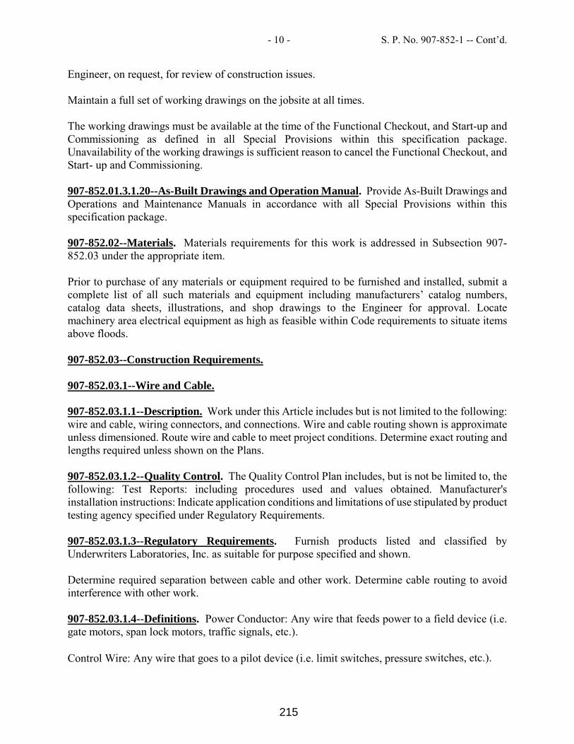
- 10 - S. P. No. 907-852-1 -- Cont’d.
Engineer, on request, for review of construction issues. Maintain a full set of working drawings on the jobsite at all times. The working drawings must be available at the time of the Functional Checkout, and Start-up and Commissioning as defined in all Special Provisions within this specification package. Unavailability of the working drawings is sufficient reason to cancel the Functional Checkout, and Start- up and Commissioning. 907-852.01.3.1.20--As-Built Drawings and Operation Manual. Provide As-Built Drawings and Operations and Maintenance Manuals in accordance with all Special Provisions within this specification package. 907-852.02--Materials. Materials requirements for this work is addressed in Subsection 907-852.03 under the appropriate item. Prior to purchase of any materials or equipment required to be furnished and installed, submit a complete list of all such materials and equipment including manufacturers’ catalog numbers, catalog data sheets, illustrations, and shop drawings to the Engineer for approval. Locate machinery area electrical equipment as high as feasible within Code requirements to situate items above floods. 907-852.03--Construction Requirements. 907-852.03.1--Wire and Cable. 907-852.03.1.1--Description. Work under this Article includes but is not limited to the following: wire and cable, wiring connectors, and connections. Wire and cable routing shown is approximate unless dimensioned. Route wire and cable to meet project conditions. Determine exact routing and lengths required unless shown on the Plans. 907-852.03.1.2--Quality Control. The Quality Control Plan includes, but is not be limited to, the following: Test Reports: including procedures used and values obtained. Manufacturer's installation instructions: Indicate application conditions and limitations of use stipulated by product testing agency specified under Regulatory Requirements. 907-852.03.1.3--Regulatory Requirements. Furnish products listed and classified by Underwriters Laboratories, Inc. as suitable for purpose specified and shown. Determine required separation between cable and other work. Determine cable routing to avoid interference with other work. 907-852.03.1.4--Definitions. Power Conductor: Any wire that feeds power to a field device (i.e. gate motors, span lock motors, traffic signals, etc.). Control Wire: Any wire that goes to a pilot device (i.e. limit switches, pressure switches, etc.).
215

- 11 - S. P. No. 907-852-1 -- Cont’d.
Field Wire: Any wire that leaves the control tower. Consider the machinery platform to be outside the control tower. 907-852.03.1.5--Materials. Use stranded copper wire and cable. Do not use aluminum conductors. Single conductor insulated wire. Provide XHHW-2 rated 600 VAC unless otherwise noted. Provide SE, or RHW-2 insulated wire for incoming services unless otherwise noted. Use seven or nineteen strand copper, minimum 98% conductivity conductors for field wiring. Furnish connector accessories for copper in sufficient quantities for a complete installation. Do not use aluminum or solid copper conductors. In cases of low level audio or digital signals, use twisted shielded pairs when required. Use no wire smaller than No. 12 AWG for power and lighting circuits and no smaller than No. 14 AWG for control wiring between cabinets, except that control wiring within a manufactured cabinet may be smaller. Use of wires smaller than No. 18 AWG, except for Ethernet or DMX512 applications, requires approval. If approved, use multi-conductor ribbon cables between components within a cabinet. Install per the requirements of UL 508. Minimum field wire size is No. 12 AWG for control conductors between cabinets and field devices and No. 10 AWG for motor loads. Use pigtails as short as feasible but no longer than 3 feet for connection of field devices that cannot accommodate a No. 12 AWG or No. 10 AWG wire as appropriate. Use No. 10 AWG for 20 A, 120 VAC, branch circuit home runs longer than 75 feet, and for 20 A, 277 VAC, branch circuit home runs longer than 200 feet. Maximum wire size allowed is 500 kcmil. Use parallel runs as needed for larger loads or voltage drop considerations. For motors on Adjustable Speed Drives, use designated VFD motor feeder cable; 3-conductor, with ground, and overall shield. Size the conductor as recommended by the ASD manufacturer for this application. 907-852.03.1.6--Construction Requirements. Installation includes placement, splicing, terminating, identifying, testing, and verifying each circuit and conductor. Do not splice wires (except for “pigtail” leads and lighting circuits), use insulated terminal blocks rated for 600 VAC in enclosures. If more than three current carrying conductors are in a conduit, de-rate the conductors according to the NEC. For derating purposes, consider all power conductors, other than the grounded conductors, as current carrying. This requirement does not apply to control wires. Cover any uninsulated conductors and connectors with heat-shrink insulation rated for 600 VAC. Neatly train and lace wiring inside boxes, equipment, and panelboards. Place an equal number of conductors for each phase (three-phase system) of a circuit in same raceway or cable. Make conductor lengths for parallel circuits equal. Pull all conductors into a raceway at the same time.
216

- 12 - S. P. No. 907-852-1 -- Cont’d.
Install two spare conductors, minimum, for long field runs to critical devices such as traffic gates, traffic signals, and all movable span mounted devices, etc. Use only water based, wax free, UL listed wire pulling lubricant for pulling wire and cables. Do not exceed the pulling tensions recommended by the manufacturer; pulling may be witnessed by the Engineer. Cap all conduit ends with threaded PVC or nylon bushings. Take precautions to avoid “sawing” through PVC conduit or the end cap bushings. Use only braided pull ropes. Do not pull bare conductors through PVC conduits. Swab conduit with a lubricant approved by the Engineer prior to pulling the conductors. Test each circuit for continuity and short-circuits for its complete length before connecting to the load. Verify identification numbers for the entire length of the circuit. Inspect wire and cable for physical damage and proper connection. Perform the insulation resistance testing for motor windings and conductor insulation as required by the latest edition of the NETA ATS (International Electrical Testing Association Acceptance Testing Specifications for Electric Power Distribution Equipment and Systems), including dielectric absorption testing. Measure insulation resistance after 30 seconds. For equipment rated at 250V nominal, test at 500VDC. For equipment rated at 600V nominal, test at 1,000VDC. Measured resistance values less than 25 M ohms on equipment with a 250 volt nominal rating are not acceptable. Measured resistance values less than 100 M ohms on equipment with a 600 volt nominal rating are not acceptable. The Engineer will witness the test. Record the test results and submit to the Engineer for review prior to energizing the circuit. Include a Table of the test results with the “as-built” drawings with additional columns left blank for recording future readings. 907-852.03.2--Grounding. 907-852.03.2.1--Description. Ground the electrical power and control system in accordance with NEC Article 250 requirements. Furnish and install ground rods and grounding conductors as shown in the Plans. The requirements for the electrical grounding system do not apply to the Lightning Protection system grounding requirements. 907-852.03.2.2--Materials. Use only insulated soft drawn annealed copper grounding conductors unless otherwise noted in the Plans. Use 1-inch diameter, 10-foot, copper clad steel ground rods and extensions. Provide ground well 10 inches in diameter, 24 inches long, PVC, with a belled hub and a galvanized steel cover. Use tin plated, high-pressure compression, one-hole lug connections for grounding equipment. Use only exothermically welded connections to ground rods. 907-852.03.2.3--Construction Requirements. Install a dedicated ground conductor, with green insulation in each conduit in which voltage of the current carrying conductors exceeds 50 V. Size grounding conductors in any conduit in accordance with NEC Table 250.122, or the same AWG as the largest current carrying conductor in the conduit, whichever is larger.
217

- 13 - S. P. No. 907-852-1 -- Cont’d.
Provide two ground rods and wells at the service entrance main disconnect switch in accordance with the NEC. Locate ground wells within 10 feet of the main disconnect switch mounting support. If the resistance between the two ground rods exceeds 25 ohms, add extensions and drive rods deeper. Provide a service entrance grounding conductor from the case ground to the well. Install the ground well so that the top of the well is 1/2 inch above the finished grade and drive the rod to just below the top. Fill well with gravel. Bond the electrical system to the lightning protection system ground at the lightning grounding electrode (rod) closest to the motor control center in the bridge pier and the ground buss in the motor control center. 907-852.03.3--Supporting Devices. 907-852.03.3.1--Description. Provide hangers and supporting devices as required by AASHTO, the NEC, and this Special Provision. 907-852.03.3.2--Materials. Provide brass or stainless steel mounting bolts, nuts, washers, and other hardware used for fastening boxes, disconnect switches, devices, lighting outlet boxes, conduit clamps, and similar devices. Use hexagonal bolt heads and nuts. Do not use bolts smaller than 3/8 inch in diameter except as may be necessary to fit the mounting holes in small devices, outlet boxes, and similar standard equipment. Provide PVC coated steel support struts and clamps to support PVC coated conduits. Furnish products listed and classified by UL as suitable for purpose specified and shown. Provide adequate corrosion resistance and ensure that the material selected for the hardware is compatible with the material of the device supported. Provide materials, sizes, and types of anchors, fasteners and supports to carry the loads of equipment and conduit. Consider weight of wire in conduit when selecting products. Minimum safety factor is 2.0. Provide stainless steel framework for supporting boxes, switches, and other externally mounted electrical devices fabricated from stainless steel not less than 3/8 inch thick. If material of thickness less than 3/8 inch is used, obtain approval of the Engineer. For U-Channel strut systems utilizing bolted construction, provide stainless steel, 12 gage and 1-1/2 inch width minimum components from the same manufacturer. 907-852.03.3.3--Construction Requirements. Do not use powder-actuated anchors or weld structural steel members. Do not drill structural steel members without prior approval of the Engineer. Do not fasten supports to piping, ductwork, mechanical equipment, or other conduit. In addition, do not allow piping, or other trades to fasten to electrical conduits and supports. Use hexagonal bolt heads and nuts with spring lock washers under all nuts. Fasten hanger rods,
218

- 14 - S. P. No. 907-852-1 -- Cont’d.
conduit clamps, and outlet and junction boxes to structure using proper fasteners. Use toggle bolts or hollow wall fasteners in hollow masonry, plaster, or gypsum board partitions and walls; expansion anchors or preset inserts in solid masonry walls; self-drilling anchors or expansion anchor on concrete surfaces; sheet metal screws in sheet metal studs; and wood screws in wood construction. Use stainless steel straps or hangers held at not less than two points for attachment to steel or concrete. Provide insulation protection between conduit and straps to protect against dissimilar metal corrosion. Provide type 316 stainless steel concrete inserts with concrete work. Install surface-mounted cabinets and panelboards with minimum of four anchors. Fasten device boxes to the mounting surface with not less than two anchors sized per manufacturer’s recommendations. Fasten hanger rods, conduit clamps, and outlet and junction boxes to structure using proper fasteners. Ensure that cut offs are cut square, ground smooth and de-burred. Where PVC coated steel has damage to the coating, coat the exposed steel with the manufacturers’ touch up coating, to the same thickness as the original, prior to installation. Use stainless steel cast in place inserts for overhead supports. 907-852.03.4--Conduit and Raceway. 907-852.03.4.1--Description. Furnish and install conduit and raceways in the quantities and sizes required to complete the work as shown in the Plans. If the Plans do not show conduit size, determine the size as required by the NEC, minimum conduit size allowed is 3/4 inch. Furnish products listed and classified by UL for purpose specified and shown. Do not use non-metallic flexible conduit, aluminum conduit, intermediate metal conduit (IMC), or electrical metallic tubing (EMT). Recombine conduit and circuits indicated in the Plans, diagrams, and schedules where appropriate and as approved. 907-852.03.4.2--Materials. 907-852.03.4.2.1--PVC Coated Metal Conduit. Hot dipped galvanized, inside and out, rigid steel conduit (ANSI C80.1) with hot galvanized threads and external PVC coating 40 mils thick; meeting the requirements of NEMA RN 1 and fittings and conduit bodies meeting the requirements of ANSI/NEMA FB 1 with steel fittings with internal and external PVC coatings to match conduit. Provide 40 mils thick PVC coating on the outside of conduit couplings and a series of raised longitudinal ribs to protect the coating from tool damage during installation. Ensure the bond between the PVC coating and the conduit surface is greater than the tensile
219

- 15 - S. P. No. 907-852-1 -- Cont’d.
strength of the coating. Verify this bond by testing as described in NEMA Standard RN-1, section 3.8. Uniformly, and consistently, apply a nominal 2-mil thick urethane coating to the interior of all conduit and fittings. Conduit or fittings having pinholes or areas with thin or no coating are unacceptable. Protect all factory cut threads on conduit, elbows, nipples, and fittings by application of a urethane coating. For threads cut in the field, apply the manufacturer’s touch-up urethane coating (not the PVC coating patching compound) according to the manufacturer’s recommendations. Allow touch-up coatings to cure fully before using the threads. The PVC exterior and urethane interior coatings applied to the conduit must afford sufficient flexibility to permit field bending without cracking or flaking at temperatures above 30°F. Furnish right angle beam clamps and U-bolts specially formed and sized to fit the outside diameter of the PVC coated conduit. Supply all U-bolts with plastic encapsulated nuts that cover the exposed portions of the threads. Ensure that only tools designed and approved by the conduit manufacturer for use on PVC coated materials are used and the workmen performing the installation are trained and certified in the installation and use of PVC coated conduit and fittings by the manufacturer. Ensure that the same manufacturer supplies all PVC coated conduit, fittings, and accessories. 907-852.03.4.2.2--Liquid-Tight Flexible Metal Conduit. UL 360 listed, interlocked galvanized steel construction, with integral ground continuity and PVC jacket. Use only PVC coated fittings, meeting the requirements of ANSI/NEMA FB 1. Use liquid tight flexible galvanized steel metal conduit only for the connection of motors, limit switches, and other devices that must be periodically adjusted in position. Make connections between the rigid galvanized steel conduit system and all motors, and movable limit switches with flexible conduit with couplings and threaded terminal fittings. Use only fully interlocked flexible conduit. Do not use flexible metal conduit extensions longer than 3 feet in length and provide with bonding jumpers. Install conduit in accordance with NECA “Standard of Installation.” Provide separate conduits for control (up to 120 VAC) conductors and power conductors. 907-852.03.4.2.3--Non-Metallic Conduit. UL listed Schedule 80 PVC conduit meeting the requirements of NEMA TC 2 and Fittings and Conduit Bodies meeting the requirements of NEMA TC 3. 907-852.03.4.2.4--HDPE Conduit. UL listed for electrical use Schedule 80 conduit meeting the requirements of NEMA TC 7. Use only UL listed fittings. 907-852.03.4.3--Construction Requirements. Use 1-inch minimum size Schedule 80 PVC or
220
- 16 - S. P. No. 907-852-1 -- Cont’d.
Reinforced Thermosetting Resin conduit for underground installations when installation is more than 5 feet from bascule pier wall. Use 1-inch minimum size Schedule 80 PVC conduit for underground installations when installation is within 5 feet from bascule pier wall. Use 1-inch minimum size Schedule 80 PVC in slab above grade (embedded). Use 1-inch minimum rigid galvanized steel (PVC coated) for outdoor locations, above grade, exposed (leaf) and exposed in dry locations (in pier, control house). Use ¾-inch minimum size Schedule 80 PVC for wet and damp locations (fender). Use ¾-inch minimum size rigid galvanized steel (PVC coated) for lighting and receptacle circuits in bascule piers. Use HDPE conduit for submarine cable installation only. Install conduit in accordance with NECA Standard Practice and in accordance with manufacturers’ instructions. Do not use plastic straps or plastic hangers. Do not support conduit with wire or perforated pipe straps. Remove wire used for temporary support. Run exposed raceway straight and parallel or at right angles to the general structure lines. Change conduit elevation when changing direction to avoid blocking the path of other conduits. Support all conduits on strut fabricated from type 316 stainless steel. Use only type 316 stainless steel conduit mounting hardware. To prevent dissimilar metal corrosion, provide isolation bushings or washers where stainless steel touches other metals. Group related conduits; support using conduit rack. Construct rack using stainless steel channel; provide space on each for 25% additional conduits. Use pull boxes wherever necessary to facilitate the installation of the conductors. Use conduit hubs to fasten conduit to sheet metal boxes. Avoid moisture traps; provide junction boxes with drain fittings at low points in conduit system. Install all conduits so that they drain properly and provide drainage tees at low points where required. On long runs of conduit, install expansion joints at 100 intervals, maximum. At any point where a conduit crosses an expansion joint, or where movement between adjacent sections of conduit is expected, install expansion fittings, per Standard Index 21210, Sheet 1 of 4. Arrange conduit to maintain headroom and present neat appearance. Route exposed conduit parallel and perpendicular to walls. Maintain adequate clearance between conduit and piping. Maintain minimum 6-inch crossing and 12-inch paralleling clearance between conduit and from surfaces with temperatures exceeding 40°C.
221

- 17 - S. P. No. 907-852-1 -- Cont’d.
Install flexible metal conduits as to drain away from the devices they serve. Provide both ends of each conduit run with a brass tag having a number stamped thereon in accordance with the conduit diagrams. Use bare copper wire to fasten these tags securely and permanently to the conduit ends. Wherever possible, run conduits in the control room and bascule piers exposed and not concealed in the walls, ceiling, or floor. Where conduits pass through the floors or walls of the control room, provide Schedule 80 PVC conduit sleeves allowing free passage of the conduits. After installing couplings, caulk openings with an approved UL listed fire stop material for airtight fits. Provide escutcheon plates on the interior walls, ceilings, and floors. Connect conduit sections to each other with approved couplings; do not use aluminum couplings. Install conduits to be continuous and watertight between boxes or equipment. Protect conduits at all times from the entrance of water and other foreign matter by being capped or well plugged overnight and when the work is temporarily suspended. Set conduits mounted exteriorly on parts of the steel work not less than 1½-inch clear from the supporting structure to prevent accumulation of dirt. Space parallel horizontal conduit 1-inch apart and securely clamp to the steel work to prevent rattling and wear. Provide conduit supports at no more than 5-foot spacing between supports and no more than 12 inches from box or fixture. Cut conduit square using saw or pipe cutter; de-burr cut ends. Clean and swab conduit after threading. Bring conduit to shoulder of fittings; fasten securely. Do not use long running threads. Tighten conduits until the cuff of the PVC coated fitting or coupling conceals all threads. Join nonmetallic conduit using cement as recommended by manufacturer. Wipe nonmetallic conduit dry and clean before joining. Apply full even coat of cement to entire area inserted in fitting. Allow joint to cure for 20 minutes, minimum. Provide embedded conduit stub-outs with threaded 316 stainless steel couplings. Install no more than the equivalent of three 90-degree bends between boxes or conduit bodies. Use conduit bodies to make sharp changes in direction where space is limited, such as around beams. Use factory elbows for bends in metal conduit larger than two inches (2”). All field bends will be long sweep, with a radius 12 times the diameter, and free of kinks to facilitate the drawing in of conductors without injury to the conductors. Make conduit runs with as few couplings as standard conduit lengths will permit. Use suitable caps to protect installed conduit against entrance of dirt and moisture. Upon completion of the conduit installation, clear each conduit with a tube cleaner equipped with a mandrel of a diameter not less than 80% of the nominal inside diameter of the conduit, and draw in the conductors. Provide suitable pull string in each empty conduit. 907-852.03.5--Boxes. 907-852.03.5.1--Description. Provide pull boxes and junction boxes as shown in the Contract Plans, at locations where more than eight conductors are gathered, and as required by the NEC. 907-852.03.5.2--Materials. Provide NEMA 4X type 316 stainless steel boxes in all exposed areas
222

- 18 - S. P. No. 907-852-1 -- Cont’d.
and machinery room. NEMA 12 in the air-conditioned areas of the Control tower. Ensure pull boxes, junction boxes, and all other miscellaneous housings used for pulling wires, terminating wires, or otherwise used to install electrical equipment, are NEMA 4X stainless steel. Provide drip proof enclosure opening with a rolled edge and cover held closed with clamps. Provide drain holes in the boxes with protective drain fittings. Provide drain fittings with neoprene tube. Ensure drain fittings provide continuous draining and thereby prevent water accumulation. Drain seals range in size from 1/2” to 4” inclusive. Provide enclosures larger than 12 inches in any dimension with a continuous stainless steel hinged cover with a glued in neoprene gasket. Provide sheet metal enclosures with “O”-ring sealing hub connectors, drain fittings, and not less than four mounting lugs. Provide all enclosures with grounding terminals, and bond to ground. Connect conduit to boxes using threaded hubs with grounding lugs, and where required, furnish isolation washers to protect against dissimilar metal corrosion. Bond hubs to ground. 907-852.03.5.3--Construction Requirements. Install insulated bushings on conduit ends projecting into all boxes and enclosures. Do not drill box or enclosure for more conduits than actually enter it. In locations exposed to weather use side or bottom conduit entries boxes only. Use of wireways (metallic or non-metallic) and/or sheet metal troughs with hinged or removable covers is not acceptable. Size boxes per NEC requirements for the size and number of conduits. Additionally, size boxes to include provisions for terminal block wiring clearance. Do not use boxes smaller than 8 by 8 by 4 inches. Provide all boxes with mounting lugs and securely fasten to the structure with not less than four stainless steel fasteners. Bond all enclosure covers and doors to ground. 907-852.03.6--Terminal Blocks. 907-852.03.6.1--Description. Provide terminal blocks for internal circuits; circuits crossing shipping splits; where it will facilitate equipment parts replacement and maintenance; and to connect the temporary systems to the permanent systems during phased construction. Provide disconnect type terminal blocks for conductors requiring connection to circuits external to the control house. 907-852.03.6.2--Materials. Furnish and install terminal blocks rated at 600 V. Furnish channel
223

- 19 - S. P. No. 907-852-1 -- Cont’d.
mounted, screw cage, box clamp type, terminal blocks for No. 8 AWG and smaller conductors, with vibration proof corrosion resistant screw. Provide terminal blocks in groups of 12 with interlocking “finger safe” type barriers with white marking strips. Furnish power distribution terminal blocks for No. 6 AWG and larger conductors, three-pole, suitable for copper conductors, UL rated for amperage equal to the largest conductor it accommodates and made out of copper. Provide all current carrying components with corrosion resistant plating on nonferrous hardware. Do not use aluminum components if installed outside of the conditioned spaces of the Control tower. Provide terminal blocks with wire protectors that physically isolate the conductor from the terminal screw. Do not use terminal blocks that require special tools. 907-852.03.6.3--Construction Requirements. Group terminal blocks for easy accessibility unrestricted by interference from structural members and instruments. Provide two inches (2”) minimum on each side of each terminal block group and between terminals and wire duct to allow an orderly arrangement of all leads terminated on the block and to allow for wire labels. Do not terminate more than two wires on any one terminal position. Permanently label each terminal block, device, fuse block, and both ends of each conductor to coincide with the identification indicated on the schematic and wiring diagrams. Ensure that terminal blocks and devices already numbered on the plans have the same numbers on the equipment supplied. 907-852.03.7--Electrical Identification. 907-852.03.7.1--Description. Provide identification for each electrical component including, but not limited to, conduit, wire, panels, boxes, motors, motor controllers, disconnect switches, and control devices. 907-852.03.7.2--Materials. 907-852.03.7.2.1--Nameplates. Provide legend nameplates for all major pieces of equipment named on the plans, and for all control devices. Provide legend nameplates for devices that show the device designation and name used on the schematic wiring diagram. Provide fuse legend nameplates that show the type, ampere, and voltage rating of the fuses.
224

- 20 - S. P. No. 907-852-1 -- Cont’d.
Provide typewritten directories, with covers and directory pockets, for all panelboards. Provide identification for each branch circuit in a panelboard. Provide nameplates of minimum letter height as scheduled below:
1. Panelboards, Switchboards, and Motor Control Centers: ¼-inch, identify equipment designation. 1/8-inch, identify voltage rating and source.
2. Individual Circuit Breakers, Switches, and Motor Starters in Panelboards, Switchboards, and Motor Control Centers: 1/8 inch, identify circuit and load served, including location.
3. Individual Circuit Breakers, Enclosed Switches, and Motor Starters: 1/8-inch, identify load served.
4. Transformers: ¼-inch, identify equipment designation. 1/8-inch, identify primary and secondary voltages, primary source, and secondary load and location.
5. Switches, control relays, timers and other control devices: 1/8-inch, identify load and source and tag identification number.
6. Control Panel switches, pushbuttons, indicating lights, meters: 1/8-inch, identify function (Raise, Lower, Pull, Drive, etc.). Provide these nameplates in addition to the lettering provided on the switch, button or lightface.
907-852.03.7.2.2--Conduit Markers. Provide adequate marking of primary conduits that are exposed or concealed in accessible spaces, to distinguish each run as either a power or a signal/communication conduit. Use orange banding with black lettering unless otherwise indicated. Provide snap-on type plastic markers. Indicate voltage ratings of conductors where above 240 V. Locate markers at both ends of conduit runs, near switches and other control devices, near items of equipment served by the conductors, at points where conduits pass through walls, floors or into non-accessible construction, and at spacing of not more than 50 feet along each run of exposed conduit. Do not mark switch-leg conduit and short branches (less than 24 inches) for power connections, except where conduit is larger than 1 inch. Provide both ends of each marked conduit run with a brass tag having a number stamped thereon in accordance with the conduit diagrams. Fasten these tags to the conduit ends securely and permanently with bare copper wire. 907-852.03.7.2.3--Conductor Identification. Furnish UL listed, typed heat shrink tubing type wire and cable markers installed per the manufacturer’s recommendations. Use numbers as indicated in the Contract Plans, or the approved shop drawings if numbers are not shown in the Contract Plans. Provide wire labels on each conductor in panelboard gutters, pull boxes, outlet and junction boxes, and at load connection. Provide wire markers on each conductor at terminal blocks. 907-852.03.7.2.4--Underground Warning Tape. Provide 4-inch wide plastic tape, colored yellow with suitable warning legend describing buried electrical lines in every conduit trench.
225

- 21 - S. P. No. 907-852-1 -- Cont’d.
Install the tape 12 inches above the conduit in the trench. 907-852.03.7.3--Construction Requirements. Degrease and clean surfaces to receive nameplates and tape labels. Install nameplates and tape labels parallel to equipment lines. Secure nameplates to equipment fronts using stainless steel screws and epoxy. Secure nameplates to inside of recessed panelboard doors in finished locations. Use embossed tape only for identification of individual wall switches and receptacles. Provide wire markers on each conductor in panelboard gutters, pull boxes, outlet and junction boxes, and at load connection. Identify with branch circuit or feeder number for power and lighting circuits, and with control wire number as indicated on schematic and interconnection diagrams or equipment manufacturers’ shop drawings for control wiring. Place Contract Plan wire number label adjacent to the manufacturers’ number where equipment already has manufacturers’ wire number. 907-852.03.8--Dry-Type Transformers/Panelboard. 907-852.03.8.1--Description. Furnish and install dry type combination transformer /panelboards as indicated in the Contract Plans. 907-852.03.8.2--Delivery, Storage, and Handling. Store in a warm, dry location with uniform temperature. Cover ventilating openings to keep out dust. Handle transformers using only lifting eyes and brackets provided for that purpose. Protect units against entrance of rain, sleet, or snow. 907-852.03.8.3--Materials. Provide factory assembled units that include a primary voltage circuit breaker and a secondary main breaker for the panel board section. Refer to the next section for panel board requirements. Ventilated dry type transformers designed according to the latest revision of ANSI/NEMA ST-20 and for continuous operation at rated kVA, 24 hours a day, 365 days a year, with normal life expectancy. Ensure required performance is obtained without exceeding 150°C average temperature rise by resistance or 180°C hot spot temperature rise in a 40°C maximum ambient and 30°C average ambient. Maximum coil hot spot temperature not to exceed 220°C. Provide transformers with proven 220°C UL tested insulation system. Use copper wound coils. Ensure that materials in the transformer are flame retardant and do not support combustion as defined in ASTM D635. Final insulation treatment will be total immersion in a 220°C insulating varnish that maintains superior bond strength, high dielectric strength, and power factors at temperatures normally associated with 220°C system. After immersion, cure the varnish thoroughly at normal operating temperatures to assure the scourging of all volatiles in the varnish solvent. Provide transformers constructed with core materials of high quality and low loss characteristics to minimize exciting currents, no-load loss, and interlaminar vibrations. Incorporate built- in vibration dampening systems in the design to minimize and isolate sound transmission. Mechanically brace the core-coil assembly to withstand short circuit tests as defined in NEMA TR-27. Coil construction and mechanical bracing members must prevent mechanical degradation of the insulation structure during the short circuit. Provide self-bracing transformer enclosure with
226

- 22 - S. P. No. 907-852-1 -- Cont’d.
drip-proof and rodent-proof protection. Include convenient knockouts for conduit entrance. Locate terminal compartment in bottom of transformer, below the core-coil assembly, for side or bottom conduit entrance. Temperature rise in terminal compartment must not exceed 5°C above ambient. Provide transformers with two 2½% full capacity taps above rated voltage and two 2½% full capacity taps below rated voltage. Minimum basic impulse level (BIL) allowed is 10 kV. Ground core and coil assembly to enclosure by means of a visible flexible copper grounding strap. Provide transformers 75 kVA and less suitable for wall, floor, or trapeze mounting; transformers larger than 75 kVA suitable for floor or trapeze mounting. Ensure coils are continuous windings with terminations brazed or welded. Include factory nameplate with transformer connection data and overload capacity based on rated allowable temperature rise. Conduct the following tests at the factory: Applied voltage test (one minute) 4 kV; induced voltage test - two times normal for 7,200 cycles; and ratio and phase relation. Test reports on electrically duplicated units certify that the first rating of any design passed the following tests: no load losses, induced voltage, total losses, sound level, applied voltage, impulse test, and temperature rise. Submit copies of test results to the Engineer for approval. 907-852.03.8.4--Construction Requirements. Run line and load conductors in separate conduits. Provide 2 inches high concrete sill pad for floor-mounted transformers. Provide wall or trapeze mounted units with sufficient space above and around the transformer for cooling per manufacturers’ recommendations. 907-852.03.9--Panelboards. 907-852.03.9.1--Description. Furnish and install, where indicated, a dead-front panelboard incorporating switching and protective devices of the number, rating, and type noted in the Contract Documents. Furnish warning labels in compliance with NEC Article 110.16 and NFPA-70E for arc flash after equipment is installed. 907-852.03.9.2--Materials. Provide only circuit breaker equipped panelboards. Except where noted, provide panelboards or combination transformer/panelboards with general-purpose, surface mounted, enclosures. Provide panelboards rated for the intended voltage and in accordance with NEMA PB 1. Provide a factory nameplate listing panel type and ratings. Provide factory assembled interiors complete with switching and protective devices, wire connectors, etc. Use terminals suitable for copper wire of the sizes indicated. Design interiors so that switching and protective devices can be replaced without disturbing adjacent units and without removing the main bus connectors and that circuits may be changed without machining, drilling, or tapping. Arrange branch circuits using double row construction. Use copper bus bars for the mains and size in accordance with NEMA standards. Unless otherwise noted, include full size neutral bars. Arrange bus bar taps for panels with single pole branches for sequence phasing of the branch circuit devices. Furnish assembled panelboard rated for 22 kA minimum in accordance with NEMA standards and their test verification. Provide full height phase bussing without reduction.
227

- 23 - S. P. No. 907-852-1 -- Cont’d.
Use copper cross and center connectors. Provide neutral bussing with a suitable lug for each outgoing feeder requiring a neutral them. Furnish boxes made from galvanized code gauge steel and of sufficient size to provide a minimum gutter space of six inches (6”) on all sides. Where feeder cables supplying the mains of a panel continue through its box to supply other electrical equipment, size the box to include this wiring space. Provide this wiring space in addition to the minimum gutter space specified above and increase the limiting width accordingly. Provide at least four interior mounting studs. Provide all panel trims with hinged doors covering all switching device handles; panelboards having individual metal clad externally operable dead front units do not have to have such doors. Ensure no live parts are uncovered when doors are open. Provide doors with cylinder lock and catch, except that doors over 48 inches in height must have auxiliary fasteners at top and bottom of door in addition to cylinder lock and catch. Furnish keyed alike locks and directory frame and card with transparent cover on each door. Provide two keys per panelboard lock. Provide the trims fabricated from code-gauge sheet steel. Clean all exterior and interior steel surfaces of the panelboard trim and finish with gray ANSI-61 paint over a rust-inhibiting phosphatized coating. Provide trims for flush panels that overlap the box by at least 3/4-inch all around. Provide surface trims that have the same width and height as the box. Provide trims that are mountable by a screwdriver without the need for special tools. Protect electrical circuits with molded case circuit breakers. Each pole of these breakers must provide inverse time delay and instantaneous circuit protection. Provide breakers operated by a toggle type handle with a quick-make, quick-break over-center switching mechanism that is mechanically trip free from the handle. Include provisions so that the contacts will not stay closed against short circuits and abnormal currents. Show tripping because of overload or short circuit by the handle automatically assuming a position midway between the manual ON and OFF positions. Grind and polish all latch surfaces. On multi-pole breakers, construct all poles so that they open, close, and trip simultaneously. Provide breakers completely enclosed in a molded case, bolt-on type construction. Plug-in type or tandem type circuit breakers are not acceptable. Seal the covers of non-interchangeable trip breakers; seal the trip unit of interchangeable trip breakers to prevent tampering. Ensure ampere rating is evident and molded into the operating handle. Provide contacts made of non-welding silver alloy. Arc chutes, consisting of metal grids mounted in an insulating support, must accomplish arc extinction. Provide circuit breakers that conform to the applicable requirements of NEMA Standards, and meet the appropriate classifications of Federal Specifications W-C.0375b. Provide circuit breaker ratings, modifications, etc., as shown on the Plans. Provide molded case breakers as follows: Thermal magnetic standard type that provides inverse time delay overload and instantaneous short circuit protection by a thermal-magnetic element. Magnetic only standard MCP (Motor Circuit Protector) that provides instantaneous only short
228

- 24 - S. P. No. 907-852-1 -- Cont’d.
circuit protection by a front adjustable magnetic only element. The adjustment button(s) will have main setting points and mid-setting points following a linear scale so that each point has a significant value within calibration tolerance. Ambient compensating standard that provides inverse time delay overload and instantaneous short circuit protection by a thermal magnetic element. Accomplish compensation by a secondary bi-metal that will allow the breaker to carry rated current between 25°C and 50°C. Provide with tripping characteristics that are uniform throughout this temperature range. to prevent corrosion. Provide all 100 A-frame breakers with an interrupting rating of 10 kA (minimum), all larger frame size breakers with an interrupting rating of 22 kA (minimum). Provide a main breaker section that includes a molded case circuit breaker with an adjustable trip unit. Furnish a breaker frame and trip rating as shown in the Plans. 907-852.03.9.3--Construction Requirements. Install panelboards in accordance with NEMA PB 1.1. Install panelboards plumb. Install recessed panelboards flush with wall finishes. Height: 6 feet to top of panelboard, install panelboards taller than 6 feet with bottom no more than 6 inches above floor. Provide filler plates for unused spaces in panelboards. Provide typed circuit directory for each branch circuit panelboard. Revise directory to reflect circuiting changes required to balance phase loads. Identify each branch circuit in a panelboard. Provide panelboards with covers and directory pockets and typewritten directories. Identify mounted electronic components by marking with contrasting colored ink beside the component. Provide engraved plastic nameplates. Measure steady state load currents at each panelboard feeder; rearrange circuits in the panelboard to balance the running phase loads to within 10% of each other. Maintain proper phasing for multi-wire branch circuits. Inspect for physical damage, proper alignment, anchorage, and grounding. Check proper installation and tightness of connections for circuit breakers, fusible switches, and fuses. Take care to maintain proper phasing for multi-wire branch circuits. Prior to energizing the panelboard, Megger check phase-to-phase and phase-to-ground insulation for proper resistance levels and check panelboard electrical circuits for continuity and for short-circuit. The Engineer may witness this test. 907-852.03.10--Wiring Devices. 907-852.03.10.1--Description. Provide wiring devices as required. 907-852.03.10.2--Materials. Toggle Switches: Provide heavy-duty use, totally enclosed type with bodies and handles of thermosetting plastic, supported on a metal mounting strap. Provide switches with screw type wiring terminals, side-wired. Do not use back-wired, clamp-type terminals. Provide snap type switches with toggle handle, rated quiet type, AC only, 20 A, 120/277 V, single pole. Receptacles: Provide heavy-duty use, duplex grounding type rated 20 A and 125 V. Provide thermosetting plastic composition bodies, supported on a metal mounting strap. Provide side wired
229

- 25 - S. P. No. 907-852-1 -- Cont’d.
receptacles with binding-type terminals. Back-wired, clamp-type terminals are not allowable. Ensure that the grounded pole connects to the mounting strap. Ground Fault Circuit Interrupter (GFCI) Receptacles: Provide duplex, feed- through type, convenience receptacle with integral ground fault current interrupter. Provide devices rated for 20 A and capable of detecting a current leak of 5 mA. Connect receptacles to protect the local load without disruption of the rest of the circuits. Telephone Jacks: Provide heavy-duty telephone wall jacks with screw terminals. 907-852.03.10.3--Construction Requirements. Install switches and receptacles as shown in the plans. Install switches 42 inches above the finished floor and receptacles 14 inches above floor unless otherwise noted. Install switches with OFF position down. Furnish and install three-way switches as indicated in the Contract Documents. Install surface mounted devices in weatherproof boxes. Inside the control house and other environmentally controlled rooms, provide 1/16 inch thick satin finished Type 302 stainless steel cover plates. Provide telephone jacks where shown on the Plans. Use GFCI type receptacles in all outside locations, rest room, and sink area. For exterior locations, provide weather proof, corrosion resistant, plates with spring loaded snap covers. Consider the machinery floor area as an outside location. 907-852.03.11--Disconnect Switches. 907-852.03.11.1--Description. Furnish and install, where indicated, heavy-duty disconnect switches having electrical characteristics, ratings, and modifications shown in the Contract Plans. Furnish and install fuses for fused disconnect switches. 907-852.03.11.2--Materials. NEMA Type 4X (stainless steel) enclosures UL listed and labeled. Units installed in the Operator Room or the Electrical Room can be NEMA 12. Equip with metal factory nameplates, front cover mounted, that contain a permanent record of switch type, catalog number, and hp rating. Equip with visible blades, reinforced fuse clips, non-teasible, positive, quick make-quick break mechanisms, and with a handle whose position is easily recognizable, that is padlockable in the OFF position. Switch assembly plus operating handle as an integral part of the enclosure base. Provide switches that are hp rated and meet NEMA Specifications. Provide switches with defeasible door interlocks that prevent the door from opening when the operating handle is in the ON position. Provide heavy-duty switches with line terminal shields. Fusible Switch Assemblies: NEMA KS 1; quick-make, quick-break, load interrupter enclosed
230

- 26 - S. P. No. 907-852-1 -- Cont’d.
knife switch. Handle lockable in OFF position. Fuse Clips: Designed to accommodate Class R fuses. Non-fusible Switch Assemblies of NEMA KS 1 construction Type HD with quick-make, quick-break, and load interrupter enclosed knife switch. Handle lockable in OFF position. Furnish non-fusible switches with one N.C. (normally closed) and one N.O. (normally open) set of auxiliary contacts. Furnish time delay, current-limiting type fuses with 200 kA interrupting rating at 600 VAC. Use only rejection type fuses, UL listed to minimize short circuit damage and applied as follows: UL Class RK1 - Service entrance, transformer feeder and panelboard feeder; UL Class RK5 - Motor branch circuit. Service Entrance: Furnish service rated disconnect switch. 907-852.03.11.3--Construction Requirements. Install disconnect switches where indicated in the plans or where required. Install switches plumb at a height with the top not exceeding 6 feet above the floor. Do not use switch enclosure as a pull box for wiring other than the load it serves. Use separate conduits for line and load conductors. 907-852.03.12--Bascule Pier and Control Tower Lighting. 907-852.03.12.1--Description. Provide lighting and fans as shown on the plans. 907-852.03.12.2--Materials. Furnish luminaires that are designated for LED use by the manufacturer. Do not use conventional incandescent or fluorescent fixtures with LED adapter lamps. Use LED light sources with color temperature as shown on the Plans and 5000K where not specified. Furnish die cast, molded, or sheet metal luminaires constructed with the minimum possible number of joints. Make joints by means of approved welded, brazed, screwed, or bolted construction methods only. Soldered joints are not acceptable. Do not use self-tapping screws, bled metal tapping methods, or rivets for fastening any removable parts to gain access to electrical components requiring service or replacement, or for fastening any electrical component or support for same. Ferrous metal parts and supports of luminaires, other than parts manufactured of stainless steel, must be completely rust proofed after fabrication, before applying finish coatings, by treatment with an approved rust-preventing process. Pre-treated sheet steel is not acceptable unless treated as above. Unless otherwise specified, use stainless steel mounting frames, screws, bolts, nuts, and other fastening and latching hardware. Provide non-ferrous metal cast or extruded parts of luminaires that are close grained, sound and free from imperfections or discolorations. Provide rigid cast or extruded parts, true to pattern, and of ample weight and thickness. Properly fit, file, ground, buff, and chase parts to be visible after installation to provide finished surfaces and joints free of imperfections. Ensure finished thickness
231

- 27 - S. P. No. 907-852-1 -- Cont’d.
of all cast parts is not less than 1/8 inch. Where anodized aluminum finishes are required, treat the aluminum surface as specified, before anodizing. Provide a final finish in the color selected, uniform, even in appearance and free from surface imperfections. Ensure that the colors of all visible parts match. Provide painted luminaire parts with a final baked synthetic thermosetting enamel coating of color and finish selected. Unless otherwise specified, provide white painted reflective surfaces, with a minimum reflectance of 85% and all non-reflective surfaces matte black. Properly prepare parts surfaces to assure paint adherence and durability. Furnish luminaires for use at wet or damp locations suitably gasketed to prevent access of moisture into electrical components or enclosing diffusers, lenses, or globes. Apply a minimum 0.0015 inch dry film-thickness paint finish that withstands standard 5% salt spray test of 300 hours duration with creepage from a scribed line not to exceed 0.25 inch. Flat test samples must withstand repeated bending around 6 mm diameter rod without cracking, peeling, or loosening the paint from the base metal. Furnish a paint finish that withstands a standard Fisher 60 inch-pound direct impact test without flaking or chipping and withstands a 0.06 inch crosshatch test without noticeable loosening of paint surface, and be sufficiently hard so than an H to 2H pointed pencil will not scratch the surface. Perform all tests in accordance with standard ASTM procedures. Anodize unpainted aluminum parts of luminaires with coating of sufficient weight to protect against corrosion. Anodize visible surfaces and trim with minimum coating of 35 mg. per square inch. Where stainless steel or non-ferrous metal surfaces (other than reflectors) are to remain unpainted, or where electroplating steel surfaces, unless otherwise specified, coat with a baked-on clear lacquer. Omit the clear lacquer coating for anodized aluminum surfaces. Provide sockets for luminaires suitable for the specified lamps; position the lamps in an optically correct relationship to lenses, reflectors, baffles, etc. Lenses, diffusers or louvers contained in frames must be removable, but positively held within the frame so that hinging or other motion of the frame will not cause the diffusing element to drop out. Face trims fabricated in pieces for rectangular or square luminaires with mitered corners continuously welded and smoothed before finishing; lapping of trim metal is not acceptable. Provide water-white crystal quality glass, with minimum 88% light transmittance, for lenses, refractors, or diffusers. Unless otherwise specified, provide borosilicate or alum inosilicate, tempered for high impact and high heat resistance, glass. Form prisms or other optical configurations sharp and true. Unless otherwise specified, provide plastic lenses or diffusers fabricated of virgin, clear material, cast, molded or extruded and provide minimum 88% light transmittance and maximum 5% haze factor. Furnish a product that is free of any casting, molding or die marks and prisms or other optical configurations formed sharp and true. Provide specified material thickness, if not specified; provide sufficient thickness to prevent sagging, warping or other deflection under luminaire operating conditions.
232

- 28 - S. P. No. 907-852-1 -- Cont’d.
Use of plastic materials for lenses or diffusers is limited to those shown for the following applications: Acrylic - Indoor and outdoor, except where high impact strength is required. Where using acrylic, furnish U.V. grade and designed so that acrylic surface temperature does not exceed 75°C in continuous service. Polycarbonate - All indoor and outdoor requiring high impact strength. Where shown on the plans, provide photocell switches hermetically sealed cadmium sulphide cell rated for the system voltage with single throw contacts rated 1,000 watts. Provide units that turn ON below three foot-candles (fc) and OFF at 3 to 10 fc. Provide a time delay to prevent accidental switching from transient light sources. Mount a directional lens in front of the cell to prevent fixed light sources from creating a turn-off condition. Aim the unit according to manufacturers’ instructions. 907-852.03.12.3--Construction Requirements. Construct, wire, and install luminaires in compliance with all applicable National, State and Local Codes. Unless otherwise specified, furnish UL listed luminaires suitable for application and location shown and conforming to any additional regulations necessary to obtain approval for use in locations shown. Set lighting fixtures plumb, square, level, in alignment, secured in accordance with manufacturers’ directions, and approved shop drawings. Install per the requirements of the NEC. Install luminaries complete with all equipment, materials, parts, attachments, devices hardware, hangers, cables, supports, channels, frames, and brackets necessary to make a safe, complete and operative installation. Ensure that the manufacturer of each luminaire supplies complete installation instructions including diagrams, illustrations, etc. Install in strict conformance with such instructions. Provide adequate supports for the weight of the luminaries. Provide extra supports from the building structure, if required, at no additional cost. Install each luminaire at locations shown in the Plans. Install rows of luminaries accurately in straight lines. Install luminaries in the same area plumb and at uniform heights, unless directed otherwise. Provide workers and tools for final focusing, under the Engineer’s supervision and at no additional cost to the Department, of all adjustable luminaries, including such focusing as may be necessary after regular working hours. Replace blemished, damaged, or unsatisfactory luminaries in a manner satisfactory to the Engineer. Do not install reflectors, cones, aperture plates, lenses, diffusers, louvers, trims, and decorative elements of luminaries until completion of plastering, ceiling tile work, painting, and general clean-up in the area. Where practical, install such components earlier, if protected by plastic sheeting, do not remove the plastic sheeting until completion of the work outlined. Immediately prior to occupancy, clean all reflectors, cones, aperture plates, lenses, diffusers, louvers, lamps, trims, and decorative elements. Upon completion of the installation of luminaries and at the time of final inspection, all luminaries must be clean and free from defects, and replace any parts broken prior to the final inspection. Align fixtures and clean lenses and diffusers at completion of work. Clean paint splatters, dirt, and debris from installed lighting fixtures. Touch up lighting fixture finish at completion of work.
233

- 29 - S. P. No. 907-852-1 -- Cont’d.
907-852.03.13--Fire Detection and Alarm System. 907-852.03.13.1--Description. Protect the Control House with sensors and alarms as shown on the Plans and as required to meet code requirements. Perform the detail design of the system to accommodate code requirements, providing additional sensors, alarms, and other functionality as needed. 907-852.03.13.2--Materials. Furnish and install all fire alarm system components from the same manufacturer. Provide the control panel with a backup battery with a standby time of at least 24 hours at 1A standby load. The control panel shall include a phone line dialer and GSM (cellular) capability built-in or provided as an accessory. Meet UL standards for fire and burglar alarm systems including but not limited to UL864, UL1076, UL1610, UL1635, UL365, and UL609. Provide a keypad interface at the control panel location. Furnish and install pull stations where shown in the Plans and as needed to meet code requirements. Furnish and install ionization chamber smoke detectors where shown on the Plans and as needed to meet code requirements. Furnish and install smoke sensors with sensitivity that meets or exceeds UL 268 at 0.6 to 1.8% obscurity. Features include field adjustable sensor, tamper resistant housing, local LED alarm indication, and local function test switch. Furnish and install carbon monoxide detectors where shown on the Plans and as needed to meet code requirements. Furnish and install fixed temperature Heat Detector units rated at 135°F and rate- of-rise rating of 15°F/min. where shown on the Plans and as needed to meet code requirements. Provide smoke, heat, and carbon monoxide detectors equipped with normally closed dry auxiliary contacts. 907-852.03.13.3--Construction Requirements. Install system per manufacturers’ instructions and code requirements. 907-852.03.14--Keyless Access Control System. 907-852.03.14.1--Description. The Scope shall include a complete, operational electronic access control system supplied, installed, programmed and commissioned to deliver the features and functionality described in this specification. Services shall include engineering, procurement, installation and associated functions necessary to provide a fully operational PACS, as per manufacturer’s guidelines and applicable building codes. The PACS shall offer integrated Intrusion Detection System (IDS) functionality and a Badging
234

- 30 - S. P. No. 907-852-1 -- Cont’d.
Software module as described in this specification. All necessary tools, equipment, hardware, software and software user licenses required as described in this specification shall be included for a complete installation of the PACS under this scope. Access control shall be provided to all rooms requiring limited access with the use of a PAC. 907-852.03.14.2--Materials. The Physical Access Control System (PACS) shall consist of Ethernet based, redundant, real-time host processors/servers, multiple workstations, and a hierarchy of Ethernet based intelligent controllers that interface with sub-controllers (reader and input/output) to connect specified readers, portal input devices, portal output devices, monitor, and control points. The system shall be capable of handling multiple sites via Distributed Architecture, or Cloud based dependency. The software shall support individual sites as small as one card reader to a virtual infinite number with alarm monitoring, video imaging, badging, digital video recorders and CCTV switching control. The system shall be scalable and allow for easy expansion or modification. The system control at the Host location shall be under single software program control, shall provide full integration of all components, and shall be alterable at any time, depending upon the facility requirements. Reconfiguration shall be accomplished through system programming, without hardware changes. The software program shall be a 3-tier client/server application based on modern operating system tools and standards and shall be offered in both 32-bit and 64-bit versions. System controller options shall allow either a two or one tier configuration with master controllers at the card reader, or master panel and sub panels. The software shall be capable of supporting both system architectures simultaneously as part of a single site deployment. The controller panels shall NOT be proprietary to a single brand of PACS software, but shall be compatible with a minimum of one dozen (OEM) manufacturers. The Intelligent Networked Locksets shall NOT be proprietary to a single brand of PACS software, but shall be compatible with multiple (OEM) manufacturers. The system shall support multiple Client Workstations as well as Web Clients. The system shall support Client Workstations running any mix of the supported operating systems simultaneously (e.g. running Windows, Linux, and/or Mac OS). If the system is utilized in a US government space/location/facility, the system shall meet or exceed the topology requirements of the FIP 201-1 and or FIPS 201-2 program and be an approved solution listed within the GSA’s FIPS 201 Evaluation Program, and have been approved for use by the Federal government under 13.01 topology definitions.
235

- 31 - S. P. No. 907-852-1 -- Cont’d.
The Physical Access Control System (PACS) shall in an HSPD-12 Environment with the required utilization of FIPS 201 and or FIPS 201-2 meeting the following requirements: Work properly when network communications to the head-end is lost. Work properly during a power outage. Can Support interagency validation, utilizing a “trust list”. Can Support the use path discovery and validation through the Federal Bridge. Can Support revocation status refreshing on a configurable time schedule. Support re-validation of the trust path on a configurable time schedule. Note the end entity certificate may be valid but the path may not: have any secure processing taking place on the unsecured or attack side of the PACS Boundary; have any security sensitive network connections on the unsecured or attack side of the PACS boundary. Provide for different reader types that support the various assurance mechanisms (E.g., contact and/or contactless, card + PIN, card + PIN + bio.) Provide the means to change the required assurance level for individual readers. Support threat level escalations allowing the raise the assurance level on all or some of your readers from CHUID to CAK or PIV+PIN to PIV+PIN+BIO. Shall Support the following types of cards:
a. PIV b. PIV-I c. CIV d. CAC (including legacy, Next Generation, End Point) e. TWIC f. FRAC
Provide a workable transition from your current access control token by simultaneously. Shall supporting legacy cards (e.g., prox, iCLASS, magnetic stripe cards) and PIV cards. Shall retain all your existing PACS functionality at each access point such as video, 2-person rule, forced door, etc. Support re-enrollment of personnel with their new PIV card. System Hardware: Server: The Host Server shall communicate with the field hardware to configure the hardware, collect status (e.g. events and alarms), and execute commands (e.g. arm an area). The Host Server shall communicate with Client Workstations to provide system status and accept
236

- 32 - S. P. No. 907-852-1 -- Cont’d.
configuration and command and control. The Host Server shall be capable of utilizing a central database to store and retrieve hardware configuration data, badge and personnel records, business rules, and event and alarm data. The Operating System shall be any currently supported Microsoft Windows (32/64 bit) server or workstation operating system; any compatible Linux operating system (32/64 bit); and OSX version 10.5 or newer. The PACS shall support use of any of the following databases: Microsoft SQL Server, MySQL and MariaDB. Hardware Requirements: CPU, RAM, disk size, and peripheral hardware will be specified by the PACS Contractor following the manufacturer’s recommendations for an appropriate robust network-based platform of the size and type necessary for the size and requirements of the system. Support for virtualization: System shall support Microsoft Azure, Hyper V virtualization, VMware and or Citrix. The Contractor shall coordinate server requirements with MDOT. Client Workstation: Workstations shall have full personnel database editing capabilities, personnel image and badge production capabilities, and shall be capable of monitoring alarms and running database and history reports and queries. The Operating System shall be compatible with Microsoft Windows OS or Current Windows Server OS (32/64 bit) or newer desktop operating system; any compatible Linux operating system (32/64 bit); and OSX version 10.5 or newer. Minimum Hardware Requirements: Intel Core i5, Minimum 16 GB RAM, 500 GB (minimum) Hard Drive, SVGA Color Monitor 17” (1024 x 768 minimum), Standard keyboard and two-button mouse and a minimum of four USB Ports. Data Infrastructure and IP Network Capacity: The basis of design for network connectivity when provided by the PACS Contractor shall be 10/100/1000 Ethernet LAN, unless the Owner’s design standard defines other requirements. Graphical User Interface: The interface and operator programming command structure shall be user friendly using standard Windows conventions such as dialog boxes, pull-down menus, menu trees, help prompts, and wizards where appropriate. Competent system use shall be possible by personnel with PC experience commensurate with a commercial work environment and minimal training on the security management system application.
237

- 33 - S. P. No. 907-852-1 -- Cont’d.
The graphical user interface shall execute as a single software program and shall provide full integration of all software modules. Each functional element of the application (e.g. alarm monitoring, personnel management, hardware configuration, etc.) shall run in its own window. Each window shall be movable and resizable. The application shall remember the size and position of each window and which windows were open when the user logged out so that the layout can be restored at next user log-in. The software program shall use graphical icons for representing hardware devices in the system. The graphical icons shall be used in graphic maps to provide the user interface to control and monitor hardware devices, and shall also be used in the hardware trees to help organize, display, and control system information. Cardholder Management: Personnel records shall be separate and distinct from badge records. A personnel record holds information about a cardholder (e.g. name, SSN, address, etc.). Any one user will normally have only one record in the system. A badge record holds information about a badge (e.g. card number, badge number, assigned access levels, etc.). A badge is assigned to the user and a user can hold multiple badges with the ability to assign unique access levels to each badge. A personnel record shall have the ability to store digital images of cardholder or other digital images such as a driver’s license or passport. The number of images shall be limited only by the maximum size of the database. Badge Creation: Provide a badge layout creation and editing module to allow for the creation of custom badge designs by the customer. The badge editing module must be included in the PACS software natively and must not be an integrated third-party add-on. The badge module shall support any industry standard thermal dye transfer ID card printer with an industry standard Microsoft Windows driver. The badge module shall provide the ability to support multiple card enrollment and/or badging stations on a single networked system. The badge module shall provide the ability to print a card in one step (requires suitable printer), without the need to reinsert the card. The badging system shall support an advanced chromakey feature. Chromakey is the process of removing a solid background from a captured image. Chromakey photos are difficult to reproduce or falsify. The system shall be capable of removing the color residing in the top left corner of the
238

- 34 - S. P. No. 907-852-1 -- Cont’d.
crop window, or remove a color of the System Operator’s choice. A tolerance setting shall be available for fine-tuning images of cardholders whose shirt, hair, etc. is close to the color of the background. Access Control: Field Hardware Communications The system shall communicate with the controllers by either EIA compliant RS- 485, or IEEE 802.xx compliant IP addressable standards. The system shall have the ability to communicate with master controllers by LAN/WAN connections utilizing TCP/IP communications protocol. Upon losing and then restoring communications between the controller and the system database, database synchronization between the system database and the local database in each controller shall be fast and efficient. When communications are restored, database synchronization shall occur immediately and without the need for System Operator intervention. When required, Data security for encrypted connections between the system and controllers shall be provided by the full implementation of the Federal Information Processing Standard, FIPS-197, utilizing the 128-bit Advanced Encryption Standard (AES), a symmetric encryption algorithm. If utilized, the 128-bit AES encryption MUST be certified by the National Institute of Standards and Technology (NIST). Implementation of FIPS-197 shall solve the data security requirements for open network connections by providing a means to secure the data over the non-secure network by encryption. Encrypted and open data transmission formats shall be supported for communication between system controllers and card readers. This shall include specifically Open Supervised Device Protocol (OSDP) AND 128 bit AES encrypted options and also, simultaneously in a mixed system, Wiegand open data format. The PACS shall support the following Reader Technologies: Proximity(125k), MiFare, MiFare EV1, Mifare EV2, Biometrics, Magnetic stripe, Bar Code, Keypad, Card/keypad (PIN), High-speed Long-Range Vehicle ID, Smart Card and SEOS. Access Features (Online connected panels or Live Online Locks Only) Support Anti-passback. Provide a latch mode of operation. Support a First Card Unlock feature. Provide a pre-alarm feature. Provide a host granted mode of operation. Card Formats Support for ALL generally available open format commercial RFID, NFC and BLE credential technology. Backwards compatibility to magnetic stripe, Wiegand, 485, OSDP and other swipe technology shall be possible with special configuration.
239

- 35 - S. P. No. 907-852-1 -- Cont’d.
Access Levels: The application shall allow the definition of access levels which shall be assigned an alphanumeric name using up to 255 characters and which combine card readers and time schedules. Within each access level, provide the ability to define groups of access points with specific times of access. Within each access level, provide the ability to define specific elevator access points which will enable the selection of specific elevator floor buttons according to each floor’s specified time schedule. Provide the ability to specify an activation date and expiration date for an access level along with specific times of access. Time Schedules: Provide a number of Time Schedules limited only by the memory available onboard the controller, gateways or intelligent lockset. Time schedule definitions shall include an unlimited number of time intervals which define a starting time, ending time, days of the week, and holiday override. Secured Areas: Ability to define Special Secured Areas. Secured Areas shall be assigned an alphanumeric name using up to 255 characters. A Secured Area shall allow for the manual or automatic arming or disarming of a group of monitor points and/or access points. Triggers and Procedures (Mercury Panels Only): Provide the ability to react to the following triggered events without host intervention: DC Power Up Diagnostics, Door Contact Activity, Monitor Point Activity, Monitor Point Group Activity, Reader Activity, Schedule Activity and Authorized User Commands. Provide the ability to perform the following actions at the Client Workstation, without host intervention, when a triggered event occurs: Change the mode of an access point; Disabled, Locked, Unlocked, Facility Code Only, Card, PIN Only, Card & PIN, and Card or PIN; Momentarily unlock a door; Arm or disarm a monitor point; Arm or disarm a group of monitor points; Activate, deactivate, or pulse a control point; Mask or unmask a door forced open or door held open alarm for a specific access point. Alarm and Event Monitoring (Real time connected devices only): Provide the ability to configure whether a specific event will be treated as an alarm. Provide ability to configure whether a specific event or alarm will be stored to the database. Provide ability to configure a specific background and foreground color for each type of alarm (e.g. monitor point active, door forced, tamper) and/or any alarm source (e.g. all alarms from devices in a specific building can be a specific color).
240

- 36 - S. P. No. 907-852-1 -- Cont’d.
Provide the ability to configure a distinct alert sound for each alarm or alarm type. Provide ability to show instructions, on a per alarm basis, for how to handle the alarm. The system shall be capable of routing individual alarms to specific monitoring operators. Provide ability to automatically show live video from a camera associated with an alarm. Event Photos: Provide the ability to automatically display the stored photo image of a card holder for card usage at a specific location or locations. The cardholder photo image shall be activated based on an alarm priority level, and/or cardholder attributes (e.g. personnel type) and/or device attributes (e.g. device address or type). Information shall include, but not be limited to the card holder’s primary image, time, date, event description, device name, and cardholder name. System Administration: Hardware Configuration. Provide a hardware identification module where system hardware definitions shall be built using a graphical tree structure, similar to the typical folder tree used to represent a file system in window organized operating systems. Provide functionality to execute commands appropriate for the device (e.g. start the driver, download firmware to the hardware device, unlock the door, etc) Provide a wizard allowing standard access control panel configurations across multiple master and slave devices to walk an operator through configuration and to automatically build devices within the tree. Profiles: Each authorized operator shall be assigned one or more operator profiles by the system administrator. Operator profiles determine which system software functions are available to the logged-on operator. Unavailable software functions or features shall be grayed out on the menus or shall not be visible to that operator. Log-ins: Manual logon shall require an operator to enter their name and password to enable the software to become active. Provide the ability to assign effective and expiration dates for a login. Software modules, menus, and data shall be dynamically loaded based on the currently logged on operator profile. Display language shall be selectable from the login screen. Reports: Provide various types of reports to include the following: Card use reports, Manual operations reports, Alarm reports, Historical reports, Time & Attendance reports, Detailed reports, Summary reports, Statistical reports, etc.
241

- 37 - S. P. No. 907-852-1 -- Cont’d.
Provide control over which fields will be displayed in the report, depending on the type of report. Allow for filtering of the information to be included in the report (e.g. time range, locations, personnel, credentials, etc.). Provide control over who is allowed to run a report. All reports shall be capable of display on-screen, printed, or sent by e-mail on a daily, weekly, or monthly basis. All event reports can be automated to be generated and sent at a specific time for a specific time frame. The system shall support at a minimum the following report formats: PDF, CSV, Text (tab-delimited) and HTML. Graphical Maps: The system shall provide Graphical Map Creation and Editing Software that must allow system administrators to import customized map backgrounds of their facility and to attach custom icons to those maps. The system shall support real time graphical maps that can be configured to appear in the alarm monitoring client workstation, either on command, or when specified alarms are selected for acknowledgment. Maps shall be dynamic so that the icons/maps do not have to refresh or repaint each time a new alarm arrives in the system. The system shall give operators the ability to acknowledge alarms from the graphical map without going back into the alarm monitoring window. The maps shall provide the ability to import floor plan graphics stored as a scalable vector graphic (SVG), PNG, JPEG, PDF, TIF or in BMP format. Map device icons shall have the ability to dynamically change color to reflect the current state of the device. The maps shall be capable of linking floor plans together in a hierarchy fashion. Provide the ability to click on an alarm to bring up live and/or recorded video. Video Interoperability: General. Provide ability to program descriptions and camera titles for all system cameras. Provide the ability to show live, or recorded video manually or automatically based on an alarm, programmed trigger, or card access event. Digital Video Server. Provide ability to interface to a network of digital video servers. Camera functions such as pan/tilt, lens control, limits, and home position shall be supported by the system. Unless specific programming dictates otherwise, an operator shall be able to control these functions for all cameras so equipped.
242

- 38 - S. P. No. 907-852-1 -- Cont’d.
A “live view”, the Digital Video Server shall be displayed on the system computer without the use of any add-in video capture card. Upon recognition of an alarm, the system shall be capable of switching and displaying a view from either the CCTV camera or video from the digital video server camera that is associated with the point/event. The PACS shall be compatible with the following video manufacturers: VideoIP, Dedicated Micros, March Networks, Salient, Exacq, Milestone, Mobotix, IPConfigure, Pelco Endura, Pelco Digital Sentry, and Pelco VideoXpert (all platforms). (Specific Models or Software version may require additional integration) Software Support: The PACS software components shall be alterable and upgradeable at any time, depending upon system expansion requirements, without having to be discarded and replaced. Completely new versions of the management system software intended to replace older versions of the system management software shall provide integral utilities to import all existing personnel records and image files, system hardware files, operator and historical log data files from previous software versions without requiring such data to be manually entered by system operators. Device Status (Real time connected devices only): The system shall support a real-time Device Status window that graphically depicts all field hardware devices that are configured in the system. The Device Status window shall list all workstations, drivers, controllers, sub- controllers, secured areas, access points, readers, door contacts, door locks/strikes, REXs, monitor points, control points, DVR, and cameras. Operators shall be able to sort any column in ascending or descending order. Operators shall also have the ability to choose what types of devices to display in the graphical system status tree or list window. Automation Rules: Provide a means for automating one or more of the following actions on a periodic, manual, or event triggered basis: Run any report that exists in the system. Execute any driver or device command that can normally be executed from the hardware tree. As an example, execute a database backup for a driver, execute a “Set Time” command for a controller, or change the reader mode (e.g. Card Only) for an access point. Perform a CSV import of Personnel/Badge records. Perform a group edit of Personnel or Badge records. A group edit applies a set of specified field changes to a group of records that satisfy the criteria in a specified filter to a narrow set of records, such as: personnel type, badge expiration date, organization, access level, badge design, etc.
243

- 39 - S. P. No. 907-852-1 -- Cont’d.
Execute an external command. An external command is any command that could be executed from the operating system command prompt. Allow multiple actions to be executed within the same automation rule. For event triggered rules, provide a filter that specifies the exact criteria for the type of event that will cause the automation rule to fire. The filter can specify, among other things, the exact log code of the event, the time window that the event must occur in, the source device of the event, specific cardholder information associated with the event, etc. Provide the ability to e-mail, FTP, export to syslog server, or export to a file on the server selected events that occur within the system. Events shall include all events/alarms defined within the system software such as Monitor point active, Door forced open, and tamper alarms. This capability provides the administrator the ability to support a global linkage feature whereby any input, output, or event could be linked to any other input, output, or event in the system. Input/Output linkages shall be able to span across controllers and across the system network. Quick Launch: Provide an editor that allows you to build customized windows providing a central location for monitoring and executing various functions - on one screen, at individual workstation locations. The editor shall allow the administrator to create any number of panels, where any one cell in the grid pattern can be populated with the status of a specific device, or with a button that will execute any one of multiple functions. Provide a Quick Launch viewer that presents the panels that have been created by the administrator. The administrator shall be able to control which logins are allowed to see each Quick Launch panel. Help Assistance: The PACS shall provide a context sensitive help screen. Approvals: The PACS shall be offer listings under UL-1076 and UL-294. Web Clients: The PACS shall be accessible on a thin-client web application utilizing the following web browsers: Chrome, Firefox, Internet Explorer, Safari. Database Import: Provide the capability to import Personnel, Credential and Access Level information from an existing PACS into the new system by using a properly formatted exported CSV file. Prior Approvals: The PACS software shall be AccessNsite, or an equal that meets all requirements in this section, with a prior approval request submitted to the Architect a minimum of 14 days prior to bid date. Only PACS Contractors employing at least two (2) technicians with active factory certifications in the deployment and commissioning of an AccessNsite PACS (or equal) prior to the proposal request are eligible to submit a bid for this project.
244

- 40 - S. P. No. 907-852-1 -- Cont’d.
Manufacturers: Approved Item Specified Equivalent Software: AccessNsite No Substitution Licenses: AccessNsite No Substitution Panels: AccessNsite No Substitution Cards/Fobs: Schlage, HID, Farpointe No Substitution Card Readers: Schlage, HID, Farpointe, Sargent, Corbin Russwin No Substitution Integrated Access Control Locks: Schlage, Sargent, Corbin Russwin, Best Lock No Substitution Video Intercom: AiPhone, 2N No Substitution Entry SPECIAL REQUIREMENTS: Electrified Locksets: All locksets to be grade 1 heavy-duty mortise or cylindrical. Refer to PACS below for electrified locksets. Terminate, test, and commission all electrified locksets and PACS devices. Provide all manufacturer recommended cable for Electrified Lockset and Intelligent Integrated Access Control Locks from PACS Panel to and through the door as necessary. Electrified Exit Devices: Refer to PACS below for all electrified exit devices. Terminate, test, and commission all electrified openings. Provide all manufacturer recommended cable to electrified exit devices. Card Readers: Mount readers per ADAAG and ANSI 117.1 handicap accessibility requirements for height above finished floor. Provide all manufacturer recommended cable for card readers from PACS panel to card reader locations. Terminate, test, and commission all card readers. Integrated Access Control Locks: Supply, terminate, test, and commission all Integrated Access Control Locks. Provide all manufacturer recommended cable for Integrated access control locks, unless connected to Owner Supplied Local Area Network (LAN) and then coordinate IP address(es) required from Owner Representative. Provide all required Panel Interface Modules (PIMs) and Gateways (GWE) for a working system. PIM and GWE locations and quantities are the responsibility of this division. Wireless coverage
245

- 41 - S. P. No. 907-852-1 -- Cont’d.
test shall be conducted after building construction is 95% complete. Biometric Reader Support: The PACS shall be capable of supporting Biometric Reader data via compatible interface. If specified on this project in the PACS Schedule, these devices shall be capable of storing biometric profiles onboard and offer a PIN function to minimize PACS latency. Control Panels: Coordinate with General and Electrical Contractors for rack or wall space required for panel installation. Coordinate with Electrical Contractor for wire runs from panel location to all PACS devices. Supply, install, and test all cable for PACS devices. PACS Contractor shall supply wiring paths, and wire types for Electrical Contractor. A minimum of an additional 10% capacity shall be built into the system controller architecture. Power Supplies: All electronic equipment within the PACS shall continue to operate for at least two (2) hours in the event of A/C power failure. The PACS Contractor shall take into consideration traffic loads and point loads when determining the size of the Uninterrupted Power Supply (UPS) as backup power. Provision of the UPS shall be under this scope, unless the building design offers a centralized emergency power source and connectivity is made available to the PACS. Verify amperage and voltage required to operate PACS devices. Coordinate 110/120 VAC connections required for all power supplies. Terminate, test, and commission all PACS devices to power supplies. Notify in writing the Engineer if additional electrical infrastructure is required, but not shown in plans or drawings. Software Licensing: All software related licensing, support agreements and control operational licenses to be provide for a period of Two (2) years. Disclose all support agreements and costs associated with the agreements listed in G.1 above for years 3, 4, and 5 at the time of bid. Credentials: This Scope of Work shall include a minimum of five hundred (500) Contactless RFID cards, unless instructed differently by the Owner representative and transmitted in writing. The Credential format shall be 13.56 Mhz Smart format, unless a different Owner design standard is defined (required meeting in Paragraph 1.3.E). ONLY the secure sector may be used to read user and identity information. Any factory deployed Encryption Keys shall be under the complete control of the Owner. Any failure to share credential encryption keys with the Owner may constitute a breach of contract.
246

- 42 - S. P. No. 907-852-1 -- Cont’d.
The Credential Format must be compatible with both HID or aptiQ wall mounted card readers. The Credential shall have a 37 bit format, unless a different Owner design standard is defined (required meeting in Paragraph 1.3.E). The Facility Code and any Sequential Numbering requirements shall be provided by an Owner Representative prior to time of order. Cable: Cable shall comply with PACS and Door Hardware Manufacturer specified requirements and supplied, installed, and tested. Cable shall be in compliance with all local and national codes affecting cable types, locations and penetrations. 907-852.03.14.3--Construction Requirements. Perform the following construction requirements. Examination. Examine doors and frames, with Installer present, for compliance with requirements for installation tolerances, labeled fire door assembly construction, wall and floor construction, and other conditions affecting performance. Examine rough-in for electrical systems to verify locations of wiring connections, before electrified door hardware installation. Proceed with installation only after unsatisfactory conditions have been corrected. Verify all wiring paths for PACS devices. Preparation: Coordinate with Owner Representative for all IP address, network switch ports and permissions, Firewall settings and other Owner Supplied LAN equipment and settings required for an operational PACS. Coordinate rack space and/or wall space required for PACS devices. Verify any Owner provided equipment, or network infrastructure meets, or exceeds manufacturer’s requirements. If Virtual LAN’s or Virtual Machines provided by the Owner are used in deployment of the PACS, verify these system components are compatible with manufacturer’s requirements. Verify Owner supplied servers, workstations and laptop PC’s are compatible with all PACS devices and software. Installation: Installation shall be by a qualified installer with a minimum five (5) years’ experience in the installation of commercial grade PACS devices. Manufacturer’s instructions shall dictate templating and installation. Provide all necessary mounting brackets, special templates, shoe supports, spacers or other special
247

- 43 - S. P. No. 907-852-1 -- Cont’d.
items required to make mechanical door hardware function together. Provide shim kits or drop brackets (etc.) as required for proper door function. PACS equipment shall be installed to comply with manufacturer's written instructions. Where cutting and fitting are required, the PACS Contractor shall insure that all such preparation is done to minimize cosmetic impact. If installation requiring cutting onto or into surfaces that are later to be painted or finished, the PACS Contractor shall coordinate removal, storage, and reinstallation of surface protective trim units (trim rings, etc.), as required. Do not install surface-mounted items until finishes have been completed on substrates involved. Set units level, plumb, and true to line and location. Adjust and reinforce attachment substrates as necessary for proper installation and operation. Drill and countersink units that are not factory prepared for anchorage fasteners. Space fasteners and anchors according to industry standards. Boxed Power Supplies: Locate power supplies as indicated or, if not indicated, above accessible ceilings. Verify location with Engineer prior to installation. Work with all other trades to establish wiring paths for all PACS devices. Wireless Integrated Locksets. Supply, install, terminate and commission Wireless Integrated Locksets using the appropriate Wireless Access devices: PIMs, GWE’s or WiFi Access Points. Coordinate with Owner’s LAN/WAN support for all Network Switch and POE connections. 907-852.03.15--Non-Conductive Floor Mats 907-852.03.15.1--Description. Provide non-conductive switchboard type floor mats for each electrical enclosure listed below: Main Breaker Transfer Switch Motor Control Center Main Control Cabinet Control Desk 907-852.03.15.2--References. ANSI/ASTM D-178-01 Standard Specification for Rubber Insulating Matting. 907-852.03.15.3--Submittal Requirements. Provide catalog data sheets. Catalog data shall include voltage ratings and conformance testing. 907-852.03.15.4--Materials. Provide vinyl compound mats, with corrugated, rib top surface. 907-852.03.15.5--Construction Requirements. Mats must be at least as wide as the equipment they are serving. Install mats before energizing panels.
248

- 44 - S. P. No. 907-852-1 -- Cont’d.
Keep mats clean during construction and painting. 907-852.03.16--Across-the-Line and Reduced Voltage Started Motors. 907-852.03.16.1--Description. Furnish and install motors as indicated in the Contract Documents. This section covers motors started across-the-line and those with reduced voltage starters (soft-starts). This section does not cover span motors. 907-852.03.16.2--Materials. Furnish motors designed for continuous operation in 40°C environment, and for temperature rise in accordance with ANSI/NEMA MG 1 limits for insulation class, service factor, and motor enclosure type. Provide raised, embossed stainless steel nameplate indicating, at a minimum, motor horsepower, voltage, phases, cycles (Hz), RPM, full load amps, locked rotor amps, frame size, manufacturer name and model, serial number, NEMA design letter, and service factor. Provide conduit connection boxes, threaded for conduit. For fractional horsepower motors, where connecting directly, provide conduit connection in end frame. Provide bolted compression lugs connections. Provide double-ended shafts on all motors requiring motor brakes. Provide motor heaters and install in accordance with the manufacturer’s recommendations. 907-852.03.16.2.1--Three-Phase Motors. Furnish 3-phase motors as follow. Start-Ups: 12 per hour. Two per ten-minute period. Power Output, Locked Rotor Torque, Breakdown or Pull-up Torque: NEMA Design B Characteristics or as recommended by the motor-drive system manufacturer to achieve the required speed-torque-time characteristics for pumps and span drive motors. NEMA Design D for mechanical locks, auxiliary drive, and gate operators. Insulation System: NEMA Class F or better. Design, Construction, Testing, and Performance: Conform to NEMA MG 1 for Design B and D Motors. Test in accordance with ANSI/IEEE 112, Test Method B. Load test motors to determine freedom from electrical or mechanical defects and compliance with performance data. Perform additional testing to determine speed/torque curve relationship.
249

- 45 - S. P. No. 907-852-1 -- Cont’d.
Motor Frames: NEMA Standard T-frames of steel or cast iron (no aluminum frames allowed) with end brackets of cast iron with steel inserts. Furnish totally enclosed fan cooled construction for motors 10 hp and larger. Thermistor System (Motor Sizes 25 hp and Larger): Three PTC thermistors imbedded in motor windings and epoxy encapsulated solid-state control relay for wiring into motor starter. Bearings: Grease lubricated anti-friction ball bearings with housings equipped with plugged provision for lubrication, rated for minimum AFBMA 9, L-10 life of 20,000 hours. Calculate bearing load with NEMA minimum V-belt pulley with belt centerline at end of NEMA standard shaft extension. Stamp bearing sizes on nameplate. Sound Power Levels: To NEMA MG 1. Nominal Efficiency: Meet or exceed values in Schedules at full load and rated voltage when tested
in accordance with ANSI/IEEE 112. Nominal Power Factor: Meet or exceed values in Schedules at full load and rated voltage when
tested in accordance with ANSI/IEEE 112. Service Factor: 1.0 for mechanical drives and 1.15 for hydraulic pump motors. Reference
horsepower ratings from a 1.0 service factor. 907-852.03.16.2.2--Storage. Provide temporary power connection to internal motor heaters, or provide external heater, to maintain constantly elevated internal temperature to assure prevention of condensation or moisture accumulation. Manually rotate the rotor every thirty days to prevent flattening of bearings. If the storage arrangement permits, rotate the entire housing 90 degrees every sixty days. The storage period continues after installation of the motors until they start actual repetitive service that will produce heat from operation. 907-852.03.16.3--Construction Requirements. Provide auxiliary fans, for motors driven by variable speed drives, if required to maintain temperature when running at less than full speed. Install motors per manufacturers’ instructions. Utilize millwright for field installations, base modifications, and shaft alignment with the machinery and the brakes. Provide motor mounting bases as required for accommodating motors. Properly align motor shaft with speed reducer shaft before connecting motor coupling. Properly align brake drums with brakes. Align if required. Coordinate motor shaft diameter and length with requirements for machine, service brakes, and tachometer. Verify alignment of motor shafts with machinery and brakes prior to installation of shaft couplings; correct as required to provide proper alignment within coupling misalignment tolerances. 907-852.03.16.3.1--Quality Control. Perform a no-load spin test and megger tests on main drive motors to verify compliance with the manufacturers’ specifications prior to make-up of machinery couplings.
250

- 46 - S. P. No. 907-852-1 -- Cont’d.
907-852.03.17--Motor Control Center. 907-852.03.17.1--Description. Furnish and install a Motor Control Center (MCC) as shown in the Contract Documents and including adequate capacities for bus ampacity, three phase circuit breakers and contactors. Furnish the input circuit in the MCC complete with an ammeter, voltmeter, and all required instrument transformers. Deliver MCC individually wrapped in factory fabricated fiberboard type containers and with lifting angles on each MCC supporting structure. Handle MCC carefully to prevent internal component damage, and denting or scoring of enclosure finish. Do not install damaged MCC. Store MCC in a clean and dry space. Protect units from dirt, fumes, water, construction debris and traffic. Where indicated or required, furnish and install motor controls having the electrical characteristics, ratings, and modifications shown in the Plans. 907-852.03.17.2--Manufacturer. Furnish Motor Control Centers that are the product of an established manufacturing company. Do not use a value-added reseller as a source. 907-852.03.17.3--Materials. 907-852.03.17.3.1--MCC Sections. Furnish NEMA Class II Type C category, 480 VAC, 3-phase, four-wire type MCC. Enclosure may be a free standing NEMA 1 or NEMA 12 class, finished with ANSI 61 gray paint with appropriate rust inhibiting primer, composed of 20 inch vertical sections. Provide copper horizontal bus with 600 A rating and a vertical bus at 300 A, braced to withstand a 65 kA short circuit. Provide incoming feeders, load and control line entrances to MCC as indicated in the Plans. Provide a ground in each vertical section as well as a connecting horizontal bus. Provide vertical sections with a vertical wireway and wireways on top and bottom with an insulated barrier with removable access covers to conceal vertical bus work. Arrange motor starters in the MCC in a logical manner, group like devices together (gates, locks, drives, etc.). Provide a storage pocket on the inside of the cabinet door for the schematics. Furnish instruction manuals, including bill of materials, theory of operation, maintenance information, and plastic laminated schematics on all units within the MCC. Provide engraved nameplates for each cubicle (including blank nameplates for unused spaces, and blank nameplates for spare cubicles). Submit nameplate-engraving schedule for approval. Fasten nameplates using stainless steel screws.
251

- 47 - S. P. No. 907-852-1 -- Cont’d.
907-852.03.17.3.2--Circuit Breakers. Provide 3-pole, heavy duty, 600 VAC, quick-make, quick-break molded case circuit breakers and MCPs. Provide a molded case type main breaker with an adjustable electronic trip unit. Furnish a 3-pole lighting panel circuit breaker as shown in the Plans. Provide an operating handle that always remains connected to the MCP or circuit breaker. Do not mount the operating handle on the door of the enclosure, but to the side of the door for safe “stand-aside” operation. Position of the operating handle will indicate ON, OFF, or TRIPPED condition. Provide interlock to prevent unauthorized opening or closing of the cubicle door with the circuit breaker in the ON position as well as turning the circuit breaker ON with the door open. 907-852.03.17.3.3--Magnetic Across-the-Line Starters. Furnish 120 VAC magnetic starter coils. Equip all magnetic starter coils with a combination R/C-MOV surge suppressor across the coil circuit to prevent inductive switching transients from damaging any connected circuitry. Furnish motor starters of the Combination Motor Starters type (across-the-line non-reversing or reversing combination starters for motors up to 100 hp, 600 VAC). Combine motor starters with disconnecting means, as indicated in the Contract Documents, in common enclosure. Provide a Motor Circuit Protector (MCP), or MCP with Current Limiter, as disconnecting means. Build and test motor starters in accordance with the latest NEMA standards. Equip combination motor starters with three NEMA Class 20 overload relays. Provide neatly typed label inside each motor starter enclosure door identifying motor served, nameplate horsepower, full load amperes, code letter, service factor, and voltage/phase rating. Provide quick-make, quick-break, and load interrupter enclosed knife switch with externally operable handle. Furnish AC magnetic controllers designed for full voltage or across the line starting of induction motors rated in horsepower. Furnish starters with provision for field installation of up to 3 N.O. and 4 N.C., 10 A., auxiliary contacts in addition to the hold-in interlock. Supply a minimum of two Normally Open and two Normally Closed contacts with each magnetic motor starter. Provide additional contacts if required. Provide starters with encapsulated coils and enclosure as required to meet conditions of installation. Overload relays should be block-type with a push-to-test feature. Provide an isolated, field-mountable alarm contact. Provide 3-pole, 480 VAC, full voltage, NEMA type, magnetic combination type starters. Provide motor starters that are a combination circuit breaker and NEMA controller with overload relay protection. Connect to the bus with stab-type contacts, including ground, and a screw-type locking mechanism to hold the chassis firmly in place. Provide quantities as shown in the Plans. Where specified, provide control voltage transformers with fused secondary. Provide OL TRIPPED status and through-the- door overload RESET button. Furnish Non-Reversing Starters (Across-the-line magnetic starters for motors up to 100 hp, 600 VAC) built and tested in accordance with the latest NEMA standards. Equip non-reversing starters with three NEMA Class 20 overload relays. Provide a HAND-OFF-AUTO switch and pilot lights for OFF, RUN, and OL TRIPPED status. For FVR units provide a HAND-OFF-AUTO switch, a FORWARD-OFF-REVERSE switch and pilot lights for FORWARD, OFF, REVERSE, and OL TRIPPED status. Provide reversing Starters (Reversing magnetic starters for motors up to 100 hp) built and tested
252

- 48 - S. P. No. 907-852-1 -- Cont’d.
in accordance with the latest NEMA standards. Equip reversing starters with three NEMA Class 20 overload relays. 907-852.03.17.4--Construction Requirements. Install MCC, where indicated, in accordance with applicable NEC standards, Manufacturers’ written instructions and recognized industry practices, to comply with requirements and serve intended purposes. Install fuses, if any, in MCC units. Tighten bus connections and mechanical fasteners. Adjust operating mechanisms for free mechanical movement. Touch-up scratched or marred surfaces to match original finish. Provide 2 inch concrete pad above finished floor elevation as shown in the Contract Documents. Provide a reverse-phase and phase-failure relays at the load side of the Main Circuit Breaker. Provide for external connections for remote display meter, on the control desk, for voltage, current, and kW. Prior to energizing the MCC, Megger check phase-to-phase and phase-to-ground insulation for proper resistance levels. Prior to energizing the circuitry, check MCC electrical circuits for continuity and for short-circuits. Subsequent to wire and cable hook-ups, energize MCC and demonstrate functioning in accordance with requirements. Provide overload relay heaters sized to the full load current of the actual motor nameplate. 907-852.03.18--Span Motor and Vector Controlled Adjustable Speed Drive. 907-852.03.18.1--Description. Provide integrated flux vector drive-motor-resistor systems utilizing the PowerFlex 700 series drive engineered, built, and tested by Allen-Bradley or approved equal. Where shown on the Plans, furnish and install matched squirrel cage span motor and vector controlled adjustable speed drive systems as described in this Special Provision. Provide motors and drive control panels including ASDs, brake starters, braking resistors, control relays, line filters, pushbuttons and indicators. Furnish systems engineered, assembled, and furnished by a single manufacturer. Procure the engineered drive system from the manufacturer of the electronic drive unit or a recognized manufacturer of factory engineered drive systems. 907-852.03.18.2--Materials. 907-852.03.18.2.1--Span Drive Motor. Provide IEEE 45 marine duty, TEFC, NEMA Design B motors (or as recommended by the motor-drive system manufacturer to achieve the required speed-torque-time characteristics), with stainless steel double extended shaft. Provide a double extended shaft for motor brake attachment, as well as machinery coupling. Provide a closed keyway on the machinery end of the shaft. Coordinate motor coupling and installation details with the machinery manufacturer. Provide approved shop drawings to the machinery manufacturer for their use in the machinery assembly drawings. Provide motors rated for inverter duty and suitable for use in a sensor-less vector controlled
253

- 49 - S. P. No. 907-852-1 -- Cont’d.
variable speed drive application. Start-Ups: 12 per hour, 2 per ten-minute period. Power Output, Locked Rotor Torque, Breakdown or Pullout Torque: NEMA Design B Characteristics. Insulation System: NEMA Class F or better. Testing Procedure: In accordance with IEEE 112, Test Method B. Load test motors to determine freedom from electrical or mechanical defects and compliance with performance data. Perform additional testing to determine speed/torque curve relationship. Motor Frames: NEMA Standard T-frames of steel or cast iron (no aluminum frames allowed) with end brackets of cast iron with steel inserts. Thermistor System (Motor Sizes 25 hp and larger): Three PTC thermistors imbedded in motor windings and epoxy encapsulated solid-state control relay for wiring into motor starter. Bearings: Grease lubricated anti-friction ball bearings with housings equipped with plugged provision for re-lubrication, rated for minimum AFBMA 9, L-10 life of 20,000 hours. Calculate bearing load with NEMA minimum V-belt pulley with belt centerline at end of NEMA standard shaft extension. Stamp bearing sizes on nameplate. Sound Power Levels: To NEMA MG 1. Nominal Efficiency: Meet or exceed values in Schedules at full load and rated voltage when tested in accordance with IEEE 112. Ship motors to a facility for dynamometer testing with the variable speed drives. 907-852.03.18.2.2--Adjustable Speed Drive. This is a functional specification. Ensure that the manufacturer sizes the motors and drives to provide the torque and speed requirements as shown in the plans. Design the ASD system to provide reversing, continuous speed adjustment with acceleration and deceleration control, of three-phase motors without exceeding the specified maximum motor and machinery torque. Provide an ASD system capable of supplying power to the motors for the required motor torques. Provide a control capable of providing selectable current limit settings. Provide a drive that is able to withstand output terminal line-to-line short circuits without component failure, be insensitive to input line rotation, and be capable of power ride-thru of 15 ms at full load. Furnish the drive with internal over temperature protection. 115 VAC input control logic board option. Provide inputs that include, enable, run, reverse, and
254

- 50 - S. P. No. 907-852-1 -- Cont’d.
full speed. Provide a drive that responds to inputs with preset direction and speed to accelerate and decelerate the bridge leaf to follow a trapezoidal speed curve as shown in the Plans. Contact outputs: Four form ‘C’ min. (functionally programmable). Provide outputs that include overload alarm, drive fault, and brake release. Provide dynamic braking function (with externally mounted power resistors) capable of 100% braking of full load motor torque for 3 minutes. Provide drives capable of converting incoming three-phase, nominal 460/480 VAC (-10% of min. +10% of max.) and 60 Hz (plus or minus 2 Hz) power to a variable potential DC bus level. Invert the DC voltage to pulse width modulated waveform with an adjusted 0 to 420 Hz frequency output. Ensure displacement power factor ranges between 1.0 and 0.95, lagging over the entire speed range. Provide an ASD capable of operating, without derating, in an ambient temperature of 0 to 40°C, an altitude of up to 3,300 feet above sea level, and humidity of 5% to 95%, non- condensing. Furnish a dry type isolation transformer, for external mounting, with “wye” connected secondaries, for each unit. Provide ASDs in NEMA 12 enclosures with complete front accessibility with easily removable assemblies. 907-852.03.18.2.3--Line Impedance and Isolation. Install, as a minimum, passive filters and traps on the load side of the ASD drive controller to ensure proper protective device coordination, harmonic damping, and compliance with IEEE 519. 907-852.03.18.2.4--Extra Materials. Furnish the following additional parts (or equivalent components or sub- assemblies) for the Adjustable Speed Drive motor controller:
1 each ----- Complete Drive for Swap out. 3 each ----- Incoming line fuses 3 each ----- Control power fuses 1 each ----- Combination MCP and starter 2 each ----- Control relays of each contact configuration.
Provide a means by which MDOT can maintain the spare drive in an operable state while in storage, such as by providing a wiring harness for connection to a standard 120 volt receptacle. Ensure that the spare drive includes, within the packaging, a single laminated sheet of simplified instructions for maintaining the drive in an operable state, including instructions to transfer the parameters to the spare drive. 907-852.03.18.3--Construction Requirements.
255

- 51 - S. P. No. 907-852-1 -- Cont’d.
907-852.03.18.3.1--ASD and Motor Testing. Factory Demonstration: Before shipping, conduct a factory Design Proof Test on the first assembly with a calibrated dynamometer to verify the performance requirements. The Engineer may witness the test. Provide 30 day advanced notice and submit description of the test stand to document the accuracy of the torque readings. This design verification operational test is required on one motor, chopper, resistor, and drive. The manufacturer must certify that all other units are reasonably similar. Test the ASD and supply test results to substantiate designs according to applicable ANSI and NEMA Standards. The tests must verify not only the performance of the unit and integrated assembly, but also the suitability of the enclosure venting and rigidity. 907-852.03.18.3.2--Shop Testing of Adjustable Speed Drives. Perform shop testing on the adjustable speed drives to insure compliance with the performance requirements of this Article before acceptance of Adjustable Speed Drive-Motor combinations. The Engineer may witness the testing based on approved shop drawings and test procedures. Testing procedures will be as follows: Apply load equal to the torque specified for TCV (Maximum Constant Velocity Torque per
AASHTO 5.4.2, formerly Condition A) to motor shaft. Run motor at 100% speed for 3 minutes (driving). Motor-drive combination should be capable of driving the load without excessive heating.
Apply overhauling load equal to TCV (formerly Condition A) torque to motor shaft. Run motor at 100% speed for 3 minutes (dynamic braking). Motor-drive combination should be capable of dynamically braking the load without excessive heating.
Demonstrate that motor drive can produce TS (Maximum Starting Torque per AASHTO 5.4.2, formerly Condition C) torque at between 0% and 25% speed for one minute.
Demonstrate that motor drive can dynamic brake at TS (formerly Condition C) torque at between 0% and 25% speed for one minute without excessive heating.
Demonstrate that the motor drive can operate in single-pinion mode (25% speed) at TCV for four minutes without excessive heating of the motor.
Demonstrate that the motor drive can dynamic brake in single-pinion mode (25% speed) at TCV for four minutes without excessive heating of the motor or resistors.
Demonstrate that motor drive can produce torque just short of (within 2.5% of) the Never-Exceed torque value at between 0% and 25% speed for 15 seconds.
Demonstrate that motor drive cannot produce or exceed the Never-Exceed torque value at zero (defined as 0-20 RPM) or any other speed.
907-852.03.18.3.3--Drive Control Functionality. Ensure that the drive control functions as follows. The drive control power is derived from the control power transformer. The initial permissive circuit begins with a control power switch and emergency stop button mounted on the door. An external emergency stop button from the control desk is connected in series with local button. The drive control and ASD units are normally energized. When starting the drive control panel the Drive reset button is pushed. A local/remote control selector switch is located on the door. When the drive is in remote control, the raise, lower, and stop commands come from switches on the
256

- 52 - S. P. No. 907-852-1 -- Cont’d.
control desk. When the drive is in local control the raise lower and stop commands come from switches on the door. The drive logic is enabled by a contact from the bridge main control panel when the span locks are pulled. At that time, the alternator relay switches states and the drive enable relay readies the selected drive. The drives are alternated with each operation of the span lock. The raise or lower contact closure to the drive also energizes the machinery brake release thruster. When the machinery brake is released, a contact closure completes the direction control and the drive is energized to operate the span drive motor in the desired direction. The ASD energizes and when it internally proves that it is producing torque it closes a “drive running” contact. When the drive running contact closes, the motor brake starter is energized to release the brakes. When the brakes are released, the ASD accelerates the motor to preset, full speed. The motor operates at full speed until the span passes the near end of travel limit switch. The speed control circuit is opened by the near end of travel limit and the speed defaults to creep speed. The ASD then decelerates the motor through dynamic braking. When raising the span, from nearly open to fully open, the ASD operates the motor at creep speed until the span reaches the fully open limit switch. At that time, the switch opens the drive directional signal and the ASD de-energizes the motor and motor brake. The fully open limit switch drops out the directional command in the bridge control logic, the machinery brake is de-energized, and sets. When lowering the span, from nearly closed to fully closed, he ASD operates the motor at creep speed until the span reaches the fully closed position. When the fully closed switch is opened, the ASD switches to reduced torque mode but maintains torque until a time delay relay in the control relays, times out. While the time delay is timing, the machinery brakes are de-energized and gradually set; controlled by a mechanical delay in the thruster. At the end of the time delay, the ASD is de-energized and the motor brake is set. When stopping the bridge in mid-travel, the directional signal is turned off by the either by pushing the stop button on the desk (in remote control mode) or releasing the switch on the door (in local control mode). When the directional signal is off, the ASD decelerates the motor, through dynamic breaking, to a stop and sets the motor brake. When the emergency stop button is pushed or there is a loss of power, the ASD enable circuit drops out and the ASD coasts to a stop, with the machinery and motor brakes doing all of the braking. The ASD controls the motor and motor brake in the same manner for either remote or local control. The ASD may be operated without the bridge main control system during construction or under emergency conditions. 907-852.03.18.3.4--Shop Testing of the ASD Control Cabinet. Perform shop testing of the control logic using contact closure inputs to simulate field conditions during the operation of the bridge. Develop and submit for approval a step by step test procedure that demonstrates the functionality of the control logic as previously described.
257

- 53 - S. P. No. 907-852-1 -- Cont’d.
907-852.03.18.3.5--Installation. Install motors per manufacturers’ instructions. Install motor mounting bases as required to accommodate motors. Properly align motor shaft with driven shaft before connecting motor coupling. Align if required. Megger motors before final connection. Record these readings and submit with “As-Built” drawings. Adjusting: Make final adjustments to installed drive to assure proper operation of fan system if so equipped. Obtain performance requirements from installer of driven loads. Cleaning: Touch up scratched or marred surfaces to match original finish. Demonstration: Demonstrate operation of controllers in automatic and manual modes. 907-852.03.19--Integrated Bridge Control System. 907-852.03.19.1--Description. Furnish and install a relay based integrated bridge control system comprising a main control panel (CP-1), control desk (CP-2), uninterruptible power supply, and field control devices. Provide a Programmable Logic Controller (PLC) monitoring system. Perform the detailed design of the control system using information in the Contract Documents with adjustments as required for the equipment provided. For compatibility with other MDOT systems, provide Allen-Bradley ControlLogix 5571 based PLC components and Panel View Plus 1500 HMI. 907-852.03.19.2--Materials. 907-852.03.19.2.1--Cabinets. Main Control Console, CP-2, freestanding, NEMA 12 enclosure with two doors. Provide stainless steel 10-gage top with 12 gage cabinet bottom. Brush the top after punching for control devices. Mount generator annunciator panel at the location shown in the Plans. Control Panel, CP-1, 12-gage stainless steel enclosure with doors in the front. Provide enclosure with body stiffeners for added strength, and doors with a heavy gage stainless steel continuous hinge on one side and a three-point latch on the other side, with oil-resistant gasket all around. For non stainless steel cabinets, clean and phosphatize internal and external surfaces prior to the application of high quality rust inhibiting primer. Furnish light gray ANSI No. 61 baked enamel or polyester powder finish coat. Furnish the back panel finished with gloss white lacquer applied over suitable primers. Provide vents (louvers with filters) and interior fans to keep temperatures to reasonable operating limits within the cabinets. Fasten a gooseneck fixture and dimmer switch with wattage as shown on the Plans to the top rear of the console CP-2 so as not to interfere or cause glare with the Message Display (MD). Fasten a fluorescent fixture with 20-watt (min.) lamp to the inside of panels CP-1 and CP-2. Install an appropriate switch as indicated in the Plans. Install a duplex receptacle on the same circuit and mount inside the cabinet. Connect both light and receptacle to a common one-
258

- 54 - S. P. No. 907-852-1 -- Cont’d.
pole circuit breaker. Install ground lug in all panels for bonding of enclosures. 907-852.03.19.2.2--Wiring. Provide interconnection wiring between all electrical devices mounted in the panels and enclosures. If the devices are to be connected to external equipment use terminal blocks. Install all interior wiring neatly and carefully and terminate on UL approved terminal blocks as per manufacturers’ instructions. Individually bundle wiring to each control switch and install with a “drop loop” of sufficient length to allow its removal for maintenance without disconnecting the wiring. Use plastic wire ways (open slot type) for routing all internal wiring in the control desk. Install internal wiring in factory prewired electronic system cabinets in compliance with the requirements of this Special Provision, except that SIS insulation is allowed for wiring within a cabinet. Segregate all low voltage signal wiring, such as data, audio, and video lines, from AC lines. Do not splice low voltage signal and data lines. 907-852.03.19.2.3--Terminal Blocks. For internal circuits crossing shipping splits, and to facilitate equipment parts replacement and maintenance, provide terminal blocks for conductors requiring connection to circuits external to the specified equipment. Furnish rail mounted, tubular screw clamp type terminal blocks. Group terminal blocks for easy accessibility unrestricted by interference from structural members and instruments. Provide sufficient space (2-inch minimum) on each side of each terminal block to allow an orderly arrangement of all leads terminating on the block. Do not terminate more than two wires on any one terminal position. Permanently label each terminal block, device, fuse block, terminal, and both ends of each conductor to coincide with the identification indicated on the manufacturers’ wiring diagrams. Number terminal blocks and devices on the equipment supplied using the same numbers shown in the Contract Documents. Identify mounted electronic components by marking with contrasting colored ink beside the component. Permanently identify individual conductors using a sleeve not less than ½ inch long. Mark each sleeve so that the identifications are permanent and waterproof. Adhesive type labels are not acceptable. 907-852.03.19.2.4--Programmable Logic Controller. Provide an Allen-Bradley ControlLogix 5571 based PLC. Furnish the PLC and all components in the PLC system manufactured by a single source and the product of a company with a minimum of five years of experience in the manufacture and service of this type of equipment. The PLC system includes all PLCs, Message Display (MD), cables, and associated peripheral equipment, software and documentation required to monitor the bridge control system as required. The PLC system includes PLC hardware and software, and bus controllers with distributed I/O racks. The following minimum features are required in the PLC: The PLC system includes a CPU with a minimum of 32MB of memory, bus controller, power supplies, distributed Input/Output (I/O) blocks, and plug-in chassis. Furnish a PLC system that uses industry standard ladder logic at all programming levels. Do not use Assembly Language, “C”, micro-code, or Function Blocks programming.
259

- 55 - S. P. No. 907-852-1 -- Cont’d.
Furnish a PLC system that is internally capable of running auto- diagnostics on CPUs, I/O blocks, bus controllers, and other devices that are part of the PLC systems. Include I/O blocks, interface module (if required) and power supply for system inputs and outputs (if required). Ensure that all I/O Blocks are compatible with the main PLC rack and Bus Controllers. Inputs: As required plus 25% expansion capability at 120/240 VAC, 4-20 mA and 0-10 VDC. Furnish input modules that provide status lights indicating active inputs. Outputs: As required plus 25% expansion capability at 2 A loads (fused with fault status light indicator on output) and 0-10 VDC. Provide output modules that provide status lights indicating active outputs. Outputs for indicator lamps may be solid state. Use relay contact output modules for motor control functions. Ensure that all functions have dedicated I/O assignments. Do not use BCD. Use industry standard wire terminals. Internal PLC Diagnostics: Log input faults in easy to understand English language message format with a date and time stamp for each fault. Include any corresponding address information (to determine location of the fault) in the logged fault message. List faults in chronological order. In addition to fault logs of input faults, provide a fault bit for each I/O point that reflects the health of the I/O point and that is easily usable in a ladder-logic application program in the form of relay contacts to allow the program to act on the diagnostic information. Ensure the fault bits are also available to a host or operator interface device. Provide diagnostic LED indicators viewable at each physical module (block). Input diagnostics include, but are not be limited to:
Input shorted. Input under range. Input over range. Loss of input module (block). Stuck on output circuit. Stuck off output circuit. Output-to-output short circuit. Open circuit load. Output circuit overload (greater than 2 A) Loss of Output module (block).
Main PLC Card Racks: Include processor, power supply, memory, bus controller, spare slots, and terminators as required. Memory: Non-volatile. Capability to program instructions from laptop PC. Provide minimum 25% spare memory capacity. Provide memory that requires no battery backup for memory retention.
260

- 56 - S. P. No. 907-852-1 -- Cont’d.
Programming Instruction Set: Language Characteristics: Ladder diagram. Logic Operations: AND, OR, XOR, NOT. Register Operations: Store, recall. Math
Instruction Set: Relay coil; latch; bit follow; timer; counter; shift register; master control relay; skip; arithmetic; comparison; data move; block transfer; search matrix; AND; OR; XOR matrix; complement matrix; first-in stack; first-out fetch; last-out fetch; bit operate; n-bit serial register; I/O update immediate. Electrical Interface: Provide the capability for 25% expansion of input/outputs and instructions by the connection of additional units of equipment. Supply Voltage: 90-130 VAC. Compatibility: Wherever possible, all assemblies and sub-assemblies performing similar functions in separate controllers furnished under these Contract Documents are interchangeable without the need to reprogram. Certification: Furnish manufacturers’ certification that the PLC, as ordered and as used with any optional devices from the manufacturer, will successfully operate in the high electrical background noise environment of a large industrial plant. Industry Standards: Provide PLC system components of normally recognized industry standards for use in heavy industry installations. House all components in structurally sound and finished metal cabinets or housings. Furnish switches and other operator-controlled devices of a size and durability for their intended use as is normally offered for industrial applications. Construct connecting cables to withstand, without damage, all normal use and handling. Provide only “off-the- shelf” components from the PLC manufacturer. Do not use custom components. Provide two laptop PCs, each system with all required software (including any hardware “keys”) and hardware to allow the programming and troubleshooting of the PLC. Provide, at a minimum, the following features:
Dual core or better processor, as recommended by the PLC manufacturer, minimum 15.6 inch screen.
1 10/100/1000 Ethernet, 2 USB 2.0 and 1 USB 3.0 ports. Wireless LAN (802.11n) capability. 8 GB RAM expandable to at least 16 GB. DVD/CD (DVD +/-RW) burner. 1TB hard drive. Windows 8.1 64 bits with full compatibility with PLC programming software. Carrying case. PLC programming software
261

- 57 - S. P. No. 907-852-1 -- Cont’d.
Final PLC program. Input/Output Tag Name and Rung documentation Ladder listing with annotations including cross-referencing. Display panel programming software. Display panel Alarm Messages.
Installation and programming manuals for the PLC processor, display panel, modules, and all related components. Programming: Develop the PLC program and Message Display text using the Description of Operation provided in this Special Provision and the Contract Plans. Allowing for specific requirements of the PLC as supplied, the program ladder logic must follow as closely as possible, the Contract Plans. Convey all software licenses and programming to the Department free and clear of all encumbrances. If programming has password protection, the Department will provide the passwords. Furnish a modular design PLC system with a plug-in processing unit, input-output frames or assemblies, and plug-in peripherals. Furnish components, including peripherals such as programming terminal and data type units, marketed and supported by one Vendor Company. Include all necessary cables. Permanently mark all major assemblies, sub-assemblies, circuit cards, and devices with the manufacturers’ part or identification number. Provide PLC system components, except programming laptops, capable of continuous operation at temperatures of 10 to 60°C, and humidity levels of 25 to 95% non-condensing. Provide programming laptops capable of continuous operation at temperatures of 10 to 40°C and humidity levels of 25 to 95%. Provide programming and monitoring equipment that can be connected or disconnected with the PLC in operation. Provide I/O blocks that are removable without disconnecting field wiring. Include manuals (7 copies), showing the operation of all equipment. This includes plastic-laminated schematics of all cards or units within the system and interconnection wiring diagrams. Include maintenance information also. 907-852.03.19.2.5--Message Display. Provide an Allen-Bradley Panel View Plus 1500 HMI. Furnish panel-mount display within an enclosure supported on an articulated arm for communication of visual alarm messages to the operator. Provide MD with the following characteristics:
Color display. Messages shall be programmed for display in response to input received from the PLC. Display programming with historical recording for at least 1500 events. Store message programming and historical data in non-volatile memory. Include provisions for
262

- 58 - S. P. No. 907-852-1 -- Cont’d.
downloading historical data to the laptop computer furnished for PLC programming. Memory firmware to include a real time clock and programming menu. Messages programmable via a “laptop” PC (personal computer). Provide display with a housing,
panel face, and arm for mounting to the control desk, along with a sunshield and polarized glare guard as needed for sunlight visibility.
Electrical Interface: Provide for 25% expansion of input/outputs and instructions by the connection of additional units of equipment.
Supply Voltage: 90-130 volts AC. Furnish the message display programming software on the laptop computers furnished for PLC programming. Provide all wires and connectors needed to interface the laptop to the message display. Do not place any password locks or similar on the message display program. Ensure that the message display programming software has any software or hardware “keys” or licenses required to run the software, create of modify message display programs, program the display, and download the historical message stack. 907-852.03.19.2.6--Pushbuttons and Operator Interface. Pushbuttons and operator interface shall be as follows. Indicating Lights: 120 V, bright LED type, 30.5 mm, corrosion resistant, heavy duty, oil-tight, NEMA 13. Lens color as indicated in the Plans and approved shop drawings. Pushbuttons: Single button operator, contacts as required, 30.5 mm, corrosion resistant, heavy duty, oil-tight. Bypass Switch: Two position, keyed operator, momentary contacts, 30.5 mm, corrosion resistant, heavy duty, oil-tight. All keyed alike. Selector Switch: Number of positions as required, maintained, lever operator knob, one N.O. and one N.C. contact in each position, 30.5 mm, corrosion resistant, heavy duty, oil-tight. Contacts as indicated in the Plans and approved shop drawings. Emergency Stop Button: Single button illuminated mushroom operator, 30.5 mm, corrosion resistant, heavy duty, oil tight. Maintained contacts, 3 contact (min), closed when button pulled out, open when button pushed in, 1 contact (min), open when button pulled out, closed when button pushed in. Red, 67 mm, jumbo mushroom button with LED illumination. 907-852.03.19.2.7--Position Indicators. Display leaf position (for each leaf) at the main control panel (CP-2) on analog meters as shown in the Plans. Provide meters powered by 120 VAC and that accept a 0-10 VDC input signal with an input impedance of not less than 200K ohms. Provide meter with 1% resolution, 0.5% accuracy of full scale, and 0.4% linearity of full scale. 907-852.03.19.2.8--Power Monitor. Provide a power monitor display connected to the Motor Control Center. The power monitor shall display 3 phase energy and power measurements and alarm loss of any phase. Interface the power monitor with the bridge control system network and provide power information to the PLC monitoring system.
263

- 59 - S. P. No. 907-852-1 -- Cont’d.
907-852.03.19.2.9--Contact Blocks. Provide contact blocks rated at 10 A, NEMA Class A600. Use clear, oil-tight, blocks to allow visual inspection. 907-852.03.19.2.10--Legend Plates. Square or rectangular, manufactured out of laminated plastic or any similar non- metal corrosion resistant material. Provide white plates with black lettering. 907-852.03.19.2.11--Relays. Relays shall be as follows. Control Relays and Plug-In Relays:
Contacts: NEMA ICS 1, Form C. 2 or 4 pole. Contact Ratings: NEMA ICS 1; Class C300, 7 amps. Coil Voltage: 120 VAC, 60 Hz. Provide indicating lamp or LED across coil. Provide push-to-test button. Clear dust cover and spade terminals. Socket mounted, provide track-mounted socket. Furnish and install plug-in surge suppressor on each coil.
Industrial Control Relays: Contacts rated at 10 A, NEMA Class A600, with replaceable contact cartridges. Coil voltage as indicated on the Contract Plans. Furnish and install surge suppressor on each coil. Contactors: Lighting type contactors, open type, and electronically held. 20 A contacts min., (field convertible) other ratings as show on Contract Plans. Coil voltage as shown on Contract Plans. 907-852.03.19.2.12--Time Delay Relays. NEMA Class B600 solid-state time-delay relay with adjustable time delays as indicated in the Contract Plans with contacts rated 5 A minimum, 600 VAC. Coil voltage as indicated on the Contract Plans. 907-852.03.19.2.13--Latching Relays. Magnetic alternating relay with contacts rated 10 A minimum, 120 VAC. Coil voltage as indicated on the Contract Plans. Permanent magnet latching mechanism shall maintain the last set position during loss of power. 907-852.03.19.2.14--Alternating Relays. NEMA B300 solid-state alternating relay with contacts rated 10 A minimum, 120 VAC. Coil voltage as indicated on the Contract Plans. 907-852.03.19.2.15--Control Power Transformers. NEMA ST 1 rated machine tool transformer with isolated secondary winding with power rating as required for application. Voltage Rating: Line volts primary; 240/120 VAC secondary, or secondary voltages as shown in the Plans or required by specific device. 907-852.03.19.2.16--Control Circuit Breakers. Provide control circuit breakers with current rating as shown in the Contract Plans to isolate the individual control circuits and to provide selective overcurrent and short-circuit protection. Provide thermal-magnetic type circuit breakers for control circuits, rated 300 VAC, 10 kA interrupting, UL listed for control circuit application.
264
- 60 - S. P. No. 907-852-1 -- Cont’d.
907-852.03.19.2.17--Control Fuses. Provide control fuses with current rating as shown in the Contract Plans to isolate the individual control circuits and to provide selective overcurrent and short-circuit protection. Provide indicating type fuses for control circuits, ceramic or fiberglass body, midget type, rated 250 VAC, 10 kA interrupting, UL listed for control circuit application. Automotive type, glass body fuses are not acceptable. Provide terminal block style, with isolating feature, fuse blocks to house the control fuses. Provide rail mounted fuse block, rated 600 VAC, 30 A maximum for midget type fuses. Provide a hinge type cover for isolating and automatic fuse extraction from circuit when lifting the cover. 907-852.03.19.2.18--Uninterruptible Power Supply. Provide backup power to the control system by battery and on-line inverter systems. Provide Uninterruptible Power Supply (UPS) including a battery charger, battery bank, and inverter. Size batteries to provide power for load connected plus 25% for the duration shown on the Plans. Size inverters so that under normal full load conditions, the load will be no more than 75% of the output rating of the inverter. The UPS equipment includes a wall hung or floor mounted self-contained enclosure housing battery, charger, inverter and control electronics. Ensure UPSs are normally online and provide NO and NC contacts that are active during alarm conditions. Provide battery chargers that continuously monitor the charge level of the batteries, automatically correct the charge rate, and automatically recharge the batteries following a power outage. Size to provide a recharge time of 4-12 hours for 67% discharged batteries. Provide gel cell type batteries. 907-852.03.19.2.19--Limit Switches. Provide oil-tight, die-cast aluminum or zinc housing, double sealed limit switches. Provide electro-mechanical, lever-operated limit switches for all indications except for rotary cam assemblies shown on the Plans or provided as part of integrated, manufactured assemblies such as traffic gates. Provide each lever type limit switch with snap action double pole, double throw, contact blocks rated 10 A at 120 VAC with high snap-through force to minimize contact bounce. Heavy duty, NEMA 4X construction with sealed bodies and pigtail leads. Provide lever arms with length required for application. 907-852.03.19.2.20--Inclinometer. Mount dual leaf-angle position transmitters to the main bascule girders at locations shown on the Contract Plans. Furnish units powered with 120 VAC and that provide a voltage or current output signal, 4 to 20 mA, as required to interface with the PLC, relative to leaf angle. House position transmitters in NEMA 4X-rated enclosures with terminal blocks, and power supply as required for connecting to power source and angle position meters. Provide a position transmitter that is adjustable and capable of calibration without moving the enclosure. Provide position transmitter with temperature drift of no more than 0.01% per degree C and have suitable vibration resistance and dampening for a bridge leaf application. Ensure Non-Linearity is less than 1x10⁻³ full scale and transverse sensitivity less than 1% at a 45-degree tilt. 907-852.03.19.2.21--Weather Station. Provide a weather station system including remote sensing unit, display unit, and interface devices to feed data to the PLC monitoring system. The system shall provide, at a minimum, temperature, wind speed, and wind direction readings at an update rate of one per second or faster. The remote unit shall be solar powered and wireless. Locate
265

- 61 - S. P. No. 907-852-1 -- Cont’d.
the display unit near or on the bridge operation console (control desk). Provide an industrial networking interface compatible with the approved PLC monitoring system. Provide mounting equipment 907-852.03.19.3--Construction Requirements. 907-852.03.19.3.1--Control Desk and Panels. Arrange bascule leaf operation controls to allow the operator to open the bascule leaf using the “Sequence Diagram” as detailed in the Plans. Control console, CP-2, will contain a message display, switches, and indicators to perform operations. The PLC, relays, timers, surge suppressors and other equipment necessary to interface to the MCC, and exterior peripheral equipment will be located in an upright cabinet, CP-1 as described in the Plans. Ensure that PLC equipment is accessible through the front doors of the CP-1 enclosure. If a bypass of a fault is available, a momentary key-operated selector switch should be enabled indicating the availability of the operation. The PLC will log the use of any bypass switch. Use reset logic at the end of each bypass operation to turn-off the function. Make provisions for full safety interlock protection. A red, mushroom head, latching, pull-to-release emergency push-button is located on CP-2. Engaging this control stops (i.e., EMERGENCY STOP) and locks the bascule leafs in whatever position they are in at the time. The emergency push-button must be manually retracted in order to restart the operation. To restart the lower or raise operation and raise or lower a bascule leaf set the leaf selector switch to OFF and back. The emergency stop push-button will operate similarly on all moving bridge components (e.g., gates and locks). 907-852.03.19.3.2--Programming of Programmable Logic Controller and Message Display. Have the manufacturer of the PLC, or his representative, review the operational sequence, flow diagrams, plans, and theory of operation of the bridge and write a program, under the direction of the Control Systems Engineer, for complete bridge monitoring as intended by the Contract Documents. Ensure the programmer consults with the equipment designer and the Engineer to determine all critical items to display on the MD display when a fault occurs. Display, at a minimum, the following indications: All bridge control system failures. All generator/ATS failures. All manual operation interlock indications. Indicate when a gate door is open, hand cranks are inserted, etc. Message shall be specific to the indication received to the extent possible given the control system configuration. All traffic gate failures. Check for excessive time for an operation, that the starters have operated when the control switch is energized, that the limit switches are in the expected states, etc. All span lock failures. Check for excessive time for an operation, that the starters have operated
266

- 62 - S. P. No. 907-852-1 -- Cont’d.
when the control switch is energized, that the limit switches are in the expected states, etc. All leaf limit-switch failures. Compare limit switch to analog span position, check for excessive time for an operation, etc. All brake failures. Check for excessive time for an operation, that the starters have operated when the control switch is energized, that the limit switches are in the expected states, etc. All drive failures. Drive fault messages on the HMI shall indicate the drive in question, the drive manufacturer’s fault code, and the English language description or summary of the fault from the drive manufacturer’s documentation. All PLC failures. PLC fault messages on the HMI shall indicate the PLC component in question, the manufacturer’s fault code, and the English language description or summary of the fault from the manufacturer’s documentation All leaf openings (not an alarm but part of the monitoring function). All uses of bypass functions, type, and time (not an alarm but part of the monitoring function). Incoming voltage and current (not an alarm but part of the monitoring function). Present this information as a digital meter-type display on the screen. Span motor and drive voltage, current, RPM, Hz, and power (not an alarm but part of the monitoring function). Present this information as digital meter-type displays on the screen while the leaf is moving. Brake limit switch state (not an alarm but part of the monitoring function). Ensure that brake limit switch state is shown for all brakes and that the HMI defaults to the brake indication screen when the bridge is operating. Assemble the PLC and MD programs such that fault and event data is stored in the MD memory, labeling the date and type of fault. Ensure bypass switch activation and date activated for gates, locks, etc., is recorded in memory and downloadable from the MD. Provide a laptop PC connectable to the MD, PLC, or networking hub or switch for download. Ensure the program also records the elapsed time for all the following operations: opening sequence, time the bridge is open, and the closing sequence. Store this elapsed time information for the last 100 openings (minimum) in databases located on the MD, downloadable to a removable memory device for examination at a remote location. Ensure that the programming supplier also supplies the following documentation (hard copy and CD): Ladder diagram address, rung address, contact addresses and English contact description, Cross reference rungs that control contacts, cross reference of contact controlled by each rung, English comments before each series of rungs, and cross reference to relay numbers in the Contract Documents. Ensure applications programs and associated software development tools for PLC, MD screens, and other programmable devices are stored and backed up on the laptop.
267

- 63 - S. P. No. 907-852-1 -- Cont’d.
Submit all documentation, including the electrical relay ladder logic, to the Engineer for review and approval. Provide clear documentation clear for easy understanding by Department personnel. Do not password protect any portions of the program. Ensure hard copy printout of all programs installed and operating on the PLC and MD are available on-site at all times. Note any program changes during start-up and the immediately update the printout. 907-852.03.19.3.3--Training. Include in the bid the cost of a two-day training session for five Department personnel. Include basic programming, interface with the PLC, as well as operation, trouble shooting and maintenance techniques related to the PLC topics. Furnish notebooks and manuals as required. Ensure manuals include all technical information covered in the class. Submit class outline to the Engineer for approval two weeks before holding the class. Ensure that a qualified manufacturers’ representative conducts the class. 907-852.03.19.3.4--Shop Inspection and Testing. Ensure that prior to shipment, the complete control system (including fully functional CP-1, fully functional CP-2, UPS, MCC, generator/ATS interface, ASD, and navigation light interfaces) are functionally tested together to assure completeness and correct operation of the entire bridge control system. It is the responsibility of the Control Systems Engineer to coordinate the assembly and staging of equipment at one facility. The Engineer may witness the testing as a complete control system. Ensure testing includes simulation of all control, diagnostics, maintenance, and emergency functions. Simulate inputs with toggle switches and outputs with indicator lights. If a computer or PLC simulator is used, provide an I/O indicator panel that clearly identifies every simulated input and output. Perform simulations and sequencing; at a pace set by the Engineer or his representative. The forcing of contacts or use of unapproved jumpers during the witnessed test will be cause for rejection. Prepare and submit a complete set of test procedures and schedules for approval. Give the Department sufficient notice of 30 days prior to testing in order to make arrangements. The procedure includes a systematic description of all semi-automatic actions or simulations and the expected control response, output, or sequence of outputs. Include exercising the entire control system and software, simulating failures including loss of utility power, equipment failures, and Emergency Stops in the procedures. Ensure the actual testing demonstrates conformance to the requirements and intent of the Contract Documents. Correct all discrepancies or other non-conformance issues, as determined, at no cost to the Department prior to shipment. Furnish a full set of “As-Shipped” schematic drawings and software listings to the Engineer prior to shipment to the Bridge site. 907-852.03.19.3.5--Field Devices. Install limit switches in accordance with manufacturers’ instructions. Provide all mounting hardware and supports as required. Install limit switches to allow for field adjustment at construction and for future maintenance. Terminate all limit switches on terminal blocks. Install drainage “T” below takeoff for limit switches on all applicable conduit runs. Submit limit switch target materials, shapes, and mounting methods to the Engineer, for review, prior to installation. After installation, test switches, in the presence of the Engineer, to determine if operation is as
268

- 64 - S. P. No. 907-852-1 -- Cont’d.
intended. Switches should relay signal to the control console at intended “point of operation.” Switches should provide positive indications with no intermittent signals or flickering of lights on control console. Adjust position of switches as required. 907-852.03.20--Communications Equipment. 907-852.03.20.1--Description. Furnish and install new communications equipment. Interface all PA and Common audio party signal lines to the copper conductor submarine conduit wiring system. 907-852.03.20.2--Material. Equipment will be a NEMA Class 1 (Master Station) or NEMA Class 4 (all others) wall mounted unit incorporating an intercom and public address systems served by a common handset, as specified below. Supply equipment by a single manufacturer with at least 5 years of experience manufacturing this type of equipment. Manufacture of the equipment is to be ISO 9002 (or equivalent) certified. Lay out the communications system with the capability of providing several different communications functions. Depressing a pushbutton switch will allow the operator to select the desired communication system function. Functions include one-way page (PA system) and Intercom communications. Provide a common interface for switching the handset (and speaker) between communications zones, matching impedance to selected zone. Mount the selector switch assembly with push buttons in a row. Provide the following selection modes: PA amplifier (Fender), PA amplifier (Roadway), and Intercom (Page and party line communication). Use a handset, with a press bar page switch in the handle (as in current use in industry), on the master control station and intercom stations. Ensure the speakers connected to the intercom stations monitor the intercom zone. Mute speakers connected to the paging intercom station when the handset press-bar is depressed. Provide adjustable speaker volume control at the intercom or speaker amplifier that connects to the speaker. Ensure that paging over the speakers occurs only when depressing the press bar and that when released, conversation is party to party and not broadcast over the speakers. Furnish one distributed P.A. amplifier per speaker and mount in close proximity to the speaker. Furnish an amplifier that delivers 10 watts RMS minimum to each speaker. Two speakers for roadway and two speakers for marine channel (separately controlled) are required. Ensure maximum distortion does not exceed 5% for 1st and 3rd harmonics. Use industrial type equipment. Provide speakers immune to salt spray and capable of 120 degrees dispersion at 12 watts. Frequency response at 3 dB to be 450 to 8000 Hz, plus or minus 5 dB. Minimum of four speakers are required. Furnish an intercom system that consists of page/party stations located at the locations shown on the Plans plus one spare zone. Provide NEMA 4X, molded fiber reinforced plastic stations with lockable, gasket sealed doors, for non-air-conditioned areas. Furnish interior or exterior type units as required and provide with 25 feet coiled cords. Equip units with page speakers. Page and private voice communication (party line communication) between Intercom Station locations indicated in the Plans. Provide transmit/receive page line communication with duplex party line communication between two or more intercom stations. One master station; speaker/microphone stations (each station on a separate zone) duplex party line as required, with two-way page line.
269

- 65 - S. P. No. 907-852-1 -- Cont’d.
Furnish intercom units with molded plastic telephone handset with a noise canceling microphone, 25 feet long permanently coiled cord, and speaker amplifier rated at 12 watts output with less than 5% total harmonic distortion and frequency response of 250 to 4,000 Hz +0, -3 dB. Handset Amplifier Circuit rated at 1.5 VRMS nominal output level into 33-ohm load. 55 dB nominal gain (below limiter level of 1.5 VRMS nominal); adjustable from 40 to 63 dB. Frequency response of 250 to 4,000 Hz, plus or minus 1.5 dB. Distortion: 1.5% maximum THD at 1,000 Hz. Provide adequate input sensitivity to deliver rated amplifier output when no more than 10 dynes per square centimeter impinge on speaker. 907-852.03.20.3--Construction Requirements. Provide manufacturer recommended cables and wiring, consult with the PA/IC manufacturer, and provide a system that is void of feedback, hum, distortion, and noise. Adjust the PA/IC system for maximum performance as determined. 907-852.03.21--Brakes. 907-852.03.21.1--Description. Provide motor and machinery brakes of mill duty quality, manufactured to AISE-NEMA Standards, and conforming to the ratings, sizes and mounting arrangements shown on the Plans. Provide drum and shoe brakes of 460 V, 3 phase, 60 Hz, spring applied, electro hydraulic released thrustor type. All torques given are continuous AISE torque ratings, and dimensions conform to the AISE Standards. 907-852.03.21.2--Materials. Provide all brakes from a single manufacturer, with a minimum of 10 years of experience supplying brakes to the movable bridge industry. Provide a NEMA 4 brake actuator enclosure of cast aluminum alloy, fitted with double shaft seals. Ensure the thrustor motor is of ample capacity for the intended application. Ensure that the rated stalled thrust of each thrustor is not less than 135% of the thrust actually required to release the brake with the torque adjusted to the continuous rated value. Brakes are to set automatically when the thrustor motor is de-energized. Provide thrustor motors rated for inverter duty operation. Use hydraulic oil specifically recommended by the thrustor manufacturer with a free operating temperature range between -10°F and +120°F. Design brake for easy replacement of the shoes, from either side, without disassembling the brake. Do not use brake wheel couplings. Mount motor brakes on the input shaft extensions of the primary reducer, and the machinery brakes on the input shaft of the secondary reducers, unless otherwise indicated on Plans. Provide the following features for all brakes:
1. Adjustable time delay for setting the brake - Provide thrustor actuator with an independent internal time delay valve constructed of stainless steel, adjustable between 0 and 5 seconds for setting the brake. Provide for step-less adjustment between the minimum and maximum settings, adjustable with the brake in full service.
270

- 66 - S. P. No. 907-852-1 -- Cont’d.
2. Chrome plated brake wheels - Manufacture wheels from ASTM A 536 Grade 65-45-12 ductile iron, finish bored to provide the specified fit with shaft. Mount the brake wheels to the shafts with an FN2 fit and keys. Check, document and submit “run-out” measurements for all brake wheels. Dynamically balance all brake wheels 16 inch diameter and larger.
3. Shoes of special high torque molded linings. 4. Latching hand releases - Provide a manual release lever and a device for holding the brake in
the released position. Mount the hand release attachment permanently on the brakes, arrange such that the brake is releasable manually without the use of apparatus not permanently attached to the brakes. Provide a hand release that is releasable without removing the brake cover. Ensure the mechanism latches in both the released and non-active positions, provides, at a minimum, 90% of the power release stroke, and not inhibit the working stroke of the actuator when fully retracted. Provide brakes that do not require more than 50 lbs of force to release the brake manually.
5. Limit switches - Three limit switches for each brake to indicate brake set, brake released, and brake hand released.
6. Provide penetrations in mounting base for limit switch, heater, and thruster conduit and wiring to maintain enclosure NEMA rating.
7. Stainless steel pins and clips, or other approved corrosion resistant material. 8. Coat all items with the manufacturers’ special paint and application process required for
corrosive atmospheres. Provide nameplates on the brakes with the following information:
1. Manufacturer 2. Model number 3. Push capacity of the actuator 4. Stroke of the actuator 5. Volts, phase, Hz, watts 6. Braking torque (indicate both the recommended setting and the maximum torque - see Plans
for the recommended setting and maximum torque) 7. Brake lining material 8. Type of fluid required in the reservoir
For each brake, provide a NEMA 3RX enclosure, constructed of 12-gauge type 304 stainless steel. Design enclosure to ensure that the thruster motor operates within acceptable temperature tolerances. Provide hinged lids that permit easy inspection of all brake components and easy operation of the hand release. Use bolts to fasten the each enclosure to the brake support. Provide thermostatically controlled space heater to prevent condensation on brake components. 907-852.03.21.2.1--Motor Brakes. Provide motor brakes with wheel diameter as shown in the Plans and factory set to the torque values shown on the Plans. Field verify that the motor brake torque setting is within +10% and -0% of the factory set torque by performing a static break-away test with a calibrated torque wrench. Adjust setting if needed and demonstrate conformance. In cases where break-away torque cannot be developed with a manually operated torque wrench, such as on large brakes, submit an alternative technique for review. 907-852.03.21.2.2--Machinery Brakes. Provide machinery brakes with wheel diameter as shown
271

- 67 - S. P. No. 907-852-1 -- Cont’d.
and factory set to the torque values shown on the Plans. Physically field-verify the machinery brake torque setting to be within +10% and -0% of the factory set torque via the scale printed on the brake assembly. Adjust setting if needed and demonstrate conformance. 907-852.03.21.3--Construction Requirements. Do not set brakes at torque values more than 90% of their continuous rated capacity for normal operation. Sequence the brakes on each leaf using time delays set as follows (time delays may be adjusted in the field during operational testing based on leaf behavior and load testing data):
1. Motor brakes to set with 0 to 2 seconds delay. 2. Machinery brakes to set 2 to 4 seconds after the motor brakes set. Coordinate hydraulic delays
in the brake thrusters and electronic delays in the control system to provide the times noted above.
907-852.03.22--Navigation Lights and Aids. 907-852.03.22.1--Description. Furnish and install a complete navigation lighting system per the Plans and including the following equipment: Fender lights, vertical clearance lights, clearance gauge floodlights, backup power supply (12 VDC/120 VAC inverter), air horn, and marine VHF radio. 907-852.03.22.2--References. Code of Federal Regulations CFR 33 Navigation and Navigable Waters Part 118 Bridge Lighting and Other Signals, further clarified in U.S. Coast Guard (USCG) Publication “A Guide to Bridge Lighting” shall be followed. 907-852.03.22.3--Materials. 907-852.03.22.3.1--General. Equip fender and clearance lights with shockproof LED lamps and surge suppressors. In the event of failure of one or more individual LEDs, remaining LEDs will continue to operate. Provide LEDs with a MTBF of 100,000 hours when installed in the fixture. Provide UV Polycarbonate lamp lenses. Wattage consumption should not exceed 8 watts. Overall luminosity of the LED array should be not less than 78 candela for red, 270 candela for green. Provide lamps with integral surge suppression with a clamping voltage of not less than 380 VAC @ 2 A. Provide lamps that have been field tested and documented for not less than six months continuous service in extremely high vibration movable bridge applications. Provide backup power to the navigation and clearance gauge lights by a gel cell battery and inverter system. Navigation lighting fixtures, lighting contactors and photoelectric cell will be remotely located. 907-852.03.22.3.2--Lights. Fender Lights: Furnish and install unpainted housings of cast aluminum construction with a 1 inch threaded conduit opening at the bottom, equipped with a 180 degrees, standard marine fresnel type, rigid, red colored heat resistant glass lens, 7 to 8-inch diameter, I.D. Furnish all stainless steel closure bolts, lens tie rods, and attachment hardware. Use
272

- 68 - S. P. No. 907-852-1 -- Cont’d.
only marine type junction boxes. Seal joints, including lid, with weatherproof gaskets. Provide tamper resistant fastenings. Provide access cover that requires a special wrench to open. Channel Lights: Furnish and install unpainted housings of cast aluminum with cushioned lenses, weatherproof gasketed joints and large service access door equipped with 180 degrees, standard marine molded single-piece fresnel type, rigid, heat resistant glass, 7 to 8 inch diameter, I.D. with the Lower Section; Red, Upper Section; Green. Furnish all stainless steel closure bolts, lens tie rods, and attachment hardware. Ensure swivel assembly is cast bronze housing and bracket with stainless steel pivot, watertight “O” ring seal, bronze bearings, cable entrance fitting, and No. 35 stainless steel service chain rated for 225 pounds. Use a hanger stem 1½ or 2-inch galvanized pipe as recommended by Manufacturer with anti-swing brake and automatic lock. Clearance Gauge Lights: Furnish and install one piece, die-cast aluminum, fixture housing fitted with watertight gasket, stainless steel hinges and fasteners, and adjustable aiming capability with 120 VAC, 35 watt, high-pressure sodium lamp. Use heavy cast aluminum junction box body, NEMA 4X, and cover with stainless steel swing bolts, water tight gasket and provisions for mounting to a platform with four 3/8 inch diameter lag bolts or screws. 907-852.03.22.3.3--Power Supply. Furnish and install a UPS back-up power supply including a battery charger, battery bank, and inverter sized to provide continuous operation of the navigation light system for the time shown on the Plans. Size inverter so that under normal full load conditions, the load will be no more than 75% of the output rating of the inverter. Furnish a power supply that is normally on-line and automatically switches to back up whenever line voltage is lost and automatically switches back to the line when power is restored. Furnish an inverter rated for 100 watts minimum continuous output. Furnish a battery charger that continuously monitors the charge level of the batteries, corrects the charge rate as required, and automatically recharges the batteries following a power outage. Size to provide a recharge time of 4-12 hours for 67% discharged batteries. House the Back-Up Power Supply assembly in a lockable, non-corrosive fiberglass enclosure. Compartmentalize the enclosure to provide a vapor proof barrier between the electronics compartment and the batteries. 907-852.03.22.3.4--Air Horn. Furnish and install a weatherproof, self-contained, air driven, and dual projector, air horn, equipped with a rapid response, direct drive, oil-less piston type compressor, powered by a 60 Hz, 120 VAC motor with sealed, self-lubricated ball bearings. Ensure the horn mechanism is air pressure actuated with a free-floating vibrating type, tempered phosphor bronze diaphragm coupled to a resonant spun brass trumpet style projector, capable of producing 120 dB measured at a distance of 10 feet @ 300 cycles per second. 907-852.03.22.3.5--Marine Radio. Provide a separate, battery powered, marine radio VHF transceiver (157-160 MHz) with output power of 1.0 watt, capable of monitoring channel 16 and transmitting on at least three additional channels as specified. Couple the radio to a stainless steel or fiberglass whip antenna at least 39 inch in length mounted as shown in the Contract Documents. Ensure that the maximum audio distortion is less than 5% and the unit complies with F.C.C. Rules and Regulations, Part 80. Provide a battery charger capable of maintaining the radio battery fully charged.
273

- 69 - S. P. No. 907-852-1 -- Cont’d.
907-852.03.22.4--Construction Requirements. Install Navigation Lights and Aids as shown in the Plans. Test operation of backup power supply by turning off branch circuit breaker. Test operation of air horn. Test VHF radio output signal-strength and antenna with SWR meter. Perform “radio check” with local courtesy service. 907-852.03.23--Submarine Conduit Assembly. 907-852.03.23.1--Description. Furnish and install a bridge submarine conduit assembly and bridge submarine conduit termination cabinets complete with disconnect type terminal blocks. Make all connections to new bridge submarine ducts. Bridge submarine conduit installation includes laying an 18”x ½” wall steel casing in trench, HDPE seamless ducts, termination boxes, and cable strain relieving clamps as described below. The submarine conduit assembly consists of industrial Type TC multi-conductor cables conductors run through HDPE ducts for power, controls, and ground. The submarine conduit assembly consists of power, control, signal/communications, and spare conduits. This specification covers multiple conductors encased in underwater HDPE sleeves. 907-852.03.23.2--Materials. 907-852.03.23.2.1--HDPE Ducts. Provide 4”, SDR 13.5 minimum HDPE smooth wall duct. Ducts are to be dry and buried. Ducts shall be continuous without mechanical couplings. 907-852.03.23.2.2--Conductors. Provide as many conductors as required plus 25% spares. Minimum conductor size for power is No. 10 AWG. Minimum conductor size for controls is No. 12 AWG. Maximum voltage allowed in a control conductor is 120 V. Minimum conductor size for signal/communication is No. 14 AWG twisted shielded pairs. 907-852.03.23.2.3--Ground Conductor. Ground cable is single conductor No. 4/0 AWG. 907-852.03.23.2.4--Conductor Identification. Start all numbering sequences with the number one (1). Provide color-coded No. 14 AWG twisted pairs so that each conductor of each pair is easily distinguishable from the other conductor of that pair, and each pair is easily distinguishable from
274

- 70 - S. P. No. 907-852-1 -- Cont’d.
all other pairs. Color-coding similar to standard telephone communication cable coding is acceptable. 907-852.03.23.2.5--Submarine Conduit Termination Cabinets. Furnish and install NEMA Type 4X, type 316 stainless steel termination cabinets, constructed of ample size per the NEC, and arranged so that terminal strips, supports and other devices are readily accessible for maintenance, repair, and replacement. Furnish cabinet with hinged doors and stainless steel hinges. The submarine cable termination cabinet for the near side is the Surge Suppression Cabinet. Furnish an approved cabinet that fits in with the scheme of installation. Furnish space heaters, connect to receptacle branch circuit, with humidistat control, and adjust to turn ON at 70°F (temperature dropping) 80% relative humidity. Provide adequate grounding lugs or bus to accept the No. 4/0 AWG Ground cable and other bonding conductors as required. Furnish and install full-depth steel dividers to isolate power, control, and signal/communications sections of the cabinets. 907-852.03.23.3--Construction Requirements. Install the conduits across the channel in an outer casing permanently buried in a trench. Install power, signal and control, ground, and spare conduits in the same casing and trench. Provide adequate equipment for installation of the conduits. Backfill trench after inspection diver has observed the installation. Ensure that the bottom of the trench is at a depth below the channel bottom as required by the Army Corps of Engineers permit and any other applicable permits. Ensure that buoyancy forces do not result in the casing floating. Calculate buoyancy based on the final approved casing, conduit, and wire as determined in detail design. Provide ballast as needed within conduit in the form of spare wires. Ensure conduit bends are of a 6 foot radius minimum curvature. Seal openings after installation of conduits. Terminate spare conductors within the conduits on terminal strips and properly identify. Arrange such that conduits enter the bottom of the termination cabinets without substantial bending of the conduits. The Engineer will witness insulation resistance testing, conductor-to-conductor, and conductor-to-ground. Furnish a copy of the test results to the Engineer and provide a copy for use during the Functional Checkout. Include an additional copy in tabular format in the O and M manuals to provide a baseline for future measurements. Refer to the Special Provisions within the Specification package for additional information regarding the Movable Bridge Functional Checkout. 907-852.03.24--Standby Generation System. 907-852.03.24.1--Description. Furnish, install, and place in permanent operating condition a diesel engine-driven stand- by generation system. Size the system as shown in the Plans. Work includes automatic regulator, automatic transfer switch, standard water cooling system, residential exhaust silencing system, water circulating system, an electric starter with battery and battery charger, exerciser, load bank, load bank-to-louver duct assembly, day tank, and a fuel storage tank. Furnish and install an ATS as shown in the Plans. Furnish and install ATS with provisions for
275

- 71 - S. P. No. 907-852-1 -- Cont’d.
remote monitoring and control. Monitoring includes ATS status and control includes Auto, Run, Off, and Test at a minimum. Furnish and install load bank as shown in the Plans. If the generator size is changed, change the load bank size accordingly. Provide a load bank that is at least 50% of the generator’s kW rating. Verify with the generator manufacturer that the available starting capacity of the proposed unit is adequate for the requirements of the connected load. Furnish and install the exhaust system in accordance with manufacturer’s recommendations. Mount the engine-generator set on vibration dampeners. Furnish and install load bank with duct to the external louvers and flex coupling. Provide a generator controller compatible with ATS and remote operation as required. Test and certify the performance of the particular system by the factory as to the full power rating, stability, voltage, and frequency regulation. Test unit at full load with a 0.80 power factor. Submit test results. The generator will be installed at an elevation of less than 500 feet above sea level, with ambient temperatures between 20 and 100°F. Furnish a system completely assembled by one manufacturer and supplied as a package. 907-852.03.24.2--Materials. 907-852.03.24.2.1--Stand-by Generator Set. Furnish a water-cooled in-line or V-type, 4 stroke cycle, compression ignition Diesel internal combustion engine, with an idle speed of 1,800 RPM. Provide an engine with enough capacity to operate at 10% overload for one hour at specified elevation and ambient limits and designed for use of No. 2 fuel oil. Provide unit with suitable spring-type vibration isolators and mounted on structural steel base. Provide isochronous type governor to maintain engine speed within 0.25%, steady state, and 0.25%, no load to full load, with recovery to steady state within 2 seconds following sudden load changes. Provide the engine with the following safety devices: engine shutdown on high water temperature, low oil pressure, over speed, and engine over crank. Set limits as recommended by the manufacturer. Provide DC starting system with positive engagement starter motor. Include remote starting control circuit, with MANUAL-OFF-REMOTE selector switch on each local engine-generator control panel. If required by the manufacturer, provide a thermal, circulation type, water heater with integral thermostatic control, sized to maintain engine jacket water at 90°F, and suitable for operation on 120 VAC. Provide radiator using glycol coolant, with blower type fan, sized to maintain safe engine temperature in ambient temperature of 110°F. Radiator air flow restriction of 0.5 inch of water maximum. Ensure the system is equipped with an ANSI/NEMA MG 1; three phase, 4-pole, 12 lead, re-connectible brushless synchronous generator with permanent magnet excitation, rated as shown in the Contract Documents, at 0.80 power factor, 60 Hz, with ANSI/NEMA MG 1, Class F insulation
276

- 72 - S. P. No. 907-852-1 -- Cont’d.
and Temperature Rise of 105°C continuous. Directly connect the stator to the engine flywheel housing and drive the rotor through a semi-flexible driving flange to ensure permanent alignment. Include generator mounted volts-per-hertz exciter-regulator to match engine and generator characteristics, with voltage regulation plus or minus 1% from no load to full load. Ensure the instantaneous voltage dip is less than 13% of rated voltage when applying full-load and rated power factor to the alternator. Provide a 3- second recovery to stable operation. Include manual controls to adjust voltage drop, plus or minus 5% voltage level, and voltage gain. Provide the engine exhaust systems with a flexible connection near the engine, a metal thimble where the exhaust line passes through the wall and a rain hood over exhaust pipe end. Provide a metal thimble with a diameter 6 inch larger than the exhaust line. Size the exhaust line per engine manufacturer recommendations. Furnish an exhaust muffler rated for residential service. Provide a leak-proof exhaust system and properly flash the wall to prevent water from entering the bascule pier where the exhaust line passes through the wall. Protect exhaust line inside the bascule pier with approved heat shield to protect from fire or excessive heat damage any object within two feet (2’) of the exhaust. Provide heavy duty, diesel starting type lead-acid storage batteries, and 200A/hour minimum capacity. Match battery voltage to starting system. Include necessary cables and clamps. Provide a plastic coated metal or wooden tray treated for electrolyte resistance, constructed to contain spillage of electrolyte. Current limiting type battery charger designed to float at 2.17 V per cell and equalize at 2.33 V per cell. Include overload protection, full wave rectifier, DC voltmeter and ammeter, and 120 VAC fused input. Provide wall mounted NEMA Type 1 enclosure. Provide a molded case circuit breaker on generator output with integral thermal and instantaneous magnetic trip in each pole sized as shown in the Plans. Include battery-voltage operated shunt trip and connection to open circuit breaker on engine failure. Mount unit in NEMA Type 1 enclosure. 907-852.03.24.2.2--Louvers. Provide intake louvered doors as indicated in the Plans. Size intake louvers to provide cooling air requirements per generator manufacturer recommendations as a minimum. Furnish extruded aluminum intake louvers frame and blades, all welded construction with minimum 50% free area. Provide exhaust louvered doors as indicated in the Plans. Size exhaust louver to provide cooling air requirements per generator manufacturer recommendations as a minimum. Furnish extruded exhaust louver frame and blades, all welded construction, with minimum 50% free area. Maximum allowable pressure drop across louver cannot exceed 1/2 inch H2O, or as recommended by the generator manufacturer. Furnish and install a sheet steel duct assembly to route the load bank and radiator air to the louvers. Duct to one louvered door and the louver assembly above the door. Make provision for existing conduit, pipes, etc. Ensure that one platform access door is accessible and operable for maintenance. 907-852.03.24.2.3--Automatic Transfer Switch. Provide electrically operated, mechanically held in both normal power and stand- by position ATS with mechanically operated, mechanically held transfer switch connected to bypass automatic switch. Provide a unit that is capable of transfer under full load operation. Provide an ATS that is compatible with the engine generator. Provide a
277

- 73 - S. P. No. 907-852-1 -- Cont’d.
visual indicator to determine whether the main contacts are open or closed. Mount the ATS in a cabinet as shown on the Plans with a key locking door. Mount controls in a dead front swing-out panel which, when opened, exposes all system components. Provide industrial type pilot devices and relays rated 10 A with self-cleaning contacts. Provide fully rated ATS to protect all types of loads, inductive and resistive, from loss of continuity of power, without de-rating, either open or enclosed and have withstand, closing, and interrupting ratings sufficient for voltage of the system and the available short circuit at the point of application in the Plans. Ensure the ATS provides complete protection with field adjustable solid-state voltage sensing logic to monitor each phase of the normal power supply. Provide a factory set close differential adjustment set to drop out when the monitored voltage drops below 70% of normal and initiate load transfer when the emergency source becomes available. Upon restoration of the normal source to a pickup level of 90% and a main drive motor is not energized, the logic initiates automatic re- transfer of the load circuits to the normal power source. Inhibit the House ATS from retransfer when operating on the Main generator. Wire the ATS to obtain its operating current from the source to which the load transfers to. Provide mechanically and electrically interlocked ATS so that a neutral position is not possible when under electrical operation. Provide positive interlock so that it is not possible for load circuits to connect to normal and emergency sources simultaneously, regardless of whether the switch is electrically or manually operated. Provide the ATS with a neutral position for load circuit maintenance. Provide an Automatic Sequence of Operation as follows: Initiate Time Delay to start Stand-by Engine Generator upon initiation by normal source monitor. Provide an adjustable Time Delay to Start Stand-by Generator. Initiate Transfer of Load to Stand-by Source upon initiation by normal source monitor and permission by stand-by source monitor. Provide an adjustable Time Delay Before Transfer to Stand-by Power Source. Initiate Retransfer of Load to Normal Source when drive motors are de energized. Provide a Time Delay before Transfer to Normal Power with an adjustable bypass time delay in the event of stand-by source failure. Provide an adjustable Time Delay Before Engine Shut Down as per engine-generator manufacturers’ recommendation. Furnish and install an Engine-Generator Exerciser to Start engine-generator every seven days and run for 30 minutes before shutting down. By-pass exerciser control if normal power source fails during exercising period. Provide indicating lights and mount in cover of enclosure to indicate NORMAL SOURCE AVAILABLE, STAND-BY SOURCE AVAILABLE, and SWITCH POSITION and include a test switch to simulate failure of normal power source. Monitor each line of normal source voltage and frequency, initiate transfer when voltage drops below 90% or frequency varies more than 3% from rated nominal value. Monitor stand-by source voltage and frequency, inhibit transfer when voltage is below 85% or frequency varies more than 5% from rated nominal value. Set and calibrate the ATS in accordance with the manufacturers’ specifications. Adjust the following: voltage sensing relays, transfer time delay relay, and engine shutdown relay. To test, perform an automatic transfer by simulating loss of normal power and return to normal power. Monitor and verify correct operation and timing of: normal voltage sensing relays, engine start sequence, time delay upon transfer, alternate voltage sensing relays, automatic transfer operation, interlocks and limit switch function, timing delay and retransfer upon normal power restoration
278

- 74 - S. P. No. 907-852-1 -- Cont’d.
exerciser, and engine shut-down feature. Provide ATS controller capable of interfacing to the integrated bridge control system for monitoring and control as required in the Contract Documents. 907-852.03.24.2.4--Panels. Provide a generator control panel complete with oil pressure gauge, water temperature gauge, low oil pressure alarm contacts, high water temperature alarm contacts, low oil pressure shut down contacts, high water temperature shut down contacts, over speed shut down contacts, and cranking limiter relay. Provide totally enclosed, ventilated, metal panel mounted on unit with channel or angle finished in enamel applied over corrosion resistant primer, complete with hinged door, ground bus, battery operated service light to illuminate panel under power outage condition, and incorporating:
Output circuit breaker. Frequency meter. AC output voltmeter with phase selector switch. AC output ammeter with phase selector switch and current transformers as required. Output voltage adjustment rheostat. Engine running time meter. Auxiliary relay, 3PDT, which operates when engine runs, with contact terminals pre-wired to
terminal strip. Provide generator control panel complete with:
Engine OFF-START-AUTO selector switch. Cranking limiter. Trouble horn and double pole, double throw silencing switch with red indicating light.
Provide illuminated annunciators with engraved nameplates reading: Low oil pressure alarm, high water temperature alarm, low oil pressure shut down, high water temperature shut down, over speed shut down, over cranking shut down, low fuel, and fuel tank leak. Provide locking type annunciators with manual reset button for DC operation from battery bank incorporating contacts for remote indication. Provide contacts so that when shut down occurs from one set of shut down contacts, subsequent operation of shut down contacts are locked off from operating annunciators. Provide lamp test feature. Operation of the silencing switch silences the trouble alarm but does not turn the pilot light OFF. On return to normal and resetting of annunciators, sound trouble horn again until the switch is returned to its normal position. For each generator, provide a remote alarm panel in a NEMA 1 enclosure installed in the operator’s room. Provide panel conforming to NFPA 110. 907-852.03.24.2.5--Fuel Supply. Provide a minimum 25 gallon day tank with fuel lift pump and control for the generator. Provide the day tank with a lift pump capable of lifting diesel fuel 17 feet above sea level at 2 GPM and a manual priming pump. Include automatic level controls with manual over ride and status indications for fuel levels and pump running. Provide a marine type combination 2 micron fuel filter element and water separator, with a clear bowl, drain valve, and water detection switch. Locate the filter ahead of the day tank.
279

- 75 - S. P. No. 907-852-1 -- Cont’d.
Provide a custom UL 142 listed, double walled tank with capacity to run the generator at 100% power for 24 hours. Design the tank to fit within the available space on the new platform as shown on the Plans. Provide a sight-level gauge. Provide a leak detector device with alarm contacts to detect leakage within the outer wall. Install leak detector in an approved location. Provide a fuel level switch with contacts for remote alarm when 25% of fuel remains in the tank. Ensure that all fittings, including fill tube cap are watertight to prevent water intrusion in the event of immersion. Provide ventilation piping to an elevation as required by applicable codes. Provide a rain and drip proof cap. Sleeve the supply line in PVC through walls and contain loops or flexible connections at expansion joints and near the engine to absorb vibration. Do not use copper or galvanized piping. Ensure the tank is full of fuel at the time of Final Acceptance. 907-852.03.24.2.6--Transient Protection and Grounding. Provide a regulator to protect the generator from transient spikes generated by SCR devices. Provide positive equipment ground for system components. Coordinate the VSD dynamic braking to avoid putting regeneration back on line when the Main generator is the power source. 907-852.03.24.3--Construction Requirements. Initially start and check the complete installation for operational compliance by a factory- trained representative of the manufacturer of the generator set and the ATS. The supplier of the generator set, as recommended by the manufacturer for operation under environmental conditions specified, will provide the engine lubrication oil and antifreeze. Upon completion of initial start-up and system checkout, the supplier of the generator set will perform a field test, with the Engineer notified in advance, to demonstrate load carrying capability, stability, voltage, and frequency. Perform a dielectric absorption test on generator windings with respect to ground. Determine and record a polarization index. Submit copies of test results to the Engineer. Perform a phase rotation test to determine compatibility with load requirements. Function test engine shutdown features: low oil pressure, over-temperature, over-speed, over-crank, and any other feature as applicable. Perform, in the presence of the Engineer, resistive load bank test at 100% nameplate rating. Provide the following loading: 25% rated for 30 minutes, 50% rated for 30 minutes, 75% rated for 30 minutes, and 100% rated for 2 hours. Maintain records throughout this period to record water temperature, oil pressure, ambient air temperature, voltage, current, frequency, kilowatts, and power factor. Record the above data at 15-minute intervals throughout the test. Provide a twenty minute unloaded run at the conclusion of the test to allow engine to cool before shutdown. Perform, in the presence of the Engineer, full operational bridge control testing to demonstrate generator capability to operate the bridge through a minimum of three raise/lower cycles. Furnish three copies of the field test data to the Engineer. Make all necessary hook-ups to accomplish field tests and furnish all fuel necessary for field tests and startup. Perform this test prior to the Functional Checkout. Locate fuel tank where shown in the plans and anchor the tank sufficiently to prevent breaking away and floating when empty and submerged in sea water. Ensure that the tank construction and anchor points are of sufficient strength to withstand buoyancy forces.
280

- 76 - S. P. No. 907-852-1 -- Cont’d.
907-852.03.25--Lightning Protection System. 907-852.03.25.1--Description. Detail the design, furnish, and install a Lightning Protection System, as described herein, for the control tower, the movable bascule leafs and their supporting piers including all machinery decks, all hand rails, guard rails and apparatus such as traffic gates, light poles, and overhead structures. Design the discharge assembly to interface with other bridge components without degrading, in any way, its structural integrity and blend with the appearance of the structure. Design the system to withstand a wind force of at least 120 mph. Ensure the system does not require periodic maintenance at intervals of less than five years. Ensure that a UL Listed Installer of Lightning Protection Systems installs the system. As an alternative, installer certification by any other independent nationally recognized lightning protection organization with standards equal to or exceeding the requirements of UL may be accepted by the Engineer in lieu of UL Listing, provided that the completed installation be inspected and certified as meeting the performance requirements and extent of protection required by UL and this Special Provision by an independent inspector whose credentials in lightning protection are satisfactory to the Engineer. 907-852.03.25.2--Materials. Use charge dissipation terminals air terminals no less than 24” high. Furnish threaded stud base for air terminal and bolted clamp for conductors. In general, use copper, bronze, type 316 stainless steel, or nickel alloys materials. Use tin plated or CU-AL marked fittings in locations where system components connect to aluminum surfaces. Conductors:
1. Furnish Class II 32 strand lead coated copper main and down conductors, No. 14 AWG
minimum size strands, 115,000 circular mils overall. 2. Bonding conductor shall be Class II 14 strand copper, No. 16 AWG minimum size strands,
26,240 circular mils overall. 3. Bond traffic gate arms to the operator base with No. 4 type W or extra flexible welding cable
in NFPA 78. 4. Bond the Bascule leaves to the system with No. 2/0 Type TW cable.
Grounding Electrodes: Grounding electrode shall be used for all ground points including submarine earth grounding electrodes and shall be 3/4 in x 10 ft. copper clad steel for land use or 1in x 10 ft. type 316 stainless steel for submarine use. In general, connect bonds and taps by exothermic weld. Bond all metal structures, including traffic light structures and traffic gate assemblies to the lightning protection main conductors.
281

- 77 - S. P. No. 907-852-1 -- Cont’d.
Mechanical, bolted connections are allowed at the air terminals, the flexible cable ends, handrails, guardrails, aluminum surfaces, and all grounded apparatus subject to movement, vibration, or replacement, only. Tin-plated, copper high-pressure compression one-hole lugs formed with hydraulically operated dies may be used in lieu of bolted connectors. Do not use crimp-on or dented lugs. 907-852.03.25.3--Construction Requirements. Fully protect the control tower in accordance with UL 96A as though it were a separate structure. Protect the moving bascule leaves and their supporting piers in accordance with UL 96A Class II. Treat the bascule leaves as structural steel framing under UL 96A Section 13 assuming that the perimeter grounding requirements apply when the bascule leaf is in the upright position. Install a minimum of two air terminals on the ridge and a decorative finial at the center of the control tower house roof. Bond the terminals to a main conductor installed around the perimeter of the roof. Provide two down conductors, each from opposite corners and extending down to submarine grounding electrodes. Encircle the windows with a bonding conductor and bond the window frames at the corners. Pay special attention to routing the down conductors from the lightning system to maintain a minimum 6-foot spacing from the control desk and interior equipment. Bond all metal structures, including traffic light structures and traffic gate assemblies, to the lightning protection main conductors. Bond handrail and guardrail to the main conductors at a maximum of 10-foot intervals. Route main conductors as shown on the plans. Conceal the main conductors in the concrete curbs and barriers. Coordinate the bonding-tap pigtail locations to coincide with rail stanchion and equipment housing locations. Embed conductors in the bascule pier walls. Bond conductors to the reinforcing steel at 10-foot intervals. Bond traffic gates housings to the main conductor with 26,240 CM tin plated copper cable. Bond the gate arm to the gate operator housing with No. 4 AWG Type W extra flexible tinned copper cable. Bond the electrical system ground to the lightning protection system at the lighting grounding electrode closest to the MCC ground bus (ground the generator to the MCC). Provide exothermic welded on all joints in the system. The bonding conductors from the bascule leaf to the fixed structure will be No. 2/0 AWG type W extra flexible cable such as welding cable or locomotive/diesel cable. All other main and secondary cables will be standard Class II conductors. Bond all machinery, fixed equipment, and metal parts within the bounds established by the back faces of the bascule leaf piers, and excluding the fender system, in accordance with UL 96A. Install grounding in the submarine earth in accordance with UL 96A using a ground rod. Conductor
282

- 78 - S. P. No. 907-852-1 -- Cont’d.
or ground terminal exposure to the water only (e.g., “reservoir grounding”) will not be an acceptable ground connection. Bury and anchor ground terminal components in a manner to provide the required service life. Furnish a diver and the necessary diving equipment for use of the UL Inspector and the Engineer for the inspections of the grounding installation. Obtain and supply a Master Label or UL Letter of Finding for the system upon completion. 907-852.03.26--Surge Suppression System. 907-852.03.26.1--Description. Furnish and install surge suppression equipment as described in this article and shown in the Plans. Transient voltage surge suppression as outlined herein applies to all of the electrical power, control, signaling, utility, and communications systems and circuits that are part of this contract. Transient surge suppression is required on electronic apparatus and other transient sensitive apparatus residing outside the confines of the protected control tower. Inter-communications amplifiers, solid-state or reed-relay position sensors, and solid-state rectifiers and flashers are examples of these types of devices. Conventional electro-mechanical devices such as motors, mechanical limit switches, or lighting devices do not require additional surge protection if all circuits connecting to such devices are protected where they enter the control tower. Reference UL Standard for Safety for Surge Protective Devices, UL 1449, 3rd Edition. 907-852.03.26.2--Materials. 907-852.03.26.2.1--General. Provide Surge Protective Devices (SPD) UL listed and labeled for the location in which they are installed. 907-852.03.26.2.2--Suppressors for Electric Services. Install Transient Voltage Surge Suppressors i.e. Lightning Arrester, on each normal and emergency service entering and leaving the control tower. Bridge house service-entrance points are typically remote from the power source; consider these as delta configuration for transient protection purposes. Furnish suppressors that provide clamping phase to phase and from each phase conductor to ground. Provide a multi-stage hybrid shunt-series-shunt design, rated for Type 1, service suppressor. Provide visible indication of suppressor failure. Arrange shunt TVSS elements to fail open. Provide suppressors that meet the following criteria: Single impulse withstand rating of 25,000 A (8 by 20 μS waveform) per phase; Pulse lifetime rating (10,000 A - 8 by 20 μS plus power-follow) of 1000 occurrences; Maximum clamping voltage (voltage with input current of 10,000 A - 8 by 20 μS) of approx. 400% normal voltage and energy rating of 10,000 joules. 907-852.03.26.2.3--Suppressors for Feeders and General Purpose Branch Power Circuits. Install transient Voltage Surge Suppressors rated for Type 2, on each power feeder, general purpose branch circuit, and non-motor load circuit (including lighting and signaling circuits) entering or
283

- 79 - S. P. No. 907-852-1 -- Cont’d.
leaving the control tower. Provide multi-stage hybrid shunt-series-shunt design power circuit suppressors inserted in series with all conductors of a circuit (including neutral) and clamping between all conductors and from each conductor to ground. Rate suppressors for dedicated loads for a minimum of 125% of their continuous load. Rate suppressors for utility circuits based on the circuit overload protection. Provide visible indication of suppressor failure. Arrange shunt TVSS elements to fail open. Provide power circuit suppressors that meet or exceed the following minimum criteria: Single impulse withstand rating of 10,000 A (8 by 20 μs waveform) plus power-follow per wire; Pulse lifetime rating (3,000 A - 8 by 20 μs plus power-follow) of 1,000 occurrences. Worst-case response time of 5 ns; Maximum clamping voltage (voltage with input current of 3,000 A - 8 by 20 μs plus power- follow) of approx. 400% normal voltage and minimum energy handling capability of 1,500 joules. 907-852.03.26.2.4--Suppressors for Motor Branch Circuits. Install Transient Voltage Surge Suppressors on each motor branch circuit entering or leaving the control tower’s protected perimeter. Install motor circuit suppressors in the surge suppression cabinet that are parallel shunt design clamping each conductor to ground, rated Type 2. Install motor circuit suppressors meeting these specifications on the power input of any field-mounted motor determined, to require supplemental protection. Provide visible indication of suppressor failure. Arrange shunt TVSS elements to fail open. Provide motor circuit suppressors that meet or exceed the following minimum criteria: Single impulse withstand rating of 25,000 A (8 by 20 μs waveform) plus power-follow per wire; Pulse lifetime rating (3,000 A - 8 by 20 μs plus power-follow) of 1,000 occurrences. Worst-case response time of 5 ns; Maximum clamping voltage (voltage with input current of 3,000 A - 8 by 20 μs plus power- follow) of approx. 400% normal voltage and Minimum energy handling capability of 1,500 joules. 907-852.03.26.2.5--Suppressors for Control and Signal Circuit Protection. Install Transient Voltage Surge Suppressors for control and signal circuits on each control or signal circuit entering or leaving the control tower. Install control circuit suppressors in a cabinet. Provide multi-stage hybrid shunt-series-shunt design, rated Type 3, clamping each conductor to ground. Provide suppressors for balanced (two-conductor) circuits that clamp conductor to conductor when required by the nature of the circuit. Provide suppression devices for control circuit protection in single or multi-circuit plug-in modules with DIN rail mounted bases. Provide Ethernet surge suppression devices with RJ-47 connectors. Provide suppression modules with visual “health” indication. Minimum performance criteria (each circuit) is as follows: Maximum single impulse conductor-to-ground current withstand of 10,000 A (8 by 20 μs waveform) plus power-follow; Pulse lifetime rating (8 by 20 μs @ 3,000 A plus power-follow) of 1,000 occurrences. Worst-case response time: 5 ns; Maximum clamping voltage (3,000 A @ 8 by 20 μs) of 200% of normal operating voltage amplitude and polarized or bipolar as appropriate for each circuit type and Minimum energy handling capability - 500 joules per conductor. Initial clamping voltage of 150% of normal operating voltage peak amplitude 5%.
284

- 80 - S. P. No. 907-852-1 -- Cont’d.
The Surge Suppression Panel, NEMA Type enclosure as shown on the Plans with doors in the front. The surge suppression panel is also the termination cabinet for the submarine cables on the near side. Provide enclosure with body stiffeners for added strength. Provide doors with heavy gage stainless steel continuous hinge on one-side and stainless steel screws and clamps on three sides with oil- resistant gasket all around. Clean and phosphatize internal and external surfaces prior to the application of high quality rust inhibiting primer. Provide light gray ANSI No. 61 baked enamel or polyester powder finish coat. Finish the back panel with gloss white lacquer applied over suitable primers. 907-852.03.26.3--Construction Requirements. 907-852.03.26.3.1--Segregation of Wiring. Classify all system wiring into protected and non-protected categories. Wiring on the exposed side of suppression devices is unprotected. Surge suppressor grounding and bonding conductors also fall into this category. All wiring between surge suppressors and protected equipment is protected. Provide a minimum of 3-inch of separation between parallel runs of protected and unprotected wiring in control panels, terminal cabinets, terminal boards, and other locations. Never bundle together, or rout through the same wire way, protected and unprotected wiring. Where bundles of protected and unprotected wiring cross, make such crossing at right angles with a minimum of 1-inch of separation or a ferrous shield between the conductors. Do not install any unprotected wiring within the protected perimeter of the control tower or any other system protected as a cluster. For the control tower cluster, mount all suppressors, except power service protectors, in a cabinet assembly at the protection window in the protection perimeter. Where cabinets are used to house surge suppressors, use painted steel backboards as a low impedance ground plane for bonding surge suppressor leads together. Drill and tap ground planes and backboards to accept brass or series 300 stainless steel machine screws or bolts, remove any paint in the area of the bond and use star washers. Bond suppressors with ground terminals not inherently bonded to the ground plane through their mounting to this plane with a bonding pigtail. Bond the suppression panel and motor feeder branch surge suppressor to the cabinet ground. Bond incoming service and branch circuit surge suppressors at the protected device ground lug. 907-852.03.27--Traffic Signals and Flashers. 907-852.03.27.1--Description. Furnish and install two 3-segment traffic signals and two advance warning signals with poles. Furnish and install four traffic gate assemblies as indicated in the Plans, MUTCD, AASHTO Standard Specifications for Movable Highway Bridges, and this Technical Special Provision. 907-852.03.27.2--References. Use the latest MUTCD. 907-852.03.27.3--Shop Drawings. Include manufacturer’s data sheets for each signal assembly,
285

- 81 - S. P. No. 907-852-1 -- Cont’d.
signs, mast arm, and poles. Include drawings of dimensions, mast arm design and anchor bolt sizing calculations, signed and sealed by a Mississippi Registered Professional Engineer. Include manufacturer’s data sheets for each gate assembly, including arms, gongs, and lights. Include drawings of dimensions and interconnect wiring for each gate. Include installation instructions and operation and maintenance data. Include anchor bolt sizing calculations, signed and sealed by a Mississippi Registered Professional Engineer. 907-852.03.27.4--Materials. 907-852.03.27.4.1--Traffic Signals. Furnish and install traffic signals, flashers, and signs as shown on the Plans 907-852.03.28--Traffic Gate Assemblies. 907-852.03.28.1--Description. 907-852.03.28.1.1--General. Furnish and install traffic gate assemblies as indicated in the Plans, MUTCD, AASHTO Standard Specifications for Movable Highway Bridges, and this Special Provision. 907-852.03.28.1.2--References. Use the latest MUTCD. 907-852.03.28.1.3--Shop Drawings. Include Manufacturer’s data sheet for each new gate assembly, including arms, gongs, and lights. Include drawing for dimension and interconnect wiring for each gate. Installation instructions and operation and maintenance data. Anchor bolt sizing calculations, signed and sealed by a Mississippi Registered Professional Engineer. 907-852.03.28.2--Materials. Furnish and install gate arms equipped with steel hot-dip galvanized, sectional bolt-on type counterweights with at least 10% adjustment and lights in accordance with the Design Standards Index No. 17890. Ensure that during the opening and closing cycles, the gate arm will begin with zero velocity and accelerate smoothly, reaching maximum velocity at mid stroke (45 degrees) then decelerate smoothly to zero velocity at full stroke (90 degrees) without whip or bounce, all within a maximum of 13 seconds for a full opening or closing cycle. Ensure the electrically operated gate will operate the arm with a wind speed of 80 mph. Furnish and install main arm shafts with a minimum of 2 inch diameter, AISI 4150 with a minimum tensile strength of 140,000 psi, mounted in heavy duty ball bearings and lubricated from inside the housing. Furnish and install a fully enclosed, all gear, direct drive unit running in oil bath and ductile iron gear case. Non-metallic gears, belts, cams, pulleys, linkages, chains or connecting rods
286

- 82 - S. P. No. 907-852-1 -- Cont’d.
are not acceptable in drive train. Furnish and install totally enclosed, Class F insulation motors, operating on 480 V, 3 phase, and specifically designed for gate actuator, capable of operating at full load when the voltage to the motor is plus or minus 10% of rated voltage. Ensure the motor has the capacity to perform all necessary functions to the satisfaction of the Engineer based on torque required for gate arm and accessories. Ensure the braking mechanism is equipped with a solenoid release, automatic motor brake that automatically releases when hand crank is inserted. Provide a hand crank to manually raise or lower gate arm in event of power failure. Provide a limit switch that interrupts the control power circuit whenever the hand crank is engaged. Fabricate the operator housing from 1/4 inch thick welded plate aluminum. Paint housing inside and outside with an industrial wash primer followed by a quick dry enamel. Equip housing with 4 1-inch holes and provide anchor bolts and template for installation. Provide front and rear access doors hung on bronze, slip-off type full cross hinges with stainless steel hinge pins. Provide held in place doors with pad lockable door locks and sealed with neoprene strip gaskets. Provide limit switches on both doors. Provide door limit switches that interrupt the control circuit, but can be defeated (circuit closed) by pulling the plunger out and automatically reset when the door is closed. Furnish and install limit switch unit assemblies consisting of eight individual switches with one set of normally open and one set of normally closed contacts each. Furnish and install contacts with a UL rating of not less than 10 A at 120 VAC. Use corrosion resistant non-ferrous materials for limit switch body, shafts and cams. Ensure that gear limit switches to the drive mechanism are in step with the actual gate position at all times, whether operation is by power or manual mode. Do not use cams or screws to set the limit switches. Do not use designs requiring battery backup methods to ensure position control in the event of power failure. Cam limit switch assembly shall be enclosed in an independent enclosure within the gate housing. Equip gate with a manual disconnect switch. Install screw clamp, pressure plate type terminal blocks inside the housing on the roadway side and terminate all control wires on terminal blocks and clearly label all circuits. Number conductors to match wiring diagram. Complete all electrical connections required to provide proper operation of the traffic gates, lights, gongs, etc. Gate Arm: Furnish and install gate arms to the length specified in the Contract Documents constructed of 6061-T6 rectangular aluminum tubing and fiberglass with ultra-violet resistive treatment. Ensure that the gate arm is covered on both sides with alternating 16 inch reflective red and white 3M “High Intensity Prismatic” reflective sheeting. Provide a retained pivot shear pin base for each gate arm so that when excessive force is applied to arm, a spring loaded latch pin engages, once the arm has rotated, to prevent the arm from rotating back into traffic. Design shear pin base and lightweight arm assembly for easy, rapid reinstallation or replacement by one person. Furnish and install warning lights with the housing constructed of molded plastic, which are moisture and corrosion proof equipped with 2-way visibility, 4-inch diameter red lens with a 100,000 hour LED lamp. Ensure the light circuit is equipped with a heavy duty, solid state, fully
287

- 83 - S. P. No. 907-852-1 -- Cont’d.
factory wired flasher, with two alternately flashing circuits with a flash rate of 0.50 seconds ON, 0.50 seconds OFF and one steady burn circuit. Mount the strobes on the gate arms as shown in the Plans. Provide all mounting hardware, solid state flashing circuitry, clearly labeled terminal block, heat sink, and transformer when required. Furnish and Install, on On-Coming gates, a heavy-duty, 120 VAC motor driven, industrial quality gong of cast aluminum construction; machined for proper fit with gasketed rear door hinged with stainless steel hinge pins and equipped with a swing bolt with provisions for a pad lock. Ensure the gear train is journaled in oil-impregnated, bronze bearings and driving a cam and hammer to strike gong shell approximately 100 times per minute. Ensure the gong shell is 8-inch in diameter, constructed of spun silicon bronze held in place with tamper resistant, stainless steel stud and protected by a cast aluminum weather guard. Ensure all items incorporated into the traffic gate assemblies are compatible and provided by the gate manufacturer. 907-852.03.28.3--Construction Requirements. Verify system voltage matches gate requirements, install in accordance with manufacturer’s instructions. Make connections to control system, manually test hand crank, and power test traffic gates to ensure proper operation of gate operator, gate arm lights and gate interlock. Adjust gate arm lengths and mounting heights as shown in the Plans. Size anchorages for gate installations on gate pilasters per manufacturer’s recommendations and make by drilled anchor bolts, set with epoxy. 907-852-17--Spare Parts. 907-852-17.1--Description. Furnish spare parts as described to facilitate maintenance and repairs of the bridge system. 907-852-17.2--Materials. 907-852-17.2.1--Traffic Gates. Furnish one spare traffic gate arm, complete with lights, arm wiring, plug assembly, and striping, for each type of gate installed. Furnish and one spare gate operator motor for each type of gate installed. 907-852-17.2.2--Programmable Logic Controller and Message Display. Furnish one spare of every type of PLC card, power supply, and module installed. “Module” includes CPU, I/O interface controller, network module, and all other PLC system components which connect to the backplane mounting system. 907-852-17.2.3--Control System. Furnish one spare of every type of control system circuit breaker, relay (including contactor, machine-tool relay, ice cube relay, timing relay, alternating relay, etc.), control switch (including, individually, each configuration of spring return, key-operated, number of positions, and number of poles), pushbutton (including momentary and
288

- 84 - S. P. No. 907-852-1 -- Cont’d.
maintained mushroom head E-stop), indicator light assembly (including, individually, each configuration of LED color and lens color), and fuse. Include MCC components in the fuse, indicator light, control switch, and pushbutton spare tally. Include drive components in the relay and fuse tally. 907-852-17.2.4--Power Distribution. Furnish one spare of each type of lighting panel breaker including main and branch breakers at all trip ratings and number of poles. Furnish one complete set of each type of fuse. Furnish one spare of each type of motor overload circuit protector and motor starter. Furnish one spare drive unit with all accessory cards and components as needed to maintain the drive in operable condition in storage. Ensure that the spare drive unit is configured and outfitted for immediate drop-in replacement. 907-852-17.2.5--Navigation Lights. Furnish one spare of each type of navigation light including span lights, fender lights, and clearance gauge lights. 907-852-17.2.6--Lighting. Furnish one spare of each type of light fixture within and attached to the Control House, within the machinery areas, and within and attached to the bascule piers. 907-852-17.2.7--Roadway Lighting. Furnish one spare roadway lighting luminaire. 907-852-18--Start Up, Commissioning, and Functional Checkout. 907-852-18.1--Description. Additional specific testing is included in other portions of the Contract Documents. 907-852-18.2--Electrical Testing and Installation Check Out. Provide circuit continuity test and megger test for conductor and motor insulation. Ensure that all electrical equipment is operational and within industry and manufacturer’s tolerances and is installed in accordance with the Contract Documents. Ensure the testing is complete and includes all materials, instruments, labor and supervision to perform such tests and inspections for the following:
1. Transformer/panelboard. 2. Grounding system. 3. Motor and motor starters. 4. Conductors.
907-852-18.3--Quality Control. Functional Checkout: Submit a systematic procedure to demonstrate the bridge systems. Number the procedure and include Pass and Fail check blanks. Testing at Electrical Installation: Provide test reports, bound and signed. Include the following:
289

- 85 - S. P. No. 907-852-1 -- Cont’d.
1. Summary of test. 2. Description of equipment tested. 3. Description of test procedure. 4. List of test equipment and calibration date. 5. Test results. 6. Recommendations. 7. Appendix - including all field test reports.
Comply with Manufacturer’s instructions and maintenance manuals for each particular apparatus. Furnish and use safety devices such as rubber gloves and blankets, protective screens, barriers and danger signs to adequately protect and warn all personnel in the vicinity of the tests. Use calibrated test equipment and certified traceable to the National Bureau of Standards. Ensure the data is no older than 12 months. Perform the testing of the various components and completion of any corrective work prior to placing equipment into service. Perform all testing after the equipment has been set in its final location. Utilize qualified personnel for the testing having a minimum of 2 years of experience performing the type of tests required. Conduct tests in the presence of the Engineer, except when advised in writing by the Engineer that his presence will not be necessary. Include all tests and inspections recommended by NETA Acceptance Testing Specifications. Maintain a written record of all tests showing the date, personnel making the tests, equipment or material tested, tests performed, manufacturer, serial number of testing equipment, and results. To prevent accidents, perform testing only during periods when traffic is off the bridge unless approved in advance in writing by the Engineer. 907-852-18.4--Technical Requirements. Technical requirements are as follow: Insulation Resistance Tests (Megger)
1. Test all conductors with a 1000 megohm DC megger, correctly calibrated, with 500V, 1000V, and 2500V settings.
2. Notify the Engineer immediately of any cable insulation defects as detected by the megger tests.
3. The minimum acceptable values of test results will be as indicated in these Special Provisions. In the event that these minimum values are not achieved, advice the Engineer, who will direct what subsequent action will be required.
290

- 86 - S. P. No. 907-852-1 -- Cont’d.
Perform the testing in compliance with the latest edition of NETA ATS 1 International Electrical Testing Association - Acceptance Testing Specifications for Electric Power Distribution Equipment and Systems, and as specified in the Special Provisions. The values of the insulation resistance measurements required by the NETA ATS 1 International Electrical Testing Association - Acceptance Testing Specifications for Electric Power Distribution Equipment and Systems will be the minimum acceptable values for his project. 907-852-18.4.1--Panelboards Including Incoming Section of MCC. Megger test 240VAC, and 120VAC panelboards. Check the internal components for the following:
Bus and cable connections to assure proper torque and tightness. Mechanical and electrical check of disconnecting devices. Electrical operation of all meters and relays. Polarity of current and potential transformers. Ratio of current and potential transformers. Wiring and operation of all control switches.
Perform testing in compliance with the latest edition of NETA ATS 1 International Electrical Testing Association - Acceptance Testing Specifications for Electric Power Distribution Equipment and Systems, and as specified in this Special Provision. 907-852-18.4.2--Grounding Systems. Include measurement of ground resistance at the following equipment and structures.
All neutral grounds. Other miscellaneous grounds selected at random in a manner to be representative of the entire
installation. Lightning protection grounds.
Perform ground tests on system ground rods using the “3 PROBE - FALL OF POTENTIAL” method. All other ground tests may be measured to system ground by use of ground reference method. Prior to testing, verify that the equipment installation is correct. Resistance values of more than 25 ohms to ground are not acceptable unless approved by the Engineer. Perform the testing in compliance with the latest edition of NETA ATS 1 International Electrical Testing Association - Acceptance Testing Specifications for Electric Power Distribution Equipment and Systems, IEEE Standard No. 81, and as specified in this Special Provision. 907-852-18.4.3--Cable. 600V Insulation Cable Feeders for motors: Check insulation resistance of all 600VAC rated motor feeders with a 1000V megger. Take readings with all motor wiring connected, with all disconnect switches of combination starters in the open position, and with all starter contactors mechanically held open. Take readings between phases and between each phase
291

- 87 - S. P. No. 907-852-1 -- Cont’d.
and ground. Mark for replacement, and replace, conductors reading less than the insulation resistance measurements required by the NETA ATS 1 International Electrical Testing Association - Acceptance Testing Specifications for Electric Power Distribution Equipment and Systems. Feeders: Check insulation resistance of all 600VAC feeders with a 1000V megger. Take readings after pulling the wires but before connections are made to equipment. Take readings between phases and between each phase and ground. Mark for replacement, and replace, conductors reading less than the insulation resistance measurements required by the NETA ATS 1 International Electrical Testing Association - Acceptance Testing Specifications for Electric Power Distribution Equipment and Systems. 907-852-18.4.4--Control Cables. Test all control cables for continuity. 907-852-18.4.5--Motor Starter and Motor. Inspect all motor control centers and starters for missing parts and any damage. Check all bus and cable connections for tightness. Check all contacts for proper alignment and pressure. Verify that all movable parts are free to operate and that all bolts are tight. Megger test all motor control centers and starters in accordance with the manufacturer’s recommendations. Mechanically and electrically, check all disconnecting devices. Install fuses and overload devices. Prepare motor list showing the following:
Motor nameplate data, including horsepower, full load and locked rotor amperes. RPM, voltage, service factor, and temperature rise. Manufacturer’s overload heater code number used for motor protection. Fuse size and type. Make a complete operational test of each motor control from each point to assure correctness of
sequencing, interlocking, and other control functions of the equipment under test. Check motors for proper lubrication. Check motors for proper rotation after insulation tests and lubrication check but before coupling
motor to the load. Perform insulation resistance test from load side of motor starter on each complete motor circuit, both phase-to-phase and phase-to-ground. Perform insulation resistance testing of the motor windings. Testing shall be performed in compliance with the latest edition of NETA ATS 1 International Electrical Testing Association - Acceptance Testing Specifications for Electric Power Distribution Equipment and Systems, and as specified in the Special Provisions. The values of the insulation resistance measurements required by the NETA ATS 1 International Electrical Testing Association - Acceptance Testing Specifications for Electric Power Distribution Equipment and Systems will be the minimum acceptable values. Record results and submit to the Engineer. 907-852-18.5--Movable Bridge Functional Checkout. Meet the requirements of the Contract Documents.
292

- 88 - S. P. No. 907-852-1 -- Cont’d.
907-852-19--Arc Flash Analysis. Prior to the formal completion of construction but after the electrical work is substantially complete, perform an arc flash analysis of the electrical power distribution system. A professional engineer registered in the state of Mississippi shall survey the installed equipment, ascertain the available current from the electric utility, perform the analysis using industry standard software, and submit the results of the analysis including arc flash label schedules for review. Address comments and resubmit until all concerns are resolved to the satisfaction of the Engineer. When the arc flash analysis is approved, furnish and install adhesive labels to all electrical equipment indicating the calculated energy and recommended personal protective equipment category. Clean and dry equipment surfaces immediately prior to label installation according to the label or adhesive manufacturer requirements. Ensure that the arc flash analysis is inserted in the O&M Manuals. 907-852-20--Temporary Work. Temporary electrical work is not shown in the Plans. Provide all temporary electrical work as necessary to furnish and install a complete and functional electrical system in accordance with Plans, Specifications, and Schedule. At the Contractor’s discretion, provide a temporary electrical and control system, maintain the existing system while the new system is installed, or remove the existing and install the new system during bridge closures as permitted by the Schedule, Coast Guard, and MDOT. Provide temporary traffic warning gates, temporary relocation of the existing gates, and temporary configuration of the new gates as may be necessary to operate the bridge through temporary lane closures. Furnish and install provision for electric power for construction activities. The cost of temporary electrical work is incidental to the work which the temporary work supports. Remove and dispose of all temporary electrical systems and components at the completion of construction. 907-852.04--Method of Measurement. Electrical Work, Electrical Service, Auxiliary Electrical Equipment, Control Console, Motor Control Center, Span Drives and Motors, PLC Cabinet and Programming, Limits and Sensors, Submarine Cables, Lightning and Surge Protection, and Training, Manuals and Spare Parts complete in accordance with the requirements of the contract, will be measured as a lump sum unit. 907-852.05--Basis of Payment. Electrical work, measured as prescribed above, will be paid for at the contract lump sum unit price, which price shall be full compensation for all items of electrical construction not specifically paid for under other pay items such as navigation lighting, conduit, wire, lighting, wiring devices, supports, enclosures, detail design for electrical construction not specifically covered under other pay items such as the preparation of conduit layout drawings, arc flash analysis, labels applied to the equipment, and all incidentals necessary to complete the work. Electrical service, measured as prescribed above, will be paid for at the contract lump sum unit
293

- 89 - S. P. No. 907-852-1 -- Cont’d.
price, which price shall be full compensation for work associated with the electric service including coordination with the electric utility, fused service disconnect, conduit, wire, and all incidentals necessary to complete the work. Auxiliary electrical equipment, measured as prescribed above, will be paid for at the contract lump sum unit price, which price shall be full compensation for all electrical work associated with the traffic control devices including traffic signal heads, traffic gates, warning flashers and signs, integral supports, and all incidentals necessary to complete the work. Control console, measured as prescribed above, will be paid for at the contract lump sum unit price, which price shall be full compensation for the control console and attached components such as display panels, meters, indicator lights, control devices, enclosures, detail design and testing as required by the contract documents, and all incidentals necessary to complete the work. Motor control center, measured as prescribed above, will be paid for at the contract lump sum unit price, which price shall be full compensation for the components of the motor control center, detail design and testing, and all incidentals necessary to complete the work. Where the drive units are included within the motor control center, the drives are covered under bridge repair, span drives and motors. PLC cabinet and programming, measured as prescribed above, will be paid for at the contract lump sum unit price, which price shall be full compensation the control cabinet, relays, PLC, miscellaneous components associated with the control system, detail design and testing as required by the contract documents, and all incidentals necessary to complete the work. Span drives and motors, measured as prescribed above, will be paid for at the contract lump sum unit price, which price shall be full compensation for the span drives and motor assemblies including enclosures, motors, drives, resistors, encoders, relays, testing as required by the contract documents, and all incidentals necessary to complete the work. Limits and sensors, measured as prescribed above, will be paid for at the contract lump sum unit price, which price shall be full compensation for limit switches, proximity sensors, transducers, support and target assemblies, testing and alignment for proper function, and all incidentals necessary to complete the work. Submarine cables, measured as prescribed above, will be paid for at the contract lump sum unit price, which price shall be full compensation for all work associated with the submarine conduit installation including terminal cabinets, HDPE conduit, wire and cable, trenching activities, ballast or protective sleeve, supports, and all incidentals necessary to complete the work. Lightning and surge protection, measured as prescribed above, will be paid for at the contract lump sum unit price, which price shall be full compensation for all work associated with the lightning protection and surge suppression system including detail design, lightning rods, conductors, supports, grounding electrodes, underwater activities, UL master label, and all incidentals necessary to complete the work.
294

- 90 - S. P. No. 907-852-1 -- Cont’d.
Training, manuals and spare parts, measured as prescribed above, will be paid for at the contract lump sum unit price, which price shall be full compensation for all electrical training, manuals, spare parts and all incidentals necessary to complete the work. Payment will be made under: 907-852-A: Electrical Work - lump sum 907-852-B: Electrical Service - lump sum 907-852-C: Auxiliary Electrical Equipment - lump sum 907-852-D: Control Console - lump sum 907-852-E: Motor Control Center - lump sum 907-852-F: Span Drives and Motors - lump sum 907-852-G: PLC Cabinet and Programming - lump sum 907-852-H: Limits and Sensors - lump sum 907-852-I: Submarine Cables - lump sum 907-852-J: Lightning and Surge Protection - lump sum 907-852-K: Training, Manuals and Spare Parts - lump sum
295

S E C T I O N 9 0 5 - P R O P O S A L
Date _______________________ Mississippi Transportation Commission Jackson, Mississippi Sirs: The following proposal is made on behalf of _______________________________________ of for constructing the following designated project(s) within the time(s) hereinafter specified.
The plans are composed of drawings and blue prints on file in the offices of the Mississippi Department of Transportation, Jackson, Mississippi.
The Specifications are the current Standard Specifications of the Mississippi Department of Transportation approved by the Federal Highway Administration, except where superseded or amended by the plans, Special Provisions and Notice(s) to Bidders attached hereto and made a part thereof.
I (We) certify that I (we) possess a copy of said Standard and any Supplemental Specifications.
Evidence of my (our) authority to submit the Proposal is hereby furnished. The proposal is made without collusion on the part of any person, firm or corporation. I (We) certify that I (we) have carefully examined the Plans, the Specifications, including the Special Provisions and Notice(s) to Bidders, herein, and have personally examined the site of the work. On the basis of the Specifications, Special Provisions, Notice(s) to Bidders, and Plans, I (we) propose to furnish all necessary machinery, tools, apparatus and other means of construction and do all the work and furnish all the materials in the manner specified. I (We) understand that the quantities mentioned herein are approximate only and are subject to either increase or decrease, and hereby propose to perform any increased or decreased quantities of work at the unit prices bid, in accordance with the above.
I (We) acknowledge that this proposal will be found irregular and/or non-responsive unless a certified check, cashier's check, or Proposal Guaranty Bond in the amount as required in the Advertisement (or, by law) is submitted electronically with the proposal or is delivered to the Contract Administration Engineer prior to the bid opening time specified in the advertisement.
INSTRUCTION TO BIDDERS: Alternate and Optional Items on Bid Schedule.
1. Two or more items entered opposite a single unit quantity WITHOUT DEFINITE DESIGNATION AS "ALTERNATE ITEMS" are considered as "OPTIONAL ITEMS". Bidders may or may not indicate on bids the Optional Item proposed to be furnished or performed WITHOUT PREJUDICE IN REGARD TO IRREGULARITY OF BIDS.
2. Items classified on the bid schedule as "ALTERNATE ITEMS" and/or "ALTERNATE TYPES OF CONSTRUCTION" must be preselected and indicated on bids. However, "Alternate Types of Construction" may include Optional Items to be treated as set out in Paragraph 1, above.
3. Optional items not preselected and indicated on the bid schedule MUST be designated in accordance with Subsection 102.06 prior to or at the time of execution of the contract.
4. Optional and Alternate items designated must be used throughout the project.
I (We) further propose to perform all "force account or extra work" that may be required of me (us) on the basis provided in the Specifications and to give such work my (our) personal attention in order to see that it is economically performed.
I (We) further propose to execute the attached contract agreement (Section 902) as soon as the work is awarded to me (us), and to begin and complete the work within the time limit(s) provided for in the Specifications and Advertisement. I (We) also propose to execute the attached contract bond (Section 903) in an amount not less than one hundred (100) percent of the total of my (our) part, but also to guarantee the excellence of both workmanship and materials until the work is finally accepted.
I (We) shall submit electronically with our proposal or deliver prior to the bid opening time a certified check, cashier's check or bid bond for five percent (5%) of total bid and hereby agree that in case of my (our) failure to execute the contract and furnish bond within Ten (10) days after notice of award, the amount of this check (bid bond) will be forfeited to the State of Mississippi as liquidated damages arising out of my (our) failure to execute the contract as proposed. It is understood that in case I am (we are) not awarded the work, the check will be returned as provided in the Specifications.
For Info
rmat
ional
Purpose
s Only

Revised 1/2016
S E C T I O N 9 0 5 -- P R O P O S A L (CONTINUED)
I (We) hereby certify by digital signature and electronic submission via Bid Express of the Section 905 proposal below, that all certifications, disclosures and affidavits incorporated herein are deemed to be duly executed in the aggregate, fully enforceable and binding upon delivery of the bid proposal. I (We) further acknowledge that this certification shall not extend to the bid bond or alternate security which must be separately executed for the benefit of the Commission. This signature does not cure deficiencies in any required certifications, disclosures and/or affidavits. I (We) also acknowledge the right of the Commission to require full and final execution on any certification, disclosure or affidavit contained in the proposal at the Commission’s election upon award. Failure to so execute at the Commission’s request within the time allowed in the Standard Specifications for execution of all contract documents will result in forfeiture of the bid bond or alternate security.
Respectfully Submitted, DATE
Contractor
BY Signature
TITLE
ADDRESS
CITY, STATE, ZIP
PHONE
FAX
(To be filled in if a corporation)
Our corporation is chartered under the Laws of the State of and the names, titles and business addresses of the executives are as follows: President Address Secretary Address Treasurer Address The following is my (our) itemized proposal.
For Info
rmat
ional
Purpose
s Only

Bridge Repair on SR 609 over Old Fort Bayou, Bridge No. 0.2, known as Federal Aid Project No. BR-9385-00(017) / 107705301 in JacksonCounty.
UnitsQuantityAdj Code Description[Fixed Unit Price]Item CodeLine no.
Roadway Items
202-B087 Square Yard20010 Removal of Continuously Reinforced Concrete Pavement, All Depths
202-B169 Linear Feet4300020 Removal of Joint Material
202-B241 Mile20030 Removal of Traffic Stripe
413-C001 Linear Feet5000040 Cleaning and Sealing Cracks
606-B010 Linear Feet500050 Guard Rail, Class A, Type 1, Thrie Beam
606-D022 Each10060 Guard Rail, Bridge End Section, Type I
606-E005 Each10070 Guard Rail, Terminal End Section, Flared
(S)608-B001 Square Yard120080 Concrete Sidewalk, With Reinforcement
618-A001 Lump Sum10090 Maintenance of Traffic
618-B001 Square Feet10100 Additional Construction Signs ($10.00)
619-A1007 Linear Feet6,9730110 Temporary Traffic Stripe, Continuous White, Type 1 or 2 Tape
619-A2008 Linear Feet7,0330120 Temporary Traffic Stripe, Continuous Yellow, Type 1 or 2 Tape
619-A3008 Linear Feet4000130 Temporary Traffic Stripe, Skip White, Type 1 or 2 Tape
619-C6001 Each120140 Red-Clear Reflective High Performance Raised Marker
619-C7001 Each1290150 Two-Way Yellow Reflective High Performance Raised Marker
619-E1001 Each20160 Flashing Arrow Panel, Type C
619-F1001 Linear Feet1,6550170 Concrete Median Barrier, Precast
619-F1002 Linear Feet900180 Portable Median Barrier
619-F2001 Linear Feet1,6150190 Remove and Reset Concrete Median Barrier, Precast
619-F2002 Linear Feet900200 Remove and Reset Portable Median Barrier
619-G4005 Linear Feet1440210 Barricades, Type III, Single Faced
619-G5001 Each400220 Free Standing Plastic Drums
619-G7001 Each130230 Warning Lights, Type "B"
619-J1001 Each10240 Impact Attenuator, 40 MPH
619-J3001 Each10250 Remove and Reset Impact Attenuator
620-A001 Lump Sum10260 Mobilization
627-K001 Each880270 Red-Clear Reflective High Performance Raised Markers
627-L001 Each1070280 Two-Way Yellow Reflective High Performance Raised Markers
907-258-A002 Lump Sum10290 Building Amenities
907-619-E3001 Each190300 Changeable Message Sign
ALTERNATE GROUP AA NUMBER 1
907-624-A002 Linear Feet3,5100310 6" Inverted Profile Thermoplastic Traffic Stripe, Skip White
907-624-B002 Linear Feet3,5100320 6" Inverted Profile Thermoplastic Traffic Stripe, Continuous White
907-624-D002 Linear Feet4,2800330 6" Inverted Profile Thermoplastic Traffic Stripe, Continuous Yellow
907-624-E001 Linear Feet1920340 Inverted Profile Thermoplastic Detail Traffic Stripe, White
08/28/19(Date Printed )
1 JacksonProposal(Sheet 2- )
BR-9385-00(017)/ 107705301000Section 905
For Info
rmat
ional
Purpose
s Only

UnitsQuantityAdj Code Description[Fixed Unit Price]Item CodeLine no.
ALTERNATE GROUP AA NUMBER 2
628-G001 Linear Feet3,5100350 6" High Performance Cold Plastic Traffic Stripe, Skip White
628-H001 Linear Feet3,5100360 6" High Performance Cold Plastic Traffic Stripe, Continuous White
628-J001 Linear Feet4,2800370 6" High Performance Cold Plastic Traffic Stripe, Continuous Yellow
628-K001 Linear Feet1920380 High Performance Cold Plastic Detail Stripe, White
Bridge Items
(S)810-A006 Pounds116,2530390 Structural Steel, A 709, Grade 50
(S)812-A001 Square Feet6,3330400 Steel Grid Floor, Open Type
(S)813-E003 Linear Feet1260410 Aluminum Railing
(S)813-E006 Linear Feet1420420 Metal Railing
(S)814-A001 Lump Sum10430 Painting of Metal Structures
(S)907-804-A002 Cubic Yard50440 Bridge Concrete, Class AA
(S)907-808-A002 Linear Feet4310450 Joint Repair
907-823-A002 Linear Feet2920460 Preformed Joint Seal, Type II Compression Joint Seal
907-823-A002 Linear Feet1360470 Preformed Joint Seal, Type II Elastomer or Wabotrans Flex Joint
907-823-B001 Linear Feet8600480 Saw Cut, Type I
907-824-PP001 Lump Sum10490 Bridge Raising Bascule Span Jacking
907-824-PP004 Lump Sum10500 Bridge Repair, Bird Proofing
907-824-PP004 Lump Sum10510 Bridge Repair, Concrete Repair
907-824-PP004 Lump Sum10520 Bridge Repair, Electric Fans
907-824-PP004 Lump Sum10530 Bridge Repair, Fender System & Access
907-824-PP004 Lump Sum10540 Bridge Repair, Remove & Replace Bumper Block
907-824-PP004 Lump Sum10550 Bridge Repair, Remove & Replace Control House Ladder
907-824-PP004 Lump Sum10560 Bridge Repair, Remove & Replace Warning Gates
907-824-PP004 Lump Sum10570 Bridge Repair, Utility Platform
(S)907-850-A001 Lump Sum10580 Mechanical Work
(S)907-851-A001 Lump Sum10590 Span Balancing
(S)907-851-B001 Each440600 Balance Plates
(S)907-852-A001 Lump Sum10610 Electrical Work
(S)907-852-B001 Lump Sum10620 Electrical Service
(S)907-852-C001 Lump Sum10630 Auxiliary Electrical Equipment
(S)907-852-D001 Lump Sum10640 Control Console
(S)907-852-E001 Lump Sum10650 Motor Control Center
(S)907-852-F001 Lump Sum10660 Span Drives and Motors
(S)907-852-G001 Lump Sum10670 PLC Cabinet and Programming
(S)907-852-H001 Lump Sum10680 Limits and Sensors
(S)907-852-I001 Lump Sum10690 Submarine Cables
(S)907-852-J001 Lump Sum10700 Lightning and Surge Protection
08/28/19(Date Printed )
2 JacksonProposal(Sheet 2- )
BR-9385-00(017)/ 107705301000Section 905
For Info
rmat
ional
Purpose
s Only

UnitsQuantityAdj Code Description[Fixed Unit Price]Item CodeLine no.
(S)907-852-K001 Lump Sum10710 Training, Manuals, and Spare Parts
08/28/19(Date Printed )
3 JacksonProposal(Sheet 2- )
BR-9385-00(017)/ 107705301000Section 905
For Info
rmat
ional
Purpose
s Only

For Info
rmat
ional
Purpose
s Only

For Info
rmat
ional
Purpose
s Only

For Info
rmat
ional
Purpose
s Only

For Info
rmat
ional
Purpose
s Only

Page 1 of 2
MISSISSIPPI DEPARTMENT OF TRANSPORTATION
CERTIFICATION
I,____________________________________________________________________________________, (Name of person signing bid)
individually, and in my capacity as_______________________________________________________ of (Title of person signing bid)
__________________________________________________________________do hereby certify under(Name of Firm, partnership, or Corporation)
penalty of perjury under the laws of the United States and the State of Mississippi that________________
______________________________________________________________________________, Bidder (Name of Firm, Partnership, or Corporation)
on Project No. BR-9385-00(017)/ 107705301000
Jackson
a) Are not presently debarred, suspended, proposed for debarment, declared ineligible, orvoluntarily excluded from covered transactions by any Federal department or agency;
b) Have not within a three-year period preceding this proposal been convicted of or had a civiljudgment rendered against them for commission of fraud or a criminal offense in connection withobtaining, attempting to obtain, or performing a public (Federal, State or local) transaction orcontract under a public transaction; violation of Federal or State antitrust statutes or commission ofembezzlement, theft, forgery, bribery, falsification or destruction of records, making falsestatements, or receiving stolen property;
c) Are not presently indicted for or otherwise criminally or civilly charged by a governmentalentity (Federal, State or local) with commission of any of the offenses enumerated in (b) above; and
d) Have not within a three-year period preceding this application/ proposal had one or more publictransactions (Federal, State or local) terminated for cause or default.
Do exceptions exist and are made a part thereof? Yes / No
Any exceptions shall address to whom it applies, initiating agency and dates of such action.
in___________________________________________County(ies), Mississippi, has not either
directly or indirectly entered into any agreement, participated in any collusion; or otherwise taken any actionin restraint of free competitive bidding in connection with this contract; nor have any of its corporateofficers or principal owners.
Except as noted hereafter, it is further certified that said legal entity and its corporate officers, principalowners, managers, auditors and others in a position of administering federal funds:
For Info
rmat
ional
Purpose
s Only

Page 2 of 2
The bidder further certifies that the certification requirements contained in Section XI of Form FHWA 1273,will be or have been included in all subcontracts, material supply agreements, purchase orders, etc. exceptthose procurement contracts for goods or services that are expected to be less than the Federal procurementsmall purchase threshold fixed at 10 U.S.C. 2304(g) and 41 U.S.C. 253(g) (currently $25,000) which areexcluded from the certification requirements.
The bidder further certifies, to the best of his or her knowledge and belief, that:
The certification contained in (1) and (2) above is a material representation of fact upon which reliance isplaced and a prerequisite imposed by Section 1352, Title 31, U.S. Code prior to entering into this contract.Failure to comply shall be subject to a civil penalty of not less than $10,000 and not more than $100,000.The bidder shall include the language of the certification in all subcontracts exceeding $100,000 and allsubcontractors shall certify and disclose accordingly.
All of the foregoing is true and correct.
(01/2016 F)
Note: Exceptions will not necessarily result in denial of award but will be considered in determiningbidder responsibility. Providing false information may result in criminal prosecution or administrativesanctions.
1) No Federal appropriated funds have been paid or will be paid to any person for influencing orattempting to influence an officer or employee of any Federal agency, a Member of Congress, anofficer or employee of Congress, or an employee of a Member of Congress in connection with theawarding of any Federal contract, the making of any Federal grant, the making of any Federal loan, theentering into of any cooperative agreement, and the extension, continuation, renewal, amendment, ormodification of any Federal contract, grant, loan, or cooperative agreement.
2) If any funds other than Federal appropriated funds have been paid or will be paid to any person forinfluencing or attempting to influence an officer or employee of any Federal agency, a Member ofCongress, an officer or employee of Congress, or an employee of a Member of Congress in connectionwith this contract, Standard Form-LLL, Disclosure Form to Report Lobbying, in accordance with itsinstructions will be completed and submitted.
Executed on _______________________ _________________________________________________ Signature
For Info
rmat
ional
Purpose
s Only

MISSISSIPPI DEPARTMENT OF TRANSPORTATION
SAM.GOV Registration and DUNS Number Bidders are advised that the Prime Contractor must maintain current registration in the System for Award Management (http://www.sam.gov) at all times during the project. A Dun and Bradstreet Data Universal Numbering System (DUNS) Number (http://www.dnb.com) is one of the requirements for registration in the System for Award Management. Bidders are advised that prior to the award of this contract, they MUST be registered in the System for Award Management. I (We) acknowledge that this contract cannot be awarded if I (We) are not registered in the System for Award Management prior to the award of this contract. ________ (Yes / No) I (We) have a DUNS Number . ________ (Yes / No) DUNS Number: Company Name: Company e-mail address: (6/2015F)
For Info
rmat
ional
Purpose
s Only

S E C T I O N 9 0 2
CONTRACT FOR
LOCATED IN THE COUNTY(IES) OF
STATE OF MISSISSIPPI,COUNTY OF HINDS
This contract entered into by and between the Mississippi Transportation Commission on one hand, and theundersigned contractor, on the other witnesseth; That, in consideration of the payment by the Mississippi Transportation Commission of the prices set out in theproposal hereto attached, to the undersigned contractor, such payment to be made in the manner and at the time of timesspecified in the specifications and the special provisions, if any, the undersigned contractor hereby agrees to accept theprices stated in the proposal in full compensation for the furnishing of all materials and equipment and the executing of allthe work contemplated in this contract. It is understood and agreed that the advertising according to law, the Advertisement, the instructions to bidders, theproposal for the contract, the specifications, the revisions of the specifications, the special provisions, and also the plans forthe work herein contemplated, said plans showing more particularly the details of the work to be done, shall be held to be,and are hereby made a part of this contract by specific reference thereto and with like effect as if each and all of saidinstruments had been set out fully herein in words and figures. It is further agreed that for the same consideration the undersigned contractor shall be responsible for all loss or damagearising out of the nature of the work aforesaid; or from the action of the elements and unforeseen obstructions ordifficulties which may be encountered in the prosecution of the same and for all risks of every description connected withthe work, exceptions being those specifically set out in the contract; and for faithfully completing the whole work in goodand workmanlike manner according to the approved Plans, Specifications, Special Provisions, Notice(s) to Bidders andrequirements of the Mississippi Department of Transportation. It is further agreed that the work shall be done under the direct supervision and to the complete satisfaction of theExecutive Director of the Mississippi Department of Transportation, or his authorized representatives, and when FederalFunds are involved subject to inspection at all times and approval by the Federal Highway Administration, or its agents asthe case may be, or the agents of any other Agency whose funds are involved in accordance with those Acts of theLegislature of the State of Mississippi approved by the Governor and such rules and regulations issued pursuant thereto bythe Mississippi Transportation Commission and the authorized Federal Agencies. The Contractor agrees that all labor as outlined in the Special Provisions may be secured from list furnished by
It is agreed and understood that each and every provision of law and clause required by law to be inserted in thiscontract shall be deemed to be inserted herein and this contract shall be read and enforced as though it were includedherein, and, if through mere mistake or otherwise any such provision is not inserted, then upon the application of eitherparty hereto, the contract shall forthwith be physically amended to make such insertion. The Contractor agrees that he has read each and every clause of this Contract, and fully understands the meaning ofsame and that he will comply with all the terms, covenants and agreements therein set forth.
Witness our signatures this the____ day of ____________,______.
________________________________________ Contractor(s)
By______________________________________
Title_____________________________________Signed and sealed in the presence of:(names and addresses of witnesses)
________________________________________
Revised 8/06/2003
BR-9385-00(017)/ 107705301000
Jackson
Executive Director
Secretary to the Commission
MISSISSIPPI TRANSPORTATION COMMISSION
By________________________________________________
________________________________________________
Award authorized by the Mississippi Transportation Commission in session on the ____ day of___________________,_______, Minute Book No. ________________, Page No. __________.
For Info
rmat
ional
Purpose
s Only

S E C T I O N 9 0 3PERFORMANCE AND PAYMENT BOND
CONTRACT BOND FOR:
LOCATED IN THE COUNTY(IES) OF:
STATE OF MISSISSIPPI,COUNTY OF HINDS
Know all men by these presents: that we, ____________________________________________________________(Contractor)
___________________________ Principal, a ________________________________________________________
residing at_______________________________ in the State of __________________________________________
and __________________________________________________________________________________________(Surety)
residing at _____________________________ in the State of ___________________________________________,
authorized to do business in the State of Mississippi, under the laws thereof, as surety, effective as of the contract date
shown below, are held and firmly bound unto the State of Mississippi in the sum of __________________________
_____________________________________________________________________________________________
($__________________________) Dollars, lawful money of the United States of America, to be paid to it for which
payment well and truly to be made, we bind ourselves, our heirs, administrators, successors, or assigns jointly and
severally by these presents.
The conditions of this bond are such, that whereas the said ______________________________________________
_____________________________________________________________________________________________
principal, has (have) entered into a contract with the Mississippi Transportation Commission, bearing the date of
______ day of _______________________ A.D. _______ hereto annexed, for the construction of certain projects(s) in
the State of Mississippi as mentioned in said contract in accordance with the Contract Documents therefor, on file in the
offices of the Mississippi Department of Transportation, Jackson, Mississippi.Now therefore, if the above bounden ________________________________________________________________________________in all things shall stand to and abide by and well and truly observe, do keep and perform all andsingular the terms, covenants, conditions, guarantees and agreements in said contract, contained on his (their) part to beobserved, done, kept and performed and each of them, at the time and in the manner and form and furnish all of thematerial and equipment specified in said contract in strict accordance with the terms of said contract which said plans,specifications and special provisions are included in and form a part of said contract and shall maintain the said workcontemplated until its final completion and acceptance as specified in Subsection 109.11 of the approved specifications,and save harmless said Mississippi Transportation Commission from any loss or damage arising out of or occasioned bythe negligence, wrongful or criminal act, overcharge, fraud, or any other loss or damage whatsoever, on the part of saidprincipal (s), his (their) agents, servants, or employees in the performance of said work or in any manner connectedtherewith, and shall be liable and responsible in a civil action instituted by the State at the instance of the MississippiTransportation Commission or any officer of the State authorized in such cases, for double any amount in money orproperty, the State may lose or be overcharged or otherwise defrauded of, by reason of wrongful or criminal act, if any, ofthe Contractor(s), his (their) agents or employees, and shall promptly pay the said agents, servants and employees and allpersons furnishing labor, material, equipment or supplies therefor, including premiums incurred, for Surety Bonds,Liability Insurance, and Workmen's Compensation Insurance; with the additional obligation that such Contractor shallpromptly make payment of all taxes, licenses, assessments, contributions, damages,
BR-9385-00(017)/ 107705301000
Jackson
Revised 09/02/2014
For Info
rmat
ional
Purpose
s Only

For Info
rmat
ional
Purpose
s Only

KNOW ALL MEN BY THESE PRESENTS, that we________________________________________________
As principal, hereinafter called the Principal, and ______________________________________________________
a corporation duly organized under the laws of the state of __________________________________________________
as Surety, hereinafter called the Surety, are held and firmly bound unto ________________________________________
As Obligee, hereinafter called Obligee, in the sum of
Dollars($_____________________________)
for the payment of which sum will and truly to be made, the said Principal and said Surety, bind ourselves, our heirs,executors, administrators, successors and assigns, jointly and severally, firmly by these presents.
WHEREAS, the Principal has submitted a bid for
Contractor
____________________________________________________________ Address
____________________________________________________________ City, State ZIP
Surety
State of Mississippi, Jackson, Mississippi
Five Per Cent (5%) of Amount Bid
(Seal)
By:_____________________________________ (Witness) (Name) (Title)
_______________________________________(Surety) (Seal)
By:_____________________________________ (Witness) (Attorney-in-Fact)
_______________________________________(MS Agent)
_______________________________________ Mississippi Insurance ID Number
Bridge Repair on SR 609 over Old Fort Bayou, Bridge No. 0.2,known as Federal Aid Project No. BR-9385-00(017) / 107705301 in Jackson County.
NOW THEREFORE, the condition of this obligation is such that if the aforesaid Principal shall be awarded the contract, thesaid Principal will, within the time required, enter into a formal contract and give a good and sufficient bond to secure theperformance of the terms and conditions of the contract, then this obligation to be void; otherwise the Principal and Suretywill pay unto the Obligee the difference in money between the amount of the bid of the said Principal and the amount forwhich the Obligee legally contracts with another party to perform the work if the latter amount be in excess of the former,but in no event shall liability hereunder exceed the penal sum hereof.
Signed and sealed this _________________day of _______________________, 20___
_______________________________________ (Principal)
_____________________________________________
_____________________________________________

OCR-485
REV. 1/2016 MISSISSIPPI DEPARTMENT OF TRANSPORTATIONOFFICE OF CIVIL RIGHTS
JACKSON, MISSISSIPPI
LIST OF FIRMS SUBMITTING QUOTES
Firm Name: ________________________________________________________________Contact Name/Title: ________________________________________________________________Firm Mailing Address: ________________________________________________________________Phone Number: ________________________________________________________________
_______ DBE Firm _______ Non-DBE Firm
______________________________
______________________________
BR-9385-00(017)/ 107705301000
Jackson
FIRM NAME
SUBMITTED BY (Signature)
Disadvantaged Business Enterprise (DBE) Regulations as stated in 49 CFR 26.11 require the MississippiDepartment of Transportation (MDOT) to create and maintain a comprehensive list of all firmsquoting/bidding subcontracts on prime contracts and quoting/bidding subcontracts on federally-fundedtransportation projects. For every firm, we require the following information:
September 24, 2019I/we received quotes from the following firms on:
Project No:
County:
Letting Date:
For Info
rmat
ional
Purpose
s Only