Aalborg Universitet De Udeklimatiske Påvirkninger Fugtig Luft
Upload
khangminh22Category
view
1download
0
Forschungsbericht 2013-28
Development of a Kinematics Model for the Assessment of Global Crash Scenarios of a Composite Transport Aircraft Fuselage
Matthias Waimer
Deutsches Zentrum für Luft- und Raumfahrt Institut für Bauweisen- und Konstruktionsforschung Stuttgart
D 93 (Dissertation Universität Stuttgart) 274 Seiten 173 Bilder 2 Tabellen 147 Literaturstellen

Development of a Kinematics Model
for the Assessment of Global Crash Scenarios
of a Composite Transport Aircraft Fuselage
A thesis accepted by the Faculty of Aerospace Engineering and Geodesy of the Universität Stuttgart in partial fulfilment of the requirements for the degree of
Doctor of Engineering Sciences (Dr.-Ing.)
by
Matthias Waimer
born in Schorndorf, Germany
Main referee: Prof. Dr.-Ing. Heinz Voggenreiter
Co-referee: Prof. Dr.-Ing. Martin Maier
Co-referee: Prof. Dr.-Ing. Peter Middendorf
Date of defence: 23rd September 2013
Institute of Aircraft Design
University of Stuttgart
2013


Ohne Ratgeber sind Pläne zum Scheitern verurteilt,
aber wo man gemeinsam überlegt, hat man Erfolg.
(Die Bibel - Sprüche 15,22)
Without counsel plans fail,
but with many advisers they succeed.
(The Bible - Proverbs 15:22)

Vorwort
Mein Dank gilt dem Deutschen Zentrum für Luft- und Raumfahrt e.V. - Institut für Bauweisen- und Konstruktionsforschung, namentlich Herrn Christof Kindervater, vormals Leitung der Abteilung Strukturelle Integrität, der mir eine spannende Forschungstätigkeit in einem interessanten Umfeld ermöglicht hat und dies weiterhin ermöglicht. Ebenso danke ich Frau Dr. Nathalie Toso, Leitung der Abteilung Strukturelle Integrität, für das Vertrauen in meine Arbeit besonders in der abschließenden Phase meiner Promotion.
Insbesondere gilt mein Dank meinem Doktorvater Herrn Prof. Dr. Heinz Voggenreiter, Direktor des DLR Instituts für Bauweisen- und Konstruktionsforschung, für die Ermutigung zur Promotion und die hilfreichen Wegweisungen zur Erreichung des Ziels.
Meinem Mitberichter Herrn Prof. Dr. Martin Maier, Technisch-Wissenschaftlicher Direktor am Institut für Verbundwerkstoffe GmbH, möchte ich danken für die Begutachtung und das Interesse an meiner Arbeit über die Begutachtung hinaus.
Meinem Mitberichter Herrn Prof. Dr. Peter Middendorf, Direktor des Instituts für Flugzeugbau der Universität Stuttgart, möchte ich herzlich danken für die offene Bereitschaft zur Begutachtung. In besonderer Weise bin ich dankbar für die konstruktiven und fruchtbaren Projektbesprechungen in den Anfangsphasen der Promotion.
Herrn Dr. Dieter Hachenberg, Airbus Operations GmbH, möchte ich in besonderer Weise herzlich danken für die anhaltend gute Zusammenarbeit sowie die Ermöglichung der Promotion in enger Kooperation mit Airbus. Mein Dank gilt insbesondere der offenen Kooperation zur Unterstützung der Promotion, den hilfreichen Beiträgen in zahlreichen Projektbesprechungen, sowie der Bereitstellung unterschiedlichster Daten. All diese Unterstützung hat bedeutsam zur Qualität der Arbeit beigetragen.
Mein ganz besonderer und herzlicher Dank gilt meinem technischen Betreuer Dieter Kohlgrüber, DLR Institut für Bauweisen- und Konstruktionsforschung, für die allumfassende Betreuung meiner Promotion, von den ersten Überlegungen zur Promotion bis zur finalen Ausarbeitung. Die Gründlichkeit, Schärfe und Tiefe der technischen Betreuung sind hier besonders zu erwähnen. Das hohe Engagement bei der Diskussion technischer Fragen, die unzählig hilfreichen Beiträge und letztlich die Ausdauer bei der akribischen Prüfung meiner Ergebnisse sind unschätzbar und haben auch mich persönlich vorangebracht. Vielen Dank Dieter, für alle Mühe und Zeit, die du in mich investiert hast!
Der größte Dank gilt meiner lieben Frau Nadine! Vielen Dank für deine große Unterstützung und deinen geduldigen Verzicht auf viel gemeinsame Zeit. Von Herzen danke ich dir für deine unermüdliche Motivation und Ermutigung. Es ist ein Segen, dich an meiner Seite zu haben!
Meinem Schwager Johannes Wiedmann danke ich für die Ausdauerleistung, als erster und voraussichtlich auch letzter Nichtfachmann die Arbeit vollständig gelesen zu haben und anglistisch beratend zur Seite gestanden zu sein.

5 Vorwort
Schließlich gilt mein Dank noch meinen lieben DLR-Kollegen, die für eine sehr schöne Arbeitsatmosphäre sorgen und es regelmäßig schaffen, durch ein nettes Gespräch oder mit einer Tasse Kaffee mich aus meinem vertieften Arbeiten zurück ins Leben zu holen.
Stuttgart, im Oktober 2013
Matthias Waimer

Contents
ABBREVIATIONS....................................................................................................................................9
ZUSAMMENFASSUNG.........................................................................................................................11
ABSTRACT.............................................................................................................................................13
1. INTRODUCTION..........................................................................................................................14
1.1. Objective and structure of the thesis ................................................................................................... 18
2. REVIEWONCRASHWORTHINESSRESEARCH–STATEOFTHEART........................21
2.1. Review on crashworthiness research ................................................................................................... 21
2.2. Review on simulation methodologies .................................................................................................. 31
2.3. Identification of open questions – definition of the thesis ................................................................... 36
3. ASPECTSOFTHEKINEMATICSMODELAPPROACH.......................................................39
3.1. Basic approach of the Kinematics Model ............................................................................................. 39
3.2. Macro modelling of crash devices ........................................................................................................ 41
3.2.1. Selection of a macro element .................................................................................................................. 42
3.2.2. Macro architecture for axial crushing ...................................................................................................... 43
3.2.3. Macro architecture for frame bending .................................................................................................... 45
3.2.4. Macro architecture for cargo‐crossbeam failure ..................................................................................... 46
3.2.5. Macro architecture for the passenger crossbeam connection ................................................................ 47
3.3. Definition of Kinematics Model output data ........................................................................................ 48
3.3.1. Output definition of macro elements ...................................................................................................... 49
3.3.2. Output definition of structural loads ....................................................................................................... 50
3.3.3. Output definition of injury risks ............................................................................................................... 51
3.4. Further modelling aspects ................................................................................................................... 53
3.4.1. Refinement of the sub‐cargo area modelling .......................................................................................... 53
3.4.2. Parameterisation of the Kinematics Model ............................................................................................. 55
4. DETAILEDINVESTIGATIONOFFRAMEFAILUREMODELLING...................................57
4.1. Positioning of the ‘kinematic hinges’ ................................................................................................... 58
4.2. Pre‐failure behaviour of a frame‐stringer‐skin structure ...................................................................... 65
4.2.1. Potential failure initiations of a frame‐stringer‐skin structure loaded under pure bending ................... 66
4.2.2. Elastic behaviour of a frame‐stringer‐skin structure ............................................................................... 69
4.3. Post‐failure behaviour of a frame‐stringer‐skin structure ..................................................................... 73
4.3.1. Frame failure of typical fuselage design .................................................................................................. 73
4.3.2. Frame failure of non‐typical fuselage design ........................................................................................... 76
7 Contents
4.3.3. Failure behaviour of CFRP frame structures ............................................................................................ 80
4.3.4. Outcomes of the investigation of the post‐failure behaviour ................................................................. 82
4.4. Influence of the kinematic hinge architecture on lateral frame stability ............................................... 83
4.5. Influence of the discretisation ............................................................................................................. 88
4.6. Influence of the bending‐compression ratio ........................................................................................ 94
4.6.1. Identification of typical bending‐compression ratios .............................................................................. 95
4.6.2. Influence of the bending‐compression ratio on the kinematic hinge behaviour .................................... 97
4.6.3. Influence of the bending‐compression ratio on the failure behaviour of a frame‐stringer‐skin
structure... ............................................................................................................................................................ 102
4.7. Summary – the final kinematic hinge macro architecture ................................................................... 103
5. IMPLEMENTATIONOFAUSERELEMENTFORFRAMEFAILUREMODELLING....106
5.1. Requirements for an improved macro element ................................................................................. 107
5.2. Implementation of the user element ................................................................................................. 112
5.3. Verification on the quasi‐single element level ................................................................................... 117
5.4. Verification on the reference model level .......................................................................................... 120
5.5. Summary and outlook ....................................................................................................................... 123
6. DEVELOPMENTOFACRASHWORTHYCOMPOSITEFUSELAGEDESIGN–
CRASHSCENARIOASSESSMENT...................................................................................................124
6.1. Natural crash kinematics ................................................................................................................... 125
6.2. Development of crash scenario A & B ................................................................................................ 129
6.3. Assessment of crash scenario A & B ................................................................................................... 136
7. DEVELOPMENTOFACRASHWORTHYCOMPOSITEFUSELAGEDESIGN–
CRASHSCENARIODEVELOPMENT..............................................................................................141
7.1. Definition of structural allowables .................................................................................................... 142
7.2. Analytical consideration of the crash zone ......................................................................................... 146
7.3. Approach for the crash scenario development ................................................................................... 149
7.4. Crash scenario development ............................................................................................................. 152
7.4.1. Crash kinematics optimisation ............................................................................................................... 153
7.4.2. Structural adaptation ............................................................................................................................. 159
7.4.3. Final crash scenario ................................................................................................................................ 163
7.5. Modification of the final crash scenario – the ovalisation effect ......................................................... 166
7.6. Summary ‐ definition of the final macro input characteristics ............................................................ 171
8. DEVELOPMENTOFACRASHWORTHYCOMPOSITEFUSELAGEDESIGN–
EXPERIMENTALINVESTIGATIONONTHEDESIGNOFCRASHDEVICES........................174
8.1. Axial crushing tests ........................................................................................................................... 175
8.2. Frame bending tests .......................................................................................................................... 184
9. CONCLUSIONANDOUTLOOK...............................................................................................192

Contents 8
9.1. Methodology of the finite element modelling approach .................................................................... 192
9.2. Methodology of the crash design process .......................................................................................... 194
9.3. Outlook ............................................................................................................................................ 195
A1. APPENDIXOFCHAPTER2.................................................................................................197
A1.1. The finite element method in the scope of this thesis ........................................................................ 197
A2. APPENDIXOFCHAPTER4.................................................................................................201
A2.1. Analysis of pre‐failure behaviour – description of the numerical model ............................................. 201
A3. APPENDIXOFCHAPTER5.................................................................................................203
A3.1. List of property parameters ............................................................................................................... 203
A3.2. List of solution‐dependent variables (SDV) ........................................................................................ 206
A3.3. Structogram of the calculation of internal forces ............................................................................... 207
A3.4. Definition of the reference model ..................................................................................................... 214
A4. APPENDIXOFCHAPTER6.................................................................................................216
A4.1. Definition of the fuselage design and the Kinematics Model used for the crash scenario assessment . 216
A4.1.1. Assumptions for the macro input characteristics ............................................................................. 218
A4.1.2. Numerical parameters ...................................................................................................................... 220
A4.2. Further simulation results of the assessment study of the crash scenarios ......................................... 220
A4.2.1. Change of sign of the moment load in the frame of scenario B ....................................................... 220
A4.2.2. Rotation angle of the absorbing kinematic hinges in both scenarios ............................................... 221
A4.2.3. Structural load – frame inner flange strains of both scenarios ......................................................... 222
A4.2.4. Tensile loads in the vertical support struts ....................................................................................... 222
A4.2.5. Simulation results of the robustness cases for scenario A ................................................................ 223
A4.2.6. Simulation results of the robustness cases for scenario B ................................................................ 230
A5. APPENDIXOFCHAPTER7.................................................................................................236
A5.1. Definition of the fuselage design and the Kinematics Model used for the crash scenario
development……. ........................................................................................................................................... 236
A5.2. Further results of the final crash scenario .......................................................................................... 239
A5.3. Further results of the ovalisation effect ............................................................................................. 246
A5.4. Further details of the metallic frame model ....................................................................................... 251
A5.5. Determination of an optional trigger load level for the vertical support struts ................................... 252
A6. APPENDIXOFCHAPTER8.................................................................................................254
A6.1. Remarks to the development of a test setup for axial crushing tests .................................................. 254
A6.2. Test matrix of the axial crushing test programme .............................................................................. 258
A6.3. Remarks to the development of a test setup for frame bending tests ................................................ 259
A6.4. Test matrix of the frame bending test programme ............................................................................. 261
BIBLIOGRAPHY..................................................................................................................................263

Abbreviations
ABAQUS/Explicit Explicit FEM solver
ALLAE Artificial strain energy (ABAQUS/Explicit)
ALLCW Total work done by constraint penalties (ABAQUS/Explicit)
ALLFD Total energy dissipated through frictional effects (ABAQUS/Explicit)
ALLIE Total strain energy (ABAQUS/Explicit)
ALLKE Total kinetic energy (ABAQUS/Explicit)
ALLPW Total work done by contact penalties (ABAQUS/Explicit)
ALLWK Total external work (ABAQUS/Explicit)
ANSYS FEM software
APDL ANSYS parameter design language
ASCII American standard code for information interchange
CCB Cargo-crossbeam
CFRP Carbon fibre reinforced plastic
CID Controlled impact demonstration (NASA full-scale crash test)
CPU Central processing unit
CRASURV Commercial Aircraft Design for Crash Survivability (European Community funded project)
CTFn Connector total force component n (ABAQUS/Explicit)
CTMn Connector total moment component n (ABAQUS/Explicit)
CUn Connector relative displacement in the n-direction (ABAQUS/Explicit)
CURn Connector relative rotation in the n-direction (ABAQUS/Explicit)
DLR Deutsches Zentrum für Luft- und Raumfahrt e.V. (Germany)
DOF Degree of freedom
DRI Dynamic response index
DRI-KRASH Hybrid code (Dynamic Response Inc.)
EA Energy absorption
EADS-IW European Aeronautic Defence and Space Company – Innovation Works
ETOTAL Total energy balance (ABAQUS/Explicit)
FAA Federal Aviation Administration (U.S.)

Abbreviations 10
FAR Federal Aviation Regulations (U.S.)
FE(M) Finite element (method)
FF Frame flange
FORTRAN Programming language
FP Frame pitch
HIC Head injury criterion
IARV Injury assessment reference values
IFF Inner frame flange
IFW Inner frame web
KH Kinematic hinge
LCF Integral frame design with LCF-shaped cross-section
LF Lower flange
MFF Middle frame flange
MIL-HDBK Military handbook (U.S. Department of Defense)
NACA National Advisory Committee for Aeronautics (U.S.)
NAL National Aerospace Laboratory (Japan)
NASA National Aeronautics and Space Administration (U.S.)
OFF Outer frame flange
OFW Outer frame web
ONERA Office National d'Études et de Recherches Aérospatiales (France)
PAM-CRASH Explicit FEM solver
PAM-OPT Optimisation software
PAX Passenger
PEEK Polyether ether ketone
RF Reserve factor
SDV Solution dependent variable (ABAQUS/Explicit)
SECFO Section force (PAM-CRASH)
SECTMESH DLR in-house mesh generation tool (based on APDL)
SP Seat pitch
UD Uni-directional
UF Upper flange
VUEL user element (ABAQUS/Explicit)
VUMAT user material (ABAQUS/Explicit)

Zusammenfassung
Die Verbesserung der Crashsicherheit von Passagierflugzeugen ist ein Thema, das zunehmend
an Bedeutung gewinnt. Stetig steigende Zahlen im weltweiten Flugverkehr erfordern eine
verbesserte Crashsicherheit, um einen Anstieg von Unfallopfern in gleichem Maße zu
verhindern. Eine weitere wesentliche Herausforderung hinsichtlich der Crashsicherheit ist die
gegenwärtige Entwicklung im Transportflugzeugbau, die eine Ablösung von metallischen
Werkstoffen durch faserverstärkte Kunststoffe zeigt. Duktiles, und damit Energie
absorbierendes, Materialverhalten wird abgelöst von hoch-elastischem jedoch sprödem
Werkstoffverhalten mit vergleichsweise geringer Energieabsorption. Alternative Crashkonzepte
unter Anwendung von diskreten Crashabsorbern müssen daher beim Designprozess von
neuartigen Flugzeugstrukturen aus faserverstärkten Kunstoffen beachtet werden. Dabei hat der
Designprozess für den Crashlastfall Einfluss auf das gesamte Rumpfdesign eines
Transportflugzeuges und sollte demnach bereits in einer frühen Phase des Entwurfsprozesses
berücksichtigt werden.
In diesem Zusammenhang entwickelt die vorliegende Arbeit in einem ersten Teil ein
Vorentwurfstool für den Crashlastfall von Passagierflugzeug-Rumpfstrukturen unter Betrachtung
einer Standard-Sektion. Auf Basis der expliziten Finite Elemente Methode wird ein
Modellierungsansatz entwickelt, der eine effiziente Abschätzung des Strukturverhaltens
ermöglicht. Der entwickelte Modellierungsansatz repräsentiert eine Kombination aus linear-
elastischem Materialverhalten und der Beschreibung von Strukturversagen durch Makro-
Modellierung. Die vorliegende Arbeit untersucht typische Versagensmechanismen einer
Rumpfstruktur unter crashrelevanter Last und entwickelt daraus entsprechende Makro-Modelle.
Insbesondere hinsichtlich der unter crashrelevanter Last dominierenden Spantstruktur wurden
detaillierte Untersuchungen durchgeführt, um eine möglichst genaue Modellierung des realen
Strukturverhaltens zu gewährleisten.
In einem zweiten Teil entwickelt die vorliegende Arbeit einen Designprozess unter Anwendung
des neuartigen Modellierungsansatzes. Ausgehend von einer Bewertung von natürlichen
Crashkinematiken wird ein Crashdesign auf Basis einer statisch vorausgelegten Rumpfstruktur
entwickelt. Als Grundlage für die Entwicklung und Bewertung des Crashkonzeptes werden die
Passagierlasten, die Strukturlasten sowie die Anforderungen an diskrete Crashabsorber definiert.
Die Entwicklung des Designprozesses beinhaltet hierbei auch experimentelle Ansätze zur

Zusammenfassung 12
Untersuchung von Crashabsorber-Konzepten. Quasi-statische sowie dynamische Komponenten-
tests unterschiedlicher Komplexität dienen dabei der Realisierung vorgegebener Absorber-
Charakteristiken oder der Generierung von Eingabedaten für die Makro-Modellierung im
Designprozess.

Abstract
Crashworthiness of transport aircraft is a topic that has gained more importance over the last
decades and that will become even more relevant in the future. The increase of the worldwide
commercial air traffic demands improved crashworthiness to avoid an increase of fatal accidents
in the same magnitude. In addition, a substantial challenge is the today´s trend in the aircraft
industry to increasingly replace metallic materials by composite materials. Ductile, energy
absorbing material behaviour is replaced by high-elastic but brittle material characteristics with
comparably low energy absorption. Therefore, alternative crash concepts using discrete crash
absorbers have to be considered in the design process of new aircraft structures made of
composite materials. The crash design process will have an influence on the overall design of a
transport aircraft fuselage structure, and hence should be considered in an early phase of the
design process.
In this context, the present thesis develops in a first part a preliminary crash design tool for
transport aircraft fuselage structures considering a standard section. A modelling approach is
developed on the basis of the explicit finite element method which enables an efficient
assessment of the structural behaviour. The developed modelling approach represents a
combination of linear-elastic material behaviour and the description of structural failure by
macro modelling. The thesis investigates typical failure mechanisms of a fuselage structure
caused by crash related loads und derives appropriate macro models. In particular with respect to
the frame that highly affects the structural behaviour of the fuselage in case of crash, detailed
investigations are performed which ensure an accurate modelling of the real structural behaviour.
In a second part, the thesis develops a design process using the new modelling approach. After
an assessment of natural crash kinematics, a crash design is developed on the basis of a statically
pre-sized fuselage structure. Basis for the development and assessment of the crash concept are
the passenger loads, the structural loads and the requirements for the discrete crash absorbers.
The development of the design process also comprises experimental approaches for the
investigation of crash absorber concepts. Quasi-static as well as dynamic component tests of
different complexity provide a basis for the realisation of the required absorber characteristics or
for the generation of input data for the macro models used in the design process.

1. Introduction
Occupant survivability and crashworthiness of transport aircraft is a topic that has gained more
importance over the last decades and that will become even more relevant in the near future. In
the last two decades the worldwide annual flight hours of commercial jet airplanes1 has increased
from about 22 million hours to 45 million hours. In the same period the number of such
commercial jet airplanes has worldwide increased from about 10,000 to 20,000 [1]. Regarding
this increase of commercial air traffic it is a widely recognized aim to avoid an increase of fatal
accidents in the same dimension.
Occupant survivability is primarily a question of prevention of accidents. High effort is made to
improve the safety standard of traffic operations that include in particular the air traffic
management at and near the airport [131]. Besides the prevention of accidents the improvement
of survivability in case of an accident is a continuous process in which the scientific world as
well as the aircraft developers bring up high effort. Typically the focus with respect to
survivability in case of aircraft accident is on fire and cabin safety. Non-flammable and non-
toxic materials as well as the improvement of the burn-through behaviour are topics which have
led to significant improvement of survivability in the past. Regarding the cabin safety,
regulations for the seat design as well as safety devices such as seat belt systems or improved
lighting systems of the escape route contributed to an enhanced survivability.
The role of the aircraft structure with respect to the occupant survivability was secondary in the
past, especially regarding the certification rules. Nevertheless, accident statistics document the
obvious influence of the aircraft structure on the survivability in an accident [2,3]. From 1983 to
2000, the U.S. national transportation safety board analysed accidents involving part 121 U.S. air
carrier operations2 [4]. 568 accidents were analysed in this study, 26 of these accidents were
categorized as serious accident. In this context a serious accident is defined as one that involved
fire, at least one serious injury or fatality, and either substantial aircraft damage or complete
destruction. Seven of the 26 serious accidents were defined non-survivable due to the impact
forces. In the remaining 19 serious but survivable accidents, 1523 (76.6 %) of the 1988
occupants survived. With respect to the 465 fatalities, 306 (66 %) occupants died from impact,
1 Commercial jet airplanes heavier than 60,000 pounds maximum gross weight 2 Air carrier operations performed under Title 14 Code of Federal Regulations Part 121

15 1. Introduction
131 (28 %) died from fire and 28 (6 %) died from other causes. Figure 1-1 illustrates these
values per year in the considered period 1983 – 2000. According to this study two-thirds of the
fatalities resulted from impact. In contrast to this, only less than one-third of the fatalities
resulted from fire.
Figure 1-1: Number of survivors and fatalities for the serious but survivable accidents [4]
The role of the aircraft structure in accidents was considered in more detail in [5]. 153 impact
survivable accidents were analysed in this study in the period of 1959 – 1979. Of these 153
accidents, 28 accidents experienced extensive damage and rupture of the fuselage lower surface
– excluding fuselage break accidents. Eleven of these were fatal accidents with 27.7 % of the
total onboard. On the one hand, these values emphasise that accidents with extensive damage of
the fuselage structure can be survivable in general. On the other hand, the study identifies the
potential to reduce the number of fatalities in such accidents by an improved crashworthiness of
the fuselage structure.
This general outcome of the accident statistics - the aircraft structure plays a major role in the
occupant survivability - is tightened by a change in the aircraft design which has arisen in the
near past. Metallic materials are increasingly replaced by composite materials. Figure 1-2a) gives
an overview on this change for military aircraft. The replacement of metallic parts by composite
structures in commercial transport aircraft is illustrated in Figure 1-2b). In the transport aircraft
category several advantages of composite material are discussed which push the increasingly
usage of such materials [7-9]. The reduction of structural weight is the most important argument
for the introduction of new composite materials. Further advantages are an improved fatigue
performance as well as a better corrosion resistance. In addition, fabrication costs may be
reduced by the usage of composite structures instead of metallic structures. In particular the
manufacturing process of the fuselage structure could be improved significantly using composite
materials. 33 % of the total parts of a metallic aircraft structure are installed in the fuselage, only

1. Introduction 16
12 % in the wing structure. The relative costs per pound of structure are accordingly. The
metallic fuselage structure identifies relative cost3 of 1.25, the metallic wing structure only 0.815
[8].
Figure 1-2: Progress in using composite material [6]
3 Relative cost for the overall airframe = 1.0
17 1. Introduction
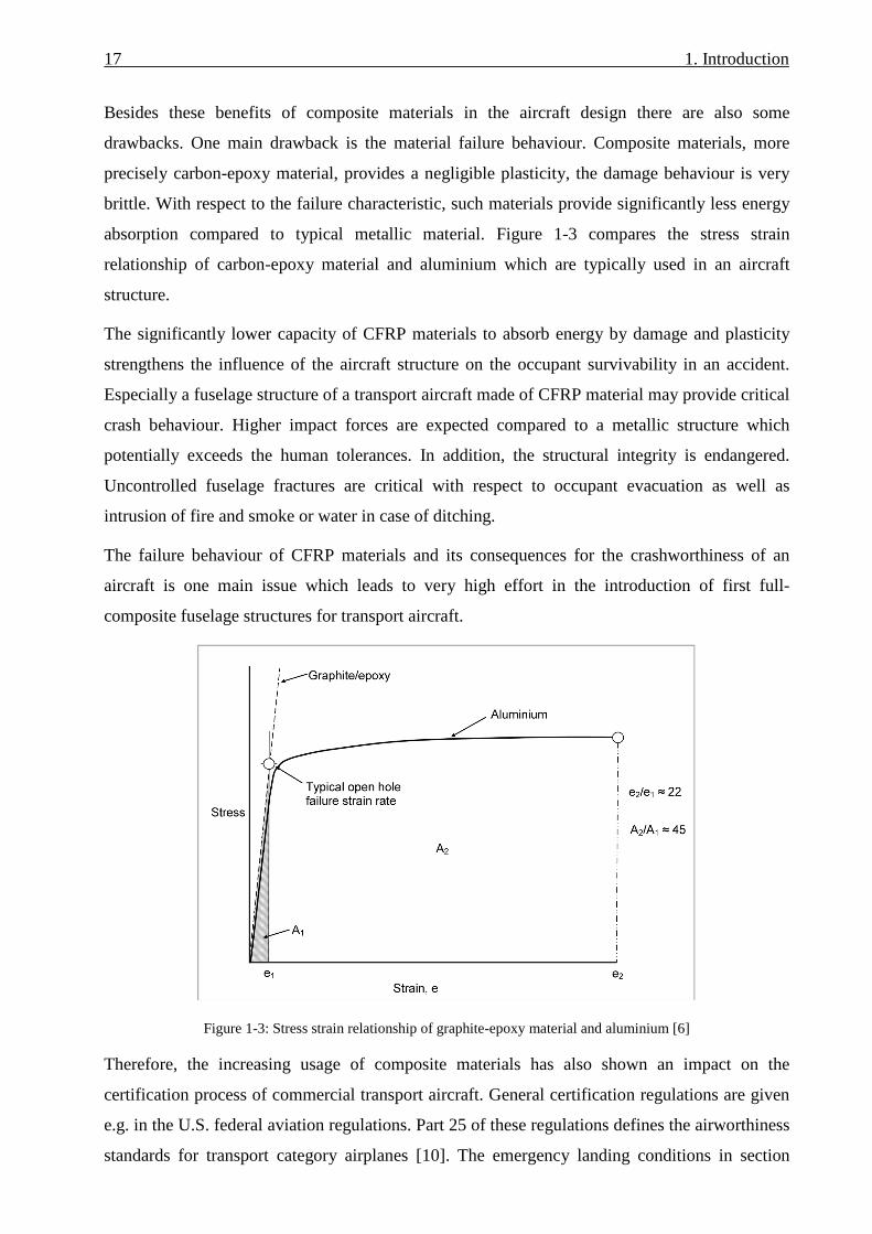
Besides these benefits of composite materials in the aircraft design there are also some
drawbacks. One main drawback is the material failure behaviour. Composite materials, more
precisely carbon-epoxy material, provides a negligible plasticity, the damage behaviour is very
brittle. With respect to the failure characteristic, such materials provide significantly less energy
absorption compared to typical metallic material. Figure 1-3 compares the stress strain
relationship of carbon-epoxy material and aluminium which are typically used in an aircraft
structure.
The significantly lower capacity of CFRP materials to absorb energy by damage and plasticity
strengthens the influence of the aircraft structure on the occupant survivability in an accident.
Especially a fuselage structure of a transport aircraft made of CFRP material may provide critical
crash behaviour. Higher impact forces are expected compared to a metallic structure which
potentially exceeds the human tolerances. In addition, the structural integrity is endangered.
Uncontrolled fuselage fractures are critical with respect to occupant evacuation as well as
intrusion of fire and smoke or water in case of ditching.
The failure behaviour of CFRP materials and its consequences for the crashworthiness of an
aircraft is one main issue which leads to very high effort in the introduction of first full-
composite fuselage structures for transport aircraft.
Figure 1-3: Stress strain relationship of graphite-epoxy material and aluminium [6]
Therefore, the increasing usage of composite materials has also shown an impact on the
certification process of commercial transport aircraft. General certification regulations are given
e.g. in the U.S. federal aviation regulations. Part 25 of these regulations defines the airworthiness
standards for transport category airplanes [10]. The emergency landing conditions in section

1. Introduction 18
25.561 define several load cases for which the aircraft design has to demonstrate every
reasonable chance for the occupant of escaping serious injury. The load cases in this section are
given by load factors which are equivalent to minor crash landing cases. More severe crash
landing cases are not considered in the FAR25. In particular, limitations of impact forces acting
on the occupant in specific crash cases are not defined. This is important with respect to new
fuselage designs made of composite materials. Due to the limited energy absorption capacity
discussed above, much higher impact forces on the occupants are expected for composite
compared to metallic fuselage structures.
To cover all issues which arise in case of composite aircraft structures regarding certification, the
U.S. federal aviation administration defines so called special conditions which are published
specifically for each new aircraft model. Such special conditions may specify survivable
crashworthiness characteristics that have to provide approximately the same level of safety as
those of a similarly sized airplane fabricated from traditionally used metallic materials [11].
Currently, the developers of transport aircraft are working intensively on this huge challenge to
fulfil such special conditions. In these development procedures crashworthiness has a completely
different significance as it is known from former developments of metallic aircraft. The design of
the fuselage structure has to be adapted to improve the poor crashworthiness characteristics of
typical composite fuselage structures. Special crash concepts have to be integrated enabling the
absorption of kinetic energy by absorber devices. Structural components in the fuselage have to
be stiffened to carry typical crash loads and to avoid uncontrolled failure. Finally, the complete
design of a composite fuselage structure is driven by the challenge to achieve crashworthiness
characteristics which are similar or better compared to metallic designs where crashworthiness
plays a negligible role in the design of a fuselage structure.
Looking back to the increasing traffic of commercial transport aircraft the global aim is to
improve the occupant survivability similarly to the increasing amount of traffic. Hence, the final
challenge is not only to achieve an equivalent level of safety for composite aircraft compared to
nowadays aircraft but even to enhance it significantly.
1.1. Objective and structure of the thesis
The objective of this thesis is to contribute to the development of a crashworthy composite
fuselage design of transport aircraft. A methodology is used which considers local crash devices
that are installed in the critical areas of a fuselage structure. A new modelling approach on
fuselage section level had to be developed, which is based on commercial explicit finite element
method, and which is used to design the local crash devices. By modification of the devices’

19 1. Introduction
characteristics the crash kinematics of the fuselage structure can be optimised. A desired crash
kinematics can be realised by the definition of trigger load and absorption level in the individual
crash devices. The aim of such a numerical analysis on the fuselage section level is the
minimisation of crash loads and the avoidance of uncontrolled crash kinematics. Furthermore,
the fuselage structure, and more precisely the critical frame structure, can be adapted to the
improved crash loads to avoid any significant uncontrolled failure outside of the crash devices.
Finally, the required characteristics of the individual crash devices, which were found in the
numerical approach on the fuselage section level, can be used as a basis for the development of
local trigger and energy absorbing concepts. The essence of this methodology is the usage of a
numerical modelling which is well suited for a preliminary design process. In addition, the
development of technological concepts can be performed on the component level and does not
need the accomplishment of large and expensive tests. Figure 1-4 illustrates such a crash concept
which is based on this methodology, covering energy absorption in the sub-cargo area, the lower
side shell and the passenger crossbeam support struts.
The structure of the thesis provides two main aspects. The first aspect considers the methodology
of the developed modelling approach and comprises chapters 2-5. The focus is on the numerical
representation of typical frame failure mechanisms which is the most important one with respect
to crash related loads on a fuselage structure.
Chapter 2 gives a review on the work which has been done in the field of aircraft
crashworthiness in the past. The state of the art is discussed in this chapter with respect to
technological as well as numerical methods. Based on this state of the art open questions are
identified which define the objective of this thesis.
In chapter 3 the basic modelling approach of the developed Kinematics Model is presented. The
macro modelling techniques as well as further modelling aspects are discussed.
Chapter 4 deals with the numerical representation of frame failure which is the main failure
mechanism of a fuselage section crash kinematics. Several aspects are analysed in detail which
contribute to a sufficiently accurate frame failure representation.
Chapter 5 describes the development of a user-subroutine for frame failure modelling. An
advanced model of the frame failure macro representation was programmed in a user element
which provides some improvements compared to the standard frame failure modelling discussed
in chapter 4.

1. Introduction 20
The second main aspect of the thesis considers the methodology of a crash design process that is
based on the application of the Kinematics Model. Chapters 6-8 discuss the design process on
the basis of an exemplary application.
In chapter 6 different natural crash kinematics of a typical fuselage section are analysed and
assessed using the Kinematics Model. The preferred natural crash kinematics represents the basis
for the development of the crash design.
In chapter 7 the selected crash kinematics, as an outcome of chapter 6, is applied on a statically
pre-sized CFRP fuselage structure. A crash scenario was developed which includes the definition
of local crash device characteristics as well as the sizing of a crashworthy frame structure.
Finally, chapter 8 deals with the development of different experimental test setups which were
used to investigate local crash device concepts. A detailed crushing test setup was developed for
the investigation of potential crush absorbers in the sub-cargo area. In addition, the development
of a generic frame bending test setup is discussed with the focus on the investigation of general
characteristics such as the energy absorption capacity.
Concluding remarks are given in chapter 9.
Figure 1-4: Crash design concept using local crash devices

2. Review on crashworthiness research – state of the art
This chapter deals with a review on research activities on the crashworthiness of aircraft.
Experimental as well as analytical work is considered.
Paragraph 2.1 discusses the main topics which have been experimentally analysed in the past. A
current state of the art of crashworthy aircraft design is outlined from these wide experimental
database gained by the discussed research activities.
The focus in paragraph 2.2 is on the simulation methodologies which have been developed and
used to investigate and improve the crashworthiness of aircraft. Different simulation methods are
discussed and a state of the art in crash simulation of aircraft structures is outlined.
Finally, paragraph 2.3 identifies open questions regarding the development of crashworthy
aircraft designs as well as simulation methodologies. Different topics are derived from these
open questions which have to be investigated within this thesis.
2.1. Review on crashworthiness research
In the 1950s and 1960s the research activities on aircraft crashworthiness were affected by full-
scale crash tests. In the 1950s the NACA performed seven full-scale crash tests of different
aircraft types such as low-wing or high-wing configurations as well as aircraft designs with and
without pressurised cabin [12]. In the 1960s two crash tests of larger aircraft were conducted on
behalf of the U.S. federal aviation agency [13-14]. A Douglas DC-7 as well as a Lockheed 1649
were crash tested in a specific environment representing survivable or potentially survivable
accidents of hard landing, wing low impact with the ground and impact into large trees in an off-
airport forced landing. In Figure 2-1 the crash test of the Lockheed 1649 is depicted.
All these conducted crash tests were performed with the main velocity component in horizontal
direction. The aircraft were mounted on a guide rail standing on their own landing gear. With its
own propulsion the aircraft were accelerated and guided against several crash barriers, obstacles
and impact hills, as exemplarily illustrated in Figure 2-1a). The aim of these full-scale crash tests
performed in the 1950s and 1960s was mainly the generation of a crash load data base of
survivable crash cases. None of the tested aircraft structures were of “jet size” and the design
differed partly significantly from today´s aircraft designs.

2. Review on crashworthiness research – state of the art 22
Figure 2-1: Full-scale crash test of the Lockheed 1649 [13]
In the 1980s an FAA crash dynamics research development program was initiated which was
jointly sponsored by the NASA in some phases. Five vertical drop tests of B707 fuselage
sections were conducted by the NASA and the FAA [15-19]. The lengths of the fuselage section
were chosen to be between approximately 3 m and 4 m (10-13 ft). Soft sections, centre sections,
conical sections and asymmetric sections with cargo door were tested. In addition to dummy or
dummy ballast loading in the cabin, some of the sections were loaded with cargo. Figure 2-2a)
depicts one of these B707 fuselage section drop tests. A further drop test was performed with a
wide-body DC-10 fuselage section [20]. In these six fuselage section drop tests the initial
velocity was defined between 6.1 m/s and 10.4 m/s (20-34 ft/s).
The research program culminated in the full-scale controlled impact demonstration (CID) test of
a remotely piloted B720 airplane which was performed on December 1, 1984 [21-22]. Besides
the generation of a good crash load data base a main interest of this test was the investigation on
post-crash fire behaviour. Figure 2-2b) illustrates the B720 airplane shortly before impact on the
wing opener barriers which were installed to enforce an extensive fuel spill with the danger of
post-crash fire.
Figure 2-2: Crash activities of the FAA and the NASA in the 1980s [23]
In the scope of the FAA crash dynamics research development program three further vertical
fuselage section drop tests were performed in the 1990s and beginning of the 2000s [24-26].
Besides a B707 fuselage section aft of the wing, two B737 fuselage sections forward of the wing

23 2. Review on crashworthiness research – state of the art
with a cargo door were drop tested. Both B737 sections were loaded with cargo, one section with
luggage and the other section with an auxiliary fuel tank. Both sections were equipped with
overhead stowage bins to investigate potential endanger of cabin safety by overhead masses that
may fail. All three fuselage section drop tests were performed with an initial velocity of 9.1 m/s
(30 ft/s). Figure 2-3 illustrates one of the B737 fuselage section drop tests.
Figure 2-3: FAA drop test of a B737 fuselage section [24]
In the 1990s the European Community funded programme “crashworthiness for commercial
aircraft” contributed to the investigation of the crash behaviour of metallic fuselage structures of
transport aircraft. Besides quasi-static and dynamic sub-component tests of an A320 rear
fuselage structure, an A320 fuselage section was drop tested [27-30]. The sub-component tests
served for detailed investigations on the failure behaviour of the sub-cargo area as well as
different located frame structures. The test results of the sub-component tests were intensively
used to improve numerical modelling techniques. Different simulation methodologies were
applied to perform pre-test simulations of the A320 fuselage section drop test. In 1995 the

2. Review on crashworthiness research – state of the art 24
research programme culminated in the drop test of a 6-frame section of an A320 rear fuselage.
The drop test was performed with an initial velocity of 6.7 m/s (22 ft/s). In Figure 2-4, sub-
component tests as well as the fuselage section drop test are depicted.
Figure 2-4: The European Community funded programme "crashworthiness for commercial aircraft" [28, 30]
Further research on crashworthiness of metallic transport aircraft structures was performed by
the National Aerospace Laboratory of Japan (NAL) in the 2000s. A forward fuselage section
with cargo compartment as well as an aft fuselage soft section of a YS-11 transport aircraft was
drop tested with an initial velocity of 7.6 m/s (25 ft/s, forward fuselage section) respectively 6.1
m/s (20 ft/s, aft fuselage section) [31-32]. The NAL also performed about 40 drop tests of
simplified structural aircraft fuselage models and analysed the influence of geometrical
parameters on the crash behaviour, such as the position of the vertical support struts as well as
the vertical location of the passenger crossbeam [132-133].
In the scope of an evaluation of the adequacy of current certification standards for seat and
restraint systems for smaller commuter airplanes, the FAA initiated the commuter airplane
crashworthiness program in the 2000s. Four different commuter category airplanes were tested in
full-scale vertical drop tests [33-38]. Besides information on the fuselage accelerations which

25 2. Review on crashworthiness research – state of the art
contributed to the certification standards, valuable information of the structural crash behaviour
of full-scale aircraft structures could be gained. In contrast to the design of large transport
aircraft, these commuter airplanes provide no cargo floor area and are partly designed in a high-
wing configuration. Nevertheless, information about local structural failure can be assigned also
to the structural behaviour of large transport aircraft. Figure 2-5 depicts two of the tested
commuter airplanes.
Figure 2-5: The FAA commuter airplane crashworthiness programme [37, 38]
All the work on crashworthiness of metallic aircraft structures, discussed above, contributes to
the definition of a “metallic equivalent” as it is specified in the special conditions for the
certification of new transport aircraft structures made of composite materials.
Crashworthiness research on composite structures
Crashworthiness research on composite aircraft structures is mainly driven by the challenge of
controlled absorption of the kinetic crash energy. All known research in this field postulates local
crash absorbers which have to be implemented in the structure to improve the crashworthiness of
composite aircraft. The basis for such absorber concepts was developed in the research on
helicopter structures. Several (metallic) sub-floor absorber concepts for a helicopter or a general
aviation airplane structure were analysed by the NASA in the 1970s and 1980s [39]. Figure 2-6
depicts the main outcomes of this work. The principles of the NASA airframe crashworthy
design concepts were adapted later to composite structures to benefit from the composites´ high
mass-specific energy absorption by crushing [40]. Although composite material, and in a
narrower sense CFRP material, generally provides brittle failure behaviour with little energy
absorption, a controllable progressive crushing process of such material can lead to a mass-
specific energy absorption which is significantly higher than that obtained for metallic materials.
Figure 2-7 compares the mass-specific energies absorbed by different materials in different

2. Review on crashworthiness research – state of the art 26
crushing processes. Wide-ranging research has been conducted in this field with the focus on the
material behaviour under crushing which has been analysed by different specimens and
components like tubes, half-tubes, cruciforms or corrugated beams [41-45].
Figure 2-6: NASA research on crashworthy airframe design concepts [39]
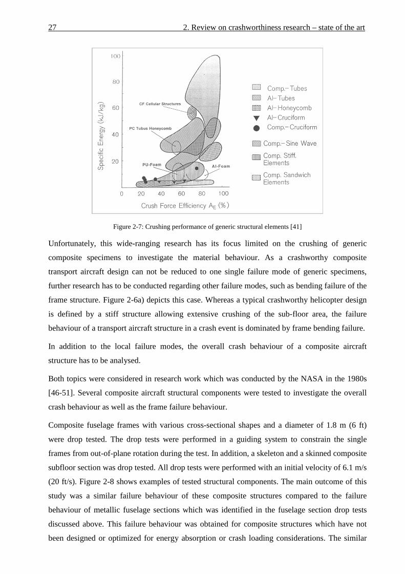
27 2. Review on crashworthiness research – state of the art
Figure 2-7: Crushing performance of generic structural elements [41]
Unfortunately, this wide-ranging research has its focus limited on the crushing of generic
composite specimens to investigate the material behaviour. As a crashworthy composite
transport aircraft design can not be reduced to one single failure mode of generic specimens,
further research has to be conducted regarding other failure modes, such as bending failure of the
frame structure. Figure 2-6a) depicts this case. Whereas a typical crashworthy helicopter design
is defined by a stiff structure allowing extensive crushing of the sub-floor area, the failure
behaviour of a transport aircraft structure in a crash event is dominated by frame bending failure.
In addition to the local failure modes, the overall crash behaviour of a composite aircraft
structure has to be analysed.
Both topics were considered in research work which was conducted by the NASA in the 1980s
[46-51]. Several composite aircraft structural components were tested to investigate the overall
crash behaviour as well as the frame failure behaviour.
Composite fuselage frames with various cross-sectional shapes and a diameter of 1.8 m (6 ft)
were drop tested. The drop tests were performed in a guiding system to constrain the single
frames from out-of-plane rotation during the test. In addition, a skeleton and a skinned composite
subfloor section was drop tested. All drop tests were performed with an initial velocity of 6.1 m/s
(20 ft/s). Figure 2-8 shows examples of tested structural components. The main outcome of this
study was a similar failure behaviour of these composite structures compared to the failure
behaviour of metallic fuselage sections which was identified in the fuselage section drop tests
discussed above. This failure behaviour was obtained for composite structures which have not
been designed or optimized for energy absorption or crash loading considerations. The similar

2. Review on crashworthiness research – state of the art 28
failure behaviour is focused on the failure locations in a fuselage structure and not on the energy
which is absorbed in the individual frame failure locations.
Figure 2-8: NASA research on composite aircraft structural components [47]
In the 1990s crashworthiness research for composite fuselage designs was conducted intensively
in the European Community funded programme “CRASURV” (Crash Survivability). In the
scope of this project a review on crashworthiness research of composite structures was
performed. Well documented reference lists of this review are given in [52, 53]. The spectrum of
the CRASURV project comprised the complete test pyramid from material coupon tests up to
fuselage sub-floor drop tests, as illustrated in Figure 2-9. Composite absorber concepts such as
corrugated beams or cruciform structures, depicted in Figure 2-9c), were tested [134-135]. The
investigated absorber structures were integrated into composite fuselage designs of a commuter
aircraft as well as a single-aisle transport aircraft. In a sub-floor drop test of the commuter
structure the desired crash kinematics could not be obtained [54-56]. Uncontrolled failure of the
absorber structures occurred with little energy absorption, Figure 2-9d). Regarding the composite
single-aisle transport aircraft design a sub-cargo structure as well as a sub-floor structure was
drop tested [57-59]. Neither the sub-cargo structure drop test nor the sub-floor structure drop test
could demonstrate the functionality of the specified crash concept. In the sub-cargo structure
drop test the absorbers, sine-wave beam structures, did not crush along its full length, Figure 2-
9e). An improved design was implemented in the sub-floor structure. Nevertheless, this drop test
again denied a successful functionality of the defined crash concept as the fuselage design above
the absorber structure was not able to carry the crash loads. The cargo-crossbeam failed and
prohibited the crushing of the sine-wave beam structure, Figure 2-9f). All three drop tests were
conducted with an initial velocity of about 7 m/s. Despite of the non-successful drop tests a main
outcome of the CRASURV project was the conclusion that an implementation of energy
absorption devices is mandatory for a composite aircraft structure [61].

29 2. Review on crashworthiness research – state of the art
Figure 2-9: The European Community funded project "CRASURV" [56,57,59,136,137]
The crash concept of the CRASURV composite transport aircraft structure specified a crush zone
which is located exclusively in the sub-cargo area. Further potential of energy absorption above
that area was not considered. As the kinetic energy has to be absorbed along a comparably small
crash distance, high crash forces can occur which lead to a massive design of the above fuselage
structure. In case of the CRASURV transport aircraft structure the cargo-crossbeam as well as
the frame structure had to be sized significantly stiffer compared to typical aircraft designs [60].
Further research on crashworthy composite fuselage design considered the cargo area as
additional crash zone to increase the available crash height. This crash zone is mainly affected by
frame bending failure. Research work was conducted in the 1990s to improve such bending
failure characteristics of CFRP frame structures with respect to an increased energy absorption
capacity [62-65]. Figure 2-10 depicts typical compression tests of curved frame components
which were conducted in the scope of this work. In this study textile composite frame structures
were investigated additionally, such as braided frames. Although an optimized design showed
limited improvements of energy absorption in a bending failure process, significant increase in
the post-failure energy absorption was not observed.

2. Review on crashworthiness research – state of the art 30
Figure 2-10: Research on improved energy absorption in CFRP frame structures [62]
Currently, transport aircraft developers work on new programmes of wide-body aircraft with
primary structures made of CFRP. Boeing is certifying its new B787 model which provides a
CFRP fuselage structure. Airbus is developing its A350XWB model which is planned to be
fabricated with a high ratio of CFRP material. To fulfil an equivalent level of crashworthiness
compared to metallic designs, as specified in the special conditions of the B787, Boeing has
defined a crash concept for the sub-cargo area [66]. Massive stanchions made of CFRP shall be
crushed in a progressive mode. In contrast to the stiff structure which was designed in the
CRASURV transport aircraft fuselage section, the B787 fuselage structure provides much less
stiffness above the sub-cargo area, as Figure 2-11 depicts. In crash cases without cargo loading,
the comparably filigree cargo-crossbeams and frames have to carry the full crash load.
Figure 2-11: Boeing 787 crash concept (fuselage section 46) [66, 67]

31 2. Review on crashworthiness research – state of the art
2.2. Review on simulation methodologies
In general, crash dynamics of detailed structural designs are too complex for manual analysis.
However, computer based modelling methods offer a capability that can provide a simulation of
all important dynamic interactions. Numerous computer simulation models have been developed
for use in simulation evaluations. And none of the developed modelling procedures is totally free
of testing requirements and analytical judgement. The reason is the extremely complex process
for the structural deformation under crash loading, which involves transient dynamic behaviour,
complicated framework and shell assemblies, large deflections and rotations as well as extensive
plastic deformation, damage and failure [5].
The multi-body approach, depicted in Figure 2-12, uses a very simple model to represent the
considered structure, based on spring and beam elements as well as mass elements. In addition,
plastic hinges can be defined to describe large rotational deformation. The equations of motion
are solved numerically. Such models are very efficient due to their simplifications and are often
used in the preliminary design phase of vehicles or trains to estimate the general crash
characteristics [68-73].
Figure 2-12: Multi-body system - generic model and vehicle model [70]
Hybrid models are based on the multi-body approach and use experimental test data as well as
detailed finite element simulations to generate input data for the spring elements and the plastic
hinges. A widely used hybrid modelling program in the field of aircraft crashworthiness is DRI-
KRASH [145]. Several crash tests discussed in paragraph 2.1 were analysed with this code,
examples are illustrated in Figure 2-13. The model efficiency can be used to simulate full-scale
crash tests such as the controlled impact demonstration (CID). Test results of the fuselage section
drop tests, which were conducted in advance of the CID test, could be used to calibrate the full-
scale model and to predict the CID test. In addition, the hybrid full-scale model was used to
perform sensitivity studies [74].

2. Review on crashworthiness research – state of the art 32
In the European Community funded project “Crashworthiness for commercial aircraft” the
hybrid code DRI-KRASH was used to predict the drop test of an A320 fuselage section. The
experimental test data of structural components of an A320 fuselage were used as characteristic
inputs for spring elements and plastic hinges. Finally, a good prediction of the fuselage section
drop test could be achieved [75].
In contrast to the usage of experimental test results, detailed finite element simulations can be
performed to generate characteristic failure data of structural components which can be used as
input for springs and plastic hinges in the hybrid model. An example of such an approach is
given in [76] on the basis of a helicopter subfloor structure.
Further examples on hybrid code applications are given in [77].
Figure 2-13: Hybrid code models (DRI-KRASH) [74,75]
The finite element method is a further analytical approach in which the structure is divided into
appropriate structural units called elements. The deformation characteristics of each component
are calculated from its material stress-strain curve. The structural mass is placed at nodes at each
element boundary and is therefore distributed throughout the structure. The equations of motion
of the elements are solved numerically. An overview on the finite element method and its
integration schemes is given in Appendix A1.1.
The finite element method is used for detailed analysis of structural design or its failure
behaviour particularly due to dynamic loads. Explicit finite element method for analysis of
crashworthiness of aircraft structures is used extensively. A wide range of literature documents
the use of FEM for crash analysis of aircraft structures [78-86]. Some of the fuselage section
drop tests discussed in paragraph 2.1 were simulated using the finite element method, Figure 2-
14b). Based on the experience gained with such simulations, the NASA prepared best practices
for crash modelling and simulation [87]. The increased computational power allows the

33 2. Review on crashworthiness research – state of the art
simulation of larger models up to detailed full-scale models of aircraft crashes, as the NASA
performed in the recent past of the full-scale drop test of an ATR42 aircraft [88], Figure 2-14a).
Nevertheless, the current state of the art in the FE simulation of aircraft crashworthiness is the
consideration of a fuselage section instead of a full-scale model. The explicit finite element
method limits its range of considered problems to short-time events. Long duration events, such
as a real aircraft crash scenario lasting several seconds, would lead to unacceptable error
propagation due to the enormous number of calculation cycles. Hence, typical FE simulations
consider purely the vertical direction which shortens the crash event to few hundred
milliseconds. The neglect of the horizontal component has minor influence on the structural
damage and crash kinematics of an aircraft fuselage. In typical crash scenarios the aircraft slides
on the ground and induces friction forces which are significantly below the impact loads of the
vertical direction. Furthermore, the longitudinal forces of the aircraft sliding are mainly carried
by the fuselage skin and the stringers whereas the vertical impact loads are carried mainly by the
frame structure. For that reason, the consideration of a fuselage section under purely vertical
crash loads is a sufficient approach for the development of crash concepts that have the aim to
reduce the impact loads on the occupants. This approach is conducted in current development
processes of new composite fuselage aircraft such as the Boeing 787 or the Airbus A350XWB.
Still, such simulation results are of generic manner and do not consider all potential loading
conditions of a real crash situation. For example, the sliding of an aircraft against hills or on
rough ground, which can lead to fuselage break events, is not considered. Again, such failure
event has less influence on the vertical impact loads which are the major cause of death in
aircraft accidents.
The consideration of a fuselage section in numerical analyses implicates another drawback
which has to be discussed. A fuselage structure comprises several sections which differ
significantly in their structural behaviour. Fuselage sections which include landing gear bays or
the centre wing box provide much stiffer behaviour compared to the typical fuselage sections. In
addition, the installation of cargo doors can lead to asymmetric crash kinematics caused by
different stiffness of the lower fuselage side shells. The concentration on a typical fuselage
section for the analyses of crash concepts can be critical. Nevertheless, it provides a sufficient
generic basis for the development of such fuselage concepts in a preliminary design phase and it
provides a basis for comparison of safety levels. On the basis of such analyses on the fuselage
section level an equivalent level of safety compared to metallic airframes can be demonstrated in
a certification process. However, it is obvious that the developed crash concept on the basis of a

2. Review on crashworthiness research – state of the art 34
typical fuselage section has to be adapted to the other fuselage sections to fulfil a real equivalent
level of crashworthiness.
Figure 2-14: Finite element models [84,88] – in comparison to hybrid code models in Figure 2-13
A further point that has to be discussed in the scope of finite element modelling is the definition
of material behaviour. In contrast to hybrid modelling, the FEM approach provides detailed
models for the representation of material behaviour. With respect to the simulation of composite
structures this is a huge challenge. The complex damage and failure behaviour of composite
structures can not be modelled by characteristic curve inputs as it is the case in hybrid models.
High effort was raised in the European project “CRASURV” to develop improved formulations
for composite materials [89-93]. The verification of such models was performed from the
coupon level up to the fuselage section level. Figure 2-15 shows exemplary results of this
research and compares the failure modes of composite cruciform and trapezoidal beam obtained
by simulation and test.

35 2. Review on crashworthiness research – state of the art
Figure 2-15: Composite material model validation [94,138]
The NASA performed simulations of composite aircraft structures as well. The simulation of a
1/5-scaled model composite fuselage concept as well as of a full-scale composite helicopter is
documented in [95-98].
Further work on simulation of composite materials in finite element methods is documented in
[99-102]. In particular [100,101] represents the current state of the art in composite modelling
using the finite element method. In this work crushing tests of CFRP specimens were simulated
using a stacked shell approach. The failure behaviour, and more important the failure load level,
of the simulation agrees well with the test results, as depicted in Figure 2-16. Nevertheless, the
presented results represent post-test simulations. With respect to the predictive capability of
composite material models further research is required.

2. Review on crashworthiness research – state of the art 36
Figure 2-16: State of the art composite modelling in finite element methods [101]
2.3. Identification of open questions – definition of the thesis
The review on crashworthiness research in paragraph 2.1 identified that a wide basis of
knowledge was gained in the past by several research programmes. The complete range from
material tests up to full-scale crash tests was considered. In addition, the critical crash behaviour
of composite structures was investigated in several research projects. Nevertheless, sufficient
crashworthiness for composite fuselage structures could not be demonstrated until now. The
research work identified, that crash concepts which were developed for composite helicopter
structures can not be adapted directly to transport aircraft structures. The static sizing of
helicopter structures provides already a stiff fuselage design as heavy masses – turbine and
transmission - are installed above the cabin. A similar crash concept adapted to transport aircraft
would lead to significant structural mass penalty compared to the static sizing, as demonstrated
by the crash improved composite transport aircraft fuselage design in the project CRASURV.
Composite fuselage designs of new wide-body aircraft which are currently being certified, such
as the Boeing 787, specify a crash concept which is mainly similar to helicopter crash concepts.
An equivalent level of safety compared to metallic designs is questionable in this aircraft model
as the fuselage structure above the crash zone provides less stiffness. The outcome of the current
state of the art is the need to develop crashworthy composite fuselage designs which provide an
equivalent or even better level of safety compared to today´s aircraft structures made of
aluminium. Such crash designs have to specify additional crash devices which control a crash
scenario and which absorb sufficient kinetic energy. The principle of these crashworthy designs
37 2. Review on crashworthiness research – state of the art
was already given in Figure 1-4. The crash devices have to be designed so that their activation
corresponds to a controlled crash kinematics which should be a cascading scenario starting with
failure and energy absorption in the lower fuselage area and progressing stepwise by the
activation of other crash devices during the crash sequence. The design of trigger load and
energy absorption level in the individual crash devices has to be performed on the fuselage
section level considering the crash kinematics of the entire fuselage cross-section. In addition to
the design of crash devices, the statically sized fuselage structure potentially has to be resized to
sustain the crash loads.
Such a design process can be conducted numerically by the methods discussed in paragraph 2.2.
Hybrid codes, for example DRI-KRASH, are efficient to analyse such problems. Failure is
described using macro elements such as springs and plastic hinges. With respect to the design of
crash devices this modelling approach is advantageous as the required characteristic of the
individual crash device can be defined directly by the macro input. The main disadvantage of
this approach is its course level of discretisation. Detailed conclusions about the structural
behaviour are hardly possible as several structural parts are not modelled in detail. As an
example, a re-sizing of the frame structure to consider the crash loads can not be performed
accurately enough with the hybrid approach, as the structural interaction of frame and skin is not
represented, which plays a major role in the bending behaviour of a frame structure. In the
hybrid model, beam elements represent frames, stringers and the skin. Hence, the discretisation
cannot resolve detailed structural design requirements.
In contrast to hybrid codes, the modelling approach of detailed finite element method offers the
possibility of detailed structural analyses. The structure is modelled more accurately which
allows the analysis of local effects and the re-sizing of structural parts due to the crash loads.
However, the detailed modelling approach also implicates disadvantages. To represent the
fuselage structure in sufficient detail a large amount of data is necessary to build up the model.
As the crash aspect is typically analysed in the preliminary design phase of an aircraft
development, these detailed data are partly not available. Assumptions can be used for the
missing data, but finally these details may have an important influence in some crash events and
have to be considered as critical. In addition, the detailed FEM approach uses material
formulations for composites which are not fully predictive, especially with respect to failure and
post-failure modelling. The results of such analyses will have a significant level of uncertainty.
The development of crash designs for transport aircraft fuselage structures requires an analytical
approach which combines some advantages of hybrid codes and detailed FEM. The possibility to
describe the required behaviour of crash devices by macro elements should be combined with a

2. Review on crashworthiness research – state of the art 38
more detailed modelling approach. The discretisation should be as detailed as necessary to
represent all important structural effects and as course as possible to avoid the need of data
which is not available in a preliminary design phase. Uncertainties caused by damage and failure
representation of composite material formulations should be avoided by the usage of mainly
linear-elastic material models. The main failure events should be described exclusively by macro
elements. The analytical approach should provide the opportunity to completely design a
fuselage structure for crash. This includes the required characteristics of the crash devices to
achieve an optimum crash kinematics, their positioning in the fuselage structure as well as the
design of the remaining structure to sustain the crash loads.
Definition of the thesis is the development of such an analytical approach. Besides the modelling
approach itself a complete crash design methodology shall be developed and demonstrated. This
includes the definition of a design process as well as the development of experimental test setups
to investigate concepts for local crash devices. Such test setups can be used either to generate
input data for the macro elements or to develop crash devices which fulfil the required
characteristics of the crash design process.
3. Aspects of the Kinematics Model approach
This chapter deals with a crash design tool that was developed according to the requirements
discussed in paragraph 2.3. Benefits of different established analyses techniques are combined to
provide a preliminary design tool for the crash scenario development of a fuselage structure.
The general modelling technique of this so-called “Kinematics Model” is discussed in this
chapter 3. Further detailed investigations, which were performed in the scope of the model
approach development, are considered in chapter 4 and 5.
3.1. Basic approach of the Kinematics Model
Chapter 2 already discussed the circumstance that in a well-defined crash scenario of a
composite fuselage structure main failure should occur exclusively in the crash devices. Failure
outside of the crash devices could lead to uncontrolled crash kinematics of the brittle structure
with the potential loss of any crashworthiness. Hence, the circumjacent structure of the crash
devices has to remain intact. This requirement leads to a modelling approach where all failure is
described by macro elements which represent the crash devices. The remaining structure, that is
not allowed to fail, is modelled linear-elastically. Crash scenarios can be developed, assessed and
optimised by modification of the macro characteristics. These modifications include trigger
loads, energy absorption capacities or in general the capability of energy absorption (brittle or
absorbing failure characteristics).
In general, the Kinematics Model is based on the commercial explicit finite element method. On
the one hand, the model is discretised in such detail that all important structural effects are
represented. Hence, the fuselage structure is represented using shell, beam and bar elements
according to the common FEM approach. On the other hand, the discretisation is as coarse as
possible to avoid the need of data which are not available in a preliminary design phase. Finally,
the structure is modelled using mainly linear-elastic material characteristics. Uncertainties
caused by damage and failure representation of CFRP material models are negligible in this
approach.
Based on the linear-elastically modelled structure an increased element size can be defined for
the representation of the fuselage structure, compared to classical explicit FE modelling
approaches considering non-linear material behaviour. In the linear-elastically modelled parts,

3. Aspects of the Kinematics Model approach 40
the deformations of the finite elements are comparatively small, at least in the range of structural
design allowables. Mesh refinement for representation of large deformation is not essential even
though the elements typically used in explicit FEM use low-order shape functions of a linear
form.
Additional model efficiency is obtained in a comparatively coarse model representation.
Structural parts which do not contribute to important effects with respect to typical crash loads
primarily have to represent their stiffness in an accurate way. For this reason, stringers are
modelled using beam elements. Details such as clips and cleats are not modelled.
The Kinematics Model considers exclusively vertical crash loads on a fuselage section, similar to
the current state of the art simulations of aircraft crashworthiness as discussed in paragraph 2.2.
The crash concept, respectively the equivalent level of safety, is assessed on a 2-bay soft section.
The generation of fuselage section geometries as well as the corresponding FE meshes was
performed using the DLR in-house mesh generation tool ‘SECTMESH’ [103].
Figure 3-1 illustrates the modelling approach of the Kinematics Model. Potential crash devices
respectively failure locations which are represented by macro architectures are highlighted in red
colour.
Figure 3-1: Modelling approach of the Kinematics Model
The macro elements are the central components of the Kinematics Model. They represent the
main crash behaviour of the structure. An accurate modelling to represent realistic failure is of
primary importance. In the following paragraph 3.2 different failure modes of a typical fuselage
structure are discussed and compared to their developed macro architectures.
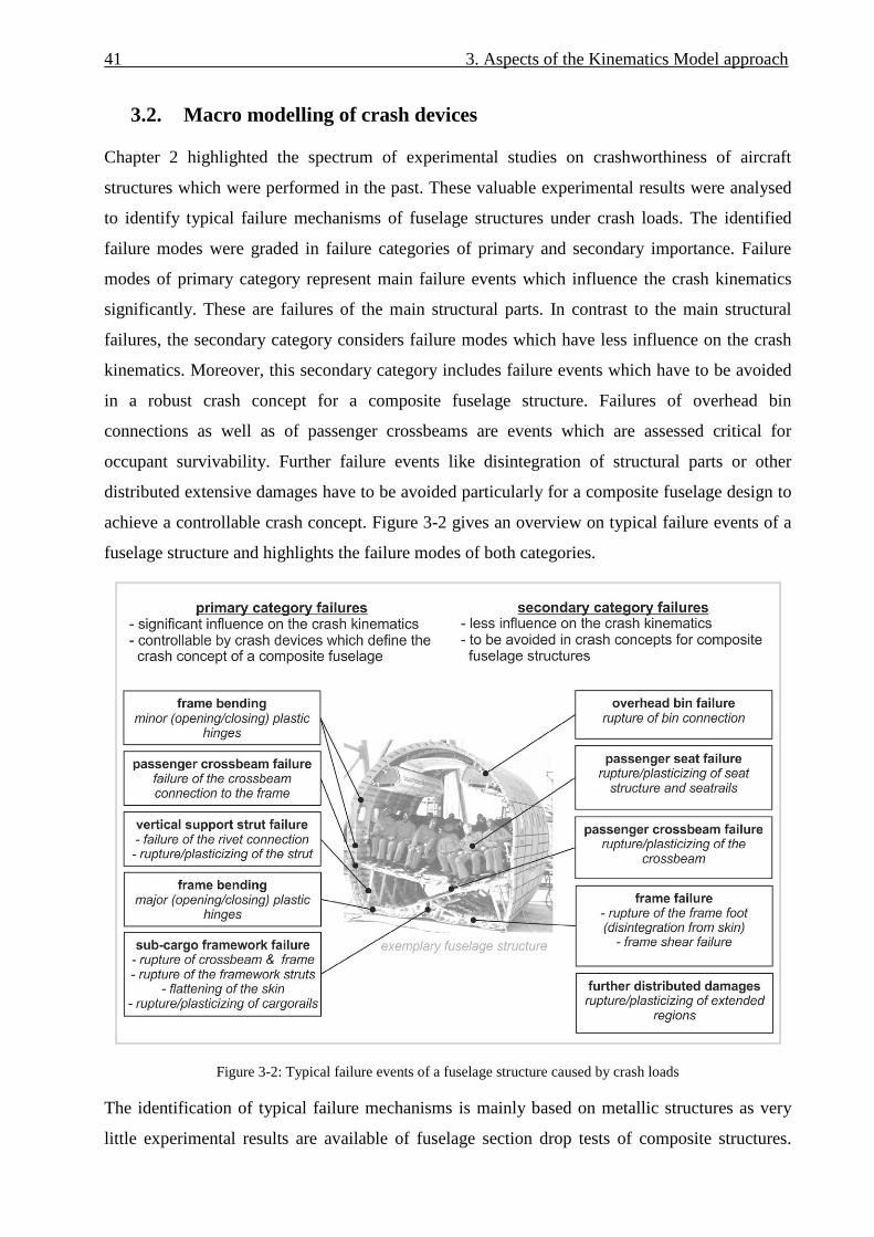
41 3. Aspects of the Kinematics Model approach
3.2. Macro modelling of crash devices
Chapter 2 highlighted the spectrum of experimental studies on crashworthiness of aircraft
structures which were performed in the past. These valuable experimental results were analysed
to identify typical failure mechanisms of fuselage structures under crash loads. The identified
failure modes were graded in failure categories of primary and secondary importance. Failure
modes of primary category represent main failure events which influence the crash kinematics
significantly. These are failures of the main structural parts. In contrast to the main structural
failures, the secondary category considers failure modes which have less influence on the crash
kinematics. Moreover, this secondary category includes failure events which have to be avoided
in a robust crash concept for a composite fuselage structure. Failures of overhead bin
connections as well as of passenger crossbeams are events which are assessed critical for
occupant survivability. Further failure events like disintegration of structural parts or other
distributed extensive damages have to be avoided particularly for a composite fuselage design to
achieve a controllable crash concept. Figure 3-2 gives an overview on typical failure events of a
fuselage structure and highlights the failure modes of both categories.
Figure 3-2: Typical failure events of a fuselage structure caused by crash loads
The identification of typical failure mechanisms is mainly based on metallic structures as very
little experimental results are available of fuselage section drop tests of composite structures.

3. Aspects of the Kinematics Model approach 42
Nevertheless, all research on composite fuselage structures done in the past indicate that typical
failure mechanisms of CFRP fuselage structures caused by crash loads are similar to that of
metallic fuselage structures, although their behaviour is significantly more brittle [46-51].
With respect to the failure modes graded in the primary category, macro architectures were
developed to describe these failure mechanisms in the Kinematics Model. The macro
architectures represent typical failure events which have to be controlled in a crash concept using
appropriate crash devices.
The following sub-paragraphs deal with the macro architectures of the individual failure modes.
3.2.1. Selection of a macro element
A macro architecture for failure representation is a formation of several finite elements which
represents the failure kinematics of individual structural parts in an airframe. The definition and
configuration of such architectures decides on the accuracy of the representation of structural
failures. Besides an appropriate architecture the choice of the central macro element decides on
the options to describe the structural failure behaviour under different loading conditions. In
general, a macro element is used to describe individual behaviours between structural nodes.
Figure 3-3 illustrates the general capabilities of macro elements. The range of available
characteristics implicates the advantage of such elements.
Figure 3-3: Conceptual illustration of the macro element behaviours [104]
With respect to the different macro architectures discussed in the following sub-paragraphs, the
representation of failure and absorbing characteristics requires the possibility to define extensive
input data for the macro element. Besides the main loading behaviour of a crash device several
options for the description of unloading and reloading behaviour are essential. The preferred
description of the macro behaviours is a load-deflection curve. Other descriptions, e.g. by
damage and failure, can not be used directly for comparison of numerical crash device

43 3. Aspects of the Kinematics Model approach
characteristics with experimental test results. Hence, a tabular input format of the macro element
behaviour is desired.
Several macro element types were assessed with respect to their functionalities and their
applicability. Joint elements are typically preferred elements of finite element programmes
which provide most options to define load-deflection behaviour for different loading conditions.
An assessment of element types in the explicit FE code PAM-CRASH resulted in the selection of
the ‘kjoint’ element. In the explicit FE code ABAQUS/Explicit the ‘connector’ element was
selected which provides similar options. The 2-node ‘kjoint’ or ‘connector’ element is a macro
type element which offers the independent description of all six degrees of freedom. It enables
the definition of a main characteristic, as well as an unloading and reloading behaviour, by
tabular curve input. The transition from loading to unloading respectively from reloading to
loading is given by a slope which is a further input value. Figure 3-4 depicts this macro
behaviour and gives exemplarily the keywords for the selected input options of the ‘connector’
element in ABAQUS/Explicit.
Figure 3-4: Tabular input options for the selected macro element [104]
3.2.2. Macro architecture for axial crushing
Structural failures in an airframe which occur in a crushing process are represented in the
Kinematics Model by axial macro architecture. This type represents the crash devices in the sub-
cargo area as well as in the vertical support struts. Although the energy absorbing concepts may
be different in both applications, as illustrated in Figure 1-4, the axial failure kinematic is similar
and can be described with the same macro architecture. The failure characteristic can be defined
using a force-deflection curve, as shown in Figure 3-5. In this sample force-deflection graph
brittle behaviour is defined for failure caused by tensile loads (positive deflection). With respect
to failure caused by compression loads (negative deflection) the residual force plateau after
triggering implicates energy absorption by crushing.

3. Aspects of the Kinematics Model approach 44
The connection of the macro element to the fuselage structure is realised by rigid bodies.
Structural nodes of the linear-elastically modelled fuselage structure form a rigid body together
with a non-structural reference-node which is allocated to the macro element.
With respect to the crash kinematics it is important to represent all released degrees of freedom
of the considered structural part. For example, some designs of vertical support struts define an
articulated connection to the fuselage structure using a pin joint. Moment loads around this pin
axis cannot be transmitted by the vertical strut. For that reason, the macro architecture is
modelled so that the crash device can be connected to the fuselage structure either fixed or
articulated. This modelling option requires the definition of two serial macro elements. The need
of two serial macro elements is founded in the definition of its degrees of freedom. All
translational degrees of freedom are described with respect to the first macro element node. The
rotational degrees of freedom are defined regarding the second element node. As the macro
element represents crash devices of finite length rotational motion may only be considered at one
end of the element, at node 2. Hence, a second macro element defined serial to the first one but
in opposite direction enables a rotation at a second location. This second macro element was
defined at the position of node 1 with a zero length. The crash device characteristic is defined in
the first macro element with its finite length whereas the second macro element has rigid
behaviour and offers exclusively the option of free or fixed rotation. Figure 3-5 illustrates this
macro architecture.
Figure 3-5: Macro architecture for axial failure

45 3. Aspects of the Kinematics Model approach
3.2.3. Macro architecture for frame bending
Frame bending representation is described by a rotational motion and represents the bending
failure mechanism of the frame structure. These ‘kinematic hinges’ provide a complex failure
behaviour which is caused amongst others by the interaction of the frame structure with the
fuselage skin. In addition, it is the main failure event in a typical fuselage crash scenario as a
large crash distance is affected by the frame bending mechanism, absorbing a significant amount
of the total kinetic energy.
The input format for the description of the frame failure characteristic is a moment-rotation
curve, as illustrated in Figure 3-6. The sample graph shows brittle failure behaviour for a so-
called opening hinge rotation, which is characterised by tensile load in the inner frame flange
(negative rotation). Different moment plateaus for a closing hinge rotation (positive rotation)
represent the energy absorption capability of this frame failure characteristic.
The macro architecture defines a cut in the linear-elastically modelled frame with rigid bodies
enforcing the free ends of the frame. Both frame parts are connected with the macro element
which describes the frame failure behaviour. This macro element is positioned in the skin plane.
The nodes of the macro element are connected to the rigid bodies of both frame sections. The
macro element, respectively the cut in the frame, has a finite length. All degrees of freedom are
fixed except the frame bending rotational degree of freedom. This rotation is defined at the
second node of the macro element. As the ‘kinematic hinge’ length is negligible small compared
to the frame length, the rigid behaviour of the macro architecture in the fixed degrees of freedom
has marginal influence on the overall stiffness. Figure 3-6 depicts this macro architecture.
Several detailed investigations were performed to analyse the frame bending behaviour and to
derive this present macro architecture which accurately represents frame bending behaviour.
These investigations are discussed in chapters 4 and 5.

3. Aspects of the Kinematics Model approach 46
Figure 3-6: Macro architecture for rotational failure in the frame
3.2.4. Macro architecture for cargo-crossbeam failure
Another structural failure which was assigned to the primary category is failure of the cargo-
crossbeam. The bending failure mechanism of this crossbeam has a significant influence on the
crash behaviour of a fuselage section and can even decide on the general crash kinematics. With
respect to a crash concept for a composite fuselage this failure has to be controlled by a crash
device.
In contrast to the frame bending failure, the cargo-crossbeam bending failure is less complex as
structural interaction with other parts is less significant. Nevertheless, the macro architecture is
defined analogue to that of the frame bending failure. A cut separates the elastically modelled
cargo-crossbeam in two parts. The nodes of each free end in the cut of the crossbeam form a
rigid body together with a non-structural node which is allocated to the macro element. The
macro element connects both rigid bodies and describes the failure behaviour of the crossbeam.
The non-structural nodes of the macro elements are positioned in the centre of area of the cargo-
crossbeam section. One simplification in this approach is the assumption that the elastic centre of
the crossbeam cross-section corresponds with the centre of area. Regarding a crossbeam
structure made of composite with typically complex layup the elastic centre does not necessarily
correspond to the centre of the cross-sectional area. Still, it is very close to the centre of area as a
typical layup definition does not differ significantly from a symmetric composition.
In Figure 3-7 the macro architecture of the cargo-crossbeam failure is given.

47 3. Aspects of the Kinematics Model approach
Figure 3-7: Macro architecture for rotational failure in the cargo-crossbeam
3.2.5. Macro architecture for the passenger crossbeam connection
The connection of the passenger crossbeam to the frame was generally identified as non-critical.
In none of the experimental results discussed in chapter 2 this connection failed. Nevertheless,
failure close to this connection occurred due to the loads introduced by the passenger crossbeam.
An additional crash device in the connection of passenger crossbeam and frame could reduce
these loads by a certain flexibility. This flexibility would enable an extensive ovalisation of the
whole frame structure utilising the comparably high failure strain of composite material. Besides
the smoothening effect of an ovalisation further energy could be absorbed in the passenger
crossbeam connection by a simple tensile absorber.
To analyse the effect of such an ovalisation concept, a macro architecture was defined for this
structural connection. Instead of a tied connection, the macro element connects the passenger
crossbeam with the frame structure. The load introduction in both elastically modelled parts is
defined by rigid bodies which describe a similar region as given by typical rivet fields of such
connections. The structural nodes inside of this region form the rigid bodies together with a non-
structural node which is allocated to the macro element.
Whereas the macro architectures discussed above are defined with one active degree of freedom,
there are two active degrees of freedom in this case. In addition to the translation in lateral
direction a rotational motion around the longitudinal axis (flight direction) is defined to enable
further ovalisation by unconstrained relative rotation between frame and passenger crossbeam.

3. Aspects of the Kinematics Model approach 48
Figure 3-8 depicts the macro architecture and illustrates exemplary characteristics of such a crash
device.
Figure 3-8: Macro architecture for the passenger crossbeam connection
3.3. Definition of Kinematics Model output data
Output definition has to be defined with respect to the specific modelling approach. Appropriate
criteria have to be specified to assess crash scenarios which are analysed using the Kinematics
Model.
Typical output definitions are energies of the whole model as well as of specific parts or
structural regions. Whole model energies like total, kinetic or internal energy give information
about the overall behaviour of the simulation model. Output of numerical energies indicates the
quality of the numerical model. Internal energy output of individual structural parts give
information about the distribution of absorbed or elastically stored energy.
Section forces and moments are additionally used to explicitly analyse the load acting in several
structural parts. Cutting surfaces are defined along the whole frame structure as well as along the
crossbeam structures. This section output can be used to analyse specific load ratios such as the
bending-compression or the shear-compression ratio. These values can further be used for the
definition of boundary conditions in the analyses of local components.
Besides these general output definitions three main types of output data are defined in the
Kinematics Model. This additional output is the basis for an assessment of crash scenarios and
provides information about the macro element characteristics, about the structural loads of the

49 3. Aspects of the Kinematics Model approach
fuselage section and about the crash loads on the passengers. In the following sub-paragraphs
these specific output definitions are discussed.
3.3.1. Output definition of macro elements
Output definition of the macro elements provides valuable information about the crash device
characteristics which are necessary to achieve a desired crash scenario. Several values are of
interest. The time of activation of the individual crash devices is an important output to
understand the general kinematics of a crash scenario. Therefore load-time and deflection-time
output is essential. In addition, the amount of energy which is absorbed in the crash devices is of
interest. Furthermore, maximum deformations in the individual crash devices play an important
role, especially with respect to the realisation of crash concepts. All this information can be used
as requirements for a sub-sequent development of local crash concepts, as depicted in Figure 3-9.
Figure 3-9: Output data of the macro elements - requirement for the development of local crash devices
The macro elements provide output options for each of its six components. The active
component(s) is of prime interest as it describes the load-deflection characteristic of the crash
device. In addition, output of the passive components can be used to check the loads which are

3. Aspects of the Kinematics Model approach 50
caused by constraints to fix these components. That output helps to check the model approach
against non-accuracy caused by high constraint loads in the passive degrees of freedom.
3.3.2. Output definition of structural loads
Research on aircraft crashworthiness in the past, as discussed in chapter 2, identified the frame
structure as the most critical part of a fuselage section. In addition, the crossbeams are critically
loaded in a crash event. Both structures, frames and crossbeams, have to carry the vertical crash
load which is the main component of the total crash load.
In contrast to this, the fuselage skin as well as the stringers are loaded uncritically. In case of a
real crash event these structural parts carry the longitudinal crash loads which are significantly
lower than the vertical ones as a typical full-scale crash scenario allows sliding of the aircraft on
the ground which induces comparably low friction forces in longitudinal direction.
Hence, the verification of structural loads concentrates on the frame as well as on the crossbeam
structure. An appropriate criterion was defined for the assessment of frame and crossbeam loads.
This criterion aligns to the model approach of a preliminary design tool with its requirement of a
coarser discretisation.
One requirement is the concentration on global loads with respect to a frame section. Detailed
information on the ply level of a frame section laminate is not convenient with respect to the
global frame sizing. Furthermore, a load based criteria such as section forces and moments does
not consider the load carrying capacity of the frame profiles in the individual frame regions.
Additional formulations would be necessary to define load limits of the individual frame designs.
Such a formulation is complex as the influence of the skin has a major effect. The skin can be
described as an additional flange with an unknown flange width. The determination of load
limits for such an unknown structural combination is not efficient.
For that reason the criterion of the Kinematics Model is based on global strains which are
measured and assessed along the frame. Bar elements with negligible stiffness are modelled
along the frame and crossbeam flanges to measure the strain distribution. These strain values can
be checked against analytical or empirical strain limit criteria such as limits against crippling
failure of compressive loaded frame flanges. Figure 3-10 shows an example of the Kinematics
Model with highlighted bar elements for the strain assessment. Exemplary bar element output in
Figure 3-10 clarifies the efficiency of such an approach to check the loads along a frame or
crossbeam structure against limit strain criteria. The exceeding of the strain limit of a large
number of strain bar elements can be checked with a single graph.

51 3. Aspects of the Kinematics Model approach
Figure 3-10: Bar elements for strain measurement
3.3.3. Output definition of injury risks
Loads on occupants are one of the main criteria for the assessment of a crash scenario. Different
injury criteria can be used to analyse the occupant response in a crash event [105-107,139]:
• The dynamic response index (DRI) is derived from a simple one-dimensional lumped-
mass spring damper system and was developed to estimate the probability of
compression fractures in the lower spine due to acceleration in a pelvis-to-head direction.
• The FAR Part 27.562 (c) (normal category rotorcraft) specifies that the spinal load should
not exceed 6672 N (1500 lb.) [109]
• A head impact tolerance specification is the Head Injury Criteria (HIC) which is based on
the resultant accelerations measured at the centre of gravity of the head.
• Injury Assessment Reference Values (IARVs) are defined for restrained Hybrid III
dummy occupants. These assessment reference values specify injury guidelines for
several parts of the body such as head, head/neck interface, chest and knee.
• Finally, the whole-body acceleration tolerance curve was established by Eiband [108].
The Eiband acceleration tolerance levels were determined from sled tests on human
volunteers, pigs, and chimpanzees that were conducted for a single input acceleration
pulse.
In the Kinematics Model the whole-body acceleration tolerance curve according to Eiband is
used to assess the passenger loads. The selection of this criterion is based on the modelling of
seat and passenger. A simplified seat-passenger model is used which represents the passenger
with a single mass element. Macro elements between mass element and seat structure represent

3. Aspects of the Kinematics Model approach 52
the seat cushion stiffness and the harness system. The seat structure is modelled with shell and
beam elements. The seat-passenger model was calibrated based on experimental test data [110].
These test data comprise load-deflection curves of seat cushion and harness system as well as
data about the seat structure. Figure 3-11 illustrates the simplified seat-passenger model used in
the Kinematics Model.
Figure 3-11: Simplified seat-passenger model (triple seat)
Occupant modelling with a single-mass element is an appropriate modelling technique for a
preliminary design tool. Two of the above described injury criteria can be used in case of single-
mass representation of occupants, the dynamic response index (DRI) as well as the Eiband
criterion. Whereas the DRI defines one index value, a complete acceleration curve over the pulse
duration provides more detailed information about the occupant loads. The DRI represents a
better quantitative criterion, the Eiband curves provide the better qualitative criterion.
With respect to the assessment of crash scenarios the more qualitative Eiband criterion provides
better information on the occupant loads. Hence, the Eiband whole-body tolerance curves of
positive, vertical acceleration are used for the assessment of passenger loads in the Kinematics
Model. This criterion is valid as the passengers typically experience one-dimensional loads in a
drop test. In case of combined loading the Eiband criterion is not recommended as there are no
tolerance curves for combined loading.
In the Eiband diagram plots of the vertical acceleration versus the pulse duration for the
passenger masses are given. This ‘acceleration - pulse duration’ graph is compared with two
Eiband curves of vertical loading direction, the limit curves to moderate and severe injury. This
type of diagram gives a good overview on the load levels of different passengers and indicates
potential injury. Figure 3-12 shows the principle of the Eiband diagram.

53 3. Aspects of the Kinematics Model approach
Figure 3-12: Principle of the Eiband diagram
3.4. Further modelling aspects
Further aspects of the modelling approach are discussed in the following sub-paragraphs and
conclude the discussion of general aspects of the Kinematics Model approach.
3.4.1. Refinement of the sub-cargo area modelling
The representation of failure exclusively by macro elements with a linear-elastically modelled
structure identified limitations in a first verification loop. In the area below the cargo-crossbeam,
significant kinematic constraints were identified. In this sub-cargo area, a complex combination
of crushing and other failure mechanisms leads to extensive failure of the sub-cargo structure.
This effect is even more evident in case of a crash concept that specifies crushing of this
structure using a comparably stiff cargo-crossbeam (bendframe concept). Such complex
structural failure mechanisms cannot be clearly divided in categories of failure locations as well
as of remaining undamaged structures. Damage and failure can occur along the whole lower
frame structure. In addition, the stringer structure can be destroyed by the crushing of lower
frame, cargo-crossbeam and the framework struts. If failure in this area is exclusively
represented by macro elements which allow one-dimensional or two-dimensional failure modes,
kinematic constraints may occur that influence the crash kinematics of the whole fuselage
section. Such constraints are shown exemplarily in Figure 3-13. Although kinematic hinges are
positioned in the lower frame structure, high compression forces lead to frame buckling which
induces the formation of elastic hinges. Unrealistically high normal forces as well as a large
amount of elastic energy which is stored in these parts falsify the crash behaviour of such a
model.

3. Aspects of the Kinematics Model approach 54
Figure 3-13: Kinematic constraints in the sub-cargo area with a kinematics modelling
A solution for this issue was found in a mixture of kinematics modelling and detailed FEM
where the main crash characteristic of the sub-cargo area is furthermore described by macro
elements. This solution represents all structural parts which could lead to kinematic constraints
in a detailed modelling with material damage and failure. These parts are the fuselage skin, the
stringers and the frames of the sub-cargo area. The remaining structure is modelled by the
kinematics modelling approach described above. These are the cargo-crossbeam, the cargo floor
and the framework of the sub-cargo area. Macro elements are positioned in the cargo-crossbeam
to represent bending failure. The framework is modelled by macro elements which describe the
failure mode and potential energy absorption of these struts. Figure 3-14 depicts the refined sub-
cargo area, where structural details such as mouseholes in the frames are modelled, too. The
stringers are modelled in detail using shell elements. The typical element size in this area is Le =
10 mm which is about 50 % of the element size used in the Kinematics Model approach. The
connection of the fuselage skin of sub-cargo area and upper fuselage part with its different mesh
sizes is realised using a tied connection. In the frame a kinematic hinge is positioned at the
transition of sub-cargo area and upper fuselage section. It is important to note that material
damage and failure of the detailed modelled parts influence the crash kinematic of the fuselage
section not in a significant way, except the avoidance of highly elastic loading which would lead
to the kinematic constraints discussed above. The main crash behaviour of this area is still
represented by macro elements.

55 3. Aspects of the Kinematics Model approach
Figure 3-14: Mixed modelling in the refined sub-cargo area
3.4.2. Parameterisation of the Kinematics Model
One requirement for the development of the Kinematics Model is a flexible and effective
assessment of crash concepts regarding global crash aspects on the fuselage section level. The
assessment of crash concepts considers different load cases besides a reference crash case, the
so-called ‘standard crash case’1, to get information about the robustness of a crash concept. In
addition, the development of a crash scenario implicates extensive adaptation of macro
characteristics as well as of the fuselage structure.
Therefore, the input definition of the Kinematics Model is parameterised which comprises the
model geometry but also the model properties which are the macro characterisation of the crash
devices, the definition of loading cases for robustness analyses as well as the definition of
numerical parameters.
With respect to the model geometry the mesh generation was embedded in the DLR in-house
fuselage mesh generation tool SECTMESH, which is based on ANSYS APDL [103]. Additional
subroutines were programmed to generate mesh modifications for the macro architectures of the
Kinematics Model such as cuts in the frame and the crossbeam or generation of reference nodes
for the macro elements. Another subroutine defines bar elements along the frames which are
used for the measurement of strains, as discussed in paragraph 3.3. Further options were defined
in additional subroutines such as renumbering of reference nodes for section output definition or
the model refinement of the sub-cargo area.
1 Within this thesis, the ‘standard crash case’ specifies impact conditions of a vertical impact with vi = 6.7 m/s, fully
loaded overhead bins, occupied seats, zero pitch and roll angle. Cargo loading is not considered in this case.

3. Aspects of the Kinematics Model approach 56
With respect to the model properties all essential input data for the FE solver were
parameterised. Input data for macro element characterisation were defined using several
parameters. By default, the tabular input of the primary loading curve offers 10 data points in
each loading direction. The tabular input for the un-/reloading curve offers 7 data points. The
parameterisation can additionally be used to define dependent parameters. Standard macro curve
characteristics with main properties such as stiffness, trigger and absorption load can be
specified. In an optimisation process these main properties can be used in the parameter variation
whereas the tabular input parameters are calculated automatically.
With respect to the assessment of crash scenarios under different loading conditions, several
loading parameters were defined such as passenger and overhead bin masses, the initial velocity,
definition of cargo loading or the definition of roll angles.
In an exemplary analysis model of a single aisle 2-frame fuselage section with a total of 46
macro definitions, a total number of 870 parameters is used for the description of the model
properties, exclusively discretisation parameters which are defined in SECTMESH.

4. Detailed investigation of frame failure modelling
The discussion of different macro models of crash devices in chapter 3.2 identified the frame
bending as the most complex and most important failure mechanism of a fuselage structure
under crash loads. Whereas other crash devices are located at specific structural connections or
even represent complete structural parts, the macro architecture of the frame bending mechanism
is highly integrated in the fuselage shell structure. Structural interactions which result from this
high integration have to be represented accordingly by the macro architecture. In addition, the
frame is the primary fuselage structure which is most affected in a crash event. Especially with
regard to single-aisle aircraft a large amount of available crash height of the fuselage section is
influenced by the frame. Approximately 70 % of a typical fuselage section crash height up to the
vertical support struts is influenced by frame failure mechanisms. Only about 30 % of the crash
height is influenced by the sub-cargo area.
Further investigations were performed to understand the structural behaviour of the frame under
crash loads in more detail and to derive a macro modelling from these results that is accurate
enough and appropriately defined for the usage in a preliminary design tool.
The present chapter deals with these investigations and will discuss several issues in the
following paragraphs which affect the structural behaviour of the frame. Figure 4-1 gives an
overview on the investigations and the corresponding paragraphs of this chapter. The outcomes
of these investigations were integrated into the final kinematic hinge macro architecture which is
discussed in paragraph 4.7.
Figure 4-1: Overview on the investigations presented in chapter 4

4. Detailed investigation of frame failure modelling 58
4.1. Positioning of the ‘kinematic hinges’
Frame bending failure is a mechanism which is generally not limited to specific locations but can
occur at positions along the whole frame. In contrast to this frame mechanism with firstly
unclear distributed failure locations, all other macro elements discussed in chapter 3.2 represent
individual crash devices with a clearly defined location. Axial crush absorbers represent crash
devices in the sub-cargo framework or in the vertical support struts. The macro model for cargo-
crossbeam failure is typically located in a centre position where the highest moment load is
expected. And finally the crash device of a passenger crossbeam connection is located at the
connection points to the frame.
The unclear distribution of potential frame failure locations affects the positioning of the
kinematic hinges in the fuselage section model which represent such frame bending failure
mechanisms. To resolve this uncertainty typical frame failure behaviour was analysed to
conclude to potential frame failure locations in a fuselage section. A combined procedure was
established for this investigation. Firstly, typical failure locations were identified by an empirical
method that evaluates the frame failure behaviour of fuselage sections which were drop tested in
the past. Secondly, an additional analytical method was used to conclude to potential frame
failure locations of individual fuselage section designs by numerical simulation. In the scope of
this thesis, the procedure considers a typical transport fuselage design of narrow-body aircraft
size.
In the empirical method, typical frame failure locations were identified by the evaluation of
fuselage section drop tests which were performed in the last decades [15-19,24-26,30-31]. Figure
4-2 shows exemplary results of some of the evaluated drop tests. Different loading conditions
were considered in this empirical evaluation. Besides the fully loaded condition of seats and
overhead bins, partly occupied conditions as well as several cargo loading conditions were tested
in the considered drop tests. In addition, different initial velocities between v1 = 6.1 m/s (20 ft/s)
and v2 = 9.1m/s (30 ft/s) were regarded. Finally, the evaluated drop tests provide fuselage
structures of different designs. For instance, the shape of a B707 fuselage, Figure 4-2a)-d),
provides less curved side shells compared to an A320 fuselage, Figure 4-2f). Furthermore, the
B707 and B737 fuselages, Figure 4-2a)-e), are designed without vertical support struts whereas
the A320 and the YS-11 fuselages provide such struts1. Variations of the general fuselage section
size are given by the difference of B707, B737, A320 and YS-11 cross-sections, in the scope of
1 Further detailed investigations about the influence of the support strut position on the location of a plastic hinge
formation are given in [115].

59 4. Detailed investigation of frame failure modelling
narrow-body fuselage designs. Further variations in the fuselage design exist by additional cargo
door or tapered rear fuselage section.
In the scope of the regarded narrow-body fuselage size, this range of considered fuselage section
designs under vertical crash loads provides a sufficient empirical basis for the definition of
potential frame failure locations of typical fuselage structures, which are depicted in Figure 4-2i).
According to this empirical basis, typical main frame failure occurs below the passenger
crossbeam between an angle of α3 ≈ -50° and α3` ≈ +50°. In this area, the frame failure locations
strongly depend on the crash scenario. Gathering all failure locations independent of the crash
scenario the locations in this area are the following: At α3 ≈ ±50° typical frame failure occurs in a
closing motion. This is close to but below the location of the vertical support strut, if such a strut
is defined in the fuselage design. Without vertical support strut, frame failure typically occurs at
a same position. Further failure location was observed below α3, near the connection of the
cargo-crossbeam at an angle of about α2 ≈ ±25°. This failure is typically of opening motion.
Finally, typical frame failure occurs in the lower centre potentially together with failure of the
cargo-crossbeam at an angle of α1 ≈ 0°. This failure at the point of the first impact is of opening
motion.
In most of the considered tests, failure between α3 ≈ ±50° and α7 ≈ ±90° was not observed. In this
area, frame failure may occur in case of higher energetic crashes or other specific load cases. In
case of frame failure in this area, three potential failure locations have to be considered. The first
one is located directly below the passenger crossbeam connection at α6 ≈ ±85°. The second
location is at an angle of about α5 ≈ ±65°. The third location is very close to α3 but above a
potential vertical support strut at α4 ≈ ±55°. Dependent on the fuselage design α4 can coincide
with α3. The potential crash kinematics develops such that at α6 opening frame bending occurs
and accordingly at α5 closing frame rotation. Hence α4 is of opening motion. An example of this
frame failure formation is given in Figure 4-2e) at the right lower fuselage shell. In general, this
local crash kinematics depends strongly on the fuselage design as well as the loading condition.
Under specific conditions this local kinematics can develop with inverse frame bending rotations
at α4 - α6.
The drop test results of the A320 fuselage structure, Figure 4-2f), show additional frame failure
which is located directly above the passenger crossbeam at an angle of about α8 ≈ ±95°. Such a
frame failure mechanism is highly influenced by the passenger crossbeam. In case of the A320
section drop test, the crossbeam failed and induced high moments in the frame location near the
crossbeam connection. A further potential failure location of the frame is the region below the
overhead bins at an angle of about α9 ≈ ±145°. In this area, the inertia loads of the stowage bins

4. Detailed investigation of frame failure modelling 60
induce high stresses in the frame. At the A320 frame structure, shown in Figure 4-2f), as well as
at the B737 frame structure, given in Figure 4-2e), frame failure was identified in this area.
Finally, another potential failure location is the upper central area of the fuselage structure at α10
≈ 180°. Load oscillations caused by the overhead bin mass on both sides of the fuselage section
as well as by the overall crash kinematics can superpose in this area and subsequently exceed the
frame strength.
Figure 4-2: Frame failure locations of typical fuselage section drop tests
The considered fuselage section drop tests of this empirical evaluation represent fuselage
structures exclusively of metallic material. Until now, there is no full-section structure made of

61 4. Detailed investigation of frame failure modelling
CFRP material which was drop tested. Nevertheless, and as mentioned in chapter 2, research
work done on CFRP structures in the past, identified frame failure locations which are similar to
metallic fuselage structures. In the following, the test results of the research work on composite
frame structures are evaluated additionally in the scope of this empirical method.
Valuable results with respect to potential failure locations of composite frames were obtained by
several tests on frame components in the scope of a joint NASA-US-Army programme [46-51].
Generic CFRP frame structures with a diameter of D = 1.8 m (6 ft) were tested statically and
dynamically. Single frame tests were performed with different configurations and loading
conditions. The configuration of the centre restraint which simulated the passenger crossbeam
varied significantly. Steel cables simulated exclusively tensile restraint, aluminium tubes
effected also constraint in compression load direction. Another variant with massive steel bars
provided additional restraint of rotations in the passenger crossbeam connection. In this case
bending moments were carried by the crossbeam. Different impact velocities between v1 = 6.1
m/s (20 ft/s) and v2 = 8.4 m/s (27.5 ft/s) as well as different added masses between m1 = 9.1 kg
and m2 = 45.4 kg were defined in the tests. The masses were installed at the crossbeam. The
location of splice plates which connected four 90°-frame components to a circumferential frame
was positioned either at β1 = 0°/90° or at β2 = ±45°. The frame structures were constrained during
the test in lateral direction to avoid out-of-plane bending.
In Figure 4-3 some of these results are summarised. Figure 4-3a) depicts failure locations of a
static single frame test which was performed with splice plates at β1 = 0°/90° and a massive steel
bar as centre restraint. The first frame failure occurred in the lower centre at an angle of α1 = -18°
and α1` = 7°. Typically, one failure location is expected in this lower centre area. The occurrence
of two failure locations was potentially caused by the splice plate at β1 = 0° which influenced the
failure mechanism in this area. Further frame failure occurred at α2 = -58° and α2` = +54°.
The dynamic single frame tests with steel bar as centre restraint (two tests) were conducted with
higher kinetic energy. The resulted failure locations are given in Figure 4-3b) & 4-3c). With the
same initial velocity, both frame tests differ in the mass which was additionally installed at the
steel bar. In the first test of frame #4, an added mass of m#4 = 45.4 kg (100 lbs) was installed. In
the second test of frame #5, an added mass of m#5 = 42.2 kg (93 lbs) was mounted on the steel
beam. In these tests, first frame failure occurred in the lower centre at α1` = +1° (frame #4)
respectively at α1` = +6° (frame #5). Further failure developed at α2 = -59° and α2` = +68° (frame
#4) respectively at α2 = -62° and α2` = +62° (frame #5). In frame #4 additional failure occurred at
α2` = +38°. In both frames the splice plates were positioned at β2 = ±45°. Hence, all second frame
failures are located above respectively directly below a splice plate.
4. Detailed investigation of frame failure modelling 62
In addition to the single frame tests, static and dynamic tests of sub-floor sections with similar
frame size were performed. Skeleton sections (frames and stringers) and a skinned floor section
(frames, stringers and skin) were tested in a two-bay configuration (3-frames). The splice plates
were located in these tests at β1 = 0°. The skeleton tests showed mainly consistent frame failure
locations in the static and dynamic test. Regarding the dynamic test, the resulted failure locations
are depicted in Figure 4-3d). The first failure was located in the lower centre at an angle of α1` =
+11.3°. The second failure occurred at α2 ≈ ±45°. Further failure was located at an angle of α3 =
±78.3° for the dynamic test. In the static test this third failure location occurred one-sided. In
general, the skeleton tests were influenced by out-of-plane bending and twisting, as boundary
conditions were not defined to constrain these motions. This circumstance as well as the absence
of the skin led to extensive failure of the skeleton with a third failure location.
Compared to the skeleton tests the skinned section test results showed less distinct failure
behaviour. After a non-destructive static test, the destructive dynamic test identified three frame
failure locations at the skinned section, which are illustrated in Figure 4-3e). The first failure in
the lower centre is located at α1` = +11.3°. Further failure developed at α2 = ±56.3°. The first
frame in the front of the skinned section differed from these failure locations as the section first
impacted in the front with a slight pitch angle.
All frame failures of skeleton and skinned section started at notched stringer locations. The
normalized circumferential strain values measured at the outer and inner frame flange showed
similar strain distributions for skeleton and skinned section. The circumferential strain values of
the dynamic test of the skinned section are given in Figure 4-3f). These strain distributions
clearly show the locations of potential frame failure. In the lower centre at α1 = 0° strain
maximum at the inner frame flange and strain minimum at the outer frame flange indicate
potential frame failure in the opening direction. Between α2 = ±50° and ±55°, strain minimum at
the inner frame flange and strain maximum at the outer frame flange identified potential frame
failure in closing direction.
Summarising these test results of the CFRP frame components, main failure regions can be
identified as depicted in Figure 4-3g). In the lower centre, opening frame bending failure is
located between α1 = ±12°. Above, closing hinge locations are located between α2 = ±45° and
±60°. Frame components with splice plates located at β2 = ±45° showed closing hinge locations
above the splice plates at slightly increased angles up to α2 = ±68°. The third failure location of
the skeleton tests indicates potential frame failure behaviour in cases of higher energetic crashes
similar to the aforementioned discussions on the metallic fuselage section level.

63 4. Detailed investigation of frame failure modelling
In general, the discussion of drop test results of CFRP frame and subfloor structures identified
similar frame failure locations as observed in the evaluation of metallic fuselage section drop test
results. However, the fuselage sections represent significantly more structural details compared
to the considered generic CFRP structures wherefore further failure locations were identified in
the evaluation of fuselage section drop test results.
Figure 4-3: Frame failure locations identified in the CFRP frame component tests
The empirical method of evaluating test results concluded to frame failure regions of typical
fuselage structures. With respect to the positioning of kinematic hinges in a fuselage section
model more accurate information is required to determine detailed hinge locations, especially
with respect to individual fuselage designs. This requires a further analytical method to conclude
to detailed locations and to position the kinematic hinges accordingly. In the analytical method

4. Detailed investigation of frame failure modelling 64
the circumferential strain along the frames is measured in the fuselage section model. In a first
step, the Kinematics Model is calculated without any kinematic hinge in the linear-elastically
modelled frames. Figure 4-4 illustrates results of such a model variant at t = 20 ms after the first
impact. The graphs show the strain distribution of the inner and outer frame flange in the critical
fuselage side shell. The strain distributions show an extremum at α3 = -41° and α3` = +42° which
indicate potential closing hinge failure. In the further procedure of this analytical method,
additional kinematic hinges can be positioned at locations where strain exceeding occurs
respectively where the strain distribution of inner and outer frame flange indicates potential
failure.
Figure 4-4: Determination of potential frame failure locations by simulation
Summarising the investigation on the positioning of the kinematic hinges, an evaluation of
several fuselage section drop test results was conducted to conclude from experimental results of
realistic structures to typical frame failure locations. A further evaluation of drop tests of generic
CFRP frame components identified comparable failure behaviour of metallic and CFRP frame
structures, with respect to the failure locations. Hence, the outcomes of the above discussed
evaluation of section drop tests of metallic fuselage sections can be transferred to the
consideration of CFRP fuselage structures.
With respect to a detailed positioning of kinematic hinges in the Kinematics Model an analytical
method was demonstrated. In this method, the strain distribution along the frame is measured to
conclude to potential frame failure locations. This approach allows to determine failure locations
of the specific fuselage design that is considered.

65 4. Detailed investigation of frame failure modelling
4.2. Pre-failure behaviour of a frame-stringer-skin structure
The behaviour of a frame structure up to failure initiation shows significant influence in crash
events of fuselage structures and has to be considered in crash analyses accordingly. Therefore,
the pre-failure behaviour of a generic frame-stringer-skin structure was analysed with respect to
two problem definitions. Firstly, the elastic behaviour of such a structural component was
investigated to define a macro architecture that enables an appropriate elastic representation.
Secondly, potential structural instabilities of a frame-stringer-skin structure were considered to
derive simplified failure criteria. These criteria can be used in the Kinematics Model to define
trigger values for the kinematic hinges as well as to determine reserve factors or potential
exceeding in the frame structure apart from the kinematic hinges.
Both problem definitions were investigated numerically with a generic frame-stringer-skin
model. Several reasons led to the decision to concentrate on numerical simulation and not to
consider analytical methods. One reason is the effective width of the skin that contributes to the
global bending stiffness and which is complex to be determined analytically. There are
formulations which define an effective width for high bending beams, such as a frame-skin
component, assuming a constant stress-based effective width along the beam [140]. However,
such assumptions can lead to discrepancies in the stiffness calculation and in the definition of the
elastic centre. Other reasons which contributed to the abandonment of analytical methods are
structural details that significantly influence the elastic behaviour but cannot easily be considered
in an analytical approach. Such details are mouseholes in the outer frame web as well as cleats
which provide lateral frame support.
The numerical model that was used in this investigation is illustrated in Figure 4-5a). A detailed
description of the model is given in Appendix A2.1. To identify the structural behaviour in
dependence of different frame stiffness, several LCF-shaped frame designs were analysed. The
considered frame designs represent extreme cases with respect to the expected stability
behaviour of different frame stiffness and comprise variations of frame height as well as of frame
thickness. The four extreme cases which were analysed numerically are depicted in Figure 4-5b)
– 4-5e). The smallest frame section, Figure 4-5e), represents a statically pre-sized frame design
of a generic CFRP standard fuselage with respect to the complete envelope of flight and ground
load cases, which was given by the project partner Airbus. Increased frame stiffness has to be
potentially provided for a robust crash design. Hence, this investigation also considers massive
frame designs and covers the full spectrum of frame profiles which are expected to be used in the
scope of a crash design for a CFRP fuselage structure.

4. Detailed investigation of frame failure modelling 66
Figure 4-5: Numerical investigation of a frame-stringer-skin structure
4.2.1. Potential failure initiations of a frame-stringer-skin structure loaded
under pure bending
In a first investigation potential failure initiations were considered to derive simplified failure
criteria for the Kinematics Model. Thin-walled structures are typically affected by stability
limits. Hence, structural instabilities have to be considered besides limitations of material strain.
Three main instability failure initiations were identified and analysed. Figure 4-6 shows
simulation results which illustrate these instability modes and which are discussed in the
following.
In case of closing frame bending the inner frame flange is loaded in compression with a risk of
potential instability in this structural part. Analyses results discussed later in paragraph 4.2.1 will
show, that the inner frame flange and the middle frame flange are loaded in the same direction
for all considered LCF-shaped frame designs. According to the stress distribution of the
moment-loaded frame cross-section, the inner frame flange is generally loaded more critically
compared to the middle frame flange and local instabilities are expected at this inner flange.
Figure 4-6a) illustrates the frame-stringer-skin component, with a filigree frame design
according to Figure 4-5e), in a closing bending mode. Buckling of the frame inner flange is
obvious. In addition, the interaction of frame inner flange buckling and frame inner web
buckling is visible. The diagram depicts the longitudinal strains along frame inner, middle and
outer flange. Additional strain output is given for the outer side of the frame inner flange. Bar
elements for strain measurement were positioned between the flange nodes along the whole

67 4. Detailed investigation of frame failure modelling
frame. Good correlation of strain values in the individual flanges illustrates the constant moment
load along the frame. After a linear increase the initiation of buckling is clearly indicated in the
frame inner flange strains. The strains along the outer side of this flange reduce whereas further
increase of strain occurs at the web side of the inner flange. Oscillations in the curves after
initiation of buckling are caused by dynamic effects. As the simulations were performed using
explicit time integration, the moment load was applied dynamically to limit the total simulation
time.
A further instability mode is lateral frame buckling which can occur in case of stiff frame
designs under closing moment loads. Figure 4-6b) shows global lateral frame buckling in the
frame-stringer-skin model with the highest frame stiffness considered in this investigation
according to Figure 4-5b), despite of cleats which provide lateral frame support. In the diagram
of Figure 4-6b) the strains indicate the initiation of frame buckling in a fan-shaped curve
progression along the frame inner flange, at inner and outer side of this flange. The strain
distribution clearly illustrates a most critical loading of the inner frame flange for this instability
mode. According to this strain distribution, tensile failure in the frame outer flange is not
expected. Instead, failure of the highly loaded cleats has to be considered that would lead to the
loss of lateral frame support inducing a significant increase of lateral frame buckling. Load
shifting in the frame inner flange that occurs in conjunction with extensive lateral frame buckling
leads to increased strain values at the web side of the inner flange. Hence, potential failure of the
lateral support would lead to more distinct lateral frame buckling and subsequently can be
observed as instability of the web-sided frame inner flange strain.
The third instability mode that was identified and analysed with the numerical model is skin
buckling which can occur under opening bending loads. In this loading condition, the frame
inner flange is loaded in tension whereas the frame outer flange respectively the skin is loaded in
compression. Figure 4-6c) shows the frame-stringer-skin model in an opening bending mode
with extensive skin buckling. The initiation of this instability mode is observable by (dynamic)
oscillations in the strain graphs along frame inner, middle and outer flange. In general, buckling
of the skin is allowed and does not necessarily lead to failure initiation. But in case of extensive
skin buckling other failure effects can be initiated. The rivet connections of stringer and frame to
the skin are at risk. In addition, potential crippling failure of the frame outer flange has to be
considered. Furthermore, after initiation of buckling in the skin potential failure could occur in
the frame outer web which is weak because of the mousehole sections. These potential failure
modes can be covered by a strain limit criterion of the longitudinal frame outer flange strain. In a
preliminary design phase such a strain based failure criterion can not be derived from detailed
4. Detailed investigation of frame failure modelling 68
failure effects as such detailed structural data are usually not available. Hence, a simplified
criterion has to be defined to cover such potential failure modes in an appropriate way. This
criterion considers the crippling strain limit of the frame outer flange and defines this value as
maximum allowed strain along the outer frame flange.
In Figure 4-6c) the strain distribution shows a frame inner flange that is loaded much higher in
opposite load direction than the frame outer flange. Hence, tensile strain limit in the frame inner
flange has to be considered in addition to the crippling strain limit of the frame outer flange in
case of opening bending.
Summarising the discussion of potential failure initiation modes of a frame-stringer-skin
structure, the identified structural behaviour can be checked for potential failure by appropriate
criteria regarding the strains at the frame inner and outer flange. Based on the required accuracy
for a preliminary design tool, the strain values measured in these flanges can be checked for
(compressive) crippling strain limits as well as for (tensile) material failure strain limits. These
criteria are used in the Kinematics Model to identify potential failure of the frame respectively to
define appropriate trigger criteria for the kinematic hinge macros.
The above discussion of potential failure modes is based on numerical investigations which
consider pure moment loads. Paragraph 4.6 considers the influence of additional load
components in normal direction. Nevertheless, the validity of the above defined failure criteria
can be extended similarly to combined bending-compression loads. Regarding the frame cross-
section under combined loads, the most critical region will similarly be at the frame inner and
outer flange. Especially with respect to typical LCF-shaped frame designs the middle flange is
designed similar to the inner flange and therefore remains less critical.

69 4. Detailed investigation of frame failure modelling
Figure 4-6: Consideration of instability modes of a frame-stringer-skin structure
4.2.2. Elastic behaviour of a frame-stringer-skin structure
A further investigation in the scope of the pre-failure analysis of a frame-stringer-skin structure
regarded the elastic behaviour up to failure, to derive an appropriate kinematic hinge architecture
from the identified characteristics. Considering again the four extreme cases of LCF-shaped

4. Detailed investigation of frame failure modelling 70
frame designs, the numerical frame-stringer-skin model was analysed regarding the strain
distribution over the frame height to conclude to the elastic centre of the frame-stringer-skin
component in dependence of the frame stiffness. The numerical model corresponds to the one
used in paragraph 4.2.1 and is described in detail in Appendix A2.1.
The macro architecture as described in chapter 3.2 defines the frame bending mechanism by the
rotational degree of freedom of the macro element. With respect to the elastic behaviour of a
frame-stringer-skin structure under bending load, the pivot point of this rotation has to be
positioned in the elastic centre to ensure accurate representation by the macro architecture.
Pure bending load is considered in this investigation although the typical crash load in a fuselage
frame structure is a combined moment-compression load. The normal load ratio in a combined
loading shifts the neutral axis compared to pure bending loading, nevertheless the bending mode
acts with respect to the elastic centre. Applying a pure moment load on the frame-stringer-skin
model, the neutral axis corresponds with the elastic centre. Hence, the location of the elastic
centre can be identified directly by the consideration of the longitudinal strains in the frame
flanges.
Figure 4-7 illustrates the ‘average strain - rotation’ graphs of the frame-stringer-skin model with
the four frame designs, which were presented in Figure 4-5b) – 4-5e). The average strain is the
average value of all strain bar elements along the frame. Hence, the set of strain curves for each
frame flange, as illustrated in Figure 4-6, is replaced by their average value. The rotation which
is plotted in the diagrams corresponds to the rotation angle that is applied at each end of the
model. Thus, the bending angle is of twice this value. Strain graphs are depicted for opening and
closing bending motion.
In all four diagrams of different LCF-shaped frame stiffness in Figure 4-7 a symmetrical strain
distribution can be identified for opening and closing bending in the range of linear-elastic
behaviour. In Figure 4-7a) the strain magnitude in the frame outer flange is very small. With this
frame design of typical static sizing the elastic centre is close to the skin. Looking at cases with
an increased frame stiffness, Figure 4-7b) and 4-7c) show the elastic centre between frame outer
and middle flange. Figure 4-7d) represents the massive frame design with a total frame height of
hF = 120 mm and a flange thickness at the inner and middle flange of tIFF/OFF = 9.2 mm. Such an
extreme frame design shifts the elastic centre to the frame middle flange as it is obvious in this
diagram. Here, the strain magnitude in the frame middle flange is close to zero.
An important outcome of this comparison is the fact that regarding all conceivable LCF-shaped
frame designs the elastic centre is positioned between frame outer and middle flange.
Consequently, the inner and middle flange is loaded in all considered variants in the same

71 4. Detailed investigation of frame failure modelling
direction and leads to a generally more critically loaded inner flange. With respect to the
discussion of potential failure initiations in paragraph 4.2.1, this result proves the definition of
failure criteria which are based purely on the consideration of failure at outer and inner frame
flange.
Figure 4-7: Longitudinal strain distribution in a frame-stringer-skin component with different frame stiffness
As a further result, the graphs in Figure 4-7 illustrate the dependence of the elastic centre
position on the frame stiffness, which is in the range between outer and middle flange. Whereas
the typical frame design of a static sizing has its elastic centre located very close to the skin, the
most massive frame design holds its elastic centre close to the frame middle flange. Regarding
the kinematic hinge architecture the positioning of the macro element would depend on the
frame stiffness if the elastic bending should be represented accurately with respect to the elastic
centre.
Such an accurate representation of the pre-failure behaviour is one requirement of the kinematic
hinge architecture. A further requirement is a realistic representation of the post-failure
behaviour. The following paragraph 4.3 discusses the post-failure bending mechanism of a
frame-stringer-skin structure and identifies a mandatory position of the bending pivot point that
is located in the skin plane. Considering both, the pre-failure and the post-failure representation

4. Detailed investigation of frame failure modelling 72
of a frame-stringer-skin bending mechanism, a compromise was defined which specifies the
macro element position in the skin plane. With this approach the pre-failure behaviour is
described accurately for typical frame designs and sufficiently for massive frame designs. The
post-failure bending mechanism is represented accurately independent from the frame stiffness.
Based on this kinematic hinge architecture with a bending rotation axis that is located in the skin
plane, a method had to be defined to calibrate the elastic stiffness of the macro element. As
mentioned at the beginning of paragraph 4.2, the analytical analysis of the elastic behaviour of a
frame-stringer-skin structure is not trivial. To enable an efficient method for the calibration of
the kinematic hinge bending stiffness, the macro element is calibrated numerically with respect
to the strain along the frame inner flange. Analogously to the strain bar elements along the frame
flange, the bending stiffness of the kinematic hinge is measured with a strain bar element that
bypasses the cut of the kinematic hinge in the frame. Figure 4-8 compares these strain values and
plots the strain along the frame inner flange as well as of the kinematic hinge. The illustrated
simulation models in Figure 4-8 show a simplified structural model according to the Kinematics
Model approach. This procedure of equal discretisation level ensures the calibration of the
kinematic hinge similar to the simplified represented frame structure of the preliminary design
tool. The diagrams in Figure 4-8a) and 4-8b) of typical and massive frame design illustrate a
good correlation of frame structure and calibrated kinematic hinge. Good correlation was
achieved similarly for the massive frame design with an elastic centre of the surrounding frame
structure that is located near the frame middle flange whereas the macro element is positioned in
the skin plane.
Figure 4-8: Calibration of the kinematic hinge bending stiffness

73 4. Detailed investigation of frame failure modelling
4.3. Post-failure behaviour of a frame-stringer-skin structure
The behaviour of a frame structure after failure initiation is the main mechanism that has to be
represented by the kinematic hinge architecture. This post-failure mechanism has to be modelled
by the macro architecture in a way that typical frame failure is represented and global crash
kinematics can be simulated accurately.
The definition of appropriate kinematic hinge architecture for the representation of the post-
failure behaviour was investigated on the basis of experimental tests which were performed in
the past. Sub-structure level tests as well as fuselage section and full-scale drop tests were
considered [15-19,24-26,28-38,46-51,56,62-65,134]. Post-failure damages of frame-stringer-skin
structures were analysed to conclude to the spectrum of potential failure mechanisms. Based on
the captured frame failure modes, the mechanisms were classified. Typical frame failure
behaviour could be derived from this classification. Besides typical frame failure, several other
failure mechanisms were identified which generally occur under specific conditions that differ
from typical fuselage design.
4.3.1. Frame failure of typical fuselage design
In the following, examples of frame failures are presented and discussed. Figure 4-9 gives
examples of the so-called typical frame failure mode. Basis of the typical frame failure
mechanism is the structural interaction of the frame with the fuselage skin. Frame failure
initiated by tensile rupture or compressive buckling reduces the frame stiffness so that the elastic
centre shifts to the skin plane. The frame-skin component provides a significantly reduced
bending stiffness which is in the final case of total frame rupture defined by the bending stiffness
of the skin. Therefore flexion is concentrated in this failure location that forms a hinge whereas
the circumjacent frame structure remains intact. In the hinge location, the skin with its
comparably small thickness bends up to very high curvatures without exceeding the material
failure strain. Thus, the skin provides structural integrity and forms the hinge. According to this
effect, typical frame failure describes a bending mechanism with a pivot point that is finally
located in the skin plane.
Figures 4-9a) – 4-9e) show examples of typical frame failure in a closing bending condition. The
examples illustrate typical closing failure that is initiated by compressive buckling of the frame
flanges. Figures 4-9a) and 4-9b) depict results of dynamic tests on sub-structure level. A320
fuselage panels in a 2-frame configuration were tested under crash relevant loads. Results of
fuselage section drop tests are given in Figure 4-9c) and 4-9d). Finally, Figure 4-9e) depicts
results of the ATR 42-300 full-scale drop test. Notable in Figure 4-9e) is the comparison of

4. Detailed investigation of frame failure modelling 74
typical frame and massive wing frame of this high-wing aircraft design. Similar hinge kinematics
developed in both frame designs.
In Figures 4-9f) – 4-9j), examples of typical frame failure in an opening bending condition are
given. Typical opening failure is initiated by tensile rupture of the frame inner flange that
propagates through the frame cross-section. Figures 4-9f) – 4-9h) show different opening hinge
locations of the drop tested A320 fuselage section. Similar hinge kinematics is given in Figure 4-
9i) for the drop tested B707 fuselage section. Finally, typical opening frame bending failure of
the ATR 42-300 structure is given in Figure 4-9j).
Notable in this selection of frame failure examples in Figure 4-9 is the occurrence of similar
frame failure kinematics despite of different frame and stringer designs in an A320, B707 and
ATR42 fuselage structure. The illustrations in Figure 4-9k) and 4-9l) depict the schematic failure
modes in closing and opening bending condition.

75 4. Detailed investigation of frame failure modelling
Figure 4-9: Typical frame failure mechanism

4. Detailed investigation of frame failure modelling 76
4.3.2. Frame failure of non-typical fuselage design
Regarding post-failure damages in regions of the fuselage that differ from the typical fuselage
section, further frame failure mechanisms were identified which can not be categorized to the
typical frame failure discussed above. These additional failure modes are illustrated in Figure 4-
10. In Figures 4-10a1) and 4-10a2) results of the drop tested ATR 42-300 are shown. The
complete area of the wing-fuselage interaction is depicted. In this high-wing aircraft
configuration high crash loads acted during the drop test on the massive wing frames and led to
complete rupture at five of the six wing frames. Separation of the skin in the frame failure
location prohibited the formation of a hinge kinematics. High stiffness in the upper fuselage area,
provided by the wing structure, hindered the massive wing frames from an inwards closing hinge
rotation. Instead, high inertia loads of the wing led to a vertical shift of the upper frame parts
including the separation of the skin. One wing frame experienced a closing hinge kinematics
according to the typical frame failure mode, which is already illustrated in Figure 4-9e).
Results of a drop tested B707 fuselage section are given in Figures 4-10b1) and 4-10b2). This
airframe test section is tapered and provides a cargo door at one side. In addition, the cargo area
was loaded with bulk luggage. Asymmetry of the fuselage section in longitudinal (tapered
section) and lateral (cargo door) direction as well as high interaction of the fuselage structure
with cargo loading led to an asymmetric global crash kinematics and untypical frame failures.
The flattening effect of the fuselage section caused skin folding inside the frame hinge location
at the left fuselage side, Figure 4-10b1). At the opposite side, Figure 4-10b2), the frame ruptured
at two locations. The frame part between both failure locations shifted outwards and enabled the
skin to fold.
Drop test results of a tapered B707 section with an auxiliary fuel tank that was installed in the
cargo floor are depicted in Figures 4-10c1) and 4-10c2). This fuselage section without cargo
door provides symmetry in lateral direction. On both sides of this section, frame shear failure is
visible. The frame ruptured and shifted in vertical direction which was enabled by additional skin
separation. The cause of such frame shear failure can be found in the tapered geometry of the
fuselage section. This asymmetric fuselage structure leads to asymmetric impact loads during the
crash sequence with the first impact at the front end of the section.
Results of a drop tested B737 fuselage section with cargo door and conformable fuel tank in the
cargo floor are depicted in Figures 4-10d1) and 4-10d2). On the left (cargo door) side, Figure 4-
10d1), a closing hinge rotation of the frame is visible. This hinge kinematics differs slightly from
typical hinge failure mechanism as lateral frame bending led to an enlarged area of the failure
location. On the opposite side, Figure 4-10d2), closing hinge failure is visible. In this failure

77 4. Detailed investigation of frame failure modelling
location the frame ruptured completely. Due to the asymmetry, caused by the cargo door, and the
flattening effect, caused by the fuel tank, the skin folded extensively in this frame failure
location.
Figures 4-10e1) and 4-10e2) illustrate drop test results of a further B737 fuselage section with
cargo door that was loaded with bulk luggage. Typical asymmetric crash kinematics is visible,
which is caused by the structural asymmetry introduced by the cargo door. Opening and closing
hinges developed similar to the test results shown in Figures 4-10d1) and 4-10d2). Here, a global
view shall be given on this asymmetric crash kinematics.

4. Detailed investigation of frame failure modelling 78
Figure 4-10: Further frame failure mechanisms (non-typical fuselage design)

79 4. Detailed investigation of frame failure modelling
Two additional main failure mechanisms can be derived from the captured frame failures
discussed in Figure 4-10: Frame shearing and skin separation. Both failure mechanisms differ
significantly from the typical frame failure kinematics. Both additional failure mechanisms are
caused by structural designs which differ from the typical fuselage design. Such differences are
high-wing aircraft design, tapered fuselage section or the existence of a cargo door, for instance.
In the considered test results, the effect of these design variants was partly intensified by
different cargo loadings. Such cargo loading avoids an unrolling of the lower fuselage shell and
leads to higher constraints in the structure.
With respect to the development of a kinematic hinge macro architecture the selection of failure
modes that have to be represented has to be discussed. In general, representation of complex
failure mechanisms by simplified macro models can not consider the full spectrum of potential
failure effects. Different macro architectures would be necessary in dependence of the individual
failure mode. Nevertheless, besides typical frame failure, the need of representation of frame
shearing and skin separation has to be assessed on the basis of the definition of the Kinematics
Model. As a preliminary design tool for composite fuselages, crashworthy designs shall be
assessed and developed with the Kinematics Model. According to the basics for crashworthy
composite designs all failure occurrences have to be controlled by crash devices to avoid
uncontrolled crash scenarios. Hence, the kinematic hinges represent crash devices in the frame
which avoid uncontrolled failure. Potential energy absorption and structural integrity has to be
ensured by such crash devices.
Typical frame failure as identified above is a frame bending mode that enables a controlled
failure motion. In contrast to this, frame shearing leads to a separation of the frame structure that
can hardly be controlled. Consequently, frame shearing should not be considered in a robust
crash design. Skin separation is a failure mechanism that can occur even in combination with the
typical frame failure mode. Especially in case of an opening hinge rotation, risk of skin
separation is supposable. Tendencies of this combined effect are visible in Figure 4-9g).
Nevertheless, skin separation is a failure mode that is hardly controllable. Propagation of rivet
failure can lead to uncontrolled skin separation that induces further failure location outside of
crash devices. For that reason, the philosophy for crashworthy design specifies the avoidance of
skin separation wherefore this failure mode is not considered in the kinematic hinge architecture.
The specification of the kinematic hinge architecture - to represent exclusively typical frame
failure - is well sufficient and effective regarding its usage in a preliminary design tool on the
typical fuselage section level. Nevertheless, further natural frame failure mechanisms of non-
4. Detailed investigation of frame failure modelling 80
typical fuselage sections can not be represented with that macro modelling approach, which is
why the usage of the Kinematics Model is generally limited to typical fuselage design.
4.3.3. Failure behaviour of CFRP frame structures
The previous discussion about the post-failure behaviour of a frame-stringer-skin component
considered failure mechanisms of metallic structures. In the following, failure behaviour of
CFRP frame structures was analysed to conclude to potential differences in the frame failure
mode compared to metallic structures. Several tests of CFRP frame structures under crash
relevant loads were conducted in the past. These results are discussed in the following.
Valuable results were generated in the past by drop tests of CFRP frame components as well as a
skeleton subfloor section and a skinned subfloor section, which were already discussed in
paragraph 4.1. The generally observed failure pattern for the tested CFRP frames and sections
was similar to the drop test results of metallic transport fuselage sections [46]. Especially in the
drop test of the skinned subfloor section typical frame failure behaviour could be identified. Due
to the brittle material behaviour of CFRP the frames partly failed more distinct, but the skin
remained intact and served as less stiff boundary condition for the broken frames. The CFRP
skin provided structural integrity and generated the hinge rotation.
Further results of CFRP frame structures tested under crash related loads are depicted in Figure
4-11. Test results of semi-circular CFRP frame structures are given in Figures 4-11a1) and 4-
11a2). A CFRP skin with a width of 1.4 times the frame outer flange width was co-cured with
the graphite/epoxy I-shaped frame. The tests were performed quasi-statically. Again, the CFRP
skin did not fail in the test but served as integer part and formed the hinge between the ruptured
frame parts. In Figure 4-11a1) opening frame failure is illustrated at the lower centre (α1 = 0°) of
the semi-circular frame. In addition, skin delamination from the frame is visible at this opening
bending failure. A closing hinge at the same frame-skin specimen is shown in Figure 4-11a2)
which occurred at an angle of α2 = 50°.
Further test results of a similar semi-circular CFRP frame-skin component are pictured in
Figures 4-11b1) and 4-11b2). The quasi-statically loaded semi-circular frame-skin component
shows an opening hinge with delamination of the skin in Figure 4-11b1). In Figure 4-11b2) a
closing hinge is pictured. In both frame failure locations the skin remained intact.
Another example of CFRP frame failure is given in Figures 4-11c1) – 4-11c4). Results are
presented of a commuter sub-passenger floor structure in a 2-frame configuration made of
CFRP, that was drop tested with an initial velocity of vi = 7 m/s. Figures 4-11c1) and 4-11c2)
illustrate an opening hinge that developed in the lower centre of the structure at both frames. At

81 4. Detailed investigation of frame failure modelling
this location a splice plate connects two frame parts to the full frame length. The splice plate
ruptured across the complete cross-section. The skin remained intact and formed the opening
hinge. Figure 4-11c3) gives an overview on the left part of the sub-floor specimen. The opening
hinge is visible on the right side of this picture. Figure 4-11c4) shows the right side of the
specimen. High curvature of the CFRP skin with an angle of about 90° is observable. This test
result demonstrates the capability of the skin to provide structural integrity and to generate a
hinge formation, even if the skin is made of CFRP.
Figure 4-11: Failure behaviour of CFRP frame structures

4. Detailed investigation of frame failure modelling 82
4.3.4. Outcomes of the investigation of the post-failure behaviour
Summarising the discussion of the post-failure behaviour of a frame-stringer-skin component,
several test results on frame structures were evaluated to identify the spectrum of frame failure
mechanisms. Besides several other frame failure modes, a typical frame failure mechanism could
be identified. The concentration on this typical frame failure mode with respect to the definition
of a macro architecture was stated reasonable. Further evaluation of test results of CFRP frame
structures identified very similar frame failure hinge kinematics compared to the previous
discussion of metallic structures.
Based on this investigation on frame failure mechanisms, the kinematic hinge macro architecture
was defined in a way that typical frame failure is represented accurately. As the skin described
the integrating structural part and frame bending rotation occurs with a pivot point that is located
in the skin, the macro element was positioned in the skin plane. Similar to the discussed test
results of typical frame failure this macro element describes the frame failure behaviour
respectively the behaviour of a frame crash device by a moment-rotation relation. The (CFRP)
skin is modelled linear-elastically as this structural part remains inside of its material failure
strain. The element size of the discretised skin was adapted so that element edges correspond
with the length of the macro element respectively the length of the kinematic hinge gap. At least
one element row is positioned inside the hinge gap. This enables the skin elements to experience
high curvatures with its typical linear shape functions. Figure 4-12 illustrates the kinematic hinge
mechanism and compares this hinge kinematic with typical frame failure of CFRP and metallic
frame structures.

83 4. Detailed investigation of frame failure modelling
Figure 4-12: Kinematic hinge architecture for representation of typical post-failure behaviour
4.4. Influence of the kinematic hinge architecture on lateral frame
stability
A typical design of an aircraft fuselage structure provides cleats for lateral support of the frames.
Cleats increase the lateral frame stiffness significantly. Hence, potential lateral frame buckling
occurs at higher loads, or vice versa frames can be designed lighter when support by cleats is
provided. As mentioned in chapter 3.1 the Kinematics Model does not provide the modelling of
cleat structures. These structural details are not considered in a preliminary design phase. On the
other hand, the neglect of lateral support may lead to an over-dimensioned frame design.
Especially in case of crash, the frame structure is typically loaded with high compression and
bending loads which leads to an increased risk of lateral frame buckling. Hence, assumptions
have to be defined to consider appropriate lateral frame support.

4. Detailed investigation of frame failure modelling 84
Furthermore, the influence of the frame cross-sections reinforced by rigid bodies in the
kinematic hinge architecture has to be analysed. It has to be ensured that the kinematic hinges do
not provide unrealistically stiff lateral frame support. Otherwise, this could lead to a non-
conservative frame design.
The numerical frame-stringer-skin model as well as the Kinematics Model on the fuselage
section level was used to investigate the lateral frame behaviour. Typical frame behaviour of
detailed numerical models was compared to the behaviour of a coarse structural representation
according to the Kinematics Model approach. In the following, this investigation is discussed.
The numerical frame-stringer-skin model which was used in this investigation was already
discussed in paragraph 4.2. A detailed model description is given in Appendix A2.1. Three
different model variants were analysed to investigate the lateral frame stiffness of different
modelling techniques. Figure 4-13 illustrates these model variants. A detailed FEM model,
pictured in Figure 4-13a), represents the reference with a typical structural design. In this variant
cleats are modelled in detail. Typical cleat design was assumed with a thickness of t = 2.5 mm
and a material stiffness based on aluminium material data. The variant in Figure 4-13b)
corresponds to the Kinematics Model approach and provides a kinematic hinge in the centre of
the frame segment. Cleats are not modelled in this approach. Figure 4-13c) represents a variant
with a coarse discretisation according to the Kinematics Model. Neither a kinematic hinge nor
lateral frame support by cleats are modelled here.
Figure 4-13: Frame-stringer-skin model variants used in the investigation on lateral frame stiffness
Similar to previous investigations different LCF-shaped frame designs were analysed to consider
the whole spectrum of frame sizing which will potentially be used in a crash design process.

85 4. Detailed investigation of frame failure modelling
These designs represent the extreme cases with respect to instability modes and were already
pictured in Figure 4-5b) – 4-5e). Pure moment load was considered in this investigation.
As expected, a general outcome of this investigation identified that filigree frame designs with
thin flanges are less affected by the design of lateral frame support. Flange buckling is the major
mode of instability for such filigree designs. In contrast to this, high influence of lateral frame
support was identified for massive frame designs. Here, lateral frame buckling is the major mode
of instability, as discussed in paragraph 4.2.1. For that reason, the discussion of simulation
results concentrates in the following on the massive frame designs. In Figure 4-14 the graphs
illustrate the strain along the frame inner flange of the variant with the most massive frame
design, which corresponds to Figure 4-5b). A comparison of the modelling technique variants
obviously shows that the neglect of lateral frame support leads to extensive frame buckling. The
detailed FEM model variant as well as the Kinematics Model variant show similar strain
distributions. The magnitude of both graphs is at a strain level between ε1 = -7000 microstrain
and ε2 = -8500 microstrain. The crippling strain limit of this frame design is εcc = -8290
microstrain. Thus, the graphs represent the strain distribution at a maximum allowed load level at
which the crash devices in the frames have to trigger at the latest. At this state the strain
distribution of the variant without lateral support indicates strain exceeding up to ε3 = -12,300
microstrain. As a result of this exceeding, modelling approaches without consideration of lateral
frame support would lead to over-sized frame designs.
Compared to the variant without lateral support, the detailed FEM variant and the Kinematics
Model variant correspond well. Small curvatures in both graphs indicate lateral frame buckling
between the cleats respectively between boundary condition and the kinematic hinge. Strain
oscillations in the centre of the graph of the Kinematics Model variant indicate little influence of
the kinematic hinge on the strain distribution.

4. Detailed investigation of frame failure modelling 86
Figure 4-14: Strain along the frame inner flange with different frame lateral supports
After the investigation on generic fuselage sub-structure level, a similar investigation was
performed with numerical models on the fuselage section level which were drop tested with an
initial velocity of vi = 6.7 m/s (22 ft/s). The basis of this investigation is a generic CFRP standard
fuselage structure with a massive frame design. In contrast to the frame-stringer-skin model
analyses more realistic loading of combined compression and bending will occur in the frame
structure of these fuselage section analyses. In addition, a curved frame structure and more
realistic boundary conditions can be found in these models. Figure 4-15 depicts the section
model variants. All three variants provide the same discretisation. The reference variant in Figure
4-15a) provides artificial lateral support by constraints of frame inner flange nodes at each
stringer position. These constraints in lateral direction represent an ideal cleat like frame support.
The Kinematics Model is illustrated in Figure 4-15b) with a kinematic hinge distribution
according to the outcomes of paragraph 4.1. A third section model without lateral frame support
is pictured in Figure 4-15c). In this model, lateral frame support of the lower side shell structure
between passenger crossbeam and cargo-crossbeam is given exclusively by the lower vertical
support strut connection which is modelled using a rigid body.

87 4. Detailed investigation of frame failure modelling
Figure 4-15: Fuselage section model variants used in the investigation on lateral frame stiffness
The results of this investigation on the fuselage section level are comparable to the results of the
frame-stringer-skin model presented above. The strain along the frame inner flange of the lower
fuselage side shell is depicted in Figure 4-16 at t = 20ms after the first impact. At this state, the
crushing of the sub-cargo area is nearly completed and the frame is loaded highly up to failure.
The graphs illustrate the strain along the frame between cargo-crossbeam and passenger
crossbeam. The frame coupling as well as the vertical support strut connection provides certain
lateral support. Thus, the graph illustration concentrates on the regions between these structural
supports. The region between cargo-crossbeam and vertical support strut is obviously the most
critical one. The graph of the variant without lateral frame support indicates extensive lateral
frame buckling in this region. The strain distribution of the Kinematics Model variant shows
minor frame buckling whereas the variant with frame support by nodal constraint indicate
negligible frame buckling. Regarding this critical region between cargo-crossbeam and vertical
support strut, maximum strain level of the variant without lateral frame support reached high
values of up to ε = -7600 microstrain. The maximum strain values of the Kinematics Model
variant is ε = -6200 microstrain. The variant with frame support by nodal constraint reached a
maximum strain level of ε = -6000 microstrain. Hence, the Kinematics Model variant provides a
lateral stiffness behaviour that is comparable to variants with exclusively defined lateral support.
The graphs in the region between vertical support strut and passenger crossbeam show similar
strain distributions for all variants. Here, the loading is not critical at this state. Thus, extensive
lateral frame buckling does not occur.

4. Detailed investigation of frame failure modelling 88
Figure 4-16: Strain along the frame inner flange of different frame lateral supports in the section model
Summarising the investigations on lateral frame stability, analyses on the sub-structure level as
well as on the fuselage section level identified good agreement of the Kinematics Model
approach with more detailed model representations of lateral frame support. The investigations
showed that appropriate lateral frame support is provided by the kinematic hinges and vice versa
the rigid body modelling in the kinematic hinges does not influence the lateral frame stiffness in
an unrealistic manner.
To achieve this good agreement an appropriate density of kinematic hinges along the frame
structure is required. Especially with regard to the upper fuselage, potential need of additional
lateral frame support by nodal constraints has to be considered. In this area, the number of
installed kinematic hinges is typically much lower compared to the lower fuselage and
comparably long frame segments without any lateral frame support are at risk to buckle laterally.
The definition of additional lateral support by nodal constraints can be specified individually in
dependence of the occurrence of potential buckling events.
4.5. Influence of the discretisation
The basic idea of the Kinematics Model, which was described in chapter 3.1, specifies a coarse
modelling for representation of the fuselage structure. Based on the linear-elastic material
formulations an increased element size can be defined as structural deformations of the finite
elements are comparatively small, at least in the range of structural design allowables.

89 4. Detailed investigation of frame failure modelling
In addition, the coarse modelling can be applied to the layup definition. Simplifications in the
stacking sequence by merging of identical layers will reduce the number of integration points
through the thickness of a finite element. Furthermore, as the material behaviour is reduced to
linear-elastic formulation the number of integration points through the thickness of each layer
could be reduced.
Finally, a reduced integration of the shell elements would significantly reduce the number of
integration points in an element compared to fully integrated elements.
All these modelling aspects lead to a significant reduction of calculation time. This is of prime
importance as modifications and adaptations are typical for a preliminary design phase and
various simulation runs are necessary to finally result in a crash optimised design.
In this paragraph the aspects of coarse modelling are discussed to ensure an accurate model
representation of the fuselage structural behaviour.
At first, the influence of the element size was analysed. Based on the frame-stringer-skin model,
which is described in detail in Appendix A2.1, four representative LCF-shaped frame designs
were calculated on different discretisation levels. The LCF-shaped frame designs correspond to
the profiles which are illustrated in Figure 4-5b) – 4-5e). Pure moment load was assumed in this
investigation.
In a first analysis, a fine discretised variant with an element size of Le1 = 12 mm was compared
to a coarse modelled variant with an element size of Le2 = 39 mm. In addition to a large element
size, the coarse model provides a simplified structural representation according to the Kinematics
Model approach. The stringers are represented by beam elements. Mouseholes are omitted in this
variant. In Figures 4-17 and 4-18 results of this comparison are given for the small, filigree
frame design (Fig. 4-17) as well as the large, massive frame design (Fig.4-18). The strains along
the frame inner flange are depicted over the time, respectively over the moment load. Both
diagrams obviously show discrepancies between fine and coarse discretisation. In Figure 4-17,
the set of graphs of the fine discretised variant approximately describes a unique slope up to
initiation of flange buckling which is indicated in the graph oscillations starting at a strain level
of about ε = -3500 microstrain. The set of graphs of the coarse modelled variant shows a fan-
shaped distribution with significant differences in the slope. Oscillations which indicate potential
flange buckling are visible at significantly higher loads compared to the fine modelled variant. In
Figure 4-18, results of the large, massive frame design are given. A similar discrepancy between
the fine and the coarse modelling variant is obvious. Here, a spread in the set of graphs of the
fine modelled variant indicates frame buckling. The graphs of the coarse modelling variant show
a fan-shaped distribution.
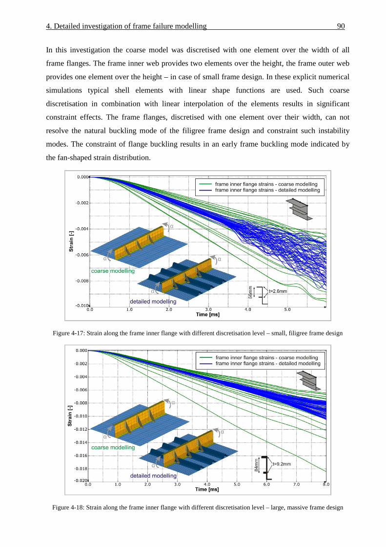
4. Detailed investigation of frame failure modelling 90
In this investigation the coarse model was discretised with one element over the width of all
frame flanges. The frame inner web provides two elements over the height, the frame outer web
provides one element over the height – in case of small frame design. In these explicit numerical
simulations typical shell elements with linear shape functions are used. Such coarse
discretisation in combination with linear interpolation of the elements results in significant
constraint effects. The frame flanges, discretised with one element over their width, can not
resolve the natural buckling mode of the filigree frame design and constraint such instability
modes. The constraint of flange buckling results in an early frame buckling mode indicated by
the fan-shaped strain distribution.
Figure 4-17: Strain along the frame inner flange with different discretisation level – small, filigree frame design
Figure 4-18: Strain along the frame inner flange with different discretisation level – large, massive frame design

91 4. Detailed investigation of frame failure modelling
In the following, the element size in the coarse variant was reduced in a way that the frame
flange width was discretised with two element rows. Three element rows are modelled over the
frame inner web height, two element rows over the frame outer web height – in case of the small
frame design. With this mesh refinement constraint effects could be avoided and an accurate
elastic behaviour was achieved, as the results in Figures 4-19 and 4-20 illustrate. Here, the fine
modelled variant is compared with the refined Kinematics Model variant. Both diagrams
illustrate good agreement in the elastic behaviour.
With respect to initiation of instabilities the filigree frame design as well as the massive frame
design show a slightly delayed initiation of flange buckling respectively frame buckling for the
Kinematics Model variant. This small discrepancy has no influence on the model accuracy as
strain limit criteria in the Kinematics Model are not defined by the FE model, but according to
the empirical handbook criteria.
Figure 4-19: Strain along the frame inner flange, kinematics and detailed modelling – small, filigree frame design

4. Detailed investigation of frame failure modelling 92
Figure 4-20: Strain along the frame inner flange, kinematics and detailed modelling – large, massive frame design
As an outcome of this study, a maximum reasonable element size can be defined so that at least
two elements are modelled over the flange width of frame inner and outer flange. Such an
element size leads to five elements over the frame height for the considered small frame profile
(typical design). Up to seven elements over the frame height are modelled in this discretisation
level for the large frame profile (massive design).
A further aspect regarding efficient calculation schemes is the usage of reduced integration for
the shell elements. With reduced integration, one section point is used instead of four section
points in the fully integrated shell element. This effect can reduce the calculation time
significantly. Nevertheless, the combination of reduced-integration elements with a coarse
regular mesh under bending loads is critical. Excessive hourglassing can increase the artificial
energy of the hourglass control which is provided by the FE solver. Therefore, at least four
elements through the section of bending regions are recommended when reduced-integration
elements are used [111,112]. With respect to the frame web this recommendation is satisfied
with the refined Kinematics Model variant discussed above. But the frame flanges are modelled
in the refined variant with only two elements over the flange width. In case of frame buckling,
the elements of the frame flanges experience in-plane bending loads. In this special case the
recommendation to use at least four elements through the section is not satisfied. It is obvious
that a mesh refinement is not reasonable. This would lead to a significant increase of calculation
time caused by a comparably fine FE mesh which is not acceptable for an efficient preliminary
design tool. Instead, the elements of frame inner and middle flange are calculated fully
integrated. Hourglass modes can not occur with fully integrated elements. Hence, potential
increase of artificial energy by hourglass control is avoided. The frame outer flange is

93 4. Detailed investigation of frame failure modelling
furthermore modelled with reduced-integration elements as this flange is connected to the skin
by tie constraints which avoid the occurrence of hourglass modes. In addition, potential in-plane
bending loads in this outer flange are negligible.
Further calculation efficiency was realised by a reduction of the number of layers as well as by
the reduction of the number of integration points through the thickness of each layer. Potential
influence of both simplifications was analysed with the frame-stringer-skin model considering
the four representative LCF-shaped frame designs which are illustrated in Figure 4-5b)-e). Pure
moment load was assumed in this investigation.
The investigation of effects caused by the merging of stacking sequences identified no influence
on the elastic behaviour for all considered frame designs. Reasonable merging was conducted in
this study which considered the fusion of similar plies.
The reduction of the number of integration points through the thickness did not show observable
influence on the elastic behaviour, either. In this study, the number of integration points was
reduced from three points per ply to one point per ply. With respect to the initiation of
instabilities small effects were observed. In one frame design variant, flange buckling occurred
marginally later with reduced layup and one integration point per ply. Once more, the initiation
of instabilities has no effect on the accuracy of the Kinematics Model as empirical handbook
criteria for failure initiation are used.
Summarising the investigation on the influence of the discretisation, several discretisation
parameters were analysed with the focus on a maximum coarse structural representation to
achieve model efficiency without the loss of model accuracy.
Investigations of the required mesh size led to a model efficient compromise that specifies a
minimum number of elements along the frame height and uses fully integrated elements in the
inner and middle flange to ensure model accuracy without further mesh refinement. Further
model efficiency could be achieved by reasonable merging of the layup stacking sequence as
well as by the reduction of the number of integration points per layer. Figure 4-21 compares the
model efficiency of typical detailed modelling with the final kinematics modelling on the basis
of the frame-stringer-skin simulation model with the small, filigree frame design. Summarising
the discretisation aspects discussed above the model efficiency of the final kinematics modelling
approach provides a factor of f = 0.034 relative calculation time compared to detailed modelling.
Minor discrepancies in the initiation of instability modes compared to detailed modelling will
have no influence on the model accuracy as the initiation of instabilities is defined in the
Kinematics Model by empirical handbook criteria.

4. Detailed investigation of frame failure modelling 94
Hence, the finally defined discretisation for the Kinematics Model significantly improved the
model efficiency without the loss of accuracy.
Figure 4-21: Model efficiency of the final kinematics modelling
4.6. Influence of the bending-compression ratio
In some of the investigations discussed in the paragraphs above, generic frame-stringer-skin
models were analysed with pure moment load. The concentration on pure moment load should
focus on the individual targets of the above investigations. In realistic crash scenarios a
combined load of moment and normal force acts on the frame-stringer-skin structure. Depending
on the location in the fuselage section and the crash phase, high normal forces can act on the
structure. Especially in the critical sub-passenger floor area the normal forces are generally in
compression direction. In this area, high compression forces can lead to small bending-
compression ratios which influence the failure behaviour of the fuselage structure.
In this paragraph typical bending-compression ratios are discussed which act on a frame
structure of a fuselage section during a typical crash event. The influence of these bending-
compression ratios on the behaviour of the kinematic hinge architecture is highlighted. Finally,
the influence of the bending-compression ratio on the failure behaviour of a frame-stringer-skin

95 4. Detailed investigation of frame failure modelling
structure is discussed and assessed with the failure criteria which were defined for pure moment
loads in paragraph 4.2.1.
4.6.1. Identification of typical bending-compression ratios
The frame structure of the sub-passenger floor area can be divided in two different regions which
experience different maximum loadings at different phases during a typical crash event. The
frame region between cargo-crossbeam and vertical support strut is one of these frame regions.
After the failure of the sub-cargo area first frame failure typically occurs in this region. The crash
phase which is of interest to analyse the bending-compression ratio in this region is the period
between the first impact of the fuselage and the failure of the frame, respectively the triggering
of the kinematic hinges. With respect to a standard crash scenario2 of a typical single-aisle
transport aircraft this period is approximately between t1 = 0 ms and t2 = 50 ms. Figure 4-22
illustrates the bending-compression ratio during this period in two cutting surfaces which are
positioned in this critical frame region at α1 = 25° and α2 = 34°. The depicted results were
generated in a simulation of a generic CFRP single-aisle fuselage section. The bending-
compression ratio is defined as
r = bending moment / normal force [mm].
The moment load was analysed with respect to a reference point that is located in the centre of
the cross-section area. The cutting surfaces include the frame as well as the skin structure.
Caused by the dynamic nature of a crash event the bending-compression ratio tends to high
oscillations. Therefore, the graphs in the diagrams of Figure 4-22 are filtered with a butterworth
filter and a cut-off frequency of f = 180 Hz. The raw data graphs, with a sampling frequency of
f = 2 kHz, are additionally illustrated in grey colour.
Figure 4-22a) depicts the measured bending-compression ratio of cutting surface CS-02. A mean
value of r2 = 400 mm can be identified for the considered crash phase. The ratio in cutting
surface CS-01 is illustrated in Figure 4-22b). The graph shows values which are mainly above a
ratio of approximately r1 = 200 mm.
In general, a bending-compression ratio higher than r = 150 mm was identified in the frame
region between the sub-cargo area and the vertical support strut.
2 Within this thesis, the ‘standard crash scenario’ specifies impact conditions of a vertical impact with vi = 6.7 m/s,
fully loaded overhead bins, occupied seats, zero pitch and roll angle. Cargo loading is not considered in this case.
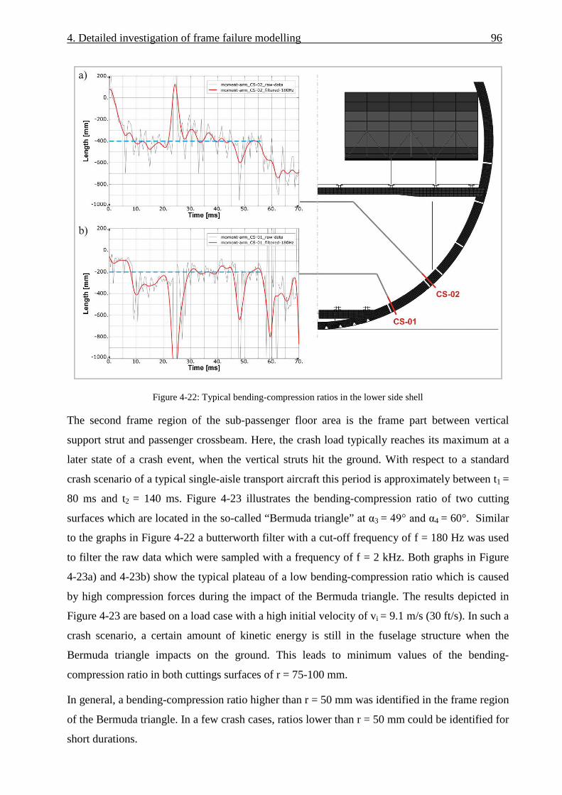
4. Detailed investigation of frame failure modelling 96
Figure 4-22: Typical bending-compression ratios in the lower side shell
The second frame region of the sub-passenger floor area is the frame part between vertical
support strut and passenger crossbeam. Here, the crash load typically reaches its maximum at a
later state of a crash event, when the vertical struts hit the ground. With respect to a standard
crash scenario of a typical single-aisle transport aircraft this period is approximately between t1 =
80 ms and t2 = 140 ms. Figure 4-23 illustrates the bending-compression ratio of two cutting
surfaces which are located in the so-called “Bermuda triangle” at α3 = 49° and α4 = 60°. Similar
to the graphs in Figure 4-22 a butterworth filter with a cut-off frequency of f = 180 Hz was used
to filter the raw data which were sampled with a frequency of f = 2 kHz. Both graphs in Figure
4-23a) and 4-23b) show the typical plateau of a low bending-compression ratio which is caused
by high compression forces during the impact of the Bermuda triangle. The results depicted in
Figure 4-23 are based on a load case with a high initial velocity of vi = 9.1 m/s (30 ft/s). In such a
crash scenario, a certain amount of kinetic energy is still in the fuselage structure when the
Bermuda triangle impacts on the ground. This leads to minimum values of the bending-
compression ratio in both cuttings surfaces of r = 75-100 mm.
In general, a bending-compression ratio higher than r = 50 mm was identified in the frame region
of the Bermuda triangle. In a few crash cases, ratios lower than r = 50 mm could be identified for
short durations.

97 4. Detailed investigation of frame failure modelling
Figure 4-23: Typical bending-compression ratios in the Bermuda triangle
4.6.2. Influence of the bending-compression ratio on the kinematic hinge
behaviour
The investigation on typical bending-compression ratios identified values of r > 150 mm in the
critical frame region between cargo-crossbeam and vertical strut and r > 50 mm in the region of
the Bermuda triangle. In the following, the influence of these bending-compression ratios on the
behaviour of the kinematic hinges is investigated.
The investigation on the bending-compression ratio is based on the generic frame-stringer-skin
model that was simulated with different frame profiles according to Figure 4-5b) – 4-5e). The
generic simulation model represents the frame-stringer-skin structure in the Kinematics Model
approach and is illustrated in Figure 4-24a). A kinematic hinge is positioned in the centre of the
frame segment. The stiffness of the kinematic hinge was calibrated under pure moment load with
respect to the frame inner flange strain, as discussed in paragraph 4.2.2. After the calibration
under pure moment load different bending-compression ratios were applied on the model.
Results with filigree as well as with massive frame design are depicted in Figure 4-24b) and 4-
24c). In the diagrams the strains along the frame inner flange are illustrated over the simulation
time respectively over the moment/compression load.

4. Detailed investigation of frame failure modelling 98
Under pure moment load (r = ∞) both model variants (filigree and massive frame design) show
good correlation between the flange strain and the kinematic hinge strain. With a bending-
compression ratio of r = 150 mm a small derivation of the kinematic hinge strain is visible.
Significant discrepancy between the kinematic hinge strain and the strain along the frame inner
flange can be identified with a bending-compression ratio of r = 50 mm for both model variants.
Furthermore, in case of r = 50 mm higher deflection of the kinematic hinge strain can be
identified for the massive frame design compared to the filigree frame design.
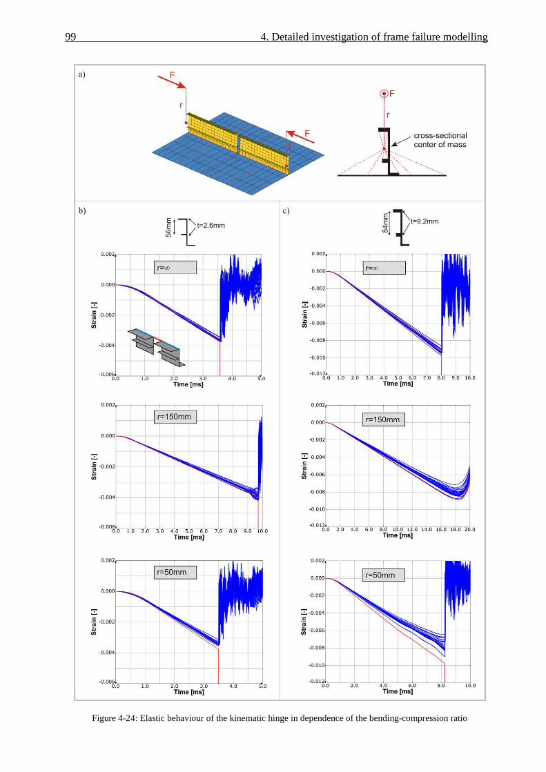
99 4. Detailed investigation of frame failure modelling
Figure 4-24: Elastic behaviour of the kinematic hinge in dependence of the bending-compression ratio

4. Detailed investigation of frame failure modelling 100
The effects that lead to the observed differences of kinematic hinge stiffness and frame stiffness
with decreasing bending-compression ratio are explained in the following. Exemplarily, the
strain graphs of Figure 4-24c), for r = ∞ and r = 50mm, are plotted again in Figure 4-25. Here,
the mean value of the frame inner flange strains as well as the kinematic hinge strain is plotted
over the frame inner flange displacement. For r = ∞ good correlation of the linear slope can be
identified between the mean values of the frame inner flange strains as well as the kinematic
hinge strain. In contrast to this, the kinematic hinge strain of r = 50 mm clearly differs. Besides
the discrepancy in the elastic slope a small difference in the trigger strain of the kinematic hinge
of ∆ε ≈ 0.5e-03 can be identified.
The small difference in the trigger strain is caused by the kinematic hinge architecture. The
characteristic of the kinematic hinge is described by a moment-rotation relation. The
translational degrees of freedom are constrained. These numerical constraints in the connector
element are not infinitely rigid. In case of high normal forces a marginal displacement in the
translational degree of freedom leads to this small difference in the trigger strain.
The more significant deflection in the elastic slope of the kinematic hinge strain is caused by
different locations of the elastic centre of the frame-skin cross-section and the pivot point of the
kinematic hinge. The positioning of the macro element in the kinematic hinge architecture was
already discussed in paragraph 4.2 and 4.3 with respect to the pre- and post-failure behaviour of
a frame-skin structure. The position of the macro element in the skin plane is essential with
respect to the post-failure behaviour. The drawback of this location is a load-dependent elastic
behaviour of the kinematic hinge. In case of a combined loading of moment and normal force,
the normal force acts in the elastic centre of the frame-skin cross-section. With respect to the
kinematic hinge pivot point positioned in the skin plane this normal force induces an additional
moment on the rotational degree of freedom of the macro element. Figure 4-26 illustrates this
relation. The effect is a higher strain in the kinematic hinge compared to the frame inner flange
strain. The higher the distance between elastic centre and pivot point the more this effect is
observable. Hence, low bending-compression ratios in combination with a massive frame design
leads to higher deflection of the kinematic hinge behaviour compared to a filigree frame design,
as observed in Figure 4-24.

101 4. Detailed investigation of frame failure modelling
Figure 4-25: Strain along the frame inner flange for different bending-compression ratios
Figure 4-26: Additional moment load caused by different locations of the elastic centre and the pivot point
The comparison of the kinematic hinge accuracy in dependence of the bending-compression
ratio in Figure 4-24 generally shows an acceptable behaviour up to a ratio of r = 150 mm. Ratios
smaller than r = 150 mm lead to a significant loss of the kinematic hinge accuracy. The
investigation discussed in paragraph 4.6.1 highlighted that a ratio smaller than r = 150 mm
typically occurs in the region of the Bermuda triangle when high compression forces are induced
by the impact of the vertical struts. With respect to such cases, the kinematic hinges in that
region should be calibrated for low bending-compression ratios instead of pure moment load.
This calibration would represent too stiff kinematic hinge behaviour during the first crash
phases. But during the critical crash phase, when triggering of the kinematic hinges is expected,
good correlation can be achieved.
Summarising the above discussed investigation, typical bending-compression ratios were
identified and the kinematic hinge behaviour was analysed for different ratios. In general, good
4. Detailed investigation of frame failure modelling 102
accuracy of the kinematic hinge was identified for typical bending-compression ratios. With
respect to very low bending-compression ratios, the kinematic hinge showed inaccurate
tendencies. Potential calibration based on lower bending-compression ratios may compensate
this effect.
4.6.3. Influence of the bending-compression ratio on the failure behaviour of a
frame-stringer-skin structure
In the following, the influence of the bending-compression ratio on the validity of failure criteria
is discussed. In paragraph 4.2.1 failure criteria were defined with respect to pure moment load on
a frame-stringer-skin structure. The strain along the frame inner flange as well as along the frame
outer flange of a LCF-shaped frame was identified to serve as failure criteria for opening and
closing bending failure. In case of additional normal load the same failure criteria are still valid
for the indication of potential frame failure. The frame middle flange remains uncritical in all
load variations.
In the extreme case of pure normal load (r = 0 mm) the frame middle flange experiences the
same strain magnitude compared to frame inner and outer flange. Typical LCF- shaped frame
design defines the frame inner and middle flange of higher stiffness, respectively thickness,
compared to the frame outer flange. The crippling strain criteria are more critical for the frame
outer flange as for the frame middle and inner flange. Hence, the frame middle flange is
uncritical in all loading conditions. To illustrate this effect, simulations were performed of
different LCF-shaped frame profiles and different loading conditions (r = ∞, r = 50 mm). Figure
4-27 provides the simulation results and depicts the mean value of the frame flange strains
plotted over the frame inner flange displacement. Exemplarily, the filigree frame design, Figure
4-27b), and the massive frame design, Figure 4-27c), are given. The diagrams illustrate opening
bending in case of positive frame inner flange displacement and closing bending in case of
negative frame inner flange displacement. The diagrams of the variant r = 50 mm illustrate a
combined loading of bending and compressive normal force. In the diagram r = 50 mm, Figure
4-27c) shows that frame middle and outer flange strains are close to each other. This is one of the
cases when the frame middle flange experiences nearly the same strain magnitude than the frame
outer flange. Nevertheless, the crippling strain limit of the frame outer flange is generally more
critical which is why even in such cases the frame middle flange is not critical. Hence, the
general validity of the frame failure criteria, defined in paragraph 4.2.1, could be proved even in
case of untypical high normal load.

103 4. Detailed investigation of frame failure modelling
Figure 4-27: Influence of the bending-compression ratio on the elastic behaviour of a frame-stringer-skin structure
4.7. Summary – the final kinematic hinge macro architecture
The final macro architecture of the kinematic hinge is based on the investigations discussed in
the previous paragraphs. In chapter 3.2.3 the basic macro architecture was already presented. In
the following the main properties of the kinematic hinge, which were derived from the detailed
investigations, are summarised. Figure 4-28 illustrates the properties of the final kinematic hinge
architecture.

4. Detailed investigation of frame failure modelling 104
The positioning of the kinematic hinges in a model of a fuselage section is firstly defined
according to the data basis of known experimental test results. Secondly, the positioning is
defined according to the strain distribution in the frame flanges which are derived from
numerical simulation of a preliminary Kinematics Model without kinematic hinges in the frame.
Lateral frame support is effected sufficiently by the kinematic hinge itself, as discussed in
paragraph 4.4. Potentially, additional lateral support by nodal constraints can be defined in
regions of the fuselage section where long frame segments are defined without kinematic hinge.
This is potentially the case in the upper fuselage area where frame failure is expected only at few
locations.
The kinematic hinge architecture is described mainly based on the discussion of pre- and post-
failure behaviour of a frame-stringer-skin structure. A cut in the frame represents the
discontinuity of the elastically modelled frame structure. Both free cross-sections of the frame
are reinforced by rigid bodies. The macro element, a connector element in case of the FE code
ABAQUS/Explicit, is positioned in the skin plane and connects both rigid bodies of the frame
cross-sections. The connector element describes the frame pre- and post-failure characteristic by
a moment-rotation curve. In this macro element the rotational degree of freedom is the only
active one. In particular, the degree of freedom in the longitudinal frame direction is constraint.
Due to the small length of the kinematic hinges compared to the total frame length in a fuselage
section this rigid behaviour has no significant influence. With respect to the kinematic of such a
hinge the longitudinal displacement in the skin plane respectively in the frame outer flange is
fixed whereas the longitudinal displacement in the frame inner flange is described by the
moment-rotation curve. Hence, calibration of the initial slope in the moment-rotation curve,
which represents the elastic frame behaviour, is defined with respect to the frame inner flange
strains. In addition, the trigger moment is generally calibrated with respect to a limit strain in the
frame inner flange. This definition is conform to typical trigger mechanisms which are specified
and located in the frame inner flange. Nevertheless, potential failure of the frame outer flange
has to be checked besides the kinematic hinge by empirical strain criteria, as discussed in
paragraph 4.2.1.
In addition to that, Figure 4-28 illustrates some properties of the kinematic hinge with the focus
on model simplifications. For an improved simulation performance a coarse modelling is
desired. In paragraph 4.5 minimum modelling refinements were identified to ensure adequate
accuracy. These minimum refinements are a discretisation with at least two shell elements along
the frame inner flange width to allow the formation of instability modes. At least five shell
elements over the frame height are required to avoid the risk of extensive generation of hourglass
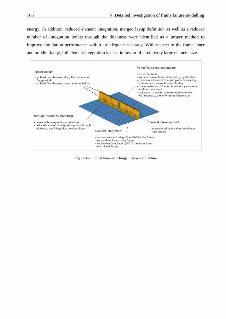
105 4. Detailed investigation of frame failure modelling
energy. In addition, reduced element integration, merged layup definition as well as a reduced
number of integration points through the thickness were identified as a proper method to
improve simulation performance within an adequate accuracy. With respect to the frame inner
and middle flange, full element integration is used in favour of a relatively large element size.
Figure 4-28: Final kinematic hinge macro architecture

5. Implementation of a user element for frame failure
modelling
The development of the kinematic hinge architecture, discussed in chapter 4, was performed on
the basis of standard macro elements which are provided by the commercial FE solver. The
selection of an appropriate standard macro element was described in chapter 3.2.1. Outcome of
this development is the final kinematic hinge architecture that is described in paragraph 4.7. This
macro architecture enables the representation of typical frame failure mechanisms in a realistic
and adequately accurate way. Although this failure representation is well sufficient with respect
to a preliminary design tool, some limitations in the kinematic hinge architecture were the
motivation to raise some effort for further improvement of the frame failure representation. In
paragraph 5.1 a discussion of these limitations will identify that some of them are caused by
restrictions of the standard macro element which is used in the kinematic hinge. The absence of
proper standard macro elements, which are able to overcome these restrictions, led to the
consideration of the development of a specific user element.
Implementation of user subroutines in an explicit finite element code is a decision which has to
be balanced carefully. High effort is essential to obtain a qualified user element. Besides the
programming of the subroutine an extensive verification is essential. In addition, the
performance of element calculation is very important in an explicit code. Hence, the source code
has to be written primarily with respect to efficient calculation, otherwise the user element is not
suitable due to high costs of CPU time.
The weighting of arguments finally resulted in the decision to program such a user element.
Paragraph 5.1 discusses the requirements which were gathered with respect to an improved
macro element in the kinematic hinge. These requirements are mainly based on some limitations
of the standard connector element which is used in the final kinematic hinge architecture
according to chapter 4.7.
The following described work is based on the explicit finite element code ABAQUS/Explicit. A
user element interface for explicit time integration is available in ABAQUS since the version
V6.7 [104,116]. The implementation of the user element was performed based on ABAQUS
versions V6.7, V6.8 and V6.9. Due to the recent option of a user element interface, the
implementation was affected by several bugs which were partly solved in later versions (V6.9) of

107 5. Implementation of a user element for frame failure modelling
ABAQUS. Some issues in the ABAQUS subroutine interface are still present for what reason the
user element could finally not be implemented in the fuselage section model. Nevertheless, the
implementation of the user element is completed and all functionalities could be proved.
In the following, paragraph 5.1 discusses requirements for an improved macro element.
Paragraph 5.2 describes the programming of the user element. The verification process is
documented in paragraphs 5.3 and 5.4 whereas paragraph 5.5 gives an outlook due to unsolved
issues in the considered FE solver versions.
5.1. Requirements for an improved macro element
A catalogue of requirements was prepared which represents the basis for the development of a
user element subroutine. A critical review of the final kinematic hinge architecture based on
standard finite elements identified some limitations which shall be solved by the user element.
Some additional requirements define the format of input definition as well as further
improvements of the kinematic hinge options.
As discussed in paragraph 4.6 the kinematic hinge provides limited accuracy in case of low
bending-compression ratios smaller than r = 150 mm. These low ratios can occur in case of high
compression peaks, for instance when the vertical support struts hit the ground. The main reason
for a deflection in the kinematic hinge accuracy in case of such low bending-compression ratios
is the representation of frame longitudinal stiffness located exclusively in the skin plane. Due to
this offset with respect to the elastic centre an additional moment is induced which leads to
higher displacement in the kinematic hinge at the frame inner flange. This circumstance was
discussed in paragraph 4.6 and is illustrated again in Figure 5-1a). To improve the kinematic
hinge accuracy in case of low bending-compression ratios, the frame longitudinal stiffness has to
be defined uniformly over the frame height. Hence, additional forces of the kinematic hinge
macro element have to be applied at the frame inner flange, as displayed in Figure 5-1b). The
ratio of applied force at the frame inner and outer flange has to be defined in a way that
equilibrium of moment is given with respect to the elastic centre. A consequence of this
requirement is the definition of a 4-node user element instead of a 2-node element, like the
standard connector element, to apply the required forces in the frame inner flange.

5. Implementation of a user element for frame failure modelling 108
Figure 5-1: Applied forces of normal stiffness in the kinematic hinge
In addition, the discussion in paragraph 4.6 identified a small discrepancy in the trigger strain of
the kinematic hinge in case of low bending-compression ratios. This discrepancy is caused by a
finite stiffness of the fixed translational degree of freedom in the standard connector element. A
trigger criterion based on strain instead of moment load would enable accurate triggering with
respect to a strain failure criterion defined in the frame inner flange. In Figure 5-2 this trigger
concept is compared to the trigger procedure of the standard connector element. Using the
connector element, the trigger moment in the moment-rotation input curve is defined by
calibration with a frame-stringer-skin reference model. The trigger moment is calibrated such
that the desired strain in the frame inner flange is reached in the reference model. In contrast to
this, the user element shall directly measure the strain in the frame inner flange and initiate
triggering when the measured value exceeds the defined trigger strain criterion. A consequence
of this requirement is again a 4-node user element. Additional element nodes in the frame inner
flange are necessary to obtain the nodal displacement respectively the strain in the frame inner
flange.

109 5. Implementation of a user element for frame failure modelling
Figure 5-2: Comparison of trigger concepts in the kinematic hinge
A further requirement was identified in the critical review of the kinematic hinge architecture
based on the standard connector element. The unloading and reloading characteristic of the
connector element can be defined in the tabular input version with an unloading curve as well as
a slope which defines the transition between main curve and unloading curve. Reloading
behaviour of the connector element follows the unloading curve backwards and finally along the
slope to the point at the main curve where unloading started. Physically more correct with
respect to the unloading/reloading behaviour is the characterisation of a hysteresis. Especially in
dynamic problems numerous unloading/reloading cycles are expected so that hysteresis effects
can have influence on the kinematic hinge behaviour. Figure 5-3 illustrates this unloading
behaviour and compares the hysteresis approach with the standard connector element behaviour.
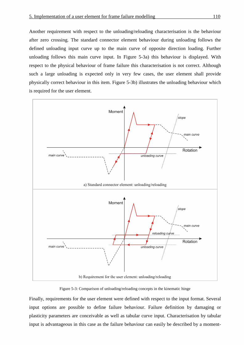
5. Implementation of a user element for frame failure modelling 110
Another requirement with respect to the unloading/reloading characterisation is the behaviour
after zero crossing. The standard connector element behaviour during unloading follows the
defined unloading input curve up to the main curve of opposite direction loading. Further
unloading follows this main curve input. In Figure 5-3a) this behaviour is displayed. With
respect to the physical behaviour of frame failure this characterisation is not correct. Although
such a large unloading is expected only in very few cases, the user element shall provide
physically correct behaviour in this item. Figure 5-3b) illustrates the unloading behaviour which
is required for the user element.
Figure 5-3: Comparison of unloading/reloading concepts in the kinematic hinge
Finally, requirements for the user element were defined with respect to the input format. Several
input options are possible to define failure behaviour. Failure definition by damaging or
plasticity parameters are conceivable as well as tabular curve input. Characterisation by tabular
input is advantageous in this case as the failure behaviour can easily be described by a moment-

111 5. Implementation of a user element for frame failure modelling
rotation relation. This is even more favourable when the kinematic hinge input is based on
component test data or the final hinge characteristic defines the basis for the development of a
crash device in the frame. Nevertheless, pure tabular input does not offer the possibility of strain
based triggering. Hence, a combined input format is required for the user element. Elastic
behaviour shall be defined by a stiffness value whereas tabular curve input is required for the
description of the post-failure behaviour. The strain based trigger criterion initiates the transition
from the elastic behaviour to the post-failure characteristic. The slope of this transition shall be
definable by a stiffness value. With respect to the unloading behaviour the slope between main
curve and unloading curve shall similarly be defined by a stiffness value. The unloading as well
as the reloading curve shall be assumed to be constants. Figure 5-4 illustrates these input
parameters which shall be individually definable for the opening and the closing bending
direction.
Additional input parameters shall be defined for the normal stiffness in tension and compression
for consideration of normal loads. Finally, the interval for history output of the element variables
shall be defined in the input deck. In contrast to the output frequency, the list of element
variables to be output shall be defined directly in the subroutine and not in the ABAQUS input
deck of the user element.
Figure 5-4: Required input parameters of the user element for the description of the moment-rotation behaviour

5. Implementation of a user element for frame failure modelling 112
5.2. Implementation of the user element
The user element subroutine, called VUEL, was written as FORTRAN code and included in the
kinematic hinge model using the Intel FORTRAN Compiler version 10.1.014 as well as the
ABAQUS/Explicit versions V6.7-3, V6.8-1 and V6.9-1 on a Microsoft Windows machine. The
interface which is used to implement the user subroutine in an ABAQUS analysis is given in
[116].
In the following the description of the user element programming is organized chronologically to
discuss the routine of the user element step by step. Figure 5-5 gives an overview of the user
element architecture. The individual aspects of the source code architecture are discussed in this
paragraph with the focus on the calculation of the internal loads which represent the user element
behaviour respectively the frame failure characteristic of the kinematic hinge.
Figure 5-5: User element (VUEL) architecture

113 5. Implementation of a user element for frame failure modelling
The ABAQUS input deck provides an interface for the user element where element data (*user
element) as well as data of the element behaviour (*uel property) can be defined. The element
data contain:
• Number of nodes of the element
• Number of property parameters to describe the element behaviour
• Number of coordinates at each element node
• Number of solution-dependent state variables to be stored within the element
The input deck of the user element is given in Appendix A3.1.
Based on the requirements of paragraph 5.1 a 4-node user element was developed. With respect
to the kinematic hinge architecture this user element substitutes the standard connector element
in one rotational (frame bending) as well as in one translational (frame normal compression)
degree of freedom. Both degrees of freedom are used to describe the main crash behaviour of a
frame structure. All other degrees of freedom are still constraint by a connector element that is
installed in the kinematic hinge in parallel. The outer nodes of the user element are positioned in
the skin plane and share these nodes with the standard connector element. The inner nodes are
positioned at the frame inner flange in the frame web plane and share these nodes with the
structural shell elements. All four user element nodes are included in the rigid bodies which
reinforce the frame cross-sections. Each element node is defined with three translational and
three rotational degrees of freedom. Figure 5-6 illustrates the kinematic hinge architecture with
the user element as well as the definition of nodal degrees of freedom in the user element.
Whereas nodal forces of frame normal stiffness is applied to all user element nodes, the moments
of the rotational degree of freedom are applied exclusively to node 1 and 2, similarly to the
standard connector element.
Figure 5-6: Kinematic hinge architecture with the user element

5. Implementation of a user element for frame failure modelling 114
In the element behaviour definition of the ABAQUS input deck (*uel property) all property
parameters can be specified. In the user element subroutine these property parameters are
imported from the ABAQUS input deck in a first step. In Figure 5-4 of paragraph 5.1 the
required moment-rotation behaviour is described which had to be developed. Most of the
property parameters are illustrated in this Figure. In total, 47 property parameters are necessary
to describe the element behaviour and which are imported in the user element. In this
configuration the post-failure curve of each loading direction can be defined with eight pairs of
values. An overview of these parameters is given in Appendix A3.1.
In a second step, nodal rotary inertia and mass are specified. The user element developed for the
kinematic hinge is a macro element and not a structural element. Material density is not
specified. Hence, definition of rotary inertia and mass does not represent structural mass but is
important to ensure stable numerical calculation. As all user element nodes are coupled to rigid
bodies in the kinematic hinge, small values for rotary inertia and mass can be defined here.
In a third step, a constant stable time increment has to be defined for element calculation. The
stable time increment of a macro element strongly depends on the input characteristic defined by
the user. The elemental time increment cannot be defined as the user element is not a structural
element. Nevertheless, the critical time increment can be calculated based on the nodal time
increment.
kmt ⋅≤∆ 2 ,
LAEk ⋅
⋅= 2 (5.1)
The critical spring stiffness k is defined by the highest slope (E·A) in the input property
definition as well as the element length (L). Although a nodal stable time increment could be
defined based on nodal mass and spring stiffness, the definition of a user-defined stable time
increment was preferred here. This procedure is used similarly in standard macro elements of
some commercial explicit finite element codes. In this procedure, the user is responsible for
stable element calculation with respect to the time increment.
The interface between finite element code and user element is based on global coordinates. In a
further step a coordinate transformation from a global to a local system has to be conducted after
the import of the nodal displacements. With respect to the application of the user element in a
fuselage section model, the coordinate transformation was simplified so that the yaw angle is
assumed to be negligible (Ψ = 0). This simplification is reasonable in a fuselage section model
with symmetry boundary conditions. The transformation as well as the definition of the local
coordinates in the kinematic hinge is illustrated in Figure 5-7.
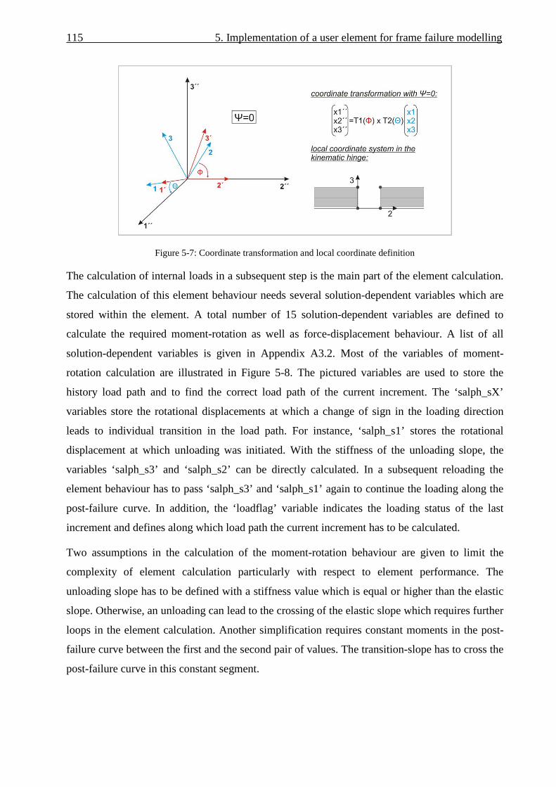
115 5. Implementation of a user element for frame failure modelling
Figure 5-7: Coordinate transformation and local coordinate definition
The calculation of internal loads in a subsequent step is the main part of the element calculation.
The calculation of this element behaviour needs several solution-dependent variables which are
stored within the element. A total number of 15 solution-dependent variables are defined to
calculate the required moment-rotation as well as force-displacement behaviour. A list of all
solution-dependent variables is given in Appendix A3.2. Most of the variables of moment-
rotation calculation are illustrated in Figure 5-8. The pictured variables are used to store the
history load path and to find the correct load path of the current increment. The ‘salph_sX’
variables store the rotational displacements at which a change of sign in the loading direction
leads to individual transition in the load path. For instance, ‘salph_s1’ stores the rotational
displacement at which unloading was initiated. With the stiffness of the unloading slope, the
variables ‘salph_s3’ and ‘salph_s2’ can be directly calculated. In a subsequent reloading the
element behaviour has to pass ‘salph_s3’ and ‘salph_s1’ again to continue the loading along the
post-failure curve. In addition, the ‘loadflag’ variable indicates the loading status of the last
increment and defines along which load path the current increment has to be calculated.
Two assumptions in the calculation of the moment-rotation behaviour are given to limit the
complexity of element calculation particularly with respect to element performance. The
unloading slope has to be defined with a stiffness value which is equal or higher than the elastic
slope. Otherwise, an unloading can lead to the crossing of the elastic slope which requires further
loops in the element calculation. Another simplification requires constant moments in the post-
failure curve between the first and the second pair of values. The transition-slope has to cross the
post-failure curve in this constant segment.

5. Implementation of a user element for frame failure modelling 116
Figure 5-8: Solution-dependent variables for the element calculation
Two additional state variables are used for normal stiffness calculation. The normal forces are
calculated as required in paragraph 5.1 and are applied to the element nodes as pictured in Figure
5-1b).
More details on the calculation of the internal loads are given in Appendix A3.3, where an
extraction of the structogram is documented.
After calculation of the internal loads, these values have to be transformed from the local to the
global coordinate system to assemble the nodal loads in the right hand side vector. This vector is
the interface for the export of nodal loads to the solver.
Finally, the internal energy has to be calculated and exported to the solver. The determination of
the user element internal energy is essential with respect to the conservation of energy of the
whole model. Internal energy calculation considers the rotational as well as the translational
degree of freedom and is defined as follows:
−⋅
++−⋅
++=
∆−∆−
∆−∆−
∆−)22(
222
)11(2
11ttt
tttttt
tttttt
asepsasepssFsF
salphsalphsMsM
energyenergy
(5.2)
Whereas the energy calculation for the translational degree of freedom is trivial due to the purely
elastic behaviour, the summation of internal energy for the rotational degree of freedom is

117 5. Implementation of a user element for frame failure modelling
depicted in Figure 5-9 for a better understanding. In this figure the graph clearly illustrates the
unloading/reloading hysteresis with its additional energy absorption effect.
Figure 5-9: Internal energy calculation of the rotational degree of freedom
In the final step of the element calculation the state variables are updated and data are written to
the output data file. Unfortunately, solution-dependent state variables of user elements can not be
written to the ABAQUS output database (.odb) file [141]. Hence, these variables are written in a
separate ASCII-file and can additionally be imported in a postprocessor. The element output is
defined in a way that all 15 state variables as well as ‘time’ and ‘internal energy’ are written to
the output data file, with an output frequency that can be defined by the property variable
‘history_interval’ in the ABAQUS input deck.
5.3. Verification on the quasi-single element level
Extensive verification of a user subroutine is essential to ensure a correct functionality for all
potential loading conditions. After the implementation of the user element, the verification firstly
concentrated on the internal element calculation, more precisely on the calculation of internal
loads and internal energy as well as on the coordinate transformation. This verification was
conducted on a quasi-single element level. As the user element was developed exclusively for
implementation in the kinematic hinge, a simplified model of the kinematic hinge was built up
which is equivalent to the single element level. Figure 5-10 illustrates this verification model. In
this model the frame structure is represented by rigid bodies consisting of both user element
nodes at one side and an additional node to apply external loads on the kinematic hinge.

5. Implementation of a user element for frame failure modelling 118
Figure 5-10: Quasi-single element model for the verification
The verification of the coordinate transformation routine was conducted with a parameterised
version of this quasi-single element model that can be rotated arbitrarily with respect to the
global coordinate system. The coordinate transformation routine was verified regarding all
combinations of quadrants of both transformation angles Θ and Φ, see Figure 5-7. This
verification ensures that in a fuselage section model the kinematic hinge can be positioned
arbitrarily with respect to roll and pitch angle. The simplified assumption of Ψ = 0, discussed in
paragraph 5.1, implicates a negligible yaw angle.
Further verification considered the calculation of the moment-rotation behaviour. The potential
load paths and unloading/ reloading combinations were verified with the quasi-single element
model. Figure 5-11 depicts an exemplary user element output of the verification procedure. The
graphs show details like unloading during the transition from elastic behaviour to the post-failure
curve, unloading with zero crossing as well as different unloading/reloading combinations
including unloading during reloading phases.

119 5. Implementation of a user element for frame failure modelling
Figure 5-11: User element output of the moment-rotation behaviour
The verification on the quasi-single element level identified a correct functionality of the user
element with respect to all element internal calculation procedures. Nevertheless, some bugs
were identified which are located in the ABAQUS solver respectively in the interface between
solver and user element.
One bug refers to the output of the internal energy [142]. After the export of the element internal
energy to the solver this value is included in the ‘whole model internal energy’. Nevertheless, the
requested internal energy output exclusively of the user element is written as null-energy to the
output data base (.odb) of the solver. This bug was solved in ABAQUS V6.9.
Another bug was identified in the import of rotational displacements of the user element nodes
[143]. In combination with several constraints (e.g. rigid body, multi-point constraint, etc.)
which are defined at the user element nodes, the solver transfers incorrect nodal rotations to the
user element subroutine. Generally, additional nodal mass can help to solve such problems.
Nevertheless, any solution failed to solve this problem especially in combination with rigid body
constraint. A solution of this bug was implemented in the subsequent solver version ABAQUS
V6.8-EF1 respectively V6.8-2. In the meantime, to avoid this bug in (at that time) current solver
versions, rotational degrees of freedom of the 4-node user element were derived from
translational degrees of freedom with the scalar product.
Finally, another discrepancy was identified in the export of internal loads to the solver. In
combination with some constraints at the user element nodes, moment loads calculated from the
user element are not applied to the model. Although correct moment history is written to the data

5. Implementation of a user element for frame failure modelling 120
base as desired, the solver does not apply these moments to the nodes. Despite of extensive
investigation and discussion with the FE solver developer this bug is not solved completely yet.
Nevertheless, one solution to by-pass this bug was found in using multi-point constraints
(*MPC) instead of rigid body formulations to constrain the user element nodes within the
kinematic hinge architecture. This modified kinematic hinge architecture worked well in the
quasi-single element model. The moment loads were applied to the user element nodes and the
kinematic hinge behaviour was identified as intended.
Unfortunately, this solution with modified kinematic hinge architecture using multi-point
constraints does not work successfully on a reference model level which is discussed in the next
paragraph. The transfer of the same kinematic hinge architecture from the quasi-single element
model to a frame-stringer-skin model led to the well-known discrepancy with missing applied
moment load on the user element nodes as described above.
5.4. Verification on the reference model level
Further verification after the quasi-single element level was conducted on a reference model
level. The reference model corresponds to a frame-stringer-skin model which is similar to the
models used in the investigations of chapter 4. A detailed definition of the reference model is
given in Appendix A3.4.
The frame-stringer-skin model enables a user element verification which is implemented in a
reference structure with typical dynamic behaviour. Instead of rigid body motions as used on the
quasi-single element level, a more realistic elastic behaviour leads to dynamic oscillation loading
of the user element. Stable element calculation under typical short-duration unloading/reloading
can be verified.
In addition, the requirements of the user element with respect to the elastic behaviour can be
verified in the reference model. Whereas the post-failure behaviour with its unloading/ reloading
options was verified intensively on the quasi-single element level, the elastic behaviour up to
failure was verified mainly on the reference model level. This is in more detail the strain-based
triggering as well as the user element behaviour under low bending-compression ratios.
As discussed in paragraph 5.3, an unsolved bug regarding applied moment loads hindered the
verification on the reference model level. Whereas a solution was found to run the user element
successfully on the quasi-single element level, the calculated moment loads are not applied by
the solver on the reference model level. To verify the elastic behaviour of the user element
despite of this bug, the assembly of internal loads on the right hand side was modified in the user
subroutine. Instead of moments on the outer user element nodes, forces on the inner user element

121 5. Implementation of a user element for frame failure modelling
nodes were applied. These forces in combination with the moment arm induce the same moment
on the outer user element nodes, as shown in Figure 5-12. This modification is accurate for small
rotation angles, hence, is an appropriate solution to verify the elastic behaviour.
Figure 5-12: Modified right hand side in the user subroutine without applied moments
The verification procedure is illustrated in Figure 5-13. For a better understanding the internal
loads of the user element are illustrated with respect to the original right hand side. In a first step,
the rotational elastic stiffness is calibrated based on the frame inner flange strain, Figure 5-13a).
Pure moment is applied on the model in this step. With calibrated rotational stiffness, applied
load with low bending-compression ratio leads to a discrepancy similar to the kinematic hinge
with a standard connector element, Figure 5-13b). In a next step, the distribution of normal
forces over the frame height of the user element is adapted so that the kinematic hinge strain
agrees with the structural frame behaviour with respect to the frame inner flange, Figure 5-13c).
This final setup of calibrated rotational stiffness and normal force distribution leads to the
required accuracy in the representation of the elastic behaviour for low bending-compression
ratios, Figure 5-13c), as well as for high bending-compression ratios, Figure 5-13d).
In addition, the strain based trigger criterion in Figure 5-13 illustrates the required behaviour. In
this example, a trigger strain of ε = -2000 microstrain was defined in the user element input deck.
Independently of the bending-compression ratio, the kinematic hinge triggered accurately at this
defined trigger strain level, Figure 5-13a) – d).

5. Implementation of a user element for frame failure modelling 122
Figure 5-13: Verification on the reference model level
123 5. Implementation of a user element for frame failure modelling
5.5. Summary and outlook
The discussion of the kinematic hinge architecture based on standard macro elements identified
limitations in the frame failure representation which are caused by restrictions of the standard
macro element. On the basis of a catalogue of further requirements, a user element was
implemented to achieve improved frame failure representation by the usage of a user-defined
macro element instead of the standard macro element.
Enhanced unloading/ reloading behaviour as well as an improved triggering on the basis of
frame inner flange strains was implemented in the user-defined macro element. Further
improvement could be achieved by an accurate representation of the frame failure behaviour for
very low bending-compression ratios.
The verification of the user element on the quasi-single element level and the reference model
level demonstrated the fulfilment of all requirements which were defined in paragraph 5.1. All
functionalities of the user element could be proved.
Unfortunately, a solver bug with missing applied moment loads on the user element nodes could
neither be definitely clarified with the FE solver developer nor solved in a subsequent solver
version. Due to this circumstance, the improved kinematic hinge architecture on the basis of the
implemented user element could not be implemented in the Kinematics Model for the aircraft
section. Hence, the Kinematics Model applications, which are discussed in the following
chapters are based on the final kinematic hinge architecture with the standard connector element,
as defined in paragraph 4.7.
However, the discussed limitations of the standard connector element mainly refer to load cases
which differ from the standard crash scenario1. Thus, the usage of the standard connector
element had minor impact on the development of a crashworthy fuselage design which is
discussed in the following chapters 6 and 7.
Nevertheless, with the foresight beyond the scope of this thesis, a final solution of the bug
situation is awaited to use the enhanced kinematic hinge architecture in the Kinematics Model.
1 Within this thesis, the ‘standard crash scenario’ specifies impact conditions of a vertical impact with vi = 6.7 m/s,
fully loaded overhead bins, occupied seats, zero pitch and roll angle. Cargo loading is not considered in this case.

6. Development of a crashworthy composite fuselage design
– crash scenario assessment
The fundamentals of the Kinematics Model were developed and discussed in the previous
chapters. The following chapters deal with the approach to develop a crashworthy composite
fuselage design based on numerical simulations using the Kinematics Model. In this approach
basic principles were established for the investigation and development of crash kinematics for
composite fuselage structures. Figure 6-1 gives an overview of this approach.
The considered method of development of crashworthiness is based on the general idea to install
discrete crash devices in the fuselage structure which control the crash behaviour. Figure 1-4 in
chapter 1 already illustrated this concept. The definition of the crash behaviour in particular
includes the crash kinematics of a fuselage section. In contrast to traditional fuselage structures
fabricated of aluminium material, the crash kinematics of composite fuselages should not
develop uncontrolled. Hence, the definition of a favourable crash kinematics, which should be
ensured by an appropriate activation of the individual crash devices, is the first step in the
development of a crashworthy composite fuselage design. To identify the most favourable crash
kinematics of a fuselage section, an assessment of crash scenarios was performed based on
numerical simulation with the Kinematics Model. Chapter 6 deals with this general investigation
of crash scenarios.
Based on the selection of the most favourable crash kinematics, the detailed development of such
a crash scenario was conducted by numerical simulation using the Kinematics Model. The basis
of this crash scenario development is a statically pre-sized CFRP narrow-body fuselage structure.
The final target of this investigation is the definition of an optimised crash scenario which
includes the characterisation of local crash devices in a way that reduced loads, which act on the
passengers and the fuselage structure, can be realised. In a subsequent step the reduction of crash
loads induces a reduction of the structural mass. Chapter 7 discusses this development process.
The optimised crash device characteristics, load-deformation relations which are outcomes of the
Kinematics Model, can be used as basis for the development of local crash devices. In several
experimental investigations on the design of crash devices, axial crush absorbers as well as
generic frame components were tested under crash related loads. Appropriate test setups were

125 6. Development of a crashworthy composite fuselage design – crash scenario assessment
developed to investigate the general characteristics of technological concepts. These
experimental investigations are discussed in chapter 8.
Figure 6-1 : Approach for the development of a crashworthy composite fuselage design
The present chapter deals with the investigation of crash kinematics in general. Several known
drop tests of fuselage sections and structural components, conducted in the past by different
research facilities, were assessed to derive natural crash kinematics of typical fuselage structures
from the test results. The natural crash kinematics were analysed with the Kinematics Model.
Based on these simulation results, an assessment of the crash scenarios identified main benefits
and drawbacks with respect to the differences in the crash kinematics and led to the selection of a
most favourable crash scenario.
6.1. Natural crash kinematics
With respect to the development of a crash concept, a lightweight design solution aligns to the
natural crash kinematics of a fuselage structure. Consequently, it is important to understand the

6. Development of a crashworthy composite fuselage design – crash scenario assessment 126
natural crash behaviour. All attempts to achieve a crash kinematics differing from the natural
structural behaviour will lead to an additional weight penalty.
In the past, several tests of fuselage structures were performed with respect to crash relevant
loads. Fuselage section drop tests performed in the last decades have given valuable information
about the natural crash kinematics of typical fuselage structures [15-19,24-26,30-32].
In addition, several detailed investigations of different research projects provided useful data,
too. The NASA research on composite frame structures, already discussed in chapter 4, shows
valuable results with respect to typical crash kinematics of frame as well as fuselage structures
[46-51].
Further experimental and numerical studies on simplified fuselage structures are documented in
[132,133]. The influence of the vertical passenger crossbeam position on the crash scenario was
investigated in these studies. The results provide basic information with respect to typical crash
kinematics of different fuselage section designs.
Other valuable results regarding general crash kinematics are given in [117]. Experimental,
analytical and numerical studies were performed considering semi-circular frame structures
which were pressed against a rigid plane. The formation of plastic hinges as well as their
kinematics was investigated which contributed to the definition of typical kinematics of semi-
circular frames under crash related loads.
Experimental studies on simplified fuselage section models, loaded under crash related
conditions, are documented in [118,119]. Crash kinematics of typical fuselage section designs
can be derived from these experimental results.
A numerical study on the influence of different vertical support strut configurations is given in
[115]. Plastic hinge locations in the frame were identified in dependence of the vertical support
strut position. Based on the plastic hinge locations typical crash kinematics can be derived.
Based on this range of empirical and analytical results two general crash kinematics of typical
fuselage structures could be identified. Figure 6-2 illustrates both kinematics and compares the
schematic scenarios with exemplary results from documented experiments.
The first natural crash kinematics, called “scenario A”, describes three main locations of frame
failure. The first frame failure occurs in the lower centre at α1 = 0°, the point of the first impact.
Induced by this first failure a second frame failure develops between α2 = ±45 to ±60°. Details on
these failure locations were already discussed in chapter 4.1. With these three main locations of
frame failure an unrolling crash kinematics develops with an upwards movement of the lower
fuselage shell. This scenario was identified as typical crash kinematics of fuselage structures

127 6. Development of a crashworthy composite fuselage design – crash scenario assessment
with quasi-circular geometry and lateral stiffness provided by a passenger crossbeam. Figure 6-
2I) illustrates examples with a crash kinematics of scenario A which are of different fuselage size
respectively different structural design. In Figure 6-2a), the crash kinematics is shown after the
drop test of an A230 fuselage section which provides a narrow-body fuselage design with
vertical support struts. Figure 6-2c) displays a B707 fuselage section after the drop test with
similar crash kinematics. This narrow-body fuselage structure is designed without vertical
support struts. A NAMC YS-11 fuselage section is depicted in Figure 6-2e) after the drop test.
The YS-11 is a short-range aircraft of smaller size compared to typical narrow-body fuselage
aircraft. Figure 6-2e) pictures the fuselage structure after removal of dummies and seats. Finally,
a component test of a 1.8 m (6 ft) diameter circular CFRP frame is illustrated in Figure 6-2g)
which shows the crash kinematics according to scenario A.
Besides scenario A, one further typical crash kinematics was identified, which develops when
different factors hinder the formation of scenario A. This so-called “scenario B” describes
multiple frame failure locations in the lower fuselage shell, as illustrated in Figure 6-2II). Instead
of an unrolling with an upwards movement, a flattening of the lower fuselage shell occurs in
scenario B. One potential factor that can lead to scenario B is illustrated in Figure 6-2b). This
figure pictures the same A320 drop test as in Figure 6-2a), but the opposite side of the tested
fuselage section. On this side, the passenger crossbeams failed and provided no further lateral
stiffness. This effect led to higher lateral flexibility in the lower fuselage shell that induced a
flattening with multiple failures in the lower frame. Besides failure of the passenger crossbeam a
fuselage design with reduced stiffness at the crossbeam connection may similarly lead to a crash
kinematics according to scenario B. Another factor that potentially effects a crash kinematics
according to scenario B is cargo loading. In case of cargo loading the upwards movement of the
lower fuselage shell can be hindered by the cargo mass, or in case of container loading by the
cargo rigidity. Figure 6-2d) illustrates a B737 fuselage section with bulk loading after the drop
test. In Figure 6-2f), a B737 fuselage section with an auxiliary fuel tank is depicted after the drop
test. Figure 6-2f) pictures the fuselage structure after removal of dummies, seats and passenger
crossbeams. Both examples of B737 drop tests show the flattening effect that is caused by
constraints of the lower shell unrolling. Finally, a scaled drop test of a simplified subfloor
fuselage section is shown in Figure 6-2h). In this scaled test, the frame stiffness was smeared in
the skin so that the fuselage structure was represented only by a comparably stiff skin. Further
examples are known where the frame stiffness is smeared in the skin for scaled fuselage section
drop tests [119]. In these tests, perfect flattening of the lower fuselage shell occurred in
combination with travelling plastic hinges. In contrast to a smeared representation of fuselage
shell stiffness, local frame failure of a real fuselage structure leads to significantly reduced

6. Development of a crashworthy composite fuselage design – crash scenario assessment 128
bending stiffness compared to the adjacent shell structure. This is the postulate for the formation
of local hinges. A smeared stiffness represented exclusively by a stiffer skin cannot represent
such local stiffness reduction, hence cannot represent the rotation of undamaged structural parts
around a location with reduced stiffness caused by damage. The given example of a scaled
model test in Figure 6-2h) shall clarify that a crash kinematics according to scenario B can occur
exclusively in combination with travelling hinges respectively (in case of a frame-skin structure)
with multiple frame failure.
Figure 6-2: Natural crash kinematics

129 6. Development of a crashworthy composite fuselage design – crash scenario assessment
Both crash kinematics, scenario A and B, were identified as natural crash kinematics of typical
fuselage structures. Further crash kinematics of typical fuselage sections could not be identified
in the review of experimental and analytical studies which were considered in this investigation.
However, in case of non-typical fuselage sections, such as cargo-door installation or tapered
fuselage section, some differing crash kinematics could be identified. For instance, cargo door
installation can lead to asymmetric crash kinematics. In a tapered fuselage section, frame failure
can develop as shear failure instead of hinge failure with according differences in the crash
kinematics. However, these untypical crash kinematics are generally based on the above
described typical scenarios A and B and are expected to be controllable by the considered crash
devices. Finally, the development of a crashworthy fuselage design concentrates on the typical
fuselage section for what reason untypical crash kinematics are not considered in the design
process.
The results of documented experimental and analytical studies discussed above exemplarily
show that both crash kinematics, scenario A and B, can occur independently of different typical
fuselage designs or fuselage sizes. Hence, with respect to the development of a crash concept for
a CFRP fuselage structure both scenarios have to be considered.
6.2. Development of crash scenario A & B
Based on the identified natural crash kinematics, both scenarios A and B were developed and
assessed using the Kinematics Model.
A generic procedure was selected for this assessment of crash scenarios:
• With respect to the fuselage structure a generic CFRP design of a typical fuselage section
was used to compare the crash scenarios. The generic CFRP structure was exclusively
used for the comparison of several effects without structural adaptation during the
assessment procedure.
• Regarding structural loads generic strain limit criteria were used to assess differences in
both crash scenarios. These strain criteria exclusively consider the most critical frame
inner flange. Tensile and compressive limit strains were defined with respect to
simplified assumptions regarding material failure respectively instability failure. The
tensile strain limit in the frame inner flange was defined as εt = +10,000 microstrain. The
compressive strain limit was defined as εc = -6000 microstrain.
• The Kinematics Model used in this scenario assessment represents an early generation
version with comparably coarse FE mesh particularly with respect to the frame structure.

6. Development of a crashworthy composite fuselage design – crash scenario assessment 130
Due to this discretisation, full accuracy of the frame bending behaviour as discussed in
chapter 4.5 was not provided in this model version. However, the model accuracy was
reasonably evaluated with respect to an assessment of crash scenarios on the generic
level.
The basis for the assessment is a generic CFRP structure of a typical fuselage section of narrow-
body size with LCF-shaped frame design. This generic fuselage design provides a specific sub-
cargo structure with a stiff cargo-crossbeam that enables to absorb energy in a first crash phase
by the crushing of the sub-cargo structure (bend-frame concept) [120]. Based on this fuselage
design the schematic crash kinematics of Figure 6-2 were adapted to idealised kinematics as
illustrated in Figure 6-3.
Figure 6-3: Idealised crash kinematics for a fuselage design with a stiff cargo-crossbeam
In both scenarios the idealised crash kinematics specify a first crash phase with energy
absorption by a crushing process below the cargo-crossbeam.
In a second phase, frame failure occurs along the lower fuselage shell and specifies different
crash scenarios dependent on the failure locations. In scenario A, crash devices in the frame,
located directly below the connection of the vertical support strut, as well as in the cargo-
crossbeam shall trigger and initiate an appropriate crash kinematics. Energy has to be absorbed

131 6. Development of a crashworthy composite fuselage design – crash scenario assessment
by a closing bending rotation of the crash devices in the frame. In scenario B, failure in the
cargo-crossbeam is not specified. In addition to the frame failure located directly below the
vertical support strut, further frame failure is specified at the coupling of frame and cargo-
crossbeam in this scenario. According to the desired crash kinematics, closing frame bending is
specified at the vertical support strut connection whereas opening frame bending is specified at
the frame coupling to the cargo-crossbeam. Energy shall be absorbed by frame bending rotation
of the opening frame hinge as the development of an opening bending absorption mechanism
was expected to be less complex.
In both scenarios the last phase of the crash sequence is specified by the crushing of the vertical
support struts.
According to the specification of the idealised crash kinematics, the Kinematics Model was built
up with a refined modelled sub-cargo area, as discussed in paragraph 3.4.1, to allow the crushing
of the sub-cargo structure without kinematic constraints. The main crushing characteristic of the
sub-cargo structure is described by axial macro elements. Two macro elements at each cargo-
crossbeam, at a lateral position of y = ±150 mm, represent the crash absorbers. A typical crush
characteristic was assumed in this study which was derived from several known test results of
CFRP crush absorbers [136]. This force-deflection characteristic describes a linear slope up to
the triggering with a following constant force plateau at 80 % of the trigger load. Figure 6-4a)
illustrates this characteristic. During the assessment study the trigger load of the axial macro
elements was the parameter for the variation of the sub-cargo crush behaviour.
The kinematic hinges in the frame where positioned similarly to the discussion of paragraph 4.1.
With the exception of the active kinematic hinges all other hinges were defined with trigger
moments that correspond to the strain limit criteria of the frame structure. Hence, passive
kinematic hinges triggered at frame inner flange strains of εt = +10,000 microstrain for opening
bending and εc = -6000 microstrain for closing bending. The active kinematic hinges were
allowed to trigger in the range between static sizing and material failure respectively instability
failure. With respect to opening bending, the range of potential hinge triggering was specified
between εtr_min = +4000 microstrain and εtr_max = +10,000 microstrain. The range of potential
hinge triggering for closing bending was specified between εtr_max = -4000 microstrain and
εtr_min = -6000 microstrain. The moment-rotation characteristic for absorbing hinge rotation was
based on detailed analysis which was conducted by the project partner ONERA [121]. In this
analysis an absorber mechanism in the frame inner flange was considered. A maximum
absorbing force level in the frame inner flange was determined over the bending rotation angle,
based on the strength and the lateral stability of the defined LCF-shaped frame design. The

6. Development of a crashworthy composite fuselage design – crash scenario assessment 132
outcome of this analysis is a moment-rotation characteristic with decreasing absorbing moment
level over the hinge rotation, as illustrated in Figure 6-4b). During the assessment study the
trigger moment was the parameter for the variation of the frame failure behaviour. In case of an
absorbing kinematic hinge the absorption levels in the moment-rotation characteristic were
defined fix, independently of the trigger moment.
In addition to the kinematic hinges in the frame, bending failure macro elements were positioned
in the cargo-crossbeam to allow brittle failure of this crossbeam as specified in scenario A.
During the assessment study the trigger moment was the parameter for variation of the cargo-
crossbeam failure behaviour.
The crushable vertical support struts were described by axial macro elements. The force-
deflection characteristic was defined according to experimental investigations on a crushable
strut design concept, conducted by the project partner EADS-IW [122]. The failure characteristic
is illustrated in Figure 6-4c). During the assessment study the trigger force of the axial macro
element was the parameter for variation of the strut failure behaviour. The failure characteristic
after triggering was defined fix according to the experimental results.
Details of the generic fuselage structure, the Kinematics Model definition as well as the
assumptions on the macro input characteristics are documented in Appendix A4.1.
The basis of the scenario development is a so-called ‘standard crash case’ that specifies impact
conditions with an initial velocity of vi = 6.7 m/s (22 ft/s) and a zero pitch and roll angle. All
seats are occupied with a passenger mass of mP = 77 kg, cargo loading is not considered. The
overhead bins were loaded with a distributed mass of mH = 47.5 kg/m on each side. An
acceleration field of aZ = -9.81 m/s2 was applied on the model. This load case definition is based
on well-known fuselage section drop tests, which were performed in the past (e.g. A320 section
drop test [30]) and represent the metallic equivalent.
Figure 6-4: Characteristic input for the macro elements

133 6. Development of a crashworthy composite fuselage design – crash scenario assessment
In a first step the Kinematics Model simulations started with a sub-cargo study. As the structural
design of the fuselage section was fixed, the maximum possible energy absorption of the sub-
cargo crushing had to be identified with respect to the load carrying capacity of the above
fuselage structure. In this simulation step all kinematic hinge trigger moments were set to the
maximum strain limit values and the trigger forces of the sub-cargo absorber macros were varied
stepwise between Fmin = 5 kN and Fmax = 25 kN per crush absorber. The frame inner flange
strains and the cargo-crossbeam flange strains were checked against the limit criteria. The
reached crushing distance inside the strain limit criteria was measured for each force level to
identify the absorbed energy. Figure 6-5 illustrates this approach. The diagram of the crushing
distance illustrates the results of the individual trigger force levels. The upper fuselage structure
could withstand trigger forces up to F = 15 kN. Higher trigger forces in the sub-cargo absorber
macro could not be supported by the fuselage structure, hence, the macro elements did not
trigger and frame failure was initiated, instead. As expected, the highest crushing distance
occurred with the lowest trigger force level. Nevertheless, the highest energy absorption, as an
integral of force level over crushing distance, was achieved with a trigger force of F = 10 kN
respectively a crushing force plateau of F = 8 kN. Regarding the above fuselage structure the
strains in the cargo-crossbeam lower flange reached the limit strain of εmin = -6000 microstrain
with the variant of F = 10 kN trigger force. Hence, further safety margin is not provided in this
variant. For that reason a trigger force of F = 5 kN was selected as final setting for the sub-cargo
crash absorbers although this value is very low and significantly more energy could be absorbed
with the F = 10 kN variant. It is obvious that a trigger force of F = 5 kN is low and may conflicts
with static loads. Nevertheless, this approach is reasonable against the background of a generic
assessment of crash scenarios.

6. Development of a crashworthy composite fuselage design – crash scenario assessment 134
Figure 6-5: Sub-cargo study
With the final setting of the sub-cargo absorber macros the development of the different crash
scenarios was realised with the determination of the individual kinematic hinge characteristics.
In an iterative process the trigger moments of the active hinges were adapted so that the desired
crash kinematics could be achieved and, in a further proceeding, improved with respect to the
crash performance. Both scenarios A and B were developed with the same simulation model
only by varying of the kinematic hinge characteristics.
Figure 6-6 illustrates the final model developed for scenario A. The kinematic hinge
characteristics are given in Figure 6-6a). A trigger strain of εtr = 4000 microstrain in the cargo-
crossbeam flange was defined to achieve a smooth transition from the sub-cargo crushing phase
to the frame failure phase. Higher trigger moments would lead to a delayed triggering of the
second crash phase with a high amount of elastic energy stored in the fuselage structure. After
cargo-crossbeam failure a trigger strain in the frame inner flange of εtr = -6000 microstrain is
sufficient to achieve controlled frame failure at the kinematic hinges located directly below the
vertical support strut connection. These kinematic hinges describe an absorbing characteristic as
illustrated in Figure 6-4b). The calculated crash sequence of scenario A is depicted in Figure 6-
6b).

135 6. Development of a crashworthy composite fuselage design – crash scenario assessment
Figure 6-6: Scenario A - developed with the Kinematics Model
Figure 6-7 illustrates the final scenario B. The kinematic hinge characteristics are given in Figure
6-7a). As the cargo-crossbeam failure load was set to the strain limit values, first failure in the
frame occurred at the critical location directly below the vertical support strut connection. A
trigger strain of εtr = -6000 microstrain was sufficient to achieve controlled frame failure at these
kinematic hinges. For further initiation of the desired flattening effect, frame failure at the cargo-
crossbeam connection had to occur directly after the first frame failure. In this crash phase the
frame experiences a change of sign in the moment load from closing direction to opening
direction at this location which is caused by frame failure of the kinematic hinge above. This
effect is clarified in more detail in Appendix A4.2.1. To achieve a smooth transition into the
flattening effect, a trigger strain of εtr = +4000 microstrain was defined at the frame inner flange
of the kinematic hinges positioned at the cargo-crossbeam connection. These kinematic hinges
describe an absorbing characteristic as displayed in Figure 6-4b). The crash sequence of scenario
B is given in Figure 6-7b).

6. Development of a crashworthy composite fuselage design – crash scenario assessment 136
Figure 6-7: Scenario B - developed with the Kinematics Model
6.3. Assessment of crash scenario A & B
The basis of the scenario assessment is the ‘standard crash case’ that is defined in detail in
paragraph 6.2 and that aligns to boundary conditions of well-known fuselage section drop tests
performed in the past.
In addition, further crash load cases were considered in this assessment to determine the
robustness of both scenarios (A/B). These load cases differ from the standard crash case in:
A/B 1. a higher initial velocity of vi = 9.1 m/s (30 ft/s),
A/B 2. one-sided loading with occupied triple seat and loaded overhead bins at one side
combined with free triple seat and unloaded overhead bins at the other side,
A/B 3. cargo loading represented by a flat plate with a distributed mass of m = 745 kg,
A/B 4. a roll angle of φ = 5°.
With respect to the standard crash case, Figure 6-8 displays the energy plot of both scenarios. As
expected the comparison of both diagrams illustrates a similar first crash phase, the crushing of
the sub-cargo area. After the crushing of the sub-cargo structure the storage of elastic energy in

137 6. Development of a crashworthy composite fuselage design – crash scenario assessment
the fuselage structure increases up to failure of the cargo-crossbeam respectively the frame. This
elastic storage is visible in the plots of total kinetic and internal energy.
In the further sequence of scenario A, the kinematic hinges rotate with energy absorption up to
the impact of the vertical support struts on the ground. With that impact the crushing of the struts
is initiated and further energy is absorbed. The total kinetic energy of scenario A altogether
shows a steady decrease during the crash sequence, except a little elastic storage effect in the
transition from sub-cargo crushing to the frame failure phase. 70 % of the initial kinetic energy
was absorbed by the crash devices respectively material failure in the sub-cargo area. The
remaining energy (kinetic and potential energy) was stored elastically in the fuselage structure
respectively remained kinetically.
After the crushing of the sub-cargo structure, the further sequence of scenario B also shows
kinematic hinge rotation with energy absorption. In contrast to scenario A significantly higher
rotation angle of the absorbing kinematic hinge must be reached to fulfil the required kinematics.
Based on the defined absorbing characteristic of the kinematic hinge according to Figure 6-4b),
the absorption capacity was exceeded and further non-absorbing hinge rotation followed up to
the impact of the vertical support struts. This non-absorbing rotation phase is obvious in the
energy plot where in the sequence of approximately t = 100-125 ms the total kinetic energy
increases. A steep decrease of the total kinetic energy at approximately t = 125-130 ms indicates
the impact of the vertical support struts on the ground. This steep decrease of the kinetic energy
is equivalent to high acceleration loads on the passengers. In the following phase, the crushing of
the vertical support struts could not be realised due to tensile failure of these struts in the
previous phase of the crash sequence. According to the crash kinematics of scenario B the struts
are loaded in tension during the frame bending phase. At about t = 110 ms these tensile loads
exceed the strength of the defined strut characteristic as displayed in Figure 6-4c). In Figure 6-
7b) the crash sequence at t = 100 ms illustrates the kinematic with oblique strut positions which
leads to tension loading of the vertical struts. Although tensile failure could be avoided by the
definition of a higher tensile failure load in the axial macro element, a modification of the basic
macro characteristics was not the objective in this assessment study as the defined characteristic
of the vertical support struts is based on experimental test results. In fact, the tensile failure can
be seen as a general indication of high tension loads acting in the vertical support struts in case
of a crash kinematics according to scenario B. Altogether, about 60 % of the initial kinetic
energy was absorbed by the crash devices respectively material failure in the sub-cargo area. The
remaining energy (kinetic and potential energy) was stored elastically in the fuselage structure
respectively remained kinetically.

6. Development of a crashworthy composite fuselage design – crash scenario assessment 138
Figure 6-8: Energy plot of scenario A and B in the standard crash case
Finally, the assessment identified the following benefits and drawbacks of both crash scenarios:
The general crash kinematics leads to significantly higher frame bending rotation in case of
scenario B. The simulation results of scenario B show a maximum hinge rotation of about φ =
43° of the absorbing opening hinge. In contrast to this, the absorbing closing hinge of scenario A
experienced a maximum rotation angle of about φ = 34°. With respect to a crash device concept
that considers energy absorption by frame bending, significantly higher complexity is expected

139 6. Development of a crashworthy composite fuselage design – crash scenario assessment
when high absorbing rotations are required. Hence, a reduced frame bending rotation in scenario
A is clearly a benefit. Appendix A4.2.2 provides a comparison of both kinematic hinge rotations.
The simulation results provided strain values along the frame inner flange that indicate
tendencies of higher frame loading in case of scenario B during the whole hinge rotation phase.
The spectrum of strain values in scenario B reaches the tensile as well as the compressive limit
criteria whereas the spectrum of scenario A is clearly less critical. A more massive frame design
is expected in case of scenario B according to these simulation results. A comparison of the
frame inner flange strains is given in Appendix A4.2.3.
The tensile failure of the vertical support struts in scenario B clearly indicates higher tensile
loads compared to scenario A where the crash kinematics does not result in an oblique strut
position. Especially with respect to the trigger mechanism of a crushable vertical strut high
tensile loads are complex to withstand. Reduced strut loads during the first crash phases up to
ground impact of the strut are a clear benefit of scenario A. Appendix A4.2.4 compares the
tensile loads in the vertical struts of scenario A and B.
With respect to the robustness load cases one obvious drawback of scenario A is a high
interaction with potential cargo loading. As mentioned in the discussion of the natural crash
kinematics in paragraph 6.1, cargo loading can hinder the developing of scenario A. In that case
of cargo loading (A3) the simulation results indicated a high risk of failure at the frame coupling
to the cargo-crossbeam. Failure at this location could potentially lead to scenario B. Another
robustness case (A4: roll angle of φ = 5°) indicates risk of frame failure at this location, too.
Hence, a drawback of scenario A is the needful requirement of additional crash devices in the
coupling of frame and cargo-crossbeam if a robust crash concept is desired.
On the other hand, some robustness load cases of scenario B identified frame failure above the
passenger crossbeam (B1: vi = 9.1 m/s; B3: cargo loading). Failure of the frame in the cabin area
is assessed critical and therefore a clear drawback of scenario B.
Detailed results of the robustness analyses are given in Appendix A4.2.5 and A4.2.6.
Finally, the summation of benefits and drawbacks identified scenario A as the most favourable
crash kinematics. Nevertheless, a potential change to a crash kinematics according to scenario B,
caused by effects such as cargo loading constraints, has to be considered secondarily to ensure
the development of a robust crash concept.
Summarising the investigations of the crash scenario assessment, natural crash kinematics of
typical fuselage sections were identified on the basis of a review of documented experimental
and analytical results which were generated in several research projects in the past. The

6. Development of a crashworthy composite fuselage design – crash scenario assessment 140
identified natural crash kinematics were developed in the Kinematics Model on the basis of a
generic CFRP fuselage design. The crash kinematics were analysed and assessed regarding
several identified effects. The outcome of the assessment is the selection of scenario A as the
preferred crash kinematics which has to be considered primarily in the following steps of the
crash scenario development.

7. Development of a crashworthy composite fuselage design
– crash scenario development
The crash kinematics assessment in chapter 6 identified scenario A to be the most favourable
crash kinematics. Based on this selection, the detailed development of a crash scenario is
discussed in this chapter. Figure 7-1 again illustrates the scope of the development of a
crashworthy composite fuselage design and highlights this detailed development step. The basis
of the crash scenario development is a CFRP narrow-body fuselage structure which was
statically pre-sized with respect to relevant flight and ground loads by the project partner Airbus.
Based on this pre-sized fuselage structure the final target of this investigation is the definition of
an optimised crash scenario which includes the characterisation of local crash devices to achieve
an optimised crash kinematics, as well as the adaptation of the fuselage structure to these
optimised crash loads. Hence, the outcome of this investigation is a crashworthy fuselage design
which includes information about additional mass penalty between statically sized and
crashworthy frame structure regarding the selected crash concept.
The statically pre-sized narrow-body fuselage structure which is considered in this investigation
differs in some parameters from the generic fuselage design which was used in the crash
kinematics assessment in chapter 6. Main differences are the length of the 2-bay fuselage section
and, as a consequence of the increased section length, the definition of two seat rows instead of
one. Nevertheless, the main fuselage design is similar and the same crash concepts shall be used
here. Details on the fuselage design as well as the Kinematics Model definitions are given in
Appendix A5.1.
In the following, paragraph 7.1 deals with the structural allowables which were used in this
scenario development. In contrast to the crash kinematics assessment of chapter 6 more precise
criteria were used, especially for the representation of compressive failure limits.
In paragraph 7.2 an analytical estimation for the crash scenario development is described. The
individual crash zones as well as the crash loads in the individual phases are discussed.
Paragraph 7.3 gives a detailed overview on the approach which was used for the crash scenario
development.

7. Development of a crashworthy composite fuselage – crash scenario development 142
The crash scenario development in detail is presented in paragraph 7.4. The adaptation of the
crash kinematics as well as of the fuselage structure are described in this paragraph. Finally, as
an outcome of the crash scenario development, the final crash scenario is discussed.
In paragraph 7.5 a further investigation of a modified final crash scenario is presented. With an
additional crash device in the passenger crossbeam connection, this investigation illustrates how
the Kinematics Model can be used efficiently for crash analyses in a preliminary design phase.
Finally, the determined macro characteristics are given in paragraph 7.6 which can be used as a
basis for the development of local crash devices.
Figure 7-1 : Approach for the development of a crashworthy composite fuselage design
7.1. Definition of structural allowables
The crash kinematics assessment, described in chapter 6, used simplified criteria to describe the
structural load limits of the frame structure - which is the main structural part in case of crash.
Here, in the detailed development of a crash scenario, more precise criteria are required to
represent the structural limits.

143 7. Development of a crashworthy composite fuselage – crash scenario development
The tensile strain limit is based on material failure and was defined similarly to the crash
kinematics assessment with εt = +10,000 microstrain. Different criteria were defined for the
compressive strain limits which are based on structural instability failure. The basis for the
definition of compressive strain limits is the assumption of crippling failure in the flanges of the
LCF-shaped frame. Crippling failure is characterised by a local distortion of the cross-sectional
shape. With the beginning of buckling the more stable portions of a cross-section take additional
load and support the already buckled portions. This leads to a typical stress distribution of a
buckled structure as displayed in Figure 7-2 for a LCF-shaped frame with compressive loaded
inner flange, e.g. caused by closing frame bending. With further increase of the compressive
load, material failure stress is exceeded in the more stable portions of the cross-section and
complete collapse of the structure may occur. This failure mode, characterised by local material
failure in the more stable portions of a cross-section, is called crippling failure.
Figure 7-2: Stress distribution along a buckled inner flange of a LCF-shaped frame just before crippling
The use of crippling failure criteria for the definition of compressive strain limits allows the
occurrence of frame flange buckling during the crash phase. Hence, the frame structure is well
utilised and a massive frame design caused by conservative strain limit criteria can be avoided.
With respect to crippling failure, no satisfactory theory exists for the prediction of the cross-
sectional average stress at failure, which is called ‘crippling stress’. Thus, it is necessary to rely
on test results or empirical methods. Empirical formulations based on tests of different carbon
composite material layups are given in the MIL-HDBK-17 [123]. In these formulations the
crippling stress is related to the laminate strength. Figure 7-3a) compares one of these empirical
formulations with test results for the ‘one-edge free’ variant. The ‘one-edge free’ formulation
describes test results of flat laminates under compression load which are supported only at one

7. Development of a crashworthy composite fuselage – crash scenario development 144
edge. This setup is comparable with the flanges of an LCF-frame design. The ‘one-edge free’
formulation recommended for preliminary design is
717.0
*63.1−
=
tb
FF
CII
cc , (7.1)
where FCC is the crippling stress and FCII is the laminate compression strength. b/t is the ratio of
flange width to flange thickness. Assuming linear-elastic material behaviour up to failure this
formulation can be described as
717.0
*63.1−
==
tb
FF
cII
cc
CII
cc
εε . (7.2)
With this formulation the crippling failure strain εCC can be determined based on the laminate
compression failure strain εCII. This crippling failure strain is the average strain over the cross-
section at failure. Figure 7-3b) illustrates a ‘one-edge free’ test setup after crippling failure.
Further discussions about post-buckling and crippling effects are given in [124-126].
Figure 7-3: Normalised crippling data of the 'one-edge free' tests [123]
With respect to the Kinematics Model the structural frame loads are measured with strain bar
elements, as discussed in paragraph 3.3.2. These bar elements are positioned at the corners of the
inner flange respectively the outer flange and the web, and measure the local strains along the
frame. Thus, an average strain over the frame flange cross-sections, which could be used directly
for a check against the crippling strain, is not measured.
On the other hand, the strain measured with bar elements in the more stable frame corners can be
checked directly against laminate failure strain according to the crippling theory. The

145 7. Development of a crashworthy composite fuselage – crash scenario development
investigations on the accuracy of the Kinematics Model approach in paragraph 4.5 identified
good agreement of the elastic frame behaviour compared to detailed FEM analysis. The buckling
modes could be resolved acceptably in the Kinematics Model. Nevertheless, the Kinematics
Model approach does not aim to represent buckling modes in detailed accuracy. Thus, it is not
recommended to use this procedure in the Kinematics Model.
Instead, a conservative assumption was used which checks the bar element strains of the frame
section corners against the average crippling strain. The check of locally increased strain values
measured at the frame corners against average crippling strains represents a conservative
estimation which is reasonable in a preliminary design process.
Accordingly, the structural allowables used in this crash scenario development for the frame
structure are defined as illustrated in Figure 7-4. Tensile failure is assumed at a strain of εt1 =
+10,000 microstrain. The static sizing was conducted with maximum tensile strain of εt2 = +6000
microstrain. Regarding compression loads, the minimum allowed compression strain for static
sizing, εc2, depends on the frame laminate. This static strain allowable includes several
parameters like open-hole reduction, b-values or hot-wet conditions. Compressive failure is
assumed by crippling, the failure strain εc1 depends on the frame flange layup thickness
according to the ‘one-edge free’ crippling formulation. Potential trigger mechanisms in the frame
are allowed to trigger in the range between static sizing and material tensile respectively
structural instability failure.
Similar structural allowables were used for the design of the cargo-crossbeam.
Figure 7-4: Structural allowables used in the crash scenario development

7. Development of a crashworthy composite fuselage – crash scenario development 146
7.2. Analytical consideration of the crash zone
In one of the first steps of the crash scenario development a general estimation of the required
energy absorption capacity in the individual crash zones of a fuselage section shall provide a
basic understanding that can be used in the following simulation procedure.
In general, a common basis for comparison of crashworthiness is the ‘standard crash case’ of a
vertical drop test with an initial velocity of vi = 6.7 m/s (22 ft/s), according to several drop tests
which were performed in the past. Regarding this standard crash case one potential analytical
approach considers the Emergency Landing Conditions of the Federal Aviation Regulations,
FAR Part 25.561, which specifies a crashworthiness that is verified by a quasi-static crash
approach: “The structure must be designed to give each occupant every reasonable chance of
escaping serious injury in a minor crash landing when… the occupant experiences the following
ultimate inertia forces… downward, 6.0g” [10]. The crash load case is covered in this regulation
by a quasi-static load which specifies a vertical acceleration of az = 6.0 g.
According to these regulations, one conceivable approach is the development of a crash concept
which enables an average acceleration of less than az = 6.0 g with respect to the standard crash
case of vi = 6.7 m/s (22 ft/s). Considering the narrow-body soft section of this development
process the sub-cargo area specifies a crushable height of about H1 = 150 mm, as illustrated in
Figure 7-5. A concept which specifies only the usage of this crash zone for the standard crash
case would lead to an average acceleration of about az1 = 15.0 g. Therefore, further crash
concepts are necessary in the fuselage structure above the sub-cargo area to reduce the average
acceleration. Considering additionally the crash zone between cargo floor and vertical support
struts the crushable height is about H1+2 = 450 mm. A concept which specifies the usage of these
two crash zones for the standard crash case would lead to an average acceleration of about az1+2 =
5.0 g, and would fulfil the quasi-static crash approach which is specified in the FAR. With
respect to this approach passive vertical support struts could be defined for the standard crash
case. Further energy absorption capacity could be provided in these struts for robustness crash
cases, e.g. with a higher initial velocity. This theoretical approach identified the necessity of
energy absorbing crash devices above the cargo floor and gives a first estimation of a potentially
necessary crash distance with respect to the standard crash case.
In this approach specified acceleration levels are considered and not the energy absorbing
capacity of a typical fuselage structure. For that reason, the crashworthiness of novel CFRP
fuselage structures is not verified against this regulation. Instead, an equivalent crashworthiness
has to be demonstrated based on certified fuselage structures of the same size that are
traditionally fabricated from metallic material [11]. Hence, higher acceleration levels than the

147 7. Development of a crashworthy composite fuselage – crash scenario development
average values discussed above are supposable if the metallic equivalent shows such crash
behaviour.
Figure 7-5: Crash zones of a typical narrow-body fuselage section
The outcome of the above discussion is a general estimation of the required energy absorption.
Looking at the individual crash zones of a fuselage section, different issues are discussed in the
following.
A theoretically optimised crash design offers constant accelerations and therefore constant and
minimised crash loads during the whole crash sequence. In the different phases during the crash
of a fuselage structure the crash load is associated with different moment arms and different
critical structural parts as illustrated in Figure 7-5.
In the first crash phase, the crushing of the sub-cargo structure, a high moment arm acts with
respect to the frame in the lower side shell and induces high loads. Furthermore, the cargo-
crossbeam is highly loaded with moment and compression loads. A massive crossbeam and
frame design is expected which strongly depends on the crushing force level of the sub-cargo
structure. Hence, it is expected that the usage of a comparably small crash height of H1 = 150
mm would lead to significant mass increase of the crashworthy fuselage structure.
In the second phase, the frame bending phase, the moment distribution along the frame differs
from phase 1 due to the specified failure of the cargo-crossbeam in scenario A. The moment arm

7. Development of a crashworthy composite fuselage – crash scenario development 148
of the average crash load is reduced compared to phase 1. It is expected that this crash phase is
less critical for the backing structure and will not affect the frame sizing. The crash distance of
zone 2 is approximately twice the height of zone 1. Considering a constant acceleration level
during the whole crash sequence, the energy absorption of the frame bending mechanism in the
kinematic hinges has to be twice the energy which is absorbed in the sub-cargo area. The
challenge here is to develop a frame bending concept which provides this high energy absorption
capacity. It is expected that an absorbing bending concept will not be able to achieve such a high
mass specific energy absorption as it is feasible in a crushing process of the CFRP structure in
zone 1.
In a last crash phase, a high crash distance of zone 3 can be used in case of several robustness
cases. In Figure 7-5, the illustration of this crash distance is limited to the lower part of the
Bermuda triangle without a specific length. Regarding zone 3 the typical fuselage section has to
be considered in the scope of a full-scale fuselage structure. Structural parts like the centre wing
box and the landing gear bay influence the crash behaviour of a typical fuselage section.
Therefore, it is expected that the height of the Bermuda triangle can not be used completely in a
real crash scenario. Nevertheless, the lower part of the Bermuda triangle can be defined as a
realistic crash zone. In this final crash phase, the moment arm of the average crash load is small
and little mass penalty is expected to achieve a crashworthy backing structure above this crash
zone. The limiting factor of this crash zone is the kinematic behaviour of the Bermuda triangle.
A crushing of the vertical support struts has to be supported by the frame structure, otherwise the
stiff frame structure may carry the crash load with a limited crushing capability, and accordingly
high accelerations may act on the structure. In addition, it is expected that a disintegration of the
Bermuda triangle may lead to critical crash kinematics which has to be controlled by the local
crash device.
The analytical consideration explained above showed benefits and drawbacks in all individual
crash zones. None of the crash zones was identified as a clear favourite. Hence, it is not
reasonable to differ from the strategy of an optimised crash kinematics with constant crash loads
during the whole crash phase. In case of a clear favourite, a compromise of theoretical
kinematics optimisation and realisation of a crash concept could specify a higher energy
absorption in the favoured crash zone compared to the other zones with the price of a certain
deviation of the optimised constant acceleration level.

149 7. Development of a crashworthy composite fuselage – crash scenario development
7.3. Approach for the crash scenario development
The effects of crash loads in the individual phases of a crash sequence were discussed in
paragraph 7.2. In general, it is expected that the crash loads will clearly exceed the load carrying
capacity of the statically pre-sized fuselage structure, in particular on the basis of a bend-frame
concept as it is considered in this study.
Hence, an adaptation of the statically pre-sized frame structure was foreseen in this crash
scenario development to adapt the frame sizing to the finally identified crash loads. The
adaptation of the frame structure was conducted on the basis of a frame profile catalogue which
was provided by a static analysis of the project partner Airbus. The frame profile catalogue
offers LCF-shaped frame profiles of similar design with increasing stiffness respectively flange
thicknesses and frame heights. The smallest frame profile of this catalogue represents the
statically sized frame design with a frame height of Hf = 92 mm and a flange thickness of tf = 2.6
mm. The stiffest frame profile provides a frame height of Hf = 120 mm and a flange thickness of
tf = 9.2 mm. In total 15 different profile definitions were provided, Figure 7-6a) shows examples.
Regarding the cargo-crossbeam a similar profile catalogue was provided. A total number of 12 τ-
shaped profiles was given in this catalogue. The smallest profile of this catalogue provides a
crossbeam height of HCCB = 55 mm and flange thicknesses of tUF = 3.4 mm as well as tLF = 5.5
mm. The stiffest profile specifies a crossbeam height of HCCB = 100 mm and flange thicknesses
of tUF = 5.5 mm as well as tLF = 8.75 mm. Figure 7-6b) shows examples of the cargo-crossbeam
profile catalogue.

7. Development of a crashworthy composite fuselage – crash scenario development 150
Figure 7-6: Examples of a) the frame and b) the cargo-crossbeam profile catalogue
The approach for the crash scenario development starts with a frame and cargo-crossbeam
definition according to the stiffest profile to avoid instability failure and strain limit exceeding
during the development process. A subsequent adaptation of the frame and cargo-crossbeam
structure is conducted downwards based on the stiffest profile.
Figure 7-7 provides an overview on this approach. The starting point of the development
procedure is a maximum structural frame and cargo-crossbeam design according to the profile
catalogues. In addition, the trigger loads of all crash devices above the cargo floor were set to the
maximum values according to the strain criteria discussed in paragraph 7.1. Based on this
starting point a sub-cargo study was conducted in the first step of the crash scenario
development. The outcome of this study is the maximum energy value which can be absorbed in
the sub-cargo area with the given maximum frame and cargo-crossbeam structure. Based on the
specified fuselage geometry this energy value is equivalent to a specific crushing force level. As
the bend-frame concept specifies a crushing of the sub-cargo structure without failure of the
above fuselage structure, this sub-cargo study could be performed independently from the
following crash kinematics.

151 7. Development of a crashworthy composite fuselage – crash scenario development
In the second step of the scenario development the crash kinematics were optimised by the
determination of appropriate input characteristics for the kinematic hinges in the frame region
between cargo-crossbeam and vertical support struts, as well as in the cargo-crossbeam. These
macro input characteristics were determined in a way that an optimised crash kinematics
according to scenario A was achieved. The outcome of this development step are optimised crash
loads with respect to a scenario A kinematics and the given fuselage structure, as well as the
input characteristics in the kinematic hinges which are necessary to achieve the requested crash
kinematics.
With this optimised crash kinematics the maximum frame design was adapted to the crash loads
in a further step. The outcome of this adaptation is a more filigree frame design compared to the
maximum design. Nevertheless, this crashworthy frame design will be significantly more
massive compared to the filigree design after the static sizing.
Figure 7-7: Approach for the crash scenario development

7. Development of a crashworthy composite fuselage – crash scenario development 152
In the following crash scenario development, the basic characteristic input of the macro elements
was defined similarly to the crash kinematics assessment discussed in chapter 6. One exception
is the input characteristic of the kinematic hinges. In chapter 6, the absorption levels in the
moment-rotation characteristic were defined at fixed values. These moment levels were based on
the lateral stability behaviour of the generic frame structure during a frame bending process.
Here, the crash scenario development includes a structural adaptation. Hence, the frame design
can vary and with the frame design the lateral frame stability varies, which leads to different
maximum possible moment levels during frame bending. To take this into account, the absorbing
moment level of the kinematic hinge was defined in dependence of the trigger moment. A basic
assumption was used here which describes the absorption level at 50 % of the trigger level.
Although this assumption is generic, the general dependence of the absorbing moment level on
the lateral frame stability is considered. In addition, the maximum absorbing rotation was
defined more conservative compared to the crash kinematics assessment of chapter 6. The
complex absorption characteristic of different moment levels used in the kinematics assessment
was replaced by a constant moment level and the maximum absorbing rotation was reduced to
φ = 20°.
Figure 7-8 illustrates the general characteristic macro input for the individual macro elements
which were used in this crash scenario development. For all macro elements the trigger load is
the independent parameter for the variation of the crash device behaviour.
Figure 7-8: Characteristic input for the macro elements
7.4. Crash scenario development
The crash scenario development started with a sub-cargo study, similar to investigations on sub-
cargo crushing described in paragraph 6.2. The maximum possible energy absorption by the
crushing of the sub-cargo floor structure was analysed, based on the given profile catalogues.
The investigation started with the stiffest of the given τ-profile for the cargo-crossbeam.

153 7. Development of a crashworthy composite fuselage – crash scenario development
Simulation runs with different trigger loads in the sub-cargo crushing macro elements identified
the individual crushing distances respectively amounts of absorbed energy.
The structural allowables in this sub-cargo study were checked by the longitudinal strains along
the frame as well as the cargo-crossbeam, which were measured with the strain bar elements.
The strain limit criteria were defined according to the discussion of paragraph 7.1.
The outcome of the sub-cargo study is an optimised trigger force for the sub-cargo absorbers of
F = 15 kN in combination with the stiffest crossbeam profile according to the profile catalogue.
Based on these results of the sub-cargo study the crash kinematics optimisation is presented in
paragraph 7.4.1. The subsequent structural adaptation of the frame structure is discussed in
paragraph 7.4.2. The results of the final crash scenario are summarised in paragraph 7.4.3.
7.4.1. Crash kinematics optimisation
The crash kinematics optimisation starts with the investigation of the maximum possible crash
scenario. Based on the maximum frame structure according to the frame profile catalogue as well
as the outcomes of the sub-cargo study, the input characteristics of the kinematic hinges were
defined in a way that the trigger strains in the frame reach the structural allowables. Based on the
characteristic macro input, given in Figure 7-8 of paragraph 7.3, this scenario provides the
maximum possible energy absorption for the given fuselage structure.
All active kinematic hinges, which describe the crash kinematics, are defined here with an
absorbing characteristic. The crash sequence of the standard crash case, vi = 6.7 m/s (22 ft/s), is
given in Figure 7-9. With maximum possible energy absorption in the kinematic hinges a
remaining distance of Δz ≈ 170 mm was identified at the end of the crash between the vertical
support struts and the ground. Figure 7-10 illustrates the output of the active kinematic hinges.
The cargo-crossbeam experienced a maximum rotation of more than φCCB = 35°. Hence, the
energy absorbing capacity, defined over a rotation of φabs = 20°, was utilised completely. The
kinematic hinges in the frame, located below the vertical support struts, experienced a maximum
rotation of about φFrame = 17° on each fuselage side. Here, the energy absorbing moment plateau
was not used up completely.

7. Development of a crashworthy composite fuselage – crash scenario development 154
Figure 7-9: Crash sequence of the ‘standard crash case’ with maximum possible energy absorption
Figure 7-10: Kinematic hinge output of the ‘standard crash case’ with maximum possible energy absorption
This variant of maximum possible energy absorption implicates high acceleration loads for the
passengers as the kinetic energy is absorbed over a minimum crash distance. Figure 7-11 shows
the passenger accelerations in the Eiband diagram. The results of the front seat-row for the
passengers A-F are given. The second seat-row in the simulation model shows similar
acceleration values. All passengers experience high accelerations which are close to the limit of
severe injury.

155 7. Development of a crashworthy composite fuselage – crash scenario development
Figure 7-11: Passenger accelerations of the first seat row – ‘standard crash case’ with maximum possible energy
absorption
In the following, the kinematic hinge input characteristics were modified stepwise to utilise the
remaining distance of Δz ≈ 170 mm between the vertical support struts and the ground for a
smoother crash kinematics. Nevertheless, passive vertical struts are still foreseen for the standard
crash case. Hence, the total kinetic energy has to be absorbed up to the ground contact of the
struts. The trigger moments respectively the absorbing levels of the frame kinematic hinges were
stepwise reduced to 75 %, 60 % and 50 % of the maximum possible level.
Figure 7-12 compares plots of the total internal energy of these three variants with the ‘100 %
variant’ investigated above. The first crash phase, the crushing of the sub-cargo structure, shows
identical curves for all variants, as expected. In the following, the frame failure, more precisely
the kinematic hinge triggering, can be identified by a small decrease of the internal energy which
is caused by the partly release of elastically stored energy. The plots illustrate the influence of
the trigger moment on the triggering time. With decreasing trigger moment, the kinematic hinges
trigger accordingly earlier. Whereas in the ‘100 % variant’ the kinematic hinges trigger at t = 35
ms, the ’50 % variant’ shows a trigger time of t = 14 ms. After triggering of the kinematic hinges
in the frame different absorbing moment levels in the individual variants are indicated by
different averaged slopes of the internal energy curves. In the further progress of the curves a
reduction of the averaged slope indicate the exceedance of absorbing bending in the cargo-
crossbeam. The absorbing rotation of φCCB = 20° is reached at that time. A further reduction of
the averaged slope indicates the end of energy absorbing rotation in the frame hinges. In the
further progress of the energy curves the averaged slope is almost horizontal.

7. Development of a crashworthy composite fuselage – crash scenario development 156
The final progress of the curves is of interest in this investigation, too. Here the curves give
valuable information about potential ground contact of the vertical support struts as well as the
amount of remaining kinetic energy at that time. As already discussed above, the ‘100 % variant’
with maximum possible energy absorption shows no ground contact of the vertical support
struts. A remaining distance of Δz ≈ 170 mm was determined in that variant. The internal energy
curve of this variant illustrates in the last crash phase a smooth progress to a horizontal level
which indicates the end of the crash sequence. In contrast to this, the variants with decreasing
energy absorption show a more distinct increase of internal energy in the final crash phase which
finally decreases again. This curve progression is caused by an elastic rebound effect of the
fuselage structure. The reduction of energy absorption leads to a higher crash distance with the
utilisation of the remaining distance of Δz ≈ 170 mm. With further reduction of energy
absorption in the kinematic hinges, the vertical support struts hit the ground with an increasing
amount of remaining kinetic energy. Hence, the ’50 % variant’ shows a very distinct rebound
effect. In this variant the energy absorption in the frame is not sufficient for the standard crash
case. The ’60 % variant’ shows a small rebound effect whereas in the ’75 % variant’ a rebound
effect is hardly visible.
In this crash kinematics optimisation, the trigger force of the vertical support struts was defined
artificially high to indicate the ground contact and to obtain valuable information as discussed
above.
Figure 7-12: Internal energy (ALLIE) with reducing energy absorption capacity in the frame

157 7. Development of a crashworthy composite fuselage – crash scenario development
The structural loads of the ’75 %’ and the ’60 % variant’ are presented in Figure 7-13. The
strains along the most critical frame inner flange are displayed over the crash duration. The first
negative peak is at the time of kinematic hinge triggering in the frames. The crash loads in the
frames abruptly reduce to a lower, constant level which is the absorbing moment level of the
kinematic hinges. After the exceedance of energy absorbing rotation the strain values drop again,
followed by a further increase up to a second negative peak. This second peak is the ground
contact of the vertical support struts. The elements showing the strain values of the first peak are
located in the most critical frame region between cargo-crossbeam and vertical support struts.
The elements showing the strain values of the second peak are located in the vertical orientated
frame region of the Bermuda triangle and above the passenger floor.
The comparison of both diagrams in Figure 7-13 clearly shows a reduction of the first peak value
for the ’60 % variant’ compared to the ’75 % variant’. This reduction is equivalent to the reduced
trigger moment in the kinematic hinge. In addition, the second peak in Figure 7-13b) shows
higher absolute values compared to the ’75 % variant’ in Figure 7-13a). This increase of absolute
strain value indicates a more distinct impact of the vertical support struts.
Regarding the analysed variants the utilisation of the remaining distance of Δz ≈ 170mm was
achieved most favourable with the ’75 % variant’. Hence, a reduction of 25 % of the maximum
possible energy absorption was found to be an improved solution.
The passenger accelerations of this optimised crash kinematics are given in Figure 7-14.
Compared to the accelerations of the maximum possible scenario, displayed in Figure 7-11, the
acceleration values could be reduced significantly, with a larger margin to the limit of severe
injury.

7. Development of a crashworthy composite fuselage – crash scenario development 158
Figure 7-13: Frame inner flange strains of a): 75 % variant, and b): 60 % variant

159 7. Development of a crashworthy composite fuselage – crash scenario development
Figure 7-14: Passenger accelerations of the first seat row – ‘standard crash case’ with optimised crash kinematics
7.4.2. Structural adaptation
With the outcomes of the sub-cargo study as well as of the crash kinematics optimisation all
macro element characteristics, except the vertical support strut macro characteristic, were
defined and the crash kinematics was optimised with respect to the standard crash case. In this
further step, the fuselage structure was adapted to the optimised crash loads. The most critical
structural part with respect to typical crash loads is the frame structure, followed by the
crossbeam structure. The fuselage skin as well as the stringers are less critical. The cargo-
crossbeam structure was already defined in the sub-cargo study. The passenger crossbeam was
not considered in this structural adaptation.
The adaptation of the frame structure is based on the most critical frame inner flange strains
which were measured in the above discussed optimised crash kinematics, the ’75 % variant’.
Structural reserve factors were determined which compare these strain values with the structural
allowabels according to the following formulation:
Allowable
FlangeFrameInnerRFε
ε= (7.3)
The reserve factors were determined for local frame regions. Figure 7-15 shows the results of the
optimised crash kinematics with the maximum frame profile. The distribution of the reserve
factors is as expected and shows the highest loaded frame region between cargo-floor and
vertical support struts. The reserve factors increase in the upper fuselage region. One exception
is the frame region below the overhead bins. Inertia effects of the loaded overhead bin mass

7. Development of a crashworthy composite fuselage – crash scenario development 160
induce higher loads in that frame region. In addition, poor lateral frame support is existent here,
due to a large distance between the kinematic hinges. This effect was discussed in paragraph 4.4.
With respect to the frame adaptation a desired reserve factor of RF = 1.0 is used instead of the
typical factor of RF = 1.5. The standard crash load case considered here is not within the
envelope of flight and ground loads which is the basis for static sizing. In addition, the mass
penalty which is caused by a crashworthy frame design should be as low as possible. A reserve
factor of RF = 1.0 leads to the full utilisation of the frame structure in the standard crash case and
as a result leads to minimised mass penalty.
The distribution of reserve factors in Figure 7-15 shows a minimum value of RF = 1.5. Hence,
the current frame design with maximum profile according to the frame profile catalogue can be
reduced in all frame regions.
Figure 7-15: Structural reserve factors of the optimised crash kinematics with the maximum frame profile
The adaptation of the frame structure was conducted iteratively as the reduction of frame
stiffness directly influences the overall crash behaviour. In addition, the adaptation of the frame
design was conducted in sections. Inside these frame sections a constant frame design was
specified. The sections were defined according to general local crash effects. The first section is
between the cargo-floor and the vertical support struts (stringer #31-#26). The frames in this
region experience high loads during the sub-cargo crushing phase. The second section is between

161 7. Development of a crashworthy composite fuselage – crash scenario development
the vertical support struts and the passenger crossbeam connection and covers the Bermuda
triangle (stringer #26-#20). A third section is defined above the passenger floor (stringer #20-
#13) and finally the last section starts above the window area (stringer #13-#1).
In a first step, the most critical frame section between the cargo-floor and the vertical struts was
adapted. In this step, the frame design of the upper sections was kept maximal. The results of this
adaptation are given in Figure 7-16. The structural reserve factors in the considered frame
section were reduced from RF = 1.5 to RF = 1.2 respectively RF = 1.1. In the following iteration
the frame profile of the upper sections were adapted stepwise as illustrated in Figure 7-16.
Figure 7-16: Adaptation of the frame design
The final frame distribution is given in Figure 7-17. Although the reserve factors could be
reduced significantly compared to the maximum frame design, the final reserve factors show a
wide range between RF = 0.8 and RF = 1.8. The lowest reserve factor of RF = 0.8 is located in
the window area. Inertia loads of the overhead bins act in this frame region. The distance
between the kinematic hinges is comparably high in that region. Hence, lateral support provided
by the kinematic hinge macro architecture is marginal. This fact is important as lateral frame
support by cleats is not modelled. In chapter 4.4 sufficient lateral frame support by the kinematic
hinges was determined for typical distances between the hinge macros. In the upper fuselage
area, this distance is significantly higher and the influence of less lateral support is obvious. A
detailed view on the window region identified little frame buckling caused by the overhead bin

7. Development of a crashworthy composite fuselage – crash scenario development 162
loads. Considering lateral frame support by cleats a reserve factor above RF = 1.0 is expected
here.
The adaptation of the frame design was conducted exemplarily and on a rough basis as it is
reasonable for a preliminary design. Further optimisation of the fuselage structure can be
performed in a detailed design phase.
Figure 7-17: Final frame distribution of the structural adaptation (grey: static sizing)
In Figure 7-17 the frame distribution of the final crashworthy frame design is compared to the
frame design of the static pre-sizing. Regarding the structural weight the increase of mass from
static sizing to maximum frame design is about +257 % with respect to the frame mass. The
structural adaptation leads to a mass reduction from maximum frame design to optimised frame
design of about -140 %. Hence, compared to the statically sized frame structure, the crashworthy
frame structure of this crash concept leads to a mass penalty of +117 %.
The energy plot in Figure 7-18 compares the optimised crash kinematics with maximum frame
profile to the structurally optimised scenario. The macro input characteristics of both variants are
identical. The variants distinguish only in the frame stiffness distribution. The total kinetic
energy as well as the internal energy curves show the same overall behaviour. Nevertheless, a
detailed view on the curves identifies differences in the time of the kinematic hinge triggering in
the frames. The stiffer maximum frame profile leads to higher moments at a certain crash
distance compared to the structurally optimised frame design. Hence, the trigger moment in the

163 7. Development of a crashworthy composite fuselage – crash scenario development
kinematic hinges is reached at a bit later time with the stiffness reduced, structurally optimised
frame profile distribution. Despite of the observed difference in the kinematic hinge trigger time,
the differences of the crash kinematics optimisation is marginal in this structurally optimised
variant.
Figure 7-18: Comparison of ‘crash kinematics optimised’ and ‘structurally optimised’ scenario
7.4.3. Final crash scenario
The final crash scenario represents the outcomes of the sub-cargo study, the crash kinematics
optimisation as well as the structural adaptation. Figure 7-19 illustrates the sequence of the
‘standard crash case’ with vi = 6.7 m/s (22 ft/s). The energy plot in Figure 7-20 shows a smooth
and steady increase of the internal energy (ALLIE) which indicates approximately constant
energy absorption. Unsteadiness in the curve progression is caused by crossbeam and frame
failure which leads to a partly release of elastically stored energy due to the differences between
trigger and absorption moment level. This release of elastic energy is described by a spring back
effect of the surrounding structure with further structural oscillations. Hence, the released elastic
energy converts directly to kinetic energy which can be seen in the plot of total kinetic energy
(ALLKE).
In Figure 7-20 the plot of external work (ALLWK) represents the effect of the gravity field. The
loss of potential energy, caused by the vertical translation of the structural mass in the gravity
field, leads to an additional amount of energy which has to be absorbed. In this scenario the
amount of external work is approximately 20 % of the initial kinetic energy.

7. Development of a crashworthy composite fuselage – crash scenario development 164
Besides the absorption of the kinetic energy by the fuselage structure, further energy is absorbed
by frictional effects, mainly between fuselage skin and the ground. A friction coefficient of μ =
0.4 was specified here. This value aligns to recent outcomes of research projects and is
significantly higher compared to test results of previous research [127,128]. About 21 % of the
initial kinetic energy could be absorbed by friction in this crash scenario (ALLFD).
Finally, the numerical energies show marginal values in Figure 7-20. The artificial strain energy
(ALLAE), representing the energy to control hourglass effects, reaches approximately 2 % of the
total energy (ETOTAL). This is a comparably small amount of energy which is clearly inside of
common limits. Further numerical energies, applied by the solver to control contact (ALLPW) as
well as constraint (ALLCW) penalties, are less than 1 % of the total energy. Hence, the small
amount of numerical energies indicates a numerically acceptable modelling.
A detailed view on the energy absorption in the individual fuselage areas is given in Figure 7-21.
The absorbed energy in the macro crash devices as well as the absorbed energy by material
failure in the detailed modelled sub-cargo structure is illustrated in this diagram. With respect to
the sub-cargo area the energy curves very clearly show the necessity of a detailed modelled sub-
cargo structure including material failure formulation. The largest amount of energy, absorbed in
the sub-cargo area, is attributed to material damage and failure described by detailed FEM,
which is approximately 45 % of the sub-cargo energy dissipation. This high amount of energy
absorption by the material is mainly founded in the bend-frame concept which specifies material
crushing below the cargo-crossbeam. Other concepts without a bend-frame would lead to
significantly less material failure in this lower fuselage area. Due to early failure of the cargo-
crossbeam caused by interaction with the lower frame, the amount of energy absorbed by the
macro crush absorbers is comparably small and reaches only 15 % of the sub-cargo energy
dissipation. The remaining approximately 40 % of the sub-cargo energy dissipation are absorbed
by cargo-crossbeam failure which is described with an absorbing kinematic hinge characteristics.
In total, 35 % of the total internal energy was absorbed in the sub-cargo area. In contrast to this,
the kinematic hinges in the frames absorbed 52 % of the total internal energy. 13 % of the total
internal energy is stored elastically in the fuselage structure. This value is comparably low,
particularly with respect to a CFRP structure with its high potential to store elastic energy
compared to a metallic structure. Hence, the comparably small amount of elastic energy indicates
a correct modelling. The Kinematics Model approach with mainly linear-elastic material
formulation did not lead to excessive strain energies in the structure.
Considering the discussion of the individual crash zones in paragraph 7.2, the crash height
influenced by the frames is twice the crash height of the sub-cargo area. Hence, a constant level

165 7. Development of a crashworthy composite fuselage – crash scenario development
of energy absorption during the crash sequence would require an appropriate ratio of absorbed
energy in both crash zones. The results of the final crash scenario provide energy absorption in
the sub-cargo area of 35 % of the total internal energy. Thus, 70 % of the total internal energy
had to be theoretically absorbed in the second crash zone. Instead, the final crash scenario
provides only 52 % energy absorption in the frames. A detailed view on the cargo-crossbeam
failure clarifies this discrepancy from the desired ratio of energy absorption. The absorbing
rotation of the cargo-crossbeam kinematic hinge is part of both, crash zone 1 and 2. The
crossbeam fails as discussed before the complete crushing of the sub-cargo area. This absorbing
rotation continues in the crash phase of zone 2. Hence, the phases of zone 1 and zone 2 overlap
in this case, and therefore the ratio of absorbed energy in the individual crash zones can hardly
be determined. In Figure 7-21, the absorbing rotation of the cargo-crossbeam was assigned to the
sub-cargo energy absorption. Despite of this circumstance, the smooth and steady increase of the
total internal energy indicates an approximately constant energy absorption which concludes to
the desired ratio of absorbed energies in the individual crash zones.
Further results of the final crash scenario are presented in Appendix A5.2.
Figure 7-19: Crash sequence of the final crash scenario
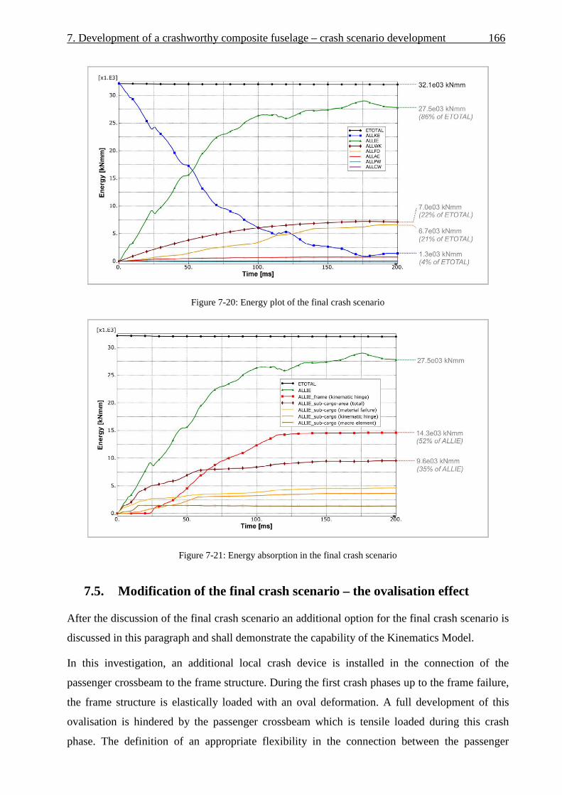
7. Development of a crashworthy composite fuselage – crash scenario development 166
Figure 7-20: Energy plot of the final crash scenario
Figure 7-21: Energy absorption in the final crash scenario
7.5. Modification of the final crash scenario – the ovalisation effect
After the discussion of the final crash scenario an additional option for the final crash scenario is
discussed in this paragraph and shall demonstrate the capability of the Kinematics Model.
In this investigation, an additional local crash device is installed in the connection of the
passenger crossbeam to the frame structure. During the first crash phases up to the frame failure,
the frame structure is elastically loaded with an oval deformation. A full development of this
ovalisation is hindered by the passenger crossbeam which is tensile loaded during this crash
phase. The definition of an appropriate flexibility in the connection between the passenger

167 7. Development of a crashworthy composite fuselage – crash scenario development
crossbeam and the frame structure would assist this ovalisation effect and would lead to a certain
displacement in this connection. Such a displacement could be used for further energy
absorption. The advantage of this mechanism is its tensile loading direction. In general, energy
absorbing concepts in tensile direction are less complex compared to compressive concepts as no
risk of instability effects exists. The crossbeam connection could be equipped with a comparably
simple bearing absorber which provides an ideal characteristic with an absorbing level of almost
100 % of the trigger load level.
Hence, the advantage of such an additional crash concept is obvious for what reason the option
of energy absorption by an ovalisation effect was analysed in the Kinematics Model. Based on
the final crash scenario, an additional macro architecture was implemented in the passenger
crossbeam connection, according to paragraph 3.2.5. In this macro architecture the passenger
crossbeam is linked to the frame structure with a connector element. Both structural parts are
reinforced with rigid bodies for the load introduction of the connector element. The lateral
displacement as well as the rotational displacement around the fuselage longitudinal axis was
defined as independent degree of freedom which had to be investigated to achieve an improved
crash performance. The input characteristic was defined linear-elastically for the rotational
stiffness. The lateral displacement was defined with a constant force plateau after triggering
which is 100 % of the trigger load.
In a first step, the tensile loads in the passenger crossbeam of the final crash scenario were
analysed to determine the load progression over the crash duration and to define a potential
trigger time and trigger load level. As expected, the natural crash behaviour of the fuselage
section provides high tensile forces in the crossbeam after the sub-cargo crushing and before
frame failure. Figure 7-22 illustrates the longitudinal loads in the passenger crossbeam of the
final crash scenario.
Based on these crossbeam loads potential trigger loads could be defined for the ovalisation
device. The influence of these trigger loads as well as different rotational stiffness were analysed
in a parameter study. Three different trigger loads were defined as illustrated in Figure 7-22. In
addition, three different rotational stiffness values were defined in this parameter study. The
stiffness values of the rotational degree of freedom were defined artificially. In total, nine
different variants were simulated in this study.

7. Development of a crashworthy composite fuselage – crash scenario development 168
Figure 7-22: Longitudinal loads in the passenger crossbeam of the final crash scenario
A first outcome of this limited parameter study was that none of the variants led to a change in
the overall crash kinematics. For all variants a crash kinematics according to scenario A could be
identified. The additional ovalisation phase occurred as desired after the sub-cargo crushing and
before the frame failure. Figure 7-23 illustrates macro element output data of a variant with a
trigger load of F = 20 kN. The elongation of the macro elements is given in this diagram over the
crash duration. In a first crash phase the modified cascading scenario shows the crushing of the
sub-cargo area. After complete crushing, the ovalisation devices experience lateral displacement
up to the triggering of the frame kinematic hinges with the following frame bending phase.
Figure 7-23: Modified cascading scenario with ovalisation (F = 20 kN)

169 7. Development of a crashworthy composite fuselage – crash scenario development
The influence of the rotational stiffness was determined to be less important compared to the
influence of the lateral trigger force. Figure 7-24 gives an overview on the results of this
parameter study. The lateral displacement of the ovalisation device is displayed over the crash
duration. The highest energy absorption in the ovalisation device is provided at a force level of
F = 20 kN.
Regarding a force level of F = 20 kN approximately 9 % of the initial kinetic energy could be
absorbed by the tensile mechanism in the ovalisation device. In the further crash sequence this
amount of energy absorption leads to a reduced utilisation of the energy absorbing capacity of
the frames. Figure 7-25 illustrates the frame kinematic hinge rotation and shows a reduction of
the frame rotation of approximately Δφ = 12°. With respect to the energy absorbing capacity,
defined for the frame kinematic hinges, the ovalisation device led to a rotational reduction of
Δφ = 5° due to the end of the absorption plateau in the frame hinges.
Figure 7-24: Lateral displacements of the ovalisation device

7. Development of a crashworthy composite fuselage – crash scenario development 170
Figure 7-25: Frame kinematic hinge rotations
Using the identical macro input characteristics of the final crash scenario, the implementation of
an ovalisation device with a trigger load of F = 20 kN led to a reduced crash distance of Δz = 150
mm. Figure 7-26 compares the final crash scenario with the option of an additional ovalisation
device and illustrates the reduction of the crash distance.
The trigger load of F = 20 kN is an outcome of an investigation which considered exclusively
crash aspects. The feasibility of such an ovalisation concept has to be checked against the static
sizing. The static analysis by the project partner Airbus identified maximum static tensile loads
in the passenger crossbeam connection of F = 21 kN with respect to all flight and ground load
cases. For that reason, the final trigger load of the ovalisation device has to be increased at least
to F = 22 kN to fulfil the static requirements. Despite of this marginal adaptation of the trigger
load, the general feasibility of such a concept could be proved.
Further results on the investigation of the ovalisation effect are given in Appendix A5.3.

171 7. Development of a crashworthy composite fuselage – crash scenario development
Figure 7-26: Final crash scenario vs. additional ovalisation device
7.6. Summary - definition of the final macro input characteristics
On the basis of the selected natural crash kinematics, scenario A, the development of a crash
scenario was discussed in this chapter. A procedure was defined to conclude to an optimised
crash kinematics as well as to an optimised fuselage structure. The development process was
conducted exemplarily on the basis of a statically sized CFRP fuselage structure with a cargo-
crossbeam according to the bend-frame concept. The developed final crash scenario provides
valuable information about the expected crash loads, the requirements for crash devices as well
as the potential structural mass penalty of the considered crash concept. In addition, the effect of
frame ovalisation, using an additional crash device at the passenger crossbeam connection, could
be analysed efficiently with the Kinematics Model.
The final macro input characteristics of this exemplary scenario development are given in Figure
7-27.
The sub-cargo crushing absorbers trigger at a load level of F = 15 kN. With two absorbers
defined per frame, the static loads in the sub-cargo framework have to be less than F = 30 kN.
This small load value is challenging, but regarding a bend-frame concept this requirement is
expected to be feasible.
The cargo-crossbeam triggers at a moment of M = 8000 kNmm. The selected τ -profile of
highest stiffness according to the profile catalogue is fully utilised at this load level.

7. Development of a crashworthy composite fuselage – crash scenario development 172
The frame structure directly below the vertical support strut connection triggers at a moment of
M = 19,000 kNmm. A large amount of energy has to be absorbed by this crash device in the
frame. An estimation of the feasibility of such a requirement was conducted by detailed analyses
of a generic frame structure. The frame region at the vertical strut connection was modelled in
detail and analysed with full FEM. A metallic frame structure was defined in that detailed model
with a similar frame profile compared to the final crash scenario. The moment-rotation curve of
this numerical analysis, on basis of a metallic frame structure, is presented in Figure 7-28a) and
is compared to the kinematic hinge output of the final crash scenario. This comparison shows
almost similar behaviour of the metallic frame and the requirements of the kinematic hinge, with
respect to the trigger load as well as the energy absorption capacity. Comparing both curves it is
obvious that the kinematic hinge behaviour is more of generic character whereas the metallic
frame provides a typical, more realistic post-failure curve. However, with respect to the required
trigger load and energy absorption the outputs of the frame kinematic hinge of the final crash
scenario can be used as a feasible requirement. Figure 7-28b) shows the considered kinematic
hinge in the Kinematics Model whereas Figure 7-28c) displays the detailed metallic frame
model. Further details on this frame model are provided in Appendix A5.4.
With respect to the vertical support struts, potential crushing could be provided in case of some
robustness crash cases. Important is a smooth transition from the frame bending phase to the
vertical support strut crushing phase. Appendix A5.5 discusses the axial forces in the vertical
struts during the final crash scenario. According to the identified loads a trigger force of F = 35
kN is recommended for potential energy absorption in the vertical support struts.
Finally, with a modified final crash scenario using the ovalisation effect an optimised trigger
force of F = 22 kN was identified for the ovalisation device which is positioned in the passenger
crossbeam connection. This trigger value already considers static requirements and guarantees
the feasibility of the ovalisation concept.

173 7. Development of a crashworthy composite fuselage – crash scenario development
Figure 7-27: Final macro input characteristics
Figure 7-28: Frame bending of the kinematic hinge output and the metallic frame
8. Development of a crashworthy composite fuselage design
– experimental investigation on the design of crash devices
The crash scenario development in chapter 7 identified crash device characteristics which are
required to achieve an optimised crash kinematics according to scenario A. Based on these
identified requirements, general concepts of local crash devices can be developed. Figure 8-1
again illustrates the scope of the development of a crashworthy composite fuselage design and
highlights this final step of investigations on the design of local crash devices.
In the scope of this thesis, the focus is on the development of the experimental methods for the
investigation on potential crash devices. Appropriate test setups were developed to test local
crash device concepts under reasonable conditions that consider structural loads, constraints or
other effects which influence the crash device in a fuselage structure and thus have to be
represented by appropriate boundary conditions in the test.
Two general kinds of experimental investigation were considered. The first one is focused on a
precise representation of structural boundary conditions and aims to investigate the detailed
crash device behaviour taking into account the interaction with the structural environment of the
aircraft fuselage. The second one is focused on fundamental experiments that concentrate on
general characteristics, such as the energy absorbing capacity of a crash device concept. In the
second kind of investigations, a detailed representation of boundary conditions is secondary and
a simplified, and accordingly a more efficient, test setup can be used. Both kinds of experimental
investigations are discussed in this chapter.
First kind of experimental investigations are discussed in paragraph 8.1. Experiments are
presented which consider the crushable absorber structure in the sub-cargo area. A detailed test
setup was developed which represents important boundary effects in the sub-cargo structure on
the crush absorber. With this specific test setup a wide range of absorber design variants was
tested with a total number of 72 specimens [147]. However, the discussion in this paragraph
concentrates on the development of the test setup to exemplarily show how experimental tests
can be used to develop local crash devices, or vice versa to generate macro input data for the
Kinematics Model.
Second kind of experimental investigations are dealt in paragraph 8.2. Experiments are discussed
which investigate energy absorbing concepts for the frame structure. In contrast to the specific

175 8. Development of a crashworthy composite fuselage design – experimental investigations
test setup of the crush absorber test programme here a basic test setup was developed. The
experiments on the frame structure concentrate on the general feasibility of energy absorption
concepts in a bending failure mechanism. The test setup was defined as simple as possible to
enable an efficient investigation of different bending absorption concepts.
Figure 8-1 : Approach for the development of a crashworthy composite fuselage design
8.1. Axial crushing tests
The exemplary development of a crashworthy composite fuselage design in this thesis considers
a so-called bend-frame concept. A stiff cargo-crossbeam provides sufficient stiffness to enable
crushing of the sub-cargo structure in a first crash phase. In Figure 8-2a) such a sub-cargo
structure is depicted, which is in this case a highly integrally manufactured CFRP part [120].
Similar to the sub-cargo design defined in chapter 6 and 7, two crush absorbers are installed at
the centre struts of the sub-cargo structure. The conceptual idea is to mount the crush absorbers
on the statically sized structure with a riveted connection. The general crush absorber design is a
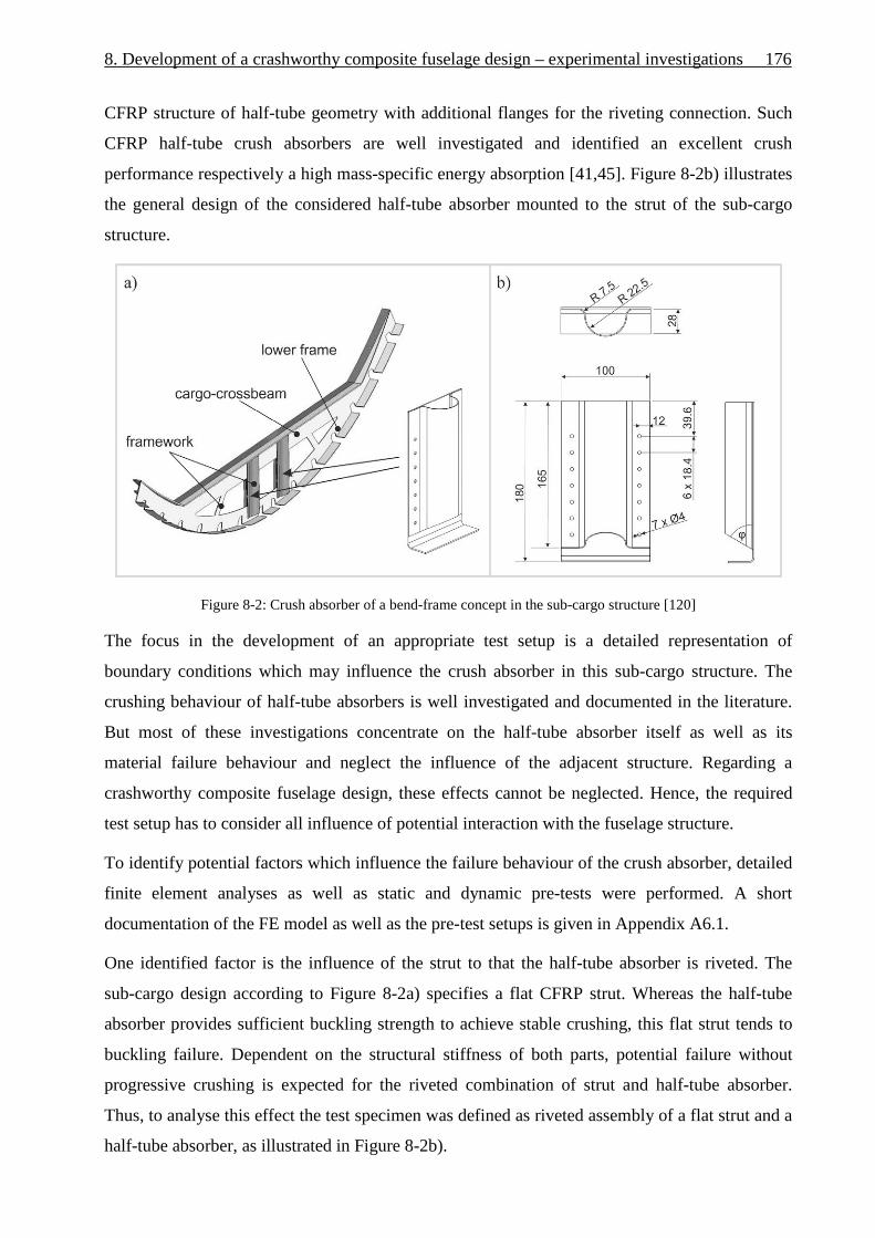
8. Development of a crashworthy composite fuselage design – experimental investigations 176
CFRP structure of half-tube geometry with additional flanges for the riveting connection. Such
CFRP half-tube crush absorbers are well investigated and identified an excellent crush
performance respectively a high mass-specific energy absorption [41,45]. Figure 8-2b) illustrates
the general design of the considered half-tube absorber mounted to the strut of the sub-cargo
structure.
Figure 8-2: Crush absorber of a bend-frame concept in the sub-cargo structure [120]
The focus in the development of an appropriate test setup is a detailed representation of
boundary conditions which may influence the crush absorber in this sub-cargo structure. The
crushing behaviour of half-tube absorbers is well investigated and documented in the literature.
But most of these investigations concentrate on the half-tube absorber itself as well as its
material failure behaviour and neglect the influence of the adjacent structure. Regarding a
crashworthy composite fuselage design, these effects cannot be neglected. Hence, the required
test setup has to consider all influence of potential interaction with the fuselage structure.
To identify potential factors which influence the failure behaviour of the crush absorber, detailed
finite element analyses as well as static and dynamic pre-tests were performed. A short
documentation of the FE model as well as the pre-test setups is given in Appendix A6.1.
One identified factor is the influence of the strut to that the half-tube absorber is riveted. The
sub-cargo design according to Figure 8-2a) specifies a flat CFRP strut. Whereas the half-tube
absorber provides sufficient buckling strength to achieve stable crushing, this flat strut tends to
buckling failure. Dependent on the structural stiffness of both parts, potential failure without
progressive crushing is expected for the riveted combination of strut and half-tube absorber.
Thus, to analyse this effect the test specimen was defined as riveted assembly of a flat strut and a
half-tube absorber, as illustrated in Figure 8-2b).

177 8. Development of a crashworthy composite fuselage design – experimental investigations
A further parameter that may have an influence on the absorber crushing behaviour is the upper
connection of the half-tube absorber to the cargo-crossbeam. In the specified design according to
Figure 8-2a) the absorber structure is riveted also to the web of the crossbeam to provide
sufficient backing strength for progressive crushing. Hence, this part of the absorber which is in
the region of the crossbeam will not be crushed, but will support the crushing of the lower part of
the half-tube absorber. The representation of this upper connection would lead to a complex test
setup which includes a riveted connection to the test fixture or alternatively the integration of the
crossbeam structure. To reduce the complexity of the test setup, the upper absorber connection
was neglected. Instead, the representation of the absorber structure concentrates on the crushable
region below the crossbeam. The upper end of the test specimen was embedded in a fixture that
was defined in a way that clear boundary conditions for the tests are provided and potential
failure in the fixture is prohibited. Therefore, the specimen was bonded into the fixture. In
addition, the fixture was designed with a bleeding system to avoid an artificial increase of the
crushing force by the compression of the air in this closed cross-section of the specimen. In the
real structure, the upper absorber part in the region of the crossbeam provides sufficient volume
to avoid any compressible effects. Figure 8-3a) compares the structural environment in the
fuselage and the derived test setup. The upper fixture is pictured and illustrates the notches for a
bonded fixation of the specimen as well as the central whole of the bleeding system.
Regarding the boundary condition at the lower end of the specimen the connection of the flat
strut to the fuselage skin was identified as a further parameter which can influence the crushing
performance of the absorber structure. According to the highly integral design pictured in Figure
8-2a), the flat strut merges with the lower frame in this lower region. The flange of the lower
frame is riveted to the fuselage skin. In case of a crash, first failure is expected in the radius
between the lower frame web and the flange. Hence, progressive crushing is triggered by this
radius design. In the test setup, the connection of the lower frame flange to the fuselage skin
cannot be neglected. Otherwise the flange would be enabled to roll up and following to fail in a
different mode respectively at a different failure load. This effect could be demonstrated
numerically in the FE analyses as well as experimentally in the pre-test investigations, as
documented in Appendix A6.1. To consider the influence of the fuselage skin, a metallic plate
was bolted to the flange. During the impact of the specimen, this plate avoids an unrolling of the
flange and affects the failure initiation similarly to the influence of the fuselage skin. In
combination with this metal plate, another effect was identified which showed a lateral
displacement of the frame flange caused by the constraint unrolling. In a real fuselage
environment the fuselage skin constraints this lateral displacement. Accordingly, a guidance
system was developed that constraints the metal plate against lateral displacement. With the final

8. Development of a crashworthy composite fuselage design – experimental investigations 178
setup of this guided plate, the failure representation of the frame radius is similar to that expected
in the real fuselage structure. In Figure 8-3a) the bolted connection of the flange to the metal
plate is depicted. Furthermore, a circular notch in the metal plate is visible which is used for the
guidance system.
The finally planned test setup is shown in Figure 8-3b). An upside-down configuration was
defined due to the installation of the dynamic test machine. The guidance system was coupled
with the load cell to enable the measurement of potential friction effects between metal plate and
guidance.
Appendix A6.1 documents the verification of this finally planned test setup by static and
dynamic pre-tests.
Figure 8-3: Test setup configuration

179 8. Development of a crashworthy composite fuselage design – experimental investigations
The final test setup was developed for the dynamic test machine Instron VHS (type:
PLS100/20M) that is shown in Figure 8-4a) together with the data acquisition systems. In
addition, the high-speed camera (FASTCAM-APX RS250K) as well as the lighting is depicted
which was used for the recording of high-speed videos.
The detailed setup in the test machine is given in Figure 8-4b) and mainly corresponds to the
schematic setup of Figure 8-3b). An additional wooden plate (t = 3 mm) was installed on the
impact plate to damp the impact of the metallic plate which is bolted to the strut flange. In
addition to the path measuring by the cylinder signal, a laser system was installed which
measured simultaneously the path over a distance of L = 100 mm. As one of the main objectives
of this test campaign is the investigation of the interaction of the flat strut and the half-tube
absorber, a mirror was installed to record the front and the rear side of the specimen with the
high-speed camera. Using this mirror, potential buckling failure of the flat strut at the rear side of
the specimen could be identified. In general, the visualisation of CFRP specimens with video or
photo systems is difficult due to the limited contrast of the black specimen. Therefore, the
specimens were painted in white colour with additional black points to improve the contrast in
the high-speed video records.
Finally, a modified configuration of the final test setup is given in Figure 8-4c). An oblique
device was mounted between load cell and impact plate to investigate the crushing performance
under an off-axis angle of β = 10°. The aim of this test setup is to identify the robustness of the
absorber crushing performance, similar to robustness analyses of the Kinematics Model. The off-
axis crushing configuration is one of several parameters which are specified in the following.

8. Development of a crashworthy composite fuselage design – experimental investigations 180
Figure 8-4: Final test setup in the dynamic test machine
A total number of 72 specimens were tested with the test setup described above. Different
parameters of the crush absorber design or its loading condition were analysed in 36 test
variants, each with two individual tests. The analysed parameters were:
• Different designs of the flat CFRP strut (complex layup, simplified layup)
• Different angles of the geometrical trigger of the half-tube absorber (α = 60°, 75°)
• Different layup thickness of the half-tube absorber (t = 1.0 mm, 2.0 mm)
• Different laminate types of the half-tube absorber (woven fabric, biaxial-, triaxial
braided laminates)
• Variants with paste bonding additionally to the riveting of the strut and the half-tube
absorber
• Variants with off-axis loading (roll angle β = 10°)
• Different loading rates (v = 6.7 m/s, v = 10 m/s)

181 8. Development of a crashworthy composite fuselage design – experimental investigations
An overview on the complete test matrix is presented in Appendix A6.2.
The evaluation of the test results was conducted mainly on the basis of the measured force-
displacement curves, the recorded high-speed videos as well as the post-test pictures which
document the absorber failure modes.
Several important effects could be identified with respect to the functionality of a robust crash
absorber in its structural environment. Exemplary results are given in Figure 8-5, which
illustrates two main characteristics of the identified absorber behaviour.
The results in Figure 8-5a) represent variants that show stable and progressive crushing. As
expected, the first load peak is influenced by the failure of the strut radius. The following phase
at a low force level is caused by the folding mechanism of the free strut length between radius
and the half-tube absorber. After this distance is crushed, the absorber gets into contact and the
load level increases according to the trigger angle up to the nearly constant crushing plateau. In
the following crushing phase, local peaks in the load level identify the individual rivet lines.
In contrast to the results discussed above, Figure 8-5b) represents variants that show unstable
crushing which also includes local or total failure of the specimens. Such failures were caused
by buckling tendencies of the flat strut. In addition, the strut variant with complex layup partly
induced local failure lines which led to total failure of the strut. The diagram in Figure 8-5b)
illustrates the significant drop of the load level after failure of the strut, at a crushing distance of
approximately L = 45 mm. Further stable crushing on the expected force level occurred at L =
100 mm where the remaining intact absorber structure gets into contact again.
Furthermore, slightly different robustness behaviour was identified for the laminate types of the
half-tube absorbers. According to the results of the test programme, triaxial braided absorber
specimens provided the highest robustness performance whereas the specimens with absorbers
made of woven fabric showed the poorest robust crushing behaviour. The differences of the
individual layups and laminate types showed significant influence on the absorber failure
modes. Figure 8-6 shows exemplary post-test pictures of different tested specimens which
illustrate the spectrum of the failure modes.

8. Development of a crashworthy composite fuselage design – experimental investigations 182
Figure 8-5: Typical characteristics identified in the absorber test programme

183 8. Development of a crashworthy composite fuselage design – experimental investigations
Figure 8-6: Spectrum of absorber failure modes identified in the test programme
Summarising the axial crushing tests, a test setup was developed which appropriately represents
the structural fuselage environment of the considered crash absorber. In contrast to several
studies on the crushing of CFRP absorbers, which analysed mainly the material failure
behaviour, the developed test setup represents a structural testing with focus on the absorbers
functionality in its structural environment. The test setup was verified by numerical analyses as
well as by experimental pre-tests. A test series of 72 specimens was conducted using the
developed test setup.
To link the test programme results with the kinematics modelling approach developed in this
thesis, a comparison is presented in Figure 8-7 which depicts the test results and the required
crushing characteristic based on the final macro inputs of the Kinematics Model according to
paragraph 7.6. In this comparison, the selected test result represents a typical crash characteristic
of stable crushing similar to Figure 8-5a). As the test setup additionally considered the lower
frame structure that induced the first peak force, the macro curve starts with respect to the second
peak force of the test curve which represents the triggering of the half-tube absorber. A detailed
comparison of the trigger forces is hardly possible as such peak forces measured in dynamic tests
are significantly influenced by inertia and other dynamic effects of the test setup and the testing
machine. Nevertheless, a comparison of the crushing force plateaus identifies a good agreement
in this example. Hence, sufficient energy could be absorbed according to the requirements of the
final crash scenario of paragraph 7.6.

8. Development of a crashworthy composite fuselage design – experimental investigations 184
Figure 8-7: Comparison of the required absorber characteristic and the test result
8.2. Frame bending tests
The outcomes of the final crash scenario in chapter 7 identified crash characteristics in the frame
kinematic hinges which have to provide a significant amount of energy absorption. With respect
to the general crash concept discussed in chapter 6 and 7, one of the main challenges is the
development of a structural crash device which provides sufficient energy absorption in a frame
bending failure mechanism. Hence, the focus of an investigation on frame bending concepts is
mainly on the energy absorbing capacity. Further design parameters such as the trigger
mechanism or the detailed crash behaviour under a combined bending-compression load are of
lower priority in this early development phase.
For that reason, the development of an experimental test setup concentrated on the investigation
of the general feasibility to absorb the required amount of energy. To realise an efficient test
method which can be used for the investigation of several absorption concepts, the test setup was
defined as simple as possible.
Figure 8-8 illustrates a schematic extraction of the planned test setup out of a typical fuselage
structure. Based on a LCF-shaped frame design the stiff C-frame component was considered in
this setup. Instead of a curved frame component, the test setup was defined with straight C-frame
segments to further reduce the complexity. A four-point bending test setup was defined to
analyse the failure behaviour of the C-frame segments with respect to pure moment loads, as
only a limited influence of additional compression loads on the general energy absorbing
capacity is expected.

185 8. Development of a crashworthy composite fuselage design – experimental investigations
The C-profile geometry aligns to typical LCF-shaped profiles and specifies a web height of
Hweb = 80 mm and a flange width of bflange = 40 mm. The segment length of the C-profile is
limited to L = 600 mm due to the boundary conditions of the test machine for the quasi-static
bending tests as well as the drop tower for the dynamic bending tests.
Figure 8-8: Derivation of the frame bending test setup out of a typical fuselage structure
Several investigations were performed to define an appropriate test setup configuration. Similar
to the axial crushing tests, detailed finite element analyses as well as experimental pre-tests were
performed to investigate effects of the test setup configuration. Appendix 6.3 provides a short
documentation of the FE model as well as the pre-test setups.
One effect that was analysed in the scope of the test setup development was the influence of the
bending-torsion coupling. In case of the pure bending load the C-profile segment tends to rotate
around its shear centre which is located outside of the C-profile. Hence, the C-segment has to be
supported against lateral displacement respectively rotation in the region of support and stamp.
Another option is the combination of two C-segments to an I-segment (back-to-back C-splicing).
In that case, the shear centre is located in the centre of the cross-sectional area and torsion effects
with respect to pure bending loads are not expected. The manufacturing of an I-profile is more
complex and potential failure or other effects in combination with a back-to-back C-splicing may
influence the test results. Therefore a supported C-profile configuration was preferred.
A further investigation considered the development of an appropriate fixture which enables a
smooth load introduction without local damages of the C-segment at the support and the stamp.
First experimental pre-tests showed that limited support by metallic plates is not sufficient and as
a consequence a robust fixture is required to avoid local material damage in the regions of the
load introduction.

8. Development of a crashworthy composite fuselage design – experimental investigations 186
Another topic is the limitation of the frame segment length. Despite of the limited length of L =
600 mm the test setup should provide realistic frame failure behaviour. As discussed in the
previous chapters, typical frame failure is initiated by crippling of the frame flanges. Hence, the
free length of the test setup between the stamps has to be defined so that the compression loaded
frame flange is allowed to buckle without significant stress concentration at the transition to the
fixture. Finite element analyses were performed to estimate the instability behaviour of the free
segment length between the stamps.
Further details about the investigations on the development of an appropriate test setup are given
in Appendix A6.3.
Based on the investigation of the above discussed effects, a test fixture was developed which is
pictured in Figure 8-9a) and 8-9b). Solid aluminium fittings encase the C-segment in the outer
regions between stamp and support. The aluminium fittings were manufactured with an
appropriate tolerance of the C-notch to enable bending tests of C-profiles within a limited range
of thickness. To fix the C-profile in the C-notch the frame segment is bonded in the fixture.
Besides the realisation of a smooth load introduction without local material damage, this fixture
avoids the deformation of the C-profile geometry due to the introduced load. As a result of the
full casing of the C-segment in the fixture, bending-torsion coupling effects can be carried and
transferred to the lateral supports, which are provided by steel brackets that were manufactured
and installed between stamp and support, as pictured in Figure 8-9c).
Based on FE analyses, the free length of the C-segment was defined to be Lf = 160 mm. This
distance is a good compromise regarding the given maximum segment length and a required
minimum distance between support and stamp to introduce the moment load.
The transition from the bonded C-segment inside the fixture to the free segment length was
designed with radii. In case of flange buckling, a deformation of the flange structure at the
transition to the fixture is allowed and the flange can align to the fixture radii. Stress
concentrations could be limited with this design.

187 8. Development of a crashworthy composite fuselage design – experimental investigations
Figure 8-9: Fixture and test setup of the four-point bending test
Several frame bending tests were performed with the developed test setup. Quasi-static four-
point bending tests were conducted in a universal testing machine (Zwick 1494) whereas the
dynamic tests were conducted in the drop tower of the DLR Institute of Structures and Design. A
test matrix of the considered frame bending tests is given in Appendix A6.4.
Regarding the energy absorption concept, the influence of hybrid laminates was analysed in this
exemplary study. Besides a reference configuration, purely made of CFRP (AS4/PEEK), a
hybrid configuration was tested with titanium sheets which were embedded in the flange
laminate of the frame segments. Previous studies on the coupon level identified a significant
potential of energy absorption regarding such hybrid laminates particularly in a bending mode
[129]. Based on the coupon level results, the hybrid concept was selected for further
investigation on the structural level. Figure 8-10 illustrates both frame variants.
Figure 8-10: Reference variant (AS4/PEEK) and hybrid variant (titanium sheets in the flange)

8. Development of a crashworthy composite fuselage design – experimental investigations 188
Results of the quasi-static bending tests are presented in Figure 8-11. Two tests of each variant
were conducted. The comparison of force-displacement curves shows similar behaviour of the
reference as well as the hybrid variant. Especially the post-failure behaviour does not show any
significant differences, neither in the force level nor in the energy absorption.
With the focus on the development of a frame bending test setup, the results of the quasi-static
tests could be used to verify the developed test setup. The failure mode, as depicted in Figure 8-
11, shows the desired typical frame failure behaviour. The compression loaded flange buckled
and initiated crippling failure in the centre of the free segment length. Hence, stress
concentrations at the transition to the fixture could be reduced by the radii design so that their
influence is secondary and failure close to the fixture is avoided.
After failure initiation in the compressive loaded flange the failure propagated through the frame
web to the lower, tensile loaded flange. Further bending rotation occurred around a pivot point
which is located in the remaining lower flange.
The compression loaded, upper flange of the C-segments was recorded in the quasi-static tests
with a high-speed camera (FASTCAM-APX RS250K) to allow a detailed analysis of the failure
initiation. Figure 8-12 pictures the failure sequence of the reference and the hybrid variant. The
sequences were recorded with a sampling frequency of 30,000 frames per second to resolve the
crack propagation in the upper flange. Both sequences show a failure propagation which starts at
the C-corner and propagates to the outer flange side. Hence, typical crippling failure could be
identified which is initiated by material failure in the stiffer corners of the frame profile.
Despite the reduced complexity, the verification of the test setup identified realistic frame failure
behaviour in the quasi-static tests.

189 8. Development of a crashworthy composite fuselage design – experimental investigations
Figure 8-11: Results of the quasi-static frame bending tests
Figure 8-12: Crippling failure recorded with the high-speed camera
Further dynamic tests were performed in the drop tower at an initial velocity of vi = 3.4 m/s. This
loading rate corresponds to the averaged loading conditions of the frame structure in a typical
crash event according to the ‘standard crash case’. Minor modifications of the test setup were
conducted for the dynamic tests. Fixtures, stamps and the frame web were painted in white
colour with an additional pattern in black colour. Foam stripes with negligible stiffness were
bonded on the frame flanges and painted with a dispersion of black points. Both modifications
were conducted to measure displacements of the individual parts on the basis of the high-speed
camera records using the optical measurement system GOM ARAMIS [146].

8. Development of a crashworthy composite fuselage design – experimental investigations 190
Furthermore, in the dynamic tests unfavourable dynamic effects are expected by the impact of
the stamps on the fixture with a velocity of vi = 3.4 m/s. In this configuration, a sharp impulse
could lead to the separation of the stamp and the fixture in the further bending sequence with
accordant consequences for the measuring of displacement and load at the stamps. Furthermore,
sharp impulses may lead to vibrations at the load cell which affect the measuring. To reduce this
dynamic effect, a damper was installed between the stamp and the fixture to enable a smooth
transfer of the dynamic loads.
The dynamic effects are obvious in the presentation of the drop test results in Figure 8-13. The
force-displacement graph compares four drop tests of the hybrid and the reference frame
segment variants. A stiff damper configuration was used in the bending tests of the hybrid frame
segments. Oscillations are visible in the pre-failure phase which were caused by the above
described dynamic effects. In the tests of the reference frame segments an optimised damper
configuration led to a steady force increase up to failure but also to a higher deflection up to
failure. Regarding the focus of this experimental study, the post-failure behaviour, the dynamic
tests showed similar results compared to the quasi-static tests with negligible improvements of
the energy absorption of the hybrid frame segment variant.
Figure 8-13: Results of the dynamic frame bending tests
Summarising the frame bending tests, a test setup was developed with the focus on the
identification of the post-failure energy absorption capacity. This focal point enabled the
development of a comparably simple and efficient frame testing setup which considers a four-
point bending load on the stiff C-segment of a typical LCF-shaped frame design. Quasi-static

191 8. Development of a crashworthy composite fuselage design – experimental investigations
tests verified the developed test setup. Stable load introduction as well as realistic frame failure
could be realised despite a limited frame segment length of L = 600 mm. Regarding the dynamic
testing, further modifications of the test setup were defined which could be verified in the drop
tests.
The exemplarily tested hybrid frame segments with ductile titanium sheets in the frame flanges
provided no significant improvements in the energy absorption capacity compared to a reference
variant purely made of CFRP. Due to the simplified test setup, which considers only the C-
segment of a LCF-shaped profile instead of the complete frame-stringer-skin panel structure, a
direct comparison of the test results with the required frame bending characteristics according to
the final crash scenario is not possible. However, the final macro inputs of the Kinematics Model
according to paragraph 7.6 specify a post-failure moment level which is 50 % of the failure load
level. Comparing this requirement with the outcomes of the bending tests, the energy absorption
capacity of the tested hybrid frame segments is clearly far below this requirement. Hence, the
developed frame bending test setup can be used for further research on energy absorbing frame
concepts, which is clearly essential.

9. Conclusion and outlook
The objective of the thesis is the contribution to the development of a crashworthy composite
fuselage design of transport aircraft. This contribution comprises in a first part of the thesis the
development of a finite element modelling approach for the investigation of crash scenarios, the
so-called Kinematics Model, that combines benefits of currently used simulation modelling
techniques. In a second part of the thesis, the objective is the development of a crash design
methodology, on the basis of the developed Kinematics Model, that considers the design process
for a composite fuselage including the verification of identified crash device requirements by
experimental testing.
Paragraph 9.1 summarises the final outcomes of the development of the finite element modelling
approach. Final conclusions of the methodology of the crash design process are presented in
paragraph 9.2. Topics for potential future research are depicted in the outlook in paragraph 9.3.
9.1. Methodology of the finite element modelling approach
The design for crash of composite fuselages is a topic that has to be considered in the early
design phases of an aircraft development. The common state-of-the-art analytical methods,
which were discussed in paragraph 2.2, show drawbacks with respect to their use in a
preliminary design process. Based on a beneficial combination of these common modelling
methods a specification was derived that represents the foundation for the development of a new
modelling approach. Chapter 3 presented this approach and dealt with the general aspects of this
modelling technique. The frame was identified as the main structural part that highly affects the
structural behaviour of the fuselage in case of crash. Accordingly, detailed investigations on the
frame failure modelling were discussed in chapter 4 and 5 which ensure an appropriate accuracy
of the developed modelling approach.
With respect to the development of the finite element modelling approach, the following
conclusions can be drawn:
• A new modelling approach, the Kinematics Model, was developed that combines the
advantages of current simulation techniques with the focus on a preliminary crash design
tool. The main benefits are the absence of composite material formulations for damage
and failure which are still hardly predictable. Besides a linear-elastic modelling of the

193 9. Conclusion and outlook
fuselage structure the main crash characteristics are described by macro elements. The
usage of macro elements additionally enables an efficient method for the investigation of
different failure characteristics in the individual structural parts. With respect to the
requirements of a preliminary design tool the modelling approach provides a
discretisation that considers efficient calculation without disregarding of structural effects
that can influence the crash behaviour.
• Typical failure modes of transport fuselage structures caused by crash related loads were
identified and assessed. With respect to failures of primary category which are of
relevance for composite fuselage structures, macro architectures were developed that
accurately represent the individual structural failure behaviour.
• Appropriate output definitions were developed which fulfil the specific requirements of a
preliminary design tool. Of interest are efficient output data which help to quickly
analyse the main results of a simulation run. Structural loads are evaluated by overall
strain plots of the most critical frame structure. Passenger loads are described in Eiband
diagrams which provide information about the risk of injury. The output for crash device
requirements are given in load-deflection characteristics that can directly be used for the
comparison with test data or other analysis results, like output data of local explicit FE
calculations.
• According to the requirements of a preliminary design tool, all relevant input variables of
the Kinematics Model are parameterised for the efficient conduction of various
simulation runs.
• Detailed investigations of the frame structure led to an accurate and efficient
representation in the Kinematics Model. Frame failure is well represented with respect to
the identification of potential failure locations, the elastic pre-failure behaviour, the
triggering respectively the definition of failure criteria for the frame structure, and the
post-failure behaviour.
• Further improvement for the representation of the frame failure behaviour was realised
by the development of a user-defined macro element in the ABAQUS environment.
Improvements such as strain-based triggering, physically correct unloading/reloading
behaviour as well as high accuracy with respect to loads with a low bending-compression
ratio were implemented in the user-defined macro element. However, due to an unsolved
bug situation, discussed in paragraph 5.5, this user element could not be proved in the
crash design process.

9. Conclusion and outlook 194
9.2. Methodology of the crash design process
The review on crashworthiness research identified the need to modify the static design of a
composite fuselage to fulfil the crash requirement. Otherwise, transport aircraft with a composite
fuselage would provide significantly worse crashworthiness compared to metallic equivalents
which are typically not designed for crash.
The need was identified to implement additional crash absorbers in a composite fuselage
structure and to adapt the structure to the expected crash loads. Chapters 6-8 dealt with a design
process that was developed to conclude to an optimised crash kinematics, to a crashworthy
fuselage structure and to the definition of required crash absorber characteristics. The design
process additionally considers the verification of identified crash device characteristics by
experimental testing on the component level. The developed crash design process was
exemplarily performed on the basis of a statically pre-sized CFRP fuselage structure of narrow-
body size with a stiff cargo-crossbeam to allow the crushing of the sub-cargo structure in case of
crash (bend-frame concept).
Considering the development of the crash design methodology, the following conclusions can be
drawn:
• The necessity was postulated to align the crash concept with the natural crash behaviour
of the considered fuselage structure. Otherwise, additional weight penalty is expected to
ensure a crash kinematics that differs from the natural structural behaviour.
• Natural crash kinematics of typical fuselage structures of narrow-body transport aircraft
were identified and assessed using the Kinematics Model. The assessment of natural
crash kinematics provided a good understanding of the typical fuselage crash behaviour.
• The most favourable natural crash kinematics was adapted to a preliminary sized CFRP
fuselage structure using the Kinematics Model. Appropriate structural allowables were
defined to assess the structural loads during the design process. The crash kinematics was
optimised with respect to the given fuselage design. Subsequently, the fuselage structure
was adapted to the final crash loads. The structural adaptation was conducted starting
with a structure of high stiffness. With respect to the final crash scenario valuable
outcomes could be provided, which include information about the structural mass penalty
caused by the crash related re-sizing of the frame and the cargo-crossbeam, loads on the
passengers as well as final requirements for the crash device characteristics which are
necessary to fulfil the optimised crash kinematics.

195 9. Conclusion and outlook
• Different experimental test setups were developed for the investigation of crash device
concepts on the basis of the required macro characteristics. The first test setup was
developed to investigate in detail the failure behaviour of axial crush absorbers in
combination with an accurate representation of the fuselage boundary conditions. A
comprehensive test programme of potential absorber designs for the sub-cargo structure
could be tested with realistic boundary conditions. The second test setup was developed
to efficiently investigate basic crash device characteristics of frame bending failure. The
energy absorption capacity is in the focus of this bending test setup, which can be
investigated with generic frame structures. The developed bending test setup was
successfully proved by experimental bending tests with composite frame structures. Both
developed test setups demonstrated options to investigate crash device concepts on
different levels of complexity. In both test setup variants efficient testing was ensured by
reasonable representation of structural boundary conditions instead of the definition of
large component tests.
• The integration of experimental testing into the crash design process ensures model
accuracy with respect to the assumptions used for the macro inputs. The feasibility of
assumed crash absorber characteristics can be checked and adapted during the design
process, when necessary.
9.3. Outlook
With respect to the final target to achieve improved crashworthiness for composite transport
fuselage structures further research work is required that may focus on the following topics.
• An implementation of the user-defined kinematic hinge macro element into the
Kinematics Model is desired. A solution of the bug situation would enable the usage of
improved frame failure representation. Further options for the user-element in ABAQUS
would enhance the usage of the developed macro element, e.g. to enable the storage of
user-element output data in the output data base file (*.odb).
• The exemplary development of a crash scenario in this thesis was performed on the basis
of a generic fuselage structure which was equipped with a stiff cargo-crossbeam to realise
the bend-frame concept. This crash concept enables extensive crushing of the structure
below the cargo-crossbeam similar to concepts known from rotorcraft designs. The final
crash scenario developed within this thesis identified a structural mass of the frame
structure which is more than twice the statically pre-sized frame mass. Research on
alternative crash concepts is recommended to reduce the structural mass penalty usually

9. Conclusion and outlook 196
associated with crashworthiness. Alternative concepts could specify e.g. a filigree sub-
cargo structure with the focus on energy absorption in the upper crash zones of the sub-
floor area. Such an alternative concept could align to the consideration of a minimum
required backing structure to achieve energy absorption in the individual crash zones,
according to the discussion in paragraph 7.2.
• Further improvement of crashworthiness could be realised by the consideration of non-
typical fuselage sections in the design process. An adaptation of the crash design for
fuselage sections with cargo-door, landing gear bay, wing-box or tail cone would
significantly improve the crashworthiness of the overall fuselage structure. Further
enhancement of the Kinematics Model is necessary to consider fuselage sections that
differ from the typical fuselage design. In particular, the kinematic hinge macro
architecture has to be extended to represent the frame failure behaviour of non-typical
fuselage sections. Frame shear failure or skin separation are requirements for such an
enhanced kinematic hinge architecture. After the implementation of enhanced modelling
options for non-typical fuselage sections, the efficient simulation technique of the
Kinematics Model can be used in a subsequent step to investigate crash concepts for
composite fuselages in full aircraft simulations.

A1. Appendix of chapter 2
Paragraph A1.1 provides a short overview on the finite element method and its integration
schemes with the focus on explicit time integration and structural elements as used in the scope
of this thesis.
A1.1. The finite element method in the scope of this thesis
There is various literature dealing with the finite element method and explaining this theory in an
excellent way, e.g. in [111,113,144]. Nevertheless, a short overview on the finite element
method shall be given here with the aspect on the selected calculation schemes in this thesis.
The finite element method uses several approximations to analyse structural problems. A first
approximation is the discretisation which represents the considered structure by finite elements.
The most complex finite element is the continuum element (solid) which represents all
components of a general stress tensor. In some of the considered problems in this thesis the
structure or parts of the structure behave according to the shell, beam or bar theory. Here,
specific structural finite elements can be used to represent these parts in the finite element
analysis. Structural elements only consider those components in the stress tensor which are
affected by the structure or the structural part, while all other components are not considered.
This leads to a significant improvement in the efficiency of element calculation. If the considered
structure is discretised by structural finite elements which behaves similar to the real structure
enormous calculation time can be saved instead of using calculation time consuming continuum
elements. In the scope of the finite element analyses discussed in this thesis, the structures were
discretised mainly with shell, beam and bar elements, as displayed in Figure A1-1.
Figure A1-1: Discretisation by structural finite elements [112]

A1. Appendix of chapter 2 198
A further approximation in the finite element method is the definition of field quantities inside of
a finite element. The field quantity “displacement” is defined at the element nodes whereas the
field quantity “stress” is defined at the element integration points which are located inside of the
element. Basic functions are used to describe the distribution of field quantities over a finite
element. To calculate the stresses at the element integration points the basic functions are used to
approximate the displacements, respectively the strains, at the integration points based on the
known displacements at the element nodes. The order of such basic functions depends on the
considered problem and on the time integration scheme which is used to solve the equation of
motion. In the scope of this thesis, the finite element analyses use basic functions of first order.
The equation of motion defines the force equilibrium at each node of the discretised structure
and is given as follows:
PuRuCuM =++ )( (A1.1)
P are the external forces which cause accelerations, velocities and displacements dependent on
the mass M, the viscosity C and the stiffness R of the element respectively the elements node.
Formulation (A1.1) is a system of n equations, n is the number of degrees of freedom defined for
this element node.
The integration of equation (A1.1) can be solved either with implicit time integration or with
explicit time integration scheme. The implicit time integration replaces the time derivation by
quantities which depend on both, the current time t and the unknown values of a time t + Δt. In
each time step this integration scheme requires the solution of a non-linear system of equations
which is accordingly complex. The advantage of the implicit time integration is the realisation of
large time steps which can be solved absolutely stable.
In contrast to the implicit integration scheme, the solution of an explicit time integration at the
time t + Δt depends only on quantities of the time t. This integration scheme is particularly
efficient if the mass matrix M and the damping matrix C are lumped, which means that they are
of diagonal form. In this case each equation of the system given in (A1.1) can be solved
independently. The drawback of this efficient time integration scheme is the limitation of small
time steps to ensure a stable solution.
If dynamic problems are considered, such as impact or shock loads, the time step has to be
reduced in both integration schemes in a way that all high-frequent portions of the structural
response are represented physically correct. Hence, the efficient explicit time integration is
preferable compared to the complex solution of non-linear systems of equation in the implicit

199 A1. Appendix of chapter 2
time integration. The implicit integration scheme is preferable in cases where the structural
response is composed mainly of the low-frequent portions.
In the case of the crash analyses of this thesis the explicit time integration is used. Equation
(A1.1) is transformed in the following form:
)]([1 uRuCPMu −−= − (A1.2)
The accelerations are calculated through time using the central difference rule, which calculates
the change in velocity assuming that the acceleration is constant. The change in velocity is added
to the velocity from the middle of the previous time step to determine the velocities at the middle
of the current time step:
)()(
)2
()2
(|
2
)||(|| )(
tt
ttttu
ttuu tt
∆+∆+= ∆+
∆−
∆+
(A1.3)
The velocities are integrated through time and added to the displacements at the beginning of the
time step to determine the displacements at the end of the time step:
)2
()()()( |||| ttttttt utuu ∆+
∆+∆+ ∆+= (A1.4)
After these nodal calculations, the displacements at each node are determined at the time t + ∆t.
In a following step - the element calculations - the element strains are computed. Based on these
strain increments the element stresses are computed at the element integration points from
constitutive equations:
),( )()( εσσ df ttt =∆+ (A1.5)
Equation (A1.5) represents the material formulations of an element which describes the
relationship of strain and stress for the considered material.
Finally, the element stresses are assembled to nodal internal forces at the time t + ∆t and the
calculation of the current increment is concluded.
To ensure the physically correct representation of all high-frequent portions of the structural
response, a stability limit is defined in terms of the highest frequency in the system. This stability
limit considers a perturbation which propagates with the wave speed of the material. As a
consequence, the stability limit can be defined using the element length Le and the wave speed of
the material cd. The wave speed is calculated from the Young´s modulus E and the mass density
ρ of the material:

A1. Appendix of chapter 2 200
d
e
stable cLt =∆ with
ρEcd = (A1.6)
The finite element analyses in this thesis are used in a preliminary design tool for crash
investigations which requires an efficient computation strategy. The explicit time integration
method is based on efficient nodal and element calculation as these calculations recur very often
due to the small time step defined by the stability limit. The approach of the developed crash
design tool, which is described in chapter 3, is based on a modelling technique which reduces the
calculation time considering the theory discussed above. A linear-elastically modelled structure,
where all failure is described in special macro elements, allows a coarse discretisation. The
structure deforms only in the scope of its linear strain limits which are defined by comparatively
small failure strains of the (composite) material. These small strains allow the use of large
elements to represent the structural deformations. An increased element size improves the
calculation efficiency significantly. On the one hand, the stability limit increases linearly with
the element size. On the other hand, an increased element size is equivalent with a reduced
number of elements that represent the considered structure and have to be calculated.
As an example, a structure is considered that is discretised by shell elements. A discretisation
with a shell element length which is twice the length compared to a reference discretisation
reduces the calculation time by a factor 23 = 8. With twice the element length, the number of
elements in a plane shell discretisation is reduced by the factor 22. In addition, the stability limit
of the time step increases proportionally to the element length and leads to half the number of
calculation cycles which are necessary for the calculation of the reference discretisation.

A2. Appendix of chapter 4
Paragraph A2.1 provides a detailed description of the numerical model that was used for
investigations on the pre-failure behaviour of a frame-stringer-skin structure.
A2.1. Analysis of pre-failure behaviour – description of the numerical
model
Figure A2-1 gives an overview on the numerical model of the generic frame-stringer-skin
structure which was considered in the scope of the investigations of the pre-failure behaviour.
One non-curved frame component is defined in this model. The radius of a standard transport
aircraft fuselage is about rF = 2000 mm, effects of the curvature are expected to be marginal for
such high radii, especially with respect to general instability failure modes. Therefore a planar
geometry was considered here. The width of the model is based on a generic frame pitch of wF =
635 mm. The length of the model is l = 700 mm. Three omega stringers with a stringer pitch of
lS = 168 mm are modelled. The LCF-shaped frame corresponds to typical, integral CFRP frame
designs with flange widths of wIFF = 25 mm, wMFF = 15 mm and wOFF = 28 mm. The outer frame
web height is hOFW = 36 mm. The inner frame web height as well as the frame thicknesses are
parameters in the present investigation. The skin thickness was defined to be constant in all
simulations with tS = 2.125 mm and a layup of [10/70/20]1. The omega stringers were specified
with a constant thickness of tSt = 1.375 mm in all simulations and a layup of [50/40/10]. Cleats
were defined at each stringer position. All material formulations used in this model were linear-
elastic, material damage and failure was not considered. Apart from the cleats, which were
modelled with isotropic material behaviour, all other structural parts were modelled with
orthotropic material formulations for composites. Elastic data of typical CFRP material was
used. The design and layup of the frame, the stringers and the skin is based on a static pre-sizing
(on fuselage section level, considering the complete envelope of flight and ground loads) which
was performed by the project partner Airbus. The connection of the individual parts was
assumed to be ideal so that tied constraints were used. Symmetry boundary conditions were
defined on both lateral sides. Both ends of the model were clamped using rigid bodies. These
rigid bodies include the frame as well as the skin. A pure rotation was specified at the reference
1 Ratios in percent of ply orientation in the layup: [0°/±45°/90°]

A2. Appendix of chapter 4 202
nodes of the rigid bodies which were positioned in the centre of the cross-sectional area of frame
and skin. Shell elements with reduced integration (S4R) were used. The characteristic element
size is LE = 12 mm. The simulations were performed on a Microsoft Windows machine with the
FE solver ABAQUS, solver version V6.8-1, using explicit time integration.
Several LCF-shaped frame designs were analysed to identify the structural behaviour in
dependence of different frame stiffness. All frame designs used in this investigation are based on
a given static sizing and provide typical layup definitions in the webs (between [0/75/25]2 and
[0/85/25]) and the flanges (between [45/45/10] and [50/40/10]). Flange thicknesses between
tFF1 = 2.5 mm and tFF2 = 9.2 mm were considered as well as inner frame web heights between
hIFW1 = 56 mm and hIFW2 = 84 mm.
This model does not conform to the standard for detailed investigation of instability problems.
For instance, imperfections or mesh dependencies were not considered in the scope of this
investigation. The general elastic behaviour and the derivation of potential failure criteria were
the focus of these simulations.
Figure A2-1: Numerical model for the analysis of the pre-failure behaviour
2 With respect to layups in the frame: Ratios in percent of ply orientation in the layup: [0°/±30°/90°]

A3. Appendix of chapter 5
Paragraph A3.1 provides a summary of all user element property parameters that have to be
defined in the ABAQUS input deck to describe the kinematic hinge behaviour. An overview of
all solution-dependent variables used for internal element calculation is given in paragraph A3.2.
A structogram of the calculation of internal forces is presented in paragraph A3.3. Finally,
paragraph A3.4 provides a detailed definition of the reference model used for the verification of
the user element.
A3.1. List of property parameters
The ABAQUS input deck of the implemented user element is given in Figures A3-1 and A3-2. A
parameterised input definition was specified (Figure A3-1) that links the complex user element
property definition (Figure A3-2) to a clear list of property parameters. The user element
property definition requires the specification of all input in real format first and hereafter the
specification of all input in integer format with eight inputs per line, separated by comma.
The following list of property parameters describes all input parameters of the user element that
are defined in the ABAQUS input deck:
‘elastic_slope_pos’/ ‘elastic_slope_neg’:
rotational elastic stiffness up to triggering – independent definition for positive and
negative bending rotation
‘eps_trigger_pos’/ ‘eps_trigger_neg’:
strain limit value for the initiation of triggering – independent definition for positive and
negative bending rotation
‘jump_slope_pos’/ ‘jump_slope_neg’:
slope stiffness of the transition from rotational elastic stiffness to the post-failure curve –
independent definition for positive and negative bending rotation
‘alpha_i_pos’/ ‘alpha_i_neg’ and ‘M_i_pos’/ ‘M_i_neg’ (i = 1-8):
tabular definition of pairs of values of the post-failure curve (max. eight pairs of values) –
independent definition for positive and negative bending rotation

A3. Appendix of chapter 5 204
‘slope_pos’/ ‘slope_neg’:
unloading slope stiffness for the transition between post-failure curve, unloading curve
and reloading curve – independent definition for positive and negative bending rotation
‘unload_pos’/ ‘unload_neg’:
moment level of the unloading behaviour – independent definition for positive and
negative bending rotation
‘reload_pos’/ ‘reload_neg’:
moment level of the reloading behaviour – independent definition for positive and
negative bending rotation
‘normal_elastic_slope_pos’/ ‘normal_elastic_slope_neg’:
translational elastic stiffness in the frame normal direction – independent definition for
positive and negative bending rotation
‘history_interval’:
definition of output frequency

205 A3. Appendix of chapter 5
Figure A3-1: Parameterised user element input definition

A3. Appendix of chapter 5 206
Figure A3-2: ABAQUS input deck for the user element
A3.2. List of solution-dependent variables (SDV)
In the following, a list of solution-dependent variables, which were defined to calculate the user
element behaviour, is given:
‘salph1’: rotational displacement of the current increment (last increment: ‘salph1Old’)
‘sM1’: moment magnitude of the last/current increment
‘loadflag’: flag for loading condition (loading/unloading/reloading/etc.) of the last/current
increment
‘jumpflag’: flag for loading condition (untriggered/triggered) of the last/current increment
‘salph_j1’: rotational displacement at the increment of triggering
‘salph_j2’: rotational displacement at the end of transition from the rotational elastic stiffness
to the post-failure curve
‘salphs_s1’: rotational displacement of the increment of the last unloading initiation
‘salph_s2’: rotational displacement at the end of the transition from the post-failure curve to
the unloading curve
‘salph_s3’: rotational displacement at the beginning of the transition from the reloading curve
to the post-failure curve
‘salph_s4’: rotational displacement of the first increment of the reloading after unloading
along the unloading curve

207 A3. Appendix of chapter 5
‘salph_s5’: rotational displacement at the end of the transition from the unloading to the
reloading curve
‘salph_s6’: rotational displacement of the first increment of the unloading after reloading
along the reloading curve
‘salph_s7’: rotational displacement at the end of the transition from the reloading to the
unloading curve
‘sF’: force magnitude (frame normal direction) of the last increment
‘seps’: strain magnitude (frame normal direction) of the last increment
A3.3. Structogram of the calculation of internal forces
The following structogram is an extraction of the calculation of internal loads and considers the
determination of the moment load (‘sM1’) based on the current rotational displacement
(‘salph1’). The given structogram exclusively considers positive rotational displacement. Figure
A3-3 again illustrates the solution-dependent variables for calculation of the moment load for a
better understanding of the following structogram.
Figure A3-3: Calculation of the moment load

A3. Appendix of chapter 5 208
Extraction of the moment calculation for ‘salph1’ ≥ 0:
IF (salph1 ≥ salph1Old AND seps2 ≤ seps_p AND loadflag = 0)
current increment on elastic-slope_positive / loading
calculate sM1 on elastic-slope_positive
ELSEIF (salph1 ≥ salph1Old AND seps2 > seps_p AND loadflag = 0 AND jumpflag = 0)
initiation of jump / loading
jumpflag = 1
calculate sM1 on elastic-slope_positive
calculate salph_j1 and salph_j2
ELSEIF (salph1 ≥ salph1Old AND loadflag = 0 AND jumpflag = 1 AND salph_j1 < salph1 ≤
salph_j2)
on jump-slope_posistive / loading
calculate sM1 on jump-slope_positive
ELSEIF (salph1 ≥ salph1Old AND loadflag = 0 AND jumpflag = 1 AND salph1 > salph_j2)
on post-failure-curve_positive / loading
calculate sM1 on post-failure-curve_positive
ELSEIF (salph1 < salph1Old AND loadflag = 0 AND jumpflag = 0)
on elastic-slope_postive / unloading ( linear elastic unloading)
calculate sM1 on elastic-slope_positive
ELSEIF (salph1 < salph1Old AND loadflag = 0 AND jumpflag = 1 AND salph1 ≤ salph_j2)
initiation of unloading on jump-slope_positive
loadflag = 1
calculate salph_s1, salph_s2 and salph_s3
calculate sM1 on jump-slope_positive
ELSEIF (salph1 < salph1Old AND loadflag = 0 AND jumpflag = 1 AND salph1 > salph_j2)
initiation of unloading on the post-failure-curve_positive
loadflag = 1

209 A3. Appendix of chapter 5
calculate salph_s1, salph_s2, salph_s3
calculate sM1 on post-failure-curve_positive
ELSEIF (salph1 <s alph1Old AND loadlfag = 1 AND salph1 ≥ salph_s2)
unloading on slope_positive
calculate sM1 on slope_positive
ELSEIF (salph1 < salph1Old AND loadflag = 1 and salph1 < salph_s2)
unloading on unloading-curve_positive
calculate sM1 on unloading-curve_positive
ELSEIF (salph1 ≥ salph1Old AND loadflag = 1 AND salph1 < salph_s2)
initiation of reloading on the unloading-curve_positive
loadflag = 2
calculate salph_s4 and salph_s5
calculate sM1 on unloading-curve_positive
ELSEIF (slaph1 ≥ salph1Old AND loadflag = 1 AND salph1 ≥ salph_s2)
initiation of reloading on slope_positive
loadflag = 2
calculate sM1 on slope_positive
ELSEIF (salph1 ≥ salph1Old AND loadflag = 2 AND salph1 ≤ salph_s5)
reloading on slope_positive (between salph_s4 and salph_s5)
calculate sM1 on slope_positive
ELSEIF (salph1 ≥ salph1Old AND loadlfag = 2 AND salph1 > salph_s5 AND salph1 ≤
salph_s3)
reloading on reloading-curve_positive
calculate sM1 on reloading-curve_positive
ELSEIF (salph1 ≥ salph1Old AND loadflag = 2 AND salph1 > salph_s3 AND salph1 ≤
salph_s1)
reloading on slope_positive

A3. Appendix of chapter 5 210
calculate sM1 on slope_positive
ELSEIF (salph1 ≥ salph1Old AND loadflag = 2 AND salph1 > salph_s1)
back on the post-failure-curve_positive
loadflag = 0
calculate sM1 on the post-failure-curve_positive
ELSEIF (salph1 < salph1Old AND loadlfag = 2 AND salph_s4 ≤ salph1 ≤ salph_s5)
initiation of unloading on slope_positive (between salph_s4 and salph_s5)
loadflag = 5
calculate sM1 on slope_positive (between salph_s4 and salph_s5)
ELSEIF (salph1 < salph1Old AND loadflag = 5 AND salph_s4 ≤ salph1 ≤ salph_s5)
unloading on slope_positive (between salph_s4 and salph_s5)
calculate sM1 on slope_positive (between salph_s4 and salph_s5)
ELSEIF (salph1 < salph1Old AND loadflag = 5 AND salph1 < salph_s4)
unloading back on unloading-curve_positive
loadlfag = 1
calculate sM1 on unloading-curve_positive
ELSEIF (salph1 ≥ salph1Old AND loadflag = 5 AND salph_s2 ≤ salph1 ≤ salph_s5)
again reloading on slope_positive (between salph_s4 and salph_s5)
loadlfag = 2
calculate sM1 on slope_positive (between salph_s4 and salph_s5)
ELSEIF (salph1 < salph1Old AND loadflag = 2 AND salph_s5 < salph1 ≤ salph_s3)
initiation of unloading on reloading-curve_positive
loadflag = 6
calculate salph_s6 and salph_s7
calculate sM1 on reloading-curve_positive
ELSEIF(salph1 < salph1Old AND loadflag = 6 AND salph_s7 ≤ salph1 ≤ salph_s6)

211 A3. Appendix of chapter 5
unloading on slope_positive (between salph_s6 and salph_s7)
calculate sM1 on slope_positive (between salph_s6 and salph_s7)
ELSEIF (salph1 < salph1Old AND loadflag = 6 AND salph1 < salph_s7)
unloading back on unloading-curve_positive
loadflag = 1
calculate sM1 on unloading-curve_positive
ELSEIF (salph1 ≥ salph1Old AND loadflag = 6 AND salph_s7 ≤ salph1 ≤ salph_s8)
again reloading on slope_positive (between salph_s7 and salph_s6)
loadflag = 2
salph_s5 = salph_s6
salph_s4 = salph_s7
calculate sM1 on slope_positive (between salph_s6 and salph_s7)
ELSEIF (salph1 < salph1Old AND loadflag = 2 AND salph_s2 ≤ salph1 ≤ salph_s1)
unloading on slope_positive (between salph_s1 and salph_s2)
loadflag = 1
calculate sM1 on slope_positive (between salph_s1 and salph_s2)
### Additional loops for zero crossing: ###
ELSEIF (salph1 > salph1Old AND loadlfag = 3 AND salph1 ≤ salph_s2)
unloading on slope_negative
calculate sM1 on slope_negative
ELSEIF (salph1 > salph1Old AND loadlfag = 3 AND salph1 > salph_s2)
unloading on unloading-curve_negative
calculate sM1 on unloading-curve_negative
ELSEIF(salph1 ≤ salph1Old AND loadflag = 3 AND salph1 < salph_s2)
initiation of reloading on unloading-curve_negative
loadlfag = 4

A3. Appendix of chapter 5 212
calculate salph_s4 and salph_s5
calculate sM1 on unloading-curve_negative
ELSEIF (salph1 ≤ salph1Old AND loadflag = 3 AND salph1 ≤ salph_s2)
initiation of reloading on slope_negative
calculate sM1 on slope_negative
ELSEIF (salph1 ≤ salph1Old AND loadflag = 4 AND salphs > salph_s5)
reloading on slope_negative
calculate sM1 on slope_negative
ELSEIF (salph1 ≤ salph1Old AND loadflag = 4 AND salph1 ≤ salph_s5)
reloading on reloading-curve_negative
calculate sM1 on reloading-curve_negative
ELSEIF (salph1 > salph1Old AND loadflag = 4 AND salph_s5 ≤ salph1 ≤ salph_s4)
initiation of unloading on slope_positive (between salph_s4 and salph_s5)
loadflag = 7
calculate sM1 on slope_negative (between salph_s4 and salph_s5)
ELSEIF (salph1 > salph1Old AND loadflag = 7 AND salph_s5 ≤ salph1 ≤ salph_s4)
unloading on slope_negative (between salph_s4 and salph_s5)
calculate sM1 on slope_negative (between salph_s4 and salph_s5)
ELSEIF (salph1 > salph1Old AND loadflag = 7 AND salph_s4 < salph1)
unloading back on unloading-curve_negative
loadflag = 3
calculate sM1 on unloading-curve_negative
ELSEIF (salph1 ≤ salph1Old AND loadflag = 7 AND salph_s5 ≤ salph1 ≤ salph_s4)
again reloading on slope_negative (between salph_s4 and salph_s5)
loadflag = 4
calculate sM1 on slope_negative (between salph_s4 and salph_s5)

213 A3. Appendix of chapter 5
ELSEIF (salph1 > salph1Old AND loadflag = 4 AND salph_s3 ≤ salph1 ≤ salph_s5)
initiation of unloading on reloading-curve_negative
loadflag = 8
calculate salph_s6 and salph_s7
calculate sM1 on reloading-curve_negative
ELSEIF (salph1 > salph1Old AND loadflag = 8 AND salph_s6 ≤ salph1 ≤ salph_s7)
unloading on slope_negative (between salph_s6 and salph_s7)
calculate sM1 on slope_negative (between salph_s6 and salph_s7)
ELSEIF (salph1 > salph1Old AND loadflag = 8 AND salph1 > salph_s7)
unloading back on unloading-curve_negative
loadflag = 3
calculate sM1 on unloading-curve_negative
ELSEIF (salph1 ≤ salph1Old AND loadflag = 8 and salph_s6 ≤ salph1 ≤ salph_s7)
again reloading on slope_negative (between salph_s7 and salph_s6)
loadflag = 4
salph_s5 = salph_s6
salph_s4 = salph_s7
calculate sM1 on slope_negative (between salph_s6 and salph_s7)

A3. Appendix of chapter 5 214
A3.4. Definition of the reference model
The reference model used for the verification of the user element considers a frame-stringer-skin
component similar to the numerical model that was used in the scope of the investigations of
chapter 4.
A non-curved frame segment is defined in this model with a LCF-shaped frame profile of typical
static sizing according to the given profile in Figure 4-5e) of chapter 4. This is a frame profile
with flange widths of wIFF = 25 mm, wMFF = 15 mm and wOFF = 28 mm. The flange thicknesses
are tIFF = 2.5 mm for the inner and middle flange as well as tOFF = 1.5 mm for the outer flange.
The inner frame web height is hIFW = 56 mm, the outer frame web height hOFW = 36 mm. Typical
layup definitions based on a static sizing were used in the frame web ([0/75/25]) as well as in the
frame flanges ([45/45/10]1). The width of the model is based on a generic frame pitch of wF =
635 mm. The length of the model is l = 700 mm. Three omega stringers with a stringer pitch of
lS = 168 mm are modelled with beam elements according to the Kinematics Model approach. The
skin thickness was defined with tS = 2.125 mm and a layup of [10/70/20]2. The orthotropic
material formulations used in this model were defined linear-elastically. The connection of the
individual parts was assumed to be ideal so that tied constraints were used. Symmetry boundary
conditions were defined on lateral side. Both ends of the model were clamped using rigid bodies.
These rigid bodies include the frame as well as the skin. In several verification runs pure rotation
as well as a combination of rotation and translation was specified at the reference nodes of the
rigid bodies which were positioned in the centre of area of the cross-section of frame and skin.
Summarising the definition of the reference model, a typical frame-stringer-skin component was
modelled with a discretisation technique according to the final kinematic hinge architecture
which is given in paragraph 4.7. In contrast to this kinematic hinge architecture the user element
was implemented additionally for representation of the hinge behaviour. Figure A3-4 depicts the
reference model.
All verification simulations of the reference model (as well as of the quasi-single element model)
were performed on a Microsoft Windows machine with the FE solver ABAQUS, solver versions
V6.7-3, V6.8-1 and V6.9-1, using explicit time integration and double precision. For compilation
and implementation of the user element the Intel FORTRAN Compiler version 10.1.014 as well
as Microsoft Visual Studio 2005 were used.
1 With respect to layups in the frame: Ratios in percent of ply orientation in the layup: [0°/±30°/90°]
2 Ratios in percent of ply orientation in the layup: [0°/±45°/90°]

215 A3. Appendix of chapter 5
Figure A3-4: Reference model for the verification of the user element

A4. Appendix of chapter 6
Paragraph A4.1 provides a detailed definition of the simulation model used in the scenario
assessment study. Further simulation results are given in paragraph A4.2, in particular results of
the robustness analyses are provided here.
A4.1. Definition of the fuselage design and the Kinematics Model used for
the crash scenario assessment
This paragraph provides additional data of the Kinematics Model which was used for the crash
scenario assessment. Figure A4-1 displays this FE model that comprises a two-frame fuselage
section. The section length is one frame pitch of lFP = 533mm plus 100 mm overlap at the front
and rear end. Symmetry boundary conditions are defined at both ends. One row of two triple-
seats is positioned in the middle of the section.
Figure A4-1: Kinematics Model used for the scenario assessment
The fuselage geometry corresponds to the cross-section of an Airbus A320 aircraft. Secondary
structural parts like passenger crossbeams, seatrails, floorpanels, rollertracks and overhead bins
are defined similarly to the A320 design. The primary structural parts were designed in CFRP
material and sized according to several ground and flight load cases as well as dynamic load

217 A4. Appendix of chapter 6
cases. The design as well as the sizing was provided by the project partner Airbus. The skin was
designed quasi-isotropic with thicknesses between tS = 1.6-4.0 mm. The LCF-shaped frame
design describes frame heights of the inner C-part between HIFW = 50-60 mm. The frame inner
flange width is defined between wIFF = 25-30 mm, the frame middle flange with wMFF = 20.8
mm. The cargo-crossbeam is designed with high stiffness to enable sub-cargo crushing. The τ-
shaped cross-section has a height of HCCB = 80mm, an upper flange width of wUF = 60 mm and a
lower flange width of wLF = 30 mm. The layup of the frame and the cargo-crossbeam web is
defined with [0/100/0]1. The layup of the frame and the cargo-crossbeam flanges is defined
between [45/55/0] and [60/40/0]. Elastic properties of CFRP UD material were used to model
these structural parts:
E11=130 GPa, E22=9 GPa, G12=4.5 GPa, υ=0.3, ρ=1.6 kg/m3
Omega as well as blade stringers were designed of CFRP material and were represented in the
simulation model by beam elements of equivalent stiffness.
The positions of the macro elements are displayed in Figure A4-2. The kinematic hinge positions
correspond to potential frame failure locations according to the investigation described in
paragraph 4.1. The lateral position of the vertical support struts corresponds to the A320 design
and is defined with y = ±1353 mm. The sub-cargo absorbers are located at a lateral position of
y = ±150 mm.
Figure A4-2: Positions of the macro elements
1 Layup orientation in percent: [0°/±45°/90°]

A4. Appendix of chapter 6 218
A4.1.1. Assumptions for the macro input characteristics
The assumptions for the macro input characteristics are based on detailed numerical or
experimental investigations which were performed by several project partners. The characteristic
of the sub-cargo absorbers was derived from quasi-static crushing tests of half-tube segments
which were performed at the DLR in the scope of the European Community funded project
CRASURV. In these crushing tests the force level of progressive crushing achieved 80 % of the
trigger force. The half-tube segments were equipped with a chamfer trigger. Figure A4-3
compares the macro input characteristic with the test results.
The absorbing characteristic of frame bending was investigated by ONERA using detailed
numerical analyses. An energy absorbing mechanism located in the frame inner flange was
assumed in this investigation. The frame stability and failure behaviour of different absorbing
force levels in the frame inner flange was analysed. From these results a moment-rotation
characteristic was derived which reduces the moment level with increasing bending rotation to
avoid lateral frame instability. The analysis was performed for an opening hinge rotation. For
comparability reasons the same macro input characteristic was used in the Kinematics Model for
the closing hinge rotation. Figure A4-4 displays the detailed FE model which was developed by
ONERA. In addition, the moment-rotation curve of the numerical simulation as well as the
derived absorbing moment-rotation characteristic for the kinematic hinges are depicted.
The crushing characteristic of the vertical support strut is based on experimental investigations
performed by EADS-IW. The crash device concept is pictured in Figure A4-5. Shear pins
provide the connection between CFRP strut and the metallic crash device which is connected to
the fuselage structures with a bolt. The failure of the shear pins describes the first peak in the
force-deflection characteristic. A small gap inside the crash device decouples the trigger
mechanism and the absorbing mechanism. This gap leads to a small crushing distance on very
low force level in the characteristic. A second peak is caused by the impact of the CFRP strut on
the deflection ring followed by a cutting process which describes a constant force plateau. The
second force peak can be modified by the design of the deflection ring and should provide a
force level which is below the first force peak. Figure A4-5 displays the crushable strut concept,
the experimental force-deflection result as well as the corresponding macro input characteristic.

219 A4. Appendix of chapter 6
Figure A4-3: Derivation of the sub-cargo macro input characteristic from crushing test results [136]
Figure A4-4: Derivation of the absorbing kinematic hinge characteristic from detailed FEM analyses [121]
Figure A4-5: Derivation of the crushable strut characteristic from experimental test results [122]

A4. Appendix of chapter 6 220
A4.1.2. Numerical parameters
The Kinematics Model used in the crash scenario assessment study contains about 35,000 nodes
as well as about 32,000 elements consisting of approximately 29,000 shell elements and
approximately 3000 other elements (bars, beams, etc.).
The average mesh size of the primary (elastically modelled) parts are lSkinL = 40 x 100 mm for
the skin of the lower fuselage shell, lSkinU = 160 x 100 mm for the skin of the upper fuselage shell
and lFrame = 40 mm for the frame. The stringer beam elements have an average mesh size of
lStringer = 50 mm.
The simulations of the scenario assessment study were performed with the explicit solver PAM-
CRASH V2005.0. The parameterisation of the Kinematics Model comprised 167 design
parameters as well as some more dependent parameters. The parameter assignment was realised
with the optimisation software PAM-OPT V2004. The simulation jobs were calculated on a
Linux cluster (Opteron 250 processors) with parallel execution of four processors in the double
precision mode. The simulation time was defined as tS = 200 ms and led to a calculation time of
tC ≈ 27 h.
A4.2. Further simulation results of the assessment study of the crash
scenarios
Further simulation results on the discussion of the scenario assessment are provided within this
paragraph. In particular results of the robustness analyses are given in the sub-paragraphs A4.2.5
and A4.2.6.
A4.2.1. Change of sign of the moment load in the frame of scenario B
In scenario B a change of sign in the moment load acting on the frame in the region of the
coupling to the cargo-crossbeam is caused by the triggering of the kinematic hinge positioned
below the vertical strut connection. Figure A4-6 illustrates the moment loads of both kinematic
hinges. The plots identify almost simultaneously triggering of both kinematic hinges. After
brittle failure of the upper kinematic hinge the moment in the lower kinematic hinge changes
abruptly and leads to triggering of the lower hinge, too.

221 A4. Appendix of chapter 6
Figure A4-6: Moment loads in the active kinematic hinges of scenario B
A4.2.2. Rotation angle of the absorbing kinematic hinges in both scenarios
The difference in the maximum rotation angle of the absorbing kinematic hinges in both
scenarios is depicted in Figure A4-7. The closing absorbing frame bending of scenario A reaches
a maximum rotation angle of φA = 34° (0.59 rad). The opening absorbing frame bending of
scenario B reaches a maximum rotation angle of φA = 43° (0.75 rad). The basis of this
comparison is the ‘standard crash case’ which is precisely described in paragraph 6.2.
Figure A4-7: Absorbing kinematic hinge rotation of scenario A & B

A4. Appendix of chapter 6 222
A4.2.3. Structural load – frame inner flange strains of both scenarios
The frame inner flange strains, as an indicator of the structural loads, identified higher loads
along the frame in scenario B. Figure A4-8 displays the frame inner flange strains along the
whole frame of scenario A and B. During the first crash phase similar strain values are displayed
as expected. The second phase, the frame bending phase, describes the crash sequence where the
general crash kinematics develops. Higher strains in case of scenario B are obvious here.
The given strain values of the third crash phase, the vertical support strut crushing, are strongly
dependent on the definition of the crushing process in the Bermuda triangle and are not
dependent on the general crash kinematics. Hence, structural loads which depend on the crash
kinematics have to be assessed with respect to the kinematic hinge rotation phase. The basis of
this comparison is the ‘standard crash case’ which is precisely described in paragraph 6.2.
Figure A4-8: Frame inner flange strains of scenario A & B
A4.2.4. Tensile loads in the vertical support struts
In case of scenario B, high tensile loads act in the vertical support struts during the second phase
of the kinematic hinge rotation. These tensile loads lead to failure of the vertical struts according
to the considered input characteristic of the axial macro element. Figure A4-9 compares the axial
load in the vertical support struts of scenario A and B. As the section model provides four
vertical support struts, exemplary force-deflection curves of one strut are given here. The basis
of this comparison is the ‘standard crash case’ which is precisely described in paragraph 6.2.

223 A4. Appendix of chapter 6
Figure A4-9: Axial load in the vertical support struts of scenario A & B
A4.2.5. Simulation results of the robustness cases for scenario A
In addition to the ‘standard crash case’, further crash load cases were considered in this
assessment to determine the robustness of scenario A. These load cases differ from the standard
crash case in:
A 1. a higher initial velocity of vi = 9.1 m/s (30 ft/s),
A 2. one-sided loading with occupied triple seat and loaded overhead bin at one side
combined with free triple seat and unloaded overhead bin at the other side,
A 3. cargo loading represented by a flat plate with a distributed mass of m = 745 kg,
A 4. a roll angle of φ = 5°.
The robustness cases of scenario A identified the frame region of the cargo-crossbeam
connection as critical with respect to potential opening bending failure. Figure A4-10 compares
the moment load in this frame region of different robustness cases with the standard crash case.
The robustness cases show more distinct opening bending load (negative moment) compared to
the standard crash case. In one robustness case, with a roll angle of φ = 5°, the moment load
exceeded the limit value and frame failure occurred in this kinematic hinge. The depicted
moment curves were generated by output definitions of cutting surfaces (SECFO) and consider
the frame as well as the skin structure.

A4. Appendix of chapter 6 224
Figure A4-10: Comparison of the moment loads acting in the frame at the region of the cargo-crossbeam connection
In the following figures, the robustness cases of scenario A are briefly documented with the
illustration of the crash sequence as well as the energy plot. The diagrams compare the most
important energies (total, kinetic and internal energy) of the standard crash case with the energies
of the individual robustness case. In particular the difference of the initial kinetic energy in some
of the robustness cases compared to the standard crash case is illustrated by this comparison.
The robustness case with an initial velocity of vi = 9.1 m/s (A1) is given in Figure A4-11. In this
robustness case the initial total energy is 84 % higher compared to the standard crash case. A
consequence of this increased initial kinetic energy is the more distinct impact of the vertical
support struts which is indicated by a steeper decrease of kinetic energy in the last crash phase.
The one-sided loading crash case (A2) is illustrated in Figure A4-12. Due to the reduced mass,
respectively reduced initial kinetic energy, the energy absorption capacity in the crash devices is
well sufficient. The plot of the kinetic energy is very smooth and shows an elastic rebound effect
in the last crash phase.
In Figure A4-13, the crash case with cargo loading (A3) shows a very steep decrease of the
kinetic energy in the energy plot after the first crash phase. This decrease of kinetic energy is
related to the cargo mass and does not indicate high acceleration values for the passengers. Due
to the enormous cargo mass the crash absorbers in the sub-cargo structure are crushed without
significant effects on the kinetic behaviour of the above fuselage structure. After this crushing
phase the cargo mass impacts on the ground. Hence, a large fraction of the total mass was

225 A4. Appendix of chapter 6
decelerated abruptly and caused the steep decrease of the total kinetic energy. The following
developing of the kinetic energy is roughly the same as observed in the standard crash case.
The robustness case with a roll angle of φ = 5° (A4) is depicted in Figure A4-14. The plot of the
total kinetic energy indicates higher energy absorption during the hinge rotation phase compared
to the standard crash case, despite of additional brittle frame failure at the cargo-crossbeam
connection. The total kinetic energy shows a smooth developing and the overall crash kinematics
was achieved.

A4. Appendix of chapter 6 226
Figure A4-11: Robustness case A1 - initial velocity of vi = 9.1 m/s

227 A4. Appendix of chapter 6
Figure A4-12: Robustness case A2 - one-sided loading

A4. Appendix of chapter 6 228
Figure A4-13: Robustness case A3 - cargo loading

229 A4. Appendix of chapter 6
Figure A4-14: Robustness case A4 - roll angle of φ = 5°

A4. Appendix of chapter 6 230
A4.2.6. Simulation results of the robustness cases for scenario B
In addition to the ‘standard crash case’, further crash load cases were considered in this
assessment to determine the robustness of scenario B. These load cases differ from the standard
crash case in:
B 1. a higher initial velocity of vi = 9.1 m/s (30 ft/s),
B 2. one-sided loading with occupied triple seat and loaded overhead bin at one side
combined with free triple seat and unloaded overhead bin at the other side,
B 3. cargo loading represented by a flat plate with a distributed mass of m = 745 kg,
B 4. a roll angle of φ = 5°.
In the following figures, the robustness cases of scenario B are documented similarly to the
robustness cases of scenario A in paragraph A4.2.5. The illustration of the crash sequence as
well as the energy plots are given. The diagrams compare the most important energies (total,
kinetic and internal energy) of the standard crash case with the energies of the individual
robustness case.
Figure A4-15 illustrates the robustness case with a higher initial velocity of vi = 9.1 m/s (B1).
The comparison of total kinetic energies shows approximately a similar slope during the first
crash phases in the standard as well as in the robustness case. In the following phase, a steeper
decrease of the kinetic energy in the robustness case indicates the impact of the vertical struts.
Hence, the difference in the initial kinetic energy was compensated by the vertical support strut
crushing. At t = 90 ms, the crash sequence in Figure A4-15b) shows opening frame failure of the
kinematic hinge that is located directly above the passenger crossbeam. In this robustness case
strain exceedance occurred along this fuselage side shell that indicates high danger of additional
failure in the cabin area.
In Figure A4-16, the one-sided loading robustness case (B2) is shown. Due to the reduced mass a
smooth developing of the total kinetic energy indicates a well sufficient energy absorption
capacity of the crash devices.
In Figure A4-17, the robustness case with cargo loading (B3) depicts a steep decrease of the total
kinetic energy which is caused by the ground impact of the cargo mass. This effect was already
discussed in paragraph A4.2.5. It was clarified that this decrease of the kinetic energy does not
induce high accelerations on the passengers. Nevertheless, the energy absorption of the sub-
cargo structure was compensated almost completely by the cargo mass. After the crushing of the

231 A4. Appendix of chapter 6
sub-cargo structure with a subsequent ground impact of the cargo mass, the total kinetic energy
provides a level that is close to the initial kinetic energy of the standard crash case. The
following energy absorption by frame bending is not sufficient and the remaining additional
kinetic energy has to be absorbed by vertical support strut crushing. Hence, the impact of the
vertical struts is more distinct with the fixed parameter settings and strain exceedance occurred
in the fuselage side shell. At t = 150 ms, the crash sequence in Figure A4-17b) shows opening
frame failure of the kinematic hinges that are located above the passenger crossbeam.
Finally, the robustness case with a roll angle of φ = 5° (B4) is given in Figure A4-18. Although
the crash sequence shows asymmetric kinematic hinge rotation the general scenario was
achieved as frame failure apart of the active kinematic hinges did not occur. The comparison of
energies shows similar developing of the graphs of the standard and the robustness crash case.

A4. Appendix of chapter 6 232
Figure A4-15: Robustness case B1 - initial velocity of vi = 9.1 m/s

233 A4. Appendix of chapter 6
Figure A4-16: Robustness case B2 - one-sided loading
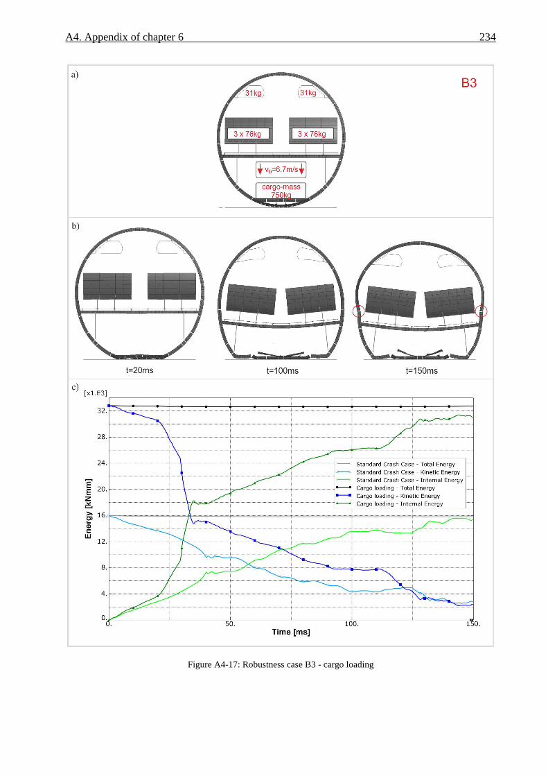
A4. Appendix of chapter 6 234
Figure A4-17: Robustness case B3 - cargo loading
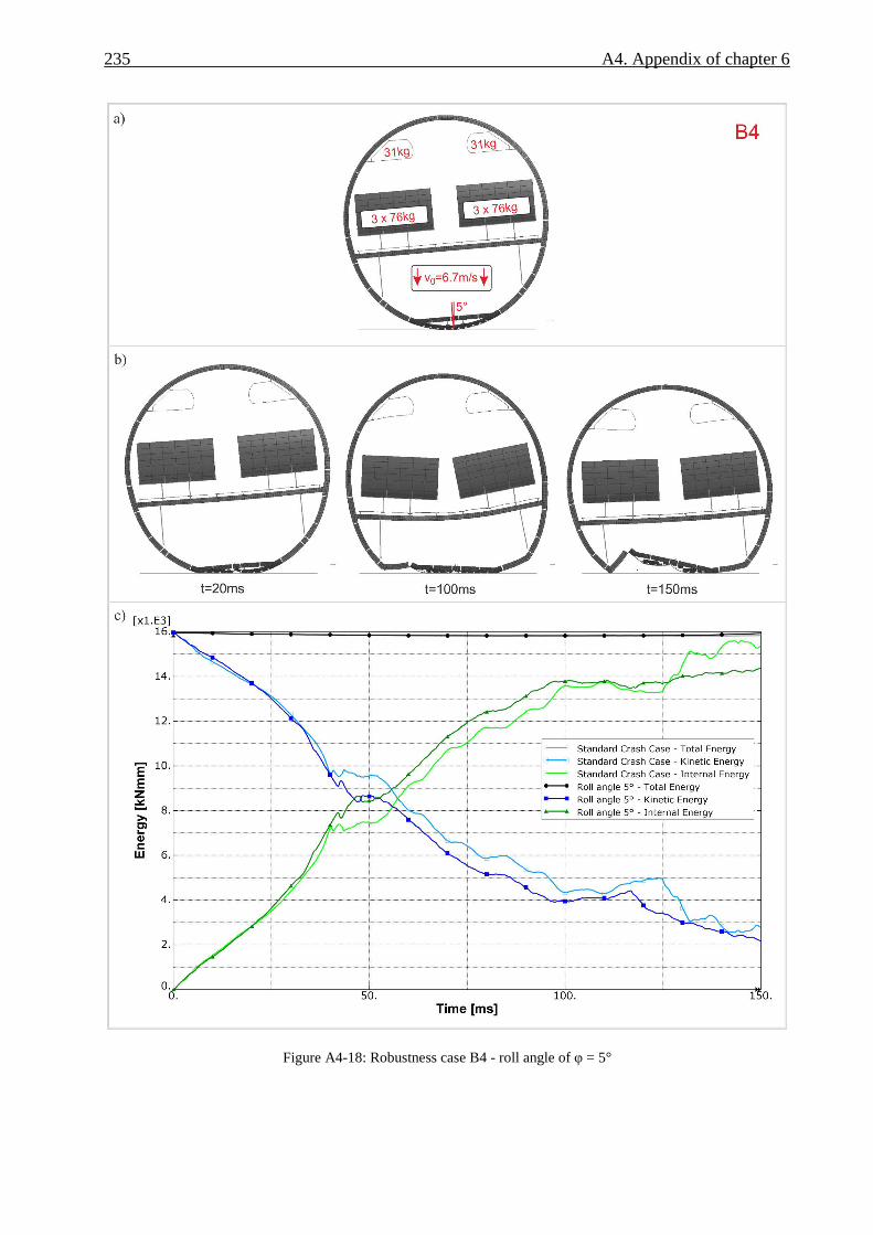
235 A4. Appendix of chapter 6
Figure A4-18: Robustness case B4 - roll angle of φ = 5°

A5. Appendix of chapter 7
Paragraph A5.1 provides a detailed definition of the simulation model used in the crash scenario
development study. Further results of the final crash scenario are given in paragraph A5.2.
Paragraph A5.3 provides further results of the simulation work on the ovalisation effect. In
paragraph A5.4 a detailed definition of the metallic frame model is provided which was used for
the comparison of the final kinematic hinge characteristics. Finally, paragraph A5.5 discusses the
axial forces in the vertical support struts of the final crash scenario to derive an appropriate
trigger force for an optional energy absorbing strut crushing in some robustness cases.
A5.1. Definition of the fuselage design and the Kinematics Model used for
the crash scenario development
Figure A5-1 displays the simulation model that was used for the crash scenario development.
The model comprises a two-frame fuselage section. The section length is Ls = 1270 mm, which is
twice the frame pitch of lFP = 635 mm. Hence a full overlap at the front and rear end of half a
frame pitch is modelled. Symmetry boundary conditions are defined at both ends. The minimum
seat pitch for this fuselage design was defined with lSPmin = 711 mm. To combine the frame pitch
and the seat pitch in an appropriate way, two rows of triple-seats were installed in the numerical
fuselage section, with passenger masses of mPAX = 68.5 kg. This passenger mass is 89 % of the
typical passenger mass and enables the adjustment of frame and seat pitch in the two-bay
fuselage section model.

237 A5. Appendix of chapter 7
Figure A5-1: Kinematics Model used for the scenario development
The fuselage geometry is similar but not identical to the cross-section of an Airbus A320 aircraft.
Secondary parts like passenger crossbeams, cargorails, seatrails and floorpanels represent a new
design, partly defined in CFRP material. The overhead bins and seats are represented by standard
models. The primary structural parts were designed in CFRP material and pre-sized according to
relevant ground and flight load cases. The design and sizing was conducted by the project
partner Airbus. The skin was designed with thicknesses between tS = 1.6-2.1 mm and typical
layups of about [15/60/25]1. The elastic properties of the CFRP UD material used to model the
skin structure are:
E11=130 GPa, E22=8.5 GPa, G12=4.2 GPa, υ=0.35, ρ=1.6 kg/m3
The LCF-shaped frame design describes frame heights of the inner C-part between HIFW = 56-66
mm. The frame inner flange width is defined with wIFF = 25 mm, the frame middle flange with
wMFF = 15 mm. The layup of the frame web is [0/75/25]2 and the frame flanges are defined with
a layup of about [45/45/10]2. The elastic properties of the CFRP UD material used to model the
frame structure are:
E11=135 GPa, E22=8.5 GPa, G12=4.2 GPa, υ=0.35, ρ=1.6 kg/m3
1 Layup orientation in percent: [0°/±45°/90°]
2 Layup orientation in percent (with respect to the frame only): [0°/±30°/90°]

A5. Appendix of chapter 7 238
The cargo-crossbeam is designed with high stiffness to enable sub-cargo crushing (bend-frame
concept). The τ-shaped cross-section has a height of HCCB = 85 mm, an upper flange width of
wUF = 60 mm and a lower flange width of wLF = 30 mm. The layup of the cargo-crossbeam web
is defined with [13/75/13]. The layup of the cargo-crossbeam flanges is defined between
[55/36/9] and [63/31/6]. The elastic properties of the CFRP UD material and woven fabric
material used to model the cargo-crossbeam structure are:
E11=126 GPa, E22=9.8 GPa, G12=4.9 GPa, υ=0.3, ρ=1.6 kg/m3
E11=56 GPa, E22=56 GPa, G12=4.3 GPa, υ=0.06, ρ=1.4 kg/m3
The stringer design describes several omega profiles with omega heights between HStr = 28-32
mm. The stringer thickness is defined between tStr = 1.1-1.4 mm with a layup between [44/44/11]
and [55/36/9]. The elastic properties of the CFRP UD material used to model the stringer
structure are similar to the skin material.
The positions of the macro elements are displayed in Figure A5-2. The kinematic hinge positions
correspond to potential frame failure locations according to the investigation of chapter 4.1. The
positions were adapted to the slightly changed fuselage section geometry compared to the
generic design used in the crash scenario assessment in chapter 6. The new cargo floor design
specifies a cargorail system instead of a central rollertrack. Therefore, the kinematic hinge in the
cargo-crossbeam could be defined directly in the lateral centre. The lateral position of the
vertical support struts corresponds to the A320 design and is defined with y = ±1353 mm. The
sub-cargo absorbers are located at a lateral position of y = ±200 mm below the inner cargorails.
Figure A5-2: Positions of the macro elements

239 A5. Appendix of chapter 7
The Kinematics Model of the crash scenario development study is a second generation model. In
contrast to the first generation model used for the crash scenario assessment study, all modelling
aspects discussed in chapter 4 are implemented. Hence, full accuracy according to the outcomes
of chapter 4 is guaranteed in this scenario development. With respect to the kinematic hinge
modelling, this second generation model does not include the user element which is described in
chapter 5. These advanced modelling capabilities could not be included due to the unsolved
issues of the solver bug.
The Kinematics Model for the crash scenario development contains about 56,000 nodes and
about 50,000 elements. The average mesh size of the primary (elastically modelled) parts are
lSkinL = 30 x 100 mm for the skin of the lower fuselage shell, lSkinU = 190 x 100 mm for the skin of
the upper fuselage shell and lFrame = 20 mm for the frame. The stringer beam elements have an
average mesh size of lStringer = 50 mm.
The simulations for the scenario development study were performed with the explicit solver
ABAQUS/Explicit V6.8-1. The parameterisation of the Kinematics Model comprised 74 design
parameters as well as 773 dependent parameters. The parameter assignment was realised with
the *parameter command in ABAQUS. The simulation jobs were calculated on a Windows
machine:
Dell Inc. Precision WorkStation T5400
Processor EM64T Family 6 Model 23 Stepping 6 GenuineIntel ~2993 Mhz
Microsoft(R) Windows(R) Server 2003 Standard x64 Edition (Service Pack 2 Build 3790)
Microsoft Compute Cluster Pack
Parallelisation on domain-level was executed with two domains respectively two processors and
double precision. The simulation time was defined with tS = 200 ms and led to a calculation time
of tC ≈ 19 h.
A5.2. Further results of the final crash scenario
The detailed crash sequence of the final crash scenario is given in Figure A5-3.
The diagram in Figure A5-4 compares the moment output of the kinematic hinges with the total
internal energy of the final crash scenario. This comparison illustrates the correlation between
failure, respectively triggering, of the kinematic hinges and the unsteadiness in the progression of
the internal energy caused by the release of elastic energy.
In addition, this diagram provides information about the chronological sequence of the absorbing
frame bending. The absorbing rotation in the frame kinematic hinges of Δφabs = 20° is spent at a
crash state where about 95 % of the final internal energy is reached. Hence, the defined
A5. Appendix of chapter 7 240
absorbing rotation of Δφabs = 20° corresponds well with the required bending deformation of this
crash kinematics.
Finally, the individual moment curves of the kinematic hinges show a good correlation. Thus, the
final crash scenario provides a good symmetrical crash kinematics with identical bending
mechanisms in both cargo-crossbeams as well as in the frames on both sides.
The structural loads in the frames are presented in Figures A5-5 and A5-6. The bar element
strains in the frame inner flange are illustrated in Figure A5-5 for both frames. The diagrams
display the strains along the whole frame. The strains of both frames show a good correlation,
both frames are loaded similarly. This correlation indicates a correct modelling method of the
two seat-rows which leads to consistent load introduction in the frame structure.
The most critical loading direction in the frame inner flange is clearly the compression direction.
The progression of the minimum strain values shows a first peak at about t = 25 ms. This peak
reaches values of about εmin = -8000 microstrain in the most critical frame region between the
cargo floor and the vertical support strut connection. In the final frame design, the crippling
strain of the frame inner flange in this region is εcc = -8290 microstrain. At this time of the first
peak, the kinematic hinges in the frame trigger. The strain values of the frame structure decrease
to a constant level which represents the energy absorbing frame bending phase. The second
minimum peak value occurs at about t = 170 ms and represents the ground contact of the vertical
support struts. The elements showing the maximum strain values of this second peak are located
in the vertically orientated frame regions of the fuselage side shell.
The elements showing the positive maximum strain values can be found in the upper fuselage
area as well as in the region of the passenger crossbeam connection. All maximum strain values
are clearly below the allowable of εt = +10,000 microstrain.
The frame outer flange strains are given in Figure A5-6. Again, the strains of both frames show a
good correlation, both frames are loaded similarly. In contrast to the frame inner flanges, the
strain values are clearly smaller in the frame outer flanges. However, due to the lower thickness
in the outer flange these strain values might be critical. In fact, the elements showing the
minimum strain values in Figures A5-6a) and A5-6b) are located in the upper fuselage area
where the frame outer flange provides a thickness of tOFF = 2.6 mm and a width of wOFF = 28 mm
in the final crash scenario. Hence, the crippling strain in this flange region is εc1 = -3300
microstrain. The minimum strain values in Figures A5-6a) and A5-6b) are εmin = -4000
microstrain. Hence, the strain limit criterion is clearly exceeded and the outer flange had to be
adapted to this maximum crash load. In this exemplary application of the Kinematics Model, the
focus of the structural adaptation was on the loads in the frame inner flange based on a specified

241 A5. Appendix of chapter 7
frame profile catalogue. Further adaptation of the frame outer flange would require the definition
of individual frame profiles in addition to the given profile catalogue which is beyond the scope
of this exemplary application. Hence, the loads in the frame outer flange were checked against
the flange design and potential exceeding was identified, but further adaptation was not
conducted.
Finally, the passenger loads in the final crash scenario are illustrated in Figure A5-7. The
accelerations are given in the Eiband diagram and are illustrated separately for both seat-rows. In
general, the passenger accelerations are similar to the values shown in chapter 7 for the variant
with optimised crash kinematics and maximum frame design. The values are clearly below the
limit of severe injuries.
In the range of the most critical duration (Δt = 6-11 ms), the correlation of both seat-rows shows
a more distinct scattering of passenger A-F in the second seat-row. Despite of that both seat-rows
show similar acceleration values over the acceleration duration. Again, this good correlation
indicates a correct modelling method with the two seat-rows.

A5. Appendix of chapter 7 242
Figure A5-3: Detailed crash sequence of the final crash scenario

243 A5. Appendix of chapter 7
Figure A5-4: Kinematic hinge moment output versus total internal energy

A5. Appendix of chapter 7 244
Figure A5-5: Strains along the frame inner flange

245 A5. Appendix of chapter 7
Figure A5-6: Strains along the frame outer flange

A5. Appendix of chapter 7 246
Figure A5-7: Passenger accelerations of the final crash scenario in the Eiband diagram
A5.3. Further results of the ovalisation effect
Based on the identified tensile forces in the passenger crossbeam, as illustrated in Figure 7-22,
the definition of the parameter study was selected as shown in Figure A5-8.
None of these nine variants identified significant divergences in the general crash kinematics.
The total internal energies in Figure A5-9 compare these variants. In addition, the total internal
energy of the final crash scenario that represents a rigid crossbeam connection is given in this
diagram. As expected, the curves are identical up to the triggering of the ovalisation device.
Depending on the amount of energy absorbed by the ovalisation device, the internal energy curve
reaches different levels respectively leads to a different trigger time of the frame kinematic
hinges. Nevertheless, the overall shape of the curves is similar which indicates similar crash

247 A5. Appendix of chapter 7
kinematics. The finally selected variant describes a trigger force of F = 20 kN as well as a
rotational stiffness of K = 1.0e04 kNmm/rad, which is highlighted in Figure A5-8 in red colour.
Figure A5-10 compares the longitudinal force in the passenger crossbeam of the final crash
scenario as well as the finally selected ovalisation variant. This diagram clearly illustrates the
load limiting effect of such a crash device. During the sequence a maximum ovalisation of Δy =
37 mm (at each side of the crossbeam) could be found.
The frame inner flange strains in the most critical frame region between the cargo floor and the
vertical support struts are plotted in Figure A5-11. The final crash scenario is compared with the
finally selected ovalisation variant. The minimum strain values at the time of frame failure in
that region are slightly reduced. This is an indication for a potential to reduce the structural mass
due to reduced crash loads in the frame structure in case of an ovalisation concept.
Finally, the crash sequence of the finally selected ovalisation variant is shown in Figure A5-12.
The sequence is compared with the final crash scenario and highlights the main differences at t =
40 ms as well as t = 200 ms.
Figure A5-8: Input characteristics of the ovalisation device, analysed in the parameter study

A5. Appendix of chapter 7 248
Figure A5-9: Total internal energies of the parameter study variants
Figure A5-10: Longitudinal forces in the passenger crossbeam of the final crash scenario and the finally selected
ovalisation variant

249 A5. Appendix of chapter 7
Figure A5-11: Frame inner flange strains in the most critical frame region of the final crash scenario and the finally
selected ovalisation variant

A5. Appendix of chapter 7 250
Figure A5-12: Crash sequence of the final crash scenario and the finally selected ovalisation variant

251 A5. Appendix of chapter 7
A5.4. Further details of the metallic frame model
A small study was performed to analyse exemplarily the energy absorbing capacity of the final
frame design between the cargo-floor and the vertical support strut, using metallic instead of
CFRP material. The detailed FE model of the metallic frame structure is shown in Figure A5-13.
In the region of expected frame failure, located directly below the vertical support struts, the
CFRP frame is replaced by a metallic frame structure which connects both CFRP frame parts as
well as the vertical support strut. This metallic frame structure provides a similar LCF-shaped
profile as the surrounding CFRP structure which is based on the final crash scenario. For
assembly reasons, the frame middle and outer flange is defined on the opposite web side. Despite
of this difference, the flange widths and thicknesses are identical to the CFRP frame profile. The
frame inner and middle flanges describe a thickness of tIFF = 9.2 mm, whereas the frame web as
well as the frame outer flange have a thickness of tOFF = 4.42 mm. The definition of the skin and
the stringer design is according to the final crash scenario. The cleat design as well as the vertical
support strut are similar to the A320 design.
An isotropic elastic-plastic material formulation was used for the representation of the metallic
parts. The material data used for the metallic frame structure as well as the cleats is according to
aluminium 2024 properties. The material data used for the vertical struts is according to
aluminium 7075 properties. The CFRP parts (frame, stringers, skin) were modelled orthotropic
linear-elastically.
Besides symmetry boundary conditions at the front and rear end of the model, the open cross-
sections of the frame-skin structure were reinforced using rigid body formulations. In addition,
the upper end of the frame-skin structure as well as the vertical support strut is constraint with fix
boundary conditions. An impact plate with a constant velocity of v = 6.7 m/s applies the crash
loads on the frame-skin structure. This model setup corresponds to an experimental test setup
which was performed with an A320 structure in the former European Community funded project
“Crashworthiness for Commercial Aircraft” [28].
The FE model size comprises 28,400 elements as well as 31,800 nodes. The simulation was
performed with the explicit solver ABAQUS/Explicit V6.8-1. The simulation job was calculated
on a Windows machine:
Dell Inc. Precision WorkStation T5400
Processor EM64T Family 6 Model 23 Stepping 6 GenuineIntel ~2993 Mhz
Microsoft(R) Windows(R) Server 2003 Standard x64 Edition (Service Pack 2 Build 3790)
Microsoft Compute Cluster Pack

A5. Appendix of chapter 7 252
Parallelisation on domain-level was executed with two domains respectively two processors and
double precision. The simulation time was defined with tS = 80 ms and led to a calculation time
of tC ≈ 8 h.
Figure A5-13: FE model of the metallic frame variant
Figure A5-14: Sequence of the metallic frame bending under crash loads
A5.5. Determination of an optional trigger load level for the vertical
support struts
In the investigations based on the ‘standard crash case’ passive vertical support struts were
foreseen and the trigger load level was defined artificially high. With respect to other crash cases
with higher initial kinetic energy or unfavourable loading conditions further energy absorption
capacity in the vertical support struts could significantly improve the crashworthiness of the
considered fuselage structure. For that reason, the definition of an appropriate trigger level for

253 A5. Appendix of chapter 7
the vertical struts is essential to ensure a stable crash kinematics respectively to ensure a
cascading scenario with a final vertical strut crushing phase.
Figure A5-15 shows the axial forces in the vertical support struts of the final crash scenario
(standard crash case). In addition, the kinematic hinge moments as well as the total internal
energy are plotted over the crash duration in this diagram to give an overview of the crash
sequence. The graphs of all four vertical struts show an increase of the compression force up to
values between F = 33-42 kN. These maximum compression forces occur at a state when
approximately two thirds of the energy absorption capacity in the frame kinematic hinges are
reached. A smooth transition from the frame bending phase to the vertical strut crushing phase
can be achieved by a trigger load level which initiates the strut crushing at this state. With
respect to the considered crash scenario such an appropriate trigger force can be defined as F =
35 kN.
Figure A5-15: Axial forces in the vertical support struts of the final crash scenario

A6. Appendix of chapter 8
Details about the development of a test setup for axial crushing are provided in paragraph A6.1.
The test matrix of the axial crushing test programme is given in paragraph A6.2.
Further details about the development of a test setup for frame bending tests are provided in
paragraph A6.3 before the test matrix of the frame bending test programme is shortly presented
in paragraph A6.4.
A6.1. Remarks to the development of a test setup for axial crushing tests
The development of the test setup for axial crushing tests was supported by detailed finite
element analyses as well as experimental pre-tests. Different factors were identified which
influence the failure behaviour of the considered crash absorber. Some of these factors are driven
by the structural environment of the fuselage.
The detailed FE model is illustrated in Figure A6-1. A multi-layered shell approach is used with
shell elements of reduced integration (S4R elements). The CFRP material is modelled using an
ABAQUS built-in user subroutine for fabric ply modelling (VUMAT ‘fabric_ply’). The rivet
connection between the half-tube absorber and the strut is modelled with connector elements and
appropriate failure models. The mesh independent fastener option (*fastener) is used to position
the connector elements at the specified rivet locations. The connection of the metallic skin plate
and the strut flange is modelled using a tied connection (*tie). The model size is 13,973 elements
and 15,361 nodes. The simulations were performed with the explicit solver ABAQUS/Explicit
V6.8-1. The simulation jobs were calculated on the following Windows machine:
Dell Inc. Precision WorkStation T5400
Processor EM64T Family 6 Model 23 Stepping 6 GenuineIntel ~2993 Mhz
Microsoft(R) Windows(R) Server 2003 Standard x64 Edition (Service Pack 2 Build 3790)
Microsoft Compute Cluster Pack
Parallelisation on domain-level was executed with two domains respectively two processors and
single precision. The simulation time was defined as tS = 20 ms and led to a calculation time of
tC ≈ 22 h.

255 A6. Appendix of chapter 8
Figure A6-1: FE model of the axial crushing test
Based on the outcomes of the finite element analyses a first pre-test was conducted statically in a
universal test machine (Zwick 1494). According to the identified tendency of the strut flange to
roll up in a first phase of the crushing sequence, a metallic plate was bonded to the strut flange
which is additionally guided to avoid further lateral displacement. Figure A6-2 pictures the
prepared absorber structure for pre-test I. The pictured upper fixture represents the clamping part
in which the specimen is embedded. This clamping part is bolted to a further fixture part which
provides the bleeding channels. In the quasi-static pre-test I, the peeling effect of the above
discussed roll up tendency induced high stresses which finally initiated failure of the bonded
connection. As predicted in the finite element analyses without the modelling of the plate, the
strut flange rotated after the bonding failure around its radius and separated from the plate.
Figure A6-3 depicts the quasi-static pre-test I and compares this effect with outcomes of the
finite element analyses.
A second pre-test was conducted with a modified connection of the strut flange and the metallic
plate. The bonding connection was replaced by a bolted one, as illustrated in Figure A6-4. After
the general feasibility of the guidance system was proved in pre-test I, the second pre-test was
performed dynamically (v = 6.7 m/s) in the test machine Instron VHS, similarly to the specified
test conditions of the planned test programme. Results of pre-test II are presented in Figure A6-5.
The failure modes of the absorber specimen are as expected, Figure A6-5a) and A6-5b). Besides
the crushing of the specimen, rupture of the strut near the flange radius occurred as well as pull-
through failure of the rivets. The inspection of the upper test fixture identified no failure of the
absorber specimen on this side, Figure A6-5c). Hence, the bonding connection in the fixture is

A6. Appendix of chapter 8 256
sufficient and potential crushing at this side of the specimen is not expected. The metallic skin
plate showed little plastic deformation which was caused by the constraint roll up effect of the
strut radius, Figure A6-5d).
In a final pre-test a hardened steel plate (C60-steel) was used to achieve higher yield strength and
to avoid any plastic deformation. Pre-test III was conducted dynamically similar to pre-test II.
Figure A6-6 depicts the specimen after the test and illustrates the metallic plate without plastic
deformation. Hence, in pre-test III the final test setup could successfully be verified.
Figure A6-2: Prepared specimen of pre-test I
Figure A6-3: Unrolling effect of the strut flange - comparison of the FE analysis and the test (pre-test I)

257 A6. Appendix of chapter 8
Figure A6-4: Prepared specimen of pre-test II
Figure A6-5: Specimen after the test (pre-test II)

A6. Appendix of chapter 8 258
Figure A6-6: Specimen after the test (pre-test III)
A6.2. Test matrix of the axial crushing test programme
The test matrix with a total number of 72 dynamic absorber tests is given in Table A6-1.
In the following, the test parameters are briefly explained to get an overview on the investigated
effects.
Two different designs of the flat strut were tested. Besides a simple geometry with a constant
thickness of t = 1.5 mm, a complex design was considered that corresponds to a statically sized
sub-cargo structure with a complex layup respectively thickness distribution along the strut.
The influence of the half-tube absorber design was regarded with several parameters.
Considering the geometry, two different angles of the geometrical trigger were tested. The
definition of the trigger angle is important to achieve a robust initiation of the crushing mode.
A further defined absorber design parameter is the thickness of the absorber laminate. The
thickness of the absorber significantly influences the crushing force level. In addition, an
increased absorber stiffness could avoid potential instability failure which is initiated by the flat
strut. Hence, the influence of the absorber thickness on the global stability behaviour was of
interest.
Furthermore, different materials respectively fabrications of the absorber structure were
investigated. Besides absorbers made of CFRP woven fabrics, variants of CFRP braided
absorbers were tested.
Another parameter considers the connection of the half-tube absorber and the flat strut. The
reference variant is defined with a riveted connection. Additionally, a further variant was tested
with a combination of riveted and paste bonded connection. Using additionally paste bonding, it
was expected to reduce the oscillations on the force-displacement curves which are caused by the
rivets. Instead a constant, increased force level was expected.
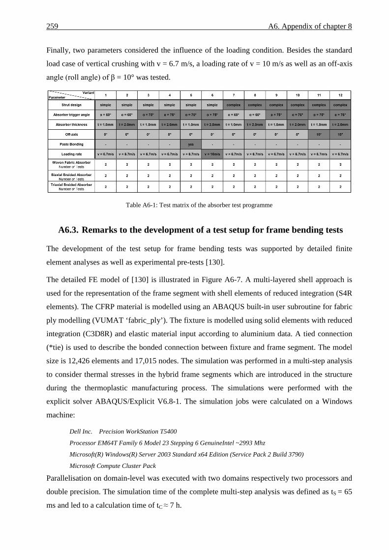
259 A6. Appendix of chapter 8
Finally, two parameters considered the influence of the loading condition. Besides the standard
load case of vertical crushing with v = 6.7 m/s, a loading rate of v = 10 m/s as well as an off-axis
angle (roll angle) of β = 10° was tested.
Table A6-1: Test matrix of the absorber test programme
A6.3. Remarks to the development of a test setup for frame bending tests
The development of the test setup for frame bending tests was supported by detailed finite
element analyses as well as experimental pre-tests [130].
The detailed FE model of [130] is illustrated in Figure A6-7. A multi-layered shell approach is
used for the representation of the frame segment with shell elements of reduced integration (S4R
elements). The CFRP material is modelled using an ABAQUS built-in user subroutine for fabric
ply modelling (VUMAT ‘fabric_ply’). The fixture is modelled using solid elements with reduced
integration (C3D8R) and elastic material input according to aluminium data. A tied connection
(*tie) is used to describe the bonded connection between fixture and frame segment. The model
size is 12,426 elements and 17,015 nodes. The simulation was performed in a multi-step analysis
to consider thermal stresses in the hybrid frame segments which are introduced in the structure
during the thermoplastic manufacturing process. The simulations were performed with the
explicit solver ABAQUS/Explicit V6.8-1. The simulation jobs were calculated on a Windows
machine:
Dell Inc. Precision WorkStation T5400
Processor EM64T Family 6 Model 23 Stepping 6 GenuineIntel ~2993 Mhz
Microsoft(R) Windows(R) Server 2003 Standard x64 Edition (Service Pack 2 Build 3790)
Microsoft Compute Cluster Pack
Parallelisation on domain-level was executed with two domains respectively two processors and
double precision. The simulation time of the complete multi-step analysis was defined as tS = 65
ms and led to a calculation time of tC ≈ 7 h.

A6. Appendix of chapter 8 260
Figure A6-7: FE model of the frame bending test [130]
Several experimental pre-tests were performed to develop an appropriate test setup. Initial pre-
tests were conducted with wooden inserts which were bonded in the C-frame segment in the
region between the supports and the stamp. In addition, metallic plates (aluminium, t = 3 mm)
were positioned at the supports and the stamp to smoothen the load introduction into the C-frame
segment. This setup was identified to be non-sufficient. Distortion of the C-profile as well as
local material damages at the supports and the stamp were observed, Figure A6-8a). Similar
results of local damage by the load introduction were identified in the numerical analysis, Figure
A6-8b). According to these results the test setup was modified and a solid aluminium fitting was
designed which encase the C-profile in the region between the stamp and the supports.
Figure 8: Damage by the load introduction of the supports and the stamp [130]
Further finite element analyses, according to the final FE model depicted in Figure A6-7, were
used to estimate the instability mode of the compressive loaded flange in dependence of the free
length between the stamps. To achieve failure of the frame segment in the centre of the free
length an instability mode of first order was desired. The simulation results identified a free
length of L = 160 mm as sufficient to allow the compressive loaded flange to buckle in a mode

261 A6. Appendix of chapter 8
of first order, as displayed in Figure A6-9. The vertical displacement is pictured in this figure
and highlights the buckling mode of the upper, compressive loaded flange.
Figure A6-9: Instability mode of first order in the compressive loaded flange, displacement in z-direction [130]
A6.4. Test matrix of the frame bending test programme
The test matrix of the frame bending test programme is given in Table A6-2. A total of eight
tests were conducted with the developed test setup. Hybrid frame segments with titanium sheets
embedded in the flanges were tested and compared with tested reference frame segments which
were made purely of CFRP. Figure A6-10 depicts the layups of both variants and illustrates the
replacement of UD-plies by titanium sheets in the hybrid variant.
The frame segments were tested quasi-statically in an universal testing machine (Zwick 1475) as
well as dynamically in the DLR drop tower facility with an initial velocity of vi = 3.4 m/s.
Table A6-2: Test matrix of the frame bending test programme

A6. Appendix of chapter 8 262
Figure A6-10: Flange and web layup of the reference and the hybrid variant

Bibliography
[1] Boeing Commercial Airplanes: Statistical summary of commercial jet airplane accidents
– worldwide operations 1959-2009, Boeing Commercial Airplanes, 2010
[2] R. H. W. M. Frijns, J. F. W. Wiggenraad, A. T. M. Schaefers: Assessment of survivable
crash scenarios – an evaluation of crash scenarios during the period 1980-1922, Sub-task
1.2 of the European Community funded research project ‘Crashworthiness for
commercial aircraft’, 1994
[3] R. G. Thomson, C. Caiafa: Structural response of transport airplanes in crash situations,
NASA TM85654, 1983
[4] US National Transportation Safety Board: Survivability of accidents involving part 121
U.S. air carrier operations – 1983 through 2000, Safety report NTSB/SR-01/01, 2001
[5] W. Widmayer, O.B. Brende: Commercial jet transport crashworthiness, NASA
CR165849, 1982
[6] M. C. Y. Niu: Composite airframe structures – second edition / fifth published, Hong
Kong Conmilit Press Ltd., 2008
[7] A. C. Jackson, M. C. Campion, G. Pei: Study of utilization of advanced composites in
fuselage structures of large transports, NASA CR172404, 1984
[8] R. W. Johnson, L. W. Thomson, R. D. Wilson: Study of utilization of advanced
composites in fuselage structures of large transports, NASA CR172406, 1985
[9] A. C. Jackson, F. J. Balena, W. L. LaBarge, G. Pei, W. A. Pitman, G. Wittlin: Transport
composite fuselage technology – impact dynamics and acoustic transmission, NASA
CR4035, 1986
[10] Federal Aviation Administration: Federal aviation regulations, part 25: airworthiness
standards: transport category airplanes, 1997
[11] Federal Aviation Administration: Special conditions: Boeing model B787-8 airplane;
Crashworthiness, US Federal register Vol.72 No.111 Docket No.NM368 special
conditions No. 25-07-05-SC, 2007

Bibliography 264
[12] G. M. Preston, G. J. Pesman: Accelerations in transport-airplane crashes, NACA
TN4158, 1958
[13] W. H. Reed, S.H. Robertson, L. W. T. Weinberg, L. H. Tyndall: Full-scale dynamic crash
test of a Lockheed Constellation model 1649 aircraft, FAA-ADS-38, 1965
[14] W. H. Reed, S.H. Robertson, L. W. T. Weinberg, L. H. Tyndall: Full-scale dynamic crash
test of a Douglas DC-7 aircraft, FAA-ADS-37, 1965
[15] M. S. Williams, R. J. Hayduk: Vertical drop test of a transport fuselage center section
including the wheel wells, NASA TM85706, 1983
[16] E. L. Fasanella, E. Alfaro-Bou: Vertical drop test of a transport fuselage section located
aft of the wing, NASA TM89025, 1986
[17] M. S. Williams, R. J. Hayduk: Vertical drop test of a transport fuselage section located
forward of the wing, NASA TM85679, 1983
[18] S. M. Pugliese: B-707 fuselage drop test report, Arvin/Calspan report No. 7252-1
prepared for FAA technical center Atlantic City N.J., 1984
[19] D. Johnson, A. Wilson: Vertical drop test of a transport airframe section, DOT/FAA/CT-
TN 86/34, 1986
[20] Arvin/Calspan: DC-10 fuselage drop test report, Arvin/Calspan report No. 7251-2
prepared for FAA technical center Atlantic City N.J., 1984
[21] R.J. Hayduk: Full-scale transport controlled impact demonstration, NASA CP2395, 1985
[22] Federal Aviation Administration: Summary report – full-scale transport controlled impact
demonstration program, DOT/FAA/CT-87/10, 1987
[23] K. E. Jackson, R. L. Boitnott, E. L. Fasanella, L. E. Jones, K. H. Lyle: A history of full-
scale aircraft and rotorcraft crash testing and simulation at NASA Langley Research
Center, Fourth triennial international fire & cabin safety research conference, 2004
[24] A. Abramowitz, T. G. Smith, T. Vu, J. R. Zvanya: Vertical drop test of a narrow-body
transport fuselage section with overhead stowage bins, DOT/FAA/AR-01/100, 2002
[25] T. V. Logue, R. J. McGuire, J. W. Reinhardt, T. Vu : Vertical drop test of a narrow-body
fuselage section with overhead stowage bins and auxiliary fuel tank on board,
DOT/FAA/CT-94/116, 1995
265 Bibliography
[26] A. Abramowitz, T. G. Smith, T. Vu: Vertical drop test of a narrow-body transport
fuselage section with conformable auxiliary fuel tank onboard, DOT/FAA/AR-00/56,
2000
[27] M. M. Sadeghi, S. M. R. Hashemi: An overview of the aircraft crashworthiness study
project ‘A European programme’, Second triennial international fire & cabin safety
research conference, 1998
[28] R. Hashemi: Sub-component dynamic tests on an Airbus A320 rear fuselage, Cranfield
Impact Centre Limited, Sub-task 2.4 of the European Community funded research project
‘Crashworthiness for commercial aircraft’, 1994
[29] R. Hashemi: Sub-component quasi-static tests on an Airbus A320 rear fuselage, Cranfield
Impact Centre Limited, Sub-task 2.4 of the European Community funded research project
‘Crashworthiness for commercial aircraft’, 1994
[30] F. LePage, R. Carciente: A320 fuselage section vertical drop test – part 2 test results,
CEAT test report S95 5776/2, European Community funded research project
‘Crashworthiness for commercial aircraft’, 1995
[31] I. Kumakura, H. Sashikuma, et al.: Summary of vertical drop tests of YS-11 transport
fuselage sections, SAE technical paper 2003-01-3027, 2003
[32] I. Kumakura, H. Sashikuma, et al.: Vertical drop test of a transport fuselage section, SAE
technical paper 2002-01-2997, 2002
[33] A. Abramowitz, S. Soltis: Summary of the FAA´s commuter airplane crashworthiness
program, Fifth triennial international fire & cabin safety research conference, 2007
[34] A. Abramowitz, T. Vu: Vertical impact response characteristics of four
commuter/regional airplanes, DOT/FAA/AR-08/20, 2008
[35] R. J. McGuire, W. J. Nissley, J. E. Newcomb: Vertical drop test of a Metro III aircraft,
DOT/FAA/CT-93/1, 1993
[36] R. McGuire, T. Vu: Vertical drop test of a Beechcraft 1900C airliner, DOT/FAA/AR-
96/119, 1998
[37] A. Abramowitz, P. A. Ingraham, R. McGuire: Vertical drop test of a Shorts 3-30 airplane,
DOT/FAA/AR-99/87
[38] A. Abramowitz, T. G. Smith, T. Vu, J. R. Zvanya: Vertical drop test of an ATR 42-300
airplane, DOT/FAA/AR-05/56, 2006

Bibliography 266
[39] J. D. Cronkhite, V. L. Berry: Crashworthy airframe design concepts – fabrication and
testing, NASA CR3603, 1982
[40] J. D. Cronkhite, T. J. Haas, R. Winter, G. T. Singley: Investigation of the crash impact
characteristics of composite airframe structures, American Helicopter Society – 34th
annual forum, 1987
[41] C. M. Kindervater, H. Georgi: Composite strength and energy absorption as an aspect of
structural crash resistance, in Structural Crashworthiness and Failure: 189-235, 1993
[42] G. L. Farley: Energy absorption of composite materials, Journal of composite materials
Vol.17: 267-279, 1983
[43] A. G. Mamalis, M. Robinson. D.E. Manolakos, G.A. Demosthenous, M.B. Ioannidis, J.
Carruthers : Review – crashworthy capability of composite material structures,
Composite structures Vol.37 : 109-134, 1997
[44] P. Feraboli, B. Wade, F. Deleo, M. Rassaian: Crush energy absorption of composite
channel section specimens, Composites: Part A Vol.40: 1248-1256, 2009
[45] A. Jackson, S. Dutton, A. J. Gunnion, D. Kelly: Effect of manufacture and laminate
design on energy absorption of open carbon-fibre/epoxy sections, International
conference on composite materials ICCM-17, 2009
[46] H. D. Carden: Unique failure behaviour of metal/composite aircraft structural
components under crash type loads, NASA TM102679, 1990
[47] H. D. Carden, M. P. Robinson: Failure behaviour of generic metallic and composite
aircraft structural components under crash loads, NASA RP1239, 1990
[48] R. L. Boitnott, E. L. Fasanella: Impact evaluation of composite floor sections, SAE
891018, 1989
[49] R. L. Boitnott, E. L. Fasanella, L. E. Calton, H. D. Carden: Impact response of composite
fuselage frames, SAE 871009, 1987
[50] H. D. Carden, R. L. Boitnott, E. L. Fasanella: Behaviour of composite/metal aircraft
structural elements and components under crash type loads – what are they telling us?,
NASA TM102681, 1990
[51] R. L. Boitnott, C. Kindervater: Crashworthy design of helicopter composite airframe
structures, European Helicopter Society – 15th European rotorcraft forum, 1989
267 Bibliography
[52] A. L. P. J. Michielsen, J. F. M. Wiggenraad: Review of crashworthiness research of
composite structures - part I, D.2.1.1 of the European Community funded research project
‘CRASURV’, 1997
[53] A. F. Johnson, C. M. Kindervater: Review of crashworthiness research on composite
structures - part II, D.2.1.1 of the European Community funded research project
‘CRASURV’, 1997
[54] J. F. M. Wiggenraad, D. Santoro, F. LePage, C. Kindervater, H. Climent Manez:
Development of a crashworthy composite fuselage concept for a commuter aircraft,
NLR-report TP-2001-108, 2001
[55] F. Le Page: Presentation of the commuter sub-passenger floor structure drop test, CEAT
test report S98/4449000 part 2, D.4.3.1 of the European Community funded research
project ‘CRASURV’, 1998
[56] F. Le Page: Results of the commuter sub-passenger floor structure drop test, CEAT test
report S98/4449000 part 3, D.4.3.2 of the European Community funded research project
‘CRASURV’, 1999
[57] F. Le Page: Results of the airliner sub-cargo floor structure drop test, CEAT test report
S98/4449000 part 1, D.4.1.7 of the European Community funded research project
‘CRASURV’, 1998
[58] F. Le Page: Presentation of the airliner sub-passenger floor structure drop test, CEAT test
report S98/4449000 part 4, D.4.3.3 of the European Community funded research project
‘CRASURV’, 1997
[59] F. Le Page: Results of the airliner sub-passenger floor structure drop test, CEAT test
report S98/4449000 part 5, D.4.3.4 of the European Community funded research project
‘CRASURV’, 1997
[60] J.-M. Souqouet, B. Beral: Design airliner sub-passenger floor structure, D.2.4.1 &
D.2.4.2 of the European Community funded research project ‘CRASURV’, 1998
[61] M. Mahe, H. Ribet, F. LePage: Composite fuselage crash FE modelling dedicated to
enhance the design in correlation with full scale drop test, Mechanique & Industries Vol.2
Issue 1: 5-17, 2001
[62] E. Moas, R. L. Boitnott, O. H. Griffin: An analytical and experimental investigation of
the response of the curved, composite frame/skin specimens, Journal of the American
Helicopter Society Vol.39 Issue 3, 1994

Bibliography 268
[63] M. B. Woodson, E. R. Johnson, R. T. Haftka: Optimal design of composite fuselage
frames for crashworthiness, International Journal of Crashworthiness Vol.1 No.4: 369-
380, 1996
[64] J. G. Perez: Energy absorption and progressive failure response of composite fuselage
frames, Master thesis – Virginia Polytechnic Institute and State University, 1999
[65] L. O. Pilkington: Impact response and failure of a textile composite fuselage frame,
Master thesis – Virginia Polytechnic Institute and State University, 2004
[66] A. O. Bolukbasi, T. R. Baxter, T. A. Nguyen, M. Rassaian, K. R. Davis, W. Koch, L. C.
Firth: Energy absorbing structure for aircraft, Patent application GB 2 444 645 A, 2008
[67] http://www.flightblogger.blogspot.com
[68] P. E. Nikravesh, I. S. Chnung, R. L. Benedict: Plastic hinge approach to vehicle crash
simulation, Computers & Structures Vol.16 No.1-4: 395-400, 1983
[69] J. Ambrosio, J. Dias: A road vehicle multibody model for crash simulation based on the
plastic hinges approach to structural deformations, International Journal of
Crashworthiness Vol.12 No.1: 77-92, 2007
[70] L. Sousa, P. Verissimo, J. Ambrosio: Development of generic multibody road vehicle
models for crashworthiness, Multibody System Dynamics 19: 133-158, 2008
[71] H.-S. Kim, S.-Y. Kang, I.-H. Lee, S.-H. Park, D.-C. Han: Vehicle frontal crashworthiness
analysis by simplified structure modeling using nonlinear spring and beam elements,
International Journal of Crashworthiness Vol.2 No.1: 107-117, 1997
[72] G. Biakeu, L. Jezequel: Simplified crash models using plastic hinges and the large
curvature description, Multibody System Dynamics 9: 25-37, 2003
[73] J. P. Dias, M. S. Pereira: Optimization methods for crashworthiness design using
multibody models, Computers & Structures Vol.82: 1371-1380, 2004
[74] G. Wittlin, B. LaBarge: KRASH parametric sensitivity study – transport category
airplanes, DOT/FAA/CT-87/13, 1987
[75] M. Lützenburger: Simulation of the A320 section drop test using the hybrid code
KRASH, DLR-report IB 435-95/24, Sub-task 3.1 of the European Community funded
research project ‘Crashworthiness for commercial aircraft’, 1995

269 Bibliography
[76] F. Invernizzi, E. Masiero, S. Poggi, M. Anghileri, L.-M. L. Castelletti, E. Francesconi, A.
Milanese: Helicopter subfloor structure design adopting a combined ABAQUS/Explicit –
KRASH approach, 6th International KRASH users` seminar, 2009
[77] M. Lützenburger: KRASH related research projects at DLR, 6th International KRASH
users` seminar, 2009
[78] A. K. Noor, H. D. Carden: Computational methods for crashworthiness, NASA CP3223,
1992
[79] S. J. Soltis: Overview of usage of crash dynamic analytical methods in civil aircraft
research and certification programs, Fifth triennial international fire & cabin safety
research conference, 2007
[80] L. G. Maia, P. H. I. A. de Oliveira: A review of finite element simulation of aircraft
crashworthiness, Publication of Advanced Composites Solutions, 2005
[81] K. H. Lyle, L. W. Bark, K. E. Jackson: Evaluation of test/analysis correlation methods for
crash applications, American Helicopter Society – 57th annual forum, 2001
[82] A. Adams, H. M. Lankarani: A modern aerospace modelling approach for evaluation of
aircraft fuselage crashworthiness, International Journal of Crashworthiness Vol.8 No.4:
401-413, 2003
[83] E. L. Fasanella, K. E. Jackson, Y. T. Jones, G. Frings, T. Vu : Crash simulation of a
Boeing 737 fuselage section vertical drop test, NASA Langley Research Center, 2004
[84] K. E. Jackson, E. L. Fasanella: Crash simulation of vertical drop tests of two Boeing 737
fuselage sections, DOT/FAA/AR-02/62, 2002
[85] D. Kohlgrüber: Numerical simulation of dynamic test II, DLR-report IB 435-94/31, Sub-
task 2.2 of the European Community funded research project ‘Crashworthiness for
commercial aircraft’, 1995
[86] E. Haug, G. Milcent, G. Munck: Thirty sixth month periodic progress report, ESI SA -
AERO-CT92-0030-4, in the European Community funded research project
‘Crashworthiness for commercial aircraft’, 1996
[87] E. L. Fasanella, K. E. Jackson: Best practices for crash modeling and simulation, NASA
TM-2002-211944, 2002
[88] K. E. Jackson, E. L. Fasanella: Development and validation of a finite element simulation
of a vertical drop test of an ATR 42 regional transport airplane, DOT/FAA/AR-08/19,
2008

Bibliography 270
[89] M. A. McCarthy, C.G. Harte, J. F. M. Wiggenraad, A. L. P. J. Michielsen, D.
Kohlgrüber, A. Kamoulakos: Finite element modelling of crash response of composite
aerospace sub-floor structures, Computational Mechanics Vol.26: 250-258, 2000
[90] J. F. M. Wiggenraad, A. L. P. J. Michielsen, D. Santoro, F. LePage, C. Kindervater, F.
Beltran, M. Al-Khalil: Finite element methodologies development to simulate the
behaviour of composite fuselage structure and correlation with drop test, Air & Space
Europe Vol.3 No.3/4, 2001
[91] M. Mahe, H. Ribet: Post-test simulation of the sub-passenger floor structure, D.3.4.3 of
European Community funded research project ‘CRASURV’, 2000
[92] M. Mahe, H. Ribet, J. Kleinwechter: Pre-test simulation of the sub-passenger floor
structure, D.3.4.2 of European Community funded research project ‘CRASURV’, 1999
[93] D. Kohlgrüber, A. Kamoulakos: Validation of numerical simulation of composite
helicopter sub-floor structures under crash loading, American Helicopter Society – 54th
annual forum, 1998
[94] D. Kohlgrüber: Improved simulation methodologies to model the crash behaviour of
composite structures, DLR research project ‘Schwarzer Rumpf’, 2002
[95] K. E. Jackson, E. L. Fasanella, S. Kellas: Crash simulation of a 1/5-scale model
composite fuselage concept, MSC aerospace users` conference, 1999
[96] K. E. Jackson: Impact testing and simulation of a crashworthy composite fuselage
concept, International Journal of Crashworthiness Vol.6 No.1: 107-121, 2001
[97] E. L. Fasanella, K. E. Jackson: Impact testing and simulation of a crashworthy composite
fuselage section with energy-absorbing seats and dummies, American Helicopter Society
– 58th annual forum, 2002
[98] K. E. Jackson, E. L. Fasanella, R. L. Boitnott, K. H. Lyle: Full-scale crash test and finite
element simulation of a composite prototype helicopter, NASA TP-2003-212641, 2003
[99] E. Haug, A. De Rouvray: Crash response of composite structures, in Structural
Crashworthiness and Failure: 237-294, 1993
[100] M. David: Analysis of crushing response in composite crashworthy structures, 10th
ONERA-DLR aerospace symposium ODAS, 2009
[101] A. F. Johnson, M. David: Failure mechanism in energy-absorbing composite structures,
Philosophy magazine Vol.90 Issue 31&32: 4245-4261, 2010
271 Bibliography
[102] C. M. Kindervater: Aircraft and helicopter crashworthiness: design and simulation,
Crashworthiness of transportation systems: structural impact and occupant protection:
525-577, 1997
[103] D. Kohlgrüber: SECTMESH V5 – Description of a tool to automatically generate finite
element meshes of transport aircraft sections, DLR-report IB435-2008/18, 2008
[104] ABAQUS: ABAQUS analysis user´s manual V6.8, SIMULIA Dassault Systèmes, 2008
[105] K. E. Jackson, E. L. Fasanella, R. Boitnott, J. McEntire, A. Lewis: Occupant response in
a full-scale crash test of the Sikorsky ACAP helicopter, Journal of the American
Helicopter Society Vol.49 Issue 2, 2004
[106] R. G. Thomson, H. D. Carden, R. J. Hayduk: Survey of NASA research on crash
dynamics, NASA TP2298, 1984
[107] D. H. Glaister: Human tolerance to impact acceleration, Injury Vol.9 Issue 3: 191-198,
1978
[108] A. M. Eiband: Human tolerance to rapidly applied accelerations: A summary of the
literature, NASA MEMO5-19-59E, 1959
[109] Federal Aviation Administration: Federal aviation regulations, part 27.562: airworthiness
standards: normal category rotorcraft, Emergency landing dynamic conditions, 1989
[110] G. L. W. M. Knops: Supporting Test Work – Aircraft Seat Component Tests, Subtask 2.4
of the European Community funded research project “Crashworthiness for commercial
aircraft”, TNO-report No.: 94.OR.BV.011.1/GKN, 1994
[111] ABAQUS: ABAQUS theory manual V6.8, SIMULIA Dassault Systèmes, 2008
[112] ABAQUS: Getting started with ABAQUS: Keywords Edition V6.8, SIMULIA Dassault
Systèmes, 2008
[113] P. Wriggers: Nichtlineare Finite-Element-Methoden, Springer-Verlag, 2001
[114] A. Haufe: Theory and application of explicit simulation methods, DYNAmore GmbH,
2007
[115] Y. Ren, J. Xiang: A comparative study of the crashworthiness of civil aircraft with
different strut configurations, International Journal of Crashworthiness Vol.15 No.3: 321-
330, 2010
[116] ABAQUS: ABAQUS user subroutines reference manual V6.8, SIMULIA Dassault
Systèmes, 2008
Bibliography 272
[117] X. W. Zhang, J. L. Yang, T. X. Yu: Elastic-plastic behaviour of a semicircular frame
being pressed against a rigid plane, Acta Mechanica Sinica Vol.24: 419-432, 2008
[118] F. X. Meng, Q. Zhou, J. L. Yang: Improvement of crashworthiness behaviour for
simplified structural models of aircraft fuselage, International Journal of Crashworthiness
Vol.14 No.1: 83-97, 2009
[119] A. Adams, C. K. Thorbole, H. M. Lankarani: Scale modelling of aircraft fuselage: an
innovative approach to evaluate and improve crashworthiness, International Journal of
Crashworthiness Vol.15 No.1: 71-82, 2010
[120] P. Westphal, W.-D. Dolzinski, T. Roming, T. Schröer, D. Kohlgrüber, M. Lützenburger:
Strukturbauteil mit Spant- und Querträgerelement, Patent application DE 10 2007 030
026 A1, 2009
[121] D. Delsart: Technical report 3/11921 DMSE, ONERA, 2007
[122] S. Heimbs, F. Strobl, P. Middendorf, J. M. Guimard: Composite crash absorber for
aircraft fuselage applications, WIT transaction on the built environment Vol.113: 3-14,
2010
[123] U.S. Department of Defense: Composite materials handbook volume 3, MIL-HDBK-17-
3F, 1997
[124] D. Bushnell: Buckling of shells – pitfall for designers, AIAA 80-0665R, 1981
[125] E. E. Spier: Postbuckling fatigue behaviour of graphite-epoxy stiffeners, AIAA-1982-
779, 1982
[126] M. C. Y. Niu: Airframe stress analysis and sizing – second edition / fourth published,
Hong Kong Conmilit Press Ltd., 2007
[127] K. E. Jackson: Friction and wear behaviour of aluminium and composite airplane skins,
NASA TP2262, 1984
[128] H. D. Carden: Impact dynamics research on composite transport structures, NASA
TM86391, 1985
[129] P. Wild: Untersuchung hybrider Werkstoffkombinationen zur Verbesserung des
Crashverhaltens von Transportflugzeugen, DLR-report IB435-2009/18, 2009
[130] R. Reiß: Untersuchung hybrider Biegeträger zur Verbesserung des Crashverhaltens von
Transportflugzeugen, DLR-report IB435-2010/08, 2010

273 Bibliography
[131] J. Jakobi, M. Roeder, M. Biella, J. Teutsch: Economic aspects of advanced surface
movement guidance and control systems (A-SMGCS), Conference on air traffic
management economics, 2009
[132] I. Kumakura, M. Minegishi, K. Iwasaki: Impact simulation of simplified structural
models of aircraft fuselage, SAE technical paper 2000-01-5586, 2000
[133] T. Hosokawa, I. Kumakura, M. Minegishi, K. Iwasaki: Drop test simulation of simplified
structural models of aircraft fuselage, ISSN 0289-260X, Vol. 44: 191-196, 1999
[134] D. Kohlgrüber, H. Weissinger: Crash behaviour of composite commuter sub-floor
components – report on dynamic tests, DLR-report IB 435-98/21, D.4.1.9 of the
European Community funded research project ‘CRASURV’, 1998
[135] D. Kohlgrüber, H. Weissinger: Crash behaviour of composite sub-floor components –
final report on component tests, DLR-report IB 435-97/38, D.4.1.4 of the European
Community funded research project ‘CRASURV’, 1998
[136] D. Kohlgrüber: Initial materials data of carbon and aramid fabric materials, DLR-report
IB 435-97/24, D.1.1.1 of the European Community funded research project
‘CRASURV’, 1997
[137] D. Kohlgrüber, H. Weissinger: Results of dynamic tests of composite sub-floor boxes –
final report, DLR-report IB 435-98/22, D.4.2.2 of the European Community funded
research project ‘CRASURV’, 1998
[138] D. Kohlgrüber: Verification and calibration of material models on cruciform elements,
DLR-report IB 435-99/34, D.3.2.1 of the European Community funded research project
‘CRASURV’, 1999
[139] M. C. Y. Niu: Airframe structural design – second edition / third published, Hong Kong
Conmilit Press Ltd., 2006
[140] Arbeitskreis Messdatenverarbeitung Fahrzeugsicherheit: Crash-Analyse Beschreibung
der Kriterien - Version 1.6.2, 2005
[141] ABAQUS: Request for enhancement – element output to odb for user-defined elements,
ABAQUS RFE #11822, 2010
[142] ABAQUS: Bug – output energy for vuel, ABAQUS bug v67_2406, 2008
[143] ABAQUS: Bug – displacements/rotations passed in vuel, ABAQUS bug v67_2413, 2008
[144] K.-J. Bathe: Finite-Elemente-Methoden, Springer-Verlag, 2002

Bibliography 274
[145] http://www.dri-krash.com
[146] Gesellschaft für Optische Messtechnik: Benutzerhandbuch Software ARAMIS v6, GOM
mbH, 2007
[147] M. Waimer, D. Kohlgrüber, D. Hachenberg, H. Voggenreiter: Dynamic component tests
on CFRP crash absorbers of a transport aircraft sub-cargo structure, 12th ONERA-DLR
Aerospace Symposium, 2012

Curriculum Vitae
Personal data
Name Matthias Waimer
Date of Birth February 07, 1979
Place of Birth Schorndorf, Germany
Marital Status Married
Nationality German
University Education
2000 – 2006 Diplom-Ingenieur, Aero- and Astronautics Engineering, Faculty of Aerospace Engineering and Geodesy, University of Stuttgart
2009 – 2013 Doctoral Candidate, Institute of Structures and Design, German Aerospace Center (DLR), Stuttgart
Experience
since 2006 Research Associate, Institute of Structures and Design, German Aerospace Center (DLR)
Investigation of crash concepts for the second generation CFRP fuselage of transport aircraft within several industrial and publicly (National &
European Community) funded research projects:
− 2006-2008: Development of FE modelling methods for the assessment of crash kinematics (industrial research project)
− 2007-2010: Experimental investigations and numerical simulations on the failure behaviour of hybrid frame bending concepts (DLR research project)
− 2008-2011: Development of a crashworthy CFRP fuselage design by numerical crash simulations (industrial research project)
− 2008-2011: Experimental investigations on the failure behaviour of CFRP crash absorber components (industrial research project)
− 2008-2013: Development and validation of FE modelling methods for the simulation of crushing of CFRP crash absorbers (European Community funded research project)
− 2012-2015: Development of improved crash concepts & -kinematics for the second generation CFRP fuselage of transport aircraft (National funded research project)
Copyright © 2022 FDOKUMEN


![Die Deutsche Glaubensbewegung als ideologisches Zentrum der völkischreligiösen Bewegung [2012]](https://static.fdokumen.com/doc/165x107/6340808b5a150e6dd70b25aa/die-deutsche-glaubensbewegung-als-ideologisches-zentrum-der-voelkischreligioesen.jpg)