Master's Thesis: CAN exchange though Internet - CiteSeerX
61
Securing In-Boat CAN Communication over the Internet Using a Cell Phone as Wi-Fi Router with Limited Hardware Master’s Thesis in Computer Science and Engineering RICKARD PERSSON ALESANDRO SANCHEZ Chalmers University of Technology Department of Computer Science and Engineering Gothenburg, Sweden 2015
-
Upload
khangminh22 -
Category
Documents
-
view
3 -
download
0
Transcript of Master's Thesis: CAN exchange though Internet - CiteSeerX

Securing In-Boat CAN Communicationover the InternetUsing a Cell Phone as Wi-Fi Router with LimitedHardware
Master’s Thesis in Computer Science and Engineering
RICKARD PERSSON
ALESANDRO SANCHEZ
Chalmers University of TechnologyDepartment of Computer Science and EngineeringGothenburg, Sweden 2015

The Author grants to Chalmers University of Technology and University of Gothen-burg the non-exclusive right to publish the Work electronically and in a non-commercialpurpose make it accessible on the Internet. The Author warrants that he/she is theauthor to the Work, and warrants that the Work does not contain text, pictures or othermaterial that violates copyright law.
The Author shall, when transferring the rights of the Work to a third party (for examplea publisher or a company), acknowledge the third party about this agreement. If theAuthor has signed a copyright agreement with a third party regarding the Work, theAuthor warrants hereby that he/she has obtained any necessary permission from thisthird party to let Chalmers University of Technology and University of Gothenburg storethe Work electronically and make it accessible on the Internet.
Securing In-Boat CAN Communication over the InternetSecuring In-Boat CAN Communication over the Internet Using a Cell Phone as Wi-FIRouter with Limited Hardware
Rickard, PerssonAlesandro, Sanchez
©Rickard Persson, June 2015©Alesandro Sanchez, June 2015
Examiner: Tomas Olovsson
Chalmers University of TechnologyDepartment of Computer Science and EngineeringSE-412 96 GoteborgSwedenTelephone + 46 (0)31-772 1000
Department of Computer Science and EngineeringGothenburg, Sweden June 2014


Abstract
Opening a communication channel to the internal vehicle bus of pleasure boats throughthe Internet, offers benefits such as remote diagnostics and software update of boatcomponents. An undesirable consequence of this communication is a broad range ofsecurity threats which could can damage to the boat and company. Therefore, it isimportant that the communication channel is secured and these threats are mitigated.In this report, we show that it is possible to create a secure communication channel tothe internal bus of a pleasure boat with an inexpensive embedded device. The solution isbased on knowledge from the automotive and embedded device sector, and possible waysfor protecting against these threats have been analyzed. A solution has been tested withan embedded device having access to the internal bus and connection to the Internetusing a smartphone, while maintaining confidentiality, integrity and authenticity. Thefinal results show that it is possible to create the communication channel with thisinexpensive embedded device. The communication between the device and the server issecured with Transport Layer Security with sufficient throughput for various tasks. Inaddition to this, the embedded device need no manual input except for configuration ofthe smartphone. In essence, this thesis offers a proof-of-concept for an inexpensive wayto improve customer support.


Acknowledgements
During the time of this project we have received valuable help from several people. Wewould like to thank Marco Monzani and Anders Lingfors at CPAC Systems AB, Marcofor the help with the project setup and design and Anders for help with Perl program-ming. Pierre Kleberger and Tomas Olovsson at Chalmers University of Technology forreviewing the report and helping us with considerations on securing in-vehicle commu-nication.
The Authors, Goteborg 2014-06-01


Contents
1 Introduction 11.1 Motivation . . . . . . . . . . . . . . . . . . . . . . . . . . . . . . . . . . . 11.2 Gap . . . . . . . . . . . . . . . . . . . . . . . . . . . . . . . . . . . . . . . 21.3 Problem description . . . . . . . . . . . . . . . . . . . . . . . . . . . . . . 21.4 System description . . . . . . . . . . . . . . . . . . . . . . . . . . . . . . . 21.5 Design requirements . . . . . . . . . . . . . . . . . . . . . . . . . . . . . . 21.6 Purpose . . . . . . . . . . . . . . . . . . . . . . . . . . . . . . . . . . . . . 41.7 Research questions . . . . . . . . . . . . . . . . . . . . . . . . . . . . . . . 5
2 Background 62.1 Similar systems . . . . . . . . . . . . . . . . . . . . . . . . . . . . . . . . . 62.2 Vehicle-to-X communications . . . . . . . . . . . . . . . . . . . . . . . . . 62.3 Security threats . . . . . . . . . . . . . . . . . . . . . . . . . . . . . . . . . 7
2.3.1 Threats that arise by connecting to the Internet . . . . . . . . . . 72.3.2 Threats on the embedded system . . . . . . . . . . . . . . . . . . . 82.3.3 Threats related to mobile hotspot . . . . . . . . . . . . . . . . . . 8
2.4 Protection . . . . . . . . . . . . . . . . . . . . . . . . . . . . . . . . . . . . 9
3 Technical Background 103.1 Transport Protocols . . . . . . . . . . . . . . . . . . . . . . . . . . . . . . 103.2 Cryptographic protocols . . . . . . . . . . . . . . . . . . . . . . . . . . . . 10
3.2.1 Transport Layer Security . . . . . . . . . . . . . . . . . . . . . . . 103.2.2 Secure Shell . . . . . . . . . . . . . . . . . . . . . . . . . . . . . . . 113.2.3 Internet Protocol Security . . . . . . . . . . . . . . . . . . . . . . . 11
3.3 Ciphers . . . . . . . . . . . . . . . . . . . . . . . . . . . . . . . . . . . . . 123.4 Block cipher mode of operation . . . . . . . . . . . . . . . . . . . . . . . . 123.5 Cryptographic hash algorithms . . . . . . . . . . . . . . . . . . . . . . . . 12
4 Related Work 14
i

CONTENTS
5 Analysis 165.1 Available resources . . . . . . . . . . . . . . . . . . . . . . . . . . . . . . . 17
5.1.1 PCAN dongle . . . . . . . . . . . . . . . . . . . . . . . . . . . . . . 175.1.2 Test rigs . . . . . . . . . . . . . . . . . . . . . . . . . . . . . . . . . 175.1.3 IAR KickStart kit for STM32F107VC . . . . . . . . . . . . . . . . 185.1.4 Wireless LAN Serial port adapter - OWS451 . . . . . . . . . . . . 195.1.5 EVCFlash . . . . . . . . . . . . . . . . . . . . . . . . . . . . . . . . 20
5.2 Selection of transport protocol . . . . . . . . . . . . . . . . . . . . . . . . 225.3 Selecting cryptographic protocol . . . . . . . . . . . . . . . . . . . . . . . 22
5.3.1 Transport Layer Security . . . . . . . . . . . . . . . . . . . . . . . 225.3.2 Secure Shell . . . . . . . . . . . . . . . . . . . . . . . . . . . . . . . 235.3.3 Internet Protocol Security . . . . . . . . . . . . . . . . . . . . . . . 235.3.4 Summary . . . . . . . . . . . . . . . . . . . . . . . . . . . . . . . . 23
5.4 TLS specific considerations . . . . . . . . . . . . . . . . . . . . . . . . . . 235.4.1 Selection of TLS library . . . . . . . . . . . . . . . . . . . . . . . . 235.4.2 Selection of cipher suit . . . . . . . . . . . . . . . . . . . . . . . . . 25
5.5 Wireless Router Connection . . . . . . . . . . . . . . . . . . . . . . . . . . 255.6 Server - Client communication . . . . . . . . . . . . . . . . . . . . . . . . 26
6 System Implementation 276.1 Communication protocol . . . . . . . . . . . . . . . . . . . . . . . . . . . . 276.2 Server side . . . . . . . . . . . . . . . . . . . . . . . . . . . . . . . . . . . . 28
6.2.1 Server implementation . . . . . . . . . . . . . . . . . . . . . . . . . 286.2.2 TLS implementation . . . . . . . . . . . . . . . . . . . . . . . . . . 28
6.3 Client side . . . . . . . . . . . . . . . . . . . . . . . . . . . . . . . . . . . . 296.3.1 Client implementation . . . . . . . . . . . . . . . . . . . . . . . . . 296.3.2 TLS implementation . . . . . . . . . . . . . . . . . . . . . . . . . . 29
7 Testing and test results 317.1 Communication quality . . . . . . . . . . . . . . . . . . . . . . . . . . . . 31
7.1.1 Data throughput and data loss . . . . . . . . . . . . . . . . . . . . 317.1.2 Communication delay . . . . . . . . . . . . . . . . . . . . . . . . . 33
7.2 Supported operations . . . . . . . . . . . . . . . . . . . . . . . . . . . . . . 367.2.1 Remote diagnostics . . . . . . . . . . . . . . . . . . . . . . . . . . . 367.2.2 Data logging . . . . . . . . . . . . . . . . . . . . . . . . . . . . . . 367.2.3 Parameter configuration . . . . . . . . . . . . . . . . . . . . . . . . 377.2.4 Software update . . . . . . . . . . . . . . . . . . . . . . . . . . . . 37
8 Results 388.1 System . . . . . . . . . . . . . . . . . . . . . . . . . . . . . . . . . . . . . . 38
8.1.1 Communication protocol . . . . . . . . . . . . . . . . . . . . . . . . 388.1.2 Client system . . . . . . . . . . . . . . . . . . . . . . . . . . . . . . 398.1.3 Server system . . . . . . . . . . . . . . . . . . . . . . . . . . . . . . 408.1.4 System quality . . . . . . . . . . . . . . . . . . . . . . . . . . . . . 40
ii

CONTENTS
8.1.5 System capabilities . . . . . . . . . . . . . . . . . . . . . . . . . . . 408.2 Security . . . . . . . . . . . . . . . . . . . . . . . . . . . . . . . . . . . . . 40
9 Discussion 429.1 Addressing the requirements . . . . . . . . . . . . . . . . . . . . . . . . . . 42
9.1.1 Low cost for the Connection device . . . . . . . . . . . . . . . . . . 429.1.2 Low cost for the system’s maintainability . . . . . . . . . . . . . . 439.1.3 Simple software for the Connection device . . . . . . . . . . . . . . 439.1.4 Automatically connect to WLAN . . . . . . . . . . . . . . . . . . . 439.1.5 Secure connection to avoid compromising the channel . . . . . . . 439.1.6 Supported operations . . . . . . . . . . . . . . . . . . . . . . . . . 44
9.2 Software Design . . . . . . . . . . . . . . . . . . . . . . . . . . . . . . . . . 449.3 Library selection . . . . . . . . . . . . . . . . . . . . . . . . . . . . . . . . 449.4 Future Work . . . . . . . . . . . . . . . . . . . . . . . . . . . . . . . . . . 44
9.4.1 Hardware accelerated cryptography . . . . . . . . . . . . . . . . . . 449.4.2 Cryptographic Protocol . . . . . . . . . . . . . . . . . . . . . . . . 459.4.3 Entropy algorithm . . . . . . . . . . . . . . . . . . . . . . . . . . . 459.4.4 TLS libraries . . . . . . . . . . . . . . . . . . . . . . . . . . . . . . 459.4.5 Automatic WLAN connection . . . . . . . . . . . . . . . . . . . . . 459.4.6 CAN security . . . . . . . . . . . . . . . . . . . . . . . . . . . . . . 45
10 Conclusion 46
Bibliography 50
iii

Terminology
Connection device The embedded device used for connecting the boat to the Internet.
CAN Controller Area Network, communication bus that connects ECUs.
TLS Transport Layer Security, Cryptographic protocol at the application layer.
SSL Secure Socket Layer, Predecessor to TLS.
IPsec Internet Protocol Security, Cryptographic protocol at the network layer.
MIPS Million of Instructions Per Second, performance measure for CPU.
DNS Domain Name System, translation between hostnames and IP addresses.
iv

1
Introduction
The world today is and has been moving towards the Internet of things. More andmore different types of devices and machines are being connected to the Internet andthe boat industry today realizes they also need to move in this direction if they want tostay relevant in the market. By connecting the boat system to the Internet it could bepossible to assist the boat owner/customer in different ways; such as performing systemdiagnostics and software updates for boat components among other things. This addedbenefit is made even more desirable given the fact that boat systems are very complextoday and their complexity keeps growing, making the risk for bugs and the need tofix them bigger. Given today’s, and tomorrow’s, huge smartphone user base and theprogresses being made in mobile phone connectivity worldwide, a new door opens to usemobile phones as a pathway for Internet access for pleasure boat systems.
1.1 Motivation
Today, many electronic control units (ECU) on boats can be accessed through a toolfor diagnosing, updating software and even to change configuration parameters, such asenabling leisure features. The ability to do all this remotely would improve productivityby reducing the need to send out technicians, something that takes much time. To createa connection from the boat to the Internet is therefore desirable. Enabling communica-tion with the boats’ internal bus also arises security threats which can affect the systemmaliciously.
1

1.2. GAP CHAPTER 1. INTRODUCTION
1.2 Gap
Opening up the internal communication bus to the outside has previously been donewithin the automotive industry, even some embedded devices have been possible to beaccessed to from the Internet previously. Could these fields be applied to the boatsector, without a monumental price increase, in a secure way to avoid access by a thirdparty?
1.3 Problem description
Opening a boat’s network for Internet access comes with certain risks. An unauthorizedindividual might gain entry to the system and cause components to malfunction. Adifferent possibility is to not harm the system but to enable software properties that wereinitially disabled since they require payment. It is clear that all communication to andfrom the boat need to be properly secured. Confidentiality, integrity and authenticationare prioritized, availability on the other hand should be enforced to best effort but is notfully required.
1.4 System description
A general overview of the system’s design can be seen in Figure 1.1, which shows differentstakeholders and elements in the project. The connection device shown in the figurerepresents the embedded device that would be needed on the boat to bridge the boat’sinner communication to the Internet. Those operating on the boat are the customer andtechnician who can enable the connection device. This device can then communicate withthe internal CAN bus on the boat and connect to a wireless router to gain Internet accessand thus be able to connect to the CPAC’s servers. At the company the technicians ordevelopers are then able to communicate with the internal bus of the boat.
1.5 Design requirements
The connection device should be able to take advantage of smartphones’ access to theInternet without the need of developing apps for said phones. The wish to not develop amobile app consists of a series of considerations, even if an application could offer betterfeedback to the customer. The reason for this was to avoid the need for maintaining andupdating an application with the continuous upgrading of the operating system on themobile phone. Other considerations include the need to support various Software Devel-opment Kit (SDK)[1][2] versions on the a specific platform, and support multiple mobile
2

1.5. DESIGN REQUIREMENTS CHAPTER 1. INTRODUCTION
Figure 1.1: General overview of the system
platforms[3]. For this reason the connection device should make use of the smartphones’ability to create a WiFi hotspot in order to gain access to the Internet.
The developed system should consist of relatively inexpensive embedded hardware (con-nection device) which enables communication with the internal bus of the boat. Thisdevice should also enable communication with a router with the use of WLAN. Thesoftware on the connection device should primarily be a forwarding node to avoid com-plexity in the device which would otherwise require updating the device if other softwarein the boat were to change. An example of this would be if, for instance, the connectiondevice was able to query the system for error codes, it would have to be updated everytime the rules for querying the system changed.
Due to cost restrictions on the connection device, the hardware will be limited whichmeans less processing power, memory and storage, which in turn limits the softwarecomplexity that can be supported locally on the device.
The connection device should be able to connect to the wireless router automaticallyonce it has been turned on. This will keep the cost of the device low since it will notneed a display and keyboard to allow the user to choose the correct router and thenenter its corresponding password. Many boats today include displays and input devicesthat could be used for this purpose, but that would mean that old displays should beupdated to offer this new functionality. Developers should then also need to include thisfunctionality on new devices. If the connection device could handle this part on its ownit would therefore mean reduced maintenance and upgrade costs.
The product developed should be able to achieve specific tasks when communicatingwith the internal bus - namely:
� Remote diagnostics
� Data logging
� Parameter configuration
3

1.6. PURPOSE CHAPTER 1. INTRODUCTION
� Software update
With remote diagnostics it should be possible to receive error codes from the system,these should be possible to identify to determine the cause of the error(s). Parameterconfiguration enables adaptation and modification which affects multiple aspects of thesystem, including steering and handling. Software update enables the possibility toupdate the software of the different ECUs existing on the internal bus. Data loggingenables the viewing of the data that is being sent on the CAN-bus.
The last, but not least, important requirement of the design is that the communicationbetween the connection device and the remote host should be safe to protect against thevarious security threats that are mentioned in chapter 2.3. A very important considera-tion to be taken when securing the communication is the lack of control over the routerthe connection device connects to. This is because this system should be able to connectto any wireless router- including a smartphone’s Wi-Fi hot-spot - meaning in most casesthe lack of ability to configure various routing settings.
To summarize the project requirements are:
� Low cost for the Connection device.
� Low cost for the system’s maintainability.
� Simple1 software for the Connection device.
� Automatically connect to WLAN.
� Secure connection to avoid compromising the channel. This includes Confidential-ity, Integrity, Availability and Authenticity.
� Fast and reliable to be able to support the different diagnostics and configurationoperations previously mentioned.
1.6 Purpose
The purpose of this project is to find different inexpensive solutions to create a secureconnection between a boat and a server. Compare them and find the most suitableone. What qualifies a security solution as appropriate for this project depends on thefollowing points:
� Able to run on inexpensive hardware.
� Be as fast as possible to reduce communication delay.
� Provide the toughest achievable security with Confidentiality, Integrity, Availability(CIA) and authenticity in mind.
1It should only forward CAN messages from and to the server to keep the complexity and the needto update the software low.
4

1.7. RESEARCH QUESTIONS CHAPTER 1. INTRODUCTION
The project consists of implementing the software in the embedded device for establishingcommunication between the CAN-network to a server over the Internet, this includesidentifying the WLAN router to connect to the Internet.
It also consists on determining and implementing a security solution of the system withconsideration to Confidentiality, Integrity & Availability (CIA) and Authentication, withless focus on Availability. Consequently the task did not involve designing a new securityprotocol for this type of communication. The project did not involve writing the serversoftware for large scale handling of multiple connections and the communication to thecustomer databases.
For testing the reading of data, a program capable of receiving and interpreting the CANdata sent from the connection device was created. EVC Flash, a program used internallyat CPAC was used to test configuration of parameters and for updating software.
1.7 Research questions
This report will address the following research questions:
� Which security threats exist for in-boat networks when connected to the Internet?
� In which ways can these threats be mitigated to protect the system?
� How to ensure CIA and authenticity while connected to the Internet?
5

2
Background
2.1 Similar systems
Products that give access to the internal bus for tasks as diagnostics, updates, supportand analysis exist both for agricultural vehicles[4] and ships[5]. The level of service thatthese products provide are considerable more advanced than the design scope of thisproject. Advanced services include the ability to communicate through satellites.
A product similar to this project is a device developed by Humphree. The major differ-ence consists of their product having a display for the selection of WLAN. This devicefrom Humphree also uses mobile phones to get connected to the Internet. We tried andfailed to contact them to find out if they secured the connection, and if so, how.
Another product with similarities is CarIQ [6], which connects to the internal bus, trans-mits the data with the use of mobile antenna to connect to mobile networks which in turnenables communication with remote servers to provide the customer with informationabout the car. HTTPS is used to secure the connection.
Both of these solutions offer a wide variety of services which require better hardwareto manage them. They are also dependent on complying with national communicationsstandards if the product has its own transmitter and receiver which require a maintainedinfrastructure.
2.2 Vehicle-to-X communications
Vehicle-to-X consist of Vehicle-to-Vehicle (V2V) and Vehicle-to-Infrastructure (V2I)communications, both of these areas offer increased safety, traffic flow, lower emissions
6

2.3. SECURITY THREATS CHAPTER 2. BACKGROUND
and enabling larger extent of autonomy for vehicles than is today available. The systemscan be used independently or in conjunction.
The distinction between the two areas can be noticed in the name. V2V is communica-tion between vehicles in the same area, this can be used for deciding the flow throughan intersection or highway entrance. Another area consist of platooning and automaticcruise control in which a group of cars autonomously drive in a chain to increase safety,fuel efficiency and thus lower emissions.
Vehicle-to-Infrastructure (V2I), as the name suggests, is communication between a ve-hicle and the infrastructure around it. Example of infrastructure include traffic signsand lights. Use case for traffic light could be notifying incoming cars that the signalwill change within a certain time frame. This enables the car to make projections andadapt the speed thereafter. V2I communication also enables the forwarding of vari-ous road hazards to the driver or vehicle, these hazards are categorized as static ordynamic. Static hazards might be road construction, while dynamic can be weatherconditions[7][8][9].
Unique for this communication in V2V and V2I is the usage of Wireless Access in Vehic-ular Environments (WAVE) also known as IEEE 802.11p when the vehicles communicatewith the surroundings.
Opening up the car for these communications also brings certain security threats thatare specific for this sector but also include more general threats. Known issues thatare specific for V2I or V2V are the exploitation of the GPS data that is transmittedby vehicles, for example the possibility to over shadow the original Global PositioningSystem (GPS) signal with an incorrect one which could cause collisions. Another exampleregards privacy concerns since it could be possible to continuously track vehicles’ positionthus revealing the habits of individuals[10].
2.3 Security threats
This section describes various security threats which exist when establishing commu-nication via the Internet. Also described are various methods for mitigating thesethreats.
2.3.1 Threats that arise by connecting to the Internet
Security threats against a system connected to an open network have various forms suchas exploiting design flaws in the security protocol itself[11] or in the implementationof the security protocol[12]. Threats can also arise from not very strict specificationsregarding the implementation of a protocol[13]. The threats do not exist on a single layerof the TCP/IP-stack but across them, with each of them offering different issues.
7

2.3. SECURITY THREATS CHAPTER 2. BACKGROUND
An attack against a system can take various forms. From stopping a service from offeringthe intended services, as is the case with Denial-of-service attacks (DoS )[14], to unau-thorized access to the system, which may contain sensitive data. Manipulation of anexisting communication channel for injection, removal or modification of packets. Thesethreats are continuously evolving as flaws are detected and resolved, but also new flawsare introduced during the process of system updates[15].
Security threats can generally be divided into two categories, passive and active attacks.Passive attacks consist of eavesdropping the communication channel, and due to thenature of this attack it is difficult to detect. It can be mitigated by encrypting thecommunication thus making it considerably more difficult to determine the content ofthe communication but the amount of data and destination of the connection can stillbe analyzed.
Active attacks consist of acting on the communication in the stream, this can be done invarious forms: from injecting, removing or modifying packets to capturing packets andthen sending them again at a later time, for example replay-attack [16].
2.3.2 Threats on the embedded system
Kleberger et al. [17] describe the different security aspects which exist for in-vehiclenetworks - among them, aspects which affect the CAN bus. Most of those threats applyalso for in-boat networks and other networks that use CAN. It is clear from their analysisthat access to the CAN bus means high risks. DoS attacks on the CAN bus can easilybe performed by sending high priority messages - effectively stopping all communicationon the bus. By being able to simply read the CAN communication an attacker will beable to reverse engineer parts of the system, e.g. understand the protocol being used bythe different ECUs to communicate. An attacker could also be able to control certaintasks of the system that could even be the cause of death, for instance by controllingthe steering or speed of the boat.
Added to these attacks there exist other security threats if the attacker is able to getphysical access to the system. If the system is not tampering resistant, the attacker cangain access to sensitive data that has been stored - e.g. certificates used to validate theboat which could then be used by an attacker to disguise itself as the same boat. Otherattacks that involve physical access include so called side channel attacks, where theattacker measures sound, power consumption and so forth to determine the workings ofthe system or algorithm[18].
2.3.3 Threats related to mobile hotspot
When it comes to a cell phone’s shared network not much (none that we found) researchhas been done on what new threats arise for this kind of Wi-Fi routing. With that
8

2.4. PROTECTION CHAPTER 2. BACKGROUND
said, most, if not all, threats that apply for regular routers apply for cell phones as well.Kanawat et al.[19] list several of those threats, of which DoS attacks is the only threat forwhich we could not otherwise protect from in a higher layer, e.g. at the Application layerwith encryption. DoS attacks could potentially make it impossible for the connectiondevice to connect to the server.
2.4 Protection
The goal of adding protection to a system is to preserve the confidentiality of the data toavoid any third party from reading it. Integrity to avoid the unauthorized modificationor destruction of data and lastly availability which establish the correct and reliableservice of the information. These three aspects of security are usually mentioned asCIA. Last but not least authenticity is necessary to verify the identity of the senderor receiver in a communication channel.
A common method for achieving the protection of a communication channel is to em-ploy a cryptographic protocol which encrypts the content in the channel. Encryptingthe communication channel provides confidentiality, ensuring that the content becomesunreadable for a third party, though the amount of data sent between each host canstill be observed. To provide integrity usually a Message Authentication Code (MAC)is used, which authenticates the message sent and provides detection of modification ofthe data. One common implementation of MAC is to use a cryptographic hash functionsuch as SHA1. To provide authentication, the host needs to be verified - this can bedone with the use of RSA keys which have been shared through a secure channel to avoidman-in-the-middle attacks, since the keys could be intercepted and changed[20].
9

3
Technical Background
3.1 Transport Protocols
Transport protocols exist on layer four in the TCP/IP stack and determine the propertiesof the communication in the application layer. There exist multiple protocols but thetwo main ones are Transmission Control Protocol (TCP) and User Datagram Protocol(UDP). TCP is a streaming protocol that provides reliable communication, orderedpackets and error detection. UDP is a connectionless protocol that transmits data in theform of packets (datagrams) and does not provide order or reliability, though checksumexists for error detection[21][22].
3.2 Cryptographic protocols
Cryptographic protocols are used to secure a communication channel from third par-ties. This protection does usually involve three main aspects: The authentication of thehost using the channel, confidentiality of the channel itself to avoid disclosing the con-tent, and authentication of the messages sent to hinder manipulation of the transmitteddata.
3.2.1 Transport Layer Security
Transport Layer Security (TLS), previously known as Secure Socket Layer (SSL), is acryptographic protocol that exists on the application level of the TCP/IP stack. Theprotocol is implemented as part of an application to secure the communication. It exists
10

3.2. CRYPTOGRAPHIC PROTOCOLSCHAPTER 3. TECHNICAL BACKGROUND
between the transport layer, more specifically TCP, and the application[23]. TLS ishighly customizable in the sense that there are multiple choices to be selected for keyexchange, cipher, compression and hash algorithms. Authentication is optional andwhen enforced TLS uses X509.v3 certificates. The first release of TLS was 1.0 whichoriginated from SSL 3.0, the latest version of TLS is 1.2. Changes between the versionsof this protocol consist of adding new options for encryption and security fixes. Thesecurity of TLS is not only dependent on the version of TLS but also on the algorithmsselected for the different parts of the protocol. TLS is commonly used for securing webbased communication for online-shopping and monetary transactions[24].
3.2.2 Secure Shell
SSH and TLS show strong similarities since both are implemented at the applicationlevel of the TCP/IP-stack. One major difference between the two is that SSH sup-ports tunneling of protocols within an SSH tunnel, making it highly flexible to secureother non-encrypted protocols. SSH also supports a wide variety of authentication meth-ods, while TLS mainly supports x509.v3 certificates. Compared to TLS, SSH requiresthe authentication of the client and server. The protocol supports many authentica-tion methods[25], among them are: public key authentication, certificate authentication,password authentication and host-based authentication[26].
3.2.3 Internet Protocol Security
Internet Protocol Security (IPsec) is considerably different compared to the previoustwo protocols since IPsec is implemented in the network layer of the TCP/IP-stack.Because of this, IPsec can encrypt all protocols that are in the above layers, including allapplication and transport protocols. The protocol also encrypts protocols on the networklayer, depending on operating mode. The difference depends on which mode is selectedfor the communication: tunneling or transport mode. Transport mode encrypts thedata of the IP packet, but not the IP header, this mode is used in direct communicationbetween client and server. Tunnel mode is used for site to site communication and in thismode, all communications are encrypted. Due to this the entire IP packet is encapsulatedinside IPsec and another IP header is added with the destination of the other site. Whena packet arrives at the destination site the receiver of the IPsec packet decrypts it andforwards the decrypted IP packet to the correct host on the network.
Like previous protocols, IPsec also supports two-way authentication. Since IPsec oper-ates on a layer below TLS and SSH this protocol becomes more complex to configure,from firewall configuration to Network Address Translation (NAT) traversal[27].
11

3.3. CIPHERS CHAPTER 3. TECHNICAL BACKGROUND
3.3 Ciphers
There exist various cryptographic ciphers which are used to ensure that the messagessent remain confidential when transmitted over an insecure channel. Ciphers are dividedinto two main categories: stream and block ciphers. In the case of stream ciphers, theywork by using a pseudo-random key stream which is used to continuously encrypt a datastream. With block ciphers, the algorithm works on blocks of data instead of a stream,the data to be transmitted is divided into blocks, the algorithm then operates on theseblocks to generate the cipher text.
Stream ciphers are generally perceived to have a higher throughput than block ciphers.The benefit with block ciphers is that it is better understood what makes an imple-mentation secure[28]. There exist numerous different block and stream ciphers but themore common are RC4 which is a stream cipher, Data Encryption Standard (DES) andAdvanced Encryption Standard (AES), these last two are block ciphers. DES was theprevious standard for encrypting data, but flaws have been discovered which caused thedevelopment of 3DES which runs DES in three iterations. The issue with this solutionis that throughput becomes low, and to resolve this issue AES was developed which isthe new standard for block cipher[29].
3.4 Block cipher mode of operation
Block cipher modes in cryptography determine the Input Vector (IV) to be used inconjunction with the block to be encrypted and how this will be used next to encryptthe next block of data. The simplest mode of operation is to not use an IV and simplyencrypt each block of data separately, this mode of operation is known as Electroniccodebook (ECB). Three other examples of commonly known block cipher modes areCipher-block chaining (CBC), Counter mode (CTR) and Galois/Counter Mode (GCM).ECB is generally not recommended since it causes identical plain texts to get identicalciphertexts. With CBC the ciphertext is XORed with the next plain text, this causeseach cipher text to become unique. CTR mode uses an increasing integer value togetherwith a nonce, these get encrypted and the result is then XORed with the plain textto obtain a ciphertext, again this means different ciphertexts for the same plain texts.GCM combines the CTR mode with the Galois mode of authentication. The strongbenefit with using GCM and CTR over CBC is that they can run in parallel which isnot possible with CBC due to the dependency between blocks[29].
3.5 Cryptographic hash algorithms
Cryptographic hash algorithms are used for authentication of messages. They create aunique fingerprint of the message. If the message is changed during transmission or by
12

3.5. CRYPTOGRAPHIC HASH ALGORITHMSCHAPTER 3. TECHNICAL BACKGROUND
a third party the hash will no longer match the message, invalidating it. There existmany different algorithms for hashing with various benefits and drawbacks, for examplehigh throughput but lower security. The Secure Hash Algorithm series are commonlyused and exist with various output size, SHA-1 has 160 bits, while other SHA has thenumber of bits included in the name such as SHA-256 and SHA-384.
13
4
Related Work
Alshamsi et al. [30] give a comparison between Secure Socket Layer (SSL) and InternetProtocol Security (IPsec). The comparison consists of the setup of two systems whichinclude key exchange, Message Authentication Code (MAC), supported encryption al-gorithms etc. The report highlights different benefits and drawbacks for each protocol,such as IPSec having more overhead but multiple users can use a single connection thusreducing the overhead for establishing connections. Possible problems with a single tun-nel is that if it becomes compromised it will affect all connections. SSL on the otherhand has one connection per session, meaning that a compromised session will not affectother sessions. Another concern is that SSL does not support compression to the sameextent as IPSec, which could make IPSec better for low bandwidth connections. IPSecis also more complex to configure due to specific requirements on the firewall, while SSLrequires minimal of these configurations. There are also incompatibility issues betweenusing IPSec from different vendors which SSL does not have.
Kleberger et al. [17] summarize security threats that exist for the internal communi-cation within a vehicle. The report gives a brief description on which domains canintroduce security threats to the connected car. These domains consist of the internalcommunication bus, portal of the automotive company and the communication link con-necting these two domains. The paper describes weaknesses that exist in the currentvehicle communication buses such as CAN. These threats consist of factors such as lackof bus protection, weak authentication, misuse of protocols and information leakage.One issue with implementing security features in the communication bus is the cost con-straints for new security solutions.
Ravi et al. [31] describe the various aspects of designing a secure embedded system.From the areas that are involved in creating security, which include identification, au-
14

CHAPTER 4. RELATED WORK
thentication, confidentiality, availability as well as tampering protection, to the threatsthat can compromise this security, which include logical, physical and side-channel at-tacks. The paper also describes the various solutions of creating this security by theusage of symmetric ciphers for data encryption, asymmetric ciphers for authenticationand hashing algorithms for message authentication. Various issues specific for embeddedsystems are mentioned such as the problem with processing complex security protocolswith increasing amount of data with limited processing power. This issue is describedas the Processing Gap. Performance tests are also done with the SSL protocol to get aprofile of how the various phases of the protocol affect performance. The results showwhich phases of the protocol use the most resources depending on the amount of datathat is transmitted. At low data rates the authentication phase contributes the mostwhile the symmetric encryption does at large data rates. The report also includes agraph for estimating the amount of encrypted data that can be transmitted per secondgiven MIPS of the processor, excluding various cryptographic hardware accelerators.
Mathias Johanson et al. [32] describe the creation of a system that tunnels CAN mes-sages from an internal bus over the Internet to a remote host. The report mentionedGPRS, 3G and WLAN as possible communication channels. The report also describesa created protocol for sending CAN messages, this protocol consists of four value types:channel, length and payload, it also mentioned that this protocol can be used over UDP,TCP and UDP/RTP. The prototype that was built consisted of an embedded Linux sys-tem, with support for using GPRS/EDGE and WLAN communication, with TCP as thetransport protocol. To secure the communication the prototype used various methods.To avoid eavesdropping they used public keys for authentication together with blowfishalgorithm for encrypting the communication data.
To evaluate cryptographic protocols, [30] was used, while [17] helped us get an overviewof security threats to internal communication. In [31] we got an understanding of possiblesecurity threats as well as impact of adding security for embedded devices. Finally [32]has strong similarities to our product which enables us to draw experience from theirsolution.
15

5
Analysis
Figure 5.1 gives the description of the system. Those elements that are involved in thisproject are colored red and consist of three elements: Remote service station which is theserver to which the client will connect to, Telematic interface is the connection devicewhich is connected to the CAN network and this module will establish the connection to
Figure 5.1: Design of the system
16

5.1. AVAILABLE RESOURCES CHAPTER 5. ANALYSIS
the server. Between these two components is the Mobile Phone (router) which enablesthem to communicate with each other. The light blue elements show individuals whichare involved in using the finished product. The Boat operator can either be the owner ofthe boat or a technician, who will help the remote operator to analyse the system. Thepurple elements are hardware that exists in the sphere of the solution but that are notdeveloped, namely the EVC (or other) which is the CAN system on the boat, the BoatController and the Volvo infrastructure which can be a customer database.
5.1 Available resources
Various resources were made available during the project. These consisted of hardwarefor creating the system and software for verifying its correctness. The available resourceswere:
� PCAN dongle
� Test rigs
� IAR KickStart kit for STM32F107VC
� Wireless LAN serial port adapter (OWS451)
� EVCFlash
CPAC’s WiFi network as well as our own mobile phones were used to establish thecommunication between the client and server.
5.1.1 PCAN dongle
A PCAN dongle is a CAN-to-USB adapter that can be used to read and send CANmessages on a PC.
5.1.2 Test rigs
The test rig (Figure 5.6) was provided by CPAC. It mimics the system of an actualboat. This rig was used to test the various operations named under section 1.5. The rigcontained two CAN buses, one for port and the other for starboard. Boats with moremotors contain more buses but due to the STM32F107VC evaluation board (see 5.1.3)only having two CAN connections it was only possible to support at most two CANconnections. We used two PCAN dongles to examine the traffic on these rigs. We foundout that over the two CAN buses the total amount of CAN messages per second was
17

5.1. AVAILABLE RESOURCES CHAPTER 5. ANALYSIS
∼950. This was confirmed by technicians at CPAC to be a realistic value for actual boatsof this kind1.
5.1.3 IAR KickStart kit for STM32F107VC
The KickStart kit consisted of a STM32F107VC evaluation board and developmentsoftware[33]. The relevant parts of the hardware were:
� Cortex-M3 CPU, 72 MHz maximum frequency[34]
� 64 to 256 Kbytes of Flash memory
� 64 Kbytes of general-purpose SRAM
� 2 USART ports
� 2 CAN ports
Figure 5.2: IAR development card
1Pleasure boats with two and four engines. More engines barely add to this number of CAN mes-sages/second.
18

5.1. AVAILABLE RESOURCES CHAPTER 5. ANALYSIS
Figure 5.3: connectBlue development card
Figure 5.4: OWS451 communication
5.1.4 Wireless LAN Serial port adapter - OWS451
The WLAN Serial port adapter (Figure 5.5) was provided by connectBlue and it isable to connect to a wireless router (with WEP, WPA and WPA2 encryption[35]) toobtain Internet access (or access to a private network). This way the device is thenable to communicate with a server through either UDP or TCP without giving accessto lower layers of the TCP/IP stack. The module was installed on a development card(Figure 5.3) provided by the same company. Since this device does not give access tothe lower layers of the TCP and UDP stacks, one cannot for example decide the size ofthe transmitted TCP or UDP packets, which could have been advantageous when tryingto obtain better data throughput.
Figure 5.4 shows how this device establishes a TCP/UDP connection to a server makingit possible to transmit and receive data to and from the server via serial connection tothis device.
19

5.1. AVAILABLE RESOURCES CHAPTER 5. ANALYSIS
Figure 5.5: connectBlue OWS451 WLAN module
It supports bit rates between 300 and 2 764 800 bits/s. The default bit rate is 57 600bits/s (or 7 200 bytes/s). Since we expect to receive 950 CAN messages per second anda CAN frame is at most 16 bytes, we get 15 200 bytes/s as the least required bit rate forunencrypted communication. This is a rough calculation but it is already obvious thatthe default bit rate is not enough. In addition, the protocols and encryption will alsogenerate some overhead. We tested different bit rates on this device and even thoughit is supposed to support a wide range of bit rates we found that it got unstable whenrunning over 460 800 bits/s (57 600 bytes/s), although the fault may lie on our STM32card. This bit rate (∼56 kB/s) should be more than enough for our purposes. Thistheory was later on confirmed to be correct, see 7.1.1.
The device contains a buffer of 256 bytes, which is where it caches data until it success-fully connects to a server. If it gets full, new data sent to it will overwrite the oldest data.According to the documentation of the device (and we never seemed to experience theopposite) this seems to only be the case when the device hasn’t connected to a server,not afterwards (the documentation is not 100% clear on this).
The device has two connection schemes: connect on data and always connected. Thefist one ensures the device will attempt to connect only after we try to send data to theserver. The latter one will connect as soon as it is powered on, it will not wait until wetry to send data.
5.1.5 EVCFlash
EVCFlash is a program developed and mostly used internally at CPAC. The programis written in Perl and is capable of performing several operations once connected tothe boat’s system via CAN. The operations that are of interest for this project were:parameter configuration and software update. This program was thus used to test ifthese operations could be performed over the Internet, see Chapter 7.
20

5.1. AVAILABLE RESOURCES CHAPTER 5. ANALYSIS
Figure 5.6: Simple test rig
21

5.2. SELECTION OF TRANSPORT PROTOCOL CHAPTER 5. ANALYSIS
5.2 Selection of transport protocol
As previously named (5.1.4) we only had access to TCP and UDP for accessing a server.The requirements taken to decide which transport protocol to use consisted of the im-portance of detecting errors in the transmitted data to avoid sending erroneous data onthe internal CAN bus, and that all packets are received and be easily ordered. This isvery important when updating software.
Error detection is supported by both protocols. On the other hand, UDP does notsupport packet loss protection nor does it guarantee that the packets received are in thetransmitted order, TCP on the other hand supports both. Another important factor inthe decision was that two of the three cryptographic protocols mentioned in section 5.3required TCP to function2. Due to these requirements, the choice was to use TCP astransport protocol for the communication.
5.3 Selecting cryptographic protocol
Due to the risks of opening the internal communication of the boat to the Internet, itis important to ensure that the communication is secured from access from an unautho-rized party. To enforce security, the communication between client and server must beencrypted and the protocol should support two-way authentication in order to guaranteethat the client connects to the correct server and vice versa.
The communication between the client and server should not be possible to be read ormodified by any third party, thus, the protocol is required to support both encryptionof the communication data and the verification of this data with the use of MessageAuthentication Code (MAC). With these requirements defined, there were three differentcryptographic protocols identified for the project:
� SSH Secure Shell
� TLS Transport Layer Security
� IPsec Internet Protocol Security
5.3.1 Transport Layer Security
TLS has multiple benefits for the project, certificates offer the possibility to use a singleroot certificate for all clients. This would enable the server to know only a single certifi-cate and each client to have unique certificates. Another benefit of TLS is the possibility
2There exist an implementation of TLS over UDP called DTLS but it simply tries to recreate TCP.It is only used in cases where TCP simply isn’t an option. A big drawback of DTLS is that it is notupdated against new threats as frequently as TLS. There is no standard implementation of SSH overUDP but Ullholm et al. [36] show how it could be possible and list potential advantages and drawbacks.
22

5.4. TLS SPECIFIC CONSIDERATIONS CHAPTER 5. ANALYSIS
to choose from a wide variety of different cipher suits, thus it is possible to adapt it tothe system requirements of the embedded device.
5.3.2 Secure Shell
There exists no need for tunneling any other protocol in the secured communicationchannel, thus removing a strong feature for SSH. Due to the clients not having a statichostname it will not be possible to use host based authentication, also due to securityissues related to the length of the password, password authentication should be avoided.Another option would be public key authentication, but this lacks scalability with largenumber of clients due to key management. Certificate authentication is therefore theonly valid authentication method that could have been used on this project.
5.3.3 Internet Protocol Security
Due to hardware limitations it was not possible to use IPsec for securing the communi-cation between the client and server. This was because the embedded system does notprovide access to the network layer of the TCP/IP-stack, instead only transport layerand above is available. Other concerns regarding the project is that most routers willbe using NAT which could cause issues with IPsec [30].
5.3.4 Summary
Due to these considerations it was decided to use TLS for securing the communicationbetween client and server. This decision was made since IPsec was not possible to usewith the hardware and because we lacked the freedom to configure the network in whichthe client connects from. SSH was also a good option but due not needing featuressuch as tunneling and due to the lack of certificate support, we decided to use TLSinstead.
5.4 TLS specific considerations
After TLS had been selected as cryptographic protocol for the communication it was nec-essary to take various decisions regarding which TLS library and cipher suit to use.
5.4.1 Selection of TLS library
There exist various libraries that implement TLS [37]. To pick the right one for thisproject some requirements were taken into account. The library had to be open-source
23

5.4. TLS SPECIFIC CONSIDERATIONS CHAPTER 5. ANALYSIS
Table 5.1: TLS libraries that matched criteria
Implementations Open Source Software licence Code Size (kSLOC)3
Botan Yes Simplified BSD License 32
cryptlib Yes Sleepycat License andcommercial license
?
CyaSSL Yes GPLv2 and commerciallicense
67
GnuTLS Yes LGPL 138
MatrixSSL Yes GPLv2 and commerciallicense
18
Network Security Ser-vices
Yes Mozilla Public License 400
OpenSSL Yes OpenSSL / SSLeaydual-license
159
PolarSSL Yes GPLv2 and commerciallicense
14
Secure Transport Yes APSL 2.0 ?
JSSE Yes GPLv2 and commerciallicense
37
Bouncy Castle Yes MIT License 56
LibreSSL Yes OpenSSL / SSLeaydual-license
56
in order to support adaptation of the library to the embedded device. Budget constrainsalso required the library to be free of charge, at least before the project goes into produc-tion. Due to security concerns with older standards of TLS it should support TLS 1.2.A list of suitable libraries are shown in Table 5.1. PolarSSL[38] was chosen as the TLSlibrary for both the server and client because it met previously mentioned criteria andbecause of the good documentation, usage of standard libraries and predefined projectsfor Visual Studio, making it the easiest of them to start coding on.
3kSLOC = thousand source lines of code
24

5.5. WIRELESS ROUTER CONNECTION CHAPTER 5. ANALYSIS
5.4.2 Selection of cipher suit
PolarSSL provides a wide number of cipher suites to secure the communication. Theyare listed here: [39]. Our main focus when deciding which one to use was:
� Low memory requirements due to small cache on OWS451
� Small performance hit
� Information protection for as long as possible
Of the different available key exchange algorithms provided by PolarSSL, ECDHE-ECDSA was the best of them all in all of the previously mentioned criteria. This ismostly due to elliptic curve cryptography (ECC) being very efficient when it comes tomemory concerns without affecting performance badly. ECC is also most desirable forour project since the keys can be smaller than the small cache found in the OWS451(see 5.1.4).
When it comes to securing the information for a long time Advanced Encryption Standard(AES) with 128 bits was considered to be good enough as symmetric encryption since thesame number of bits are considered to be secure for 25 years. For Hash-MAC (HMAC)at least 224 bit should be used [40], therefore it was decided to use SHA256 for HMAC.For these reasons it was decided to use TLS-ECDHE-ECDSA-WITH-AES-128-GCM-SHA256 as cipher suit for the communication between the client and the server.
5.5 Wireless Router Connection
The connection device needs to connect to a wireless router in order to reach the Internet.Because of the project’s requirements (see section 1.5) this should be done automatically- no input should be given to the device for it to find the correct router. Since the cellphone owner should be the one enabling Internet sharing, they could be asked to setthe SSID to something of our choosing. It could then also be possible to ask himto set a specific password for it. There are two options then: Have a specific SSIDand password for the connection device to find or have the SSID and password to berandomly generated. The second option is the most secure one. A simple rule could bedone so that the beginning of the SSID starts with some standard name, like CPAC andfollowed by a random part, let’s call that X. The password Y could then be generatedand calculated using X. For example with X op Z = Y, where Z is unique value for eachdevice, only known to it and the server and op an appropriate operation. We did notfocus on this aspect but it is important to make sure this issue is resolved.
25

5.6. SERVER - CLIENT COMMUNICATION CHAPTER 5. ANALYSIS
5.6 Server - Client communication
For the server and client to be able to communicate they should speak the same lan-guage. A common protocol for sending CAN messages and other kinds of messages, e.g.handshake messages, is therefore necessary. Johanson et al. [32] proposed a protocolfor relaying CAN frames over the Internet. This protocol describes a message frameto be used to send messages that can be sent both over TCP and UDP. These framescan be used to send many different types of messages and allows, besides sending CANmessages, to set filtering rules, periodic frames and more. Although we do recommendthe use of this protocol, with some minor changes, we found that we didn’t need to fullyimplement all parts of the protocol for our tests. For instance, since in the system wewill be using for our tests only extended frames (29 bit addressing) will be sent, we didnot have to add support for standard frames (11 bit addressing). We also needed to sendtimestamps for the CAN messages, something that is not supported by the previouslynamed protocol, since this is necessary when logging data.
26

6
System Implementation
This chapter consists of two parts: 1) Establishing a connection between the connec-tion device and the server and 2) testing the communication capabilities. Then theconnection is secured and testing is done again. Testing was done with EVCFlash (see5.1.5) and a program developed by ourselves for testing which operations (error codereading, diagnosis, software update etc) work. This testing was done with and withoutTLS implementation. The last part of the testing consisted of trying different ciphers tofind the best performance. Both sides of the communication (server side 6.2 and clientside 6.3) need to understand each other (see 5.6) so a communication protocol (6.1) wasdesigned.
6.1 Communication protocol
As noted in the previous chapter 5.6, there was a need for a communication protocolbetween the server and the client. For that reason a protocol was designed for sendingmessages from and to the server (Figure 6.1). A frame of this protocol contains a headerand a payload. The header consists of three parts: length, info and type. Where lengthis the number of bytes in the payload, info specifies information which is dependent onthe type, and type defines what kind of message this is.
This protocol was simply named CAN communication protocol.
27

6.2. SERVER SIDE CHAPTER 6. METHOD
Figure 6.1: CAN communication protocol
6.2 Server side
The development of the server side application was done in two steps: the first one wasto develop the server for the specified tasks and after this was tested the second stepconsisted of adding TLS to the communication.
6.2.1 Server implementation
The server was implemented as a Windows based C++ dynamic-link library (DLL), withan interface for it written in C code. The reason behind not having the interface of theDLL written in C++ was due to incompatibility in the support for C++ structures suchas the String & Vector types in other languages. The need to support other languagesthen C & C++ comes from testing tools used to verify the product not being writtenin any of these two languages. The design of the server was to enable multiple clientsto be connected at once, with an interface for other programs to communicate with theconnected clients. This server program understands the CAN communication protocolonly at a basic level. The information that the server interprets is type and size of themessage, it is up to the program that uses this DLL to interpret the remaining parts ofthe messages.
6.2.2 TLS implementation
To simplify debugging of the communication it was decided to implement the TLS func-tionality as the last stage of the server implementation. The addition of the TLS supportto the code consisted of changing the calls to write and receive functions to that of thePolarSSL library (ssl write, ssl read). It was also decided that each client should have itsown entropy source to increase the security of the connection. The only elements that areshared between connections are the certificates, all other elements are generated when aconnection is established.
28

6.3. CLIENT SIDE CHAPTER 6. METHOD
6.3 Client side
The implementation of the client program was done in two steps: Establishing an un-encrypted communication (6.3.1 Client implementation) to the server and then securingsaid communication (6.3.2 TLS implementation).
6.3.1 Client implementation
As mentioned previously in 5.1, we had access to two components that could be used tocreate the connection device. A Wireless LAN Serial port adapter (OWS451) with itscorresponding development board and an IAR KickStart kit for STM32F107VC. Thosetwo components were connected through serial communication (RS232).
The STM32F107VC was programmed to set up the OWS451 so that it connects to aparticular router of our choosing and then establishes a TCP connection to our server.The router it connects to was hard coded in the beginning, and remained so during ourthesis work (there is an issue with this explained in 5.5). The same thing applied forthe server, the IP address was hard coded since we did not have access to a domainname.
The STM32F107VC was then configured to receive and send CAN messages. A max-imum of two CAN connections could be made on the card. The CAN messages arereceived and buffered in a circular buffer until they are ready to be sent. They need tobe buffered since during the process of encrypting the messages new ones arrive, so thenew ones have to wait for their turn. How big this buffer should be was later tested andis explained in 7.1.1.
6.3.2 TLS implementation
The PolarSSL library was used on this project - the reason it was chosen is explained insection 5.4.1. The library includes a client example code that helped to make TLS workin the connection device. Only some minor changes were needed, e.g. specify our owncertificates. The important changes that were needed were specifying which functionsPolarSSL should call for sending and receiving data - which in our case were simplythe functions used to send and read data via the serial port to the OWS451. Otherconcerns was the lack of a source of entropy on the STM32F107VC card, therefore itwas specified that clock info should be used to help generate random values, while notthe most optimal solution it was simply the only one available.
One of the main problems when implementing PolarSSL was the need for memory,specially RAM memory especially during the initial TLS handshake where certificatesare received from the server. Besides the handshake, increased memory demand alsodepended on the fact that TLS added some extra time to send the messages to the
29

6.3. CLIENT SIDE CHAPTER 6. METHOD
server. This extra time meant that the buffers used to save CAN messages needed to beas big as possible to avoid overwriting old CAN messages.
30

7
Testing and test results
The ciphers used for the testing had similarities to the cipher selected in 5.4.2, exceptfor RC4 and DES which were used as reference.
7.1 Communication quality
Several tests were made to assert the quality of the communication. To do this wefocused on:
� Data throughput
� Data loss
� Communication delay
The tests were performed with and without encryption for comparison.
7.1.1 Data throughput and data loss
Encryption impact
The purpose of this test was to see how much the data throughput was affected by theTLS encryption. To test the data throughput we programmed the STM32 chip to sendas many unencrypted faked CAN messages as possible. This means that the result willdepend on how fast this chip works and gives us an upper bound on how many messagesthis particular device is able to send. This upper bound can be compared with thenumber of CAN messages that are normally sent by the internal bus, were this device
31

7.1. COMMUNICATION QUALITY CHAPTER 7. TESTING
should be installed. We then run the test with the different ciphers we had to choose(described in 5.4.2).
The upper bounds that we found by faking CAN messages were:
� Without timestamps: ∼3300 msg/s (CAN messages per second)
� With timestamps: ∼2550 msg/s
� Real value1: ∼950 msg/s
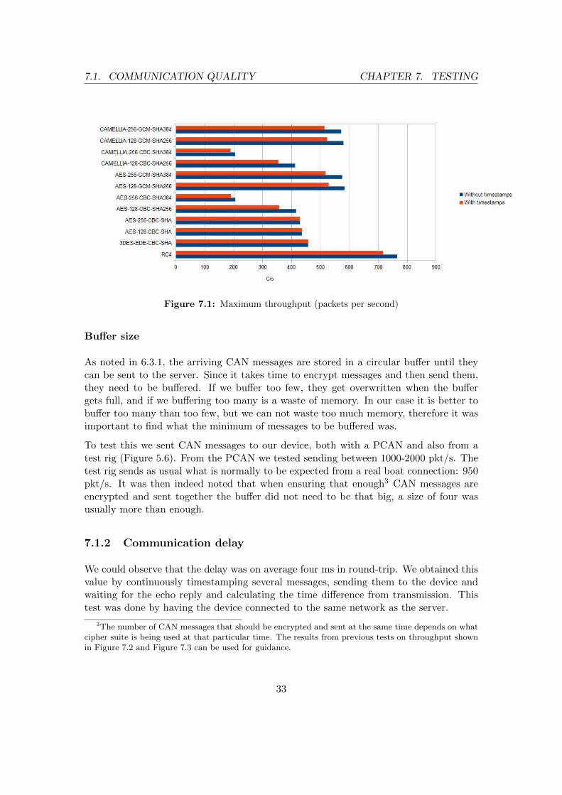
The test was then run using the cipher suite that we had initially chosen and also withother ciphers that were found to be suitable but not preferred, for comparison. Ascan be seen in Figure 7.1, the values never go over the necessary 950 pkt/s for theconnection to be able to send all the messages that are expected to be received in areal life setting. The reason for this is that each CAN message was encrypted separatelybefore being sent. Better results can be obtained by encrypting a certain number of CANmessages together and then sending them at the same time. Figure 7.2 shows the impactof bundling multiple CAN messages together in relation to throughput; larger bundlesincrease throughput. By sending no less than seven CAN messages simultaneously anycipher can be used to ensure that no CAN message is lost, at least when the CANmessages aren’t timestamped. If encrypting with RC4 only a minimum of two CANmessages are required to be sent together. For the cipher we picked (see 5.4.2) we needto send at least three messages together. Figure 7.3 shows performance when the CANmessages are timestamped. Adding timestamps require at least 10 messages to be bundletogether, for all ciphers to meet the minimum requirement of 950 msg/s. But just likewithout timestamps, two messages are enough for RC4 to work and three for the ciphersuite we initially picked.
OWS451 bit rate
As explained in 5.1.4 the bit rate at which the OWS451 device runs is important sinceif it is not fast enough it will not be able to properly send all the data, leading to dataloss.
The maximum bit rate that the OWS451 could properly handle2 was 460 800 bits/s,or 57 600 bytes/s. During tests in the first section of 7.1.1 we found that said bit ratewas never exceeded. Even when sending twice the number of necessary CAN messages(∼2000) the bit rate was around 330 kbits/s. Therefore, said bit rate was more thanenough.
1This is the maximum number of CAN messages sent over two CAN buses in the boats where ourdevice is expected to be installed. See 5.1.2
2This was explained in 5.1.4
32
7.1. COMMUNICATION QUALITY CHAPTER 7. TESTING
Figure 7.1: Maximum throughput (packets per second)
Buffer size
As noted in 6.3.1, the arriving CAN messages are stored in a circular buffer until theycan be sent to the server. Since it takes time to encrypt messages and then send them,they need to be buffered. If we buffer too few, they get overwritten when the buffergets full, and if we buffering too many is a waste of memory. In our case it is better tobuffer too many than too few, but we can not waste too much memory, therefore it wasimportant to find what the minimum of messages to be buffered was.
To test this we sent CAN messages to our device, both with a PCAN and also from atest rig (Figure 5.6). From the PCAN we tested sending between 1000-2000 pkt/s. Thetest rig sends as usual what is normally to be expected from a real boat connection: 950pkt/s. It was then indeed noted that when ensuring that enough3 CAN messages areencrypted and sent together the buffer did not need to be that big, a size of four wasusually more than enough.
7.1.2 Communication delay
We could observe that the delay was on average four ms in round-trip. We obtained thisvalue by continuously timestamping several messages, sending them to the device andwaiting for the echo reply and calculating the time difference from transmission. Thistest was done by having the device connected to the same network as the server.
3The number of CAN messages that should be encrypted and sent at the same time depends on whatcipher suite is being used at that particular time. The results from previous tests on throughput shownin Figure 7.2 and Figure 7.3 can be used for guidance.
33

7.1. COMMUNICATION QUALITY CHAPTER 7. TESTING
Figure 7.2: Throughput depending on packet buffer, without timestamps.
Red line realistic throughput value when deployed.34

7.1. COMMUNICATION QUALITY CHAPTER 7. TESTING
Figure 7.3: Throughput depending on packet buffer, with timestamps.
Red line realistic throughput value when deployed.
35

7.2. SUPPORTED OPERATIONS CHAPTER 7. TESTING
7.2 Supported operations
As noted in 1.5, the system should be able to perform certain operations, there is nopoint in a secure connection that can not be used for practical purposes. The operationsthat we tested were:
� Remote diagnostics
� Data logging
� Parameter configuration
� Software update
The goal of these tests was to verify the validity of the communication and the perfor-mance. Two different tools were used during the test, one which was developed as partof the project and EVCFlash an internal testing tool at CPAC.
7.2.1 Remote diagnostics
For this task a program called Remote diagnostics was created using Visual Studio andwritten in C#. The program was able to use the server library (DLL file) describedin 6.2.1. Also, as noted in that same chapter, the server library only understands theCAN communication protocol at a basic level. This means that this program needs tounderstand the protocol in order to send and receive data.
The program had two different ways to use the communication:
� Show error codes
� Display and interpret all data being sent
These tasks were used to see if all data was being sent. The data received was comparedto the data on the CAN bus to which we had access by being directly connected with aPCAN dongle.
7.2.2 Data logging
For this test the same program was used. All the CAN messages received are simplystored in one of two formats .asc or .trc. This task is trivial, the only requirement is tonot lose CAN packets, or at least lose as few as possible. Reasons for data loss couldbe loss of Internet access or the buffer on the client side getting full leading to old CANmessages being overwritten by new ones.
36

7.2. SUPPORTED OPERATIONS CHAPTER 7. TESTING
7.2.3 Parameter configuration
The server library was added not only to the program but also to EVCFlash, in this caseto utilize EVCFlash’s parameter configuration capabilities. EVCFlash normally uses aCAN-to-USB adapter to connect to the bus, either a Kvaser or a PCAN dongle. Theserver library was disguised as a dongle in the newly implemented module for EVCFlash.This way not many changes were needed and we could test our system as a CAN-to-Internet dongle.
Once implemented, EVCFlash was used for parameter configuration as if it was con-nected to a regular dongle.
7.2.4 Software update
EVCFlash was used to test if software could be installed on the boat components throughour system. The time it takes to update software through a regular PCAN dongle wascompared to the time it took (when it worked) with our system. The EVCFlash programhas two ways of updating the software on an ECU, an older that does not put anyrequirements on the connection’s speed and a newer that does. The one that does putrequirements on the speed demands the delay on the messages to be much shorter thanthe one we can achieve. This is also the way to be used in the future, the other lessrestrictive one is outdated. Our connection can only support software download withthe older process, not the new one.
37

8
Results
8.1 System
This section describes the finished system including the client and server, and the pro-tocol they use to communicate. Also described are the capabilities and security of thefinished system.
8.1.1 Communication protocol
The communication between client and server is done with the protocol seen in Fig-ure 8.1, this protocol consists of four different sections. The first, Length, consists of an8 bit unsigned char which specifies the length of the Payload. The second section, Info,contains information directly related to the Type part. Type defines how the Payloadshould be interpreted, since the content of the payload differs between types. Both Typeand Info consist of unsigned values. Lastly the Payload is the content of the packet.The different types are shown in Table 8.1.
Figure 8.1: Communication protocol
38

8.1. SYSTEM CHAPTER 8. RESULTS
Table 8.1: CAN transfer protocol types
Type name Type value Info specifies Payload contains
Handshake 0 Number of busesconnected
Boat name
Single CAN 1 Source/destinationchannel
CAN ID, data
Timed CAN 2 Same as SingleCAN
Timestamp, CAN ID, data
Single RTR CAN 5 Same as SingleCAN
Empty
Times RTR CAN 6 Same as SingleCAN
Timestamp
8.1.2 Client system
The client system, or connection device, consists of simple hardware that can be con-nected to a CAN bus and to a wireless router to gain Internet access and then connectto a server. This way the server and the client can exchange CAN communication overthe Internet.
Hardware - Connection Device
The connection device we developed consists of two main components: An STM32F107VCcard and a OWS451 Wireless LAN Serial port adapter from connectBlue. These devicesare better described in 5.1.3 and 5.1.4. The two are serially (RS232) connected.
Software
The software running on the connection device has three main tasks:
� CAN transfter protocol
� CAN communication
� OWS451 communication
The software is as simple as possible in the sense that it only handles the sending andreceiving of CAN messages and not how to perform certain tasks (like the ones describedin 1.5). This in order to keep one of the requirements named at the start of 1.5. Thesoftware only uses 227 kB of flash memory and 40 kB of RAM.
39

8.2. SECURITY CHAPTER 8. RESULTS
8.1.3 Server system
The server software is a DLL library to facilitate its incorporation to other softwarewithout the need for recompiling. The code of the library could also be easily includeddirectly into C++ projects if necessary. The software waits for a connection device totry to establish a TLS communication and then accepts it if the certificate provided bythe client is valid. After that both can communicate using the CAN transfer protocoldescribed in 8.1.1.
This server library can be used by a program1 to send and receive messages to and froma connection device.
8.1.4 System quality
As noted in 7.1.1 it was possible to ensure that no data is lost regardless of which ofthe selected cipher suites (see 5.4.2) is used. It is only necessary to ensure that enoughCAN messaged are encrypted and sent together. Chapter 7.1.2 also shows that the delay(over a private network) is on an average of four ms in round-trip which is completelyacceptable for a communication expected to take place over the Internet.
8.1.5 System capabilities
This system supports the use of most of the operations that were part of a requirementfor this project (see section 1.5). As was found under 7.2, the only operation that cannotbe fully implemented is software update. This is due to the requirements for low delaysto be shorter than what can be realistically achieved over the Internet. Given that theother operations lack this requirement they are totally feasible for as long as it can beguaranteed that no data will be lost.
8.2 Security
To ensure the Confidentiality, Integrity and Authenticity for the communication Trans-port Layer Security (TLS) 1.2 was used. Authenticity between client and server isguaranteed by Elliptic Curve Digital Signature Algorithm (ECDSA) with Elliptic CurveDiffie–Hellman Exchange (ECDHE) for key exchange. The size of the generated keysused by ECDHE must be 224 bits or longer. Confidentiality is achieved with the usageof Advanced Encryption Standard (AES) of 128 bits, with the usage of Galois/CounterMode (GCM) as mode of operation. Lastly the authentication of the entire message
1This server library does not fully understand the CAN transfer protocol - it only knows the partshown in Figure 8.1 without knowing what the different type values mean. This means that any programthat uses this library needs to understand the rest of the protocol.
40

8.2. SECURITY CHAPTER 8. RESULTS
was done with the usage of HMAC of 256 bytes, namely SHA256. These security fe-tures are combined in the TLS cipher suit TLS-ECDHE-ECDSA-WITH-AES-128-GCM-SHA256.
With the selected solution it would be possible to protect against a subset of the securitythreats described in section 2.3. The attacks which the system does not protect againstare Denial of Service (DoS) attacks, against the CAN communication or implementationissues in the TLS library itself. The system does protect against attacks which involveeavesdropping or alternating the communication, the solution also protects against im-personation due to the mutual authentication.
41

9
Discussion
9.1 Addressing the requirements
This section goes through the different requirements which were mentioned in 1.5 anddiscusses how well the finished product responds to these.
9.1.1 Low cost for the Connection device
Given the simplicity of the client side software (see 9.1.3) the hardware needed is then alsovery simple, meaning that the cost for the hardware can be kept low. The prototype forthe connection device consists of very simple hardware: A STM32F107VC developmentboard and a OWS451 WLAN to serial port adapter. A final version of the product couldsimply consist of the necessary components from the STM32 evaluation board, listed in5.1.3. Those specifications cover the requirements for the client side software. As notedin 8.1.2 the software’s footprint is 227 kB of flash memory and 40 kB of RAM. Most ofthat comes from the PolarSSL library. Seeing how the memory footprint of the softwareis very close to the limits of the STM32 it might be wise to try a different TLS libraryto make that footprint smaller, like CyaSSL or MatrixSSL. That way it is not necessaryto buy more memory to ensure that the hardware will be able to be reprogrammed withnewer versions of the software down the road.
Since the solution uses a router to connect to the Internet it was not required for theconnection device to support mobile broadband. This reduces the complexity of thehardware and consequently the price.
42

9.1. ADDRESSING THE REQUIREMENTS CHAPTER 9. DISCUSSION
9.1.2 Low cost for the system’s maintainability
Once the client is installed will it be self-sufficient, since only bug-fix updates are neededto maintain a working product. This is due to the simplicity of the device in whichvery little processing of the data is taking place. Also the decision to not support anapplication for smart-phones reduces the cost of maintainability, as we do not have tokeep track of changes in the smart-phone operating system or SDK. The only cost formaintainability comes from having the servers running.
9.1.3 Simple software for the Connection device
One of the core requirements which were specified in section 1.5 was that the node shouldonly consist of being a forwarding node to reduce the complexity of the code. This partwas accomplished with the usage of a simple protocol which enabled good flexibility.One concern would be that the current implementation does not provide the possibilityto extend the protocol with more types without updating the software in the embeddeddevice, but on the other side, backwards compatibility can easily be achieved whichreduces the need for updating old systems.
9.1.4 Automatically connect to WLAN
The automatic WLAN connection was not completed due to time constrains, the workingdemo that was produced was able to connect to a WLAN by means of hard-coding theSSID for the routers. This solution would not be practical since it would require aunique compiled version on every embedded device, alternatively having identical SSIDand password for all WLAN. It is important to have a pattern for finding the correctnetwork, to distinguish between networks in order to connect to the correct one. Anotherimportant issue is security, if it is possible to determine the connection details used bythe embedded device, an attacker could gain anonymous Internet access. This securityrisk is partly mitigated with the fact that the router will only be active for a shortduration during the time when the customer is in need of support.
9.1.5 Secure connection to avoid compromising the channel
Since TLS 1.2 was used as cryptographic protocol for all the communication between theconnection device and client, it was possible to support Confidentiality, Integrity andAuthenticity but not Availability.
43

9.2. SOFTWARE DESIGN CHAPTER 9. DISCUSSION
9.1.6 Supported operations
The operations which were specified in section 1.5 were Remote diagnostics, Data logging,Parameter configuration and Software update. As mentioned before it was possible toperform all of these except for the last one due to the communication delay, mainlyadded by communicating over the Internet, which made this impossible or impracticaldepending on update procedure (not all of the update procedures had a requirement onlow delay by this is the direction that CPAC/Volvo is taking).
9.2 Software Design
The design of the communication protocol 8.1.1 went through multiple iterations as moreof the project became defined. The end specifications showed remarkable similarities withthe protocol designed by Mathias Johanson et al.[32], which only was discovered afterour protocol was finished. The differences between the two consisted of the order of thedifferent elements of the segments in the header, and the size of these. Their protocolalso included some added features that may be worth taking into consideration, suchability to communicate through GPRS/EDGE.
9.3 Library selection
The selection of PolarSSL and as the TLS library, could possible be replaced by either ofCyaSSL and MatrixSSL since there are strong similarities between all of these three. Ifthe project was done during a longer time period then all of these would have been testedto see which library has the best performance and smallest size. The importance of thesefactors are mainly for the embedded device since the system resources are considerablymore limited compared to those on the server. In general we believe that either of theselibraries would have worked for this project.
9.4 Future Work
During the development of this project it was noticed that there exist areas where futurework could be done. This to improve the solution or to show if other solutions are moresuitable.
9.4.1 Hardware accelerated cryptography
If the embedded device incorporated cryptographic circuits it should be possible to in-crease the throughput, this would be especially useful if the circuit did support AES and
44

9.4. FUTURE WORK CHAPTER 9. DISCUSSION
GCM.
9.4.2 Cryptographic Protocol
Due to the strong similarities between TLS and SSH it would be possible to apply asimilar security solution for the communication with the use of the SSH protocol insteadof the TLS protocol.
If another device was used instead of the OWS451 (see 5.1.4) which gave access to thenetwork layer of TCP/IP-stack, then it would be possible to use IPSec for security.
9.4.3 Entropy algorithm
The entropy algorithm could be considerably improved (currently the clock is used asinput for the algorithm). The importance of this part should not be underestimated dueto the importance of random values in creating strong and secure communication. Oncemore, better hardware or entropy algorithm provided by the operating system couldmake this an easier task.
9.4.4 TLS libraries
Since only one TLS library was tested it could be of interest to test some other libraries(MatrixSSL and CyaSSL recommended) to compare the toll they take on the hardware’sperformance.
9.4.5 Automatic WLAN connection
While a proposition for this issue was given (see 5.5) it was never actually tested andsome more thought should be put onto this aspect.
9.4.6 CAN security
As stated in 9.1.3, the connection device only forwards packets from and to the CAN-bus, therefore it is possible to send any kind of CAN messages. This could potentiallybe a security risk, even if the communication is protected with TLS it does not stopan authorized host to send incorrect messages by mistake. Possible solutions could beadding authorization levels to different operations on the server side. Another solutionwould be to add restrictions on which CAN packets are allowed to be transmitted overthe Internet by filtering these in the connection device. Finally, having a firewall isimportant to mitigate attacks below the Application layer of the TCP/IP-stack.
45

10
Conclusion
This thesis describes the implementation a remote secure channel using TLS 1.2 tocommunicate with the internal CAN-bus on a boat. With this channel it is possibleto perform various operations such as remote diagnostics, parameter configuration anddata logging over the Internet. The implementation was done on low cost embeddeddevice, which used WLAN to connect to a router for Internet access. Since any routercan be used to access the Internet, this means the added benefit of mobility since thecustomers’ own smart-phones with mobile hotspot can be used. To ensure simplicityand low maintenance the embedded device acts merely as a forwarding node.
The implementation included evaluation of which security risks could exist when con-nected to the internal CAN bus of a vehicle via the Internet. This assessment showedthat the general threats of being on the Internet exist but also specific ones with strongsimilarities to the automotive sector. This was due to the commonly shared internalCAN bus which controls the vehicle.
During the thesis a few areas were identified where future work would be needed. Thisincluded creating an algorithm for determining which WLAN to connect to, since nouser input should be needed, improved entropy source on the embedded device to im-prove security, evaluate multiple TLS libraries to determine the best one, etc.. We alsosee that improvements can be done for the hardware, specifically the introduction of acryptographic circuit to enhance the communication speed.
Overall, Confidentiality, Integrity and Authenticity were solvable by using TLS.
46

Bibliography
[1] A. Inc, Sdk compatibility guide, last visited 2010-11-15.URL https://developer.apple.com/library/mac/documentation/
DeveloperTools/Conceptual/cross_development/cross_development.pdf
[2] Google, Device compatibility, last visited 2014-05-03.URL http://developer.android.com/guide/practices/compatibility.html#
Versions
[3] A. Hammershøj, A. Sapuppo, R. Tadayoni, Challenges for mobile applicationdevelopment, Intelligence in Next Generation Networks (2010) 1–8.URL http://ieeexplore.ieee.org/xpl/articleDetails.jsp?&arnumber=
5640893
[4] New john deere strategy takes intelligent farming to the next level, last visited 2014-05-03 (nov 2011).URL http://www.deere.com/wps/dcom/en_NAF/our_company/news_and_media/
press_releases/2011/nov/farm_sight.page
[5] Kongsberg, Kongsberg k-ims, last visited 2014-05-03.URL http://www.km.kongsberg.com/ks/web/nokbg0397.nsf/AllWeb/
737F465C7ECC8A7AC12579EA002EFA83/$file/K-IMS.pdf
[6] CarIQ, Cariq, last visited 2014-05-07.URL http://mycariq.com/product
[7] S. Andrews, Vehicle-to-Vehicle (V2V) and Vehicle-to-Infrastructure (V2I) Commu-nications and Cooperative Driving, Springer London, pp. 1121–1144, last visited2014-05-16.URL http://link.springer.com/referenceworkentry/10.1007%2F978-0-
85729-085-4_46
[8] H. Zhu, X. Shen, R. Lu, X. Lin, Security in service-oriented vehicular networks 16,
47

BIBLIOGRAPHY BIBLIOGRAPHY
last visited 2014-05-16.URL http://ieeexplore.ieee.org/xpls/abs_all.jsp?arnumber=5281251
[9] IEEE (Ed.), Collaborative Efforts for Safety and Security in Vehicular Communi-cation Networks, last visited 2014-05-16.URL http://ieeexplore.ieee.org/xpls/abs_all.jsp?arnumber=6065075
[10] C. Laurendeau, M. Barbeau, Threats to Security in DSRC/WAVE, pp. 266–279.URL http://link.springer.com/chapter/10.1007/11814764_22
[11] A. Bittau, M. Handley, J. Lackey, The final nail in wep’s coffin, last visited 2014-05-07.URL http://tapir.cs.ucl.ac.uk/bittau-wep.pdf
[12] W. R. S. Kevin R. Fal and, Attacks involving window mangement, in: TCP/IPIllustrated, 2nd Edition, Vol. 1, Pearson, 2011, pp. 723–723.
[13] M. Baggett, Ip fragment reassembly with scapy, last visited 2014-05-08.URL http://www.sans.org/reading-room/whitepapers/tools/ip-fragment-
reassembly-scapy-33969
[14] CPNI, Security assessment of the transmission control protocol, last visited2014-05-07.URL http://www.bsdcan.org/2009/schedule/attachments/75_tn-03-09-
security-assessment-TCP.pdf
[15] C. Vulnerabilities, Exposures, Cve-2014-0160, last visited 2014-05-07.URL https://cve.mitre.org/cgi-bin/cvename.cgi?name=CVE-2014-0160
[16] W. Stallings, Security attacks, in: Cryptography and Network Security:Principlesand Practice: International Edition, 5th Edition, Pearson, 2010, pp. 39–42.
[17] P. Kleberger, T. Olovsson, E. Jonsson, Security Aspects of the In-Vehicle Networkin the Connected Car, Intelligent Vehicles Symposium (IV) (2011) 528–533.URL http://ieeexplore.ieee.org/xpl/articleDetails.jsp?arnumber=
5940525
[18] B. Yang, K. Wu, R. Karri, Scan based side channel attack on dedicated hardwareimplementations of data encryption standard, Test Conference, 2004. Proceedings.ITC 2004. International (2004) 339–344.URL http://ieeexplore.ieee.org/xpl/articleDetails.jsp?arnumber=
1386969
[19] S. D. K. P. S. Parihar, Attacks in wireless networks 1.URL http://interscience.in/IJSSAN_Vol1Iss1/paper25.pdf
[20] H. Xia, J. C. Brustoloni, Hardening web browsers against man-in-the-middleand eavesdropping attacks, International World Wide Web Conference Commit-
48

BIBLIOGRAPHY BIBLIOGRAPHY
tee (2005) 489–498.URL http://dl.acm.org/citation.cfm?id=1060817
[21] Transmission control protocol (sep 1981).URL http://tools.ietf.org/rfc/rfc793.txt
[22] J. Postel, User datagram protocol (aug 1980).URL http://www.ietf.org/rfc/rfc768.txt
[23] W. Stallings, Secure socket layer and traport layer security, in: Cryptography andNetwork Security:Principles and Practice: International Edition, 5th Edition, Pear-son, 2010, pp. 513–526.
[24] T. Dierks, E. Rescorla, The Transport Layer Security (TLS) Protocol (aug 2008).URL http://tools.ietf.org/rfc/rfc5246.txt
[25] S. C. S. Corp., Ssh authentication, last visited 2014-05-03.URL https://support.ssh.com/manuals/server-admin/32/Authentication.
html
[26] E. C. Lonvick, T. Ylonen, The Secure Shell (SSH) Protocol Architecture (jan 2006).URL http://www.ietf.org/rfc/rfc4251.txt
[27] S. Kent, K. Seo, Security Architecture for the Internet Protocol (dec 2005).URL https://tools.ietf.org/rfc/rfc4301.txt
[28] C. D. Canniere, A stream cipher construction inspired by block cipher design prin-ciples, last visited 2014-05-28.URL http://link.springer.com/chapter/10.1007/11836810_13
[29] K. W. R. James F. Kurose, Computer Networking:A Top-Down Approach: Inter-national Edition.
[30] A. N. Alshamsi, T. Saito, A Technical Comparison of IPSec and SSL, Advanced In-formation Networking and Applications, 19th International Conference on 2 (2005)395–398.URL http://ieeexplore.ieee.org/stamp/stamp.jsp?tp=&arnumber=1423719
[31] S. Ravi, A. Raghunathan, P. Kocher, S. Hattangady, Security in embedded sys-tems: Design challenges, ACM Transactions on Embedded Computing Systems3 (3) (2004) 461–491.URL http://dl.acm.org/citation.cfm?id=1015049
[32] M. Johanson, L. Karlsson, T. Risch, Relaying controller area network frames overwireless internetworks for automotive testing applications, in: Systems and Net-works Communications, 2009. ICSNC ’09. Fourth International Conference on,IEEE.URL http://ieeexplore.ieee.org/xpl/abstractAuthors.jsp?tp=&arnumber=
5281251
49

BIBLIOGRAPHY
[33] IAR, Iar kickstart kit for stm32f107vc, last visited 2014-05-03.URL https://old.iar.com/website1/1.0.1.0/3096/1/?item=prod_prod-s1%
2F489
[34] STMicroelectronics, Stm32f105xx, stm32f107xx, last visited 2014-05-03.URL http://www.st.com/st-web-ui/static/active/en/resource/technical/
document/datasheet/CD00220364.pdf
[35] connectBlue, cB-OWS451 and OWL253 Electrical Mechanical Data Sheet, last vis-ited 2014-05-19.URL http://support.connectblue.com/display/Dashboard/OWS451
[36] M. Ullholm Karlsson, A. Habib, Ssh over udp, last visited 2014-05-03.URL http://publications.lib.chalmers.se/records/fulltext/123799.pdf
[37] Comparison of tls implementations, last visited 2014-05-06.URL http://en.wikipedia.org/wiki/Comparison_of_TLS_implementations
[38] O. B.V, Polarssl, last visited 2014-05-06.URL https://polarssl.org/
[39] PolarSSL, Supported ssl / tls ciphersuites, last visited 2014-10-25.URL https://polarssl.org/supported-ssl-ciphersuites
[40] E. II, Ecrypt ii yearly report on algorithms and keysizes.URL http://www.ecrypt.eu.org/documents/D.SPA.17.pdf
50