
Master's Thesis
65
DEMOCRATIC AND POPULAR ALGERIAN REPUBLIC MINISTRY OF HIGHER EDUCATION AND SCIENTIFIC RESEARCH ECHAHID HAMMA LAKHDAR UNIVERSITY OF EL-OUED FACULTY OF: TECHNOLOGY Master’s Thesis In order to obtain a diploma of an Academic Master Department: Mechanical Engineering Specialty: Renewable energies Submitted by: BELOUL Samir FERHAT Chihab KHOUAZEM Hatem Theme President Dr .BOUKHARI ali M.C.A El-Oued University Examiner Dr .GHODBANE M.A.A El-Oued University Supervisor Dr. ATIA Abdelmalek M.C.A El-Oued University Co supervisor Mr. HADJADJ Abdessamia PHD El-Oued University University year: 2019/ 2020 Mémoire préparé au sein du Laboratoire d'Exploitation et de Valorisation des Ressources Energétiques Sahariennes ENERGETIC PERFORMANCE ANALYSIS OF GEOTHERMAL HEAT EXCHANGER UNDER SAHARAN CLIMATE
-
Upload
khangminh22 -
Category
Documents
-
view
0 -
download
0
Transcript of Master's Thesis
DEMOCRATIC AND POPULAR ALGERIAN REPUBLIC
MINISTRY OF HIGHER EDUCATION AND SCIENTIFIC RESEARCH
ECHAHID HAMMA LAKHDAR UNIVERSITY OF EL-OUED
FACULTY OF: TECHNOLOGY
Master’s Thesis
In order to obtain a diploma of an Academic Master
Department: Mechanical Engineering
Specialty: Renewable energies
Submitted by:
BELOUL Samir
FERHAT Chihab
KHOUAZEM Hatem
Theme
President Dr .BOUKHARI ali M.C.A El-Oued University
Examiner Dr .GHODBANE M.A.A El-Oued University
Supervisor Dr. ATIA Abdelmalek M.C.A El-Oued University
Co supervisor Mr. HADJADJ Abdessamia PHD El-Oued University
University year: 2019/ 2020
Mémoire préparé au sein du Laboratoire d'Exploitation et de Valorisation des Ressources
Energétiques Sahariennes
ENERGETIC PERFORMANCE ANALYSIS OF
GEOTHERMAL HEAT EXCHANGER UNDER SAHARAN
CLIMATE

i
Acknowledgements
First, we would like to thank our GOD, for giving us the strength to carry out this work.
The research contained in this thesis would not have been remotely possible without the contribution of a number of people, so without further
due they will be acknowledged!
I would first like to extend my gratitude to my coach Mr Abdelmalek ATTIA, without whose experience, expertise and
guidance this research would not have been possible.
I would like to thank my mentor Mr. Abdessamia HADJADJ for their confidence in me, for their constant
availability, their patience, their advice, their major contribution to the direction of my research, for his constant help and support.
I would also like to thank all those who have helped me to complete this
work, especially all the teachers of the Department of Mechanical Engineering Department of El Oued University.

ii
Dedication
Thank you to everyone who help us to complete this work.

Table of Contents

Table of Contents
iv
Table of Contents
Acknowledgements .............................................................................................................. i
Dedication ........................................................................................................................... ii
Table of Contents ............................................................................................................... iii
List of, Figures ................................................................................................................... vi
List of Tables .................................................................................................................... viii
GENERAL INTRODUCTION: .......................................................................................... 1
CHAPTER I: Generality and Historical Of Geothermal Heat Exchanger
I. INTRODUCTION: ......................................................................................................... 4
I.1 Geothermal Heat exchanger definition: ..................................................................... 4
I.2 Operating principal of the EAHE: ............................................................................. 5
I.3 Types of Geothermal Heat exchangers: ..................................................................... 5
I.3.1 Open& Closed loop systems: .............................................................................. 6
I.3.2 Horizontal & vertical closed loop: ...................................................................... 6
I.3.3 Pond or chain of lakes: ........................................................................................ 7
I.3.4 Hybrid systems: ................................................................................................... 7
II. STATE OF ART GEOTHERMAL HEAT EXCHANGER: .......................................... 8
II.1 Geothermal heat exchanger Renewable energy in Algeria: ...................................... 8
II.2 Geothermal heat exchanger Renewable energy international studies: ................... 14
III. GENERAL REVIEW OF MAIN FACTORS AFFECTING THE GEOTHERMAL
HEATEXCHANGER: .............................................................................................................. 17
III.1 Moisture content and soil properties: .................................................................... 17
III.1.2 Thermal conductivity: .................................................................................... 18
III.1.3 Thermal Diffusivity (α): ................................................................................. 19
III.2 Climatic Surface: ................................................................................................... 20
III.3 Soil loop: ............................................................................................................... 20
III.3.1 Number of the pipes: ...................................................................................... 21
III.3.2 Length of the pipes: ........................................................................................ 21
III.3.3 Diameter of the pipes: .................................................................................... 21
III.3.4 Distance between the pipes: ........................................................................... 21
III.3.5 Pipes material: ................................................................................................ 22
III.3.6 The other factors: ............................................................................................ 22
Conclusion: ........................................................................................................................ 23

Table of Contents
v
CHAPTER II: Experimental study of EAHE
I. INTRODUCTION: ........................................................................................................ 25
II. EXPERIMENTAL STUDY: ........................................................................................ 25
II.1 Experimental setup: ................................................................................................ 25
II.2 EAHE installation description: ............................................................................... 26
II.3 Measuring Equipment: ............................................................................................ 29
II.3.1 Temperature measurement device: .................................................................. 29
II.3.2 Digital thermometer: ........................................................................................ 30
II.3.3 Temperature data acquisition systems: ............................................................ 30
II.3.5 Velocity and flow rate measurement (Anemometer):...................................... 32
III. THERMAL STUDY OF GEOTHERMAL HEAT EXCHANGER: .......................... 32
CONCLUSION : ............................................................................................................... 35
Chapter III Results &Discussion of The Experimental Study of EAHE
INTRODUCTION: ............................................................................................................ 37
I-TEMPERATURE VARIATION VERSUS UNDERGROUND DEPTH: ..................... 37
II. TEMPERATURE EVALUATION BETWEEN INLET AND OUTLET: .................. 38
II.1 Flow rate influence on the inlet and outlet temperature: ........................................ 38
II.2 Temperature ratio for an earth-to-air heat exchanger ............................................. 39
III. HEAT TRANSFER RATE: ........................................................................................ 39
IV. EFFICIENCY:............................................................................................................. 40
V. COEFFICIENT OF PERFORMANCE COP: .............................................................. 41
CONCLUSION: ................................................................................................................ 42
GENERAL CONLUSION: ............................................................................................... 45
Reference: .......................................................................................................................... 47
Abstract: ................................................................................................................................

List of Figures
vi
List of, Figures
CHAPTER I: Generality and Historical Of Geothermal Heat Exchanger
Fig I.1: EAHE components (Blower, Ducts, ground exchanger) .............................................. 5
Fig I.2 Open Loop EAHE system. ............................................................................................. 6
Fig I.3 Closed Loop EAHE system. ........................................................................................... 6
Fig I.4 Horizontal and Vertical Loop EAHE system. ................................................................ 7
Fig I.5 Distribution of the ground temperature along its depth.................................................. 8
Fig I.6 Numerical distribution of the air temperature along the exchanger according to various
volume throughputs and various diameters. ............................................................................... 8
Fig I.7 Variation of outlet temperature depending on the length of the tube for different
depths. ......................................................................................................................................... 9
Fig I.8 Variation of outlet temperature depending on the depth for different lengths of tube. .. 9
Fig I.9 Variation of outlet temperature depending on the length of the tube for different
diameters (Z = 5m). .................................................................................................................... 9
Fig I.10 Variation in efficiency depending on the length of the tube throughout the year. ..... 10
Fig I.11 Energy saving as a function of the burial depth of the tube ....................................... 11
Fig I.12 Energy saving as a function of air speed. ................................................................... 11
Fig I.13 underground temperature profile at 2m depth (Oran, Bechar and Adrar). ................. 12
Fig I.14 Cooling needs of Rooms. ........................................................................................... 12
Fig I.15 3D View of both conducts linked to the home. .......................................................... 13
Fig I.16 Evolution of the ambient and outlet temperature of heat exchangers, August 2015. . 14
Fig I.17 Soil temperature profiles for (a) winter condition and (b) summer condition. .......... 15
Fig I.18 Inlet, outlet, ambient air temperature and ground temperature at 2 m depth and inlet
air velocity for (a) winter condition and (b) summer condition ............................................... 15
Fig I.19 Temperature change with pipe length for (a) winter and (b) summer ........................ 16
Fig I.20 Thermal conductivity of some soils as a function of water content. .......................... 19
CHAPTER II: Experimental study of EAHE
Fig II.1 Location and geographical coordinates of the studied area(Google Map, 2020). ...... 25
Fig II.2 Mean daily solar radiation intensity and duration of the day and its bright sunshine
insolation in El-Oued region. ................................................................................................... 26
Fig II.3 Earth Air Heat Exchanger system installation ............................................................ 27

List of Figures
vii
Fig II.4 Thermocouple type K ................................................................................................. 30
Fig II.5 Digital thermometer .................................................................................................... 30
Fig II.6 Temperature recorder BTM-4208SD .......................................................................... 31
Fig II.7 Arduino temperature recorder ..................................................................................... 31
Fig II.8 Anemometer testo 416 ................................................................................................ 32
Chapter III: Results &Discussion of The Experimental Study of EAHE
Fig III.1 Experimental soil temperature profile at different depths ......................................... 37
(Jun21th
to 23th
, 2020) ............................................................................................................... 37
Fig III.2 Variation of air outlet temperature as function of flow rate ...................................... 38
Fig III.3 Heat exchange rate of exchanger versus Inlet temperature. ...................................... 40
Fig III.4 Efficiency variation with difference flow rate. ......................................................... 41
Fig III.5 A/B COP versus Temperature inlet and flow rate ..................................................... 42
List of Tables
viii
List of Tables
CHAPTER I: Generality and Historical Of Geothermal Heat Exchanger
Table I.1 Thermal properties of the main constituents of a soil ....................................... 18
Table I.2 Thermal Conductivity of Typical Rocks and Sediments. ................................. 19
Table I.3 Thermal Conductivity of Typical Rocks and Sediments. ................................. 20
CHAPTER II: Experimental study of EAHE
Table II.1 Experimental parameter ................................................................................... 27
Table II.2 Physical and thermal properties used in the present study .............................. 28
Chapter III: Results &Discussion of The Experimental Study of EAHE
Table III.1 Temperature ratio at difference flow rate ...................................................... 39

Nomenclature
ix
Nomenclature
Cp specific heat capacity of the air, J kg-1
K-1
D exchanger diameter, m
h enthalpy, kJ kg-1
L exchanger lengths, m
ṁ mass flow rate, kg s-1
Q heat exchange rate, W
Re Reynold number
s entropy, kJ kg-1
°C -1
S surface area, m2
T temperature, °C
U overall heat transfer coefficient, W m-2
°C-1
V air velocity inside the pipe, m s-1
Z depth of soil, m
∆P pressure loss, Pa
∆T temperature difference between the inlet and outlet EAHE of circulated water, °C
LMTD log mean temperature difference, °C
Greek letters
λ thermal conductivity, W m-1
K-1
ρ density, kg m-3
ε thermal efficiency, %
η exergy efficiency, %
Ʌ linear loss ratio of load
ζ singular loss ratio of load
μ dynamic viscosity of air, N s m-2
Subscripts
amb ambient
des destruction
in inlet
lin linear
out outlet
sin singular
wat water

General Introduction

Introduction
1
GENERAL INTRODUCTION:
Algeria is currently working on a set of new legal measures aimed at encouraging the
production of renewable energies aspiration 2030. These procedures include conditions that
take advantage of financing and sales mechanisms in relation to electricity produced from
renewable energies or power and heat generation systems from geothermal sources.
Such efforts have yet to fully exploit its capacities and reserves of renewable and non-
renewable energy resources to diversify its economy, reduce its dependence on the
hydrocarbons sector and achieve its economic security, while the integration of renewable
resources into its energy strategy remains very low compared to the available potential.
Algeria has a 2030 window to incorporate 27 % of renewable energy associated with
global energy use growth. Techniques for renewable energy use the natural resources that are
constantly replenished by natural resources , such as solar radiation, wind, waves and
geothermal energy.[1]
Geothermal energy is a source of renewable energy which can be used to provide
electricity and space heating / cooling. Geothermal energy power can be harnessed through a
variety of methods, all of which aim to exploit the thermal energy stored within the earth.
Refreshing by geothermal energy is a technique traditionally used in our region of Sahara;
People build their houses under the ground (the caves) to refresh the habitats in summer, we
can develop this traditional technique with a deep scientific study and new methods that allow
us to use it properly and in the best conditions in a modern society.
The achievement of indoor thermal comfort whilst minimizing energy consumption in
buildings is a key challenge in desert climates. The desert climate can be classified as hot and
arid and such conditions exist in a number of areas throughout the world. One such area is
South Algeria, with an average ambient temperature around 45°C during summer months. In
general, most people feel comfortable indoors when the temperature is between 22, 26 °C,
and relative humidity is within the range of 30-50%.
The aim of our project is to study the valorization of refreshing/heating technique using
horizontal air-to-ground exchanger in our region El oued, its principle is simple; the air of
renewal is passed before it enters the house, into a buried tube that depth between 2 and 4
meters and a length of about 45 meters. In winter, the air is thus preheated because the ground
is warmer than the outside air. In summer, the air is refreshed because it is the opposite
phenomenon that occurs.

Introduction
2
To achieve the objective set out in this work, we have summarized this problematic in
three essential chapters:
Chapter I Generality and Historical of Geothermal Heat Exchanger
Chapter II Experimental study of Earth Air Heat Exchanger
Chapter III Results &Discussion of The Experimental Study of EAHE

CHAPTER I:Generality and Historical Of
Geothermal Heat Exchanger
CHAPTER I:
Generality and Historical Of
Geothermal Heat Exchanger

CHAPTER I: Generality and Historical Of Geothermal Heat Exchanger
4
I. INTRODUCTION:
This study falls within the interests of the Algerian state in diversifying and developing
renewable energy sources in order to reduce the electricity bill resulting from fossil fuels and
protect the environment (2030 program).
Buildings are ranked first in terms of electricity consumption (Total power building
consumption 25-40%), and the demand for heating or cooling represents 20 to 30% of the
total consumption[1][1].
Earth Air heat exchanger geothermal technique it can conveyed about 30-48% of heating
and cooling demands.An EAHE is a geothermal underground heat exchanger that can capture
heat from and/or dissipate heat to the ground. They use the Earth's near constant subterranean
temperature to warm or cool air or other fluids for residential, agricultural or industrial uses. If
building air is blown through the heat exchanger for heat recovery ventilation.
The EAHE they call it Canadian well when the installation is mainly intended to preheat
the air in winter, while they call Provencal well in case, we use it to cool the air in summer.
The Canadian well is a technique that allows us to take advantage of the heat of
thesubsoil. In the architecture of passive or bioclimatic houses is one of the simplest systems
that we can find. Circulating the air through the surface layer of the subsoil will provide to the
home coolness in summer and a heartiness in winter.
I.1 Geothermal Heat exchanger definition:
Geothermal energy has made it possible for many to heat their homes in winter, cool
them in summer and have plenty of hot water throughout the year, while reducing utility bills
by up to 48%[2]. Geothermal heat exchangers are technologies that heat and cool buildings
using the almost constant temperature below the earth (regardless of the season). The Planet
has a steady temperature of 25.2 ° C just a few feet under the ground[3]. The temperature
below the planet is colder than the air that circulates above it in the winter and cooler in the
summertime. Geothermal heat exchanger is often combined with solar heating to create geo-
solar, which is a much more effective method.
Geothermal heat pumps harness this energy from underneath the earth and utilize this
ability to heat and cool buildings.
Nowadays, there is a growing interest to the systems based on renewable energy sources
due to rising cost of energy and environmental concerns. As one result of efforts of decreasing
energy cost and importance of indoor air quality, it is seen that earth energy can be used easily
as energy sources by using an earth-air heat exchangers (EAHX) in ventilation and air
conditioning systems. EAHX, also called earth tubes, ground-coupled heat exchangers, earth

CHAPTER I: Generality and Historical Of Geothermal Heat Exchanger
5
channels, earth–air tunnel, or pipe system, are quite simple. EAHX systems consist of pipes in
which air passes and a fan for air movement[4].
I.2 Operating principal of the EAHE:
Heating and cooling is achieved through a geothermal heat exchanger system, which is
made up of three main parts: Blower, the ground heat exchanger, and the air delivery system
or ductwork. The heat exchanger encompasses a series of pipes known as loop, which is
installed a few feet beneath the earth close to the building. The Air circulates through the
series of pipes to suck up or disseminate heat into the ground.
The geothermal heat exchanger removes heat from the ground during the winter, and
directs it to the air transfer system of the home, which keeps the house warm and comfortable.
The cycle is reversed during summer. The geothermal exchanger collects heat from the air
inside the building and moves it to the heat exchanger on the ground. The heat exchanger
discharges the heat into the ground.
Fig I.1: EAHE components (Blower, Ducts, ground exchanger)[5]
Geothermal heat exchangers are much more efficient than conventional heating and
cooling systems because under the ground they tap natural, free heat.
Not only can geothermal heat exchangers save energy and resources but they also help to
minimize air pollution. Even they are more effective in house cooling.
I.3 Types of Geothermal Heat exchangers:
There are 4 major types of geothermal heat exchangers; closed loop systems, open looped
systems, pond or lake systems, and hybrid systems. Further, closed looped systems are
subdivided into two: horizontal and vertical. Let 's look in depth at these:

CHAPTER I: Generality and Historical Of Geothermal Heat Exchanger
6
I.3.1 Open& Closed loop systems:
In open loop EAHE system, fresh ambient air is drawn through buried pipes which gets
moderated to the earth’s undisturbed temperature and finally is supplied to the building to
meet the heating/cooling requirement of the building as shown in FigI.2 while in closed loop
EAHE system recirculation of the air from building through the buried pipes is done as shown
in FigI.3.
The closed loop EAHE system is not preferred over open loop EAHE system because it
does not meet the building’s fresh air requirement[6].
Fig I.2 Open Loop EAHE system. Fig I.3 Closed Loop EAHE system.
I.3.2 Horizontal & vertical closed loop:
These types of closed loop systems are best designed for large land areas. They are cost-
effective and are usually built in suburban areas, more so where there is sufficient land
available for new construction. Horizontal closed loop systems require trenches with a
minimum depth of four feet (2 m). Horizontal closed loops have various configurations but
the most common use two pipes. This method of looping allows more pipes to be mounted
inside a narrow and shorter trench, which significantly minimizes construction costs and
allows for horizontal construction in sites not suitable for conventional horizontal
applications.
Vertical closed loop systems are common where space is very limited in offices, colleges,
and commercial establishments. In essence, land size cannot allow for construction of
horizontal loops. Vertical closed loops are often implemented in areas where the soil is not
sufficiently deep to trench, and they are beneficial as they reduce the effect on landscape. Two
vertical loops bent in U-shaped are inserted into small holes (four inches in diameter, 100 to
400 feet wide, and 2 feet apart) into the ground for this kind of geothermal heat pump. Then,
these vertical loops are bound by horizontal loops.

CHAPTER I: Generality and Historical Of Geothermal Heat Exchanger
7
Fig I.4 Horizontal and Vertical Loop EAHE system.
I.3.3 Pond or chain of lakes:
Most properties have a nearby pond or lake. Under this body of water a closed system can
be installed. Coiled pipes are placed at least eight feet below the water surface, to minimize
the freezing risk. Nevertheless, before it can be considered a prime location for a geothermal
heat pump, the pond or lake must meet certain standards regarding minimum capacity, depth
and consistency requirements.
I.3.4 Hybrid systems:
Hybrid system is a combination of geothermal heat pumps and air source heat pumps to
provide a highly efficient and cost-effective system. They exploit the fact that setting up
heating and cooling loads is not completely managed because of internal benefits, with
cooling dictating proceedings on several occasions. Instead of upsizing the heat exchanger to
meet higher cooling load, the heat exchanger is remodeled to meet the heating load, and a heat
rejecter is integrated into the system. Hybrid systems also get rid of boilers and fossil fuel
deployment, thus reducing the land area and the start-up costs needed to set up the ground
heat exchanger.
The advantages of geothermal heat pumping systems are enormous. They use a green
energy source for instance, which is heat that exists naturally underground. Seasons do not
impact this sun, meaning it will be available until the end of time. The energy is green and
safe too, ensuring you won't have to worry about air pollution that leads to deadly respiratory
diseases. The geothermal systems particularly last uniquely long. They will last for more than
50 years and a fantastic 56-year warranty comes with the loops. This long-term guarantee
alone underlines the fact that for the rest of your life you will reap the benefits of geothermal
energy[7].

CHAPTER I: Generality and Historical Of Geothermal Heat Exchanger
8
II. STATE OF ART GEOTHERMAL HEAT EXCHANGER:
II.1 Geothermal heat exchanger Renewable energy in Algeria:
N. Hatraf et al [8]. In this article they try to evaluate the ground temperature profile to
determine the depth to bury the exchanger by modelling and experimenting, and also to
evaluate the pipe's longitudinal efficiency for this finite differential process , which consists of
dividing the exchanger 's length on multiple equal segments and knowing the initial and final
boundary conditions, the air profile Ultimately they concluded that many parameters affect
earth's efficiency as an air exchanger, such as the structure of the ground, ground depth, duct
diameter, and the flow throughput.
Fig I.5 Distribution of the ground temperature along its depth.
Figure I.5 indicates that the difference in the ground temperature is inversely proportional
to the depth, the more one penetrates the earth, the lower the effect of the radiation until a
certain value below which the ground temperature stays constant, and in this case the depth is
about 3 metres.
Fig I.6 Numerical distribution of the air temperature along the exchanger according to various volume
throughputs and various diameters.

CHAPTER I: Generality and Historical Of Geothermal Heat Exchanger
9
The figure I.6 shows the different parameter variation compared with the distribution of
the air temperature of several parameters such as: the duct diameter, the volume throughput.
The author concluded that the efficiency of an exchanger depends on several parameters
such as the flow, the pipe depth, the dimensions of the pipe and its characteristics.
B. Draoui et al [10]. In this work, a study of the performance of an air-ground was
undertaken with a view to perform an analytical modeling. We first validated the model of
soil temperature and air temperature in the heat exchanger, and then we analyzed the
influence of several parameters, namely depth, diameter and length of the tube on the
temperature interior of the exchanger.
Fig I.7 Variation of outlet temperature depending on the length of the tube for different depths.
Fig I.8 Variation of outlet temperature depending
on the depth for different lengths of tube.
Fig I.9 Variation of outlet temperature depending
on the length of the tube for different diameters
(Z = 5m).

CHAPTER I: Generality and Historical Of Geothermal Heat Exchanger
10
Fig I.10 Variation in efficiency depending on the length of the tube throughout the year.
The results obtained by the authors make it possible to fully understand the functional of
the air-ground heat exchanger during the seasons and thus the following conclusions was
gathered by the authors [9-11]
A sandy ground will be more inert than the other types of ground simulated and therefore
much more efficient in terms of heat exchange, because it allows reaching the ground
temperature.
The pipes must be chosen with a diameter of 75 mm and less. Indeed, when the diameter of
the pipe is doubled, the exchange surface doubles as well, while the quadruple air flow rate
for the same air velocity. This is reflected in a loss of the exchange efficiency.
The pipes must be rigid, 25 m long and positioned at a single depth (3 m), because this
depth will allow an acceptable set temperature (20°C) which is the comfort temperature for
the winter period
The speed of the air in the town of Bechar, whether for winter or summer, favors a enough
period of the exchange with the ground.
Menhoudj et al [11]. This paper studies on earth air heat exchanger (EAHE) energy
performance for home in the Algeria climate (Oran, Bechar and Adrar regions in Algeria).
Two air conducts (one of galvanized sheet metal and the other in polyvinyl chloride – PVC)
are considered under the same geometric conditions (a conducting length of 20 m, diameter of
120 mm, and ground depth of 2 m) to verify the material 's effect. They are used separately
for ventilation in clear current flow of two adjacent rooms that constitute a test cell located on

CHAPTER I: Generality and Historical Of Geothermal Heat Exchanger
11
the Oran university in Algeria. An experimental device has been set up to test the temperature
at various points (air inlet/outlet air duct). Measurements were carried out in August 2015,
and we were able to measure their cooling output by testing both exchanges: 35.41 % for the
Zinc pipe and 58.42 % for the PVC pipe. Experimental findings have been contrasted with
those obtained from the simulation (under the Trnsys 16), and a reasonable similarity has been
achieved. To optimize the exchanger's energy efficiency (EAHE), numerical simulations are
performed by varying parameters: atmosphere, burial depth, duct length, and diameter. Other
simulations showed that the cooling exchanger supplied energy by the cooling exchanger
(EAHE) is more significant in the south of the country (Adrar and Bechar) than in the north
(Oran).[12, 13]
The energy potential of the climate zone depends on the depth at which it is recorded
(Figure I.11) and on the position of environmental conditions such as sun’s radiation, air
temperature and wind velocity.
Fig I.11 Energy saving as a function of the burial depth of the tube
By varying the air velocity from 1.0 to 2.5 m / s, they showed that the economy energy
increases by increasing the speed of the air (Figure II.9).
Fig I.12 Energy saving as a function of air speed.

CHAPTER I: Generality and Historical Of Geothermal Heat Exchanger
12
Fig I.13 underground temperature profile at 2m depth (Oran, Bechar and Adrar).
By comparing the three climate sites analyzed and over an annual duration, we notice that
the soil temperature at 2 m depth ranges from 12.7 °C to 27.3 °C at an amplitude 14.6 °C for
Oran and from 6.7 °C to 35.2 °C at an amplitude 28.5 °C for Bechar. On the other hand, that
of Adrarit changebetween 11.4 °C and 36.4 °C with an amplitude of 25 °C (Fig.13). The
thermal gradients and greater solar radiation in Bechar and Adrar explain these variations than
in Oran.
A first exchanger representing a zinc pipe buried at 2 m, inlet of it is an air intake
chimney with a blowing mouth within room1.
Fig I.14 Cooling needs of Rooms.
A second exchanger is a PVC pipe in room 2 which has the same configuration as the
previous one with a blower.
• The construction of the two pipes guarantees a slope of 2 percent for potential
condensate evacuation to the ground.
• Mini weather station (inlet air temperature, outlet air temperature, relative humidity ,
wind velocity, air pressure) is installed for data collection.

CHAPTER I: Generality and Historical Of Geothermal Heat Exchanger
13
• Acquisition chain type thermocouples (KEITHLEY7700) allow us to record
temperatures at different measurement points related to the device studied (air temperature at
pipe inlet and outlet, air temperature inside the building, etc.).
• No regulation (control) for blower fan on/off.
• Regular bursts of air in the space.
• The PVC and Zinc tube is responsible for the clear flow of ventilation from room1.
By Trnsys simulations, the EAHE exchanger dimensioning (pipe length and diameter,
burial depth, blower flow) was done. The analysis of the soil, carried out at the IGCMO
Geotechnical Laboratory, showed that it was a salty clay soil.
Fig I.15 3D View of both conducts linked to the home.
In-room air at a flow rate of 90 m3/ h. The ground part of the pipe is mounted on a sand
bed with a slope of 2 % enabling the removal of condensate.
Temperature measurements were reported during a time in which cooling needs are
expressed in the rooms, respectively at both the inlet and outlet pipes. Fig.16 describes the
evolution of the blowing air temperatures (over a period of 7:44 h in August 2015). We
remarque that the exchanger (Zinc- EAHE) delivers an air temperature drop of 6, 5 °C at its
outlet. For the (PVC – EAHE) exchanger, on the other hand, the decrease is of 6 °C.
We can remarqued that the substance of the pipe has no effect on the calorific exchange
between air and the surrounding soil. We also note that at the PVC or zinc pipe outlet air
temperature will reach a minimum of 16 °C and a maximum of 26 °C.

CHAPTER I: Generality and Historical Of Geothermal Heat Exchanger
14
Fig I.16 Evolution of the ambient and outlet temperature of heat exchangers, August 2015.
This can clarify that during the nighttime cycle the ground continues to interact thermally
with the duct. During the day cycle corresponding to 20 August 2015, the average air
temperature at the exchange point (PVC-EAHE) is 20.6 °C, changing from 17.8 °C to 23.1
°C; while that of the EAHE zinc exchanger is 19.9 °C, changing from 17.2 °C to 22.3 °C,
respectively. The average decrease for the Zinc EAHE exchanger is 10,5 °C while that of the
PVC EAHE one is 9,8 °C. It can be assumed that for this series the two exchangers catch up,
and the existence of the material has no impact on the interactions between the buried air
pipes and the surrounding ground.
II.2 Geothermal heat exchanger Renewable energy international studies:
Serageldin et al [2]. In this article they analyzed the efficiency of an Earth-Air Heat
Exchanger (EAHE), used under Egyptian weather conditions for heating and cooling. The
profile of soil temperature and the distribution of temperature of moving air through the
horizontal Earth-Air Heat Exchanger (EAHE) is studied experimentally. Also, a mathematical
model.
The model and CFD simulation result which was established mathematically validated
against experimental results. Good agreement for CFD simulation and mathematical model is
achieved with an average error and correlation coefficient of 2.09, 97 % and 3.3 and 95.5 %
respectively. The CFD model is used in a parametric survey. A parametric study conducted to
explore the effect of various parameters such as pipe diameter, pipe content, pipe volume,
pipe length, and fluid velocity flow. Results indicate some of these parameters have notable
air temperature effects.Whereas the diameter of the pipe raises the decreasing air temperature.
The temperature of the outlet air drops from 20.4 ° C to 18.7 ° C, as the diameter of the pipe

CHAPTER I: Generality and Historical Of Geothermal Heat Exchanger
15
increases from 2 to 3 in. Moreover, as the length of the pipe increases, the temperature of the
outlet air changes.
The temperature ranges from 19.7 to 19.9 ° C, while the length of the pipe goes from 5.45
m to 7 m. Outlet air temperature changes a little from 19.7 ° C to 19.8 ° C as the pipe space
changes from 0.2 m to 0.5 m. In addition, it means three separate pipe materials, such as PVC,
steel, and copper. The outlet air temperature for steel and copper was 19.7 ° C in the PVC
tubing, and 19.8, 19.8 ° C respectively. The inference, therefore, is that the difference in outlet
air temperature for different pipe materials is ignored relative to their values. Finally, it
explored the influence of the fluid velocity. And the temperature of the outlet air decreases
from 20.4 ° C to 19.2 ° C as the air accelerates from 1 to 3 m / s.
Experiments performed between 16 December and 1 January, and between 2 August and
7 August. The first time was chosen to explore the feasibility and capability of using the
device to absorb heat from the surrounding soil to heat air flowing through buried pipes.
During the second cycle the heat dissipated to the neighboring soil to cool the air through the
heat exchanger, on the other. From weather data reported concurrently with experiments,
Fig.17-a&b shows that the ambient air temperature ranged from 16.3 ° C at 16 December to
10.0 ° C at 1 January at an average heating value of 14.7 ° C.It also ranged from 37.3 ° C
during 6 August to 32.1 ° C at 7 August, with a mean value of 32.9 ° C during cooling.
Fig I.17 Soil temperature profiles for (a) winter
condition and (b) summer condition.
Fig I.18 Inlet, outlet, ambient air temperature and
ground temperature at 2 m depth and inlet air
velocity for (a) winter condition and (b) summer
condition

CHAPTER I: Generality and Historical Of Geothermal Heat Exchanger
16
While, FigI.17-b: shows a divergence between 34.1 °C and 26.8 °C. From these graphs, it
is concluded that there is -7.7 °C and +7.3 °C differences between the soil surface and the soil
at 2 m depth. The negative sign indicates that surface of the ground temperature is less than
the ground temperature at 2 m depth; this character can be utilized as heating potential.
However, positive sign shows the adverse condition.
FigI.18-a,b indicates the variation of inlet air temperature, outlet air temperature, ambient
air temperature, soil temperature at 2 m depth and the exit air velocity with time. FigI.18-a
illustrates that the experiments start at 16 of December with 1 m/s inlet air velocity to reach to
3.9 m/s at 1st January. The average inlet air temperature is 2.7 °C more than ambient air
temperature. However, it is 3.7 °C less than outlet air temperature. Moreover, outlet air
temperature is 1.1 °C less than soil temperature at 2 m depth.
Therefore, it can be concluded that inlet air temperature depends on ambient air
temperature and outlet air temperature depends on the ground temperature at the depth of
buried despite air velocity.
Consequently, inlet air velocity has less effect on exit air temperature. So, we can say that
convective heat transfer between flowing air and pipe inner surface has less influence
compared to conductive heat transfer between outside pipe surface and surrounding soil.
Consequently, the soil temperature increases, the outlet air temperature increases. The same
explanation can be said for FigI.18-b. In vice versa manner.
Fig I.19 Temperature change with pipe length for (a) winter and (b) summer

CHAPTER I: Generality and Historical Of Geothermal Heat Exchanger
17
Flow temperature variance with pipe length for both heating mode and cooling mode
shown in Fig.19-a&b, respectively. FigI.19-a shows that the inlet and outlet pipes did not so
much impact the process of heat transfer between moving air and soil. The most prevalent
process of heat transfer occurs through horizontal pipes. But the length of the exit pipe
negatively affects the heat exchanger 's efficiency.
Where the temperature of the soil surface is affected, air temperature increases from
Fig.19-a as the length of the tube increases until it reaches the beginning of the outlet pipe at a
length of 8.7 m due to heat loss to the surrounding cold soil. In FigI.19-b the opposite
occurred. From these results it may be suggested to insulate the length of the exit pipe to
preserve the heat exchanger's good thermal efficiency.It is also apparent from these statistics
that the outlet air temperature differed between different volume flow rates of 2 ° C, except
for a flow rate of 28 m3 / s. At which the ambient air temperature was 9.9 ° C at its lowest
value; inlet air temperature was 15.0 ° C and soil temperature was 21.0 ° C at 2 m depth.
III. GENERAL REVIEW OF MAIN FACTORS AFFECTING THE
GEOTHERMAL HEATEXCHANGER:
There are many factors influencing in the geothermal heat exchanger as follow:
III.1 Moisture content and soil properties:
Heat is transmitted mainly by conduction in soil, and in some cases by moisture
migration to a certain degree. Through the extraction / injection of thermal energy, ground
source heating systems induce heat flow and then moisture flow[14]. The thermal
conductivity depends on the soil's thermal properties , i.e. the thermal conductivity and real
heat power. The thermal properties of a soil differ greatly depending on the form, mineral
composition, texture , structure and components[15].
The main factors of the ground properties and moisture content are presented as follow:
III.1.1 Heat capacity:
The thermal capacity Cs of a soil is expressed by a weighted average of the respective
calorific capacities of its constituents (minerals, organic material, air, water):
…………………………………………………………….(1)
Where χi, ρi, ci represent respectively the content (in m3/m
3 total), the density and the
calorific capacity of one of the constituents.
Thus, since water and organic material are distinguished by a higher calorific capacity
than the mineral elements (Table I.1), a moist soil will store heat better than a dry soil. An
effect sometimes used to increase the performance of air / ground exchangers[15]. By the
s i i iC X C

CHAPTER I: Generality and Historical Of Geothermal Heat Exchanger
18
way, this phenomenon is also important in agriculture, where the spring warming of a soil will
be slower as its water content and organic material content will be high. Moreover, for a dry
soil, this heating will be the faster as its porosity is great. These considerations underline the
importance of efficient drainage during the winter season,
accelerated warming of the soil, which makes it possible to start the crops at an earlier
stage and to lengthen the vegetative period, which promotes the development of plants[16].
Table I.1 Thermal properties of the main constituents of a soil
III.1.2 Thermal conductivity:
This is a calculation of the amount of heat transmitted per unit area, per unit gradient of
temperature and in unit time, under stable conditions. Multiplying this factor by the thermal
gradient will give the flow of heat inside the earth. Its value will be calculated by considering
thermal conductivity in rock variables such as porosity, composition, and the presence of any
saturating liquids. Generally, the greater the degree of porosity, the lower would be the
thermal conductivity, unless the rock is saturated. Thermal conductivity can differ by a factor
of two for rocks most frequently found near the surface, and even more importantly for the
sediment range found in this region. Generally speaking, the rocks have K values higher than
the soils. Variability is explained in the latter due to the combination of mineral and organic
particles and their related thermal properties.

CHAPTER I: Generality and Historical Of Geothermal Heat Exchanger
19
Fig I.20 Thermal conductivity of some soils as a function of water content.
Furthermore in dry soils air is trapped, and since this has a low K value (TableI.2),
saturation will raise the conductivity of soils;[17-19].
Table I.2 Thermal Conductivity of Typical Rocks and Sediments.
III.1.3 Thermal Diffusivity (α):
Is a measure of thermal conduction at ground level in relation to thermal power. This is a
mixture of thermal conductivity, real heat (Cp) and density (ÿ). Specific heat multiplied
density is called volumetric heat power. The relationship is shown in the formulation (SI unit
= meters squared per second) below:
…………………………………………………………………...……….(2)
A high thermal diffusivity value is advantageous, since this ensures that the material can
easily change temperature to that of the surrounding environment since heat is rapidly
absorbed relative to thermal mass. Specific heat capacity (c) defines how much heat is needed
by unit temperature to alter the unit mass of the material , i.e. how much energy can be used
KCp

CHAPTER I: Generality and Historical Of Geothermal Heat Exchanger
20
Dissipated / consumed before temperature rise. Water has a high specific heat capacity (4190
J / Kg-1) which explains how saturation for rock / soil will increase the overall value [18, 20,
21].
Table I.3 Thermal Conductivity of Typical Rocks and Sediments.
III.2 Climatic Surface:
A number of authors have studied seasonal ground temperature fluctuations with
precision, most notably [22-24]. The proximity of horizontal ground loops to the ground
surface places them in a soil area subject to annual temperature fluctuations, climate
dependency, soil properties and surface conditions[14]. Therefore it can be deduced that the
ground thermal activity is a function of both the extracted / injected thermal energy into the
ground along with the climatic, ground properties and surface conditions. The following
paragraph presents numerical investigations of horizontal ground source heat which
investigate the impact of the surface conditions.[25, 26]Considered six fixed ambient air
temperatures (0 , 5, 10 , 15, 20 and 25 ° C) when investigating the efficiency of a horizontal
ground source heating system, 2 meters deep working in a cooling mode ( i.e. rejecting
ground heat) in Turkey; [25]. A derived analytical model projected that the system 's
efficiency in cooling mode fell from 56% to 46% when the ambient air temperature rose from
0 ° C to 25 ° C [7] .
III.3 Soil loop:
In addition to the selection of mechanical components the ground loop length is the
primary concern of the design of the ground source heat system. Despite this, few studies
have taken into account the long-term impact of ground loop characteristics on ground
behavior or device optimization[27, 28]. To date, ground-loop construction is non-
standardized, resulting in the use of a variety of ground-loop configurations, installation
lengths, pipe diameters, and materials. The following paragraphs indicate the key affecting
ground-loop influences on the geothermal heat exchanger.

CHAPTER I: Generality and Historical Of Geothermal Heat Exchanger
21
III.3.1 Number of the pipes:
The conduit of the well may consist of a single tube laid in a meander or loop around the
building or be organized in the form of a network of parallel tubes installed between
collectors in order to increase the flow of air circulating in the well[29].
III.3.2 Length of the pipes:
The length of the tubes determines the exchange surface and the residence time of the air
in the tubes. In a first approximation, the temperature profile of the air in the tubes is
asymptotic. The optimum length of the exchanger will depend on the flow in the pipes.
Indeed, the bibliography shows that for low flows, the minimum temperature is reached rather
quickly, and that after a certain length, the exchanger no longer tempers the air: It has reached
its limit of effectiveness. On the other hand, the more the flow increases, the more this limit
length increases.[10, 30]
Therefore there is an optimum length of the exchanger, linked to the characteristic length
of the heat exchange, which can be obtained by comparing the economic cost of the
exchanger with the energy saving provided by the elongation of the tubes. Therefore, it is
preferable to use several tubes of reasonable length (20m to 40m) rather than one or two tubes
that are much longer.
III.3.3 Diameter of the pipes:
An increase in the diameter of the tubes results in an increase in the exchange surface, but
does not necessarily increase heat exchange. Beyond a certain optimum value, depending on
the velocity of air flow, the coefficient of convective exchange falls[31]. This is due to the
fact that increasing this flow velocity reduces the thickness of the boundary layer, where the
heat will be exchanged.
The air circulating in the center of the pipe will no longer be in contact with the pipe and
its temperature will be little influenced by the temperature of the ground. This optimum is
independent of the length of the pipe. A direct relation between air flow and optimum
diameter will therefore be obtained. In general, for the flows used, this optimum is around 20
cm in diameter.
III.3.4 Distance between the pipes:
The storage and thermal buffer function of the well is ensured by the soil layer which is
in contact with or near each pipe, the thickness of the soil concerned depending on the period
of the phenomena involved. The role of the distance between the pipes was not really
addressed in the documents consulted. However, it seems important to ensure a sufficient
CHAPTER I: Generality and Historical Of Geothermal Heat Exchanger
22
distance to maintain a minor interaction between two adjacent pipelines. A distance of 40 cm
will be sufficient to maintain the thermal storage effect for daily variations. Seasonal thermal
storage would require a spacing of several meters which is generally not practical in
practice[9, 18, 19, 32].
III.3.5 Pipes material:
The choice of the material is important because it is directly affecting the soil / well
thermal exchanges. The use of compact walls with high thermal conductivity must be favored
because it allows to increase the exchanges and thus to reduce the length of the well. The
materials used must also have a good resistance to burial and the pipes used in the Canadian
wells currently in operation are generally made of PVC, polyethylene or flexible or rigid
polypropylene. some pipes are made of plastics (structured PVC or sheaths type TPC)
trapping air bubbles, which reduces soil / conduit heat exchange. The use of this type of pipe
is therefore discouraged[8, 12].
III.3.6 The other factors:
Some parameters are not mentioned in the air / soil exchanger bibliographies due to their
low influence on the behavior of these exchangers. These include the internal roughness of the
pipes, the physical properties of the pipes, the overall geometry of the Canadian well, the
impact of solar radiation on soil temperature, and the operating regime of the Canadian
well[9, 33].
a. Internal roughness of the pipes:
It induces undesirable hydraulic pressure losses which will require an oversizing of the
ventilation systems and additional induced losses of energy. On the other hand, it favors
convective transfer by creating turbulence. However, since roughness may lead to stagnant
accumulations of water, a slight slope of all pipes is essential to allow the condensed water to
flow naturally[18].
b. Physical properties of the pipes:
The thermal capacities and conductivity of the pipes are generally neglected in all the
documents consulted, the small thickness of the pipes rendering these pipes little influencing
the general behavior of the well. However, these properties can have an impact on the
dynamic behavior of the exchanger, and it is necessary to consider them[18, 28].

CHAPTER I: Generality and Historical Of Geothermal Heat Exchanger
23
c. Geometry of the exchanger:
The exchanger generally consists of a layer of tubes placed parallel and grouped at the
inlet and outlet by collectors. Elbows, bifurcations induce additional pressure drops, to be
avoided as far as possible[28].
Conclusion:
Based on the principle of operation for buried air exchanger and components, several
parameters have been identified that directly or indirectly influence the performance of such a
system for the refreshing of air in the building. Many research have been carried out to
investigating the main factors influencing on the geothermal heat exchanger such as ground
properties and moisture content, surface or climatic and ground-loop which are very important
for dimensioning geothermal heat exchangers, from these factors we can certainly understand
the behavior of the geothermal heat exchanger, therefore these main factors can be gathered
into analytic model which can showing many scenarios and then to compare and select the
optimal exchanger for the case studied.
We will focus in our experimental study by changing the volumetric flow to understand
the behavior of this parameter and showing the relation between the performance and flow
variation.

CHAPTER II: Experimental study of EAHE
CHAPTERII:
Experimental study of EAHE

CHAPTER II Experimental study of EAHE
25
I. INTRODUCTION:
In this chapter will discussed the different steps of the experimental study of the EAHE
system.
Experimental setup of earth air heat exchanger has been studied at El Oued, Algeria for
the performance study. The climate of El oued is representative of a composite climate and
summers (Mai to September) are hot with a maximum temperature of 47 °C, while the
minimum temperature is nearly 28 °C. The weather during the summer is very hot.
Soil temperature depends on several parameters, such as: the soil nature, the thermal
conductivity, the heat quantity absorbed by the soil from the solar radiation and the ambient
temperature. In the region of El Oued it is known that at a depth of 3m, the soil temperature
remains fairly constant and less sensitive to external climatic conditions.
II. EXPERIMENTAL STUDY:
II.1 Experimental setup:
El-Oued is an Algerian state, located in the southeastern part of Algeria; it is a desert
area. This zone has abundant solar radiation throughout the year as shown in (FigII.2).The
coordinates of the selected site for the completion of the solar power station are: the latitude is
33.36º north, the longitude is 6.85 º east, and the altitude equals 42 m.[34, 35]
Fig II.1 Location and geographical coordinates of the studied area(Google Map, 2020).
The Average Weather in El Oued region as follow: In El Oued, the summers are
sweltering, arid, and clear and the winters are cold, dry, and mostly clear. Over the course of

CHAPTER II Experimental study of EAHE
26
the year, the temperature typically varies from 5°C to 40°C and is rarely below 2°C or
above 45°C.
The hot season lasts for 3.2 months, from June 5 to September 12, with an average daily
high temperature above 35°C. The hottest day of the year is August 4, with an average high
of 40°C and low of 27°C.The cool season lasts for 3.5 months, from November 19 to March
5, with an average daily high temperature below 21°C. The coldest day of the year is January
12, with an average low of 5°C and high of 16°C[36].
Fig II.2 Mean daily solar radiation intensity and duration of the day and its bright sunshine insolation
in El-Oued region.
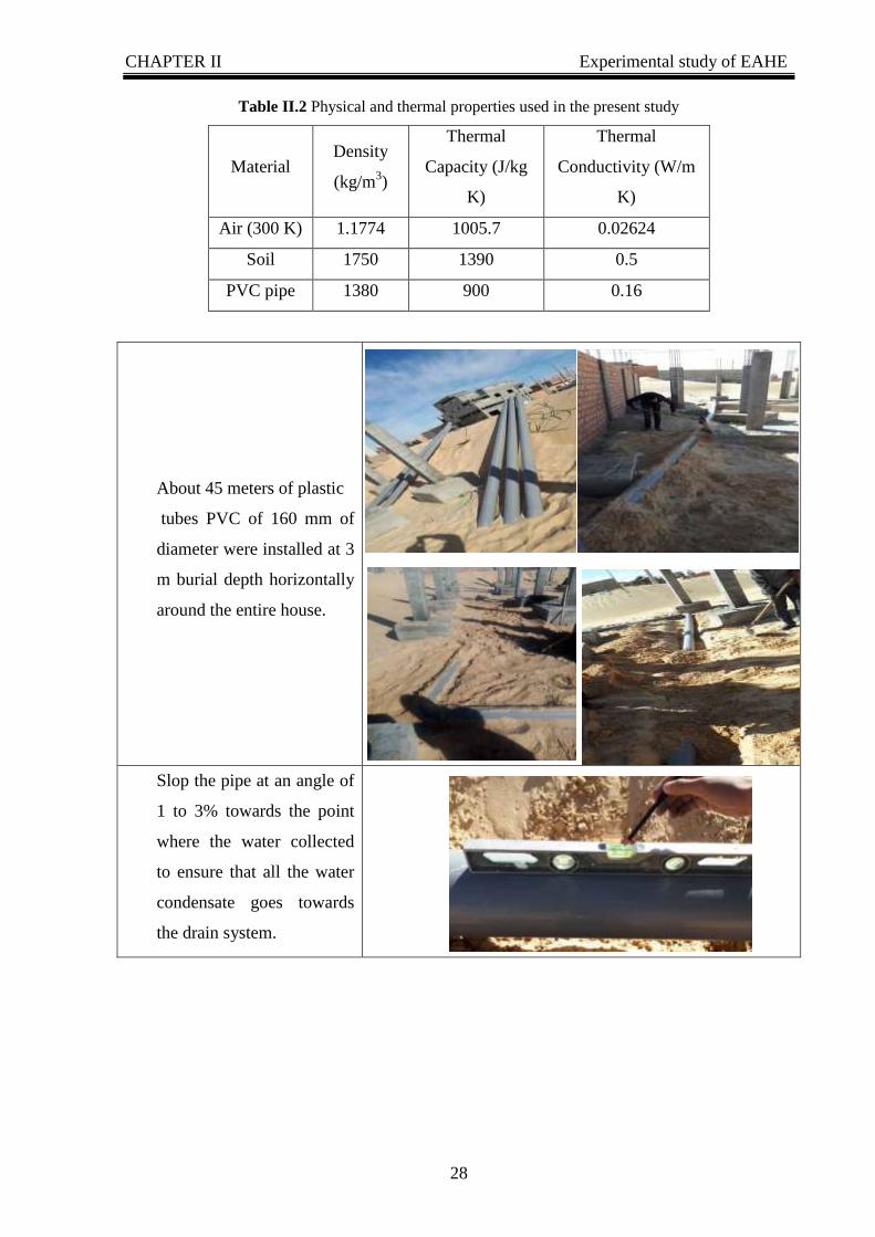
II.2 EAHE installation description:
The air of renewal is passed before it enters the house, into a buried tube PVC (Polyvinyl
chloride) that length of about 45m conduct length, 160 mm diameter and 3 m burial depth
with a 2% slope. A water drain system installed for removing the condensation water
molecules coming from the air. In winter, the air is thus preheated because the ground is
warmer than the outside air. In summer, the air is refreshed because it is the opposite
phenomenon that occurs.

CHAPTER II Experimental study of EAHE
27
Fig II.3 Earth Air Heat Exchanger system installation[5]
For the measure of the soil temperature profile, four thermocouples (K-type) were
inserted under the soil at 0, 1, 2, and 3 m of depth. Three other thermocouples (K-type) were
placed for the measurement of the ambient and inlet and outlet temperature in the EAHE. The
fluid (air) was supplied to the system by a blower.
The air mass flow rate was measured by the anemometer TESTO 416 type. The air
temperatures inside the EAHE were recorded every 10 minutes during three days of operation
mode in June 2020.
Characteristics of the system and the technical propriety of measuring instruments are
reported in below.
Table II.1 Experimental parameter
Length of pipe (m) 45
Diameter of pipe (m) 0.160
Depth of pipe (m) 3
Slope of pipe (%) 2
Soiltemperature (°C) 24.5
Ambient temperature (°C) 38
CHAPTER II Experimental study of EAHE
28
Table II.2 Physical and thermal properties used in the present study
Material Density
(kg/m3)
Thermal
Capacity (J/kg
K)
Thermal
Conductivity (W/m
K)
Air (300 K) 1.1774 1005.7 0.02624
Soil 1750 1390 0.5
PVC pipe 1380 900 0.16
About 45 meters of plastic
tubes PVC of 160 mm of
diameter were installed at 3
m burial depth horizontally
around the entire house.
Slop the pipe at an angle of
1 to 3% towards the point
where the water collected
to ensure that all the water
condensate goes towards
the drain system.

CHAPTER II Experimental study of EAHE
29
Water drain system play
role for removing the
condensation water
molecules coming from the
air.
Four thermocouples (K-
type) were placed under the
soil at 0, 1, 2, and 3 m of
depth to evaluate and
measure the temperature
variation of the ground.
II.3 Measuring Equipment:
II.3.1 Temperature measurement device:
Thermocouple type K: is the most commonly used general purpose thermocouple. It is
inexpensive and a wide variety of probes are available in its −200 °C to +1350 °C / -330 °F to
+2460 °F range. Sensitivity is approximately 41 µV/°C. Wire color standard is yellow (+)
and red (-).
The Type K thermocouple (chromel -alumel) is made up of two dissimilar conductors in
contact with one another, which produce a voltage when heated.
Thermocouples are used as temperature sensors for measurement and control and can
also be used to convert a temperature gradient into electricity.

CHAPTER II Experimental study of EAHE
30
Fig II.4 Thermocouple type K
II.3.2 Digital thermometer:
Precision instant thermometer GTH 1170 (NiCri-Ni, K type). Gives temperature
measurements in the -65 to +1150 ºC range, in seconds.
Highlights & Details:
Measuring ranges: -65.0 to +199.9 °C or -65 to +1150 °C
Resolution: 0.1 °C resp. 1 °C
Standard flat-pin plug (free of thermo-voltage) and suitable for all NiCr-Ni (type K) -
probes
Digital offset and scale adjustment for optimum precision.
Fig II.5 Digital thermometer
II.3.3 Temperature data acquisition systems:
A. Temperature digital recorder BTM-4208SD:
12 channels Temperature recorder, use SD card to save the data along with time
information, paper less. Real time data logger, save the 12 channels Temp. measuring data

CHAPTER II Experimental study of EAHE
31
along the time information (year, month, date, minute, second) into the SD memory card and
can be down load to the Excel ,Sensor type: Type J/K/T/E/R/S thermocouple.
Fig II.6 Temperature recorder BTM-4208SD
B. Arduino temperature recorder:
A 4-channel temperature acquisition system was developed by using controller Arduino
Mega 2560 and MAX6675 interface. K type thermocouples were integrated to take a
temperature measurements, and a control system was designed to access the real-time input to
be acquired from these sensors. Arduino Integrated Development Environment (IDE) is used
as back-end software for programming and is integrated with MS Excel to store and display
the acquired data.
Fig II.7 Arduino temperature recorder

CHAPTER II Experimental study of EAHE
32
II.3.5 Velocity and flow rate measurement (Anemometer):
The Anemometer testo 416 is an easy to use small vane with an attached vane probe on a
telescoping handle to measure CFM in air ducts. This handheld digital vane anemometer
allows to switch between volume flow and velocity readings quickly.
Timed average eases and quickens the task of duct register traverses
Hold button to freeze readings
Optional Top Safe case provides superior protection from dirt, moisture, and impact
Auto-off function saves battery life
Handheld digital vane anemometer with telescoping handle to measure CFM
in air ducts.
Fig II.8 Anemometer testo 416
III. THERMAL STUDY OF GEOTHERMAL HEAT EXCHANGER:
III.1 Energetic and analytical analysis:
III.1.1 Heat Exchanger Rate:
The total heat transferred to the air when flowing through a buried pipe is given by[37]
…………………………………………………………………(3)
where ṁ is the mass flow rate of air (kg/s)
ρ: density of air flowing in the pipe, where the density of air varies with the temperature
ambient under normal conditions of pressure equal P0= 1,01325 atm.
and Qv: Air flow rate.
exp out inQ m Cp T T

CHAPTER II Experimental study of EAHE
33
Cp is the specific heat of air (J/kg-K), under normal condition of temperature and
pressure.
Tout is the temperature of air at outlet of EAHE pipe (°C), and Tin is the temperature of air
at inlet of EAHE pipe (°C).
III.1.2 Efficiency Thermal:
The efficiency of the EAHE is defined as the ratio of the air temperature drop between
the outlet and the inlet of the EAHE and the difference between soil and inlet air
temperatures, is defined as the ratio of the actual exchanged Q e thermal power and the
maximum theoretically possible exchange power (Q e max)[30, 38], expressed by:
…………………………………………………………………………(4)
III.1.3 Temperature ratio for an earth-to-air heat exchanger
The temperature ratio RT is an important characteristic for passive cooling applications
which describes the temperature damping between inlet and outlet temperature. The smaller
RT is, the more cooling energy is supplied to the building mean (high conductive heat transfer
between soil and pipe and high convective heat transfer between pipe and air)[39].
RT is independent of the climate if the inlet air temperature is related to same limits
(Tin,max and Tin,min):
……………………………………………………………………(5)
III.1.4 Coefficientof Performance COP:
The coefficient of performance or COP of a heat pump, refrigerator or air conditioning
system is a ratio of useful heating or cooling provided to work required. Higher COP's equate
to lower operating costs. The COP usually exceeds 1, especially in heat pumps, because,
instead of just converting work to heat (which, if 100% efficient, would be a COP of 1), it
pumps additional heat from a heat source to where the heat is required.
For complete systems, COP calculations should include energy consumption of all power
consuming auxiliaries. COP is highly dependent on operating conditions, especially absolute
temperature and relative temperature between source and system, and is often graphed or
averaged against expected conditions[9].
The thermal performance of the EAHX system can be estimated in terms of the
coefficient of performance (COP). So is a ratio between the removal heat of cooling and the
power input to the blower[9]
outlet inlet
soil inlet
T T
T T
,max ,min
,max ,min
out in
T
in in
T TR
T T

CHAPTER II Experimental study of EAHE
34
……………………………………………………………………………..(6)
Qh is The total heat transferred to the air when flowing through a buried pipe
Pf is the power required to drive the blower on an earth-air heat exchanger.
III.2 Physic and Fluid mechanic Analysis:
III.2.1 Pressure losses at the buried exchanger:
An ideal heat exchanger is assumed to have infinite conductance, i.e. the heat transfer
does not involve any pressure drop. However, the calculation of pressure losses is essential to
better quantify the heat transfer through the buried exchanger. There are two types of pressure
losses: The linear pressure loss ∆Plin and the singular pressure loss ∆Psin. The total pressure
loss is calculated using (Eq. 7).
…………………………………………………….………………(7)
A. Linear pressure loss:
The linear pressure loss ∆Pl in describes the pressure losses by friction with
the wall of pipes. They are caused by fluid viscosity, the linear pressure loss for a flow in a
rectilinear control is determined in the following way
………………………………………………………..………………(8)
With,
: linear loss ratio of load.
ρ: density of air flowing in the pipe
V: flow velocity
D: exchanger diameter
L: exchanger lengths
The calculation of the pressure drop coefficient Ʌ depends on the nature of the flow,
laminar or turbulent. Flow is characterized by its Reynolds number:
………………………………………………………………………………(9)
Or, µ represents the dynamic viscosity of air (1.85*10-5
Pa.s)
For values of Re <2000, the flow regime is laminar and the coefficient Ʌ is not affected
by the relative roughness. It is a function of the flow rate Q is given by the Hangen-Poiseuille
relation: Ʌ = 64 / Re………………………………………………………...………………(10)
exp
f
QCOP
P
sintotal linP P P
2
2lin
LVP
D
Λ
ReVD
CHAPTER II Experimental study of EAHE
35
Within the limits 2000 <Re <4000, the regime is considered unstable and Ʌ is determined
by the Frenkel relation: Ʌ = 2.7/Re0.53
………………………………...……………………(11)
For 4000 < Re < 100000, the regime is considered unstable and Ʌ is estimated by Blasius
relation:
……………………………………………………………………………….(12)
We can remark that for the range of the flow and the diameter that we study here, the
flow is partially turbulent. We therefore consider for the following the pressure loss for a
turbulent flow whose pressure loss coefficient can be calculated by the Blasius relation:
(
)
…………………………………………………......…….……..(13)
B. Singular pressure loss
The singular pressure loss ∆Psin is the result of velocity differences and changes
of direction of the fluid and can be given as[40]
……………………………………………………………….……….…..(14)
with represents the coefficient of the singular pressure loss[41]
CONCLUSION :
Theoretical thermal study of the EAHE of refreshing buildings was done, this technique
intended for refreshing in summer and warming in winters including experimental
background was discussed in brief in this section. Also in this chapter we have presented an
overview of the main equipment used and experimental works done in our project, which
presented the first time in our region in El oued.
2
2
VP

Chapter III Results &Discussion of The
Experimental Study of EAHE
Chapter III
Results &Discussion of The Experimental
Study of EAHE

Chapter III Results &Discussion of The Experimental Study of EAHE
37
INTRODUCTION:
This chapter presented the results obtained from the experimental with explanation of
them, the analytic & the experimental results with detailed discussion was done under
different air flow rate influence, the soil temperature, the outlet air temperature and others.
I- TEMPERATURE VARIATION VERSUS UNDERGROUND DEPTH:
Ground temperature is a crucial factor in understanding natural phenomena happening in
the ground and on atmospheric layers close to its surface. From the energy point of view,
ground temperature is an index of the geothermal energy stored in the ground the knowledge
of which is an important factor in energy potential evaluation. Furthermore, it is a significant
factor in designing and sizing energy systems in various applications, since most of them are
constructed near the ground surface. These systems consist of underground tubes where air or
water circulates before entering in a building for heating or cooling, usually in connection
with blower system. in horizontal systems up to 300 cm.
Fig III.1 Experimental soil temperature profile at different depths
(Jun21th
to 23th
, 2020)
Fig III.1 shows the variation in soil temperature at different depths as measured in
summer (21–23 June 2020). This figure shows that temperature change decrease as the depth
of the ground increases. The surface temperature ranges between 38 and 48 °C compared to
the ambient temperature ranges between 32 and 38 °C. This fluctuation is caused by solar
radiation. From 1 m, the ground temperature remains relatively constant. It varies from 30 °C
at 1 m deep to 25 °C at 3 m depth. These results allow us to experiment in a region El-Oued. a
Chapter III Results &Discussion of The Experimental Study of EAHE
38
pleasant and favourable temperature level for cooling in summer the buildings in this region is
achieved.
II. TEMPERATURE EVALUATION BETWEEN INLET AND
OUTLET:
II.1 Flow rate influence on the inlet and outlet temperature:
The aim of this study is to know the influence of the variation of the speed of the air flow
on the difference between the outlet temperature and input which leads us to find the ideal
speed for EAHE.
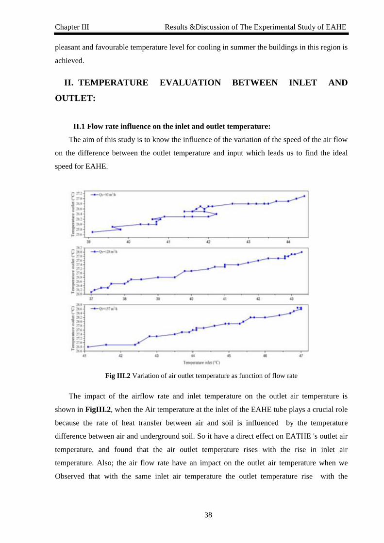
Fig III.2 Variation of air outlet temperature as function of flow rate
The impact of the airflow rate and inlet temperature on the outlet air temperature is
shown in FigIII.2, when the Air temperature at the inlet of the EAHE tube plays a crucial role
because the rate of heat transfer between air and soil is influenced by the temperature
difference between air and underground soil. So it have a direct effect on EATHE 's outlet air
temperature, and found that the air outlet temperature rises with the rise in inlet air
temperature. Also; the air flow rate have an impact on the outlet air temperature when we
Observed that with the same inlet air temperature the outlet temperature rise with the
Chapter III Results &Discussion of The Experimental Study of EAHE
39
increasing in flow rate (from 92 to 157 m3/h ) due to the decreasing of the residence time of
air in the EAHE pipes.
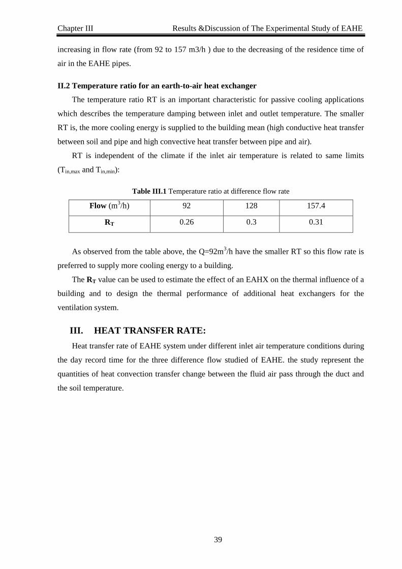
II.2 Temperature ratio for an earth-to-air heat exchanger
The temperature ratio RT is an important characteristic for passive cooling applications
which describes the temperature damping between inlet and outlet temperature. The smaller
RT is, the more cooling energy is supplied to the building mean (high conductive heat transfer
between soil and pipe and high convective heat transfer between pipe and air).
RT is independent of the climate if the inlet air temperature is related to same limits
(Tin,max and Tin,min):
Table III.1 Temperature ratio at difference flow rate
Flow (m3/h) 92 128 157.4
RT 0.26 0.3 0.31
As observed from the table above, the Q=92m3/h have the smaller RT so this flow rate is
preferred to supply more cooling energy to a building.
The RT value can be used to estimate the effect of an EAHX on the thermal influence of a
building and to design the thermal performance of additional heat exchangers for the
ventilation system.
III. HEAT TRANSFER RATE:
Heat transfer rate of EAHE system under different inlet air temperature conditions during
the day record time for the three difference flow studied of EAHE. the study represent the
quantities of heat convection transfer change between the fluid air pass through the duct and
the soil temperature.

Chapter III Results &Discussion of The Experimental Study of EAHE
40
Fig III.3 Heat exchange rate of exchanger versus Inlet temperature.
FigIII.3 above illustrates the quantities of heat transfer rate change during the day with
inlet air temperature at three difference flow rate. It is observed that the amount of heat
transfer increased with increasing inlet air temperature during the day, so the heat transfer rate
is proportional to the temperature inlet.
From this figure, also it can be seen the effect of increasing the flow on the rate of heat
transfer at Tin=43Cº the heat rate reach until 480 W for the smaller flow rate(92 m3/h) on the
other hand, it was record 800 W of heat transfer rate for the same temperature inlet at the
great air flow rate(157 m3/h) by increasing estimated as 60%of total heat transfer rate, so the
heat transfer increased with increasing airflow rate.
That is, the greater the flow of incoming air, the higher the temperature with it, because
the surface of contact with the tube decreases, and vice versa, the smaller the flow, the lower
the temperature.
And if we take the second point into account and perform the test on a lower flow, then
the result that we will get will be poor room cooling output in the future.
IV. EFFICIENCY:
The efficiency of the EAHE is defined as the ratio of the air temperature drop between
the outlet and the inlet of the EAHE and the difference between soil and inlet air temperatures

Chapter III Results &Discussion of The Experimental Study of EAHE
41
Fig III.4 Efficiency variation with difference flow rate.
Fig III.4 above shows the variation of the efficiency with difference flow rate studied
during three days record of difference temperature conditions from 21 to 23 of June,2020.
From this figure, it is easy to see that the Efficiency decreased with increased air flow rate due
to increasing temperature drop between inlet and outlet with increased air flow rate (refer to
Fig III.1 Variation of air outlet temperature as function of flow rate), where the Efficiency is
inversely proportional with temperature drop.
Also, from the figure, it can be noted that the small flow rate (92 m3/h) has the maximum
Efficiency value(93%) and the high flow rate (157 m3/h) has the minimum Efficiency(86%),
this is due to increasing of flow rate give less time of heat exchanges, so the difference
between inlet and outlet temperature become minimal, and vice versa.
V. COEFFICIENT OF PERFORMANCE COP:
COP is a ratio between the cooling capacity of EAHX that the heat rejected to soil, c Q
and the power consumption of the fan, Pf [21].

Chapter III Results &Discussion of The Experimental Study of EAHE
42
Fig III.5 A/B COP versus Temperature inlet and flow rate
Fig III.5 shows clearly the effect of inlet air temperature on COP of EAHX. When inlet
air temperature increases, COP increases, and vice versa for the flow rate where the COP
decrease when the flow increase as shown in Fig III.5 A, so This occurs because there is less
time available for air to stay in the pipe (as proved in the precedent see Fig III.3 Heat
exchange rate of exchanger versus Inlet temperature). This means that the time it takes for air
inside the tube is very short, meaning that the COP cannot be high. We conclude that the
performance parameter is related to the time taken by the air inside the tube, which in turn
returns to the air flow.
Fig III.5 B confirm the linearity between the COP and temperature and flow rate
during the day record time, where the COP register a maximum value when a temperature
higher (COP=1.8 at Tin=47Cº).
CONCLUSION:
In this study, the experimental thermal performance analysis of the EAHX system was
carried out under hot and dry climatic conditions of El oued, Algeria. Although the outdoor
temperature varies in its normal trends during summer day about 45Cº, the constant air
temperature is obtained from the outlet of EAHX. The mean outlet air temperature is found as
26.2Cº to 28Cº. The EAHX appears very effective at clipping temperature peaks during hot
days in summer. It is found out that the average of maximum values of EAHX effectiveness is
0.94 and the mean of COP values vary from 1.16 to 1.8, the maximum COP value is obtained
as 1.8 at the high flow rate of 157 m3/s. The cooling capacity increases with higher air
velocities due to increasing the mass flow rate. But the difference between inlet and outlet air
temperature decreases. It is concluded that there is potential for EAHX systems to make a

Chapter III Results &Discussion of The Experimental Study of EAHE
43
useful contribution to energy saving in El oued, Algeria arid climate locations. The results
have shown that the system has the potential to become an effective energy saving technology
in buildings.

GENERAL CONLUSION
GENERAL CONLUSION:
45
GENERAL CONLUSION:
This project presents the experiment of installing a horizontal EAHE, which was the first
time in El oued region southern of Algeria. An energetic analysis study was done to evaluate
and valorization this technique for refreshing/heating mode using in building, which
concluded and confirm from it the following:( all results obtained was analyzed and treated in
summer season for cooling mode)
The constant soil temperature was confirmed at 3 meter of depth is about 25 Cº in
all-time records.
A constant outlet air temperature is obtained from EAHE system especially when
the flow rate becomes low until critical value.
The mean outlet air temperature is found as 26. 4 Cº min and 28.8 Cº max during
the three-day record time.
High effectiveness system discovered especially at low flow rate, were the
average effectiveness are 0.927 ,0.886 and 0.876 for the three different flow rate.
The EAHX appears very effective at clipping temperature peaks during hot days
in summer at max temperature of 44 Cº efficiency was 0.93.
An acceptable cooling performance COP of the EAHE was found in summer
seasons during the three days record time (21,22,23 of June 2020) in El Oued
region (southern of Algeria).
The maximum COP obtained is 1.8 which was supposed as good performance
comparing with a cost of production and the most benefit.
The best performance was recorded with the highest air flow rate 157 m3/h which
gave an average change in the air temperature of 3.1 °C.
A good agreement with many researchers was found in all above.
All the above results confirm that the EAHE system was capable of reach the
cooling in the summer.
The obtained results give a good encouragement to use the proposed EAHE as an air
refreshing tool in the region of El-Oued and even in the whole Sahara of Algeria.
So, show great potential for EAHE development as a solution to the building's passive
cooling system in El Oued region.
This technique still needs more study and development by researchers, which will be
focus in the value of the energy can provide from it in the next work study for the given
energy results.

Reference

Appendix:
Reference:
[1] N. a. o. i. development. (2017,April). Renewable Energy (2017 ed.). Available:
http://www.andi.dz/index.php/en/les-energies-renouvelables
[2] A. A. Serageldin, A. K. Abdelrahman, and S. J. E. c. Ookawara, "Earth-Air Heat
Exchanger thermal performance in Egyptian conditions: Experimental results,
mathematical model, and Computational Fluid Dynamics simulation," Energy
conversion management, vol. 122, pp. 25-38, 2016.
[3] T. S. Bisoniya, "Design of earth–air heat exchanger system," Geothermal Energy, vol.
3, no. 1, p. 18, 2015.
[4] H. Bulut, Y. Demirtaş, R. Karadağ, and İ. Hilali, "Experimental analysis of an earth
tube ventilation system under hot and dry climatic conditions," in Proceedings of The
8th Mediterranean Congress of Heating Ventilation and Air-Conditioning-Climamed,
2015, pp. 1-8.
[5] T. S. Bisoniya, A. Kumar, and P. Baredar, "Study on calculation models of earth-air
heat exchanger systems," Journal of Energy, vol. 2014, 2014.
[6] N. Bordoloi, A. Sharma, H. Nautiyal, and V. Goel, "An intense review on the latest
advancements of Earth Air Heat Exchangers," Renewable Sustainable Energy
Reviews, vol. 89, pp. 261-280, 2018.
[7] C. F. FUTURE, " Energy Efficiency and Renewable Energy," 2020, April.
[8] N. Hatraf, F. Chabane, A. Brima, N. Moummi, and A. Moummi, "Parametric study of
to design an earth to air heat exchanger with experimental validation," Engineering
Journal, vol. 18, no. 2, pp. 41-54, 2014.
[9] M. Benhammou and B. Draoui, "Parametric study on thermal performance of earth-to-
air heat exchanger used for cooling of buildings," Renewable and Sustainable Energy
Reviews, vol. 44, pp. 348-355, 2015.
[10] M. Benhammou, B. Draoui, M. Zerrouki, and Y. Marif, "Performance analysis of an
earth-to-air heat exchanger assisted by a wind tower for passive cooling of buildings in
arid and hot climate," Energy conversion management, vol. 91, pp. 1-11, 2015.
[11] B. Draoui, B. Mebarki, S. Abdessemed, A. Keboucha, S. Drici, and A. Sahli, "Etude
d’un système de climatisation intégrant un puits canadien dans les zones arides, cas de
Béchar," Revue des Energies Renouvelables, 2015.
[12] S. Menhoudj, M.-H. Benzaama, C. Maalouf, M. Lachi, and M. Makhlouf, "Study of
the energy performance of an earth—Air heat exchanger for refreshing buildings in
Algeria," Energy Buildings, vol. 158, pp. 1602-1612, 2018.
[13] M. H. Benzaama, S. Menhoudj, K. J. Kontoleon, A. M. Mokhtari, and M. C. Lekhal,
"Investigation of the thermal behavior of a combined geothermal system for cooling
with regards to Algeria’s climate," Sustainable Cities and Society, vol. 43, pp. 121-
133, 2018.
[14] M. J. Bell and S. T. Leong, Slow space. Monacelli Press, 1998.
[15] W. Van Wijk and D. de Vries, The atmosphere and the soil, , 2nd ed. Amsterdam:
North-Holland Publishing Co, 1966.
[16] B. D. P. Hepburn, "An investigation of the behaviour of the ground in response to
energy extraction," Cardiff University, 2013.
[17] P. Hollmuller, "Utilisation des échangeurs air/sol pour le chauffage et le
rafraîchissement des bâtiments: mesures in situ, modélisation analytique, simulation
numérique et analyse systémique," University of Geneva, 2002.
[18] K. K. Agrawal, G. D. Agrawal, R. Misra, M. Bhardwaj, and D. K. Jamuwa, "A review
on effect of geometrical, flow and soil properties on the performance of earth air
tunnel heat exchanger," Energy Buildings, vol. 176, pp. 120-138, 2018.
Appendix:
[19] N. Sakhri, Y. Menni, A. Chamkha, M. Salmi, and H. Ameur, "Earth to Air Heat
Exchanger and Its Applications in Arid Regions - An Updated Review," TECNICA
ITALIANA-Italian Journal of Engineering Science, vol. 64, no. 1, pp. 83-90, 2020.
[20] K. K. Agrawal, R. Misra, G. D. Agrawal, M. Bhardwaj, and D. K. Jamuwa, "The state
of art on the applications, technology integration, and latest research trends of earth-
air-heat exchanger system," Geothermics, vol. 82, pp. 34-50, 2019.
[21] M. K. Ghosal and G. N. Tiwari, "Modeling and parametric studies for thermal
performance of an earth to air heat exchanger integrated with a greenhouse," Energy
Conversion and Management, vol. 47, no. 13-14, pp. 1779-1798, 2006.
[22] E. Penrod, W. Walton, and D. Terrell, "A method to describe soil temperature
variation," Journal of the Soil Mechanics Foundations Division, vol. 84, no. 1, pp. 1-
21, 1958.
[23] M.-H. Benzaama, M. Lachi, C. Maalouf, A.-M. Mokhtari, G. Polidori, and M.
Makhlouf, "Study of the effect of sun patch on the transient thermal behaviour of a
heating floor in Algeria," Energy buildings, vol. 133, pp. 257-270, 2016.
[24] T. Kusuda and P. R. Achenbach, "Earth temperature and thermal diffusivity at selected
stations in the United States," National Bureau of Standards Gaithersburg MD1965.
[25] H. Esen and M. Inalli, "In-situ thermal response test for ground source heat pump
system in Elazığ, Turkey," Energy Buildings, vol. 41, no. 4, pp. 395-401, 2009.
[26] H. Esen, M. Inalli, and M. Esen, "A techno-economic comparison of ground-coupled
and air-coupled heat pump system for space cooling," Building and Environment, vol.
42, no. 5, pp. 1955-1965, 2007.
[27] G. Wang, X.-Y. Chen, F.-L. Qiao, Z. Wu, and N. E. Huang, "On intrinsic mode
function," Advances in Adaptive Data Analysis, vol. 2, no. 03, pp. 277-293, 2010.
[28] K. K. Agrawal, R. Misra, G. D. Agrawal, M. Bhardwaj, and D. K. Jamuwa, "Effect of
different design aspects of pipe for earth air tunnel heat exchanger system: A state of
art," International Journal of Green Energy, vol. 16, no. 8, pp. 598-614, 2019.
[29] M. I. Hasan and S. W. Noori, "A study of the potential of using the Earth to air heat
exchanger for cooling and heating of residential buildings in Iraq," Heat Transfer—
Asian Research, vol. 48, no. 8, pp. 3902-3927, 2019.
[30] A. Hadjadj, B. Benhaoua, A. Atia, A. Khechekhouche, N. Lebbihiat, and A. Rouag,
"Air Velocity Effect on Geothermal Helicoidally Water-Air Heat Exchanger under El
Oued Climate -Algeria," Thermal Science and Engineering Progress, p. 100548,
2020/04/15/ 2020.
[31] S. Thiers and B. Peuportier, "Modélisation thermique d'un échangeur air-sol pour le
rafraîchissement de bâtiment," in Journée thématique SFT-IBPSA: froid solaire et
confort d'été, 2007, pp. 96-103.
[32] P. Le Feuvre, "An investigation into ground source heat pump technology, its UK
market and best practice in system design," Mechanical Engineering, University of
Strathclyde. MSc
vol. 180, 2007.
[33] A. Atia, A. Hadjadj, B. Benhaoua, N. Lebbihiat, and A. Brima, "A Review of Studies
on Geothermal Energy System Applied on Sub-Saharan Climate Regions," Water and
Energy International, vol. 60, no. 5, pp. 63-68, 2017.
[34] M. Ghodbane, B. Boumeddane, Z. Said, and E. Bellos, "A numerical simulation of a
linear Fresnel solar reflector directed to produce steam for the power plant," Journal of
Cleaner Production, vol. 231, pp. 494-508, 2019.
[35] g. map, "El Oued region," 2020,April.
[36] d. source. (2020,April). Average Weather in El Oued Algeria. Available:
https://weatherspark.com/y/53031/Average-Weather-in-El-Oued-Algeria-Year-Round
[37] Y. Cengel, Heat and mass transfer: fundamentals and applications. McGraw-Hill
Higher Education, 2014.
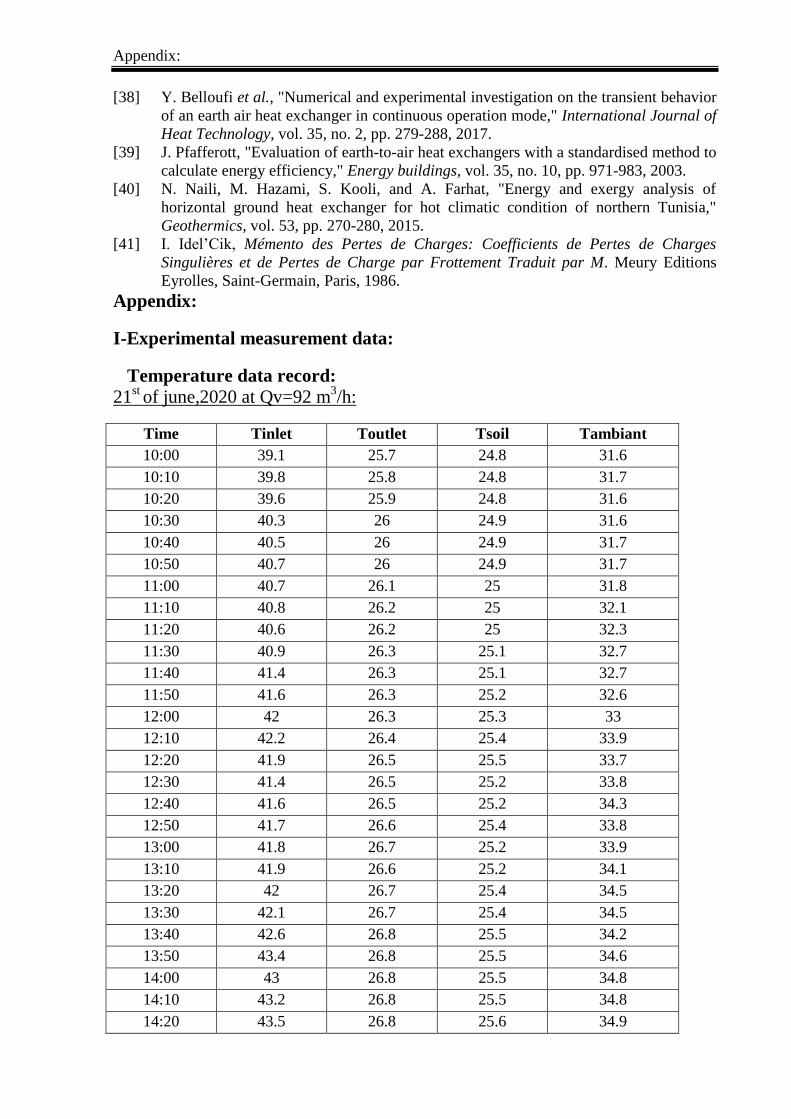
Appendix:
[38] Y. Belloufi et al., "Numerical and experimental investigation on the transient behavior
of an earth air heat exchanger in continuous operation mode," International Journal of
Heat Technology, vol. 35, no. 2, pp. 279-288, 2017.
[39] J. Pfafferott, "Evaluation of earth-to-air heat exchangers with a standardised method to
calculate energy efficiency," Energy buildings, vol. 35, no. 10, pp. 971-983, 2003.
[40] N. Naili, M. Hazami, S. Kooli, and A. Farhat, "Energy and exergy analysis of
horizontal ground heat exchanger for hot climatic condition of northern Tunisia,"
Geothermics, vol. 53, pp. 270-280, 2015.
[41] I. Idel’Cik, Mémento des Pertes de Charges: Coefficients de Pertes de Charges
Singulières et de Pertes de Charge par Frottement Traduit par M. Meury Editions
Eyrolles, Saint-Germain, Paris, 1986.
Appendix:
I-Experimental measurement data:
Temperature data record:
21st
of june,2020 at Qv=92 m3/h:
Time Tinlet Toutlet Tsoil Tambiant
10:00 39.1 25.7 24.8 31.6
10:10 39.8 25.8 24.8 31.7
10:20 39.6 25.9 24.8 31.6
10:30 40.3 26 24.9 31.6
10:40 40.5 26 24.9 31.7
10:50 40.7 26 24.9 31.7
11:00 40.7 26.1 25 31.8
11:10 40.8 26.2 25 32.1
11:20 40.6 26.2 25 32.3
11:30 40.9 26.3 25.1 32.7
11:40 41.4 26.3 25.1 32.7
11:50 41.6 26.3 25.2 32.6
12:00 42 26.3 25.3 33
12:10 42.2 26.4 25.4 33.9
12:20 41.9 26.5 25.5 33.7
12:30 41.4 26.5 25.2 33.8
12:40 41.6 26.5 25.2 34.3
12:50 41.7 26.6 25.4 33.8
13:00 41.8 26.7 25.2 33.9
13:10 41.9 26.6 25.2 34.1
13:20 42 26.7 25.4 34.5
13:30 42.1 26.7 25.4 34.5
13:40 42.6 26.8 25.5 34.2
13:50 43.4 26.8 25.5 34.6
14:00 43 26.8 25.5 34.8
14:10 43.2 26.8 25.5 34.8
14:20 43.5 26.8 25.6 34.9

Appendix:
14:30 43.7 26.9 25.6 35.1
14:40 44 26.9 25.6 35.2
14:50 44.2 27 25.6 35.6
15:00 44.4 27.1 25.9 35.9

Appendix:
22nd
of june,2020 at Qv=128.4 m3/h:
Time Tinlet Toutlet Tsoil Tambiant
10:00 37 26.1 25.1 31.1
10:10 37.1 26.2 25.1 31.2
10:20 37.1 26.2 25.2 31.4
10:30 37.3 26.3 25.2 31.2
10:40 37.5 26.3 25.2 31.6
10:50 37.6 26.5 25.2 31.8
11:00 38 26.5 25.3 32
11:10 38.1 26.6 25.3 32.1
11:20 38.2 26.7 25.4 32.4
11:30 38.5 26.7 25.5 32.7
11:40 39 26.8 25.5 33
11:50 39.5 26.8 25.5 33.1
12:00 39.8 27.1 25.2 33.4
12:10 40 27.1 25.2 33.6
12:20 40.5 27.2 25.6 33.5
12:30 40.7 27.3 25.2 33.5
12:40 41 27.3 25.2 33.7
12:50 41 27.4 25.4 33.8
13:00 41.4 27.4 25.4 34
13:10 41.7 27.5 25.5 34.1
13:20 41.7 27.5 25.5 34.3
13:30 42 27.6 25.5 34.3
13:40 42.3 27.7 25.5 34.4
13:50 42.6 27.7 25.6 34.5
14:00 42.8 27.7 25.6 34.5
14:10 42.8 27.8 25.6 34.5
14:20 42.9 27.8 25.6 34.6
14:30 43 27.9 25.5 34.6
14:40 43.1 27.9 25.5 34.7
14:50 43.3 28 25.9 34.8
15:00 43.3 28 25.9 34.8

Appendix:
23rd
of june, 2020 at Qv=157 m3/h:
Time Tinlet Toutlet Tsoil Tambiant
10:00 41.1 26.8 25 30.4
10:10 41.6 26.9 25.1 31
10:20 42.4 26.9 25.2 31
10:30 42.5 27 25.2 31.2
10:40 42.5 27 25.3 31.8
10:50 42.8 27.3 25.3 32
11:00 43 27.3 25.3 32.2
11:10 43.5 27.4 25.4 32.4
11:20 43.7 27.5 25.4 32.4
11:30 43.9 27.5 25.5 32.5
11:40 44 27.6 25.5 32.7
11:50 44.1 27.6 25.5 33
12:00 44.1 27.7 25.2 33.2
12:10 44.3 27.7 25.2 33.4
12:20 44.6 27.8 25.4 33.4
12:30 44.9 27.9 25.2 33.5
12:40 44.9 27.9 25.2 33.5
12:50 45 27.9 25.4 33.6
13:00 45.3 27.9 25.4 34
13:10 45.4 28 25.5 34.6
13:20 45.4 28 25.5 34.6
13:30 45.6 28.2 25.5 34.7
13:40 45.7 28.2 25.5 34.8
13:50 46 28.2 25.6 34.9
14:00 46.4 28.3 25.6 35
14:10 46.7 28.4 25.6 35
14:20 46.7 28.4 25.6 35.2
14:30 46.8 28.5 25.5 35.4
14:40 47 28.6 25.5 35.5
14:50 47 28.66 25.7 35.6
15:00 46.9 28.66 25.7 35.5

Appendix:
II. The value of the project in economic terms :
materials price
Drilling 50000.00 DA
Tubes (160 mm) 11250.00 DA
Tubes (110 mm) 1000.00 DA
elbow 1000.00 DA
blower 5000.00 DA
cable type k 5000.00 DA
hand working 40000.00 DA
accessory 5000.00 DA
total 118250.00 DA

Abstract
Thesis title: ENERGETIC PERFORMANCE ANALYSIS OF GEOTHERMAL HEAT
EXCHANGER UNDER SAHARAN CLIMATE.
Master: Renewable energies
Authors: BELOUL Samir/ FERHAT Chihab/KHOUAZEM Hatem.
Keywords: geothermal energy, Earth Air Heat Exchanger, heating, cooling, renewable
energy.
Abstract:
This project presents an experimental analysis to examine the performance of earth to air
heat exchanger (EAHE) for cooling building. This system has never been used or exploited in
the EL Oued region. Therefore, an experimental system was designed, installed and tested
under 3m depth and 45 m of length. The experiments are conducted between 21th and 23th
June 2020. The results obtained show that the EAHE system can be used in the homes and
poultry and greenhouses for cooling and heating. During the experimental period, the
maximum average temperature difference between the inlet and outlet EAHE system is
approximately 20 °C, with a measured air flow rate of 128 m3/s. The EAHE efficiency
decreased with the increase of the airflow. The efficiency of heat exchanger was obtained to
be 93%, 88% and 85% for the average flow rate value of 92, 128 and 157 m3/s, respectively.
According to the obtained results, the EAHE presented in this study may be used for cooling
and heating of buildings or greenhouses in southeastern Algeria.
Titre du mémoire : ENERGETIC PERFORMANCE ANALYSIS OF GEOTHERMAL
HEAT EXCHANGER UNDER SAHARAN CLIMATE.
Mots clés : geothermal energy, Earth Air Heat Exchanger, heating, cooling, renewable
energy.
Résumé : Ce projet présente une analyse expérimentale pour examiner les performances de
l'échangeur de chaleur terre-air (EAHE) pour le refroidissement des bâtiments. Ce système n'a
jamais été utilisé ni exploité dans la région d'EL Oued. Par conséquent, un système
expérimental a été conçu, installé et testé sous 3 m de profondeur et 45 m de longueur. Les
expériences sont menées entre le 21 et le 23 juin 2020. Les résultats obtenus montrent que le
système EAHE peut être utilisé dans les habitations et les volailles et les serres pour le
refroidissement et le chauffage. Pendant la période expérimentale, la différence de
température moyenne maximale entre le système EAHE d'entrée et de sortie est d'environ 20 °
C, avec un débit d'air mesuré de 128 m3 / s. L'efficacité EAHE a diminué avec l'augmentation
du débit d'air. L'efficacité de l'échangeur de chaleur a été obtenue à 93%, 88% et 85% pour
une valeur de débit moyen de 92, 128 et 157 m3 / s, respectivement. Selon les résultats
obtenus, l'EAHE présentée dans cette étude peut être utilisée pour le refroidissement et le
chauffage de bâtiments ou de serres dans le sud-est de l'Algérie.