
MASTER - UNT Digital Library
694
MASTER Technical Notes for the Conceptual Design for an Atmospheric Fluidized-Bed Direct 'Combustiin Power Generating Plant Volume 2 April 1978 Prepared For US. Department of Energy Assistant Secretary for Energy Technology Division of Power Systems Under Contract No. EF-77-C-01-2583
-
Upload
khangminh22 -
Category
Documents
-
view
2 -
download
0
Transcript of MASTER - UNT Digital Library

MASTER Technical Notes for the Conceptual Design for an Atmospheric Fluidized-Bed Direct 'Combustiin Power Generating Plant
Volume 2
April 1978
Prepared For US. Department of Energy Assistant Secretary for Energy Technology Division of Power Systems
Under Contract No. EF-77-C-01-2583
DISCLAIMER
This report was prepared as an account of work sponsored by an agency of the United States Government. Neither the United States Government nor any agency Thereof, nor any of their employees, makes any warranty, express or implied, or assumes any legal liability or responsibility for the accuracy, completeness, or usefulness of any information, apparatus, product, or process disclosed, or represents that its use would not infringe privately owned rights. Reference herein to any specific commercial product, process, or service by trade name, trademark, manufacturer, or otherwise does not necessarily constitute or imply its endorsement, recommendation, or favoring by the United States Government or any agency thereof. The views and opinions of authors expressed herein do not necessarily state or reflect those of the United States Government or any agency thereof.

DISCLAIMER
Portions of this document may be illegible in electronic image products. Images are produced from the best available original document.

4
The following pages are an exact
representation of what is in the originaldocument folder.
Technical Notes for the Conceptual Design for an Atmospheric Ruidized-Bed Direct Combustion Power Generating Plant
Volume 2
April 1978
Prepared By Stone & Webster Engineering Corporation
For
U.S. Department of Energy Assistant Secretary for Energy Technology Division of Power Systems Washington, DC 20545
Under Contract No. EF-77-C-01-2583
NOTICE
lhir .uar prepared m uccOYf;t of work ,pnrored by United Stater C o v e m m t . Neither the united steter nor the United Statcr D c p m f m ~ n ~ Of
E , , ~ , ~ , no, any of their employees, nor BnY of their contracton, s u ~ o n m c t ~ m , or theu employeeas maker Bny ~ ~ " t y , exprcu cr imvLiod. nr awmes my b d lisbility rerpon&,iilitY 10, the accuracy, com~letmc= ,, ,(ha any information, nppmtur, P'O~UC' Or
proorn diwlmd, or r epnvna that i u up would not
' \, ' .
infringe privately owned r i k a . i
NOTICE
This report was prepared as an account o f work sponsored by the United States Government. Neither the United States nor the United States Department ot tnergy, nor any of their employees, makes any warranty, express or implied, or assumes any legal liability or responsibility for the accuracy, completeness, or usefulness of any infortnation, apparatus, product, or process discloscd, or represent6 that its use would not infringe privately owned rights. Reference herein t o any specific commercial product, process, or service by
1 trade name, mark, manufacturer, or otherwise, does not necessarily constitute or imply i t s endorsement, recommendation; or favoring by the United States Government or any agency thereof. The views and opinions o f authors expressed herein do not necessarily state or reflect those of the United States Government or any agency thereof.
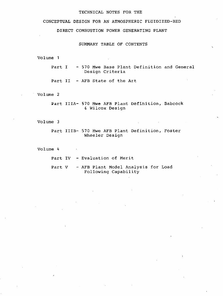
TECHNICAL NOTES FOR THE
CONCEPTUAL DESIGN FOR AN ATMOSPHERIC FLUIDIZED-BED
DIRECT COMBUSTION POWER GENERATING PLANT
SUMMARY TABLE OF CONTENTS
Volume 1
Part I - 570 Mwe Base Plant Definition and General Design Criteria
Part I1 - AFB State of the Art
Volume 2
Part IIIA- 570 Mwc AFB Bld~lt Definition, Babcock & Wilcox Design
Volume 3
Part IIIB- 5 7 0 Mwe AFB Plant Definition, Foster Wheeler Design
Volume 4
Part IV - Evaluation of Merit Part V - AFB P.lant Model Analysis for Load
Following Capability

PART I I I A
570 Mwe BABCOCK C WILCOX AFB DEFINITION AND
DESIGN ' CRI!l%RIA

TABLE OF CONTENTS
Section Description
OBJECTIVE INTRODUCTION GENERAL THERMODYNAMIC CY:CLE PLANT ECONOMICS Capital C o s t s Operating Costs Economic Evaluation Factors B6W AFB PLANT PROJECT SCHEDULE PLANT ARRANGEMENT S i t e Turbine Room Boiler Roosn PROCESS SYSTEMS General Steam Systems W a t e r Systems Material Handling Systems W e t Limestone Flue G a s Desulfurization
System (ED) A i r and Gas Systems Other Systems ELECTRICAL SYSTEMS Lighting Design Criteria Raceways Design Criteria W i r e and Cable Design Criteria Grounding System Design Criteria CONTROL SYSTEMS AND INSTRUMENTATION General Control System Plant Protection and Safety Start-up and Loading Procedure ONM MENTAL SYSTm4s A i r Quality Noise Waste Treatment Environmental Monitoring
Paqe
APPENDICES Appendix IIIA-A: BSW Plant Description of Work Appendix IIIA-B: System Descriptions ~ppendix IIIA-C: Babcock E Wilcox Final Report Appendix IIIA-D: Equipment Data Sheets Appendix IIIA-E: Instrument Schedule
LIST OF TABLES
Table
IIIA-1
IIIA-2
If IA-3
I I I A - 4
I I I A - 5
ZIIA-6
IIIA-7
D e s c r i p t i o n
C a p i t a l C o s t E s t i m a t e for a BSW AFB P l a n t
E c o n d c P a r a m e t e r s
C a p i t a l C o s t Change Identification - BCW AFB l38W AFB Plant Annual Operating Costs N e t
H e a t R e j e c t i o n S y s t e m P a r a m e t e r s - BEW AFB
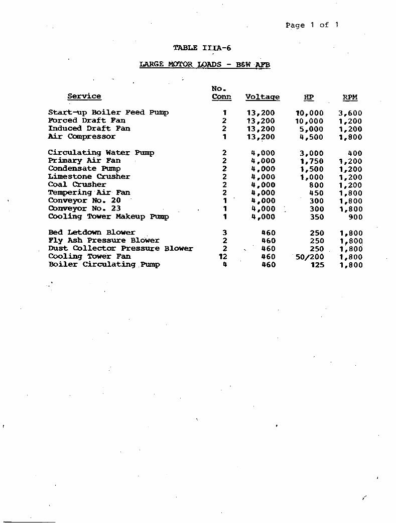
Large Motor Loads - B6W AFB P l a n t
Running Auxiliary Power - BSW AFB Plant
' LIST O F FIGURES
A r r a n q e m e n t D r a w i n q s
12919,02A-EY-602A
12919 ,02A-EM-202A
12919-02A-EM-212A
12919-02A-EE-251A
12919-02A-E-251B
C o m p o s i t e Drawincrs
S i t e P l a n - B 6 W AFB
B6W AFB G e n e r a l Arrangeme& - B o i l e r Ftoosn - Ground Floor Plan B6W AFB General Arrangement - oiler Room Side Section
AFB G e n e r a l A r r a n g e m e n t - Turbine Room - Ground Floor
B 6 W AFB. C o a l 6 L i m e s t o n e H a n d l i n g S y s t e m A r r a n g e m e n t - Inplant - P l a n View BCW AFB C o a l & L i m e s t o n e H a n d l i n g S y s t e m Ar rangemen t - Y a r d BCW AFB C o a l & L i m e s t o n e H a n d l i n g System Arrangement - *her House
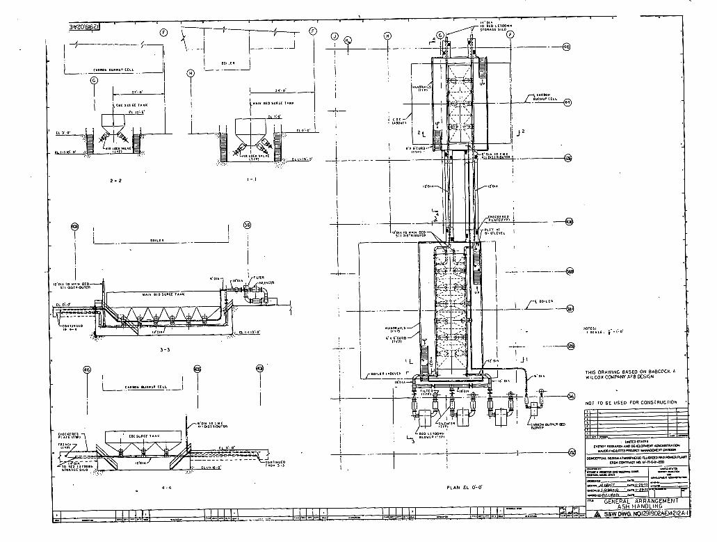
BEW AFB Ash H a n d l i n g S y s t e m Arrangement
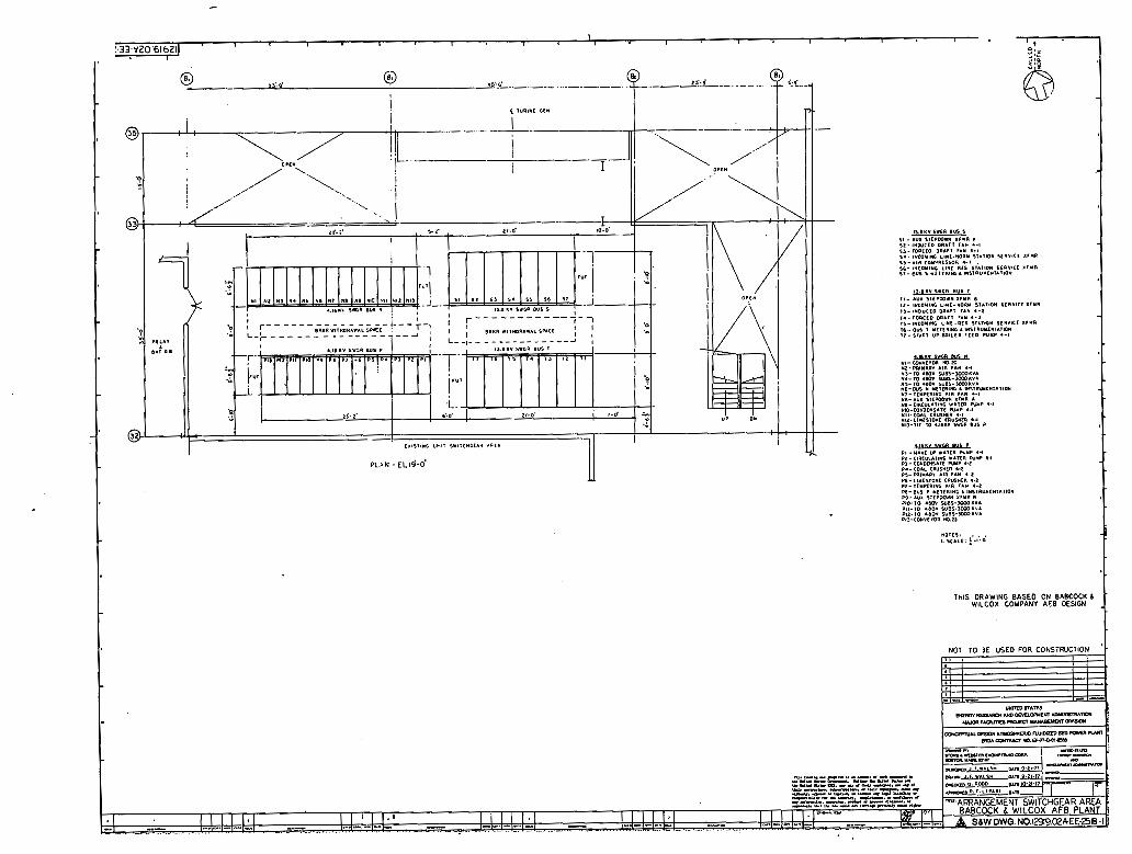
AFB P l a n t C o n t r o l , R e l a y and Battery Room Arrangement AFB P l a n t S w i t c h g e a r Roam A r r a n g e m e n t
1 2 9 1 9 -0-2A-EP-202A B&W AFB Ccunposi te - ~ 1 a . h El, OB-Om 12919,02A-EP-202B B6W AFB C o m p o s i t e - Plan E l , 55B-0n , 12919-02A-EP-202C BLW A . C o m p o s i t e - P l a n - E l , 1 12 m-Om 12919 *02A-EP-202D B6W AFB C a m p o s i t e - Plan E l , 148m-0m 12919 .Om-EP-202E B6W AFB C o m p o s i t e - Plan E l , 1 7 8 m - 0 m 12919-02A-P-202F B6W AFB C o m p o s i t e - Section 1-1 12919,02A-EP-20X B 6 W AFB C o m p o s i t e - section 2-2
S t r u c t u r a l Steel Drawinqs
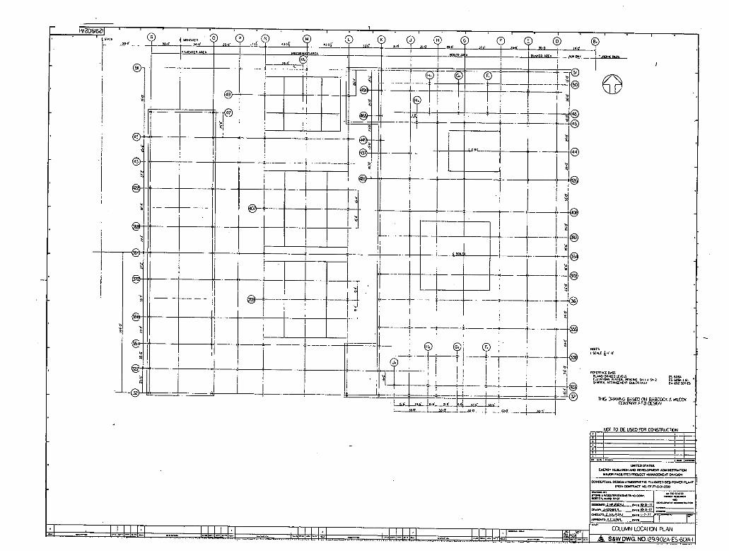
12919 -02A-ES-601A B6W AFB B o i l e r ' Area - Column Location P l a n
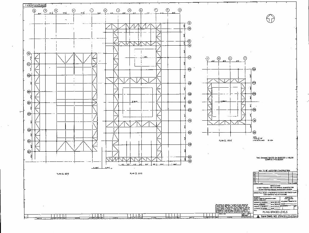
12919-02A-ES-606A B6W AFB B o i l e r Area - Plan B r a c e d Levels - Sh- 1
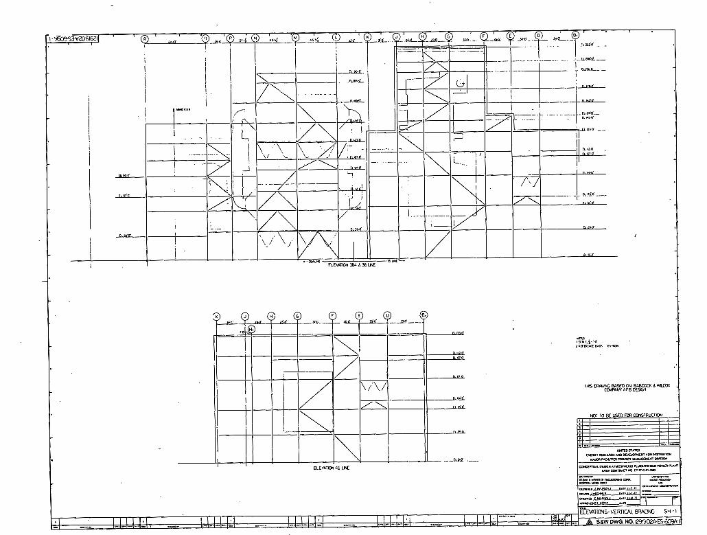
129 19 r02A-ES-609A B6W AFB B o i l e r Area - V e r t i c a l Bracing - Sh- 1
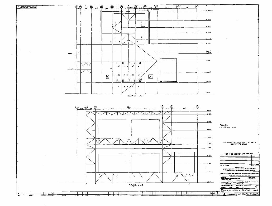
12919 ,02A-ESd09B B6W AFB B o i l e r Area - V e r t i c a l B r a c i n g - Sh- 2
L - LIST OF FIGURES (CONT'D)
Main Steam H o t and C o l d R e h e a t B o i l e r Feedwater and D e s u p e r h e a t i n g Water C a n b u s t i o n Air and Flue G a s C o a l and Limestme Distribution and Injection Ignit ion Oil and A i r B e d Material L e t d o w n and D i s p o s a l Carbon C o l l e c t i o n s and R e i n j e c t i o n Fly Ash C O l l e c t i o n and D i s p o s a l C o a l and Limestone H a n d l i n g
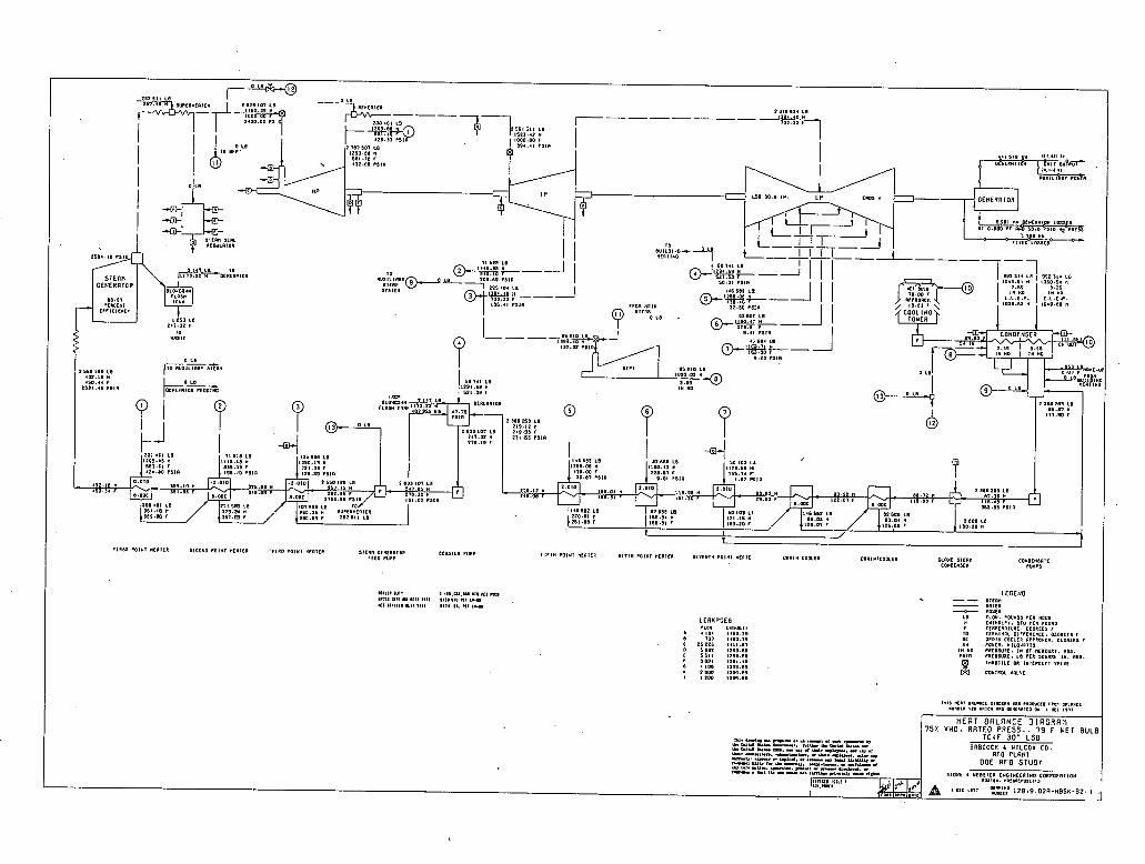
Heat Balance D i a c r r a m s
12919,02A-fIBSK-1 BCW Plant Heat B a l a n c e D i a g r a m - VWO, 5% OP
12919 -02A-HBSK-2 BSW P lan t H e a t Balance D i a g r a m - 75% VWO 12919,OZA-BBSK-3 B&W Plant Heat Balance Diagram - 50% VWO 12919 ,02A-HBSK-4 WW Plant H e a t B a l a n c e D i a g r a m - 25% VWO
Electrical One-Lime D i a q r a m
12919-02A-EW-IA BEW AFB Station One-Line D i a g r a m
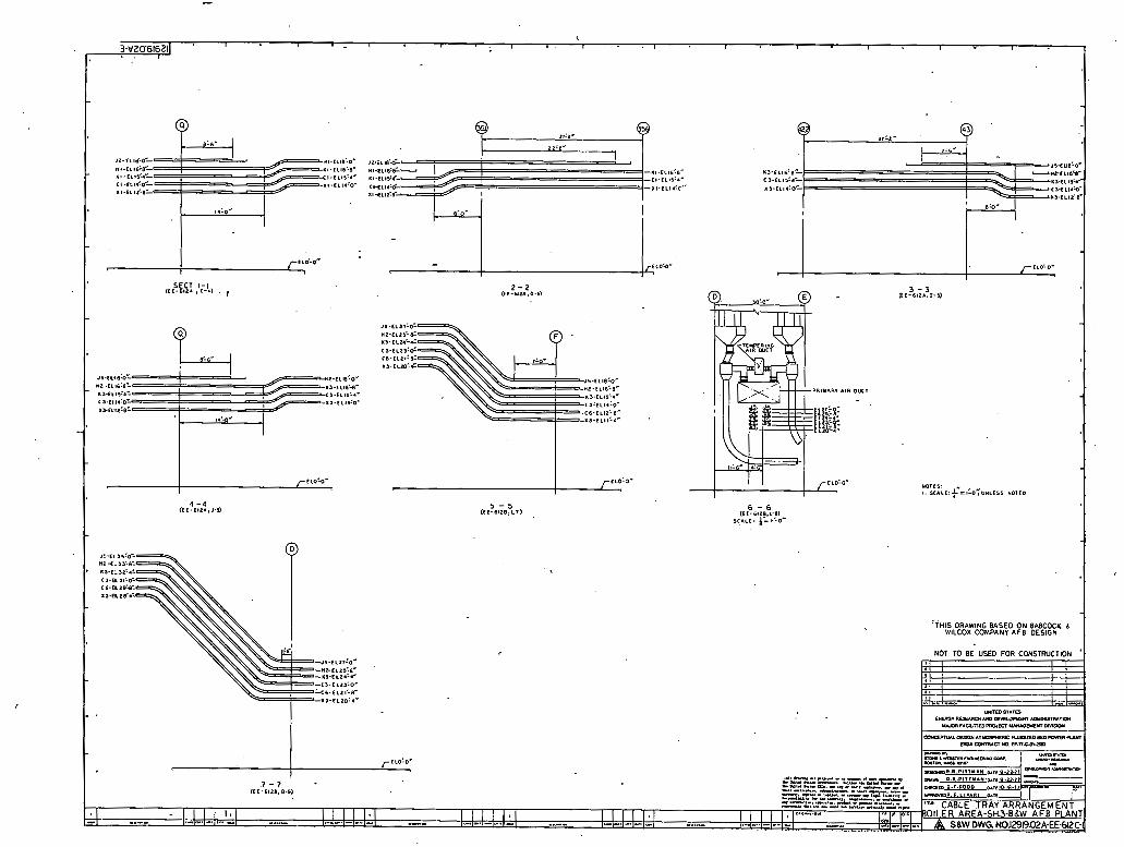
Electrical Tray D r a w i n q s
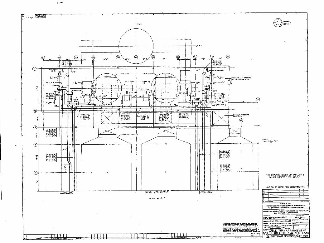
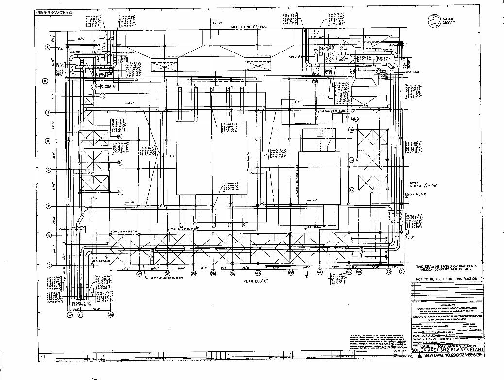
12919.02A-EB-612A E38W AFB Boiler Area C a b l e Trays - Sh, 1 12919,02A+E-612B BSW AFB B o i l e r Area Cable Trays - Sh, 2 12919-02A-EEd12C BCW AFB Boiler Area Cable Trays - Sh. 3
schedulixhcr N e t w o r k
12919-W-PSN-1 BEW AFB Project Summary Network
Other \
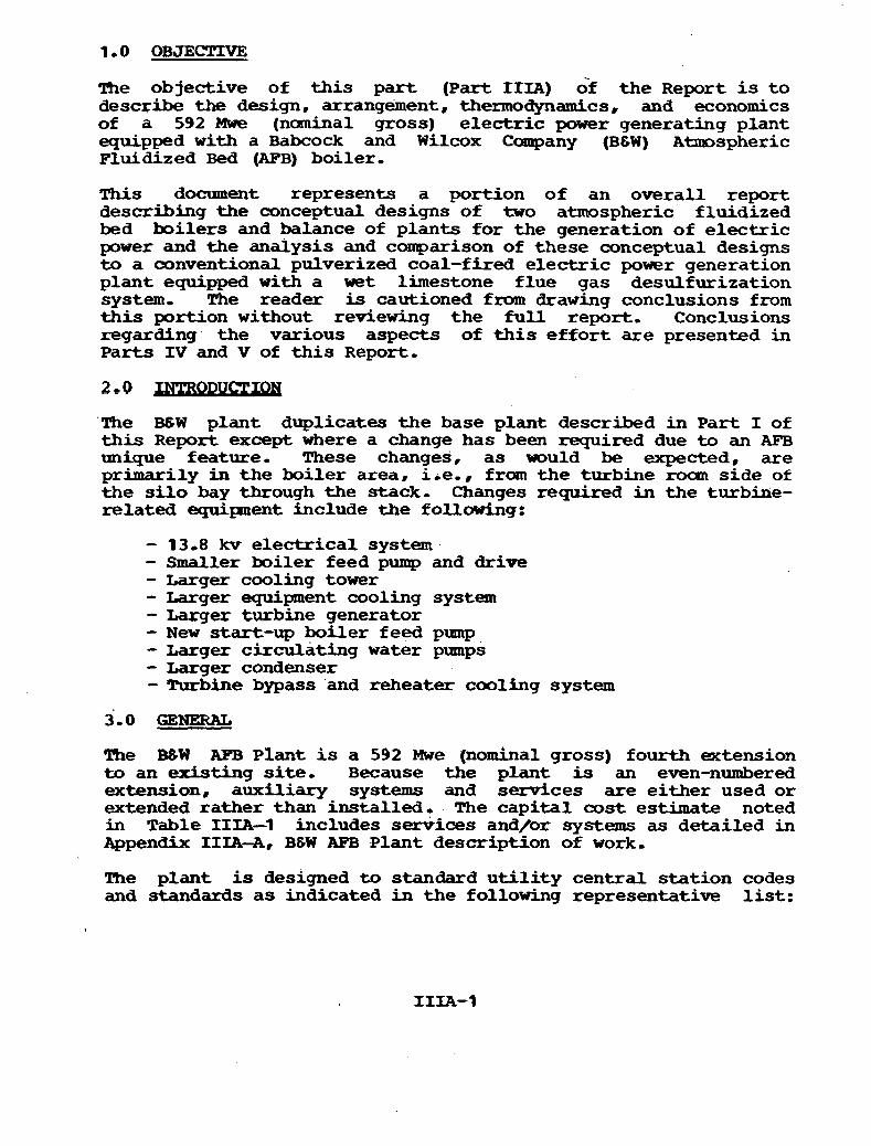
h e objective of t h i s par t ( P a r t I I I A ) of the Report is t o describe the design, arrangement, thermodynamics, and economics of a 592 Mwe (nominal gross) electric power generating plant equipped with a Babcock and Wilcox Company (B&W) Atmospheric Fluidized Bed (AFB) boiler,
This document represents a portion of an overal l report describing the conceptual designs of two atmospheric fluidized bed boi lers and balance of plants for the generation of e l ec t r i c power and the analysis and conparison of these conceptual designs t o a conventional pulverized coal-fired e l ec t r i c p o e r generation plant equipped with a w e t limestone f lue gas desulfurization system, The reader is cautioned fxom drawing conclusions from this portion without reviewing the f u l l report, Conclusions regarding. the various aspects of t h i s e f f o r t a re presented in Parts IV and V of t h i s Report,
'The BSW plant duplicates t he base plant described in P a r t I of t h i s Report except where a change has been required due to an AFB unique feature- These changes, a s muld be expected, are primarily in the boiler area, i ie , , froan the turbine rocun s ide of the silo bay through the stack - Changes required in the turbine- related equipnent include the following:
- 13.8 kv e lec t r i ca l system - Smaller boiler feed pump and drive - Larger cooling tower - Larger equipment cooling system - Largex turbine generator - New s tar t -up boiler feed pump - Larger circulating water pumps - Larger condenser - Turbine bypass and reheater cooling system
3.0 GENERAL
The B t i W AFB Plant is a 592 Mwe (nominal gross) fourth extension to an existing site, Because the plant is an even-numbered extension, auxiliary systems and services are e i ther used or extended rather than installed. The capi ta l cost estimate noted in Table IIIA-3 includes services and/or systems a s detailed in Appendix IIIA-A, B6W AFB Plant description of work,
TAe plant is designed t o standard u t i l i t y central s ta t ion codes and standards as indicated in the following representative list:

Federal EPA Standard/Regulations OSHA Regulations ASME Codes ANSI Standards NFPA Codes Nationdl Electrical Code Uniform Building Code Zlocdl Codes and Standards
1
The plant, is equipped with an AFB boiler and .an electrostat ic precipitator t o meet the 1.2 lbper-million-3tu EPA SO2 emission limit and a 0.06 Ib-per-million-Btu particulate emission l i m i t ,
Like current f a c i l i t i e s , the plant has an economic l i f e . of 30 yr, s ta r t ing in 1982, with a planned loading cycle as noted in Table 11-2.
4.0 T'HERMODYNZWIC CYCLE
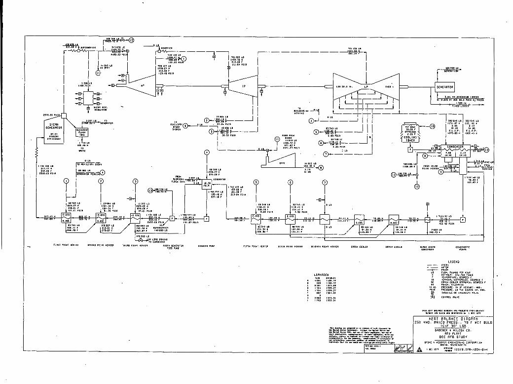
Diagrams 12919.02A--RBSK-1, 2, 3, and 4 describe the thermodynamic characteristics of the plant a t maximum ( W O ) , 75 percent, 50 percent, and 25 percent load, respectively.
The balanced draft , assisted circulation, drum-type boiler has a heat input of 5,495,500,000 Btu/hr a t VWO with a mixed gas outlet temperature of 274 F-
The turbine is a 2,520 p s i g / l , O ~ O F/1,000 P fbur-flar tandem oompound machine with 30 in- l a s t stage blades- It is rated a t approximately 592 Mwe when supplying seven stages of feedwater heating, the boiler feed pump drive, and exhausting into a multipressure condenser with approximately 1/2 percent makeup.
Using the fuel and the economic evaluation factors noted in Table 1-2, in Part I of this Report, the following plant design features were optimized as p a r t of the base plant e f for t and have not been reoptimized as part .ok the AFB effort.
- Main turbine end size
- Boiler feed pump drive
- Feedwater heater number, terminal difference, and drain cooler approach
- Condenser tube material, length, and diameter
- Cooling tower range approach and flow

TABLE IIn-1
block Description
1 Land and Land Rights
CAPITAI. OOST ESTIJWPE FOR A
570 MWE BABCOCX AND WIlrCOX APB
Material Labor (000) COOOL
N o t Included
*3 Main poorerhopse 10.748 10.644
4 . Admilnis tra t i c m Emilding N o t Included
*5 Miscellir~leous Bu.ild.mgs Not Included
*6 Boiler Equipment by Vendor 34.724 25.214
*7A B6;Lhnce of Borler P l a t Equipnrent 10 954 , 7,219
*lB Ash Handling Equipment 7,363 4.095
*8 mel flandling and Storage Equipment 4,014 2,392
*9 Stack 794 1.300
10 Precipitator 9.718 4,331
*I1 Flue Gas Desulfurization 0 U
12 Turbine Generator Equipment by Vendor 18,939 868
*13 Balance of Turbine Plant Equipment (Excluding Condeing System)
*ir Carrdenser/Ciraalbting Whter. System 5,533 . 2.509
15 Water Treatment 412 58
*16 waste heatment o o
17 Accessory P l e c t r i c d Equipment 7.623 6,298
Total _Loo01
Manhours (000)
S P W (Net)
*Change from Base Plant
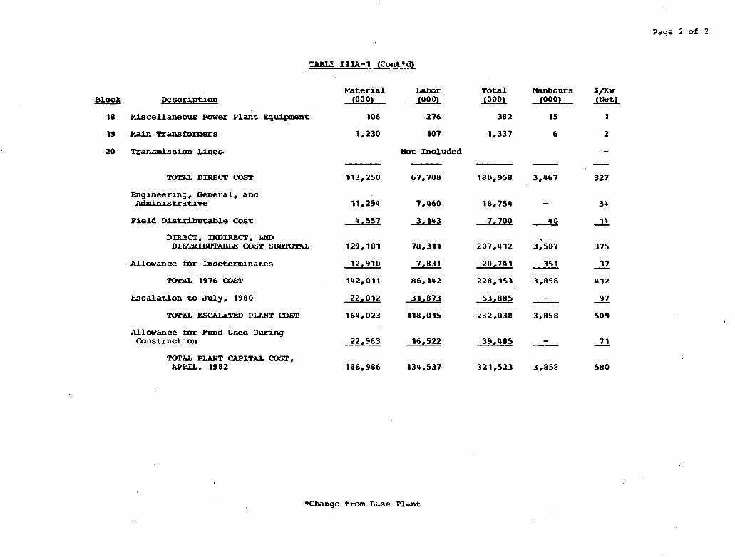
Page 2 of 2
Block Description Material Labor Total
(000) (000) JOOO)
20 h-ansmission Lines
TUFS& DIREKX COST
Eng meerins , General. and Mminlstrative
N o t Incluced
113,250 67,708 180.958
F i e l d Distributable Cost 4,557 3.143 7,700
DIR3CT. INDIRECT. A m DIS- COST SUi)TOYlL 129,101 78,311 207,412
U o w a n c e for Indeterminates
TOTAL 1976 alST
Escalation to July, 1980 22,012 31,873 53,885
TOTAL ESCALbTED PLANT COST 164.023 118,015 282,038
Allawirnce fDr Fund Used During C o n s t r u c t m 22.963 16.522 39.485
W A L PLANT CAPITAL COST. APKU. 1982 186.986 134,537 321,523
*Change from B d e P l a t
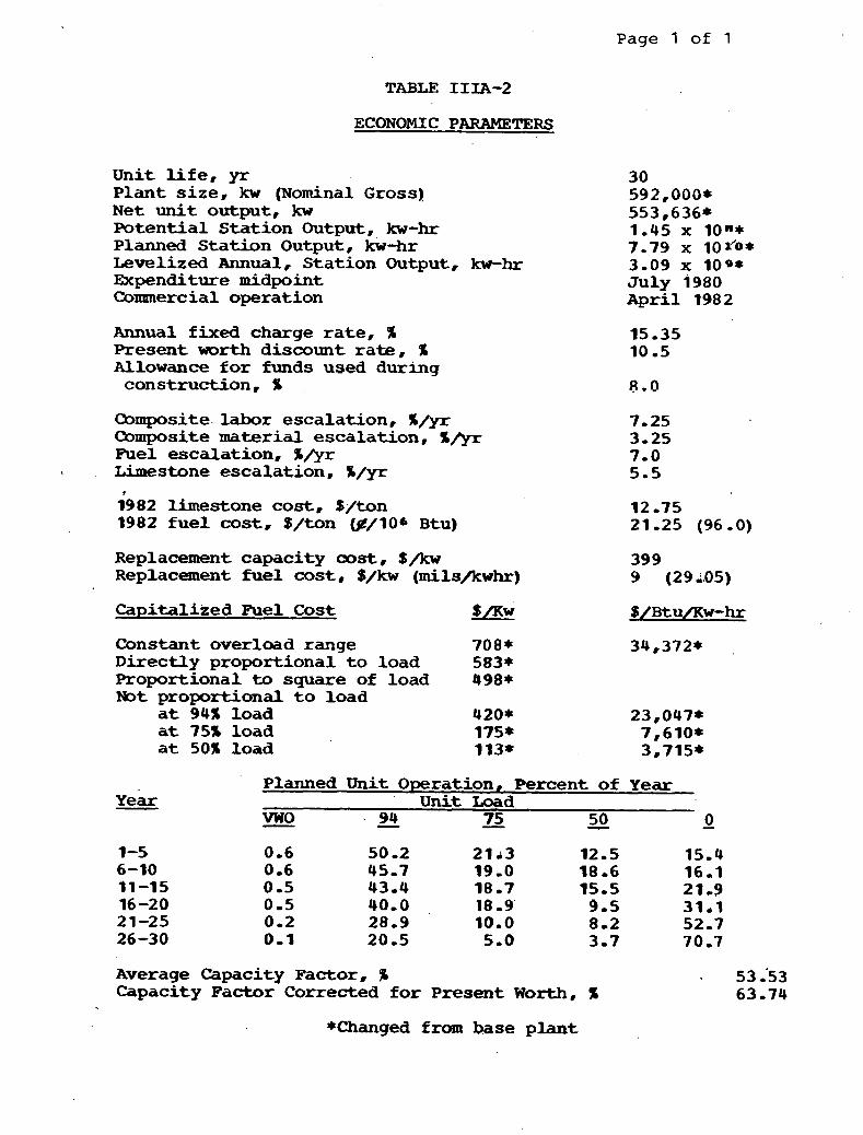
Page 1 of 1
TABLE IIIA-2
ECONOMIC PARAMETERS
Unit l i f e , yr Plant s i ze , kw (Nominal Gross) N e t u n i t output, kw Potent ia l S ta t ion Output, kw-hr Planned Stat ion Output, kw-hr Levelized Annual, Stat ion Output, kw-hr Expenditure midpoint Commercial operation
Annual fixed charge ra t e , % Present w o r t h discount ra te , % Allowance f o r funds used during construcldon, %
30 592,000* 553,636* 1.45 x lo"* 7.79 x 10~'0* 3-09 x l O Q * J U ~ Y i980 April 1982
Composite.labor escalation, %/yr 7-25 Composite material escalation, %&r , 3-25 Fuel escalation, %&r 7-0 Limestone escalation, %/yr 5-5
1982 limestone cost, $/ton 1982 f u e l cost. $/ton (#/lob Btu)
Replacement capacity cost, $/kw 399 Replacement f u e l cost , $/kw (mils/kwhr) 9 (29~05)
Capitalized Fuel C o s t
Constant overload range 708* Directly proportional t o load 583* Proportional t o square of load 498* Not proportional t o load
a t 94% load 420* at 75% load 175* a t SOX load 113*
Y e a r -
Average Capacity Factor. 'A 53.'53 Capacity Factor Corrected f o r Present Worth, % 63-74
*Changed from base plant
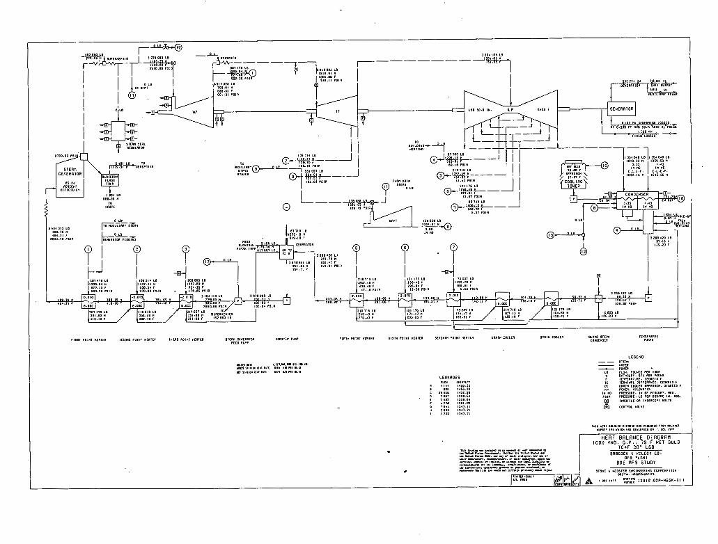
I HEAT BALANCE DlRGRRM 100%. V W O . O . P . . 79 F H E T BULB
l r r C 3"- I <PI . %.L. Y.*" -. ..."3 .. Y U, .I -.. - 4 Y m,U ".a -,_ ..,Y, Y. mS.4 -8.. - Y PIY .!.u mm. .- Y ., Y1' ".I.,..., " UI .r - --. _n-.. .I YI r ,, , O ,.. n ..- ."eizu:Z z .YCLLYV rn Y .-. '91.Y.. 'UIYY .f
~"=:k?sl","=:~%&-~$u=%CC ,111, 11111 t
"I. rnI Ppl~l.p(l 101111??110111
,..a -" ."" BRBCOCK L Y l L C O X C O .
R F B 'LRNT D O E RF3 S T U D Y
STONE & Y l s S l l R C Y O l l t E l l Y O C O I P O R R I I O Y 1011D". WI,IC""I<IIS
, otc ,,,, 'Ec 1 2 9 1 9 . 0 2 R - H B S K - 8 1 1
LERKRCES

1101 a61 LB
190.11 1 4 1 1 . 1 1 F
1510.19 P S l l
S T 0 c SrLDlQ P01.11 XCI -CE 1H1(10 .'1*1 I R I C R I I C P a OTNClF lOR BOOSIF I I t m ? F J ~ H .I~MZ MEOITR 51111 POIXI ~ ~ 0 1 ~ 1 1 ITI:XII( ~ 0 1 ~ 1 ~ ~ 1 1 1 1 0111* TOOUR D R O ~ Y COOLTI l m v r srcen COUCCXSCR
c u a r v s n 8 c
TCCO sUnP tuns9
LECENO
H c a ~ s a ~ a ~ c c D S R O R P ~ WPS noourro r ~ o n OIIL~*II ?unBCR I t 7 " V l C * "(IS WIRllmD 0" I OFT ! D l 7 1 HER1 WLRNCE O i R G R R t l
5 0 % V H O . R R T ~ ~ A ~ R % ~ 5 . 1 . 9 ~ 9 -4 F W E T BULB
N. d..ng-. P1d .. u -I ., m .- " ..-, -- b""
Y. mt.4 2UL.t" O 1 . l - L . I.- Y m u n*. .- Ir mt.4 .ru nu. rr .m, .a vll, +-. u ur .r
enscocr r UILCOX cC u u -u.r.., n-m...,.. .r u,. -.. -... .s -*. W.. .r i-d. .. -w ", L . d .lLL.IUU " .rC."Y,, l., a. .-.,. W.U... " u.-. .f
D O E AFB S - U O Y ul -"I. .pm".. p.o " C.". d I . b . 3 . " ..cur r u l s r ... -.u -t tvny rr..*lr -4 "LY STOXI I YCBSITI EIGIYEEBIHC CORPORIIION
1,11111 1'1.1 1 .S,,O*. "1,1.1111~111 -A roTi ar.l ontr A om 1.77 ~ ~ : ~ ~ ~ ~ ~ 9 ~ t l B S K - 8 3 ~ I 1
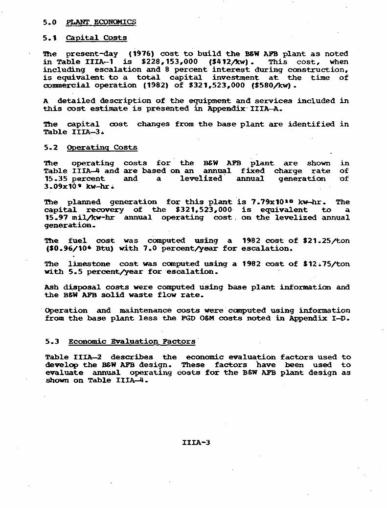
5-0 PLANT ECONOMICS
5.1 Capital Costs
The present-day (1976) cost t o build the B g W AFB plant a s noted inTab le IIIA-1 is $228,153,000 ($412/kw). This cost, when including escalation and 8 percent in te res t during construction, is equivalent t o a total capi ta l investment a t the time of commercial operation ' (1982) of $321,523,000 ($580/kw) . A detailed description of the equipment and services included in t h i s cost estimate is presented in Appendix. IIIA-A.
The capi ta l cost changes f r o m the base plant are identified in Table IIm-3r
5 - 2 Operathq Costs
The operating costs f o r ' the B E W AFB plant are shown in Table II IA-4 and are based on an ann-1 fixed charge r a t e of 15-35 percent and a levelized annual generation of 3,09x10* kw-hri
The planned generation fo r this plant is 7.79x101o kw-hr. The capi ta l recovery of the $321,523,000 is equivalent t o a 15 -97 m i l & - h r annual operating cost , on the levelized annual generation - The fue l cost was computed using a 1982 cost of $21;25/ton (S0,96/106 Btu) w i t h 7.0 percent&- f o r escalation-
The limestone cost was computed using a 1982 cost of $12;75/ton w i t h 5-5 pe rcen tmar fo r .escalation.
Ash disposal costs were computed using base plant information and the B6W APB sol id waste flow rate.
Operation and maintenance costs w e r e canputed using information from the base plant less the K D 06M costs noted in Appendix 14,
5.3 Ecanomic EMluation Factors
Table IIIA-2 describes the economic evaluation factors used t o develop the BGW AF'B design. These factors have been used t o evaluate annual operating costs for t he B 6 W A . plant design as shown on Table IIIA-4-

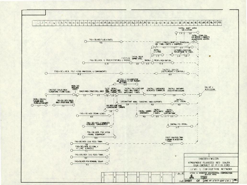
6.0 B 6 W AFB PIANT PROJECT SCHEMJLE
The level I network 12919-BW-CN-1 describes the plan for procurement, fabrication, and erection to place the plant in operation in April, 1982.
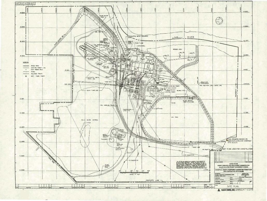
7.1 S i t e
Drawing 12919~02A-EY-602A depicts the B&W AFB plant site.. Those features included i n the construction of the plant are
- highlighted with heavier lines,
A new coal/limestone crusher house w i l l be located in the yard, ~n independent dual set of be l t conveyors w i l l t i e i n t o the exis t ing conveying system i n the yard and the existing be l t oonveyors w i l l be extended in to the new boiler building .,
This u n i t u t i l i z e s a twelve-cell mechanically induced dra f t -ling tower fo r heat rejection,
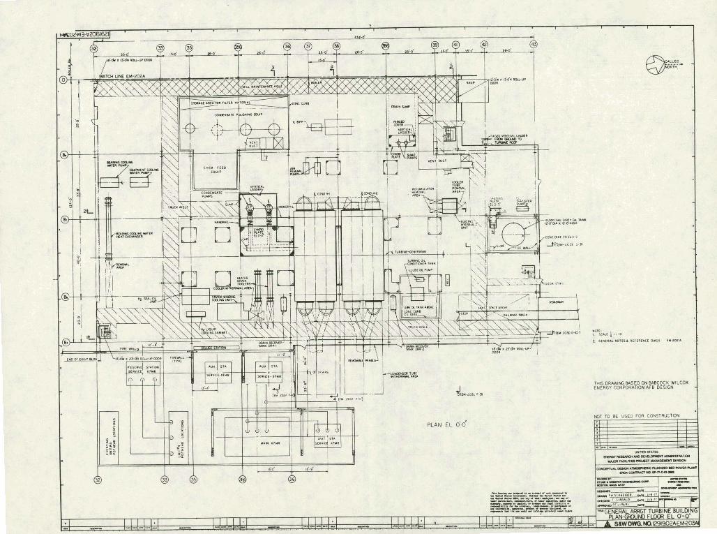
7.2 Turbine Room
The turbine room is essent ial ly identical to the base except fo r a start-up boiler feed pump on the ground floor as noted on Drawing 129 19& 02A-EM-203A. ..,
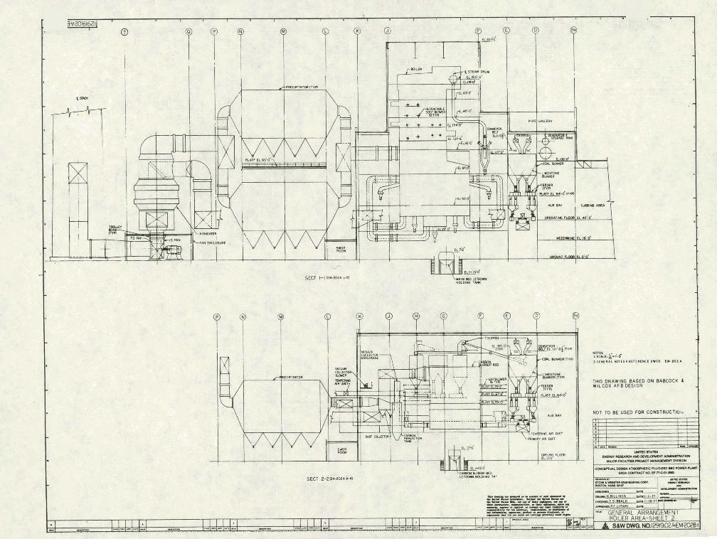
7.3 B o i l e r Fmom
A s noted on Drawings 12919-02A--EM--202A and 202B, the boi ler r o o m n dimensions are approximately 338 f t wide by 157 f t deep by 222 f t high with the ground, operating, and mezzanine f loors matching those of t he turbine room,
The three coal bunker bays on three sides df the boiler are a total of 512 f t lonq by 33 f t deep by 131 f t hiqh, w i t h the CC>A~. tripper conveyor f loor a t E l - 107 f t and gravimetric feeders a t E l , 64 ft-0
The forced draf t , induced draf t , primary a i r and tempering a i r fans are located in a closed roam for sound attenuation. Because t h i s room w i l l operate a t subatmospheric pressure, double door a i r locks are supplied.
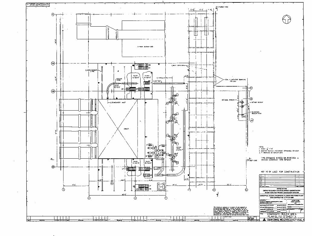
Boiler area composites are shown on Drawings 129 19 ,02REP-202A through 20X. Column locations and bracing are as nated on Drawings 12919.02A-ESdOlA, 606A, 609A, and 609B.
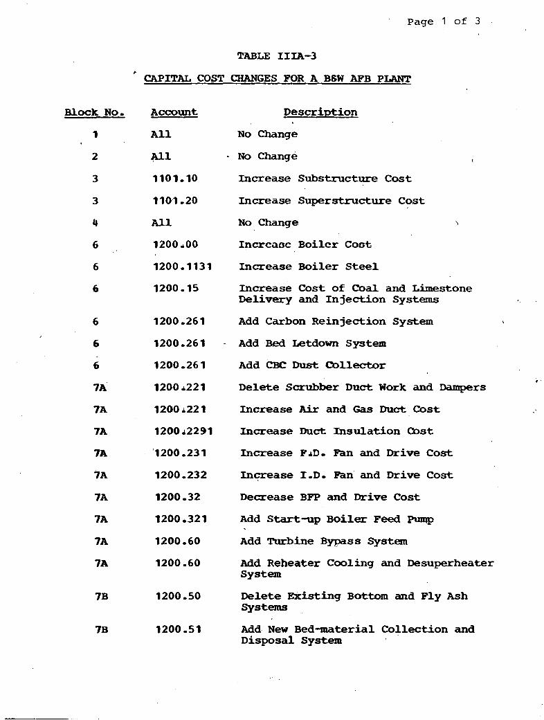
Page 1 of 3
TABLE IIIA-3
' CAPITAL COST CHANGES FOR A BSW AFB PLANT
Block No, Account Description
1 A l l N o Change
2 A l l - N o Change
3 3101,lO Increase Substructure Cost
3 1107 -20 Increase Superstructure Cost
4 A l l No Change
G 1200 -00 Incrcaoc Boilcr Coot
6 1200 - 1131 Increase Boiler Steel
6 1200,15 Increase C o s t of Coal and Limestone Delivery and Injection Systems
6 1200,261 Add Carbon Reinjection System
6 1200,261 - Add B H Letdown System
6 1200,261 Add CBC D u s t mllector *
Delete Scrubber D u c t Work and Dampers
Increase Air and Gas Duct Cost
Increase Duct Insulation Oost
Increase F A D - Fan and Drive Cost
Inqease 1 . D - Fan and D r i v e Cost
Decrease BPP and Drive Cost
Add Start-up B o i l e r Feed Plmsp
Add Turbine B y p a s s System
Add Reheater Cooling and Desuperheater System
Delete Existing B a t t o m and Fly Ash systems
7B 1200-51 Ada New Bed-material Collection and Disposal System

Page 2 of 3
TABLE IIIA-3 (Cont 'd)
Block Nor
7B
Account Description
1200 -54 Add N e w Fly Ash Collection and Disposal System
1241.20 * Add New Coal and Limestone Crushing and Conveying Equipment
1241-20 Add New Tripper Equipment
1241-41 Increase Inplant Coal and Limestone Stor aye
Delete Limestone Preparation Equipment
1241 -49 Increase Coal and Limestone Chutes, Gates, etc,
1242-00 New Ignition Oil System for the Same C o s t
ZU1 Ms Change
A l l Add .New Crusher House
1200.81 Change Stack Liner t o Steel
1200,252 Increase Precipitator Cost
9200 - 252 Add N e w CBC Precipitator
1280 -27 Delete All Scrubber . C o s t s
1400 10
1400 -85
A l l
1400.21
1900*281
1400 -30
All
1400 134
1400,348
Increase Turbine-Generator Cost
Increase Component Cooling System C o s t
Change Included i n Block 14E
Increase Condenser Cost
Increase Circulating Water Pump and Drive Cost
No Change
N o Change
Increase Cooling Tbwer Cost '
Increase MU Water Pump and Drive Cost
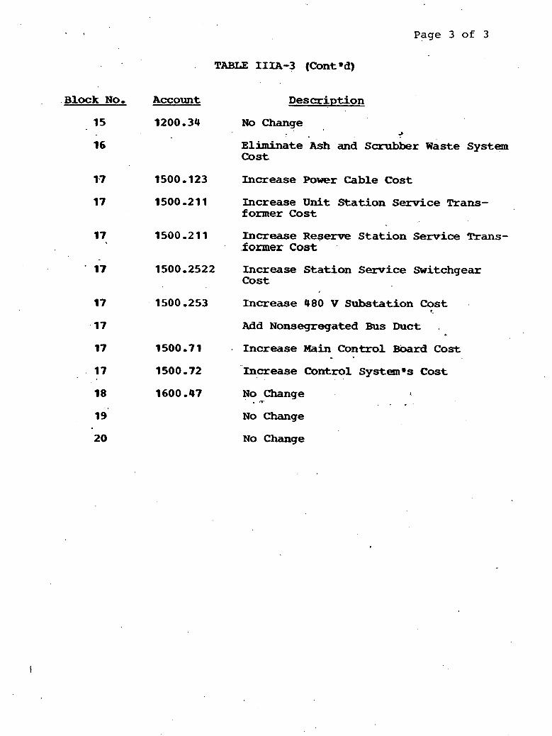
Page 3 of 3
, .Block No ,
15
Account
TABLE IIIA-3 (Cont d )
Description
1200,34 N o Change A
~liminate Ash and Scrubber w a s t e System Cost
Increase Power Cable Cost
1500,211 Increase U n i t Station Serv ice Trans- former Cost
1500,211 Increase R e s e r v e S t a t i o n Service Trans- .former Cost .
1500.2522 Increase Sta t ion Service Switchgear C o s t . ,
1500,253 Increase 480 V Substat ion Cost <
Add Nonsegregated Bus buct a
1500,71 . Increase Main Control Board C o s t
1500,72 Increase Control Systemms Cost , .
1600 -47 N o Change d
* "I' . . . No Change
NO Change

TABLE I I IA-4
Page 1 of 1
B6W AFB PLANT ANNUAL OPERATING COSTS (MILLSPW-HR) NET
capital Recovery
Fuel Cost
Limestone Cost
Operation and Maintenance
Power P l a n t
FGD Plant-
Sludge Stabilization Plant
Ash and Sorbent Disposal
Particle Emission Control Equipment


. - - -
---- --- - - - --
i rrtrv DWN - - I l _ l k f - L L 1 --
lH16 ORAWIN6 RASED ON %ABCOCK d WlLCOX COMPANY ACE OES1GN
Pi", &.i.d RPN EL 178.0 1 PITrnt * [ I m cs.6LY
lMSCRaWNGWEDONBneUXXSWLC(D: COWWi AFB USCN I
8.0 PROCESS SYSTEMS
8.1 General
The flow diagrams indicated hereinafter u t i l i z e the notation q i p e C 1 YYYYX, wInsul C 1 Xw and "VXX-YYYX, where X denotes an alpha character and Y denotes a numeric character,
q i p e C 1 YYYYXm is a denoter of pipe material, pressure rating, schedule, etc,, a s described in Appendix 1-2,
mInsul C 1 Xu is a denoter of pipe insulation material and thickness a s described in Appendix ,I-3,
"VXX-YYYXa is a denoter of valve type. pressure rating, construction, end preparation, e t c - These de ta i l s are identified in the "Pipe Clm indicated on the flow diagram, A general explanation of the notation system is sham on Drawing STD-MM- 1002-1-2, (See Part I of t h i s Report ,)
8 -2 , I Main Steam, ~ o t and Cold Reheat
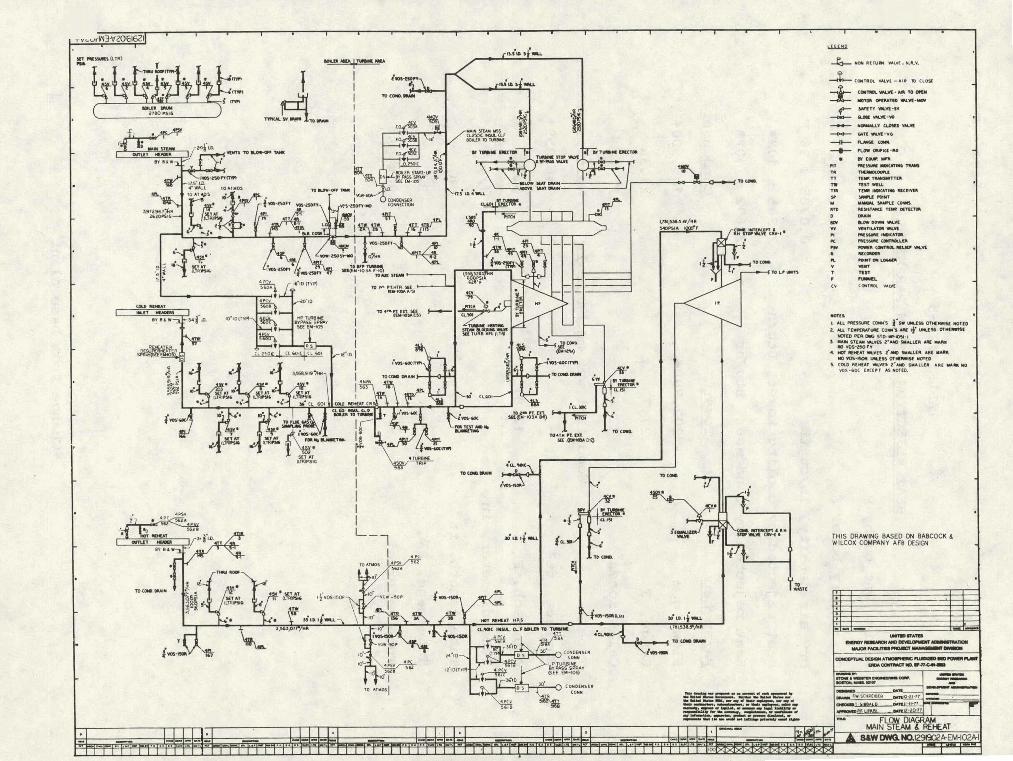
Refer t o Flaw Diagram 12919,02A-EM-l02A,
Main' 'Steam
The main steam system is ident ical to the'base plant described i n Section 8,2,1 except t ha t a high pressure turbine bypass system is supplied t o assure minimum flow through the superheater, The pressures, temperatures, and flows vary s l igh t ly as noted on heat balances 12919-02A-HBSK-1, 2, 3, and 4 a s a result of permitting the base plant stack gas reheating steam t o expand through the turbine.
Cold Reheat
The cold reheat system is ident ical t o t he base plant described i n Section 8-2.1 except for the addition of a safety valve and a ~mnreturn valve , The pressures, temperatures, and flow? vary s l igh t ly a s noted on heat balances 12919-02A--tIBSK-1, 2, 3, and 4 as a resu l t of permitting the base plant stack gas reheating steam t o expand through the turbine,
Hot Reheat
The hot reheat system is ident ical t o the base plant described in Section 8-2-1 except t ha t two electranat ic re l ief valves were instal led, The pressures. tempgratuxes, and flows vary s l igh t ly as noted on heat balances 12919,02IHiBSK-l, 2, 3, and 4 a s a

result of permitting the base plant stack gas reheating steam t o expand through the turbine,
Reheater C o o l i n q
A reheater cooling systaa has been imposed on B&W t o assure m i n i m u m flow through the reheater following a turbine t r i p .
8-2-2 Extraction
Refer t o Flow Diagram 12919,01-EM-103A.
The extraction steam system is ident ical t o the base plant system - described in Section 8-2.2 of Pa r t I of this Report except tha t
the extraction stage pressures, temperatues, and flows vary s l i g h t l y as noted on the heat balances 1291 9-02A-HBSK-1,2,3, and 4 ., The auxiliary steam system is ident ical t o the base plant system described in Section 8.2-3 of Part I of t h i s Report except t h a t there is no requirement fo r stack gas reheating.
8 -3 W a t e r Systems
8 -3.1 Circulatinq and Makeup Water and Condenser A i r Renroval
Refer t o Flow Diagram 12919.01-EM-ldOA,
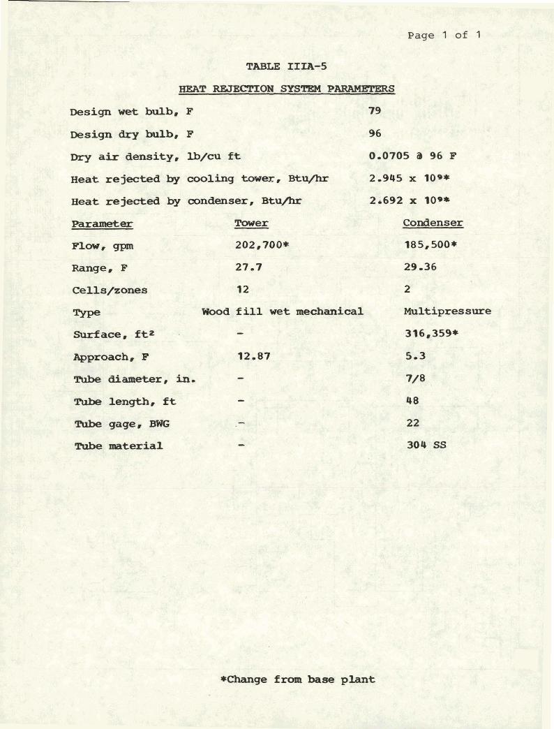
me circulating and makeup water'and the condenser a i r removal systems are ident ical t o the base plant systems described in Section 8 ,3,1 of Part I of this Report except tha t the armponent cooling water system (Section 8 -3.5 1) duty has increased due t o the additiogl of bed m a t e r i a l letdown ooolers, The condenser duty has increased by approximately 5 percent a s a r e s u l t of permitting the base plant stack gas reheating s-am t o expand through the turbine, Table IIIA-5 ident i f ies these changes.
8.3-2 Condensate
Refer- t o Flow D i a g r a m 12919 -01-EM-104A,
The condensate system is ident ical to the base plant system described in Section 8-3-2 of Part I of t h i s R e p o r t ,
8 d 3 -3 Feedwater and Desuperheating Water
Refer t o Flow Diagram 129 19 -02A-EM-105A.
Page 1 of 1
TABLE IIIA-5
HEAT REJECTION SYSTgM P-
Design w e t bulb, F 79
Design dry bulb, F 96
Dry air density. I.b/cu f t 0.0705 a 96 F
H e a t rejected by cooling tower, Btu/hr 2-945 x lo**
Heat rejected by condenser, Btu/hr 2d692 x loo*
Parameter Tower Condenser
Fl-r QPan 202,700* 185,500*
Range. F 27-7 29-36
C e l l s / z o n e s 12 2
W E = K.!F .?gUb Wood f i l l w e t mechanical Multipres sure :&.;:-t;q
Surface . f t2,~;.7~$, - . :L?$,$@$ - 316,359*
Approach, F 12-07 5.3
Rlbo ~ ~ r , in- - 7 / 8
Tube length, f t - 48
mbe gage@ - 22
Tube material 304 SS
*Change f ram base plant

I :-r0-nS0U-8z0~61621 c,'RzI LLSI >lo l 1m '1"
IIIIS"Y,II*I" '"PIID* I llfllO"110 XOllllDdIDl I*II11YIONl 1110911 > lWDlE
lonls nju 300 INL(1d Ed8
'03 X0311H 9 Y303888
ESl .OE dV31 ElflE 13U 4 6L "SS3ld 031tlU 'OUA %SZ
"Qu r- 0""- *rLl I- nr. en9 %- "ur - ..."I"" -- - .- lnrvh .-n- '" L -.--..-.- .ow. .n ..l .,m.*r =:~~-y:~;&mm=-,L~&K
2. '.. 1- ....' ".m '1.3.'. Ma .C. "ry mm - -." nm .n I."". 'S-rus -ru nm '.P-.-.l"-.i.r-.n..LIU.-h
I -- WH83H10 3JNHltlB 1H3H 1
Feedwater
The feedwater system is ident ica l t o the base p lan t system described i n Section 8-3-3 of P a r t I of t h i s Report except t h a t a t low boi le r pressures during start-up, t h e 5,860 gpm, 7,556 it TDH (68 percent load) start-up feed pump w i l l be used t o supply bo i l e r f eedwater . Main Steam Desuperheatinq Water
Water f r o m the bo i l e r feed pump 'discharge is injected i n t o the primary supexheater o u t l e t t o maintain a secondary superheater o u t l e t temperature of 1,000 F.
Water from an intermediate s tage of t h e bo i l e r feed is supplied t o t h e reheater i n l e t t o maintain a hot reheat steam temperature of 1,000 F, Water is a l s o supplied to t h e Turbine Bypass and Reheater Cooling System f o r steam desuperweating during a --up, shutdown, o r turbine t r i p ,
8.3-h H e a t e r Drains
Refer t o 12919-01-EM-106A-
The heater drain system is ident ica l t o the base plant system described i n Section 8-3.4 of Part I of t h i s Report except t h a t t h e pressures, temperatures, and flows vary s l i g h t l y as noted on heat balances 12919-02A-HBSK-1,2,3, and 4.
8-3-5 Coolinq W a t e r Systems L $ 1
8.3-5-1 CampOnent Coolins Water
The canponent &ling water system is iden t i ca l to t h e base plant I
system described in Section 8-3-5-1 of P a r t I 02 t h i s Report except t h a t t h e duty and flow have been increased by one-third a s a result of cooling the bed material leaving t h e AFB *boiler-
8,3,512 B e a r i n s Coolinq Water
The bearing cooling water system is iden t i ca l to the base plant system described i n Section 8.3-5.2 of Part I of t h i s Report,
8,3,6,1 Condensate Polishinq
Refer t o Flow D i a g r a m 12919.01-EM-128A.
me condensate polishing system is ident ical to the base plant system described in Section 8-366-1 of Part I of t h i s Report,
8.3.6~2 Chekcal Feed
Refer t o flow Diagram 12919.01-EM-l19A,
The chemical feed. system is ident ical t o the base plant system described in Section 8.3-6.2 of Part I of this Report,
8 . 4 Material Handling Systems
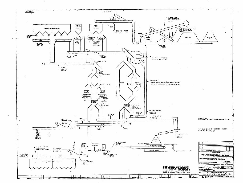
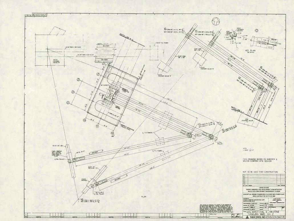
.8,,4,1 Coal and Limestone Handlinq System
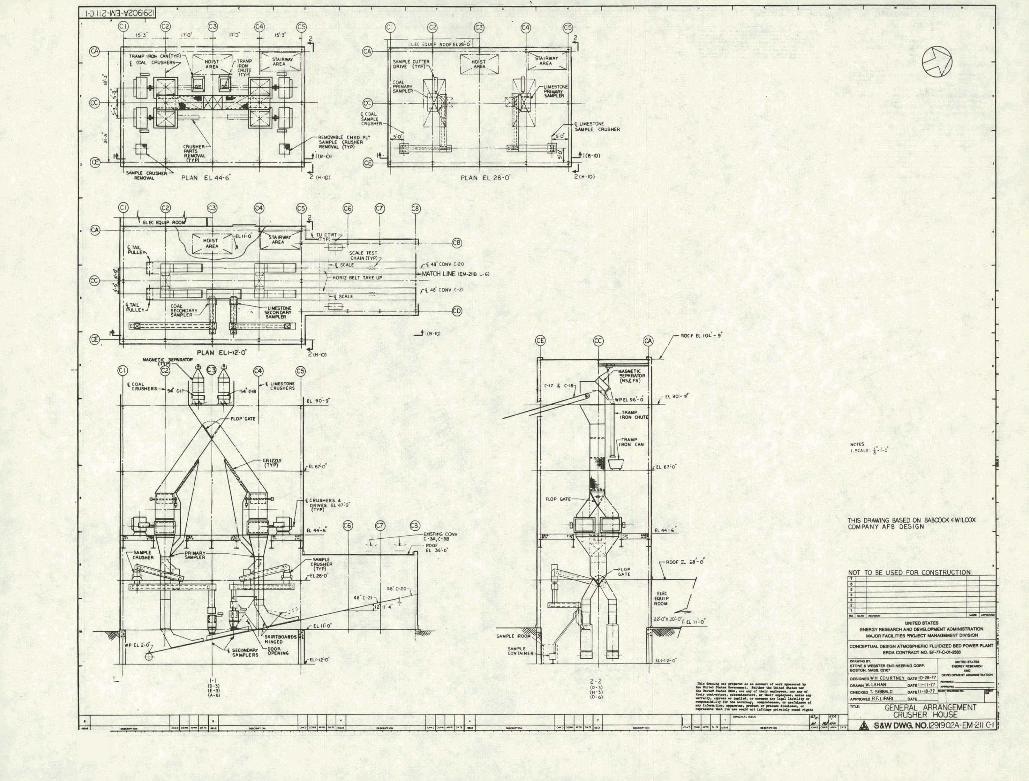
Refer to Flow Diagrams 12919-02A-EM-l7OA, EM-17OB, EM--170C, and General Arrangement Drawings 129 19 -02A4M-2 1 1A, EM-2 11B, and EMj11C- I
The coal and 1ime~tone pa~amsZ;ex~ for this study u e shown in Tables 1-4 and 1-7 i n Part I of $his Report-
2Ae coal/limestone handling system consists of the yard and s t a t i on subsystem and the dis tr ibut ion and injection subsystem,
8-$,I-1 Delivery Subsystem
Sections 8i4-1-1-1 Delivery to Site , 8-4-1-1-2 Transfer Storase, 8 ~ 4 - 1 - 1.1 Transfer to Station remain a s described in
'
P a r t I of this Report fo r the existing Units 1-3,
In order t o t ransfer coal and limestone t o the s ta t ion f rcnn the as-delivered -state, or f ram storage, new mnveyoxs to and from the new crushers w e r e required,
The preparation of the coal and limestone t o the specif ic s ize requirements f o r use in the fluidized bed required new ma1 and limestone crushers f o r this uni t -
The transfer of coal and limestone t o the AFB unit can be accomplished by using two paths from ei ther source: A s Delivered or Storage,
As Delivered
The coal and limestone are delivered from the railroad unloading bppers ants existing~conveyors.C-2B, C-3B bypassing the existinq mushe~rs 1B &lit 2B onto conveyor C-5B mid-I is used nomally as the stackout conveyor t o yard storage Location 1, A new fixed t r ipper w i l l t ransfer coal o r limestone from the existing mnveyor C-5B onto new conveyors C-tS to C-17 t o the surge hopper through the new coal or limestone crushers v i a f lop gate, Rosn the crushers, the coal or limestone is transferred by e i the r one

DETAIL A .I WCClrCO YrRl 6
,cu.,,m r.,,
DETAIL C AS r l P C 0 W P L C
111.110A 1.101
THIS DRAWING B A S D CN BABCOCK AWlLCOX COMPANY AFB DESIGN
.6U) r P Y 66 I , P I U bIO(m"l Y.LlO(rml
- O W m*r c-,s
DETAIL B .1 r l l ( l W C 0 YPLl <EM- IW ,,I
E T A l L E a % (rh.110< I)L<CIYIO 0-C.6-6) SIYsLC


. .
THIS WlLCOX DRAWING COMPPNY BASED AFB MSIGN ON BABCOCK 6
THLS DWlNO 89SED ON BABOMCCWUCOD( COMPANY AFB DESIGN

of two parallel paths v ia conveyors C--20 t o C-22 onto the exist ing cmveyors C-8A and C--9A and onto the t r ipper conveyors Go9A extended C-24, and C-25 and into the bunkers, o r via C-21 t o C-23 onto existing conveyors C-8B and C-9B and onto t r ipper mnveyors C-9B extended, C-24, and C-25 and in to the bunkers. C--28 and C--25 are t r ipper conveyors t h a t 'feed the bunkers on the l e f t and r igh t s ide of the boiler, respectively,
Ran Yard Storaqe Location 2
Coal o r limestone from coal p i l e 2 is reclaimed using the existing stacker reclaimer conveyor C-7Bi A new fixed t r ipper w i l l t ransfer coal o r limestone from C-7B.onto new conveyors C-16 and to'C-18 into surge hopper and in to the crusher house and the coal or limestone bunkers a s described above,
The i n l e t chute of both the new coal and limestone crushers will be equipped with magnets to remove tramp iron; otherwise, the section remains as described in Part I of this Report,
8 4 , I - 1 5 Mass Transfer Measurement
This remains a s described in P a r t I of this Report,
8,4,1;1,6 Crushers
Rexnains a s in the base plant report f o r Units 1-3, For Unit 4, the new coal crushers, discharge - 114 in , coal with - 2 1/2 in, ROM input, The new limestone crushers discharge - 1/8 in, Limestone w i t h - 3/4 i n - input- Each crusher is rated a t
,900 TPH, ,
~n m a s f i redm sampling system is included in the discharge chute of each set of new crushers f o r the AFB unit; otherwise, the section remains a s described i n Part I of t h i s Report.
8,Udl,1,8 System Included W i t h This Unit
The axl/limestone handling system included i n the scope of t h i s uni t is a s follows:
1, The ins ta l la t ion of fixed t r ippers on existing conveyors C-5B and C-7B,
2, The ins ta l l a t ion of a new crusher house which would include two limestone crushers and two coal crushers and associated -pent such as ductwork, samplers, gr izzl ies , etc,
3 - The ins ta l la t ion of 10 complete new conveyors, The two existing tripper conveyors w i l l be extended,
4 , The instal lat ion of a t o t a l of 25 coal bunkers and 25 limestone bunkers including vibrators, s l ide gates, and piping-
5 -, The instal lat ion of 25 pairs of gravimetric feeders, 25 mixing bustles, and 25 feed pipes t o the boiler material feed distributors-
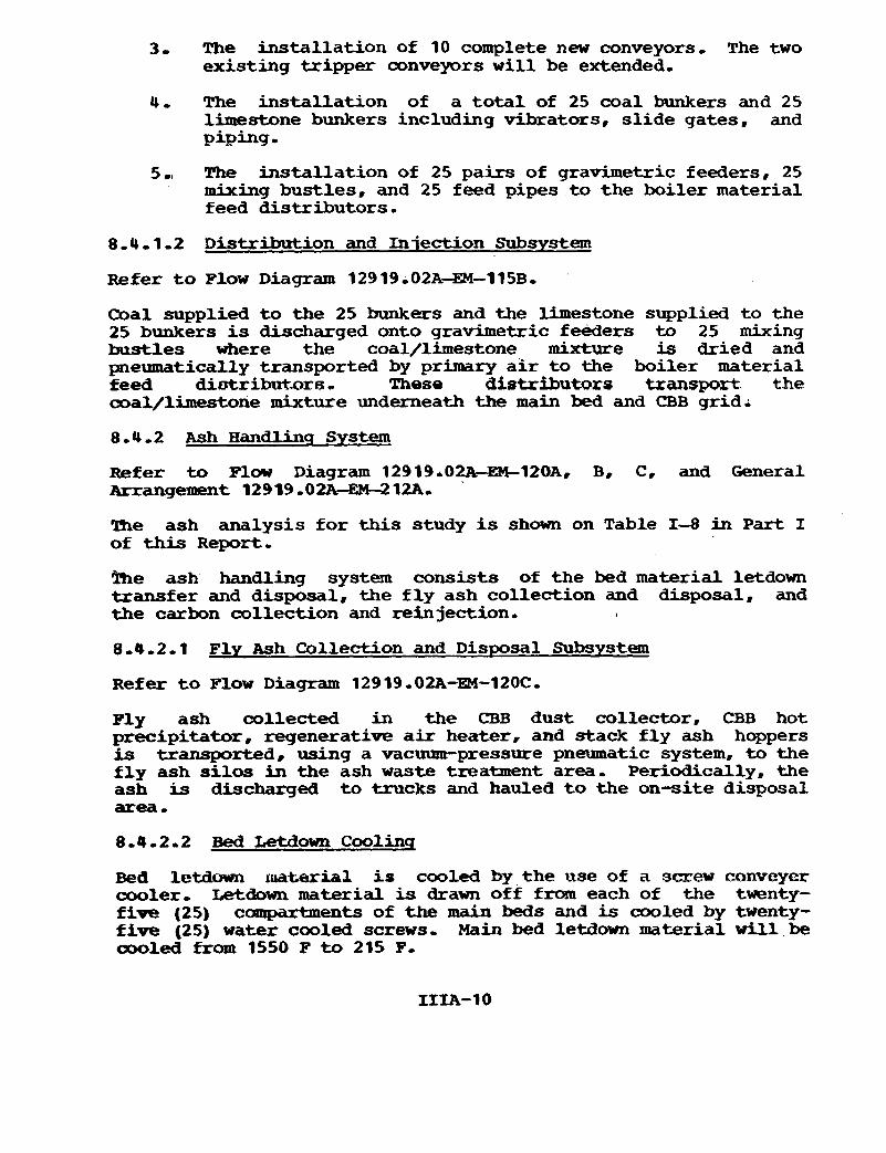
8.4 - 1 -2 Distribution and Injection Subsystem
Refer t o Flow Diagram 12919.02A-EM--115B,
Coal supplied t o the 25 bunkers and the limestone supplied t o the 25 bunkers is discharged onto gravimetric feeders to 25 mixing bustles where the coal/limestone mixture is dried and pneumatically transported by primary a i r t o the boiler material feed diatribntorcr- These distributors txanspsrt the ooal/lhestone mixture underneath the main bed and CBB grid,
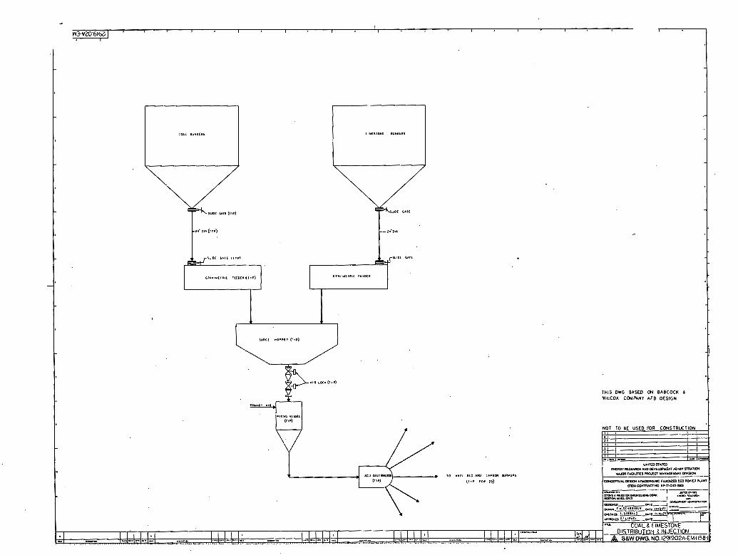
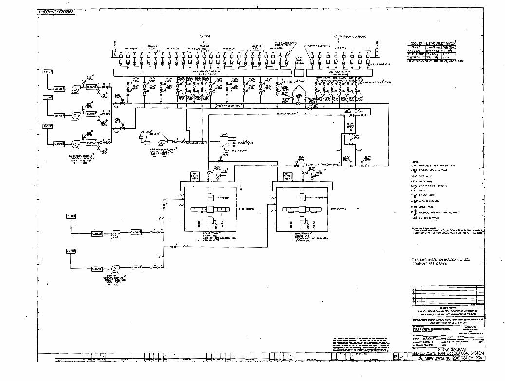
8 , 4 -2 Ash Handlins System
Refer to Fluw Diagram 12919.02AeM-l20A, B, C, and General Arrangement 12919-02A-EX-212A.
Ihe ash analysis fo r this study is shown on Table I--8 in Part I of this R e p o r t -
!he ash' handling system consists of the bed material letdown transfer and disposal, the f l y ash collection and disposal, and the carbon collection and reinjection. ,
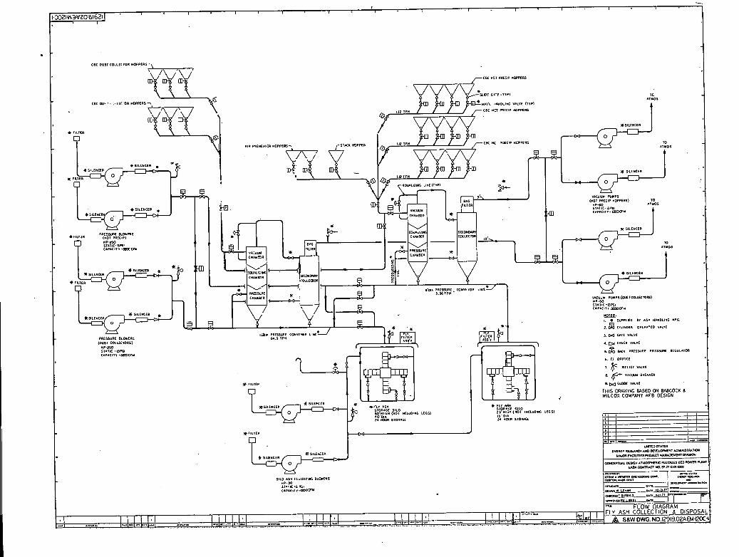
8-0-2-1 Fly Ash Collection and Disposal Subsystem
Refer t o Flow Diagram 12919,0224-EM-120C,
Fly ash collected in the CBB dust collector, CBB hot precipitator, regenerative a i r heater, and stack f l y ash hoppers is transported, using a vat-pressure pneumatic system, to the f l y ash silos in the ash waste treatment area, Periodically, the ash is discharged t o trucks and hauled t o the on-site disposal area 0
8-4-2,2 Bed Letdown Coolinq
Bed letdow~~ rmtesrial is cooled by the use of a screw canvcyer cooler, Letdown m a t e r i a l is drawn off f r o m each of the tventy- five (2'5) compartments of the main beds and is cooled by twenty- five (25) water cooled screws, Main bed letdown material w i l l be amled from 1550 F t o 215 P.
'6 TPH 7.e r~H'(puag,.; LEIDM
THS M BASED CN B/\eCOO( C WILCOX CCMPANY AFB DESIGN
d=UI-r OPLII.. I rn C I " Inn .6 PSI "P -JO
I -- (1111 5 "lo,,
similar ly, d material from the CBB is drawn off from each of t he e ight (8) compartments and is cooled by eight (8) water- cooled screws, CBB letdown material w i l l be cooled froan 2000 F to 215 .F-
Cooling w a t e r is supplied by the component cooling water portion of t he circulating water system. Cooling water is continually fed through the s c r e w conveyor hollow shaf t and f l i t e s while the material is conveyed i n the opposite airection. The cooling water is then returned t o the condenser return s ide of the c i rcula t ing water system,
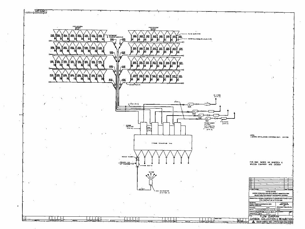
8,4,2,3 Carbon Collection and Reinjection Subsystem
Refer t o Flow Diagram 1 29 19 r 028--EM--120B ,
Fly ash collected by the main bed hot precipi tators is vacuum transported to the carbon reinjection tank, and from there it is pneumatically transported to the carbon birrnup bed by e i t he r the primary o r tempering a i r system, o r both. Ash flow from the reinject ion tank is controlled by rotary feeders located a t the bottom of each of the eight hoppers, A single feed line t o a 30:1 d is t r ibutor wi l l rcons i t i tu te one of eight underbed feeds a t the CBB.
8-4-2-4 Bed Material Letdown Transfer and Disposal Subsystem
Refer t o Flow Diagram 12919*02A-EM-l2OA.
Bed l e tdam material is transported to s i l o s i n the ash waste treatment area by a pressurized pneumatic system, Periodically, the ash is discharged to a truck and hauled to the on-site disposal area - Bed material, when required, w i l l be used as a supplennent to maintain bed level in the carbon burnup bed and main bed feedback should any me of the f ive beds be dumped during shutdown-
8.5 W e t Limestone Flue Gas Desulfurization System (FGDL
mere is no reqdxement fo r a FGD System on the BCW AFB boiler.
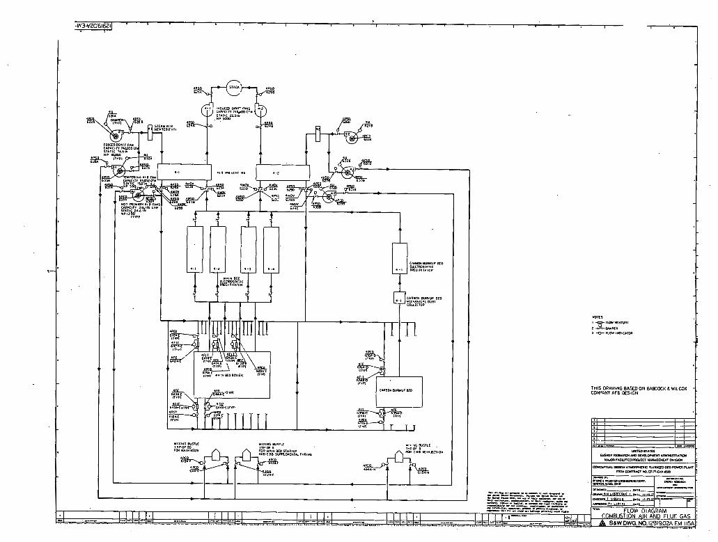
8 - 6 Air and G a s Systems
Refer t o Flow Diagram 12919.02A-EM-llSA,
me a i r and gas systems consist of the following subsyst-ms:
cudnuztion a* Primary a i r Flue gas (excluding f lue gas desulfurization)
, Ignition a i r
Each of two half-capacity, forced dra f t (F-D,) fans takes suction from the fan room and discharges a i r t o the boiler undergrid plenum r i a a half s ize s t e w a i r heater and one part of a two section, half size, regenerative a i r heater (APH) ,
Air pressure is maintained . by ad juating the inlet (suction) vanes on the F,D. fans,
! The s t e w a i r heater is used t o maintain the average cold end temperature of the APH t o minimize corrosion, F,D, fans also supply air t o the suction of the primary and tempering air fans,
8.6-2 Primary A i r (Includinq Temperinq Air)
The main function of the primary a i r (PA) fans is t o evaporate surface m o i s t u r e and transport the coal from the mixing bustles to the furnace,
Each of the half-capacity PA fans takes suction from the F.D. fan discharge dawnstream of the APH and discharges. through the mixing bustles to the furnace,
Each of the half-capacity tempering a i r (TA) fans takes suction from the F,D. fan discharge upstream of the APH and discharges t o the mixing bustles to control the temperature of the primary a i r .
PA and TA f l w is held constant by varying the position of the inlet (suction) vanes on the fans,
8-6-3 Flue Gas
Flue gas (combustian products) is drawn from the furnace through the convection pass (heat recovery area) , through ' the e lec t ros ta t i c precipitator, and through one section of the two section APHs by two half-capacity axial-type induced dra f t (I.D.) fans, The I ,D, fans discharge t o the stack,
Freeboard pressure is maintained a t approximately 0 in, H20 by varying the blade angle of the I.D. fans,
8 -7 Other Systems
8 7 1 Iqnition O i l and A i r
Refer t o Flow Diagram 12919.02A-EM-116A.
'Jhe ignition o i l and a i r system consists of ignition o i l and igni t ion a i r subsystems*
mTI5
I 9 FUII YE*",II
2 a A m m a -0- nor amtcrm,

m n m
---.--- p r o CLP80" I Y P W P ero
THIS DRAWING BASED ON BABCOCK &WILCa( COMPANY AFR OESIGN
8-7-1-1 Iqnition Oil
Tim ignition o i l pumps take suction from the existing l i gh t o i l storage tank through an extension t o the existing suction header. The ignition o i l pumps discharge t o 5 igni tors located a t the f ive main bed levels- One ignition burner is a l so located a t the CBB 0
8,7,1,2 Iqnition Air
~ g n i t i o k air is supplied to each ignition burner fo r combustion. to mi zing and operation (retract) a i r . i s supplied from the existing canpressed air system-
8-7-2 Canbustion A i r B e a t i n q and A i r Preheat& Wash
Refer to F l o w Diagram 12919-01-EM-117A-
The Combustion A i r Heating and A i r Preheater Wash is identical t o the system described in Section 8-7-2 of Part I of this Report,
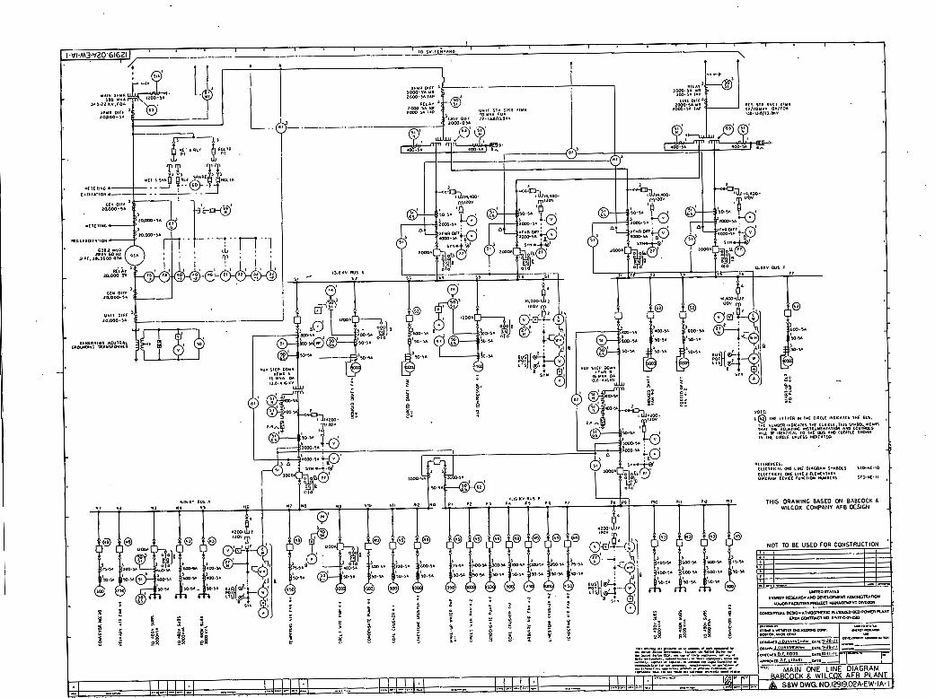
9-0 eLECPRIQUI SYSTEMS
The B & W AFB plant electrical system is shown on Drawing 12919r02A-EW-1A- Refer t o Table IIIA-6 Large Motor Loads, The bases fo r the plant auxiliary requirements a s shown on the heat balances are defined in Table IIIA-7, Running Auxiliary Power,
The e lec t r i ca l system fo r the E S W AFB is considerably clifftirent than tha t ' of the base plant- Due to the large F,D. and 1 - D , fan loads and the addition of a s ta r t -up ,bo i le r feed pump, it was necessary t o use 13-8 kv switchgear t o avoid exceeding the short circuit rat ing of the 4 kv bus and ensure suff ic ient ly high s ta r t ing voltages,
In the base . plant, the 4 kv s ta t ion service loads w e r e divided among six buses primarily because of short c i r cu i t considerations- 'Ihis is not pract ical in the AFB because the six larges t w t o r s account fo r approximately 70 percent. of the s ta t ion auxiliary load. To ensure sat isfactory opea t ion of the system, a l l large motors 4,500 hp and larger are supplied from two 13.8 kv buses- Voltages for smaller motors follow the same c r i t e r i a as in the base plant. The number of 4 kv buses has been reduced t o two in the AFB, with consequent simplification of the system and ellmmn . . t ion of some tie breakers no longer required. However, it is necessary t o use 350 mva class breakers for the 'incoming l i ne and bus t i e positions in the 4-16 kv switchgear, since a 3,000 amp ra t ing is not available i n the 250 mva class , A l l feeder breakers are 250 mva class, w i t h high mmentary rating, as in the base plant-
One f u l l s i ze un i t s t a t ion service transformer is provided rather than the two half -size transformers used i n the base plant. However, two auxil iary s ta t ion service transformers are required to supply the 4 kv systan frau the 13.8 kv switchgear,
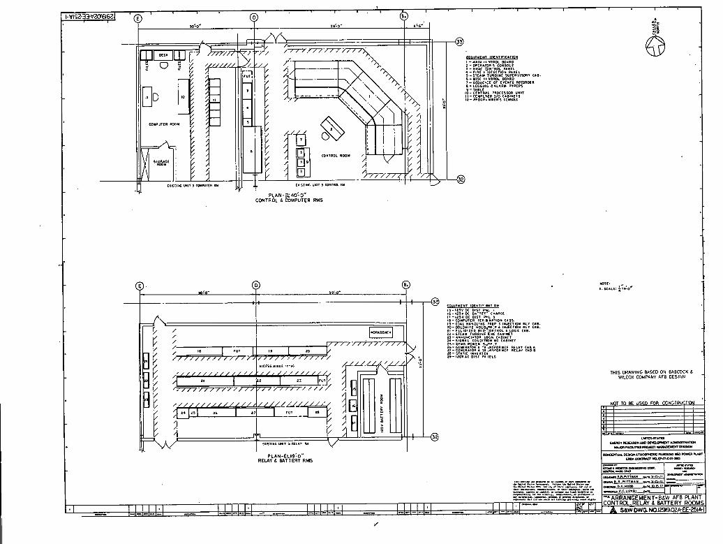
me rest of the auxiliary s ta t ion service system fo r the BSW AFB is designed t o the same c r i t e r i a a s the base' plant- General arrangements are a s noted on Drawings 12919.02A--EE-612A8 6123, 612C, 251A, and 251B-
9.1 Liqhtinq Desiqn Cr i ter ia
9,l.l System Requirements *
The l ight ing system criteria f o r the B6W AFT3 plant are identical t o t he base plant c r i t e r i a noted i n Section 9.1 of P a r t I of this R e p o r t -
9.2 Raceways Desiqn Cr i ter ia
The raceway design c r i t e r i a fo r the B&W AFB plant are ident ical to the base plant c r i t e r i a noted in Section 9.2 of P a r t I of this Report-
9.3 W i r e and Cable Desiqn Cri ter ia
The w i r e and cable design c r i t e r i a fo r the B&W AFB plant are ident ica l to the base plant c r i t e r i a noted in Section 9.3 of Part I of t h i s Report except t h a t 15 kv shielded cable w i l l be required i n addition t o the types listed i n Section 9,3,1.
9 -4 Groundinq System D e s i c m Criteria
The grounding design c r i t e r i a f o r the B&W AFB plant are identical to the base plant c r i t e r i a noted i n 9.4 of Part I of this Report,
10 -0 CONTROL SYSTEMS AM) INSPRUMENTATION - 10.1 General
The general design c r i t e r i a t o r conuol systems a d ins=tmmentatfon f o r B8W AFB plant w i l l be ident ical to those of t he base plant as detailed under Section 10 of Part I, The AFB plant employs sixtilar conventional techniques fo r load control, start-up. eanergency shutdown, and t r i p s , This section presents a brief description of the control system, highlights of the protective systexn. and a slmanary of the start-up and loading procedure f o r the fluidized bed boiler equipment, Operation and mnt ro l s of other major systems a re described i n the appropriate system descriptions in Appendix I I I A - 8 .
Page 1 of 1
TABLE IIIA-6
LARGE MOTOR IDADS - B€W .AFB
No, Service - Conn V o l t a q e
Start-up B o i l e r Feed P u p Fbrced Draft Fan Induced D r a f t Fan Air Compressor
Circulating Water Pump P r i m a r y A i r Fan Condensate Pump L i m e s t o n e Crusher C o a l Crusher Tempering A i r Fan Conveyor No. 20 Qnveyor No, 23 Cooling Tower Makeup Pump
Bed Letdown Blower 3 4 6 0 Fly Ash P r e s s u r e B l o w e r 2 4 6 0 Dust C o l l e c t a r Pressure B l o w e r 2 . 4 6 0 Cooling Tower Fan 12 4 6 0 B o i l e r Circulating . Pump 4 4 6 0

#
TABLE IIIA-7
Page 1 of 1
RUNNING AUXILIARY POWER - BABCOCK 6 Wna>X AFB PLANT ( A l l , Figures in K i l o w a t t s )
Plant Load YE? - 75% - 50%
Forced Draft Fans 10,769 4,544 1,346 Induced Draft Fans 4,713 1,989 590 primary Air Fans 1,492 630 174 Tempering A i x Fano 379 160 47 Carbon Reinjection Blowers 189 80 24 Ply Ash T r a n 6 ~ r . L B l m r s .378 159 47 Bed Material Transport Blowers 378 159 47
Coal and Limestone Conveyors Included in margin below Coal and Limestone Crushers Inoluded i n margin below Material Stock-out/Reclaim Equipment Included in margin below
Circulating Water Pumps Condensate Pumps Start lrp B o i l e r Feed Pump Boiler- Circulation Pumps Cooling m e r Makeup Pumps
Cooling F m s 1,443 1,082 72 1 AFr Compressors 3,357 2,518 1,679 Precipitator 4,500 4,500 4,500 Margin for Intermittent Loads and
Undefined l a d s 3,247 ,.2,787 2,319
mtal Running Auxiliary Power 38,638 24,118 16,466
CALLED ------ NORIM I
D r E : 0 , SCALE: g:#!O*
EQUIPYEN7 IDEL7lF C I I . 0 " , ,- ,1,v DC 0,s. RI . 16- 1 1 5 V D( B 1 - I E F . C.OARLt I7 -625" DC D l l l P L I I8 - C O I P U l C f l , E l m #1710#4 C I O I . 19-COLL MaYDLIWG ' R I P L I " U C I 0 " I," C I S . m - m r o r t r ~ M o L c e a : ~ # * s c r w w air c r t l . 21 - r w l o n z r o 0 6 0 . .OIIPIOL L LOCK CAB. 2 2 - S T E A " TURBINE Em CABl)(tT I I - I # N U U < l A 7 O I I LCGl l CLBIMrr 24 - S I G N A L C O Y D I ~ M I M C CA11MET 2,- X,"B W W E n LrnP.. 16- GCNERATOIl S r l . M ? F O R l E I R E L A I C.I.1 1 7 - C r m n A l o m 6 TI . * > F O P ~ M C P RELAY CAB B 2 0 - STLTIC I * Y F I . L I 2 9 - IZOYAC D l l r Pa lE1'5
THIS DRAWING WSED ON BABCOCK 6 WlLCOX COMPANY AFB DESIGN
NOT TO BE USED FOR CONZTRUCTON I

ifin instrument list has been compiled t o identify the quantity of i n h e n t a t i o n required and to supplement the information contained in the system flow diagrams, The instrument l ist i s made up in two parts and is included under Appendix. 1IIA-E. part C of the instrument list shows a l l the instruments common t o both boiler designs - B6W and FWEC, whereas Part A shows the instnmentation for the particular boi ler design included i n t h i s report
Equipment technical data sheets have been prepare'd f o r a l l s ignif icant control components which are not a par t of any vendor engineered .and supplied subsystem. These data sheets are i n two - parts and are included under Appendix IIIA-D, Part C combines data sheets coamnon fo r both boi ler manufacturers'and Part A combines data sheets for the Babcock 6 Wilcox design,
Wherever appropriate, t h i s description sha l l be supplemented by the de ta i l s contained i n the report supplied by t boiler manufacturer (Appendix 1IIA-C) ,
The presentation is conceptual in nature and it w i l l be apparent t ha t there are many interface areas t h a t m u s t be defined completely before a plant can be instrumented,
~t should be recognized t h a t the development of the control systems design is based on incomplete -st data from smaller s i ze uni ts and t h e i r similarity 'with t he conventional pulverized coal power plant systems, It w i l l be improper t o use these controls on any large un i t until the performance of these large u t i l i t y sized units are simulated using mathematical modeling techniques and the interrelationships of the various process parameters a re w e l l established-
10 -2 Control System
10 &2,1 General
The control systems objective fo r the B6W AFB steam generator power plant is t o provide controls t o operate the plant efficiently. safely, and with the maximum amount of plant avai labi l i ty , To accamplish this, the follcnsing features are provided :
a, The automation required t o start up and shut down the various plant components required fo r load changes
b, A loading scheme t h a t w i l l provide the bes t heat r a t e a t a l l times
c,, An emergency o r safety system to handle contingency conditions
d, A control system t o operate a l l of the plant cosnponents properly .
A t o t a l analog control system, with a d ig i t a l infomation system of the type currently used on conventional pulverized coal plants , is applied t o the BbW AFB plant, To some extent, d ig i t a l equipment w i l l be used for plant automation, sequential loading, and sa fe shutdam-
The d i g i t a l portion includes a Bed Segment Control System which incorporates the necessary cantrols f o r purging, ignition, and sequential loading, A safety system t o monitor the c r i t i c a l boiler parameters and, i f necessary, t o shut down the BCW AFB boiler i n a safe and orderly fashion is a part of the segment mntrol - Tfie analog control oy~tcm develops neaessary control signals corresponding to u n i t load demand, monitors fue l flow, airflow, f e e d w a t e r flow, ctc*, c u d uullkola these parameters t o achieve t h e required steam flow, pressure, and temperature, Included i n the analog control systems are a l l the sensors, controllers, hand/auto s tat ions, and f i n a l drive units, The analog system w i l l provide suitable buffered outputs t o indicators and/or recorders in the main control room, The hand/auto s tat ions wi l l be mounted i n the control r o o m r T'he following is a brief description of the major analog control systems of Babcock 6 Wilcox designed AFB drum-type subcr i t ica l steam generator,
10,2,2 U n i t Load Control
The U n i t Load Control System regulates process mass and energy balance - The uni t load con$rol system w i l l contain feed forward elements and establ ish demand fo r the boiler and turbine subsystems, The un i t load control system w i l l place megawatt load demand on the turbine valves f m e i ther a load dispatch system or operator set t ing, wnile the camsequent steam flow demand corrected by the throttle pressure mr will be used for the boi ler load demand, The boi ler load dentand sets the demand for boi ler firing rate. Various equipment, operational limits, and runbacks w i l l prevent the load demand t o exceed uni t capabili ty a t a l l tines-
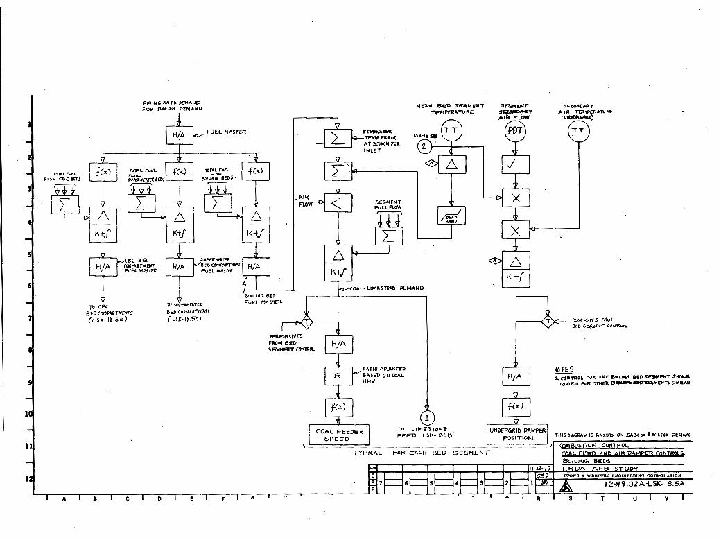
10,2,3 Cambustion Control i n Main Beds
Refer to Logic Diagrams 12919-O2A-LSR-18,SA and 18.5C fo r schematic logics,
The combustion control is designed t o s a t i s fy the eneryy input demand fram the fuel-air demand - A t the outset, it should be recognized that the u t i l i t y sized AFB boiler design mandates the use of horizontal surface within the bed and consequently requires t h a t bed expansions ,be maintained a t a relat ively
-
FUEL MASTEX
LIMESlVE DEMAND
RP#l5.5lV€5 W L%O SE6yEuT CON~POL
I. CIITWOL FOR ONE BorUyg BED S E W E Y T SNOuN
C O ~ O L M R omfll .LD=%w~cn SI~IIAR
FEED LSM-18.55
COMBUSTION LIM~STONE. BE- n u € GAS AIR T ~ M ~ E U A T U R E FEED RATE unm RATE BED L E V E L
I. CONTRVL F ~ R ONE S U P E R N ~ T E R BED SEGMFITSH~~)N. CONTROL DP OTHER SYPE'FHEATER 8- SGMENTS SIMILAR.
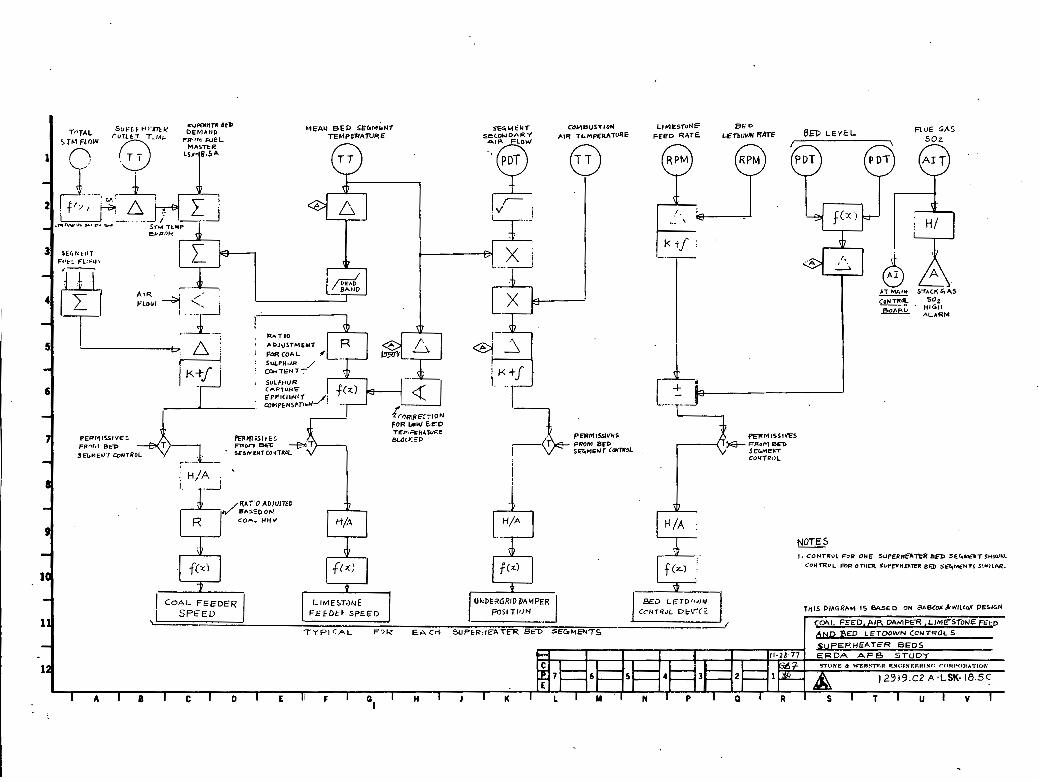
constant value by maintaining a constant a i r velocity through the bed. This restricts variation of a i r mass to a very narrow band throughout the entire load range, Thus, the coxubusticm control of the AFB boiler is real ly restricted t o control of the fuel only - The basic fuel demand for each cell is developed by suitably modifying the boiler load demand t o achieve proper s p l i t between the boiling beds and superheater beds based on designed heat distribution within the fumace . me adjusted signal is then compared w i t h the actual measured t o t a l fuel flow t o derive the master fuel demand for a l l operating bed segments in the boiling or the superheater beds ,
Por the boiling beds (12919-O2A-LSK-18,5A), the master fuel demand is further corrected for the feedwater i n l e t temperature, For the superheater beds (12919.02A4SK-18 ,5C) , the master fuel demand is adjusted for the superheat temperature error,
Mean bed temperature is monitored for a l l beds and imposes a trinrming signal on the individual bed segment fuel demand signal. Normally, the bed temperature is regulated around 1,550 F (ad justable) set point. I f the bed temperature increases, the fuel feed w i l l be proportionately ' reduced and vice versa, A limited amount of load turndawn capability w i l l be achieved by varying the bed temperature between 1,450 F and 1,650 F to change the heat flux.
Airflow is measured on each bed segment and controlled t o maintain a coinstant a i r velocity, The airflow measurement is adjusted for undergird a i r temperature and mean bed temperature t o compute the air velocity, The.calculated velocity is compared w i t h Me set point to derive the modified a i r demand signal.
prevent fuel tram exceeding available air, the fuel demand signal is always limited by the measured airflow,
Individual bed segment Hand/Auto stations in Me control room will allow the operator to interrupt or bias the fuel-air demand,
Pinal control of ccaubustion is achieved by gosition-ing the individual segment combustion a i r control damper and by varying the coal . feeder speed corresponding to air and fuel demand, respectively,
10.2.4 Bed Material Control in Main Beds
Refer t o Logic Diagrams 12919.02A-LSK-18.5B and 18-SC,
The inventory of bed material is regulated by control of the limestone feed ra te and the bed letdown rate.
Limestone feed ra te is maintained as a r a t i o of coal flow demand, This r a t i o is based on the recent as-fired coal sampling and is adjustable by the operator, The limestone demand is adjusted t o compensate for the effect of temperature on CaO sulfur capture efficiency- Normally, when the beds are operated around 1,550 F, t h i s compensation w i l l not be operative, However, when bed temperature is modulated t o achieve a load turndown, the limestone feed r a t e w i l l be changed based on the Calcium Oxide/Sulfur Utilization Temperature Curve,
Limestone feed ra te is also increased manually by the operator i f an average SO2 value of greater than set point is detected in the SO2 monitors,
Bed material letdawn ra te is matched with limestone feed ra te t o provide the necessary bed material i n v ~ t o r y a t any time, Although it w i l l not be possible t o measure the bed height acm~rately, a bed level measurement using differential pressure transmitters (PDTs) w i l l be emplOyed to deteimine the approximate bed level error from the set point. This deviation w i l l be ' used t o bias the bed letdown control, t o restore bed level error t o zero, and .to maintain proper mass of bed material,
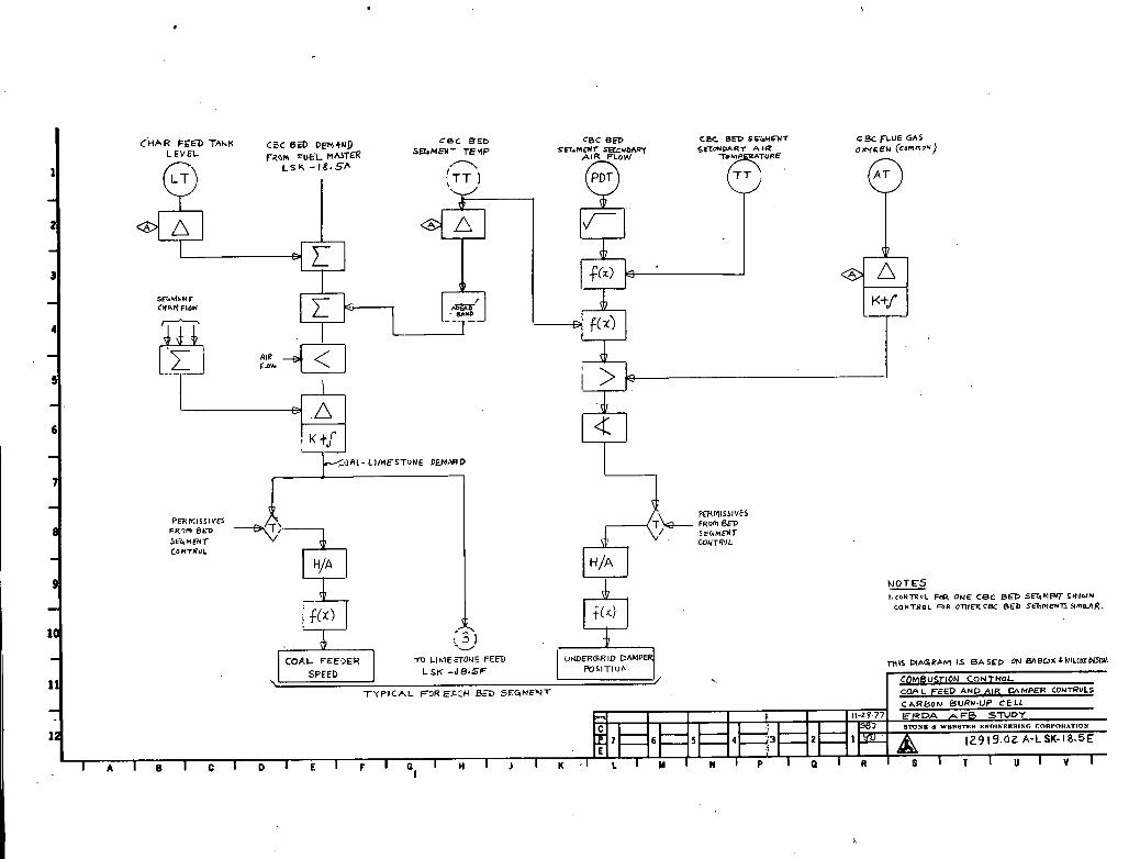
10 -2 -5 Combustion Control in Carbon Burnup Beds
Refer t o Logic Diagrams 12919-02A-LSR-18.5E for schematic loaic.
The fuel demand for the CBB is developed from the boiler demand a f t e r appropriate modification based on the boiler heat distribution, During normal operation CBB burns high carbon content chat- ( f ly ash) elutriated from the other beds, which is consumed a t the ra te it is produced- Char inventory in the char feed tank remains constant, To accomplish the carbon burnup, the bed temperature in CBB must be maintained a t a canstant higher value (1950 F 50 F) . The bed temperature error is used for further adjusting the fuel and a i r demand signal, The adjusted fuel demand signal is then campared w i t h the char flow t o develop a fuel error signal,
Bed segment excess oxygen is measured and airflow corrected as necessary to maintain oxygen w i t h i n l i m i t s ,
Bed fluidizing velocity is aomputed f r o m the airflow measurement modified by undergrid a i r temperature and the mean bed temperature r
10 -2 -6 Bed Material Control in Carbon Burnup Beds
Refer t o Logic Diagram 129 19 -02A-LSK-98.W for schematic logic.
The fluidized mass of bed material i n the CBB normally does not need any regulation* The lose bed material inventory due t o

P BED T E W R R A T U I E SEGMENT
FROM LSK-18SA
COAL -LIMESTAU€ DEMAND SIGNAL
L SK - 18:SA
C O R R E < T I O Y F-OR
BED TEMPERATURE
E F F I C I C N C ~
LIACITOUE ' FEEDER I s _ G n (
A T MAIM - CONTRA. 6NRD
C.HAR FEED T A ~ K C ~ C Dw,4UD C B C EEL, CBC 6- CBC BED SCGhIENT c9< FLUE GAS
LEVEL FLQM =UEL MUTER SE~MEM- T E ~ P ~ I R FLOW rEbn€NT SRCUOAR~ SFCONOAR* A I-R OXyCFu (commo~)
L S Y - 1 8 . 5 h 9 dnl
I -,+K] Sf ih tkNT C H W FLON
i
i > b 1x1 I
1
NOTES I.CONTROL ONE c e c B= S G M M S H O W N
CONTROL FDR OMmCB( BED S€z?Mt%TJSlmlb?R.
m LI~IE;TOUE .FEED LSK -dB-SF
T Y P I C A L F D R S . : H B=T S E G M N T
16- I N C O ~ D N G uwc acs S ~ A I I O M scav l r r rrua S l - B v I I Y r I c P I I ~ . I * s r n Y Y I I I A I , o *
I3.0"" l l G R BUS 7
,a- a", STCPrnW" X<"R 8
1 2 - 1*(0~1ffi L I * c - ~ o ~ ~ S~LIION rclvmcr XSMR
13- IMOUCCD O I l A f l r l M 4 - 2
7 4 - TORCCD D F l l l 4 . 2 rS-t"<o"tNG Lt"t.RCS ST*,"," scnv,cc ,,"R
IS- Btn I I I ICa I * ' .I"S1IIU"C*1.1I0*
~ r - s ~ a n t UP mmcn l c c o PUMP +-I
THIS DRAWING BASED ON BABCOCK 6 WlLCOX COMPANY AFB DESIGN

PFRMlSSlVt6 FRUm
I . CONTROL F.,R 3NE C B C B t D S t h M E N T SHOUW. CONTROL FOR J T u m CgC BED StLIME?iTS SPWILAR.
a t t r i t i o n and elutr iat ion, w i l l be made up by extraction from the m a i n bed letdarm' a t a point after the cooler, Whenever supplanental coal burning is required t o maintain the CBB operating temperature, fresh limestone feed and associated bed letdown control w i l l be activated*
Limestone feed r a t e is determined a s a r a t i o of the ma1 flow demand. The r a t i o adjustment incorporates'correction for lower sulfur capture efficiency a t -higher (1,950 F) CBB operating temperature. SO2 indication w i l l be provided f o r manual adjustment of the limestone demand by t h e operator, whenever required
Bed level is measured by using dif ferent ia l pressure transmitters and is.used t o control the bed material replenishment from the main beds into the CBB fo r lower than normal (set point) CBB bed level ..
Bed material withdrawal r a t e from the CBB is matched with the limestone feed r a t e t o provide a constant bed material inventory a t any time,
For a bed level higher than normal, t he bed letdown control device demand signal is biased by the level e r ro r t o keep the bed &eve1 within l i m i t s ,
10 -2 r 7 Feedwater Control
Refer t o Logic Diagram 12919r02A-LSK-18,SD for schematic logic,
The feedwater control is designed t o provide a demand f o r feedwater flow to the boi ler- The boiler demand is used t o establ ish a demand f o r f eedwater flow. The f eedwater f l w demand is established using a three-element control w i t h the steam flow (function of the f i r s t stage steam pressure) , the drum , level error, and the temperature compensated f eedwater flow plus the spray flows,
10,2,8 Forced Draft Fan
Refer t o Logic Diagram 129 19,02A-LSK-18, SD,
The forced dra f t fan supplies the t o t a l secondary a i r t o a l l the six beds f o r fluidizing the coal and limestone bed material and maintains adequate a i r f o r proper combustion and excess a i r control - A programmed (based on f i r i ng ' r a t e demand) ' secondary a i r duct pressnre is maintained by regulating the F,D, fan inlet vanes,
Airflow t o the bed segments is regulated by the individual segment undergrid dampers

I
10,2,9 Induced Draft Fan
Refer t o Logid Diagram 129 19.02A-LSK-18 ,SD for schematic logic,
The d r a f t control system maintains the combustion cel ls at a oonstant (slightly negative) pressure a t the in l e t t o the transverse convection pass a t steady s ta te conditions and rminimizes deviations during transient disturbances, The ,draf t control system provides a demand for the I ,Dm fan blades. The control system uses the t o t a l airflow corrected by the transverse convection pass i n l e t draft error as the feed forward demand signal, The total a i r is determined as' the sum of a l l combustion airflaws through the main beds increased by the computed combined primary and tempering airflow, This demand is then compared w i t h actual 1,D. fan suction pressure and the resultant error signal then controls the 1,D. fan blades-
A damper in the CBB gas out le t controls the CBB pressure t o the designed ncgaeim m.Snq - 10 -2 , 10 -heat Steam Temperature
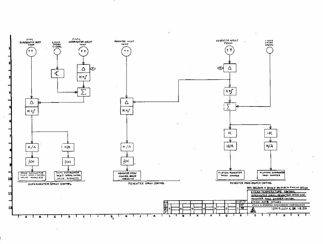
Refer t o Ingic Diagram 12919 . 02A-LSK-18 . 5G for schematic logic.
The main steam temperature is a function of the heat absorbed by the superheat surface, The superheater surface was designed t o absorb more heat than is required to superheat the steam, with spray a t temperators controlling the main steam temperature t o its desired value, However, rapid changes in load ca l l s for rapid temporary correction by extra spray while the f i r ing rate is being adjusted t o produce a slower permanent correcticm,
The superheat temperature controls are designed for a two-stage attemperation system with sprays a t the inlets t o the second f u l l superheater bed and the f h a 1 full superheater bed,
The set point for 4zhe f ina l 3&am tunpcraturc io camparcd with the measured superheater out le t temperature and this temperature error is used to trim the final superheater bed i n l e t temperature s e t point* This s e t point is then compared with the actual nreasured f ina l superheater bed i n l e t temperature t o develop resultant demand signal for the spray valve- The total spray demand goes directly t o the second f u l l superheater bed spray control valves fo r f i n a l temperature control, The f h a 1 f u l l superheater bed sprays receive the same demand as the second f u l l superheater sprays, I f the demand t o seobnd f d l $txpc%rh&ter bed sprays are nut l h ~ u t e d , tile L h c r l supeilreater bed spxay demand is zero, When second f u l l superheater bed spray is limited, f inal superheater sprays will make up for the balance of the demand.

12 RDA A F R STUDY
c -NX d WSSWl'SR ENOINBSRINO CORPORATION
E 7 E 12 9 19.02A-LSK-18.5D
I A I B I C I D I E I F ~ Q I I S l T l U I V I
FINAL FIU*L SUPEMCATER LOAD S U P ~ M ~ T U I OUTLET
SUPERHEATER SPRAY ' C W W L
L O A D X N D 6 X SIGNAL
0 H /A
f ( ~ !
r l REHWER SPRM' CWTROL W E
WOIIUUTF
Ef HEATER SPRAY CCWTROL REMEATER PASS MMPER CONTROL

10 ,2 r 11 Reheat Steam Temperature Control
Refer t o Logic Diagram 12919~02A-LSK-18.5G for schematic logic.
The Heat Recovery Area D a m p e r s located in the gas pass provides the primary control for the reheat steam temperature control. Zhese dampers are operated between minimum and maximum limits w i t h additional control provided through the use of spray systems, i f required* The spray system controls transient temperature excursions on a rapid, t e a r y basis, For low reheat temperature, when the reheat pass damper is a t its extreme open position, the f i r ing ra te in a l l beds w i l l have to be readjusted, The reheater outlet temperature error modified by the boiler demand signal is used sequentially t o position the reheat and superheat pass dampers,
10 -2 12 Turbine Start-up Bypass for Minimum Flow Throuqh Beds
Refer t o Logic Diagram 12919-02A-LSK-18r5H for schematic logic.
A turbine bypass system, sized to pass 40 percent of VWO main steam flow to the condenser, is required a s a prerequisite t o maintain flow and temperature conditions through the f i red bed segments during start-up and shutdown*
me bypass control valves operate to maintain the minimum flow through the AFB boiler during start-up, A s turbine load is ramped to 40 percent, the turbine bypass control valve gradually closes responding t o keep the throttle pressure s e t point, A t 40 percent MCR flow through the turbine, the turbine bypass w i l l be ful ly closed,
The bypass control system includes spray attemperation for temperature matching of the bypass steam flow a t the condenser,
10-2-13 Steam to Reheat Coolinq
Refer t o Logic Diagram 12919-0~SK-18r5H for schematic logic,
A 40 percent MCR steam to reheat cooling system is provided t o protect the reheater tubes from overheating following a turbine trip, The reheater cooling i n l e t valves redirect the main steam around the HP turbine into the reheater and reheater cooling out le t valves redirect the outlet steam around the IP/LP turbine and in to the main condenser,
10 -3 P l a n t Protection and Safety
The AFB plant is designed with a rel iable protective system t o maintain plant safety& This system overrides a l l other plant
controls to return the plant t o a safe condition, either operational or shutdown. The protection system consists of the m basic modes of operation,
3, mrgency Shutdown and Trips \
2, R u n b a c k s and Limits
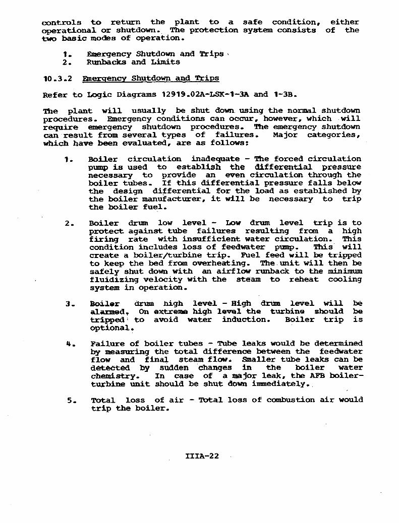
10 , 3 -2 mercrencv Shutdown and Trips
Refer t o Logic Diagrams 12919.02A-LSK-1-3A and 1-3B,
The plant w i l l usually be shut down using the normal shutdown procedures, Rnergency conditions can occur, however, which w i l l require emergency shutdown procedures, The emergency shutdown can resul t f ram several types of failures, Major categories, which have been evaluated, are as follows:
1, Boiler circulation inadequate - The forced circulation pump is used t o establish the differential pressure necessary t o provide an even circulatian through the boiler tubes, If this differential pressure f a l l s below the design differential for the load as established by the boiler manufacturer, it d l 1 be necessary to t r i p the boiler fuel,
2, Boiler drum low level - Low drum level t r i p is t o protect against tube fai lures resulting from a high f i r ing ra te w i t h insufficient water circulation, This condition includes loss of feedwater pmup, This w i l l create a builer/turbine trip, Fuel feed w i l l be tripped t o keep the bed from overheating, The unit w i l l then be safely shut down with an airflow runback to the minimum fluidizing velocity w i t h the steam t o reheat cooling system in operation,
3, Boiler drum high levell - H i g h &um 1-1 w i l l be alarmed, On extreme high le-1 the turbine should be tripped t o avoid water induction- Boiler t r i p is optional.
4, Failure of boiler tubes - Tube leaks would be determined by measuring the total difference between the feedwater flow and f inal steam flaw. Shzaller tube leaks can be detected by sudden changes in the boiler water chemistry, In case of a major leak, the AFB boiler- tqrbine unit should be shut down immediately,
5 , Total loss of a i r - Total loss of combustion air would t r i p the boiler.

THROTTLE PEESSLIRE (9 4
~OurroL @LYE& (3) c o l m O L VNKs (4)
% I TURBINE sTP.RT-UP BYPASS cONTRoL Tu46rwC TeiP B ' I P ~ s S C O ~ O L /
s~m~nmc RCHEAT R E U ~ T C~)NCENSER ounrs remP 1 N ~ b - r T m P OvT~t.7 7 m p INLET T E M P
7 TT
n tr K +J-
v
I n k 1 n 8 K+f K - u
rnl5 DIAGRAM IS BASED ON M B C ~ ~UIUO,YD~SII,I
I U ( I I Y e STAR WE ByRsSS AND . , S T E A M Td REHEAT C O O L I N O BYPASS4
I 1 SPRAY C O N T R O L

CONTROL ACTION RESULTANT ' MONITOR C O N D I T I O N
E N E F G I L E D
3
NOTES: , THE 'DLLOWINO ACTIONS A R E INITIATED WHEN THE BOILER T R I P
LOCiOUT R E L A Y I S eNERGIZIED : A. TURBINE T R I P P E D 6 . S O I L E R EMERGENCY SHUTDOWN PROCEDURE INITIATED MASTER WPLI 'RIP R F U I N T H E FOLLOWlNG SE~UENCE FOR A L L OPERATIN6 B€DS:.
Bl. F U R FEED T R I P S BZ. HP 8 L P BYPASS V A L V E S WR REHFAT C ~ ~ L I N ~ O R Y S
AND ON ,AUTOMATIC C O N W L 8 3 , FEFDWATER FLOW RUNS BACK TO 4 0 % . ~ q . A I R FLOW RUNS BACK . MAINTAINS m w m u M FLUIDIEIM
VELOCIT* 65. W H E N BED T F h l P E R A l U R E W O P S BEWW 1 0 0 0 ' ~
0 5 . 1 AIR FLOW TRIPS 5 5 . 2 SUPERHEATER BLOCK L SPRAY VALVES CLOSE 8 5 . 3 RE HEATER BLOC^^ SPRAY VALVES CLOSE 05.4. t ipa L p a r r v* WR REHE~T W L I Y ~ C L a n a TURBlMEBYPASS VALVE OP-s
5 6. WHEN BED TEIT~PEW\TVRE IS 7 0 0 e F FEEaUATER FLOW T R I P S
67. T U R B I N E B y p ~ s c VALVE CLOSES AS T H E WESSUPS DECAYS IN S U P E R H ~ T E R
2 . F U E T R I P A L A R m S WILLBE P R W D E D FOR A L L hUOR PROCESS PAP*WKTEUS m p T GENERATES A BOILER OR BED S Y I M M TRIP-
. f La(AT€3 IN BED SFGMFIIT GJNTROL I N S E R ~ ON MAIN CONTROL S O A R R
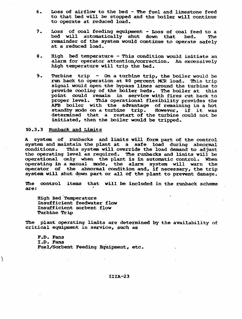
6 - Loss of a i r f l w t o the bed - The fuel and limestone feed t o t h a t bed w i l l be stopped and the boiler will continue t o operate a t reduced load,
7 , Loss of coal feeding equipment - mss of coal feed t o a bed w i l l automatically shut down that bed, The remainder of the system would continue t o operate safely a t a reduced load,
8, High bed temperature - This condition would i n i t i a t e an alarm for operator attention/correction- A n excessively high temperature w i l l t r i p the bed,
9, Turbine t r i p - On a turbine t r i p , the boi ler would be run back t o operation a t 40 percent MCR load, This t r i p signal would open the bypass l i ne s around the turbine t o provide cooling of .the boi ler beds. The boi ler a t t h i s point could remain i n service with f i r e s cut back t o proper level- This operational f l e x i b i l i t y provides the AFB boiler w i t h the advantage of remaining in a hot standby mode on a turbine t r i p . Howeve r , i f it w a s determined tha t a r e s t a r t of the turbine could not be in i t ia ted , then the boi ler would be tripped,
10.3.3 Ihrnback and Limits
A system of runbacks and l imi ts w i l l form par t of the control system and maintain the plant a t a sa fe load during abnormal oonditions, T h i s system w i l l override the load demand to adjust the operating l w e l as required - The runbacks and limits w i l l be operational only when the plant is in automatic controlr When operating i n a manual d e , the alarm system w i l l warn the operator of the abnormal condition and, i f necessary, the t r i p system w i l l shut dpwn pa r t o r a l l of the plant t o prevent damage,
The control i t e m s t h a t w i l l be included in the runback scheme are: .
High Bed '~emperature Insufficient f eedwater flow Insufficient sorbent flow Turbine ' h i p
The plant' operating limits are determined by the avai labi l i ty of c r i t i c a l equipment in service, such as
F-Do Fans I ,D, Fans -l/Sorbent Feeding Eqbipment , etc ,

10-4 Star t -up and Loadhq Procedure
10,4,1 General
The normal start-up of the AFB uni t is sequential, The components are placed i n operation in a def in i te order, The procedure is similar t o other BSW drum-type subcrit ical pulverized coal f i r ed steam generators except f o r the f i r i ng and sequencing of the various beds,
Bed purging is performed a t each individual level s t a r t ing w i t h t he l o w e r beds and working upward, Each bed is purged w i t h 25 percent 'MCR a i r s imi lar t o the NFPA requirement for a P,C, boiler,
10,4,1~2 Liqht Off
After completion of purging, the boi ler drum is f i l l e d , The boiling beds are then lit off using ignition o i l , The lower boiling bed is fiked f i r s t and then the s p l i t bed and carbon burnup bed, me f i r i ng r a t e is increased by s ta r t ing additional sections of the boiling beds t o r a i s e f l u id temperature and pressure. During this phase steam generation starts,
10 ,4,1,3 Turbine Bypass, Warm, and Roll
During start-up of the uni t , a l l generated steam is diverted t o the condenser v ia the turbine bypass system. Superheater beds are not f i red u n t i l suff ic ient steam flow is es tab l i shed to prevent tube overheating. Once the bottom superheater beds are f i red , the gas temperature is quenched by adding a i r through,the upper beds, During t h i s phase steam lines are warmed and the turbine vdlves are opened for warming and rol l ing, A t about 1,000 psi , the turbine is brought up t o speed and the un i t is synchronized and i n i t i a l loading applied. Steam flow i s then transferred froan the bypass system t o the turbine, Above 40 percent load, the bypass valve is completely closed and the en t i r e steam flow passes through the turbine, Load is then increased by placing additional segments in service.
10.4.2 On-line Ioadinq
The plant load can be varied by adjusting the f i r i n g of the bed segments simrlltaneously o r sequentially, Sequentia 1 operation of the segexnents requires starting and stopping equipment- The f a s t e s t load changes are accomplished by adjusting the segments already in service, Since time is required t o igni te additional segments, load increases beyond Me operating range of the equipment already in service w i l l be slower, Also it may be
possible t o accomplish rapid load decrease by slumping portions of the operating beds-
The sequential segment loading scheme is used fo r normal demands for increase o r decrease of the load- As a par t of the Bed Segment Control, a c e p u t e r program determines the most desirable s ta r t ing and loading sequence,
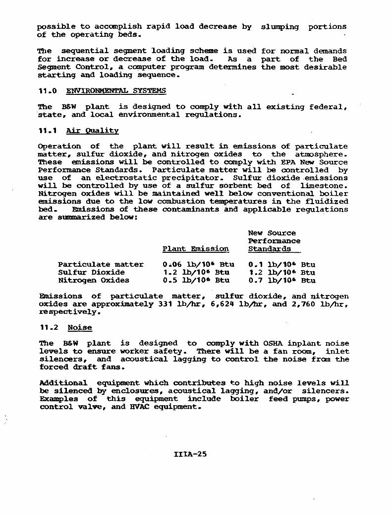
1 1 -0 ENVIRONHEMXL SYSTEMS
The B S W plant is designed t o comply with a l l existing federal, state, and local environmental regulations.
1 . 1 Air Ouality
Operation of the plant w i l l r e su l t in emissions of part iculate matter, sulfur dioxide, and nitrogen oxides t o the atxmsphere. These emissions w i l l be controlled t o canply w i t h EPA New Source Performance Standards- Particulate matter w i l l be controlled by use of an electrostat ic precipitator, Sulfur dioxide .emissions will be controlled by use of a sulfur sorbent bed of limestone. Nitrogen oxides w i l l be maintained w e l l below conventional boiler emissions due to the low cambustion temperatures i n the fluidized bed, Eutissions of these contaminants and applicable regulations are summarized below:
New Source Performance
Plant M s sion Standards
Particulate matter 0 i06 lb/l06 Btu 0.1 lb/lO6 Btu Sulfur Dioxide 1.2 -/lo6 Btn 1.2 lb/l06 Btu Nitrogen Oxides 0.5 l b / l O 6 Btu 0.7 l b / l O 6 Btu
Efnissions of part iculate matter, sulfur dioxide, and nitrogen oxides are a p p r o x h t e l y 331 lb/hr, 6,624 lb/hr, and 2,760 lb/hr, respectively . 11.2 Noise
The B 6 W plant is designed t o comply with OSHA inplant noise levels to ensure worker safety, There will be a fan roam, i n l e t si lencers, and acoustical lagging t o control the noise from the forced d r a f t fans.
Additional equipment which contributes t o high noise levels w i l l be silenced by enclosures, acoustical lagging, and/or si lencers, Examples of t h i s equipment include boi ler feed pumps. power control valve, and WAC equipment .
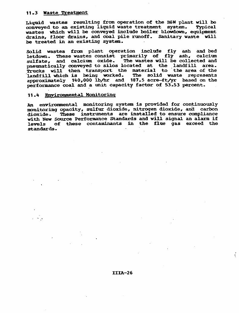
11 -3 Waste Treatment
Liquid wastes resul t ing from operation of the B C W plant w i l l be conveyed to an exist ing l iquid waste treatment system, Typical wastes which w i l l be conveyed include boiler blowdown, equipment drains, f loor drains, and coal p i l e runoff. Sanitary w a s t e w i l l be t rea ted in an exist ing system,
Sohid wastes froan plant operation include f l y ash and bed letdown, These wastes consist primarily of f l y ash, calcium sulfate: and calcium oxide. The wastes w i l l be collected and pneumatrcally mnveyed t o s i l o s located a t the l a n d f i l l area, m c k s w i l l then transport the material t o 'the area of the -Mf ill which is being worked, The sol id waste represents approximately 140,000 lb/hr and 18715 a c r e f t / y r based on the performance coal and a unit capacity factor of 53.53 percent,
d 1 - 4 Environmental Monitorinq
AII environmental monitoring system is provided fo r continuously monitoring opacfty, su l fur dioxide, nitrogen dioxide, a& carbon dioxide, These instruments are instal led t o ensure compliance w i t h New S o u r c e Performance Standards and w i l l signal an alarm i f levels of these contaminants in the f lue gas exceed the standards -

APPENDIX IIIA-A
DESCRIPTION OF WORK
FOR A
570 MW ATMOSPHERIC F'LUIDIZED B W BOILEX ELECTRIC GENWATING PLMW
October 1977
SMNE & WEBSTER ENGINEERING CORPORATIOM B o s t o n , Massachusetts
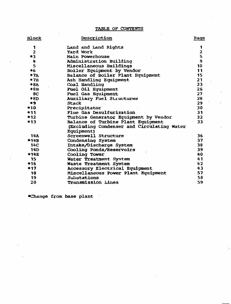
TABLE OF CONTENTS
Block Description
Land and Land Rights Yard Work Main Powerhouse Administration Building Miscellaneous Buildings Boiler Equipaent by Vendor Balance of Boiler Plant Equipment Ash Handling Equipment Coal Handling Fuel Oil Equipment Fuel Gas Eguipment Auxiliary Fuel Sl..~ucturt?s Stack Precipitator Flue Gas Desulfurization Turbine Generator Equipent by Vendor Balance of Turbine Plant Equipment (Excluding Condenser and Circulating Water Equipment) Screenwell Structure Condensing System Intakenischarge System Cooling Ponds/Reservoirs Cooling Tower Water Treatment .System Waste Treatment System Accessory Electrical Equipment Miscellaneous Power Plant Equipment Substations Transmission EitieS
Paqe
Change from base plant

BLOCK NO1 1 - LAND AND LAND RIGHTS
AS this unit is the fourth extension to an exist ing site already owned by the Client, no land or land rights are included.
rn addition, transmission l i n e rights-of-way or ownership is presumed to exist.
BLOCK NO, 2 - YARD WORK . . - -+
. 1100~00000 YARD WORK - r .
* + . 1900,10000 Clearinq. Gradinq, and Surfacinq
9100,91000 Clearinq
~o clearing is included i n t h i s scope-
Preliminary s i t e grading is assumed t o be complete, Minor regrading fo r the construction of the new structure w i l l be performed,
Fina l site grading 1 he! done irwaedkately before aamnercial operation of the plant-
No surfacing is included in th i s scope,
1100,14000 Landscapinq
No landscaping is included in t h i s scope-,
9100.20000 Roads, Barkinq Areas. and Fences
1100~21000 Roads and Parkins Areas
No parking areas are ihcluded in this scope* Station access road will be 24 f t 4 in. wide asphalt paved g one course 3 in. th ick fo r a total of 1,200 L.F. The 8 h, crushed stone base'and 4 in- stabilized topping for the stat ion access road w i l l be provided. Finish grading w i l l be provided before applying the asphalt paving, Station service roads w i l l be 24 f t - 0 in, wide using an 8 in, crushed stone base and 4 in, stabilized tapping for a t o t a l of 4,300 LaFi being provided. m, asphalt paving is provided on s ta t ion service roads, A l l railroad grade crossings w i l l be provided* Any subgrade work required t o establish the ,
specified grades before applying the base material w i l l be provided,
J No fencing is included in this scope,

1100630000 Water and Sewer Systems and Other Service Lines
1100.31000 Water Systems . . a . .
D o m e s t i c Water
Domestic w a t e r f o r the plant w i l l be supplied from the previous unit 0
. S w i m W a t e r
Service water f o r t h e s t a t i o n w i l l be taken from t h e exis t ing w e l l water system. Service water w i l l be used f o r t h e makeup water demineralizers, and hose staticms,
River Water
River water f o r t h e s t a t i o n w i l l be taken from t h e exis t ing makeup w a t e r pump house, River water w i l l be used f o r cooling tower makeup. A i r preheater washing w i l l be from the ex is t ing ash s lu ice system.
Water Pipinq
Piping, mlves, and f i t t i n g s will be provided.
11 00.33000 Storm Sewer System
The storm sewer system w i l l receive surface runoff, roof drainage, and the ef f luent from o i l separators which servle plant f l o o r drains, equipment drains and s t a t ion transformers. The storm s e w e r will terminate a t a connection furnished with the previous uni t ,
1100034000 Fi re Protection System
The yard f i r e system w i l l cons is t of a buried pipe d is t r ibut ion system serving f i r e hydrants with connections to the plant t o serve i n t e r i o r hose s t a t ions and special f i r e protection systems,
A l l yard hydrants w i l l be provided with f u l l y equipped hose houses. Yard f i r e piping s h a l l be buried and s h a l l be 150 l b seamless carbon steel pipe, with mlded f i t t i n g s , protected with X-TRV-Coat coating, or equivalent, Piping f o r i n t e r i o r hose s t a t ions and stand-pipe systems s h a l l be seamless carbon steel w i t h welded f i t t i n g s . Post indicator i so la t ion valves w i l l be 175 l b type,
1100~36000 Yard Steam Lines
Piping, mlves , and f i t t i n g s w i l l be provided.
1100.60000 Trackwork
~n exist ing rai l road spur from the main l i n e w i l l provide access t o the main powerhouse, Removal of the existing trackwork 'in the boiler and turbine areas w i l l be performed as required.
1100,70000 Yard Liqhtinq
The yard l ight ing w i l l serve the additional roadway requirements of the site, Lighting w i l l be provided a t corners, curves, and gate entrances and the l ight ing leve'l w i l l be no greater than 1/2 f t candle in these areas,
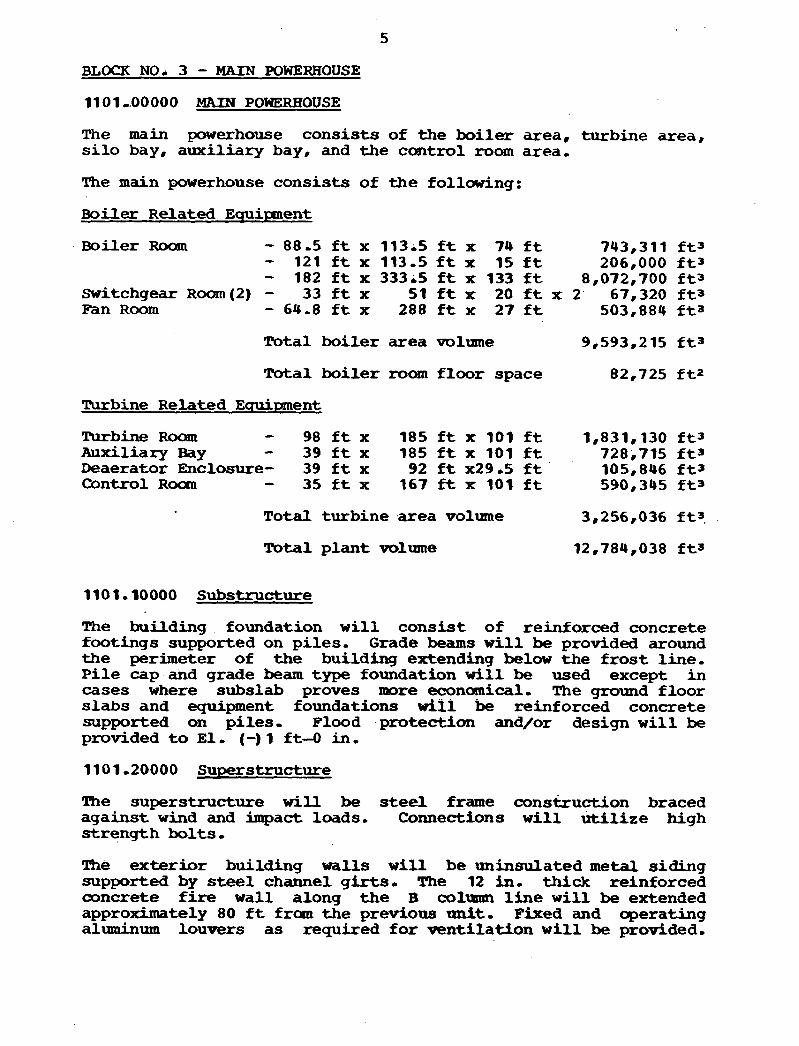
BLOCK NO* 3 - MAIN POWERHOUSE
1101 .400000 MAIN POWRHOUSE
The main powerhouse consis ts of the boi le r area, turbine area, s i l o bay, auxi l iary bay, and the control room area,
The main powerhouse consis ts of the following:
Boiler Related Ecruirntent
Boiler Roam - 88-5 f t x 113.5 ft x 74 f t 743,311 f t 3 - 121 f t x 113.5 f t x 15 f t 206,000 f t 3 - 182 f t x 333;5 f t x 133 f t 8,072,700 f t 3 Switchgear Room (2) - 33 f t x 51 f t x 20 f t x 2' 67,320 f t 3 Fan Room - 64.8 f t x 288 f t x 2 7 f t 503,884 f t a
Total bo i l e r area volume 9,593,215 f t 3
Total bo i l e r r o a n f loo r space 82,725 f t 2
Turbine Related Equipment
Turbine Rooan - 98 f t x 185 f t x 101 f t 1,831,130 f t 3 Auxiliary Bay - 39 f t x 185 f t x 101 f t 728,715 f t a Deaerator Enclosure- 39 f t x 92 f t x29 .5 f t 105,846 f t 3 Control Room - 35 f t x 167 ft x 101 f t 590,345 f t 3
Total turbine area volume 3,256,036 ft3.
Total p lan t volume 12,784,038 f t 3
1101,10000 Substructure
The building foundation w i l l cons is t of reinforced concrete footings supported on p i l e s , Grade beams w i l l be provided around the perimeter of the building extending below the f r o s t line, P i l e cap and grade beam type foundation w i l l be used except in cases where subslab proves more economical. The ground f loor slabs and equipment foundations w i l l be reinforced concrete supported on piles. Flood protection and/or design w i l l be provided t o E l , (-) 1 ft--O in,
1101-20000 Superstructure
The superstructure will be steel frame <=ons&uction braced against wind and impact loads, Connections w i l l u t i l i z e high s t rength bol ts ,
Tfie exteriror building walls w i l l be uninsulated m e t a l s iding supported by steel channel girts. The 12 in. thick reinforced concrete f ire wall along t h e B column line w i l l be extended approximately 80 f t from t h e previous unit, Fixed and operating aluminum louvers as required f o r vent i la t ion w i l l be provided.
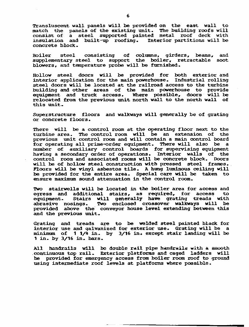
Transluscent w a l l panels w i l l be provided on the east wall t o match the panels of the existing unit , The building roofs w i l l consist of a s t ee l supported painted metal roof deck w i t h insulation and built-up roofing, Interior partit ions w i l l be concrete block,
Boiler s t e e l consisting of columns, girders, beams, and supplementary s t ee l t o support the boiler, retractable soot blowers, and temperature probe w i l l be furnished.
Hollow s t ee l doors w i l l be provided for both exterior and in te r ior application for the main powerhouse, Industrial rolling s t ee l doors w i l l be located a t the railroad access to the turbine building and other areas of the m a i n powerhouse t o provide equipment and truck access, Where possible, doors w i l l be relocated from the previous u n i t north wall to the north wall of t h i s unit ,
Superstructure floors and walkways w i l l generally be of grating or concrete flwrsd
There w i l l be a control room a t the operating floor next t o the turbine area, The control room w i l l be an extension of the previous uni t control room and w i l l contain a main control board fo r operating a l l prime-order equipment. There w i l l also be a number of auxiliary control boards for supervising equipment having a secondary order of operations, Interior walls of the control room and associated rooms w i l l be concrete block, Doors w i l l be of hollow s t e e l construction with pressed steel frames, Floors w i l l be vinyl asbestos t i l e , A hung luminous ceiling w i l l be provided for the entire area, special care w i l l be taken t o ensure maximum sound attenuation in the control room,
!Fwo stairwells w i l l be located in the boiler area for access and egress and additional stairs, as required, for access t o equipment. Stairs w i l l generally have grating treads w i t h abrasive nosings. Two enclosed crossover walkways w i l l be provided above the' conveyor house level extending between this and the previous unit ,
Grating arad treads are t o be welded s tee l painted black for in te r ior use and qalvanized for exterior use- Grating w i l l be a minimum of 1 1/4 in , by 3/16 in+ except stair landing w i l l be 1 in- by 3/16 in, bars.
All hanbralls w i l l be double rail pipe harlrkails with a smooth .continuous top r a i l , Exterior platforms and caged ladders w i l l be provided for v e n c y access from boiler room =of to ground using intermediate roof levels a t platforms where possible.
1101,40000 Service Equipment
1101-41000 Plumbins System
Floor and equiptent drains w i l l be collected i n pipes and trenches and empty in to an in-plant sump, mom here the drains will be pumped t o an existing valved connection which leads t o the above ground o i l separator system f o r subsequent disposal to' the ash pond-
Roof drainage system consisting of roof boxes, horizontal piping and downspouts w i l l be provided, Water w i l l discharge d i rec t ly into the storm sewer system-
Potable water w i l l be provided by the previous unit. Water' &ill be distributed to drinking water coolers within the powerhouse- Emergency shower and eyewash stat ions w i l l be provided i n acid areas, H o t water and sanitary f a c i l i t i e s are not being provided fo r this un i t ,
11 01,42000 Heatinq System
Steam uni t heaters w i l l be provided*
1101,43000 Ventilation System (a i r density equals ,0754 lb/cu f t a t 60 F)
Boiler roam ventilation w i l l require approrcimately l 8 2 O O , O O O cfm of a i r t o be supplied t o and exhausted from the boi ler roam t o l i m i t t he indoor temperature t o 120 F during maxinnmn summer ambient temperature of 96 F, A i r w i l l be brought i n through fan morns i n the upper levels of the boi ler room and distributed through ductwork to the hot region of the room, Air w i l l a l so enter the plant by natural ventilation through motor-operated hooded louvers and doors- A i r w i l l exhaust through gravity roof ventilators,
M i n e roam venti lat ion w i l l require approximately 500,000 cfm t o l i m i t t he indoor temperature t o 110 F during maximum summer temperatures, Air w i l l be brought in by fan and duct systems and by naturalmeans, A i r forced i n t o the turbine room w i l l be f i l t e r ed with 85 percent ASHRAE weight arrestance, r o l l type f i l t e r s - ~ d n s w i l l exhaust the a i r through the roofs and walls-
Other areas w i t h i n the powerhouse w i l l be ventilated by conventional means, These include the conveyor gallery. auxiliary bay, deaerator area. switchgear area, battery r am, cable'roan, clean and d i r ty o i l tanks room. limestone preparation area and the laboratory and sample area of the turbine room,
New yard structures w i l l a l so be ventilated, These include the cooling tower pump house and the new crusher house,
The control and relay rooms w i l l each be a i r conditioned by sepaxate, independent systems. Heating w i l l be provided by means of dnctinounted e l e c t r i c a i r heaters,
1101,46000 Fire Protection System
lb bring f i r e protection water i n to the plant, connections w i l l be made t o the existing bellow ground f i r e protection loop which surrounds this unit ,
Halon f i r e protection systems w i l l be provided f o r the computer room, selected areas of the control room, the e lec t r i ca l equipmnt room, and miscellaneous e lec t r i ca l areas.
Water spray systems w i l l be provided to protect the turbine lubrication o i l tank, o i l pumps and coolers, o i l conditioning equipment, o i l storage rooms, hydrogen sea l o i l uni t , and the outdoor transformers,
Water hose stations w i l l be s t ra tegica l ly located thmughout th.e e n t i r e powerhouse.
1101~47000 Elevator
Elec t r ic f re ight and passenger elevators w i l l not be provided. Elevator access w i l l be f ran the previous uni t ,
11 0 1 - 5000 Liqhtinq System
The main powerhouse l ight ing systan . w i l l be a combination of vapor l ight ing f ixtures , fluorescent f ixtures , and incandescent f ix tu res a s required t o give a level of 100 f t candles in the m a i n control board areas: 30 f t candles cm the operating floor, i n the relay equipment rooms, and in the switchgear areas; and 20 f t candles in other areas, Fixtures w i l l be sui table f o r each area a s classif ied, Emergency d-c l ight ing w i l l be provided for s a f e egress from a l l areas.
1101.90000 Paintinq
Structural s t e e l w i l l be sand blasted and painted w i t h one coat of an inorganic zinc primer and a top coat of an acryl ic la tex in the shop, It w i l l be'touched up a s required& A t selected areas, concrete block w i l l be given one coat of f i l l e r and one f inish -at of paint-

BI;OCK NO. 4 - ADMINISTRATION BUILDING
AS the exist ing f a c i l i t y includes an administration building/ office, no provision is included for an administration building.

BLOCK NO1 5 - MISCELLANEOUS BUILDINGS
The existing facility includes a number of miscellaneous buildings for construction and/or operation which will be utilized for. this unit.

BLOCK NO- 6 - BOUEIQ EQUIPMENT BY VENDOR
1200,10000 Boiler Equipment
The boiler w i l l be a controlled circulation, drum type, balanced d ra f t AFB boiler, producing 3,972,963 lb/hr of steam at 2,620 psig/1,000 F, wit.! . s i ng l e reheat t o 1,000 F, The boiler w i l l be designed t o burn Midwest bituminous coal with No, 2 fuel o i l provided f o r ignition, The coal w i l l have a heat value of 11,081 Btu per lb, an ash content of 10 percent, a moisture content of 13-52 percent, and a sul fur content of apprartimately 3 percent. Final feedwater temperature w i l l be 487 F,
1200.11100 Boiler Pressure Parts
Pressure parts include boi ler tubing, headers, safety valves, power re l i e f n l v e , and boi ler trim, The furnace w i l l be designed fo r i20 in. H 2 0 (f32 in , H20 yfeld),
1200,11310 Support Steel With Boiler
The boiler package includes hangers f o r top supporting un i t and auxiliary equipment from the main girders, columns, beams, and supplementary s t e e l which a r e not included in the boi ler package, but are included as p a r t of the building frame,
1200,11400 Boiler Casinq
Outer casing f o r boiler, furnace, reheater, superheater and economizer and air heater w i l l be of 18 gage galvanized steel, except fo r the top of the boiler, and w i l l be furnished an a delivered basis with the boiler,
1200,11800 Boiler-Circuldtinq Pumps
Four circulating pumps with motor drives w i l l be furnished with the boiler, The pumps will be supported by the suction header, Each pump w i l l be f i t t e d with a manually operated stop-check in the pump discharge,
1200,12100 Boiler Superheater and Reheater
The superheater and reheater w i l l maintain steam temperatures a t 1,000 F with a tolerance of 10 F over the range of 60 percent t o f u l l load, Included with the boi ler a r e the necessary controls, valves, piping, and nozzles f o r attemperator water fluwk
The reheater is designed fo r reheating to 1,000 F-
1200,13000 Boiler Economizer
The economizer, ins ta l led within the boiler set t ing, w i l l be of the -0th tube type and have suff icient capacity t o pass the en t i re quantity of feedwater required when operating a t f u l l load,

1200,14000 Boiler Set t inq and Insulation
Boiler se t t ing , insulat ion, casing, and lagging a r e included with t h e b o i l e r package, Insulat ion f o r f lues , ducts, mechanical co l lec tors , and a i r heaters w i l l be covered with 18 gage ribbed aluminum, Piping insulat ion w i l l be covered with 0,020 i n , thick aluminum,
1200,15000 Coal and Limestone Distr ibution and Inject ion Equipment
Twenty p a i r s of b e l t feeders (18 tph coal and 8 tph limestone; one per segment) are included t o de l iver coal and limestone a t a control led r a t e from the bunkers to t h e main bed coal inject ion system, Each feeder is equipped with 1.5 hp and 1.0 hp (coal and limestone, respectively) var iab le speed, 460 v 3 phase, 60 Hz dr ive motor,
In addit ion, 5 p u s of b e l t feeders (1 1 tph coal and 5 - 5 tph limestone) are included t o del iver coal and limestone from t h e bunkers t o t h e CBB coal in jec t ion system o r the main bed iqni t ion segments. Each teeder is equipped with a 1.5 hp and a 1.0 hp (coal and limestone, respectively) var iable speed, 460 v, 3 phase, 60 Hz drive motor,
Two half-capacity (202,000 cfm a t 600 F) primary fans w i l l be supplied with t h e boi ler . Each fan is equipped with a 1,750 hp, 1.200 rpn. 13.2 kv, 3 phase, 60 Hz motor, These fans w i l l be located i n t h e enclosed fan room,
Wo half -capacity (97,800 c f m a t 130 F) tempering air fans w i l l be supplied with the boi le r , Each fan is equipped with a 450 hp, 1,800 rpm, 13.2 kv, 3 phase, 60 H z motor, These fans w i l l be located in t h e enclosed fan room,
1208,16000 Boiler Burners and Iqni t ion Eauipment
A b e l t feeder o u t l e t hopper, ro ta ry s e a l valve, mixing bust le , coal and limestone t ranspor t pipes, a 40:l flow dis t r ibutor and t h e 40 coal/limestone in jec t ion pipes w i l l be supplied with the b o i l e r fo r each bed segment,
Twenty retractable, e l e c t r i c a l l y ignited l i g h t oil i g n i t o r s w i l l be furnished with t h e boi le r i n the a i r plenum and igni t ion segment of t h e main beds, llwelve will be fmnished f o r the CBB,
1200.17 100 Boiler Soot B l o w e r s
The boi le r w i l l be furnished with air soot blowers- The blowers w i l l be furnished with a l l interconnecting piping, valves, drives. motors. supports a t the casing, and complete w i t h an automatic/hanual sequential control system,
1200,22200 Draft Ducts with Boiler
a, Forced draf t air ducts between air heaters and fue l burners, including sectionalizing dampers, tempering air ducts, dampers, and controls fo r secondary air dampers a t burners,
b, Flue gas ducts betweb economizer ou t l e t and a i r heaters,
1200.22920 Boiler Duct Insulation w i t h Boiler
Insulation f o r ducts w i l l be mineral f i be r covered with 18 gage ribbed aluminum,
1200 -26 100 Air Heaters
Two bisector regenerative type a i r heaters w i l l be included with the boiler, Included w i l l be o i l coolers, o i l piping, main and auxiliary e l ec t r i c motor drives, a i r soot blowers, and water wash devices, .
12 00.26 200 Other Boiler E d r j S n e n t
Carbon Reiniection System
A vacuum-pressure carbon collection system is supplied w i t h the boiler t o transport the high-carbon ash from the main bed precipitators hoppers t o the carbon reinjection tank and then t o the carbon burnup bed,
Four full s ize carbon collection vacuum blowers are supplied, equipped w i t h 100 hp, 1,800 r p , 460 v, 3 phase, 60 Hz anotors, t o oonvey the ash to the carbon reinjection tank,
Ash collected in the carbon reinject ion tank is conveyed pneumatically to the CBB by supply air from the primary and tempering a i r fan systems.
Each main bed precipitator hopper is equipped with a material handling valve. Each hopper on the carbon reinjection tank w i l l be supplied with a rotary feeder,
Bed Letdown Cooler
Twenty-five water-cooled screw canveyor coolers are supplied with the boi ler t o cool the material removed Rrom the main bed to 250 F and deliver it t o the bed material removal and disposal system (Block 7B, Account 1200,51),
Each screw conveyor w i l l be equipped w i t h a variable speed 2 hp, 460 v, 3 phase, 60 Hz motor.
Eight water-cooled screw conveyor coolers are supplied with the boiler to cool the material removed fram t h e CBB bed segments. Each screw conveyor is equipped with a -5 hp, 460 V, 3 phase, 60 H z motor-

Flow control w i l l 'be provided with a rotary feeder a t the outlet of each screw conveyor coder , Each rotary feeder w i l l be equipped with a 'variable speed 1/2 hp, 460 .v, 3 phase, 60 H z rnotor ,
Carbon Burnup Bed (CBB) Dust Collector
A cyclone type mechanical dust collector w i l l be supplied with the boiler a t the outlet of the CBB*

BLOCK NO* 7A - BAL?iNCE OF BOILER PLANT EOUIWENT
1200 -22 100 Draft Ducts Not With Boiler
A i r ductwork f r m the FWD& fans t o the a i r heaters and gas ductwork from the a i r heaters t o the 1,D. fans, from the I ,D, fans t o 18 in, outside of the stack w i l l be supplied. Ductwork from 18 in, outside of the concrete stack t o the liner w i l l be furnished w i t h the stack,
1200 -22400 Air Preheaters
Combustion aik is preheated a f t e r the forced dra f t fans by steam- a i r heating coils designed to maintain the minimum average. cold end temperature of the regenerative a i r heaters,
1200 -22 9 10 Duct Insulation N o t ' With Boiler
Gas ducts not supplied w i t h .the boi ler w i l l be insulated w i t h pref ahaicated f actory-assembled , mineral f ibe r , panels with 18 gage ribbed aluminum lagging, (This insulation w i l l include the precipitator and hoppers, )
1200-23000 DRAPP FANS
1200 ,23100 Forced Draft Fans
TWO half-capacity centrifugal type forced draft fans, each with a rated capacity 'of 742,035 cfq a t 96 F (,0695 lb/cu f t ) , w i l l be furnished, The fans w i l l be located indoors in enclosed fan r o o m s - Each fan w i l l be driven by one 10,000 hp; 1,200 rpm, 13.2 ,kv, 3 phase, 60 H z motor,
1200,23200 Induced Draft Fans'
%o half-capacity axia l type induced draft fans, each with a rated capacity of 749,500 cfm a t 299 F. w i l l be furnished, The fans w i l l be located outdoors, Each fan w i l l be driven.by a . 5,000 hpo- 700 rpm, 13,2 ,h, 3 phase, 60 Ha motor-
1200.31000 Feedwater Heaters
Seven stages of extraction feedwater heating w i l l be furnished consisting of three l o w pressure stages, a deaerator, and three
'1
high pressure stages, A l l closed heaters are the horizontal she l l and tube type, The feedwater heater insulation w i l l be mineral f iber with aluminum lagging,
FIiqh Pressure H e a t e r s
The 1st. 2nd. and 3rd point heaters w i l l be located on the operating f loor level and w i l l have carbon steel tubes. High
pressure heater drains w i l l cascade in sequence t o the deaerator under normal l e v e l conditions and t o the condenser under extreme high l e v e l conditions. Tube s ide design pressure w i l l be 4,500 psig, Feedwater bypasses w i l l be provided f o r the high pressure heaters-
Deaeratdr (4th Point Heater)
e deaerator w i l l be a t r a y type equipped with internal sprays and a vent condenser. The deaerator storage tank w i l l have a 5 min capacity a t f u l l load, D e s i g n pressure w i l l be 75 psig.
L m Pressure Heaters and Drain Coolers
The 5th point, 6th point, and s p l i t 7 th point heaters w i l l have s t a i n l e s s steel tubes and w i l l be located i n t h e condenser necks. H e d t e r drciirls from the 5th point and f m m the 6th paint heaters cascade to t h e i r respective separated drain coolers and then directly to t h e condenser, me 7th point heater drains flow through loop s e a l s t o the condenser, Tube s ide design pressure w i l l be 600 psig,
The 5th, 6th, and 7th point heaters w i l l be provided with a common bypass w i t h motor-operated valves,
1200,32000 BOILER FEED PUMP
1200,32100 Boiler Feed Pump, Turbine Driven
One full-capacity cent r i fuga l barrel type b o i l e r feed pump with s h a f t driven matched booster pump w i l l be furnished, The booster pump w i l l take suction from the deaerator and supply the boi ler feed pump which. in turn, discharges t o t h e high pressure heaters. The bo i l e r feed pump with its matched booster pump w i l l be driven by a steam turbine, The pump w i l l have an approximate capacity of 10,700 c p m ,
Start-up Boiler Feed Pump. Motor Driven
One 5,860 g p start-up boi le r feed pump w i l l be furnished with a 10,000 hp, 1,800 rpm, 13.2 kv, 3 phase, 60 Hz drive motor, The mbt6rdr iven s t a r t - u p pump w i l l take suction from the deaerator and supply water to t h e bo i l e r through t h e high pressure heaters.,
1200,33000 BOILER CHEMICAL TREATMEWT EOUIPMENT
A covered steel measuring tank and chemical feed pump w i l l be provided t o feed phosphate t o the bo i l e r drum. The pump w i l l have a nominal capacity of 5-10 g a l per hr and a discharge pressure suitable f o r the service. The tank will be equipped w i t h a level indica tor and a low l e v e l switch,

1200,34000 Condensate Chemical Treatment Equipment
F a c i l i t i e s w i l l be provided f o r feeding hydrazine t o t h e condensate system, Each system w i l l cons is t of a covered steel measuring tank and chemical feed pump, The chemical feed pmps w i l l have a nominal capacity of 10-30 g a l per hr and discharge pressures suitable f o r the service* The tanks w i l l be equipped w i t h a l eve l indicator and a low level switch,
1200,34900 SAMPLING SYSTEM
Samplinq Panel 0
Sampling and analysis f o r chemical control i n condensate, bo i l e r feed, boi le r w a t e r , and steam systems w i l l be proyided by a cen t ra l sampling system which includes two freestanding cent ra l sampling panels located i n t h e laboratory and sample area i n t h e previous u n i t bo i l e r room-
The sampling panel provided f o r terminal points of sampling l i n e s will include two sections, It w i l l provide f o r sample conditioning, pressure and flaw control , and sample analysis, including continuous automatic analyzers for conductivitys hydrazine, pH, s i l i c a , phosphate, and dissolved oxygen- Sinks for col lect ion of samples and necessary piping f o r returning samples t o t h e system o r dumping t o waste w i l l be ins t a l l ed ,
Samplinq System
Samples t o be piped t o the cent ra l sampling panel s h a l l include the following:
Condensate pump discharge Condensate a t deaerator inlet Boiler feed pump suction Economizer i n l e t Superheater o u t l e t Reheater inlet Reheater o u t l e t Heater drains
Conductivity cells, recorders, and control lers w i l l be provided, a s required, f o r the condensate pump discharge, feedwater entering and leaving t h e deaerator, economizer inlet steam, and heater drains.
C e l l s f o r pH measurement, reoorders, and cont ro l le rs w i l l be provided on the panel, as necessary, fo r the condensate pump discharge and economizer inlet.
One oxygen analyzer w i l l be provided to monitor t h e amdensate pump discharge and t h e deaerator out le t . A silica analyzer w i l l be provided t o monitor the economizer inlet, if required, and t h e bo i l e r water, These analyzers w i l l be located a t the sample panel ,

$
1200,38000 Blowdown and Blowoff Equipment
A blowoff tank, ASME Code Section -11, A285C and a continuous blowdown f lash tank w i l l be provided.
1200,60000 Pip ins and Coverinq
Piping, valves. f i t t i ngs , ahd hangers w i l l be provided for the following systems:
Main Steam Auxiliary Steam Hot Reheat Cold Reheat Extraction Condensate Turbine Bypass Reheater C o o l i n g Boiler Feed Discharge Boiler Feed Suction Steam Line Blowout LP Feedwater Heater Drains Condensate Makeup and Drawoff Ignition O i l Service Water River Water Potable Water Makeup Water Drains t o Condenser Drains t o Boiler Blowoff Tank Boiler Safety Valves, Vents, and Drains Beyond the First Valve
Feedwater Heater Relief, Vents, and Drips Chemical Fecd Nitrogen ~ l a n k e t i n g S ~ r v i c c A i r Instrument A i r c02 Halon Hydrogen Scanner Cooling Air Boiler Chemical Cleaning and A c i d Wash Preboiler and Heater Shell Chemical Cleaning and Flush
1200.65200 Nitroqen System
.A nitrogen system w i l l be provided fo r blanketing the carbon steel tube feedwater heaters, boiler drqm, and deaerator. The nitrogen source w i l l be extended frcm the previous ~ n i t - i
1200 -67200 : ' Pipins - Electr ic Heat Tracinq
Elect r ic heat tracing w i l l be provided on waterlines and horizontal a i r lines subject t o freei ingr
The system w i l l be complete w i t h heating cable, contactor, thernrostats, transformers, monitoring ammeters, and c i r c u i t breakers, Primary instrument tubing out of doors w i l l be heat traced bundles,
A l l l i n e s requiring insulat ion w i l l be insulated with m i n e r a l f i b e r and aluminum jacketing,
1200,84000 Miscellaneous Equipment Foundatibns
The forced d r a f t and induced d r a f t fan foundations w i l l be rein- forced concrete mats supported on p i l e s ,
1200,85000 Miscellaneous Pumps and Tanks
One full-capacity bearing cooling water pump and heat exchanger w i l l be furnished, The bearing cooling water pump w i l l be motor- driven. The bearing cooling water system w i l l be cross-tied t o the previous un i t ,
The bearing cooling water system w i l l serve t h e - bo i l e r c i rcu la t ing w a t e r pumps. fan bearings and o i l coolers, pulverizer o i l coolers, condensate pump bearings, bo i l e r feed pump turbine o i l coolers, furnace doors, a i r heater o i l coolers, and other miscellaneous coolers,
m i s t i n g tanks f o r f i r e protection water, service water, condensate, acid, caus t ic and igni t ion o i l are adequate to serve t h i s un i t ,
1200,86000 Hoist and Monorails
F a c i l i t i e s w i l l be provided t o handle the forced and primary a i r fan ro to r s and e l e c t r i c motors, removable sect ions of the combustion a i r preheaters, b o i l e r room hois t , ash s lu ice pumps, service water pumps, and similar pieces of equipment,
A i r heater baskets and pulverizer dismantling w i l l have ,mtor ized hois t s and t r o l l e y beams,
A t r o l l e y beam and ho i s t system w i l l be provided by the preci- p i t a to r manufacturer to remove T-R sets from t h e i r roof-mounted locations and lower the T--R sets t o grade elevation,
A t r o l l e y beam and ho i s t system w i l l be provided f o r t h e SO2 reanoval system,
1200,89000 Paintinq. Equipment and Pipinq
' Stee l surfaces w i l l be shop cleaned and shop painted with a prime ,and f in i sh coat, .No f i n i sh coat w i l l be provided unless required by safety code, Touch-up painting w i l l be done in the f ield. Items not sui table f o r shop cleaning and shop painting w i l l be cleaned and painted i n the f i e ld -
1200,90000 PRELIMINARY OPERATIONS AND TESTS
1200,91000 Preliminary Operations
Provisions f o r preliminary operation and start-up, including blowing of the steam leads, w i l l be included,
1200~92000 Preboiler Cycle and Boiler Chemical Cleaninq
Temporary provisions w i l l be made t o alkaline clean the feedwater and condensate system,
Provisions fo r preoperational chemical cleaning of the boiler tubes and economizer, including the alkaline boilout, acid cleaning, acid neutralization, all flushes, and surf ace passivation w i l l be included.
BLOCK NO, 7B - ASH HANDLING EQUIPMENT
1200~50000 Ash Handlinq Equipment
The design of the ash systems w i l l be based upon a 15 percent ash coal w i t h 90 percent of the ash t o the precipitator i n l e t and 35 percent of the ash in the bed material letdown,
1200,51000 Spent Bed Material Holdinq Tanks
A 60 f t long by 16 f t wide by 8 f t high (s t ra ight side) dry holding tank w i t h six 6 f t high hoppers w i l l be provided fo r collection of the main bed material letdown. A 40 f t long x 12 f t wide x 3 f t high dry holding tank with three 6 f t high hoppers w i l l be provided for collection of the carbon burnup c e l l bed material letdown, The tanks w i l l be made of s t e e l and be provided w i t h observation windows, internal illumination, and two air-operated a i r lock devices on each hopper,
1200,52000 Spent Bed Material Disposal Svstem
Two half-capacity pneumatic bed material letdown removal systems w i l l be provided complete w i t h abrasion-resistant piping, f i t t i ngs , and controls f o r transporting bed material from the two holding tanks t o two storage s i l o s located in the ash waste treatment area. The bed material is then removed from the s i l o by trucks and transported to the onsite so l id waste disposal area.
Three half-size bed material letdown transport blowers w i l l be provided t o supply pressurized conveyor a i r t o transport the ash to the s i los , Each blower w i l l by driven by a 250 hpr 1,800 r p m , 460 v, 3 phase, 60 H z motor.
1200 -54000 Fly Ash H a n d P h c r Sy.stean
The f l y ash handling system w i l l be designed t o remove ash from the carbon burnup bed (CBB) dust collector hoppers, the CBB precipitator hoppers, the regenerative a i r preheater (APH) and stack hoppers, and transport the ash pneumatically using two vacuum-pressure systems t o two s i l o s located in the ash waste treatment area,
Che full-size vacuum-pressure system 'will serve the dust oollector hoppers while the other f u l l she system w i l l serve the CBB precipitator hoppers and the APFf and stack hoppers, Each transport system is capable of serving the other,
o ful l -s ize vacuum-producing f l y ash transport blowers, each driven by a 60 hp, 1,800 r p m , 460 v motor, 3 phase, 60 Hz, and t w o f u l l s i z e pressure-producing f l y ash transport blowers. each driven by a 250 hp, 1,800 rpm, 460 v motor, 3 phase, 60 Hz w i l l provide the transport a i r f o r the CBB precipitator, preheater, and stack f l y ash removal systems.
TWO f u l l s i ze vacuum-producing dust collector f l y ash blowers each driven by a 60 hp, 1,800 rpm, 460 v, 3 phase, 60 Hz motor and two f u l l s i z e pressure-producing dust collector f l y ash blowers each driven by a 250 hp, 1,800 rpn, 460 v, 3 phase, 60 Hz motor w i l l provide the transport a i r for the dust collector f l y ash removal system-
Each set of s i l o s f o r the spent bed material and f l y ash w i l l use a i r a s s i s t f luidizing a i r when unloading., Fluidizing a i r w i l l be provided fo r each set by two f u l l s i ze blowers, each driven by a 30 hp, 1,800 rpm, 400 v, 3 phase, 60 H z m t o r .
Spent bed material w i l l be used to maintain bed level in the carbon burnup bed and a lso to replenish a main bed should any bed k dumped. Supply material fo r the main beds w i l l be provided from a tap off the bed letdown disposal system, Material f o r the CBB w i l l be conmyed pneumatically via a pair of main bed holdhg tank a i r lock devices by a b l w e r driven by a 40 hp, 1,800 rpm, 460 v, 3 phase, 60 Hz motor,
Air-operated s l i d e gates \sill control the discharge of individual collection hoppers.
Pipe, valves, f i t t i ngs , primary and secandary collectors, and control gates w i l l be furnished t o nrake a complete system, '
A f l y ash panel located near the bed letdown panel w i t h a graphic display of the f l y ash handling system w i l l be provided f o r each system. Each panel w i l l include pushbuttons with indicating l i g h t s required t o operate and monitor the f l y ash handling system, Each panel w i l l include a pressure and vacuum recorder.
Cbntrol rooan annunciators and monitoring w i l l be provided.
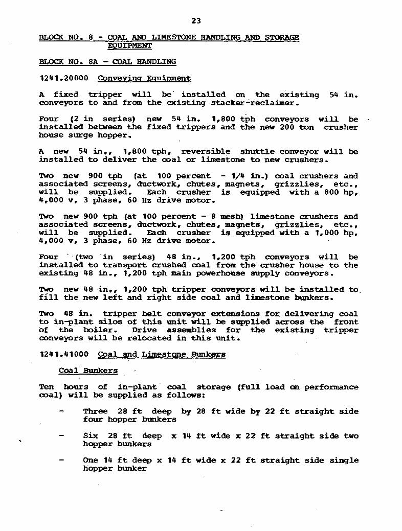
BLOCK NO. 8 - COAL AND LIMESTONE HANDLING AND ST8RAGE EQUIPMENT
BLOCK NO, 8A - a A L HANDLING
A fixed tripper w i l l be' instal led an the existing 54 in, conveyors t o and from the existing stacker-reclairner,
Pour (2 i n series) new 54 in. 1,800 tph conveyors w i l l be . ins ta l led between the fixed t r ippers and.the new 200 ton crusher house surge hopper,
A new 54 in,, 1,800 tph, reversible shut t le conveyor w i l l be ins ta l led t o deliver the ooal o r limestone t o new crushers,
Two new 900 tph ( a t 100 percent - 1/4 in,) coal crushers and associated screens, ductwork, chutes, magnets, gr izzl ies , e tc , , w i l l be supplied, Each crusher is equipped with a 800 hp, 4,000 v, 3 phase, 60 H z drive motor,
lWo new 900 tph (a t 100 percent - 8 mesh) -limestone crushers and associated screens, ductwork, chutes, magnets, gr izzl ies , e tc , , w i l l be supplied, Each crusher is equipped with a 1,OO.O hp, 4,000 v, 3 phase, 60 H z drive motor,
Pour ' (two ' in series) 48 in,, 1,200 tph conveyors w i l l be ins ta l led t o transport crushed coal fram t h e crusher house t o the existing 48 in,, 1,200 tph main powerhouse supply conveyors.
T m new 48 in,, 1,200 tph t r ipper conveyors w i l l be ins ta l led to. f i l l the new l e f t and r igh t s ide coal and limestone bunJcers.
n o 48 in, t r ipper be l t conveyor extensions f o r delivering coal t o in-plant s i l o s of this un i t w i l l be supplied across the front of the boiler, Drive assemblies f o r the existing t r ipper conveyors w i l l be relocated in this unit ,
1241-41000 Coal and Linteatone Bunkers
Ten hours of in-plant' coal storage ( fu l l load sol performance ooal) w i l l be supplied a s follows:
- Three 28 f t deep by 28 f t wide by 22 f t s t ra igh t s ide four hopper bunkers
- Six 28 f t deep x 14 f t wide x 22 ft s t ra igh t s ide two > hopper bunkers
- One 14 f t deep x 14 f t wide x 22 f t s t ra igh t side single hopper bunker
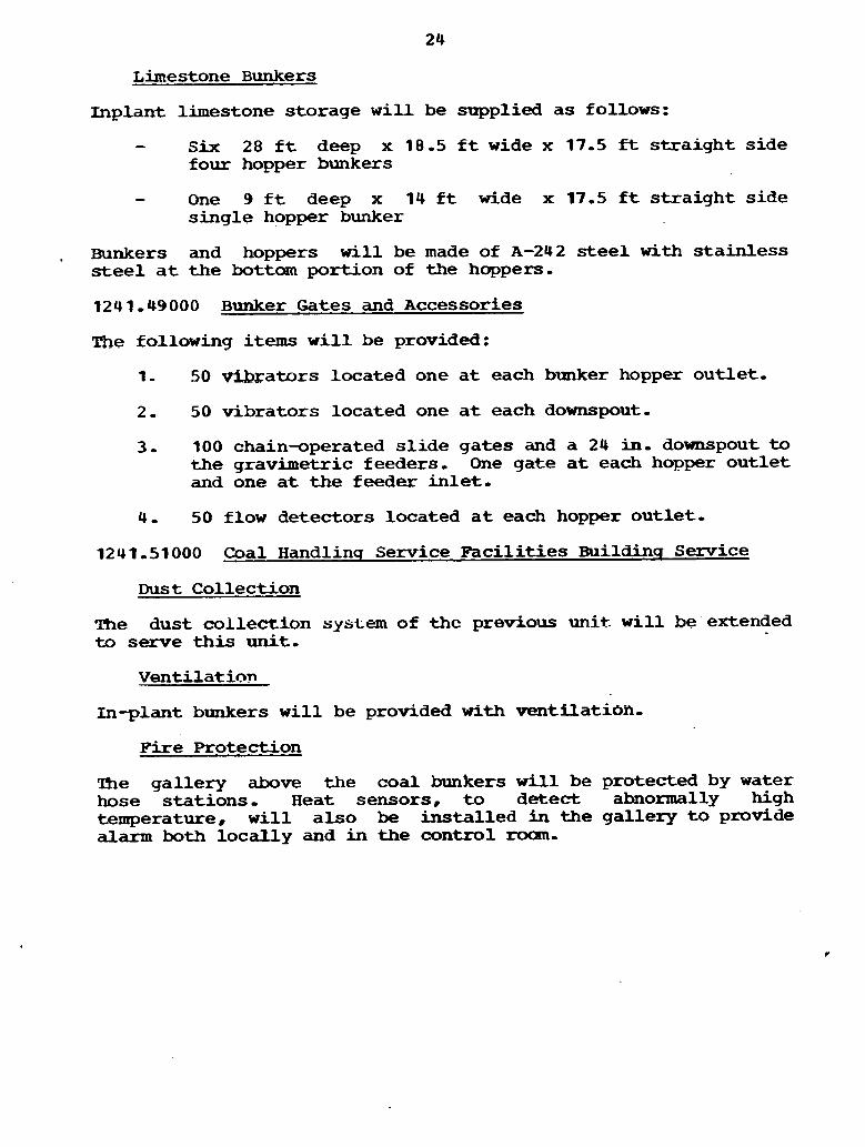
Limestone Bunkers
Inplant limestone storage w i l l be supplied as follows:
- S i x 28 f t deep x 18.5 f t wide x 17.5 ft straight side four hopper bunkers
- One 9 f t deep x 14 it wide x 17.5 f t s traight side single hopper bunker
, Bunkers and hoppers w i l l be made of A-242 s t ee l w i t h stainless s t e e l a t the bottom portion of the hoppers,
1241,49000 Bwker Gates and Accessories
The followin9 i t e m s w i l l be provided:
1- 50 e r a t o r s located one a t each bunker hopper outlet,
2,( 50 vibrators located one a t each downspout,
3. 100 chain-operated s l ide gates and a 24 in, downspout to the gravimetric feeders, One gate a t each hopper outlet and one a t the feeder in le t ,
4 - 50 flow detectors located a t each hopper outlet,
1241,51000 Coal Handlinq Service Faci l i t ies Buildinq Service
ms t Collection
The dust collection system of thc previous unit. w i l l be extended to serve this u n i t ,
Ventilation
In-plant bunkers w i l l be provided with ventflatioil.
Fire Protection
The gallery above the coal bunkers w i l l be protected by water hose stations, Heat sensors, t o detect abnormally high temperature, w i l l also be installed in the gallery t o provide alarm both locally and in the control rooan,

1241,52000 Coal Handlinq Service Facilities - Electrical
Lighting will be provided i n gal leries across the front of the boiler and above the in-plant bunkers-
1241,72000 Coal Storaqe and Reclaiminq Equipment - R.R. Track
The stacker-reclaimer track w i l l not be extended for th i s unit,
1241-95800 Conveyor Gallery
A conveyor gallery will be furnished across the front of the boiler to join the previous unit. including superstructure. siding, roofing, and f loor.
BLOCK NO*. 8B - FUEL OIL EQUIPMENT (XNU-D 'IN BUX% 7A O S P S L
12&2 ,00000. FITEL OIL EQUIPMENT AND STRU-S
1242,20000 Fuel O i l - Pumps
Iqnition O i l hmtps
Two full-capacity igniticm o i l pumps w i l l be furnished to supply light oi l t o the boi ler ignitors, The pumps w i l l be located i n the boi ler area, The pumps w i l l be arranged to take suction from the exist ing system.

BLoCK NO. 8C - FUEL GAS EQUIPMEMT
There is no plan to use gas for main or ignition fuel. There is, ' therefore, no provision included for the combustion of fuel.

BLOCK NO. 8D - AUXILIARY FUEL ST'RU-S
A new 39 ft-6 in- x 64 ft-6 in. x 108 ft-9 in. high crusher house will be provided-
aLOCK NO- 9 - STACK
1200,81000 Stack
One 616 f t high reinforced concrete s h e l l designed to be f r ee standing against wind loads w i l l be provided, Seismic design w i l l be incorporated.
A carbon steel l i n e r w i l l be provided,
Test connections w i l l be provided as required fo r mni to r ing the stack gases,
A ladder located i n t h e annular space between t h e concrete s h e l l and l i n e r w i l l be provided from the ground t o the top of the stack, Galvanized steel grat ing platforms w i l l be provided as required,
1200.81 400 Stack Liqhtinq
High in tens i ty strobe l i g h t s w i l l be provided on t h e outside of t h e concrete she l l ,
In te rna l l igh t ing w i l l be provided f o r t h e ladder and f o r the platforms within the concrete shel l .
1200r82000 Stack Foundatian . -
The s tack w i l l have a reinforced concrete foundation supported on p i l e s ,

BLOCK NO, 10 - PRECIPITATOR
1200.25200 Precipitator - Electrostat ic
MAIN BED PRECIPITATORS
One hot e lec t ros ta t i c precipitator w i l l be furnished i n the main bed f l ue gas path between the boi ler ou t le t and the regenerative air heater i n l e t , The precipitator w i l l be located outdoors i n four main box sections. The precipi tator w i l l be designed t o handle 2,345.436 cfm of gas a t 725 F. The precipitator is designed f o r a 3.15 ft /sec gas velocity, a 5.6 cm/sec migration velocity, four f i e ld s long by four hoppers wide, with a 99.8 percent part iculate collection efficiency,
Insulation
The precipi tator insulation w i l l be prefabricated mineral f iber "
panel with aluminum lagging.
Foundations and Superstructure
The foundations and superstructure for t h e precipitator w i l l be constructed similar t o the foundations and superstructure of the main powerhouse - CBB PRECIPITATOR - ELECTROSTATIC
One hot e lec t ros ta t i c precipi tator w i l l be furnished i n the CBB f l ue gas path between the CBB mechanical dust collector and the point where the main bed and CBB gas paths join before the regenerative a i r heater. The precipitator w i l l be located outdoors in one main box section, The precipi tator w i l l be designed t o handle. 413,950 cfm of gas a t 775 P. The precipitator Is designed for a 3.3 ft/sec gas velocity, a 5r32 cm/sec migration velocity, f ive f i e lds long. with a 99.44 percent par t icula te collection efficiency.
Insulation
The precipitator. insulation w i l l be prefabricated mineral fiber panel with aluminum lagging,
~oundations and Superstructure
The foundations and superstructure f o r the precipitator w i l l be oonstructed similar t o the foundations and superstructure of the main powerhouse-

BLOCK NO. 8 1 - FLUE GAS DESULFURIZATIOBY
No flue gas desulfurization is required for t h i s plant. There is no provision included for this equipment.
BLOCK NO. 12 - TURBINE GENERATOR EQUIPMENT BY -&
14 00,10000 ' Turbine Generator Unit
1400.11000 Turbine Generator
The turbine w i l l be a tandem compound, s ingle reheat unit, w i t h one s ingle flow HP-IP element and two double flow I9 elements with 30 in. l a s t s tage blades operating a t 3,600 r p m , Generation is 592,274 kw a t out steam conditions of 2,520 psig and 1,000 F a t t h e t h r o t t l e , 1,000 F s ingle reheat exhausting a t 3.9 in- Hg abs average, w i t h f u l l extraction f o r a l l seven stages of feedwater heating with 0.04 percent makeup and extraction steam for a f u l l ca*city turbine-driven b o i l e r feed pumpP Nameplate r a t i n g of the turbine generator w i l l be 552,124 kw.
Tho turbine generator w i l l be supplied with electrohydx-aulic cont ro l system and lube o i l system-
The generator w i l l be a hydrogen-cooled, 3,600 rpm, 22 kv, 3 phase, 60 H z un i t ra ted a t 662,946 kva a t 60 psig hydrogen pressure, 0 -9 PF, 0 -58 short c i r c u i t r a t i o , An Alterrex type exc i t a t ion system w i l l be furnished.
Also included with the turbine generator equipment will, be a gland steam sealing, system and s h e l l and tube gland exhaust condenser w i t h two motor-driven gland steam exhausters, supervisory instrumentation, hydrogen coolers, and other accessories necessary f o r a complete ins t a l l a t ion ,
1400,13000 Turbine Generator - C o o l i n s System
Hydrogen circulated through generator coolers will be used t o cool the generator ro tor , Hydrogen s e a l o i l coolers w i l l be included with the turbine generator,
1400,14000 Whine Generator - O i l Coolers
The turbine lube of1 system c o z ~ u i s t s primarily of a main o i l reservoir cm which w i l l be mounted two a-c auxi l iary o i l pumps and a d-c emergency o i l pump. Also i n t h e main o i l reservoir a r e t w o f u l l capacity tube type o i l coolers. A s h a f t driven main o i l pump is furnished a s p a r t of t h e f r o n t standard, Interconnecting piping, f i t t i n g s , and valves are included with the turbine,
An i n i t i a l o i l charge w i l l not be furnished with t h e turbine.

BLOCK NO, 13 - BAIANCE OF TURBINE P M BIUIPMENT (EXCLUDING CONDENSING AND C I R V . . WATER EQUIPMENT)-
I
1400,15000 Turbine Generator - Lubricatinq O i l Conditioninq Equipment
A f i l t e r type lube o i l conditioner w i l l be furnished including a recirculating pump and motor t o continuously circulate a portion of the o i l from the main o i l reservoir through the f i l t e r and back to the reservoir, Also a t ransfer pump w i l l be furnished t o t ransfer o i l t o and from "Dirtym and Wleanm o i l tanks,
1400,16000 Turbine Generator - Purpe System
C02 fo r generator purging w i l l be supplied from the previous uni t which is equipped with an adeqwte high pressure system,
1400,61000 Turbine Pipinq and Valves
The turbine manufacturer w i l l furnish a l l pipe and f i t t i n g s and a l l necessary valves and accessories , a s required, f o r a l l integral l ines involved i n the operation, cooling, purging, draining, venting, sa.npling, sealing, and lubrication of the turbine generator and auxiliary equipment furnished, A l l piping, f i t t i ngs , and valves are t o be furnished in accordance w i t h the requirements of ANSI code fo r pressure piping B31,1,0.
In addition, pipes, valves,. f i t t i ngs , ,and hangers f o r the following systems w i l l be provided:
Turbine Generator Lubricating O i l Cmponent Cooling Water Condenser Air Removal Gland Sealing Steam M i s cellaneou8 Drains
Hydrogen f o r generator cooling sha l l be extended .f ran U n i t No, 3.
1400,67000 Heat Tracinq
Heat tracing w i l l be provided for certain piping and exposed par ts and w i l l be e lec t r i c ,
1400.69000 pipe Insulation
The turbine manufacturer wi$l furnish all, thermal insulation and appearance lagging required t o completely insulate and f in i sh a l l equipment and piping provided-
Insulation w i l l be applied where necessary fo r personnel protection such that the surface temperature a t any point a t any time does not exceed 140 F when the ambient is 100 F.
Preformed segmented pipe insulation. mineral f iber , w i l l be provided f o r a l l steam jacketing,
Flat, brushed aluminum jacketing w i l l be used f o r a l l hot piping, valves, and f i t t i n g s , and w i l l be sealed t o prevent the absorption of o i l i n t o the insulation.
1400.8 1000 Turbine Generator Poundation
The turbine generator w i l l ' be supported on a reinforced concrete r i g i d frame pedestal rest ing on a . reinforced.. concrete mat supported on p i l e s -
1400,82000 Turbine Generator Vibration Jo in t
A vibration joint w i l l be la id around the periphery of +he pedestal a t the operating floor,
1400,84000 Miscellaneous Equipment Foundations
Reinforced concrete foundations supported on p i les will be provided f o r t he miscellaneous equipment,
All support steel and framing, platforms, walkways, and stairs w i l l be furnished a s necessary to permit access t o equipnrent.
1400.85000 Miscellaneous Pumps and TanRs
TWO full-capacity equipment cooling water pumps w i l l be furnished, The equ ipen t cooling water pumps w i l l be motor- driven, The equipment cooling water system w i l l be cross-tied t o the previous unit,
The equipment cooling water system will serve the turbine generator hydrogen, lube o i l , e lectrohydradic fluid. s ta tor cooling, Alterrex, generator leads, vacuum pumg sea l w a t e r . a bearing cooling _water heat exchanger. and the bed material letdown s c r e w conveyor coolers.
One carbon steel "Clean* oil tank and one carbon steel "Dirtym o i l tank w i l l be furnished.
1400,86000 Monorails
Monorails w i l l be provided for equipment such as pumps and motors.

1400,89000 ~ a i n t i n q Equipment and Pipinq
J Stee l surfaces w i l l be shop cleaned'and shop pain.i=ed with a prime and f h i s h coat. Touch--up paint ingJwil l be done ' in the' f i e l d , '
Items not su i tab le fo r shop cleaning and shop p a h t i n g w i l l be cleaned and painted in t h e f i e l d - Insulated and jacketed equipment and piping w i l l not be painted,
1400.90000 .Preliminarv Operation and Test
The turbine manufacturer w i l l provide technical direct ion to the Purchaser and Engineers regarding methods and procedures f o r t h e ins t a l l a t ion and s t a r t -up of t h i s specified equipment,

BLOCK NO, 14A - SCREENWELL STRUCTURE
A s the cooling tawer basin w i l l be extended to permit the circulating water pumps t o return water through the circulating water system. no provision is included for a screenwell structure,
BLOCK NO- 14B - CONDENSING SYSTEM
1400-20000 CONDENSING SYSTEM
. 1400 -21000 Condenser
The turbine exhaust condenser w i l l be a transverse, dual pressure, twin she l l , s ingle pass uni t w i t h 316,359 sq f t of 7/8 in- diam, 22 gage, 48 f t , 304 s t a i n l e s s steel tubes, Provisions w i l l be made f o r mounting four low pressure. heater s h e l l s in the condenser necks- The water box design pressure w i l l be 75 psig,
1400-22000 Condenser-Air Removdl S y s t e m
Noncondensibles w i l l be extracted from t h e condenser by .two full- capacity mechanical air removal pumps - 1400-28100 Circulatinq Water Pumps
Circulating water w i l l be pumped from the cooling t o w e r basin t o t h e condenser by two, half-capacity, vertical, c i rcu la t ing water pumps each rated a t 101,356 gpmand driven by 3,000 hp, 400 rpm, 4 kv motors,
1400,28200 Condensate Pumps
!Wo, five-eighths capacity v e r t i c a l condensate pumps with motors w i l l be furnished- Each pump w i l l have a capacity of approldmately 4,700 gpm with a total head of 1,040 f t and be driven by a 1,500 hp, 1,200 rpm, 4 kv motor- There w i l l be no provision f o r a third condensate pump-

BLOCK NO, 14C - INTAKE/DISCEARGE SYSTEM i
1400 -30 00 0 Intake and Discharqe System
Cooling water w i l l be pumped fram the cooling tower basin through the condenser and then t o the discharge line with approximately 1,500 l inear f t of 9 f t diam pipe, Double fixed screens w i l l be provided instead of traveling screens.
1400,37000 Chlorination and Inhibitor Feed Systems
The liquid chlorine evaporator, chlorine solution feed equipnent, and necessary controls provided with the previous unit w i l l be used t o t r e a t the circulating water. A n inhibitor feed system consisting of a 12,500 gal sulfuric acid storage tank, a 100 gal sulfuric acid 'feed tar*, and .two 1 gpm acid metering pumps w i l l be provided t o t r e a t the circulating water in the cooling tower-
BLOCK NO- 14D - COOLING POM)S/RESERVOIRS .. . Since the heat rejection system utilizes cooling towers, no provision is included for heat rejection system cooling ponds or reservoirs,
1400-34000 Coolinq Tower EXmiment
A mechanical d r a f t cooling tower w i l l be provided t o re jec t the heat from the condenser and component cooling water systems- Twelve ce l l s , each with motor-driven fan, rated a t 50/200 hp, reversible, w i l l be designed t o cool 202,700 gpm of water from 119.5 F t o 91-8 F with a w e t bulb temperature of 79 F (a i r density equal t o ,0705 lb/cu f t ) ,
A reinforced concrete foundation supported on s o i l w i l l be provided .,.
1400-34800 Makeup Water Pump
A W~.Xfc%l, 9,000 gpm makeup pump will be instal led i n the exist ing pump house- The pump w i l l be driven by a 350 hp, 900 rpn, 4 kv motor. The existing makeup l i ne from the pump house t o the exist ing un i t cooling twer w i l l be extended t o serve the tower of this unit-
BLOCK NO. 15 - WATER TREATMENT SYSTEM
1200.34000 WATER TREATING EQUIPMENT
Makeup w a t e r txeatment w i l l be extended from the previous unit t o serve this unit .
1200,34 320 Qndensate Polisher
A f u l l flaw, Powdex condensate polishing system w i l l be provided. The polisher w i l l consist of t w o half-capacity vesse l s complete with holding and precoat pumps, slurry mixing tank with agitator, freestanding control panel with instrumentation, control valves, and piping, '"

BLOCK NO. 16 - WASTE TREATMENP SY-
Equipment Washinq and Clean- hreatnent System
Washing and cleaning wastes w i l l 'be collected and pumped to exist ing f a c i l i t i e s ,
Sewaqe meatment System
Sewage will be pumped t o existing f a c i l i t i e s ,
OilFJater Separation System
Oily wastes w i l l be connected t o existing oil/water separator f a c i l i t i e s ,
BM>Q( NO, 17 AOCESSORY ELECTRICAL EQUIPMENT
8500-00000 ACCESSORY ELECTRICAL EOUPPMENT
d5OO~lllOO Elec t r ica l Equipment Footinqs
Reinforced concrete foundations supported on p i l e s w i l l be provided f o r the main step-up, uni t , and reserve s t a t i o n service transformers, w i t h f a c i l i t i e s to c o l l e c t s p i l l e d oil,
Concrete block pa r t i t ions w i l l be provided between the transformers ,
1500,11400 Miscellaneous Supports
Miscellaneous supports w i l l be required f o r t h e outdoor portion of t h e i so la ted phase bus duct generator leads and the 7.2 kv s t a t ion service leads-
1500,11500 Electrical Structures
Duct l i n e s w i l l consis t of 4 in, p l a s t i c conduit encased i n reinforced concrete ducts and will extend underground t o s i te locations a s required, Where roadways a re crossed, o r where encased in concrete s labs , steel conduits w i l l be used i n duct l i nes , Manholes w i l l be provided a s required,
A
1500.12220 Generator Leads
Isolated phase bus ducts w i l l be provided f o r carrying the output of t h e generator t o t h e main transformer, The buses w i l l be of t h e continuous, a l l welded type, dorced'cooled f o r use a t 22 kv, The u n i t s t a t i o n service transformer w i l l be fed f r m these buses by self-cooled isolated phase bus taps , The bus assemblies w i l l include potent ia l transformers and forced cooling units,
1500 - 82300 Power Cable and Accessories
Cables f o r 13-2 kv and 4 kv service w i l l be copper o r aluminum, shielded o r unshielded, as required, w i t h an o v e r a l l . jacket, Constructions w i l l be single, tr iplexed, . o r th reemnduc to r f lame-retardant ,
Cables f o r 480 v service w i l l be nonshielded, flame-retardant, t r iplexed o r three conductor copper o r aluminum, a s required,
Nonsegregated phase bus duct ra ted 15 kv, 2,000 amp w i l l connect the 13.8 kv s t a t ion service switchgear t o t h e un i t and reserve s t a t i o n service t'ransforrner,
Nonsegregated phase bus duct ra ted 5 kv, 3,000 amp, w i l l connect the 4,160 v switchgear t o t h e auxi l ia ry s t a t ion service transformers,

1500,12400 Control Wirinq
Cable fo r control wiring w i l l be s ingle and multiconductor copper stranded with f i re-resis tant 90 C thermosetting insulation over each conductor and with an overall thermosetting jacket on multiconductor cables,
Instrument cables w i l l be twisted pair and multiconductor copper w i t h f i re- res is tant thermosetting insulation,. shielded, with thermosetting jacket overall ,
Thermocouple extension wire w i l l be twisted pai r or multi- conductor of the chromel-constantan type with f ire-resistant thermosetting insulation, shielded o r unshielded, a s required, with thermosetting jacket overall,
1500,62500 Groundins System
The growding system w i l l consist of 500 mcm and No, 4/0 bare copper cable w i t h 3/4 in, by 10 f t long ground rods and w i l l be connected t o the previous un i t grid,
A I . ~ equipment and/or s t ructura l s t e e l w i l l be connected t o the main ground gr id as required so t h a t the steel w i l l essent ial ly extend the ground system*
A l l equipment w i l l be connected t o the grid o r building s tee l , as required, using 4/O AWG o r 2 AWG bare copper cables,
1500-12600 Cathodic Protection
An induced current cathodic protection system w i l l be designed and ins ta l led fo r protection of pilings, buried pipelines , condens ing f a c i l i t i e s , and other buried and submerged structures as de-ed necessary,
1500,13200 Conduit - Steel
S tee l r ig id conduits w i l l be u$ed i n general fo r all conduits embedded in concrete, including duct l ines under heavily trafficked areas, Conduit in concrete will be used only when a cable--in-tray ins ta l l a t ion is impractical o r more expensive ,
1500,13300 Conduit-Aluminum
Rigid aluminum conduit w i l l be used a l l exposed areas both indoor and outdoor,
1500 , 13800 Cable Trays
Cable trays, ladder type, w911 be aluminmi for all applications, Fire stops will be provided where cable t rays penetrate w a l l s o r f loors ,

1500 -21 100 -sf ormer - Stat ion Service
One three-winding u n i t s t a t i o n service transformer w i l l be provided, The transformer w i l l be ra ted 70 m a , foa, 22-13,8/13.8 kv, 65 C rise, 3 phase, o i l inrmersed, with no load taps- Each secondary winding w i l l be ra ted 35 m,
The three-winding reserve s ta t ion service transformer w i l l be ra ted 42/70 mva oa/foa 138-13-8/13,8 kv with no load taps, Each secondary winding w i l l be ra ted 21/35 mva oa/foa,
ltro auxi l iary s t a t ion service transformers w i l l be provided, each ra ted 16 mva, oa, 13-8-4.16 kv, 65 C rise, 3 phase, o i l immersed, The auxi l iary s t a t ion service transformers w i l l be equipped with load t a p changers-
Transformer impedance s h a l l be a s required fo r shor t c i r c u i t and motor s t a r t i n g considerations,
1500,21300 Liqhtinq and Secondarv F o w e r Transformers
Lighting and secondary power transformers, a s required, w i l l be of t h e s ingle phase o r 3 phase, dry type, with taps , ranging i n capacity from 1 kva t o 30 kva,
1500 -23000 Surqe and Protection Equipment
The generator neut ra l s w i l l be connected through neutral grounding e q u i p e n t consist ing of a dry type d is t r ibut ion transformer and secondary loaded res i s to r . These w i l l be m e t a l - enclosed and located near t h e generator leads bus ducts,
1500 - 25220 Sta t ion Service Switchsear
The 13.8 kv switchgear consis ts of two buses w i t h a total of four 2,000 amp and eight 1,200 amp, 750 m a metal-clad a i r c i r c u i t Weakers, Each bus is fed from the un i t s t a t i o n service transformer w i t h the capabi l i ty of being fed from t h e reserve s t a t i o n service transformer fo r start-up, o r i f the normal source is out of service f o r any reason,
The 4,160 v switchgear consis ts of two buses with a t o t a l of three 3,000 amp. 350 ntva class, and twenty-one 1,200 amp, 250 mva c l a s s metal-clad a i r circuit breakers, Each bus w i l l be from t h e 13.8 kv switchgear through an awciliary s t a t i o n service transformer, A bus t i e breaker w i l l allow both buses to be fed f ran one transformer f o r emergency operation a t reduced load,
1500.25300 Unit Subotakion~ - 480 V
Ten double-ended 480 v u n i t substat ions with d r a w t type thermal-magnetic t r i p air circuit breakers w i l l be provided- These substations w i l l have various combinations of 1,600 arap and 600 amp breakers a s required- Each substation includes two 4,160-480 v, 1,000/1,333 kva, dry type transformers, c lose

coupled t o the switchgear, These substations are fo r uni t aux i l i a r ies i n the turbine, fluidized bed boiler, precipitator, and cooling tower areas, One ver t i ca l section of spare compartments f o r future breakers w i l l be provided per transformer - 1500,25600 Motor Control Centers
Motor control centers w i l l be furnished and located throughout t he plant and auxil iary buildings, Approximately 35 w i l l be required ,
Each motor control center w i l l include molded case a i r c i r cu i t breakers and drawout type wlded case c i r c u i t breaker combination starters, The m a i n bus w i l l be rated 600 o r 800 amp, 600 v, and the ve r t i ca l buses w i l l be rated 300 amp, 600 v, The buses w i l l be braced to withstand a short c i rcu i t current of 22,000 amp symmetrical, Spare c~~npclrtn~ents w i l l be reduced to d mrrh'~im,
1500,.45200 Batteries and Battery Charcrers
A 125 v d-c, 59 cell lead-calcium battery, rated approximately 1,800 amp/hr a t the 8 hr discharge ra te , w i l l be provided t o supply power to UPS inverter, emergency bearing o i l pumps, emergency seal o i l pumps, emergency d-c and lighting loads, controls, indicating l ights , e tc , A battery output voltmeter, ammeter, shunt, and ground detector w i l l be provided,
. A regulated solid-state battery charger w i l l be furnished t o recharge the battery within 12 h r while supplying the normal d-c s ta t ion load, Cross-connections w i l l be provided t o enable the spare battery charger fo r t he previous uni t t o a l so be used a s a spare fo r this unit - The ba.ttesy and battery charger w i l l be connected t o the 125 v d-c dis tr ibut ion bus, The d~ system w i l l be ungrounded-
The battery system w i l l have suf f ic ien t capacity to permit orderly shutdown of the un i t w i t h no other power available,
One 20 kva single-phase uninterruptible puwer m l y w i l l be provided fo r continuous power requirements to v i t a l a--c systems such a s data logger, recorders # boiler controls, and burner controls
1500 ,48000 Power Transformer Fire Protection
The uni t s t a t ion service transfarmer and the reserve stat ion service transformer w i l l be protected by automatic deluge water spray systems, E l e c t - t i c dual sensor detection w i l l be provided w i t h local alarms and alarm annunciation i n the control room. Remote+mnual operation of deluge valves w i l l be from the control roan,
1500,70000 INSTRUMENTS AND CONTROLS
All principal controls fo r the s ta t ion tha t are essent ial fo r the operation of t h e uni t and require manipulation, adjustment, o r mnitoring during normal operation w i l l be located i n the main control rooan,
The m a i n control roan w i l l be located on the operating floor,
The control room w i l l contain the main control board, the f i r e and ventilation control panel, coal handling system panel, and auxiliary control panel. In addition, it w i l l contain the logging typewriter, alarm typewriter. u t i l i t y typewriter, events recorder printer, and the operator8s oonsole fo r the uni t data logger operation,
Adjoining the mnt ro l room w i l l be an electronic equipment room. This room w i l l contain a l l the electronic equipment which requires a i r conditioning or calibration i n conjunction with the ~ a r i o u s monitoring devices located in the control room, This includes the data logger cabinets, turbine electrohydraulic control cubicles, analog control cabinets, burner control cabinets, events recorder, and annunciator cabinets, uninterruptible power supply, control parer panel boards, and relay panels,
1500,71000 Main Control Board
The system sha l l include combination bench and ver t ica l type control board i n a central control roam fo r t h i s and the previous uni ts , The main control board arrangement of this uni t w i l l be similar t o t h a t of the previous unit. The board sha l l contain instruments and controls f o r the major control systems, together with generator and . s ta t ion service power metering and miscellaneous controls,
Included in the front ve r t i ca l section sha l l be the turbine supervisory instrumentation, monitoring instrumentation f o r the fluidized bed steam generator, illuminated annunciator uni ts munted near the top of the panel, and turbine water induction protection controls,
The rear ve r t i ca l section sha l l include protective relays for the generator and transformers, metering and to ta l iz ing equipment, and a d-c distribution panel,
The. benchboard section sha l l include the turbine electrohydraulic controls and controls for major auxiliary equipment. including the bed segment management system and boiler, and turbine control system,
Miniaturized control recording/indicating devices w i l l be used, wherever possible, to assure maximum re l i ab i l i t y , and the location of the devices on the boards sha l l allow the operator t o v i e w the alarms and major variables, The boards shal l be
designed for operation by a standing operator, Voltages over 125 v and high pressure steam, water, a i r , ar gas w i l l not be used i n the control room.
Auxiliary Control Panels
mcated i n the main control room there w i l l also be auxiliary control panels which shal l include instruments and controls and comprise various sections of the miscellaneous control board, These panels shall include:
I , Fly Ash and Bed Letdown Handling System Monitoring Panel
2 , Cooling Tower Control Panel 3 ,. Fire Protection System Panel 4, Soot Blower Control Panel 5 , HVAC Control Panel
An auxiliary system electr ical board w i l l be adjacent t o the miscellaneous control board and sha l l be complete with mimic bus and bench controls,
Transmitter and instrument racks shal l be located about the plant for mounting of instrumentation fo r associated equipanent not located in the main control room, In addition, there w i l l be located i n the plant the following control panels and cabinets:
, Generator Hydrogen and Seal O i l Panel , B e d Letdown and Fly A s h andl ling Control Panels . Chemical Fee4 Control Panel
4. Water and Steam Sample Panel 5, Electrostatic Precipitator Panel 6 , HVAC Panel
1500,72000 Instrumentation and Controls
Major control systems sha l l be electronic and part of the centralized controls in the main control roam. Local control systems w i l l be pneumatic and rack mounted where possible. Electr ic drives w i l l be used, where suitable, taking economics into consideration.
A plant manual containing loop, logic, and elementary e lect r ical diagrams, instrument list and data sh-tsr flow diagrams, heat balances, and canputer information w i l l be provided for personnel training,
INSTRUMENTS AND -0LS - MAJOR SYSTEMS
Boiler-Turbine Control System
A control system ut i l iz ing solid s t a t e electronic control components w i l l be provided fo r boiler-turbine control and
miscellaneous systems, Transfers to and from the automatic and manual control modes w i l l be bumpless, The boiler-turbine oontrol system w i l l place megawatt load demands on the turbine valves from ei ther a load dispatch system or operator se t t ing , while the throttle-pressure e r ro r w i l l be used for the boiler load demand,
The system w i l l be capable of operating i n the boi ler following control mode, Runbacks w i l l be provided t o limit the boiler and turbine load in the wen t of unbalance i n the various systems, such as loss of one FD fan, loss of one I D fan, e tc ,
Steam Temperature Control
me system will provide f u l l automatic or manual control of superheat and reheat temperature, Reheat temperature w i l l be primarily controlled by bypass dampers and spray attemperation. Superheat temperature w i l l be maintained by spray attemperation and adjustment of f i r i ng r a t e in the superheater beds-
Deaerator Level Control
A three-element level control system w i l l be provided, The control system w i l l operate two control valves sequentially. One ~ l v e w i l l modulate t o control the deaerator level up t o approximately 50 percent load, The second valve w i l l modulate t o control deaerator level from approximately 50 percent load t o maximum load,
Solid-state electronic controls w i l l be provided with remote manual s tat ions located on the main control board, Final operators w i l l be pneumatic with electropneumatic converters,
Feedwater Control
A three-element feedwater control system w i l l be provided t o maintain proper flow t o the boi ler- The system combines steam flow, boi ler drum level, and feedwater flow signals fo r automatic or manual control of the turbine-driven boi ler feed pump, A feedwater regulator bypass control valve is provided fo r i n i t i a l f i l l of the feedwater system and u n i t s tar t -up,
Combustion Control
Combustion controls w i l l be provided t o maintain proper fue l and combustion airflow t o generate the steam required while maintaining safe conditions, Coal feed and airflow w i l l be regulated i n response t o Mw load change. The bed temperatue w i l l be used t o t r i m fue l flow demand so t h a t the bed temperature can be maintained within designed limits, A i r flow is controlled to provide constant bed expansion. A i r flow w i l l be trimxed t o maintain proper excess oxygen, Oxygen w i l l be measured for each of the f ive beds,
Solid-state electronic controls w i l l be provided with rernrote manual s ta t ions located on the main control board,
Beif Seqment Control
A solid-state bed segment control system w i l l be provided t o sa fe ly l i g h t off the steam generator a d t o provide sequential operation of bed segments as a function of load* Purging w i l l be incorporated a s a precautionary meamare., A preprogrammed logic f o r determining the optimum number of bed segme~ts required and t h e i r sequence of f i r i ng w i l l be included a s a par t of the control scheme t o achieve the m o s t ef f ic ien t boi ler operation,
The controls fo r operating the system w i l l be mounted on the main control board, The conixol subpanel indicators and indicating l i g h t s w i l l t rack the s teps during sequential bed segment loading.
Bed Material Letdown Control
A control system w i l l be provided t o regulate bed material inventory by ccmtrol of limes-ne feed r a t e and material dump feeder speed, Limestone feed r a t e w i l l be primarily adjusted from the coal feed via a r a t i o control ler based on coal sample analysis.
Solid-state electronic controls w i l k be provided with remote manual s ta t ions located on the main control board,
Carbon B w n w Bed C m t r o l s
CBB w i l l be controlled t o maintain a constant bed temperature , The f l y ash (char) feed t o CBB a s available from the m a i n beds is continuous but not controlled, T'he temperature in CBB w i l l be controlled by modulating the bed level and/or coal feed, Bed l eve l w i l l be zneasured by means of d i f fe ren t ia l pressure transmitter, C e l l excess oxygen i s mondtored to maintain oxygen w i t h i n limits.
Solid-state electronic controls w i l l be provided w i t h remote' manual s ta t ions located on the main control board,
Combustion Air Preheater Control System
Steam t o the combustion a i r preheaters w i l l be supplied from a turbine extraction stage with automatic backup of steam a t reduced pressure from the auxiliary steam system- Average cold- end a i r preheater temperature w i l l be used as an index of steam flaw requirements, Condensed steam from the c o i l heaters w i l l pass t o the main condenser via two drain receivers and receiver level control valves.
Solid-state electronic controls w i l l be provided with remote manual s tat ions located on the main control board, Final operators w i l l be pneumatic with electropneumatic converters,
Air Heater Cold-End Temperature Control
Two autamatic control systems w i l l be provided, one fo r each a i r heater- The cold-end temperature fo r each system w i l l be obtained from six chromel-constantan the'imocouples located in the air duct t o the a i r heater and i n the f lue gas duct from the a i r heater, The temperature w i l l be averaged and compared t o a set point.
Solid-state electronic controls w i l l be provided with remote manual s tat ions located on the main control board,
Final operators w i l l be pneumatic with electropneumatic converters -
Draft Control
A complete d ra f t control system w i l l be provided t o maintain a constant pressure a t the i n l e t t o the transverse convection pass a t steady s t a t e conditions and t o minimize deviations during t ransient disturbances. The system w i l l maintain d ra f t consistent with the steam generator design by modulating the i n l e t louvers of the induced dra f t fans as required,
Draft w i l l be measured at the tap in the transverse convection pass a s recommended by the steam generator manufacturer.
Solid-state electronic c m t r o l s w i l l be provided w i t h remote manual s tat ions located on the main cohtrol board,
Final drive uni ts w i l l be pneumatic with electropneumatic -
Converters,
Main Boiler Feed P u m ~ Recirculation Control
A recirculation control system w i l l be provided t o maintain minimum flow through the main boiler feed p-s whenever the feedwater flow to the boiler is below that required by the boiler feed pumps fo r protection of the pump internals,
A primary flow metering device (orif ice plate) a t the suction s ide of the pumps w i l l provide for a measurement of flow, The flow measurement w i l l be u t i l i zed t o operate a modulating. recirculat ion control system
The control system w i l l operate the recirculation control valve,
An override OPEN-AUTO switch will be provided on the ma in control board fo r remote operation of this system.
A l l controls w i l l be mounted local ly and w i l l be pneumatically operated.
The f i n a l operator w i l l be pneumatically actuated and open on a i r f a i l u r e o r power fai lure.
Condensate Recirculatiosi Control
A recirculat ion control system w i l l be provided to maintain a specified minimum flow through the condensate pumps and the gland steam condenser- The condensate recirculation w i l l be based on the minimum flow requirement of the condensate pumps or the gland steam condenser, whichever is higher,
A primary flow metering device (or i f ice plat'e) a t the i n l e t of the gLand steam condenser w i l l provide fo r a measurement of flow, The flow measurement w i l l be u t i l i zed t o modulate the recirculation valve as required t o maintain the flow requirements,
The controls fo r this system w i l l be mounted locally and w i l l be pneumatically operated.
The condensate recirculation valve w i l l be pneumatically a.=tuated and w i l l open on a i r failwe,
Turbine Lube O i l Temperature Control
A control system w i l l be provided to maintain the temperature of t he lube o i l leaving the lube o i l coolers a t a preselected value recomnded by the turbine manufacturer. Two completely separate control systems w i l l be furnished, one f o r the main turbine and one for t he boi ler feed pump turbine,
The systems w i l l control the lube o i l temperature leaving the respective coolers by modulating pneumatically operated control valves in each cammon cooling water discharge l i n e from the coolers, The temperature control wi l l be based on the temperatures of the lube o i l i n each CommEDn header downstream of the coolers,
All controls w i l l be wunted local ly anrd be pneumatically operated,
Generator Hydroqen Temperature Control
A control system w i l l be provided t o maintain t he temperature of the hydrogen leaving the coolers a t a preselected value recommended by the turbine generator manufacturer,
The system w i l l control the hydrogen temperature leaving the coolers by modulating a pneumatically actuated control valve in the oomon cooling water discharge l ine from the coolers. The temperature control w i l l be based on the temperature of the hydrogen in the common cold hydrogen stream leaving the coolers.
A l l controls w i l l be mounted local ly and be pneumatically operated.
Heater Drains Control
A control system w i l l be provided for each heater in the condensate and feedwater system t o maintain the level i n the heater a t a preselected value,
The systems w i l l control the level i n the heaters e i ternal t o the condenser neck by modulating the drain valve fo r t h a t heater, An alarm w i l l be provided fo r h i g h ' l w e l plus contacts which w i l l i n i t i a t e the closing of the upstream drain valve-
On extreme high level, the control systems w i l l i n i t i a t e the following actions :
1 , Close extraction l i ne nonreturn valve, 2 - Close extraction l i ne nmtor-operated block valve. 3 - Open extraction l i n e drain valve.
For the highest point condenser neck heaters, the systems w i l l control the level in the drain molers by modulating the control ~ l v e and alarm on high level , On extreme high level, the control systems w i l l i n i t i a t e the opening of the condensate l ine mtor-operated bypass valve,
For the lowest point condenser neck heaters, the system w i l l alarm a t high level and on extreme high level w i l l initiate the opening of the condensate l i ne motor-operated bypass valve,
A l l controls w i l l be mounted local ly and w i l l be pneumatically operated - Final operators w i l l be pneumatically actuated-
Turbine Control
The turbine-generator w i l l be equipped with an electrohydraulic control system tha t w i l l provide load, speed or acceleration control, and emergency functions which t r i p the uni t on overspeed, low vacuum, th rus t bearing wear, and low bearing o i l pressure. A n operator's subpanel, mounted on the main control

board, w i l l be included a s part of the system and w i l l contain t he -opeat ing, monitoring, and tes t ing controls- A control cabinet containing the solid-state integrated c i r cu i t s w i l l be located in a roam di rec t ly adjacent t o the un i t control room. A hydraulic power supply u n i t w i l l be located on t h e ground floor elevation - A turbine supervisory system w i l l be located in the un i t control r o o m which w i l l provide the following nronitoring and alarming functions: vibration, eccentricity, spindle position, control valve position, speed, and rotor position- A turbine metal temperature recorder w i l l be provided t o guide turbine metal and m a i n steam temperature matching-
me following auxiliary systems w i l l be provided with remote panels: hydrogen seal o i l system and emergency sea l o i l pumps, hydrogen pressure and purity, and hydrogen dryers - Turbine generator bearing and o i l temperatures w i l l be monitored by the plant data logger.
Annunciator and Sequence of Events Printer
A coordinated control room annunciator and events pr in ter w i l l be provided consisting of a l l so l id state equipnent,
The alarms w i l l be coordinated by means of logical groupings i n respect t o location of corresponding controls, inaportance, and required response time to the alarm, Additionally, alarms w i l l be grouped under a cammon window with the part icular alarm ident if ied by the events pr in ter -
Turbine Bypass Control
A turbine bypass control system is required a s a prerequisite t o maintain f l o w and temperature conditions through the f i r ed bed segments, The turbine bypass control valve w i l l operate t o maintain the mininnxn flaw through the boi ler during start-up and shutduwn,
The turbine bypass control system w i l l include spray attemperations fo r temperature mt-g of the bypass steam flow w i t h the flow a t the condenser,
S o P i d - ~ l i a b electrenic controls w i l l be provided with remte manual s t a t ions located on the main control board- Final operators w i l l be pneumatic w i t h electropneumatic cmverters.
D r u m Level !k l ens ion System
A closed circuit 111 system w i l l be provided t o -nitor the drum leve l - The CRT receivers fo r this system w i l l be located i n the main control roam,
Instruments
Sufficient instrumentation w i l l be provided to permit safe operation of the uni t when the central information system is out of senrice, The monitoring devices f o r these instruments w i l l be located on the main control board or a t local s tat ions, depending upon the i r degree of importance-
A maximum of local instrumentation w i l l be provided fo r local mnitoring and equipnent cal ibrat ion- These devices w i l l be primarily thermometers and pressure gages,
Environmental Source Monitorincr System
Environmental source monitoring w i l l be in accbrdance with current Ehviroxnental Protection Agency requirements,
The S02, NO2, oxygen, and opacity taken from the downstream side of the scrubber w i l l be monitored and recorded by the data logging system- Sampling connections for SO2, N 0 2 , oxygen, and part iculate w i l l be provided. A s t r i p chart recorder f o r oxygen and opacity meter fo r smoke density w i l l a l so be provided,
A data logger monitoring system w i l l be provided t o monitor and log the various plant parameters, The system w i l l contain the fo l lw ing monitoring devices: an operatorrs console, a logging typewr i t e r , an alarm typewriter, a u t i l i t y typewriter, and- - t w 6 CRTs ,
The system w i l l be capable of performing the following functions: scan-alarm of analog and d ig i t a l inputs, periodic log, demand log, group review, postinortan review, analog trend recording (4 points), and d i g i t a l trend plus performance calculation, and turbine monitoring, Application software is not included,
The system w i l l be used for analog and d ig i t a l inputs, and those ronta* closi~res used for i n i t i a t i ng the po&-mortem review, The system may a lso be used fo r operating guides,
1500,76000 Instruments, Tubinq, and Wirinq
Tubing, piping, f i t t i ngs , valves, and instrument support materials w i l l be provided- A s many a s possible o r a l l transmitters, switches, and associated equipment w i l l be located on local racks o r panels, Level controls fo r the condensate receiver, deaerator storage tank, and feedwater heaters w i l l be ins ta l led on standpipes-
In general, primary sensing lines and s ~ l ~ lines will be fabricated from stainless steel tubhg; whereas air supply and control signal tubing w i l l be of copper, Since most instrumentation i s e%ect.ronio, coppar tubing will be used only

for local control loops, such as heater level controls and simple pressure and tenperatwe controls.
Heat tracing w i l l be provided for a l l outdoor primary sensing lines -
1600-00000 - MISCELLANEOUS POWER PIANT EQUIPMENT e
1600,100000 Turbine Room Travelinq Crane
The exis t ing crane furnished f o r t h e previous u n i t w i l l be extended t o serve t h i s u n i t -
1600-21000 Compressors and Auxil iaries
The compressed a i r systems, including instrument, service, and swt-blowing air w i l l be extended from exis t ing f a c i l i t i e s t o serve t h i s uni t , N o new a i r compressors w i l l be furnished but a 4,160 v feeder w i l l be furnished t o supply one of t h e ex is t ing 4,500 hp a i r campressors from the auxi l ia ry system of this un i t ,
1600.26000 Air Pipinq Valves and Fittincrs
A l l a i r system piping, valves, and f i t t i n g s w i l l be provided,
1600 -41000 Shop Equipment
Existing site shop equiptent w i l l serve t h i s u n i t -
1600.47000 A u x i l i a r v Steam
Auxiliary steam w i l l be supplied f r o m ex is t ing f a c i l i t i e s -
1600.70000 - Plant Communication and Sisnal System
Conduit and junction boxes w i l l be provided fo r the plant communications system- Wiring and equipment w i l l be furnished by others-
1600,89000 - Paintinq
Stee l surfaces w i l l be shop cleaned and shop painted with a primer and f i n i s h coat- Touch- painting w i l l be done i n t h e f i e l d , Items not su i tab le f o r shop cleaning and shop painting w i l l be cleaned and painted in the f i e l d - Insulated and jacketed equipment and piping w i l l not be p a i n t e d ~
BLOCK NO, 19 - SUBSTATIONS
5300 SUBSTATION AND SWITCHING STRTION EOUIPMEIW
5300.10000 Connections, Supmrts. and Structures
Reinforced concrete foundations supported on pi les w i l l be provided f o r the main t r a n s f o m r with f a c i l i t i e s t o col lect sp i l l ed o i l .
Structures w i l l ,be provided t o f a c i l i t a t e takeoff of the high voltage lines f r o m the main transformer.
All 345 kv lines, equipment, and associated relays w i l l be by others- Controls and instruments located on boards in the main 1 ram and w b - h g terminated on . t h e m boards w i l l be provided - One breaker position will be added by others t o the existing 138 kv switchyard f o r the tie t o the reserve s ta t ion service transformer, This addition w i l l include a disconnecting switch, a circuit breaker, pot heads, and sol id dielectric paver cable, relays, controls, and accessories required t o provide a complete termination f o r this unit's reserve s ta t ion service transformer leads consisting of three single conductors and one spare,
Relay panels w i l l be added t o the existing control house for the control of the above switchyard breakers.
5300.21000 Transformers . .
The main generator step-up transformer w i l l be 3 phase, 580 mva FOA, 65 C temperature rise, 22-345 kv w i t h no--load taps. Lightning arresters and auxiliary equipment w i l l ,be provided.
5300,48000 F i r e Protection
The main transformer w i l l be protected by an automatic deluge w a t e r spray system. Elect r ic dual sensor detectiors w i l l be provided w i t h local alarms and alarm annunciation in the control roomb Operation of the deluge valve w i l l be accomplished by remote+nanual means from the control room,

59
BMX3K NO. 20 - TRANSMISSION LINES
~o provision is included for the installation, relocation, or renaoval of transmission l ines.


J,O, No, 12919.02~
SYSTEM DESCKIP!CION 2-1 C I R C U U T I N G WATER - B&W
1 - 0 System ' Requirements
1-1 Function
The circulating w a t e r system removes heat from the condens,cx and releases it t o the atmosphere through the cooling tawer. In addrtion, t h e tower is u t i l i z ed t o xelease the heat collected by the annponent cooling water system,
1-2-1 General
The circulating. water system w i l l be designed f o r re l i ab le power generation.
The type and number of pumps, towers, condensers and tubes w i l l be consistent w i t h high r e l i ab i l i t y , operatang f l ex ib i l i t y and canbined minimum' investment, performance penalty and euviranmental impact,
1.2-2 Codes and Standards
The cucu la t ing w a t e r pumps w i l l be designed to the liyckaulic In s t i t u t e Standard and all other codes and standards referenced in specification P121N.
The condensers w i l l be designed to the H e a t Exchange Institute Standards fo r Surface Condensers a d ill other d e s and standards referenced in speci f icaaun P111V-
The cooling tawex w i l l be designed t o the Cooling 'Ibwer Manufacturers Association Standards f o r cooling towers a d . ' a l l other codes cind - standards referenced u specification S106B- . -
' ' The crrculating w a t e r piping and valves w i l l be designed t o the codes and standards referenced in specifications S107A/S107F and P302Q.
A l l other system components w i l l be designed t o a l l codes and standards referenced in the specif icaticm (s) in Section 7.02, '

The circulating w a t e r system w i l l be designed t o 105 f t H20 a t 92 F and f u l l vacuum,
The c i rcu la t ing water system is designed to permit continued u n i t aperation without exceeding 5.0 in. tigA h c k pressure o r requiring load reduction on the design day with a w e t bulb temperature of 79/82 F,
The cooling tower is designed t o reject 2.749~109 stu/hr a t a flow rate of 202,730 gpm on t h e design day w h l e maintaining a cold water basin temperature of 92 F,
The pump discharge valve w i l l be interlocked with the pump motor to prevent backflow through t h e pump on s t a r t -up , shutdown ox t r i p .
The i n l e t water box bu t t e r f ly valves are interlocked with t h e o u t l e t water box valves to minimize hydraulic shocks to the condenser and expns ion joints.
Spare pumplng or cooling tower capacity is not required,
2 , I Detailed System Description
Refer to Plow Diagram 12919-01-EM-IlOA.
~ w o 101,365 gpm, 105 ft TDH, vertical centrif;ugal pumps take w a t e r £ram the cooling t o w e r basin and discharge h t o one Ime- The l i n e ydlsses-into the w i i t e r boxes of the low pressure condenser; the water then passes t o the M e t of the hrgh pressure condenser, The condenser is ii
t ransverse, dual pressure, t w m she l l , s ing le pass u n i t with 316,354 sq f t of 7/8 in- durn, 22 gage, 48 f t , 304 stainless steel tubes,
The w a t e r then flows to the mechaxucal d r a f t cooling tower to cool the c i rcu la t ing water, The cooling tower is provided w i t h l i cells, each with a motar-driven f an ra t ed a t SU/2OO hp, reversible and is designed t o cool 202,730 gpm of water from 115 F to 92 F w i t h a w e t bulb temperature of 79 F,
Motor-operated valves are supplied a t t h e discharge of the pumps,
The discharge of each pump and the lnlet anit o u t l e t w a t e r boxes are equipped wlth an expansion joint ,
Removable screens and stop logs are supplied fo r each pump t o peaslit i so la t ion f o r maintenance and protection against large materials entering the pumps-
2.2 Performance Character~s t ics
The performance character is t ics of the system components w i l l be a s Included in the specifications, manufacturersg drawmgs, instructions and/or operatinn books referenced in Section 7.02-
The predic-ed t o w e r plume, d r i f t and freezing data are included in the study report PS-6,
The schematic pipring, wiring and tubing arrangement shall be as nowd on the flow diagrams, elementary diagrams and loop bagrclms referenced i n Sections 7.03, 7-08, and 7,-ns, T P S ~ ~ ~ W ~ Y ,
The physical arrangeinent of the system, machinery and other equipment w i l l oe as noted on the piping, machine location and mmuf acturers * drawings rezerenced m Sectlans 7-07, 7.06, and 7-02, respectively.
2.4 Component Desiqn
The bases of desiyn of each canpament sha l l be as ulcluded in the specification (s) and the manufacturers* drawings, specifications and/or information referenced in Section 7.02.
2.5 Instr-ntat.i=on and C m t r o l s
2-5-1 General
The specific design of the instrument and control cdmponents sha l l be as described i n the specification and shown on the drawings reierenced i n t he Instrument Schedule &or t h a t amponento
The . description of the system control and monitoring functions will be a s shown and described in the loyic d i a g r a s cind mn t ro l descriptions referenced i n Secuon 7-04-
2.5.2 Testabi l i ty
All circulating w a t e r system mponen t s d e normally in service.
L.5-3 Specific Kequlatory Requirements
There a re no regulatory reqxgirements spec i f i cd ly applicable to the circulat ing water system.
2.b System Interfaces
Tne system int&faces with the f o 1 l w ~ c . j other p l a i t systems: . -
T i t l e Number
Condenser iur Removal 5-1
3-0 -- System . . Limitations, Set Points, and Precautions
Failure of one circulating water pump a t rull load operat ion 'wll l require load ~educticm.
The circulating w a t & r pumps w i l l have to be tripped manually when the basin level f a l l s 2 f t below normal w&er level ,
4, b System Operation
4. 1 Fi l l ing
The basin is f i l l e d using the normal t o w e r basin makeup valve (4UNlti) i n approximately 6 hr using t w o roakeup w d t e r pumps-
4-2 Start--up
Circulating w a t e pmup should be started oqe at a. time in any order- The pump discharge vhlve w i l l automatically open on a start signal to the pump-
The candenser inlet and outlet water box and cooling tower return valves should be opened,
4.3 Shutdown
The system is shut down in t he reverse order det;crA~t?d in it -2 h v e -
Any side of the condenser m y be - isolated by closing the inlet water box xsolation valve and then the corresponding ou t l e t w a t e r box isolat ion valve.
5.0 Safety Features f o r Potential Bmerqencies
Not applicable

6.0 System Maintenance
T h e s y s t e m cawponents should be m a i n t m d i n accordance w i t h the, manufacturers@ operating, instruction and/or m a i n t k c e books,
7.0 Appendix
7 - 0 1 G e n e r a l
7 , 0 1 - 1 Summary of Des i crn Conditions
7.U1-2 Line Desiqnation Table No,
7 . 0 1 . 3 Instrument Schedule
7-02 Specification(s)/Purchase O r d e r s / M a n u f a c t u r e r s 8 P r i n t P r e f i x
L A , 160 V Sw~tchgear 4 Kv Motors C o n d e n s e r C i r c u l a t i n g Water Pump Motor Operated Flanged Butterfly V a l v e s R u b b e r Expinsion Joints - Mechanical D r a f t Cooling Tower s top ms Circulating Water Pipe C i r c u l a t i n g W a t e r Pipe
7 , Q 3 Plow D i a q r a m s
T i t l e
7-04 Iaqic D i a q r a m s
L a t e r
C i r c u l a t i n g & Makeup Water 6 C o n d e n s e r Air kr?moval
T i t l e
L a t e r
7-05 Ump D i a q r a m s
Number
Later
T i t l e
Later

7.08 Electrical Drawinqs
N u m b e r
Boiler Area Machine Location
hrrbine Area Machine Incation
T i t l e
Boiler Area Piping Compoc ites
T i t l e
12919 -02A-U-612Ant3,C C a b l e Tray Arrangements, boiler Area
7.09 Eaqineerinq Sketches anu Other Enqineerinq Lnf ormation

3.0- No- 12919-02A
1.0 System R e q u i r e m e n t s
1.1 Function
The mzun steam system transports steam f r a n t h e boi ler , superheat-aatlet t o t h e turbine,
1.2 Desicm Requirements
1-2-1 General
The m a i n steam system is designed f o r r e l i a b l e power genercltion ,
1-2-2 Codes and Standards
The =a steam system downstream of the main steam s top valve inlet up to but not including the turbine stop valves w i l l he designed in accordance with A N S I B -3 1 - 1 -0 and' a l l codes and standards referenced in specif icat ion P301B-
A l l piping downstream of and including the turbine s top vdlves w i l l be designed t o the turbine manufacturer8s sLadards -
A l l d ther system components will be designed to the codes and standards referenced in the spec i f ica t ion(s ) i n Section 7.02-
1.2.3 Specif ic Requirements
The main steam system w i l l be designed t o set sa te ty valve 2,620 psig a t 1,005 Y;.
The m a i n steam system pressure drop f r o m t h e outboard i s o l a t i o n valve t o t h e turbine s top valve shall not exceed 100 psi a t rated f luw condit%ons,
2.0 System D e s i q n
2.1 Detailed System Description
Hefer t o flow dlagram 12919.02A-EM-102A.
The main steam system consists of a single header extending froen two superheater ou t le t s to the t w o turbine stop valves,
, A motor-operated main steam stop valve is instal led in marn steam line t o i so l a t e the boiler frm the environs,
Tm, spring loaded safety and one electromatic re l ief valves are ins ta l l ed on the main steam lines between the boiler and the turbine stop valve to prevent boiler m a i m s t . e a m 1.j.ne overpressure {System Description 32-43). The ehectromatic valve w i l l provide uveryresswe relief whenever required and them-hy forego the operation oi the safety valves on the drum and main steam leads,
The s ingle header s p l i t s i n t o two lines to the two turbine stop vdves .
The tm m a i n steam lines a re then joined in a 'manifold to permit pressure equ;ilization and flow distribution t o the turbine .
Tile stop valves are piped to the high pressure turbine tlxough four turbine control valves. The turbine s top and control valves w i l l close on any turbine t r i p . The control valves modulate the f l a w to the turbine t o maintain the turbine speed, load, and boi ler pressure.
A line is piped to the IW turbine drive for the boiler feed pump.
The main steam system is drained at several points (System Description 32-5) to prevent line quenching and turbine waer inductron and t o permit line preheating.
During start-up. it is necessary to assure a minlmum flow of 40 percent MCR flow through the superheater, This is accomplished a s follows:
The turbine bypass valve is modulated to pass the cbAf erence between 40 percent MCK flow and BP turbine f l o w . This flow is desuperheated and introduced i n t o the condenser, The turbine bypass closes on a boiler or turbine tr ip . ,
Boiler o r Turbine T r i p
Ori a boi ler on turbine t r i p , the =in s t e a m crossover line t o cold reheat and hot reheat crossover t o c3ondenser are opened to assure superheater and reheater cooling a s the residual carbon in the bed is burned out,
2-2 ~erformance Characteristics
The performance character is t ics of the system components are as included i n the amended specifications, m u f a c t u r e r g s drawings, instructions, and/or operation books referenced in S e e o n 7-02.
The schematic piping and e l ec t r i ca l m a g e m e n t and instrumentatiori i s as noted on the flow diagrams and loop diagrams referenced in Sections 7-03, 3-05, and 7-08. respectively-
The physical arrangement of the system, machinery, and other equipem is a s noted on the piping, machine location, and rrranuf acturer a s drawings referenced in Sections 7 -07, 7 - 0 6 , and 7-02, respecbvely-
2 -4 Component D e s i q n
The bases of design of each component are as included in tne specification (s) and the manufacturer s drawrngs , specifications, and/or i n t o m t i o n referenced i n Sectlon 7-02,
2.5 Instrumentation and Controls I .
2-5-1' 6eneral
The specif ic design of the instrument and coritrol components are as described in the specification and shown on the drawings referenced in the Instrument Schedule t o r that component.
The descriptron of the system control and agorutoring functions shall be a s shown and described i n the logic diagrams and control descriptions referenced in Section 7-04.
2-5-1-2 Desiqn Information
2-5.2 Testabili ty
Each main steam stop valve, turbine stop valve, and turbine control valve 1s equipped w i t h test circuits which permit closure t o prove operirbility-
2-5-3 Specif ic iiecyulatory Requirements
2.6 System In ter faces
The system in ter faces with the following other plant systems :
System ~ i t l e System Number
Cold Reheat 3 -2 Hot K e h e a t 3-3 tr;xtract ion Steam 3-4 ~ s c e l l a n e o u s ?hrbine n u l d i n g Drains 11-1 Main Steam Safety Valve Vents and 'Drains 11-4
3 . 0 System Limitations, S e t Points, and Precautions
R e f e r to the loop and log ic diagrams for the set point of spec i f i c instruments,
4.U System Oyeration
Refer t o turbine m u f a c t u r e r m s operation ins t ruc t ion f o r operation of t h e main steam system,
5 - 0 Satety P e a t u e s f o r Potent ia l nherqencies
Not k p p l ~ c a b l e
6-0 System kiaintenace
A l l system components should be maintained i n accordance w l t h the manufacturer .s operating ins t ruc t ion and/or maintenance books 0
7-01 & A A ~ L &
7-01.1 S u m n a r y of Desiqn Conditions
7.0 I , 2 Line Desiqnation T a b l e No, 4MSS
7.0 6, 3 Instrument Schedule
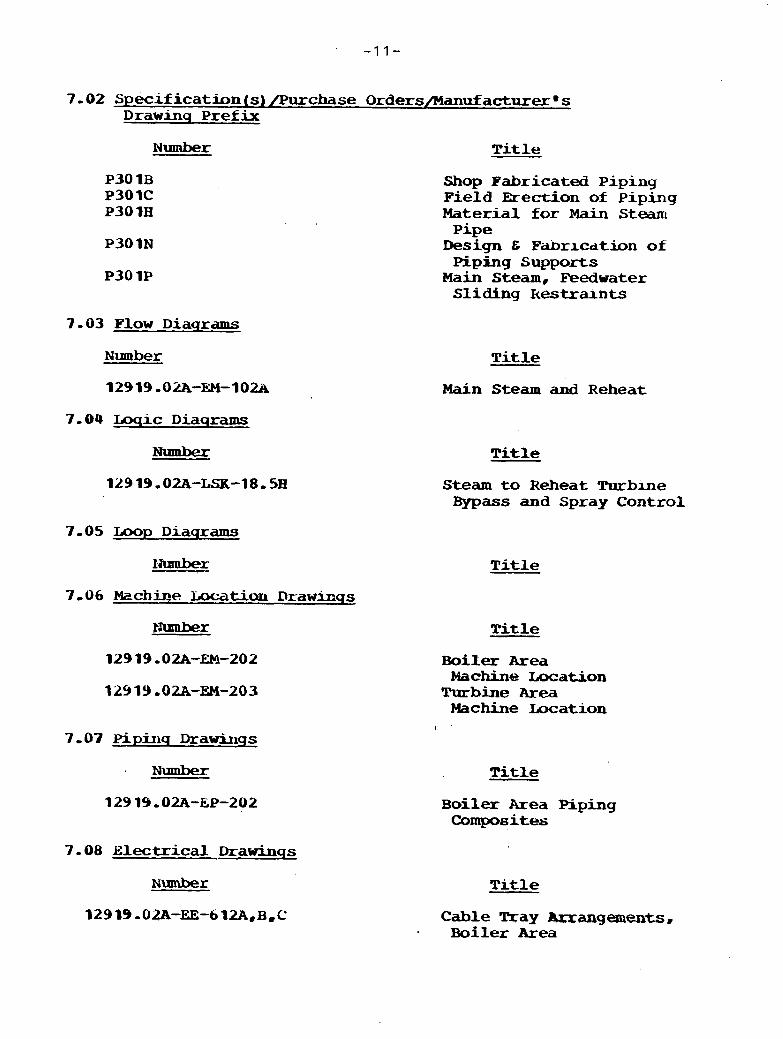
7-02 Specification(s)/Pu~cbase O r d e r s / M a n u f a c t u r e r m s D r a w i n q P r e f i x
N u m b e r T i t l e
Shop F a b r i c a t e d Piping F i e l d Erection of P i p i n g Material for Main Steam
Pipe Design & Fabrication of Pipiing Supports
Main S t e a m , F e e d w a t e r Sliding kestralnts
7-03 F l o w D i a q r a m s
Number T i t l e
Main Steam and R e h e a t
7-04 Ioqic D i a q r a m s
T i t l e
Steam to R e h e a t Turblne Bypass and Spray C o n t r o l
7-05 Loop D i a q r a m s
T i t l e
Title
Boiler Area Machine Iacat;ion
Turbine Area Machine Incation
Number T i t l e
B o i l e x Area Piping Composites
3-08 E l e c t r i c a l Drawinqs
T i t l e
C a b l e may ~ a a g e m e n t s , Boiler Area

7-09 mqineerinq Sketches and Other Information
7 - 09.6 Heat Balances
Number T i t l e
Tmrbine VWO 75% Turbine VWI) SOX Tulbine VWO 25% Turbine VWO
7.09.2 Stress Analysis
Nlnnbex T i t l e
7-69-3 other
Wumber T i t l e

J,u, No, 12919,O;W October 1977
S Y S T U DESCRIPTION 3-2 COLD REHEAT - SGW '
LRDA AFB STUDY
1.0 System H e q u i x e i n e n t s
The coid reheat system transports ste& from the high pressure turbine exhaust t o the boiler reheater and maintains the hot reheat steam temperature.
1 . 2 Des iqn Requirements
1-2-1 General '
The cold rehea t - system is designed f o r re l i ab le power generation, t -
1-2-2 Codes and Standards
A l l piping w u l be designed t o ANSI 1831 - 1-0 and al l oodes . and standards: referenced in Specification P30 1B-
7' . . 1.2-3 Specific Requirements
The system- w i l l be designed t o 600 psia a t 625 F and f u l l vacuum.
The system pressure drop w i l l not excecid 8 p s i at rdted boller conditxons,
2.1 Detailed System Description
Refer to Flow Diagram 12919-02A-EM-102A- . A single cold reheat line is piped- f r o m t h e kc$
pressure turbine t o the reheaters. me turbine header has double lead^,
Auxiliary steam is taken off of t h e cold reheat l i ne -
Six safety vdlves are ins ta l led on the cold reheat l i ne -
L.;xtracbon s teamfor the f i r s t point extraction is taken off or the cold reheat line and piped t o the heater (System Description 3--4) ,
Turbine Startup
During star tup, ~ t . is necessary t o assure a minimuxu flow or 40 percent k flow through the superheater, Thas is accomplished a s follaws:
The turbine bypass valve is modulated to pass the difference between 40 percent MCH flow and PLP turbine f lw. This -flow is desuperheated and introduced i n t o the condenser, The turbine bypiss closes on a boiler o r turbine t r i p ,
BoiLer or Turbine T r i p
On a boiler or turbine tr ip , the .lrilairl stecun cmssonter l i n e to cold reheat and hut reheat crossover to condenser are opencxi to assue superheater and reheater cooling a s the residual carbon i n the bed is burned out-
The performance character is t ics of the system canppnerkts are a s included in the specifications, manufacturerms drawings, i r~s t ruct ions , and/or operation books referenced in Section 7 -02.
The schematic piping and wiring arranganent is as noted on the flow -grams and elementary diagrams referenced i n Sections 7-03 and 7-08-1, respectively,.
The physical arrangement of the system, m d c h i n e r y and other equipment is ds noted on the piping, machine locatmq, a d wlufacturercms drawxngs retermcedl in Sections 2 - 0 7 , 7 -06 , and 7-02 , respectively,
The bases of design of each conqponcllt ;Ire a$ included in the s p e i f i c a t i o n (s) and the manufacturerB s dr a w u ~ g s , specificdtions, and/or information referenced i n Section 7 - 0 2 ,
2.5 ~nstrumentaticm and Controls
The speci f ic design of the instrument and control components is a s described in the specificatxon and sham on the drawings referenced i n the Instrument ScheCule for t ha t component -
The description of the systan control and monitoring functions s h a i l be as shown and described in the logic diagrams and control descriptions referenced in Section 7,i)4,
(Later)
2 - 5 , 3 Specif ic Requlatory Requirments
There are no reyulatory requirements spec i f i ca l ly applicable t o the cold reheat system,
2.6 System Interfaces
The cold reheat system in te r faces with the f o l l o w i n g o ther p lan t systans:
System T i t l e System L u m b e r
Main Steam Hot Reheat System Extraction Steam Auxiliary Steam System D r a i n s t o the Condenser Boiler Safety Valve Vents Turbine Bypass
3.0 System Limitatians, Set point$, and Precautions
Refer t o t h e loop and logic diagrams for the set points of s p e c i f i c instruments -
4.0 System Operation
Refer to t h e turbine manufacturerms operating ins t ruc t ion f o r operation of the cold rehea t system-
5.0 Safety Features for Potential Emerqencies
N o t applicable
6 , i) System Maintenance
The system and its canponents s b u l d be m;lintdned in accordance with the manufacturerm s operating and/or maintenance lns t ruc t ians ,
7 - 0 Appendix
7-03 General
\ 7.0 1, '1 Summary of D e s i q n Conditions
7-01.2 Line Besiqnation Table N o , 4 CRS
7,01,3 Instrument Schedule
7 -02 Specification (s) /Purchase Orders/Manufacturere s D r a w i n q Prefix
P103l.l Turbine Generator P30 IN Design and mrication of Piping Supports
7-03 F l o w D i a q r a m s
7-04 L o y i c D i a q r a m s
Number
12919,02A-LSK-l8,5B
T i t l e
M a i n Steam and R e h e a t
Title
steam to Reheat Tur~fne B y p a s s t Spray C o r ~ t r o l
Later
7 -06 Machine Incation D r a w h q s
Number
/ 3-07 Vlpinq D r a w i n q s
Number
129 19 -0;UL-EP-202
7 -08 Electrical D r a w i n q s
Number
12919.02A-612A,B,C
T i t l e
Turbine R o a n Machine T m a t.i.ons
Boiler Area Machine UxatjQns
T i t l e
Boiler Area P i p i n g C a n p o s i t e s
T i t l e . .-
Cable Tray Arrange- ments, Boiler Area

7-09 ,Enqineerinq Sketches d i d Other Informatiord
7 ,09 ,1 Heat Balances
N u m b e r T i t l e
7 .09-2 ' Stress Analysis
Turbine VWO 75% Turbine VWG 50% Turbine VWO 25% Turbine WSO
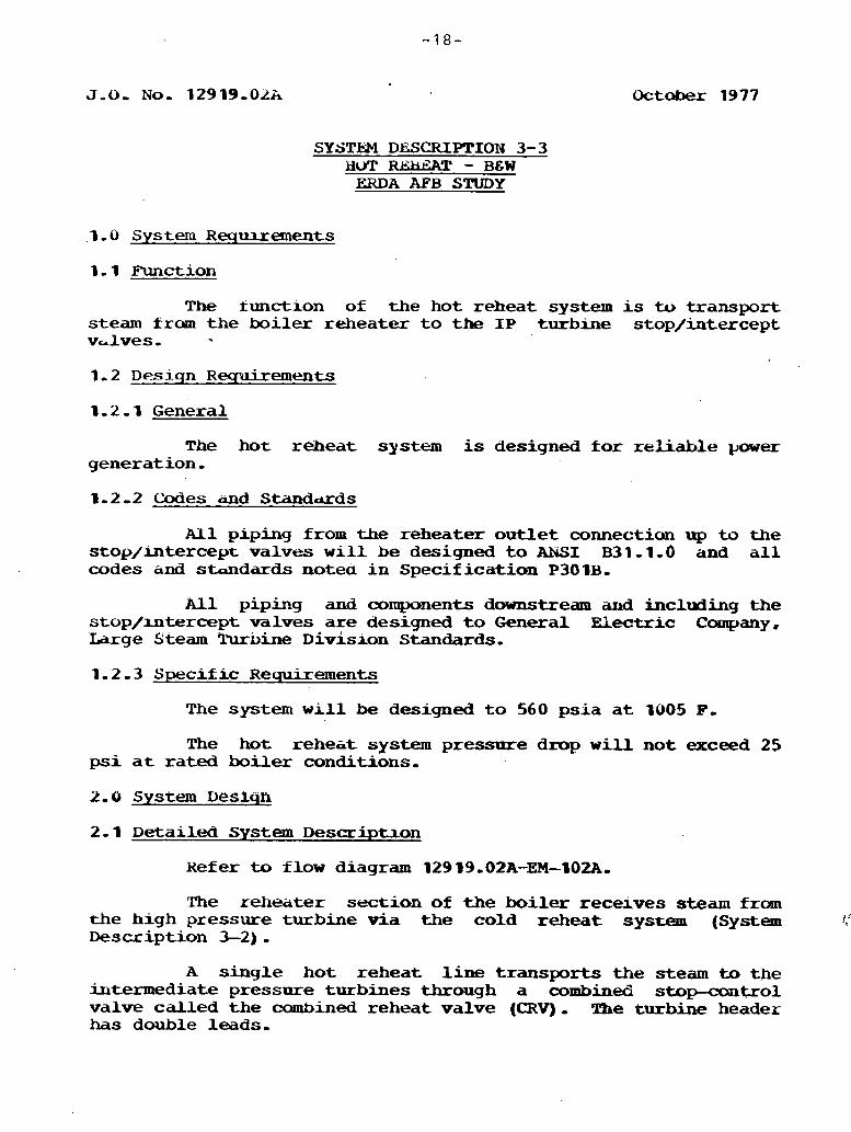
J-0, No, 12919,OLk
SYSTEM DJSCRIPTION 3-3 LivT RUiEZU? - B&W
ERDA AFB STUDY
.I -0 System Requirements
1, 1 Function
The function of the hot reheat system is to transport steam frann the boi ler reheater t o the I P turbine stop/inte.rcept v d v e s ,
1-2 - D e s i q n R e q u i x e m e n t s
The hot reheat s y s t e m is designed fo r reliable pwer generation,
1.2 -2 Codes a d Standuds
All piping from the reheater ou t l e t connecticm up to the stop/mtercept valves w i l l be designed t o ANSI B31,l.O and a l l codes and standards notea i n Specification P301B,
All piping and components downstream am3 including the stop/mtercept vdlves a re designed t o General Electric Company. Iarge Steam Turbine ~ i v i s l a n Standards,
1-2-3 Specific Requirements
The system w i l l be designed t o 560 psia a t 1905 P,
The hot reheiit system pressure drop will not exceed 25 ps i a t rated boiler conditions,
2.1 Detailed System Description
Refer to flow diagram 129 19,0ZA-EM--102A.
The reheater section of the boiler receives steam from the high pressure turbine via the cold reheat system (System I,'
Description 3-2)-
A single hot reheat l i n e transports the steam to the iutermediate pressure turbines through a combined s topcont ro l valve cal led t he combined reheat valve (CRV) , The turbine header has double leads,
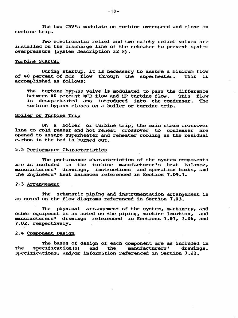
The two CRVms modulate on turbine overspeed and close on turbine trip-
Tuo e1ectromati.c r e h e f and two safety r e l l e f valves a r e ins ta l l ed on t h e hscharge l i n e of the reheater t o prevent system overpressure (system Description 32-4) - Turbine Startup
D u r i n g startup, it 1s necessary t o assure a mi-I flow of 40 percent of M a flow through the superheater- T h i s is accomplished as follows:
The turbime bypass valve is modulated to pass the b f f e r ence between 40 percent MCR flow and HP turbine flow, This flow is desuperheated a m introduced into the condenser- The turbine bypass closes on a boi ler o r turbine t r i p .
Hoiler o r Turbine lcrip
On a boi ler or turbine t r ip , the main steam crossover line to cold'reheat and hot reheat crossover to condenser a r e opened to assure superheater and reheater cooling as the residual carbon in the bed is burned out,
2-2 Performance Characteristics
The performance character is t ics of the system campar~ents are a s included in the turbine manufacturerms heat balance, manufacturersm ' drawings, instructions and operation books, and the Engineersm heat balances referenced in S e m o n 7,09,1.
The schematic piping and instrranentation arrangement is as noted on the flow diagrams referenced in Section 7.03-
The physical arrangement of the system, machinery, and other equipment is a s noted on the piping, machine location, and manufacturers drawings referenced i n Sections 7 - 07, 3 -06 , and 7-02 , respectively.
The bases of design of each oomponent are as included in the speclf icat ian(s) and the manufacturers drawings, specirications, and/or information referenced m Section 7.32.
2. 5 Instrumentation ar~d Controls
The speci f ic desiyn of the instrumeut and control components are as descrlbecl in the specification and shown on the drawings referenced in the Instrument Schedule fo r thdt component .
The description of the system control aud monitoring functions will be as shown and described i n the logic tiiagrams and ccmtrol descrlptxons referenced in Section 7 ,
2.5 -2 TestabiLity
The C=EsY's can be tested, to prove op . ta .h iJ i ty s
2.5.3 Specific Requlatory Requ~lcements
There are no regulatory requirements specif ical ly applicable t o the hot reheat system,
2.6 System Interfaces
The hot reheat system interfaces with the following other plant systems :
System T i t l e System Number
Maln Steam Cold Reheat System Drains t o the Condenser Boilex Safety V a l v e Vents
3- 0 .System r.imitatrons, Set Points, and Precautions
Refer t o the loop and logic didgrams for the set -points oi specif ic instruments.
4.0 System Operation
Kef er to the rurbine mannfacturer*~ operating instruction fo r operation of the hot reheat system,
5.0 Satety Features f o r Potential merqencies
Not applicable
6.0 Systcm Maintenance
The system and i ts components should be m;lintai~ed in accordance with tne manufacturer's operating, instruction, and/or maintenance books.

7-01 General
7-01.2 Line D e s i q n a t l o n T a b l e N o - 4 HRS
3-01.3 Instrum- Schedule
7 - 0 2 Specidlcauon (s) /Purchase Orders/Manuf acturer s D r a w i n q Prefix . -.. I
Number T i t l e .
Turbh~e G e n e r a t o r , Design & Fabricauon of
Piping Supports Piping F a b r lc ation
7 -03 Flow D i a q r a m s
N u m b e r T i t l e
829 19.02A-E;M-l02A Main Steam and keheat
7-04 L o q i c D i a q r a m s
Number Title
Steam to R e h e a t Turbine Bypass & Spray Control
N u m b e r T i t l e
7-06 MacWe Location . D r a w u i q s
N u m b e r T l t l e
Turbine Room Machine Locations
Boiler Area Machvle Locations
Number Title
B o i l e r Area Piping Composites -
N u m b e r T i t l e
Cable Tray Arrangements, B o i l e r k e a
7, u9 Enqineerins Sketcnes and Other Information
7-09-1 Heat Balances
Number Title
7-09-2 Stress Analysis
Turbine Vwo 75 pexce;nt TUrhir~p VWO 50 P e r c e n t Turbine VWO 25 Percent Turbine VWO
7.09.3 Other
O c t o b e r , 1977
SYSTEM iJESCRIPTION 3-4 UTtcACTIuN STEAM - B E W
rnDA -5 STUDY
1.0 System Requirements
The function o i the extraction steam sys tem is t o tracsport steam t ram seven levels of turbine extraction t o the respective feedwater heaters, the auxiliary steam system, and t o the boi ler xeed pump turbine (System 7-4).
1-2 Desiqn Requirements
The .extraction' steam system w i l l be deslgned f o r reliable power generation,
1-2-2 Codes and Standuds
All piping will , be designed t o ANSI B- 31 . 1-0 and a i l codes and standards referenced in specification P30 1B.
A l l other system components w i l l be designed to the codes and standards referenced in the specifrcation(s) in Sectian 7-02 ,
The systems w i l l be designed t o attain the heater s h e l l pressures noted ou the VWO heat balauce noted i n Appendix 7-09.01-
Xn addition, the extraction steam system w r l l be designed to limit the total entrained energy to a level equal t o or less than the tu rbGe manufacturerms requrements and t o prevent turbine water induction in accordance with the recommendation contained in ASME Standard TWDPS par t 1.
AU extraction lines inside the condenser neck w i l l be s t a d a r d weight s t a in less s tee l .
M1 valves 2 1 in. and la rger operating below atmospheric pressure are w a t e r sealed,
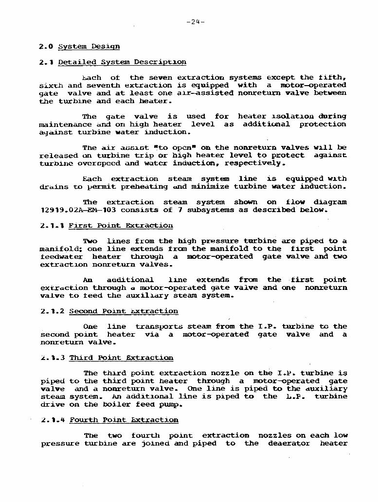
2.0 System Deslqn
2.1 Detailed System Descriptxon
Lath of the seven extraction systems except the f i f t h , sixth and seventh extraction is equipped w i t h a motor-operated gate valve and a t l e a s t one air-assisted nometurn valve between the turbine and each heater,
The gate valve is used fo r heater l so la t lon during maintenance dnd on high heater l eve l a s add i t ima l protection against turbine water induction.
The air acs l c t 4to opcno on the nonretunn valves w i l l be released rn turbine trip o r high heater level t o protect against turbinc ovcrcpccd and wcl tc r induckion, respectively,
Each extraction steam system l i n e is equipped w ~ t h drdins u, permit preheating a d minimize turbine water induction.
The extraction steam system shown on flow diagram 12919,02A-434-103 consis ts of 7 subsy.stems a s described below.
2 , 1 - 1 F i r s t Point Extractior~
Wo Ljlnes from the high pressure turbine are piped to a m a n i f old; one line extends f ran the manifold t o the f i r s t point feedwater heater through a nntor-operated gate W v e and 4wo extraction nonreturn valves.
An aaditional l l n e extends from the f i r s t point exudct ion through a motor-operated gate valve and one nonreturn valve t o teed the auxiliary steam system,
2-1-2 Second Point mt rac t ion
Oae line transports s t eam Srom the 1 - P , turbine to the second point heater v ia a motor-operated gate valve and a nonreturn valve,
2. T , 3 Third Point Extraction
The thurd point extraction nozzle on the 1 - P . turbine is piped t o the t h i rd point heater through a motor-operated gate valve and a nonreturn valve, One line is piped to the duxiliary steam system, An addxtional line i s piped to the L,P, turbine dtive on the biler feed pump,
2.1.4 Fourth Point Extraction
The two fourth point extraction nozzles on each low pressure turbirie are joined and piped t o the deaerator heater
t.kough q motor-operated gdte valve and three nonreturn vcilves, Ara,adchtioqal line is plpeci t o t h e auxiliary steam system,
2-1.5 Fifth Point Ehctractron
The two kifth point extract ion nozzles on the low pressure turbrne are pxped directly t o t h e f i f t h point heater i n that' cond.enser neck,
2-1.6 Sucth Point Extraction
The t w o sixth point extract ion nozzles on t he l o w pressure turbine atl piped d i r e c t l y t o the s ix th point heater in trle condenser neck of that turbine-
2.1- 7 Seventh Point Extractnan
The seventh poin t ex t rac t ion nozzles on each low pressure turbine are piped d i r e c t l y t o the swenth point heater in the cwndenser neck, one per each LP turbine.
2 - 1 Performance Ciuracteristics
Each extract ion system is designed t o maintain t h e heater s h e l l pressure noted on the Engineersm hea t balances noted
- in Section 7-09-01,
The schema-c piping and wiring arrangement is as 'no ted an the flow 'diagram m d elementary diagrams referenced m Sections. 7-03 and 7 .08.1, respectively-
. . The physical arrangement of the system, machinery, and other equipment is as noted on the piping, machine location, . and mmufacturersm cktiwings referenced in Sections 7-07, 7.06, ana -1, UZ , respectively .
The bases o& design of each camponent are as lncluded in t h e spec i f ica t ian(s ) and tkie manufacturer s drawings, specif icat ions , and/or m f ormatbn referenced i n Section 7 - 0 2 - 2-5 Instnmenthtion and Controls
: The spec i f ic design of the instrument and ccxitrol components is as described i n the specif icat ion and shawn on the d r a w i n g s referenced in the Instrument Schedule.

The descxiption of . the system contyol and monitoring functions shall be as shown and described i n t l e logic drayrams and control descriptions referenced i n Section 7.04,
2 -5 -2 Testabi l i ty
Lach lronreturn valve can be tes ted p e r i d a l l y by nranoally unloading the a i r cylinder and observing the motion of the counterweight arm t o verify t h a t the d i s c shaft is not bound.
2-5-3 Specific Kequlatory Requirements
There are no regulatory requirements specifically applicable t o the extraction steam systems.
2.6 System Interfaces
T k extraction steam system interfaces with the following othe .~ plant systems.
system T i t l e System Number
I'faln Steam Cold Reheat A u x i l i a r y Steam System Condensate System Law Pressure H e a t e r D r a i n s Feedwater System High Pressure Heater l)r& Feedwater Pump Turbine Steam Drains t o Condenser
3- 1 3-2 3-5 4-1 4-2 6-1 6-6
and Exhaust 7-4 11-1
3.0 System Limitations, Set Points, and Precautions
Refer t o t h e l m p and logic diagrams f a r the set point of speci f ic instrumentaaon ,
4.0 System Operatxan
( l a te r )
5.0 Safety Features fo r Potential Emerqencies
N*- applicable
6.0 System Maintenance
The system components should be maintained in accordance - w i t h the manuf anurer s operating, in~ctxxctim, and/or maintenance books,

7.0 Appendix
7.01 General
7 - C) l , 'l summa^ y o+ Design Conditions
7.31,2 Line Desiqnation Table . .
7.0 1.3 Instmqnent Schedule
7-02 Specificatio~(s)/Purchase Orders/Manufacturerms Drawinq P r e f i x
12919,OZA-P301B Shop Fabricated Piping 12919.02A-P301H F i e l d Erect ion of Piping 12919 -02.A-P301N Deslyn and Fabrication of Piplng
Supports 12919,02A-P302R M o t o r ~ p e r a t e d Carban Steel and
Alloy Valves, 2 1/2 In, and Larger 1 2 9 1 9 - 0 2 ~ - ~ 3 0 3 ~ Turbine Extraction Steam N o n r e t u r r ~
Valves 12919.02A-P305Q S t a i n l e s s S t e e l Expansion J o i n t s
7-93 Flow Diaqranns
Nlmaber T i t l e
124 19-02A-EM-103A Extraction Steam
T i t l e
Later Extraction C a n t r o l
Latier Extraction steam
7. 06 Machine m u a n D r a w i n q s 1
Number T i t l e
72Y 79 -0%-EM-LO3 Rnrbine Area Machine Locations
7 - 0 3 Pipinq Drawlnqs
L a t e r
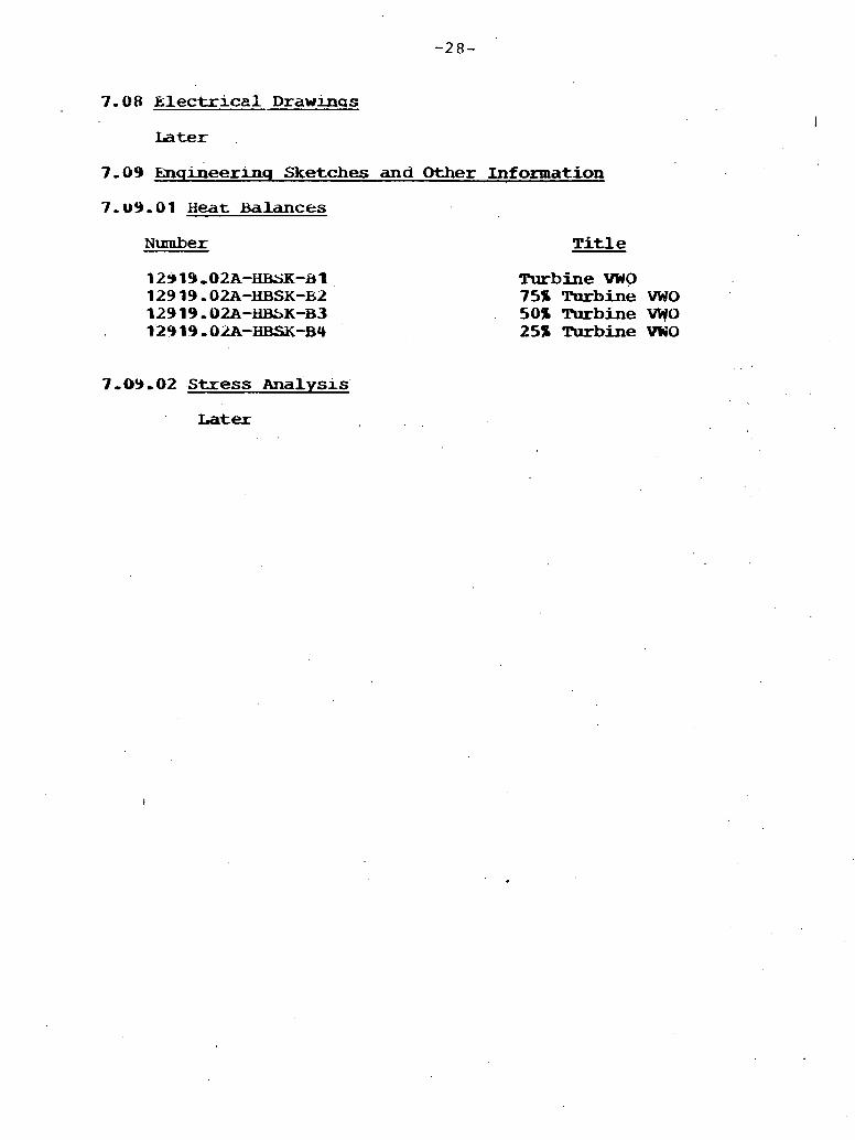
7 - 0 8 EAectriceP D r a w i n a s
Later
7-09 knqineerinq Sketches and Other Infomation
7-uY-01 Heat Balances
Number T i t l e
Turbine VWO 75% Turbine W O 50% Turbine W O 25% Turbine VWO
7-09-02 Stress Analysls
Later
J.O. No. 1L919.02u October ,1977
SYSTMul DkSCRIPTION 4-1 CONDENSATE - B6W
LRDA AF'B S.RIDY
. . 1.0 System Requirements
The *unctions or the condensate systan are to deliver preheated, dwuineralized water t o the deaerator, to supply packing sea l water, and exhaust hood sprays,
. , : I . ..
1.2.1 General
The condensate system w i l l be designed fo r re l iable power ' generation,
1.2.2 Codes and Standards
A piping w i l l be designed to ANSI B-31.1.0 and h l l codes and standards referenced in Specification Y3UIi3,
All heat exchangers w i l l 'be designed t o ASME V I I I . The feedwater heiaters a d g i m d steam condenser w i l l dso coniorm t o all oodes and standards referenced in Specificatrons P221b, P113V, and P183D, respectively,
I I ' 1 -
All pumps will be designee to the Hydralllic Irutitute standards - and all 'codes and standards rezerenced i n Specification P222V.
A l l other system components w i l l be deslgned to the codes and standards reterencec! i n the s p c i f i c a U o n ( s ) in Section .7,02.
I .
' ' The condensate ' system will be capable of delivering 62.5'percent rated feedwater flaw on the loss of one candensate pump t o assure continued'safe VWO 1-d operation.
The canderrs~te system w i l l be designed t o pernrt the loss .of a t l e a s t me single canponent without requiring unlt shutdown .

2.1 Detailed System Description
Refer t o flow d i a g r a .12919,01-a-104~-
Two five-eighths capacity condensate pumps take suction f r m the candenser hotwell and deliver the condensate t o the deaerator v i a the f u l l r l o w condensate polishing dauineralizer (System Description 4-6) , the full f l o w in tegra l bypass gland steam condenser, two drain coolers, two ha1 t -capacity seventh point heaters and the f u l l capacity sixth and f i f t h point extrciction feedwater heaters,
A permanent basket thpe strainer is instal led a t the suction of each candensate pump. I n addition, each candensate pump is equipped with a noanally open pump suction vent, an o r i f i ced n o m l l y closed pump start--up vent, and shaf t packing seal water,
The condensate system also. supplies water to the exhaust hood sprays, boiler f i l l , and the valve and pump packing seals subsystems 0
The exhaust hood sprays a r e fed downstream of the polishing demheralizer through an isola t ion valve and a modulating control valve,
Valve and Yump Stem Seal Subsystem
The valve s t e m and pump shaf t packing s e a l water is supplled through a pressure reducing valve. Loss of qeal water pressure will be annwcueed in the m a i n cuntrol iwm,
kxcessive condensate is drawn off to the condensate storage tank (System Description 4-3)-
. . Muumum conde~lsiite system f low is assured by recirculat lny a portion Of the flow back to the ~wxldq~Stkd LO maintam the flow at the gland steam condenser outLet equal to or g r e a t e r than the minimum i low set point,
H o t w e l l condensbte purity is w r m a l l y monitored a t the condensate pum~, disch&ge header, (See System Description 21-1.) un high readings, however, provision is made to monitor the con~eusate purity in each half of each condenser she l l and a t each tube sheet t o permit locating any tube leaJc.
Condenser pressure and hotwell l e y 1 &re indicated m the control roam,
Lou pressure heaters ' are equipped w r t b sola at ion and bypass valves.

I n additlon to remote manual heater i so la t ion , au tana t ic neater i s o l a a o n w i l l occur an high heater l e v e l as p a r t of turbine watec induction prevention (System Description 3-4).
The perfornance cha rac te r i s t i c s of the systein carmponents are a s ulcluded in the syeclf icat ions , manufacturer rn s drawmgs , ins t ruct ions , and/or operation books referenced in Sectxon 7-02,
The schematic piping, e l ec t r i ca l , and i n s t n u e n t a t i o n iurangement is aoted an the flow diagrams, elementary diagrams, and loop d iay rms referenced in Secbons 7-03, 7-00, and 7 -05, respectively,
The physical arrangement of the system, machinery, and other equipment is as noted on t h e piping, machine location, and manufacturerms drawings rekerenced in Sections 7-07, 7 - 0 6 , and 7.32, respectively-
2-4 Component Desiqn
The bases of design of each component are a s uc luded in the specification (s) and the manufacturer rn s drawings, specif icat ions , and/or information referenced i n Section 7 .02 -
2.5 Instruxuentation a d Controls
2-5-1 General
The spec i t rc design of the instrument and carltrol components AS a s descr'ibed m the specif icat ion and shown on the drawings referenced in the Instrument Schedule f o r t h a t component,
The description of the system control a d monitoring tunctl~ons s h a l l be as shown and described i n the log ic diagrams and control descriptions ref ezenced in Section 7-04,,
Later
2-5-3 Spec i f ic RequLatory Requirements
2 - 6 System Interfaces
The system in ter faces with the following other p lan t systems :
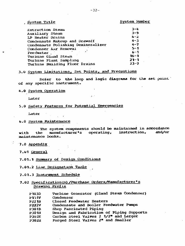
system T l t l e System Number
Extraction Stew Auxiliary Steam LP H e d t e r Drains Condensate Makeup and Drawoif Condensate Polishing Demineralizer Condenser Rir Removal Feedwater : '
t
Turbine G l d d Steam Turbine Plant Sampling Turbine -ding Floor D r a i n s
3.6 System d t a t i o n s , Se t Points, . - and Precautions
Reker to the loop and logic diagrams far- the se t ~ u 1 L ' of any spec i f i c instrument.
4.0 System O p e r a t i o n
5-0 Safety Features dor Potent ia l Rnerqencies ,
Later '
. b
6-0 System Maintenance
Tne system components should be maintained i n accordance with the mannfacturer 's operating, ins t ruct ion, and/or maintenance books -
7 .b'l General
7-01-1 S'unanary of Desiqn C o n d i t i o n s
7 .0 1 . 3 Instrument Schedule
7-02 Specification (s) /Purchase Ordersflanuf ac tu re rm s D r a w i n q Yr'ef lx
Turblne Generator (Gland Steam Condenser) Condenser Closed Feedwater H e a t e r s Candensate and Boiler Feedwater Pumps Shop Fabricated Piping Design iand Fabrication of Piping Supports Carbon S t e e l V a l v e s 2 1/2" and Larger Forged S t e e l V a l v e s 2' and Smaller

Y30LP Motor-Operated Carbon S t e e l . Valves . . Z ,I/Zm and Larger
P305D Permanent . S t r a i n e r s P305P R u b b e r Expansion Joints P306A . Thermal Insulation EOlSE 4,160 V Swltchgecir
7 - 0 3 Flow D i a q r a m s
Number T i t l e
12919,Ol-ELM-104A Condensate
7 - 0 4 mqic Diaqrams
N u m b e r T i t l e
Later ,
7 , 0 5 Ikcrp D l a q r ~ m s ' .
Number Title . .
Later . . .. . .
7-06 Machine Localxon Drawmqs
N u m b e r T i t l e
129 19-02A-EM-202 Boiler Area Machine Locat ions 129 19.02A-EM-203 Turbine Area Machine Locat ions
7 - 0 7 P ip lnq Drawinqs
Number T r t l e
129 19.02A-EP-202 . boiler Area P i p i n g Canpos i tes -
7.08 Uectrical Drawinqs
7 - 0 8 . 1 Alementary Diaqram
Number Title
L a t e r
7 .08 .2 ~ = r i n q Drawmqs
Number T i t l e
Later
7-08-3 Ccrble Tray D r a w i n q s
N u m b e r
Later
T i t l e
7 - r)d . 4 C o n d u i t D r a w i n q s
L a t e r
7.09 hqineerhkq Sketches and Other Information
7-09 - 0 1 H e a t . Balances
Title
1-09-02 S tre s s Analysis
Turbj.ne VWO 75% Turbiue VFK)
50% Turbine W O 25% Turbine WO
Later
7-09-3 Other

J.O. No, 12919.02A October 1977
SYSTLM DESCRIPTION 4-2 LOP, Fr;EDWATU U&ATKR DRAINS - DEW
ERDA AFB STUDY
1.0 System Requirements
I. 1 Function
The function of the Lww Pressure Heater Dralns System is to transfer the condensed steam drains fman the she l l s ide of the low pressure heaters t o the drain mlers or oondenser during normal operation and t o the candenser during abnormal operation,
1.2 D e s l q n R e q u i r e m e n t s
1.2-1 General
The L,Yo Feedwater Heater Drains System w i i l be desrgned fo r relihble power generation.
The system w i l l be designed tor f l a s h n g f lu ids and t o prevent turbine w a t e r induction in accordance with ASME Standard TWDPS, Part 1,
1.2-2 Codes and Standards
A l l piping w i l l be designed t o ANSl B31.1,0 and a l l codes and s t andads referenced in Specification P30 IB,
The feedwater heaters w i l l be designed to ASMh V I I I and a l l codes and standards referenced in Specification P22IV-
All other system components w i l l be designed to a l l codes and standards referenced in the Specifrcation(s). i n Sectiurs 7.02.
4
1-2-3 Specrfic Requirements . A l l control valves in the drain lines will be placed a s
close t o the receiving vessel as possible,
Piping between the control valve and the receiving vessel sha l l be one schedule h a v i e r than required before the cuxltrol valve,
2.0 System Desiqn
2.1 Detailed System Description
The l o w pressure reedwater heater drain system includes the following subsystems:
a, Four I9 feedwater heaters, t w o seventh, a sixth, and a fifth point heater located in the condenser neck along with inawidual level control systems for the ciralns
u, LP f eedwater heaters bypass and isolation system to preclude turbine water induction
c. The deaerator level control system
Seventh Point Heater D r d n s
The seventh point heater is drained directly to the condenser through a loop sea l drain l ine, N o drains are cascaded to this heater, Each heater and loop seal is equipped nth local gage glasses ana each heater is equipped with d r a m temperature indication for performance testing, Each of the seventh point heaters is equipped with h g h level alarm, On an extreme high seventh point heater level, the whole LY heater string will be isolated Bnd bypssed as a pa r t of turbine water induction prott?ct.Lon - sixth and Fifth P o u t Heater Drains
The s ixth i+d f l f th point heaters are installed in the condenser neck, and w i l l have no drains cascaea to themc Each heater w i l l be provided w i t n an external drain receiver tank which w i l l eliminate water level fram the heater and keep t h e w d t e r further from the turbine, Also, a drain cooler w i l l be provided between the receiver tank and the condenser- The flow of drains (frow the heater drain receiver) through the -1- and to the condenser w i l l he controlled by individual mwdulating mnormaln water level drain control valves. In the event e l a t rloimal water level cannot be maintained, a secculd. campletely separate, modulatmg memergencya water level drain control valve w L L l drain excess ievel t o t h e candenser direct ly tram the receiver taxix bypassing the drain cooler.
On an extreme high heater water level the whole LP heater s tr ing w l L l be isolated and bypassed a s a part of turbine w a t e r induction protectioh. Eigh drain recexver level and extreme lugh heater level w i l l also be annunciated' rn the, cork.rol room,
Each drain receiver w i l l be equipped with local gage glasses, Each control valve station consists of an inlet and
ou t l e t isolat ion valve, an upstream and downstream pressure t e s t connection, and an upstream drain,
Deaerator Level control
A horizontal t ray type deaerator heater w i t n in ternal vent condenser will be prmrded, The heater is mounted- on a horizontal storage tank with a capacity of &out 5 rain of operation a t f u l l load,
The level in the storage * tank is maintained by regulating the w u n t of condensate entering the deaerator. A three element control system is ut i l i zed which compares the actual condensate flow t o a demand (feeduater f l w ) and is corrected-by the storage tank level,
The control system w i l l be equipped w i t h two l eve l control valves, one block valve, one bypass valve, one dxain valve, a narrow range, and a wide range level transmitter,
The level contxol valves are arranged in parai lel and 'me srzed so that only one of t w o valves will operate under 'cavitating canditions- The level control valves w i l l close on an extreme high w a t e r l eve l in the deaerator storage tank, The block valve is provrded t o f a c i l i t a t e isolation of the t w o control valves and to shut off the condensate flow when cuntrol valves f a i l t o close, A motor--operated bypass valve is provided to enable remote-manual throt t l ing of candensate flw when l eve l controllers are out of service, The drain valve is provided t o dr- condensate from the deaerator storage tank to the condenser on high tank level and is sized t o handle expected leakage through the closed oontrol valve,
2-2 Performance Characteristics
The performance r-haracteristics of the s y s t e u ccmpanents are a s included in the specifications, Manufacturer9s drawiugs, instructions and/or operatam books referenced in Section 7.02.
The piping schematic, e l ec t r i ca l scfiematic, and instrumentation axrag-nt are as noted on the flow chagrams, elementary diagrams and loop diagrams referenced ' in Sections 7-03, 7-0t3, and 7-05. respectively,
' 1 physlcai arrangement ot the system, machrnery and other equipment is as w t e d on the Prping, Machine Iocation, and P h n u f acturer s drawings referenced in Sections 7 -07, 7 - 06, and 7-02, respectively,
1.4 Component Desiqn
'fie bases of design of each component are as included in the spec i f i ca t~on( s ) and the manufacturer~s drawings, specifications and/or inkormcrtion referenced in Sectron 7.02,
2.5 Instrumentatxhn and ~ a n t r o l s
L.S.1 General
The. spec i f i c deslgn of the instrument and control components are a s described i n the specification and mown on the drawings re&erenced in the Instrument Schedule.
The description of the system control and monitoring functions s h a l l be as shown and described i n the logic diagrams and control descriptions referenced in Section 7.04,
2.5-2 Testabi l i ty
Later
2.5-3 Specific Requlatory R e q u i r e m e n t s
N a n e
2.6 System Interfaces
The low pressure heater d r a i n system interfaces with the following syslxms:
S y s m T i t l e System Number
Extraction Steam Can densate Feedwater High Pressure Heater Drains
3.0 System Lirmtatims, Set Points, - and Precautions
R e f e r t o t h e loop and logic diagrams f o r the set point of speci f ic ins t rmenta t ion ,
4.0 System Operation
Later
5.0 Satety Features f o r Potential EmP-rqencies
Not applicable

6.0 System Maintenance
A l l system mechanical camponents are to be mninbined in accordance w i t h the operation and mintenance instructmns submitted in accordance with the component spec i f i cat ion listed in Section 7-02,
7-9 Appendix
7-0-1 General
7 - 0 9 - 1 Summary of Desisn Canchtions
7-01.2 Line of Desicmation Table No- HDL
7.01-3 Instruntexkt Schedule
7-02 Speci f icat ion (s) /Purchase Orders
1291Y,OLA-P221V Closed Feedwater Heaters 129 19,02A-P222V Condensate and Boiler Peeduater P u m p 129 19 -02A-P301N Design 6 ~abr icat ion of Piping Supports 12919-02A-P302E Carbon S t e e l Valves 2 112" & Larger 129 19.02A-P302H Forged S tee l Valves 2- 6 Smaller
7-03 F l o w Diaqrams
Number T i t l e
1W 19,02A-EM-106A Heater D r a m s
T i t l e
Later LIP- Feedwater Heater Drains LOP, Feedwater Beater Isolation and and Bypass
Deaerator Level Control
7 -05 Loop D i a q r a m s T i t l e
~ a t e r L,P, Heater D r a i n
7-06 Machine Uxation D r a w i n q s
129 19 -02A-kM-203A Turbine Room Machine Location

7 - 07 P i p l n q D r a w i n q s .
T i t l e
L a t e r
7-08 Electrical D r a w i n q s
L a t e r
7-09 Enqineerinq Sketches
N o n e
LP Heater D r a i n Piping Feedwater Piping
October 1977
SYSTEM DESCRIPTION 4-3 CONDENSkTe MAKEUP AND DRAWOFF - B&W
E;RDA mn STUDY
1.0 System Requirements
The f u n e o n of the condensate makeup and d r a ~ f f system is t o maintain the condenser hatwell level at a predetermined level and supply a source of w a t e r for various' other systems.
A
1-2 D e s l q n Requements
1-2-1 General
The condensate makeup and drawoff system w i l l be designed for re l i ab le power generatian;
1.,2.2 Codes and Standards
A l l p ~ p i n g will be designed to ANSI B31-1.0 or as' applicable and codes and standards referenced in ,
specification P30 1B.
A l l 'other system components will be designed to the d e s and s h d u d s referenced in the ' - specifications i n Section 1-02,
' 1 , . . I
1.2 - 3 Specific Requirements
The normal condenser makeup and drawft shall be sued fox f ive percent ob rated feedwater flow, The emergency condenser makeup shall be sized xor (later) lbm.
The demineralized w a t e r storage tank overtlw w i l l be sized for the la rges t s ingle flow i n t o t h e tank.
'2.0 System D e s i q n
2.1 Detailed System Description
+ Refer to Plow D i a g r a m 12919.01-EM-104A.
2-1-1 General
A s p l l t condenser is provided with a high pressure s h e l l and a low pressure she l l , The hatwell makeup l i n e trom the d ~ e r a l i z e s water storage tank is connected t o the LP s n e l l s ide- Contiensate pmp suction is taken froru the m t w e l l on the H P she l l side,
2.1-2 Makeup System
Makeup w a t e r is added to the condenser from the exist lny u n i t dexuineral~zed water storage tank through two control valves, t he normal makeup control valve and the emergency makeup control valve, The hotwell level control valve set p a n t s dre established such that during narmal operating conditions the normal mke\rtg valve 1s m d i a . l a t i . n r j and the emergency makeup valve and drawoff valves are closed, On an extreme low level , the emergency makeup valve w i l l open to supply acht icmal makeup t o the system,
2-1-3 Drawoff System .
On a high condenser hotwell level, the condensate ~s drawn otf fram the system a t a point downstream of gland steam condenser and returned t o the deminerdlized storage tank through a modulating control valve, D u r i n g p e r ~ o d s of high conductivity, the condensate-drawoff w i l l be dumped t o the waste sump through a blowdown valve-
2-2 Performance Characteristics
The performance character is t ics of the exlsting system components are as included i n the specifications, mnnufacturer8s drawhgs, ulstructions, and/or: opera-on books referenced in Section 7 -02
The schematic piping and wiring arrangement x a s noteci on the flow diagrams and elementary diagrams referenced m Sections 7-03 and 7 - 0 0 , respectively,
The physical arrangement of the system, machinery, and other equi-nt is a& notcd on t h piping, machhe location, and manufacturerBs drawings referenced in S e o n s 7-07, 7.06, and 7-02, respectively.

2. b Component Desiqn
The basis of design of each component is a s Included i n the specification (s) and the manufacturer ' s drawings, specifications, &/or information referenced i n Section 7 - 0 2 , . .
2.5 Instrumentatian and Controls
2.5- 1 General
The specif ic design of the instrument and controi oomponents is ds described I n the specification and shown on the drawings referenced in tne Instrument Schedule fo r that oomlponent -
The description of the system control and d t o r m g functions shall be as shown and described i n the logic diagrams and control descriptions referenced .in Sect;ron 7 ,O4,
No specif ic requurements,
2-5-3 Specific R e q u h t o r y Requirements
Nane
2.6 System Interfaces - The candensate makeup and drawoff system, interfaces
w i t h the sollawing systPslrs:
System T i t l e System Number
Chemical Feed C o 1 l d e n s a t c Candensate Demineralizer Boiler Feed
3.0 System r.imlt-tions, Set Points, and Precautions
Refer t o the ~nstrument schedule for tne 'set point of any instrument,
The normal condenser rn-up valve m i n t a m s hotwell normal water level (NWL) a t E l , 1 - The emergency condenser makeup valve will start opening clatex) m- below NWL and w i l l be l u l l y open (lata) m- below NWL-
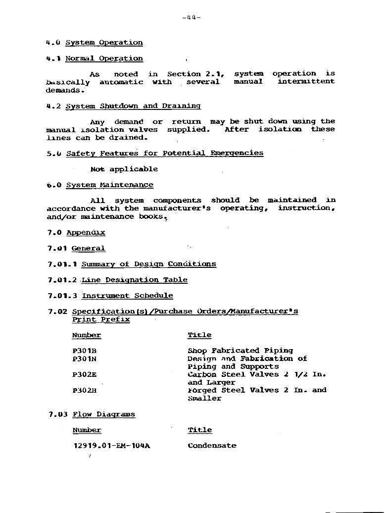
4.0 System Operation
4.1 N o r m a l Operation I
A s noted in Section 2.1, system operation is basically autamatic w i t h , several manual internuttent demands -'
4.2 System Shutdown and Dralninq
Any demand o r return may be shut down using the m a n u a l i so la t ion valves supplied- After isolatiaol these h n e s can be drained,
5-b Safety ~ e a t u r e s f o r Potential Emexqencies
~ o t applicable
6-0 System Blaintenance
A l l system components should be maintained m accordance w i t h the manukacturerms operating, instruction. and/or maintenance booksg .
7,4)1,2.Line Desiqnation Table
7 - 0 1 , 3 Instrument Schedule
7-02 S p e c i f f c a t i o n ( s ) ~ c h a s e Orders/Manufacturerms Print Prefix
Number T i t l e
Shop Fabricated Piping Design and mbriaatian of Piping and Supports Carbon Steel Valves 2 I/& In. and Larger Sorged Steel Valves 2 In- and Smaller
7-03 Flow D i a q r a m s
N u m b e r T i t l e
12919-01-EM-1U4A Condensate
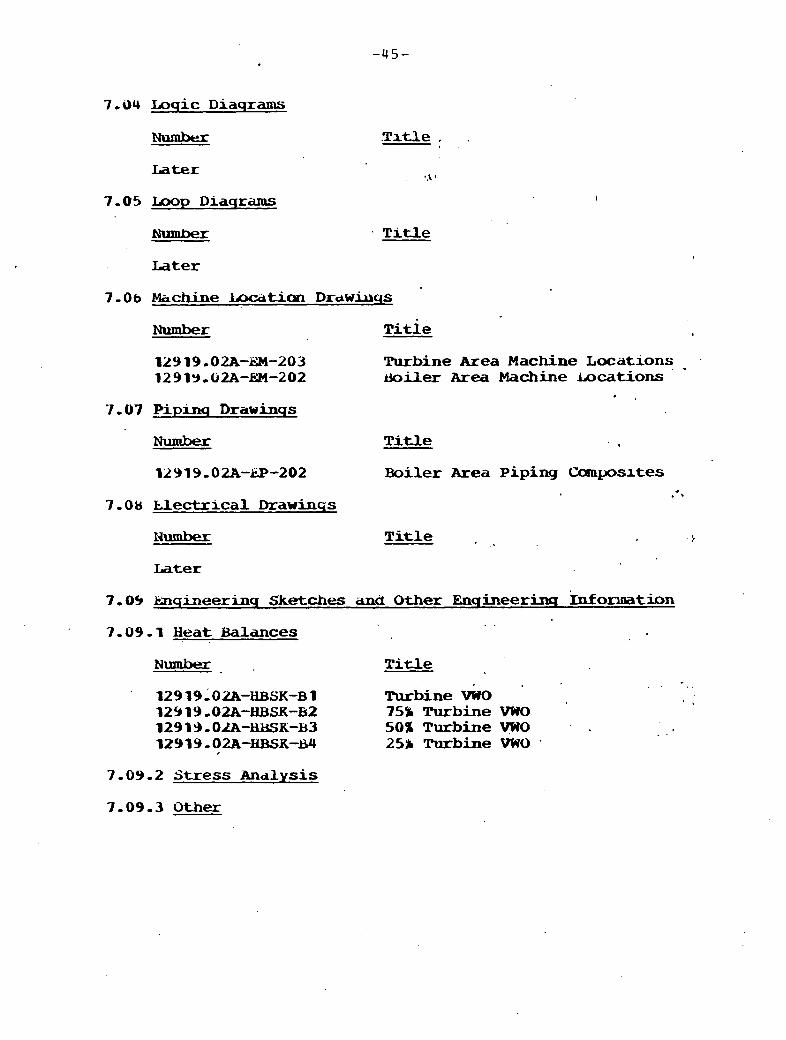
7-04 Inqic Diaqrams
Number
Later
7 - 0 5 Ump D i a q r a m s
T i t l e
7 -06 Machine l a x t i a n DrdwiuqS
Number ~itle
12919-02A-dM-203 Turbine Area Machine Locations .
12919,62A-EM-202 miler Area Machine &cations *
' ,
7 -07 Pipinq Drawinqs
Number T i t l e
129 19,02A-kP-202 Boiler Area Piping Coaoposltes . .
7 ,0& Electrical Drawinqs
l J u m b e x T i t l e z
Later
7-09 lmqineerinq Sketches and Other Enqineerinq Information . .
7-09.1 H e a t Balances
bhmber. T i t l e , . . .
12919;02?i-H)3~~-~1 Turbine GO b I
12919 -02.-HBSK-B2 75% Turbine VWO 12913.OlA-WK-B3 50% Turbine VWO . . 12919.02A-ELBSK-I34 25% Turbine VWO ,
7-09.2 S t r e s s Analysis
7-09.3 Other

SYSTEM DkSUUPTION 5-1
O c t o b e r 1977
CONDENSER U R REMOVAL - B&W ImbA APB STUDY
I , c, System Requirements
The functlon of the condenser a i r xemoval system is t o provlde the reyuurck start-up vacuum f o r turbine genecator opel-ation and t o remove norlcondensable gases Fran t he condenser s h e l l s dwing p d n t operatlori,
1-2-1 General
The anr removal system w i l l be designed f o r r e h a b l e power generation-
The system s h a l l have s u f f i c i e n t duplication t o assure coutinued operatmn.
The capacity of the a i r removal puxups shall be deterrmned i n accordance with potent ia l air inledcage, dnd t h e water vapor contained in the air-gas mhture ,
1-2.2 Codes and Standards
A l l piping w i l l be designed to ANSI B-31-1 and all codes and standards referenced in specif icat ions PlllV and P11&.
Motor driven a x removal pmps w i l l be sized in iccordc~nce with the rea>mnendlations of the Heat Exchange I n s t i t u t e Standards r o r Condensers,
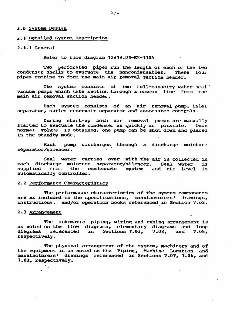
2 - 0 System Deslqn
i, 1 Detailed System Description
Refer t o flow diagram 12919.01-EPI-llOA
!hm perforated pipes run the' length oi each of the two condenser shells to evacuate the noncondensables- These four pipes combine to fono t h e main a i r removal suction header,
The system cansists of t w o full-capaclty w a t e r sed' vacuum pumps whch take suction through a common line from the main a i r removal suction header-
Each system consis ts of an air rexraoval pump, inlet separator, o u t l e t reservoir separator and associated controls.
During start-up both air removal pumps iue ~nanudly s t a r t e d t o evacuate t h e condenser a s quickly as possible. Once nonnal volW IS obtained, one pump can be shut dawn and placed iu t h e standby mode,
Each pump h c h a r g e s through a, d i s c h a g e moisture separator/silencer,
Seal w a t e r ca r r led over with the air i s collected in each discharge moisture separator/si lencer- Seal water ~s
supplied from the condensate system and t he l e v e l is automatically controlled-
2.2 Performance Characteristics
The performance characteristics of t h e system canponents are as included in t h e specif icat ions , nranufacturers' drawings, instructions, -0s operation books referenced in Section 7 - 0 2 .
The schematic ,piping, w i r i n g and tubing aurranyement is as noted on the flow diagrams, elemeneary diagrams and loop di-rams referenced m Sections 7-03, 7 -08, and 7 - 0 5 . respectively,
The physical arrangement of the system, machinery and of the equipment is as noted on the Piping. Machine Locatron and manufactnrersg drawings referenced in Sections 7-07, 7-06, and 7-02, respectively.

Phe bases of design of each component are as included in the specificatiun (s) and the manufacturers 9 drawings, specifications, and/or information referenced in Section 7 -02,
2.5 Instrumentation and Controls
2.5-1 General
The specific design of the instmment and control cunponents are as described in the specification and sham an the - d r a m s referenced in the -t Schedule for that COlItpnent 0
9 dwcription of the system ~xsntroi and manitoring functions shall be as sbovn and described in the logic diagrams and &trol descriptions referenced in S e c t i o n 7-04,
a .
2-5-2 Testability
All standby equipaent. is periodically tested, . 2.5.3 Specific Rsqulatory Reaimments
There are no regulatary requirements directly 'applicable to the -denser air removal system,
2.6 System Inte~f aces
T ~ E oomdeplser a i r msmval system interfaces with 'the f o l l o ~ g other plant systems:
S v s t a T a t l e
Condensate
Condensate Makeup and Drawoff
system N\lmber
3 -0 System r.imitatioa3s. Set Points, and Precamaarm
Refer to instmment schedule. for the set point of specific i n a t r u ~ ~ ~ % ~ t a t l o i ~
4.0 System Operatian
. 4-1 Start-= -. . I
start- vacmmn. i.e., less than or *,to 5%&. H ~ A , is established by opening vacuum pump inlet valves and starting both kir m v a l prmpps- The start- vacrmn will be' attained in approJximately 1 hour-

After a t ta in ing 5 in, HgA, the vacuum p q s w i l l automatically t ransfer t o the i r holding mode,
4.2 N c m m 1 Operation
During normal operation, the air remaval shstem requires l i t t le at tent ion, Periodically, the standby vacuum pump' should be cycled and/or placed i n service,
5.0 Safety Features f o r Poten-al Emerqencies
Not applicable
6.0 System Maintenance
The system components should be m a i n t a i n e d in accordance with t h e manu£acturers' operating instruction and/or maintenance book. . .
7.0 Appendix
1-01 General
7.0 1.1 Summary of ~esiqn Conditions
7-91-2 Line Designation Table 4ARC
7.8 1 , 3 Instrument Schedule
7. ul Specification (s] /Purchase Orders
PI1 lV Condenser P112E Condenser A i r Removal Pumps P301B Shop Fabricated Piping P30 lN Design and Fabrication of Plging Supports P302E Carbon Steel Valves 2 1/2- & Smdler -
Category II
7-03 Flow Diacrrarns
T i t l e
12919,Ol-EM-11OA C i r c , & Makeup Water & Condenser A i r Removal
Number T i t l e
Later

Number T i t l e
7 -86 Mhchine Lociitian D r a w i n q s
Number T i t l e
129 19-0a-EM-202 Boiler Area Machine Locations 12919-02A-EM-203 Turbine Area Machine Iocatians
7-07 Pip- Draw-s
Number - Ti +.l e a-
12919-02A-EP-202 Boiler Area Piping Drawings
7.08 Electrical Drawinqs
Number lktle
(later)
7-09 Eslsineerinq Sketches
None

J.0, No. 12919-02A $ .
SYSTEM DLSUIPTION 6-1 BOTT.I.:R FEEDWATRR - S W
m A AFB m y
1.0 System Requix-ts
The function of the feedwater system is to deliver feedwater trom the condensate system to the Mler a t t&e required pressure and temperature,
1.2.1 General
The f eedwater system up to, brrt not hcluding, the a t b o a r d boi ler isolat ion valve w i l l be designed f o r re l l ab le pover generation . 1-2-2 Codes and Stanckrds
Piping frcmn the boiler feed pump discharge up to , but not i n c l u b g , the outermost boi ler isolat ion valve w i l l be furnished i n accordance w i t h t he l a t e s t A N S I B31.1.0 and dl codes and slxndiirds referenced in Specification P301i3.
Piping froen the boiler t o the o u t e m s t isolat ion valve will be furnished in accordance with the latest ASME I and a l l codes and standards referenced in Specification P301B-
A l l heat exchangers w i l l be designed to ASME; V I I I and all codes and standards referenced in Specification P221B-
The feedwater pumps will be dekigned to the Hydraulic Insatute Standards and a l l codes and standards referenced in Specif icat ion P222V.
A l l other system components w i l l be designed t o the codes and standards referenced in t h e specifications i n Eeckian 7 ,02 .

1-2.3 Specific Recruirements
The feedwater system shall be capable of delivering 3,813,688 lb of water per hour a t 484.03 P and 2,920 psia t o the boi ler at turbine valve wide open condition,
2.0 System Desiqn
2.1 Detailed System Description
Refer t o flow diagram 12919,02A-EM-IOSA,
One full-capacity, centrifugal barrel type, st-- turbine driven boiler feed pump w i t h shaf t driven matched booster pump is provided.. The booster pump w i l l take suctian f ran the deaerator and supply the suction of the boiler feed pump which, in turn, discharges to the economizer section of the boll- via, i n series, the three high pressure heaters .. Boiler feedwater is also used fo r desuperheating the superheater and the reheater.
Feedwater t o the superheater desuperheaters is prowided froan a tap off the boiler feedwater line damstreant of the motor-operated isolat ion valve. Feedwater is taken from me t ap and then a v i d e s in to two lines, each with a flowmeter and feedwater caotrol valve which closes on a turbine t r i p - mese two lines then divide into t w ~ l ines each havlng a temperature control valve before enterug the superheater desuperheater section of the boiler,
Feedwater t o the reheat desuperheater is provided directly f r o m an interstage portion of the feedwater pump. Feedwater flows through a flawmeter, through a feedwater control valve which shuts o f t on a turbine trip, and a temperature mn t ro l valve before entering the reheat desnperheater section ot the boiler.
Peedwater is also provided by the interstage takeoff t o the turbine bypass system- Feedwater ilws throuqh a flowmeter, throuqh a feeawater contra1 valve which s h e off on a turbine t r i p , and a temperature m t m l valve before entering the turbine ,bypass desuperheater,
Fedwater- ~s also provided by the interscage takeoff t o the reheater cooling system for desuperheating. A s ingle line is provided fo r the desuperheating of the cooling steam i n t o the reheater, Feedwater flows through a floymeter, through a f eeduater c m t r o l valve which shuts off on a turbine t r i p , and a temperature control valve before enterlng the reheat cooling steam desuperheater. A s ingle line vhrch dxvides i n t o t w o separate lines is provided f o r
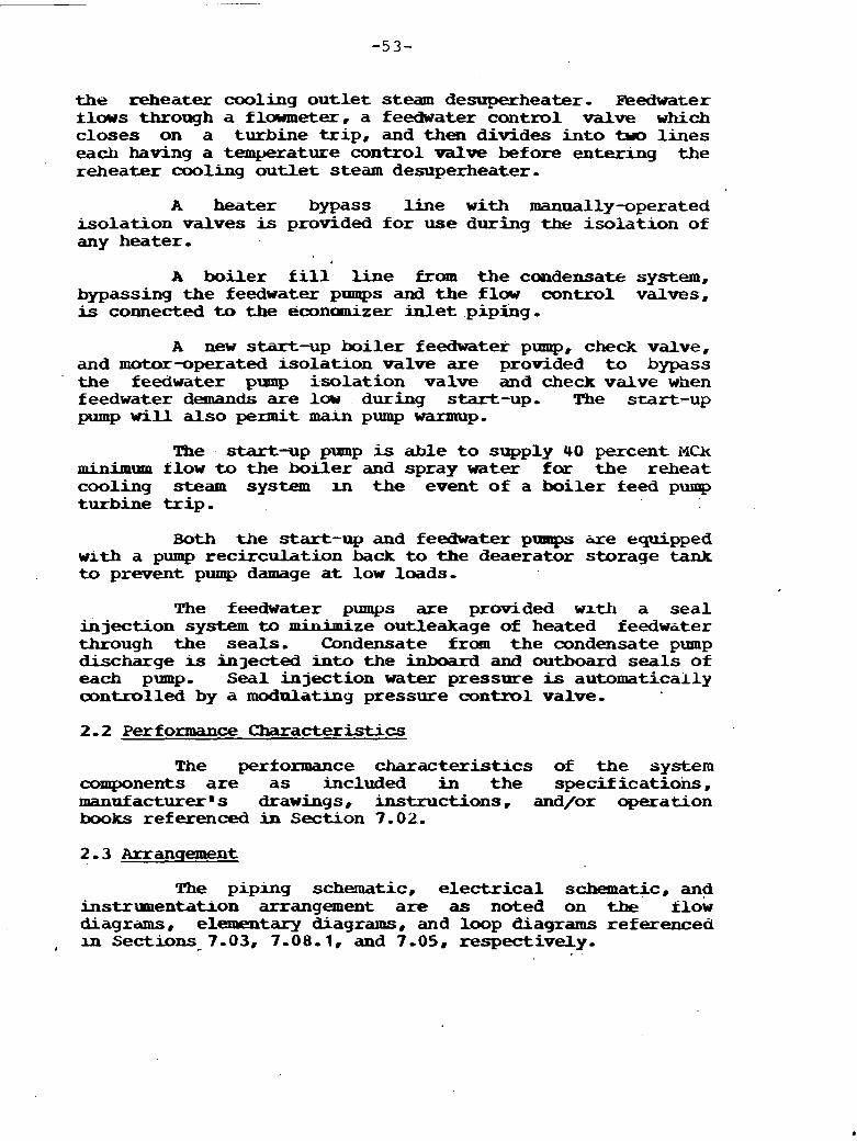
the reheater cooling ou t le t steam desuperheater- Feedwater ilws through a flawmeter, a feedwater control valve which closes on a turbine t r i p , and then divides i n t o .tvo l ines each having a tenyeratwe control valve before entering the reheater cooling outlet steam desuperheater,
A heater bypass line with manually-operated isolat ion valves is provided fo r use during the isolat ion of any heater,
A boiler f i l l line £ram the condensate system, bypassing the feedwater pumps and the flow control valves, is connected to the econanizer inlet piping,
A new s tar t -up boiler feedwater pump, check valve, and motor-operated isolatron valve are provided t o bypass the feedwater pump isolat ion valve and check valve when feedwater demands are 1- during start-up- The start-up pump will a l so peanit marn pmp warntup-
The start-up pump is able t o supply 40 percent MCk minim- &low to the bol ler and spray w a t e r far the reheat cooling s t e a m system m t he event of a boi ler feed pump turbine t r i p -
Bath the start-up and feedwater pumps &re equipped w i t h a pump recirculation back t o the deaerator storage tank to prevent pump damage a t low loads-
The feedwater pumps are provided wxth a sea l injection system to minimize outleakage of heated feedw~ter through the seals , Condensate from the condensate pump discharge is injected into the inboard and outboard seals of each pump- Seal injection w a t e r pressure is automatically controlled by a modula-g pressure control valve,
2.2 Perf orxuance Characteristics
The performance character is t ics of the system components axe a s included in the specifications, manufacturerms drawings, instructions, and/or aperation books referenced in Section 7-02,.
The piping schematic, e l ec t r i ca l schematic, and instrunentabon arrangement a r e as noted on the flow diagrduns, el-tary diagrams, and l m p Ciagrams referenced
, ;m Sections_7-03, 7.08-1, and 7-05, respectively-

The physical arrangement of the system machinery and other equipmencis a s noted on the piping, machine location, and maufacturer rn s drawings referenced in Sections 7-07, 1 - 0 6 , and 7.02, respectively.
The bases of design of each component iire as Included in the specdicat ion (s) and . manut acturer s drawings , specif lcations , and/or inf o m t i o n referenced in Section 7 -02 .
2.5 Instrumentation and Controls
2.5 , 1 General
The specl t lc desigti of the mbbmait arid mntrwl cumponents is a s described In the specification and shawn on the carawinqs referenced in the Instrument Schedule f u r that cumponent ,
The description of the system mnt ro l and monitoring functions shall be a s shown and described in the logic diagrams and control descriptions referenced in Section 7.
Later
2-5.3 Specific Kequlatory Requirements
N o n e
2.6 System Interfaces
The system interfaces with the follwlng other plant systems :
System T i t l e System N&I
E x t r a c t i ~ Steam Condensate H .P, Heat-er Drains Turbine Plant Sampling
3.0 System Lxmitations, Set Points, and Precautions
Refer t o the loop and logic diagrams fo r any speclf i c instrument,
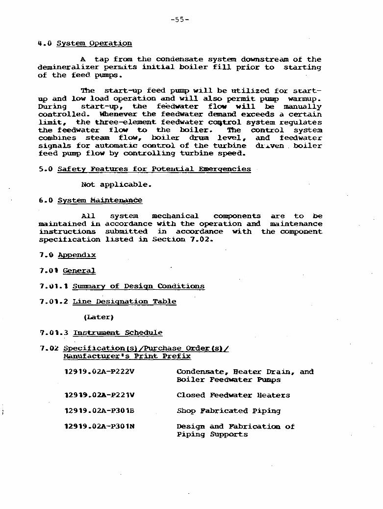
4.0 System Operation
A t a p fram the condensate system dawnstream of the deminqal izer wts initial bo i l e r f i l l p r ior to s t a r t i n g of t h e feed. pumps,
The start-up feed pump w i l l be u t i l i z e d for shart- up and low load operation and w i l l also permit pump warmup. During start-up, the fekdwater flaw will be manually controlled, Whenever t h e feedwater demand exceeds a ce r t a in l imi t , t h e three-element feedwater ccqtrol system regulates the feedwater f l w to t h e boiler . The control system combines steam flow, boiler drum l eve l , and f e e d w a t e r s ignals f o r automatic cant ro l of t h e turbine dr-iven . boiler feed pump flow by cantrol l ing turbine speed.
5.0 Safety Features f o r P u t w t i a l Emercrencies
Nat applicable.
6.0 System Maintenani%
All system mechanical components are t o be maintained in accordance with the operation and maintenance instructions submitted in accordance w i t h the component speclf lcat ion l i s t e d in Section 7-02.
7.01 General
7.01.1 Sunrmary of Design Conditians
7.01.2 Line Desiqnation Table
(Later)
7.0 9 . 3 Instrument Schedule
7.02 Specification (s) /Purchase Order (s) / Manufacturer s P r i n t Pref ix
12919-02A-P222V Condensate, H e a t e r Drain, and Boiler FeecWater Pumps
12919.02A-P221V Closed Feedwter Heaters
12919-02A-P301B Shop Fabricated Piping
Design and Fabrication of Piping Supports

12919-02A-P302E Carbon S t e e l Valves 2 V 2 In, and Larger - Category I1
U 9 19.02A-P302H Forged S t e e l Valves 2 In, and Smaller - Category I1
129 19,028-P302P Motor-Operated Carban S t e e l Valves 2 6/2 In, and Larger - Category I1
7 -03 Flow D i a a a m s 3
T i t l e
12919-02A-EM-1058 Boiler Pleed
7 .O4 mie Dia<rrams
T i t l e
Fa-) Boiler Eeedwater
Fatex) Boiler Feedwater
Title
12919-02A-EM-20- Turbine Room Machine Location
129 19 ,02A-En-202APB I B d l er A r e a
7 , U'I Pip* Urawin~s
T i t l e
12919,02A-EP-2028-6 Boiler Feedwmter piping
(Later)
7 - 09 Enqineerinq Sketches

J-0, No, 12919-02A October 1977
SYSTEM DESCRIPTION 6-6 H I P I FEEDWATER H.EATW DRAINS - BSW
ERDA APB STUDY
1.0 System R e c d m m e n t s
1-1 Function
The function of the HOP, Feedwater Heater D r a i n s System is t o transfer condensed steam drains from the shell s ide of the high pressure heaters to the next lower pressure heater or , during abnormal operation, the amdenser,
The h g h pressure feedwater heater drain system will be designed fo r reliable, power generation-
. . 1.2 -2 cod& and Standards
All piping w i l l be designed t o ANSI B.31-1-0 and dl codes and standards referenced in Specification P301B,
The feedwater heaters w i l l be designed to & V I I I and a l l codes and standards referenced in Specification P221B-
A U other components w i l l be designed to tlie codes and standards referenced in the specifications in Sectiun 7-02.
1-2.3 Specific R e ~ u h x n e n t s ,
The P , f eeduater heater. dra* system w i l l be designed t o minimize turbme w a t e r induction in accordance with ASME Standad IWDPS, P e 1 -
All control valves i n the drain l k s w i l l be placed a s close t o the receiving vessel as possible,
Piping b e t w e e n the cantrol valve and the receiving vessel sha l l be one schedule 'heavier than t h a t required before the cor~t ro l valve,
2-0 System Desicm
2-1 Detailed System Description
Refer to' flow 'diagram 12919,02A-EM-106A-
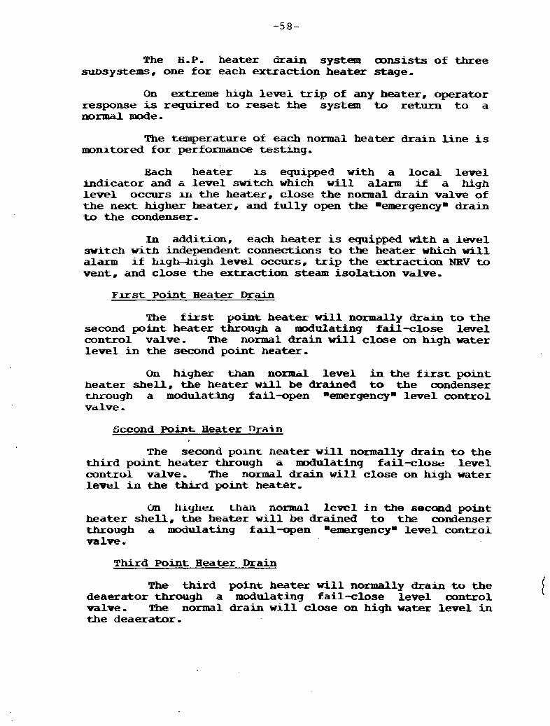
The P heater drain system oonsists of three subsystems, one f o r each extraction heater stage,
On extreme high lever trip of any heater, operator response is r q u i x e d .to reset khe system to return t o a normal nmde-
The temperature of each normal heater drain l i ne i s monitored f o r performance tes+ilng,
Each heater 1s equipped with a local level indicator and c level s w ~ t c h which will alarm if a high leve l occurs ru the heater, close the normal drain valve of the next higher heater, and fu l ly open the nemergencyn drain to the condenser.
In addition, each heater is eqixipped ~ t h a A w e 1 swlech w i t h independent c o n n e ~ s to the heater which w i l l alarm i f high-high level occurs, t r i p the extraction NRV t o vent, and close the -action steam isolat ion valve,
Flr st Point. Heater Drain
The f i r s t point heater w i l l normally drain to the second point heater through a d u l a t i n g fail-close level control valve. The normal drain w i l l close on hlgb water level in the second point heater,
On higher than normil level in the f i r s t point heater shell, the heater w r l l be drained to the oondenser m o u g h a modulating fail-open nemergencyn level control valve.
The second yomt heater w i l l normally drain t o the th i rd point heater through a d u l a t i n g fail-clo* lwel control valve, The normal drain w i l l close on high water level in the third point heater.
On h ~ y h e . ~ Uian normal lcvcl i n the second pint heater shel l , the heater w i l l be drained to the condenser through a modulating fiul-open aeolergencym level control - r r a l v e .
T h i r d Point Beater Drain
The th i rd point heater w i l l normally drain to the deaerator through a modulating fail-close level control valve, !t!he normal drain w i l l close on high water level in the deaerator-
On higher th;ln normal level i n the third point heater shel l , the heater w i l l be drained to the oonaenser tnrough a wdulating fail-open memergencym level mn t ro l valve,
2.2 Perfomance Characteristics
The performance characteristics o t the system oomponemts a r e as included in the specifications, manufacturer rn s drawings, instructions. and/or operation books referenced in Section 7-02,
Tbe piping schematic. elect=ical schematic, and i n s t r ~ e n t a t i o n arrangement are as noted on the f l o w .diagrams, elementary diagrams, and loop diagrams referenced in Sections 7.03, 7-08, and 7.05, respectively.
The physical. arrangement of the system, machinery, and other equip~lent is a s noted on the piping, machine location. and manufacturer @s drawings referenced in Sections 7.07, 7.06, and 7.02. respectively.
bases of design of each amponent are as included in the specification (s) and the manuf acturer~s drawings, specifications, and/or information referenced in Section 7.02.
2.5.1 General
The specific design of the instrument and oontrol components are as described in the specification and shown m d r a w i n g s ref brenced in the Instrument Schedule for that oonponent.
The description of the system, contxol and monitoring functions w l l l be as sham and described ' iri the logic diagrams and control descriptions referenced in Section 7.04.
2.5. Z Testability
Later
2.5-3 Specific ~ .. Requlatory ,- -- -
2.6 System Interfaces
The HIP. heater drain system interfarsea w i l l s Lk~e f ol lwing systems r
System Title
Extraction Steam Condensate m Pressure Heater Drains Feedwater
System Number
3- 0 System Limitations, Set Points, and Precautions
R e i e r .to the loop lqic diayram $or the 6et point,of specific instrumentation.
Later
5.0 Safety Features for Potential Emerqmcies
Not applicable

6 -0 System Maintenance
A l l system components a r e t o h maintained in accbrdince with the operatian and maintenance ins t ruc t ions submiteed in accoia'mce with t h e component specif icat ion l i s t e d in Section 7-02,
7.0 Appendix
7-01 General
7-01.1 Summary of Desiqn Conditions I
7-01-2 Line Desiqnation Table No, HDH
7-01.3 Instrument Schedule HDH
7-02 Specif i c a t m n (s) /Purchase Orderrs/Manutacturers~ Print Prefix
12919 -02A-P22W Closed Feedwater ~eactt?lls 129 19,028-P30 1B Shop Fabricated Piping 129 19-02A-P30 1N Design and Fabricatinn of Piping
Supports 32919-02A-P302E Carbon Stee l Valves 2 1/2 In, and
Larger 12919.02A-P302H Forged S tee l Valves 2 In, and
Smal le r
7-03 Flow Diacrrir~ns I
S 6 W Number T i t l e
12919.02A-M-106 H e a t e r Draans
Number Title
Later HOP- Heater Drains
7-05 Loop D i a w a m s
Later HOP. H e a t t x Drains
. 7 -06 Machine Incation Drirwinqs ,.
T i t l e
Turbine Rcxxu Machine Location

7 . 0 7 P ~ p i n q D r a w i n q s T i t l e
HP Heater D r a i n Piping Feeduater Piping
7.08 Electrical D r a w i n g s
Later
7.09 hnqmeexmq Sketches
N o n e
J-0. No. 12919.02A - 6 3 - November, 1977
SYSTEM DESCRIF'TIOR 8- 1 COAL AND LIMESTONE HANDLING - B C W
W A - AFB STUDY
1.0 SYSTEM REQUXRlWXNTS
The a m l and Limestorre system prepares and transports coal ar~d limestone fran the yprd t o the boi ler ,
1.2 Design Re-ements
1 .2,t General
The aoal and limestone handling system is designea f o r re l iable power generation,
1.2 ,L Codes and Standards
The coal and limestone handling system components w i l l .be designed to the codes and standards referenced i n the specifications in Section 7 -02.
I. 2- 3 Specific kequhenents
The coal and limestone handling system w i l l be designed t o deliver 543,360 U/hr of coal and 277,452 lb/hr of limestone to the m-rin boller beds.
2.0 SYSTEM DESIGN
2.1 Detailed System Description
Refer to the flow diagrams 12919,02ZkEI%170A, 170B, 170C, and msn,
me coal and limestone handling system consists of a yarci handling system and an in-plant dis tr ibut ion and injection systan,
The yard coal/limestone h a d l i n g system coniiists of a dual series of conveyors t ied i n t o the existing canveyor system t h a t serves Units 1-3.
The oonveyors transport the , coal/limestane t o a new crusher house, The crusher house contains t w o new m a 1 crushers and two new limestone crushers each rated a t a gross capacity of 900 tph.
A series of new conveyors transports the crushed @/limestone to the existing coal conveyors in the yard which transport t he c o a l / ~ s t o n e t o t h e ex is t ing and new t r ipper conveyors in the p lan t which f i l l the coal and limestone bunkers,
There are 25 coal and 25 limestone hoppers, There is a g r a v k t r i c belt feeder t each hopper o u t l e t , Coal and U s t o n e are ccnubined in a mixing bustle and -asported by primary air to t h e 40: 1 d i s t r ibu to r s which feed under t h e main beds and the CBC of t h e boiler,
2.2 Perf onaance Chi%rdAx?ristics
PIhe perfonaance ckracteristics of the system ccnnponents are as included in t h e specif icat ions , manuf actura- 's drawings, i n s t r u d x o a l d / o r operation books refermced i n Section 7.02,
Tne schematrc piping arrangement and instrumentation is as noted an the flow diagrams a d loop diagrams references in Sectioms 1-03 and 7-05, respectively-
The physical arrangement of t h e ' system machinery and other eqlupment is as notea on the piping, machine location, and mdnufiictarerms drawings referenced in Sections'7.07, 3 - 0 6 , 7-02, respectively,
The bases of design of each canpoolent are included in the spec i f ica t ions and t h e manufacturer @ s drawings, specif icat ions , and/or information referenced i n Section 7 - 0 2 .
2-5-1 General
The spec i f i c design of the instrument and control components hl-e as de.scribed in the specif icat ion and shown on the drawings re f e r e a d in the wtrunent schedule fox that component.
The d e s c r r p t i m of the system control and monitoring functions shall be as shown and described in t h e log ic diagrams and cantrol descr ipt ions referenced A n Section ,7 -04,
The coal and limestbne handling ' system in the yard operates in te rmi t ten t ly when loading the bunkers,
The d i s t r ibu t ion and in jec t ion system is normally in service,
There are no regulatory requirements spec i f ica l ly applicable to the coal and P i m e s t m e bandling systena,
C
2.6 System Interfaces
The system interfaces with tne f o l l a i n g othek'plant system:
T i t l e Number
Canbustion A x and Flue Gas 12919-02A-EM-115A
3.0 SYSTW ~ T A T I O b l S S W POINTS, AND PRECAUTIONS
Later
4.0 SYSTE3l OPERATION
Later
3,U SAFETY FEATURES FOR EMERGENCIES
F i x e protection wall be provided for the crusher bouse.
A l l system canponents shovld be .maintained in accordance. with the manufactuirer~s operating instruction and/or maintenaxkcbooks,
7.0 APPENDIX 7- .
7-01 General
7.01.1 S m a m a r ~ of Design ~ondi~.irons
7,01-2 Line Desiqnation Table No, Later
7-02 Specifications, Purchase Orders/Manufacturers@ Drawinq Prefix
N u m b e r T i t l e
P 301B Shop-Fabricated Pipinq I
2 301C Field-Fabricated piping
P 301N Design and Fabrication of Piping Supports
- Coal and Limestone Handling 4uipment
7-03 Flow D i a q r a m s
Number T i t l e
12919.028-M-170A
12919,02A-EM-115B Coal and L i m e s t o n e D i s t r i b u t i o n and Injection
7-04 Loqic D i a q r a m s
Number - T i t l e
Later
7-05 Loop D i a q r a m s
Number T i t l e
Later
1-06 Machine Location D r a w i n q s
12919.02A-EM-211A Sh, 1 Gen Arrget C o a l / L i n a e s t a n e Handling i n P l a n t
12919-02A-EM-211B Sh- 2 G e n Arrgmt C o a l f i i m e s t o n e H a n d l i n g in Yard
12919.02A-XM-211C Sh- 3 Gen Arrg8t C ~ ~ h e r House
7-03 P i p i n q D r a v i n q s
Number T i t l e
12919-02A-EP-2028 C a m p o s i t e B a i l e r Area P l a n EL- 08-On
12919 -02A-E;P-202B C o m p o s i t e Boiler Area P l a n El, 55'-Om
13919-O;LA-EP-202F Ccqmsite Boiler Area Secticm 1-1
129 I3,02?i-EP-2OX C a p o s i t e Boiler Area Sectron 2-2
7 - 08 E l e c t r i c a l I k i i w i n q s
Number T i t l e
7-09 Enqineerinq Sketches and Other Information

7.09 - 1 Heat Balances
N u t applicable.
7.09.2 Stress Analysis
L a t e r
7-09.3 O t h e r

J,O, No, 12919 ,02A O c k o b e r , 1975
SYSTEM DESCRIPTZ010 9-15 Im&EUP WATKR - B S W
ERnA - AFB STUDY
The functions of the makeup water system are: i
1 . 'Po deliver river W a t e r to the plant site for use as makeup for cooli.ng lwses, i -e., evaporat-Lonr bl&wu, and drift.
2, To supply wter for other plant uses,
1-2-1 General
The makeup w a t e r system w i l l be designed for rel iahle power generation,
1,2,2 C o d e s and Standards
All pumps w i l l be d-igned to the Hydraulrc Institute Standards and a l l codes and standards referenced in specif ica- P222G or P222W,
All tanks w i l l be designed to ASME V Z I I , A P I , or AWPQlP a n d dU d e s and standards referenced in specification P223A or P223F-
A l l piping w i l l be designed to ANSI B - 3 1 , 1 , 0 or sSME =I, as appliccrble. and all codes and standards referenced in specificat- P301B.
All other system components will be designed to all codes and standards referenced in the apecificatAuo (s) in Section 3-02 ,
1 , 2 , 3 Specific Requirements
The river w a t e r subsystem shall be designed t o permit the removal of any one of the mechanical components w~thout requiring the shutdown of the pomer generating unit-
2 -0 SYSTEM DESIGN
2 - 1 Detailed System Description
Refer t o Plow Dragram 12919-01-EM-llOA,
A fuU capa~city. ver t ica l , 9,000 gpm mbkeup yurq is provided, The pump delivers river water from the makeup pump house t o the coohng tower- Three gumps are located in the pump house, t w o & s a g and me new, The existing e e u p line from the pump house t o the existing u n i t cooling tower w i l l be extended to serve the tower of this unit .
A motor-operated discharge valve is provided t o open automatically when the makeup pump is started.
The pump w i l l be tied in to the existing un i t makeup l l n e and w i l l supply -up w a t e r t o t he cooling t o w e r basin thpough the l& control valve.
A motor-operated s t ra iner is provided a t t he discharge of the makeup pump- The s t ra iner is supplied,with automatic backwash control t o permit intermittent backflushing, The oantrol m i s t s of a pneumatic cylinaer- operated ball valve which is actuated by a pressure &iff erential . 2.2 Performance CharacteristYcs
The performance characteristics of the system components are as included in the amended s p e c i f r c a ~ o n s . manufacturers 9 drawings, instructions and/or operation books referenced in Section 7 -02-
The schematic piping and wiring arrangement is as noted an the flw diagrams and elementary diagrams referenced in Sections 7-03 and 7-08, respectively-
The physical dragememt of the system, r n a c b h e q , and other equipment is a s noted on the piping, machine location, and &uf acturers drawings referenced in Sections 7-07, 7-06. and 7-02. respectively-
The bases of design of each a m p n e n t are as included in the specification (s) and the manufacturer s drawings, specifications, ;rmd/or information referenced i n Section 7.02-
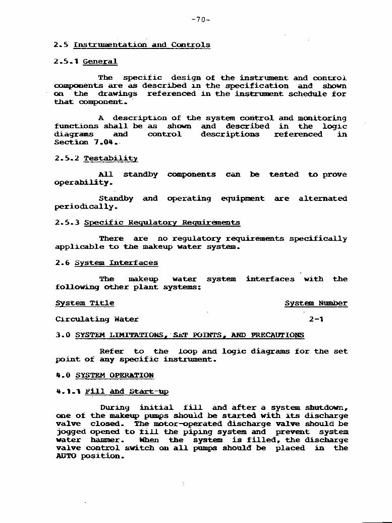
2.5 Instrumentation and Controls
2.5-1 General
The specific design of the instrument and conuoi aompments are as described m the specification and shown an the drawings referenced in the instrumznt schedule for tha t component, '
A descripuon of the system con-01 and monitoring functions sha l l be as sham and described in the logic bagrams and control descriptions referenced in Sectian 7-04..
All standby components can be tested to prove operability,
S t a n d b y and operating equipment are alternated periodically,
2 . S - 3 Specific Wequlatory Requirements
There are no regulatory requirements specifically applrcable t o the makeup water system,
2.6 System Interfaces
The naakeup water system interfaces with the following other plant systems:
System T i t l e
Clrculathg W a t e r
3.0 SYSTEM LIIUTATIONS, ' SaT POINTS, AND PFtECAUTIONS
Refer t o the loop and logic diagrams for the s e t point of any specific instrument.
4.0 SYSTEM OPERBTION,
Durnng i n i t i a l f i l l and a f t e r a system shutdown, one of the makeup pumps shouid be started w i t h its discharge valve closed, The motor-operated discharge valve should be jogged opened t o f i l l the piping system and prevent system water hanmaer, When the system is f i l l ed , the discharge valve control switch an a l l pumps should be placed in the AUTO position,
4.1-1 N o r m a l Operation
One manually started makeup pamp is normally runn-. When the ' oonnnon pump discharge header pressure drops below the s e t point, it is annunciated in the control r o o m , and the second automatic standby pump starts a seoond PumP- The discharge valve of tlze second pump w i l l automatically open in response t o the pump starting.
Xhen pump flaw decreases below the low flow set point, it is annunciated and the operator should secure one of the operating pumps, The discharge valve of tha t pump w i l l automatically close.
SHOULD TBE S W N D PUMP BE REQUIRED !JU STNU? MORE TaAN (L-) TIMES PXR (LATE;R), IT SHOULD BE UDT' IN THX RUNNING MODE kQR (LA!l!ER) , OR mJTlL Al'?43SPHERIC CONDITIONS CHANGE !l!O PRBCLUDB TFlE RESTAFU! OF THE SECO14D HIR (UU'W).
4-1.3 Shutdown
The makeup pumgs may be shut down anly i.k both units a re shut down and some other unit i n the plant is i n operation, 1 all mts are shut dawn, one of the makeup pumps must be left in service t o assure t h a t river w a t e r is avdilable to the site-
5.0 SAFETY PEATURFS POR PUPENTUU. EMERGENCIES
N o t applicable
All system components should be main-d i n accordance w i t h the manufacturers* operating, instruction, and/or maintenance books,
7.0 APPEM)IX
7.01 General
7.01.1 Sumnary of D e s i q n Conditions
7.01.2 Line Deg4natran Table
7.0 1.3 Instrumc?nt Schedule
7.02 SpecFticaUon ( s ) /Purchase Order (s) /Manufacturers 8 Print P r e f i x
P121D' ' W a t e r Screens P222G . . Miscellaneous Vertical Centrifugal ~ u m y s P301B' - Shop-Fabricated Piping P301N Design and Fabrication of Piping Supports P30LE Carbon Steel V a l v e s 2 1/2 In. and Larger P302H Porged S t e e l Valves 2 In- and Smaller P302P ' Motor-Operatea Carbon S t e e l Valves 2 1/2 In-
and Larger
7 -03 F l w Diaqrams . .
IUumber T i t l e
12919.01-EM-110A - - C i r c . Water and Cmd. Air R-Val
Later
7.05 L m p D i a g r a m s
N u m b e r
L a t e r
T i t l e
Later
T i t l e
Later
Number T i t l e
Turbine Area Machine Locations Bo i l er Are. Machine '
Locations

- 7-07 Pipinq D r a w i n q s
Number T i t l e
B o i l e r Area Piping Composites
7.08 Electrical D i a q r a m s
Number T i t l e
Later L a t e r -4
7 - 09 mqineerinq Sketches iind Other fnfolmi;rtion
7-09-1 Heat balances
Number
8-09-2 Stress Analysis
T i t l e . .
Turbine VWO . 75% Turbine VWO 50% Turbine V#O 25% Turbine VWO .
S7-09-3 Other
J.0- No. 12919.U2A October, 1977
SYSTW DESCRIPTION 17-1 BED LFPDOWN, TRANS=, AMD DISPOSAL - B&W
ERDA-AFB STUDY
1.1 Function
The , bed letdown system transports cooled spent bed material collected fram the main beds .either to toe bed letdown si 1-5, to replenish tAe main beds, or t o cai lso~~ burnup bed makeup- Bed m a t e r i a l oollected from the c:nr-n buhn~p b-d gmo ta w m t e (sila) .
8 1.2 Desiqn Requirements
1 2 1 General
The bed letdown system is designed fo r re l iable power generation.
1- 2 - 2 M e s and Standards
The bed letdown system piping w i l l be designed t o the ash handling manufacturer s standard - All other system components w i l l be designed to the codes and standards zeierenced i n t h e specification(6) i n Section 7.02.
1.2.3 Specific R e q u i r e m e n t s
The bed letdown system w i l l be designed t o remove bed letdown materid at the rdte of 150 tons per hour.
2.0 SYSTEM D U I G N
2.1 Detailed System Descriptian
R e f e r to P l w Diagram 12919.02A-EM-120A.
The bed l e t d m system consists of a double header extend- ing fram the blowers t o the silos.
Three blowers, two running and one standing, convey the ash froin beB letdown holding tanks via air lock devices t o two s i los .
A h e wrteniiing froan each header oombines to a single line t o a 5 t o 1 dis t r ibutor box- T h s serves t o supply spent bed material t o any one of the 5 beds,
A single carbon burnup bed makeup blower is used t o supplement the airbun burnup bed.
h c h header has the capability t o supply ash t o ei ther s i l o ,
Pluidizmg blower; are supplied with the s i l o s to pmvlde air assist when removing ash from the silos-
2-2 Performance Characterrstics
The performance character is t ics of the system components are as included in the amended specif icaaons, manufacturersm drawings, instructions, and/or operation books referenced in Section 7-02.
The schematic p i p u g axrangement and instrumentation is as noted on the flow -grams and loop diagrams referenced in Sections 7.03 and 7.05, respectively-
The physical arrangement of the s y s t e ~ ~ , machinery, and other equipment is as noted on the piping, machine location, and manufacturers 8 drawings referenced in Sections 7-07, 7.06, 7.02, respectively.
2.4 Component Desiqn
The bases of design of each camponent are ZIS included in the specif lcat ion (s) and the manufacturer s drawings, specifications , and/or information referenced in Section 7-02.
2.5 Instrmuentation and Controls
2-5-1 General
The specific deslgn of the instrument a d control components are a s described in the specification and sham on the drawings referenced in the instrument schedule for tha t c3mponent.
The description of the system a m t r o l and wnitorlng func- tions sha l l be as shown and described in the logic diagrams and control descriptions referenced m Section 7.04,
A l l bed letdown system components are normally in service.
2.5-3 Specifrc Requlatory Requirements
There are no regulatory requirements s p e c i f i c a l l y appli- cable to t h e bed letdown system.
2.6 System Interiaces I .
The system in ter faces w i t h the following other plant systems :
Fly Ash Collectmn & ~ i s ~ ~ ~ a l 17-2 Carbon Collection & Reinjection 17-3
3.0 SYSTEM U M I T A T I O N S , SET POINTS, AND ~ T I O N S
Refer t o the loop and' l o g i c diagrams f o r the-'set point of spec i f i c instruments.
4.0 SYSTEM OPERATION
Refer ..to ash handling manufacturerBs operating instruc- tions for operation ofi the bed letdown system.
Not applicable. I
All system camponeuts ,should 'be maintained i n accordance with the manufacturer's operating ins t ruct ions and/or maintenance books.
7.01.1 Summary of D e s i q n Condituns
7.0 1.2 Line Desiqnation Table No. (Later)
7.0 1-3 Instrument Schedule (Later)
, . 7.02 Specif ication (sl Purchase ' ~ r d e r s k n u f a c t u r e r 8 s D r a w i n q
.met= Z
mmber T i t l e
Shop Fabricated Piping 'Fie ld Erection o f Piping Design and Fabrication ok Piping S,UPPO~~S Ash Handling ~quipment
7- 03 Plow D i a y r a m s
Number T i t l e
12919.02k-EM-120s Bed Letdown, Transfer, and Disposal System
7-04 laqic Diaqrams
Number Title
Later
Number T i t l e
Later
7-06 Machine Location Drawinus
Number T i t l e
129 19-02A-EM-202 Boi ler Area Machine Iacaticms 12915-02A-EM-203 Turbine Area Machine Locations
7-07 Plplnq Drawinqs
Number T i t l e
12919-02A-EP-202 B o i l e r krea Piping Camposltes
7.08 Electrical --- - Drawinqs
N u m b e r T i t l e
12919-O2A-EE-6 12A8 Cable R a y Arrangements, Boi ler Area BD C
7-09 mqineerinq Sketches and Other Information
7-09.1 Heat Balances
Number T i t l e
12919.02A-HBSK-1 Turbine VWO 12919,02A-H&SK-2 75% Turbine VWO 129 19 -0Zi-HBSK-3 50% Turbine VWO 12919-02A-HBSK-4 25% Turbine VWD
7.09-2 Stress Analysis
7-09.3 Other

J,O, No, 12919,02A ,
October , 1977
SYSTEM DESCRIPTION 17-2 FLY ASH COLLECTION AND DISPOSAL - B S W
ERDA-AF'B STUDY
1.0 SYSTEM REQUIREMENTS
The f l y ash collection and disposal system cb l l ec t s f l y ash from the CBB dust collector, CBB hot 'precipi ta tor , a i r preheater, and stack hoppers and transports it to the f l y ash silos.
1 , 2 Desicm . Requirements
1-2-1 General
The f l y a&' collection system is designed fo r r e l i ab le parer generation,
1-2.2 Codes and Standards
The f l y ash collection system piping w i l l be designed to the ash handling manufacturer s stxmdard ,
All other system components w i l l be designed to the codes and standards ref erenceii i n the specif icat ion (s) in Section 3-02,
1 , 2-3 Specific R e q u i r e m e n t s I
me f l y ash collection system w i l l be designed t o remove f l y ash materid a t the rate of 68 tans per hour,
2.0 SYSTEM DESIGN
Refer ' to F l w Dlagram 12919.02A-M-120C.
The f l y ash collection system consists 02 a parr of vacuum- pressure systems. Each system w i l l consis t of .two full-size pressure blowers, primary and secandary collectors, t w o M C l l U i p=odu&rs, and ane silo, One full-size vacuum system will serve the CBB dust collectors w h i l e t h e other serves t h e hot precipitators, stack, and alr preheaters.
Each vacm-pressure system w i l l have t h e capabil i ty to convey the entire ash f l a w should one become inoperable,
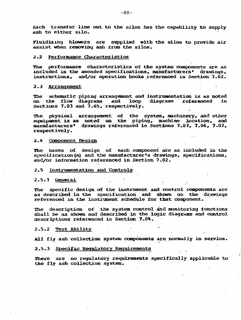
~ a c h t ransfer line ou t to the s i l o s has t h e capabihty to supply ash to e i ther s i lo .
Fluidizmg blowers a r e supplied with the silos to provide a i r assist when remavin9 ash iram the ,si los.
2 -2 Performance Charactexistics
The performance character is t ics of the system components are as included in the amended specifications, manufacturersm drawings, instructions, and/or operation books referenced in Section 7 -02.
The ~c1lrm;rtic pfpxng arrangement and instruPaentaticm 1s iis noted an the flow diagrams and logp diagrams refexexzed jm se~ct~uns 7.03 and ?,US, respectively,
The physical arrangement of the system, machinery, and other equipment is as noted on the piping, machine location, and manufacturersD drawings reerenced i n Sectfbns 7-07, 7.06, 7-02, respectively-
- . 2.4 Coanponent Desiqn
Ihe bases of design of each coaaponent are as inkluded in the specif icatxon (s) and the manufacturer @s drawings, specifications , and/or Mormation referenced i n Section 7 -02 ,
2 -5 Instrumentation and Controls
2 General
The specif ic design of the instnmezrt and mntxol canpcments are as described in the spec i f~ca t ion and s h m on the drawings referenced in the instrument schedule f o r that component-
The description of the system control &d monitoring functions shall be as shown and described in the logic diagrirlns and control descriptions referenced in Section 7-04. -
2.5 -2 Test Abili ty
sll f l y ash collection systlem cuup&ents are normally in service, +
2-5-3 Specific Requlatory Requirements . . There are no regulatory requirements specif ical ly applicable to the f l y ash collection system,
2.6 System Interfaces t
me system interfaces w i t h the.following other plant systems:
Title Number
~ e d Letdown Transfer and Disposal 17-1 Carbon Collection and Reinjection 17-3
3-0 SYSTEM LIMITAZXONS~ SET POINTS# AND PRECAUTIONS
Refer to the loop and logic diagrmms~ for the set point of specific ins-ts-
Refer to ash handling manufacturer@s operating instructions for operation of the f l y ash collection and disposal system,
N o t Applicable
All system components shnuld be maintained in accordance with the manu&acturerms operating instructions and/or maintenance books.
. . *
7.01 General
7 -01 -2 Line Desiqnation Tdble No- (Later1
7-01-3 Instrument Schedule
7-02 Specif icatian (s) Purchase Orders/ManufaCturer s D r a w i n q Prefix
Number -- Title
Shop Fabricated Piping Field Erection of Pip- Design and Fabrication of Piping Supports Ash' Handling Equipment
7.03 Flow Diaqrams
Number Title
12919-02A-EM-12OC Fly Ash C o l l e c t i o n and Disposal
7-01, Loqic D i a q r a m s
Immber Title
3-05 Loop D i a q r a m s
Nlmaber T i t l e
7-06 Machine Location Drawinqs
Nklxubex T i t l e
129 19-OZA-EM-202 Boiler Area Machine Locations 129 19-02A-FM-203 Turbine Area Machine L o c a t i o n s
7-01 Pipinq D r a w i n q s
Mrmber Title
12919-02A-EP-202 Boiler Area P i p i n g Canposites
Number Title
12919,02A-EE-612A,B,C Cable Tray Arrangements, boiler Area
7 Er~qmeerinq sketches and Other Informat ion
7-09.1 Heat Baiaces
Number Tit1.e ._
119 19 - 02A-HBSK-1 Turbine VWD 129 09.02A-HBSK-2 75 P e r c e n t Turbine VWl 129 19-02A-HBSK-3 50 Percent Turbine VWO 12919,02A-WK-4 25 Petcent lbrbine V W
7-03-2 Stress Analysis
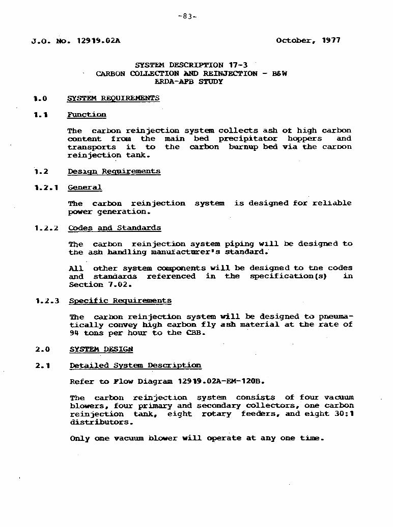
SYS'SZ24 DESCRIPITON 17-3 .
CARBON OOLLECPION AND REINJECTION - B6W EaDA-AFB STUDY
1-0 SYSTEM REOu1-s
1.1 Functian
The carbon reinject ion system collects ash ot high carbon content frora t he main bed parecipitator hoppers and t ransports it to t h e carbon burnup bed v ia the carDon re inject ion tank -
1.2 Desxqn Requirements
2 . 1 General
The carbon re in jec t ion system is designed for rehable pawer generation,
1 ,Lo 2 Codes and Standards
The c i i rbn re inject ion system piping w l l l be designed t o the ash bandling manukactucer8 s standard.'
A l l other sy-ctem camponents w i l l be designed to the codes and staxxiarbs referenced in t h e specif icat ion(s) in S e c t i o ~ 7 - 0 2 ,
1-2-3 Specific Requirements
The carbon reinject ion system w i l l be designed ta pneuma- t i c a l l y convey Lugh carbon f l y ash material a t t h e r a t e of 94 tons per hour t o the CBB.
2.1 Detailed System Descriptiau
Refer to Plow Diagram 129 19.02A-EM- 120B.
The c a r b n reinjection system consists of four vacuum blowers, four primary and secondary collectors, one carbon re inject ion tank, e ight rotary feeders, and e lgh t 30:1 distributors - Only m e vacuum blower will operate a t any one time,
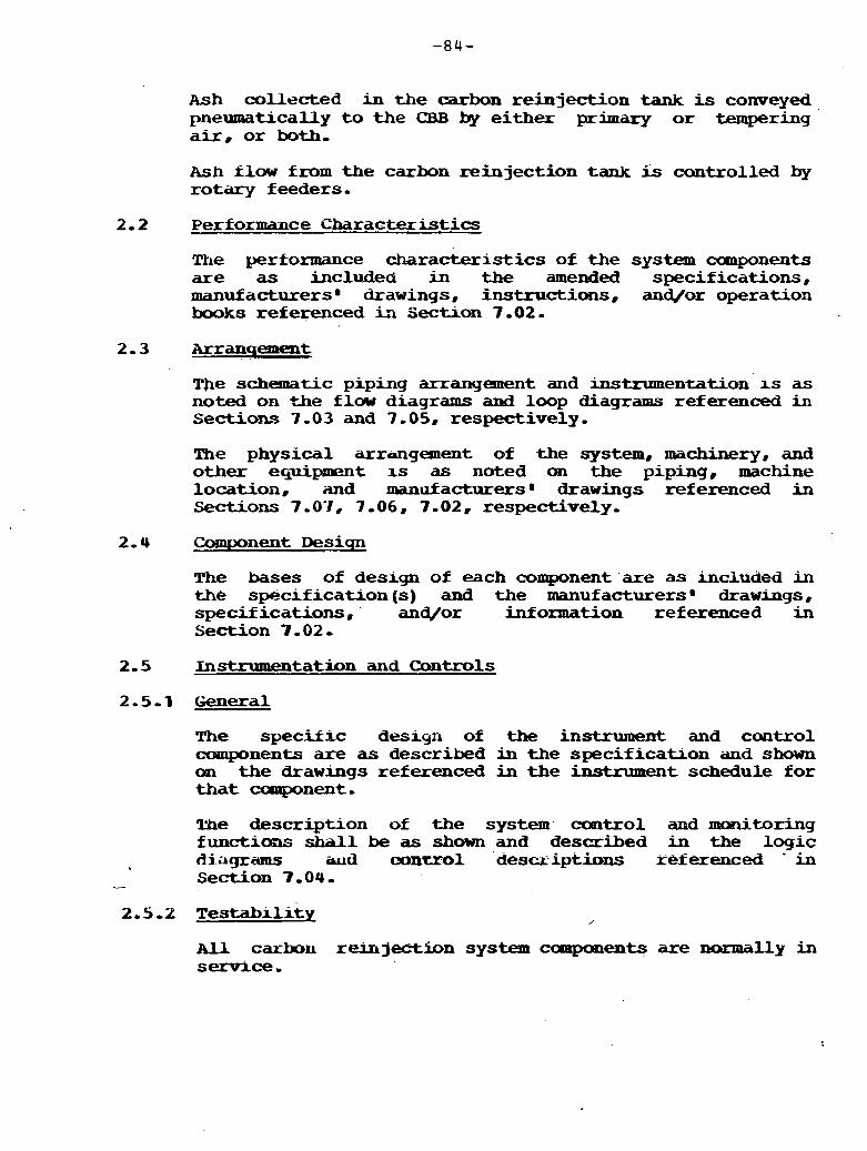
~ s h co l l e c t ed in the carbon reinjection tank is conveyed pneumatically t o the Q3B by either pr imary or tempering a i r . o r both-
Ash f l o w from the carbon reinjection tank is controlled by rotary feeders-
2.2 Performance Characteristics
The performance characteristics of the system cunponents are as included i n the amended specifications, manufacturers8 drawings, instructions, and/or operation books referenced in Section 7 -02-
The schematic piping arranyement and instrumentation rs as noted on +he f l w diagrams and loop diagrams referenced in Section3 7 -03 and 7-05. respectively,
The physical arrmgement of the system, machinery, and other equipment is as noted on the piping, machine location, and manufacturers8 drawings referenced in Sections 7.0.1, 7.06, 7-02, respectively-
The bases of deslgn of each component are as lncluded in the specif i c a a o n (s) and the manufacturers 8 drawrngs , specifications, and/or inf orxnation referenced in Section 7 -02 -
2.5 Instrumentation and Controls
2-5-1 General
!I%e specif ic design of the instrument and cantrol amponents are as described in the specif icahon and shown on t he drawings referenced in the instrument schedule fo r t h a t campnent - The description of the system control arnd monitoring functiosls shall be as shown and described in the logic d i i ~ g r a m s aud control descz iptions referenced ' in
- Section 7.04,
2-5.2 Tes tabi l i ty ,
ALL carbou reiujectjibn system caoqmnents are normal ly in ser9ice-
2.5-3 Swc i f i c RecruLatory R ecmimments
I There are no regulatory requirements specifically applicable to the carbon reinjection system.
2.6 System Interfaces
The system ipterfaces with the following plant systems:
T i t l e Number
Fly Ash C o l l e c t i o n and D i s p o s a l 17-2 Bed Letdown, Transfer, and Disposal 17-1
3.0 SYSTEM LIMITATIONS, SET PO=, AND P-IONS
Refer to the loop and logic diagrams for the set point of specific instauments.
Refer t o ash' handling manufacturerms operating instruc- tions for operatmn of the carbon collection and reinjection system.
Not applicable-
All system components should be maintained i n accordace with the manufacturerms operating instructions and/or maintenance books .
, I . -
7.0 APPENDIX
7.01 General
. . 7.01.2 Line Desiqna'tion Table No . (later)
7 .0 1-3 In.gt.nyrlmf?n+, Schedule : (LakerJ-
7-02 Specif icakion (s) Purchase Orders/Manufacturer~ s D r a w i n q 'me£ ix
Number T i t l e
Shop Fabricated Piping Field Erection of Piping D e s i g n and Fabrication of Prping Supports Ash Handling Equipanent
7-03 Plow Diaqlrams
Number Title ,
12919-O2A-EM-12OB Carbon Collection and Reinjection
Number
Later
Title
7-05 Loop Diaqrams
Number T i t l e .
Mumbcr T i t l e
129 19-02A-EM-202 B o i l e r Area Machine m a t i o n s 12919-02A-EM-203 Turbine Area Machine Locations
7-07 Pipinq Drawinqs
Number T i t l e
12919-02.A-EP-202 B o i l e r Area Piping Composites
7 .00 E l e c t r i c a l Drawinqs
Title
12919-02A-EE-6 12A, Cable R a y lhrrangexoents, Boiler Area B, C

7.09 Ensheerins Sketches and O t h e r Information
7 ,u9.1 Heat Balances
Number T i t l e
12919,OZA-HBSK-1 Turbine VWO. 12919,OLA-HBSK-2 75% Turbine VWO 12919.02A-HBSK-3 50% Turbine VWO 129 19 . 0;LA-HBSK-4 25% Turbine VeJO
7-09-2 Stress Analys i s
7.09-3 Other
October, 1937
SYSTEM DESCRIPTION-19-2 PRlMARY AND TEMPERING AIR - B&W
ERDA AFB STUDY
1-0 SYSTEM REQ-
1-1 Function
The function of the Primary and !kmpering Air System is t o transport and &humidify the coal-Pimestone mixture from the bunkers to t h e boiler beds f o r ambustion,
1.2 Desiqn Requirements
2 General
The Primary and Tempering Air System w i l l be designed f o r reliable power generation,
1-2-2 Codes and Standards
A l l system components w i l l be designed to all codes and standards referenced in the specif icat ion(s) i n Section 7-02.
1.2-3 Specif ic Requirements
The Primary and Tempering Air System w i l l bc? designed t o pneumatically canvey coal and limestone to the FBC at the rate of 300 tans per hour and t o convey high c a r h f l y ash material to t h e CBB a t t h e r a t e of 94 tons per hour.
2-0 SYSTEM DESIGN
2.1 Detailed Syst-em Description
Refer t o Flow Diagram 12919-02A434-195A.
The Prbary and Tempering Air System consis ts of tw hot primary diT fans and t w o tempaing a ir fans.
U c h of the half--capacity hot primary air fans takes suct ior~ from the forced draft fan discharge dawnstreant of the ai r preheater and discharges through t h e mixing bustles t o the furnace,
Each of the half-capacity tempering air fans takes suction from the forced draft fan discharge upstream of the air preheater and discharges t o the Iuixing bust les t o control the te-rature of, the primary a i r -
Primary and tempering airf low is cantrolled, based on load, t varying t h e posi t ion of the inlet (suction) vanes ou the fans-
2.2 Performance Character is t ics
The performance cha rac te r i s t i c s of the system amponents are a s included in the specifications, manufacturer's drawings, ins t ruct ions , and/or operation books referenced in Section 7.02-
TAe piping schematic, electric& schematic, and instrumentation arrangement are as noted on the f l a w diagrams, elementary diagrams, and loop didgrams referenced in Sections 7-03, 7 . 0 8 , and 7 -0 5, respectively-
The physical arrangement of the system, machinery, and d e r equipment is as noted on the piping, machine location, and manu- fac turer ' s drawings referenced in Sections 7-07, 7-06, and 7 - 0 2 , respectively - 2.4 Component Desiqn
The bases of design of each ,component are a s included in the specif icat ion (s) and t h e manukacturer B s drawings, specif icat ions , and/or information referenced in Section 7.02.
2.5 l i l s t r u ~ ~ e n t a t i a n and Controls
2-5.1 General
me spec i f i c design of t h e instrument and control components is as described in the specif icat ion and shown on the drawings referenced in the b s t m n m a t Schedule.
The description of the system control and monitoring h c t i o n s s h a l l be as shown and described in the l og ic diagrams and control descriptions referenced in S e c t i o n 7-04, . .
2.5-2 Testabi l i ty
Later
2-5.3 Specific R e q u l a t o r y Requirements
N o n e
2.6 System Interfaces
The primary and Tempering A i r Systems in te r face w i t h t h e f o l l w i n g systems:

System T i t l e System Number
C o a l and Limestme Handling Carbon Collection and Reinjection Secondary AFr and F lue Gas
3-0 SYSTEM -IONS, SET POIN!CS, AEB) PRECAUTI:OHS
Refer to the l m p and logic diagrams for the set point of specific ~ t ; r t i o n ~
4 - 0 SYSTEM OPER?mION
Later
N o t applicable
A l l system mechanical cmpments are to be maintained in accord- ance w i t h the operation and mailltenan- instructions snhmitted in accordance w i t h the ampon-t specification Usted in Section 7-02-
7-0-1 General
7-01.2 Line Desiqnation Table
7-01.3 Instrument Schedule
7-02 Specification (s) /Purchase Orders
Later
7-03 Flaw D i a q r a m s
Number
12919~OaA=EM-l15A
7-04 Loqic D i a q r a m s
Number
Later
TAtZe
Cbmhstion Air afld Flue Gas
T i t l e
7.06 Machine Location D r a w b s
'Number T i t l e
12919 -02A-EM-202A.B B o i l e r Area Machine Locations
7-07 Pip- Drawinqs
Nmnber T i t l e
12919 -02A-EP-202A-G B o i l e r Area P i p i n g C o m p o s i t e s
7.0 8 Electrical Drawinqs
Iater b
7-09 Faqineerinq Sketches
N o n e
. a

J,O,No, 12919-02A October 19 77
SYSTEM DESCRIPTION - 19-3 SeOONDARY AIR AND FLUE GAS - B 6 W
ERDA AFB STUDY
1.0 SYSTEM REQUIREMENTS
The function of the Secondary A i r and Flue Gas System is twofold: 1, Supply heated air t o the boi ler for cOmbustion,.,and 2, Remove the f lue gas £ram the boi ler and particulate from the f lue gas before being discharged t o the stack,
1.2-9 General '
The Secondary Air and Flue G a s System w i l l be designed fo r reliable power generation-
1-2-2 Codes and Standards
All system components w i l l be designed t o a l l codes and standards referenced in the specification (s) i n Section 7-02.
1.2-3 Specific R e q u . i r e m e n t s
The forced d r a f t (POD,) fans sha l l be capable of supplying 3,004,884 lb o&.air per hour a t 600 F t o the boi ler a t turbine valves w i d e open (VWO) conditions-
The e lec t ros ta t i c precipitators s h i l l be capable of meeting the, m r r e n t Federal Standard fo r particulate emission of 0-1 lb/lO6 Bta of heat input,
The induced draft ( I D ) fans shall be capable of supplying 5,959,115 Ib of f l ue gas per hour a t 279 ,r to the stack a t turbine VWO conditions,
2-0 SYSTEM DESIGN
2.1 Detailed System Description
Refer t o Flow Diagram 12919,02A-I3l-l15A,
i The Secondary A i r portion of the system has two half-capacity FWD- fans to take outside a i r from a fan roan and discharge the air into a regenerative air heater (APE'), The APH heats the ambustion a i r before discharging it, through sui table ductwork, t o the undergrid plenums of the m a i n beds and CBB,
Two steam/air heaters are provided upstream of the APE 4 maintain the average cold end temperature of the APH and minimiz- corrosion,
Air flow is regulated by adjusting the inlet (suction) vanes on the FWD. fans - The P ,D , fans also supply a i r t o t he . sucticm of the primary and tempering a h fans (see 19-2) - The Flue G a s portion of the system has an e lec t ros ta t i c precipitator ' (ESP) i n the ductwork from the main beds and a mechanical collector and an ESP in the ductwork from the CBB,
The , ESP in the gas stream f r w the main beds is used t o reduce part iculate &ions and t o recapture any unburned, carbon t h a t may have become entrained in t he f lue gas, The recaptured carbon is reinjected into the CBB portion of the boiler to increase boiler efficiency aDd reduce fue l costs-
The mechanical collector and ESP i n the gas stream from the CBB are used fo r the purpose of reducing part iculate emissions,
The f lue gas enters the APH and t ransfers heat to the secondary air before entering the two half-capacity, axia l type I .Dm fans. The I-D. fans p~11l the f lue qas fruan the boiler through the preceding equipment and discharges t o the atmosphere v i a the stack,
!the f lue gas flow 'is maintained by varying the blade angle of the 1 - D - fans.
2-2 perf 0-ce Characteristics
The performance character is t ics of the system canponents are as included in the specif icatiuns , manufacturer m s drawings, instructions, and/or operation books r e f e r e e d i n Section 7-02,
2.3 Arranqement
The piping schematic, electrical schematic, and instrumentation arrangement are as noted on the f l a w diagrams, elementary diagrams, and loop diagrams referenced in Sections 7-03, 7-08, and 7 -05 , respectively,
The physical arrangement of the system, machinery, and other equipaaent is as noted on the piping, machine location, and manufacturerBs drawings referenced i n Section 7-07, 7-06, and 7-02, respectively ..
The* bases of design of each component are a s included in the specification (s) and the manufacturer 9s drawings, specifications , and/or information referenced in Section 7-02,
2.5 Xnstmmwmbticm and Controls
2 5 1 General
The speci f ic designs 'of the instrument and oontrol anuponen- are as described i n the specification and shawn on the drawings referenced in the Instrument Schedule,
, The description of the system control and nronitoring functions shall be as shown and described in the logic diagrams and control descriptions referenced in Section 7 -04.
2-5-2 Testabi l i ty
Later
2-5-3 Specific R e q u l a t o r y Requirements
None
2-6 System Interfaces
me Semndary A i r and Flue G a s System interfaces w i t h the following systems :
System T i t l e System Number
Fly Ash Collection and Disposal Carbon Collection and R e i n jectitm P r i m a r y and Tempering Bir
3-0 SYSTEM LIMITATIONS. SET POINTS* AND PRECAUTIQNS
Refer to the loop and logic diagrams for the .set point of specific instrumentation,
4.0 SYSTEM OPERATION
Later
N o t applicable
6-0 S Y m MAI-
All system mechaaical components are to be maintained i n accordance w i t h the operation and maintenance instructious submitted in accordance with the campanent specification l i s t e d in Section 7-02.
7-0 APPEND=
7-0.1 General
7.01-1 Smmar~ of Desicm Conditions
7 -0 1 - 2 Line Desiqnation Table
Later
7. '01- 3 Irstmmmt Schedule
7-02 Specif Lcation 1s) /Purchase Orders
IPorced D r a f t Fans - Cen- trif ngal Drived for Forced Draft and Induced Draft Pans Induced Draft B m s - 94ial
3-03 Flow D i a q r a m s
J!dmber T i t l e
12919-02A-EM-115A Cumbust ion Air and Flue Gas
7 - 05 Loop D i a q r a m s
Number
Later
7-06 Machine Ibcation Drawinqs
Number
12919-02A-EM-202A, B
T i t l e
T i t l e
Title
General Arrang-t B o i l e r Area
T i t l e
-mite B o i l e r Area

7-08 E l e c t r i c a l Drawinqs
129 19.02A-EW-1A
7.09 Enqineexinq Sketches
mne
Main One Line Diagram
APPENDIX IIIA-C
BABCOCK & WILCOX COMPANY FINAL REPORT

SOURCE C O N D I T I O N MONITOR CONTROL ACTION MON 1 T O 9
(TC 'I- - AND i F P*M BED
S€(.M~NT EktFRBENCY T R I P
3. d - S E 4 r n T
T R I P U ~ C I ~ U S T R n A Y N E R G I C R )
i3 (TRIP FUEL-AIF - L I ~ G ~ N E
FOR T h A T S#ZGMENT )
3
8ED SGVErT TOTAL LOSS S
BREAHER CLdSEb
w 9 L. I A
MASOR BOILER RUNBACKS 3
NOTES : TUlS DlAGRhM I S BASED ON 6- 8 W I U O I ! DESIGN I. F?€F€F? L S K I -3A
BOILER T R I P & RUNBACK- S n m Z w Z
I-4 C I E 7 E
2 I
I A I B I C I D I E I F I ~ I I
PRELIMINARY DESIGN OF A 570 MW ATMOSPHERIC FLUIDIZED BED BOILER
Prepared by:
The Babcock & Wilcox Company Fossil Power Generation Division Barberton, Ohio
Submitted by: . The Babcock & Wilcox Company Contract Research Division Alliance, Ohio
November 30, 1977
Prepared for : The Stone & Webster Engineering Corporation S&W Contract No. E.C.C.2 B&W Contract No. CRD-1008

LIST OF CONTRf BUTORS
.W. Hansen - Project Manager Becker Bloss Bolumen Doss Hornof f James Lapple Smith Wenderoth
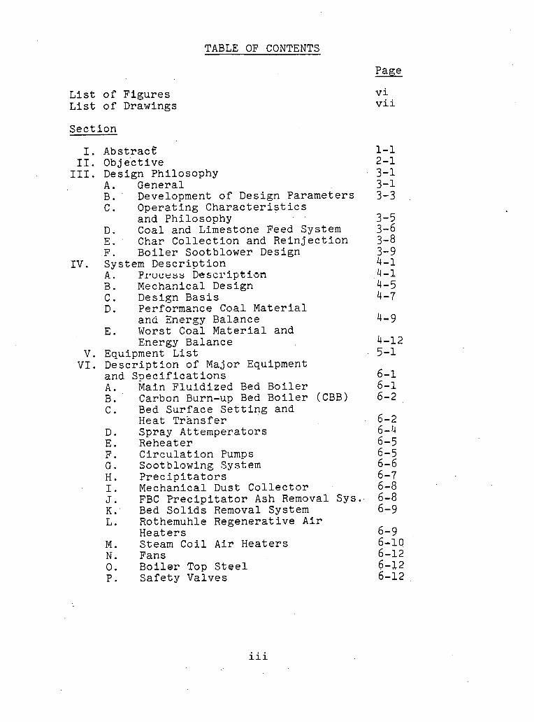
TABLE OF CONTENTS
Page
L i s t o f F i g u r e s L i s t o f Drawings
S e c t i o n
Abst rac t ' Obje 'ct ive Design Ph i losophy A . Genera l B . Development o f Design pa r ame te r s C . Ope ra t i ng C h a r a c t e r i s t i c s
and Phi losophy . ,
D . Coal and Limestone Feed System E. ' Char C o l l e c t i o n and R e i n j e c t i o n F. B o i l e r Sootblower Design System D e s c r i p t i o n A . P ~ w c e s s Desci i ip t ian B . Mechanical Design C , Design B a s i s D. Performance Coal M a t e r i a l
and Energy Bala.nce E . Worst Coal M a t e r i a l and
Energy Balance Equipment L i s t D e s c r i p t i o n o f Major Equipment and S p e c i f i c a t i o n s A . Main F l u i d i z e d Bed B o i l e r B . ' Carbon Burn-up Bed B o i l e r (CBB) C . Bed S u r f a c e S e t t i n g and
Heat T r a n s f e r D . Spray A t t empe ra to r s E. Rehea t e r F. C i r c u l a t i o n Pumps G . Sootblowing System H . P r e c i p i t a t o r s .I. Mechanical Dust C o l l e c t o r J . FBC P r e c i p i t a t o r Ash Removal Sys. . K: Bed S o l i d s Removal System L. Rothemuhle Regene ra t i ve A i r
H e a t e r s M . Steam C o i l A i r H e a t e r s . Fans 0 . B o i l e r Top S t . e e l P. S a f e t y Valves
vi vii
iii

TABLE OF CONTENTS
Q. S p e c i f i c a t i o n s Coal and Limestone Grav imet r ic Feeders Coal and Limestone Rotary S e a l B o i l e r Water R e c i r c u l a t i o n Pump F l u i d Bed B o i l e r Sootblower Carbon Burnup Bed Sootblower Main FBC P r e c i p i t a t o r Mechanical Dust C o l l e c t o r FBC P r e c i p i t a t o r Ash Removal System CBB Feed Tank Char Rotary Feeder /Sea l CBB P r e c i p i t a t o r FBC Main Bed Underflow Cooler FBC S t a r t u p Bed Underflow Cooler CBB Undcrflow Cooler Rothemuhle A i r Hea te r Data Motor F o r FD Fan Motor Fo r I D Fan Motor For Temp A i r Fan Motor For Primary A i r Fan S a f e t y Valves Coal Bunkers Limestone Bunkers PD Fan I D Fan Hot Primary A i r Fan Temp A i r Fan
V I I . System Termina ls A . Water Connections B. F u e l Connections C . Steam Connections D . A i r I n l e t s E . Misce l laneous Terminal P o i n t s F . Gas O u t l e t s G. P i p i n g H . Wir ing I. Tubing ,T. Other
V I I I . Con t ro l s and I n s t r u m e n t a t i o n A . Conceptua l ized Con t ro l Philosophy
and Uni t Opera t ion B . Analog C o n t r o l System C. F u e l Equipment D i g i t a l Cont ro l3 D . Guide S p e c i f i c a t i o n s , Meter ing
and Con t ro l ,Equipment Con t ro l Systems, Recommended I n t e r l o c k s
Page
6-19
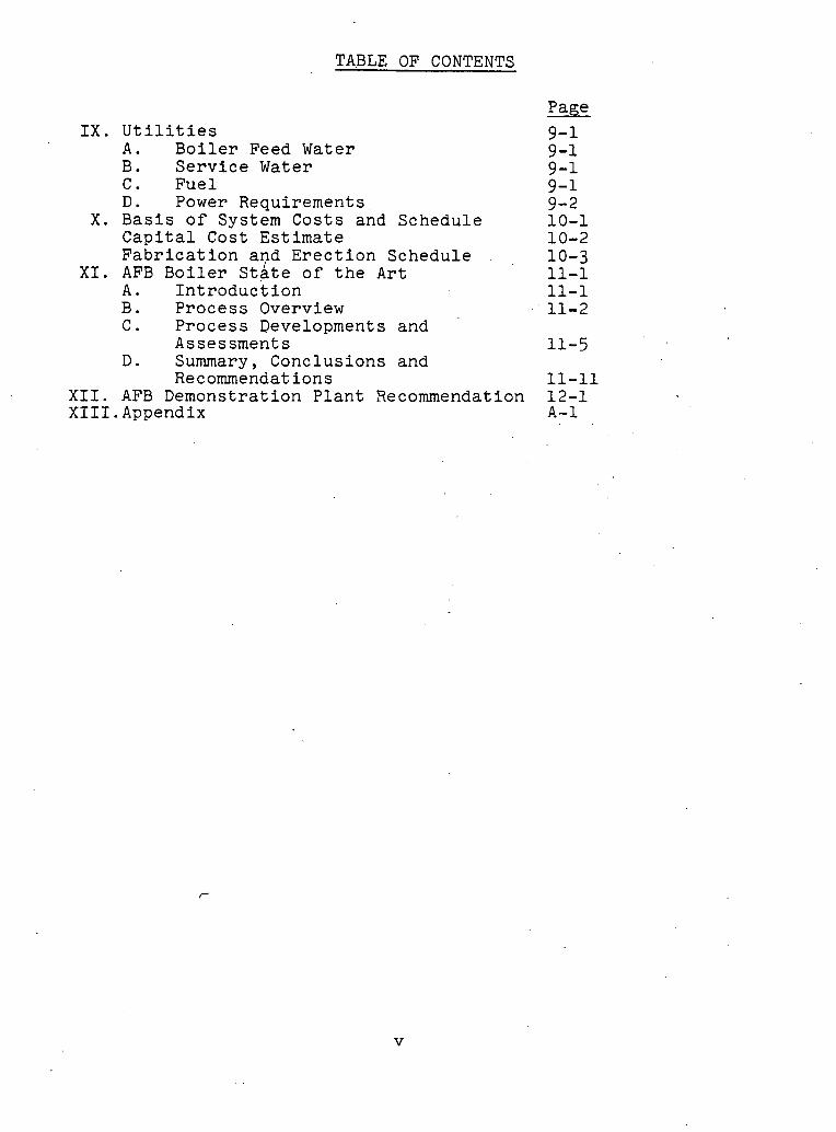
TABLE OF CONTENTS
IX. Utilities A . Boiler Feed Water B. Service Water C. Fuel D. Power Requirements
X. Basis of System Costs and Schedule Capital Cost Estimate Fabrication a ~ d Erection Schedule
XI. AFB Boiler State of the Art A. Introduction B. Process Overview C. Process Developments and
Assessments D. Summary, Conclusions and
Recommendations XII. AFB Demonstration Plant Recommendation XIII.Appendix
Page
9-1 9-1 9-1 9-1 9-2 10-1 10-2 10-3 11-1 11-1 11-2

LIST OF FIGURES
Page
Fluid Bed Coal and Limestone Feeding and Distribution Systems Precipitator Arrangement Base Scheme Precipitator Arrangement Modifications Predicted Performance Summary Sheet Spray Attemperator Superheater Spray Attemperator Rothemuhle Precipitator General Description Rothemuhle Regenerative Air Heater Column Loadings Furnace Draft Control Fabrication and Erection Schedule Simplified Flow Schematic SO2 Reduction ( % ) vs. Ca/S Combustion Efficiency vs. Superficial Velocity Combustion Efficiency vs. Superficial Velocity SO Removal as a Function of Ca/S Ratio ~fsiciency ( % ) , Ca/S vs. Gas Velocity Cost Comparison

LIST OF DRAWINGS ,
Name '-
2503703 2 Fluid Bed Boiler Flow Schematic 2503743 - Arrangement of Carbon Burn-up Bed 2503713 - Layout of CBB Feed System 250372E - Solids Storage Tank Precipitator
to CBB and Mixing Bustle 2503733 - Layout of In-Bed Surfaces 39161F - Arrangement of Reinjection System
Precipitator to CBB - Plant Section "A-A"
39163F - Layout of Bed Support and Coal Pipe Location for Main Bed Boiler
39164F - CBB Distribution Plate Support 39162F - Arrangement of ~einj ect ion- System
Precipitator to CBB - Plan
Page
Sect ion "B-Bft A-9 39168F - Arrangement of Precipitator to
CBB - Sectional Side View A-10 39167F - Airheater Plan E -E A-11 39166F - Precipitator lags 61-~1 and
E -E' A-12 39160F - - ~&ct$onal Side View A-13 39165F - Plan Sections D-D and E-E A-14 250399E - Arrangement Side View, TVA
A.F.B. 200 M.W. A-15 250391E - Plant Section AA A-16 250389E - Coal Bunkers 6-40 250388E - Limestone Bunkers 6-41 145528B-O'Coal and Limestone Feeding and
- Distribution System 3-12 140024A-0 Two Cyclone One Precipitator System
for Overhead Solids Collection 3-13 140023A-0 One Cyclone System and Two
Precipitators for Overhead Solids Collection 3-14
I. ABSTRACT
In recent years, fluidized bed combustors have received a great deal of attention as a result of their ability to reduce undesirable stack emission when burning sulfur bearing fuels. While these abilities are well supported by fundamental data, it must be recognized that fluidized bed combustors have not reached the state of co.mmercia1 application attained by stack.gas scrubbers and, more obviously, conventional coal fired boilers. The fact remains, however, that the fluidized bed combustor has the ability to reduce sulfur.dioxide emissions and limit nitric oxide formation and, therefore, it is desirable'to pursue its development.
Presently many investigators are directing their attention toward the development of fundanlei~tal f'luidlzed bed combustion technology. While this work is necessary, engineering studies are also required to investigate the commercial practicality and estimate the economic feasibility of fluidized bed boilers.
Until recently, the bulk of fluidized bed boiler development has been fundamental in nature. Early in 1977, the Federal ERDA initiated a major effort to investigate the engineering aspects of fluid bed boilers by making funds available to two architect/engineering firms and, in turn, the three major boiler manufacturers. This document describes the results-of the work performed by B&W over the last seven months and represents the Company's input to ERDA1s' fluidized bed boiler commercialization investigation. More specifically, B&W has prepared a conceptual design of a 570 MW fluidized bed boiler with its auxiliaries, prepared preliminary drawings showing the arrangement of this equipment, and prepared a cost estimate for the equipment. This final report summarizes the results of this work.
11. OBJECTIVE
To develop a preliminary design for a conceptualized 570 MW atmospheric pressure fluidized bed boiler (AFB) capable of burning high sulfur coal in an environmentally acceptable manner without recourse to flue gas desulfurl- zation. This preliminary design will be in sufficient detail to describe the technical feasibility and costs associated with the conceptualized AFB boiler and equipment.
111. DESIGN PHILOSOPHY
A. General
The steam generating portion of the fluid bed system consists of two major units, the main fluid bed boiler and a separate carbon burn-up bed unit. The overall design arrangements of these units are shown on Pages A-13, A-14, and. A-2 .
The main bed unit is made up of five (5) beds, each 71 feet wide and 24 feet deep. All of the coal and limestone and a major portion of the combustion air are fed to this unit. The boiler is arranged with two elevations of beds on the front wall; two on the rear, and one at the base of the central furnace. While time did not permit extensive study of various bed arrangements, the selected arrange- ment appears to have merit in that it did not require unusual unit height or plan area. Also, it permitted reasonable integration of the bed enclosure walls into the overall boiler enclosure circulation system. While this arrangement is not optimum, we believe it is adequate.
In retrospect, there may have been some added benefit if four larger beds had been utilized, eliminating the upper rear bed. This might have allevfated some of the congestion at the back of the unit and permitted a slightly more efficient arrangement of reheat surface. If future studies are performed, this alternative should be pursued.
An inspection of the arrangement drawings will reveal that the windbox areas located between the vertically disposed beds are rather large. This arrangement was dictated by the significant structural requirements within the windbox, due to high gas pressure differentials, distributor plate support systems, and thermal expansion requirements. In additfon, routing of the many coal and stone feed pipes added to the congestion problem in these areas.
The main boiler design was predicated on the philosophy of not placing any reheater surface within the beds. This eliminated the need for a sophisticated by-pass system for protection of the reheater during start-up and unit trip conditions. The downflow convection pass which resembles a conventional boiler arrangement consists of a primary superheater section and a primary reheater
section in parallel, with gas flow biasing for reheat steam temperature control. The major portion of the superheater surface is submerged in the beds. The superheater surface is located in three and one-half (3-%) of the five ( 5 ) beds. The reniainfng one and one-half (I-%) beds contain boiling .heat transfer surface.
A pump-assisted circulation boiler design was selected rather than a once through design. The AFB system with its many enclosure walls for both main unit and the CBB as well as the in-bed horizontal boiler surface in the main beds presents a large number of tubes to be cooled. The use of a once through design would require several sequential passes through the enclosure in order to achieve sufficiently high mass velocities in the tubes to assure that departure from nucleate boiling would n ~ t occur. consider in^ thp design problems that are known on conventional 2400 psi once through boilers,if multiple passes must be used, it seemed prudent not to utilize the once through design philosophy. In addition, the avoidance of a once through design permits the use of large (2%" OD) diameter enclosure tubes. This size, as opposed to the 1%" or 1%" OD tubes usually used in once through designs provides greater enclosure wall rigidity and hence reduces structural design requirements.
A pump assisted circulation design was selected over natural circulation for two primary reasons. First, the horizontal boiler tubes submerged in the beds require relatively high fluid mass flows to assure that there will be no departure from the nucleate boiling regime. Second, the heat absorbed by thc vertical wall enclosure tubes is significantly lower than for a conventional coal fired unit, resulting in insufficient natural pumping head.
The carbon burn-up bed unit is designed as a physically separate enclosure, although It is fed by the common circulating pumps and its water circuitry is integral with the main boiler. The alternative of physically integrating the CBB into the main boiler setting was discarded for structural reasonn. Und.er certain ciperating conclit;-lons, significant gas pressure differentials could exist between the main unit and the CBB, and if a common tubular wall was used to separate the two units, there appeared to be no reasonable means of buck- staying this wall to accommodate the resulting forces.
The CBB consists of four (4) beds with vertical water cooled tubular enclosure walls. Unlike the FBC there is no horizontal transfer surface within
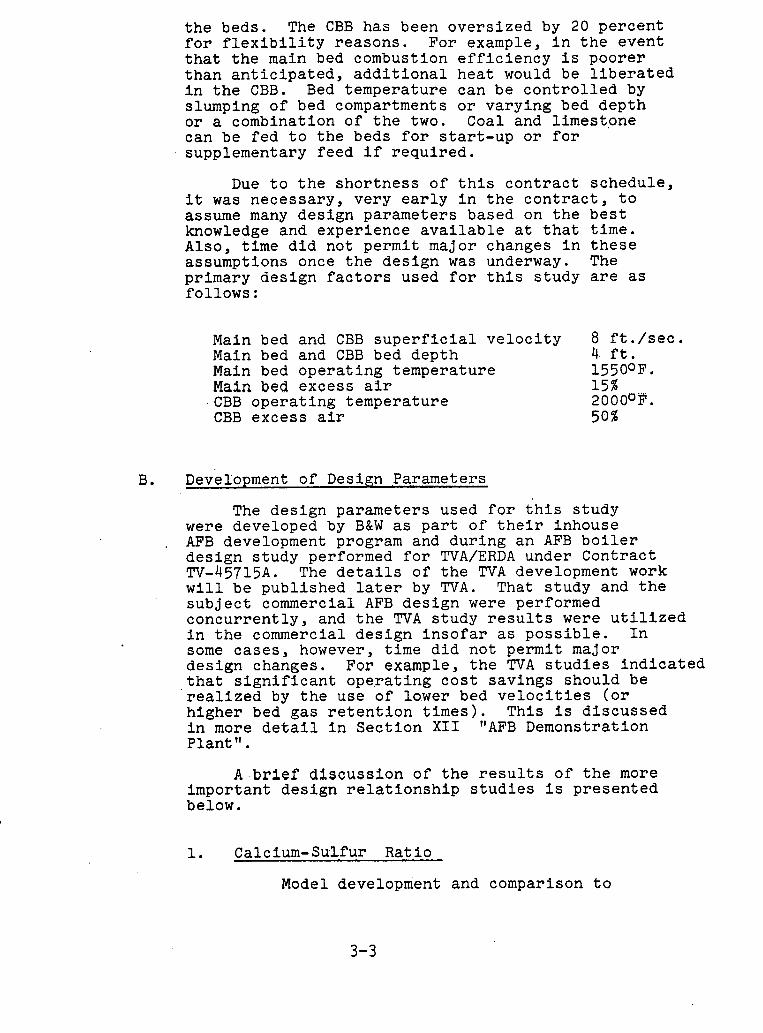
the beds. The CBB has been oversized by 20 percent for flexibility reasons. For example, in the event that the main bed combustion efficiency is poorer than anticipated, additional heat would be liberated in the CBB. Bed temperature .can be controlled by slumping of bed compartments or varying bed depth or a combination of the two. Coal and limestpne can be fed to the beds for start-up or for supplementary feed if required.
Due to the shortness of this contract schedule, it was necessary, very early in the contract, to assume many design parameters based on the best knowledge and experience available at that time. Also, time did not permit major changes in these assumptions once the design was underway. The primary design factors used for this study are as follows :
Main bed and CBB superficial velocity 8 ft./sec. Main bed and CBB bed depth 4. ft. Main bed operating temperature 15500F. Main bed excess air 15% CBB operating temperature 20OOUP. CBB excess air 50%
B. ~evelo~ment of Design ,Parameters
The design parameters used for this study were developed by B&W as part of their inhouse
, AFB development program and during an AFB boiler design study performed for TVA/ERDA under Contract TV-45715A. The details of the TVA development work will be published later by TVA. That study and the subject commercial AFB design were performed concurrently, and the TVA study results were utilized in the commercial design insofar as possible. In some cases, however, time did not permit major design changes. For example, the TVA studies indicated that significant operating cost savings should be realized by the use of lower bed velocities (or higher bed gas retention times). This is discussed in more detail in Section X I 1 "AFB Demonstration Plant 'I.
A . b r i e f discussion of the results of the more important design relationship studies is presented below.
1. Calcium-Sulfur Ratio
Model development and comparison to

experimental data yielded a relationship between calcium-sulfur ratio, sulfur capture, stone sizing and gas residence time. This relationship matched the data reported by PER* and ANL** as well as data obtained by B&W under an EPRI contract with reasonable accuracy.' Using this relationship and the selected bed operating conditions yielded a required calcium-sulfur ratio of 2.5'for this design, in order to lower the SO2 emis ions from the AFB system combustion to 1.2 lb/1OZ BTU input.
Combustion Efficiency
A model was developed to define the combustion process. This model yielded a relationship that considered suchlitems as coal sizirig, volatile matter of the coal, gas residence time, excess air and bed temperature. This relationship was compared to published data of combustion efficiencies determined by several investigators (1). While the reported data showed considerable scatter, the relationship of the model, with appropriate evaluation of constants relating to isothermal combustion rates, provided reasonable agreement with the statistical trend. For the selected bed operating conditions and coal characteristics, the overall bed combustion efficiency was predicted to be 88%. The split between in- hed and above bed combustion was assumed to be 91%/9% for the selected bed velocity. This value is based on judgment and available experimental results. The combustion efficiency for the CBB was evaluated using the stme model as far the main bed u r ~ i L but with the assumption that the reactivity of the char was an order of magnitude less than for the coal. For the selected operating conditions this yielded the same combustion efficiency for the CBB as for the main unit.
3. Heat Transfer
Afl ni~ggcnted Ref~rcncc (1) it. was assumed that the outside heat transfer coefficient could be expressed as
Where: U = outside heat transfer coefficient hc = convection-condu.ction coefficient hr = radiation coefficient
* Pope, Evans & Robins * * Argone National Lab
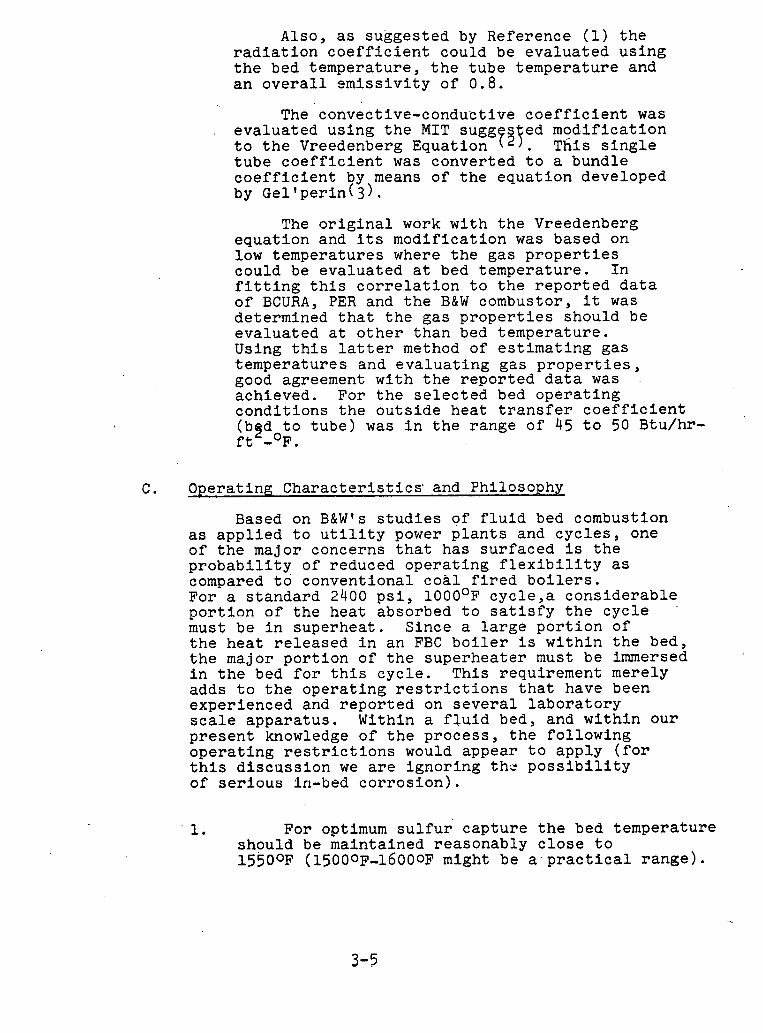
Also, as suggested by Reference (1) the radiation coefficient could be evaluated using the bed temperature, the tube temperature and an overall ~missivity of 0.8.
The convective-conductive coefficient was evaluated using the MIT sugg s ed modification to the Vreedenberg Equation . his single tube coefficient was converted to a bundle coefficient by means of the equation developed by ~ell~erin(3).
The original work with the Vreedenberg equation and its modification was based on low temperatures where the gas properties could be evaluated at bed temperature. In fitting this correlation to the reported data of BCURA, PER and the B&W combustor, it was determined that the gas properties should be evaluated at other than bed temperature. Using this latter method of estimating gas temperatures and evaluating gas properties, good agreement with the reported data was achieved. For the selected bed operating conditions the outside heat transfer coefficient (b2d to tube) was in the range of 45 to 50 Btu/hr- ft -OF.
C. Operating Characteristics' and Philosophy
Based on B&W1s studies of fluid bed combustion as applied to utility power plants and cycles, one of the major concerns that has surfaced is the probability of reduced operating flexibility as compared to conventional coal fired boilers. For a standard 2400 psi, 1 0 0 0 ~ ~ cycle,a considerable portion of the heat absorbed to satisfy the cycle must be in superheat. Since a large portion of the heat released in an FBC boiler is within the bed, the major portion of the superheater must be immersed in the bed for this cycle. This requirement merely adds to the operating restrictions that have been experienced and reported on several laboratory scale apparatus. Within a fluid bed, and within our present knowledge of the process, the following operating restrictions would appear to apply (for this discussion we are ignoring the possibility of serious In-bed corrosion).
1. For optimum sulfur' capture the bed temperature should be maintained reasonably close to 15500~ (15000~-16000~ might be a.practica1 range).
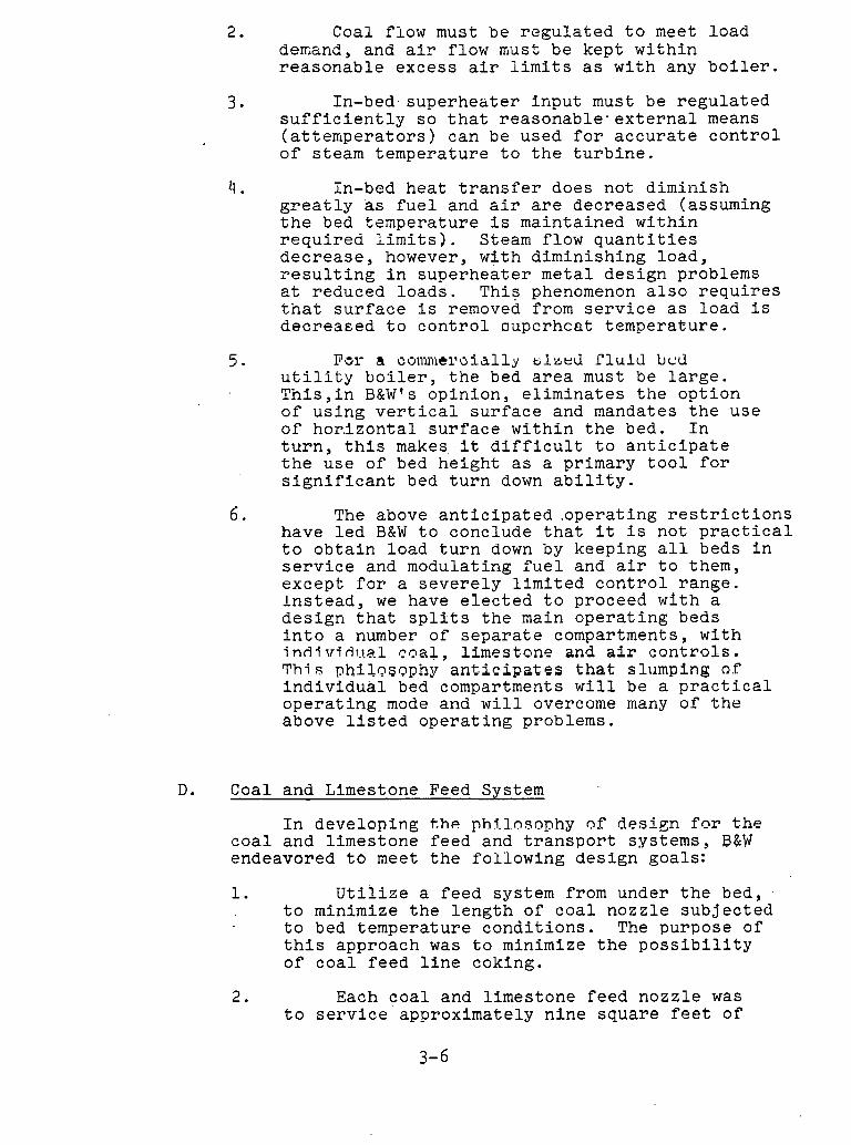
2. Coal flow must be rcgulated to meet load demand, and air flow nust be kept within reasonable excess air limits as with any boiler.
3 In-bed.superheater input must be regulated sufficiently so that reasonable* external means (attemperators) can be used for accurate control of steam temperature to the turbine.
In-bed heat transfer does not diminish greatly as fuel and air are decreased (assuming the bed temperature is maintained within required limits). Steam flow quantities decrease, however, with diminishing load, resulting in superheater metal design problems at reduced loads. This phenomenon also requires tnat surface is removed from service as load is decrea~ed to control oupcrhcat temperature.
POI- a oon1111ci~oially ~ 1 n t . d rluld bcd utility boiler, the bed area must be large. This,in B&Wts opinion, eliminates the option of using verticai surface and mandates the use of hor.izonta1 surface within the bed. In turn, this makes it difficult to anticipate the use of bed height as a primary tool for significant bed turn down ability.
6 . The above anticipated .operating restrictions have led B&W to conclude that it is not practical to obtain load turn down by keeping all beds in service and modulating fuel and air to them, except for a severely limited control range. Instead, we have elected to proceed with a design that splits the main operating beds into a number of separate compartments, with i nd - lv idua .1 coal, limestone and air controls. T h i s phil~slaphy anticipates that slumping o f individual bed compartments will be a practical operating mode and will overcome many of ,the above listed operating problems.
D. Coal and Limestone Feed System
In developing t h e phTlosophy of design for the coal and limestone feed and transport systems, B&W endeavored to meet the following design goals:
1. Utilize a feed system from under the bed, to minimize the length of coal nozzle subjected to bed temperature conditions. The purpose of this approach was to minimize the possibility of coal feed line coking.
2. Each coal and limestone feed nozzle was to service approximately nine square feet of

bed area, suggested by existing technology for reasonable bed distribution.
3 The design should eliminate the need for predrying coal or limestone.
4. Existing conventional boiler coal feeding and transport te.chnology should be utilized as much as possible.
The resulting coal and limestone system is shown in sketch 'form on page 3-12 .
The coal and limestone injection system takes the crushed coal and limestone from their respective silos, mixes the coal and the limestone in the proper ratio for sulfur removal, dries, transports, .distributes and injects the mixture into the fluid bed boiler. and carbon burn-up beds.
The design of the coal and limestone injection system is based on an almost identical system supplied by B&W for injecting crushed coal into B&W Cyclone Furnaces.
Twenty-five (25) id used in parallel. Each coal and limestone silos point just ab,ove the dis bed boiler.
ent.ical transport starts at the out and ends at the tributor plate in
syst let o injec the
ems are f the t ion fluid
As shown on the sketch, crushed coal and limestone are fed by gravity through fifty (50) gravimetric belt feeders to a discharge hopper. The mixture then passes through a rotary seal and to a mixing bustle. Here, the material is mixed and partially dried. Hot air to dry the mixture of coal and limestone and to convey it from the bustle is supplied by the primary air fans. A tempering air fan is used to provide ambient air to control the temperature into the mixing bustle. This air temperature will be dependent on the outlet temperature of the two-phase mixture transported from the mixing bustle. Thissolids-air mixture is split into forty (40) streams before injection into the fluid bed boiler.
In addition to the above, a similar system to convey limestone and coal was provided for CBB starst-up, or for supplementary feed if it is found necessary.
The described system has been used and proven on commercial conventional coal fired units, with the exception of two areas that require further development:
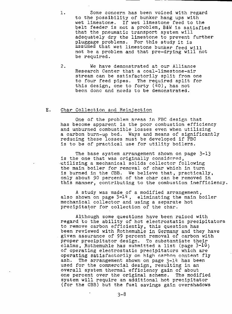
1. Some concern has been voiced with regard to the possibility of bunker hang ups with wet limestone. If wet limestone feed to the belt feeder is not a problem, B&W is satisfied that the pneumatic transport system will adequately dry the limestone to prevent further pluggage problems. For this study it is assumed that wet limestone bunker feed will not be a problem and that pre-drying will not be required.
2. We have demonstrated at our Alliance Research Center that a coal-limestone-air stream can be satisfactorily split from one to four feed pipes. The required split for this design, one to forty (40), has not been donc and need3 to be demonstrated.
E. Char Collection and Reinjection
One of the problem areas in FRC design that has become apparent is the poor combustion efficiency and unburned combustible losses even when utilizing a carbon burn-up bed. Ways and means of significantly reducing these losses must be developed if FBC is to be of practical use for utility boilers.
The base system arrangement shown on page 3-13 is the one that was originally considered, -utilizing a mechanical solids collector following the main boiler for removal of char which in turn is burned in the CBB. We believe that, practically, only about 90 percent of the char can be removed in this manner, contributing to the combustion inefficiency.
A study was made of a modified arrangement, also shown on page 3-14, eliminating the main boiler mechanical collector and using a separate hot precipitator for collection of the char.
Although some question8 have been raised with regard 'to the ability of hot electrostatic precipitators to remove carbon efficiently, this question has been reviewed with Rothemuhle in Germany and they have given assurance of 99 percent removal of carbon with proper precipitator design, To substantiate their claims, ,Rothemuhle has submitted a list (page 3-10.) of operating electrostatic precipitators which are operating satisfactorily on high c.a.rhon content fly ash. The arrangement shown. on page 3-14 has been used for the commercial design, resulting in an overall system thermal efficiency gain of about one percent over the original scheme. The modified system will require an additional hot precipitator (for the CBB) but the fuel savings gain overshadows
the higher equipment costs.
A mechanical solids collector is utilized following the CBB and prior to the CBB electrostatic precipitator. The reason for this is economics, since the gas solids loading leaving the CBB is much higher than leaving the FBC, and use of a mechanical collection device at this point significantly reduces the CBB precipitator size (and cost).
Boiler Sootblower Design
The number and spacing of sootblowers for this boiler arrangement were set in accordance with B&W standards for conventional P.C. fired units using the contract fuel. Some authorities predict that fluid bed fired boilers (with lower combustion temperatures and high stone carryover rates) will need fewer or no sootblowers and there may be some justification for this speculation. However, this point is presently unknown and therefore we have adopted a conservative position.
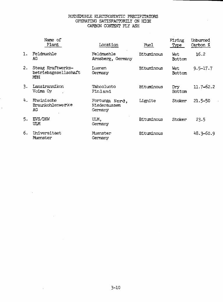
Name of Plant
R r n i ELECTROSTATIC PRECIPITATORS OPERATING SATISFACTORILY ON HIGH
CARBON c o r n FLY ASH
2. Steag Kraftwerks- betriebsgesellschaft MBH
4. Rheinische Braunkohlenwe r k e AG
6. Universitaet Muenster
Locat ion Fuel
Fe ldmehle Bituminous Arnsberg, Germany
Luenen Bituminous @rmany
Tahcoluoto Bituminous Fin1 and.
Fort- Nord, Lignite Niederaussem Germany
Muenster Bituminous Germany
Firing Unburned Type Carbon %
Wet 16.2 Bottom
Wet 9 5-17 7 Bottom
Dry 11.7-62.2 Bottom
Stoker 21.5-50
Stoker 23.5
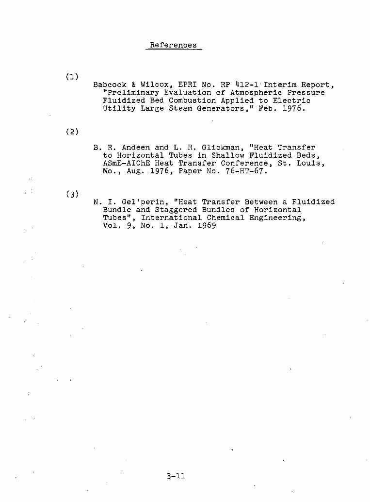
References
(1) Babcock & Wf lcox, EPRI No. RP 412-1: Interim Report, "Preliminary Evaluation of Atmospheric Pressure Fluidized Bed Combustion Applied to Electric Utility Large Steam Generators," Feb. 1976.
B. R. Andeen and L. R. Gliclunan, "Heat Transfer to Horizontal Tubes in Shallow Fluidized Beds, ASmE-AIChE Heat Transfer Conference, St. Louis, Mo., Aug. 1976, Paper No. 76-HT-67.
( 3 ) N. I. Gellperin, "Heat Transfer Between a Fluidized Bundle and Staggered Bundles of Horizontal Tubes", International Chemical Engineering, Vol. 9, No. 1, Jan. 1969
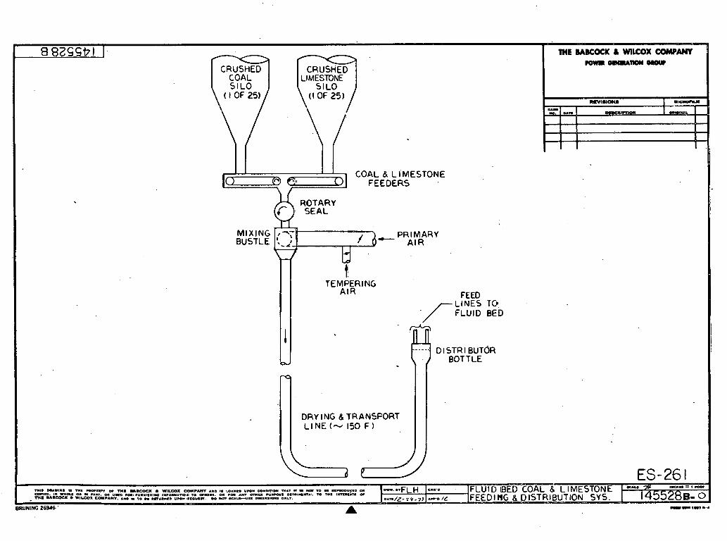
COAL & L I'MESTONE
MIXING BUSTLE
ROTARY
PRIMARY AIR
TEMPERING A I R FEED
-/- LINES TO FLUID BED
----. D l STR l BUTOR : W BOTTLE
DRY l NG & TRANSPORT LINE (-v 150 F I I
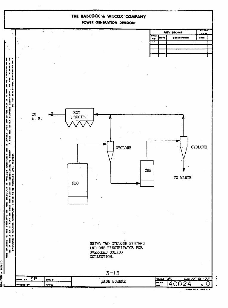
ITSING rwn mn,oh SYSTEMS AND ONE PRECIPITATOR FOR OVERREAD SOLIDS COLLECTION.
'W L
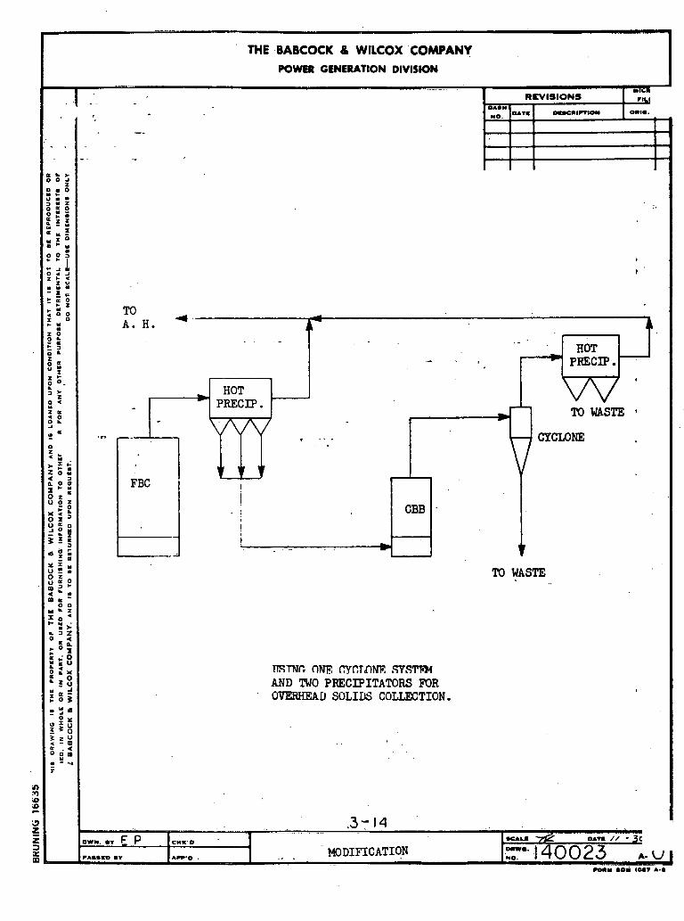
TISTNC C)e, aCTDm SVSTFM AND TWO PRECIPITATORS FOR OVERHEAD SOLIDS COLLECTION.
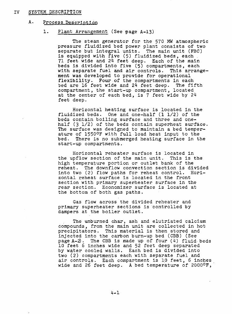
SYSTEM DESCRIPTION
A. P roce s s D e S s r i o t i m
1. P l a n t Arrangement (See page A - 1 3 )
The s t eam g e n e r a t o r f o r t h e 570 MW a tmosphe r i c p r e s s u r e f l u i d i z e d bed power p l a n t c o n s i s t s o f two s e p a r a t e b u t i n t e g r a l u n i t s . The main u n i t (FBC) i s equipped w i t h f i v e ( 5 ) f l u i d i z e d b e d s , e ach 71 f e e t wide and 24 f e e t deep. Each o f t h e main beds i s d i v i d e d i n t o f i v e ( 5 ) compartments , e ach w i t h s e p a r a t e f u e l and a i r c o n t r o l s . T h i s a r r a n g e - ment was deve loped t o p r o v i d e f o r o p e r a t i o n a l f l e x i b i l i t y . Four o f t h e compartments i n each Sed a r e 16 f e e t wide and 24 f e e t deep. The f i f t h compartment, t h e s t a r t - u p compartment, l o c a t e d a t t h e c e n t e r o f e ach bed , i s 7 f e e t wide by 24 f e e t deep.
H o r i z o n t a l h e a t i n g s u r f a c e i s l o c a t e d i n t h e f l u i d i z e d b e d s . One and one-hal f (1 1 / 2 ) o f t h e beds c o n t a i n b o i l i n g s u r f a c e and t h r e e and one- h a l f ( 3 1 / 2 ) o f t h e beds c o n t a i n s u p e r h e a t s u r f a c e . The s u r f a c e was d e s i g n e d t o m a i n t a i n a bed temper- a t u r e o f 15500F w i t h f u l l l o a d h e a t i n p u t t o t h e bed. There i s no submerged h e a t i n g s u r f a c e i n t h e s t a r t - u p compartments .
H o r i z o n t a l r e h e a t e r s u r f a c e i s l o c a t e d i n t h e upflow s e c t i o n o f t h e main u n i t . T h i s i s t h e h i g h t empe ra tu r e p o r t i o n o r o u t l e t bank o f t h e r e h e a t . The downflow convec t i on s e c t i o n i s d i v i d e d i n t o two ( 2 ) f low p a t h s f o r r e h e a t c o n t r o l . Hori- z o n t a l r e h e a t s u r f a c e i s l o c a t e d i n t h e f r o n t s e c t i o n w i t h pr imary s u p e r h e a t e r s u r f a c e i n t h e r e a r s e c t i o n . Economizer s u r f a c e i s l o c a t e d a t t h e bot tom o f b o t h g a s p a t h s .
Gas f low a c r o s s t h e d i v i d e d r e h e a t e r and pr imary s u p e r h e a t e r s e c t i o n s i s ' c o n t r o l l e d by dampers a t t h e b o i l e r o u t l e t .
The unburned c h a r , a sh and e l u t r i a t e d c a l c i u m compounds, from t h e main u n i t a r e c o l l e c t e d i n h o t p r e c i p i t a t o r s . T h i s m a t e r i a l i s t h e n s t o r e d and i n j e c t e d i n t o t h e ca rbon burn-up bed (CBB) (See page A-2). The CBB i s made up of f o u r ( 4 ) f l u i d beds 1 0 f e e t 6 i n c h e s wide and 52 f e e t deep s e p a r a t e d by w a t e r coo l ed w a l l s . Each bed i s d i v i d e d i n t o two ( 2 ) compartments each w i t h s e p a r a t e f u e l and a i r c o n t r o l s . Each compartment i s 1 0 f e e t , 6 i n c h e s wide and 26 f e e t deep. A bed t e m p e r a t u r e o f 2000°F, '

at f u l l l oad i n p u t , i s maintained by v i r t u e o f f u r n a c e d e s i g n . There i s no in-bed h e a t i n g s u r f a c e , bu t t h e membraned b o i l e r p e r i p h e r a l walls -are designed t o remove s u f f i c i e n t h e a t t o m a i n t a i n bed tempera ture .
Three walls on t h r e e and one-half (3-1/2) f o o t c e n t e r s , p l u s t h e e n c l o s u r e w a l l s ,. provide t h e r e q u i r e d h e a t t r a n s f e r s u r f a c e . B o i l i n g s u r f a c e comprises t h e e n t i r e CBB. H o r i z o n t a l b o i l i n g s u r f a c e i s l o c a t e d above t h e beds t o r ecove r t h e h e a t from t h e combustion gas .
CBB f l u e gas p a r t i c u l a t e removal i s ob ta ined w i t h a mechanical d u s t c o l l e c t o r and ho t e l e c t r o - s t a t i c p laec lpLta tor i n series. F lue gas from t h e CBB ho t p r e c i p i t a t o r t hen i s mixed w i t h flue gas f P O m the LclBC h o t p r e c i p i t a t o r s p r i o r t o e n t e r i n g t h e two ( 2 ) r e g e n e r a t i v e a i r h e a t e r s . From t h e a i r h e a t e r s t h e gas pas ses through t h e induced
. d r a f t f a n s and t h e n e x i t s t o t h e s t a c k .
A i r plow (See page A-14
Combustion a i r i s s u p p l i e d by two ( 2 ) f o r c e d d r a f t f a n s . The a i r p a s s e s through steam c o i l a i r h e a t e r s , r e q u i r e d f o r a i r h e a t e r c o l d end p r o t e c t i o n at low l o a d s ; and i s p rehea ted by
. two ( 2) r e g e n e r a t i v e a i r h e a t e r s . The combustion a i r l e a v i n g t h e a i r h e a t e r s i s d i v i d e d i n t o two ( 2 ) s t r eams w i t h approximately twenty pe rcen t going t o ho t primary a i r fa.ns and t h e remaining e i g h t y pe rcen t supp ly ing t h e secondary a i r f o r the FBC and the C R R . The secondary a i r flow t o t h e i n d i v i d u a l compartments of t h e beds i s c o n t r o l l e d w i t h dampers a t t h e windboxes. A i r f o i l s a r e provided for f low measurement a t t h e I n d i v i d u a l windb oxes . The a i r t h e n pas ses through a p e r f o r a t e d d i s t r i b u t i o n p l a t e f o r f l u i d i z a t i o n o f t h e coa l - l imes tone mix ture . The h o t a i r l e a v i n g t h e p r i m a r y ' a i r f a n s flows t o t h e coal- l imestone f e e d system where, a f t e r i t i s mixed w i t h tempering a i r f o r a i r tempera ture c o n t r o l , i t i s used t o t r a n s p o r t t h e f e e d m a t e r i a l t o each bed compartment.
3. Coal-Limestone Feed System (See page A - 1 )
The coal- l imestone feed r a t e s t o t h e i n d i v i d u a l bed compartments i n t h e main u n i t a r e c o n t r o l l e d by g r a v i m e t r i c f e e d e r s . Twenty-flve ( 2 5 ) c o a l and twenty-f ive ( 2 5 ) l imes tone f e e d e r s a r e provided . A c o a l f e e d e r and a l imes tone
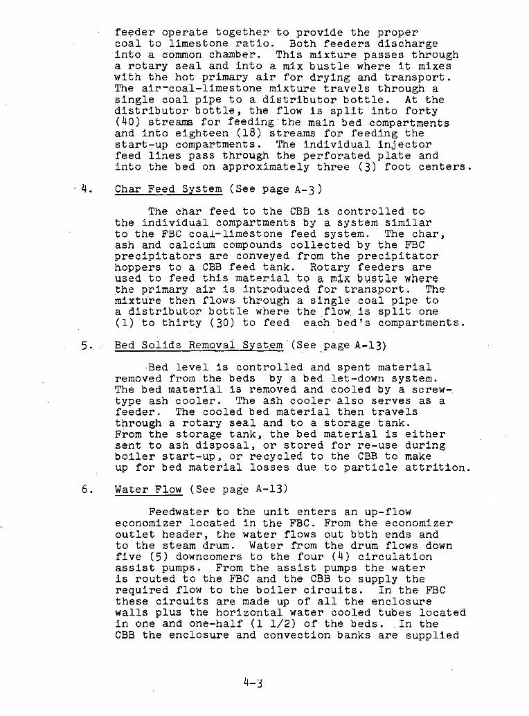
. f e e d e r o p e r a t e t o g e t h e r t o p r o v i d e t h e p r o p e r c o a l t o l im,es tone r a t i o . 3 0 t h f e e d e r s d i s c h a r g e i n t o a common chambe'r. T h i s m i x t u r e p a s s e s t h r o u g h a r o t a r y s e a l and i n t o a mix b u s t l e where i t mixes w i t h t h e ho t pr imary a i r f o r d r y i n g and t r a n s p o r t . The a i r - coa l - l imes tone mix tu r e t r a v e l s t h rough a s i n g l e c o a l p i p e t o a d i s t r i b u t o r b o t t l e . A t t h e d i s t r i b u t o r b o t t l e , t h e f low i s s p l i t i n t o f o r t y ( 4 0 ) s t r e a m f o r f e e d i n g ' t h e main 5 e d .compartments and i n t o e i g h t e e n ( 1 8 ) s t r e a m s f o r f e e d i n g t h e s t a r t - u p compartments . The i n d i v i d u a l i n j e c t o r f e e d l i n e s p a s s th rough t h e p e r f o r a t e d p l a t e and i n t o . t he bed on app rox ima te ly t h r e e ( 3 ) f o o t c e n t e r s .
4 . Char Feed System (See page A-3)
The c h a r f e e d t o t h e CBB i s c o n t r o l l e d t o t h e i n d i v i d u a l compartments by a sy s t em s imilar t o t h e EBC coa l - l imes tone f e e d sys tem. The c h a r , a s h and ca lc ium compounds c o l l e c t e d by t h e FBC p r e c i p i t a t o r s a r e conveyed from t h e p r e c i p i t a t o r hoppers t o a CBB f e e d t a n k . Rota ry f e e d e r s a r e used t o f e e d t h i s m a t e r i a l t o a mix bustle where t h e p r imary a i r i s i n t r o d u c e d f o r t r a n s p o r t . The mix tu r e t h e n f lows t h rough a s i n g l e c o a l p i p e t o a d i s t r i b u t o r b o t t l e where t h e f low, i s s p l i t one (1) t o t h i r t y ( 3 0 ) t o f e e d each b e d ' s compartments .
Bed S o l i d s e em oval Syst.em (See page A-13) , -
Bed l e v e l i s c o n t r o l l e d and s p e n t m a t e r i a l removed from t h e beds by a bed let-down sys tem. The bed m a t e r i a l i s removed and coo l ed by a screw- t y p e a sh c o o l e r . The a s h c o o l e r a l s o s e r v e s as a f e e d e r . The coo l ed bed m a t e r i a l t h e n t r a v e l s t h rough a r o t a r y s e a l and t o a s t o r a g e t a n k . From t h e s t o r a g e t a n k , t h e bed m a t e r i a l i s e i t h e r s e n t t o a s h d i s p o s a l , o r s t o r e d f o r r e -u se d u r i n g b o i l e r s t a r t - u p , o r r e c y c l e d t o t h e CBB t o make up f o r bed m a t e r i a l l o s s e s due t o p a r t i c l e a t t r i t i o n .
6 . Water Flow (See page A - 1 3 )
Feedwater t o t h e u n i t e n t e r s a n up-flow economizer l o c a t e d i n t h e FBC. From t h e economizer o u t l e t h e a d e r , t h e water f lows o u t b b t h ends and t o t h e s t eam drum. Water from t h e drum f l ows down f i v e ( 5 ) downcomers t o t h e f o u r ( 4 ) c i r c u l a t i o n assist pumps. From t h e a s s . i s t pumps t h e w a t e r i s r o u t e d t o t h e FBC and t h e CBB t o supp ly t h e r e q u i r e d f low t o t h e b o i l e r c i r c u i t s . I n t h e FBC t h e s e c i r c u i t s a r e made up o f a l l t h e e n c l o s u r e walls p l u s t h e h o r i z o n t a l w a t e r coo l ed t u b e s l o c a t e d i n one and one-hal f (1 1 / 2 ) o f t h e b e d s . . I n t h e CBB t h e e n c l o s u r e and c o n v e c t i o n banks are s u p p l i e d

from t h i s s o u r c e . The steam-water m i x t u r e from t h e b o i l e r c i r c u i t s e x i t s t h e o u t l e t h e a d e r s v i a r i s e r s which r u n d i r e c t l y t o t h e steam drum. The steam-water m ix tu r e i s s epa ra - t e d i n t h e s t eam drum by cyc lone s e p a r a t o r s .
7 . - Steam Flow (See pageA-13)
The s a t u r a t e d s team l e a v i n g t h e cyc lone s e p a r a t o r p a s s e s t h rough a secondary s c r u b b e r and e x i t s t h e drum th rough m u l t i p l e c o n n e c t i o n s r u n n i n g t o a c o l l e c t i n g heade r . The s t eam e x i t s t h e c o l l e c t i n g heade r t h rough end c o n n e c t i o n s which a r e r o u t e d t o t h e p r imary s u p e r h e a t e r i n - l e t heade r . The s team f l ows t h rough t h e up- f l ow pr imary s u p e r h e a t e r l o c a t e d i n t h e rear g a s p a s s o f t h e down-flow convec t i on p a s s . The steam then f l ows t o t h e secondary a u p e r h c a t c r which i s l o c a t e d i n t h r e e and one-hal f ( 3 1 /2 ) a s rhe seds all8 f l a w s t h m u g h these banks I r i s e r i e s . More s p e c i f i c a l l y t h e s team e x i t s t h e p r imary s u p e r h e a t e r v i a q u a r t e r p o i n t o u t l e t c o n n e c t i o n s on t h e o u t l e t heade r and e n t e r s t h e s u p e r h e a t e r l o c a t e d i n t h e lower r e a r f l u i d i z e d bed. T h i s bed c o n t a i n s b o t h b o i l i n g and super - h e a t e r s u r f a c e . The s u p e r h e a t e r s u r f a c e i s l o c a t e d i n t h e r i g h t two compartments . The i n l e t and ou t - l e t h e a d e r s have q u a r t e r p o i n t c o n n e c t i o n s . The steam i s r o u t e d from t h e s p l i t bed t o t h e t o p rear w a l l bed, which i s t h e f i r s t a l l s u p e r h e a t e r bed. The i n l e t heade r i s l o c a t e d on t h e b o i l e r r i g h t hand s i d e and ha s q u a r t e r - p o i n t c o n n e c t i o n s . The s team p a s s e s t h rough t h e s u p e r h e a t e r and e x i t s v i a q u a r t e r p o i n t o u t l e t c o n n e c t i o n s on t h e o u t l e t h e a d e r l o c a t e d on t h e b o i l e r l e f t hand s i d e . Spray a t t e m p e r a t o r s , l o c a t e d i n t h e c r o s s - o v e r p i p i n g between t h e f i rs t and second f u l l s u p e r h e a t e r bed , r educe t h e i n l e t e n t h a l p y t o t h e second a l l s u p e r h e a t e r bed. The second a l l super - h e a t e r bed i s t h e lower f r o n t wall bed and ha s q u a r t e r p o i n t i n l e t and o u t l e t c o n n e c t i o n s . The i n l e t h e a d e r i s l o c a t e d on t h e b o i l e r l e f t s i d e w h i l e t h e o u t l e t heade r i s on t h e b o i l e r r i g h t side. A second a t a g e o f ap r ay a t t c m p c r a t i o n i s p rov ided i n t h e c ro s s -ove r p i p i n g between t h e second a l l s u p e r h e a t e r bed and t h e t h i r d a l l super - h e a t e r b e d . T h i s i s t h e f i n a l stage of superheater and i s t h e t o p f r o n t wall bed. The s t eam e n t e r s t h e i n l e t h e a d e r , l o c a t e d on t h e b o i l e r r i g h t s i d e , v i a q u a r t e r p o i n t c o n n e c t i o n s ; and e x i t s t h e o u t l e t heade r , l o c a t e d on t h e b o i l e r l e f t hand s i d e , v i a a c e n t e r p o i n t o u t l e t c o n n e c t i o n , The s t eam e x i t s t h e B&W t e r m i n a l a t 2620 p s i g and 10050F.

8 . - Reheat Steam Flow
Cold reheat steam enters the reheat inlet header via a single end inlet connection. iThe steam passes through the counter-flow reheater, located in the down-flow convection section of the FBC, flows to the high temperature section located in the up-flow of the FBC, and extts via a center point outlet connection on the outlet header. The outlet header is located at the front of the unit. Reheat steam tempera- ture is controlled by biasing the gas flow in the parallel back end; An attemperator is provided in the cold reheat line to control temporary temperature excursions.
9 . Predicted Performance Summary ~heet'(See pg. 4-6)
The AFB is designed to perform as shown on the Predicted Performance Summary Sheet. Boiler and air heater heating surfaces are also summarized. It should be noted that slight discrepancies between the predicted performance summary sheet and the material balance sheet exist. The material balance sheet was not prepared from the final boiler efficiency calculations. Sufficient time was not available to update the material balance sheet to the final boiler efficiency calculations;' and where dis- crepancies occur,, the information on the Predicted Performance Summary sheet should be used.
B. Mechanical Design
A review of the mechanical design of the FBC, was performed. Existing procedures and techniques were used whenever possible. While these existing procedures covered numerous areas of the design, many unique design features were identified as being specific to fluid bed boilers. These unique areas were investigated to a sufficient degree to establish their feasibility and to establish a basis for an approximate cost estimate, but within the scope of this contract, the details of the structural design in these areas could not be completely developed. The final and detailed mechanical design will have to be addressed in much more detail in subsequent design phases.

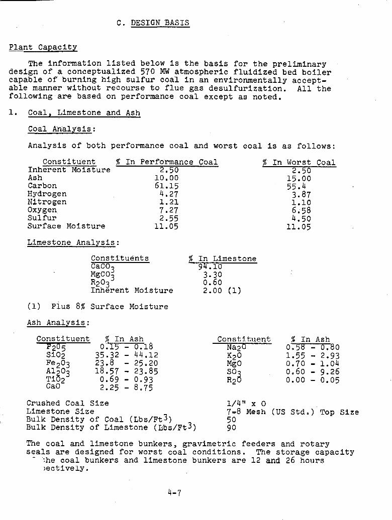
C. DESIGN BASIS
Plant Capacity
The information listed below is the basis for the preliminary design of a conceptualized 570 MW atmospheric fluidized bed boiler capable of burning high sulfur coal in an environmentally accept- able manner without recourse to flue gas desulfurization. All the following.are based on performance coal except as noted.
1. Coal, Limestone and Ash
Coal An'alysis :
Analysis of both performance coal and worst coal is as follows:
Constitu'ent %' I'n 'Perfo'rmance Coal Inherent Moisture 2.50 Ash 10.00 Carbon 61.15 Hydrogen 4.27 Nitrogen 1.21 Oxygen 7.27 Sulfur 2.55 Surface Moisture 11.05
Limestone Analysis:
Const i'tuent s CaCO,
% In Limestone 94.10
M~CO; 3.30 R2°3 0.60 Inherent Moisture 2.00 (1)
(1) pius 8% Surface Moisture
Ash Analysis:
Constituent % In Ash P70 E; 0Z15 - 0.18 F ~ ~ o ~ 23.8 - 25.20 A1203 18.57 - 23.85 Ti02 0.69 - 0.93 CaO 2.25 - 8.75
%' In Worst Coal 2.50
Const.l.t.i.~ent. % In Ash Na20 0,58 - 0.80
Crushed Coal Size 1/4" x 0 Limestone Size 7-8 Mesh (US Std,) Top Size Bulk Density of Coal (~bs/~t3) 50 Bulk Density of Limestone (kbs/~t3) 90
The coal and limestone bunkers, gravimetric feeders and rotary seals are designed for worst coal conditions. The storage capacity - .
;he coal bunkers and limestone bunkers are 12 and 26 hol~rs ~ectively.
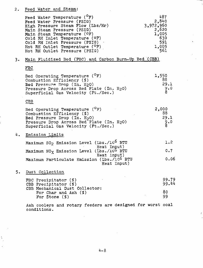
2. Feed Water and Ste'am:
Feed Water Temperature (OF) Feed Water Pressure (PSIG) High Pressure Steam Flow (Lbs/Hr) Main Steam Pres'sure (PSIG) Main Steam Temperature (OF) Cold RH Inlet ,Temperature (OF) Cold RH Inlet Pressure (PSIG) . Hot RH Outlet Temperature (OF) Hot RH Outlet Pressure (PSIG)
3. Main Fluidized Bed (FBC).and Carbon Burn-Up 'Bed (CBB)
'FB C - Bed Operating Temperature (OF) Combustion Efficiency ( % ) Bed Preesi . l . r~! Tlrog (In. H20) Pressure Drop Across Bed Plate (In. H20) Superficial Gas Velocity (Ft./Sec.)
CBB - Bed Operating Temperature (OF) Combustion Efficiency ( % ) Bed Pressure Drop (In. H20) Pressure Drop Across Bed Plate (In. H20) Superficial Gas Velocity (Ft./Sec.)
4. Emission Limits
Maximum SO2 Emission Level (Lbs ./lo6 BTU Heat In ut) e Maximum NOX Emission Level (Lbs./lU BTU Heat Input)
Maximum Particulate Emission (Lbs ./lo6 BTU Heat Input)
5. Dust Collection
FBC Precipitator ( % ) CBB Precipitator ( % ) CBB Mechanical Dust Collector:
For Char and Ash ( % ) For Stone ( % )
Ash coolers and rotary feeders are designed for worst coal conditions.
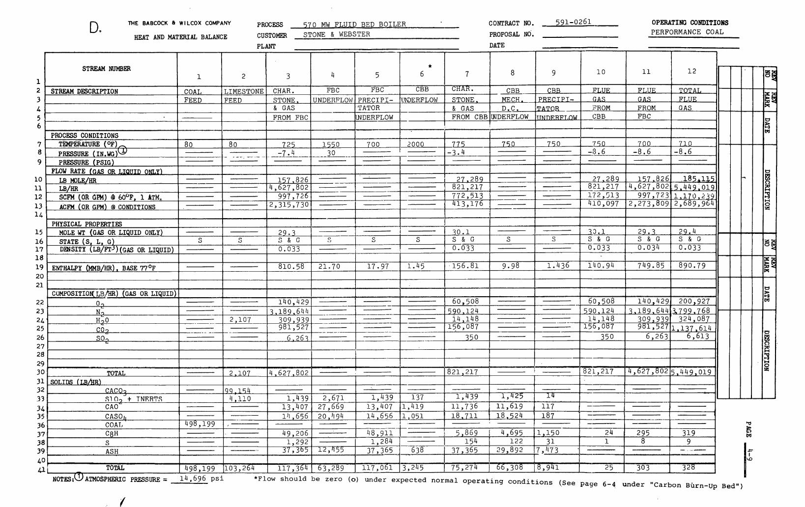
THE BABCOCK e WILCOX COMPANY PROCESS 570 MW FLUID BED BOILER D. CONTRACT NO. 591-0261 OPERATING CONDITIONS
HEAT AND MATWAL BALANCE CUSTOMER S T O N E & W E B S T E R PROPOSAL NO. P E R F O R M A N C E C O A L
PLANT DATE
.
11
F L U E G A S FROM F B C
700 -8.6
1 5 7 , 8 2 6 4 ,627 ,802
997 ,723 -o,og72,273,809
2 9 . 3 S & G 0 .034
7 4 9 . 8 5
1 4 0 , 4 2 9 3 , 1 8 9 , 6 4 4 . 3 7 9 9 . 7 6 8
309,939 981,527
6 , 2 6 3
4 ,627 ,802
--
- - -- -- pp
295 8
303
under
u ~3 9 M
8 Z 3 n 0 z
1 2
T O T A L F J J U E G A S
710 -8.6
.1854135 . 5 , 4 4 9 , 0 1 9 1 , 1 7 0 , 2 3 9 2 ,689 ,964
29 .4 S & G 0 . 0 3 3
890 .79
200,927 .
324 ,087 - 1 , 1 3 7 , 6 1 4
6 , 6 1 3
5 , 4 4 9 , 0 1 9 -
-- - - - 319
9 - . ...-
328
BBrn-Up
u
g M
I I \O
8
-- C B B
9
C B B P R E C I P I - T m R TJNnERPT,C)W p-
10
F J , U E G A S l R O M C B B
7 8 9
10 11 12 13 14
15 16 17 18 19 2 0 21
22 2 3 24 25 26
27 28 29 3 0 31 3 2 3 3 34 3 5 3 6 37 38 3 9 40 dl'
1 2
* 6
C B B
7
CHAH.
3 4 5 6
PROCESS CONDITIONS TPiPERATURE(°F)- P R E ~ ~ U R E ( I N . W G ) W .- PRESSURE ( ~ S I C )
FLOW RATE (GAS OR T,IQUIDONLP) LBMOLE/HF~ L B / m
STREAM NUMBER
STREAM DESCRIPTION mERFLOW
-
F E E D
80 ---
1
COAL
1 1
S T O N E . & G A S FROM C B B
F E E D
-
80 - -.- ~ --. .- ...
2
L I M E S T O N E MECH. D . C .
WDER-FLOW
SCFM (OR CM) 61 60°F, P ATM. ACFM (OR GPM) 63 CONDITIONS
PHYSICAL PROPERTIES MOLE .WT (GAS OR LIQUID ONLY) STATE (S, L, G ) DENSITY (LB/FT~) (GAS OR LIQUID)
, ENTHALPY (MMB/HR) , BASE 77'~
CUMPOSITIO~ L?)HR) (GAS OR LIQUID)
. O1 L
Nc, '
-- 997,726
2 ,315,730
29 .3 S & G 0.033
810.58
140 ,429 3 ,189 ,644
309,939 981,527
S T O N E . & G A S
- FROM F R C
725 . -7.4
3
C H A R *
CO 9
S
1 5 7 , 8 2 6 4 ,627,802 - - -
- -- S
21.70
-
S
350
-
UNDERFLOW
4
F B C
1550 750 750 '750
350
P R E C I P I - T A T O R
W D E R F L O W
5
F B C
------.-----.--------- 30
--
-- - - -
-
-
SO1
-3.6
1 7 2 , 5 1 3
--
v
821,217
2 ,107
6 .263
-
..--Te , . .. .
TOTAL
-------- - 2 27 - 2 8 9 27 .289 .
821 ,217 821,217
.- 1 5 6 , 0 8 7 -. - - - -
821 ,217
156 ,087
-- - -- --
24 1
--- 25
--
2,107 b
S
9 98
--
NOTES:UATMOSPHERIC PRESSURE= 1 4 , 6 9 6 p s i low s h o u l d be =era (0) u n d e r e x p e c t e d n o r m a l o p e r a t i n g c o n d i t i o n s (See paqe 6-4
3 0 . 1 S & G 0 . 0 3 3
, 1 5 6 . 8 1
6 0 , 5 0 8 590.124
1 4 , 1 4 8
- I
4 , 6 2 7 , 8 0 2
S
137 1 , 4 1 9
SOLIDS Lr.R/HR) C A C 0 3 S10, + TNERTS
L
CAO 1 , 4 3 9
1 1 , 7 3 6
S
1 . 4 3 6
- - ---
S
CASOI, COA Zl C 8 H S ASH
- ,
TOTAL
3 3 . 1 S & G 0 .033
140 .94
60 ,508 590.124
1 4 , 1 4 8 -
--
1 , 4 2 5
I
498,199
--
498,199
1 4
17 .97
-
:--=-.
99 -154 4 ,110
1 1 , 6 1 9 1 1 7 ,
1 .45
-
1 , 4 3 9 13 ,407
-. r
103,264
1 4 , 6 5 6 1 1 , 0 5 1 1 1 8 , 7 1 1 1 8 , 5 2 4 1 8 7 ---- 4 % ; 9 1 7 - t - - 1 ~ 1 , 1 5 0
2 ,671 27 ,669
l h , 656
49 ,206 1 , 2 9 2
37 ,365
117,364
1 ,284 - 37 ,365 -
1 1 7 , 0 6 1 -~ ----
1 , 4 3 9 13 ,407
20 ,'I 34
1 2 , 4 5 5
63 ,289
- 154 638 ' 37 ,365
1 2 2 29 ,892
6 6 , 3 0 8 3 ,245
3 1 7,1173
8 , 9 4 1 75 ,274
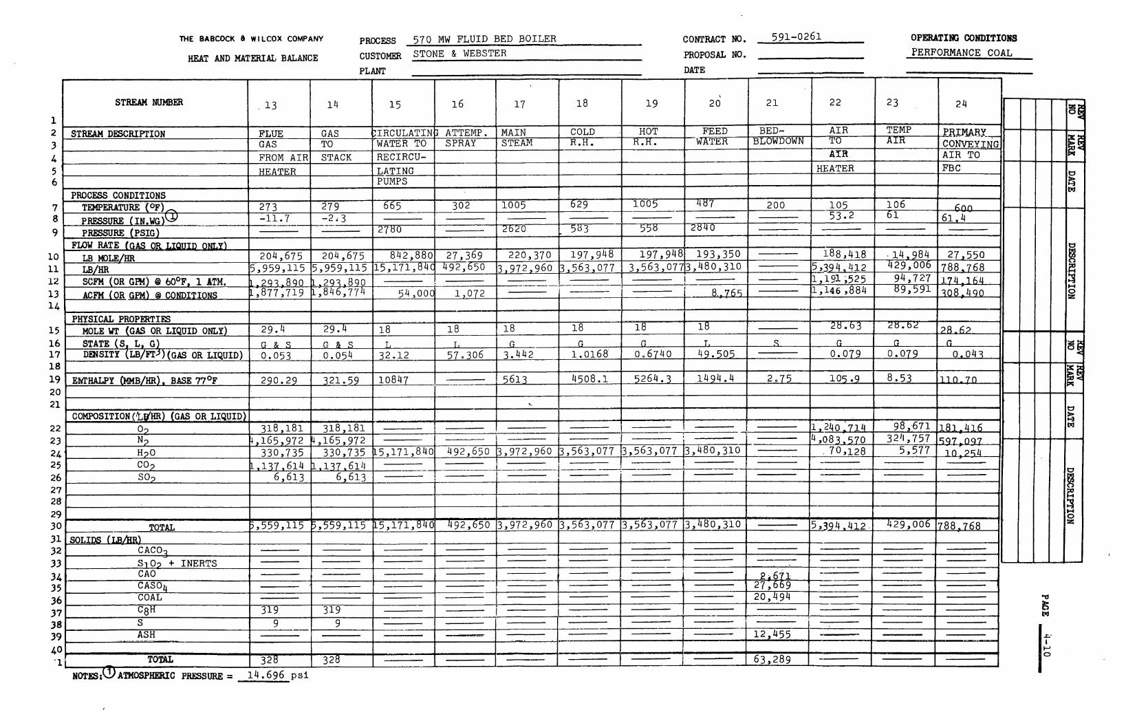
THE BABCOCK 8 WILCOX COMPANY PROCESS 570 MW FLUID BED BOILER CONTRACT NO. 591-0261 OPERATING CONDITIONS
HEAT AND MATEXI& BALANCE CUSTOMER STONE & WEBSTER PROPOSAL NO. PERFORMANCE COAL
PLANT DATE
STREAM NUMBER

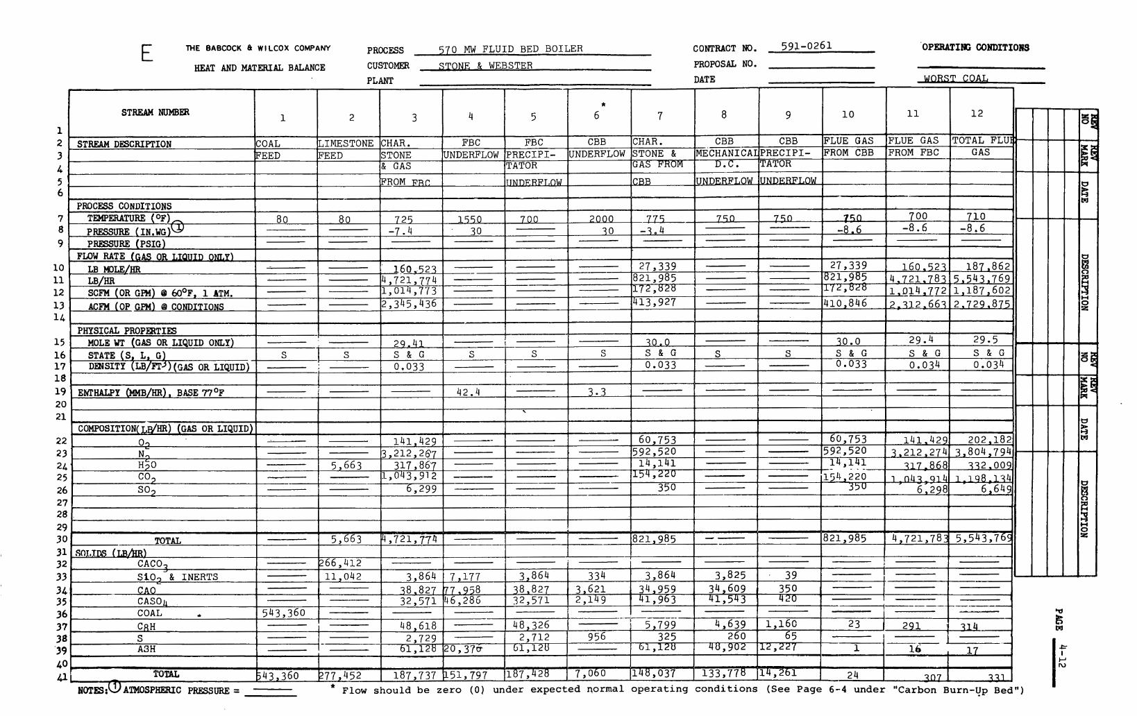
E THE BABCOCK d WlLCOX COMPANY PROCESS 570 MW FLUID BED BOILER CONTRACT NO. 59b-0261 OPEhUIlU3 CONDITIORS
HEAT AND MATERIAL BALANCE CUSTOMER STONE & WEBSTER PROPOSAL NO.
PLANT DATE
STREAM NUMBER
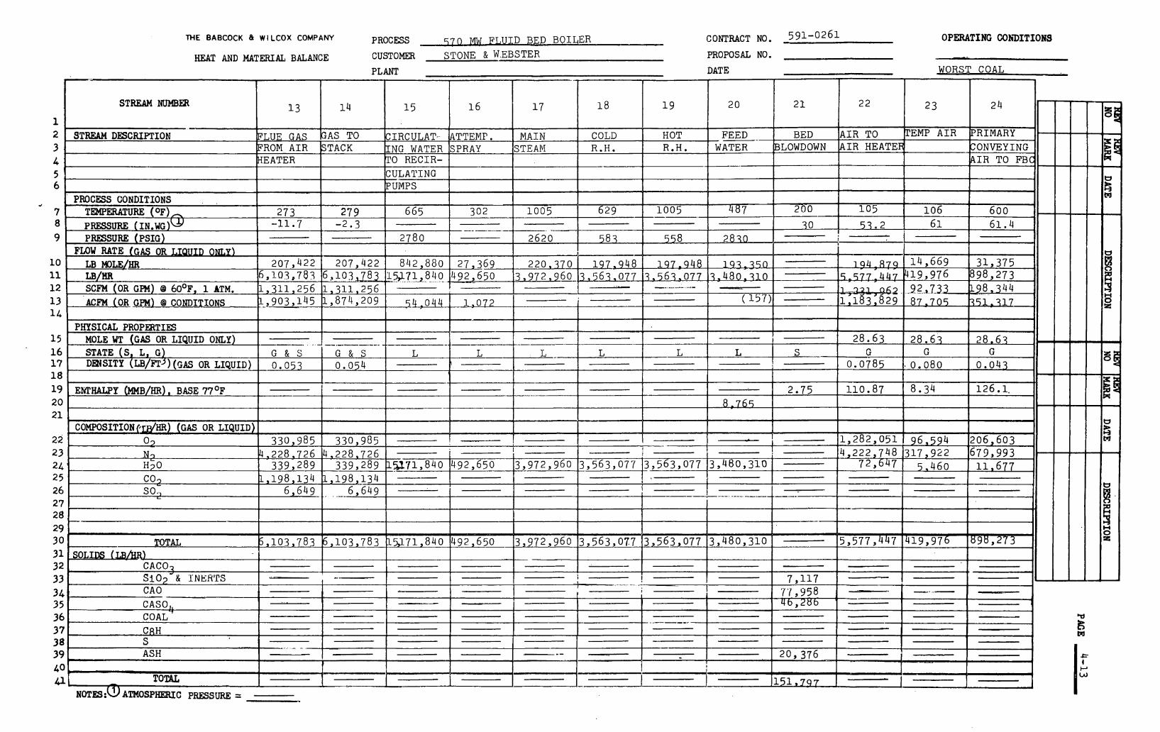
THE BABcOCK e WILCOX COMPANY PROCESS 5 7 0 MW FJ,UID BED BOILER CONTRACT NO. 591-0261 OPERATING COhDITIONS
HEAT AND MATERIAL BALANCE CUSTOMER STONE & W.EBSTER PROPOSAL NO.
PLANT DATE WORST COAL
STREAM MTMBEXt
.,
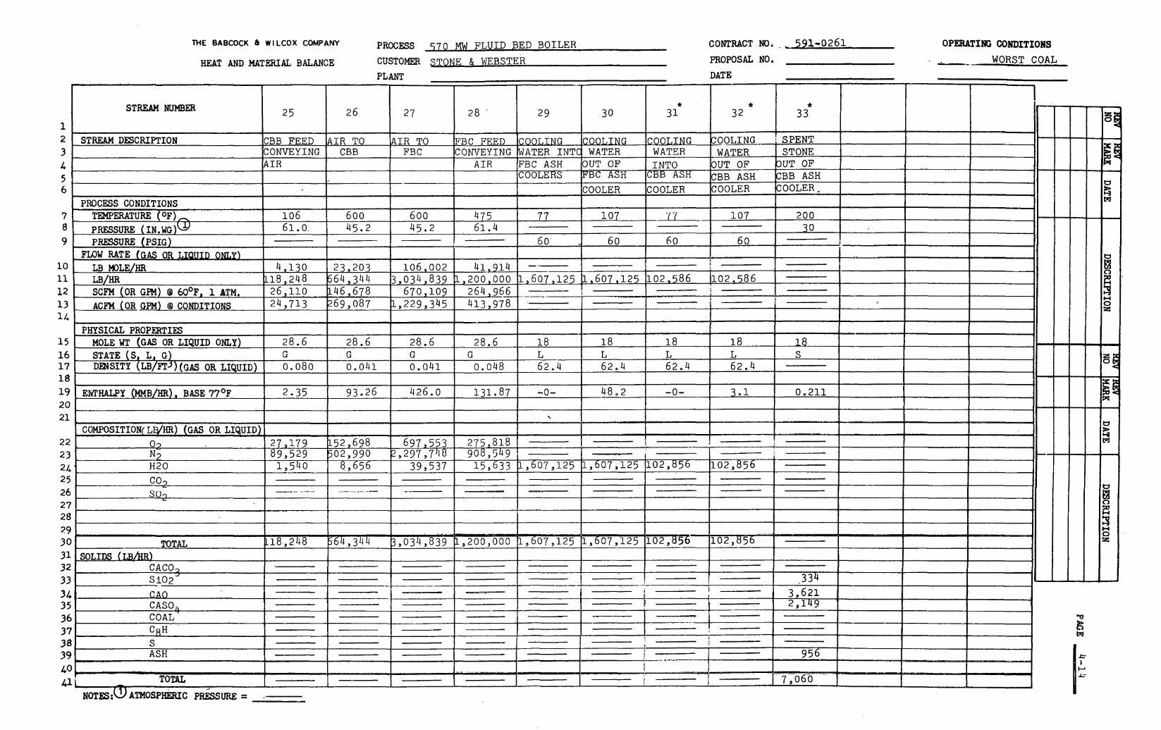
THE BABCOCK 8 WlLCOX COMPANY
HEAT AND MATERIAL BALANCE
PROCESS 570 MW FLUID B E D B O I L E R
CUSTOMER S T O N E & WEBSTER
COWTRACT NO. - , 591-0261 PROPOSAL NO.
OPERBTING CONDITIONS
-- WORST COAL
PLANT DATE
2
3 4 5 6
7 8 9
l o 11 12 13 . .
I COMPOSITION( LWHR) (GAS OR LIQUID) I I I I I I I I II I I I I Z I
* 33
14
15
1 6 , 17 18
* 32
1 , STREAM DESCRIPTION
PROCESS CONDITIONS TEMPERATURE (OF), P R E S S U R E ( I N . W G ) ~ PRESSURE (PSIG)
FLoW RATE (GAS OR -1 , LB MOLE/HR
LB/HR SCFM (OR GPM) @ 60°~, 1 ATM. ACFM (OR GPM) GI CONDITIONS
19 - EhTHALPY (MMB/HR). BASE 7 7 O ~ 2 .35 93.26 426.0 131.87 -0- 48 .2 0.2111 20 2 1 ..
_PHYSICAL P R O P W T I E S MOLE WT (GAS OR LIQUID ONLY) STATE (S, L, G ) D E ~ S I T Y (LB/FT' ) (GAS OR LIQUID)
CBB F E E D CONVEYING A I R
106 61.0.
4 ,130 118 ,248
STREAM NUMB=
28.6 G 0 .0 8 0
26 25
A I R T O CBB
600
28.6 G 0 .041
AIR TO FBC
600
26,110 b46 ,678 24 ,713 k69,087
I
2 7
28.6 G 0 .041
29 28
FBC FEED CONVEYING
A I R
475
I I I
4.5 . 2 45.2 61.4
' 670, 109 1 ,229 ,345
1
- 1
23 ,203 664,344
2 @ a 6 6 413,978
28.6 G
0.048 ------
30
1 I I I
1 I
B n o 2
60
-------
* 3 1
1 , 6 0 7 , 1 2 5 b , 6 0 7 , 1 2 5 1102.586 1102,586
60 60
COOLING I C ~ ~ L I N G WATER I N T ~ WATER F B C A S H IOUT O F
1
1 8 L 62.4
.COOI,ING WATER I N T O
C B B A S H
COOLER
COOLEHS
77
1 0 6 , 0 0 2 3 ,034,839
60
k l B C A S H
COOLER
107
41,914 1 ,200 ,000
i
30 1
I
Ei
2 0 , O L I N G S P E N T
1 8 L 62.4
WATER OUT S F CBB ASH C O O L E R
1 0 7
E
1 8 L 62.4
I
STONE 3 U T O F 'JBB ASH C O O L E R ,
200 -
1 8 L 62 .4
I 1
1 8 S
-
-----
1
p-,
B M
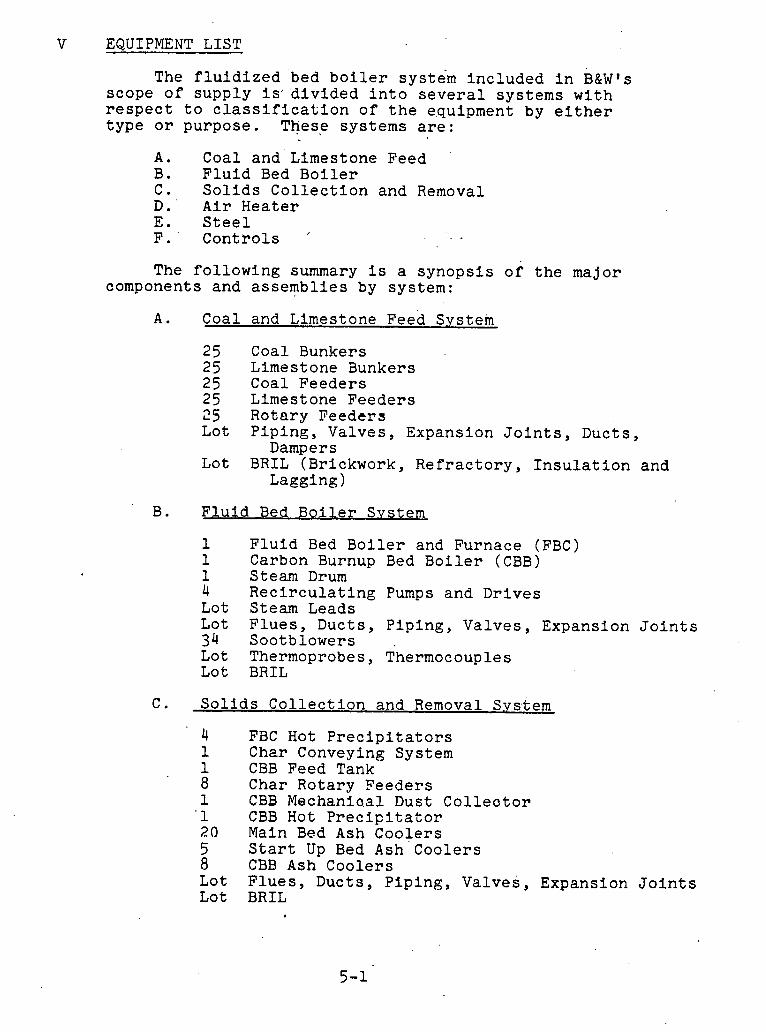
V EQUIPMENT LIST
The fluidized bed boiler system included in B&W1s scope of supply is"divided into several systems with respect to classification of the e.quipment by either type or purpose. These systems are: . .
A. Coal and Limestone Feed B. Fluid Bed Boiler C. Solids Collection and Removal D. Air Heater E. Steel F. Controls '
The following summary is a synopsis of the major components and assemblies by system:
A. Coal and Limestone ~ e e d System
25 Coal Bunkers 25 Limest one Bunkers 25 Coal Feeders 25 Limestone Feeders 25 Rotary Feeders Lot Piping, Valves, Expansion Joints, Ducts,
Dampers Lot BRIL (Brickwork, Refractory, Insulation and
Lagging)
B. Fluid Bed Boiler Svstem
1 1 1 4 Lot Lot 34 Lot Lot
Fluid Bed Boiler and Furnace (FBC) Carbon Burnup Bed Boiler (CBB) Steam Drum Recirculating Pumps and Drives Steam Leads Flues, Ducts, Piping, Valves, Expansion Joints Sootblowers Thermoprobes, Thermocouples BRIL
C. Solids Collection and Removal System
- 4 1 1 8 1
' 1 20 5 8 Lot Lot
FBC Hot Precipitators Char Conveying System CBB Feed Tank Char Rotary Seeders CBB Mechanioal Dust Colleotor CBB Hot Precipitator Main Bed Ash Coolers Start Up Bed Ash Coolers CBB Ash Coolers Flues, Ducts, Piping, Valves, Expansion Joints BRIL
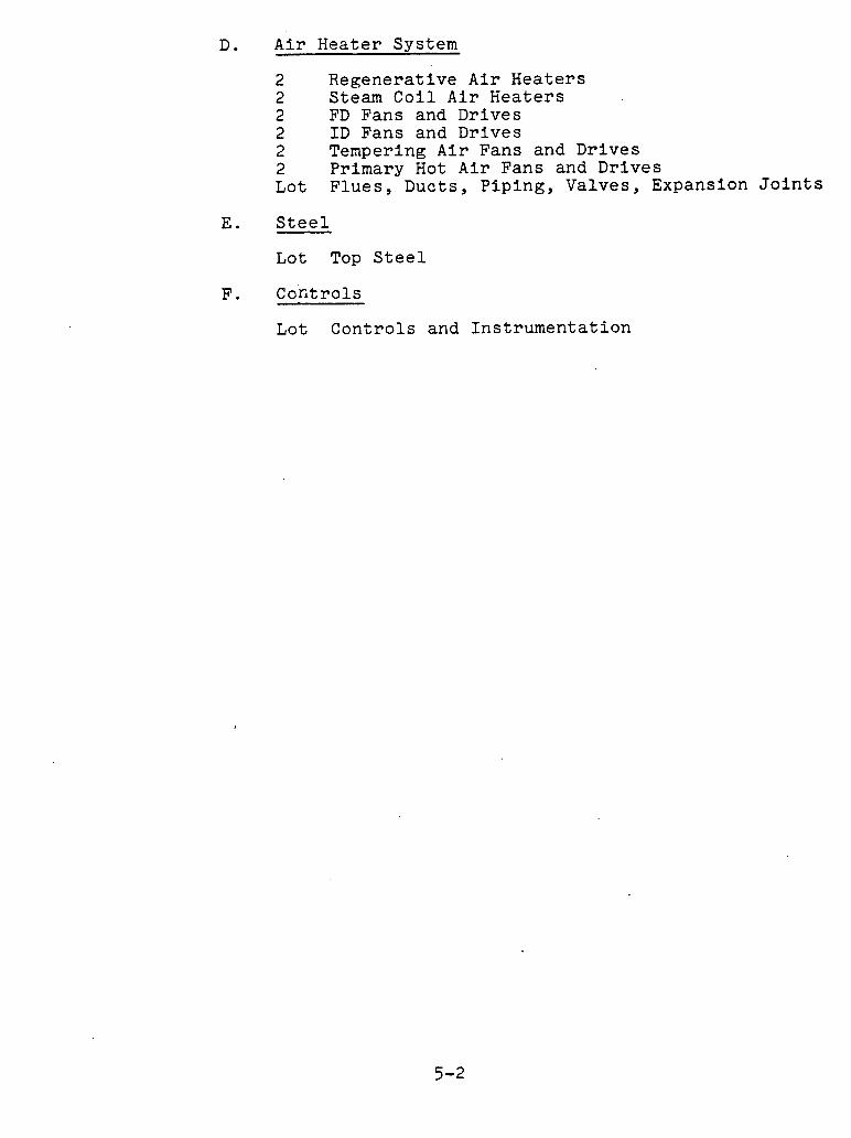
D. Air Heater System
2 Regenerative Air Heaters 2 Steam Coil Air Heaters 2 FD Fans and Drives 2 ID Fans and Drives 2 Tempering Air Fans and Drives 2 Primary Hot Air Fans and Drives Lot Flues, Ducts, Piping, Valves, ~xpansion'Joints
E. Steel
Lot Top Steel
F. Controls
Lot Controls and Instrumentation
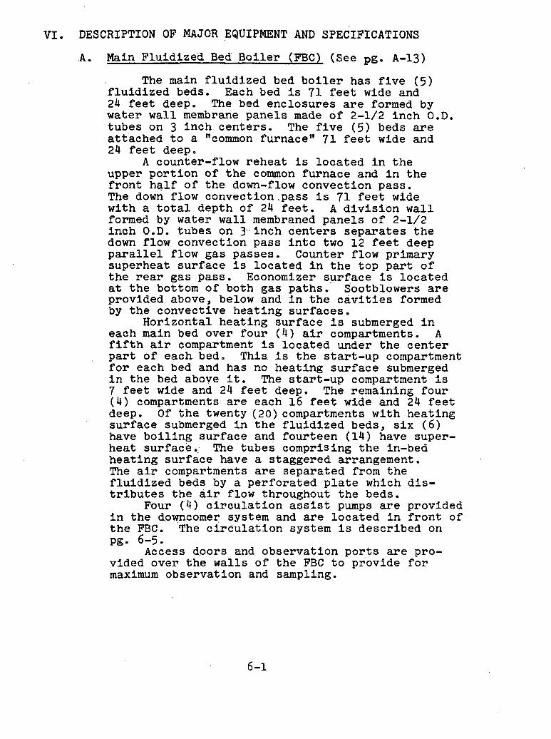
VI. DESCRIPTION OF MAJOR EQUIPMENT AND SPECIFICATIONS
.A. 'Main F lu id ized Bed B o i l e r (FBC) (See pg. A-13)
The main f l u i d i z e d bed b o i l e r has f i v e ( 5 ) f l u i d i z e d beds, Each bed i s 71 f e e t wide and 24 f e e t deep. The bed enclosures a r e formed by water w a l l membrane pane l s made of 2-1/2 i n c h O.D. t ubes on 3 , i n c h cen te r s . The f i v e ( 5 ) beds a r e a t t ached t o a "common furnacew 7 1 f e e t wide and 24 f e e t deep.
A counter-flow r e h e a t i s l o c a t e d i n t h e upper p o r t i o n of t h e common furnace and i n t h e f r o n t h a l f of t h e down-flow convect ion pass . The down flow convect ion.pass i s 71 f e e t wide with a t o t a l depth of 24 f e e t . A d i v i s i o n w a l l formed by water w a l l membraned pane l s of 2-1/2 inch O.D. tubes on 3 . , inch c e n t e r s s e p a r a t e s t h e down flow convection pass i n t o two 12 f e e t deep p a r a l l e l flow gas passes . Counter flow primary superheat su r face i s loca ted i n t h e t o p p a r t of t h e r e a r gas pass . Economizer s u r f a c e i s l o c a t e d a t t h e bottom of both gas paths. Sootblowers a r e provided above, below and i n t h e c a v i t i e s formed by t h e convect ive hea t ing su r faces .
Hor izonta l hea t ing su r face i s submerged i n each main bed over f o u r ( 4 ) a i r compartments. A f i f t h a i r compartment i s loca ted under the , c e n t e r p a r t of each.bed. This. i s t h e s t a r t - u p compartment f o r each bed and has no hea t ing s u r f a c e submerged i n t h e bed above i t . The s t a r t -up compartment i s 7 f e e t wide and 24 f e e t deep. The remaining f o u r ( 4 ) compartments a r e each 16 f e e t wide and 24 f e e t deep. O f t h e twenty (20)compartments w i t h hea t ing s u r f a c e submerged i n t h e f l u i d i z e d beds, s i x ( 6 ) have b o i l i n g .surface and f o u r t e e n (14) have super- hea t surface, . The tubes comprising t h e in-bed h e a t i n g su r face have a s taggered arrangement. The a i r compartments are separa ted from t h e f l u i d i z e d beds by a p e r f o r a t e d p l a t e which d i s - t r i b u t e s t h e a i r flow throughout t h e beds.
Four ( '4 ) a i r o u l a t i o n a e s i s t pumps a r e provided i n t h e downcomer system and a r e l o c a t e d i n f r o n t of t h e FBC. The c i r c u l a t i o n system i s descr ibed on pg. 6-5.
Access doors and observat ion p o r t s a r e pro- vided over t h e walls of t h e FBC t o provide f o r maximum observat ion and sampling.
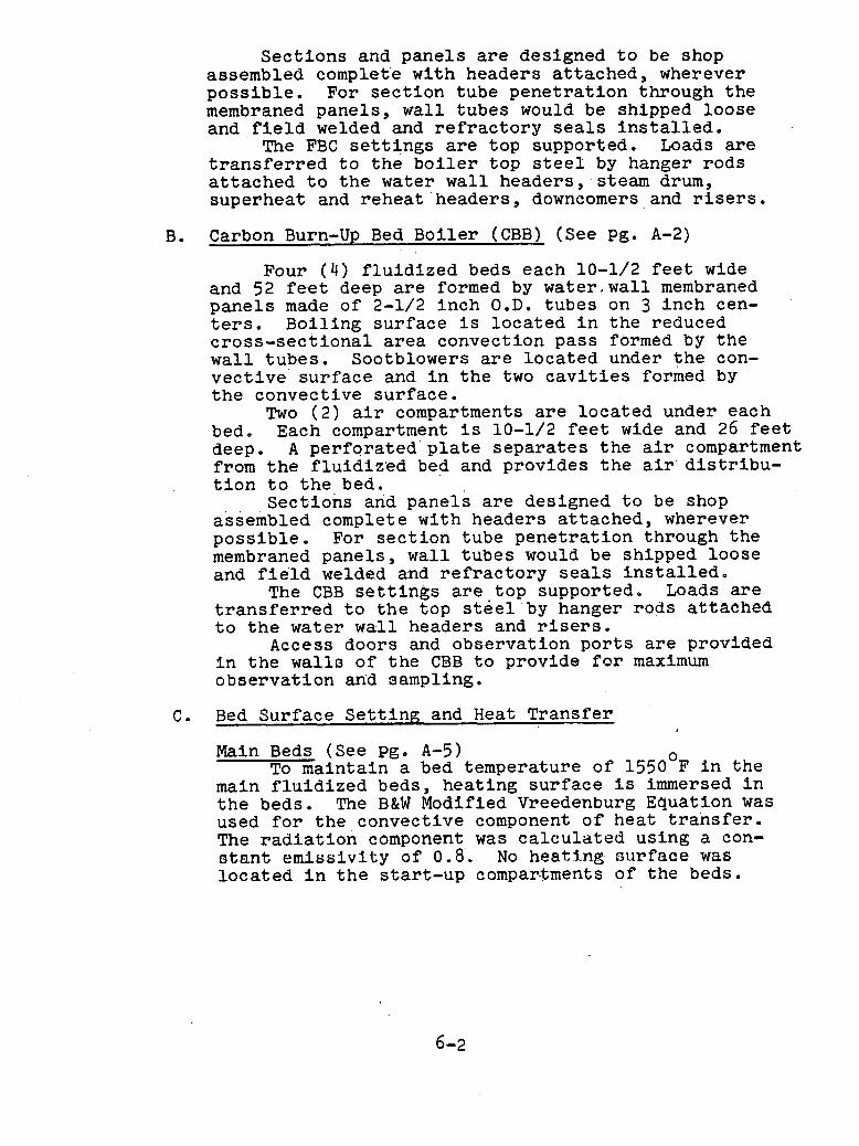
S e c t i o n s and panels a r e designed t o be shop assembled complete wi th headers a t t ached , wherever p o s s i b l e . For s e c t i o n tube p e n e t r a t i o n through t h e membraned panels , w a l l tubes would be shipped loose and f i e l d welded and r e f r a c t o r y s e a l s i n s t a l l e d .
The FBC s e t t i n g s a r e top supported. Loads are t r a n s f e r r e d t o t h e b o i l e r t o p s t e e l by hanger rods a t t a c h e d t o t h e water w a l l headers , steam drum, superheat and r e h e a t ' h e a d e r s , downcomers and r i s e r s .
Carbon Burn-Up Bed Boi l e r (CBB) (See pg.
Four ( 4 ) f l u i d i z e d beds each 10-1/2 f e e t wide and 52 f e e t deep a r e formed by wa te r ,wa l l membraned pane l s made of 2-1/2 inch O.D. tubes on 3 i n c h ten- t e r s . Bo i l ing su r face i s loca ted i n t h e reduced c r o s s - s e c t i o n a l a r e a convection pass formed by t h e w a l l t ubes . Sootblowers a r e loca ted under t h e con- v e c t i v e s u r f a c e and i n t h e two c a v i t i e s formed by t h e convect ive su r face .
Two ( 2 ) a i r compartments a r e loca ted under each bed, Each compartment i s 10-1/2 f e e t wide and 26 f e e t deep. A pe r fo ra ted p l a t e s e p a r a t e s t h e a i r compartment from t h e f l u i d i z e d bed and provides t h e a i r d i s t r i b u - t i o n t o t h e bed.
Sec t ions and panels a r e designed t o be shop assembled complete with headers a t t ached , wherever p o s s i b l e . For s e c t i o n tube p e n e t r a t i o n through t h e membraned panels , wal l tubes would be shipped loose and f i e l d welded and r e f r a c t o r y s e a l s i n s t a l l e d .
The CBB s e t t i n g s a r e t o p supported, Loads a r e t r a n s f e r r e d t o t h e top s t e e l by hanger rods a t t ached t o t h e water w a l l headers and r i s e r s .
Access doors and observat ion p o r t s a r e provided i n t h e w a l l o of t h e CBB t o provide for maximum obse rva t ion and sampling,
C. Bed Surface S e t t i n g and Heat Transfer
Main Beds (See pg, A-5) To maintain a bed temperature of 1550°F i n t h e
main f l u i d i z e d beds, hea t ing s u r f a c e i s immersed i n t h e beds. The B&W Modified Vreedenburg Equation was used f o r t h e , c o n v e c t i v e component o f hea t t r a n s f e r . The r a d i a t i o n conlponent was c a l c u l a t e d us ing a con- r ~ t a n t emiss iv i ty of 8.8 , No heatj..ng s i ~ s f a c e was loca ted i n t h e s t a r t - u p compar-tments of t h e beds.

The hea t ing su r face requ i red t o maintain bed temperatures .of 1550°F i s as follows':
A l l b o i l e r bed = 12,940 Sq. F t .
S p l i t bed Boi l e r su r face = 6,470 Sq. F t . Superheat su r face = 6,470 Sq. F t .
1st f u l l superheater bed I n bed su r face = 13,640 Sq. F t .
2nd f u l l superheater bed I n bed su r face = 7,230 Sq. F t . - l e f t h a l f -
1.75tt OD tubes 8,260 Sq. F t . - r ight h a l f -
2.0t1 OD t u b e s 15,490 Sq. F t .
F i n a l superheat bed I n bed su r face = 8,360 Sq. F t . - r ight h a l f -
1.75tt OD tubes 9,550 sb, Ft ,-left half -
2.0tt OD t u b e s 17,910 Sq. F t .
The i n l e t and o u t l e t s i d e s of t h e las t two a l l superheat beds r e q u i r e d i f f e r e n t amounts of hea t ing surface!. I n t h e pressure-enthalpy range t h a t t h e las t two superheat beds opera te , t h e temperature of t h e steam i s inc reas ing more r a p i d l y than i n t h e s p l i t bed o r t h e f i r s t a l l superheat bed. A s t h e tempera- t u r e of t h e steam inc reases , t h e o v e r a l l heat t r a n s f e r r a t e decreases f o r a given bed temperature ( 1 5 5 0 ~ ~ ) . This r e s u l t s from t h e lower temperature d i f f e r e n t i a l between t h e steam and t h e f l u i d i z e d bed. The s u r f a c e change i s accomplished by changing from 1.75 inch O.D. tubes i n t h e i n l e t h a l f t o 2.0 i n c h O.D. tubes i n t h e o u t l e t h a l f .
The tube metals were s e l e c t e d by applying upse t absorpt ion r a t e s t o account f o r bed temperature v a r i - a t i o n s and v a r i a t i o n s i n t h e hea t t r a n s f e r c o e f f i c i e n t ; and accounting f o r reduct ion of steam flow through t h e tubes due t o poss ib le tube t o tube flow unbalances.
The m a t e r i a l s s e l e c t e d f o r t h e tubes submerged i n t h e f l u i d i z e d beds a r e i d e n t i c a l t o m a t e r i a l s used i n convent ional c o a l f i r e d b o i l e r s . The s e l e c t i o n was based on p ressu re - s t r e s s c a l c u l a t i o n s per t h e A.S.M.E. Code and t h e ox ida t ion l i m i t s of t h e mater- ials. No allowance was made t o account f o r t h e p o s s i b l e co r ros ive e f f e c t s t h a t could occur i n t h e beds.
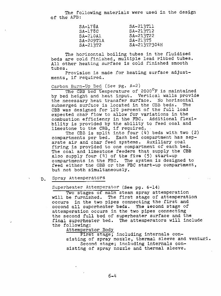
The foilowing materiais were usea in the design of the AFB:
The h ~ ~ l z o n ~ a i boiling tubes in the fluidized beds are cold finished, multiple lead ribbed tubes. All other heatPng s~rface is cold finished smooth tubes.
Provis.ion 2s made for heating surface adjust- ments, if required.
Carbon Bu~n-Up Bed (See pg. A-2) The CBB bed temperature of 2 0 0 0 ~ ~ is maintained
by bed height and he&% input. Verticai walls provide the necessary heat transfer surface. No horizontal submerged surf~ce is located in the CBB beds. The CBB was designed for 1 2 0 percent of the fuil load expected char flow to allow for variations in the combustion efficiency in the FBC. Additional flexi- bility is provided by the ability to feed coal and limestone to the CBB, if required.
The CBB is split. into four ( 4 ) beds with two ( 2 ) compartments per bed. Each bed compartment has sep- arate air and char feed systems. Auxiliary coal firing is provided to one compartment of each bed. ,The coal and limestone feeders that supply the CBB alao aupply four (4) of the fLve (5) start-up compartments in the FBC. The system is designed to feed either the CBB or the FBC start-up compartment, but not both simultaneously.
D. Spray Attemperators
Superheater Attemperator (See pg. 6-14) Two stages of main steam spray attemperation
will be furnished. The first stage of attemperation occurs in the two pipes connecting the-first and occond all ~uperheater beds. The second stage of attemperation occurs in the two pipes connecting .
the second full bed of superheater surface and the final superheater bed. The attemperators will include the following:
At'te'mp'e'ra'tor Body First stage; including internals con-
sisting of spray noz'zle, thermal sleeve and ventur,i, Secon,d stage; including internals con-
sisting of spray nozzle and thermal sleeve.

Va1ve.s The' 'fol'lowing valves" .are included wi th t h e
a t tempera tors ;.
Spray Water' Control Valves Block Valves
Reheat er: .At:t'emp'e.rat'or ( see . pg . 6 - 1 3 ) One set.. of spray a t tempera tor i n t e r n a l s comprising
a thermal s l eeve p lus spray water connection and nozzle i s furn ished t o be i n s t a l l e d i n t h e 'steam p ip ing a t t h e i n l e t t o t h e r e h e a t e r .
E. Reheater (.See pg. .6-4).
The e n t i r e r e h e a t e r i s loca ted i n t h e common furnace enclosure above t h e f l u i d i z e d beds and t h e f r o n t h a l f of t h e p a r a l l e l down-flow convection pass . This des ign philosophy avoided p l a c i n g r e h e a t s u r f a c e i n t h e beds and e l imina tes t h e need f o r a p r o t e c t i o n system f o r s t a r t -ups , shutdowns and u n i t t r i p s ; and a l s o f a c i l i t a t e s matching of main and r e h e a t steam temperatures t o t h e t u r b i n e over t h e load range.
Reheat steam temperature c o n t r o l i s obta ined by b i a s i n g t h e gas flow over t h e r e h e a t e r s u r f a c e loca ted i n t h e down-flow sec t ion . The s u r f a c e was designed t o o b t a i n a r e h e a t steam temperature of 10050F, with no gas b ias ing , a t t h e b o i l e r ' s maximum continuous r a t i n g . The d r a f t l o s s i n d i c a t e d on t h e performance summary shee t was, however, c a l c u l a t e d by b i a s i n g gas over t h e r e h e a t e r t o account f o r p o s s i b l e gas temperature f l u c t u a t i o n s e n t e r i n g t h e r ehea t e r .
The only lower load t h a t time permit ted checking w a s seventy-f ive percent load. Reheat steam tempera- t u r e w a s e a s i l y a t t a i n e d wi th a minimum of gas b ias ing . Based on t h e s e ' r e s u l t s , we would a n t i c i p a t e t h a t f u l l r ehea t steam temperature can be maintained a t loads considerably below seventy-f ive percent , poss ib ly as low as s i x t y percent .
F. C i r c u l a t i o n Pumps
This u n i t employs f o u r ( 4 ) wet motor pumps t o assist i n maintaining t h e d e s i r e d r a t e of c i r c u l a t i o n f o r p r o t e c t i o n of t h e enclosure and b.ed c i r c u i t s . This des ign concept, wi th t h e pumps i n s t a l l e d i n t h e drum downcomer system, i s similar t o t h e one used on s e v e r a l l i g n i t e fue led cyclone r a d i a n t b o i l e r s re - c e n t l y b u i l t by the' Babcock' & Wilcox Company. It i s necessary t o assist t h e c i r c u l a t i o n of both t h e FBC and the' CBB because t h e phys ica l c h a r a c t e r i s t i c s of

some of t.he. enclosure circuits are such that natural. 'circulation' impart.ed by heat .absorption is not' adequate.. The absorption' rates to the' 'enclosure walls are 'greatly reduced from' the rates in conven- tional coa'l fired units utilizing natural circulatior and'to obtain the' desired velocities' in the tubes requires additional available pressure differential tha'n is. provided by the heat absorbed. The motors of these pumps are immersed in boiler water and subject to. full boiler ppessure. Each pump is cap- able of handling one-third of the flow required at maximum continuous load, thereby permitting one pump to be removed from service for maintenance. Each pump will be valved with one motor operated inlet gate valve and two non-return stop-check out- let valves, permitting the valves to be left open when the pump motor is out of service, and providing means of positive 'isolation when required.
Wate~ flows from the drum by means of the di3- charge downcomers'which feed the circulating water to a suction manifold. The four (4) pumps are mounted between this suction manifold and a discharge manifold. The flow is then through two secondary downcomers and a branch downcomer to bottles from which FBC and CBB circuits are supplied. Each of the three (3) bottles are fitted'with a manhole access to allow adjustment in the orifices determining the flow rate to the various heat. absorbing water cooler circuits, if required.
G , Sootblowing System
A complete automatic sequential air blowing electrically driven and operated sootblowing system for cleaning the primary superheater, reheater ,- air heater, economizer, and horizontal convective boiler surface is included. The sootblowing sys kern consists of the following:
Convective Surfaces IK sootblower including wall boxes and drives.
Air Heaters Cl e a n i ng d e v i nes I nnl i i d i n g d r i yes.
Accessory Equipment One graphic insert type, selectronic automatic
sequential panel with unit and group variable control. Piping, valves, and flttings Safeguards and interlocks :Fwshbwk.eon stat b:o.ns ,at. ea.ch ..blower Blower mounted starters

H. Precipitators (See Pgs. 6-15 and 6-16) A n important area in the design of fluidized
bed combustion systems is the control of particulate emissions. The fluidized bed is specially designed to control SO2 emission. The NOx emissions are expected to be acceptable due to the low combustion temperatures. The question that arises, will the particulate emission suffer while the SO2 and NOx are being reduced? The question is especially critical since a great deal of extra noncombustible material (in this case limestone) is being added to the combustor for sulfur dioxide reduction.
Hot Rothemuhle eleetrostatlc precipitators have been designed and sized to meet the particulate re- quirements of 0.06 Lbo per 106 Btu. The Rothemuhle precipitator is conservatively designed based on extensive knowledge and many years of experience and evaluation of test results.
Rothemuhle precipitators are arranged to pass flue gases horizontally through a series of fields containing alternating parallel lanes of discharge frames and collecting plates. An electrical field develops between the negative discharge frames and the grauunded ~Ollecting plates. A portion of the flue gas is ionized and the ions adhere to the dust particles carried by the gases. The dust particles, Bus,charged are attracted'to the positive collecting surfaces. Rapping devzces periodically strike the base of each collecting plate-curtain and dislodge the dust particles which are then collected in hoppers.
Each Rothemuhle precipitator consists of a shell casing reinforced to withstand positive and negative gas pressures and maintain a gas tight enclosure. Inlet and outlet flanges are provided for attachment of dampers or flue transition sections. Proper gas distribution is accomplished by means of a model test which establishes the number of perforated plates to be placed in series at the inlet.
The self-supporting shell casing, consists of plates reinfarced by stiffenezes-of standard.ro-l.led- sections welded together. Roof support beams are designed as hollow box girders and carry the loads of all internal equipment as well as house the high voltage insulators. The precipitator structure rests on special sliding bearings which allow movement due to thermal expanslon. Sufficient number of access doors are provided for maintenance and inspection purposes. Hoppers are provided under the precipitators for collection and disposal of entrapped dust.

Collecting plates are roll formed from cold rolled strip incorporating a number of parallel grooves and recesses. These recesses are designed to form flow shadows which enhance collecting properties and minimize dust reentrainment. The plates feature high frequency vibration character- istics which aid in adequate cleaning performance. Each plate is rigidly connected at top and bottom to assure maximum transmission of rapping forces.
Rapping devices are of the hammer and anvil type. Rappers are mounted on slowly rotating shafts across the width of' the unit, and staggered so that each surface row is rapped independently.
Each precipitator field is equipped with its own high voltage transformer and silicon rectifier set which steps line voltage up to 60 KV and provides pulsating direct current to the electrodes.
Tie control system components are housed in a sepalgate r=crntrol cabinct. The s y o t e n s e e k 2 t n mxin- tain optimum voltage under varying load and operating conditions. The voltage and current fluctuations at a flash-over are instantly monitored and adjustments made to the operating voltage to automatically extinguish possible arcs.
1. Mechanical Dust Collector
A mechanical .dust collector is included for particulate removal prior to the hot precipitator for the CBB. The dust collector wlll be a U.O.P. 105AWHT $15-360. Refer to page 6-zx
J. FBC Preciwitator Removal System (see Pg. 6-28)
Four precipitators are used to remove the parti- culate matter from the flue gas Peavl r ig the FDC. Each precipitator I s t'ittttci w i t 1 1 s ix teer i (16,) lloppe~s for ash storage. Periodically, the accumulated ash is removed from the hoppers and transported to the CBB feed tank by the FBC precipitator ash removal system.
'The FBC precipitator ash removal system is made up of fnilr ( 4 ) ~ndependen t vacuum transport systems with one system servicing each of the four ( 4 ) precipitators. Further, the main transport line of each system is split into four branch lines'with each branch line serving Pour ( 4 ) precipitator hoppers. Thus , t e four branch lines per system serve all sixty-four (dl) hoppers.
During opera t ion only four ( 4 ) o f t h e s i x t e e n (16) hoppers p e r p r e c i p i t a t o r a r e emptied a t one time. These hoppers d ischarge i n t o a s i n g l e branch l i n e which i n t u r n d ischarges t o t h e main t r a n s p o r t l i n e . The remainink twelve (12) hoppers a r e i s o l a t e d from t h e i r r e s p e c t i v e branch l i n e s by a i r opera ted valves. I n a d d i t i o n , t h e t h r e e i n a c t i v e branch l i n e s a r e i s o l a t e d from t h e main t r a n s p o r t l i n e t o minimize vacuum requirements.
Each of t h e main t r a n s p o r t l i n e s feeds an a i r - s o l i d s s e p a r a t i o n system loca ted on t o p of t h e CBB feed tank.
Each separa t ion system c o n s i s t s o f a primary cyclone, a secondary cyclone and a t e r t i a r y bag f i l t e r . I n t h i s system t h e cleaned t r a n s p o r t a i r i s discharged t o t h e atmosphere and t h e separa ted s o l i d s flow i n t o t h e CBB feed tank.
Four ( 4 ) blowers a r e ' p r o v i d e d ( ~ n e f o r each system) t o induce t h e r equ i red t r a n s p o r t a i r flow and c r e a t e t h e des i red vacuwn. Each blower i s r a t e d a t 1300 CFM a t 18 inches of mercury and i s d r i v e n by a 1 0 0 HP motor. A l l conveying l i n e s a r e f a b r i c a t e d from 8 inch Ashcol i te wear r e s i s t a n t pipe. Fur the r , t h e primary cyclone c o l l e c t o r s a r e f i t t e d wi th wear l i n e r s .
Bed So l ids .Removal.. System
Ash, unreacted s tone and s u l f u r compounds a r e drawn o f f from each of t h e twenty-five (25) compart- ments of t h e main bed (FBC) t o mainta in bed he igh t . These compounds l eave t h e FBC a t approximately 155O0F0 They a r e cooled t o 200°F i n twenty-five (25) water cooled screws and then s t o r e d i n t h e FBC s to rage tank.
S imi la r ly , t o maintain bed he ight i n t h e CBB, s o l i d s a r e removed a t approximately 2000°F, cooled t o 2000F a s they pass through e i g h t ( 8 ) water cooled screws, and then s t o r e d i n t h e CBB s t o r a g e tank .
From each of t h e s t o r a g e tanks t h e r e i s t h e op t ion of e i t h e r r e i n j e c t i n g t h e s o l i d s into the FBC and CBB o r conveying t h e s o l i d s t o a f a c i l i t y f o r d isgo sal . -
Piping from each of t h e beds up t o t h e a s h coo le r s i s Incol loy 800. For ash coo le r s p e c i f i c a t i o n s s e e pages 6-31, 6-32, and 6-33.
L. Rothemuhle Regenerative A i r Heaters
The Rothemuhle Regenerative A i r Heater i s of t h e r o t a r y regenera t ive type which employs s t a t i c hea t ing su r face contained wi th in a f i x e d housing ( s t a t o r ) . A l t e rna t ing gas and a i r flow i s obtained by t h e r o t a - t i o n o f a d i s t r i b u t i n g duct (hood) on each f a c e of t h e s t a t o r . Both hoods a r e keyed t o a common main s h a f t .

The hea t ing s u r f a c e elements a r e arranged i n t h e s t a t o r . Acce'ss door permi ts removal and maintenance .of e lements .
A geared e l e c t r i c d r i v e u n i t r o t a t e s t h e hoods. An a u x i l i a r y a i r motor d r i v e i s provided f o r emergency o p e r a t i o n should electr ic- 'power t o t h e main d r i v e be i n t e r r u p t e d .
The fol lowing i tems a r e included with t h e a i r h e a t e r assembly:
Driving mechanism inc lud ing speed reducer and motor. Auxi l ia ry a i r motor. d r i v e . Cold end l a y e r of hea t ing elements of co r ros ion
r e s i s t a n t low a l l o y s t e e l mounted i n baskets f o r removal. Hot end and in termedia te l a y e r s of baskets a r e of
m i l d .carbon s t e e l . Lubr ica t ing o i l sys tem ' inc lud ing p ip ing , va lves
and f i t t i . n .gs , Access doors as requi red f o r maintenance. Terminal frnme f langes integral t.0 t h e a . ~ hea.ter
assembly a t cold a i r i n l e t and spent gas o u t l e t .
Cleaning Devices The a i r h e a t e r s a r e equipped with sootblowing
dev ices a t t h e cold s i d e of t h e s t a t o r . The blowing dev ices a r e i n s t a l l e d a t t h e a i r hoods between t h e two wings and r o t a t e with t h e hoods. Permanent water washing nozzles a r e a l s o provided.
M. Steam Coil A i r Heaters
S t e m c o i l a i r hea t ing i s included t o preheat t h e combustion a i r f o r lower load a i r hea te r cold-end p r o t e c t i o n . The c o i l s w i l l be mounted i n t h e forced d r a f t a i r duct ing wi th provis ion f o r removal of c o i l s ,
N . Fans
Two ( 2 ) forced d r a f t , two ( 2 ) induced d r a f t , two ( 2 ) boos ter hot p r i m a r y a i r f ans , and two ( 2 ) boos te r tempering primary a i r f ans a r e included. Stone & Webster des ign c r i t e r i a were followed i n e s t a b l i s h i n g t h e f an requirements.
Forced Draft Fans The forced d r a f t f a n s a r e designed t o supply
a l l of t h e combustion a i r , ( i n a d d i t i o n t o t h e expected a i r h e a t e r leakage) r equ i red t o maintain the b o i l e p ' s maximum continuous r a t i n g .
The n e t and des'ign ( t e s t block) cond i t ions a r e 'as fol lows :.
Capacity/Fan (Expected = 2,713,110 Lb/Hr) Net = 2,925,735 l b / h r Design = 3,072,025 l b / h r
S t a t i c (Expected System Resis tance = 53.2 i n . H 2 0 ) Net = 55.6 i n . H 2 0 Design = 74.5 i n . H20 I n l e t Temperature Net = 8 0 O ~ Design = 1 0 5 ' ~
The s p e c i f i c a t i o n s f o r t h e f ans a r e on page 6-42.
Induced Draft Bzns The induced draft f ans a r e designed t o convey
t h e e n t i r e gaseous products of combustion, i n a d d i t i o n t o t h e expected a i r h e a t e r leakage, produced a t t h e b o i l e r ' s maximum continuous r a t i n g . The n e t and des ign ( t e s t block) condi t ions a r e as fol lows:
~ a p a c i t y / F a n ( ~ x p e c t e d = 2,988,760 Lb/Hr) Net = 3,313,440 l b / h r Design = 3,479,110 l b / h r
S t a t i c (Expected= 14.7 i n . H 2 0 ) N e t = 16.5 i n . H20 Design = 22.2 i n . H20 I n l e t Temperature . '
Net = 2 7 4 ' ~ Design = 2 9 9 ' ~
The s p e c i f i c a t i o n s f o r t h e f ans a r e on page 6-43.
Hot Primary A i r Fans The.hot primary a i r f a n s are designed t o convey
t h e e n t i r e a i r flow requ i red t o t r a n s p o r t and d r y . t h e c o a l and l imestone feed t o t h e beds. I n a d d i t i o n , t h e a i r q u a n t i t y r equ i red t o t r a n s p o r t t h e char feed t o t h e carbon burn-up beds can be suppl ied should d ry ing be L-eyufred. The n e t arid des ign ( t e s t block) cond i t ions a r e as fol lows:
Capacity/Fan (Expected = 492,340 Lb/Hr) Net = 542,800 l b / h r Design = 569,940 l b / h r
S t a t i c Rise (Expected = 16.2 i n . H90) L
N e t = 18.6 i n . H20 Design = 24.9 i n . H20
I n l e t Temperature Net = 6 0 0 ' ~ Design = 6 2 5 ' ~
The s p e c i f i c a t i o n s f o r t h e fans a r e on page 6-44.
6-11
Tempering Primary A i r Fans The t emper ing a i r f a n s a r e designed t o supply - - -
s u f f 2 c i e n t c o l d a i r t o t h e primary a i r system t o r educe t h e a i r t empera tu re e n t e r i n g t h e mix b u s t l e s t o 3 0 0 ' ~ a t t h e b o i l e r ' s maximum cont inuous r a t i n g . The n e t and d e s i g n ( t e s t b lock ) c o n d i t i o n s a r e as f o l l o w s :
Capacity/Fan (Expected = 360,250 Lb/Hr) Net = 397,200 l b / h r Design = 417,060 l b / h r
S t a t i c Rise (Expected = 1 2 . 1 i n . H20) Net = 14.5 i n . H 2 0 Design = 19.6 i n . H 2 0 I n l e t Temperature Net = 105OF Design = 1 3 0 ~ ~
Tlic s p e c i f i e a t i o n o f o r t h e f a n s a r e on page 6-45,
0. B o i l e r Top S t e e l
The b o i l e r t o p s t e e l i s des igned i n accordance w i t h t h e c u r r e n t A.I.S.C. standard^ and B&W s t a n d a r d s . The t o p s t e e l i s designed f o r suppor t o f B&W s u p p l i e d equipment on ly .
The t o t a l weight f o r t h e s t r u c t u r a l s t e e l f o r t h e FBC i s 720 KIPS and f o r t h e CBE i s 148 KIPS. The column l o a d i n g s a r e shown on Page 6-18.
S a f e t y Valves
P r e s s u r e - r e l i e v i n g va lves amst! Irlcluded t o s a t i s f y t h e requi rements of t h e c u r r e n t ASME Code.
S a f e t y v a l v e s a r e i nc luded f o r f u l l r e h e a t e r cteam f low i n accordance wi th the ASME Code.
The ~ a f e t y va.lves f o r the reheater a r e t n be mounted i n p i p i n g e x t e r n a l t o t h e B&W t e r m i n a l .
I n a d d i t i o n , an e l ec t ro rna t i c r e l i e f va lve i s inc luded a t t h e s u p e r h e a t e r o u t l e t ,
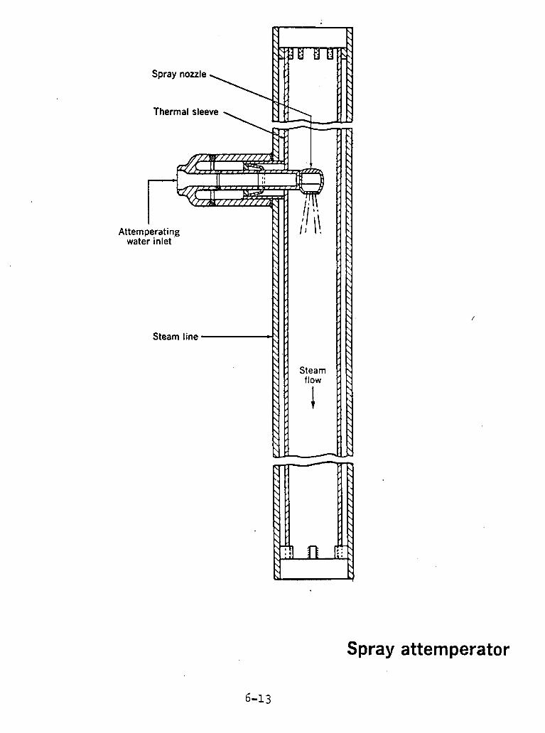
Thermal sleeve
Attemperating water inlet
Spray atternperator

water inlet
Superheater spray attemperator
6-14
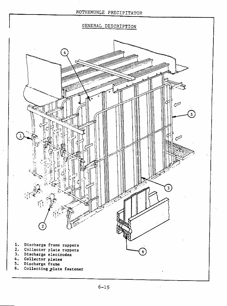
ROTHEMUHLE PRECIPITATOR
I I I GENERAL DESCRIPTION
Discharge Collector Discharge
frame rappers plate rappers electrodes
4 . ~ o l l e c t o t plates 5 . Discharge frame 6 . Collecting s l a t e fastener

GENERAL DSSCXIPTION
1. Collector p lates 7 . Discharge frame support bracket 2. Collector plate support beams 8. Discharge frame carrier 3. Collector plate rapper bars 9 . Discharge frame rapping device 4 . C o l l e c t o ~ plate rappixtg device 10. Discharge frame anvil 5 . Dust hopper 11. Support insulator 6. Discharge electrode frame assembly
GENERAL DESCRIPTION

Rothemuhle regenerative air heater
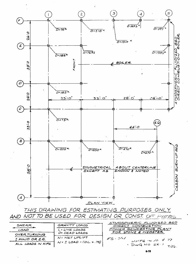
SHE4 R - - LOAD
ATMOSPHERIC FLU/eEED BED D/R.€CT C O M S U S 7 / 0 ~
POWER GEh/,CRAT/h/G PLAMT FL3R STONE d NESS7ER
GRAVITY LOADS
L = LIVE LOAOS 1 OVE R7URU/hlG
--- + W/rc/D OR E,Q, - ALL LOADS IN KIPS
D m DEAD LOADS
A/= f LOAD - (0.L. % .75)
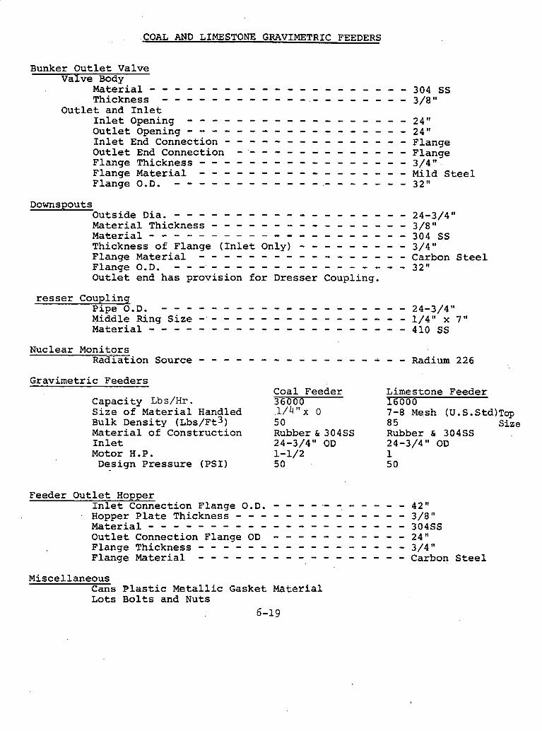
.COAL AND LIMESTONE GRAVIMETRIC FEEDERS
Bunker Outlet Valve Valve Body
M a t e r i a l - - - - - - - - - - - - - - - - - - - - - 304 SS Thickness - - - - - - - - - - - - . - - - - - - - - 3/8 "
Outlet and Inlet Inlet Opening - - - - - - - - - - - - - - - - - - 24" Outlet Opening - - - - - - - - - - - - - - - - - - 24" Inlet End Connection - - - - - - - - - - - - - - - Flange Outlet End Connection - '- - - - - - - - - - - - - Flange Flange Thickness - - - - - - - - - - - - - - - - - 3/4" Flange Material - - - - - - - - - - - - - - - - - Mild Steel Flange 0.D. - - - - - - - - - - - - . - - - - - - - 32"
Downspouts OutsideDia. - - - - - - - - - - - - - - - - - - - 24-3/4" Material Thickness - - - - - - - - - - - - - - - - 3/8" Material - - - - - - - - - - - - - - - - - - - - - 304 SS Thickness of Flange (Inlet Only) - - - - - - - - - 3/4" Flange Material - - - - - - - - - - - - - - - - - Carbon Steel Flange0.D. - - - - - - - - - - - - - - - - - - - 32" Outlet end has provision for Dresser Coupling.
resser Couplinq pipe0.D. - - - - - - - - - - - - - - - - - - - - 24-3/4" Middle Ring Size - - - - - - - - - - - - - - - - - 1/4" x 7" M a t e r i a l - - - - - - - - - - - - - - - - - - - - - 410 SS
Nuclear Monitors Radiation Source - - - - - - - - - - - - - - ; - - Radium 226
Gravimetric Feeders
Capacity Lb s/Hr . Size of Material Handled Bulk Density (~bs/Ft3) Material of Construction Inlet Motor H.P. Design Pressure (PSI)
Coal Feeder 36000 1 / 4 " ~ 0 50 Rubber& 304SS 24-3/4" OD 1-1/2 5 0
Limestone Feeder 16000 7-8 Mesh (U.S.Std)Tap 85 Size Rubber & 304SS 24-3/4" OD 1 5 0
Feeder Outlet Hopper Inlet Connection Flange O.D. - - - - .- =. - - - - - 42" Hopper Plate ~hickness - - - - - - - - - - - - - - 3/8" M a t e r i a l - - - - - - - - - - - - - - - - - - - - - 304SS Outlet Connection Flange OD - - - - - - - - - - - 24" Flange Thickness - - - - - - - - - - - - - - - - - 3/4" Flange Material - - - - - - - - - - - - - - - - - Carbon Steel
Miscellaneous Cans Plastic Metallic Gasket Material Lots Bolts and Nuts
6-19
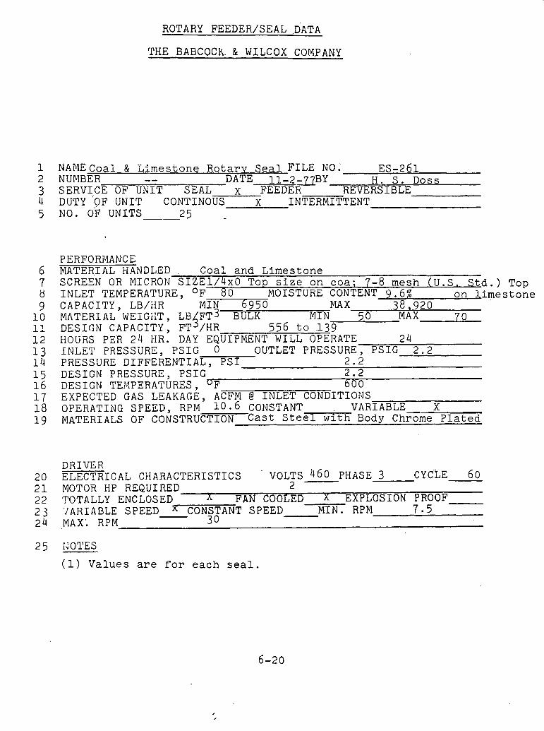
ROTARY FEED.ER/SEAL .DATA
THE BABCOCh. & WILCOX COM,PANY
NAME C o a l & E l m e s t o n e R o t a r v S e a l F I L E NO; ES-261 NUMBER -- DATE l l - 2 - 7 ' ~ B Y H . S . D o s s SERV1,CE OF UNIT SEAL x FEEDER REVERSIBLE DUTY 'OF UNIT C O N T I N O ~ S X INTERMITTENT NO. OF UNITS -.- 2 5
PERFORMANCE MATER.IA=NDLED . Coal a n d L i m e s t o n e SCREEN OR ClICRON S I Z E 1 / 4 x O T o p s i z e o n c o a ; 7-8 m e s h ( U . S . S t d . ) INLET TEMPERATURE, OF 8 0 MOISTURE CONTENT 9 . 6 % o n Lime CAPACITY, LB/XR ' M I N 6 9 5 0 MA X 3 8 , 9 2 0 MATERIAL WEIGiiT, LB F T ~ BULK 5 M I N 5 0 MAX 7 0 DESIGN CAPACITY, FT /HR 5 5 6 t o ,139 HOURS PER 24 MR. DAY EQUIPYENT WILL OPERATE 24 INLE'I' PRESSURE, PSIG 0 OUTLET PRESSURE, PSIG-2.2 PRESSURE DIFFERENTIA- - 2 . 2 DESIGN PRESSURE, PSIG 2 . 2 DESIGN TENPERATURES , 'F 6 0 0 EXPECTED GAS LEAKAGE, ACFM @ INLET CONDITIONS OPERATING SPEED, RPM 1 0 . 6 CONSTANT , VARIABLE X MATERIALS OF CONSTRUCTION C a s t S t e e l with Body Chrome T l a t e d
DRIVER 2 0 ELECTRICAL CHARACTERISTICS ' VOLTS - 4 6 0 PHASE 3 CYCLE 6 0 2 1 MOTOR HP REQUIRED 2 2 2 TOTALLY ENCLOSED n FAN COOLED X EXPLOSION PROOF 2 3 'JAHIABLE SPEED - CONSTANT SPEED M I N . RPM 7 5 2 4 MAX: RPM 3 0
TOP s t o n e
(1) V a l u e s are f o r e a c h s e a l .
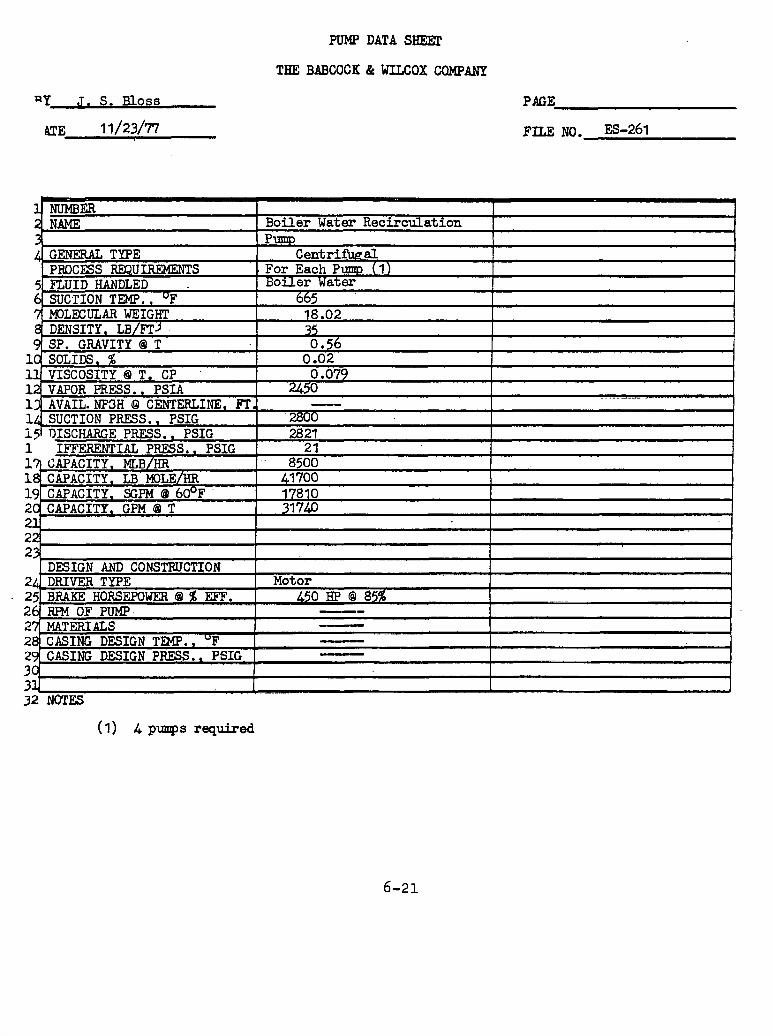
PlJMF' DATA SHEEX
THE BABCOCK & WILCOX CQMPBNP
PAGE
FILE NO. ES-261
1 NUMBER I I 2. NAME I Boiler Water Recirculation
I I
3 I, -- 1 32 NOTES
(1) 4 p q s required
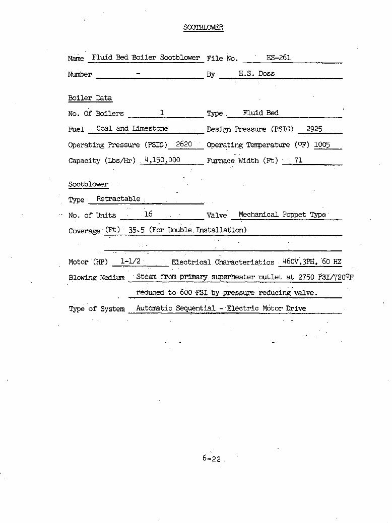
N& Flu3d Bed 'Boiier Sootblower F i l e NO. ES-261
Number - BY H.S. Doss
Boiler Data
NO. of oilers 1 Type . Fluid Bed
Fuel Coal and Limestone Design Pressure (PSIG) 2925
Operating Pressure (PSIG) 2620 ' Operating Temperature ( O F ) 1005
Capacity (Lbs/Hr) . 4,150,000 -c; width (n) . 71
Sootblower . -
45rpe Retractable ,
. - NO. o f u n i t s . -16 - . . Valve Mechanical Poppet Type. . .
Coverage - (Ft ) . 35.5. (For Double. I n s t a l l a ~ i o n ) . .
Motor (HP) 1-112 . .~. Electr ical Characteris3ics . 4 6 0 ~ ; 3 ~ ~ , HZ
, . . mduc,ed to. 600 -PSI .by .pressure reducing valve.
Type of System Automatic Sequential - Electric ~ o t o r Drive -
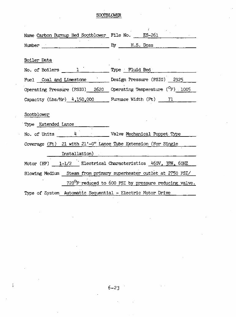
I
Name Carbon Burnup Bed Sootblower File No. ES-261
Number BY H.S. Doss
Boiler Data
No. of Boilers 1 Type Fluid Bed
Fuel Coal and Limestone Design Pressure (PSIG) 2925
Operating Pressure (PSIG) 2620 Operating Temperature (%) 1005
Capacity (Us/Hr) 4,150,000 Furnace Width (Ft) 7 1
Sootblower
Type Extended Lance
No. of Units 4 Valve Mechanical Poppet Type
Coverage (Ft) 21 with 21'-0" Lance %be Extension (For Single
Installation) . .
Motor (HP) 1-1/2 ' Electrical Characteristics 460V, 3PH, 60HZ
Blowing Medium Steam P m m primary superheater outlet at 2750 PSI/
720%-reduced to 600 PSI by pressure reducing valve.
Type of System Automatic Sequential - Electric Motor Drive
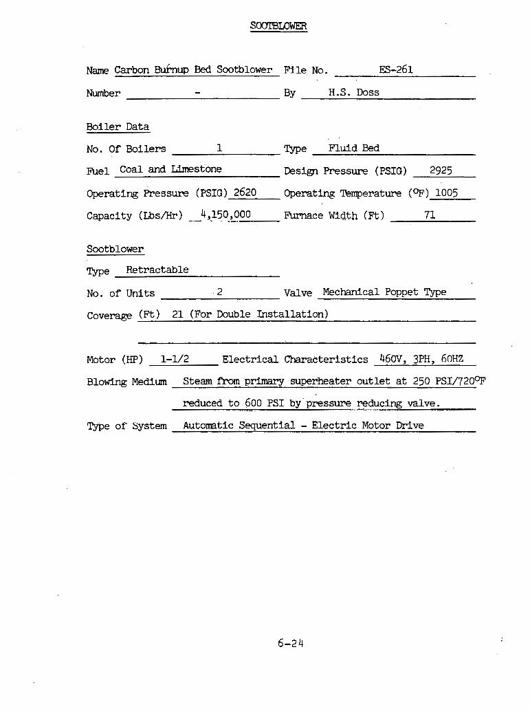
Name Carbon Buhup Bed Sootblower F i l e No. 133-261
Number - BY H.S. Doss
Boiler Data
No. O f Boilers 1 Type Fluid Bed
fie1 Coal and Limestone Design Pressure (PSIG) 2925
Operating Pressure (PSIG) 2620 Operating Temperature (OF) 1005
Capacity (Us&) --4,150,000 -- Furnace Width (Ft) 71
Sootblower
Type Retractable
No. of Units 2 Valve Mechanical Poppet Type
Cove- (Ft) 21 (For Double Instal lat ion)
Motor (HP) 1-1/2 Elec t r ica l Characteristics 460V, 3PH, 6 0 ~ ~
B l o w Medium Steam from primary superheater outlet a t 250 ~ ~ 1 / 7 2 0 9
reduced t o 600 PSI by pressure reducing valve. ... .. .." ---,,",~-.-
Type of System Automtic Sequential - Electr ic Motor Drive

Name Fluid Bed Boiler Sootblower F i l e No. ES-261
Nmber - ?y H.S. Doss
Boiler Data
No. Of Boilers 1 Type Fluid Bed
Fuel Coal and Limestone Design Pressure (PSIG) 2925
Operating Pressure (PSIG) 2620 Operating Temperature (OF) 1005
Capacity (Lbs/Hr) 4,150,000 F'urnace Width (Ft) 71
Sootblower
No. of Units 12 Valve Mechanical Poppet Type
Coveras (Ft) 17.75 with 17.75 Lance Tube =ension (For Double
Ins ta l l a t ion)
Motor (HP) 1-1/2 Electr ical Characteristics 4 6 0 ~ , 3PH, 6 0 ~ ~
Blowing Medium Steam from primary superheater out le t a t 2750 P S I / ~ ~ O ~ F
reduced t o 600 PSI by pressure reducing valve.
Type of System Automatic Sequential - Electr ic Motor Drive
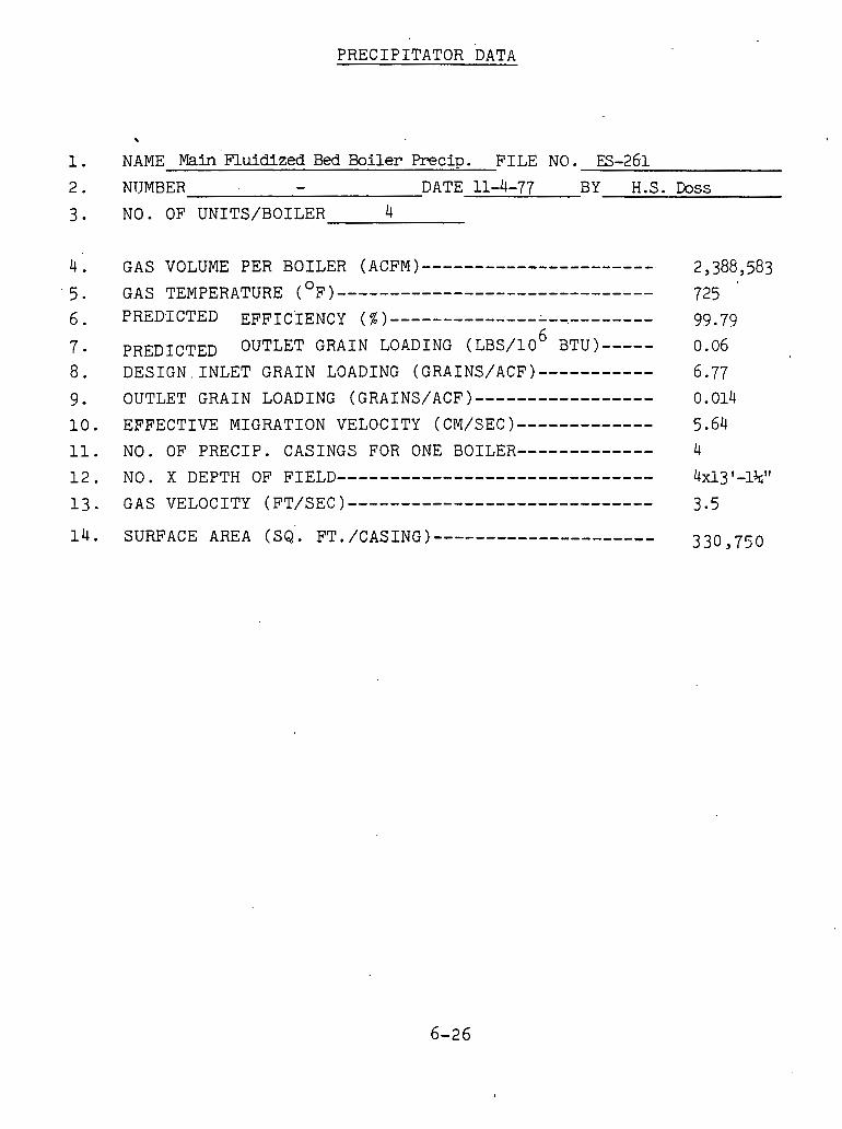
P R E C I P I T A T O R DATA
1 . NAME Main Fluidized Bed B o i l e r Precip. F I L E NO. ES-261
2 . NUMBER - D A T E 11-4-77 BY H . S . D o s s
3 . N O . O F U N I T S / B O I L E R 4
G A S VOLUME P E R B O I L E R (ACFM)---------------------- 0 G A S T E M P E R A T U R E ( F)------------------------------
P R E D I C T E D EFFICIENCY (%)-----------------.--------
PREDICTED OUTLET G R A I N LOADING ( L B S I ~ O ' B T U ) ----- D E S I G N . I N L E T G R A I N LOADING (GRAINS/ACF)-----------
OUTLET GRAIN LOADING (GRAINS/ACF)-----------------
E F F E C T I V E M I G R A T I O N V E L O C I T Y (CM/SEC)-------------
N O . O F P R E C I P . C A S I N G S F O R ONE BOILER------------- N O . X D E P T H O F FIELD------------------------------
G A S VELOCITY (FT/sEC)-----------------------------

M E C H A N I C A L D U S T C O L L E C T O R E Q U I P M E N T
T H E B A B C O C K AND W I L C O X COMPANY
1. NAME CBB Mechanical U u s t C o l l e c t o r F I L E N O . ES-261 2 . NUMBER D A T E 11-3-77 BY H . S . D o s s 3. T Y P E OF U N I T M u l t i c l o n e 4 . NUMBER O F U N I T S 1
C(JNS'I'KUC'r1ON ,
1 5 . D E S I G N P R E S S U R E , P S I G - 3 6 D E S I G N T E M P E R A T U R E , "F 800 1 6 . A S M E C O D E S T A M P E D Y E S NO X 1 7 . C O R R O S I O N A L L O W A N C E , I N C H E S - 18. S H E L L T H I C K N E S S , I N C H E S P/4" S H E L L M A T E R I A L 'carbonaSteel P i a t e 1 9 . L I N I N G M A T E R I A L - 2 0 . G A S I N L E T C O N N E C T I O N , . ? 5 1 x 1.5.7 ' G A S O U T L E T C O N N E C T I O N , 251 .x 6 . 2 1
BODY S H E L L I D (Over a l l D i m e n s i o n ) length-251-011 w i d t h - 1 6 1 0 1 1 H e i g h t - 1 8 '-6"
.' 22 . N O T E S
* C o l l e c t i o n E f f i c i e n c y - C h a r -- 80% - Stone - 9 9 %
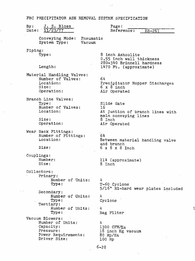
FBC PRECIPITATOR ASH REMOVAL SYSTEM SPECIFICATION
By: J. S. Blo'ss D a t e : ' '1 1/23'/7'7' ' '
Page : . . .
Reference: E'S-.2'6',1' . .
Conveying Mode: Pneumatic System Type: Vacuum
P ip ing : Type :
Length :
8 i n c h Ashco l i t e 0.55 i n c h w a l l t h i c k n e s s 280-340 B r i n n e l l hardness 1470 F t . approximate)
M a t e r i a l Handling Valves: Number o f Valves: 6 4 Loca t ion : P r 8 e c i y i t a t o r Hopper Discharges S i z e : 6 x 8 i n c h Operat ion : A i r Operated
Branch Line Valves: Type : S l i d e Gate Number o f Valves : 16 Locat ion: A t j u n t i o n o f branch l i n e s w i th
main conveying l i n e s S i z e : 8 Inch Operat ion: A i r Operated
Wear Back F i t t i n g s : Number o f F i t t i n g s : 64 Locat i o n : Between m a t e r i a l handl ing va lve
and branch S i z e : 6 x 8 x 8 Inch
Couplings: Number : Size :
1 1 4 (approximate) 8 . Inch
C o l l e c t o r s : Primary :
Number o f Uni t s : 4 Type : T-6U Cyclone
5/16'' N1-hard wear p l a t e s i nc luded Secondary:
Number o f Unitn: 4 Type : Cyclone
T e r t i a r y : Number o f Uni t s : . 4 Type : Bag F i l t e r
Vacuum Blowers : Number o f Un i t s : 4 Capaci ty: 1300 CFMha P res su re : 18 i n c h Hg vacuum Power Requirements: 80 Hp/Ea Dr iver S i z e : 100 Hp
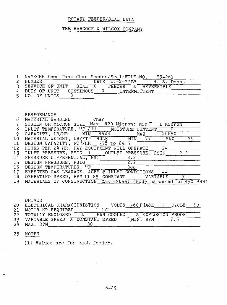
ROTARY FEEDER/SEAL DATA
THE BABCOCK & WILCOX COMPANY
1 NAMECBB F e e d T a n k i C h a r F e e d e r / S e a l . F I L E . , . N O . ES-261 2 NUMBER DATE-11-2-77EY H . S . DOSS- ,
3 SERVI'CE OF UNIT SEAL X FEEDER X REVERSIBLE 4 DUTY OF UNIT CONTINOUS X INTERMITTENT 5 N O . OF UNITS 8
PERFORMANCE IjIATERIAL HANDLED Chal\ SCREEN OR MICRON S I Z E Max. 4 2 0 M i c r o n ; Min . 1 M i c r o n INLET TEMPERATURE, O F ' (00 MOISTURE CONTENT 0 CAPACITY, LB/HR
jMiN 4 9
MA X - MATERIAL WEIGHT, LB F T ~ BUL? M I N 53 MAX / 5 DESIGN CAPACITY, FT /HR 3 5 8 t o 8 9 . 5 HOURS PER 24 HR. D A Y EQUIPMENT WILL OPERATE 2 4 INLET PRESSURE, PSIG 0 OUTLET PRESSURE, PSIG 2 . 2 PRESSURE DIFFERENTIAL, P S I - 2 . 2 DESIGN PRESSURE, PSIG 2 . 2 DESIGN TEMPERATURES, "F 8 0 0 EXPECTED GAS LEAKAGE, ACFM @ INLET CONDITIONS -- OPERATING SPEED, RPM 1 1 . 8 5 CONSTANT VARIABLE X MATERIALS OF CONSTRUCTION C a s t - S t e e l ( B o d y h a r d e n e d t o 4 5 0 BHN)
DRIVER 20 ELECTRICAL CHARACTERISTICS VOLTS 4 6 0 P H A s ~ ' 3 CYCLE 6 0 2 1 MOTOR HP REQUIRED 1 1 / 2 2 2 TOTALLY ENCLOSED X FAN COOLED X EXPLOSION PROOF 2 3 VARIABLE SPEED ' X CONSTANT SPEED M I N . RPM 7 5 24 MAX. RPM 3 0
( 1 ) V a l u e s are f o r each f e e d e r .
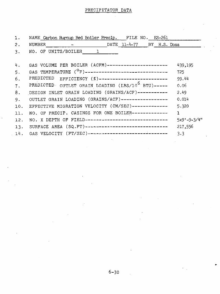
PRECIPITATOR DATA
1. NAME Carbon Burnup Bed Boiler Precip. FILE NO. 13-261
2. NUMBER - DATE 11-4-77 BY H.S. D ~ S S
3. NO. OF UNITS/BOILER 1
4. GAS VOLUME PER BOILER (ACFM)---------------------- 439,195
5 . 0 GAS TEMPERATURE ( F)------------------------------ 725
6. PREDICTED EFFICIENCY (%)------------------------- 99 . 44
7 . PRKDICTED OTJTLET Gf,AZN I . O A D l N G ( T.Rs/~o~- BTU) ----- 0.06
8. ,DESIGN INLET GRAIN LOADING (GRAINS/ACF)----------- 2.49
9. OUTLET GRAIN LOADING (GRAINS/ACF)----------------- 0.014
10. EFFECTIVE MIGRATION VELOCITY (CM/SEC)------------- 5.320 11. NO. OF PRECIP. CASINGS F.OR ONE BOILER------------- 1
12. NO. X DEPTH OF FIELD------------------------------ 5x9 ' -9-3/4" 13. SURFACE AREA (sQ.FT)------------------------------ 217,556
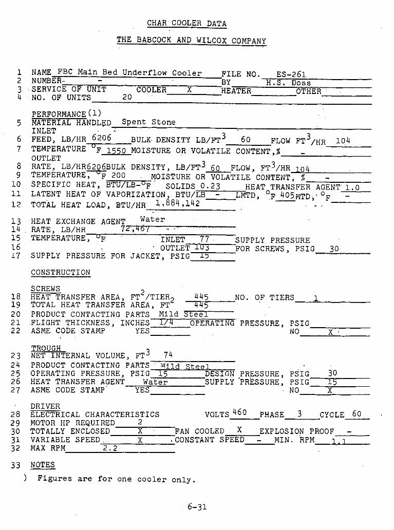
CHAR COOLER DATA
THE BABCOCK AND WILCOX COMPANY
1 NAME FBC Main B e d U n d e r f l o w C o o l e r F I L E NO. ES-261 2 NUMBER- - BY H.S . D o s s 3 .SERVICE OF UNIT COOLER x HEATER OTHER 4 NO. OF UNITS 2 0
PERFORMANCE ( 1 ) 5 MATERIAL HANDLFD S p e n t S t o n e
INLET 3 6 FEED, LB/HR 6 2 0 6 ' BULK- DENSITY L B / F T ~ 6 0 FLOW FT /HR 1 0 4 7 'I'EMPERATURE OF 1 5 5 0 MOISTURE OR VOLATILE CONTENT,% -
OUTLET 8 RATE, LB/HR6206BULK DENSITY, L B / F T ~ 6 0 FLOW, F T ~ / H R 1 0 4 9 TEMPERATURE^ 2 0 0 . MOISTURE OR VOLATILE CONTENT, I -
1 0 SPECIFIC HEAT, BTU/LB-OF SOLIDS 0 . 2 3 HEAT TRANSFER AGENT 1 . 0 0 11 LATENT HEAT OF VAPORIZATION, BTU/LB - LMTD, , F ~ O ~ M T D , . O.F - -
1 2 TOTAL HEAT LOAD. BTU/HR 11884!142 .. .
1 3 HEAT EXCHANGE AGENT , Water 1 4 RATE, LB/HR 72 94b.l - . 1 5 TEMPERATURE, INLET 7 7 . SUPPLY PRESSURE 1 6 * OUTLET l(J3 FOR SCREWS, PSIG 3 0 1 7 SUPPLY PRESSURE FOR JACKET, P S I G ~
CONSTRUCTION
SCREWS 18 HEAT TRANSFER AREA, F T ~ / T I E R ~ 4 4 5 NO. OF TIERS - 1 1 9 TOTAL HEAT TRANSFER AREA, FT 4 4 5 2 0 PRODUCT CONTACTING PARTS Mild S t e e l 2 1 .FLIGHT THICKNESS, INCHES -- l / 4 OPERATING PRESSURE, PSIG 2 2 ASME CODE STAMP YES NO X .
TROUGH 2 3 NET INTERNAL VOLUME. F T ~ 74 2 4 PRODUCT CONTACTING PARTS Mild S t e e 25 OPERATING PRESSURE, PSIG 15 AESIGIJ PRESSURE, PSIG 3 0 2 6 HEAT TRANSFER AGENT Water SUPPLY 'PRESSURE, PSIG 1 5 2 7 ASME CODE STAMP' YES NO X
DRIVER ELECTRICAL CHARACTERISTICS
m VOLTS 460 PHASE 3 -
MOTOR 1.1F RI ,LI T.Zr TOTALLY ENCLOSED X FAN COOLED X' EXPLOSION VARIABLE SPEED. X CONSTANT SPEED - M I N . R MAX RPM 2 . 2
CYCLE 6 0 - PROOF -
'MA
33 NOTES
) F i g u r e s are f o r one coo le r o n l y .

CHAR COOLER DATA
THE BABCOCK AND WILCOX COMPANY
1 NAME FBC S t a r t u p B e d Underflow C o o l e r FILE NO. ES-261 2 NUMBER - BY H . S . .Doss 3 SERVICE OF UNIT COOLER X HEATER OTHER 4 NO. OF UNITS 5
PERFORMANCE ( 1 ) 5 MATERIAL HANDLED 'pent Stone
INLET 6 FEED, LB/HR 3049 BULK DENSITY LB/FT 3 6 0 FLOW FT 3 /HR 5 1 7 TEMPERATURE O F 1 5 5 0 MOISTUiLE OR VOLATILE CONTENT,% -
OUTLET - -
RATE, L B / H R ~ O ~ ~ B U L K DENSITY, LB/FT' 60 FLOW, F T ~ C H R 5 1 TEMPERATURE^ 2 o o MOISTURE OR VOLATILE CONTENT, % - S P E C I F I C HEAT, BTU/LB-OF SOLIDS 0 . 2 3 0 HEAT TRANSFER AGENT 1 . 0
0 0 LATENT HEAT OF VAPORIZATION, BTU/LB - LMTD, F 4 6 5 ~ ~ ~ ~ F - TOTAL HEAT LOAD, BTU/HR 9 4 6 , 7 1 5
HEAT EXCHANGE AGENT Water RATE, LB/HR 3 1 3 5 5 7 TEMPERATURE, "F INLET 7 7 SUPPLY PRESSURE
OUTLET 1 0 7 FOR SCREWS, PSIG 5 0 SUPPLY PRESSURE FOR JACKET, PSIG 15
CONSTRUCTION -. <. . - . . ... .- SCREWS
188 18 HEAT TRANSFER AREA, F T ~ / T I E R ~ NO. OF TIERS - 1 1 9 TOTAL HEAT TRANSFER AREA, FT 1 8 8 2 0 PRODUCT CONTACTING PARTS ~ i ~ d 2 1 FLIGHT THICKNESS, INCHES -- 3/16" OPERATING PRESSURE, PSIG
5 0
2 2 ASME CODE STAMP YES NO X
TROTJGH 2 3 NET INTERNAL VOLUME' F T ~ 32 2 4 PRODUCT CONTACTING PARTS M i l d S t e e l 2 5 OPERATING PRESSURE, PSIG 1 5 DESIGN PRESSURE, PSIG 5 0 2 6 HEAT TRANSFER AGENT Water SUPPLY PRESSURE, PSIG 1, 2 7 ASME CODE STAMP YES --- - NO x
DRIVER ELECTRICAL CHARACTERISTICS VOLTS 4 6 0 PHASE 3 . CYCLE 6 0 MOTOR HP REQUIRED 1 -1 /2 TOTALLY ENCLOSED X FAN COOLED EXPLOSION PROOF . - VARIABLE SPEED X CONSTANT SPEE
2 . 8 M I N . RPM 1 . 4
MAX RPM
3 3 NOTES
( 1 ) F i g u r e s are f o r o n e c o o l e r o n l y
6 - 3.2

CHAR COOLER DATA
THE BABCOCK AND WILCOX COMPANY
~ ~ ~ E C a r b o n B u r n u p B e d U n d e r f l o w D o o l e r F I L E NO. ES-261 '
2 NUMBER - BY H . S . D o s s 3 SERVICE OF UNIT COOLER X HEATER OTHER 4 NO. OF UNITS 8
PERFORMANCE ( 1 ) 5 MATERIAL HANDLED S p e n t S t o n e
INLET 6 FEED, LB/MR 883 BULK DENSITY L B / F T ~ 6 0 FLOW F T ~ / H R 15 7 TEMPERATURE OF 2 1 0 0 MOISTURE OR VOLATILE CONTENT,% -
OUTLET 3 8 RATE, LB/HR 883BuLK DENSITY, L B / F T ~ 6 0 FLOW, FT /HR ; 5
9 TEMPERATURE, "F 2 0 0 MOISTURE OR VOLATILE CONTENT, % - 1 0 SPECIFIC HEAT, BTU/LB-OF SOLIDS 0 . 2 3 HEAToTRANSFER AGENT 1 . 0
0 11 LATENT HEAT OF VAPORIZATION, BTU/LB - LMTD, F 6 4 0 MTD, F , - - 1 2 TOTAL HEAT LOAD, BTU/HR 3 8 5 , 7 0 0
1 3 HEAT EXCHANGE AGENT Water 1 4 RATE, LB/HR 1 2 , 8 5 7 15 . TEMPERATURE, U~ INLET 7 7 SUPPLY PRESSURE 1 6 OUTLET 1 0 7 FOR SCREWS, PSIG 1 7 SUPPLY PRESSURE FOR JACKET, PSIG 15 .,.-
CONSTRUCTION
SCREWS . . 2
HEAT TRANSFER AREA, FT /TIER2 6 2 . 2 NO. 0 F . T I E R S 1 TOTAL HEAT TRANSFER AREA, FT 6 2 . 2 PRODUCT, CONTACTING PARTS 1 1 6 ~ st*, , q t l . FLIGHT THICKNESS, INCHES 3 /16 OPERATING PRESSURE, ESIG 6 0 ASME CODE STAMP YES NO 7
PRESSURE, PRESSURE,
PSIG 6 0 PSIG 1 5 NO - X
DRIVER 2 8 ELECTRICAL CHARACTERISTICS VOLTS 4 6 0 PHASE 3 CYCLE 6 0 2 9 MOTOR HP REQUIRED 1 / 2 3 0 TOTALLY ENCLOSED X FAN COOLED x EXPLOSION PROOF - 31 VARIABLE SPEED -CONSTANT SPEED - MIN. RPM 2 . 2
33 NOTES
1 ) F i g u r e s are for orle c v o l e r o n l y .
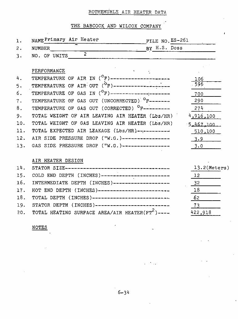
THE BABCOCK AND WILCOX COMPANY
1. NAME Primary Air Heater - FILE NO. ES-261 2. NUMBER BY H.S. Doss
3. NO. OF UNITS 2
PERFORMANCE , 0 4 . TEMPERATURE OF AIR IN ( F)-------------------- 106
b 5. TEMPERATURE OF AIR.' OUT ( F) .................... . . 5 9 6 0 6. TEMPERATURE OF GAS IN ( F)------------+------- 700
7. TEMPERATURE OF GAS OUT (UNCORRECTED ): OF------- 2 9 0
8. TEMPERATURE OF GAS OUT (CORRECTED) OF--------- 274 9 . TOTAL WEIGHT OF AIR LEAVING AIR HEATER (Lbs/HR) '
10. TOTAL WEIGHT OF GAS LEAVING AIR HEATER (L~S/HR) 11. TOTAL EXPECTED AIR LEAKAGE (Lbs/HR]--.---------
12. AIR SIDE PRESSURE DROP ("W;G.)----------------
13. GAS SIDE PRESSURE DROP (IfW.G.)----------------
AIR HEATER DESIGN STATOR SIZE-----------------------------------
NOTES
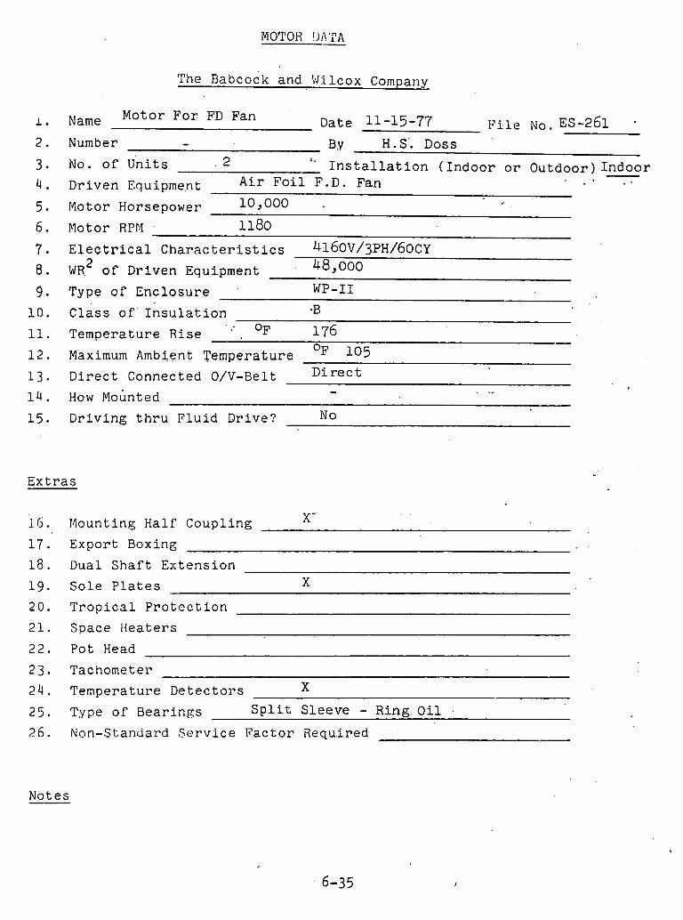
MOTOR !,I?'I"A
The ~ a b c o c k and Wilcox Company
Name Motor F o r FD Fan Date 11-15-77 ~ ? i l e NO.ES-261 - - BY H. S'. Doss Number
No. o f U n i t s . 2 " - I n s t a l l a t i o n ( I n d o o r o r 0 u t d o o r ) I n d o o r A i r F o i l F.D. Fan Dr iven Equipme.nt . .
r4otor Horsepower 10 ,000 # .
Motor RPr.1 . 1180 E l e c t r i c a l C h a r a c t e r i s t i c s ~ ~ ~ O V / ~ P H / ~ O C Y
2 W R o f Dr iven Equipment 48,000
Type o f E n c l o s u r e ' WP-I1
C l a s s o f ' I n s u l a t i o n -B .. OF 176 Tempera ture Rise -
OF 1 0 5 Maximum Ambient Tempera ture . .
D i r e c t Connected O/V-Belt D i r e c t - . .-
How ~ o u n t e d
D r i v i n g t h r u F l u i d Dr ive? No
E x t r a s
X - iG. Mounting Hal f Coup l ing
1 7 . Expor t Boxing
1 8 . Dual S h a f t E x t e n s i o n
19 . S o l e P l a t e s X
2 0 . T r o p i c a l P r o t e c t i o n
21. Space H e a t e r s
22. Po t Head
23 . Tachometer
2 4 . Tempera ture D e t e c t o r s X
25. Type o f B e a r i n g s S p l i t S l e e v e - R i n g O i l - 2 6 . Non-Standard S e r v i c e F a c t o r Requ.ired
Notes
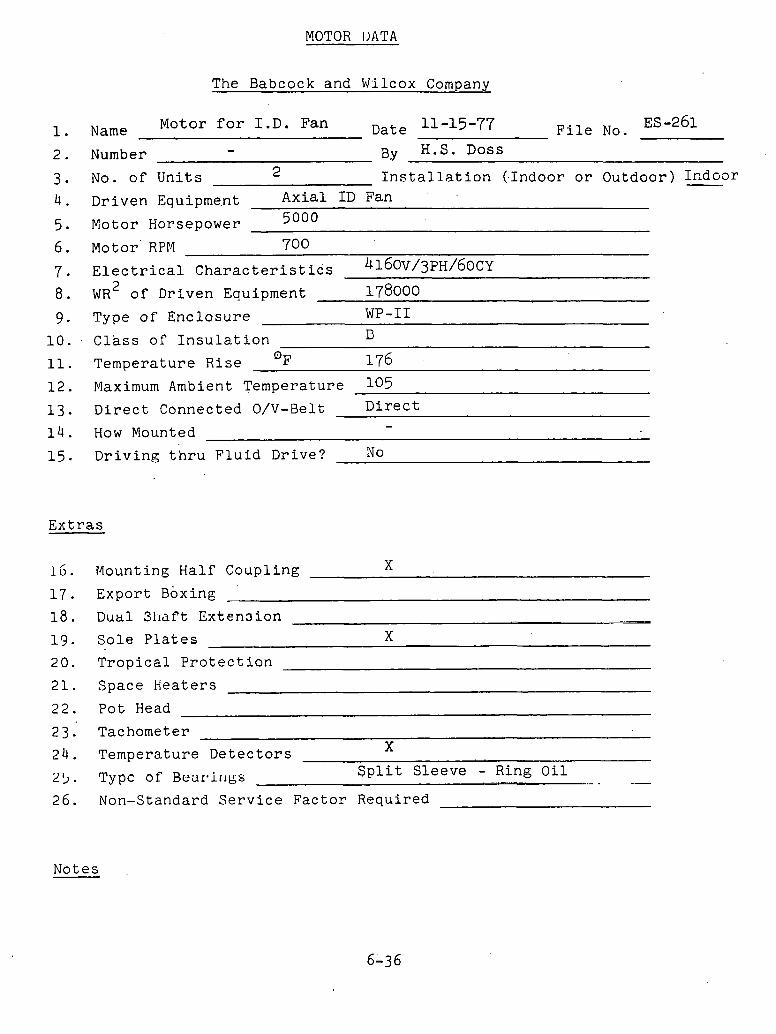
MOTOR IjATA
The Babcock and Wilcox Company
Name Motor f o r I . D . Fan Date 11-15-77 F i l e No. ES -261
Number - BY H.S. Doss
No. o f U n i t s 2 I n s t a l l a t i o n ( - Indoor o r Outdoor ) Indoor A x i a l I D Fan Dr iven Equipment 5000 Motor Horsepower
Motor RPM 700
E l e c t r i c a l Charac t e r i s t iCs 4160v/3~H/60cy 2 WR o f Dr iven Equipment 178000
Type of E n c l o s u r e WP-I1
C l a s s o r I n s u l a t i o n C
Tempera ture R i s e 176 -
Maximum Ambient Temperature 105 D i r e c t Connected O/V-Belt D i r e c t
- How Mounted
D r i v i n g t h r u F l u i d Dr ive? No
E x t r a s
1 6 . Mounting Hal f Coupl ing X
1 7 . Expor t Boxing
1 8 . Dual 311af't Extension -. -- X 13 . S o l e P l a t e s
2 0 . T r o p i c a l P r o t e c t i o n
21. Space H e a t e r s
22. P o t Head
23. Tachometer **
24. Temperature D e t e c t o r s A
2 5 . 'Type of Beartir~gs S p l i t S l eeve - Ring O i l - .. .... - -- 26. Non-Standard S e r v i c e F a c t o r Required
Notes
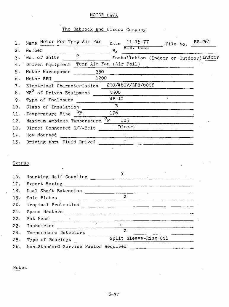
MOTOR. DATA
The Rabcock and Wilcox Company
Name Motor For Temp Air Fan Date 11-15-77 .File No. ES-261 . - h.s. uoss
Number BY
No. of Units 2 ~nstaliation (Indoor or 0utdoor)Indoor
Driven Equipme.nt TemP Air Fan (Air Foil) - Motor Horsepower 350
1200 Motor RPr4
Electrical Characteristics 230/460~/3PH/60~Y 2 WR of Driven Equipment 5500
WP-I1 Type of Enclosure
10. Class of Insulation B
11. Temperature R ~ S L OF. 176 0
12. Maximum Ambient Temperature F 105
13. Direct Connected O/V-Belt Direct -
14. How Mounted
15. Driving thru Fluid .Drive? -
Extras
X 16. Mounting Half Coupling
17. Export Boxing
18. Dual Shaft Extension
19. Sole Plates X 20. 'l'ropical Protection
21. Space IIeaters
22. Pot Head
23. Tachometer 1
24. Temperature Detectors X
25. Type of Bearings Split Sleeve-Ring Oil
26. Non-Standard Service Factor Required -
Notes
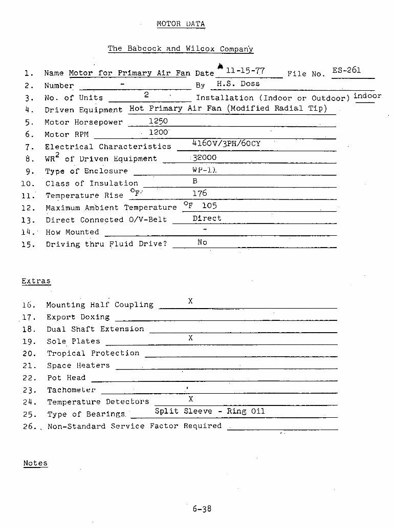
MOTOR LjATA
The Ba'bcock and Wilcox Company
1. Name Motor f o r P r i m a r y A i r Fan Date. ' 11 -15 -77 F i l e No. ES-261
2 . Number - H.S. DOSS
2 3. No. o f U n i t s I n s t a l l a t i o n ( I n d o o r o r Ou tdoor )
4 . D r i v e n ~ q u i p m e , n t Hot P r i m a r y A i r Fan (Mod i f i ed R a d i a l T i p )
5 . Motor Horsepower 1250 1200' Motor RPr4
E l e c t r i c a l C h a r a c t e r i s t i c s ~ ~ ~ O V / ~ P H / ~ O C Y - WR' o f Dr iven Equipment .32000
T y p e o f ~ n c i o s u r e W P-.],I:
Class o f I n s u l a t i o n B . .
OF .' ~ e m ~ e r a t u r e R i s e 176 Maximum ~ m b i e n t Tempera ture OF 1 0 5
D i r e c t Connected O/V-Belt D i r e c t
How Mounted -
D r i v i n g t h r u F l u i d Dr ive? No
E x t r a s
. .
1 . Mount ing Ha l f Coup l ing X
1 7 . Exp01-t Doxing
1 8 . Dual s h a f t E x t e n s i o n
1 9 . S o l e P l a t e s X
20. T r o p i c a l P r o t e c t i o n
21. Space H e a t e r s
22 . Po t Head
2 4 . Tempera tu re D e t e c t o r s X
2 5 . Type o f B e a r i n g s . ' S p l i t S l e e v e - Ring O i l
2 6 . . Non-Standard S e r v i c e F a c t o r Requ i r ed - .
Notes

SAFETY VALVES
Name Electromtic Relief Valve F i l e No. ES-261 Number - Date 11-28-77 By H.S.Doss
B o i l e r Data
Type Natural circulat ion Capac i t y (Lbs/Hr) Design P r e s s u r e (PSIG -F@=
2780 Drum Ope ra t i ng P r e s s u r e S u p e r h e a t e r Ope ra t i ng P r e s s u r e 2620 PSIG S . H AP 160 S .HAP 5.9% ERV S e t S.H.AP 5.8% Low S e t S.H. Vlv . Drum Valves To B e P a i r e d Yes No X S.H.O. Va lves To B e P a i r e d Yes No X
Rehea t e r Data
Capac i ty (Lbs/Hr) Design P r e s s u r e (PSIG Rehea t e r I n l e t P r e s s u r e @ Temp. 604
R . H . AP 25 Rehea t e r O u t l e t P r e s s u r e @ Temp.
R . H . I . v a l v e s To B e P a i r e d Yes No X R . H . O . Valves To B e P a i r e d Yes No X
E l e c t r o m a t i c R e l i e f Valve
S e t @ 2700 PSIG @ 1005OF, CF = 0.8058 P r e s s u r e To Be Sensed From Drum S.H.O. X R e l i e v i n g C a c i t y Base.d on Bore Dia 1.812 I n . K e l l e v l n g Capac i t y Based on Baye Area 2.5802 Sq. I n . R e l i e v i n g Capac i t y Based on 100 % o f F u l l Capac i t y Minimum Blow Down 1 % ~ a s e d On I n d i c a t e d Capac i t y
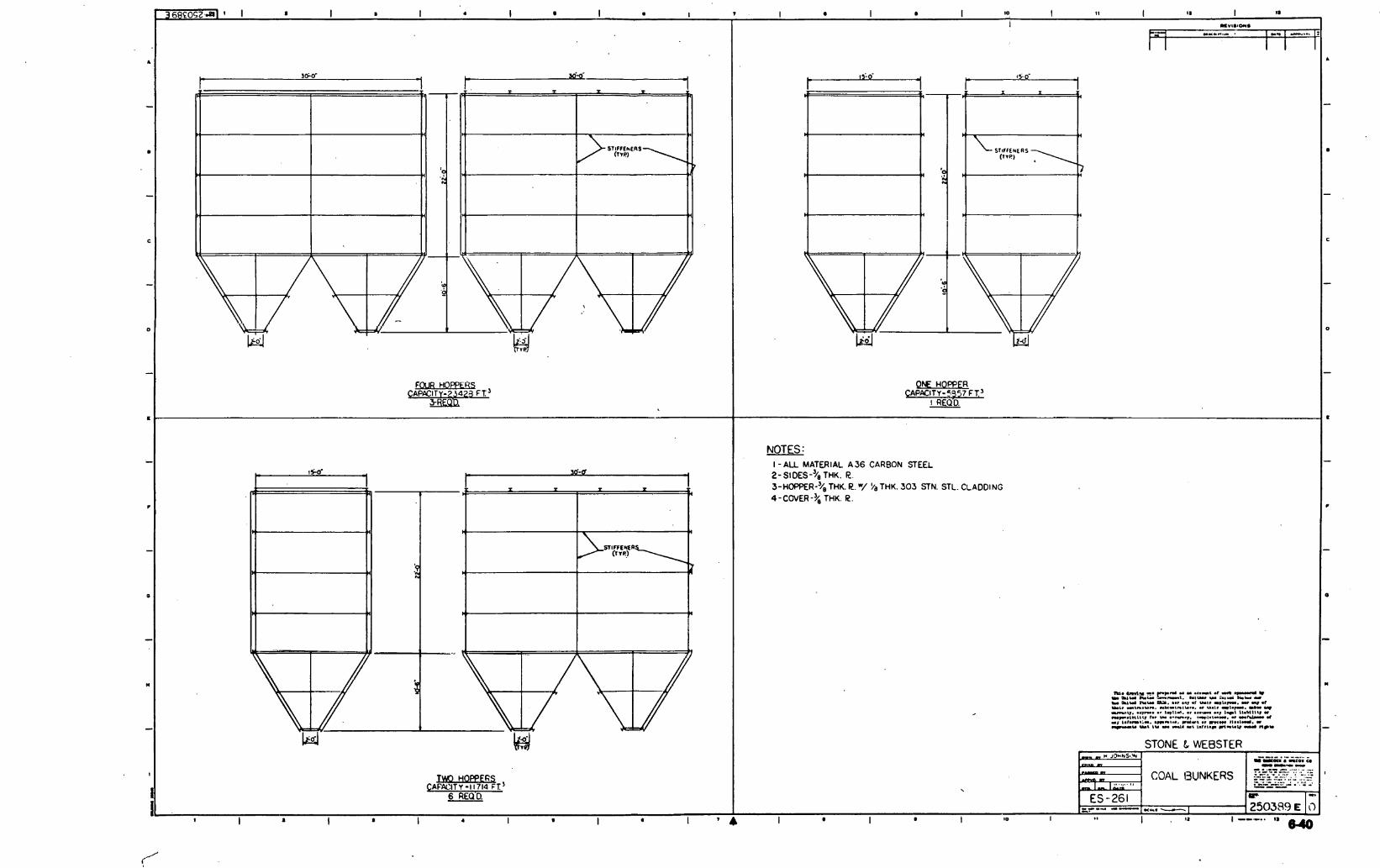
N HOFPFR CA%lTY-5357 FT'
I R E Q ~ .


FAN OR BLOWER, DATA S-
THE BABCOCK & WILCOX COMPANY H. S. Doss
DATE November 14, 1977
PAGE - ..
FILE NO. ES-261

FAN OR BLOWEX DATA SHEET
B Y H . S . Doss
DATE November 1 4 , 1977 FILE NO. ES-261
1 NUMBER 1 2 NAME I D Flue Gas Fan ill .Flue Gas Fan
I Net
-A
DESIGN AND CONSTRUCTION I -- -- 24, DRIVER T Y P E Motor Motor 25 DRAICE I I O R S I X ' O ~ Q % EFT'. 3153 @ 85.5 4609 @ 8 5 . 1 1
-- -- -- -- I -- -- J
- ~ ~ C P / C V 1 I , .
-- - I -- !
- -
I I I 32 NOTES
T W . RISE, OF . . 8.. . 12 ! I 1

FAN OR BLOWER DATA SHEET.
THE BABCOCK & WILCQX CObPANY
H . S . Doss
DATE November 1 4 , 1977 FILE NO. ES-261
2 I
32 NOTES
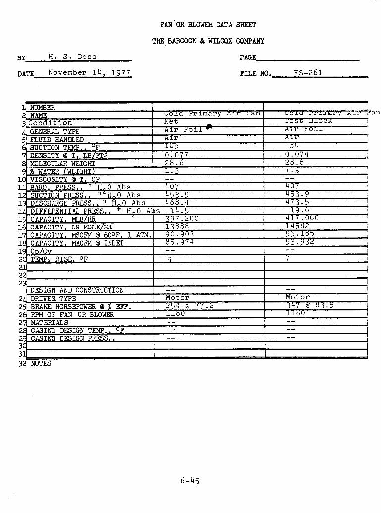
BY H . S . Doss
DATE November .14, 1977
FAN OR BLOWER! DATA SHEET
THE BABCOCX & WILCOX COMPANY
PAGE
FILE NO. ES-261
GJ ! I
DESIGN AND COWL ,,.,,,,,.. 24 DI~IVER TYPE Motor Motor i
254 @ 77.2 25 BRAKE HORSEPOWER Q % EFF. 347 ' & 8 3 . 3 1 26 RPM OF FAN OR B L O w m 1180 1180 I

VII .' B&W 'SYSTEM 'TERMINALS
A. Water'Conne'c't'io'ns
1. I n l e t t o feedwater stop-check a t econsmizer i n l e t header.
2. I n l e t t o chemical feed va lve on steam drum. 3. I n l e t and o u t l e t connections of a l l B&W
furn ished equipment r e q u i r i n g water cool ing such as ash coolers .
4. I n l e t t o water c l ean ing device on regenera t ive a i r hea te r .
5. I n l e t t o spray water nozzle on spray a t tempera tor . 6. Water l e v e l r ecorde r va lves a t steam drum. 7. Feedwater r e g u l a t o r connections a t steam drum. 8. I n l e t t o valve a t a l l a c i d c leaning i n l e t
connections. 9 . Outle t of d r a i n va lves f o r water column and gage
loca ted a t ope ra t ing f l o o r l e v e l . 10. Out le t of d r a i n valves. 11. Out le t of continuous blowdown valve on steam drum. .12. Out le t of water sampling valve on economizer
i n l e t header. 13. Out le t of valve a t a l l a c i h c leaning o u t l e t
connections.
Fuel Connections
1. I n l e t t o o i l l i g h t e r control package loca ted a t f l u i d i z e d beds.
2. Coal and l imestone i n l e t s . t o t h e crushed c o a l and l imestone bunkers.
C . Steam Connections
I n l e t of r e h e a t e r p ip ing at rehea t i n l e t header on b o i l e r r i g h t hand s i d e . Out le t of superheater p ip ing a t b o i l e r f r o n t w a l l on b o i l e r l e f t hand s ide . Out le t of r e h e a t e r p ip ing a t r e h e a t o u t l e t header on b o i l e r f r o n t wal l . Out le t of each s a f e t y valve. Out le t of e l ec t romat ic r e l i e f valve. Out le t of each vent va lve . Out le t of p ressu re gage t e s t valve. Out le t of steam sampling va lve . Out le t of a u x i l i a r y steam valve on steam druni. Out le t of d r a i n valve i n sootblower p ip ing .
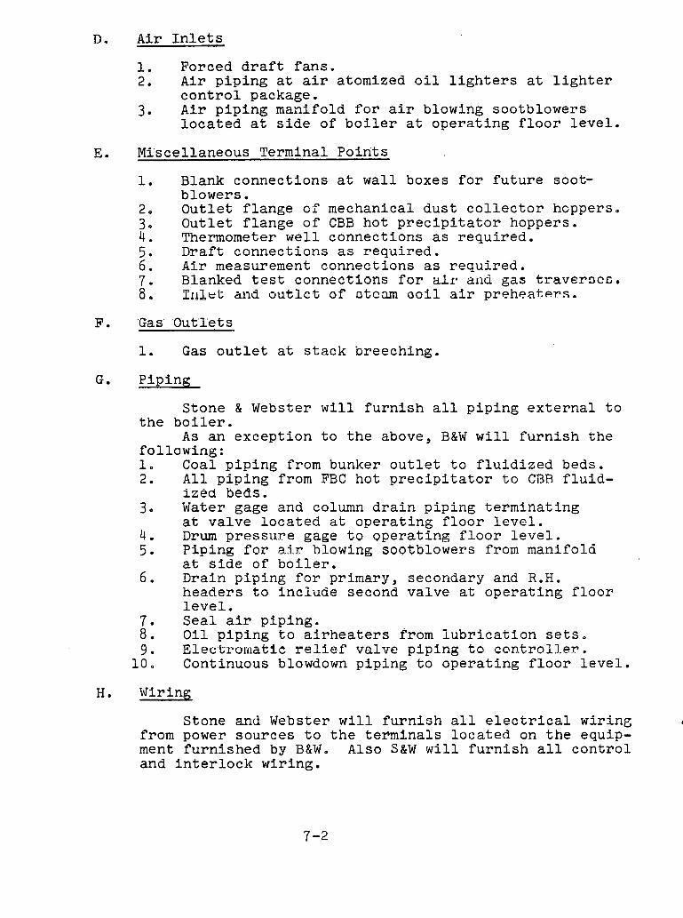
D. A i r I n l e t s
1. Forced d r a f t f a n s . 2. A i r p i p i n g a t a i r atomized o i l l i g h t e r s a t l i g h t e r
c o n t r o l package. 3. A i r p i p i n g manifold f o r a i r blowing sootblowers
l o c a t e d a t s i d e of b o i l e r a t o p e r a t i n g f l o o r l e v e l .
E. Miscel laneous Terminal P o i n t s
1. Blank connec t ions a t w a l l boxes f o r f u t u r e soot- b lowers .
2. O u t l e t f l a n g e of mechanical d u s t c o l l e c t o r hoppers, 3. O u t l e t f l a n g e o f CBB h o t p r e c i p i t a t o r hoppers. 4 . Thermometer w e l l connec t ions a s r e q u i r e d . 5. Dra f t connec t ions as r e q u i r e d . 6. A i r measurement connect i o n s as r e q u i r e d . 7. Blanked t e s t connec t ions f o r all* aiid gas t r a v e r o c c , 8. Pribet and o u t l e t of o tcam o o i l a i r p r e h e a t e r s .
'Gas' 'Ou t l e t s
1. Gas o u t l e t a t s t a c k breeching.
P ip ing
S tone & Webster w i l l f u r n i s h a l l p i p i n g e x t e r n a l t o t h e b o i l e r .
A s an excep t ion t o t h e above, B&W w i l l f u r n i s h t h e fo l lowing : 1. Coal p i p i n g from bunker o u t l e t t o f l u i d i z e d beds. 2. A l l p i p i n g from FBC ho t p r e c i p i t a t o r t o CBB f l u i d -
i z e d beds. 3, Water gage and column d r a i n p ip ing t e r m i n a t i n g
a t va lve l o c a t e d a t o p e r a t i n g f l o o r l e v e l . 4 . Drum pressi.l.re gage t o o p e r a t i n g f l o o r l e v e l . 5. P ip ing f o r a , i r blowing s o ~ t b l o w e r s from manifold
a t s i d e of b o i l e r . 6. Drain p ip ing f o r primary, secondary and R.H.
heade r s t o i n c l u d e second va lve a t o p e r a t i n g f l o o r l e v e l .
7 . S e a l a i r p ip ing . 8 . O i l p i p i n g t o a i r h e a t e r s from l u b r i c a t i o n s e t s , 9 . E l e ~ , t ~ ~ o m a t i c r e l i e f va lve p ip ing t o c o n t r o l 3 . e ~ .
1 0 . Continuous blowdown p ip ing t o o p e r a t i n g f l o o r l e v e l .
H. Wiring
Stone and Webster w i l l f u r n i s h a l l e l e c t r i c a l w i r ing d
from power sources t o t h e t e r m i n a l s l o c a t e d on t h e equip- ment f u r n i s h e d by B & W o Also S&W w i l l f u r n i s h a l l c o n t r o l and i n t e r l o c k wir ing .
As an exception to the preceding, the following wiring will be furnished by B&W.
1. Permanent thermocouples with leads to terminal box located at side of boiler.
I. Tub'i'ng
Stone and Webster will furnish all power and control tubing to connect the equipment furnished by B&W except the pressure control line for the electro- matic relief valve.
J. The following equipment is included in B&Wts scope '0'f 'supply
1. Sootblower control panel for mounting on S&W's control panel.
2. Reheat attemperator sleeve and spray nozzle to be installed in cold reheat piping.
3. Controller for electromatic relief valve, 4. Bailey Meter Company's switches and indicators.
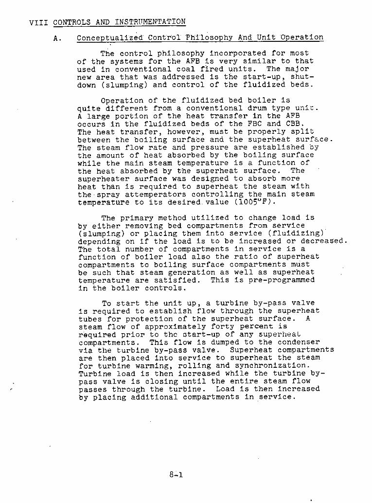
V I I I CONTROLS AND INSTRITMENTATI'ON
Conceptual i ' zed C'ont'rol 'Phi'losophy And 'Unit' 'Opera t ion
The c o n t r o l ph i l o sophy i n c o r p o r a t e d f o r most o f t h e sys tems f o r t h e AFB i s v e r y similar t o t h a t used i n c o n v e n t i o n a l c o a l f i r e d u n i t s . The major new area t h a t was a d d r e s s e d i s t h e s t a r t - u p , shu t - down ( s lumping) and c o n t r o l o f t h e f l u i d i z e d beds .
Ope ra t i on o f t h e f l u i d i z e d bed b o i l e r i s q u i t e d i f f e r e n t from a c o n v e n t i o n a l drum t y p e unf, . A l a r g e p o r t i o n o f t h e h e a t t r a n s f e r i n t h e AFB o c c u r s i n t h e f l u i d i z e d beds o f t h e FBC and C 3 B . The h e a t t r a n s f e r , however, must be p r o p e r l y s p l i t between t h e b o i l i n g s u r f a c e and t h e s u p e r h e a t s u r % c e . The s team f low r a t e and p r e s s u r e a r e e s t a b l i s h e d By t h e amount o f h e a t absorbed by t h e b o i l i n g s u r f a c e wh i l e t h e main s team t empe ra tu r e i s a f u n c t i o n o f t h e h e a t absorbed by t h e s u p e r h e a t s u r f a c e . The '
s u p e r h e a t e r s u r f a c e was des igned t o a b s o r b more h e a t t h a n i s r e q u i r e d t o s u p e r h e a t t h e s team w i t h t h e s p r a y a t t e m p e r a t o r s c o n t r o l l i n g t h e main s t eam t e m p e r a t u r e t6 i t s d e s i r e d v a l u e (1005°F).
The pr imary method u t i l i z e d t o change l o a d i s by e i t h e r removing bed compartments from s e r v i c e ( s lumping) o r p l a c i n g them i n t o s e r v i c e ( f l u i d i z i n g ) ' depending on i f t h e l o a d i s t o be i n c r e a s e d o r d e c r e a s e d . The t o t a l number o f compartments i n s e r v i c e i s a f u n c t i o n o f b o i l e r l o a d a l s o t h e r a t i o o f s u p e r h e a t compartments t o b o i l i n g s u r f a c e compartments must be such t h a t s team g e n e r a t i o n as w e l l a s s u p e r h e a t t e m p e r a t u r e a r e s a t i s f i e d . T h i s i s pre-programmed i n t h e b o i l e r c o n t r o l s .
To s t a r t t h e u n i t up , a t u r b i n e by-pass v a l v e i s r e q u i r e d t o e s t a b l i s h f low th rough t h e s u p e r h e a t t u b e s f o r p r o t e c t i o n o f t h e s u p e r h e a t s u r f a c e . A s team f l ow of app rox ima te ly f o r t y percent i s r e q u i r e d p r i o r t o t h c 3 t a r t - u p of any supe~*heaL compartments . T h i s f low i s dumped t o t h e condenser v i a t h e t u r b i n e by-pass v a l v e . Supe rhea t compartments a r e t h e n p l a c e d i n t o s e r v i c e t o s u p e r h e a t t h e s team f o r t u r b i n e warming, r o l l i n g and s y n c h r o n i z a t i o n . Turb ine l o a d i s t h e n i n c r e a s e d w h i l e t h e t u r b i n e by- p a s s v a l v e i s c l o s i n g u n t i l t h e e n t i r e s team f low p a s s e s t h rough t h e t u r b i n e . Load i s t h e n i n c r e a s e d by p l a c i n g a d d i t i o n a l compartments i n s e r v i c e .
To remove t h e u n i t from s e r v i c e , t h e l oad i s reduced by removing compartments from s e r v i c e u n t i l t h e s team flow i s reduced t o approximately f o r t y p e r c e n t o f f u l l l o a d steam flow. The t u r b i n e by- p a s s v a l v e i s t h e n opened t o a c c e p t t h e exces s steam f low as l o a d on t h e t u r b i n e i s reduced. When t h e t u r b i n e i s no l o n g e r t a k i n g steam f low, t h e s u p e r h e a t e r compartments a r e removed from s e r v i c e . After t h e supe rhea t compartments have cooled t h e b o i l i n g compartments a r e slumped and t h e u n i t b o t t l e d up.
I n t h e even t o f a u n i t t r i p whi le any super- h e a t bed i s i n s e r v i c e , t h e t u r b i n e by-pass v a l v e w i l l open t o a s s u r e steam flow through t h e super- h e a t t u b e s f o r p r o t e c t i o n .
The concep tua l i zed c o n t r o l system f o r t h e AFB 1s attached f n S e n t ? . n n s : B, C and U. Items shuwri w i t h an unde r l i ned b lank a r e a r e a s t h a t r e q u i r e a d d i t i o n a l s tudy o r t e s t i n g b e f o r e a va lue can be a s s i g n e d .
B. Analog C o n t r o l System
Index
S e c t i o n S u b j e c t
B o i l e r .Demand F u e l Demand Master Compartment Group C o n t r o l A i r Flow C a l i b r a t i o n Primary A i r Contr.01 Secondary A i r . Flow C o n t r o l Forced Draft Fan C o n t r o l Induced Draft Fan C o n t r o l Furnace/CBB Draft C o n t r o l Superhea t Temperature C o n t r o l Reheat Temperature C o n t r o l Feedwater Flow C o n t r o l A i r H e a t e r C o n t r o l Steam Turb ine Bypass C o n t r o l
B o i l e r Demand (Target Load)
The purpose of t h e b o i l e r demand subsystem i s t o develop t h e f i r i n r a t e demand f o r combustion c o n t r o l , t o develop a s i g n a l f o r Btu c o r r e c t i o n r e l a t e d t o v a r i a t i o n s i n t h e Btu inpu t of t h e f u e l , and. t o i n i t i a t e b o i l e r runbacks f o r b o i l e r s a f e t y ,
F i r i n g Rate Demand De'velopine-nt
A s t h e t u r b i n e va lves a r e pos i t ioned t o vary t h e generated megawatts, energy demand and t h r o t t l e p ressu re w i l l vary. A t a cons tant t h r o t - t l e p r e s s u r e (and t empera tu re ) , megawatts a r e p ropor t iona l t o t h e energy d e l i v e r e d by t h e b o i l e r t o t h e t u r b i n e . The product of mega- w a t t s and t h r o t t l e p ressu re e r r o r i s a d i r e c t i n d i c a t i o n of t h e energy demanded by t h e t u r b i n e . This energy flow gained by t h e t h r o t t l e p r e s s u r e e r r o r , i s r e f e r r e d t u as t a r g e t load s i n c e it r e p r e s e n t s t h e a c t u a l energy rcqu i red by the ~ ~ n - f t , a t zero t h r o t t l e p r e s s u r e e r r o r . The t a r g e t load ( requ i red energy ou tpu t ) s e t s t h e demand f o r f u e l f low ( requ i red energy I n p u t ) t o t h e u n i t . The t h r o t - t l e prcosure ersm 1.s an I n d i c a t i o n of t h e o v e r f i r i n g o r u n d e r f i r i n g requi rements , du r ing load changes, which compensate ~ U T changPng energy s t o r a g e l e v e l s i n t h e b o i l e r a t va r ious load r a t i n g s .
Btu Correc t ion
Under i d e a l cond i t ions , t h e f i r i n g r a t e demand w i l l a ccura te ly de- te rmine t h e f u e l flow i n t o t h e b o i l e r . how eve^, because .of v a r i a - t i o n s i n t h e Btu. content of t h e fue l ' , i t i s n e c e s s a ~ ~ t o provide a c o r r e c t i o n t o t h e a c t u a l f u e l flow i n t o t h e b o i l e r . The basis f o r th1.s c o r r e c t i o n Is t h e i n t e g r a t e d t h r o t t l e p ressu re e r r o r a t s teady s t a t e condf t ions . This coriiection 1s a p p l i e d through t h e Rtu cor-- r e c t i o n s t a t i o n t o t h e f e e d e r speed c o n t r o l t o reduce t h e t h r o t t l e p r e s s u r e e r r o r t o zero . It should be noted t h a t under a f a s t r a t e of load change, t h e i n t e g r a l on t h e t h r o t t l e p ressu re e r r o r i s ' blocked. .


2 F u e l Demand Master Subsystem
Purp'o'se
The purpose of t h e f u e l demand mas te r subsystem i s t o develop a demand f o r f u e l and t o d i s t r i b u t e t h i s demand t o t h e fu rnace and CBB compartments.
Furnace F u e l (Coal ) Demand Development \
I n o r d e r t o m a i n t a i n proper d i s t r i b u t i o n of h e a t i n p u t w i t h i n t h e f u r n a c e , i t is' necessa ry t o t u r n down compartments c o n t a i n i n g b o i l e r s u r f a c e a t a d i f f e r e n t r a t e t h a n t h e compartments c o n t a i n i n g super- h e a t e r s u r f a c e . The fu rnace f i r i n g r a t e demand-is s p l i t between b o i l e r s u r f a c e compartment demand and s u p e r h e a t e r s u r f a c e compart- ment demand. The split can be b i a s e d by t h e o p e r a t o r . I n a d d i t i o n , t o a s s u r e t h a t p rope r . abso rp t ion i s mainta.lned i n t h e s u p e r h e a t e r s u r f a c e t h e s p l i t i s modif ied based on s u p e r h e a t e r a b s o r p t i o n i . e . s u p e r h e a t e r sp ray f low. The f i r i n g r a t e demands a re . compzred t o t h e t o t a l f u e l f low i n t o t h e compartments. Both e r r o r s i g n a l s a r e s c a l e d i n " s e n s i t i v i t y 1 ' m u l t i p l i e r s by t h e number of compartments i n s e r v i c e . The f u n c t f o n g e n e r a t o r p rov ides a r e c i p r o c a l f u n c t i o n s o t h a t when a l a r g e number of compartments a r e i n s e r v i c e t h e out- pu t of t h e m u l t i p l i e r w i l l be reduced, and when only a few compart- ments a r e i n s e r v i c e t h e ou tput of t h e m u l t i p l i e r w i l l be i n c r e a s e d . P r o p o r t i o n a l p l u s i n t e g r a l c o n t r o l a c t i o n on t h i s modif ted e r r o r s i g n a l t h e n p rov ides an ou tpu t s i g n a l r e p r e s e n t a t i v e of f u e l demand f o r each of t h e compartments under t h e i n f l u e n c e of t h e c o n t r o l sys- t e m . The ou tpu t s i g n a l i s low l i m i t e d t o a p e r compartment minimum.
CBB Fue l (Char) Demand Development
During normal o p e r a t i o n c h a r i s consumed i n t h e CBB a t t h e r a t e t h a t i t i s produced i n t h e fu rnace . That i s , c h a r i nven to ry remains con- s t a n t . The CBB f i r i n g r a t e demand a s modified by any change i n c h a r i nven to ry i s compared t o t h e t o t a l f u e l f low i n t o t h e CBB. T h i s e r r o r s i g n a l i s t h e n s c a l e d i n t h e " s e n s i t i v i t y t t m u l t i p l i e r by t h e number of compartments i n s e r v i c e . The f u n c t i o n g e n e r a t o r pro- v i d e s a r e c i p r o c a l f u n c t i o n s o t h a t when a l a r g e number of compart- ments a r e , i n s e r v i c e , t h e ou tpu t o f t h e m u l t i p l i e r w i l l be reduced, and when only a few compartments a r e i n s e r v i c e , t h e ou tpu t of t h e m u l t i p l i e r w i l l be i nc reased . P r o p o r t i o n a l p l u s i n t e g r a l c o n t r o l a c t i o n on t h i s modif ied e r r o r s i g n a l t hen p rov ides a n ou tput s i g n a l r e p r e s e n t a t i v e of f u e l demand f o r each of t h e bed s e c t i o n s under t h e I n f l u e n c e of t h e c o n t r o l system.. The ou tpu t s i g n a l i s low l i m i t e d t o a p e r compartment minimum.
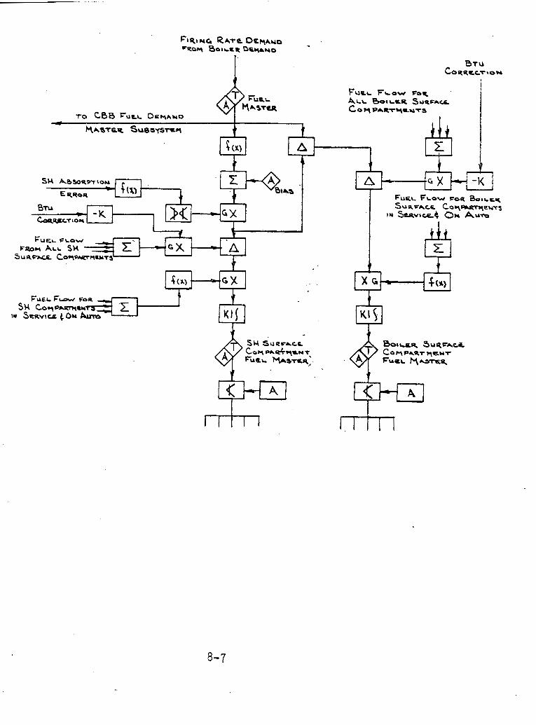
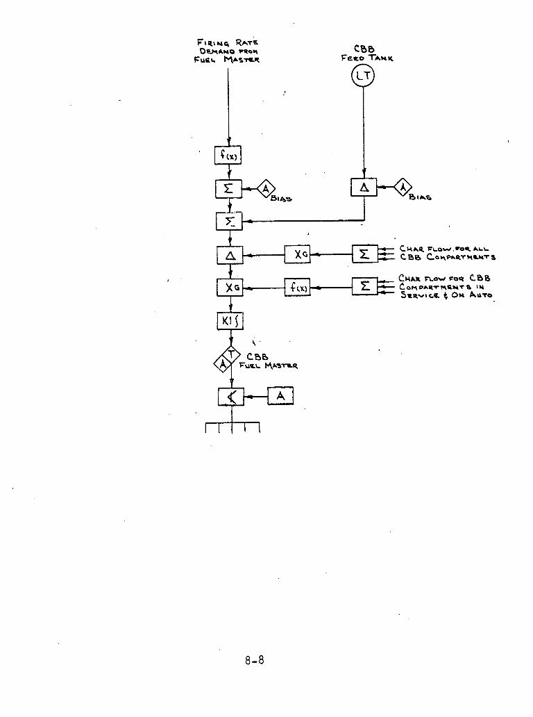

Compartment Group c o n t r o l
Purpose
he purpose of t h e compartment c o n t r o l log ' ic i s t o c o n t r o l f e e d e r nd r o t a r y s e a l speed and t o g e n e r a t e t h e demand f o r s e c o n d a r y . a i r
flow.
Furnace Compartment
The f u e l demand from t h e f u e l mas te r through t h e compartment f u e l mas te r s e l e c t o r s t a t i o n s becomes t h e demand f o r compartment Btu i n - p u t . Th i s demand de te rmines t h e s e t p o i n t f o r compartment bed l e v e l and secondary a i r . The compartment bed tempera ture i s used as a feedforward index s i g n a l . f o r bo th t h e Btu demand and bed l e v e l demand whenever t h e bed tempera ture exceeds i t s upper o r lower o p e r a t i n g l i m i t . A f t e r be ing sca l ed by t h e Btu c o r r e c t i o n t h e demand i s pro- po r t ioned , b i a s e d , and modified by a feedforward index s i g n a l t o e s t a b l i s h t h e l imes tone f e e d e r speed demand. SO2 a s measured leav- i n g t h e u n i t cannot be used as a t r i m on l imes tone f low because of the' o v e r a l l s lugg i shness of t h e f l u i d bed. This measurement r a t h e r should be used as an i n d i c a t i o n t o t h e o p e r a t o r o f t h e need t o make changes i n a predetermined so rben t f low r a t i o .
Feeder Speed Cont ro l
The f e e d e r speed demand w i l l be t h e ou tput o f t h e Btu c o r r e c t e d f u e l demand, provided t h e f e e d e r speed s t a t i o n i s on a u t o and t h a t second- a r y a i r i s not c r o s s l i m i t i n g t h e f u e l f low through t h e low a u c t i o n e e r . The secondary a i r f low c r o s s l i m i t u ses compartment secondary a i r f low p i u s t h e f e e d e r speed c o r r e c t i o n f o r Btu c o r r e c t i o n .
Feeder Speed T o t a l i z i n g
If t h e f e e d e r has been i n s e r v i c e f o r - seconds ( s t a r t u p t i m e r ) , t h e f e e d e r speed i s s e l e c t e d f o r t o t a l i z i n g i n t h e f u e l mas te r sub- system. When t h e f e e d e r s t o p s , t h e c u r r e n t f e e d e r speed i s s t o r e d f o r - seconds (shutdown t i m e ) . A f t e r t h i s , o r when t h e c l o s e p r i - mary a i r f low s i g n a l i s r ece ived from t h e f u e l equipment d i g i t a l con- t r o l system, t h e ze ro f e e d e r speed i s s e l e c t e d f o r t h e f u e l t o t a l i z i n g c i r c u i t . This a l lows t h e c o n t r o l system t o have r e p r e s e n t a t i v e v a l u e s of f u e l f low i n t o t h e fu rnace du r ing t h e t r a n s i e n t shutdown c o n d i t i o n s s o a s t o minimize u p s e t s I n t h e p rocess .
CBB Compartment
The f u e l demand from t h e f u e l master th rough t h e CBB f u e l mas te r s e l e c t o r s t a t i o n becomes t h e demand f o r compartment f u e l . Th i s demand de te rmines t h e s e t p o i n t , compartment bed l e v e l and secondary a i r . The compartment bed tempera ture i s used a s a feedforward index s i g n a l f o r bo th t h e f u e l demand and bed l e v e l demand whenever t h e bed tempera- t u r e exceeds i t s upper o r lower o p e r a t i n g l i m i t .
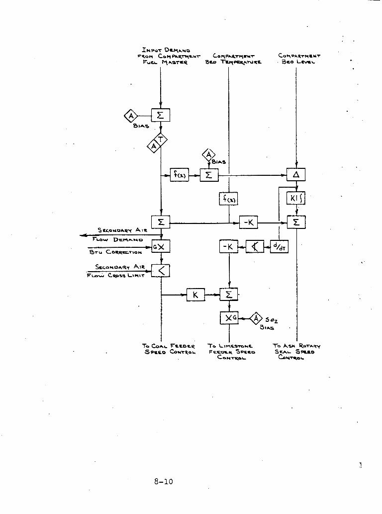
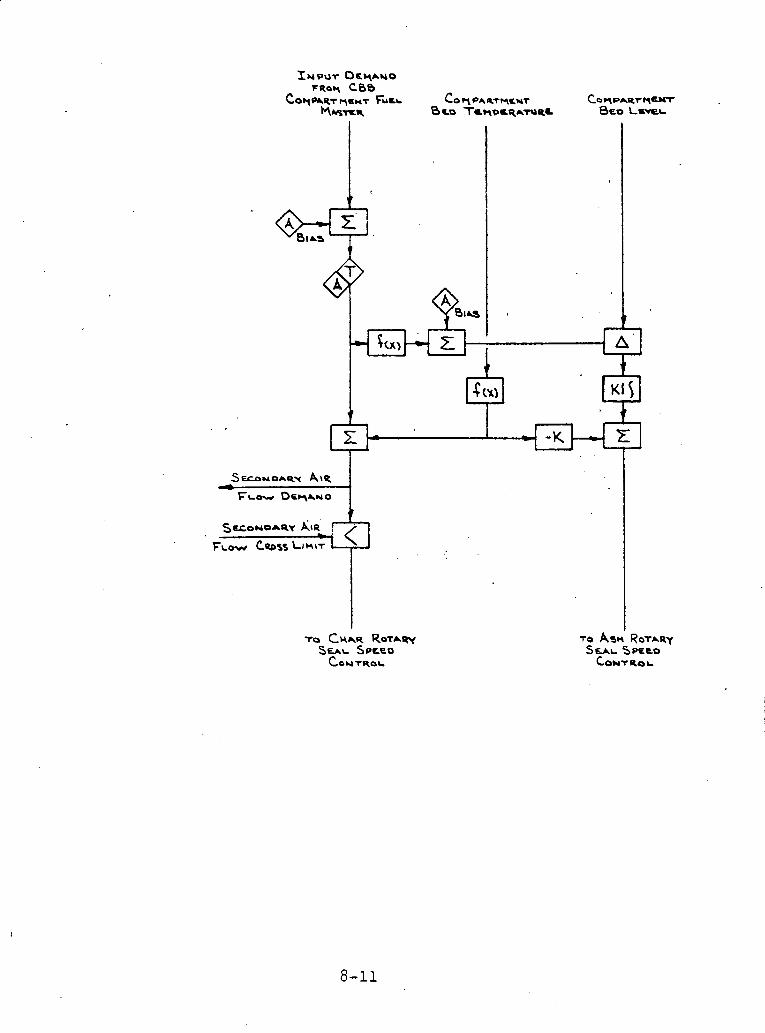

4. A i r . Flow C a l i b r a t i o n
Purpose
T h i s subsystem works i n con junc t ion w i t h t h e i n d i v i d u a l bed s e c t i o n a i r f low c o n t r o l s t o main ta in t h e proper t o t a l b o i l e r a i r f low f o r t h e e x i s t i n g combustion c o n d i t i o n s . The a i r f low c a l i b r a t i o n sub- system p r e v e n t s t h e oxygen con ten t of t h e main bed o r carbon burn-up bed e x i t f l u e g a s from dropping below a minimum a l lowab le va lue .
Analog Logic D e s c r i p t i o n Minimum 02 L i m i t
The minimum oxygen l i m i t i s determined by cons ide r ing t h e i n c r e a s e d e f f i c i e n c y ga ined by reduc ing t h e excess a f r and t h e p o s s i b i l i t y of incomplete combustion and - b o i l e r t u b e c o r r o s i o n which w i l l r e s u l t Yrom ve'ry low excess 8fr ~ p e f l a t l a n ,
A i r Flow C o r r e c t i o n
The subsystem compares t h e measured O2 con ten t t o t h e .minimum l f m i t and r a i s e s t h e a i r f low demand t o t h e compartments i f . t h e O2 con ten t e v e r drops below t h e minimum. A p r o p o r t i o n a l p l u s i n t e g r a l c o n t r o l l e r o p e r a t e s t o keep t h e oxygen con ten t from d ~ o p p i n g below t h e minimum l i m i t . The ou tpu t o f t h e c o n t r o l l e r i s l i m i t e d s o t h a t i t can on ly raise t h e a i r flow.
An a i r f low t r i m s t a t i o n i s provided f o r manual c o n t r o l of excess a i r . The ou tpu t o f t h e c o n t r o l l e r i s l i m i t e d t o a l l o w only reason- a b l e ad jus tmen t s t o t h e a i r flow.
The a i r f low c o r r e c t i o n goes t o t h e s e c o n d a r y ' a i r f low demands In a l l . a c t i v e bed s e c t i o n s .


5 , Primary A i r Cont-rol
Primary and Tempering A i r Fan Coh t ro l
The maximum f u e l demand p rov ides t h e s e t ' p o i n t f o r a i r duc t p res - s u r e . An o p e r a t o r a d j u s t e d bias i s a1,so provided. I f two f a n s a r e i n o p e r a t i o n , t h e e r r o r s i g n a l i s brought d i r e c t l y t o a pro- p o r t i o n a l p l u s i n t e g r a l c o n t r o l l e r which, th rough t h e primary a f r f a n s e l e c t o r s t a t i o n , p o s i t i o n s t h e i n l e t damper t o p rov ide t h e p r o p e r a i r duc t p r e s s u r e . A b i a s may be a p p l i e d t o t h e i n d i v i d u a l f a n s i f n e c e s s a r y . I f on ly one f a n i s i n o p e r a t i o n , a n i n c r e a s e d g a i n i s a p p l i e d t o t h e e r r o r s i g n a l t o provide b e t t e r response t o t h e system. I n t e r l o c k s downstream of t h e s t a t i o n a l l o w c l o s i n g t h e dampers r e g a r d l e s s of s t a t i o n mode of o p e r a t i o n .
P r i m a r y A i r Flow Cont ro l
The a i r f low i s compared t o t h e set p o i n t demand, and t h e e r r o r s i g n a l i s modif ied by a p r o p o r t i o n a l p l u s i n t e g r a l c o n t r o l whleh, th rough t h e primary a i r flow con'brol stakiwns, provides p o s i t i o n i n g o f t h e pr imary a i r c o n t r o l damper. When a compartment i s not i n s e r v i c e , as i n d i c a t e d by t h e l o g i c developed i n t h e fuel equipment d i g i t a l c o n t r o l system, t h e primary a i r Slow w i l l b e reduced t o z e r o through t h e t r a n s f e r below t h e c o n t r o l s t a t i o n .
Primary A i r Temperature Con t ro l
The tempera ture of t h e a i r i s measured a t t h e o u t l e t of t h e mixing b u s t l e . Th i s t empera tu re i s compared t o a n o p e r a t o r a d j u s t a b l e f u e l - a i r t empera tu re s e t p o i n t and t h e r e s u l t a n t e r r o r s i g n a l i s brought t o a p r o p o r t i o n a l p l u s i n t e g r a l c o n t r o l l e r which, th rough ' the a i r temper ing s e l e c t o r s t a t i o n , c o n t r o l s t h e h o t a i r damper and tempering a i r damper. These two dampers a r e c o n t r o l l e d i n a r e c i p r o c a l f a s h i o n s o t h a t when one opens, t h e o t h e r c l o s e s t h e r e - by c o n t r o l l i n g t h e o u t l e t t empera ture .
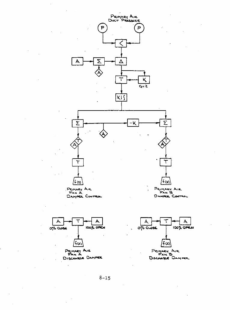
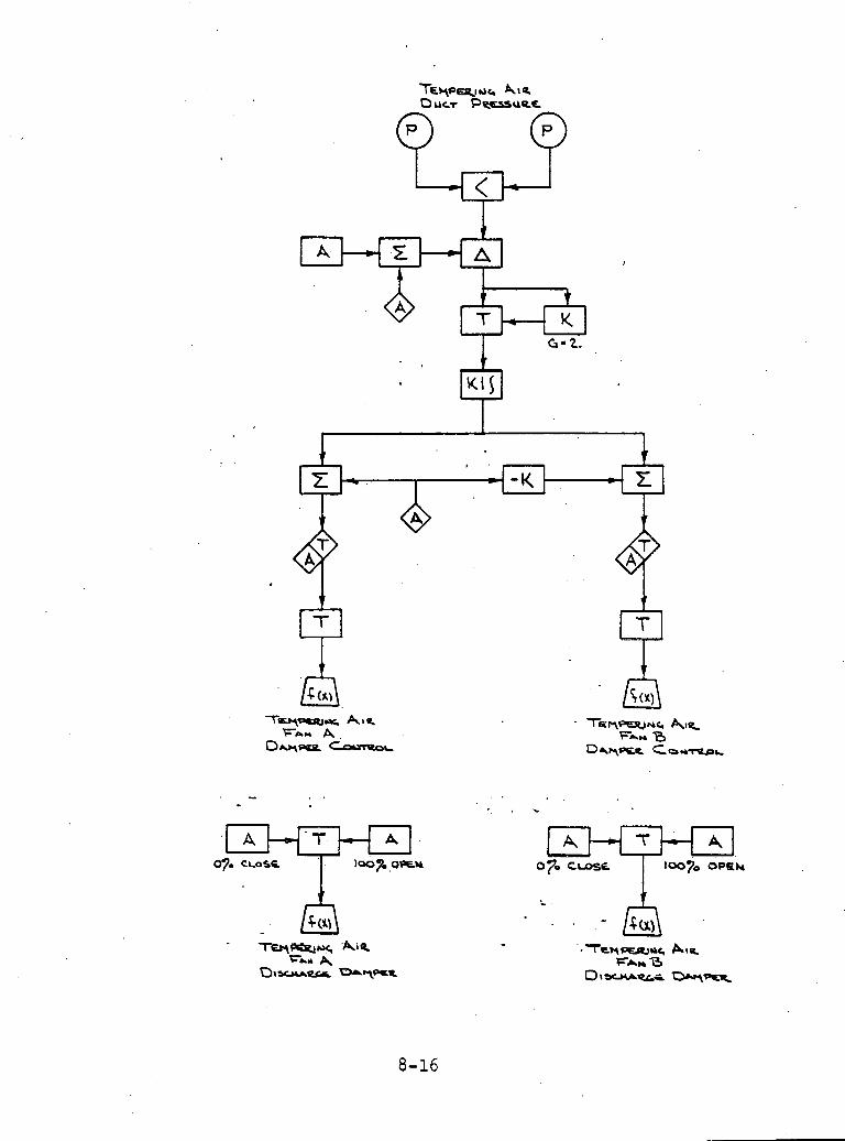

6 . Secondary A i r Flow Control
Purpose
Th i s l o g i c r e g u l a t e s t o t a l bed s e c t i o n a i r flow f o r a l l opera t ing c o n d i t i o n s by rnoduia t ing4he secondary a i r flow c o n t r o l damper.
Secondary A i r Flow Desc r ip t ion
The secondary a i r f low c o n t r o l subsystem programs t o t a l secondary a i r flow u s i n g t h e combustion a i r flow demand p l u s t h e excess a i r demand (opera to r a d j u s t a b l e b i a s ) . The excess a i r demand i s t r i m - med by a c o r r e c t i o n from t h e a i r flow c a l i b r a t i o n subsystem. The demand i s compared t o bed s e c t i o n a i r flow and t h e compartment secondary a . i r dampers a r e pos i t ioned through p r o p o r t i o n a l p l u s in - t e g r a l c o n t r o l a c t i o n . During purge o r l i g h t - o f f , t h e f u e l equip- ment d i g i t a l c o n t r o l system w i l l demand l i g h t - o f f flow through a t r a n s f e r module. When t h e compartment i s shut down, a minimum a i r f low w i l l be maintained through t h e compartment f o r coo l ing pur- poses . The secondary a i r flow l s measured by use of an a i r f o i l a t t h e ,entrance of t h e compartment. This measurement i s temperature c o r r e c t e d t o compensate f o r changes i n t h e secondary a i r d e n s i t y .
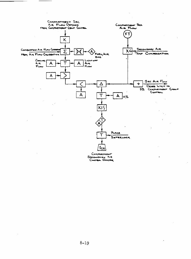
Co.,o- Src Auo rw
I I I xc, - SECO~orgy Am.
AIR F-w &UWT,OU T i e Cow--- BIAS
cw,* I
LIG.:YTOWV
AIR A A Atr F-
5 ' FLW

7 - Forced .Draf t Fan Con t ro l
General D e s c r i p t i o n
The fo rced d r a f t (FD) f a n s provide t h e t o t a l secondary a i r r e q u i r e d by t h e b o i l e r . The FD f a n i n l e t dampers a r e modulated t o main ta in a programmed secondary a i r duc t p r e s s u r e . This c o n t r o l l o g i c a l s o i n c o r p o r a t e s s a f e t y f e a t u r e s t o p r o t e c t t h e b o i l e r and f a n s d u r i n g b o t h manual and au tomat ic s t a r t u p ope ra t ion .
FD Fan I n l e t Damper Cont ro l
The FD fan i n l e t dampers a r e modulated t o c o n t r o l t h e secondary a i r d u c t p r e s s u r e . By va ry ing t h e secondary a i r duc t p r e s s u r e , i t i s p o s s i b l e t o reduce t h e modulation r e q u i r e d by t h e secondary a i r dampers on each f l u i d f z e d bed s e c t i o n . I d e a l l y , t h e secondary a i r dampers w i l l remain f i x e d f o r a l l loads . A program based on f i r 2 n g ra te demand i s used t o develop t h e s e t p o i n t f o r t h e secondary a i r d u c t p r e s s u r e . T h i s program can be b i a s e d by t h e o p e r a t o r t o e f r e c t a program change wfthout r e q u i r i n g r e c a l i b r a t i o n of t h e a s s o c i a t e d f u n c t i o n g e n e r a t o r . Th i s s e t p o i n t w i l l respond i n s t a n t l y t o l oad increase, whi le responding s lowly t o load dec reases . This a s s u r e s t h a t t h e a i r f low w i l l i n c r e a s e f a s t e r than f u e l on load i n c r e a s e s and w i l l d e c r e a s e a t t h e same r a t e a s f u e l on load r educ t ions .
Secondary a i r duc t p r e s s u r e i s compared t o t h e developed s e t p o i n t . Con t ro l a c t i o n a p p l i e d t o any d e v i a t i o n develops t h e base c o n t r o l s i g n a l f o r FD f a n i n l e t damper p o s i t i o n when only one FD f a n i s i n a u t o , t h e g a i n on t h e gas f low e r r o r s i g n a l i s doubled t o main ta in a uniform dynamic response .
FD Fan I n l e t Damper C o n t r o l S t a t i o n s
The FD f a n i n l e t damper c o n t r o l s t a t i o n s permit t h e o p e r a t o r t o se- . l e c t e i t h e r a u t o o r manual c o n t r o l of t h e i n l e t dampers.
FD Fan .. I n l e t - - Damper I n t e r l o c k s and Discharge Damper Con t ro l s
The FD f a n i n l e t and d i scha rge d i g i t a l l o g i c i n t e r l o c k s t h e i n l e t dampers and p o s i t i o n s t h e d i scha rge dampers t o main ta in s a f e opera- t i o n of t h e u n i t .
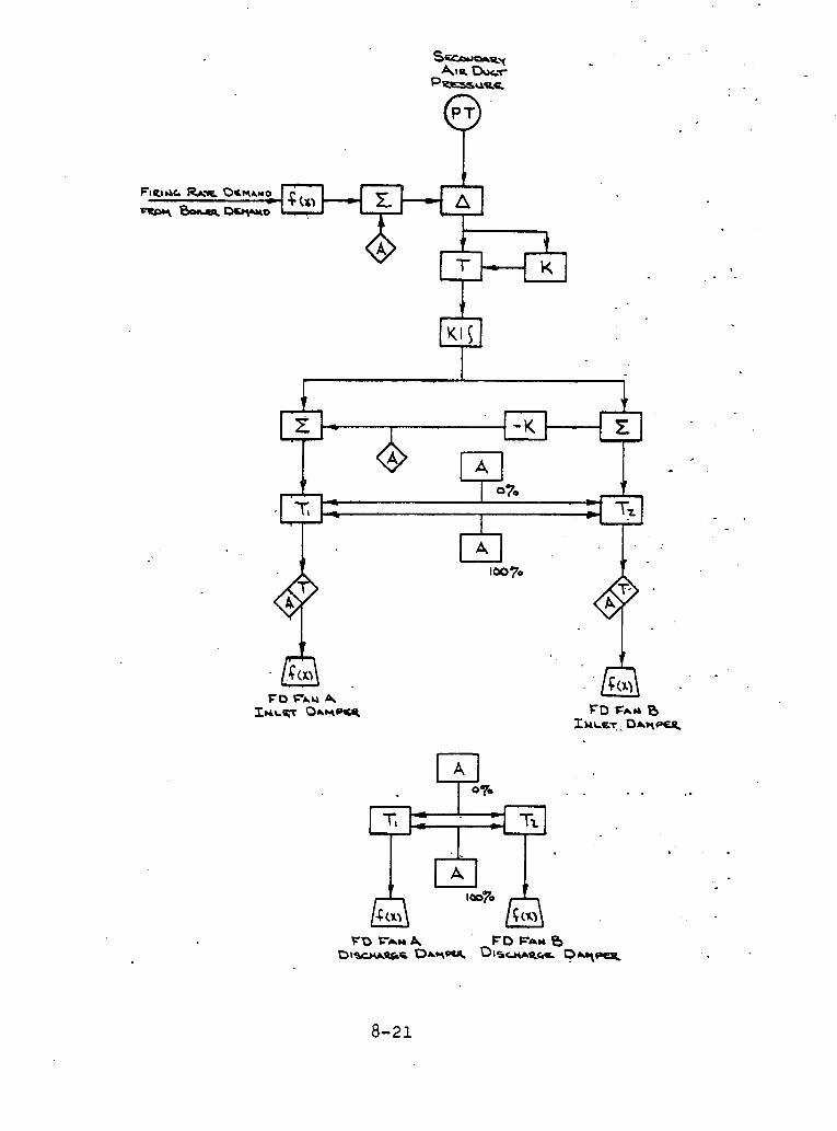
S. I D ( Induced D r a f t ) Fan Cont ro l .Gen.er.a.l .D " . . . . e s c r i p t i ' o n
The I D f a n s p rov ide t h e exhaus t ing f o r c e f o r gas f low through t h e b o i l e r . When t h e FD f a n s and ID f a n s a r e p r o p e r l y balanced, t h e f u r n a c e p r e s s u r e w i l l be a t t h e proper va lue . The I D fans ' f u n c t i o n i s t o c o n t r o l t h e I D f a n i n l e t plenum p r e s s u r e . . A f e e d f o r w a ~ d from f i r i n g r a t e demand a l lows r a p i d response t o load changes. Provis- i o n s t o p r o t e c t t h e fu rnace and CBB from exceeding low p r e s s u r e l i m i t s a r e i nc luded .
D r a f t Con t ro l
P r e s s u r e i s measured by a p r e s s u r e t r a n s m i t t e r , The o p e r a t o r s e l e c t s a d r a f t s e t p o i n t . Th i s s e t p o i n t i s compared t o t h e fu rnace o r CBB d r a f t . S i n c e t h e d r a f t c o n t r o l i s i n h e r e n t l y a low ga in h igh i n t e - g r a l c o n t r o l , a non- l inear f u n c t i o n g e n e r a t o r i s added between t h e e r r o r and t h e p r o p o r t i o n a l p l u s i n t e g r a l c o n t r o l l e r . This conf igura- t i o n p rov ides a c o n t r o l s t a b i l i t y by us ing a h i g h g a i n p r o p o r t i o n a l c o r r e c t i o n on l a r g e p r e s s u r e e r r o r s but low g a i n c o n t r o l when n e a r set p o i n t .
Feedforward Program
Under normal c o n d i t i o n s , t h e f i r i n g ra te demand w i l l p rov ide t h e feedforward s i g n a l f o r t h e I D f ans . Th i s feedforward s i g n a l i s c o r r e c t e d by t h e d r a f t c o n t r o l (desc r ibed above) t o ma in ta in t h e f u r n a c e o r CBB p r e s s u r e a t s e t p o i n t . The feedforward s i g n a l i s low l i m i t e d t o a va lue which w i l l keep t h e I D f a n b l ades open t h e r e q u i r e d amount t o exhaust t h e no-load b o i l e r a i r f low.
I D Fan Gas Flow Con t ro l
The p r e s s u r e drop between t h e fu rnace and t h e I D i n l e t plenum can be used a s a n i n d i c a t i o n of t h e gas f low r a t e th rough the I D fans. S i n c e t h e fu rnace p r e s s u r e i s always c l o s e t o a tmospher ic , t h e I D f a n i n l e t p r e s s u r e i s a d i r e c t i n d i c a t i o n of gas f low r a t e . The re fo re , t h e I D i n l e t plenum p r e s s u r e s i g n a l i s conver ted t o f low r a t e by a f u n c t i o n g e n e r a t o r .
The a c t u a l g a s f low s i g n a l i s compared t o t h e demand f o r g a s f low. Any e r r o r h a s p r o p o r t i o n a l p l u s i n t e g r a l a c t i o n a p p l i e d t o develop t h e I D fan b l a d e p o s i t i o n c o n t r o l s i g n a l . When only one I D f a n i s i n a u t o , t h e g a i n on t h e gas f low e r r o r s i g n a l i s doubled t o main- t a i n a uniform dynamic response .
I D Fan Blade Cont ro l
The developed i n l e t b l ade c o n t r o l s i g n a l i s s e n t t o t h e b l a d e s o f each I D f an . The o p e r a t o r may i n c r e a s e t h e b i a s t o one f a n and a t t h e same t ime reduce t h e b i a s t o t h e o t h e r f a n . Th i s a l lows t h e

I D Fa'n Bl'ade C'ontr'ol - (Cont ' d )
o p e r a t o r t o ach ieve ba lance gas f low between t h e two f a n s . A hand- a u t o s t a t i o n a l lows t h e o p e r a t o r t o s e l e c t t h e developed b l ade con-
' t r o l s i g n a l o r manually c o n t r o l t h e b l ades of t h e f a n . The o u t p u t of t h e i n l e t damper s e l e c t o r s t a t i o n can b e ove r r idden by i n t e r l o c k s which ensu re s a f e o p e r a t i o n du r ing f a n s t a r t u p s and shutdowns and f i n a l l y i n t e r l o c k s which ma in ta in furnace p r o t e c t i o n .
Furnace Implosion P r o t e c t i o n
If fu rnace o r CBB p r e s s u r e drops below a nominal s e t p o i n t , a s p e c i a l c o n t r o l c i r c u i t downstream of t h e s e l e c t o r s t a t i o n s w i l l be a c t i v a t e d , This c i r c u i t w i l l o v e ~ r i d e t h e normal c o n t r o l s i g n a l and c l o s e t h e I D f a n b l ades ( a s r e q u i r e d ) t o keep t h e p r e s s u r e from dropping below s e t p o i n t . T h i s c i r c u i t i s implemented i n such a way t h a t no f a i i u ~ e of t h e p r e s s u r e t r a n s m i t t e r o r c o n t r o l c i r c u i t r y w i l l cause t h e I D f a n b l ades t o open beyond t h e i r d e s i r e d p o s i t i o n .
This c o n t r o l system recogn izes when a main f u e l t r i p has occur red and t a k e s a c t i o n t o reduce t h e ' r e s u l t i n g nega t ive ppessure excur s ion . When a main f u e l t r i p occurs , a l a r g e n e g a t i v e b i a s , based on l o a d , i s added t o t h e c o n t r o l s i g n a l t o t h e .ID f a n b l ades . This immediately s t a r t s t h e b l ades running c losed . This "k i cke rv s i g n a l decays t o ze ro s e r c e n t i n a s h o r t t ime .
I D Fan I n l e t and Discharge Damper I n t e r l o c k s
The I D f a n dampers a r e i n t e r l o c k e d t o ensu re s a f e u n i t o p e r a t i o n du r ing f a n s t a r t u p s and shutdowns. The i n t e r l o c k s prevent a complete blockage of t h e a i r f low p a t h through t h e b o i l e r ,
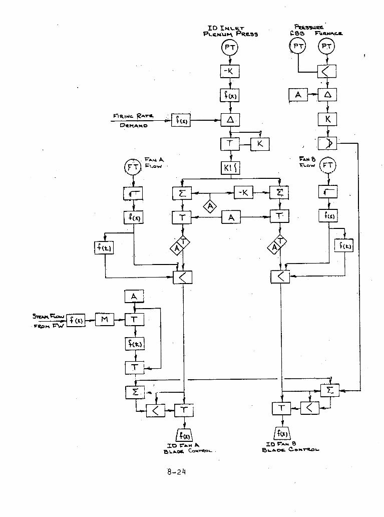
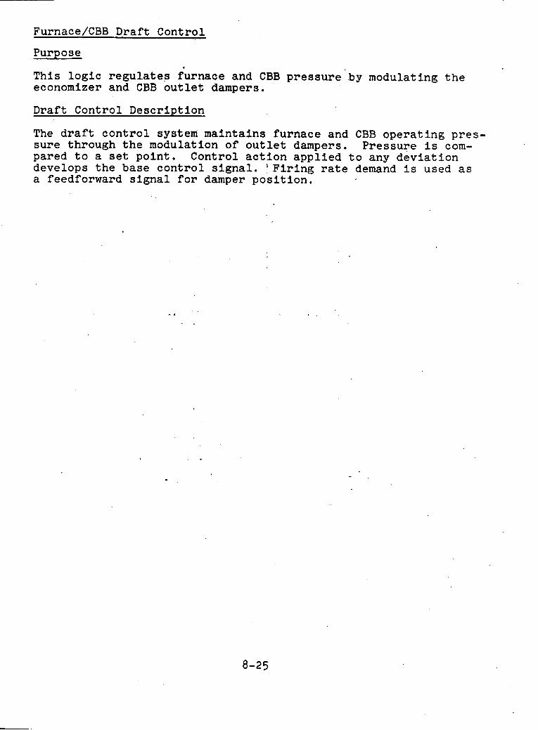
Furnace/CBB Draf t Control
Purpose *
This l o g i c r e g u l a t e s furnace and CBB p r e s s u r e by modulating t h e economizer and CBB o u t l e t dampers.
Draft Control Descr ip t ion
The draft c o n t r o l system mainta ins furnace and CBB opera t ing p res - su re through t h e modulation of o u t l e t dampers. Pressure i s com- pared t o a s e t po in t . Control a c t i o n a p p l i e d t o any d e v i a t i o n develops t h e base c o n t r o l s i g n a l . ' F i r i n g r a t e demand i s used as a feedforward s i g n a l f o r damper p o s i t i o n .
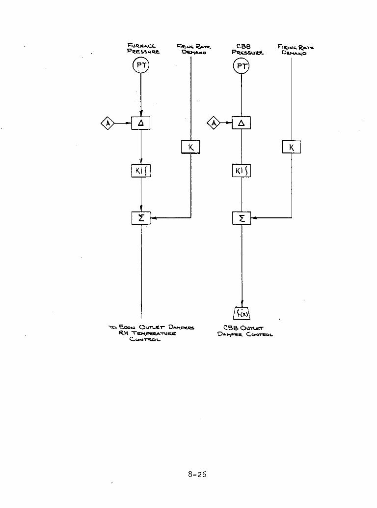
10. Superheat Temperature C'o'nt'r'ol 'wi'th Two S tage Attemperat ion
The superheat tempera ture c o n t r o l system prov ides c o n t r o l over t h e normal tempera ture range of t h e b o i l e r . It i s des igned f o r use wi th a two s t a g e a t t e m p e r a t i n g system where sp ray water i s i n t r o - duced a t t h e i n l e t of t h e second f u l l s u p e r h e a t e r bed, a s w e l l a s t h e f i n a l f u l l s u p e r h e a t e r bed i n l e t . The system recogn izes t h e need f o r e x t r a spray when o v e r f i r i n g on load i n c r e a s e and s r a y P r e d u c t i o n f o r load dec reases over and above t h e s t eady f e e d orward program. L i m i t s a r e provided t o p reven t sp ray ing t h e f i n a l f u l l s u p e r h e a t e r bed i n l e t i n t o s a t u r a t i o n .
S e t Po in t Generat ion
The s e t p o i n t i s manually a d j u s t e d by t h e o p e r a t o r , however, t h e t h r o t t l e p r e s s u r e e r r o r , a s a n i n d i c a t i o n of over and u n d e r f i r i n g , t empora r i ly b i a s e s t h e s e t p o i n t t o more r a p i d l y i n c r e a s e o r de- c r e a s e t h e sp rays a t load change.
Superhea te r I n l e t Temperature Program
The secondary i n l e t tempera ture s e t p o i n t i s programmed from l o a d . A s t h e program w i l l va ry wi th changing b o i l e r c o n d i t i o n s , t h e set p011lL 1s Lr~lmmed from final steam tempera tu re e r r o r through a pro- p o r t i o n a l p l u s i n t e g r a l e r r o r . The p r o p o r t i o n a l and i n t e g r a l con- t r o l l e r s a r e s e p a r a t e d t o permit t h e h igh g a i n and low i n t e g r a l r a t e s r e q u i r e d on f i n a l steam tempera ture c o n t r o l .
Superhea te r I n l e t Contro l
The h i g h e r of t h e two secondary i n l e t t empera tu res i s compared t o t h e set p o i n t genera ted above, and through- a p r o p o r t i o n a l .plus in - t e g r a l c o n t r o l l e r , sets t h e sp ray va lve demand. This s i g n a l i s l i m i t e d t o ze ro pe rcen t t o prevent t h e . i n t e g r a 1 from winding down below ze ro when t h e b o i l e r i s below tempera ture r a t i n g .
Second F u l l Superheater Bed Spray Contro l
The t o t a l spray demand goes d i r e c t l y t o t h e second f u l l s u p e r h e a t e r bed c o n t r o l v a l v e s f o r f i n a l tempera ture c o n t r o l . However, under h igh load o r r a p i d load i n c r e a s e s , t h i s may d r i v e t h e i n l e t tempera- t u r e i n t o s a t u r a t i o n . To prevent t h i s , t h e steam p r e s s u r e i s c a l i - b r a t e d t o s a t u r a t i o n tempera ture p l u s 50°F and compared t o t h e second f u l l superhea te r bed i n l e t tempera ture and l i m i t i n g t h e open- i n g of t h e second f u l l superhea te r bed sp ray va lves .
For ba lanc ing t h e s i d e t o s i d e t empera tu res , a manual b i a s i s a v a i l - a b l e t o t h e o p e r a t o r .
F i n a l F u l l Superheater Bed Spray Contro l
The f i n a l f u l l superhea te r bed sp rays r e c e i v e t h e same demand as t h e second f u l l superhea te r bed sp rays . If t h e demand t o t h e second
f u l l s u p e r h e a t e r bed sp rays a r e n o t l i m i t e d , however, t h i s demand i s s u b t r a c t e d from t h e demand t o t h e f i n a l f u l l s u p e r h e a t e r sprays,6 l e a v i n g a n e t z e r o demand f o r t h e f i n a l f u l l s u p e r h e a t e r bed sp rays . When t h e second f u l l s u p e r h e a t e r bed sp rays a r e l i m i t e d , t h e demand t o t h e s e s p r a y s w i l l be l e s s t h a n t h e t o t a l demand, i n c r e a s i n g t h e f i n a l f u l l s u p e r h e a t e r bed s p r a y s .
Block Valves Con t ro l
These v a l v e s open wide when t h e c o n t r o l v a l v e s a r e open g r e a t e r . t h a n ze ro . They a r e c l o s e d whenever t h e c o n t r o l v a l v e s a r e c l o s e d . When- e v e r t h e b o i l e r o r t u r b i n e i s t r i p p e d , bo th t h e c o n t r o l v a l v e s and b l o c k v a l v e s a r e c l o s e d . The b lock va lves may a l s o be t r i p p e d from a manual t r i p b u t t o n . Once t h e b lock va lves a r e t r i p p e d from a b o i l e r , t u r b i n e o r manual t r i p , t h e r e s e t b u t t o n must be a c t u a t e d b e f o r e they w i l l a g a i n o p e n , a u t o m a t i c a l l y ' f r o m t h e c o n t r o l system.
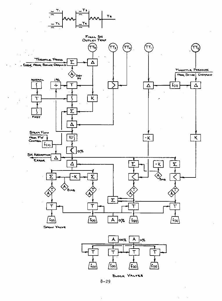

1. Reheat Temperature C o n t r o l
Reheat steam tempera tu re i s b a s i c a l l y c o n t r o l l e d by b i a s i n g t h e gas f l o w i n t h e p a r a l l e l back end of t h e u n i t . The system a l s o provide= f o r sp ray a t t e m p e r a t i o n t o c o n t r o l temporary tempera ture excurs ioi
Spray Con t ro l
The sp ray c o n t r o l i s normally n o t r e q u i r e d . Whenever t h e damper c o n t r o l i s n o t l i m i t e d t h e s e t p o i n t f o r t h e spray i s b i a s +lO°F. Thus, t h e sp ray a c t s a s a s a f e t y o v e r r i d e coming i n t o s e r v i c e when r e h e a t t empera tu re r e a c h e s 10°F above s e t p o i n t . A s t h e damper con- t r o l i s l imi t ed , t h e b i a s i s removed and sp ray w i l l c o n t r o l t o s e t p o i n t .
Reheat Spray Block Valves
The r e h e a t sp ray b lock v a l v e s open whenever t h e sp ray c o n t r o l va lve i s n o t r e q u i r e d c l o s e d , and c l o s e when t h e c o n t r o l va lve i s r e q u i r e d c l o s e d . On a b o i l e r o r t u r b i n e t r i p o r o p e r a t o r i n i t i a t e d spray t r i p , bo th c o n t r o l and b l o c k . v a l v e s a r e c losed . The v a l v e s w i l l n o t respond t o au tomat ic c o n t r o l a f t e r a t r i p u n t i l t h e o p e r a t o r h a s ene rg ized t h e r e s e t pushbut ton.
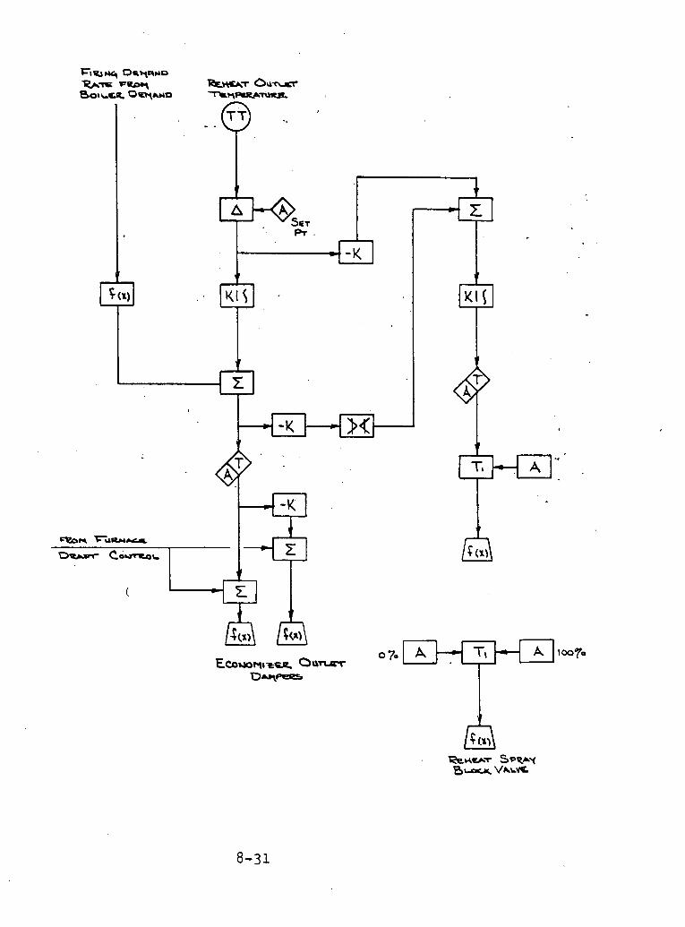
1 2. Feedwater Flow Control
Pur~ose
An adequate feedwater flow is required at all loads to replace the water which has been converted to.steam and sent to the turbine'. The feedwater flow control subloop uses a cascaded feedforward type of control to regulate the feedwater pumps. Drum level set point is selected by the operator. Shrink and swell effects are minimized by using a fe.edforward load index based on steam flow.
Feedwater Flow Demand Development
Steam flow is used as the feedforward signal to generate the basic demand for feedwater flow. This feedforward signal is modified by proportional action applied to drum level error. The operator se- lects the drum level set point which is compared to the actual drum level. Any error, such as errors due to blowdown, meter error, ctc., is used to correct the feedforward program. Since the basic demand for feedforward is developed based 011 load, shrink and swell have only minimal effect on the control system.
Feedwater Flow Control
The feedwater flow from each feedwater pump is measured by a differ- ential pressure transmitter. The AP is converted through square root action to a flow signal. The feedwater flow signal is also temperature compensated.
The demand for feedwater flow is compared to the actual temperature compensated feedwater flow. Any error is operated on by a propor- tional plus integral controller through a control station to correct the feedwater pump speed.
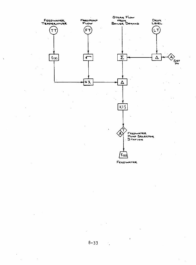

3 A i r 'Heater Cont ro ls
Purp'o s e
During low load opera t ion and to r low ambient temperatures , t h e r e e x i s t s t h e p o s s i b i l i t y t h a t t h e metal temperatures I n t h e h e a t e r w i l l be below t h e dewpoint of t h e f l u e gas . This cond i t ion could r e s u l t i n condensation f o m i n g on t h e su r faces of t h e h e a t e r which l e a d s t o r a p i d co r ros ion and plugging, To prevent - t h i s condi t ion from occurr ing , t h e a i r e n t e r i n g t h e a i r - h e a t e r i s hea ted . The c o r r e c t i v e a c t i o n w i l l i n c r e a s e t h e temperature of t h e su r faces of t h e h e a t e r .
A i r Heater F l u i d Flow Cont'rol
The temperature of t h e a i r e n t e r i n g t h e a i r h e a t e r and t h e temperature of t h e f l u e g a s . l e a v i n g t h e a i r h e a t e r a r e averaged t o provide average a i r he.ater metal temperature. The average metal temperature l o oompared t o a n a p e r a t o r a d j u s t a b l e s e t poin t t o pro- v i d e t h e average meta l temperature e r r o r , This e r r o r has propor- t i o n a l p l u s i n t e g r a l a c t i o n appl led t o develop. t h e f l u i d flow con- t r o l valve p o s i t i o n demand, L i m i t s on t h e i n t e g r a l prevent t h e s i g n a l from exceeding e i t h e r 0% o r 100%. A hand/auto c o n t r o l s t a - t i o n I s provided t o permit d i r e c t opera tor c o n t r o l of t h e f l u l d va lve .
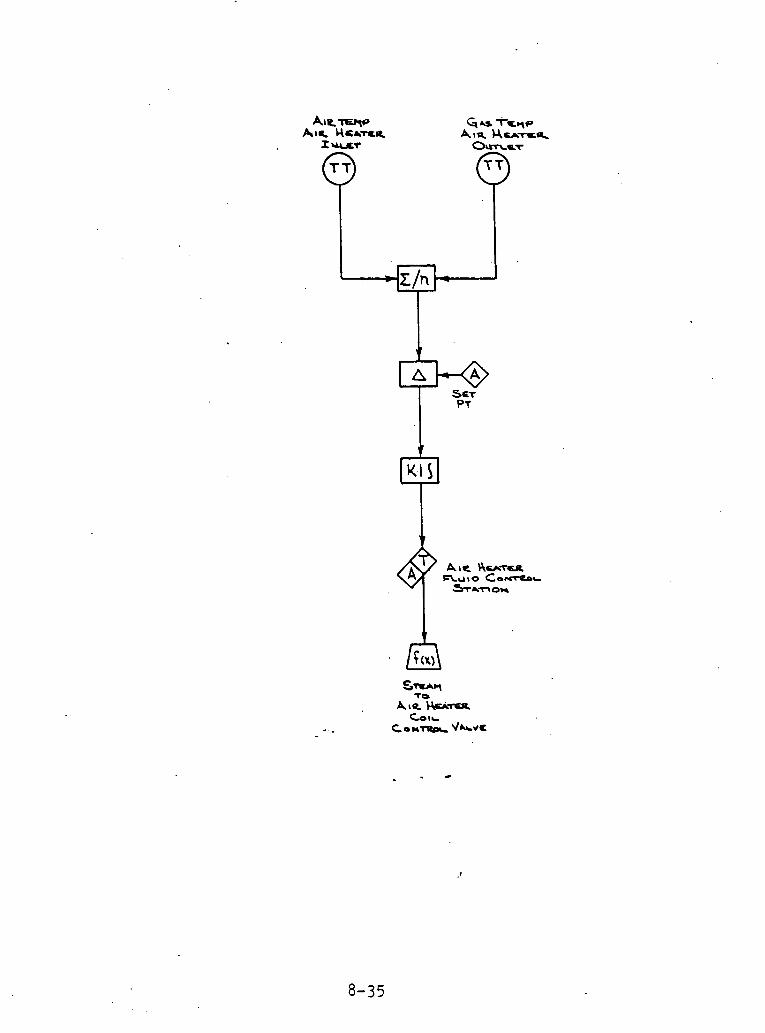

,4 . Steam Turbine Bypass Con t ro l System
Purpose
The purpose o f t h e steam t u r b i n e bypass c o n t r o l system i s to. dump s u p e r h e a t e r o u t l e t steam t o t h e condenser. '
D e s c r i p t i o n
During s t a r t u p of t h e u n i t s u p e r h e a t e r steam w i l l be d i v e r t e d t o t h e condenser u n t i l steam tempera ture i s ach ieved . During normal shutdown, steam f low i s maintained through t h e u n i t by d i v e r t i n g . s t e a m t o t h e condenser . Following u n i t o r a p p r o p r i a t e equipment t r i p s t h e c o n t r o l system w i l l demand' the bypass va lve t o open through a t r a n s - f e r module.
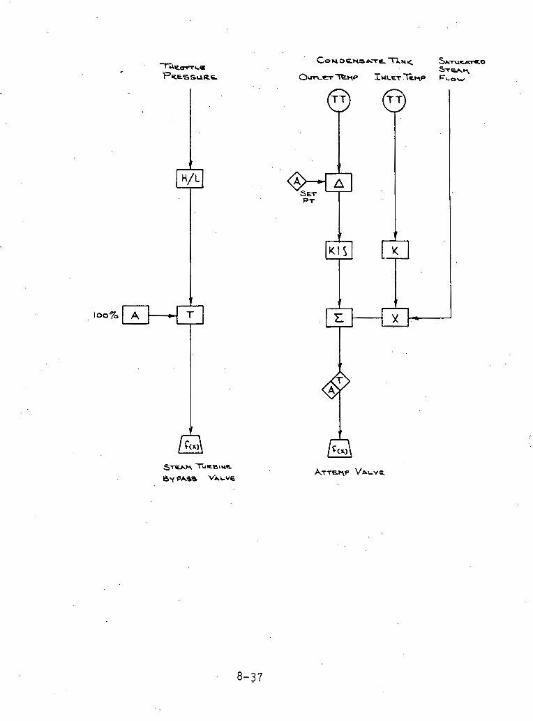
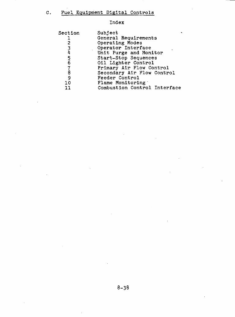
Fuel Equipment D i g i t a l Controls
S e c t i o n 1
Index
Subjec t General Requirements Operating Modes Operator I n t e r f a c e Unit Purge and Monitor S tar t -S top Sequences O i l L ighter Control Primary A i r Flow Control Secondary A i r Flow Control Feeder Control Flame Monitor ing ' Combustion Control I n t e r f a c e
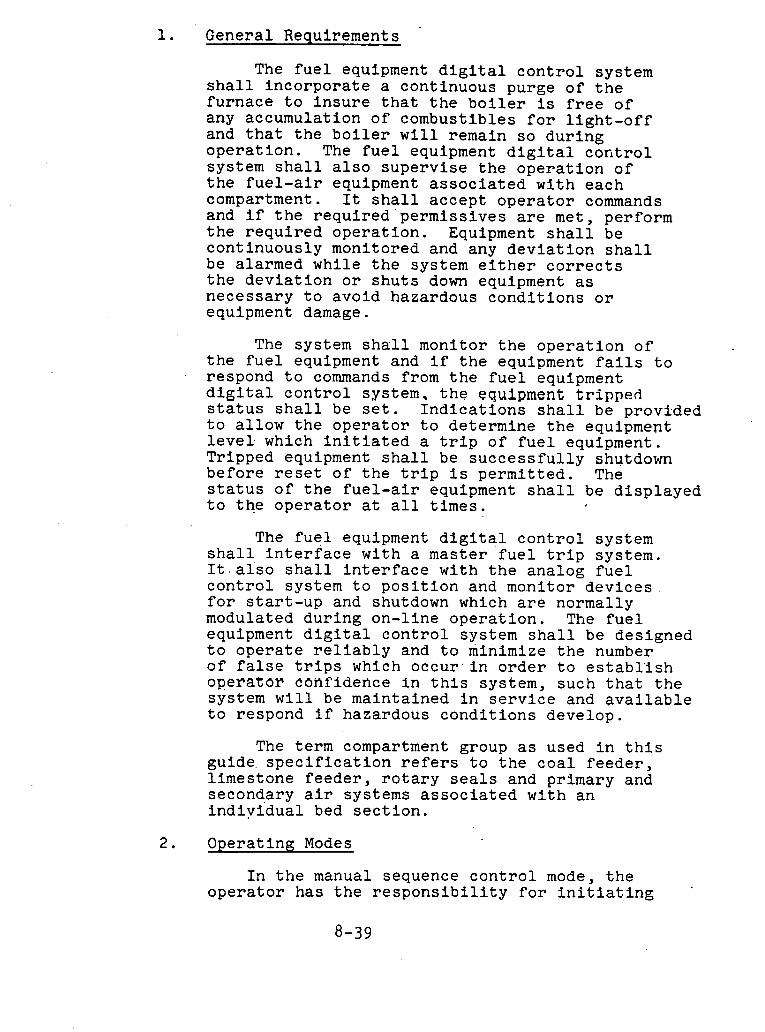
1. General Requirements
The fuel equipment digital control system shall incorporate a continuous purge of the furnace to insure that the boiler is free of any accumulation of combustibles for light-off and that the boiler will remain so during operation. The fuel equipment digital control system shall also supervise the operation of the fuel-air equipment associated with each compartment. It shall accept operator commands and if the required'permissives are met, perform the required operation. Equipment shall be continuously monitored and any deviation shall be alarmed while the system either corrects the deviation or shuts down equipment as necessary to avoid hazardous conditions or equipment damage.
The system shall monitor the operation of the fuel equipment and if the equipment fails to respond to commands from the fuel equipment digital control system, the equipment tripped status shall be set. Indications shall be provlded to allow the operator to determine the equipment level. which initiated a trip of fuel equipment. Tripped equipment shall be successfully shutdown before reset of the trip is permitted. The status of the fuel-air equipment shall be displayed to the operator at all times.
The fuel equipment digital control system shall interface with a master fuel trip system. It,afso shall interface with the analog fuel control system to position and manitor devices for start-up and shutdown which are normally modulated during on-line operation. The fuel equipment digital control system shall be designed to operate reliably and to minimize the number of false trips which occur'in order to establish operator confidence in this system, such that the system will be maintained in service and available to respond if hazardous conditions develop.
The term compartment group as used in this guide. specification refers to the coal feeder, limestone feeder, rotary seals and primary and secondary air systems associated with an individual bed section.
Operating Modes
In the manual sequence control mode, the operator has the responsibility for initiating '

each step in the start and stop sequences at the. proper time and for positioning the modulating devices controlled by the analog fuel and air control system. This system shall monitor the operator's progress and inhibit him from departir from t.he proper operating sequences. The manual control mode does not include sequence timing functions other than for lighter and boiler purge functions. The manual mode of control includes the basic supervisory interlocks, trips and monitorin functions including proper positi'oning of functions contro,lled by the analog system.
In the automatic sequence control mode, the fuel equipment digital control system shall automatically place the compartment group in service, or remove it from service on opera.tor initiation to start or stop that compartment group. In the automatic mode, start/stop sequences, including timing between the steps, are superimposed over the manual mode. As such, all of the interlocking and tripping functions that are part of the manual mode shall be an integral part of the automatic mode.
3. 0p.erator Interface
To provide for operator interaction with the fuel equipment digital control system, inserts for boiler purge control and feeder group control (one for each compartment group) which are 'suitable for mounting on the plantls main control board from which sy.s.tem operat ions .can be monitored anddirected, shall be provided.
Means shall be provided for the operator to initiate a compartment group emergency trip which will shutdown all compartment group equipment.
4. UnLt Purge and Monitor
The unit purge control shall incorporate a oontinuous pl-lrge nf the f i ~ r n a c e and CBB to insure that the boiler is free of any accumulation of combustibles far light-off and that the boiler will remain .so during operation.
Prior to light-off, the air and gas passages of the unit shall be purged of any combustible that may have accumulated. This purging shall be accomplished by maintaining a minimum of 30 percent air flow through all compartments with all sources of fuel to the unit shut-off for at least minutes. Purge permissives shall include:

1. All rotary seals stopped. 2. All feeders stopped. L
3. .All primary air control dampers closed. 4. All lighter oil valves closed. 5. Lighter oil header trip valve closed. 6. All air heaters running. 7. At least one FD and ID fan running. 8. No primary or tempering air fan running. 9 . Purge air flow established through all
compartments. 10. Furnace and CBB air flow greater than
30 percent.
Accumulation of purge credit shall start automatically when the purge permissives are establ.ished. Once the purge is complete, a continuous purge with greater than 30 percent boiler air flow must be maintained. The boiler shall not be tripped on low air,flow, but the start of any additional fuel equipment shall be blocked until air flow has been restored for at least minutes. A continuous purge of one minute with greater than 30 percent air flow shall occur after the start or trip of any feeder, or rotary seal, or the occurrence of a compartment group emergency trip, before any additional fuel equipment may be started.
Completion of the furnace and CBB purge shall allow reset of the master fuel trip. A purge shall be required on a master fuel trip, no FD fans operating, or when all lighters and compartment groups are stopped or tripped after main fuel firing has been initiated. Purge required shall trip the master fuel trip,
j the lighter oil header trip valve and all fuel equipment in the compartment groups.
The unit monitor shall prevent starting any fuel equipment if the firing permissives are not met. The firing permissives shall include :
1. Master fuel trip not present. 2. Continuous purge req~~rements met. 3. All Compartment group equipment trips reset. 4 . Lighter oil header valve open. 5. Lighter oil header pressure above min.imum.

The purge control insert shall provide indications to the operator of the status of the purge and firing permissives and the progress of the purge. These shall include:
1. Purge required. 2. Purge in progress. 3. Purge complete. 4. Status of each individual purge permissive. 5. Status of each individual firing permissive.
A first-out annunciator shall be included to indicate to the operator the initiating cause of a unit trip. Points to be included in the first-out display shall include:
Master fuel trip. Turbine trip. FD fan trip. ID fan trip. Furnace pressure high trip. Furnace pressure low trip. CBB pressure high trip. CBB pressure low trip. PA fan trip. Tempering fan trip. All fuel off trip. Drum level trip. Secondary air duct pressure high. Primary air duct pressure high. Tempering air duct pressure high.
5. Start-Stop Sequences
The fi.le1 equipment digital control system shall start and stop the compartment group following fixed sequences. The system shall be capable of transferring between the start-up and shutdown sequences at any time.
The recommended start-up sequence for main bed compartments with lighters is:
Establish compartment secondary air flow at light-off through the manipulation of the analog a i r flow control sub loog . Start lighters. Hold for bed tempersture to reach light-off value (minimum 1000"~) . Start primary air flow, Hold to allow primary air flow to stabilize (approximately - seconds). Start rotary seals. Start feeders.

8. Release mixing bust.le outlet fuel-air temp,erature. control to automatic.
9. Hold for initial stabilization period (approximately - minutes).
10. Release. 'compartment secondary air flow control to automatic.
11. Release compartment group demand to automatic control.
12. Hold for final stabilization period (approximately minutes).
13. Stop lighters after stable combustion has been established (approximately - minutes) . The recommended start-up sequence for main
bed compartments without lighters is.:
Establish compartment secondary air flow at light-off through the manipulation of the analog air flow control subloop. s old for bed temper~ture to peach light-off value (minimum 1000 F). Start primary air flow. Hold to allow vrimarv air flow to stabilize "
(approximately seconds). Start rotary seals. Start feeders. Release mixing'bustle outlet fuel-air temperature control to automatic. Hold for stabilization period (approxi- mately minutes) . Release compartment secondary air flow control to automatic. Release compartment group demand to automatic control.
The recommended start-up sequence for CBB compartments is:
Establish c'ompartment secondary air flow at light-off through the manipulation of the* analog air flow control subloop. Start lighters. Hold for bed temper~ture to reach light-off value (minimum 1000 F). Start primary air flow. Hold to allow primary air flow to stabilize (approximately - seconds). Start rotary seals. Start feeders. Release mixing bustle outlet fuel-air temperature control to automatic. Hold for initial stabilization period (approximately - minutes).

~elea'se compartment secondary air flow control to automatic. Hold for final stabilization period (approximat'ely' '- minutes). Stop lighters after stable combustion has been established (.approximately '- minutes). Release compartment group demand to manual. Reduce coal-limestone demand to minimum. Close hot air damper and open cold air damper to reduce primary air temperature to minimum. Hold for mixing bustle cooling (approximately - minutes). /
Stop feeders. Stop rotary seals. Establish compartment air flow at light-off. Stop coal-limestone p r 1 r n a . r ~ air flow. Start char primary air flow. Hold to allow primary air flow to stabilize (approximately - seconds). Start rotary seals. Release char mixing bustle outlet fuel-air temperature control to automatic. Hold for initial stabilization period (approximately - minutes). Release compartment secondary air flow control to automatic. Release fuel demand to automatic control.
The recommended shutdown sequence for all compartments is:
1. Reduce fuel demand to minimum. 2. Close hot air damper and open cold air
damper t o reduce primary air tempersal;ure to minimum.
3. Stop fuel flow. 4. Stop rotary seals. 5. Establish compartment secondary air
flow at light-off. 6. stop primary air flow. 7. Hold for compartment burn out
( a p p r o x i r n a . t ~ l y 1 5 minutes 1 , 8. Release compartment secondary air flow
to cooling value.
Start-up and shutdown sequence indicatfona shall be provided to allow the operator to follow the progress of compartment start-up or shutdown sequences when in the automatic sequence mode and to guide the operator through the sequence in the manual sequence mode. These indications shall show the next
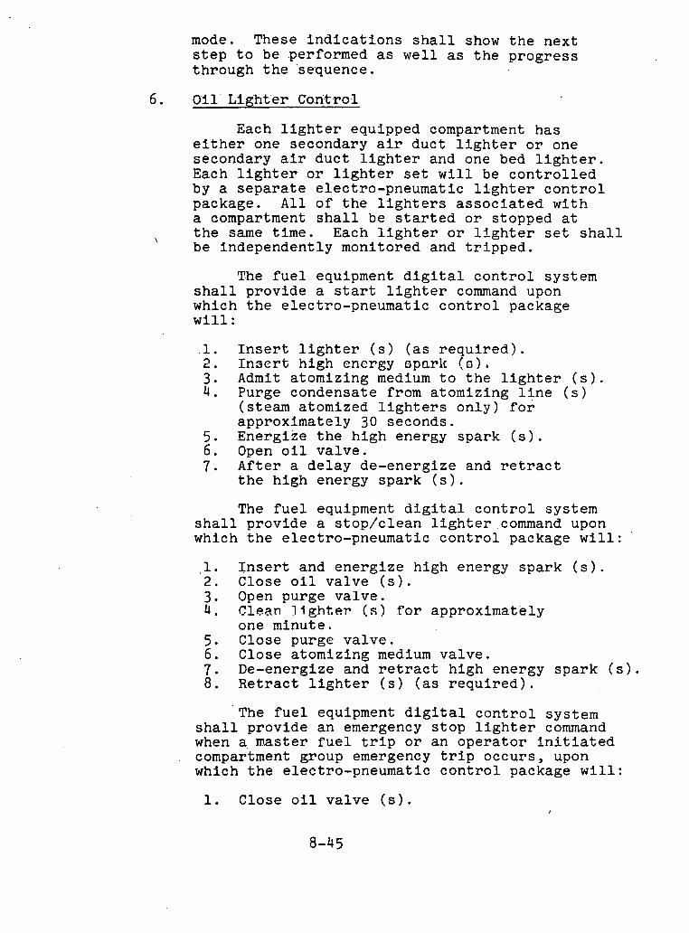
mode. These indications shall show the next step to be performed as well as the progress through the :sequence.
Oil Lighter Co.nt ro.1
Each lighter equipped compartment has either one secondary air duct lighter or one secondary air duct lighter and one bed lighter. Each lighter or lighter set will be controlled by a separate electro-pneumatic lighter control package. All of the lighters associated with a compartment shall be started or stopped at the same time. Each lighter or lighter set shall
\ be independently monitored and tripped.
The fuel equipment digital control system shall provide a start lighter command upon which the electro-pneumatic control package will :
.l. Insert lighter (s) (as required). 2. Insert high energy oparlc (0). 3. Admit atomizing medium to the lighter (s). 4. Purge condensate from atomizing line (s)
(steam atomized lighters only) for approximately 30 seconds.
5. Energize the high energy spark (s). 6. Open oil valve. 7. After a delay de-energize and retract
the high energy spark (s).
The fuel equipment digital control system shall provide a stop/clean 1ighter.command upon which the electro-pneumatic control package will:
1. Insert and energize high energy spark (s). 2. Close oil valve (s). 3. Open purge valve. 4 . Clean Jlghter (s) for approximately
one minute. 5. Close purge valve. 6. Close atomizing medium valve. 7. De-energize and retract high energy spark (s). 8. Retract lighter (s) (as required).
The fuel equipment digital control system shall provide an emergency stop lighter command when a,master fuel trip or an operator initiated compartment group emergency trip occurs, upon which the electro-pneumatic control package will:
1. Close oil valve (s).

2 . Close purge v a l v e . 3. Clos'e atomi.zing medium va lve . 4 . De-energize. h igh energy s p a r k (s) . 5. ~ e t r a c t h igh energy spa rk . (s) . 6 . Re t r ac t ' l i g h t e r ( s ) ( a s r e q u i r e d ) .
The fol'lowing o u t p u t s from t h e e l e c t r o - pneumatic c o n t r o l package a r e a v a i l a b l e f o r u s e by t h e f u e l equipment d i g i t a l c o n t r o l system:
1. L i g h t e r ( s ) i n s e r t e d . 2 . Purge p r e s s u r e t o a tomizer ( s ) g r e a t e r
t h a n minimum (purge va lve open) . 3 . O i l p r e s s u r e t o a tomizer ( s ) g r e a t e r
t h a n minimum ( o i l va lve ( s ) open ) .
A l i g h t e r group s h a l l be t r i p p e d if:
1. B o i l e r t r i p p e d . 2 . Compartment group emergency t r i p
i n i t i a t e d by o p e r a t o r . 3. L i g h t e r f a i l s t o s t a r t when commanded. 4. L i g h t e r o i l va lve no t open a f t e r t r a i l
f o r i g n i t i o n . 5 . L i g h t e r f lame no t d e t e c t e d a f t e r t r a i l
f o r i g n i t i o n .
Maintained l i g h t e r s e l e c t i o n on a compartment group basis s h a l l be provided f o r any system which i n c l u d e s automat ic sequence c n n t r n l . T h t s ca.pa.bl.ll.ty shall. a.1 1 nw t h e o p e r a t o r t o s t a r t o r s t o p t h e l i g h t e r ( s ) any t ime f i r i n g i s pe rmi t t ed i n t h e b o i l e r , provided t h e au tomat ic sequence does not r e q u i r e t h e l i g h t e r ( s ) i n s e r v i c e a t tha t time. I f t h e l i g h t e r 13 i n s e r v i c e , s e l e c t i o n o f main ta ined l i g h t e r ( s ) s h a l l p revent shu t - down of t h e l i g h t e r ( s ) by t h e au tomat ic sequence c o n t r o l .
I n d i c a t i o n s s h a l l be provided t o t h e npe ra . t a r on t h e s t a t u s of t h e l i g h t e r ( s ) . These s h a l l i n c l u d e :
1. L i g h t e r ( s ) ready t o s t a r t . 2 . L i g h t e r ( s ) mainta ined . 3. L i g h t e r group s u c c e s s f u l l y l i t . 4 . L i g h t e r group s u c c e s s f u l l y shutdown. 5. L i g h t e r group t r i p p e d . 6 . L i g h t e r group c l e a n i n g . 7 . L i g h t e r group t r o u b l e due t o unsucces s fu l
shutdown o r shutdown without c l e a n i n g .
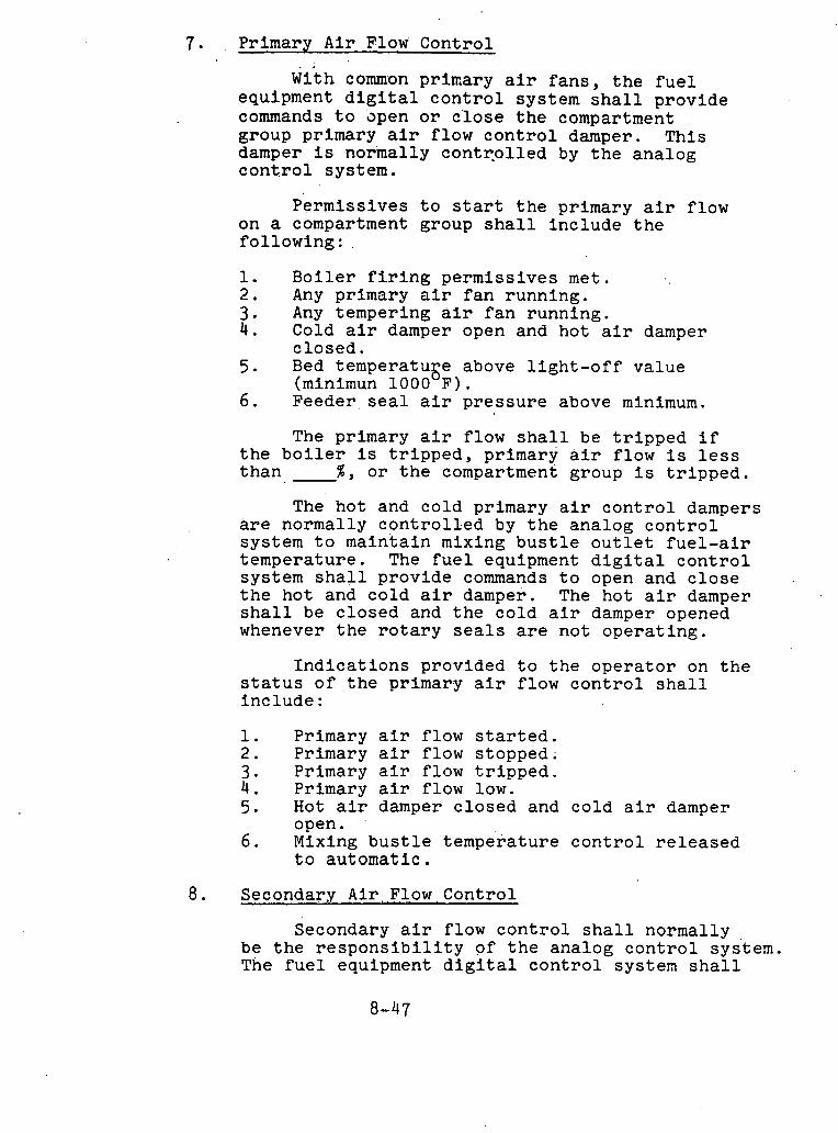
Primary Air )?low 'Control
With common primary air fans, the fuel equipment digital control system shall provide commands to apen or c'lose the compartment group primary air flow control damper. This damper is normally contqolled by the analog control system.
Permissives to start the primary air flow on a compartment group shall include the following: .
1. Boiler firing permissives met. 2, Any primary air fan running. 3. Any tempering air fan running. 4. Cold air damper open and hot air damper
closed. 5 . Bed temperatuge above light-off value
(minimun 1000 F). 6. Feeder,seal. air pressure above minimum.
The primary air flow shall be tripped if the boiler is tripped, primary air flow is less than %, or the compartment group is tripped.
The hot and cold primary air control dampers are normally controlled by the analog control system to maintain mixing bustle outlet fuel-air temperature. The fuel equipment digital control system shall provide commands to open and close the hot and cold air damper. The hot air damper shall be.closed and the cold air damper opened whenever the rotary seals are not operating.
Indications provided to the operator on the status of the primary air flow control shall include :
1. Primary air flow started. 2. Primary air flow stopped. 3. Primary air flow tripped. 4. Primary air flow low. 5. Hot air damper closed and cold air damper
open. 6. Mixing bustle temperature control released
to automatic.
Sec,gn_dary Air, Flow Control
Secondary air flow control shall normally be the responsibility of the analog control s~s'tem. The fuel equipment digital control system shall

prov ide o u t p u t s t o t h e ana log c o n t r o l system t o e s t a b l i s h t h e a i r f lows r e q u i r e d f o r b o i l e r purge and c0mpartmen.t s t . a r t -up and shutdown. During o p e r a t i o n a t .low'er l o a d s t h e d i g i t a l c o n t r o l system s h a l l avo id c a l l i n g f o r i n d i v i d u a l compartment a i r f lows which could reduce t o t a l b o i l e r a i r f low below i t s minimum va lue . On a mas te r f u e l t r i p , t h e d i g i t a l c o n t r o l system s h a l l avo id any c o n f l i c t w i t h t h e normal a n a l o g c o n t r o l o f secondary a i r f low.
I n d i c a t i o n s provided t o t h e o p e r a t o r on t h e s t a t u s o f t h e secondary a i r f low c o n t r o l s h a l l i n c l u d e :
1. Secondary a i r f low c o n t r o l r e l e a s e d t o au toma t i c . , A
2, Seaondary a i r flow a t 1 ,dght-off . 3 . Secondary a i r f low released t;o cuo l ing .
9 . Feeder 'Control
The f e e d e r may b e s t a r t e d i f t h e f e e d e r i n l e t g a t e i s open, bo th r o t a r y s e a l s a r e running , f i r i n g pe rmis s ives a r e met, c o a l o r l imes tone i s d e t e c t e d a t t h e f e e d e r i n l e t and t h e f e e d e r o u t l e t i s no t plugged. The f e e d e r s h a l l be s topped i f t h e b o i l e r i s t r i p p e d o r e i t h e r r o t a r y s e a l i s s topped . The f e e d e r s h a l l be t r i p p e d i f t h e f e e d e r o u t l e t i s plugged, primary a i r f low i s below minimum f o r 20 seconds o r no c o a l o r l imes tone i s d e t e c t e d a t t h e f e e d e r i n l e t o r .on t h e feeder b e l t f oq 20 seconds.
I n d i c a t i o n s provided t o t h e o p e r a t o r on t h e s t a t u s of t h e f e e d e r c o n t r o l s h a l l i n c l u d e : 7
1. Feeder runnlng . . 2 . Feeder s topped . 3. Feeder t r i p p e d . . 4 . Feedel. i n l e t g a t e c l o s e d . 5 . No c o a l o r l imes tone d e t e c t e d a t
f e e d e r i n l e t .
10 . Flame Moni tor ing
The f u e l equipment d i g i t a l c o n t r o l system s h a l l minimfze t h e p o s s i b i l i t y o f developing hazardous c o n d i t i o n s by shi.itt J;ng down l i g h t e r equipment on l o s s o f i g n i t i o n . It s h a l l a l s o minimize t h e number of f a l s e t r i p s which occur.

I n d i c a t i o n s of t h e s t a t u s o f each f lame d e t e c t o r s h a l l be provided t o t h e o p e r a t o r .
11. I n t e r f a c e wi th Analog Con t ro l System
The d i g i t a l c o n t r o l system s h a l l i n t e r f a c e w i th t h e ana log c o n t r o l system t o p o s i t i o n d e v i c e s f o r s t a r t - u p and shutdown which a r e normally modulated d u r i n g on- l ine o p e r a t i o n . Th i s i n t e r f a c e s h a l l be des igned such t h a t t h e l o s s o f power i n one system does no t i n t e r f a c e w i t h t h e p rope r o p e r a t i o n of t h e o t h e r system.
S i g n a l s from t h e d i g i t a l c o n t r o l system t o t h e ana log c o n t r o l system s h a l l i n c l u d e , bu t a r e no t l i m i t e d t o :
1. Close primary a i r c o n t r o l damper. 2 . Allow secondary a i r f low t o c o o l i n g v a l u e . 3. S e t secondary a i r f low t o l i g h t - o f f va lue . 4 . C1os.e hot a i r damper and open c o l d a i r
damper. 5. ,Set compartment f u e l demand t o l i g h t - o f f
va lve .
S i g n a l s from t h e ana log c o n t r o l system t o . t he d i g i t a l c o n t r o l system s h a l l i n c l u d e :
Furnace and CBB a i r f low g r e a t e r t h a n 30%. E i t h e r PA f a n running . E i t h e r tempering a i r f a n running . Unit load g r e a t e r t han 35%. Unit l oad l e s s t h a n 30%. Unit l oad . g r e a t e r t h a n 60%. Compar t~en t f u e l demand a t l i g h t - c f f . Primary. a i r c o n t r o l damper. c l o s e d . Secondzrag air flow a t l ight-csf f . Sec0nda . r~ a i r f low a t coo l ing .
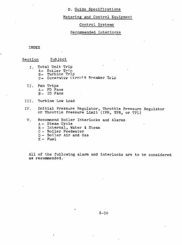
D. Guid.e S p e c i f i c a t i o n s
Meter ing and Cont ro l Equipment
Con t ro l Systems
Recommended I n t e r l o c k s
INDEX
S e c t i o n S u b j e c t
1, T o t a l Uni t T r i p A - B o i l e r T ~ l p B- Turbine T r i p c - C c n ~ r s t o r f . : I~ r .~ l l t Ares.kex8 T r i g
11. Fan T r i p s A - FD Fans B - I D Fans
111. Turbine Low Load
IV. I n i t i a l P re s su re Regula tor , T h r o t t l e P re s su re Regulator o r T h r o t t l e P re s su re L i m i t (IPR, TPR, o r TPL)
V . Recommend B o i l e r I n t e r l o c k s and A l a r m s A - Steam Cycle B - I n t e r n a l , Water & Steam c - B o i l e r Feedwater D - B o i l e r A i r and Gas E . - Fue l
A l l o f t h e fo l lowing alarm and i n t e r l o c k s a r e t o be cons idered as recommended.'
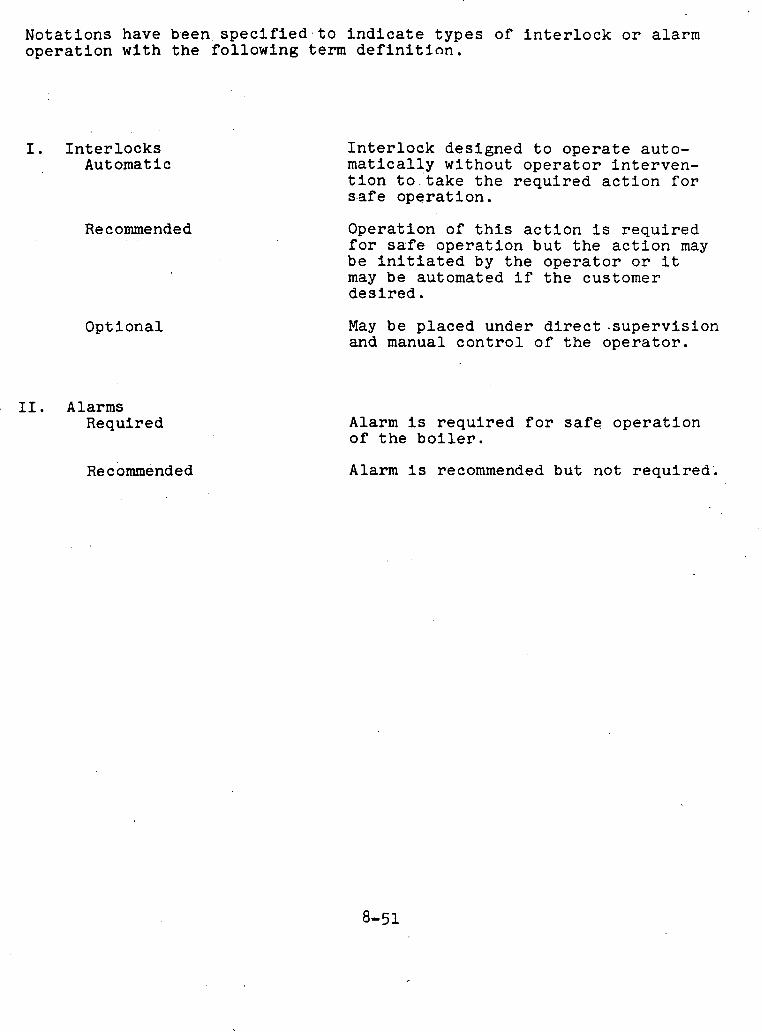
Nota t ions have b.een s p e c i f i e d . t o i n d i c a t e t y p e s of i n t e r l o c k o r alarm o p e r a t i o n w i t h t h e fo l lowing term d e f i n i t i o n .
I . I n t e r l o c k s Automatic
Recommended
Opt l o n a l
11. A l a r m s Required
I n t e r l o c k des igned t o o p e r a t e au to - m a t i c a l l y w i thou t o p e r a t o r i n t e r v e n - t i o n t o . ' t a k e t h e r e q u i r e d a c t i o n f o r s.af e o p e r a t i o n .
Opera t ion of t h i s a c t i o n i s r e q u i r e d f o r s a f e o p e r a t i o n b u t t h e a c t i o n may be i n i t i a t e d by t h e o p e r a t o r o r i t may be automated i f t h e customer d e s i r e d .
May be p l aced under d i r e c t - s u p e r v i s i o n and manual c o n t r o l o f t h e o p e r a t o r .
A l a r m i s r e q u i r e d f o r s a f e o p e r a t i o n o f t h e b o i l e r .
A l a r m i s recommended b u t no t required' .
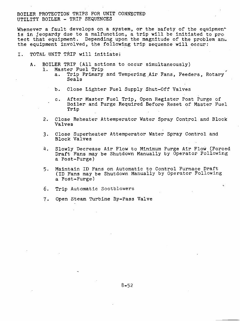
BOILER PROTECTION TRIPS FOR UNIT CONNECTED UTILITY BOILER - TRTP SEQUENCES
Whenever a f a u l t deve lops on a system, o r t h e s a f e t y of t h e equipmen' i s , i n jeopardy due t o a malfunct ion, a t r i p w i l l be i n i t i a t e d t o pro. t e c t t h a t equipment. Depending upon t h e magnitude of t h e problem ank t h e equipment i nvo lved , t h e fo l lowing t r i p sequence w i l l occur :
I. TOTAL UNIT TRIP w i l l i n i t i a t e ;
A . BOILER TRIP ( A l l a c t i o n s t o occur s imul taneous ly) 1. Master Fue l T r i p ./
a. T r i p Primary and Tempering,Air Fans, Feeders , Rotary S e a l s
b. Close L i g h t e r Fue l Supply Shut-Off Valves
c . A f t e r Master Fue l T r i p , Open R e g i s t e r Post Purge of B o i l e r and Purge Required Before Reset of Master Fuel T r i p
2 . Close Reheater At temperator Water Spray Cont.rol and Block Valves
3 . . C l o s e Superhea te r Attemperator Water Spray Cont ro l and Block Valves
4. Slowly Decrease A i r Flow t o Minimum Purge A i r a low (Forced Dra f t Fans may be Shutdown Manually by Operator Following a Post-Purge)
5 . Maintain I D Fans on Automatic t o Cont ro l Furnace Draft (ID Fans may be Shutdown Manually by Opera tor Following a Post-Purge.)
6. T r i p Automatic Sootblowers
7. Open Steam Turbine By-Pass Valve
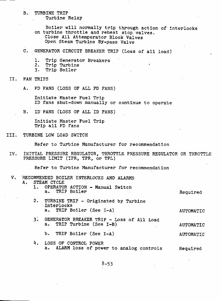
B.: TURBINE TRTP Turbine Relay
B o i l e r w i l l normally t r i p through a c t i o n of i n t e r l o c k s on t u r b i n e t h r o t t l e and r e h e a t s t o p v a l v e s .
Close A l l ACtemperator Block Valves Open Steam Turbine BY.-pass Valve
C . GENERATOR CIRCUIT BREAKER TRIP (Loss of a l l l o a d )
1. T r i p Generator Breakers 2. T r i p Turbine 3. T r i p B o i l e r .
A. FD FANS (LOSS OF ALL FD FANS)
I n i t i a t e Master Fue l T r i p I D f a n s shut-down manually o r , c o n t i n u e t o o p e r a t e
B. I D ' FANS (LOSS OF ALL I D FANS)
I n i t i a t e Master Fue l T r i p T r i p a l l FD f a n s
111. TURBINE LOW LOAD SWITCH
Refer t o Turbine Manufacturer f o r recommendation
I V . INITIAL PRESSURE REGULATOR, THROTTLE PRESSURE REGULATOR OR THROTTLE PRESSURE LIMIT CIPR, TPR, o r TPL)
Refer t o Turbine Manufacturer f o r recommendation
V. RECOMMENDED BOILER INTERLOCKS AND ALARMS A. STEAM CYCLE
1. OPERATOR ACTION - Manual Switch a. TRIP B o i l e r
2. TURBINE TRIP - Orig ina ted by Turbine I n t e r l o c k s a. TRIP B o i l e r (See I - A )
3: GENERATOR BREAKER TRIP - Loss o f A l l Load a. TRIP Turbine (See I-B)
b e TRIP B o i l e r (See I-A)
4. LOSS OF CONTROL POWER a. ALARM l o s s o f power t o ana log c o n t r o l s
Required
AUTOMATIC
AUTOMATIC
AUTOMATIC
Required

b. TRIP b o i l e r on l o s s of power t o ana log . Optional c o n t r o l s a f t e r 0-5 second t ime d e l a y when a l t e r n a t e power supply i s no t a v a i l a b l e .
c . ALARM l o s s of power t o a l l c o n t r o l Required d r i v e s and v a l v e s
d. TRIP b o i l e r on l o s s of power t o a l l c o n t r o l d r i v e s and va lves a f t e r 0-5 second t i m e d e l a y
e . ALARM l o s s o f power t o f u e l equipment Required d i g i t a l c o n t r o l system
f . T R I P b o i l e r on l o s s of power t o f u e l Opt ional equipment d i g l t a l cori.trul s y s't ern art ern 0-5 second t ime d e l a y
5. REHEAT WATER SPRAY CONTROL AND BLOCK VALVES
a. ALARM t h e c o n d i t i o n where t h e b lock and Required c o n t r o l v a l v e s a r e demanded c losed and t h e by-pass va lve i s no t c losed . (Appli- c a b l e when a by-pass va lve around t h e c o n t r o 1 , v a l v e i s provided.)
b e CLOSE c o n t r o l and block v a l v e s whenever Recommended u n i t l o a d i s l e s s t h a n 25 pe rcen t o r t h e demand f o r c o n t r o l va lve p o s i t i o n i s r e q u i r i n g t h e c o n t r o l va lve c losed .
c . TRIP c o n t r o l . a n d b lock va lves c losed on a Master Fuel T r i p o r a Turbine Tr ip . Prevent r e s e t o f con . t ro l and. b l o c k va lve t r i p un t i l . Master Fuel Trip and Turbine T r i p a r e r e s e t , t h e demand f o r c o n t r o l va lve p o s i t i o n i s zero , u n i t l oad i s g r e a t e r t h a n 25 p e r c e n t , and r e s e t i s i n i t i a t e d by t h e o p e r a t o r .
AUTOMATIC
6 . SUPERHEATER WATER SPRAY CONTROL AND BLOCK VALVES
a . ALARM t h e c o n d i t i o n where t h e by-pass Required va lve i s no t c losed under a Master Fuel T r i p cond i t ion . (Appl icab le when a by- p a s s va lve around t h e c o n t r o l va lve i s provided . )

b. TRIP c o n t r o l and b lock va lves c l o s e d on AUTOMATIC a Master' Fuel Tr ip . Prevent r e s e t o f c o n t r o l and b lock va lve t r i p u n t i l Master Fuel T r i p i s r e s e t , t h e demand f o r con- t r o l va lve p o s i t i o n i s zero , and b lock va lve r e s e t i s i n i t i a t e d by t h e o p e r a t o r .
7. STEAM TURBINE BY-PASS VALVE
a. OPEN by-pass va lve on a Master Fue l T r i p AUTOMATIC o r a Turbine Tr ip . Prevent c los ' ing o f by-pass va lve u n t i l Master Fue l T r i p and Turbine T r i p are r e s e t .
B. INTERNAL, WATER & STEAM
1. SECONDARY SUPERHEATER OUTLET TEMPERATURE
a. ALARM h igh steam tempera ture
b. BOILER TRIP - high steam tempera ture
o . ALARM low o t c m tcmpcra turc
d. TURBINE TRIP - low steam tempera ture
Required
Opt iona l
Recommended
Turb. Manuf.
2. FINAL SUPERHEATER BED 1NLET.TEMPERATURE - a. ALARM low steam temperature (TSAT + - OF,) Required
3 . STEAM PRESSURE - a t t u r b i n e s t o p va lves
a. ALARM low steam p r e s s u r e ( l o a d cu tback Turb. Manuf. by t u r b i n e i n i t i a l o r t h r o t t l e p r e s s u r e r e g u l a t o r )
4 . REHEATER OUTLET TEMPERATURE
a. ALARM h igh steam tempera ture Required
5. CIRCULATING WA'!t'ER PUMPS
a. ALARM - c i r c u l a t i n g pump manifold d i f f - Required e r e n t i a l p r e s s u r e swi t ch imbalance.
b. ALARM - 4 pumps i n s e r v i c e and pump Required manifold d i f f e r e n t i a l p r e s s u r e - p s i .
c . ALARM - 3 o r more pumps i n s e r v i c e and Required pump manifold d i f f e r e n t i a l p r e s s u r e
p s i . -
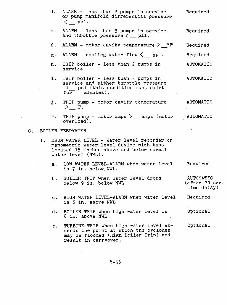
d . ALARM - l e s s t h a n 2 pumps i n s e r v i c e Required o r pump manifold d i f f e r e n t i a l p ressu re < PSI.
e. ALARM - l e s s than 3 pumps i n s e r v i c e and t h r o t t l e p r e s s u r e < ' - p s i .
f. ALARM - motor c a v i t y temperature >-OF
g. ALARM - cool ing water flow < ' gpm.
h . TRIP b o i l e r - l e s s than 2 pumps i n s e r v i c e
i. TRIP b o i l e r - l e s s than 3 pumps i n s e r v i c e and e i t h e r t h r o t t l e p ressu re
?.- p s i ( , t h i s c o n d i t i o n mu& . e x i s t f a r minutes 1.
j. TRIP pump - motor c a v i t y temperature > F.
k. TRIP pump - motor amps > - amps (motor over load) .
C . BOILER FEEDWATER
1. DRUM WATER LEVEL - Water l e v e l r ecorde r o r manometric water l e v e l device wi th t a p s l o c a t e d 15 inches above and below normal water l e v e l (NWL).
a . LOW WATER LEVEL-ALARM when water l e v e l i s 7 i n . below NWL.
b . BOILER TRIP when water l e v e l d rops below 9 In. below NWL
Required
Required
Required
AUTOMATIC
AUTOMATIC
AUTOMATIC
AUTOMATIC
Required
AUTOMATIC (aftel- 20 s e a . time d e l a y )
c . H I G H WATER LEVEL-ALARM when water l e v e l Required i s 6 i n . above NWL
d. BOILER TRIP when high water l e v e l i s Optional 8 i n . above NWL
e . TURBINE TRIP when high water l e v e l ex- Optional ceeds t h e po ln t a t which t h e cyclone^ may be flooded (High Boi l e r T r i p ) and r e s u l t i n car ryover .

Opt iona l f . BOILER FEEDPUMP TRIP - when water l e v e l exceeds t h e l e v e l a t which t h e cyc lones may be f looded (High B o i l e r T r i p ) and r e s u l t i n ca r ryove r a f t e r t h e f u e l and t u r b i n e have been t r i p p e d .
ECONOMIZER RECIRCULATTON VALVE - ( ~ u t omat i c Opera t ion) - t h e feedwater f low s t a r t e d should be developed by t h e f eed pumps s t a r t e d and t h e feedwater f low p a t h t o t h e b o i l e r open ( i . e . , f eedwa te r , shu t -o f f v a l v e s open and feedwater c o n t r o l v a l v e s not c l o s e d ) .
a . CLOSE - economizer r e c i r c u l a t i o n v a l v e s - AUTOMATIC when feedwater i s f lowing t o t h e b o i l e r o r when f i r i n g i s s topped.
b . OPEN - economizer r e c i r c u l a t i o n v a l v e s - AUTOMATIC when feedwater f low t o t h e b o i l e r , i s s topped and f i r i n g i s i n p rog res s .
c,. ALARM - econom.izer r e c i r c u l a t i o n v a l v e s - Recommended mal func t ion i f a c t i o n i n a. o r b . above f a i l s t o t a k e p l ace .
, D. BOILER A I R AND GAS
1. I n t e r l o c k s r e q u i r e d f o r s t a r t of any Induced Draft ( I D ) Fan:
a . Shut-off dampers and c o n t r o l b l ades AUTOMATIC c lo sed on' I D f a n t o be s t a r t e d . Dampers
. r ema in .open on o t h e r I D fan .
b . Shut-off and c o n t r o l dampers open on a t Recommended l e a s t one and' p r e f e r a b l y a l l c e n t r i f u g a l FD f a n s .
c . A t l e a s t one of each kind of shut-off Recommended .damper ( a i r h e a t e r , e t c . ) between t h e
FD f a n i n l e t and t h e s t a c k open.
d. For a i r p o l l u t i o n c o n t r o l systems, a t Recommended l e a s t one s e t o f shut-off dampers open on a p e r module b a s i s .
e . Open shut-off damper on o p e r a t i n g I D AUTOMATIC f a n a f t e r f i r s t I D and FD f a n have been , (Simultaneous s t a r t e d . w i th 2e. )
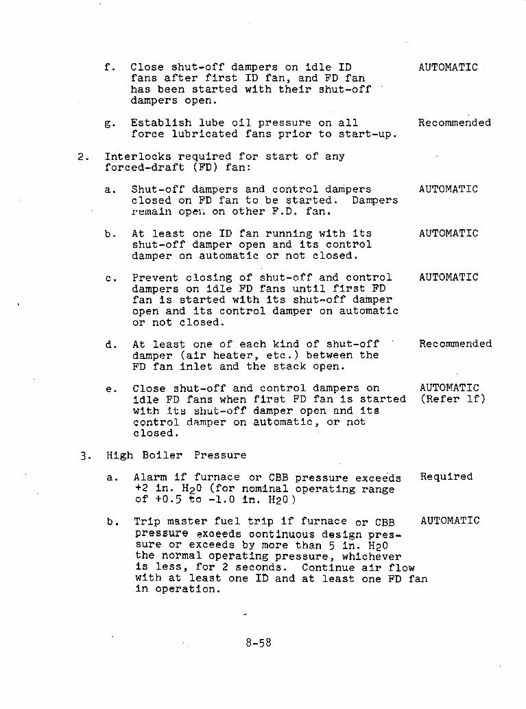
f . Close shut -of f dampers on i d l e I D AUTOMATIC f a n s a f t e r f i rst I D . f a n , and FD f a n h a s been s t a r t e d wi th t h e i r shut-off '
dampers open.
g. E s t a b l i s h lube o i l p r e s s u r e on a l l Recommended f o r c e l u b r i c a t e d f a n s p r i o r t o s t a r t - u p .
2. I n t e r l o c k s r e q u i r e d f o r s t a r t of any f o r c e d - d r a f t (FD) f a n :
a . Shut-off dampers and c o n t r o l dampers AUTOMATIC c l o s e d on FD f a n t o be s t a r t e d . Dampers remain opec on o t h e r F.D. f a n .
b . A t l e a s t one I D f a n running wi th i t s AUTOMATIC shu t -of f damper open and ' i ts c o n t r o l damper on au tomat ic o r n o t c lo sed .
c , Prevent c l o s i n g of shut-off and c o n t r o l AUTOMATIC dampers on i d l e FD f a n s u n t i l f i r s t FD f a n i s s t a r t e d w i t h i t s shut-off damper open and i t s c o n t r o l damper on automat ic o r n o t c lo sed .
d. A t l e a s t one of each k ind of shut-off ' Recommended damper ( a i r h e a t e r , e t c . ) between t h e FD f a n i n l e t and t h e s t a c k open.
e . Close shut-off and c o n t r o l dampers on AUTOMATIC I d l e FD f a n s when f i r s t FD f a n i s s t a r t e d (Refer l f ) with I t s shu t -o f f damper open and i t s c o n t r o l damper on au toma t i c , o r not c lo sed .
3. High B o i l e r P re s su re
a . A l a r m if furnace o r CBB p r e s s u r e exceeds Required +2 i n . Hz0 ( f o r nomlnal o p e r a t i n g range o f +0.5 t o -1.0 i n . H 2 0 )
b. T r i p mss t e r f u e l t r i p if furnace o r CBB AUTOMATIC p r e s s u r e exoeeds oontinuous des ign pres- s u r e o r exceeds by more than 5 i n . Hz0 t h e normal o p e r a t i n g p r e s s u r e , whichever i s l e s s , f o r 2 seconds. Continue a i r f low wi th a t l e a s t one I D and a t l e a s t one FD f a n i n o p e r a t i o n .
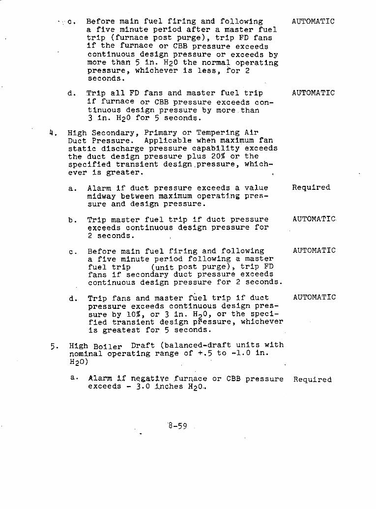
- c. Before main fuel firing and following AUTOMATIC a five minute period after a master fuel trip (furnace post purge), trip FD fans if the furnace or CBB pressure exceeds continuous design pressure or exceeds by more than 5 in. Hz0 the normal operating pressure, whichever is less, for 2 seconds.
d. Trip all FD fans and master fuel trip AUTOMATIC if furnace or CBB pressure exceeds con- tinuous design pressure by more than 3 in. Hz0 for 5 seconds.
4. High Secondary, Primary or Tempering Air Duct Pressure. Applicable when maximum fan static discharge pressure capability exceeds the duct design pressure plus 20% or the specified transient design-pressure, which- ever is greater. ,
a. Alarm if duct pressure exceeds a value Required midway between maximum operat.j.ng pres- sure and design pressure.
b. Trip master fuel trip if duct pressure AUTOMATIC exceeds continuous design pressure for 2 seconds.
c. Before main fuel firing and following AUTOMATIC a five minute period following a master fuel trip (unit post purge), trip FD fans if secondary duct pressure exceeds continuous design pressure for 2 seconds.
d. Trip fans and master fuel trip if duct AUTOMATIC pressure exceeds continuous design pres- sure by lo%, or 3 in. H20, or the speci- fied transient design pressure, whichever is greatest for 5 seconds.
5. High Boiler Draft (balanced-draft units with nominal operating range of +.5 to -1.0 in. H20)
a. Alam $.f neg;a$fiue .furnace or CBB pressure Required exceeds - 3.0 .j,nches H20..

b . T r i p master f u e l t r i p i f negat ive Required furnace o r CBB p ressu re exceeds nega- t i v e 7' i n . Hz0 f o r two seconds,
c . Before main f u e l f i r i n g and fol lowing a AUTOMATIC f i v e minute pe r iod a f t e r a master f u e l t r i p (unit pos t purge) , t r i p a l l FD and I D f a n s If furnace o r CBB p ressu re exceeds n e g a t i v e ' ? in.. H20 f o r two .seconds,
d . An emergency c o n t r o l system t o c l o s e t h e Optional I D f a n b lades i n t h e event of high d r a f t should be considered. This ' con t ro l would a c t e v e n . i f t h e f a n s were on manual c o n t r o l . For u n i t s wt th high negat ive .head c a p a b i l i t i e s such as those wi th g a s clcan-up ~ y ~ t e m s , t h e emergency con- t r o l should p r e f e r a b l y a l s o be app l i ed , t o a s e p a r a t e s e t of dampers. (See
- Pg. 8-65) Loss of Forced-Draft Fans -- pressure switch or ( e l e c t r i c a l i n t e r l o c k . Inc lude a l i m i t swi$ch on each FD f a n shut-off damper t o prove open.
,a. A l a r m l o s s of i n d i v i d u a l f a n and c l o s e Required dampers on t r i p p e d fan .
b , T r i p master f u e l t r i p on l o s s of a l l a l l PD f a n s . Open a l l FD f a n dampers which a r e not a l r eady open, a f t e r a t ime de lay t o avoid high duct p ressu re dur ing f a n coas t down. Dampers t o re - main open (except on t h e f a n t o be s t a r t e d ) . I D f a n s may cont inue t o o p e r a t e o r be shutdown manually.
AUTOMATIC
7 . Loss of Induced Draft Fans -- pressure swi tch o r e l e c t r i c a l i n t e r l o c k . Inc lude a l i m i t swi tch on each I D f a n shut-off damper t o prove open.
a. A l a r m l o s s of i n d i v i d u a l f a n and c l o s e Required dampers and b lades on t r i p p e d fan .
b. T r i p master f u e l t r i p on l o s s of a l l I D AUTUMATIC f a n s -- Tr ip a l l ' FD fans . Open a l l I D f a n dampers a f t e r a t ime delay (0-1 minute should be .adequa te t o avoid high d r a f t dur ing fan coas t down). Dampers t o remain open except on t h e f a n t o be s t a r t e d u n t i l a t l e a s t one I D f a n i s s t a r t e d and i t s shut-off damper opened.
8-60
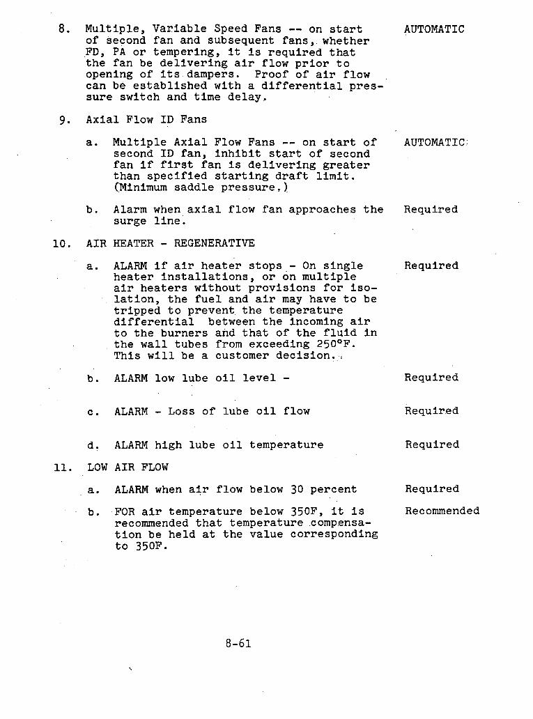
8. Mul t ip l e , Var i ab le Speed Fans -- on s t a r t of second f a n and subsequent f a n s , whether FD, PA o r tempering, i t i s r e q u i r e d t h a t t h e f a n be d e l i v e r i n g a i r f low p r i o r t o opening of i t s dampers. Proof of a i r f low can be e s t a b l i s h e d wi th a d i f f e r e n t i a l p re s - s u r e swi tch and t i m e de l ay .
9. Axial Flow I D Fans
a. Mul t ip l e Axia l Flow Fans -- on s t a r t o f second I D f a n , i n h i b i t s tar t of second f a n i f f i r s t f a n i s d e l i v e r i n g g r e a t e r t han s p e c i f i e d s t a r t i n g d r a f t l i m i t . (Minimum sadd le pressure . ) .
b . Alarm when a x i a l f low f a n approaches t h e surge l i n e .
10. A I R HEATER - REGENERATIVE
a. ALARM i f a i r h e a t e r s t o p s - On s i n g l e h e a t e r i n s t a l l a t i o n s , o r on m u l t i p l e a i r h e a t e r s wi thout p r o v i s i o n s f o r i s o - l a t i o n , t h e f u e l and a i r may have t o be t r i p p e d t o prevent t h e tempera ture d i f f e r e n t i a l between t h e incoming a i r t o t h e bu rne r s and t h a t of t h e f l u i d i n t h e w a l l t u b e s from exceeding 250°F. This w i l l be a customer d e c i s i o n .
b . ALARM low lube o i l l e v e l -
c . ALARM - Loss of l ube o i l flow
d . ALARM h igh lube o i l t empera ture
11. LOW A I R FLOW
a . ALARM when a i r f low below 30 pe rcen t
b. .FOR a i r t empera ture below 350F, i t i s recommended t h a t temperature .compensa- t i o n be h e l d a t t h e va lue corresponding t o 350F.
AUTOMATIC
AUTOMATIC
Required
Required
Required
Requir.ed
Required
Required
Recommended
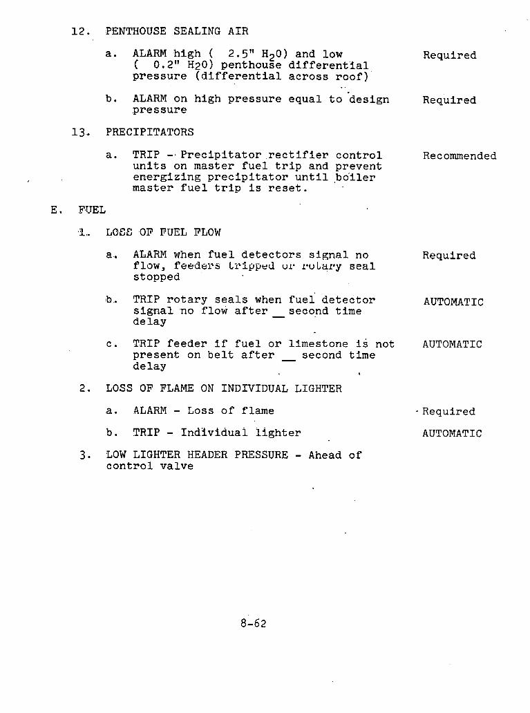
12 . PENTHOUSE SEALING A I R
a . ALARM h i g h ( 2.5" H20) and low Required ( 0.. 2'' H20) penthouse d i f f e r e n t ' i a l p r e s s u r e ( d i f f e r e n t i a l a c r o s s r o o f ) '
b. ALARM on h igh p r e s s u r e e q u a l t o h e s i g n Required p r e s s u r e
13 . PRECIPITATORS
a . TRIP -. P r e c i p i t a t o r . r e c t i f i e r cant-rol Recommended u n i t s on mas te r f u e l t r i p and prevent e n e r g i z i n g p r e c i p i t a t o r u n t i l ,bo ' i l e r mas te r f u e l t r i p i s r e s e t .
I.. LOSE OF FUEL FLOW
a. ALARM when f u e l d e t e c t o r s s i g n a l no Required f low, f eedel%s tr8ipped ulW IOU Lary seal s topped
b. TRIP r o t a r y s e a l s when f u e l d e t e c t o r AUTOMATIC s i g n a l no flow a f t e r second t ime - d e l a y
c . TRIP f e e d e r i f f u e l o r l imes tone i s not AUTOMATIC p r e s e n t on b e l t a f t e r - second t ime de lay
2. LOSS OF FLAME ON I N D I V I D U A L LIGHTER
a. ALARM - Loss o f f lame
b . TRIP - I n d i v i d u a l l i g h t e r
- Required
AUTOMATIC
3. LOW LIGHTER HEADER PRESSURE - Ahead of c o n t r o l v a l v e

E. FUEL - (contld) a. ALARM high or low lighter pressure
after the pressure regulator
b. TRIP individual lighter
c. TRIP individual cyclone if,no main flame detector installed
Required
AUTOMATIC
Recommended
4. LOW LIGHTER ATOMIZING STEAM OR AIR-OIL PRESSURE DIFFERENTIAL
a. ALARM low lighter atomizing steam or Required air-oil differential
b. TRIP lighters AUTOMATIC
5. HARDWARE TROUBLE
a. TRIP individual compartment on second- AUTOMATIC ary air shut-off damper NOT open, feeder off, or rotary seal stopped
b. TRIP feeder or prevent start if.rotary AUTOMAT I C seal is stopped
6. LOW COAL LEVEL IN COAL LINE TO FEEDER - Nuclear or capacitance level detector
a. ALARM'when fuel or limestone level Required is below bunker outlet valve. (Rappers, if used, may be automatically started at this point).
7. LOSS OF PRIMARY OR TEMPERING AIR FANS
a. ALARM and close dampers on tripped fan Required on loss of individual fan.
b. TRIP FIRING on loss of both PA fans AUTOMATIC or loss o f both tempering air fans
8. PRIMARY OR TEMPERING AIR FAN START
a. ESTABLISH lube oil pressure on all force lubricated fans prior to start- UP *
Recommended
b.. Shut-off dampers and control dampers AUTOMATIC closed on fan to be started.
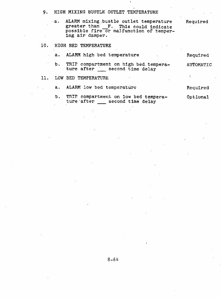
9. HIGH MIXING BUSTLE OUTLET TEMPERATURE
- a . ALARM mixing _ .bus t l e out l e t t empera ture Required g r e a t e r t h a n F. This could i n d i c a t e p o s s i b l e f i reor ma1.function of temper- i n g a i r damper.
1 0 . HIGH BED. TEMPERATURE
a. ALARM high bed tempera ture Requi r e d
b. TRIP compartment on h igh bed. tempera- AUTOMATIC t u r e a f t e r ' second t i m e d e l a y -
11. LOW BED TEMPERATURE l
a . ALARM low bed tempera ture Required
b . TRIP comparptmerit on Pow bed tempera- Op t;luntrl t u r e ' a f t e r - second t ime de lay

I.D. FAN INLET DRAFT
LIMITS VS. LOAD
FURNACE DRAFT CONTROL
REDUNDANT FURNACE DRAFT TRANSMITTERS AND SELECTOR
:F?cE@+~~
POINT
FROM: FD FAN -- FURNACE DRAFT CONTROL CONTROL
I FURNACE To: OTHER r DRAFT I
ID FANS ERROR
ID FAN
STATION*
FUEL TRIP LARGE
w L I.D. FAN RUNBACKS 4
FURNACE DRAFT ERROR
I.D. FAN CONTROL DPR.
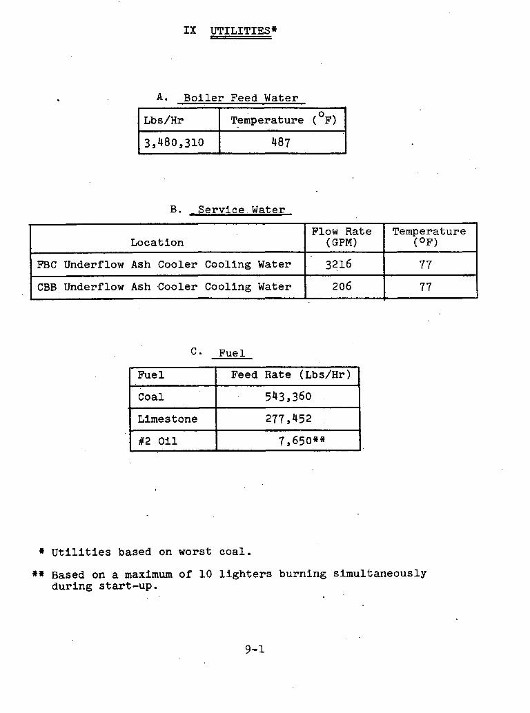
A. Bo i l e r F.eed Water
B. Se rv ice . Water
. .
Lbs/Hr t
C * Fuel
Temperature (OF)
1 ~ u e l 1 Feed Rate (Lbs/Hr) I
>
I ~ i m e s t o n e 1 277,452 I
Flow Rate (GPM)
3216
206
Location
FBC Underflow Ash Cooler Cooling Water
CBB Underflow Ash Cooler Cooling Water
I
I .. . -
#2 o i l 7 , 6 5 0 ~ " I
Temperature (OF>
77
77 =,
* U t i l i t i e s based on worst coa l .
** Based on a maximum of 10 l i g h t e r s burning s imultaneously dur ing s ta r t -up .
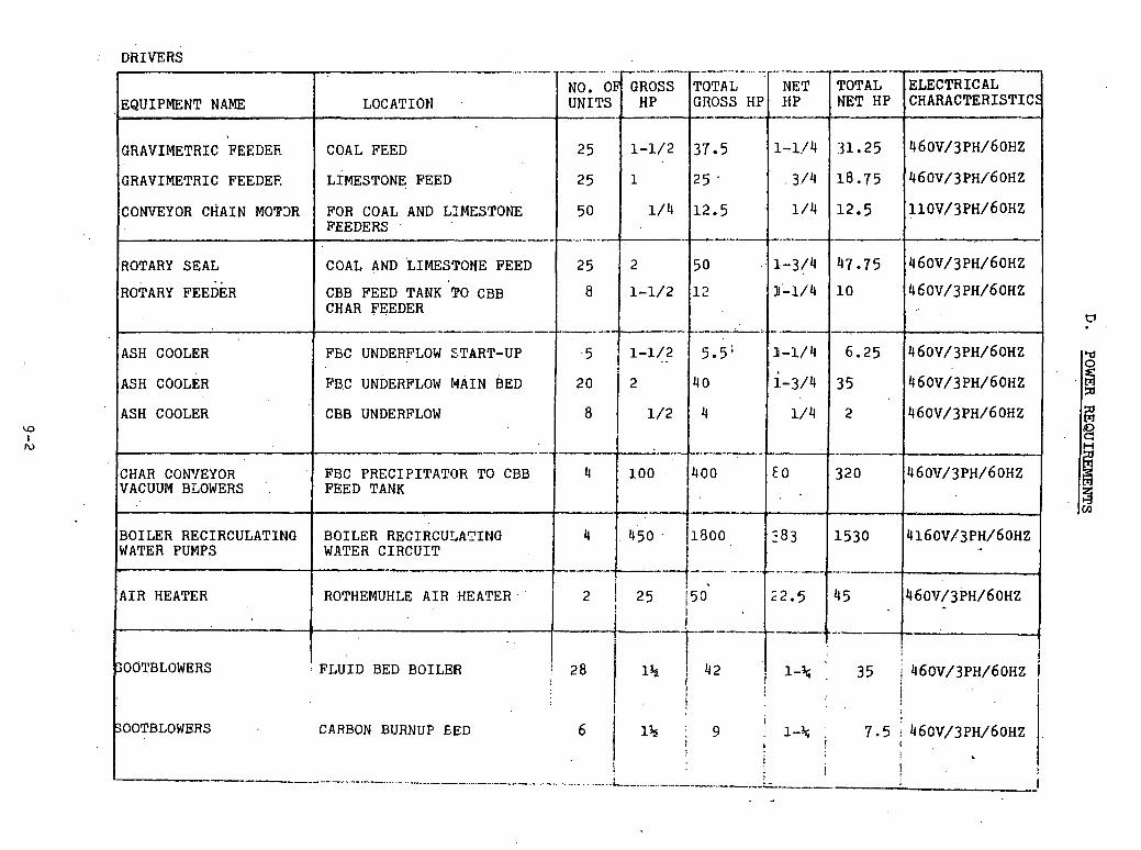
.
DRIVERS
NO. OF UNITS --.
25
25
50
-.-
EQUIPMENT NAME .
GRAVIMETRIC FEEDEF.
GRAVIMETRIC FEEDEE
CONVEYOR CHAIN MOT3R
...?- ...- - ..-. - GROSS HP .
1-1/2
1
1/4
LOCATION
COAL FEED
LIMESTONE FEED
FOR COAL AND LIMESTONE FEEDERS
---.-.-
ROTARY SEAL . .
ROTARY FEEDER
ASH COOLER
ASH COOLER
ASH COOLER
CHAR CON'IEYOR VACUUM BLOWERS
BOILER RECIRCULATING WATER PUMPS
AIR HEATER
-.
SOOTBLOWERS
--.?... ..--.
NET .HP
1-1/4
.3./4
1/4
,-..,--.--
----- TOTAL GROSS HP --ye-,
37.5
25 *
12.5 -I
"-....a-
COAL AND LIMESTONE FEED 2 5 0 1-314 47.75 ~ ~ O V / ~ P H / ~ O H Z
CBB FEED TANK TO CBB 1-1/2 12 - 1 10 460V/3PH/60HZ CHAR FEEDER '3
------..
FEC UNDERFLOW START-UP . . 1-1/4 6.25 460~/3PH/60H~ 'd
FBC UNDERFLOW WAIN BED 2 o 2
CBB UNDERFLOW 8 460V/3P~/60HZ
----- - FBC PRECIPITATOR TO CBB 320 FEED TANK
--- in
BOILER RECIRCULATING 4160~L3PH/60HZ WATER CIRCUIT -- ROTHEMUHLE AIR HEATER,'
-- !
:FLUID BED BOILER i 28 1% 1 42 I I
35 j 4 6 0 ~ / 3 ~ ~ / 6 0 ~ ~ I ,I i I ! . .
300TBLOWERS CARBON BURNUP E.ED 7.5 ; ~ ~ ~ V / ~ P H / ~ O H Z 1 .
I ! : -------.--. - ------... '.. ........ . .---..: -.-----,-.,-.-----..- ----:- . . 1
- -
---.-..------.-
TOTAL NET HP
31.25
18.75
12.5
----..
ELECTRICAL CHARACTERISTICS
~ ~ O V / ~ P H / ~ O H Z
460V/3PH/6OHZ
~ ~ O V / ~ P H / ~ O H Z
--
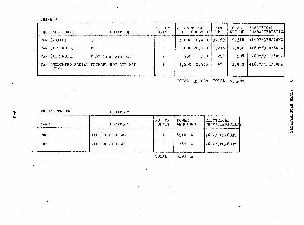
D R I V E R S .
TOTAL 35,688 ~ O T A L 25,307
P R E C I P I T A T O R S
NAME .-
EQUIPMENT NAME
FAN ( A X I A L )
FAN ( A I R F O I L )
FAN ( A I R F O I L )
FAN ( M O D I F I E D R A D I A L T I P ) - .
F B C
CBB
NO. O F LOCATION - U N I T S
.-.---
I G 2
F D ?
T E M P E 3 I N G A I R FAN 2
PRIMARY HOT A I R FAN 2
.-.-
GROSS HP -.--. 5,OOC
l0,OOC
35c
l,25~
LOCATION
TOTAL GROSS H P .-.-.----.--... 10,000
20,000
700
2,500
-
LOCATION ---. ---..---
E X I T F B C B O I L E R
E X I T GBB B O I L E R
-
---.--.--.--.--.- N E T H P
.- .---
3.159
7,215
254
975
TOTAL N E T HP .-- 6,318
14,430
508
1,950
E L E C T R I C A L C H A R A C T E R I S T I C
4 1 6 0 ~ / 3 ~ ~ / 6 0 ~ ~
4160~/3~~/60Hz
460~/3PH/60Hz
4 1 6 0 ~ / 3 ~ ~ / 6 0 H z
TOTAL 5290KW
.--- NO. O F
U N I T S ------
4
1 -
P0WE.R E L E C T R I C A L REQUIRED C H A R A C T E R I S T I C -- ..-- - -----
4510 KW 460V/3PH/60HZ
780 KW . 4 6 0 V / 3 P W 6 0 ~ ~
--- ..-.-.-. 7 .-..----
BASIS OF SYSTEM COSTS 'AND SCHEDULE
The costs developed for the system (See Page 10-2) were based on B&Wts base.estimating data for those items normally supplied by B&W -,and on. vendor quotat ions for items normally purchased. The costs include B&Wts G & A expense and profit as normally used by B&W in a proposal for a commercial boiler. No development costs or risk contingencies were Included in the, estimate. All costs
. are present day dollars.as of December 1, 1977. As stated above, no'contingency has been included
in the costs presented in this section. However, it must be remembered that certain assumptions were made to establish the design of the FBC system. If these assumptions are borne out by future developments, we believe that the costs presented.here represent a reason- able appraisal of what an FBC system would cost. Develop- ing technology may identify areas and. conditions which could significantly affect system costs.
Page 10-3 is a graphical representation of the design and construction schedule for the.570 MW fluid bed boiler commercial unit culminating in start-up fifty months after engineering begins. '

'! MATERIAL ERECTION MANHOURS
I. BASE 36;709,6OO ' 1,197,630'
11. CONTROLS '
111. PRECIPITATORS 9,035,600 154,100
IV. TOP STEEL . .
. . 307,700 .
V.. COAL AND LIMESTONE 5,673,800 BUNKERS
. BALANCE OF BOILER 2,562,700 17,840 PLANT
TOTAL 57,485,000 1,433,000

XI. AFB Boiler State of The Art
A. Introduction
Recent interest in fluidized bed combustion for utility application has been stimulated by the in-process pollution control capability of the FBC:
SO, emo oval: CaC03 + SO2 + 1/202%caso4 + C02
Low NOx Format ion
SO removal is accomplished by reaction of limestgne or lime with the SO released during coal combustion to produce a dry ~ 2 ~ 0 ~ waste product. LOW NOX formation is experienced as well begause of the low operating temperature (1500-1600 F). However, the viability of this approach must still be established relative to that of wet scrubbing:
L Wet Scrubbing: CaC03 + SO2- CaSO + C02
3 This alternate approach also involves the
reaction of limestone with SO2 in the stack gas but produces a wet slurry of CaSO . Wet scrubbing is fairly well developed and accgpted as a commercial system.
The above consideration is primary in nature and worth emphasizing because one of the key problems currently facing the FBC is the'hlgh limestone requirements to meet EPA sulfur dioxide emission standards (1.2 lbs. SO /million Btu input). This situation could be furlher aggravated if the EPA proceeds to enact more restrictive standards for sulfur emission. This'is a 1i.kelihood based on recent reports'in the literature (Energy .Research Digest, November 7, 1977). In wet scrubbing systems the required Ca/S mole ratio is on the order of 1.1, while in the FBC system ratios of up to 4-5 may be needed depending on the sulfur content of the coal.' The latter represents an economically unacceptable amount of limestone, and a major R&D thrust is needed to minimize these requirements. NO formation, on the other hand, can be comfortablg maintained below current EPA emission standards (0.7 pounds per million Btu or about 525 ppm) but as low as expected because of fixation of fuel nitrogen. Values of 250 to 500 ppm of NO In the off-gases have been observed when, burnfng coal containing about 1.0 to 1.4% fixed nitrogen in fluidized beds.
Nevertheless, while.the economics of the fluid bed combustion process are not firmly established, some investigators feel that capital and operating costs could be lower than
conventional plants using wet scrubbing for sulfur control and that further improvement is potentially possible. To achieve an acceptable status, large- scale demonstration of the concepts is needed. However, before this can be accomplished, it is our general feeling that the level of confidence in design knowledge must be increased as the desirable configurations of the system become more clearly defined through pilot activities.
Background history and documentation is thoroughly treated in References 1-4. It is the purpose of this section to analyze some of the existing problem areas in the light of this literature and/or in-house knowledge and to identify areas requiring additional development work. In order to develop this overall picture, we' will first scan'a simple schematic flowsheet (page 1 1 - 2 8 ] for an FBC system and highliaht such problem areas in the following pages.
B. Process overview
starting at the front end of the process on page 11-28 , the first objective is to combine coal and limestone and to convey them to the FBC. To date the.pref.erred method of doing this has been pneumatic transport and introduction of the feed materials near the bottom of the FBC just above the air,distributor plate. Based on prior B&W experience with cyclone furnace firing, we believe that it may be possible to avoid predrying by employing preheated air as the conveying medium. This practice requires about 20% of the combustion air which is several fold greater than the amount necded from the standpoint of conveying alone. The effect of thio ad.d.l . t j .onal amount s f air on FBC performance needs to be developed.
The next step is a problem of major concern and relates to the means of splitting the feed stream into a large number of smaller ones for distribution into the FBC.. This is required to assure reasonably good combustion in the PBC. As the,coal enters at or near the bottom of the bed, it must be further distributed in a radial direct'icrn by means of injcctl.on nozzlee. Overhead feeding and spreading in the freeboard of the FBC is an alternate approach under consideration by same investigators.
The desfgn of the atmospheric FBC involves the selection of a number of critical operating
Parameters. Those of greatest significance are:
.Bed temperature
.Excess ai'r
.Superficial gas velocity
.Feed particle size and/or elutriation of bed solids
With regard to bed temperature the efforts of many investigators have reasonably well defined the desirable operating range. In order to promote rapid combustion and reactionorates of SO2 with lime, temperatures ~bove 1400 F are preferred. However, above 1600 F sorbent activity appears to drop and at higher temperatures volatilization of corrosive alkali metals can potentially commence to become a problem, in addition bed agglomeration may occur., Therefore, an operating temperature of about 1550 F is considered optimum for the FBC. Operation of the FBC at 15% excess air seems to be an acceptable design condition. However, inothe case of the CBB a higher temperature of 2000 F and also a greater amount of excess air (50%) is desirable to assure adequate carbon burnout.
Wide ranges of gas velocity .from 3 to 15 ft/sec have been studied, but no specific guidelines have been found in the open literature to establish design recommendations. However, general preference has developed- for the use of coarse feed materials. Pope, Evans and Robbins appears to be the prime proponent of coarse grinds (-%,11 x 0) requiring a high superficial gas velocity of 10-15 ft/sec., whereas'others such as Westinghouse, the British consortiums, etc. prefer to operate under conditions permitting the use of lower velo~ities in the range of 3-8 ft/sec.
It should be noted that particle size, gas velocity and bed voidage are all interrelated by laws of fluid flow thru particle assemblages. These conditions can therefore not be independently selected. Predictive relationships for this purgose are suggested in Reference (3). In Reference (4) the values of voidage for given values of particle size and gas velocity 'were estimated based on these relationships for conditions no~.mally encountered in the FBC. Relationships such as these are predicated on data for unrestricted beds and must still be verified or modified for use in the case where heat transfer tubes are immersed in the bed. This knowledge is needed for estimating the pressure drop across the fluid bed and is also
useful in the design of an AFB to establish an appropriate gas velocity and/or particle size distribution. For example, once an average particle size of the bed is chosen, a superficial gas velocity corresponding to a suitable bed voidage can be determined via relationships mentioned above to permit the desired turndown capability, or the particle size distribution may be selected to limit the amount of elutriation for a given velocity, etc.
The heat released in the bed is absorbed by tubes immersed in the bed. Because the temperature and the amount of heat transfer surface'is "fixed", flexible response to wide load charges is not easy to attain. Such variations in load also present a problem of eajntaining good air distribution thru the distribution plate without undue pressure drop at full load.
As previously mentioned, the amount of limestone required for sulfur capture in the FBC has been found to be excessive. Most of the available data base consists only of plo.ts of % SO removal versus the Ca/S ratio with or without addstives as shown on Page 29 Combustion efficiency has also been found to be a problem area in FBC units in that it is generally in the range of 85-95% or less as shown on page 11-30. This graph is a 'plot of the available combustion efficiencies versus superficial velocity reported in Reference (3) (Page 11-12). Although this graph shnws a great deal of scatter, there is a statistical trend. As the velocity is increased, the combustion efficiency is decreased. This serves as a preliminary basis f u r plsedicting.thc vclocity dependency of combustion efticiency, but more information is needed relative t u the effects of bed height and/or other variables'such as air, bed voidage and temperature.
Most of the unburned char, together with a fair amount of spent lime, are elutriated and must he s l ~ h s e q u e n t l y collected and reprosessed in order to achieve an acceptable level of thermal efficiency for the overall system. This calls for the possible use of a number of different dust collection devices such as a mechanical cyclone Collector, a baghouse and a hot or cold electrostatic precipitator. The nature and performance of an appropriate dust collection system is still to be defined.

One approach for re-treating the dust collected is to recycle it back to the FBC. This practice would would result in high dust loadings and potential economic penalties. Another approach is to inject the dust in a carbon burnup bed (CBB) which is another fluid bed but is operated at a much higher temperature and excess air so that acceptable single pass combustion efficiencies can be achieved. In accordance with PER experience, no decomposition of CaS04 should occur in this step. The degree of sulfur capture is said to vary between zero and that corresponding to equilibrium concentrations in the exit gases. The sources of this sulfur may be two fold: (1) sulfur contained in the unburned char from the FBC and (2) additional coal that may be fired in the CBB to maintain temperature control..
'. In commercial practice it would be anticipated that
spent bed material from the FBC would provide the material comprising the flutd bed in the CBB. In any case the sensible heat lost in this material and that discharged from the CBB is significant and means for recovering this heat must be developed.
Process Developments and Assessments
Many problem areas still exist relative to the operation of a fluid bed combustor for steam generation. Broadly speaking, questionable areas can be classified as being mechanical or technical in nature. The former are largely associated with startup procedures, response to load changes and controls, operating compatibility of system components, and turndown. The 1atter.relate to process conditions affecting operating performance such as heat transfer, pressure drop, reaction efficiencies, etc. Appropriate data in both of these areas still need to be developed in order to establish feasibility of an FBC system versus alternative solutions, namely a conventional PC boiler provided with a wet scrubbing system.
There are many existing R&D programs that are aimed at these broad objectives and associated subtasks These are summarized on pages 11-13 through 11-27, "Current Projects Influencing AFBC of Coal" compiled by the Radian Corporation. In review of these efforts and prior discussions, it is apparent that most of the significant problem areas involve the new fluid bed technology and auxiliaries that is being employed in the FBC and CBB. For the purpose of subsequent discussions, those areas of major concern beyond normal efforts of obtaining or deriving design information will be covered under the following categories:
a. Feed distribution b. Combustion efficiency c. Turndown control
d. Sulfur capture e. Disposal of spent bed material f. Corrosion and erosion g. Dust collection
1. Feed Distribution
In the area of feed distribution, the main problem relates to the large number of coal injection points that are required to assure reasonably good combustion. Previous experience indicates the need for one fuel injector per nine square feet when feeding crushed coal to beds approximately 3-4 feet in depth. For operation at 8 ft/sec., this criteria requires more than 1,000 feed points in a 600 MW plant. To supply all the multiple feed points, prior splitting would therefore be desirable.
One solution to this problem is pneumatic splitting into the bottom portion of the bed. This problem will be partially addressed during the operation of the EPRI/B&W 6' x 6 ' unit at Alliance, Ohio, which will be equipped to split feed to four 3' x 3' quadrants. However, more scale-up information will be needed for supplying the larger number of feed points required in a demonstration plant, particularly in the presence of a'pulsating back pressure of a fluidized bed. Similar problems will exist in redistributing entrained char from the FBC unit into the CBB unit.
Another approach is overhead feeding in the freeboard. This alternative is being investigated by others. It is possible that this practice may result in come cacrifice in combuotion efficiency and sulfur capture unless special attention is given to coal sizing, but this remains to be proven.
Firm recommendations are also needed for the design of injection nozzles. It is probably that such information will arise thru efforts under EPRI contracts at B&W and Oregon State University (OSU) or various govenment sponsored activities at PER, etc.
2. Combustion Efficiency
The basic problem here results from the low single-pass combustion efficiency which is in the range of only 85-95%. In this area, we continue to need more lriformation which will permit us to predict the effects of bed operating conditions and the amount of in-bed burning versus freeboard
performance so that we can more accurately design the heat transfer surface for the heat release expected in each zone. This information 1s.equally as important as the capability of predicting heat transfer coefficients.
Since coal oxidation is basically a chemical reaction involving oxygen transport, it is our feeling that gas residence time is an important parameter to be studied. This infers that improved efficiency should be achieved by resorting to the use of lower velocities and higher bed heights. We would also expect significant sensitivity with temperature, excess air and coal properties. A B&W analysis (3) of fluidized bed combustion allowed us to draw some 'conclusions on the significance of coal sizing:
(1) Complete burnout of the very fine coal particles (-270 mesh) is feasible in a fluid-bed combustor.
(2) The problem of incomplete burnout may not be associated with the coarse fractions but is more likely the result of inadequate retention time of the elutriatable fraction of intermediate sizes.
It is very likely that the volatile matter in the coal is rapidly consumed. Since complete combustion of the residual char contained in the very coarse and fine fractions is also expected, then one can postulate that the prime problem 5s one of burning the residual char in the intermediate size fraction with the remaining combustion air.
While some of the discussion above is within the realm of speculation, it illustrates the need for a better understanding of the basic combustion process. One of the main objectives of the EPRI/B&W 6 ' x 6 ' fluid bed at Alliance, Ohio, will be to provide valuable inputs on possi- bllities of improving carbon utilization and to further delineate the significance of.the above- mentioned variables; In addition OSU (Oregon State University) under contract to EPRI/B&W Is also obtafnlrig basic data on the flow characteristics of coarse char and concentration gradients of elutriatable fines. Hopefully this effort will increase our ability to understand the combustion process and suggest possibilities

for improving it.
The use of coarse coal as overhead feed has been logically suggested as a means for improving combustion and alleviating the problem of feed distribution. At this point in time, however, there is insufficient experience to confirm its feasibility and/or justify its application as a basis for design. If feasible, other benefits can be anticipated as well: possible elimination of the CBB by restricting most of the combustion in the main FBC, reduction of char content in the carryover material, reduction in CO formation which is probably promoted in the freeboard due to the .presence of the char particles and also reducing NO formation because of the lower time averag$d temperature during the combustion of larger coal particles. The disadvantage wou:I,,A be the need f u r cqal '~re~lassification and separate disposal of fines.
3. Turndown Control
In this area of concern, the p~wblem is inflexibility of heat transfer versus load changes resulting from the fact that bed temperatures are llfixedl'.
The preferred solution to this problem appears to be the technique of "bed slumping1' although there is little background experience in its application on a large scale. The approach is to compartmentalize the boiler windbox and provide separate air flow to each section, so that each ocction oan in turn be shut off. This capability i~ provided in the EPRI/B&W 6 ' x 6 ' unit. Also OSTJ ilnder contract to EPRI/B&W has built and will test a cold test unit to study the phenomenon of slumping.
There is, however, an urgent need for an alternate backup method, should bed slumping fail to provide the desired results. An engineering study should b e urldertaken to investigate the feasibility of alternate methods. One such approach might lr~vulve an unexplored cvr~cept employing gradnt cd vertical spacing of heat transfer tubes so .that just the proper amount of surface is exposed as bed height Is varied with air flow. This, of course, would also call for a near constant differential pressure air distribution plate so that uniformity of fluidization is always maintained.

4. Sulfur Capture
This is a very significant problem area because based..on available :data' t.he limestone requirements may be unduly high as explained earlier. The high cost of limestone, resulting thermzl inefficiencies and requirements for spent lime disposal would give rise to severe economic penalties.
Again, more information is needed to permit the designer to predict the effects of bed conditions and increased gas-solids contact time. The generation of appropriate data will be within the scope of the B&W program sponsored by EPRI at Alliance, Ohio. Supporting information should also be available thru the operation of the fluidized bed combustion unit at Rivesville, West Virginia.
In addition, there are also some advanced concepts that can be conceived or are under development:
(1) Precalcination of limestone under selected conditions (EPRI-Westinghouse),
(2) The use of additives such as sodium chloride (EPRI, ERDA-PER, University of Maryland),
( 3 ) Recycle system with external regenerat ion ' ( ANL) ,
(4) Fine grinding of spent sorbent and recycle, etc.
We feel that some,of. these concepts would warrant preliminary engineering studies to establish their economic potential and future R&D priorities. Associated efforts should be closely monitored to assess future impacts as early as possible.
5. Heat Recovery from Spent Bed Material
.Another problem area is the disposal of hot spent bed material. This represents a thermal inefficiency due to the sensible heat loss and the unburned carbon contained in the bed material. Solutions to counteract these inefficiencies must be found eventually. Although it is not considered critical,
e n g i n e e r i n g s t u d i e s should be i n i t i a t e d t o a s s e s s p o t e n t i a l a l t e r n a t i v e ' s s o t h a t t h e b e s t p r o s p e c t ( s ) can be p i l o t e d a t a l a t e r d a t e .
6. Cor ros ion and Eros ion
Because of t h e long-term n a t u r e o f c o r r o s i o n and r e l a t e d s t u d i e s , t hey should proceed as q u i c k l y a s p o s s i b l e s o t h a t r e q u i r e d i n p u t s become a v a i l a b l e be fo re des ign ing a demons t ra t ion p l a n t . There a r e 4nd ica t ions t h a t h igh c o r r o s i o n r a t e s may e x i s t f o r submerged s u r f a c e i n a f l u i d i z e d bed o f spen t l ime , and f i r m d e s i g n in fo rma t ion i s l a c k i n g . Fur thermore, t h e degree o f upse t c o n d i t i o n s ' i n an FBC and r e l a t e d e f f e c t s on c o r r o s i o n a r e unknown. EPRI has r e c e n t l y c o n t r a c t e d wnrk In t h i s a r e a t o BCURA i n c l u d i n g a n e f f o r t t o p r e p a r e a th ree-d imens iona l corrosion map emanating around a feed p o i n t where upse t c o n d i t i o n s may be t h e most s e v e r e . In fo rma t ion i s a l s o needed on t h e e f f e c t of h i g h d u s t l o a d i n g s i n convec t ion p a s s e s , p a r t i c u l a r l y from t h e s t a n d p o i n t of e r o s i o n . c e r t a i n l y t h e f a t e of some r e c y c l e concepts f o r improving combustion e f f i c i e n c y and s u l f u r c a p t u r e a r e dependent on such knowledge.
Dust C o l l e c t i o n
The p r e d i c t i o n and c h a r a c t e r i z a t i o n of d u s t c a r r y 0 v e r . i ~ e s s e n t i a l i n s p e c i f y i n g subsequent d u s t c o l l e c t i o n f a c i l i t i e s , but s u b j e c t i n fo rma t ion i s q u i t e s p a r s e i n t h e l i t e r a t u r e . Rothemuhle f e e l s t h a t ho t e l e c t r o s t a t i c p r e c i p i t a t o r s can be des igned t o handle F i n a l gas c leanup . Others have expre'ssecl some doubt r e l a t i v e to t h e o p e r a b i l i t y o f an e l e c t r o s t a t i c p r e c i p i t a t o r due t o t h e presence o f carbon p a r t i c l e s and t h e reduced c o n c e n t r a t i o n of t h e SO2 i n t h e gas . I n any c s s e , o p e r a t i n g daga f o r an ESP under ho t (700 F ) and co ld (300 F) c o n d i t i o n s i s needed t o v e r i f y f e a s i b i l i t y and de te rmine t h e a p p r o p r i a t e mode of o p e r a t i o n .
Recent r e p o r t s i n d i c a t e t h a t 'EPA i s expec ted t o propose a s u b s t a n t i a l reduc t iu r i o f p a r t i c u l a t e emiss ions t o a f r a c t i o n of t h e c u r r e n t s t a n d a r d ( 0 . 1 pounds p e r m i l l i o n B t u ) . Th i s i s noteworthy because o f i t s p o t e n t i a l impact on R&D. Some u t i l i t y sou rces b e l i e v e t h a t i f t h e l e v e l of emiss ions were reduced by a n o r d e r o f .magn i tude t h i s would a l l bu t mandate t h e u se o f baghouses. Rothemuhle, however, ,
anticipates no problems in achieving emission levels down to at least 0.03 pounds per million Btu with a hot precipitator for the performance coal and limestone specified in this contract. L - .
D. Summary Conclusions and kecommendat ions . .
1. Technical Performance
There is a continuing need for more data on the effects of process conditions before scale-up to commercial size utility units can be accomplished with a reasonable level of confidence.
~dchanical Operability
~t is "necessary to demonstrate the feasibility of a total system on a pilot scale. Such efforts should .be expedited. a j
~dditional Efforts*
(1) Data acquisition for higher gas residence time (increased bed heights and/or lower velocities)
(2) Feed dhtribution: pneumatic splitting to a large number of feed points
(3) Turndown contpol: backup method needed: (a) Gradated vertical spacing of heat
transfer tubes (b) ' Con'stant pressure drop across the
air distribution plate (4) Effect of high dus.t loadings in convection
passes : erosion (5) Heat recovery from spent bed material
(a) Complete combustion of remaining carbon (b) Recovery o f sensible heat
(6) Engineering studies of advanced concepts (precalcination, use of additives, recycle system with external regeneration, etc.) (a) Establish economic potential (b) Establish R&D priorities
*Unpublicized or beyond the known scope of current or planned activities
References
1. D. H. Archer, Westinghouse Research Laboratories, "Evaluation of the Fluidized Bed Combustion Process", Volume I1 - Technical Evaluation, Office of Air Programs (EPA), Contract No. CPA 70-9, November 15, 1969 - November 15, 1971.
2. Babcock & Wilcox Company, "Summary Evaluation of Atmospheric Pressure Fluidized Bed Combustion Applied
' to Electric Utility Large Steam Generators", Volume I - Final Report, EPRI FP-308, Project 412-1 - October 1, 1976
3. Babcock & Wilcox Company, "Summary Evaluation of Atmospheric Pressure Fluidized Bed Combustion Applied to Electric Utility Large Steam Generatorsf', Volume I1 - Appendices, EPRI FP-308, Project 412-1 - October 1, 1976
4. Babcock & Wileox Company, EPRI No. RB 718 - 2 , Progress Report No. 2, "Fluidized Bed Development Facility", November 15, 1976, Appendix A

PROJECTS INFLUENCING
AFBC OF COAL
9 September 1977
To :
R. R. Fleischbein
U.S. Energy Research & Development Administration
Division of Maj or Facilities Program i.lanagement
20 Massachuietts Ave., N. W.
Washington, D.C. 20545
Prepared by:
William C. Howe
Radian Corporati~n
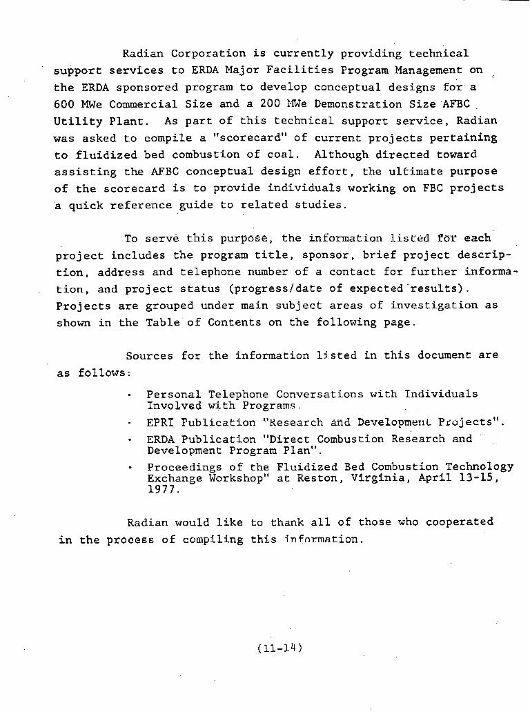
Radian Corporation is currently providing technical support services to ERDA Major Facilities Program Management on .
the ERDA sponsored to develop conceptual designs fos a 600 MWe Commercial Size and a 200 l4We Demonstration Size .AFBC . Utility Plant. As part of this technical support service, Radian
was asked to compile a "scorecard" of current projects pertaining
to fluidized bed combustion of coal. Although directed toward
assisting the AFBC conceptual design effort, the ultimate purpose
of the scorecard is to provide individuals working on FBC projects
a quick reference guide to related studies.
To serve this purpose, the information l i s ~ e d For each project includes the program title, sponsor, brief project descrip-
tion, address and telephone number of a contact for further informa- tion, and project status (progress/date of expected -results).
Projects are grouped under main subject areas of investigation as
shown in the Table of Contents on the following page.
Sources for the information ljsted in this document are
as follows:
Personal Telephone Conversations with Individuals Involved with Programs.
- EPRP Publication ?'Kesearch and Developrne~~L Pco jec t s " .
ERDA Publics-tion "Direct Combustion Research and ' Development Program Plan".
Proceedings of the Fluidized Bed Combustion Technology Exchange Workshop" at Reston, Virginia, April 13-15, 1977.
Radian would like to thank all of those who cooperated
in the proceEE of compiling this infnxmation.

TABLE OF CONTENTS
PAGE
. . . . . . . . . . . . . . . . . . . . . . . . . . . . . . . . . . . . . . . . AFBC DEVELOPMENT 1 & 2
. . . . . . . . . . . . . . . . . . . . . . . . . . . . . . AFBC INDUSTRIAL APPLICATIONS 3
. . . . . . . . . . . . . . . . . . . . . . COMBUSTION & HEAT TRANSFER STUDIES 4 & 5
. . . . . . . . . . . . . . . . SULFUR CAPTURE & REGENERATION OF SORBENT 6
. . . . . . . . . . . . . . . . . . . WASTE HANDLING. UTILIZATION & DISPOSAL 7
. . . . . . . . . . . . CORROSION. EROSION. & ENVIRONMENTAL STUDIES '. 8
AFBC ADVANCED TECHNOLOGY . . . . . . . . . . . . . . . . . . . . . . . ' . . . . . . . . . . . 9
. . . . . . . . . . . . . . . . . . . . . . . . . . . . . . . INSTRUIENTATION Ei CONTROL 10
. . . . . . . . . . . . . . . . . . . . . . . . . . . . . . MATERIAL'FEEDER DEVELOPIIENT 11
. . . . . . . FEASIBILITY/ECONOMIC/CONCEPTUAL & GENERAL STUDIES 12

PROJECTS ~NFLUEKCINC AFBC OF COAL
TOPIC : AFBC DEVELOP>IENT
n I-' I-' I F' m V
Program T i t l a
Elult i-cell F lu id ized Bed Boi lcr ; (MFBD). Pope, Evans 6 Robbins Inc.
Alexandria, Virgin ia . 5 tIIJe Fluidized Ded Con~bustor. Pope, Evans 6 Bobbins, Inc.
F lu id ized Bed Deve lop mcnt F a c i l i t y
S p ~ n s o r
EE3A
,
E.RDA
mRI RP 71.3
Progress/Date Of Expcctcd Scsu?cs
Phascs I and I1 complctc. Light-off and continous f i r - ing of one c e l l dur ing Dcccmhcr, 1977, and now i n operation a t t e s t i n g phnsc. Current ly dc-hugl;i111; sysccms and co11tr111s co c l r c c t conti.nuou:, r ~ l n s and ma te r i a l halnnces. b l o n t l ~ l y / ~ u a r t c r l y / In ter im progress r cpo r t s submitted t o ERDA.
Currcntly a ncv combustor i s baing p~~rc lmscd and w i l l bc i ~ l s t ~ l l c d i n clle f a l l of 1977. The f a c i l i t y has been a opera t ing s incc 1965. ant1 has over 8.000 l ~ o u r s of coa l burning t e s t opera t ion . Nontl~ly/Qunrcerly/Interi .m progress r e p o r t s a r e sub- mitted t o ERDA. (Note: thcse a r e contained i n t he same r epor t s a s tlie PIFBB progress repor ts . )
The un i t ltas bccn constructed and i ~ ~ s t r u ~ t ~ e n t c d and i s cur- r e n t l y i n t he shakedown phase The u n i t i s 6 ' x 6 ' .
--- Prograra Description
I n i t i a t e d in 1372. the projcc t i s co design, cons t ruct and ape ra t e a 30 NHc s i z c f lu td i l rd-hed b o i l c r under p r a c t i c a l u t i l i t y eondi- t ions . The b o i l e r , h i l t by Fostcr Ir'heelcr Encrgy Corp., w a s crcctcd i n OIIC ell.: of thc cxlst inp, pov~cr p l an t a t tlie Ilcnon@hcla Power Company a t F:Lvcsuille, \Jest Virgin ia , and conols ts of 4 s i d c by s i d c c c l l s . Stcaa c o n d l t i o ~ l s a r e t o match tho requiremcxts of the cxisti11g plnnto' turbo-gcncrntors. This i s a four-phnnt: pro- . gram a s follows:
1. Engineering and Dcsign Ver i f i ca t ion . i 11. Design and P a b ~ l c n t i o n of MFB Doilcr and Auxi lar ies
111. Operational Tcstinp,
I V . Dcsign bIanu:l s1d Tcst Reports '
A labora tory r e s c c r c l ~ program In support of 30 tIWc Hu l t i - ce l l FDC pro jcc t a t R ivesv i l l e , \,lest V i rg in i a , the instrumentation, con t ro l systcm, and a u x f l = r i e s c lo se ly reocmble tliose associated with the R lvcsv i l l e u n i t . Thc f a c i l i t y is used fo r proccss t e s t i n g &.nd o p t i n i z a t i o ~ l . a s wlL1 a s ope ra t iona l p lanning/ tcs t ing ' t o aic: thc R ivcsv i l l e fac i1 i t .y .
This p ro j ec t is aimeC a t bu i ld ing a t e s t f a c i l i t y on a s c a l e chat w i l l a l low explora t ion oE var ious bed des igns , s o l i d s and a i r sup- p ly systems, and the mixing pa t t e rns and chemical r eac t ions of the r e s u l t i n g s o l i d s . The primary con t r ac to r is Dabcock 6 Wilcoz..
i
:lame/Xdd. /Tel. of Person i n Charge
C. T. Claypoole l.lnnagcr, Rives- v i l l c Operations Pope, Evans 6 rob bin^, Inc. c /o Honongahela Powcr Company Rivesvi l le , W . VA 26503 304-278-5315
I{. R. Reed (Mgr. Alexandria Opera- t i on ) Popc, Evans b Robbins, Inc. 320 King S t r e e t f d e x m d r i a , VA 22314 703-549-2864
Elr. Steve Strom Sabcock 6 Wilcox Rcsearch 6 Devel- opment Divlsion Al l iance , Ohio 44661 216-821-9110 '
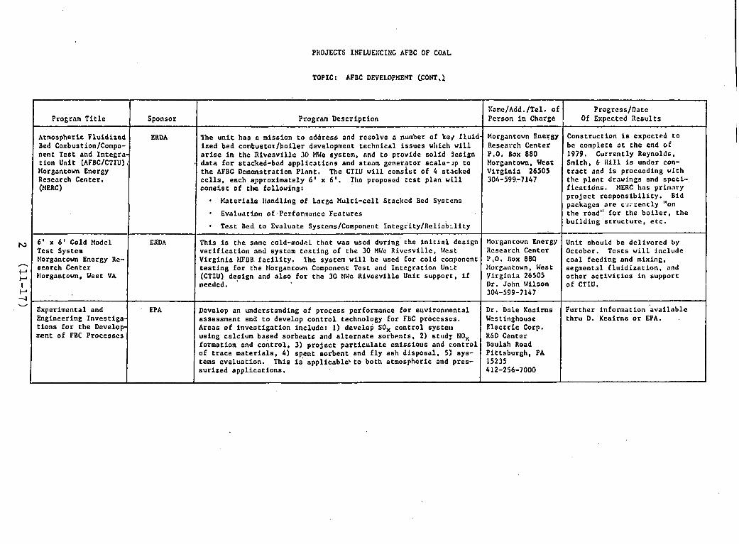
PROJECTS 1NFLUE;iCIZU'C AFBC OF COAL
TOPIC : AFBC DEVELOPtlENT CCONT ,l
I Program T i t l e I Sponsor I Program Desc r ip t ion I XamelAdd. /Tel. of Pro&ress /Datc
Person i n Charge Of Expected i l e s u l t s I Atmospheric F lu id i zed Bed Combust ion/Compo- nent Tes t and I n t e g r a t ion Unit [AFBC/CTIU) Itorgantown Energy Research Center. OreRc)
ERDA
- H a t e r i a l s l l o n d l i ~ ~ g of Large Mul t i - ce l l Stacked Bed Systems
E v a l u a t h n of~PerCormance Fea tu re s
The u n i t ha s a mission t o add res s and r c so lvc a number of keg f l u i d - i r e d bed comhustox/boiler development t echn ica l i s s u e s wlrich w t l l a r i s e i n t he R i v e s v i l l e 30 MJe system, nnd t o provide s o l i d 3esign d a t a f o r stacked-bed a p p 1 i c a t i c . n ~ and steam gener? tor s c a l e - ~ p t o t h e AFBC Demcmstration P l a n t . The CTIU w i l l c o n s i s t of 4 s tacked c e l l s , each approximately 6 ' x 6' . Tl~e proposed :est p lan w t l l c o n s i s t of tlle following:
Const ruct ion is expected t o be complete a t t h e end of 1979. Cur ren t ly Reynolds, Smith, I l l i l l is under con- t r a c t and is proceeding wl th t he p l a n t drawings and spcc i - f i c a t i o n s . HERC has primary
Morgantown Enargy Research Center P.O. Box 880 Morgantown, Veer V i r g i n i a 26505 304-599-7147
p r o j e c t r e s p o n s i b i l i t y . Bid packages a r e c s r r e n t l y "on the road" f o r the b o i l e r , t h e I
I T C G ~ Bed t o Evaluate Systems/Component 1 n t e g r ' i t y / ~ e l i a b ~ l i t y
6 ' x 6 ' Cold Modcl Tes t Sys tcn Morgantown Energy Re- s ea rch Center Ilorgantown, West VA
b u i l d i n g s t r u c t u r c , e t c .
ERDA
Experimental and Engineering Inves t iga - t i o n s f o r t h e Develop- ment of FBC Processes
Unit should be d e l i v e r e d by Occobcr. T c s t s w i l l i nc lude c o a l feeding and mixing, segmental f l u i d i z a t i o n , and o t h e r a c t i v i t i e s i n suppor t of CTIU.
Th i s i s t h e same cold-model t h a t was usetl d u r i n g the i n i t i a l des ign v e r i f i c a t i o n and systcm t c s t i n g of t h e 30 MVc R i v e s v i l l c , Wcst V i r g i n i a bFBB, f a c i l i t y . The systcm w i l l be uscd f o r cold component t e s t i n g f o r t he blorgancown Componcnt Tes t and I n t e g r a t i o n U n ~ t (CTIU) des ign and a l s o f o r t h e 30 tIWe R i v c s v i l l e Unit suppor t , i f needed.
Develop an understanding of process performance f o r e~rvi ronmenta l assessment. and t o develop c o n t r o l technology f o r FBC processes . Areas o f i n v e s t i g a t i o n inc lude: 1) develop SOx c o n t r o l systela us ing calcium based sorbeirts and a l t o r n a t e so rben t s , 2) stud?. NO, format ion and c o n t r o l , 3) p r o j e c t p a r t i c u l a t e emiss ious and c.ontro1 of t r a c e m a t e r i a l s , 4) spen t so rben t snd f l y a sh d i s p o s a l , 5: sys- terns eva lua t ion . This is' appl icableP t o both atmospheric and pres- s u r i z e d a p p l i c a t i o n s .
EPA Fur the r informat ion & a i l a b l e t h r u D. Keai rns o r EPA. -
Morgantown Energy Research Ccnter 1',0. Dox 880 Mor~antown, West Y i rg in i a 26505 Dr. John I J i l ~ o n 304-599-7147
Dr. Dale Keai rns Westinghouse E l e c t r i c Corp. KLD Center Beulah Road P i t t s b u r g h , PA 15235 412-256-7000
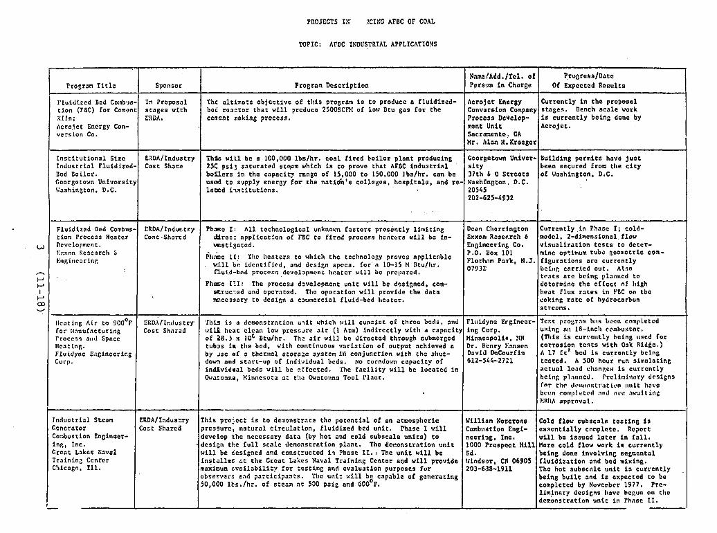
PROJECTS IS' lCILC AFDC OF COAL
TOPIC: AFDC INDUSTRIAL APPLICWIOYS
Prosran Ti t l c
Fluidized Bcd Co:nbus- t i on (FBC) fo r Ccncnt Xiln; Acrojct Encrgy Con- vcrslon Co.
Sponsor
f?l Proposal s tages with ERDA.
Thc u1timo:e objec t ive of t l i i s program i s t o produce a f lu id ized- bci r e a t t o r t h a t w i l l prcduce 2500SCRI of lot# Btu gas for the ceuent ztaking proccss.
1 Fluidized Bed Combas t ion Proccss Hcaccr nevclopmcn t . I'xxnn Rcscnrclr 5 linp.iteccrinp.
I n s t i t u t i o n a l S i r c Indus t r i a l Fluidized- Dcd Coi lcr . Ccorgetovn University Pashington. D.C.
I ERDA/Ind=.try Phme I: A l l t e c h n o l o g i c ~ l unknown fac tors prcsent ly l imi t ing Cont.Sharcd ctlrec: appl ica t lon of W C to f i r e d proccss hcntcrs w i l l bc in-
w s t i g o t c d .
t
Procram Description
Acrojet Energy Conversion Company Process Develop- ment Unit Sacranento.. CA Hr. hlan H. Kreeget
~lr.&c I [ : Thc Irentcrs to wlriclc thc technology provcs npplicnblc , w i l l bc! i den t i f i ed , and d c s i ~ n spccs. fo r n 10-15 El Btu/ l~r .
flu1.d-bed procrsn dcvcl~l~ment lrcatcr rill bc prcpnrcd.
Currently i n the proposal s tages . Dench sca l e work i s cu r r en t ly bcing donc by Acrojct.
I EIDA/Industry Cost Sharc
Phmc 111: The proccss d=vclopmcnt uni t w i l l bc dt?signcd, con- tDruc.:ed slid opctnted. Tlic operation w i l l provide the data mcessa ry t o design n c~mmcrcia l fluid-bed Iccater.
NnmelAdd ./Tcl. of Pprson i n Charge
Dean Cherrjngton bxxon Rcser.rch b Enginccrinb Co. P.O. Dox 101 Florlrim Pork, N.J 07932
Prugress/Datc Of Expcctcd Rcsults
ThPs w i l l be n 100,000 lb s lh r . coa l Sired bo i l c r plnnt producing 25C psi: sa tura ted s twm which i s t o prove tha t AFBC i n d u s t r i a l b o n e r s i n the capacity range of 15,000 t o 150.000 Ibs lh r . can be u s 4 t o s - ~ p p l y energy f o r the nat i6h ' s col leges , hospi ta lo , and re- labcd i - ~ s t i t u t i o n s ,
Currently i n Phasc I ; cold- model, 2-dincnsional f l o v v i sua l i za t ion t c s t s t o de tcr - mine optimum tubc gconlctric con- f igura t ions ore currently I ) c i n ~ cnrr icd out. Also t c s t s a r c bcing 111a111ecd to dcterminc thc cf fec t of high heat f lux r a t e s i n FEC on tho coking r a t c of hydrocorbun s t reams.
Ccorgetovn ~ n i v e r - s i t y 37th b 0 St reo t s Washiington, D.C. 20545 202-625-4332
Building pcrmits have j u a t been secured from the c i t y of Uashington, D.C.
llcat ing Air to 900°P fo r tlanufacturing Process J I I ~ Spocc I1ca:int. Pluidjmc E.1ginccrir.g Curp.
I Or~aconna, Xinncsota a: t lc.? Owa tonna Tool Plant .
EItD,\/Industry. Cost Shnred
TIrFs i s a clcmonstrntion u ~ i t vhiclr v i l l cuns is t 01 threc bctls, and w i l l heat clcan low p r c s s ~ r e a i r (1 Atm) indirectly wit1i.a capacity of 28.5 x loc Btulhr. Thz a i r v i l l be d i rec ted through submcrgcd tub25 i n tlre bcd, v i t h continuous va r i a t i on of output nchicved a by ~ s c of s thcrlnal .storo;c systcm i i i conjunction with tho slrut- dom and s tar t -up of i n d k ~ i d u a l beds. No turndorm capaci ty a l individual becls v i l l be cf fcc tcd . The f n c i l i t y w i l l be located i n
bcing planncd. Frclinilrary drs igns f o r t l ~ c d c e t ~ ~ r s t r : ~ t i c n 1111it havc bwn eonll)lt!tctl ant1 ncc nwaltinl; I.:Rl),f npproval .
Tndustrial Stcam Ccncrator Co-~bus t i on Enginaer- inp., Inc. Crcct Lakcs Save1 Trainin2 Ccnrcr C!iicego, Ill.
Pluidyna Erginccr- ing Corp. Minneapolis, ?IN Dr. H'cncy llanscn David DcCourf i n 612-544-2721
Tcst pro;;ranl II:IS bocn cnml~lctcd using nlr 1.8-lncll coml)ustnr, ( n l i s is CurrcllLly being rlscd fo r corrosion t e s t s With Oak Ridkc.) A 17 ft"cd i s current ly bcing tcs tcd . A 500 hour run simulating ac tua l load c1ranp.c~ is ccrrrcntly
William Noreroes Combustion Engi- neering, Inc. 1000 Prospect H i l l Fid . Nindssr, CR 06905 203-6.38-1911
ERDA/Iaduszy Cost Sharcd
Cold flow subscale t e s t i n g i s cvacnt ia l ly cnnplctc. Rcport w i l l bo issucd l a t c r i n f a l l . Uore cold f l ov work i s current ly being done involving segncntal f l u id i za t ion and bed mixing. The hot subscnle u n i t i s cc r r cn t ly ,
being b u i l t and is cxpcctcd to be completcd by Nuvcnber 1977. Prc- l lminary designs llavc bcpl~n on t l ~ c demonstration u n i t i n Fhnsc 11.
This ptofcc: i s t o deaonstrnte thc po ten t i a l of an atmosplreric prcssurc, na tu ra l circulation, f lu id ized bcd uni t . Phasc 1 w i l l develop the neccssory data (by hot and cold subscale un i t s ) t o dcsign tbc f u l l s ca l e demonstration plant. Tho Bcnonstration u n i t w i l l be designcd and constructcd i . ~ ?hose 11.1 The u n i t will. be i n s t a l l e c a t t he Crcat Lakes Naval Training Ceotcr and w i l l provide moxinun c v a i l a b i l i i y f o r t e s t i n c and evaluation purposes f o r obscrvera end partici?an:s. Thc un i t %ill be capable of generating 50,030 lt.s./hr. of siezzl ac 530 p s i g and GOOOF.

PROJECTS INFLUENCING AABC OF COAL
TOPIC: COMBUSTION 6 HEAT TRANSFER STUDIES
Propam T i t l e
>letlrods f o r Improvinl Hcrrt T r a ~ i s f e r . Film Cc e f f i c i e n t s i n c Pluic izcd Ded Packed with Heat Excl~;lngcrs
Ccd Dynamics and lleat TrsnsLcr a r Sur faccs of Immcrscd Tubcs i ~ i
Fluld iscd Reds. !-- Elodcline of Hcrrt T rans fc r Cllaracter- i s t i c s i n a Fluidized Ocd
Bcl~avlor of Fine P a r t i c l e s i n a Fluid- izcd B e d of Coarse Pla tcr is l .
Sponsor - EWA
EPCI Corporetc Re- search and De- vcloprnr-nt, - Ccncral Elec- t r i c Campany
ERDA
Program Desc r ip t ioz
[nves t iga t e clre i n t s r r e l a t i o n s h i p between temperature d i s t r i b u t i o n f l u i d flow, and heat exchanger des ign and performance i n a coa l f i r e d fluidized-bed combustor.. This is mostly pressurized work.
:xperimeritally determine the dynamics of f l u id i zed bcd emulsion ~ n d bubbles n t the su r lncc of I.mu~erscd t u l ~ s f o r var ious p a r t i c l c ; i z c s and a i r flow r a t e s , and m'ensure l oca l lrent t r a n s f e r coe f f i - : i c n t s arou~td the c t r c i ~ ~ n f c r c ~ ~ c c of I ror lzo~l tn l tubes.
- -
n v c , s t i ~ n t e and model hcat t r a n s f e r from a f l u i d i z r d bcd t o hor i - onto1 tubes a s a funct ion of gas ve loc t ty , p a r t i c l e s i z e , p a r t i c l e linpe, p n r r i c l e and Ens thcrmnl p ropc r t i c s , t u b s i z c . shnpc, nnd 11tclt w l t l ~ d i l f c r c n r bed materials. Tl~c t c s t u n i t i s 12" by 12".
h i e p ro j ec t i s intcnded t o provide qrrnnt l ta t ive d a t a on the be- av lo r of f i n e p a r t i c l e s In fluidized bcd of coarse ma te r i a l , p c c i f i c n l l y on the r e l evan t ccnd i t l ons ncnr t h e d j s t r i b u t o r p l a t e hot bcar on p r a c t i c a l ques t ions r e l a t i n g t o r eac t an t fced systems. hc information coc~ld l cad t o s u b s t a n t i a l inrprovemcnts i n the ef - i c i e n c i c s o t combustion and s u l f u r cap tu re upon which the economic f f l u i d bed b o i l e r s heav i ly depcnd.
Nane/Add. l T e l . of Person i n Charge
Dept. of Applied Sciences Ncw York Univer- s i t y 26-36 Stuyvesanc S t r e e t ,
ldestbury, L . I . , N.Y. 10003
John C. Chen Lclligh University Depi. of Mcchani- c n l E t ~ ~ i n c c r i n g Dczlilchnm, PA 18015
Univcrs t ty of I l l i n o i s Ucpt. of Fmcrgy Engineering UOK ft3ft8 Clricago C l r c l e I:l~fcrry,o, IL 60680
) r . Dcrek-Gcldart Iepartment of :hcmical E n ~ l n e e r - J"' Ira~rd ford Univcr- i i t y lradford 8D7 IDP lent Yorkshiro , Znglnnd 1-011-44-274-33466
- Progrcss/Date
O f Expected Resu l t s
Data has been obta ined on a one f o o t diameter bed. A t l trce foot d iameter bed is p resen t ly under const ruc- t i o n and f u r t h e r t e s t s w i l l be performed. Monthly rc- p o r t s s e n t t o ERDA under Contrac t No. EF-76-C-01-22 Dis t . Category UC-90E.
Contact npon;. c f o r ava i l - able d a t a .
Hontlily r e p o r t s setit t o ERDA'undcr c o n t r a c t No. E (49-18)-1787.
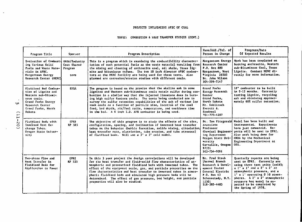
PROJECTS IXPLUENCINC AFBC OF COAL
TOPIC: CaYBUSTION 6 HEAT TRANSFER STUDIES (CONT.)
Program T i t l c
Evaluation of Combust- ing Various SoliZ Fuels and Waste Hate- r i a l s i n AFBC. Norgentown Encrgy Research Center bMERC)
Fluidized Bed Conbus- t i on of L ign i t e 2nd Western sub-Dituni: nous coals . Crand Forks E n c r ~ y Research Center Crand Forks. Norcl~ Dakota
Spor.sor
ERDAfIndustry Cost Shared Program
. t o r s
E R C ~
Program Descr ip t ion
This is a program which is examining the combust ib i l i ty character- istics of such p o t e n t i a l f u c l s a s the waste mater ia l . r e s u l t i n g from the mining ond cleaning of an th rac i t e coa l , o i l sha l e , Texas l i g - n i t e and bituminous refuse. The two 18 inch diametcr AFBC combus- t o r s at t h e HERC f a c i l i t y a r e being uscd f o r these t e s t s . Also plantied a r e corrosion/erosion s t u d i e s with d i f f e r e n t coals .
The program i s based on tile premise t h a t t h e akal ine ash i n some l i g n i t e s and Western sub-bituminous coa l s r e t a i n s u l f u r during com- bus t ion i n a s imi l a r way t h a t the i n j ec t ed l imcstonc does i n Burn- i ng high s u l f u r Eastern coals . The t e s t s being conducted a r e t o survey the s u l f u r r e t en t ion c a p a b i l i t i e s of the ash of var ious low rank c o a l s a s a function of p a r t i c l e s i z e , 1ocatl.on of the cool fced, bcd dcpth, a l r / f u e l r a t i o , tcrnpcratrtre. and residence time i n tire bed. A 6 inch I . D . APD combustor i s being used.
Flufdized Bcds v f t h EPM 1mm~rscd llcat Ex- chanbe Tuhcs. Orcgon S t a t e Univer- 7 - F The ob jec t ive of t h i s program is t o study the e f f e c t s of t he s i z e ,
conf igura t ion , spacing, and inc l ina t ion of immersed heat t r a n s f e r t ubes on the behavior (buhblc formation, s o l i d s mixing, c i r cu l a t ion , heat of ELuidizcd t r a r ~ s f e r beds. r o t e , Will e l u t r i e t i o n , usc a 3' tube x 3' e ros ion, cold model. and tube s t r e s s e s )
I n t h i s 3 year projec t t he design co r r e l a t i ons w i l l be developed f o r t he heat t r a n s f e r and f lu id-sol id f l o v c h a r a c t e r i s t i c s of a t - mospheric and pressurized f lu id i zed beds with immersed tubes. The e f f e c t of t he equipment s ca l e , gas, and p a r t i c l e p rope r t i e s on ttlc flow ~ h a r a c t e r i s t i c s and heat t r a n s f e r t o immersed tubes i n atmos- pheri: f l u id i zed beds and simulated high prcssure beds w i l l be determined. The e f f e c t of gas pressure , bed height , and p a r t i c l e p rope r t i c s w i l l a l s o be s tudied .
'Do-phase Flov and Heat Transfer i n Fluidized Beds f o r Application t o Power
. Nane/Add . /Tel. of Person i n Charge
b r g a n t o w r Energy Research Center P.O. Box 880 Ciorgantom, Vest Virgin ia 26505 Dr. John Wilson 304-599-7147
Crond Forks '
Energy Researcll Center Grand Forks. North Dakoto Ur. Coblirsch Evcrctt A. Sondreal
EPRI RP 525
. Progress/Dato
Of Expected Resul ts
Work has becn completed On burning a n t h r a c i t e , Western sub-Bituminous Coa1;Texos Ligni te . Contact MERC di- . r ec t ly f o r more information.
18" combt~stor t o be b u i l t i n 9-12 months. Currently t e s t i n g l i g n i t e , recycl ing ash and obta in ing approxi- mately 60Z s u l f u r r e t en t ion . ,
701-775-4207
Dr . Tom Fi tzgera ld Associate Professor
Oregon Chemical ing Dcp;~rtment S t a t e Engineer- Uni-
r c r s i t y Corva l l i s , Oregon 97331 503-7%-2091
Mr. Fred Staub Thermal Branch Eescarch 6 Dcvel- opnent Center General E l e c t r i c P.0. Box 43 Schenectady, N.Y. 12301 518-385-6683
I
Model has been b u i l t 011d instrumented. Expcrimcnte . have j u s t commenccd. Re-
.ERDA Also p o r t s work by w i l l the being be Hcchnnical sent done t o f o r EPRI.
Engineering Dcpartmcnt a t OSU.
Quar ter ly r epo r t s a r e being sen t t o EPRI. Current ly a r e
,using th ree t e s t u n i t s (cold); a 1 ' x 1 ' and a 2' x 2 ' a t atmospheric pressure , and a I ' x 1 ' opera t ing @ 10 atmos- phcres. A 2' x 2' atmospheric pressure hot model is ex- pected t o be completed by the Spring of 1978.
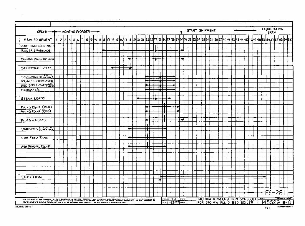

PROJECTS INFLULNCING AFDC OF COAL
TOPIC: SULFUR CAPTURE L RECENEP.ATION OTSORnENT
- t-' I-' I rLl F U
P r o s r a n T i t l c
Ir.:.provrncnts i n St11- f u r Disx idc Sorbcn t U t i l i t i z a c i o n i n Fluidized Dcd Coal Cocbust ion. Task I: E f f c c t of Sorben t P a r c i c l c S i z e
E f f e c t of Clicmicsl ~ \ d d i t i v c s on tllc Re- covn l of SO2 by Limc- s t o n c i n F111id Dcd 3 o l l c r :
Imprnvczcnts i n Sul- f u r Dioxidc Sorbcn t U t i l i z ~ t i o n i n F lu id - i zcd Bcd Coal Combus- t i o n ; Task 2: E f f c c t of Lim-s tonc Ca lc ina- t i o n .
C r i t e r i a f o r t h ? S c l c c t ~ o n of S u l f u r Dioxidc Sorbcncs
Sponsor .
EPRI RP 7
.
EPRI RP 837
EPllI RP 720
EPRI RP 721
Prograx D c s c r i p t i o n -. his onc ycnr p r o j c c t i s f n invcsc ip ,a t ion of t h c c f f e c t of limc- s t o n c p a r t l c l c s i z e on s u l f u r c a p t u r c i n a fluidized bed b o i l c r . Tlic obj 'cct ivc is t o f i n d o u t i f vc ry l i n c particles, such a s rhosc produced i n a h y d r a t o r , can rcducc tlic q u a l i t y of l i n c s t o n c r e - q u i r c d t o n c c t s u l f u r d i o ~ : i d a clnission s t a n d a r d s . U l t i ~ n a c c l y , t h c v i ~ b i l i t y o f t h c f l u i d i z e d bed combustion systcm, which a l lows i n s i t u removal o f s u l f c r canpounds, w i l l jcpcnd on how i t s economic compare wi th t h o s e of c o n ~ r c ~ ~ t i o n a l b o i l e r s wi th s t a c k gas clcan-up systems. Uscd P i t t s b u r g h No. 8 c o a l wi th t h r c e typcs of l imcs tonc .
Thc purpose of t h i s p r o j e c t i s t o dctcrmino t h e ncchan isn of a c t i o n o f chemical a d d i t i v e s on :;illfur c a p t ~ l r c by l imcs tonc i n o r d e r co
dcvclop t c c l ~ n i q u c s atid rcco~~;ccnd additives t o promocc s ~ ~ l f a t i o n r e a c t i o n . Zlcasurcmcnt of k i ~ i c t i c ynramctcrs w i l l bc mntlc by chcr- ma1 a ~ r a l y s i s of spcc iCic rcnc t io : i s i l l ci;i::ci~ig cqu lp~ncn t . Tllc pro- j c c t u i l l providc infornlnt ion on t h e c f l c c t of a d d i t i v c s on s ~ r l f u r rcmovnl i l l ,111 a t tcmpt co rcducc t h c quan t icy of llmcsconc rcqu i rcd dur ing t h c p rocess .
Tlic k k i c t i c s of l l ~ n c n t o n c c n l c i ~ ~ a t i o n and i t s c IEcc t on tlic li111-
f a t i o n r c a c t i o n i n fluidized bcJ c o a l :c.nl~ustion w i l l be i n v c s t i - ga ted i n a l a b o r a t o r y apptra2t is . Espcrimental s t u d i c s w i l l be c a r r i d o u t c o n c c r n i n ~ t h e ' e f f e c t of ca lc inoc ion psrnmetcrs on sor - b c n t u t i l i z a t i o n and on t k e o v c r a l l fluidized-bcd combt~st ion sys- t en . Sliould t h e s c s t u d i c s i n d i c a t e r l ia t p r c - c a l c i n a t i o n is favored i n nch iev inc maxirnum,l imc~tone u t i l i z a t i o n , thcn optimum c a l c i n a -
. t i o n p roccdurcs and condi:ic.r.s w i l l bc s p c c i f i e d .
Thc o b j c c t i v c of t h i s one ;e:r p r o j e c t i s t o establish c r i t c r i a f o r prcdic:iny, t h e a b i l i t y of a givcn 1it:iestono t o c f f i c i c n t l y c a p t u r e s u l f u r d i o x i d e i n a f luidized-bed c o a l com!~ujtor. k complete scarcl i and cva lunc ion w i l l be nadc of a v a i l a b l e d a t a on t h e desu l - f u r i z a t i o n c a p a b i l f t y of d i f f e r e n t 1ir.lcstonc and dolomites.
NanelAdd. l T c l . of Person i n Charge
Dr. Howard Langc Chemical Enginccr- i n g Scc t ion A l l i a n c e Rcscarch Ccntcr Dabcock 6 Wilcox P.O. Dox 835 A l l i a n c e , Ohio 44601 216-821-9110
Dr. Lorry Casncr Chcmicfl EncincCr- i n s Dcpartmcnt U n i v e r s i t y of Elarylirnd Co1lcy.c Park , E.ID 20742 301-164-4593
Dr. E. P . O ' N c i l l Westinghouse E l e c t r i c Corp. Rcscarch I Dcvcl- opmcnt Contcr CculaIi Road P i t t s b u r g h , PA 15235 4 12-256-7687
Dr. K. P. O ' N c i l l I Jcs t i~ ighouse E l e c t r i c Corp. Rcscarclt L Dcvel- opaent Ccn tc r Dculah Road P i t t s b u r g h , PA 15235 4 12-256-7687
~ r o g r c s s f ~ a t c Of E x p c c ~ c d , R c s u l t s
Program is complete. F i n a l
I Rcport shou ld bc available in'h'ovcmbcr, 1977, t h r u EPRI.
I
i I
Deta i l ed a n a l y s i s of thc s u l f u r c a p t u r e p rocess us ing t l icrn- ogrev imct r i c n n a l y s : ~ of l imc particles of d i f f c r c n c s l z c s wit11 and v i t l iou t s a l t . Computcr procranis avai1.lblc f o r p r c d i c c i n g s u l r u r c:lpturc capabilities of any randon
1 i
samlllc of l imcs tonc . Prc- l i m i n a r y r e p o r t s liavc bccn s c n t t o EPKZ. i Procram i s c s s c : n t i a l ~ y con- p l c c c and r c s u l t s have becn s e n t t o EPRI. R c s t ~ l t s were ob ta incd u s i n g bcnch s c a l e apparatuses.
i
This w i l l bc i n e f f c c t n c o c t i n u a t i o n of tllc p rcv ious work done on EPRI-RP-720 scart in: , Scptcmbcr, 1377. .Closer d c f i n i t i o a of f a c t o r s influencing s u l f u r c a p t u r c w i l l bc addrcsscd .
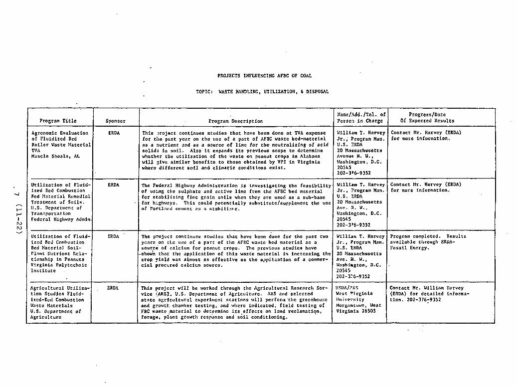
PROJECTS INFLUESCINC AFBC OF COAL
TOPIC: WASTE MNDLINC, UTILIZATION, 6 DISPOSAL
Program T i t l e
Agronomic Evaluation of Fluidized Bed Boi ler Vastc Ha te r i a l NI\ Muscle Shoals, A t
U t i l i z a t i o n of Fluid- ized Bed Combustion Ped Nn te r i a l Rcmcdinl Trcatmcnt of So i l s . 1I.S. Dcpartmcnt of Transpor ta t ion Fedcral Higl~wny AJnlitl.
U t i l i z a t i o n of Fluid- izcd Bed Con~lruatlon Dcd Material Soi l -
Sponsor
ERDA
.
ERD A
ERDA
,P l an t t:utricnt Rcla- i t ionship i n Peanuts
Progress/Date bP Expcctcd Itcsults
Contact Mr. Harvey (ERDA) f o r more information.
Contact Mr. Harvey (ERDA) f o r more information.
Progrntn complctcd. Results avn l l ah l c tltroccgl~ ERUA- Vossil Encrgy.
Yrograr Description
This x o j e c c continues s t u d i e s t ha t have becn done a t TVA expense f o r t h e pas t year on the usc of n pa r t of AFDC waste bed-matcrial a s a nu t r i en t and a s a source of l ime f o r t he ncu t r a l i e fng of ac id so l id ; i u s o i l . Also i t expands i ts previous scope t o dctcrmine whothor the u t i l i z a t i o n of the waste on peanut crops i n Alnbama w i l l :;ivc s imi l a r bene f i t s t o thosc obtained by VPI i n Virgin ia wherc different s o i l and c l ima t i c cocdi t ions e x i s t .
The Federal Highway Administration i s invcstigattinp, t l ~ c f e a s i b i l i t y of using the s u l p l ~ a t e and a c t i v e l ime from the AFBC bed material . f o r s t a b i l i z i n g f lnc g ra in s o i l s when they o re usctl a s ' a sub-basc f o r h~ghrreys. This could p o t e n t i a l l y subati tute/supplenlcnt the use of Port1ai:d cc~ncnc a s a s t ab i1 i ;~ r : r .
The y ro j cc t continues s tud ie s , t h a t have becn done f o r the pas t two ycnrs on cllc I I : ; ~ oC a pa r t of the AFDC waste hcd ma te r i a l a s o s o u y e of calcium f o r p c ~ n u t crops. Thc prcvious s t u d i c s have
Virginia Polytcchnic I n s t i t u t e
Agr icul tura l U t i l i za - t l on Studies Fluid- Ixcd-Ecd Combustion Glastc Mater ia ls U.S. Department of Agr icul ture
.
Contact Mr. William llarvcy (CRDA) f o r d c t ~ i l e d informa- t i on . 202-376;9352
Name/Add. / f e l . . of Pe r sc :~ i n Charge
William T. Harvey J r . ; Program Man. U.S. 3Nll\ 20 Hassachosetts Avcnuc N. V.. Igashiugton , D.C. 20545 202-3 16-9352
Wlllirm T. llarvey J r . . 3rogram Man. U.S. ZRDA 20 F f m s ~ c h u s e t t s Avn. 0 . W., l\'asliiogton, D.C. 20545 202-316-9352
' W i l l i a m T. Harvey J r . , Program Man. U.S. ERDA
.,shown tha t t he ~ p p l i c a t i o n of t h i s waste mnter ia l i n increas ing tlic crop y i e ld vas almost a s e f f e c t i v e a s t he a t>p l i s a t ion of a commer- c i a l procbred calcium source.
This proJcct w i l l be rtorkcd tltrouih tltc Agr icul tura l Rescarc!~ Scr- v i c e {ARS], U.S. Dcpartlnent of Agriculture. AltS and se lcc tcd s t a t e a g r i c u l t u r a l experimcnt s ca t ions will perforla 'tllc grecnhou!;~ and growtt chamber t e s t i n g , and vltcre indica ted , f i e l d t e s t i n g of FBC waste.moteria1 t o dcccrminc i t s - e f f e c t s on land reclamation, forage. p l an t growth responsc and s o i l conditioning.
, ERDIL
20 H ~ s e c h u s e t t s Avc. A. W,., IJashimgton, D.C. 20545 202-X6-9352
llSl)A/,!RS Wcst PI r e i n i a llrlivr:slty Morgnntuvn, West Virgin ia 26505
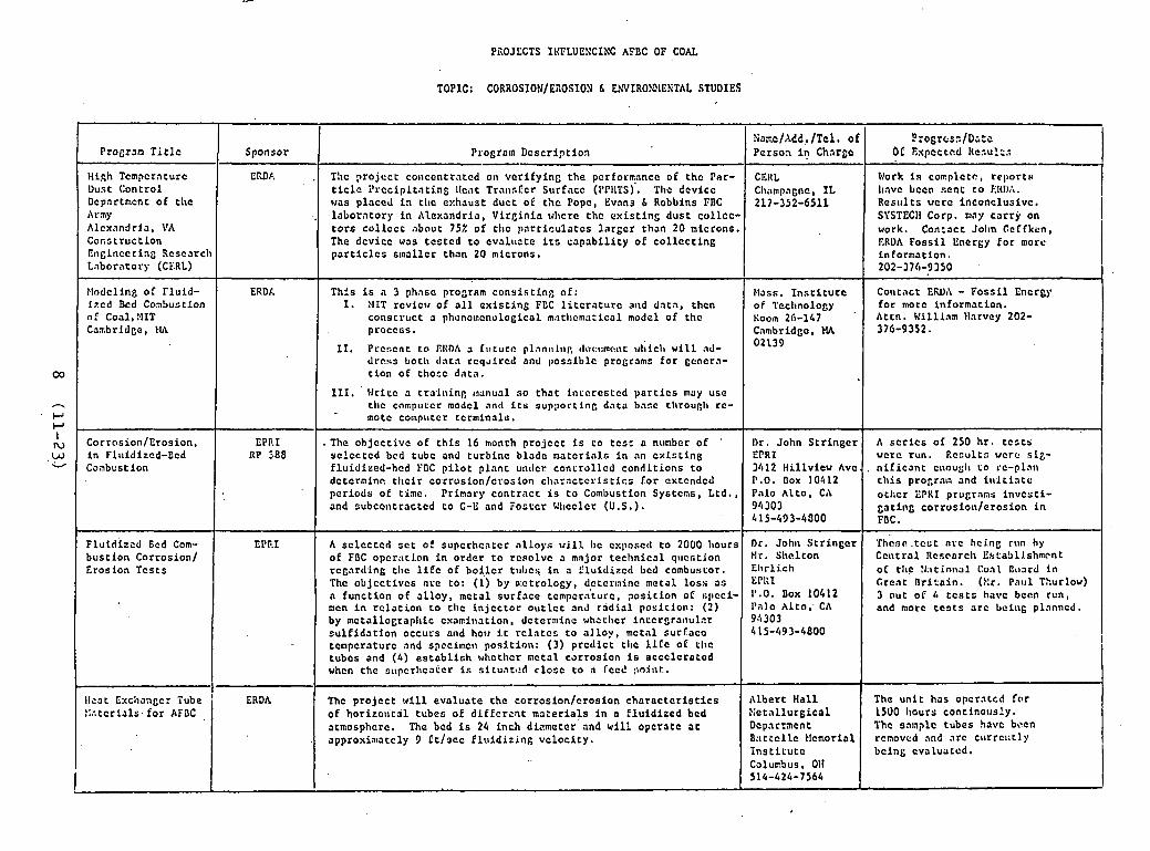
PiiOJCCTS IKFLUENCIKC ACEC OF COAL
TOPIC: CORROSION/KiiOSION h EhVIROSlENTAL STUDIES
Xaac/AdC,, /Tcl , of ?:ogrcss/D;:o P r o ~ r ~ n T i t l c Sponsor Progroln Dcscriptioa -
High Tcmpcraturc EN)A Vork i s co rp l c t c , rcporru -1 Oust Control t i c l c i ' rccipitntj .ng Ilc;tt Trcrnsfcr Surface (I'PIITS). Tha dcvicc Cl~;~mpagnc, IL lravc bccn sen t t o El(l);r. Dcpartncnt of tlre Results vc rc inconclusive.
I
hr rp , labora tory i n A1cxandria, Vire in ia vlrcrc thc ex i s t i ng dus t col lcc- SYSTECII Corp. may carry on Alexandria, irA t o r s col lccc about 75% of t l ~ c ~ ~ a r t i c u l a t c s l a r g c r than 20 microns. work. Contact John Gcffkfn,
I Cocstruction The dcvicc was tcs tcd t o e v a l u ~ t e i t s capab i l i t y of collecting ERUA Foss i l Energy f o r morc Engineering Scsca rc l~ p a r t i c l e s smallcr than 20 microns. information. Laborarory (CL..RL) 202-376-9350
I.lodclinfi of Fluid- ixcd k d Conbustion of C o d , :.!IT Carbridge, Pb\
Corrosion/Erosion, i n Flt~idizcd-Ecd Combustion
~ l u t d i z c d bcd Com- bus t lon Corrosion/ Erosion Tcs ts
ERDF.
EPP.1 RP J88
'
EPF.1
s u l f i d a t i o n occurs and how i t r c l n t c s to a l l oy , metal su r f acc tcmpcraturc and spccilnctr pos i t ion: (3) prcdic t t l ~ c l i l c oE C I I C tubcs and (4) e s t ab l i sh whcthcr ~ c t a l corrosion is accclcrnted whcn the supc r l~ca t c r i s s i t u n t ~ d c lose t o n C-ccc! : io j~r t .
Thc p ro j cc t w i l l eva luate the corrosion/crosion c h a r a c t o r i s t i c s ! : a t c r i ~ l s . f o r AFaC , of h o r i z o ~ i t i l tubes of d i f f c r c n t mazerials i n n f l u id i zed bcd
atmosphcrc. The bed i s 24 inch diameter and w i l l opera te a t approxia~atcly 9 f t / s c c f l u i d i z i n g velocity.
This i s n 3 phasc pro~rnm cons i s t i nc of : I. NIT rcvicv of a l l ex i s t i ng FCC l i t c r n t u r c aird data , then
conscruct a phcnomcnological matl~cma:ical model of thc procccs.
11. Prcscnt t o EIUM a C~~turcl plnn11111,: ~lnc:l:mr:nt ul;icl~ wil.1 nd- drc.ss I)ocl\ da ta r c q ~ i r c d and ~ ) o s s i b l c programs f o r gcncra- t ion of thosc data .
111. Glritc a traininp, 1!1anua1 so t h a t inccrcs tcd y a r t i c s may use tlrc cnmputcr modcl and i t s sup;>ortinp. data hnsc tl\roup,lr rc- moCc computcr tcrminalc .
.The objcc t ivc of t h i s 16 month projcc t i s t o t c s r a nunber of sc lec tcd bcd tubc and turbine bladc matcr ia lc i n an c x i s t i n g fluidized-hcd YBC p i l o t p lant untlcr concrollcd conditions t o dc t cminc t h e i r co~rrosion/cyosion c l ~ a r n c t c r i s t i c s f o r cxtcndcd periods of time. Primary contrac t i s t o Combustion Systcns, Ltd. , and subco~rtractcd t o C-E and Fostcr Wl~cclcr (U.S.).
'
A sc lcc tcd s c t of supcrhcatcr i11l.oys w i l l I)c cxposctl to 2000 hours of FDC opcr:~tl.on i n order t o rcaolvc a mnjor technica l q l~cs t ion rcgartling t l ~ c l i f c of b o i l c r ~ I I I J C * i n a fluidized bcd combustor. Thc objcc t ivcs a r c to: (1) by n:ctrology, dctcrlsinc metal l o s s a s n function of a l l o y , metal surface tempcraturc, pos i t ion of clicci- mcn i n r e l a t i o n t o tlrc in jcccor o i ~ t l c t and r i d i a l posicioll: (2) by mctallograpllic cxaainat ion , dc tern~inc whcrhcr intcrgranu1t.r
415-493-4800
Albert Hal l > :c ta l lurgica l Dcpartrent B ; ~ t t c l l c Elcmoriol I n s t i c u t c Calurbus , 011 514-424-7564
I I
The un i t has opcratcd fo r 1500 Irours c o n t i n o ~ ~ s ? y . The saaplc tubes !rave bacn rcnoved and a rc c11rrcl:tIy bcing cvaluatcd. I
Mass. I n s t i t u t e of Technolop,y Koo~n 26-147 '
Cnmbridgc, MA 02139
Dr. John S t r ingc r EPRI 3412 Hillview Avc. P.O. Box 10412 Palo Al to , CA 9'4303 4 15-493-4300
Dr. John S t r inge r Mr. Sllclton Ellrlich W!:I " -0 . Box 10412 I'nlo Alto: CA 94303
Collcact EMI\ - Foss l l Encrgy fo r morc information. Attn. Vill iam Harvcy 202- 376-9352.
A s c r l c s of 250 h r . t co t s wcrc run. Ecsul ts wcrc s l z -
. n i f i c ~ n t c~lougl~ t o rc-plan t h i s prograls and i ~ t i t i ~ t c o thcr LPKI prugrnns invcs t i - ga t ing corrus ion/eros ion i n FDC.
' fhcsr. . tcct a r c hclng run hy C c ~ l t r a l Rcscarch E%ta'JlJ.shmcnt oC tlic :r:ttfn~~;ll Coal Oo~rd in Great Br i t a in . (Xr. Pal11 Thurlow) 3 out of 4 t c s t o h a w been rcn, and morc t c s t s a r c being planncd.

PROJECTS IEFLUENCIWC AFDC OF COAL
TOPIC: AFDC ADVANCED TECHNOLOGY
F l u i d i z c d Dcd Combus- t i o n I n d u s t r i a l A p p l i c a t i o n Demon- s t r a t i o n P r o j c c t s . B n t t e l l e Xcmorial I n s t i t u t e . Columbus, Ohio
- I-' I-' I r u .I2 V
AFUC Closcd Cycle Cas Turb inc Tcclr~lology T c s t Uni t . Oak Ridgc N a t i o n a l Lobora to ry Oak 3 i d g e , TN
- ~ --- -
I Sponsor I
ERDA/Industry Cos t Shared
Program D e s c r i p t i o n I -
Namc/Adi. /Te l . o f P r o g r c s s / ~ a t e Person fn Chargc Of Expcctcd R c s u l t s
3 h i s i s cons idcrcd a l l u l t l s o l i d Fluidized-Bed Combustion Process b h i c h ~ t i l t r e s a h i g h s p e c i f i c g r a v i t y bed m a t e r i a l i n a dense f l u i d i a c d phase coupled ~ d i t h an e n t r a i n e d o r " f a s t " phase of simi- l a r o r d i f h r e n t bed m a t e r i a l . I t has been shown on a bench s c a l c t h a t tl-is type of f l u i d i z a t i o n p r o c e s s enhances g a s s o l i d c o n t a c t ,
' t h e r e f c r e , cnlianccs g a s s o r b e n t r e a c t i o n s . B a t t e l l e i s teaming in t h e devel3pment , demons t ra t ion and subsequen t commerc ia l i za t ion of t h e p r o c z s s . The program w i l l be 3-pllases a s f o l l o w s :
I Phase I: U b D ' u t i l i z i n g a s u b - s c a l e e x p e r i m e n t a l u n i t i n s u p p o r t o f l ccnoas t rn t ion p l a n t dcslp,n ur.L~rg 400 l b s l l i r . oC co;1l pro- ducLng -000 l b s / l ~ r . oE stcom.
f'lio3c [I: C o n s t r u c t i o n atid s t a r t - u p o f dc~mons t ra t ion 11lnnt wlriclr w i l l produce 25,000 l b s / l l r . oE s team @ 100 p s i g . Thc p l a n t w i l l bc b u i l t @ D a t t e l l c I n s t i t u t e .
2 P b a i c I I I : Thrce y e a r o p e r a t i o n a l p e r i o d f o r t h e c o l l e c t i o n of
d a t a t o bc uscd f o r f u t u r e i n d u s t r i a l a p p l i c a t i o n d e s i g n .
EHDA ; TLc program c o ~ ~ s i s t s of dcvc lop ing a Tcc l~nology T c s t Uni t (TTU) I wliich r ~ i l . 1 k c ;I con1 burni l lg ,IFDC sys tcm coupled u l t i m n t c l y t o n / c l o s c d c y c l e ho t n i r gas t u r b i n c - g e n e r a t o r . The u n i t c a p n c i t y : w i l l bc 300 t o 500 I:W p l u s approximately 2.5 x l o G Utu /hr . of re-
I c o v e r a b l e wcs tc h e a t . The s i z c t c s t u n i t w i l l p rov ide c r e d i b l c sca le -up do tn t o tlre 5 t o 50 MWe r a n z e f o r commercial a p p l i c a t i o n i n t h e : n d u s t r i a l / i n s t i t u t i o n a l s e c t o r .
--
D a t t e l l e Memorial I n s t i t u t ? Columbus. Ohio Mr. Heru.sn Nack 614-424-i998
C u r r e n t l y i n Phase I ; t h e s u b s c a l e exper imcnto l u n i t h a s j u s t b c c n . b u i l t and is now i n t h e p r e - o p e r a t i o n a l shakedown phasc. L igh t -o f f is expec ted by Sept.. 1. T l ~ c u n i t w i l l run a t 30-40 f t l n e c and t h e bed is a l ~ p r o x i m a t c l y 1 f t x 2 f t 2 . F ive mont l~s of c o n c c n t r a t c d o p e r a t i o n is plnnncd b e f o r c p rocced inc t o Pliase 11.
klr. R . S. llolcomb Oak Rir1y.r N a t i o n a l Labora to ry P.O. Oox Y Oak Rid&., Tennessee ,37850 615-483-5611
Phase XI: Complete a c o n c e p t u ~ l d e s i g n f o r t h e TTU. I I
Design h a s bccn complctcd. c u r r e n t c o n s t r u c t i o n and perforurance s p e c i f i c a t i o n s a r e b e i n g v r i t t e n i n p r c p a r a - t i o n f o r b i d s .
I Phase I: Technology s t u d i c s and p rc l j ln ina ry e n g i u c e r i n g and c c o e o n ~ i c a n a l y s i s ( comple te ) .
[ Pliase 111: D e t a i l e d t e s i g n and c o n s t r u c t i o n of TTU. I I
Ex t . 37416
1 Phase :V: Gpera t lon . t e s t . a n a l y s i s m d e v a l u a t i o n o f r c s u l t s . I I

PROJECTS IWFLUENCINC AFBC OF COAL
v 0
n I-' I-' I rU ul V
Program T i t l c
P a r t i c d a r e Analysis Ins t ruecncat ion f o r Fluidized Bed Combus- t i o n Systems Lecds 6 Korthrop Co.
In-sLtu Llser Elsa- surcmcnts i n FDC Sys- tems
t lathcmatical Modelinl of FBC Process f o r Control Analysis
ERDA
ERDA
TOPIC: INSTRLXENTATION 6 CONTROL
Program Descr ip t ion
The p ro j ec t i s d i r ec t ed t o development and de l ive ry of ode pa r t i cu . l a t e monitoring instrument t o ERDA t o measure p a r t i c u l a t e loadings of mic ron - s i zc ' pa r t i c l c s i n t he gas streams of FBC reac to r s . The f i r s t phase w i l l be the des ign and cons t ruc t ion of an in s t runcn t t o be used on tllc Argonne Nat ional Laboratory 6 inch AFBC reac to r . This w i l l be followed by the i ~ l s t a l l a t i o n and t e s t i n g i n conjunc- t i o n with C c r t i s s k ' r i ~ l i t ' s 3 ' x 3' PFDC reaccor f o r t h e i r 13 W e p i l o t p l an t p ro j ec t .
~ - ~ -~ ~ ~
A l a s e r i n t cc fe ron~c te r was developed t o measure p a r t i c l c s a t the Argonne-National Labor-tory FBC f a c i l i t y . The u n i t simultaneously measures p a r t i c l e s i z e and v e l o c i t y .
-- - - - - -
Develop mathematical models f o r FBC process c o n t r o l , a cqu i r e d a t a t o " f i t " i n t o model t o check i t s accuracy. then analyze and > p t i - mi te t h e con t ro l modes.
Name/Add ./Tol, of Person i n Charge
Leeds 6 Northrup Compnoy Dickerson Road North Wales, PA 215-663-2000
Spectron Develop- ment I.ahoratory, Lllc. 3303 narbor Blvd. s u i t e C-3 Costa Mesa, CA 92626
Dr. David' Berkovit The NITRE Corp. P.O. Box 208 Bedford, MA 01730
. + .
Progrcss/Datc O f Expoctcd R c s ~ ~ l t s
The instrument i s cu r r cn t ly being t e s t e d a t Argonne Nat ional Libora tory . Some pre l iminary r e p o r t s a r e a v a i l - a b l e t h r u ERDA. (Jol~n Cef fken, ERDA. 202-376- 9350)
Work has been co~nplc ted . Reports ve rc s e n t to'ERDA Contrac t No. EX-76-C-01-2413 (John Ceffken, ERDA, 202-376- 9350)
M a t h e m t i c a l models havc been formulated. A d a t a a c q u i s i t i o n system was in- '
s t a l l e d a t Pope, Evans 6 Robbins F'BC Lab i n Alexandria, V i rg in i a . The d a t a has been gathered and i s c u r r e n t l y being " f i t " i n t c t h e models.

PXOJECTS INFLUEKCIWC APBC OF COAL
TOEIC: IlATERIAL FEEDER DEVELOPMENT
Program T i t l e
Coal Fccd Tcsting 6 Dcvelopncnt (Pres- surized) Lock!!ced
I I I I I Phase i : L a b l i a l c Devclopnent
I
Sponsor
~ o c k l c c d ~ i s s i l e e L Spcce Co., Inc. Sunnbvale , CA
~~
NaaeMdd. i t e l . of Proaress/Datc Prog-am Caecription Pcrscn i n C h a r ~ c Of Expoct~d Rcsults
ERDA
a
Monthly reports issued t o ERDA. (Attn. R. R. Flcischbcin
' MFPM)
This EroGram is to generate ana ly t ica l and t c s t data t o permit conficcnt Jcsign and fabricat ion of equipment i n t o pressurized cnvirc nments. A 3-plrose program is in proercss:
Phosc 1: Concepts Sclsct icn
P .
- P
(3\ v
I I I I I ( 1. . Centrifueol Solids Fe2dcr
In~c?soll-Rand Rcscnrcll Xnc. Princeton, N J
Fo'u~tar-Hlllcr Assoda tes 1~;lltlhlfr18 bw
1' 1 1 2. Fluidized Piston Fccdcr I 1 I
Can1 Pccdcr Dcvclop- mcn t Inccraoll-Rand (Prlrnarily fo r PFBC)
Dry Coal Fccd Syotcq Dcvelopmcnt (Postcr-Zlillcr)
FIontl~ly rcports fssucd t : ~ ERDh. (Attn. R. R . FLniscl~l~c (11 klr~rl)
Monthly reports issucd t o ERDA. (Attn. R . R, Flcitchbcin k11:Pk1) .
I I , - I 1 3, Linear Pocket Fecdtr I . I I I 1 4. .:ompncted Coal Plug Feeder 1 , I I
ERDA
ERDA
Phase .3: P i l o t Plant Dwelnpment
'Ellis L o dry coal screw fccdcr program f o r tcedinfi coal i n a re- .actor opcrat inc up t o 1500 lysfc.
This is a program to dcvelop a l tc rna t ive methods of fccding coal in to pzc~sur ized convcrcion proccsscs. Four methods h ~ v e been t c s cod!.

PROJI:.CTS INFLUENCING AFDC OF COAL
TOPIC: FFASIDILITY/ECONOHIC/CONCEPTUAL 6 GENERAL STUDIES
n
I-' I-' I IU 4 w
Progress /Date Of Expected R e s u l t s
P r o j e c t complete - r e p o r t should be a v a i l a b l e t h r u EPRI.
I
Pre l iminnry d r a f t s complete. c u r r e n t l y b e i n g rev ieved by EPRI. P u b l i c a t i o n s w i l l be o v a l l a b l e i n Decemitcr o r Jonuary from EPRI.
No progress noted a t t l r i s d a t e .
.,
Burns 6 Roe Itas c o n t r a c t e d Combustion Engineering. ' Inc. . and S tone 6 Webster h a s con- t r a c t e d F o s t e r Wheeler and Dabcock h Wilcox f o r t h e b o i l e r des igns . F i n a l Reports a r e due by January 1, 1978. Pope, Evans, 6 Robbina, Inc . is vork ing wi th S tone 6 .Vcbster .
Name/Add. ITe l . of Person i n Charge
Mr. S t e v e Strom Dnbcock 6 Wilcox Company Rescarch 6 Devel- opment D i v i s i o n A l l i a n c e . Ohio 44601 216-821-9110
Sltelton E h r l i c h EPRI 3412 H i l l v i c v Ave. P.O. Dox 10412 Pol Alto. CA 94303
S l ~ e l t o n E h r l i c h EPRI P.O. Box 3412 l l i l l v i e v Ave. Polo A l t o , CA 94303 415-493-4800
Will iam Bradley P r o j e c t Engineer Burns 6 Roe, Inc. 185 Cmsavays Park Dr.. Woodbury, NY 11797 516-677-4000
. T. G. Wella Pover Enginecr Stone 6 Webster P.O. Box 2325 Boston, HA 02107
Program T i t l c
Englnecring Evalua- t i o n of Atmosplreric Fluidized-Bed Combus- t i o n (AFDC) Applled to E l e c t r i c U t i l i t y Largc Steam Genera- t o r s
F l u i d i z e d Bed Combus- t lon (FBI:) R e t r o f i t Study f o r Convcrslon of O i l F l r e d no l . l c r s t o Coal.
Preliminary Design and Cost Est imate f o r a Commerclnl Sca le Atmospltcric F l u i d i z e d Dcd Comhustiorr (AFDC) Steam Ccnerntor
Conceptual Design of an Atmospheric F lu id ized Bed Combus- t i o n Steam C c n e r j t i n g P lan t .
/
Sponsor
EPRI UP 412
.
EPRI RP 71; '
EPRI RP 722
*
ERDP.
Program D e s c r i p t i o n
Thc o b J e c t i v e of t1rj.s 16 month program is t o e v a l u a t e t h e adequacy of o v a i l a h l e in format ion f o r commercial izat ion of t h e AFBC process . The program i n c l u d e s a s t u d y of e x i s t i n g d e s i g n s of u t i l i t y b o i l e r s us ing ITIC.
Decaufie of l ? g i s l a t i v e a c t i o n o r o curtaj . lment of a v a i l a b l e f u e l . some u t i l i t i e s may be forced t o c o n s i d e r conversirm of u n i t s from o i l t o c o a l € i r i n g r e t r o f i t s o t h a t a reasonable cva lunt ion of a l c e r n a t i v c s con bc made. Two r e t r o f l t concepts i ~ r e . a v a i l o b l r : ( I ) an c x t c r i a l system t h a t involves high s ~ l l f u r 011. and (2) t h e ap- prooch, t o h:! evaluat'cd In t h i s s t u d y , tlrnt involves p u t t i n g sev- c r a l flul.diz.sd bed combustors l n s i d e an e x l s t i n g furnace. Thc tlcv York S c a t s 11crp.y Rcscnrcl~ 6 Dcvclopmcnt Autlrority is t h e major Eunder. Thc s tudy i f i being c a r r i e d ou t by Combttstion Engineering w i t h suppor t from Co~nhustion Processes . Inc. '
This p r o j e c t c a l l s f o r p r e p a r a t i o n of n s i t e - o r i e n t e d pre l iminary des ign and e s t i m a t e i n o r d e r t o e v a l u a t e tlte c o s t of a 200 MWe demonstration plnnt . Tltc des ign contemplated would bc a t an e x i s t - i n g u t i l i t y s i t e us ing a s much mechanical and e l e c t r i c a l equipment a s p o s s i h l e r n a s t o mlnimize c o s t s . .
The object1v.s i s t o prepare a conceptua l des ign f o r an e l e c t r i c power g e n e r a t i n g p l a n t of an approximately 600 MI c o m e r c i a l s i z e AFB B o i l e r and a 150-200 MJ demonstrat ion s i z e unit. t h a t is a s c a l e d down ereio ion of t h e 600 ElW u n i t . The work v i l l be o f s u f f i - c i e n t d e t a i l such t h a t f i rm b i d s could be madc f o r a c t u a l cons t ruc- t i o n of t h e p l a n t . T W ~ types of con1 v i l l be used: Durns 6 Roc - Western sub-3ituminous; Stone h Wcbster - Eas te rn Coal
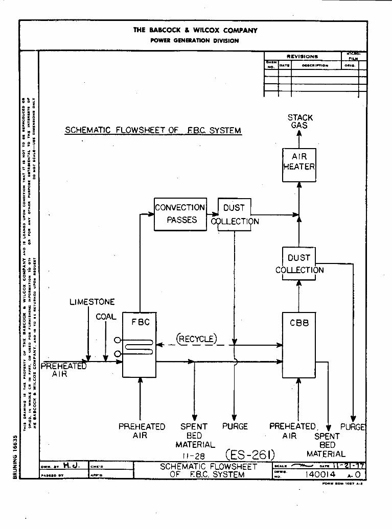
I THE BABCOCK 8 WlLCOX COMPANY I I POWER GENERATION DIVISION I
SCHEMATIC FLOWSHEET OF E8.C SYSTEM
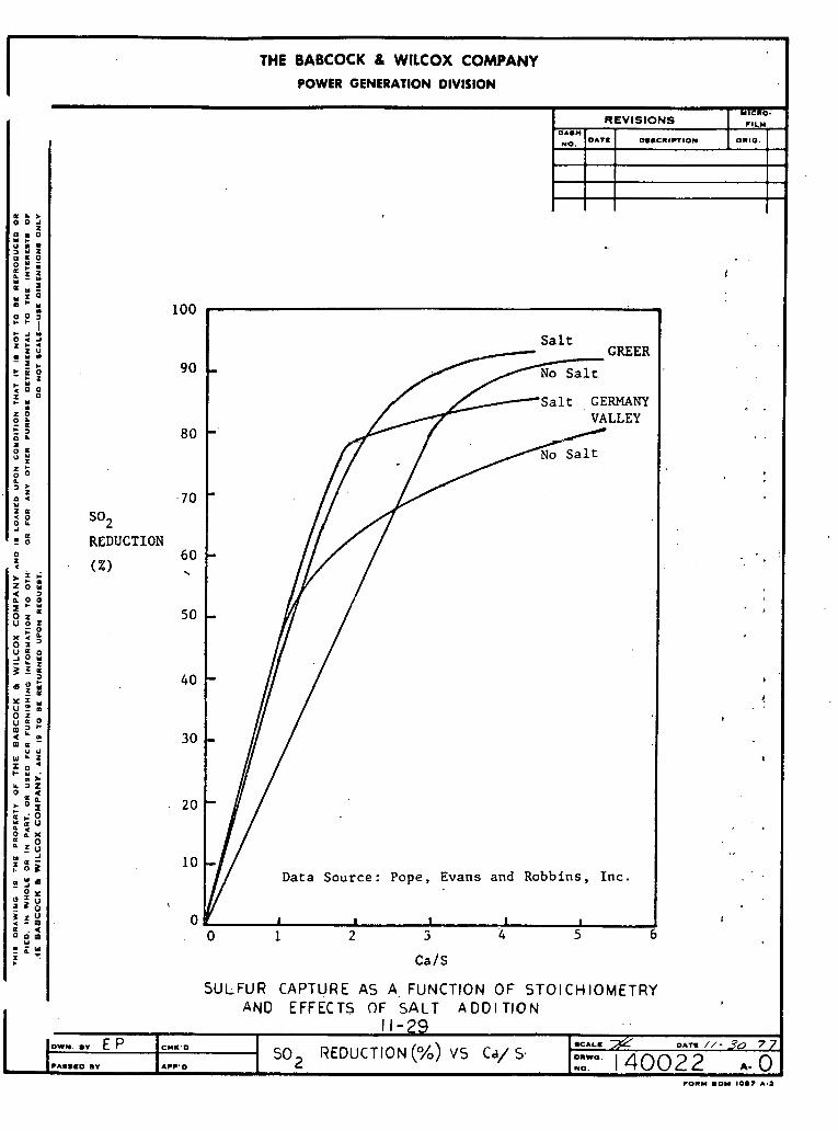
THE BABCOCK 8 WlLCOX COMPANY POWER GENERATION DIVISION
I 1-29 OWN. a* E P P I a a C D O T + Awn 2 0mwa~140022 No, L O A
r O R Y a D Y 10.7 A-a
C Y I . 0 REDUCTION (%) VS Cd/ S- U A L . o r r m //- 30 7 7
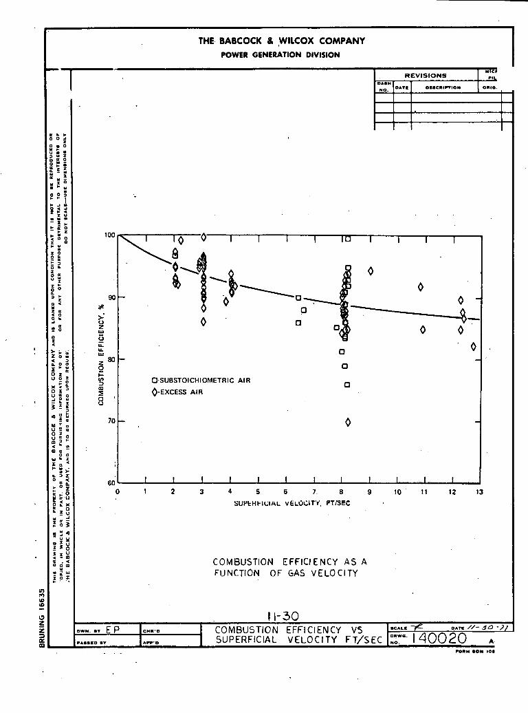
O.SUBSTOICHIOI'AETRIC AIR
0-EXCESS AIR
THE. BABCOCK 8 ,WILCOX COMPANY POWER GENERATION DIVISION
COMBUSTION EFFICIENCY A S A FUNCTION OF GAS VELOCITY
.
MICI R E V I S I O N S .#I,
.
0A.W
NO,
8
:
,
.
,
In m (0
!e U z z 3 a 00
OAT.
a & * 0 0 2 g c ' U r n .
7 : f 2:s h 5 E Z " ! : E : e e l i;:
z U . u r n =:: * t Z
0 0 T 0
u z 0 n P * 3 I a
:: :
= ; 0 ( Y z l l
0 0, ' .: 0 2
> - . '
26:
; e s 0 z a u z ,Z " 5 5 0 I u a o 2 : ; z 5 ., M ' u z : z : o m 3
; L o 0 0
W ' Z ::: >
k J Z
O . 2
t , - 0 m .t1
I:; & l u u - 4 :03 8 5 4 ; 9 : r X 2 5 : a . < o o m
r n U w ;!:
O..C11W10* 0 1 1 0 . J
. .
100 I I I I l u I I I 1
90- - a p ,
>- 0 0 ' Z
z W 0 u. LL
' w 80
5 V) 3 m
E + ? O -
:
60
0 ' 0 . - - 0
0
- , 0
I I I I I I I I I I. I I . , - 0 1 2 3 4 5 6 7. 8 9 10 ' 11 12 13
S U I J ~ H ~ I C I A L VELOCITY. PTBEC
1 1-30 Ow)l. .. E P ICHI.o I COMBUSTION EFFICIENCY V5 KAL.
OAT. 3c) - I ]
PASS.0 a* . A ~ . . I SUPERFICIAL VELOCITY ~ ~ / ~ € ~ 1 ~ ~ ? 1 4 0 0 2 0
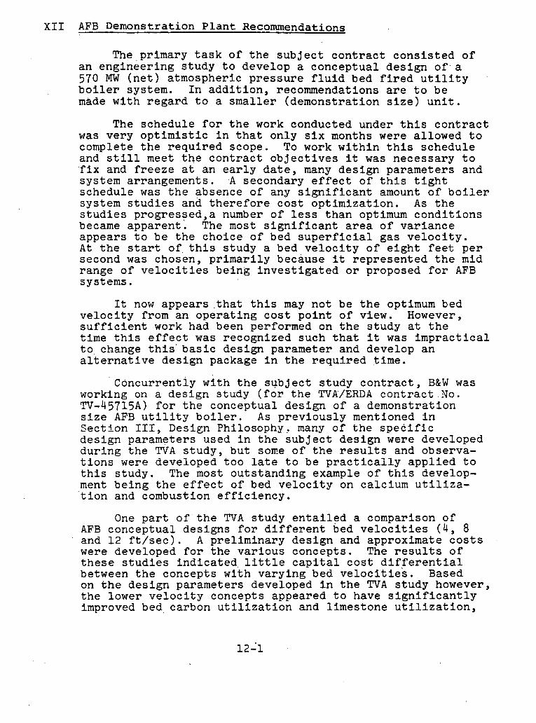
xII AFB Demonstration P l a n t Recommendations
The ,pr imary t a s k of t h e s u b j e c t c o n t r a c t c o n s i s t e d of an eng inee r ing s tudy t o develop a concep tua l d e s i g n 0 f . a 570 MW ( n e t ) a tmospher ic p r e s s u r e f l u i d bed f i r e d u t i l i t y b o i l e r system. I n a d d i t i o n , recommendations a r e t o be made wi th r e g a r d t o a s m a l l e r (demons t ra t ion s i z e ) u n i t .
The schedule f o r t h e work conducted under t h i s c o n t r a c t was very o p t i m i s t i c i n t h a t on ly s i x months were a l lowed t o complete t h e r e q u i r e d scope. To work w i t h i n t h i s schedule and s t i l l meet t h e c o n t r a c t o b j e c t i v e s it was necessa ry t o ' f i x and f r e e z e a t an e a r l y d a t e , many d e s i g n parameters and system arrangements . .A secondary e f f e c t o f t h i s t i g h t schedule was t h e absence of any s i g n i f i c a n t amount of b o i l e r system s t u d i e s and t h e r e f o r e c o s t o p t i m i z a t i o n . A s t h e s t u d i e s p rog res sed , a number of l e s s t h a n optimum c o n d i t i o n s became appa ren t . The most s i g n i f i c a n t a r e a of v a r i a n c e appears t o be t h e choice of bed s u p e r f i c i a l gas v e l o c i t y . A t t h e s t a r t o f t h i s s tudy a bed v e l o c i t y o f e i g h t f e e t p e r second was chosen, p r i m a r i l y because it r e p r e s e n t e d t h e mid range o f v e l o c i t i e s be ing i n v e s t i g a t e d o r proposed f o r AFB systems.
It now appears . t h a t t h i s may n o t be t h e optimum bed v e l o c i t y from an o p e r a t i n g c o s t p o i n t o f view. However, s u f f i c i e n t work had been performed on t h e s tudy a t t h e t ime t h i s e f f , e c t was recognized such t h a t i t was i m p r a c t i c a l t o change t h i s ' b a s i c des ign parameter and develop a n a l t e r n a t i v e des ign package i n t h e r e q u i r e d t ime.
Concurrent ly wi th t h e s u b j e c t s tudy c o n t r a c t , B&W was working on a des ign s tudy ( f o r the TVA/ERDA c o n t r a c t .No. TV-45715A) f o r t h e conceptua l des ign of a demons t ra t ion s i z e AFB u t i l i t y b o i l e r . A s p r e v i o u s l y mentioned i n S e c t i o n 111, Design Philosophy, many of t h e s p e c i f i c des ign parameters used i n t h e s u b j e c t des ign were developed du r ing t h e T V A s tudy , bu t sone of t h e r e s u l t s and observa- t i o n s were developed t o o l a t e t o b e p r a c t i c a l l y a p p l i e d t o t h i s s tudy . The most o u t s t a n d i n g example of t h i s develop- ment be ing t h e e f f e c t of bed v e l o c i t y on calc ium u t i l i z a - ' t i o n and combustion e f f i c i e n c y .
One p a r t o f ' t h e T V A s tudy e n t a i l e d a comparison of AFB conceptua l des igns f o r d i f f e r e n t bed v e l o c i t i e s ( 4 , 8 and 1 2 f t / s e c ) . A p re l imina ry d e s i g n and approximate c o s t s were developed f o r t h e v a r i o u s concepts . The r e s u l t s o f t h e s e s t u d i e s i n d i c a t e d , l i t t l e c a p i t a l c o s t d i f f e r e n t i a l between t h e concepts wi th va ry ing bed v e l o c i t i e s . Based on t h e d e s i g n parameters developed i n t h e TVA s tudy however, t h e lower v e l o c i t y concepts appeared t o have s i g n i f i c a n t l y improved bed, carbon u t i l i z a t i o n and l imes tone u t i l i z a t i o n ,
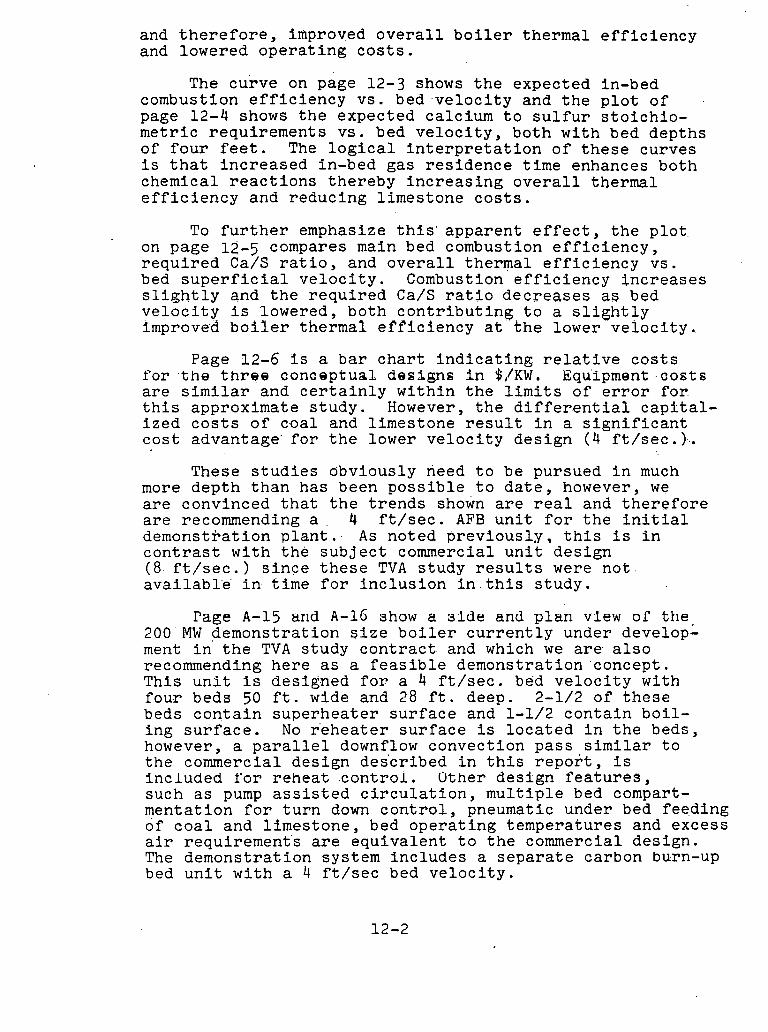
and t h e r e f o r e , improved o v e r a l l b o i l e r t he rma l e f f i c i e n c y and lowered o p e r a t i n g c o s t s .
The cu rve on page 12-3 shows t h e expec ted in-bed combustion e f f i c i e n c y vs . b e d . v e l o c i t y and t h e p l o t o f .
page 12-4 shows t h e expec ted calc ium t o s u l f u r s t o i c h i o - m e t r i c r equ i r emen t s v s . bed v e l o c i t y , bo th w i t h bed dep ths of f o u r f e e t . The l o g i c a l i n t e r p r e t a t i o n of t h e s e curves i s t h a t i n c r e a s e d in-bed gas r e s i d e n c e t ime enhances bo th chemical r e a c t i o n s t he reby i n c r e a s i n g o v e r a l l thermal e f f i c i e n c y and r educ ing l imes tone c o s t s .
To f u r t h e r emphasize t h i s ' a p p a r e n t e f f e c t , t h e p l o t on page 12-5 compares main bed combustion e f f i c i e n c y , r e q u i r e d Ca/S r a t i o , and o v e r a l l thermal e f f i c i e n c y vs . bed s u p e r f i c i a l v e l o c i t y . Combustion e f f i c i e n c y i n c r e a s e s s l i g h t l y and t h e r e q u i r e d Ca/S r a t i o d e c r e a s e s as bed v e l o c i t y i s lowered, bo th c o n t r i b u t i n g t o a s l i g h t l y improved b o i l e r t he rma l e f f i c i e n c y a t t h e lower v e l o c i t y .
Page 12-6 I s a bar c h a r t i n d i c a t i n g r e l a t i v e c o s t s for? . t h e t h r e e s o n s e p t u a l des igns i n $,/KW. Equipment # c o s t s a r e s imi la r and c e r t a i n l y w i t h i n t h e l i m i t s of e r r o r . f o r t h i s approximate s t u d y . However, t h e d i f f e r e n t i a l c a p i t a l - i z e d c o s t s o f c-oal and l imes tone r e s u l t i n a s i g n i f i c a n t c o s t advantage ' f o r t h e lower v e l o c i t y d e s i g n ( 4 f t / s e c . ) . . .
These s t u d i e s obvious ly need t o be pursued i n much more d e p t h t h a n has been p o s s i b l e t o d a t e , however, we a r e convinced t h a t t h e t r e n d s shown a r e r e a l and t h e r e f o r e a r e recommending a . 4 f t / s e c . AFB u n i t f o r t h e i n i t i a l demons t r a t i on p l a n t . . A s no ted p r e v i o u s l y , t h i s i s i n c o n t r a s t w i t h t h e s u b j e c t commercial u n i t d e s i g n ( 8 - f t / s e c . ) s i n c e t h e s e TVA s tudy r e s u l t s were n o t . ava i lab l ' e ' i n t ime f o r i n c l u s i o n i n . t h i s s t u d y .
Page A-15 arid A - 1 G show a 31de and p l a n v l e w or the 200 MW demons t r a t i on q i z e b o i l e r c u r r e n t l y under develop- ment i n t h e TVA s tudy c o n t r a c t and which we a r e a l s o recommending h e r e as a f e a s i b l e demons t ra t ion concept . This u n i t i s des igned f o r a 4 f t / s e c . bed v e l o c i t y wi th f o u r beds 50 f t . wide and 28 f t . deep. 2-1/2 o f t h e s e beds c o n t a i n s u p e r h e a t e r s u r f a c e and 1-1/2 c o n t a i n b o i l - i n g s u r f a c e . No r e h e a t e r s u r f a c e i s l o c a t e d i n t h e beds, however, a p a r a l l e l downflow convec t ion pas s similar t o t h e commercial de s ign des 'cr ibed i n t h i s r e p o r t , i s inc luded Yor r e h e a t c o n t r o l . Uther d e s i g n f e a t u r e s , such as pump a s s i s t e d c i r c u l a t i o n , m u l t i p l e bed compart- menta t ion f o r t u r n down c o n t r o l , pneumatic under bed f eed ing of c o a l and l imes tone , bed o p e r a t i n g t empera tu re s and excess a i r r equ i r emen t s a r e e q u i v a l e n t t o t h e commercial de s ign . The demons t ra t ion system i n c l u d e s a s e p a r a t e carbon burn-up bed u n i t w i t h a 4 f t / s e c bed v e l o c i t y .
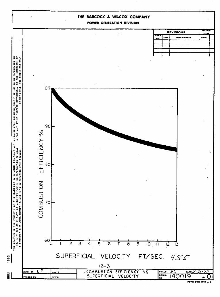

I - -
THE BABCOCK I WllCOX COMPANY POWER GENERATION DIVISION
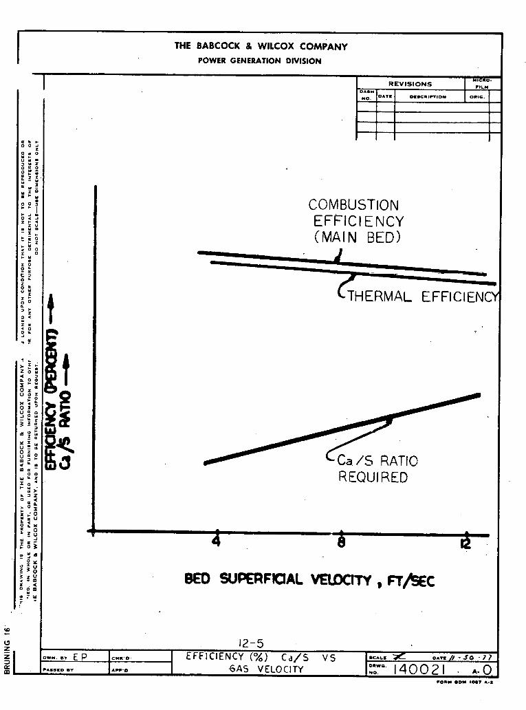
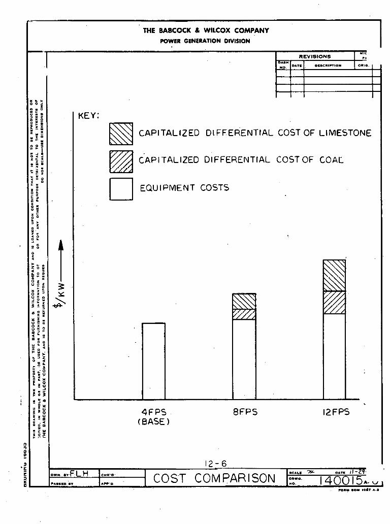
THE BABCOCK 8 WlLCOX COMPANY POWER GENERATION DIVISION

APPENDIX IIIA-D
EQUIPMENT DATA SHEETS
Page
Babcock & Wilcox Equipment i
Equipment Common to Babcock & Wilcox and Foster Wheeler 39

BABCOCK E WILCOX EQUIPMENT

COOLING 'TOWER DATA SHEET - AFJ3 J.O,NO, 12919-02A-B&W
l v h r ~ No. 4CTWR-1 Specification No. Purchase Order No.
Service
No of Units Operation Type F i l l Number of Cells Fans per C e l l Circulating W a t e r Flow,- g p H o t ( in l e t ) W a t e r Temp, Y Cold (outlet) Water Temp, F W e t Bulb l k lup , F Approach A i r Density C o r r e s p m h g to 79 F, l b / f t
Motor ~p H e a t Re jetted by Cooling Tower, B t u / h r
-ge, Maxinnmt D r i f t , % of
Circuldting Water Flow
~dn'denser Circulating W a t e r and Cooling W a t e r Systems
1 Cantinnous Mechanical Induced ~ r a f t Wood 12 1 202,713 121.23 . - 91-87 5
79 12-87
A S T M A m e r i c a n Society for Testing and ,; Materials
ANSI ..
.. AISI
ClT Std
American National Standards I n s t i t u t e
r American Iran and S t e e l Xnstitute
American Concre te Insertute
Cooling Tbwer I n s t i t u t e Standard Specification

VERTICAL PUMP DATA SHEET - BFB J-0-No, 12919-02A-B&W
Mark N o . UCWP-IA,B Specification No- Purchase Order No,
Service Circulating Water Pumps No, o* Qnits 2 Xndoors or Outdoors Outdoors Operatum Continnous Liquid Punrrped Cooling Tower Discharge -1-w TPmn 32 F - 95 P pH $6'- 7 Sp- Gr- a t PIT- 1.0 - -994 Viscosity a t POT, 1.79 - -70 cg Capaclty at PITI - 101,365 gpm each Pressure a t suction nozzle: - ~ i d e d ' Differential Pressure or . . ,
Total Head 100 ft, 43 p i g Shutoff TDH, Max * ' 160 ft, 68-8 psig HP 3,000 r'
Pump Speed* rpm - 400 Driver Type ' Motor Driver Furnished by Purchaser Type Lubrication Water Pumped Discharge Size, in, 60
Codes:
ANSI B31-1
Hydraulic Institute Standards
I-* American National Standards Institute
Cast Iron Pipe Phr1gc3 4 Pl;lnged - Fittings
Steel Pipe Flanges, Flanged Valves,, and Fittings
- . I Factory Made Wrought Steel 'Butt-
welding Fittings
. ' - mrged Stee l rittings, socket Welding and Threaded
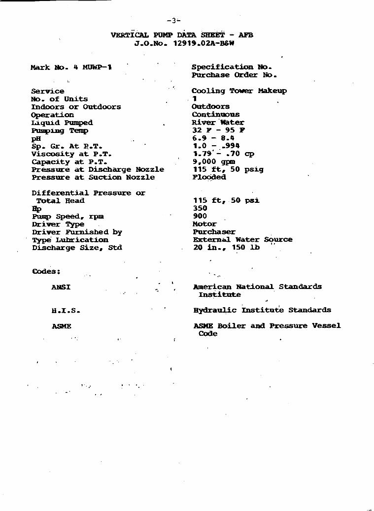
vg~lrlCAL PUMP I l k Sl?EEi! - AFB J,O,No, 12919,OZA-BSW
ark m- 4 MUWP-I specirication No- Purchase Order No-
* ,
Service No, of Units Indoors or Outdoors Operation Liquid Pumped p-4'- T-W PH , . Sp, Gr, At ROT, ,
Viscusity at POT, Capacity at P-To Pressure at Discharge Nozzle Pressure at Suction Nozzle
Differential Pressure or Total H e a d
m Pump Speed8 rpm D r i v e r Type Driver Furnished by ~ype' Lubrication Discharge Size, Std
Codes: - .
Cooling Tower Makeup 1 Optdoors Continp~us R i v e r 'Water 32 F - 95 P 6.9 - 8.4 1.0 --,994 1-79'- -70 cp 9,000 gptn 115 f t , 50 psig Floc@ed
115 ft, .50 p s i 350 900 Motor Purchaser Externtil Water Source
b l
20 in-, 150 lb
. \
-1 .. , American National Standards -* . Ust i i tUte
a
. + H - 1 , s - H y l r a P l i c k t i tnt le Standards
A S M X Boiler and Pressure V e s s e l Code
I
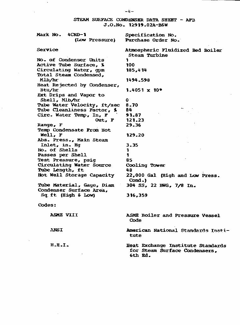
STEAM SURFACE COND&NSKR DATA SHEET - APB J,O,No, 12919 -02A-B&W
MarkNo. 4CND-1 Specification No, (Low Pressure) Purchase Order No,
Service
NO, of Condensex units Active Tube Surface, % C i r c u l a t i n g W a t e r , gpm Tbtal Steam Condensed,
M u m H e a t Rejected by Condenser, Btu/hr Ext Drips and Vapor t o Shell , M.Lb/hr Tube Water Velocity, ,f t/sec Tube C l e a n l i n e s s Factor, % C i r c - W a t e r Temp, In, F' -
Out, F Range, F Temp Condensate Ran H o t
W e l l , F Abs, Press,, Main Steam Inlet, in, Hg
No, of Shel ls Passes per She l l Test Pressure, psig Circulating W a t e r Source Tribe Length, f t Eot W e l l Storage Capacity
'Rlbe Material, Gage, Diam Condenser Surface Area, Sq. ft (Hiqh 6 Low)
Codes :
ANSI
Atmospheric Fluidized Bed Boiler Steam I'urbine
1 100 185,414
3.35 1 1 85 Cooling Tower 48 22,000 Gal (High and LaJ Press. cona -)
304 SSP 22 BWG, 7j0 mi
ASME Boiler and Pressure Vessel Code
American National Stan&- r d s I n ~ t i , - t u t e
Beat Exchange I n s t i t u t e Standards for Steam Surface Condensers, 6th Ed.

3 T W SURFACE CONDENSER MTA S H E E T - kPB J.0-No, 12919,02A-BSW
ark 140. 4CND-2 Specification No. (Eigh Pressure) Purchase Order No.
Service
N o , of Condenser Units Actnve Tube Sur.fdce, ff Circulating W d t e r , gpm Tota l Steam Condensed,
1 4 l b / h r Heat He jected by Condenser,
H t u / h r Ext Drips and V a p o r to ShelL, Mlb-
Tube Water Velocaty , f t/sec Tube C l e a n l i n e s s Factor, % C:irc. Water m, u;, P
out, I? Hange, B Tkmp Condensate from H o t
W e l l , F abs. Press., Main Steam Inlet, an, H g
N o , of S h e l l s Passes per S h e l l Test Pressore, psig
k w s p h e r i c Fluidized Bed Borler Steam Turbine 1 100 185,414
Circulating Water Saurce: Cooling Tower Tube Material, gage, diam 304 SS, 22 BWG, 7/8 in- Condenser Surf ace A r e a , sq ft (High C Low) 316,354
Tube Length, ft 48
ASME VIII ASME Boiler and Pressure V e s s e l Code
ANSI American National Standards Instatute
H e a t Exchange Institute Standards for Steam Surface Condensers, 6th Ed,
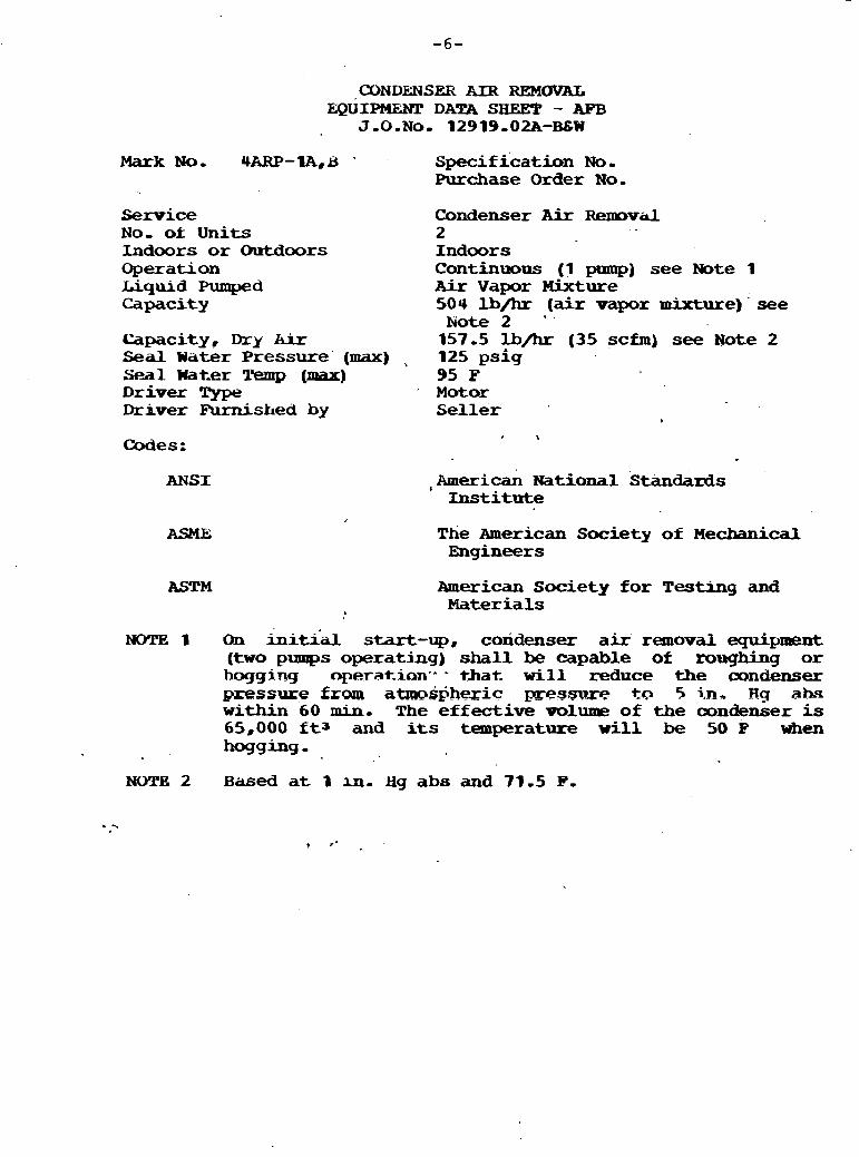
CONDELNSER AIR REMOVAL EQUIPMZXL! DATA SHEET - AFB
J , O . N o - 12919.02A-BGW
Mark No, 4ARP-1A,t3 ' specification No. Purchase Order N o ,
Service N o , of: Units Indoors or Outdoors Operation Liquid Pumped Capacity
Capacity, Dry kir Seal Water Pressure' (max) S-1. Water Temp (max) Driver !l!ype Driver Aurnislled by
Condenser A i r Rem,vaC 2 Ind~or s Continuous (1 pump) see Note 1 AFr Vapor Mixture 504 lb/hr (air vapor mixture) see
N o t e 2 '
157 -5 lb/hr (35 scfm) see N o t e 2 125 psig 95 F Motor Se l l er
Codes; I
ANSI ,~meriCan National standards Institute
The American Society of Mechanical Engineers
American Society for Testing and Materials
NOTE 1 On t i ' start-up, coxidenser air removal equipment ( t w o pumps operating) shall be capable of roughing or hoggjng operatian'' - that will reduce the condenser pxessure frm atmos~hexic prestsure to 5 Hg ah- within 60 lain. The effective volume of the oondenser is 65,000 f tJ and its temperature will be 50 P when hogging -
NOT& 2 Based a t 1 ;m. Hg abs and 71.5 F.

VERTICAL PUMP DATA SHEET - AFS J,O,No. 12919,OZA-B&W
Service - - No. of Units Indoors or Outdoors Operation Liquid Yumped Pumpinq T-P/PH Sp. Gr. a t P.T. Viscosity a t POT, Capacity a t P.T.
Pressure a t discharge nozzle
Pressure a t suction i
Differential 'Prdsure or Total Head
Available MPSH, ft 4? pl=v Speed, w m D r i . v e r type Driver Purnished by Type Lubrication Discharge Size, Std Sue-ion Size, S t d
Specification No, Purchase Order Ho.
Condensate 2 Indoors ~ O R ~ ~ ~ W U S Condensate 130.64 F D - 3 to 9.7 . ,987 051 cp 3,750 gpm (2 pump operation) - 4,700 g ~ a n (1 pump operation)
1,040 f t , 444.8 psig -30.40 f t , -13 ,-psig .
to7094 #, 457.8 gsig-. r 2 . ~
i ,a 1,500 1,200 rpIt
Motor Sel ler r + , .
Water puruyed . . I
14 in,, 300 l b - 3
24 in,, 150 l b
Codes : ', I
ANSI
NEMA MG1
ASME Boiler and Pressure V e s s e l Code
American National Standards.' Institute
I
National Electrical Manuiacturers , Association: Motors and Standards
H - I S - IPydrhUlic~ In s t i t u t e Staxlards

BOILER FILED BOOSPER PUMP DATA SHEET - AFB J-0-No, 12919-02A-B&W
Mark NO, 4 BFP-IA
service N o , of Units No, of Stages Indoors or O u t d o o r s Operation Liquid Pumped mrmping
Sp- . GK, A t POT. V i s c o s i t y at PDT, Capacity at P.P. Pressure a t D i s c h a r g e N o z z l e Pressure a t S u e o n Nozzle
D i f f e r e n t i a l Pressure or T o t a l H e a d HP Pump Speed, rpm Driver 1 . D r i v e r Furnished by Type Lubrication D i s c h a g e S ize , Stc i
Codes :
ANS I
Specification No. Purchase Order No.
B o i l e r feed booster 1 1 Indoors C o n t i n u o u s Feed Water 299 F 9.2 - 9 . 6 , 9 1 8 8 -46 cp 9 ,567 g p m 450 f t 56.5 f t
4 5 0 ft 1 , 0 3 2 5 , 8 4 5 Turbine Purchaser Turbine oil 1 4 , i n , , 300 lb
A m e r i c a n National Standards Institute
Hydranlic Institute Standards
AS'ME B o i l e r and Pressure V e s s e l Code
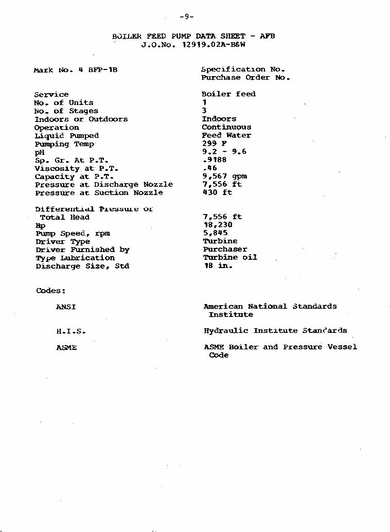
hark No. 4 BFP-1B
B3TI.ER FEED PUMP DATA SHEET - APB J.O,No, 12919,02A-R&W
Service No, of Units N o , of Stages Indoors or Outdoors Operauon Liqui6 Pumped Pumping Temp. pH Sp, G r , A t POT- Viscosity a t P-T. Capacity a t P-T- Pressure a t Discharge Nozzle Pressure a t Suction Nozzle
Specification N o , Purchase Order rJo,
B o i l e r feed 1 3 Indoors Continuous Feed Water 299 F 9.2 - 9.6 ,9188 -46 9,567 gpm 7,556 f t 430 f t
Dif f ere11tid Pressure Oi T o t a l Head 7,556 f t w 18,230 Pump Speed, rpm 5,845 Driver Type Turbine Driver Furnished by Purchaser Type Lubrication Turbine o i l Discharge Size, Std 18 in,
Codes :
ANSI American National Standards I n s t i t u t e
Hydraulic I n s t i t u t e Stan?ards
ASME Boiler and Pressure V e s s e l Code

START-UP I33TC.TZR FEED PUMP DATA SHET - AFB J,O,lJo, 12919,02A-BCW
Mark N O , 4 SBFP-1
Service No. of Units No, 0s Stages -doors or Outdoors Operdaon Liquid Pumped ming Temp PH Sp. G r , A t PDT, viscosity a t r .#.r, Capacity at P,T, Pressure at Discharge Nozzle Pressure a t Suctron Nozzle
Di f fe ren t i a l Pressure or lbtal Head HP Pump Speed, r p m Driver Type Driver Furnished by Type Lubrication
Discharge Size, Std
ANSI
H.1.S.
Specification No, Purchase Order No,
Start-up bo i l e r feed 1 4 Indoors Start-up Feed Water 299 F 9.2-9-6 ,9188 ,9fi cp 5,860 gpm 7,556 ft 96.2 ft
7,556 f t 10,000 5,600 M o t o r Purchaser Any o i l grea ter than 150 SSU
h t lOOF 11 in,, Schedule 160
American National Standards I n s t i t u t e
Sydraulic Institute Standards
ASME Boiler a d Pressure V e s s e l Code

DEAERATOR' DATA SHEET J.O. No. 12919.02A-B&W
Mark No.: 4 CNM-EH4
Quantity: 1
Ikcation: Indoors
Specification No. ' -
Purchase Order
Flow - Enthalpy '
Ram Blowdown Flash Tank: 2,196 -Ib/hr 1179.36 Btu/ lb
Condensate to Heater: 3,269,420 lb/hr 237.73 Btu/ lb
Feedwater H e a t e r Returns: 617,557 Ib/hr 281.9 ~ & u / l b
Extraction Steam t o H e a t e r : 87,789 lbfhr . 1292-16 Btu/lb
Total Water Delivered lb Boiler , Feed Pump: 3,976,963 Ib/hr 26.8 -39 Btu/lb . -.
' . . ' . ' .. 1 - - 4 .
Operating Pressure: 51 psig
Pressure' of Extraction Steam a t Deaerator: 69.2 psia
Design Temperature, Shell: 320 deg F.
Design Temperature, Steam I n l e t Nozzle: 560 deg F.
Design .Pressure: 70 psig
Required Storage Capacity Below Normal Level: 46,000 ga l
Code Requirements: ASME Boiler and Pressure V e s s e l Code, ., . Section VIII, D i v . 1 Standards of t h e Beat Exchange I n s t i t u t e , ,
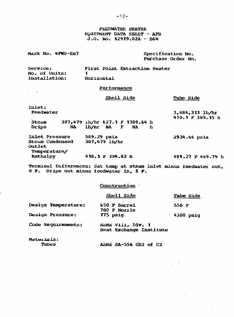
Mark No. 4ms-EM7
FEEDWATER H E U W t E Q U L P M N T DArRA SHFBT - AFB J.O. KO. 12919.02A - BEW
S p e c i f i c a t i o n No. Purchase Order No.
Service : First Point Retraction H e a t e r No. of Units: 1 I n s t a l l a t i o n : Horizonta l
Performance
S h e l l S i d e Tube S i d e
Inlet: Feedwater 3,484,313 lb/hr
410.1 P 389.15 h Steiim 307,479 Ib/k 627.1 F 1308-64 h D r i p s NA lb/hr F NA h
Inlet Pressure 589.29 psia Stea Ccmdensed 307,479 lb/hr Outlet
Temperature/ m - 1 ~ ~ 418.3 P 394.82 h
2934 -66 p s i a
484.27 F 469.74 h
Terminal D ~ f f e r e n c e s : Sat temp a t steam inlet minus feedwater out, 0 P. Drips o u t minus feedwater in, 8 F.
Shell Side TPbe Side .
Design Temperature: 650 F Barrel 700 F Nozzle
Design Pressure : 775 p i g
Code R e q u u e m e n t s : ASME vlil, D i v . 1 H e a t Exchange In s t i t u t e
M c l t A J L i a l s : Tubes
550 F
4300 psig

Mark No. URr'S-AEI6 .
PEEDWATER Hum3R EQUIPMEW! DATA SHEET - AFB J.0. No- 12919.02A - BGW
Specif rcation . No. ;:.+. . Purchase Order N o ,
Service : Second Point Errtractiuin H e a t e r ,
No- or Units: 1 - - . Instal lat ion: Horizontal
Perf onnance
Shel l S ide Tube Side
In le t : _ I _ Peedwater 3,484,313 lb/hr
374.46 d 351.69 h Steam 109,214 lb/hr 838.34 F 1442.44 h * a b
D r i p s 307,473 lb/hr 418.1 B 394.82 h ' 4
Inlet Pressure 270.9 psla 2959.66 ps la _
Steam Condensed 109,214 l b / k -.. - i s
Outlet Temperature/ E ~ W W 382.46 F 356.22 h 410.1 P 389,15 h
TeraindL Differences: Sat temp at steam inlet minus feedwater out, -2 P. Drips out minus feedwater in, 8 F. -
Construction
Shell Side , .Tube Side
Design Temperature: 650 F Barrel 875 F Nozzle .
Deslgn Pressure: 325 psig .
Code R e q u i r e m e n t s : ASME -11, D i v . 1 H e a t Exchange Ins t i tu t e
Materials : Tubes
475 F + . - 4300 psig
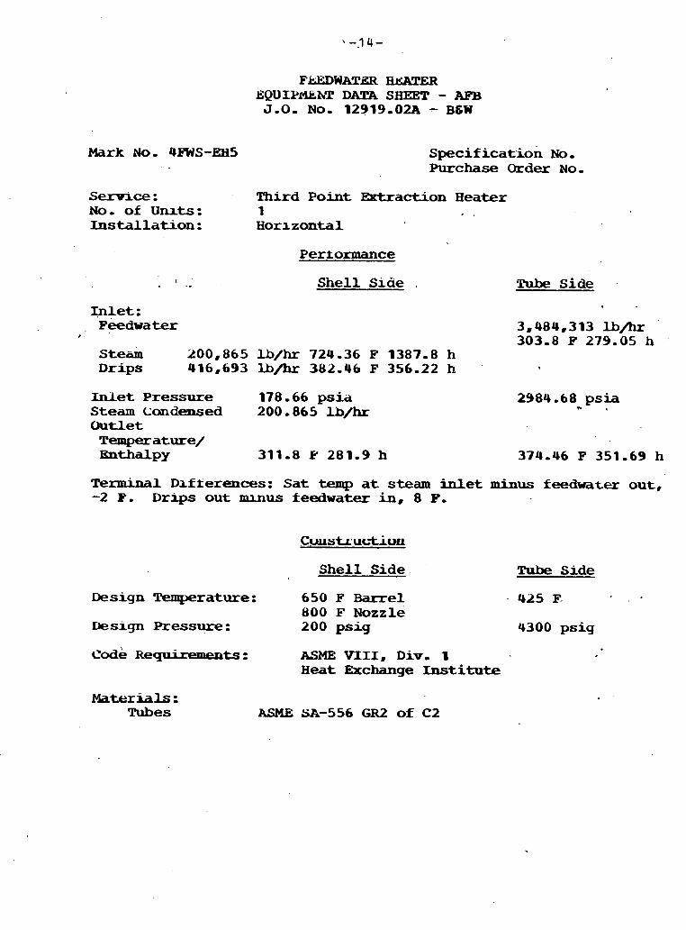
Mark N o . 4-S-EH5 Specif icat'ion No. Purchase Order NO.
Service : Third Point Extraction Heater No. of Unrts: 1 Installation: Horizontal
Performance
I .- Shell Siae . Tube side
Inlet : Feedwater 3,484,313 U/hr
I 303.8 F 279.05 h Steam 200,865 U/hr 724.36 F 1387.8 h Drips 416,693 U/br 382.44 F 356.22 h
Inlet Pressure 178.66 psia Steam Condensed 200,865 lb/hr Outlet
Temperature/ E n a a ~ ~ 311.8 Y 281.9 h
2984-68 psia - 1
Terminal Dxfterences: Sat temp at steam inlet minus feedwater out, -2 P. Drips out muus feedwater in, 8 P.
Shell Side Tube Side
Design Temperature :
Iiesign Pressure:
code Requ i t en t s :
650 F Barrel 425 F- 800 F Nozzle 200 psig 4300 psig
ASME VIII, Div. 1 Heat Exchange Institute
Materials : ~ubes
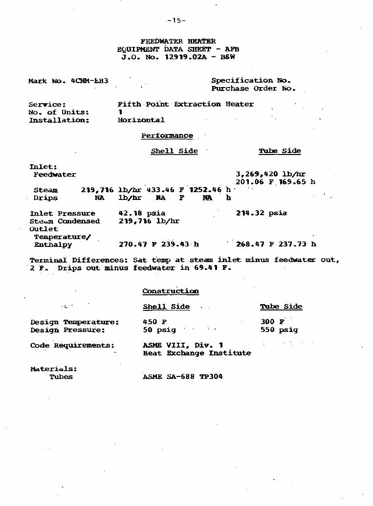
PFZDWATER HEATER EQUIPMHW DATA SHEET - AFB J.O. No. 12919.02A - B 6 W
Mark Wo. 4CNM-hH3 !
Specification No, Purchase Order hog
Service : F i f t h Po*. Extraction Heater No, of Units: 1 Installation : H o r i z o n t a l
Performance
Shell Side Tube Side
Inlet: P e e d w a t ~ , 3,269,420 lb/hr
201,06 F , 169.65 h Steam 219,716 U/hr '433.46 F '1252-46 'h ' ' . D r i p s NA lbfbr A1P P l@8 ' h
I
Inlet Pressure 42-18 psia 214.32 psia S t e a Candensed 219,716 lb/hr O u t l e t
T e m p e r a t u r e / = ~ P Y 270.47 F 239.43 h 268-43 I? 237.73 h
Terminal D i f f e r e n c e s : Sat t'emp at s t e a m inlet minus feedwater out, ' 2 F, D r i p s out minus f eedwater in 69.4 1 P.
Design Temperature: Design Presswe :
Code '~equi rements :
Shell Side - Tube Side
450 F 300 F' 50 ps ig + . . 550 psig
ASME VIII, Div, 1 H e a t Exchange Instiate
hterials: Tubes
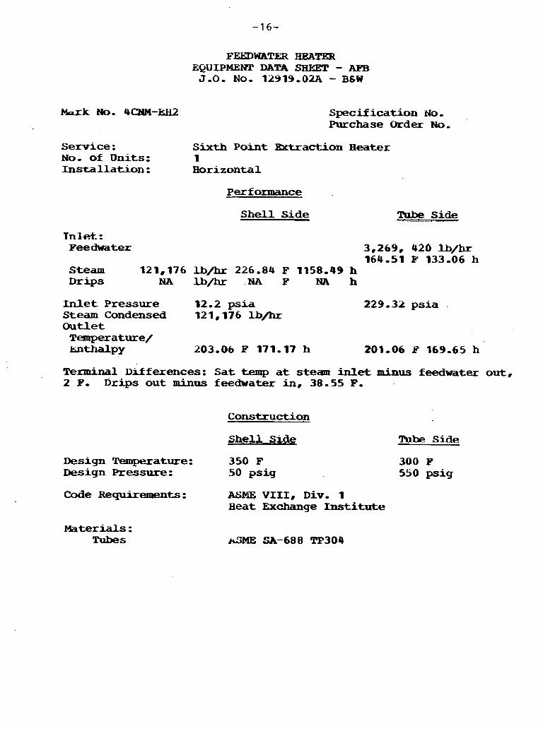
k r k No. 4CNM-kH2
FEEDWATER HEATER EQUIPMENT DATA SHEJ3T - APB J.0. NO. 12919-02A - BfW
Spec i f i ca t ion Purchase Order No.
Service : Sixth Point Extraction Heater N o - of U n i t s : 1 I n s t a l l a t i o n : Borizontal
Performance
S h e l l Side Tube Side - - - . . . . .. - .
Tnlctt,: Feedwater 3,269, 426 Ib/hr
164.51 Y 133-06 h Steam 121,176 lb/hr 226.84 F 1158-49 h D r i p s NA lb/hr NA F NA h
Inlet P r e s s u r e 12.2 psia 229 -32 psia .
Steam Condensed 121,176 lb/hr Outlet Temperature/ k.nthalpy 203.06 P 171,17 h 201.06 A? 169-65 h
Terminal Ilrfferences: S a t temp a t steam inlet minus feedwater out, 2 F- Drips out m i n u s feedwater in, 38-55 F,
Construction
Shell, T%I& Side
Design Temperature: 350 F Design Pressure : 50 p s i g
Code ReQuirements: ASYE, V I I I , Div. 1 Heat Exchange Institute
Materials : Tubes
300 P 550 psig
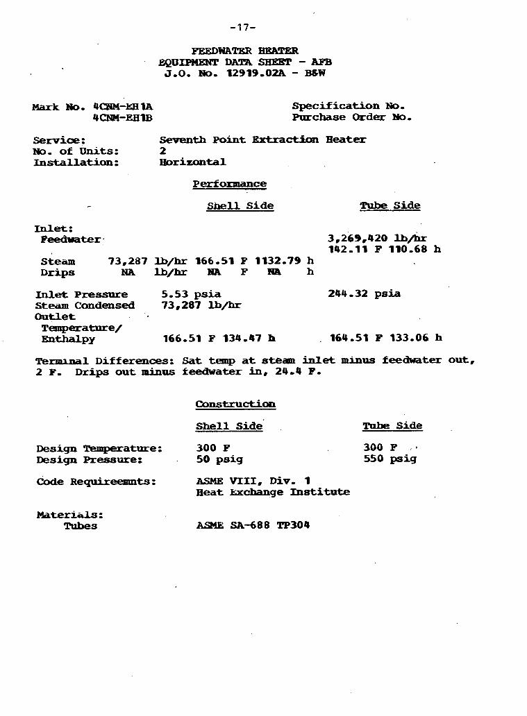
Mark No* 4CeTM-EElA 4cNM-EEIIB
FEEDWATBR HRA!rER EQIIIPMlSNT DAlR 'SEEET - AFB J.0. No. 12919.02A - B 8 W
Specification No. Purchase Qrder No.
Service: Seventh Point Extract.5~11 H e a t e r No. of U n i t s : 2 Installation: HDrizuntal
Perf onnance
Shell Side Tube Side
Inlet: Feedwater. 3,269,420
142.11 F 110.68 h S t e a m 73,287 U/hr 166.51 F 1132.79 h Drips NA lb/h HA F HA h
Inlet Pressrrre 5.53 psia 244 -32 psia Steam Candensed 73,287 U/hr Outlet . .
Temperature/ ~ W P Y 166.51 F 134.47 h . 164.51 F 133.06 h
Terminal Differences: Sat temp at s t e a m inlet minus feedwater out, 2 F. D r i p s out minus feedwater in, 24.4 F.
Shell side' Tube Side
Design -atme: 300 F Design Pressure: . 50 psig
Code R e Q u i r e e a m t s : ASME VIII, Div. 1 H e a t kxchange Institute
Materials: Tubes
300 F ...
550 psig
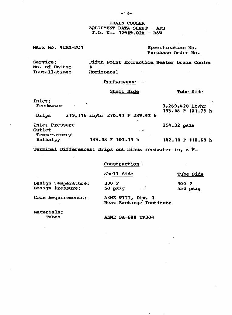
Mark No, 4CNM-DCI
Service : No, of units: I n s t a l l a t i o n :
DRAIN COOLER hQUIPMlWE DATA SHEET - AEB J-0. N o , 12919.02.A - BLW
~ p e c i f i c a t i o n No, Purchase 'Order .No,
Fifth Point Extkaction Heater Drain Cooler. I Horizontal
P e r f o m c e -
*ell Side Tuae Side
mleE : Feedwatex 3,269,420 U/hr
133.18 l? 101.78 h Drips 219,716 lb/hr' 270.43 F 239;43 h
Inlet Pressure 254.32 psia Outlet - a Temperature/ -*&PY 139.18 P 107.13 h 142,11 F 1'10.68 h
Terminal D i f f e r e n c e s : Drips o u t minus f eedwater in, 6 'F .%.
Construction *
S h e l l Side Tube Side
besign T e m p e r a t u r e : 300 F 300 E' Design Pressure: 50 paig 550 psi9
Code kequirements: , AhME V I I I , D i v , 1 H e a t ~xchange' Institute
Materials : Tubes
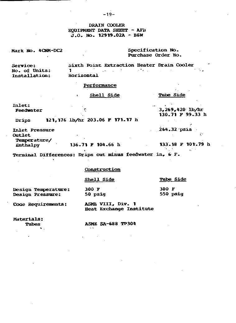
Mark No, 4QW-DC2
Service: N o , of Units: Installaticm:
DRAIN COOLER EQDIPMENT DATA SBET - AEB J.0, No, 12919-02A - BSW
Specif ication N o , Purchase Order N o ,
sixth P o i n t =action Heater Drain Cooler 1 ' * .
. - _ I .
Horizontal
Performance
1 Shell Side Tube Side
Inlet: . . , Feedwater ? 3,269,420 lb/hr
130.71 F 99-33 h Drips 121,976 lb/hr 203.06 F 171-17 h .-
Wet Pressure 264 -32 +psis . Outlet i'
Temperature/ ~ W P Y 136-71 P 104-66 h 133',18 . I F 101;79 h
4
Terminal Di'f ferences: Drips out m i n u s f eedwater in, 6. F , %
Construction
She l l Side Tube Side
Design Temperature : 300 F Design Pressure: 50 psig
Coae R e q u i x e m e n t s : ASME; VIII, D i v , 1 Heat &change Inst i tute
M a t e r i a l s : Tubes
* <
300 F 550 psig

Mark No..
BED LETDOWN BIBERS-APB 12919 -02A-BSW
Service: Spent Bed Material Disposal
No, of U n i t s No, Running Indoors or O u t d o o r s Operation M a t e r i a l C o n v e y e d Eed Material Temp Bed Material D e n s i t y , lb/fts Flow Rate, T/hr B L o w e r Capacity, cfm B l o w e r Static, psi Driver Type Driver H p Driver Furnished by Discharge Size, in- B l w e r Type
Specification N o , Purchase Order
3 2 Indoors Intermittent Bed Letdown 250 P 80 150 3,800 15 M o t o r 250 Seller 12 Positive Displaceroent

FLY ASH BIDWERS-AW 129 19 -02A-B&W
Mark No. Specification No. Purchase Order
Service : Fly Ash Disposal (CBC Dust C o l l e c t o r )
No. of U n i t s No, Running Indoors or Outdoors Operation Material Conveyed' ~ l y Ash Material k p Fly Ash Material Density, lb / f t3 Flow Rate, T/hr B l o w e r Capacity, CPM B l w w Statio, psi Driver Xp D r i v e r Type Driver Furnished By Discharge Size, in- Blower Type
2 1 Indoors Continuous Fly llsh 750 F - 40 64.5 3,800 15 2 50 Hotor Sel ler 12 Posititne Displacement

FLY ASH BrnWEHS-AFB 12919,02A%6W
Mark No, Specification No, Purchase Order
Service: Ply A s h D i s p o s a l ( H o t P r e c i p s )
No, of U n i t s No. R u n n i n g Indoors or Outdoors' Malzerial 134iiveyed '
Fly A s h Material Temp ply ksh mteriai Density ~ b / f t a F l o w Rate, T/hr B l o w e r C a p a c i t y , c f m B l o w e r Static, p s i D r i v e r lip D r i v e r Furnished By
r Intake Size, in, B l w e r Type
2 1 Indoors- .
F l y Ash 750 F . 40 3 -36 3 , 8 0 0 15 '
2 50 I
Seller 8 P o s i t i v e D i s p l a c e m e n t

Mark N o .
FLY ASH VACUUM PRODUCERS-AFB 12919.02A-BSW
Spec i f i ca t ion N o . Purchase Order
Service: Fly Ash Disposal ( a C Dust Collector) .
No, of units No, Running Indoors or Outdoors I .
Operation Material Conveyed Fly Ash Material Temp F ly Ash Material Density, Flaw Rate, T/hr B l o w e r Capacity, cfm Blawer S t a t i c , p s i Driver Up D r i v e r Type Driver Furnished By Intake s i z e , . in. Blower Type
2 1 Indoors lbntinuous Fly Ash 750 Fb
lbyf t3 40 64.5 3,000 13 60 Motor S e l l e r . 1 2 Centrifugal

Mark No,
FLY ASH VACUUM PRODUCERS-AFB 12919,OZA-B6W
Specification No, Purchase Order
Service: Fly Ash D i s p o s a l (Hot Precips)
No, of Units No, Running Indoors or Outdoors Operation M a t e r i a l Conveyed Fly Ash Material Density, l b / f t a Flow Rate, T/hr Blower Capacity. cfm Blower Static, psi Driver Bp Driver Type Driver Purnished By Intake Size, in, Blower Type
2 I Indoors Continuow Fly Ash 40 3-36 1,800 '
13 60 Motor Seller 8 Centrifugal
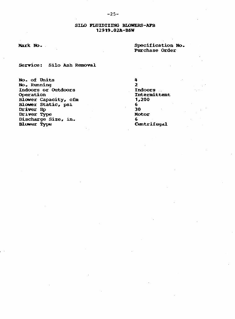
Mark No,
Service: Silo Ash R e m o v a l
No- of Units No, Running Indoors or Outdoors Operation Bluwer Capacity, cfm Blader Static, psi Driver Hp Drrver Type Discharge Size, in, Blwu Type
Specification No, Purchase Order
4 2 Indoors Intermittent 1,200 6 30 M o t o r 6 Ctzltr-Lf u y d
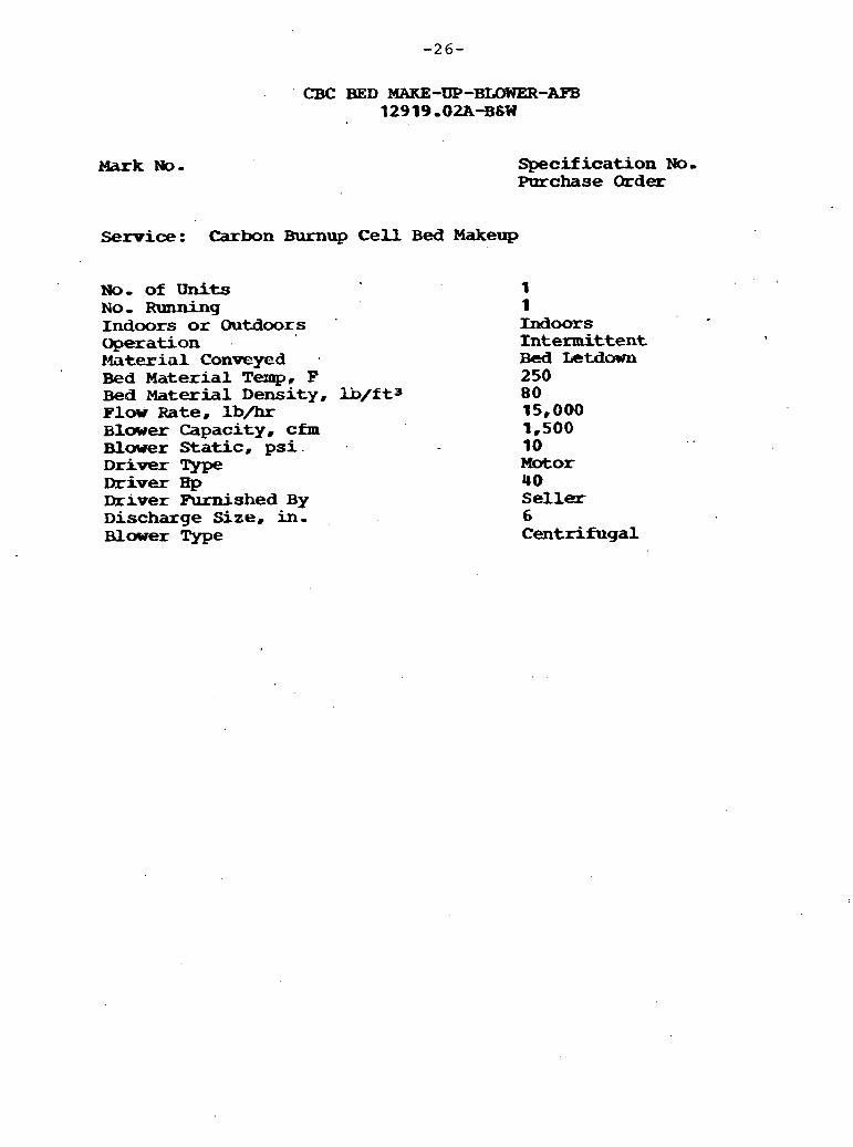
W k No-
CBC BED MAKE-UP-BLOWER-AFB 12919,02A%6W
Specification No, Purchase Order
Service : Carbon -up C e l l Bed Makeup
No. of U n i t s N o , Running Indoors or Outdoors Uperation Material Conv@yed Bed Material Temp, F Bed Material Density, Flow Rate, lb/hr Blawer Capacity, cfm Blower Static, p s i . D r i v e r Type Driver H p Driver Aunished By Discharge Size, in- Blwer Type
1 1 Indoors Intermittent Bed Letdm 250 80 15,000 1,500 10 M o t o r 4 0 Seller 6 ' Centrifugal
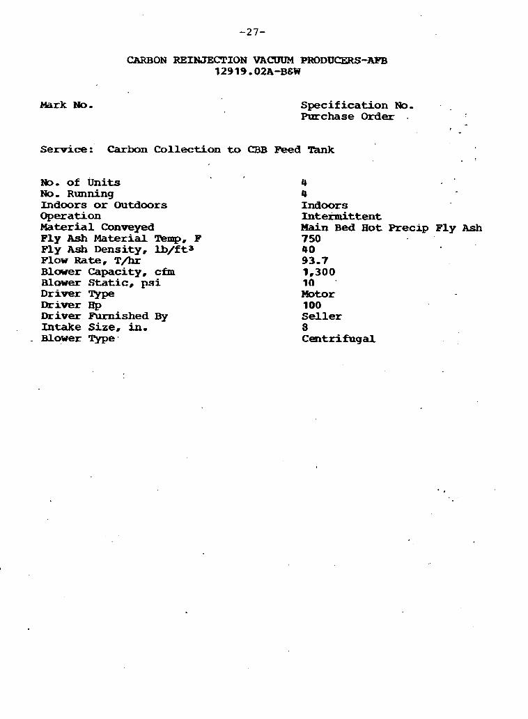
Mark No.
CARBON REINJECTION VACUUM PRODUCERS-AFB 1 2 9 19, 02A1B&W
S p e c i f i c a t i o n No- Purchase O r d e r .
I
Service: Carbon C o l l e c t i o n to CBB F e e d Tax& . !
No- of U n i t s No. Running Indoors or O u t d o o r s O p e r a t i o n Material Canveyed F ly Ash Material Wnp, F Fly Ash Density, lb/fts F l o w R a t e , T/hr B l o w e r C a p a c i t y , cfm Blower Static, psi D r i v e r Type Driver H p Driver Furnished By Intake Size, in. B l o w e r Type.
4 4 Indoors Inte-ttent Main B e d H o t Precip F ly Ash 750 40 93-7 1,300 1Q - Motor 100 Seller 3 C e n t r i f u g a l
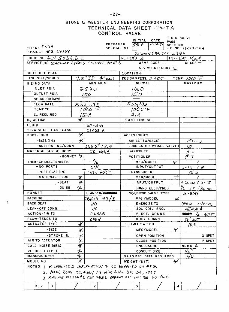
STONE & WEBSTER ENGINEERING CORPORATION
TECHNICAL DATA SHEET- P A ~ T 4 CONTROL VALVE
T . D. S. NO. VI I N I T I A L DATE PAGE
PREPAFiER CLIENT f'kbA 11-3°-"/ SPEC. NO.
S P E C I A L I ST 1-1 J .0 . No. lb71's.oa.q ? 3 O J E C T AFB S-'IL(DY & p , c O ~ < f WILL C i)i.& 1G.U EQUIP. NO +c\l-5o3AI B , c I NO. REQ'D 3 ( FSK- €A- /C&/.l SERVICE t / P START-UP B V ~ ' , ~ S 20117CcOL VALVES ASME CODE - CLASS -'
S & W CATEGORY
I -SIZE (IN.) XI I AIR SET (W/GAGE) I VEL - 1 I
SHUT-OFF P S l A
LINE SIZE/SCHED I 17.5 " 1.9 4'' WALL
S I Z I N G DATA 1 M I N I M U M
I N L E T P s l A
OUTLET PSlA -- . SP. GR. OR (MW) --
-. FLOW R 4 T C
T E M P OF ---- C, REQUIRED
LOCAT ION:
DESIGN: PRESS. a 40 o TEMP. 1000 O F
NORMAL 1 M A X I M U M
TRIM-CHARACTERISTIC 1 ; "/ I MFG/MODEL 9 -NO. PORTS I O A ~ F INPUT/OUTPUT
as ao /.C 0 -
5 3 3 , 3 3 7 lob0 CF / c i ? i
M A T E R I A L (ASTMI-BODY
-?ORT SIZE (IN) 1 r q ~ ~ . peer I TRANSDUCER
-MATERIAL-PLUG Y I MFG/MODEL
1000 /,TO -
~ 3 3 , a~ 100 0 "F 4/-3
P L A N T L INE NO.
ACCESSORIES
Cv ACTUAL * F L U I D
s E w SEAT LEAK C L A S S
BODY-FORM 9
cR ML' / I HANDWHEEL
BACK SEAT I Ale ' 1 ENERGIZE TO
57' FA A4 CUSS a
Yf-L -BONNET POSlT lONER . Y E S -
GUIDE CONNS-ELEC/PNEU. B O N N E T F L A N G E D / I B L SOLENOID VALVE TYPE
PACKING SR4Fo lL 18 7 /2 MFG./MODEL #.
,
v& i;.- /)+ ! ~ p r 3-WAY
a
, .- - LEAK-OFF CONN. I UO ACTION-AIR TO I c L o S &
-STROKE IN. -1 I OPEN POSITION I 2 SPDT
A IR TO ACTUATOR x I CLOSE POSITION 2 SPDT
- SOL COIL ENCL.
ELECT. CONNS.
FLOW-TENDS TO
- ACTUATOR-TYPE
-SIZE X
1 I
CALC. NOISE ( ~ B A ) .+ i ENCLOSURE 1 NEMA 4-
-
0P5d
A . V A L V E aoo\l cre. MoL\/ A S P S R AnlSl B i b . 3&, 1 9 7 7 3, A I R P R F S S ~ Q E O P E R A T I O & / WILL BE EC
BODY CONNS.
L I M I T SWITCH
MFG/MODEL Yr
VELOCITY (FPS) p, MANUFACTURER %
.A' MODEL NO.
NOTES: \, + IIA/DIca7€S /NJoRbiA7lun/ TO 13E S L ~ P P L ' I I F ~ IJ\/ MFG.
CONDUIT SIZE
S E I S M I C DATA REQUIRED
WEIGHT (NET)
R E V I 2
y ' 1
/2/ 0
3 4 1
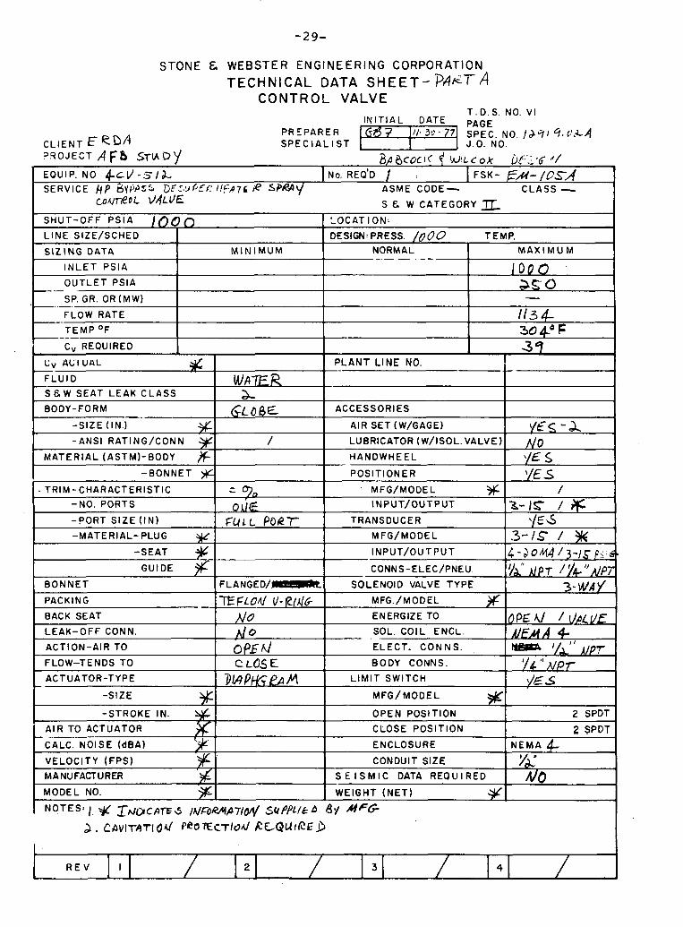
STONE & WEBSTER ENGINEERING CORPORATION
TECHNICAL DATA S H E E T - ? A ~ T A CONTROL VALVE
T.D.S. NO. VI I N I T I A L DATE PAGE
PREPARER SPEC. NO. IJql 9, C . L ~ CL IENT E e D A SPEC I A L I S T J.O. NO. ?.SOJECT A FB STIAD)I & ~ C O C I ( f W ! L C O ~ i)!:;,~ C/
EQUIP. NO 4 t v - ~ 1 a , I NO. REO'D I I FSK- F / c I - / ~ ~ A SERVICE RP av~jr'55 GE,',yPEC I!c/zp7h a %p&\/ ASME CODE- CLASS - . . .
~ U n e o L VdLVE S & W CATEGORY I - SHUT-OFF P S l A / O O O I LOCAT ION: I L I N E SIZE/SCHED
S I Z I N G DATA
I N L E T PS lA
-- OUTLET PSlA
SP. GR. OR (MW)
FLOW RATE
T E M P OF
M I N I M U M
113 4- 30 do F
i C, REQUIRED 1
- TRIM - CHARACTERISTIC
-NO. PORTS
-PORT S I Z E ( I N )
-MATERIAL- PLUG W
VELOCITY (FPS) I I CONDUIT SIZE 1 y&' MANUFACTURER $1 I S E I S M I C DATA REQUIRED I A/&
DESIGN: PRESS. / 0 0 0 TEMP.
1 $9 C V ALI UL\L % FLU I D S & W SEAT LEAK CLASS
BODY-FORM --"
-SIZE (IN.)
-ANSI RATING/CONN + MATERIAL (ASTMI-BODY &
-BONNET ))C
BACK SEAT
LEAK-OFF CONN.
ACTION-AIR TO
FLOW-TENDS TO
ACTUATOR-TYPE
-SIZE
-STROKE IN.
I AIR TO ACTUATOR -- ----- CALC NOISE ( ~ B A )
- -
I MODEL NO. % I I WEIGHT ( N E T ) Y/I 1
NORMAL --
P L A N T L I N E NO.
ACCESSORIES
AIR SET (W/GAGE)
LUBRICATOR (W/ISOL. VALVE)
HANDWHEEL
POSlT lONER
WAF-R 2-
GLOBE
/
- - Oj./g
~ U L L PORT
M A X I M U M
1 0 0 0
- as 0
vI5-2 - A /'ID $5 $ \/Es
-SEAT
GUIDE
BONNET FLANGED/-
PACKING - . T E F L O d V-PI46 No A0 0f.W c LGS E
W?P&~!AM
MFG/MODEL 3)r INPUT/OUTPUT
TRANSDUCER
M FG/MODEL
R E V I 2 3
/ 3-15 / 6
\/E 6 .3-IS /
INPUT/OUTPUT
CONNS-ELEC/PNEU.
SOLENOID VALVE TYPE
MFG./MODEL
ENERGIZE TO
SOL COIL ENCL
ELECT. C O N N S
BODY CONNS.
L I M I T SWITCH
MFG/MODEL
OPEN POSITION
CLOSE POSITION
4
OPEU / O L E A/FA A 4-
I / " A/PT I $1 r /E 5
2 SPDT
2 SPDT I ENCLOSURE^^-
4 - a 0 M A / 3-15 ~2:s.
v i APT /;14'J,,/pp 3-wd2/
NEMA A
L

STONE & WEBSTER ENGINEERING CORPORATION
TECHNICAL DATA SHEET- 1 ~ 4 l e - r ~ C O N T R O L V A L V E
T.D.S. NO. VI I N I T I A L DATE PAGE
PREPARER 11-30-7'1 SPEC. NO. CLIENT EeDA S P E C I A L I S T l!!!E€l J.O. NO. I V ~ I ~ , O L A ? 3 0 J E C T A F ~ 57uC'/ -.
L A ! > c o c K f W I L C c'( ot: :.:.I. ' 1
EQUIP. NO ~ P C V - S ~ O A , A, C, I NO. REQ'D 4 I FSK- EJI-/OJ.~ SERVICE /?EN€/ z d C O O L J A ~ G /&L E T cO-oc VAL V c ASME CODE - CLASS -
S & W CATEGORY
I - . . -- INLET PSIA I I asao I
HUT-OFF PSIA as& 0
L I N E SIZE/SCHED 1/7,5 "ID 9" WdLL S I Z I N G DATA 1 M I N I M U M
O U T L E T P31A
SP. GR. OR (MW)
FLOW RATE
T E M P OF -- Cv REQUIRED
Cv ACTUAL
LOCAT I ON:
DESIGN: PRESS. TEMP.
NORMAL 1 M A X I M U M
F L U I D
s E.W SEAT LEAK C L A S S 1 CLASS a I BODY-FORM % I
700 - ~l00,llO 0 #(&L &J
jOpC 7;- ' I I '7
P L A N T L l N E NO. a-
ACCESSORIES I . . -SIZE (IN.) % -ANSI RAT1 NG/CONN
M A T E R I A L (ASTMI-BODY
-BONNET a
PACKING IGRAFOIC 187 /3 1 MFG./MODEL 1
TRIM:CHARACTERISTIC
-NO. PORTS
-?ORT SIZE (IN)
-MATERIAL- PLUG I)L -SEAT 9
GUIDE jlL BONNET
' ~ 0 0 ~ / g w cR. MOLY
AIR TO ACTUATOR ' I CLOSE POSITION
90 0A.F
FULL PORT
FLANGED/-
B A C K X A T
LEAK-OFF CONN.
ACTION-AIR TO
FLOW-TENDS TO
ACTUATOR-TYPE x
I
CALC. NOISE (dBA) 1 1 ENCLOSURE
AIR SET (W/GAGE)
LUBRICATOR (W/ISOL.VALVE)
HANDWHEEL
POSlT lONER
I VELOCITY ( F P S ) I CONDUIT SIZE
I - & A/o EL \/t's
MFG/MODEL % INPUT/OUTPUT
TRANSDUCER
M ~ G / M U U ~ L $ INPUT/OUTPUT
CONNS- ELEC/PNEU.
SOLENOID VALVE TYPE
b& /1/0
CL 05 I 5
OP Y FA/
/ 3-15 1 g'
)'€- 5 /
4 - j o ~ ~ / 3-1s I /& / \if T
3 - WAY
ENERGIZE TO
SOL COIL ENCL.
ELECT. C O N N S
BODY CONNS.
L I M I T SWITCH
-SIZE
-STROKE IN. 2 SPDT
MFG/MODEL % OPEN POSITION
MANUFACTURER y MODEL NO.
2 SPDT
S E I S M I C DATA REQUIRED
WEIGHT ( N E T ) %
NEMA 4 YA No
NOTES: I, rAlbC~7f~ /#T~/MAT/& '10 BE S U P $ ) L f f b B y MGf. 2 , VALVE B O D Y ce. M O L Y 45 PER Ah(SI Blb134-,~q77 3, MAX AIR P R E S ~ ~ E W R VALUE, OPEPMIUN WILL BE b* 616-
R E V I 2 3 4

STONE & WEBSTER ENGINEERING CORPORATION
TECHNICAL DATA SHEET - PAET A CONTROL VALVE
T.D.S; NO. VI I N I T I A L DATE PAGE
PREPARER ' 1 - 0-17 SPEC. NO. CLIENT ER'PA S P E C I A L I S T I!EEEI J.O. NO. ,3919. o r A JqOJECT AF(3 S7UD1/ B A l j c a ~ / ( f W I L C O X ~ & S ( G A /
EOUIP. NO ~ c L J - & - & , ~ I NO. REO'D 1 I FSK- t;*l-/os A SERViCE I.-'C-CIEA?L'< Co0Ll~lG iAJIET ASME CODE- CLASS -
g ~ ~ 4 D E ~ u P E R ~ ~ , C P : E K 5PQAY C0NiR.OC VALUE s E. w CATEGORY=
BONNET
PACKING
BACK SEAT
LEAK-OFF CONN.
ACTION-AIR TO
FLOW-TENDS TO
ACTUATOR-TYPE
-SIZE %
' NOTES: ) , J ) L S / ~ ~ C A ' F & / ~ F & U ~ T I O N SUPPLIE:.~ BY M f k
I
SHUT-OFF P S I A 1OOO
-STROKE IN.
AIR TO ACTUATOR
CALC. NOISE (dBA)
VELOCITY (FPS)
MANUFACTURER
MODEL NO.
R E V I 2 3 4 I
L I N E SIZE/SCHED *
S I Z I N G DATA
I N L E T PSIA
OUTLET PSIA -- . SP. GR. OR (MW) -..- FLOW RATE
T E M P OF --.--
Cv REQUIRED
LOCAT ION:
DESIGN: PRESS. TEMP.
FLANGED-
T E F L 0 4 V-t/N6- NO UO o k i d Cl-OSts
D/AP+l@a M
M I N I M U M NORMAL -- - . . - - 1000
- 5700
6 d g 304 OF 45
OPEN POSITION
CLOSE POSITION
ENCLOSURE
CONDUIT SIZE
S E I S M I C DATA REQUIRED
WEIGHT ( N E T ) #
M A X I M U M
SOLENOID VALVE TYPE
. MFG./MODEL
ENERGIZE TO
SOL.. COIL ENCL.
ELECT. C O N N S .
BODY CONNS.
LIMIT SWITCH
MFG/MODEL Yf 2 SPDT
2 SPDT
N E M A 4 YA 1\10
Cv AC'rUAL
F L U I D
S & W SEAT LEAK CLASS
BODY-FORM
-SIZE (IN.)
-ANSI RATING/CONN # MATERIAL (ASTM)-BODY w
-BONNET # TRIM-CHARACTERISTIC
-NO. PORTS
-PORT S I Z E ( I N )
-MATERIAL- PLUG g -SEAT
GUIDE % 3- !Nh1/
G P E ~ / J A L V F A/EMA 4
pef#A '/A'' d p ~ 1/4 N W
y€ i
P L A N T L INE NO.
ACCESSORIES
AIR SET (W/GAGE)
LUBRICATOR (W/ISOL.VALVE)
HANDWHEEL
POSlT lONER
MFG/MODEL
INPUT/OUTPUT
TRANSDUCER
MFG/MODEL
INPUT/OUTPUT
CONNS- ELEC/PNEU.
WATE -R &
GLo BE
/
- 0 A/L
F U L L
YES- a No !/c s \ /E s
/
. 3 - /5 / % - ' / E .s
i'
4-20 M A 13 -15- & .!dl? 1 y4 M O T ,
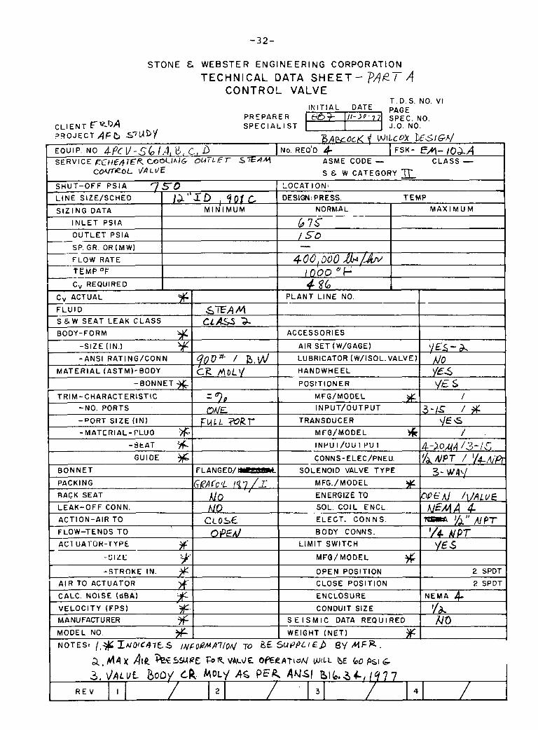
STONE & W E B S T E R E N G I N E E R I N G C O R P O R A T I O N
TECHNICAL DATA S H E E T - PART A C O N T R O L V A L V E
T . D. S. NO. VI I N I T I A L DATE PAGE
P R E P A h E R e? - ' SPEC. NO. C L I E N T F ~ Q A S P E C I A L l S T l??33 J.O. NO. ? Q O J E C T AF b s 7 ~ I D ) I AWOCK { WILCO!~ &SIGA/ EQUIP. NO 4Pc 11-56 1.4, E , c., 1 NO. REO'D 4 I FSK- EM- IOAA SE RV lC E CoOClhlG- oQTLE r S SAY ASME CODE - C L A S S -
R E V I 2 3 4
C O V ~ R O L \ /ALL/€
S H U T - O F F P S l A 7 5 0
a. M A x AIL ' ~ ~ C S W P E FOR V A ~ ~ E . O E R A T ~ J N WILL o~ 60 PSI g
L I N E SIZE/SCHED
S I Z I N G DATA
I N L E T PSIA
O U T L E T PS lA -/ .
SP. GR. OR (MW) -. .-
-. FLOW RATE
TEMP "F C, REQUIRED
S 6 W CATEGORY
LOCAT I ON:
DESIGN: PRESS. T E M P / A " X ~ , 4 0 1 c M I N I M U M NORMAL
b 7 c- - / 5-0 -
4oolooo &/ !- bo CJ +
4 86
M A X I M U M
Cv ACTUAL
FLUID
s & w SEAT L E A K C L A S S
BODY-FORM
-S IZE (IN.)
-ANSI RATING/CONN
M A T E R I A L (ASTM)-BODY
-BONNET % TRIM-CHARACTERIST IC
-NO. PORTS
-PORT SIZE (IN)
- M A T E R I A L - F L U 0 .*- - S ~ A T r+
GUIDE
BONNET
PACKING
RACK SEAT
L E A K - O F F CONN.
ACTION-AIR TO
FLOW-TENDS T O
AC I UA1'UH-I'YPk 3F .-SIL E 9 -STROKE IN.
A I R TO ACTUATOR # CALC. NOISE (dBA) X VELOCITY ( F P S ) %. MANUFACTURER ?6 MODEL NO.
NOTES: I,$ L A I O I C ~ ~ E S
P L A N T L I N E NO.
ACCESSORIES
AIR SET (W/GAGE)
LUBRICATOR (W/ISOL. VALVE)
HANDWHEEL
POSITIONER
MFG/MODEL # INPUT/OUTPUT
TRANSDUCER
Mr(3 /MODEL * INPUI/UUI P U I
CONNS-ELEC/PNEU.
SOLENOID VALVE TYPE
MFG./MODEL % ENERGIZE TO SOL. C O I L ENCL.
ELECT. C O N N S .
BODY CONNS.
L I M I T SWITCH
MFO/MODEL
OPEN POSITION 9G
CLOSE POSITION
ENCLOSURE
CONDUIT SIZE
S E I S M I C DATA REQUIRED
WEIGHT ( N E T ) % S U P P L I E ) B\/ M F R .
S T A M f 2 L A - S a-
9 0 0 ~ 1 B.& t i e MoL'/
- - OAIE
F U L L WRT
FLANGED/-
Gk'AfCl l IR7 /L Mo No
C C O ~ ~ O ~ E A /
/~&0k?/uA7/0M 70 86
\/EL - YE& YE s
/
3-1s # LIE s
/ .
4-2044 /3-,1c VA IW 7 / '/4 , q ' ~
3- waq
Q K A J /VALUE MfAA 4
YJ" APT A/ PT
Yg.5
2 SPOT
2 SPDT
N E M A 4 I
kt)

STONE & WEBSTER ENGINEERING CORPORATION
TECHNICAL DATA SHEET - PJjeTh CONTROL VALVE
T.D.S. NO. VI I N I T I A L DATE PAGE
PREPARER lzFEEl SPEC. NO. CLIENT S P E C I A L I S T J.O. NO. !.: -, ;-I. C. LA ? q O J E C T &/(jrtu~ f : V ! L ~ C ~ . ::.s./(;+'
EQUIP. NO 4~ vc S[ $?A, g I NO. REQ'D a, I FSK- E-A- / U S A SERVICE R E C I E : A - T F ~ I A / ~ O U U - T ASME CODE - ' CLASS -
S X A / ~ 0 t ~ ~ ~ p r e v i ~ ~ r R SPRP\/ C o n / X o ~ VALVE CATEGORY 1~ - SHUT-OFF P S l A 100 0
-BONNET POSlT lONER . ' /E S TRIM-CHARACTERISTIC - -
A MFG/MODEL /
-NO. PORTS OVE INPUT/OUTPUT 3-15 + -PORT S IZE ( I N ) F ~ A L P O E T TRANSDUCER YE -s -MATERIAL- PLUG M FG/MODEL # /
-SEAT INPUT/OUTPUT 4-d6b14 13-1 GUIDE CONNS-ELEC/PNEU. 7"h /p7 174
BONNET FLANGED/- SOLENOID VALVE TYPE 3-wl/ PACKING y - . . .. . . . . . , . . . . . . . . T€F$O~..V-C I , ~ / T , MFG./MODEI.
BACK SEAT N O ENERGIZE TO CPFM UALUE I -EAK-OFF CONN. Jf o SOL COIL ENCL. VEA A 4 ACTION-AIR TO opdl ELECT. C O N N S . y" ,c,pr FLOW-TENDS TO c~~~ BODY CONNS. l/4 NPT ACTUATOR-TYPE DIAWGPA~Y\ LIMIT SWITCH YE 5
-SIZE MFG/MODEL
OPEN POSITION x
-STROKE IN. 2 SPDT
AIR TO ACTUATOR CLOSE POSITION 2 SPDT
CALC. NOISE (dBA) ENCLOSURE N E M A 4 VELOCITY (FPS) #= CONDUIT SIZE f& MANUFACTURER S E I S M I C DATA R E Q l l l R E D No MODEL NO. WEIGHT ( N E T )
7 36
' I NOTES: 1. ' 3 (~ ~ ~ D I C A T E S I N F O M O M SUPPCITD by M C ~
2, CAVIT/JTIOA/ P~?FCTIOA/ R E W I P E D
L I N E SIZE/SCHED
S I Z I N G DATA
I N L E T PS lA
O U T L E T PSlA - .
SP. GR. OR (MWI -- FLOW RATE
T E M P OF ---- C, REQUIRED
LOCAT I ON:
DESIGN: PRESS. T E M P
MAXIMUM NORMAL
/ o o o 0 -
1371, @/vl 304- " F 48
M I N I M U M
P L A N T L I N E NO.
ACCESSORIES
AIR SET (W/GAGE)
LUBRICATOR (W/ISOL. VALVE)
HANDWHEEL
yr .-.d L. . :* r/o Y E s
Cv ACTUAL I I
F L U I D
s E w SEAT LEAK C L A S S
BODY-FORM
-S IZE (IN.)
-ANSI RATING/CONN jL M A T E R I A L (ASTMI-BODY %
W A T R &
GLOBE
/
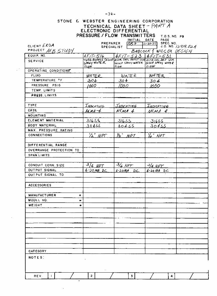
- 3 4 -
STONE & WEBSTER ENGINEERING CORPORATION
TECHNICAL DATA S H E E T - A ELECTRONIC DIFFERENTIAL
PRESSURE / FLOW TRANSMITTERS T. D.S. NO. ~9 I N I T I A L DATE PAGE
C L I E N T ERI)A P R E P A R E R (A? 11,-jo-77 SPEC. NO. S P E C I A L I S T I J.0. NO. /J?'/q, 024
P R O J E C T A,C& s_~s-L/D(/ B A ~ C O C K f WILCOY DE3G.4
1 TEMPERATURE OF 1 3.4- 1 304- 304 1
EQUIP. NO.
S E R V I C E
OPERATING CONDITIONS FLUID
4 FIT-516 7 U R 8 6mSS OE)ESLIP SMAY WhTE R FLOW
WAF/?
PRESSURE PS l G
TEMP. L I M I T S
PRESS, LIMITS . ..
TYPE
C A S L
MOUNTING
1 M A X . PRESSURE RATING I I I I 1
1 - 5 3 RllTR CWL OUrLr SW bESY P S P Q ~ V WATER FLOW
UA-E R
1000
..&..'..., .-
1
CONNECTIONS I I I
4 ~ f 7 - ~ 3 1 RbllY COCL IA/LT S 7 4
DESU P .sPeat/ L J A Y E ~ FLOW
W A E R
TN DKA T J A ~ ~
~ A A -4
3 1 L S S L
I I I I D I F F E R E N T I A L RANGE I i
/OO o
--.-
BODY MATERIAL 304s 3o4SS . 3 0 4 ~ 5 ELEMENT MATERIAL
I OVERRANGE PROTECTION TO I I I 1 ' 1
.~-~I)IcA T I NG N N I A 4
10 80
-~.-- ,.....-.,.. ,.,,,.. ,-,, -
I ~ n l c ~
,ll/C,tiA $
316 5 S
.1
31645
SPAN LIMITS
ACCESSORIES
I I L
CONDUIT CONN. SIZE
OUTPUT SIGNAL
O U T P U T S IGNAL TO
L
MANUFACTURER )C
M U U t L NO. P .
1 1
WEIGHT * I I I
3/4 HPT ~ - Z O M A DC
CATEGORY ;
N O T E S :
44 AJPT- 4-.20&/ DL
dl4 up7 ~ - J o M A Dc

S T O N E & WEBSTER ENG. .ERING CORPORATION TEC HNlCAL DATA SHEET -?A e7- A
THERMOCOUPLES WITH THERMOWELLS T.D.S. NO. T 3
INITIAL DATE P A G E
CLIENT E R D A pnEpAREA -1 !S,\ECi:.O 4 0 2 4 ZPECIALIST
SERVICE /RANGE
I W wl I
HEAD
E X T E N S I O N NIPPLES & 'JNION
COVDUIT CONN. S I Z E
MANUFACTURER *
N O T E S :
R E V I S I O N I / 2 / . I 3 i / 1 4 1 /
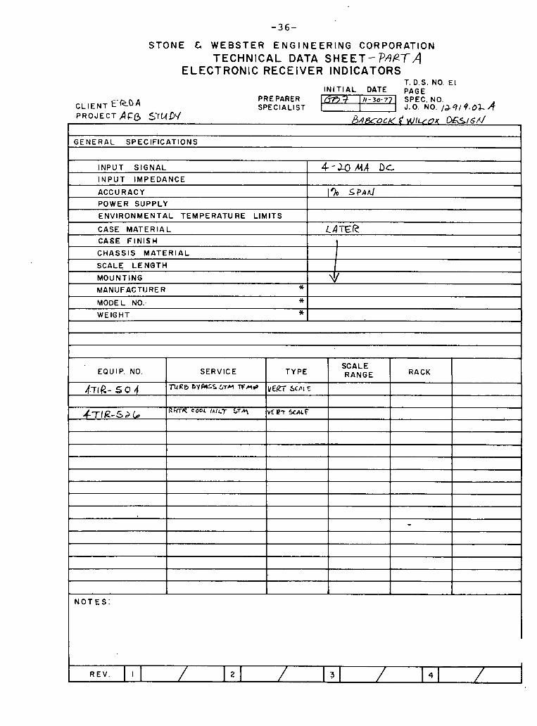
STONE E, WEBSTER E N G I N E E R I N G CORPORATION TECHNICAL DATA SHEET- PAPTA
ELECTRONIC RECEIVER INDlCATORS T. D.S. NO. E l
I N I T I A L DATE PAGE
C L I E N T E'RDA PRE PARER N - 3 0 - 7 SPEC. NO. SPECIALIST -1 J. o. NO. 1 . ~ 9 1 9 , oa A
PROJECT S r u D V ~ A ~ X O C K t W I L ~ D X O.&IG~./ 1 I
G E N E R A L SPECIFICATIONS 1
INPUT SIGNAL 1 4-WMA DL I N P U T I M P E D A N C E
ACCURACY
POWER SUPPLY
E N V I R O N M E N T A L TEMPERATU RE L I M I T S
CASE M A T E R I A L
C A 6 E F I N I S H
1 % SPA^
CA'iFR t
L
C H A S S I S M A T E R I A L
SCALE L E N G T H
MODEL NO: * WEIGHT *
4
L
MOUNTING
MANUFACTURER * v
R E V . I 2 4
EQUIP NO
, r l-T~p,-504
4 7 I R - 5 2 b
- I
SERVICE
T U U 0 b V w S STM TFnP
R H T R C O ~ ~ L I A ~ L T 94
TYPE
VEg-i- Scnl F_
V ~ @ T % A L ~
SCALE RANGE RACK
-
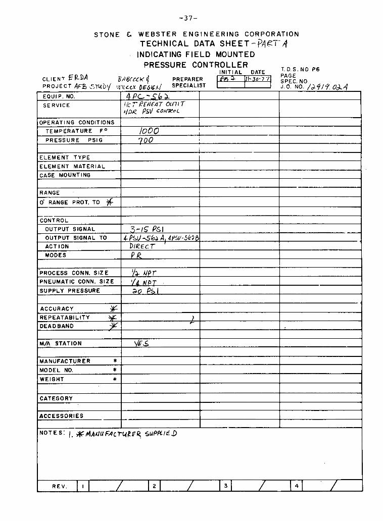
STONE & WEBSTER ENGINEERING CORPORATION TECHNICAL DATA SHEET-?A~'i-'-d
A INDICATING FIELD MOUNTED PRESSURE CONTROLLER
T. D.S. NO P6 IN IT IAL DATE PAGE CL IENT EkDA 81) 8tcL K $ PREPARER m 111-30-7 71 PROJECT AFB i57~b\/ q e , l ~ c w ~ ~ b g n / SPECIALIST J. 0 . NO. /dcj/?. 00-3-4
- ! 700 PRESSURE PSlG 1
EQUIP. NO.
SE RVlCE
OPERATING CONDITIONS
TEMPERATURE F 0
4 P c - S b & i !::- 7' REtlF.4 T 0L17 1 r r/D< PSL/ C o h m L
I 1
loo0 I
ELEMENT TY.PE
ELEMENT MATERIAL
RANGE .
0' RANGE PROT. TO 3(: -
I
I
CASE MOUNTING I I
CONTROL - OUTPUT SIGNAL
OUTPUT SIGNAL TO
ACT ION
MODES
PROCESS CONN. S I Z E
PNEUMATIC CONN. SIZE
SUPPLY PRESSURE
I I I
M/A STATION I !&A I I
3-1s PSI kP51j156b A, ~ Y S V - S ~ ~ B
D I R E C ~ I
P k
l/a NPr YLFJPT . ao P 5 l
ACCURACY
REPEATABI LITY
DEADBAND
MANUFACTURER * MODEL NO. * WEIGHT *
-
r C
CATEGORY I I I -- --
ACCESSORIES
I , & A A ~ U F A C ~ Q ~ ! E R SUPPLIEJ
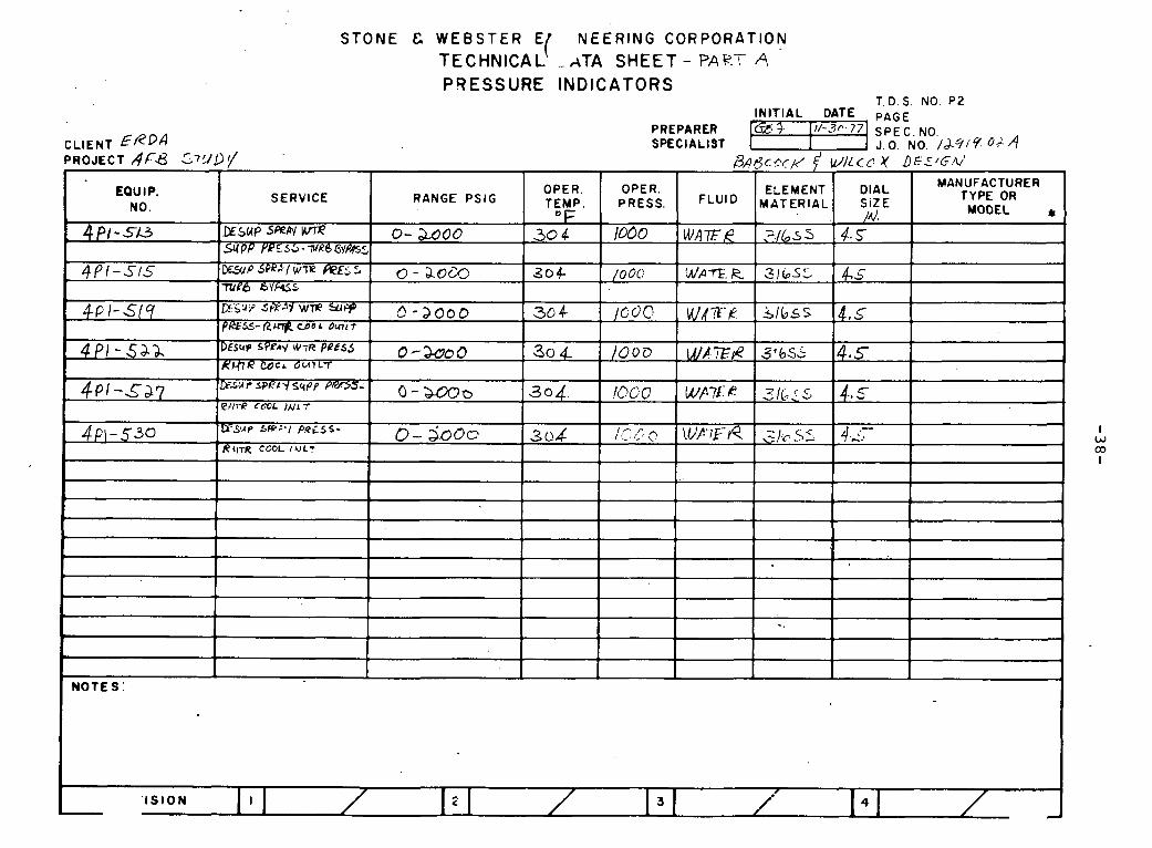
STONE t2 WEBSTER E NEERING CORPORATION I TECHNICAL -ATA SHEET- PART A PRESSURE INDICATORS
T. D. S. NO. P 2 INITIAL DATE PAGE
PREPARCR SPECIALIST J. 0. NO. /k?i'? 0; /q
I W CO I
I
I -. L
I N O T E S :
I
' I S I0 N
EQUIPMENT COMMON T O
BABCOCK & WILCOX AND FOSTER WHEELER '

STONE & WEBSTER ENGINEERING CORPORATION TECHNICAL DATA SHEE,T - P A Z T T
ELECTRONIC Dl FFERENTIAL PRESSURE / FLOW TRANSMITTERS T. D.S. NO. p9
I N I T I A L DATE PAGE PREPARER 9 Ill-1.q- 7 SPEC. NO. S P E C I A L I S T I J.O. NO. I b q l q , ~ ~ C L I E N T ERDA
PROJECT AFB .$ r M O r / EQUIP. NO. 4 1 1 7 - 2 SERVICE D E A E ~ A T D R SnlrU)H 7&4K ~ ~ w L L C L E V E L
I OPERATING CONDITIONS ' I FLUID ! W E & TEMPERATURE OF 1 300 PRESSURE PS lG I 45
I TEMP. L IM ITS I I
' PRESS. L IM ITS
1 TYPE TAIDICA rlue G A S t tVm4- 4 MOUNTING
ELEMENT MATERIAL 31b S.S BODY MATERIAL 304.~3 " M A X . PRESSURE RATING /,cO 0 CONNECTiONS
I . YAM N P ~
DIFFERENTIAL RANGE
OVERRANGE PROTECTION TO
SPAN LIMITS ! I CONDUIT CONN. SIZE I 3/u iu mr
- -
1 4 - - --
~ O U T P U T SIGNAL -Je MA PC OUT PUT 31GNAL TO (4~ j le - X
I ACCESSORIES
I MODEL NO. * I
CATEGORY I N O T E S :

STONE & WEBSTER ENGINEERING CORPORATION TECHNICAL DATA SHEET - PART C.
ELECTRONIC Dl FFERENTIAL PRESSURE / FLOW TRANSMITTERS T. D.S. NO. ~9
TEMP. L I M I T S
PRESS. L I M I T S
I N I T I A L DATE PAGE PREPARER
C L I E N T EkbA S P E C I A L I S T PROJECT AB 5 T U D ~
D l F F E RENTIAL RANGE
OVERRANGE PROTECTION TO
SPAN LIMITS I I I I
i EQUIP. NO.
S E R V I C E
OPERATING CONDIT ImS
FLUID TEMPERATURE OF
PRESSURE PSI G
N O T E S :
4~1T- /+A ~ L I T - / # ~ ~rm * m m EQAI*/
CONDUIT CONN. S IZE
OUTPUT SIGNAL
OUTPUT SIGNAL TO
ACCESSORIES
MANUFACTURER * MODEL NO. Y
WEIGHT Y
CATEGORY
W P k R L O O -3
Wa7E R LbS 35
3/4 /A/, rclm 4-a0MA O C
4 L f Q - 144
14, # P T 4 - ~ O M A D C 4 L I R - 140

STONE & WEBSTER ENGINEERING CORPORATION
T E C H N I C A L DATA SHEET- PART C. E L E C T R O N I C P R E S S U R E T R A N S M I T T E R S
T.D.S. NO. P I 0 I N I T I A L DATE P A G E
E R DA PREPARER C L I E N T S P E C I A L I S T P R O J E C T AFi3 STUDY
S E R V I C E
-
OPERATING CONDITIONS
F L U I D OR GAS
TEMPERATURE OF
PRESSURE PSlG
ELEMENT T Y P E
I E L E M E N T MATERIAL
ENCLOSURE (NEMA T Y P E )
MOUNTING
I BODY M A T E R I A L
RANGE
OVERRANGE PROTECTION TO
I SPAN LIMITS
OUTPUT SIGNAL
PROCESS CONN. S l Z E
CONDUIT CONN. S lZE
DEADBAND
ACCESSORIES
MANUFACTURER i t
MODEL NO. * WEIGHT *
I I
CATEGORY I I I I -f
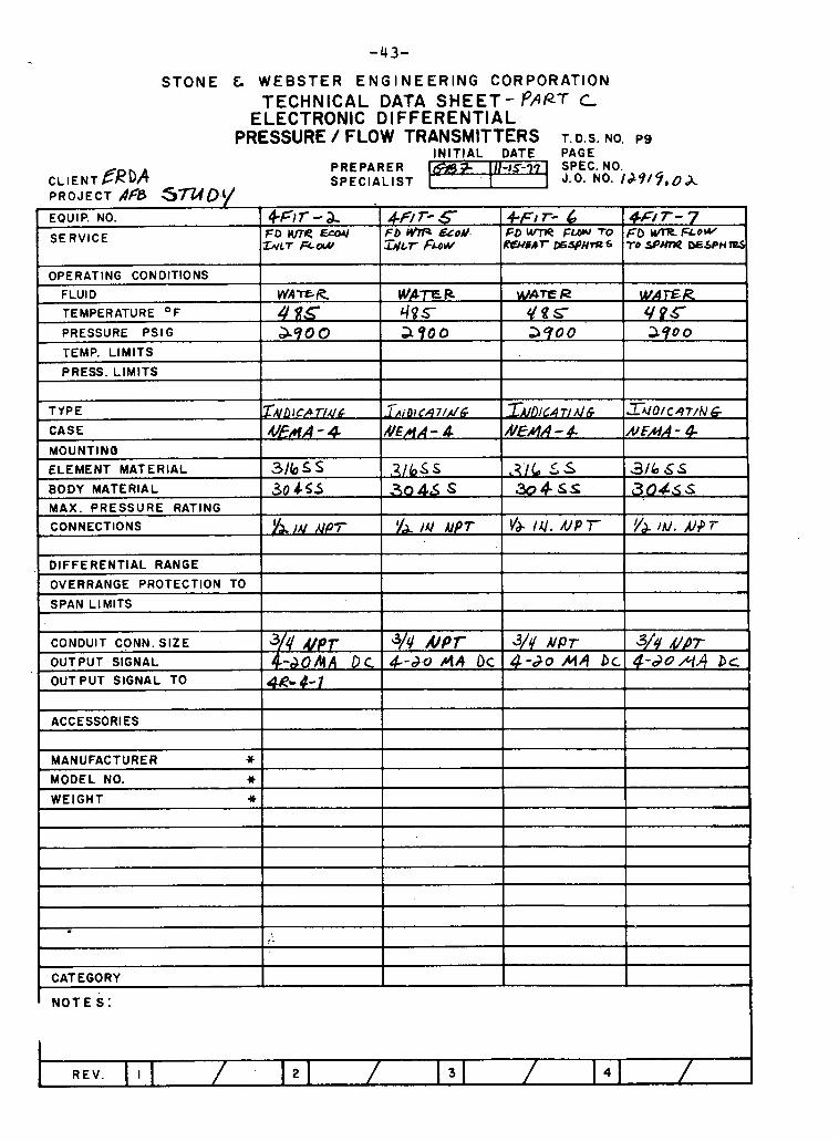
STONE & WEBSTER ENGINEERING CORPORATION TECHNICAL DATA S H E E T - PART C
ELECTRONIC DIFFERENTIAL PRESSURE / FLOW TRANSMITTERS T. D.S. NO. p g
IN IT IAL DATE PAGE . . . . . . - - . -
CLIENT 6RDP PREPARER SPEC. NO. SPECIALIST 1 J.O. NO. 1J915, 0 A
PROJECT AfS SmD.(/
OPERATING CONDITIONS
FLUID
TEMPERATURE OF
PRESSURE PSI G
9
4Ff r - 7 60 umt FLOW TO spm WSPH W,
TEMP. LIMITS
PRESS. L lM lTS
EQUIP. NO.
SERVICE
Vu'rQl=K 4 8 5 3-90 0
1
TYPE
CASE
4F/ 7- 5 Fb M?P &oU. ~ L ' T FUW
4-Flf -2 FO WC ErMl
~ L T FLW
MOUNTINB
ELEMENT MATERIAL
+FI r- 6 FD w-ne FW TO RwsrCr P ~ J P U - s
W M l S f k
49.5 a900
i
~ A I D J C P T I A ~ ~
U!r(A - 4
-
MAX. PRESSURE RATING
CONNECTIONS
BODY MATERIAL - 3 0 45s 30 46 s 3 0 4 s ~ ~ 3 0 4 ~ s 31b 5 5
,
W T E R rigs 3900
- J ~ i & C 4 7 / d &
NEHA - 4
YA IN APT
DIFFERENTIAL RANGE
OVERRANGE PROTECTION TO
SPAN LIMITS
L CONDUIT CO.NN. SIZE
OUTPUT SIGNAL OUT PUT SIGNAL TO
W A F R 4 P C 290 0
216s S
ACCESSORIES
MANUFACTURER 4 t
MODEL NO. Y
WEIGHT Y
CATEGORY
LATI TI AS # E M - 4
) ' A l i l l ~ P ~
3/4' & p r &&OAA Dc
4R- 4- I I
2
Z U O / C ~ T / N ~ ,
NFAA - 4
L / I , S S
N O T E S :
3 / 6 SS
% / l Y . A J P T Y',',)ff.N+T
3/y d / f 4 - d o A A P C ,
&/r/ NPT 4-d .0 PI4 QC
3/4 NPT 4-20 MA 9~
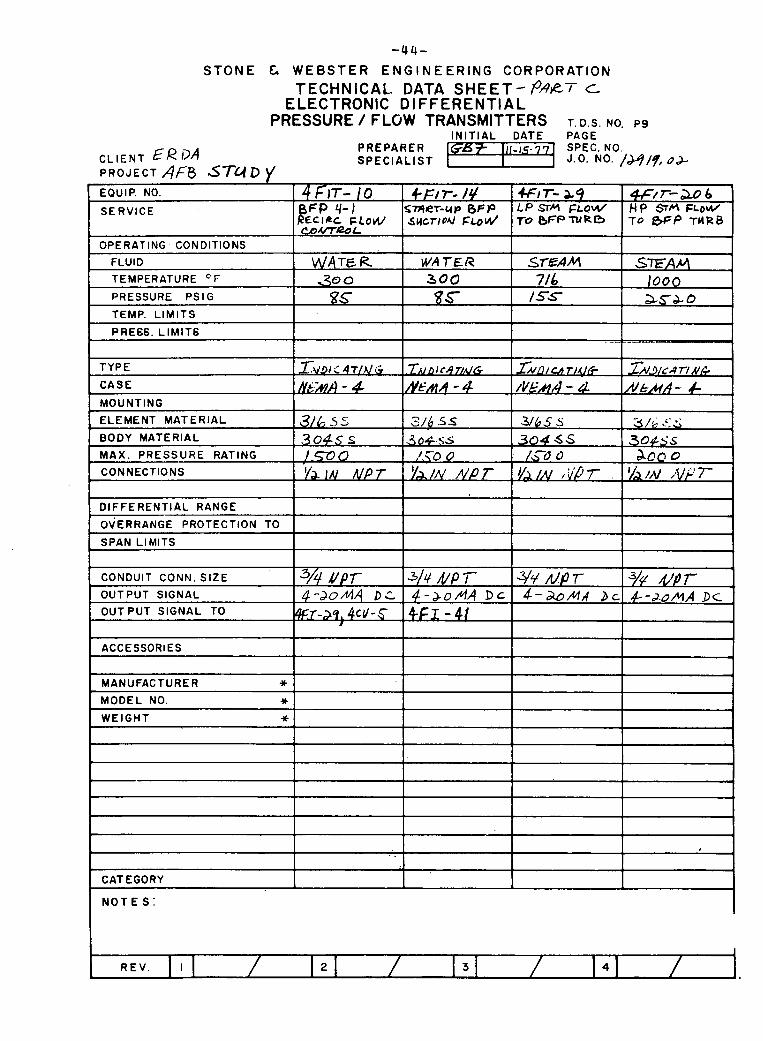
STONE L WEBSTER ENGINEERING CORPORATION TECHNICAL. DATA S H E E T - c
ELECTRONIC DIFFERENTIAL PRESSURE / FLOW TRANSMITTERS T. D.S. NO. pg
IN IT IAL DATE PAGE
CLIENT E R D A PREPARER 111-15-77 SPECIALIST
PROJECT Afg STUD EQUIP. NO. 4 FIT- 1 0 4-~1r- /4 SERVICE f P q-1 STIOLT-UP BFP
€crac FLOW s~crroU F u d P ComeoL
_I
I OPERATING CONDITIONS 1 1 -- -
FLUID ! WATER I WATER TEMPERATURE T ,'(€I 0 300 PRESSURE PS l G g s gs TEMP. L IMITS I 1 PRE66. L IM IT6
TYPE Z~'3l c 4 f1.k~ .TN n 1 c 4 n d ~
CASE - #EAA - 4 MOUNTING
ELEMENT MATERIAL 3/& =j 5 3/6 .SS
BODY MATERIAL 304s 5 3 0 4 ~ s MAX. PRESSURE RATING /-= 0 ,/.a 0 CONNECTIONS UP 7 h'k' 7-
DIFFERENTIAL RANGE
OVERRANGE PROTECTION TO
SPAN LIMITS
CONDUIT CONN. SIZE 3A VPT 314 UP 'i- OUT PUT SIGNAL 4-d0/l/lA Dc 4-&0/r/l4 D C OUT PUT SIGNAL TO Wz-a4,4cr/-6 4FI - 41
1 ACCESSORIES I I
I MANUFACTURER * 1 I MODEL NO. Y
WEIGHT Y
. .
CATEGORY
N O T E S :
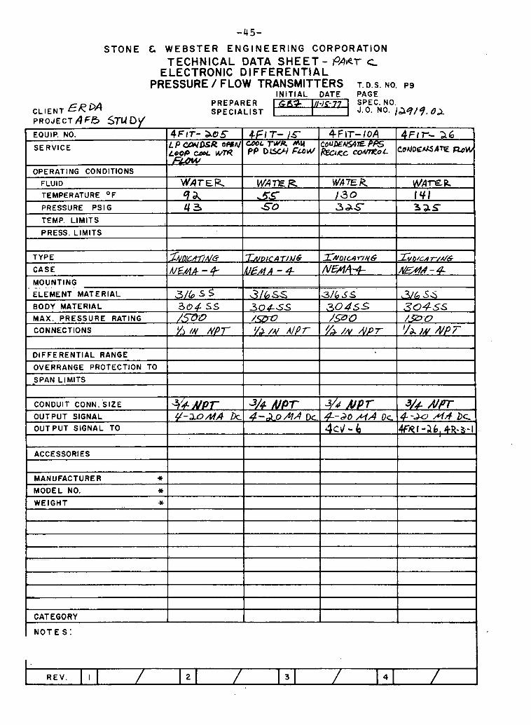
STONE & WEBSTER ENGINEERING CORPORATION TECHNICAL DATA SHEET - @er c
ELECTRONIC DIFFERENTIAL PRESSURE / FLOW TRANSMITTERS T. D.S. NO. p g
CLIENT &RDA PROJECT A F A STU O\/
IN IT IAL DATE PAGE. PREPARER SPECIALIST
I
DlFFE RENTlAL RANGE
OVERRANGE PROTECTION TO
SPAN LIMITS
I
EQUIP. NO.
SERVICE
OPERATING CONDITIONS
FLUID
TEMPERATURE OF
PRESSURE PSI G
TEMP. LIMITS
PRESS. LIMITS
TYPE
CASE
4f / T- /C W L W R h h PP O W FuUl
WA7E R . 50
4Flr- a05 LPCZW#ROPSA/
~4 FLOW
WATER qa 4 3
ACCESSORIES I I
1 kEAA - 4
CONDUIT CONN. SIZE
OUTPUT SIGNAL
OUTPUT SIGNAL TO
MANUFACTURER w MODEL NO. * WEIGHT Y
4 F IT- I O A C O ~ P E N S ~ ~ E b e c CO&?L
W A E R 130 3 d S
-
L-
CATEGORY
N O T E S :
FIT- a6 C o 4 D g 1 5 * 7 ~ m W
W A m R 141 32s
I;VDICAT/AI~ &EAR - 4
.3@ NPT #-=MA k
I 3/4 AJPT 3/4 k p r 3/4 R/Pr 4-&0/zlA Dc 4-20 H A D c 4-du /*I& DC ,
4 3 - 6
ZNOICO~.'/YG #HA+
ZVO/C~ T M ~
A&XA-4-

STONE & WEBSTER ENGINEERING CORPORATION
TECHNICAL DATA SHEET- ?ART C ELECTRONIC PRESSURE TRANSMITTERS
C L I E N T P R O J E C T AFB STUDY
T.D.S. NO. P I 0
PREPARER SPECIALIST J. 0. NO. /29/9,@ %
EQUIP. NO.
S E R V I C E
OPERATING CONDITIONS
FLUID O R G A S
TEMPERATURE O F
PRESSURE PSIG
ELEMENT T Y P E
PI r- 9 CIOT &I# r'
STEAM loao SqC
4 ~ i r - I / C l n ~ STERA fl,aoce PRESS
STEAM /OOO 2 5 2 0
+PIT- 4 &P 7HRB ERST& b s
STE~A
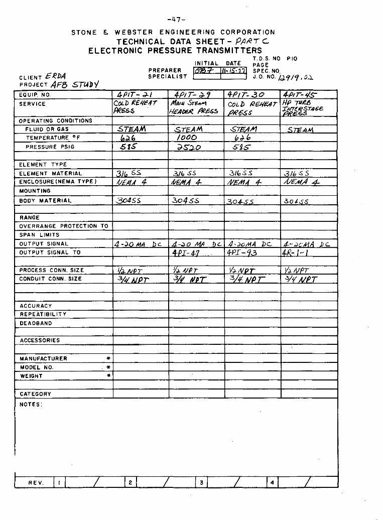
STONE & W E B S T E R E N G I N E E R l N G C O R P O R A T I O N
TECHNICAL DATA SHEET - PAAT C ELECTRONIC PRESSURE TRANSMITTERS
T.D.S. NO P I 0 I N I T I A L DATE PAGE
PREPARER C L I E N T EJ?D4 S P E C I A L I S T PROJECT Afg STUDV EQUIP. NO.
SERVICE
OPERATING CONDITIONS
FLUID OR GAS
TEMPERATURE O F
PRESSURE P S ~ G
ELEMENT TYPE
ELEMENT MATERIAL
ENCLOSURE (NEMA TYPE 1 MOUNT tNG
BODY M A T E R I A L
RANGE
OVERRANGE PROTECTION TO
SPAN LIMITS
OUTPUT SIGNAL
OUTPUT SIGNAL TO
PROCESS CONN. SIZE
CONDUIT CONN. SIZE
ACCURACY
R E P E A T l B l L l T Y
DEADBAND P
ACCESSORIES -.---
4P/T-&9 /ut~)~u ST- k'€AfZU &&
STEAM lo00 asao
3 / 6 S.5 kE?fA 4
304 55
6-3.0Af.4 .DL 4PI- 47
?'A UP 7 3// NPT
4 P I T - -3-1 COLD UEqEdf P%SS
STEAM ha6 5 8 5
31b SS & M A 4
-4.5s
4 - 3 0 ~ 4 bc
r / , ~ p r 3/4 upr
- . .
MANUFACTURER Y
MODEL NO. . * WEIGHT *
CATEGORY
~ P / T - ~ o co L D RL%% T p jpas
S W M 6 J 6 5 s
316 S S &EAR 4
,304-SS
4-&MA Dc +PI- 4 3
Yk#pf. 3/4 ~p 7-
&'I r- 4s :!%yT. M lo&€
.
3/1; S S &EM/ 4
30465
4 -.A (; 'k 14 .DL a- 1 - 1
Y" UPT 3/V NPT
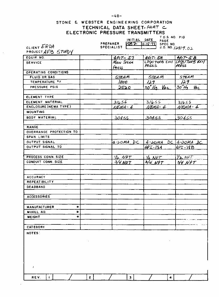
-48-
S T O N E & W E B S T E R E N G I N E E R I N G C O R P O R A T I O N
TECHNICAL DATA SHEET-PART C ELECTRONIC PRESSURE TRANSMITTERS
I I I I
ELEMENT TYPE I 1 1 1
T.D.S. NO. P I 0 IN IT IAL DATE PAGE
PREPARER % I I I I S ~ . . SPEC. NO. - CLIENT ERDA SPECIALIST. J .O. No, /&9/ 7, 0 A P R O J E C T A F ~ ~ STVIO\I EQUIP. NO.
SERVICE
OPERATING CONDITIONS
FLUID OR GAS
TEMPERATURE O F
PRESSURE PSIG
I MOUNTING I I I I I
---
ELEMENT MATERIAL
ENCLOSURE (NEMA TYPE 1
1 I
BODY MATERIAL I 3 0 4 5 ~ I30455 130 45s I I I
..- ".. I ."U.~VL"'.Y~"V,.1.. , , ,
@IT- 5 7 MAIM %AN
PREG
S E A M /DOO
asao
PROCESS CONN. SIZE NPT I h x / p r CONDUIT CONN. SIZE d / L ~ p f J/* U p 7
3/65-5 h!!kV - 4
ACCURACY 1 I I I REPEATlBlLlTY I
.*.">.-..-IYI,,.U..l.
4P/ 7- S A L P(AJ M R ~ EYH paws
s'Ei4M 1'2 9
3 0 ' / / ~ l lat
DEADBAND
ACCESSORIES
4P/ T- S B LP(B/~u@S HE./ PRrss
SFAM /A 7
30'% V ~ C
316 ,!i .L bzfl#- 4-
3 / 6 5 5 #&&/A - 4
MANUFACTURER * MUDtL NO. 4 t
WEIGHT Y ... . --. --.-- .. . ... ..
CATEGORY
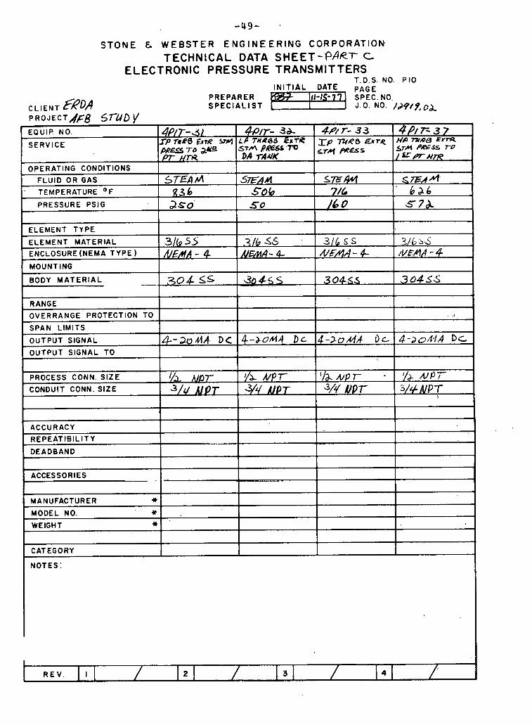
STONE & WEBSTER E N G I N E E R I N G CORPORATION, T E C H N I C A L DATA S H E E T - P A R ~ c
ELECTRONIC PRESSURE TRANSMITTERS T.D.S. NO. P I 0
IN IT IAL DATE PREPARER
CLIENT fk?DA SPECIALIST J. 0. NO. /d4/9,0&
ELEMENT TYPE
ELEMENT MATERIAL
ENCLOSURE (NEMA TYPE)
MOUNTING
BODY MATERIAL --.
3 / ( g 5.5 & , M A - 4
RANGE OVERRANGE PROTECTION TO
SPAN LIMITS
OUTPUT SIGNAL
OUTPUT SIGNAL TO
,304 ss
PROCESS CONN. SIZE
CONDUIT CONN. SIZE
MANUFACTURER Y
MODEL NO. ' * WEIGHT I)
3 / b s6 IC/i%nA - 4-
&-&rA. DC
1
ACCURACY REPEATlBlLlTY
DEADBAND
I I 1
CATEGORY 1 I I I
..- 30455 .
I/a AL~~T J/r/ MOT
NOTES:
316 S S /C/g/utA - 4
4-&0A4 D L
- .
.2 > / & b~ /L'Fm - 4
304S5
'/a &P r - 3/c/ b'OT
1
304SS
4-2oAA I)c-
v& A l p 7 314 NPT
I
, .;
4-ao/r,/R D L ,

-50-
STONE L WEBSTER ENGINEERING CORPORATION TECHNICAL DATA SHEET- r ~ P r c
ELECTRONIC PRESSURE TRANSMITTERS
I I i 1 OPERATING CONDITIONS I I
T.D.S. NO. P I 0 I N I T I A L DATE PAGE
PREPARER CLIENT ERDA S P E C I A L 1 S T J. 0. NO. /d.9/5, O& PROJECT 4F.B S T U D Y
PRESSURE PSlG I 3 5 0 I / s o I x & o I
. EQUIP. NO.
SERVICE
- - - . 1
F L U I D OR GAS I 577544 I SEAM TEMPERATURE O F 1 8-36 1 710
ELEMENT T Y P E
ELEMENT MATERIAL
ENCLOSURE (NEMA TYPE ) b E h A - 4 /VE/rlA -4 I
+PI r- '-0 IP m R B Em* GM -5s To 3a PT M T R
441~-3 B 'Turn E X H STM
Pf'GS n~ a e q - If*
I MOUNTING I I I I I
5773V"l 7 /6
BODY M A T E R I A L I
4 ~ 1 r - 305 rP 7URB Ex* 94
PRESS ~b BFP L P me&
r sx/?A‘l /uoo
RANGE I 1 I I OVERRANGE PROTECTION TO I I
4 ~ 1 ~ - 306 7
~p S T . ~ @ E S S TO O F P HP r~ RB
I S P A N L IMITS
OUTPUT SIGNAL
O U T P U T SIGNAL TO
PROCESS CONN. SIZE
CONDUIT CONN. S I Z E
ACCESSORIES
4-20/clA DL
ACCURACY
R E P E A T I B I L I T Y
DEADBANO
3/4
-.
-. . . -.
& ~ / c l 4 DC
MANUFACTURER * MODEL NO. +t
WEIGHT it
N O T E S :
Y . UPT 3/4 N P T
.-. . .,,.,. - I 1 I I
4-J-oMA D c
~p -
I/! N P I YJ NPT
I I CATERORY
4->0/ul# Be
. -
I
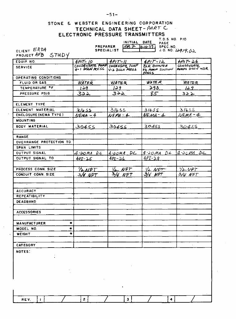
STONE & WEBSTER ENGINEERING CORPORATION TECHNICAL DATA SHEET-I3ARr C
ELECTRONIC PRESSURE TRANSMITTERS T.D.S. NO. P I 0
IN IT IAL DATE P A G E PREPARER SPECIALIST
MANUFACTURER * MODEL NO. * WEIGHT *
CATEGORY
NOTES:
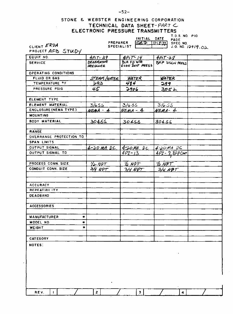
STONE & WEBSTER ENGINEERING CORPORATION TECHNICAL DATA SHEET-PAKT C
ELECTRONIC PRESSURE TRANSMITTERS . T.D.S. NO P I 0
PREPARER 9 11i-l.F71 SPEC. NO, CLIENT ERPA SPECIAL1 ST 1 J .0 . NO. l & 9 l Y , o & PROJECT A F b ST(AD~ EQUIP NO.
SERVICE
I I I I
ELEMENT TYPE I
OPERATING CONDITIONS
FLUID O R GAS
TEMPERATURE O F
PRESSURE PSIG
I
I I I I
RANGE I f
4f? T- 3 9 DEAE~?~T~A mESCURE
s r - / W ~ R 393 4s
I ELEMENT MATERIAL
ENCLOSURE (NEMA T Y P E )
MOUNTING
BODY MATERIAL
I I 1 I OVERRANGE PROTECTION TO I 1 I SPAN LIMITS I I I I I
4p1 r- 14 BLR FD rn
EcoU W U PPESS
WA TEA 4 f 4 290 6
3165s AImA - 4
30455
&P/T-&B b=P b l W &a
WAXR 39 9 306 Z
3 / 6 55 NEAA - 4
30455
OUTPUT SIGNAL
OUTPUT SIGNAL TO
ACCURACY R F P F A T l R l l I T Y
316 3s NEAA- P
30456
I PROCESS CONN. SIZE
CONDUIT CONN. SIZE
I I DEADBAND I I I I
4-20 Y A OC
ACCESSORIES 1 1 I I I
YL. /VPT 3/'$ # p T
MANUFACTURER * MODEL NO. Y
WEIGHT sc
4-XMA. Dc ~ P J - 1.3 . .
I I I I
CATEGORY I I I
~ - J O M A 3 C 4PT - 7, BFPCM
I
j/d NPT 3/1/ #p
% ~ P T 3/4 /c/P 7
REV. I

STONE & WEBSTER ENGINEERING CORPORATION TECHNICAL DATA SHEET- PfieT C
ELECTRONIC PRESSURE TRANSMITTERS T. D.S. NO P I 0
PREPARER C L I E N T ERD? S P E C I A L I S T PROJECT AFB STUD V
I
EQUIP. NO.
SERVICE
OPERATING CONDITIONS
FLUID OR GAS
I I I I
ELEMENT TYPE 1 1 I
4 P r - L// 4.~17- 4 X 4 ~ / T- 9 #a WAIA/ ~ S S MAIM RPSS W ~ L PRESS WELL PRwS
PRESSURE PSlG
ELEMENT MATERIAL I , ~ / L c < s I 3/& AS I 3/6 ss I 311k3.5 1 NEMA 4 4 1 &&&A 4 IA/EAA 9 ENCLOSURE (NEMA TYPE ) 1
TEMPERATURE O F a 6.7 . 199 l b 3 I& me
3s 1 - 3 I - 9
MOUNTING I 1
I I I
BODY M A T E R I A L I 304 &s I 3 0 & 6 I 304% I 304A.S I I
S E A 4 / WR 7ER 57E4A /W&E R S T C T A M / ~ ~ ? & A
RANGE
OVERRANGE PROTECTION TO
SPAN LIMITS
OUTPUT SIGNAL
OUTPUT SIGNAL TO
ACCURACY I I I I 1
PROCESS CONN. S IZE
CONDUIT CONN. SIZE
DEADBAND 1 I 1 I
4-90 44 9 C
ACCESSORIES I I 1 I
I/& h p ~ 3/4 Nf'T
MANUFACTURER * MODEL NO. 4t
WEIGHT *
4-b0 /c(h t:C
I I 1 I
CATEGORY I I I 1 1
I/> upr 3/4 NPr
NOTES:
~ - J O M A Dc. d--loAA .DL-
I
y& NPT 3/4 N P r
/& IV P T 3/p NPT
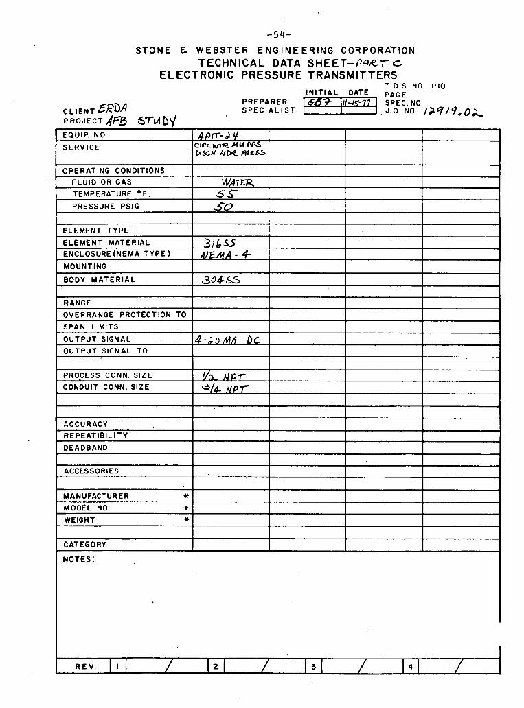
STONE & WEBSTER ENGINEERING CORPORATION'
TECHNICAL DATA SHEET-P4R.r C ELECTRONIC PRESSURE TRANSMITTERS
T.D.S. NO. P I 0 INITIAL DATE PAGE
PREPARER CL IENT EeDA S P E C I A L I S T PROJECT AfB STuf)\/ EQUIP. NO.
SERVICE 4Plr- d 4
ClRc M U P a b S c N tlm
OPERATING CONDITIONS
FLUID OR GAS
TEMPERATURE OF
PRESSURE PSlG
WAER 5s 5-0
ELEMENT TYPE - . ELEMENT MATERIAL
ENCLOSURE (NEMA TYPE
MOUNTING
BODY' MATERIAL
3 1 6 ~ 5 R/E/HA - 9-
304s-5
RANGE
OVERRANGE PROTECTION TO
SPAN LIMIT3
-
1
OUTPUT SIGNAL
OUTPUT SIGNAL TO 4 -2.0 MA Dc
PROCESS CONN. SIZE
CONDUIT CONN. SIZE I/> A p r a/k ~ p r
ACCURACY .-.
REPEATle lL lTY - DEADBAND
ACCESSORIES
NOTES:
I
MANUFACTURER %
MODEL NO.^ * WEIGHT *
--

S T O N E & W E B S T E R E N G I N E E R I N G C O R P O R A T I O N TECHNICAL DATA SHEET- PART C
ELECTRONIC DIFFERENTIAL PRESSURE / FLOW TRANSMITTERS T. D.S. NO. ~9
INITIAL DATE PAGE PREPARER j 1 \ 1 / 5 7 - - SPEC. NO.
C L I E N T ERDA SPECIALIST J. 0 . NO. /M/% 0~ . P R O J E C T A F B S - T U ~ ~
r EQUIP. NO.
SE RVlCE
OPERATING CONDITIONS
FLUID
TEMPERATURE OF
PRESSURE PSI G
TEMP. LIMITS
PRESS. LIMITS
TYPE
CASE
MOIJNTING
ELEMENT MATERIAL
BODY MATERIAL
MAX. PRESSURE RATING
4 ~ 0 ~ - ar P e E S blFr€e B Er ~ F P DISC&/ MI0 eu,N / ! T
u /bEH
&?9'/#8Y ~ o S S / 2 r j P 6
NWA 4
6 3045s
CONNECTIONS
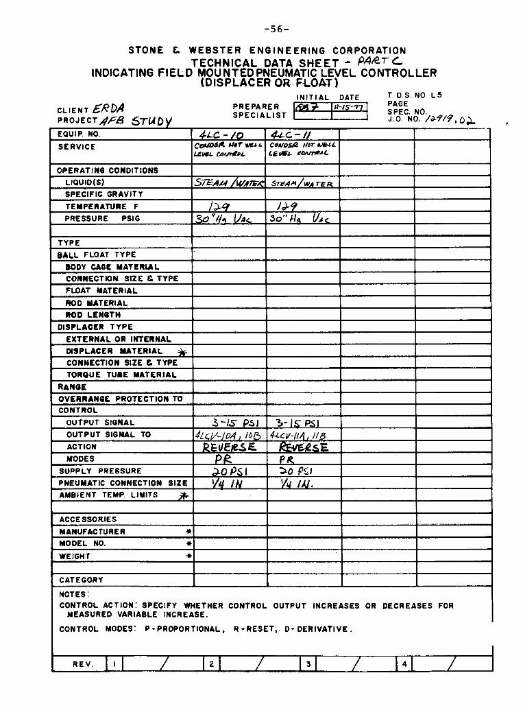
STONE C WEBSTER ENGINEERING CORPORATION TECHNICAL DATA SHEET - paRr/.
INDICATING FIELD MOUNTED PNEUMATIC LEVEL CONTROLLER (DISPLACER oa.FLom
I N I T I A L DATE T. D.S. NO L 5
CLIENT &RDA PREPARER 111-15-79 PAGE SPECIALIST I SPEC. NO.
PROJECT^^? STUDY J.O. NO. /d-4/9,0& EQUIP. NO.
SERVICE
OPERATING CONDITIONS I
LIOUID(S)
SPECIFIC GRAVITY
TEMPERATURE F
PRESSURE PSlG
BALL FLOAT TYPE
WEIGHT *
CATEGORY
NOTES: CONTROL ACTION: SPECIFY WHETHER CONTROL OUTPUT INCREASES OR DECREASES FOR
MEASURED VARIABLE INCREASE.
CONTROL MODES: P - PROPORTIONAL, R - RESET,. D - DERIVATIVE .
~ L C - /O CDIAD.J& uor ~r L
& Y ~ L ~ 0 ~ 0 1
S ~ A L I / u / A ~ F ~
/ M -"#, VAL
e c - / I C O M O ~ Q Hor m L LbUsA- ccwrrt'L
STE.~A/WA 7-E R
/ A 9 30" 119 v . c
---- -
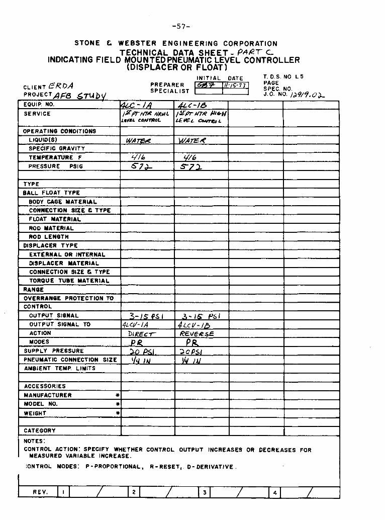
STONE C WEBSTER ENGINEERING CORPORATION TECHNICAL DATA SHEET - 6'her C
INDICATING FIELD MOUNTED PNEUMATIC LEVEL CONTROLLER (DISPLACER OR FLOAT)
I N I T I A L DATE T. D.S. NO L 5
CLIENT ERDA PREPARER I -15-7 PAGE
P R O J E C T A F6 GTU b l/ S P E C ~ A L ~ S T ?p~ci$o,Jws. or
EQUIP. NO.
SERVICE
OPERATING CONDITIONS
LIQUID(S) - SPECIFIC GRAVITY
TEMPERATURE F
PRESSURE PSlG
CONNECTION SIZE C TYPE 1 I I I
TYPE
BALL FLOAT TYPE
BODY CAGE MATERUL
COWNECTtON S t r E C TYPE
FlDAT MATERIAL
ROD MATERIAL
ROD LENGTH
DISPLACER TYPE
E X 1 ERNAL OR INTERNAL
DSPLACER UATERIAL
a - / A / s f l ~ l ~ N M L
L E J B ~ C O A I r n L
WA 7ZX
4/16 57d-
I
I I I I
ACCESSORIES I I I I
&(-/43 /gPrUTR HcH L € n E ~ a o U r t o ~
W7EN
C//s st2
TORQUE TUBE MATERIAL
RANGE
OVERRANOL PROTECTION TO CONTROL
MANUFACTURER * MODEL NO. *
I
WEIGHT *
CATEGORY
I NOTES: CONTROL ACTION: SPECIFY WHETHER CONTROL OUTPUT INCREASES OR DECREASES FOR
MEASURED VARIABLE INCREASE.
IONTROL MODES: P-PROPORTIONAL, R -RESET,. D - DERIVATIVE .

S T O N E C W E B S T E R E N G I N E E R I N G CORPORATION TECHNICAL DATA SHEET- MT
INDICATING FIELD MOUNTED PNEUMATIC LEVEL CONTROLLER (DISPLACER OR FLOAT)
I OPERATING CONDITIONS I 1 1 1 1
I N I T I A L DATE T. D.S. NO L 5
CLIENT ER&? PREPARE R 9 Ill-15-77 PAGE SPECIALIST 1 SPEC. NO.
PROJECT AFo STUD r/ J-O. /29/?,0& EQUIP. NO.
SERVICE
I . -- . - -- .- I TYPE I 1 1 1
SPECIFIC GRAVITY
TEMPERATURE F
PRESSURE PSIG
BALL FLOAT TYPE
BODY CAGE MATERIAL
CONNECTlON StZE & TYPE
FLOAT MATERIAL
ROD MATERIAL
ROD LENQTH
DISPLACER TYPE 1 I
&C -&A NwL
LEVEL Wnta
EXTERNAL OR INTERNAL I DISPLACER U T E R I A L
376 260
CONNECT ION SlZE C TYPE
TORQUE TUBE MATERIAL
RANGE
OVERRANUE PROTECTION TO CONTROL
+LC- a& )*pr r(/6U '6-ncl
3 76 aso
4Lc- 3A 3@ HfR W C LEVEL CQIyreQL
OUTPUT SIONAL
OUTPUT SIGNAL TO
I
I i ACCESSORIES
&c- 3h 3- ~ I J G N ' LESL CffNmoL
30G /SO
ACTION
MODES
SUPPLY PRESSURE
' PNEUMATIC CONNECTION SIZE
306 /SO
J & ~ v - a 4 . kcu-W3 ~ L C V - 3A 4 ~ c l / - 3 0 .
k .- / s Pal
I NOTES: CONTROL ACTION: SPECIFY WHETHER CONTROL OUTPUT INCREASES OR DECREASES FOR
MEASURED VARIABLE INCREASE.
DIRECT
PR 2-0 PSI .
l/q
MANUFACTURER * MODEL NO. *
t
WEIGHT *
CATEGORY I
I CONTROL MODES: P - PROPORTIONAL, R - RESET,. D - DERIVATIVE .
.5 - 1
.
E V E ~ S C PR
Xl Ps( '14 / A /
3-15 PIS / 3-)s PSI
hREc r P R 30 Ps \ 'I4 / A /
R € ~ / & a e ,
PR 3 0 PSI '/u hv

I SPECIFIC GRAVITY I I I I
STONE t WEBSTER ENGINEERING CORPORATION TECHNICAL DATA SHEET- Pher C
INDICATING FIELD MGUNTED PNEUMATIC LEVEL CONTROLLER (DISPLACER OR FLOAT)
I N I T I A L DATE T. D.S. NO L 5
CLIENT &ROA PREPARER * I I I - I s - ~ ~ PAGE SPECIALIST I SPEC. NO.
PROJECT AFB STlA b J J.O. NO. /J7/9, 4~ .EQUIP. NO.
SERVICE
OPERATING CONDITIONS
TYPE
BALL FLOAT TYPE . . BODY CAGE MATERIAL
TEMPERATURE F PRESSURE P S ~ G
e p r m DEN &Yl3 NRML. YVGL wA/neaL.
I DISPLACER MATERIAL I 1 I
4 ~ c - 5 0 5*w HTR w R d R H16U L t W L CMlnzOL
3 b 6 as
c o N n E c r t o n s n E e T Y P ~
FLOAT MATERIAL
ROD MATERIAL
ROD LENGTH
DISPLACER TYPE
EXTERNAL OR INTERNAL
t
CONNECTION SlZE C TYPE
TORQUE TUBE MATERIAL
RANOE
OVERRANIE PRO1 ECTlON TO CONTROL
OUTPUT SIONAL -., - a )S 95r 1 LJ > - / c ; - P s - l I
I 1 1
abb
[
I
-
t ACCESSORIES
MANUFACTURER 4k
MODEL NO. 4 t
WEIGHT 4 t
OUTPUT SIGNAL TO
ACTION
MODES
SUPPLY PRESSURE
PNEUMATIC CONNECTION SIZE
AMBIENT TEMP. LIMITS L
I 1 I I 1 CATEGORY I 1 I 1 NOTES : CONTROL ACTION: SPECIFY WHETHER CONTROL OUTPUT INCREASES OR DECREASES FOR
MEASURED VARIABLE INCREASE.
' -3NTROL MODES: P - PROPORTIONAL, R - RESET,. D - DERIVAT I V E .
4 LLV- s A D I R E C T
P/? 2 0 PSI. v4 /N
4~ C V- 5-13 KRSF
PA 3 0 I/(/ /A/
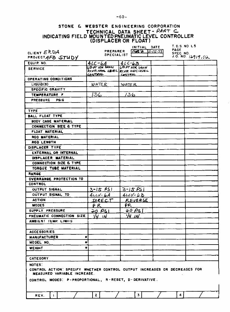
( CONTROL MODES: P - PROPORTIONAL, R-RESET, D - DERIVATIVE.
STONE & WEBSTER ENGINEERING CORPORATION TECHNICAL DATA SHEET - PAPr C
INDICATING FIELD MOUNTED PNEUMATIC LEVEL CONTROLLER (DISPUCER OR FLOAT)
I N I T I A L DATE T 0 s NO L 5
CLIENT ERDA PREPARE R PAGE NO.
I & q / q , l&
-
-
CONTROL ACTION: SPECIFY WHETHER CONTROL OUTPUT INCREASES OR DECREASES FOR MEASURED VARIABLE INCREASE.
P R O J E C T / j F 0 S T U D)/ EQUIP. NO.
SERVICE
OPERATING CONDITIONS . LIOUID(S)
SPECIFIC GRAVlT Y
TEMPERATURE F
PRESSURE PSlG
T YPE
BALL FLOAT TYPE
BODY CAOE MATERUL
CONNECTION snE c TYPE FWAT MATERIAL
ROD MATERIAL
ROD LENBTH
DISPLACER TYPE
E X 1 ERNAL OR INTERNAL
MSPLACER W T E R I A L
CONNECTION SlZE C TYPE
TOROU2 TUBE MATERIAL RANBE
OVERRANQL PROTECT ION TO C O N 1 ROL
OUTPUT SIONAL
OUTPUT SIGNAL TO
ACTION
MODES
SUPPLY PRESSURE
PNEUMATIC CONNECTION S lZE
A H B I ~ N ~ I t M r . LINIIS
ACCESSORIES
MANUFACTURER * MODEL NO. * WEIGHT *
CATEGORY
NOTES :
SPECIAL IST
~ L c - 6 A d*Pr Hm RcVR NWL LOEL &t3u7ROC
W A E fz
136
3-1s P S I ~ L c I / - 6 A
t=tr P a 20 P& I '/g
4 L C - 6 ~ b*W U r n ~epA/ RCVR Ul6d LEWL ~purreo~
WA7E R
/3 b
3-13&I ~ L c J - b 8
RFVCif2.X Pa a0 PSI
i
SPEC J.0 NO.
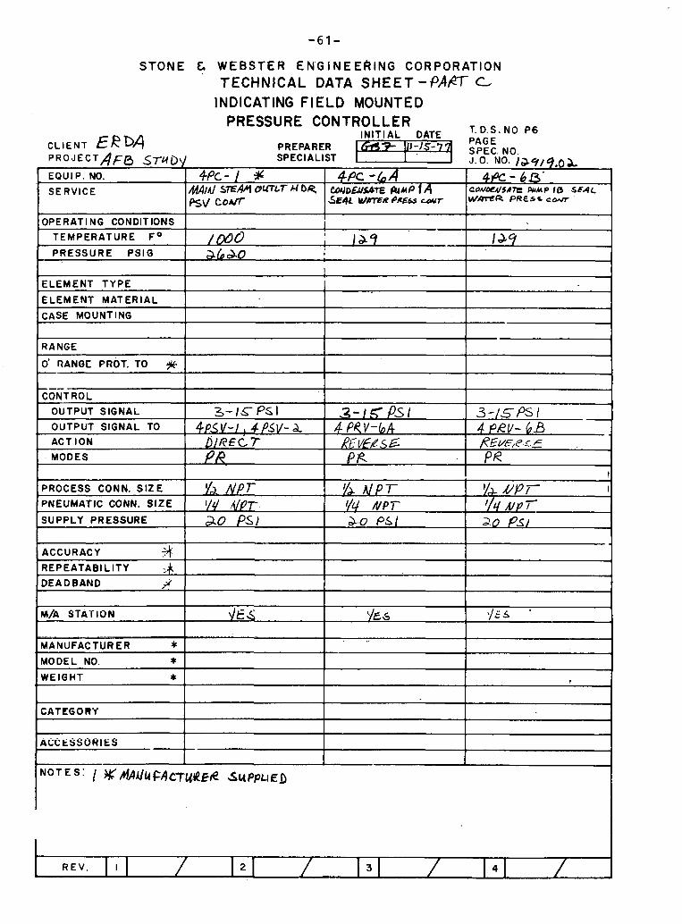
S T O N E & W E B S T E R E N ' G I N E E ~ I N G CORPORATION TECHNICAL DATA SHEET - 6 ' A f l c
INDICATING FIELD MOUNTED PRESSURE CONTROLLER
T.D.S.NO P 6
CLIENT ERDA IN IT IAL DATE
PAGE PREPARER 7 1'11-15-7 P R O . J E C T A F ~ STUD\I SPECIALIST I '
SPEC. NO. J. 0. NO. tacl/q.02 .
EQUIP. NO.
SERVICE
OPERATI NG CONDITIONS
TEMPERATURE F 0
PRESSURE PSIG
ELEMENT TYPE
ELEMENT MATERIAL
4Pc - I S M/Al S E A 4 bUTLT A blp Psv coJT
i
I
/mo I
I 1 ~ 9 abao
I I
CASE MOUNTING
RANGE b
0' RANQC PROT. TO .jiC-
CETROL
4Pc - 6 A I 44c-65- W a ~ a s h~ P f A I C M / O W I I Q ~ LUMP 18 SSAL 5
-
laq
-
OUTPUT SIGNAL
OUTPUT SIGNAL TO
ACT ION
. MODES
PROCESS CONN. S I Z E
PNEUMATIC CONN. S IZE
SUPPLY PRESSURE
3-1&-fsI ~ P S V - I ! CPSV- h.
DIREC.7 PI?.
ACCURACY +4 . REPEATAB1 L l T Y # DEADBAND X
I -- I MANUFACTURER * I
I
M/A STATION
- 1
MODEL NO. * 1 1 1
- .q p.5 1 4 PeV-bA ,?~~vE%s E: f f R
f lp r I/C/ ,f@r ao PSI
--
3 - / 5 6 / - 4 PRV- 6B /?L?v' P.<.._F
PR
-
di s
CATEGORY
l/J NPT h.0 P S I
I WEIGHT *
YA UP/- qlf , V p 7 a.o PSI
YES Y E S .
1 I

STONE & WEBSTER ENGINEERING CORPORATION TECHNICAL DATA SHEET - PART c
INDICATING F IELD MOUNTED PRESSURE COF PRESSURE CONTROLLER
IN IT IAL DATE P6
CLIENT E R D A PREPARER 9- 111-15-77 PROJECT ~ F B S7LIDy SPECIALIST
SPEC. NO. J.O. NO. / > y / ( 1 . 0 2
EQUIP. NO.
SERVICE
OPERATING CONDITIONS
TEMPERATURE F 0
PRESSURE PS lG
ELEMENT T Y P E
ELEMENT MA1 LRIAL
CASE MOUNTING
~ P c - S / clec WTE MAKE-UP
DISCH PW55
6s !
S O I
I R I I I M L YMlC
CLIENT E R D A PREPARER r 111-15-77 PAGE SPEC. NO. . ~ J.O. NO. / > y / ( 1 . 0 2
EQUIP. NO. I
RANGE
0' RANGE PROT. TO
ACT ION 1 I 1
~ P c - s /
I
CONTROL
OUTPUT SIGNAL
OUTPUT SIGNAL TO
3-/S f's/ 4pcv- 51
I
MODES
, .-, ' . I . I I
SUPPLY PRESSURE 20 P ~ I I I
I 1
kx I I
PROCESS CONN. S I Z E
PNEUMATIC CONN. S I Z E
ACCURACY
REPEATABI L l T Y
DEADBAND
I l /a Alp? 'Id
MANUFACTURER * MODEL NO. * WCIBHT 4
M/A STATION ' /E 5
I I
I N O T E S :
CATEGORY
ACCESSORIES
1 I
1 I

STONE & W E B S T E R E N G I N E E R I N G CORPORATION
TECHNICAL DATA SHEET- * c LEVEL GAGE GLASSES
T.D.S.NO. L2 I N I T I A L DATE PAGE
PREPARER S P E C I A L I S T J.O. NO. 1&4/V.OA
GAGE MATERIAL 'BODY CONN.SlZE '/b )U N p r
VALVE BODY MATERIAL &
1 VALVE CONN. S I Z E //1 111 1 [ MANUFACTURER * 1 I NOTES:
REV. >
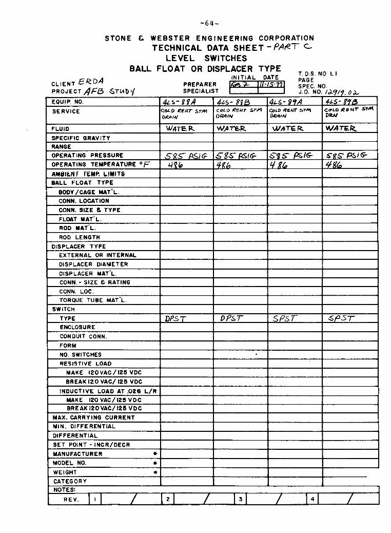
STONE t WEBSTER ENGINEERING CORPORATION TECHNICAL DATA SHEET -PART c
L E V E L SWITCHES BALL FLOAT OR DISPLACER TYPE
T. D.S. NO L I
AMDIkN I' VEMR LIMITS BALL FLOAT TYPE
BODY /CAGE MAT'L. CONN. LOCATION
CONN. SlZE tk TYPE
FLOAT MAT'L.
ROD MAT'L.
ROD LENGTH
DISPLACER TYPE EXTERNAL OR INTERNAL
DISPLACER DIAMETER
DISPLACER MAT'L.
CONN. - SlZE & RATING
CONN. LOC. TORQUE TUBE MAT'L.
SWITCH
TYPE
ENCLOSURE
CONDUIT CONN.
FORM
NO. SWITCHES
9ESIST!VE LOAD
MAKE 1 2 0 ~ A C / I 2 5 VDC
BREAK 120 VAC/ 125 VDC
INDUCTIVE LOAD AT .026 L/R
MAKE 120VAC/125VDC BREAK 120VAC/ 126 V O C
MAX. CARRY lNG CURRENT
MIN. DIFFERENTIAL
DIFFERENTIAL
SET POINT - INCR/DECR
MANUFACTURER * MODEL NO. * WEIGHT u CATEGORY NOTES:
3 4
D P s T DPST
. . -. --
SPST s p s r '

S T O N E & W E B S T E R E N G I N E E R I N G CORPORATION TECHNICAL DATA SHEET- PART: C
LEVEL SWITCHES BALL FLOAT OR DISPLACER TYPE , , ,
I N I T I A L DATE CLIENT E R W PREPARER 659) W-15-77
PAGE
/a/? O L
~ L S - / & B ,
cO(I0sP UoT wEL L LEVEL
WATER
/a4 30"% ~ A C
>
.
SPEC. NO J.0 NO
4w -/dA W b S R W WUL LEVEL
WIPER
J 24 30"//q I /Ac
-
4
P R O J E C T A f b STUD Y EQUIP. NO.
SERVICE
FLUID
SPECIFIC GRAVITY
RANGE
OPERATING PRESSURE
OPERATING TEMPERATURE OF AMBIENT TEMP. L IMITS
BALL FLOAT TYPE
BODY /CAGE MAT'L.
CONN. LOCATION
CONN. SIZE C TYPE
FLUAT MAT'L.
ROD MAT'L. ROD LENGTH
DISPLACER TYPE
EXTERNAL OR INTERNAL
DISPLACER DIAMETER
DISPLACER MAT'L
CONN - SIZE & RATING
CONN LOC
TORQUE TUBE MAT'L
SWITCH
TYPE
ENCLOSURE
CONDUIT CONN.
FORM
NO SWITCHES
RESISTIVE LOAD
MAKE 120VAC/125 VDC
BREAK 120 VAC/ 125 VDC
SPECIALIST
U- L/A sroRAa~ TK
LEJEL
W A E R
4 s PS~G 4
1
I
&s- 48 DA S T O W TK U V E L
t&tWR
SCS WG
INDUCTIVE LOAD AT .026 L / R
MAKE I20 VAC/ 125 VDC BREAK 120 VAC/ 125 VDC
MAX. CARRYING CURRENT
HIN. DIFFERENTIAL
DIFFERENTIAL
SET POINT - INCR/DECR
MANUFACTURER * MODEL NO. * WEIGHT w /-
CATEGORY NOTES:
3
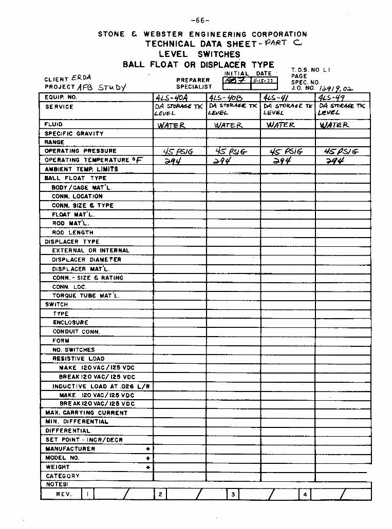
STONE C WEBSTER ENGINEERING CORPORATION TECHNICAL DATA SHEET- PhQT C
LEVEL SWITCHES BALL FLOAT OR DlSPL
CLIENT ERDA SPECIALIST
ENCLOSURE
CONDUIT CONN.
FORM
NO. SWITCHES
RESISTIVE LOAD
MAKE 1 2 0 VAC / 12s VDC
BREAK 120 VAC/ 125 VDC
INDUCTIVE LOAD AT .O26 L/R MAKE 120VAC/I25VDC BREAK 120VAC/125 VDC
MAX. CARRY lNG CURRENT
MIN. DIFFERENTIAL
DIFFERENTIAL
SET POINT - INCR/DECR
MANUFACTURER * MODEL NO. * WEIGHT * CATEGORY NOTES:
A
3
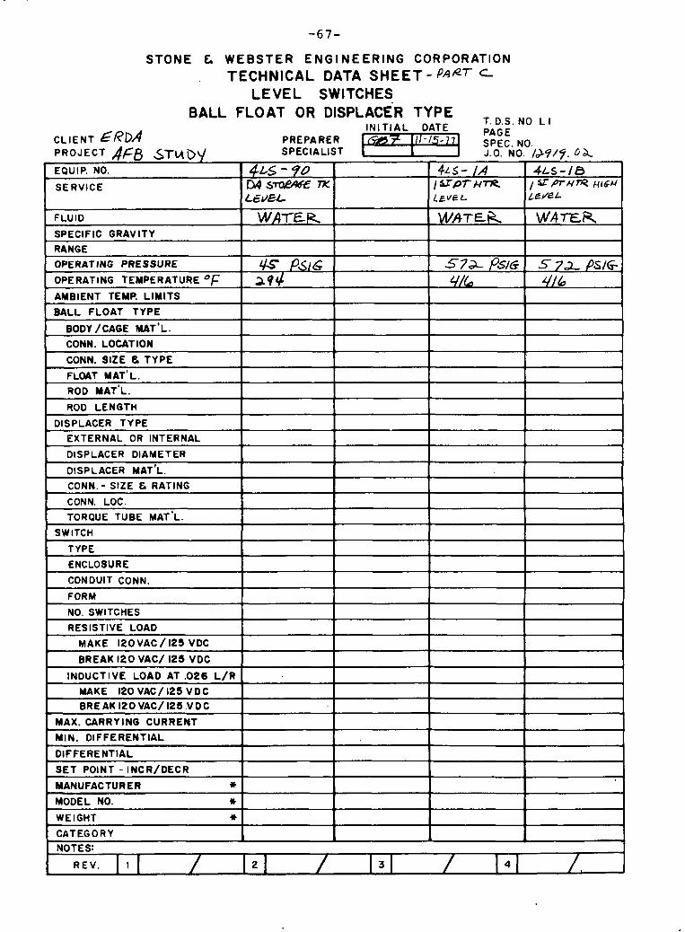
STONE & WEBSTER ENGINEERING CORPORATION TECHNICAL DATA SHEET - PAAT
LEVEL SWITCHES BALL FLOAT OR DISPLACER TYPE , I
I N I T I A L DATE CLIENT ERDA PREPARER 3 1 1 1 - 1 5 - 7 7
PAGE
CATEGORY i 4
NOTES:
3 4
SPEC NO J o NO
~ L S - /A / Y P T H ~ L E V E L
W A T E ~
57a- PS/G 4/6
I PROJECT AFB .STMD\/ EQUIP. NO.
SERVICE
FLUID
SPECIFIC GRAVITY
RANGE OPERATING PRESSURE
OPERATING TEMPERATURE OF AMBIENT TEMP. LIMITS
BALL FLOAT TYPE
BODY /CAGE MAT'L. CONN. LOCATION
CONN. SIZE e TYPE
FLOAT MAT'L.
ROD IYAT'L.
ROD LENGTH
DISPLACER TYPE
EXTERNAL OR INTERNAL
DISPLACER DIAMETER
DISPLACER MAT'L
CONN - SIZE & RATING
CONN LOC
TORQUE TUBE MAT'L
SWITCH
TYPE
ENCLOSURE
CONDUIT CONN.
FORM
NO SWITCHES - -
RESISTIVE LOAD
MAKE 120VAC / 125 VDC
BREAK 120 VAC/ 125 VDC
INDUCTIVE LOAD AT .026 L / R
MAKE 120 VAC/125 VDC BREAK I2OVAC/125 VDC
MAX. CARRY lNG CURRENT
MIN. DIFFERENTIAL
DIFFERENTIAL
SET POINT - INCR/DECR
MANUFACTURER * MODEL NO. * WEIGHT 1)
/&9/5. fi a 4 ~ s - 1 0 S m N m ~ 1 0 4
LCJEL
WATER
S 7 2 PS/G, a6
-
- -
2
SPECIALIST
4 ~ s - 5'0 I34 S- TK LEQEL
WATER
G Psi6 394
~ --
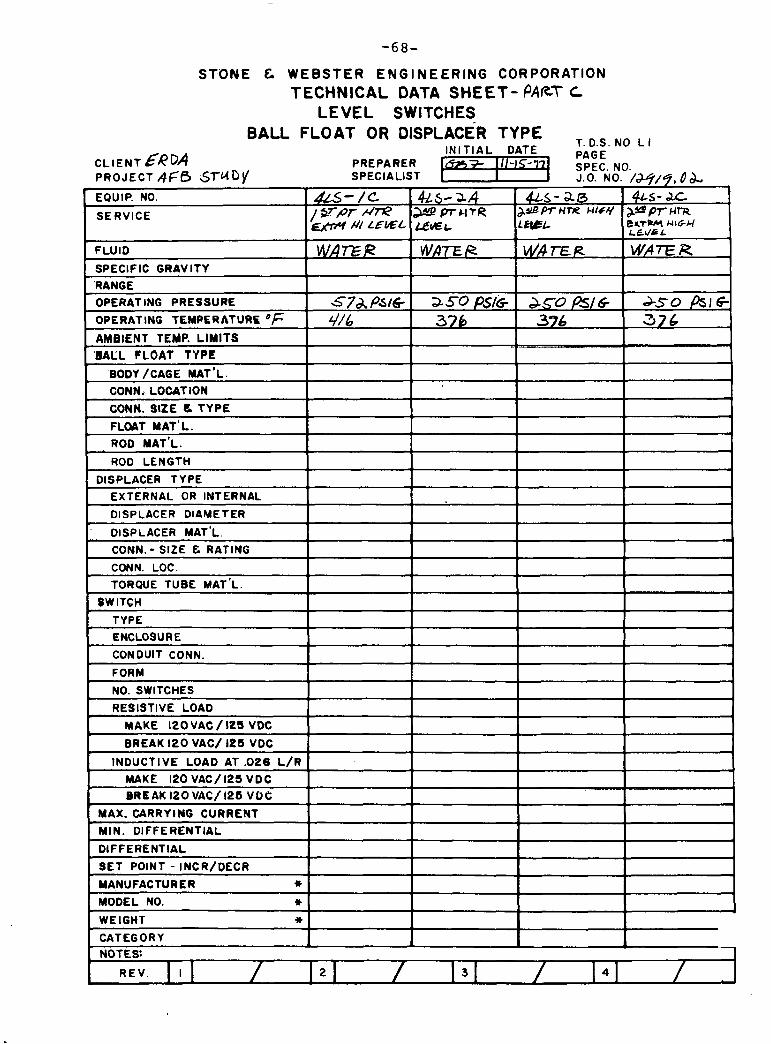
S T O N E & W E B S T E R E N G I N E E R I N G CORPORATION TECHNICAL DATA SHEET- PAET c
LEVEL SWITCHES BALL FLOAT OR DISPLACER TYPE
INITIAL DATE T. D.S. NO L I
CLIENT 6RDA T 111 - rs - 7 PAGE
PREPARER PROJECT ,qf 0 STUDY I
SPEC. NO. SPECIALIST J.O. NO. /*/?, d & .
EQUIP. NO. U - / C 4 ~ s - 34 ~ L S - a 4 ~ s - .LC SERVICE 1 a m Mm prurR &*Bprune@uuq p p r UR
/// LPSL &*L e r r w NIGH LC\/& I
FLUID W A ~ R w a z R WAEP WPTE R SPECIFIC GRAVITY - 'RANGE OPERATING PRESSURE 5 7 d , ~ 5 l & ~ ~ O P S I G 3 5 0 ~ s l ~ ~ S O ~ S I G , OPERATING TEMPERATURE OF 4/6 378 376 376
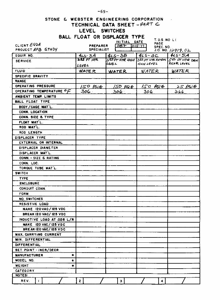
STONE & WEBSTER ENGINEERING CORPORATION .
TECHNICAL DATA SHEET - P4AT LEVEL SWITCHES
BALL FLOAT OR DISPLACER TYPE I N I T I A L DATE
T. D.S. NO L I
C L I E N T &Q3A PREPARER 6 ~ 3 3 - 111-15-77 PAGE
PROJECT ,4F& STUDY SPECIALIST I J.0. NO. /J-Y/Y, O b . SPEC. NO.
&s- SA S * P T ~ ~ Q & A A RcvR L E V ~ L
W A Z R
- ss f3616 , a66
.
4f i - 34 b&0PfhnR
LWeL wAT€ R
1.50 psh5 306
C
EQUIP. NO.
SERVICE
FLUID
SPECIFIC GRAVITY RANGE OPERATING PRESSURE
OPERATING TEMPERATURE
~ L S - 30 3 ~ " P r ~ ~ ~ 6 ~ 3 @ p r m m ~ r ( LEdE L
WATER
1 9 PS16 306. .
4 ~ s - 3c c l r s ~ L E ~ E L
WATER
/So &la 306

STONE & WEBSTER ENGINEERING CORPORATION TECHNICAL DATA SHEET -PART c
LEVEL SWITCHES BALL FLOAT OR DISPLACER TYPE
IN IT IAL DATE T D S NO L I
CLIENT ERDA PRoJECT,4 Ff3 STU B EQUIP' NO.
SERVICE
FLUID
SPECIFIC GRAVITY
RANGE OPERATING PRESSURE
OPERATING TEMPERATURE
AMBIENT 1 EMP. LIMITS
' BALL FLOAT TYPE
BODY /CAGE MAT' L CONN. LOCATION
CONN. Slf E & TYPE
F L W T MAT'L.
ROD MAT'L. . ROD LENGTH
DISPLACER TYPE
EXTERNAL OR INTERNAL
DISPLACER DlAMET ER
DISPLACER MAT'L
CONN - SIZE E RATING
CONN LOC
TORQUE TUBE MAT'L
SWITCH
r f P E
ENCLOSURE
CONDUIT CONN.
FORM
NO SWITCHES
RESISTIVE LOAD
MAKE 120 VAC / 125 VDC I
BREAK 120 VAC/ 125 VDC
INDUCTIVE LOAD AT .026 L/R
MAKE 120 VAC/ 125 VDC BREAK 120 VAC/ 125 VDC
MAX. CARRYING CURRENT
MIN. DIFFERENTIAL
DIFFERENTIAL
SET POINT - INCR/DECR
MANUFACTURER * MODEL NO. * WEIGHT * CATEGORY NOTES:
/&q/9, oa, 4 ~ 5 - 6 0 66wpr~~~o~lu' mrrk #/GU LCVICL
/ f &/A -0
PREPARER 6 ~ 3 3 111-~5-?7 PAGE
SPECIALIST
4 L S - S 8 S " r n C / r p D e ~ 5 % b p r ~ r r r p RGvR Ul6H LEVEL
PSIG 266
2
I
d L s - 5 ~
LEVEL
as W I G * L
3
SPEC NO J 0 NO
4 L S - 6 4 ~ f b m u m b n ~ A C ~ R LEVEL
11 &/A 0
4

STONE C WEBSTER ENGINEERING CORPORATION TECHNICAL DATA SHEET- PAPT t
LEVEL SWITCHES BALL FLOAT OR DISPLACER TYPE
I N I T I A L DATE T. D.S. NO L I
SPECIALIST
AMBIENT TEMP. LIMITS
BALL FLOAT TYPE
BODY /CAGE MAT'L. CONN. LOCATION
CONN. SIZE U TYPE
FLOAT MAT' L. ROD IYAT'L.
ROD LENGTH
DISPLACER TYPE EXTERNAL OR INTERNAL
DISPLACER DIAMETER
DISPLACER MAT'L.
CONN. - SIZE C RATING
CONN. LOC.
TORQUE TUBE MAT'L.
SWITCH
TYPE
ENCLOSURE
CONDUIT CONN.
FORM
NO SWITCHES
RESISTIVE LOAD
MAKE 1 2 0 ~ A C / 125 VDC
BREAK 120 VAC/ 125 VDC
INDUCTIVE LOAD AT .026 L / R
MAKE 120VAC/125VDC BREAK I20 VAC/ 125 VDC
MAX. CARRYING CURRENT
HIN. DIFFERENTIAL
DIFFERENTIAL
SET POINT - INCR/DECR
MANUFACTURER * MODEL NO. * WEIGHT * CATEGORY NOTES:
-
2 3 4
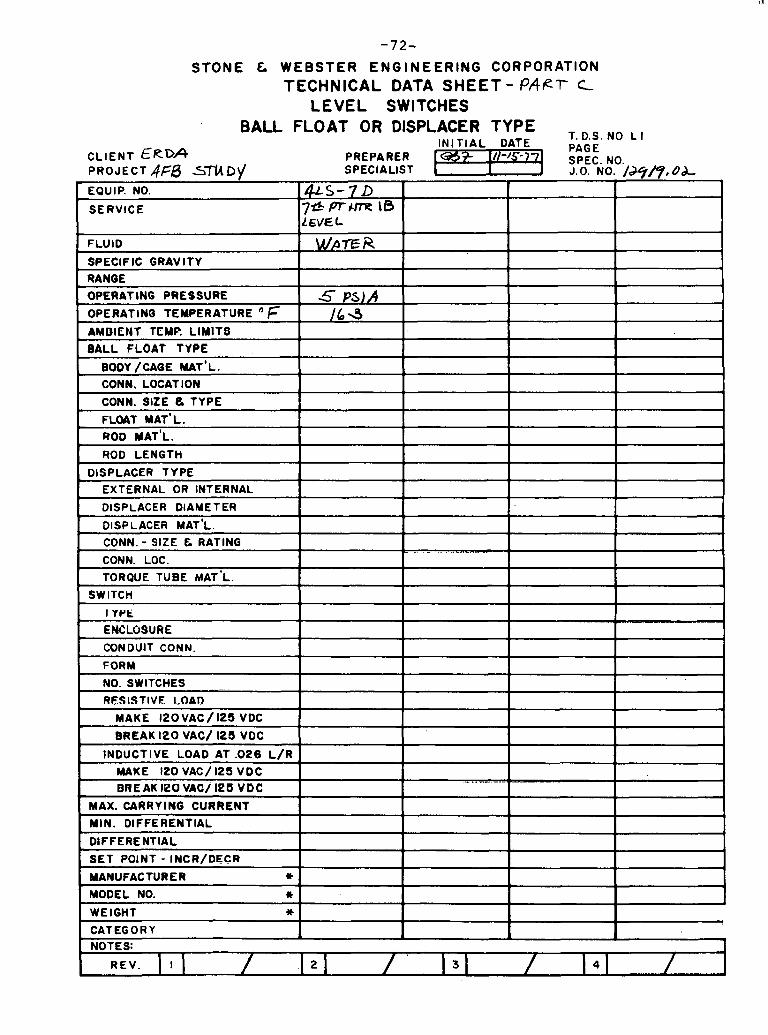
-72-
S T O N E & W E B S T E R E N G I N E E R I N G CORPORATION TECHNICAL DATA SHEET - P A P r c
L E V E L SWITCHES BALL FLOAT OR DISPLACER TYPE
T, ,.,. ,, , , I N I T I A L DATE
PREPARER SPECIALIST
MODEL NO. * WEIGHT Y
CATEGORY 1
NOTES:
2 3 4
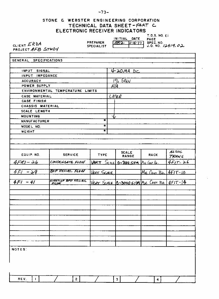
STONE & WEBSTER ENGINEERING CORPORATION TECHNICAL DATA SHEET-P412T c
ELECTRONIC RECEIVER INDICATORS T.D.S. NO El
CLIENT EebA PROJECT AFB S m D V
-.
IN IT IAL DATE PAGE PRE PARER U%% 111-/6-77 SPEC. NO. SPECIALIST J.O. NO. /&9/9, d c L
GENERAL SPECIFICATIONS
INPUT SIGNAL
INPUT IMPEDANCE
ACCURACY POWER SUPPLY
ENVIRONMENTAL TEMPERATURE LIMITS
CASE MATERIAL
CASE F IN ISH
CHASSIS MATERIAL
SCALE LENGTH
MOUNTING
MANUFACTURER * MODEL NO. * WEIGHT *
&&a M A D.c
1070 5P~nl MI
1 m&?
\J
SCALE AS SOC EQUIP. NO. SERVICE TYPE RANGE RACK ;T'iw&S
4r=/e/- a6 c ~ * A J G ~ ~ ~ ~ 0 l . d VEUT ~ L E . 0-7000 c p 4 MU. C,u &, .
A
-*- . .
L
-. . -
N O T E S :
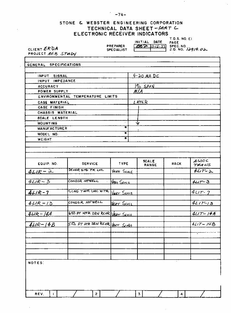
STONE G WEBSTER ENGINEERING CORPORATI0.N TECHNICAL DATA SHEET-WPT c
ELECTRONIC RECEIVER INDlCATORS T.D.S. NO. E l
IN IT IAL DATE PAGE PREPARER I - 7 SPEC. NO.
CLIENT &RDA SPECIALIST I J. 0 . NO. /d9/4. od, PROJECT AFA STUDV
GENERAL SPECIFICATIONS I INPUT SIGNAL MA Dc INPUT IMPEDANCE 1
r MOUNTING
- ACCURACY
POWER SUPPLY - . ENVIRONMENTAL TEMPERATURE LIMITS
CASK MATERIA'L . . -
CASE F I N I S H
CHASSIS MATERIAL
SCALE LENGTH
MANUFACTURER " 1 . I
)%I Sf'~4 f l /A
k 47%-k -....- 1 1 I
--
t MODEL NO: 1 WEIGHT * I
N O T E S :
,&&a C 7 . A& - #& r- a.
Pur- 3
EQ U I P. NO.
#LIR- a- 4 L / R - 3
SERVICE
XACR 57%- r K LVL
CWOSI? WELL
TYPE
\lem scAL6
\leA LIE
SCALE RANGE RACK
-
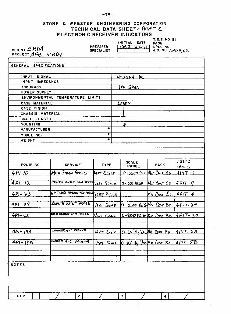
STONE C WEBSTER ENGINEERING CORPORATION TECHNICAL DATA S H E E T - W e ? C
ELECTRONIC RECEIVER INDICATORS T.D.S. NO. E l
IN IT IAL DATE PAGE
CLIENT &RDA PRE PARER - I - SPEC. NO. SPECIALIST I J.0. NO. /w/y. O X
P R O J E C T A F B -0q I
GENERAL SPECIFICATIONS
INPUT SIGNAL
INPUT IMPEDANCE
ACCURACY 1 % sP11d POWER SUPPLY
ENVIRONMENTAL TEMPERATU RE LIMITS
I CASE MATERIAL I L A ~ . R CASE F I N I S H \ CHASSIS MATERIAL
. SCALE LENGTH
MOUNl IN6 J
I MANUFACTURER " 1 I 1 MODEL NO: +I
I WEIGHT *
SCALE A S o C EQUIP. NO. SERVICE TYPE RANGE RACK
TPflUS
4 PI- 10 &I# STF,W ~ G S VU37 S C ~ C E 0-3500 P \ G /YA/ CorUl 804 4PIT - 1
PI- 12. R E W * o U T L T S r A ~ b S \ I ~ ~ ~ SCALE 0-1000 BIG Mu C o r c n & ~ . 4PlT- 4 1
N O T E S :
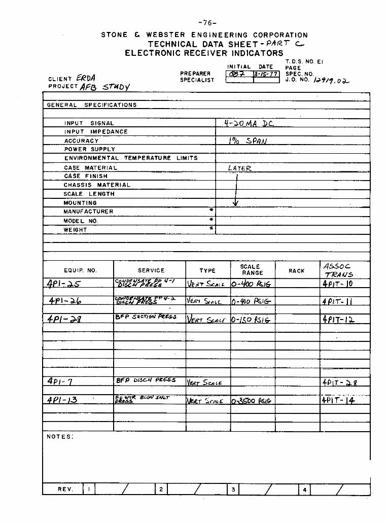
STONE C, WEBSTER ENGINEERING CORPORATION TECHNICAL DATA S H E E T - PART t
ELECTRONIC RECEIVER INDlCATORS T. D.S. NO. E l
I N I T I A L DATE PAGE PRE PARER a+ 111-1s-77 SPEC. NO.
CLIENT ERDA SPECIALIST I J - 0 . NO. )J9/9,0& P R O J E C T A ~ B 5 7 U D I /
~ -
GENERAL SPECIFICATIONS
CHASSIS M A T E R I A L I 1 SCALE LENGTH 1
I MODEL NO. * I
MOUNTING * MANUFACTURER
I WEIGHT *
4
N O T E S :
C
SERVICE TYPE SCALE
RACK A S O t
RANGE TEA US C.7OEU5A X L / ~ F E ~ ~ ' - ' \ I F ~ Z T & A : C . ' O - ~ & I ~ 4pjr- 10
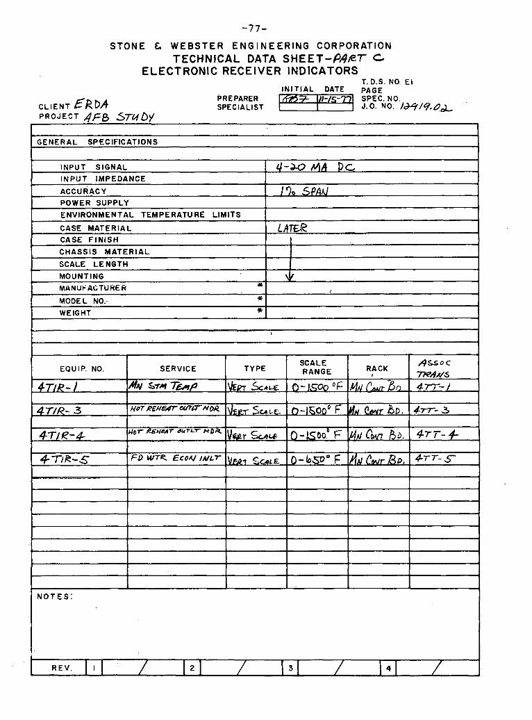
STONE & WEBSTER ENGINEERING CORPORATION TECHNICAL DATA S H E E T - P H R T C
ELECTRONIC RECEIVER INDlCATORS T. D.S. NO. El
INITIAL DATE PAGE
CLIENT ERDA PRE PARER SPECIALIST
PROJECT AFB S7bIO)' I 1
GENERAL SPECIFICATIONS 1 INPUT SIGNAL 4-J-0 All I>c INPUT IMPEDANCE
ACCURACY I 70 SPAnl POWER SUPPLY
L
L CHASSIS MATERIAL I I 1
CASE MATERIAL
CASE FINISH
- SCALE LENGTH I MOUNTING + MANuPuCTUHER Y
I
MODEL NO: * WEIGHT *
I
M€f? I i
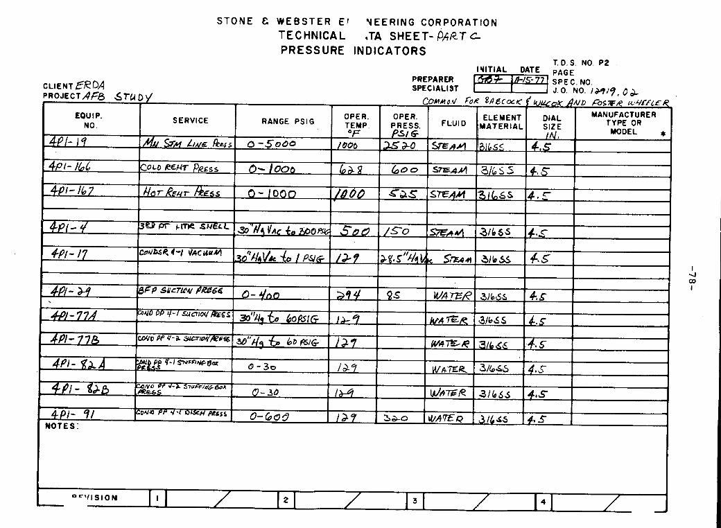
S T O N E C W E B S T E R E l V E E R I N G C O R P O R A T I O N T E C H N I C A L .TA SHEET- PART c P R E S S U R E I N D I C A T O R S
T. D. S. NO. P2
PREPARER CLIENT ERDA SPECIALIST PROJECTAFB &TU D )/
J.0 . NO. I M " 9 , O b , C0~ua.V OR g A d c m ~ <U&oX AUD B s T U &v.CfLfR
EQUIP. OPER. OPER. ELEMENT DIAL MANUFACTURER
NO. SERVICE RANGE PSlG TEMP. PRESS. 'MATERIAL SIZE TYPE OR
"F PSI G j IN . MODEL * - &M LIME ~ Y S 0 - 5 0 0 0 / 600 =a-0 SEAM i3ibs5 4, s
I 4 OD
I
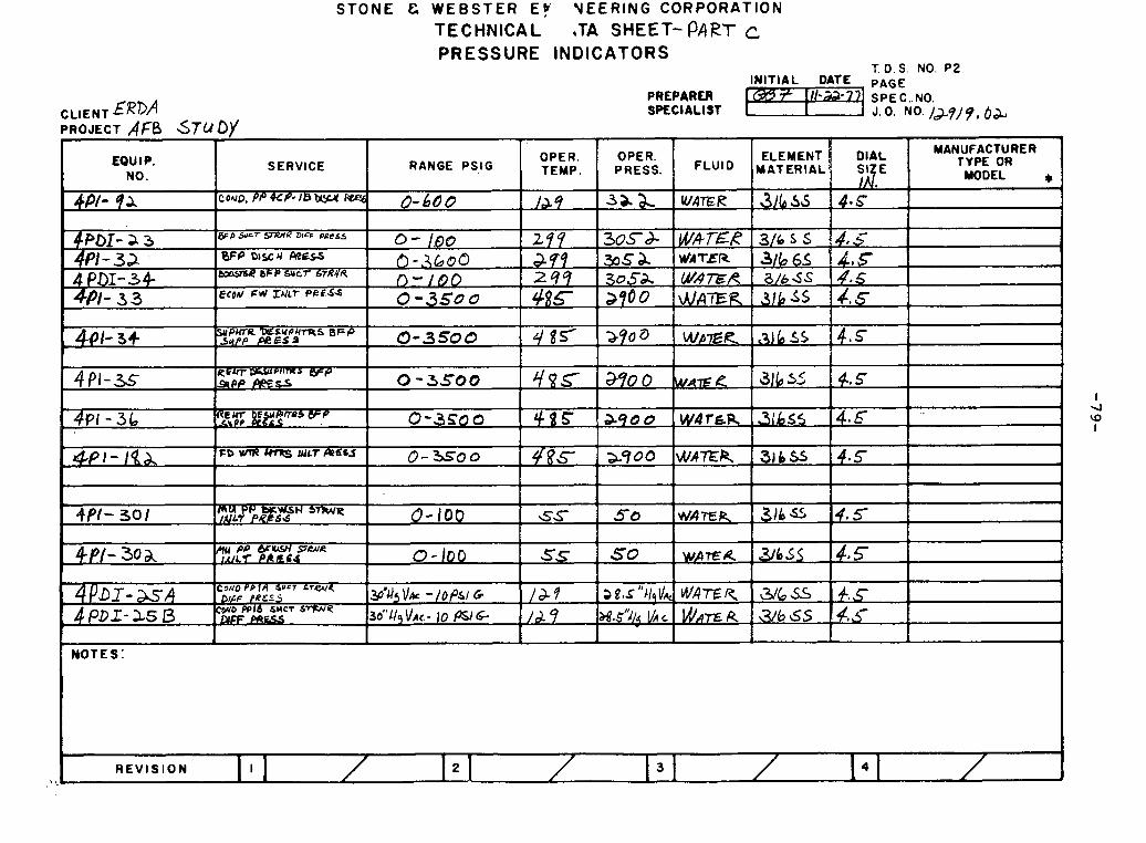
I QI I- I
lSllV13MS
2d 'ON 'S '0 1 SUOlV3laNI 3CIflSS3tJd
3 IaWd -133HS Vl' lV3lNH331 N011Vt40dkl03 9Nlt133h ,43 831S83M '3 3NOIS
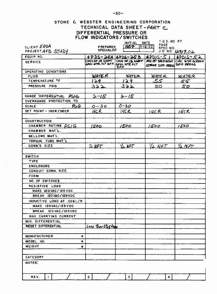
S T O N E & W E B S T E R E N G I N E E R I N G C O R P O R A T I O N TECHNICAL DATA SHEET -PART c
DIFFERENTIAL PRESSURE OR FLOW INDICATORS /SWITCHES
CLIENT &&OA PREPARER SPECIALIST P R O J E C T A F D $mD,v 9 . 0 ~ .
EQUIP. NO.
SERVICE
OPERATING CONDITIONS FLUID TEMPERATURE OF
PRESSURE PSIG
RANGE DIFFERUTIAL mG OVERRANGE PROTECTION TO
SCALE f2srG SET POINT - INCR/DECR
SWITCH
TYPE
ENCLOSURE
,
4PDS - X A COr lbPP IA~AFt - S ~ ~ L ~ F L ~ ~ ~ : F W L W ~ R F C T
W h E R I &9 32s-
C H A M B E R RATING P.</G CHAMBER MAT'L.
BELLOWS MAT'L.
0-30
IA/~ k
1 I
NO. OF SWITCHES I 1 1 1
4 PDS- X 0 CON0 PP1bdLUPT
DtFF
Wm€R lL9 3 a a
/.=O
L CONDUIT CONN. SIZE
FORM
RESISTIVE LOAD 1 I I 1 MAKE lPOVAC/ 125VDC
3-/.5 ,
0-30 ~ U C R
I BREAK 120VAC/125VDC I I 1 I
t4PD1S - .C I MUflBALKWYI m ~ b ~ ~ m
WAE k 55 SO
/ s o 0
---
INDUCTIVE LOAD AT . 0 2 6 L / R I I I MAKE 120VAC/125VDC 1 I
4Pb5 - , c A ClRc UnRSrPall OlFF WE-
WATER S6 SO
I ~ L P
~ ..
/A(< R
/ G o 0
I I I
RESET DIFFERENTIAL ]Less -i%~or/SadR*rk, I I 1 I
/ S O 0
BREAK 120 VAC / 125VDC
MAX. CARRYING CURRENT
MIN. Dl FFERENTIAL
1 MANUFACTURER * 1 1 I
I
MODEL NO. * WEIGHT *
1 I 1 I
CATEGORY 1 I 1 I

NOTES: REFER TO TD.S NO. SW 1 FOR GUIDE IN DETERMINING CONTACT RATINGS. A DIFFERENCE BETWEEN ACTUATION AND REACTUATION POINT EXAMPLE: I F SWITCH IS SET FOR HIGH ALARM CONTACT CLOSURE
AT 600 PS I ; WHAT I S PRESSURE DROP NECESSARY TO OPEN CONTACTS.
STONE & WEBSTER ENGINEERING CORPORATION TECHNICAL DATA SHEET- Q9R-i -c
PRESSURE SWITCHES T.D.S. NO P I
PREPARER SPEC1 A L l S T
NO. SWITCHES
RESISTIVE LOAD
M A K E 120 VAC / 125 VDC BREAK l2OVAC / 125 VDC
INDUCTIVE LOAD AT .026 L / R MAKE 120 VAC / 125 VDC
BREAK 120 VAC/ 125 VDC
MAX. CARRYING CURRENT . ..
MIN. DIFFERENTIAL
RESET DIFFERENTIAL D * MANUFACTURER Y
MODEL NO. * WE1 GHT * CATEGORY
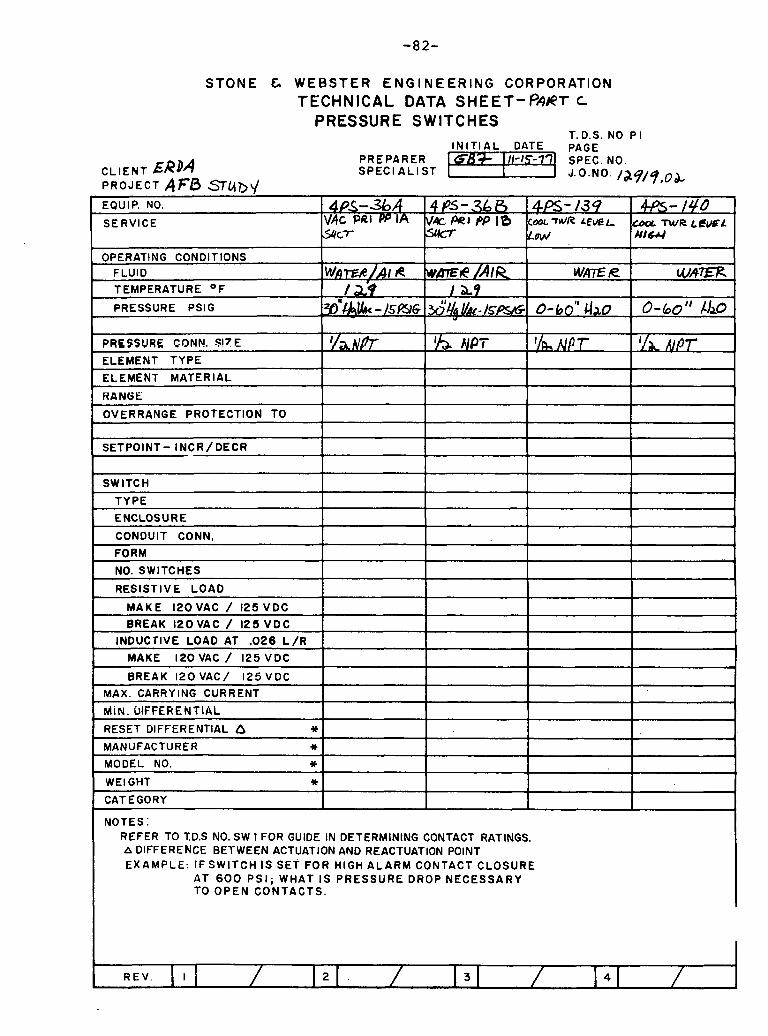
STONE & WEBSTER ENGINEERING CORPORATION TECHNICAL DATA SHEET-PART t
PRESSURE SWITCHES T. D.S. NO P I
I N I T I A L DATE PAGE PREPARER
CL IENT ERDA 5 SPEC1 A L l ST
PROJECT AFB .Sub\/
OVERRANGE PROTECTION TO
SETPOINT- INCR/DECR
SWITCH
TYPE
ENCLOSURE
CONDUIT CONN,
FORM
NO. SWITCHES
RESISTIVE LOAD
M A K E 120VAC / 125 VDC
BREAK l 2OVAC / 125 V D C
INDUCTIVE LOAD AT .026 L / R
MAKE 120 VAC / 125 VDC
BREAK 120 VAC/ 125 VDC
MAX. CARRY lNG CURRENT
MiN. DIFFERENTIAL
RESET DIFFERENTIAL a w
MANUFACTURER * MODEL ' NO. 3 t
WE1 GHT * CATEGORY
NOTES: -
REFER TO TD.S NO. SW 1 FOR GUIDE IN DETERMINING CONTACT RATINGS. A DIFFERENCE BETWEEN ACTUATION AND REACTUATION POINT EXAMPLE: IF S W I T C H IS SET FOR HIGH ALARM CONTACT CLOSURE
AT 600 PS I ; WHAT I S PRESSURE DROP NECESSARY TO OPEN CONTACTS.
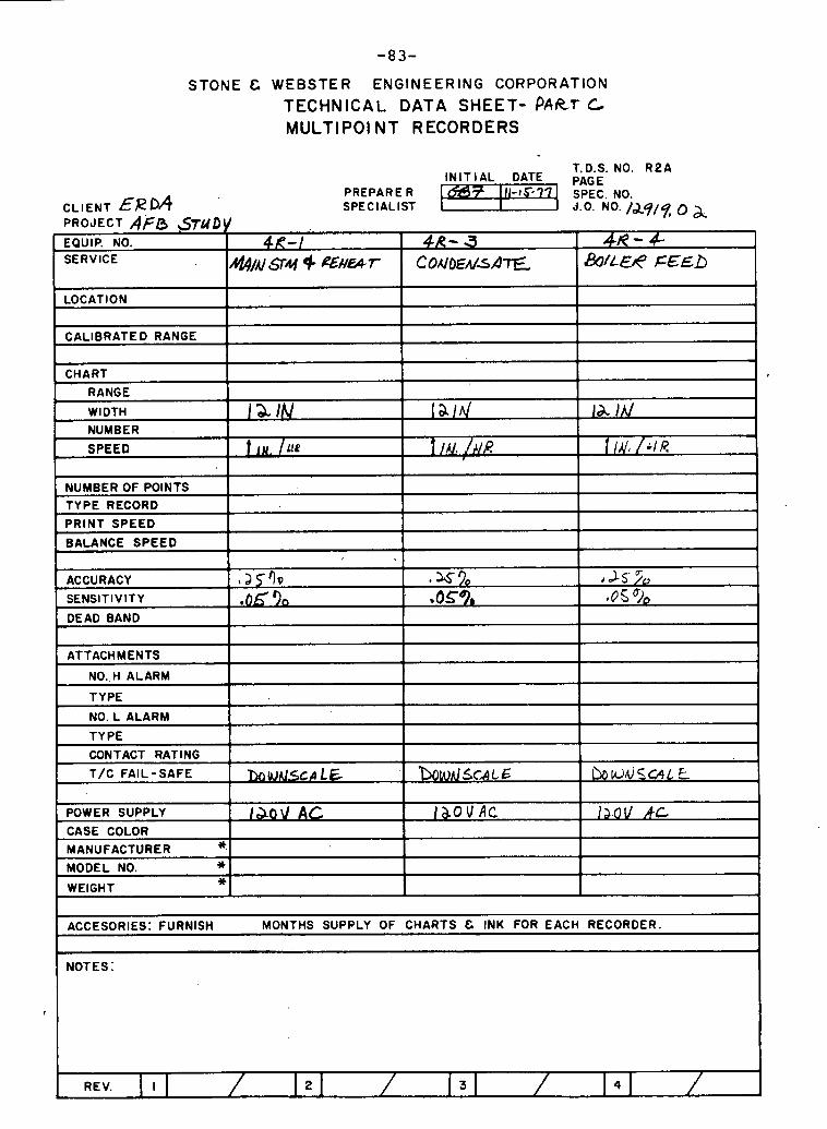
-83-
STONE C WEBSTER ENGINEERING CORPORATION
TECHNICAL DATA SHEET- PART C, MULTlPOl NT RECORDERS
LOCATION 1 I I I
T.D.S. NO. R 2 A I N I T I A L DATE PAGE
PREPARE R f 111-1577 SPEC. NO. CLIENT ERDA SPECIALIST I d . 0 NO. /d9/ 9. 0 PROJECT AFG ?STUDY
I 1 I
CALIBRATED RANGE I I I 1
- BOIL€& FEED
- C O A I O E ~ / ~ A I E
EQUIP. NO. SERVICE
CHART
RANGE
WIDTH
- &/' S ~ Y 9 eNWT
NUMBER .
SPEED
+ l a IN
NUMBER OF POINTS TYPE RECORD
PRINT SPEED
BALANCE SPEED
? i N , / U P
I
ACCURACY
SENSITIVITY
DEAD BAND
I T/C FAIL-SAFE I
la/d
I / c / ; / A / R
ATTACHMENTS
NO..H ALARM
TYPE
NO. L ALARM
TYPE
CONTACT RATING
la /A/
, a ~ l ~ e 90
I
1
MODEL NO. * WEIGHT *
POWER SUPPLY
CASE COLOR
MANUFACTURER *.
ACCESORIES: FURNISH MONTHS SUPPLY OF CHARTS & INK FOR EACH RECORDER.
L.5 9', .as?,
NOTES:
, J S > ~ 4 s %
130U AC
REV. I 2 3 4
I ; S O V A C 1a.o ll k c

-84-
STONE C WEBSTER ENGINEERING CORPORATION
TECHNICAL DATA SHEET- p4RT L MULTlPOl NT RECORDERS
LOCATION
T.D.S. NO. R 2 A IN IT IAL DATE PAGE
PREPARE R CL IENT &eDA SPECIALIST J.0. NO. /d9/7. 0~ PROJECT AFg STk h\l q - - -
SERVICE
L CALIBRATED RANGE
SW &rrr
1
I
WIDTH
NUMBER
SPEED
- - --
NUMBER OF POINTS TYPE RECORD
PRINT SPEED
BALANCE SPEED
DEAD DAND I I I I
MAN %M +&HUT
la /hl
I l@R
ACCURACY I *as 9, SENSITIVITY ,o 530
ATTACHMENTS
NO. H ALARM
TYPF ,
h$prVS- +~WU)T
-
-
I NO. L ALARM I I I T Y PF
I & / A /
f IN / I IR - - - -
4
.S~Q bas 70
CONTACT RATING
T/C FAIL- SAFE
I
I& /d
i I U I H R
135 .OS %
1 POWER SUPPLY I I I d - - I
CASE COLOR I I I I MANUFACTURER * I 1
I MODEL NO. *I I I I
ACCESORIES: FURNISH . MONTHS SUPPLY OF CHARTS C INK FOR EACH RECORDER.
\
REV. I 2 3 4 I

STONE 8 W E B S T E R ENGI. R I N G C O R P O R A T I O N
TECHNICAL bnrA SHEET - P A R T c MU LTlPOlNT RECORDER
POINT IDENTIFICATION LIST T.D.S. NO. R2B
REVISION
INITIAL DATE PAGE PREPARER
CLIENT ERbA SPECIALIST J.0. NO. Ib.9 1 9 , ~ ~ PROJECT A Ff i
EQUIP NO.
4tf-3
4i2- 3
INPUT SOURCE - NOTES :
RECORDER POINT NO.
INPUT EQUIP. NO.
I 14 FIT-26 I
a, 1 LIT- & I
I
I
1
I
I
wbEAl54TE FLOW
w 576 TK LVL
I
I
I
I
I
I
II
I
l NPUT SOURCE
SPECIFY INPUT SOURCE SIONAL . I F TC,OIVE CALIB. CURVE. EXS. TC- E , RTD, 0 - LOMV, ETC.
SERVICE OPERAT lNG
RANGE NOTES
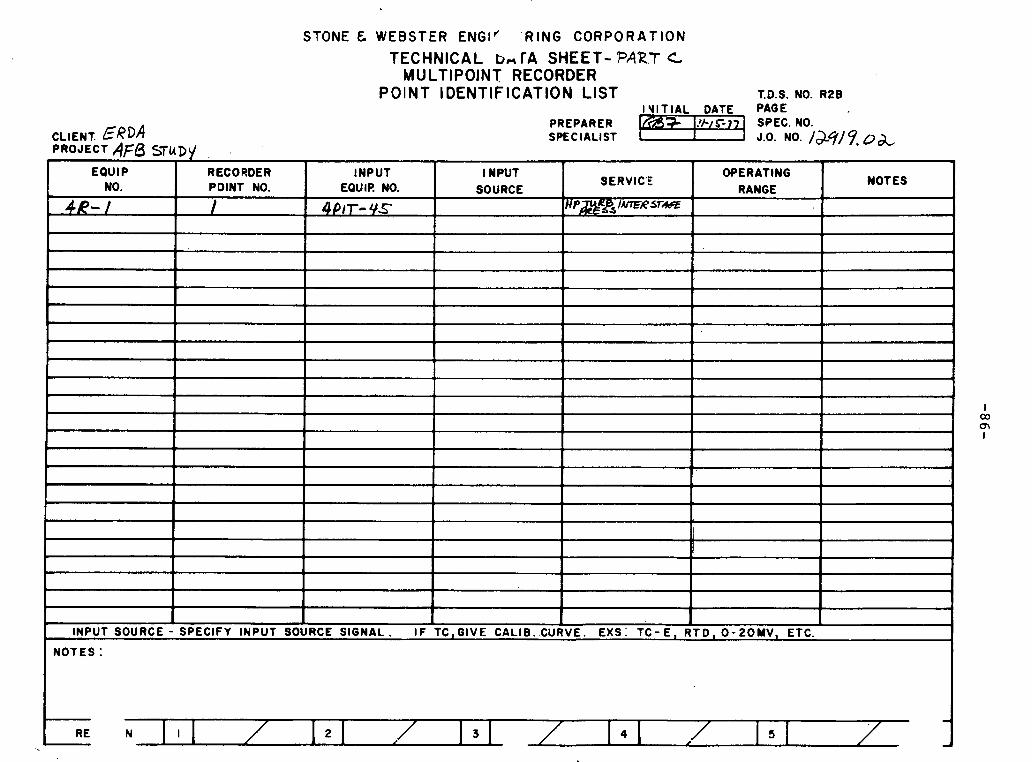
STONE & WEBSTER ENGI' ' R I N G C O R P O R A T I O N
TECHNICAL b- TA SHEET- PART C MU LTlPOlNT RECORDER
POINT IDENTIFICATION LIST T.D.S. NO. R2B IY lT lAL DATE PAGE
PREPARER 7 I SPEC. NO. CLIENT ERDA SPEC IALIST I PROJECT 4f 5 STUDY
J.0. NO. law 9, ua, EOUlP
NO.
I
INPUT SOURCE - SPECIFY INPUT SOURCE SIGNAL. I F TC, GIVE CALIB. CURVE. EXS. TC- E, RTD, 0- POMV, ETC.
NOTES :
OPERAT lNG
RANGE
R ECO SDE R POINT NO.
/
NOTES
I
I
INPUT EQUIP. NO.
4 PIT- 4 s
l NPUT SOURCE
SERVICE
HP&RPj IMFRJTAsT
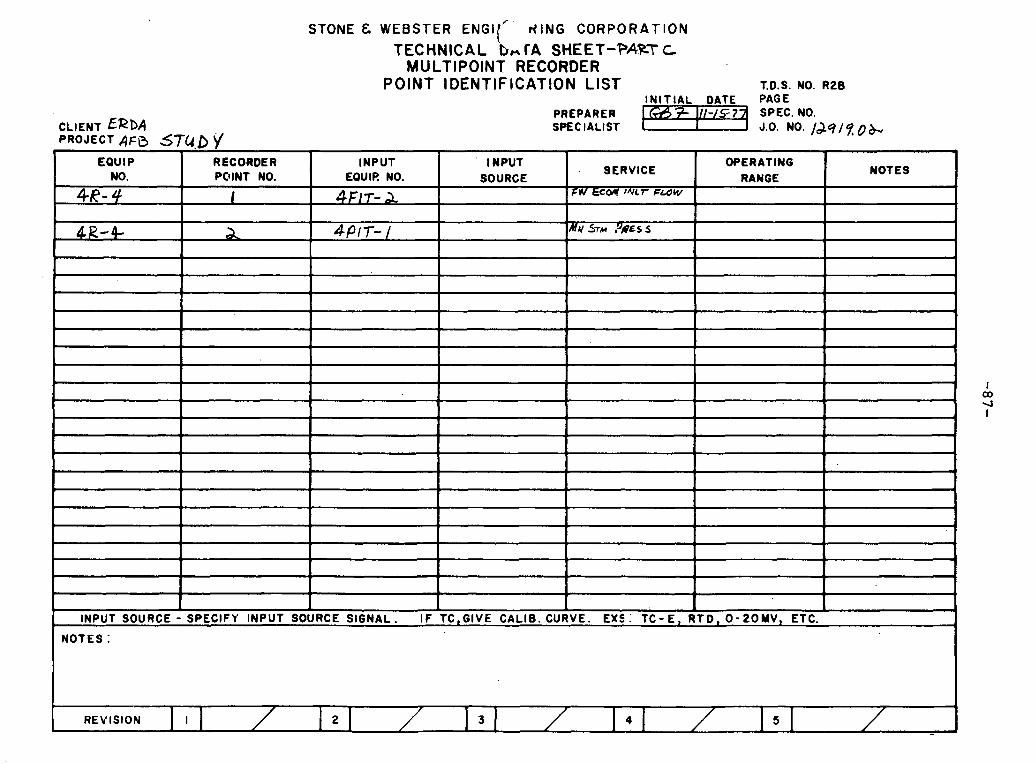
STONE L WEBSTER E N G I / . ~ ' ~ ( I N G CORPORATION
TECHNICAL bn fA SHEET-PART C MULTIPOINT RECORDER
POINT IDENTIFICATION LIST T.D.S. NO. R ~ B
REVISION 2 3 5
INITIAL DATE PAGE PREPARER
CLIENT ERbA SPECIALIST J.0. NO- /d.9/9,0 & PROJECT AFB 57CI.D \/
2
EQUIP RECORDER INPUT l NPUT SERVICE
WERAT lNG NO. POINT NO. EQUIP. NO. SOURCE RANGE NOTES
4R- 4 I ~ F / T - A FW ECW 1w.r F L ~ W
A aPlT- / Mu STM P R ~ S s
I 00 4 I
I I I I
I
INPUT SOURCE - SPECIFY INPUT SOURCE SIGNAL. I F TC,GIVE CALIB. .CURVE. EX$ : TC- E l RTD, 0 - 2 0 M V l ETC. t
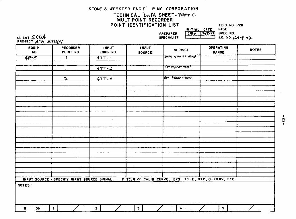
STONE & W E S S T E R E N G I ~ ' . R I N G C O R P O R A T I O N
TECHNICAL 'b- TA SHEET- W R ~ c MULTIPOINT RECORDER
POINT IDENTIFICATION LIST T.D.S. NO. R28 INITIAL DATE PAGE
PREPARER SPECIALIST . - -
PROJECT AFB STLID\/
NOTES : INPUT SOURCE -
SERVICE
S # P U m OUTLT 7E& P
OPERATING RANGE
2-
SPECIFY INPUT
7
NOTES
k EQUIP
NO.
4a-s I
INPUT EQUIC! NO.
~ T T - I
RECORDER POINT NO.
I
~ T T - 4
SOURCE SIGNAL. I F
l NPUT SOURCE
!
TC,GIVE CALIB..CURVE. RT D , 0 - 2 0 M V , ETC. EXS: TC- E ,
I CO OD I
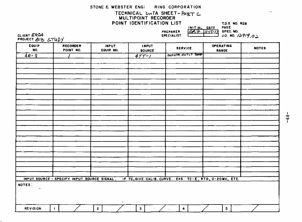
STONE & WEBSTER ENGl R I N G C O R P O R A T I O N
I NOTES :
TECHNICAL t h T A SHEET- P4p-t- t MULTIPOINT RECORDER
POINT IDENTIFICATION LIST T.D.S. NO. R ~ B INITIAL DATE PAGE
PREPARER CLIENT SPECIALIST
REVISION I 4
PROJECT ~ F B r
EQUIP NO.
4a- s
INPUT SOURCE -
STIc.D)( RECORDER POINT MO.
I
SPECIFY INPUT
OPERATING RANGE
RTD, 0 - 2 0 M V , ETC.
INPUT EQUIP. NO.
SOURCE SIGNAL. I F
NOTES l NPUT
SOURC'E
4rr-/
I
SERVICE
S ~ P ~ O U T L ~
I
TC,GIVE CALliB. .CURVE. EXS: TC- E ,
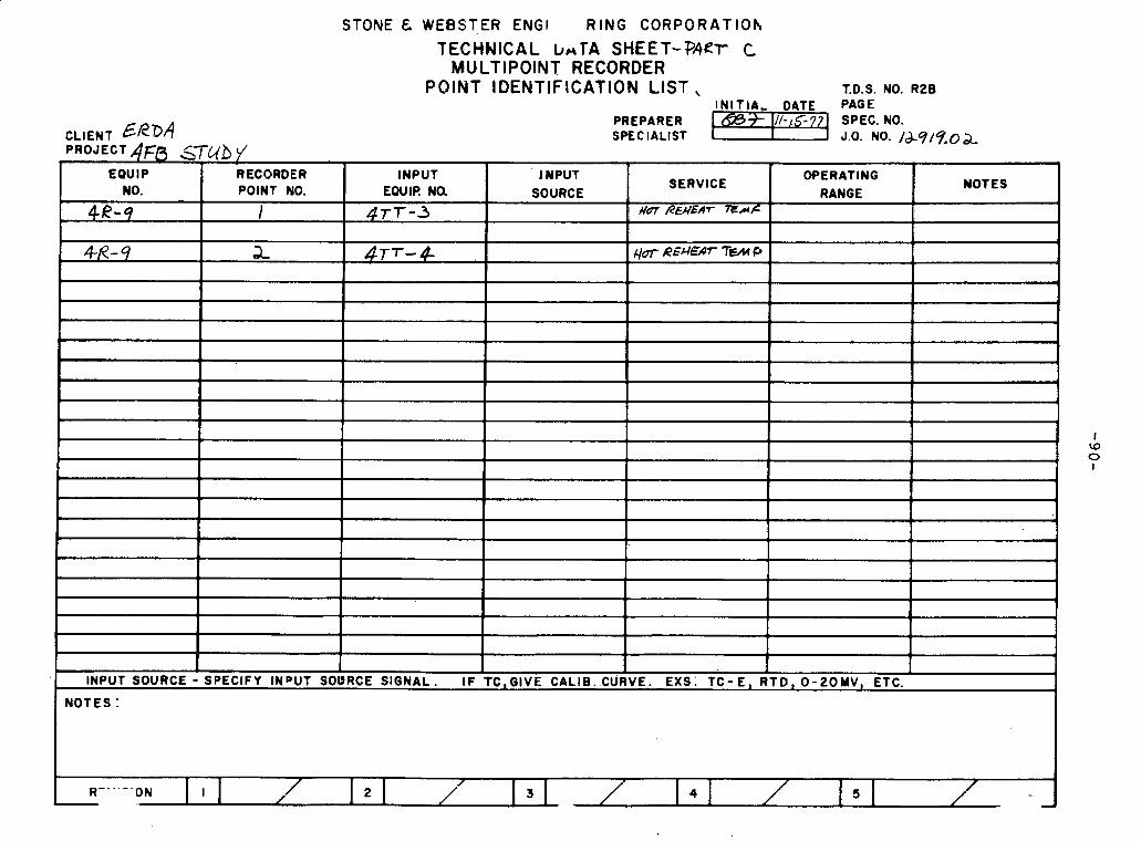
STONE & WEBSTER ENGl R I N G C O R P O R A T l O h
TECHNICAL LnTA SHEET-PART C MULTIPOINT RECORDER
POINT IDENTIFICATION LIST. T.D.S. NO. R28
NOTES :
INITIA, D9TE PAGE PREPARER
CLIENT ERDd SPEC IALlST J 0. NO. /&9/%0&
EQUIP NO.
4R-9
, 4R-9
RECORDER POINT NO.
1
a
I w 0 I
INPUT EQUIP. N0.
~ T T - 3
4~7- 4
I . #
I
1
1
INPUT SOURCE - SPECIFY INDUT SOURCE SIGNAL. I F TC, GIVE CALIB. CURVE. EXS. TC- E , RTD, 0 - 20MV, ETC. *
NOTES
I
OPERATING RANGE
l NPUT SOURCE
SERVICE
f f 6 ~ REHEAT ~ A K
qrn R S M ~ ~ TEM F,
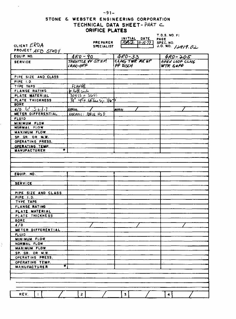
- 9 1 - S T O N E C W E B S T E R E N G I N E E R I N G C O R P O R A T I O N
TECHNICAL DATA SHEET- PART c ORIFICE PLATES
T. D.S. NO. F I IN IT IAL DATE PAGE
PREPARER
BORE I I I d / D / / / 1
, PIPE SIZE AND C L A S S
, PIPE I . D. TYPE TAPS
, FLANGE RATING , PLATE MATERIAL
PLATE THICKNESS
1 METER D IFFERENTIAL I I I 1
1 A
-
, FLUID MINIMUM FLOW NORMAL FLOW MAXIMUM FLOW SP. GR. OR M.W. OPERATING PRESS. OPERATING TEMP.
, Mb.NUFACTURER *
I
1
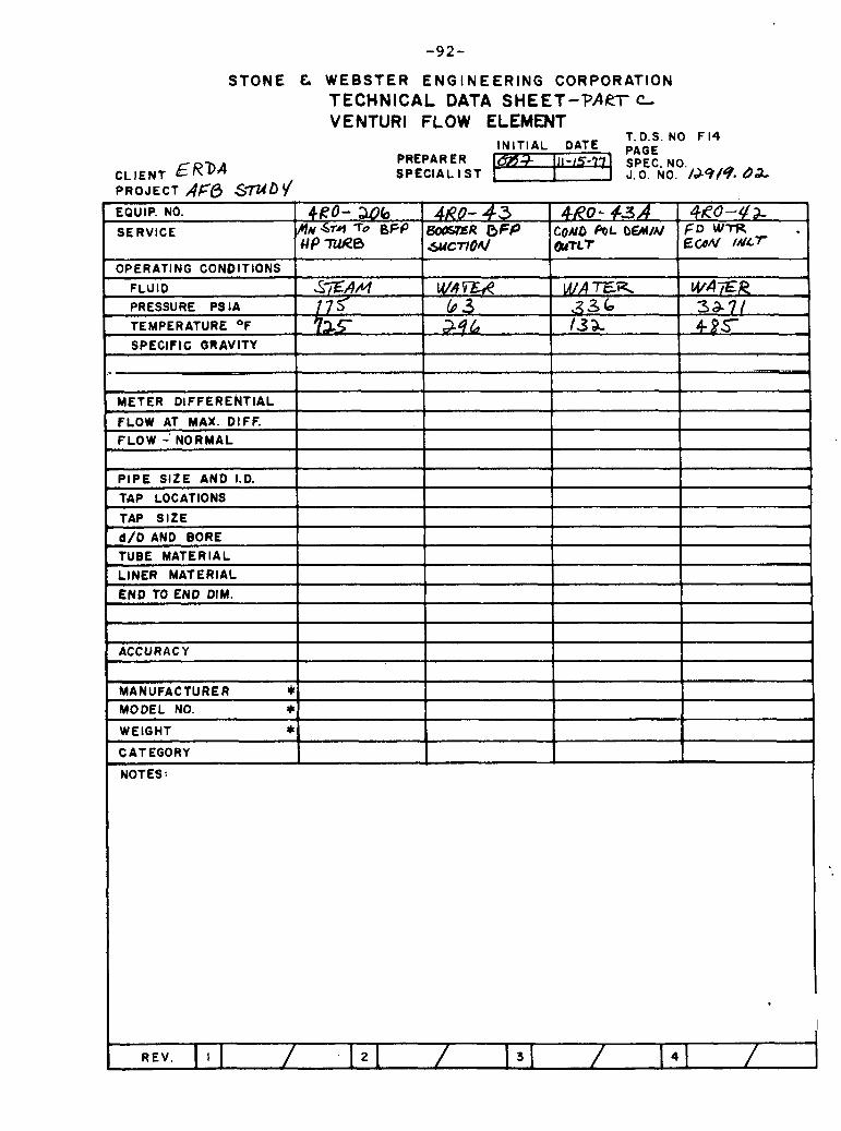
S T O N E C W E B S T E R E N G I N E E R I N G C O R P O R A T I O N TECHNICAL DATA SHEET-PART c VENTURI FLOW ELEMENT
T. D.S. NO F 14 INITIAL DATE PAGE
PREPAR ER 3 Ill - . 17 97 CLIENT ER'DA
SPEC. NO. SPECIAL l ST 1 J.O. NO. /M/9. 02
PROJECT AFO S W D ~
' MANUFACTURER * MODEL NO. * WEIGHT * CATEGORY
.
NOTES :

STONE C WEBSTER E N G I N E E R I N G CORPORATION TECHNICAL DATA SHEET-PAeT C VENTURI FLOW ELEMENT
CLIENT ERDA PROJECT AfB S7do )(
T.D.S. NO F 1 4 I N I T I A L DATE PAGE
PREPAR ER SPECIAL l S T
. v
OPERATING CONDITIONS
FLUID
PRESSURE P s lA
TEMPERATURE OF
SPECIFIC GRAVITY
I I I --
FLOW - NORMAL --
4RO- 47 BFP DISCY TO a p m ~ P ~ E A
EQUIP. NO.
SERVICE
W A X R 34ar
METER DIFFERENTIAL
FLOW AT MAX. DIFF.
P I P E S IZE AND 1.0.
TAP LOCATIONS
TAP S IZE .mw,.-..-.- ---- - .--A -..-
d /D AND BORE
~ R o - 4s 6FP DI6CY 70 REMERr ~ 5 u ~ W n e 3
WAX. A .\ 4 ~ 1
30 r
I
-3 o I
1
END TO END DIM. I I I I
-. - - - -
TUBE MATERIAL
LINER MATERIAL
1 I I 1 ACCURACY I I I
I
I
MANUFACTURER * MODEL NO. * WEIGHT * CATEGORY
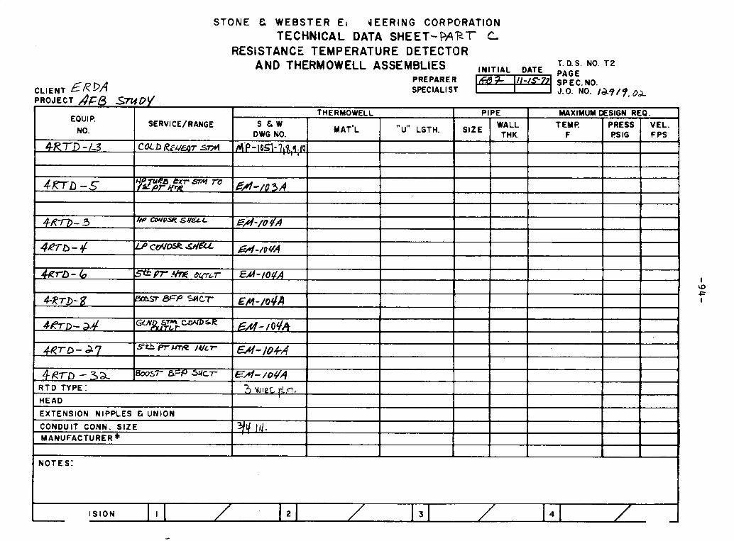
STONE C W E B S T E R E i JEERING CORPORATION TECHNICAL DATA SHEET- P A R T C
RESISTANCE TEMPERATURE DETECTOR AND THERMOWELL ASSEMBLIES T. D.S. NO. ~2 INITIAL DATE PAGE
PREPARE R CLIENT ERDA SPECIAL1 ST PROJECT AFB S ~ D S ,
THERMOWELL PIPE EQUIP.
MAXIMUM DESIGN REQ. SERVICE/ RANGE S & W
MAT'L "u" LGTH. WALL TEMP. NO.
PRESS VEL. DWG NO. 'IzE THK. F FSlG FPS
4 R T D -13 COLD Rfu-T sml A-P-IO~I-?&~~IQ I
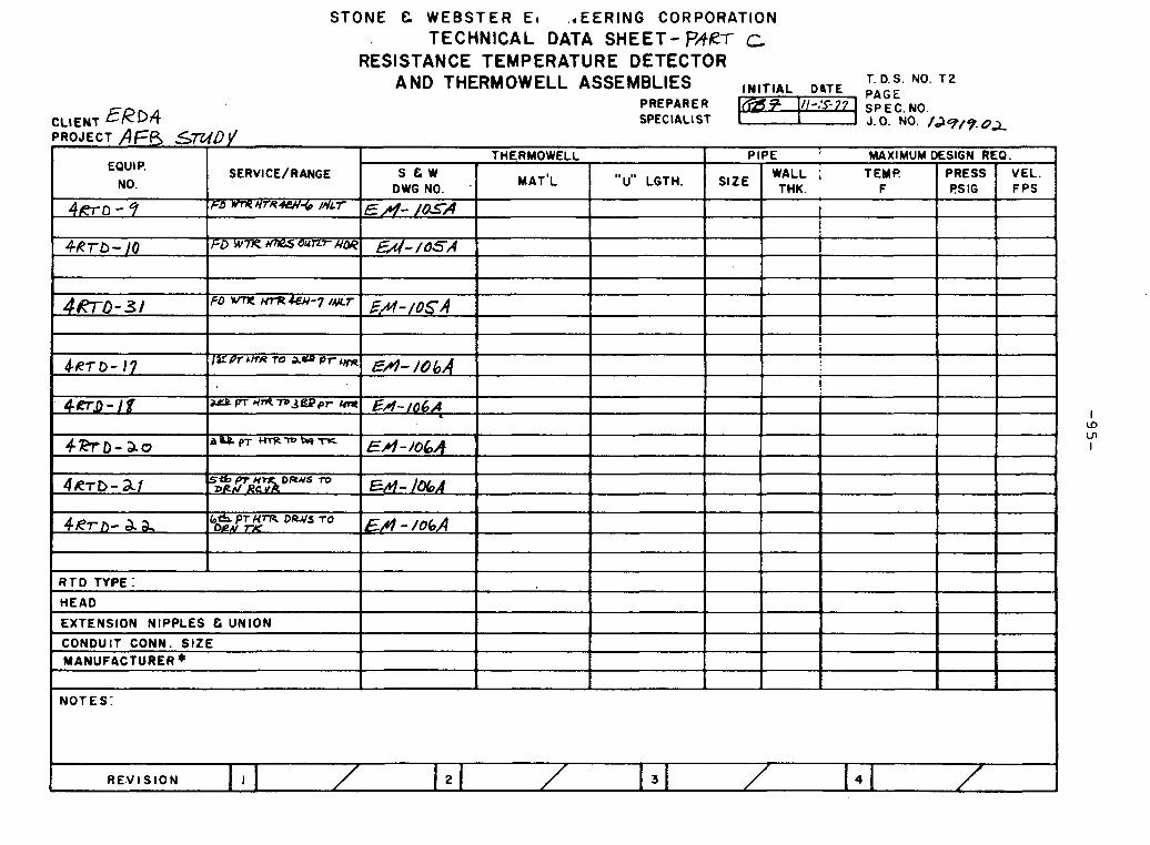
S T O N E & W E B S T E R Et . d E E R I N G CORPORATION TECHNICAL DATA SHEET- PART C
RESISTANCE TEMPERATURE DETECTOR AND THERMOWELL ASSEMBLIES INITIAL D . ~ T E T. D.S. NO. ~2
PAGE
SPECIAL1 ST
SERVICE/RANGE
NOTES:

STONE & WEBSTER E l JEERING CORPO3ATION TECHNICAL DATA SHEET-PA,K C
RESISTANCE TEMPERATURE DETECTOR
CLIENT El? DP PROJECT A F B S r M D f
AND THERMOWELL ASSEMBLIES I I AND THERMOWELL ASSEMBLIES INITIAL DATE T. D . S . NO. T2 PAGE
SPEClALl ST PREPARER r @ ~ !,,-,5-7? SP E C. NO. SPEClALl ST
N O T E S :
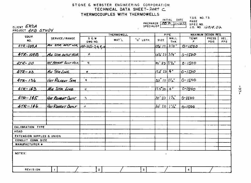
S T O N E & W E B S T E R ENGINEERING CORPORATION TECHNICAL DATA SHEET- PAR? c
THERMOCOUPLES WITH THERMOWELLS T.D.S. NO. T 3
INITIAL DATE P A G E
J . 0 . NO. /o;lq/q, OA
I \D 4 I
N O T E S :
I R E V I S I O N I 2 3 ...-
4 1

NOTES:
L
S T ONE & WEBSTER ENGINEERING CORPClRATION TECHNICAL DATA SHEET - w,er c
THERMOCOUPLES WITH THERMOWELLS ' T.D.S. N O . T 3
IN TlAL DATE P A G E PREPARER af 1//-/577
CLIENT Ef'?bA I SPEC. NO.
SPECIAL1 ST J .0 . NO. Jd9/7, QA
PROJECT AF6 STUD
SERbICE / RANGE
' I S ION I 3 4
CALIBRATION TYPE
HEAD
EXTENSION NIPPLES & UNIGN
CONDUIT CONN. SIZE MANUFACTURER *
I I
I !
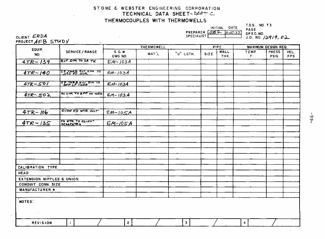
S T O v V E & W E B S T E R ENGINEERING C O R P O R A T I O N TECHNICAL. DATA SHEET-DPR7 C-
THERMOCOUPLES WITH THERMOWELLS T.D.S. N O . T 3
N I A L DATE PAGE PREPARER Ci;9% 111-/~-77 SPECIALIST I SPEC. NO.
CLIENT ERDA J.0. NO. /&9/qe Od, PROJECTAFB STU'O I/
I w w
I
NOTES:
R E V I S I O N I / 2 / / 4 /
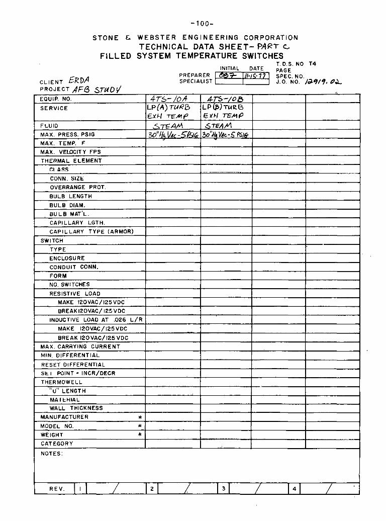
NOTES
S T O N E & W E B S T E R E N G I N E E R I N G CORPORATION TECHNICAL DATA SHEET- PART c
FILLED SYSTEM TEMPERATURE SWITCHES T. D.S. NO T 4
INITIAL DATE PAGE PREPARER m+ ] / / I S . - 7 7
CL IENT SPECIALIST 1 SPEC. NO. J.O. NO. /d9/9, O&
PROJECT A F 6 STUD^ EQUIP. NO.
SERVICE
FLUID
MAX. PRESS. PSlG
MAX. TEMP. F
MAX. VELOCITY FPS
TIIERMAL ELEMENT
Cl ASS
CONN. SIZE
OVERRANGE PROT.
BULB LENGTH
BULB DIAM.
, BULB MAT'L.
CAPILLARY LGTH.
CAPILLARY TYPE (ARMOR)
SWITCH
TYPE
ENCLOSURE
CONDUIT CONN.
FORM
NO. SWITCHES
RESISTIVE LOAD
MAKE I2OVAC / 125 VDC
BREAK I20VAC/ 125VDC
INDUCTIVE LOAD AT .026 L / R
MAKE 120VAC/125VDC
BREAK 120VAC/125 VDC
MAX. CARRYING CURRENT
4rs- /oA LP(A)TuRO Efcl rtzhp
S m A f l w"& VAC -5&&
~.
4T5-/00 LP@)TURD E Yrl TEMP 67wb"l
%'N. VVAC-$ PSI6
-. .- - -... - .,.-,,,,,,*,

CLIENT ER '4 PROJECT A F B 5 7
EQUIP. I&
1 MOTES:
STONE & W E B S T E R E N E E R I N G CORPORATION TECHNICAL, uATA SHEET- PA&'?- <C
THERMOWELLS T. D.S. NO. T I
INITIAL DATE PAGE PREPARER SPECIAUST
PIPE SERVICE OR
DESIGN REQUIREMENTS s t w LENGTH"^" 1 LOCATION DWG. NO. (F REQ'O.) SIZE
WALL TEMP. PRESS VEL. TWK. OF PSlG FPS
~ X X D REHF#r .ST/: i Elur-t02A -
REVISION . .

STONE & W E B S T E R E N E E R I N G CORPORATION
TECHNICAL DATA SHEET- P4R7 C THERMOWELLS
T. D.S. NO. T I INIITIAL DATE. PAGE
PREPARER SPECIALIST J.0. NO. /&q/q. O&
. -
EQUIP. NO.
.4w- 4
I -. 0 h, I
+ DESIGN REQUIREMENTS
TEMP. OF
S'ERVICE OR LOCATION
rP TURB ~ $ 7 STM r 6 zyn pr ~ ' T R
s e w DWG. NO.
E/ul-10.3 A.
PRESS PSlG
LENGTH"^" (F REQ'D.)
VEL. FCS
, MATERIAL
I
PIPE
SIZE WALL
THK.

NOTES :
REVISION I
S T O N E & W E B S T E R E V E E R I N G C I ~ R P O R A T I O N
TECHNICAL ,DATA SHEET- PARr L,
THERMOWELLS T. D.S. NO. T I
INITIAL DATE PAGE PREPARER
CLIENT ERDA I ~33- 111-/S- 77 S P€Cl.tLI ST
PROJECT A Fb S ~ U 0 S/ EQUIP.
NO.
, 4W-.8
~ T W - 7
I 2
. O W I
I 1 1 1 1 I 1 I 1 MANUFACTURER:
SERVICE OR LOCATION
b e m m C O A I D E J M L r
5il pr m c m s d w&r
S E W DWG. NO.
0 4 ~
EM-/O 4 4
. .
LENGTH"^" (F REQ'D.)
PIPE *
SIZE
DESIGN REQUIREMENTS WALL
THK. TEMP. OF
PRESS PSlG
VEL. FCS
.

CLIENT ERDA PROJECT AGB SWDV I
EQUIP. SERVICE OR NO. :LOCATION
S T O N E & W E B S T E R E Y E E R l N G CORPORATION
TECHNICAL uATA SHEET - C A P r c- THERMOWELLS
T. D.S. NO. T I INITIAL DATE PAGE
PREPARES SPEC. NO. SPECIALIST J. 0. NO. /dV/q. OJ
PIPE DESIGN REQUIREMENTS S E W LENGTH"^" MATERIAL
.
DWG. NO. (F REQ'D.) S IZE WALL TEMP. PRESS VEL.
T H K . O F PSlG FPS
EA -/=A I
I I 1 I 1 I 1
EM- I O S A I I I I I I I 1

S T O N E &. WEBSTER ENGINEERING C0F:PORATION TECHNICAL DATA SHEET- ~ A F ' T c
THERMOCOUPLES WITH THERMOWELLS
CLIENT E R D A
T.flS. N O . T 3 INITIAL DATE P A G E
PREPARER SPECIALIST
SP E C. NO. J.0. NO. /&5/9. 0 2
REVlS ION
47oCI -J6 rn - l06d
; 4rw- a 7 ~
I 4 ~ - a 7 o
4 w - 7 / A
4Tui/-'?/B
CALIBRATION TYPE
HEAD
EXTENSION NIPPLES E UNION
' CONDUIT CONN. SIZE
MANUFACTURER *
NOTES:
7 m m m I 4 - P W C OW EM- t06A
b*Prb WwCLADrws mVJ?
SEG.uH~nRDRuuR
EM-,obA
E M - I o ~ A
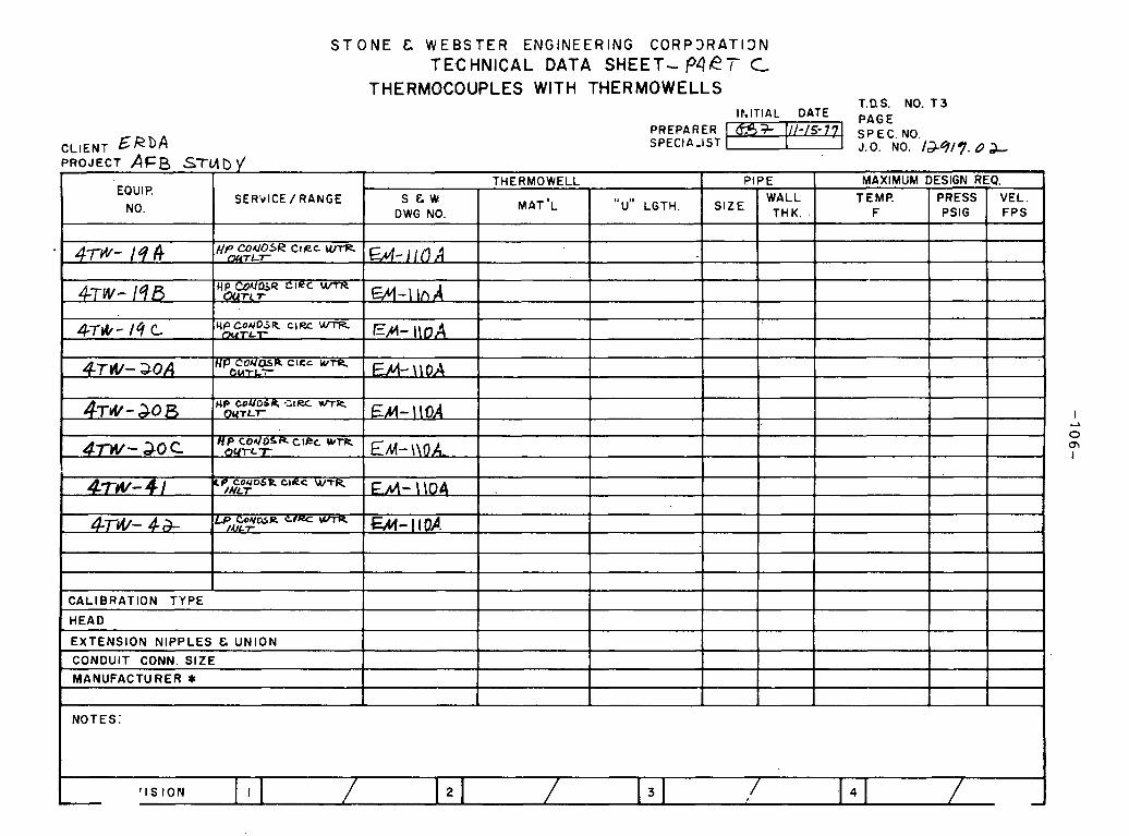
S T O N E & WEBSTER ENGINEERING CORP3RAT13N TECHNICAL DATA SHEET- P4RT C
THERMOCOUPLES WITH THERMOWELLS T.D.S. NO. T 3
I h l T l A L DATE PAGE
SER'r lCE / R A N G E
I I I 1 i I I I N O T E S :
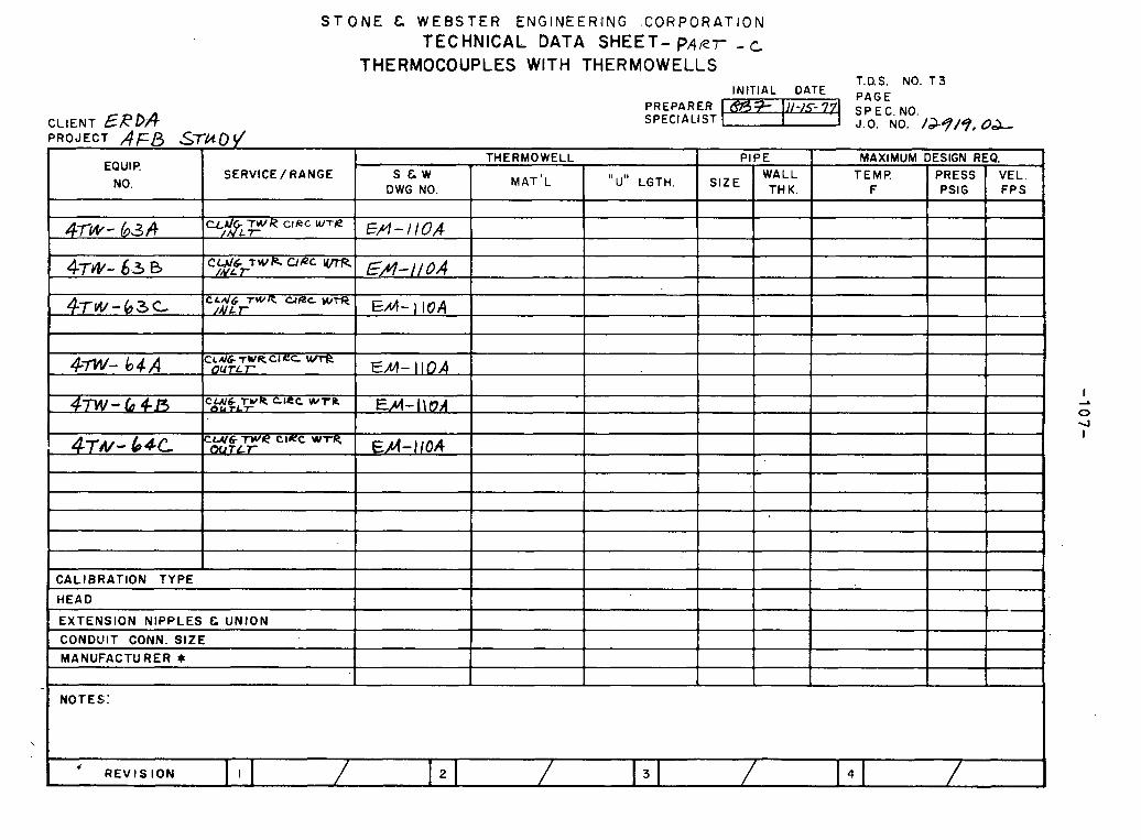
S T ONE & W E B S T E R ENGlNEER'lNG .CORPORATION T E C HNlCAL DATA SHEET- P A R T - c
THERMOCOUPLES WITH THERMOWELLS T.D.S. N O . T 3
INITIAL DATE P A G E
J.0. NO. /aq/q, O L
SERVICE / RANGE
I * R E V l S I O N I 2 3 4

STONE & WEBSTER ENGINEERING CORPORATION TECHNICAL DATA SHEET-PART C
CONTROL VALVE
C L I E N T E R D q ? ~ O J E C T AFO ~ r ~ 3 t /
T . D. S. NO. V I I N I T I A L DATE PAGE
PREPARER S P E C I A L I S T J.0. NO. /J?/$?OL
EQUIP. NO 4-u~- 104 I NO. REQ'D 7 I FSK-EY-~O+A SERVICE COAJDENSPPE. / V t A i ( f - ~ f l I- ASME CODE CLASS
I s & W CATEGORY I SHUT-OFF P S l A 1 0 0
4
LINE SIZE/SCHED
S I Z I N G DATA
INLET PSIA
-. . - 0l.lTL.ET PS lA
SP. GR. OR (MW) -.- FLUW HA'I'E
T E M P OF ---- C, REOUIRED
J
LOCAT I ON: AT COAIDEAI~ER DESIGN:PRESS. 6 1 4 TEMP. ?S *F
R E V
X / B o M I N I M U M NORMAL --
15 3,s " ; / q ,795 - h s (54'4 Cis
/7# 8
M A X I M U M
~ .-
Cv ACTUAL
FLUID S & W SEAT L E A K C L A S S
BODY-FORM
-SIZE (IN.)
-ANSI RATING/CONN
M A T E R I A L (ASTMI-BODY
-BONNET
TRIM-CHARACTERISTIC
-NO. PORTS
-PORT S I Z E ( I N )
-MATERIAL-PLUG
-3EQT
wu~utl + BONNET
PACKING
BACK SEAT
LEAK-OFF CONN.
ACTION-AIR TO
FLOW-TENDS TO
ACTUATOR-TYPE b
-SIZE
-STROKE IN. % AIR TO ACTUATOR
CALC NOISE (dBA) $ VELOCITY (FPS) -W MANUFACTURER
MODEL NO.
NOTESI 1 , + /NDIc&SES
W A W R CLASS L
/
C S c-2 * - o 1 / ~ FULL. f%dT
FLANGED/BL
F- FLoN v-Rid6 No NO
CL OLE O P E d
IIIFO&/AnoM X ) 8~
P L A N T L I N E NO.
ACCESSORIES
AIR SET (W/GAGE)
LUBRICATOR (W/ISOL.VALVE)
HANDWHEEL
POSlT lONER
MFG/MODEL W INPUT/OUTPUT
TRANSDUCER
Y f S - J . It/D YES 1/ES
/ 3-15 1%
MFG/MODEL / INPUT/OUTPUT ~-&OMA / 3 - ic CUNNS- ~ L E C / P N ~ U , j&,'{u P r y4"
SOLENOID VALVE TYPE 3-WAV MFG./MODEL
ENERGIZE TO
SOL COIL ENCL. .- ELECT. C O N N S .
BODY CONNS.
L I M I T SWITCH
M F G / M O b E L * O p t N PUS1 TIOh CLOSE POSITION
ENCLOSURE
CONOUIT SIZE
S E I S M I C DATA REQUIRED
WEIGHT ( N E T )
a= I /PLI / . - R/WA 4-
I / " 11 AIp
YE 6
2 SPDT
2 SPDT
N E M A
y'pl A/O
SU#L/&D W G

STONE 8 WEBSTER ENGINEERING CORPORATION TECHNICAL DATA SHEET-?APT c
CONTROL VALVE
CLIENT EfiDA ?ROJECT A66
PREPAl SPEC lP
EQUIP. NO #LC [/-I00 SERVICE @~IJEA/SATE W 6 R G M4fE-dP
SHUT-OFF PSlA
LGE SIZE/SCHED I SIZING DATA M I N I M U M
I I N L E T PSlA I OUTLET PSlA ---. . SP. GR. OR (MW) -.-. FLOW RATE
TEMP OF -- Cv REQUIRED
CY ACTUAL I .,,,... ...,. . . . -. -
FLUID I ( o d e s E W SEAT LEAK CLASS I CLASS L
PACKING l€FJ..od \ /-ad& BACK SEAT No
- -
BODY-FORM % -SIZE (IN.)
-ANSI RATING/CONN 3t: MATERIAL (ASTMI-BODY
-BONNET
TRIM- CHARACTERISTIC
-NO. PORTS
LEAK-OFF CONN.
FLOW-TENDS TO
/
C S c-5
?n 0dK
-STROKE IN. % AIR TO ACTUATOR
CALC. NOISE (dBA)
-PORT SIZE ( IN) FQL C! f@kT -MATERIAL-PLUG $
-SEAT
GUIDE % BONNET FLANGED/rnP.MIL
VELOCITY (FPS)
MANUFACTURER kl MODEL NO. k i
T.D.S. NO. VI IN IT IAL DATE PAGE
SPEC. NO. L I S T J.0. NO. /&q/% b&
NO. REO'D 1 I FSK-EM- /04/ ASME CODE CLASS
S E W CATEGORY
LOCATION: C O ~ D E A / ! R L
DESIGN: PRESS. TEMP. NORMAL I M A X I M U M I
PLANT LINE NO. I I
TRANSDUCER
MFG/MODEL
INPUT/OUTPUT
CONNS-ELEC/PNEU.
SOLENOID VALVE TYPE 3 -WAC/
ACCESSORIES
AIR SET (W/GAGE)
LUBRICATOR (W/ISOL. VALVE)
- HANDWHEEL
POSITIONER
MFG/MODEL % INPUT/OUTPUT
MFG./MODEL I ENERGIZE TO IO/&A/ / VA L VL
YES - & /t/O
yc;' 5 YE S
/ 3-/5 / %
I -. - SOL. COIL ENCL. #E&A 4
ELECT. CONNS. Ptetm z" BODY CONNS. r/q " /ypT
LIMIT SWITCH YES i
CONDUIT SIZE p " 1 I
S E I S M I C DATA REQUIRED 1 MO I -
WEIGHT (NET) * I 1
R E V 4 . .- -

STONE & WEBSTER ENGINEERING CORPORATION
TECHNICAL DATA S H E E T - P A P 7 C CONTROL VALVE
CLIENT ERbA WOJECT AFB S W D ~
T.D.S. NO. V I IN IT IAL DATE PAGE
PREPARER 1 / 1 7 SPEC. NO S P E C I A L l S T I J.O. NO. / $ f / Y , dd-
. . I EQUIP. NO 4 ~ c l / - 3- I , 4 ~ c g - 3 -& I NO. REO'D & I FSK- € f l - / o 4 A
SERVICE D€A&R&-i-0& L E U E L c~NROL ,ASME CODE CLASS S & W CATEGORY I
SHUT-OFF PSIA 5 4 q
R E V
L I N E SIZE/SCHED
S I Z I N G DATA
I N L E T P S l A
O U T L E T PSIA 7-
SP. GR. OR (MW) -- - FLOW RATE
L O C A T I O N /7- DEAEPATO~ DESIGN PRESS 5-48 PSI/ T E M P A 6 3 6d=
4
/ STlc M I N I M U M NORMAL -- -
-" - - 7 --.--- -
-
M A X I M U M
344 h 3 y 3 d
"- .?.? qq&p/vt -_ >6 3
-
I EMP V F -- -- Cv REQUIRED
-
Cv ACTUAL - FLU1 D MfA?E - 6 S & W S E A T L E A K C L A S S &Ass 2- BODY-FORM
P L A N T L l N E NO.
ACCESSORIES
AIR SET (W/GAGE)
LUBRICATOR (W/ISOL VALVE)
HANDWHEEL
POSITIONER
- MFG/MODEL ?& INPUT/OUTPUT
TRANSDUCER
MFG/MODEL
INPUT/OUTPUT . CONNS-ELEC/PNEU ---
SOLENOID VALVE TYPE
MFG /MOOEL
ENERGIZE TO
- SOL COIL ENCL
ELECT. LUNNt;
BODY CONNS.
L I M I T SWITCH
MFG/MODEL
.- OPEN POSITION
CLOSE POSITION
ENCLOSURE
CONDUIT SIZE
S E I S M l C DATA REQUIRED
WEIGHT ( N E T )
-S IZE ( I N )
-ANSI RATING/CONN
M A T E R I A L (ASTMI-BODY
-BONNET
TRIMLCHARACTERISTIC
-NO PORTS
-DORT SIZE (IN)
-MATERIAL- PLUG
-SEAT
GUIDE
BONN^ r PACKING
BACK SEAT
L E A K - O F F CONN.
ACT lnN-A IR TO
"FLOW-TENDS TO
- ACTUATOR-TYPE 96 -SIZE Y-
- -STROKE IN.
AIR TO A C T U A ~ O R 3u CALC N O I S E (dBA) % VELOCITY (FPS) % MANUFACTURER sf= MODEL NO
YES- & NO Y2z 6 vE 6
/ 3-/s /;rw . r& s
/ 4-aom/.3-j . t &"N'PT 1 y& #PT,
3- WAY
@EM 1 WE E 6"
y+",vpr \/Es
2 RPDT
2 SPOT
N E M A 4 I 11
- n/o
/ Cs Cs - - l%JE -
F U L L POP I
FLANGED/-L
?ZEFLOA/ v- RIYG f l o /ti0 ~ f ' l d OPE^
By M f G I,% DDIC~ES IUBPMATIO~/ 70 8 E ~ Y P P L I ~ D
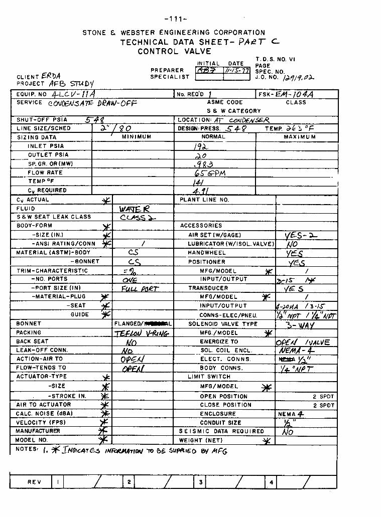
STONE & WEBSTER ENGINEERING CORPORATION TECHNICAL DATA SHEET- ?PET- C-
CONTROL VALVE
CLIENT ERbA ?9OJECT AFO m D I /
T . D. S. NO. VI IN IT IAL DATE PAGE
PREPARER SPEC. NO. S P E C I A L I S T J.0. NO. /Jq)q,Ud,
I,
-SIZE (IN.)
-ANSI RATING/CONN j/C MATERIAL (ASTM)-BODY
-BONNET
TRIM-CHARACTERISTIC -NO. PORTS
-PORT SIZE (IN)
-MATERIAL- PLUG W -SEAT
GUIDE
BONNET
PACKING
BACK SEAT
LEAK-OFF CONN.
ACTION-AIR TO
FLOW-TENDS TO
ACTUATOR-TYPE * -SIZE
-STROKE IN.
'AIR TO ACTUATOR
CALC. NOISE (dBA)
- VELOCITY (FPS) MANUFACTURER I I
MODEL NO.
NOTESt I , % Jr"lutc47~ ~Nf?w%wmJ n, (36 5uWlG0 W MFG
/ (3 c.\ - - -
oc/E FUU ~ a e r
FLANGED/ I I I I I I IRL
'TZC&d \/&& Ah
N O o @ Z ~
AIR SET (W/GAGE)
LUBRICATOR (W/ISOL.VALVE)
HANDWHEEL
POSlTlONER
MFG/MODEL ))r INPUT/OUTPUT
, TRANSDUCER
MFO/MODEL
INPUT/OUTPUT
CONNS-ELEC/PNEU.
SOLENOID VALVE TYPE
MFG./MODEL
ENERGIZE TO
- - SOL. COIL ENCL.
ELECT. CON N S.
BODY CONNS.
L IMIT SWITCH
MFG/MODEL
OPEN POSITION CLOSE POSITION
ENCLOSURE
CONDUIT SIZE S E I S M I C DATA REQUIRED
WEIGHT (NET)
vgs- 2- ;c/o yes V€&
/
3-1s kF \ / E S
/ 4-Ndd / 3 - ) 5
&"wPr / I/4."A/PT - y
@€A/ /\IAL\IE R/EMA - 4
y"" I/e *M ;r
2 SPOT
2 SPOT
NEMA 9
A/O
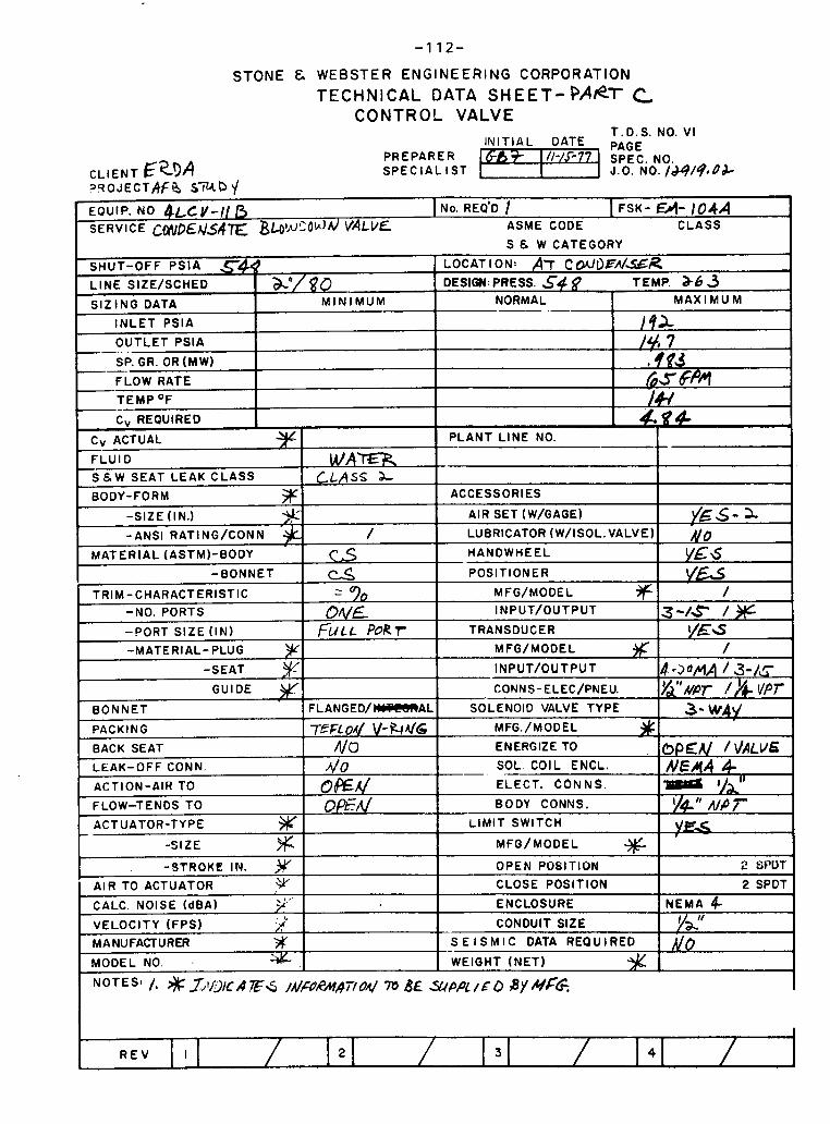
STONE 8 WEBSTER E N G I N E E R I N G CORPORATION TECHNICAL DATA SHEET- P A ~ T C
CONTROL VALVE T.D.S. NO. V I
IN IT IAL DATE PAGE PREPARER 6% 3- I '/-/5- 77
CLIENT S P E C I A L I S T J.O. NO. /a)9/9,0& ? F ~ O J E C T A ~ R sciLCP \/ EQUIP. NO 4~cv-11 I NO. REQ'D I FSK- a- IO4A SERVICE C ~ Y V D & A / ~ ~ E B ~ W S O ~ d VALVE ASME CODE CLASS
S E W CATEGORY
R E V 2 3 4 -
,
SHUT-OFF PSIA 548 L INE SIZE/SCHED
S IZ ING DATA
INLET PSIA
OUTLET PSlA .
SP. GR. OR (MW) --. FLOW RATE
TEMP OF --
3
LOCAT I ON: Ar c mfl>~A/sR DESIGN: PRESS. 5 4 9 TEMP. a63 ah/ $? o
M I N I M U M NORMAL --- .-
FLOW-TENDS TO
ACTUATOR-TYPE % -SIZE % =STROKE IN. ,v
AIR TO ACTUATOR ,y' CALC. NOISE (dBA) , 3.''
VELOCITY (FPS) :.; MANUFACTURER % MODEL NO. .
M A X I M U M
1 9 2 /$/, 7
I
6 5 6p4 -
/& 4. B 4
BODY CONNS.
L IMIT SWITCH
MFO/ MODEL % OPEN POSITION
CLOSE POSITION
ENCLOSURE
CONDUIT SIZE
S E I S M I C DATA REQUIRED
WEIGHT (NET)
*PA / E o BY #&
oe-n/ v#" /I/@ 7 'IF..
2 6PUT
2 SPDT - NEMA 4-
yL'f do
/, $3;~21c R .ES IA/..PRMR~ OA/ 76 BE
C, REQUIRED
CV ACTUAL
FLUID W A n S & W SEAT LEAK CLASS CLASS 2- BODY-FORM 5F
-SIZE (IN.) 3;t'
PLANT L INE NO.
ACCESSORIES
AIR SET (W/GAGE)
LUBRICATOR (W/ISOL. VALVE)
HANDWHEEL
POSlTlONER
MFG/MODEL +f INPUT/OUTPUT
TRANSDUCER
MFO/MODEL
INPUT/OUTPUT
CON.$-ELEC/PNEU
SOLENOID VALVE TYPE
MFG./MODEL
ENERGIZE TO
-. SOL. COIL ENCL.
ELECT. CONNS.
-ANSI RATING/CONN
MATERIAL (ASTMI-BODY
-BONNET P
TRIM-CHARACTERISTIC -NO. PORTS
-PORT S IZE ( IN)
-MATERIAL- PLUG y -SEAT
GUIDE
BONNET
PACKING
BACK SEAT
LEAK-OFF CONN.
ACTION-AIR TO
G S - 3. No y&6 YE&
/ 3-/* 1%
YES /
4 - 2 0 ~ / 3-/c J/dl,V,, /,$ VPT '
3- \HA\/
oPEU /VALVE NEA((A 4 ~ m ~ a
/
c s - - DUE
FULL PoRr
F L A N G E D / m A L
TEFL04 \I-Fr(dG NO
40 O E M
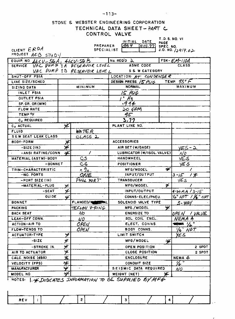
STONE & WEBSTER ENGINEERING CORPORATION TECHNICAL DATA SHEET-?APT C
CONTROL VALVE T.D.S. NO. V I
IN IT IAL DATE PAGE PREPARER f I I / - / c - ~ ?
CLIENT €PDA SPEC. NO.
S P E C I A L I S T J.". NO. /J 919. O& ?!?OJECT M-6 5not/ EQUIP. NO v - = A , 4 &I/-SE, A I NO. REQ'D I FSK- EA-IIOA SERVICE VPC (PIAN P '1 A PESRVOIR LEVf L ASME CODE CLASS
R E V t
VA c pufl P 1 ~ E . % P ~ o I R E d € SHUT-OFF PSlA
L INE SIZE/SCHED
SIZING DATA
I N L E T PSlA
OUTLET PSIA --.. . SP. GR. OR (MW)
FLOW RATE
TEMP OF -- CV REQUIRED
L S 8 W CATEGORY
LOCATION: h~ QND€A/SER DESIGN: PRESS. / ~ P S / G TEMP. B0 f
M I N I M U M NORMAL -- .- /-s &G
e
2.0 @lq 93-
3 . 7 7 ~
M A X I M U M
- ..,,, ,, ,,. ,, , ,, , . , ,
cV ACTUAL
FLUID S & W SEAT LEAK CLASS
BODY-FORM
-SIZE (IN.)
-ANSI RATING/CONN
MATERIAL (ASTM)-BODY
I -BONNET
TRIM-CHARACTERISTIC
-NO. PORTS
-PORT SIZE ( IN)
-MATERIAL- PLUG % -SEAT
GUIDE $ BONNET
PACKING
BACK SEAT
LEAK-OFF CONN.
ACTION-AIR TO
FLOW-TENDS TO
ACTUATOR-TYPE y -SIZE F -STROKE IN.
AIR TO ACTUATOR '3Y CALC. NOISE (dBA)
VELOCITY (FPS) MANUFACTURER
MODEL NO.
NOTES# I , + ~ O I C ~ T E S
PLANT LINE-NO.
ACCESSORIES
AIR SET (W/GAGE)
LUERICATOR (W/ISOL.VALVE)
HANDWHEEL
POSlTlONER
MFG/MODEL 5F I NPUT/OUTPUT
TRANSDUCER
MFG/MODEL F INPUT/OUTPUT
CONNS-ELEC/PNEU.
SOLENOID VALVE TYPE
MFG./MODEL ?cC ENERGIZE TO
. - SOL. COIL ENCL.
ELECT. CON NS.
BODY CONNS.
L IMIT SWITCH
MFG/MODEL
OPEN POSITION CLOSE POSITION
ENCLOSURE
CONDUIT SIZE
S E I S M I C DATA REQUIRED
WEIGHT (NET)
BE SUPPLIED B)T/YFe
Wh7E:R CLASS L
/ CS c$ - - c!/VF, Fk POR'T-
F L A N G E D / m L
~~~ v-RA~G MO A/O C'Ed 0 PEA/
Zr/FbMA~/odm
VES - a 'n/o YES YES
/ 3 - 1 5 /*
\/&s /
4 - w n ~ 13-16 ,
y&" A P T /h" ~ / f l
3- WAY
OPE^ VALLIE NEAA 4
I/ 1'
'/Q " f l P T YES
2 SPDT
2 SPOT
NEMA 4 v NO
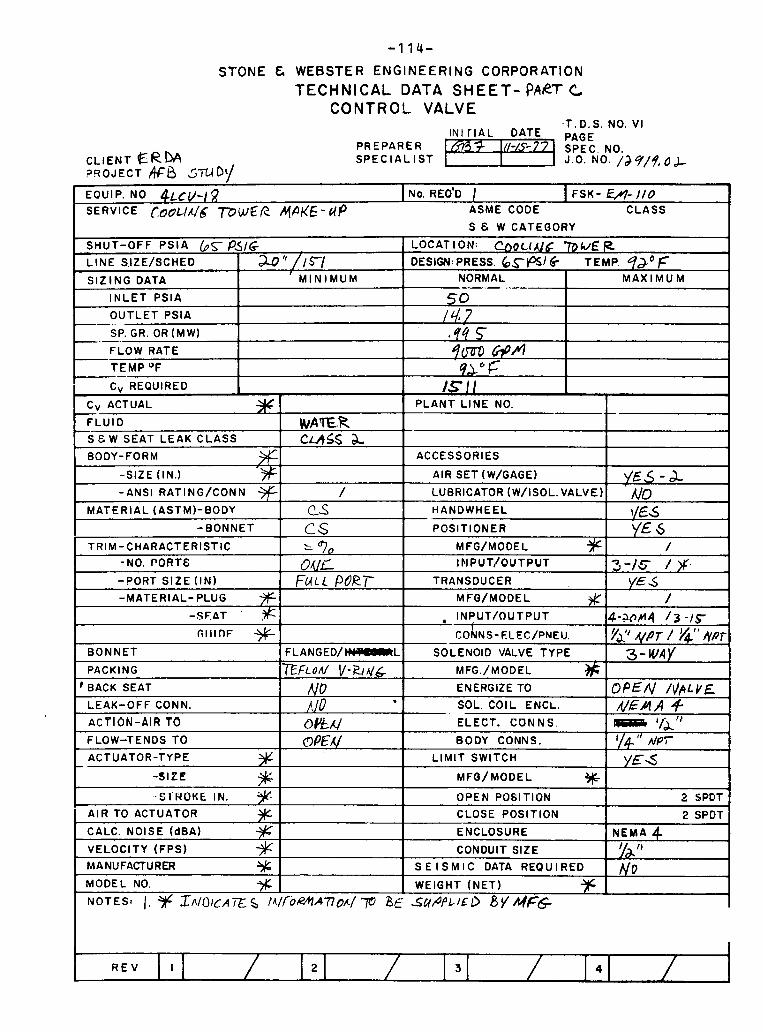
STONE 8 WEBSTER ENGINEERING CORPORATION TECHNICAL DATA SHEET- PART C
CONTROL VALVE
C L I E N T ERM ?!?OJECT && STU~' /
.T . D. S. NO. V I I N I T I A L DATE PAGE
PREPARER S P E C I A L I S T
I
EQUIP. NO ~ L C V - I ~ 1 NO. REO'D / I FSK- W - I / O
SERVICE (10~LlAl6 777 WeR A@/& - dP ASME CODE CLASS I S 8 W CATEGORY I
R E V 4
SHUT-OFF P S l A 65- P ! I G L I N E S,IZE/SCHED
S I Z I N G DATA
I N L E T P S l A
O U T L E T PS lA --..
SP. GR. OR (MW) -.-.. FLOW RATE
TEMP O F - C, REQUIRED
LOCAT I ON: ~ O C ~ I V C mu€ IZ DESIGN: PRESS. 6.$-+516 TEMP. qaO f 2" / I !TI
M I N I M U M
.- .-
NORMAL .-
so
by $ 7m-D @A 9a0 F
lSI/
M A X I M U M
CV ACTUAL
F L U I D
S & W SEAT L E A K C L A S S
BODY-FORM
-SIZE (IN.)
-ANSI RATING/CONN
M A T E R I A L (ASTMI-BODY
-BONNET
TRIM-CHARACTERISTIC
-NO. PORT&
-PORT S I Z E ( I N )
-MATERIAL- PLUG
- $ F A T . ,$
T ; l l lnF + B O N N E T
PACKING
' BACK SEAT
LEAK-OFF CONN.
ACT ION-AIR TO FLOW-TENDS TO
ACTUATOR-TYPE 9 - -SIZE % ..c - ' ' 9 1 NUKE IN.
A IR TO ACTUATOR % - CALC. NOISE (dBA)
VELOCITY (FPS) S MANUFACTURER % MODEL NO. % N O T E S ~ 1, 3 1 ~ SI\IOICA i ~ , s
WA E l ? c u s s &
/ C-s C S : bjo OIUL
FUL c PdRT
F L A N G E D / m L
EFLOM v - ~ A / & NO ,!]2/0 . O&X/ optF&/
I A / / O ~ + I A ~ ~ O A / -p a~
P L A N T L I N E NO.
ACCESSORIES
AIR SET (W/GAGE)
LUBRICATOR (W/ISOL. VALVE)
HANDWHEEL
POSITIONER
MFG/MODEL + INPUT/OUTPUT
TRANSDUCER
MFQ/MODEL # , INPUT/OUTPUT
CO~NS-ELEC/PNEIJ.
SOLENOID VALVE TYPE
MFG./MODEL
ENERGIZE TO
SOL. COIL ENCL.
ELECT. CON NS.
BODY CONNS.
L I M I T SWITCH
MFO/ MODEL W OPEN POSITION
CLOSE POSITION
ENCLOSURE
CONDUIT SIZE
S E I S M I C DATA REQUIRED
WEIGHT ( N E T )
SUPPLIE I) 8 v MFG
YE5-A A/D \/&Ed YE 6
/
3 - / 5 / x. YE 6
/ 4-a0M4 1 3 -1c &'' A,@T / $' NPT
3 - W d Y
OPEN /IlpLYE M A A 4 m '{J." I/+'' nlPT
YE6
2 %PDT
2 SPDT
N E M A 4 I 11
NO
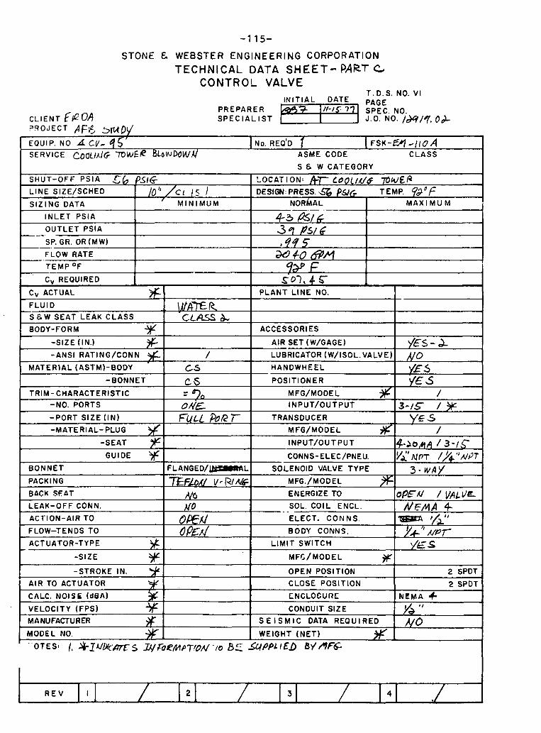
CLIENT ?qOJECT PFC 5mDd
STONE & WEBSTER ENGINEERING CORPORATION TECHNICAL DATA SHEET- PART c
C O N T R O L VALVE T.D.S. NO. V I
- - . - , EOUIP. NO CV- q Sf I NO. REO'D ( FSK-W d~co A SERVICE CO~JL/A/(; 'TOWER BLowDowAI ASME CODE C L A S S
SHUT-OFF P S l A 5 6 PSIG LINE SIZE/SCHED 1 tot1 /c, 1
I S I Z I N G DATA I ' M I N I M U M
I I N L E T PS lA 1 -- O U T L E T PSlA
SP. GR. OR (MW) --.
-. FLOW RATE
T E M P OF -- CV REQUIRED
Cv ACTUAL
F L U I D
S E W SEAT LEAK C L A S S
BODY-FORM
TRIM-CHARACTERISTIC I - - -NO. PORTS I O d E
I BONNET I F L A N G E D / m L
-PORT SIZE (IN)
-MATERIAL- PLUG
-SEAT
GUIDE
PACKING I 7?3hv Vrw% BACK SFAT N A
FULL PuR T-
-
-SIZE
-STROKE IN.
AIR TO ACTUATOR
CALC. NOISE (dBA)
LEAK-OFF CONN.
ACTION-AIR TO
FLOW-TENDS TO
ACTUATOR-TYPE bt
t VELOCITY (FPS) % 1 MANUFACTURER # I
No (%Ex/ d m . /
I MODEL NO. 4K 1
S E W CATEGORY
LOCATION: hr L O O [ I X / ~ P W E B DESIGN: PRESS. a PUG TEMP.
N O R ~ A L I M A X I M U M
S03,4 c 1 1 P L A N T L I N E NO. 1
ACCESSORIES
AIR SET (W/GAGE) . . ~~.
LUBRICATOR (W/ISOL.VALVEl
- HANDWHEEL
POSlT lONER
CONNS-ELEC/PNEU. Ivi' N P T /y+ "NPT SOLENOID VALVE TYPE 1 7 - W A ~
TRANSDUCER
MFG/MODEL # INPUT/OUTPUT
ENERGIZE TO IOPFA/ / V A L V E
YE /
4 - ~ O M A 1 3 - / S
-. - SOL. COIL ENCL. I NEMA 4- ELECT. C O N N S .
BODY CONNS.
L I M I T SWITCH
R E V
'/+it' Y.' " A / P ~ '/E s
OPEN POSITION
CLOSE POSITION
CNCLOCURE
CONDUIT SIZE
S E I S M I C DATA REQUIRED - WEIGHT ( N E T )
2 SPDT
2 SPDT
N L M A + h " NO
WPPL 1 Eb B\/ mrd:
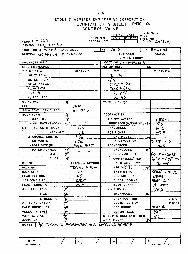
STONE 8 WEBSTER ENGINEERING CORPORATION
TECHNICAL DATA SHEET- PART C CONTROL VALVE
T. D. S. NO. V I
PREPARER S P E C I A L I S T
EOUIP. NO ~ c v - ~ o I A , &CV- 3 0 1 8 I NO. REQ'D & I FSK- €A- 1104 SERVICE V&C ppg /A ' , SUc?!od ASME CODE CLASS
I S & W CATEGORY I SHUT-OFF PS lA
I t OUTLET PSlA I
L INE SIZE/SCHED
S IZ ING DATA
I N L E T PSIA
SP. GR. OR (MW)
FLOW RATE
M I N I M U M
' C, REQUIRED 1 Cv ACTUAL *I
' FLUID I AIR IS-EAT LEAK CLASS I c(-AS5 2 I BODY-FORM %I
-- --
LOCAT I ON- AT Cohl.Di.VJEIEC DESIGN PRESS TEMP
31, bdc I PLANT LINE NO.
I
t I
~ - - . .
I ACCESSORIES 1
NORMAL - - - - . . -
1 I d l i q 14 ' t 7 0 7 5 0 so 4 ?!!
71, c f 0
M A X I M U M
-SIZE (IN.) % , -ANSI RATlNG/CONN 9
GUIDE CONNS-ELEC/PNEU. vJ 'f ,,@,- / v+l' ,,pi
R E V
/
BONNET
PACKING
BACK SEAT
LEAK-OFF CONN.
ACTION-AIR TO
FLOW-TENDS TO
ACTUATOR-TYPE
-SIZE
-STROKE IN.
AIR TO ACTUATOR
CALC. NOISE (dBA)
VELOCITY (FPS)
MANUFACTURER
MODEL NO
AIR SET (W/GAGE)
LUERICATOR (W/ISOL.VALVE)
F L A N G E D / I m
TE~LON L/-elW /vo n/o ow CLOSE
NOTES: 1, ~A/~KAEs I N W W IjL sffPPL~&a BY M F 6 3
MFG/MODEL )r OPEN POSITION
CLOSE POSITION
ENCLOSURE
CONDUIT SIZE
S E I S M I C DATA REOUlREb
WEIGHT (NET)
YES- % A/O
2 SPDT
2 SPDT
NEMA 9- I & I 1
No
SOLENOID VALVE TYPE
MFG./MODEL j)r ENERGIZE TO '
. - SOL. COIL ENCL.
ELECT. CON N S.
BODY CONNS.
L IMIT SWITCH
3 - WAY
URd /VALVE &€ah 4
% " NPY Y E S

APPENDIX IIIA-E
INSTRUMENT SCHEDULE
PART A - Babcock & Wilcox Equipment
PART B - Equipment Common to Babcock & Wilcox and Foster Wheeler

BABCOCK & WILCOX EQUIPMENT
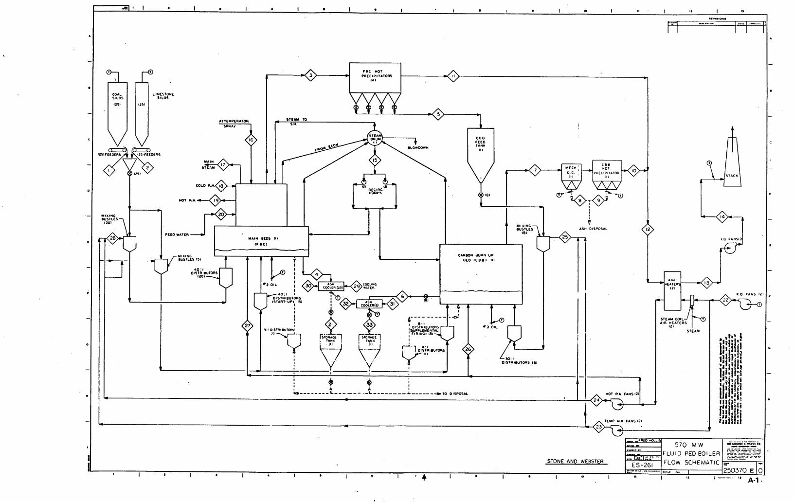
I
w
I a I a I 4 I a I * I a a to ,250370 E 0 -.
' 4 I I I 1 I I 2 11 I --.-... 1 1 A-1
STONE AND WERSTER
LFWD HOCLIS
w 0 - qi.2'. 17
ES-261 I
-
570 M W :FLUID RED POlLER
FLOW SCHEMATIC
- --. .- --. - I Y(OC. . "(0. CO. ---- - . .-- - .-.- .... ..----- .... -.-. . ..- -... .- -. - - ---
b. ." '----.-- ,,' 1
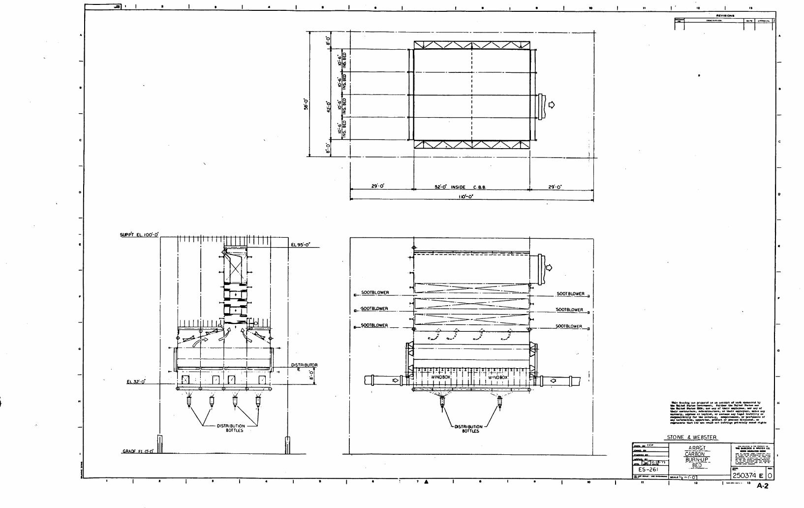
surJpi EL. 100'-0'
SOOTBLOWER --. - SOOTBUWER .
& S O O T B L o w E l 3 ~
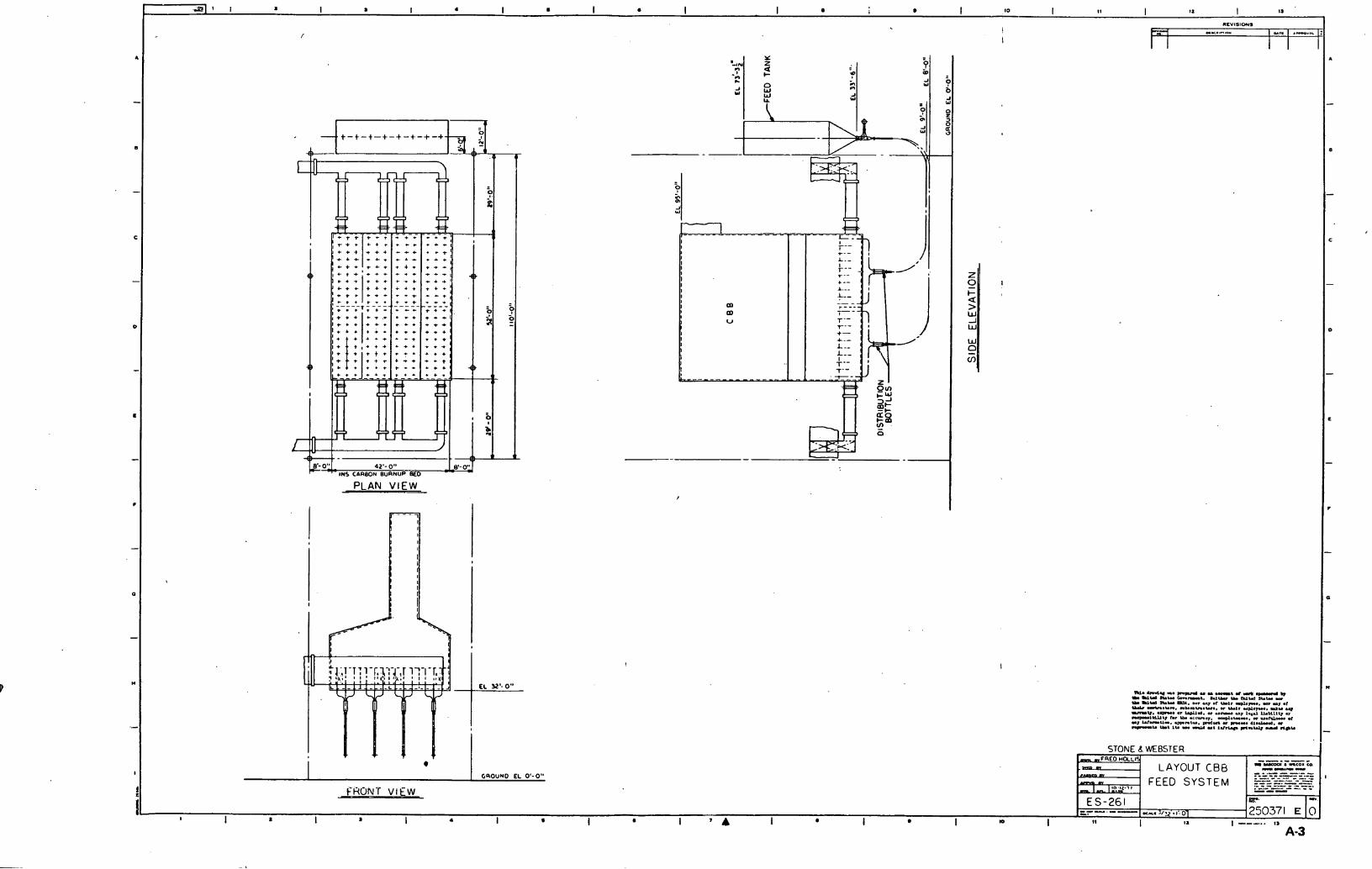
/
PLAN V I E W
. .
m.M"r.-uu.-..rd-., L U(d N W *-.. Irl- I.. hlld 3L.W .D.
rr Urr N W ODL. .ol .y or -1. dm. a .f U.Y ~.n.un. nr-u..~., r -1. &a,-. rtr -w. .-. " Wd. " u- .a, I..& U .Wl I " r -l.LIlO h r .c-q. @.~..r.. w us- .I ..I W-U-. -nb. PDOllDI " -I. dl-. - -U -8 lU .r d u S Idr- m-84 rul
GROUND EL 0'-0" FEED SYSTEM

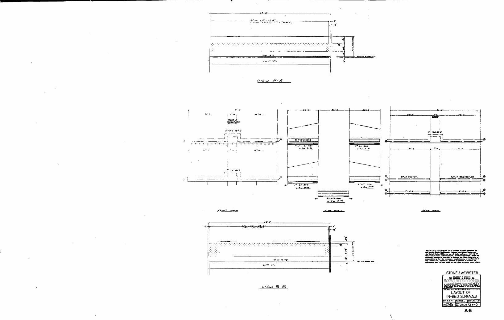
. . 8 I , . . . . _ _ _ . ).- .- " .... . . . --
! I -. . . . . . . - - . - . - .- .. ....
I I "I.., 9.9
.- i

93'- 0' I 03'- 0" J
, 77'- 4" INS PRECIP , 7.- 103 7'- 10.. 77'- 4" INS PHfClP
T 7'- 0:
I I \ ,
I T
STONE B WERSTER r

- /c :o' ,? -.& -... r.sr - -. - - -
i, ;I .-.. 5'. ,d ' .q ' L --,.. *-.** f...i...", ...- i a. :i.; .a ." 3. cr.. me .?, .# '2 .-.-.-+,
5 - 6 2 - -. .- 4.") ..
I I
I '
. . I I
1 - 1 ..
# r r .
a . I I I i .. . ! ' I : , . . . . I I - - ...-- -v-, ...- r *
I I . . . I I I
. . I I
. t I I
........ : I ' I D ' =.+-~s; ?,?-* ~ c l r ~ d c - -.
I , ,
I I 1 . 1 I I I I
I ' I
I ' I I . I I I I I I I : I I ' I
I : I
I ! I
> 0 . I . --+--
. I ? A-A ' -
I I I ' I s r C a L - . - - & ~ -
: t I I I I C."" ( 7 . p ) b ~ ~ " .... ... /uD= 0" 3"=Pr-
I I - -. - . .
7. -- -- I I I I I I ' . . 4 I I I I i I i I
1 .
I -,..- 1 . 1 1 I I I I I . . I I I I
: ' 6 I . . . . L ..I-,--, , I : I
I I I I ! I I I
I .. Y I C W FOR d B T f O H ~ . 4 ? x p E c .LO H.. -. -4 r ...-. n -r - w
C YY m.,.. *.I-.. I.,- Y r n I Y IUW - 'B-&f~ll TUBE SUpt%RT
-v. ~?~~~u?.~~-~'?~,:~ .Ow, .. ,..tn-. .. .a*-. ~ ~ ? & ? ; L - ~ ~ : ~ ur ~ y h I~..IIIV - y l C W rOR W O E BED SUPPOR~
lCl l l l" t., Y ..me,. .-.1..-.. .. ".-. ., U -I"-. ..Cn,.,. C-' " C." ."I--. -
& Y 5 3 L c M m IC-" U., I,. - 4. ". 3.r . ty CI",." -.. ".I *FOR rs
1-1 - - . . . . . . . . . .- .. : . . STI)I.IC & Wt' RSTt'R . . . . . . - . - 'I*, . -. , SZ? Z", $&- . ,5 : 5 % .- -. .....
..-...-...-..---.. " .....-... "..... .... ".. ..... ........ .... .... -.,.-. ..-. - -..... .- . . . . . . . ".. ........ ....
..... - -c7- i . ' * r p ZY'CO -.-- .-... -..*
...... c I .C'DETAIL 7w.c 5 0 ~ 3 3 ~ ~
....


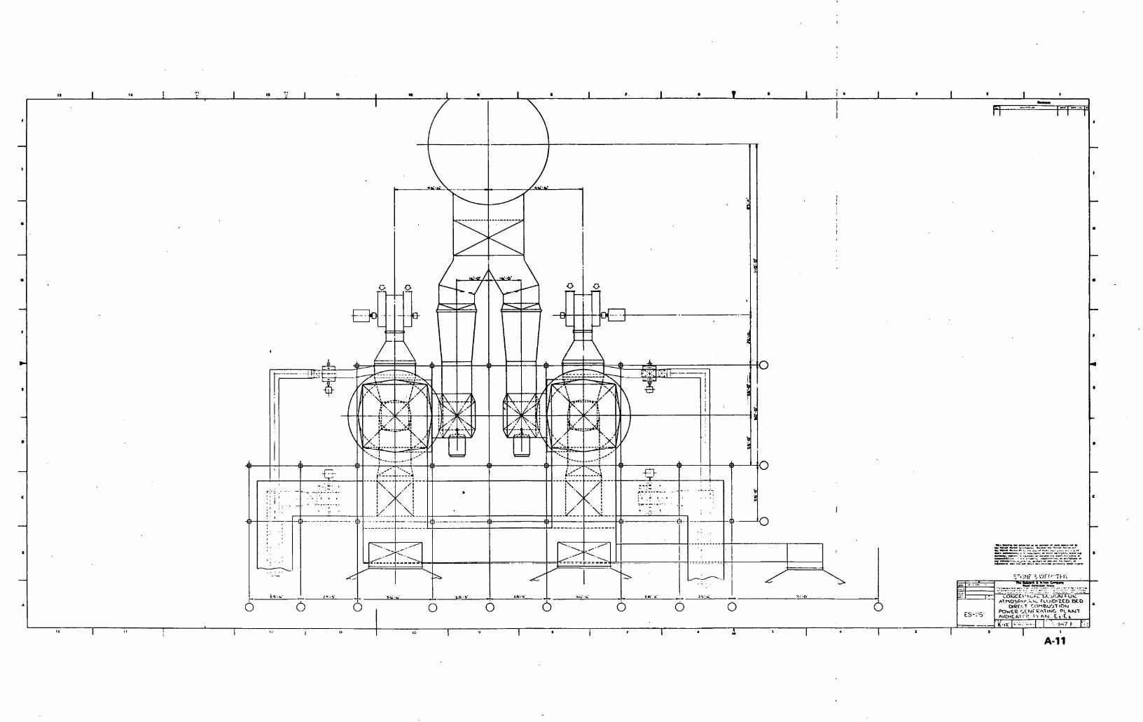
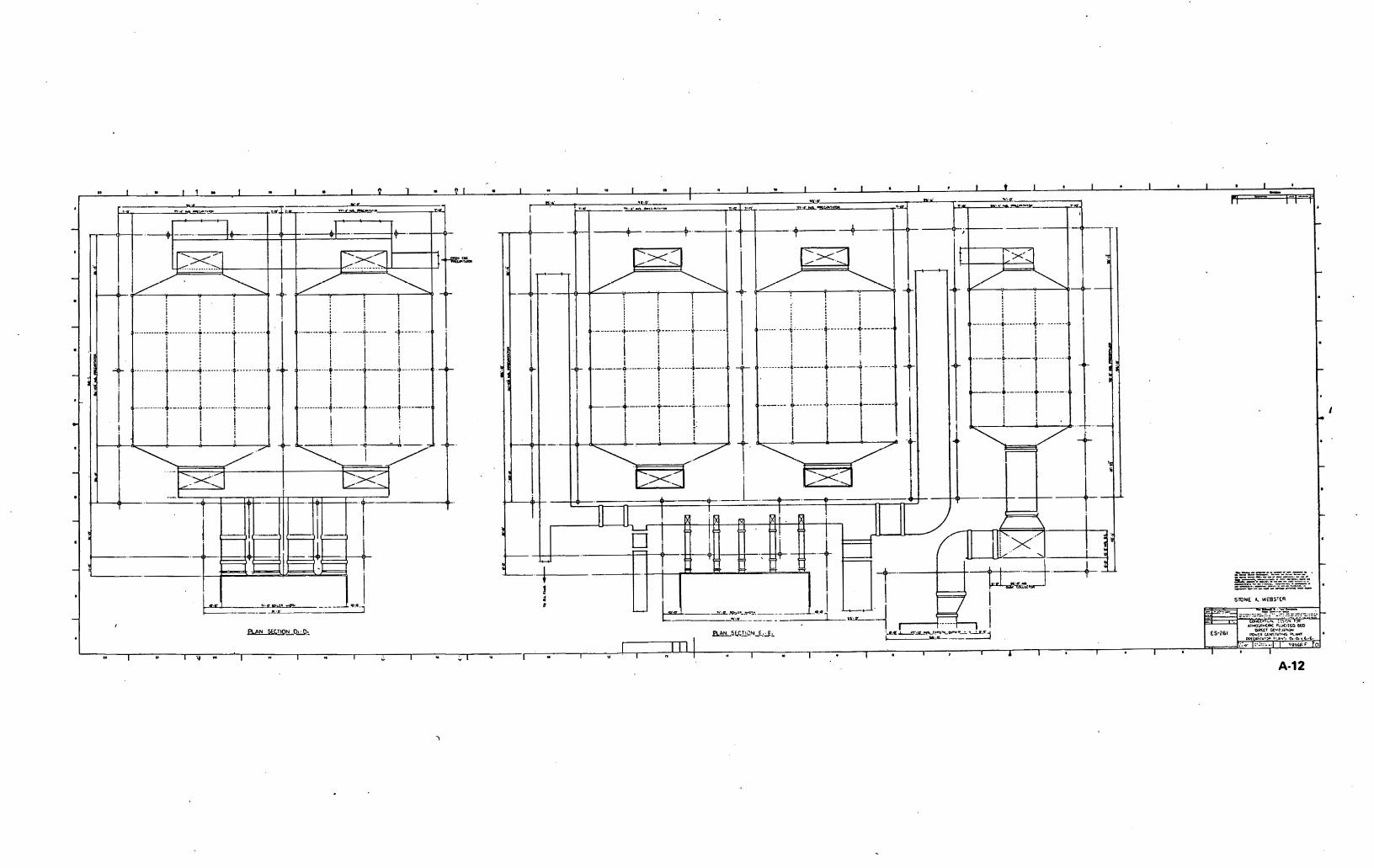
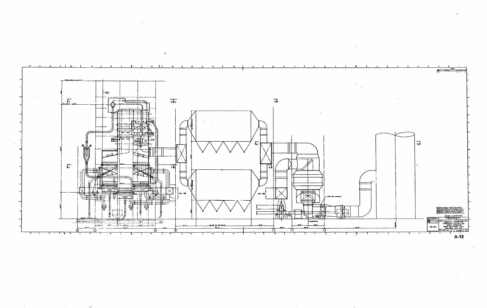
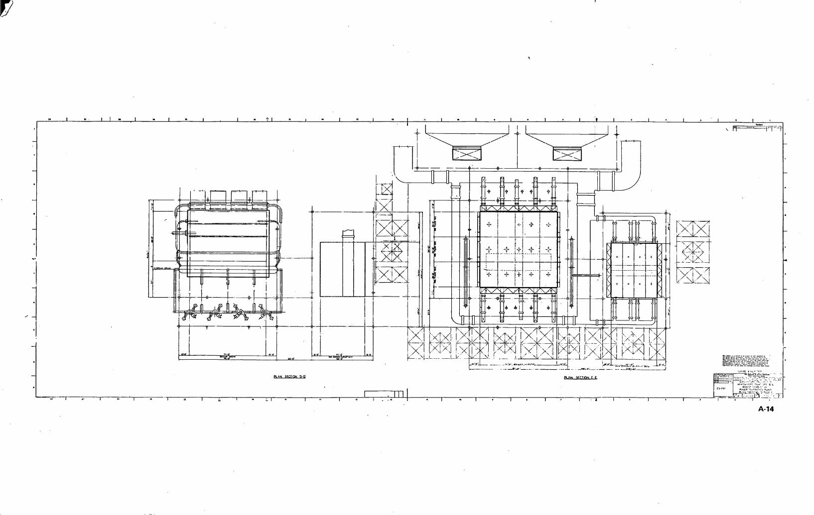


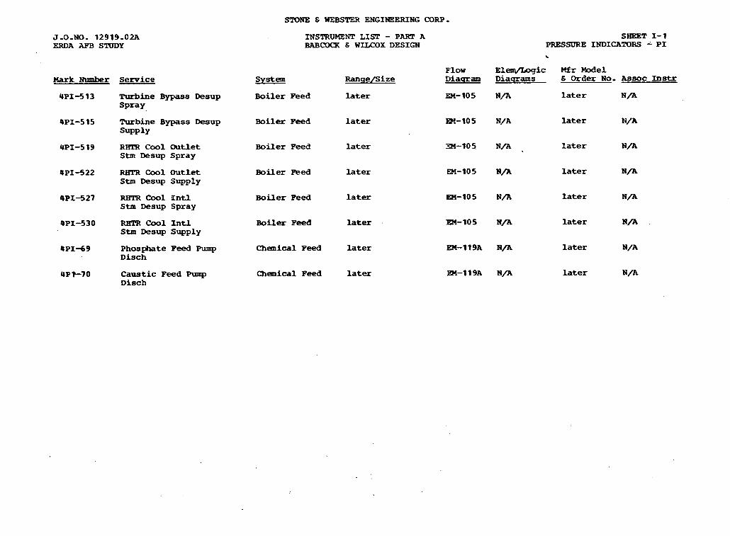
SPONE & WEBSTER ENGINEERING CORP.
J-0-NO. 1 2 9 1 9 - 0 2 A ERDA AFB S'RTDY
Mark Number
4 P I - 5 13
@PI-515
4PI -5 1 9
OPI-S22
OPI -527
@PI--530
4 P I - 6 9
4PF-70
Service
Turbine Bypass D e s u p S P ~ Y
Turbine B y p a s s Desup S u p p l y
RRIR C o o l Outlet Stm D e s u p S p r a y
RmR cool O u t l e t Stm D e s u p Supply
RHTR Cool Kntl S t m D e s u p S p r a y
Rm'R Cool I n t l Stm D e s u p S u p p l y
P h o s p h a t e Peed hrmp D i s c h
C a u s t i c P e e d Pump D i s c h
INSTRUMENT LIST - PART A BABCOCK & WILCOX DESIGN
S y s t e m
Boiler Feed
B o i l e r Feed
B o i l e r Peed
B o i l e r wed
Boiler Peed
Boiler Peed
C h e m i c a l Peed
C h e m i c a l F e e d
R a n q e / S i z e
later
later
later
later
la ter
later
later
la ter
r l o w El-ic M f r Model D i a q r a m D i a q r a m s 6 Order No. A s s o c Instr
EM-105 N / A later N / A
FX-105 N/A later N/A
3 l - 1 0 5 N / A later N/A
EM-105 N / A later N/A
EM-105 N/A later N/A
EM-105 #/A later R m
En-119A R / A later N/A
EM-119A N / A later N/A
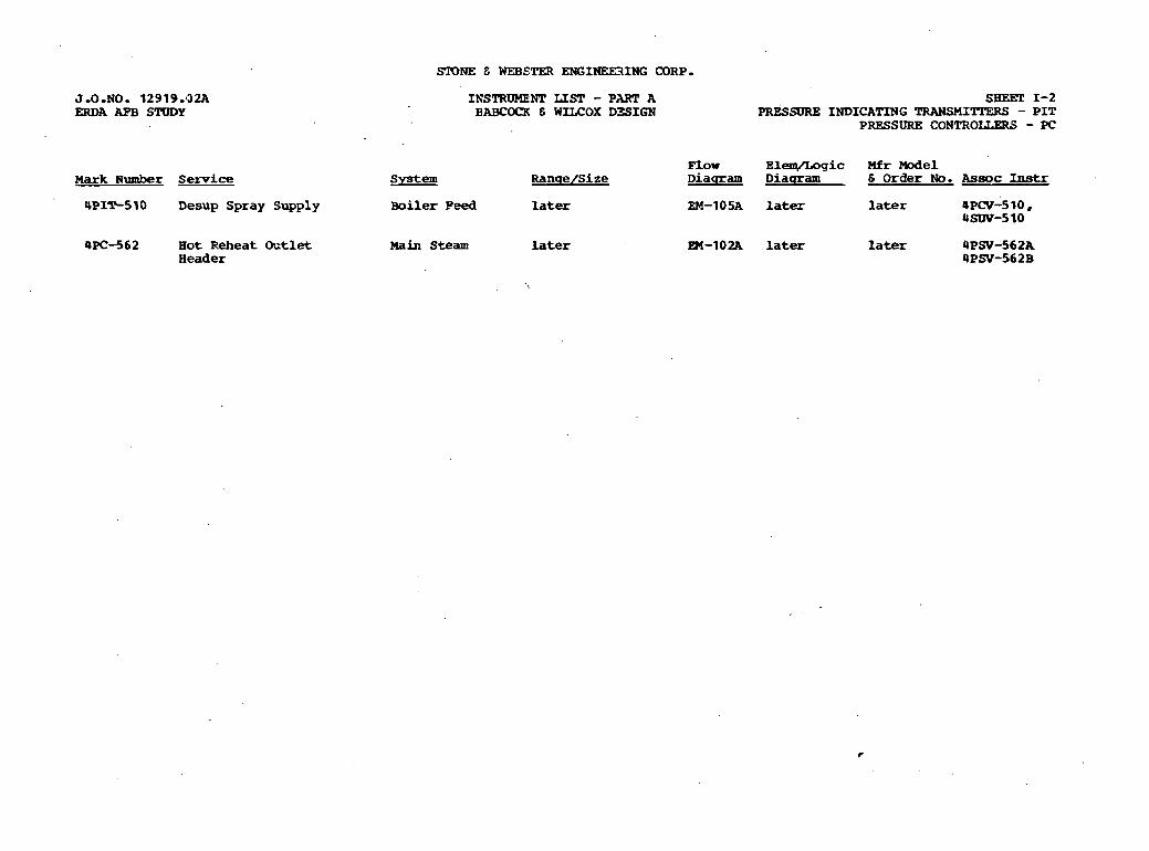
J.0-NO. 12919.9224 INSTRUMENT LIST - PART A ERDA APB STDDY BABCCNX E WILCOX DZSIGN
Mark N u m b e r Service System Ranqe/Size
WIT-510 Desup Spray Supply Boiler Peed later
4kC-562 Hot Reheat mtlet Main Steam later Header
Smm! 1-2 PRESSRE INDICATING TRANSMI'ITERS - PIT
PRESSURE CONTROLLERS - PC
F l o w EleqAogic Mfr Model Diaqram Diaqram 6 Order No. Assoc Instr
EM-10% later later 4PCV-5 10, 4SW-510
SIONE C WEBETER ENGINEEZtING CORP.
EM-102A later later 4PSV-562A 4PSV-562B
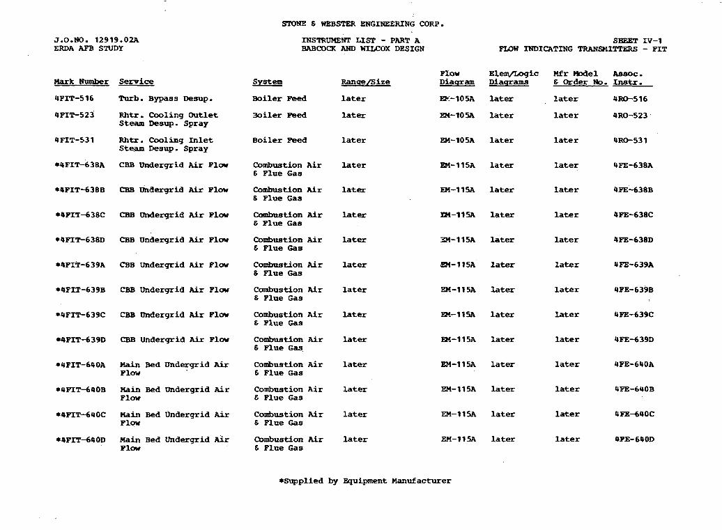
SPONE 6 WEBSTER ENGINEERING CORP.
J.0.NO. 12919.02A ERDA APB STUDY
INSTRUMENT LIST - PART A BABCOCR AND WLLCOX DESIGN
SHEET IV-1 P I D W INDICATING TRANSMITTERS - PIT
Flow Elem/Logic Mfr Model Assoc. Diacmam Diacrrams E Order No. Instr.
EK-105A l a t e r l a t e r 4-516
EN-10% l a t e r l a t e r 4RO-523
Mark Number
4FIT-516
4 PIT-5.2 3
System
Boiler Peed
Ranpe/Size
l a t e r
l a t e r
Turb. Bypass msup.
Rhtr. Cooling Outlet Steam Desup. Spray
3oi ler Feed
R h t r . Cooling In l e t Steam Desup. Spray
Boiler Peed l a t e r EH-105A l a t e r l a t e r 4RO-531
CBB Undergrid Air Plow Combustion Air 6 Flue Gas
l a t e r R4-115A l a t e r l a t e r 4FE-638A
CBB milergrid Air Plow Combustion Air 6 Flue Gas
l a t e r EM-11% l a t e r l a t e r 4FE-638B
CBB Undergrid Air P l w Combastion Air E Plue Gas
l a t e r lZ4-11% l a t e r l a t e r 4PE-638C
CBB Undergrid A i r P l w Combustion Air E Plue Gas
later 34-1 1% l a t e r l a t e r 4FE-638D
CBB Undergrid Air Plow Conbaation Air 6 Plue Gas
later m-115~' l a t e r l a t e r 4FE-639A
CBB Undergrid Air F l w Combustion Air E Flue Gas
l a t e r EM-115A later l a t e r 4PE-639B
*4FIT-639C CBB Undergrid A i r Flow Combustion A i r later 6 Flue Gas
E24-115A l a t e r l a t e r 4PE-639C
EM-115A l a t e r l a t e r 4FEd39D
EM-11% l a t e r l a t e r 4PE-640A
EM-115A l a t e r l a t e r 4FE-640B
EM-ll5A l a t e r l a t e r 4FE-640C
EM-115A l a t e r l a t e r OPE-64OD
WFIT-639D CBB Undergrid Air Flow Combustion Air l a t e r 6 Flue Gaq
*UPIT-640A Main Bed Undergrid A i r Combustion Air l a t e r Plow E Flue Gas
*4PIT-640B Main Bed Undergrid Air Conbustion ~ i r l a t e r Flow E Flue Gas
*4FIT-640C Main Bed undergrid A i r Combustion Air l a t e r Flow 6 Flue Gas
*4FIT-640D Main Bed Undergrid &r Combustion Air l a t e r P l w & Flue Gas
*Supplied by Equipment Manufacturer

J.O.NO. 12919.02A ERDA AFB SlVDY
Mark N u m b e r
*4FIT-640E
*4PIT-64 1A
*@FIT-64 1B
*4FIT-64 1C
*4PIT-64 ID
-PIT-64 1E
*4FIT-642A
*OFIT-642B
*4~1T-642~
*UPIT-642D
*4FIT-642E
*4FIT-643A
Service
Main Bed Undergrid A& Flow
Hain Bed Underqrid Air Plow
Main Bed Ondezgrid Air Plow
Main Bed Undergrid Air P l W
Main Bed Undergrid Air Flaw
Main Bed Undergrid Air Floor
H a i n Bed Undergrid 'Air Flaw
Hain Bed Uneergrid kir Plow
bin Bed Underqrid .Gr Flow
Main Bed Undergrid bir Flaw
Main Bed Undergrid P i r Plow ,
Main Bed Undergrid kFr P l w
04FIT-643B Main Bed Undergrid Air Plcrr
*4PIT-693C Main Bed Pmdergrid Air PIDW
*4FIT-643D Mairi Bed Undergrid Air Plow
STONE E WEBSTER ENGINEERING 03P.P.
MSTR3MENT LIST - PART A BABCOCX AND WILCOX DESIGN
Flow System Ranue/Size Diaqram
Combustion Ai r l a t e r EM-1 1 SA 6 Flue Gas
Combustim A i r later Rd-115A 6 Plue Gas
Combustion Ai r later EW-115.A & Plue Gas
Combustion Ai r later EM-1 1 SA 6 Flue Gas
Canbustic-n Air later EM-11- E Flue Gas
Codmation Air later EM-115A & Flue Gas
~onrbust ion Ai r later h-11~~ 6 Flue Gas
Combastion fir later En-1 1% 6 P l w Gas
Combustion A i r later EM-11s & FIue 3as
Combustlor Air later EM-1 1SA 6 Plue 6as
~ o m b n s k o n Air l a t e r Sm-llIA E Flue G a s
Combustion Air later EM-11% & Plue Gas
Combustion Air Later EM-115A Plue Gas
Combusti-~n Air l a t e r 83-1 15A E Flue Gas
Combustion A i r later EM- 1 1 SA & Flue Gas
SHEET Iv-2 F X B W INDICATING TRANmITTERS - FIT
Elem/Logic Mfr -el Assoc. Diaqrams 6 Order No. I n s t r .
later l a t e r 4FE-640E
later later 4PE-641A
later later 4FE-6QlB
later l a t e r .4PE-64 1C
l a t e r l a t e r 4PE-64 1D
l a t e r
iater
l a t e r
later
later
l a t e r
later
later
l a t e x
l a t e r
later
l a t d r
l a t e r
later
l a t e r
later
later
later
l a t e r later 4FE-643D
*Supplied by Equipment Manufacturer
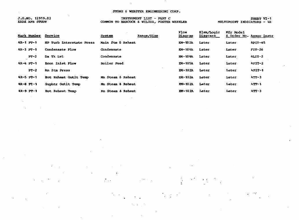
SIONE E WEBSTER ENGINEERING CORP.
Mark Number
4R-1 -1
UR-3 PT-1
PT-2
9R-4 PT-1
PT-2
4 R - 5 PC-1
4 R - e PT-1
OR-9 PT-1
Service
EP Turb Interstate Press
C o n d e n s a t e P l o w
D a Tk Lvli
E c o n I n l e t P l o w
rm stm Press
H o t Reheat Outlt Temp
Suphtr Chxtlt Temp
H o t R e h e a t Temp
INSTRUMENT LIST - PART C CONON TO BABCOCK 6 =COX, POSTER WHEELER
S y s t e m R a n q e / S i z e
Main Stm 6 R e h e a t
(hndensate
C o n d e n s a t e
B o i l e r Peed
Mn S t e a m 6 R e h e a t
Mn S t e a m 8 R e h e a t
Mn S t e a m & R e h e a t
EM- 1 0 4A
SHEET VI-1 MULTIPOIKP INDICAlXlRS - UR
Later
L a t e r
Later
Later
L a t e r
Later
Later
Later
Mfr W e 1 6 Order No.
Later
Later
Later
Later
L a t e r
Later
L a t e r
Later
A s s o c I n s t r
4 P I T - 4 5
PIT-26
ULIT-2
UFIT-2
UPIT-1
urn-3
U T r - 1
4Tr-3
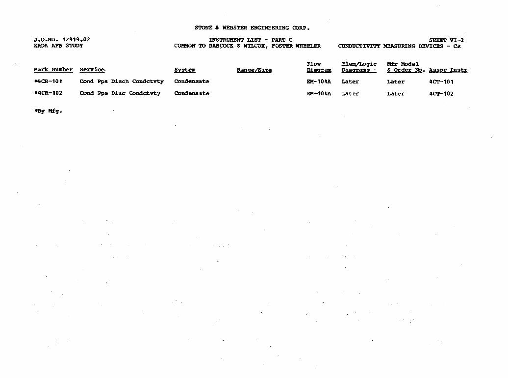
STONZ .6 WEBSTER E N G I N E E R I N G m.
J.O.NO. 12919.02 ERDA AFB SRlDY
MSTRUHENT LIST - PART C SBET YX-2 COmON 10 BASCOCB; 6 WZLCOX, FOSTW WHEELER CONDUCTrVITP MEASURING DEVICES - (314
F l o w E l m g i c M f r Mode l Mark Number Semice. System RanqeBize Diapram Diacrrams 6 Order No. A s s o c Instr
*om-10 1 Cond Pps D i s c h Condctvty Qndensate EM-10QA L a t e r L a t e r Om?-10 1
*Om-102 Cond Pps Diac Condctvty Qndenaate EM-104A Later L a t e r 4-102
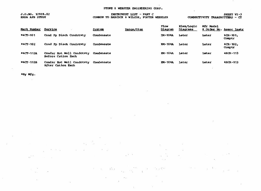
J-0-NO- 12919-02 ERDA AFB S'LULYY
Mark Number Service
STONE E WEBSTER ENGINEEXING a3RP.
INSTRDMENP LIST - PART C SHEET VI-3 COMMON TD BABOOCR 6 WILCOX, FQSTER WHEELER CONDUCTIVrrY TRANSMI- - CT
System
*4~~-101 Cond Pp D i s c h Condctvty Condensate
*Urn-102 Cond Pp D i sch Condctwty Condensate
*UCT-113A Condsr Hot Well Condctvty Condensate Before Cation Exch
*Urn-113B Condsr Hot Well Condctvty Condensate Rfter Cation Rch
Plow E l e w g i c M f r We1 Ranqe/Size Diaqram Diaqrams 8 Order No. A s s o c Instr
34-104A Later Later 4CR-101, comptr
EM-104A Later Later 4 m - 102, Comptr
EM-lO4A Later Later 4Rm-113
m-104A Later Later 4RQI-113
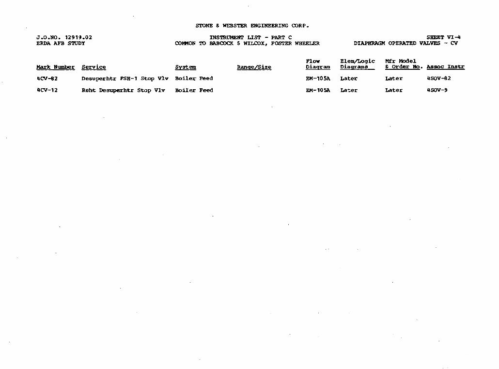
STONE 8 WEBSTER ENGINEERING CORP.
J.0.NO. 1 2 9 1 9 . 0 2 ERDA AFB STUDY
INSTRLWWI' LIST - PART C SHEET VI-4 COWOF !m BABCDQ( 6 WIUX)X, FOSTER WHEELW DIRPHRAL;M OPERATED VALVES - CV
Flow E l e q / I m g i c Mfr We1 Mark Number Service System R a n s e f S i z e D i a q r a m D i a q r a m s 6 Order No. Assoc Instr
4CV-82 Desuperhtr FSH-1 Stop Vlv Boiler F e e d EM-1 0 5A L a t e r ~ a t e r 4SOV-82
4CV-12 Reht Desuperhtr S W p Vlv Boiler Feed EM-1OSA L a t e r L a t e r 4SOV-9
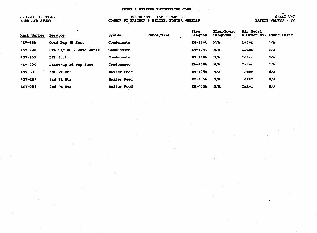
Mark N u n b e r
4 ~ ~ 4 5 ~
4SV-204
4 s - 2 0 5
4SV-206 \
4SV-63
4SV-207
QSV-208
S e r v i c e
C o n d Pmp 1B Suct
D m CLr DC-2 C o n d O u t l t
BFP Suct
Start-up W Pmp Suct
1st P t Rtr
3rd P t B t r
2nd Pt lltr
INSTRUMENT LIST - PART C <X)MMON TD BABCOQl 6 WlLCOX, FOSTER WHEELER
F l o w S v s t e m R a n c r e / S i z e D i a q r a m
Condensate EM-10 4A
C o n d e n s a t e m - 1 0 4 A
C o n d e n s a t e EM-104A
C o n d e n s a t e =.-lo 4A
Boiler Peed m - 1 0 SA
biler Peed =-lo% Boiler Peed
E l e q / L o g i c M f r M o d e l D i a q r a m s 8 Order No. A s s o c In-
N/A Later N/A
N/A Later N/A
N/A L a t e r N/A
N/A Later N / A
N/A ~ a t e r N/A
N / R Later N / A
N/A Later N/A
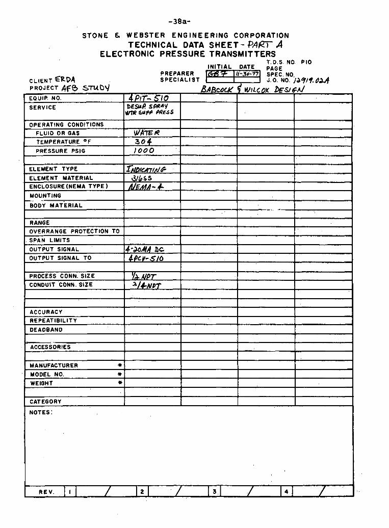
STONE G WEBSTER ENGINEERING CORPORATION TECHNICAL DATA SHEET - QAm A
ELECTRONIC PRESSURE TRANSMITTERS T.D.S. NO. P I 0
PREPARER CLIENT ERpq SPECIALIST PROJECT AFB STUD J
I ) O O O PRESSURE PSlG I I I 1
EQUIP. NO.
SERVICE,
OPERATING CONDITIONS
FLUID OR GAS
TEMPERATURE O F
I I
ELEMENT TYPE I frrl~~on/n/~ I I I
4 /'IT- 51 0 DESUR SPRAY ws? sup4 MwS
W I P E f i 3 0 4
RANGE
OVERRANGE PROTECTION TO
SPAN LIMITS
ELEMENT MATERIAL
ENCLOSURE (NEMA TYPE
MOUNTING -, .. .-
BODY MATERIAL -. .-
PROCESS CONN. SIZE
CONDUIT CONN. SIZE
OUT'PUT SIGNAL
OUTPUT SIGNAL TO
ACCURACY 1 I I I REPEATlBlLlTY
I I I -.
DEADBAND
4-&AIR hc ~ P c v - S I O
I I I - ACCESSORIES I I I
1
I
1 I I I CATEGORY I
I I I I .
MANUFACTURER * MODEL NO. * WEIGHT 1)
1

SrONE & WEBSTW ENGINEERING CORP-
m r k Number Service
4NRV-1 H P Turb .Ext S t m to 1st Pt Htr
UNRV-2 IP ~ u r b E x t Stm to 2 n d Pt Htr
4NRv-3 LP A s EXt Stm to DA
UNRV-U IP Turb Ert Stm
4NRV-5 H P Turb Ert Stm to Auu stm
UNRV-7 L P m ' b Btt S t m to DA
4NRV-5 1 IP Tub E x t Stm t o 3rd Pt Htr
4NRV-5 2 IP Turb Ext Stm to BPP LP Turb
INSTRUMENT LISP - PART C COIMON TO BABCOCK & WfLCOX, FOSTER WHEELW
SBEET v-5 NONRETURN VALVES - NRV
F l o w Elem/I .og ic Mfr M o d e l s y s t e m R a n q e / S i z e D i a q r a m D i a q r a m s 6 O r d e r No. A s s o c Instr
E x t Stm
EM-103A Later L a t e r 4SOV-28, ULS-IB, TUTb T r i p
Eb!-103A Later L a t e r USOV-29, 41.5-2~, m b
Trip
S x t Stm EM-103A Later Later Turb R i p
E x t S t m
Ext stm
E k t s t m
E x t S t m
En-103A Later Later 4SOV-31, 4LS-UB, TUIf) T r i p
EM-1O3A Later Later Turb P i p
EN-103A Later Iater usOV-62 #
ULS-3B. Turb T r i p
EM-103A L a t e r Later Turb P i p
34-103A Later ~ a t e r
EM-lO3A L a t e r L a t e r . 4 S W - 3 0 2
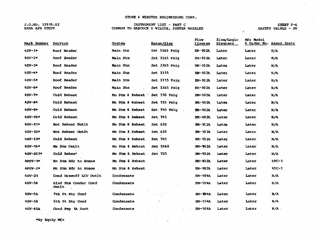
STONE E WEBSTER ENGINEERING CORP . J.O.NO. 1 2 9 1 9 . 0 2 ERDA RFB STUDY
Mark N u m b e r Service
4SV-l* R o o f H e a d e r
4SV-2 R o o f H e a d e r
4SV-3* R o o f H e a d e r
4 S V - 4 8 R o o f H e a d e r
USV-S* Roof H e a d e r
4SV-68 Roof H e a d e r
4SV-7* C o l d R e h e a t
INSTRUMEWP L I S T - PART C COMMOX TO BABCOCK E WILCOX, POSTW WHEELER
SHEET V-6 SAFETY VALVES - su
,
low Ele-gic Mfr M o d e l Systen R a n u e / S i z e L i a q r a m D i a q r a m s E Order No, Assoc Instr
Hain stm S e t 3 2 6 5 P s i g m - l O 2 A L a t e r Later N/A
Main Stm Set 3 2 6 5 Psig En-102A Later Later N/A
Main Stm S e t 3 3 6 5 P s i g . EH-lO2A Later Later N/A
M a i n Stm Set 3315 EH-102A Later Later N / A
Main Shn Set 3315 P s i g E H - 1 0 a L a t e r Later N/A
Main Stm . Set 3365 P s i g EX-102A Later L a t e r N / A
Mn Stm 6 R e h e a t - Set 730 P s i g B t t o 2 A Later Later N / A
4SV-8* C o l d R e h e a t Ehr Stm S R e h e a t Set 735 Psig EM-10ZA Later Iater N/A
4SV-9* C o l d R e h e a t Mn Stm 8 R e h e a t S e t 7bO Psig m - 1 0 2 R La- Later N / A
4SV-lo* C o l d R e h e a t Hn Stm 6 R e h e a t Set 7 4 5 En-#OZA Later Later N/A
4SV-1 l* Bot R e h e a t ehrtlt Mn Stm S R e h e a t Set 630 En-102A Later Later N/A
OW-IZ* 'IEot R e h e a t Outlt Mn Stm B R e h e a t Set 6 3 0 R4-802A Later Later N/A
USV-13* Cold Reheat Mn S t m 8 R e h e a t .Se t 745 EM-102A Later Later N/A
4SV-14* HD Stm O u t l t
4SV-203* Cold Reheab.
4Pm-1* - Mn Stm H d r to A t m o s
4PSV-Z* Mn Stm H d r to A t m o s
4SV-21 C a d D r a w o f f O u t l t
4 s - 5 4 G l n d Stm Condsr C o n d Ouflt .
Mn Stm Z Reheat Set 3060
Mn Stm 6 wheat Set 725
rn Stm . R e h e a t
MI Stm S R e h e a t
C o n d e n s a t e
Condensate
Condensate
4SV-58 5th Pt H t r C o n d Condensate
4 S y - 6 5 A C o n d Pmp 1A Soct C o n d e n s a t e
EM-WZA Later Later N/A
m - l D 2 A Later Later N I A
EM-102A Later Later 4PC-1
EM-102A L a t e r Later 4PC- 1
EM-'J09A Later Later N/A
EM-lO4A Later Later N/A
EM-1D4A Later.. Later N/A
EM-194A Later L a t e r N /A
EM-1OPA L a t e r L a t e r N/A ,

SrONE & WEBSTW ENGINEERING CORP.
J.O,NO. 12919.02 ERDA APB STUDY
INSTRUMENT LISP - PART C C3MMON TO BABo(IR & WILCOX, FOSTER WAEELZR
Smwr v-3 MrnOR-OPERAZeD VALVES '- MOV
Elem/Logic M f r We1 D i a q r a m s 6 O r d e r No. A s s o c Instr
Fl >or S y s t e m R a n s e / S i z e D i s q r a m Mark Number Service
4lOV-6 2 Start-up R e c i r c L i n e Shutoff
4MOV-63 S t a r t - u p BPP D i s c h t o BFP
4MOV- 16A , C i r c W t r Pp 1A D i s c h
Eoiler Feed EM-105A Later Later
B o i l e r Peed Later Later
Later Later C i r c Wtt, C o n d s r air Ehmtl
~MOV-I~B C i r c W t r Pp 1B D i s c h C i r c W t r . C o n d s r Air Ehmtl
L a t e r L a t e r
O W - 3 7 A Clng ISllr: C i r c W t r I n l t Later Later
O W - 3 7 B C l n g Twr C i r c W t r Inlt 8Circ Wtr, C o n d s r Air Rmvl '
Later Later
C i r c mr, Cpndsr A h Rnlvl
Later Later
QMOV-115 C l n g Twr Mkup Rnp D i s c h Vlv
C i r c W t r . C b n d s r L a t e r L a t e r
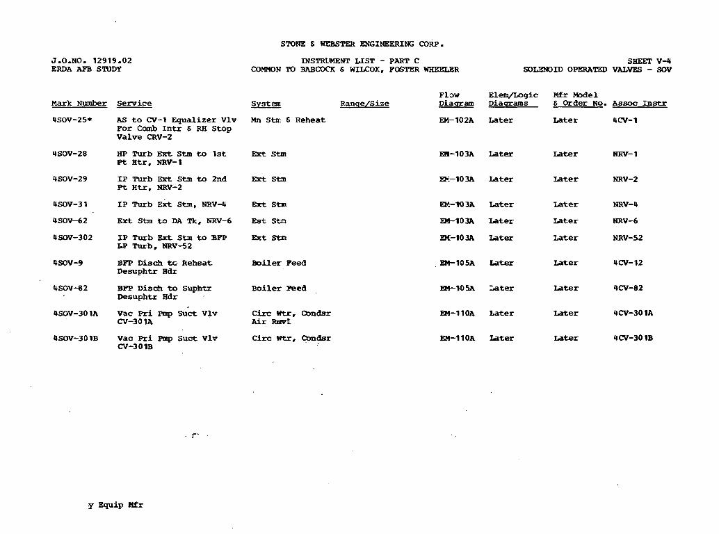
STONE 6 WEBSTER ENGINEERING CORP.
J-0-NO- 12919.02 ERDA APB STUDY
INSTRZrMEWT L I S T - PART C COMMON TO SABCOCK 6 WLLCOX. FOGTER WBEELER
SHEET v-4 SOLENOID OPERATED VALVES - SOV
F LDW E l w g i c Mfr M o d e l S y s t e m R a n q e / S i z e D i a q r a m D i a q r a m s E Order No. Assoc Instr Mark N u m b e r
4SOV-25*
Service
AS t o CV-1 E q u a l i z e r Vlv For Comb Intr E R E Stop V a l v e CRV-2
Mn Stn. E R e h e a t EM-102A L a t e r ~ a t e r UCV-1
HP Turb E K t Stm t o 1st at H t r , NRV-1
Brt Stm EH-103A Later ~ater NRV- 3
IP Turb Ext S t m to 2nd Pt H t r , NRV-2
Bet Stn EE-103A Later Later NRV-2
-103A Later Later NRV-U
EM-1D3A Later Later NRV- 6
m-103A Later Later NRV-52 I P T u r b Ext Stm t o BFT I9 Turb , NRV-52
BFP D i s c h t o R e h e a t D e s u p h t r H d r
Boiler Feed ,EM-105A Later Later 4CV-12
B o i l e r Feed W 1 0 5 A Later Later 4CV-82 BPP D i s c b t o Suphtx Desuphtr H d r
Vac Pri Pmp Suct Vlv CV-30 1A
C k c Wtr, Ccm&r A i r Rmvl
EM-11OA L a t e r Later 4CV-30 1A
EM-11OA Iater Later 4CV-30 1B 4SOV-301B Vac P r i Pmp Suct V l v OI-3 0 1B
C i r c Wtr, Ccmdsr
y E q u i p Hfr
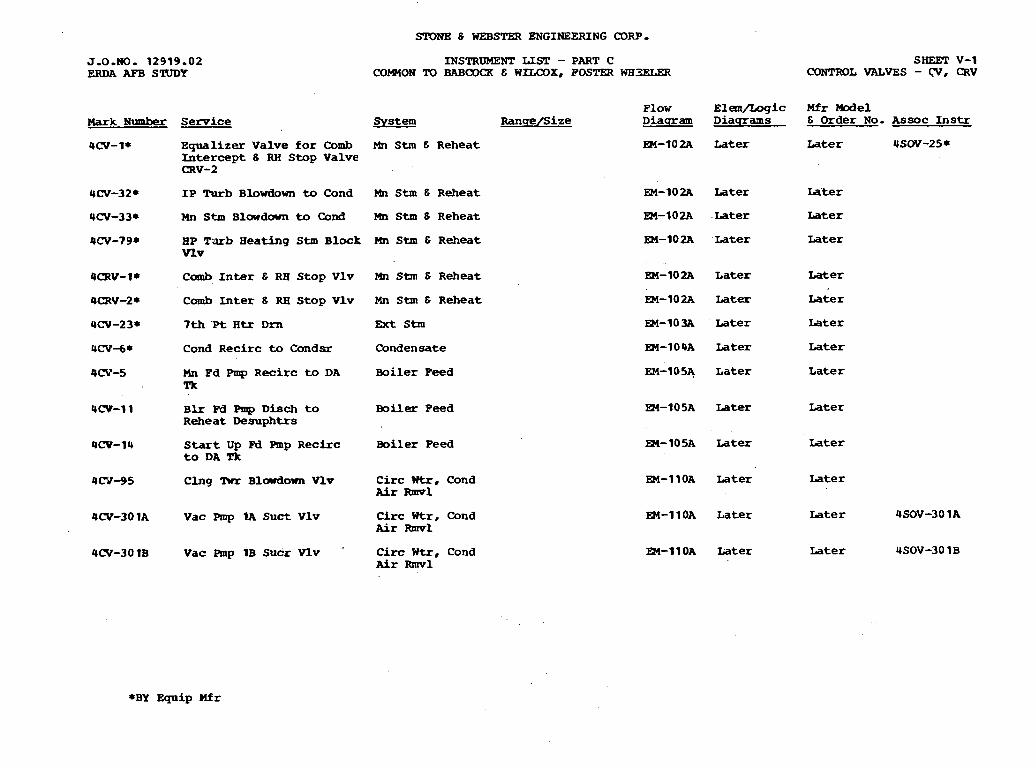
SrONE 6 WEBS= ENGINEERING CORP,
Mark Number Service
INSTRUMENT LIST - PART C COmON 'IQ BABCWX C WlLCOX, FOSTER WB3ELER
SHEET V-1 CONTROL VALVES - (V, CRV
P l o w E l a n / L o g i c Mfr Model S v s t e m Ranqe/S ize D i a q r a m D i a q r a m s & Order No. A s s o c Instr
4CV-l* E q u a l i z e r V a l v e for Comb Mn S t m E R e h e a t Intercept 6 RH Stop V a l v e m v - 2
4CV-32* IP Turb Blowdown to Cond S t m 6 R e h e a t
4CV-33* Mn S t m B l w d o w n t o Cond Hn Stm 8 R e h e a t
4CV-798 BP T u b Heating S t m B l o c k Mn S t m 6 R e h e a t Vlv
4CRV-I* Comb I n t e r C RR Stop V l v Mn Sm E R e h e a t
4CRV-2* Comb I n t e r 6 RB Stop Vlv Mn S t m 6 R e h e a t
4W-2 3* 7th Pt H t r D m Ext S t m
4CV-6* Cond R e c i r c to C o n d s r C o n d e n s a t e
4CV-5 Hn P d Pmp R e c i r c to DA B o i l e r Feed Tk
4CV-11 Blr W Pmp D i s c h t o B o i l e r F e e d R e h e a t D e s u p h t r s
4CV-14 Start Up W Pmp R e c i r c B o i l e r F e e d t o DA Tk
4N-95 C l n g 'Rrr Blowdown Vlv C i r c Wtr. Cond fir Rmv1
4W-301A V a c Rnp 1A Suct V l v C i r c Wtr, Cond Air Rmv1
4W-30 1B V a c Rnp 1B Sucr Vlv C i r c W t r , Cond Air -1
EM-102A Later Later 4SW-258
Later
L a t e r
Later
L a t e r
Later
Later
Later
L a t e r
Later
EM-105A Later
EM-11OA Later
EM-11OA Later
L a t e r
L a t e r
Later
Later
Later
L a t e r
L a t e r
L a t e r
L a t e r
L a t e r
Later
Later
L a t e r
*BY E q u i p Mfr
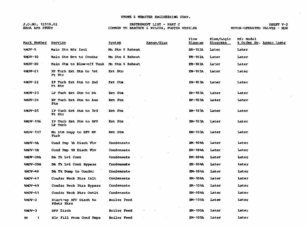
S'10NE E WESSTER ENGINEERING CORP-
J.O.NO. 12919.02 ERDA AFB STUDY
INSTRlMENT LIST - PART C COMMON TO BABCOCK C WILCOX, FOSTER WHE?CZR
SHEET V-2 MOTOR-OPERATED VALVES - MOV
F l o w Elerq/Logic Mfr Model Mark Number Service System R a n s e / S i z e Diaqzram D i a q r a m s 6 Order No. A s s o c Z n s t r
4MOV-5 Main Stm Hdr Is01 Mn Stm & R e h e a t EM-102A Later L a t e r
4 m v - 1 0 -%in Stm Dm t o C o n d s r Mn Stm 6 R e h e a t 0 - 1 0 2 A L a t e r Later . .
4MOV-2 0 Plain Stm t o B l w - o f f Tank Mn Stm 6 R e h e a t Later Later
~ater L a t e r 4 W - 2 1 EP Turb Bct S t m t o 1st Ext Stn Pt H t r
4 ~ 0 ~ - 2 2 I P Turb E x t Stm t o 2 n d E x t Stm P t H t r
Later L a t e r
4MLIV-2 3 LP Turb Ext Stm t o DA Ext Stn L a t e r L a t e r
Later Later 4MOV-24 BP Turb Ext Stm to Aux Ext Strr Stm
4MOV-2 5 I P T u r b E x t Stm t o 3rd . Ext Stx Pt Htr
Later L a t e r
I P Turb &t Stm t o BFP LP Turb
L a t e r Later
Mn Stm supp to BPP iRP h u b
Btt Stm L a t e r Later
Cond Fmp lA D i s c h Vlv Q n d e n s a t e L a t e r
Later
L a t e r
Later
Later
L a t e r
Later
Later
Later
L a t e r
Later
Later
Later
Later
Later
Later
Later
Later
Cond Pmp 1B D i s c h Vlv C o n d e n s a t e
Condensate
C o n d e n s a t e
DA Tk L v l C d n t
DA Tk L v l C o n t Bypass
DA IX Dump to Condsr Condensate
C o n d e n s a t e
C o n d e n s a t e
C o n d e n s a t e
Boiler F e e d
C ~ n d s r Neck 3trs In l t
C o n d s r Neck 3trs B y p a s s
C o n d s r Neck a t rs . O u t l t
Start-up BFP Disch to Fdwtr H t r s
B o i l e r Peed BFP D i s c h Later
Later
Later
Later B l r Pill -on Cond Pmps B o i l e r Feed
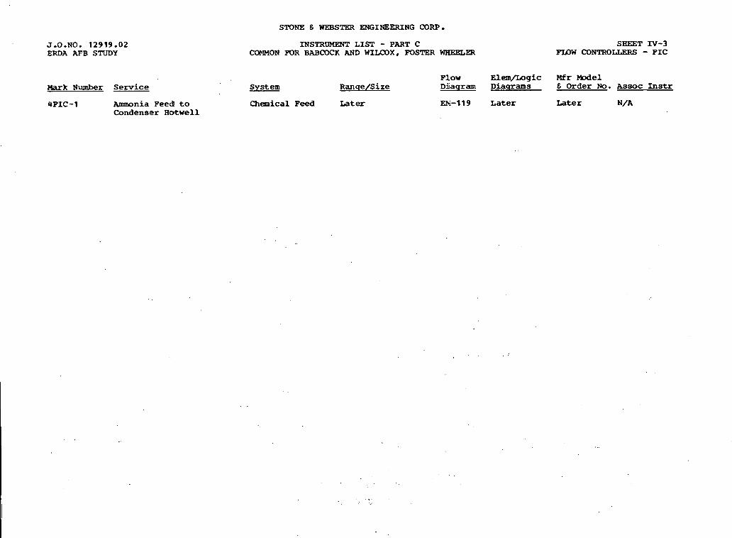
J - 0 - N O . 12919.02 ERDA AFB STUDY
Mark N u m b e r Service
UPIC-1 Ammonia F e e d to C o n d e n s e r H o t w e l l
STONE 6 WEBS- ENGINEERING CORP.
INSTRUMENT L I S T - PART C COMMON FOR BABCOCK AND WILCOX, FOSTER WHEELER
SHEET IV-3 F I D W CONTROLLERS - F I C
F l o w E l e m / L o g i c Mfr Model S y s t e m R a n q e / S i z e D i a q r a m D i a q r a m s E Order N o . Assoc Instr
C h e m i c a l P e e d Later m-119 L a t e r L a t e r N/A
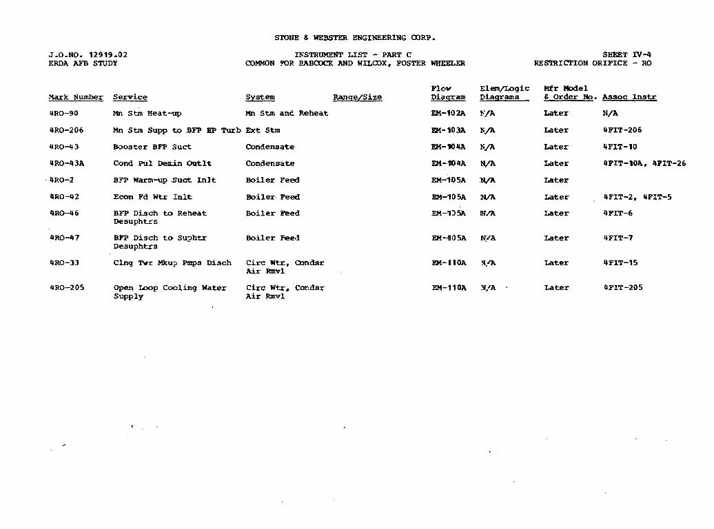
SFDtlE E WEBSTEZt ENGINEERING CORP.
J.O.NO. 12919 .02 ERDA AFB STUDY
~Yark Number Service
URO-90 Mn Stm Heat-up
mSTRUt4ENT LIST - PART C COMMON FOR EABCOCK AND WILODX, FOSTER WHEELER
S I E T IV-4 RESTRICl'ION ORIFICE - RO
Plc-v Elem/Logic Mfr Model System Ranqe/Size Diasram Diaqrams E Order No. kssoc I n s t r
Mn Stm an& Reheat EM-102A F/A Later N/A
4RO-2 0 6 Mn Stm Supp to BFP HP ~ u r b Ext Stm Later FIT-206 Dl-103A K f l
4 R 0 - 4 3 Ba~oster BPP Suct Condensate
4 R O 4 3 A Cond Pul D e d n Ont l t Condensate
KM-W4A ti/A Later 4FIT-10
EM-#)4A N/A Later UFIT-IOA, UPIT-26
4RO-2 BFP Warm-up .Suet 1nl.t Boiler Peed EM-105~ N/A Later
Q R O 4 2 Econ Fd W t r InLt Boiler Peed EM-10 SA N/A Later UFIT-2, 4FIT-5
4R0-46 BFP Disch to Reheat Boi ler Bed Desuphtrs
UR0-97 BPP Disch to Su?htr Boiler Feed Desuphtrs
4RO-33 C l n g 'Rrr Mku? Pmps Disch Circ W t r , Condsr A i r Rmvl
URO-205 Open h o p Cooling W a t e r C i r c W t r , Coridsr supply Air Rmvl
EM-135A W / A Later 4FIT-6
EM--805A N/A Later UFIT-7
EM-I IOA 3 .a Later &FIT-15
Later QFIT-205
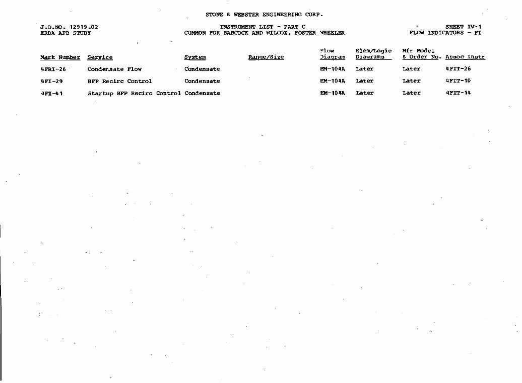
SrONE & WEBSTER ENGINEERING CORP.
J.0.W. 1 2 9 1 9 - 0 2 ERDA AFB STUDY
INSTRUMENT L I S T - PART C COMMON FOR BAB- AND WILCOX, FOSrW YAEELHl
S H E T N - 1 FLCH INDICATORS - PI
P low ElemJLogic Mfr -el Mark N u m b e r S e r v i c e System R a n q e / S i z e '3 iaqram D i a q r a m s & O r d e r N o . A s s o c Instr
4 F R I - 2 6 . C o n d e n s a t e F l o w C b n d e n s a t e m - 1 0 4 A L a t e r L a t e r 4 F I T - 2 6
4 P I - 2 9 BFP R e c i r c C o n t r o l C o n d e n s a t e a - 1 0 4 ~ ~ a t e r L a t e r 4 F I T - 1 0
U F I - 4 1 Startup BFP R e c i r c C o n t r o l C o n d e n s a t e EM-104A L a t e r L a t e r @ F I T - 1 4
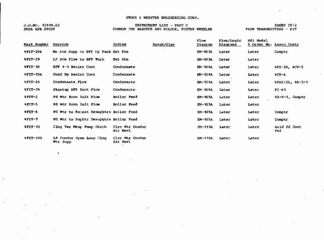
SIDh-E 6 WEB- ENGINEERING CORP.
J -0 -NO. 1 2 9 1 9 . 0 2 W D A AFB STUDY
INSTRUMENT L I S T - PART C COMMON ?OR. BAB- AND WILCOX, FOSTER WBEELER
S-T IV-2 FLOW TRANSMITTERS - F I T
I F l o w E lenc /Log ic Mfr Model Mark umber Service S y s t e m R a n q e / S i z e D i a q r am C i a q r a m s E Order No. A s s o c I n s t r
UPIT-206 C4n S t m Supp t o BIT E p Turb Ext Stm EM-lO3A Lqter Later C o m p t r
I 4 P I T - 2 9 L? Stm F l a v to BET Turb Ext Stm EM-103A Iater Later
BPP 4-1 R e c i r c C o n t C o n d e n s a t e
C o n d Pp R e c i r c C o n t C o n d e n s a t e .
C o n d e n s a t e F l o w C o n d e n s s t e
Startup BPP S u c t F l c w . C o n d e n s ~ t e
Pd W t r E c o n In l t ~ l c w Boiler Fee8
P d W t r E c o n hit F l o w B o i l e r Eked
Pd W t r t o R e k e a t Desuphtrs B o i l e r Psed
Fd W t r to S u g h t r D e s u p h t r s B o i l e r P e e d
Cling Tur M k u ~ Pump D i s c h C i r c W t r Oondsr Air R m v 1
L P C o n d s r Open Loop Zing C i r c W t r (Ipnd-sr Wtr Supp Air Ehnvl
EM-1O4A Iater
EM-lO4A Iater
EM-10 UA .Idtw
EM-10% Later
EM-IOSA L a t e r
EM-1OSA L a t e r
EM-lO5A L a t e r
EM-11OA L a t e -
EM-P1OA Iater
L a t e r
L a t e r
Later
L a t e r
L a t e r
Later
L a t e r
Later
Later
L a t e r
UFI-29, UCV-5
UCV-6
4FkU-26, 4R-3-1
F I Y 1
UR-4-1, C o m p t r
Acid Pd Cont P n l
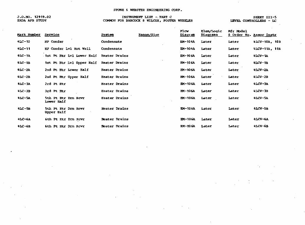
STONE & WEBSTER ENGINEERING CORP.
J.O.NO. 12919.02 ERDA AFB STUDY
Mark N u m b e r Service
4LC-10 H P C o n d s r
INSTRUMEHT LIST -.PART C COMMDN FOR BABCOQ[ 6 WILCOXe FOSrW WAEELeR
SHEET 111-5 LEVEL COrnRoLLgRs - IC
Plcw E l e m J L o g i c M f r We1 S y s t e m R a n s e / S i z e D i a q r a m D i a q r a m s 6 Order No. Assoc Instr
C o n d e n s a t e EM-1O4A Later L a t e r 4UX-10A8 1OB
4LC-I1 HP Condsr L v l H o t Well C o n d e n s a t e
@LC-1A . 1st P t H t r L v l L o w e r H a l f H e a t e r Drains
EM-IOUA Later Later 4LCV-1 1A8 11B
EM-106A Later Later 4 L N - I A
4fC-1B 1st P t H t r L v l U p p e r H a l f H e a t e r Drains EM-106A Later L a t e r 4LCV- 1B
@LC-2A 2 n d Pt B t r Iaver H a l f H e a t e r Drains EM-106A Later Later 4XW-2A
OIL-2B 2nd Pt IItr Upper H a l f H e a t e r Drains
@LC-3A 2 r d Pt Htr H e a t e r Drains
4LC-3B 3rd Pt Rtr H e a t e r Drains
@LC-5A 5th Pt Btr Dm R c v r H e a t e r Drains Lower Half
4fC-SB 5 t h Pt Etr D m R c v r Eeater Drains U p p e r B a l f
4 L C d A 6th Pt E t r D m R c v r Water Drains
4 W d B 6th Pt H t r Dm R c v r water Drains
EM-106A Later Later 4LN-2.B
PW-106A Later Later 4LN-3A
R4-106A Later L a t e r 4 W - 3 B
EM-106A Later Later 4 W - 5 A
EM-10 6A Later Later 4U-V-5B
EM.-106A Later Later 4 L C V d A
EM-106A L a t e r Later 4 L C V d B
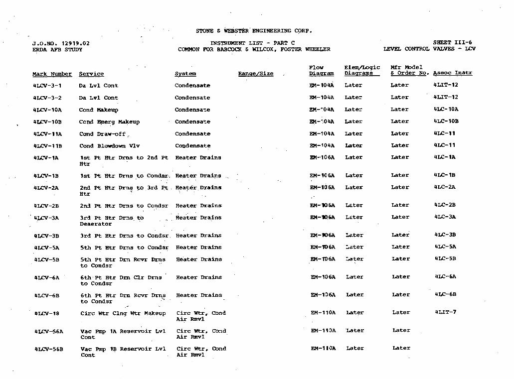
SPONE & ENGINEERING CORP.
WSTRUHENT LIST - PART C COMMON m3 BABCO(R 6 WILCOX, POSTW WHEELER
SHEET 111-6 LEVEL CONTROL VALVES - LCv
F l o w E l e q 5 o g i c Mfr M o d e l D i a p r a m D i a q r a m s & O r d e r No. A s s o c Instr S y s t e m &qe/Size . Mark Number Service
ULCV-3-1 Da L v l C o n t
ULCV-3-2 D a L v l C o n t
ULCV-1 OA C o n d Makeup
C o n d e n s a t e
C o n d e n s a t e
C o n d ensa~e
EM-IOUA ~ a t e r ~ a t e r ULIT-12
EM-1O4A Later L a t e r 4LIT-12
EM-"0UA Later Later ULC- 1OA
C o n d Eplerg W e u p C o n d e n s a t e E?t-:OUA L a t e r
EM-fO4A L a t e r
EM-? 04A Iater
EM-106A L a t e r
L a t e r
L a t e r
Later
Later
C m d D r a w v f f I. C o n d e n s a t e
C a n d Blowdown Vlv C o n d e n s a t e
1 s t Pt Btr Drns to 2 n d P t H e a t e r Drains H t T
1st Pt H t r F s ,to C o n d s r , H e a t e r Drai3s . . , . . Later
Later EM-106A L a t e r 2nd Pt Htr p r y m. 3rd p t . H e a t e r , Drains H t r
2 n d Pt Rtr Drns t o C o n d s r H e a t e r Drains Later
Later . .
3xd ~t ~ t r ~ m s . t o , ., . ~ e i t k mqins D e a e r a t o r
. . Later
Later
3rd Pt H t r Drns t o C o n d s r H e a t e r Drains
5th P t H t r D m t o C o n d s r H e a t e r Drains
UUN-5B 5 t h P t H t r D m Rmm Dqns eater Drabs t o C ~ n d s r
EM-fDt6A 'La ter Later ULC-5B
4 I C V d A 6th Pt Htr D m Qr D r n s H e a t e r Drains to C o n d s r
EM-106A L a t e r Later 4LC-6A
U M N d B 6 t h ~t ~ t r Dm ~ c v r Dm8 B e a t e r Drains t o C o n d s r -
4LCV-18 C i r c Wtr C h g Wtr M a k e u p C i r c W t r , a n d A i r R m v l
EM-136A Later Later 4LC-6B
EM-11OA later L a t e r 4LIT-7
EM-1 I 3 A ' L a t e r Later .
EM-1 1OA L a t e r Later
U r n - 5 6 A V a c Pmp 1A R e s e r v o i r Lvl C i r c ntr, C-nd C o n t Air Ihavl
4 U N - 5 6 B V a c Rap 1B R e s e r v o i r L v l C i r c Wtr, Cbnd C o n t . Air Rmvl
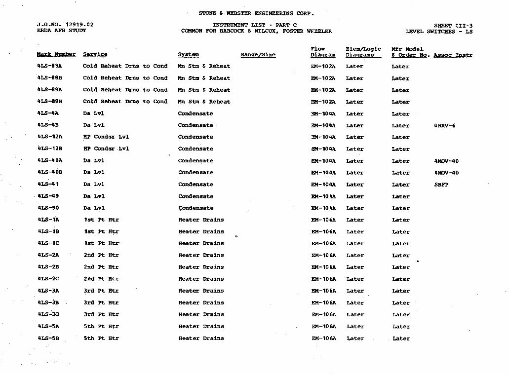
Sr0NE 6 WEBSTW ENGINEERING CORP.
J - 0 - N O . 12919.02 ERDA AFB STUDY
Mark Number
@IS-88A
ULS-8 BB
4 s - 8 9 A
ULS-89B
4 L S 4 A
4 M 4 ~
4 s - 1 2 A
4 G - 1 ZB
4 x 3 4 OA
4 ~ ~ 4 0 ~
4LS-41
i ~ s - 4 9
Service
Cold Reheat Drns t o Cond
Cold Reheat Drns to Cond
Cold Reheat Drns to Qnd
Cold Reheat Drns t o Cond
Da L v l
D a L v l
FW Condsr L v l
HP Qndsr L v l >
Da L v l
Da L v l
Da L v l
Da L v l
QLS-)A 1 s t P t H t r
ULS-1B 1 s t Pt H V
4LS-1C 1 s t Pt H t r
4LS-2A '' 2 n d P t H t r
4 s - 2 B 2nd P t H t r
QLS-2C 2nd Pt H t r
. . 4IS-3B . 3rd P t Htx
ULS-32 3rd Pt Atr
4M-SA 5th P t H t r
4LS-!5B 5th Pt H t r
INSTRUMENT LIST - PART C COMMON FOR BABCOCX 6 WILCOX, FOSTER WEEKXZR
System Plow
Ranqe/Size Diaqram
Mn S t m S Reheat EM-102A
Mn S t m 6 Reheat
Mn S t m 6 Reheat
Mn Stm 6 Reheat
Condensate
Condensate -
Condensate
condensate
Condensate
Condensate
Condensate
Conderisate
Condensate
Heater Drains
Heater Drains 4
H e a t e r Drains
Heater Drains
Heater Drains
Heater Drains
Heater Drains
Heater Drains
Heater Drains
Heater Drains
Heater Drains
Elenl /Lngic Diaqrams
Later
Later
Later
Later
Later
Later
Later
Later
Later
Later
Later
Later
Later
Later
Later
Later
Later
Later
Later
Later
Later
Later
Later
Later
SHEET 111-3 LJ3vEL SHITCaES - LS
M r W e 1 t3 Order N o . Assoc Instr
Later
Later
Later
Later
Later
Later 4 NRV-6
Later
Later
Later 4MllV-40
Later 4IDV-40
Later SBPP
Later
Later
Later
Later
Later
Later . Later
Later
Later
Later
Later
Later
Later
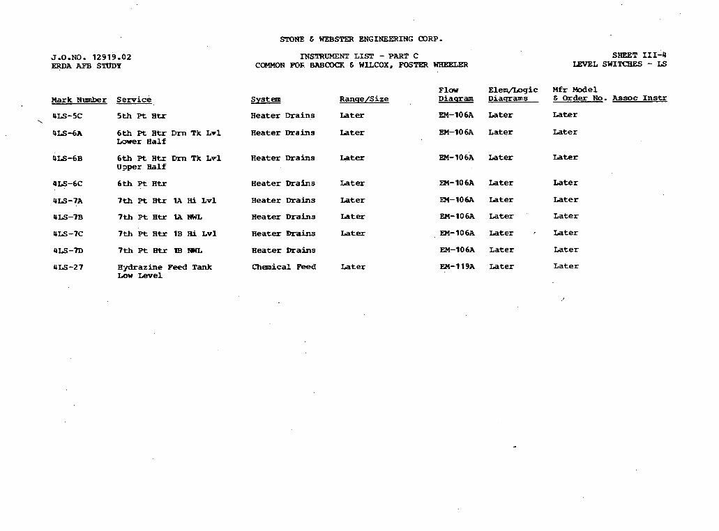
SrONE C WEBS= ENGINEERING CORP-
J.0.NO. 12919-02 -A AFB STUDY
Mark N u m b e r Semice
5th P t B t r
6th Pt B t r Dm Tk L v 1 Lnwer H a l f
6th Pt H t r Tk Lvl Ugper H a l f
6th Pt H t r
7th Pt Btr U Hi L v ~
7th Pt Btr IA tWL
7th 'bt H t r 1B F l i L v l
7 t h P t E t r m N W L
L V - a z i n e Feed Tank Low Level
INSTRUMENT L I S T - PART C COMMON POF. BAB- & WILCOX, FOSTER WHEELER
SHEET 111-4 LEVEL swIms - LS
Flaw E l e m / L o g i c M f r Model S y s t e m R a n q e / S i z e D i a q r a m D i a q r a m s & Order N o . Assoc I n s t r
H e a t e r Drains Later EM-106A Later L a t e r
H e a t e r Drains L a t e r EM-106A L a t e r Later
H e a t e r Drains Later EM-lO6A Later Later
H e a t e r Drains Later
H e a t e r Drains Later
H e a t e r Ihrahs L a t e r
H e a t e r D r a i n s Later
H e a t e r Drains
Chemica?. F e d L a t e r
EM-106A Later
EM-106A Later
EM-lO6A L a t e r
EM-106A Later
Later
Later
Later
Later
EM-106A L a t e r Later
EM-119A Later Later
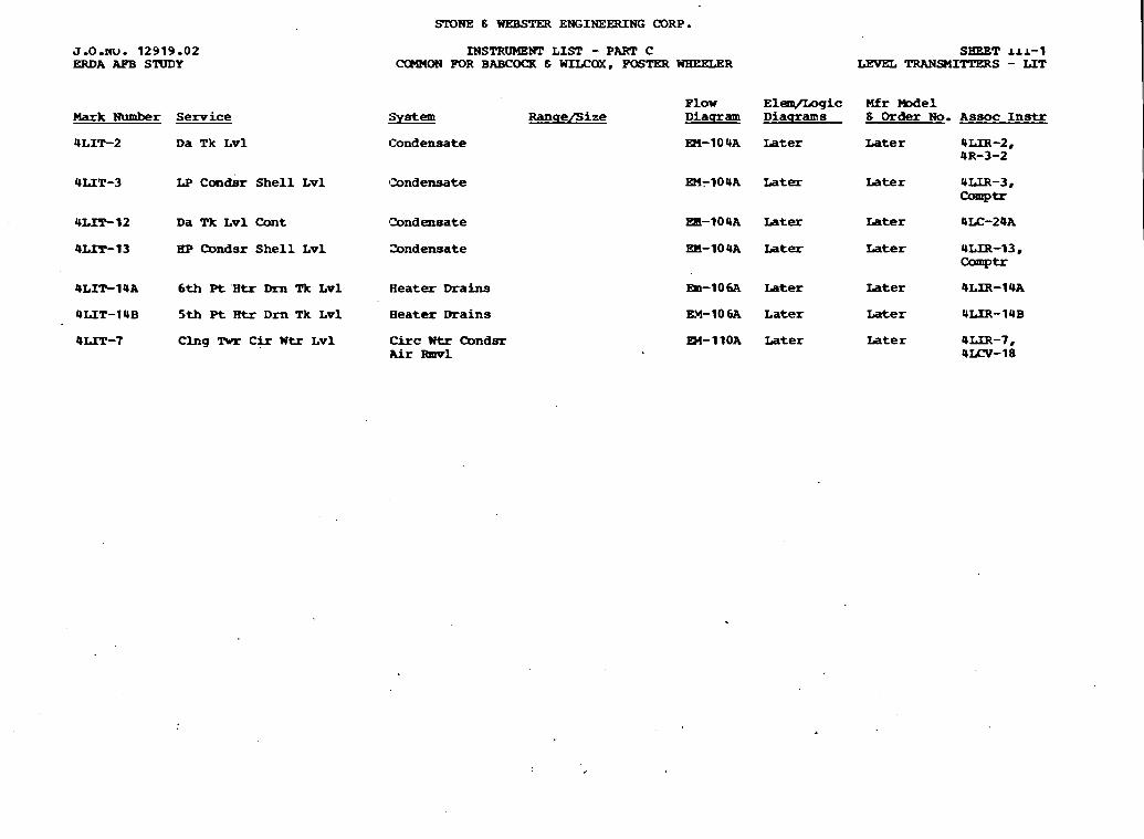
SrOlOE 8 WEBSTER ENGINEERING CORP.
J.0.w. 12919-02 ERDA AF'B SlUDY
Mark Number Service
MSTROMENT LIST - PART C CCtWON FOR BABCOQt 8 WILCaX, POSTER WBEELER
SHEET 111-1 LEVEL TRANSUTTERS - LIT
Plow El-gic Mfr W e 1 iiY&!22 Ranqe/Size Diataram Diaqrams 8 Order No. A s s o c I n s t r
ULIT-2 D a Tk Lv1 Condensate
OUT-3 LP Con& Shell Lvl Condensate
En-IOUA Later Later ULIR-2, UR-3-2
En-104A Later Later ULIR-3, Comptr
UL-12 D a Tk Lvl Cont Condensate Edl-104A Later Later 4LC-24A
@LIT-13 IiP Condsr Shell Lvl andensate EM-10UA Later Later ULIR-13 Comptr
4LIT-14A 6th P t 'Htr Dm Tk Lvl Aeater Drains Em-lO6A Later rater 4LIR-1 UA
QUT-14B 5th P t Rtr D m Tk Lvl Beater Drains EX-10 6A Later Later ULIR-14B
@LIT-7 Clng Twr C i r W t r Lvl Circ Wtr Cbndsr En-11OA Later Later 4LfR-7, Air Rmv1 4LN-18

STONE C WEBSTER ENGINEERING CORP.
J.O.NO. 1 2 9 1 9 . 0 2 ERDA AFB STUDY
Mark Number S e m i c e
ULIR-2 Da S t g Tk L v l
4LIR-3 C o n d s r H o t W e l l L v l
4LIR-13 C o n d s r H o t W e l l L v l
LiLIR-1 4A 6 t h Pt H t r D m Rcvr Lv1
4LIR-t4B 5th Pe Rtr Dm R C V ~ L v l
ULIR-7 C l n g Twr C i r c Wtr L v l
I?JSTRUMENT LIST - PART C COMMON FOR BABCOCK & WILCOX, FOSTER WAEELER
S W t e m
C a n d e n s a t e
C o n d e n s a t e
C o n d e n s a t e
H e a t e r Drains
H e a t e r Drahs
C i r c Wtr C o n d s r Air -1
F l w Ranqe /S i ze Diaqram
EM-104A
EM-IOUA
EM-IOU
EM-10 a
E M - I O ~ A
Dl-1 1 OA
SHEET 111-2 LEVEL INDICATING RECEIVERS - LXR
El -g i c M f r M o d e l D i s c r a m s 6 Order N o . Assoc Instr
Later L a t e r 4LIT-2
L a t e r L a t e r ULIT-3
Eater L a t e r &LIT-13
later L a t e r 4LIT-14A
later L a t e r 4LIT-14B
Eater L a t e r 4LIT-7

J.L....,. 12919 .02 ERDA AFB STUDY
m r k Number Service
4TIR-1 Hn Stm Temp
4TIR-3 H o t R e h e a t O u t l e t H d r
4TI.R-5 Eam W Wtr Inlet
STONE 8 WEBSTW ENGINEERING CDRP.
T W S T R m H T LIST - PART C SHEET 11-3 COMMON FOR BAB(IW & WLLCOX, H)STER WHEgLW TEMPERATURX INDICATING RECEIVERS - TIR
P l o w E l e m / L o g i c Mfr Model SYeZ! R a n s e f i i z e D i a q r a m D i a q r a m s S Order No. Assoc Instr
1
Mn S t m & R e h e a t
Kn Stm 13 R e h e a t
Mn Stm & R e h e a t
EM-102A Later L a t e r 4TR-143, , 4-1
EM-102A Iater ~ a t e r 4TR-145, 4-3
b
m-102A Iater Later 4TT-5

SLT)NE 6 WEBSTER ENGINEERING CORP.
J.O.NO. 12919 .02 ERDA RFB STUDY
Mark Number
URTD-13
URTD-5
Service
-1.d R e h e a t L i n e
Hp Turb E x t S t m to 1st P t H t r
H p C o n d a r Shel l
L p C o n d s r Shel l
5th Pt 3tr O u t l e t
B o o s t BPP Suct
Glnd Stn C o n d O u t l e t
5th Pt Btr Inlet
Boost E m Suct
~d w t r litr 9EH-6 H d r
Pd W t r H t r s Outlet H&
Pd W t r Htrs Inlet H&
3rd Pt H t r to .Da T k
5th Pt H t r Drns to D m R c v r
6 t h Pt Htr Drns t o D m Tk
7th Pt H t r (1A) a p Seal Dm
7 th Pt H t r (1B) Loop Seal D m
6 t h Pt H t r Drn C l r D r n s to Cond
INSTRUMEM' LIST - PART C COMMON FOR BABCOQ[ E =OX, FOSTER
System R a n q e / S i z e
t4n Stm 6 R e h e a t
EKt Stm
C o n d e n s a t e
C o n d e n s a t e
C o n d e n s a t e
C o n d e n s a t e
Condensate
C o n d e n s a t e
Condensate
B o i l e r Feed
B o i l e r Feed
Boiler P e e d
R e a t e r D r a i n s
H e a t e r Drains
B e a t e r Drains
H e a t e r Drains
H e a t e r Drains
SHEET 11-11 WHEELER RESISTANCE TPMPERATURE DETECTORS - RTD
Plow E l e m / L o g i c Mfr M o d e l D i a g r a m D i a q r a m s 6 Order No . Assoc Instr
EP-102~ L a t e r ~ a t e r cowl=
EK-103A Later ~ a t e r c o m p t r
Later
Later
L a t e r
L a t e r
Later .
L a t e r
Later
Later
Later
L a t e r
Later
L a t e r
Later
L a t e r
L a t e r
Later
Later
L a t e r
Later
Later
Later
Later
L a t e r
Later
Later
L a t e r
Later
Later
cow- C o m p t r
C o m p t r
C o m p t r
cow- C o m p t r
C o w -
cow- C o m p t r
Comptr
C o m p t r
C o m p t r
-wtr
EX-lO6A L a t e r Later c o m P t r
H e a t e r Drains R4-106A L a t e r L a t e r
H e a t e r Drains EM-106A L a t e r L a t e r C o m p t r
H e a t e r Drains EM-106A Later Later corn-
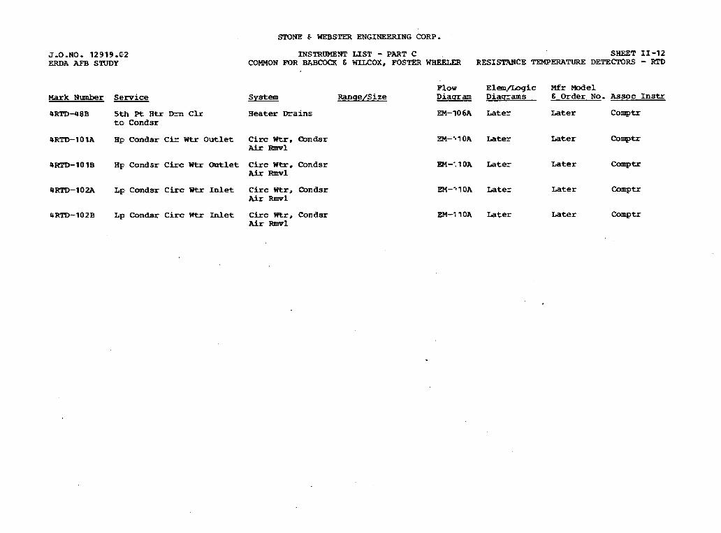
J.O.NO. 12919.'2 ERDA AFB STUDY
Mark Number Service
4RTD-48B 5th Pt R t r Dm C l r t o C o n d s r
4RTD-1OlA Hp C o n d s r C i r W t r O u t l e t
4T(TD-lOlB Hp C o n d s r C i r c Wtr Outlet
QRTD-102A L p C o n d s r C i r c Utr I n l e t
~RTD-102~ ~p C o n d s r C i r c W t r Inlet
SrONE & WEBSTER ENGINEERING CORP.
INSTRUMEm L I S T - PART C SHEET 11-12 COMMON FOR BABCOQC & WLLCOX, FOSTER WHEEtER RESISI?WCE TEMPERATURE DETECTORS - RTD
System R a n q e / S i z e
H e a t e r Drains
Circ W t r , CBz-dsr ALr Ehnvl
C i r c W t r , C o n d s r A h R m v l
C i r c Wtr, C o n d s r Air Rwl
C i r c Wtr, C o n d s r A i r Rmvl
Flov E l a a . / L o g i c Mfr M o d e l D i a q r a m D i a s r a m s E O r d e r No. A s s o c I n s t r
EM-10 6A L a t e r Later C o m p t r
ZM--~lOA Later Later
EM-'. 1 OA L a t e r Later C o m p t r
EM-'1OA Later Later C o w -
EM-; 1OA L a t e r Later C o m p t r
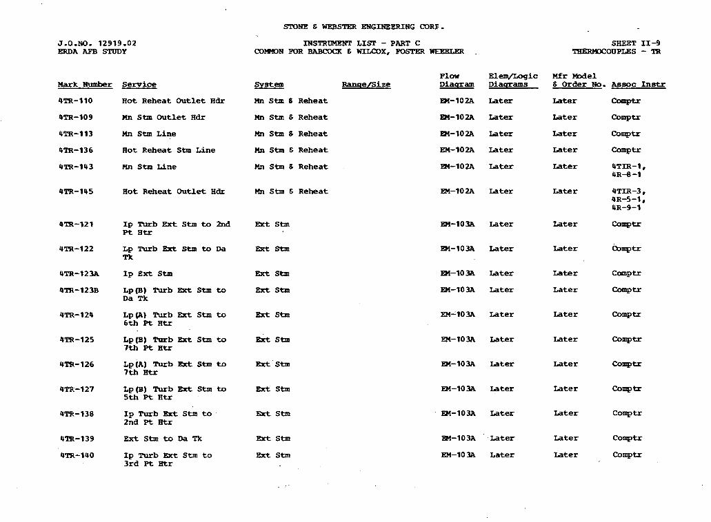
SlQNE & WEBSTER ENGINEERING CORE.
INSTRUMENT L I S T - PART C C O m N FOR BABCOCK E WIUXIX, F O S r W WEELW .
F l w Elen\/Logic Mfr Model Ranqe/Size D i a q r a m D i a q r a m s 6 O r d e r No. Assoc Ins t r Hark Numbr Service
4TR-110 H o t R e h e a t O u t l e t H d r
4TR-109 Hn Stm O u t l e t H d r
4TR-113 Mn Stm L i n e
4TR-136 H o t Reheat Stm Line
4TR-143 Mn Stm LFne
System
Mn Stm S R e h e a t EM-102A Later Later Coop>tr
Mn Stm 6 R e h e a t RJI-102A Later Later COrnPtr
Mn Stm S R e h e a t Rd-102A L a t e r L a t e r c o m p t r
h ~tm 6 R e h e a t En-102A Later Later comptr
Mn Stm 6 R e h e a t EM-102A L a t e r Later 4TIR-1, 4R-B -1
4TR-145 H o t R e h e a t O u t l e t H d r Mn Stm & R e h e a t EM-102A L a t e r L a t e r UTIR-3, 4R-5-1, 4R-9-1
E5Kt Stm En-103A L a t e r Later C-tr 4IR-12 1 I p Turb Ext Stm to 2nd Pt H t r
a - 1 0 3 ~ ~ a t e r Later bxuptr
EM-1034 Later Later C m p t r
EM-103A Later L a t e r C o m ~ t r
4TR-12 3A I p Ext Stm Ext Stm
Brt stm 4TR-123B Lp(B) Turb Ext Stm to D a Tk
4TR-124 L p (A) Turb Ext Stm to 6 t h ~t ~ t r
Later L a t e r c o m p t r
4TR-125 Lp(B) Rnb Ext Stm to 7 t h P t Htr
Ext Stm Later Later C o m p t r
UTR-126 Lp(A) Turb gxt Stm to 7 t h H t r
Later Later COW=
4TR-127 L p (B) Turb R t Stm to 5 t h Pt H t r
Later L a t e r COmPtr
4-138 I p Turb Ext Stm t o 2nd Pt Btr
L a t e r L a t e r C o m p t r
L a t e r Later C o m p t r
L a t e r Later a m p -
428-139 Ext Stm to Da Tk Brt Stm
QTR-140 I p Turb Ext Stm t o 3rd Pt atr
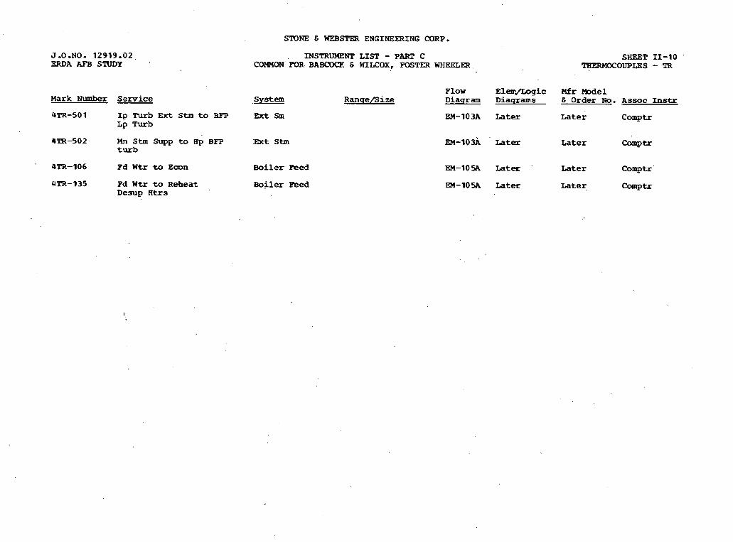
J-0-NO. 1 2 9 1 9 - 0 2 ERDA AFB STUDY
Mark Number S e r v i c e
4TR-50 1 I p Turb E x t Stm to BFP Lp Turb
4ZR-502 Mn Stm Supp to Ap BFP turb
4TR-106 Pd Wtr tb Eoon
4TR-135 Fd W t r to R e h e a t Desup ' K t r s
STQNE E WEBSTER ENGINEERING CORP-
INSTRUMENT LIST - PART C SHEET I1 -10 COMMON 'FOR. B A B ~ . s WIXOX, FOSTER WHEELW TI~ERMOCOUPL~S - TR
F l o w E l e m D g i c Mfr Model S y s t e m R a n q e / S i z e Diaqram Diaqrams E Order N o . A s s o c Instr
F x t Sm EM-10% Later L a t e r Comptr
:Ext Stm EM-IO& ' ~ a t e r L a t e r Comp tr
5oiler Pee3
Boiler Peed
EM-10% L a t e r
EM-105A L a t e r
L a t e r Comptr
Later, mtr

Hark Number Semice
STONE 6 WE- ENGINEERING CORP.
INSTRUMENT LIST - PART C COWON FOR BABCWX E WILCOX, FOSTER WBEELW
system
Air Rmvl
Q'IH-69C C l n g Rrr Circ W t r Outlet C i r c W t r , Condsr A i r Ihavl
SHEET 11-7 TESTWELLS-'IW
Plow E l e m / L o g i c Mfr Model R a n q e / S i z e D i a q r a m D i a q r a m s 6 Order N o . Assoc Instr
EM-11OA N/A Later
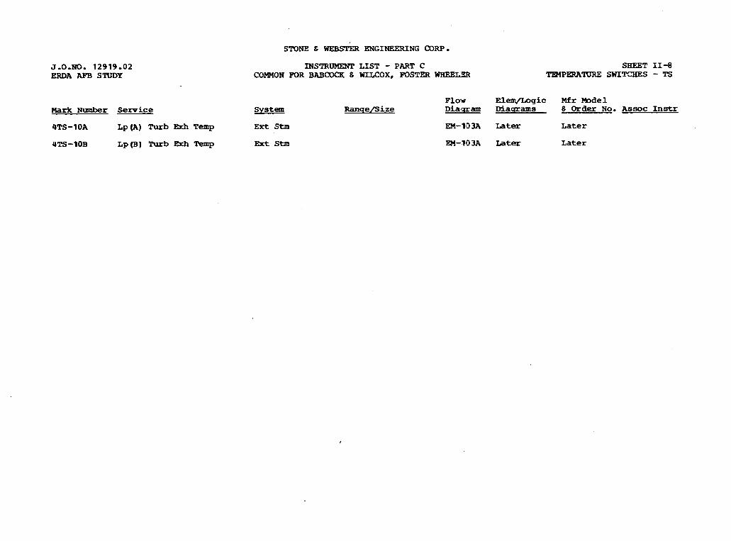
J.O.NO. 1 2 9 1 9 - 0 2 ERDA APE STUDY
S'IT)NE 6 WEB= ENGINEERING CORP
INSTRUMENT LIST - PART C COMMON FOR BAB(IDCR 6 WILCOX, POSTER WHEEIZR
SHEET 11-8 TR4PERATUR.E SWIT!XES - TS
F l o w Elem/Logic Mfr Fbdel ark N u m b e r Service S y s t e m R a n q e l S i z e Dia-qram Diacrrams 6 Order N o . A s s o c Instr
4TS-1OA ~p (A) ~ u r b BEh Temp E x t Stm EM-1-33A Later ~ a t e r
4TS-IOB Lp(B1 m b Temp Brt Stm EM-lO3A Later Later
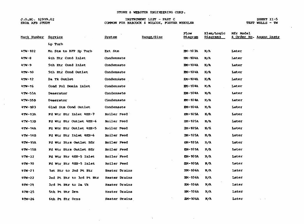
STONE & WEBSTER ENGINEERING CORP.
Mark N u m b e r Service
L p Rrrb
Mn Stm to BPP H p Turb
6 t h H t r C o n d Inlet
5th H t r Cond In l e t
5th H t r Cond Outlet
D a Tk Outlet
Cond Pol D e m h Inlet
D e a e r a t o r
D e a e r a t o r
G l n d S t m C o n d O u t l e t
Pd W t r H t r Inlet QKH-7
Pd W t r H t r Outlet 4EH-6
W W t r H t r O u t l e t 4EH-5
Pd W t r H t r Inlet 4E8-6
Fd W t r H t r s O u t l e t H d r
Pd W t r H t r s O u t l e t H d r
m W t r H t r urn-5 Inlet
W W t r H t r 9EB-5 Inlet
1st H t r t o 2nd Pt H t r
2nd P t H t r t o 3rd Pt H t r
3rd Pt H t r t o D a Tk
5th Pt H t r Dm
6 t h Pt H t r Drns
INSTRUMENT LIST - PART C COMMON FOR BABCOCK 6 WILCOX, WSTW UHJBLER
F l o w ElemJl[rogic Mfr W e 1 R a n q e / S i z e M a c r a m D i a u r a m s & Order No. Assoc Instr
Ext S t m
C o n d e n s a t e
Qndensate
C o n d e n s a t e
C o n d e n s a t e
C o n d e n s a t e
Condensate
C o n d e n s a t e
Condensate
Boiler F e e d
B o i l e r Feed
Boiler Peed
B o i l e r Feed
B o i l e r Peed
Boiler Feed
B o i l e r Feed
Boiler Feed
H e a t e r Drains
H e a t e r Drains
H e a t e r Drains
H e a t e r Drains
H e a t e r Drains
L a t e r
Later
Later
Later
Later
L a t e r
Later
Later
Later
Later
L a t e r
Later
Later
Later
Later
Later
EM-10- N / A Later
EM-106A N/A Later
EM-106A N/A ~ a t e r
EM-106A H/A L a t e r
m - 1 0 6 A 10/A L a t e r
EM-lO6A N/A Later
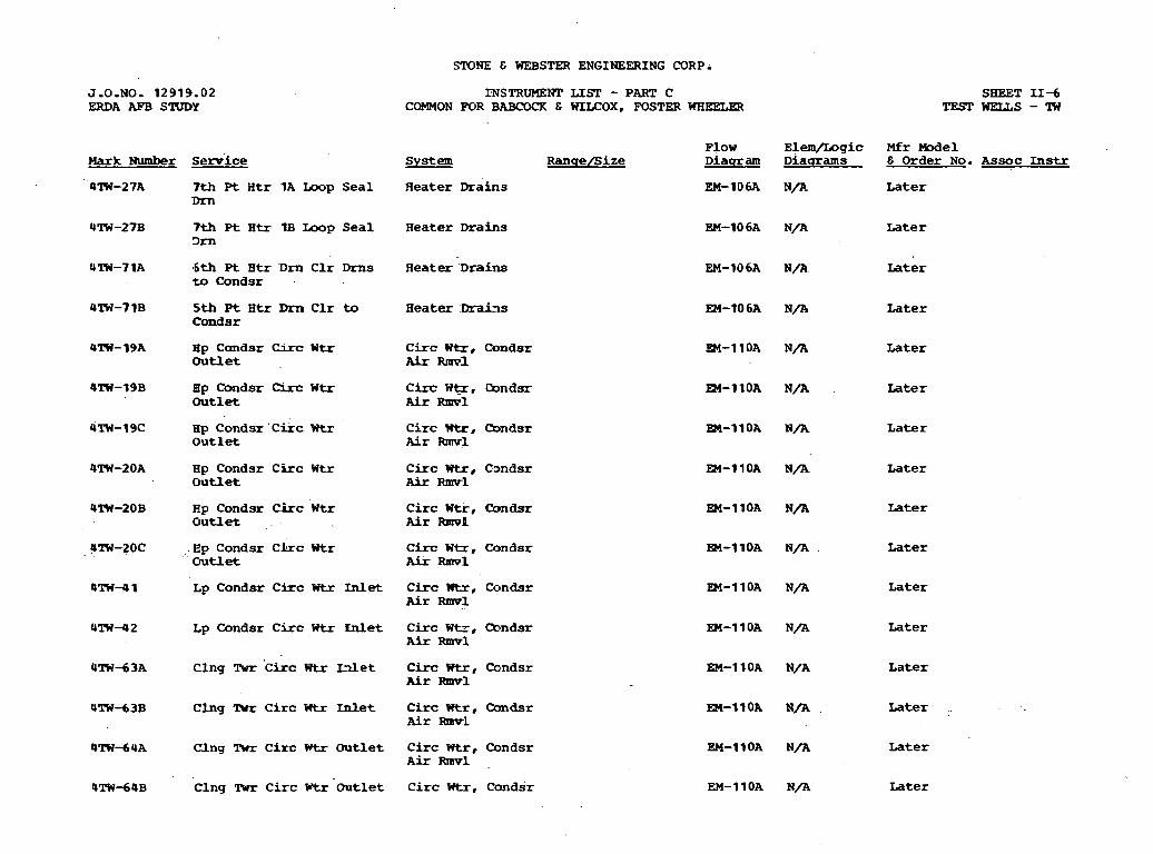
STONE & WEBSTER ENGINEERING CORP.
rNSTRUMENT LISP - PART C C-ON FOR BABCOCK & WILCOX, FOSTER WRELW
F l o w E l e m / L o g i c M f r M o d e l Mark Number S e r v i c e S y s t e m R a n q e / S i z e D i a q r a m D i a u r a m s E O r d e r No. A s s o c Instr
4lW-2 7A 7th Pt H t r 1A Ump Seal H e a t e r Drains EM-106A Nfl- L a t e r Dm
4TW-27B 7 t h P t H t r 1B Loop Seal H e a t e r Drains 3rn
EM-106A N/A Later
4TW-7 1A ' 6 t h Pt H t r D m C l r Drns H e a t e r D r a i n s t o C o n d s r .
EM-IO6A N/A. Later
4lW-7lB 5th P t Htr Dm C l r to H e a t e r Ikai~s Conds r
EM-106A N/A Later
OW-19A Hp C o n d s r Circ Wtr C i r c W h r , Condsr Outlet A h Rnml
EM-1lOA N/A Later
4lW-19B ap C m d s r C i m Wtr C i r c W q , Cbndsr O u t l e t A i r Rmv1
~ T W - 1 9 ~ H p C o n d s r ' C i i c Wtr C i r c W t r , C D n d s r O u t l e t Air R m v l
EM-11OA N / A Later
EM-11OA N/A L a t e r
4TW-20A Hp C o n d a r C i r c Wtr C i r c W t r , C o n d s r O u t l e t A i r Rmvl
a i - l l O A N/A. Later
4lW-208 H p C o n d s r C i r c Wtr C i r c W t r , Condsr O u t l e t Air RmwP
EM-1POA N / A L a t e r
9TW-20C .Ep C o n d s r C h c Wtr C i r c W e , C o n d s r O u t l e t A i r Rlml
m-11OA N / A Later
4 l W 4 1 Lp C o n d s r C i x c Wtr Inlet C i r c W t r , C o n d s r Air Rmv1
PI-11OA N / A Later
4 l W - 4 2 Lp C o n d s r C i r c Wtr Enlet C i r c W t z , Cbndsr A i r Rmvl
EM-1lOA N / A Later
4 T W d 3 A C l n g Twr ' ~ i r c W t r Lllet C i r c W t r , C o n d s r Air Ftmv1
EM-1 1OA N/A L a t e r
4 lW-63B C l n g 'Rrr C i r c U t r Inlet C i m Wtr, C h n d s r Air R m v L
EM-1IOA N / A L a t e r ..
4lW-64A Clng Twr Cimrc Htr Outlet C i r c W t r , C o n d s r A i r -1 .
EM-11OA N / A Later
UTW-64B Clng !IWr C i r c W t r . 0 u t l e t C i r c Wtz, C o n d s r EM-11OA N/A Later

ST3NE 6 WEBSTER ENGINEERING CORP.
INSTRUKEHT LIST - PART ' C COMMON Er3R BABCOCK & WILCOX, FOSTER WHEELEP.
SHEET 1 1 - 4 TEST WELLS - !lW
J.O.NO. 1 2 9 1 9 . 0 2 ERDA AFB STUDY
Flow Diacr am
EM-1 0 2A
EM-102A
a-162A
EM- 1 0 2A
EM-10 2A
EM-WZA
m-W2A
EM-lo2A
EM-102A
EM-m2.A
E M - D M
Mfr Model & Order No. A s s o c 1x1s- Mark Number
4TW-1A
4TW-1B
4TW-2A
4TW-2B
4TW-3A
4 m - 3 B
4TW-388
4TW-56
4 T W 3 7 A
4'lW-58
4TW-4
Serv ice
Cold Reheat
Cold Reheat
System Ranqe/Size
Main Stm E Reheat
Main Stm 6 Reheat
Hain Stm & Reheat
Hain Stm 6 Reheat
Main Stm & Reheat
Main Stm 6 Reheat
Main Stm E Reheat
Main Stm 6 Reheat
Main Stm E Reheat
Main Stm 6 Reheat
La te r
La te r
La te r Mn Stm Hdr
Mn Stm Hdr La te r
La te r H o t Reheat
Hot Reheat La te r
Stm Drain Later
La te r Mn Stm O u t l e t Hdr
Cold Reheat Desup O u t l e t La te r
La te r
La te r
Hot Reheat Ou t l e t
I D Turb Ext Stm t o 2 n d D t Htr
Ext stm
Lp Turb E x t Stm to Da Tk
BR Stm anlooa N/A Later
Ip Turb Ext shm adr B r t Stm
BR Stm
mt Stm
EM-1D3A N / A ~ a t e r
EM-13- N/A Later
m - 1 3 m N/A Late r
EM-133A N/A Late r
E M - 1 3 ~ N/A Later
EM-133A N / A Iater I p Rrrb Ext Stm t o 3 r d Pt Htr .
EX-1113A N/A Late r
.R4-103A N/A Late r
Ext Stm
Ext Stm Ip Rrrb Ext Stm t o BEP
*By ipnent Manufacturer

J-U-NU. 12919.02 ERDA AFB STUDY
Mark 'Number S e m i c e
STONE 6 WEBSTER ENGINEERING CORP.
INSTRUMFNT LIST - PART C SHEEZ LL-1 C W O N FOR BABCOCK 6 WILCOX. FOSTER TmfPgRATURE TRANSMITTERS - 'IT
?low Elemlf iog ic Mfr Model Syatem Ranqe/Si z e 3ia-8n Diaqrams 6 Order No. A s s o c I .
Urn-1 Super ' R t O u t l e t Main Steam
Urn-3. Hot Reheat Main Steam
OTT-5 E c o n d z e r Inlet H d r B o i l e r Peed
ZM-102A L a t e r L a t e r 4 T n - 1 . 4R-8-1
3l-102A Later L a t e r UTIR-3, 4R-5-1, 4R-9-1
3M-105A L a t e r Later 4TIR-5

J.O.NO. 12919.02 ERDA AFB SWDY
Mark Number Service
STONE 6 WEESTER ENGINEERING CORP.
INSTRUMENT LIST - PART C SIfEET 11-2 COMMON P3R EABCOCR 6 WILCOX, FOSTER WHEELER mPERATURE CONTROL VALVES - CV
F l o w E l e m , Z o g i c Mfr M e 1 Svstem R a n q e / S i z e Diagram D i a q r a m s 6 Order No. A s s o c Instr
4CV-11 Reheat Desuperheater B o i l e r F'eed 'Penp C o n t r o l V a l v e
4CV-13 Superheater Desuper- Boiler Feed heater PSH-1
EM-10% Later Later
R4-105A Later Later
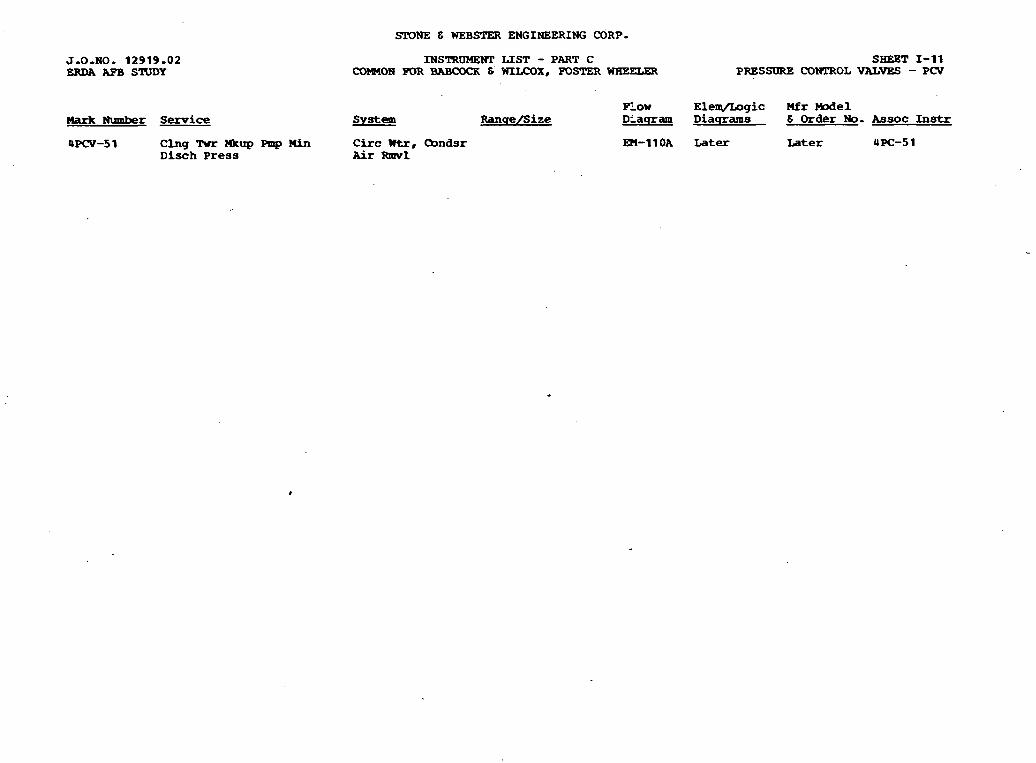
Hark Number S e r v i c e
SPONE E WEBSTER ENGINEERING CORP-
INSTRUMENT LIST - PART C SEIEBT 1-11 COMON FOR BABC0<3R 6. WILCOX, POSTER WHEELeR PRESSDRE CONTROL VALVES - PCV
s y s t e m
4PCV-5 1 Clng Rrr Mcup Pmp H i n C i r c W t r , Oondsr D i s c h P r e s s Air Wwl
Flow Elem/Logic Mfr Model Ranqe/Size D l a q r a m D i a q r a m s 6 Order N o . kssoc Instr
EM-1lOA Later Later UPC-5 1
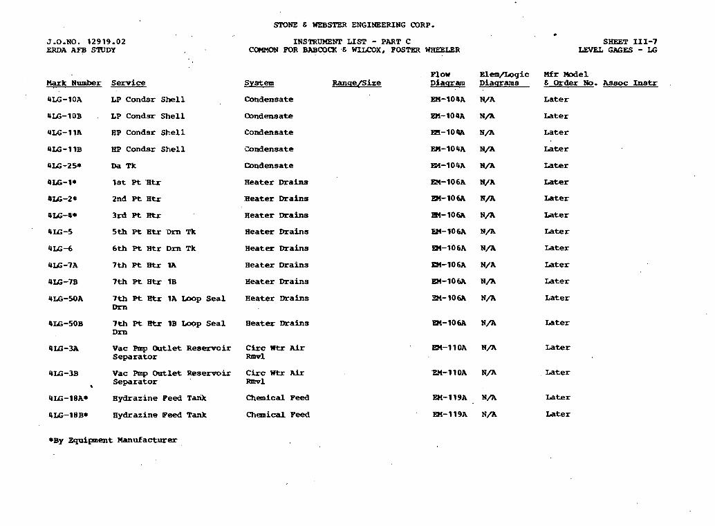
STONE E WEBSTER ENGINEERING CORP.
J-0 -NO. 1 2 9 1 9 . 0 2 ERDA AFB STUDY
INSTRUMENT LIST - PART C COMMON FOR BABCOCK . . .E WILCOX, POSTER WHEELeR
SHEET 111-7 LEVEL GAGES - I&
Fl ow Elem/Logic Mfr Model System RanqeIS ize Diaqram Diaqrams 6 0 r d e r N o . A s ~ o c I n s t r . Mark N u m b e r Semice
4LG-10A LP Condsr Shell Condensate En-lO4A N/A Later
4IG-10B . LP Cond.sr Shell Qnd ensate En-lO4A N/A Later
4LG-11A HP Condsr Shell Condensate m-IOPA N / A ~ a t e r
4 U - 1 1B HP Condsr Shell ~Zondensate
Condensate
Later
Later
Later
Later
Later
Later
Later
Later
Later
Later
Weater Drains
Heater Draina
Seater Drains
Heater Drains
Heater Drains
OX&-21 2nd Pt H t r
@I&-@* 3rd Pt R t r
BIG-5 5th P t H t r D m Tk
4 I G - 6 6 t h Pt H t r D m Tk
Heater Drains
Heater Drains
Heater Drains
4I&-7B 7 t h Pt H t r 1B
ULG-SOA 7 t h P t Htr 1A Iaop Seal Dm
OX-SOB 7th pt. Btr 1B Loop Seal Drn
Heater Drains Later
@I&-3A Vac Rnp Outlet Reservoir Separator
Circ W t r Air Fanvl
Later
4I&-3B Vac Pmp Outlet Resemir Separator
a
Citc Wtr Air mnvl
Later
Later 4IL;-18A* Hydrazine Peed Tank Chenical Peed
Chenical Peed EM-119A N/A Later 9I&-18B* Hydrazine Peed Tank
*BY Equipment Manufacturer

SMNE 6 WEB= ENGINEERING OORP.
J.O.KO. 12919.02 ERDA AFB STUDY
Mark Number S e r v i c e
INSTRUMENT LIST - PART C SHEET 1-9 COMMON FOR BABCOCR 6 WILCOX, POSTER WaeELW PRESSURE DIPFeRENTIAL SWrrCBES - PDS,
P D I S
Plow E l e m / L o g i c Mfr Me1 S y s t e m Ranqe/Size Diaqram D i a u r a m s 6 Order No. Assoc Instr
OPDS-25A Cond Fmp 1A Shaft Seal Condensate 2-15 P s i g EM-1O4A L a t e r L a t e r w t r F l t D i f f
Om-25B Cmd Pmp 1B S h a f t Seal Cand ensate 2-15 P s i g En-104A Iater L a t e r W t r P l t D i f f
4H)IS-5 1 C i r c Utr Mkup Pmp Backwsh Circ Wtr, Condsr S t r n r AFr m1
YPDIS-52 C i r c ' t? t r S c r e e n w e l l C i r c W t r , Qndsr Screen D F f f Air Rmvl
EII-11OA L a t e r L a t e r
EX-11OA L a t e r L a t e r

%ONE S WEBSTER ENGINEERING CORP.
J.O.NO. 1 2 9 1 9 . 0 2 ERDA AFB SlWDY
NSTRUMEKP LIST - PART C SHEET 1-10 COMMON !?OR SABCOCX E WILCOX, FOSTER PRESSURE REGUIATING VALVES - PRV
F l o w . E l e m / L o g i c Mfr M o d e l Mark Number Service S y s t e m Ranqe /S i z e D i a q r a m D i a q r a m s I% Order No. kssoc Instr
4 P R V d A C o n d Pmp 1A Shaft Sealing Condensate L a t e r EM-104A L a t e r L a t e r 4PC-6A
4PRV-6B C o n d Pmp 1B Shaft Sealing Z o n d e n s a t e L a t e r EM-104A L a t e r L a t e r 4PC-6B
UPRV-25~ m n i a C y l KO. 1 Outlet Zhem Fee3 uter m-119~ ate- L a t e r N/A
9PRV-25B Ammonia C y l No. 2 O u t l e t Chem Feed L a t e r EM-119A Later . L a t e r N/A
SPRV-25C Ammonia C y l Ro. 3 O u t l e t ilhem Feed Later EM-119A Later Later N/A
4PRV-38 Instr Air S w l y Cond Pol EM-128A
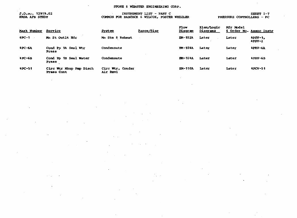
SIT)NE 6 U~STH( ENGINEERING CORP.
J - 0 - n u . 12919.02 ERDA AFB STUDY
Mark Number Service
4PC-1 . Mn S t O u t l t B d r
4 P C d A Cond Pp 1A Seal Wtr Press
4 P C d B Cond Pp 1B Seal Water P r e s s -
4PC-51 Circ W t r PDrup Rap D i s c h Rws C o n t
INSTRUMENT LIST - PART C COMMON POR BABOOCK & WILCOX, WSTW WBE9.ER
.System R a n q e / S i z e
Mn S t m 6 R e h e a t
C o n d e n s a t e
C o n d e n s a t e
C i r c Wtr, C o n d s r Air Rmvl
SHEET 1-7 PRESSURE CONTROLLERS - PC
Plow Elem/I .ogic M f r W e 1 M a q r a m D i a q r a m e 8 Order No. A s s o c I n s t r
EM-102A L a t e r . Later 4PSV-1, 4 P a - 2
PM-104A L a t e r L a t e r 4PRVdA
R4-104A Later Later 4PRV-6B
EM-1lOA L a t e r Later 4PCV-5 1
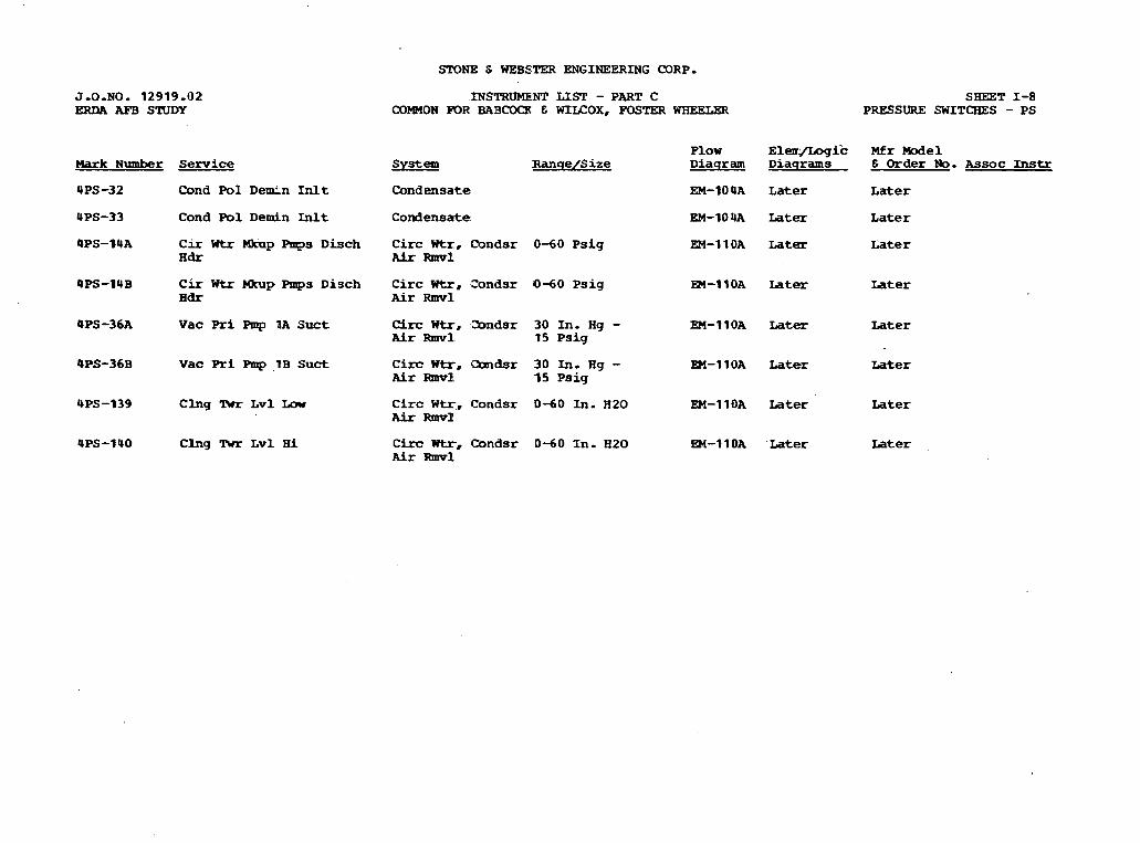
STONE S WEBLC.TER ENGINEERING CORP,
Mark Number Service
4PS -32 Cond P o l D e e n Inlt
4PS-33 Cond P o l Demin L n l t
4PS-14A C i r ntr h p Pups D i s c h Iidr
4PS-14B C i r Wtr Hkup Pmps D i s c h H d r
4PS-36A V a c Pri Pmp 1A Suct
4PS-36B V a c Pri Pmp ,BB Suct
4PS-139 C l n g 'Rrr L v l Low
UPS-1UO C l n g Rrr L v l H i
INSTRUMENT LIST - PART C COMMON FQR BABCOCR E WIICOX, FOSTER WREELgR
SgEET 1-8 PRESSURE SWITCHES - P S
F l o w E l e a J L o g i c M f r Model S y s t e m :Ranqe/S i ze D i a q r a m D i a q r a m s 6 Order No. Assoc Instr
C o n d e n s a t e EM-10 OA L a t e r L a t e r
C o n d e n s a t e EM-1OUA Later L a t e r
C i r c Wtr, Condsr , 0 4 0 P s i g EM-11OA L a t e r L a t e r AFr Rmv1
C i r c Wtr, =ondsr 0 - 6 0 P s i g R4-11OA L a t e r L a t e r Air Ihmrl
Circ Wtr, -2ondsr 3 0 In. Hg - EM-11OA Later Later Air R m v l 1 5 P s i g
C i r c Wtr. Condsr 3 0 In, Hg - EM-11OA Later Later Air -1. 15 P s i g
C i r c W t r . C o n d s r 0 6 0 In. A20 EM-11OA L a t e r L a t e r Air Ihnv11
C i r c Wtr, C o n d s r 0 - 6 0 I n - H 2 0 EM-1 lOA ' L a t e r Later Air Rmvl

J.O.NO. 1 2 9 1 9 - 0 2 ERDA APB STUDY
STONE E WEB- ENGINEERING CORP.
INSTRUMENT LIST - PART C SHEBT 1-5 C M O N FOR BABCXXX E WILCOX, PaSTKR WBEELER PRESSURE DIFPEREKPUU, TRAXSMIlTERS - PDT
Mark Number Semice 2lssz RanqelSize
4PDl'-2 1 P r e s s D F f f B e t BYP and B o i l e r m d B c o n L n l t
F l o w Bl-ic M f r -el Diaqram D i a q r m s 6 Order No. Assoc Instr
Bl -10 SA . L a t e r L a t e r
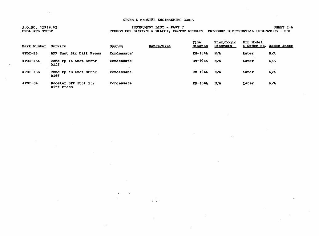
J.O.NO. 1 2 9 1 9 . 0 2 ERDA AE'B STUDY
Mark Number Service
4 P D I - 2 3 BFP Suct Str D i f f P r e s s
4PDI-25A Cond Pp 1A S ~ c t Strnr . D i f f
UPDI-25B Cond Pp 1B Snct Strnr D i f f
4PDI-34 B o o s t e r BFT Suct S t r D i f f P r e s s
.SEINE 6 WEBSTER ENGINEERING CORP.
INSmUMEYT L I S T - PART C SBEET I d COMMON FOR BAMIO<IK E WILCOX, FOSPEX WIEELER PRESSURE DIFFERENTIAL INDICATORS - P D I
P l o w ELem,'Logic Mfr Model System R a n q e / S i z e Diaqram DLaqrams 6 O r d e r No. Assoc Instr
C o n d e n s a t e - EM-104A N,% Later N / A
C o n d e n s a t e
*
C o n d e n s a t e
m - 1 0 U A N,% L a t e r N / A
EM-104A N/'A L a t e r N / A
C o n d e n s a t e EM-1OUA Y / a Later N/A

SHEET 1-3 PRESSURE TRANSMXTIZRS - PIT
J.0.NO- 12919.02 ERDA APB S'RJDY
INSIRUMENT LIST - PART C COMnON POR BAB(?O(K 6 =OX, FOSTER WHEELER
Elen\/Ingic Mfr We1 D i a q r a m s 6 Order No. Assoc Instr Mark Number Service,
4PIT-1 Mn Stm H d r Press . Hn Stm 6 R e h e a t W-10 2A L a t e r Later 4PI-10, 4R-4-2 #
C o m p t r
~ a t e r Later @PI-23 4PIT-4 HP hrrb Intrstage Press
4PIT-9 H o t R e h e a t Press
Hn Stm 6 R e h e a t
Mn Stm 6 R e h e a t Later Later 4PI-12, mmptr
4PIT-138 Turb S& C h e s t . Press
4PIT-21 C o l d R e h e a t Press
Hn Stm 6 R e h e a t EM-102A
Hn Stm 6 R e h e a t E4-102A
Later Later ComP-
Later Later
Rn Stm H d r Press Mn Stm S R e h e a t m-102A Later Later 4PI-47, C o m p t r
C o l d Reheat Press Mi Stm S R e h e a t 83-10% Later Later
AP Turb Interstage Press- Mn Stm S R e h e a t
HP Turb Interstage Press Mn Stm S R e h e a t
Mn Stm H d r Ress . MN Stm 6 R e h e a t
LP (A) Turb Exh Press Ext Stm.
=-lo% L a t e r
m-102A Iater
EM-10% Later
EH-103A Later
L a t e r
Later
L a t e r
Later 0-30 In. Hg
LP (B) Turb Exh Press ExtStm 0-30 In. B g 34-103A Later Later 4PI-18Bn C o m p t r
I P Rnb Exh Stm to 2nd EKt Stm Pt H t r Press
30 In. E g to 300 P s i g
:gM-l03A Later Later
30 In. Hg to 200 P s i g
R4-10%. L a t e r Later LP Turbs E x t Stm t o stm DA Tk P r e s s
30 In. B g t o 100 P s i g
EM-103A Later Later IP ~ u r b ~ x t stm press m Stm
'EM-103A Later HP Turb E x t Stm t o 1st E x t Sta! Pt H t r Press
L a t e r
I P Turf, Ext Stm t o 2 d Ext Stm Pt H t r
i -15 t o +200 P s i g EM-10% L a t e r Later

SrONe & WEBSTEa ENGINEERING CORP.
J-0-NO. 12919..02 ERDA AFB STUDY
Mark N u m b e r S e r v i c e
4PIT-40 I P Turb F k t S t . t o 3 rd P t H t r
4PIT-305 I P Rrrb Ext Stm t o 3FP LP Turb
4PIT-306 MI Stm Supp t o BFP I i P 'hub
4PIT-10 Cond Pmp 1A Disch
4PIT-11 Cond Pmp 1B Disch
4PIT-12 Boos t Pd Pmp S u c t
4PIT-26 Cond Rnps Common Disch
4PIT-39 DA P r e s s
4PIT-14 Fdwtr Econ Iiilt Press
4PIT-28 BPP Disch P r e s s
UPIT-4 1 5kh Pt H t r D m
4PIT-42 6 t h Pt Htr Dm
4PIT-44A 7th Pt H t r (1A) S h e l l
4PIT-44B 7th'Pt H t r (1B) S h e l l
4PIT-24 C i r c W t r Mk-ap P p s D i s c h Hdr
INSTRUMENT LIST - PART C COMMON FOR BABCOCK 6 WILCOX, FOSTER WHEE-LEZ
Plow System Ranqe/Size D i a ~ a m
E x t Stm -15 to +I00 P s i g EM-503A
Condensate EM-1 0 4~
Condensate R4-10 4A
Condensate EM-1 C* 4A
Condensate -15 t o +200 P s i g EM-1Cm4A
B o i l e r Feed EM-IC 5A
B o i l e r Pee2 EM-IC 5A
H e a t e r IDrahs -15 to +30 P s i g EM-1 C 6A
H e a t e r 3 r a b -15 to +15 P s i g EM-1E6A
H e a t e r D r a b -15 to +15 P s i g EM-1 C 6A
Heater D r a h -15 to +15 P s i g EM-106A
C i r c Wt- 0-60 EMllOA
SHEET 1-4 PRESSURE TRANSMITTERS - P I T
Elea\/Logic Mfr Model Diaqrams & Order No. Assoc Instr
L a t e r ~ a t e r a m p -
Lat-s L a t e r Comptr
La t , e r L a t e r ComP*
Later L a t e r 4PI-25, Comptr
L a t e r ~ a t e r 4PI-26, Comptr
L a t e r L a t e r 4PI-28, Comptr
L a t e r Later ComPtr
L a t e r L a t e r Comptr
L a t e r L a t e r 4PI-13, Comptr
-Later L a t e r 4PI-7, Comptr, BPPT Cont
-Later L a t e r -we Later L a t e r -P-
Later L a t e r COW-
Later L a t e r ?
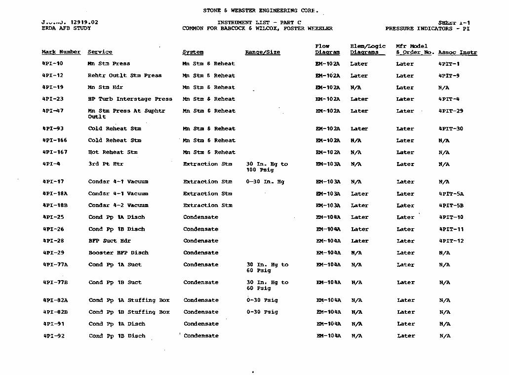
STOF 8 WEBSTER ENGINEERING CORE.
5-w.a.3 . 12919.02 ERDA AFB STUDY
Mark N u m b e r Serv ice
QPI-10 Hn S t n Press
INSTRUMENT LIST - PART C COMMON FOR BABCOCK 6 WLLCOX, FOSTER WEEKXXR
sHh5-1' 1-1 PRESSURE INDICATORS - P I
Plow Elem/Ingic Mfr Model System Ranqe/Size D i a q r a m Diaqrams 8 Order No. Assoc Instr
Mn Stm 6 Reheat EM-102A La te r La te r 4PIT-1
4PI-12 Rehtr O u t l t Stm Press Mn Stm 6 Reheat EM-102A Later La te r 4PXT-9
4PI-19 Hn Stm H d r Mn Stm 8 Reheat EM-102A N / A La te r N/A
4PI-23 LIP T u b I n t e r s t a g e Press Mn Stm 8 Reheat EM-102A La te r L a t e r UPIT-4
4PI-47 Mn Stm Press A t Suphtr Mn Stm 8 Reheat outlt
EM-1O2A La te r Later 4PIT-29
4P1-93 Cbld Reheat Stm Mn Stm 6 Reheat EM-102A Later La te r 4PIT-30
@PI-166 Cold Reheat Stm ' rn ~ t m 8 Reheat EM-102A N/A La te r N / A
4PI-167 Hot Reheat Stm Mn Stm 6 Reheat EM-102A N/A La te r N/A
Extract ion Stm 30 In. Hg t o 83-10- N/A La te r N / A 100 Ps ig
4PI-17 Condsr 4-1 Vacuum Extract ion Stm 0-30 In- Hg EM-10- N/A La te r N/A
@PI-18A Condsr 4-1 Vacuum Extrac t ion Stm W-103A Later Later UPIT-5A
Condsr 4-2 Vacuum Extrac t ion Stm
Cond Pp 1A D h c h Condensate
Cond Pp 1B Disch Condensate
BFP Suct H d r Condensate
Booster BPP Disch Condensate
Cond Pp 1A Suct Condensate 30 In. Hg t o 60 Ps ig
Cond Pp 1B Snct Condensate 30 In, Hg t o 60 Psig
Cond Pp 1A Stu f f ing Box e n d e n s a t e 0-30 Ps ig
Cond Pp 1B S tu f f ing Box Condensate 0-30 Ps ig
Cond Pp 1A D b c h Condensate
Cond Pp 1B Disch I Condensate
EM-103A Later
R-l-104A La te r
EM-104A La te r
EM-1O4A Later
EM-104A N/A
EM-104A N/A
Eater
La te r
La te r
La te r
La te r
La te r
La te r
Later
La te r
Later
La te r

J.O.NO. 12919.02 ERDA AFB STUDY
Mark N u m b e r Service
4PI -7 BFP D i s c h
E c o n Fdwtr Idt
BPP D i s c h
E c o n Fdwtr I n L t
BFP D i s c h to iuphtr D e s u p h t r s
BFP D i s c h to Z e h e a t D e s u p h t r s
BPP D i s c h t o R e h e a t D e s u p h t r s
Fdwtr H t r s I n E t
SPONE 5 WEBSTER ENGINEERING CORP.
PN.STRUMENT LIST - PART C COMMON FOR EWCOCK E WILCOX, FOSTER wmnm
SHEET 1-2 PRESSURE INDICATORS - P I
F l o w E l e m / L o g i c M f r M o d e l System R a n q e / S i ze D i a q r a r n D i . s g l r m s E Order No. Assoc Lnstr
Boiler Feed
Boiler Peed
EM-10% Later Later 4PIT-28 ' I
EM-10% La-Ler Later 4PIT-14
Boiler peed EM-1OSA N/A L a t e r N / A
Boiler Peed En-lOSA N / X L a t e r N / A
Boiler Feed EM-1OSA N/A Later N / A
Boiler Feed m-lO5A N/A L a t e r N/A
B o i l e r Feed
Boiler Pea
4PI-30 1 *up Pp B k w s h S t r n r L n l t C k c Titr, Condsr Air Ibnrrl
4PI-302 M k u p Pp B b s h . S t m r O n t l t C i r c Wtr, C o n d s r AFr m1
@PI-71 H y d r a z i n e Fd & D i d C h e m i c a l Feed
@PI-196 A n a r o n i a S u p p l y H e a d e r C h e m i c a l Teed
EM-10- M/A Later N / A
EM-10% h-n Later N / A
EM-110A K/a Later N / A
m-l lOA N / a Later . N/A
EM-119A N / h L a t e r N / A
EM-119A N / h Later N / A

STONE 8 WEBSTER ENGINEERING CDRP.
Mark Number
*UCOV479B
*UCOV-580A
W V - 5 8 0 B
-481
*UCOY-58 2A
WCOV-582B
* W - 5 8 3
Serpice
P r e s s u r e C o m r e y o r L i n e Isolatic-n V a l v e
P r e s s u r e Q n v e y o r L i n e Isolation V a l v e
Pressure Q n v e y o r Line Isolation Valve
Silo Inlet V a l v e
Vacuum Armp Inlet Valve
Vacuum Rrmp Inlet V a l v e
V a m u m Pump Inlet Cro8sover V a l v e
INSTRUMENT LIST - PART A BABCOQl 6 UILCOX DESIGN
ae!z!! R a n q e / S i z e
Fly Ash C o l l e c t i o n Later 6 D i s p o s a l
P l y Ash C o l l e c t i o n Later b D i a p o s a l
P l y Ash C o l l e c t i o n L a t e r 8 D i s p o s a l
P l y Ash C o l l e c t i o n Later
P l y Ash C o l l e c t i o n Later 8 D i s p o s a l
P l y Ash C o l l e c t i o n L a t e r
P l y Ash Collection L a t e r
SaEET VI-23 CYLINDER OPERATED VALVES - mv
Pl 3w E l e m / L o g i c M f r M o d e l D i n q r a m D i a q r a m s 6 Order No. Assoc Instr
EM-12OC L a t e r Later USOV-579B.
W-120C L a t e r . L a t e r 4SOV-580A
EM-12OC Later Later 4SOV-580 B
R4-120C Later L a t e r 4SOV-58 1
EM-12OC Later Later 4 S O V j 8 2 A
EP!-12OC Iater Iater USOV-582B
=.-I 2OC Later Later USOV-583
*Supplied by E q u i p m e n t Manufacturer

EQUIPMENT COMMON TO
BABCOCK & WILCOX AND FOSTER WHEELER

SlONE 6 WEBSTER ENGINEERING COW,
J-0-NO. 12919.02A ERDA AFB STUDY
Hark Nllmber Service
*4COV-567 C B C D u s t Bopper H e a d e r V a l v e
*OCOV-568A CFC Dust H o p p e r H e a d e r Isolation valve
*KWV-568B CBC D u s t H o p p e r H e a d e r Isolation V a l v e
cUI IV-569A Vacuum Chamber Inlet V a l v e
-69B Vacuum Qlambe!r Inlet valve
*QCOY-57OA Pressure B l o w e r D i s c h ,
*QCOV-S70B Pressure Blarer D i s c h .
*COV-571 Pressure Blarer D i s & -
W a W - 5 7 2 A M a t e r i a l Eandling V a l v e
rOCOV-572B Material Handling V a l v e
W V - 5 7 2 C Material B a n d l i n g VaLve
rqCOV-572D Material H a n d l i n g V a l v e
W V - 5 7 3 A Haterial H a n d l i n g V a l v e
+Q(mr-573B M a t e r i a l H a n d l i n g V a l v e
lNSl"RUME10T LIST - PART A BABmQ[ 6 WILCOX DESIGN
as!?!!! R a n q e B i z e
P l y Ash Collection Later 6 D i s p o s a l
Ply Ash Collection Later 6 D i s p o s a l
Ply Ash Chllection Later 8 D i s p o s a l
Ply Ash C o l l e c t i o n S D i s p o s a l
Ply Ash Collection S D i s p o s a l
Ply AE& Collection S D i s p o s a l
Fly Ash C o l l e c t i o n 6 Msposal
P l y mh Collection
Ply Ash Collection S D i s p o s a l
P l y Ash C o l l e c t i o n 6 Disposal
P l y Ash mllection 6 D i s p o s a l
Fly Ash C o l l e c t i o n 6 D i s p o s a l
Ply Ash C o l l e c t i o n 6 D i s p o s a l
P l y Ash Collection 6 D i s p o s a l
Later
Later
Later
L a t e r
Later
Later
L a t e r
L a t e r
Later
Later
Later-
S8EFT VI-21 CnmER OPERATBD VALVES - cov
P l o w glem/logic Mfr We1 D i a q r a m D i a q r a m s 6 Order No. Assoc Instr
EM-12OC L a t e r Later QSOY-567
gM-120C Later Later OS(IV-568A
m-12OC Later Later I S W 3 6 8 B
m - 1 2 0 ~ ~ a t e r Later Q S W - 5 6 9 A
R4-12OC Later Later USOV-569B
En-120C Later Later OSW-570A
W-12OC Later' Later OSOV-570B
ZH-12OC Iater Later O W - 5 7 1
ZM-12OC Later Later 4SW-572A
31-12OC Later Later 4SOV-572B
5%-120C Later Later OSW-572C
EM-12OC L a t e r L a t e r OSOV-572D
m-120C L a t e r L a t e r OSW-573A
EN-12OC Later L a t e r US(IV373B
*Supplied by E q u i p m e n t Manufacturer
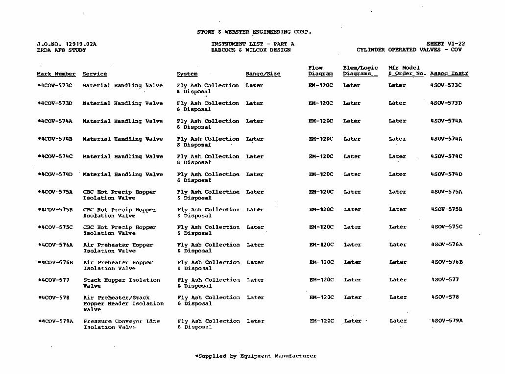
SLYME C WE- ENGINEERING C O D .
J - 0 - N O . 1 2 9 1 9 . 0 2 A ERDA AFB S m Y
INSTRUMENT LIST - PART A BABCOCK & WILCOX DESIGN
SHEET V I - 2 2 CYLINDER OPERATED VALVES - COV
Flow E l e m / L o g i c M f r M o d e l D i a q r a m D i a q r a m s 6 Order No. Assoc In-
m-120~ ~ a t e r Later USOV-573C
Mark N u m b e r Sexvice
*UCOV-573C Haterial H a n d l i n g V a l v e
S y s t e m R a n s e a ze
Later
Later
Later
Later
Later
Later
L a t e r
L a t e r
L a t e r
Later
L a t e r
L a t e r
L a t e .
Fly Ash C ~ l l e c t i o n 6 D i s m a l
Fly AS^ Collection 6 D i s p o s a l
WCOV-573D M a t e r i a l H a n d l i n g V a l v e M - 1 2 0 C L a t e r Later 4 S W - 5 7 3 D
*W30V-574A Material Haadling V a l v e P ly Ash C b l l e c t i o a 6 D i s p a L
En-12OC Later Later USW-!57UA
*OCOV-5748 M a t e r i a l H a d l i n g V a l v e Fly Ash rnl$sction 6 D i s p o 5 a . K
EEI-12OC hter Later U S W - 5 7 U A
*4COV-57UC Haterial Handling V a l v e P ly Ash mllection 6 D i s p o s a l
EM-12OC Later Later 4 S W - 5 7 4 C
*rlCOV-574D ' Haterial H a n d l i n g V a l v e Ply Ash C o l l e c t i o n & D i s p o s a l
EM-12OC Later Later U S W - 5 7 4 D
CBC H o t Precip Bopper Iso~ation valve
Ply mh C o l l e c t i o n 6 D i s p m a l
M - 1 2 O C L a t e r Later U S W - 5 7 5 A
EM-12OC Later Later 4SOV-575B CBC H o t Preeip H o p p e r Isolation V , a l v e
Fly Ash Collection & D i s p o s a l
F ly Ash C o l l e c t i o a 6 D i s p o s a l
EM-120C Later Later 4SOV-575C ZBC H o t Preaip R o p p e r Isolation Vdve
EM-12OC Later Later 4 S W - 5 7 6 A A i r Preheatsr Hopper Isolatim V a l w
Fly Ash C o l l e c t i o n 6 D i s p a . ~ a l
EM-12OC Later Later USOV-576B Air P r e h e i i t a H o p p e r Isolation V a l v e
F l y Ash C k l l e c t i o x & D i s p o s a l
EM-12OC Later L a t e r USOV-577 Stack H o p p e r I solation V a l v e '
Fly Ash C o l l e c t i o x 6 D i s p o u a l
EM-120C Later Later USOV-578 P ! r P r e h e a t e r / S t a c k . H o p p e r H e a d e r Isolation V a l v e
Fly Ash Collection & D i s p o s a l
EM-1ZOC .Later . Later ' USOV-579A Pressure ('onveyor L.ine Isolation V a l . v e
F l y Ash C o l l e c t i o n L a t e r E D i s p o s a l
*Sapplied by E q u i p m e n t Manufacturer
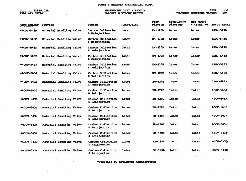
X W S T R W LIST - PART A BAEaWR 6 WILCOX DESIGN
ELea/Logic Mfr nodel Diasrams 6 Order No. Assoc Instr
Plow System RanqelSize Diaqram Mark Rlmrber S w i m
8QOOY-543B Material Handlhg Valve Carbon Qllection Iater 6 Reinjection
Later Later 4SOV-543B
*9COV-54U: mterhl Bandling Valve Carbun Oollection S Reinjection
Later
Later
Later
Later
Later
Later
Later
Later
Later
Later
~ater rater 4sw-543C
rUX)V-543D mtetial Eandlhg Valve Carbon Collection 6 Reinjection
- 8
Carbon Collection 8 Reinjection
Later Later 4SW443D
Wa3V-543E Material Handling Valve Later Later 4SW-543E
*OCOY-543P Material Handling Valve carbon CollectLon s ReinjectLon
carbon Collection 8 Reinjection
Iater Later 4SW-543P
*4CO'W-543G Materhl Handling Valve Later Later 4SW-543G
* Later Later 4SW-5438 *U?OY-5438 Naterial Handling Valve Carbasl Collection
8 Reinjection
--SOU Material Handling Valve Carbon Collection 8 Reinjection
Later Later 4SW-543J
rK0v-543~ llatelial andl ling Valve carbon Collection 8 Reinjection
Later Later 4SW-543K
Later Later 4SW-543L *OCOV-543L Material Handling Valve
*UXN-543H Haterial Handling Valve
rqCWJ43N Material Handling Valve
&rbon Collectbn 8 Reinjection
Carbon Collection 6 Reinjection
Later Later 4SW-543M
Carbon Collection Later 8 Reinjection
Later Later 4SW-543N
*QCOV-543P Material Handling Valve
4COV343Q Material Handling Valve
*4COV--543R Material Handling Valve
Carbon Collection Later S Reinjection
Later Later 4SW-543P
Later Later 4SW-543Q Caqbon Collection Later 8 Reinjection
Carbon Collection Later 8 Reinjection
Later Later 4SW443R
*Supplied by Equipment Manafactr?rer
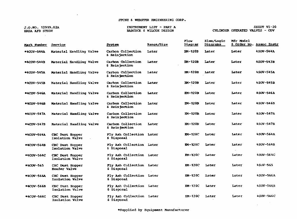
STCNE Z; WEB= ENGINEERING CORP-
J-0-NO. 12919.02A ERDA AFB STUDY
Mark Number Swice
*4COV-544A Material H a n d l i n g V a l v e
*4COV-544B Material Handling Valve
*4COV-545A Uaterial Handling V a l v e
r W V - 5 4 5 B Material H a n d l i n g V a l v e
*UCOV-546A Uaterial H a n d l i n g V a l v e
*UCQV-546B Material Handling Y a l v e
*OCOV-547A Material Bandling V a l v e
* W - 5 4 7 B P l a t e r i a l H a n d l i n g V a l v e
*4CW-564A CBC D u s t H o p p e r Isolation Valve
*4COV-S64B CBC Dust H o p p e r Isolation Valve
*4COV-564C CBC D u s t H o p p e r Isolation V a l v e
* W - 5 6 5 C B C I ) u s t H o p p e x H e a d e r V a l v e
* 4 ~ ~ - 5 6 6 ~ CBC mst H o p p e r Isolation V a l v e
*4COV-566B CBC D u s t H o p p e r Isolation V a l v e
*4COV-566C CBC D u s t H o p p e r Isolation V z l v e
INSTRUMENT LIST - PART A BABCOCK 6 WIU30X DESIGN
system
Carbon C o l l e c t i o n 6 R e i n j e c t i o n
Carbon Collection 6 R e i n j e c t i o n
C a r b o n Callection 6 R e i n j e c t i o n
C a r b o n Collection 6 R e i n j m o n
Carbon Collection 6 R e i n j e c t i o n
Carbon C d L l e c t i o n 6 R e i n j e c t i o n
C a r b o n C o l l e c t i o n 6 R e i n j e - i o n
Carbon C o l l e c t i o n 6 Reinfection
P l y Ash C o l l e c t i o n 6 D i s p o s a l
P l y Ash C S l l e c t i o n 6 D i s p o s a l
P l y Ash C b l l e c t i o n 6 D i s p o s a l
P l y Ash C . ~ l l e c t i o n 6 D i s p o s a l
Fly Ash Callection 6 D i s p o s a l
Fly Ash C ~ l l e c t i o n t3 D i s p o s a l
F l y Ash C o l l e c t i o n 6 D i s p o s a L
R a n u e / s i z e
Later
Later
L a t e r
Later
L a t e r
L a t e r
Later
Later
L a t e r
L a t e r
L a t e r
Later
L a t e r
L a t e r
L a t e r
P l o w D i a q r a u
EM-12OB
EM-12OB
R4-120B
EM-12OB
EM-12OB
EM- 1 2 OD
E)3-120B
E)3-12OB:
EM-12OC
EM-120C
EM-12 OC'
EM-120C
EM-12OC
EM-12oc
EM-12oc
SIlEET VI-20 CYLINDER OPERATED VALVES - COV
E l e n / I m g i c Mfr M e 1 D i a q r a m s 6 Order No. A s s o c Instr
Later ~ a t e r USOV-544A
Later L a t e r 4 S O V S 4 3 B
L a t e r L a t e r 4SOV-545A
L a t e r L a t e r USOV-545B
L a t e r Later 4 S W - 5 4 6 A
L a t e r L a t e r 4 SOV -54 6B
Later Later 4SW-547A
L a t , e r Later USOV-547B
Later L a t e r USW-56UA
L a t e r L a t e r 4SOV-56UB
L a t e r Later USOV-56 4C
L a t e r L a t e r PSOV-565
Uber L a t e r USW-566A
L a t e r L a t e r USOV-566B
Later Later 4SW-566C
*-?lied by E q u i p m e n t Manufacturer
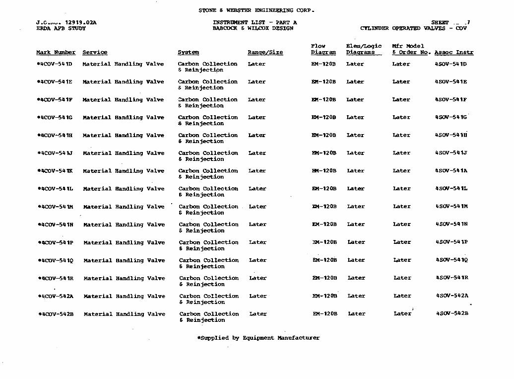
STONE E WEBSTER ENGINEERING CORP.
J - C - n u - 12919-02. . ERDA AFB STUDY
IN!X'RWElFT L I S T - PART A BABCOCR 8 WLLCOX DESIGN
SHEET .- - 7 CYLINDER OPERATED VALVES - COV
Mfr M o d e l E Order NO. R a n s e / S i ze
Later
Mark Ehrmber Senice
*4COV-54 ID Material H a n d l i n g V a l v e C a r b o n Qllection S R e i n j e c t i o n
L a t e r Later
*4COV-541E Material Handling Valve Carbon C o l l e c t i o n 3 R e i n j e c t i o n
Later Later Later
*000V-541P H a t e r i a l H a n d l i n g V a l v e , Z a r b o n C o l l e c t i o n E Reinjection
Later Later
Later
Later
*4COV-541G Material H a n d l i n g V a l v e Carbon C o l l e c t i o n 6 Reinjection
Later Later
*4COV-54 1H M a t e r i a l H a n d l i n g V a l v e Carbon C o l l e c t i o n 6 Reinjection
Later Later L a t e r
*UCOV-5U lJ M a t e r i a l H a n d l i n g V a l v e Carbon C o l l e c t i o n E R e i n j e c t i o n
Later Later Later
M a t e r i a l H a n d l i n g V a l v e
Material H a n d l i n g V a l v e
Material H a n d l i n g V a l v e
Material Bandling V a l v e
M a t e r i a l H a n d l i n g V a l v e
Material H a n d l i n g V a l v e
Material H a n d l i n g V a l v e
Material H a n d l i n g V a l v e
M a t e r i a l H a n d l i n g V a l v e
C a r b o n C o l l e c t i o n E R e i n j e c t i o n
Later L a t e r L a t e r
Carbon C o l l e c t i o n E Reinjection
Later Later
C a r b o n C o l l e c t i o n E R e i n j e c t i o n
L a t e r L a t e r Later
C a r b o n C o l l e c t i o n L a t e r E Reinjection
Later Later
C a r b o n C o l l e c t i o n Later 8 R e i n j e c t i o n
Iater Later
Carbon C o l l e c t i o n L a t e r 6 R e i n j e c t i o n
EM-120~
m-12OB
EM-120B
EM- 1 2 0B
Later Iater 4SW-541Q
C a r b o n C o l l e c t i o n Later E R e i n j e c t i o n
Later Later 4SW-54 1 R
Later Later 4SW-542A C a r b o n C o l l e c t i o n L a t e r 6 Reinjection
L a t e r L a t e r 4SW-542B C a r b o n C o l l e c t i o n L a t e r E Reinjection
*Supplied by E q u i p m e n t M a n u f a c t u r e r
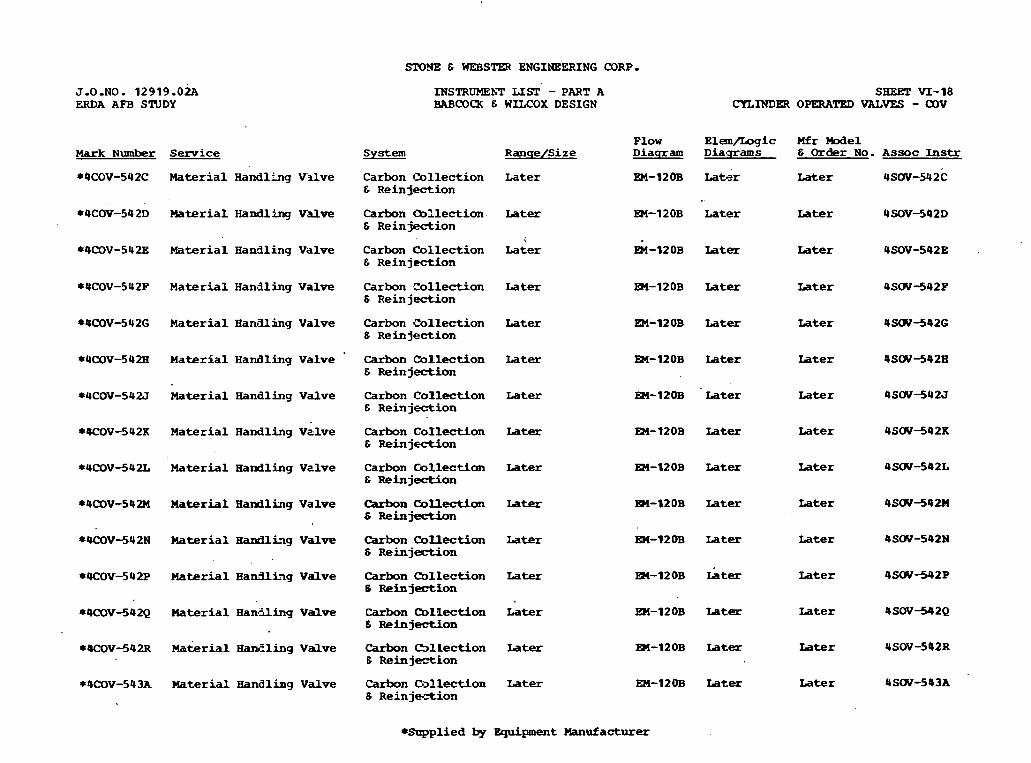
SPONE & WEBSTW ENGINEERING CORP.
J.O.NO. 1 2 9 1 9 . 0 h ERDA AFB STUDY
Mark Number Service
*4COV-542C Material H a n d l k g V ~ l v e
*4COV-542D Material H a n d l i n g V d v e
44COV-542E Katerial Handling V a l v e
*UCOV-542F M a t e r i a l H a n d l i n g V a l v e
*4COVJ42G M a t e r i a l H a n a l i n g V a l v e
*UCOV-5U2H M a t e r i a l H a n d l i n g V a l v e
*4COV-542J Material Handling V a l v e
*KOV-542K Material H a n d l i n g V s l v e
*4COV-542L Material H a n d l i n g V i i l v e
*UW-542M Material H a n d l i n g V a l v e
* W V - 5 4 2 N Material Haadliag V a l v e
*OCOV-542P Material H a d l i n g V a l v e
*4COV-542Q Material H a m f l i n g V a l v e
*4COV-542R Makrial H a n E l i n g V a l v e
*4COV-543A Material H a n d l i n g V a l v e
INSTRUMEhT LIST - PART A BABCOCX E WILCOX DESIGN
System
C a r b o n Collection E R e i n j e c t i o n
C a r b o n mllection & R e i n j e c t i o n
C a r b o n C o l l e c t i o n & R e i n j e c t i o n
C a r b o n tol lect ion 6 R e i n j e c t i o n
C a r b o n C o l l e c t i o n & R e i n j e c t i o n
C a r b o n Collection 6 Reinjection
C a r b o n C o l l e c t i o n & R e i n j e c t i o n
C a r b o n C o I l e c t i o n & R e i n j e c t i o n
C a r b o n C o l l e c t i f m E R e i n j e c t i o n
carbon Collection S R e i n j e c t i o n
Carbon Qllection S R e i n j d o n
Carbon Collection 6 R e i n j e c t t o n
R a n q e I S i z e
L a t e r
Iater
L a t e r
Later
Later
Later
Later
Later
Later
Later
Later
Later
Carbon CollectLon L a t e r 6 Reinjection
Carbon Cdlect ion Later 6 Rein jeztion
Carbon Callection Later 6 R e i n j e c t i o n
SHF3T VI-18 CYLMDW OPERATED VALVES - OOV
F l o w E l e m / L o g i c Mfr We1 D i a q r a m D i a q r a m s & Order No. A s s o c Instr
EM-12OB Later ~ a t e r 4SOV-542C
EM-12OB L a t e r Later USOV-542D
EM-12OB later L a t e r 4SOV-542E .
m - 1 2 0 B L a t e r later USW-5UZP
EM-12OB Later Later 4 S W - 5 4 2 G
R4-120B Later later 4 S W J 4 2 H
Later
L a t e r
Later
L a t e r
Later
Later
Later
L a t e r
Later
Later
Later
Later
Later
Later
Later
Later
later
Later
*Supplied by E q u i p m e n t Manufacturer

mHE 6 w.EBsTm ElPGINEERING ODRP.
INSTRUMEWl' LIST - PART A BABCOQ( 6 =OX DESIGN
'P low E l e m / L o q i c Mfr -el Diacrram D i a q r a m s 6 O r d e r No. A s s o c Ins t r Hark Nlrmber S e h c C e
*00DV-605A B&d Material D i s p o s a l V a l v e
Bed M a t e r i a l Later Transfer 6 D i s p o s a l
.EM-lZOA Later Later 4SOV-6OSA
* 4 a m - 6 0 5 B B e d 1 3 a t e r i a l D i s p o s a l valve
Bed M a t e r i a l Later Transfer 6 D i s p o s a l s y s t e m
83-12oA Iater Later 4 S O U d 0 5 B
*4UW-606A B e d Material D i s p o s a l V a l v e
Bed L e t d m . L a t e r mansfer 8 D i s p o s a l system
en-12OA Iater Later USOV-606A
EM-12OA Later . Later 4 S W - 6 0 6 B
EM-12OA Iater Later 4SOV-607A
* 4 a l V - 6 0 6 B Bed Material D i s p o s a l V a l v e
BedLetdoim Later Transfer 8 D i s p o s a l S y s t e m :
*OCOV-607A B e d Material D i s p o s a l V a l v e . .
Bed Letdm L a t e r hansfer 8 D i s p o s a l sy-
*4CXY?-607B B e d Material D i s p o s a l valve
Bed Letdown L a t e x Transfer 6 D i s p o s a l syst-
.EM-12OA L a t e r
EM-IZOA Later
Later USW-607B
Later 4SOVdOBA *4COV-608A Si lo L n l e t V a l v e B e d L e t d o w n L a t e r hansfer 6 D i s p o s a l System
*QCOVdOBB Si lo W e t V a l v e .Bed L e t d o w n . Later Tranafer 6 D i s p o s a l system
m - 1 2 0 A Later Later USOV-608B
W W - 5 4 0 A Haterial H a n d l i n g V a l v e C a r b o n ODllection L a t e r 6 R e i n j e c t i o n
EM-12OB Later Later USOV44OA
. Carbon C o l l e c t i o n Later 6 Reinjection ,
WCOV-540B U a t e r i a l H a n d l i n g V a l v e EM-12OB Later Later USW-540B
EM-12OB L a t e r Later USOV-54OC
En-12OB Later Later - 4SW-54OD
*QC(W--5UOC H a t e l i a l H a n d l i n g V a l v e Carbon C o l l e c t i o n Later 6 R e i n j e c t i o n
*UCOV-540D Material H a n d l i n g V a l v e C a r b o n C o l l e c t i o n Later 6 R e i n j e c t i o n
*supplied by E q u i p m e n t Gufacturer
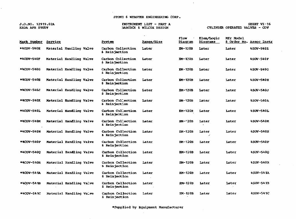
SIION3 6 WEBSTER ENGINEERING CORP-
:RJSTRUMEKT LIST - PART A 3ABCDQ( 6 WILCOX DESIGN
SHEET VI-16 CYLINDW OPERATED VALVES - a V
F l o w . E l e q 5 o g i c Mfr M o d e l RanqelSize D i a q r a m D i a q r a m s 6 Order No. A s s o c Instr Mark Number Service
*4COV-540B Material H a n f l i n g V a l v e Carbon Collection Later 6 R e i n j e c t i o n
EM-120B L a t e r Later 4SOV-540E
*4COV-540P Material H a n d l i n g V a l v e C a r b o n (Sllection Later S Reinjection
EW-1IOB Later Later 4 s w - 5 4 O P
84COV-540G Material H a n d . l i n g V a l v e C a r b o n (bllection Later 6 Reinjection
EH-1ZOB Later Later 4SW-54OG
*4alV-540H M a t e r i a l H a n d l i n g V a l v e Carbon (Sllection L a t e r S R e i n j e o n
EM-1ZOB L a t e r L a t e r USW-54OH
*OCOV-540J M a t e r i a l H a n d l i n g V a l v e Carbon Cbllection L a t e r S Reinj-Lon
EM-1ZOB Later Later 4 S W - 5 4 0 J
*OCOV-540X M a t e r i a l H a n d l i n g V a l v e C a r b o n C > l l e c t i o n Later 6 R e i n j e c t L o n
m - 1 2 0 B L a t e r Later 4SW-540A
*4COV-540L Material Bandling V a l v e Carbon ~ l 2 e c t i m Later S R e i n j e t L o n
EM-020B Later L a t e r 4SW-54OL
*QalV-540M M a t e r i a l andl ling Va.Lve Carbon C 3 l k t i o n Later 6 R e i n j e = t i o n
m-"20B L a t e r Later 4SW-540M
*4COV-540N Material H a n d n i n g V a l v e Carbon h l l ec t ion L a t e r 6 Reinjeztion
EM-11OB Later Later 4SW-540N ,'
*QCOV-540P M a t e r i a l H a n d l i n g V a l v e C a r b o n C - 3 l l e c t i o n Later 8 R e i n j e t i o n
PM-1.1OB Later L a t e r 4SW-54OP
*4COV-540Q Material H a f l i n g V a l v e C a r b o n C . > l l e c t i o n L a t e r 6 Rein j e t i o n
EM-120B L a t e r Later 4SW-54OQ
W O V - 5 4 0 R M a t e r i a l H a n d l i n g V a l v e Carbon C o l l e c t i o n L a t e r . S R e i n j e c t i o n
eM-120B Later Later 4SOV-540R
*OalV-54lA Material H a n d l i n g V a l v e
*W30V341B M a t e r i a l H a n d l i n g Valve
*4COV-54 1C Material H a n d l i n g V a l v e
Carbon C o l l e c t i o n Later 6 Reinjection
EM-IPOB L a t e r Later 4SOV-54 1A
C a r b o n C o l l e c t i o n Later S Reinject ion
EM-120B L a t e r Later 4 S W - 5 4 1B
C a r b o n C o l l e c t i o n Later 6 R e i n j e c t i o n
EM-12OB Later Later 4SOV-54 1C
* S u p p l i e d by ~ ~ u i p m k t M a n u f a c t u r e r

STONE E WEBSTER ENGINEERING CORP,
INSTRUMEW LIST - PART A BABCOQ( 6 KlLCOX DESIGN
SHEET VI-13 CYLINDW OPERATED VALVES - COV
Mark .k&er Service P l o w Ele!q/Logic Mfr Model
S y s t e m R a n q e / S i z e D i a q r a m D i a q r a m s 6 Order No. A s s o c Instr
* 4 W - 5 9 9 J Air Lock V a l v e s Bed Letdown L a t e r ! W a n s f e r 8 D i s p o s a l S y s t e m
EM-12OA L a t e r Later 4SOV-599 J
* 4 W - 5 9 9 K Air Lock V a l v e s Bed L e t d m L a t e r Transfer 8 D i s p o s a l - S y s t e m
EM-120A Later L a t e r 4SOV-599K
WCOV-599L A i r Lock V a l v e s Bed Letdown L a t e r Transfer 6 D i s p o s a l System
EM-12OA Later Later
* 4 W - 5 9 9 M A i r I D C ~ V a l v e s B e d Letdown L a t e x Transfer 8 D i s p o s a l S y s t e m
EM-120A Later Later 4 ~ 0 ~ 3 9 9 ~
*4COV-600A B e d Material M a k e u p Bed L e t d o w n Later V a l v e s Transfer 6 D i s p o s a l
s y s t e m
EM-12OA L a t e r L a t e r 4 S W - 6 0 0 A
W O V - 6 0 0 B Bed Mazerial M a k e u p B e d Letdown Later V a l v e s Transfer 6 D i s p o s a l
S y s t e m
EM-120A Later Later 4SOV-600B
cOCOV-6OlA Bed Material Isolation Bed Letdawn Later V a l v e Transfer 8 D i s p o s a l
S y s t e m
m-12OA Later L a t e r 4SOV-601A
* 4 a l V d O l B B e d Material Isolation B e d L e t d o w n at ex Valve T r a n s f e r 8 D i s p o s a l
Sy.*em
EM-120A Later L a t e r USOV-60 1 B
WCOV-602A A i r ~ c k V a l v e s Bed L e t d o w n Later T r a n s f e r 8 D i s p o s a l S y s t e m
IN-12OA Later L a t e r 4 S O V d O 2 A
*UOOV-602B A h m k V a l v e s B e d Letdm Later Transfer 6 D i s p o s a l S y s t e m
EM-120A Later Later 4SOV-602B
W o v d O X AFr m c k V a l v e s B e d L e t d o w n Later Transfer 6 D i s p o s a l S y s t e m
EM-12OA L a t e r Later USW-602C
* S u p p l i e d by E q u i p m e n t Manufacturer
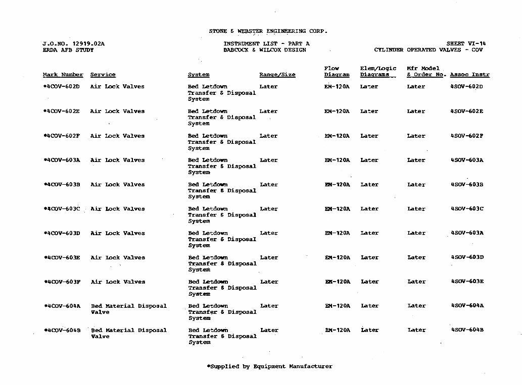
STONE & WEBS- E N G I F I N G CORP.
J.O.NO. 12919.02A ERDA AFB STUDY
INSTRUMENT L I S T - PART A BABCOCK & WILCOX DESIGN
SHEET VI-14 CYLINDW OPERATED VALVES - COV
F l o w E l e W L O g i c Mfr Model R a n q e / S i ze D i a q r a m D i a q r a m s & O r d e r No. A s s o c Instr Mark Number Service
*4COV-602D Air L o c k V a l v e s Bed Lecdown L a t e r Transfer 6 D i s p o s a l s y s t e m
h - 1 2 0 ~ ~ a z e r Later 9SOVdO2D
Bed Letdown L a t e r Transfer 6 D i s p o s a l . S y s t e m
A i r L o c k V a l v e s M-120A La-Ler
EX-12OA Later
EEd-12OA Later
Later
Air U c k V a l v e s Bed L e t d m Later T r a n s f e r 6 D i s p o s a l S y s t e m
Later
Later Air U c k V a l v e s Bed L e t d o w n Later T r a n s f e r 6 D i s p o s a l system
Air U c k V a l v e s Bed U+Am Later T r a n s f e r C D i s p o s a l S y s t e m
m - 1 2 0 A Later
M-120A Later
En-120A Later
En-120A Later
Later
Air Wck V a l v e s Bed Ler-down Later T r a n s f e r & D i s p o s a l S y s t e m
Later
Air Lock V a l v e s Bed Le~down Later Transfer 6 D i s p o s a I S y s t e m
Later
Air W c k V a l v e s B e d L e ~ d o w n L a t e r Transfer 6 D i s p o s a l S y s t e m
L a t e r
Air Uck V a l v e s Bed Letdown Later T r a n s f e r 6 D i s p o s a l S y s t e m
Later
Bed M a t e r i a l D i s p o s a l V a l v e
Bed Lerdovn Later Transfer 6 D i s p o s a l S y s t e m
Later
Later EN-120A Later Bed Material D i s p o s a l V a l v e
Bed Letdown L a t e r Transfer 6 D i s p o s a l sy==
*Supplied by E q u i p m e n t Manufacturer
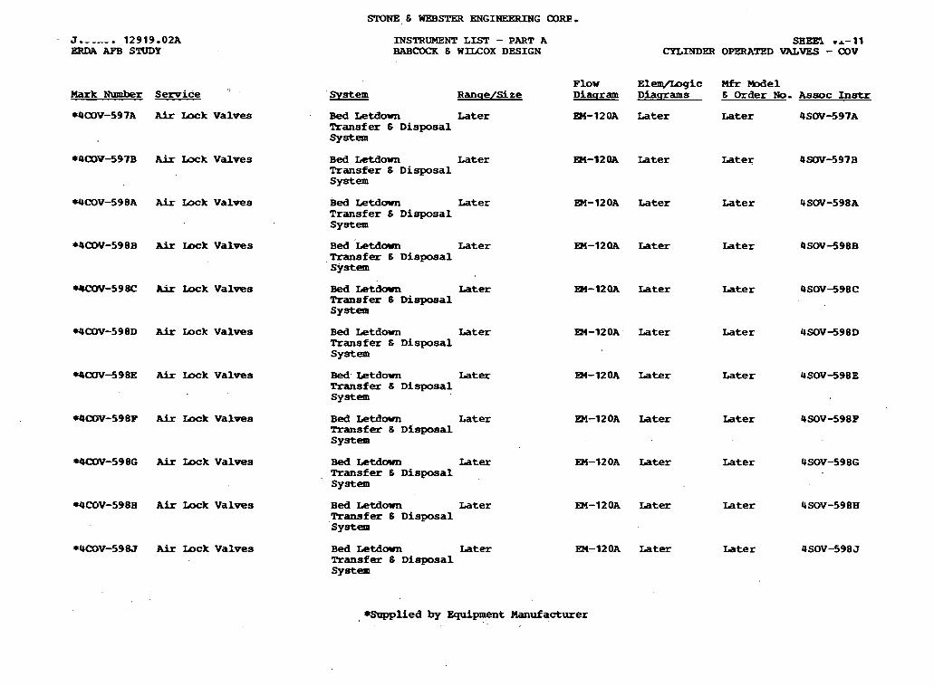
J.- ---. 12919.02A ERDA APB STUDY
SHE= rr-11 CYLMDW OPERATED VALVES - COV
INSTRUMENT L I S T - PART A BABCOCK 6 WILCOX DESIGN
F l o w Elelq/ljogic Mfr -el Diaqrarm D i a q r a m s 6 O r d e r No. A s s o c Instr Mark Number Service ''
WalY-597A Air b x k V a l v e s
S y s t e m R a n q e / S i z e
Bed L e t d o w n Later Transfer 6 D i s p o s a l s y s t e m
EM-12OA Later L a t e r 4 S W - 5 9 7 A
*4alV-597B Air L x k V a l v e s B e d Letdown L a t e r Transfer 6 D i s p o s a l S y s t e m
EM-12OA L a t e r Later 4SOV-597B
m - 1 2 0 A Later L a t e r
L a t e r
Later
Later
L a t e r
L a t e r
Later
Later
Later
WCOV-598A Air b k V a l v e s B e d L e t d o w n Later T r a n s f e r 6 D i s p o s a l S y s t e m
* 4 W - 5 9 8 B Air b x k V a l v e s ~ e d tetdm Later Transfer 6 D i s p o s a l S y s t e m
EX-12OA Later
rUSOV-598C Air I n c k V a l v e s
WCOV-598D Air I n c k V a l v e s
W00V-598E Air L o c k V a l v e s
Bed L e t d m Later Transfer 6 D i s p o s a l s y s t e m
m - 1 2 0 A Later
B e d L e t d o w n ~ a t e r Transfer E D i s p o s a l S y s t e m
EM-12OA. Later
Bed. Letdown Later Transfer 8 D i s p o s a l S y s t e m
R4-120A Later
W00V-598P A i r L o c k V a l v e s
*4(30V-598G Air L E ~ V a l v e s
B e d L e t d o w n L a t e r Transfer 8 D i sposal S y s t e m
EM-12OA Later
Bed Letdown Latex Transfer 6 D i s p o s a l S y s t e m
EM-120A Later
EM-12OA Later
EM-12OA Later
WCOV-5988 A F r Lock V a l v e s
*4COV-598J A i r mck V a l v e s
B e d Letdown L a t e r Transfer I3 D i s p o s a l S y s t e m
B e d Letdm L a t e r Transfer 6 D i s p o s a l s y s t e m
*Supplied by Equipent Manufacturer
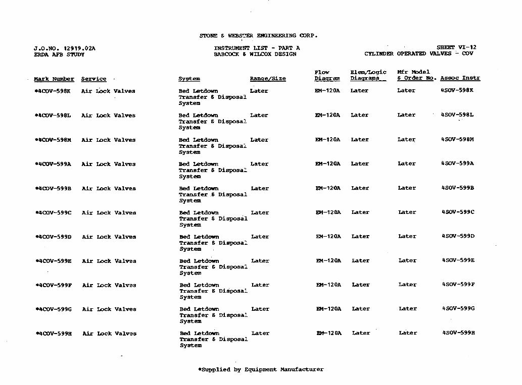
INSTRUMENT LISI! - PART A BABCOQl & WILCOX DESIGN
SHEET VI-12 C Y L m E R OPWATED VALVES - Cov
J.O.NO, 12919.02A HUlA AFB S W Y
Plov Elem,Irogic M f r -el D i a q r a m D i a q r a m s 6 Order No. A s s o c Instr S y s t e m Ranqe/Size . Mark Number S e n r i c e .
*OWV-598X At I k k V a l v e s EM-12OA Later Later 4SOV-598X B e d Letdm L a t e r Transfer S D i s p o s a l S y s t e m
B e d Letdown L a t e r Transfer 6 D i s p o s a l S y s t e m
* 4 W - 5 9 8 L Air L o c k V a l v e s
*0alV-598M Air m c k V a l v e s
*4COV-599A A i r L o c k Val-s
EM-12OA L a t e r Later
Bed Letdown L a t e r Transfer 6 D i s p o s a : S y s t e m
EM-12OA L a t e r Later
EH-12OA Later L a t e r Bed Letdm L a t e r Transfer 6 D i s p o s a ? S y s t e m
W W V - 5 9 9 B Air l o c k V a l v e s
WCOV-599C A i r Lock V a l v e s
Bed L e t d m Later Transfer .6 D i s p o s a l System
EX-t20A Later
EM-t2OA Later
L a t e r
Later Bed L e t d o w n L a t e r Transfer 6 ~isposal S y s t e m
WCoV-599D Air I o c k V a l v e s
WCOV-599E A i r L o c k V a l v e s
EM-12OA Later
R4-120A L a t e r
Rd-120A Later Later
EM-12OA L a t e r Later
R4-120A Later ~a ' t e r
Later
Later
Bed Letdown Later Transfer 6 D i s p o s a l s y s t e m
B e d L e t d k L a t e r Transfer 6 D i s p o s a l S y s t e m
WCOV-599P AFr I o c k Val-s
W V - 5 9 9 G A i r m k V a l v e s
.9a lV-599H AFr I o c k V a l v s s
Bed L e t d m Later T r a n s f e r 6 D i s p o s a l S y s t e m
B e d L e t d o w n Later Transfer 6 D i s p o s a l S y s t e m
Bed I a t d o w n Later Transfer 6 D i s p o s a l S y s t e m
*Supplied by E q u i p m e n t Manufacturer

SPDNE 6 WEBSTER ENGINEERING CORP-
J . 0 - U O . 12919 .02A ERDA AFB STUDY
Mark Number Service
*4PSD-629B Air Preheater Outlet
*4PSD-629C Air Preheater O u t l e t
*4PS8)-629D A i r Preheater O u t l e t
*UPSO-630A Primary Aix Pan Inlet
r4PSD-630B Primary Air Pan Inlet
r 4 P S D - 6 3 1A Primary Air Pan Outlet
*4PSD-631B P r i m a r y Air P a n outlet
INSTRUMENT LIST - PART A BRBCOCR & WILCOX DESIGN
SHEET VI-9 POWER OPERATED DAMPERS - PSD
P l o w E l e q l L o g i c M f r b d e l S y s t e m R a n q e / S i z e , D i a q r a m D i a q r a m s & Order No. Assoc Instr
C o m b u s t i o n A i r & L a t e r F l u e G a s
C o m b u s t i o n Air E Later F l u e G a s
C o m b n s t i o n Air E Later F l u e Gas
C a n b u s t i o n Air E Later F l u e G a s
C a n b u s t i o n A i r & L a t e r F l u e G a s
C o a r b u s t i o n Air & Later F l u e Gas
C o m b u s t i o n Air 6 Later F l u e Gas
EM-115A Later Later 4MOV-629B
EM-115A Later Later 4MOV-629C
E M - 1 1 s Later Later 4MOV-629D
EM-115A Later Later L a t e r
EM-11% L a t e r Later Later
EM-11% Later L a t e r L a t e r
EM-11% Later L a t e r L a t e r
*Supplied by EQui..pment Manufacturer

J.O,NO. 12919.02A ERDA AFB STUDY
Hark Number
*4U-621A.
*4U-62 1B
*4U-632A
*OU-632B
*m-634A
r U l d 3 4 B
*QnOV-623A
*luu)V423B
*4MOVd 23C
~ m v - 6 2 ~ )
*4tUN-629A
*4HOV-6 2 9B
. r O n O V d 2 9 C
*4nOVd29D
Service
PD Pan I n l e t
PD Pan Lnle t
Tempering Air Pan
Tempering Air Pan
Primary Air P a n
Primary A i r Pan
Air Preheater I n l e t
Air Prehezter Inlet
A i x Preheater Inlet
AFr Preheater Inlet
AFr Preheater Outlet
Air Preheater Outlet
Air Preheater Out le t
Air Preheater m e t
INSTP.UMENT LIST - PART A EABCOCK 6 WZLCOX DESIGN
System
C o m b u s t i o n A i r 6 Flue G a s
Qlnbustion Ai r 6 Flue GiL9
Caubustion A i r 6 Flue Gas
C a m b u r t i o n A i r 6 Plue Gae
C a d m s k t o n A i r E Plue Gas
CombustLon Air 8 Plue GaB
,Caglbastion A i r G Flue Gas
Combustion Air 6 Plue Gas
C c m k s t i o n A i r 6 Plue Gas
Combastion Air S Flue Gas
Combnstion A i r 6 Flue Gas
Combustion Air 8 Flue Gas
CombustLon Air G Flue Gaa
C a n b r a s t i o n A i r 6 Plue G a s
RanqeISize
La te r
La te r
La te r
Later
Later
La te r
. Late r
La te r
La te r
La te r
La te r
Later
La te r
La te r
SBEET VI-10 UNIT DRIVE - 4U
MOTOR OPERATED DRIVE - MOV
Flow Elem/Logic Hfr Model Diaqram D i a q r a m s 6 Order No. Assoc Instr
eM-115A Later La te r 4PCD-622A
ESl-115A Later ~ a t e r 4PCD-622B
m-11% ~ a t e r ~ a t e r 4 m - 6 3 3 A
.=-I 1 SA L.ater L a t e r 4 m - 6 3 3 B
- 1 Later L a t e r 4PCD-634A
3M-115A Later La te r 4 m - 6 3 4 B
. 3 I - l l S A Iater L a t e r 4PSD-623A
EU-115A L a t e r Later 4PSD-623B
En-11SA Later L a t e r 4 P S D d 2 3 C
W-115~ xater Late r OPSD-623D
W-11- later Later 4PSD-629A
PI-115A Iater La te r 4PSD-629B
EB-llSA Later L a t e r 4PSD-629C
En-115A Later L a t e r 4PSD-629D
Equipment Manufacturer

STONE E WEB= ENGINERRING CORP,
J-0~~0. 12919.02A ERDA AFB STUDY
INSTRUMENT LIST - PART A BAB- E WILCOX DESIGN
SHEET TI-? POWER OPERATED CONTRDL DAMPERS - PCD
Mfr Model E Order No. Assoc Instr Mark Number Service S y s t e m . R a n q e l S i z e
Later *4P<P-620E Main B e d U n d e r g r i d D a m p e r .
C o m b u s t i o n Air 6 P l u e Gas
Later Later B l r Cant r l
*4P(=D-622A PD Pan Inlet V a n e C o l n b u s t i o n Air 6 F l u e G a s
Later L a t e r Later 4U-621A
* Q P C D d 2 2 B R) Pan Inlet V a n e C o m b u s t i o n Air 6 P l u e Gas
Later L a t e r Later UU-62 lB
* 4 S 3 3 A Tempe+g Air F a n C o m b u s t i o n Air 6 mue G a s
L a t e r L a t e r Later 4U-632A
*OP(=D-633B Tempering A h P a n Cabust ion Air E P l u e Gzis
Later L a t e r Later 4U-6 32A
*4PQ)-63SA Primary Air Fan C o m b u s t i o n Air E F l u e Gas
Later Iater Later 4U-634A
*QFCD-635B Primary Air Pan C o m b u s t i o n Air 6 P l u e G a s
Later Later Late r 4 0 - 6 3 4 B
*4pa)-636A (318 Undergrid D a m p e r
rQPCD-636B CBB Undergrid D a m p e r
*4P(p-636C CBB O n d e w i d D a m p e r
C o m b u s t i o n Air 6 Later F l u e Gas
m - 1 1 5 A Later Later B l r btrl
C a n b u s t i o n Air E Later F l u ? G a s
EM-115A L a t e r Later B l r Cbntrl
R4-115A Later L a t e r B l r CMtrl C o m b u s t i o n A i r E Later F l u e Gas
*UPCD-636D CBB U n d e r g r i d D a m p e r
*4--637A CBB D n d e r g r i d D a m p e r
*UPCD-637B CBB U n d e r g r i d D a m p e r
Combustion Air 6 Later F l u e G a s
EM-115A Later Later B l r Qn t r l
C o m b u s t i o n Air 6 Later Flue G a s
EM-11% Later Later B l r Qn t r l
C o m b u s t i o n Air E Later Plw G a s
Catbastion Air E L a t e r Flue G a s
C o m b u s t i o n A i r E L a t e r Plue Gas
EM-11SA Iater Later B l r mntrl
EM-115A L a t e r Later B l r O o n t r l
EM-11SA L a t e r Later B l r Qnt r l
*4--637C CBB U n d e r g r i d D a m p e r
*UPCD-637D CBB undergrid D a m p e r
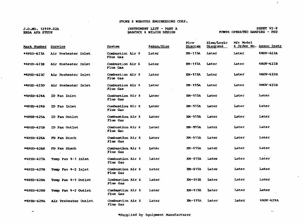
J.0290. 12919-02A ERDA APB STUDY
INSTRUMENT LIST - PART A BABCOCK 6 WILCOX DESIGN POWER
SEEET VI-8 OPERATED IlAMPERS - PSD
Mfr M e 1 6 Order N o - Assoc Instr Serv i ce
Air Prehea ter Inlet Combustior Air 6 Flue Gas
La te r EM-11% La te r L a t e r 4 W - 6 2 3 A
A i r R e h e a t e r -let
A i r R e h e a t e r I i r l e t
Air Preheatez mlet
I D Pan Inlet
I D Pan Inlet
I D Pan Ou t l e t
I D Fan Ou t l e t
Combastion A i r 6 Flue Gaa
La te r
Later
L a t e r
L a t e r
L a t e r
Later
L a t e r
La t e r
Latex
La te r
La t e r
L a t e r
La t e r
L a t e r
La t e r Later 4MW-623B
CombustLon Air 6 Flue Gas
La te r ~ a t e r 4MOVd23B
Combustion A i r 6 F lue Gaa
La te r 4MOV-623B Later
~ a t e r Later Qmbastion A i r 6 F lue Gas
Later
Combustion B i r 6 Flue Gas
Later La t e r L a t e r
Canbustion A i r 6 Flue Gas
La te r
Later
L a t e r L a t e r
Combnstion A i r 6 Flue Gae
La te r L a t e r
PD Pan Disch
PD Pan D h c h
Temp Fan 4-1 Inlet
Temp Pan 4-2 I r i l e t
Temp Pan 4-1 O u t l e t
'Pemp Fan 4-2 O u t l e t
Air Preheatex O u t l e t
Cambustion A i r 6 Flue G a s
~a ter ~ a t e r L a t e r
('nmbustfon. A i r 6 Flue Gaa
Later L a t e r La t e r
Caabustfon Ai r 6 Flue Gas
Later L a t e r La t e r
Canbustion A i r E Flue Gas
Later La t e r L a t e r
Combustion Air 6 Flue Gas
La te r L a t e r
C o m h P s t h n A i r 6 F lue Gas:
La te r L a t e r La t e r
Cambustbn Air 6 Flue Gas
La te r Later 4MOV-629A
*pen t Manufacturer
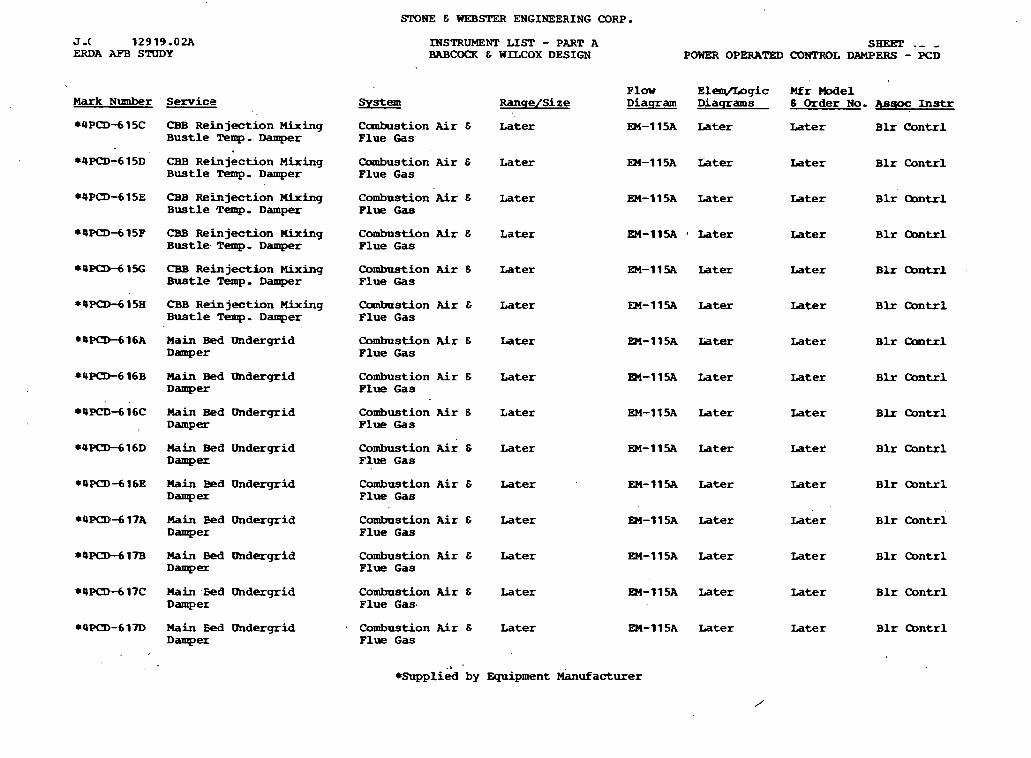
STONE & WEB= ENGINEERING CORP.
SBEET .- , POWER OPERATED CONTROL DAMPERS - PCD
J .( 12919,02A ERDA AFB STUDY
INSTRUMENT L I S T - PART A BABCOCK & WILCOX DESIGN
F l o w ~ l w g i c Mfr We1 D i a q r a m D i a q r a m s 8 Order No, 4s- Instr Mark Number ' Service SYeE!! R a n q e / S i z e
*4PCD-615C CBB R e i n j e c t i o n Mixing C o m b u s t i o n Air & L a t e r B u s t l e Temp. D a m p e r F l u e Gas
*4PQ)-6 15D CBB R e i n j e c t i o n Mixing C o m b u s t i o n Air & L a t e r B u s t l e Temp. D a m p e r F l u e G a s
EM-11% Later Later Blx C o n t r l
EM-115A h te r Later B l r C o n t r l
CBB R e h j e c t i o n Mixing B u s t l e Temp, D a m p e r
C o m b u s t i o n Air 6 Later P l u e G a a
EM-115A Later Later B l r O o n t r l
CEB R e i n j e c t i o n nixing B u s t l e . Temp. Damper
C o m b a s t i o n Air & L a t e r P l u e G a s
EM-11% Later wter B l r C o n t r l
CBB R e i n j e c t i o n Mixing Bustle Temp. Damper
C o m b u s t i o n Air 6 Later F l u e Gas
EM-115A L a t e r L a t e r B l r O o n t r l
CBB R e i n j e c t i o n Mixing B u s t l e Temp. Damper
C a n b u s t i o n Air & L a t e r F l u e G a s
EM-11% Later Later B L r Q n t r l
Main Bed U n d e r g r i d D a m p e r
C o m b u s t i o n Air & Later F l u e G a s
~ m - 1 1 5 ~ ui- L a t e r B l r C o n t r l
Main Bed Undergrid D a m p e r
C o m b u s t i o n Air 6 L a t e r F l u e G a s
m-11SA Later Later B l r C o n t r l
Main B e d U n d e r g r i d D a m p e r
C o m b u s t i o n Air 6 L a t e r Flue G a s
EM-115A Later L a t e r B l r C o n t r l
Main Bed U n d e r g r i d Damp=
C o m b u s t i o n Air & Later F l u e G a s
EM-11% Later ~ a t e t B l r C o n t r l
?lain B e d U n d e r g r i d Damp-
C o m b u s t i o n Air & Later F l u e Gas
EM-11% L a t e r L a t e r B l r O o n t r l
ESl-115A L a t e r Later B l r Contrl Main B e d undergrid Damper
C o m b u s t i o n Air & Later F l u e G a s
Main Bed Ilhdergrid Damp=
C o m b u s t i o n Air & L a t e r P l u e G a s
EM-115A L a t e r L a t e r B l r O o n t r l
Main Zed Undergrid D a m p e r
C o m b u s t i o n Air & Later F l u e Gas .
EM-115A Later Later B l r Contrl
Main Eed Undergrid Damper
Combustion Air 6 L a t e r F l u e G a s
EM-115A Later Later B l r Chntrl
. I '
*Supplied by -pent Manufacturer
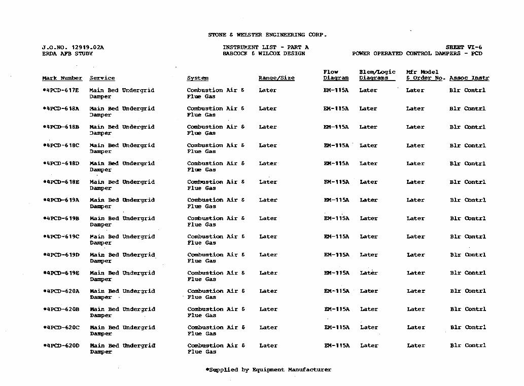
SIDNE E WEESTW ENGINEERRSG CORP.
J.O.NO. 12919.02A ERDA AFB STUDY
Mark N u m b e r
*4PCD-617E
*4PCD-6 18A
eQPCD-6 1 8 B
*4PCD-6 18C
*UPCD-618D
*4P<D-6 1 8 E
eQP(3D-6 19A
WPCD-6 19B
*OPcD-6 1 9 C
84PCD-6 l 9 D
*4P(3D-619E
*4PCD-620A
84--62OB
*4PCD-620C
*4PCD-620D
Service
Main B e d U r - d e r q r i d D a m p e r
b i n Bed Undergrid D a m p e r
lhin B e d Undergrid 3 a m p e r
M a i n R e d Undprgrid 3 a m p e r
Main Bed U n d e r g r i d D a m p e r
H a i n Bed Undergrid Damp-
Hain B e d Undergrid D a m p e r
Hain B e d Undergrid D a m p e r
Pain Bed U n d e r g r i d D a m p e r
Hain Bed U n d e r g r i d D a m p e r
Hain B e d U n d e r g r i d Damp-
Hain Bed U n d e r g r i d D a m p e r .
H a i n B e d U n d e r g r i d D a m p e r
Plain B e d U n d e r g r i d D a m p e r
Plain Bed undergrid Damp-
INSTRUErENT LIST - PART A BABCOCK E WILCOX DESIGN
System
C o m b u s t i o n Air E F l u e G a s
C o m b u s t i o n A i r E F l u e G a s
C o m b u s t i o n Air E F l u e G a s
C o m b u s t i o n Air E F l u e G a s
C o m b u s t i o n Air E F l u e G a s
C o m b u s t i o n Air 6 F l u e G a s
C o m b u s t i o n Air E F l u e G a s
R a n q e / S i z e
Later
Later
Later
Later
L a t e r -
L a t e r
L a t e r
C o m b u s t i o n Air 6 L a t e r F l u e G a s
C o m b u s t i m Air E Later F l u e G a s
C o m b u s t i o n Air E Later F l u e G a s
C o m b u s t i o n Air E Later F l u e G a s
C c u a b u s t i o n Air E Later F l u e G a s
C o m b u s t i o n A i r E L a t e r F l u e G a s
C o m b u s t i o n Air E Later F l u e G a s
C o m b n s t i o n Air E L a t e r Flue G a s
SBEBT VI-6 POHER OPERATED WNTROL DAMPERS - PCD
F l o w E l e q / L o g i c Mr -el D i a q r a m D i a q r a m s E O r d e r No. A s s o c Instr
EM-115A L a t e r Later B l r mntrl
EM-115A L a t e r Later B l r O M t r l
EM-115A L a t e r Later B l r Oontrl
EM-115A ' Later Later B l r Qntrl
EEI-115A L a t e r Later B l r (3ontrl
EM-115A Later Later B l r Contrl
EM-l15A Later Later B l r Qnt r l
EM-115~ ~ a t e r Later B l r mntrl
EM-11% L a t e r L a t e r B l r O o n t r l
EM-115A Later L a t e r B l r Cbntrl
EM-115A La& Later B l r Contrl
EM-1 ISA L a t e r L a t e r B l r mntrl
EM-ll5A L a t e r Later B l r Contrl
EM-115A L a t e r Later B l r Om-1
EM-1 15A L a t e r L a t e r B l r Cantrl
* S u p p l i e d by E q u i p n e n t Manufacturer
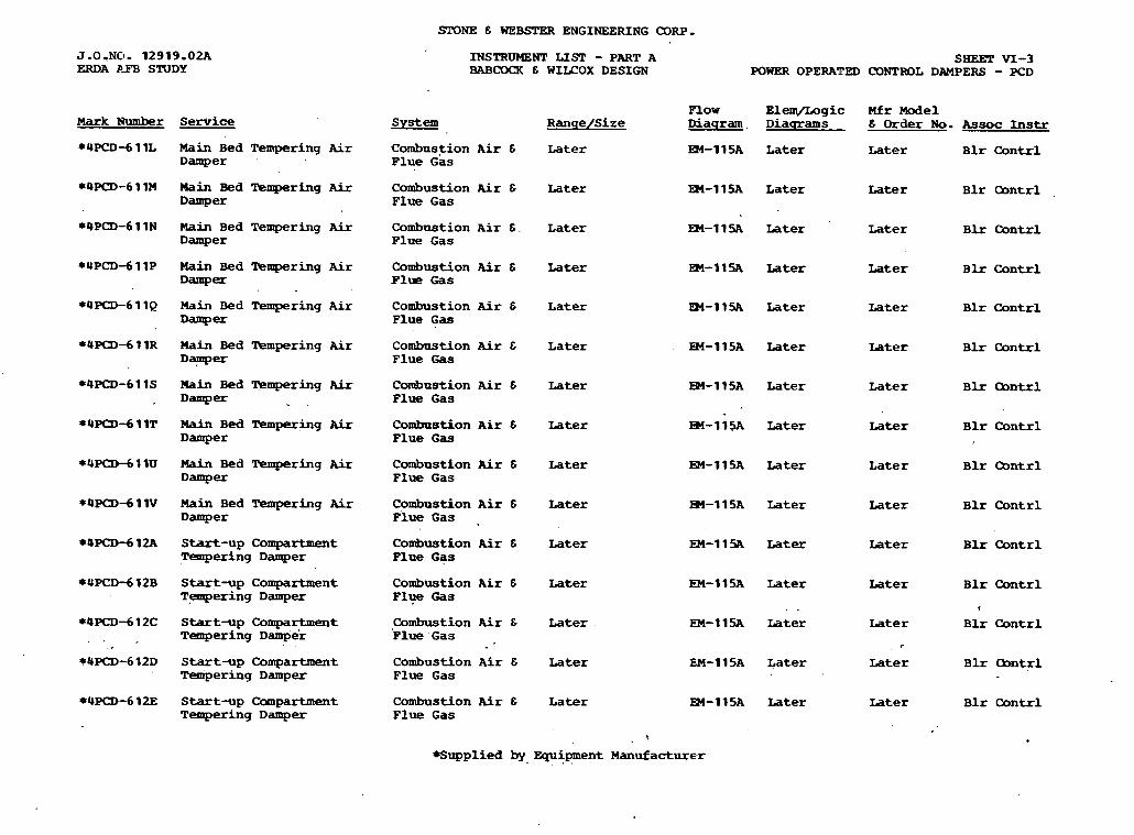
SrONE 6 WEBSI'ER ENGINEERING CORP.
J.O.NO- 12919.02A ERDA P P B STUDY
INSTRUMENT LIST - PART A BABCMR 6 WILCOX DESIGN
s m \TI-3 POWER OPERATED CONTROL DAMPERS - PCD
F l o w Elem/Logic M f r Model D i a g r a m . D i a q r a m s & Order N o . Assoc Instr Mark Number Service , S y s t e m R a n q e / S i z e
, C o m b u s t i o n A i r 6 L a t e r Flue G a s
C o m b u s t i o n Air 6 Later F l u e G a s
C o m b u s t i o n A i r 6 . L a t e r Plue G a s
C o m b u s t i o n A i r 6 Later Flue Gas
C o m b u s t i o n Air & L a t e r Plue G a s
M a i n B e d T e m p e r i n g Air D a m p e r
EX-115A L a t e r Later B l r C o n t r l
M a i n B e d Tempering Air D a m p e r
EM-11SA L a t e r L a t e r B l r Qn t r l
Main B e d T e m p e r i n g Air D a m p e r
EM-11% Later Later B l r Cuntrl
M a i n Bed T e m p e r i n g Air D a m p e r
M a i n Bed T e m p e r i n g A i r Damp-
m-11% Later Later B l r C o n t r l
EM-11SA Later Later B l r Contrl
Hain Bed ' I remper ing Air C o m b u s t i o n A i r & Flue G a s
L a t e r
Later
Later
Later
L a t e r
L a t e r
Later
L a t e r .
L a t e r
L a t e r
EM-115A Later Later B l r C o n t r l
M a i n B e d Tempering Air Damp-
C o m b u s t i o n Air & P l u e G a s
EM-115A L a t e r L a t e r B l r Q n t r l
EM-115A Later Later B l r h t r l Main B e d l k m p e r i n g Air D a m p e r
C o m b u s t i o n A i r & Plue G a s
Main Bed T e m p e r i n g Air Damp-
C o m b u s t i o n Air & Flue G a s
EM-115A Later L a t e r B l r Qntr l
EM-115A Later L a t e r B l r Contrl M a i n B e d T e m p e r i n g Air D a m p e r
C o m b u s t i o n A i r & P l w G a s .
Start-up C o m p a r t m e n t T e m p e r i n g D a m p e r
C o u b u s t i o n Air 6 Plue G a s
EM-115A Later Later B l r Contrl
Start-up C o m p a r t m e n t T . emper ing D a m p e r
C o m b u s t i o n A i r 6 Ply3 Gas
EM-IISA Later Later B l r Cont r l
. . <
EM-11% L a t e r L a t e r B l r C o n t r l Start-up C o m p a r t m e n t T e m p e r i n g ~ a m p ' e r
C o m b u s t i o n Air E F l u e G a s ,
EM-1 15A L a t e r Later B l r h t r l Start-up C o m p a r t m e n t T e m p e r i n g D a m p e r
C o m b u s t i o n Air 6 F l u e G a s
Star t -up C o m p a r t m e n t T e m p e r i n g Damper
C o m b u s t i o n Air 6 Flue G a s
EM-115A Later Later B l r Contrl
*Supplied by, E q u i p m e n t M a n u f a c t u r e r . * ,
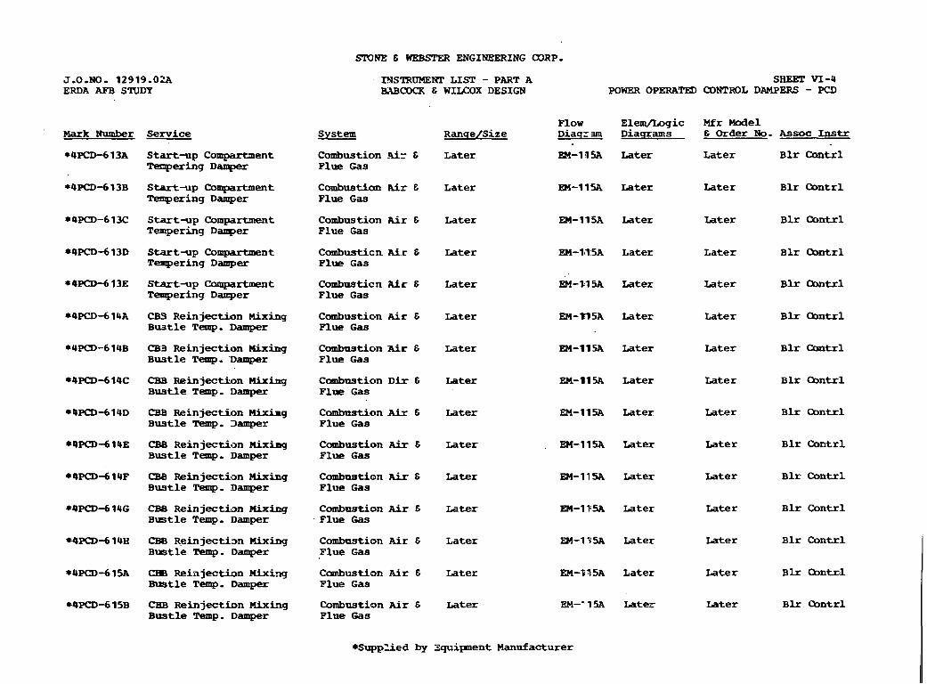
SIONE 6 WEBSPER ENGINEERING (XIRP.
INSTRUMENl' L I S T - PART A SHEET VI-4 BXBCOCK E WILCOX DESIGN POWER OPERATED CONTROL DAMPERS - PCD
J.O.NO- 12919.02A ERDA AFB STUDY
F l o w E l e m / L o g i c Mfr M o d e l S y s t e m R a n q e / S i z e D i a q z rn D i a s r a m s E Order No. Assoc Instr
C o m b u s t i o n -9ir E L a t e r EM-19% Later L a t e r B l r C a n t r l F l u e G a s
Mark Number
*4PCD-6 13A
Service
S t a r t - u p C o m p a r t m e n t T e n p e r i n 9 Damper
Start-up C o m p a r t m e n t T e m p e r i n g Damper
C o m b u s t i a n .Air E L a t e r F l u e Gas
EM-11% L a t e r L a t e r B l r Contrl
S t a r t - u p C o m p a r t m e n t T e m p e r i n g D a n p e r
C o m b u s t i o n Air E L a t e r F l u e G a s
EM-115A Later L a t e r B l r Qntrl
C o m b u s t i c n Air E Later F l u e G a s
EM-111 5A L a t e r L a t e r B l r Qntrl S t a r t - u p C o m p a r t m e n t T e m p e r i n g Damper
Start-up C o m p a r t m e n t T e m p e r i n g Damper
C o m b n s t i c n A i r E L a t e r F l u e G a s
EM-M5A Later Later
L a t e r
Later
Later
Later
Later
L a t e r
Later
Later
Later
Later
B l r Oontrl
B l r Qntrl
B l r O M t r l
B l r O o n t r l
B l r k t r l
B l r Qn t r l
B l r C o n t r l
B l r C o n t r l
B l r C o n t r l
B l r OonlzEl
B h B n t r l
CB3 R e i n j e c t i o n M i x i n g B u s t l e T e m p . Damper
C o m b u s t i o n Air E Later Plue G a s
EM-3?5A Later
CB3 Reinjection nixing B u s t l e Temp. 'Damper
C o m b u s t i o n Air & Later F l u e G a s
EM-11% Later
(IB9 R e i n j e c t i o n Mixing B u s t l e Temp. Damper
C o m b u s t i o n DFr C Later F l u e Gas
EM-11% L a t e r
(388 R e i n j e c t i o n Mixirg B u s t l e Temp. Damper
C a m b a s t i o n A h 8 Later F l u e G a s
EM-11% Later
CBB R e i n j e c t i o n nixing B u s t l e Temp. Damper
C o m b u s t i o n A i x E Later EM-11SA Later P l u e G a s
(IBB Reinjection Mixing B u s t l e Tiemp. Damper
C o m b u s t i o n Air E Later F l u e G a s
EM-11- Later
CB8 R e i n j e c t b n nixing B u s t l e Temp. Damper
C o m b n s t i o n A F r & Latex F l u e Gas
EM-115A Later
CBB R e i n j e c t i m nixing B w t l e Temp. Damper
C o m b n s t i o n A i r E L a t e r F l u e G a s
M-11% Later
(388 R e i n j e c t i o n nixixj m t l e Temp. Damper
C a m b u s t i o n Air E L a t e r F l u e G a s
W-Y15A L a t e r
CHB R e i n j e c t i o n Mixirlg B u s t l e Temp. Damper
C o m b u s t i o n M r & L a t e r F l u e G a s
EM-"1% Later
*SuppZied by 3quipnent M a n u f a c t u r e r
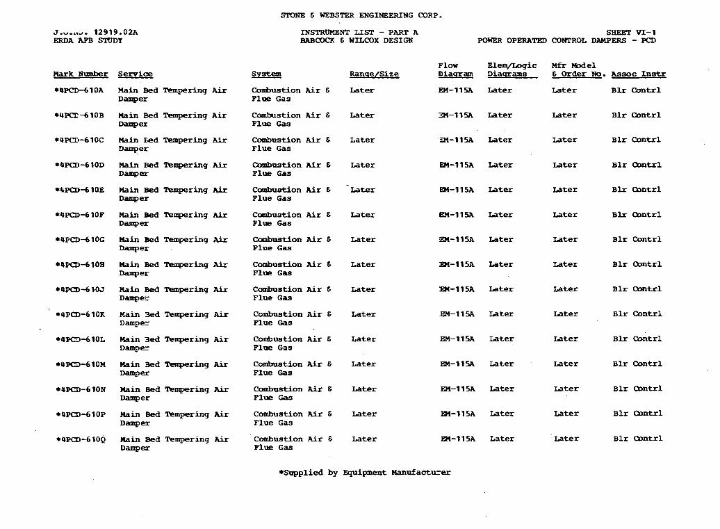
STONE & WEBSTER ENGINEERING CORP.
J - v - , ~ . 12919-02A ERDA AF'B STUDY
INSTRUMENT LIST - PART A BAB- & WfLCOX DESIGN
SHEET VI-1 WWeR OPERATED CONTROL DAMPERS - FCD
P l o w E l e w g i c Mfr W e 1 R a n q e / S i z e D i a s r a m D i a q r a m s & Order No. A s a o c I n s t r Mark Number
*4PCD-6 10A
Service s y s t e m
M a i n Bed % m p e r h g Air Damper
C o m b u s t i o n A i r G Later P l u e G a s
W-11% Later Later B L r C o n t r l
C o m b u s t i o n Air & L a t e r F l u e G a s
34-11% L a t e r Later B l r Contrl M a i n Bed T e m p e r i n g Air Damp=
Hain &d Tempering Air Damper
C o m b u s t i o n Air C L a t e r F l u e G a s
C o m b u s t i o n Air C L a t e r F l u e G a s
- C o m b u s t i o n Air & L a t e r P l u e G a s
C o m b u s t i o n Air C Later F l u e G a s
Combnstion Air 6 Later F l u e G a s
C o m b u s t i o n Air 6 L a t e r F l u e G a s
C o m b u s t i o n Air 6 Later F l u e G a s
: - A Later ~ a t e r B l r C o n t r l
PI-115A Later ~ a t e r B l r Qnt r l
E3l-115A Later ~ a t e r B l r C o n t r l
W-11% Later rater B l x Qn t r l
IW-11% L a t e r ~ a t e r B l r Contrl
Bl-115A L a t e r Later B l r Qntr l
83-115A L a t e r ~ a t e r B l r C o n t r l
Main Bed T k m p e r i n g Air Damp-
Main Bed T e m p e r i n g Air Damper
Main Bed lkmpering Air Damper
M a i n Bed T e m p e r i n g Air Damper
H a i n Bed Tempering Air Damper
Main Bed m p e r i n g Air Damper
C o m b u s t i o n A i r & Later Flue G a s
- 1 Later L a t e r B l r C o n t r l M a i n 3ed Tempering Air Dampez
C o n b u s t i o n Air & L a t e r Flne G a s
EM-11% Later Later B l r O o n t r l *4PO-610L Main 3ed l k m p e r i n g Air Damper
*4PQ-610M M a i n 3ed T e m p e r i n g Air Damper
C o m b u s t i o n Air & L a t e r F l u e Gas
EM-11% L a t e r Later B l r C o n t r l
C o m b u s t i o n Air 6 Later F l u e Gas
EM-115A Later ~ a t e r B l r O D n t r l *4PCI)-610N M a i n Bed Tempering A i r Damper
C o m b u s t i o n Air E L a t e r F l u e Gas
EM-115A Later Later B l r C o n t r l *4P<D-6lOP M a i n Bed T e m p e r i n g A i r Damp=
C o m b u s t i o n A i r C L a t e r F l u e G a s
m-115A L a t e r ~ a t e r B l r Contrl *4~<1)-610~ M a i n Bed T e m p e r i n g Air Damp=
*Supplied by E q u i p m e n t Manufacturer

3lWTE 6 WEBSTER ENGINEERING a R P .
INSTRUM3NT LISP - PART A SHEET VI-2 BABOCX & WIU?OX DESIGN POWER OPERATED OOHPROL DAMPERS - PCD
J,O.NO. 12919.02A ERDA APB STUDY
Flaw ElemjLogic M f r Model Ramelsize Diaqram D i a ~ r a m s 6 Order No. Asreoc Instr Hark Number
*YPCD-610R
Service
Hain Bed Tempering A i r Damper
Combustion Air 8 Later Flue Gas
EM-11SA Later Later B l r Contrl
Main Bed Tempering Air Damp-
Combustion Air & Later Flue Gas
EM-11% Later Later B l r Contrl
Main Bed l k q e r i n g Air Damper
Combustion Air 6 Later Flue Gas
EM-11% Later Later B l r Contrl
Rain Bed Tempering Air Damper
Combustion Air 6 Flue Gas
Later
Later
Later
Later
Later
EM-11% . Later Later B l r w r l
EM-115A Later Later B l r Oontrl
EM-IISA Later Later B l r Contrl
EM-11% Later Later B l r Contrl
EM-115A Later Later B l r Contrl
Rain Bed 'IrePrpering Air am per
Combustion Air E Plue Gas
Uain Bed 'Ikmpering Aix Damper
Combustion A i r 6 Flue Gas
Main Bed =ing A i r Damper
Coubuetion Air E Flue Gas
Rain Bed Tempering bir Damp-
Combustion Air & Flue GB
*4PCDdllD Nain Bed m p e r i n g M.r Damper
Combastion Air & Plue Gas
Later
Later
~ a & r
Later
Later
Later
Later
EM-115A Later Later B l r Cantrl
- Combustion Air 6 Flue Gas
*4PCD-611E Nain Bed Wmpering Air D a m p e r
EM-115A Later Later B l r Contrl
*4PCD-611F Nain Bed Tempering Air Damper
Combastion Air 6 Plue Gas
m-115A Later Later B l r Contrl
Later B l r Oontrl *4p<lD-611G Nain Bed -ring Air Damp-
Combustion Air E Flue Gas
EM-115A Later
*QPCDdllH Nain Bed m p e r i n g Air Damper
Combustion Air 6 Flue Gas
~ a t e r B l r Cantrl
EM-1 15A Later *4PCD-6 1 1J Main Bed Tempering Air Damper
Combustion A i r E Plue Gas
~ a t e r B l r Cbntrl
*UP(I>-611K Nain Bed Teqering Air Damper
Combustion Air 6 Flue (;irs
EM-115A Later Later B l r Contrl
*Supplied by Equipment Manufacturer

STONE 6 WEBSTER ENGINEERING COR?
J-0-NO. 12919.02A ERDA AFB S'KIDY
SHEET V-15 SOLENOID OPERATED VALVES - SOV
INSTR- L I S T - PART A BABCOCX 6 -OX DESIGN
F l o w E lenL/Lag ic W r We1 D i a q r a m D i a q r a m s 6 Order No. A s s o c In8tr Mark Number Semice
*USOV-543K M a t e r i a l H a n d l i n g V a l v e
Carbon Collec- later tion and R e j e c - t i o n
En-12OB later later U C W - 9 3 K
EM-12OB later later 4COV-543L *USOV-54 3 L Material Handling V a l v e
Carbon Qllec- later t ion and R e j e c - t ion
~arboi C o l l e c - uter tion and R e j e c - t ion
*4SOV-543M M a t e r i a l Handling V a l v e
EM-12OB later la ter UCW-543M
*USOV-5U3N M a t e r i a l Handling V a l v s
Carbon C o l l e c - later t i o n and R e j e c - t i o n
EM-12OB later later 4COV-543N
*4SW-543P M a t e r i a l Handling valve
EM-12OB later later 4COV-543P Carbon C o l l e c - later t ion and R e j e c - t i o n
EM-12OB later *4SDV-54 3Q H a t e r i a l Handling V a l v e
C a r b o n Qllec- later t ion and R e j e c - t ion
later
later *4SW-S43R Material H a n d l i n g V a l v e
Carbon O o l l e c - la ter tion and R e j e c - t ion
EM-12OB later
En-120B la te r
EM-12OB la ter
later
later
later
later
WSOV-5U4A M a t e r i a l H a n d l i n g V a l v e
&bon Qllec- later t im and R e j e c - tion
*QSOV-544B M a t e r i a l Handling V a l v e
Carbon C o l l e c - later t ion and R e j e c - t ion
WSOV-54 5A, Material H a n d l i n g V a l v e
Carbon Qllec- later t ion and R e j e c - t i o n
EM-12OB later
C a r b o n Qllec- later t i o n and R e j e c - t i o n
*USOV-545B M a t e r i a l Handling V a l v e
*Supplied by E q u i p m e n t M a n u f a c t u r e r
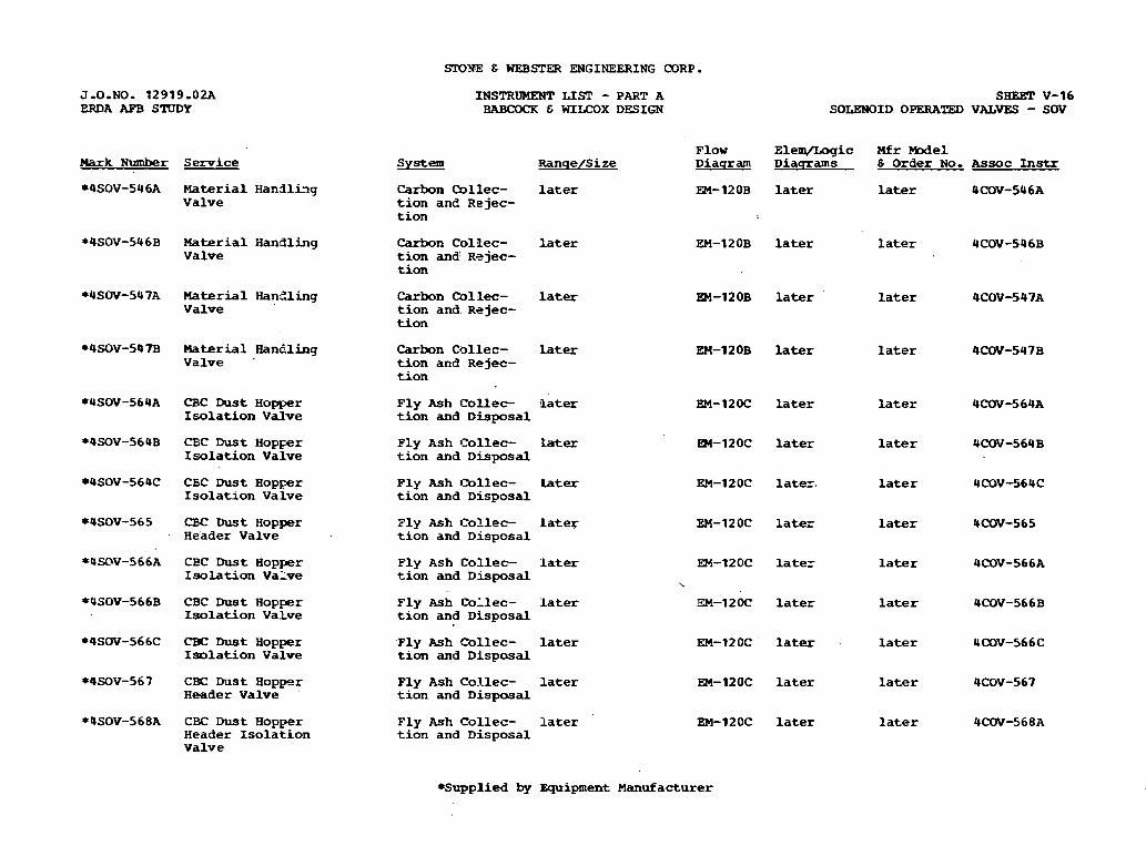
!XDITE E WEBSTER ENGINEERING CORP . J.0.NO. 12919-02A ERDA AFB STUDY
INSTRUMENT L I S P - PART A BABCOCR C WILCOX DESIGN
SHEET V-16 SOLENOID OPERATED VALVES - SOV
F l o w E l e m / L o g i c Mfr Model D i a q r a m D i a m a r n s 6 O r d e r No, A s s o c Instr Hark N u n h e r Service S y s t e m Ranqe/Size
*4SOV-596A M a t e r i a l H a n d l i n g V a l v e
Carbon Qllec- later t ion and R D j ec- t ion
EM-12OB later later UCOV-5U6A
*OSOV-546B Material H a n d l i n g V a l v e
Carbon C o l l e c - later tion and' R 2 j ec- t ion
EM-12OB later later UCOV-546B
EM-12OB later l a t e r UCOV-5 47A *USW-547A M a t e r i a l IianZling V a l v e
C a r b o n mllec- later t i o n a n d . R e j e c - t ion
*4SOV-597B Material Hanaing V a l v e .
later later Carbon C o l l e c - later t ion and R e j e c - t i o n
*4SW-564A CBC D u s t H o p p e r Isolation V a l v e
F l y Ash C o l l e c - l a t e r t ion and D i s p o s a l
later
later
l a t e r .
late-
later
later
later
later
later
later
later
later
later
l a t e r
later
la ter
l a t e r
la ter
*4SOV-564B CBC 'bust H o p p r Isolation V a l v e
F l y A s h C o l l e c - L a t e r t i o n and D i s p o s a l
+USOV-56UC CEC Dust H o p p e r Isolation V a l v e
P l y Ash 13llec- Later t i o n and D i s p o s a l
*OSOV-565 CBC LhLst H o p p e r H e a d e r V a l v e
P l y Ash C o l l e c - later t i o n and D i s p o s a l
*U=V-566A CEC D u s t E o p p e r Isolation V a l v e
F l y A s h C o l l e c - - later t i o n and D G p o s a l
*USOV-566B CBC Dust H o p p e r I so la t ion V a l v e
F l y Ash C o l l e c - later t i o n and D i s p o s a l
*4SOV-566C CBC D u s t H o p p e r Isolation V a l v e
' F l y Ash C o l l e c - later t i o n and D i s p o s a l
*@SOV-567 CBC D u s t H o p p e r R e a d e r V a l v e
P l y Ash C o l l e c - l a ter t ion and D i s p o s a l
*4SOV-568A CBC D u s t H o p p e r H e a d e r Isolation V a l v e
F l y Ash C o l l e c - later t i o n and D i s p o s a l
*Supplied by E q u i p m e n t M a n u f a c t u r e r
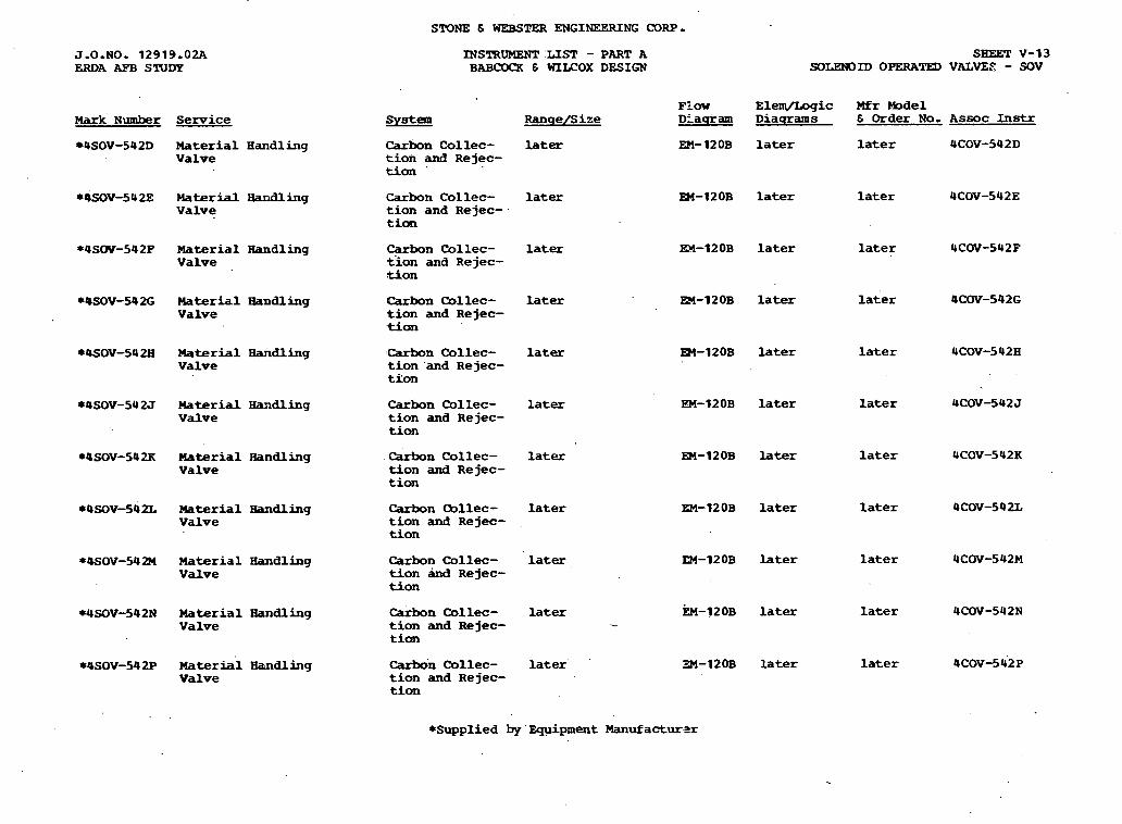
STONE 6 WEBSTER ENGINEERING CORP.
SBEET V-13 SOLENOID OPERATED VALVE,@ - SOV
J.O.NO. 12919.02A ERDA AFB STUDY
INSTRUMENT LIST - PART A BAB- 6 WILCOX DESIGN
Flow E l e m / L o g i c Mfr Model DFaqram D i a q r a m s 6 O r d e r No. A s s o c Instr Mark Number Senrice System Ranqe /S i z e
later *4SOV-542D M a t e r i a l H a n d l i n g V a l v e
EM-12OB later later 4COV-542D Carbon C o l l e c - t ion and R e j e c - t ion '
*4SOV-54 2E M a t e r i a l Handling V a l v e
Carbon C o l l e c - t ion and R e j e c - tion
la ter En-120B later later 4COV-542E
* 4 S W - 5 4 2 P Haterial Fiandling V a l v e
Carbon C o l l e c - t ion and R e j e c - Lion
later
later
EX-120B l a t e r later 4COV-542F
R4-12OB later later 4COV-542G *4SOV-542G M a t e r i a l H a n d l i n g V a l v e
lcarbon C o l l e c - t ion and R e j e c - tion
*OSOV--542Ei M a t e r i a l Handling V a l v e
'Carbon Collec- t ion 'and R e jec- t lon
later m - 1 2 0 B later later UCOV-542~
*4SOV-542J M a t e r i a l Haadling V a l v e
Carbon C o l l e c - t ion and R e j e c - t ion
later
la ter
EM-12OB later
m-12OB later
la ter
later WSOV-542K M a t e r i a l Handling V a l v e
Carbon C o l l e c - t ion and R e j e c - t ion
*4SOv-542L Material Bandling V a l v e
Carbon C o l l e c - t ion and R e jec- t ion
later EM-12 OB later
EM-12OB later
later
later *OSOV-542M Uaterial H a n d l i n g V a l v e
Carbon C o l l e c - t ion ind R e j e c - t ion
later
later
la ter
E M - 1 2 0 ~ later
3M-120B later
later
later
WSOV-542N M a t e r i a l Handling V a l v e
C a r b o n C o l l e c - t ion and R e j e c - t ion
CarSdn C o l l e c - t ion and R e j e c - t ion
W O V - 5 4 2 P Material 5 d l i n g V a l v e
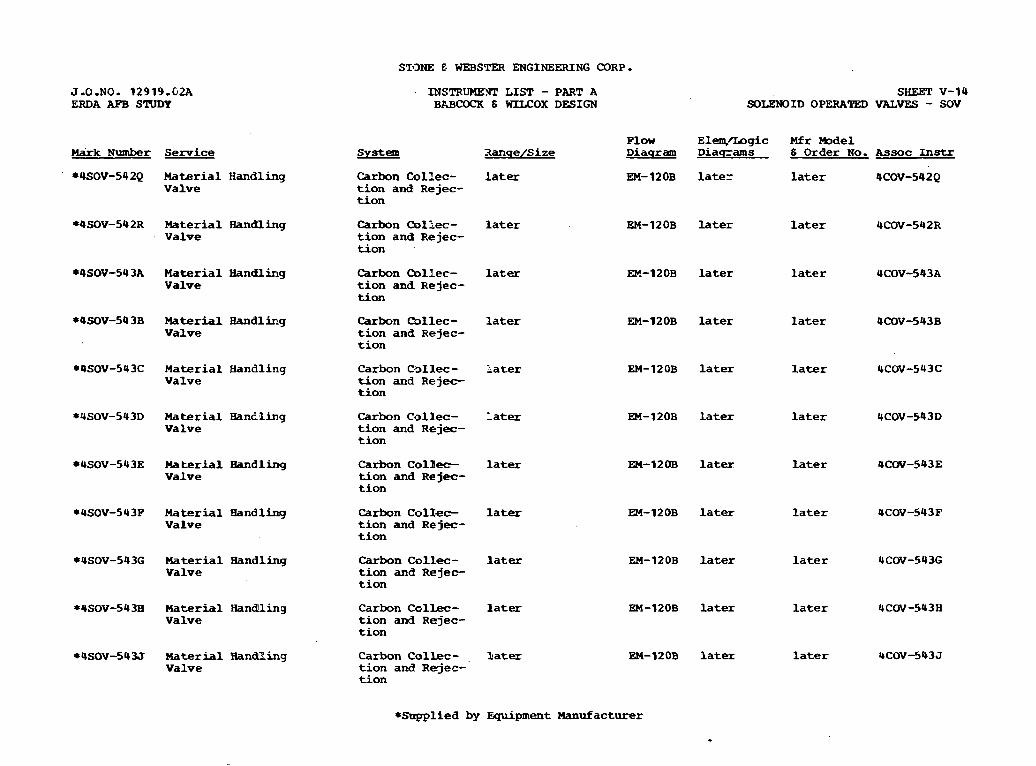
STONE E- WEBSTER ENGINEERING CORP.
J-0-NO. 12919.02A ERDA AFB STUDY
INSTRUWWI' L I S T - PART A BlgCOCK S =OX DESIGN
SHEET V-14 SOLENOID OPERATED VALVES - SOV
F l o w E l e n m g i c Mfr M o d e l System 3 a n q e / S i z e D i a q r a m D i a q z a m s 6 Order No. A s s o c Instr Ndrk Number Service
*4!SOV-542Q M a t e r i a l H a n d l i n g V a l v e
C a r b o n C o l l e c - later t ion and R e j e c - t ion
EM- 12OB later la ter 4COV-542Q
*4SOV-542R Material Handling V a l v e
C a r b o n mllec- later t ion and R e j e c - t i o n
EM-12OB later later 4COV-542R
*4SOV-543A M a t e r i a l Ban&ling V a l v e
Carbon C o l l e c - later t ion and R e j e c - t i o n
E M - 1 2 0 ~ later la ter 4COV-543A
*QSOV-54 3B Material Bandling V a l v e
Carbon (Sllec- later t ion and R e j e c - t ion
EM-1 2 OB later later 4COV-543B
*OSOV-543C Material H a n d l i n g V a l v e
C a r b o n C - s l l e c - la ter t ion a n d R e j e c - t ion
EM-12OB later later 4COV-543C
*USOV-543D M a t e r i a l B a n t l i n g V a l v e
C a r b o n C o 1 l . e ~ - later tion and R e jec- t i o n
EM-12OB l a t e r later 4COV-543D
*4SOV-543E Material B a n d l i n g V a l v e
C a r b o n C o l B e c - later t ion and R e jec- t i o n
EM-12UE later later 4CW-543E
*4SOV-543P M a t e r i a l H a n d l i n g V a l v e
C a r b o n C o l l e e - l a t e r EM-120B la ter l a t e r 4CW-543F t i o n and Rejec- t ion
*4SOV-543G M a t e r i a l H a n d l i n g V a l v e
C a r b o n C o l l e c - later t ion a n d R e j e r t ion
EM-12OB later later 4CW-543G
*4SOV-543B Material HandUing V a l v e
C a r b o n C o l l e c - later t ion and R e j e c - t ion
EM-12OB later later 4COV-543H
*4SOV-54U M a t e r i a l H a n d l i n g V a l v e
C a r b o n C o l l e c - , later t ion and R e j e c - t i o n
EM-12OB l a t e r la ter 4COV-543J
*!Supplied by E q u i p m e n t Manufacturer
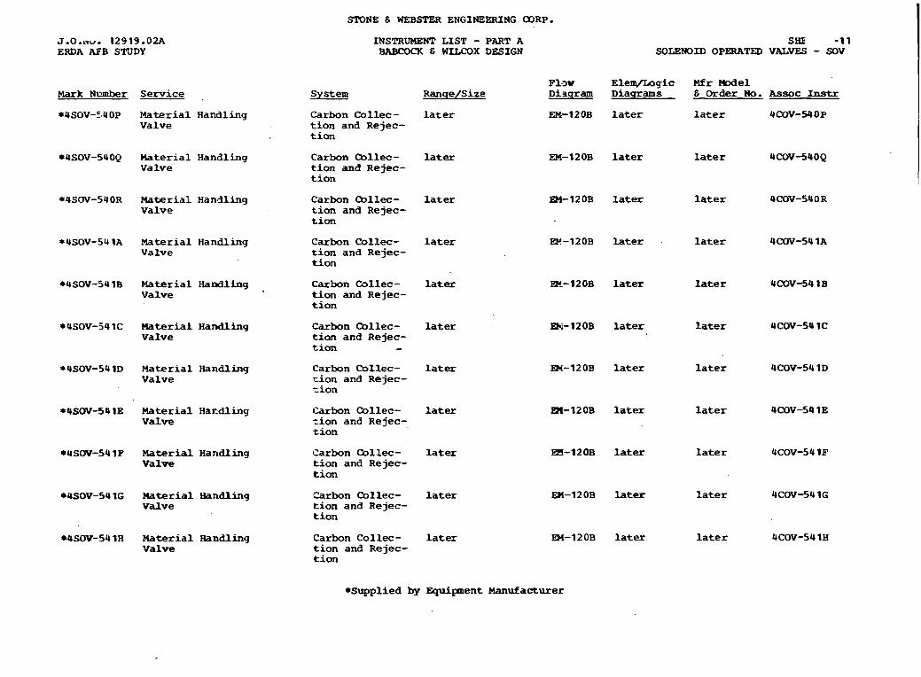
STONE E WEB- ENGINEERING CORP.
J . 0 . n ~ . 12919.02A ERDA AFB STUDY
INSTRUMENT L I S T - PART A BABCOCK C WILCOX DESIGN
SHE -1 1 SOLENOID OPERATED VALVES - SOV
F1->w E l e m / L o g i c M f r -el S y s t e m R a n q e I S i z e D i n q r a m D i a w a m s E O r d e r No. A s s o c Instr Mark Number Service
*4SOV-540P Material H a n d l i n g V a l v e
C a r b o n C o l l e c - l a ter t ion and R e j e c - . t i o n
E M - 1 2 0 ~ l a t e r l a t e r UCOV-WOP
*4SOV-54OQ Material H a n d l i n g V a l v e
C a r b o n O o l l e c - later t i o n and R e j e c - t ion
EM-12OB later later 4COV-54OQ
EM-12OB later later
later
later
later
later
C a r b o n Cbllec- later t ion and R e j e c - t i o n
*4SOV-540R Material H a n d l i n g V a l v e
*4SOV-54 1A Material H a n d l i n g V a l v e
C a r b o n C o l l e c - later t ion and R e j e c - t i o n
E24-120B later
Bc-12OB later
Et4-120B later
W - 1 2 0 B later
*4SOV-541B M a t e r i a l Handling V a l v e
C a r b o n Collec- later t i o n and R e jec- t i o n
C a r b o n Qllec- later tion and R e jec- t ion -
*4SOV-54 1C M a t e r i a d . H a n d l i n g V a l v e
*USOV-5UlD M a t e r i a l H a n d l i n g V a l v e
C a r b o n C o l l e c - la ter x i o n and R e j e c - =ion
*USOV-541E M a t e r i a l H a r d l i n g V a l v e
Carbon C o l l e c - la ter =ion a n d R e j e c - . t i o n
a - 1 2 0 B later
m - 1 2 0 B later
later
later *USOV-54lF M a t e r i a l H a n d l i n g V a l v e
C a r b o n C o l l e c - l a ter tion and R e j e c - tion
*4SOV-54 1G Material Handling V a l v e
Carbon C o l l e c - later t ion and R e j e c - t ion
En-120B later
EM-1 2 0B later.
later
later MSOV-54 l H M a t e r i a l Handling V a l v e
C a r b o n C o l l e c - l a t e r t ion and R e j e c - t ion
*Supplied by E q u i p m e n t Manufacturer
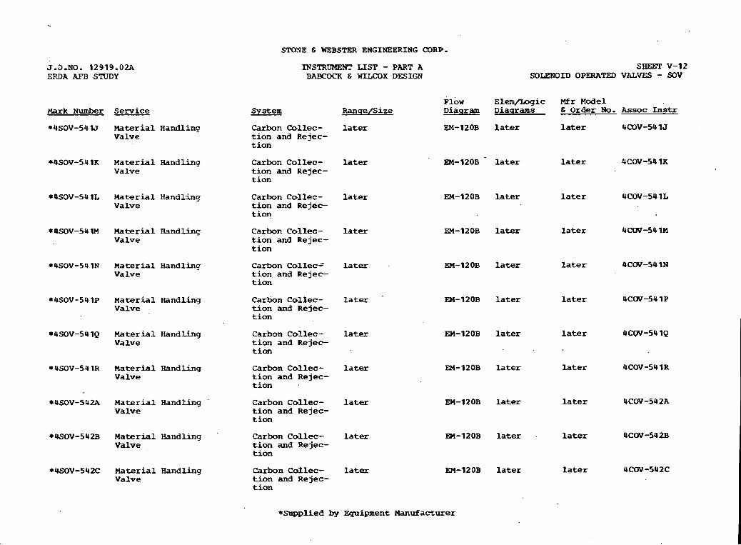
STOYE & WEBSTER ENGINEERING CORP.
J.O.NO. 12919 .02A ERDA A??B S'NDY
INSTRUMENT LIST - PART A BABCOCK G WILCOX DESIGN
s m v-12 SOLENOID OPERATED VALVES - SOV
F l o w E l e m / L o g i c M f r M o d e l D i a q r a m D i a q r a m s E O r d e r No. Assoc Instr Mark Number Service S y s t e m R a n q e / S i z e
la ter *4SOV-54 lJ Material H a n d l i n q V a l v e
C a r b o n C o l l e c - t ion and R e j e c - t ion
EM-12OB later later 4COV-54 1 J
EM-12OB later
EM-12OB later
EM-12OB later
later
later
later
*4SOV-54 1K M a t e r i a l H a n d l i n c V a l v e
C a r b o n C o l l e c - t ion and R e j e c - t i o n
la ter
*QSOV-54 1L Material H a n d l i n q V a l v e
C a r b o n C o . 1 l e c - t ion and R e j e c - t ion
later
*4SOV-54 lM M a t e r i a l R a n d l i n g V a l v e
C a r b o n C o l l e c - t ion and R e j e c - t ion
la ter
*4SOV-54 l N M a t e r i a l H a n d l i n g V a l v e
C a r b o n C o l l e c = t ion and R e j e c - t ion
la ter
later
l a t e r
EM-12OB l a t e r
W - 1 2 0 B later
later
later *4SOV-54lP M a t e r i a l H a n d l i n g V a l v e
C a r b o n C o l l e c - t ion and R e j e c - t ion
*4SOV-54 1Q M a t e r i a l H a n d l i n g V a l v e
Carbon C o l l e c - t i o n and R e j e c - t ion
EM-I2OB later
EM-12OB later
later
*r(SOV-54 1~ M a t e r i a l Handling V a l v e
C a r b o n C o l l e c - t ion and R e j e c - t ion
later later
En-12OB later l a t e r
EM-120B later later
EM-12OB la ter rater
*4SOV-542A M a t e r i a l H a n d l i n g V a l v e
C a r b o n C o l l e c - t i o n and R e j e c - t i o n
later
la ter *WOV-542B M a t e r i a l H a n d l i n g '
V a l v e C a r b o n C o l l e c - t ion and R e j e c - t ion
* W O V - 5 4 X M a t e r i a l Handling V a l v e
C a r b o n C o l l e c - t ion and R e j e c - t i o n
l a t e r
*Supplied by F q u i p m e n t Manufacturer
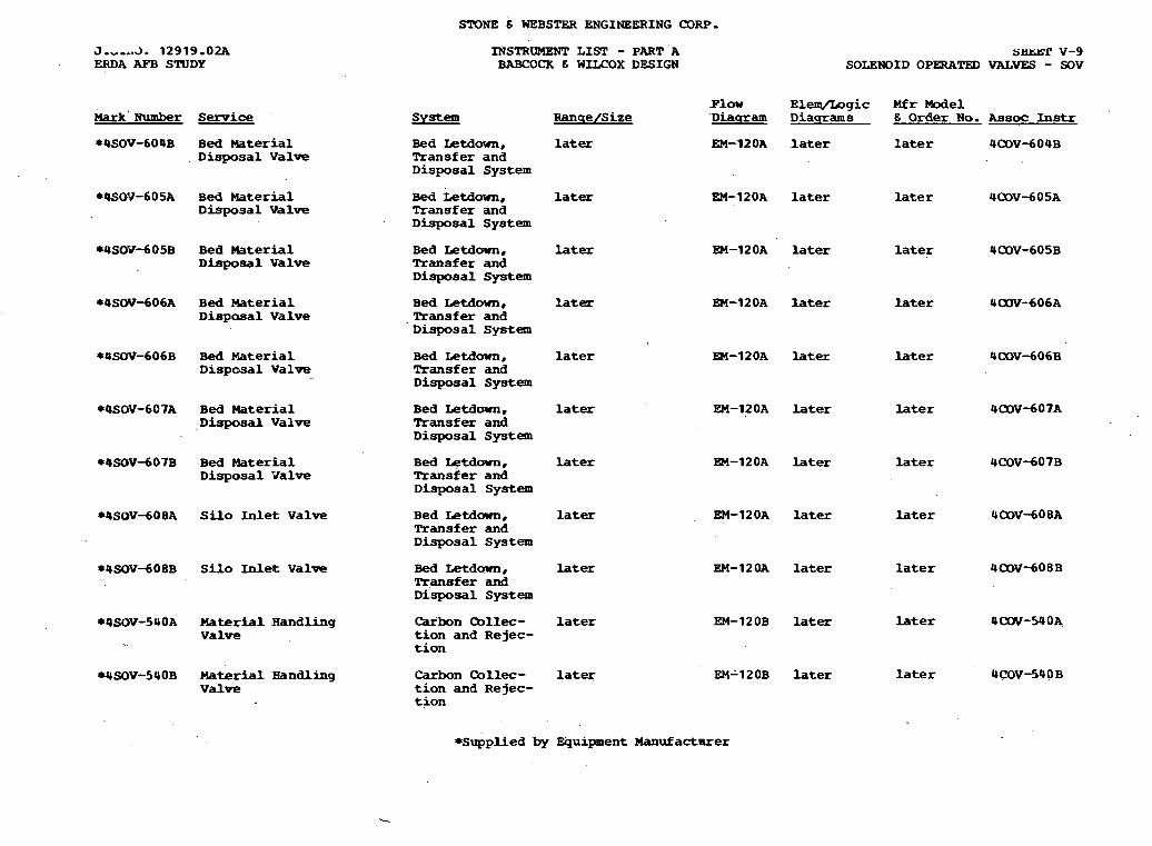
STONE 6 WEBSTER ENGINEERING (30RP.
J.,,,3. 12919.02A ERDA M B STUDY
INSTRUMENT LIST - PART A BABCOCK 6 WZLCOX DESIGN
s w r V-9 SOLENOID OPERATED VALVES - SOV
. F l a w E l e q / L o g i c Mfr M o d e l ' D i a a a m D i a q l r a m s 6 O r d e r No. Lsoc Instr
EM-12OA la ter later 4COV-604B
Mark' Number Service S y s t e m R a n q e / S i z e
*4SOV-609B B e d Material . D i s p o s a l V a l v e
Bed Ietdown, later Transfer and D i s p o s a l S y s t e m
*4SOV-605A B e d M a t e r i a l D i s p o s a l V a l v e
B e d Letdown, la ter Transfer and D i s p o s a l S y s t e m
EM-12OA later later 4 a l V - 6 0 5 A
EM-12OA later
EM-12OA later
later
later
later
later
later
later
la ter
later
later
*9SOY-605B B e d M a t e r i a l D i s p o s a l V a l v e
B e d L e t d o w n , later Transfer and D i s p o s a l S y s t e m
* 4 S W d 0 6 A B e d Material D i s p a s a l V a l v e
B e d L e t d o w n , later Transfer and D i s p o s a l S y s t e m
*4SOV-606B B e d M a t e r i a l D i s p o s a l V a l v e
Bed Letdown, later Transfer and D i s p o s a l S y s t e m
m-12OA later
*OSOV-607A B e d Material D i s p o s a l V a l v e
B e d Letdown, later Transfer and D i s p o s a l S y s t e m
EM-12OA later
*4SOV-607B Bed Material D i s p o s a l V a l v e
B e d I&down, later Transfer and D i s p o s a l S y s t e m
EM-120A later
*OSOV-608A Silo Inlet V a l v e B e d L e t d o w n , later Transfer and D i s p o s a l S y s t e m
EM-12OA later
EM-12OA later *4SOVdO8B Silo InLen V a l v e Bed L e t d o w n , later Transfer and D i s p o s a l S y s t e m
Carbon mllec- later t i o n and R e j e c - t ion
EM-12OB later
EM412OB later
*4SOV-540A M a t e r i a l H a n d l i n g V a l v e
WSQV-54OB M a t e r i a l Handling V a l v e
Carban C o l l e c - later t ion and R e j e c - t ion
*Supplied by Q u i p n e n t Manufacturer
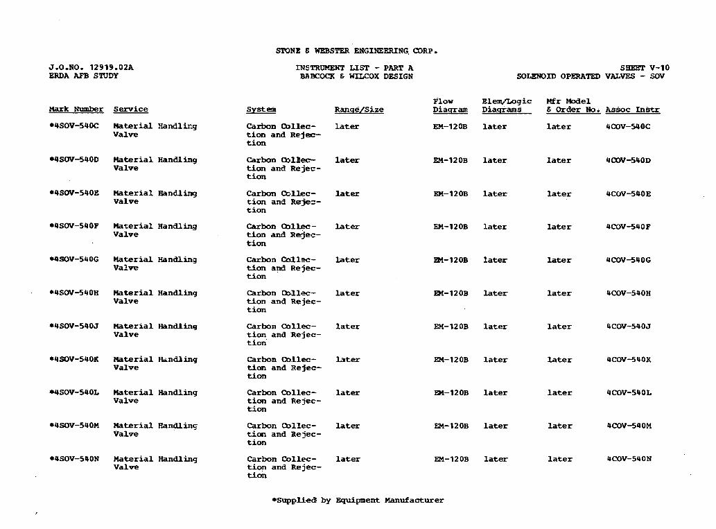
SrONE E WEBSTER ENGINEERING. CDRP.
J-0-NO- 12919.02A ERDA AFB STUDY
INSTRUMJZNT L I S T - PART A BABCOCK 6 =OX DESIGN
SHEET v-10 sox.mm OPEDATED VALVES - sov
P l o w Elem/Logic MEr Model R a n q e / S i z e D i a q r a m D i a q r a m s E Order No. A s s o c Instr Mark Number S e r v i c e S y s t e m
*4SOV-540C Material H a n d l i r g V a l v e
C a r b o n Qllec- la ter t ion and R e j e c - t ion
EM-12OB later later 4 W - 5 4 O C
*QSOV-540D Material H a n d l i n g V a l v e
C a r b o n m l l e e later tion a n d R e j e c - tion
EM- 1 2 OB later later 4OOVJ4OD
*4SW-54OE M a t e r i a l B a n d l i n g V a l v e
C a r b o n C X l l e c - later t ion and Rejez- t ion
EM-12OB later later 4COV-54OE
*4SOV-540P Material R a n d l b y V a l v e
Carbon Bllec- L a t e r t i o n and R e j e c - t ion
EM-120B later later 4COV-540F
WSOV-540G M a t e r i a l Handling V a l v e
Carbon Call=- later t ion and R e j e c - t ion
m-12OB later later 4COV34OG
*4SOV-540H M a t e r i a l H a n d l i n g V a l v e
C a r b o n Cbllec- later t ion a n d R e j e c - tion
m - 1 2 0 B later later 4COV-540H
*4SOV-54OJ M a t e r i a l Handling V a l v e
C a r b o n Qllec- l a t e x t ion a n d R e j e c - t ion '
FN-120B later later 4COV-540J
*4SOV-540K Material Hrindliing V a l v e
C a r b o n Q.Llec- later tion a n d R e j e c - t ion
EM-12OB later later 4COV-54OK
WSOV-540L M a t e r i a l H a n d l i n g V a l v e
C a r b o n Qllec- later t ion and R e j e c - t ion
m-120B later la ter 4COV-54OL
*4SOV-540M Material Ffan-g V a l v e
C a r b o n Qllec- l a t e x t im a n d R e j e c - t ion
EM-120B later later 4COV-540M
*4SOV-540N M a t e r i a l Handling V a l v e
C a r b o n C o l l e c - later t ion and R e j e c - t ion
EM-12OB la ter later 4COV-540N
*Supplied by E q u i p m e n t Manufacturer
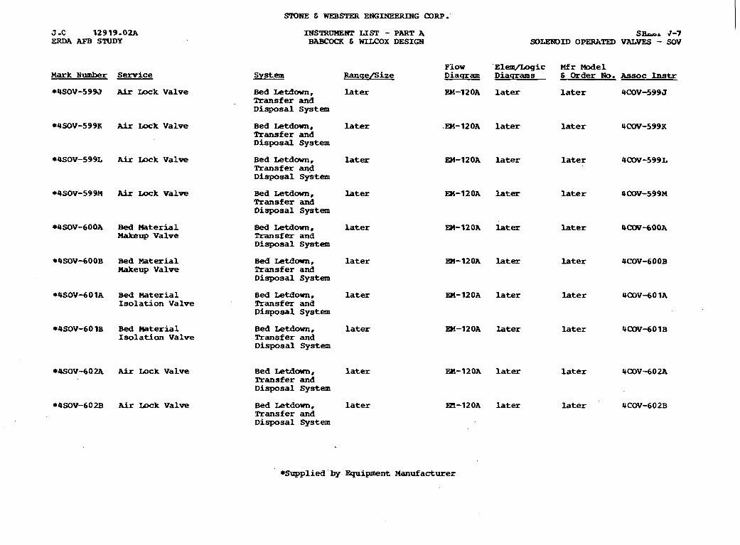
SPONE E WEB- ENGINEERING CORP.'
INSlRUMENT LIST - PART A BABCOCK 6 WLLCOX DESIGN
SBopa 3-7 SOLENOID OPERkTED VALYES - SOV
F l o w ' E l e m / I a g i c Mfr Model D i a q r a m D i a q r a m s 6 Order No. Assoc Instr Mark Number Service
*USOV-599J AFr W k V a l v e
S y s t e m Ranqe /S h e
later B e d L e t d o w n , Transfer and D i s p o s a l S y s t e m
EH-12OA later later 4COV-599 J
*4SOV-59% Aix Lock V a l v e B e d Letdown, Transfer and D i s p o s a l S y s t e m
later .M-12OA later later 4 m - 5 9 9 K
*USOV-599L A h Lock V a l v e B e d LetdOWn, Transfer and D i s p o s a l S y s t e m
later EH-12OA later later 4COv-599L
*USOV-599M Air Lock V a l v e B e d Letdown, Transfer and D i s p o s a l S y s t e m
later M-120A later later OCOV-599M
*4SOV-600A Bed M a t e r i a l Makeup V a l v e
Bed Letdam, Transfer and D i s p o s a l S y s t e m
later M-12OA later later UCW-600A
*QSOVdOOB Bed M a t e r i a l M a k e u p V a l v e
Bed' L e t d o w n , Transfer and D i s p o s a l S y s t e m
later a - 1 2 0 A later later 4COVdOOB
*USOVdO l A B e d M a t e r i a l Isolation V a l v e
Bed Letdown, R r a n s f e r and D i s p o s a l S y s t e m
later En-120A later later UCOV-60 1A
*4SOV-60 1B B e d M a t e r i a l Isolatian V a l v e
Bed Letdown, Ransfer and D i s p o s a l S y s t e m
later BI-12OA later later 4COV-60 1 B
*PSOV-602k kir mck V a l v e B e d Letdoun, later Transfer and D i s p o s a l S y s t e m
En-120A later later 4COV-602A
El%-120A later later 4 C O V d 0 2 B *OSOV-602B Air I D C ~ V a l v e B e d L e t d o w n , later Transfer and D i s p o s a l S y s t e m
m p l i e d ' b y Equipment Manufacturer

J-0-NO. 12919-0% ERDA AFB STUDY
SHBFP V-8 ==ID OPERATED VALVES - !BV
NSTRUMWI' LIST - PART A BABCOCK 6 WILCOX DESIGN
F l o w E l e q A ~ q i c Mfr Model D i a q r a m D i a s r a m s 6 Order No. Assoc Instr Mark Number Service
*4SOV-602C Air Iock V a l v e
System Ranqe/Size
Bed Letdown, later Transfer and D i s p o s a l S y s t e m
EM-12OA later later 4alVd02C
*4SOV-602D Air Iack Val- Bed Letdown, later Transfer an3 D i s p o s a l S y s t e m
En-12OA later la ter 4w-602D
4SOV-602E . Air Lock' Val-
*USOV-602F Air Lock V a l v e
Bed Letdoran,, later Transfer and D i s p o s a l S y s t e m
EM-12OA later
En-12OA later
later
later Bed Letdmm. later Transfer and D i s p o s a l S y s t e m
*QWV-603A Air Iack V a l v e
rOSOV-603B Air Iack V a l v e
YSOV-603C A i r Iock V a l v e
*4--603D Air Lock V a l v e
4SOV-603E Air Lock V a l =
EM-12OA later later Bed Iatdom, la te r Transfer and D i s p o s a l S y s t e m
Bed Letdown. later Transfer and D i s p o s a l System
EM-12OA later later
EM-120A latex later Bed L e t d m , Rater Transfer .and D i s p o s a l S y s t e m
Bed Letdown, later Trapsfer and D i s p o s a l S y s t e m
EM-12OA later later
EM-l2OA later later Bed Letdcmm, later Transfer ard D i s p o s a l System
B e d Iatdm. later Transfer and D i s p o s a l S y s t e m
*4SOVdO3P Air Lock V a l v e EM-12OA latex later
later aSOV-604A Bed M a t e r i a l D i s p o s a l V a l v e
B e d Letdawn, btff Transfer a d D i s p o s a l System
m-120A later
*Supplied by Equipment M a n u f a c t u r e r

STONE & WEBSTER ENGINEERING CORK
Mark Number Service
*USOV-597A Air ILIC~ V a l v e
*4SOV-597B A i r U c k V a l v e
*QSOV-598A A i r Lock V a l v e
*4SOV-598B A ~ K Lock V a l v e
*4SOV-598C AFr Lock V a l v e
WSOV-598D AFr I o c k V a l v e
*4S(W-59BB A i r U x k V a l v e
*4SW-598P air Uxk V a l v e
*&SOY-598G A i r L Q C ~ V a l v e
W S W - 5 9 8 H A i r L o c k V a l v e
*4SW-59BJ A i r Lock V a l v e
INSTRUMEW LIST - PART A - BABCOCK & WILCOX DESIGN
"-*' v-5 SOLENOID OPERATED VALVES - sov
P l o w E l ~ g i c Mfr M o d e l S y s t e m R a n q e / S i ze D i a q t a m D i a s r a m s 6 O r d e r No. A s s o c Instr
B e d Letdown, later Transfer and D i s p o s a l S y s t e m
B e d L e t d o w n , later Transfer and D i s p o s a l S y s t e m
B e d L e t d o w n , later T r a n s f e r and D i s p o s a l S y s t e m
~ e d Letdown, later Transfer and '
D i s p o s a l S y s t e m
Bed Letdown, later Transfer and D i s p o s a l S y s t e m
Bed L e t d o w n , later Transfer and D i s p o s a l S y s t e m
Bed Letdown, later Transfer and D i s p o s a l S y s t e m
B e d Letdown, later Transfer and D i s p o s a l ' S y s t e m
~ e d L e t d o w n , later Transfer and D i s p o s a l S y s t e m .
B e d L e t d o w n , later Transfer and D i s p o s a l S y s t e m
B e d L e t d o w n , later Transfer and D i s p o s a l S y s t e m
m - 1 2 0 A later later 4COV-597A
EM-12OA later later ' 4COV-597B
EM-12OA latff later
EM-12OA later later
EM-12OA later later
m - 1 2 0 A later later
PN-120A. later iater
EM-12OA later later
EM-12OA later later
EM-12OA later
EM-12OA later . ,
later
later
+Supplied by Equipment Manufacturer

J.0.190. 12919.02A ERDA AFB STUDY
Mark Number S e d c e
*4SOV-598K A i r Lock V a l v e
*4SOV-S98L Air Iock V a l v e
*4SOV-59811 A i r h x k V a l v e
r4SOV-599A Aix Iack V a l v e
r4SOV-599B Air Lock V a l v e
WSOV-599C A i r Lock V a l v e
*4SOV-599D Air ID& V a l v e
WSOV-599E A k hxk V a l v e
* O W - 5 9 9 P Air I&ck V a l v e
*4SW-59% Air Lock V a l v e
*4SOV-599H Air Iock V a l v e
System
INSTRUMEM' LISl' - PART A BABCOCK E WILCOX DESIGN
Bed Letdawn, la ter Transfer and D i s p o s a l S y s t e m
Bed I a t d m , later Transfer and D i s p o s a l S y s t e m
Bed Letdown, later Transfer and D i s p o s a l S y s t e m
Bed Letdown, later Transfer and D i s p o s a l S g s t e m
Bed Iatdmm, later Transfa and D i s p o s a l System
Bed Letdam, later Transfer a d D i s p o s a l . S y s t e m
Bed betdawn, later Transfer and D i s p o s a l S y s t e m
Bed Letdown, later Transfer zud D i s p o s a l System
Bed w- later Transfer a d D i s p o s a l System
Bed Letdown, later Transfer a d Disposal System
Bed Letd- later Transfer an3 D i s p o s a l System
SBEET V-6 SOLENOID OPERATED VALVES - SOV
F l o w E l e m / L o g i c Mfr M o d e l D i a q r a m D i a q r a m s 6 Order No. Assoc Instr
EM-12OA later later 4CW-598K
Dl-12OA later
EM-12OA later
EM-12OA later
EM-12OA later
EM-120A l a t e x
EM-12OA later
EM-12OA later
later 4COV-598L
later 4COV-598M
later 4COV-599A
later 4COV-599B
later 4COV-599C
later 4 W - 5 9 9 D
later 4COV-599E
EM-120A later later 4 a W - 5 9 9 R
EM-120A latex later 4COV-599G
EM-12OA later later UOW-599H
*Supplied by Bquipment Manufacturer
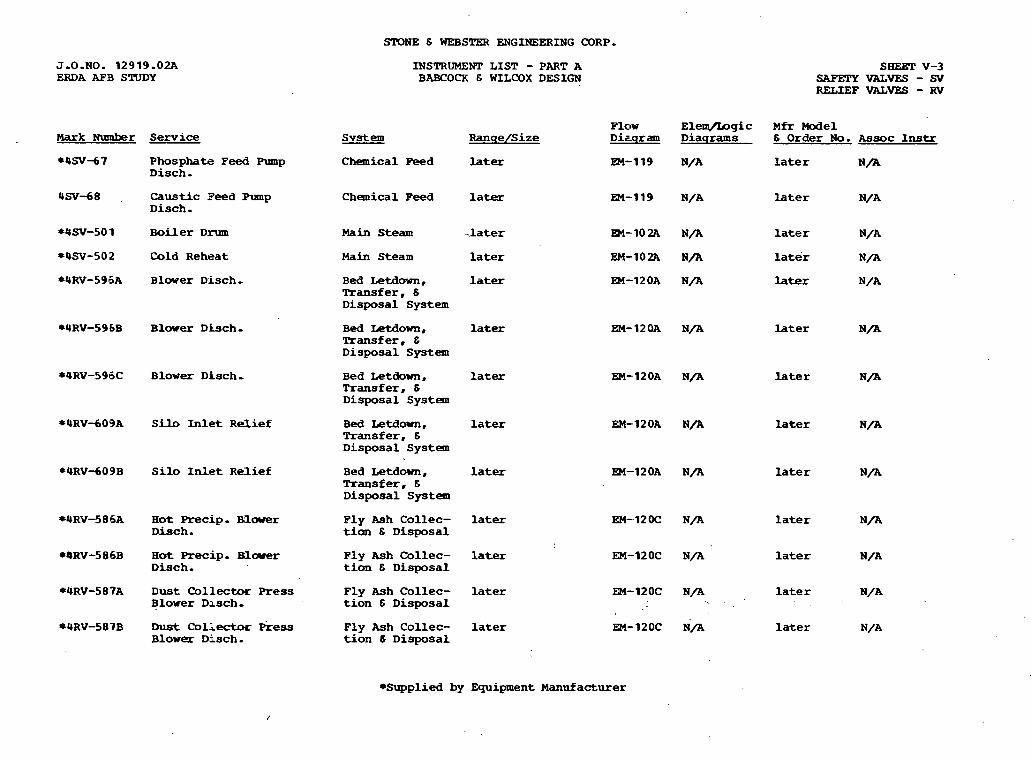
STONE 6 WEBSTER ENGINEERING CORP.
J.O.NO. 12919.02A ERDa AFB STUDY
INSTRUMENT L I S T - PART A BABCOCX & WLLCOX DESIGN
SHEgT v-3 SAFETYVALVES-SV RELIEF VALVES - RV
F l o w El-gic M f r Model D i ~ g r a m D i a g r a m s 6 O r d e r No. A s s o c Instr Mark Number Service
*4SV-67 P h o s p h a t e F e e d Pump D i s c h .
C h e m i c a l Peed later EM-119 N/A later N/A
4SV-68 , Caustic Feed Pump D i s c h . C h e m i c a l Feed later EM-119 N/A l a t e r N/A
Main S t e a m -later *4SV-50 1 B o i l e r D r u m EM-102A N/A later N/A
EM-102A N/A l a te r N/A
EM-12OA N / A later N/A
*4SV-502 Cold R e h e a t Main S t e a m later
*4RV-596A B l o w e r D i s c h . B e d Letdown, later Transfer, 6 D i s p o s a l S y s t e m
*4RV-596B B l o w e r D h c h - B e d -own, later hansf er, 6 D i s p o s a l S y s t e m
EM-12OA N/A later N/A
*4RV-596C B l o w e r D i s c h . B e d L e t d o w n , la ter T r a n s f e r , 6 D i s p o s a l S y s t e m
EM-12OA N/A later N/A
* 4 R V d 0 9 A Silo Inlet R e l i e f B e d Letdown, later Transfer, 6 D i s p o s a l S y s t e m
EM-12OA N / A l a t e r N/A
*4RV-609B Silo I n l e t R e l i e f B e d L e t d o w n , la ter Transfer, 6 D i s p o s a l System
EM-120A N/A later N/A
W R V S 8 6 A Hot Precip. Blarer D i s c h . F l y A s h C o l l e c - la ter EM-12OC N/A later
t ion 6 D i s p o s a l N /A
F l y A s h C o l l e c - l a ter EM-120C N / A later N/A t ion 6 D i s p o s a l
*4RV-586B H o t Precip. Blarer D i s c h .
*4RV-587A D u s t C o l l e c t i x Press B l o w e r D l s c h .
F l y Ash C o l l e c - later EM-12OC N/A l a t e r N/A t ion 6 D i s p o s a l .
*4RV-587B D u s t C o l l e c t o r hess B l o w e r D i s c h .
F l y Ash C o l l e c - later t ion 6 D i s p o s a l
E M - 1 2 0 ~ N/A later N/A
*Supplied by E q u i p m e n t Manufacturer

J.O.NO. 12919.02A ERDA AFB STUDY
Uark Number Service
4NRV-563. H P T u r b . E x h a u s t
STONE B . h i ENGINEERING CORP.
INSTRUMENT LIST - PART A BABCOQl E WILCOX DESIGN
System R a n q e / S i z e
Main Steam lazer
SHEET v-4 NONRerURN VALVES - NRV
Flow E l e m / L o g i c M r M o d e l Diaqi-am D i a q r a a t s 6 Order No. Assoc Instr
EM-1O2A later later OW-563
+Supplied by Epipment Manufacturer
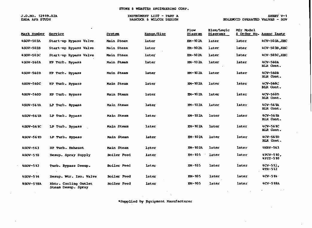
J.O.No. 32919.02A ERDA AFB STUDY
Mark Number S e r v i c e
USOV-503A S t a r t - u p Bypass V a l v e
USOV-503B S t a r t - p B y p a s s V a l v e
USOV-503C S t a r t - p B y p a s s V a l v e
EP Turk.. Bypass
RP Turk,. Bypas s
HP Turk . B y p a s s
HP Turb . B y p a s s
LP Turk*. Bypass
LP Turk*. Bypass
LP T-. B y p a s s
LP Turbo B y p a s s
RP Turbo m u s t
Desup. S p r a y S u p p l y
Turb. B y p a s s Desup.
USOV-5 1 4 Desup. W t r . Iso. V a l v e
4 9 0 ~ - 5 . 1 8 ~ Rhtr . C o o l i n g Outlet Steam Cesup. S p r a y
SIONE 6 WEBSTER ENGINEERING CORP.
INSTRUMENT LIST - PART A BABaxx 8 WfLCOX DESIGN
F low Sys t em R n n q e l S i z e Diaqram
Main Steam later EM-10 2A
Main Steam later EM-102A
Main Steam late? EM-102A
Main Steam later EM-10 2A
Main Steam later EM-10 2A
Main Steam later m-102A
Main Steam later EM-10 2A
Main Steam later EM-102A
Main Steam later EM- 10 2A
Main S t e a m later EM-102A
Main S t eam later EM-10 2A
Main Steam later FM-102A
B o i l e r F e e d later EM-105
B o i l e r P e e d later EM-10 5
B o i l e r Peed later EM-105
B o i l e r Feed later EM-105
SBEET. v-1 SDLWOID OPERATED VAL- - SOV
ElePq/I.ogic D iaq rams
later
later
later
later
later
later
later
later
later
later
later
later
later
later
later
later
Mfr Model 6 O r d e r NO.
later
later
later
later
later
later
later
later
later
later
later
later
later
later
later
later
Assoc Instr
UCV-503A,EEC
UCV-503B ,EHC
UCV-503C.EHC
4CV-560A BLR Oont.
4CV-560B BLR cbnt . UCV-56OC BLR %ont.
4CV-56OD BLR Cant.
4CV-56 IA BLR Oont.
4CV-56 1B BLR Cant.
UCV-561C BLR C o n t
4CV-561D BLR Oont.
UNRV-563
UPCV-510, UPIT-510
UCV-512, 4TR-512
UCV-5 1 U
UCV-5 18A
* S u p p l i e d by ,Equipment Manufacturer

STONE & WEESTER ENGINEERING CORP.
J - 0 - N O - 12919.02A ERDA AFB SRIDY
Hark Number Service
4SOV-518B Rhtr. Cooling +3utlet S t e a m D e s u p . Spray
4SOV-520 Rhtt. C o o l i n g 3utlet S t e a m D e s u p . S?ray
4SOV-526 Rhtr. C o o l i n g Wet Steam Desnp.
USOV-528 Rhtr . C o o l i n g Inlet Steam D e s u p .
Ih'STRDMENT LISP - PART A 6ABCUfX & WILCOX DESIGN
SHEET v-2 SOLENOrD OPERATED VALVES - SOV
E l a n / l s g i c Mfr M o d e l F l o w S y s t e m R a n q e f i i z e D i a g r a m D i a g r a m s & O r d e r No. . A s s o c I n s t r
Boiler m d la ter EM-105 later later UCV-5 18B
B o i l e r Peed later EM-105 later later 4CV-520
Boiler Peed later EM-105 later later 9CV-526
Boi ler Peed later EM-105 later la ter PCV-528
*Supplied by E q u i p m e n t Manufacturer
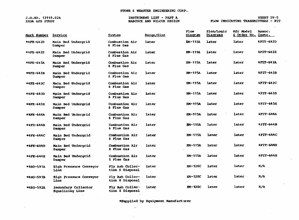
STONE & WEBSPER ENGINEERING CORP.
J.O.NO. 12919.02A ERDA AFB SlUDY
MSTRUMENT L I S T - PART A BABCOCK AND WILCOX DESIGN
SHEET IV-5 FLOW INDICATING TRANSMITTERS - P I T
F l a w E l e m / L o g i c Mfr Model Assoc. S y s t e m R a n q e / S i z e D i a q r a m M a s r a m s 6 Order No. Instr. Mark Number
*4FE-642D
Service
Main B e d Undergrid D a m p e r
C o m b u s t i o n Air later 6 Plue G a s
EM-11SA later later 4PIT-642D
Main B e d U n d e r g r i d D a m p e r
C o m b u s t i o n Air later 6 F l u e G a s
EM.-11% later later 4 P I T d 4 2 E
C o m b u s t i o n A r later 6 Flue Gas
EM-11SA later later 4F'IT-643A Main Bed D n d e r g r i d Damp-
C o m b u s t i o n Air later 6 F l u e G a s
EM-1 1SA later later 4 P I T d 4 3 B H6in B e d U n d e r g r i d D a m p e r .
C o m b u s t i o n Air later 6 P l u e G a s
EM-11% later later 4 P I T - 6 4 3 C Main B e d Qndergrid Damper
C o m b u s t i o n Air later 6 Plue Gas
EM-115A later later U F I T d 4 3 D M p i n Bed Undergrid D a m p e r
C o m b u s t i o n Air later 6 P l u e G a s
En-11% later later 4PIT-643E Main Bed U n d e r g r i d D a m p e r
C o m b u s t i o n Air 6 Plue G a s
la ter
later
later
later
later
later
later
later
EM-11% later
EM-115A later
EM-115A later
EM-11% later
EM-11SA later
EM-12OC later
EM-12OC later
EM-12OC later
later
later
later
later
later
later
later
later
H a i n Bed U n d e r g r i d Damper
Main Bed [mdergrid D a m p e r
C o m b u s t i o n Air 6 F l u e Gas
Main Bed U n d e r g r i d D a m p e r
C o m b u s t i o n Air 6 q u e G a s
Main Bed mdergrid D a m p e r
C o m b u s t i o n Air 6 Flue G a s
Wain Bed D n d e r g r i d D a m p e r
C o m b u s t i o n Air & Plue Gas
H i g h P r e s s u r e C o n v e y o r L i n e
F l y A s h Collec- tion .6 D i s p o s a l
H i g h pressure Conveyor Line
F l y Ash C o l l e c - . t ion 6 D i s p o s a l
*4RO-592A Secondary C o l l e c t o r E q u a l i z i n g Line
Ply Ash C o l l e c - t ion 6 D i s p o s a l
-plied by E q u i p m e n t Manufact-lrer

S F 3 N 3 6 WEB- E N G I N E W I N G CORP.
J.0.NO. 1 2 9 1 9 . 0 2 A ERDA AEB S ' N D Y -
Mark Number Service
*4RO-592B Seoondary C o l l e c t o r E q u a l i z i n g h e
*4RO-!593A Seoondary C o R l e c t o r E q u a l i z i n g Line
04R0-593B Secondary Collector E q u a l i z i n g Line
INSTRIIMEYT LIST - PART A 3ABCOCK -9M) W I I C O M DESIGN
System R a n q e / S i z e
P l y Ash Collec- Later t ion 6 Msposal
Ply Ash Collec- later tion 8 Disposal
P l y Ash C o l l e c - later tion 6 Disposal
SaEET IV-6 ?'LOW INDICATING TRANSMITTERS - FIT
F l o w Elem/Logic Mfr Model A s s o c . D iaqram D i a s r a m s 6 Order N o . Instr.
R4-12OC later later N/A
EM-12OC later later N/A
EM-12OC later later N / A
+-lied by E q u i p m e n t Manufacturer
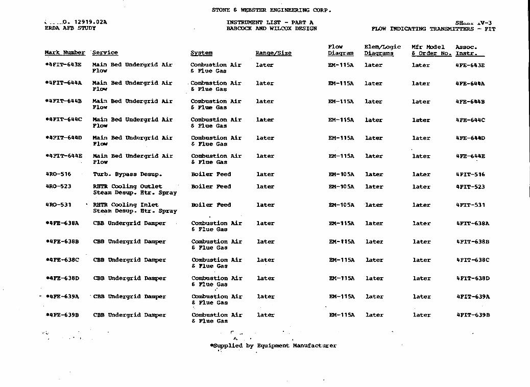
SrONE E WSTW ENGINEERING CORP.
C ._ ._.Do 12919-02A ERDA AFB STUDY
INSTRUMEWI' LIm - PART A BABCOCK AND WILCOX DESIGN
S h r rv-3 FLOW INDICATING TRANSUTTERS - FIT
Flow EleIWLogic Mfr Model Assoc. System Ranqe/Size Diaqram D i a q r a m s E Order No. Instr. Hark Number 'Service
*UFIF643E M a i ? Bed Undergrid Air Plow
Combustion Air l a t e r 6 Flue Gas
EM-115A l a t e r l a t e r 4PE-643E
*QFITdUQA MaF? Bed Undergrid A i r F l w
Combustion Air l a t e r 6 Plue Gas
EM-115A later l a t e r 4FE-644A
*UMT-64UB Mah Bed Undergrid Air Plow
Combustion Air l a t e r E Flue 'Gas
EM-11% later l a t e r 4FE-644B
*4PIT-644C Wat? Bed Undergrid Air Plow
Combustion Air later 6 Flue Gas
EM-115A later later 4FB-644C
*@FIT-644D Main Bed Ondr+rgrid Air Plcrw
Combustion Air l a t e r E Plue Gas
EM-115A later l a t e r 4FE-644D
EM-115A later l a t e r 4FE-644E *4XT-644E Main Bed Ilndergrid Air Plow
Combustion Air later E Flue Gas
4RO-516 Rub. Bypass Desup. B o i l e r Peed later EM-105A later l a t e r 4 FIT-5 16
URO-523 RETR Cooling Outlet Steam Desup. H t r . Spray
Boiler wed l a t e r EM-IOSA later l a t e r 4PIT-523
Boiler Feed l a t e r m-1OSA later l a t e r 4MT-531 4x3-531 ' REIS Cooling Inlet Steam Desup. H t r . Spray
Combustion Air l a t e r E Flue Gas
m-11% l a t e r l a t e r 4PIT-638A *4FE-638A CBB Undergrid Damper
*UFE-638B CBB Undergrid Damper Combustion Air later E Plue Gas
EM-11% l a t e r l a t e r 4PIT-638B
rQPe-638C CBB Undergrid Damper Clmbustion Air l a t e r 6 Flue Gas
EM-11% l a t e r l a t e r 4FITd38C
-?%-638D CBB Undergrid Damper Combastion Air later 6 Flue Gas
EM-11SA l a t e r l a t e r UFIT-638D
- *4PE-639A ' CBB Undergrid Damper Qmbustion Air l a t e r EM-11- l a t e r l a t e r 4PIT-639A 6 Flue Gas
Combustion Air l a t e r EM-11% l a t e r l a t e r 4PIT-639B E Flue Gas
84PE-639B CBB 'Undergrid Damper
- ?- -, A , '
-plied by Equipment Manufact iuer r :
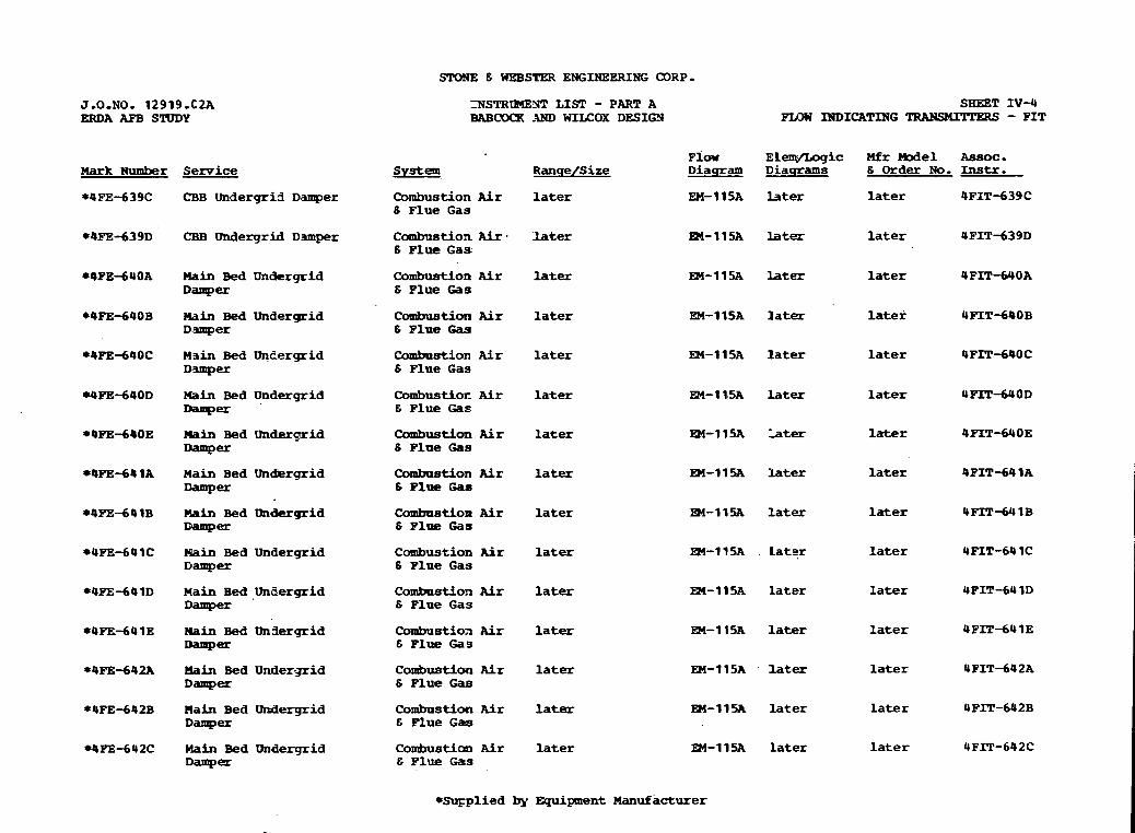
STONE 6 WEBSTER ENGINEERING CDRP.
XSTRlME1JT LIST - PART A BAB- -9ND WILCOX DESIGN
SHEET IV-4 F U W INDICATING - F I T
J-0-NO. 12919.C2A ERDA APB STUDY
S y s t e m P ~ O W ELem/Logic M f r nodel ~ s s o c -
R a n q e / S i z e D i a q r a m D i a q r a m s 6 Order No. Instr. Mark Number Semice
*4FE-639C CBB U n d e r g r i a Damper Combustion Air later 6 P l u e G a s
EM-1 15A later later 4PIT-639C
*4PE-639D CBB Undergrid Damper C o m b u s t i o n Air- later 6 Flue G a s
R4-115A later later
*4PE-640A Main Bed Wndtrgrid Damper
C o n t b u s t i o n Air later 6 P l u e Gas
Fbl-11% later later
later
later
later
later
later
later
later
later
later
later
la ter
later
Combuat icm Air later 6 P l u e Gk9
EM-11SA later *QPE-690B Hain Bed Undergrid D.smper
*4PE-640C Main Bed Wneergrid D3mper
Combastion Air later 6 P l u e G a s
EM-115A la ter
rUPE-640D Main Bed U n d e r g r i d C o m b u s t i o r Air later E P l u e Gas
EM-115A later
*4FE-640E bin Bed U n d e r a r i d Damper
capbustion A i r later 6 Flue Gas
*4PE-641A M a i n Bed Un&ergrid Damp-
Combostion Air later 6 P l u e Gas
En-11- later
M-11% later
EM-1 15A . L a t q r
EM-115A later
EM-115A later
*OPE-641B Chin Bed U n d e r g r i d Damp=
C o m b u s t i o n Air later 6 P l u e Gas
*4FE-641C Main Bed U n d e r g r i d Damper
C o m b u s t i o n Air later 8 Flue G a s
*OPEdOlD M a i n Bed U n a e r q r i d Damper
C o m b a s t i o n Air la te r 6 Flue G a s
*4FE-641E nain Bed U n f l e r g r i d Damp-
C a m b u s t i o a Air later 6 Plue Gas
*4=-642A main Bed U n d e r g r i d Damper
C o m b u s t i o n f i r later 6 F l u e Gas
*4FE-642B M a i n B e d Undergrid Damp-
C o m b u s t i o n Air later 6 Plue G a s
En-115A later
*4PB-642C nain Bed Undergrid Damp-
Combus t i cm Air later E Flue Gas
EM-11% later
*Su~plied by E q u i p m e n t Manufacturer

Mark Number Serrrice
WLG-26A Mixing Tank
*OX&-26B Mixing Tank
*OX&-14A Phosphate Feed Tank
*OX-14B Phasphate Feed Tank
rOLG-1SA Caust ic Feed Tank
*ex-1SB Caust ic Peed Tank
STOlPE E WEBSTER ENGINEZRING QRP.
INSTRUMENT LIST - PART A B A B C D ' ~ s W~LCOX DESIGN
F l w System Ranqe/Size Diaqram
Chemical Peed Later EM-1 19A
Chemical Feed Later EM-11%
Chemical Peed Later EM-1 19A
Chemical Feed Later EM-1 1 9A
Chemical Feed Later EM-119A
Chemical Peed Later EM-1 19A
SHE iI -1 LEVEL GAGES - I&
Hfr W e 1 & Order No. Assoc I n s t r
~ a t e r N/A
Later N/A
Later N/A
Later N/A
Later N/A
Later N/A
. .
s u p p l i e d by Equipment Manufa-er

,cTDNE 8 WEESTER ENGINEERING O R P .
J.O.NO. 12919.02A INSTRUlrZNT LIST - PART A ERDA AFB . STUDY 3ABfXCX E WLLCOX DESIGN
SHEET 111-2 LEVEL SWITCBES - LS
Wark Number Service System
* 4 L S 4 2 nixing Tank L o w Level Chemical Peed L a t e r
*Om-33 Phosphate! Feet? Tank Chemical Peed L a t e r High Level
Y L S - 3 9 Phosphate Peed Tank Chemical Peed Later Iaw Iavel
* 4 U - 3 5 C a u s t i c Peed Tank Chemical Peed L a t e r High L e v e l
*4LS-36 Caustic Peed Tank Chemical Peed L a t e r Low Level
Flow Elem/Logic Mfr Model Diaqram Diaqrams & Order N o . Assoc Instr
EM-119A L a t e r Later
EM-119A Later L a t e r
EM-119A L a t e r L a t e r
EM-119A L a t e r L a t e r
En-719A L a t e r L a t e r
BmppXied by Eqnipnent Manufacturer

nark Numher S e r v i c e
Urn-504 Turbine Bypass
4m-518A Rhtr Cool Outlet ' D e s u p Stm Temp
UTR-5 1#8B Rhtr C o o l Outlet D e s u p Stm Temp
4TR-5 1 7 Desup K a t e r
Om-52 5 Rhtr -1 outlet s t m D e s u p
UTR-533 Rhtr Cool Idlt Stm Desnp
INSTRUMENT LIST - PART A BABCOCK 6 WUOOX DESIGN
S y s t e m R a n q e f i i z e
Main S t e a m L a t e r
Main s t e a m Later
thin S t e a m L a t e r
Boiler P e e d L a t e r
Boiler P e e d L a t e r
B o i l e r P e e d L a t e r
SHEET 11-3 TElERMoa,UPLBS
Flaw Eleq/Logic Mfr Me1 Dlaqram Diaqrams 6 Order No. Assoc Instr
IM-102A N/A L a t e r 4TICSOU, 4CV-512
m-102A Later L a t e r 4Tl'-518A, 4CV-5 18A
En-lO2A L a t e r L a t e r 4TF518B, UCV-518B
EH-105A N/A L a t e r Later
EM-10% N/A L a t e r L a t e r
En-lO5A N/A L a t e r Later
*Supplied by Equipment M a n u f a c t u r e r
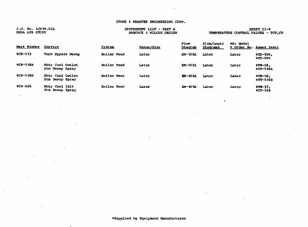
J.O. No. 12919.02A ERDA AFB STUDY
Mark Number Service
4CV-5 12 Rlrb Bypass Desup
4CV-5 18A Rhtr C o o l O u t l e t Stm Desup Spray
4CV-5 18B Rhtr C o o l Outlet S t m Desup Spray
4CV-526 Rhtr C o o l I n l t Stm D e s u p Spray
System
SIDME 6 WEBSPW ENGINEERING CORP.
INSPRUMWT L I S T - PART A BABOOCK E WILODX DESIGN
SHEET 11-4 TEMPERATURE CONTROL VALVES - W , C V
P l a v E l w i c M f r We1 R a n q e / S i z e D i a q r a m D L a q r a m s E Order No. kssoc Instr
B o i l e r Peed Later
Boiler Peed Later
Boiler Pe* Later
Boiler P e e Later
EM-10% Later Later 4ZR-SOU, UlT-504
EM-105A Later Later 4TW-58, 4-518A
m-105A Later Later U'IW-58, U'IT-518B
m-105A Later Later 4-57, 4TC-526
*Supplied by E q u i p m e n t Manufacturer
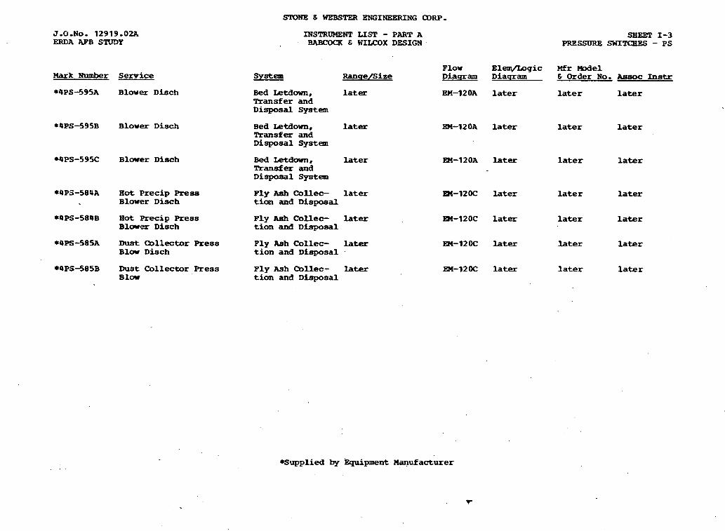
SIDNE 6 UEBSTER ENGINEERING CDRP.
J - 0 - N O - 1 2 9 1 9 - 0 2 A ERDA AFB STUDY
Mark Number Semice
* 4 P S 4 9 5 A B l m e r D h c h
*4PS-595B B l o w e r D i s c h
WPS-595C B l o w e r D i s c h
*4P3-584A Hot Precip Press B l o w e r D i s c h
*4PS-584B Hot Precip Press B l o w e r D i s c h
*4PS-585A Dust Qllector Press B l o w D i s c h
*4PS+85B D u s t Collector Press B l o w
INSTRUhBNT LIST - PART A BABCOCK E WLU:OX DESIGN
System Ranqe/Size
B e d Letdown, later Transfer and D i s p o s a l S y s t e m
B e d Letdown, later Transfer and D i s p o s a l S y s t e m
B e d Letdown, later Transfer and D i s p o s a l S y s t e m
Ply Ash C o l l e c la ter t ian a ~ d D i s p o s a l
Ply Ash C o l l e c later t ion and D i s p o s a l
P l y Aah Qllec- later t ion and D i s p o s a l
Ply Ash Qllec- later t ion and D i s p o s a l
SBEET 1-3 PRESSURE swIT<BEs - P S
P l o w B l w g i c Mfr Mudel D i a q r a m D i a q r a m 6 Order No. Assoc Instr
EM-12 OA later later later
EM-12OA later la ter later
EM-12OA later later later
EM-12OC later later later
W-12OC later later later
EM-120C later later later
EM-12OC later later later
+ S u p p l i e d by Equipment mufacturer

Sr(?NE 6 WEB- ENGINEERING CORP.
J.0.No. 12919.02A ERDA AFB STUDY
Mark N u m b e r Service
*OPRV-588A Vacuum Qlamber E q u a l i z i n g V a l v e
*4PRV-588B Vacuum Chamber m l i 2 i n g valve
WPRV-589A Secondary C o l l e c t o r E q u a l i z i n g V l l v e
*4PRV-589B Secondary Collector E q u a l i z i n g V a l v e
*4PRV-590A Secondary C o . U e c t o r Equalizing Vdve
*4PRV-590B Semndary C o l l e c t o r Equalizing Valve
lYSTRUMENT LIST - PART A BRBCOCX E WUEOX DESIGN
System R a n q e f S i z e
P l y Ash O o U e c - la ter t ion and D i s p o s a l
P l y Ash C o l l e c - later tion and D i s p o s a l
Ply Ash tbllec- later tian and D i s p o s a l
F l y A s h Qllec- later t i o n and D i s p o s a l
Fly Ash allec- later tion an& D i s p o s a l
Ply Ash Q L l e c - later t ion and Disposal
SHEgT 1-4 PRESSURE REGULATING VALVES - PRV
F l o w E l e m / L o g i c Mfr M o d e l D i a q r a m D i a q r a m 6 Order No. Assoc Instr
EM-12OC later later N/A
EM-l20C lrter later N/A
EM-l2OC later later N/A
EM-1ZOC later later N/A
EH-12OC lster later N/A
~ ~ 4 2 0 ~ htff later N/A
*,cupplied by E q u i p m e n t Manufacturer

SrONE & WEBSTER ENGINEERING CORP.
rNSTRQMEWl' LISP - PART A BABCOCR E WILCOX DESIGN
SHEET 1-6 lJONTROL VALVES - (N
F l o w D i a q r am
M f r W e 1 S Order No. Assoc Instr M a r k Number S y s t e m .
4CV-503A S t a r t - u p B y p a s s Main S t e a m
R a n q e / S i z e
later later later 4SOV-503A, EHC
4CV-503B S t a r t - u p B y p a s s M a i n S t e a m later later la ter USOV-503B, EHC
4CV-503C Start-up B y p a s s Main S t e a m later later l a t e r QSOV-503C. BHC
later 4SOV-560A8 BLR Qnt
4PCV-560A RHTR C o o l INLT CONT VLV Main S t e a m later later
UPCV-560B RRIR C o o l INLT CONT VLV Main Steam later later later 4SOV-SLOB, BLR Qnt
4PCV-560C RBTR Cool INLT CONT VLV Main S t e a m later later later: 4 S m - 5 6 0 C 8 BLR mnt
4PCV-560D RRIR C o o l INLT CONT VLV Main S t e a m later EM-102A later la ter USOV-560D8 BLR mat
~ P C V - 5 6 1 ~ R m Coo l O W T MNT VLV M a i n S t e a m later EM-IOZA later later QSOV-!ibOA, BLR O o n t
QPCV-56 1B RHTR C o o l O m T CONT VLV M a i n S t e a m later EM-102A later later 4SW-5bOB. BLR Qnt
OPCV-561C RHTR Cool 0WlT.T CONT VLV M a i n S t e a m later PM-102A la ter later 4SOV-SBOC, BLR C o n t
4PCV-561D RETR Cool OUTLT CONT VLV Main St- later EM-102A later later USOV-560D8 BLR Cont
4WC-510 Desup Spray Supply B o i l e r Feed l a t e x EM-1OSA later later USOV-5 10. 4PIT-580
4CV-5 1 4 D e w p Spray Supply Isolation V a l v e
B o i l e r Feed later EM-1OSA, later la ter USOV-514
la ter 4CV-520 R h t r C o o l Outlet Boiler Feed S t e a m D e s u p Iso V a l v e
EM-10 SA later later 4SW-520
EM-1OSA later later 4SOV-528 OCV-528 Rhtr Cool Inlet B o i l e r Peed S t e a m D e s u p Iso V a l v e
later
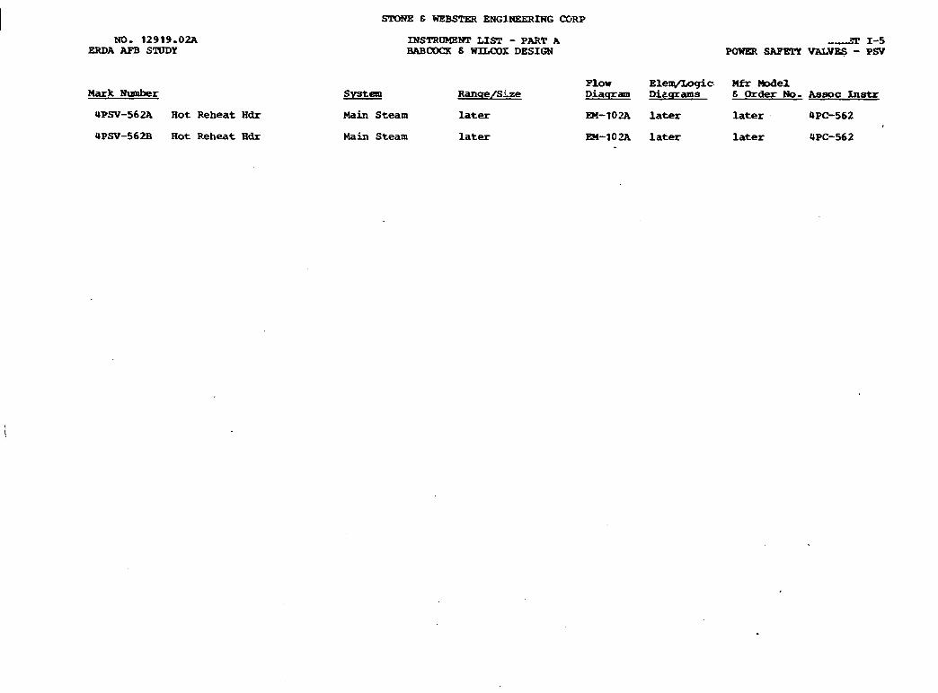
NO. 12919.02A ERDA AFB STUDY
Mark N u m h r
UP=-562A Rot Reheat Hdr
4PSV-562B Hot Reheat Edr
INSTROMENT LIST - PART A BAB(1DQI 8 WlLCOX DESIGN
Flow Elem/Logic Mfr Model %!se! Ranqe/SFze Diaqram D i e q r a m s 8 Order No- Assoc Instr
Main Steam later
Main Steam later
EM-10% later later 4PC-562
EEI-10% later later 4PC-562

Hark Number Service
am-50 4 Turbine Bypass Desup SFaY
~m-51 BA ~ h t r C o o l outlet Stm Desup Spray
4lT-518B Rhtr Cool Outlet Stm Desup Spray
4TP-526 Rhrt Cool Inlt Stm Desup Spray
SPDIPE E WEB- ENGINEERING CORP. * ,
System
Main Steam
INSTRUMENT LIST - PART A BABCOCK 6 WILCQX DESIGN
Main Steam
Hain Steam
Main Steam
Ranqe/S ize
Later
Plow Elem/L~gic Mfr Model Diaqram Diaqrams 6 Order No. Assoc Instr
EM-10- Later Later 4TR-504. 4CV-512
EM-102A Later Later 4TR-5 18A 4CV-5 18A
EM-102A Later Later 4TR-518B UCV-518B
EM-10- Later Later 4TW-57, PCV-526
-upplied by h i p n e n t Manufacturer ,.-.la- . ' I
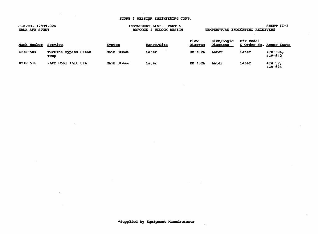
STONE E- WEBS- ENGINEERING CORP-
INSTF:UMEWl' LIST - PART A BABCOCR 8 WILCQX DESIGN
Mark N u m b e r Senrice. sY!ze?! RanqeISize
4TIR -50 U Turbine Bypass Steam Main Steam Later Temp
4TIR-526 Rhtr C o o l I n l t Stm Main Steam Later
SHEET 11-2 TEMPEW.TURE IrnICATrNG RECEIVERS .
Flow EPeqlLogic Mfr Model Diaqram Diaqrams 6 Order N o . Assoc Instr
EM-10 2A Later Later 4TR-504, 4CV-512
EM-102A Later Later 4lW-57 , 4CV-526
*Su?plied by Equiplaent Manufacturer

STONE E WEBSTER ENGINEERING CORP,
J.0.PO. 12919.02A ERDA AFB STUDY
Mark Number Service
*USOV-568B CBC D u s t H o p p e r H e a d e r Isolation V a l v e
*4SOV-569A Vacuum Chanber I n l e t V a l v e
*USOV-569B Vacuum C h a m b e r Inlet V a l v e
*4SOV-570A P r e s s u r e B l o w e r D i s c h .
*QSOV-570B P r e s s u r e B l o w e r D i s c h .
*OSOV-571 Pressure B L o v e r D i s c h . Crossover
*@SOU-580A Pressure C o n v e y o r L i n e Isolation V a l v e
. *9SOV-580B Pressure C o n v e y o r L i n e Isolation V a l v e
*4SOV-58 1 Silo Inlet V a l v e
*4SOV-582A Vacuum PIlmp Inlet Valve
*QSOV-582B . Vacuum I n l e t V a l v e
*USW-583 Vacuum Pump Inlet Crossover V a l v e
INSTRtMENT L I S T - PART A BABCOCK 8 WITLOX DESIGN
S y s t e m R a n q e / S i z e
P ly A s h C o l l e c - later t ion and D i s p o s a l
Fly Ash C o l l e c - .. later t ion and D i s p o s a l
F l y A s h C o l l e c - later t i o n and D i s p o s a l
F l y A s h C o l l e c - later t ian and D i s p o s a l
F l y A s h C o l l e c - later t i o n and D i s p o s a l
P ly Ash C o l l e c - later t i o n and D i s p o s a l
F l y .Ash Collec- later t ion and D i s p o s a l
F l y A s h C o l l e c - later t i o n and D i s p o s a l
F l y Ash C o l l e c - later t ion and ~isposal
F l y A s h C o l l e c - later tFon and D i s p o s a l
Fly A s h C o l l e c - later tion and D i s p o s a l
F l y A s h C o l l e c - later . t ion and D i s p o s a l
SHEET V-17 SOLENOID OPERATED VALVES - SOV
P l o w E l e m / L o g i c Mfr Model D i a q r a m D i a c r r a m s 8 Order No. Assoc Instr
EM-12OC later la ter UCOV-568B
:EM-120C later la ter UCOV-J69A
- EM-12OC la ter later UCOV-569B
EM-l20C later later UCOV-570~
!EM-120C later later 4COV-570B
EM-12OC later later UCOV-571
EM-12012 la ter later UCW-580A
EM-120C later later UCOV-580B
FM-12OC later . later UCOV-58 1
3M-12OC later la ter OCOV-582A
34-12OC later la ter 4 COV-582B
EM-120C later later UCOV-58 3
*Supplied by E q u i p m e n t M a n u f a c t u r e r