Master Document Library - Audiovias
393
1 Soundweb TM May 2005 Master Document Library How to use this document • In Acrobat Reader, use the table of contents links in the left window to move to the page you require. • Clink on any link in the Contents list below. • Print out the sections you require. SOUNDWEB MASTER CONTENTS Datasheets 2 Designer Software v1.50 Help File 20 Installation Guides 218 Serial Interface Kit documentation 288 Networking 322 Frequently Asked Questions 328 Extending RS-232 connections 332 9010 Power Options 340 DXF Outline Drawings Reference 342 Architect’s & Engineers Specifications 346 Software Release Notes 350 WHISEWORKS NTM filters white paper 370 Controlling other equipment via Soundweb 372 Colour Brochure 374 www.audiovias.com
-
Upload
khangminh22 -
Category
Documents
-
view
3 -
download
0
Transcript of Master Document Library - Audiovias

1
Soundw
ebTM
May 2005
Master Document Library
How to use this document
• In Acrobat Reader, use the table of contents links in the left window to move to thepage you require.
• Clink on any link in the Contents list below.
• Print out the sections you require.
SOUNDWEB MASTER CONTENTS
� Datasheets 2� Designer Software v1.50 Help File 20� Installation Guides 218� Serial Interface Kit documentation 288� Networking 322� Frequently Asked Questions 328� Extending RS-232 connections 332� 9010 Power Options 340� DXF Outline Drawings Reference 342� Architect’s & Engineers Specifications 346� Software Release Notes 350� WHISEWORKS NTM filters white paper 370� Controlling other equipment via Soundweb 372� Colour Brochure 374
www.audiovias.com

Soundweb
TM
2
Brochures & Datasheets
Click on the titles to reach the datasheets.
1. 9088ii Networked Signal Processor2. 9000ii Networked Signal Processor3. 9008 Networked Expansion Processor4. 9010 Programmable Controller5. 9012 Wall Panel6. 9014 Fibre Interface7. 9016 Video/Audio Matrix Switcher8. 9026 Audio Matrix Switcher9. 3088 Soundweb Lite Signal processor10. 9015 Wall Panel
www.audiovias.com

3
Soundw
ebTM
• 8 Analogue Mic/Line Inputsand 8 Analogue Outputs
• Optional AES/EBU digitalinput/output (2xstereo)cards with external wordclock input
• Standalone unit with200MIPS of DSP resource
• Integral multivoltage PSU(85V - 270V AC)
• Analogue Control ports forGPI hardware interfacingeg faders, switches & LEDs
• Front and rear accessRS232 ports for PC control
• Integral memory holds upto12 DSP system designs.
• Optional lacing bar tosecure cabling
Soundwebtm 9088iis DSP System
Architects and Engineers Specifications
The Digital Signal Processor shall be a stand-alone unit of one rack space, capable ofproviding a fully-functional system with 8 analogue inputs and 8 analogue outputs, withoutthe need for a dedicated, on-line computer system. The Analogue inputs shall have aremotely-adjustable gain stage prior to A/D conversion.
The system designer shall be provided complete flexibility in system configuration.
Line inputs or combination Microphone/Line inputs shall be provided, together withchannel-selectable 48 volt phantom power for the microphone inputs. The unit shall providea tamper-proof front-panel with no user-adjustable controls. Front panel LED indicators willprovide monitoring of signal presence, clip and network status. Analogue/Digital/Analogueconversion shall be by 24-bit A-D converters and 24-bit D-A converters to providemaximum operating headroom and performance. The Dynamic Range shall be 105dBminimum (unweighted, 108dB A-weighted), with a THD figure of less than 0.01%.
Optional AES/EBU Digital input/output cards shall be available, each card having 2 stereoinputs and 2 stereo outputs. Input sample rates shall be accepted from digital sources withrates from 32kHz to 96kHz, and the user shall be able to select output sample rates of44.1kHz, 48kHz, 88.2kHz, 96kHz or any sample rate between 32KHz and 96KHz usingexternal clock synchronisation. Clock synchronisation shall be possible with the first digitalinput, the internal clock or an external word clock on a BNC connector.
Input and Output connections are provided via modular, Phoenix/Combicon style hardware.Mating connectors (Phoenix/Combicon MSTB 2.5/6-ST-5.08 or equivalent) shall be suppliedwith each unit on delivery or in advance.
The Signal Processor shall also be networkable over Category 5 cable (as established in theTIA/EIA-568-B standard), to provide 8 channels of audio signals and control data routingbetween processors for system expansion or communication. This network shall beterminated on RJ-45 connectors, and be stable over distances up to 1000 feet between units.There shall be available a fibre-optic converter to extend this distance to 1.2 miles. Thenetwork shall allow system expansion at a later date through the addition of further SignalProcessors.
System Configuration shall be by a Personal Computer, which may be disconnected afterconfiguration without affecting installed operation of the unit. Up to 12 System Configura-tions shall be stored in each processing device, and these configurations shall not be limited
by factory-only presets or pre-determined processing. It shall be possible to configure anumber of system presets, which may be recalled at any time via the PC or externalcontrol devices.
The unit’s software shall provide a palette of audio processing objects for use in systemdesigns to include, but not be restricted to: Automatic Microphone Mixers, AmbientNoise Compensators, Crossovers, Compressors, Gates, Duckers, Expanders, Limiters,Gain blocks, Graphic Equalisers, Parametric Equalisers, Stereo Parametric Equalisers,Filters, Metering points, Delays, Mixers, Matrix Routers, Matrix Mixers, Source Matrices,Tone Generators, and Source Selectors. The software shall provide the facility toconstruct user-defined control panels incorporating elements of the processing objectparameter controls. Multi-level password-based security shall protect the integrity of thesystem.
The device configuration window shall provide a DSP gauge to inform the designer as tothe percentage of DSP usage. The system design software shall be compatible with eitherWindows 95 or Windows NT4, 32 bit operating systems.
The software shall provide a facility to create personalised, custom processing objects foruse in system designs, with provision for intellectual property cloaking via Macros.
It shall be possible to connect standard potentiometers and switches or control voltagesto 8 control input ports to allow non-technical operators to change system presets orvariable parameters. An additional 8 control output ports shall provide logic outputs forpurposes of signal indication, external switching systems, or other similar system controlapplications. An opto-isolated failsafe indicator shall be provided on an open-collectoroutput.
Two RS-232 ports shall be provided to allow control of the unit from Multimedia Systemssuch as AMX, Crestron, Dataton, Avenger or other PC devices communicating in a serialmode, as well as independent, simultaneous control and programming from a PCoperating Soundweb Designer software. The RS232 port on any device shall provideaccess to all devices that are properly networked together. It shall be possible to usemultiple PC’s connected to separate signal processors in a network to control the system.It shall also be possible to remotely control the system network using a PC & modem toconnect over telephone lines to another modem connected to the system network.
To aid in system management, the software shall provide a method of event logging sothat system diagnostics are available. This event log shall include failures, warnings andinformation notices, and shall display the time of the event occurrence and the device towhich the event applies and the design file originally loaded.
Overview
The Soundweb 9088iiDSP unit is the heart of the Soundweb system.As a standalone single rack space device it has all the facilitiesrequired for a sound system processor - 8 inputs, 8 outputs, a DSPengine, networking for connection and signal distribution to othersoundweb units, Analogue GPI control interfacing, and RS232 portsfor external control by PC or AMX/Crestron type systems. Plug in anaudio source, an amplifier, and speakers and you are away
All the facilities are included in a 9088ii, there is no additionalSoundweb system hardware required to begin building physicalsystems. The only option decision to make is a choice of line input,mic/line input cards or AES/EBU Digital input/output cards. Eachdigital card accepts 2 stereo inputs at sample rates from 32khz to96kHz, and can output at 44.1, 48, 88.2, and 96kHz. When digitalinputs are used, the analogue outputs remain in use as a mirrorversion of the digital output.
Each Soundweb 9088ii can typically hold up to 12 completelydifferent system designs in its own memory. Programming the unit isaccomplished via the Soundweb Designer software, available free ofcharge from BSS Audio (website www.bss.co.uk).
For safety-critical systems, the Soundweb 9088ii has an opto-isolatedoutput which functions as a watchdog: the opto-isolator conductswhen power is applied to the unit and the software is functioningcorrectly; it is cut off if there has been a power failure or other fault.This function can be used to trigger alarm systems or to constructredundant systems.
www.audiovias.com

4
Soundw
ebTM
9088iis Technical SpecificationsInputs: 8 Analogue, electronically balanced, on Phoenix/
Combicon removable screw connectors.Line Inputs: Nominal gain 0dB, electronically switchable to
+12dB gain, input impedance 10kOhmMic/Line Inputs: Nominal gain 0dB, electronically switchable up to
+72dB, in +6dB steps, input impedance 3.5kOhmMaximum input level +20dBu with 0dB input gain (+8dBu with 12dB gain)CMRR >75dB at 1KHzEquivalent Input Noise <-128dBu typ with 150 Ohms source(EIN)Phantom power: 48V nominal, selectable per inputAES/EBU Digital Inputs:2 x 2-channel inputs per card, sample rates accepted
from 32 to 96kHz, auto selected, on Phoenix/Combicon removable screw connectors
Outputs: 8 Analogue, electronically balanced, on Phoenix/Combicon removable screw connectors.
Maximum output level:+20dBuAES/EBU Digital 2 x 2-channel outputs per card,Outputs: sample rates 44.1, 48, 88.2, 96kHz, user selectable,
on Phoenix/Combicon removable screw connectorsDigital Resolution: 24 bit
Frequency response: (+-0.5dB) 15Hz to 20KHzTHD: <0.01% (20Hz to 20KHz, +10dBu output)Dynamic range: 105dB typ. (22Hz to 22KHz unweighted)
108dB typ. (A-weighted)Crosstalk: <-75dB
Mains voltage 85-270V AC, 50/60Hz,Power Consumption <35VA
Control ports (8 inputs and 8 outputs)Control input voltage: 0 to 4.5vControl input impedance: 4.7kOhms to +5V (2-wire mode)
>1MOhm (3-wire mode)Logic output voltage 0 or +5V unloadedLogic output impedance 440 OhmOpto output series impedance 220 Ohms (isolated)
Watchdog Output: Phoenix/Combicon connector for failsafe control.Opto Output current 14mA max.Opto output 80V max. (Off)withstanding voltage
Network: 2xRJ45 connectors for Soundweb network connection.Maximum network 300m/1000ft, longer distance using 9014 fibrecable length converters
Led Indicators: Signal Present (per input), CLIP (per input), network(front panel) input active, network output active, network Master
indicator.
Soundweb 9088iis DSP System
Input ConnectorPin-outsEach connector accomodates two inputs, pin1 is on right when viewed from rear:Pin 1: Input 1 (3,5,7) Screen (ground)Pin 2 : Input 1(3,5,7) +ve (hot)Pin 3 : Input 1 (3,5,7) -ve (cold)Pin 4 : Input 2 (4,6,8) Screen (ground)Pin 5 : Input 2 (4,6,8) +ve (hot)Pin 6: Input 2 (4,6,8) -ve (cold)
Output ConnectorPin-outsEach connector accomodates two inputs, pin1 is on right when viewed from rear:Pin 1: Output 1 (3,5,7) Screen (ground)Pin 2 : Output 1(3,5,7) +ve (hot)Pin 3 : Output 1 (3,5,7) -ve (cold)Pin 4 : Output 2 (4,6,8) Screen (ground)Pin 5 : Output 2 (4,6,8) +ve (hot)Pin 6: Output 2 (4,6,8) -ve (cold)
Digital cards have 2 inputs and 2 outputs percard, wired as above, with inputs to the rightas viewed from the rear.
Control port pin-outs
Upper Row: Logic InputsPin 1, 2, : Common. Pin 11, 12 : Reference
Pin 3,4,5,6,7,8,9,10: Logic Input
Lower Row: Logic OutputsPin 1, 2, 11, 12 : CommonPin 3,4,5,6,7,8,9,10: Logic Output
BSS Audio have apolicy of continuedproduct improvementand accordinglyreserve the right tochange features andspecificationswithout prior notice.May 2005
Network Port pin-outsPairs, according toTIA/EIA-568-B standardPin 1 (White) with Pin 2 (Orange)Pin 3 (White/Green) with Pin 6 (Green)Pin 4 (Blue) with Pin 5 (White/Blue)Pin 7 (White/Brown) with Pin 8 (Brown)
BSS Audio UK A Division of Harman International Industries Ltd
Cranborne House, Cranborne Road, Potters Bar,Hertfordshire, England, EN6 3JNTel +44 (0)1707 660667, Fax +44 (0)1707 660755www.bss.co.uk/soundweb/email: [email protected]
Harman Music Group8760 S. Sandy ParkwaySandy, Utah 84070
Tel: 801-566-8800 Fax: 801-568-7662web: www.bssaudious.com
A Harman International Companywww.audiovias.com

Soundw
eb
5
TM
Soundweb 9000iis Network Hub
Compatibility with originalSoundweb 9000 hubs
(mark 1 units)
The 9000iis is a drop-in replacementfor the original 9000 hub, and can berun without a change in the systemdesign.
To get the maximum performance andfeatures from the 9000iis model, theSoundweb Designer software must beupgraded to a version that supportsthe 9000iis (V1.30 or later) , and thedesign file recompiled and loaded.
The 9000iis Network Hub can be used used to extend the matrixingand signal routing capabilities of a Soundweb System Network,and large systems can be constructed using one or more 9000iis
hubs to interface with 9088iis devices.
As an example, a single 9000iis hub linked to three 9088iis devicescan produce a fully matrixed 24 x 24 system.
Hubs can also be connected to each other to formlarge signal busses. Again, as an example, a 24-waybus could be designed quite easily.
The Soundweb 9000iis Network hub isused to expand the routing capabilitiesof the Soundweb system. It has all theprocessing facilities of the 9088iis DSPunit; 200MIPS of DSP horsepower,analogue GPI control interfacing, andRS232 ports for external control by PCor AMX/Crestron type systems; but has 6network ports instead of analogue inputsand outputs.
Like the 9088iis, each Soundweb 9000iis can hold up to 12 com-pletely different system designs in its own memory. The DSP in a9000iis hub is most often used for matrixing, mixing, and routingthe signals from 9088iis devices, which are then free for signalprocessing.
The Soundweb 9000iis Hub occupies just a single rack space (1U)and includes it’s own power supply. Programming the unit isaccomplished via the Soundweb Designer software, available freefrom BSS Audio.
For safety-critical systems, the Soundweb 9000iis has an opto-isolated output which functions as a watchdog: the opto-isolatorconducts when power is applied to the unit and the software isfunctioning correctly; it is cut off if there has been a power failure oranother fault. This function can be used to trigger alarm systems orto construct redundant systems.
Features
• 6 Network ports
• 200MIPS of DSP resource with
all the DSP processing objects ofthe 9088
• Integral PSU
• Control ports for analogue GPI
hardware interfacing
• Front and rear access RS232
ports for PC control
• Integral memory holds up to 12DSP system designs.
www.audiovias.com

Soundw
eb
6
TM
Soundweb 9000iis Network Hub
Technical Specifications
Power consumption <35VAMains voltage 85-270V AC, 50/60Hz
Control ports:Control port inputs 8Control input voltage 0 to 4.5vControl input impedance 4.7kOhms to +5V
Control port outputs 8Logic output voltage 0 or +5V unloadedLogic output impedance 440 OhmOpto output series impedance 220 Ohms (isolated)
Watchdog output:Fail safe connector Phoenix/Combicon connector.Opto output current 14mA max.Withstanding voltage 80V max. (Off)
Network connections: 6xRJ45 connectors.Max. network cable length 300m/1000ft
Led Indicators: Network Activity, Network Sync, NetworkMaster, DSP Clip, Power.
Network Port pin-outsPairs, according to TIA/EIA-568-Bstandard
Pin 1 (White) with Pin 2 (Orange)Pin 3 (White/Green) with Pin 6 (Green)Pin 4 (Blue) with Pin 5 (White/Blue)Pin 7 (White/Brown) with Pin 8 (Brown)
Control port pin-outs
Upper Row: Logic Inputs
Pin 1, 2, 11, 12 : CommonPin 3,4,5,6,7,8,9,10: Logic Input
Lower Row: Logic OutputsPin 1, 2, 11, 12 : CommonPin 3,4,5,6,7,8,9,10: Logic Output
Rear panel RS232 Port pin-outs
Pin 1: DCD Pin 2: RXPin 3: TX Pin 4: DTRPin 5: GND Pin 6: DSRPin 7: RTS Pin 8: CTSPin 9: N/C
BSS Audio have a policy of continued productimprovement and accordingly reserve the right tochange features and specifications without prior
notice. May 2005
Dual Redundant Ring System
Using Soundweb 9000iis hubs, it is possible to create adual-redundant ring, where two network cables carry audio andcontrol around a ring in both directions, so that if one cable isaccidentally damaged, the other intelligently routes the signals tocontinue full operation.
BSS Audio UK A Division of Harman International Industries Ltd
Cranborne House, Cranborne Road, Potters Bar,Hertfordshire, England, EN6 3JNTel +44 (0)1707 660667, Fax +44 (0)1707 660755www.bss.co.ukemail: [email protected]
Harman Music Group8760 S. Sandy ParkwaySandy, Utah 84070
Tel: 801-566-8800 Fax: 801-568-7662web: www.bssaudious.com
A Harman International Companywww.audiovias.com

Soundw
ebTM
7
» 8 Analogue Outputs.
» 200MIPS of DSP resource.
» Integral multivoltage PSU, (85V -
270V AC).
» Analogue control ports for GPIhardware interfacing; eg faders,switches & LEDs.
» Front and rear access RS232ports for PC control.
» Integral memory holds up to 12
DSP system designs.
» Supported in Soundweb Designer
v1.22 and above.
» Optional cable lacing bar.
Soundweb™
9008iis Networked Processor
BSS Audio introduces a significant addition to theSoundweb range. The 9008iis hardware device isan expansion unit for Soundweb systems wheremore outputs are needed, but input sources arealready covered using 9088iis’s. The 9008iis isalmost identical to the 9088iis, and delivers thesame dsp and control capabilities, but lacks anyinput circuitry. By dispensing with the input cards,and associated sockets the 9008iis is cost effectivein situations where extra inputs are unnecessary.
The unit is envisaged to be especially useful providing additionaloutputs for larger systems where each additional 9008iis can routeand process up to 8 channels of audio to its balanced outputs. Alsowith its built in networking capabilities the 9008iis cancommunicate with all the other Soundweb devices on the network.
Front and rear RS232 ports are provided for programming, upgradeaccess and for connection to control systems such as AMX, Crestronor similar. For safety-critical systems, the Soundweb 9008iis has anopto-isolated output which functions as a watchdog to trigger alarmsystems or to construct redundant systems. Programming the unit isaccomplished using Soundweb Designer software, available freefrom the BSS Audio website, www.bss.co.uk.
9008iis Technical Specifications
General
DSP capability 200MIPS (Million Instructions Per Second)Frequency response 15Hz to 20kHz (+-0.5dB)Total Harmonic Distortion (THD) <0.01% (20Hz to 0kHz, +10dBu output)Dynamic range 105dB typical (22Hz to 22kHz unweighted)
108dB typical (A-weighted)Maximum output level +20dBuInter-channel crosstalk <-75dBMaximum network cable length 300m/1000ftMains supply 85-270V AC, 50/60HzPower consumption <35VA
Control Ports
Control input voltage 0 to 4.5vControl input impedance (2 wire mode) 4.7kOhms to +5VControl input impedance (3 wire mode) >1MOhmLogic output voltage 0 or +5V unloadedLogic output impedance 440 OhmOpto output current 14mA maxOpto output withstanding voltage 80V maxOpto output series impedance 220 Ohms (isolated)
BSS Audio UK A Division of Harman International Industries Ltd
Cranborne House, Cranborne Road, Potters Bar,Hertfordshire, England, EN6 3JNTel +44 (0)1707 660667, Fax +44 (0)1707 660755www.bss.co.ukemail:[email protected]
Harman Music Group8760 S. Sandy ParkwaySandy, Utah 84070
Tel: 801-566-8800 Fax: 801-568-7662
web: www.bssaudious.com
A Harman International Companywww.audiovias.com

Soundwebtm
9010 Programmable RemoteSoundw
ebTM
Technical Specifications
Mic Input: 18 Bit A/D ConversionExternal Input SpecificationsDynamic Range: 81dB
(22Hz to 22kHz unweighted)Gain Control Range: 34dB to 72.5dBMax. Input Level: -14dBuEIN: -106dBu @ 150 Ohm
Audio Output: 18 Bit D/A ConversionDynamic Range: >88dB
(22Hz to 22kHz unweighted)Frequency Response: 30Hz to 20kHz, +/-0.5dBTHD: <0.05%
(20Hz-20kHz, 0dBu)Max. Output Level: +4dBuChannel Separation: 80dB, 20Hz-20kHz
Power Requirements: +24V DC, <5VA
BSS Audio offer a universal AC input +24V DCpower supply (Z-999-PSU) and the interfaceadapter (Z-SW9011). The PSU may connectdirectly to a SW9010, or connect via theinterface adapter where power will be suppliedvia the network.
SoftwareRequires Soundweb Designer V1.14 or later.
The 9010 is fitted in a sturdy steel case, and isdesigned to mount in a standard US 3 gang outletbox.
BSS Audio have a policy of continued productimprovement and accordingly reserve the right tochange features and specifications without priornotice.
The Soundweb 9010 Remote control is thelong awaited solution to the problem ofproviding a sophisticated system controlinterface which requires no technicalknowledge to operate.
The 9010 extends the already outstandingflexibility of the Soundweb system byproviding multi-purpose programmableremote control. The 9010 has a rotaryencoder and 6 push buttons which arelabelled by a graphic LCD display.
The encoder and each button can be usedto adjust almost any processing parameterwithin a Soundweb network; the user setsup the functions in the Soundweb Designersoftware. Multiple ‘control pages’ can beconstructed with navigation between them and passwordprotection, i.e. a button can have a different function in eachpage.
Backlit graphic liquid crystal display with programmablelayout.
One programmable continuous rotary encoder to adjustparameters.
Six programmable pushbuttons.
Internal electret capsule microphone withcomputer-controlled gain.
External dynamic microphone input withcomputer-controlled gain.
Two channel audio output.
In addition to its control facilities, the 9010 provides an internalcapsule microphone, an external microphone input, and twochannels of audio output.
With suitable external amplification and loudspeakers, the audiooutputs can be used for local monitoring of network audiosignals or local communications.
The 9010 connects into the Soundweb network using RJ-45connectors and category 5 cable, just like any other Soundwebdevice. The 9010 is powered from a standard 24V DC powersupply; BSS provide a suitable supply capable of powering up tofour 9010s. The optional 9011 adapter allows power to be sentto a daisy chain of 9010s down the network cable.
www.audiovias.com

Soundwebtm
9010 Programmable Remote
TM
Soundw
eb
Programming the 9010
To program the 9010, the ‘Button Setup’ functionwithin Soundweb Designer opens a designwindow which allows the user to decide thefunctions of each button and the encoder;whether it is to adjust parameters, trigger presetsor change menu pages. The 9010 can controlvirtually any parameter of any Soundweb 9088,9008 or 9000 device on the network.
For example, to assign a button to afader to control gain, it is simply a matterof opening the gain control panel (indesign mode) and dragging the faderobject onto the desired button. Thebutton adds default text, which may bechanged with the text tool. When thebutton is pressed on the actual remote,the encoder will then control that fader.
Parameter controls, presets andparameter presets can all be placed ontobuttons. Buttons can also be used toaddress new menu pages, by firstcreating a new page, then programminga button to access that page. Thesepages can be password protected for security. In this way, somefunctions can be left for general facility staff to operate, whileother functions are secured for technician use only.
Mechanical Installation
The 9010 Remote is designed to fit into a standard US 3-gangwallbox (available from BSS Audio) using the screws providedwith the unit. We also offer a decorative bezel that fits around the9010 when mounted in this box.
Ordering Information
Z-SW9010 9010 Programmable RemoteZ-SW9011 Interface Power AdapterZ-999-PSU Universal 24V PSUZ-010-BEZEL Decorative bezel for 9010 RemoteZ-010-WALLBOX Standard metal 3-gang mounting box
Dimensions
Once the design is complete, using the SIMULATEfunction allows you to check and debug the set up toensure all the functions operate as expected, prior tocompiling and loading the program into the 9010device.
Drag and drop controlsonto the button -simple
BSS Audio UK A Division of Harman International Industries Ltd
Cranborne House, Cranborne Road, Potters Bar,Hertfordshire, England, EN6 3JNTel +44 (0)1707 660667, Fax +44 (0)1707 660755www.bss.co.uk/soundweb/email: [email protected]
Harman Music Group8760 S. Sandy ParkwaySandy, Utah 84070
Tel: 801-566-8800 Fax: 801-568-7662
web: www.bssaudious.com
A Harman International Company
www.audiovias.com

10
Soundw
ebTM
Soundwebtm
9012 Wall Panel
Connector Pin-outs
GND:Common Connection (to Control PortsCOMMON pin)
1: SOURCE SELECT/PRESETconnection (switch)
2: LEVELconnection (rotary fader)
9012 Features
• Rotary fader for Volume control etc.
• 5-way rotary switch for source select etc.
• Standard UK light-switch fitting or US fitting in Beige
Overview
The Soundweb 9012 Wall Panel is a simple hardware interface tothe Soundweb Programmable DSP system.
It provides a quick and easy way for designers to provide a rotaryfader control and source select (or other multiway switch func-tion) in a standard UK-sized light switch panel mounting.
Using Soundweb Designer to ‘map’ functions onto the 9088iiscontrol ports, these hardware controls can then be used to pro-vide local control of, for example, volume, source select, orparameter presets.
Connection is viathe Soundwebstandard Phoenix/Combicon remov-able screw terminalconnectors. Threeterminals are usedfor common, switchoutput and faderoutput.
The switch has blank ident areas for marking the switch positions,either directly onto the white area or on self-adhesive labels. A setof ‘standard’ labels in 4 languages (English, French, German &Spanish) are supplied with the 9012 which should cover mostlocational requirements.
Additional or replacement switches and potentiometers areavailable from BSS Audio under the following part numbers:
Rotary Switch: DH10007
Potentiometer: DM10018
○
○
○
○
○
○
○
○
○
○
○ ○ ○ ○ ○ ○ ○ ○ ○ ○ ○ ○ ○ ○ ○ ○ ○
BSS Audio UK A Division of Harman International Industries Ltd
Cranborne House, Cranborne Road, Potters Bar,Hertfordshire, England, EN6 3JNTel +44 (0)1707 660667, Fax +44 (0)1707 660755www.bss.co.uk/soundweb/email: [email protected]
Harman Music Group8760 S. Sandy ParkwaySandy, Utah 84070
Tel: 801-566-8800 Fax: 801-568-7662
web: www.bssaudious.com
A Harman International Companywww.audiovias.com

11
Soundw
ebTM
Technical SpecificationsPowerDC Supply: 12-24V DC, <5VAConnector: Phoenix screw terminal or
2.4mm inline barrelconnector
Network: Single RJ-45Can be input node oroutput node - auto-sensed(no setup required)
Fibre Connections: Snap-in SC fibre inputSnap-in SC fibre output
Fibre cable: Multimode 62.5/125umor Multimode 50/125um
Optical Power Budget: 10dB
Indicators: Power ledFibre Link Active ledNetwork cable present led
Max fibre length 2000 metres/6550 feet/1.2 miles
Dimensions 5.3” x 5.5” x 1.4”135 x 139 x 36mm
Three 9014 devices can be mounted side-by-sidein a 1U panel (available from BSS Audio). Thepanel can be used to rackmount a single or two9014 devices if required, and can be fitted withthe Z-999-PSU in this case.
BSS Audio offer a universal AC input +24V DCpower supply (Z-999-PSU).
BSS Audio have a policy of continued productimprovement and accordingly reserve the right to change featuresand specifications without prior notice.May 2005
Soundwebtm
9014 Fibre InterfaceFibre for long distance
The 9014 Fibre Interface has been designedto extend the networking capabilities of theSoundweb system. Using the 9014 FibreSystem, the distance between Soundwebdevices can be increased to 1.2 miles (2km).
Fibre for noise immunity
The added advantage of using a fibre systemis that fibre itself is totally immune tooutside noise and interference, so youraudio signals remain pristine from end toend.
Installation
A pair of 9014 Fibre Interface units are used to replace a standardcategory 5 Soundweb network cable. Each fibre cable will transfer 8channels of digital audio plus control data.
To utilise the fibre system, each end of the fibre link requires one9014 device. Each device is equipped with an RJ-45 Soundwebnetwork cable jack into which the network cable is connected, andtwo snap-in SC type fibre connectors.
Two fibre cables are then required to connect between 9014 devices- this is to enable the bi-directional audio transfer.
Each 9014 device requires a DC supply of 12V to 24V DC (BSS partZ-999-PSU). This PSU is capable of powering 8 9014 Fibre Interfacemodules. Power can be shared with the 9010 Remote Control, butnot via the network cable.
Multiple 9014 InterfacesA mounting panel is available so that up to three 9014 devices maybe installed in a single rack space.
BSS Audio UK A Division of Harman International Industries Ltd
Cranborne House, Cranborne Road, Potters Bar,Hertfordshire, England, EN6 3JNTel +44 (0)1707 660667, Fax +44 (0)1707 660755www.bss.co.ukemail: [email protected]
Harman Music Group8760 S. Sandy ParkwaySandy, Utah 84070
Tel: 801-566-8800 Fax: 801-568-7662
web: www.bssaudious.com
A Harman International Company
www.audiovias.com

Soundw
ebTM
SW9016 Video/Audio Matrix Switcher
PreliminaryInformationMarch 2002
12
SW9016 Video/AudioSwitcher Features
� 8 Video input sources and16 audio inputs matrixable to 4video outputs and 8 balancedaudio outputs, either audio-follows-video or independ-ently, with audio output levelcontrols
� Controlled via SoundwebDesigner or 9010/9012 con-troller presets, or a standalonePC application
� Simple control via simple
switches
� 2 units may be cascadedto increase capacity
Expanding the applications of Soundweb is the SW9016 Video/Audio Matrix Switcher, allowing video and audio sources to berouted by Soundweb Designer presets or simple remote control.
Integrating Soundweb Audio Processing and Networking with theseswitchers provides a unique and totally integrated multimediaprocessing system for Theme Bars, Restaurants, Clubs, HomeTheatre Systems, Videoconferencing, Corporate Boardrooms,Classrooms and other environments where there may be severalareas, each requiring it’s own video/audio feed possibilities. In thesesystems, the theme is very much ‘video follows audio’ in that thevideo feeds are switched when the audio sources are re-routedaccording to event need.
The SW9016 features 8 video source inputs (NTSC or PAL) on BNCconnections, along with 16 balanced audio inputs which allow easyinput expansion for Soundweb audio inputs. Four video output zonesare fed from BNC connectors with 8 balanced audio outputs.
In addition to seamless integration within Soundweb systems, theSW9016 is equally suited to stand alone operation. When used inthis way it can be used as simple routing switches or alternativelyloaded with up to eight pre-sets that allow any combination ofaudio/video routing and audio level to be instantly recalled in up tofour independent zones. If no pre-sets are loaded, the units auto-matically default to a simple four zone source selector with ‘audiofollows video’ routing, audio level control being independent foreach zone.
Control can be remote via RS232 using simple string commands, orlocal from a contact closure port, for example using up to four 9012panels. The baud rate of the RS232 can be changed to suit theapplication. BSS can also supply an ‘active X’ plugin to aid the easyintegration with bespoke windows based control applications.
BSS Audio supplies a standalone PC program that can be used toboth set-up and control the devices when they are not part of aSoundweb system. To increase flexibility, up to two SW9016s maybe connected to a single Soundweb or other RS232 device.
Seam-free switching
The SW9016 is capable of switchingthe video during the ‘vertical blankinginterval’ which will provide interfer-ence free switching between videosources that are synchronised. Sync canbe taken from either a dedicated syncinput or from video input 1. A ‘sync out’connector is provided for connection toother equipment. If no sync is detected,the SW9016 will switch after 25msthereby preventing it from locking up issync is lost.
Each video input is provided with a‘loop’ connection to allow daisy chain-ing. Plugging a cable into the loopconnector automatically disconnectsthe 75Ohm termination inside the unitto avoid double terminating the source.www.audiovias.com

SW9016 Video/Audio Matrix SwitcherSoundw
ebTM
PreliminaryInformationMarch 2002
13
Technical Specifications
Video Inputs 8 Composite Video inputs (CBVSor SVideo) on BNC connectors withBNC loopthrough connectors
Video Standard PAL or NTSC (auto selected)Video Bandwidth 150MhzVideo Crosstalk <70dBR up to 10MHzSync Automatically either Channel 1 or
‘Sync’ inputImpedance 75 Ohm self-terminatingRouting 8x4 Video MatrixVideo outputs 4 x 75Ohm Composite Video Outputs
on BNC connectors
Audio Inputs 16 Balanced Audio inputs on PhoenixCombicon removable screwconnectors.
Routing 16x8 Audio Matrix, each channelindependently addressable
Input Impedance 10kOhmMaximum Input Level +20dBuTHD <0.02%Frequency Response 20Hz-20kHz +0/-0.2dBS/N Ratio >110dBR at unity gainCrosstalk <-100dBCMRR >40dBR
Audio Outputs 8 Balanced Audio Outputs on Phoenix/Combicon removable screwconnectors.
Output gain adjustable, -inf to +20dB
Control & PresetsPresets 8 presets per video output zone when
used with standalone PC appSerial Control Port RS232 connects to Soundweb 9088iis,
9008iis or 9000iis or PC
Dimensions 2RU (3.5") high, 19" wide, 6.6" deep(89mm x 445mm x 168mm)
Weight 3kgs (6.6lbs)
BSS Audio have a policy of continued product improvement and accordinglyreserve the right to change features and specificationswithout prior notice. May 2005
BSS Audio UK A Division of Harman International Industries Ltd
Cranborne House, Cranborne Road, Potters Bar,Hertfordshire, England, EN6 3JNTel +44 (0)1707 660667, Fax +44 (0)1707 660755www.bss.co.uk/soundweb/email: [email protected]
Harman Music Group8760 S. Sandy ParkwaySandy, Utah 84070
Tel: 801-566-8800 Fax: 801-568-7662
web: www.bssaudious.com
Audio Input ConnectorEach 6-way connector accomodates two inputs,pin 1 is on right when viewed from rear:Pin 1: Input 1 (3,5,7,9,11,13,15) Screen (ground)Pin 2 : Input 1(3,5,7,9,11,13,15) +ve (hot)Pin 3 : Input 1 (3,5,7,9,11,13,15) -ve (cold)Pin 4 : Input 2 (4,6,8,10,12,14,16) Screen (ground)Pin 5 : Input 2 (4,6,8,10,12,14,16) +ve (hot)Pin 6: Input 2 (4,6,8,10,12,14,16) -ve (cold)
Audio Output ConnectorEach 6-way connector accomodates twooutputs, pin 1 is on right when viewed from rear:Pin 1: Input 1 (3,5,7,9,11,13,15) Screen (ground)Pin 2 : Input 1(3,5,7,9,11,13,15) +ve (hot)Pin 3 : Input 1 (3,5,7,9,11,13,15) -ve (cold)Pin 4 : Input 2 (4,6,8,10,12,14,16) Screen (ground)Pin 5 : Input 2 (4,6,8,10,12,14,16) +ve (hot)Pin 6: Input 2 (4,6,8,10,12,14,16) -ve (cold)
Video Input and OutputConnectorCentre - Signal, Outer - Ground
Control port pin-outs
Preset/Zone Trigger InputsPin 1 is on right when viewed from rear:Pin 1, 2, : +5V. Pin 11, 12 : CommonZone ModePin A Source Select, Pin B GainPreset ModeUse Z1 connections only
Z1 Z2 Z3 Z4
C C A B A B A B A B + +
www.audiovias.com

Soundw
ebTM
SW9026 Audio Matrix Switcher
PreliminaryInformationMarch 2002
14
SW9026 Audio SwitcherFeatures
� 16 balanced audio inputsmatrixable to 8 balanced audiooutputs, freely assignable
� Controlled via SoundwebDesigner or 9010/9012controller presets, or astandalone PC application
� Simple control via simpleswitches
� 2 units may be cascaded toincrease capacity
Expanding the applications of Soundweb is the SW9026 AudioMatrix Switcher, allowing multiple audio sources to be routed bySoundweb Designer presets or simple remote control.
Integrating Soundweb Audio Processing and Networking with theseswitchers provides the ability to route selected inputs from anumber of sources. There are many instances where only a numberof signals from multiple sources are required simultaneously, andthe SW9026 permits low-cost input expansion for Soundwebsystems, as well as offering a standalone solution for sourceselection and matrixing.
The SW9026 features sixteen balanced audio inputs, and the eightbalanced outputs can then feed a Soundweb 9088ii for processingand further zone distribution.
In addition to seamless integration within Soundweb systems, theSW9016 is equally suited to stand alone operation. When used inthis way it can be used as a simple switcher or alternatively loadedwith up to eight pre-sets that allow any combination of audiorouting and level to be instantly recalled in up to four independentstereo zones. If no pre-sets are loaded, the units automaticallydefault to a simple four zone source selector with ‘audio followsvideo’ routing, audio level control being independent for eachzone.
Control can be remote via RS232 using simple string commands, orlocal from a contact closure port, for example using up to fourSW9012 wall panels. The baud rate of the RS232 can be changed tosuit the application. BSS can also supply an ‘active X’ plugin to aidthe easy integration with bespoke windows based control applica-tions.
BSS Audio supplies a standalone PC program that can be used toboth set-up and control the devices when they are not part of aSoundweb system. To increase flexibility, up to two SW9026s maybe connected to a single Soundweb or other RS232 device.
Both the SW9016 Video/Audio MatrixSwitcher and SW9026 Audio MatrixSwitcher are programmable withinSoundweb Designer
www.audiovias.com

SW9026 Audio Matrix SwitcherSoundw
ebTM
PreliminaryInformationMarch 2002
15
BSS Audio UK A Division of Harman International Industries Ltd
Cranborne House, Cranborne Road, Potters Bar,Hertfordshire, England, EN6 3JNTel +44 (0)1707 660667, Fax +44 (0)1707 660755www.bss.co.uk/soundweb/email: [email protected]
Harman Music Group8760 S. Sandy ParkwaySandy, Utah 84070
Tel: 801-566-8800 Fax: 801-568-7662
web: www.bssaudious.com
Audio Input ConnectorEach connector accomodates two inputs, pin 1 ison right when viewed from rear:Pin 1: Input 1 (3,5,7,9,11,13,15) Screen (ground)Pin 2 : Input 1(3,5,7,9,11,13,15) +ve (hot)Pin 3 : Input 1 (3,5,7,9,11,13,15) -ve (cold)Pin 4 : Input 2 (4,6,8,10,12,14,16) Screen (ground)Pin 5 : Input 2 (4,6,8,10,12,14,16) +ve (hot)Pin 6: Input 2 (4,6,8,10,12,14,16) -ve (cold)
Audio Output ConnectorEach connector accomodates two outputs, pin 1 ison right when viewed from rear:Pin 1: Input 1 (3,5,7,9,11,13,15) Screen (ground)Pin 2 : Input 1(3,5,7,9,11,13,15) +ve (hot)Pin 3 : Input 1 (3,5,7,9,11,13,15) -ve (cold)Pin 4 : Input 2 (4,6,8,10,12,14,16) Screen (ground)Pin 5 : Input 2 (4,6,8,10,12,14,16) +ve (hot)Pin 6: Input 2 (4,6,8,10,12,14,16) -ve (cold)
Control port pin-outs
Preset/Zone Trigger InputsPin 1 is on right when viewed from rear:Pin 1, 2, : +5V. Pin 11, 12 : CommonZone ModePin A Source Select, Pin B GainPreset ModeUse Z1 connections only
Z1 Z2 Z3 Z4
C C A B A B A B A B + +
Technical Specifications
Audio Inputs 16 Balanced Audio inputs on PhoenixCombicon removable screwconnectors.
Routing 16x8 Audio Matrix, each channelindependently addressable
Input Impedance 10kOhmMaximum Input Level +20dBuTHD <0.02%Frequency Response 20Hz-20kHz +0/-0.2dBS/N Ratio >110dBR at unity gainCrosstalk <-100dBCMRR >40dBR
Audio Outputs 8 Balanced Audio Outputs on Phoenix/Combicon removable screwconnectors.
Output gain adjustable, -inf to +20dB
Control & PresetsPresets 8 presets per video output zone when
used with standalone PC appSerial Control Port RS232 connects to Soundweb 9088ii,
9008ii or 9000ii or PC
Dimensions 1RU (3.5") high, 19" wide, 6.6" deep(45mm x 445mm x 168mm)
Weight 2.3kgs (5lbs)
BSS Audio have a policy of continued product improvement and accordinglyreserve the right to change features and specificationswithout prior notice. May 2005
www.audiovias.com

Soundw
ebTM
Soundwebtm
lite 3088 Signal Processor
16
» 8 Analogue Mic/Line Inputs
and 8 Analogue Outputs
» Optional AES/EBU digitalinput/output (2 x stereo)cards with external wordclock input
» Standalone unit with200MIPS of DSP resource
» Integral multivoltage PSU
(85V - 270V AC)
» Analogue Control ports for
GPI hardware interfacinge.g. faders, switches, LEDs
» Front and rear access
RS232 ports for PC control
» Integral memory holds up
to 12 DSP system designs.
» Optional lacing bar tosecure cabling
Overview
For applications requiring a maximum 8 inputs and 8 outputs, theSoundweb lite 3088 has all the facilities required for a sound systemprocessor; 8 inputs and outputs, a DSP engine, analogue GPI controlinterfacing, and RS232 ports for external control by PC or AMX/Crestron type systems. The 3088 integrates with the 9012 and 9015wall panels, and with the 9016 and 9026 Video/Audio MatrixSwitchers, and is highly suited for use in small bars, restaurants,houses of worship, boardrooms and clubs, and many otherapplications.
Options include the choice of line input, mic/line input cards or AES/EBU Digital input/output cards which accept 2 stereo inputs atsample rates from 32kHz to 96kHz, and can output at 44.1, 48,88.2, and 96kHz. When digital inputs are used, the analogue outputsremain in use as a mirror version of the digital output.
Each Soundweb 3088 can typically hold up to 12 completelydifferent system designs in its own memory. Programming the unit isaccomplished via the Soundweb Designer software, available free ofcharge from the BSS Audio website (www.bss.co.uk), and of coursecustom control panels may be constructed on the PC.
For safety-critical systems, the Soundweb 3088 has an opto-isolatedoutput which functions as a watchdog. The opto-isolator conductswhen power is applied to the unit and the software is functioningcorrectly, but stops conducting in the event of a power failure orother fault. This function can be used to trigger alarm systems.
Architects and Engineers Specifications
The Digital Signal Processor shall be a stand-alone unit of one rack space, capable ofproviding a fully-functional system with 8 analogue inputs and 8 analogue outputs,without the need for a permanent and dedicated, on-line computer system. TheAnalogue inputs shall have a remotely-adjustable gain stage prior to A/D conversion.
The system designer shall be provided complete flexibility in system configuration.
Line inputs or combination Microphone/Line inputs shall be provided, together withchannel-selectable 48 volt phantom power for the microphone inputs. The unit shallprovide a tamper-proof front-panel with no user-adjustable controls. Front panel LEDindicators will provide monitoring of signal presence, clip and network status. Analogue/Digital/Analogue conversion shall be by 24-bit A-D converters and 24-bit D-A convertersto provide maximum operating headroom and performance. The Dynamic Range shallbe 105dB minimum (unweighted, 108dB A-weighted), with a THD figure of less than0.01%.
Optional AES/EBU Digital input/output cards shall be available, each card having 2stereo inputs and 2 stereo outputs. Input sample rates shall be accepted from digitalsources with rates from 32kHz to 96kHz, and the user shall be able to select outputsample rates of 44.1kHz, 48kHz, 88.2kHz, 96kHz or any sample rate between 32KHzand 96kHz using external clock synchronisation. Clock synchronisation shall be possiblewith the first digital input, the internal clock or an external word clock on a BNCconnector.
Input and Output connections are provided via modular, Phoenix/Combicon stylehardware. Mating connectors (Phoenix/Combicon MSTB 2.5/6-ST-5.08 or equivalent)shall be supplied with each unit on delivery or in advance.
System Configuration shall be by a Personal Computer, which may be disconnected afterconfiguration without affecting installed operation of the unit. Up to 12 SystemConfigurations shall be stored in each processing device, and these configurations shallnot be limited by factory-only presets or predetermined processing. It shall be possible toconfigure a number of system presets, which may be recalled at any time via the PC orexternal control devices.
The unit’s software shall provide a palette of audio processing objects for use in systemdesigns to include, but not be restricted to: Automatic Microphone Mixers, Ambient
Noise Compensators, Crossovers, Compressors, Gates, Duckers, Expanders, Limiters,Gain blocks, Graphic Equalisers, Parametric Equalisers, Stereo Parametric Equalisers,Filters, Metering points, Delays, Mixers, Matrix Routers, Matrix Mixers, SourceMatrices, Tone Generators, and Source Selectors. The software shall provide thefacility to construct user-defined control panels incorporating elements of theprocessing object parameter controls. Multi-level password-based security shallprotect the integrity of the system.
The device configuration window shall provide a DSP gauge to inform the designer asto the percentage of DSP usage. The system design software shall be compatible withWindows 95, 98, Windows NT4, Windows 2000 and Windows XP 32 bit operatingsystems.
The software shall provide a facility to create personalised, custom processing objectsfor use in system designs, with provision for intellectual property cloaking via Macros.
It shall be possible to connect standard potentiometers and switches or controlvoltages to 8 control input ports to allow non-technical operators to change systempresets or variable parameters. An additional 8 control output ports shall provide logicoutputs for purposes of signal indication, external switching systems, or other similarsystem control applications. An opto-isolated fail-safe indicator shall be provided onan open-collector output.
Two RS-232 ports shall be provided to allow control of the unit from MultimediaSystems such as AMX, Crestron, Dataton, Avenger or other PC devices communicatingin a serial mode, as well as independent, simultaneous control and programming froma PC operating Soundweb Designer software. It shall also be possible to remotelycontrol the system network using a PC & modem to connect over telephone lines toanother modem connected to the system network.
To aid in system management, the software shall provide a method of event logging sothat system diagnostics are available. This event log shall include failures, warningsand information notices, and shall display the time of the event occurrence and thedevice to which the event applies and the design file originally loaded.
A small wall-mounting panel shall be available that allows control of sources andlevel (or similar functions) by connecting onto the control ports on the digital signalprocessor or network hub housed in a standard UK light switch wall panel.
The Digital Signal processor shall be the BSS Audio Soundweb Lite 3088The wall-mounting panel shall be the BSS Audio Soundweb 9012 or 9015 Wall Panel.
www.audiovias.com

Soundw
ebTM
Soundwebtm
lite 3088 Signal Processor
17
3088 Technical Specifications
INPUTS 8 Analogue; electronically balancedConnectors: Phoenix/Combicon removable screw connectors.Line Inputs: Nominal gain 0dB, electronically switchable to
+12dB gain, input impedance 10kOhmMic/Line Inputs: Nominal gain 0dB, electronically switchable up to
+72dB, in +6dB steps, input impedance 3.5kOhmMaximum input level: +20dBu with 0dB input gain
(+8dBu with 12dB gain)CMRR >75dB at 1KHzEquiv. Input Noise (EIN): <-128dBu typ with 150 Ohms sourcePhantom power: 48V nominal, selectable per inputAES/EBU Digital Inputs: 2 x 2 channel inputs per cardSample Rates: 32 to 96kHz, auto selectedConnectors: Phoenix/Combicon removable screw connectors
OUTPUTS 8 Analogue; electronically balancedConnectors: Phoenix/Combicon removable screw connectors.Maximum Output Level: +20dBuAES/EBU Digital Outputs: 2 x 2 channel outputs per cardSample Rates: 44.1, 48, 88.2, 96kHz, user selectableConnectors: Phoenix/Combicon removable screw connectorsDigital Resolution: 24 bitFrequency Response: 15Hz to 20KHz (+-0.5dB)THD: <0.01% (20Hz to 20KHz, +10dBu output)Dynamic Range: 105dB typ. (22Hz to 22KHz unweighted)
108dB typ. (A-weighted)Crosstalk: <-75dB
CONTROL PORTS 8 inputs and 8 outputsControl Input Voltage: 0 to 4.5vControl Input Impedance: 4.7kOhms to +5V (2-wire mode)
>1MOhm (3-wire mode)Logic Output Voltage: 0 or +5V unloadedLogic Output Impedance: 440 Ohm
WATCHDOG OUTPUT Phoenix/Combicon connector for failsafe controlOpto Output current: 14mA maximumWithstanding voltage: 80V maximum (Off)Series Impedance: 220 Ohms (isolated)
Panel Led Indicators: Signal Present (per input), CLIP (per input)
Mains Voltage: 85-270V AC, 50/60Hz,Power Consumption: <35VA
Input ConnectorPin-outsEach connector accommodates two inputs, pin 1 ison right when viewed from rear:Pin 1: Input 1 (3,5,7) Screen (ground)Pin 2 : Input 1(3,5,7) +ve (hot)Pin 3 : Input 1 (3,5,7) -ve (cold)Pin 4 : Input 2 (4,6,8) Screen (ground)Pin 5 : Input 2 (4,6,8) +ve (hot)Pin 6: Input 2 (4,6,8) -ve (cold)
Output ConnectorPin-outsEach connector accommodates two inputs, pin 1 ison right when viewed from rear:Pin 1: Output 1 (3,5,7) Screen (ground)Pin 2 : Output 1(3,5,7) +ve (hot)Pin 3 : Output 1 (3,5,7) -ve (cold)Pin 4 : Output 2 (4,6,8) Screen (ground)Pin 5 : Output 2 (4,6,8) +ve (hot)Pin 6: Output 2 (4,6,8) -ve (cold)
Digital cards have 2 inputs and 2 outputs per card,wired as above, with inputs to the right as viewedfrom the rear.
Control port pin-outs
Upper Row: Logic InputsPin 1, 2, : Common. Pin 11, 12 : Reference
Pin 3,4,5,6,7,8,9,10: Logic Input
Lower Row: Logic OutputsPin 1, 2, 11, 12 : CommonPin 3,4,5,6,7,8,9,10: Logic Output
BSS Audio have a policy of continued product improvement and accordinglyreserve the right to change features and specificationswithout prior notice. May 2005
BSS Audio UK A Division of Harman International Industries Ltd
Cranborne House, Cranborne Road, Potters Bar,Hertfordshire, England, EN6 3JNTel +44 (0)1707 660667, Fax +44 (0)1707 660755www.bss.co.ukemail: [email protected]
Harman Music Group8760 S. Sandy ParkwaySandy, Utah 84070
Tel: 801-566-8800 Fax: 801-568-7662
web: www.bssaudious.com
A Harman International Company
www.audiovias.com

Soundw
ebTM
Soundwebtm
9015 Wall Panel
Connector Pin-outs
1. GND: Common connection(to Control Ports COMMON pin)
2. SOURCE SELECT/PRESET
connection (switch)
3: LEVEL UP connection (button)
4. LEVEL DOWN connection(button)
9015 Features
» Up/Down buttons forvolume control etc.
» 8-way rotary switchfor source or presetselect etc.
» Standard UKlightswitch fitting(Green) or US fitting
Overview
The Soundweb 9015 Wall Panel is a simple hardware interface to theSoundweb programmable DSP system.
It provides a quick and easy way for designers toprovide a pair of spin or ‘up-down’ buttons controland source or preset select (or other multiwayswitch function) in a standard UK-sized lightswitch panel fitting.
These hardware controls can be used to providelocal control of, for example, volume, sourceselect, or parameter presets. Soundweb Designersoftware is used to ‘map’ these functions onto thecontrol ports of a Soundweb device. Gain or Leveltype controls must be ‘morphed’ into spin pairs to be mapped onto thecontrol ports.
Connection is via screw terminal connectors.
Four terminals are used for common, rotary switch output and the 2up/down button outputs.
The switch has blank ident areas for marking the switch positions,either directly onto the white area or on self-adhesive labels. Sets of‘standard’ labels in 4 languages (English, French, German & Spanish)are supplied with the 9015 to cover most locational requirements.
BSS Audio have a policy of continued product improvement and accordingly reserve the right to change features andspecifications without prior notice. May 2005
BSS Audio UK A Division of Harman International Industries Ltd
Cranborne House, Cranborne Road, Potters Bar,Hertfordshire, England, EN6 3JNTel +44 (0)1707 660667, Fax +44 (0)1707 660755www.bss.co.uk/soundweb/email: [email protected]
Harman Music Group8760 S. Sandy ParkwaySandy, Utah 84070
Tel: 801-566-8800 Fax: 801-568-7662
web: www.bssaudious.com
A Harman International Company
○ ○ ○
○ ○ ○ ○ ○ ○ ○ ○ ○ ○ ○ ○ ○ ○ ○ ○ ○ ○ ○ ○ ○ ○ ○ ○ ○ ○ ○ ○
www.audiovias.com

19
Soundw
ebTM
May 2005
Master Document Library
This page intentionally blank
www.audiovias.com

20
Soundw
ebTM
Soundweb Designer 1.40
1.50 Help File
Connect here first...
www.audiovias.com

21
Soundw
ebTM
Soundweb Designer 1.40
Contents
Contents
Soundweb Information 27
What is Soundweb? 28Hardware Overview 289088 Networked Signal Processor 299088ii Networked Signal Processor 299008 Networked Expansion Processor 299000ii Active Network Hub 30iis Devices 309010 Remote Control Panel - ‘The Jellyfish’ 309014 Optical Fibre Interface 309012 Dual Control Wall Plate 309016/9026 Video/Audio matrix devices 31Software Design and Control 32Designing a system overview 32
Tutorial 1 - Working Example 33
Tutorial 2 - Security 47
Soundweb Designer V1.40 New Features 52
Soundweb Designer V1.30 Updates 52Introduction 53Connections 53Configuring the network 54Design file considerations 55Controlling the 9016/9026 56External Control 57Connecting the 9016/26 to another Soundweb device. 57Audio Connections 58Video Connections 58
Soundweb Enhancements 59V1.40 59V1.30 59V1.22 60V1.20 60
www.audiovias.com

22
Soundw
ebTM
Soundweb Designer 1.40
Soundweb Designer Reference Section 61
1. General Program description 62Status bar 62Map toolbar 62Object toolbar 63Main toolbar 63Network toolbar 64Configuration windows 64Network window 65System Design Files 65Program Preferences 66
2. Map windows 69Creating Map windows 69Using Tabs to group Map windows 70Navigating between Map windows 70Design and Operate modes 71Map window preferences 71Full Screen Mode 72Map Window layout options 73Adding text and graphics 73Exporting map window contents 77Title Blocks 79Printing Layouts 80
3. Devices 81Defining the Devices in your system 81
4. Configuration of a Device 82Configurations 82Device options 83Device names 83Deleting a Device 84Naming Ports on Devices 85Defining network connections between Devices 85Multiple Configurations 86Audio Processing Objects 87
5. Virtual Wiring 89Wiring up two connection points 89Adding a wire to an existing net 90Adding a corner to an existing wire 91Deleting a net 91
www.audiovias.com

23
Soundw
ebTM
Soundweb Designer 1.40
Moving one or more nets 91Copying one or more nets 91Reshaping nets 91Net Notes 93Automated wiring 93
6. Control Panels 95Device Control Panels 969088/9088ii Inputs Control Panel 969088ii Digital Inputs Control Panel 979088ii Digital Outputs Control Panel 989088/9088ii Network Status Control Panel 1009000/9000ii Network Status Control Panel 1009088/9088ii Analogue Outputs Control Panel 101Control Surface Objects 102Resetting a control to its defaults 103Custom Control Panels 104Customising Control Surface Objects 105Copying settings between objects 105Morphing a Control Surface Object 106Link button 106Linking Control Surface Objects 107
7. Parameter Presets 108
8. Presets 110Auto - Online 111Excluding Devices from a Preset 114Preset Button 114Preset Combo Box 115
9. Compiling the Design 116Resources 116Compiler problems 117Compensation Delays 118‘Log in as a different user’ 119
10. Working ‘online’ 120Connecting the PC 120Comms settings 121Using the rear RS232 Port 122The Network window and going ‘online’ 122
www.audiovias.com

24
Soundw
ebTM
Soundweb Designer 1.40
Going ‘off-line’ 124Using more than one PC on the network at once 125Remote access using a modem 125Online Notes 127
11. Kit List 128
12. Security 130Securing the system from unauthorised access 130
13. Auto Online/Full Screen 131Full Screen Mode 131Auto-Online 131
14. Macros 132Create a Macro 133
15. Event Log 135Filtering Events 137Event Log window 138Selecting Events 140Event details 140Deleting Events 140Display Filters 141Opening other Event Log databases 141Exporting the Event Log 142Event Log auto backup 142
16. External control options 143Control Inputs and Logic Outputs 1432-wire mode 1433-wire mode (9088ii only) 145Configuring Control Inputs in Designer 145Control Ports & Combo Boxes 147Control Ports & Configurations 147Logic Outputs 148Watchdog Output 148
17. 9010 ‘Jellyfish’ Remote Control Panel 149Getting started with a Jellyfish 1499010 - The Page Design window 1499010 Simulator window 151
www.audiovias.com
25
Soundw
ebTM
Soundweb Designer 1.40
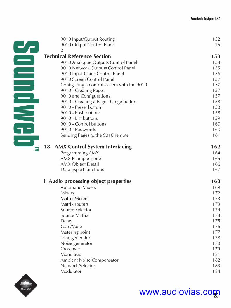
9010 Input/Output Routing 1529010 Output Control Panel 152
Technical Reference Section 1539010 Analogue Outputs Control Panel 1549010 Network Outputs Control Panel 1559010 Input Gains Control Panel 1569010 Screen Control Panel 157Configuring a control system with the 9010 1579010 - Creating Pages 1579010 and Configurations 1579010 - Creating a Page change button 1589010 - Preset button 1589010 - Push buttons 1589010 - List buttons 1599010 - Control buttons 1609010 - Passwords 160Sending Pages to the 9010 remote 161
18. AMX Control System Interfacing 162Programming AMX 164AMX Example Code 165AMX Object Detail 166Data export functions 167
i Audio processing object properties 168Automatic Mixers 169Mixers 172Matrix Mixers 173Matrix routers 173Source Selector 174Source Matrix 174Delay 175Gain/Mute 176Metering point 177Tone generator 178Noise generator 178Crossover 179Mono Sub 181Ambient Noise Compensator 182Network Selector 183Modulator 184
www.audiovias.com

26
Soundw
ebTM
Soundweb Designer 1.40
ii Understanding Networks 185Using the 9000ii Network Hub device 188Network restrictions 188Compressor 190Expander 192Ducker 194Gate 195Limiter 197Leveller 198EQ - Parametric Equaliser 200Stereo Parametric Equaliser 201Graphic Equaliser 201Phase Filter 202High Pass Filter 202Low Pass Filter 203FIR Filter 203Building in fault tolerance 204
iii Firmware Updates 205Locating the latest software 205How to Update the Firmware 207Loader.exe 208Software Loader 211BackupLoader.exe 2139014 Optical Fibre Interface 214
Glossary of terms 215
Soundweb Designer Keyboard Shortcuts 217
www.audiovias.com

27
Soundw
ebTM
Soundweb Designer 1.40
Soundweb Information
As of the 14th February 2003
Soundweb Designer is version 1.40 and runs under Microsoft Windows 98SE, NT, 2000 andXP.It can be run under emulation on a fast Apple Mac running either Virtual PC or SoftWindows.
Firmware versions:
9088 1.60
9088ii 1.20
9088iis 1.12
9008 1.12
9008iis 1.08
9000/9000ii 1.50
9000iis 1.06
9010 1.34
All subject to change, please check our website for updates.
Contact:
BSS Audio UK
Cranborne House,
Cranborne Road,
Potters Bar,
Hertfordshire,
England, EN6 3JN
Tel: +44 (0)1707 660667
Fax: +44 (0)1707 660755
email: [email protected]
website: www.bss.co.uk
A division of Harman International Industries Ltd.
BSS Audio USA
Harman Pro North America Inc.
1449 Donelson Pike,
Nashville,
TN37217,
USA
Tel: +1(615)360 0277
www.audiovias.com

28
Soundw
ebTM
Soundweb Designer 1.40
What is Soundweb?
Soundweb is a configurable distributed audio network. It is based on two principles:
• Hardware Devices
• Software Design and Control
Hardware Overview
These accept audio inputs and control signals from a variety of sources, e.g. microphones, CDplayers etc. for audio and, switches, potentiometers, 9010 remote, AMX or similar for systemcontrol.
The audio is converted into digital data in order to be routed and processed by acomprehensive selection of DSP algorithms, (developed by BSS and based on years ofexperience designing and building analogue audio dynamics processors and loudspeakermanagement systems).
The resultant signal is then reconverted back to the analogue domain at line level forconnection to sound systems, recording equipment or for further external processing.
The core hardware devices have no front panel controls (only indicators) which provides longterm reliability, consistency of operation and renders the system ‘tamperproof’.
These signal processing devices are networked together using industry standard CAT5 cablingand large networks can be easily realised using BSS 9000 series network hubs.
Fault tolerance and redundancy is ensured by the use of bi-directional cable routing in a ‘tokenring’ network configuration. If a device or section of the network goes offline, this will notaffect the operation of the remaining Soundweb network. Further backup subsystems can alsobe configured.
www.audiovias.com

29
Soundw
ebTM
Soundweb Designer 1.40Hardware
9088 Networked Signal Processor
A signal processing unit with 8 analogue inputs, 8 analogue outputs and 160 MIPS (millioninstructions per second) of DSP power.
The 9088 was factory fitted with a pair of four-channel input cards which provided pre-amplification of the signals before being converted from analogue to digital.
The card options were:
• Z-088LIN Line level card - each channel can be set to 0 or 12dB gain (for pro/consumerlevel use).
• Z-088MIC Mic level card - each channel can be set to a gain between 0 and 72 dB (in6dB steps), with phantom power selectable on each input.
9088ii Networked Signal Processor
A signal processing unit with up to 8 analogue inputs and outputs or 4 AES/EBU stereo digitalinputs and outputs. With 200 MIPS of DSP power this is the workhorse and main processingunit of the family.
The card options are:
• Z-088DIG digital card – up to 4 channels of digital interface at AES/EBU standard.
• Z-088MIC Mic level card - each channel can be set to a gain between 0 and 72 dB (in6dB steps), with phantom power selectable on each input.
• Z-088LIN Line level card - each channel can be set to 0 or 12dB gain (for pro/consumerlevel use).
9008 Networked Expansion Processor
The 9008 lacks the input circuitry of the 9088 but is otherwise identical. This unit is envisagedto be especially useful as an additional device in a larger system, where further routing andprocessing of audio is required to up to 8 outputs but, the required source signals are alreadycovered by 9088 devices elsewhere in the network.
www.audiovias.com

30
Soundw
ebTM
Soundweb Designer 1.40
9000ii Active Network Hub
A unit with 6 network jacks and 200 MIPS of DSP power. This unit replaces the 9000, whichhad 160MIPS, delivering more power for mixing and routing signals. The 9000ii is backwardcompatible with the 9000, so any design created for 9000s can be loaded into a 9000ii withoutchange.
iis Devices
Soundweb Designer 1.30 now includes the support of iis devices for 9000 series of products.These devices have different firmware to the ii units and utilise new internal hardware, althoughfor the user the performance is the same.
Within the Soundweb Designer software these are treated as ii devices.
9010 Remote Control Panel - ‘The Jelly-fish’
A wall mountable remote control unit with sixkeys, a rotary knob, and a graphic LCD displaywhich is used to provide control for thenetwork.
The 9010 has a built in condenser microphone,second mic input and two outputs for use as apaging station.
9014 Optical Fibre Interface
For network systems that need extension beyond the physical limitation of the standard 300m/1000ft cable length. One pair of fibre interfaces and 2 fibre cables replace one cat 5 cable,routing 8 channels of digital audio and control in both directions up to 1.2 miles (2km).
9012 Dual Control Wall Plate
A wall mounted plate housing an analogue potentiometer with a 5-way source select switch and rotary fader for use as external control-lers to the devices.
Hardware
www.audiovias.com

31
Soundw
ebTM
Soundweb Designer 1.40Software overview
9016/9026 Video/Audio matrix devices
The 9016 and 9026 are matrix routing units. These do not contain any DSP power but areintended primarily to extend the routing capabilities of existing Soundweb networks. The de-vices can however, also be used as stand alone units.
The Soundweb 9016 features 16 audio inputs, 8 audio outputs, 8 video inputs and 4 videooutputs.
The Soundweb 9026 features 16 audio inputs and 8 audio outputs.
In common with existing Soundweb units, the devices use the familiar six way Phoenix connec-tors, for audio connections. Video signals are connected to the 9016 using BNC Connectors.Both devices have two RS232 ports: RS232 IN and RS232 OUT.
The 9016 and 9026 operate in the same way as the existing source matrix processing objects inSoundweb Designer. Each output can be sourced from any one of the inputs at a time, whereasthe same input can be fed to all outputs simultaneously.
3088 Signal Processor
A signal processing unit with up to 8 analogue inputs and outputs, or 4 AES/EBU stereo digitalinputs and outputs. With 200 MIPS of DSP power, this device has the processing power of a9088ii and the exclusion of networking capabilities make it a cost-effective option in situationswhere only a single Soundweb unit is required.
The 3088 DSP is supported in Soundweb Designer 1.40 and above.
The card options are:
• Z-088DIG digital card - up to 4 channels of digital interface at AES/EBU standard.
• Z-088MIC Mic level card - each channel can be set to a gain between 0 and 72 dB (in6dB steps), with phantom power selectable on each input.
www.audiovias.com

32
Soundw
ebTM
Soundweb Designer 1.40
Software Design and Control
The Soundweb system is totally user configurable via connection to a PC (desktop or laptop)computer running BSS Soundweb Designer software.
Soundweb Designer is a specially written application that can be run whilst connected to aSoundweb network to effect ‘live’ adjustment of parameter values (e.g. output levels,compressor threshold etc.) and complete changes of system configuration using ‘Presets’.
Equally, it can also be used ‘offline’ (i.e. unconnected to the network) for designing a system,which can later be uploaded into the hardware.
The advantages of this approach are multiple.
• System designers can layout an audio system without the need for access to the hardware.
• The software helps create a ‘virtual’ version of possible configurations using a familiarCAD environment.
• The user can both ‘dry run’ the system and be fully aware of the use of DSP resources.
• Contractors can printout a graphical representation of their system schematic and a ‘kitlist’ of equipment used directly from the software to aid in setting up the hardware or toinclude in tenders and specifications for clients.
• Updates and enhancements to existing systems can be worked on and tested withoutrecourse to the hardware.
• Offsite system adjustments can still be performed ‘online’ to the network via remoteaccess using a conventional modem connection.
Designing a system overview
To design a system use Soundweb Designer software to perform the following tasks:
• Create and save your design in a system design file (.sdf).
• Define the Soundweb devices to use in the system.
• Choose and configure the audio processing objects to be loaded into the devices.
• Adjust the parameters of the audio processing objects using control panels.
• Designate Presets in order to change complete system set-ups.
• Select control surface objects to control the system.
• Design ‘custom’ control panels for use when the PC is ‘online’ to the network.
• Define Macros for frequently used sets of DSP functions.
• Secure the system (or parts of) from unauthorised access if necessary.
The design steps are actioned in several windows, each giving a different picture of part or all ofthe system - these are known as Map windows.
www.audiovias.com

33
Soundw
ebTM
Soundweb Designer 1.40
Tutorial 1 - Working Example
This tutorial is designed as a ‘quick guide’ to demonstrate the process of designing asimple Soundweb virtual system or layout. We hope that it will give you some idea ofhow Soundweb Designer works with map windows and objects and, how these relateto the processes that can be programmed into a Soundweb device.
It does not cover issues such as macro creation, graphics import/export, event logging,and use of external controllers or working ‘online’. Please refer to the ‘Soundweb indepth’ section for details on these subjects and the many other features of Soundweb.
It is advised that the user should have read the preceding overview sections in order tofamiliarise with the basic workings and concept of the Soundweb system.
There is a Glossary at the end of this manual, which may help to explain some of theterminology used. There is also a list of keyboard shortcuts which you can print out forreference and an in depth description, including functions, options and connections ofall the DSP processing objects.
Follow these steps to design an example Soundweb system:
1 Create a System Design File.
2 Define a Soundweb device to program.
3 Lay out the audio processing block diagram.
4 Adjust audio settings.
5 Set up Presets for different occasions/applications.
6 Use a Preset to change DSP Configurations.
7 Design a ‘custom’ Control Panel.
8 Add a second Soundweb device to the system.
Security issues are covered in the second tutorial which follows the Working Example.
www.audiovias.com

34
Soundw
ebTM
Soundweb Designer 1.40
Step 1
Create a System Design File
Before you start, make sure that you have Soundweb Designer software installed onyour computer!
1 Launch the application.
2 Maximise the Soundweb Designer main window and use a high monitor resolu-tion in order to give yourself plenty of work area.
3 If you do not already have a blank ‘map window’ on the screen use File>New tocreate one.
4 Select File>Save As.. (to give your system design file a name).
5 Save it in a chosen directory of your hard disk.
From this point all information related to this system (DSP layout, Presets, etc.) will besaved with your system design file - so long as you remember to press Save occasion-ally...
Step 2
Define a Soundweb device to program
1 Select Add>Device...from the menu, or press the button in the toolbar.
2 Choose ‘9088 DSP’ from the list of ‘Available Device Types’.
There are options and settings associated with this device, don’t worry about these forthe moment but, naming the device to reflect its purpose is good practice - especiallywhen using multiple devices.
3 Press OK and then click anywhere on the map window.
You should see a representation of the 9088 device on your screen.
Tutorial 1
www.audiovias.com

35
Soundw
ebTM
Soundweb Designer 1.40
Step 3Layout the audio processing block diagram
The objective is to layout a simple system consisting of a 4:2 mixer, with EQ on eachinput, and a compressor on each output.
1 Double click the 9088 DSP object; this opens its ‘Configuration’ window.
You should see objects representing the analogue inputs and outputs and network portsof the device.
On the next page is a picture of the system we are trying to create. Please refer to thisdiagram to help layout your arrangement.
To the left of the Configuration window there is a list of the available Processing Ob-jects:
The Processing Objects are grouped into categories (such as Mixers,Dynamics, EQ, etc.) The list works like a Windows Explorer ‘treecontrol’. To view all the items in a category (forexample the Crossovers category) click on the‘+’ sign next to it.
This changes the window to the following:
2 Click on the ‘-’ sign to collapse the category down and sim-ply show the category name without any of the contents.
3 Now open the ‘Eq - Parametric’ list of Processing Objects click on and drag a ‘4-Band Parametric EQ’ onto the main window, opposite one of the analogue inputports.
4 Next, make three more copies of this EQ by holding down the CTRL key anddragging the EQ object to a new location.
! Keep the CTRL key down for the whole dragging process, and only release it after youhave released the mouse button to drop your new EQ object into place.
5 Now also add one ‘Mixer 4:2’ (‘Mixers’), and two ‘Compressor’ blocks (‘Dynam-ics’) to the layout.
Tutorial 1
www.audiovias.com

36
Soundw
ebTM
Soundweb Designer 1.40
Step 4Wiring up the processors
We are now ready to wire up the block diagram.
! If you have a laptop computer, you may find it easier to use a mouse rather than atrackpad or ball to perform the wiring of the processing objects.
To connect the first EQ to the analogue input port:
1 Select Edit>Add Wires, also available in the right-click menu or press the
button in the toolbar.
2 Click on the connection point (the small square ‘node’) of the ‘In1’ object, a vir-tual ‘wire’ should appear attached to a crosshair (+) cursor.
3 Move the mouse to the ‘In’ port of the first EQ object, and click again.
A link should have been made between the two objects.
Repeat this process for each object in the system, i.e. wire the analogue input ports tothe inputs of the EQs; the outputs of the EQs to the inputs of the mixer; the mixer out-puts to the compressor inputs, and the compressor outputs to analogue ‘Out1’ and‘Out2’.
You can make a wire go round corners by clicking on a place on the map windowwhere you want the current wire segment to change direction.
Tutorial 1
www.audiovias.com

37
Soundw
ebTM
Soundweb Designer 1.40
To delete a wire put in the wrong place:
1 Select Edit>Edit Wires from the menu, also in the right-click menu or use the
toolbar icon.
2 Click on the unnecessary wire, and press the Delete/Backspace key (or selectDelete from the right click menu).
Wires can be moved by dragging the middle of the wire, which moves the whole net.Alternatively, to reshape the wiring move the black square at the end or a junction inthe wire.
A red wire signifies that a connection has not been made or is not an appropriate ac-tion.
Tutorial 1
www.audiovias.com

38
Soundw
ebTM
Soundweb Designer 1.40
Step 5
Adjust audio settings
• Double click on the mixer object.
A ‘control panel’ for the mixer, like the one shown below, should appear. Experimentwith the controls by using the mouse to adjust their settings until you are happy withhow faders, buttons and rotary controls work.
Tutorial 1
www.audiovias.com

39
Soundw
ebTM
Soundweb Designer 1.40
Step 6
Create Presets for different occasions/applications
Next, we’re going to create two ‘Presets’. One for a ‘Conference’ use, which will use allfour inputs on the mixer. The second is for a ‘Wedding’, and will use the first two inputsonly.
To set up the ‘Conference’ Preset:
1 Adjust all the gains on the mixer control panel to -10dB (either by moving thesliders or by selecting the textbox above them and typing in the number), andunmute all the inputs and outputs of the mixer (grey buttons, not red).
2 Select View>Go to Preset View, or press the shortcut icon at the bottom of thescreen.
3 In the dialogue box press New; type “Conference”; press OK.
This set-up is now stored in a Preset suitable for the ‘Conference’ application.
Tutorial 1
www.audiovias.com

40
Soundw
ebTM
Soundweb Designer 1.40
To create the second Preset.
4 Return to the mixer control panel by closing, minimising or resizing the Presetwindow.
5 Mute inputs 3 and 4, and adjust the gain to around -30dB on inputs 1 and 2.
6 Select Preset View as before; Press New; type “Wedding” and press OK.
These new settings are now stored in a second Preset.
To recall a Preset, select it from the list in the Preset View, and press Recall.If the mixer control panel is visible, you should see the fader and mute settings change.
Tutorial 1
www.audiovias.com
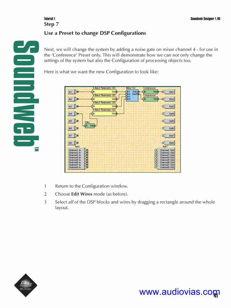
41
Soundw
ebTM
Soundweb Designer 1.40
Step 7
Use a Preset to change DSP Configurations
Next, we will change the system by adding a noise gate on mixer channel 4 - for use inthe ‘Conference’ Preset only. This will demonstrate how we can not only change thesettings of the system but also the Configuration of processing objects too.
Here is what we want the new Configuration to look like:
1 Return to the Configuration window.
2 Choose Edit Wires mode (as before).
3 Select all of the DSP blocks and wires by dragging a rectangle around the wholelayout.
Tutorial 1
www.audiovias.com

42
Soundw
ebTM
Soundweb Designer 1.40
4 Copy this set-up by using Edit>Copy (also in the right click menu, or CTRL-C).5 Now press the button next to the ‘Configuration’ combo box.
This dialog box should appear:
6 Press New.
7 Type “Plus Gate”. Press OK. (If you want you can rename the ‘Default’Configuration).
8 Select “Plus Gate” and press Activate.
A new layout page should appear.
To retrieve the Configuration that you designed originally.
• Select Edit>Paste (or CTRL-V).
! If you have resized windows or moved them you may find that the input and outputports are not connected - if this is so connect them up again.
Now to add the gate to the layout.
www.audiovias.com

43
Soundw
ebTM
Soundweb Designer 1.40
1 Delete the wire between ‘In4’ and the EQ.
2 Drag a ‘Gate’ from the ‘Dynamics’ Processing Objects list.
3 Wire ‘In4’ to the Gate input.
4 Wire the Gate output to the now vacant EQ input.
5 Return to the Preset View, select ‘Conference’ and press Store.
6 Switch between the ‘Conference’ and ‘Wedding’ Presets by selecting them in turnand pressing Recall.
You should see the block diagram change and that recalling a Preset picks up the DSPConfiguration that was stored with it.
Note that Configurations are specific to a particular device but that Presets are systemwide, i.e. a Preset stores all the settings for all of the devices on the network.
Tutorial 2
www.audiovias.com

44
Soundw
ebTM
Soundweb Designer 1.40
Step 8
Design a ‘custom’ control panel
Let’s suppose that we want to create a control panel that has just the output gains fromthe mixer, and some dedicated buttons for Preset selection.
1 Go back to the Configuration window and double click on the mixer to bring upits ‘default’ control panel.
2 Select Map>Design (also in the right-click menu, or ALT+D).
3 Use Map>New Window or press the button to provide a new map window in
which to create the new control panel.
4 Select Map>Rename and give it a name like “Main control panel”.
5 Adjust the window sizes to allow space to drag and drop between this windowand the default control panel.
6 Next, drag an output gain fader from the mixer control panel to the new window.
7 If the software asks whether you want to resize the grid press ‘Yes’.
Repeat this operation for the second gain fader.
8 Now click on the window and select Map>Operate (also in the right-click menu,or ALT+O). Also, switch the default control panel back to Operate mode.
You should now see that if you move a fader in either control panel, the correspondingfader in the other panel will track it.
Next, to add a button to select a Preset (i.e. “Wedding”).
1 Click on the new ‘Main control panel’
2 Select Map>Design.
3 Select Add>Preset or press the button and click again on the ‘Main control
panel’ to place the button.
4 Right click on the resulting Preset button and select Properties from the pop-upmenu
Tutorial 2
www.audiovias.com
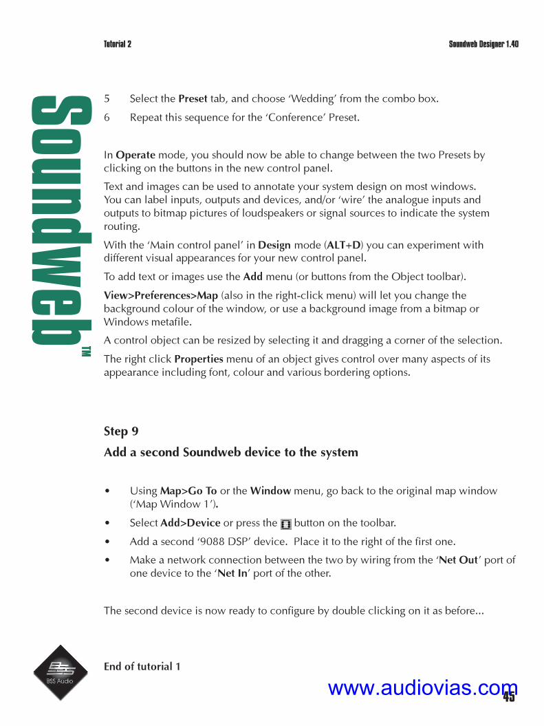
45
Soundw
ebTM
Soundweb Designer 1.40
5 Select the Preset tab, and choose ‘Wedding’ from the combo box.
6 Repeat this sequence for the ‘Conference’ Preset.
In Operate mode, you should now be able to change between the two Presets byclicking on the buttons in the new control panel.
Text and images can be used to annotate your system design on most windows.You can label inputs, outputs and devices, and/or ‘wire’ the analogue inputs andoutputs to bitmap pictures of loudspeakers or signal sources to indicate the systemrouting.
With the ‘Main control panel’ in Design mode (ALT+D) you can experiment withdifferent visual appearances for your new control panel.
To add text or images use the Add menu (or buttons from the Object toolbar).
View>Preferences>Map (also in the right-click menu) will let you change thebackground colour of the window, or use a background image from a bitmap orWindows metafile.
A control object can be resized by selecting it and dragging a corner of the selection.
The right click Properties menu of an object gives control over many aspects of itsappearance including font, colour and various bordering options.
Step 9
Add a second Soundweb device to the system
• Using Map>Go To or the Window menu, go back to the original map window(‘Map Window 1’).
• Select Add>Device or press the button on the toolbar.
• Add a second ‘9088 DSP’ device. Place it to the right of the first one.
• Make a network connection between the two by wiring from the ‘Net Out’ port ofone device to the ‘Net In’ port of the other.
The second device is now ready to configure by double clicking on it as before...
End of tutorial 1
Tutorial 2
www.audiovias.com

46
Soundw
ebTM
Soundweb Designer 1.40
There follows a further tutorial for setting up a secure system, if this is likely to beneeded then we recommend to work through both tutorials one after the other as theyare intended to follow on.
Tutorial 2
www.audiovias.com
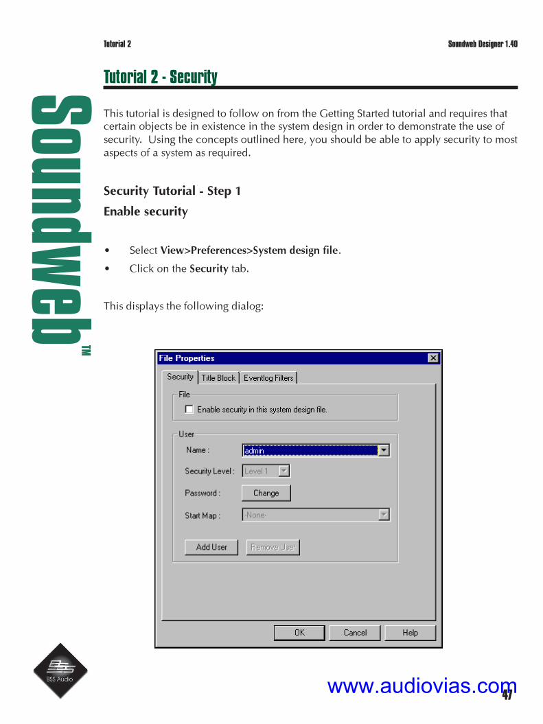
47
Soundw
ebTM
Soundweb Designer 1.40
Tutorial 2 - Security
This tutorial is designed to follow on from the Getting Started tutorial and requires thatcertain objects be in existence in the system design in order to demonstrate the use ofsecurity. Using the concepts outlined here, you should be able to apply security to mostaspects of a system as required.
Security Tutorial - Step 1
Enable security
• Select View>Preferences>System design file.
• Click on the Security tab.
This displays the following dialog:
Tutorial 2
www.audiovias.com

48
Soundw
ebTM
Soundweb Designer 1.40
• Check the box labelled ‘Enable security in this system design file’.
• Press OK.
• Save the system design file.
• Now close and re-open it.
www.audiovias.com

49
Soundw
ebTM
Soundweb Designer 1.40
You should see the following screen:
There is currently only one user, ‘admin’, whose password is also ‘admin’.
Type in the password (‘admin’), and click OK.
You now have access to the system as usual.
Step2 - Set a password for the admin
To set the administrator’s password to something other than the default (in order to preventother people logging in as you).
• Select View>Preferences>System design file>Security.
• Press Change.
Type in the existing password (‘admin’) followed by the password that you wish to use. You will
be asked to repeat this as confirmation.
Step 3 Set up a new user
• Select View>Preferences>System design file>Security.
• Press Add User.
• Type in a name (such as ‘operator’), and press OK.
A new user has been added with level 10 security (the lowest level and with the least accessdependant on the security set-up), and with a password which is the same as the ‘operator’name.
To change the security attributes of a user, i.e. security level and password:
Modify the attributes in the other dialog fields, and select OK.
www.audiovias.com

50
Soundw
ebTM
Soundweb Designer 1.40
Step 4 - Controlling access to map windows
To allow a user access to a particular window only.
• Select View>Preferences>System design file>Security.
• Select the user in the ‘Name’ combo box.
Choose the map window to be opened when the user logs in from the Start Map combo box.
To test these changes to the security set-up:
• Save the system design file.
• Close it and re-open it.
• At the login screen, select the user named ‘operator’.
• Type in the password.
You should see that the system has been opened with only the specified window active.
www.audiovias.com

51
Soundw
ebTM
Soundweb Designer 1.40
Step 5 - Selective control access
Suppose we want to allow the user to see the input gain settings of the mixer, but not changethem.
• First, close the file and re-open it, this time using the administrator’s password.
• Next, create a new map window, and rename it ‘Input control panel’.
• Now return to ‘map window1’.
• Double-click on the main device to open its Configuration window.
• Double-click on the mixer processing object.
• Choose Design mode from Map>Design (also in the right-click menu, or ALT+D).
• Select the block of input faders by dragging a rectangle around them with the mouse.
• Drag the block across to your new map window, some shuffling of windows may beneeded on the screen first to make this possible.
• Click somewhere on the ‘Input control panel’ to ensure that this window is selected.
• Select View>Preferences>Map and click on the ‘Security’ tab.
• Set all the levels to ‘Level 1’, except the ‘Security level to View’ - leave this at ‘Level 10’.
• The user ‘operator’ (who is at level 10) is now able to view the controls, but not operatethem.
To test this, a linking button is needed to allow ‘operator’ to navigate to the ‘Input controlpanel’.
• Go back to ‘map window 1’ (for example by selecting Map>Go To).
• Enable Design mode, as before.
• Select Add>Linking Button or press the button on the toolbar.
• Place the new button somewhere on the control panel.• Right click on the button and select Properties.
• Select the ‘Target Window’ tab.
• Choose ‘Input control panel’ from the list of available target windows.
• Now save the file, close it, re-open it and login as ‘Operator’.
• You should enter the first map window as before.
• Click on the linking button to access the ‘Input control panel’.
You should be able to view the mixer settings, but you should not be able to move any of thecontrols.
From this tutorial it should be possible to assign security to either the whole file or for selectiveareas and functions in the design.
! Remember your passwords or keep an unsecured backup copy of the sdf so that access doesnot become denied to you too…
www.audiovias.com

52
Soundw
ebTM
Soundweb Designer 1.40
Soundweb Designer V1.40 New Features
9016/9026 Video/Audio Matrix Devices.
• Introduction
• Connecting to other Soundweb devices
• Configuring the network
• Adding to a Design File
• Controlling the devices
• External control options
• Connection information
Enhancements and bug fixes
• Soundweb Designer 1.40
• Soundweb Designer 1.30
• Soundweb Designer 1.22
• Soundweb Designer 1.20
Soundweb Designer V1.30 Updates
3088 Signal Processor
A signal processing unit with up to 8 analogue inputs and 8 analogue outputs, or 4 AES/EBUstereo digital inputs and outputs. With 200 MIPS of DSP power, this device has the processingpower of a 9088ii and the exclusion of networking capabilities make it a cost-effective option insituations where only a single Soundweb unit is required.
The 3088 DSP is supported in Soundweb Designer 1.40 and above.
The card options are:
• Z-088DIG digital card - up to 4 channels of digital interface at AES/EBU standard.
• Z-088MIC Mic level card - each channel can be set to a gain between 0 and 72 dB (in6dB steps), with phantom power selectable on each input.
• Z-088LIN Line level card - each channel can be set to 0 or 12dB gain
www.audiovias.com

53
Soundw
ebTM
Soundweb Designer 1.40Designer 1.30 New Features
Introduction
The 9016 and 9026 are matrix routing units from BSS Audio. These units do not contain anyDSP power but are intended primarily to extend the routing capabilities of existingSoundweb networks. The devices can however, also be used as stand alone units.
The Soundweb 9016 features 16 audio inputs, 8 audio outputs, 8 video inputs and 4 videooutputs.
The Soundweb 9026 features 16 audio inputs and 8 audio outputs.
In common with existing Soundweb units, the devices use the familiar six way Phoenixconnectors, for audio connections. Video signals are connected to the 9016 using BNCConnectors. Both devices have two RS232 ports: RS232 IN and RS232 OUT.
The 9016 and 9026 operate in the same way as the existing source matrix processing ob-jects in Soundweb Designer. Each output can be sourced from any one of the inputs at atime, whereas the same input can be fed to all outputs simultaneously.
Connections
Soundweb Video/Audio Matrix devices are connected to a Soundweb system via the rearRS232 Port of a 9088ii, a 9000, a 9000ii or a 9008. Up to two external devices can beconnected in series, the second matrix device being connected to the rear port of the first. Ifthere is one Matrix device connected, the “unit ID” switch on the rear must be set as unit A.A second matrix device connected in series with this one, must have the “unit ID” switchset as unit B. The “Baud Rate” switches on both matrix switches must be set to the“Soundweb” (out) position.
www.audiovias.com
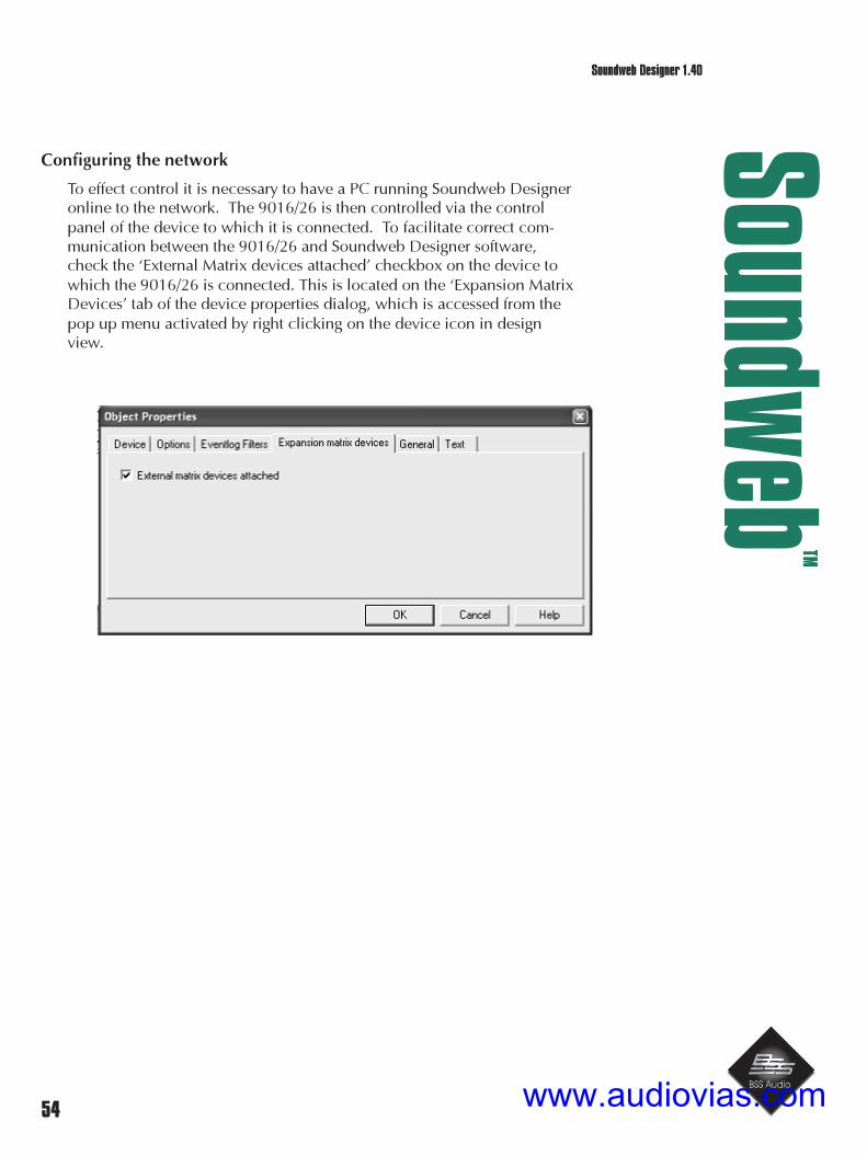
54
Soundw
ebTM
Soundweb Designer 1.40
Configuring the network
To effect control it is necessary to have a PC running Soundweb Designeronline to the network. The 9016/26 is then controlled via the controlpanel of the device to which it is connected. To facilitate correct com-munication between the 9016/26 and Soundweb Designer software,check the ‘External Matrix devices attached’ checkbox on the device towhich the 9016/26 is connected. This is located on the ‘Expansion MatrixDevices’ tab of the device properties dialog, which is accessed from thepop up menu activated by right clicking on the device icon in designview.
www.audiovias.com

55
Soundw
ebTM
Soundweb Designer 1.40Designer 1.30 New Features
Design file considerations
There is no direct representation of the 9016 or the 9026 in SoundwebDesigner; that is, you cannot create a new device of type 9016 or 9026as you might with other Soundweb devices. However as an aid to systemdesign, a bitmap representation of both matrix devices can be added byright clicking on a map window in design view, selecting Add NewImage from the pop up menu, then browsing to the appropriate image inthe pictures folder of your Soundweb installation. The Bitmaps are named“AudioMatrix” and “VideoAudioMatrix”. Any wires drawn to theseBitmaps will be for illustration purposes only.
Bitmaps included with Soundweb Designer
www.audiovias.com

56
Soundw
ebTM
Soundweb Designer 1.40Designer 1.30 New Features
Controlling the 9016/9026
There are in fact two sets of controls, on two separate tabs entitled ‘Matrix Device A’ and‘Matrix Device B’. Inputs can be patched to each output within the corresponding device,using either the drop down list or the push buttons. The currently active input for eachoutput is indicated with a green LED. The gain of each audio output can be adjusted be-tween –INF and +20dB, using the up/down spin controls, or by typing directly into thecorresponding edit boxes.
Any changes made when the PC is online to a device will have immediate effect.
In common with other Soundweb Designer controls, the Matrix Device Controls can bedragged to map windows in order to create custom control panels. BSS recommend the useof presets to store and recall Matrix setups, this will enable multiple input/output routes andgain settings to be changed simultaneously. More information on presets can be found inthe relative section of this document.
www.audiovias.com

57
Soundw
ebTM
Soundweb Designer 1.40
External Control
All of the controls on the Matrix control panels can also be placed on a control port, whichwill enable control using external hardware devices such as the BSS 9012 Dual ControlWall Plate. See the relevant section for more information on using control ports.
The matrix devices can of course also be controlled by a BSS 9010 remote control providedthey are being used as part of a network that includes Soundweb DSP devices.
Connecting the 9016/26 to another Soundweb device.
To Connect the 9016/26 to another Soundweb device a standard PC Serial Extension cableis used. Only the following connections are necessary.
Male 9-way D type - identical pin out to that used in a standard PC serial port:
Pin No. Signal type Function 9-way pin No. 25-way pin No.
1 DCD Data carrier detect (input) - -
2 RXD Receive data (input) 2 3
3 TXD Transmit data (output) 3 2
4 DTR Data terminal ready (output) - -
5 GND Ground 5 7
6 DSR Dataset ready (input) - -
7 RTS Request to send (output) - -
8 CTS Clear to send (input) - -
9 (not used) - -
Note: This is not the same wiring as the Null Modem cable currently used to connect a PC tothe rear RS232 port of Soundweb DSP devices.
NB: ‘commercial’ cables may have some of the other connections wired up, this is perfectlyacceptable.
www.audiovias.com

58
Soundw
ebTM
Soundweb Designer 1.40
Analogue Connections
Audio Connections
These connectors are in pairs at the back of the unit on six way Phoenix connectors. Inputsare on the top level and outputs on the bottom. The signal pin out is marked on the silk-screen of the case rear. Seen from the back of the unit, from left to right, the connection isalways
(S) shield/ground
(+) +ve signal
(-) -ve signal
Video Connections
Video inputs/outputs on the 9016 use standard BNC connectors.
www.audiovias.com

59
Soundw
ebTM
Soundweb Designer 1.40
Enhancements
Version 1.40
• Along with the familiar 'no problems' message displayed in the network window ofDesigner when online to a fully functional network, a list of the devices on thenetwork and the firmware versions contained in these devices is also displayed.This will allow the user to quickly check that all devices are running on the latestfirmware versions, essential for prolonged reliable operation.
Version 1.3
• ID info for parameter presets is now shown in the status bar rather than on a tooltip.
• Buttons placed on Control Ports as toggle buttons no longer get left out of presetsand param. presets.
• Delays in Crossover objects - corrected occassional errors in reported delay times.
• Audio mutes caused by DSP reloads now corrected.
• Firmware will report if an earlier version than 1.22 of Soundweb Designer is used.
• Hubs can now detect a fibre failure in one leg of the two cores.
• Maximum number of configurations raised to 78.
• Preset changes from 9010 remote buttons can now be combined with passwordsecurity.
• Hub mastership improved.
• Master LED remains illuminated when selecting device on network view.
• Serial control across networks improved for large numbers of parameters.
• Delay ranging fixed in macros.
• Parameter presets in ‘Button Mode’ now ‘depress’ like normal buttons when
clicked.
• Any changes in a devices serial window will now signal the need to re-load thedevice.
• Compiler - delay compensation improvements.
• Windows ’98 - long path name problem fixed.
• Event Log – problems displaying events using an SDF with a filename longer than
30 characters fixed.
• Macros - now exporting delay properties correctly.
• Metering – fixed problem with faders and parametric eqs not sending values when
there were multiple meters on screen.
• Metering – fixed problem with meters requesting updates from devices, thereforecausing extra network activity, even when they had been closed down in Designer.
• Automated wiring – crashes when trying to implement this feature now fixed.
• Configuration window – interface ports are now sent to back when first opening an
www.audiovias.com

60
Soundw
ebTM
Soundweb Designer 1.40
Bug Fixes
Version 1.22
• Fixes Bug that caused 9010 to request unnecessary Reload when going online.
• Modem is now initialised only on power up of device (Some users experienced problemswith modem being initialised during Configuration changes).
• Correct Delay units are now displayed on 9010 and initial values are read correctly.
• Fibre system muting scheme altered - previously this could result in inaudible signalsappearing at unconnected 9000 Hub network inputs.
• Devices no longer reboot when loaded with large design files containing Ambient Noisecompensators.
• Macros containing gain objects that have their default values set to –INF no longer crashwhen their control panel is opened.
• Control range definintion in macros now fixed (problem with -infinity).
• Designer no longer allows you to go online to a serial port that is not valid, i.e being usedby another application or not physically existent.
• Keep alive timer re-introduced. Designer will timeout after 5 seconds. Network will timeout after 2 seconds and perform a network reset.
• Closing Designer whilst online no longer causes the software to crash.
• Comms.exe now reboots on startup if Soundweb left it running on the last shutdown.
Version 1.2
• Compiler - delay compensation improvements.
• Windows ’98 - long path name problem fixed.
• Event Log – problems displaying events using an SDF with a filename longer than 30characters fixed.
• Macros - fix for exporting delay properties correctly.
• Metering – fixed problem with faders and parametric eqs not sending values when therewere multiple meters on screen.
• Metering – fixed problem with meters requesting updates from devices, therefore causingextra network activity, even when they had been closed down in Designer.
• Automated wiring – crashes when trying to implement this feature now fixed.
• Configuration window – interface ports are now sent to back when first opening an SDFso that user defined text labels can be seen.
Designer Bug Fixes
www.audiovias.com

61
Soundw
ebTM
Soundweb Designer 1.40
Soundweb Designer Reference Section
1. General program description
2. Map windows
3. Devices
4. Configuration windows
5. Virtual wiring
6. Control Panels
7. Parameter Presets
8. Presets
9. Compiling the design
10. Working ‘online’
11. Kit List
12. Security
13. Macros
14. Event Log
15. External control options
16. 9010 Remote Control programming
17. AMX control system interfacing
www.audiovias.com

62
Soundw
ebTM
Soundweb Designer 1.40
1. General Program description
The Soundweb Designer application runs successfully under Windows 95/98 (Release 2) or NT.
The main Soundweb Designer window looks like most typical Windows application programs:it has a menu bar, various iconic toolbars, a main work area, and a status bar.
Status bar
The status bar, located at the bottom of the main window, has an indicator to show the presentsystem status; ‘ONLINE’ is displayed when the PC is in active connection to the Soundwebhardware devices and ‘OFFLINE’ when the PC is working independently of the network.
The status bar also provides shortcuts to other windows.Click on one of these to go directly to the selected window:
Event log application
Network view
Macro creation page
Preset window
Kit list
It also displays an explanation of the buttons in the toolbars at the top of the screen when themouse rolls over these icons (when available for use). Momentary ‘Tooltips’ also showabbreviated info at this point.
Map toolbar
The Map Toolbar contains buttons for creating a new map window and deleting the currentlyopen map window. It also contains a combo box with a list of all the map windows in thesystem design file. Map windows can be selected by name from this combo box.
It can be switched on or off using the View>Map Toolbar menu command and can berepositioned on the screen by clicking and dragging from an area of the toolbar which is not abutton.
www.audiovias.com
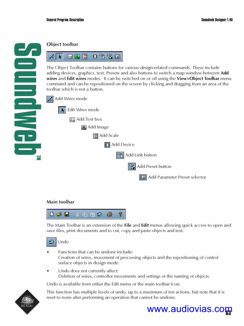
63
Soundw
ebTM
Soundweb Designer 1.40
Object toolbar
The Object Toolbar contains buttons for various design-related commands. These includeadding devices, graphics, text, Presets and also buttons to switch a map window between Addwires and Edit wires modes. It can be switched on or off using the View>Object Toolbar menucommand and can be repositioned on the screen by clicking and dragging from an area of thetoolbar which is not a button.
Add Wires mode
Edit Wires mode
Add Text box
Add Image
Add Scale
Add Device
Add Link button
Add Preset button
Add Parameter Preset selector
Main toolbar
The Main Toolbar is an extension of the File and Edit menus allowing quick access to open andsave files, print documents and to cut, copy and paste objects and text.
Undo
• Functions that can be undone include:Creation of wires, movement of processing objects and the repositioning of controlsurface objects in design mode.
• Undo does not currently affect:Deletion of wires, controller movements and settings or the naming of objects.
Undo is available from either the Edit menu or the main toolbar icon.
This function has multiple levels of undo, up to a maximum of ten actions, but note that it isreset to none after performing an operation that cannot be undone.
General Program Description
www.audiovias.com

64
Soundw
ebTM
Soundweb Designer 1.40
Network toolbar
A new toolbar indicates the network status of Designer, i.e. either ‘Online’ or ‘Offline’. Thetoolbar can be undocked from the top of the screen and the resultant floating window can berelocated as required.
Also the Network view icon on the status bar will now flash ‘load’ when a device needsloading.
Configuration windows
A Configuration window enables the detailed layout of signal processing objects for a device. Italso shows their interconnections and relation to the external audio, control and network portson the rear of the device.
Each device can have one active Configuration window, which can be switched between anumber of different Configuration layouts.
This window has two main areas; to the left there is a list of available audio ‘ProcessingObjects’, a section to work with ‘Configurations’ and a button to ‘Compile’ your design. Themain window area on the right is used to layout the processing objects.
When you create a new Configuration the main area contains objects that represent each of theInput and Output ports for the device. Also there may be processing objects which arepermanently fixed in the device and do not vary when different Configurations are selected.
General Program Description
www.audiovias.com

65
Soundw
ebTM
Soundweb Designer 1.40
Network window
The Network window (or ‘view’) is used to work ‘online’ with the network of Soundweb devicesand to load the compiled version of your system design into the hardware. It displays therelationship between the devices in your design and the actual devices on the network to whichthe PC is connected. It is also used to load revised ‘firmware’ operating software into thedevices
See ‘Firmware Updates’ for more details.
System Design Files
The system design file (extension .SDF) is the principal data file. It contains all of theinformation about your Soundweb design; layout of the devices, processing blocks,Configurations, Presets, parameter settings, security information, graphical annotation, etc.
When transferring your system design between different computers you need only copy thesystem design (.sdf) file - no other files are required.(The only exception to this is user defined Macros - see the ‘Macros’ topic for details).
They consist of one or more map windows which contain graphical representations of the DSPprocessing functions which are wired together to form the required system. This is thencompiled into code, which is loaded into the Soundweb hardware.
Soundweb Designer works with one system design file open at any one time. To comparedifferent systems, you need to open two copies of the Soundweb Designer application.
If you exit a session without changing the design since the last file save, but you have adjustedsome parameters, you will be asked if you want to save before quitting. ‘Yes’ will save theupdated parameters. ‘No’ will retain the original parameter values.
System design files are manipulated with the usual commands on the Windows File menu:New, Open, Save and Save As.
General Program Description
www.audiovias.com

66
Soundw
ebTM
Soundweb Designer 1.40
Program Preferences
A number of aspects of the Soundweb Designer software can be customised to suit yourindividual needs. These are called ‘Preferences’.
General Application Preferences
For items which are related to the installation of Soundweb Designer, and which thereforeapply across all system design files
Select View>Preferences>Application and click on the General tab.
This dialog gives access to the following preferences:
There are further tabs to set up the Comms, Event Logging and on startup preferences, pleaserefer to ‘Working Online’ and ‘Event Logging’ for information relating to these settings.
Windows settings
These check boxes allow you to select how a window is sized when it is created for the firsttime. If a box is checked, the window type indicated will always be made as large as possibleto fit within your main Soundweb Designer area (note that this is different from the Windowsmaximised style). If the box is unchecked, the window type indicated will be set to a defaultsmaller size.
General Program Description
www.audiovias.com

67
Soundw
ebTM
Soundweb Designer 1.40
Rotary control method
You have three choices for the way on screen rotary control objects work.
• ‘Horizontal’ - adjust by clicking in the centre of the control then moving the mouse fromside to side.
• ‘Vertical’ - adjust by clicking the mouse on the control and by moving the mouse up anddown.
• ‘Angular - adjust by clicking the mouse on the control and using a circular motion tomimic a hand turning the control.
Each method has its advantages. Linear (vertical or horizontal) control is easier to use whenadjusting rotary controls blind, i.e. when looking up to listen to audio. The rotary method isperhaps more intuitive for novice users.
Logging out
This option enables the designer to disable the dialogue box that would normally be shownwhen logging out of a design file in which changes have been made. As this can apply toparameter changes and not just design / layout changes it can be advantageous to disable thisdialogue to prevent users from overwriting previously configured control settings.
General Program Description
www.audiovias.com

68
Soundw
ebTM
Soundweb Designer 1.40
Directories
• Select View>Preferences>Application and then the Directories tab to display the follow-ing dialog:
The Soundweb Designer application will use these directories.
• Default directory for Soundweb data files: specifies where Soundweb Designer storesSystem Design Files.
• Default directory for image files: specifies where Soundweb Designer will look for images(bitmaps, WMF files etc.) when loading graphics.
• Default directory for macro files: specifies where Soundweb Designer will read anyMacros, and where it will export Macros.
The example screen shows some defaults set by the installation program.
• Click on the button to the right of the required directory name to change any of them to adifferent directory.
General Program Description
www.audiovias.com

69
Soundw
ebTM
Soundweb Designer 1.40
2. Map windows
Map windows are the ‘virtual canvases’ on which you designyour system. They enable the configuration of the deviceaudio processing and the construction of control panels in aneasy to understand graphical method. When you first start anew system design file, you are presented with a blank mapwindow - this is like a canvas onto which you can paint apicture of your system.
You may choose to only use one map window in your design,or you may wish to use several different map windows, eachpresenting a unique picture of different parts of the system.
Map windows contain one or more of these:
• Icons representing hardware devices in the design.
• Wires indicating the connections between the devices.
• Software controls such as pushbuttons or faders.
• Images such as lines, bitmaps and text for adding colour and shape to help clarify adesign.
A special form of map window exists that contains software controls but no device icons: this iscalled a control panel.
Creating Map windows
When you create a new system design file, you normally automatically create a map window,called ‘Map Window 1’. You can create further map windows using the Map>New Window
menu command or the button on the Map toolbar.
www.audiovias.com

70
Soundw
ebTM
Soundweb Designer 1.40
Using Tabs to group Map windows
When you create a new map window, you can group it with another map window into a singletabbed frame.To do this:
1 Select an existing map window.
2 Right-click anywhere in the middle of the window.
3 Select New Tab from the menu.
A new map window will be created as part of a tabbed group with the old one, like this:
Note that tabs have to be created before using a map window, i.e. map windows cannot betransformed into a tab window later. To put already created objects into a tabbed window, usethe standard cut and paste functions.
Navigating between Map windows
You can navigate between open map windows using the list of open windows at the bottom ofthe Window menu (there may be a More Windows... option if the list has become rather long).
To go to a map window which has been closed, and which therefore does not appear in the listof windows in this menu, use the Map>Go To command - this displays a list of all availablemap windows in use in the system design file. Alternatively, you can also select a map windowin the combo box on the map toolbar.
It is also possible to arrange ‘link’ buttons to switch between map windows.
Map Windows
www.audiovias.com

71
Soundw
ebTM
Soundweb Designer 1.40
Design and Operate modes
A map window can be in one of two modes: ’Design’ or ‘Operate’.You can tell which mode you are in by looking at the mouse pointer.In Design mode, it is the conventional windows arrow.In Operate mode, the mouse pointer is a pointing hand.
• In Design Mode, the mouse is used to change the design of the window by adding,deleting, modifying or removing control surface elements, devices and graphic items.
• In Operate Mode, none of these things can be moved, and the mouse is used to adjustcontrols, or to activate pushbuttons.
You can switch between modes using the Map>Design and Map>Operate menu commands.Alternatively, right-click on a blank area of map window, and use the Design or Operatecommands in the right-click menu, or press ALT+D or ALT+O.
Map window preferences
Select View>Preferences>Map and click on the ‘Map’ tab to display a dialog with settingsrelated to the active map window.
The following things can be changed:
• Grid: choose to display a design grid or not (Design mode only - the grid is neverdisplayed in Operate mode). Also select the grid size and choose to ‘snap’ window itemsto the grid or not.
• Background: change the colour or use of an image for the window background.
• Show Title Block: enables title blocks to be added to the layout, mainly for printing.
Clicking on the Security tab allows you to set the protection requirements for the window via asystem of security ‘levels’; see Security topic for more information.
Map Windows
www.audiovias.com

72
Soundw
ebTM
Soundweb Designer 1.40
Full Screen Mode
Accessed from the View menu, or using CTRL+ALT+F.
Selecting full screen mode enlarges the currently active map window to fill the screencompletely. This allows the design of larger control panels, and the menus and tool bars can behidden from view (and therefore tampering made impossible). Using this feature, a pccontrolled Soundweb system can be made more aesthetically intrinsic to the task that it is set upfor.
CTRL+ALT+F toggles between full screen and normal operation, while CTRL+TAB cyclesthrough any active map windows. Menus can still be accessed with the usual windows key-board commands: ALT+F(File menu); ALT+V(View menu) etc.
Whilst in full screen mode (in an unsecured design file), a ‘Close Window’ button is present.Pressing this button repeatedly will close all active map windows until the last remaining mapwindow has been closed. Then the button changes to ‘Exit Designer’ and returns the user backto the normal Designer working overview. A dialogue box will ask if you wish to save the filebefore closing Designer.
When in ‘auto-online’ mode the ‘Close Window’ button is hidden and keyboard shortcuts canbe disabled, i.e. CTRL+ALT+F will not work.
Map Windows
www.audiovias.com
73
Soundw
ebTM
Soundweb Designer 1.40
Map Window layout options
To alter the order in which overlapping objects are displayed in order to prevent text andgraphics looking messy:
• Right-click on an object and select one of the commands Bring to front, Bring forwardone, Send to back, or Send back one.
Map windows can be deleted and renamed using the Map>Delete, or toolbar button, and
Map>Rename commands from the menus.
It is now possible in Design mode to align multiple objects, remove gaps between them andmake them the same size as a chosen object.
• Select two or more objects and use these options from the context menu: Make samesize by: Width, Height or both
• Choose one of these options and then click on the object that you wish to use as thetemplate for the operation.
For example, 2 sliders are selected, the leftmost being wider than the right, and Make same sizeby: Width is chosen from the right click menu. The cursor then changes to reflect a scaleoperation and if the right hand slider is now clicked on then the left hand slider will changewidth to match it.
Align by: Top edges or Left edges
Remove gaps: Horizontally or Vertically
These options will align objects immediately without the need for further selection.
All these operations can be undone with the Undo feature.
Adding text and graphics
Three forms of graphical items can be added to map windows and the Configuration window:
• Text objects.
• Images.
• Scales.
These can be used to help the user navigate the design, or simply to improve the appearance.
To add, move, delete or modify graphical items in a map window.
• Select Design mode.
New graphic items can be snapped to a grid by selecting this option in theView>Preferences>Map... dialog.
Map Windows
www.audiovias.com

74
Soundw
ebTM
Soundweb Designer 1.40
The order of overlapping graphic items may be changed using the right click options asdescribed for objects on map windows. Arrange objects to avoid messy layouts!
Wires can also be added for annotation purposes at arbitrary positions in map or Configurationwindows, even if they do not connect active system items. If a wire does not have both endsconnected to active connection points, it is considered dumb and is simply ignored bySoundweb Designer.
Text objects
To add a text object:
• Select Add>Text Object, or use the button in the Object toolbar, and click on theplace in the window where you want the text to be placed. A flashing cursor will appearwhere you may type in your text.
To move a text object:
• Click on it to select it. A box will appear around the text; you can now drag the box to anew location.
To delete a text object:
• Select it and press Del/Backspace.
To edit a text object:
• Double-click on it - this brings up a flashing cursor which allows you to edit the text.
To change properties of a text object (such as its font size, type style or colour):
• Right-click on the text object and select Properties from the right-click menu.
Map Windows
www.audiovias.com

75
Soundw
ebTM
Soundweb Designer 1.40
Scale objects
Scale objects are rectangular blocks that contain a series of numbers placed in accuratepositions. They are often used next to a fader or EQ control box.
To create a scale:
1 Select Add>Scale Object or button in the Object toolbar.
2 Click in the map window where you want the scale text to be placed.
3 Stretch the scale object to the desired size by dragging a corner out.
4 Select Properties from its right-click menu.
5 Change the style and font properties of the object as required.
6 From the Scale tab, select its ‘Orientation’ and ‘Type’ as required and choose ‘Minimum’and ‘Maximum’ values for the scale (to a defined decimal place).
To input the numbers for the scale:
7 Double-click somewhere on the scale and type in a relevant number; repeat this for asmany numbers as needed.
As they are inputted, they will be placed automatically in the correct position on the scale.Double clicking on one of the numbers allows you to edit it (or delete it).Double clicking on a blank area of the scale object allows you to put in further numbers.
Images
Soundweb Designer supports two graphics file types:Windows bitmap files (.BMP) and Windows metafiles (.WMF).
To add an image to your map or Configuration window:
1 Select Add>Image or button in the Object toolbar.
2 Click on the place in the window where you want the top left-hand corner of the image tobe placed.
A dialog box will open asking you to select the file to be displayed.
3 Select the file and press OK.
To move an image:
4 Click anywhere inside it to select it, and drag the image to the new location.
To resize an image:
5 Select it and then use the handle provided at the bottom right hand corner.Alternatively, use the Properties dialog from its right-click menu. Here ‘Size’ and ‘Scale’can be adjusted with constrained proportions; i.e. if you change any one of these items,the other two will change to reflect the modification that you have made. The image canbe stretched to fit the new size or tiled to fill the new dimensions.
To delete the image:
6 Select it and press Del/Backspace.
Map Windows
www.audiovias.com

76
Soundw
ebTM
Soundweb Designer 1.40Map Windows
www.audiovias.com

77
Soundw
ebTM
Soundweb Designer 1.40
Image Gallery
The Image Gallery is accessed from View>Image Gallery... or by using the Gallery button thatcan be found in a new image ‘open’ dialog box. It contains a list of all of the images and WMFfiles currently in use within this system design file.
You can add images from your hard disk using the Gallery dialog box, or remove them.Whenever you load an image from disk into a map window or Configuration window, thatimage is also added to the Gallery and saved with the system design file. Therefore, images canbe retrieved from the Gallery even if the original files are no longer available.
Exporting map window contents
In addition to printing your map window, it may be useful for you to export it for inclusion inother Windows applications such as a word processor file.To do this:
1 Click on the map window you wish to export.
2 Select File>Export Map Window...
The file can be saved as either a standard Windows metafile (.wmf) or enhanced Windowsmetafile (.emf). Select whichever is preferable for your use. Here is an example of a simple
Map Windows
www.audiovias.com

78
Soundw
ebTM
Soundweb Designer 1.40
map window exported in this way:
9088 DSP
U1
In1In2In3In4In5In6In7In8
Out1Out2Out3Out4Out5Out6Out7Out8
Net1 Net1
Main cluster
You may find that using a screen capture program and a bitmap file may look better on the PCscreen, however the metafile will render text better when printed (and will take up considerablyless disk space).
Map Windows
www.audiovias.com

79
Soundw
ebTM
Soundweb Designer 1.40
Title Blocks
A Title Block is a user-defined metafile that can be applied to all, or selected, map windows. Itcan display particular information to accompany the design (e.g. company logo and contactdetails) for screen viewing or printing. Information such as the date, system design file nameand path, map name and currently logged on user can be automatically filled in toappropriately predefined fields. In addition, custom fields can be set up in the metafile whichcan have extra information typed into as required by the system designer.
To add a title block to your system design schematics:
1 Use View>Preferences>System Design File.
2 Select the Title Block tab.
3 Enable display of Title Blocks by checking the box.
! This will apply to all map windows in this system design file unless switched off individuallyby using View>Preferences>Map and deselecting the ‘Show Title Block’ checkbox.
4 Press the ‘Choose’ button to select a Windows metafile, its contents will be previewed inthe window above this button.
The complete image can be ‘framed’ so that its actual size can be seen on the screen.
To fill in a predefined Title Block ‘form’:
1 Click on one of the fields in the ‘Fields’ list box.
2 Type the required text to be displayed on the Title Block into the ‘Value’ text box.Alternatively, press the ‘>’ button to select one of the options (Date, File Name, File Path,Map Name or User Name) to be filled in automatically.
3 Press OK:
The Title Block graphic is justified to the top left hand corner of your map window.
Defining your own Title Block
You may already have a standard company logo and/or details as a Windows metafile, whichyou can import into Soundweb Designer. If not, or you wish to create a form using text fields toinput information about the system design, this can be implemented using any of the morereasonable Windows graphics applications. Save the resultant file as a .wmf or .emf.
Alternatively, you can create your own custom Title Blocks from within Soundweb Designer.
Here are the steps for doing this:
1 Create a new map window with Map>New Window, or button on the
toolbar.
2 Design your Title Block by adding text boxes, wires and bitmaps. You canplay with the text fonts and properties to make them more attractive. A usefultechnique is to use an empty text box with the edge style ‘bump’ as a simple
www.audiovias.com

80
Soundw
ebTM
Soundweb Designer 1.40
way of drawing a rectangle.
3 To define a ‘field’ for inputting information when the Title Block is used, define a text boxwhere the text is enclosed by the vertical bar character ‘|’. For example, to create a fieldfor the author of a project, create a text field “|Author|”. When the Title Block is in use,the author of the project will be able to replace this field with their name.
4 When you’re happy with the way your Title Block looks in the map window, useFile>Export to export it as an enhanced metafile (.emf).
You should use an ‘empty’ system design file, create your Title Block in a map window andkeep this file available for Title Block design revisions in the future. Be sure to save the systemdesign file, so that you can change the design later - you can’t edit the metafile itself inSoundweb Designer after it has been saved.
Printing Layouts
Individual map window layouts can be printed with or without a title block. Select the windowthat is required to be printed and use either File>Print or CTRL+P.
A Print Preview option is also available from the File menu so that the layout can be seen fittedto the selected page size from Print Setup. If the option to draw a frame has been used in theTitle Block preferences then this will border the edge of the paper.
Devices
www.audiovias.com

81
Soundw
ebTM
Soundweb Designer 1.40
3. Devices
Defining the Devices in your system
Before a hardware device can be configured, it needs to be represented in the software.
To add a device to your design:
1 Create or select an open map window.
2 Select Add>Device (also available in the right-click menu), or button on the object
toolbar.
This displays a dialog box with a list of available device types.
3 Select one and press OK.
4 Move the mouse to the location in the map window where you want the device to beplaced. Click again to place the device.
An icon representing the device will appear on the map.
Adding further devices:Repeat this process to define more devices. Alternatively, create a second device identical tothe first by holding down the control key and dragging the icon to another place on the mapwindow (or select the device and use the usual Windows copy and paste functions).
Devices
www.audiovias.com

82
Soundw
ebTM
Soundweb Designer 1.40
4. Configuration of a Device
To configure a device for audio processing:
• Double-click on its icon in a map window or select Configure from the right-click menuof the device object. This opens its Configuration window.
Configurations
Each Soundweb device can store a number of different Configurations.A Configuration is set of processing data for each device and relates to one device only.You can switch Configurations instantly while the system is running.
The set of data includes the following:
• A list of the audio processing objects that are loaded in the device that defines whatfunction in the system the device will perform.
• The signal paths between the inputs and outputs of the device (including networkchannels) and the position of the processing objects in those signal paths and theirconnection to each other.
• Certain other functions such as data relating to the switches on the contact closure ports,or the RS-232 serial interfaces.
A Configuration sets the operation of one particular device so does not store information aboutother devices in the system. A 9088 device can store around 12 complex Configurations (ormore if simpler).
Note: use of foreign characters, e.g. ü, in Configuration names can cause devices to stop
www.audiovias.com

83
Soundw
ebTM
Soundweb Designer 1.40
Device options
If a Soundweb device has factory-set options, these can be configured in the new device dialogwhen the device is first created or by selecting Properties from the device’s right-click menuand selecting the Options tab.For example, a Soundweb 9088 options screen looks like this:
• Select the setting of each input card(Line or Mic level) and press OK.
More options relating to the deviceobject’s appearance can be set in theGeneral and Text tabs.
Device names
Each device in your system must have aunique name, this enables the Soundwebnetwork to distinguish one device fromanother.
When you create a device, SoundwebDesigner will allocate a default name forit (the first device defaults to U1, thesecond to U2 and so on), as shown in theNew Device dialog.
If you prefer, you can replace it with a name of your own, such as “Conference room 1” or“Main paging mixer”.
To change the name:
• Right click on a device icon and select Properties then the Device tab and type a new
Configurations
www.audiovias.com

84
Soundw
ebTM
Soundweb Designer 1.40
Name.
Deleting a Device
To delete a device:
• Select it and press Del/Backspace, or select Delete from the device’s right-click menu.
Audio Processing Objects
www.audiovias.com

85
Soundw
ebTM
Soundweb Designer 1.40
Naming Ports on Devices
A Soundweb device object shows connection points for any analogue ports on the device aswell as network ports.These ports are not active as far as the design software is concerned, but can be used toannotate the diagram.
For example, you could add text and/or images to your diagram to represent the source anddestination equipment - i.e. a microphone, dat machine, amplifier and loudspeakers. These canthen be ‘wired’ to the inputs and outputs of the Soundweb device to clarify your design.
Defining network connections between Devices
The network connection points (e.g. labelled NET In, NET4 Out etc.) represent the jack socketson the back of the devices.
To specify in your schematic that network sockets should be connected up, add wires betweenthe connection points representing the jacks.
Wiring network connections of devices on different map windows creates a flag on each of themap windows showing the destination device names and port identifiers.
See also Device Control Panels in the Control Panels (section 6).
www.audiovias.com

86
Soundw
ebTM
Soundweb Designer 1.40
Multiple Configurations
To define multiple Configurations for a device, press the button next to the Configurations
combo box in the Configuration window.
The resulting dialog contains a list box with the names of all the Configurations defined for thedevice, associated with five buttons: New, Rename, Delete, Activate, and Close.
To create a Configuration:
• Press New.
• Type in the name and click OK.
• To make this new Configuration the current one, click on its name and press Activate.
The Rename and Delete buttons allow you to change the name of the Configuration, and todelete it altogether. These actions prompt you for confirmation, as significant amounts of datacan be lost. Standard Edit menu functions (cut, copy and paste) work on highlightedConfigurations.
Wiring
www.audiovias.com
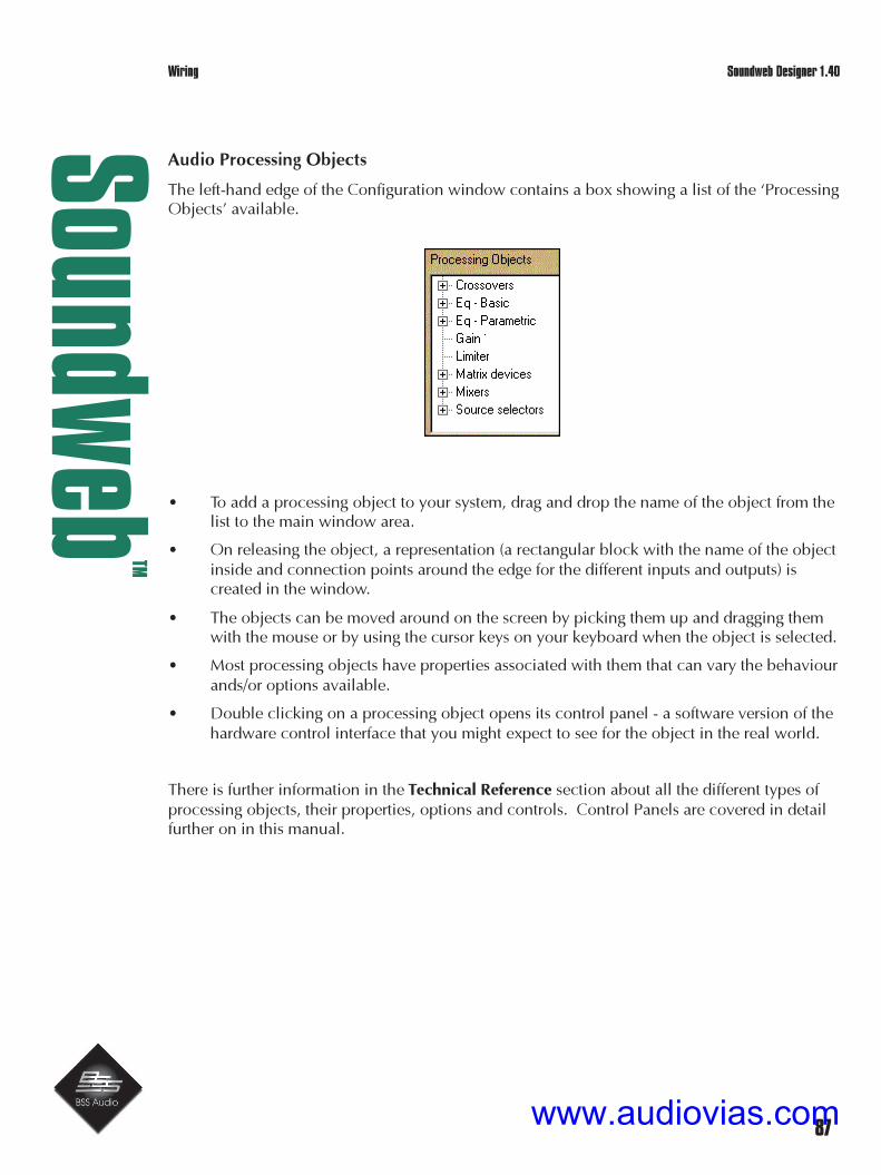
87
Soundw
ebTM
Soundweb Designer 1.40
Audio Processing Objects
The left-hand edge of the Configuration window contains a box showing a list of the ‘ProcessingObjects’ available.
• To add a processing object to your system, drag and drop the name of the object from thelist to the main window area.
• On releasing the object, a representation (a rectangular block with the name of the objectinside and connection points around the edge for the different inputs and outputs) iscreated in the window.
• The objects can be moved around on the screen by picking them up and dragging themwith the mouse or by using the cursor keys on your keyboard when the object is selected.
• Most processing objects have properties associated with them that can vary the behaviourands/or options available.
• Double clicking on a processing object opens its control panel - a software version of thehardware control interface that you might expect to see for the object in the real world.
There is further information in the Technical Reference section about all the different types ofprocessing objects, their properties, options and controls. Control Panels are covered in detailfurther on in this manual.
Wiring
www.audiovias.com

88
Soundw
ebTM
Soundweb Designer 1.40
www.audiovias.com

89
Soundw
ebTM
Soundweb Designer 1.40
5. Virtual Wiring
‘Virtual wires’ are used to connect the objects on the layout and route the signals between theconnection points of processing objects or Input and Output ports.This section explains the use of the mouse when creating wires.
The mouse behaves differently according to whether or not you are in Edit or Add Wires mode.You change modes with the Edit>Edit Wires and Edit>Add Wires menu commands (also in theright-click menu).
Add Wires Edit Wires
Wiring up two connection points
1 Select Add Wires mode.
2 Click the mouse on a connection point (the small square node) on one of the objects; thepointer changes to a ‘+’, and a wire is shown ‘rubber-banded’ from this node to thepresent mouse position.
To change the direction of a wire:
• Move the mouse to the place where you want to end the first segment of the net, andclick there. A new wire is shown ‘rubber-banded’ from this point to the present mouseposition.
Repeat this action to create more segments and finally click the mouse on the second node to
Control Panels
www.audiovias.com

90
Soundw
ebTM
Soundweb Designer 1.40
finish creating the ‘net’.
Note that you can also end the wire by double clicking on open space, this leaves the end ofthe wire floating, for later connection.
Adding a wire to an existing net
1 Select Add Wires mode.
2 Click the mouse somewhere on the net: a junction will be shown there, and wiring pro-ceeds as in the section above.
Wiring can also be completed in reverse, by starting at the new connection point, and endingon the net to which the new wire is to be added. This may in fact prove to be easier as a rule.
Control Panels
www.audiovias.com

91
Soundw
ebTM
Soundweb Designer 1.40
Adding a corner to an existing wire
1 Select Add Wires mode.
2 Move the mouse to the place on the net where you wish to add the corner.
3 Drag that point in the direction in which you want the new wire to go.
A node (junction) will be created, and the single wire will be replaced by two wires, rubber-banded from the present mouse position to the original end-points of the two wires.
4 Release the mouse to freeze the wires in their new position.
Repeat this process to tidy up any unwanted diagonal lines that have been created.
Deleting a net
1 Select Edit Wires mode.
2 Click somewhere along the net to select it.
3 Press the Delete/Backspace key.
To delete more than one net at a time, select the first net and use Shift-click to select furtherwires.
Moving one or more nets
1 Select Edit Wires mode.
2 Click on a net to select it; use shift-click to select more than one.
3 Drag the net and drop it in its new location.
Copying one or more nets
1 Select Edit Wires mode.
2 Click on the net to select it; use shift-click to select more than one.
3 Hold down the Ctrl key, and drag the net and drop it in its new location.
Reshaping nets
1 Select Edit Wires mode.
2 Click on the net to select it.
Control Panels
www.audiovias.com

92
Soundw
ebTM
Soundweb Designer 1.40
You should see that a node appears for each end of the net, and at each junction point orcorner.
3 Drag one of the nodes to create the new shape.
Note that dragging a node onto another node will delete a section of line.
Control Panels
www.audiovias.com

93
Soundw
ebTM
Soundweb Designer 1.40
Net Notes
An incorrect connection (e.g. an input to input or output to output between processing objects)is indicated by the wire turning red.
The processing objects supplied in Soundweb Designer are set up for the default grid, which is10x10 pixels. It is strongly suggested that you leave the grid on this setting, and leave the ‘snapto grid’ option enabled.
By default, you are permitted to create vertical, horizontal and diagonal line segments.However, you can tighten this restriction by selecting Edit>No Diagonal Lines.
If you are in the middle of dragging something and you realise that you are doing the wrongthing, pressing the Esc key will abort the drag operation.
Most of the time you can stay in Edit Wires mode, as this will also allow you to add new wires.On occasions, Soundweb Designer will automatically switch modes for you. This saves youconsiderable frustration and time in flipping modes, at the expense of losing you some control.For example:
• If you are in Edit Wires mode, and you click on an empty connection point of a device,Soundweb Designer will assume that you are trying to wire it up and flip you into AddWires mode temporarily.
• If you are in Add Wires mode and you click inside the body of a device, bitmap, text boxor processing object, Soundweb Designer will assume that you are trying to move theobject and switch you into Edit Wires mode temporarily.
Automated wiring
To save time when wiring many identical connections that are spaced a regular number of gridspaces apart (e.g. wiring net inputs to net outputs or audio inputs to audio outputs).
Control Panels
www.audiovias.com

94
Soundw
ebTM
Soundweb Designer 1.40
• Put in the topmost (or leftmost) wire, then press a number key which is the number oftimes you want this connection duplicated (e.g. 7 if you want 8 connections).
This will not only work for single wires, but also for whole nets.
Control Panels
www.audiovias.com

95
Soundw
ebTM
Soundweb Designer 1.40
6. Control Panels
Adjustments to audio settings are almost invariably made from virtual ‘control panels’ on thePC. External hardware controls can also be used to adjust these panels.
The settings of an audio processing object are initially adjusted using its ‘default’ control panel.
To open the default control panel of an audio processing object:
• Double-click on the object in the Configuration window.
The layout of a default panel cannot be changed but can be copied into a map window in orderto create a new ‘custom’ control panel.
Here is an example of the default control panel for a mixer:
Control Panels
www.audiovias.com

96
Soundw
ebTM
Soundweb Designer 1.40
Device Control Panels
Most Soundweb devices have control panels for adjustment of parameters like input andoutput gain. The control panels are accessible from the right-click menu of the device or bydouble clicking on one of the input/output port nodes in the Configuration window.
They contain settings that are related to the device, and are independent of any of theConfigurations, although settings in these panels can be stored in ‘Presets’ as with othersettings. Controls from these panels can be used in custom control panels.
9088/9088ii Inputs Control Panel
Select ‘Control Panel’ from the right click menu of a 9088 DSP object.
The displayed control panel reflects a 9088 equipped with mic option selected in its deviceproperties and includes options to add phantom powering and change the polarity of anyselected channel. Input gain can be adjusted between 0dB and 72dB in increments of 6dBfor mic inputs and between 0dB and 12dB for line inputs.
Control Panels
www.audiovias.com

97
Soundw
ebTM
Soundweb Designer 1.40
9088ii Digital Inputs Control Panel
Select ‘Control Panel’ from the right click menu of a 9088ii DSP object.
A 9088ii with digital interface card displays information about the digital clock frequency andsynchronisation status.
The Soundweb system must be ‘online’ to accurately communicate the digital settings in thispanel.
If an external clock signal is detected the system will ‘Lock’ to it lighting the green indicator andthe sample rate will change to reflect the detected frequency. The blue led indicates that thereceived clock is phase locked to the internal 48kHz system clock.
The red ‘Marginal Signal’ and the ‘Error’ indicators will light if the clock signal is unreliable ordamaged. In this instance the affected channel will mute audio output to avoid nasty digitalartefacts which could damage external equipment. The error will also light when no clocksignal is present.
Control Panels
www.audiovias.com

98
Soundw
ebTM
Soundweb Designer 1.40
9088ii Digital Outputs Control Panel
Select ‘Control Panel’ from the right click menu of a 9088ii DSP object.
The dialogue shown is to demonstrate a range of possibilities available and is not necessarily apractical set of options.
• The Soundweb system must be ‘online’ to accurately communicate the digital settings in
this panel.
• There are four standard internal fixed sample rates available plus options to lock to re-ceived clock from Inputs 1&2 or from an externally generated word clock signal con-nected to the BNC on the rear panel.
• Synchronisation to external clock source frequencies is possible between 16 and 100kHz.
Control Panels
www.audiovias.com

99
Soundw
ebTM
Soundweb Designer 1.40
If the received signal is outside this range then the red ‘Out Of Range’ indicator will light.
! The digital outs should not be connected to analogue inputs (especially amplification/speakersystems) as the high frequency nature of the digital signal could cause damage to yourequipment.
Control Panels
www.audiovias.com

100
Soundw
ebTM
Soundweb Designer 1.40
9088/9088ii Network Status Control Panel
Select ‘Control Panel’ from the right click menu of a 9088 or 9010 DSP object.
The Network Status tab displays network traffic with two leds to represent signals received onthe input or passing to the net out port.
9000/9000ii Network Status Control Panel
Select ‘Control Panel’ from the right click menu of a 9000 DSP object.
The 9000 series hubs display the existence of network signals through their six ports.
www.audiovias.com

101
Soundw
ebTM
Soundweb Designer 1.40
9088/9088ii Analogue Outputs Control Panel
Select ‘Control Panel’ from the right click menu of a 9088 DSP object.
A 9088 has controls for the analogue output levels. Note that there are now value input boxeson each output for the selection of more exact decibel levels.
On a 9088ii fitted with digital interface cards the analogue outputs will still function (as they arepart of the main board), i.e. these outputs will mirror the digital outputs.
It is also now possible to link the output fader objects together on a custom control panel.
www.audiovias.com

102
Soundw
ebTM
Soundweb Designer 1.40
Control Surface Objects
A control panel could contain any combination of these control surface objects:
� Continuous controls
� Pushbutton
� Combo box
� Meter
� LED
� Parametric EQ
� Crossover
Continuous controls
Control any continuously variable parameter. There are four different types:
• Linear fader
• Rotary knob
• Text box (for typing in a value)
• Spin increment and decrement (text boxes with up/down arrows attached).
Rotary controls can be adjusted either by vertical, horizontal or angular (radial) mousemovement (selected in View>Preferences>Application>Rotary control method).
Pushbutton
Most pushbuttons are toggle buttons, which select between on/off states for a particularparameter (such as a mute switch).Additionally, there are two special types of pushbutton: ‘Preset’ buttons and ‘linking’ buttons.
Combo box
A drop down list box used for selecting one of a number of options. Typical of this would be alist of modes for a particular algorithm, e.g. filter types.Presets can also be selected using the Preset combo.
Meter
Displays the value of a parameter of an audio processing object.When ‘online’ meters cause much data to be passed from the devices to the PC, so the limitedcomms bandwidth can cause updating of the meters to appear slow. Since this bandwidth isshared between all the on-screen meters, the best meter response is realised by closing down(not just minimising) all unnecessary control panels and map windows which have meters onthem.
Presets
www.audiovias.com

103
Soundw
ebTM
Soundweb Designer 1.40
LED
The equivalent of a physical LED - displays the status of a true/false parameter.
Parametric EQ
An intricate graphical control allowing EQ to be set using a curve drawing mechanism.
Crossover
A compound graphical control-allowing crossover points and slopes to be set.
Resetting a control to its defaults
This can be used to set a gain control to 0dB, or a Parametric EQ control to ‘all flat’.
• Hold down the shift key and double-click on the control object.
Presets
www.audiovias.com

104
Soundw
ebTM
Soundweb Designer 1.40
Custom Control Panels
A ‘custom’ control panel is simply a map window containing control surface objects that areallocated and set up for your own use.For example, a simple custom control panel might have the master gain settings for two or threedifferent user determined ‘zones’, and a number of buttons to select Presets.
Creating a custom control panel
Select Map>New Window or press the button on the toolbar.
This opens a blank map page to which you can add control surface objects.
Alternatively, you can start with a ‘default’ panel and customise it.
To do this:
1 Double click on a processing object that contains control surface objects that you require;this opens its ‘default’ control panel.
2 Use Map>Rename to turn the default panel into a custom panel.
A warning message states:“This operation will turn this control panel into a map window”.
3 Press OK.
A dialog box appears to type a name for the new map window.
4 Use Map>Design to switch the panel into Design mode.
You can now modify this panel as desired, by adding, deleting or moving control surfaceobjects, text and graphics. Also cut and paste objects from other control panels to build yourown selection of controls.
To test the controls switch the map layout back into Operate mode by either usingMap>Operate, ALT+O or from the right click menu.
Remember that controls taken from other panels will operate the parameters as if they were stillpart of that panel, i.e. moving a copied gain fader will move both the fader in your new panelas well as that in the old control panel. They are not ‘linked’ just accessing exactly the sameparameter.
www.audiovias.com

105
Soundw
ebTM
Soundweb Designer 1.40
Customising Control Surface Objects
To customise a control surface element.
• Select Properties from its right-click menu, this displays a dialog box with various tabs.
The General tab allows controlover the colour or transparencyof an object and to select a
variety of ‘styles’ for its edge.
Objects using text have a Text tab enabling control of font size, style and justification.
Other objects have an Operation tab, which contains various properties related to thatparticular type of control.
Copying settings between objects
To copy the whole set-up from one object to another similar object (e.g. when a processingobject has a complex set-up).
1 Select Copy settings from the right-click menu of the object that you have set up.
2 Select Paste Settings from the right-click menu of the object that you wish to copy it to.(Note that this is different from Copy and Paste, which would create a new object).
The most common example of this is to set up an EQ on a channel, and then to copy thesettings to another EQ which needs the same set-up.
! If you copy settings between two processing objects whilst ‘online’, Soundweb Designer willgo ‘offline’. This is because some changes in settings lead to changes in the compiled design.
If you only wish to copy control values, use Paste control values only and you can remain
Compiling
www.audiovias.com

106
Soundw
ebTM
Soundweb Designer 1.40
‘online’. This will only work if the processing objects have the same option settings.
Morphing a Control Surface Object
Soundweb allows you to transform the nature of a control surface object. For example, you canchange a fader into a rotary control or edit box, or a switch into a combo box.
Some of the possibilities are subtler: you can change a pushbutton switch into an LED: this willprovide a read-only indicator of the state of the switch.
To do a transformation:
• Select Morph from the right-click menu of the object you want to transform.
It is recommended that you make a copy of it first, since this process will lose any graphicproperties you may have already applied to the object.
To transform a fader to an up/down button pair, it is necessary to copy the fader twice, thenmorph one to an increment control, and the other to a decrement control.
Link button
A link button is a pushbutton that can be pressed to change to a different map window, use thisto give the user a fast way of navigating between control panels. It can also be used to eitherlog out then log in again or, to exit Soundweb Designer.
To use a link button:
1 Select Add>Link button, also available in the right click menu and from the button
on the map toolbar.
2 Click on the map window where you want the button to be placed.
3 Right-click on the button and select Properties.
4 Click on the Target Window tab.
5 Select the name of the desired map window or operation from the combo box.
In Operate mode, pressing the button will now open the chosen map window, log out or exitDesigner as specified in the object properties.
www.audiovias.com

107
Soundw
ebTM
Soundweb Designer 1.40
Linking Control Surface Objects
Sometimes, it is desirable to link two control surface objects together. A typical example wouldbe the linking of two faders in order to produce a stereo gain control.
This is only possible for control surface objects in ‘custom’ control panels.
• Select the two desired objects (click on the first, and then Shift-click on the second).
• Right-click on one of the objects and select Link.
Note that the controls can be selected from different devices if you wish.
A dialog box asks what ‘law’ to use for linking the controls:
� Matched group - operating one switch operates them all.
� Radio group - switching on one switch clears the others in the group.
� Radio group (all off allowed) - all switches can be in the ‘off’ state.
• Choose the appropriate law, and press OK.
For faders there are different laws:
Soft Link - allows the linked faders to have offset values, i.e. they will follow the operation ofthe moved fader but not match its exact value.
Exact Copy - the faders will follow the fader being adjusted exactly.
Whilst in Design mode, a chain link icon will appear next to each linked control so you can seeinstantly which controls are linked.
A new button will appear on the control panel.This button is used in Operate mode to make or break the link.If this facility is unnecessary, you can move the button to an unused map window.
! Note that if you delete a linking button, the link itself will also be deleted.
Working Online
www.audiovias.com

108
Soundw
ebTM
Soundweb Designer 1.40
7. Parameter Presets
A Parameter Preset adjusts control settings only.The audio is not muted during a Parameter Preset change so it is therefore preferable to a fullPreset for changing parameter values whilst ‘online’.
If the system is ‘online’ when you operate a control surface object, you are actually changingthe value in real hardware.If the system is ‘offline’, you are changing a representation in the PC’s memory of what thesetting will be in the real hardware when the PC is hooked up to it.
Parameter Presets also have the advantage of taking up much less memory in the hardware (somany more of them can be stored).
Creating a Parameter Preset
1 Drag all the controls (in Design mode) that you want the Parameter Preset to adjust onto anew map window.
2 Next select Add>Parameter Preset, also in the right-click menu, or click the button in
the object toolbar.
3 Click on the map window where you want the Parameter Preset selector to be placed.
4 Now select Add State in the right-click menu of the Parameter Preset selector.
This opens a dialog box to enter the name for this Parameter Preset state.
5 Type in the name (for this state of control settings) then click OK.
The controls may then be adjusted (in Operate mode)
Another state can be added, having changed some control values, to the Parameter Presetselector by going back to Design mode and going back to Add State as before.
When all the required states have been added to the Parameter Preset selector, return to Oper-ate mode. The button on the right-hand end of the Parameter Preset selector will then allowyou to change to any of your predetermined sets of control settings.
To change the control settings associated with a Parameter Preset state:
1 Select the state and adjust the controls as required.
Working Online
www.audiovias.com

109
Soundw
ebTM
Soundweb Designer 1.40
2 Select Store State in the right-click menu of the Parameter Preset selector.
! Parameter-Presets were known as ‘Mini-Presets’ in older versions of Soundweb Designer.
Working Online
www.audiovias.com

110
Soundw
ebTM
Soundweb Designer 1.40
8. Presets
A ‘Preset’ is a collection of settings information, or ‘snapshot’ of the whole system.Each device can store a number of Presets - subject to there being enough memory in thedevices to store them.
A Preset contains:
• The Configuration to be selected for each device.
• A list of the parameter settings for all of the audio processing objects.
• A screen layout of the map windows to be displayed when the Preset is activated.
• Information about the utilisation of any hardware control surface objects when the Presetis activated.
Working with Presets
1 Select View>Go to Preset View (or use shortcut icon at the bottom of the screen).
This opens a window showing a list of the Presets defined in the design:
2 Press New to create a Preset.
3 Give the Preset a name and press OK.
This will allocate the current data (Configurations and control settings) to this Preset.
To update the information in a currently existing Preset, highlight its name in the list and pressStore. This transfers the ‘current’ information into the selected Preset.
To recall the information in an existing Preset, highlight its name in the list and press Recall.
Working Online
www.audiovias.com

111
Soundw
ebTM
Soundweb Designer 1.40
Auto - Online
Enables a specified design file to be loaded to a network of devices when Designer is launched.The chosen file will be opened, the PC will go ‘online’ to the devices, and the design file willbe loaded.
Auto online is activated from View>Preferences>Application>On Startup
Control parameters can be synchronised either to reflect the settings stored in the devices on thenetwork or, to update the network with the parameter values stored in the design file. Thedesign file can be forced to open in full screen mode and the keyboard shortcuts for full screenoptions can be disabled.
Working Online
www.audiovias.com

112
Soundw
ebTM
Soundweb Designer 1.40
The auto login feature allows a chosen user (with associated security clearance) to beautomatically logged in, with password also. This allows the designer to set up a system with aPC connected, which on running the design file boots straight in to a preconfigured controlpanel. Operators can then be barred from design access or other sensitive areas of the systembut they themselves never have to log in with a password. Equally this feature can speed upaccess to the design/network for the designer too, which could be especially useful whensetting up larger systems.
If there are problems during the auto-online process, such as devices not present, mis-named,or not responding, incorrect comms settings etc., the auto-online process will stop but the filewill be opened. If the ‘Ignore missing devices’ option is selected, then only those devices thatcan be found on the network will be loaded and the auto online process will continue.
The ‘Command to execute on failure’ option allows Designer to browse for a file such as anexecutable (.exe), text file or script that will be run in this instance. This could, for example, beused to run a script that would send an email to a system administrator to inform of the failure.
The ‘Remove cancel option’ omits the ‘cancel’ button that is normally displayed when goingonline, thus preventing an unauthorised user from breaking into the design file by cancellingthe process before it has finished.
Dynamic Metering
It is now possible to visually monitor the existence of a signal through the dsp layout on the PCscreen using a flying meter probe.
This is enabled in a device’s configuration window by ticking the ‘Dynamic Metering’ boxlocated under the ‘Configuration:’ popup box in the top left of the window.
Once activated, pointing the mouse at a connected wire will register an led bargraph styledisplay of signal level present through that connection.
This facility only works when the PC is online to the network of devices and will take thesystem offline if it is deselected. As with all metering objects there will be a slight DSPoverhead which should be taken into account if this feature is to be used in a configuration thatuses nearly all of a device’s resources.
Working Online
www.audiovias.com

113
Soundw
ebTM
Soundweb Designer 1.40
This activates the Preset, making it the current set of data.
The two security level combo boxes allow you to restrict a user to being able to use or editcertain Presets. See ‘Security’ for more details.
Working Online
www.audiovias.com

114
Soundw
ebTM
Soundweb Designer 1.40
Excluding Devices from a Preset
• Press the Devices... button to open a dialog which will allow you to ‘un-check’ thedevices you wish to exclude from the Preset.
Two particular control surface objects are not found in any of the standard control panels, butcan be useful; these are Preset buttons and combo boxes. These are especially useful insystems where a PC is left permanently connected to the system for control purposes.
Preset Button
A Preset Button is a pushbutton that activates a Preset when pressed. Use this for a fast methodto select a particular Preset.
To create a Preset Button:
1 Select Add>Preset Button, also in the right-click menu or press the button in the
toolbar.
2 Click on the place in the map window where you want the button to be placed.
3 Right-click on the button and select Properties.
4 Click on the Preset tab, and then select the desired Preset from the combo box.
To associate the current layout of map windows with a Preset Button, right-click on the buttonand select Capture.
In Operate mode, pressing the button will activate the appropriate Preset.
Working Online
www.audiovias.com

115
Soundw
ebTM
Soundweb Designer 1.40
Preset Combo Box
A Preset Combo Box activates a Preset when it is selected from a list in the combo.Use this for a fast method to select from a list of Presets. A combo may be used to allow aselection of Presets to be triggered from a control port.
To create a Preset Combo:
1 From a map window, select Add>New Preset Combo, also in the right-click menu.
2 Click on the map window where you want the combo to be placed.
3 Right-click on the combo and select Properties.
4 Click on the Preset tab.
5 Select Add and choose the desired Presets from the list by highlighting and pressing OK.
You can change the order in which the Presets are listed either by highlighting the Preset nameand pressing Up or Down. A Preset may be removed from the list by pressing Delete.
In Operate mode, selecting a Preset using the combo box will activate the appropriate Preset.
Working Online
www.audiovias.com

116
Soundw
ebTM
Soundweb Designer 1.40
9. Compiling the Design
When your design is ready, press the Compile button in the Configuration window.
Soundweb Designer then computes the instructions that would be sent to the device to createthe audio processing system you have just designed.
If all is well, you should see a message similar to this:
Now would be a good time to save your design!
Resources
The complexity of the design that you can create is limited by the DSP resources ineachhardware device. For example, the amount of memory, or the number of DSP processorsand the power of each.
At the bottom left-hand side of the Configuration window is a ‘resource’ gauge, see above,which gives you a percentage reading of the resources which have been used up by your designso far.
This gauge updates automatically when you change the design, but may take several seconds toupdate after every change you make.
If the gauge shows less than 100%, the design is certain to fit once compiled. Its reading is onlyapproximate and sometimes pessimistic. A reading of, say, 90% may not mean that you canonly get 10% more into the design; it is possible that you may to do better than this.
9000ii/9088ii note:When you convert a 9000 or 9088 in your design to version ii, the resource gauge will refreshand display a lower value. This is because the new models have approximately 25% more dsp
www.audiovias.com

117
Soundw
ebTM
Soundweb Designer 1.40
power than the old versions. Not all designs will show a 25% improvement though.
Compiler problems
If you have run out of resources or if the compiler detects a problem with the design, you willsee a dialogue or one of a number of possible error messages.
For an explanation of error messages and warnings, see Compiler Error Messages.
Kit List
www.audiovias.com

118
Soundw
ebTM
Soundweb Designer 1.40
If a processing object is named in an error:
1 Locate the processing object by using the Locate command (right-click menu) in theappropriate Configuration view.
2 Type in the name (excluding the device name – e.g. P3 not U1\P3) and the object inquestion should be highlighted.
The design may need to be modified, usually by removing one or moreof the processing objects. If all of these are critical, it may be necessaryto add another device to your system and move some of the processingto the new device.
3 Press OK to disregard the error and continue with compilation, orpress Cancel to abort the compile.
Compensation Delays
Designs which show more than 100% on the gauge could still compile successfully if, whencompiling you decide to omit ‘compensation delays’.
These are normally included to equalise the processing delays (which may be up to 100microseconds) so that all signals have the proper phase relationship. These are incurred assignals pass through the various paths and between the outputs of the hardware device. Youmay decide that this is not critical in your design.
www.audiovias.com

119
Soundw
ebTM
Soundweb Designer 1.40
‘Log in as a different user’
In a security enabled design file it is now possible to log out, then relogin as a different user,without having to close and re-open the design file, as was previously required. In this way, adesigner can now quickly switch between different operator set-ups, whilst being able to easilyreturn to the main design enabled version of the file to make additions and changes. At leasttwo users need to have been configured in the ‘Security’ section of the ‘System Design File’preferences in order to take advantage of this system.
To change user:
• Select ‘Log in under different name’ from the File menu (or use the CTRL+L keyboardshortcut).
Designer will probably ask whether you want to save the file, and state that any changes madeup to this point will still be retained, even after logging in as a different user. This save optioncan be disabled (to prevent users changing the design file inadvertently) in the ‘General’ tab ofthe ‘Application’ preferences.
To login again:
• Select the user name from the popup box.
• Type in the correct password.
Clicking cancel on the log-in dialogue will close the file.
The design will now reopen based on the accesses permitted for the new user that has justlogged in. A different map window, as specified in the new user’s security set-up, may bedisplayed instead of the one that was being displayed before logging out. Note: If no defaultmap window is specified, ‘map window 1’ will be displayed. Also access to other mapwindows and control panels may be disallowed and, design mode may not be available untillogging back in at a higher security level, i.e. Admin.
It is possible to specify a particular map window that will be the only one that a user can see byusing full screen mode and the auto online facility. Also, access to all shortcut keys and menus(apart from CTRL+L) can be restricted. In this way, an administrator can log in to edit the file,change privileges etc. by using the CTRL+L shortcut.
Security
www.audiovias.com

120
Soundw
ebTM
Soundweb Designer 1.40
10. Working ‘online’
Most of your time with Soundweb Designer will probably be spent ‘offline’ - on a standalonePC that is not connected to any actual Soundweb hardware.
When the design is finished connect the PC to the network of Soundweb devices in order toload the system and to use the control panels for ‘live’ adjustments. The system design iscompiled into a code version to be loaded into the Soundweb hardware devices. If you haven’talready done this then please refer to the section ‘Compiling the Design’
Loading a system overview
1 Connect the Soundweb devices with the appropriate network cabling and plug in yoursource and destination audio equipment.
2 Plug a PC into the front panel RS-232 port of any one of the devices on the network.
3 Check that the list of devices on the network agrees with the list in your design file, andresolve any differences.
4 Load the design into the devices.
5 Make any final adjustments to the parameter settings, and save them in an updated sys-tem design file.
• When you are ‘online’ to the network adjustments performed in Control Panels are trans-mitted immediately to the devices.
• When the PC is disconnected from the network, the adjustments are stored in the systemdesign file, and will be transmitted to the devices when you next go ‘online’.
Connecting the PC
First, you must ensure that the Soundweb devices have been installed in their equipment racks,and that the connections between them have been made in agreement with your system design.
Now plug your PC into the front panel RS-232 port of any of the devices on the network, itdoesn’t matter which one as long as the devices are connected together your PC will be able tocommunicate with all devices on the network.
Macros
www.audiovias.com

121
Soundw
ebTM
Soundweb Designer 1.40
Comms settings
Ensure that SoundwebDesigner is configured forthe correct serial port onyour PC.The serial port and speed canbe selected in the SoundwebPreferences dialog(View>Preferences>Application>Comms).
‘Bit Rate’Selects the serial bit rate.This should be 38400 if the PC is connected to the front port or 115200 if connected to the rear.Note that AMX panels connect to the rear port at 38400.
‘Comm Port’Selects the serial port to which your Soundweb network is connected.For PC’s with old-style serial mice and only two serial ports, this will usually be COM2.For PC’s with PS/2 mice (round connectors) and one serial port this will be COM1.
‘Address’Specifies a unique PC id.If more than one PC is connected to the network then they should all have unique addresses.
Macros
www.audiovias.com

122
Soundw
ebTM
Soundweb Designer 1.40
The ‘Modem’ area of this dialog enables the Designer software to remotely access and control aSoundweb network by ‘dialling in’ using a conventional modem. See Working Online (section10) for more details.
Using the rear RS232 Port
To use the rear port for going online from the PC you should:
1 Use a normal NULL modem cable (5 wire) to connect the PC to the rear port of thedevice.
2 Set the bit rate speed of the PC to 115200 in the Comms preferences.
3 Ensure that the device is not using the rear port for AMX communications.
The 9088 and 9000 devices’ rear RS232 port runs at 115200 baud instead of the 38400 baudused by the front port. This higher baud rate means that data can be sent and received muchfaster than the front port which results in quicker network operation i.e. going ‘online’, loading,control, firmware updating etc.
For large networks (20 devices or more), it is recommended that the rear port is used instead ofthe front port as it will provide more reliable operation.
The Network window and going ‘online’
• Select View>Go To Network View, or press the shortcut icon at the bottom of the
screen.
With your PC connected and the Soundweb devices all switched on.
• Press Go Online.
www.audiovias.com

123
Soundw
ebTM
Soundweb Designer 1.40
Soundweb Designer will now scan the network to find what devices are connected up, andchecks the information that is loaded into them against what is in your design.
This process can take some time...
While it is in progress, there is a dialog box open allowing you to cancel the operation.
If your system design file contains devices whose Configurations have not been compiled, youwill get a dialog box asking you to compile them now.
Note the compiler may need to make adjustments for differences in the hardware.This can cause a recompile when you go ‘online’ to a device.
The PC will examine the set-up in each device to see if anything has changed from last timethat it was ‘online’.
• If nothing has changed in the devices, the PC will go ‘online’ to them immediately.
• If the Configuration has changed, the device will need loading.
• If the Configuration has not changed but the parameter values are different (if for examplea control was adjusted on the PC when ‘offline’), a Parameter Synchronisation dialog boxwill offer a choice between sending the PC control settings to the device, or the devicesettings to the PC.
The devices are displayed in four lists:
1 Everything OK: The name, type and options in the system design file agree with thedevice on the network, and the Configuration and parameter values are correct.
2 Needs Loading: The name, type and options agree, but the Configuration is different.
3 Not Found in Network: Devices in the system design file are not existent on the network,either physically or by name or, have the wrong options fitted (e.g. wrong type ofanalogue input card).
Event Log
www.audiovias.com

124
Soundw
ebTM
Soundweb Designer 1.40
4 Not Found in Design: Devices that are on the network, but not in the system design file.
If the system has been installed according to your design, you would expect the latter three liststo be empty. If not, you will need to act:
For entries in the ‘Needs Loading’ list. You will probably need to reload the device from yoursystem design file using Load.
WARNING - loading a device will overwrite its entire set of information about Configurations,audio settings, control ports, etc. There is no Undo!
Before loading a device, you need to be very sure that either:
a You do not require the Configuration settings currently in it or,
b You have the system design file which was used to load it originally.
For entries in the ‘Not found in Network’ list, you will need to do one of four things:
1 Install and/or connect and/or switch on a missing device.
2 Delete a device from your design file
3 Change the options for the device in the design file to match the actual device, or fit thecorrect option in the device. (Double-clicking the device name in this column will openthe properties dialog for the device)
4 Rename a device, either on the network, or in the system design file, so that the twodevices match. This is done by selecting the list item and hitting the Rename button.
For entries in the ‘Not Found in Design’ list, you may wish to add the extra device to yourdesign file, or you may simply ignore it completely.
If you have a large system and you are not sure which device is not in the design, click on itsname in the fourth column. This will cause it to flash its front panel indicator LED’s on and off afew times.
Once you are satisfied that the devices on the network are in order, download your design intothe network by pressing Load All devices.
Alternatively, you can load the part of your design that relates to a single device by selecting itin the list of devices on the network and in your design, and pressing Load.
Going ‘off-line’
If you are working ‘online’, any parameter changes you make will normally be transmittedimmediately to the network as well as being updated in your design. To make changes withoutaffecting the audio, the PC must be taken ‘off-line’ - either by pressing Go off-line or by simplyunplugging the serial cable.
Event Log
www.audiovias.com

125
Soundw
ebTM
Soundweb Designer 1.40
Using more than one PC on the network at once
It is possible for a Soundweb network to have more than one PC connected simultaneously.This is very useful if control is required in more than one location at once.
All the PCs on the network must have a unique address. This address is simply a numberbetween 0 and 255 and is set in the View>Preferences>Application>Comms dialog.
For example, in a network with two PCs online, you could set the address of the first PC to 0and the second PC to 1.
You must ensure that no two PCs have the same address, and that they are all using the sameSoundweb Designer file.
Once online, the PCs will operate as normal, but will report a change to the network when oneof the other PCs is taken offline.
Remote access using a modem
It is possible to access a Soundweb system/network of devices using a standard Hayescompatible modem (e.g. US Robotics).
The desktop computer or laptop used to remotely control the system must have a copy of thecorrect System Design File and a working modem connection. If it is possible to get on theinternet with the PC then it should work for Soundweb.
The connection sequence is as follows:
1 Load the relevant SDF onto the local computer, and load it into the device/network in thenormal on-line way.
2 Plug a modem into the rear serial port of one of the Soundweb devices in the network.
3 Connect its phone wire to a working telephone point. This can be tested by plugging astandard telephone into the point and checking to see if a dial tone exists.
4 Make sure that the modem is powered up.
5 Reboot the Soundweb device that has been connected to the modem by switching thepower off and then on – this allows the device to sense the modem. Activity lights shouldflash on the modem indicating that the device has made a connection.
At this point it may be useful to check the installation by reloading the SDF into the device/network, although this should not be necessary.
You can now remove the computer from the network, or leave it connected locally.
To remote control the network:
On the PC intended for remote control, first ensure the copy of the SDF is loaded, then go to the
Event Log
www.audiovias.com

126
Soundw
ebTM
Soundweb Designer 1.40
Comms preferences in Soundweb Designer (View>Preferences>Application>Comms) andselect the following options:
1 Tick the ‘I am using a modem’ box.
2 Select the correct ‘Comm Port’ that the PC is using for the modem connection.
3 The ‘Address’ should be fine as ‘0’ unless there are other PCs connected to the networkyou are trying to access. In which case assign a unique number to this connection.
4 The ‘Bit Rate’ should be set at ‘115200’ but in cases of bad connections or continuouslydropped lines experiment with reducing this figure.
5 Only ‘Use pulse dialing’ if you are connected to an old-fashioned telephone exchangestill using this protocol.
6 ‘For external number dial:-‘. If there is a number required to access an outside line, e.g.‘9’, input it here.
7 Type in the phone number, including std area code, of the modem connected to theSoundweb system.
8 Open the Network window and press ‘Go Online’.
The computer should now dial up a connection to the remote modem and once thehandshaking process has finished access to the Soundweb system should be available as if thePC was connected directly to the serial port.
Network messages similar to going on-line locally may be received, such as ‘Different DeviceData, synchronise?’ which means that Soundweb Designer has found different settings existenton the network of devices it is accessing. Press OK to update the SDF to reflect the actualsettings of the device.
Event Log
www.audiovias.com

127
Soundw
ebTM
Soundweb Designer 1.40
Online Notes
Configuration windows are read only when the system is online. A safety feature to preventaccidental offlining whilst observing a configuration layout. Existing objects cannot be changedalthough it is possible to add new objects and this action will still force the system offline.
If the PC is to be left ‘online’ for extended periods of time, you need to be careful about ‘sleep’or ‘low power’ modes, especially on laptop computers. Ensure that the comms port is notdisabled when the PC automatically enters a low power mode.
Note that the device has software resident in a flash EPROM. This software is distinct from theSoundweb Designer software, and either may undergo revisions that can lead to compatibilityconflicts. When going ‘online’, the system checks for compatibility and may advise the user totake steps to update the software in a device. Instructions for this process are available in the‘Firmware Updates’ section.
If Soundweb Designer fails to find thedevices on the network…
Try the following:
• Check that the Comms set-up is correct. (Remember, the front port of the devices runs at38400 baud, and the rear port runs at 115200 baud.)
• Make sure that the PC has a different address to the other PC’s on the network.
Event Log
www.audiovias.com

128
Soundw
ebTM
Soundweb Designer 1.40
11. Kit List
Soundweb Designer can print out a ‘Kit List’ to add to a tender document, or as a systemoverview document to be given to the contractor who will install the system.
The Kit List displays information about the system hardware, i.e. Soundweb devices in thesystem (including their names), the options that should be installed in them and the networkconnections that should be made between them.
Comments pertinent to the installation of a particular device can be added. For example, toinform the installer to beware of overheating device U4 (if placing it directly over an amplifierin the rack), and a reminder to install the 9010 remote in a 3-gang wall socket near the lobby ofthe building.
To add a comment to a device:
1 Select Properties from its right-click menu.
2 Click on the Device tab.
3 Type comments into the box provided. To put in a line break use CTRL+Enter.
To preview the Kit List.
4 Select View>Go To Kit List, or press the shortcut icon at the bottom of the screen.
The Kit List for this example would look like this:
www.audiovias.com

129
Soundw
ebTM
Soundweb Designer 1.40
For each device in the system that has options, the Kit List will indicate which options shouldbe fitted.
Remember to set up the device options for the type of input cards to be used in the 9088s.In this example, U1 has mic level cards in both positions, and the other 9088s use line levelcards.
It is useful to rename some of the units from the default U1, U2 etc. generated by SoundwebDesigner. Good practice is to use names to describe the function of the devices in the system,or their positions in the equipment racks.
To change the name of a device:
1 Select Properties from its right-click menu.
2 Change the name field in the Device tab.
Rather than printing the Kit List, you can copy the text intoyour favourite word processor.
3 With the Kit List view open select Edit>Copy to copythe text onto the Windows Clipboard.
Now it can be pasted into your application. Note that thetext will be pasted as plain text; you will need to add yourown formatting.
External Control Options
www.audiovias.com

130
Soundw
ebTM
Soundweb Designer 1.40
12. Security
Securing the system from unauthorised access
Security is handled by a system of ‘users’ and ‘levels’.
All security settings are stored in the system design file - they relate to a particular systemdesign, not to the installation of the software on your PC.
The principle is this:Define users by giving them a
√ Name
√ Password
√ Security level (defined as a number between one and ten).
You can protect various aspects of your system by defining the minimum security level requiredto operate them.
The system starts with one user called ‘Admin’, whose initial password is also ‘Admin’ andwhose security level is ‘1’. Level ‘1’ is the highest level and gives you access to everything.
Items that can be secured include Presets, map windows, and Configuration settings.
The most useful of these is map window security.
A user, below a particular security level, can be forbidden from opening a map window at all.In addition the user may be allowed to open it; open it and copy controls from it; to changesettings; or to change the design of the window.
Security settings are accessed through View>Preferences>System design file>Security orView>Preferences>Map and there are further security settings available in the Preset View.
! Keep track of your passwords and/or keep an unsecured backup copy of your system designfile should you need to return to a site that has security set up but access is not forthcoming...
For a more in depth overview of security issues please refer to the ‘How to set up a securesystem’ tutorial.
www.audiovias.com

131
Soundw
ebTM
Soundweb Designer 1.40
13. Auto Online/Full Screen
Auto-Online
Enables a specified design file to be loaded to a network when Designer is launched. Thechosen file will be opened, the PC will go “online” to the devices, and the design file willbe loaded.
Auto online is activated from View>Preferences>Application>On Startup
Control Parameters can be synchronised either to reflect the settings stored in the deviceson the network or, to update the network with the parameters values stored in the designfile. The design file can be forced to open in full screen mode and the keyboard shortcutsfor full screen options can be disabled.
The auto login feature allows a chosen user (with associated security clearance) to beautomatically logged in, with password also. This allows the designer to set up a systemwith a PC connected, which on running the design file boots straight in to a preconfiguredcontrol panel. Operators can then be barred from design access or other sensitive areas ofthe system but they themselves never have to log in with a password. Equally, this featurecan speed up access to the design/network for the designer too, which could be especiallyuseful when setting up larger systems.
If there are problems during the auto-online process, such as devices not present, mis-named, or not responding, incorrect comms settings etc., the auto-online process will stopbut the file will be opened. If the “Ignore missing devices” option is selected, then onlythose devices that can be found on the network will be loaded and the auto online processwill continue.
The “Command to execute on failure” option allows Designer to browse for a file such asan executable (*.exe), text file or script that will be run in this instance. This, for example,could be used to run a script that would send an e-mail to a system administrator to informof failure.
The “Remove cancel” option omits the “cancel” button that is normally displayed whengoing online, thus preventing the user from breaking into the design file by cancelling theprocess before it have finished.
Full Screen Mode
Selecting “Full Screen Mode” enlarges the currently active map window to fill the screencompletely. This allows the design of larger control panels, and the menus and tool bars canbe hidden from view (and therefore tampering made impossible). Using this feature, a pccontrolled system can be made more aesthetically intrinsic to the task that it is set up for.
This option can be accessed at any time using the following keyboard shortcut“Ctrl+Alt+F”. Alternatively this can be setup as part of an Auto online system inView>Preferences>Application>On Startup.
www.audiovias.com

132
Soundw
ebTM
Soundweb Designer 1.40
14. Macros
A Macro is a template for a collection of audio processing objects and their interconnections,together with a suitable control panel for operating the collection. Use a Macro to define afrequently used set of DSP functions; the Macro then appears in the list of available processingobjects.
If you are a consultant, you can use Macros to hide details of your design from the end-user, inorder to disallow access and/or to protect your intellectual property.
To select the page for configuring Macros.
• Use View>Go to Macro Creation view, or press the shortcut icon at the bottom of thescreen.
The right hand half of the Macro creation view is a map window that will define the controlpanel for the Macro.
Configuring a Macro is just like designing a Configuration, except that you have to add yourown input and output flags.
Note that whilst all Macros created in the current design will be saved in the same Macro file,all Macro files present in the macro subdirectory (set in View>Preferences>Application>Directories) will be made available to all subsequent designs. It is our advice not to use thesame design file used for creating Macros for a serious design project as there are issuesregarding linked objects within the same file. It is far better to use a separate file to create theMacros and then backup this file in case the Macro needs to be edited later.
You may wish to create a different Macro file for each project, or use one central Macro filecommon to all projects.
Note that the design details of the Macro are only available to the design file in which it wasoriginally created. Therefore, if you need to subsequently edit the Macro, this can only be donein the original project.
www.audiovias.com

133
Soundw
ebTM
Soundweb Designer 1.40
Create a Macro
The procedure for creating a new Macro is as follows:
• NameClick New, then in the dialog box, type in the name for your new processing object, andclick OK.
• Insert into groupSelect from the list of processing object categories to determine where the new Macro isplaced. Alternatively, you can leave ‘<NONE>’ selected to make the Macro appear in thetop-level of the list, or you can enter your own name to create a new group category.
• Inputs and OutputsAdd inputs and outputs for the object by pressing the In or Out button as appropriate,Type a name for the port (e.g. ‘Sidechain In’ or ‘Audio Out’ etc.) in the dialog box.Click on the Macro configuration window (the left-hand window) to place the tag.Note that inputs and outputs will appear on the final object processing box in the sameorder that they are defined in the Macro.
Ticking the ‘Create Multiple Ports’ option and selecting the number of ports required inthe Input or Output configuration dialogues can now create multiple ports. The ports alltake on the name typed in here and are differentiated by numbers added to the name.
• Processing ObjectsNow add your processing objects and wire them together, just as you would in a normalConfiguration. Wire the input tag to the input of your processing block and the output ofthe block to the output tag.
• Control PanelOpen the control panels for your processing objects and adjust the default settings of thecontrols that you do not wish the user to have access. Now decide what controls youwish the user to have. Drag these controls (in Design mode) to the right-hand part of theMacro window, arranging them, and adding text etc. exactly as you want the user to seethe control panel.
Note that controls whose action is determined by selection in a complex graphicalcontrol (such as the frequency control in a Parametric Equaliser) may not be used withoutthe associated control panel itself.
The background colour for the panel is selected using Map>Preferences in the usual way.
• PropertiesSet up the option properties for the Macro by clicking the Properties button.
External Control Options
www.audiovias.com

134
Soundw
ebTM
Soundweb Designer 1.40
Select each processing object in turn by clicking on its name in the ‘Processing Object’ column.
Set the default value you would like the property to have by selecting it in the ‘Default Value’combo box.
If you want this property to be available to the user to adjust: Click in the ‘Make externallyavailable’ checkbox.
Enter the name you want to assign to this property in the ‘Exported Name’ textbox.
Click OK when you have completed this for all processing objects.
• CompileNow click the Compile button to compile all the Macros you have created into a file which willsubsequently be made available not only to the current design, but all other designs.The name of the file may be changed from the default name if you wish.
The newly created Macro will not be available until you next restart Soundweb Designer, whenit will appear in the normal list of Processing Objects.
External Control Options
www.audiovias.com

135
Soundw
ebTM
Soundweb Designer 1.40
15. Event Log
Event logging provides a means of monitoring the operation of a Soundweb network to solveproblems, find ways of making the system more efficient or just to give a picture of how thenetwork is being used.
Each device stores events as they happen and, when ‘online’ to Soundweb Designer, ‘logs’ ofthese events are collected and entered into a database. These can then be viewed with theEvent Log client from either within Designer, or as a separate program.
Event logging is enabled from View>Preferences>Application>Logging.
This dialog is used to configure general options for Event Logging.
‘Log collection frequency ‘Determines how often Designer requests logs from devices. Lower settings (i.e. toward Hardlyever) will lead to larger logs (and in extreme cases may lead to some lost events) so thefrequency should be kept high unless the resultant performance reduction is a problem.
www.audiovias.com

136
Soundw
ebTM
Soundweb Designer 1.40
‘Logging enabled’Enables or disables the collection of logs. Disabling logging stops the collection of logs from thecurrent instance of Soundweb. This should be used when more than one PC is online to anetwork to prevent logs being divided between them.Note: Disabling logging will not stop devices from logging data, only the PC from collecting thedata.
9010 Remote Control
www.audiovias.com

137
Soundw
ebTM
Soundweb Designer 1.40
Filtering Events
Soundweb units have a finite space for storing events - when a device runs out of space, earlierevents will be removed from the log and lost.
Filters can be defined to allow storage of only those events that are of interest and thus reducethe likelihood of events being lost.
Filtering events allows you to specify events which will be logged either on a per-device orsystem wide basis.
To specify for a single device, select Properties from a device’s right-click menu and go to theEventlog Filters tab.
Events are organised into classes of related events so, by selecting a class in the left-hand listyou will see the events in that class detailed in the right hand list.
• A checked box means that the specified event will be logged.• By default, no events are logged.
Groups of events in the right hand box can be enabled or disabled by using the Shift and Ctrlkeys for multiple selections.
To filter events for all devices simultaneously.
• Go to View>Preferences>System Design File and select the Eventlog Filters tab.
The interface is almost identical to the one above, except that where devices have differentsettings for an event the cross in the check box will be greyed. (If left greyed then the settings forthat event will remain the same when OK is clicked).
9010 Remote Control
www.audiovias.com

138
Soundw
ebTM
Soundweb Designer 1.40
Event Log window
Used to both display and manipulate the events within the event log database.
• To display this window either select the View>Go to Event Log menu item, or press the
Event Log shortcut button at the bottom of the screen.
The main section of this window is the event list, which displays various information abouteach event.
There are 5 columns within which event information is organised:
• Type – states the general nature of the event (e.g. Fault, Warning, Info etc.).
• Event – every possible event that can be generated by Soundweb devices has a uniquename.
• Info – extra information about the event.
• Device – the name of the device that reported the event.
• Time – the recorded time at which the event took place.
Initially, events are ordered by time – with the most recent event at the top of the list. Clickingon a column heading will order the events in the event list according to the information withinthat column. Clicking twice on a column will reverse the order.
When Soundweb Designer receives new events, the Update toolbar button is highlighted.
The newly received events can then be added to the event list by clicking on it. (Also from theView>Update List menu item.)
Events that have just been updated will appear in bold, while events that were present beforethe update will appear as normal text.
9010 Remote Control
www.audiovias.com

139
Soundw
ebTM
Soundweb Designer 1.409010 Remote Control
www.audiovias.com

140
Soundw
ebTM
Soundweb Designer 1.40
Selecting Events
Events within the list can be selected by clicking on them. Multiple selections can also bemade in conjunction with the Shift and Ctrl keys. To select all the events currently displayed inthe list:
• Use the Edit>Select All menu command or click the Select All toolbar button.
Event details
To display extended details about an event - including a brief explanation of the event’smeaning and a help section describing any actions the user can or should take upon seeing thisparticular type of event.
• Double–click on an event, use the View>View Details… menu item or Details
toolbar icon.
A Notes edit box has been provided at the bottom of the dialog. Text can be typed here by theuser as comments that will then be added to the Event Log database.
Deleting Events
Selected events can be deleted from the event list using the Delete toolbar button, or
Edit>Delete menu item. However, deleted items are not removed from the database, and canactually be displayed in the list by selecting View>View All Events – with deleted itemsdisplayed in grey text. Selecting the View>View Undeleted events only menu item will stopdeleted events being displayed.
It is possible to permanently remove all deleted events within the event log database. This isachieved with Edit>Clear Out Deleted Events.
! It is advisable to only do this when the amount of event log information in the databasebecomes unmanageable. Otherwise, potentially helpful event information could be lost ifdeleted events are cleared too often.
9010 Remote Control
www.audiovias.com

141
Soundw
ebTM
Soundweb Designer 1.40
Display Filters
Next to the toolbar are three combo boxes.
These are the display filters and are used to limit which events are displayed within the eventlist.
Events can be filtered by:• Class.• Device that reported them.• The .sdf file with which they are associated.
By default, these filters are set to display all types of event.To filter the event list, open one of the three dialog boxes and choose an item from the dropdown list:
Once selected, only events that adheres to that filter setting will be displayed.All three filters can be used in combination with each other - i.e. with all filters activated, onlyevents of a particular class, from a particular device and from a particular .sdf file will bedisplayed.
Opening other Event Log databases
During normal operation, the event log will use the default event log database, which isspecified when Soundweb Designer is first installed. However, it is possible to temporarily opena different event log database.To do this:
• Select File>Open Database….
A new database file will need to be specified.(Event log information is contained within Microsoft Database files - .mdb files).
Once the event log program or Soundweb Designer itself is restarted, the event log applicationwill return to using the default database file.To change this default database path:
• Select File>Set Default Database Path...
Please Note: During normal operation, it should not be necessary to alter the database file theevent log uses. These options have been added just for extra flexibility.
9010 Remote Control
www.audiovias.com

142
Soundw
ebTM
Soundweb Designer 1.40
Exporting the Event Log
The event log provides an Export function that converts the event information currentlydisplayed in the event list into a text file.To export the information:
• Use the File>Export… menu item.
Event Log auto backup
In an extensive system of Soundweb devices where a large amount of events are beinggenerated and stored in the log there has been problems with the size of the log file becomingtoo large. To prevent this a backup system has been added.
This dialogue enabled from the Edit>Preferences menu in the Event Log application allows thebackup options to be changed.
The default settings, as shown, create a backup of the Event Log every seven days then deletethose backups when they become a month old. This way there will never be more than about4 backups stored on the host computer and the information can never be older than a month.
On starting Soundweb Designer this window may occasionally appear to inform the user that abackup has been created. The file name contains the date of backup.
Even if you are not running a large system of Soundweb devices, this process will continueautomatically. It should be considered that by default, the event log does not receive anyevents from a Soundweb system; the collection of events has to be enabled and the desiredevents have to be chosen using the filters. Therefore, the contents of the database may beminimal if the Event Log is not configured to collect large amounts of information.
9010 Remote Control
www.audiovias.com

143
Soundw
ebTM
Soundweb Designer 1.40
16. External control options
Even when the PC is disconnected from the Soundweb system, it is still possible to adjust audiosettings and activate Presets using:
• Switches and knobs hard wired to the control inputs.
• The Soundweb 9010 network remote control panel.
• Proprietary control systems such as AMX, Avenger, Crestron or Dataton.
Control Inputs and Logic Outputs
A Soundweb system can be controlled and monitored without an ‘online’ PC using devicesconnected to the ‘control inputs’ and ‘logic outputs’.
A switch or potentiometer, e.g. 9012 selector wall plate (Part no. Z-SW9012), connected to acontrol input can do anything that could be done with a switch, fader or rotary knob on acontrol panel in the Designer Software.
A Soundweb 9088 has a set of 8 control inputs, 8 logic outputs and an opto circuit. These arepins as part of a 24 way connector at the rear of the unit (the other pins are common/ground orreference depending on the device).
The control inputs connectors on the back of a 9088 or 9000 unit have four common (ground)connections (C), two either side of the eight Control Inputs.
9088ii note
A 9088ii has two common (C) connections to the left of the Control Inputs and two softwareassignable reference voltage outputs (R) to the right.
The control inputs of the 9088ii also have two modes of operation. In Soundweb Designer’sControl Ports window these are labelled ‘2-wire’ and ‘3-wire’.
2-wire mode
This mode is the standard that the original 9088 and 9000 series work to, 3 wire mode beingparticular to the 9088ii.
9010 Remote Control
www.audiovias.com

144
Soundw
ebTM
Soundweb Designer 1.40
In this mode the eight Control Inputs are internally ‘pulled up’ to +5V DC via a 4.7kOhmresistor. Therefore, no external voltage source is needed to create contact closure to ground (forswitches such as mute buttons) or, resistance to ground (for other multi-state or continuouscontrols such as Parameter Presets or faders).
A 47kOhm-log potentiometer (Part no. DM10018) connected between a control input andcommon will allow parameters to be controlled linearly.
9010 Remote Control
www.audiovias.com

145
Soundw
ebTM
Soundweb Designer 1.40
3-wire mode (9088ii only)
This mode allows the use of linear pots or faders for continuous controls. A pot would be wiredas a potential divider with the top of the track connected to the reference output (R), the wiperto a control input and the bottom of the track to the common (C). For good performance potswith track resistance between 10K and 100K are recommended.
Configuring Control Inputs in Designer
As an example, imagine connecting a momentary push-button switch to control input 1 of aSoundweb 9088, and a potentiometer to control input 2.
To use the potentiometer as the output gain of a mixer, and the push-button as a mute control:
1 Add a device object to a map window - to represent the unit that is to have controls wiredto its ports.
2 Select Control Ports from the device object’s right-click menu.
3 Double click the device object to access its Configuration window.
4 Add a mixer object to the Configuration window.
5 Double-click on the mixer to access its Control Panel.
6 Select Design mode.
7 Arrange the windows on the screen so that both the Configuration window and theControl ports window are visible.
8 Select and drag the mute button and the gain fader from the Configuration window to thelower (initially blank) portion of the Control ports window.
9 Now, drag the fader from the lower Control ports window and drop it onto therepresentation of Input pin number ‘2’.
You should see the following screen:
9010 Remote Control
www.audiovias.com

146
Soundw
ebTM
Soundweb Designer 1.40
• Press ‘Analogue input’.
Also drag the push-button switch from the lower portion of the Control ports window and dropit onto the representation of Input pin number ‘1’. A dialog is displayed offering a choice ofwhat type of action you require:
Direct, Inverted Direct or Toggle?Direct action allows one value when a momentary switch is at rest, and another value when theswitch is held pressed. This is useful for temporary muting, i.e. mute when pressed.
Inverted Direct action would reverse this state to become a press to talk/for signal – useful forpaging systems.
Direct action could also be used for a multi-position rotary switch (with its ‘wiper’ connected tocommon) to select between a number of button functions (such as a group of Preset buttons).
Toggle action alternately switches a parameter on and off each time a momentary switch ispressed - for example activating/deactivating a bypass button.
• Choose Toggle.
Pressing the pushbutton should now operate the mute control of the mixer, and moving thepotentiometer should operate the gain control fader.
Note that the mixer being controlled need not be in the same physical device as the controlinputs being used for this. The Soundweb network connects all the devices together and allowsa control input on any one device to be used with processing objects on any other.
In addition, instead of a potentiometer, you could use a pair of push button switches as Up andDown controls. This would require two control inputs to operate one fader.
Momentary switches connected to the control inputs can be used to control any item which canbe operated by a pushbutton, i.e. Preset buttons and Parameter-Preset selection bars. A similarprocedure is followed for these. Once a Preset button or Parameter-Preset bar has been createdon a map window, drag it to the control port window, then drag it onto the appropriate inputcontact.
9010 Remote Control
www.audiovias.com

147
Soundw
ebTM
Soundweb Designer 1.40
Control Ports & Combo Boxes
When combo-boxes such as Preset combos or source selectors are dragged onto an input port,a dialog asks if you want the various states to be selected by a number of input pins (‘Buttons’),or if you want a resistor ladder on a single input pin to be able to select from a number of states(‘Analogue Input’).
Preset combos additionally allow you to include a ‘dead state’ so that an open-circuit makes noselection. This allows you to connect a momentary push-switch in series with the wiper of arotary switch, which is used to select the voltage from a resistor ladder; there is a table of resis-tor values at the end of this manual.
The push switch may then be used to activate the selection made by the rotary switch, whichprevents multiple Preset selection when the rotary switch is turned.
Control Ports & Configurations
The control port set-up can be assigned to a particular Configuration by selecting theappropriate Configuration from the Configuration combo box at the top of the window. Thisallows the control port to act in different ways in different Configurations.
For example, a potentiometer connected to control input 1 adjusting output level in ‘Wedding’Configuration, but adjusting a limiter threshold in ‘Conference’ Configuration.
You could also activate a different Preset from the same control input in different Configurationsso that one push button could be used to cycle through various Presets.
For the same control input to control a similar parameter in different Configurations, set thecontrol port window up in a similar way for each Configuration.
www.audiovias.com

148
Soundw
ebTM
Soundweb Designer 1.40
Logic Outputs
This works in a similar way to the control inputs. An LED control is the typical object that youwould drag to a logic output. When dragging this object onto the control port, a dialog will askif you want the action to be:
• ‘Normal’ (LED on causing a logic High, +5v)
or
• ‘Inverted’ (LED on causing a logic Low, 0v).
Note: To create an LED indicator for the states of an on-off switch use the Morph feature.
Watchdog Output
The Soundweb 9088 also has an opto-isolated output that functions as a watchdog. The opto-isolator conducts when power is applied to the unit and the software is functioning correctly - itis cut off if there has been a power failure or a software crash. This function can be used totrigger alarm systems or to construct redundant systems. It is not configurable by SoundwebDesigner.
AMX Control
www.audiovias.com

149
Soundw
ebTM
Soundweb Designer 1.40
17. 9010 ‘Jellyfish’ Remote Control Panel
The 9010 is a wall-mounted panel for remote control of the Soundweb network. It may beconfigured to operate controls from any of the audio processing objects located in any 9088 or9000 unit connected to it.
Getting started with a Jellyfish
This section describes the various windows available and how to set up a 9010 remote unit tocontrol the 9088 system. As the remote is of very little use on its own, it is assumed that thedesigner will already have a preconfigured 9088 system.
With a map window open.
1 Select Add>Device (or New Device from the right click menu).
2 Select 9010 Remote and click on the map window.
A device with two analogue inputs, two analogue outputs, and Net in and Net out socketsshould appear.
9010 - The Page Design window
• Select Button Set-up from the right-click menu of the device object.
This opens a design window for the screen display and controls of the 9010 remote.
The ‘screen’ of the remote is divided into sections by dotted lines. These show the boundariesof each button, and an area on the right for the rotary encoder. Each button section can be re-sized to allow different length names or parameters to be assigned.
For example, the middle buttons could be used for source select lists, with longer names and,the left and right buttons could be simple page navigation buttons such as next and last.
AMX Control
www.audiovias.com

150
Soundw
ebTM
Soundweb Designer 1.40
In the illustration the button ‘1’ area is highlighted and the ‘Properties’ associated with it are onthe right showing that the ‘Sources’ page has a password. The word ‘Conference’ has beenmade to fit in the button ‘3’ area using the ‘dragable construction lines’.
A drop-down list shows that the ‘Current Page’ defaults to ‘Main Menu’.The buttons New, Delete and Rename are for working with Pages.
The ‘Properties’ section allows changes to the options for each of the sections of the screen.For example, a Page-change property can be set which would enable a particular button tochange the remote to a different Page view.When a property is set, a red tick is shown next to that property.
Note: There is now an extra button which can load in a 128x64 pixel monochrome bitmapimage to display on the remote’s screen, e.g. a company logo. An image can be added to eachconfigured page. Account should be taken of any text and operation graphics that may obscurethe new image.
AMX Control
www.audiovias.com

151
Soundw
ebTM
Soundweb Designer 1.40
9010 Simulator window
The simulator window is provided for testing the Page layouts and functionality of actionsassigned to the controls. To access this screen:
• Press the Simulate button in the Page design window.
This representation of the 9010 emulates the operation of the real unit and will perform Pagechanges and radio groups of control values for the rotary encoder, but does not control anyactual parameters.
• Return to the Page design window by pressing the End Simulation button.
AMX Control
www.audiovias.com

152
Soundw
ebTM
Soundweb Designer 1.40
9010 Input/Output Routing
Double clicking on the 9010 device object opens a Configuration window similar to that for a9088 or 9000.
An input and output routing control panel is displayed by double clicking on the ‘9010 Router’object in the centre of the window.Routing is split into two parts:
• Route any analogue or network input to either of the analogue outputs.
• Either route an analogue or network input to each of the eight network outputs.
9010 Output Control Panel
Output mutes are available by double-clicking the input or output blocks in the Configurationwindow, or by selecting Control Panel… from the 9010 device objects right-click menu.
AMX Control
www.audiovias.com

153
Soundw
ebTM
Soundweb Designer 1.40
Technical Reference Section
www.audiovias.com

154
Soundw
ebTM
Soundweb Designer 1.40
9010 Analogue Outputs Control Panel
An analogue or network input can be selected for each of the analogue outputs.There are no restrictions to this routing and both channels may be routed from the same source.
A ‘None’ option is provided in the drop down list which will route silence to the selectedchannel.
www.audiovias.com

155
Soundw
ebTM
Soundweb Designer 1.40
9010 Network Outputs Control Panel
By default, the network inputs route to their corresponding network outputs. Routing one of theanalogue inputs to a network output will replace this default route.
If both channels are routed to the same network output, the internal microphone input takespriority - regardless of the order in which they were routed. Routing may be set to ‘None’ foreach channel, which will restore the through route from a network input.
www.audiovias.com

156
Soundw
ebTM
Soundweb Designer 1.40
9010 Input Gains Control Panel
Input gain adjustment controls are available by double-clicking the input or output blocks in theConfiguration window, or by selecting Control Panel… from the 9010 device objects right-clickmenu.
The ‘Inputs’ tab displays gain faders for both the external input and the built in condenser mic.
Audio Processing Objects
www.audiovias.com

157
Soundw
ebTM
Soundweb Designer 1.40
9010 Screen Control Panel
Brightness and Contrast controls to adjust the screen are available by double-clicking the inputor output blocks in the Configuration window, or by selecting Control Panel… from the 9010device objects right-click menu. Brightness controls the backlight level and Contrast thecontrast and viewing angle.
Configuring a control system with the 9010
9010 - Creating Pages
• Clicking the New button in the Page design window prompts for a name for the newPage.
After a Page is created, the Page name is displayed both in the ‘Current Page’ popup box and inthe screen area. The real name of the Page and the name shown on the screen do not have tobe the same.
• Clicking on the screen name and pressing the Text property will allow you to change thedisplayed name of the page.
Pages can be renamed or deleted using the corresponding buttons.
9010 and Configurations
A 9088 or 9000 Soundweb device may be set up with a number of Configurations, each with adifferent layout of audio processing objects and associated parameter controls.
The 9010 remote may have controls assigned to its Pages from a number of devices, each ofwhich is able to change its Configuration. It is therefore possible that some of the controls onthe remote will be controlling a parameter on a processing object that is not in a currentlyactive Configuration.
In this case, the button parameter is shown as a
This symbol is also shown at start-up to indicate that the control is not yet ready for use and willdisappear once the system has settled.
Audio Processing Objects
www.audiovias.com

158
Soundw
ebTM
Soundweb Designer 1.40
9010 - Creating a Page change button
To create a link from one Page to another:
1 Select the originating Page.
2 Click on one of the empty button sections of the display.
The Page and Preset properties for this button will become available.
3 Click on the Page property and you will be prompted for a Page name from a drop-downlist containing all the available Pages.
4 Choose the destination Page that you would like this button to select.
You can test your Page change by pressing the Simulate button.
• A Preset may be also added to this button at the same time as it being a Page changebutton.
Remember to provide a way back from a new Page to, say, the ‘Main Menu’ by repeating thisprocess using another button.
9010 - Preset button
Highlighting a spare button section of the screen and pressing the ‘Preset’ property will promptyou for a Preset to assign to the button.
9010 - Push buttons
Audio Processing Objects
www.audiovias.com

159
Soundw
ebTM
Soundweb Designer 1.40
Dragging a control panel button, e.g. the mute button from a gain object, onto the 9010 designwindow will prompt for a choice of button types.
These can be either Direct action (momentary) or a Toggle.
• Toggle action is the default action for a mute button; i.e. the button will change state witheach press.
• Direct action is provided for circumstances where the action of the button is requiredonly whilst the button is held down, such as push-to-talk. The operation of this type ofcontrol can be inverted so that a push-to-talk button can be made from a mute button, i.e.‘push to un-mute’.
9010 - List buttons
A control, such as a source selector from a Configuration window will create a List button whendragged onto the design window. The text associated with the button should not be more thana single line, as the currently selected list item will be shown in the second line.
Pressing the list button will cause a list to appear on the screen, which will scroll withsubsequent presses of the button. The selection is activated when the button is pressed andafter a couple of seconds of in-activity the list will disappear, leaving the currently selected itemvisible.
Audio Processing Objects
www.audiovias.com

160
Soundw
ebTM
Soundweb Designer 1.40
9010 - Control buttons
Control buttons allow a number of different parameters to be controlled from the rotaryencoder. When a control button is pressed, the function of the encoder is changed to adjust theparameter associated with that button, e.g. a fader level. During parameter adjustment, thescreen area immediately to the left of the encoder will show the current control and its value.
For example, the rotary controls for Brightness and Contrast can be dragged onto buttons in thePage design window to become control buttons. Now by pressing the respective button thescreen display can be adjusted with the rotary control.
9010 - Passwords
A password may be added to any properly assigned Page change button. Pressing a Pagechange button displays the password protected screen (in simulation mode or on the real re-mote) and will prevent access to the linked Page unless the correct password is entered.
To assign a password to protect access to a page:
1 Set up the page change.
Once there is a valid destination page available the password option should become active inthe button setup screen.
2 Select the start page from the current page menu.
3 Click on the page change button that requires password protection.
4 Press the Password button to input your chosen password.
One of two methods of password entry may be configured for each page change:
• Six-digit numeric - Access to a numeric password protected Page is gained by inputtingthe correct six-digit number using the buttons.
• Alphanumeric - Access to an alphanumeric password protected Page is gained by rotatingthe encoder until the correct first letter is shown on the screen. Passwords can be set upwith between one and eight upper case letters.
5 Select a method to use type in the password and press ok
The page change is now protected. To test this use simulation mode.
Audio Processing Objects
www.audiovias.com

161
Soundw
ebTM
Soundweb Designer 1.40
During password entry, the currently selected letter is highlighted and the rest of the letters areshown as asterisks.• A left-arrow button allows the user to go back to a letter previously entered in error.• A ‘Cancel’ button is provided to return to the previous Page.Press the right-arrow button to move to the next character.Repeat this process, until all the letters have been entered. Press the ‘Enter’ button to gainaccess to the new page.
Sending Pages to the 9010 remote
As the 9010 Remote does not have any DSP power, it is not necessary to compile any set-upthat you may have created for the unit. It is however, necessary to load the unit with the Pagesand control parameters that you have configured. This is achieved by going ‘online’ and load-ing as follows:
1 Select View>Go to Network view or press the button on the toolbar.
2 Ensure that the 9010 is in the ‘Needs loading’ column. If not, then the name of the de-vice is not the same as the device in your design.This can be rectified by renaming the device (select it and press Rename or right click onthe device in its map window and change the name property).
3 Highlight the 9010 device and press Load.
After a few seconds of activity, the top level Page should appear on the device.
Audio Processing Objects
www.audiovias.com

162
Soundw
ebTM
Soundweb Designer 1.40
18. AMX Control System Interfacing
Soundweb can be interfaced to the range of control systems made by AMX Corporation.
To connect a AMX controller to a particular Soundweb device:
1 See the ‘Connector Pin outs’ for information on how to wire an AMX controller to aSoundweb device.
2 Decide which settings and Presets will be communi-cated between the Soundweb system and the AMX control-ler.
3 Select Serial… from the right click menu of a chosenSoundweb device.
This displays a map window like this: (the control surfaceobjects shown in the window below are to demonstrate thepossibilities available).
To operate say, the output gain and mute of a mixer from the AMX control system:
Audio Processing Objects
www.audiovias.com

163
Soundw
ebTM
Soundweb Designer 1.40
1 Add a mixer into your Configuration window.
2 Double-click on it to access its control panel.
3 Select Design mode.
4 Shuffle the windows on your screen so that both the Configuration window and the Serialinput/output window are visible.
5 Select and drag the mute button and the fader from the Configuration window to theSerial window.
6 Go to the Serial menu and select Export.
7 Choose the location of ‘SWFUNC.AXI’ to which you will export the information.
The file is in a format suitable to be included into a AMX AXCESS or Netlinx program; itcontains functions to map Soundweb controls to equivalents on the touch panel. It alsocontains the channel code numbers assigned to the controls that are used by the AMX deviceand by the Soundweb serial protocol for AMX communications.
If opened in a text editor, the file will contain comments which cross-reference Soundwebcontrol references with AMX channel and level codes so that the touch panel layout can bedesigned correctly.
E.g.
(* U2/P2/Gain has level code :- 1 *)
(* U2/P1/Mute has channel code :- 4 *)
The exportable controls are:
• Faders
• Buttons including toggles, spin pairs and momentary.
• Meter bar graphs
• Source selectors
• Preset buttons
• Parameter Preset bars
Audio Processing Objects
www.audiovias.com

164
Soundw
ebTM
Soundweb Designer 1.40
Programming AMX
Run the ‘AXCESS’ compiler program or ‘AMX Studio’ and create a new project, importing thefiles:BSSMAIN.AXSSWLIB.AXISWFUNC.AXI
Open the file BSSMAIN.AXS, this file is supplied as an example minimum to get your systemrunning. It contains all the calls to the library functions that live in an ‘include’ file SWLIB.AXI.For Soundweb controls to co-exist with controls for other systems, the relevant calls from thisfile may be placed in another .AXS file, or you may add extra functions to this one. Bear inmind all the channel codes that have been allocated in the exported file SWFUNC.AXI whenadding or merging another set of controls for other AMX controlled devices. It is also advisableto keep these three files together in a chosen directory.
Compile the file ‘BSSMAIN.AXS’ as AXCESS or Netlinx as appropriate (the export and libraryare compatible with both) and download it to the ‘Master’.
Before anything will work, you must have buttons and levels set up on the panel with thecorrect channel codes as described in the ‘SWFUNC.AXI’ comments.
Set up touch panel controls with the following attributes:
• Text objects - have a variable text number and a channel number of zero. There is amaximum of 255 text objects but, these are not currently controllable from Soundweb
• Level objects - have a unique level number from 1 to 32.
• Toggle buttons are to be set as CHANNEL feedback.
• Preset change buttons should have a page change associated with them and areMOMENTARY feedback. The page change is so that the correct controls for a particularPreset come into view. If a page change is not assigned to a Preset button be prepared forcontrols not to respond because they are not relevant to the current Preset. This is theequivalent of controls being ‘greyed-out’ on a Soundweb map window.
• Spin pairs are to be set as feedback.
• Source selectors are MOMENTARY feedback buttons and have mutually exclusive andlatching attributes associated with them in the master. This is handled automatically bythe exported code.
Finally, compile the Soundweb layout and load the device. Upon loading, the back serial portwill be configured for AMX control. Ensure that the AMX master has its dipswitches set for38,400 baud 8N1 with no handshaking and messaging will commence.
Audio Processing Objects
www.audiovias.com
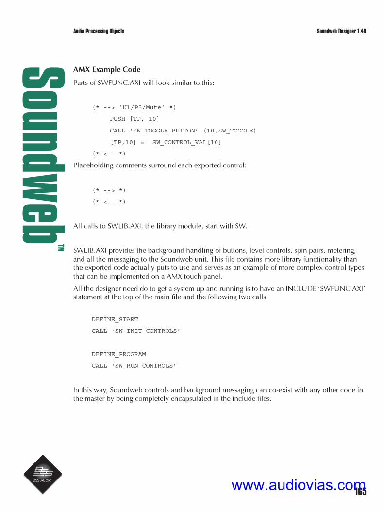
165
Soundw
ebTM
Soundweb Designer 1.40
AMX Example Code
Parts of SWFUNC.AXI will look similar to this:
(* --> ‘U1/P5/Mute’ *)
PUSH [TP, 10]
CALL ‘SW TOGGLE BUTTON’ (10,SW_TOGGLE)
[TP,10] = SW_CONTROL_VAL[10]
(* <-- *)
Placeholding comments surround each exported control:
(* --> *)
(* <-- *)
All calls to SWLIB.AXI, the library module, start with SW.
SWLIB.AXI provides the background handling of buttons, level controls, spin pairs, metering,and all the messaging to the Soundweb unit. This file contains more library functionality thanthe exported code actually puts to use and serves as an example of more complex control typesthat can be implemented on a AMX touch panel.
All the designer need do to get a system up and running is to have an INCLUDE ‘SWFUNC.AXI’statement at the top of the main file and the following two calls:
DEFINE_START
CALL ‘SW INIT CONTROLS’
DEFINE_PROGRAM
CALL ‘SW RUN CONTROLS’
In this way, Soundweb controls and background messaging can co-exist with any other code inthe master by being completely encapsulated in the include files.
Audio Processing Objects
www.audiovias.com
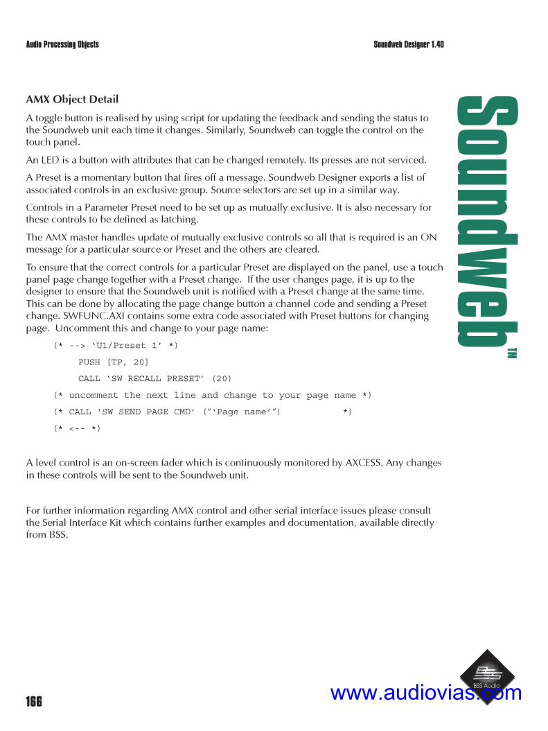
166
Soundw
ebTM
Soundweb Designer 1.40
AMX Object Detail
A toggle button is realised by using script for updating the feedback and sending the status tothe Soundweb unit each time it changes. Similarly, Soundweb can toggle the control on thetouch panel.
An LED is a button with attributes that can be changed remotely. Its presses are not serviced.
A Preset is a momentary button that fires off a message. Soundweb Designer exports a list ofassociated controls in an exclusive group. Source selectors are set up in a similar way.
Controls in a Parameter Preset need to be set up as mutually exclusive. It is also necessary forthese controls to be defined as latching.
The AMX master handles update of mutually exclusive controls so all that is required is an ONmessage for a particular source or Preset and the others are cleared.
To ensure that the correct controls for a particular Preset are displayed on the panel, use a touchpanel page change together with a Preset change. If the user changes page, it is up to thedesigner to ensure that the Soundweb unit is notified with a Preset change at the same time.This can be done by allocating the page change button a channel code and sending a Presetchange. SWFUNC.AXI contains some extra code associated with Preset buttons for changingpage. Uncomment this and change to your page name:
(* --> ‘U1/Preset 1’ *)
PUSH [TP, 20]
CALL ‘SW RECALL PRESET’ (20)
(* uncomment the next line and change to your page name *)
(* CALL ‘SW SEND PAGE CMD’ (“‘Page name’“) *)
(* <-- *)
A level control is an on-screen fader which is continuously monitored by AXCESS. Any changesin these controls will be sent to the Soundweb unit.
For further information regarding AMX control and other serial interface issues please consultthe Serial Interface Kit which contains further examples and documentation, available directlyfrom BSS.
Audio Processing Objects
www.audiovias.com

167
Soundw
ebTM
Soundweb Designer 1.40
Data export functions
Designer now incorporates a new export function that allows the class name and id of particu-lar processing objects within configurations in devices to be saved to a file. This file can thenbe imported into suitable third party control software applications for further external control ofa Soundweb system.
Processing objects are chosen to be exported by either right clicking on an object and selecting‘Marked for export’ or by renaming the object; which automatically selects this option. Objectscan be chosen from multiple devices and then exported using the File menu command ‘Exportobject data..’. Note that this command is only available at map window level, i.e. it does notappear in the File menu if a configuration window is the currently open window.
When you roll over an exportable object in a configuration or map window the status bar atbottom left of the screen displays the network address or ‘handle’, i.e. Handle=0x00000002. Acontrol surface object on a control panel will display its handle and ‘Method’ code briefly onrollover with the mouse. Note that the method is currently not exported as part of the file.
The file that is exported can be saved either as a standard comma separated value (.csv) or as anobject data file (.hdl). The format of the file is as follows:
1st line “File version”, “Designer version”
Next lines “Object name”, “Object type”, “Handle”
The SW Interface Kit documentation provides further detail on how to control processing ob-jects using this data.
Note: when controlling a Soundweb system (via a rear RS232 port) you need to add ‘+s’ to thename of the device that you wish to connect to. This changes the protocol used on the rearRS232 port to the SW Interface Kit protocol.
Audio Processing Objects
www.audiovias.com

168
Soundw
ebTM
Soundweb Designer 1.40
i Audio processing object properties
Many processing objects have options that may be set prior to compiling. These allow optionalor advanced features to be set up, such as access to sidechains, adding auxiliary buses to mix-ers, or controlling the maximum slope of crossovers.
To adjust the options for a processing object
1 Right-click on the object and select Properties.
For objects that have more than one property:2 Select the property you wish to change in the ‘Option’ column3 Set the value you wish to assign to this property in the ‘Setting’ column.
The options for Processing objects default to ‘off’ to prevent overuse of DSP resources.
To access an object’s control panel double click on it in the map window.
Audio Processing Objects
www.audiovias.com

169
Soundw
ebTM
Soundweb Designer 1.40
Audio Processing Objects
AUTOMATIC MIXERS
In addition to the features of a conventional mixer ‘Automixers’ allow ‘hands-free’ multi-micro-phone mixing without the need for ‘manual gain riding’ to keep background noise and feed-back under control. These objects use an Adaptive Threshold Gain Sharing technique to con-trol the attenuation in each input channel.
Note that due to this automation automatic mixers can use many dsp resources.
All inputs share the available gain; i.e. an ‘open’ microphone will attract the most gain.If more than one microphone is in use, the gain in the active channels is shared to give thesame overall system gain. When all inputs are idle, the shared gain keeps all channels slightlyactive to avoid ‘pumping’ of the background noise.
Downward expansion is available for further reducing the background noise contribution fromidle microphones. Options are provided to allow the mixer to be expanded not only within agiven device, but also across the network. Aux. buses can be created and direct channel out-puts may be made available for final mixing elsewhere, or for adding equalisation or otherprocessing.
Inputs and Outputs
• The number of inputs and outputs for an Automixer is specified in its name; e.g. ‘8 to 1’has 8 inputs and 1 output.
• There is additionally an output for each aux. bus.
• The direct out property produces an additional output per channel for further processingor mixing elsewhere.
• The master option adds a further Mix Input, Chain Input and Master OutputThe slave option adds a further Mix Input, Chain Input and Chain Output.
Properties
Aux. Buses (0/1/2):The number of aux. buses can be selected between 0 and 2.
Master/Slave Status:For expanding the mixer, either for making a larger mixer within a device, or for splitting amixer across more than one device. The control signals are shared using two special versionsof the auto mixer - Master and Slave.
Voiceband filters:Filtering may be included so that the automixing action favours frequencies in the human vocalrange. This helps the mixer to distinguish between speech and noise, giving a voice signal abetter chance of ‘winning’ against a noise signal on another channel.
Audio Processing Objects
www.audiovias.com

170
Soundw
ebTM
Soundweb Designer 1.40
Control Panel
Two tabs - ‘Automatic Mixer’ (or ‘Channels’) and ‘Aux Buses’:
Automatic Mixer Tab:
• Fader for each input.
• Mute button for each input.
• Polarity button for each input (for signal inversion).
• Solo button for each input.Allows only ‘soloed channels to be heard.! This is a ‘solo-in-place’ which impacts the main output.
• Override button for each inputForces this channel to be heard above all the others.Useful for a chairperson to interrupt a conference speaker for example.
• Auto/Manual buttonAssigns each channel to operate as either a conventional mixer channel or an automatedchannel.
• Off Gain control for each input.Determines what maximum attenuation will be applied by the downward expander to anidle channel.When this control is set to 0dB, no downward expansion is applied.The setting of this control has some effect on the point at which the On indicatorsilluminate.
• Gain control for the output.
• Master Mute button for the output.
• Slope control.Determines how aggressive the gain sharing is.Low slope settings cause the object to behave just like a conventional mixer. High slopesettings cause the inputs to attenuate more deeply for ‘closed’ microphones. The fullyclockwise 2:1 setting will be appropriate for most applications, but if you find the actionto be too aggressive and do not want idle microphones to be ‘dimmed’ as much, thenback this control off slightly.
• Speed control.Determines how quickly a channel recovers from being open.Fast (anti-clockwise) settings will be needed if different speakers are speaking in quicksuccession, since slow settings would prevent a newly active channel from fading upquickly enough.If the setting is too fast however, the gain sharing could ‘pump’ the gain up and downbetween spoken words.A setting somewhere near the centre of the travel will be found suitable in most cases.
• On Indicator for each input.Shows when a channel is active.
Audio Processing Objects
www.audiovias.com

171
Soundw
ebTM
Soundweb Designer 1.40
The ‘on’ level is related to the setting of the ‘off gain’ control. Since the gain sharingalgorithm is a linear process, there is actually no concept of absolute ‘on’ or ‘off’.Note that only one On indicator is allowed to be ‘on’ at a time so that the indicators maybe applied to logic outputs to identify the speaker in automated camera applications.
Aux Buses Tab (optional)
• Aux (send) output control for each input and each bus.(Auxes are post-fader and post processing)
Notes:
Mixer Expansion
To make two automixers act as one:Connect the Master Out on the master to the Master In on the slave, and the Chain Out of theslave to the Chain In on the master.
If you require the outputs of the two mixers to be combined, connect the Mix Out of the slaveto the Mix In of the master, then use the Mix Out of the master.
To interconnect more than two auto mixers.Create one master and several slaves and connect the Master Out of the master to all the MasterIn’s of the slaves, and ‘daisy Chain’ the Chain Out of one slave to the Chain In of the next slave,and so on (in any order) to the Chain In of the master. Note that the master-slave routing may berouted as if it were audio, but should not be routed to any audio inputs since it is a controlsidechain signal.
If you require the outputs of all the mixers to be combined, ‘daisy chain’ the Mix Out of oneslave to the Mix In of the next slave and so on (in any order) to the Mix In of the master, thenuse the Mix Out of the master.
Note that the Speed and Slope controls should be set the same on all linked Automixers forcorrect operation.
! This object is capable of raising signal levels beyond the clipping point, so care should beexercised when using positive gain values.
Audio Processing Objects
www.audiovias.com

172
Soundw
ebTM
Soundweb Designer 1.40
MIXERS
A straightforward mixer object to mix an array of inputs to an output (or stereo output). Auxbuses are optional.
Inputs and Outputs
The number of inputs and outputs for the Mixer processing object is specified in it’s name, e.g.‘8 to 2’ has 8 inputs and 2 outputs. There is optionally one output for each aux bus.
Properties
Aux Buses
The number of aux buses can be selected between 0 and 2.
Pan Law (stereo mixers only)
The law of the pan controls may be set to either 3dB, 4.5dB or 6dB. These figures relate to theattenuation applied to each channel at the central pan position.
Control Panel
Two tabs (‘Mixer’ and ‘Aux’ Buses):
Mixer tab:
• Fader for each input
• Pan control (stereo objects only)
• Mute button for each input
• Polarity button for each input to invert the signal
• Gain control for each output
Aux Buses tab:
• Aux (send) output control for each input for each bus (optional)
• Aux Pre-Fade button to allow the aux signal to be routed either from before or after thefader (optional).
! This object is capable of raising signal levels beyond the clipping point, so care should beexercised when using positive gain values.
Audio Processing Objects
www.audiovias.com

173
Soundw
ebTM
Soundweb Designer 1.40
MATRIX MIXERS
This object is used to connect an array of inputs to an array of outputs with an individual gainsetting for each crosspoint.
Inputs and Outputs
The number of inputs and outputs for the Matrix Mixer processing object is specified in itsname, e.g. ’16 to 8' has 16 inputs and 8 outputs.
Control Panel
Two tabs (‘Route’ and ‘Mix’):
Route tab:
• Connect button for each crosspoint.Click this to connect an input to an output (green), or to disconnect (no-colour).
Mix tab:
• Gain control for each crosspoint.
• Overall Gain control for each output.
• Navigation buttons (Larger matrix mixers):Select which section of the mixer is displayed in the control window.The labels on the axes change accordingly.
• Select button to switch between Connect buttons or Gain controls.
MATRIX ROUTERS
These are identical to matrix mixers except that the gain at each crosspoint is fixed at 0dB
Audio Processing Objects
www.audiovias.com

174
Soundw
ebTM
Soundweb Designer 1.40
SOURCE SELECTOR
An input select switch to choose between a predetermined number of inputs.
Inputs and Outputs
The number of inputs for the Source Select processing object is specified in its name; e.g. ‘8 -Input’ has 8 inputs. One output.
Properties
State ‘None’ Available: The user may choose whether the ‘None’ position is available or not (noinput).
Control Panel
• One combo box permits the selection of one input, or optionally ‘None’.
SOURCE MATRIX
Routes between a predefined number of inputs and outputs. Each output can be sourced fromone input or none.
Control Panel
• One combo box per output permits the selection of a source input or none.
Audio Processing Objects
www.audiovias.com

175
Soundw
ebTM
Soundweb Designer 1.40
DELAY
A basic delay line for delaying an input signal by a predetermined delay time without affectingthe signal in any other way.
Inputs and Outputs
• One audio input.
• One audio output.
Properties
Max. Delay Length - (Short(80ms)/Medium(340ms)/Long(1360ms)/V.Long(5450ms)):The maximum delay time may be selected between four different values so that minimal re-sources are consumed where only short delays are likely to be required, whilst still allowingvery long delays to be used in applications that demand them.
Units:Adjust and display the delay in terms of inches, feet, metres or seconds.
Control Panel
• Delay timeAdjustable using spin increment/decrement box.
Audio Processing Objects
www.audiovias.com
176
Soundw
ebTM
Soundweb Designer 1.40
GAIN/MUTE
A straightforward gain control for raising or lowering the level of the signal and integral mutebutton.
Inputs and Outputs
• One audio input
• One audio output.
Control Panel
• Gain faderAdjusts the gain from +10dB down to off.
• Mute buttonMutes the output. On multi channel gain objects there are separate mutes per channeland an overall mute.
• Polarity buttonInverts the signal.
! This object is capable of raising signal levels beyond the clipping point, so care should beexercised when using positive gain values.
There is now a new category of processing objects – ‘Gains’, 2 in, 4 in and 8 in gains have beenincluded to accompany the single Gain control. Comprising of straight through gains withindividual muting, polarity, overall mute of gain group and ‘master’ control of level. In this waymultiple channels can have their levels adjusted with overall adjustment of relative level and
signal mute from one control panel and without mixing.
Audio Processing Objects
www.audiovias.com

177
Soundw
ebTM
Soundweb Designer 1.40
METERING POINT
A signal level metering object to monitor and display signal levels on the screen.
Inputs and Outputs
• One input.
• One optional output.
Properties
Control Output Available (Yes/No)Outputs the DC sidechain of the meter for special applications.Note that the signal at the meter output is not audio, but the meter ‘sidechain’.
Control Panel
Different styles of display are available in different tabs.
‘Bar’ tab (only if you do the Soundweb training!)An LED bar graph type display
‘Needle’ tabAn analogue style VU meter display
‘Controls’ tab:
• Attack time controlAdjusts how the meter responds to short duration transients.
• Release time controlAdjusts how long the meter takes to recover.
• Reference controlSets where 0dB on the meter refers.
Audio Processing Objects
www.audiovias.com

178
Soundw
ebTM
Soundweb Designer 1.40
TONE GENERATOR
A test tone signal source that generates a sine wave of adjustable frequency and level.
Inputs and Outputs
• One audio output.
Control Panel
• Level control.Adjusts the output level.
• Frequency control.Adjusts the frequency of the test tone emission.
NOISE GENERATOR
A random noise signal source which generates either white or pink noise of adjustable level.Two or more instances of these noise generators will produce uncorrelated outputs.
Inputs and Outputs
One audio output.
Control Panel
• Level control.Adjusts the output level.
• Type combo box.Selects between white or pink noise generation.
Notes
White noise has equal energy per linear (Hz) bandwidth, and is useful for FFT based analysis.Pink noise has equal energy per percentage (Octave) bandwidth, and is useful for use withconventional Real Time Analysers that have equal octave width bands (e.g. 1/3 octave).
Audio Processing Objects
www.audiovias.com

179
Soundw
ebTM
Soundweb Designer 1.40
CROSSOVER
A fully featured loudspeaker management processor consisting of various alignments ofcrossover filters, gain controls, and mid-band limiters. The limiter is a two-stage protectionlimiter for protecting against amplifier clipping and loudspeaker damage. The first stage hasballistics suitable for long term protection whilst retaining transparency and minimising signallevel loss. The second stage has much faster ballistics to protect against loudspeaker overexcursion. Limiter ballistics are automatically set by the system to give the optimumperformance based on the high-pass frequency of the band. Options include delays, phasefilters and limiter metering.
Inputs and Outputs
• One audio output per band
• One common audio input.
When the option for individual inputs is selected, there is one input per band.
Properties
Max Slope (out, 24, 48)
The maximum cut-off slope can be adjusted for each band edge so that resources are notwasted in allowing for high-slope crossover filters (such as 48dB/Octave) in applications wheregentler, and less resource-hungry slopes are acceptable. The default is 24dB/Octave, which issuitable for most applications. Note that regardless of the maximum setting, the control panelwill always allow lower slopes to be selected at any time.
Delay (off/on)A delay-line may be inserted into each band for aligning loudspeaker drivers in time.
Meters (off/on)Metering may be added to monitor the action of the limiters.
Phase (off/on)Phase filters may be included to apply phase shifts between adjacent bands for fine-tuningalignment.
Polarity/Mute (off/on)Polarity inversion and mute controls may be added.
Inserts (off/on)The input feeds to the crossover filters are normally internally connected together to form asingle common input, they may optionally be split into separate inputs so that equalisation (forexample) can be uniquely applied to individual outputs without disturbing the calibration of thelimiter.
Control Panel
The graphical representation of crossover areas indicates what part of the frequency range eachband occupies but is not intended to be accurate. Each band is a different height and colour,
Audio Processing Objects
www.audiovias.com

180
Soundw
ebTM
Soundweb Designer 1.40
with numbers on the right-hand edge of the graphics window to show which output the band issent. The band edge is indicated by a square box (node) on the corner of the ‘frequency re-sponse’. When selected the node becomes ‘solid’ and the frequency band can now be ex-panded or contracted by moving this node horizontally left or right.
Four tabs (Crossover, Delay/Phase, Gain, Limiter):
Crossover tab
• FrequencyDrag nodes horizontally with the mouse to change the crossover frequency. Normally thenode at the intersection of two adjacent bands would be moved so that the adjacentbands track together.Some applications require adjacent crossover frequencies to be offset (overlapped forexample). This can be done by selecting one band edge so it can be movedindependently. Alternatively, the Frequency control below the window may be adjusted.
• Filter TypeThis combo box selects the alignment of the crossover (the crossover filter ‘shape’). Notethat the shape can be set differently on each band edge and, even on adjacent bandedges, although this latter situation is probably best avoided in audio terms.
All X-overs now have the option of using Thiele Filters. This new filter type is designedaround the Australian WHISEWORKS - Neville Thiele Method* filter and BSS Audio is the firstpro audio manufacturer to embrace the new technology. Select the NTM filter type from thedrop down list.
WHISEWORKS - *NTM™ and WHISEWORKS - Neville Thiele Method™ are trademarks of Precision Audio Pty.Ltd
Delay/Phase tab
• Delay spinbox (for each band)Together with an optional graphical representation of the delay time using ‘speaker’ icons.
• Phase spinbox (optional)Adjusts the phase shift applied between a pair of bands.As there is some interaction between the phase controls, it is recommended that thehighest frequency band phase be adjusted first, and then successively lower ones.
Audio Processing Objects
www.audiovias.com

181
Soundw
ebTM
Soundweb Designer 1.40
Gain Tab
• Band Gain controlTrims the output level of the band.The gain control is before the limiter, so does not alter the calibration of the limiterthreshold. For optimal gain structure management, remember that any attenuation isbetter done in the analogue output control rather than in the crossover. If the crossoveroutput is connected directly to an analogue output, the crossover limiter threshold willremain in calibration.
! This control is capable of raising signal levels beyond the clipping point; so, care should beexercised when using positive gain values.
• Polarity buttonReverses the polarity of the band. (optional)
• Mute buttonSilences the band output. (optional)
Limiter tab
• Threshold controlAdjusts the level threshold above which limiting will take place.The system will track changes made to the main analogue output level control so that thelimiter threshold setting relates to the level at the output terminals rather than the level atthe output of the crossover.
If other processing objects are connected between the output of the crossover and the outputthe limiter threshold setting may be inaccurate, and the user must compensate for level changeswhich occur in these objects.
• MeterDisplays the input signal level relative to the limiter threshold.A reading of 0dB corresponds to the limit threshold, whereas a reading of +6dB for in-stance means the signal is exceeding the threshold by 6dB, and is being compressed by6dB.
MONO SUB
Identical to the Crossover object except that it is a single band crossover with two inputs,which are internally mixed together with 6dB of signal loss so that a mono sub-bass feed canbe created from a stereo signal.
This would normally be used in conjunction with a pair of crossover processing objects tohandle the main stereo channels.
Audio Processing Objects
www.audiovias.com

182
Soundw
ebTM
Soundweb Designer 1.40
AMBIENT NOISE COMPENSATOR
Allows the level of an announcer (or other programme material) to ‘ride’ on the averagebackground (ambient) noise level so that the programme is kept at an audible level above thatof the ambient noise.
It does this by measuring the level of the ambient noise (using a suitably placed microphone),and controlling the gain of the programme channel accordingly. Since the gain must becontrolled only by the ambient noise, and not by the level of the programme itself, the ambientsignal level will only be measured and the gain adjusted during periods of inactivity in theprogramme channel. The length of the gap in programme required for sampling to occur isadjustable to allow for reverberation on the programme.
Various controls further allow the user to vary the announcement threshold level for gapdetection, the minimum and maximum applied gain, the speed of gain change, and thereference ambient level.
Inputs and Outputs
• One announcement (Programme) input• One ambient input - labelled ‘Amb in’• One audio output
Control Panel
• (Ambient) Threshold controlAdjusts the ambient signal level at which unity gain will exist.The amount by which the announcement channel gain is increased is equal to theamount by which the ambient level exceeds this threshold.Lower threshold settings will tolerate lower ambient signal levels before increasing theannouncement gain.To lift the announcement out of the ambient noise more, reduce the setting of this control.
• Ambient Level MeterDisplays the current ambient noise level. It’s positioning next to the Threshold controlshows the difference between the ambient level and the threshold, (which is equal to theapplied gain).
• Announcement gain meterIndicates the current announcement channel gain.
• Min Gain controlDetermines the minimum gain that will be applied to the announcement channel.This should be set (with the aid of the Min Gain button) during quiet ambient levels sothat an adequate announcement level is obtained.
• Min Gain buttonForces the gain to the minimum setting for set-up purposes.Illuminates when activated.
• Max Gain controlDetermines the maximum gain that will be applied to the announcement channel.
Audio Processing Objects
www.audiovias.com

183
Soundw
ebTM
Soundweb Designer 1.40
NETWORK SELECTOR
A simple switch that chooses between two inputs depending on the status of a network port.Designed for ‘fault tolerance’ applications where dual circuit loop redundancy is necessary. Forfurther details see Building in fault tolerance in the Technical Reference section.
Inputs and Outputs
Two inputs ‘Default’ and ‘Backup’.One of these inputs is fed to the output depending on the state of a given network port.
• If the network port has a valid connection, then ‘Default’ is fed to the output.
• If the network port does not have a valid connection then ‘Backup’ is routed to the out-put.
Properties
Network Port Control (Net in/Net out)Selects what network port on the hardware device is configured as the ‘default’ or ‘backup’.
Control Panel
3 indicators:
• Input - displays receipt of network signal.
• Default - Lights to show that the ‘default’ input is providing network communication.
• Backup - Lights when the default system has failed or is not present and indicates that the‘backup’ input is now handling network traffic.
Audio Processing Objects
www.audiovias.com

184
Soundw
ebTM
Soundweb Designer 1.40
MODULATOR
This processing object is found in the ‘Primitives’ group and has no control panel or properties.
Inputs and Outputs
• Two inputs.
• One output
The output is one input multiplied by the other input, i.e. the output is the product of the inputs.The inputs can be AC (i.e. normal audio signals) or DC (e.g. dynamics sidechains etc.). Notethat distortion will result if both inputs are AC(audio).
The modulator could for instance be used to allow the amplitude in one signal path to controlthe amplitude of a signal in another signal path to achieve a level-riding effect. To do this, youwould put the controlling signal through a ‘meter’ to turn it into DC, then apply that to onemodulator input, then pass the controlled signal through the other modulator input to theoutput.
Audio Processing Objects
www.audiovias.com

185
Soundw
ebTM
Soundweb Designer 1.40
ii Understanding Networks
Soundweb devices, such as the 9088 processor, are connected in a ‘token ring’ style network inorder to route audio from one input to another output elsewhere in the system. The network isbi-directional; this improves robustness and tolerance to faults.
A basic system routes 8 signals between boxes on the network. An exception to this is if there isonly two 9088 devices in the system, in this instance 16 channels can be routedsimultaneously.
Hubs
If routing only 8 signals then up to 20 devices can be connected without the need for a hub. Tocreate larger routing matrices using more channels a 9000 series hub is necessary. The hub has6 network ports, each of which can support up to 6 Soundweb devices that become discreterings in themselves.
Network wiring protocols
A network jack on a Soundweb device is designated as one of two types: Input or Output. Theseare identical apart from two things:
• The pin out of the transmit and receive pins is reversed.
• The Output jack contains a power source whereas the input jack contains a power sensoronly.
The jacks are labelled ‘In’ and ‘Out’ but, data travels in both directions through either, so thesenames are not intended to represent data flow direction. Although by convention, audio chan-nels are thought of as passing from an Output to Input.
A Soundweb network must be connected ‘point-to-point’, i.e. connect a single ‘In’ jack to asingle ‘Out’ jack, using a standard straight through cable. Such a connection is compatible withindustry standard structured cabling systems. Refer to ‘Connector Pin outs’ for wiring details.
This allows audio channels to be passed ‘downstream’ from the Net ‘Out’ jack on one device tothe Net ‘In’ jack on the next device. Soundweb automatically analyses the cabling and createsa network ring for itself by utilising a ‘back-channel’. Audio channels are then routed backfrom the terminal device (the one without a connection on its Net ‘Out’ jack) to the first device(the one without a connection on its Net ‘In’ jack). These two jacks constitute end nodes.
! There must be no physical cable connection between these two end devices.
Note that all 6 network connections on a Soundweb 9000 Hub always become ‘end nodes’.Each connection to the Hub thus becomes a discrete ring.
www.audiovias.com

186
Soundw
ebTM
Soundweb Designer 1.40
Networks - Example using 9088s
Consider a collection of three 9088 devices which are connected in a simple ‘daisy-chain’ sothat audio channels pass from the first device to the second, and from the second device to thethird.
The ‘Out’ jack of the first device and the ‘In’ jack of the third device will become ‘end nodes’.Soundweb will automatically complete a phantom connection from the third device back to thefirst device (using a ‘back channel’) to form a network ring.
Audio channels sent to the Net ‘Out’ of the third device will then be received at the Net ‘In’ ofthe first device.
No physical connection is permitted between the Net ‘In’ jack of the first device and the Net‘Out’ jack of the third device.
9 088 DSP
F irs t 9 088
In1In2In3In4In5In6In7In8
Out1Out2Out3Out4Out5Out6Out7Out8
Ne t in Net out
90 88 DSP
Seco nd 908 8
In1In2In3In4In5In6In7In8
Out1Out2Out3Out4Out5Out6Out7Out8
Net in Net out
90 88 DSP
Th ird 9088
In1In2In3In4In5In6In7In8
Out1Out2Out3Out4Out5Out6Out7Out8
Net in Net out
8 Channels 8 Channels
8 Channels P hantom c onnec tion - do not c onnect
Understanding Networks
www.audiovias.com

187
Soundw
ebTM
Soundweb Designer 1.40
Networks - Example using 9088s and 9000 hubs
Building on the previous system of 9088 devices and plugging the ‘Out’ jack of the third 9088into ‘In 1’ of a 9000 hub, then plugging ‘Out 4’ of the Hub into the ‘In’ jack of a fourth 9088.
Soundweb will complete two rings using two ‘back channels’, One between the ‘In 1’ jack ofthe 9000 and the ‘In’ jack of the first 9088, and one between the ‘Out 4’ jack of the 9000 andthe fourth 9088.
Audio channels will pass along from the first 9088 to the second, the second to the third andfrom the third to the hub. The audio is then routed from the hub to the fourth 9088. The ‘backchannels’ will also allow audio channels to pass back from the hub to the first 9088 and fromthe fourth 9088 back to the hub.
Understanding Networks
www.audiovias.com

188
Soundw
ebTM
Soundweb Designer 1.40
Using the 9000ii Network Hub device
If you are have 9000ii’s available to your design and wish to make use of their extra dsp power(i.e. you don’t need to retain compatibility with the standard 9000):
1 Use Add>Device and select 9000 hub as usual.
2 Set the ‘Type’ to 9000ii (9000 is the default).
This can be done later using the device options in the device’s properties menu.
If you look in the Kit-List, you should see something like this:
When you go ‘online’, you should be able to load the 9000ii as normal.If, however, you see something like this:
Confirm that you have named the device correctly. If the physical device is a 9000ii, make surethat it is loaded with the latest software (if you load a 9000ii with old 9000 software it will notwork correctly) and try again.
Note: A 9000 hub cannot be physically upgraded to ii status as it contains fundamentally differ-ent hardware.
Network restrictions
Soundweb allows you a lot of freedom in how the network cabling visits the devices on thenetwork, so long as ‘In’ jacks are connected to ‘Out’ jacks, and that all devices are connectedtogether by at least one cable (so that the PC can communicate with all of them), and they cancommunicate with one another.
The only limitations are:
• There must be at least one end-node device that is not a 9000 hub somewhere in thenetwork, i.e. there must be a 9088 with one unconnected network jack. This is becausethere must be a network master, which can only be a terminal device and not a hub.
• There must not be a physical loop created by cabling. However It is quite acceptable toconnect two or more cables between hubs, since these will be discrete rings.
Understanding Networks
www.audiovias.com
189
Soundw
ebTM
Soundweb Designer 1.40
This should be set (with the aid of the Max Gain button) during high ambient levels suchthat sensible operating levels, free of distortion etc. are maintained.
• Max Gain buttonForces the gain to the maximum setting for set-up purposes.Illuminates when activated.
• Speed controlDetermines the speed at which the gain will change. Obtrusiveness will be minimised atslower speed settings, although responsiveness to sudden changes in ambient level willbe reduced.
• Gap Time controlDetermines the amount of time the announcement channel must be ‘silent’ in order forthe ambient channel to be sampled.In highly reverberant environments, a long gap time may be required to avoid false gainchanges because of measuring the reverb tail of the announcement, rather than theambient noise level. Use the Ambient Meter as a guide to how quickly the signal diesaway after an announcement ends.
• Gap ThresholdDetermines the announcement input signal level below which the announcement chan-nel signal must drop before it is considered to be in a gap, and thus allow ambient levelsampling.Try setting the Threshold control 10dB or so above the idle noise of the announcementchannel.
• Gap LEDInforms the user when there is an announcement gap that is allowing ambient signalsampling to take place.
• Bypass buttonRemoves the processor from the signal path.Use bypass to set up the nominal announcement level.
Notes
The ambient microphone should be connected to a microphone input on a 9088 SignalProcessor. The input gain should be adjusted to achieve a sensible operating level. Whensetting the Ambient Threshold control, the input gain should be taken into account.
The Ambient microphone should be positioned clear of non-representative sources of soundand, to prevent tampering, preferably a place not accessible to the public. In a largeenvironment, several microphones could be used with a mixer object in Soundweb to get anaverage of the levels.
! This object is capable of raising signal levels beyond the clipping point, so care should beexercised when using positive Maximum Gain values.
! It is recommended that a Limiter be used on the output of the Ambient Noise Compensatorso that short term high-level signals are not allowed to pass through to the output.
Understanding Networks
www.audiovias.com
190
Soundw
ebTM
Soundweb Designer 1.40
COMPRESSOR
A fully featured compressor with the classic BSS ‘progressive knee’ sound, which produces agentle ratio near the threshold becoming progressively more aggressive further intocompression. An auto-release mode not only allows the release time to be related to the user-setattack time, but also varies this relationship depending on the nature of the program to give avery natural sounding result.
Two versions of the compressor are available, a single channel version, and a stereo version,where two independent audio channels are controlled by a single control panel, the sidechainsbeing locked together to prevent stereo image shifts.
Inputs and Outputs
The single channel compressor has one audio input and one audio output, the stereo versionhaving two of each. If the sidechain property is switched on, an additional input is available,giving access to the control sidechain.
Properties
Sidechain
A sidechain input can be made available so that an equaliser for example can be introduced tomake compression frequency conscious. Any sidechain processing would normally derive itssignal from the same source that is fed to the audio input of the compressor.
Control Panels
• Threshold controlAdjusts the level threshold above which compression will take place. Below thisthreshold, no compression will take place.
• Ratio controlAdjusts the aggressiveness of compression.
• Gain controlAdjusts out any gain anomalies.
• Attack controlAdjusts the time it takes for the compressor to respond to signal levels above thethreshold.Note that this control also affects the release time in ‘Auto Release’ mode.
• Release controlAdjusts the time it takes for the compressor to recover after the signal level goes belowthreshold.Note that this control has no effect in ‘Auto Release’ mode.
• Bypass buttonRemoves the compressor from the signal path.
• Auto Release buttonAutomatically adjusts the release time optimally for the programme material.Note that the time constants are still dependent on the attack setting.
www.audiovias.com

191
Soundw
ebTM
Soundweb Designer 1.40
• Gain Reduction meterDisplays the amount of gain reduction being applied.
Notes
! This object will cause audible distortion if the Attack and Release times are too fast since itwill be trying to apply dynamic gain reduction to the instantaneous values of lower frequencywaveforms.
! This object is capable of raising signal levels beyond the clipping point so; care should beexercised when using positive gain values.
Firmware / Embedded Software Updates
www.audiovias.com

192
Soundw
ebTM
Soundweb Designer 1.40
EXPANDER
Reduces the level of signals that fall below a threshold level.
Inputs and Outputs
One audio input and one audio output.
Properties
Sidechain
A sidechain input can be made available so that an equaliser (for example) can be introducedto make expansion frequency conscious. Any sidechain processing would normally derive itssignal from the same source that is fed to the audio input of the expander.
Control Panel
• Threshold controlAdjusts the level threshold below which gain reduction will take place. Above this thresh-old no gain reduction will take place.
• Ratio controlAdjusts the aggressiveness of expansion.
• Attack controlAdjusts the time it takes for the expander to recoverafter the signal level goes above threshold.
• Release controlAdjusts the time it takes for the expander to respondto signal levels which fall below the threshold.
• Bypass buttonRemoves the expander from the signal path.
• Q Gain Reduction meterDisplays the amount of gain reductionbeing applied.
Notes
! The expander can cause distortionat low frequencies when the Releasecontrol is set to low values. Unlessyou particularly need the expander to
attenuate very quickly when the signal falls below threshold, set the Release control to areasonably high value.
Firmware / Embedded Software Updates
www.audiovias.com

193
Soundw
ebTM
Soundweb Designer 1.40Firmware / Embedded Software Updates
www.audiovias.com

194
Soundw
ebTM
Soundweb Designer 1.40
DUCKER
Reduces the level of a (music) signal depending on the level of a control (mic) signal.Features an exponential attack and decilinear (linear dB per unit time) recovery for naturalsounding fades.
Inputs and Outputs
• One audio input for music.
• One audio input for the control (microphone) signal.
• One audio output.
Control Panel
• Threshold controlAdjusts the level threshold of the Mic signal above which gain reduction of the musicsignal will take place. Below this threshold, no gain reduction will take place.
• Range controlAdjusts how ‘deeply’ the ducker will reduce the signal level of the music signal.
• Duck time controlAdjusts the time it takes for the ducker to fade the music down when the Mic signal levelsgoes above threshold.
• Hold controlExtends the ‘ducked’ phase to prevent ‘chatter’.
• Recover time controlAdjusts the time it takes the ducker to fade the music signal up when the mic signal levelfalls below the threshold.
• Bypass buttonRemoves the ducker from the signal path.
• Gain Reduction meterDisplays the amount of gain reduction being applied.
Notes
! This object will cause audible distortion if the Attack and Release times are too fast since itwill be trying to apply dynamic gain reduction to the instantaneous values of lower frequencywaveforms.
Firmware / Embedded Software Updates
www.audiovias.com

195
Soundw
ebTM
Soundweb Designer 1.40
GATE
Reduces the level of signals that fall below a threshold level. Features an exponential attackand reverse exponential release, which helps to preserve the natural decay of the instrument orsignal source, rather than imposing a synthetic envelope upon it.
Inputs and Outputs
• One audio input.
• One audio output.
If the sidechain option is switched on an additional input is available, giving access to thecontrol sidechain.
Properties
Sidechain
A sidechain input can be made available so that an equaliser for example can be introduced tomake gating frequency conscious. Any sidechain processing would normally derive its signalfrom the same source that is fed to the audio input of the gate.
Control Panel
• Threshold controlAdjusts the level threshold below which gain reduction will take place. Above this thresh-old, no gain reduction will take place.
• Range controlAdjusts how ‘deeply’ the gate will reduce the signal level of below-threshold signals.
• Attack controlAdjusts the time it takes for the gate to recover after the signal level goes above threshold.
• Hold controlExtends the ‘gate-open’ phase to prevent ‘chatter’.
• Release controlAdjusts the time it takes for the gate to respond to signal levels which fall below thethreshold.
• Bypass buttonRemoves the gate from the signal path.
• Manual Open buttonTests the attack/hold/release settings without having to manipulate the signal level.
Firmware / Embedded Software Updates
www.audiovias.com

196
Soundw
ebTM
Soundweb Designer 1.40
• Below Threshold meterDisplays the input signal level relative to the current threshold setting. Note that it is quitenormal for this meter to show erratic readings when the threshold is set to very low val-ues.
• Open indicatorShows when the gate is not reducing the signal level.
Notes
! The gate can cause distortion at low frequencies when the Release control is set to lowvalues. Unless you particularly need the gate to attenuate very quickly when the signal fallsbelow threshold, set the Release control to a reasonably high value.
Firmware / Embedded Software Updates
www.audiovias.com

197
Soundw
ebTM
Soundweb Designer 1.40
LIMITER
A two-stage protection limiter for protecting against amplifier clipping and loudspeaker dam-age. The first stage has ballistics suitable for long term protection whilst retaining transparencyand minimising signal level loss. The second stage has much faster ballistics to protect againstloudspeaker over-excursion.
Inputs and Outputs
• One audio input
• One audio output.
Control Panel
• Threshold controlAdjusts the level threshold above which limiting will take place. Note that the system willtrack changes made to the main analogue output level control so that the limiter thresh-old setting relates to the level at the output terminals rather than the level at the output ofthe limiter. If any processing objects are connected between the output of the limiter andthe main output however, the limiter threshold setting may be inaccurate, and the usermust compensate for level changes which occur in these algorithms.
• Attack controlAdjusts the time it takes for the limiter to respond to signal levels above the threshold.
• Release controlAdjusts the time it takes for the limiter to recover after the signal level goes below thresh-old.
Notes
An indication of limiting action can be achieved by applying a standard meter processingobject to the input side of the limiter. If the attack and release settings of the meter are set to thesame values as the limiter, and the meter reference set to the same value as the limiter thresh-old, then the meter will faithfully represent the limiting action of the limiter.
! This object will cause audible distortion if the Attack and Release times are too fast since itwill be trying to apply dynamic gain reduction to the instantaneous values of lower frequencywaveforms.
Firmware / Embedded Software Updates
www.audiovias.com

198
Soundw
ebTM
Soundweb Designer 1.40
LEVELLER
The leveller will attempt to keep the nominal level of the signal close to the desired target levelset by the user, by gently changing the gain. An intelligent detection algorithm makes thisprocessing object very free of side effects and easy to set up.
Inputs and Outputs
• One audio input.
• One audio output.
Properties
Voiceband Filter
Optionally included so that the levelling action favours frequencies in the human vocal range,helping to discriminate from noise signals.
Control Panel
• Target Output controlAdjusts the level which the leveller tries to maintain. The more positive the value, thehigher the output level will be.
• Ratio controlAdjusts the aggressiveness of levelling. Lower values allow more tolerance; allowing theoutput level to differ more from the target level, which preserves more of the originaldynamics of the signal at the expense of firm control over the level. Higher ratio valuescause the output level to be more tightly ‘driven’ towards the target level.
• Maximum Gain controlDetermines how much gain the object is allowed to apply to bring a low level signal upto the target level. Higher gain values allow the leveller to add more gain when the signallevel is low, but will also bring up the noise floor more.
• Speed controlAdjusts the time it takes for the leveller to recover from high levels when low levels areencountered. Higher values make the recovery slower, so there are no sudden jumps ingain. Lower (faster) values allow the leveller to track and counteract rapidly decreasinglevels.
• Bypass buttonRemoves the leveller from the signal path.! WARNING - significant changes in signal level can be caused by this control.
• Threshold controlDetermines the lowest input level that the Leveller will attempt to correct. The setting ofthis control is critical to the leveller’s ability to discriminate unwanted noise from thewanted signal. Lower values will allow the leveller to ‘pull-up’ lower level signals, butwill also make it more prone to activate on noise signals. Note that the intelligent detec-tion algorithm helps to prevent noise signals from triggering levelling action even whenthey are above the threshold level, (if the leveller does not recognise them as vocal sig-
Firmware / Embedded Software Updates
www.audiovias.com

199
Soundw
ebTM
Soundweb Designer 1.40
nals).
• Active LEDShows when the intelligent detector is allowing levelling action to take place. This is usedalong with the Threshold control to confirm that noise signals do not activate the detector,but wanted signals do.
• Gain meterDisplays how much adjustment the leveller is applying to the signal.
Notes
An expander connected on the input side of the leveller may be useful in aiding the leveller todiscriminate noise signals from wanted signals.
! It should be noted that this object is capable of raising signal levels beyond the clippingpoint, so care should be exercised when using large Maximum Gain values.
! It is recommended that a Limiter be used on the output of the Leveller so that short-termhigh-level signals (which may not be attenuated by the Leveller), are not allowed to passthrough to the output.
www.audiovias.com

200
Soundw
ebTM
Soundweb Designer 1.40
EQ - PARAMETRIC EQUALISER
A multi-function equaliser for corrective, or creative frequency response control. This mayconsist of a predetermined number of ‘bands’, each of which may have all parameters (i.e.Frequency, Bandwidth, Boost/Cut) controlled from a convenient graphics window.
Inputs and Outputs
• One audio input.
• One audio output.
Properties
Asymmetric Boost/Cut (Yes/No)’Yes’ produces cut curves which have the specified bandwidth at 3dB from the 0dB line (yield-ing non-complementary boost/cut shapes).’No’ produces cut curves which have the specified bandwidth 3dB from the tip of the bell(yielding complementary boost/cut shapes).
Control Panel
Most of the manipulation may be done in the graphics window, which also shows the actualcombined response of the filters. Empty squares (nodes) denote the current positions of thefilters (in terms of frequency and boost/cut). A solid square (the selected filter node) denotes thecurrently selected filter, and any adjustments made to the controls will affect this filter. Tocreate an additional EQ curve feature, click and drag a new filter up (or down) from the 0dBline.
Also it is now possible to copy the eq curve from a parametric eq window and impose it onto anew parametric eq using the Copy Settings command found in the right click menu. The bandnumbers will default to new bands numbered sequentially from 1.
Note that the right-click menu allows access to a filter ‘bypass’ function that allows anindividual band of equalisation to be temporarily taken out of the signal path.
• Filter Type combo boxSelects between bell, high-pass shelving or low-pass shelving shapes. May also beadjusted in a menu by right clicking on the filter node.
• Slope combo boxAllows the cut-off slope to be adjusted (for shelving shapes only).
• Frequency controlAdjusts the centre frequency of a bell filter, or the cut-off frequency of a shelving filter.May also be adjusted by moving the filter node in the graphics window horizontally usingthe mouse.
• Width controlAdjusts the bandwidth of the filter (bell shape only).May also be adjusted by pressing the shift key and moving the filter node in the graphicswindow vertically using the mouse.
• Boost/Cut control.May also be adjusted by moving the filter node in the graphics window vertically usingthe mouse. Shift+double click will return all of the boost/cut settings to 0dB.
• Bypass buttonRemoves the equaliser from the signal path
www.audiovias.com

201
Soundw
ebTM
Soundweb Designer 1.40
then it is necessary to delete the links, then re-construct map windows using the newparametric control panels. These can be linked much more reliably.
STEREO PARAMETRIC EQUALISER
Identical to the Parametric Equaliser except with two audio inputs and two audio outputs.Applies identical filtering to two channels of audio.
GRAPHIC EQUALISER
Simulates a conventional graphic equaliser for fast, intuitive frequency response control. It hasthe additional benefit of a ‘Selectivity’ control to determine the combining characteristics of thefilters. An actual combined eq curve is available on the Response tab in the control window.
Inputs and Outputs
One audio input and one audio output.
Control Panel
• Boost/Cut fader per band.
• Selectivity controlAdjusts how the bands interact.Lower selectivity settings produce a smooth overall response with some interaction.Higher settings reduce interaction but tend to produce a response with more ripple.
• Flat buttonSets all the faders to 0dB.Note that this loses all the fader settings.
• Bypass buttonRemoves the equaliser from the signal path.
www.audiovias.com

202
Soundw
ebTM
Soundweb Designer 1.40
PHASE FILTER
A first order (single pole) all-pass filter for applying frequency-conscious phase shifting, whilstmaintaining a flat magnitude response. The phase angle, and the frequency, at which the phaseangle is to apply, are both adjustable.
Inputs and Outputs
• One audio input.
• One audio output.
Control Panel
• Frequency control for adjusting the frequency at which the phase angle is to apply.
• Phase control for adjusting the phase angle by which the signal is to be shifted at thefrequency set by the Frequency control.
HIGH PASS FILTER
Removes low frequencies, or for use as a single band crossover for creating feeds for high-frequency drivers.
Inputs and Outputs
• One audio input.
• One audio output.
Properties
Max Slope (24/48)The maximum cut-off slope can be adjusted so that resources are not wasted in allowing forhigh-slope filters (such as 48dB/Octave) in applications where gentler, and less resource hungryslopes are acceptable. Note that regardless of what the maximum is set to, the control panelwill always allow lower slopes to be selected at any time.
Control Panel
• Frequency controlAdjusts the high-pass frequency.
• Filter Type combo boxSelects the filter shape (or crossover alignment) and cut-off slope.
• Bypass buttonRemoves the filter from the signal path.
Connector Pin Outs
www.audiovias.com

203
Soundw
ebTM
Soundweb Designer 1.40
LOW PASS FILTER
Removes high frequencies, or for use as a single band crossover for creating feeds for sub-bassdrivers for example.
Inputs and Outputs
• One audio input.
• One audio output.
Properties
Max Slope (24/48)The maximum cut-off slope can be adjusted so that resources are not wasted in allowing forhigh-slope filters (such as 48dB/Octave) in applications where gentler, and less resource hungryslopes are acceptable. Note that regardless of what the maximum is set to, the control panelwill always allow lower slopes to be selected at any time.
Control Panel
• Frequency controlAdjusts the low-pass frequency.
• Filter Type combo boxSelects the filter shape (or crossover alignment) and cut-off slope.
• Bypass buttonRemoves the filter from the signal path.
FIR FILTER
A new filter processing object that can import mathematically created FIR filter coefficientsexported from other applications as .csv (comma separated value) or .dat format files. Thenumber of coefficients can be up to 50,100, 200, 400 or 600. The import files are locatedusing a dialogue box displayed by right clicking on the FIR filter object and selecting ‘Importcoefficients’.
www.audiovias.com

204
Soundw
ebTM
Soundweb Designer 1.40
Building in fault tolerance
When building a large Soundweb system it is often necessary to build in some provision foraccidental cable breaks.
In the example below, a voice alarm signal must be routed to the speakers at all times. In caseof a cable break the microphone signal must be routed via a backup network cable so that itstill reaches the speakers.
The two racks could be some distance apart, and are connected by two network cables, ‘De-fault’ and ‘Backup’.
The signal is routed from ‘Hub1’ down both network cables to ‘Hub2’ where it is sent on to theoutputs. Normally, ‘Hub2’ would route the signal from the ‘default’ cable to ‘Outputs’.However, if the ‘default’ cable were accidentally cut, then it would route the signal from the‘backup’ cable. The configuration in ‘Hub2’ looks like this:
The Network Selector object has been set up to monitor the ‘Net 1’ port for a valid connection(‘Net 1’ has the ‘default’ cable plugged into it).If the ‘default’ cable is intact, it will route audio from ‘Net 1’ to ‘Net 4’.However, if the cable is cut, it will switch to routing from ‘Net 2’ (the ‘backup’ cable).
www.audiovias.com

205
Soundw
ebTM
Soundweb Designer 1.40
iii Firmware Updates
Firmware is the operating system code, or application software, that runs the hardware devicesas stand alone units and also enables them to communicate with an external PC. The firmwareis stored in a user updateable eprom inside the device. A device cannot function properlywithout the correct firmware installed and possibly may not even function at all.
Occasionally, the software inside your Soundweb units will need to be updated to takeadvantage of new features, bug fixes and to retain proper compatibility with new versions ofSoundweb Designer.
In these situations, the firmware ‘loader’ needs to be used. This application updates the datastored on the chips in your Soundweb units.
Locating the latest software
All new Soundweb devices come with the appropriate application code on the set-up disks orCD. This is also copied into the user’s Soundweb directory during installation. So if SoundwebDesigner is installed on the PC then there should be software available to update the hardwaredevices.
The embedded software is stored in ‘.dis’ files - e.g. ‘9088v116.dis’, this would be version 1.16software for 9088 devices.
Alternatively, the ‘latest’ software can be found on the BSS Audio web site:
www.bss.co.uk
www.audiovias.com

206
Soundw
ebTM
Soundweb Designer 1.40
In the diagram the ability to switch between 6 states is available though the use of a five resistorladder. The sixth state is achieved through an unconnected (open circuit) terminal.
The following table gives the resistor values in Ohms for each segment of the resistor ladder. Toachieve the last state for a given number of states one less resistor is needed and the last termi-nal is open circuit / not connected (NC).
States: 3 4 5 6 7 8 9
1st resistor to ground 820 560 470 390 300 270 220
2nd resistor 2700 1600 1200 1000 820 680 560
3rd resistor NC 3300 1800 1300 1000 820 680
4th resistor NC 3600 2200 1500 1100 910
5th resistor NC 3600 2400 1600 1200
6th resistor NC 3900 2400 1800
7th resistor NC 3900 2400
8th resistor NC 4300
- NC
Control Port Connections
www.audiovias.com

207
Soundw
ebTM
Soundweb Designer 1.40
How to Update the Firmware
To load the latest firmware into hardware from Soundweb Designer:
1 Select the Network view by pressing the button on the status bar.
2 Go ‘online’.
3 Ensure that all devices are ‘found’ correctly.
When going ‘online’ with the hardware, one of the following messages may be displayed:
“The device <name> has old application software, which is too old to use the integrated loader.Please use ‘loader.exe’ in your Soundweb directory to download new application software tothis device. See ‘loader.txt’ in the Soundweb directory for more details.”
This means that the code in the device(s) does not support the new fast loader that is built intoSoundweb Designer software.
Use the Loader.exe application to update these devices first, see the next section for how to usethis utility.
Once loaded with more up to date software, then the integrated loader in the Soundweb De-signer software can be used to update the firmware in the future.
If you receive the following message:
“Soundweb has detected that some of the devices need new application software. Would youlike Soundweb to open the Software Loader dialog now?”
This means that Soundweb has found devices that have out of date software, but which can beloaded with the new integrated loader.
In certain circumstances a Soundweb device may have completely lost or damaged applicationcode; a state denoted by the leds on the front panel ‘chasing’ from one end to the other.Neither Soundweb Designer nor Loader.exe will be able to find the device on the network.
A second comms program is provided in the Soundweb installation folder calledBackupLoader.exe in case of this rare instance.
www.audiovias.com

208
Soundw
ebTM
Soundweb Designer 1.40
Loader.exe
When Soundweb Designer cannot use its integrated software loader to update the firmware in adevice, a separate application called Loader.exe can be used to bring the device up to date.
IMPORTANT NOTES:
Soundweb designer must be closed down before using the Loader.exe application.
The loading process must not be stopped or interrupted. This includes removing cabling,switching power off/resetting and closing the program loading window.
Loading can take anything up to 20 minutes per 9088/9000 device. Do not begin loadingunless there is sufficient time to complete the process.
Instructions to use Loader.exe
1 Connect a PC to a Soundweb device serial port as normal. If more than one device needsupdating this can be done through the network by connection to any device on the samenetwork.
2 Loader.exe can usually be found from Start Menu>Programs>Soundweb>Loader.exe
3 Select File>Settings from the program loader window.
4 Check that the correct comm port is selected for the computer to Soundweb connection.“Clear device memory before downloading software” should normally be left uncheckedas it will erase the current device name and any loaded design file.
5 Press OK
6 Select File>Download code.
The names of connected devices should be displayed in the ‘Devices Found’ window of theresultant dialogue box.
Further information about each device, e.g. id number and current embedded software versioncan be displayed by clicking the ‘Details/Summary’ button
www.audiovias.com

209
Soundw
ebTM
Soundweb Designer 1.40
7 Click ‘Browse’ to locate the latest .dis file appropriate for the device that is to beloaded. The software version and device type of the file will be displayed in the ‘Pro-gram File Details’ area of the dialogue box.
8 Select the device(s, of the same type, to be loaded in the ‘Devices Found’ window.Use the Control key to make multiple selections. The dialogue must be displaying thedevice names only, i.e. ‘Summary’ mode, in order to load multiple devices. Deviceswill be loaded sequentially.
9 Press ‘Transfer’ to begin loading.The ‘Progress’ area of the dialogue box displays the status of the download.
10 When loading is complete press ‘Done’
11 Reset the Soundweb devices by cutting the power to them for a few seconds.
12 Restart Soundweb Designer.
13 Recompile the design files if necessary, go ‘online’ to the devices and reload.
Now that the devices are up to date this process can be handled in future by the fasterintegrated software loader built into Soundweb Designer.
AMX Connections
www.audiovias.com

210
Soundw
ebTM
Soundweb Designer 1.40
Troubleshooting:
• No devices are displayed in the ‘Devices Found’ window.Click the ‘Refresh’ button.Check connections and cabling.Close Loader.exe and restart.
• Could not start Comms.Check that Soundweb Designer is closed.Check that no other applications are using the selected comm port.Check that there are no other Soundweb comms applications open – these appear as an
icon in the windows taskbar.
If there are more than one showing there will be a conflict on the ports. PressCTRL+ALT+Delete, select ‘Comms’ and click ‘End Task’.
• Soundweb Designer still reports that the device contains old software.Reset the device by cutting power, waiting for a few seconds then reapplying power.
• If loading is interrupted or stopped.Do NOT reset or cut power to the device(s). The device may still be loadable provided itis not reset. Restart loading immediately.
If the device is reset with incomplete embedded software Loader.exe will not be able to func-tion. In this case use BackupLoader.exe
www.audiovias.com

211
Soundw
ebTM
Soundweb Designer 1.40
Software Loader
Before using the integrated loader in Soundweb Designer, ensure that all devices with firmwaretoo old to be loaded with it have been updated using the old application ‘loader.exe’.
In the Network window:
1 Remain ‘Offline’.
2 Select a device to load and go to the Software Loader window from the Tools>LoadSoftware menu.
The Software loader dialog displays a list of all devices on the network. Clicking on a device inthe list displays its information. The dialog also displays the path to the current distribution file.If the file is not the one which you wish to load, then click the Browse button to locate thelatest ‘.dis’ file.
The Software Loader Dialog Box
Once the correct ‘.dis’ file has been located, the devices displayed in the dialog are displayedin either grey or black.• Black - the device can be loaded with the ‘.dis’ file.
• Grey – the device cannot be loaded because it is the wrong type of device (i.e. a 9088when the ‘.dis’ file is for 9000s) or, it is already loaded with the correct ‘.dis’ (denoted bya tick).
Technical Specifications
www.audiovias.com

212
Soundw
ebTM
Soundweb Designer 1.40
3 Click Load All
This loads all devices that are displayed black in the list.
You can also select devices by clicking in the list to select a device (click and drag to selecta number of devices).
Clicking Load will load the highlighted devices only.
Once you have clicked Load or Load All, Soundweb will start loading the devices.This dialog is displayed to show the progress of the load.
This takes a few minutes..
Once loading is 100% complete, Soundweb prompts if the devices should be reset.Resetting the devices causes them to use the new software that has been loaded.
This takes about 10 seconds.
If you choose not to reset the devices, the new software will not be run until the user powersthe boxes down and then back up again.
! If at any stage Soundweb designer reports that it had problems loading devices, the usershould not power down devices.
! If Soundweb persistently fails to load devices then the user should contact BSS Audio forfurther assistance.
Technical Specifications
www.audiovias.com

213
Soundw
ebTM
Soundweb Designer 1.40
BackupLoader.exe
A second comms program (BackupLoader.exe) is provided in the Soundweb installation folderin case a Soundweb device has lost or damaged application code; a state denoted by the ledson the front panel ‘chasing’ from one end to the other.
IMPORTANT NOTES:
Soundweb Designer must be closed down before using BackupLoader.
BackupLoader uses different files from those used by Designer and Loader. The identifyingname is the same but the file extension is .A21 instead of .dis.
To use BackupLoader.exe
1 Connect a PC to the front serial port of the 9088/9000 device.
2 Launch BackupLoader.exe from StartMenu>Programs>Soundweb>BackupLoader.exe
3 Select the appropriate .a21 file by clicking the ‘Browse’ button and locating these files inthe Soundweb directory.
4 Select the comm port that the PC uses to communicate to the Soundweb networknormally within Designer.
5 Ignore the ‘Midi Channel’ option.
6 Press ‘Go’ to begin loading the device. A ‘Loading…’ window will appear.
7 Once loading has completed, the device needs to be reset by cutting and reapplyingpower.
Technical Specifications
www.audiovias.com

214
Soundw
ebTM
Soundweb Designer 1.40
9014 OPTICAL FIBRE INTERFACE
Power Supply: 12-24V DC, <5VA
Connector: Phoenix screw terminal or 2.4mm inline barrel connector
Network: Single RJ-45
Can be input node or output node - auto-sensed (no setup required)
Fibre Connections: Snap-in SC fibre input
Snap-in SC fibre output
Fibre cable: Multimode 62.5/125um or Multimode 50/125um
Optical Power Budget: 10dB
Indicators: Power led
Fibre Link Active led
Network cable present led
Max fibre length 2000 metres/6550 feet/1.2 miles
Dimensions 5.3” x 5.5” x 1.4” (135mm x 139mm x 36mm)
Three 9014 devices can be mounted side-by-side in a 1U panel (available from BSS Audio). Thepanel can be used to rackmount a single or two 9014 devices if required, and can be fitted withthe Z-999-PSU in this case.
BSS Audio offer a universal AC input +24V DC power supply (Z-999-PSU).
Technical Specifications
www.audiovias.com

215
Soundw
ebTM
Soundweb Designer 1.40
Glossary of terms
Audio processing object
The representation of a piece of DSP software running in one of the devices which performssome processing on a piece of audio. Displayed as a box with a number of input and outputs, italso has a control panel available to it.
Chatter
Describes the effect caused in a noise gate by a borderline threshold signal that triggers the gateto open and close intermittently.
Compiling
The process of validating a configuration that you have designed, and translating it into a formof data suitable for being loaded into a Soundweb device.
Configuration
A set of information for a Soundweb device, which includes the list of audio processing objectsand their interconnection, also a list of hardware control surface objects, implemented in thedevice.
Control panel
Refers to a map window that contains control surface objects but no device icons. A controlpanel may be designed by the software (a default panel) or by you (a custom panel).
Control surface object
Any item which can be used to adjust settings in a Soundweb network. This could be ahardware control surface object (such as a physical knob or switch), or a software controlsurface object in a map window, e.g. a fader or rotary.
Device
A physical piece of audio processing equipment (hardware) which can be controlled bySoundweb designer, such as a Soundweb 9088 Networked Signal Processor.
Dialogue Box (Dialog box)
A window that appears on screen either when called by a function, as a result of an error or, towarn a user about an action or possiblilty. A dialogue box usually needs some user input,whether to ‘ok’ or ‘cancel’ or to choose an option, in order to dismiss the window.
Map window
A window depicting part or all of the system. It may contain icons representing devices, controlsurface objects, and/or miscellaneous graphic items such as lines and bitmaps.www.audiovias.com

216
Soundw
ebTM
Soundweb Designer 1.40
Network window
A window indicating the status of the physical devices on the system, and comparing thisagainst the list specified in the system design file.
Object
The software representation of something on the network. There are principally three types ofobject: a control surface object (such as a switch or fader), a device (representation ofhardware) and an audio processing object (such as an audio delay or compressor).
Offline
The state in which the PC is not connected to a network of devices. The network being workedon is a notional one for the time being until the PC is plugged into a real network.
Online
The situation in which the PC is connected to the network of devices, and can be used tocontrol them directly.
Parameter
A numeric quantity which affects signal processing. For example, the amount of boost or cut ina filter is a parameter, as is the gain of a mixer stage or the threshold of a compressor.
Parameter Preset
A collection of parameter value information for the system, containing a selected set ofparameter settings for the audio processing objects for one or more devices.
Preset
A collection of set value information for the system. This contains the configuration to beselected for each device, a list of parameter settings for the audio processing objects, theutilisation of any hardware control surface objects and the set of control panels to be displayedwhen the Preset is activated.
System Design File
The PC file (with DOS extension .SDF) which stores all of the information about your design.
Zone
An assigned area, (e.g. lounge, main room, booth), that has separate controls for volume level(and maybe other parameters) from the main system.
Glossary
www.audiovias.com

217
Soundw
ebTM
Soundweb Designer 1.40
Soundweb Designer Keyboard Shortcuts
These keyboard shortcuts are also displayed in the menus themselves.
�� New design file
�� Open existing design file
�� Save design file
�� Cut
�� Copy
�� Paste
Design mode
� Operate mode
�� � Move the selected object
�� Next window
�� Full Screen mode
SHIFT & Double click - Set control to default value
www.audiovias.com

218
SoundwebTM
SoundwebTM Installation Guides
Copies of installation guides as supplied with associatedSoundweb hardware.
SoundwebTM 3088 lite Signal Processor 219
SoundwebTM 9000iis Network Hub 225
SoundwebTM 9008iis Output Expander 231
SoundwebTM 9010 Programmable Remote Control 239
SoundwebTM 9012 Wall Panel 247
SoundwebTM 9014 Fibre Interface 250
SoundwebTM 9088 Networked Signal Processor 255
SoundwebTM 9088 iis Networked Signal Processor 262
SoundwebTM 9016 Video/Audio Matrix Switcher 270
SoundwebTM 9026 Audio Matrix Switcher 278
www.audiovias.com

����������� ����������������
�
������������� ����������������������������
�������������������������������������������������������������������������������� ����������� ���������������������� ������ ������� �������
�������� ��������! "#$ %&&�� !�''(#�) �������! "#$ %&&��*� !�''(# ����+����������! "#$ %(��(& !�''�# ����+����������!"�,#$ "-(&��. �- !����# ����+����������!/,%#$ /,%./�,* (��(&*�� !�''0#
������������ ������������������� ����������������������������������� ����� ����������� ������������������������������ ����������� ���������������������� ������������������������������������� �� ��������
��������������������������������!������������� ��"������ �����������1���������������� ��������������������� ��������������������#������������� ������
������������� ����������������$ ��� �����������������������������������% �� ������������������������������������������������������������������������������ ������������������
��&�������� �������������������������������������� ������������������������������������������������� ������� ����� ����'�������� ������������
��(������������ ����)����������������������� ����������������*������ ������������������� �������������� ������������������������
%#+,�,-� �$(�+.�*�.�$/.�+�01�(����+.�(+�0/(�1���(�,($�.2&(0.�$/�0#&&#+#$*0�$(�+#�,�(+�3(�0$*+.�
�(�,($�+.3(4.��(4.+0��,(�*0.+�0.+4��.#�5.�&#+$0��,0��.� �+.�.+0.+4���,-�$(�6*#5���.��0.+4��.�&.+0(,,.5�
������������������ ����!"
�$�0/(*5��,($��.�,.�.00#+7�$(�+.3(4.�#,7�&+($.�$�4.�.#+$/�(+�0�-,#5�#�5.�0/�.5���(,,.�$�(,0�$(�&+.4.,$�-+(*,��5((&0��#,7�0*�/��0�(,,.�$�(,0�#+.�(*$0��.�$/.�+.�(33.,�.��&+#�$��.�(���00�#*��(#,��%�55�+.,�.+�$/.�.3��(+�0#�.$7��.+$����#$�(,�4(���
)�+���������������������������+�������� 2/+����������3��������+���������������������+�����3���������������������$8�#��������������������� ���9:;;���������������8������������������������� �����������������!��������� ����������
www.audiovias.com

����������� ����������������
����������������������
������������4���������+���5�+���6��+�������+�����5�����6�+����+��4���������+���3�������������+��������+��+���.�+������������������+���������+�����������������1"�������+�+����*�����+��4�+���+��������������������������+�����17������������������������������+��������6�+���������++����1
���+�6�����������������������+��������������3����+������6����������������+���+��4�������������1
#���������$�!#��������
������ �� ���
�������������- 7��������+��������$
���
����������8�5�����6���������6��1
0���
����������8���������+�����������������������1
& ����
����������8�����������+������6���+����2���������1
��+�������+��+����������8+���6�+�����3�����6���9���+���+������+��������1
�0&����
����������8�����������������+���������������������������+�����1
� ���
#�����
)�������:�����8��������������+�����+1����������������+�����+3�������������������+������+�����+1
)����������8����������������1
www.audiovias.com

����������� ����������������
0
� ���
�����������8��������������������+�������������������1
���������!������
���� �� ��� � ����� ��
���������������+��������������+�6��;������!����4������<-3=�����5�+/�������#�����������+���������4��������+�1
��5(*���������;��������������+��+�����������+��4�������������������1
)�+�������������+4��������������3������=+�����>6�+6�������������+��$7�+���/�����������-��1���$!���#?0�&��''���1��+��������1��1�4
%���+����*%���+�������+�+��������+4�����1=.%�&����=�����5*@-�����������=.%���&��
���� ���������������� ������������ �!���� �
���������+�������+�6�����������������A���4�+����������������B������������+���������+������1���+���+�3���������!�#����������������������+������3���+������������������������������������������!�����������������6��������+��������+4���+������+ 2/����������#1
���������+���*������6��������+����������+���!�*��+�����������#��$
<����������������� �������������
=��$/���C*D=���$E��CFD=���$������
������+������������������������, ������������+������+�1
*���������+���!�����������������#*������6��������+������������+��������������!�*��+�����������#��$
"������������������� �������������
=���$������=���$E��DFD=��$-��4��=���!>���������+���������#
www.audiovias.com

����������� ����������������
&
���������
/����+��������+3��+�����������������������!���*�?�G,/3&�.(�EH#1
�����"���# ���
�����+���������,-��������17����+����������������������+�������+��������������1
��$%&�'�'
,�����+����6�������������+�����+��=/3������+,2@./+���+�����������1������+���+4���������&������1%�������,2@������������++���������������0�����1
&����
�*7/7 (*7���*�@ ?*���*�@ �*/��0*7�� '*%./&*��>"%7
� ��� ������
"���������������������+������������+�3�1�1'����������+���������!=�+���1I*�J'���#1-��4������������+����+���������+!��������4���������#3���+��+����������!�+����#�����������A/B�������������������/>%��>- %="�����3���������+�����������+���+����6�������������A�B�����+����1
�������+����+�������6��������������+�����1 ���������7������+D�/���+��=�+��������������+���������A�*��+�B���A*��+�B1
< ��������
�����������������/>%��>- %="���+�����+�����A��������B��F&G7/6���01?4>��+������+1���+���+�3���5��+���6���������+�������������+����������������+����+������+��������������������������+3+������������+����!��+����+�����*������+��������������+���������=�+�����+=+������+����+�#1
��������������7������+������+��������+������+6�������+�������=�+�����+=+������+���+���������+�1
���A������B�+����������������+��+�6���������������A/B��������+���������������/>%��>- %="��1
,0?4>��*���������������+!=�+���172�����#���������������������+���������������������������+�����+���������+����������+��1
9 ��������
���������������������������+�����+����+���+��������������+���1,������������+����������������6���+����������������+��4��������������+���+����������A�B3�������+�������+�������������������������+��4���������A/B1)�+����
www.audiovias.com

����������� ����������������
(
��+��+��������������+��4+������������������������4>����+�+����������1
( ��� ������
"������������D�����D��������+- 7D��++�����1
���+��+������������+�->� />"�="��������+������G�+F&G7/6��������+���00�>��+������+����������+��������������������!�+����#�����������A/B1
,�- 7�������������������������!,����3,#���������!/������3;#��������������������������������������6����3�������+����+�������5��+�����++�����������+������+1
,�����������6���+����!�������+���+����#������+�6�����������������+�����������+�����1�����++��������������6����0G��+����&��>������3�+�6���������������+��������+�������������������������1
(&$(�(�����
�������������������������+�������������3���+�������������������3��������������!������+����#����������������������1
�������������6��������������+*������+����+�������+!����������������������������#3����+�����������*>���+��������+������+1 ����K��������������5��+���7/����+���+��!��5��G#3����������������+�6�6�+���������������+�����1
www.audiovias.com

����������� ����������������
?
%���������������$�&��'�������������������&���
www.audiovias.com

225
SoundwebTM
SoundwebTM
9000iisInstallation Guide
www.audiovias.com

226
SoundwebTM
Regulatory InformationAn example of this equipment has been tested and found to comply with the following Europeanand international Standards for Electromagnetic Compatibility and Electrical Safety:Radiated Emissions (EU): EN55022B (1994)Immunity (EU): EN50082/1 (1992) RF Immunity, Fast
Transients ESDMains Disturbance (EU): EN61000/3/2 (1995)Electrical Safety (EU): EN60065 (1993)Radiated Emissions (USA): FCC part 15 Class BElectrical safety (USA): UL6500
Important safety information - read and followDo not remove covers. No user serviceable parts inside, refer servicing to qualified servicepersonnel. For continued compliance with international EMC regulations, it is important that allcables be screened, and connected as follows: Control cable screens to the ground screwsadjacent to the connector. Network cables should be of type CAT.5. WARNING: This equipmentmust be earthed. It should not be necessary to remove any protective earth or signal cable shieldconnections to prevent ground loops. Any such disconnections are outside the recommendedpractice of BSS Audio, and will render the EMC or safety certificate void. Do not defeat the safetypurpose of the polarised/grounding plug. A polarised plug has 2 blades, one wider than the other. Agrounding type plug has 2 blades, and a third grounding prong. The third prong is provided foryour safety. When the provided plug does not fit an electrical outlet, consult a qualified electrician.
Mechanical Installation
If the unit is likely to undergo extreme vibration through extensive road trucking and touring, theunit must be supported at the rear and/or sides to lessen the stress on the front mounting flange.The necessary support can generally be bought ready-built as a rack tray, or the 9000 unit can bemounted between other units. Damage caused by insufficient support is not covered by thewarranty. To prevent cosmetic damage to the front panel finish, use protective plastic cups underthe rack mounting bolts.
No-user servicable partscompartment warning.
www.audiovias.com

227
SoundwebTM
RX - 5GND - 4
TX - 3RTS - 1
CTS - 2
Front panel detailsRS232RS232RS232RS232RS232Used to connect one of the 9000 units in the network to a controller PC, which can thencommunicate with any device on the network. The pin out is:
Control cable wiring detailsAll control connections to the 9000 are via Klippon pluggable terminal block connectors(also known as BL, Phoenix or Combicon). 6-way female Klippon connectors aresupplied for making these connections.
Front panel LED functionsNetwork monitoringNetwork monitoringNetwork monitoringNetwork monitoringNetwork monitoring
Each node has 3 LED indicators showing:
NetworkNetworkNetworkNetworkNetwork
MasterMasterMasterMasterMasterFlashing - The network is initialising. If it does not cease to flash, there is a cabling fault -either a double ring error or a problem with one of the cable connectors.
Steady - This node has become the hub master for this unit. It is either directly connectedto the network master, or connected to a ring which contains the network master.
Off - This node is slaving to the master's clock.
SyncSyncSyncSyncSyncSteady - This indicates the presence of a valid network connection on this node.
Flashing - There is a problem with the incoming network signal - possibly the maximumcable length has been exceeded.
ActivityActivityActivityActivityActivityFlashing - This LED indicates data transfer. The flashing is not regular, but dependant onthe rate of transfer.
The node 1 light also indicates RS232 serial messaging in the same manner.
DSP ClipDSP ClipDSP ClipDSP ClipDSP ClipIlluminated - Indicates that the signal is clipping internally.
PowerPowerPowerPowerPowerSteady - This indicates that the power supply is functioning.
www.audiovias.com
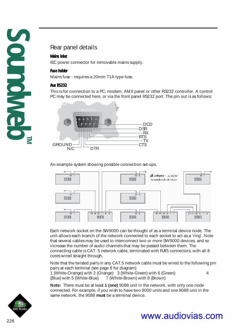
228
SoundwebTM
Rear panel details
Each network socket on the SW9000 can be thought of as a terminal device node. Theunit allows each branch of the network connected to each socket to act as a ‘ring’. Notethat several cables may be used to interconnect two or more SW9000 devices, and soincrease the number of audio channels that may be passed between them. Theconnecting cable is CAT. 5 network cable, terminated with RJ45 connectors, with all 8cores wired straight through.
Note that the twisted pairs in any CAT.5 network cable must be wired to the following pinpairs at each terminal (see page 8 for diagram):1 (White-Orange) with 2 (Orange) 3 (White-Green) with 6 (Green) 4(Blue) with 5 (White-Blue) 7 (White-Brown) with 8 (Brown)
Note: There must be at least 1 (one) 9088 unit in the network, with only one nodeconnected. For example, if you wish to have two 9000 units and one 9088 unit in thesame network, the 9088 must be a terminal device.
An example system showing possible connection set-ups.
DCDDSR
RXRTS
TXGROUND CTS
DTRN/C
Mains inletMains inletMains inletMains inletMains inletIEC power connector for removable mains supply.
Fuse holderFuse holderFuse holderFuse holderFuse holderMains fuse - requires a 20mm T1A type fuse.
Aux RS232Aux RS232Aux RS232Aux RS232Aux RS232This is for connection to a PC, modem, AMX panel or other RS232 controller. A controlPC may be connected here, or via the front panel RS232 port. The pin out is as follows:
www.audiovias.com

229
SoundwebTM
Control InputsUsed to connect switches or potentiometers to the 9000. These eight inputs are internally‘pulled up’ to +5V DC via a 4.7kOhm resistor, so no external voltage source is needed.Four common (ground) connections are provided (all connected together internally). A47kOhm log potentiometer connected between one input and common will allowparameters to be controlled linearly. Alternatively, a switch may be connected between aninput and common, or a multiway switch may be connected to several inputs with thewiper connected to common.
Logic OutputsUsed to connect the 9000 to ‘tally’ indicator LEDs or relays. There are eight standardlogic outputs which produce 0V or +5V DC via an internal 440 Ohm resistor. Twocommon (ground) connections are provided (connected together internally). A LEDconnected between one output (Anode, A) and common (Cathode, K) will illuminatewhen the logic output is activated, without requiring any external current limiting resistor.A high sensitivity relay (such as a reed relay) may be driven by connecting four outputs inparallel. This arrangement will develop 4V across a 500 Ohm coil, providing that all fouroutputs are made logic 1 simultaneously.
Opto outputIn addition to the eight standard logic outputs, there is an isolated output, which fails safe(open circuit) if the 9000 becomes faulty. This is effectively the collector-emitter of atransistor (which may be thought of as a switch) in series with a 220 Ohm protectionresistor. In conjunction with an external DC power source (max 80V), this may be used todrive various loads such as relays.
47kOhm logpotentiometer relay
switch
LEDrelay
multiway
- +V
www.audiovias.com

230
SoundwebTM
Technical specifications
GeneralGeneralGeneralGeneralGeneralMaximum network cable length 300m/1000ft
Power consumption <35VAMains Voltage 85-270V 50/60Hz
Control portsControl portsControl portsControl portsControl portsLogic output voltage 0 or +5V unloaded
Logic output impedance 440 OhmOpto output series impedance 220 Ohms (isolated)
Control input voltage 0 to 4.5vControl input impedance 4.7kOhms to +5V
Opto Output current 14mA maxOpto output withstanding voltage (off) 80V max.
Network cable wiringWiring convention for all CAT.5 cables.
Note: Looking at the wiring diagram,the clip on the terminator is facingaway (at the back of the connector).
Twisted pairs of wires in the cable areshown here grouped together.
www.audiovias.com

Installation Guide
www.audiovias.com

SoundwebTM
232
9008 Installation Guide
Regulatory InformationAn example of this equipment has been tested and found to comply with the followingEuropean and international Standards for Electromagnetic Compatibility and ElectricalSafety:
Emissions (EU): EN55013 (1990)
Generic Immunity (EU): EN50082-1 (1997)
Electrical Safety (EU): EN60065+A11 (1993)
Electrical Safety (USA): UL6500/ETL (1996)
Electrical Safety (CAN): CAN/CSA-E65/ETLc (1994)
Radiated Emissions (USA): FCC parts 15 Class B
For continued compliance with international EMC regulations, it is important that allcables be screened, and connected as follows:
• Audio cable screens to their 9008 connector ground.
• Control cable screens to the ground screws adjacent to the connector.
Network cables should be of type CAT. 5
IMPORTANT SAFETY INFORMATIONDo not remove covers.
No user serviceable parts inside - refer servicing to qualified service personnel.This equipment must be earthed.It should not be necessary to remove any protective earth or signal cable shieldconnections to prevent ground loops. Any such disconnections are outside therecommended practice of BSS Audio and will render the EMC or safety certificationvoid.
Mechanical Installation
If the unit is likely to undergo extreme vibration through extensive road trucking andtouring, it must be supported at the rear and/or sides to lessen the stress on the frontmounting flange. Use either a ready-built rack tray or mount the 9008 unit between otherunits. Damage caused by insufficient support is not covered by the warranty.
To prevent cosmetic damage to the front panel finish, use protective plastic cups underthe rack mounting bolts.
www.audiovias.com

SoundwebTM
9008 Installation Guide
233
Front Panel LED Functions
DSP ClipIlluminated = indicates that the processed signal is clipping internally.
Network
MasterFlashing = the network is initialising. If the led continues to flash formore than a few seconds, there is a cabling fault - either a double ringerror or a problem with one of the cable connectors.Steady = this unit has become the clock master for the network.Off = this unit is slaving to an external master clock.
SyncSteady = indicates the presence of one or more valid network connections.
Flashing = there is a problem with the incoming network signal - check connections and/or possibly the maximum cable length has been exceeded.
ActivityFlashing Yellow = indicates data transfer. The flashing is not regular, but dependent onthe rate of transfer.
Flashing Red = indicates bad data and is usually caused by network faults. Checknetwork connections, see Rear Panel details.
PowerIlluminated = indicates that the power supply is functioning.
www.audiovias.com

SoundwebTM
234
9008 Installation Guide
Rear Panel Details
Mains inletIEC power connector, for connection to mains supply (100-270V AC, 50/60Hz).
Mains fuse holderRequires a 20mm T1A type fuse. Do not replace with anything other than therecommended fuse.
Audio & Control connectors9008 audio and control connections are via Klippon (also known as BL, Phoenix orCombicon) pluggable terminal block connectors.8 x 6-way female Klippon connectors are supplied for making these connections.
For audio and network cables and looms, see the Product Overview 2000 catalogue from:
Direct Cable Systems Ltd.Tel: (020) 7485 0899www.directcable.co.uk
Neutricon-Neutricon tour grade network cable. P/N 150001
Phoenix-XLR audio cable P/N 100521
Audio Output wiring conventionSoundweb products provide cable shielding ‘back from the destination’ to eliminateground loop problems. Therefore, the shield (S) connection on an input is grounded,whereas the shield connection on an output is floating (although connected via aninternal network to ground for EMC compliance).
Balanced wiring - The convention for balanced wiring (2-core plus shield) is:
Balanced connection 9008 connection
Pin 3 : Cold '-'
Pin 2 : Hot '+'
Pin 1 : Shield
www.audiovias.com

SoundwebTM
9008 Installation Guide
235
Network In/OutThe Network Out socket on a Soundweb unit connects to the Network In socket onanother unit. Repeat this process to make a network of devices. Audio channels arepassed ‘downstream’ from the Net Out socket on the first unit to the Net In socket on thenext unit. The Soundweb system automatically completes this ‘daisy chain’ of deviceconnections to form a loop (using a 'back channel'), as shown by the dotted line in thediagram below.
This shows that audio channels are routed back from the terminal device (the one withouta connection to its Net Out socket) to the first device (the one without a connection on itsNet In socket).There must be no physical cable connection between the two end devices.
The connecting cable is CAT. 5 network cable terminated with RJ45 connectors, with all 8cores wired straight through.
Note that the twisted pairs in any CAT. 5 network cable must be wired to the following pinpairs at each terminal:
1 (White/Orange) with 2 (Orange)
3 (White/Green) with 6 (Green)
4 (Blue) with 5 (White/Blue)
7 (White/Brown) with 8 (Brown)
Aux. RS232An alternative connection for a control PC, modem or AMX/Crestron type panel. Thisport works at 115200bps. Note that AMX panels only currently connect at 38400bps.
1-DCD6-DSR2-RX7-RTS3-TX8-CTS5-GROUND
4-DTR9-N/C
www.audiovias.com

SoundwebTM
236
9008 Installation Guide
CONTROL INPUTSUsed to connect switches or potentiometers, e.g. 9012 selector wallplate (Part no. Z-SW9012).
Looking at the control port connector (on the back of the unit), there are two common(ground) connections C to the left of the eight CONTROL INPUTS and, two softwareassignable reference voltage outputs R to the right.
The control ports now have two modes of operation. In Soundweb Designer's ControlPorts window these are labelled '2-wire' and '3-wire'.
2-wire mode
In this mode the eight CONTROL INPUTS are internally ‘pulled up’ to +5V DC via a4.7kOhm resistor. Therefore, no external voltage source is needed to create contactclosure to ground for switches such as mute buttons or, resistance to ground (for othermulti-state or continuous controls such as Parameter Presets or faders).
See the Soundweb Designer help for a table of resistor values for use with ParameterPresets or source selectors.
Two 'common' ground connections are provided using the two C connectors to the left ofthe CONTROL INPUTS.
A 47kOhm-log potentiometer (Part no. DM10018) connected between a control inputand common will allow parameters to be controlled linearly.3-wire mode
This mode allows the use of linear pots or faders for continuous controls. A pot would bewired as a potential divider with the top of the track connected to the reference output R,the wiper to a control input and the bottom of the track to a common C. For goodperformance pots with track resistance between 10K and 100KOhms are recommended.
LOGIC OUTPUTSUsed to connect ‘tally’ indicator LED’s or relays.
There are eight standard LOGIC OUTPUTS which produce 0V or +5V DC via an internal440 Ohm resistor and two internally connected common (ground) connections C.
An LED connected between one output (Anode, A) and common (Cathode, K) willilluminate when the logic output is activated, without requiring any external currentlimiting resistor.
A high sensitivity relay (such as a reed relay) may be driven by connecting four outputs inparallel. This arrangement will develop 4V across a 500-Ohm coil, providing that all fouroutputs are made logic 1 simultaneously.
OPTO OutputIn addition to the eight standard logic outputs, there is an isolated output, which fails safe(open circuit) if the unit becomes faulty.
This is effectively the collector-emitter of a transistor (which may be thought of as aswitch), in series with a 220-Ohm protection resistor. In conjunction with an external DCpower source (max 80V), this may be used to drive various loads such as relays.
www.audiovias.com

SoundwebTM
9008 Installation Guide
237
Control Inputs and Logic Outputs connection diagram
switch
2 wire mode
relayLED
relay
3600R1800R
1200R
unconnected
ladder
+supplyvoltage
47kOhmlog
potentiometer
10K-100kOhmlinear
potentiometer
switch
1k1k
1k
ladder
1k
ground
4k7
3 wire mode
470R
www.audiovias.com

SoundwebTM
238
9008 Installation Guide
ZM10085 V1.1 CB 100101
9008 Technical Specifications
General
DSP capability 200MIPS (Million Instructions Per Second)Frequency response 15Hz to 20KHz (+-0.5dB)Total Harmonic Distortion (THD) <0.01% (20Hz to 0KHz, +10dBu output)Dynamic range 105dB typical (22Hz to 22KHz unweighted)
108dB typical (A-weighted)Maximum output level +20dBuInter-channel crosstalk <-75dBMaximum network cable length 300m/1000ftMains supply 85-270V AC, 50/60HzPower consumption <35VA
Control Ports
Control input voltage 0 to 4.5vControl input impedance (2 wire mode) 4.7kOhms to +5VControl input impedance (3 wire mode) >1MOhmLogic output voltage 0 or +5V unloadedLogic output impedance 440 OhmOpto output current 14mA maxOpto output withstanding voltage 80V maxOpto output series impedance 220 Ohms (isolated)
www.audiovias.com

Installation Guide9010 Remote Control
www.audiovias.com

2
Regulatory InformationAn example of this equipment has been tested and found to comply withthe following European and international Standards for ElectromagneticCompatibility (only when used with a metal wallbox).
Radiated Emissions (USA): FCC part 15 Class ARadiated Emissions (EU): EN55022 (1990) Associated Equip.Immunity (EU): EN50082/1 (1992) RF Immunity,Fast
Transients ESD
Important safety informationIt should not be necessary to remove any protective earth or signal cableshield connections to prevent ground loops. Any such disconnections areoutside the recommended practice of BSS Audio, and will render the EMCcertificate void.
We have written this guide with the aim of helping installers and soundengineers to get the most out of the 9010. We recommend that you readthis manual, particularly the section on installation, before attempting tooperate the unit.
Mechanical InstallationThe 9010 is designed to fit into a standard 3-gang US wallbox. Screws areprovided to fix the unit in place. An optional bezel is available to ‘dress’the edges of the panel if required.
Dimensions of the unit are shown below. The use of a metal wall box toensure that the installation meets necessary EMC standards isrecommended.
For suitable wallboxes, contact your distributor for part Z-010-BOX.
www.audiovias.com

3
PowerThe 9010 requires 24v DC to be suppliedexternally.
There are two ways to power the unit:
• Connect a 24v DC power supply to the Power/Mic/Logic screw terminal
block. Up to three more 9010’s may be powered via network cablingfrom the Net Out of the 9010 which has the power supply connected(depending on cable length). Refer to diagrams on page 7 for more details.
• If it is inconvenient to cable a DC feed into the wallbox for the 9010,power may be applied via the network cable (on the Net In side), by usingthe Soundweb 9011 Power Interface to inject 24v DC from the powersupply. Up to three more 9010’s may be powered via network cablingfrom the Net Out of the 9010 which has the power supply connected(depending on cable length).
To assist calculating the maximum cable lengths between 9010s, refer tothe spreadsheet 9010pwr.xls, which may be found in the SoundwebDesigner PC installation, or on our website, www.bss.co.uk.
Front panel LED functionsActivity (yellow)Irregular Flashing - This LED indicates data transfer
Sync (green)Steady - This indicates the presence of one or more valid networkconnections.
Flashing - There is a problem with the incoming network signal - possiblythe maximum cable length has been exceeded.
Master (yellow)Flashing - The network is initialising. If it continues to flash for more thana few seconds, there is a cabling fault - either a double ring error or aproblem with one of the cable connectors.
Steady - This unit has become the clock master for the network.
Off - This unit is slaving to the master’s clock.
www.audiovias.com

4
Front panel detailsDisplay Contrast buttonThis is used to optimise the contrast of the display. Press and hold thecontrast button to adjust. If you go past the optimum setting, keep holdingthe button so that adjustment starts from the beginning again.
Backlit graphics displayThe details displayed are specified by the Soundweb Designer software.
Six push buttonsAs with the rotary control, the operation of these are determined by theSoundweb Designer software.
MicrophoneThe built-in microphone may be used for paging etc. The routing of thesignal from the microphone is determined by the Soundweb Designersoftware.
Rotary controlUsed to adjust parameter values. The function of this control is determinedentirely by the Soundweb Designer software.
www.audiovias.com

5
Rear panel detailsNetwork In/Out*Network In - connects to the Network Out socket on another unit.Connecting multiple units is done in the same way - In to Out.
Refer to the 9088 installation guide and Soundweb Designer help forfurther details.
The connecting cable is CAT. 5 network cable, terminated with RJ45connectors, with all 8 cores wired straight through.
Note that the twisted pairs in any CAT.5 network cable must be wired tothe following pin pairs at each terminal:
11111 (White-Orange) with 2 2 2 2 2 (Orange)
33333 (White-Green) with 66666 (Green)44444 (Blue) with 5 (White-Blue)
77777 (White-Brown) with 88888 (Brown)
Power/Mic/Logic screw terminal block*Power InPower InPower InPower InPower In
DC power input (+24V and Gnd). See Power section.
Mic Mic Mic Mic Mic _, +, S, +, S, +, S, +, S, +, S
Three connections for an external dynamic microphone:
Mic -
Mic +
Mic Screen
www.audiovias.com

6
Serial Port*RS232RS232RS232RS232RS232
For connection to a PC running Soundweb Designer. The 10-pin IDCconnector is arranged so that a short IDC ribbon cable can be connectedto a male 9-pin D type connector to form an adapter cable. A standard'null-modem' cable can be used to connect a PC to the adapter cable.
Expansion Port*Right/Left Outputs/Audio GndRight/Left Outputs/Audio GndRight/Left Outputs/Audio GndRight/Left Outputs/Audio GndRight/Left Outputs/Audio Gnd
An unbalanced line-level feed for use in custom applications, e.g.monitoring etc. The outputs are polarity inverted so that external invertingamplifiers may be used. The signal on these outputs is determined by theSoundweb Designer software.
Mic Shield, Mic Mic Shield, Mic Mic Shield, Mic Mic Shield, Mic Mic Shield, Mic _, Mic+, Mic+, Mic+, Mic+, Mic+
Commoned with the Mic In terminals on the Power/Mic/Logic screwterminal block.
+5Vdc Out+5Vdc Out+5Vdc Out+5Vdc Out+5Vdc Out
A low current regulated +5V output for supplying power to electronics forcustom applications. No more than 100mA may be drawn. Current drawnfrom this output will impact the length of network cable that may be usedbetween the power supply and the 9010.
*refer to label on back of unit for connection positions.www.audiovias.com

7
When using the 9010 unit with a 9011 power interface, connect asfollows:
AccessoriesZ-010-BEZEL Soundweb 9010 BezelA sculptured plastic surround to ‘dress’ the 9010 panel edges for moreelegant presentation.
Z-999-PSU Soundweb Power supply kitA 24Vdc universal input power supply suitable for powering up to four9010’s. This is a free-standing unit with integral IEC power inlet.
Z-010-BOX Soundweb 9010 wallboxA standard U.S. 3-gang outlet wallbox suitable for housing the 9010 in aninstallation.
Z-SW9011 Soundweb Power InterfaceAllows DC power from a power supply to be injected into the networkcable feeding the 9010(s).
Connecting to a power supplyConnecting to a power supplyConnecting to a power supplyConnecting to a power supplyConnecting to a power supply
If using the 9010 unit without a 9011 power interface, the network and9010 should be connected in the following fashion:
www.audiovias.com

8
9010 Remote Control Technical specifications
External Microphone InputFrequency response (+-1dB) 20Hz to 20KHzTHD 0.05% (20Hz to 20KHz, +10dBu output)Dynamic range 80dB typ. (22Hz to 22KHz unweighted)Gain control range 34 to 72dBMaximum input level -20dBuInput impedance 2k OhmEquivalent Input Noise -106dBu @150 Ohm
Audio OutputsFrequency response (+-1dB) 20Hz to 20KHzTHD <0.05%(20Hz to 20KHz, 0dBu output)Dynamic range 88dB typ. (22Hz to 22KHz unweighted)Maximum output level +4dBuOutput impedance 220 Ohm
Note - polarity is inverted to allow external headphone amplifier or linedriver to be inverting.
GeneralMaximum network cable length 300m/1000ftPower consumption <5VA (<200mA at 24V DC)
ZM10046-02 CB/PW/JMK/SH 311000www.audiovias.com

247
SoundwebTM
SoundwebTM 9012Installation Guide
www.audiovias.com
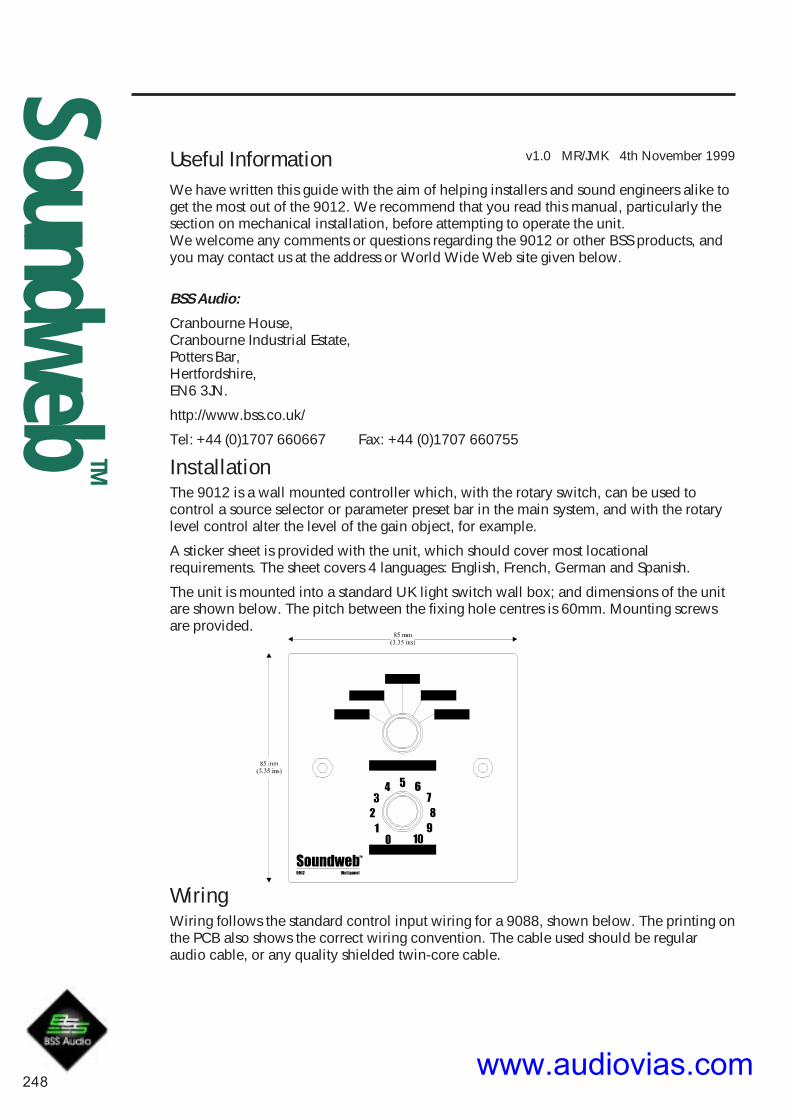
248
SoundwebTM
v1.0 MR/JMK 4th November 1999Useful InformationWe have written this guide with the aim of helping installers and sound engineers alike toget the most out of the 9012. We recommend that you read this manual, particularly thesection on mechanical installation, before attempting to operate the unit.We welcome any comments or questions regarding the 9012 or other BSS products, andyou may contact us at the address or World Wide Web site given below.
BSS Audio:
Cranbourne House,Cranbourne Industrial Estate,Potters Bar,Hertfordshire,EN6 3JN.
http://www.bss.co.uk/
Tel: +44 (0)1707 660667 Fax: +44 (0)1707 660755
InstallationThe 9012 is a wall mounted controller which, with the rotary switch, can be used tocontrol a source selector or parameter preset bar in the main system, and with the rotarylevel control alter the level of the gain object, for example.
A sticker sheet is provided with the unit, which should cover most locationalrequirements. The sheet covers 4 languages: English, French, German and Spanish.
The unit is mounted into a standard UK light switch wall box; and dimensions of the unitare shown below. The pitch between the fixing hole centres is 60mm. Mounting screwsare provided.
WiringWiring follows the standard control input wiring for a 9088, shown below. The printing onthe PCB also shows the correct wiring convention. The cable used should be regularaudio cable, or any quality shielded twin-core cable.
www.audiovias.com

249
SoundwebTM
through wall toSoundweb units
Example setupShown below is a typical Soundweb setup for use with the 9012 wall panel.
Parts for the 9012 are also available as spares, should you wish to design your owncontrol panels.
BSS Part numbers are:
Source switch: DH10007
Level pot: DM10018
Please contact BSS sales for more details.
www.audiovias.com

250
SoundwebTM
SoundwebTM 9014Installation Guide
www.audiovias.com

251
SoundwebTM
Regulatory InformationAn example of this equipment has been tested and found to comply with the following Europeanand international Standards for Electromagnetic Compatibility (only when used with a metalwallbox).Radiated Emissions (EU): EN55022 (1995) Associated Equip.Immunity (EU): EN50082/1 (1997) RF Immunity, Fast Transients ESDRadiated Emissions (USA): FCC part 15 Class A
v1.0 MR/JMK 8th September 1999
Important safety information - read and followIt should not be necessary to remove any protective earth or signal cable shieldconnections to prevent ground loops. Any such disconnections are outside therecommended practice of BSS Audio, and will render the EMC certificate void.We have written this guide with the aim of helping installers and sound engineers alike toget the most out of the 9014. We recommend that you read this manual, particularly thesection on mechanical installation, before attempting to operate the unit.We welcome any comments or questions regarding the 9014 or other BSS products, andyou may contact us at the address or World Wide Web site given below.
BSS Audio:
Cranbourne House,Cranbourne Industrial Estate,Potters Bar,Hertfordshire,EN6 3JN.
www.bss.co.uk
Tel: +44 (0)1707 660667 Fax: +44 (0)1707 660755
Mechanical InstallationDimensions of the unit are shown below.
Three 9014 devices can be mounted side-by-side with a 1U panel, available from BSSAudio as part number Z-999-FPNL.
BSS Audio also offer a universal AC input +24V DC power supply, available as partnumber Z-999-PSU.
The panel can be used to rack mount one or two 9014 devices if required, and can befitted with the Z-999-PSU power supply, with the use of a PSU tray; part number Z-999-TRAY.
www.audiovias.com

252
SoundwebTM
UseThe 9014 requires 12-24v DC to be supplied externally. There are two ways of gettingpower into the unit:
• Connect a 24v 1A DC power supply to the 2.4mm barrel connector. Up to nine more9014s may be powered from the paralleled combicon connector.
• Connect a 12-24v DC power supply to the combicon connector.
A pair of 9014 Fibre Interface units are used to replace a standard category 5 Soundwebnetwork cable. Each fibre cable will transfer 8 channels of digital audio plus control data.
To utilise the fibre system, each end of the fibre link requires one 9014 device. Eachdevice is equipped with an RJ-45 Soundweb network cable jack into which the networkcable is connected, and two snap-in SC type fibre connectors.
Two fibre cables are then required to connect between 9014 devices - this is to enable thebi-directional data transfer.
Network socketThis connects to either the Network Out socket or the Network In socket on another unit.
The connecting cable is CAT. 5 network cable, terminated with RJ45 connectors, with all8 cores wired straight through.
Note that the twisted pairs in any CAT.5 network cable must be wired to the following pinpairs at each terminal:
1 (White-Orange) with 2 (Orange); 3 (White-Green) with 6 (Green);4 (Blue) with 5 (White-Blue); 7 (White-Brown) with 8 (Brown)
Note:
Ensure that all Out sockets are connected to their correct In sockets at each end of everycable. Connecting In - In (or Out - Out) will result in improper operation of the network.
www.audiovias.com

253
SoundwebTM
Rear panel connectionsThe unit has the following connections on the rear face:
PowerPhoenix socket: Power supply to or from a 9011 power interface.
Barrel socket: Power supply from a Z-999-PSU power supply.
NetworkSignal at the network socket is in electrical form.
The network socket is bi-directional, so information can pass in and out of the 9014 unitthrough this connection simultaneously. It is also auto-sensing, meaning that it can beconnected to either an OUT or an IN socket on one of the other Soundweb series units.
Fibre-in/outSignal at the fibre in/out sockets has been converted to an optical format.
Information arriving from a Soundweb unit at the network socket is passed through the9014 for conversion, and out of the fibre out socket.
Information arriving at the fibre in socket is passed through the 9014 for conversion andout of the network socket.
Front panel LED functionsThe unit has three LED indicators showing:
PowerSteady - This indicates the power supply is functioning.
Fibre-inSteady – Data is arriving on the fibre input.
Intermittent – You have exceeded the optical power budget by either exceeding themaximum fibre length or by having too much attenuation in fibre splices. See thespecification section.
Cable-inSteady – Data is arriving on the cable.
www.audiovias.com

254
SoundwebTM
Technical specifications
PowerPowerPowerPowerPowerDC Supply 12-24V DC, <5VA
ConnectorPhoenix screw terminal or 2.4mm inline barrel connector
NetworkNetworkNetworkNetworkNetworkSingle RJ-45 Auto-sensed input node or output node - no setup required.
Max cable length 20m
Fibre ConnectionFibre ConnectionFibre ConnectionFibre ConnectionFibre ConnectionSnap-in SC fibre inputSnap-in SC fibre output
Fibre cableFibre cableFibre cableFibre cableFibre cableMultimode 62.5/125um or Multimode 50/125um
Optical Power BudgetOptical Power BudgetOptical Power BudgetOptical Power BudgetOptical Power Budget10dB
Max fibre length 2000 metres/6550 feet/1.2 miles
N.B this distance is based on the optical power budget and maximum allowable networkdelay of one sample in any one ring.
Dimensions 5.3" x 5.5" x 1.4"
135 x 139 x 36mm
www.audiovias.com

255
SoundwebTM
SoundwebTM
9088Installation Guide
www.audiovias.com

SoundwebTM
256
Regulatory InformationAn example of this equipment has been tested and found to comply with the following Europeanand international Standards for Electromagnetic Compatibility and Electrical Safety:Radiated Emissions (EU): EN55013 (1990) Associated EquipmentImmunity (EU): EN50082/1 (1992) RF Immunity, Fast Transients ESDMains Disturbance (EU): EN61000/3/2 (1995)Electrical Safety (EU): EN60065 (1993)Radiated Emissions (USA): FCC part 15 Class BElectrical safety (USA): UL813
Mechanical Installation
v1.2 JK 4th June 1998
Important user informationDo not remove covers. No user serviceable parts inside, refer servicing to qualified servicepersonnel. For continued compliance with international EMC regulations, it is important that allcables be screened, and connected as follows: Audio cable screens to their 9088 connectorground. Control cable screens to the ground screws adjacent to the connector. Network cablesshould be of type CAT.5, fitted with a clip-on ferrite sleeve (STEWART TYPE 28A2029-0A0) nearthe network socket end. This equipment must be earthed. It should not be necessary to remove anyprotective earth or signal cable shield connections to prevent ground loops. Any suchdisconnections are outside the recommended practice of BSS Audio, and will render the EMC orsafety certificate void.
If the unit is likely to undergo extreme vibration through extensive road trucking and touring, theunit must be supported at the rear and/or sides to lessen the stress on the front mounting flange.The necessary support can generally be bought ready-built as a rack tray, or the 9088 unit can bemounted between other units. Damage caused by insufficient support is not covered by thewarranty. To prevent cosmetic damage to the front panel finish, use protective plastic cups underthe rack mounting bolts.
www.audiovias.com

257
SoundwebTM
Front panel LED functionsInput monitoringInput monitoringInput monitoringInput monitoringInput monitoring
Each channel has 3 LED indicators showing:
ClipClipClipClipClipIlluminated - Excessive signal level, close to clip.
SignalSignalSignalSignalSignalIlluminated - A signal is present on this channel input.
PhantomPhantomPhantomPhantomPhantomIlluminated - Phantom power is active for this mic channel.
ALL flashing - Unit selected in Soundweb designer/Network view.
DSP ClipDSP ClipDSP ClipDSP ClipDSP ClipIlluminated - Indicates that the signal is clipping internally.
NetworkNetworkNetworkNetworkNetwork
MasterMasterMasterMasterMasterFlashing - The network is initialising. If it continues to flash for more than a few seconds,there is a cabling fault - either a double ring error or a problem with one of the cableconnectors.
Steady - This unit has become the clock master for the network.
Off - This unit is slaving to the master's clock.
SyncSyncSyncSyncSyncSteady - This indicates the presence of one or more valid network connections.
Flashing - There is a problem with the incoming network signal - possibly the maximumcable length has been exceeded.
ActivityActivityActivityActivityActivityFlashing - This LED indicates data transfer. The flashing is not regular, but dependant onthe rate of transfer.
PowerPowerPowerPowerPowerSteady - This indicates that the power supply is functioning.
www.audiovias.com

SoundwebTM
258
Audio & Control cable wiring detailsAll audio and control connections to the 9088 are via Klippon pluggable terminal blockconnectors (also known as BL, Phoenix or Combicon). 6-way female Klippon connectorsare supplied for making these connections.
Aud io I npu t and Ou tpu t w ir i ng conven t i onAud io I npu t and Ou tpu t w ir i ng conven t i onAud io I npu t and Ou tpu t w ir i ng conven t i onAud io I npu t and Ou tpu t w ir i ng conven t i onAud io I npu t and Ou tpu t w ir i ng conven t i onSoundweb products provide cable shielding ‘back from the destination’ to eliminateground loop problems. This means that the shield (S) connection on an input isgrounded, whereas the shield connection on an output is floating (although connectedvia an internal network to ground for EMC compliance).
Balanced wiring - The convention for balanced wiring (2-core plus shield) is:
Balanced connection 9088 connection
Pin 3: Cold '-'Pin 2 : Hot '+'Pin 1 : Shield
Unbalanced wiring - The convention for unbalanced wiring to the inputs (1-core plusshield) is:
Unbalanced connection 9088 connection
Pin 1: ShieldPin 2 : Hot '+'
Pin 3 : Link to Pin 1(Optional for 9088 inputs)
RX - 5GND - 4
TX - 3RTS - 1
CTS - 2
Front panel detailsRS232RS232RS232RS232RS232Used to connect one of the 9088 units in the network to a controller PC (cable suppliedwith unit), which can then communicate with any device on the network. The pin out is:
www.audiovias.com

259
SoundwebTM
Rear panel detailsMains inletMains inletMains inletMains inletMains inletIEC power connector for removable mains supply.
Fuse holderFuse holderFuse holderFuse holderFuse holderMains fuse - requires a 20mm T1A type fuse.
Network In/OutNetwork In/OutNetwork In/OutNetwork In/OutNetwork In/OutNetwork In - connects to the Network Out socket on another unit. Connecting multipleunits is done in the same way - In to Out. This allows audio channels to be passed‘downstream’ from the Net Out socket on one device to the Net In socket on the nextdevice. The Soundweb system automatically completes this ‘daisy chain’ of deviceconnections to form a loop (using a back-channel), as shown by the dotted line in thediagram below. This shows that audio channels may be routed back from the terminaldevice (the one without a connection on its Net Out socket) to the first device (the onewithout a connection on its Net In socket). There must be no physical cable connectionbetween these two end devices however.
The connecting cable is CAT. 5 network cable, terminated with RJ45 connectors, with all8 cores wired straight through.
Note that the twisted pairs in any CAT.5 network cable must be wired to the following pinpairs at each terminal:
1 (White-Orange) with 2 (Orange) 3 (White-Green) with 6 (Green)4 (Blue) with 5 (White-Blue) 7 (White-Brown) with 8 (Brown)
Aux RS232Aux RS232Aux RS232Aux RS232Aux RS232This is for connection to a PC, modem or AMX panel (a control PC may be connectedhere, or via the front panel RS232 port).
DCDDSR
RXRTS
TXGROUND CTS
DTRN/C
www.audiovias.com

SoundwebTM
260
Control InputsUsed to connect switches or potentiometers to the 9088. These eight inputs are internally‘pulled up’ to +5V DC via a 4.7kOhm resistor, so no external voltage source is needed.Four common (ground) connections are provided (all connected together internally). A47kOhm log potentiometer connected between one input and common will allowparameters to be controlled linearly. Alternatively, a switch may be connected betweenan input and common, or a multiway switch may be connected to several inputs with thewiper connected to common.
Logic OutputsUsed to connect the 9088 to ‘tally’ indicator LEDs or relays. There are eight standard logicoutputs which produce 0V or +5V DC via an internal 440 Ohm resistor. Two common(ground) connections are provided (connected together internally). A LED connectedbetween one output (Anode, A) and common (Cathode, K) will illuminate when the logicoutput is activated, without requiring any external current limiting resistor. A highsensitivity relay (such as a reed relay) may be driven by connecting four outputs inparallel. This arrangement will develop 4V across a 500 Ohm coil, providing that all fouroutputs are made logic 1 simultaneously.
Opto outputIn addition to the eight standard logic outputs, there is an isolated output, which fails safe(open circuit) if the 9088 becomes faulty. This is effectively the collector-emitter of atransistor (which may be thought of as a switch) in series with a 220 Ohm protectionresistor. In conjunction with an external DC power source (max 80V), this may be used todrive various loads such as relays.
47kOhm logpotentiometer
relay
switch
LEDrelay
multiway
-V +V
www.audiovias.com

261
SoundwebTM
Technical specificationsGeneralGeneralGeneralGeneralGeneral
Frequency response (+-0.5dB) 15Hz to 20KHzTHD <0.01% (20Hz to 0KHz, +10dBu output)
Dynamic range 100dB typ. (22Hz to 22KHz unweighted)103dB typ. (A-weighted)
Maximum output level +20dBuInter-channel Crosstalk <-75dB
Maximum network cable length 300m/1000ftPower consumption <35VA
Mains Volts 85-270V 50/60Hz
Line input cardLine input cardLine input cardLine input cardLine input cardInput Impedance 10kOhms
Maximum input level +20dBu (+8dBu with 12dB gain)Gain range 0 or 12dB
Universal microphone/Line input cardUniversal microphone/Line input cardUniversal microphone/Line input cardUniversal microphone/Line input cardUniversal microphone/Line input cardInput impedance 3.5kOhms
Maximum input level +20dBu (with 0dB gain)Gain range 0 to 70dB
CMRR >75dB at 1KHzEquivalent Input Noise (EIN) <-128dBu typ with 150 Ohms source
Phantom power 48V nominal
Control portsControl portsControl portsControl portsControl portsLogic output voltage 0 or +5V unloaded
Logic output impedance 440 OhmOpto output series impedance 220 Ohms (isolated)
Control input voltage 0 to 4.5vControl input impedance 4.7kOhms to +5V
Opto Output current 14mA maxOpto output withstanding voltage (off) 80V max.
www.audiovias.com

Soundweb 9088ii Installation Guide
262
SoundwebTMInstallation Guide
www.audiovias.com

Soundweb 9088ii Installation Guide
263
SoundwebTM
Regulatory InformationAn example of this equipment has been tested and found to comply with the followingEuropean and international Standards for Electromagnetic Compatibility and ElectricalSafety:
Emissions (EU): EN55013 (1990)Generic Immunity (EU): EN50082-1 (1997)Electrical Safety (EU): EN60065+A11 (1993)Electrical Safety (USA): UL6500/ETL (1996)Electrical Safety (CAN): CAN/CSA-E65/ETLc (1994)Radiated Emissions (USA): FCC parts 15 Class B
IMPORTANT SAFETY INFORMATIONDo not remove covers.No user serviceable parts inside - refer servicing to qualified service personnel.
This equipment must be earthed.It should not be necessary to remove any protective earth or signal cable shieldconnections to prevent ground loops. Any such disconnections are outside therecommended practice of BSS Audio and will render the EMC or safety certificationvoid.
For continued compliance with international EMC regulations, it is important that allcables be screened, and connected as follows:• Audio cable screens to their 9088 connector ground.• Control cable screens to the ground screws adjacent to the connector.
Network cables should be of type CAT. 5
Mechanical InstallationIf the unit is likely to undergo extreme vibration through extensive road trucking andtouring, it must be supported at the rear and/or sides to lessen the stress on the frontmounting flange. Use either a ready-built rack tray or mount the 9088 unit between other
www.audiovias.com

Soundweb 9088ii Installation Guide
264
SoundwebTM
Front Panel LED Functions
Input MonitoringInput MonitoringInput MonitoringInput MonitoringInput Monitoring
Each channel has 3 LED indicators showing:
ClipClipClipClipClipIlluminated = excessive signal level.
SignalSignalSignalSignalSignalIlluminated = signal is present on this channel input.
PhantomPhantomPhantomPhantomPhantomIlluminated = phantom power is active for this Mic channel.ALL flashing = this device is selected in Soundweb Designer's Network view.Scrolling from right to left = recovery mode, the device's firmware needs reloading.
DSP ClipDSP ClipDSP ClipDSP ClipDSP ClipIlluminated = indicates that the processed signal is clipping internally.
NetworkNetworkNetworkNetworkNetwork
MasterMasterMasterMasterMasterFlashing = the network is initialising. If the led continues to flash formore than a few seconds, there is a cabling fault - either a doublering error or a problem with one of the cable connectors.Steady = this unit has become the clock master for the network.Off = this unit is slaving to an external master clock.
SyncSyncSyncSyncSyncSteady = indicates the presence of one or more valid network connections.
Flashing = there is a problem with the incoming network signal - check connections and/or possibly the maximum cable length has been exceeded.
ActivitActivitActivitActivitActivityyyyyFlashing Yellow = indicates data transfer. The flashing is not regular, but dependent onthe rate of transfer.Flashing Red = indicates bad data and is usually caused by network faults. Checknetwork connections, see Rear Panel details.
PowerPowerPowerPowerPowerIlluminated = indicates that the power supply is functioning.
www.audiovias.com

Soundweb 9088ii Installation Guide
265
SoundwebTM
Balanced wiring - The convention for balanced wiring (2-core plus shield) is:
Balanced connection 9088 connection
Pin 3 : Cold '-'Pin 2 : Hot '+'Pin 1 : Shield
This wiring can also be applied to the AES digital interface card.
Rear Panel Details
Audio & Control connectors9088 audio and control connections are via Klippon (also known as BL, Phoenix orCombicon) pluggable terminal block connectors.12 x 6-way female Klippon connectors are supplied for making these connections.For audio and network cables and looms, see the Product Overview 2000 catalogue from:Direct Cable Systems Ltd.Tel: (020) 7485 0899www.directcable.co.ukNeutricon-Neutricon tour grade network cable. P/N 150001Phoenix-XLR audio cable P/N 100521
Audio & AES/EBU Input and Output wiring conventionSoundweb products provide cable shielding ‘back from the destination’ to eliminateground loop problems. Therefore, the shield (S) connection on an input is grounded,whereas the shield connection on an output is floating (although connected via an inter-nal network to ground for EMC compliance).
Unbalanced wiring (analogue audio only) - The convention for unbalanced wiring to theinputs (1-core plus shield) is:
Unbalanced connection 9088 connection
Pin 1 : ShieldPin 2 : Hot '+'Pin 3 : Link to Pin 1
(Optional for 9088 inputs)
www.audiovias.com

Soundweb 9088ii Installation Guide
266
SoundwebTM
Mains inletIEC power connector, for connection to mains supply (100-270V AC, 50/60Hz).
Mains fuse holderRequires a 20mm T1A type fuse. Do not replace with anything other than the recom-mended fuse.
Network In/OutThe Network Out socket on a Soundweb unit connects to the Network In socket onanother unit. Repeat this process to make a network of devices. Audio channels arepassed ‘downstream’ from the Net Out socket on the first unit to the Net In socket on thenext unit. The Soundweb system automatically completes this ‘daisy chain’ of deviceconnections to form a loop (using a 'back channel'), as shown by the dotted line in thediagram below.This shows that audiochannels are routedback from the terminaldevice (the one with-out a connection to itsNet Out socket) to thefirst device (the one without a connection on its Net In socket).
There must be no physical cable connection between the two end devices.The connecting cable is CAT. 5 network cable terminated with RJ45 connectors, with all 8cores wired straight through.
Note that the twisted pairs in any CAT. 5 network cable must be wired to the following pinpairs at each terminal:
1 (White/Orange) with 2 (Orange)
3 (White/Green) with 6 (Green)
4 (Blue) with 5 (White/Blue)
7 (White/Brown) with 8 (Brown)
Aux. RS232An alternative connection for a control PC, modem or AMX/Crestron type panel. Thisport works at 115200bps. Note that AMX panels only currently connect at 38400bps.
1-DCD6-DSR2-RX7-RTS3-TX8-CTS5-GROUND
4-DTR9-N/C www.audiovias.com

Soundweb 9088ii Installation Guide
267
SoundwebTM
CONTROL INPUTSUsed to connect switches or potentiometers, e.g. 9012 selector wallplate (Part no. Z-SW9012). Looking at the control port connector (on the back of the unit), there are twocommon (ground) connections C to the left of the eight CONTROL INPUTS and, twosoftware assignable reference voltage outputs R to the right.
The control ports now have two modes of operation. In Soundweb Designer's ControlPorts window these are labelled '2-wire' and '3-wire'.
2-wire modeIn this mode the eight CONTROL INPUTS are internally ‘pulled up’ to +5V DC via a4.7kOhm resistor. Therefore, no external voltage source is needed to create contactclosure to ground for switches such as mute buttons or, resistance to ground (for othermulti-state or continuous controls such as Parameter Presets or faders).
See the Soundweb Designer help for a table of resistor values for use with ParameterPresets or source selectors.
Two 'common' ground connections are provided using the two C connectors to the left ofthe CONTROL INPUTS.
A 47kOhm-log potentiometer (Part no. DM10018) connected between a control inputand common will allow parameters to be controlled linearly.
3-wire modeThis mode allows the use of linear pots or faders for continuous controls. A pot would bewired as a potential divider with the top of the track connected to the reference output R,the wiper to a control input and the bottom of the track to a common C. For goodperformance pots with track resistance between 10 and 100KOhms are recommended.
LOGIC OUTPUTSUsed to connect ‘tally’ indicator LED’s or relays.
There are eight standard LOGIC OUTPUTS which produce 0V or +5V DC via an internal440 Ohm resistor and two internally connected common (ground) connections C.An LED connected between one output (Anode, A) and common (Cathode, K) willilluminate when the logic output is activated, without requiring any external currentlimiting resistor.
A high sensitivity relay (such as a reed relay) may be driven by connecting four outputs inparallel. This arrangement will develop 4V across a 500-Ohm coil, providing that all fouroutputs are made logic 1 simultaneously.
OPTO OutputIn addition to the eight standard logic outputs, there is an isolated output, which fails safe(open circuit) if the unit becomes faulty.
www.audiovias.com

Soundweb 9088ii Installation Guide
268
SoundwebTMswitch
2 wire mode
relayLED
relay
3600R1800R
1200R
unconnected
ladder
+supplyvoltage
47kOhmlog
potentiometer
10K-100kOhmlinear
potentiometer
switch
1k1k
1k
ladder
1k
ground
4k7
3 wire mode
470R
Control Inputs and Logic Outputs connection diagram
www.audiovias.com

Soundweb 9088ii Installation Guide
269
SoundwebTM
9088ii Technical SpecificationsGeneral
DSP capability 200MIPS (Million Instructions Per Second)Frequency response 15Hz to 20KHz (+-0.5dB)Total Harmonic Distortion (THD) <0.01% (20Hz to 0KHz, +10dBu output)Dynamic range 105dB typical (22Hz to 22KHz unweighted)
108dB typical (A-weighted)Maximum output level +20dBuInter-channel crosstalk <-75dBMaximum network cable length 300m/1000ftMains supply 85-270V AC, 50/60HzPower consumption <35VA
Control PortsControl input voltage 0 to 4.5vControl input impedance (2 wire mode) 4.7kOhms to +5VControl input impedance (3 wire mode) >1MOhmLogic output voltage 0 or +5V unloadedLogic output impedance 440 OhmOpto output current 14mA maxOpto output withstanding voltage 80V maxOpto output series impedance 220 Ohms (isolated)
Card Options:
Universal microphone/line input cardInput impedance 3.5kOhmsMaximum input level +20dBu (with 0dB gain)Gain range 0 to 70dBCMRR >75dB at 1KHzEquivalent Input Noise (EIN) <-128dBu typical (with 150 Ohms source)Phantom power 48V nominal
AES Digital CardInterface standard AES/EBUDigital resolution 24bitSupported input sampling rates 32-96kHzSupported output sampling rates 44.1, 48, 88.2, 96kHz
(independent for each output)Output clock source Internal, Inputs 1 & 2, External Word Clock
or System Clock (48kHz)
www.audiovias.com

Soundweb 9016 Installation Guide
270
SoundwebTM
Installation Guide9016 Video/Audio Switcher
www.audiovias.com

Soundweb 9016 Installation Guide
271
SoundwebTM
Important Safety Information - Read this carefullyThis equipment has been tested and found to comply with the followingEuropean and international Standards for Electromagnetic Compatibility andElectrical Safety:
Radiated Emissions (EU): EN55013 (1996)RF Immunity (EU): EN55013-2 (1996)Electrical Safety (EU): EN60065+A11 (1998)Electrical Safety (USA): UL6500/ETL (2000)Electrical Safety (CAN): CAN/CSA-E65/ETLc (1994)
Before using the apparatus, read these instructions. Follow all instructions, heedthem and keep them in a safe place.
* Clean only with a damp cloth.* Do not block any of the ventilation openings. Install in accordance with themanufacturers instructions.* Do not place objects filled with liquid on this apparatus.* Do not defeat the safety purpose of the grounding type plug. A grounding plug has twoblades and a third grounding prong. The third prong is provided for your safety. Whenthe provided plug does not fit into your outlet, consult an electrician for replacement ofthe obsolete outlet.* Protect the power cord from being walked upon or pinched, particularly at plugs,convenience receptacles and the point where they exit from the apparatus.* Only use attachments/accessories specified by the manufacturer.* Unplug this apparatus during lightning storms or when not in use for a long time.
WARNING - TO REDUCE THE RISK OF FIRE OR SHOCK, DO NOT EXPOSE THISAPPARATUS TO RAIN OR MOISTURE.
DO NOT REMOVE COVERS. NO USER SERVICEABLE PARTS INSIDE - REFERSERVICING TO QUALIFIED SERVICE PERSONNEL.
THIS EQUIPMENT MUST BE EARTHED.
IT SHOULD NOT BE NECESSARY TO REMOVE ANY PROTECTIVE EARTH OR SIGNALCABLE SHIELD CONNECTIONS TO PREVENT GROUND LOOPS. ANY SUCHDISCONNECTIONS ARE OUTSIDE THE RECOMMENDED PRACTICE OF BSS AUDIOAND WILL RENDER THE EMC OR SAFETY CERTIFICATION VOID.
For continued compliance with international EMC regulations, it is important that allcables be screened, and connected as follows:• Audio cable screens to their 9016 connector ground.• Control cable screens to the ground screws adjacent to the connector.www.audiovias.com

Soundweb 9016 Installation Guide
272
SoundwebTM
Mechanical InstallationIf the unit is likely to undergo extreme vibration through extensive road trucking andtouring, it must be supported at the rear and/or sides to lessen the stress on the frontmounting flange. Use either a ready-built rack tray or mount the 9016 unit between otherunits. Damage caused by insufficient support is not covered by the warranty.To prevent cosmetic damage to the front panel finish, use protective plastic cups underthe rack mounting bolts.
PowerPowerPowerPowerPowerWhen illuminated, indicates that thepower supplyis functioning.
ActivitActivitActivitActivitActivityyyyyFlashes when a command isbeing processed.
UserUserUserUserUserThe unit is operating at a user-definable serial bitrate.
Front Panel LED Functions
ZoneZoneZoneZoneZoneThe unit is operating in zone mode with no presets loaded into it. Voltages presented to thecontrol port switch stereo pairs of inputs to stereo pairs of outputs, with video following audio.
PresetPresetPresetPresetPreset
The unit is operating in presetmode. Voltages presented tothe “Z1” section of thecontrol port will recallpresets from memory.
Device ADevice ADevice ADevice ADevice AThe unit is addressed as device A.
Device BDevice BDevice BDevice BDevice BThe unit is addressed as device B.
SoundwebSoundwebSoundwebSoundwebSoundwebThe unit is operating at the correctserial bitrate for connection to aSoundweb unit (38400bps)
www.audiovias.com

Soundweb 9016 Installation Guide
273
SoundwebTM Balanced wiring - The convention for balanced wiring (2-core plus shield) is:
Balanced connection 9016 connection
Pin 3 : Cold '-'Pin 2 : Hot '+'Pin 1 : Shield
Rear Panel Details
The 9016 audio and control connections are via Klippon (also known as BL, Phoenix orCombicon) pluggable terminal block connectors.
12 x 6-way female Klippon connectors are supplied for making these connections.For audio cables and looms, see the Product Overview 2000 catalogue from:Direct Cable Systems Ltd.Tel: (020) 7485 0899www.directcable.co.ukPhoenix-XLR audio cable P/N 100521
Unbalanced wiring - The convention for unbalanced wiring to the inputs (1-core plusshield) is:
Unbalanced connection 9016 connection
Pin 1 : ShieldPin 2 : Hot '+'Pin 3 : Link to Pin 1
(Optional for 9016 inputs)
Mains inletIEC power connector, for connection to mains supply (100-270V AC, 50/60Hz).
Mains fuse holderRequires a 20mm T1A type fuse. Do not replace with anything other than the recom-mended fuse.
www.audiovias.com

Soundweb 9016 Installation Guide
274
SoundwebTM
Video Inputs and Outputs
The video connections are on BNC connectors on the rear of the unit.
There are 8 inputs, each with a loop-through socket. If nothing is plugged into the loopconnectors, then the video signal will be 75-ohm terminated inside the unit. If the loopsockets are connected, then whatever is plugged into them will have to provide 75-ohmtermination itself. There are four video outputs.
The “sync in” socket should be connected to a pure sync or composite video source ofsynchronisation which the unit will use when instructed to set a video crosspoint. Ifnothing is plugged into this socket, the unit will take it’s synchronisation from thecomposite video source connected to video input 1. If the unit does not receive a syncpulse within 25ms of a command to switch being received, it will switch anyway. The“sync loop” socket outputs whatever has been used as the sync source.
RS-232The RS232 port is for connecting the unit directly to a PC, or the rear port of a Soundweb9088ii, 9000, 9000ii or 9008 device.
Soundweb devices can be connected to two 9016 units as follows:
Soundweb 9088ii, 9008, 9000 or 9000ii
9016 Unit A
9016 Unit B
Rear Serial Port
RS-232 In
RS-232 In
RS-232 Out
ErrorErrorErrorErrorErrorBlinks when a malformed serialmessage has been received, or anerror has occurred within the unit.
www.audiovias.com
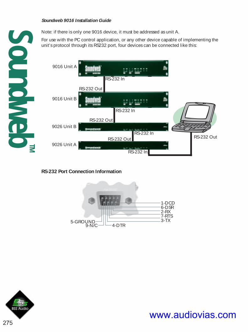
Soundweb 9016 Installation Guide
275
SoundwebTM
1-DCD6-DSR2-RX7-RTS3-TX5-GROUND
4-DTR9-N/C
Note: if there is only one 9016 device, it must be addressed as unit A.
For use with the PC control application, or any other device capable of implementing theunit’s protocol through its RS232 port, four devices can be connected like this:
RS-232 Port Connection Information
9016 Unit A
9016 Unit B
RS-232 In
RS-232 In
RS-232 Out
RS-232 Out
RS-232 InRS-232 Out
9026 Unit A
9026 Unit B
RS-232 In
RS-232 Out
www.audiovias.com

Soundweb 9016 Installation Guide
276
SoundwebTM
Control InputsThe control ports are designed to be used with a 9012 wall panel or simple switches andfaders or potentiometers. There are four sets of ports, or “zones”, marked Z1 - Z4. Thecontrol port facilities are used in conjunction with the PC setup software; see its onlinehelp for more details, and for electrical specifications of the 9012 and it’s resistor values,see Soundweb Designer’s online help (under “control inputs and logic outputs”).
The “A” pin of any given zone should be connected to a potentiometer for gain control.The “B” pin should be connected to a resistor ladder for preset recall/individualcrosspoint control.
The unit is in “zone mode” when there are no presets loaded. (Note that these are presetswithin the unit and nothing to do with Soundweb Designer presets). With each 9012, youcan control the routing of a stereo pair of audio channels and one video channel (a“zone”). Up to four 9012s can be connected, so all the outputs can be controlled.
The outputs controlled by each 9012 are dictated by which “Z” pair of terminals (seewiring section) they are connected to.
For example, a 9012 plugged into Z1 with the unit in zone mode will:
! let you control the gain on outputs 1&2 (stereo pair) with the pot! let you control the source of the signals routed to audio out 1&2and video out 1 using the selector switch. With a 9012, this can beany of the first 5 inputs.
So with the selector in position ‘2’ in the example above:! Audio input 5 would be routed to audio output 1.! Audio input 6 would be routed to audio output 2.! Video input 3 would be routed to video output 1.
The pair of inputs routed to a given output corresponds to the number printed on the9012 control +1 e.g 0 = inputs 1+2
In “preset mode”, only the 9012 wall panel connected to “Z1” has any effect. Theselector will recall the unit’s five internally installed presets. (again, position 0 on theselector means preset 1 will be recalled).
Control port pin-outs
Preset/Zone Trigger InputsPin 1 is on right when viewed from rear:Pin 1, 2, : +5V. Pin 11, 12 : CommonZone ModePin A Source Select, Pin B GainPreset ModeUse Z1 connections only
Z1 Z2 Z3 Z4
C C A B A B A B A B + +
www.audiovias.com

Soundweb 9016 Installation Guide
277
SoundwebTM
9016 Technical Specifications
Video Inputs 8 Composite Video inputs (CBVS or SVideo) on BNCconnectors with BNC loopthrough connectors
Video Standard PAL or NTSC (auto selected)Video Bandwidth 150MhzVideo Crosstalk <70dBR up to 10MHzSync Automatically either Channel 1 or ‘Sync’ inputImpedance 75 Ohm self-terminatingRouting 8x4 Video Matrix
Video Outputs 4 x 75Ohm Composite Video Outputs on BNC connectors
Audio Inputs 16 Balanced Audio inputs on Phoenix Combiconremovable screw connectors.
Routing 16x8 Audio Matrix, each channel independently addressable
Input Impedance 10kOhmMaximum Input Level +20dBuInput gain adjustable, -inf to +20dB (via PC App or 9012 in zone mode)THD <0.02%Frequency Response 20Hz-20kHz +0/-0.2dBS/N Ratio >110dBR at unity gainCrosstalk <-100dBCMRR >40dBR
Audio Outputs 8 Balanced Audio Outputs on Phoenix/Combicon removablescrewconnectors.
Output gain adjustable, -inf to +20dB
Control & PresetsPresets 8 presets per video output zone when used with standalone PC
applicationSerial Control Port RS-232 connects to Soundweb 9088ii, 9008ii, 9000 or 9000ii or
PCDimensions 2RU (3.5") high, 19" wide, 6.6" deep
(89mm x 445mm x 168mm)
Weight 3kg (6.6lbs) unpacked
BSS Audio have a policy of continued product improvement and accordingly reserve the right to change features andspecifications without prior notice.
Part no. ZM10094-01 Feb 2002
www.audiovias.com

Soundweb 9026 Installation Guide
278
SoundwebTM
Installation Guide9026 Audio Switcher
www.audiovias.com

Soundweb 9026 Installation Guide
279
SoundwebTM
Important Safety Information - Read this carefullyThis equipment has been tested and found to comply with the followingEuropean and international Standards for Electromagnetic Compatibility andElectrical Safety:
Radiated Emissions (EU): EN55013 (1996)RF Immunity (EU): EN55013-2 (1996)Electrical Safety (EU): EN60065+A11 (1998)Electrical Safety (USA): UL6500/ETL (2000)Electrical Safety (CAN): CAN/CSA-E65/ETLc (1994)
Before using the apparatus, read these instructions. Follow all instructions, heedthem and keep them in a safe place.
* Clean only with a damp cloth.* Do not block any of the ventilation openings. Install in accordance with themanufacturers instructions.* Do not place objects filled with liquid on this apparatus.* Do not defeat the safety purpose of the grounding type plug. A grounding plug has twoblades and a third grounding prong. The third prong is provided for your safety. Whenthe provided plug does not fit into your outlet, consult an electrician for replacement ofthe obsolete outlet.* Protect the power cord from being walked upon or pinched, particularly at plugs,convenience receptacles and the point where they exit from the apparatus.* Only use attachments/accessories specified by the manufacturer.* Unplug this apparatus during lightning storms or when not in use for a long time.
WARNING - TO REDUCE THE RISK OF FIRE OR SHOCK, DO NOT EXPOSE THISAPPARATUS TO RAIN OR MOISTURE.
DO NOT REMOVE COVERS. NO USER SERVICEABLE PARTS INSIDE - REFERSERVICING TO QUALIFIED SERVICE PERSONNEL.
THIS EQUIPMENT MUST BE EARTHED.
IT SHOULD NOT BE NECESSARY TO REMOVE ANY PROTECTIVE EARTH OR SIGNALCABLE SHIELD CONNECTIONS TO PREVENT GROUND LOOPS. ANY SUCHDISCONNECTIONS ARE OUTSIDE THE RECOMMENDED PRACTICE OF BSS AUDIOAND WILL RENDER THE EMC OR SAFETY CERTIFICATION VOID.
For continued compliance with international EMC regulations, it is important that allcables be screened, and connected as follows:• Audio cable screens to their 9026 connector ground.• Control cable screens to the ground screws adjacent to the connector.www.audiovias.com

Soundweb 9026 Installation Guide
280
SoundwebTM
Mechanical InstallationIf the unit is likely to undergo extreme vibration through extensive road trucking andtouring, it must be supported at the rear and/or sides to lessen the stress on the frontmounting flange. Use either a ready-built rack tray or mount the 9026 unit between otherunits. Damage caused by insufficient support is not covered by the warranty.To prevent cosmetic damage to the front panel finish, use protective plastic cups underthe rack mounting bolts.
Front Panel LED Functions
ZoneZoneZoneZoneZoneThe unit is operating in zone mode with no presets loaded into it. Voltages presented to thecontrol port switch stereo pairs of inputs to stereo pairs of outputs, with video following audio.
PresetPresetPresetPresetPreset
The unit is operating in presetmode. Voltages presented tothe “Z1” section of thecontrol port will recallpresets from memory.
Device ADevice ADevice ADevice ADevice AThe unit is addressed as device A.
Device BDevice BDevice BDevice BDevice BThe unit is addressed as device B.
SoundwebSoundwebSoundwebSoundwebSoundwebThe unit is operating at the correctserial bitrate for connection to aSoundweb unit (38400bps)
PowerPowerPowerPowerPowerWhen illuminated, indicates that thepower supplyis functioning.
ActivitActivitActivitActivitActivityyyyyFlashes when a command isbeing processed.
UserUserUserUserUserThe unit is operating at a user-definable serial bitrate.
ErrorErrorErrorErrorErrorBlinks when a malformed serialmessage has been received, or anerror has occurred within the unit.
www.audiovias.com

Soundweb 9026 Installation Guide
281
SoundwebTM
Balanced wiring - The convention for balanced wiring (2-core plus shield) is:
Balanced connection 9026 connection
Pin 3 : Cold '-'Pin 2 : Hot '+'Pin 1 : Shield
Rear Panel Details
The 9026 audio and control connections are via Klippon (also known as BL, Phoenix orCombicon) pluggable terminal block connectors.
12 x 6-way female Klippon connectors are supplied for making these connections.For audio cables and looms, see the Product Overview 2000 catalogue from:Direct Cable Systems Ltd.Tel: (020) 7485 0899www.directcable.co.ukPhoenix-XLR audio cable P/N 100521
Unbalanced wiring - The convention for unbalanced wiring to the inputs (1-core plusshield) is:
Unbalanced connection 9026 connection
Pin 1 : ShieldPin 2 : Hot '+'Pin 3 : Link to Pin 1
(Optional for 9016 inputs)
Mains inletIEC power connector, for connection to mains supply (100-270V AC, 50/60Hz).
Mains fuse holderRequires a 20mm T1A type fuse. Do not replace with anything other than the recom-mended fuse.
www.audiovias.com

Soundweb 9026 Installation Guide
282
SoundwebTM
RS-232The RS232 port is for connecting the unit directly to a PC, or the rear port of a Soundweb9088ii, 9000, 9000ii or 9008 device.
Soundweb devices can be connected to two 9026 units as follows:
Soundweb 9088ii, 9008, 9000 or 9000ii
9026 Unit A
9026 Unit B
Rear Serial Port
RS-232 In
RS-232 In
RS-232 Out
Note: if there is only one 9026 device, it must be addressed as unit A.
For use with the PC control application, or any other device capable of implementing theunit’s protocol through its RS232 port, four devices can be connected like this:
9016 Unit A
9016 Unit B
RS-232 In
RS-232 In
RS-232 Out
RS-232 Out
RS-232 InRS-232 Out
9026 Unit A
9026 Unit B
RS-232 In
RS-232 Out
www.audiovias.com

Soundweb 9026 Installation Guide
283
SoundwebTM
RS-232 Port Connection Information
1-DCD6-DSR2-RX7-RTS3-TX5-GROUND
4-DTR9-N/C
www.audiovias.com
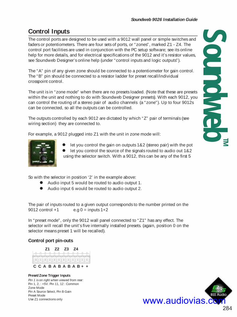
Soundweb 9026 Installation Guide
284
SoundwebTM
Control InputsThe control ports are designed to be used with a 9012 wall panel or simple switches andfaders or potentiometers. There are four sets of ports, or “zones”, marked Z1 - Z4. Thecontrol port facilities are used in conjunction with the PC setup software; see its onlinehelp for more details, and for electrical specifications of the 9012 and it’s resistor values,see Soundweb Designer’s online help (under “control inputs and logic outputs”).
The “A” pin of any given zone should be connected to a potentiometer for gain control.The “B” pin should be connected to a resistor ladder for preset recall/individualcrosspoint control.
The unit is in “zone mode” when there are no presets loaded. (Note that these are presetswithin the unit and nothing to do with Soundweb Designer presets). With each 9012, youcan control the routing of a stereo pair of audio channels (a “zone”). Up to four 9012scan be connected, so all the outputs can be controlled.
The outputs controlled by each 9012 are dictated by which “Z” pair of terminals (seewiring section) they are connected to.
For example, a 9012 plugged into Z1 with the unit in zone mode will:
! let you control the gain on outputs 1&2 (stereo pair) with the pot! let you control the source of the signals routed to audio out 1&2 using the selector switch. With a 9012, this can be any of the first 5
inputs.
So with the selector in position ‘2’ in the example above:! Audio input 5 would be routed to audio output 1.! Audio input 6 would be routed to audio output 2.
The pair of inputs routed to a given output corresponds to the number printed on the9012 control +1 e.g 0 = inputs 1+2
In “preset mode”, only the 9012 wall panel connected to “Z1” has any effect. Theselector will recall the unit’s five internally installed presets. (again, position 0 on theselector means preset 1 will be recalled).
Control port pin-outs
Preset/Zone Trigger InputsPin 1 is on right when viewed from rear:Pin 1, 2, : +5V. Pin 11, 12 : CommonZone ModePin A Source Select, Pin B GainPreset ModeUse Z1 connections only
Z1 Z2 Z3 Z4
C C A B A B A B A B + +
www.audiovias.com

Soundweb 9026 Installation Guide
285
SoundwebTM
9026 Technical Specifications
Audio Inputs 16 Balanced Audio inputs on Phoenix Combiconremovable screw connectors.
Routing 16x8 Audio Matrix, each channel independently addressable
Input Impedance 10kOhmMaximum Input Level +20dBuInput gain adjustable, -inf to +20dB (via PC App or 9012 in zone mode)THD <0.02%Frequency Response 20Hz-20kHz +0/-0.2dBS/N Ratio >110dBR at unity gainCrosstalk <-100dBCMRR >40dBR
Audio Outputs 8 Balanced Audio Outputs on Phoenix/Combicon removablescrewconnectors.
Output gain adjustable, -inf to +20dB
Control & PresetsPresets 8 presets per video output zone when used with standalone PC
applicationSerial Control Port RS-232 connects to Soundweb 9088ii, 9008ii, 9000 or 9000ii or
PCDimensions 1RU (1.75") high, 19" wide, 6.6" deep
(45mm x 445mm x 168mm)
Weight 2.3kg (5lbs) unpacked
BSS Audio have a policy of continued product improvement and accordingly reserve the right to change features andspecifications without prior notice.
BSS AudioA Division of Harman International Industries Ltd
Cranborne House, Cranborne Road, Potters Bar, Herts EN6 3JN EnglandTel +44 (0)1707 660667 Fax +44 (0)1707 660755 http://www.bss.co.uk
Part no. ZM10095-01 Feb 2002
www.audiovias.com

Soundweb TM
286
Serial Interface KitLimited warranty 288Introduction 288The Serial Interface Kit FAQ 289Hardware 292Messaging protocol 293Message Format 293Message Body Format 294Message Types 294Protocol details 295Implementing the Soundweb/AMX protocol on other equipment 296Sending out a message 296Receiving a message 297AMX controll 298Equipment required: 298AMX touch panel 298Procedure 299Example code 300Object detail 301Interfacing to Non-AMX Equipmentt 302Debugging 302Setting up a device for raw messages 302Message Format 303Processing Object Handles 303Processing Object Methods 303Method Values 303Activating Presets 305Activating Parameter Presets 305Sending and Receiving Messages 307Example Messages 308Messages 309
www.audiovias.com

SoundwebTM
287
Serial Interface KitAppendix A - Processing Object Methods 310Soundweb 9088 DSP 310Gain 311Delay 311Parametric Eq 311Crossover 312Mixers 313Matrix Routers and Mixers 316Graphic Eq 318Metering Point 319Source Selector 319Compressor 320Limiter 320Leveller 320Filter High Pass And Low Pass 321
www.audiovias.com

SoundwebTM
288
Serial Interface KitLimited warranty
No warranties: BSS Audio expressly disclaims any warranty for the ‘Soundweb Interface Kit’. The
‘Soundweb Interface Kit’ and any related documentation is provided ‘as is’ without warranty of any
kind, either express or implied, including, without limitation, the implied warranties or
merchantability, fitness for a particular purpose, or non infringement. The entire risk arising out of use
or performance of the ‘Soundweb Interface Kit’ remains with you.
No Liability for damages: In no event shall BSS Audio or its suppliers be liable for any damages
whatsoever (including, without limitation, damages for loss of business profits, business interruption,
loss of business information, or any other pecuniary loss) arising out of the use of, misuse of, or inabil-
ity to use this BSS Audio product, even if BSS Audio has been advised of the possibility of such dam-
ages. Because some states/jurisdictions do not allow the exclusion or limitation of liability for conse-
quential or incidental damages, the above limitation may not apply to you.
BSS Audio is a division of Harman International Industries Ltd., 4th floor, Windsor House, Pepper
Street, Chester CH1 1DF, United Kingdom.
IntroductionThis document is intended for Soundweb users who wish to provide their own user interface for a
Soundweb system. The user interface can be based on an PANJA system, a PC running a custom
application, or even a custom piece of hardware.
There are two ways in which the developer can control a Soundweb network. There’s the PANJA
interface which is a very simple RS232 protocol designed for use with PANJA devices running the
AXCESS development system. However, the PANJA RS232 protocol is tailored for PANJA, and is
therefore not generic enough to control all of Soundweb’s processing objects. For this reason we
created the RAW_MSG extension which gives almost complete control of a Soundweb network via
RS232.
Both protocols share the same message protocol and use the rear RS232 port of a Soundweb device.
www.audiovias.com

SoundwebTM
289
Serial Interface KitThe Serial Interface Kit FAQv1.4 29/11/00
Q1. AMX interfacing - where do I start?
Q2. Are there any examples?
Q3. What if I already have an AMX system in use?
Q4. How do handles work?
Q5. Where do I get handles from?
Q6. So, what are method codes then?
Q7. Are presets global?
Q8. How do I control a matrix mixer?
Q9. What’s the most efficient way to switch between
two configurations with the control port?
Q1. AMX interfacing - where do I start?
A1. A complete walk-through of setting a system up to interface with an AMX panel is in the
Soundweb help. It describes both hardware and software requirements and is for a user who
wants to add a panel to his Soundweb network. The idea is that you should not need to write
any code if you just want a panel on your system.
Q2. Are there any examples?
A2. Yes. There is a file called Example.SDF available which is a system with various objects already
set up.
Q3. What if I already have an AMX system in use?
A3. If, after generating the code from Soundweb Designer, you have channel codes that conflict
with ones already on the panel, you can edit SWFUNC.AXI which is where PUSH events (etc.)
meet our messaging functions. You must include the library functions which are to be run
inside mainline for messages to be sent and received.
Q4. How do handles work?
A4. Each processing object in a design file (.SDF) is allocated a unique number to identify it when
the design is compiled. If there is more than one unit in the design, a range of numbers are
allocated to each box. This range is big enough for more processing objects than you could
possible need or even fit in one unit. It is 100000 in hexadecimal (written 0x100000 orwww.audiovias.com

SoundwebTM
290
Serial Interface Kit100000h) which is 1048576 in decimal.
For example a gain element in the first unit may be allocated the number 2. The first handle, 1,
is reserved for the box itself for permanent objects associated with the box rather than the
design you have created such as phantom power on the inputs, gain trim on the outputs.
The second unit in a design will have the handle 0x100001 and processing objects will start
from 0x100002. Because of these ranges, the number will always be a dword, or 4 bytes or 32
bit value when used in a messaging protocol.
Q5. Where do I get handles from?
A5. They do not exist until you have compiled your design file (.SDF) in Soundweb Designer. Once
compiled, you can find them by moving the mouse over the object in the design and the handle
will appear in the status bar which is in the bottom left of the main Soundweb designer window.
This is one of the places where an application would normally tell you what buttons do as you
pass the mouse pointer over them.
Q6. So, what are method codes then?
A6. Each processing object has a unique handle to identify it but this one reference is not enough to
uniquely identify a particular control. For example, our gain element has three controls associ-
ated with it. These are the gain itself or the fader, the mute button and the phase button. We give
these three controls numbers which we call method codes because they identify a function or
method of an object. You may have noticed that these numbers are re-used on different process-
ing objects - this is because the handle makes the control unique.
Think of method codes like doors, windows and chimneys and handles as the house number.
Two houses can have the same chimney but will be unique if referred to with the house number
as well. Method codes are also dwords or 4 bytes or 32 bit values, however you like to think of
them.
Q7. Are Presets global?
A7. There are two type of presets. Parameter presets involve all the controls on the map window in
which they are created. A common technique is to have a special map window for the controls
your are interested in and make the preset there. This preset bar is then copied to your main
control panel.
Major presets have the option to include devices at your discretion to save memory. Thesewww.audiovias.com

SoundwebTM
291
Serial Interface Kitpresets can affect the entire network. Each box has a copy of the control ids and parameter
values for each control in the preset. Activation is a single message rather than all the values
sent around. If a box doesn’t contain any controls in the preset, it doesn’t need a copy of the
preset.
Q8. How do I control a matrix mixer?
A8. The gain of each route channel is controlled by usung a method code calculated as follows:
Identify the output you want to route.
Find the base method code for this in this Soundweb interface kit document. They start at
0x01000800.
Add to this the input channel-1.
Routing is similar but the base method codes start at 0x01001000, e.g. the button for Output 5
Input 4 has a method of 0x010010C0+4-1 = 0x010010C3.
Q9. What’s the best way to switch between two configurations with the control port?
A9. Use a couple of Presets. We recommend two momentary buttons. If you change to each con-
figuration and store this in a preset, you can add a preset button for each, then drag these preset
buttons onto control inputs.
See the section on Presets in the online help in Soundweb Designer for further information.
www.audiovias.com

SoundwebTM
292
Serial Interface KitHardwareSoundweb to AMX
master
GNDRX1
TX1 5 32
RX
TXGND
t S d b
Soundweb
3-wire Null modem cable for AMX to Soundweb connection.
PC to Soundweb (Rear RS232) Cable7-wire Null modem cable.
www.audiovias.com

SoundwebTM
293
Serial Interface KitMessaging protocol• Always use 8-bit data with no parity.
• Bit rate 38400 bps.
The following bytes have special meanings:
• 0x02 STX• 0x03 ETX• 0x06 ACK• 0x15 NAK• 0x1B Escape• Any other single byte can be used within a message body
To use one of the special bytes within a message body, do the following:
• 0x02 - substitute with 0x1B 0x82
• 0x03 - substitute with 0x1B 0x83
• 0x06 - substitute with 0x1B 0x86
• 0x15 - substitute with 0x1B 0x95
• 0x1B - substitute with 0x1B 0x9B
The following bytes are command bytes to appear at the beginning of a message after STX.
• 0x80 SET_VALUE• 0x81 SET_STRING• 0x82 REQUEST_VALUE• 0x83 REQUEST_STRING• 0x84 RAW_MSG
Message Format<message> = <STX> <Body> <Checksum byte> <ETX>
<Checksum byte> is the xor of all the bytes in <Body>
Note:If the checksum is one of the special characters it must be substituted in the same way as body bytes.
www.audiovias.com

SoundwebTM
294
Serial Interface KitMessage Body FormatThis is one of the following:
<Body> = <SET_VALUE> <group> <id> <value Hi> <value Lo>
or <SET_STRING> <group> <id> <char 0> <char 1> <char 2>...<Zero>
or <REQUEST_VALUE> <group> <id>
or <REQUEST_STRING> <group> <id>or <RAW_MSG> <Soundweb Message>
<group>
a byte identifying which type of control you are changing.
<id>
a byte uniquely identifying which control of the group you are changing.
<Value Hi> <value Lo>
a sixteen bit value.
<char 0> <char 1> <char 2>...<Zero>
an ASCII null-terminated string in the standard Windows character set.
<Soundweb Message>
a raw Soundweb message.
The following group numbers are allocated.
SW_AMX_BUTTON = 0 (* MOMENTARY BUTTONS (255) *)
SW_AMX_TOGGLE = 1 (* LATCHING BUTTONS. (255) *)
SW_AMX_LED = 2 (* LED’S (255) *)
SW_AMX_PRESET = 3 (* MOMENTARY, AND LINKED TO PAGE CHANGE. *)
SW_AMX_SPIN = 4 (* CONTINUOUSLY SENDS WHILST HELD DOWN. *)
SW_AMX_LEVEL = 5 (* THERE ARE 32 LEVELS - FADERS AND BARGRAPHS *)
SW_AMX_SOURCE = 6 (* SOURCE SELECTORS - MUTUALLY EXCLUSIVE *)
SW_AMX_TEXT = 7 (* THERE ARE 255 SUB TEXT FEEDBACKS *)
Message TypesSET_VALUE is sent from Soundweb to AMX to indicate that a value has been changed which must
be reflected on the PANJA controller. The same message from AMX to Soundweb indicates that the
user has moved a control which must be reflected on the Soundweb system.
On issuing a SET_VALUE the Soundweb to PANJA messaging code detects when a value has been
changed as a result of activity on the PANJA system, but does NOT echo the changes. The AMX
system is expected to do the same - this is necessary in order to avoid an endless loop whereby the
two systems send messages to each other continuously.
www.audiovias.com

SoundwebTM
295
Serial Interface KitRAW_MSG is used to send raw Soundweb messages to and from external equipment via the RS232
port. The AMX system ignores these messages.
SET_STRING is reserved for future use.
REQUEST_VALUE is reserved for future use.
This message would be sent by one or other side in order to demand a SET_VALUE for a particular
parameter and would typically be used at start-up to ensure that the two sides are in sync. The other
side responding with a SET_VALUE message.
REQUEST_STRING is reserved for future use.
This would be sent in order to demand a piece of text. The correct response is a SET_STRINGmessage.
Protocol detailsWhen a message is received successfully, an ACK is returned.
This should be done within one second of receiving the ETX.
When a message is received unsuccessfully, (determined by the checksum being incorrect or the
frame incorrectly formed with start and end characters), a NAK is returned.
This should be done within one second of receiving the ETX (or the last character received).
If an ACK or NAK is not received within 1 second of sending a message, then the message should be
resent.
www.audiovias.com

SoundwebTM
296
Serial Interface KitImplementing the Soundweb/AMX protocol on other equipmentIt is quite possible for other equipment to talk to a Soundweb device using the Soundweb/AMX
protocol. It is simply a matter of implementing the protocol on the chosen platform.
Sending out a messageThe following pseudo code sends a message by putting in escape characters, checksum STX and ETX.
SEND (STX)
CHAR CHECKSUM = 0
FOR EACH CHARACTER IN MESSAGE BODY
{
CHECKSUM = CHECKSUM XOR CHARACTER
IF (IS_SPECIAL (CHARACTER))
{
SEND (ESCAPE)
SEND (CHARACTER + 128)
}
ELSE
{
SEND (CHARACTER)
}
}
IF (IS_SPECIAL (CHECKSUM))
{
SEND (ESCAPE)
SEND (CHECKSUM + 128)
}
ELSE
{
SEND (CHECKSUM )
}
SEND (ETX)
/* NOW WAIT FOR AN ACK OR NAK */
www.audiovias.com

SoundwebTM
297
Serial Interface KitReceiving a messageThe following pseudo code receives a message, takes out escape characters, and makes sure the
message is valid by looking at the checksum.
/* TELLS US THAT THE PREVIOUS CHARACTER WAS ESCAPE*/
BOOL GOT_ESCAPE
CHAR CHECKSUM = 0
ON RECEIVED CHARACTER
{
IF (CHARACTER = STX)
{
/* START OF MESSAGE */
CHECKSUM = 0
/* CLEAR THE MESSAGE BUFFER */
CLEAR_MESSAGE_BUFFER()
GOT_ESCAPE = FALSE
}
ELSE IF (CHARACTER = ETX)
{
/* END OF MESSAGE, CHECK THE CHECKSUM */
IF (GET_LAST_BYTE_IN_MESSAGE_BUFFER() = CHECKSUM)
{
/* THE MESSAGE IS OK */
SEND (ACK)
}
ELSE
{
SEND (NAK)
}
GOT_ESCAPE = FALSE
}
ELSE IF (CHARACTER = ESCAPE)
{
GOT_ESCAPE = TRUE
}
ELSE
{
IF (GOT_ESCAPE = TRUE)
{
ADD_BYTE_TO_MESSAGE_BUFFER (CHARACTER - 128)
CHECKSUM = CHECKSUM XOR (CHARACTER - 128)
}
ELSE
{
ADD_BYTE_TO_MESSAGE_BUFFER (CHARACTER)
CHECKSUM = CHECKSUM XOR CHARACTER
}
GOT_ESCAPE = FALSE
}
} www.audiovias.com

Soundweb TM
298
Serial Interface KitAMX control
Equipment required:AMX AXCESS or NETLINX master device
AMX touch panel or other input device
12V DC supply
AX link cable
AMX touch panelThere are 255 available channels which can be assigned to buttons or icon objects on the panel.
These allow presses to be processed and sent to Soundweb and for visual feedback to be echoed to
the panel. In addition to this, there are 32 level channels which are linked to level controls or bar
graph meters.
The library functions make use of a variable number for every control on the touch panel. How this
variable number maps to a channel code is explained below for each control, the result being that
some channel codes are not used. We recommend that channel codes for other devices in a shared
system, i.e. one that has device control in addition to Soundweb on the same master, be allocated
from outside the range of channel codes used by the export process, even if it appears they are not
being used.
For example:
A level control requires a variable number to store it’s value and subsequently this variable number
will not be available for use as a channel code within the Panja to Soundweb communication system.
Source selectors require a channel code for each button in the exclusive group but only use one
variable number to store the overall state.
Spin pairs require a channel code for each of the up and down buttons but have only one variable to
store the current setting.
All other controls: presets and buttons have a direct mapping of channel code to variable number.
The master, AXB-EM232, is one of a number of available masters which stores and executes the
AXCESS programming language.
The library, SWLIB.AXI has been written in such a way that it can be compiled for Netlinx or AXCESS.
www.audiovias.com

SoundwebTM
299
Serial Interface KitProcedure1. Having designed your Soundweb audio layout, open the Serial Input/Output map window.
2. Place the controls you wish to export to AMX on this map window.
3. Go to the Serial menu and choose Panja export to generate the file SWFUNC.AXI.
This file contains functions to map Soundweb controls to equivalents on the touch panel. When
opened in a text editor, the file will contain comments at the top describing how to assign channel
codes on the touch panel.
4. Run the AXCESS compiler program or PANJA Studio and create a new project, importing the
files BSSMAIN.AXS, SWLIB.AXI and SWFUNC.AXI.
5. BSSMAIN.AXS is supplied as an example minimum to get your system running. For Soundweb
controls to coexist with controls for other systems the relevant calls from this file may be placed in
another .AXS file or you may add extra functions to this one.
Avoid using the channel codes that have been allocated in SWFUNC.AXI.
6. Compile as AXCESS or Netlinx as appropriate (the export and library are compatible with both)
and download to the Master.
Before anything will work, you must have buttons and levels on the panel with the correct channel
codes as described in the SWFUNC.AXI comments.
7. Set up the buttons with the following attributes:
• Toggling buttons are to be channel feedback.
• Text objects have a variable text number and a channel number of zero.
• Level objects have a unique level number from 1 to 32.
• Preset change buttons can have a page change associated with them and are momentary
feedback.
• Spin pairs are momentary feedback.
• Source selectors are momentary buttons and have mutually exclusive and latching
attributes associated with them in the master. This is done automatically by the exported
code.
8. Finally, compile the Soundweb layout and load the Soundweb device.
Upon loading, the back serial port will be configured for PANJA control (currently at 38,400 baud
8N1 and no handshaking) and messaging will commence.
www.audiovias.com

SoundwebTM
300
Serial Interface KitExample codeParts of SWFUNC.AXI will look like this:
(* --> ‘U1/P5/Mute’ *)
PUSH [TP, 10]
CALL ‘SW TOGGLE BUTTON’ (10,SW_TOGGLE)
[TP,10] = SW_CONTROL_VAL[10]
(* <-- *)
Placeholding comments surround each exported control:
(* --> *)
(* <-- *)
All calls to SWLIB, the library module, start with SW.
SWLIB.AXI provides the background handling of buttons, level controls, spin pairs, metering and all
the messaging to the Soundweb unit. This has much more functionality as library functions than the
exported code puts to use. It serves as an example of more complex control types that can be
implemented on an AMX touch panel.
All the designer need do to get a system up and running is to have an INCLUDE ‘SWFUNC.AXI’
statement at the top of the main file and the following two calls:
DEFINE_START
CALL ‘SW INIT CONTROLS’
DEFINE_PROGRAM
CALL ‘SW RUN CONTROLS’
In this way, Soundweb controls and background messaging can coexist with any other code in the
master by being completely encapsulated in the include files.
www.audiovias.com

SoundwebTM
301
Serial Interface KitObject detailA toggle button is realised by using script for updating the feedback and sending the status to the
Soundweb unit each time it changes. Similarly, Soundweb can toggle the control on the touch panel.
• An LED is a button with attributes that can be changed remotely. Its presses are not serviced.
• A preset is a momentary button which fires off a message. Soundweb Designer exports a list of
associated controls in an exclusive group. Source selectors are set up in a similar way.
Controls in a parameter preset need to be set up as mutually exclusive. It is also necessary for these
controls to be defined as latching. The AMX master handles update of mutually exclusive controls so
all that is required is an ON message for a particular source or preset and the others are cleared.
In order for the relevant controls to come in and out of scope for a particular preset, it is proposed that
a preset change involves a change in touch panel page so that there is no chance of a user pressing a
button that is not relevant for that preset. If the user changes page, it is up to the designer to ensure
that the Soundweb unit is notified with a preset change at the same time.
This can be done by allocating the page change button a channel code and sending a preset change.
SWFUNC contains some extra code associated with preset buttons for changing page.
Uncomment this and change to your page name:
(* --> ‘U1/Preset 1’ *)
PUSH [TP, 20]
CALL ‘SW RECALL PRESET’ (20)
(* uncomment the next line and change to your page name *)
(* CALL ‘SW SEND PAGE CMD’ (“‘Page name’”) *)
(* <-- *)
• A level control is an on-screen fader which is continuously monitored by AXCESS. Any changes
in these controls will be sent to the Soundweb unit.
www.audiovias.com

SoundwebTM
302
Serial Interface KitInterfacing to Non-AMX EquipmentMost external equipment will use the RAW_MSG message to communicate with Soundweb, as this
enables detailed and accurate control of every processing object. However, if you are using control
equipment such as Crestron and Dataton, and require a simpler, less accurate method, SET_VALUEtype message strings can be used by entering them into the design software.
To generate these strings and to serve as a test application, we have supplied the Soundweb message
tool. This application allows you to construct messages with a simple dialogue and send them to a
Soundweb device. The actual bytes sent are displayed in a text field in hexadecimal.
e.g.
SET_VALUE, Button, 1, 1 translates as:
2, 80, 0, 1, 0, 1, 80, 3
Hex 80 may also be written as $80 or 0x80 or &H80 or 80H, depending on your control system.
DebuggingA good way of debugging a system is to be connected to the front port of a Soundweb device from
Soundweb Designer and to run the message tool connected to the rear port of the device. With this
method, messages can be tested from both directions; sending from the unit by adjusting a control in
Soundweb designer and by sending from the message tool. Messages sent from Soundweb will appear
in the incoming box and serve as examples of message construction for sending from your piece of
equipment, (since they will be the same).
Remember, start simple with perhaps just a couple of mute buttons to establish you have everything
cabled correctly and each device configured correctly.
A Soundweb Designer file ( Example.sdf) is supplied which has an example of each type of control
that can be remotely controlled with this method.
Refer also to the Serial Interface Kit FAQ for more details.
Setting up a device for raw messagesSoundweb devices do not normally send and receive the Soundweb messages out of the rear RS232
port. Instead the back port is usually used as an alternative to the front port for connecting to
Soundweb Designer. Therefore the device must be told to use the back port for Soundweb messages.
This is done by renaming the device object in the layout so that the name ends with the characters
‘+s’ e.g. “MyDevice +s”. The device will need rebooting after the name change for the change to
take effect.
NOTE: This naming convention is only used as a temporary device until a version of Soundweb
Designer is released which allows the user to set the back port mode explicitly.www.audiovias.com

SoundwebTM
303
Serial Interface KitMessage FormatThe format of the RAW_MSG message is:
RAW_MSG <Soundweb Message>
where the format of the ‘Soundweb Message’ is
<Handle> <Method> <Value>
where
• Handle (32 bit) is the identifier of the object that the message is to/from.
• Method (32 bit) is the object’s ‘method’ that has changed.
• Value (16 or 32 bit) is the new value of the method.
NOTE: In the following paragraphs, numbers are represented in both decimal and hexadecimal
depending on context. Hexadecimal numbers are preceded by the characters ‘0x’.
Any numbers NOT preceded by ‘0x’ are decimal.
Processing Object HandlesEach audio processing object in a Soundweb device is given a network Handle. This handle is a 32 bit
unique number which allows Soundweb Designer to communicate with it. Once a device has been
compiled, you can find the handles for the objects by placing the mouse over each object in turn, and
reading the handle displayed in the status bar.
Processing Object MethodsA method of a processing object is a ‘property’. For example, a gain processing object has 3 methods:
Mute, Gain and Phase. If you look at the gain control panel you will see the three controls which are
used to change those three methods. For processing object method numbers see Appendix A.
Method ValuesSoundweb uses 16 bit and 32 bit methods values. These values are the actual settings for the objects
controls. For example, the gain method might have a value of +3dB, or the mute method might have a
value of OFF.
• Object methods come in two flavours continuous and discrete.
Continuous: Decibels, Hz, µs or scalar (generic floating point values).
Discrete: Anything that can be represented by a fixed number of states. For example, a
mute method has two states (on and off).
www.audiovias.com

SoundwebTM
304
Serial Interface KitNearly all continuous and discrete values are 16 bits. To represent a realistic range of values, each
type is encoded in a different way.
Decibels16 bits, a signed word in the range –32,768 to +32,767.
To find the value in dBs simply divide by 256.0.
Example
+1536 represents +6 dB.
(1536/256 = 6).
Hz16 bits, unsigned word in the range 0 to 65535.
The frequency is 10 to the power of (value divided by 10000).
Example
33010 represents 2000 Hz.
(10 to the power of (33010/10000) = 2000).
µS32 bits, unsigned long in the range 0 to 4,294,967,295.
Example
1530000 represents 1.53 seconds.
Scalar16 bits, a signed word in the range –32,768 to 32,767.
To find the value simply divide by 256.
Example
320 represents -1.25.
(-320/256 = -1.25).
www.audiovias.com

SoundwebTM
305
Serial Interface KitActivating PresetsPresets are activated by sending a broadcast message. A broadcast message has a handle of
0xFFFFFFFF. The method should be set to 0x0000000B and the value is the preset ID (32 bits). The
preset ID is a unique identifier which is it’s index in the list of presets.
To find a preset’s ID goto the preset view and find the preset:
Now counting from the top, the presets have the ID’s 0, 1, 2, 3, 4 etc. So, the three presets shown
above have the following Ids:
• Show Preset 0
• Setup Preset 1
• Test Preset 2
Activating Parameter PresetsParameter presets are activated in a similar way, except that the preset ID is made up of two numbers,
the parameter preset ID, and the state. The parameter preset ID can be found by letting the mouse
pause over a parameter preset bar, and a tool tip will pop up with the ID:
www.audiovias.com

SoundwebTM
306
Serial Interface KitNote: The parameter preset ID can only be found once the system has been loaded.
Once you have the parameter preset ID, you need to find the state index in the parameter preset:
The state index is simply its index in the list. So, for the above parameter preset the states have these
indices
• Mute All 0
• All On 1
• Quiet 2
Once you have found the parameter preset ID, and the state index, you are ready to create the preset
ID. The preset ID is 32 bits long, 16 bits for the parameter preset ID and 16 bits for the state index:
Parameter Preset ID
31 16 15 0
State Index
As with normal preset messages, Presets are activated by sending a broadcast message. A broadcast
message has a handle of 0xFFFFFFFF. The method should be set to 0x0000000B and the value is the
preset ID (32 bits).
www.audiovias.com
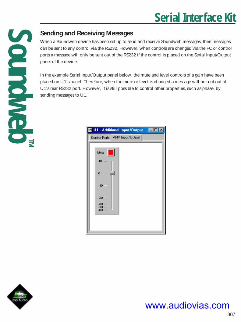
SoundwebTM
307
Serial Interface KitSending and Receiving MessagesWhen a Soundweb device has been set up to send and receive Soundweb messages, then messages
can be sent to any control via the RS232. However, when controls are changed via the PC or control
ports a message will only be sent out of the RS232 if the control is placed on the Serial Input/Output
panel of the device.
In the example Serial Input/Output panel below, the mute and level controls of a gain have been
placed on U1’s panel. Therefore, when the mute or level is changed a message will be sent out of
U1’s rear RS232 port. However, it is still possible to control other properties, such as phase, by
sending messages to U1.
www.audiovias.com

SoundwebTM
308
Serial Interface KitExample MessagesThe following messages would be sent to the Soundweb device to control the following configuration
Object handles in italics:Gain Objects: Gain1 (2) and Gain2 (3)4-Band Parametric Eqs: Eq1 (4) and Eq2 (8)Metering Points: Meter1 (12) and Meter2 (13)
www.audiovias.com

SoundwebTM
309
Serial Interface KitMessagesTo unmute Gain1:
Handle Method Id Value2 0x01000801 (Mute) 0 (off)
To unmute Gain2:
Handle Method Id Value3 0x01000801 (Mute) 0 (off)
Change Eq1 filter 1 to 2000Hz, +10.0 dB, Width 1.0, bell filter type:
Handle Method Id Value4 0x01000801 (Frequency) log10(2000.0)x10000
4 0x01000802 (BoostCut) 10x256
4 0x01000803 (Width) 1x256
4 0x01000804 (FilterType) 0
Change Eq1 filter 2 to 3000Hz, -5.0 dB, Width 2.0, bell filter type:
Handle Method Id Value5 0x01000801 (Frequency) log10(3000)x10000
5 0x01000802 (BoostCut) -5x256
5 0x01000803 (Width) 2x256
5 0x01000804 (FilterType) 0
Example messages received from meters Meter1 and Meter2:
Handle Method Id Value Decoded Value12 0x01000800 (Level) -2476 - 9.67 dB
13 0x01000800 (Level) -8947 - 34.95 dB
12 0x01000800 (Level) -10 - 0.039 dB
13 0x01000800 (Level) +258 + 1.008 dB
Activating preset 0:
Handle Method Id Value0xFFFFFFFF 0x0000000B (Preset Activate) 0
Activating preset 5:
Handle Method Id Value0xFFFFFFFF 0x0000000B (Preset Activate) 5
www.audiovias.com

SoundwebTM
310
Serial Interface KitAppendix A - Processing Object Methods
Soundweb 9088 DSPThese are the methods for the 9088 DSP device. These control the input and output gains, phase and
phantom power.
Method Name Method Id TypePhase1 0x01000809 Discrete 0 = off 1 = on
Phase2 0x0100080a Discrete 0 = off 1 = on
Phase3 0x0100080b Discrete 0 = off 1 = on
Phase4 0x0100080c Discrete 0 = off 1 = on
Phase5 0x0100080d Discrete 0 = off 1 = on
Phase6 0x0100080e Discrete 0 = off 1 = on
Phase7 0x0100080f Discrete 0 = off 1 = on
Phase8 0x01000810 Discrete 0 = off 1 = on
Phantom1 0x010008011 Discrete 0 = off 1 = on
Phantom2 0x010008012 Discrete 0 = off 1 = on
Phantom3 0x010008013 Discrete 0 = off 1 = on
Phantom4 0x010008014 Discrete 0 = off 1 = on
Phantom5 0x010008015 Discrete 0 = off 1 = on
Phantom6 0x010008016 Discrete 0 = off 1 = on
Phantom7 0x010008017 Discrete 0 = off 1 = on
Phantom8 0x010008018 Discrete 0 = off 1 = on
LineGain1 0x01000819 Discrete 0 = 0dB 1=12dB
LineGain2 0x0100081a Discrete 0 = 0dB 1=12dB
LineGain3 0x0100081b Discrete 0 = 0dB 1=12dB
LineGain4 0x0100081c Discrete 0 = 0dB 1=12dB
LineGain5 0x0100081d Discrete 0 = 0dB 1=12dB
LineGain6 0x0100081e Discrete 0 = 0dB 1=12dB
LineGain7 0x0100081f Discrete 0 = 0dB 1=12dB
LineGain8 0x01000820 Discrete 0 = 0dB 1=12dB
MicGain1 0x01000821 Discrete. Values are 0=0, 1=6, 2=12, 3=18, 4=24, 5=30,6=36
7=42, 8=48, 9=54, 10=60, 11=66, 12=72
MicGain2 0x01000822 As above.
MicGain3 0x01000823 As above.
MicGain4 0x01000824 As above.
MicGain5 0x01000825 As above.
MicGain6 0x01000826 As above.
MicGain7 0x01000827 As above.
MicGain8 0x01000828 As above.
OutGain1 0x01000829 dB (-15 to +15)
OutGain2 0x0100082a dB (-15 to +15) www.audiovias.com

SoundwebTM
311
Serial Interface KitOutGain3 0x0100082b dB (-15 to +15)
OutGain4 0x0100082c dB (-15 to +15)
OutGain5 0x0100082d dB (-15 to +15)
OutGain6 0x0100082e dB (-15 to +15)
OutGain7 0x0100082f dB (-15 to +15)
OutGain8 0x02000830 dB (-15 to +15)
GainMethod Name Method Id TypeValue 0x01000800 dB
Mute 0x01000801 0 = off, 1 = on
Phase 0x01000802 0 = off, 1 = on
DelayMethod Name Method Id TypeValue 0x02000800 ms
Parametric EqThe parametric eq comes in 5 different configurations: 1, 2, 4, 6 and 12 bands. Each band is a sepa-
rate processing object, and therefore has it’s own handle. Soundweb will display the handle for the
first eq band on the status bar when the user moves the mouse over the parametric object. The other
bands in the parametric eq can be found by incrementing the handle for each band. For example, if a
4 band parametric eq displays a handle of 23, then the individal eq band objects have handles of 23,
24, 25 and 26. So, to change filter 3, send messages to object 25.
Each eq band has the follow methods:
Method Name Method Id TypeBypass 0x01000800 0 = off, 1 = on
Frequency 0x01000801 Hz
BoostCut 0x01000802 dB
Width 0x01000803 Scalar (0.05 - 3.0)
FilterType 0x01000804 Discrete. Values are: 0 = Bell
1 = High Shelf
2 = Low Shelf
www.audiovias.com

SoundwebTM
312
Serial Interface KitCrossoverLike the parametric eqs, the crossover comprises of several individual bands which are separate
objects. There are currently 5 different crossovers defined :- 1,2,3,4 and 5 bands. There is also the
mon sub object which is basically a 2:1 mixer followed by a crossover band.
Method Name Method Id TypeLowPassType 0x01000800 Band type (see below)
HighPassType 0x01000801 Band type (see below)
LowPassFrequency 0x01000802 Hz
HighPassFrequency 0x01000803 Hz
BandGain 0x01000804 dB
Threshold 0x01000805 dB
Band types are:
0 = Out , 1 = But, 2 = 12But, 3 = 12Bess, 4 = 12LR, 5 = 18But, 6 = 24But, 7 = 24Bess, 8 = 24LR, 9 =48But, 10 = 48LR.
The monosub crossover object is a 2:1 mixer followed by a crossover band. The mixer’s handle is 1+
the crossover band’s handle. For the 2:1 mixer methods see the section headed Mixers.
www.audiovias.com
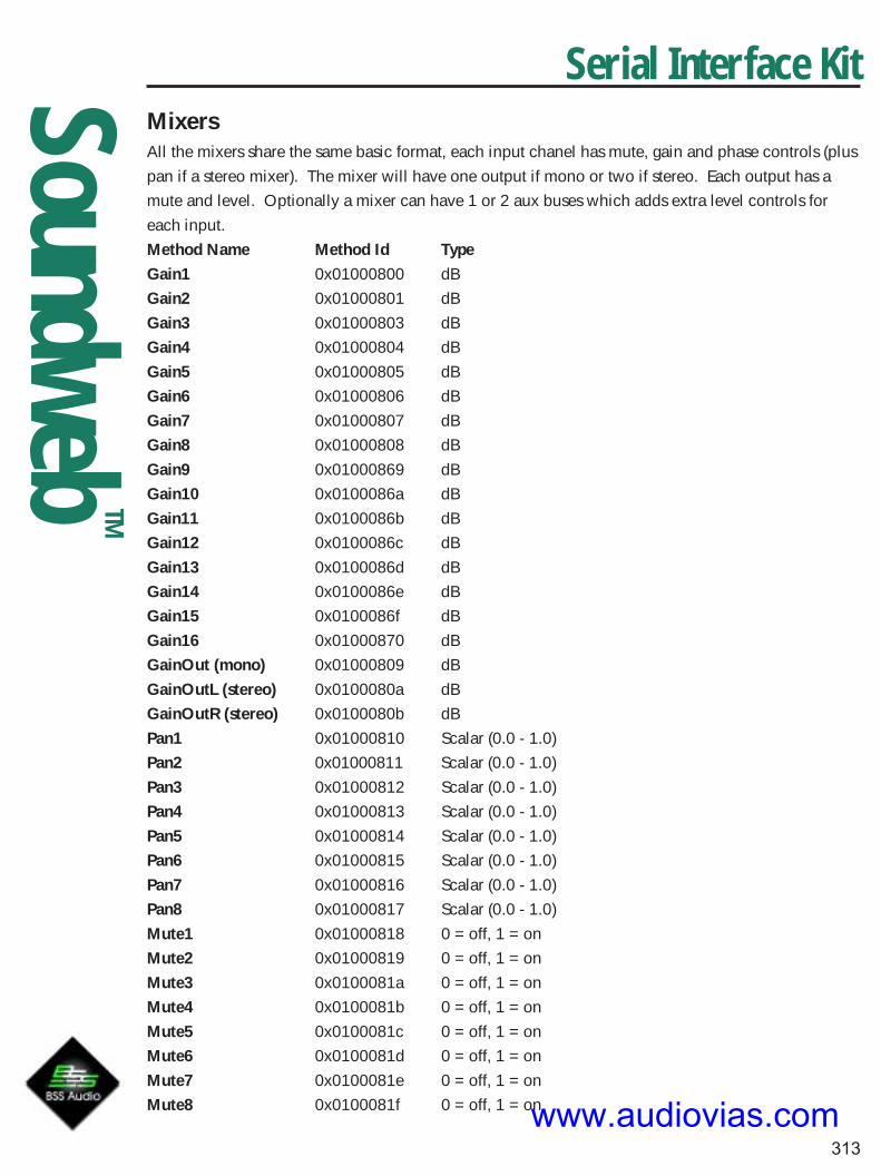
SoundwebTM
313
Serial Interface KitMixersAll the mixers share the same basic format, each input chanel has mute, gain and phase controls (plus
pan if a stereo mixer). The mixer will have one output if mono or two if stereo. Each output has a
mute and level. Optionally a mixer can have 1 or 2 aux buses which adds extra level controls for
each input.
Method Name Method Id TypeGain1 0x01000800 dB
Gain2 0x01000801 dB
Gain3 0x01000803 dB
Gain4 0x01000804 dB
Gain5 0x01000805 dB
Gain6 0x01000806 dB
Gain7 0x01000807 dB
Gain8 0x01000808 dB
Gain9 0x01000869 dB
Gain10 0x0100086a dB
Gain11 0x0100086b dB
Gain12 0x0100086c dB
Gain13 0x0100086d dB
Gain14 0x0100086e dB
Gain15 0x0100086f dB
Gain16 0x01000870 dB
GainOut (mono) 0x01000809 dB
GainOutL (stereo) 0x0100080a dB
GainOutR (stereo) 0x0100080b dB
Pan1 0x01000810 Scalar (0.0 - 1.0)
Pan2 0x01000811 Scalar (0.0 - 1.0)
Pan3 0x01000812 Scalar (0.0 - 1.0)
Pan4 0x01000813 Scalar (0.0 - 1.0)
Pan5 0x01000814 Scalar (0.0 - 1.0)
Pan6 0x01000815 Scalar (0.0 - 1.0)
Pan7 0x01000816 Scalar (0.0 - 1.0)
Pan8 0x01000817 Scalar (0.0 - 1.0)
Mute1 0x01000818 0 = off, 1 = on
Mute2 0x01000819 0 = off, 1 = on
Mute3 0x0100081a 0 = off, 1 = on
Mute4 0x0100081b 0 = off, 1 = on
Mute5 0x0100081c 0 = off, 1 = on
Mute6 0x0100081d 0 = off, 1 = on
Mute7 0x0100081e 0 = off, 1 = on
Mute8 0x0100081f 0 = off, 1 = onwww.audiovias.com

SoundwebTM
314
Serial Interface KitMute9 0x01000850 0 = off, 1 = on
Mute10 0x01000851 0 = off, 1 = on
Mute11 0x01000852 0 = off, 1 = on
Mute12 0x01000853 0 = off, 1 = on
Mute13 0x01000854 0 = off, 1 = on
Mute14 0x01000855 0 = off, 1 = on
Mute15 0x01000856 0 = off, 1 = on
Mute16 0x01000857 0 = off, 1 = on
MuteOut (mono) 0x01000828 0 = off, 1 = on
MuteOutL (stereo) 0x01000829 0 = off, 1 = on
MuteOutR (stereo) 0x0100082a 0 = off, 1 = on
Phase1 0x01000880 0 = off, 1 = on
Phase2 0x01000881 0 = off, 1 = on
Phase3 0x01000882 0 = off, 1 = on
Phase4 0x01000883 0 = off, 1 = on
Phase5 0x01000884 0 = off, 1 = on
Phase6 0x01000885 0 = off, 1 = on
Phase7 0x01000886 0 = off, 1 = on
Phase8 0x01000887 0 = off, 1 = on
Phase9 0x01000888 0 = off, 1 = on
Phase10 0x01000889 0 = off, 1 = on
Phase11 0x0100088a 0 = off, 1 = on
Phase12 0x0100088b 0 = off, 1 = on
Phase13 0x0100088c 0 = off, 1 = on
Phase14 0x0100088d 0 = off, 1 = on
Phase15 0x0100088e 0 = off, 1 = on
Phase16 0x0100088f 0 = off, 1 = on
AuxGain1a 0x01000840 dB
AuxGain1b 0x01000841 dB
AuxGain2a 0x01000842 dB
AuxGain2b 0x01000843 dB
AuxGain3a 0x01000844 dB
AuxGain3b 0x01000845 dB
AuxGain4a 0x01000846 dB
AuxGain4b 0x01000847 dB
AuxGain5a 0x01000848 dB
AuxGain5b 0x01000849 dB
AuxGain6a 0x0100084a dB
AuxGain6b 0x0100084b dB
AuxGain7a 0x0100084c dB
AuxGain7b 0x0100084d dB
AuxGain8a 0x0100084e dB www.audiovias.com

SoundwebTM
315
Serial Interface KitAuxGain8b 0x0100084f dB
AuxGain9a 0x01000858 dB
AuxGain9b 0x01000859 dB
AuxGain10a 0x0100085a dB
AuxGain10b 0x0100085b dB
AuxGain11a 0x0100085c dB
AuxGain11b 0x0100085d dB
AuxGain12a 0x0100085e dB
AuxGain12b 0x0100085f dB
AuxGain13a 0x01000860 dB
AuxGain13b 0x01000861 dB
AuxGain14a 0x01000862 dB
AuxGain14b 0x01000863 dB
AuxGain15a 0x01000864 dB
AuxGain15b 0x01000865 dB
AuxGain16a 0x01000866 dB
AuxGain16b 0x01000867 dB
AuxPreFade 0x01000868 0 = off, 1 = on
www.audiovias.com

SoundwebTM
316
Serial Interface KitMatrix Routers and MixersTo save space in this document, the methods are listed in groups of 48 buttons. Each group
corresponds to a row of buttons or rotaries on the control panels. To find the method of a particular
button or rotary, simply look down the table for the group corresponding to the output number (e.g.
Output 5 methods start at 0x010010C0). Take the input number, subtract one, and add it to the start
method. So, the button for Output 5 In 4 has a method of 0x010010C0+4-1 = 0x010010C3.
Methods Method Ids TypeRoute inputs (1-32) to output 1 0x01001000 + (Input-1) 0 = off, 1 = on
Route inputs (1-32) to output 2 0x01001030 + (Input-1) 0 = off, 1 = on
Route inputs (1-32) to output 3 0x01001060 + (Input-1) 0 = off, 1 = on
Route inputs (1-32) to output 4 0x01001090 + (Input-1) 0 = off, 1 = on
Route inputs (1-32) to output 5 0x010010C0 + (Input-1) 0 = off, 1 = on
Route inputs (1-32) to output 6 0x010010F0 + (Input-1) 0 = off, 1 = on
Route inputs (1-32) to output 7 0x01001120 + (Input-1) 0 = off, 1 = on
Route inputs (1-32) to output 8 0x01001150 + (Input-1) 0 = off, 1 = on
Route inputs (1-32) to output 9 0x01001180 + (Input-1) 0 = off, 1 = on
Route inputs (1-32) to output 10 0x010011B0 + (Input-1) 0 = off, 1 = on
Route inputs (1-32) to output 11 0x010011E0 + (Input-1) 0 = off, 1 = on
Route inputs (1-32) to output 12 0x01001210 + (Input-1) 0 = off, 1 = on
Route inputs (1-32) to output 13 0x01001240 + (Input-1) 0 = off, 1 = on
Route inputs (1-32) to output 14 0x01001270 + (Input-1) 0 = off, 1 = on
Route inputs (1-32) to output 15 0x010012A0 + (Input-1) 0 = off, 1 = on
Route inputs (1-32) to output 16 0x010012D0 + (Input-1) 0 = off, 1 = on
Route inputs (1-32) to output 17 0x01001300 + (Input-1) 0 = off, 1 = on
Route inputs (1-32) to output 18 0x01001330 + (Input-1) 0 = off, 1 = on
Route inputs (1-32) to output 19 0x01001360 + (Input-1) 0 = off, 1 = on
Route inputs (1-32) to output 20 0x01001390 + (Input-1) 0 = off, 1 = on
Route inputs (1-32) to output 21 0x010013C0 + (Input-1) 0 = off, 1 = on
Route inputs (1-32) to output 22 0x010013F0 + (Input-1) 0 = off, 1 = on
Route inputs (1-32) to output 23 0x01001420 + (Input-1) 0 = off, 1 = on
Route inputs (1-32) to output 24 0x01001450 + (Input-1) 0 = off, 1 = on
Route inputs (1-32) to output 25 0x01001480 + (Input-1) 0 = off, 1 = on
Route inputs (1-32) to output 26 0x010014B0 + (Input-1) 0 = off, 1 = on
Route inputs (1-32) to output 27 0x010014E0 + (Input-1) 0 = off, 1 = on
Route inputs (1-32) to output 28 0x01001510 + (Input-1) 0 = off, 1 = on
Route inputs (1-32) to output 29 0x01001540 + (Input-1) 0 = off, 1 = on
Route inputs (1-32) to output 30 0x01001570 + (Input-1) 0 = off, 1 = on
Route inputs (1-32) to output 31 0x010015A0 + (Input-1) 0 = off, 1 = on
Route inputs (1-32) to output 32 0x010015D0 + (Input-1) 0 = off, 1 = on
Mix inputs (1-32) to output 1 0x01000800 + (Input-1) dBwww.audiovias.com

SoundwebTM
317
Serial Interface KitMix inputs (1-32) to output 2 0x01000830 + (Input-1) dB
Mix inputs (1-32) to output 3 0x01000860 + (Input-1) dB
Mix inputs (1-32) to output 4 0x01000890 + (Input-1) dB
Mix inputs (1-32) to output 5 0x010008C0 + (Input-1) dB
Mix inputs (1-32) to output 6 0x010008F0 + (Input-1) dB
Mix inputs (1-32) to output 7 0x01000920 + (Input-1) dB
Mix inputs (1-32) to output 8 0x01000950 + (Input-1) dB
Mix inputs (1-32) to output 9 0x01000980 + (Input-1) dB
Mix inputs (1-32) to output 10 0x010009B0 + (Input-1) dB
Mix inputs (1-32) to output 11 0x010009E0 + (Input-1) dB
Mix inputs (1-32) to output 12 0x01000A10 + (Input-1) dB
Mix inputs (1-32) to output 13 0x01000A40 + (Input-1) dB
Mix inputs (1-32) to output 14 0x01000A70 + (Input-1) dB
Mix inputs (1-32) to output 15 0x01000AA0 + (Input-1) dB
Mix inputs (1-32) to output 16 0x01000AD0 + (Input-1) dB
Mix inputs (1-32) to output 17 0x01000B00 + (Input-1) dB
Mix inputs (1-32) to output 18 0x01000B30 + (Input-1 ) dB
Mix inputs (1-32) to output 19 0x01000B60 + (Input-1) dB
Mix inputs (1-32) to output 20 0x01000B90 + (Input-1) dB
Mix inputs (1-32) to output 21 0x01000BC0 + (Input-1) dB
Mix inputs (1-32) to output 22 0x01000BF0 + (Input-1 ) dB
Mix inputs (1-32) to output 23 0x01000C20 + (Input-1) dB
Mix inputs (1-32) to output 24 0x01000C50 + (Input-1) dB
Mix inputs (1-32) to output 25 0x01000C80 + (Input-1) dB
Mix inputs (1-32) to output 26 0x01000CB0 + (Input-1) dB
Mix inputs (1-32) to output 27 0x01000CE0 + (Input-1) dB
Mix inputs (1-32) to output 28 0x01000D10 + (Input-1) dB
Mix inputs (1-32) to output 29 0x01000D40 + (Input-1) dB
Mix inputs (1-32) to output 30 0x01000D70 + (Input-1) dB
Mix inputs (1-32) to output 31 0x01000DA0 + (Input-1) dB
Mix inputs (1-32) to output 32 0x01000DD0 + (Input-1) dB
www.audiovias.com

SoundwebTM
318
Serial Interface KitGraphic EqMethod Name Method Id TypeBandGain1 0x01000820 dB
BandGain2 0x01000821 dB
BandGain3 0x01000822 dB
BandGain4 0x01000823 dB
BandGain5 0x01000824 dB
BandGain6 0x01000825 dB
BandGain7 0x01000826 dB
BandGain8 0x01000827 dB
BandGain9 0x01000828 dB
BandGain10 0x01000829 dB
BandGain11 0x0100082a dB
BandGain12 0x0100082b dB
BandGain13 0x0100082c dB
BandGain14 0x0100082d dB
BandGain15 0x0100082e dB
BandGain16 0x0100082f dB
BandGain17 0x01000830 dB
BandGain18 0x01000831 dB
BandGain19 0x01000832 dB
BandGain20 0x01000833 dB
BandGain21 0x01000834 dB
BandGain22 0x01000835 dB
BandGain23 0x01000836 dB
BandGain24 0x01000837 dB
BandGain25 0x01000838 dB
BandGain26 0x01000839 dB
BandGain27 0x0100083a dB
BandGain28 0x0100083b dB
BandGain29 0x0100083c dB
BandGain30 0x0100083d dB
Selectivity 0x01000841 Scalar (1.0 - 1.5)
Bypass 0x01000842 0 = off, 1 = on
www.audiovias.com

SoundwebTM
319
Serial Interface KitMetering PointTo implement metering in an external device it must be able to receive meter messages. These will be
MeterLevel messages from a metering point object.
Method Name Method Id TypeMeterLevel 0x01000800 dB
MeterAttack 0x02000801 ms
MeterRelease 0x02000802 ms
MeterReference 0x01000803 dB
Source SelectorMethod Name Method Id TypeSourceSel 0x01000800 Discrete. Values are:
0 = none
1 = Input 1
2 = Input 2
3 = Input 3
4 = Input 4
5 = Input 5
6 = Input 6
7 = Input 7
8 = Input 8
9 = Input 9
10 = Input 10
11= Input 11
12 = Input 12
13 = Input 13
14 = Input 14
15 = Input 15
16 = Input 16
www.audiovias.com
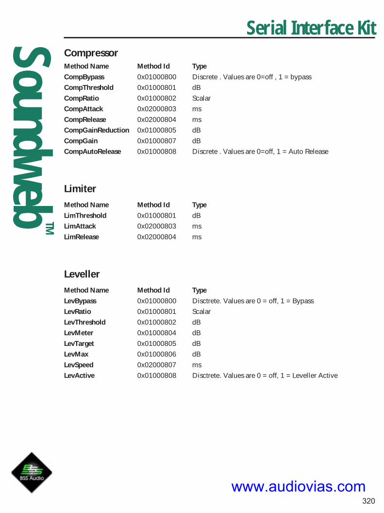
SoundwebTM
320
Serial Interface KitCompressorMethod Name Method Id TypeCompBypass 0x01000800 Discrete . Values are 0=off , 1 = bypass
CompThreshold 0x01000801 dB
CompRatio 0x01000802 Scalar
CompAttack 0x02000803 ms
CompRelease 0x02000804 ms
CompGainReduction 0x01000805 dB
CompGain 0x01000807 dB
CompAutoRelease 0x01000808 Discrete . Values are 0=off, 1 = Auto Release
LimiterMethod Name Method Id TypeLimThreshold 0x01000801 dB
LimAttack 0x02000803 ms
LimRelease 0x02000804 ms
LevellerMethod Name Method Id TypeLevBypass 0x01000800 Disctrete. Values are 0 = off, 1 = Bypass
LevRatio 0x01000801 Scalar
LevThreshold 0x01000802 dB
LevMeter 0x01000804 dB
LevTarget 0x01000805 dB
LevMax 0x01000806 dB
LevSpeed 0x02000807 ms
LevActive 0x01000808 Disctrete. Values are 0 = off, 1 = Leveller Active
www.audiovias.com

SoundwebTM
321
Serial Interface KitFilter High Pass And Low PassMethod Name Method Id TypeFilterBypass 0x01000800 Disctrete. Values are 0 = off, 1 = bypass
Filter Frequency 0x01000801 dB
FilterType 0x01000804 Discrete. Values are 0=Out
1=6But
2=12But
3=12Bess
4=12LR
5=18But
6=24But
7=24Bess
8=24LR
9=48But
10=48LR
www.audiovias.com

SoundwebTM
322
NetworkingAudio Networking White PaperBuilding Soundweb Networks
Background 1 - packet networks 323
Background 2 - streaming networks 323
The Soundweb network 324
Delays in a Soundweb network 325
Resilience in a Soundweb network 325
Synchronisation 325
Connecting up Soundweb boxes with the network 325
Example 1: connecting up two daisy chain boxes 326
Example 2: using a hub device 326
Example 3: connecting up four daisy chain boxes 327
www.audiovias.com

SoundwebTM
323
White paper – audio networking and Soundweb
This paper explains some of the concepts which underlie the Soundweb network, and explains some
of the background to the techniques used.
Background 1 - packet networks
The most common type of network system for transmitting data is a packet network. This is found in
the Ethernet systems used to hook up most office computers, and the X.25 networks used to link
banking transactions. The Internet is a rather large form of packet network.
Packet networks operate in a particular way; a quantity of data to be sent (usually anything up to a
couple of kilobytes or so) is bundled together and sent out from one network station to another. The
main issue for the designers of packet networks is so-called “Access to the medium”: when two
stations desire to transmit a packet at the same time, how is one to prevent them clashing?
Many techniques are used for this. The technique employed in Ethernet, the most widespread packet
network, is called “CSMA/CD”, which stands for “Carrier Sense Multiple Access with Collision Detec-
tion”. In this method, if two stations start to transmit at the same time, the packets collide. This is
detected; a jamming signal is put out on the network to ensure that both packets are trashed, and the
stations retry after a random wait. If there is a second collision, they wait again for a longer random
period, and retry again – this is repeated until the packets get through (or some maximum limit is
reached).
This technique is disastrous for real time audio transmission. The collision process can introduce
delays of many tens of milliseconds, which, worse still, cannot be predicted. Raw Ethernet is not a
suitable system for transmitting audio in real time, unless very large delays can be tolerated.
When it comes to transmitting audio, any packet network (even one not suffering from the CSMA/CD
collision problem) requires the audio to be bundled into packets before being sent out over the net-
work. This inevitably causes delay through the network hardware. It also requires relatively expensive
hardware, since substantial buffer memory is required in which to store the packets, together with
circuitry for packet assembly and disassembly.
Background 2 - streaming networks
The most widespread audio network (which is now mostly digital) is the Public Switched Telephone
Network. This takes quite a different approach: that of the streaming protocol. In this sort of system, a
flow of audio samples is sent at a fixed rate. The audio fills the entire signal, so any control informa-
tion must be buried in well-defined parts of the stream.
In the professional audio world, point to point digital audio transmission has followed this model, as
exemplified by the AES-3 or SP-DIF interfaces. There are two reasons for this:
Audio Networking White Paper
www.audiovias.com

SoundwebTM
324
• Because A/D and D/A converters work on the basis of a steady stream of audio samples, the
hardware needed to reformat the stream to be placed on the network is minimal. It is not neces-
sary to have substantial packet buffer memory and DMA processing.
• Since there is no packet assembly or disassembly, the delay through the network hardware is
also minimal – it is often below a single sample for one particular network station.
The digital telephone network provides a good example of a streaming audio network with multiple
addressable stations. However, this technology is not immediately applicable to professional audio
because of its restricted sample size and data rate (8 bit samples at 7 or 8 kHz sample rate), and
because the telephone system tends to use very large switches with very small (one or two line) sta-
tions.
The Soundweb network
The Soundweb network clearly follows the second paradigm – that of the streaming protocol. In the
case of Soundweb, both audio and control data are transmitted as a series of 256-bit frames, one per
sample time (20.8333us). Each frame holds up to eight 24-bit audio samples, with the remaining bits
providing a control channel: this gives about 3 Mbit/s of control information when all eight audio
streams are in use.
The custom IC which controls Soundweb networking has the ability to insert and extract control
information in the “spare” part of the frame. This information is formatted into packets: the interface to
the microprocessor which controls the box looks very like a conventional Ethernet solution, even
though the underlying transmission technology is totally different.
The network uses a multiple point-to-point topology: each network port on a station is connected to a
single port on another, with no shared medium as is found on Ethernet. In terms of its technical herit-
age, Soundweb can be thought of as a telephone network for professional audio.
Soundweb has one unique feature which sets it apart from telephone technology: this is the ability to
string several stations together without the use of a central hub. It is this feature which allows two-box
or three-box Soundweb networks to be cost-effective. The feature is implemented by forming a logical
ring between all the stations. Each station can choose to relay its eight audio streams to the next
station in the ring; alternatively, it can choose to overwrite one or more streams with audio signals
from its inputs, or from internal processing.
Another unusual feature is the choice made for the bandwidth/distance trade-off. When using cat-
egory 5 cable, a modern Fast Ethernet solution picks a speed of 100 Mbit/s with distance limited to
100 metres. Soundweb was designed for audio installations where the 100 metre limit could have
been a significant constraint, and the choice was made to operate at a data rate of 12.288 Mbit/s, but
with a maximum distance between nodes of over 300 metres.
Audio Networking White Paper
www.audiovias.com

SoundwebTM
325
Delays in a Soundweb network
When a network is formed out of several Soundweb boxes daisy-chained together, the principle on
which the network operates is that the audio must travel around the ring in less than one sample time.
When audio is simply forwarded between stations, the delay between any two units varies according
to the cable length, but is certainly less than one sample time (20.83333us). If a station processes
audio before forwarding it, a single sample time is added.
A Soundweb hub forms the interlock point between rings. The transition across a hub always involves
the addition of a further sample time of delay.
Resilience in a Soundweb network
Soundweb networks are as resistant as possible to failure of one of the boxes on the network, given
that audio and control is unable to pass through a box which has failed.
If a Soundweb box fails, the remaining boxes on the network will detect its absence and re-initialise
communication. They will be able to pass control information to other units to which they are still
connected, and any audio paths which did not pass through the failed unit will also be unaffected.
Synchronisation
In any distributed digital audio system, the question of synchronisation inevitably arises. Each box in a
Soundweb network is tightly synchronised to word clock. One unit is the “clock master” for the
network; the other units phase-lock their word clock to the master.
The decision as to which unit is to be clock master is negotiated between units when the network is
powered up, and re-negotiated if it should need to be re-initialised for any reason (such as the failure
of a unit). In the absence of Soundweb units with digital input, the choice is arbitrary. When a
Soundweb unit supporting digital input is designed, it will be possible to designate it as the preferred
clock master for the network, allowing the whole network to be synchronised to an external word
clock. Note, however, that Soundweb operates strictly at 48 kHz sample rate: other digital input
sample rates can only be supported via sample rate converters.
Connecting up Soundweb boxes with the network
The Soundweb network carries both audio and control information between Soundweb boxes over
low-cost category 5 twisted pair cable. The cable is connected to a Soundweb box via RJ-45 type 8-
pin jacks - similar to the jacks used in most data cabling applications and many telecommunications
installations.
A Soundweb network cable carries up to 8 channels of 24-bit 48 kHz digital audio in either direction,
Audio Networking White Paper
www.audiovias.com

SoundwebTM
326
plus control information.
Box types and connector types
As far as the network is concerned, Soundweb boxes come in two types:
• Daisy chain boxes have two network jacks: one is labelled NET IN and one is labelled NET
OUT. An example of a daisy chain box is the Soundweb 9088 Networked Signal Processor.
• Hub boxes have a larger number of network jacks and are used to build up more complex
networks. An example of a hub box is the Soundweb 9000 Active network hub. Network jacks in a
hub may be labelled INnnn or OUTnnn where nnn is a network port number.
Jacks labelled IN and OUT have identical functions, and indeed are quite identical except for one
thing: their connections are reversed. This means that a standard straight through cable is used to
connect an input jack to an output jack. Such a connection is compatible with industry standard
structured cabling systems.
In some circumstances (when working with multiple hubs), it may be necessary to connect two output
jacks together, or two input jacks together. This will work OK, but only if a crossover cable is used.
Example 1: connecting up two daisy chain boxes
Connect a cable from the NET OUT jack of one box to the NET IN jack of the other.
Control information can pass between the two boxes, and 8 channels of audio are available in either
direction on the cable.
Example 2: using a hub device
For large systems, connectivity can be provided by the Soundweb 9000 hub unit.
Each cable from U2, U3 or U4 to the hub can carry 8 channels of audio in either direction. The hub
permits any channel on any network jack to be routed to any other, giving a high degree of flexibility
in the way the audio can be routed around the system.
Building Soundweb Networks
www.audiovias.com

SoundwebTM
327
Example 3: connecting up four daisy chain boxes
For medium-sized systems where the cost of a hub would be unjustified, it is possible to string many
daisy chain boxes together. However, care is required, as well as a reasonable understanding of the
paths provided in each daisy chain box.
Connect a cable from NET OUT of one box to NET IN of the next, and continue doing this until all
four boxes are connected together.
Control messages can flow freely between all four boxes. Audio, however, is limited by the fact that
only 8 channels of audio can pass over the cable.
8 audio channels come into U2 through the NET IN port. These are all available as inputs to the signal
processing circuitry in U2. The output channels sent on the NET OUT port can be one of two things:
they can be audio outputs from U2 itself, or they can be signals forwarded directly from the NET IN
port (for use by U3 or U4).
In addition to the paths from U1 to U2 to U3 to U4, the cables also provide a return path from U4 to
U1. This forms the boxes into a logical ring, so that any box can send audio to any other, but the
restriction of 8 channels of audio applies.
It would be possible, for example, to send 6 channels from U1 to U2, 2 channels from U1 to U3, 6
channels from U2 to U4, 2 channels from U3 to U4 and 8 channels from U4 to U1. Figure 4 shows
what the signal path would look like within U2:
It would not be possible to send 4 channels from U1 to U2 and 5 channels from U1 to U3, because
the cable link between U1 and U2 would need 9 channels and would overflow its 8 channel limit.
For the same reason, it would not be possible to send 8 channels from U1 to U4, and 1 channel from
U2 to U3.
Building Soundweb Networks
www.audiovias.com
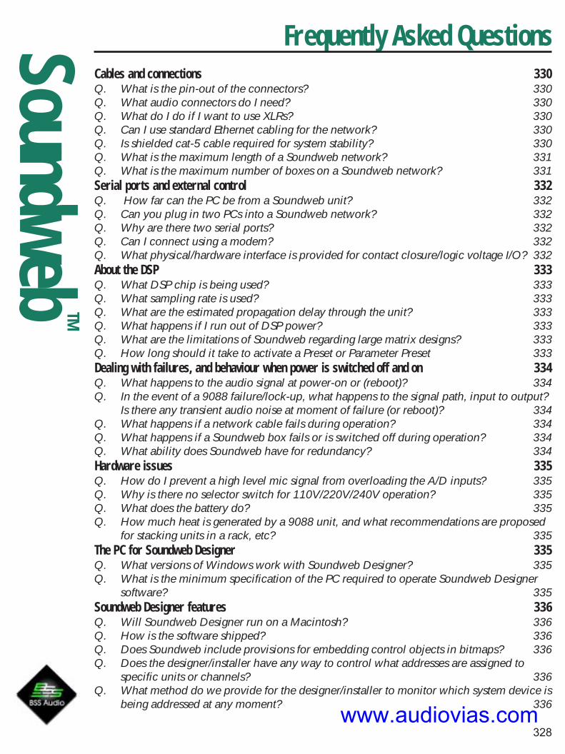
Frequently Asked Questions
328
SoundwebTM
Cables and connections 330Q. What is the pin-out of the connectors? 330Q. What audio connectors do I need? 330Q. What do I do if I want to use XLRs? 330Q. Can I use standard Ethernet cabling for the network? 330Q. Is shielded cat-5 cable required for system stability? 330Q. What is the maximum length of a Soundweb network? 331Q. What is the maximum number of boxes on a Soundweb network? 331Serial ports and external control 332Q. How far can the PC be from a Soundweb unit? 332Q. Can you plug in two PCs into a Soundweb network? 332Q. Why are there two serial ports? 332Q. Can I connect using a modem? 332Q. What physical/hardware interface is provided for contact closure/logic voltage I/O? 332About the DSP 333Q. What DSP chip is being used? 333Q. What sampling rate is used? 333Q. What are the estimated propagation delay through the unit? 333Q. What happens if I run out of DSP power? 333Q. What are the limitations of Soundweb regarding large matrix designs? 333Q. How long should it take to activate a Preset or Parameter Preset 333Dealing with failures, and behaviour when power is switched off and on 334Q. What happens to the audio signal at power-on or (reboot)? 334Q. In the event of a 9088 failure/lock-up, what happens to the signal path, input to output?
Is there any transient audio noise at moment of failure (or reboot)? 334Q. What happens if a network cable fails during operation? 334Q. What happens if a Soundweb box fails or is switched off during operation? 334Q. What ability does Soundweb have for redundancy? 334Hardware issues 335Q. How do I prevent a high level mic signal from overloading the A/D inputs? 335Q. Why is there no selector switch for 110V/220V/240V operation? 335Q. What does the battery do? 335Q. How much heat is generated by a 9088 unit, and what recommendations are proposed
for stacking units in a rack, etc? 335The PC for Soundweb Designer 335Q. What versions of Windows work with Soundweb Designer? 335Q. What is the minimum specification of the PC required to operate Soundweb Designer
software? 335Soundweb Designer features 336Q. Will Soundweb Designer run on a Macintosh? 336Q. How is the software shipped? 336Q. Does Soundweb include provisions for embedding control objects in bitmaps? 336Q. Does the designer/installer have any way to control what addresses are assigned to
specific units or channels? 336Q. What method do we provide for the designer/installer to monitor which system device is
being addressed at any moment? 336www.audiovias.com

Frequently Asked Questions
329
SoundwebTM
Q. How can you be sure you are on-line? 336Q. While online, can your PC be unplugged from one box and plugged into another and
remain online? 336
www.audiovias.com

Frequently Asked Questions
330
SoundwebTM
Cables and connections
Q. What is the pin-out of the connectors?A. This is described in the Soundweb Designer on-line Help under the topic ‘Connectorpinouts’.
Q. What audio connectors do I need?A. The analogue audio connections use two-part screw terminal connectors: these have severalnames, such as Phoenix, Euro, Klippon or Combicon. The male connectors are mounted on theunit, and the mating female connectors are shipped with each unit, so you should not need topurchase additional connectors.
Q. What do I do if I want to use XLRs?A. The assumption made is that the XLRs will be in a wall panel or an input panel of your rack,and not used for the connection to the Soundweb box itself. There are no plans at present toproduce a 2U version of the 9088 with 16 XLRs.
Q. Can I use standard Ethernet cabling for the network?A. Passive Ethernet components such as RJ-45 connectors, patch leads, cat-5 cables, wall boxes,etc. can be used – although you must ensure that they connect all eight cores of the cable,including the ones that ordinary Ethernet does not use. Soundweb is not compatible with activeEthernet components hubs, routers or repeaters.
Q. Is shielded cat-5 cable required for system stability?A. Unshielded cat-5 cable (UTP) will work fine, and is indeed recommendedbecause it will work over the full 300 metre distance. Shielded (STP) cat 5 cable should be usedto comply with EMC regulations.
www.audiovias.com
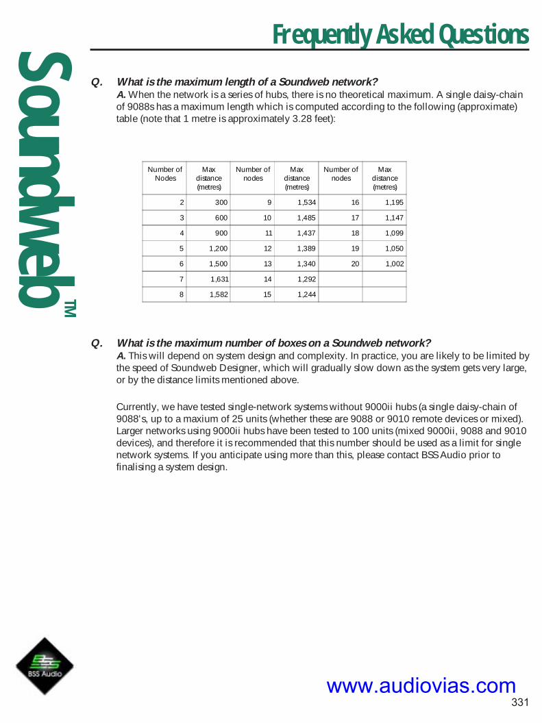
Frequently Asked Questions
331
SoundwebTM
Q. What is the maximum length of a Soundweb network?A. When the network is a series of hubs, there is no theoretical maximum. A single daisy-chainof 9088s has a maximum length which is computed according to the following (approximate)table (note that 1 metre is approximately 3.28 feet):
Number ofNodes
Maxdistance(metres)
Number ofnodes
Maxdistance(metres)
Number ofnodes
Maxdistance(metres)
2 300 9 1,534 16 1,195
3 600 10 1,485 17 1,147
4 900 11 1,437 18 1,099
5 1,200 12 1,389 19 1,050
6 1,500 13 1,340 20 1,002
7 1,631 14 1,292
8 1,582 15 1,244
Q. What is the maximum number of boxes on a Soundweb network?A. This will depend on system design and complexity. In practice, you are likely to be limited bythe speed of Soundweb Designer, which will gradually slow down as the system gets very large,or by the distance limits mentioned above.
Currently, we have tested single-network systems without 9000ii hubs (a single daisy-chain of9088's, up to a maxium of 25 units (whether these are 9088 or 9010 remote devices or mixed).Larger networks using 9000ii hubs have been tested to 100 units (mixed 9000ii, 9088 and 9010devices), and therefore it is recommended that this number should be used as a limit for singlenetwork systems. If you anticipate using more than this, please contact BSS Audio prior tofinalising a system design.
www.audiovias.com

Frequently Asked Questions
332
SoundwebTM
Serial ports and external control
Q. How far can the PC be from a Soundweb unit?A. The RS-232 connection from the PC has a theoretical limit of 15m, although considerablylonger distances seem to work in practise. If you want to take the PC further from the unit, it isrecommended that you use one of the many RS-232 extender products available at fairly lowcost. These products usually work by converting RS-232 to RS-422 or RS-485, although someuse their own protocol. Note that you will need to extend the handshake lines also. A separatedocument is available detailing the use of converters.
Q. Can you plug in two PCs into a Soundweb network?A. Yes, in the Soundweb Designer >Preferences>Application>Comms section, you can assigndifferent system addresses for each PC connected. As an alternative to using the front RS-232port, you can connect into a 9088 device using the rear RS-232 port, but not both on one unit.Theoretically, you can assign a number of PC’s in the network, as long as each has a differentaddress.
Q. Why are there two serial ports?A. The front panel serial port is provided so that you can plug in a notebook PC forconfiguration. The rear panel is there to allow you to plug in an external control device such asan AMX/Crestron controller, although it can also be used to plug in the PC as an alternative tothe front panel port.
Q. Can I connect using a modem?A. Version 1.18.2 of Soundweb Designer includes modem support, so that using a modemconnected to the rear port of a 9088/9000ii, you can dial-up and connect with your local PC,and control the system.
Q. What physical/hardware interface is provided for contact closure/logic voltage I/O?A. The 9088 and 9000ii hub provides 8 “control inputs”. Each control input is assigned to anADC channel, has a 4.7 k pull-up resistor, and accepts a voltage between 0 and 5V. You canconnect a switch between the signal pin and common and use the port as a simple contactclosure input, or you can use a potentiometer (which must be 47k logarithmic) and use it as acontinuous parameter control. The software allows you to configure the control inputs for each9088/9000ii. The 9088/9000ii also provides 8 logic outputs, which can drive either 0 or 5V,protected by a 440 Ohm series resistor. They can be used to drive LEDs or possibly relays.
An additional logic output is opto-isolated, and coupled directly to the watchdog output. Thiswill energise when the system is up and running OK; if power fails, or if the software crashes,the opto-isolator will stop conducting. The connections to all these inputs and outputs areprovided on a two-level 24 way Phoenix connector. Seen from the back of the unit, theconnections look like this:
Cmn Cmn In1 In2 In3 In4 In5 In6 In7 In8 Cmn Cmn
Opto+ Opto- Out1 Out2 Out3 Out4 Out5 Out6 Out7 Out8 Cmn Cmnwww.audiovias.com

Frequently Asked Questions
333
SoundwebTM
About the DSP
Q. What DSP chip is being used?A. The Soundweb 9088 has two chips running in parallel at 80 MHz each. These execute oneinstruction per clock cycle, hence the figure of 160 MIPS (Million Instructions Per Second). TheSoundweb 9000ii and 9088ii use 100MHz DSP chips, and have 200 MIPS of dsp resource.
Q. What sampling rate is used?A. Internally, Soundweb uses a fixed 48 kHz sampling rate, which cannot be changed. The AES/EBU digital i/o interfaces support other rates via sample rate conversion.
Q. What are the estimated propagation delay through the unit?A. Each A/D converter and each D/A converter adds an estimated delay of less than 2ms intotal. Other delays internally are counted in samples (1/48 kHz each, or approximately 20.8microseconds). Note: Soundweb uses a 48KHz sampling rate. A typical delay due toprocessing and intra-DSP communication might be 5 samples, or 104 microseconds. Themaximum delay for a network chain of 9088’s is one sample, and each 9000ii hub inserts oneadditional sample: in other words, the network contributes only a very small amount to theoverall delay.
Q. What happens if I run out of DSP power?A. The DSP power cannot be increased internally, but there are several things that you can do:1. You can ‘turn off’ delay compensation in the devices.2. If you don’t need all the DSP power at the same time, you can split your design intodifferent configurations, and only activate the power you need at a particular time.3. If you have several Soundweb units in your system, you can try to move some of theprocessing into a different box.4. Finally, you can buy extra boxes (either 9000ii’s or 9088’s) and route signals to and fromthe extra boxes across the network.
Q. What are the limitations of Soundweb regarding large matrix designs?A. The main limitations are to do with the number of analogue inputs and outputs in each box.A single box can do an 8x8 matrix mixer; a pair of boxes connected by a single network cablecan do a 16x16 matrix mixer. In order to create configurations larger than 16x16 one or more9000 network hubs is necessary. If you add enough hubs you can create a system with anumber of inputs and outputs which is essentially unlimited. However, if you try to allow theuser to make every output and arbitrary mix of every input, you will run into bottlenecks both inDSP power, your ability to simultaneously route all the signals, and in your ability to create asensible control panel. For example, a full 96:48 matrix mixer is possible but uses 12 hubs inaddition to the 12 x 9088s, and designing the control panel is quite difficult. A new processingobject, the SOURCE MATRIX, has been added to streamline matrix resource useage, whereeach output is tied to only one input.
Q. How long should it take to activate a Preset or Parameter PresetA. Depending on the number of processing objects and number of controls, a Preset will takeanywhere from a small fraction of a second to several seconds.
www.audiovias.com

Frequently Asked Questions
334
SoundwebTM
Dealing with failures, and behaviour when power isswitched off and on
Q. What happens to the audio signal at power-on or (reboot)?A. The audio outputs remain muted by relay until the unit’s software has completedinitialisation. The unit will restore the audio path to the configuration and settings that were inplace at the last time the unit was switched off.
Q. In the event of a 9088 failure/lock-up, what happens to the signal path, input tooutput? Is there any transient audio noise at moment of failure (or reboot)?A. Hardware failures can have unforeseen consequences which may include transient noise,although the majority of hardware failures are not like this. If the hardware is OK but there is asoftware crash, the watchdog timer will kick in and reboot the unit.
Q. What happens if a network cable fails during operation?A. The audio processing of all the units will continue as normal, although any audio signalsbeing passed down the network may not be available. (Warning – at present, this can mean thatan unexpected audio signal is routed: it is a wishlist item to ensure that network audio inputsmute if their source becomes disconnected.) The control processing will work fine for unitswhich are still connected to each other, so there will be two sub-networks remaining which willwork OK internally. Naturally, any control information which would have been routed acrossthe failed cable will not operate correctly.
Q. What happens if a Soundweb box fails or is switched off during operation?A. The remaining units will continue to function as normally as is possible given the fact thatsome of their audio sources may be missing, and they may no longer have a physical means ofreceiving control information. If a box simply loses power, the network will automaticallyreconfigure itself when power is reapplied. However, any Preset changes will not be applied toa box which was switched off at the time the Preset was activated. Soundweb Designer softwarewill still think that the system is on-line, but you will be unable to access the unit which wasswitched off. This also applies to any other units which are on the far side of it, since there willbe no path for network messages from your PC to reach them.
Q. What ability does Soundweb have for redundancy?A. The 9088 and 9000ii provide an opto-isolated output which works from the watchdog. If theopto-isolator is conducting, then the hardware is on and the software is working OK. If power isremoved from the hardware, or if the software crashes for any reason, the opto-isolator willcease to conduct. This output can be used to trigger an alarm, or to switch in a backup systemautomatically.Here is an example of how this might work: you could connect two 9088s to your system, witha box of relays to switch between the two 9088s. The opto output of the primary unit wouldenergise the relays so that all signals pass through the primary unit.
Should the primary unit fail, the opto would cease to conduct, so the relays would flip over tobring the secondary 9088 into the circuit. Conceivably, the backup unit could have a different,non-critical, function when in the normal mode, and double as a backup for the main unit. ADCLR system is also incorporated, where two sets of cat 5 cables are used to create a redundantring network. If one cable is damaged, the other still transmits the signals around the network.
www.audiovias.com

Frequently Asked Questions
335
SoundwebTM
Hardware issues
Q. How do I prevent a high level mic signal from overloading the A/D inputs?A. The quad mic preamp card has programmable gain, which is applied before the A/Dconverter. You should set the gain such that the maximum output level of the microphone willnot reach +20dB, even if someone is singing very close to the microphone. This setting formspart of your Presets, so you can have different settings for different microphone types or evendifferent types of event.
Q. Why is there no selector switch for 110V/220V/240V operation?A. Because the unit doesn’t need one. The 9000 and 9088 both contain universal powersupplies which can be plugged in to any ac mains voltage between 95V and 245V.
Q. What does the battery do?A. 9088s and 9000s do not have batteries, firmware and settings are held in flash EPROM. Theobject inside that looks like a battery is in fact a button with the unique hardware serial numberof the unit. This is provided in detachable form because there are plans to use it in future as thedecryption key for copy-protected software, and it is desirable that this can be swappedbetween units in case of failure.
Q. How much heat is generated by a 9088 unit, and what recommendations areproposed for stacking units in a rack, etc?A. No special precautions are required compared to any other DSP products, and it should bepossible to stack several units adjacent to each other in a rack. We would of course recommendthat normal precautions be taken, particularly if the rack contains power amplifiers.
The PC for Soundweb Designer
Q. What versions of Windows work with Soundweb Designer?A. Soundweb Designer requires a 32-bit version of Windows; that is Windows 95, 98, 2000,Windows NT Workstation (version 4.0 or later), or XP.Soundweb Designer will NOT work on Windows 3.10 or 3.11.
Q. What is the minimum specification of the PC required to operate Soundweb Designersoftware?A. Soundweb Designer requires a recommended P266 PC with 48MB RAM. Hard disk spacerequirement is roughly 20MB.
System speed will depend on system (network) size and computer speed. For large systems (20boxes plus), a much faster PC is required.
System design files will take up additional space, approximately 250KB for a typical smallsystem layout. Although the software is usable on 640x480 screen resolution, 800x600 isconsiderably more comfortable, and 1024 x 768 is even better. Higher resolutions are betterstill, of course, particularly if you are doing a complex design.
www.audiovias.com

Frequently Asked Questions
336
SoundwebTM
Soundweb Designer features
Q. Will Soundweb Designer run on a Macintosh?A. There is no version of Soundweb Designer specially written for the Macintosh, nor is itsupported for the MAC. The program is working in the field on MAC computers, underSoft-Windows / Virtual PC Emulation, but requires a change in the serial cable.
Q. How is the software shipped?A. The software is shipped on CD-Rom, and is available for download on the website.
Q. Does Soundweb include provisions for embedding control objects in bitmaps?A. Yes, by adding a bitmap object to a newly created map window, and dragging appropriatecontrols onto it. Alternatively, you can set a bitmap as the background of the map window. Youmay also edit the background colour of these controls to be transparent.
Q. Does the designer/installer have any way to control what addresses are assigned tospecific units or channels?A. Each DSP box has an address set by the ‘Location’ item on its right-click menu. Once thesystem is configured, and the addresses of the actual hardware devices matches the addresses inthe system design, the addresses stay correct forever: the user need not be aware of thehardware addresses.
Q. What method do we provide for the designer/installer to monitor which systemdevice is being addressed at any moment?A. Each DSP box has an ‘activity’ LED that is lit when data is being transferred to or from it.When setting up the system, if you click on the name of a unit in the network window (whileon-line!), all the LEDs on the unit will flash so that you can tell which physical hardware unitmatches the name on your screen.
Q. How can you be sure you are on-line?A. The status bar (at the bottom of your Soundweb Designer window) will show the word‘OFFLINE’ if you are offline. The corresponding area is blank if you are on-line. Alternatively, goto network view: if you are on-line, the ‘go on-line’ button will be greyed out. There is also nowa network status toolbar which shows whether you are on or off line.
Q. While online, can your PC be unplugged from one box and plugged into another andremain online?A. No – the connection will be lost a couple of seconds after unplugging from the first unit. Thecorrect procedure is to go off-line, unplug the PC from the first unit, plug it into the second unit,and then go on-line again.
Soundweb FAQ Last updated 28/11/00
www.audiovias.com

337
SoundwebTM
Converting Soundweb's RS-232 connection for long distance RS-422 use
BSS Audio have tested the configurations shown below with an RS232 to RS422 convertersupplied by Mutek Transcom Ltd., Farleigh House, Frome Rd., Bradford on Avon, Wiltshire, BA151LE, U.K.Tel +44 (0)1225 866501 http://www.mutek.co.uk/
RS232RS422
Converter
Null ModemRS422 cable
RS232RS422
Converter
Modem cable
Computer
SoundwebDevice
Front connector
Cable suppliedwith Soundweb38kbps link Null modem
cable
Gender changer
Only the 38kbps link is guaranteed to work as this is the maximum rated speed of the converter box.The limitation is due to the RS232 chips used. However, we have tested standard converters with a115kbps link over 200m of CAT-5 cable and very short RS232 cables with no problem.
RS232RS422
Converter
Null ModemRS422 cable
RS232RS422
Converter
Modem cable
Computer
SoundwebDevice
Rear connector115kbps link
Modem cable
RS-232 to RS-422 conversionRS-232 to RS-422 conversionRS-232 to RS-422 conversionRS-232 to RS-422 conversionRS-232 to RS-422 conversion
www.audiovias.com

338
SoundwebTM
ComputerSide
SoundwebSide
TXD+ 4 6TXD- 22 24
RXD+ 6 4RXD- 24 22
RTS+ 7 9RTS- 25 27
CTS+ 9 7CTS- 27 25
Connections required for the Null Modem RS422 cable
Both ends require a DB-37 male plug.The table on the left shows the pin connections.A suitable cable type is CAT-5 or any other similardata cable containing twisted pairs.Ensure that each wire pair shown in the tablecorresponds to a twisted pair in the cable.
Mutek also offer to make converter boxes with faster RS232 chips on request for a smalladditional charge. This can not be guaranteed to work but based on our experience probablywill. Be prepared to revert to the 38kbps link if need be.
In the US, Hullspeed Data Products Inc. make a converter, the AD U232-422.Contact details: P.O. Box 1749 Melbourne, Florida USA 32902-1749Phone: 800-771-4855 or 407-768-0063http://www.hullspeed.com/
Note: We have not tested this converter but the spec. and connections are the same or better.
If another manufacturer of RS232 to RS422 converter is used please ensure the followingspecifications are met…
1) Must operate to at least 38kbps,2) Must handle the RTS and CTS lines, not just RXD and TXD.
RS-232 to RS-422 conversionRS-232 to RS-422 conversionRS-232 to RS-422 conversionRS-232 to RS-422 conversionRS-232 to RS-422 conversion
www.audiovias.com

339
SoundwebTM
RS-232 to RS-485 conversionRS-232 to RS-485 conversionRS-232 to RS-485 conversionRS-232 to RS-485 conversionRS-232 to RS-485 conversionThe serial connection between PCs and Soundweb devices can also be extended using RS-485, thisproviding higher noise immunity due to the use of a balanced differential. Distances up to 1200meters (4000feet) can be realised using this protocol.
Patton Electronic Co. offer a small converter, the 2089f, to provide a four wire RS485 link betweenSoundweb and PC. A converter is required at both ends, the connections are as follows:
Converter at PC end Converter at Soundweb end
RCV+ XMIT+RCV- XMIT-XMIT- RCV-XMIT+ RCV+
The dip switches found on both top and bottom of the converter are set up as shown below:
Converter viewed from top Converter viewed from below
----------------------------------Terminal end------------------------------------
on4321
----------------------------------Converter end-----------------------------------
on
1234
www.audiovias.com

SoundwebTM
340
9010 Power OptionsThe 9010 remote control unit is normallypowered from a single 24V dc, 1.2A powersupply that is connected directly to the unit.In larger network systems, where multiple9010 units are needed, power can be sup-plied in a variety of configurations.
If a large enough power supply, i.e. capable ofsupplying many amps, is available then each9010 can be connected directly from thesupply itself, see below. This is possible up toa maximum of 25 units and within the correctcurrent output rating ofthe power supply.
Green Screw Terminals
24V PSUMulti Amp
network connection 9010RJ45
9010RJ45
9010RJ45
BSS Audio 9010 Power Supply
If a large power supply is not an option, either because one is not available or through cost, then anetwork containing multiple 9010s can be powered using lower rated PSUs as demonstrated in thefollowing diagrams.
The basic rule is that up to four 9010 units can be powered from asingle 1.2A PSU using the 9011 network power interface. The 9011accepts power from the supply and then relays it across the networkto the 9010 units and, acts both as a power distributor and anisolator when used in conjunction with more than four 9010s. If youintend to use multiple instances of 9010 remote controls then BSSAudio recommends the following solutions using the 9011 interface.
BSS Audio 9011 Network Power Interface
www.audiovias.com

SoundwebTM
341
9010 Power Options
24V PSU1.2A
9011RJ45 RJ45
9011RJ45
RJ45
networkconnection 9010
RJ45 RJ45
9010RJ45 RJ45
9010RJ45 RJ45
24V PSU1.2A
9010RJ45 RJ45
9010RJ45 RJ45
+3x 9010s etc.
Powering multiple 9010s with1.2A PSUs and 9011The 9010 is capable of relaying power to other 9010s in the system via the network using the optional9011network power interface.
Powering 9010s directly and with 9011 interfaceIn this example the first 9011 is omitted and the 9010 is powered directly. Note that it is stillnecessary to use a 9011 after the fourth 9010 to break the power and isolate the second batch of9010s from the first block.
24V PSU1.2A
networkconnection 9010
RJ45 RJ45
9010RJ45 RJ45
24V PSU1.2A
9010RJ45 RJ45+3x 9010s etc.
9011RJ45 RJ45
9010RJ45 RJ45
9010RJ45 RJ45
Powering 9010s with 2.4A PSUsIn this example a 2.4A supply is used to provide power for between five and eight 9010 units. Furthersupplies would be needed to run more remotes.
24V PSU2.4A
9011RJ45 RJ45
9011RJ45
RJ45
networkconnection 9010
RJ45 RJ45
9010RJ45 RJ45
9010RJ45 RJ45
9010RJ45 RJ45
9010RJ45 RJ45
+3x 9010s etc.www.audiovias.com

342
SoundwebTM
A&E SupportA&E SupportA&E SupportA&E SupportA&E Support
DXF Format drawings for use in CAD programs,documentation etc
Contents
Front view : Filename 9088fron.dxf 343Rear view : Filename 9088rear.dxf 343Side view : Filename 9088side.dxf 343Front view : Filename 9000fron.dxf 344Rear view : Filename 9000rear.dxf 344Side view : Filename 9000side.dxf 344Front view : Filename 9010fron.dxf 345Sideview : Filename 9010side.dxf 345Architects and Engineers Specifications 346Soundweb 9014 Fibre Interface Additional Specifications 347
www.audiovias.com

343
SoundwebTM
9088 DXF Drawings
Front view : Filename 9088fron.dxf
Rear view : Filename 9088rear.dxf
Side view : Filename 9088side.dxf
www.audiovias.com

344
SoundwebTM
9000 DXF Drawings
Side view : Filename 9000side.dxf
Rear view : Filename 9000rear.dxf
Front view : Filename 9000fron.dxf
www.audiovias.com

345
SoundwebTM
9010 DXF Drawings
Front view : Filename 9010fron.dxf
Sideview : Filename 9010side.dxf
www.audiovias.com

346
SoundwebTM
Architect’s & Engineer’s Specifications
Architects and Engineers Specifications
November 2000
The Digital Signal Processor shall be a stand-alone unit of one rack space, capable of providing afully-functional system with 8 analogue inputs and 8 analogue outputs, without the need for a dedi-cated, on-line computer system. The Analogue inputs shall have a remotely adjustable gain stage priorto A/D conversion.
The system designer shall be provided complete flexibility in system configuration.
Line inputs or combination Microphone/Line inputs shall be provided, together with channel-selectable 48 volt phantom power for the microphone inputs. The unit shall provide a tamper-prooffront-panel with no user-adjustable controls. Front panel LED indicators will provide monitoring ofsignal presence clip and network status. Analogue/Digital/Analogue conversion shall be by 24-bit A-Dconverters and 24-bit D-A converters to provide maximum operating headroom and performance.The Dynamic Range shall be 105dB minimum (unweighted, 108dB A-weighted), with a THD figure ofless than 0.01%.
Optional AES/EBU Digital input/output cards shall be available, each card having 2 stereo inputs and2 stereo outputs. Input sample rates shall be accepted from digital sources with rates from 32kHz to96kHz, and the user shall be able to select output sample rates of 44.1kHz, 48kHz, 88.2kHz, 96kHzor any sample rate between 32KHz and 96KHz using external clock synchronisation. Clock synchro-nisation shall be possible with the first digital input, the internal clock or an external word clock on aBNC connector.
Input and Output connections are provided via modular, Phoenix/Combicon style hardware. Matingconnectors (Phoenix/Combicon MSTB 2.5/6-ST-5.08 or equivalent) shall be supplied with each uniton delivery or in advance.
The Signal Processor shall also be networkable over Category 5 cable (as established in the TIA/EIA-568-B standard), to provide 8 channels of audio signals and control data routing between processorsfor system expansion or communication. This network shall be terminated on RJ-45 connectors, andbe stable over distances up to 1000 feet between units. There shall be available a fibre-optic con-verter to extend this distance to 1.2 miles. The network shall allow system expansion at a later datethrough the addition of further Signal Processors.
System Configuration shall be by a Personal Computer, which may be disconnected after configura-tion without affecting installed operation of the unit. Up to 12 System Configurations shall be storedin each processing device, and these configurations shall not be limited by factory-only presets or pre-determined processing. It shall be possible to configure a number of system presets, which may berecalled at any time via the PC or external control devices.
The unit’s software shall provide a palette of audio processing objects for use in system designs toinclude, but not be restricted to: Automatic Microphone Mixers, Ambient Noise Compensators,Crossovers, Compressors, Gates, Duckers, Expanders, Limiters, Gain blocks, Graphic Equalisers,Parametric Equalisers, Stereo Parametric Equalisers, Filters, Metering points, Delays, Mixers, MatrixRouters, Matrix Mixers, Source Matrices, Tone Generators, and Source Selectors. The software shallprovide the facility to construct user-defined control panels incorporating elements of the processingobject parameter controls. Multi-level password-based security shall protect the integrity of the sys-tem.
www.audiovias.com

347
SoundwebTM
Architect’s & Engineer’s SpecificationsThe device configuration window shall provide a DSP gauge to inform the designer as to the percent-age of DSP usage. The system design software shall be compatible with either Windows 95 or Win-dows NT4, 32 bit operating systems.
The software shall provide a facility to create personalised, custom processing objects for use insystem designs, with provision for intellectual property cloaking via Macros.
It shall be possible to connect standard potentiometers and switches or control voltages to 8 controlinput ports to allow non-technical operators to change system presets or variable parameters. Anadditional 8 control output ports shall provide logic outputs for purposes of signal indication, externalswitching systems, or other similar system control applications. An opto-isolated failsafe indicatorshall be provided on an open-collector output.
Two RS-232 ports shall be provided to allow control of the unit from Multimedia Systems such asAMX, Crestron, Dataton, Avenger or other PC devices communicating in a serial mode, as well asindependent, simultaneous control and programming from a PC operating Soundweb Designer soft-ware. The RS232 port on any device shall provide access to all devices that are properly networkedtogether. It shall be possible to use multiple PC’s connected to separate signal processors in a networkto control the system. It shall also be possible to remotely control the system network using a PC &modem to connect over telephone lines to another modem connected to the system network.
To aid in system management, the software shall provide a method of event logging so that systemdiagnostics are available. This event log shall include failures, warnings and information notices, andshall display the time of the event occurrence and the device to which the event applies and thedesign file originally loaded.
The Digital Signal processor shall be the BSS Audio Soundweb 9088ii.
Soundweb 9014 Fibre Interface Additional Specifications
(to be used in conjunction with the above)
The wide-area fibre interface shall take a network cable feed from the Digital Audio system, andtranslate the data into a form which can be transmitted down fibre-optic cable. The signal shall bestable over a minimum distance of 1.2 miles (2 kilometres), and shall operate fully with signals attenu-ated up to 10dB from the originating signal. Two interfaces shall be required to transmit 8 channels ofdigital audio in both directions on the network between digital audio devices, with control data, eachblock of 8 channels in each direction requiring a separate fibre cable.
The fibre interface shall use Multimode 62.5/125um or Multimode 50/125um fibre cable, which shallterminate at the interface module on snap-in SC connectors.
www.audiovias.com

348
SoundwebTM
Soundweb 9016 Video/Audio Matrix Switcher
Architects and Engineers Specifications April 2002
The Video/Audio Matrix Switcher shall accept up to eight video inputs on BNC connectors, and becapable of switching these to any or all of 4 video outputs. These outputs shall also be on BNCconnectors. The video source standard shall be automatically recognised from either PAL or NTSCvideo sources, and shall be either SVideo or CBVS composite video format.
There shall be a loop-through BNC connector paralleled to each input, which may be used to passthe video input signal onwards. Termination of the input source shall be automatically providedinternally unless a cable is plugged into the loop-through connector.
Sync for the unit shall be taken either from the sync input connector, or in the absence of such asignal, the sync shall be derived from the source signal on input 1. A Sync output connector shall beprovided for onward transmission of sync source.
There shall be 16 balanced Audio inputs on Phoenix/Combicon type connectors, which may beconfigured as 8 stereo pairs or 16 mono inputs. It shall be possible to matrix these to 8 mono or 4stereo pairs of outputs. It shall be possible to assign audio destinations independently of video desti-nations if desired.
The unit shall contain sufficient memory to store 8 matrix configurations per video output zone.These configurations shall be recalled via a standalone PC application software controller, by whichit shall be possible to setup and recall matrix configurations.
There shall be a connector for external control devices, which shall allow the selection of thesematrix configurations, and also provide control of the stereo audio output level for each output zone.If no configurations are in memory, it shall be possible to connect a switch to select an input sourcefor each output zone, along with audio output level control via a potentiometer.
It shall be possible to connect the video/audio matrix switcher to a Soundweb DSP device, such asan SW9088ii, SW9008 or SW9000ii, using an RS-232 cable. It shall be possible for the switcher toreceive configuration change data from the Soundweb system by way of Preset configuration data.Such commands will override any matrix configurations stored in the switcher’s own internalmemory.
It shall also be possible to control the switcher’s matrix configurations using RS-232 control stringcommands from other external equipment such as multimedia control systems.
The video/audio matrix switcher shall have a video bandwidth of at least 150MHz.
The video/audio matrix switcher shall be the BSS Audio Soundweb SW9016.
Architect’s & Engineer’s Specifications
www.audiovias.com

349
SoundwebTM
Architect’s & Engineer’s SpecificationsSoundweb SW9026 Audio Matrix Switcher
Architects and Engineers Specifications April 2002
The Audio Matrix Switcher shall accept up to 16 balanced Audio inputs on Phoenix/Combicon typeconnectors, which may be configured as 8 stereo pairs or 16 mono inputs. It shall be possible tomatrix these to 8 mono or 4 stereo pairs of outputs.
The unit shall contain sufficient memory to store 8 matrix configurations per output zone. Theseconfigurations shall be recalled via a standalone PC application software controller, by which it shallbe possible to setup and recall matrix configurations.
There shall be a connector for external control devices, which shall allow the selection of thesematrix configurations, and also provide control of the stereo audio output level for each output zone.If no configurations are in memory, it shall be possible to connect a switch to select an input sourcefor each output zone, along with audio output level control via a potentiometer.
It shall be possible to connect the video/audio matrix switcher to a Soundweb DSP device, such asan SW9088ii, SW9008 or SW9000ii, using an RS-232 cable. It shall be possible for the switcher toreceive configuration change data from the Soundweb system by way of Preset configuration data.Such commands will override any matrix configurations stored in the switcher’s own internalmemory.
It shall also be possible to control the switcher’s matrix configurations using RS-232 control stringcommands from other external equipment such as multimedia control systems.
The audio matrix switcher shall be the BSS Audio Soundweb SW9026.
www.audiovias.com

Software Release NotesSoundwebTM
350
1.30 Build 54 to 1.40 Build 58 Update 3511.30 Build 53 to 1.30 Build 54 update 3511.30 Build 52 to 1.30 Build 53 update 3511.20 Build 23 to 1.22 Build 25 update 352
Software changes in Soundweb Designer V1.18.2 to V1.20 353Soundweb Designer V1.16 to V1.181 356Software changes in Soundweb Designer V1.16 to V1.18 356Software changes in Soundweb Designer V1.16 to V1.16 update 1 357Software changes in Soundweb Designer V1.14 to V1.16 358Soundweb Designer V1.10 to V1.14 update 360Soundweb Designer V1.08 to V1.10 update (and 9088 embedded V1.14 to V1.16) 362Soundweb Designer V1.06 to V1.08 update (and 9088 embedded V1.10 to V1.14) 363Soundweb Designer V1.04 to V1.06 update (and 9088 embedded V1.08 to V1.10) 365Soundweb Designer V1.02 to V1.04 update (and 9088 embedded V1.06 to V1.8) 366Soundweb Designer V1.00 to V1.02 update (and 9088 embedded V1.00 to V1.6) 368
www.audiovias.com

Software Release NotesSoundwebTM
351
1.30 Build 54 to 1.40 Build 58 UpdateNew Features
1. Added support for 3088 device.2. Added firmware version list in network dialog.3. Added buttons to turn on and off multiple eventlog filters.
Bug Fixes
1. Fixed various power down flash problems.2. More consistent parameter presets for handles in different configurations.3. Error in frequency response in digital cards (9088 devices only).
Firmware changes9088 v1.58 to v1.60 9088II V1.18 to V1.20 9088IIs v1.10 to v1.129000 V1.48 to V1.50 9000IIs v1.04 to v1.06 9010 V1.32 to v1.349008 V1.10 to V1.12 9008IIs v1.06 to v1.08 3088 V1.00
1.30 Build 53 to 1.30 Build 54 updateNo fixes or enhancements to Soundweb Designer 1.30
Firmware changes9088 v1.56 to v1.58 9088II V1.16 to V1.18 9088IIs v1.04 to v1.109000 V1.46 to V1.48 9000IIs v1.02 to v1.04 9010 V1.30 to v1.329008 V1.08 to V1.10 9008IIs v1.00 to v1.06
1.30 Build 52 to 1.30 Build 53 updateBug Fixes
Fixed Video Switch flag is not lost in properties.Firmware changes9088II V1.14 to V1.16 9088IIs v1.02 to v1.04 9000 V1.44 to V1.469000IIs v1.00 to v1.02 9010 V1.28 to v1.30 9008 V1.06 to V1.089008IIs v1.00
1.28 Build 42 to 1.30 Build 52 updateNew Features
1. Video and Audio switch support.2. Support in the loader for 9000iis.
Bug Fixes
1. Buttons placed on Control Ports as toggle buttons no longer get left out of presets andparam. presets.2. ID info for parameter presets is now shown in the status bar rather than on a tooltip.3. Parameter presets in 'Button Mode' now 'depress' like normal buttons when clicked.4. Any changes in a devices serial window will now signal the need to re-load the device.
www.audiovias.com

Software Release NotesSoundwebTM
352
Firmware changes9088 V1.54 to V1.56 9088II V1.12 to V1.14 9088IIs v1.00 to v1.029000 V1.42 to V1.44 9000IIs v1.00 9010 V1.28 to v1.309008 V1.04 to V1.06
1.20 Build 23 to 1.22 Build 25 update
New Features
1. Auto-Online - it is now possible to launch the application with a specified design file andthe PC will go online to the devices, and load the design file.2. It is now possible in a security enabled design file to Log Out, then Log In as a different userwithout closing and re-opening the design file, as was previously required.3. Full Screen Mode - enlarges a map window to full screen size.4. Link Buttons can now have bitmaps and also be used to exit the application, and to log in/out in a security enabled file.5. Export handles function (i.e. for SMAART) is now a permanent part of Designer.
- Added Class ID- Added File version number and Soundweb version number to start
6. New Processing Object - Modulator.7. New Groups:
- ‘Primitives’ - containing Modulator- ‘Tools’ - containing Tone Generator, Metering Point, Noise Generator & Network
Selector ( ‘Special’ group has been Removed)8. Macro Control panels which are bigger than the Soundweb Designer window are nowresizable and scrollable.9. Multiple ports can now be created simultaneously in the Macro creation view10. Duplicate Macros (different Macro-files containing Macros with the same name) arehandled much more clearly by new startup dialogues11. Old design files with lost Macro links are recognized and a list of the affected macros isshown to the user
Bug Fixes
1. The control port setting now takes precedence over settings in Presets when controls areplaced on control ports and also included in Presets & parameter presets.2. Asymmetric boost/cut now works in Macros.3. Closing a design file whilst online no longer cause problems.4. Linking parametric controls no longer causes all controls to affect band 1.5. Shift - double click for default settings of parametrics now working properly.6. Changing the property of a boost/cut control of a parametric no longer shifts the 0db positionincorrectly.7. Groups are no longer ‘lost’ when created with Macros.8. links in Macros are now much more stable.9. Macros containing gains with default value set to -INF no longer cause problems.10. Control properties [RANGE] are now stored for Macros.11. Linking controls from Device control panels (e.g. analogue output gains) no longer causesproblems12. Copy Settings & Paste Settings between Parametric EQ control panels now works properly.13. Innacuracies in Parametric EQ curve display, especially for notch settings. Now fixed.
Note: AMX is now called Panja.SW9088 embedded software changes V1.48 to V1.50
www.audiovias.com

Software Release NotesSoundwebTM
353
Software changes in Soundweb Designer V1.18.2 to V1.20
New Features
1. Dynamic MeteringIt is now possible to visually monitor the existence of a signal through the dsp layout on thePC screen using a flying meter probe.
2. Warning dialoguesOn deleting device or processing objects from the layout. Reintroduced.
3. PresetsLoss of information warning dialogue when deleting Presets introduced.Faster Preset activation achieved.More memory now available for storage of Presets in devices.
4. UndoA simple undo facility has been added that can reverse recent operations.
5. About dialogue enhancementsThe About dialogue now displays extra information including a list of any Macros that areinstalled for use with the active copy of Soundweb Designer.
6. 9088ii supportThis includes new device control panels for the AES digital cards. Also a 9088 object in alayout can be transformed into a 9088ii device.
7. 9088 analogue output control panel additionsBoth the 9088 and 9088ii analogue output control panels have been updated to include editboxes under the faders for the input of accurate output level values. It is also now possibleto link these outputs when used in a custom control panel.
8. Configuration windowsAre now read only when the system is online. A safety feature to prevent accidentalofflining whilst observing a configuration layout.
9. New Layout toolsIn Design mode it is now possible to align multiple objects, remove gaps between them andmake them the same size as a chosen object.
10. New clip eventA new event has been added to the Event Log functionality that registers the presence ofover peak signals in the dsp of a Soundweb device.
11. New Gain Processing objectsThere is now a new category of processing objects - ‘Gains’. 2 in, 4 in and 8 in gains havebeen included to accompany the single Gain control.www.audiovias.com

Software Release NotesSoundwebTM
354
12. FIR FilterA new filter processing object that can import mathematically created FIR filter coefficientsexported from other applications as comma separated value (.csv files) or .dat format files.
13. Parametric EQ revisionsParametric EQ processing objects now include extra controls to adjust parameters such asfrequency, slope, type, width and boost/cut for each band.
14. Momentary buttonsControl panel buttons, e.g. mutes, can now be used in momentary mode, i.e. the button willbe active as long as the mouse is kept clicked on it.
15. Network status additionsA new toolbar indicates the network status of Designer, i.e. either ‘Online’ or ‘Offline’.
16. Control port support for three wire connectionsLinear potentiometers or faders can now be used as continuous controllers via the 9088iicontrol port connectors. In the Control Ports window there are now two buttons to selectwhether the device functions in 2 or 3 wire mode (2-wire mode emulates the original 9088/9000 control ports).Select ‘3-wire’ mode to use linear controls and ‘2-wire’ mode to use logarithmic controls.Note: only one mode can be used per device although different configurations could haveeither mode set up.
17. ‘Inverted Direct Action’ optionA third option has been added to the possible operation of a button attached to a controlport.Inverted Direct Action is basically the same as Direct Action but in reverse, i.e. this could beused as a Press to talk as opposed to a press to mute.
18. Rename ObjectA ‘Rename’ function is now available in the right click menu of a processing object. Thischanges its unique id assigned by Designer, e.g. P12, to a name of the user’s choice.
19. 9010 bitmapsIn the Button Setup screen for the 9010 remote there is now an extra button which can loadin a 128x64 pixel monochrome bitmap image to display on the remote’s screen, e.g. acompany logo.
20. New online help system, specially rebuilt for verion 1.2
SW9088 embedded software changes V1.44 to V1.46SW9000 embedded software changes V1.32 to V1.34SW9010 embedded software changes V1.20 to V1.22
www.audiovias.com

Software Release NotesSoundwebTM
355
SW9088 embedded software changes V1.42 to V1.44
1.For Designer 1.18.2 compatibility with issue 1 AES cards.
SW9088 embedded software changes V1.40 to V1.42
SW9000 embedded software changes V1.30 to V1.32
SW9010 embedded software changes V1.18 to V1.20
1. Fixes mastership issues2. Fixes Hub crashing problem3. Reduces rougue noises
SW9088 embedded software changes V1.38 to V1.40
SW9000 embedded software changes V1.28 to V1.30
SW9010 embedded software changes V1.16 to V1.18
1. FIR Filter processing object has been added
SW9088 embedded software changes V1.36 to V1.38
SW9000 embedded software changes V1.26 to V1.28
SW9010 embedded software changes V1.12 to V1.16
1. Release to Fix Network polling
SW9088 embedded software changes V1.34 to V1.36
SW9000 embedded software changes V1.24 to V1.26
1.Fibre Tmix fix
www.audiovias.com

Software Release NotesSoundwebTM
356
Soundweb Designer V1.16 to V1.181
SW9088 embedded software changes V1.24 to V1.34
SW9000 embedded software changes V1.14 to V1.24
SW9010 embedded software changes V1.06 to V1.12
Software problems corrected:1. The network is now more robust.2. On 9088s the mic gain was not being recalled correctly from presets.3. Controls on the control ports where not being read correctly after a preset
change.4. Parameter preset buttons on control ports would activate continuously if the
button was held down. This caused problems when used with latching buttons.
Software additional features:1. Parameter preset lists can now be added to the 9010.2. Source selectors are now more efficient.3. All Parametric EQ's now have a stereo equivalent, and 8-band parametrics have
been added.4. An ambient noise compensator object has been added.5. Support has been provided for modem operation of Soundweb networks.6. Meters used to stop working with a release of more than five seconds. This has
been fixed.7. Source matrix processing objects have been added.
Software changes in Soundweb Designer V1.16 to V1.18
Software problems corrected:1. Updates to the resource bar (configuration view) are now delayed whilst
changes are being made to a configuration. This stops editing from being sloweddown.
2. An installation problem with Windows NT has now been resolved.3. The Flat button in the parametric has been removed - shift double-clicking the
parametric curve will still serve the same purpose.4. Window layouts for map windows are now accurately restored after save.5. Screen "artefacts" were being left behind when editing in some configurations.
This has now been resolved.6. The kit list now displays wires which start and end on different map windows
correctly.7. Files which refer to macros which have subsequently been removed can now
be opened - the references to macros will be removed when the file is opened.Warnings about missing macros will now be displayed once per missing macrotype rather than per missing macro instance.www.audiovias.com

Software Release NotesSoundwebTM
357
8. Feedback loops no longer result in multiple compiler warnings.9. Multiple wires connected to the same box output or processing object input in a
configuration window will now show as red to highlight the error.10. Soundweb Designer will now go offline if a box resets.11. Scale objects now work in macros.12. Mixer control panels have been tidied up.13. Compressor processing objects used to have problems with resizing when
sidechains were enabled. This has been fixed.14. When you copy a compressor the sidechain settings are now copied also.
Software additional features:1. Presets / Parameter presets can now be controlled by a resistor ladder on a
control port.2. The 9010 simulator window can now accept keyboard input.3. The PC can now log events and faults from Soundweb units and display them for
reference and / or troubleshooting.4. Excluding devices from presets now turns the mouse cursor into an hourglass
whilst busy.5. Source matrix objects have been added.6. Preset lists can now be added to the 9010.7. Connections in the kit list are now sorted.8. You can now double-click in the the "Go to map window" view as an alternative
to selecting a window and click "OK".9. Copy / Paste control values has been added to allow copying of settings which
needn't force Soundweb to go offline.10. All Parametric EQ's now have a stereo equivalent, and 8-band parametrics have
been added.11. An ambient noise compensator object has been added.12. Support has been provided for modem operation of Soundweb networks.13. Some PCs would crash when loading devices which had AMX controls or control
links.14. In some circumstances a parametric EQ filter could move to the wrong position
when clicked on and released without moving it.
Software changes in Soundweb Designer V1.16 to V1.16 update 1
Software problems corrected:1. Some PCs would crash when loading devices which had AMX controls or control
links.2. In some circumstances a parametric EQ filter could move to the wrong position
when clicked on and released without moving it.1.14 to 1.16 update (9088V1.20 to V1.22, 9000 V1.10 to V1.12 & 9010 V1.00 to V1.04).
www.audiovias.com

Software Release NotesSoundwebTM
358
Software changes in Soundweb Designer V1.14 to V1.16
Software problems corrected:1. Radio grouped buttons placed on control ports did not function correctly.2. Several large matrix mixers on-screen at once could interfere with each
other when selecting different tabs.3. Designer now detects when the serial cable is disconnected.4. It was posible for users to see map windows which they did not have access
to.5. In a secure design file there were menu options which were still
accessible to users who did not have access.6. There were circumstances when deleting the last visible map would cause
designer to crash.7. Designer did not warn the user when they had exceeded their preset limit.8. There were problems with parameter synchronisation which caused designer
to incorrectly sync to devices which did not need it.9. Start maps for users did not work.10. It was not possible to delete the last macro in an SDF file.11. Designer did not launch correctly when the user clicked on an SDF file in
explorer.12. When a fader’s ‘Max’ and ‘Min’ were changed, the values were lost on
saving and then opening the file again.13. Parametric Eq curves were sometimes displayed incorrectly when first
created.14. There were problems with non-ascii characters in configuration names. This
would cause problems when using non-english versions of Windows.
Software additional features:1. You can now ‘morph’ a combo control into buttons.2. Now fully compatible with the new 9000ii hub.3. LEDs can now be inverted on logic outputs.4. A phase processing object has been added.5. There is now a ‘Paste control values only’ menu option so that designer
is not taken offline when copying the settings from one processing objectto another.
6. You can now have several PCs online at the same time.7. Larger matrix devices have been added.8. There are now ‘Network Selectors’ which can be used to create fault
tolerant networks.9. A ‘Locate Object’ menu item has been added for finding processing objects
in a configuration.
www.audiovias.com

Software Release NotesSoundwebTM
359
SW9088 embedded software changes V1.20 to V1.22
Software problems corrected:1. The networking is now much more robust.
Software additional features:1. There are now ‘Network Selectors’ which can be used to create fault tolerant
networks.
SW9000 embedded software changes V1.10 to V1.12
Software problems corrected:1. The networking is now much more robust.
Software additional features:1. There are now ‘Network Selectors’ which can be used to create fault tolerant
networks.
SW9010 embedded software changes V1.00 to V1.04
Software problems corrected:1. Controls which are inactive are now displayed as a ‘no entry’ sign.
Software additional features:1. There are now ‘Network Selectors’ which can be used to create fault tolerant
networks.
www.audiovias.com

Software Release NotesSoundwebTM
360
Soundweb Designer V1.10 to V1.14 update
(9088 V1.16 to V1.20, 9000 V1.06 to V1.10).Software problems corrected:
1. Parameter preset bar added to ADD menu2. Generation of corrupt presets was possible in V1.103. Parameter preset bar on AMX window crashed Designer on closing4. Delay/distance conversion accuracy improved5. After deleting many links Designer could crash on close of file6. Tone generators didn’t work in macros7. Preset button colour option removed to avoid confusion8. Stereo linking was not working in macros9. Changing control port set up did not kick you off line.10. Save as/first save did not save file as ‘compiled’, so forced a compile on loading11. Editing macros could cause SD crash12. Not saving changes to presets could cause crashes13. Meters from dynamics did not work in macro control panels14. Bypass EQ’s in parametrics didn’t update graphics when used in presets.15. Deleting linked controls which are in a parameter preset could cause a crash16. Auto mixers (8:1 & 16:1) had no slave/master out.17. Copied (duplicated) parameter preset bars could cause problems
Software additional features:
1. Linking now works on most control types2. Stereo linking across devices now possible3. New Device Dialog now allows options to be set4. Crossovers now include (optionally) delays, meters, phase and mutes.5. Progress bar added to splash screen at startup6. Designer can now detect a change in the network layout7. Can now place macros into groups8. Reverse action property added to led object on control ports9. Presets controlled from control ports now allows permanent selection10. All-flat button added to graphic equalisers11. Bypass button added to Parametric and Graphic equalisers12. Leveller added13. Changed phi to POL on gain and mixer panels14. Sidechain property added to expanders15. Faster and more efficient compiler16. 9010 compatibility17. Resource gauge is now absolutely accurate18. Compiler now allows you to omit compensation delays if >100%
www.audiovias.com

Software Release NotesSoundwebTM
361
SW9088 embedded software changes V1.16 to V1.20
Software problems corrected:
1. 6dB/Octave crossovers could go unstable and oscillate2. PC and control port toggles could get out of sync3. Had to press toggle switches twice after Preset/load/power-up4. Network reliability improved for large systems
Software additional features:
1. Ducker range increased2. Soundweb Interface Kit now available for extended RS232 control3. Linking now works on most control types4. Stereo linking across devices now possible5. Crossovers now include (optionally) delays, meters, phase and mutes.6. Reverse action property added to led object on control ports7. Presets controlled from control ports now allows permanent selection8. Leveller added9. Maximum number of control links increased
SW9000 embedded software changes V1.06 to V1.10
Software problems corrected:
1. 6dB/Octave crossovers could go unstable and oscillate2. PC and control port toggles could get out of sync3. Had to press toggle switches twice after Preset/load/power-up4. Network reliability improved for large systems
Software additional features:
1. Linking now works on most control types2. Stereo linking across devices now possible3. Crossovers now include (optionally) delays, meters, phase and mutes.4. Reverse action property added to led object on control ports5. Presets controlled from control ports now allows permanent selection6. Leveller added7. Maximum number of control links increased8. Ducker range increased9. Soundweb Interface Kit now available for extended RS232 control
www.audiovias.com

Software Release NotesSoundwebTM
362
Soundweb Designer V1.08 to V1.10 update (and 9088 embedded V1.14 to V1.16)
Software problems corrected:
1. Aux bus B on 16 to 1 mixer produced no sound.2. Devices with nonsense names were being found on the network.3. Comms had to closed manually (with CTRL-ALT-DEL) if Soundweb crashed.4. Comms remained open when Soundweb couldn’t find a device.5. Crash when number of decimal places in scale control properties was set above 20.6. Config change from control port window wouldn’t take Designer offline.7. Device name was allowed to exceed limit set by hardware.8. Odd graphical behaviour when notching symmetrical parametric eqs.9. 16x8 matrix devices imported from v1.02 wouldn’t control audio properly.10. Soundweb always forced compile after load under some circumstances.11. Parameter sync had problems with send all / receive all.12. Soundweb could crash on closing documents with amx controls.13. Selecting OK in the gallery when empty caused a crash.14. Crash occurred intermittently on loading some boxes.15. Designer was not updated to reflect control port settings on loading a config.
Software additional features:
1. Application loader integrated into Designer.2. Controls for 1 band peq can now be placed on control ports.3. Improved configuration loading reliability.
SW9088 embedded software changes V1.14 to V1.16
Software additional features:
1. Code added to support new integrated loader.
SW9000 embedded software changes V1.04 to V1.06:
Software additional features:
1. Code added to support new integrated loader.
www.audiovias.com

Software Release NotesSoundwebTM
363
Soundweb Designer V1.06 to V1.08 update (and 9088 embedded V1.10 to V1.14)
Software problems corrected:
1. Mini preset bars sometimes did not work in minimised windows.2. Loading a device could ‘time out’ (fail) for very complex configurations or large
number of presets.3. Could get 101% compile error on some designs.4. Pulling up a new Parametric EQ filters could remove a nearby one.5. Mini preset bar would not ‘drop down’ if close to the bottom of screen.6. PC Crashed at load time when parameter preset put on a control port.7. Graceful recovery when (unavailable) 9010s found in designs.8. Choose title block dialoge box should default to .enh not .wmf.9. Configuration names could be reserved names.10. Deleting map window was not setting modified flag, so did not prompt
to save.11. Was not going off line when deleting Devices.12. Control sub-ranging was wrong, so changing the range of a control had
incorrect effect.13. Pressing Go Offline button in network view did not move device name
from everything OK box.14. Cutting/copying inputs and outputs in macro view caused crash.15. Resource leaks in tabs - could cause PC crash after extended use.16. Parametric EQ Controls which grey out on pulling a filter to 0db didn’t
grey out on flattening the eq (dbl-click).17. Occasionbally PEQ filters showed as 1 oct on PC but were 0.05 in device.18. Macros in macros could fail to pass audio.19. Adjusting an unselected Parametric EQ filter shape using the right-click
menu did not adjust the parameters correctly.20. Controls in macros were not defaulting correctly.21. Presets did not change filter type in crossovers.22. Crossover slopes jumped to out when adjusted.
Software additional features:
1. Symmetrical boost/cut property added on Parametric EQs.2. Now checks data when going online to determine whether device needs reloading.3. Now allows one device configuration to be changed changed without muting rest of
devices.4. Presets can now exclude nominated devices.
www.audiovias.com
Software Release NotesSoundwebTM
364
SW9088 embedded software changes V1.08 to V1.10
Software problems corrected:
1. 16x8 matrix mixer version fixup from pre V1.06 was wrong.2. Meter attack times were resetting to minimum value.3. Mic gain was incorrect when networked audio was used on the same device.4. Automixer o/ride stopped channel ‘on’ LED action.5. Presets did not change filter type in crossovers.6. Upgrading from 9088v108 to 9088v110 allowed incompatible data.7. Single band parametric eq’s didn’t store curves which had been flattened in parameter
presets.8. Mixer controls now work on AMX panel.9. Audio channels could occasionally get swapped over the network.10. Very large configurations with many presets could cause data to be lost at power-up.11. Some layouts could cause DSPs to crash.12. Large networks could become fragmented at startup.
SW9000 embedded software changes V1.02 to V1.04
Software problems corrected:
1. Hub could crash if a double ring was connected.2. Large networks could become fragmented at startup.3. Hub sometimes did not recognise changes to network connections.
www.audiovias.com

Software Release NotesSoundwebTM
365
Soundweb Designer V1.04 to V1.06 update (and 9088 embedded V1.08 to V1.10)
Software problems corrected:
1. The network window has been updated, and now gives more information whendevices fail to load.
2. Devices would not load correctly when presets or configurations had names longerthan 21 characters. It is now impossible to enter names which are too long.
3. Soundweb Designer files have correct icon when viewed in Explorer and file dialogs.4. Soundweb was crashing on opening some files containing macros which were no
longer present. This has been fixed.5. Soundweb is now able to recognise when a device is running software which is more
recent than itself. When it is unable to work with a device, this will be conveyed to theuser.
6. Rotary controls on matrix processing objects will now display their value whilst beingadjusted.
7. When exporting macros, the design file will retain the name of the last exported macrofile - making it easier to keep track of your macros.
8. Designs which had more than one feedback path to the same object would crash oncompile.
9. Designer would allow you two have configurations with the same name. This has beenfixed.
Software additional features:1. It is now possible to specify different control port and logic output setups for different
configurations.2. Links can now relate up to 512 controls. In line with this, “stereo link” has been
renamed to “soft link”3. The default frequency settings for High Pass and Low Pass filters have been swapped.4. “Mini-presets” have been renamed to “Parameter-presets” as this is considered a less
ambiguous name.5. Matrix processing objects have been optimised and new, larger matrix objects have
been added. In order to make these more usable, navigation buttons have been addedto the control panels.
N.B.Matrix mixers / routers have been improved for the new version of Soundweb.However, this may impact old files. The following should be noted:
Push-buttons copied from a matrix device to a custom control panel willperform in reverse. Switching the colours on the operation tab of the buttonproperties will solve this problem. This will also be true of matrix controlpanels which have been renamed.
Push-buttons copied from matrix devices onto control ports / logic outputswill also perform in reverse - this may require some rearrangement of controls.www.audiovias.com

Software Release NotesSoundwebTM
366
SW9088 embedded software changes V1.08 to V1.10
1. The default state of the logic outputs may have been incorrect after initialisation.2. Some parameter changes made before power off were not reinstated when powering
up.3. Occasional crash when changing presets. Caused by DSP memory not being correctly
initialised.4. Some network communications when units power up could be lost. As a result the
state of some control inputs and logic outputs were not correct.5. Incompatible configuration files from older versions of Soundweb Designer could be
loaded and caused the DSP to crash. This has been prevented by adding versionnumber checking on configuration files.
Soundweb Designer V1.02 to V1.04 update (and 9088 embedded V1.06 to V1.8)
Software problems corrected:
1. Pasting controls to a Control Port window often led to them being pasted to the AMXwindow. This is now fixed.
2. Soundweb failing to open the com port could lead to five dialogs with the text ‘Couldnot start comms’. This has been fixed to only appear once.
3. Having a mini preset bar on an AMX view could cause a crash on loading. This hasbeen fixed.
4. There were problems with creating presets which contained buttons controlling stereolinks. These have now been remedied.
5. An aux-bus port on the 4:2 mixer was being displayed as an input.6. The capture facility on the preset button now accurately restores window positions.7. The step size on delay spin switches is now 1 sample.8. Preset changes now correctly set crossover parameters.9. Input and output ports in the macro-creation view can now be deleted and checking
has been added to make sure that no ports have the same name.10. Buttons controlling stereo links now copy correctly and the copies will reflect changes
in each other.11. Radio groups are now correct and handling has been added for the case where the
currently on button is pressed.12. The crossover filters no longer jump erratically when the control has been copied.13. The compressor release control is now labelled correctly.
Software additional features
1. The graphics in the ‘Control Ports’ window are now clearer with new ‘Inputs’ and‘Outputs’ text labels.
2. The network labels on the 9088 Dsp and 9000 Hub are labelled more clearly.3. Buttons can now be placed on control ports as either direct action or momentarywww.audiovias.com

Software Release NotesSoundwebTM
367
action.4. The gain control panel has been updated.5. Soundweb designer is now ready to be used with 9000 Hub devices.6. Compiling a device now sets the ‘needs saving’ flag for the file, so that the user is prompted to save the file before closing it.7. A dialog box will now request confirmation on deleting devices and macros.8. 4:1, 8:1 and 16:1 Automixers have now been added.9. Further speed and efficiency improvements have been made to the compiler. These
will particularly affect configurations containing matrix devices.10. Linked controls are now highlighted in design mode. Links can be deleted by deleting
all copies of the linking control.11. Deleting large groups of processing objects has been accelerated.12. A cancel button has been added to the compiler dialog.
SW9088 embedded software changes V1.06 to V1.08
Software problems corrected:
1. Microphone input gain control corrected.2. Incompatibility issues between previous Soundweb Designer version and 9088v1.06
caused configuration problems. File version checking has been updated to cope withthis.
3. Using matched group link buttons occasionally failed to action the audio processing.This had been fixed
4. Radio group button links did not work properly.5. Some radio group button operations informed the audio processing but did not reply to
the PC when on-line.6. A preset change which is triggered whilst another preset change is already taking place
can cause the unit to restart.7. Changing presets took too much time.8. Outputs not in phase. This had been fixed
Software additional features:
1. Noise generators2. Network start-up compatibility for new SW9000 units.
www.audiovias.com

Software Release NotesSoundwebTM
368
Soundweb Designer V1.00 to V1.02 update (and 9088 embedded V1.00 to V1.6)
Software problems corrected:
1. Compiler would crash if a user macro contained crossovers with more than one band.2. Compiler is more efficient and more designs will compile with less than 100%
resource usage. The resource gauge is now more accurate.3. Soundweb is more resilient with handling missing or corrupted temporary files. In
cases of doubt it will force a recompile.4. Preset changes were not correctly handling some parameters, such as crossover slopes.5. Stereo linked gains would not work correctly when dragged down to minus infinity.
The fader being dragged would go to minus infinity, but the linked fader would only goto -60 dB.
6. Stereo link button status is now stored correctly in .SDF files.7. The compiler would crash when a wire had been duplicated and connected to the
same inputs and outputs as the original.
Software additional features:
1. Separate directories for data files and design files.2. Gains now go down to -80 dB before snapping to minus infinity.3. Mini-presets can now be assigned to control ports.4. The communications have been improved for increased reliability.5. Soundweb Designer now detects the Hardware configuration of devices. With older
versions of the SW9088 this can result in extra compilation when going ‘on line’.6. The help file has been updated to document new features.7. AMX control has been added to Soundweb Designer. See help file for details.8. The Soundweb Designer configuration compiler now produces smaller files, resulting
in shorter load times and space for more configurations in a device.
SW9088 embedded software changes V1.02 to V1.06
Software problems corrected
1. Stereo linking could fail to control linked objects in certain situations.2. Stereo linked faders could allow signal through when fully down.3. Mixer controls could start with random settings.4. ‘Open’ Led on gate did not initialise correctly.5. Expander meter did not initialise correctly.6. Mixer Auxiliary bus did not initialise correctly.7. DSP delay compensation corrected for EQs, Crossovers and Filters.
Software additional features
1. AMX control interface using rear comms. port (see Soundweb Designer Help).www.audiovias.com

Software Release NotesSoundwebTM
369
2. Configuration loading speed increased.3. Total Configuration space increased.4. Communications stability improved.
SW9088 embedded software changes V1.00 to V1.02
1. File truncation problem, could cause processing objects in large configurations to losesome functionality. This has been fixed.
www.audiovias.com

1
BSS Audio
1
WHISEWORKS - Neville Thiele Method*
Crossover Filters
New Crossover designs
What is the WHISEWORKS - Neville Thiele
Method * Crossover Filter?
A WHISEWORKS - Neville Thiele MethodCrossover Filter (WHISEWORKS - NTM) is a newtype of electrical/acoustical filter offeringsignificant performance advantages over allprevious crossover filter types in audioapplications. The filter was developed by
Neville Thiele (pronounced “Teel”).
Technical overview
It is not possible to provide one loudspeakerdriver to cover all audible frequencies. Even ifthe frequency response could be achieved, thelarge size of the driver required to shift enoughair at low frequencies would offer an impossiblydirectional beam at high frequencies because atsmall wavelengths, the differing path lengthsfrom the extremities of the diaphragm to thelistener would cause cancellations off-axis. It isnecessary to provide more than one driver andto split the bands with an electrical filter orcrossover. This filtering can be done by passive,active or digital means, external to or within theloudspeaker cabinet.
Ideally, the filtering is done so that whenacoustically combined, the drivers produce aconstant output across the whole range offrequencies of interest. Some crossover filterdesigns do not achieve this. Additionally, thesignal phase behavior with frequency shouldoffer smooth transitions to achieve a constantgroup delay. Many crossovers do not achievethis either.
Another important consideration is that thecrossover should control the beaming propertiesso that listeners off-axis do not hear anomaliesin the response. Many crossovers do notachieve this.
Finally, the signal should be quicklyattenuated outside the optimum band ofoperation for each driver to avoid driveranomalies such as resonance and over-excursiondistortion at low frequencies. Here some othercrossover shapes have limitations.
The WHISEWORKS - NTM Crossover Filterachieves all these objectives.
� It sums to give constant output againstfrequency.� It has a well-behaved phase response.� It keeps the phase difference betweenadjacent drivers at zero degrees throughout thecrossover region to prevent beam shifting.� It has the highest known rate of attenuationin the stop band of all conventional analogue oranalogue-equivalent filters of similar order.
How does it work?
The WHISEWORKS - NTM crossover uses aunique notched response to achieve a verysteep roll-off rate outside the pass-band. The 4th
order NTM crossover amplitude response lookslike the diagram overleaf. You will see thatnotches in the responses speed-up the rate ofroll-off. Beyond the notch, the response risesagain, but remains respectably attenuated.
* WHISEWORKS - NTM and WHISEWORKS - Neville Thiele Method aretrademarks of Precision Audio Pty Ltd
www.audiovias.com

2
a3 4
50
40
30
20
10
0
10Thiele 4 rolloff
dB
The advantages are:
� Controlled frequency/phase response� Faster roll-off rates enabling lower distortionand/or smaller drivers for a given low cornerfrequency of reproduction. This is particularlyvaluable in applications where space is at apremium. Driver and cabinet design constraintsare also eased since designers can work ‘closerto the edge’ where resonance, breakup, or otheranomalies may occur.
It can be seen from these comparisons that the4th Order WHISEWORKS - NTM crossover shapeoffers the best group delay flatness of anycrossover shape with a roll-off of at least 24dB/Octave.
Furthermore, the 8th order WHISEWORKS - NTMshape offers the steepest roll-off rate of all thecrossover shapes compared here.
BSS Audio
A Division of Harman International Industries Ltd
Cranborne House, Cranborne Road,Potters Bar, Herts EN6 3JN, England
T: +44 (0)1707 660667F: +44 (0)1707 660482
email: [email protected]
A Harman International Company
Shape Order Amplitude Group Polar Roll-offResponse Delay Response RateFlatness Flatness
BUT 6 1st ������ ������ � �
BUT 12* 2nd � ����� ������ ��
BES 12* 2nd ����� ������ ��� �
L-R 12* 2nd ������ ������ ������ ��
BUT 18* 3rd ������ ������ �� ���
BUT 24 4th � ���� ������ ����
BES 24 4th �� ������ ����� ���
L-R 24 4th ������ ���� ������ ����
BUT 48 8th � � ������ �����
L-R 48 8th ������ �� ������ �����
NTM 36 4th ������ ���� ������ �����
NTM 52 8th ������ �� ������ ������
Advantages
A WHISEWORKS - NTM Crossover Filter sumsprecisely to give constant output and welldefined phase response, which is identicalbetween the drivers (zero degrees difference)throughout the crossover region.
At the same time the WHISEWORKS - NTMfilters enable far greater rates of attenuationwith frequency outside the pass band for eachspeaker.
* Requires polarity inversionBUT is Butterworth, BES is Bessel, L-R is Linkwitz-Riley
NTM is WHISEWORKS - Neville Thiele Method
For many years, Linkwitz-Riley crossovers havebeen the ‘industry standard’ as they offered thebest compromise for most of the importantparameters.
The new WHISEWORKS - NTM crossover shapesnow represent the optimal combination ofcharacteristics for most applications, assuring itat least a place alongside Linkwitz Riley, if notbecoming the new industry standard.
WHISEWORKS - NTM 4th order
100Hz 1khZ 10kHz
www.audiovias.com

If you have designed with, sold, and/or installed Soundweb, or would like to, this is for you. This document focuses on a new way to look at Soundweb in terms of control and opportunity.
Advanced control and automation systems are comprehensive and easy to navigate after installation and programming. They are often the right choice for the customer. At times they are the only solution. That comes at a price, as they are costly in hardware and programming labor. Many projects can and do accommodate the expense. However, these systems help bust budgets frequently, or more often the budget is reduced (“value engineered”). This presents an opportunity for Soundweb to control the action instead of being the first to get cut out of it!
Graphically Designer is the best-developed and most flexible software GUI in the installed sound DSP market
because of its easy to program and use custom control windows. In addition, many are unaware of Designer’s “Full
Screen Mode” which, on an inexpensive touch screen, completely takes over and functions very much like the costly touch screens the ‘advanced control and automation systems’ use.
Soundweb as well boasts the 9010 Jellyfish, which is also acclaimed for being an easy to program and simple to operate control interface, with the tactile advantage of real buttons and a real knob. Built in mic, second mic input, local audio outputs, networked audio I/O, 999 custom pages possible with unlimited password protection, gain control range limits available; the list of Jellyfish advantages is extensive.
What does Soundweb offer as an alternative?
Let’s start with control interfaces. Soundweb offers two clever options: Designer software in Full Screen
mode on a touch screen and the SW9010 ‘Jellyfish’ remote control.
How about the little-noticed Output Control Ports on Soundwebs’ DSP units? Did you know that every Soundweb DSP unit has 8 logic control output ports? That includes the 9088iis networked signal processor, the 9008iis networked output expander, the 9000iis active network hub, and the newer, lower cost, non-networked 3088 Soundweb Lite.
We know Soundweb is not a show controller or an integrated control system, nor has it been presented as such. But what if we could convert our output control ports to the following, using low cost third party logic converters?
• Infrared Control
• High Current Relay
• Latching Relay
• Momentary Relay
• MIDI Control
• Serial Control
We have identified and are testing products from Radio Design Labs (RDL), Xantech, Lutron MIDI Solutions, and others. Most of them fall into a price range of $10 to $100 per Soundweb control port. Cost effective and simple.
That’s great, but how can Soundweb control external devices?
Soundweb in Control
www.audiovias.com

The bottom line? You can successfully convert to the superior Soundweb DSP and control platform when all of the following conditions are present:
An advanced, “control any device” automation system is specified.•
• Lower priced, lower performing audio DSP has been specified, or is being considered to replace Soundweb due to ‘value engineering’.
• The list of external control commands required fits the total number of output control ports if Soundweb were to be specified. It is important to note that it can be significantly less expensive to add one or more Soundweb DSP units JUST FOR THEIR CONTROL PORTS when more control is required!
• Complex functionality is not required, i.e.: sophisticated feedback from external Devices, video streaming in a window on a touch screen, etc.
Depending on which Soundweb control interface is chosen (and what is being replaced), these conversions should result in significant savings compared to using the most commonly
used control/automation systems. An interesting result from switching to SW9010 Jellyfish controllers is that the Soundweb portion of the project budget actually grows as the overall cost
goes down! And touch screens running customized Designer control panels is a very satisfying GUI experience with the added bonus of superior audio performance with Soundweb replacing
inferior DSP.
The conference room example below uses two Soundweb 9088iis units, which provide a total of 16 output control ports. They are converted to infrared with a Xantech 590 and to three types of relays with
three different RDL “Logic Control Relays” as listed.
Soundweb DSP Logic Converter Control Type Command
9088iis #1 (port 1) Xantech 590 (port 1 of 16) Infrared DVD Stop (port 2) (port 2 of 16) Play (port 3) (port 3 of 16) Previous (port 4) (port 4 of 16) Next (port 5) (port 5 of 16) VCR Stop (port 6) (port 6 of 16) Play (port 7) (port 7 of 16) FF (port 8) (port 8 of 16) RR
9088iis #2 (port 1) (port 9 of 16) Projector On (port 2) (port 10 of 16) Off (port 3) (port 11 of 16) Input 1 (port 4) (port 12 of 16) Input 2 (port 5) (port 13 of 16) Input 3 (port 6) RDL LCR-1 Momentary relay Screen Projection screen
up/down (Port 7) RDL LCR-1H High current relay AC power AC power to A/V
system (port 8) RDL LCR-2 Latching relay Lighting 2 lighting system
presets
This is only one example! If you have an opportunity to take advantage of Soundweb in Control and in turn ensure the sound system will benefit from Soundweb’s superior performance, please contact us for more information and design assistance!
BSS AudioCranborne House, Cranborne Road, Potters Bar, Herts EN6 3JN, EnglandTel +44 (0)1707 660667 Email [email protected]
BSS Audio USAHarman Music Group, 8760 S. Sandy Parkway, Sandy, Utah 84070
Tel: 801-566-8800 Fax: 801-568-7662www.audiovias.com

The advent of programmable DSP systems has dramatically changed the way audio systems are installed. Tedious changeovers between sessions with large amounts of equipment to re-program and re-patch are a thing of the past, and gone are the large racks full of audio processing gear and complicated multi-way cabling between areas.
Easy to Design
Easy to Integrate
Easy to Install
Easy to OperateEasy to OperateEasy to Install
Easy to Design
Easy to Integrate
Harnessing the power ofprogrammable DSP with
flexible control
www.audiovias.com

A free design programmable DSP system means that you can have virtually any audio system design. It means that you can change what your audio system is doing according to the type of event you are holding, just by recalling a preset.It means that you can easily and quickly add more processing to the system without increasing the hardware budget.It means that any specification changes during or after the design phase can easily be implemented.
But while there are many DSP systems to choose from, Soundweb has a complete system
approach unrivalled by virtually any manufacturer. A client base that includes the World’s premier
theme bar and Hotel chains is testimony to BSS’s total approach to providing a universal system.
Soundweb is a set of audio processing units that can be linked by a digital communications network. The units are
completely flexible; you program the signal paths and block diagram of the processing using a PC, choosing the processing
blocks from an extensive library. Soundweb units can be fitted with microphone pre-amplifiers, so you can create almost any audio system, including all of the processing, all the way from
microphone to power amplifier.
FEATURES❑ Distributed processing, networking and DSP means that hardware can be installed where it’s needed.
❑ Proprietary networking that requires no external networking hardware or setups.
❑ Network carries both control data and 8 channels of bi-directional 24-bit 48kHz digital audio for pristine audio performance throughout the system.
❑ Proprietary and simple networking needs no IT skills to implement.
❑ High network tolerance and stability.
❑ Very low network latency makes Soundweb ideal for use in Live Event and Theatre applications.
❑ A variety of control options and interfaces mean that you can give your clients the exact level of control they need.
❑ Systems can easily be expanded or updated.
Flexibility, easy expansion, digital audio networking over long distances, quality, heritage, simplicity of control, security and power — Soundweb by BSS Audio probably has more than any other digital matrix
or processing system.
Pristine Audio Quality
2
Vitally, you can be sure of the highest audio quality, with Soundweb’s 24-bit internal processing, headroom management, and advanced A/D and D/A conversion.
Importantly for your peace of mind, any Soundweb system can easily be expanded with further devices at a later date. Start-up costs for small systems are low, while sophisticated large-scale installations are cost-effective and very powerful.
What makes Soundweb so special?
www.audiovias.com

All your audio system design is done offline (even while travelling on an aeroplane, if you like!). Using BSS’s own Soundweb Designer software, you can build your
system, design the processing path, set initial gains, routing, equalisation and dynamics processing. When you’re ready, connect the PC to one device in the system, and upload.
Soundweb offers a library of DSP processing objects that contains most of the commonly used audio processing functions. These include: automatic mic mixing, levelling, mixing, equalisation, filtering, crossovers, delay, and dynamics processing, as well as utility functions such as tone generators and meters, and macros allow you to create your own proprietary DSP objects.
Soundweb a l s o h a s
comprehensive RS-232 serial interfacing, so that you can control the audio from external multimedia systems such as AMX or Crestron panels. Creating the control scripts for these systems is made easy within Soundweb Designer, while a complete serial interface programmers development kit is readily available and supplied with every unit on CD.
Soundweb doesn’t stop at audio. Integrate audio with video using the SW9016 Video/Audio Matrix Switcher to control the simultaneous routing of video and audio sources to several zones, all under Soundweb control, or through AMX/Crestron multimedia systems.
From untrained operators and staff to fully-trained engineers, you can leave a Soundweb system with whatever degree of local control you like, whether it’s no control whatsoever, or simple volume and switches for waiters and bar staff, or more sophisticated programmable control using the 9010 ‘Jellyfish’ controller. This latter
option provides customisable menu screens and a rotary encoder that can control virtually any system parameter that you choose to assign to it.
The most control obviously comes from leaving a PC on-line to the system with the original design file running. If you leave this PC for local control, ten levels of password protection offer your design the security you’ll be happy with.
2
Easy to DesignEasy to Design
Easy to IntegrateEasy to Integrate
Soundweb’s audio and control network runs over standard computer Cat 5 cable, so installation is both low cost and simple. The network runs up to 300 metres/1,000 feet
between devices with no degradation in audio quality.
Each Soundweb DSP device is totally self-contained, and the network means that you can install devices locally to their amplifier racks rather than in any one centralised location, and the low network latency (possibly the lowest in use) means that signal delays are minimal.
Each Cat 5 cable carries 8 channels of bi-directional 48kHz digital audio, so arrives at each point in the chain with exactly the same performance, even over very long distances. No other manufacturer provides such integrated audio and control networking capabilities over a single cable and network, at distances up to 300 metres/1,000 feet.
Easy to InstallEasy to Install
Easy to OperateEasy to Operate
A New Filter Design for Outstanding Performance
The new Version 2.0 firmware includes new filter designs in the shape of the WHISEWORKS – NTM* topology. This new design, developed by Neville Thiele and patented by Australia’s Precision Audio, provides the fastest roll-off slopes outside of the pass band in modern IIR filter designs, while maintaining zero phase difference between adjacent bands throughout the crossover region, preventing beam-tilting. Listening tests have shown a marked and noticeable enhancement in performance over traditional Linkwitz-Riley 48dB filters. The new filters are kinder on the ear, and like the L-R design also maintain a flat frequency response throughout the crossover region.
So if you want the best for your clients, and a future-proof installation, there can only be one choice — Soundweb by BSS Audio.
*The words “WHISEworks”, “Neville Thiele Method” and NTM logotype are trademarks of Precision Audio Pty. Ltd.Manufactured under licence from Precision Audio Pty. Ltd.
www.audiovias.com

The Soundweb network is based on a proprietary custom FPGA, which allows the transmission of 8 channels of 24 bit, 48 kHz audio in each direction, and also provides around 3 Mbit/s of bandwidth for control packets - these are used to send parameter changes, meter data, and various other control items.
Soundweb was one of the first systems to offer both audio and control networking on a single cable, and remains one of the easiest to install and use. Designed to incur only a very low latency, Soundweb systems
are ideal for use in delay-sensitive applications such as Theatre Sound and other live events, including use on monitor systems.
The network uses standard category 5 cable, and connection is made via readily available RJ-45 connectors. No IT or network management knowledge is required, nor
is any external networking hardware.
SIMPLE SYSTEMS
The simplest Soundweb network is formed by connecting one RJ-45 cable between two Soundweb 9088iis’s, which can be up to 300
metres/1,000 feet long. This enables 8 channels of audio plus control to travel between the two units. The existence of the control path means,
for example, that a potentiometer connected to the control inputs on one unit can be used to control the output gain of a mixer in the other unit, and also allows a PC plugged into either one of the units to reload programs and adjust parameters on both devices.
LARGER SYSTEMS
For larger systems, daisy-chain a number of 9088iis’s. In this case the network
‘Out’ jack of the first device is connected to the network ‘In‘ jack of the second, then the ‘Out’ jack of this unit is connected to the ‘In’ jack of the third, and so on.
The Soundweb Network The Soundweb Network
The dotted line shows the ‘virtual’ return path
of the audio; no physical connection is made between these other
network ports.
4 5
9088iis 9088iisDSP
8 Audio Ch’sIN OUT
DSP
8 Audio Ch’sIN OUT
Soundweb network ControlData
8 audio channels returning to first 9088iis
9088iisDSP
8 Audio Ch’sIN OUT
9088iisDSP
8 Audio Ch’sIN OUT
9088iisDSP
8 Audio Ch’sIN OUT
Soundweb network ControlData
8 audio channels returning to first 9088iis
www.audiovias.com

The 9088iis’s form an audio ring in which 8 channels travel from the first unit to the last and then back to the f i r s t . At each device a channel can either be passed on from the previous unit in the ring or, replaced by an audio signal from one of the inputs or processing objects.
COMPLEX SYSTEMS
To produce more complex networks, the Soundweb 9000iis hub is used. Each hub has six network jacks; each generating a full 8 channels of audio in each direction. It is possible to hook a chain of 9088s to each hub jack, so that the hub forms the interlock point between the audio rings. Multiple hubs can be connected together, and multiple connections can be made between these hubs to increase the number of channels available. Working on this principle a ‘web’ of processing devices can be built up; so naming the product.
I f a
Soundweb unit should lose contact with the rest of the network (perhaps because of a cable fault or power failure downline in another unit), it will continue operating according to its current audio settings. If power is removed and re-applied, it will recover the settings which were in force at the time that the power failed. The reason that this is possible is because of Soundweb’s distributed processing.
A dual redundant ring fault tolerant system has been developed for critical voice-evacuation situations using the 9000iis network hubs. The system will detect a break in a network cable, and choose the routing of the audio signals accordingly.
4 5www.audiovias.com

The SW 9016 Audio/Video Matrix Switcher was recently installed at the new Murray Bros. Caddy Shack theme restaurant in Myrtle Beach. Taking its name from the hit 1980 Warner Bros. film co-written by Brian-Doyle Murray and starring his famous brother, Bill, as loony greens keeper Carl Spackler, the two Murrays and their four other brothers are all partners in the venture.
Orlando-based production company Paradise Sound and Light, won the bid for the audio and video systems based on a design by Dave Becker, A/V Systems Integration Division.
Becker describes how the 9016 is being implemented: “All of the restaurant’s video sources are patched into the BSS matrix switcher, including eight satellite receivers that
are combined in one dish system as well as DVDs, VCRs and other sources. Aside from routing signals out to numerous televisions throughout the facility, the 9016 feeds out to
a video splitter, the four outputs of which are tied into an NTSC quad generator allowing four games to be shown at once on each of the restaurant’s 150-inch TVs in the Bunker Bar.
It worked out really well and looks very nice.”
Along with the 9016, the Murray Bros. Caddy Shack system includes several other Soundweb products, including a 9088ii DSP unit, one 9008 output expander and one 9010 programmable “Jellyfish” remote controller.
Luminar Leisure have carried out a major £1m conversion of their Chicago Rock Café in Northampton, UK, providing the company with a flagship venue and increasing the capacity to 1500. With the relocation of the stage to its own mezzanine level, the venue is centred around live music. The large venue (with a massive 18 metres floor-to-ceiling height) is divided into three areas — the main room, the restaurant and Cuba Bar, situated inside the main entrance — and this is configured as a 16-zone system.
The primary task facing installer Lynx Lighting was the ability to change the venue’s soundscape — with automatic
adjustment of the room’s EQ settings in accordance with the different modes of music. This they did with the aid of four BSS 9088 Soundwebs and a 9010 Jellyfish remote. Via Soundweb, each area can select local sources, such as satellite — or multiplay CD in the Cuba Bar — while still receiving announcements from the main DJ booth.
Four BSS 9012 wall-mount panels provide the local user interface — featuring a five-way switch and rotary fader. However, in the live mixing area on the balcony, the house engineer has access to the Jellyfish and this allows him to override the system at any time.
The idea is to use the different processing blocks from each Soundweb to route around the whole network. The DSP is used for matrix routing and storing gain settings and limiting — delays in particular are used heavily depending on the different loudspeaker set-ups. As soon as a band takes the stage, emphasis switches to the front of the room and the delay settings will change. The engineer will type a preset and reconfigure in the Jellyfish.
Chicago Rock Café, UK
“This is probably the sixth or seventh installation I’ve done with Soundweb devices and they always amaze me,” notes Becker. “You can get so much performance out of such a small package. The heart of Caddy Shack’s entire audio and video system is pretty much contained within four single-rack-space units.”
System Designer Jerry Denning
states “Soundweb proves itself
every time. This is because
engineers’ requirements change
once you are on site. And so
rather than have to add another
analogue processor at the 11th.
hour, it’s simply a case of a few
minutes’ re-programming to
extend his virtual dynamics.”
6 7
Caddy Shack, USA
CLU
BS
AN
D
REST
AU
RA
NT
SC
LUB
S A
ND
R
EST
AU
RA
NT
S Flexibility is the keyFlexibility is the key
www.audiovias.com

Major leisure and fitness centre — the Furzefield Centre in Potters Bar, UK — had been experiencing communications difficulties since undergoing a major refurbishment programme a few years ago. Local company Promedia Systems diagnosed that an audio cabling redesign and deployment of a BSS Soundweb system, with a touchscreen-driven front end, would provide the best solution to their public address requirements, and facilitate paging messages to the correct zones.
They rationalised all the cables and replaced all the amplifiers that weren’t working – as well as specifying two 9088ii Soundwebs and a touchscreen to handle the front end. Via Soundweb, Promedia even applied tone generation to two duckers, linked together, to create the classic paging ‘bing bong’ sound.
Promedia also adopted the feature that allows Soundweb to load automatically at computer switch-on, whereupon it goes online and full screen (in this instance to a 15.1” TFT touchscreen resistive panel). The control surface is broken down into the 12 different zones around the venue (14 including induction loops). The zones can be highlighted and the respective mic activated at the press of the button.
This is a highly intuitive system, even with a lot of background music implemented, – from a general CD player as well as a dedicated gym CD player and a tuner – staff can easily select each music source in any of the zones from the touch panel. Soundweb also stores parametric EQ settings for the zones.
Ford Field, the new $500M home turf of the NFL’s Detroit Lions, benefits from BSS Audio processing thanks to local contractor Sound Media who installed the entire audio system based on a general specification provided by WJHW of Dallas, Texas.
A Soundweb system comprised of five 9088ii DSP units and a 9000ii network hub is called upon to provide signal processing and routing for Ford Field’s extensive back-of-house areas, including concourses, suites, concessions areas, restrooms, press facilities, interview rooms, locker rooms and other locations. Most of the 1.85M square foot facility’s BOH spaces rely on JBL Control 25 loudspeakers for uniform audio coverage throughout.
Steve Robinson, president of Sound Media, elected to install BSS components right from the start. “I use BSS primarily for one reason: because it works. I put Soundweb into the Greektown Casino here in Detroit a while back and it runs great. No problems. No reliability issues. Just solid, dependable performance.”
Robinson further cited “ease of programming with Soundweb Designer” and “helpful tech support” as other key reasons for choosing BSS gear.
Ford Field, USA
Furzefield Centre,UK
The result is a system that the front-of-house reception desk staff have been able to embrace with the minimum of training.
Soundweb Designer running on a desktop PC provides control over the BOH system at Ford Field, while control over the other BSS devices in the bowl is via Soundbench software on a laptop.
6 7
LEIS
UR
E
CEN
TR
ES
LEIS
UR
EC
EN
TR
ES
Paging and simple controlPaging and simple control
www.audiovias.com

A major new-build house of worship in Pusan, Korea’s second largest city, has its audio communication through the various auditoria networked via a number of 9088ii Soundweb digital devices.
T h e main 5,000-seat sanctuary at the Soo Young Ro Presbyterian Church is joined by an1800-seat and several 800 - 900-seat satellite chapels, all within a single complex.
T h e design is based around 18 Soundwebs and other BSS processing hardware, and installed by Daiyoung, BSS’s distributor. These take a live mix from the choir and floating mics used by the clergy, via a Soundcraft
Series FIVE console and also routes the audio from the recording studio, based on the site. There is also a video editing room, and the audio tracks are also processed through Soundweb. Services in the main sanctuary c a n be televised and relayed into the smaller chapels.
BSS Soundwebs are at the heart of an installation at Salisbury Cathedral, designed to make audio preset distribution a simple task for members of the vestry. The brief handed out by audio
designer John Del Nero to BSS Audio for the routing of sound around Salisbury Cathedral’s digital highway was to make the system conform to the traditional style of presentation, in an
operator-friendly fashion. This was achieved using nine Soundweb 9088s, a 9000 hub and a 9010 ‘Jellyfish’ remote. Vergers can select the type of service required, whereupon the system will reconfigure and the desired touch screen control panel will present itself.
The greatest challenge for BSS was in setting the correct delays. “Traditionally if a speechwas being delivered from the East end of the cathedral, you would delay from East toWest – and vice versa. But the problem comes when people start speaking in the middleof the nave. We solved this by putting delays on the inputs.” Rather than the traditionaltechnique of mixing mic signals together and delaying each speaker send, John DelNero’s design uses five discrete time delays for each cabinet, utilised dependant onwhere the signal originates.
BSS also use a Fujitsu Stylistic PC touch screen working on a radio-wave LAN, which can be operated from any part of the Cathedral. The main page has a plan of the cathedral and dropped onto that are little LEDs
to show the status of each microphone - using a similar graphical representation of the loudspeaker zones, with presets which activate the system components required for a given service.
Salisbury Cathedral, UK
New Birth Missionary Church, USA
Soo Young Roo Church, Korea
The New Birth Missionary Baptist Church in the Atlanta suburb of Livonia, GA is a very good example of how technology is becoming increasingly important and increasingly integral to the design and building of church and multimedia facilities, and particularly how sound has become very critical to the entire media design of the building.
Crucial to Custom Sound Designs’ ability to meet all of the church’s media needs was the choice of the Soundweb system controller and processing system. The ultimate goal was phenomenal sound to every seat in the house, and the sound sources range from a single voice in the pulpit to a six-hundred-voice choir with fifteen musicians and ten more solo singers. The Soundweb enabled the designers to connect the dots between the huge number of sound sources and the ultimate goal of perfect sound for everyone.
The system includes 20 SOUNDWEB DSP modules, a pair of 9000ii Hubs and five 9010 remotes. The control system also addresses audio system elements in a second building.
“Any of the church’s technical personnel can use it easily to essentially send any signal, anywhere, anytime they want, as the circumstances change. Once it’s in, there’s not a whole lot that has to be done.”That kind of adaptability and flexibility is not only nice to have, but absolutely nec-essary these days, because situations can change quite radically very quickly.”Doug Hood, General Manager of Custom Sound Designs
8 9
HO
USE
S O
FW
OR
SHIP
HO
USE
S O
FW
OR
SHIP Distributing the WordDistributing the Word
www.audiovias.com

Soundweb Processors were selected to outfit the Gonzales Convention Center expansion in San Antonio, Texas. Over seventy 9088/9000 DSP processors and an additional eighty 9010 ‘Jellyfish’ remote controls are in use. The Soundweb Network is used to transport audio signals originating from the main A/V room, such as background music, paging and audio for video, to the various rooms throughout the convention center.
The recent Gonzales expansion consists of three exhibit halls, which can be combined or divided, one large banquet/meeting/performance hall, pre-function area and 26 meeting rooms. Additional rooms have also been constructed.
Conference room mixing and combining is done utilising the Gain-sharing automixer algorithm and matrix mixing between rooms. Soundweb processing was chosen for the versatility the network provides as well as the plethora of control options available for each room. In addition, the Soundweb system is expandable, making the next two phases of expansion just as easy.
Richard Bertrand of ASC says of the Soundweb system, “It’s amazing! With simple CAT 5 networking, we are able to eliminate miles of analogue multi pair wire. Control is seamless. When you operate a remote control to bring up the background music, you forget you are operating a device over a half mile away! The digital delivery of audio via the Soundweb network saved the client hundred of thousands of dollars and resulted in vastly improved quality. It was the only solution available for this venue to work.”
The design features an elaborate three stage paging override in the design to allow for local, wide area or emergency override paging. Design and installation was supervised by ASC Company of Dallas, Texas.
Gonzales Convention Center, USA
Installers Horn Audio-Video-Systeme won the contract to install a BSS Soundweb system — comprising eight 9088MM and two 9010 Jellyfish — bringing Hanover’s historic Hodler-Saal town hall into the 21st century.
The requirement was for a system that would enable council discussions to be heard with clarity and monitored with ease. Essential ly the new discussion system needed to be tactfully integrated into this historical room in a way that would not disturb the optics of
the hall. The system needed to be practically invisible, user friendly and enable multiple and individual control for each member present.
Consultant Wolfgang Kintscher chose Soundweb on the strength of its flexibility. The Soundweb system controls over 60 microphones available to the members, each of whom can activate his or her microphone manually. Automatic mixers then control the levels, whilst the overall volume can be controlled by the chairman — allowing him the ability to direct the forum efficiently. The system is also designed to automatically prevent more than four mics being active at
Hodler-Saal, Germany
BO
AR
DR
OO
MS
&
CO
NFER
EN
CE
CEN
TR
ES
BO
AR
DR
OO
MS
&
CO
NFER
EN
CE
CEN
TR
ES
8 9
Audio VisualAudio Visual
www.audiovias.com

Systems are designed around three basic hardware devices: The 9088iis DSP unit with 8 analogue inputs and outputs, the 9008iis output expander with 8 analogue outputs, and the 9000iis network hub. Each of these devices contains its own DSP power that can be programmed the way you want.
Another device, the 3088 Soundweb Lite, has all the functionality of a 9088iis, but with no networking capability. For simple 8x8 systems, the 3088 provides an elegant, lower-cost solution.
The system design software, Soundweb Designer, runs on a PC under Windows™ 95, 98, NT, 2000, or XP.
Soundweb Designer
The main screen in Soundweb Designer is where the system layout begins. The Soundweb devices are simply added to this screen to produce the necessary input/output configuration, and hubs added where network
demands mean more signals are fed around.
This overall system design can incorporate images of the installation, text boxes and equipment icons, so that a total representation of the complex is shown. Once your design is complete, you can export this as a Windows™ Metafile for inclusion in other documentation or CAD programs.
These 'Map' windows can contain system designs, or used to create custom control panels (see page 12). Custom control panels could be, for example, a set of meters for instant monitoring, or a set of EQ controls for each area. Navigating between multiple windows is because you can place linking buttons on each window, or use tabs on the top of each window.
Your finished design can then be exported as a 'shopping list' using the View Kit List function. This allows you to print a complete list of devices and network connections for inclusion in bid specifications.
10 11
System Design and Soundweb DesignerSystem Design and Soundweb DesignerSO
UN
DW
EB
DESI
GN
ER
SOU
ND
WEB
DESI
GN
ER
www.audiovias.com

Designing your processing layout
To design your signal processing path, double-click on one of the DSP devices. Here you’re presented with the input, output and network nodes, and a clear screen for you to design the processing you need. The layout of the processing is completely flexible. Processing objects are represented on the PC screen by boxes with connection points for their inputs and outputs; these are simply hooked up using a CAD-like interface, to produce any layout that may be desired. To add an object, simply drag its item from the palette list on the left.
Simply interconnect the processing objects with the ‘wire’ mode, complete the design, and compile the DSP. You're ready to upload the design to a Soundweb device.
DSP Power – how much can you have?
The amount of DSP power in a Soundweb device is 200MIPS (million instructions per second). The amount of power needed for processing the audio depends on the design complexity, but in real terms a single Soundweb 9088iis could for example,
implement 14 channels of 12-band parametric EQ; or 8 channels with a compressor and gate in each; or a stereo 4-way crossover with limiters, delays and 12 bands of parametric EQ on each output and a stereo compressor on the input.
The configuration window includes a DSP resource meter that shows how much DSP processing capacity you are using in that device. You will normally find that you have more than enough capacity for quite complex systems. However, in a networked system, it is possible to utilize
spare DSP in another device by sending a signal across the network and back after processing.
Once you have designed your DSP layout, it is saved as a CONFIGURATION. By starting a new configuration you can have a completely different set of DSP objects and routing as another design, and save that.
Each Soundweb device can store about 60 completely different DSP configurations in memory, which can be recalled simply either within the configuration window or as part of a system-wide PRESET (see page 12). This allows you to completely change a system’s setup for a different event at the touch of a single button.
10 11www.audiovias.com

Control panels
Soundweb Designer provides default control panels to allow the adjustment of each audio processing object, which are activated by double-clicking on the object when in the processing design window.
In addition to using these, you can build your own ‘custom’ control panels. The software allows a great deal of customisation of the panel layouts, including the use of colour or
images as backgrounds, and control over the shape, size, colour and edge styles of particular control items such as faders or buttons. Some
types of object can be ‘morphed’ into other types, such as a fader into a rotary pot or a pair of ‘up/down’ spin buttons.
Control Options & Control Ports
Using the control inputs and logic outputs, it is possible to provide a custom hardware control panel for the facility. This can be built from readily available off the shelf components, and can be made to whatever cosmetic styling is required; an engraved brass plate for a hotel reception would be an example. We offer standard simple devices, such as the 9012 Wall Panel that combines a 5-way switch (source selector or preset switcher, for example) and a rotary fader (for level).
The logic outputs can be used to provide an indicator for any binary output function such as a gate open light, or to provide a tally for a switch.
Cost-Effective Control of External Devices
Every Soundweb DSP unit has eight logic control output ports. That includes the 9088iis networked signal processor, the 9008iis networked output expander, the 900iis active network hub and the newer, lower cost non-networked 3088 Soundweb Lite.
Using low-cost, third party logic convertors, these output control ports can provide the following functions:❑ Infrared Control ❑ High Current relay ❑ Latching Relay ❑ Momentary Relay❑ MIDI Control ❑ Serial Control
The bottom line? You can successfully convert to the superior Soundweb DSP and control platform when all of the following conditions are present:❑ An advanced, “control any device” automation system is specified.❑ Lower priced, lower performing audio DSP has been specified, or is being considered, to replace Soundweb due to “value engineering”.
❑ The list of external control commands required fits the total number of output control ports if Soundweb were to be specified.❑ Complex functionality is not required, i.e. sophisticated feedback from external devices, video streaming in a window on a touch screen, etc.
Depending on which Soundweb control device is chosen (and what is being replaced), these conversions should result in significant savings compared to using the most commonly specified control/automation systems.
1312 www.audiovias.com

Watching for problems
System performance can be monitored using Soundweb’s Event Logging system. Events that can be allocated to be recorded include failures, warnings and information notices. The time of the event occurrence, the device to which the event applies and the design file originally loaded are all displayed. An auto backup facility ensures that the logs generated by larger systems remain manageable.
Macros
Macros allow you to group together frequently used collections of processing objects, complete with their usual settings. Once defined, a macro looks to the user exactly like any other processing object.
Macros can be used as a way of protecting a consultant’s intellectual property. Details of the macro definition are not available to the end user, who only sees the form of the macro, i.e. its inputs and outputs, and the parameters that are available for adjustment.
Serial Control
The serial port connector on the back of a Soundweb device can be used to interface to an external control system. Currently devices supported include AMX, Crestron, Dataton and Avenger.
Requirements differ for interfacing to these systems. For an AMX system, the user exports a header file suitable for inclusion with the AMX program
(BSS provide a suitable library file to support the AXCESS compiler). With Crestron systems, the user edits the Crestron control data to map the control icons to the Soundweb elements. Similarly, other systems can use the RS-232 control strings to access Soundweb parameters.
Presets – full system changes or just parameters
Soundweb Designer allows you to specify ‘presets’; these are complete records of the state of your system that can be stored or recalled as necessary. ‘Parameter presets’ are a variation on this that allow you to store and recall the state of a particular group of parameters, without affecting the whole system.
Most commonly, presets are used to recall different sets of parameter adjustments. However, they can do more than this. If a preset being recalled requires a different dsp ‘configuration’ from the currently active layout within a Soundweb device, the unit will mute its outputs and reload the DSP with the appropriate program before continuing. Each Soundweb unit can store up to 60 totally different DSP layouts or configurations.
Password Protection for security
Soundweb Designer allows you to specify multi-level password protection for your system. You can define different users, assign security levels to each user, and then dictate that certain features of the system require a particular security level in order to allow them to be operated. You can also specify that a particular user should be forced into a particular control panel at start-up, thus ensuring that personnel get just the control screens that you have in mind for them.
1312 www.audiovias.com

The Soundweb 9088iis DSP unit is the heart of the Soundweb system. As a standalone single rack space device it has all the facilities required for a sound system processor - 8 inputs, 8 outputs, a DSP engine, networking for connection and signal distribution to other soundweb units, Analogue GPI control interfacing, and RS232 ports for external control by PC or AMX/Crestron type systems. Plug in an audio source, an amplifier, and speakers and you are away.
❑ 8 Analogue Mic/Line Inputs and 8 Analogue Outputs.❑ Optional AES/EBU digital input/output (2 x stereo) cards with external word clock input.❑ 200MIPS of DSP resource.❑ Integral multi-voltage PSU, (85V - 270V AC).❑ Analogue control ports for GPI hardware interfacing; eg faders, switches & LEDs.❑ Front and rear access RS232 ports for PC control.❑ Integral memory holds up to 60 DSP system designs, depending on complexity.❑ Optional cable lacing bar.
All the facilities are included in a 9088iis, there is no additional Soundweb system hardware required to begin building physical systems. The only option decision to make is a choice of line input, mic/line input cards or AES/EBU Digital input/output cards.
Each analogue card handles four inputs and each input can be switched individually, together with phantom power and phase reversal. Each digital card accepts 2 stereo inputs at sample rates from 32kHz to 96kHz, and has two stereo digital outputs at selectable rates of 44.1, 48, 88.2, and 96kHz. When digital inputs are used, the analogue outputs remain in use as a mirror version of the digital output.
I/O connections are made via ‘Phoenix’ style two-part screw terminals; the female connectors are shipped with the Soundweb unit, so installation can be made with no soldering and no extra connectors to buy.
Each Soundweb 9088iis can typically hold up to 60 completely different system designs in its own memory. Programming the unit is accomplished via the Soundweb Designer software, available free of charge from BSS Audio (www.bss.co.uk).
Front and rear RS232 ports are provided for programming, firmware upgrade access and for connection to control systems such as AMX, Crestron or similar.
For safety-critical systems, the Soundweb 9088iis has an opto-isolated output which functions as a watchdog: the opto-isolator conducts when power is applied to the unit and the software is functioning correctly; it is cut off if
there has been a power failure or other fault. This function can be used to trigger alarm systems or to construct redundant systems.
14
HA
RD
WA
RE
DESC
RIP
TIO
NS SW9088iis Networked Signal ProcessorSW9088iis Networked Signal Processor
HA
RD
WA
RE
DESC
RIP
TIO
NS
www.audiovias.com

The 9008iis hardware device is an expansion unit for Soundweb systems where more outputs are needed, but input sources are already covered using 9088iis. The 9008iis is almost identical to the 9088iis, and delivers the same DSP and control capabilities, but lacks any input circuitry. By dispensing with the input cards, and associated sockets the 9008iis is cost effective in situations where extra inputs are unnecessary.
❑ 8 Analogue Outputs only, no input capability except via network.❑ 200MIPS of DSP resource.❑ Integral multi-voltage PSU, (85V - 270V AC).❑ Analogue control ports for GPI hardware interfacing; eg faders, switches & LEDs.❑ Front and rear access RS232 ports for PC control.❑ Integral memory holds up to 60 DSP system designs.❑ Optional cable lacing bar.
The unit is envisaged to be especially useful providing additional outputs for larger systems where each additional 9008iis can route and process up to 8 channels of audio to its balanced outputs. Also with its built in networking capabilities the 9008iis can communicate with all the other Soundweb devices on the network.
Soundweb lite 3088 Signal ProcessorFor simple standalone 8x8 DSP processing, the Soundweb Lite 3088 draws on the phenomenal success of the larger networked Soundweb 9088iis and associated products, but provides a less-expensive alternative for situations where the design requires a maximum of 8 inputs and 8 outputs. There are no network facilities on the 3088, hence the lower price.
This device will fulfil many applications such as small houses of worship, theme bars, boardrooms and clubs.
❑ 8 Analogue Mic/Line Inputs and 8 Analogue Outputs.❑ Optional AES/EBU digital input/output (2 x stereo) cards with external word clock input.❑ 200MIPS of DSP resource.❑ Integral multi-voltage PSU, (85V - 270V AC).❑ Analogue control ports for GPI hardware interfacing; eg faders, switches & LEDs.❑ Front and rear access RS232 ports for PC control.❑ Integral memory holds up to 60 DSP system designs.❑ Optional cable lacing bar.
The 3088 has all the capabilities of the networked version — totally free-design DSP layout, a large palette of processing objects, custom control panels etc, and runs under the common Soundweb Designer platform. This means that Consultants and Contractors who are familiar with Soundweb already will be able to incorporate designs using the 3088 immediately.
Control options for the 3088 are similar to the 9088iis, with PC control (custom control panels), simple control from the 9012 and 9015 wall panels and control ports, or serial control from AMX, Crestron and other serial-based control systems. However, as there is no network, the 9010 controller cannot be used with the 3088.
All standard input configuration options are available for the 3088, including mic, line and AES/EBU digital I/O. The 3088 will also integrate with the 9016 Video/Audio and 9026 Audio switchers.
Soundweb 9008iis Output Expander/ProcessorSoundweb 9008iis Output Expander/Processor
14
Soundweb lite 3088 Signal Processor
www.audiovias.com

The Soundweb 9000iis Network hub is used to expand the routing capabilities of the Soundweb system. It has all the processing facilities of the 9088iis DSP unit; 200MIPS of DSP horsepower, analogue GPI control interfacing, and RS232 ports for external control by PC or AMX/Crestron type systems; but has 6 network ports instead of analogue inputs and outputs.
Like the 9088iis, each 9000iis can hold up to 60 completely different system designs in its own memory. The DSP in a 9000iis hub is most often used for matrixing, mixing, and routing the signals from 9088iis devices, which are then free for signal processing.
The 9000iis Hub occupies just a single rack space (1U) and includes its own power supply. Programming the unit is also accomplished via the Soundweb Designer software.
The 9000iis can be used to extend the matrixing and signal routing capabilities of a Soundweb System Network, and large systems can be constructed using one or more 9000iis hubs to interface with 9088iis
devices.
❑ 6 Network ports.❑ 200MIPS of DSP resource with all the DSP processing objects of the 9088iis.
❑ Integral PSU.❑ Control ports for analogue GPI hardware interfacing.
❑ Front and rear access RS232 ports for PC control.❑ Integral memory holds up to 60 DSP system designs.
As an example, a single 9000iis hub linked to three 9088iis devices can produce a fully matrixed 24 x 24 system.
Hubs can also be connected to each other to form large signal busses. Again, as an example, a 24-way bus could be designed quite easily.
For safety-critical systems, the Soundweb 9000iis has an opto-isolated output which functions as a watchdog: the opto-isolator conducts when power is applied to the unit and the software is functioning correctly; it is cut off if there has been a power failure or another fault.
This function can be used to trigger alarm systems or to construct redundant systems.
Dual Redundant Ring System
Using Soundweb 9000iis hubs, it is possible to create a dual-redundant ring, where two network cables carry audio and control around a ring in both directions, so that if one cable is accidentally damaged, the other intelligently routes the signals to continue full operation. (see page 5).
SW9000iis Network HubSW9000iis Network Hub
16 17www.audiovias.com

SW9016 Video/Audio SwitcherSW9016 Video/Audio Switcher
The SW9016 and SW9026 Matrix Switchers allow video and audio sources to be routed by Soundweb Designer presets or simple remote control.
The SW9016 Video/Audio Matrix Switcher features 8 video source inputs (NTSC or PAL) on BNC connections, along with 16 balanced audio inputs which allow easy input expansion for Soundweb audio inputs. Four video output zones are fed from BNC connectors with 8 balanced audio outputs.
The SW9026 Audio Matrix Switcher features 16 balanced audio inputs, and 8 balanced outputs which can then feed a Soundweb 9088iis for processing and further zone distribution.
Integrating Soundweb Audio Processing and Networking with these switchers provides a unique and totally integrated multimedia processing system for Theme Bars, Restaurants, Clubs, Home Theatre Systems, Videoconferencing, Corporate Boardrooms, Classrooms and other environments where there may be several areas, each requiring its own video/audio feed possibilities. In these systems, the theme is very much ‘video follows audio’ in that the video feeds are switched when the audio sources are re-routed according to event need,with the ability to break audio and video sources. This means, for example, that a zone could have Sport video with radio audio playing.
❑ SW9016 - 8 Video input sources and 16 audio inputs matrixable to 4 video outputs and 8 balanced audio outputs, either audio follows-video or independently, with audio output level controls.❑ SW9026 - 16 audio inputs matrixable to 8 balanced audio outputs, with audio output level controls.❑ Controlled via Soundweb Designer or 9010/9012 controller presets, or a standalone PC application, MatrixMate. ❑ Simple control via simple switches. ❑ Two units may be cascaded to increase capacity.
There are many instances where only a number of signals from multiple sources are required simultaneously, and the SW9026 permits low-cost input expansion for Soundweb systems, as well as offering a standalone solution for source selection and matrixing.
In addition to seamless integration within Soundweb systems, the SW9016 and SW9026 switchers are equally suited to stand alone operation. When used in this way they can be used as simple routing switches or alternatively loaded with up to eight pre-sets that allow any combination of audio/video routing and audio level to be instantly recalled in up to four independent zones. If no pre-sets are loaded, the units automatically default to a simple four zone source selector with ‘audio follows video’ routing, audio level control being independent for each zone.
Control can be remote via RS232 using simple string commands, or local from a contact closure port, for example using up to four 9012 panels.
BSS Audio supplies a standalone PC program, MatrixMate, that can be used to both set-up and control the devices when they are not part of a Soundweb system.
SW9026 Audio SwitcherSW9026 Audio Switcher
16 17www.audiovias.com

The Soundweb 9010 Remote control is the long awaited solution to the problem of providing a sophisticated system control interface that requires no technical knowledge to operate.
The 9010 extends the already outstanding flexibility of the Soundweb system by providing multi-purpose programmable remote control. The 9010 has a rotary encoder and 6 push buttons which are labelled by a graphic LCD display.
The encoder and each button can be used to adjust almost any processing parameter within a Soundweb network: the user sets up the functions in the Soundweb Designer software. Multiple “control pages” can be constructed with navigation between them and password protection; a button can have a different function in each page.
❑ Backlit graphic liquid crystal display with programmable layout.❑ One programmable continuous rotary encoder to adjust parameters.❑ Six programmable pushbuttons.❑ Internal electret capsule microphone with computer-controlled gain.❑ External dynamic microphone input with computer-controlled gain.❑ Two channel audio output.❑ Available in green or beige finish.
In addition to its control facilities, the 9010 provides an internal capsule microphone, an external microphone input, and two channels of audio output. With suitable external amplification and loudspeakers, these audio outputs can be used for local monitoring of network signals or local communications.
The 9010 connects into the Soundweb network using RJ-45 connectors and CAT 5 cable, just like any other Soundweb device. The 9010 is powered from a standard 24V DC power supply; BSS can provide a suitable supply capable of powering four 9010s. The optional 9011 adapter allows the power to be sent to a daisy chain of 9010’s down the network cable.
Programming the 9010
To program the 9010, the ‘Button Setup’ function within Soundweb Designer opens a design window, which allows the user to decide the functions of each button and the encoder, whether it is to adjust parameters, trigger presets or change menu pages. The 9010 can control virtually any parameter of any Soundweb DSP device on the network.
To assign a button to a fader to control gain, for example, it is simply a matter of opening the fader control panel (in design mode) and dragging the fader onto the desired button. The button adds default text which may be
changed with the text tool. When the button is pressed on the actual remote, the encoder will then control that fader.
Parameter controls, presets and parameter presets can all be placed onto buttons. Buttons can also be used to address new menu pages, by first creating a new page, then programming a button to access that page. These pages can be password protected for security. In this way, some functions can be left for general facility staff to operate, while other functions are secured for technician’s use.
SW9010 ‘Jellyfish’ Programmable Remote ControllerSW9010 ‘Jellyfish’ Programmable Remote Controller
Mechanical InstallationThe 9010 Remote is designed to fit into
a standard US 3-gang wallbox (available
from BSS Audio) using the screws
provided with the unit. We also offer
a decorative bezel that fits around the
9010 when mounted in this box.
18 19
Programming can be totally checked off-line on the PC with the powerful ‘simulate’ mode.
www.audiovias.com

The Soundweb 9012 Wall Panel is a simple hardware interface to the Soundweb Programmable DSP system. It provides a quick and easy way for designers to provide a rotary fader control and source select (or other multiway switch function) in a standard UK-sized light switch panel mounting.
❑ Rotary fader for Volume control etc. ❑ 5-way rotary switch for source select etc.❑ Standard UK light-switch fitting mounting size, in green.❑ Available in USA single gang switch fitting in beige.
Using Soundweb Designer to ‘map’ functions onto the Soundweb device control ports, these hardware controls can then be used to provide local control of, for example, volume, source select, or parameter presets.
Connection is via the Soundweb standard Phoenix/Combicon removable screw terminal connectors. Three terminals are used for common, switch output and fader output.
The switch has blank ident areas for marking the switch positions, either directly onto the white area or on self-adhesive labels. A set of ‘standard’ labels in four languages (English, French, German & Spanish) are supplied with the 9012 which should cover most locational requirements.
Fibre for long distance
The 9014 Fibre Interface has been designed to extend the networking capabilities of the Soundweb system. Using the 9014 Fibre System, the distance between Soundweb devices can be increased to 2km/1.2 miles.
A pair of 9014 Fibre Interface units is used to replace a standard CAT 5 Soundweb network cable. Each fibre cable will transfer 8 channels of digital audio plus control data.
To utilise the fibre system, each end of the fibre link requires one 9014 device. Each device is equipped with an RJ-45 Soundweb network cable jack into which the network cable is connected, and two snap-in SC type fibre connectors. Two fibre cables are then required to connect between 9014 devices — this is to enable the bi-directional audio transfer.
Each 9014 device requires a DC supply of 12V to 24V DC (BSS part Z-999-PSU). This PSU is capable of powering eight 9014 Fibre Interface modules. Power can be shared with the 9010 Remote Control, but not via the network cable.
Fibre for noise immunity
The added advantage of using a fibre system is that fibre itself is totally immune to outside noise and interference, so your audio signals remain pristine from end to end.
Multiple 9014 Interfaces
A mounting panel is available so that up to three 9014 devices may be installed in a single rack space.
SW9014 Fibre InterfaceSW9014 Fibre Interface
SW9015 Wall PanelSW9015 Wall PanelThe SW9015 Wall Panel is similar to the SW9012, except that the rotary switch allows eight settings and the rotary level control is replaced by up and down buttons. Available in UK (Green) or USA (Beige) single gang switch fittings.
18 19
SW9012 Wall PanelSW9012 Wall Panel
www.audiovias.com

BSS AudioA Division of Harman International Industries Ltd.Cranborne House, Cranborne Road, Potters Bar, Herts, England EN6 3JN Tel: +44 (0)1707 660667 Fax: +44 (0)1707 660755e-mail: [email protected] www.bss.co.uk
Soundweb 9088iis, 9008iis, 3088 and 9000iis devicesDSP capability 200MIPS (Million Instructions Per Second)
Input Section (9088iis, 3088)8 Analogue, electronically balanced, on Phoenix/Combicon removable screw connectors.Line Inputs: Nominal gain 0dB, electronically switchable to +12dB gain, input impedance 10kOhmMic/Line Inputs: Nominal gain 0dB, electronically switchable up to +72dB, in +6dB steps, input impedance 3.5kOhmMaximum input level +20dBu with 0dB input gain (+8dBu with 12dB gain)CMRR >75dB at 1KHzEquivalent Input Noise <-128dBu typ with 150 Ohms source (EIN)Phantom power: 48V nominal, selectable per input
Digital Input/Output option (9088iis, 3088)2 x 2-channel inputs and 2 x 2-channel outputs per card, on Phoenix/Combicon removable screw connectors. Corresponding Analogue outputs remain live and in parallel with Digital outputs.Interface standard: AES/EBUDigital resolution: 24bitSupported input sampling rates: 32-96kHzSupported output sampling rates: 44.1, 48. 88.2, 96kHz (independent for each output)Output clock source: Internal, Inputs 1 & 2, External Word Clock or System Clock (48kHz)Input clock source: Independent or System Clock
Output Section (9088iis, 9008iis, 3088)Maximum output level: +20 dBuFrequency response (±0.5 dB): 15 Hz to 20 kHz (±0.5dB)Total Harmonic Distortion (THD): <0.01% (20Hz to 0kHz, +10dBu output)Dynamic range: 105 dB typical (22 Hz to 22 kHz unweighted) 108dB typical (A-weighted)Inter-channel crosstalk: <-75 dB
Control Ports (All devices)Control input voltage: 0 to 4.5vControl input impedance (2 wire): 4.7kOhms to +5VControl input impedance (3 wire): >1mOhmLogic output voltage: 0 or +5v unloadedLogic output impedance: 440 OhmsOpto. output current: 14mA maxOpto. output withstanding voltage: 80V maxOpto. output series impedance: 220 Ohms (isolated)
Network (9000iiss, 9088iis, 9008iis)Maximum network cable length: 300m/1000ft between any two devices
Power & Dimensions (9000iis, 9088iis, 9008iis, 3088)Mains supply: Integral multi-voltage switching PSU, 85-270V AC, 50/60HzPower consumption: <35VADimensions (h (U) x w x d): 1.75” (1U) x 19” x 11.3” (45mm x 483mm x 287mm)Weight: 6.6lbs (3kgs)
Soundweb 9010 Programmable ControllerMic Input: 18 Bit A/D ConversionExternal Input SpecificationsDynamic Range: 81dB (22Hz to 22kHz unweighted)Gain Control Range: 34dB to 72.5dBMax Input Level: -17dBu EIN: -106dBu @ 150 OhmAudio Output: 18 Bit D/A ConversionDynamic Range: >88dB (22Hz to 22kHz unweighted)Frequency Response: 30Hz to 20kHz, +0/-0.5dBTHD: <0.05% (20Hz-20kHz, 0dBu)Max Output Level: +4dBuChannel Separation: 80dB, 20Hz-20kHzPower Requirements: +24V DC, <5VA
SPECIFICATIONS
SW9016/9026 — Video/Audio Switcher and Audio SwitcherVideo Inputs (SW9016): 8 Composite Video inputs (CBVS or SVideo) on BNC connectors with BNC loopthrough connectorsVideo Standard: PAL or NTSC (auto selected)Video Bandwidth: 150MhzVideo Crosstalk: <70dBR up to 10MHzSync: Automatically either Channel 1 or ‘Sync’ inputImpedance: 75 Ohm self-terminatingRouting: 8x4 Video MatrixVideo outputs: 4 x 75Ohm Composite Video Outputs on BNC connectors
Audio Inputs (SW9016/SW9026): 16 Balanced Audio inputs on Phoenix/Combicon removable screw connectors.Routing: 16x8 Audio Matrix, each channel independently addressableInput Impedance: 10kOhmMaximum Input Level: +20dBuTHD: <0.02%
Frequency Response: 20Hz-20kHz +0/-0.2dBS/N Ratio: >110dBR at unity gainCrosstalk: <-100dBCMRR: >40dBRAudio Outputs: 8 Balanced Audio Outputs on Phoenix/ Combicon removable screw connectors.Output gain: adjustable, -inf to +20dB
Control & PresetsPresets: 8 presets per video output zone when used with standalone PC appSerial Control Port: RS232 connects to Soundweb 9088iis,9008iis 3088, 9000iis or PCDimensions (h (U) x w x d): SW9016: 3.5” (2U) x 19” x 6.6” (89mm x 445mm x 168mm)SW9026: 1.75” (1U) x 19” x 6.6” (44.5mm x 445mm x 168mm)Weight SW9016: 3kgs (6.6lbs) SW9026: 2.3kgs (5.3lbs)
SW9014 — Fibre InterfacePowerDC Supply: 12-24V DC, <5VA Connector: Phoenix screw terminal or 2.4mm inline barrel connectorNetwork: Single RJ-45 Can be input node or output node - auto-sensed (no setup required)Fibre Connections: Snap-in SC fibre input, Snap-in SC fibre outputFibre cable: Multimode 62.5/125um, or Multimode 50/125umOptical Power Budget: 10dBIndicators: Power led, Fibre Link Active led, Network cable present ledMax fibre length: 2,000 metres/6,550 feet/1.2 milesDimensions (h x w x d): 1.4” x 5.3” x 5.5” (36mm x 135mm x 139mm)
Three 9014 devices can be mounted side-by-side in a 1U panel (available from BSS Audio). The panel can be used to rackmount a single or two 9014 devices if required, and can be fitted with the Z-999-PSU in this case.
BSS Audio offer a universal AC input +24V DC power supply (Z-999-PSU) for the 9010 and 9014 devices and an interface adapter for the 9010(Z-SW9011). The PSU may connect directly to an SW9010, or connect via the Interface adapter where power will be supplied via the network.
BSS Audio USAThe Harman Music Group
8760 S. Sandy Parkway, Sandy, Utah 84070, USATelephone: 801-566-8800 • Fax: 801-566-7662web: www.bssaudious.come-mail: [email protected]
BSS Audio reserves the right to change product designs and specifications without notice in the interest of product development. E&OEThis product is designed and produced by BSS Audio, EnglandAll trademarks acknowledged. All use of client photographs and images within this publication is gratefully acknowledged.
Part No. ZL10089 ocs3810dec03
www.audiovias.com