Single-nanopore investigations with ion conductance microscopy
Upload
independentCategory
view
1download
0
Magnetic vortices in tridimensional nanomagnetic caps observed using transmission electronmicroscopy and magnetic force microscopy
Márcio M. Soares,1,2 Emilio de Biasi,1,2 Letícia N. Coelho,1,3 Maurício C. dos Santos,4 Fortunato S. de Menezes,5
Marcelo Knobel,2 Luiz C. Sampaio,6,* and Flávio Garcia1
1Laboratório Nacional de Luz Síncroton, Giuseppe Máximo Scolfaro, 10000, Campinas, São Paulo 13.084-971, Brazil2Instituto de Física “Gleb Wataghin,” Universidade Estadual de Campinas, Campinas, São Paulo 13.083-970, Brazil
3Departamento de Física, Universidade Federal de Minas Gerais, Avenida Antônio Carlos, 6627, Belo Horizonte,Minas Gerais 31270-901, Brazil
4Departamento de Física, Universidade Federal Rural do Rio de Janeiro, BR 465 Km 7, Seropédica, Rio de Janeiro 23890-000, Brazil5Universidade Federal de Lavras, Departamento Ciências Exatas (DEX), Lavras, Minas Gerais 37.200-000, Brazil
6Centro Brasileiro de Pesquisas Físicas, Xavier Sigaud, 150, Rio de Janeiro, Rio de Janeiro 22.290-180, Brazil�Received 8 January 2008; revised manuscript received 29 April 2008; published 2 June 2008�
Magnetic domain formation on three-dimensional nanostructures was investigated. Co/Pd multilayers weredeposited on polystyrene nanospheres �50–1000 nm� to form a magnetic cap with variable thickness. Highresolution transmission electron microscopy and magnetic force microscopy images, allied with micromagneticsimulations, were used to correlate the three-dimensional shape of the caps with their domain structures. Forsmaller spheres �50–100 nm�, the caps are segmented into nanopillars ��10 nm� oriented toward the radialdirection. For larger spheres �500–1000 nm�, the cap is a continuous film with the magnetization forming avortex at the top of the cap, with a core well larger than the ones observed in planar disks.
DOI: 10.1103/PhysRevB.77.224405 PACS number�s�: 75.75.�a, 75.60.Ch, 75.70.�i
I. INTRODUCTION
One of the most interesting aspects of nanostructuredmagnetic materials is the possibility of tailoring the magneticproperties, changing its size and shape. Such small structurescan assume different magnetic domain configurations and,therefore, different magnetic and electronic transportproperties.1,2
Nanostructures based in Co/Pd and Co/Pt multilayershave been intensively studied in the last years.3–9 An inter-esting feature of Co/Pd�Pt� thin films, which can be evenimproved in artificial nanostructures, is the possibility ofmodifying the magnetic anisotropy �from perpendicular to inplane, for instance�, simply by varying the parameters suchas the number of repeats, buffer layer thickness, relative Co/Pd�Pt� thicknesses,3–8 or by ion irradiation.9 A further param-eter that can also be modified is the substrate curvature.Magnetic films deposited onto small spheres, such as poly-styrene nanospheres, form a cap with a variable thicknessthat is actually a nice and simple bottom-up process to obtaina nanosized system.
Among the magnetic structures that can be formed insmall scales, the magnetization vortex has received a largeinterest in the last years. Since its first experimental observa-tion in small permalloy disks,10 an increasing activity on thestudy of magnetic vortex properties has been recently re-ported. Diverse aspects such as the vortex core structure,11,12
chirality,13 and magnetization reversal dynamics induced bya pulsed field14 or by a polarized spin current15–17 have beenexplored, just to cite a few studies. Aside from this effort, theinfluence of the nanostructure shape on the vortex propertiesstill remains unexplored. In spite of many magnetic nano-structures that have been experimentally and theoreticallystudied so far, a deeper understanding of the relationshipbetween the domain pattern, shape, and atomic microstruc-
ture is still lacking mainly in three-dimensional structures.Using a combination of high resolution microscopies and
magnetic measurement techniques, allied with micromag-netic simulations, we report, herein, the magnetic domainstructures in small caps grown on nanospheres. For largespheres �diameter 500 and 1000 nm�, the magnetic vortexstructure was observed with a core whose size can be 30times larger than the ones observed in planar disks.10 On theother hand, for small spheres �50 and 100 nm�, the film isno longer continuous; it is segmented into nanopillars��10 nm� oriented toward the radial direction. The presentwork reports an experimental observation of the magnetiza-tion vortices on three-dimensional nanostructures and aimsto show how the magnetic configuration in small scales canbe affected by the shape and atomic microstructure.
II. EXPERIMENT
A. Sample preparation
To obtain small caps, we have deposited a magnetic thinfilm onto the nanospheres of polystyrene monodisperse withdiameters of 50, 100, 500, and 1000 nm. The spheres self-organize in a hexagonal closed-packed array, forming one orseveral layers. In this work, we report the data for thesamples with a single layer of spheres. Initially, the substratesurface has to be treated to become hydrophilic in order tospread the spheres over the entire substrate �7�7 mm2�.The Si substrate is cleaned and exposed to O2 plasma for 30min �100 W and 600 mTorr�. Isopropanol alcohol �20 �L� isthen dropped over the substrate and then a few microliters�e.g., 1.25 �L for spheres with size of 1000 nm� of nano-spheres suspended in water �2.5 % wt� are added. Such quan-tities were calculated in order to cover the entire substratewith one monolayer. During alcohol evaporation, the convec-
PHYSICAL REVIEW B 77, 224405 �2008�
1098-0121/2008/77�22�/224405�7� ©2008 The American Physical Society224405-1

tion motion homogeneously spreads the spheres and a thinwater layer with a thickness comparable to the sphere diam-eter remains at the end. The water evaporates and the super-ficial tension pulls the spheres out toward the water filmborder, providing the bi-dimensional growth of the spherearray �see also Ref. 18�. Usually, the spheres cover most partof the substrate surface with one monolayer. The organiza-tion of the spheres was verified by a scanning electron mi-croscopy �SEM� and atomic force microscopy �AFM�. Fig-ure 1 shows a typical image for an array of spheres.
After the sphere array preparation, the Pd�10� /�Co�X� /Pd�1 nm���6 multilayers �X=0.8, 0.6, 0.4, and 0.2nm� were grown by dc sputtering onto the planar Si /SiO2substrates and nanospheres. All depositions were performedduring the same sputtering run in order to ensure the samegrowth conditions. The substrates were kept rotating in orderto avoid shadow effects, leading to a homogeneous deposi-tion. Due to the sphere topography, the deposited film as-sumes a variable thickness along the surface, being thicker atthe top and very thin close to the sphere equator.
In planar films, depending on the Co thickness, the mag-netic anisotropy favors the out-of-plane or in-plane magneti-zation due to the competition between the surface and theshape anisotropies, respectively. For thicker films, the sur-face anisotropy, which is proportional to the inverse of thefilm thickness, decreases and the shape anisotropy prevails�see, for instance, Ref. 19�. Recently, interesting results onCo/Pd multilayers with out-of-plane magnetic anisotropy de-posited onto the polystyrene nanospheres were reported.20,21
The caps are single domains and are magnetized up or downin relation to the plane defined by the spheres. We have fo-cused our work on the Co/Pd multilayers with 0.8 nm Cofilm where the magnetization is in plane. Deposited on thecaps, this Co thickness corresponds to an interesting mag-netic domain structure leading to the formation of vortices.We have also studied the caps with 0.4 nm Co film and foundresults equivalent to those found in Refs. 20 and 21.
B. Film structure by transmission electron microscopy
The film thickness and its inner structure were obtainedby TEM �JEOL HRTEM-JEM 3010 URP� in cross-section
mode. The sample preparation was performed by ion millingat low temperature in order to avoid heating the latexspheres. The milling intensity was optimized to avoid dislo-cations in the film structure.
Figure 2 shows a TEM image for a sphere 500 nm large.This image is a representative for the large spheres �both 500and 1000 nm�. Since the sphere was sliced approximately atthe center, the film thickness at the top of the cap is approxi-mately at the multilayer nominal deposition, which is 20.4nm, and it continuously varies following a cosine angulardependence �see Fig. 3�. Since the sputtering guns are lo-cated far enough from the substrates, such cosine depen-dence is expected although it has never been reported before.The films exhibit a polycrystalline fcc structure with sometexture, which is commonly observed in sputtered multilay-ers deposited on planar substrates.22 Independent of thesphere curvature, such texture was also observed for the capsand the grains have a mean size of approximately 6 nm �seeFig. 4�. The vertical lines show the limit between the grains;the atomic ordering is more visible in a high resolution im-age. Notice that although the sphere acts as a curved sub-strate, the film remains continuous at least for 500 and 1000nm. Furthermore, also due to the sphere curved topography,the film close to the sphere equator becomes inhomogeneous,
FIG. 1. SEM image of an ensemble of spheres with a diameterof 500 nm.
FIG. 2. TEM cross-section image of a single sphere with a di-ameter of 500 nm. The cap thickness is shown for each 10°
FIG. 3. Film thickness for different points on the cap shown onFig. 2. The line is a guide for the eyes.
SOARES et al. PHYSICAL REVIEW B 77, 224405 �2008�
224405-2

especially the multilayer structure and the interface defini-tion. It happens because, at the edge, the film deposition isalmost grazing to the sphere surface. As can be seen in Fig.5, from the image of the edge, some granular structure arisesand the Co/Pd interfaces are no longer flat, producing avariation on the magnetic anisotropy9 �we will return to thispoint later�.
Figures 6 and 7 show TEM images for spheres with di-ameters of 50 and 100 nm. They are the representative forthe small size spheres. For these spheres, the film thicknessis comparable to the sphere diameter. Furthermore, the cur-vature produces a tension on the film, which is large enoughto cause the segmentation of the cap into nanopillars. Thenanopillars are radially oriented with lateral dimensions ofabout 7 and 11 nm at the base and the top, respectively.
From the TEM analysis, it becomes clear that the use ofnanospheres as substrates is interesting to produce nanostruc-tures such as caps with the possibility to alter the inner struc-ture, changing the relative dimensions between the filmthickness and the sphere size.
C. Magnetic structure by magnetic force microscopy
The atomic/magnetic force images were obtained with amultimode III microscope �Veeco Instruments� using a
Co-Cr covered Si probe �typical curvature radius of 30 nm�in tapping mode. The magnetic measurements were per-formed at a distance between the sample and the probe from30 to 100 nm �lift mode�, where no van der Waals forces areexpected to be detected. Therefore, the magnetic image ispurely due to the interaction between the magnetized probeand the sample stray magnetic field. The tests with nonmag-netic tips with the same experimental conditions yielded nomagnetic signal at a lift height of 10 nm, showing that what-ever frequency variation that is detected comes from themagnetic stray field of the caps. Prior to the MFM measure-ments, a magnetic field was applied perpendicular to the Sisubstrate.
Figure 8 shows the magnetic contrast for magnetic capson the spheres with a diameter of 1 000 nm. The main fea-ture observed is a dark disk on the center of the cap and adark ring at the sphere equator. This indicates a nonhomoge-neous magnetization profile at the equator and also at the topof the cap. The same profile was observed in 500 nm spheresbut now with a magnetization reversal from the equator tothe top of the cap �see inset of Fig. 9�. The opposite magne-tization at the equator and at the top of the cap yields a black
FIG. 4. Detail of the top of the cap taken from Fig. 2. The whitehorizontal lines are stacking of the Co/Pd multilayers.
FIG. 5. Detail of the edge of the cap taken from Fig. 2.
FIG. 6. TEM cross-section image of a single sphere with a di-ameter of 50 nm.
FIG. 7. TEM cross-section image of a single sphere with a di-ameter of 100 nm.
MAGNETIC VORTICES IN TRIDIMENSIONAL… PHYSICAL REVIEW B 77, 224405 �2008�
224405-3

and/or white contrast in these two regions. Despite themultilayer relative thickness, which favors an in-plane mag-netization, the observed MFM contrast suggests that themagnetization at the top and at the equator are oriented per-pendicular to the Si substrate plane. As for the rest of thecap, the magnetization continuously varies and no magneticsignal is detected, and since MFM images are sensitive tovariations in the perpendicular component of the strayfield,23 this suggests that the magnetization in these regionslies in plane. Figure 9 shows the topographic profile com-bined with the magnetic signal �in hertz�. It is possible tonotice that the magnetic ring at the sphere equator does notcompletely coincide with the topographic equator. The topcore, however, coincides with the center of the spheres andhas a diameter of �180 nm. This is not necessarily the sizeof the vortex core since MFM images are not a precise mea-surement of the magnetic nanostructure size. One can onlysay that the vortex is of the order of 180 nm.
D. Magnetization measurements
We have measured the magnetization of the caps with asuperconducting quantum interference device magnetometer
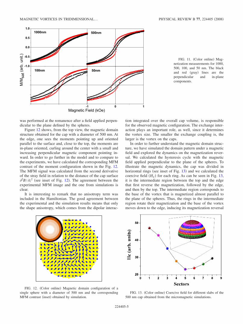
and by magneto-optical Kerr effect. We show only the mag-netization measurements since both exhibit the same behav-ior. Figure 10 shows the hysteresis cycle for the Co/Pd filmdeposited on Si. The measurements of the in-plane �blackline� and the perpendicular �red line� magnetic componentsshow that the magnetic anisotropy is in-plane oriented. Thisscenario dramatically changes for the caps. Figures11�a�–11�d� show the magnetic hysteresis for the arrays ofcaps with diameters of 1000, 500, 100, and 50 nm, respec-tively. It is interesting to remark that for the caps, the mag-netization exhibits both in-plane and out-of-plane compo-nents. The latter is more pronounced as the sphere sizedecreases, as can be verified by the coercivity increase in theperpendicular measurements. The presence of the in-planeand out-of-plane magnetic components is closely related tothe cap shape mainly due to the film thickness gradient andcurvature.
III. NUMERICAL SIMULATION
In order to interpret the MFM images and further investi-gate the magnetic domain formation for larger spheres �500and 1000 nm�, numerical simulations were performed. Wehave used a modified Heisenberg Hamiltonian given by
H = − ��i,j
JS� i · S� j − ��i
S� i · D� i − ��i
S� i · H� . �1�
The first term corresponds to the ferromagnetic exchangecoupling �J is the exchange constant�, the second term isassociated with the dipolar interaction, and the last one is the
Zeeman energy �� is the magnetic moment per cell and S� i is
the normalized moment�. D� i and H� are the dipolar and ap-
plied magnetic fields, respectively, being D� i=��� j−S� j
rij3
+3r�ijS� j·r�ij
rij5 �. We have taken into account the cap thickness
variation following a cosine dependence, as experimentallyobserved in the TEM analysis. The lower energy configura-tion was obtained, minimizing the total energy through gra-dient like methods.24 Similar results were obtained using theMonte Carlo method, as well. We have used the J=1�10−6 erg /cm, Ms=700 emu /cm3, and the cell size equalto 5 nm. The simulations follow the experimental protocol; it
FIG. 8. Magnetic contrast obtained by MFM for 1 000 nm di-ameter magnetic caps.
FIG. 9. �Color online� Vertical profile of the AFM �black line�and MFM �red �gray� line� signal for the 500 nm diameter capcrossing the center of the particle, and its corresponding MFM im-age �inset�.
FIG. 10. �Color online� Magnetization measurement for a planefilm. The black and red �gray� lines are the perpendicular and in-plane components.
SOARES et al. PHYSICAL REVIEW B 77, 224405 �2008�
224405-4
was performed at the remanence after a field applied perpen-dicular to the plane defined by the spheres.
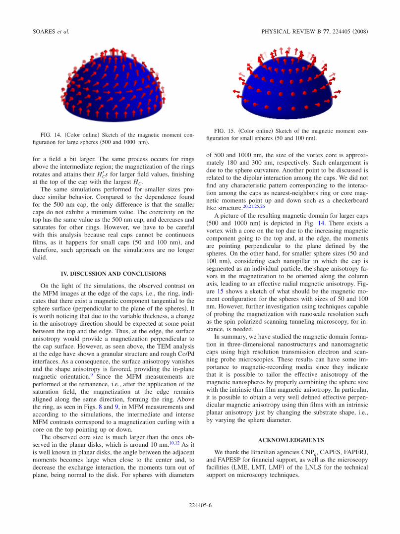
Figure 12 shows, from the top view, the magnetic domainstructure obtained for the cap with a diameter of 500 nm. Atthe edge, one sees the moments pointing up and orientedparallel to the surface and, close to the top, the moments arein-plane oriented, curling around the center with a small andincreasing perpendicular magnetic component pointing in-ward. In order to go further in the model and to compare tothe experiments, we have calculated the corresponding MFMcontrast of the moment configuration shown in the Fig. 12.The MFM signal was calculated from the second derivativeof the stray field in relation to the distance of the cap surface�2B /�z2 �see inset of Fig. 12�. The agreement between theexperimental MFM image and the one from simulations isclear.
It is interesting to remark that no anisotropy term wasincluded in the Hamiltonian. The good agreement betweenthe experimental and the simulation results means that onlythe shape anisotropy, which comes from the dipolar interac-
tion integrated over the overall cap volume, is responsiblefor the observed magnetic configuration. The exchange inter-action plays an important role, as well, since it determinesthe vortex size. The smaller the exchange coupling is, thelarger is the vortex on the caps.
In order to further understand the magnetic domain struc-ture, we have simulated the domain pattern under a magneticfield and explored the dynamics on the magnetization rever-sal. We calculated the hysteresis cycle with the magneticfield applied perpendicular to the plane of the spheres. Toillustrate the magnetic dynamics, the cap was divided inhorizontal rings �see inset of Fig. 13� and we calculated thecoercive field �HC� for each ring. As can be seen in Fig. 13,it is the intermediate region between the top and the edgethat first reverse the magnetization, followed by the edge,and then by the top. The intermediate region corresponds tothe base of the vortex that is magnetized almost parallel tothe plane of the spheres. Thus, the rings in the intermediateregion rotate their magnetization and the base of the vortexmoves down to the edge, inducing its magnetization reversal
FIG. 11. �Color online� Mag-netization measurements for 1000,500, 100, and 50 nm. The blackand red �gray� lines are theperpendicular and in-planecomponents.
FIG. 12. �Color online� Magnetic domain configuration of asingle sphere with a diameter of 500 nm and the correspondingMFM contrast �inset� obtained by simulation.
FIG. 13. �Color online� Coercive field for different slabs of the500 nm cap obtained from the micromagnetic simulations.
MAGNETIC VORTICES IN TRIDIMENSIONAL… PHYSICAL REVIEW B 77, 224405 �2008�
224405-5
for a field a bit larger. The same process occurs for ringsabove the intermediate region; the magnetization of the ringsrotates and attains their HC� s for larger field values, finishingat the top of the cap with the largest HC.
The same simulations performed for smaller sizes pro-duce similar behavior. Compared to the dependence foundfor the 500 nm cap, the only difference is that the smallercaps do not exhibit a minimum value. The coercivity on thetop has the same value as the 500 nm cap, and decreases andsaturates for other rings. However, we have to be carefulwith this analysis because real caps cannot be continuousfilms, as it happens for small caps �50 and 100 nm�, andtherefore, such approach on the simulations are no longervalid.
IV. DISCUSSION AND CONCLUSIONS
On the light of the simulations, the observed contrast onthe MFM images at the edge of the caps, i.e., the ring, indi-cates that there exist a magnetic component tangential to thesphere surface �perpendicular to the plane of the spheres�. Itis worth noticing that due to the variable thickness, a changein the anisotropy direction should be expected at some pointbetween the top and the edge. Thus, at the edge, the surfaceanisotropy would provide a magnetization perpendicular tothe cap surface. However, as seen above, the TEM analysisat the edge have shown a granular structure and rough Co/Pdinterfaces. As a consequence, the surface anisotropy vanishesand the shape anisotropy is favored, providing the in-planemagnetic orientation.9 Since the MFM measurements areperformed at the remanence, i.e., after the application of thesaturation field, the magnetization at the edge remainsaligned along the same direction, forming the ring. Abovethe ring, as seen in Figs. 8 and 9, in MFM measurements andaccording to the simulations, the intermediate and intenseMFM contrasts correspond to a magnetization curling with acore on the top pointing up or down.
The observed core size is much larger than the ones ob-served in the planar disks, which is around 10 nm.10,12 As itis well known in planar disks, the angle between the adjacentmoments becomes large when close to the center and, todecrease the exchange interaction, the moments turn out ofplane, being normal to the disk. For spheres with diameters
of 500 and 1000 nm, the size of the vortex core is approxi-mately 180 and 300 nm, respectively. Such enlargement isdue to the sphere curvature. Another point to be discussed isrelated to the dipolar interaction among the caps. We did notfind any characteristic pattern corresponding to the interac-tion among the caps as nearest-neighbors ring or core mag-netic moments point up and down such as a checkerboardlike structure.20,21,25,26
A picture of the resulting magnetic domain for larger caps�500 and 1000 nm� is depicted in Fig. 14. There exists avortex with a core on the top due to the increasing magneticcomponent going to the top and, at the edge, the momentsare pointing perpendicular to the plane defined by thespheres. On the other hand, for smaller sphere sizes �50 and100 nm�, considering each nanopillar in which the cap issegmented as an individual particle, the shape anisotropy fa-vors in the magnetization to be oriented along the columnaxis, leading to an effective radial magnetic anisotropy. Fig-ure 15 shows a sketch of what should be the magnetic mo-ment configuration for the spheres with sizes of 50 and 100nm. However, further investigation using techniques capableof probing the magnetization with nanoscale resolution suchas the spin polarized scanning tunneling microscopy, for in-stance, is needed.
In summary, we have studied the magnetic domain forma-tion in three-dimensional nanostructures and nanomagneticcaps using high resolution transmission electron and scan-ning probe microscopies. These results can have some im-portance to magnetic-recording media since they indicatethat it is possible to tailor the effective anisotropy of themagnetic nanospheres by properly combining the sphere sizewith the intrinsic thin film magnetic anisotropy. In particular,it is possible to obtain a very well defined effective perpen-dicular magnetic anisotropy using thin films with an intrinsicplanar anisotropy just by changing the substrate shape, i.e.,by varying the sphere diameter.
ACKNOWLEDGMENTS
We thank the Brazilian agencies CNPq, CAPES, FAPERJ,and FAPESP for financial support, as well as the microscopyfacilities �LME, LMT, LMF� of the LNLS for the technicalsupport on microscopy techniques.
FIG. 14. �Color online� Sketch of the magnetic moment con-figuration for large spheres �500 and 1000 nm�.
FIG. 15. �Color online� Sketch of the magnetic moment con-figuration for small spheres �50 and 100 nm�.
SOARES et al. PHYSICAL REVIEW B 77, 224405 �2008�
224405-6

*[email protected] J. I. Martin, J. Nogues, K. Liu, J. L. Vicent, and I. K. Schuller, J.
Magn. Magn. Mater. 256, 449 �2003�.2 S. D. Bader, Rev. Mod. Phys. 78, 1 �2006�.3 S. Honda, Y. Ikegawa, and T. Kuasada, J. Magn. Magn. Mater.
111, 273 �1992�.4 W. R. Bennett, C. D. England, D. C. Person, and C. M. Falco, J.
Appl. Phys. 69, 4384 �1991�.5 U. Gradmann, Appl. Phys. 3, 161 �1974�.6 J. I. Hong, S. Sankar, A. E. Berkowitz, and W. F. Egelhoff, Jr., J.
Magn. Magn. Mater. 285, 359 �2005�.7 S. Landis, B. Rodmacq, B. Dieny, B. DalZotto, S. Tedesco, and
M. Heitzmann, Appl. Phys. Lett. 75, 2473 �1999�.8 X. Zhang, M. H. Manghnani, and A. G. Every, Phys. Rev. B 62,
R2271 �2000�.9 C. Chappert, H. Bernas, J. Ferré, V. Kottler, J. P. Jamet, Y. Chen,
E. Cambril, T. Devolder, F. Rousseaux, V. Mathet, and H.Launois, Science 280, 1919 �1998�.
10 T. Shinjo, T. Okuno, R. Hassdorf, K. Shigeto, and T. Ono, Sci-ence 289, 930 �2000�.
11 C. L. Chien, F. Q. Zhu, and J. G. Zhu, Phys. Today 60�6�, 40�2007�.
12 A. Wachowiak, J. Wiebe, M. Bode, O. Pietzsch, M. Morgenstern,and R. Wiesendanger, Science 298, 577 �2002�.
13 W. Jung, F. J. Castano, and C. A. Ross, Phys. Rev. Lett. 97,247209 �2006�.
14 B. Van Waeyenberge, A. Puzic, H. Stoll, K. W. Chou, T. Tyliszc-zak, R. Hertel, M. Fhnle, H. Brckl, K. Rott, and G. Reiss, Nature
�London� 444, 461 �2006�.15 V. Pribiag, I. Krivorotov, G. Fuchs, P. M. Braganca, O. Ozatay,
J. C. Sankey, D. C. Ralph, and R. A. Buhrman, Nat. Phys. 3,498 �2007�.
16 K. Yamada, S. Kasai, Y. Nakatani, K. Kobayashi, H. Kohno, A.Thiaville, and T. Ono, Nat. Mater. 6, 270 �2007�.
17 R. Cowburn, Nat. Mater. 6, 255 �2007�.18 N. D. Denkov, Langmuir 8, 3183 �1992�.19 Robert C. O’Handley, Modern Magnetic Materials: Principles
and Applications �Wiley, New York, 1999�.20 M. Albrecht, G. Hu, I. L. Guhr, T. C. Ulbrich, J. Boneberg, P.
Leiderer, and G. Schatz, Nat. Mater. 4, 203 �2005�.21 T. C. Ulbrich, D. Makarov, G. Hu, I. L. Guhr, D. Suess, T.
Schrefl, and M. Albrecht, Phys. Rev. Lett. 96, 077202 �2006�.22 J. Moritz, F. Garcia, J. C. Toussaint, B. Dieny, and J. P. Nozières,
EPL 65, 123 �2004�.23 D. Sarid, Scanning Force Microscopy with Applications to Elec-
tric Magnetic, and Atomic Forces �Oxford University Press,New York, 1991�.
24 J. Miltat, G. Albuquerque, and A. Thiaville, in Spin Dynamics inConfined Magnetic Structures I, edited by B. Hillebrands and K.Ounadjela �Springer, New York, 2001�, p. 1.
25 L. C. Sampaio, M. P. de Albuquerque, and F. S. de Menezes,Phys. Rev. B 54, 6465 �1996�.
26 L. C. Sampaio, R. Hyndman, F. S. de Menezes, J. P. Jamet, P.Meyer, J. Gierak, C. Chappert, V. Mathet, and J. Ferré, Phys.Rev. B 64, 184440 �2001�.
MAGNETIC VORTICES IN TRIDIMENSIONAL… PHYSICAL REVIEW B 77, 224405 �2008�
224405-7
Copyright © 2022 FDOKUMEN