Hippophae rhamnoides berry related Pichia kudriavzevii yeast ...
Upload
independentCategory
view
1download
0
CHAPTER 10
Toward Sub-second Correlative Lightand Electron Microscopy of Saccharomycescerevisiae
Christopher BuserDepartment of Molecular and Cell Biology, University of California, Berkeley, California 94720
AbstractI. IntroductionII. RationaleIII. Methods
A. Holder Assembly and Light MicroscopyB. Plunge FreezingC. Freeze-Substitution and Post-Processing
IV. MaterialsA. InstrumentationB. MaterialsC. Reagents
V. ResultsA. Light MicroscopyB. Freezing Damage and CryoprotectionC. Correlating Fluorescence and Electron Microscopy
VI. DiscussionAcknowledgmentsReferences
Abstract
The yeast Saccharomyces cerevisiae is a model organism widely used to study cellbiological processes because of its easy genomic manipulation and its close related-ness to higher eukaryotes. For electron microscopy, the good freezing properties and
METHODS IN CELL BIOLOGY, VOL. 96 978-0-12-381007-6Copyright � 2010 Elsevier Inc. All rights reserved. 217 DOI: 10.1016/S0091-679X(10)96010-X

the small size of yeast cells make it a nearly ideal specimen for the development ofcryopreparation techniques. Here we report on the development of a method tocorrelate yeast cells by live-fluorescence and electron microscopy with the potentialto achieve sub-second correlation times. This is possible by plunge-freezing of anoptically transparent sample sandwich, so that the temporal resolution is only deter-mined by the transfer speed from the fluorescence microscope to the freezing device.While direct correlation was not yet achieved, the system already offers the possibilityto verify the state of the identical population of cells by fluorescence microscopyimmediately before freezing and processing for transmission electron microscopy.
I. Introduction
The yeast Saccharomyces cerevisiae has been a longtime favorite organism ingenetics and cell biology research. Extensive research has shown that, while being arather simple organism, many cell biological processes are highly conserved fromyeast up to mammalian cells. A key advantage of budding yeast is the possibility togenomically integrate tags and mutations while maintaining normal expression levelsof the protein of interest, whereas mammalian systems rely on protein overexpressionfrom a transfected plasmid. With respect to electron microscopy, yeast has servedwell as a test specimen in the development of cryopreparation techniques. S. cerevi-siae has been imaged numerous times by both scanning and transmission electronmicroscopy (SEM and TEM), either at ambient temperatures or in the frozen-hydrated state. For an in depth discussion of cryo-methods we refer to Echlin(1992). As early as 1963, Moor and Müehlethaler have used plunge freezing inliquid propane followed by freeze-etching, platinum-carbon coating, and imaging ofthe replica by TEM to reveal the fine structure of S. cerevisiae (Moor and Mühletha-ler, 1963). The article describes various fine structures with previously unattaineddetail, among those nuclear pore baskets, hexagonal protein arrays and rod-likeinvaginations in the plasma membrane, and endocytic sites. The authors alreadymade two key observations important in relation to this chapter: (1) Cryoprotectionwith 20% glycerol drastically increased the success rate of the plunge freezingpreparation and (2) cryofixed samples were structurally superior to chemicallyfixed cells. Later, the freezing rates and thus the success rates of cryopreparationwere improved by the development of propane jet freezing (Müller et al., 1980). Thistechnique allowed cryofixation of Schizosaccharomyces pombe without cryoprotec-tion followed by high-resolution TEM and SEM imaging of the plasma membrane,including the cell wall and the characteristic furrows (Walther et al., 1984). Thefunction of these striking furrows in the plasma membrane has been elusive untilrecently. During their investigation of the membrane compartment of Can1 (MCC),Stradalova et al. (2009) have found evidence that the MCC coincides with yeast furrows,thus connecting the furrows with an extensive signaling network. This again underlinesthe importance of these early structural studies made possible by the advancementof cryopreparation techniques. A further beautiful example of plunge freezing of
218 Christopher Buser

S. cerevisiae followed by freeze-substitution (FS) for SEM and TEM is the work byBaba and Osumi (Baba and Osumi, 1987). The authors showed detailed views of nuclearpores, multivesicular bodies, Golgi-apparatus, secretory vesicles, and more, and synthe-sized their findings into a diagram of the yeast ultrastructure. A notable point of thiswork is the excellent structural preservation of the samples, even by today’s standards. Inrecent years, cryopreparation of yeast has been used to study a variety of cell biologicalprocesses, including mitosis (McDonald et al., 1996), autophagy (Roberts et al., 2003),and interphase microtubule organization in S. pombe (Hoog et al., 2007). With therecent “spreading” of Cryo-Electron Microscopy of Vitreous Sections (CEMOVIS)(Al-Amoudi et al., 2004), yeast is again a popular sample.
Sadly, many cell-biology groups still prepare their yeast samples for TEM bychemical fixation, irrespective of the relative ease and vast superiority of cryo-methods. It is clear that a multitude of artifacts are induced by both the aldehydefixative and the dehydration at room temperature. Of special interest with respect tothis chapter are the striking structural changes induced in the endocytic pathway (Murket al., 2003). To make things worse many protocols first remove the cell wall, whichmost probably causes changes in the underlying structures before fixation can arrestthe native state. While cryopreparation methods avoid the chemical stress by immobi-lizing cellular structures by non-invasive physical means on a timescale of millise-conds, they usually require concentrating the cells to achieve a sufficiently highdensity. In the case of high-pressure freezing (HPF) the cells also have to be transferredinto the cavity of the freezing hats. These concentration and transfer steps do their partin stressing the cells and can cause large-scale morphological changes or more subtlechanges in the cellular process to be studied. In respect to endocytosis, brief centrifu-gation of yeast cells causes depolarization of actin patches (Soto et al., 2007) and alsoappears to disrupt endocytosis for several minutes (Buser and McDonald, 2010), whilecollection by filtration (McDonald and Mueller-Reichert, 2002) is more gentle but cancause osmotic effects by partial drying of the sample during loading into the freezinghats. To avoid both centrifugation and osmotic stress to the yeast cells, we recentlyproposed a filtration technique using syringe filters (Buser and McDonald, 2010)followed by a transfer into capillary tubes (Hohenberg et al., 1994). While this methodis a good compromise, it still requires a resuspension step and immersion in1-hexadecane (Studer et al., 1995), with which the cells are in contact for up to aminute. Ideally, the yeast cells should be immobilized in their native state without anymanipulation whatsoever. This is an important advantage of the correlative light andelectron microscopy (CLEM) approach presented below, which does not requirecollection of the cells. In addition, this approach allows us to verify by fluorescencemicroscopy if the process of interest is occurring normally in the same population ofcells which are immediately plunge-frozen and prepared for TEM.
In this chapter we use S. cerevisiae as a model system to study the processof endocytosis by CLEM. Yeast actin patches, which were shown to be sites ofendocytosis, have been studied extensively by fluorescence microscopy (Kaksonenet al., 2003; Waddle et al., 1996) and also by immuno-TEM (Idrissi et al., 2008;Mulholland et al., 1994). The emerging picture is that of a temporally and spatially
10. Toward Sub-second Correlative Light and Electron Microscopy of Saccharomyces cerevisiae 219

highly regulated assembly of protein modules, consisting of a total of > 60 proteins,which drive the processes of coat recruitment, invagination of the plasma membranecoinciding with a burst of actin polymerization, and ultimately vesicle scission(Kaksonen et al., 2005, 2006). While recruitment of the coat proteins takes placeover a period of 1–2min, membrane invagination and scission occur very rapidlywithin 15 s. This process is very well defined by fluorescence microscopy, but theexact geometry of the endocytic site and the dynamic localization of the individualproteins at the ultrastructural level can currently only be inferred based on thefluorescence data or alternatively imaged by TEM without the temporal information.True correlation of these datasets requires a technique able to image endocytic sites bylive-fluorescence microscopy and to correlate this information with a TEM-image ofthe same site.The current cryopreparation method of choice is HPF, which allows the freezing of
non-cryoprotected samples up to a thickness of 200 µm without significant ice-crystaldamage (Studer et al., 1989). HPF is a very reproducible technique, but requires thesample to be positioned between two metal planchettes or sapphire discs (Hawes et al.,2007). Unfortunately, manual assembly of the sample “sandwich” usually takes> 20 s inboth the Abra (formerly BAL-TEC) and the Wohlwend-type HPF machines. The HPFwith the shortest loading time is the Leica EM PACT2 equipped with the rapid transfersystem which was specifically developed for CLEM (McDonald et al., 2007; Muller-Reichert et al., 2007; Pelletier et al., 2006; Verkade, 2008). The system offers a temporalresolution of approximately 4 s combined with fluorescent imaging with low-numericalaperture (NA) 60� air objectives. This limitation is caused by the relatively thick samplecarrier which prevents the use of high-NA oil immersion lenses due to their shortworking distance. Recently, Brown and colleagues (2009) have reduced the possibleworking distance by thinning the sample carrier. As outlined above, the final steps ofendocytosis occur in a small volume within a few seconds. The imaging of fluorescentlytagged endocytic proteins in yeast thus requires the use of high-NA objectives and a hightemporal resolution with freezing to be able to the correlate rapid processes of membraneinvagination and scission.To fulfill these criteria, we propose a CLEM approach based on plunge freezing of a
sample sandwich consisting of two glass coverslips separated by a thin formvar spacer.This system is ideal for fluorescence microscopy in that it allows imaging with astandard microscope using high-NA oil immersion objectives and can yield temporalcorrelation times of less than 1 s even by manual plunge freezing. Using a small samplevolume, the inherent cryoprotection of yeast cells and the added cryoprotection bysugars in the growth medium, the sample can be fixed by plunge freezing in liquidpropane with only minor crystal damage. Unfortunately, we still did not achieve same-cell imaging because of a lack of reproducibility in manually plunging the samples.Nevertheless, we believe that the ability to verify that the kinetics of endocytosisbefore cryo-immobilization and the potential to achieve sub-second correlation timesare very valuable. At the end of this chapter, we will propose several experimentalpathways that we intend to pursue to increase the rate of success in the plunge-freezingprocess.
220 Christopher Buser

II. Rationale
S. cerevisiae is frequently used for cryopreparation methods because of its naturalcryoprotection by the dense cytoplasm. In addition, yeast can be grown in media withcryoprotectants as a carbon source (e.g., glucose or glycerol). Accordingly, yeastsuspensions are easily frozen by HPF with little ice-crystal damage and vitrified forCEMOVIS, if grown in media containing 20–30% dextran. However, working withyeast also has its complications. Yeast cells are highly sensitive to changes in theirenvironment, such as shifts in temperature, osmotic stress, chemicals, and the depletionof carbon sources. In addition, the sugars added to the medium in order to further reduceice-crystal damage can cause infiltration problems during resin embedding since theyare only poorly soluble in acetone during FS and need to be washed out beforeinfiltration. Furthermore, the dense cytoplasm is a natural cryoprotectant, but alsofrequently obscures fine structures in sections.
Considering all aspects related to cell homeostasis, fluorescence microscopy, plungefreezing, and the preparation for TEM, the general requirements to be fulfilled by aCLEM holder system for the work proposed here are the following:
1. Imaging by fluorescence microscopy should be simple to perform and allow the useof oil immersion objectives.
2. The yeast cells need to be maintained in a stable and non-perturbing environmentduring assembly and imaging of the sample.
3. Sufficiently high cooling rates have to be achievable by plunge freezing to preventexcessive ice-crystal growth.
4. The sample design needs to be simple to allow sufficiently high throughput.5. Disassembly of the sample for FS and resin embedding should be feasible without
damaging or losing the cells.6. A coordinate system has to be in place to identify the area of interest for both
fluorescence and electron microscopy.
The approach presented here uses two 5mm diameter glass coverslips separated by a<10 µm thin formvar spacer, which is bonded to the lower coverslip (Fig. 1A). Acavity is cut in the spacer and a carbon image of a finder grid is evaporated into thecavity. The yeast cells are attached to the carbon with concanavalin A (Kaksonen etal., 2003) and embedded in 2% low-melting agarose (Sims and Hardin, 2007). Thissandwich is sealed at the edges with vacuum grease (Kaksonen et al., 2003) andattached onto a wire loop with Scotch tape. The sample rests on the microscope stageby attaching the wire loop to a support ring. After recording a time-lapse movie of thearea of interest, the holder is picked up manually by the support ring and the sampleon the central wire loop is plunged into liquid propane and prepared for TEM by FSand embedding in Epon.
The design presented here was optimized for fluorescence microscopy by usingstandard glass coverslips to sandwich the yeast, instead of using sapphire coverslips.Sapphire has superior thermal properties but is far more expensive and also has a
10. Toward Sub-second Correlative Light and Electron Microscopy of Saccharomyces cerevisiae 221

higher refractive index of 1.71, which would have to be matched with a specializedimmersion fluid for optimal imaging. It is also crucial for light microscopy to bring thecoverslip parallel to and into working distance of the oil immersion objective (commonworking distances are between 0.1 and 0.2mm), and thus a thin but stable support isrequired. Here we used a piece of Scotch tape with a central viewing hole to attachthe coverslip sandwich to the holder. This setup keeps the sample in focus of the
(A) (B)
(C)
Sample
Sample
Liquid propane
Metal cup
Liquid nitrogen
Adhesive tape
5 mm
1 mm
Objective
plungingTransfer &
Fluorescencemicroscope
StageW
ire lo
op
Hol
der
Hol
der
Dew
ar
Fig. 1 Sample preparation for CLEM. (A) Schematic representation of the sample setup duringfluorescence microscopy and after plunge freezing (not drawn to scale). The yeast cells are sandwichedbetween two glass coverslips separated by the formvar spacer and supported by a piece of Scotch tape with acentral hole. The Scotch tape is sticking to the wire loop and the holder ring. During fluorescence microscopythe holder ring rests on the stage of the microscope, bringing the sample into the focal plane of the oil-immersion objective. At the desired moment, the holder is transferred and the sample plunged into the liquidpropane bath. (B) Image of a fully assembled sample attached to the wire loop and the plastic holder ring. Theholder is then inverted and positioned on the stage of the fluorescence microscope for imaging. Note theexcess vacuum grease surrounding and sealing of the coverslip sandwich. (C) Image of a pre-assembledbottom coverslip with formvar spacer and the evaporated carbon finder grid in the center. The yeast cells arelater attached in the central cavity by concanavalin A.
222 Christopher Buser

immersion objective and perfectly level on the stage, thus allowing stage movementswithout the objective touching the sample at its edges. Furthermore, the tape is soft andprevents accidental scratching of the objective lens.
The next problem we addressed was how to maintain a stable environment. Asdiscussed above, yeast cells respond very quickly to changing conditions. Propersealing of the sample sandwich is exceedingly important to prevent drying of thevery small volume of medium. To achieve a good seal the outer rim of the formvarspacer ring was coated with very little vacuum grease. When pressing the top coverslipin place the excess grease is expelled from the sandwich thus creating a tight seal. Inaddition, the outer edge of the sandwich was sealed off with more vacuum grease.
Optimizing the thermal properties to ensure adequate freezing was a key issue. Theholder ring and the attached loop possess a low heat mass, position the sampleparallel to the microscope stage and fit into the cavity of the liquid propane bathfor plunge freezing. The design ensures minimal influence on the cooling rates, arobust way of manually transferring the sample for plunge freezing and also asufficient stability during fluorescent imaging. For optimal freezing by immersionin liquid propane, the sample volume needs to be as small as possible, i.e. thethickness of the aqueous layer should be less than 10 µm and additional cryoprotec-tion is usually required (Echlin, 1992). A low heat mass of the holder can be achievedby preferentially using parts made of metal with small dimensions. Formvar filmswere chosen as spacers because they can be cast reproducibly and the thickness iseasily adjusted by varying the concentration of formvar in the casting solvent. Forexternal cryoprotection, yeast can be grown in high concentrations of sugars withoutobvious adverse effects (see below). Here we supplemented our medium with 10%glucose, since 2% glucose is routinely present in the media used in our lab. Whilecryoprotectants like dextran or glycerol are more frequently used, dextran is knownto cause infiltration problems while glycerol affects the morphology of mitochondria(Egner et al., 2002) and thus might affect endocytosis as well.
More restrictions are imposed by practical aspects of assembly and post-processing ofthe frozen sample. The lower coverslip covered with the formvar spacer and the carbonfinder pattern can be pre-assembled in large quantities and is stable over months. If theassembled sample is sealed well, the cells remain unperturbed for 30min or more (seebelow). This currently allows the full assembly of 3–5 samples in parallel, whilefluorescence microscopy, propane plunging, and sample storage together requireapproximately 10min per sample under optimal conditions. The most challenging andtime-consuming step remains the deposition of the cells and the sealing and mounting ofthe sample.
Post-processing of the frozen samples is possible with standard protocols for FS,embedding, trimming, and sectioning. Care has to be taken to remove the excess sugarafter FS by repeated washing in ethanol, since remaining sugar causes incompleteinfiltration with the resin. An important and often underestimated function of the carbonlayers (one thin over the entire surface and one thicker for the finder pattern) is to act as aseparator when breaking the coverslip off the polymerized resin. Cells directly adheringto uncoated glass slides are frequently ripped out of the resin during this step.
10. Toward Sub-second Correlative Light and Electron Microscopy of Saccharomyces cerevisiae 223

An additional advantage of the setup we used here is that it does not requireexpensive or highly specialized EM equipment, except for a FS device, a goodmicrotome and diamond knife for serial sectioning, and a standard 80–120 kV TEM.In addition, the parts used are cheap and widely available. Accordingly, this system isalso useful for facilities which do not have access to HPF equipment but are interestedin using cryopreparation to study the yeast ultrastructure by TEM, with or withoutcorrelation with fluorescence microscopy. The ultrastructure of yeast prepared by HPFand FS is well documented (for examples see the following references: Giddings,2003; Heiman et al., 2007; McDonald and Mueller-Reichert, 2002; Murray, 2008;Walther and Ziegler, 2002). For an inexpensive alternative to HPF, the technique ofself-pressurized rapid freezing has been recently introduced (Leunissen and Yi, 2009).
III. Methods
A. Holder Assembly and Light Microscopy
A wire loop with a diameter of approximately 10mm was made from steel wire, theextensions bent into a “U”-shape and attached to a 2 cm high section of a 50ml Falcontube (Fig. 1B). Formvar films were manually cast on glass slides from a 6% formvarsolution in ethylene dichloride, attached to a cardboard frame with Scotch tape at the edgesand carefully detached while breathing onto the film (Chowdhury et al., 1999). Glasscoverslips (diameter 5mm) were then placed onto the suspended films and baked in anoven at 120°C for 45min, which causes the formvar to adhere firmly to the coverslip.Under a binocular, the coverslips were excised from the film and circular holes were cutout in the center of the coverslip with a scalpel to create a cavity with an approximatediameter of 3mm and 10µm depth (Fig. 1C) and received a first carbon-coat of approxi-mately 5 nm thickness. A copper finder grid was then placed in the cavity and a secondcarbon-coat (20 nm thickness) was evaporated, creating an image of the finder grid in thecavity of the coverslips. The carbon was then stabilized by baking at 120°C for 1 h.Scotch tape was placed adhesive side up in a petri dish with wet paper to create a
humid chamber. A 4mm hole was punched in the center of the adhesive tape and thecoverslip was then positioned on top of the hole (cavity up), held in place by theadhesive. The formvar spacer ring was carefully coated with 1-hexadecene using a finebrush to prevent wetting of the spacer and a small layer of vacuum grease was appliedon the outer edge of the spacer with a toothpick. A 10 µl drop of a concanavalin Asolution (0.5mg/ml in water) was then placed in the cavity for 5min and removed.Then, a 10 µl drop yeast cell suspension in log phase was pipetted in the cavity andallowed to settle for 5min before carefully washing once with medium. The mediumwas then completely removed, quickly replaced by a drop of 2% agarose (in SDmedium, kept liquid at 35°C). The top 5mm coverslip was immediately placed ontop and pressed in place with a forceps. Excess agarose was removed with a scalpeland the sample sandwich was carefully sealed off completely by applying morevacuum grease at its outer edge. The wire loop was then pressed in place on the
224 Christopher Buser

adhesive tape and secured to the sample with two thin strips of scotch tape from thetop. The holder was then placed on the stage of an inverted fluorescence microscopeand imaged with a 100�, 1.4 NA oil immersion objective using bright field illumina-tion and epifluorescence with GFP-optimized filters. GFP-images and time-lapsemovies of cells expressing Abp1-GFP were taken with collection times of 500ms.
B. Plunge Freezing
Beforehand, commercial grade propane was cooled in a standard liquefier (seeEchlin, 1992) and placed next to the fluorescence microscope. At the desired timepoint, the holder was manually removed from the stage and the sample plunged asquickly as possible into the propane by horizontal entry (lab safety goggles shouldbe worn to protect eyes from splashes of liquid propane). The frozen samples were thenstored in liquid nitrogen and prepared for FS.
C. Freeze-Substitution and Post-Processing
Before FS, the supporting Scotch tape was removed under liquid nitrogen and theexcess grease was carefully scratched off with a forceps. The intact sample sandwichwas then transferred to a 1.5ml microcentrifuge tube filled with 1ml pre-cooled FSmedium (at LN2 temp.), consisting of acetone, 2% glutaraldehyde, 0.1% (w/v) uranylacetate, and 5% (v/v) water (Buser and Walther, 2008; Walther and Ziegler, 2002).FS was performed overnight from �90 to 0°C and programmed the following: �90°C, 1 h; 3°C/h, 10 h; �60°C, 1 h; 9°C/h, 6.5 h; 0°C; total duration 18.5 h. At 0°C thesamples were shifted to room temperature, washed 5� with ethanol and infiltratedwith 50% Epon in ethanol for 2 h. The top coverslip was then carefully removed andthe lower coverslip with the attached yeast cells was infiltrated with pure Epon for6 h. The Epon was exchanged once more before polymerization at 60°C for 2 days.
The coverslip was removed by repeated short freeze-thawing cycles in liquid nitrogen.The remaining pieces of glass were loosened by placing a drop of water on the surface,followed by a freeze-thaw cycle in liquid nitrogen. The water is pulled into gaps bycapillary action and expands on freezing, thus gently separating the glass from the resinsurface. If necessary, fragments of glass were then carefully removed with a scalpel.
For electron microscopy, the surface was trimmed down to the area with the cells ofinterest (approx. 250 � 400 µm), serially sectioned (100 nm thickness, >25 sections),and picked up on formvar-filmed slot grids. The sections were stained in 2% aqueousuranyl acetate for 10min and 2% lead citrate for 2min and imaged.
IV. Materials
A. Instrumentation
Carbon evaporator: DV-502A, DentonVacuum, USA.Freeze-substitution: Leica AFS, Leica Microsystems, Austria.
10. Toward Sub-second Correlative Light and Electron Microscopy of Saccharomyces cerevisiae 225

Fluorescence microscopy: Olympus IX71, Olympus, USA.TEM: Tecnai 12 (FEI, USA) equipped with an Ultrascan 1000 CCD camera (Gatan
Inc., USA).
B. Materials
Finder grid: Maxtaform “London Finder” 200 mesh; Cat# LF200Cu, Electronmicroscopy Sciences, USAGlass coverslips: round, 5mm diameter; Cat# 72296-05, Electron microscopy
Sciences, USAPunch: Harris Uni-core 4mm diameter; Cat# 15080, Ted Pella, Inc., USASlot grids: PELCO©, 1 � 2mm slot; Ted Pella, Inc., USAWire: steel, 0.41mm diameter
C. Reagents
Agarose: 2% (w/v) in SD medium with 10% glucose; FMC Bioproducts,Cat#50107.Concanavalin A: type IV; 0.5% (w/v) in water; Cat# C2010, Sigma-Aldrich, USA.Formvar: 6% in ethylene dichloride; Cat# 15800 and Cat# 13250, Electron Micro-
scopy Sciences, USA.Growth medium: SD tryptophan dropout medium supplied with 10% glucose.1-hexadecene: Cat# H2131, Sigma-Aldrich, USA.Vacuum grease: Dow Corning high vacuum grease; Dow Corning, USA.
V. Results
We explored the possibility of studying endocytosis in S. cerevisiae by correlativelight- and electron microscopy using a plunge freezing approach to achieve sub-second time resolution. At first glance the combined restrictions imposed by thebiological system, fluorescence microscopy, and the preparation for electron micro-scopy seem irreconcilable. The following results show that by carefully controllingevery individual step in the protocol both a high spatial and temporal correlationbetween fluorescence and TEM appears feasible, and in the future will allow us tocorrelatively investigate short-lived endocytic intermediates.
A. Light Microscopy
Drying out of the sample due to imperfect sealing was a major issue. With a totalliquid volume of less than 0.1 µl, even small leaks will lead to massive dryingand osmotic shock thus causing morphological changes. Sealing with vacuumgrease (Kaksonen et al., 2003) effectively prevents drying and keeps the cells in astable environment. After 30min in the sample sandwich, yeast cells still maintained
226 Christopher Buser

polarized and motile actin patches (Fig. 2A), and no signs of drying or oxygendepletion were observed.
The thickness of the carbon films strongly affects the fluorescence intensity and thusshould be kept as thin as possible while still being visible by bright field illumination(Fig. 2B and C). We are still experimenting with different thicknesses, but 5 nm for thefirst layer and 20 nm for the finder pattern was sufficient to image relatively abundantendocytic proteins. Accordingly, live-cell imaging on Abp1-GFP expressing cells wasperformed with acquisition times of 500ms per frame.
An important aspect for the imaging with oil-immersion objectives is a perfectlyparallel positioning of the sample in the plane of the objective. In our first experiments,a 70 µm thin adhesive copper foil was used instead of Scotch tape as a base support dueto its superior thermal properties. Unfortunately, after punching the viewing hole therigidity of the copper made it difficult to perfectly flatten the foil. This caused parts of
(A) (B)
(C)
Fig. 2 Light microscopy of S. cerevisiae cells imaged within the setup shown in Fig. 1. The cells areexpressing the actin-binding protein Abp1-GFP, which is recruited to endocytic sites together with actinduring the invagination process. (A) Fluorescence image of yeast cells assembled in the sample sandwichimaged after 30min show characteristically polarized actin patches (arrows). (B) The carbon finder patternallows clear identification of the area of interest by bright-field imaging, here the letter “R”. (C) Fluorescenceimage of the same region as in B. Differences in the recorded fluorescence intensity due to absorption offluorescent light by the carbon film can be seen between cells located only on the 5 nm thin carbon film,i.e. on the letter “R” (arrow) versus cells viewed through both carbon films (total thickness of 25 nm,arrowhead).
10. Toward Sub-second Correlative Light and Electron Microscopy of Saccharomyces cerevisiae 227

the copper foil to contact the objective and thus made it impossible to bring thecoverslip in the central hole into working distance. Using the flexible Scotch tapesolved this problem and the entire area of the coverslip could now be imaged with oilimmersion. Interestingly, the Scotch tape did not affect the quality of freezing.In our initial experiments the yeast cells were attached to the coverslip by concana-
valin A alone. While this method is sufficient with standard media containing 2%glucose (Kaksonen et al., 2003), increasing the concentration to 10% results inincomplete attachment of the cells to the coverslip. This caused the yeast cells towiggle and made it impossible to track individual endocytic sites by fluorescencemicroscopy. Furthermore, the cells easily and randomly detach from the coverslipduring the infiltration process, which is only noticed in the last step when imaging thesections in the TEM. To better immobilize cells for fluorescence microscopy and at thesame time prevent cell loss during infiltration, the yeast cells were first attached to thecoverslip with concanavalin A and then embedded in 2% low-melting agarose. Thisadditional encasing prevented both wiggling and the loss of cells and did not disturbthe infiltration process or the imaging by fluorescent light microscopy.
B. Freezing Damage and Cryoprotection
Since freezing by manual plunging in liquid propane is not expected to yield highcooling rates, it is important to assess the amount of ice-crystal damage that can betolerated for the imaging of endocytic sites. In yeast cells, the vacuole is the bestindicator for freezing damage, as it has a high water content and is difficult to vitrifyroutinely without cryoprotection, even by HPF. Intermediate ice-crystal damage iseasy to identify in the electron dense lumen of the vacuole, manifesting as brighterpatches formed by the exclusion of solutes from growing ice crystals.We first tried to plunge freeze yeast suspensions sandwiched between two sapphire
discs (3mm diameter, 50 µm thickness) separated by a 20 µm thin copper TEM grid,with 8% glucose present in the medium and a 70 µm thin adhesive copper foil with acentral hole as support. This configuration represents a setup in which high-coolingrates are expected, due to the optimal thermal properties of sapphire and copper. Asshown, freezing damage was excessive and organelles were barely recognizable(Fig. 3A). The absence of morphologically detectable ice-crystal damage is representedby a high-pressure frozen sample (Fig. 3B).This comparison argues that even with a low thermal mass of the sample sandwich
the aqueous layer was too thick and thus a thinner spacer was needed. Additionally,fluorescence microscopy and sample assembly was very tedious with the small sap-phire discs. We thus decided to explore the advantages of 5mm diameter glass cover-slips with a 10 µm thin formvar spacer. During the initial experiments it also becameclear that manual plunge freezing in liquid propane would require a certain extent ofcryoprotection. Instead of introducing an additional component with reported cryopro-tective properties (e.g., dextran, sucrose or glycerol) we decided to increase theconcentration of glucose, which is used as carbon source in our yeast growth media.Cryoprotection in 10% glucose already resulted in sufficiently well-preserved
228 Christopher Buser
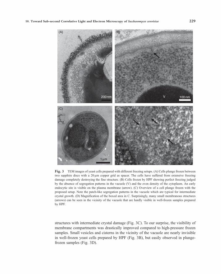
structures with intermediate crystal damage (Fig. 3C). To our surprise, the visibility ofmembrane compartments was drastically improved compared to high-pressure frozensamples. Small vesicles and cisterns in the vicinity of the vacuole are nearly invisiblein well-frozen yeast cells prepared by HPF (Fig. 3B), but easily observed in plunge-frozen samples (Fig. 3D).
(A)
(C) (D)
200 nm
1 µm
100 nmV
(B)
Fig. 3 TEM images of yeast cells prepared with different freezing setups. (A) Cells plunge frozen betweentwo sapphire discs with a 20 µm copper grid as spacer. The cells have suffered from extensive freezingdamage completely destroying the fine structure. (B) Cells frozen by HPF showing perfect freezing judgedby the absence of segregation patterns in the vacuole (V) and the even density of the cytoplasm. An earlyendocytic site is visible on the plasma membrane (arrow). (C) Overview of a cell plunge frozen with theproposed setup. Note the patch-like segregation patterns in the vacuole which are typical for intermediatecrystal growth. (D) Magnification of the boxed area in C. Surprisingly, many small membranous structures(arrows) can be seen in the vicinity of the vacuole that are hardly visible in well-frozen samples preparedby HPF.
10. Toward Sub-second Correlative Light and Electron Microscopy of Saccharomyces cerevisiae 229

The addition of high concentrations of glucose can affect infiltration. Sugars arevery poorly soluble in acetone (the standard solvent used for FS), aggregate around thecells during FS, and prevent infiltration of the cell periphery if not removed (Buser andMcDonald, 2010). Initially, we washed the samples with acetone before infiltrationwith 50% Epon in acetone. This procedure resulted in poor infiltration of the cellperiphery and cells were frequently ripped out of section. Extended washing in ethanoland infiltration with 50% Epon in ethanol solved this problem due to the increasedsolubility of sugars in ethanol.
C. Correlating Fluorescence and Electron Microscopy
After removal of the coverslip, the imprinted carbon image of the finder grid wasused to determine the position of the observed cells. The block was trimmed downto include the cells in an area as small as possible to facilitate the search for thepreviously observed cells within the section in the TEM. Furthermore, a small areaallows more sections to be placed on a single slot grid. Starting with the first completesections, up to 40 serial sections of 100 nm thickness were collected, stained and imagedat an acceleration voltage of 120 kV. Median cross-sections were usually obtained in thesections 10–20, corresponding to an approximate Z-depth of 1–2µm. The same cellsimaged by fluorescence microscopy could be identified in thin sections, but unfortu-nately were extensively damaged by crystallization and thus not usable for correlativemicroscopy (Fig. 4A). Since good freezing rates were obtained with the identical samplesetup without attempting correlation (Fig. 4B), the probable culprit for the poor freezingin correlated samples is a slow entry speed of the sample into the cryogen due toimperfect manual plunging.
VI. Discussion
Endocytosis is a highly conserved process from single-celled eukaryotes to humansand is central to the development of many diseases and a frequent entry point for viralinfections. With its easy genomic manipulation and the possibility of preparing yeastfor electron microscopy by plunge freezing, S. cerevisiae offers unique opportunities tounravel the molecular mechanism of endocytosis. The protocol presented here demon-strates the feasibility of correlative live-cell light and electron microscopy in yeast withoil-immersion fluorescence microscopy, cryopreparation, and the potential to achievesub-second temporal resolution. Relying on a reduction of the sample volume andcryoprotection by addition of sugars, sufficient cooling rates can be achieved bymanual plunge-freezing even when using standard glass coverslips. The approachpresented here has three major advantages over HPF: (1) A collection process byfiltration is not needed before freezing and the cells can be imaged by fluorescencemicroscopy immediately before plunging into the cryogen. This ensures that the cellsare frozen in their native state. (2) The temporal resolution is only restricted by the timerequired for transferring the sample from the fluorescence microscope to the plunge
230 Christopher Buser

freezing device, thus offering correlation times in the sub-second range especially ifautomated. (3) The proposed setup does not compromise on fluorescence microscopy.By using Scotch tape as support and glass coverslips, the conditions are optimal for theuse of immersion objectives with very short working distances and high-NA values,and the full cavity with the cells is accessible for observation. Furthermore, there is norisk of damaging the expensive objectives. This combination allows a simple imagingof small and highly dynamic GFP-labeled structures. Further optimization in fluores-cence microscopy might be required to allow the visualization of very dim fluoro-phores and dual-color imaging in the usually dimmer red part of the spectrum.Fine-tuning of the thickness of the carbon films is necessary to decrease its absorbanceof emitted fluorescent light while still preserving the good visibility of the finderpattern in bright-field mode. The key aspect in allowing proper imaging of the yeastcells was the embedding in 2% low-melting agarose to prevent both the movement ofthe cells during live-imaging and their loss during infiltration with the resin (Sims andHardin, 2007). Surprisingly, the agarose did not cause any infiltration problems.
The above results suggest that the quality of freezing by plunging into liquid propanedepends on the sample thickness and the entry speed into the cryogen as describedpreviously (Costello, 1980). Reduction of the sample thickness to 10µm yielded well-frozen samples even with suboptimal materials as glass coverslips and adhesive tape assupport, as long as plunging was done quickly. Unfortunately, the freezing failed so far incorrelative experiments probably due to suboptimal entry speeds into the cryogen bymanual plunging. Thus, the main goal of our further experiments is the improvement of
(A) (B)
0.5 µm 100 nm
Fig. 4 Attempts at sub-second CLEM. (A) An Abp1-GFP expressing cell previously imaged by time-lapse fluorescence microscopy and plunge-frozen within less than one second of the last frame at thefluorescence microscope. The cells have suffered from extensive crystal damage similar to Fig. 3A. (B)An Abp1-GFP expressing cell prepared with the same setup, but plunge-frozen without attemptingcorrelation by fluorescence microscopy. The freezing quality is sufficient to clearly identify endocyticintermediates during the invagination process of the plasma membrane (arrows), which are labeled withAbp1-GFP in fluorescence microscopy (Fig. 2).
10. Toward Sub-second Correlative Light and Electron Microscopy of Saccharomyces cerevisiae 231

the thermal properties of the sample. The main focus will thus be to further reduce thespacer thickness from approximately 10 down to 5 µm and concurrently increase theglucose content from 10 to 20%. Judging from the data presented above, improvingthese parameters alone might already suffice to ensure adequate freezing even in acorrelative experiment with less than optimal cooling rates at the sample surface. Afurther compromise would be the use of sapphire discs to utilize the better thermalproperties of sapphire compared to quartz glass. The downside of sapphire for routinefluorescence microscopy is the high refractive index of 1.71, which would have to bematched with a special immersion fluid. It is also known that the depth of the cryogencan have an effect on the cooling rate (Robards and Sleytr, 1985). When the entry rate isrelatively slow, the samples need to enter deeper into the cryogen to reach the desiredfreezing rate. We will experiment with a deeper well for the cryogen as a means toachieve a higher percentage of well-frozen cells.An unsolved problem for both fluorescence and electron microscopy is the lack of
a reference marker for the Z-position. Currently, the Z-position of endocytic sites hasto be estimated from the diffraction rings around the cells in bright-field mode andusually a medial focal plane is chosen for the cells of interest. The correspondingendocytic site in the section then has to be found by searching the serial sections forthe expected invaginated membrane profile. This approach fails in putative caseswhere no morphological patterns can be expected, e.g., the membrane has not beendeformed yet. Furthermore, the depth of field in the fluorescence microscope isapproximately 1 µm, which corresponds to ten 100 nm sections. A possible solutionwould be to add latex or Dynal® beads of a defined size and to use the diameter of thecross-section in the TEM as a measure for the Z-position. Additionally, the FS andinfiltration protocol could be modified to allow immunogold labeling (Buser andMcDonald, 2010). To further reduce the dependency on specialized equipment, FScould also be carried out in a simple dry-ice system or by using freezers to regulatethe temperature Echlin, 1992; McDonald and Mueller-Reichert, 2002).An interesting aspect would be the automation of the transfer and plunging process,
which would allow more reproducible freezing and an even better time resolution of themethod. This could offer correlative insights into very rapid processes similar to theoriginal work of Heuser and Reese (Heuser and Reese, 1981; Heuser et al., 1979).Alternatively, the dual coverslip system presented here could be adapted for propane jetor HPF applications for samples thicker and harder to freeze than yeast.In conclusion, live-cell correlative fluorescence and electron microscopy by plunge
freezing is a promising method to investigate rapid cellular processes in S. cerevisiae.Further optimization and simplification of the protocol would also allow the techniqueto be implemented in laboratories without cryopreparation equipment.
AcknowledgmentsI thank David Drubin and Kent McDonald for their support and critical discussions, and Yidi Sun and
Voytek Okreglak for their help with the fluorescence microscope. I also acknowledge a fellowship forprospective researchers from the Swiss National Science Foundation (SNF).
232 Christopher Buser

References
Al-Amoudi, A., Chang, J. J., Leforestier, A., McDowall, A., Salamin, L. M., Norlen, L. P., Richter, K., Blanc,N. S., Studer, D., and Dubochet, J. (2004). Cryo-electron microscopy of vitreous sections. EMBO J. 23,3583–3588.
Baba, M., and Osumi, M. (1987). Transmission and scanning electron microscopic examination of intracel-lular organelles in freeze-substituted kloeckera and saccharomyces cerevisiae yeast cells. J. ElectronMicrosc. Tech. 5, 249–261.
Brown, E., Mantell, J., Carter, D., Tilly, G., and Verkade, P. (2009). Studying intracellular transport usinghigh-pressure freezing and correlative light electron microscopy. Semin. Cell Dev. Biol. 20(8), 910–919.
Buser, C., and McDonald, K. L., (2010). Correlative GFP-immunoelectron microscopy in yeast. MethodsEnzymol. 470, 603–618.
Buser, C., and Walther, P. (2008). Freeze-substitution: The addition of water to polar solvents enhancesthe retention of structure and acts at temperatures around �60 degrees C. J. Microsc. 230, 268–277.
Chowdhury, A., Naik, P. A., and Gupta, P. D. (1999). Development of free-standing submicron formvar filmswith multiple thickness steps for XUV-soft X-ray applications. Sadhana 24, 551–555.
Costello, M. J. (1980). Ultra-rapid freezing of thin biological samples. Scan. Electron Microsc. 361–370.Echlin, P. (1992). “Low-Temperature Microscopy and Analysis.” Plenum Press, NY.Egner, A., Jakobs, S., and Hell, S. W. (2002). Fast 100-nm resolution three-dimensional microscope revealsstructural plasticity of mitochondria in live yeast. Proc. Natl. Acad. Sci. U. S.A. 99, 3370–3375.
Giddings, T. H. (2003). Freeze-substitution protocols for improved visualization of membranes in high-pressure frozen samples. J. Microsc. 212, 53–61.
Hawes, P., Netherton, C. L., Mueller, M., Wileman, T., and Monaghan, P. (2007). Rapid freeze-substitutionpreserves membranes in high-pressure frozen tissue culture cells. J. Microsc. 226, 182–189.
Heiman, M. G., Engel, A., and Walter, P. (2007). The golgi-resident protease kex2 acts in conjunction withprm1 to facilitate cell fusion during yeast mating. J. Cell Biol. 176, 209–222.
Heuser, J. E., and Reese, T. S. (1981). Structural changes after transmitter release at the frog neuromuscularjunction. J. Cell Biol. 88, 564–580.
Heuser, J. E., Reese, T. S., Dennis, M. J., Jan, Y., Jan, L., and Evans, L. (1979). Synaptic vesicle exocytosiscaptured by quick freezing and correlated with quantal transmitter release. J. Cell Biol. 81, 275–300.
Hohenberg, H., Mannweiler, K., and Muller, M. (1994). High-pressure freezing of cell suspensions incellulose capillary tubes. J. Microsc. 175(Pt 1), 34–43.
Hoog, J. L., Schwartz, C., Noon, A. T., O’Toole, E. T., Mastronarde, D. N., McIntosh, J. R., and Antony, C.(2007). Organization of interphase microtubules in fission yeast analyzed by electron tomography. Dev.Cell 12, 349–361.
Idrissi, F. Z., Grotsch, H., Fernandez-Golbano, I. M., Presciatto-Baschong, C., Riezman, H., and Geli, M. I.(2008). Distinct acto/myosin-I structures associate with endocytic profiles at the plasma membrane. J. CellBiol. 180, 1219–1232.
Kaksonen, M., Sun, Y., and Drubin, D. G. (2003). A pathway for association of receptors, adaptors, and actinduring endocytic internalization. Cell 115, 475–487.
Kaksonen, M., Toret, C. P., and Drubin, D. G. (2005). A modular design for the clathrin- and actin-mediatedendocytosis machinery. Cell 123, 305–320.
Kaksonen, M., Toret, C. P., and Drubin, D. G. (2006). Harnessing actin dynamics for clathrin-mediatedendocytosis. Nat. Rev. Mol. Cell Biol. 7, 404–414.
Leunissen, J. L., and Yi, H. (2009). Self-pressurized rapid freezing (SPRF): A novel cryofixation method forspecimen preparation in electron microscopy. J. Microsc. 235, 25–35.
McDonald, K. L., Morphew, M., Verkade, P., and Muller-Reichert, T. (2007). Recent advances in high-pressure freezing: Equipment- and specimen-loading methods. Methods Mol. Biol. 369, 143–173.
McDonald, K. L., and Mueller-Reichert, T. (2002). Cryomethods for thin section electron microscopy.In “Methods in Enzymology” (C. Guthrie, G. R. Fink, eds.) Vol. 351, pp. 96–123. Academic Press, SanDiego, CA.
McDonald, K., O’Toole, E. T., Mastronarde, D. N., Winey, M., and Richard McIntosh, J. (1996). Mapping thethree-dimensional organization of microtubules in mitotic spindles of yeast. Trends Cell Biol. 6, 235–239.
10. Toward Sub-second Correlative Light and Electron Microscopy of Saccharomyces cerevisiae 233

Moor, H., and Mühlethaler, K. (1963). Fine structure in frozen-etched yeast cells. J. Cell Biol. 17, 609–628.Mulholland, J., Preuss, D., Moon, A., Wong, A., Drubin, D., and Botstein, D. (1994). Ultrastructure of theyeast actin cytoskeleton and its association with the plasma membrane. J. Cell Biol. 125, 381–391.
Müller, M., Meister, N., and Moor, H. (1980). Freezing in a propane jet and its application in freeze-fracturing. Mikroskopie (Wien) 36, 129–140.
Muller-Reichert, T., Srayko, M., Hyman, A., O’Toole, E. T., and McDonald, K. (2007). Correlative light andelectron microscopy of early caenorhabditis elegans embryos in mitosis. Methods Cell Biol. 79, 101–119.
Murk, J. L., Posthuma, G., Koster, A. J., Geuze, H. J., Verkleij, A. J., Kleijmeer, M. J., and Humbel, B. M.(2003). Influence of aldehyde fixation on the morphology of endosomes and lysosomes: Quantitativeanalysis and electron tomography. J. Microsc. 212, 81–90.
Murray, S. (2008). High pressure freezing and freeze substitution of schizosaccharomyces pombe andsaccharomyces cerevisiae for TEM. Methods Cell Biol. 88, 3–17.
Pelletier, L., O’Toole, E., Schwager, A., Hyman, A. A., and Muller-Reichert, T. (2006). Centriole assembly incaenorhabditis elegans. Nature 444, 619–623.
Robards, A. W., and Sleytr, J. B. (1985). “Low Temperature Methods in Biological Electron Microscopy.”North-Holland, Amsterdam, NY, Oxford.
Roberts, P., Moshitch-Moshkovitz, S., Kvam, E., O’Toole, E., Winey, M., and Goldfarb, D. S. (2003).Piecemeal microautophagy of nucleus in saccharomyces cerevisiae. Mol. Biol. Cell. 14, 129–141.
Sims, P. A., and Hardin, J. D. (2007). Fluorescence-integrated transmission electron microscopy images:Integrating fluorescence microscopy with transmission electron microscopy. Methods Mol. Biol. 369,291–308.
Soto, T., Nunez, A., Madrid, M., Vicente, J., Gacto, M., and Cansado, J. (2007). Transduction ofcentrifugation-induced gravity forces through mitogen-activated protein kinase pathways in the fissionyeast schizosaccharomyces pombe. Microbiology 153, 1519–1529.
Stradalova, V., Stahlschmidt, W., Grossmann, G., Blazikova, M., Rachel, R., Tanner, W., and Malinsky, J.(2009). Furrow-like invaginations of the yeast plasma membrane correspond to membrane compartment ofcan1. J. Cell Sci. 122, 2887–2894.
Studer, D., Michel, M., and Muller, M. (1989). High pressure freezing comes of age. Scanning Microsc.Suppl. 3, 253–268, discussion 268–269.
Studer, D., Michel, M., Wohlwend, M., Hunziker, E. B., and Buschmann, M. D. (1995). Vitrification ofarticular cartilage by high-pressure freezing. J. Microsc. 179(Pt 3), 321–332.
Verkade, P. (2008). Moving EM: The rapid transfer system as a new tool for correlative light and electronmicroscopy and high throughput for high-pressure freezing. J. Microsc. 230, 317–328.
Waddle, J. A., Karpova, T. S., Waterston, R. H., and Cooper, J. A. (1996). Movement of cortical actin patchesin yeast. J. Cell Biol. 132, 861–870.
Walther, P., Mueller, M., and Schweingruber, M. E. (1984). The ultrastructure of the cell surface and plasmamembrane of exponential and stationary phase cells of schizosaccharomyces pombe, grown in differentmedia. Arch. Microbiol. 137, 128–134.
Walther, P., and Ziegler, A. (2002). Freeze substitution of high-pressure frozen samples: The visibility ofbiological membranes is improved when the substitution medium contains water. J. Microsc. 208, 3–10.
234 Christopher Buser
Copyright © 2022 FDOKUMEN