
Low Temperature and High Pressure Evaluation of Insulated ...
16
UCRL-JC- 139427 PREPRINT Low Temperature and High Pressure Evaluation of Insulated Pressure Vessels for Cryogenic Hydrogen Storage Salvador Aceves J. Martinez-Frias, Centro de Ingenieria y Desarrollo Industrial O. Garcia-Villazana, FIMEE, Universidad de Guanajuato This paper was prepared for submittal to the Department of Energy Hydrogen Program Review Meeting San Ramon, California May9- 11,2000 6125/00 -This is a preptinl of a paper intended for publication in a journal or prcceedi”gs. Since changes may k made before publication, this preprint is made available with [he understanding tha( it will not be tiled or reproduced without the permission O( the author.
-
Upload
khangminh22 -
Category
Documents
-
view
1 -
download
0
Transcript of Low Temperature and High Pressure Evaluation of Insulated ...

UCRL-JC- 139427
PREPRINT
Low Temperature and High PressureEvaluation of Insulated Pressure Vessels for
Cryogenic Hydrogen Storage
Salvador AcevesJ. Martinez-Frias, Centro de Ingenieria y Desarrollo Industrial
O. Garcia-Villazana, FIMEE, Universidad de Guanajuato
This paper was prepared for submittal to theDepartment of Energy Hydrogen Program Review Meeting
San Ramon, CaliforniaMay9- 11,2000
6125/00
-This is a preptinl of a paper intended for publication in a journal or prcceedi”gs.
Since changes may k made before publication, this preprint is made available with[he understanding tha( it will not be tiled or reproduced without the permission O( theauthor.

DISCLAIMER
This document was prepared as an account cd work sponsored by an agency ofthe United States Government. Neither the United States Government nor theUniversity of CaMomia nor any of their employees, makes any warranty, expressor implied, or assumes any legal liability or responsibility for the accuracy,completeness, or usefulness of any information, apparatus, product, or prcxessdisclosed, or reprewnts that its “se woutd not infringe privately owned rights,Reference herein to a“y specific commercial pmd.et, process, or service by tradename, trademark manufacturer, or otherwise, dces not necessarilyy consti t“te orimply its endorsement, reccmmw”dation, or favoring by the United StatesGovernment or the University of California. The views and opinions of authorsexpressed herein do “ot necessarily state or reflect those of the United StatesGmm’rmw”t or the University of C&tfomia, and shall not be used for advertisingor pmd”ct endorsement p“l’pO*.

LOW TEMPERATURE AND HIGH PRESSURE EVALUATION OF INSULATEDPRESSURE VESSELS FOR CRYOGENIC HYDROGEN STORAGE
S. M. Aceves, J. Martinez-FriasLawrence Llvermore National Laboratory Centro de Ingenieria y Desarrollo Industrial
7000 East Ave., L-64 1 Queretaro, Qro., MexicoLivermore, CA 94551, USA jmartinez@cidesi. mx
O. Garcia-VillazanaFIMEE, Universidad de Guanajuato
Salamanca, Gto. Mexicovilla [email protected]
Abstract
Insulated pressure vessels are cryogenic-capable pressure vessels that can be fueled with liquidhydrogen (LH*) or ambient-temperature compressed hydrogen (CHZ). Insulated pressure vesselsoffer the advantages of liquid hydrogen tanks (low weight and volume), with reduceddisadvantages (fuel flexibility, lower energy requirement for hydrogen liquefaction and reducedevaporative losses). The work described here is directed at verifying that commercially availablepressure vessels can be safely used to store liquid hydrogen. The use of commercially availablepressure vessels significantly reduces the cost and complexity of the insulated pressure vesseldevelopment effort. This paper describes a series of tests that have been done with aluminum-Iined, fiber-wrapped vessels to evaluate the damage caused by low temperature operation. Allanalysis and experiments to date indicate that no significant damage has resulted. Requiredfuture tests are described that will prove that no technical barriers exist to the safe use ofaluminum-fiber vessels at cryogenic temperatures.
Hydrogen-fueled vehicles present features that make them serious candidates as alternatives totoday’s petroleum-powered vehicles. Hydrogen vehicles can use the advanced technology ofelectric vehicles to improve environmental quality and energy security, while providing therange, performance, and utility of today’s gasoline vehicles.
Probably the most significant hurdle for hydrogen vehicles is storing sufficient hydrogen onboard. Hydrogen storage choices can determine the refueling time, cost, and infrastructurerequirements, as well as indirectly influence energy efficiency, vehicle fuel economy,performance, and utility. There are at least three viable technologies for storing hydrogen fuel oncars. These are compressed hydrogen gas (CHZ), metal hydride adsorption, and cryogenic liquidhydrogen (LHz). Each of these has significant disadvantages.
Storage of 5 kg of hydrogen (equivalent in terms of energy to 19 liters; 5 gallons of gasoline) isconsidered necessary for a general-purpose vehicle, since it provides a 640 km (400 mile) range
in a 34 km/liter (80 mpg) hybrid vehicle or fuel cell vehicle. Storing this hydrogen as CH2requires a volume so big that it is difficult to package in light-duty cars (Pentastar Electronics,1997). The external volume for a pressure vessel storing 5 kg of hydrogen at 24.8 MPa (3600psi) is 320 liters (85 gal). Hydrides are heavy (300 kg for 5 kg of hydrogen, Michel et al., 1996),resulting in a substantial reduction in vehicle fuel economy and performance.
Low-pressure LHz storage is light and compact, and has received significant attention due to itsadvantages for packaging (Braess and Strobl, 1996). Significant recent developments haveresulted in improved safety (Pehr, 1996a, 1996b), and fueling infrastructure (Hettinger et al,1996). Disadvantages of low-pressure LHz storage are the substantial amount of electricityrequired for Iiquef ying the hydrogen (Peschka, 1992); the evaporation losses that may occurduring fueling low-pressure LHz tanks (Wetzel, 1996); and the evaporative losses that occurduring periods of inactivity, due to heat transfer from the environment.
An alternative is to store hydrogen in an insulated pressure vessel that has the capacity to operateat LH2 temperature (20 K), and at high pressure (24.8 MPA 3600 psi). This vessel has theflexibility of accepting LHz or CHZ as a fuel. Filling the vessel with ambient-temperature CHZreduces the amount of hydrogen stored (and therefore the vehicle range) to about a third of itsvalue with LH2.
The fueling flexibility of the insulated pressure vessels results in significant advantages.Insulated pressure vessels have similar packaging characteristics as liquid hydrogen tanks (lowweight and volume), with reduced energy consumption for liquefaction. Energy requirements forhydrogen liquefaction are lower than for liquid hydrogen tanks because a car with an insulatedpressure vessel can use, but does not require, cryogenic hydrogen fuel. A hybrid or fuel cellvehicle with 34 kmll (80 mpg) gasoline-equivalent fuel economy could be refueled withambient-temperature CH* at 24.8 MPa (3600 psi) and still achieve a 200 km range, suitable forthe majority of trips. The additional energy, cost, and technological effort for cryogenic refuelingneed only be undertaken (and paid for) when the additional range is required for longer trips.With an insulated pressure vessel, vehicles can refuel most of the time with ambient-temperature

hydrogen, using less energy, and most likely at lower ultimate cost than LHZ, but with thecapabi lit y of having 3 times the range of room-temperature storage systems. Use of compressedhydrogen in all trips under 200 km (which represent 85% of all the distance traveled in the USA,(Klinger and Kuzmyak, 1984) reduces the total energy consumption by 16% over the energyconsumed by a vehicle that is always filled with LH~.
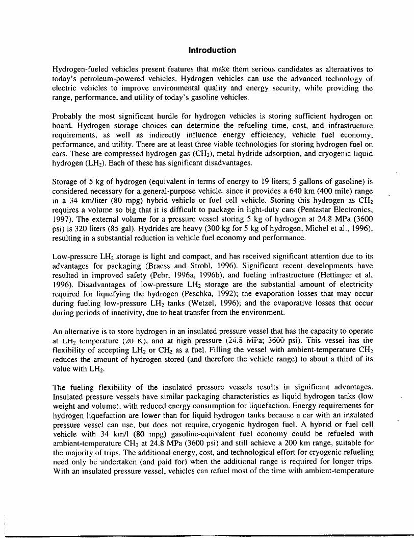
Insulated pressure vessels also have much reduced evaporative losses compared to LHz tanks.This bas been demonstrated in a previous work (Aceves and Berry, 1998), which presents athorough analysis of evaporative losses in cryogenic pressure vessels based on the first law ofthermodynamics. Figure I illustrates some of the main results. This figure shows hydrogenlosses during vehicle operation. The figure assumes that two vehicles are fitted with cryogenichydrogen storage tanks with the same capacity (5 kg). One vehicle bas a low-pressure (0.5 MPa;70 psia maximum) conventional liquid hydrogen tank, and the other has an insulated pressurevessel. The vehicles are identical in every respect, except for the tanks. The vessels are filled tofull capacity with liquid hydrogen, and then the vehicles are driven a fixed distance every day.When tbe fuel runs out, the amount of fuel burned by tbe engine and the amount of fuel lost toevaporation are calculated, and the results are shown in Figure 1. The figure shows totalcumulative evaporative hydrogen losses out of a full tank as a function of the daily drivingdistance, for a high-efficiency vehicle (34 knoll or 80 mpg gasoline equivalent fuel economy). Asexpected, evaporative losses increase as the daily driving distance is reduced, because lessdriving results in a longer time for hydrogen evaporation. The figure shows that a low-pressureLH2 tank loses hydrogen even when driven 100 km per day, Losses from a LHq tank growrapidly as the daily driving distance drops. A vehicle driven 50 km per day (the average for tbeUSA, Aceves and Berry, 1998) loses almost 1 kg (20%) of the fuel to evaporation. On the otherhand, insulated pressure vessels lose hydrogen only for very short daily driving distances (lessthan 5 km/day). Most vehicles are driven considerably more than this distance, so that mostvehicles equipped with an insulated pressure vessel would never lose any hydrogen toevaporation.
The low losses in insulated pressure vessels are the result of the flow work (work required toextract the hydrogen from the vessel, VanWylen and Sonntag, 1978). The hydrogen stored in thevessel does work as the hydrogen is being extracted, cooling down in tbe process. This effect isvery significant for hydrogen, due to its low molecular weight.
From an engineering and economic perspective, insulated pressure vessels strike a versatilebalance between the cost and bulk of ambient-temperature CHZ storage, and the energyefficiency, thermal insulation and evaporative losses of LHj storage,
Considering all the potential benefits of insulated pressure vessels, it is important to determinewhat type of pressure vessel could be operated at both high pressure and cryogenic temperature.Of the available pressure vessel technologies commonly used for vehicular storage of natuml gas(Institute of Gas Technology, 1996), it appears that aluminum-lined, composite-wrapped vesselshave the most desirable combination of properties for this application (low weight and affordableprice). However, commercially available aluminum-composite pressure vessels are not designedfor low temperature applications.
\ ‘— low-pressure LH2 tank------- insulated pressure vessel
,,... . . . . .. . . . .. . . . . .. . . . . .. . . . .. . . . .. . . . . . .. . . . .. . . . . .. . . . . . . . . .. . . . . . .. . . . . . .. . . . .
Goo 10 20 30 40 50 60 70 80 90 1
daily driving distance for a 34 km/1 (80 mpg) car, km
Figure 1. Cumulative hydrogen losses in kg as a function of dailydrivina distance. for vehicles with 17 km/liter (40 mpg): or 34 km/1(80 m~g) fuel economy, for three cryogenic hydroge;”storagevessels.
This paper describes work in progress directed at evaluating the possibility of usingcommercially available aluminum-fiber pressure vessels at cryogenic temperatures and highpressures, as would be required for vehicular hydrogen storage in insulated pressure vessels. Thepaper gives a description of previous and ongoing tests, followed by a list of future tests. Thepurpose of these tests is to demonstrate that no technical barriers exist that prevent the use ofaluminum-fiber pressure vessels at cryogenic temperatures. However, it is recognized thatfurther tests may be necessary for certification, which is required for commercialization ofinsulated pressure vessels. Certification also requires subjecting several pressure vessels to therequired tests, to determine the statistical significance of the results (Bauer, 1996). Obtainingvessel certification is beyond the scope of this work. It is the authors’ belief that the current workwiII provide vessel manufacturers with an additional option for vehicular hydrogen storage. Itwould then be left to manufacturers to conduct the required tests to achieve certification andguarmrtee safety under all possible conditions. It is worth pointing out that the aluminum-fiberpressure vessels used in all these tests have been certified according to the DOT standards (CFR-

DOT, Title 49, 1996a) for storage of compressed natural gas. The current tests are beingperformed because these pressure vessels are being used outside their typical range of operation,and also because they are being modified to attach a vacuum insulation to them.
Previous and Ongoing Tests
Pressure and Temperature Cycling
Pressure vessels have been cycled through 900 high-pressure cycles and 100 low-temperaturecycles. The cycles are alternated, running 9 pressure cycles followed by a temperature cycle, andrepeating this sequence 100 times. This test is expected to replicate what would happen if thesevessels were used in a hydrogen-fueled car. Liquid nitrogen is used for low-temperature cyclingand gaseous helium for high-pressure cycling. To accomplish the required testing, anexperimental setup has been built inside a high-pressure cell. A schematic is shown in Ilgure 2.The valves shown in the schematic are controlled by computer, which allows the system to runwith no supervision, resulting in fast cycling. An aramid-ahrminum and a carbon fiber-aluminumpressure vessel have been cycled. The characteristics of these are listed in Table 1.
tramduce.r
VI V.2Rv-1
PumpA
24MPaVessels
IM Pa
I
I
I
1~TestVessel
I——— —.— —.
A
Figure 2. Schematic of the experimental setup for temperature and pressurecycling of pressure vessels.

Table 1. Characteristics of the Tested Hydrogen Vesselsand Their Planned Insulation
Aramid- Carbon Fiber-Aluminum Aluminum
Mass of hydrogen stored, kg 1.13 0.44Vessel weight, kg 10 4.1
Internal volume, liters 17.6 6.8Internal diameter, m 0.2 0.17
Internal surface area, mz 0.48 0.25Desian messure. MPa (msi) 24.1 (3500) 31 (4500)
Perfor;ahce factori, m ({O’%) 13000 (o.5j 13”Safety factor 3.0
15 (0.5” )2.5
1 defined as burst pressure’voltsme/weight.
Two cyclic tests have been completed, one on an aramid-ahsmimsm pressure vessel and other ona carbon fiber-aluminum pressure vessel. The vessels have not failed during the test, and theyhave not shown supetilcial evidence of damage under observation. The carbon fiber-aluminumvessel was instrumented with strain gages in addition to the thermocouples and pressure sensor.Results from the strain gages will be used for validating the firrite element analysis.
Burst Test
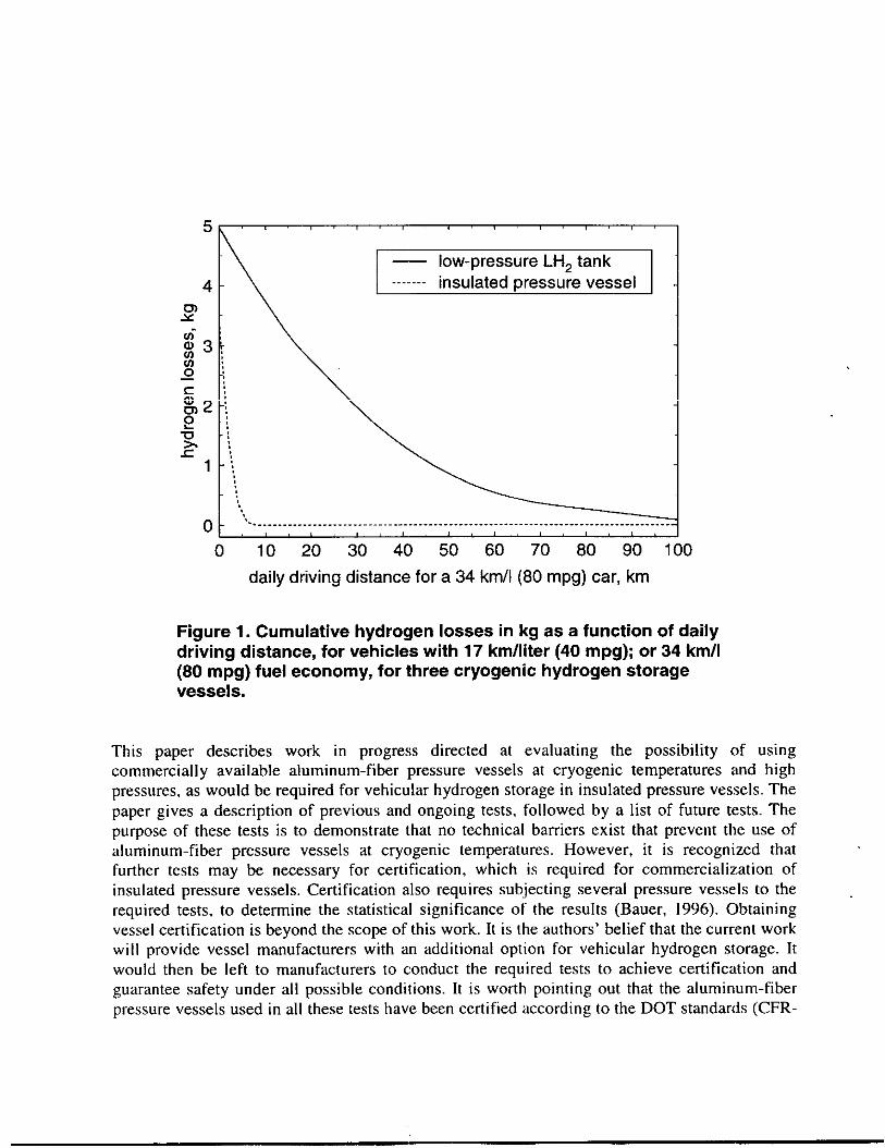
The aramid-aluminum and the carbon fiber-aluminum pressure vessels were burst-tested afterbeing cycled and ultrasound-tested. The burst test was conducted according to the Code ofFederal Regulations-Department of Transportation standards for pressure vessel certification(CFR-DOT, 1996a). Figure 3 shows the variation of pressure as a function of time for thearamid-ahsminum vessel. Failure occurred by hoop mid cylinder separation, which is thepreferred mode of failure. The burst pressure was 94.2 MPa ( 13.7 ksi), which is substantial yhigher than the minimum burst pressure of 72.4 MPa ( 10.5 ksi). The very high value of the burstpressure compared to the minimum burst pressure may be due in part to work hardening thattook place during the cold cycling of the vessel. The carbon fiber-aluminum also failed at apressure higher than the minimum required.
Finite Element Analysis
Cyclic, ultrasoundand burst testing of the pressurevesselsis being complementedwith a finiteelement analysis, which will help to determine the causes of any potential damage to the vesselduring low temperature operation. Finite element analysis is currently in progress. A mesh hasbeen built and preliminary mns have been made. Physical properties of fiber-epoxi Iaminae wereobmined from available literature at ambient and cryogenic temperatures (Reed and Golda, 1994,Morgan and All red, 1989). Lamina properties are then converted into properties of the compositematrix. This is done by using a computer program (Hull and Clyne, 1996). This program
assumes that the matrix is a homogeneous, orthotropic material. The properties of the matrix wi 11be used in the finite element thermal and stress analysis. Results of the finite element analysiswill be validated by comparison with the strain gage measurements.
I14 -
12 -
.~ 10 --x
$8vlm!??6Q
burst pressure: 13657 psig
m’”’m”m/
maximum operating pressure. . .. . .. . .. . .. . .. . . .. . .. . .. . .. . . .. . .. .. . .. . .. . .. . .. . .. . .. . .. . .. .. .. . . .. . . . .. . . .. . . . . .
“O 20 40 60 80 100 120 140 160 160
time, seconds
Figure 3. Pressure as a function of time during the burst test of the aluminum-Iined, aramid-wrapped vessel. The burst pressure wss 94.17 MPa (13657 psig).
Insulation Design and Insulated Pressure Vessel Construction
Insulated pressure vessels have been designed to operate with multilayer vacuum superinsulation(MLVSI). MLVSI has a good thermal performance only under a high vacuum, at a pressurelower than 0.01 Pa (7.5x105 mm Hg; Kaganer, 1969). Therefore, the use of MLVSI requires thatan outer jacket be built around the vessel. Two designs for the insulation have been built: a first-generation design and a second-generation design. The first-generation vessel is a I/5-scalevessel that stores about I kg of liquid hydrogen, and it is shown in Figure 4. This design has beenbuilt for cyclic testing and for DOT certification tests. The insulation design includes access forinstrumentation for pressure, temperature and level, as well as safety devices to avoid acatastrophic failure in case the hydrogen leaks into the vacuum space. Five pressure vessels havebeen built according to the first-generation pressure vessel design. One of these has beenextensively cycled at a high-pressure cell, and has also been tested with liquid hydrogen. Theremaining 4 insulated pressure vessels have been delivered to the pressure vessel manufacturer toverify compliance with DOT standards.

03
Figure 4. Insulation design for first-generation pressure vessel. The figure showsa vacuum space, for obtaining high thermal performance from the multiiayer
insulation, and instrumentation for pressure, temperature and level. Dimensionsare given in cm.
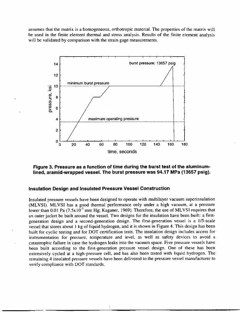
The second-generation pressure vessel design is shown in Figure 5. This vessel can store about 6kg of liquid hydrogen. This design includes a vapor shield to reduce evaporative losses inaddition to tbe instrumentation and safety devices that exist in the first generation vessel. Thesevessels are currently being built. The second generation of pressure vessels will be used for DOTand SAE tests, and for incorporation into a demonstration vehicle.
Cyclic Testing of Insulated Pressure Vessels
The insulated pressure vessels of the first generation (Figure 4) have been cycle tested. This isdone to verify that the pressure vessel or the outer jacket does not develop leaks during repeatedstresses that occur during cycling. One of these first-generation pressure vessels has beensubjected to 1000 cycles, following the same procedure as previously used for the pressurevessels with no insulation (see “Pressure and Temperature Cycling” above). The remaining fourfirst-generation pressure vessels have been subjected to a cold shock and pressure test beforebeing delivered to the vessel manufacturer for DOT testing. The experimental setup for this testis the same as previously used for cyclic testing (Figure 2). The test procedure is as follows: Thevessel is pressurized with compressed helium to 1.2 times the Maximum Allowable WorkingPressure (MAWP). The pressure is held for a minimum of 30 minutes. Then, the pressure vesselis shock conditioned by cycling it 3 times to low temperature with liquid nitrogen. Finally, Thevessel is leak tested with helium to 0.25 times the MAWP. Any leakage detected with a massspectrometer leak detector is unacceptable.
c 8.
\
!, ,!, 1o.,
.,, ,
,.,, >
Figure 5. Insulation design for second-generation pressure vessel. The figureshows a vacuum space, for obtaining high thermal performance from the
multilayer insulation, instrumentation for pressure, temperature and level, and avapor shield for reducing hydrogen evaporative losses.
The same shock conditioning test procedure will be used for the second-generation, full-sizepressure vessel before being tested according to the DOT and the SAE standards.
Liquid and Gaseous Hydrogen Testing
A first-generation insulated pressure vessel has been tested with liquid and gaseous hydrogen.The vessel was first shock-tested and leak-tested. The insulated pressure vessel was thentransported to a remote facility for testing with liquid hydrogen. Testing involved filling thevessel with LH2 to study the insulation performance, the performance of the sensors, and theproblems involved with pumping tbe LHz into the vessel. This test is expected to replicate whatwould happen to the vessel during fueling and operation in an LHZ-fueled car. The test wasconducted successful Iy. There was no damage to the vessel due to the low temperature operation,all the instrumentation operated properly at the low temperature, and there was no hydrogenignition or explosions.
Future Work
Future work includes performing additional tests on insulated pressure vessels. A list of tests hasbeen obtained from standards issued by institutions dedicated to pressure vessel and vehicularsafety, including the Department of Transportation (DOT), the Society of Automotive Engineers(SAE) and the National Fire Protection Association (NFPA). These institutions have establishedtest procedures for pressure vessels that guarantee safety under regular operating conditions.Successful completion of these tests by insulated pressure vessels will demonstrate that nosignificant safety problems exist with pressure vessel operation at low temperature. However,additional tests (and multiple execution of any individual test) will be still required for insulatedpressure vessel certification. The list of planned tests is:
● Cycling, ambient temperature. 10000 cycles from less than 10% of the service pressure tothe service pressure, 10 cycles per minute maximum (CFR-DOT, Title 49, 1996a). Each ‘test cylinder must withstand the cycling pressurization test without any evidence ofvisually observable damage, distortion, or leakage.
● Cycling, environmental. 10 cycles per minute maximum. 1) 5000 cycles from zero toservice pressure with tank at 60”C ( 140°F) and air at ambient temperature and 95%humidity, 2) 5000 cycles from zero to service pressure with tank at–51. 1“C (-60”F) andair at ambient temperature, 3) 30 cycles from zero to service pressure, ambientconditions 4) burst test the cycled vessel (CFR-DOT, Title 49, 1996a). Each test cylindermust withstand the cycling pressurization test without any evidence of visuallyobservable damage, distortion, or leakage.
. Cycling, Thermal. 10 cycles per minute maximum. 1) 10000 cycles from zero to servicepressure at ambient temperature, 2) 20 thermal cycles with tank temperature varying from93.3°C (200”F) to –51. 1‘C (-60”F) at service pressure, 3) burst test the cycled vessel(CFR-DOT, Title 49, 1996a). Each test cylinder must withstand the cyclingpressurization test without any evidence of visually observable damage, distortion, orleakage.
● Gunfire. Pressurize vessel with air or nitrogen to service pressure, and impact the vesselwith a 0.30 caliber armor-piercing projectile with a speed of 853 m/s (2800 ft/s). Thecylinder is positioned in such a way that the impact point is in the cylinder side wall at a45° angle with respect to the longitudinal axis of the cylinder. The distance from thefiring location to the cylinder may not exceed 45.7 meters (150 feet) (CFR-DOT, Title49, 1996a). The cylinder shall not fail by fragmentation.
● Bonfire. Pressurize cylinder with air or nitrogen to service pressure. Set pressure reliefdevices to discharge at 83% of the cylinder test pressure. The cylinder shall be exposed tofire until the gas is fully vented. The temperature measured on the surface tank exposedto the fire has to be between 850 and 900”C (CFR-DOT, Title 49, 1996a). The venting ofthe gas must be predominantly through the pressure relief device.

. Drop Test from 3 m (10 ft). I ) The cylinder is dropped vertically onto the end, 2) thecylinder is dropped horizontally onto the side wall, 3) the cylinder is dropped onto a 3,8 x0.48 cm ( 1 V2 x 3/16 inch) piece of angle iron, 4) after the drops, the vessel is cycled over1000 pressure cycles from 10% of service pressure to the service pressure, at 10 cyclesper minute (CFR-DOT, Title 49, 1996). The cylinder then has to be burst tested; the burstpressure of this vessel has to be at least 90 % of the minimum burst pressure.
. Drop tests from 10 m and 3 m. 1) Drop from 10 m. The drop test subjects a full-sizevehicle fuel tank to a free-fall impact onto an unyielding surface from a height of 10 m,The fuel tank is released by firing one or more explosive cable cutters simultaneously.The fuel tank impacts the outer shell on the critical area as determined by themanufacturer. The fuel tank is filled with an equivalent full weight of liquid nitrogensaturated to at least 50’70of the maximum allowable working pressure of the fuel tank. 2)Drop from 3 m. The drop test subjects a full-size vehicle fuel tank to a free-fall impactonto an unyielding surface from a height of 3 m. The fuel tank is released by firing one ormore explosive cable cutters simultaneously. The fuel tank impacts the outer shell on thecritical area as determined by the manufacturer. The fuel tank is filled with an equivalentfull weight of liquid nitrogen saturated to at least 50% of the maximum allowableworking pressure of the fuel tank (SAE J2343, 1997), There shall be no loss of productfor a period of 1 hour after the drop other than relief valve operation and loss of vaporbetween the filler neck and the secondary relief valve in the case of a test involving thefiller neck. Loss of vacuum, denting of the vessel, piping and piping protection, anddamage to the support system are acceptable.
. Flame test. The tank should contain an equivalent full level of liquid nitrogen saturated atone half the maximum allowable working pressure (MAWP). Tbe tank should beinverted and subjected to an external temperature of 538°C ( 10OO”F) for 20 minuteswithout the vessel reaching relief pressure (SAE J2343, 1997).
Insulated pressure vessels for the first four tests have already been delivered to the vesselmanufacturer. These will be tested shortly. Additional plans include the installation of insulatedpressure vessels into demonstration hydrogen-powered vehicles. For this application, the NFPA(NFPA 57, 1996; NFPA 52, 1998), and CFR-DOT (Title 49, 1996) standards will be reviewed toprepare the required tests to guarantee the safety of the operation. Future work will also focus ondeveloping a testing procedure for achieving certification of insulated pressure vessels.
Conclusions
Insulated pressure vessels are being developed as an alternative technology for storage ofhydrogen in light-duty vehicles. Insulated pressure vessels can be fueled with either liquidhydrogen or compressed hydrogen. This flexibility results in advantages compared toconventional hydrogen storage technologies. Insulated pressure vessels are lighter than hydrides,more compact than ambient-temperature pressure vessels, and require less energy forliquefaction and have less evaporative losses than liquid hydrogen tanks.

For reduced cost and complexity it is desirable to use commercial Iy avai table aluminum-fiberpressure vessels for insulated pressure vessels. However, commercial] y available pressurevessels are not designed for operation at cryogenic temperature. A series of tests has been carriedout to verify that commercially available pressure vessels can be operated at cryogenictemperature with no performance losses. All analysis and experiments to date indicate that nosignificant damage has resulted. Required future tests are described that will establish that nosignificant safety issues exist with pressure vessel operation at cryogenic temperature.
Acknowledgments
This project is funded by the DOE Hydrogen Program, Sig Gronich and Neil Rossmeisl,Program Managers. The authors also express their appreciation for the significant contributionsof Structural Composites Industries (SCI) to this project. Work performed under the auspices ofthe U.S. Department of Energy by Lawrence Livermore National Laboratory under Contract W-7405 -ENG-48.
References
Aceves, S. M., Berry, G.D., 1998, ``Thermodynamicsof InsulatedPressureVesselsfor VehicularHydrogen Storage:'ASMEJournal of Energy ResourcesTechnology, June, Vol. 120, pp. 137142.
Baur L., 1995, “Composite Pressure Vessel with Metal Lhrer for Compressed HydrogenStorage,’’ Proceedings of the ls'EAWorkshop on Fuel Processing for Polymer Electrolyte FuelCells, Paul Scherrer Institut, Villigen, Switzerland, International Energy Agency, Swiss FederalOffice of Energy, September 25-27, 1995, p. 45-69.
Braess, H.H., and Strobl, W., 1996, “Hydrogen as a ~1 for Road Transport of the Future:Possibilities and Prerequisites,” Proceedings of the 11 World Hydrogen Energy Conference,Stuttgart, Germany.
Code of Federal Regulations, Department of Transportation (CFR-DOT), 1996a, “BasicRequirements for Full y Wrapped Fiber Reinforced Aluminum Lked Cyi inders,” Title 49, CFR10~.105 Standard. ‘-
Hettinger, W. Michel, F., Ott, P., and Theissen, F.,Hydrogen Vehicles,” Proceedings of the ll’h WorldGermany, pp. 1135-1143.
1996, “Refueling Equipment for LiquidHydrogen Energy Conference, Stuttgart,
Hull, D., and Clyne, T. W., 1996, “An Introduction to Composite Materials,” CambrigeUniversity Press, Cambridge, Great Britain.
Institute of Gas Technology, 1996, ’’Compressed Natural Gas Storage Optimization for NaturalGas Vehicles,” Gas Research Institute Report GRI-96/0364, Des Plaines, IL.
Kaganer, M. G., 1969, “Thermal Insulation in Cryogenic Engineering,” Israel Program forScientific Translation Ltd., Jerusalem, Israel.
Klinger, D., Kuzmyak JR., 1984, “Personal Travel in the United States,” Vol. 1, 1983-1984,Nationwide Personal Transportation Study, Report PB89-235378, prepared for the USDepartment of Transportation, Office of Highway Information Management, Washington, DC.
Michel, F., Fieseler, H., Meyer, G., and Th:issen, F., 1996, “Onboard Equipment for LiquidHydrogen Vehicles,” Proceedings of the II World Hydrogen Energy Conference, Stuttgart,Germany, pp. 1063-1077,
Morgan, R.J. and Allred, R, E., 1989, “Aramid fiber reinforcements,” in “Reference Book forComposite Technology,” Edited by Lee, S. M., pp. 143-166, Technomic Publishing, Lancaster,PA.
National Fire Protection Association (NFPA), 1998, ’’NFPA52: Compressed Natural Gas(CNG)Vehicular Fuel System Code,” Quincy, MA,
National Fire Protection Association (NFPA), 1996, ’’NFPA 57: Liquefied Natural Gas(LNC)Vehicular Fuel System Code,” Quincy, MA.
Pehr, K., 1996a, ’’Experimental Examinationson the Worst Case Behavior of LH2/LNG Tanksfor Passenger Cars,” Proceedings of the ll’h World Hydrogen Energy Conference, Stuttgart,German y.
Pehr, K., 1996b, ``Aspects of Safety and Acceptance of LHz Tank Systems in Passenger Cars,”International Journal of Hydrogen Energy, Vol. 21, pp. 387-395.
Pentastar Electronics, 1997, “Direct-Hydrogen-Fueled Proton-Exchange-Membrane Fuel CellSystem for Transportation Applications, Conceptual Design Report,” Report DOE/CE/50390-9,prepared for U.S. Depatiment of Energy, Office of Transportation Technologies, under contractDE-AC02-94CE50390.
Peschka, W., 1992, ’’Liquid Hydrogen, Fuel of the Future,” Springer-Verlag, Vienna, Austria.
Reed, R. P., and Golda, M., 1994, “Cryogenic Properties of Unidirectional Composites,”Cryogenics, Vol. 34, No. 11, pp. 909-928.
Society of Automotive Engineers (SAE). 1997, “Recommended Practices for LNG PoweredHeavy-Duty Trucks,” SAE.J2343.
Wetzel, F.J., 1996, “Handlingof Liquid Hydrogen at Filling Stations,” Proceedings of the ll’hWorld Hydrogen Energy Conference, Stuttgafi, Germany, pp. 1123-1134,

Figure Captions
Figure l. Cumulative hydrogen losses inkgasa function ofdaily driving distance, for'vehicles with 17 km/liter (40mpg); or34 km/l (80mpg) fuel economy, for threecryogenic hydrogen storage vessels.
Figure 2. Schematic of the experimental setup for temperature and pressure cycling of pressurevessels.
Figure 3. Pressure as a function of time during the burst test of the aluminum-lined, aramid-wrapped vessel, The burst pressure was 94.17 MPa ( 13657 psig),
Figure4, Insulation design forpressure vessel. The figure shows avacuum space, for obtaininghigh thermal performance from the multilayer insulation, and instrumentation for pressure,temperature and level. Dimensions are given in cm,
Figure 5. Insulation design for second-generation pressure vessel. The figure shows a vacuumspace, forobtaining high themalperfomance from themultilayer insulation, instmmentation forpressure, temperature and level, and a vapor shield for reducing hydrogen evaporative losses.