Low Temperature and High Pressure Evaluation of Insulated ...
Upload
khangminh22Category
view
0download
0
�����������������
Citation: Wang, B.; Zhang, Z.; Huang,
K.; Zhang, Y.; Zhang, Z.; Gao, H.; Fu,
L. Stress and Pressure Pulsation
Analysis of Low Temperature
Compressor Piping System in LNG
Vaporizing Station. Energies 2022, 15,
1874. https://doi.org/10.3390/
en15051874
Academic Editor: Luiz C. Wrobel
Received: 24 December 2021
Accepted: 28 February 2022
Published: 3 March 2022
Publisher’s Note: MDPI stays neutral
with regard to jurisdictional claims in
published maps and institutional affil-
iations.
Copyright: © 2022 by the authors.
Licensee MDPI, Basel, Switzerland.
This article is an open access article
distributed under the terms and
conditions of the Creative Commons
Attribution (CC BY) license (https://
creativecommons.org/licenses/by/
4.0/).
energies
Article
Stress and Pressure Pulsation Analysis of Low TemperatureCompressor Piping System in LNG Vaporizing StationBaoqing Wang 1, Zhi Zhang 2,*, Kun Huang 2, Yaotong Zhang 1, Zhenwu Zhang 3, Hui Gao 1 and Lingdi Fu 4
1 Sinopec Tianjin LNG Co., Ltd., Tianjin 300457, China; [email protected] (B.W.);[email protected] (Y.Z.); [email protected] (H.G.)
2 Petroleum Engineering School, Southwest Petroleum University, Chengdu 610500, China;[email protected]
3 Anhui Province Natural Gas Development Co., Ltd., Hefei 230051, China; [email protected] Environment and Technology Supervision Research Institute, PetroChina Southwest Oil & Gasfield Company,
Chengdu 610041, China; [email protected]* Correspondence: [email protected]
Abstract: LNG (Liquefied Natural Gas) vaporizing stations are usually built in the cities and towns,and the BOG (Boiled Off Gas) pressurizing system is a very important element. In the pressurizingsystem, the severe vibration of the low-temperature reciprocating compressor may lead to a failureof the pipeline system and the equipment. Therefore, this paper analyzes the stress and pressurepulsation of the BOG compressor piping system in the LNG vaporizing station. The beam model wasused to establish the pipe model. The static, harmonic and modal analysis were carried out basedon the plane-wave theory and the pressure-fluctuation theory, and the influence factors of supportspacing, the settlement of the fulcrum foundation, pipe pressure and elbow angle were analyzed.The main conclusions are as follows: (1) the unbalanced excited force caused by pressure pulsationgreatly affects the stress of the exhaust pipe and compressor outlet pipe, and has less influence onthe stress of the suction pipe and compressor inlet pipe; (2) although unbalanced excited force isgenerated in the elbow, it also has an impact on the straight pipe stress; (3) adding an expansion jointto the pipe of the BOG compressor can effectively reduce the stress of the pipe its the displacement,and can increase the flexibility of the pipe.
Keywords: LNG vaporizing station; low temperature compressor; piping system; stress analysis;modal analysis; pressure pulsation
1. Introduction
LNG (Liquefied Natural Gas) is a type of cryogenic liquid that cools gaseous naturalgas to −162 ◦C under atmospheric pressure. The LNG pipeline may experience destructivestress because of cold shrinkage, and there is a great safety hazard in the process ofoperation. Especially in the LNG vaporizing station with BOG (Boiled Off Gas) compressionprocess, the operation of the compressor causes pipe vibration and increase the stress ofthe pipe [1–5]. If the equipment or pipe ruptures, the LNG will leak and then rapidlyvolatilize and disperse. It can easily cause fires, explosions and other accidents, causinghuge economic losses and casualties. Therefore, according to the regulation of GB/T 20801“Pressure piping code Industrial piping Part 1: General” [6], a pipe-stress analysis shouldbe carried out for pipes running at temperatures not less than 400 ◦C or not greater than−70 ◦C.
Chilton and Handley [7] discussed the installation position of two kinds of buffer(single-volume buffer and filter buffer) in the piping system. It was concluded that thecontrol effect of the filter buffer on pressure pulsation is better in cases with the samevolume. Sun Siying et al. [8] studied the installation position of the buffer, and found thatthe closer the buffer to the cylinder, the more obvious the effect of vibration elimination.
Energies 2022, 15, 1874. https://doi.org/10.3390/en15051874 https://www.mdpi.com/journal/energies

Energies 2022, 15, 1874 2 of 21
Josef and Zhang Heli [9] designed an attenuator with a perforated tube, and provedthat it could effectively attenuate the pulsation of the air flow. Shin et al. [10,11] carriedout a theoretical analysis and experimental verification on the problem of attenuator-reducing pressure pulsation. The device is equivalent to the spring damping system, whichcan effectively control the pressure pulsation. Chen Lingli et al. [12,13] put forward amathematical model for the optimization of the supporting stiffness of the piping structureof the compressor, and deduced the sensitivity analysis formula of the steady-state responseamplitude with design variables under the exciting force. Cheng Mugen [14] analyzed thevibration causes of the inlet pipe of the water-injection pump, and put forward dampingmeasures such as adding the accumulator and reducing the number of elbows. XingKeli et al. [15] analyzed the conventional parallel capsule accumulator and a new type oftandem bladder accumulator, and discussed the effect of the installation position of theaccumulator on the pressure-pulsation attenuation of the pump. Zhang Hongjuan [16]analyzed the vibration causes of the reciprocating pump pipe and proposed the additionof an air chamber to reduce the pressure pulsation. Xie Poan [17] used the transfer matrixmethod to establish the acoustic model of the accumulator, analyzed the attenuation effectof accumulator on the fluid pulsation in the pipeline, and verified it by experiment. WangQiang [18] put forward a structure for a pipeline vibration elimination device, whichcan reduce the vibration of the pipe and attenuate the pressure pulsation of the fluid.Xue Weifei [19] used the ANSYS software to analyze the vibration of the reciprocatingcompressor outlet pipe and to reduce the vibration by reforming the layout of the pipe.Xiao Gaomian [20] calculated the pressure pulsation of a complex piping system based onplane-wave theory by using the stiffness matrix method, and made use of Matlab softwareto compile the calculation program of gas pulsation. Yu Chenglong et al. [21] analyzedvibration and vibration-reduction measures for the reciprocating compressor pipe, andput forward measures to increase the buffer tank, namely by reducing the diameter. ChenHaifeng [22] analyzed the vibration characteristics of reciprocating compressor piping bythe method of acoustic and electric simulation. This method equates the pipe unit to thecircuit, which is convenient and fast, but it can only calculate the frequency of the pipe. SuiKai and Wang Jie [23] analyzed the pressure pulsation of the water supply pipeline. Theexpression of the pressure pulsation was derived by the separation of variables, and theexpression of the exciting force was deduced. Lu Hongfang [24] analyzed the stress andvibration of the reciprocating pump piping system using CAESAR II software, and putforward the measure of stress reduction.
Su Peng et al. [25] studied the effect of thermal stress on the LNG pipeline. LiuHuafeng et al. [26] carried out the stress calculation for a company’s LNG storage tank’scryogenic inlet pipeline, studied the stress concentration and the large displacement posi-tion of the pipeline, and studied the influence of the spring hanger on the stress of the pipingsystem. Yu Guopeng et al. [27] conducted a stress analysis of LNG cryogenic pipelines,and analyzed the influence of wind load, earthquake load and other factors on pipe stress.Qiang Xu et al. [28,29] conducted research on two-phase flow regimes of a long-distancepipeline-riser system and found that differential pressure signals at different pipe positionscan have a significant impact on the recognition rate. Se-Yun Hwang et al. [30] studiedpipe stresses of piping system installed on LNG carriers under various conditions usingCAESAR-II software based on beam elements and conducted an evaluation of analyticalresults of piping arrangement of LNG.
According to the literature survey, there are few studies on the vibration of lowtemperature pipes, and the stress analysis of the BOG compressor piping system has notbeen studied yet. Based on the theory of pressure pulsation, this paper calculates theunbalanced exciting force of the pipeline. The stress and a harmonic and modal analysis ofpipelines are studied by CAESAR II software, the influence factors of stress are analyzedand the corresponding stress-reduction measures are presented.

Energies 2022, 15, 1874 3 of 21
2. Basic Theories
The system only vibrates when the system is disturbed by the initial disturbance (ex-ternal force or displacement), and it is easy to cause resonance when the natural frequencyof pipeline is close to the excitation frequency. In the BOG compressor piping system, theeffect of pressure pulsation on pipeline stress is primarily studied.
2.1. Plan Wave Theory
The plane-wave theory uses linear equation to simplify the initial equation, so thelinear vibration theory can be used to directly facilitate the calculation. As shown inFigure 1, at moment t, the physical parameter pressure, velocity and density are p, u and ρ,respectively. When the fluid is a one-dimensional flow, p, u, ρ are all functions related to xand t.
Energies 2022, 15, x FOR PEER REVIEW 3 of 22
2. Basic Theories The system only vibrates when the system is disturbed by the initial disturbance (ex-
ternal force or displacement), and it is easy to cause resonance when the natural frequency of pipeline is close to the excitation frequency. In the BOG compressor piping system, the effect of pressure pulsation on pipeline stress is primarily studied.
2.1. Plan Wave Theory The plane-wave theory uses linear equation to simplify the initial equation, so the
linear vibration theory can be used to directly facilitate the calculation. As shown in Figure 1, at moment t, the physical parameter pressure, velocity and density are p, u and ρ, re-spectively. When the fluid is a one-dimensional flow, p, u, ρ are all functions related to x and t.
Figure 1. Fluid micromass of control volume in the pipe.
(1) Continuity equation
0ρ ρ uu ρt x x
∂ ∂ ∂+ + =∂ ∂ ∂
, (1)
(2) Motion equation
1u u put x ρ x
∂ ∂ ∂+ = −∂ ∂ ∂
, (2)
(3) Wave equation
2 0p p uu ρct x x
∂ ∂ ∂+ + =∂ ∂ ∂
, (3)
2.2. Pressure Pulsation and Unbalanced Exciting Force Pressure pulsation refers to the maximum amplitude deviating from the average
pressure p. Without the pressure data of the pipeline in the scene, it is difficult to adopt the shock-wave theory calculation. In order to be able to carry out the analysis more ac-curately, the calculation is made by the method of separation of variables.
The expression of pressure pulsation is as follows [23]:
( ) ( ) ( )2 22 2, cos 1 cos cos 1 sin sinn np u np x t n l t n l t x
n n cl lΔ− − = − + −
ππ ω π ωπ π
(4)
where pΔ(x,t) = pressure pulsation at x position and t moment, Pa; n = order number; c = sound velocity, m/s; l = total pipe length, m; x = distance from the starting point, m; ωn = excitation circular frequency, rad/s; p = initial pressure, Pa; u = initial velocity, m/s.
The pressure inhomogeneity is the symbol used to measure the pressure pulsation, and the pressure inhomogeneity can be calculated as:
max min
0
= 100%p pδp
Δ Δ− × , (5)
Figure 1. Fluid micromass of control volume in the pipe.
(1) Continuity equation∂ρ
∂t+ u
∂ρ
∂x+ ρ
∂u∂x
= 0, (1)
(2) Motion equation∂u∂t
+ u∂u∂x
= −1ρ
∂p∂x
, (2)
(3) Wave equation∂p∂t
+ u∂p∂x
+ ρc2 ∂u∂x
= 0, (3)
2.2. Pressure Pulsation and Unbalanced Exciting Force
Pressure pulsation refers to the maximum amplitude deviating from the averagepressure p. Without the pressure data of the pipeline in the scene, it is difficult to adopt theshock-wave theory calculation. In order to be able to carry out the analysis more accurately,the calculation is made by the method of separation of variables.
The expression of pressure pulsation is as follows [23]:
p∆(x, t) =[−2pnπ
(cos nπl − 1) cos ωnt +−2u
n2π2cl(cos nπl − 1) sin ωnt
]sin
nπ
lx (4)
where p∆(x,t) = pressure pulsation at x position and t moment, Pa; n = order number;c = sound velocity, m/s; l = total pipe length, m; x = distance from the starting point, m;ωn = excitation circular frequency, rad/s; p = initial pressure, Pa; u = initial velocity, m/s.
The pressure inhomogeneity is the symbol used to measure the pressure pulsation,and the pressure inhomogeneity can be calculated as:
δ =p∆max − p∆min
p0× 100%, (5)
where p∆max = the maximum value of pressure pulsation; p∆min = the minimum value ofpressure pulsation; p0 = the average pressure, p0 = pmax−pmin
2 .According to the requirements of API 618 “Reciprocating Compressors for Petroleum,
Chemical, and Gas Industry Services” [31], the unfiltered gas pressure inhomogeneity at

Energies 2022, 15, 1874 4 of 21
the cylinder flange of the compressor should be within the range of Equation (6), and if thecalculated value is greater than 7%, it should be taken as 7%.
δcf = 3R, (6)
where δcf = allowable value of pressure inhomogeneity, %; R = the ratio of the absolutepressure of the compressor outlet to the absolute pressure of the inlet.
In the BOG compressor piping system, the BOG gas becomes periodically excitedby the compressor due to the reciprocating motion of the BOG compressor, creating apressure pulsation. The pressure pulsation is transmitted through the BOG as a pressurewave. At different locations, the pressure pulsation reaches a peak at different times. Thepressure pulsation produces the exciting force at the elbow, tee or other components, andthe exciting force varies with time, which affects the stress of the pipes. As it shown inFigure 2, assuming that d represents the inner diameter of the pipe, β stands for the angleof elbow, the inlet and outlet pressures are p, and the resultant force of elbow can becalculated as:
R = 2F1 sin(
β
2
)= 2F2 sin
(β
2
)= 2
(πd2 p
4
)sin(
β
2
), (7)
Energies 2022, 15, x FOR PEER REVIEW 5 of 22
Figure 2. Elbow force diagram.
2.3. Model of Pipe and Constraints Due to the complexity of the BOG compressor piping system, the stress calculation
using the beam model is relatively simple. The pipeline model includes the straight pipe model, elbow model and tee model. Constraint models include compressor nozzle con-straints, valve seat constraints, and guidance constraints. The relevant details were ex-plained in another article by one of the authors in reference [24].
2.4. Stress Analysis Method This study applied the finite element method to analyze the stress of the BOG com-
pressor piping system. Since large deformation and nonlinearity problems are not in-volved in the stress of BOG compressor piping, the advantages and disadvantages of AN-SYS (ANSYS 2019 R3, ANSYS, Inc., Canonsburg, PA, USA), ABAQUS (ABAQUS 2020, ABUQUS Inc., Palo Alto, CA, USA) and CAESAR II (CAESAR II 2019 v11.00, COADE, Inc., Houston, TX, USA) software were compared, and CAESAR II software was judged to be more appropriate. Through engineering verification, the software can meet the ac-curacy of calculation, and we found that the CAESAR II software is superior in the case of a complicated piping system for its fast calculation speed and easy modeling processes. 1. Assumed condition
CAESAR II software performs the stress analysis on the assumption that [30]: (a) The assumption of small deformation: in the cross section, the local deformation
of the element under load is negligible; (b) The plastic deformation and large deformation are not considered in the elastic
range of the pipe material, which means the nonlinear problem of the pipe structure is not taken into account;
(c) In the process of loading the aircraft remains flat; (d) Considering only the elastic changes and loads of the pipe, and Hooke’s law
applies to the full load range of the tubular section; (e) Assuming that the points, the forces and moments acting on the structure are on
their central axes; (f) The rotational deformation of the system is small; (g) The force is not affected by structural deformation.
2. Grid precision For all pipes supported by the ground, whether the soil is covered or not, the distance
between the nodes of the pipe with diameter greater than 304.8 mm should be less than or equal to 20 times the diameter of the pipe, and for a pipe diameter smaller than or equal
Figure 2. Elbow force diagram.
According to the above formula, R is constant if p is constant while the bend deforma-tion and stress are static. In the case where the pressure is pulsating, p = p0 + ∆p. Hence,the resultant force of elbow should be:
R = 2
(πd2
i4
)(p0 + ∆p) sin
(β
2
)= 2
(πd2
i4
)p0 sin
(β
2
)+ 2
(πd2
i4
)∆p sin
(β
2
)(8)
In the above formula, p0 represents average pressure, Pa; ∆p represents amplitude ofpressure pulsation, Pa.
In Equation (8), the two terms represent the force generated by the static pressure onthe elbow and the exciting force ∆R generated by the pressure pulsation, respectively.
∆R = 2
(πd2
i4
)∆p sin
(β
2
)= 2S∆p sin
(β
2
), (9)
In Equation (9), ∆p is pressure pulsation, the unit is Pa; S is cross sectional area of pipe,the unit is m2.

Energies 2022, 15, 1874 5 of 21
2.3. Model of Pipe and Constraints
Due to the complexity of the BOG compressor piping system, the stress calculationusing the beam model is relatively simple. The pipeline model includes the straightpipe model, elbow model and tee model. Constraint models include compressor nozzleconstraints, valve seat constraints, and guidance constraints. The relevant details wereexplained in another article by one of the authors in reference [24].
2.4. Stress Analysis Method
This study applied the finite element method to analyze the stress of the BOG compres-sor piping system. Since large deformation and nonlinearity problems are not involved inthe stress of BOG compressor piping, the advantages and disadvantages of ANSYS (ANSYS2019 R3, ANSYS, Inc., Canonsburg, PA, USA), ABAQUS (ABAQUS 2020, ABUQUS Inc.,Palo Alto, CA, USA) and CAESAR II (CAESAR II 2019 v11.00, COADE, Inc., Houston, TX,USA) software were compared, and CAESAR II software was judged to be more appropri-ate. Through engineering verification, the software can meet the accuracy of calculation,and we found that the CAESAR II software is superior in the case of a complicated pipingsystem for its fast calculation speed and easy modeling processes.
1. Assumed condition
CAESAR II software performs the stress analysis on the assumption that [30]:
(a) The assumption of small deformation: in the cross section, the local deformation ofthe element under load is negligible;
(b) The plastic deformation and large deformation are not considered in the elastic rangeof the pipe material, which means the nonlinear problem of the pipe structure is nottaken into account;
(c) In the process of loading the aircraft remains flat;(d) Considering only the elastic changes and loads of the pipe, and Hooke’s law applies
to the full load range of the tubular section;(e) Assuming that the points, the forces and moments acting on the structure are on their
central axes;(f) The rotational deformation of the system is small;(g) The force is not affected by structural deformation.
2. Grid precision
For all pipes supported by the ground, whether the soil is covered or not, the distancebetween the nodes of the pipe with diameter greater than 304.8 mm should be less thanor equal to 20 times the diameter of the pipe, and for a pipe diameter smaller than orequal to 304.8 mm, the distance between the nodes should not be greater than 30 times thediameter of the pipe [32]. For pipes with support constraints, the nodes must be distributedat the pipe support, otherwise the nodes between the pipe supports produce the wronglongitudinal displacement because of the unbearable weight.
3. Mass matrix of piping system
The element mass matrix is:
[Me] = ρSl
1315
11l210
970
−13l420
11l210
l2
10513l420
−l2
1409
7013l420
1315 − 11l
210−13l420
−l2
140 − 11l210
l2
105
, (10)
The total mass matrix of the piping system is [26]:
[M] =m
∑e=1
[G]T [Me][G], (11)

Energies 2022, 15, 1874 6 of 21
2.5. Natural Frequency and Excitation Frequency
The natural frequency of piping system is expressed as [33–36]:
W0 =y2
2π
√km
, (12)
where y2 = order of natural frequency, y2 = 1, 2, 3 . . . ; k = stiffness of piping system;m = mass of piping system.
Excitation frequency refers to the number of vibrations of the vibrating object within aunit of time, its expression is:
W1 =nmA
60, (13)
where n = compressor speed in RPM, r/min; m = number of cylinders; A = action mode,A = 1 for single-action, A = 2 for dual-action.
2.6. Pipe Stress and Model Calibration
1. Stress calibration
The main loads acting on the LNG pipe system are as follows: self-weight, pressuretemperature, restraints force at piping support, forced displacement. Primary stress andsecondary stress of the pipe stress can be divided by the destruction forms of the pipe.ASME B31.3 “Process Piping” standard should be followed for the stress calibration of theLNG vaporizing station piping [37].
Primary stress is caused by external loads such as pressure and gravity, and shouldmeet the following condition:
SL ≤ Sh, (14)
While secondary stress is generated by temperature difference and should satisfy thefollowing condition:
SE = (Sb + 4S2t )
0.5 ≤ SA = fR(1.25Sc + 0.25Sh), (15)
In Equations (14) and (15),SL, the sum of longitudinal stresses due to gravity and other continuous loads in
the pipe;Sh, allowable stress in the thermal state;SE, the calculated displacement stress range due to thermal expansion and end
point displacement;SA, the allowable displacement stress range;Sc, allowable stress in the cold state;fR, stress range factor;Sb, the stress due to composite bending moment of pipe under thermal expansion,
cold shrinkage and endpoint displacement;St, the stress due to the torque of the pipe under the action of thermal expansion, cold
shrinkage, and endpoint displacement.
2. Model calibration
As shown in Figure 3, in order to avoid resonance between the pipe and the equipment,the following is required [38–42]:
W0
W1< 0.8 Or
W0
W1> 1.2, (16)

Energies 2022, 15, 1874 7 of 21
Energies 2022, 15, x FOR PEER REVIEW 7 of 22
In Equations (14) and (15), SL, the sum of longitudinal stresses due to gravity and other continuous loads in the
pipe; Sh, allowable stress in the thermal state; SE, the calculated displacement stress range due to thermal expansion and end point
displacement; SA, the allowable displacement stress range; Sc, allowable stress in the cold state; fR, stress range factor; Sb, the stress due to composite bending moment of pipe under thermal expansion,
cold shrinkage and endpoint displacement; St, the stress due to the torque of the pipe under the action of thermal expansion, cold
shrinkage, and endpoint displacement. 2. Model calibration
As shown in Figure 3, in order to avoid resonance between the pipe and the equip-ment, the following is required [38–42]:
0
1
0.8WW
< Or 0
1
1.2WW
> , (16)
Figure 3. Resonance zone. (Note: β = amplification factor; W0 = natural frequency; W1 = excitation frequency).
3. Case Study 3.1. Project Overview
As shown in Figure 4, the direct compression process was used to pressurize the BOG generated in the LNG storage tank and unloading system using a compressor. The pres-surized BOG and the natural gas vaporized in the aero-thermal vaporizer were mixed in the main pipe, and after confluence, it was transported to a water-bath vaporizer and then warmed to above −5 °C.
Figure 3. Resonance zone. (Note: β = amplification factor; W0 = natural frequency; W1 = excita-tion frequency).
3. Case Study3.1. Project Overview
As shown in Figure 4, the direct compression process was used to pressurize theBOG generated in the LNG storage tank and unloading system using a compressor. Thepressurized BOG and the natural gas vaporized in the aero-thermal vaporizer were mixedin the main pipe, and after confluence, it was transported to a water-bath vaporizer andthen warmed to above −5 ◦C.
Energies 2022, 15, x FOR PEER REVIEW 8 of 22
Figure 4. Schematic diagram of the process flow of LNG vaporizing station.
According to the maximum amount of BOG, two BOG compressors (RC1—Recipro-cating compressor 1, RC2—Reciprocating compressor 2) were set up with the same dis-placement (3000 Nm3/h). As shown in Figure 5, the main elements of the BOG compressor piping system include the main suction pipe, main exhaust pipe, compressor inlet pipe and compressor outlet pipe. All the pipes are built above the ground.
Figure 5. Sketch map of pipe distribution.
The operating condition (0~50~100%) of the BOG compressor is regulated by the pressure of the LNG tank. If the BOG flow exceeds the compressor capacity, the pressures of the LNG storage tank and the main BOG pipe increase. If the pressure exceeds the set point of the control valve, the control valve will turn on, and the extra BOG will be deliv-ered to the torch and burned. In the case of normal operation (no unloading operation), only one BOG compressor is needed. During the unloading operation, the amount of BOG is several times that of the normal condition, and two compressors are required to work at the same time. The parameter of the pipes can be seen in Table 1.
Table 1. Parameters of pipes.
Pipe Type Main Suction Pipe
Main Exhaust Pipe
Compressor Inlet Pipe
Compressor Outlet Pipe
Material 06Cr19Ni10 06Cr19Ni10 06Cr19Ni10 06Cr19Ni10 Diameter (mm) 219 219 219 219 Thickness (mm) 6.0 6.0 6.0 6.0
Insulation thickness (mm) 30 30 30 30 Fluid density (kg/m3) 0.75 0.75 0.75 0.75
Installation temperature (°C) 20 20 20 20 Operation temperature (°C) −152 −68 −152 −68 Operation pressure (MPa) 0.115 0.6 0.115 0.6
Figure 4. Schematic diagram of the process flow of LNG vaporizing station.
According to the maximum amount of BOG, two BOG compressors (RC1—Reciprocatingcompressor 1, RC2—Reciprocating compressor 2) were set up with the same displacement(3000 Nm3/h). As shown in Figure 5, the main elements of the BOG compressor pip-ing system include the main suction pipe, main exhaust pipe, compressor inlet pipe andcompressor outlet pipe. All the pipes are built above the ground.
Energies 2022, 15, x FOR PEER REVIEW 8 of 22
Figure 4. Schematic diagram of the process flow of LNG vaporizing station.
According to the maximum amount of BOG, two BOG compressors (RC1—Recipro-cating compressor 1, RC2—Reciprocating compressor 2) were set up with the same dis-placement (3000 Nm3/h). As shown in Figure 5, the main elements of the BOG compressor piping system include the main suction pipe, main exhaust pipe, compressor inlet pipe and compressor outlet pipe. All the pipes are built above the ground.
Figure 5. Sketch map of pipe distribution.
The operating condition (0~50~100%) of the BOG compressor is regulated by the pressure of the LNG tank. If the BOG flow exceeds the compressor capacity, the pressures of the LNG storage tank and the main BOG pipe increase. If the pressure exceeds the set point of the control valve, the control valve will turn on, and the extra BOG will be deliv-ered to the torch and burned. In the case of normal operation (no unloading operation), only one BOG compressor is needed. During the unloading operation, the amount of BOG is several times that of the normal condition, and two compressors are required to work at the same time. The parameter of the pipes can be seen in Table 1.
Table 1. Parameters of pipes.
Pipe Type Main Suction Pipe
Main Exhaust Pipe
Compressor Inlet Pipe
Compressor Outlet Pipe
Material 06Cr19Ni10 06Cr19Ni10 06Cr19Ni10 06Cr19Ni10 Diameter (mm) 219 219 219 219 Thickness (mm) 6.0 6.0 6.0 6.0
Insulation thickness (mm) 30 30 30 30 Fluid density (kg/m3) 0.75 0.75 0.75 0.75
Installation temperature (°C) 20 20 20 20 Operation temperature (°C) −152 −68 −152 −68 Operation pressure (MPa) 0.115 0.6 0.115 0.6
Figure 5. Sketch map of pipe distribution.
The operating condition (0~50~100%) of the BOG compressor is regulated by thepressure of the LNG tank. If the BOG flow exceeds the compressor capacity, the pressures

Energies 2022, 15, 1874 8 of 21
of the LNG storage tank and the main BOG pipe increase. If the pressure exceeds theset point of the control valve, the control valve will turn on, and the extra BOG will bedelivered to the torch and burned. In the case of normal operation (no unloading operation),only one BOG compressor is needed. During the unloading operation, the amount of BOGis several times that of the normal condition, and two compressors are required to work atthe same time. The parameter of the pipes can be seen in Table 1.
Table 1. Parameters of pipes.
Pipe Type MainSuction Pipe
Main ExhaustPipe
CompressorInlet Pipe
CompressorOutlet Pipe
Material 06Cr19Ni10 06Cr19Ni10 06Cr19Ni10 06Cr19Ni10Diameter (mm) 219 219 219 219Thickness (mm) 6.0 6.0 6.0 6.0
Insulation thickness (mm) 30 30 30 30Fluid density (kg/m3) 0.75 0.75 0.75 0.75
Installation temperature (◦C) 20 20 20 20Operation temperature (◦C) −152 −68 −152 −68Operation pressure (MPa) 0.115 0.6 0.115 0.6
3.2. Numerical Simulation
According to the actual data of the LNG vaporizing station, the corresponding pipemodel was established and the constraints were set. The main constraints of the pipelineare: compressor nozzle, valve seat constraints and guidance constraints.
The nozzle of the BOG compressor and the equipment were connected through theflange. In general, the compressor nozzle flange was simulated as a fixed point (Anchor),indicating that the line displacements and angular displacements in the direction of X, Yand Z are constrained, as shown in Figure 6. Considering the effect of cold shrinkage, theinitial displacement at the nozzle was set to 0.174 mm.
Energies 2022, 15, x FOR PEER REVIEW 9 of 22
3.2. Numerical Simulation According to the actual data of the LNG vaporizing station, the corresponding pipe
model was established and the constraints were set. The main constraints of the pipeline are: compressor nozzle, valve seat constraints and guidance constraints.
The nozzle of the BOG compressor and the equipment were connected through the flange. In general, the compressor nozzle flange was simulated as a fixed point (Anchor), indicating that the line displacements and angular displacements in the direction of X, Y and Z are constrained, as shown in Figure 6. Considering the effect of cold shrinkage, the initial displacement at the nozzle was set to 0.174 mm.
Figure 6. The model of compressor nozzle.
The function of valve seat is the same as the load-bearing bracket and could hold back the downward displacement of the pipe. In CAESAR II software, the valve seat is represented by a unidirectional upward constraint (+Y), which means that the restraining force acts in the +Y direction of the pipe. As the pipe slides relative to the valve seat, a friction model should be built and the friction coefficient between the valve seat and the pipe need to be defined. Figure 7 shows the valve seat model.
Figure 7. The model of valve seat.
In the LNG vaporizing station, four-directional guide are usually used to constrain the displacement of the pipeline. The four-directional guide can better control the reso-nance, and it also needs to define the friction coefficient. In addition, the size of the gap can be defined. When the installation is completed, there is no contact between the pipe and the support, which is a passive constraint. However, when the pipe is thermally dis-placed, the gap between the two can be closed to become an active constraint. The gap
Figure 6. The model of compressor nozzle.
The function of valve seat is the same as the load-bearing bracket and could holdback the downward displacement of the pipe. In CAESAR II software, the valve seat isrepresented by a unidirectional upward constraint (+Y), which means that the restrainingforce acts in the +Y direction of the pipe. As the pipe slides relative to the valve seat, afriction model should be built and the friction coefficient between the valve seat and thepipe need to be defined. Figure 7 shows the valve seat model.

Energies 2022, 15, 1874 9 of 21
Energies 2022, 15, x FOR PEER REVIEW 9 of 22
3.2. Numerical Simulation According to the actual data of the LNG vaporizing station, the corresponding pipe
model was established and the constraints were set. The main constraints of the pipeline are: compressor nozzle, valve seat constraints and guidance constraints.
The nozzle of the BOG compressor and the equipment were connected through the flange. In general, the compressor nozzle flange was simulated as a fixed point (Anchor), indicating that the line displacements and angular displacements in the direction of X, Y and Z are constrained, as shown in Figure 6. Considering the effect of cold shrinkage, the initial displacement at the nozzle was set to 0.174 mm.
Figure 6. The model of compressor nozzle.
The function of valve seat is the same as the load-bearing bracket and could hold back the downward displacement of the pipe. In CAESAR II software, the valve seat is represented by a unidirectional upward constraint (+Y), which means that the restraining force acts in the +Y direction of the pipe. As the pipe slides relative to the valve seat, a friction model should be built and the friction coefficient between the valve seat and the pipe need to be defined. Figure 7 shows the valve seat model.
Figure 7. The model of valve seat.
In the LNG vaporizing station, four-directional guide are usually used to constrain the displacement of the pipeline. The four-directional guide can better control the reso-nance, and it also needs to define the friction coefficient. In addition, the size of the gap can be defined. When the installation is completed, there is no contact between the pipe and the support, which is a passive constraint. However, when the pipe is thermally dis-placed, the gap between the two can be closed to become an active constraint. The gap
Figure 7. The model of valve seat.
In the LNG vaporizing station, four-directional guide are usually used to constrain thedisplacement of the pipeline. The four-directional guide can better control the resonance,and it also needs to define the friction coefficient. In addition, the size of the gap can bedefined. When the installation is completed, there is no contact between the pipe and thesupport, which is a passive constraint. However, when the pipe is thermally displaced, thegap between the two can be closed to become an active constraint. The gap between thepipe and the support was 3 mm in this study. The four-directional guide model is shown inFigure 8.
Energies 2022, 15, x FOR PEER REVIEW 10 of 22
between the pipe and the support was 3 mm in this study. The four-directional guide model is shown in Figure 8.
Figure 8. The model of four-directional guide.
The established model of overall piping system can be seen in Figure 9.
Figure 9. The model of overall piping system.
4. Results 4.1. Static Stress Analysis Result
In the case of RC1 and RC2 running together, the stress and displacement distribu-tion of the pipes were as follows. 1. Stress analysis result
The primary stress, secondary stress, comprehensive stress of main suction pipe, main exhaust pipe, compressor inlet pipe and compressor outlet pipe are shown in Figure 10, and representative pipe elbow and tee locations are marked. As fluid passed through pipe elbow and tee, the flow rate and the pressure in the pipe increased, which resulted in an increase in stress at these locations.
Figure 8. The model of four-directional guide.
The established model of overall piping system can be seen in Figure 9.
Energies 2022, 15, x FOR PEER REVIEW 10 of 22
between the pipe and the support was 3 mm in this study. The four-directional guide model is shown in Figure 8.
Figure 8. The model of four-directional guide.
The established model of overall piping system can be seen in Figure 9.
Figure 9. The model of overall piping system.
4. Results 4.1. Static Stress Analysis Result
In the case of RC1 and RC2 running together, the stress and displacement distribu-tion of the pipes were as follows. 1. Stress analysis result
The primary stress, secondary stress, comprehensive stress of main suction pipe, main exhaust pipe, compressor inlet pipe and compressor outlet pipe are shown in Figure 10, and representative pipe elbow and tee locations are marked. As fluid passed through pipe elbow and tee, the flow rate and the pressure in the pipe increased, which resulted in an increase in stress at these locations.
Figure 9. The model of overall piping system.
Energies 2022, 15, 1874 10 of 21
4. Results4.1. Static Stress Analysis Result
In the case of RC1 and RC2 running together, the stress and displacement distributionof the pipes were as follows.
1. Stress analysis result
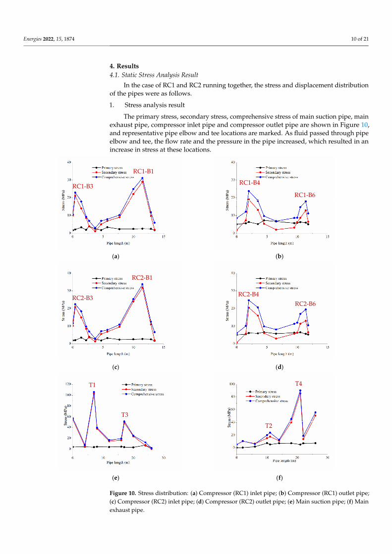
The primary stress, secondary stress, comprehensive stress of main suction pipe, mainexhaust pipe, compressor inlet pipe and compressor outlet pipe are shown in Figure 10,and representative pipe elbow and tee locations are marked. As fluid passed through pipeelbow and tee, the flow rate and the pressure in the pipe increased, which resulted in anincrease in stress at these locations.
Energies 2022, 15, x FOR PEER REVIEW 11 of 22
(a) (b)
(c) (d)
(e) (f)
Figure 10. Stress distribution: (a) Compressor (RC1) inlet pipe; (b) Compressor (RC1) outlet pipe; (c) Compressor (RC2) inlet pipe; (d) Compressor (RC2) outlet pipe; (e) Main suction pipe; (f) Main exhaust pipe.
The following conclusions can be drawn from Figure 10: a. The stress distribution of the same type of pipe is basically the same, and the larger
stress is produced at the tee or the elbow. b. The comprehensive stress of each pipe is the largest, the secondary stress is slightly
less than the comprehensive stress, and the primary stress is the smallest. It shows that the temperature difference (Secondary stress) had the greatest influence on the pipe stress for the low-temperature pipeline in the LNG vaporizing station.
RC1-B1
RC1-B3 RC1-B4
RC1-B6
RC2-B1
RC2-B3 RC2-B4 RC2-B6
T1
T3
T2
T4
Figure 10. Stress distribution: (a) Compressor (RC1) inlet pipe; (b) Compressor (RC1) outlet pipe;(c) Compressor (RC2) inlet pipe; (d) Compressor (RC2) outlet pipe; (e) Main suction pipe; (f) Mainexhaust pipe.

Energies 2022, 15, 1874 11 of 21
The following conclusions can be drawn from Figure 10:
a. The stress distribution of the same type of pipe is basically the same, and the largerstress is produced at the tee or the elbow.
b. The comprehensive stress of each pipe is the largest, the secondary stress is slightlyless than the comprehensive stress, and the primary stress is the smallest. It showsthat the temperature difference (Secondary stress) had the greatest influence on thepipe stress for the low-temperature pipeline in the LNG vaporizing station.
c. The stress of compressor inlet pipe is slightly greater than the compressor outlet pipe,the stress of main suction pipe is slightly larger than the main exhaust pipe (Thetemperature of BOG in the compressor inlet pipe and main suction pipe is lower thanthe compressor inlet pipe and main exhaust pipe, but the pressure of compressoroutlet pipe and main exhaust pipe is larger), indicating that the impact of temperaturedifference on the stress is greater than the impact of pressure.
2. Displacement analysis
In the BOG compressor piping system, the pipes have axial, horizontal and longitudi-nal displacements. Axial displacement and longitudinal displacement are mainly causedby the expansion and contraction of the pipe, and the horizontal displacement is mainlycaused by gravity. The displacement of each pipe can be seen in Figure 11.
Energies 2022, 15, x FOR PEER REVIEW 12 of 22
c. The stress of compressor inlet pipe is slightly greater than the compressor outlet pipe, the stress of main suction pipe is slightly larger than the main exhaust pipe (The tem-perature of BOG in the compressor inlet pipe and main suction pipe is lower than the compressor inlet pipe and main exhaust pipe, but the pressure of compressor outlet pipe and main exhaust pipe is larger), indicating that the impact of temperature dif-ference on the stress is greater than the impact of pressure.
2. Displacement analysis In the BOG compressor piping system, the pipes have axial, horizontal and longitu-
dinal displacements. Axial displacement and longitudinal displacement are mainly caused by the expansion and contraction of the pipe, and the horizontal displacement is mainly caused by gravity. The displacement of each pipe can be seen in Figure 11.
(a) (b)
(c) (d)
(e) (f)
RC1-B1
RC1-B3
RC1-B4
RC1-B6
RC2-B3
RC2-B1
RC2-B4 RC2-B6
T1 T3
T2 T4
Figure 11. Displacement distribution: (a) Compressor (RC1) inlet pipe; (b) Compressor (RC1) outletpipe; (c) Compressor (RC2) inlet pipe; (d) Compressor (RC2) outlet pipe; (e) Main suction pipe;(f) Main exhaust pipe.

Energies 2022, 15, 1874 12 of 21
The following conclusions can be drawn from Figure 11:
a. The horizontal displacement of the pipe was restricted by the bracket and support, sothe horizontal displacement of the pipe was the smallest.
b. Compressor inlet pipe and main suction pipe experienced larger negative axial dis-placements and longitudinal displacements, and the displacement was recorded to beas high as 70 mm because the low temperature of BOG in the pipe, which caused thecold contraction of the pipe.
4.2. Harmonic Analysis Result
A harmonic analysis of the pipe was performed using the dynamic analysis modulein CAESAR II software, which loads the unbalanced exciting force on the piping system.The compressor speed in RPM is 480 r/min, characteristic of a single cylinder single-actionequipment, and the sound velocity is 374 m/s.
1. RC1 runs separately
The calculation results of unbalanced exciting force caused by RC1 compressor inpiping system can be seen in Table 2, while the stress distribution of pipes under staticaction and pressure pulsation action are shown in Figure 12.
Energies 2022, 15, x FOR PEER REVIEW 13 of 22
Figure 11. Displacement distribution: (a) Compressor (RC1) inlet pipe; (b) Compressor (RC1) outlet pipe; (c) Compressor (RC2) inlet pipe; (d) Compressor (RC2) outlet pipe; (e) Main suction pipe; (f) Main exhaust pipe.
The following conclusions can be drawn from Figure 11: a. The horizontal displacement of the pipe was restricted by the bracket and support,
so the horizontal displacement of the pipe was the smallest. b. Compressor inlet pipe and main suction pipe experienced larger negative axial dis-
placements and longitudinal displacements, and the displacement was recorded to be as high as 70 mm because the low temperature of BOG in the pipe, which caused the cold contraction of the pipe.
4.2. Harmonic Analysis Result A harmonic analysis of the pipe was performed using the dynamic analysis module
in CAESAR II software, which loads the unbalanced exciting force on the piping system. The compressor speed in RPM is 480 r/min, characteristic of a single cylinder single-action equipment, and the sound velocity is 374 m/s. 1. RC1 runs separately
The calculation results of unbalanced exciting force caused by RC1 compressor in piping system can be seen in Table 2, while the stress distribution of pipes under static action and pressure pulsation action are shown in Figure 12.
(a) (b)
(c) (d)
Figure 12. Stress distribution of pipes under static action and pressure pulsation action: (a) Com-pressor (RC1) inlet pipe; (b) Compressor (RC1) outlet pipe; (c) Main suction pipe; (d) Main exhaust pipe.
Figure 12. Stress distribution of pipes under static action and pressure pulsation action: (a) Compres-sor (RC1) inlet pipe; (b) Compressor (RC1) outlet pipe; (c) Main suction pipe; (d) Main exhaust pipe.

Energies 2022, 15, 1874 13 of 21
Table 2. Calculation results of unbalanced exciting force caused by RC1 compressor.
Pipe Type LocationPressurePulsation
(Pa)
UnbalancedExcitingForce (N)
DirectionPhaseAngle
(Degree)
Compressorinlet pipe
RC1-B1 67,394.59 −3207.53 X 0RC1-B2 117,453.19 −2046.08 Z 3.21RC1-B3 402,706.47 19,166.12 Y 15.42
Compressoroutlet pipe
RC1-B4 46,248.18 2201.10 X 0RC1-B5 80,599.89 −1404.08 Z 2.21RC1-B6 247,275.66 11,768.66 Y 10.89
Main suction pipe T1 415,325.64 −19,766.71 Z 16.04Main exhaust pipe T2 250,621.06 −11,927.87 Z 11.73
2. RC1 and RC2 run together
The calculation results of unbalanced exciting force caused by RC2 compressor can beseen in Table 3, and the summary of maximum stress and location can be seen in Table 4.
Table 3. Calculation results of unbalanced exciting force caused by RC2 compressor.
Pipe Type LocationPressurePulsation
(Pa)
UnbalancedExcitingForce (N)
DirectionPhaseAngle
(Degree)
Compressorinlet pipe
RC1-B1 67,391.59 −3207.53 X 0RC1-B2 117,453.19 −2046.07 Z 3.21RC1-B3 402,706.47 19,166.12 Y 15.42
Compressoroutlet pipe
RC1-B4 46,248.18 2201.10 X 0RC1-B5 80,599.89 −1404.08 Z 2.21RC1-B6 247,275.69 11,768.66 Y 10.89
Main suction pipe T3 415,325.64 −19,766.71 Z 16.04Main exhaust pipe T4 254,731.38 −12,123.50 Z 11.73
Table 4. Summary of maximum stress and location.
Pipe Type Maximum Stress(MPa) Location Allowable Stress
(MPa)
RC1 compressor inlet pipe 31.76 RC1-B1
205.5
RC1 compressor outlet pipe 31.85 RC1-B4RC2 compressor inlet pipe 34.14 RC2-B1RC2 compressor outlet pipe 44.91 RC2-B4
Main suction pipe 105.99 T1Main exhaust pipe 108.50 T4
It can be seen from Figure 12 that the unbalanced exciting force has great influence onthe stress of the compressor outlet pipe and the main exhaust pipe, and has little influenceon the stress of the compressor inlet pipe and the main suction pipe. Moreover, althoughthe unbalanced exciting forces are produced at the elbows and the tees, the stresses of theelbows and the tees are greatly influenced, and it has a certain impact on the straight pipes.
It can be seen from Table 4 that in the case of double-compressor operation, themaximum stress of the RC1 compressor outlet pipe and main exhaust pipe would be lowerthan those of the case of RC1 single compressor operation. However, this has little effect onthe stress of the RC1 compressor inlet pipe and the main suction pipe.
4.3. Modal Analysis Result
The speed of the compressor is 480 r/min and the number of cylinders is 1, so theexcitation frequency is 8 Hz. Therefore, the resonance region of the piping system is

Energies 2022, 15, 1874 14 of 21
6.4~9.6 Hz. Because the natural frequency of the pipe is positively correlated with theorder, the first-order natural frequency of the pipe should be of no less than 9.6 Hz if theresonance region is avoided. The modal analysis module of CAESAR II software was usedto perform a modal analysis, for which the analysis parameters are shown in Table 5, andthe results are shown in Figure 13.
Table 5. Parameters of modal analysis.
Parameter Content
Cut-off frequency 200 HZMass model Lumped mass model
Estimated value of the effective number of the eigenvalues 8Jacobi scanning tolerance 10−12
Decomposition singular tolerance 1010
Frequency array space 100
Energies 2022, 15, x FOR PEER REVIEW 15 of 22
4.3. Modal Analysis Result The speed of the compressor is 480 r/min and the number of cylinders is 1, so the
excitation frequency is 8 Hz. Therefore, the resonance region of the piping system is 6.4~9.6 Hz. Because the natural frequency of the pipe is positively correlated with the or-der, the first-order natural frequency of the pipe should be of no less than 9.6 Hz if the resonance region is avoided. The modal analysis module of CAESAR II software was used to perform a modal analysis, for which the analysis parameters are shown in Table 5, and the results are shown in Figure 13.
Table 5. Parameters of modal analysis.
Parameter Content Cut-off frequency 200 HZ
Mass model Lumped mass model Estimated value of the effective number of the eigenvalues 8
Jacobi scanning tolerance 10−12 Decomposition singular tolerance 1010
Frequency array space 100
Figure 13. Natural frequency of compressor inlet pipe and outlet pipe.
It can be seen from Figure 13 that the natural frequency of the compressor inlet pipe is higher than that of the outlet pipe. The first-order natural frequency of the compressor inlet pipe is 16.81 Hz, while the first order natural frequency of the compressor outlet pipe is 11.53 Hz, both of which are larger than 9.6 Hz, meeting the requirement of modal cali-bration. Because the lowest natural frequency of the BOG compressor piping system is 11.53 Hz, the condition that the pipe does not have structural resonance is that the com-pressor speed is less than 541 r/min.
5. Discussion In this paper, several factors influencing the stress of the pipe are analyzed: pipe sup-
port spacing, pressure and elbow angle, and the measures of stress reduction are put for-ward.
Figure 13. Natural frequency of compressor inlet pipe and outlet pipe.
It can be seen from Figure 13 that the natural frequency of the compressor inlet pipeis higher than that of the outlet pipe. The first-order natural frequency of the compressorinlet pipe is 16.81 Hz, while the first order natural frequency of the compressor outletpipe is 11.53 Hz, both of which are larger than 9.6 Hz, meeting the requirement of modalcalibration. Because the lowest natural frequency of the BOG compressor piping systemis 11.53 Hz, the condition that the pipe does not have structural resonance is that thecompressor speed is less than 541 r/min.
5. Discussion
In this paper, several factors influencing the stress of the pipe are analyzed: pipesupport spacing, pressure and elbow angle, and the measures of stress reduction areput forward.
5.1. Influence of Pipe Support Spacing
In piping design, the setting of the support has a great influence on the stress of thepipe. This paper used the RC1 compressor outlet pipe as an example, assumed the distancebetween the elbow and the support 1 to be x mm, and the distance between the support 1and the support 2 to be y mm, as shown in Figure 14. Pipe stress under different supportspacing can be seen in Table 6.

Energies 2022, 15, 1874 15 of 21
Energies 2022, 15, x FOR PEER REVIEW 16 of 22
5.1. Influence of Pipe Support Spacing In piping design, the setting of the support has a great influence on the stress of the
pipe. This paper used the RC1 compressor outlet pipe as an example, assumed the dis-tance between the elbow and the support 1 to be x mm, and the distance between the support 1 and the support 2 to be y mm, as shown in Figure 14. Pipe stress under different support spacing can be seen in Table 6.
Table 6. Pipe stress under different support spacing.
Variable Spacing (mm) Stress (MPa)
x
400 39.76 600 37.6 800 36.04
1000 38.13 1200 40.52
y
1000 37.53 1500 37.75 2000 38.13 2500 38.24 3000 39.49
Figure 14. Layout of the pipe support of the compressor outlet pipe.
As shown in Table 6, with the increase in x (the distance between the elbow and the support 1), the pipe stress tends to decrease firstly and then increase. This is because the support limits the deformation of the elbow so that it cannot reduce the stress through its own flexible deformation when the distance is small. When the spacing increases, the el-bow can offset part of the stress through its own flexible deformation. When the spacing continues to increase, the stress of pipe increases as the suspension section of the pipe is too long.
For this paper, the pipe stress is the smallest when x is 800 mm. On the other hand, the pipe stress increases with the increase in y (the distance between the support 1 and the support 2), but the increase is not significant.
Figure 14. Layout of the pipe support of the compressor outlet pipe.
Table 6. Pipe stress under different support spacing.
Variable Spacing (mm) Stress (MPa)
x
400 39.76600 37.6800 36.04
1000 38.131200 40.52
y
1000 37.531500 37.752000 38.132500 38.243000 39.49
As shown in Table 6, with the increase in x (the distance between the elbow and thesupport 1), the pipe stress tends to decrease firstly and then increase. This is because thesupport limits the deformation of the elbow so that it cannot reduce the stress throughits own flexible deformation when the distance is small. When the spacing increases, theelbow can offset part of the stress through its own flexible deformation. When the spacingcontinues to increase, the stress of pipe increases as the suspension section of the pipe istoo long.
For this paper, the pipe stress is the smallest when x is 800 mm. On the other hand,the pipe stress increases with the increase in y (the distance between the support 1 and thesupport 2), but the increase is not significant.
5.2. Influence of Pressure
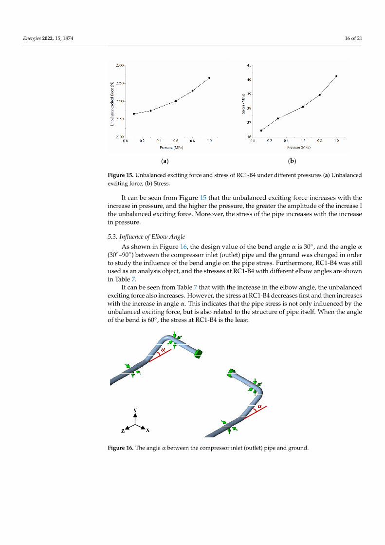
The operation pressure of the compressor outlet pipe is 0.6 MPa, and the designpressure of the pipe is 1 MPa. The pressure of pipeline in actual operation is lower than thedesign pressure, and the pressure is regulated by frequency-conversion control. This paperused the RC1 compressor outlet pipe as an example, nd the stress of a pipe with a pressureof 0.1–1.0 MPa was discussed. Because the maximum stress is produced at RC1-B4, it wasused as the research object. The unbalanced exciting force and stress of RC1-B4 underdifferent pressures are shown in Figure 15.
Energies 2022, 15, 1874 16 of 21
Energies 2022, 15, x FOR PEER REVIEW 17 of 22
5.2. Influence of Pressure The operation pressure of the compressor outlet pipe is 0.6 MPa, and the design pres-
sure of the pipe is 1 MPa. The pressure of pipeline in actual operation is lower than the design pressure, and the pressure is regulated by frequency-conversion control. This pa-per used the RC1 compressor outlet pipe as an example, nd the stress of a pipe with a pressure of 0.1–1.0 MPa was discussed. Because the maximum stress is produced at RC1-B4, it was used as the research object. The unbalanced exciting force and stress of RC1-B4 under different pressures are shown in Figure 15.
(a) (b)
Figure 15. Unbalanced exciting force and stress of RC1-B4 under different pressures (a) Unbalanced exciting force; (b) Stress.
It can be seen from Figure 15 that the unbalanced exciting force increases with the increase in pressure, and the higher the pressure, the greater the amplitude of the increase I the unbalanced exciting force. Moreover, the stress of the pipe increases with the increase in pressure.
5.3. Influence of Elbow Angle As shown in Figure 16, the design value of the bend angle α is 30°, and the angle α
(30°–90°) between the compressor inlet (outlet) pipe and the ground was changed in order to study the influence of the bend angle on the pipe stress. Furthermore, RC1-B4 was still used as an analysis object, and the stresses at RC1-B4 with different elbow angles are shown in Table 7.
Table 7. Pipe stress under different support spacing.
Elbow Angle (Degree) Pressure Pulsation
(Pa) at RC1-B5 Unbalanced Exciting Force at RC1-B5 (N) Stress of RC1-B4 (MPa)
30 80,599.89 −1404.08 38.13 35 80,599.89 −1631.31 39.49 40 80,599.89 −1855.44 39.16 45 80,599.89 −2076.04 40.51 50 80,599.89 −2292.68 42.73 55 80,599.89 −2504.96 39.04 60 80,599.89 −2712.47 34.92 65 80,599.89 −2914.82 39.71 70 80,599.89 −3111.62 42.43 75 80,599.89 −3302.49 45.07 80 80,599.89 −3487.08 47.91 85 80,599.89 −3665.04 48.30 90 80,599.89 −3836.01 49.46
Figure 15. Unbalanced exciting force and stress of RC1-B4 under different pressures (a) Unbalancedexciting force; (b) Stress.
It can be seen from Figure 15 that the unbalanced exciting force increases with theincrease in pressure, and the higher the pressure, the greater the amplitude of the increase Ithe unbalanced exciting force. Moreover, the stress of the pipe increases with the increasein pressure.
5.3. Influence of Elbow Angle
As shown in Figure 16, the design value of the bend angle α is 30◦, and the angle α
(30◦–90◦) between the compressor inlet (outlet) pipe and the ground was changed in orderto study the influence of the bend angle on the pipe stress. Furthermore, RC1-B4 was stillused as an analysis object, and the stresses at RC1-B4 with different elbow angles are shownin Table 7.
It can be seen from Table 7 that with the increase in the elbow angle, the unbalancedexciting force also increases. However, the stress at RC1-B4 decreases first and then increaseswith the increase in angle α. This indicates that the pipe stress is not only influenced by theunbalanced exciting force, but is also related to the structure of pipe itself. When the angleof the bend is 60◦, the stress at RC1-B4 is the least.
Energies 2022, 15, x FOR PEER REVIEW 18 of 22
Figure 16. The angle α between the compressor inlet (outlet) pipe and ground.
It can be seen from Table 7 that with the increase in the elbow angle, the unbalanced exciting force also increases. However, the stress at RC1-B4 decreases first and then in-creases with the increase in angle α. This indicates that the pipe stress is not only influ-enced by the unbalanced exciting force, but is also related to the structure of pipe itself. When the angle of the bend is 60°, the stress at RC1-B4 is the least.
5.4. Stress Reduction Measures According to the analysis of influence of elbow angle on pipe stress, the stress can be
reduced by optimizing the elbow angle in the design stage. However, for pipes that are already running, pipe stress can be reduced by adding constraints and setting expansion joints.
In order to show the effect of stress reduction measures more intuitively, in 2016, Hongfang Lu first proposed the concept of the stress-reduction factor, which can be de-fined as follows: In pipeline engineering, the ratio of the change of stress caused by the stress reduction measures and the stress before the retrofit. Its expression is [43]:
2 1
1 1
-= =RKΔσ σ σ
σ σ, (17)
where KR = stress reduction factor; σ1 = the stress before the retrofit; σ2 = the stress after the retrofit; Δσ = the difference between the stress before the retrofit and the stress after the retrofit.
When KR is in the range of (−1, 0], the greater the value is, the worse the stress reduc-tion effect is, when KR is in the range of [0, +∞), the stress reduction measure is invalid. 1. Add constraint
In this paper, the T1 in the compressor piping system was taken as an example, and a constraint was added near T1. The constraint positions are shown in Figure 17. The stress reduction effects are shown in Table 8.
Table 8. Pipe stress after adding constraints.
Position of Constraint
Constraint Type
Constraint Expression
Stress before Adding Con-straint (MPa)
Stress after Adding Con-straint (MPa)
Stress Reduc-tion Factor KR
R1
Unidirectional constraint
+Y
105.68
126.21 0.19 R2 +Y 103.96 −0.02 R3 +Y 91.63 −0.13 R4 +Y 96.75 −0.08 R5 +Y 102.80 −0.03
Figure 16. The angle α between the compressor inlet (outlet) pipe and ground.

Energies 2022, 15, 1874 17 of 21
Table 7. Pipe stress under different support spacing.
Elbow Angle(Degree)
Pressure Pulsation(Pa) at RC1-B5
Unbalanced ExcitingForce at RC1-B5 (N)
Stress of RC1-B4(MPa)
30 80,599.89 −1404.08 38.1335 80,599.89 −1631.31 39.4940 80,599.89 −1855.44 39.1645 80,599.89 −2076.04 40.5150 80,599.89 −2292.68 42.7355 80,599.89 −2504.96 39.0460 80,599.89 −2712.47 34.9265 80,599.89 −2914.82 39.7170 80,599.89 −3111.62 42.4375 80,599.89 −3302.49 45.0780 80,599.89 −3487.08 47.9185 80,599.89 −3665.04 48.3090 80,599.89 −3836.01 49.46
5.4. Stress Reduction Measures
According to the analysis of influence of elbow angle on pipe stress, the stress canbe reduced by optimizing the elbow angle in the design stage. However, for pipes thatare already running, pipe stress can be reduced by adding constraints and setting expan-sion joints.
In order to show the effect of stress reduction measures more intuitively, in 2016,Hongfang Lu first proposed the concept of the stress-reduction factor, which can be definedas follows: In pipeline engineering, the ratio of the change of stress caused by the stressreduction measures and the stress before the retrofit. Its expression is [43]:
KR =σ2 − σ1
σ1=
∆σ
σ1, (17)
where KR = stress reduction factor; σ1 = the stress before the retrofit; σ2 = the stress afterthe retrofit; ∆σ = the difference between the stress before the retrofit and the stress afterthe retrofit.
When KR is in the range of (−1, 0], the greater the value is, the worse the stressreduction effect is, when KR is in the range of [0, +∞), the stress reduction measure is invalid.
1. Add constraint
In this paper, the T1 in the compressor piping system was taken as an example, and aconstraint was added near T1. The constraint positions are shown in Figure 17. The stressreduction effects are shown in Table 8.
Energies 2022, 15, x FOR PEER REVIEW 19 of 22
R1
Three-direc-tion constraint
+Y, +Z, −Z
105.68
133.48 0.26 R2 +Y, +Z, −Z 101.47 −0.04 R3 +Y, +Z, −Z 86.32 −0.18 R4 +Y, +Z, −Z 97.05 −0.08 R5 +Y, +Z, −Z 100.52 −0.05
Figure 17. Constraint positions near T1.
It can be seen from Table 8 that regardless of what kind of restraint is added at R1, the stress cannot be reduced, but the stress will be increased. The stress can be reduced by adding any constraint at R2, R3, R4 and R5. Among them, the stress-reduction effect of adding three-direction constraint is better than that of a unidirectional constraint, and adding a constraint at R3 is the best way to reduce stress. Therefore, a three-direction con-strained steel bracket can be added at R3 to reduce the stress in the actual project. 2. Set expansion joint
In the flexible design of compressor piping, it is not suitable to use a natural compen-sator with elbow. Generally, expansion joints are used to reduce pipeline stress and in-crease pipeline flexibility. Bellows’ expansion joint mainly depends on the deformation of bellows that absorbs displacement, and can set a larger diameter and bear higher pressure. Therefore, the bellows’ expansion joint should be considered in the compressor nozzle. Considering that the stiffness of bellows is small, the pressure that it can bear is limited. Therefore, it is necessary to set up support (Fixed point) at the two ends of expansion joint to withstand the pressure and thrust, as shown in Figure 18.
Figure 18. Schematic diagram of the expansion joint model.
The material used to construct the expansion joint was 06Cr19Ni10, the length L was 500 mm, the axial stiffness A was 200 N/mm, 300 N/mm, 400 N/mm, 500 N/mm, 600 N/mm, and the horizontal stiffness T was:
Figure 17. Constraint positions near T1.

Energies 2022, 15, 1874 18 of 21
Table 8. Pipe stress after adding constraints.
Position ofConstraint
ConstraintType
ConstraintExpression
Stress beforeAdding
Constraint(MPa)
Stress afterAdding
Constraint(MPa)
StressReductionFactor KR
R1
Unidirectionalconstraint
+Y
105.68
126.21 0.19R2 +Y 103.96 −0.02R3 +Y 91.63 −0.13R4 +Y 96.75 −0.08R5 +Y 102.80 −0.03
R1Three-
directionconstraint
+Y, +Z, −Z
105.68
133.48 0.26R2 +Y, +Z, −Z 101.47 −0.04R3 +Y, +Z, −Z 86.32 −0.18R4 +Y, +Z, −Z 97.05 −0.08R5 +Y, +Z, −Z 100.52 −0.05
It can be seen from Table 8 that regardless of what kind of restraint is added at R1,the stress cannot be reduced, but the stress will be increased. The stress can be reducedby adding any constraint at R2, R3, R4 and R5. Among them, the stress-reduction effectof adding three-direction constraint is better than that of a unidirectional constraint, andadding a constraint at R3 is the best way to reduce stress. Therefore, a three-directionconstrained steel bracket can be added at R3 to reduce the stress in the actual project.
2. Set expansion joint
In the flexible design of compressor piping, it is not suitable to use a natural com-pensator with elbow. Generally, expansion joints are used to reduce pipeline stress andincrease pipeline flexibility. Bellows’ expansion joint mainly depends on the deformation ofbellows that absorbs displacement, and can set a larger diameter and bear higher pressure.Therefore, the bellows’ expansion joint should be considered in the compressor nozzle.Considering that the stiffness of bellows is small, the pressure that it can bear is limited.Therefore, it is necessary to set up support (Fixed point) at the two ends of expansion jointto withstand the pressure and thrust, as shown in Figure 18.
Energies 2022, 15, x FOR PEER REVIEW 19 of 22
R1
Three-direc-tion constraint
+Y, +Z, −Z
105.68
133.48 0.26 R2 +Y, +Z, −Z 101.47 −0.04 R3 +Y, +Z, −Z 86.32 −0.18 R4 +Y, +Z, −Z 97.05 −0.08 R5 +Y, +Z, −Z 100.52 −0.05
Figure 17. Constraint positions near T1.
It can be seen from Table 8 that regardless of what kind of restraint is added at R1, the stress cannot be reduced, but the stress will be increased. The stress can be reduced by adding any constraint at R2, R3, R4 and R5. Among them, the stress-reduction effect of adding three-direction constraint is better than that of a unidirectional constraint, and adding a constraint at R3 is the best way to reduce stress. Therefore, a three-direction con-strained steel bracket can be added at R3 to reduce the stress in the actual project. 2. Set expansion joint
In the flexible design of compressor piping, it is not suitable to use a natural compen-sator with elbow. Generally, expansion joints are used to reduce pipeline stress and in-crease pipeline flexibility. Bellows’ expansion joint mainly depends on the deformation of bellows that absorbs displacement, and can set a larger diameter and bear higher pressure. Therefore, the bellows’ expansion joint should be considered in the compressor nozzle. Considering that the stiffness of bellows is small, the pressure that it can bear is limited. Therefore, it is necessary to set up support (Fixed point) at the two ends of expansion joint to withstand the pressure and thrust, as shown in Figure 18.
Figure 18. Schematic diagram of the expansion joint model.
The material used to construct the expansion joint was 06Cr19Ni10, the length L was 500 mm, the axial stiffness A was 200 N/mm, 300 N/mm, 400 N/mm, 500 N/mm, 600 N/mm, and the horizontal stiffness T was:
Figure 18. Schematic diagram of the expansion joint model.
The material used to construct the expansion joint was 06Cr19Ni10, the length Lwas 500 mm, the axial stiffness A was 200 N/mm, 300 N/mm, 400 N/mm, 500 N/mm,600 N/mm, and the horizontal stiffness T was:
T =23× (
DL)
2× A, (18)
where D = diameter of bellows, mm; L = length of bellows, mm; A = axial stiffness, N/mm.

Energies 2022, 15, 1874 19 of 21
The stresses of RC1-B4 after adding different kinds of expansion joints are shownin Table 9. It can be seen from Table 9 that the stiffness of the expansion joint greatlyinfluences the compensation effect. The smaller the stiffness of expansion joint, the betterthe compensation effect. However, the smaller the stiffness, the more difficult the designof the expansion joint will be. Hence, the performance and cost of the expansion jointshould be considered synthetically. Therefore, the expansion joint with an axial stiffness of300 N/mm is more suitable. In addition to reducing the pipe stress, the expansion joint canalso reduce the displacement of the pipe. Taking the axial displacement of the inlet pipeand outlet pipe of the RC1 compressor as an example, the displacement comparison beforeand after adding the expansion joint is shown in Figure 19. It can be seen from Figure 19that after the expansion joint is added, the displacements of the compressor inlet and outletpipes become markedly reduced, and the displacement can be reduced by up to 14 mm.
Table 9. The stresses of RC1-B4 after adding different kinds of expansion joints.
Axial Stiffness(N/mm)
Stress beforeAdding Expansion
Joint (MPa)
Stress after AddingExpansion Joint
(MPa)
Stress ReductionFactor KR
200
38.13
25.93 −0.32300 30.89 −0.19400 35.08 −0.08500 36.60 −0.04600 36.61 −0.04
Energies 2022, 15, x FOR PEER REVIEW 20 of 22
22 ( )3
DT AL
= × × , (18)
where D = diameter of bellows, mm; L = length of bellows, mm; A = axial stiffness, N/mm. The stresses of RC1-B4 after adding different kinds of expansion joints are shown in
Table 9. It can be seen from Table 9 that the stiffness of the expansion joint greatly influ-ences the compensation effect. The smaller the stiffness of expansion joint, the better the compensation effect. However, the smaller the stiffness, the more difficult the design of the expansion joint will be. Hence, the performance and cost of the expansion joint should be considered synthetically. Therefore, the expansion joint with an axial stiffness of 300 N/mm is more suitable. In addition to reducing the pipe stress, the expansion joint can also reduce the displacement of the pipe. Taking the axial displacement of the inlet pipe and outlet pipe of the RC1 compressor as an example, the displacement comparison before and after adding the expansion joint is shown in Figure 19. It can be seen from Figure 19 that after the expansion joint is added, the displacements of the compressor inlet and out-let pipes become markedly reduced, and the displacement can be reduced by up to 14 mm.
(a) (b)
Figure 19. Displacement comparison before and after adding the expansion joint (a) RC1 compres-sor inlet pipe; (b) RC1 compressor outlet pipe.
Table 9. The stresses of RC1-B4 after adding different kinds of expansion joints.
Axial Stiffness (N/mm)
Stress before Adding Expansion Joint (MPa)
Stress after Adding Ex-pansion Joint (MPa)
Stress Reduc-tion Factor KR
200
38.13
25.93 −0.32 300 30.89 −0.19 400 35.08 −0.08 500 36.60 −0.04 600 36.61 −0.04
6. Conclusions In this paper, the pressure pulsation and the unbalanced exciting force in the recip-
rocating pump piping system were calculated by the separation variable method. Based on the beam model, the stress, harmonic and modal analysis of the BOG compressor pip-ing system in the LNG vaporizing station were carried out using CAESAR II software. In addition, the influence factors of stress and the measures of stress reduction were dis-cussed in this paper. The following conclusions were obtained: 1. For a BOG compressor piping system which belongs to low-temperature piping sys-
tem, the secondary stress is much larger than the primary stress, indicating that the temperature difference plays a leading role in the stress of low-temperature pipes.
Figure 19. Displacement comparison before and after adding the expansion joint (a) RC1 compressorinlet pipe; (b) RC1 compressor outlet pipe.
6. Conclusions
In this paper, the pressure pulsation and the unbalanced exciting force in the recipro-cating pump piping system were calculated by the separation variable method. Based onthe beam model, the stress, harmonic and modal analysis of the BOG compressor pipingsystem in the LNG vaporizing station were carried out using CAESAR II software. Inaddition, the influence factors of stress and the measures of stress reduction were discussedin this paper. The following conclusions were obtained:
1. For a BOG compressor piping system which belongs to low-temperature pipingsystem, the secondary stress is much larger than the primary stress, indicating thatthe temperature difference plays a leading role in the stress of low-temperature pipes.
2. The unbalanced exciting force has great influence on the stress of the compressoroutlet pipe and the main exhaust pipe, and has little influence on the stress of thecompressor inlet pipe and the main suction pipe.

Energies 2022, 15, 1874 20 of 21
3. Although unbalanced exciting forces are produced at the elbows and the tees, thestresses of the elbows and the tees are greatly influenced, which also has a certainimpact on the straight pipes.
4. The pipe stress is not only influenced by the unbalanced exciting force, but by thestructure of pipe itself.
5. Adding constraints or expansion joints can effectively reduce the pipe stress.
Author Contributions: Conceptualization, B.W. and K.H.; methodology, K.H., Z.Z. (Zhenwu Zhang)and L.F.; software, Z.Z. (Zhenwu Zhang), Y.Z. and H.G.; investigation, B.W. and K.H.; resources,B.W., Y.Z. and H.G.; data curation, Z.Z. (Zhang Zhi) and H.G.; writing—original draft preparation,B.W. and Y.Z.; writing—review and editing, Z.Z. (Zhi Zhang) and L.F.; visualization, K.H. and Z.Z.(Zhi Zhang); supervision, B.W.; project administration, B.W. All authors have read and agreed to thepublished version of the manuscript.
Funding: This research received no external funding.
Institutional Review Board Statement: Not applicable.
Informed Consent Statement: Not applicable.
Data Availability Statement: Not applicable.
Conflicts of Interest: The authors declare no conflict of interest.
References1. Xu, Z.-D.; Shen, Y.-P.; Guo, Y.-Q. Semi-active control of structures incorporated with magnetorheological dampers using neural
networks. Smart Mater. Struct. 2003, 12, 80–87. [CrossRef]2. Xu, Z.-D.; Liao, Y.X.; Ge, T.; Xu, C. Experimental and Theoretical Study of Viscoelastic Dampers with Different Matrix Rubbers. J.
Eng. Mech. 2016, 142, 04016051. [CrossRef]3. Lu, H.; Xu, Z.-D.; Azimi, M.; Fu, L.; Wang, Y. An Effective Data-Driven Model for Predicting Energy Consumption of Long-
Distance Oil Pipelines. J. Pipeline Syst. Eng. Pract. 2022, 13, 04022005. [CrossRef]4. Lu, H.; Iseley, T.; Matthews, J.; Liao, W. Hybrid machine learning for pullback force forecasting during horizontal directional
drilling. Autom. Constr. 2021, 129, 103810. [CrossRef]5. Xu, Z.-D.; Jia, D.-H.; Zhang, X.-C. Performance tests and mathematical model considering magnetic saturation for magnetorheo-
logical damper. J. Intell. Mater. Syst. Struct. 2012, 23, 1331–1349. [CrossRef]6. GB/T 20801; Pressure Piping Code Industrial Piping Part 1: General. China Standardization Committee on Boilers and Pressure
Vessels: Beijing, China, 2006.7. Chilton, E.G.; Handley, L. Pulsations in gas compressor systems. Trans. ASME 1952, 45, 214–218.8. Sun, S.Y.; Ren, T.R.; Shi, Y.M.; Cui, T.S. Optimum disposition of assembled piping system for parallel operation of multiple
compressors. Int. J. Press. Vessel. Pip. 1996, 68, 145–151.9. Attenuation of Gas Pulsations Using A Perforated Tube. Available online: https://docs.lib.purdue.edu/icec/237 (accessed on
20 December 2021).10. Shin, Y.W.; Wiedermann, A.H. A Method for Suppression of Pressure Pulses in Fluid-Filled Piping—Part I: Theoretical Analysis.
J. Press. Vessel Technol. 1992, 114, 60–65. [CrossRef]11. Shin, Y.W.; Bielick, E.F.; Wiedermann, A.H.; Ockert, C.E. A Method for Suppression of Pressure Pulse in Fluid-Filled Piping—Part
II: Experimental Verification. J. Press. Vessel Technol. 1992, 114, 66–73. [CrossRef]12. Chen, L.L.; Xie, Z.N. A research for the optimization of the vibrating excitation in reciprocating compressor piping system. Chin.
J. Appl. Mech. 1995, 12, 102–105.13. Chen, L.L.; Wang, R.; Xu, J.X. A study on the dynamic optimum of the supported stiffness for piping structure in reciprocating
compressor systems. J. Xi’an Jiaotong Univ. 1996, 30, 95–100.14. Cheng, M.G. Vibration analysis and vibration reduction for inlet of water filling pump. Petro-Chem. Equip. Technol. 1995, 16,
51–52.15. Xing, K.L.; Ge, S.H.; Ding, C.S.; He, R. Theoretical analysis of a new serial pocket-type accumulator. Constr. Machin. Equip. 1997,
28, 24–26.16. Zhang, H.J. Vibration analysis and modification measures for piping of reciprocating pump. Chem. Eng. Design 2000, 10, 12–15.17. Xie, P.A.; Wang, Q. Study on attenuation of fluid-borne pulsation using accumulator. Noise Vib. Control 2000, 4, 2–5.18. Wang, Q.; Shen, R.Y.; Yao, B.Y.; Ding, W. Attenuation of vibration and pulsating pressure of pipeline using pipe attenuator.
Shipbuild. China 2003, 44, 39–45.19. Xue, W.F. The Study on Vibration and Vibration Control of the Pipeline of Reciprocating Compressor. Master’s Thesis, Fuzhou
University, Fujian, China, 2003.

Energies 2022, 15, 1874 21 of 21
20. Xiao, G.M. The Research on Vibration Control of the Pipeline of Piston Compressor. Master’s Thesis, Southwest JiaotongUniversity, Chengdu, China, 2006.
21. Yu, C.L.; Wei, Y.; Hu, X.M. Piping vibration analysis for the type of reciprocating compressor. China Offshore Platf. 2007, 22, 52–56.22. Chen, H.F. Study on Vibration Characteristics and Safety Evaluation of Reciprocating Compressor Pipeline. Master’s Thesis,
China University of Petroleum, Qingdao, China, 2009.23. Sui, K.; Wang, J. Calculation and analysis on residential pipeline pressure pulsation. Environ. Technol. 2013, z1, 203–206.24. Lu, H.; Huang, K.; Wu, S. Vibration and Stress Analyses of Positive Displacement Pump Pipeline Systems in Oil Transportation
Stations. J. Pipeline Syst. Eng. Pract. 2016, 7, 05015002. [CrossRef]25. Su, P.; Liu, Y.H.; Wang, Z.Y.; Wang, Y.B. Finite element numerical simulation on thermal stress distribution of LNG pipeline.
Contemp. Chem. Industry 2013, 42, 1198–1200.26. Liu, H.F.; Xu, H.Z. The LNG pipe stress calculation and analysis. Chem. Ind. Times 2013, 27, 21–22.27. Yu, G.P.; Zhao, G.M.; Zhang, Y.X. Stress analysis of low temperature pipeline in LNG tank area. Petro-Chem. Design 2015, 32,
22–25.28. Xu, Q.; Liu, C.; Wang, X.; Cao, Y.; Yu, H.; Li, W.; Guo, L. Machine learning classification of flow regimes in a long pipeline-riser
system with differential pressure signal. Chem. Eng. Sci. 2021, 233, 116402. [CrossRef]29. Xu, Q.; Liang, L.; She, Y.; Xie, X.; Guo, L. Numerical investigation on thermal hydraulic characteristics of steam jet condensation
in subcooled water flow in pipes. Int. J. Heat Mass Transf. 2022, 184, 122277. [CrossRef]30. Hwang, S.-Y.; Kim, M.-S.; Lee, J.-H. Thermal Stress Analysis of Process Piping System Installed on LNG Vessel Subject to Hull
Design Loads. J. Mar. Sci. Eng. 2020, 8, 926. [CrossRef]31. American Petroleum Institute. Reciprocating Compressors for Petroleum, Chemical, and Gas Industry Services; API 618; American
Petroleum Institute: Washington, DC, USA, 2007.32. Lu, H.; Wu, X.; Ni, H.; Azimi, M.; Yan, X.; Niu, Y. Stress analysis of urban gas pipeline repaired by inserted hose lining method.
Compos. Part B Eng. 2020, 183, 107657. [CrossRef]33. Xu, Z.-D.; Wang, D.-X.; Shi, C.-F. Model, tests and application design for viscoelastic dampers. J. Vib. Control 2011, 17, 1359–1370.
[CrossRef]34. Xu, Z.-D.; Yang, Y.; Miao, A.-N. Dynamic Analysis and Parameter Optimization of Pipelines with Multidimensional Vibration
Isolation and Mitigation Device. J. Pipeline Syst. Eng. Pract. 2021, 12, 04020058. [CrossRef]35. Xu, Z.-D.; Zhu, C.; Shao, L.-W. Damage Identification of Pipeline Based on Ultrasonic Guided Wave and Wavelet Denoising. J.
Pipeline Syst. Eng. Pract. 2021, 12, 04021051. [CrossRef]36. George, M. Pipe Stress Analysis Theory Guide; COADE Inc., China Technical Service and Training Center: Beijing, China, 1998.37. ASME. Process Piping; B31.3; ASME: New York, NY, USA, 2013.38. Song, K.K. Industrial Pipe Stress Analysis and Engineering Applications; Press of China Petrochemical: Beijing, China, 2011.39. Xu, Z.-D.; Gai, P.-P.; Zhao, H.-Y.; Huang, X.-H.; Lu, L.-Y. Experimental and theoretical study on a building structure controlled by
multi-dimensional earthquake isolation and mitigation devices. Nonlinear Dyn. 2017, 89, 723–740. [CrossRef]40. Lu, H.; Xu, Z.-D.; Iseley, T.; Matthews, J.C. Novel Data-Driven Framework for Predicting Residual Strength of Corroded Pipelines.
J. Pipeline Syst. Eng. Pract. 2021, 12, 04021045. [CrossRef]41. Lu, H.; Iseley, T.; Matthews, J.; Liao, W.; Azimi, M. An ensemble model based on relevance vector machine and multi-objective
salp swarm algorithm for predicting burst pressure of corroded pipelines. J. Pet. Sci. Eng. 2021, 203, 108585. [CrossRef]42. Xu, Z.-D.; Xu, F.-H.; Chen, X. Vibration suppression on a platform by using vibration isolation and mitigation devices. Nonlinear
Dyn. 2016, 83, 1341–1353. [CrossRef]43. Lu, H.F. Stress and Vibration Analysis of Reciprocating Pump Piping Systems. Master’s Thesis, Southwest Petroleum University,
Chengdu, China, 2016.
Copyright © 2022 FDOKUMEN