Unfired pressure vessels
60
BSI Standards Publication BS EN 13445-6:2014 Unfired pressure vessels Part 6: Requirements for the design and fabrication of pressure vessels and pressure parts constructed from spheroidal graphite cast iron
-
Upload
khangminh22 -
Category
Documents
-
view
1 -
download
0
Transcript of Unfired pressure vessels

BSI Standards Publication
BS EN 13445-6:2014
Unfired pressure vesselsPart 6: Requirements for the design andfabrication of pressure vessels and pressureparts constructed from spheroidal graphitecast iron

BS EN 13445-6:2014 BRITISH STANDARD
National foreword
This British Standard is the UK implementation of EN 13445-6:2014.It supersedes BS EN 13445-6:2009 which is withdrawn.
The UK participation in its preparation was entrusted to TechnicalCommittee PVE/1, Pressure Vessels.
A list of organizations represented on this committee can beobtained on request to its secretary.
This publication does not purport to include all the necessaryprovisions of a contract. Users are responsible for its correctapplication.
© The British Standards Institution 2014. Published by BSI StandardsLimited 2014
ISBN 978 0 580 86801 6
ICS 23.020.30
Compliance with a British Standard cannot confer immunity fromlegal obligations.
This British Standard was published under the authority of theStandards Policy and Strategy Committee on 30 September 2014.
Amendments issued since publication
Date Text affected
BS EN 13445-6:2014
EUROPEAN STANDARD
NORME EUROPÉENNE
EUROPÄISCHE NORM
EN 13445-6
September 2014
ICS 23.020.30 Supersedes EN 13445-6:2009
English Version
Unfired pressure vessels - Part 6: Requirements for the design and fabrication of pressure vessels and pressure parts
constructed from spheroidal graphite cast iron
Récipients sous pression non soumis à la flamme - Partie 6: Exigences pour la conception et la fabrication des récipientssous pression et des parties sous pression moulés en fonte
à graphite sphéroïdal
Unbefeuerte Druckbehälter - Teil 6: Anforderungen an die Konstruktion und Herstellung von Druckbehältern und Druckbehälterteilen aus Gusseisen mit Kugelgraphit
This European Standard was approved by CEN on 19 August 2014. CEN members are bound to comply with the CEN/CENELEC Internal Regulations which stipulate the conditions for giving this European Standard the status of a national standard without any alteration. Up-to-date lists and bibliographical references concerning such national standards may be obtained on application to the CEN-CENELEC Management Centre or to any CEN member. This European Standard exists in three official versions (English, French, German). A version in any other language made by translation under the responsibility of a CEN member into its own language and notified to the CEN-CENELEC Management Centre has the same status as the official versions. CEN members are the national standards bodies of Austria, Belgium, Bulgaria, Croatia, Cyprus, Czech Republic, Denmark, Estonia, Finland, Former Yugoslav Republic of Macedonia, France, Germany, Greece, Hungary, Iceland, Ireland, Italy, Latvia, Lithuania, Luxembourg, Malta, Netherlands, Norway, Poland, Portugal, Romania, Slovakia, Slovenia, Spain, Sweden, Switzerland, Turkey and United Kingdom.
EUROPEAN COMMITTEE FOR STANDARDIZATION C O M I T É E U R OP É E N D E N O R M A LI S A T I O N EUR O P Ä IS C HES KOM I TE E F ÜR NOR M UNG
CEN-CENELEC Management Centre: Avenue Marnix 17, B-1000 Brussels
© 2014 CEN All rights of exploitation in any form and by any means reserved worldwide for CEN national Members.
Ref. No. EN 13445-6:2014 E

BS EN 13445-6:2014EN 13445-6:2014 (E) Issue 1 (2014-09)
2
Contents Page
Foreword ..............................................................................................................................................................5
1 Scope ......................................................................................................................................................7
2 Normative references ............................................................................................................................7
3 Terms, definitions, units and symbols ................................................................................................8 3.1 Terms and definitions ...........................................................................................................................8 3.2 Units ........................................................................................................................................................9 3.3 Symbols ..................................................................................................................................................9 3.4 Inter-relation of thicknesses definitions ...........................................................................................11
4 Service conditions ...............................................................................................................................11 4.1 Cyclic loading .......................................................................................................................................11 4.2 Limitations on temperature and energy content ..............................................................................12
5 Requirements .......................................................................................................................................12 5.1 Materials ...............................................................................................................................................12 5.2 Design ...................................................................................................................................................14 5.2.1 Technical documentation ...................................................................................................................14 5.2.2 Design methods ...................................................................................................................................14 5.3 Founding ...............................................................................................................................................20 5.3.1 General ..................................................................................................................................................20 5.3.2 Welding .................................................................................................................................................20
6 Material testing .....................................................................................................................................20 6.1 General ..................................................................................................................................................20 6.2 Frequency and number of tests .........................................................................................................20 6.3 Chemical analysis ................................................................................................................................20 6.4 Graphite structure................................................................................................................................21 6.5 Inspection documents .........................................................................................................................21
7 Testing and final assessment .............................................................................................................21 7.1 Testing ..................................................................................................................................................21 7.1.1 General ..................................................................................................................................................21 7.1.2 Testing requirements for CQ = 0,8 .....................................................................................................21 7.1.3 Testing requirements for CQ = 0,9 .....................................................................................................21 7.1.4 Surface imperfections .........................................................................................................................22 7.1.5 Cracks, laps, cold shut and non-fused chaplets ..............................................................................23 7.1.6 Ultrasonic testing and/or sectioning .................................................................................................23 7.1.7 Magnetic particle testing (only for ferritic grades) ...........................................................................23 7.1.8 Penetrant testing ..................................................................................................................................23 7.1.9 Radiographic testing ...........................................................................................................................23 7.1.10 Surface roughness ..............................................................................................................................24 7.1.11 Minimum wall thickness ......................................................................................................................24 7.1.12 Wall thickness tolerances ...................................................................................................................24 7.1.13 Other dimensions ................................................................................................................................24 7.1.14 Qualification of testing personnel ......................................................................................................24 7.2 Final assessment .................................................................................................................................24 7.2.1 General ..................................................................................................................................................24 7.2.2 Hydraulic test pressure .......................................................................................................................24
8 Pressure vessels constructed of a combination of parts in different materials ...........................25
9 Marking and documentation ...............................................................................................................25 9.1 Marking of castings .............................................................................................................................25 9.2 Name plate for the complete pressure vessel ..................................................................................25 9.3 Documentation .....................................................................................................................................25

BS EN 13445-6:2014EN 13445-6:2014 (E)
Issue 1 (2014-09)
3
Annex A (normative) Technical data for the design calculations ............................................................... 26 A.1 Purpose................................................................................................................................................. 26 A.2 Technical data ...................................................................................................................................... 26 A.2.1 Ferritic spheroidal graphite cast iron according to EN 1563:1997 ................................................. 26 A.2.2 Austenitic spheroidal graphite cast iron according to EN 13835:2002 .......................................... 27
Annex B (informative) Ductility ...................................................................................................................... 28
Annex C (informative) Determination of the minimum local wall thickness and minimum required burst test pressure .............................................................................................................................. 29
Annex D (normative) Assessment of fatigue life .......................................................................................... 30 D.1 Purpose................................................................................................................................................. 30 D.2 Specific definitions .............................................................................................................................. 30 D.3 Specific symbols and abbreviations ................................................................................................. 30 D.4 Limitations ............................................................................................................................................ 31 D.5 General.................................................................................................................................................. 31 D.6 Simplified fatigue assessment ........................................................................................................... 31 D.6.1 Pseudo-elastic stress range ............................................................................................................... 31 D.6.2 Correction factors ................................................................................................................................ 32 D.6.3 Fatigue design curves ......................................................................................................................... 32 D.6.4 Allowable number of cycles ............................................................................................................... 38 D.6.5 Allowable stress range ............................................................................................................... 38 D.7 Detailed fatigue assessment .............................................................................................................. 38 D.7.1 Pseudo-elastic stress ranges ............................................................................................................. 38 D.7.2 Corrections to stress range ................................................................................................................ 39 D.7.3 Fatigue design curves ......................................................................................................................... 40 D.7.4 Allowable number of cycles ............................................................................................................... 41 D.7.5 Allowable stress range ........................................................................................................................ 42 D.8 Assessment rule for total fatigue damage ........................................................................................ 42 D.9 Repairs of surface imperfections ....................................................................................................... 42
Annex E (normative) Design by analysis for castings ................................................................................. 43 E.1 Introduction .......................................................................................................................................... 43 E.2 Special requirements to EN 13445-3:2014, Annex B ........................................................................ 43 E.2.1 Addition to B.8.2.3: Design checks for normal operating load cases ............................................ 43 E.2.2 Addition to B.8.2.4: Design checks for testing load cases ............................................................. 43 E.3 Additions to EN 13445-3:2014, Annex C ............................................................................................ 43 E.4 Requirements ....................................................................................................................................... 44
Annex F (informative) Recommandations for in-service validation and inspection ................................ 45 F.1 Purpose................................................................................................................................................. 45 F.2 Tests during operation ........................................................................................................................ 45 F.3 Measures to be taken when the calculated allowable fatigue lifetime has been reached ........... 46 F.3.1 General.................................................................................................................................................. 46 F.3.2 Testing of vessels and pressure parts at end of life without indicated damages ........................ 46 F.3.3 Hydraulic testing of vessels and vessel parts with indicated damages ........................................ 46
Annex G (normative) Specific design requirements .................................................................................... 47 G.1 Scope .................................................................................................................................................... 47 G.2 Design ................................................................................................................................................... 47 G.2.1 General.................................................................................................................................................. 47 G.2.2 Cover thickness, pressure to convex side ........................................................................................ 48 G.2.3 Pressure to concave side ................................................................................................................... 48 G.2.4 Flange thickness .................................................................................................................................. 48
Annex H (normative) Experimental cyclic pressure testing procedure ..................................................... 49 H.1 Purpose................................................................................................................................................. 49 H.2 Validity .................................................................................................................................................. 49 H.3 Tests requirements .............................................................................................................................. 49 H.3.1 General.................................................................................................................................................. 49 H.3.2 Number of parts ................................................................................................................................... 49 H.3.3 Procedure ............................................................................................................................................. 49

BS EN 13445-6:2014EN 13445-6:2014 (E) Issue 1 (2014-09)
4
H.3.4 Material tests ........................................................................................................................................51 H.4 Allowable number of cycles ...............................................................................................................51
Annex Y (informative) History of EN 13445-6 ...............................................................................................53 Y.1 Differences between EN 13445-6:2009 and EN 13445-6:2014 .........................................................53
Annex ZA (informative) Relationship between this European Standard and the Essential Requirements of the EU Pressure Equipment Directive 97/23/EC .................................................54
Bibliography ......................................................................................................................................................55

BS EN 13445-6:2014EN 13445-6:2014 (E)
Issue 1 (2014-09)
5
Foreword
This document (EN 13445-6:2014) has been prepared by Technical Committee CEN/TC 54 “Unfired pressure vessels”, the secretariat of which is held by BSI.
This European Standard shall be given the status of a national standard, either by publication of an identical text or by endorsement, at the latest by December 2014, and conflicting national standards shall be withdrawn at the latest by December 2014.
Attention is drawn to the possibility that some of the elements of this document may be the subject of patent rights. CEN [and/or CENELEC] shall not be held responsible for identifying any or all such patent rights.
This document has been prepared under a mandate given to CEN by the European Commission and the European Free Trade Association, and supports essential requirements of EU Directive(s).
For relationship with EU Directive(s), see informative annex ZA, which is an integral part of this document.
This European Standard consists of the following Parts:
Part 1: General
Part 2: Materials
Part 3: Design
Part 4: Fabrication
Part 5: Testing and Inspection
Part 6: Requirements for the design and fabrication of pressure vessels and pressure parts constructed from spheroidal graphite cast iron
CR 13445-7, Unfired pressure vessels — Part 7: Guidance on the use of conformity assessment procedures
Part 8: Requirements for the design and fabrication of pressure vessels and pressure parts constructed from spheroidal graphite cast iron.
CEN/TR 13445-9, Unfired pressure vessels — Part 9: Conformance of EN 13445 series to ISO 16528
Although these Parts may be obtained separately, it should be recognised that the Parts are inter-dependant. As such the manufacture of unfired pressure vessels requires the application of all the relevant Parts in order for the requirements of the Standard to be satisfactorily fulfilled.
Corrections to the standard interpretations where several options seem possible are conducted through the Migration Help Desk (MHD). Information related to the Help Desk can be found at http://www.unm.fr ([email protected]). A form for submitting questions can be downloaded from the link to the MHD website. After subject experts have agreed an answer, the answer will be communicated to the questioner. Corrected pages will be given specific issue number and issued by CEN according to CEN Rules. Interpretation sheets will be posted on the website of the MHD.
This document supersedes EN 13445-6:2009. This new edition incorporates the Amendments which have been approved previously by CEN members, and the corrected pages up to Issue 5 without any further technical change. Annex Y provides details of significant technical changes between this European Standard and the previous edition.

BS EN 13445-6:2014EN 13445-6:2014 (E) Issue 1 (2014-09)
6
Amendments to this new edition may be issued from time to time and then used immediately as alternatives to rules contained herein. It is intended to deliver a new Issue of EN 13445:2014 each year, starting with the present document as Issue 1, consolidating these Amendments and including other identified corrections.
According to the CEN-CENELEC Internal Regulations, the national standards organizations of the following countries are bound to implement this European Standard: Austria, Belgium, Bulgaria, Croatia, Cyprus, Czech Republic, Denmark, Estonia, Finland, Former Yugoslav Republic of Macedonia, France, Germany, Greece, Hungary, Iceland, Ireland, Italy, Latvia, Lithuania, Luxembourg, Malta, Netherlands, Norway, Poland, Portugal, Romania, Slovakia, Slovenia, Spain, Sweden, Switzerland, Turkey and the United Kingdom.
BS EN 13445-6:2014EN 13445-6:2014 (E)
Issue 1 (2014-09)
7
1 Scope
This European Standard specifies requirements for the design, materials, manufacturing and testing of pressure vessels and pressure vessel parts intended for use with a maximum allowable pressure, PS, equal or less than 100 bar and shell wall thicknesses not exceeding 60 mm, which are constructed of ferritic or austenitic spheroidal graphite cast iron. The thickness limitation of the shell does not apply to thickness of flanges, reinforcements, bosses etc.
The allowable grades do not include lamellar graphite cast iron grades for ferritic and austenitic grades, which are explicitly excluded from this European Standard because of low elongation and brittle material behaviour, which requires the use of different safety factors and a different approach.
NOTE 1 Austenitic spheroidal graphite cast iron grades are principally used for high and low temperature applications and for their corrosion resistance properties.
NOTE 2 The allowable grades of spheroidal graphite cast iron are listed in Tables 3 and Tables 4. Service conditions are given in Clause 4.
2 Normative references
The following documents, in whole or in part, are normatively referenced in this document and are indispensable for its application. For dated references, only the edition cited applies. For undated references, the latest edition of the referenced document (including any amendments) applies.
EN 764-2:2012, Pressure equipment — Part 2: Quantities, symbols and units
EN 764-5:2002, Pressure equipment — Part 5: Compliance and inspection documentation of materials
EN 837-1:1996, Pressure gauges — Part 1: Bourdon tube pressure gauges — Dimensions, metrology, requirements and testing
EN 837-3:1996, Pressure gauges — Part 3: Diaphragm and capsule pressure gauges — Dimensions, metrology, requirements and testing
EN 1369:2012, Founding — Magnetic particle testing
EN 1370:2011, Founding — Examination of surface condition
EN 1371-1:2011, Founding — Liquid penetrant testing — Part 1: Sand, gravity die and low pressure die castings
EN 1559-1:2011, Founding — Technical conditions of delivery — Part 1: General
EN 1559-3:2011, Founding — Technical conditions of delivery — Part 3: Additional requirements for iron castings
EN 1563:1997, EN 1563:1997/A1:2002, EN 1563:1997/A2:2005, Founding — Spheroidal graphite cast irons
EN 12680-3:2011, Founding — Ultrasonic testing — Part 3: Spheroidal graphite cast iron castings.
EN 12681:2003, Founding — Radiographic examination
EN 13445-1:2014, Unfired pressure vessels — Part 1: General
EN 13445-3:2014, Unfired pressure vessels — Part 3: Design
EN 13445-5:2014, Unfired pressure vessels — Part 5: Inspection and testing

BS EN 13445-6:2014EN 13445-6:2014 (E) Issue 1 (2014-09)
8
EN 13835:2002, EN 13835/A1:2006, Founding — Austenitic cast irons
EN ISO 945-1:2008, Microstructure of cast irons — Part 1: Graphite classification by visual analysis (ISO 945-1:2008)
EN ISO 8062-1:2007, Geometrical product specifications (GPS) — Dimensional and geometrical tolerances for moulded parts — Part 1: Vocabulary (ISO 8062-1:2007)
EN ISO 8062-3:2007, Geometrical product specifications (GPS) — Dimensional and geometrical tolerances for moulded parts — Part 3: General dimensional and geometrical tolerances and machining allowances for castings (ISO 8062-3:2007)
3 Terms, definitions, units and symbols
3.1 Terms and definitions
For the purposes of this European Standard, the following terms and definitions apply.
3.1.1 critical zone highly stressed area where a fracture is expected to occur in a burst test or where surface fatigue cracks are expected to be initiated due to fluctuating pressure loads
Note 1 to entry: Critical zones may occur, for example, by any of the following:
sudden change in cross section;
sharp edges;
sharp radii;
peak stresses;
bending stresses;
stresses due to other than membrane stress;
changes in curvature.
Note 2 to entry: A critical zone is analysed by any appropriate method, e.g. holographic, interferometric, strain gauge methods, burst test, fatigue testing, FEM analysis etc.
Note 3 to entry: Additionally, thermal gradients and thermal stresses due to different operating wall temperatures need to be considered in defining critical zones.
3.1.2 purchaser individual or organisation that buys pressure equipment, including assemblies or parts, for its own use or on behalf of the user and/or operator
3.1.3 manufacturer individual or organisation responsible for the design, fabrication, testing, inspection, installation of pressure equipment and assemblies where relevant
Note 1 to entry: The manufacturer may subcontract one or more of the above mentioned tasks under its responsibility.

BS EN 13445-6:2014EN 13445-6:2014 (E)
Issue 1 (2014-09)
9
Note 2 to entry: In EU member states the manufacturer is responsible for compliance with the Pressure Equipment Directive 97/23/EC. For those manufacturers outside of the EU their authorized representative inside the EU assumes this responsibility.
3.1.4 casting manufacturer subcontractor that produces the castings used in the manufacture of pressure equipment
3.1.5 testing factor A reduction factor applied to the nominal design stress to take account of possible manufacturing deficiencies
3.1.6 temperature factor A reduction factor applied to the 0,2 % proof strength to take account of temperature influence
3.1.7 wall thickness factor a reduction factor applied to the nominal design stress to take account of reduced mechanical properties
3.1.8 ferritic spheroidal graphite cast iron cast material, iron and carbon based (carbon being present mainly in the form of spheroidal graphite particles) with a predominantly ferritic matrix
3.1.9 austenitic spheroidal graphite cast iron cast material with an austenitic matrix which is iron and carbon based and alloyed with nickel and manganese, copper and/or chromium in order to stabilize the austenitic structure at room temperature
3.2 Units
For the purposes of this European Standard, the units given in EN 764-2:2012 apply.
3.3 Symbols
Symbols used in this European Standard are listed in Table 3.3-1.

BS EN 13445-6:2014EN 13445-6:2014 (E) Issue 1 (2014-09)
10
Table 3.3-1 — Symbols
Symbol Quantity Unit
c Corrosion allowance mm
e Required thickness mm
ea Analysis thickness mm
eact Actual thickness mm
emin Minimum thickness as specified on drawing mm
E Modulus of elasticity MPa
f Nominal design stress MPa
F Fatigue factor related to 99,8 % survival _
Pb,act Actual burst test pressure MPaa
Pb Minimum required bursting pressure MPa a
Pd Design pressure MPa a
PS, Ps Maximum allowable pressure MPa a
PT, Pt Test pressure MPa a
RM Material strength parameter MPa
Rp0,2 0,2 %-proof strength MPa
Rm Tensile strength MPa
Rm(3) Average tensile strength of 3 test bars taken from the same lot or heat
MPa
TSmin , TSmax Minimum / maximum allowable temperature °C
T Calculation temperature °C
V Volume L
Ce Wall thickness factor _
CT Temperature factor _
CQ Testing factor _
n Factor depending on shape of shell _
fe Thickness correction factor _
fm Mean stress correction factor _
fs Surface finish correction factor _
S Safety factor _
R Partial safety factor _
Casting tolerance mm
ε Extra thickness due to casting process mm
Poisson’s ratio _
a MPa for calculation purpose only, otherwise the unit be bar (1 MPa = 10 bar)

BS EN 13445-6:2014EN 13445-6:2014 (E)
Issue 1 (2014-09)
11
3.4 Inter-relation of thicknesses definitions
Key
e is the required thickness
ea is the analysis thickness
emin is the minimum thickness including corrosion allowance as indicated on drawings
eact is the actual thickness
c is the corrosion allowance
is the extra thickness due to casting process
is the casting tolerance
Figure 3.4-1 — Inter-relation of thicknesses definitions
4 Service conditions
4.1 Cyclic loading
Spheroidal graphite cast iron pressure vessels and vessel parts can be used for cyclic operation if the stress factor is limited to 3. If the calculated number of cycles is close to a limit number of cycles mentioned in Table 4.1-1 below to determine the need for fatigue analysis, a worst-case model shall be implemented for this determination.
If it is expected that under service conditions the maximum number of full pressure cycles will exceed the limit number according to Table 4.1-1, or exceeds more than the equivalent number of cycles with smaller amplitude, then a fatigue analysis shall be performed according to Annex D.

BS EN 13445-6:2014EN 13445-6:2014 (E) Issue 1 (2014-09)
12
Table 4.1-1 — Number of full pressure cycles for cyclic loading consideration
Testing factor Maximum number of full pressure cycles without mandatory fatigue analysis according to Annex D
CQ = 0,9 1 000
CQ = 0,8 40 000 if 2,5 < stress factor ≤ 3
200 000 If stress factor ≤ 2,5
NOTE 1 A testing factor of 0,9 implies the application of higher nominal design stresses and consequently results in a lower maximum number of full pressure cycles without mandatory fatigue analysis.
NOTE 2 A stress factor (ratio of peak stress to fatigue stress) of more than 3, determined by any of the design methods given in 5.2 can be the result of inappropriate design. By enlarging radii or other small changes, an acceptable design may be generated.
For pressure cycles at a pressure difference ∆Pi less than the full pressure, the number of equivalent full cycles is
given by Equation (4.1-1):
6,8i
1iin
max
ieqn
P
ΔPN
(4.1-1)
where
N is the total number of envisaged types of pressure cycles with different amplitude;
ni is the number of cycles of amplitude ∆P;
∆Pi is the pressure cycle amplitude;
Pmax is the maximum permissible pressure, as defined in EN 13445-3:2014, 3.15.
4.2 Limitations on temperature and energy content
The minimum and maximum allowable temperatures TSmin and TSmax shall be in accordance with the limits given in Tables 5.1-1 and 5.1-2.
The product PS · V for a single casting shall not exceed 100 000 barL.
5 Requirements
5.1 Materials
All cast iron grades subject to internal or external pressure shall comply with EN 1563 for ferritic spheroidal graphite cast iron and EN 13835 for austenitic spheroidal graphite cast iron.
The ferritic material grades given in Table 5.1-1 shall be used for applications where the minimum allowable temperature is higher or equal to –10 C.
The material grades listed in Table 5.1-2 are intended for low temperature or high temperature design conditions.

BS EN 13445-6:2014EN 13445-6:2014 (E)
Issue 1 (2014-09)
13
Table 5.1-1 — Allowable material grades for usual design temperatures (-10 °C up to 300 °C)
Material standard Material designation b Design temperature limits
°C Symbol Number
EN 1563
EN-GJS-350-22 EN-JS1010 -10 TS 300
EN-GJS-350-22-RT EN-JS1014 -10 TS 300
EN-GJS-350-22 U a EN-JS1032 -10 TS 300
EN-GJS-350-22U-RT a EN-JS1029 -10 TS 300
EN-GJS-400-18 EN-JS1020 -10 TS 300
EN-GJS-400-18-RT EN-JS1024 -10 TS 300
EN-GJS-400-18U a EN-JS1062 -10 TS 300
EN-GJS-400-18U-RT a EN-JS1059 -10 TS 300 a Mechanical properties verified on test pieces from cast-on samples. These grades should be chosen in preference to the material grades with the separately cast samples when the unit mass of the casting is equal to or greater than 2 000 kg or when the relevant wall thickness varies between 30 mm and 200 mm.
The material grades listed in Table 5.1-1 and Table 5.1-2 may be produced in the as-cast or heat treated condition (see EN 1563:1997, Clause 6).
b When materials specified in these tables are not available, other suitable materials may be used when the technical documentation defining the characteristics of the materials has been accepted in accordance with the requirements for European approval for materials (EAM) or particular material appraisal (PMA).
Table 5.1-2 — Allowable material grades for low or high temperature design conditions
Material standard Material designation b
Design temperature limits °C
Symbol Number
EN 1563
EN-GJS-350-22-LT EN-JS1015 -40 TS 300
EN-GJS-350-22U-LT a EN-JS1019 -40 TS 300
EN-GJS-400-18-LT EN-JS1025 -20 TS 300
EN-GJS-400-18U-LT a EN-JS1049 -20 TS 300
EN 13835
EN-GJSA-XNiMn23-4 EN-JS3021 -196 TS 300
EN-GJSA-XNi22 EN-JS3041 -40 TS 540
EN-GJSA-XNiMn13-7 EN-JS3071 -40 TS 300 a Mechanical properties verified on test pieces from cast-on samples. These grades should be chosen in preference to the material grades with the separately cast samples when the unit mass of the casting is equal to or greater than 2 000 kg or when the relevant wall thickness varies between 30 mm and 200 mm.
The material grades listed in Table 5.1-1 and Table 5.1-2 may be produced in the as-cast or heat treated condition (seeEN 1563:1997, Clause 6 and EN 13835:2002, Clause 6).
b When materials specified in these tables are not available, other suitable materials may be used when the technical documentation defining the characteristics of the materials has been accepted in accordance with the requirements for European approval for materials (EAM) or particular material appraisal (PMA).
BS EN 13445-6:2014EN 13445-6:2014 (E) Issue 1 (2014-09)
14
Material grades EN-GJS-350-22-LT or EN-GJS-350-22U-LT can be used at design temperatures down to –60 °C. When used between (–40 ± 2) °C and (–60 ± 2) °C, impact testing at the minimum design temperature shall be:
mean value from 3 tests 12 J for acte ≤ 60 mm;
10 J for 60 mm ≤ acte ≤ 200 mm;
individual value 9 J for acte ≤ 60 mm and 7 J for 60 mm ≤ acte ≤ 200 mm.
The applicable requirements for the delivery conditions given in EN 1559-1:2011 and EN 1559-3:2011 shall also apply.
NOTE The use of materials working in the creep domain is not applicable to this standard since stress ranges are limited to elastic behaviour.
5.2 Design
5.2.1 Technical documentation
The manufacturer shall document those items listed in EN 13445-5:2014, Clause 5 prior to fabrication.
5.2.2 Design methods
5.2.2.1.1 Principle
The loadings to be accounted for shall be in accordance with EN 13445-3:2014, Clause 5.
The service conditions of Clause 4 shall be accounted for.
Design methods shall be in accordance with this European Standard and, when applicable, with the relevant clauses of EN 13445-3:2014.
If the geometry of the component or the loading case do not allow calculation by the formulas given in EN 13445-3:2014 and Annex G, design by analysis (DBA) (see Annex E) or design by experiment (DBE) shall be applied.
Depending on the complexity of the component, the loading conditions and the level of NDT testing, the designer may choose one of the following available design methods mentioned below. Guidance is given on the correlation between safety factor, testing factor and the method to assess dynamic loading (see Table 5.2-1).
5.2.2.1.2 Static loading
In order to design the part for static loading, the following options can be considered by the designer.
5.2.2.1.3 Design by formula (DBF)
Equations for the calculation of the various components of the pressure part are given in EN 13445-3:2014 and Annex G. Annex G gives additional equations for non-standard shaped parts often used in casting design.

BS EN 13445-6:2014EN 13445-6:2014 (E)
Issue 1 (2014-09)
15
5.2.2.1.4 Design by analysis (DBA)
The following applies:
1) decide whether the direct route (limit load – EN 13445-3:2014, Annex B) or the stress categorisation method (EN 13445-3:2014, Annex C) will be followed. Decide whether linear or non-linear approach will be used;
2) base modelling and interpretation of calculation results shall be based on analysis thicknesses (ea) and material characteristics at operation temperature;
3) for interpretation of calculation results, follow the evaluation procedures and assessment criteria in order to evaluate the fitness for purpose of the real structure. These design checks and related procedures are typical for the failure mode to be dealt with. For the different failure modes see EN 13445-3:2014.
5.2.2.1.5 Design by experiment (DBE)
Where design by equations according to EN 13445-3:2014 is not considered appropriate due to complex shape of the component, then a hydraulic burst test to determine the analysis thickness ea and the minimum thickness emin
shall be performed according to the procedure in 5.2.2.1.6. This test is also a part of the technical documentation.
This design method may be used without additional calculations if Pd · V < 60 00 barL.
If Pd · V > 6 000 barL for the complete vessel, this method can be used in addition to DBA or DBF.
The minimum required thickness at a specific location is given by:
n
eTQpactb
macta CCCRP
RPSSee
1
2,0,
)3(
(5-1)
cee amin (5-2)
where
eact. is the minimum measured wall thickness at the specific location;
Rp0,2 is in accordance with Annex A;
Pb,act is the actual obtained value of burst pressure or the highest pressure during the test;
n = 1 for curved surfaces (cylinders, spheres) or cones with angles 60°, stayed surfaces and stressed parts if bending stress is less than 2/3 of the total stress;
n = 2 for all other surfaces.
5.2.2.1.6 Determination of the hydraulic burst pressure and maximum allowable pressure for static loading
A random sample from the production of the vessel or vessel part shall be taken for the burst test or to determine the maximum allowable working conditions. The procedure shall be as follows:

BS EN 13445-6:2014EN 13445-6:2014 (E) Issue 1 (2014-09)
16
1) verify that the part or vessel to be tested is cast according to the specified drawing and any revision thereof. The material used shall be the same type and grade as for the production part;
2) verify that the part or vessel is machined to the same dimensions as the production part;
3) verify that the material properties meet the requirements of 5.1. For each casting used for the burst test, 3 test pieces for tensile testing, and, if applicable, for impact testing, shall be separately cast and tested. The results and the calculated average tensile strength shall be certified in accordance with 6.5;
4) the wall thicknesses of the entire casting shall be measured (at least one measurement per 100 mm x 100 mm). The results shall be marked on the casting at the location of the measurement or on the drawing;
5) verify that a calibrated pressure gauge is used; maximum tolerance shall conform to at least class 1 or better according to EN 837-1 and EN 837-3. The scale of the pressure gauge shall be approximately 4/3 of the anticipated burst pressure;
6) the pressure shall be increased in a controlled manner until the minimum required burst pressure is obtained:
n
ce
e
f
RPSP
min
act)3(mb (5-3)
The pressure shall be increased further in a controlled manner until rupture occurs. Record burst pressure Pb,act, test date, material specification, details of material, part number, and wall thickness eact measured at burst location. A relation with the actual burst pressure Pb,act , which can be higher than Pb on account of a better stress distribution, and the maximum allowable pressure PS, can be deducted according the converted Equation (5-3), replacing Pb by Pb,act
n
e
ce
R
fPPS
act
min
)3(mact,b (5-4)
7) if a part fails to meet any of those requirements, a second identical production part may undergo the same test procedure. If this second part meets the test requirements, this part may be accepted after investigation of the cause of failure of the first part. If the second part does not meet the test requirements, the design of the part shall be deemed not to conform to the specification;
8) during the burst test, it is acceptable for leaks and lack of pressure tightness to occur between flanged, gasketted or bolted parts as long as the pressure Pb can be reached during the test. It is acceptable for gasket(s) to break during the burst test; their characteristics may be modified without unduly changing flange load properties as long as their design meets the design rules of EN 13445-3:2014 for the anticipated maximum allowable pressure Ps;
9) only for the test, bolts of higher mechanical strength than required by the design specification may be accepted;

BS EN 13445-6:2014EN 13445-6:2014 (E)
Issue 1 (2014-09)
17
10) when flanged connections are designed according to the requirements of EN 13445-3:2014 with respect to minimum required thickness, minimum required bolt area and shape, it is acceptable, in order to reach burst test pressure, to install extra bolts in addition to the number specified for production;
11) the rupture under test pressure or any hydraulic test shall not be performed by means of a construction on a hydraulic press that can counteract the free shell bending under pressure.
5.2.2.1.7 Dynamic loading
If the number of full pressure cycles or equivalent full pressure cycles according to Equation (4.1-1) exceeds the number of full pressure cycles for static loading considered in Table 4.1-1, a fatigue assessment of the complete design is required. In order to design the part for dynamic loading, the following options can be considered by the designer.
5.2.2.1.8 Simplified fatigue assessment (SFA)
A simplified fatigue assessment will return a value of maximum allowable number of equivalent pressure fluctuations under service conditions. The assessment shall be performed according to Annex D. A maximum stress factor of 3 is pre-supposed, unless for construction details as limited in Table D.1A where equal or lower values than 3 may be used.
NOTE This Table D.1A may also be used for other metallic castings than spheroidal graphite cast iron (e.g. cast steel, cast aluminium and so on).
5.2.2.1.9 Detailed fatigue assessment (DFA)
A detailed fatigue assessment returns a value of maximum allowable number of equivalent pressure fluctuations using detailed stress analysis in service conditions. The assessment shall be performed according to Annex D.
5.2.2.1.10 Experimental fatigue assessment (EFA)
This method, as described in Annex H, shall be used if a theoretical stress analysis is inadequate or for which the design analysis shows abnormal low fatigue life values indicating a too conservative approach by theory.
An evaluation of a part by experimental fatigue design is not required when a similar part underwent already such a fatigue assessment and the data are available and transposable into the new design.
Cyclic loading shall be in accordance with EN 13445-3:2014, 5.3.
This method does not take into account excessive wall thickness of the material, linings and all material, which does not contribute to strength.
NOTE For vessels for which Pd · V 6 000 barL this experimental method may be used in addition to detailed fatigue design.

BS EN 13445-6:2014EN 13445-6:2014 (E) Issue 1 (2014-09)
18
Table 5.2-1 — Determination of safety factor, testing factor and design method
Non destructive testing
Safety factor S Testing factor CQ Design method
Static loading
Design assessment
dynamic loading
Not required 3,0 0,8
DBF DBA DBE
SFA
DFA
EFA
Required 2,0 0,9
(SFA) a
DFA
EFA
NOTE: DBF = design by formula DBA = design by analysis DBE = design by experiment SFA = simplified fatigue analysis DFA = detailed fatigue analysis EFA = experimental fatigue analysis
a not recommended
5.2.2.2 Design conditions
The design stress for ferritic and for austenitic grades shall be calculated as follows:
S
CCCRf eQT0,2p (5.2-1)
where
0,2 % proof strength at calculation temperature:
0,2pT/T0,2p RCR (5.2-2)
The temperature reduction factor CT is:
for ferritic grades
CT = 1 for T 20 °C (5.2-3)
CT = 1 – 0,001 (T – 20) for 20 °C < T 200 °C (5.2-4)
CT= 0,82 for 200 °C < T 300 °C (5.2-5)
and for austenitic grades
CT = 1 for T 20 °C (5.2-6)
CT = 1 – 0,000 5 (T – 20) for 20 °C < T 540 °C (5.2-7)
Wall thickness reduction factor:
1eC for mm60min e (5.2-8)

BS EN 13445-6:2014EN 13445-6:2014 (E)
Issue 1 (2014-09)
19
8,0eC for mm20060 min e (5.2-9)
5.2.2.3 Testing conditions
The test pressure may exceed the value given in Equation (7.2-1) either intentionally or occasionally. However, the
nominal design stress for testing conditions, ftest shall not exceed the 0,2 % proof strength test/p0,2 TR corrected with
the factor Ce at test temperature divided by the safety factor 1,33.
331testp0,2/T
test ,
eCRf
(5.2-10)
5.2.2.4 Reinforcement of openings in cylinders, flat ends, dished ends, cones, etc.
Reinforcement of openings in cylinders, flat ends, dished ends, cones, etc. shall be determined in accordance with EN 13445-3:2014. When reinforcement is calculated with the area replacing method, the reinforcing length along the vessel wall considered shall be 2emin to calculate the additional reinforcing area.
5.2.2.5 Design for external pressure
Design for external pressure shall be carried out according to EN 13445-3:2014, Clause 8, where:
eQTp CCRf /2,0 (5.2-11)
and
5,3S (5.2-12)
5.2.2.6 Fillet radius
The largest possible fillet radius shall be used for walls under internal or external pressure in accordance with good foundry practice (fabrication tolerances are to be taken into account). Good foundry practice makes it sometimes necessary to increase wall thickness and to choose a corresponding fillet radius. Parts cast according to this European Standard therefore exhibit enhanced fatigue properties. It is important to verify that local stresses never exceed the maximum permissible values, especially at changes in section thickness or at change in radii.
If it is not possible, for any reason, to avoid sudden changes in cross-section area, and the pressure bearing wall is subject to cyclic loading, a taper of maximum ratio 1:3 from the thin wall to the thick wall shall be included.
All radii applied to a vessel part, including external cast lugs, support feet, etc. shall be greater than or equal to 1,5 times the thickness of the thinnest adjacent wall.
If, for any reason, a smaller radius is applied (as cast or after machining), the design verification shall be made by DBA.

BS EN 13445-6:2014EN 13445-6:2014 (E) Issue 1 (2014-09)
20
5.3 Founding
5.3.1 General
The castings shall be free from surface and internal defects that might impair their usability. No excessive residual stress shall be permitted to be built up in the casting that can impair the fracture behaviour or the fatigue life of the casting. This can be achieved by allowing the casting sufficiently long cooling periods in the mould followed by cooling in still air. The casting manufacturer shall document this cooling procedure (required cooling time) in a process or work instruction. If this procedure to avoid excessive residual stresses cannot be complied with, a stress relieving heat treatment shall be carried out, based on agreement between the parties concerned.
5.3.2 Welding
No production, repair or cosmetic welding shall be carried out on cast iron parts both in ferritic or austenitic grades, which are manufactured according to this European Standard.
6 Material testing
6.1 General
All material tests as required by EN 1563 or EN 13835 shall be performed.
6.2 Frequency and number of tests
For each batch the amount of testing shall be, on each ladle treated for spheroidization or each heat treatment batch:
chemical analysis;
one tensile test;
one hardness test;
impact testing, when required by material specification (consisting of 3 test pieces).
If the spheroidizing treatment is carried out in the mould, the same amount of testing for each 2 500 kg cast weight of identical parts produced during the same day shall be carried out.
For series production of RT grades according to Table 5.1-1, the amount of impact testing can be reduced to one test per day on the ladle with the highest silicon content.
The separately cast or cast–on test pieces shall be chosen according to EN 1563 or EN 13835. The test sample size shall represent the wall thickness of the part (see EN 1563 or EN 13835 for size determination).
NOTE Cast-on test pieces are representative of the castings to which they are attached and their size depends on the relevant wall thickness of the casting.
6.3 Chemical analysis
The methods used to determine the chemical composition of the material shall be in accordance with recognised standards.
For ferritic spheroidal graphite cast iron the following elements shall be analysed: C, Si, Mn, P, S and Mg.

BS EN 13445-6:2014EN 13445-6:2014 (E)
Issue 1 (2014-09)
21
For austenitic spheroidal graphite cast iron the following elements shall be analysed: C, Si, Mn, P, S, Mg, Cu and Ni.
6.4 Graphite structure
Graphite morphology of the material shall comply with form VI and V in accordance with EN ISO 945-1. The verification of nodularity shall preferably be carried out either by microscopic examination or by an ultrasonic method. Visual or computerised and/or automated methods are allowed.
When the ultrasonic method is used, the ultrasonic velocity shall be a minimum of 5 460 m/s using a calibrated measuring device. If the velocity is less than 5 460 m/s, the nodularity may still be verified and approved using the microscopic method on the worst test specimen. If the spheroidization is found acceptable, the material is approved. When ultrasonic examination is used, the verification shall be carried out on the last cast metal of each ladle.
6.5 Inspection documents
Inspection documents shall be in accordance with EN 764-5:2002, 4.3.3.
7 Testing and final assessment
7.1 Testing
7.1.1 General
All material tests of cast vessels and vessel parts, manufactured according to this part, shall be in accordance with Table 7.1-1 and Table 7.1-2.
Table 7.1-1 — Summary of testing requirements
Testing factor
CQ
Magnetic particle
inspection
Ultra sonic testing/
radiographic testing
Sectioning Visual
inspection
Wall thickness measure-
ment
Initial sample 0,8 - + + + +
0,9 + + + + +
0-serie: pre-production
0,8 - + (10 %) - + +
0,9 + + + (1 part) + +
Serial production 0,8 - - - + +
0,9 + - - + +
NOTE + = required, - = not required
7.1.2 Testing requirements for CQ = 0,8
Testing shall be carried out in accordance with the requirements and adopting the acceptance criteria given in Table 7.1-2 for surface imperfections only.
7.1.3 Testing requirements for CQ = 0,9
At non critical zones: testing same as for CQ = 0,8 as given in 7.1.2;
at critical zones: all castings shall be subjected to a magnetic particle inspection of all critical zones as indicated on the drawing, without revealing any unacceptable imperfection.

BS EN 13445-6:2014EN 13445-6:2014 (E) Issue 1 (2014-09)
22
The last casting representing a batch of castings made from the same ladle or during the same day shall be subjected to a radiographic examination or equivalent (see footnote b in Table 7.1-2) of a zone indicated on the drawing, without revealing any unacceptable imperfections.
Table 7.1-2 — Testing according testing factor
Testing factor
CQ = 0,8 CQ = 0,9
Location Complete part Non critical zone Critical zone
Surface imperfections
Requirement See 7.1.4
Cracks, laps, cold shot and non-fused chaplets are not permitted. See 7.1.5
Testing method Visual (both for CQ = 0,8 and CQ = 0,9)
Testing frequency 100 %
Imperfections close to the surface
Requirement No requirement No requirement See 7.1.7
Testing method Not applicable. Not applicable. Magnetic particle testing for ferritic grades.
Dye penetrant testing for austenitic grades.
Testing frequency Not applicable. Not applicable. 100 %
Internal imperfections (micro and macro porosity)
Requirement See 7.1.6
(EN 12680-3, severity level 3)
See 7.1.6
(EN 12680-3, severity level 3)
See 7.1.9
Testing method Ultrasonic testing/ sectioning Ultrasonic testing/ sectioning Radiographic testing b
Testing frequency Initial samples Random sampling production
series a
Initial samples Random sampling production
series a
Initial samples Last casting of each batch
a According to agreement between the parties concerned. b Ultrasonic testing of castings may substitute radiographic testing following an agreement between the parties concerned.
7.1.4 Surface imperfections
Sand inclusions, slag inclusions and blowholes shall be limited as follows.
For CQ = 0,8 and CQ =0,9 - non critical zone:
A maximum of five imperfections in a square 100 mm x 100 mm facing inwards or outwards shall be accepted. None of these shall cover an area larger than 100 mm² and the total area of the imperfections shall not exceed 200 mm².

BS EN 13445-6:2014EN 13445-6:2014 (E)
Issue 1 (2014-09)
23
The maximum permissible depth of an imperfection is such that the minimum wall thickness is maintained. Grinding of such surface imperfections is permitted down to the minimum wall thickness indicated on the drawing.
CQ = 0,9 - critical zone:
No imperfections are permitted within the critical zone. Grinding of surface imperfections is permitted down to the minimum dimensions as indicated on the drawing, provided no stress concentration occurs.
7.1.5 Cracks, laps, cold shut and non-fused chaplets
No visible cracks, laps, cold shuts or non-fused chaplets are permitted.
In case of doubt about the severity of the imperfection, liquid penetrant inspection according to EN 1371-1:2011 can be necessary.
7.1.6 Ultrasonic testing and/or sectioning
The ultrasonic testing shall be carried out in accordance with EN 12680-3:2011.
If ultrasonic testing is not feasible, sectioning shall be carried out to visually detect internal imperfections.
Imperfections shall not be permitted on the main pressure bearing part (casting section with minimum required wall thickness specified on the drawing). However, micro shrinkage (centreline porosity) is permitted provided that all mechanical properties in the material standard are fulfilled.
NOTE Micro shrinkage is defined as a cavity smaller than 0,5 mm.
On other parts of the casting imperfections which are centrally located and not covering an area of 300 mm² shall be permitted, provided the minimum distance of the imperfection from the surface is a minimum of 1/3 of the wall thickness or at least 3 mm. Imperfections are not permitted around drilled holes, or where holes are to be drilled, within an area with a diameter of two times the diameter of the hole and concentric with the hole. Only micro shrinkage on the centreline is accepted provided that the required mechanical characteristics of the material standard are fulfilled.
7.1.7 Magnetic particle testing (only for ferritic grades)
The testing shall be carried out in accordance with EN 1369:2012. The maximum severity level shall be equal to or better than SM 3 in Table 1 of EN 1369:2012 and LM4/AM4 in Table 2 of EN 1369:2012.
7.1.8 Penetrant testing
The testing shall be carried out in accordance with EN 1371-1:2011. The maximum severity level shall be equal to or better than SP 02/CP 02 in Table 1 of EN 1371-1:2011 and LP 2/AP 2 in Table 2 of EN 1371-1:2011.
7.1.9 Radiographic testing
The testing shall be carried out in accordance with EN 12681:2003 on a film size at least 100 mm x 240 mm.
The following is not permitted at any size:
mottling, inserts, cracks, hot tears;
porosity > Type A Grade 5;

BS EN 13445-6:2014EN 13445-6:2014 (E) Issue 1 (2014-09)
24
sand inclusions > Type B Grade 5;
shrinkage > Type C Grade 5.
7.1.10 Surface roughness
Casting roughness or surface finish shall be approved by the purchaser on a sample casting. Production castings shall have a surface roughness comparable to the approved sample.
The casting surface roughness shall, when required, be tested and specified according to EN 1370:2011 using visual tactile comparators, or as specified by the manufacturer.
7.1.11 Minimum wall thickness
Castings shall be measured on specified locations in order to verify that the required minimum wall thickness has been reached.
Results shall be recorded in an appendix to the material certificate.
The measurement shall be made by ultrasonic or any mechanical measuring devices with an accuracy in accordance with indicated design tolerances.
7.1.12 Wall thickness tolerances
The casting manufacturer shall determine on a regular basis the wall thickness tolerance.
The wall thickness tolerance shall be given in accordance with EN ISO 8062-3:2007.
The casting tolerance grade to be applied depends on the casting process. The casting manufacturer shall prove its capability to meet the agreed tolerances.
7.1.13 Other dimensions
A full dimensional examination shall be made on the initial samples.
During series production, relevant dimensions shall be inspected on a regular basis to guarantee conformity to the drawing.
7.1.14 Qualification of testing personnel
The personnel carrying out testing shall be qualified as indicated in EN 13445-5:2014.
7.2 Final assessment
7.2.1 General
Final assessment shall be carried out according to EN 13445-5:2014, Clause 10, except for the standard hydraulic test pressure.
7.2.2 Hydraulic test pressure
All pressure bearing spheroidal graphite cast iron parts shall be hydraulically tested with a test pressure, greater or equal to:
Q
dt CC
PP
T
431, (7.2-1)
BS EN 13445-6:2014EN 13445-6:2014 (E)
Issue 1 (2014-09)
25
When the assembly consists of spheroidal graphite cast iron parts designed with different testing factors, the highest test pressure shall be applied. It shall be checked that at the hydraulic test pressure no part exceeds the allowable stress specified for that part, as defined in 5.2.2.3.
8 Pressure vessels constructed of a combination of parts in different materials
When spheroidal graphite cast iron parts are linked by non-permanent joining with other metallic parts fabricated by welding, forging etc. to form a pressure vessel, the components made according to different fabrication techniques shall satisfy design, inspection and test requirements of the relevant clauses of EN 13445-5:2014.
The assembled vessel shall satisfy the requirements for hydraulic testing at the pressure which is the highest test pressure of the individual components of the assembly. It shall be checked that at the hydraulic test pressure no component exceeds the allowable stress specified for that component.
9 Marking and documentation
9.1 Marking of castings
Pressure vessel castings and cast vessel parts, irrespective of the testing factor, shall be marked at least with the following information, preferably in cast characters with a minimum height of 6 mm:
— casting manufacturer logo or identification;
— type or designation;
— material grade according to EN 1563:1997 or EN 13835:2002.
— cast date, mould or batch number;
— testing factor if CQ = 0,9;
Cast characters, either standing proud, raised or embedded shall not cause any adverse effect on the strength, static and dynamic stability or local stress concentration of the pressure vessel or vessel parts. The cast marking described above may be replaced by a coded system agreed between the parties concerned, and may also be hard stamped. Full traceability of the part to material and test certificates shall be guaranteed.
9.2 Name plate for the complete pressure vessel
The marking of the vessel shall be made according to EN 13445-5:2014, Clause 11.
9.3 Documentation
The written declaration of compliance with the standard, records and other relevant documents shall be in accordance with EN 13445-5:2014.

BS EN 13445-6:2014EN 13445-6:2014 (E) Issue 1 (2014-09)
26
Annex A (normative)
Technical data for the design calculations
A.1 Purpose
This annex gives for the allowable standard material grades of ferritic and austenitic spheroidal graphite cast iron for pressure vessels and vessel parts the corresponding relevant technical data, which shall be used for design calculations. The material designation and corresponding requirements are in conformity with EN 1563 or EN 13835.
If other materials according to 5.1, last sentence, are used, then the technical data used for calculation shall be taken from the applicable European Approval for Materials (EAM) or Particular Material Appraisal (PMA).
A.2 Technical data
A.2.1 Ferritic spheroidal graphite cast iron according to EN 1563:1997
Table A.2.1-1 — Technical data of ferritic spheroidal graphite cast iron
Material designation 0,2 % proof strength
Rp0,2
Modulus of elasticity
E
Poisson’s ratio
Density
Symbol Number MPa 103 MPa kg/dm3
EN-GJS-350-22 EN-JS1010
220
169 0,275 7,1
EN-GJS-350-22-RT EN-JS1014
EN-GJS-350-22-LT EN-JS1015
EN-GJS-350-22U EN-JS1032
EN-GJS-350-22U-RT EN-JS1029
EN-GJS-350-22U-LT EN-JS1019
EN-GJS-400-18 EN-JS1020 250
EN-GJS-400-18-RT EN-JS1024
EN-GJS-400-18-LT EN-JS1025 240
EN-GJS-400-18U EN-JS1062 250
EN-GJS-400-18U-RT EN-JS1059
EN-GJS-400-18U-LT EN-JS1049 240

BS EN 13445-6:2014EN 13445-6:2014 (E)
Issue 1 (2014-09)
27
Table A.2.1-2 — Effect of design temperature on modulus of elasticity of ferritic spheroidal graphite cast iron
Design temperature (°C) 20 100 150 200 250 300
Modulus of elasticity E (103 MPa) 169 167 165 163 161 159
Poisson’s ratio 0,275 0 0,278 0 0,279 5 0,281 0 0,282 5 0,284 0
A.2.2 Austenitic spheroidal graphite cast iron according to EN 13835:2002
Table A.2.2-1 — Technical data of austenitic spheroidal graphite cast iron
Material designation 0,2 % proof strength
Rp0,2
Modulus of elasticity
E
Poisson’s ratio
Density
Symbol Number MPa 103 MPa kg/dm3
EN-GJSA-XNiMn23-4 EN-JS3021 210 130 0,17 7,45
EN-GJSA-XNi22 EN-JS3041 170 100 0,17 7,40
EN-GJSA-XNiMn13-7 EN-JS3071 210 145 0,17 7,30
Table A.2.2-2 — Effect of design temperature on modulus of elasticity of austenitic spheroidal graphite cast iron
Design temperature
(°C)
Modulus of elasticity E (103 MPa)
EN-GJSA-XNiMn23-4 EN-GJSA-XNi22 EN-GJSA-XNiMn13-7
20 130 100 145
100 128 98 143
150 127 97 141
200 125 96 140
250 124 95 138
300 123 94 137
350 NA 93 NA
400 NA 92 NA
450 NA 91 NA
500 NA 90 NA
540 NA 89 NA

BS EN 13445-6:2014EN 13445-6:2014 (E) Issue 1 (2014-09)
28
Annex B (informative)
Ductility
The use of a ductile material such as ferritic or austenitic spheroidal graphite cast iron for applications involving tensile loads requires load-related evaluation of the strength and toughness characteristics in relationship to the operating temperature and the rate of loading with the aim of ensuring safety against brittle fracture under all operating conditions.
Among others, the evaluation criteria for a design are based on the strength calculation and the establishment of the nominal stress. Not only dynamically loaded components should be ensured that brittle fracture does not lead to failure. Under conditions that promote brittle fracture it is possible that a fracture can be initiated at a component stress lower than the yield strength and then lead to fracture through unstable crack propagation. It is only with a sufficient and known fracture toughness or ductility that a material can guarantee the “Leak before fracture” requirement of a component.
The notched bar impact test of spheroidal graphite cast iron is the usual method to determine safety against brittle fracture. Impact energy or notch toughness or notched bar impact energy respectively are mostly used as a measure for determining the toughness or lack of brittleness. Because it is not possible to separate the individual mechanisms of the energy, such as plastic deformation, crack initiation and crack propagation, one uses the instrumented notched bar impact test or the various methods of fracture mechanics. The latter are especially suitable for larger components.
With the fracture mechanics concept, crack size and component stress are quantitatively linked together with a material characteristic, which then is a measure to resistance to crack propagation. The objective is to determine the critical crack size, or the stress that leads to an unstable crack path and to sudden failure of the component.
Linear-elastic fracture mechanics enable quantitative acquisition of the failure of crack-affected components as a result of an unstable crack propagation with static loading or a stable crack propagation with cyclical loading. This determined fracture toughness KIC establishes the material resistance to unstable crack propagation leading to brittle fracture. With ductile materials this concept is only applicable at low temperatures or the presence of embrittlement effects, e.g. through microstructure or large wall thickness.
General yielding fracture mechanics are used if elongated plastic deformation occurs ahead of the crack tip i.e. an elasto-plastic material behaviour. Determination can firstly be by means of the CTOD concept (Crack Tip Opening Displacement), in which the damage mechanism is controlled by the critical deformation at the crack tip.
With the J-integral concept a line integral is defined around the crack tip. Analogous with the previous concept one obtains a material characteristic that defines resistance to the initiation of cracks.
In view of the foregoing comments it is understandable that, on its own, determination of the notch impact energy in a ferritic spheroidal graphite cast iron in no way represents a suitable measure for comparing its toughness or ductility with that of steel. This is because it is not possible to make any statement regarding the plastic deformability and cracking behaviour of the material.
Contrary to this, the ferritic spheroidal graphite cast irons which have a notched bar impact energy of 12 J to 20 J, have a crack initiation behaviour that corresponds with an unalloyed to a low alloy steel with a far higher notch impact energy of around 50 J in the high position. The fracture toughness values of ferritic spheroidal graphite cast iron results in elasto-plastic fracture behaviour even down to –60 °C, i.e. a tough fracture characteristic, so that the KIC values are on the same level as with an unalloyed and low alloyed steel.

BS EN 13445-6:2014EN 13445-6:2014 (E)
Issue 1 (2014-09)
29
Annex C (informative)
Determination of the minimum local wall thickness and minimum required
burst test pressure
Equations used:
n
eQpactb
macta CCCRP
RPSSee
/1
T2,0,
)3(
(C.1)
cee amin (C.2)
TT20
2020 1
CR
R
/,
/,
p
p (C.3)
200,0011 TCT (C.4)
for ferritic grades
n
e
ce
R
fPPS
actmactb
min
)(,
3
(C.5)
Table C-1 — Data
Design data Calculated data Measured data
PS = 8 bar (0,8 MPa) max. working pressure
Pd =1,30 MPa Design pressure
Pb,act = 13 MPa (130 bar) actual burst pressure
emin = 7 mm minimum thickness on drawing
ea = 3,69 mm analysis thickness
eact = 8 mm actual measured thickness at ruptured
wall
c = 1 mm f =60 MPa, nominal design stress
T = 120 °C CT = 0,9 temperature factor
S = 3
CQ = 0,8
n = 1 (curved area)
Annex A design data Measured material data
Rp0,2 = 250 MPa Rp0,2 = 280 MPa actual proof strength
for EN-GJS-400-18 Rm(3) = 450 MPa average of actual tensile strength on 3 test samples
Conclusion
Pd design pressure = 1,3 MPa > PS : Satisfactory.
eact = 8,0 mm > emin = 7,0 mm ea + c = 3,69 + 1 = 4,69 mm; the wall thickness satisfies the maximum operating conditions (PS = 8 bar or 0,8 MPa).

BS EN 13445-6:2014EN 13445-6:2014 (E) Issue 1 (2014-09)
30
Annex D (normative)
Assessment of fatigue life
D.1 Purpose
D.1.1 This annex specifies requirements for the simplified and/or detailed assessment of fatigue life of pressure equipment due to pressure fluctuations, additional stress by temperature changes in operating conditions or additional induced stresses due to external forces in the critical zones (for critical zone see definition 3.1.1). Pressure equipment from spheroidal graphite cast irons shall be designed and manufactured according to this European Standard, and the material grades according to Tables 5.1-1 and 5.1-2 shall be used.
D.1.2 The rules for the simplified assessment may be applied in case of internal pressure fluctuations only. The detailed assessment concerns pressure fluctuations and possible other cyclic loads, such as additional stress by rapid temperature changes in operation conditions or additional induced stresses due to external forces in the critical zones (for critical zone definition see 3.1.1).
NOTE The rules for the simplified assessment are based on conservative assumptions. More accurate, less conservative results can be obtained with the rules for the detailed assessment.
D.1.3 It is assumed that the vessel has been designed according to all requirements of EN 13445-6:2014. This annex only applies if the service conditions for static load consideration (see Clause 4, Table 4.1-1) are not fulfilled.
D.1.4 Fatigue cracks can propagate from surface imperfections located on the side opposite to pressure loading. Acceptance criteria for these imperfections are given in 7.1. Evidence for possible failure under cyclic loading gives the occurrence of a surface fatigue crack, which can be detected by applying an appropriate non-destructive test method and which nature can be assessed by optical examination.
D.2 Specific definitions
See EN 13445-3:2014 and Clause 3.
D.3 Specific symbols and abbreviations
The following symbols and abbreviations are in addition to those given in 3.3 and in EN 13445-3:2014, Clause 4, 17.3 and 18.3.
CC factor in equation of fatigue design curve for spheroidal graphite cast iron components;
mC exponent in equation of fatigue design curve for spheroidal graphite cast iron components.
emax maximum local thickness (mm) of component at the location of a possible fatigue crack initiation
BS EN 13445-6:2014EN 13445-6:2014 (E)
Issue 1 (2014-09)
31
D.4 Limitations
D.4.1 These rules apply to components designed by:
a) Formulae;
b) Finite Element Analysis
D.4.2 These rules apply only to components operating outside the creep range (i.e. when the nominal design stress is time-independent).
D.4.3 The data on which these rules are based are valid for fatigue in non corrosive environment. It is assumed that in the case of corrosive conditions precautions are taken i.e. corrosion allowance and / or surface protection.
D.5 General
D.5.1 P shall be obtained by applying either the simplified cycle counting method described in EN 13445-3:2014, 18.9.2 or the reservoir cycle counting method in EN 13445-3:2014, 18.9.3.
D.5.2 The calculations according to D.6 or D.7 shall be performed for the various components of the vessel. The stress determination in castings is based on a stress analysis of notched parts. The lowest life obtained from each component is the fatigue life of the vessel.
D.5.3 Any notch radius should be at least 1,5times the adjacent minimum wall thickness in order to reduce the local stress factor. To avoid abrupt section thickness transitions a taper ratio of 1:3 should be introduced as pointed out in 5.2.2.6.
D.6 Simplified fatigue assessment
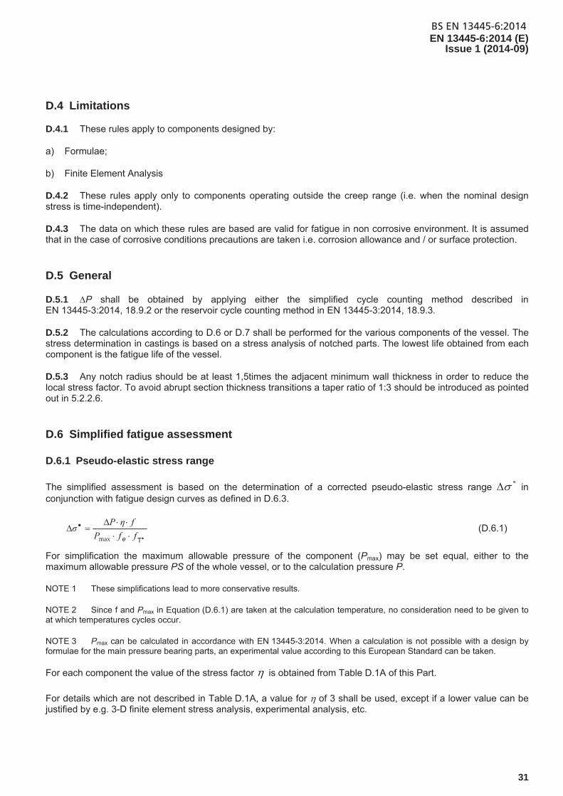
D.6.1 Pseudo-elastic stress range
The simplified assessment is based on the determination of a corrected pseudo-elastic stress range * in conjunction with fatigue design curves as defined in D.6.3.
TffP
fηPσ
emax
(D.6.1)
For simplification the maximum allowable pressure of the component (Pmax) may be set equal, either to the maximum allowable pressure PS of the whole vessel, or to the calculation pressure P.
NOTE 1 These simplifications lead to more conservative results.
NOTE 2 Since f and Pmax in Equation (D.6.1) are taken at the calculation temperature, no consideration need to be given to at which temperatures cycles occur.
NOTE 3 Pmax can be calculated in accordance with EN 13445-3:2014. When a calculation is not possible with a design by formulae for the main pressure bearing parts, an experimental value according to this European Standard can be taken.
For each component the value of the stress factor is obtained from Table D.1A of this Part.
For details which are not described in Table D.1A, a value for of 3 shall be used, except if a lower value can be justified by e.g. 3-D finite element stress analysis, experimental analysis, etc.

BS EN 13445-6:2014EN 13445-6:2014 (E) Issue 1 (2014-09)
32
NOTE 4 It is no longer required to use Table 17-1 from EN 13445-3:2014 substituting the weld joint factor z=1.
The correction factors ef and *Tf shall be determined as indicated in D.6.2.
A correction factor for surface finish and mean stress level is not required since this factor is already taken into account in the fatigue design curves of D.6.3. The actual surface conditions should meet the requirements of 7.1.
D.6.2 Correction factors
D.6.2.1 Correction for wall thickness
182,0
maxe
25
ef (D.6.2)
1e f for emax < 25 mm (D.6.3)
For emax > 150 mm, the value of e
f for emax = 150 mm applies.
D.6.2.2 Correction for temperature
The temperature correction factor fT* is given by:
for ferritic materials:
264 105,1105,103,1 ***T TTf (D.6.4)
for austenitic materials:
*TfT 4* 103,4043,1 (D.6.5)
where the mean cycle temperature is:
minmax 25,075,0 TTT * (D.6.6)
fT* = 1 for temperatures *T < 100 °C,. (D.6.7)
D.6.3 Fatigue design curves
The fatigue design curves given in Figure D.1 are described by Eequation (D.6.8):
cm/1CQ
R 9,0 N
CCσ (D.6.8)
where
CC and mC are constants whose values are given in Table D.1.
For constant amplitude loading, the endurance limit D (i.e. stress range below which the fatigue life can be assumed to be infinite) corresponds to the stress range R at 2 106 cycles.

BS EN 13445-6:2014EN 13445-6:2014 (E)
Issue 1 (2014-09)
33
The dotted lines in Figure D.1 apply only to cumulative damage calculations (Equation (D.8.1)) under variable amplitude loading which includes stress ranges larger than D. The curves end at N = 108 cycles. The corresponding stress range is the cut-off limit Cut. For appropriate values of Cut see Table D.1. The fictitious stress ranges below this limit Cut are assumed to be non-damaging in fatigue for the pressure equipment.
Table D.1 — Coefficients of the fatigue design curves for spheroidal graphite cast iron grades- simplified assessment
Material
Constants of curve R – N (a) Allowable stress range at N cycles
MPa
103 < N < 2 × 10⁶ 2 × 10⁶ < N < 108 CQ = 0,9 CQ = 0,8
1/mC CC 1/mC CC D
at 2×10⁶ cut
at 108 D
at 2×10⁶ cut
at 108
EN-GJS-400-18
EN-GJS-350-22
EN-GJSA-XNiMn23-4
EN-GJSA-XNi22
EN-GJSA-XNiMn13-7
0,116
0,116
0,116
0,116
0,116
786
731
714
642
714
0,1
0,1
0,1
0,1
0,1
623
579
566
507
566
146
136
133
119
133
99
92
89
80
89
130
121
118
106
118
88
81
79
71
79
(a) For E according to Table A.2.1-1 and Table A.2.2-1.
Figure D.1 — Fatigue design curves for ferritic and austenitic spheroidal graphite cast iron grades at ambient temperature - Simplified assessment
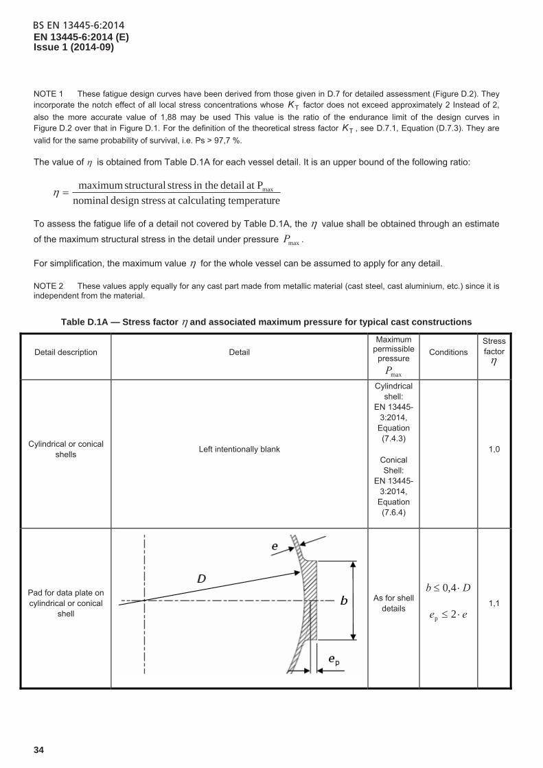
BS EN 13445-6:2014EN 13445-6:2014 (E) Issue 1 (2014-09)
34
NOTE 1 These fatigue design curves have been derived from those given in D.7 for detailed assessment (Figure D.2). They incorporate the notch effect of all local stress concentrations whose TK factor does not exceed approximately 2 Instead of 2,
also the more accurate value of 1,88 may be used This value is the ratio of the endurance limit of the design curves in Figure D.2 over that in Figure D.1. For the definition of the theoretical stress factor TK , see D.7.1, Equation (D.7.3). They are
valid for the same probability of survival, i.e. Ps > 97,7 %.
The value of is obtained from Table D.1A for each vessel detail. It is an upper bound of the following ratio:
re temperatugcalculatinat stressdesign nominal
Pat detail in the stress structural maximum max
To assess the fatigue life of a detail not covered by Table D.1A, the value shall be obtained through an estimate
of the maximum structural stress in the detail under pressure maxP .
For simplification, the maximum value for the whole vessel can be assumed to apply for any detail.
NOTE 2 These values apply equally for any cast part made from metallic material (cast steel, cast aluminium, etc.) since it is independent from the material.
Table D.1A — Stress factor and associated maximum pressure for typical cast constructions
Detail description Detail
Maximum permissible
pressure
maxP
Conditions Stress factor
Cylindrical or conical shells
Left intentionally blank
Cylindrical shell:
EN 13445-3:2014,
Equation (7.4.3)
Conical Shell:
EN 13445-3:2014,
Equation (7.6.4)
1,0
Pad for data plate on cylindrical or conical
shell
As for shell details
Db 4,0
ee 2p
1,1

BS EN 13445-6:2014EN 13445-6:2014 (E)
Issue 1 (2014-09)
35
Table D.1A (continued)
Detail description Detail
Maximum permissible
pressure
maxP
Conditions Stress factor
Stiffening ring (single or multiple) on
cylindrical or conical shell
As for shell details
ete 42
ehe 62
1,0
Single opening with reinforcement in shell or spherical
end
As for shell details
ee 2sa,
dd 2r
3,0
Multiple openings with reinforcement in
shell or spherical end
As for shell details
ee 2sa,
rir, 2 dd
rnr, 2 dd
nib ddL
3,0
Nozzle with reinforcement in shell or spherical
end
As for shell details
ee 5,1sa,
ee 5,1ba,
bi,r 2 dd
6,0/ ibi, eDd
2,0
Nozzle without reinforcement in shell or spherical
end
ee sa,
ee ba,
6,0/ ibi, eDd
3,0

BS EN 13445-6:2014EN 13445-6:2014 (E) Issue 1 (2014-09)
36
Table D.1A (continued)
Detail description
Detail
Maximum permissible
pressure
maxP
Conditions Stress factor
Tangential inlet/outlet in cylindrical or conical shell
As for shell details
ee 2sa,
dwd 53 2,5
Flange with hub
See EN 13445-
3:2014, Clause 11 or Annex
Ga
01 4 gg
)(3 01 ggh 1,5
010 24 ggg )( 01 ggh
2,0
Flange without hub
See EN 13445-
3:2014, Clause 11
or Annex Ga
01 gg
0h 2,0
Torispherical end knuckle
region
See EN 13445-
3:2014, Equation (7.5-7) b
8,0/ eDR
15,0/ i Dr 2,0
Other parameters according
EN 13445-3:2014 Clause 7.5.3.1
2,50

BS EN 13445-6:2014EN 13445-6:2014 (E)
Issue 1 (2014-09)
37
Table D.1A (continued)
Detail description
Detail Maximum
permissible
pressure maxP
Conditions Stress
factor
Reinforced opening in
torispherical end
As for torispherical end detail
ee 2sa,
dd 2r 2,0
Opening for drain in
torispherical end
As for torispherical end detail
3,0
Flat end knuckle region
See EN 13445-
3:2014 Clause 10 c
af3,1 er d 1,5
afaf3,1 ere 3,0
Opening in flat end
See EN
13445-3:2014, Clause 10.6.1
2,0
Separation rib in dished
cover
As for cover detail, see Annex G
ca ee 1,1
NOTE afe is the analysis thickness of flat end calculated without opening (see EN 13445 -3:2009 Clause 10.4.3)
a The maximum calculation pressure is not given explicitly in EN 13445-3:2014 Clause 11. It shall be calculated as the pressure which gives
stresses to their allowable limits, or in EN 13445-3:2014 Annex G a load ratio equal to 1,0. As a conservative simplification maxP may be taken
as designP .
b For use within the present clause maxP is taken as equal to yP given by Equation (7.5-7) in EN 13445-3:2014. The other possible
determinations sP and bP (given by equations 7.5-6 and 7.5-8 respectively) are not relevant here.
c The maximum calculation pressure is that of the flat end (not that of the adjacent cylindrical shell). In Equation (D.6-1), the value f to be introduced is the lowest of that for the end and that for the shell. d Since no explicit formula is given for maxP in EN 13445-3:2014 Clause 10 maxP shall be calculated as the pressure which gives the
required end thickness equal to the analysis thickness. As a conservative simplification maxP may be taken as designP .
e iD is the vessel internal diameter

BS EN 13445-6:2014EN 13445-6:2014 (E) Issue 1 (2014-09)
38
D.6.4 Allowable number of cycles
In order to obtain the allowable number of load cycles N, at a specified stress range *, the following shall be calculated:
mCQ
9,0
σ
CCN (D.6.9)
The value for * shall be calculated using Equation (D.6.1)
D.6.5 Allowable stress range
Alternatively, to obtain the allowable stress range for a specified number of applied load cycles N:
TeR ffσσ (D.6.10)
where
cm/1CQ
R 9,0 N
CCσ
(D.6.11)
ef and T
f shall be calculated according to D.6.2.
D.7 Detailed fatigue assessment
D.7.1 Pseudo-elastic stress ranges
According to the method described in EN 13445-3:2014, Clause 18 for un-welded components the values of the
maximum equivalent stress range eq and the structural stress range struceq, are determined using a detailed
numerical calculation method. From these values the corrected equivalent effective notch stress range * can be obtained by use of Keff :
mes
struceqeff ffff
σKσ
*T
,* (D.7.1)
where
T
T
T
1501
1511 K
σ
σKMAX
KK
D
struceqeff
,;,
, (D.7.2)
struceq
eq
,σ
σK
T (D.7.3)
where
D is the endurance limit for N > 2 106 cycles from Table D.2.

BS EN 13445-6:2014EN 13445-6:2014 (E)
Issue 1 (2014-09)
39
It is conservative to assume Keff = KT. The correction factors sf , ef , Tf and mf shall be determined as indicated
in D.7.2.
D.7.2 Corrections to stress range
D.7.2.1 Correction for wall thickness
465,0ln1,0ee
NFf (D.7.4)
where
182,0
maxe
25
eF (D.7.5)
where
ef = 1 for emax < 25 mm.
For mm 150max e , the value of ef for mm 150max e applies
D.7.2.2 Correction for temperature
The temperature correction factor fT* is given in D.6.2.2.
D.7.2.3 Surface finish correction factor
In order to keep local stresses low, a finer surface finish due to appropriate moulding techniques is advantageous on the side opposite to the fluctuating pressure.
465,0ln1,0s
Ns Ff (D.7.6)
where
200lnln03,01 mR
RF zs (D.7.7)
ss Ff if 6102 N
where
RZ is the peak-to-valley height in μm. (Set RZ = 200 if not specified.)
D.7.2.4 Correction for mean stress
The mean stress correction factor fm is to be determined from EN 13445-3:2014, 18.11.1.3. However the mean stress sensitivity factor M for spheroidal graphite cast iron grades according this European Standard is:
08,000035,0 m RM (D.7.8)

BS EN 13445-6:2014EN 13445-6:2014 (E) Issue 1 (2014-09)
40
D.7.2.5 Plasticity correction factors
Correction factors for mechanical ek and thermal k loadings in the hyper plastic range can be ignored, as a result
of the high safety factors on 0,2 % proof strength used for the calculation of the nominal design stress in EN 13445-6:2014 together with structural stresses never exceeding 3f.
D.7.3 Fatigue design curves
The fatigue design curves given in Figure D.2 are described by Equation (D.7.9):
Cm/19,0 N
CCσ CQ
R (D.7.9)
where
CC and mC are constants whose values are given in Table D.2.
Table D.2 — Coefficients of the fatigue design curves for spheroidal graphite cast iron grades - detailed assessment
Material
Constants of curve R – N (a)
Allowable stress range at N cycles
MPa
103 < N < 2 × 10⁶ 2 × 10⁶ < N < 108 CQ = 0,9 CQ = 0,8
1/mC CC 1/mC CC D
at 2 × 10⁶cut
at 108 D
at 2 × 10⁶ cut
at 108
EN-GJS-400-18 EN-GJS-350-22 EN-GJSA-XNiMn23-4 EN-GJSA-XNi22 EN_GJSA-XNiMn13-7
0,10 0,10 0,10 0,10 0,10
1 173 1 091 1 065 957
1 065
0,10 0,10 0,10 0,10 0,10
1 173 1 091 1 065 957
1 065
275 256 249 224 249
186 173 168 151 168
244 227 222 199 222
165 154 150 135 150
(a) For E according Table A.1 and Table A.3.

BS EN 13445-6:2014EN 13445-6:2014 (E)
Issue 1 (2014-09)
41
Figure D.2 — Fatigue design curves for ferritic and austenitic spheroidal graphite cast iron grades at ambient temperature - Detailed assessment
NOTE The fatigue design curves in Figure D.2 have been derived from data (See ref [1]) obtained from un-notched test pieces of spheroidal graphite cast iron grade EN-GJS-400-18 from axial and bending fatigue tests performed under load control or, for applied strains exceeding yield (low cycle fatigue), under strain control. The allowable stresses have been derived from the mean results by applying safety factors of 5 on fatigue life and 1,3 on stress range. The resulting design curves embody a probability of survival Ps of at least 97,7 %.
The dotted lines in Figure D.2 apply only to cumulative damage calculations (Equation (D.8.1)) under variable amplitude loading which includes stress ranges larger than D. The curves end at N = 108 cycles. The corresponding stress range is the cut-off limit Cut. For appropriate values of Cut see Table D.2. The stress ranges below this limit Cut are assumed to be non-damaging in fatigue for the pressure equipment.
D.7.4 Allowable number of cycles
In order to obtain the allowable number of load cycles N, at a specified stress range *, the following shall be calculated:
mCQ
9,0
σ
CCN (D.7.10)
The value for * shall be calculated using Equation (D.7.1).

BS EN 13445-6:2014EN 13445-6:2014 (E) Issue 1 (2014-09)
42
D.7.5 Allowable stress range
Alternatively, in order to obtain the allowable structural stress range struceq, for a specified number of applied
load cycles N:
effmseRstruceq Kffff /*, T (D.7.11)
where
ef , sf , mf and Tf shall be calculated according to D.7.2. effK is calculated from Equation (D.7.2) or
conservatively set equal to TK .
D.8 Assessment rule for total fatigue damage
The total fatigue damage index due to the cumulative effect of cycles of variable amplitude loading, forming a specified design stress range spectrum, is calculated as follows:
...3
32
1
1
i
i N
n
N
n
N
n
N
nD
2
k
i (D.8.1)
Where ni are the numbers of cycles of each stress range (*)i applied during the design life of the vessel, and Ni
are the allowable number of cycles corresponding to that stress range, obtained in accordance with D.6.4 or D.7.4 from the appropriate fatigue design curve.
The design is acceptable if the following condition is met:
1D (D.8.2)
If D > 1, the condition is not met and the design shall be modified.
D.9 Repairs of surface imperfections
If an unacceptable surface imperfection occurs which does not meet the requirements of 7.1, an improvement can only be made by grinding. The minimum actual required thickness shall be calculated according to this annex, taken into account all clauses of this European Standard about the design requirements. Welding is not allowed, as has been stated in 5.3.2.

BS EN 13445-6:2014EN 13445-6:2014 (E)
Issue 1 (2014-09)
43
Annex E (normative)
Design by analysis for castings
E.1 Introduction
For cast iron pressure vessels the general procedures and corresponding rules as covered by:
Annex B “Design by Analysis – Direct Route“ and
Annex C “Design by Analysis – Method based on stress categories“
of EN 13445-3:2014 shall be modified as follows.
E.2 Special requirements to EN 13445-3:2014, Annex B
E.2.1 Addition to B.8.2.3: Design checks for normal operating load cases
Material strength parameters (RM) and partial safety factors (R ) shall be as given in following table:
Table E.1 — RM and R for normal operating load cases
Material RM R
Spheroidal graphite cast iron a
p0,2/TR )./(67.1 Q eCC
a For allowable material grades see Table 5.1-1 and Table 5.1-2.
E.2.2 Addition to B.8.2.4: Design checks for testing load cases
RM and R shall be as given in following table:
Table E.2 — RM and R for testing load cases
Material RM R
Spheroidal graphite cast iron a /Ttestp0,2R eC/33,1
a For allowable material grades see Table 5.1-1 and Table 5.1-2.
E.3 Additions to EN 13445-3:2014, Annex C
The symbol “f“ used in C.7. “Assessment criteria“ is defined in 5.2.2.2.
BS EN 13445-6:2014EN 13445-6:2014 (E) Issue 1 (2014-09)
44
E.4 Requirements
Design by analysis calculations shall include the following:
a detailed description of the numerical method used, including the name and version of computer software, if applicable;
description of model geometry (including element type for finite element analysis);
loading conditions and boundary conditions used to address the load cases in the User’s Design Specification;
material characteristics used for all required physical properties (i.e. modulus of elasticity, Poisson’s ratio, thermal expansion coefficient, thermal conductivity, thermal diffusivity), strength parameters (i.e. yield and tensile strength), and the design membrane stress intensity;
description of whether material nonlinearity is utilized in the analysis including a description of the material model (i.e. stress-strain curve and cyclic stress-strain curve);
description of the numerical analysis procedure (i.e. static analysis, buckling analysis, natural frequency analysis, dynamic analysis) and whether geometrically linear or non-linear option is invoked;
Graphical display of relevant results (i.e. numerical model, deformed plots, and contour plots of thermal and stress results);
method used to validate the numerical model (i.e. mesh sensitivity review and equilibrium check for finite element analysis, e.g. check of hoop stress in a component away from structural discontinuity and a check to ensure that global equilibrium is achieved between applied loads and reactions at specified boundary conditions);
description of processing the numerical analysis results in order to obtain final results (i.e. stress linearization method, use of centroidal or nodal values for stress, strain, and temperature results);
a summary of the numerical analysis results showing the acceptance criteria utilized to meet the requirements of this European Standard;
electronic storage of analysis results including input files and output files that contain numerical analysis results utilized to demonstrate code compliance.
BS EN 13445-6:2014EN 13445-6:2014 (E)
Issue 1 (2014-09)
45
Annex F (informative)
Recommandations for in-service validation and inspection
F.1 Purpose
This annex gives recommendations for the continued acceptance of cast equipment made according to this European Standard.
The instructions for use issued by the manufacturer may contain requirements for in-service inspections and may contain recommendations for re-inspections depending on the design, service and required service life.
F.2 Tests during operation
Every pressure vessel or pressure vessel part should be externally and, if necessary, internally inspected (by non-destructive methods) at a period not later than the calculated allowable fatigue lifetime according to Annex D. If the lifetime due to normal service conditions is considered to be infinite by the manufacturer an inspection shall be made after 10 years of service when no adverse situation has been signalled from the operator or the inspector to the manufacturer.
NOTE 1 This time corresponds to the allowable number of cycles when the design stress range spectrum includes only one type of cycle. For more complex loading spectra, it corresponds to the time when a total fatigue damage index of 0,5 (see definition in Annex D) has been reached.
The operator should record the number of load cycles in use in a suitable way and, if necessary, arrange for internal or external inspections.
NOTE 2 The records can indicate a need for a sooner inspection interval than originally laid down. If no records exist, the inspector may choose the least favourable occurring condition during operation of the vessel or vessel part.
NOTE 3 Longer inspection intervals may possibly result from calculations according to Annex D with a detailed assessment of fatigue life than from the simplified fatigue assessment method.
NOTE 4 A damage to be expected can also be found in non-pressure bearing parts such as intersections between supporting lugs and vessel wall which might induce fatigue crack initiation and consequently reduce the life of the pressure part.
If no record exists the number of load cycles may be estimated in normal operating conditions and agreed upon between the user and the inspector.
For pressure vessels subject to cyclic loading, in-service inspections are of particular importance to detect incipient damage in good time. Therefore, the internal inspections should be supplemented by non-destructive tests on highly stressed locations, especially by test methods suitable to detect surface cracks.
For monitoring inaccessible areas, ultrasonic testing from the outside surface of the vessel is recommended.
If the operating conditions deviate greatly from those assumed in the calculation according to Annex D in terms of a greater cyclic loading, or if damage of the vessel wall is to be expected before the end of the inspection intervals owing to other operating influences, the inspection intervals should be shortened.

BS EN 13445-6:2014EN 13445-6:2014 (E) Issue 1 (2014-09)
46
Conversely, if no incipient cracks are detected during the regular inspections, the vessel can be operated further up to the next inspection in the interval laid down or agreed, even if the allowable lifetime as calculated according to Annex D has already been reached or has been exceeded.
F.3 Measures to be taken when the calculated allowable fatigue lifetime has been reached
F.3.1 General
If the allowable fatigue lifetime for a vessel or component, determined by calculation according to Annex D or by experiment according to Annex H, shows an infinite lifetime by calculation or experimentation, no non-destructive tests have to be carried out when the vessel or vessel part has been working at no higher than the design conditions where it was intended for.
If the allowable fatigue lifetime of the component given in the operating instructions has been reached (i.e. if the allowable number of cycles has been reached different from an infinite number of cycles or if the total fatigue damage index according to Annex D has reached the value 1, non-destructive tests should be performed as completely as possible concentrating on highly stressed locations and critical zones.
If no cracks are detected by the non-destructive tests conducted in the inspection intervals and in the test above, continued operation may be allowed.
If cracks or crack-like defects or other more extensive damage are found, the component or the structural element concerned should be replaced, unless continued operation appears admissible after verification by appropriate measures.
F.3.2 Testing of vessels and pressure parts at end of life without indicated damages
When the number of equivalent full pressure cycles has reached the end of life, a pressure test should be performed when deemed necessary for certain service parameters. For the method of testing see next subclause.
F.3.3 Hydraulic testing of vessels and vessel parts with indicated damages
When the number of equivalent full pressure cycles has reached the end of life, a hydraulic pressure test should be performed. The time held shall be at least sufficient to perform a complete inspection with a minimum time of 10 min irrespective of part size.
If the test is successfully passed, then the operation can be continued.
When indicated damages are visible before the number of equivalent full pressure cycles has been reached, a reconsidering of the design may be necessary, either to choose another material grade, to lower design parameters or to verify if all possible load cases have been considered.

BS EN 13445-6:2014EN 13445-6:2014 (E)
Issue 1 (2014-09)
47
Annex G (normative)
Specific design requirements
G.1 Scope
This annex will give requirements to the designers in detail designs of cast nodular parts to determine the required thickness by formulae of uncommon shapes, not included in EN 13445-3:2014 but frequently used in cast design.
NOTE This Annex G contains only one example of flange design, but may be extended with other construction details when such is indicated by the manufacturers and no specific DBF rules are given in EN 13445-3:2014. Odd shapes can always be verified by DBA design methods, but are often more expensive.
This design rule is applied to cast dished covers without the knuckle radius, subject to pressure, for which the following conditions are satisfied.
Figure G.1 — Cast dished cover
201A and
R
eA a 1151 where
1000R mm.
The spherical part needs to be above the flange horizontal half centreline.
G.2 Design
G.2.1 General
Calculation of nominal design stress according 5.2.
Bolt loads and areas, calculation according 11.4.3 and 11.5.2 of EN 13445-3:2014.

BS EN 13445-6:2014EN 13445-6:2014 (E) Issue 1 (2014-09)
48
G.2.2 Cover thickness, pressure to convex side
f
RPSe
85,0c (G.2-1)
G.2.3 Pressure to concave side
If the pressure on the convex side is larger than on the concave side the thickness of the crown shall not be less than
E
nPSRe
65,1c (G.2-2)
where
n is determined according to the table below. Intermediate values are obtained by linear interpolation.
Table G.1 — Form factor
eC/R n
0,001 5,5
0,003 4,0
0,005 3,7
0,01 3,5
0,1 3,0
G.2.4 Flange thickness
For metal to metal contact and O-ring gaskets:
22
3,2op
f dnC
BC
f
We
(G.2-3)
For gaskets inside the bolt circle diameter
dBA
BC
f
We
opf 1,1 (G.2-4)
where
n is the number of bolts;
Wop is the operating force determined by EN 13445-3:2014, Clause 11.

BS EN 13445-6:2014EN 13445-6:2014 (E)
Issue 1 (2014-09)
49
Annex H (normative)
Experimental cyclic pressure testing procedure
H.1 Purpose
This annex gives requirements for the fatigue testing of pressure vessels or pressure vessel parts in cases where a fatigue assessment cannot be adequately performed due to special shape or lack of experience.
All the requirements given form a consistent set which should be applied as a whole. This test is also a part of the technical documentation.
H.2 Validity
The fabrication of pressure vessels or vessel parts presumes that the manufacturer intending the production has acquired the necessary competence and sufficient experience to manufacture according to the specified standard. This means that tests, performed by the manufacturer or a recognised laboratory are only valid for the same manufacturer producing the production parts with the same casting process.
H.3 Tests requirements
H.3.1 General
Test conditions shall be deduced from the maximum operating conditions. When a pressure part is subject to cyclic pressure testing at ambient temperature, and when TSmax and TSmin differs from the test temperature, test pressure shall be increased by 1/fT* according Equation (D.6-3) for ferritic grades and D.6.4 for austenitic grades.
H.3.2 Number of parts
Random samples taken from production of the vessel or vessel part shall be used for fatigue test to determine the allowable number of load cycles. This is called the fatigue batch.
H.3.3 Procedure
Verify that the vessels or vessel parts to be tested are in accordance with the appropriate drawing and specification.
Verify that the vessel or vessel part is machined to the same dimensions and tolerance specifications as the production part.
Verify that a calibrated pressure gauge is used; maximum tolerance shall conform to at least class 1 or better according to EN 837-1:1996 and EN 837-3:1996.
The scale of the pressure gauge shall be approximately 4/3 of the anticipated maximum cyclic test pressure.

BS EN 13445-6:2014EN 13445-6:2014 (E) Issue 1 (2014-09)
50
The following test set–up may be used for a layout.
Key
1 pressure regulation 7 Pmin
2 air tank 8 pressure pulse frequency
3 variable pressure 9 three way valve
4 constant pressure 10 membrane
5 air circuit as short as possible 11 cycle counter
6 Pmax 12 water level detector
Figure H.1 — Test set-up
Pressure cycling shall be performed in accordance with the following procedure:
fill the pressure part to be tested with a non-corrosive fluid such as oil, inhibited water or glycol;
vent all air pockets.
The rate of pressurization shall not exceed 14 bar/s. If, for pressure in excess of 80 % of the design burst pressure, the rate of pressurization exceeds 3,5 bar/s, then either the temperature shall be recorded to show no abnormal or excessive heating of the vessel, or there shall be a 5 s hold at the next pressure pulse.
Ensure that the number of pressure cycles shall not exceed 10 cycles/min.
It is not acceptable that, during the test, leaks and lack of tightness occur between flanged, gasketed or bolted parts.

BS EN 13445-6:2014EN 13445-6:2014 (E)
Issue 1 (2014-09)
51
The test shall not be performed by means of a clamped construction on a hydraulic press which can counteract the shell bending stress resulting in no free movement of the wall under pressure.
The number of cycles to failure shall be reported, along with the location and description of the failure initiation.
H.3.4 Material tests
The following tests and examinations shall be carried out on each vessel submitted for approval tests:
a hydraulic pressure test according to 7.2.1 shall be carried out prior to the cyclic pressure testing;
visual examination in the final condition according to 7.1.1;
magnetic particle inspection (only for ferritic grades). The inspection shall be carried out in accordance with EN 1369:2012;
after the test a material sample shall be taken from the location where the fatigue crack occurred. The following tests shall be carried out:
a) thickness measurement;
b) microstructure investigation;
c) analysis of the type of fracture.
H.4 Allowable number of cycles
To decrease the test time a higher cyclic pressure than the maximum allowable pressure can be applied. Three or more tests are required. In each test the pressure shall be cycled between the minimum value given by the installation minP and maxexpP where the elasticity limit is expected to be reached for the most stressed vessel component. In most designs, )3,min(2 maxexpmax PSPPPS .
If the required fatigue life exceeds 10000 cycles, it is permissible to accelerate the test by applying a higher cyclic pressure range P where minexpmax PPP .
The geometric mean fatigue life (in cycles) obtained shall not be less than
FNP
PSN req
m
gmc
c
. (H.4-1)
where
gmcN . is the geometric mean fatigue life obtained from the tests;
reqN is the required number of full pressure cycles;
PS is the maximum allowable pressure ( MPa)
P is the pressure range in fatigue test
cm is the exponent in the equations describing the fatigue design curves
F is a test factor

BS EN 13445-6:2014EN 13445-6:2014 (E) Issue 1 (2014-09)
52
NOTE gmcN . should be a lower value compared with reqN . If the value is still too high one could used a higher P or
a larger amount of samples.
The test factor F depends on the required probability of survival, the number of test results and the standard deviation of Nlog , . For consistency with the design N R curves for spheroidal graphite cast iron Annex D of this standard, the required probability of survival is 97,7 %.A selection of values of k , which correspond to 95 % confidence in 97,7 % survivability are given in Table H.1. Values for other numbers of tests may be obtained from ISO 12107.
Table H.1 — Values of k with number of test specimen
Number of tests k
3 9,1
4 6,1
5 5,0
6 4,4
7 4,0
8 3,8
9 3,6
10 3,5
F is derived using the one-sided tolerance limit factor, k , such that:
kF 10
The standard deviation of Nlog may be obtained from these tests or other representative tests.
NOTE The standard deviation of log N is a measure of the scatter in fatigue lives obtained from a number of fatigue tests.
Values of F for a standard deviation of 0,222, which is the largest value found from fatigue tests of spheroidal graphite cast iron pressure vessels, are given in Table H2.
Table H.2 — Values of F
Number of tests F
3 105,3
4 22,6
5 12,6
6 9,4
7 7,8
8 6,9
9 6,3
10 5,8
If a lower value for the standard deviation of Nlog =0,222 is obtained in the test, it may be applied.
BS EN 13445-6:2014EN 13445-6:2014 (E)
Issue 1 (2014-09)
53
Annex Y (informative)
History of EN 13445-6
Y.1 Differences between EN 13445-6:2009 and EN 13445-6:2014
The 2014 edition of EN 13445-6 contains the 2009 edition of the standard and all corrections issued in the meantime.
NOTE The changes referred include the significant technical changes but is not an exhaustive list of all modifications.
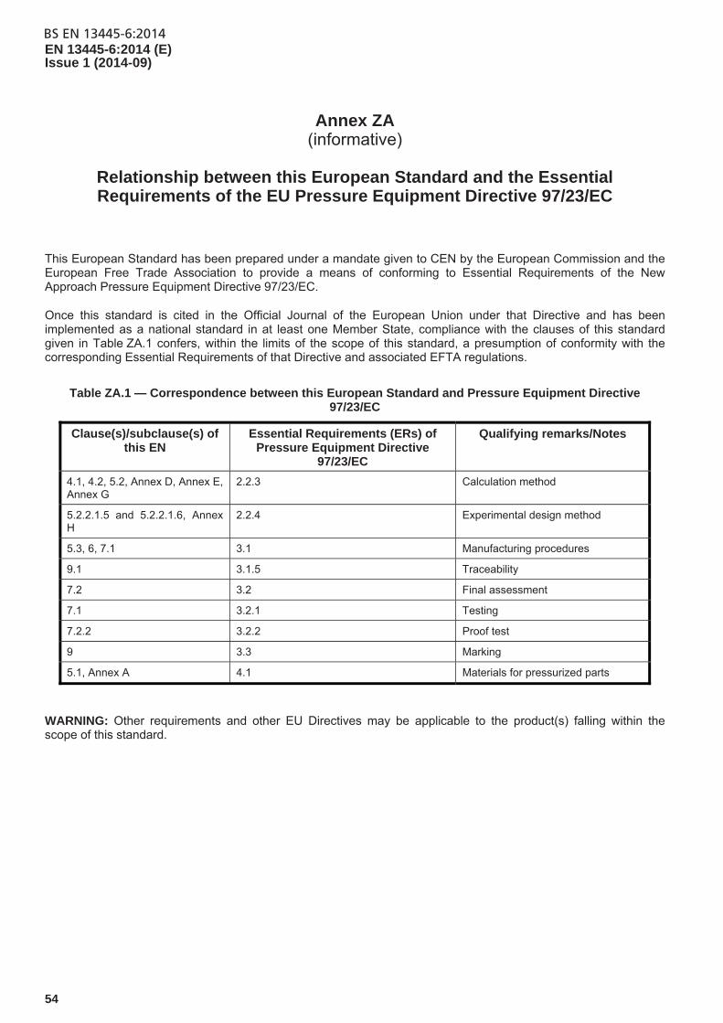
BS EN 13445-6:2014EN 13445-6:2014 (E) Issue 1 (2014-09)
54
Annex ZA (informative)
Relationship between this European Standard and the Essential Requirements of the EU Pressure Equipment Directive 97/23/EC
This European Standard has been prepared under a mandate given to CEN by the European Commission and the European Free Trade Association to provide a means of conforming to Essential Requirements of the New Approach Pressure Equipment Directive 97/23/EC.
Once this standard is cited in the Official Journal of the European Union under that Directive and has been implemented as a national standard in at least one Member State, compliance with the clauses of this standard given in Table ZA.1 confers, within the limits of the scope of this standard, a presumption of conformity with the corresponding Essential Requirements of that Directive and associated EFTA regulations.
Table ZA.1 — Correspondence between this European Standard and Pressure Equipment Directive 97/23/EC
Clause(s)/subclause(s) of this EN
Essential Requirements (ERs) of Pressure Equipment Directive
97/23/EC
Qualifying remarks/Notes
4.1, 4.2, 5.2, Annex D, Annex E, Annex G
2.2.3 Calculation method
5.2.2.1.5 and 5.2.2.1.6, Annex H
2.2.4 Experimental design method
5.3, 6, 7.1 3.1 Manufacturing procedures
9.1 3.1.5 Traceability
7.2 3.2 Final assessment
7.1 3.2.1 Testing
7.2.2 3.2.2 Proof test
9 3.3 Marking
5.1, Annex A 4.1 Materials for pressurized parts
WARNING: Other requirements and other EU Directives may be applicable to the product(s) falling within the scope of this standard.

BS EN 13445-6:2014EN 13445-6:2014 (E)
Issue 1 (2014-09)
55
Bibliography
[1] Gorsitzke, B.: Berechnung der Ermüdungslebensdauer wechselbeanspruchter Druckbehälter aus Gusseisen mit Kugelgrafit
[2] Kikkert, J. Bepaling van de elasticiteitsgrens van verschillende nodulaire gietijzersoorten op verhoogde temperatuur
[3] ISO/CD 1083, Spheroidal graphite cast iron (2001-01-18)
[4] EN 13068-1:1999, Non-destructive testing — Radiographic testing — Part 1: Quantitative measurement of imaging properties
[5] EN 13068-2 :1999, Non-destructive testing — Radiographic testing — Part 2: Check of long term stability of imaging devices
[6] Hasse, S.: Duktiles Gusseisen. Schiele & Schön, 1995
[7] SFS 3320, Design of pressure vessels — Dished cover
[8] ISO 12107:2003 — Metallic materials — Fatigue testing — Statistical planning and analysis of data

This page deliberately left blank

This page deliberately left blank

BSI is the national body responsible for preparing British Standards and other standards-related publications, information and services.
BSI is incorporated by Royal Charter. British Standards and other standardization products are published by BSI Standards Limited.
British Standards Institution (BSI)
BSI Group Headquarters
389 Chiswick High Road London W4 4AL UK
About usWe bring together business, industry, government, consumers, innovators and others to shape their combined experience and expertise into standards -based solutions.
The knowledge embodied in our standards has been carefully assembled in a dependable format and refined through our open consultation process. Organizations of all sizes and across all sectors choose standards to help them achieve their goals.
Information on standardsWe can provide you with the knowledge that your organization needs to succeed. Find out more about British Standards by visiting our website at bsigroup.com/standards or contacting our Customer Services team or Knowledge Centre.
Buying standardsYou can buy and download PDF versions of BSI publications, including British and adopted European and international standards, through our website at bsigroup.com/shop, where hard copies can also be purchased.
If you need international and foreign standards from other Standards Development Organizations, hard copies can be ordered from our Customer Services team.
SubscriptionsOur range of subscription services are designed to make using standards easier for you. For further information on our subscription products go to bsigroup.com/subscriptions.
With British Standards Online (BSOL) you’ll have instant access to over 55,000 British and adopted European and international standards from your desktop. It’s available 24/7 and is refreshed daily so you’ll always be up to date.
You can keep in touch with standards developments and receive substantial discounts on the purchase price of standards, both in single copy and subscription format, by becoming a BSI Subscribing Member.
PLUS is an updating service exclusive to BSI Subscribing Members. You will automatically receive the latest hard copy of your standards when they’re revised or replaced.
To find out more about becoming a BSI Subscribing Member and the benefits of membership, please visit bsigroup.com/shop.
With a Multi-User Network Licence (MUNL) you are able to host standards publications on your intranet. Licences can cover as few or as many users as you wish. With updates supplied as soon as they’re available, you can be sure your documentation is current. For further information, email [email protected].
RevisionsOur British Standards and other publications are updated by amendment or revision.
We continually improve the quality of our products and services to benefit your business. If you find an inaccuracy or ambiguity within a British Standard or other BSI publication please inform the Knowledge Centre.
CopyrightAll the data, software and documentation set out in all British Standards and other BSI publications are the property of and copyrighted by BSI, or some person or entity that owns copyright in the information used (such as the international standardization bodies) and has formally licensed such information to BSI for commercial publication and use. Except as permitted under the Copyright, Designs and Patents Act 1988 no extract may be reproduced, stored in a retrieval system or transmitted in any form or by any means – electronic, photocopying, recording or otherwise – without prior written permission from BSI. Details and advice can be obtained from the Copyright & Licensing Department.
Useful Contacts:Customer ServicesTel: +44 845 086 9001Email (orders): [email protected] (enquiries): [email protected]
SubscriptionsTel: +44 845 086 9001Email: [email protected]
Knowledge CentreTel: +44 20 8996 7004Email: [email protected]
Copyright & LicensingTel: +44 20 8996 7070Email: [email protected]
NO COPYING WITHOUT BSI PERMISSION EXCEPT AS PERMITTED BY COPYRIGHT LAW