Criteria for crack extension in cylindrical pressure vessels
24
International Journal of Fracture Mechamcs, Vol 5, No. 3, September i969 Wolters-Noordhoff Pubhshing Grohingen Printed m the Netherlands 187 Criteria for Crack Extension in Cylindrical Pressure Vessels G. T. HAHN, M. SARRATE, AND A. R. ROSENFIELD* Metal Sctence Group, Battelle Memortal Instztute, Columbus Laboratories, Columbus, Ohto 43201 (Received September 11, 1968; in revised ~om February 28, 1969) ABSTRACT This paper describes three closely related cnterm for the extensaon of axial through-cracks m cyllndncal pressure vessels : (1) a fracture-toughness criterion mainly for low- and medium-tough materials, (2) a plastic flow stress criterion for short cracks m tough materials, and (3) a mothficatlon of (1) for relatively thin-walled containers. The development couples the Fohas theoretical treatment of a pressurized cylindrical shell with the fracture-toughness approach and a new plasticity correction. This correction, which ts consistent with crack-tip dxsplacement measurements, shows that the plastic-flow strength governs the extension of short cracks in vessels fabricated from tough materials. This is to be contrasted with the behavior of longer cracks or more brittle materials which depends on the fracture toughness. The formulation is extended to vessels with large radius to wall-thickness ratios, e.g., R/t > 50 by way of a simple empirical modification. In this way, estimates of critical hoop stress-crack length combinations can be derived from the vessel radius to wail-thickness ratio, and either the ordinary yield strength, the yield and ultimate strengths, or K c without prior full-scale test experience. Such estimates are shown to be in accord wxth the large body of published data encompassing ductile-steel, brittle-steel, as well as aluminum- and titanium-alloy vessels. 1. Introduction The driving force for crack extension in a pressure vessel has two components : one is associated with the hoop stress, the second is a consequence of the radial pressure which tends to bulge the unsupported vessel wall adjacent to a through-crack. The radial-pressure component has no counterpart in the flat-plate test, but in a vessel it can make an even larger contribution to the crack-driving force than the hoop stress. Peters and Kuhn [1] devised a s,tmple scheme for dealing with the two components that has since been given theoretical backing by Folias [2]. The basic premise is that a cylindrical pressure vessel can be treated like a flat panel (of the same material, thickness, and containing the same through-crack as the vessel) loaded in simple ten- sion provided the nominal stress on the panel a is taken to be a multiple M of the hoop stress O'H*'~ : = Ma., (1) where M is a function of the crack length 2c, the vessel radius r, and the wall thickness t. The critical hoop stress for crack extension in the pressure vessel a* can thus be described in terms of a*, the nominal stress for crack extension in the flat plate : 4=a* M -1 (2) Various proposals for the form of M for axial through-cracks in cylindrical vessels are sum- marized in Table 1. Expressions A, C, D, and E are based on experiments while expression B is derived from a theoretical analysis by Follas [2]. Anderson and Sullivan [3] enhanced the versatility of the approach by making it possible to draw on the larger body of fracture toughness data existing for flat plates. They coupled equation (2) with linear elastic fracture mechanics by replacing a* (which depends on crack length) with the fracture toughness parameter K c (which is independent of crack length) : * The authors are associated with Battelle Memorial Instatute, Columbus, Ohio, with M. Sarrate on leave of absence from the Argentine Atomm Energy Commission. Tins paper is scheduled for the 1969 WESTEC Conference, Los Angeles, California, 10-13 March. *-* A complete list of symbols and definitions is in Appendix A. Int. Journ. of Fracture Mech., 5 (1969) 187~10
-
Upload
khangminh22 -
Category
Documents
-
view
7 -
download
0
Transcript of Criteria for crack extension in cylindrical pressure vessels
International Journal of Fracture Mechamcs, Vol 5, No. 3, September i969 Wolters-Noordhoff Pubhshing Grohingen Printed m the Netherlands
187
Criteria for Crack Extension in Cylindrical Pressure Vessels
G. T. H A H N , M. SARRATE, A N D A. R. R O S E N F I E L D *
Metal Sctence Group, Battelle Memortal Instztute, Columbus Laboratories, Columbus, Ohto 43201
(Received September 11, 1968; in revised ~om February 28, 1969)
A B S TR AC T This paper describes three closely related cnterm for the extensaon of axial through-cracks m cyllndncal pressure vessels : (1) a fracture-toughness criterion mainly for low- and medium-tough materials, (2) a plastic flow stress criterion for short cracks m tough materials, and (3) a mothficatlon of (1) for relatively thin-walled containers. The development couples the Fohas theoretical treatment of a pressurized cylindrical shell with the fracture-toughness approach and a new plasticity correction. This correction, which ts consistent with crack-tip dxsplacement measurements, shows that the plastic-flow strength governs the extension of short cracks in vessels fabricated from tough materials. This is to be contrasted with the behavior of longer cracks or more brittle materials which depends on the fracture toughness. The formulation is extended to vessels with large radius to wall-thickness ratios, e.g., R/t > 50 by way of a simple empirical modification. In this way, estimates of critical hoop stress-crack length combinations can be derived from the vessel radius to wail-thickness ratio, and either the ordinary yield strength, the yield and ultimate strengths, or K c without prior full-scale test experience. Such estimates are shown to be in accord wxth the large body of published data encompassing ductile-steel, brittle-steel, as well as aluminum- and titanium-alloy vessels.
1. Introduction
The driving force for crack extension in a pressure vessel has two components : one is associated with the hoop stress, the second is a consequence of the radial pressure which tends to bulge the unsupported vessel wall adjacent to a through-crack. The radial-pressure component has no counterpart in the flat-plate test, but in a vessel it can make an even larger contribution to the crack-driving force than the hoop stress. Peters and Kuhn [1] devised a s,tmple scheme for dealing with the two components that has since been given theoretical backing by Folias [2]. The basic premise is that a cylindrical pressure vessel can be treated like a flat panel (of the same material, thickness, and containing the same through-crack as the vessel) loaded in simple ten- sion provided the nominal stress on the panel a is taken to be a multiple M of the hoop stress O'H *'~ :
= M a . , (1) where M is a function of the crack length 2c, the vessel radius r, and the wall thickness t. The critical hoop stress for crack extension in the pressure vessel a* can thus be described in terms of a*, the nominal stress for crack extension in the flat plate :
4 = a * M -1 (2)
Various proposals for the form of M for axial through-cracks in cylindrical vessels are sum- marized in Table 1. Expressions A, C, D, and E are based on experiments while expression B is derived from a theoretical analysis by Follas [2].
Anderson and Sullivan [3] enhanced the versatility of the approach by making it possible to draw on the larger body of fracture toughness data existing for flat plates. They coupled equation (2) with linear elastic fracture mechanics by replacing a* (which depends on crack length) with the fracture toughness parameter K c (which is independent of crack length) :
* The authors are associated with Battelle Memorial Instatute, Columbus, Ohio, with M. Sarrate on leave of absence from the Argentine Atomm Energy Commission. Tins paper is scheduled for the 1969 WESTEC Conference, Los Angeles, California, 10-13 March. *-* A complete list of symbols and definitions is in Appendix A.
Int. Journ. of Fracture Mech., 5 (1969) 187~10
188 G. T. Hahn, M. Sarrate, A. R. Rosenfield
Kc M - 1 = , (3 )
The factor q = ~0 (a*/#) is a plasticity correction to the linear elastic fracture mechanics, which becomes significant when a*/8 > 0.6, where ~ is the average plastic flow stress for the material. It should be noted here that K~ varies with plate thickness [8] and that the K~-value inserted in equation (3) must be consistent with the wall thickness of the pressure vessel. If the fracture toughness is not known for a flat plate of the same thickness as the wall of the pressure vessel, an appropriate thickness correction should be made to the value of K~ used in equation (3).
TABLE 1. Criteria for crack extension in unsttffened cylindrical pressure vessels ~ t h axial through-cracks*
Failure criterion M q~ Investigators
A a~ = a * M -~
B try, = a * M -1
[1+9 .2R1 - - Peters and Kuhn, 1957 [~Z1
ca R ~ [1 + 1.61 ( ~ 5 ) ~1 - - Fohas, 1965 [2]
C Kc ~ = - - M - ~
2G 2 J 1966 [3]
D** a~ = {oJra~(g+hW}~M -1 [c ~] Nichols, Irvine~ Quirk and Bevitt, 1965 [4]
I c2 I Kiharm Ikeda and E a~ = or* M-1 1 + ~ - - Iwanga, 1966 [5]
F ~ = a * M -1 ~1+0.81(. ,,/] °7~ __ Crichlow and Wells, L \ (Rtp/j • 1967 [6]
G I I Kc M_ ~ 1+1.61 sec or* = ~ ~ and Maxey, 1967 [7]
* A complete list of symbols and their definitions appears m Apl:~'~ndix A. ** Nichols et al. [4] give the relation in the following form: a~c ~= Const.
Duffy, McClure, Eiber, and Maxey [7] obtained a useful expression of these concepts by coupling (i) the Folias' equation for M (item B in Table 1), (ii) the fracture mechanics idea, and (iii) an estimate of ~p derived from the Dugdale crack model. Their expression (Criterion G, Table 1) facilitates the prediction of burst pressures because the two material parameters in- volved, Kc and 6 are well defined and, in principle, can be measured independently. In fact, the predictions made in this way by Duffy et al. [7] are in accord both with 2014-T6 aluminum vessels tested by Getz et al. [-9] and with their own extensive measurements on steel pipes.
However, Criterion G has certain limitations when it is applied to very tough materials such as the usual steel vessels and pipes at ambient temperatures where crack extension pro- ceeds by the ductile shear mode.* In this case, valid flat-plate Kc-determinations require very large test pieces, e.g., 10-15 ft. wide, and this makes the flat-plate test prohibitive. In the absence of a K:value, burst-pressure predictions cannot be made without a prior full-scale test of a vessel. Predictions for short cracks in tough materials also involve very large plasticity correc- tions which are uncertain. Another problem is encountered when Criterion G is applied to relatively thin-walled nonferrous vessels, e.g., R/t > 100. Contrary to the Folias analysis and experience with thicker steel vessels [5], [7], the M-values for the thin-walled vessels appear to be independent of thickness [1], [3].
* At least initially.
Int. J ourn. of Fracture Mech., 5 (1969) 187-210
Criteria for crack extension in cylindrical pressure vessels 189
In the long term, solutions to these problems will be drawn from more rigorous elastic- plastic treatments of a cracked pressure vessel along the lines begun by Sechler and Williams [-10] and Folias [-2].
This paper offers two suggestions for improving the description by Duffy and co-workers. An alternative, in part a more rigorous plasticity correction based on crack-tip displacement, is identified. When this correction is employed it becomes apparent that the fracture toughness plays a minor role in the extension of short cracks in tough materials. In this case, a measure of the toughness is not needed and failure pressures can be estimated directly from either the ordinary yield strength or yield and ultimate strength values. However, the Kc-value does in- fluence the performance of vessels with long cracks and those constructed of more brittle materials. The wall-thickness discrepancies are dealt with by modifying the Folias expression for M empirically. The resulting criteria for crack extension are shown to be in accord with the large body of published data on pressure vessels.
2. The Plas t ic i ty Correct ion
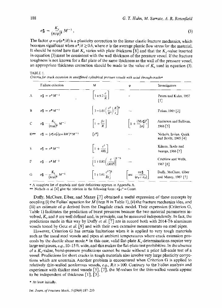
A brief discussion of the significance of K c and (p appears in Appendix B. Previous workers have evaluated q~ by way of the simplifying assumption that the plastic zone supports no stress and can be treated like an extension of the crack. Anderson and Sullivan [-3] obtain their cor- rection, referred to as (Pl, from a zone-size estimate based on the linear elastic stress-field solu- tion, an approximation which is not sound at high stress levels. The Duffy et o2. ]-7] correction, (P2 is more meaningful at higher stresses because its size estimate is drawn from Dugdale's [,11] elastic-plastic model. However, their procedure still overestimates the value ofcp since the plastic zone really supports stresses comparable to the flow strength of the material. A more realistic treatment that is based on the distortion at the crack tip and accounts for the stress supported by the plastic zone in a flat plate is given in Appendix B and leads to equation (B.7).
These plasticity corrections are derived from analyses of fiat plates. To make the transition to a cylindrical vessel a*, the flat-plate failure stress must be replaced by a~" M, a procedure consistent with the sense of equation (1)% and adopted previously by Anderson and Sullivan
12 2 [ - [ ----
~ 8 ~=()-8--) In [sec(-ff~--)
O
5 1.1_ c-
_9_o
o
o ~ 4 1 .L L 0.6 0_8 10 1_2 d~ 8"
Flgnare 1 Comparison of plastic-zone corrections evaluated for fiat plates' cpl is the form employed by Anderson and Sullivan [3], cp2 by Duffy et al. [-7], and ~3 and cp4 in the present study. Note that the relative posltmns of the curves
changed when the corrections m'e applied to cylindrical vessels.
* The pressure vessel behaves like a flat plate loaded to a stress cr = MaB.
Int. Journ. of Fracture Mech., 5 (1969) 187 210
190
(Table 1). Accordingly"
~°3= 28 J
G. T. Hahn, M. San'ate, A. R. Rosenfield
[sec = 2ff ] ' (4)
The quantity ~7 must be interpreted as an average flow stress acting in the plastic zone, and can not be precisely def'med. At low nominal stresses the plastic strains generated in the zone are small, and 6 = ar (crr is the yield stress) is probably a good estimate. At higher stress levels the influence of strain hardening is felt, and ff > at, with # = O-v (av is the ultimate tensile strength) an approximate upper limit. The two limits are used here because they probably bracket the true correction and reflect the inherent uncertainty of this part of the analysis :
(p3(ff = O ' y )< (/0 *( (p3 (I~=O'u) . (5)
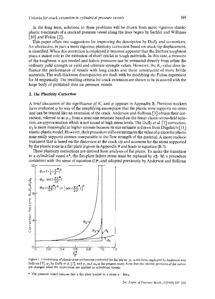
Figure 1 compares the three corrections as evaluated for flat plates and shows that q)z is larger than either qh or (f13 (for a given value of ~r*/6). Figure 2 shows that the positions are
4
-I- CLip gage • Der-ived from v o
¢-•
o 2 r -
>:
3 f" Calculations ........... ~D = ~1
= ~2
,~-----~ ~ = ~3
/ /
/ /
/ ./ / ..,"
7 ••, / .•," ••..•
¢ . •
-0 10 20 30 40 50 a H , 1000 psi
Figure 2. Compar ison of crack-tip displacement measurements with calculations based on cp 1, g~2, and rp3. The measure- ments were performed on a 5-in.-internal diameter, 0.5-in.-thick mild steel vessel (a r = 45 7 ksi, a v = 66 ksl). The calcula- tions employ the following relations: vc=nBca2q~, a=aH M, and the different expressions for ~0.
reversed when the corrections are applied to cylindrical vessels• This arises because Duffy et al. [7] equate the critical flat-plate stress with the critical hoop stress : O-* _= a* while Anderson and Sullivan [3] and the present authors take a* - Ma~. Also note that different definitions of F are involved; Anderson and Sullivan" F=ar, Duffy et al. ff=½(ar+av), and the present authors: a t < if< av. As a result, q~3 is similar to rp2 at low-stress levels, but much larger at high-stress levels because ~p3~ oo as a n ~ 6 / M , while cp2~ oo as a * ~ 6 . The crack-tip displace- ment values derived from the work of Almond et o2. [12], which are reproduced in Fig. 2, provide direct experimental evidence in support of the formulation of rp 3*. The values were ob- * A~ noted m Appendix B.1, v,, the crack opening displacement is also a function of the plasticity correction: v,= (a2nc/2E~)cp, where a is the flat plate nominal stress (~=MaB) , 2c is the crack length, E is the elastic modulus, and ¢7 is the average flow stress. Thus, measurements of v c can provide a direct check of the value of q).
Int Jourr~ of Fracture Mech, 5 (1969) 187-210
Criteria for crack extension in cylindrical pressure vessels 191
tained from two sources: (1) directly, from clip-gage measurements at the crack tip, and (2) indirectly, from crack center displacement values* and equation (B.11). Figure 2 shows that vo the crack tip displacement increases very rapidly in pressurized pipes at stresses in the range a t < Man< a~. Calculated curves based on the maximum and minimum values of ~P3 bracket the measurements, while calculations based on ~p ~ and ~p2 do not reproduce the trends observed. The rapid increase of v¢ as an--*g/M, revealed in Fig. 2, is attributed to a gross distortion of the region surrounding the crack to which bulging probably contributes. It cannot be identified with the general yielding of the pressure vessel that occurs when an--+6. To draw attention to this distinction, the phenomenon is referred to as "large-scale yielding" in this paper.
3. Criteria for Crack Extension
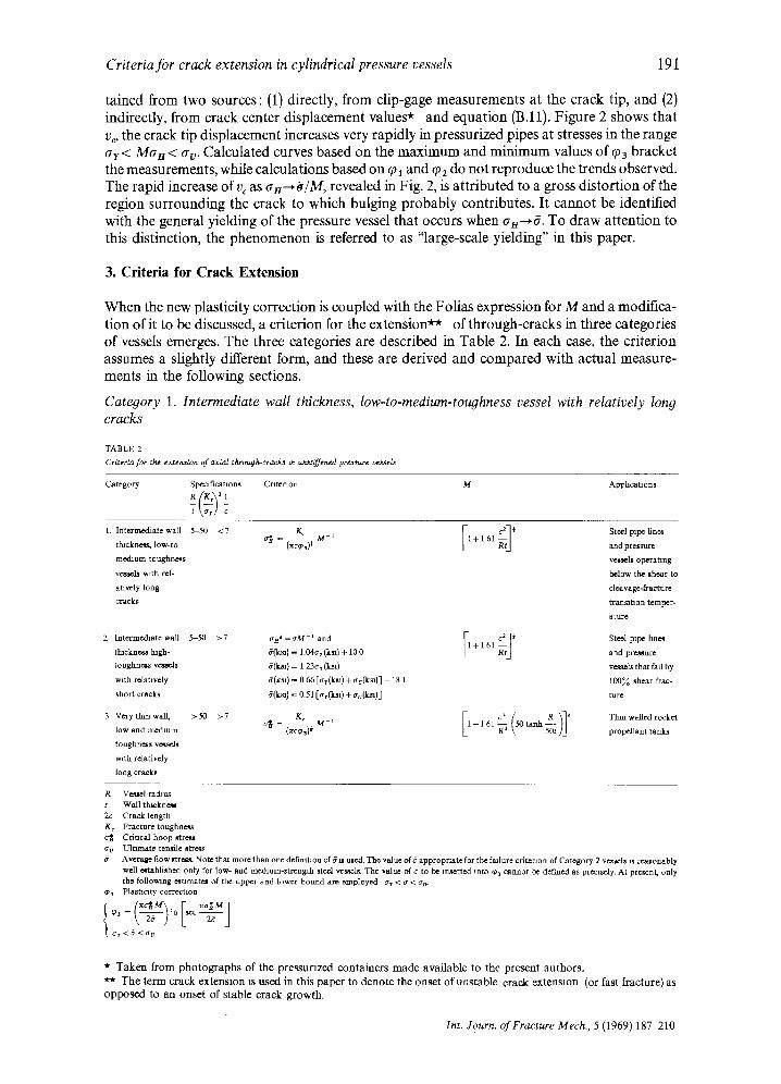
When the new plasticity correction is coupled with the Folias expression for M and a modifica- tion of it to be discussed, a criterion for the extension** of through-cracks in three categories of vessels emerges. The three categories are described in Table 2. In each case, the criterion assumes a sightly different form, and these are derived and compared with actual measure- ments in the following sections.
Category 1. Intermediate wall thickness, low-to-medium-toughness vessel with relatively long cracks
TABLE 2
Crlterla fo~ the emenMon of axMl through-cracks m tw,~ffened pressu~'e vessels
Category Spectficata on~ Crateraon M Apphcat~on~
t \a,/ c
[ ; t ] ' steel p~m l/n~ 1, Int~'medialewall 5-50 <7 _ _ K ~ M- ~ 1+161 tb~ckne~ low-to o~ = (~c¢~) i and pr~lx~
me, cfium-t o ughne~ ve~.el~ operratmg
ve*s¢l~ w~th l~l- below th~ shear-to
atavely long cle~tvage-fi-actu re
cracks tmumtaon temper-
2 Intermediate wall 5-50 > 7
thtckne¢~ high.
toughn~s ve*ads
with mlatavely
short cracks
3 Ve~ythmwa1[, >50 >7
low and medmm
toughneas ve*se~
wnh relatively
long e r a c ~
a~*=eM -1 and I1 ; t l i 5(k~) - 1.04<rr (k~a) + 10 0 +1 61
~(k~a) ~ (151 [¢Ty(~l) + O'u(k~l)]
Kc M 1 o~ = (~c~ ) ~'
c 1
ature
Ste~l pipe fine*
and pre~ure
ve~.~ls that fail by
100% shear frac-
ture
Thin walled rocket
propellant tanks
R Vessel radius t Wall t h~ckne~l 2c Crack length K~ Fracture toughness a~ Criueal hoop ~tre~ c~ o Ultamate tense Btre~
Average flow ~ Note that more than one defimtann of ~ ~ uted. The v~lue of 6 appropriate for the fmlure crltenon of Category 2 ve~Jeh is reasonably well ~b l l ahed only for low- and medunm-~trength steel ve~elL The value of g to be m ,~ed into ~o 3 cannot be defined as pre~qsdy. At pre*ent, only the foiIowmg e~Umate~ of the upper and lower bound am employed ar < ~ < ac-
¢,~ Plast]caty correction
a r < 6 < a v
* T a k e n f r o m p h o t o g r a p h s o f the p r e s s u r i z e d c o n t a i n e r s m a d e a v a i l a b l e to the p r e s e n t a u t h o r s .
*~ T h e t e r m c r a c k e x t e n s i o n IS u s e d in th i s p a p e r to d e n o t e the o n s e t o f u n s t a b l e c r a c k e x t e n s i o n (or fast f rac ture) as
o p p o s e d to a n o n s e t o f s t ab le c rack g r o w t h .
Int. Journ. of Fracture Mech., 5 (1969) 187 -210
192 G. T. Hahn, M. Sarrate, A. R. Rosenfield
Inserting q~3 and the Folias expression for M into equation (3) leads to the following criterion :
G~ - (~c~0~)~ 1 + 1 .61 (6)
While this expression should be generally valid for wall thicknesses in the range 5 < (R/t) < 50, a simpler expression is derived in the next section for high-toughness vessels with short cracks. In view of this, equation (6) can be restricted to the range (KJGr) 2 c- a < 7, which encompasses low- to medium-toughness vessels with relatively long cracks.
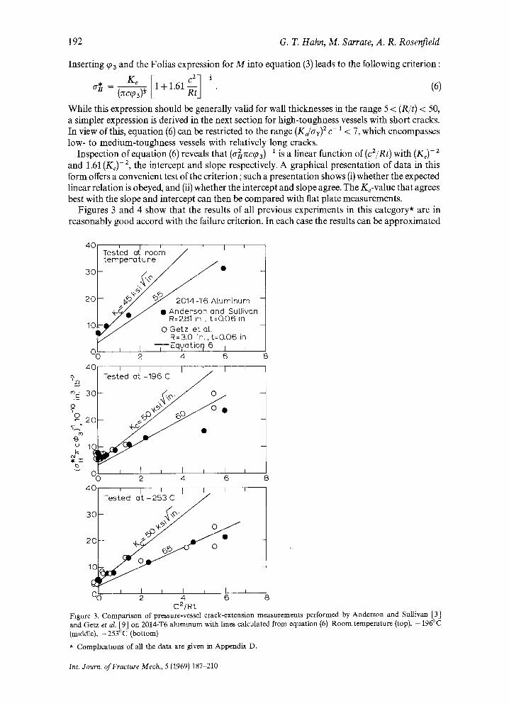
Inspection of equation (6) reveals that (a~rccq03)-t is a linear function of (cZ/Rt) with (K~)-2 and 1.61 (K¢)-a, the intercept and slope respectively. A graphical presentation of data in this form offers a convenient test of the criterion; such a presentation shows (i) whether the expected linear relation is obeyed, and (ii) whether the intercept and slope agree. The K¢-value that agrees best with the slope and intercept can then be compared with flat plate measurements.
Figures 3 and 4 show that the results of all previous experiments in this category* are in reasonably good accord with the failure criterion. In each case the results can be approximated
40 ~ / r I~ ' I r Tested at room ~ / t empera tu re
20 uminum -
+Ye J ~ s 2 n ~Rd su[[ivon R:zsl t - -o .o{
10 J / ~ j OGetz eta[ . i
R=3.0 in., t=G06 in O0 ~ I Equatior~ 6 I I I I
2 4 6 8
40 i i i i ~ i ~'x~ Tested at -196 C
-
° "
~-~ ~ •
i I i i i i 0 2 4 6 8
4 0 ~ I I I I I T e s t e d a t - 2 5 3 C ' J
/ -
/_ / 3C
J ~ : / 0 J
20 ~ O
10
06 I I I i ~ i 2 4 6 8
C2/Rt Figure 3. Comparison of pressure-vessel crack-extension measurements performed by Anderson and Sullivan [3] and Getz et al. [9] on 2014-T6 aluminum with lines calculated from equation (6) Room temperature (top), - 196~C (middle), -253°C (bottom) * Comphcatlons of all the data are given in Appendix D.
Int. Journ. of Fractw'e Mech., 5 (1969) 187-210
Criteria for crack extension in cylindrical pressure vessels 1.93
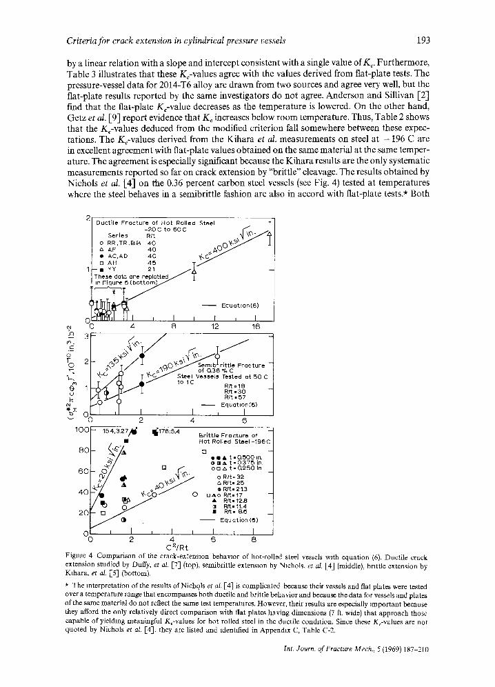
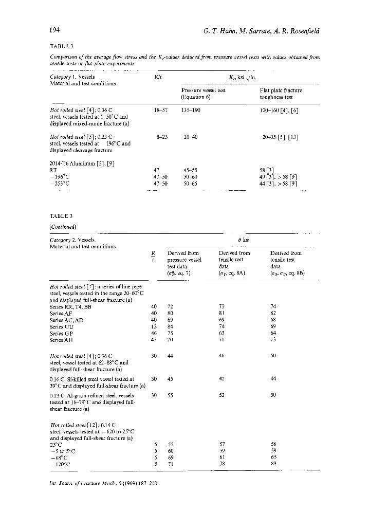
by a linear relation with a slope and intercept consistent with a single value of Kc. Furthermore, Table 3 illustrates that these KFvalues agree with the values derived from flat-plate tests. The pressure-vessel data for 2014-T6 ahoy are drawn from two sources and agree very well, but the flat-plate results reported by the same investigators do not agree. Anderson and Sillivan [2] fred that the flat-plate Kc-value decreases as the temperature is lowered. On the other hand, Getz et o,/. [9] report evidence that K c increases below room temperature. Thus, Table 2 shows that the K¢-values deduced from the modified criterion fall somewhere between these expec- tations. The KFvalues derived from the Kihara et al. measurements on steel at - 1 9 6 C are in excellent agreement with flat-plate values obtained on the same material at the same temper- ature. The agreement is especially significant because the Kihara results are the only systematic measurements reported so far on crack extension by "brittle" cleavage. The results obtained by Nichols et al. [4] on the 0.36 percent carbon steel vessels (see Fig. 4) tested at temperatures where the steel behaves in a semibrittle fashion are also in accord with flat-plate tests.* Both
oJ ~J "-f (J
o-
p / ,, _ , v ,
1 " / X / / ( ~ ) / t to lC
% z I I I
1 0 0 b 1 5 4 , 3 . 2 ; / ~ 11~176;5.4
60 0 []
4O ~.
0 I , I I 0 2 4
C2/Rt
- Duct i le F roc tu re of Ho t Rolled Steel T - 2 o c to 6o c K ~ /1
S e r i e s R/t ~1 \ ~ J / " z~ 0 RR TR EbB 40 rx~ I/~ z~ AF ' 4 0 ~ 0 ~ " ~
[ II AC, AD 40 %0~/"~ I [] AH 4 5 T ~
Ii--ii YY 21 / ~ I These dato ore replotted~
b~r i t t le F rac tu re -- of (3.36 % C
Vespers Teated at 5 0 C
Rtt =18 Rtt - 3 0 Rlt • 57
Equat lon ((5)
, I 2 4 6
Br i t t l e F rac tu re of Hot Rolled S tee l -196C
r-i
e u A t - 0 ~ 0 0 tr~ ~ i l ia t - 0 3 7 5 in, o B t~ t - Q 2 5 0 In
o R/t= 32 R/t- 25 R]{ - 2 !.3
n A o R~-17 • R / t - 12.8 rl R/t= 11.4
-- Equat ion (5)
I ~ I 6 8
Figure 4 Comparison of the crack-extension behavior of hot-rolled steel vessels with equation (6). Ductile crack extension studied by Duffy, et aL [7] (top), semibrittle extension by Nichols, et al. [4] (middle), brittle extension by Klhara, et a/. [5] (bottom).
* The interpretation of the results of Nichols et al. [4] is complicated because their vessels and fiat plates were tested over a temperature range that encompasses both ductile and brittle behavior and because the data for vessels and plates of the same material do not reflect the same test temperatures. However, their results are especially tmportant because they afford the only relatively direct comparison with flat plates having dimensions (7 ft. wide) that approach those capable of yielding meaningful Kc-values for hot rolled steel in the ductile condition. Since these KFvalues are not quoted by Nichols et al. [4], they are listed and identified in Appendtx C, Table C-2.
Int. Journ. o f Fracture Mech., 5 (I969) 187-210
194 G. T. Hahn , M . Sarrate, A. R. Rosenf ield
TABLE 3
Comparison of the average flow stress and the Kc-values deduced from pressure vessel tests with values obtaaned from tensile tests or fiat-plate experiments
Category 1. Vessels R/t Material and test conditions
Ko ksi ~/in.
Pressure vessel test Flat plate fracture (Equation 6) toughness test
Hot rolled steel [4] ; 0.36 C steel, vessels tested at 1-50°C and displayed mixed-mode fracture (a)
Hot rolled steel [5] ; 02,3 C steel, vessels tested at - 196°C and displayed cleavage fracture
18-57 135-190 120-160 [4], [6]
8-23 2 0 4 0 20-35 [5], [13]
2014-T6 Aluminum [3], [9] RT 47 45-55 58 [3] -196°C 47-50 5(P60 49 [3], >58 [9] -253°C 47-50 5(P65 44 [3], >58 [93
TABLE 3
(Continued}
Category 2. Vessels. 6 ksi Material and test conditions
R Derived from Derived from Derived from t pressure vessel tensile test tensile test
test data data data (a~, eq. 7) (ar, eq. 8A) (at, ~rv, eq. 8B)
Hot rolled steel [7] ; a series of line pipe steel, vessels tested in the range 2(g60°C and displayed full-shear fracture (a) Series RR, T4, BB 40 72 Series AF 40 80 Series AC, AD 40 69 Series UU 12 84 Series GP 46 75 Series AH 45 70
Hot rolled steel [4] ; 0 36 C 30 44 steel, vessel tested at 62-88°C and displayed full-shear fracture (a)
0.16 C, Si-killed steel vessel tested at 30 45 39°C and displayed full-shear fracture (a)
0.13 C, Al-grain refined steel, vessels 30 55 tested at lf~79°C and displayed full- shear fracture (a)
Hot rolled steel [12] ; 0.14 C steel, vessels tested at - 120 to 25~C and displayed full-shear fracture (a) 25~C 5 55 - 5 t o 5~C 5 60 - 6 8 ° C 5 69 -- 120°C 5 71
73 74 81 82 69 68 74 69 63 64 71 73
46 50
42 44
52 50
57 56 59 59 61 65 78 83
Int. Journ. of Fracture Mech., 5 (1969) 187-210
Criteria for crack extension in cylindrical pressure vessels
TABLE 3 ( Conunued)
195
Category 3. Vessels R/t Material and test conditions
K~, ksi ,,/in.
Pressure vessel test Flat plate fracture (Equation 9) toughness test
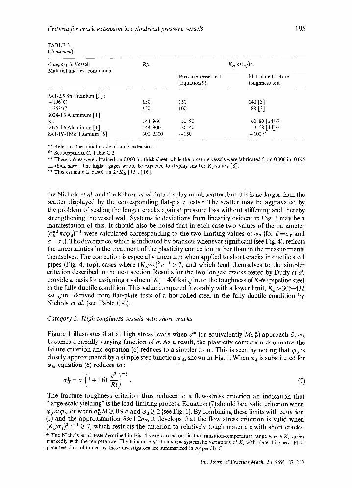
5A1-2.5 Sn Titanium [3] ; - 196~c 150 150 140 [33 -253°c 150 100 88 [3] 2024-T3 Aluminum [1] RT 144-960 50-80 6(~0 [14] (¢) 7075-T6 Aluminum [1] 144-900 30-40 53-58 [14] (¢~ 8AI-IV-1Mo Titanium [6] 300-2300 ~ 150 - 100 ~d)
t.) Refers to the initial mode of crack extension. co~ See Appendix C, Table C.2. c¢~ These values were obtained on 0.060 in.-thick sheet, while the pressure vessels were fabricated from 0 006 in.-0.025 m.-thlck sheet. The higher gages weuld be expected to display smaller Kc-vahies [8]. (a) This estimate is based on 2.K~ [15], [16].
the Nichols et al. and the Kihara et al. data display much scatter, but this is no larger than the scatter displayed by the corresponding flat-plate tests.* The scatter may be aggravated by the problem of sealing the longer cracks against pressure loss without stiffening and thereby strengthening the vessel wall. Systematic deviations from linearity evident in Fig, 3 may be a manifestation of this. It should also be noted that in each ease two values of the parameter (a~Zncq)3)-1 were calculated corresponding to the two limiting values of cp 3 (for 6 = a t and
= av). The divergence, which is indicated by brackets whenever significant (see Fig. 4), reflects the uncertainties in the treatment of the plasticity correction rather than in the measurements themselves. The correction is especially uncertain when applied to short cracks in ductile steel pipes (Fig. 4, top), cases where (K j a r ) 2 c - 1 > 7, and which lend themselves to the simpler criterion described in the next section. Results for the two longest cracks tested by Duffy et al. provide a basis for assigning a value of K c =400 ksi ,,/in. to the toughness of X-60 pipeline steel in the fully ductile condition. This value compared favorably with a lower limit, Kc > 305-432 ksi ~/in., derived from flat-plate tests of a hot-rolled steel in the fully ductile condition by Nichols et al. (see Table C-2).
Category 2. High-toughness vessels with short cracks
Figure 1 illustrates that at high stress levels when a* (or equivalently Me*) approach 8, ~03 becomes a rapidly varying function of 8. As a result, the plasticity correction dominates the failure criterion and equation (6) reduces to a simpler form. This is seen by noting that ~o 3 is closely approximated by a simple step function ~04, shown in Fig. 1. When ~o 4 is substituted for ~o3, equation (6) reduces to:
1 + 1 . 6 1 k 5 ' (7)
The fracture-toughness criterion thus reduces to a flow-stress criterion an indication that "large-scale yielding" is the load-limiting process. Equation (7) should be a valid criterion when ~o3 ~ ~0 4, or when a ~ M > 0.9 a and ~o3 ~ 2 (see Fig. 1). By combining these limits with equation (3) and the approximation 6 ~ 1.2a r, it develops that the flow stress criterion is valid when (KJGr) 2 c - 1 ;~ 7, which restricts the criterion to relatively tough materials with short cracks. * The Nichols et al. tests described in Fig. 4 were carried out in the transition-temperature range where Kc varies markedly with the temperature. The Kihara eta/. data show systematic variations of Kc with plate thickness. Flat- plate test data obtained by these investigators are summarized in Appendix C.
Int. Journ. of Fracture Mech., 5 (1969) 187-210
196 G. T. Hahn, M. Sarrate, A. R. Rosenfield
.13
t -
O
v o l o
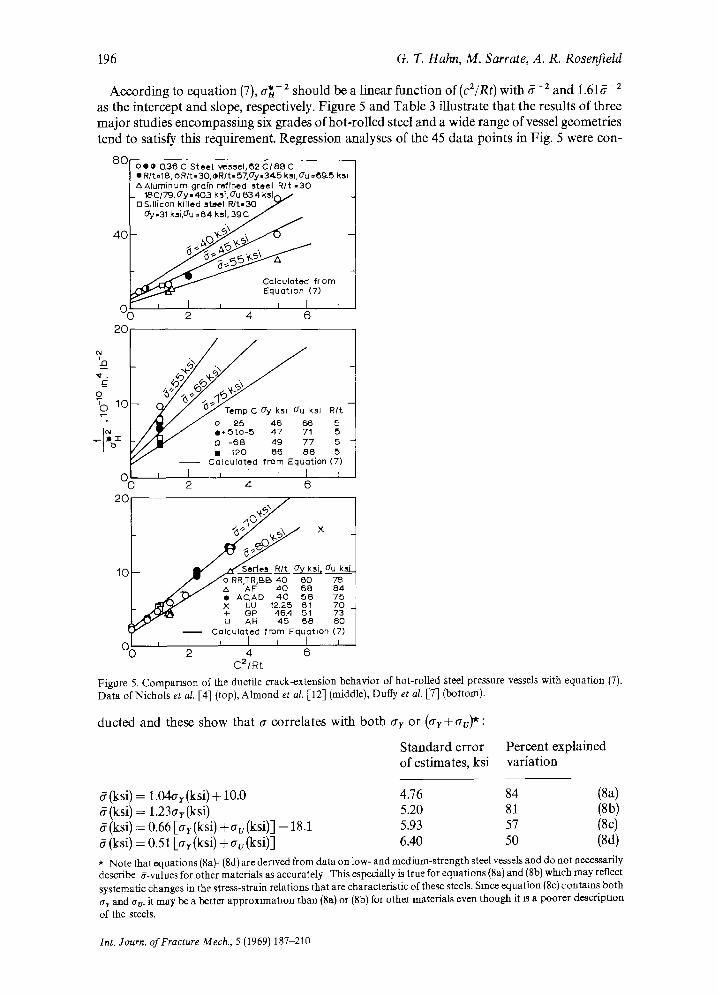
According to equation (7), ~ - 2 should be a linear function of (c2/Rt) with 6 -2 and 1.616-2 as the intercept and slope, respectively. Figure 5 and Table 3 illustrate that the results of three major studies encompassing six grades of hot-rolled steel and a wide range of vessel geometries tend to satisfy this requirement. Regression analyses of the 45 data points in Fig. 5 were con-
8 0 o * o 0~36C Steel vessel,~2 C /88 C ORlt=lS, oRlt.30,oRIt.57,dy.34~5 ksl,Gu =( }~5 k~i AAluminum grain refined steel R / t - 3 0
. 18 C/79, 0"y - 4 0 3 k sl, 0"u 63A ksicL / nSlll[con killed st,~el R / t . 3 0 J ~.31 k.si,Gu ~64 ksl, 39C / " "
Equot~on
n i I i I I I l 2 4 6 2O
/ b V / o 25 46 es 5 / ~ / o , 5 t o - 5 47 71 ' / j ~ r# - 6 8 49 77 5
• -120 (~6 8 8 5 - - Calculated from Equation (7)
0 I [ , ] I I r 2 4 6
20 "6~/07 X
10 I / ~ s e d e s R/t o'y ksi, u k~J . / ~ / o RR TR.BB 4 0 6 0 78
/ ~ / ,, " " A ¢ - - 46 68 ~ • AC, AD 4 0 5 8 75
I : ~ r ~ X UU 12.25 61 7 0 • ~ + (3P 46,4 51 73
[] AH 4 5 6 8 80 Calculated from Equation (7)
2 4 6 C21Rt
Figure 5. Comparison of the ductile crack-extension behavior of hot-rolled steel pressure vessels with equation (7). Data of Nichols et al. [4] (top), Almond et al. [12] (middle), Duffy et al. [-7] (bottom).
ducted and these show that 6 correlates with both ~r r or (at + av)*:
Standard error Percent explained of estimates, ksi variation
6 (ksi) = 1.04at (ksi) + 10.0 4.76 84 (8a) 6 (ksi) = 1.23ar(ksi) 5.20 81 (8b) 6 (ksi) = 0.66 [at (ksi) + av (ksi)] - 18.1 5.93 57 (8c) 6 (ksi) = 0.51 [or (ksi) + av (ksi)] 6.40 50 (8d) * Note that equations (8a)-(8d) are derived from data on low- and medium-strength steel vessels and do not necessarily describe g-values for other materials as accurately This especially is true for equations (8a) and (8b) which may reflect systematic changes in the stress-strain relations that are characteristic of these steels. Since equation (8c) contains both ar and av, it may be a better approxtmataon than (Sa) or (Sb) for other materials even though it xs a poorer descriptaon of the steels.
Int. Journ. of Fracture Mech., 5 (1969) 187-210
Criteria for crack extension in cylindrical pressure vessels
-~ 6 0
d~
L
rn 4C .~_ ~D
8 2c t::,
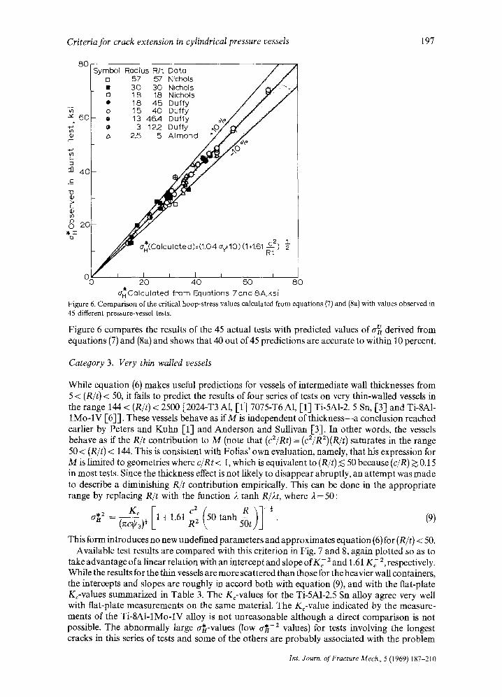
Symbol Radius R/t Data D 57 57 Nichols m 30 30 Nichols o 18 18 Nichols • 18 45 Daffy o 15 40 Duffy
- • 1:3 4~4 Duffy :3 12.2 Duffy
z~ 2.5 5 A lmond
197
O~ I I I I I I I I 20 40 60 80
dHCUlculated from Equations 7rind 8A, ksi Figure 6. Comparison of the critical hoop-stress values calculated from equations (7) and (8a) with values observed in 45 different pressure-vessel tests.
Figure 6 compares the results of the 45 actual tests with predicted values of a v derived from equations (7) and (8a) and shows that 40 out of 45 predictions are accurate to within 10 percent.
Category 3. Very thin walled vessels
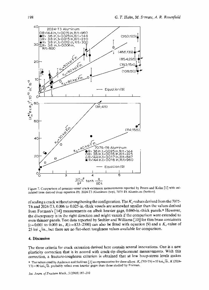
While equation (6) makes useful predictions for vessels of intermediate wall thicknesses from 5 < (R/t) < 50, it fails to predict the results of four series of tests on very thin-walled vessels in the range 144 < (R/t) < 2500 [2024-T3 A1, [1] 7075-T6 A1, [1] Ti-5A1-2. 5 Sn, [3] and Ti-8A1- 1Mo-IV [6]]. These vessels behave as ifM is independent of thickness---a conclusion reached earlier by Peters and Kuhn [1] and Anderson and Sullivan [3]. In other words, the vessels behave as if the R/t contribution to M (note that (c2/Rt)= (c2/R2)(R/t) saturates in the range 50 < (R/t) < 144. This is consistent with Folias' own evaluation, namely, that his expression for M is limited to geometries where c/Rt< 1, which is equivalent to (R/t) ~ 50 because (c/R) >~ 0.15 in most tests. Since the thickness effect is not likely to disappear abruptly, an attempt was made to describe a diminishing R/t contribution empirically. This can be done in the appropriate range by replacing R/t with the function 2 tanh R/2t, where 2 = 50:
R -~ a ~ 2 (~c¢3) ~rKc I1+1.61 ~c2 (50 tanh~0t ) 1 . (9)
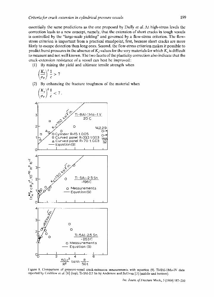
This form introduces no new undefined parameters and approximates equation (6) for (R/t) < 50. Available test results are compared with this criterion in Fig. 7 and 8, again plotted so as to
take advantage of a linear relation with an intercept and slope ofK~- 2 and 1.61 K~- 2, respectively. While the results for the thin vessels are more scattered than those for the heavier wall containers, the intercepts and slopes are roughly in accord both with equation (9), and with the flat-plate Kc-values summarized in Table 3. The K¢-values for the Ti-5A1-2.5 Sn alloy agree very well with flat-plate measurements on the same material. The Kc-value indicated by the measure- ments of the Ti-8AI-IMo-IV alloy is not unreasonable although a direct comparison is not possible. The abnormally large ¢*-values (low G*-2 values) for tests involving the longest cracks in this series of tests and some of the others are probably associated with the problem
Int. Yourn. of Fracture Mech., 5 (1969) 187-210
198 G. T. Hahn, M. S-rrate, A. R. RosenfieId
40 2024-T3 Aluminum
0R=14.4 ira, t= 0.015 irLR/t =960 / , OR= 3.6 in.,t=O.O25ir~,R/t=144 ~ (36.0;12_5)1 mR= 3.6 irL, t=O.O15in.,R/t=230 ~ T IR= 3.6 in.,t=O.012 in, Rl t=300 / T ~ - t
30~R= 3.6 irtt=O.OO6in ~ / ] / R/t=6oo " T~.T / ? / T I
S , y t 1 / (8 4;29 +# 20 -- ~ O ~ . N ~ O ~ (3CJ3;15A) ~Jr
m._ c . ~ _ _ ~ l ~ J ~ ~ Equation (9)
'0 I I II I I I I I I r -
u (81;4.5)
b
, - . (114;15.5)
40- - Q
/ , ~0 ~ I ~ 7 0 7 5 - T 6 Aluminum ~_ / ~-c_~>f@R= 3.6in.t=O.O25in..R/t=144 , -u / / 0 R--3.6 In,t= 0,016 In.,R/t=22 5
2 0 - / ~ ~ . 7!n.R/t=847 / n / ~ t - • R=14~, in.,t= 0.016 in.,R/t=960
• - - Equation )
c I I I I I 1 3 2 4 6
50 c 2 tunh R R 2 50 t
Figure 7. Comparison of pressure-vessel crack-extension measurements reported by Peters and Kuhn [1] with cal- culated lines derived from equation (9). 2024-T3 Aluminum (top), 7075-T6 Aluminum (bottom).
of sealing a crack without strengthening the configuration. The Kc-values derived from the 7075- T6 and 2024-T3, 0.006 to 0.025-in.-thick vessels are somewhat smaller than the values derived from Forman's [-14] measurements on albeit heavier gage, 0.060-in.-thick panels.* However, the discrepancy is in the right direction and might vanish if the comparison were extended to even thinner panels. Test data reported by Sechler and Williams 1-10] for thin brass containers (t=0.001 to 0.003 in., R/t=833-2500) can also be fitted with equation (9) and a Kc-value of 25 ksi ,,/in., but there are no flat-sheet toughness values available for comparison.
4. Discussion
The three criteria for crack extension derived here contain several innovations. One is a new plasticity correction that is in accord with crack-tip displacement measurements. With this correction, a fracture-toughness criterion is obtained that at low hoop-stress levels makes
* The values cated by Anderson and Sullivan [-3] as representative for these alloys : K~ (705-T6) = 53 ksix/~., K (2024- T3) =90 k s i , ~ , probably reflect even heavier gages than those studied by Forman.
Int. Journ. of Fractgre Mech., 5 (1969) 187-210
Criteria for crack extension in cylindrical pressure vessels 199
essentially the same predictions as the one proposed by Duffy et al. At high-stress levels the correction leads to a new concept, namely, that the extension of short cracks in tough vessels is controlled by the "large-scale yielding" and governed by a flow-stress criterion. The flow- stress criterion is important from a practical standpoint, first, because short cracks are more likely to escape detection than long ones. Second, the flow-stress criterion makes it possible to predict burst pressures in the absence of Kc-values for the very materials for which K c is difficult to measure and not well known. The two facets of the plasticity correction also indicate that the crack-extension resistance of a vessel can best be improved:
(1) By raising the yield and ultimate tensile strength when
- > 7 WY/ c
(2) By enhancing the fracture toughness of the material when
- < 7 . \~y / c
% m 3
O % ~ 2
t~
U
l i t lb
v
- ¢ \ ~ . I - 1 M o -1 '\~" o o * ~ ; / 2 o - - c - - _
- o 4.2 ~ r ~ / _ 9 . . . . . 'o
u / ~ ' 0 Cy l inder R--15 t 0 .05 O_V - / [] C u r v e d panel R=3::&3 t Q 0 3 ~,~ y R=-70 t 0.03
- - Eque t i on (9 ) r i i I I I I
.•0•0 Ti- 5 A l - 2 _5Sn
U -196C
) 0 ~ : ) 0 0 M e a s u r e m e n t s ~-~ - Equa t l on (9)
I I I I ~ I
l o o
Ti- 5 A l - 2 . 5 Sn - 2 5 3 C
0 M e a s u r e m e n t s - - EquQt ion (9)
I i ~ I i I t 2 4 6
50 c 2 t a n h R R 2 5 0 t
Fxgure 8. Comparison of pressure-vessel crack-extension measurements with equation (9). Ti-SAI-IMo-IV data reported by Crichlow et al. [6] (top), Ti-5A1-2.5 Sn by Anderson and Sullivan [3] (middle and bottom).
Int. Journ. of Fracture Mech., 5 (1969) 187-210
200 G. T. Hahn, M. Sarrate, A. R. Rosenfield
This clarifies the metallurgy of the problem since composition and processing are not likely to affect ff and K~ in the same way. The tanh-modification extends the usefulness of the approach and points to an underlying connection between the results for medium- and very thin-walled vessels.
In fact, all three criteria are closely related--the ftrst two are special forms of the third. Although other criteria can be fitted to some of the measurements with good precision, the present formulation allows the bulk of the data in the literature to be described reasonably successfully with essentially one expression that involves no undefined material or geometric parameters. Finally, this formulation lends itself to making of predictions. This is in contrast with the Criterion D, Table 1, proposed by Nichols et al. [4] which Quirk [17] has recently fitted to a wide range of pressure-vessel data. The Nichols et al. criterion does not explicity describe the contribution of vessel radius or wall thickness and involves three material constants and four disposable parameters.
Although si~ifieant agreements with experiment are cited, both the "large-scale yielding" idea and the tanh-modification need to be examined more critically. In the first case, M is derived from Follas' elastic treatment which is most vulnerable in the presence of gross yielding. Further work on this aspect of the problem will benefit from more systematic measurements of the distortions of a cracked vessel along the lines begun by Almond et aI., particularly the crack opening, the character of the bulge, and the extent of local plastic deformation. In the second case there is the possibility that the departures from a c2/Rt-dependence displayed by very thin- walled vessels result wholly or in part from the added stiffness and strength conferred by the patch that seals the cracked vessel against pressure loss. Although the observed departures appear too systematic to be explained in this way, the effect of the patch has received tittle at- tention and cannot be discounted. More measurements on vessels fabricated from sheets and plates with well-established Kc-values are needed to fill the large gap that now exists between 50< (R/t)< 150, and to provide a more critical test of tanh-modification in the range 200 < (R/t) < 1000. Studies of longer cracks, i.e., (c/R) > 0.5, are also desirable since the expressions for M used in both criteria are untested beyond this point. Information on long cracks is a prerequisite for treating crack propagation and the speed of failures in pressure vessels.
5. Conclusions
(1) Three closely related criteria for the extension of through-cracks in pressure vessels are derived : (i) a fracture-toughness criterion mainly for low- and medium-tough materials, (ii) a flow-stress criterion for short cracks in tough materials, and (iii) a modification of (i) for very thin vessels. The criteria make use of the Folias analysis for a pressurized cylindrical shell (the fracture toughness approach) and a plasticity correction based on the crack-tip displace- ment of the Dugdale crack model. (2) The plasticity correction is small when failure occurs at relatively low hoopstress levels such as may be encountered with low- and medium-tough materials. In such cases, burst pres- sures can be estimated with a fracture-toughness criterion like the one devised by Duffy and coworkers which relies on a knowledge of Kc (the flat-plate fracture toughness of the material). The toughness criterion is shown to be in good accord with test experience for 2014-T6 alu- minum as well as brittle and semibrittle steel vessels. (3) The plasticity correction departs significantly at high hoop-stress levels from existing for- mulations. It suggests that in this range, cracked vessels undergo "large-scale yielding'--a phenomenon similar to "general yielding" in fiat plates--and that this can occur while the hoop- stress level is still below the yield stress of material. The "large-scale yielding" concept also re- ceives support from crack-tip displacement measurements on vessel and burst-pressure data. (4) The fracture-toughness criterion reduces to a simpler flow-stress criterion at stress levels corresponding to "large-scale yielding". Accordingly, critical hoop-stress and burst-pressure predictions can be made for relatively short cracks in tough materials from a knowledge of ordinary yield and ultimate tensile strength values for materials, and without recourse to Kc.
Int. Jowrn. of Fracture Mech., 5 (1969) 187-210
Criteria for crack extension in cylindrical pressure vessels 201
Excellent predictions can be made in this way for virtually all steel vessels that have failed with full-shear fractures. (5) A simple empirical modification of the Folias result which involves no additional undefined parameters offers the possibility of extending the validity of the fracture-toughness criterion to very thin walled vessels, i.e., vessels with wall radius-to-thickness ratios in excess of 50. The modification appears to be in accord, at least approximately, with results for a wide range of thicknesses and geometries.
Note added in proof: The readers' attention is drawn to the papers by Sanders and his associates which came to our attention after this manuscript was submitted. The papers appear on pages 117 and 133 of the International Journal of Fracture Mechanics, Vol. 5.
Acknowledgements
The authors are grateful to the American Gas Association for financial support. They wish to thank E. A. Almond for generously making available unpublished results of his work on pres- sure vessels, M. F. Kanninen for many useful contributions to the manuscript, and J. H. Broehl for assistance with the regression analyses. The authors are also indebted to A. R. Duffy, R. J. Eiber, W. A. Maxey for their fruitful discussions and cooperation, and to C. Pepper for her work on the manuscript.
Appendix A
List of symbols
B C
e, f ,g,h E K K~ K,~ M n
P R r
t
Vc
v o
W
~7
GH
flU
~ol, ~o2, ~o3, ~o4, ~o5
Displacement coefficient B - 2E6 Crack half length Coefficients that depend on the geometry of the vessel Young's modulus Stress intensity parameter Kc = a (rccq)) ~ Fracture toughness parameter Kc = a* (Tre(p) ~r Plane strain fracture toughness parameter Bulging factor. M = a/aB Strain hardening coefficient Internal pressure Internal radius of cylinder Vessel radius Plate thickness Crack tip displacement A critical displacement Crack center displacement Charpy V-notch energy Coefficient that depends on the material and geometry of the vessel True strain at fracture displayed by an unnotched tensile specimen Nominal stress in a flat plate Plastic flow stress of a nonstrain hardening material Nominal stress in a flat plate at the onset of crack extension or fracture Hoop stress an = (P'R)/t Critical hoop stress for crack extension Ultimate tensile stress Yield stress Plastic zone correction factors.
Int. Journ. of Fracture Mech, 5 (1969) 187-210
202 G. T. Hahn, M. Sarrate, A. R. Rosenfield
Appendix B
Derivation o f the plastic zone correction
The major premise of linear elastic-fracture mechanics is that fracture is controlled by a stress or strain (generated within the plastic zone ahead of a crack) which is a function of the single variable K, where K =a(rcc) ~. The onset of fracture occurs when the stress or strain attains a critical value, which then corresponds to a critical value K:
Kc = ~* (~c) ~ (B.1)
Simple models of a flat plate in simple tension containing a crack with a plastic zone, such as the Dugdale [11] or the Bilby-Swinden model [18], illustrate this property. For example, v~, the crack-tip displacement, which is closely related to the distortions responsible for ductile fracture [16], [19], can be calculated [1%21]. To simplify matters, a nonstrain hardening material that yields and flows at a stress c7 is treated, and for this material at low stress levels, a,~ ~, the equations reduce to the following expression: [11], [1%22]
v c = B- 1 K z ' (B.2)
where B = 2E6. This illustrates that, for a given material, v c is a function of the single variable K. The critical stress intensity K~ (called the fracture toughness) can then be related to ~ , a critical displacement which is independent of nominal stress or crack length* :
Kc = (By*) ~ • (B.3)
Both K c and vc can be regarded as material properties. Equation (B.2) is not valid at high nominal stress levels, and must be replaced by the complete
solution' [20], [21]
[ v~ = B \ 2 ~ ] In sec2~Tj (B.4)
or v~ = B-tK2~p3, (B.5)
where
~ p 3 - - \ 2 e j ha e c ~ j . (U.6)
This shows that v c cannot be expressed only as a function of K at high stresses. This is done by combining (B.3) and (I3.4) which gives:
K = o" (7~c(03) ~ (B.7)
and Kc = ~* (~c~03) ~ . (B.8)
In this context, ~03 can be regarded as a correction factor for large plastic zones. Figure 1 presents ~o 3 graphically and illustrates that q~3 can usually be neglected in the evaluation of Kc when (a*/6) < 0.6 (error < 10 percent). Unpublished evidence from this laboratory has shown that ~o 3 is a useful plasticity correction for flat plate tests.
An expression for v0, the crack center displacement--which is where the largest opening is observed--can be derived from the same model [20], [21]:
2c6 Vo = ~ - ~o,, (B.9)
where
* A discussion showing the relation between ~ and more basic properties of the material is given in [16].
Int. Journ. of Fracture Mech., 5 (1969) 187-210
Criteria for crack extension in cylindrical pressure vessels 203
+sin 2-~ q ~ - I n . ( g . 1 0 )
C o m b i n i n g this with equa t ion (B.2)"
v~ = v o . (B.11) \,26J ~o5
This express ion can be used to es t imate c rack- t ip d i sp lacement values f rom the crack center displacement measurements.
Appendix C
Summary of flat plate K~-values for hot-rolled steels
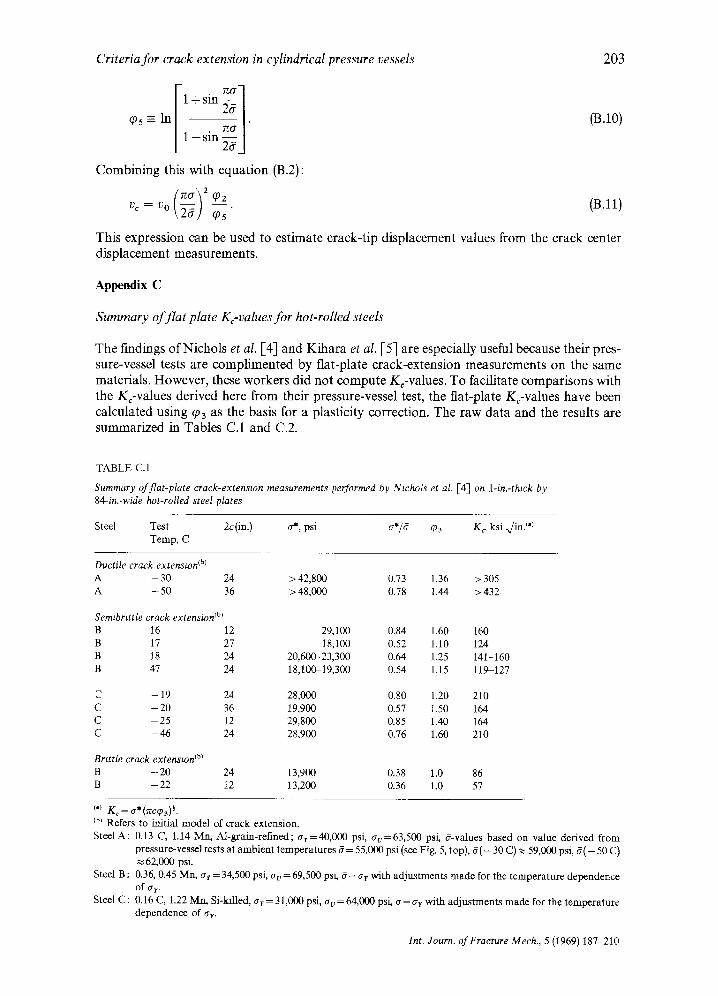
The findings of Nichols et al. [4] and Kihara et al. [5] are especially useful because their pres- sure-vessel tests are complimented by flat-plate crack-extension measurements on the same materials. However, these workers did not compute Kc-values. To facilitate comparisons with the Kc-values derived here from their pressure-vessel test, the flat-plate Kc-values have been calculated using cp3 as the basis for a plasticity correction. The raw data and the results are summarized in Tables C.1 and C.2.
TABLE C.1
Summary of flat-plate crack-extension measurements performed by Nwhols et al. [4] on 1-in.-thzck by 84-in.-wide hot-rolled steel plates
Steel Test 2c(in.) o-*, psi G*/6 q~3 K~ ksi ~/in. ('> Temp, C
Ductile crack extenston tbJ A - 30 24 > 42,800 0.73 1.36 > 305 A - 5 0 36 > 48,000 0.78 1.44 >432
Semtbrtttle crack extension Ib~ B 16 12 29,100 0.84 1.60 160 B 17 27 18,100 0.52 1.10 124 B 18 24 20,600-23,300 0.64 1.25 141-160 B 47 24 18,100-19,300 0.54 1.15 119-127
- 19 24 28,000 0.80 1.20 210 C - 2 0 36 19,900 0.57 1.50 164 C - 2 5 12 29,800 0.85 1.40 164 C - 4 6 24 28,900 0.76 1.60 210
Brtttle crack extenston tb) B - 2 0 24 13,900 0.38 1.0 86 B - 22 12 13,200 0.36 1.0 57
I.~ Kc = a*(~cq~3p. (b~ Refers to initial model of crack extension~ SteelA: 0.13 C, 1.14 Mn, Ai-grain-reflned; a r=40 ,000 psi, av=63,500 psi, &values based on value derived from
pressure-vessel tests at ambient temperatures 6 = 55,000 psi (see Fig. 5, top), 6( - 30 C) ~ 59,(X)0 psi, 6 ( - 50 C) 62,000 psi.
Steel B : 0.36, 0.45 Mn, crr = 34,500 psi, av = 69,500 pst, 6 = crr with adjustments made for the temperature dependence of ax.
Steel C: 0.16 C, 1.22 Mn, Si-kflled, ar = 31,000 psi, a v = 64,000 psi, 6=~r r with adjustments made for the temperature dependence of at.
Int. Journ. of Fracture Mech., 5 (1969) 187-210
204 G. T. Hahn, M. Sarrate, A. R. RosenfieId
TABLE C.2
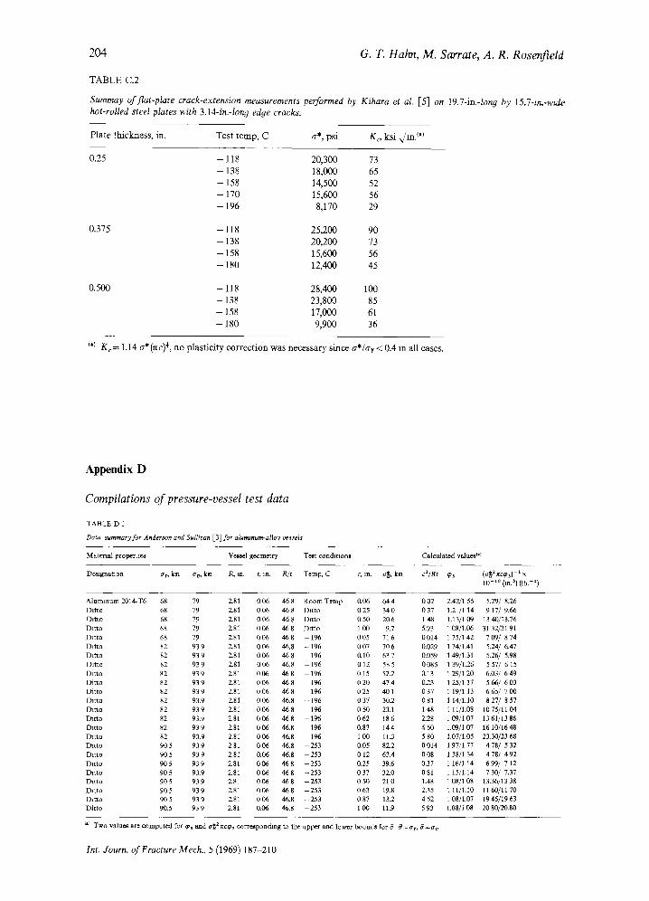
Summay of flat-plate crack-extension measurements perJbrmed by Kihara et al. [5] on 19.7-in.-lon 9 by 15.7-m.-wtde hot-rolled steel plates with 3.14-in.-long edge cracks.
Plate thickness, in. Test temp, C a*, psi K o ksi ~/m.0o
0.25 - 118 20,300 73 - 138 18,000 65 - 158 14,500 52 - 170 15,600 56 - 196 8,170 29
0.375 - 118 25,200 90 - 138 20,200 73 - 158 15,600 56 - 180 12,400 45
0.500 - 118 28,400 100 - 138 23,800 85 - 158 17,000 61 - 180 9,900 36
0o Kc= 1.14 a*(nc) ~', no plasticity correction was necessary since a*/ar< 0.4 m all cases.
A p p e n d i x D
Compilations o f pressure-vessel test data
TABLE D 1
Data summary for Anderson and Sullivan [3]for alumlmo~alloy t~sels
Material propeme~ Ve~..el g~ometry Te~L condttlOnl
Demgnataon at , km a v, km R, m. t, m~ /~/t Temp, C c, m~ ,c~, k~
Calculated valum~ (')
c~/Rt ¢3 (~ IP~¢~) t ×
lO- to 0nS) (lb. 2)
Aluminum 2014-T6 68 79 Z81 0 06 46 8 R o o m Temp 0.06 64 4 0 02 Ditto 68 79 Z81 006 468 Ditto 025 340 037 Dit to 68 79 Z81 0 0 6 468 Drtto 050 206 148 Dttto 68 79 2.81 0 06 46 8 D m o 1120 93 5.93 DUto 68 79 2.81 0 0 6 468 - 1 9 6 005 716 0014 Dffto 82 93 9 2.81 0 06 46.8 - 196 0 07 70 6 0,029 Dffto 82 93 9 2_81 0 06 46 8 196 0.10 63 7 0.059 Ditto 82 939 2.81 006 46.8 - 1 9 6 012 585 0085 Datto 82 939 2.81 006 468 196 015 52.2 0.13 Dit to 82 939 Z81 006 468 - 1 9 6 020 474 0.23 Ditto 82 939 2.81 006 468 196 025 401 037 Ditto 82 93.9 2.81 006 46.8 - 1 9 6 0,37 30.2 081 Ditto 82 939 2.81 006 468 - 1 9 6 050 23,1 148 Darto 82 93.9 2.81 0 0 6 468 - 1 9 6 062 186 2.28 Datto 82 939 2.81 006 46.8 - 1 9 6 0.87 144 450 Ditto 82 93.9 181 006 46.8 196 1 0O 11.3 5 80 Ditto 99 5 93 9 2.81 0 06 46.8 253 0.05 8Z2 0 014 Dttto 905 939 2.81 0.06 46.8 - 2 5 3 012 63.4 008 Ditto 905 939 ZS1 006 468 - 2 5 3 0.25 39.6 0.37 Ditto 905 93.9 2.81 006 468 - 2 5 3 037 32.0 081 I~t to 905 939 Z81 006 468 --253 050 210 1.48 Ditto 90 5 93 9 2.81 0 06 46 8 - 2 5 3 0 63 19.8 2.35 Dit to 995 939 2.81 0 0 6 46.8 --253 087 13.2 452 DRto 9t),5 93 9 2.81 0"06 46.8 - 2 5 3 1 0O 1L9 5 93
7..42/1 55 1.2 /1 14 1.13/1 09 1 08/1.136 1 75/i 42 1 74/1.41 1 49/1.31 1 3 9 / 1 2 6
1 29/1 20 1 25/1 17 i 19/1 13 1 14/1.10 1 11/1.08 1 09/1 07 1.09/1 07 L07/1.05 1 97,/1 77 1 38/1 34 1 16/1 14 1 15/1.14 108/108 1 11/1.10 1 08/1.07 1 , o 8 / 1 08
5.29/8.26 9 17/ 9.66
13 40/13.76 31 32/31 91 709/874 5.24/ 6.47 5.26/ 5.98 557/ 615 6.03/ 6 49 566/ 603 665/ 70O 8 27/ 8 57
10 75/11 04 13 61/13 86 16 10/16 48 23,30/23 68 478/ 532 478/ 492 699/ 712 7 30/ 7.37
13.36)13 38 1160/1170 19 45/19 63 2O 8O/29.8O
0,1 Two va lu~ are c~mputed for q~s s ad cr~2nc¢3 commlmndmg to the upper and lower botmch for 8 # = a r , f f~a v
Int. Journ. of Fracture Mech., 5 (1969) 187-210
Criteria for crack extension in cylindrical pressure vessels
TABLE D 2
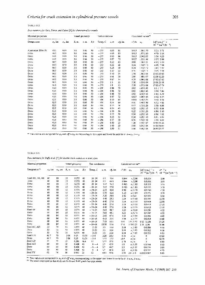
Dasa summary for Getz, Pierce, and Calvet [9]for aIummum~loy vessels
205
Material properue~
De~gnataon
Ve~,el geometry Te~t cOndltlOn~
~rr, km ~rv, k~ R, m~ t, m. R/t Temp, C c, m e~, lon
Calculated v~l uea t'l
c~/Rt ¢:3 (¢,~2 nc¢~)- t x 10- t°(t~3) (Ib a)
Aluminum 2014-T6 90 5 93 9 3 0 0 06 50 - 2 5 3 0,05 81 Datto 90 5 93.9 3.0 0.06 50 - 253 0 05 83 Datto 9.05 939 3 0 0 0 6 50 - 2 5 3 005 86 Ditto 9 05 93 9 3.0 0 06 50 - 2 5 3 0 07 73 Datto 905 939 3.0 0 0 6 50 - 2 5 3 0,12 63 Ditto 90 5 93 9 3 0 0 06 50 253 025 40 Ditto 90 5 93,9 3 0 0 06 50 - 253 0.25 39 l~tto 91)5 939 3 0 006 50 - 2 5 3 037 33 Ditto 9(15 939 3 0 0.06 50 - 2 5 3 050 21 Dat~o 905 939 3 0 006 50 --253 061 20 Drtto 9'05 939 3,0 006 50 --253 087 14 Ditto 905 939 3 0 0.06 50 - 2 5 3 10 11 Datto 905 939 3 0 006 50 --253 I 0 13 Ditto 82.0 93 9 3 0 0 06 50 - 196 0 06 70 Datto 82.0 93 9 3 0 0 06 50 - 196 0 06 72 Datto 82.0 93 9 3 0 0 06 50 - 196 0 06 75 Ditto 82.0 93 9 3 0 0 06 50 196 0 07 72 Datto 82.0 93 9 3 0 0.06 50 - 196 0 10 65 Datto 82.0 93 9 3 0 0.06 50 - 196 0,14 60 Ditto 8Z0 93 9 3 0 0.06 50 - 196 0 15 54 Ditto 82.0 93 9 3 0 0 06 50 -- 196 02.0 45 Eh~o 8Z0 939 3 0 006 50 - 1 9 6 020 50 Dlt'to 82.0 93 9 3 0 0 06 50 - 196 0 25 39 Drtto 82.0 93 9 3 0 0 06 50 - I96 0.25 41 D~tto 82.0 939 3 0 000 5.0 - 1 9 6 037 30 Ditto 82-0 93,9 3 0 006 50 - - I96 050 23 Dit to 82-0 939 3 0 006 50 - 1 9 6 100 20 Ditto 82.0 93 9 3 0 0 06 50 - 196 1.00 11
0013 186 /170 5.21/ 571 0013 197 /180 470 / 514 0013 2.5.4/Z05 339 / 4.20 0027 153/146 557/ 584 008 1 36/1 31 491 / 5 10 0.34 1 14/I 13 6.98/ 7 04 0 34 1 13/1 12 7.41/ 7 47 0 76 1 12/1 11 7.05/ 7 18 1,38 106/106 13 63/13 63 2.06 1 08/1 07 12.08/12,20 42.0 1 06/1 06 17 63/17 63 5 50 1 05/1 04 25 06/25 18 550 107/106 1763/1779 0 02 1 65/1,40 6 5 / 7 7 002 1.80/145 569 / 7.06 002 l l 0 / 1 50 449 / 6_79 0.027 1.90/1 45 4 62/ 6 05 0055 1.50/1.35 502/ 558 0 10 1 40/1 30 4.51/ 4 86 012 135/1.20 539/ 6.06 0.22 1.20/1 15 6 55/ 6.84 0.22 1 30/1.20 4 89/ 5 30 034 1.20/'1 10 698 / 762 0 34 1.20/1 10 6.31/ 6 89 0.76 1 10/1 10 8 69/ 8.69 1 38 1 10/1 07 10 95/11.26 5 50 1.05,/1 04 30 33/30.60 550 106 /104 2489/ '2537
,.I Two values are computed for % and a~anccps c o r r ~ x m d m g to the upper and lower bound* for ~ t~lo- l , ~ = a U
TABLE D 3
DaIa summary for Duffy et aL [ 7 I f or ducglle crack exten~on m steel pipes
M~tcnal propeme~ Ve~el geometry Te~rt conchlaons Calculated vnlue~ °)
Desagnanon cb) at , k*l e~, k ~ P,, m. t, in. R/t Temp, C c, tm o4h, k~ c2/Rt q~ (o-']t 2 r~c(p~)- ~ x o ~ a × 1 0 - 1 ° ( m ? ) ( l b -2) 1 0 - t O ( m / ) ( l b -2)
Steel RR, TR, BB 60 80 Ditto 60 80 Ditto 60 80 Ditto 60 80 Datto 60 80 DIt$O 60 80 Ditto 60 80
Ditto 60 80 Datto 60 80 DII~O 64) 80 Dzt~o 60 80 Steel AF 68 84 Dit to 68 84 Datto 68 84 Ditto 68 84 Entto 68 84
Ditto 68 84 Steel AC, A D 53 75 Ditto 53 75 Datto 53 75 Steel U U 61 7 70 Ditto 61 7 70 Steel G P 51 73 Steel A H 60 80 Ditto 60 80 D m o 60 80 Steel YY 62 74
15 0375 40 20-24 0 5 706 15 0375 40 - 2 0 - 2 4 0 5 698 15 0.375 40 2 ~ 2 4 1 65 56 2 15 0375 40 - 2 0 - 2 4 165 558 15 0375 40 - 2 0 - 2 4 2.25 468 15 0 375 40 - 2 0 - 2 4 2,70 4Z6 15 0 375 40 - 2 0 - 2 4 3 20 38 8 15 0375 40 - 2 0 - 2 4 440 282 15 0.375 40 - 2 0 - 2 4 440 278 15 0 375 40 20-24 4,40 27 6 15 0.375 40 - 2 0 - 2 4 440 276 15 0375 40 - 1 6 - 1 6 2,65 48.7 15 0375 40 - 1 6 - 1 6 2.65 481 15 0375 40 - 1 6 - 1 6 2.65 474 15 0,375 40 - 1 6 - 1 6 440 316 15 0375 40 - 1 6 - 1 6 750 165 15 0375 40 16-16 I000 114 15 0.375 40 2 2 3 3,5 33.0 15 0 375 40 2-23 3 5 32.8 15 ff375 40 2 23 35 32.4
306 0 2 5 12.25 - 2 ~ 3 2.20 25.3 3136 0.25 12.25 - 2 ~ 3 3.55 153
13 0.281 46.4 17 Z55 37 9 18 0.4015 45 - 8 - - 4 2.7 439 18 0.406 45 - 8 - - - 4 2.7 44,7 18 0.406 45 - - 8 - - - 4 2.7 460 18 0861 21 62 485 336
0,044 ~/ 'Z00 0/0.638 2.(:0 0 044 :c/?_00 0/0.654 Z05 0483 ~ / 1 8 5 0/0331 316 0483 cc/185 0/0335 320 099 or_/1 70 0/0380 450 1,30 cc/185 0/0351 550 1 82 o=/2.0 0/0 329 6 64 3.34 ~ / 1 60 0/0,569 1950 3.34 cc/l 55 0/0604 1Z90 334 co/1 55 0/0613 1310 3 34 a:/1 55 0/0,613 13 10 12.5 cc/'2- 20 0/0230 4 22 1.25 ~/2 , I0 0/02.47 4 32 125 o~/1 90 0/0.281 445 3 34 ~ / 1 75 0/0.414 I0 00
100 1 9 /1 35 0,82 /1.156 3720 17 6 1 59/1 25 1 54 /1,96 76 90 2..18 cc/1 65 0/0.506 9 18 Z18 : c / l 65 0/0512 930 2,18 ~ / 1 6 2 0/0535 953 635 co/co 0 1560
16.4 ~/cc 0 4970 1 78 w._/cc 0 6 90 1 0 cc/1.55 0/0 394 5 10 1.0 ~ / 1 57 0/0,376 5 00 1,0 ~ / 1 65 0/0 337 4 70 1 50 2.6 /1 5 0.223/0 387 8.80
I.I Two va/ues are compmed for ~3 and o~3 ncCt corre~ix3ndmg to the upper and lower bounch for 6" ~ - er, a - ~ (b) The st¢~1~ employed in thin a~xtdy are X-50 and X ~ 0 grade hne-~pe ate~]l.
In t . J o u r n . o f F r a c t u r e M e c h . , 5 ( 1 9 6 9 ) 1 8 7 - 2 1 0
206 G. T. Hahn, M. Sarrate, A. R. Rosenfield
TABLE D 4
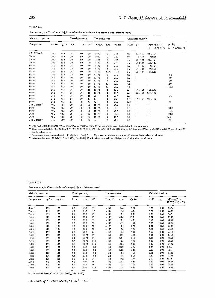
Data summary for Nichols a al [4] for ducrlle ard semibrittle crack exum,ston in steel, pressure ve~l~
MatenN propert3e~
De*lgllatt on
Vo~mel geometry T e~ condltaon~ Calculated valuos o°
ar, k~ o'/7, k~ R, trh ~ t n R/t Temp, C c, ux o'*a, kaa ca~ Rt 9s (°'~2xc93) t x ° ~ - a x 1 0 - 1 0 ( ~ ' ) ( l b -x) 10-x0(tt~*(Ib. -2)
0,36 C Steel c*) 34.5 69 5 30 1.0 30 1 51 3 27.6 0,3 2,3 /1 12 0.6 /1.24 Ditto 34 5 69 5 30 1 0 30 1-51 3 32.2 0 3 co/1 16 0/0.88 Ditto 34.5 69 5 30 1.0 30 1-51 6 18.8 1.2 1.8 /1.09 083 /137 Ditto 34 5 69 5 30 1 0 30 1-51 6 17.9 1 2 1 62/1 08 1 02,/1 53 Ditto 34.5 69 5 30 1.0 30 1-51 6 21.0 1,2 cc/1.12 (3/1 07 Ditto 345 695 30 10 30 1-51 6 159 12 1.4 /166 149/1.98 Ditto 34.5 69 5 30 1 0 30 1-51 12.37 9 6 5 0 1 5 /1 07 1 8612.61 Ditto 34 5 69 5 30 1.0 30 6 2 4 8 3 33 0 0,3 - - - - 9.8 Ditto 34 5 69.5 30 1 0 30 6 2 4 8 6 25.7 1,2 - - - - 15.0 Ditto 34 5 69 5 30 1 0 30 6 2 4 8 6 27.7 1.2 - - - - 13 0 Dit to 34.5 69 5 30 1 0 30 62~88 12 12.7 4.8 - - 62.0 Ditto 34 5 69.5 30 1 0 30 6 2 4 8 12 15.2 4 8 - - - 43.28 Ditto 34.5 69.5 18 i 0 18 10-50 6 13 9 2.0 1.4 /1.06 1 96/2.59 Dit to 34.5 695 18 10 18 10-50 6 174 2.0 Z15/1C~ 0.81/162 Ditto 345 695 18 1.0 18 79 6 234 2.0 - - - - 182 Ditto 345 695 57 1.0 57 17 6 22.1; 063 1.55/1.07 07 /1.02 Ditto 34.5 69.5 57 1 0 57 80 6 27,2 0.63 - - - - 13 5 0 13 C SleeF °) 40.0 63 5 30 1 0 30 16-79 6 29.9 1.2 - - - - i l l Ditto 40.0 63.5 30 1 0 30 16-79 6 31 8 1.2 - - - - 9 g8 Dit to 40 0 63 5 30 1 0 30 16-79 6 29 4 1.2 - - - - 11 56 Dit to 40 0 63 5 30 1.0 30 16-79 6 31.8 122 - - - - 9.88 Dit to 40 0 63.5 30 1.0 30 16-79 12 19 5 4.8 - - - - 26 2 0 16 C Steel I~) 31.0 64.0 30 1 0 30 39 6 28 5 12 - - - - 13.5
t,) Two value~ are compured for cps mad o~ a xcg~ c o ~ n d m g to the upper and lower bound8 for 0 ' 0 = at . ~ - ao, col Phun carbon steel, C 0 3 6 ~ M n ' 0 4443 46%, Sl 0 1 0 ~ .1 3 % The mode oi" crack extemuon m th~ ~ted w ~ 100 percent ductile shear above 51 C., seam-
brittle below 51 C. col A luminum gram-refined ~ceel, C" 0 ,13~ , M n ' 1 .14~, Si 0 12~0 Crack exten~on mode was 100 p e r ~ n t ductile shear m all (d~ Stticon-/alled steel, C 0 ,16~ , M n 1 2 2 ~ , $1 .0-20~, Crack extemmon mode was 100 percent ductile shear m all
TABLE D 5
Data rummary for Kthara, lk2da~ and Iwanaa [5]for brlttle-st2el vess*la
Materml propertae~ Ve*tet geometry Test condltaonw Calculated value*
l~t~on ar, ktl a ~ l o n R, m~ t, m~ R/t Temp, C c, l ~ o'~, kta ca//~ ~3 ( ~ 3 ) -~ x 10- lO{m))(lb -a)
Steel I'l 115 125 4,3 0 25 17 - 196 2.44 3,98 5 56 1 00 82.64 Dit to 115 125 4.3 0`25 17 - 1 9 6 196 495 359 100 6622 D m o 115 125 4 3 0.25 17 - 1 9 6 135 8.25 170 1.00 34.6 Dit to 115 125 4,3 025 17 - 1 9 6 086 132 069 ICO 21 17 Ditto 115 125 8 0 0,25 32 - 1 9 6 3.22 495 518 11713 40.48 IMtto 115 125 8.0 0225 32 - 1 9 6 2.53 560 320 1.1113 4016 Ditto 115 125 8 0 0.25 32 - 1 9 6 185 852 171 1.00 2369 Ditto 115 125 8 0 0225 32 - 196 1,16 9 613 0.67 1 00 29.76 Ditto 115 125 6 0 025 25 - 1 9 6 165 756 180 100 3378 Drcto 115 125 6 4 0,375 17 - 1 9 6 2.0 4 4 0 166 100 8196 Dit to 115 125 6 4 0 375 17 - 196 2.0 5.70 1.66 1,00 49.01 Dit to 115 125 4.3 0.375 114 - 1 9 6 165 740 168 1130 3591 Drtto 115 125 8.0 0.375 21.3 - 1 9 6 2.24 990 167 100 1442 Dit to 115 125 4 3 0.50 8.6 - 1 9 6 2.30 342 544 100 176.0 Ditto 115 125 4 3 0 5 0 8 6 --196 2.63 3.50 32.0 100 99.0 Ditto 115 125 4 3 0.50 8 6 -- 196 1 94 4.20 1.75 1.00 92.59 Ditto 115 125 4.3 0.50 8 6 -- 196 1.16 9.20 0.62 1130 32.46 Ditto 115 125 8 0 0 50 16 -- 196 3 62 2.40 3.27 1.C~ 153.8 Ditto 115 125 g 0 0 5 0 16 --196 2.53 480 160 1.00 54.64 Ditto 115 125 8-0 0 50 16 - 196 1.55 7.20 0 60 1 00 39.68 Dit to 115 125 6.4 0,50 12.8 --196 2.34 490 171 I 0 0 5649
o0 Hot-Rolled S t ~ l . C. 0-25%, Sd 0 0 2 % , M a : 0,85%
Int. Journ. of Fracture Mech., 5 (1969) 187-210
Criteria f o r crack extension in cylindrical pressure vessels
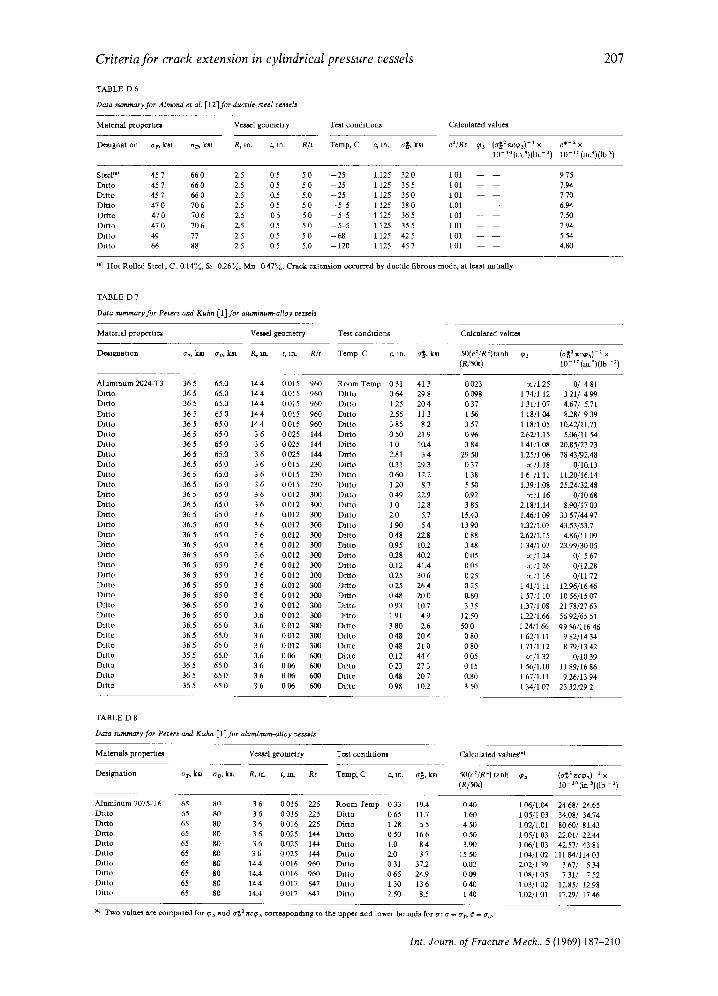
TABLE D 6
Data summary for Almond et al. [12]for ducrtle-~eel ve~sel~
207
Material properia~ Ve~el geometry Test conchtions
Demgnatton Or, kan o-~, km R, in. t, in. R/t T~mp, C c, m~ o~, k~
Calculated value~
c21Rt ~3 (~r~ancg~) -1× c *-2× I0 ' ° (m) ) ( lb . 2) 10 '°(m.*)(lb 2)
Steel I') 457 6 6 0 2.5 0 5 5 0 - 2 5 1.125 320 I01 975 Ditto 45 7 66 0 2.5 0 5 5 0 - 25 1 125 35 5 1 01 7.94 Dit to 457 6 6 0 2.5 0.5 5.0 - 2 5 1125 360 101 770 Ditto 470 706 2.5 0 5 5 0 - ~ 5 1 125 380 1.01 6.94 D m o 470 706 2.5 0 5 50 - 5 - 5 1125 365 101 7.50 Ditto 470 706 2.5 0 5 5 0 - -5 .5 1125 355 101 794 Ditto 49 77 2.5 0 5 5 0 - 68 1 125 42 5 1 01 5 54 Dit to 66 88 2.5 0 5 5,0 - 1 2 0 1 125 45 7 1 01 4.80
(*) Hot Rolled Steel, C . 0 .14~ , St 0.26%, Mn 0 47,°,~. Crack extension occurred by ductile fibrou~ mode, at l e ~ lm~ally.
TABLE D 7
Da*a summary for Peter~ and Kuhn [1 I f or aluminum-alloy ve~ l s
Material propertttm Vestal geometry Te~t condltfoas
D~lgna taon at, kta cv, k*l R. to- r, in. R/t Temp C c~ in. o~, ksa
Ca. !cu~ ed valu~n
50(c:/R2)tanh c~3 (e45a) 10-tO(m ~)(lb -2)
A luminum 2024-T3 36 5 65.0 14 4 0 015 960 R o o m Temp 0 31 41 3 0 023 Ditto 36 5 65.0 14 4 0"015 960 Ditto 0 64 29 8 0 098 Ditto 365 65.0 144 0015 960 Ditto 1 25 204 037 Ditto 36 5 65 0 14 4 0.015 960 Drtto Z55 11 3 1 56 Ditto 36 5 65.0 14 4 0 015 960 Ditto 3 85 8 2 3 57 Ditto 365 6 5 0 3 6 0025 144 Drtto 050 219 096 Dit to 365 6 5 0 3 6 0025 144 Dit to 10 10.4 384 Ditto 36 5 65.0 3,6 0 025 144 Drtto 2.81 3 4 29 50 Ditto 36.5 65,0 3 6 0015 230 Ditto 0-31 29.3 0 37 Ditto 36 5 65.0 3 6 0015 230 Ditto 060 17.2 1 38 Dit to 365 6 5 0 3 6 0015 230 Di t to I 2 0 8.7 550 Dit to 36 5 65 0 3 6 0 012 300 Drtto 0 49 22.9 0.92 Dit to 36 5 65 0 3 6 0012 3 ~ Dit to 1 0 12.8 3 85 Ditto 36 5 65 0 3 6 0.012 300 Ditto 2.0 5.7 15.40 Ditto 36.5 650 3 6 0'012 300 Ditto 190 54 I390 Ditto 36 5 65 0 3 6 0.012 300 Ditto 0 48 22.8 0 88 Ditto 365 65.0 3 6 0012 309 Ditto 0.95 10.2 348 Ditto 36 5 65 0 3.6 11012 3(;0 D m o 0.28 40.2 005 Ditto 365 650 3 6 0012 300 Ditto 0.12 41.4 005 Ditto 365 650 3 6 0012 300 Drtto 0.25 306 025 Ditto 365 6 5 0 3 6 0"012 3.03 Drtto 025 264 025 Ditto 365 6 5 0 3 6 0012 300 Ditto 048 290 0,80 Dit to 36.5 650 3 6 0012 300 Dit to 093 107 335 Ditto 365 650 3,6 0012 303 Dit to 191 49 12.50 Drtto 36,5 65 0 3.6 0012 300 Dit to 3 80 Z6 500 Ditto 36 5 65.0 3 6 0 012 3 ( 7 0 Dit to 0 48 20 4 0 80 Dit to 365 6 5 0 3 6 0012 300 Ditto 048 210 080 Ditto 36 5 65.0 3.6 0 06 6130 Ditto 0.12 44 4 0 05 Ditto 365 6 5 0 3 6 006 600 Ditto 023 273 015 D~tto 36 5 65 0 3 6 0 06 600 Ditto 0,48 20 7 0.80 Ditto 36 5 65 0 3 6 0 06 6/30 IMtto 0 98 102 3 50
oc/125 0/ 481 174 /112 3 2 1 / 4 9 9 1 31/1 07 4,67/ 5.7i 1 18/1 04 828/ 9 39 1 18/105 10.42/11.71 2.62/1.15 5.06/11 54 1 41/1.138 20.85/27 23 1.25/1 06 78 43/92.48
oc/1.18 0/10"13 16 /111 11.20/16.14 1.39/1.08 25.24/32.48
co/1 16 0/1068 2.18/1A4 8.90,/17 03 1.46/1 09 33 57/44 97 1.32/1.07 43.53/53.7 2.62/i.15 4.86/11 09 1 34/i 07 23.99/30 05
oc/i 24 (3,/ 5 67 ac/1 26 0/12.28 co/1 16 0/11 72
1 41/1 11 12.96/'16 46 157 /110 1056/1507 1.37/1 08 21 78/27 63 122/1.66 56 92/65 51 I 24/1 66 0956/116 46 162/111 9 82 /14M 1 71/1 12 8 79,/13 42
co/1 32 0/10 39 1 56/1.10 11 89/16 86 1 67/1.11 926/13 94 1 34/1 07 23.32/29 2
TABLE D 8
Da~a summary for Peters and Kuhn [1]for a l u m t ~ o y vc~,~is
Mater iah propertae~ Vezad geometry Te~t condition*
Designation at, klfi atj, k~ R, ~ t, In. Rt Temp, C c .m. a~, Io~
Calculated vultte!l(')
50(c2/R2) tanh q~a (acaa r~c~n) - ' × (R/5Ot) 10 - 1, (in ~)(lb - x)
A luminum 7075-T6 65 80 3 6 0016 225 Room Temp 0 33 19.4 040 1.06/1.04 24 68/ 24.65 Dit to 65 80 3 6 0 016 225 Dit to 0 65 11.7 1.60 1 05/I 03 34.08/ 34.74 Ditto 65 80 3 6 0016 225 Ditto 128 55 450 1.02/L01 8060/ 81.43 Drcto 65 80 3 6 0.025 144 Ditto 0 50 16 6 0 50 1 05/1 03 2Z01/ 22.44 Dit to 65 80 3 6 0,025 144 Ditto 1.0 84 3.90 106/103 42.57/ 4381 Dit to 65 80 3 6 0025 144 Dit to 2.0 37 1550 104/102 11184/11403 Dit to 65 80 14 4 0 016 960 Dit to 0 31 37.2 0.02 2.024'1 39 3 67/' 5 34 Ditto 65 80 I4.4 0016 960 Drtto 065 24.9 009 108 /105 7 31/ 7 52 Drtto 65 80 144 0017 847 Drtto 130 136 040 103/102 12.85/ 12.98 Ditto 65 80 I4.4 0 017 847 Dit to 2-50 8.5 1 40 L02/1 01 17.29/ 17 46
o,) Two value~ ~re computed for cp3 and eta a r.c~3 corroapondmg to the upper and lower bomad.~ for #: # - at , ~ I a ~
lnt. Journ. of Fracture Mech., 5 (1969) 187-210
208
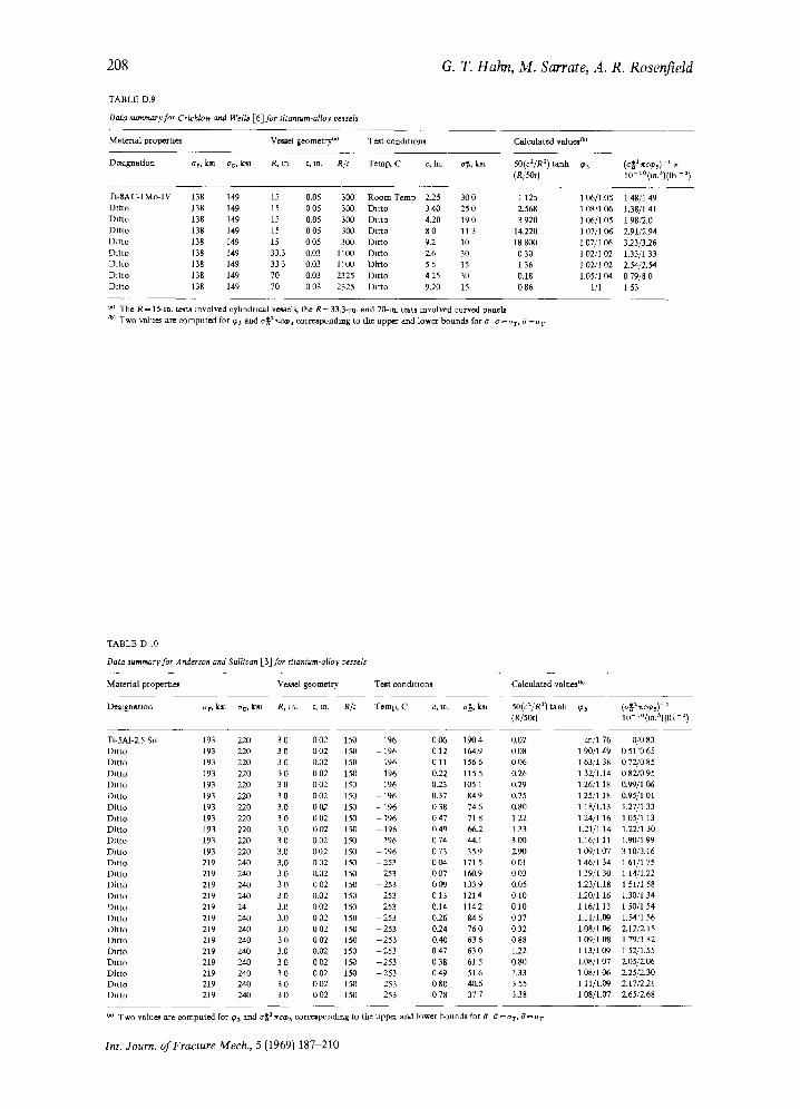
TABLE D.9
Data summary for Crtchlow and Wells [6]for r#.amum-alloy veasels
G. T. Hahn, M. Sarrate, A. R. Rosenfield
Materml p ropemes Vem~el geometry <') Te*t condltaon*
Deaignation err, ~ fro, kal R.m. t, tm R/t Temp, C c, in. eta, k~l
Calculated v a l u e ~ I
50(c2/Ra) tanh q~3 (o'1}2 :~ctPs) - I x (R/50I) 10 t ° (m.S)( lb-a)
T1-SAC-I Mo-IV 138 149 Dttto 138 149 l~ t to 138 149 Dit to 138 149 Dit to 138 I49 D m o 138 149 Dit to 138 149 Dit to 138 149 Ditto 138 149
15 0.05 300 R o o m Temp 2.25 300 1 125 15 005 300 Dit to 340 250 2-568 15 0,05 308 Ditto 4.20 19 0 3 920 15 0 05 300 Ditto 8 0 11 3 14.220 15 0 05 3010 Ditto 9.2 10 18 800 33.3 0.03 11C~ Ditto 2.6 30 0 30 333 0.03 1100 Ditto 55 15 136 70 0.03 2325 Dit to 4 25 30 0.18 70 0 03 2325 Dit to 9,20 15 0 86
1 06/1.05 1 48/149 1 08/106 1.38/141 1 06/1.05 1 98/2.0 1 07/1 06 2.91/2-94 1 07/I 0,6 3.23/3-26 1 02/I 02 1.33/1 33 1 02/1 02 954/2.54 1.05,/104 079/8 0
1/1 1 53
I.) The R ~ 15-m~ ~ revolved cyhndncal ve*~els, the R - 33.3-m~ and 70-m~ test~ revolved curved panet~ co) Two value* are m m p u t e d for ~Ps and o~= 7rvxp3 corresponding to the upper and lower bounds for 8 # = O r , 6=or v
TABLE D 10
DaZa aumma~y for Anderson and Sulllva~ [3] for titanium-alloy t~asds
Material proper t~s Ve.~eI geometry Te~rt condattons
De~tgnatton ar, kJu av, k~ R. trL t. m, R/t Temp, C c, t~ o~, ksa
Calculated val~e:s I';
50(c:/R 2) mnh ~ (R/~) 10-1° ( f in ' ) l i b7 z )
TI-SA1-2.5 Sn 193 220 3 0 0 0 2 150 - 1 9 6 006 1904 Datto 193 220 3 0 0 02 150 - 196 0 12 16-&9 Ditto 193 220 3 0 0,02 150 196 011 1566 Ditto 193 220 3 0 0 02 150 196 0-22 115 5 Datto 193 220 3 0 0 02 150 196 023 105 1 IMtto 193 220 3 0 0 02 150 - 196 0.37 84,9 Ditto 193 220 3.0 0 02 150 - 196 0 38 74 6 DRto 193 220 3 0 002 150 - 1 9 6 047 718 Ditto 193 220 3.0 0 02 150 - 196 0 49 66.2 Ditto 193 220 3 0 002 150 --196 074 44.1 IMtto 193 220 3,0 0 02 150 - 196 0 73 35.9 Da'ao 219 240 3.0 002 150 - 2 5 3 004 171 5 Dttto 219 240 3 0 0.02 150 - 2 5 3 007 160.9 Ditto 219 240 3 0 002 150 - 2 5 3 009 1339 Datto 219 240 3 0 0.02 150 253 0 13 121 4 Ditto 219 24 3.0 0 0 2 150 - 2 5 3 0.14 1142 Ditto 219 240 3.0 0 02 150 - 253 0_26 g4 6 Dll to 219 240 3.0 0 02 150 - 253 0.24 76 0 Ditto 219 240 3 0 0 02 150 253 0.40 63 6 D~tto 219 240 3.0 0.02 150 253 0 47 63.0 Datto 219 240 3 0 0 02 150 - 2 5 3 0 38 61 5 Dit to 219 240 3 0 0-02 150 - 2 5 3 049 516 Ditto 219 240 3 0 0 0 2 150 - 2 5 3 080 40£ Ditto 219 240 3 0 0 02 150 253 0 78 37 7
0.02 0 08 0O6 O.26 0-29 O,75 0.80 122 133 300 Z90 001 0O3 0.05 010 010 037 0 32 088 1_22 0.8O 1.33 3 55 3,38
oc/1 76 0/0 83 i 9 9 / 1 4 9 051,/065 163/138 072 /085 132/1.14 082 /095 1 26/1 18 0.99/1 06 125/1 18 0.95/101 1 18/1.13 127/1 33 124/1 16 1 05/1 13 1.21/1 14 1.22/1 30 1.16/111 1.90/199 109/107 3 10/3.16 146/1 34 1 61/1 75 1 39/1 30 1 14/1.22 123/1.18 1 51/1,58 1.20/1 16 1.30/1 34 1 16/1 13 1 50/1 54 1.11/1.09 1.54/1 56 1,08/1 06 2.12/2.15 1 09/1 08 1 79/1 82 1 13/109 152/1.55 1.08/1 07 2.05/2.O6 1 08/1 O6 225/2.30 1 11/1.09 2.17/221 108/1.07 2.65/2.68
~,a Two value* aro computed for ~pa and o~2 r, ap3 corre tpondm8 to the uppe~ and lower bounds for 6 d = ~ r , 8=cry
Int. Journ. of Fracture Mech., 5 (1969) 187-210
Criteria for crack extension in cylindrical pressure vessels
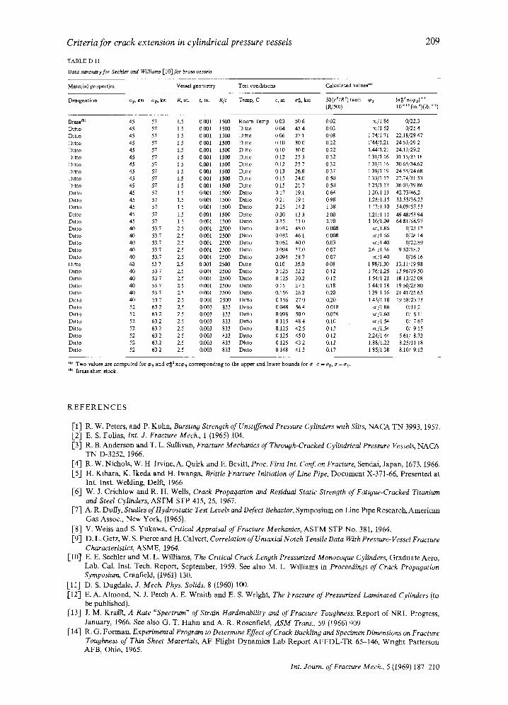
TABLE D 11
Data summary for SecLl~r and WlUJam~ [ lO] for bra~ vessel~
209
MatefiM proFerfies
De~tgnation at, k~ av, k~
Ves~l geometry Test conchtaons
R, m. r, m. R/t Temp, C c~ m o~. ks1
Calculated valm~ I')
50(ca/R 2) t ~ h ~3
(P4500 (035 =c,~) - 1 0 - ' ° ( ~ ) ( l b . - : )
Brasa c°l 45 57 1.5 0 C01 1 5 0 0 Room Temp 0 03 50 6 0 02 Ditto 45 57 1.5 0 001 15£O Datto 0 04 45 4 0 03 Ditto 45 57 1 5 0001 1 5 0 0 Ditto 006 37 1 008 Ditto 45 57 1 5 0 001 15~ Ditto 0 10 30 0 022 Ditto 45 57 1.5 0"001 1 5 0 0 Ditto 0"10 30 0 03.2 Datto 45 57 1 5 0 001 15130 Ditto 0 12 25 5 0 32 Ditto 45 57 1 5 0"001 1500 Ditto 0.12 25 7 0 32 Dffto 45 57 1 5 0 001 1500 Ditto 0 13 26.8 0 37 Drtto 45 57 1.5 0 CO1 1 5 0 0 Ditto 0 15 24.0 0 50 Ditto 45 57 1 5 0001 1500 Ditto 015 21 7 050 Dttto 45 57 1 5 0 001 1 5 0 0 Datto 0 17 19.l 0 64 Drtto 45 57 1.5 0001 1 5 0 0 Ditto 021 19 1 098 Dffto 45 57 1 5 0031 15(!0 Ditto 025 142 1 38 Ditto 45 57 1.5 0001 1500 Dffto 030 133 203 Ditto 45 57 1.5 0 001 15130 Ditto 0 35 11 0 2_70 Ditto 40 53.7 2.5 0 001 2500 Datto 0 032 48 0 0 008 Ditto 40 53.7 2.5 0 COl 2500 Ditto 0 032 46 1 0 008 Ditto 40 53.7 2̀ ,~ 0001 2500 Ditto 0.062 400 0.03 Ditto 40 53.7 2`5 0 CO1 25130 Ditto 0 094 37.0 0 07 Ditto 40 53.7 Z5 0001 2500 Ditto 0.094 38 7 007 Ditto 40 53 7 95 0 001 2503 Ditto 0" 10 35.0 0 08 Datto 40 53 7 2.5 0 001 2500 Ditto 0 125 32`2 0 12 Ditto 40 53 7 2_5 0001 2500 Ditto 0 125 302 0 12 Datto 40 53 7 2_5 0 001 2500 Ditto 0 15 27 5 0"18 Ditto 40 53 7 2.5 0 00l 2500 Ditto 0.156 26 2 0.20 Ditto 40 53 7 2`5 0031 2500 Ditto 0 156 270 0.20 Datto 52 63 2 2.5 0 003 833 Datto 0 048 56 4 0 018 INtto 52 63 2 2.5 0.003 833 Ditto 0 098 50 0 0.076 Drcto 52 63 2 2.5 0.003 833 Ditto 0 115 48 4 0.10 Ditto 52 63 2 2.5 0.003 833 Ditto 0.125 42`5 0 i2 Ditto 52 63 2 2.5 0003 833 Ditto 0 125 45 0 0 12 Ditto 52 63.2 2.5 0.003 833 Ditto 0 125 43 2 0.12 Ditto 52 63 2 2.5 0.003 833 12ntto 0 148 413 0.I7
~/'1 86 0/2Z3 cell 52 0f25 4
174/171 22`18/29 47 1'44/1.21 2453/29 2 1.44/1.21 24.13/29.2 131/1 16 31 15/35 18 1 31/1 16 3065/34.62 139/1 i9 2455/2468 1 33/1 17 27.74/31 53 1 25/1 13 3603/3986 1.20/I 11 42.73/46.2 1.28/1.15 3Z55/36,23 l 17/1.10 54.09/57.53 1.21/1 11 4948/5394 1 16/1.09 6481/68.97
ce/1.86 0,/23 17 co/1 66 0/'28 14 cc/l 40 0/22.89
2.6 /1 36 9 52/18.2 ~/1 40 0/16 16
1 98/1.30 13.11/19 98 1 76/1.26 13 96/19 50 1 54/121 18 13/23 08 1 44./I 18 19 50/23 8O 1 39/1 16 2141/25 65 1 43/i 18 19 58/23.73
az/1 86 0/11.2 cc/1.60 0/ 8.ll co/1 54 0/ 7 67 0z/1.54 O/ 9 15
2224/1 44 5 61/ 8.73 1.88/1.22 8.25/11 18 1 85/1 38 8.10/ 9.13
(.I Two value~ are computed for qh and o'~ 2 nccpa corresponding to the upper and lower bounds for ff 5 - ar, ff = a v. (b) Bra~s shHn stock.
R E F E R E N C E S
[ 1 ] R . W . P e t e r s , a n d P. K u h n , Bursting Strength of Unsuffened Pressure Cylinders wuh Slits, NACA TN 3993, 1957.
I-2] E. S. F o l J a s , Int. J. Fracture Mech., 1 (1965) 104.
[-3] R . B. A n d e r s o n a n d T . L. S u l l i v a n , Fracture Mechanics of Through-Cracked Cylindrical Pressure Vessels, NA CA T N D - 3 2 5 2 , 1966.
[ 4 ] R . W . N i c h o l s , W . H I r v i n e , A. Q u i r k a n d E. Bev i t t , Proc. First Int. Conf on Fracture, S e n d a l , J a p a n , 1673, 1966.
[ 5 ] H . K l h a r a , K . I k e d a a n d H . I w a n g a , Brittle Fracture Initiation of Line Pipe, D o c u m e n t X - 3 7 1 - 6 6 , P r e s e n t e d a t
In t . Ins t . W e l d i n g , De l f t , 1966
[6 ] W . J. C r i c h l o w a n d R . H . W e l l s , Crack Propagation and Residual Static Strength of Fatigue-Cracked Titanium and Steel Cylinders, A S T M S T P 415, 25, 1967.
[ 7 ] A . R . D u t I y , Studies of Hydrostatic Test Levels and Defect Behavior, S y m p o s i u m o n L i n e P i p e R e s e a r c h , A m e r i c a n
G a s A s s o c . , N e w Y o r k , (1965).
[ 8 ] V. W e i s s a n d S. Y u k a w a , Crztical Appraisal of Fracture Mechanics, ASTM S T P N o . 381, 1964.
[ 9 ] D . L . G e t z , W . S. P i e r c e a n d H . C a l v e r t , Correlation of Uniaxial Notch Tensile Data With Pressure-Vessel Fracture C h a z a c t e r / s t / c s , A S M E , 1964.
[ 1 0 ] E. E. S e c h l e r a n d M. L. Williams, The Critical Crack Length Pressurized Monoeoque Cylinders, G r a d u a t e A e r o ,
L a b . Ca l . Ins t . T e c h . R e p o r t , S e p t e m b e r , 1959. See a l so M. L W i l l i a m s in Proceedings of Crack Propaoation Symposium, C r a n f i e l d , (1961) 130.
[ 1 1 ] D . S. D u g d a l e , J. Mech. Phys. Solids, 8 (1960) 100.
[ 1 2 ] E . A . A l m o n d , N . J. P e t c h A . E. W r a i t h a n d E. S. Wright, The Fracture of Pressurized Laminated Cylinders (to
b e p u b l i s h e d ) .
[ 1 3 ] J. M . K r a f f t , A Rate "Spectrum" of Strain Hardenability and of Fracture Toughness, R e p o r t o f N R L P r o g r e s s ,
J a n u a r y , 1966. See a l s o G . T . H a h n a n d A . R . R o s e n f i e l d , ASM Trans., 59 ( I966) 909
[ 1 4 ] R . G . F o r m a n , Experimental Program to Determine Effect of Crack Buckling and Specimen Dimensions on Fracture Toughness of Thin Sheet Materials, AF F l i g h t D y n a m i c s L a b R e p o r t A F F D L - T R 65 - 146 , W r i g h t P a t t e r s o n A F B , O h i o , 1965.
Int. Journ. of Fracture Mech., 5 (1969) 1 8 7 - 2 1 0
210 G. T. Hahn, M. Sarrate, A. R. Rosenfield
[15] W. G. Degnan, P. D. Dripchak and C. J. Matvsovitch, Fatigue Crack Propagation in Aircr@ Materials, U.S. Army Aviat. Mat. Lab. Fort Eusti~ Va~ Technical Report 66-9, March 1966.
[16] G. T. Hahn and A. R. Rosenfield, Sources of Fracture Toughness. The ReIatmn Between Kit and the Ordinary Tensile Properties of Metals, ASTM STP 432, 5, 1968.
[17] A. Quirk, A Maximum Stress Theory for the Failure of Pressure Components Containin 9 Tl~oagh Thickness Defects, UKAEA Report AHSB(S) R 134, 1%7.
[18] B. A. Bilby and K. H. Swinden, Proc. Roy. Soc. A, 285 (1965) 22. [19] A. A Wells, Brit. Weld. J., 10, 855 (1963). [20] J. N. Goodier and F. A. Field, Fracture of Solids (Edited by Drucker and Gtlman), Interscience, New York, 103,
1963. [21] G.T. Hahn and A. R. Rosenfield, Acta Met., 13 (1965) 293. [22] A. R. Rosenfield, P. K. Dai and G. T. Hahn, Proceedings of the First International Conference on Fracture,
T Yokobori, et al., eds., 1 (1966) 223.
RI2SUMI2 Le m6moire d&zit trois crithres pour l'extension" de fissures ardales traversant de part en part la paroi de r&apients sous pression de forme cytindrlque. Ces crit6res sont 4troitement li6s:
1) Un crit&e de t~nacat6/~ la rupture, applicable surtout aux mat&aaux/l ductiht6 fmble ou moyenne. 2) Un crit6re bas6 sur l'+coulement plastique, applicable aux mat6riaux ductiles. 3) Une adaptataon du critbre 1 au cas des r~ciplents d'+paisseurs relativement faibles. L'analyse proc~de/t un couplage entre l'6tude th6orique par Folias du cas d'une enveloppe cylindrique sous pression,
les concepts de r6sistance/~ la rupture brutale, et une nouvelle forme de correction plastique. Cette correctmn, qui est compatible avec des mesures de d+placements ~ fond de fissure, montre que la contramte limite d'bcoulement plastique gouverue l'extension de fissures de faibles dimensions darts les r6clpients construits en mat6riaux ductiles. Par contre, l'extension de fissures plus importantes, ou te cas de mat6riaux moins ductfles, sont sanctionn& par la t6nacit6/i la rupture bmtale. Moyennant une simple adaptation empinque, cette analyse peut &re 6tendue au cas des r&apients dont le dema-dlametre est grand vts h vis de l'6palsseur (R/t > 50). A cet 6gard, une estimation des combinaisons criti- ques entre contrainte de membrane et longueur de fissure peut &re d6duite de la connaissance du rapport du demi- diam~tre h l'6paisseur, et soit de la limite ~lastlque, soit des charges hmites d'61asticit6 et de rupture, soit de K~. II n'est pas n6cessaire de proc6der/i un essai prgalable en vraie grandeur.
On montre que de telles estimaUons sont en accord avec les donn6es pubh&~s, qui couvrent des cas de r~ipients en acier ductile, en acier fragile, en alliages d'aluminium et en alliages de titane.
Z U S A M M E N F A S S U N G Diese Abhandlung beschreibt drei nab. verwandte Kriterien ffir die Erwelterung von achsenf6rmlgen Durchrissen m
zylindrischen DruckgefiiBen. (1) ein FrakturhS.rtekriterium besonders ffir niedrlg- und mittelhartes Material, (2) ein plastisches Zustrom-Spannungskritenum fftr kurze Rasse in harten Materialen, und (3) eine Modifikation zu (1) ffir verhgltmsmS.Blg dfinnwandige BehLiter. DleSe Entwicklung verbindet die theoretasche Behandlung bei Folias von emer sich unter Druck befindenden
Muschel mit der Anngdierungsmethode der Frakturstfirke und einer neuen Plastizitatsverbesserung. Dlese Verbesse- rung, welche mit den Magen der Ril3spatzenverschiebungen vereinbart ist, zeigt dab die plastische Zustromspannung die Erweiterung yon kurzen Rissen m Ge~3en, die aus harten Materialen fabriziert wurden, bestimmt. Dleses steht tm Kontrast mit dem Verhalten yon liingeren Rassen oder spr6deren Materialen, welche yon der Frakturstgrke abhfingen. Die Formulierung wurde auf Gef~ge mit grol3em Radius lm Verhfiltms der Wandstgrke, z.B. R/t >50 durch eine einfache, empmsche Modif'lkation, ausgedehnt. Auf dlese Art und Weise konnten Schgtzungen ffir Kom- bmationen der Bandspannungsl~inge yon dem GelSBradius zum Verhhltnis in der Wandst~rke and yon der gew6hu- lichen Gewinnstfirke, den CJewinn- und Grundstfirken o~ter Kc ohne frfihere, vollstgmdige Testerfahrung errelcht werden. Es wurde gezelgt, dab solche ScMtzungen in Obereinstimmung mat der groBen Anzahl yon ver6ffentlichten Daten stehen. Eingeschlossen sind biegsame Stable, spr6de Stahle, sowle Alumimum- and Titanlegaerungsgefage.
Int. Journ. of Fracture Mech; 5 (1969) 187-210