Crack Propagation in Main Coolant Pumps.
20
i a- r<frJce CRACK PROPAGATION IN MAIN COOLANT PUMPS S. Gopalakrishnan Vice President, Research and Technology G. K. Vaghasia, Senior Project Engineer and C. R. Reimers, Senior Engineering Analyst BW/IP International, Inc. Pump Division 230D E. Vernon Avenue Los Angeles, California ABSTRACT The Byron JacksonO main coolant pumps in pressurized and boiling water reactors have experienced cracking in the shaft and cover. Based on detailed metallurgic studies and analyses it is now clear that crack initiation is due to thermal cyclic fatigue. The cracks propagate due to temperature cycling and mechanical loading phenomena. In the vast majority of cases, the cracks propagate only to small depths in spite of many thousands of hours of operation as the propagation is mostly due to the thermal cycling occurring in the annulus region. However, it appears that circumferential cracks can be driven to unacceptably large depths when mechanical loads or other cyclic loads of large magnitude occur during operation. Analytical calculations give good bounding predictions for axial cracks. Countermeasures to overcome the thermal cracking problem are briefly described. 1.0 INTRODUCTION Byron Jackson boiling water recirculation pumps, (Figure 1.1) have provided many years of reliable, trouble-free service. In the early 1980s, however, significant linear indications (shallow cracks) began to appear in the thermal barrier area of these units. These were observed both on the shaft and in the cover bore in a region extending one inch axially into the thermal barrier to approximately one inch below the barrier. Subsequent in-service inspections have shown that most BWR recirculation pumps are affected. Crack depths range in magnitude from mils to
-
Upload
khangminh22 -
Category
Documents
-
view
0 -
download
0
Transcript of Crack Propagation in Main Coolant Pumps.

i a- r<frJce
CRACK PROPAGATION IN MAIN COOLANT PUMPS
S. GopalakrishnanVice President, Research and Technology
G. K. Vaghasia, Senior Project Engineer
and
C. R. Reimers, Senior Engineering AnalystBW/IP International, Inc.
Pump Division230D E. Vernon Avenue
Los Angeles, California
ABSTRACT
The Byron JacksonO main coolant pumps in pressurized and boiling water
reactors have experienced cracking in the shaft and cover. Based on
detailed metallurgic studies and analyses it is now clear that crack
initiation is due to thermal cyclic fatigue. The cracks propagate due
to temperature cycling and mechanical loading phenomena.
In the vast majority of cases, the cracks propagate only to small
depths in spite of many thousands of hours of operation as the
propagation is mostly due to the thermal cycling occurring in the
annulus region. However, it appears that circumferential cracks can be
driven to unacceptably large depths when mechanical loads or other
cyclic loads of large magnitude occur during operation. Analytical
calculations give good bounding predictions for axial cracks.
Countermeasures to overcome the thermal cracking problem are briefly
described.
1.0 INTRODUCTION
Byron Jackson boiling water recirculation pumps, (Figure 1.1) have
provided many years of reliable, trouble-free service. In the
early 1980s, however, significant linear indications (shallow
cracks) began to appear in the thermal barrier area of these
units. These were observed both on the shaft and in the cover
bore in a region extending one inch axially into the thermal
barrier to approximately one inch below the barrier. Subsequent
in-service inspections have shown that most BWR recirculation
pumps are affected. Crack depths range in magnitude from mils to

fractions of an inch on both the cover and the shafting.
Fractographic examination of the cracked shaft surfaces and
analytical studies have convincingly shown that these cracks
propagate as a result of thermal cycling fatigue.
The mechanical seal cavity area in these pumps is separated from
the hot system water by the provision of the thermal barrier,
through which cold water from the closed cooling water (CCW)
system is circulated. Further a small quantity of cold water
(about 3 gpm.) is injected into the seal cavity to keep the area
free of contaminants and to provide a substantially constant
thermal environment to the seal. Part of this injection water
(0.75 gpm) flows upward through pressure reduction devices in the
seal cartridge providing the pressure breakdown for the seal
stages. The remaining water (about .2 gpm or more) flows down the
annulus between the shaft and the thermal barrier and mixes with
the system water. Since mixing is an unsteady phenomenon, it can
be expected that the shaft and cover metal surfaces will
experience alternating temperatures. If the magnitude of
temperature fluctuations is sufficiently large, and if the
alternations are repeated enough number of times, cracks will be
initiated on the surfaces as a result of thermal cyclic fatigue.
This phenomenon has also been observed on the reactor coolant
pumps of pressurized water reactors, where the physical
configuration is substantially similar. Cracks have also been
observed in pumps without injection. In these pumps, the
controlled bleed-off flow for the seal is drawn from the system
water. This hot water flows up the annulus and it is cooled by
the CCW flowing within the thermal barrier. The water then mixes
with the ambient cooler water at the bottom of the seal cavity and
hence thermal cracking is observed in that area.
The dynamics of thermal mixing is not very well understood. The
frequency and magnitude of thermal fluctuations can be expected to
be random if turbulent mixing alone is the cause. However, other
phenomena may also be expected to contribute to this problem.
Pressure fluctuations are known to exist in the mixing region.
These are generated by the nature of the impeller flow field

(which characteristically contains once per revolution
fluctuations as well as low frequency components generated by
rotating stall and separation). Also fluctuations in the pressure
generated by the injection pump could be felt in the mixing area.
The position of the shaft within the thermal barrier may be
eccentric due to radial loads and this will create a non-uniform
pressure distribution around the periphery resulting in a
circumferentially non-uniform velocity and temperature field. The
reactor piping system may also contribute to pressure
fluctuations. It is evident that alternating pressures will drive
the hot reactor water in and out of the thermal barrier causing
the metal surfaces to be exposed to cyclic temperatures.
The orientation of the cracks is axial in the area where there are
ACME threads. On the smooth portion of the shaft, the cracks have
a circumferential orientation. Also, it has been observed that
axial cracks after some degree of propagation into the solid metal
can turn circumferential. Whereas the axial cracks driven by
thermal cycling tend to reach only finite depths, the
circumferentially oriented cracks can be driven by mechanical
loads (occurring in the radial direction) and can reach
catastrophic depths.
To determine the long-term implications of fatigue cracking,
Byron Jackson has developed predictive models of the cracking
phenomenon for their recirculation 'pump geometries. These
analyses have been based on certain assumptions regarding
frequencies of temperature changes, metallurgical susceptibility
to cracking magnitude and direction of mechanical loads and other
considerations.
This paper will first describe the observations from the field for
BWR pumps. These involve crack depth measurements as well as
detailed netallographic examination of the crack surfaces. The
paper then summarizes the methods of analyses and compares the
results of the calculations against field data. Finally, we will
touch briefly upon the countermeasures undertaken to eliminate
thermal cracking.

2.0 FIELD OBSERVATIONS
2.1 Rotatina Element
Thermal cracking has been found on both BWR and PWR pump shafts.
The fatigue cracks range in depth from a few nils to fractions of
an inch. The severity of the cracks is governed by the
interacting effects of the rate and temperature of seal injection
flow (or absence of injection), the presence of pressure
oscillations, and the particular pump geometry. For this reason,
there is considerable variation from one pump to another.
Thermal fatigue cracks occur both on the ACME thread region within
the thermal barrier and on the smooth portion of the shaft
immediately below the threads. Crack length varies from one
thread width (0.062 inch) up to six-threads (1.00D inch). (Figure
2.1) shows a typical crack pattern. The longer, continuous cracks
are believed to be deeper. In the groove region the orientation
of the cracks is axial. on the smooth portion, cracks occur in a
random, 45 degree, or "turtle back" pattern. These cracks can
coalesce and form single circumferential cracks, which generally
tend to grow deeper.
In the ACME thread region, the fatigue cracks appear to be axial.
However, a destruction examination of one BWR pump shaft (which
had operated for about 110,000 hours) showed that at a depth
between 0.100 and 0.200 inch, the cracks tended to bend into a
circumferential direction. On this shaft portion, circumferential
crack lengths up to three-quarters of an inch were measured.
Metallographic examination indicated that the crack sides had
moved relative to each other and the crack tips showed a large
plastically deformed material zone.
Thermal cracks have also extended down to the fillet weld that
joins the upper side plate of the hydrostatic bearing journal of
the shaft. This may jeopardize the integrity of the journal
support plate attachment weld.

2.2 Cover/Heat Exchanger
Thermal fatigue cracks occur in the lower portion of the thermal
barrier where the tw.o fluids mix. The observed fatigue cracks
have been axial- in direction, ranging from one thread width
(0.062 inch) in length to as long as six threads (1.000 inch).
(Figure 2.2) shows a typical thermal crack pattern. On one cover,
for which measurements are available, the thermal cracks were
found to have propagated into the cover bore to an elevation
coinciding with the tapered bottom of the water jacket drilled
holes. Thus, crack propagation into the ligament region of the
thermal barrier in these BWR covers could breach the pressure
boundary. However, there has been no documented evidence in this
or other covers of such a pressure boundary breach.
3.0 ANALYSIS
3.1 Crack Initiation
Cyclic thermal stresses are induced in the shaft material as a
result of the mixing of the cold injection water with the hot
system water. The modelling of this phenomena is complex.
However, based on certain assumptions regarding pressure
pulsations, an unsteady flow and heat transfer analysis can be
performed (1)- If a further assumption is made, the analysis can
be greatly simplified. This assumption is that the bounding value
of temperature fluctuations is that given by steady-state results
for the extreme cases of purge flow on and off (i.e., zero flow
through the annulus). This quasi-steady state assumption is
justified in view of the thermal boundary layer thickness which
can be shown to be less than 0.025" for the once per revolution
driving frequency.
Steady-state thermal and stress calculations were made for annulus
flows of 5 gpm, and 0 gpm (no flow). (Figure 3.1) shows the
temperature distribution along the shaft length for these flows,
and (Figure 3.2) shows the hoop stress variation along the shaft
length at the bottom of the thermal barrier.
Element 64 is near the critical shaft area where cracks have been
observed. At this location the hoop stress changes from a tensile

value of about 20,000 psi to a compressive value of -12,000 when
the flow rate changes from 5 gpm to 0 gpm. Thus, if the flow were
to change from 5 gpn to 0 gpm cyclically, the shaft element will
see a stress variation from +20,000 to -12,000 psi at the same
frequency, thus giving rise to a peak-to-peak alternating stress
magnitude of 32,000 psi. If the driving frequency were of the
order of shaft speed, it is easy to see that high cycle fatigue
can be set up and cause the shaft to have crack initiation.
3.2 Crack Propagation
After initiation, cracks can continue to grow if the alternating
stresses through the shaft are adequate to drive the crack. The
driving stresses are calculated using a set of transient boundary
conditions on a sufficiently refined finite element model.
Transient Stress Analysis
The steady-state analysis results presented in (Figure 3.1) show
that the fluid temperature in the annulus at the critical location
changed from 450'F when there was no flow to 120'F where there was
a 5 gpm downward flow. During cycling conditions induced by
mixing, the actual temperature difference AT will be less than the
one computed for steady-state conditions. Therefore, if we assume
that AT will remain as 3306F, (450'-120*F), independent of
frequency, then the results will provide a conservative estimate
for crack propagation.
The metal temperature difference, of course, will be a function of
the frequency. Unfortunately, the frequency at which the pressure
pulsations occur is not known at this stage. Therefore,
parametric calculations were carried out for several frequencies
using a detailed finite element model of one land with individual
element sizes of about 0.005". Boundary conditions for the land
model were extracted from the analysis results using the overall
model of the cover and shaft.
For the calculation of crack propagation, the variation of hoop
stresses with time was established by inputting the water
temperature as a sinusoidal function of time at a specified

frequency (25 Hz, 12.5 Hz and 2.5 Hz) with an amplitude of 330'F.
At each element, stresses were calculated as a function of time
and the maximum and minimum stresses were established. These
stresses vary with depth and a typical variation is shown in
(Figure 3.3). It can be seen that at this frequency of 2.5 Hz,
beyond about 1/4 in. the stress is independent of time i.e., the
cyclic fluctuations of water temperature are not felt beyond
1/4 in. depth. The depth of penetration decreases rapidly with
increasing frequency.
Growth Analysis
The rate of crack propagation depends upon the stress intensity
factor range AK. The method of AX calculation for arbitrary
stress loading is described in. Appendix 1. It is assumed that the
actual crack conditions resemble an edge crack in a semi-infinite
plane subjected to concentrated forces. The calculated AK values
for frequency = 2.5 Hz are shown in (Figure 3.4).
The crack growth rate is a function of the AK values. A Paris Law
form is used for this purpose.
daTNh - C (AV,
where C and m are constants, being properties of the material and
a: crack depth
and N the number of cycles.
A piecewise integration technique is used to calculate the number
of cycles required for the crack to grow to various depths.
The constants, C and m are material properties and they vary
somewhat with material condition. For the calculations shown in
the report, the following values were used for the 2.5 Hz case
D = 3.86
C - 5 * 10'24 for AK expressed in psi yin

It is known that below a certain threshold value for AK, crack
growth is arrested. -This AK (threshold) is estimated to be
anywhere between 3000 and 6000 psi /in. The present calculations
do not assume a threshold limit so that conservative predictions
can be made.
(Figure 3.5) shows the predicted crack depths as a function of
operating hours. As may be expected, the 2.5 Hz case shows larger
crack depths than the higher frequency cases.
3.3 Effects of Mechanical Loads
Centrifugal pump impellers experience radial forces during
operation. These forces consist of steady-state and sinusoidal
components. If the shaft contains a-circumferential crack, as the
shaft turns, the steady radial force appears as an alternating
moment to the crack. Consequently such cracks can be driven by
steady-state radial loads.
Most double volute pumps operating at their best efficiency point
(B.E.P.) experience very low radial loads. (3). A radial force
coefficient Fr is commonly defined as follows
- 2.31 P
T H*D 2 B2
where F Radial force in lbs.
H: Pump head in ft.
D2 Impeller diameter in inches
and B2 : Impeller exit width in inches
For most recirculating pumps, with specific speeds of 2500, the
value of Fr is about 0.03 at B.E.P. However, for some pumps
operated at off design conditions as in BWR6 plants, the value can
increase up to 0.06 or more. Further, unsteady dynamic loads
almost equal in magnitude to the steady loads are also possible
(A). Also, the axial thrust does not pass exactly through the
centerline because of pressure non-uniformities and this generates

an additional bending moment. If all of these factors work in
phase, the net radial force tending to drive the circumferential
crack can indeed be well in excess of the 0.03 value quoted above.
Whether a radial load will drive a circumferential crack depends
upon its magnitude and the crack depth. The crack tip stress
intensity factor increases with load and crack depth. When this
value exceeds the threshold value (- 3000 psi jin), crack growth
will occur. The critical crack depth at which such growth is
possible is shown plotted as a function of Fr in (Figure 3.6). It
can be seen that in order to drive a crack of 0.3" depth (a value
that is likely from thermal growth alone), F. has to be in excess
of about 0.12. The foregoing considerations suggest that this
eventuality of crack growth through mechanical loads cannot be
ruled out.. (Figure 3.7) shows crack growth, scenarios for
different assumed F. values superimposed on 2.5 Hz thermal growth.
If the radial load is large (F. - 0.2), a very short life of
40,000 hours is indicated. But for normal radial loads
(Fr < 0.12) applicable to most recirculating pumps, the potential
for mechanical loads driving a thermally induced crack is very
small.
3.4 Cover Crack Analysis
The analysis for prediction of crack growth in the cover was
carried out using an advanced time dependent method in which the
unsteady flow and heat transfer in the annulus were solved
simultaneously. Full details may be found in (1J.
40. COMPARISON WITH FIELD OBSERVATIONS
Crack depth data were obtained from some of the operating pumps.
The measurements were made using the A.C. potential drop method or
by progressive machining. These data are plotted as a function of
operating hours in (Figure 4.1). Axial and circumferential cracks
are shown separately. The prediction for thermal cracks is shown
for 2.5 Hz and 25 Hz. It can be seen that nearly all axial cracks
are bounded by these two curves. Some of the circumferential
cracks clearly fall well outside the thermally expected range,
demonstrating that mechanical loads have driven them. It is also

interesting to observe that a number of circumferential cracks are
bounded by the thermal curves indicating that for these cases, the
mechanical loads are small enough not to be able to drive these
cracks.
Of the four circumferential crack points clearly driven by
mechanical loads, three are from the same plant and a great deal
of study has gone into understanding the root cause of the
problem. A report on this activity is beyond the scope of this
paper.
The metallographic finding that axial crack tips show blunting and
oxide deposits is supported by the theoretical calculation that
beyond about 50,ODO hours, crack growth is very slow, if not
arrested. For circumferential crac~ks, once they start growing by
mechanical loads, the growth rate will be rapid and blunting of
the crack tip can not be expected.
The fact that the analysis predicts the axial crack depths
reasonably well suggests that no major phenomena is left
unaccounted for. In other words, environmental effects, material
imperfections etc. are unlikely to have played an important part
in this phenomenon.
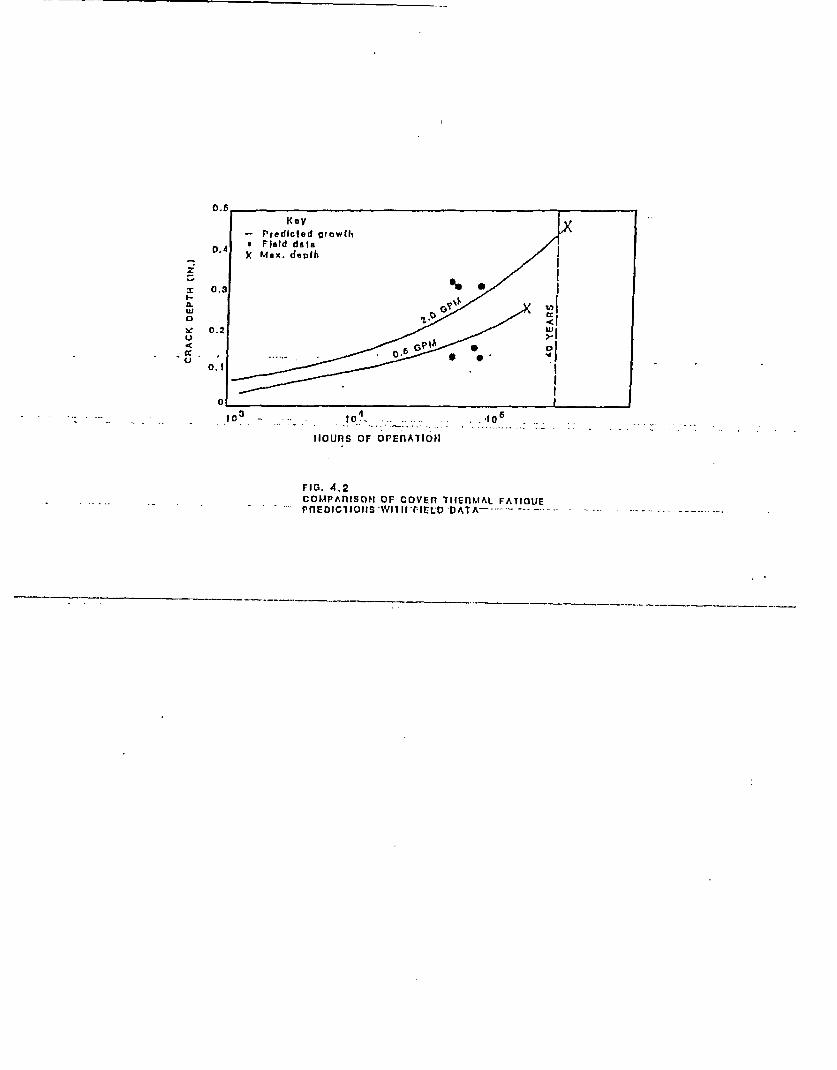
(Figure 4.2) shows the comparison between calculation and
measurement for the cover. The more advanced calculations
differentiates the effect of purge flow quantity. The field
points do not belong,, specifically, to a given flow rate as the
purge flow was changed during operation. Field observations to
date support the reduction of purge flow. A recommendation was
made to the operating utilities to reduce the purge flow from the
3-5 gpm range to a value consistent with the flow control system
capability and accuracy.
5.0 COUNTERMEASURES
Based on the research work. done to date and field observations, a
two-phase strategy has been adopted as countermeasure to the
cracking problem. The first phase applies to installations which
have reached a number of operating hours at which it was

considered prudent to conduct. an in-service inspection. For these
installations, new components of the same basic design but with
some significant improvements were offered. These improvements
include welded impeller, welded journal, optional provision of
*U.T. hole through the shaft to facilitate future inspections,
higher strength/lower carbon materials, optimized drilled hole
construction for the cover, optional inspection ports, double
gaskets etc. These upgrades, by themselves, do not eliminate the
mechanism for thermal cracking, but provide a greater margin for
safe operation in combination with reduced purge flow operation.
The second phase in this program is the development of a permanent
countermeasure which will substantially eliminate the thermal
cracking mechanism. The basis for this concept, as described
in -(),-is the elimination of.the temperature differential between
the mixing streams by elevating the temperature of the purge flow
after emerging from the seal cavity and just prior to mixing with
the system water. The concept has been fully tested in mock-up
arrangements and other configurations in Japan. It is scheduled
to be installed at a new plant, in the near future.
6.0 CONCLUSIONS
* The thermal cracks observed on the shaft and cover
of Byron Jackson reactor recirculating pumps are
initiated by thermal mixing between the cold
injection water and hot system water.
* Cracks propagated purely by thermal cycling
phenomena reach depths not much in excess of about
1/4 in. Such cracks by themselves do not cause
significant impact on safety or operability of the
pump.
* Thermal cracks can reach circumferential
orientation and in this configuration can be
driven by mechanical loads. The potential for the
crack to reach unacceptable depth under these
circumstances can not be minimized.
An analysis based on a quasi steady approximation
of the temperature field gives a bounding

prediction for axial cracks.
a Unbounded crack growth is predicted only for
mechanical loads well in excess of normal design
values such as may be.expected in pumps operated
at off-design conditions.
a An interim countermeasure consisting of the same
basic design but with some significant upgrades
has been offered for installations for which the
10 year in-service inspections had to be
performed.
* A per3manent countermeasure which will
substantially eliminate the thermal cracking
problem has been developed and has just completed
final'verification tests. -It will be offered for-
installation in the very near future.
7.0 REFERENCES
1. S. Gopalakrishnan, P. Payvar and C. Reimers, "An Analytical
Investigation of Thermal Cracking in Reactor Recirculating
Pumps". Paper to be presented at the VDMA Pumpentagung at
Karlsruhe, October 1992.
2. G.C. Sih ed, "Handbook of Stress Intensity Factors for
Researchers and Engineers", Lehigh University, PA, 1973.
3. E. Makay, "Centrifugal Pump Hydraulic Instability", EPRI
Report No. CS-1445 (1980).
4. J. Verhoeven, "Rotordynamic Considerations in the Design of
High Speed, Multistage Centrifugal Pumps", 5th International
Pump Users Symposium, Texas A&M University, 1988.
5. C. Boster, S. Gopalakrishnan, C. Reimers and G. Vaghasia,
"Pump with Seal Purge Heater" Patent applied for.

ArrENDix I
CALCULATION OF STRESS INTE21SITY FACTORS AJW CRACK CROWTH RATES
For a half-plane containing an edge crack subjected to a pair of equal
and opposite concentrated force, the stress intensity factor ic given in
Reference (2), These results can be extended to an arbitrary stress
diatribution as showrn below
Fau + 6o1+1
bj 2 (LJ+1 4 Ij )
bj. (Ii~ 4 ij+d)f2.
i 2 Ji
1 4 F (bIlai)
i 2
Let b/a - r
F (r) - (l-r ) 1.2945 - .3912 r2 + .76B5 r4
-.9942 r6 4 .3094 rJI
In the above equations for deriving P and 6K, It is assumed that the
stress distribution is tension at all times.

Fig. 1.1 BJ PRIMARY NUCLEAR PUMP

aIlAr?
Vliki1 WeL
I
I F C U AL
- ACMETitnE AD S
Fig. 2.1TYPICAL CnACK PATTERN3 ON SHAFT
B PAIN HOLE
Clot 270' as 22O 1S'
COVER
COVER THERMAL FATIOUE CRACKSITYPICAL FOR Du PS WITH INJECTIONH

i///////' /I
/I /,/ /) ,11 a noa
' 400t-
m 300
2C
: 200
2~ to OI-
I I I 3 b , 197 *I0 2,*
not 316 - .205 - 334ar.300 .o J2g 240 246 16 , 11 se
- shall made iumbitf -_
rlo. 3.1tEuPtriAitint D1lSnIDU1IO1 ALONG SItArT sUnrAcE
c
&1
I0L
,
-1l
_13i
FIG. 3.2HOOP STRESS ON SHAFT SURFACE

0aTw 200'F
0g- °15 ______z~ l
0
I0
10 -
Deplh (In.) 0.1 0.2 0.3 0.4 0.5
FIG. 3.3VARIATION OF HIOOP STRESS WITH DEPTH (2.5H2)
FREOUEtJCY - 2.5 HZ
6000 AT - 330'
Y- 400P -/ -
1000c.
2000 _ _ _ _ _ _ _
AT 1.1000 I__ _ _ _ _ _
0 0.1 0.2 0.3DEPTH (IN)
Fl. 3.4VARIATION OF STRESS INTENSITY FACTOR RANGE

F19. 3.5 CRACK GROWTH vs. TIME
CRITICAL CRACK DEPTH
4
w0C,
m 2
z I1
00.1
i... ...... ... ...... ..1* .... ..... . ........ ........ . .............
.......... ... ...........
iII
I.;
2_D0,. .
0.05 O.10 0.1S
RADIAL LOAD FAC7OR F.
a.
Fig. 3,6

CRACK GROWTH PREDICTIONSEFFECTS OF MECHANICAL LOADS
4 Therrna9 A lJ(=0.2 0 RmO 15 + /(=O. 12
w
p-
C)
j
12 - I . i
II
i II -- - -1 -I I--. I F
I .1f I I 0--I *., � - I - d- -,.-
o - - I0 20 40 66-80- � 100'. 120 140 " 160 - 180 200
HOURS OF OPERATION IN 1000s
Fig. 3.7
CRACK GROWTH ON SHAFT
I t
SHAF.I -
0.500K
AXIAL
s CinCUMFErnENTIAL
X 9WR Plr1t, (hollow shnll)
2.5 1 lIz
** 25 lIzN -**
p p * p I0.00
0 20 40 au s0 100 120 140
nouns OF OPEnAflO N 1 inoosFig. 4.1
z
r 0.3
I-.. t <
~e0.2
0 0 . I
-0
hOUnS OF OPEnA7IOt
FIG. 4.2cOMPkPAnisO OF covEn lIIEnLIAL FATIGUE
.PnEDIC1IOtIS-WhIfI-IIELD DATA--