DESIGN, MANUFACTURE, AND TEST OF COOLANT PUMP ...
204
NASA CONTRACTOR REPORT NASA CR-2176 c*«4 wo FILE 1 I In £— c DESIGN, MANUFACTURE, AND TEST OF COOLANT PUMP-MOTOR ASSEMBLY FOR BRAYTON POWER CONVERSION SYSTEM by Louis E. Gebacz Prepared by PESCO PRODUCTS Bedford, Ohio 44146 for Lewis Research Center NATIONAL AERONAUTICS AND SPACE ADMINISTRATION • WASHINGTON, D. C. • MARCH 1973
-
Upload
khangminh22 -
Category
Documents
-
view
1 -
download
0
Transcript of DESIGN, MANUFACTURE, AND TEST OF COOLANT PUMP ...

N A S A C O N T R A C T O R
R E P O R T
N A S A C R - 2 1 7 6
c*«4
wo
F I L E1 I In £—
c
DESIGN, MANUFACTURE, AND TEST
OF COOLANT PUMP-MOTOR ASSEMBLY
FOR BRAYTON POWER CONVERSION SYSTEM
by Louis E. Gebacz
Prepared by
PESCO PRODUCTS
Bedford, Ohio 44146
for Lewis Research Center
NATIONAL AERONAUTICS AND SPACE ADMINISTRATION • WASHINGTON, D. C. • MARCH 1973

Page Intentionally Left Blank

1. Report No.
NASA CR-21762. Government Accession No. 3. Recipient's Catalog No.
4. Title and Subtitle ,DESIGN, MANUFACTURE, AND TEST OF COOLANT PUMP-MOTOR ASSEMBLY FOR BRAYTON POWER CONVERSIONSYSTEM
5. Report Date
March 19736. Performing Organization Code
7. Author(s)
Louis E. Geba.cz
8. Performing Organization [Report No.
None10. Work Unit No.
9. Performing Organization Name and Address
Pesco Products24700 North Miles RoadBedford, Ohio 44146
11. Contract or Grant No.
NAS 3-10935
12. Sponsoring Agency Name and Address
National Aeronautics and Space AdministrationWashington, D. C. 20546
13. Type of Report and Period Covered
Contractor Report14. Sponsoring Agency Code
15. Supplementary Notes
Project Manager, Guy H. Ribble, Jr., Power Systems Division, NASA Lewis ResearchCenter, Cleveland, Ohio
16. Abstract
This report covers the design, development, fabrication, and testing of seven coolantcirculating pump-motor assemblies. The pump-motor assembly is driven by the nominal44.4-volt, 400-Hz, 3-phase output of a nominal 56-volt dc input inverter. The pump-motor assembly will be used to circulate Dow Corning 200 liquid coolant for use in aBrayton cycle space power system. The pump-motor assembly develops a nominal headof 70 psi at 3.7 gpm with an over-all efficiency of 26 percent. The report includes thedesign description, drawings, photographs, reliability results, and developmental andacceptance test results.
17. Key Words (Suggested by Author(s))
Pump; Pump motor assembly; Centrifugalpump; Coolant pump; Circulating pump;Hermetically sealed pump; Wet motor; 400 Hzmotor; Inverter; Hydraulic
18. Distribution Statement
Unclassified - unlimited
19. Security Oassif. (of this report)
Unclassified20. Security Classif. (of this page)
Unclassified21. No. of
200
22. Price*
$3.00
*For sale by the National Technical Information Service, Springfield, Virginia 22151
fSftte; yvy : vjr.iflhilr.-aj

TABLE OF CONTENTS
Page
SUMMARY 1
INTRODUCTION . . 2
UNIT DESIGN 3
Pump Assembly 3
Pump design 8Hydraulic calculations 8Bearings 8Filter 10Barstock unit tests 10
Motor Assembly 10
Motor design 11Motor laminations 12Motor insulation 12Connectors . 12Thermocouples 13Speed sensor 13Motor development tests 13Motor-pump development tests in cold box . . . . 15Connector cross-talk test 15Dow Corning DC-200-2 compatibility tests . . . . 16Final design motor performance 16
PUMP-MOTOR ASSEMBLY DEVELOPMENT TEST PROGRAM .- . 17 -
Pump Calibration - Sine Wave Power . 18Pump Calibration - Inverter Power 18Reduced Diameter Impeller Tests 22Net Positive Suction Head Tests 23Low Temperature and High Temperature Tests 23
111

Page
Shutoff Flow Tests ............ .......... 24Reverse Rotation and Dry Start-up . . . . ......... 25Dielectric and Continuity Check ............... 25250 Hour Design Assurance Test .............. 25Unit Disassembly and Inspection .............. 2620, 000 Hour Endurance Test ............ . . . . 26
PUMP-MOTOR ASSEMBLY ACCEPTANCE TESTS
Motor Acceptance Tests ................... 31PMA Unit Acceptance Tests ................. 31
RELIABILITY PROGRAM - PUMP MOTOR ASSEMBLY ...... 32
Component Reliability Analysis for Pump-Motor Assembly 32Reliability Failure Mode, Effect and Criticality Analysis
for Pump-Motor Assembly ............... 34
CONCLUSIONS ............................ 35
REFERENCES ............................ 36

APPENDIXES
Page
APPENDIX A - Figures
1 Specific gravity versus temperature. Dow-Corningsilicone fluid 200-2 centistokes. 37
2 ASTM Standard viscosity - temperature chart.Dow-Corning silicone fluid 200-2 centistokes. 38
3 Barstock Pump Test Performance - head versus flowcomposite curve for various unit configurations. 39
4 Barstock Pump Test Performance - input HP versusflow composite curve for various unit configurations. 40
5 Barstock Pump Test Performance - efficiency versusflow composite curve for various unit configurations. 41
6 Motor Performance Curve - predicted versus prototypetest results, wet motor, 43. 5 volts quasi-square wave,three phase, 400 Hz input. 42
7 Prototype motor no-load saturation test curve - drymotor with sinusoidal voltage input. 43
8 Prototype motor no-load saturation test curve - wetmotor with sinusoidal voltage input. 44
9 Prototype motor iron loss test curve - wet motor,sinusoidal and quasi-square wave inverter input. _. .45
10 Prototype motor test performance curve - wet motor,38. 8 volts, sine wave input, 400 Hz - three phase. 46
11 Prototype test performance curve - wet motor, 43.5volts sine wave input, 400 Hz - three phase. 47
12 Prototype test performance curve - wet motor, 46. 5volts sine wave input, 400 Hz - three phase. 48

Figures Page
13 Prototype motor test performance curve - dry motor,38. 8 volts, sine wave input, 400 Hz, three phase. 49
14 Prototype motor test performance curve - dry motor,43. 5 volts, sine wave input, 400 Hz, three phase. 50
15 Prototype motor test performance curve - dry motor,46. 5 volts, sine wave input, 400 Hz, three phase. 51
16 Prototype motor locked rotor saturation test curve, wetmotor, sine wave input, 400 Hz. 52
17 Prototype motor two-phase test performance curve, wetmotor, 46. 5 and 38. 8 volts, sine wave input, 400 Hz. 53
18 Prototype motor two^-phase locked rotor saturation testcurve, wet motor, sine wave input, 400 Hz. 54
19 Prototype motor test performance curve, wet motor, 39volts, quasi-square wave input, 400 Hz, three phase. 55
20 Prototype motor test performance curve, wet motor, 43. 5volts, quasi-square wave input, 400 Hz, three phase. 56
21 Prototype motor test performance curve, wet motor, 47volts, quasi-square wave input, 400 Hz, three phase. 57
22 Prototype motor test performance curve, dry motor, 39volts, quasi-square input, 400 Hz, three phase. 58
23 Prototype motor test performance curve, dry motor, 43. 5volts, quasi-square wave input, 400 Hz, three phase. 59
24 Prototype motor test performance curve, dry motor, 47volts, quasi-square wave input, 400 Hz, three phase. 60
25 Motor test performance curve, dry motor with 0. 188 inchesrotor skew, 39 volts, quasi-square wave input, 400 Hz,three phase. 61
26 Motor test performance curve, dry motor with 0.188 inchesrotor skew, 43.5 volts, quasi-square wave input, 400 Hz,three phase. 62
vi

Figures Page
27 Barstock PMA acceleration test curve at -65 °F, sinewave input, 41 volts, 400 Hz, three phase, 30 minutetest. 63
28 Barstock PMA acceleration test curve at -65°F, sinewave input, 47.0 volts, 400 Hz, three phase, 20 minutetest, 64
29 Barstock PMA acceleration test curve at -65 °F, sinewave input, 41. 0 volts, 400 Hz, three phase, threesecond test. 65
30 Barstock PMA acceleration test curves at -65 °F atvarious voltages - sine wave input, 400 Hz, three phase. 66
31 Barstock PMA acceleration test curves at -65 °F atvarious voltages - pump discharge pressure versus time,quasi-square wave input, 400 Hz, three phase. 67
32 Barstock PMA acceleration test curves at -65 °F atvarious voltages - motor current versus time, sinewave input, 400 Hz, three phase. 68
33 Barstock "PMA acceleration test curves at -65 °F atvarious voltages - motor current versus time -quasi-square wave input, 400 Hz, three phase. 69
34 Barstock PMA acceleration test curves at +78 °F atvarious voltages - speed versus time - quasi-squarewave input, 400 Hz, three phase. 70
35 Barstock PMA acceleration test curves at +78 °F atvarious voltages - speed versus time - quasi-squareinput, 400 Hz, three phase. 71
36 Barstock PMA acceleration test curves at +78°F atvarious voltages - speed versus time - sine wave input,400 Hz, three phase. 72
37 PMA S/N X2149 test performance - calibration perE. R. 5289B para. 4. 2. 2, sine wave power, 39. 8 v ac. 73
VI1
Figures Page
38 PMA S/N X2149 test performance - calibration perE. R. 5289B, para. 4 .2 .2 , sine wave power, 44. 4 v ac. 74
39 PMA S/N X2149 test performance - calibration perE. R. 5289B, para. 4 .2 .2 , sine wave power, 47. 5 v ac. 75
40 PMA S/N X2149 test performance - calibration perE. R. 5289B, para. 4.2.3, inverter power, 39. 6 v ac. 76
41 PMA S/N X2149 test performance - calibration perE. R. 5289B, para. 4.2.3, inverter power, 44. 4 v ac. 77
42 PMA S/N X2149 test performance - calibration perE. R. 5289B, para. 4.2.3, inverter power, 47.5 vac. 78
43 Barstock pump test performance - calibrations on adynamometer at various impeller diameters perE.R. 5289B, para. 4.2.4. 79
44 PMA S/N X2149 test performance - NPSH calibrationper E.R. 5289B, para. 4.2.5, at 39-6 v ac. 80
45 PMA S/N X2149 test performance - NPSH calibrationper E. R. 5289B, para. 4.2.5, at 44. 4 v ac. 81
46 PMA S/N X2149 test performance - NPSH calibrationper E.R. 5289B, para. 4 .2.5, at 47. 5 v ac. 82
47 PMA S/N X2149 test performance - calibration at -71 °Fand 39- 6 v ac inverter power per E. R. 5289B, para.4.2.6. 83
48 PMA S/N X2149 test performance - calibration at -71 °Fand 44. 4 v ac inverter power per E. R. 5289B, para.4.2.6. 84
"49 PMA S/N X2149 test performance - calibration at -71 °Fand 47. 5 v ac inverter power per E.R. 5289B, para.4.2.6. " 85
50 PMA S/N X2149 test performance - calibration at+ 150°F and 39- 6 y ac inverter power per E. R. 5289B,para. 4. 2. 6. 86
VI11

Figures Pag
51 PMA S/N X2149 test performance - calibration at+ 150°F and 44. 4 v ac inverter power per E. R. 5289B,para. 4. 2. 6. 87
52 PMA S/N X2149 test performance - calibration at+ 148°F and 47. 5 v ac inverter power per E. R. 5289B,para. 4. 2. 6. 88
53 PMA S/N X2149 test performance - calibration at 44.4v ac inverter power (prior to starting 250 hour assurancetest) per E. R. 5289B, para. 5.2. 89
54 PMA S/N X2149 test performance - calibration at 44.4 v acinverter power (after 250 hour assurance test) per E. R.5289B, para. 5. 4. 90
55 PMA S/N X2149 test performance - test calibration at44.4 v ac power before 20,000 hour endurance test. , 91
56 PMA S/N X2149 test performance - test calibration at44.4 v ac power after 5000 hours of endurance test. 92
57 PMA S/N X2149 test performance - test calibration at44.4 v ac power after 20,000 hour endurance test. 93
58 PMA S/N X2149 head and speed versus running time0 to 3300 hours. Twenty thousand hour endurance test. 94
59 PMA S/N X2149 head and speed versus running time3300 to 6700 hours. Twenty thousand hour endurance test. 95
60 PMA S/N X2149 head and speed versus running time6700 to 10,000 hours.Twenty thousand hour endurance 96test.
61 PMA S/N X2149 head and speed versus running time10,000 to 13,300 hours. Twenty thousand hour endurance 97test.
62 PMA S/N X2149 head and speed versus running time13,300 to 16,700 hours. Twenty thousand hour endurance 98test.
63 PMA S/N X2149 head and speed versus running time16,700 to 20,000 hours. Twenty thousand hour endurance 99test.
IX

Figures Page
64 Motor test performance variation of all motors (X2143through X2149), wet motor, 39 volts, 400 Hz, threephase quasi-square wave input taken from acceptancetest calibration data. 10°
65 PMA S/N X2143 test performance - final acceptancetest calibration at 39. 8 v ac inverter power. 101
66 PMA S/N X2144 test performance - final acceptancetest calibration at 39. 6 v ac inverter power. 102
67 PMA S/N X2145 test performance - final acceptancetest calibration at 39- 6 v ac inverter power. 103
68 PMA S/N X2146 test performance - final acceptancetest calibration at 39. 6 v ac inverter power. 104
69 PMA S/N X2147 test performance - final acceptancetest calibration at 39- 6 v ac inverter power. 105
70 PMA S/N X2148 test performance - final acceptancetest calibration at 39- 6 v ac sine -wave power. 106
APPENDIX B - DESIGN DATA
Pump Hydraulic Calculations 107Bearing Design Data 114Motor Design Data Sheets
Table Bl AC motor computer calculation run-off38. 8 L-L volts, three phase, 400 Hz -predicted hot performance at +100°F.
Table B2 AC motor computer calculation run-off--"• 38. 8 L-L volts, three phase, 400 Hz -
predicted cold performance at -100°F.
Table B3 AC motor computer calculation run-off43. 5 L-L volts, three phase, 400 Hz -predicted hot performance at +100°F.

Page
Table B4 AC motor computer calculation run-off43. 5 L-L volts, three phase, 400 Hz -predicted cold performance at -100°F. 128
APPENDIX C - MOTOR TEST DATA
Table Cl Prototype motor test performance -sample of computer reduced data.
Table C2 Prototype motor no-load saturation -sample of reduced data. 130
Table C3 Cross talk between thermocouple pins,power pins, and rpm pickup pin. 131
Table C4 Dielectric, continuity, and insulationresistance checks on PMA'S/N X2149-A(typical) 132
Table C5 PMA electrical test data sheet forPMA S/N X2149-A (typical) 133
Table C6 Computer run-off - reduced motor datathru C12 from acceptance test calibration for
PMA S/N X2143 through S/N X2149,respectively. 134
APPENDIX D - DISASSEMBLY INSPECTION RECORDS PMA S/N2149-A 138
APPENDIX E - RELIABILITY ANALYSIS DATA
1. Failure Rate Analysis Sheets - ComponentReliability Report 151
2. Failure Mode Cause Analysis 159
APPENDIX F - DEVELOPMENT TEST PROGRAM PLAN
. 5289B 170
XI

SUMMARY
Pesco Products has designed and developed a hermetically sealedpump-motor assembly (PMA) to circulate Dow Corning coolant in aBrayton Cycle Space Power Conversion System.
The PMA has a nominal rating of 3. 7 gpm and 70 psi head rise atan operating speed of 11,200 rpm with a nominal inverter input of 56 v dc,and an over-all PMA efficiency of 26%. The specification requirement is60 psi minimum head rise at rated flow. The PMA has an average weightof 15 pounds and the average weight of the inverter is 25 pounds sixounces.
This report includes a description of the pump and motor design,assembly and envelope drawings, reliability results, pump, motor, andbearing calculations, development test results, and acceptance testresults.
Seven PMA's were fabricated and acceptance tested under the con-tract. Six assemblies were shipped to NASA-Lewis Research Centerand the seventh unit was used for development testing. Test results showa pumping ability down to five feet NPSH at 79°F; a starting capability at-71 °F with a head rise of 62 psi at 3. 7 gpm and at +150°F with a head riseof 68. 6 psi at 3. 7 gpm flow. A 20, 000 hour endurance test on the PMAand inverter was successfully completed.
No degradation in unit performance was observed during the 20, 000hour test. Disassembly inspection showed the unit to be in excellentcondition with the parts meeting the original blueprint requirements. Theunit was reassembled as is and seal-welded for use as a spare unit.
A minimum of design and testing problems were encountered duringthe performance of this program. The PMA meets or exceeds the require-ments of the contract specification.

INTRODUCTION
NASA-Lewis Research Center issued contract number NAS3-10935 for the design, development, fabrication, and testing of a pump-motor inverter assembly for the circulation of Dow Corning 200 coolantin a Brayton Cycle Space Power Conversion System.
The power conversion system has potential use with solar, radio-isotope and nuclear reactor heat sources. The power output is Z. 0 KW to15 KW at 1200 Hertz. The system is designed for an unattended space lifeof five years.
The PMA is a hermetically sealed unit that is powered by a staticinverter designed and developed by Gulton Industries, Incorporated undera subcontract, for the Borg-Warner Corporation, Pesco Products Division.A portion of the 1200 Hertz Brayton Power System electrical output is con-verted to dc power. The static inverter inverts and conditions the dc power(50 to 60 v dc), to 400 Hertz quasi-square wave three phase power (approxi-mately 39. 5 v ac - 47. 5 v ac) to drive the PMA. All inverters were accep-tance tested for 100 hours at Gulton. The work conducted by GultonIndustries on the inverter - Gulton P/N EMIU-104D - is documented inNASA CR-72671 entitled "Final Report - Design and Manufacture of StaticInverter for Brayton Power Conversion System" (Reference 1).
The purpose of the program is to develop flight type hardware withmaximum reliability during the design life as the primary objective. Otherobjectives are maximum combined efficiency of the pump, motor, and in-verter, small size and light weight. The units are designed to meet NASAenvironmental specifications P-1224-1 and P-1224-2 but were not tested tothese specifications.
The development PMA and inverter were assurance tested for 250hours running time with 250 start-stop cycles. Also run were cold starttests at -65°F, hot tests at 150°F, NPSH tests down to 5 feet, reverserotation tests, and dry start-up tests. This same unit has subsequently com-pleted a 20, 000 hour endurance test in the test loop at Pesco/- The test loopis automated for unattended operation and has hot and cold ambient capabilitybut no vacuum ambient capability. The other six PMA's were acceptancetested at Pesco for 100 hours prior to shipment to NASA-Lewis ResearchCenter, five with inverters and one using sine wave power.

The PMA is similar to liquid hydrogen and liquid oxygen chilldownpumps that Pesco has developed for use on the Saturn vehicle. Thesepumps are also powered by a 400 cycle quasi-square wave inverter.
UNIT DESIGN
Pump Assembly
The pump assembly is of the centrifugal type mounted directly onthe same shaft with the 400 Hz electric motor. The unit is designed topump Dow Corning 200 (dimethyl silicone fluid) with a viscosity grade of2. 0 centistokes at 77°F and to meet the following performance requirements.
Pump Design Capacity - 3. 7 gpnaPump Design Head Rise - 60 psi (159 ft) min.Available Net Positive Suction Head - 20 psi (53 ft) min.Steady-State Fluid Temperature - 20° to 100°FMinimum Temp - Initial Start-up - -65 °F
The PMA and integral filter are contained in a stainless steelcylindrical casing. The design includes provisions for seal welding forhermetically sealing the assembly. The seal weld joints provide a minimumcapability of three (3) rewelds with only minor machining for disassemblyand reassembly. Drawing 115146-100, Figure A and Figure B shows theunit assembly and envelope dimensions. Figure C is a photograph of thePMA, and Figure D is a photograph of the individual components in the PMA.

ill
FIGURE A

*i*»£o« iMl§;
eSfit'y .•s5:i?!-
rS.id(?)i
?KojEi
|5-fi*Bs*i"Si"ltr.fpss
I!f^-'ff-f ,1
! 1 1 ; : I • - . i ! nJ—illUuP
J 1sS .< |Z|! JB*| ?I8s
»P-?5«S§
MSMilS
FIGURE B

INLET
OUTLET
PUMP MOTOR ASSEMBLY

Ioc<a.
FIGURE D

Pump design
Pumping is provided by a radial flow impeller discharging into adiffuser. The flow is then directed through the motor cavity. In thismanner, the entire pump flow is used to cool the motor windings and helpsto promote long unit life.
The pump design includes a replaceable orifice in an external bypassfrom the pump discharge to the pump inlet. The design provides for eithero-ring sealing or seal welding. Present units have the bypass blocked off andthe assembly seal welded.
The unit pressure and flow requirements dictate a specific speed ofapproximately 480, which is at the low end of the specific speed rangenormally covered by centrifugal pumps. A radial flow impeller design witheight drilled . 123" diameter holes and a diffuser with nine . 056" diameterholes was utilized to obtain the required performance. The efficiency of thistype of pump design is inherently low and the pump efficiency obtained forthis unit is approximately 45% to 50%.
The general head-flow characteristic of this low specific speed pumpis relatively flat from shut-off to rated flow conditions. The head character-istic is flat or rises slightly to approximately 60% rated flow, then itdecreases slowly as it approaches rated flow. Beyond rated flow, the headdecreases more rapidly.
Hydraulic calculations
The hydraulic calculations for the pump impeller and the diffuserare included in Appendix B.
Bearings
The pump rotating assembly support is provided by two hydro-dynamically lubricated sleeve-type bearings. These carbon graphite bearingsare used in conjunction with chrome plated journals on the shaft. Hydrodynamiclubrication is provided by the Dow Corning ZOO (2. 0 centistokes) fluid beingpumped.
8

Figure 1 in Appendix A is a plot of the specific gravity versustemperature for the Dow Corning silicone fluid 200 at 2 centistokes.Figure 2 is a plot of the ASTM Standard viscosity versus temperaturefor Dow Corning 200 fluid at 2 centistokes.
Bearing design calculations were based on the design criteriadefined in the Cast Bronze Bearing Design Manual, Franklin InstituteResearch Laboratories (Reference 2).
A copy of the bearing computer study for the journal bearings isincluded in Appendix B.
All axial thrust is taken by the bearing installed in the diffuserhousing assembly. This bearing includes two thrust faces and one radialbearing in one assembly. The bearing in the motor cover assemblycarries only radial loads.
Bearing lengths determined by the foregoing procedure were:
. 365 diameter journal - .2625 length
. 300 diameter journal - . 210 length
Diametral clearance between journal and bearing bore were:
. 365 diameter journal - .0015 in.
. 300 diameter journal - .0015 in.
Based on 110 °F ambient oil temperature, fluid temperatures ofthe film in the bearings were:
. 365 diameter journal - 120 °F
. 300 diameter journal - 120°F
The minimum film thickness (ho) was calculated to be . 000181inches for the . 300 diameter bearing assuming a one pound load, and. 000163 inches for the . 365 diameter bearing assuming a three pound load.
9

Filter
The full flow filter is located integrally in the pump housing at theimpeller inlet. The filter element is of all metal woven mesh construction,and has a nominal rating of 2 microns and an absolute rating of 5 microns.The maximum allowable design pressure drop is 5 psi at 30 7 gpm, butactual test experience has shown the filter drop to be less than one psi atrated flow. The filter element is assembled in the unit with two o-ring sealsto prevent contaminant leaks past the filter element.
Barstock unit tests
An aluminum barstock pump was fabricated to the selected diffuserand impeller hydraulic design. The unit was mounted on a dynamometerand tests were conducted to evaluate pump performance with and without adiffuser, with two holes plugged in the diffuser, two holes plugged in theimpeller, and with increased hole size in the diffuser. A plot of pump per-formance at 11, 300 rpm with each of the above unit configurations is shownon Figures 3 through 5 in Appendix A.
Motor Assembly
The 4-pole, 3-phase motor in the Model 115146-100 PMA is used todrive a centrifugal pump which circulates coolant in the Brayton power con-version system. The motor is rated at . 6 hp at 11, 000 rpm. It is designed forcontinuous and unattended operation in a space environment for a minimumperiod of five years and is designed to achieve maximum efficiency with anobjective of 0. 7 power factor at the design point. It is also designed to runfor a period of five minutes at maximum pump capacity without exceeding awinding temperature of 180°F.
In the preliminary design stage of the program, three alternativemotor designs were offered. These were briefly:
10

Alternative 1 - A motor and inverter design to meet allof the listed requirements of the initialRFP.
Alternative 2 - A motor design to meet all of the listedrequirements driven by a previouslyqualified inverter.
Alternative 3 - A motor design which exceeds the 5% sliprequirements at 150% of rated torquedriven by a previously qualified inverter.
Alternative 3 was chosen for reasons discussed in the motor designsection, and was modified to obtain maximum efficiency during the finaldesign stage. Development tests were then performed on a prototypemotor and compared to predicted performance.
Motor design
A motor designed to meet the requirements of the initial requestfor proposal was large in size and had a rotor resistance such thatthe existing qualified static inverter could not be utilized. The large sizeof the motor also yielded a very high pull-out to running torque ratioresulting in a lower than peak value of efficiency at the operating point.The larger rotor size also increased the hydraulic fluid losses whichfurther reduced the efficiency.
A motor design to meet all of the listed requirements driven by apreviously qualified inverter would be feasible, but would have to becoordinated with the invertei supplier because the operating power factorwould be low. This alternative would necessitate deviations from theinverter specification since the inverter would not have sufficient capacityto drive the motor.
An alternate motor design was proposed which exceeded the specified5% slip requirement at 150% of rated torque and which produced slightlyless than 150% starting torque at -100°F. The 5% slip requirement, whilein the original request for proposal, was not included in the final contractspecifications. This design, however, was capable of meeting all of the
11

application requirements with the advantages of minimum weight, higherefficiency and power factor, and lower current drain. The final computercalculation is included in Appendix B, Tables Bl through B4, and the motorcharacteristic performance curve is shown in Figure 6., Appendix A.
Motor laminations
The motor laminations are of a new optimized design, specificallydeveloped for this unit. They are silicon sheet steel per AISI M-19, 29gage (. 014 inch), heat treated after punching to restore permeability lostdue to punching stresses and to reduce iron losses. The stator slot sizewas designed to provide maximum efficiency. The L/D ratio for the rotorwas optimized for wet running in DC 200-2 fluid. The rotor cage wasdesigned to provide the necessary starting torque over the specified tempera-ture range of +100°F to -100°F.
Motor insulation
The motor insulation system is composed of polyimide coated glass,Teflon, and DuPont Pyre ML impregnating varnish. These materials haveproven to be effective in motors running submerged in various fluids attemperatures comparable to the specified operating temperatures. Tests•were conducted which showed compatibility with Dow Corning DC-200-2.The test results are included in the section titled "Dow Corning DC-200-2Compatibility Tests. "
Connectors
In the initial design Pesco proposed using three separate connectors,one for power input, one for thermocouple output, and one for th<2 speedsensor. An investigation was conducted concerning the possibility of using asingle connector for all leads. Cross-talk tests were performed at Pescousing a dummy motor. No cross-talk or interference could be detectedduring the performance of these tests. Details are included in the section"Connector Cross-Talk Test. "
12

In the final design, two connectors were used, ITT Cannon PartNo. PV3H14B5PN SPCL for the power lead connector and ITT CannonPart No. PV3H12B10PN SPCL, for the instrumentation connector.
T he r mo c ouple s
Two iron-constantan thermocouples are used to sense statorwinding temperature in the PMA. The thermocouples are located in thecenter of the end turns approximately 180° apart on the lead end ofstator.
Speed sensor
The speed sensor used is a standard catalog item purchased fromElectro Products Lab, Incorporated - Chicago, Illinois. This transducerhad previously been used satisfactorily on the Saturn chilldown pumps. Acompatibility test with DC-200-2 was performed at Pesco and no ill effectscould be detected.
Motor development tests
The original design called for the use of eighteen turns per coilof No. 20 AWG magnet wire. In order to minimize the possibility of wireand insulationdimage, and to allow easier assembly, equivalent coilsconsisting of one No. 22 and one No. 24 AWG wound in parallel were used.
Upon their completion, the prototype stator and rotor assemblieswere placed in a bar stock body having the same internal dimensions asthe final pump body configuration. Also incorporated into this body werethe final design carbon bearings.
13

The following tests were performed on the prototype motor usingsinusoidal input from a standard 400 Hz generator:
1. No load saturation-dry motor.
2. No load saturation-wet motor (submerged inDC-200-2 fluid)
3. Locked rotor saturation-wet motor.
4. Wet motor performance at 38. 8, 43. 5, and 46. 5line-to-line volts.
5. Dry motor performance 38. 8, 43. 5, and 46. 5 volts.
6. Two-phase performance-wet motor, 38. 8 and 46. 5.
A breadboard static inverter was then obtained from Gulton and theabove tests were repeated with the exception of the two-phase tests (No. 6above).
In order to improve starting at low temperature, a second rotor wasfabricated with a 0. 188 skew (skew of the first rotor was 0. 094). This rotorwas assembled in the prototype housing and stator and performance tests•were run at 39- 0 and 43. 5 volts. Results showed that the . 094 skew rotorwas more efficient and therefore it was used in the final design.
Plotted results of above tests are found in Figures 7 through 26,Appendix A.
Test data on the prototype unit with . 094 skew rotor revealed that thelosses due to fluid friction and the iron losses were less than those calculatedresulting in a slightly higher efficiency than was calculated. The lower powerfactor resulted from the test current value being higher than the calculatedcurrent. These results are shown in Tables Cl and C2 of Appendix C, andgraphically on Figure 6, Appendix A.
14

In comparing a motor tested dry to one submerged in DC-200(Figures 11 and 14), the speed is higher while the current and power inputis lower for a dry motor. This results in a significantly higher efficiencybecause of the absence of the fluid drag on the rotor.
In comparing a motor tested with a sine wave voltage input to onewith a quasi-square wave input (Figures 11 and 20) the speed is lower whilethe current and input power are slightly higher for the inverter poweredmotor. This results in a slightly lower efficiency which is attributed tothe increase in iron losses due to the shape of the input wave form.
A motor test using a rotor with a larger skew (0. 188 versus 0. 094)resulted in a fairly large drop in efficiency (6%) Figure 26. Based on this,it was decided to retain the original rotor with the 0. 094 skew.
Motor-pump development tests in cold box
Since the predicted starting torque was not realized during the motorprototype test, several tests were performed with the barstock motor-pumpcombination placed in a cold chamber at a temperature of -65 °F. (Acontract modification changed the minimum fluid temperature requirementfor start-up from -100°F to -65 °F. )
Acceleration and voltage variation tests showed that the motor wascapable of starting and accelerating the unit to rated conditions, at voltagesthat were below the low specification limit. These test results are showngraphically in Figures 27 through 36, Appendix A.
Connector cross-talk test
An MS3102A connector and mating plug with pins for two iron-constantan thermocouples was used for the test.
The connector was mounted to an available Pesco motor of similarsize. Two I/C thermocouples were taped to the end turns of the motorwindings. A speed pickup was mounted in the motor cavity and leadsincluding the power leads were brought out through the connector. The
15

motor was operated no-load and the speed was monitored on a digitalcounter and also by a Strobotac. Temperature was recorded on a stripchart recorder. Phase resistances were taken before and after the test.Since the counter and strobe readings agreed and no noise could be detectedon either the counter or temperature recorder signals, it was concludedthat a single connector could be used for all leads and that accurate datacould be obtained without cross-talk interference. Results are shown inAppendix C, Table C3.
Dow Corning DC-200-2 compatibility tests
In order to determine if the working fluid in any way affected thematerials in the motor assembly, a stator assembly and all assemblyparts were submerged in 1000 ml of the fluid for a period of four weeks;no evidence of deterioration, weight loss or gain, color change, softening,or crazing was detected.
A Model 115146-100 speed pickup was submerged in the fluid for aperiod of nine weeks. Coil resistance, insulation resistance and dielectricstrength were measured and recorded during this period. No deteriorationwas detected during this test.
Final design motor performance
Table I is a tabulation of motor performance at rated horsepower(0. 36) with nominal voltage input.
16

TABLE I
MOTOR PERFORMANCE
rpm
efficiency (%)
power factor (%)
locked rotor torque (Ib. in. )
torque at operating point (Ib. in. )
life
PredictedValue
11,280
67.0
67.0
2.60
2.00
5 years
ActualValue
11,280
68.5
64.5
2.06
2.00
See note
NOTE: Endurance tested for 20,000 hours with no deteriorationin performance.
Although the motor did not develop the predicted starting torque, thenature of the centrifugal pump is such that very little starting torque is re-quired, and this was not considered to be critical. The motor met orexceeded all of the application requirements.
PUMP-MOTOR ASSEMBLY DEVELOPMENT TEST PROGRAM
•
The development test program was performed on the final packageddesign of the coolant circulating pump, Pesco Model 115146-100, UnitS/N X-2149.
The development tests were run in accordance with Engineering Report5289, Revision B, entitled "Development Test Program Plan for PescoModel 115146-100 Coolant Circulating Pump for a Brayton Cycle Space PowerSystem. " A copy is included in Appendix F.
17

PMA S/N X-2149A was mounted in the test loop per test schematics,Figures 1 through 5 of Engineering Report 5289, Revision B. Figure E isa photograph of the test setup used for the hot and cold ambient testing.Figure F is a photograph of the PMA installed in the test loop, and FigureG is a photograph of the Gulton inverter installed on the cold plate.
Electrical checks (dielectric, resistance, and continuity) were con-ducted at various times during the development program. No performancedegradation was noted.
Test Series 1 - PMA Calibration-Sine Wave Power
Tests were made to determine the head-flow performance to substantiateanalytical pump characteristics and to determine motor performance using400 Hz sine wave power. Testing was conducted at the conditions defined inparagraph 4. 2. 2 of Engineering Report 5289-B.
Figures 37 through 39 show unit performance with sine wave power.
Test Series 2 - PMA Calibration-Inverter Power
The calibrations outlined in Test Series 1 were repeated using quasi-square wave input power (Gulton Inverter S/N 25509). Motor input voltagewas the same as in Test Series 1. Figures 40 through 42 are plots of the unitperformance at the three input voltages.
Table II compares the pump performance at 78°F and 3. 7 gpm flow fora sine wave input and a quasi-square wave input. The tabulation shows thatthe PMA head rise is slightly higher with sine wave power than the quasi-square wave power for an equivalent input voltage. The PMA efficiency,however, is approximately the same.
18

Q.
(/>
LLJ
UJ
ffl
8QZ
FIGURE E
19

FIGURE F
20
0.OO
V)tu
z
Q

Q.oo
Q.
Q
O
FIGURE G
21

TABLE II
PMA PERFORMANCE AT 78°F AND 3. 7 GPM
Inverter inputvoltage, dc
Motor inputvoltage, ac
Head, psi
Line current, amps
Motor input, watts
PMA Efficiency, %
Sine Wave
39.8 44.4 47.5
69 71.9 73
9.1 9.0 9.1
454 473 480
24.5 24.5 24.5
Square Wave
50
39.6
68.0
9.2
456
24.0
56
44.4
71. 1
9.1
465
24. 6
60
47.5
72.6
9.2
475
24.6
Test Series 3 - Reduced Diameter Impeller Tests
Tests were performed to determine the maximum amount that the outsidediameter of the impeller could be reduced before the head rise and the pumpefficiency decreased approximately 20%. It was determined that the impellerO. D. could be reduced from 2, 120" O. D. to 1. 820" O. D. This amount ofimpeller trimming reduced the head rise from 66 psi to 49- 5 psi and the pumpefficiency from 40% to 33% at a nominal pump flow of 3. 7 gpm and a pumpspeed of 11, 300 rpm. Tests were run on a dynamometer using the bar stockpump assembly. Figure 43 is a plot of the test results.
22

Test Series 4 - Net Positive Suction Head Tests (NPSH)
These tests were run to determine the effect of reduced inletpressures on pump performance in accordance with paragraph 4. 2. 5 ofEngineering Report 5289-B. Pump inlet pressures were varied from0 psig to 25 inches Hg vacuum (37 feet to 5 feet NPSH, approximately) asmeasured ahead of the integral filter rather than at the pump inlet down-stream of the filter. At 79°F fluid temperature, a NPSH of seven (7)feet was obtained before pump performance fell significantly with anaudible cavitation noise. This means the pump will function normally atinlet pressures as low as 2. 7 psia which far exceeds the 20 psia (53 feet)minimum required by the contract. Due to the low vapor pressure of DC-200, the NPSH and pump inlet pressure values are practically the same.
Figures 44 through 46 show NPSH performance at three inputvoltages and four pump flow rates.
Test Series 5 - Low Temperature and High Temperature Tests
The purpose of these tests was to determine the effect of fluid viscosityand temperature on motor-pump performance. Pump calibrations asdescribed in Test Series 2 were conducted at an ambient and pump inlettemperature of -65°F and also with an inverter cold plate outlet temperatureat 150°F maximum.
Table III shows the DC-200 viscosity effects on pump performance.The DC-200 viscosity varies from two centistokes at 78°F to approximatelyone centistoke at 150 °F and to approximately twelve centistokes at -65 °F.
23

TABLE III
PMA PERFORMANCE - SQUARE WAVE AT 3. 7 GPM
Input voltage, dc
Head, psi
Line current, amps
Motor input, watts
PMA efficiency, %
78°F
50 56 60
68 71.1 72.6
9.2 9.1 9-2
456 465 475
24 24.6 24.6
150°F
50 56 60
64.5 68.6 70.1
8.8 8.5 8.8
433 425 431
24 26 26.3
-65°F
50 56 60
57.2 62 62.5
11.8 10.8 10.6
562 571 580
16.4 17.5 17.5
The test loop side and top covers were in place for the hot and coldambient temperature testing.
Figures 47 through 49 are plots of performance at three input voltagesand -65°F ambient, and Figures 50 through 52 are performance plots with150°F fluid and three input voltages.
During the -65 °F temperature run, the unit reached operating speed in1.01 seconds with the maximum starting current at 21.0 amperes. This agreeswith the cold test results obtained with the barstock unit - Figure 29. The roomambient temperature acceleration time is one-half second.
Test Series 6 - Shut-off Flow Tests
The PMA was operated at shut-off conditions for three minutes witha fluid inlet temperature of 80°F and an inverter input voltage of 60 v dc. Unitspeed increased from 11, 340 rpm at a flow of 3. 7 gpm to 11, 500 rpm at shutoffand the motor winding temperature increased from 87°F to 110°F. Pump headdecreased from 72. 7 psi to 69. 5 psi.
24

Test Series 7 - Reverse Rotation and Dry Start-up
With the PMA filled with fluid, the unit was subjected to three reverserotation starts with 50 v dc input to the inverter. Pump head dropped from68. 3 psi at 3. 7 gpm to 22. 6 psi at 1. 94 gpm and the unit speed increasedfrom 11, 040 rpm to 11, 350 rpm.
The PMA was drained and the unit was subjected to two dry startsof 10 seconds maximum each conducted thirty minutes apart. No adverseeffects were noted in unit performance.
Dielectric and Continuity Check
A dielectric check was performed on the power connector only byapplying 1500 volts (rms) and 60 Hz between the four motor pins connectedtogether and the motor housing. The current leakage was less than 500micro-amperes.
Table C4 in Appendix C shows the results of the dielectric, continuity,and insulation resistance checks. This is typical of the electrical checksmade throughout the program.
250 Hour Design Assurance Test
The 250 hour design assurance test with 250 start-stop cycles wasperformed on unit S/N X2149A which had been used for series 1 through 7development tests. A pump calibration was performed prior to the start ofthe assurance test and Figure 53 is a plot of the unit performance. At theconclusion of the test, a recalibration of the pump was performed andFigure 54 is a plot of the post test unit performance. Unit performanceafter the 250 hour test was better than at the start.
25

No unit performance degradation was noted after the environmentaltests, NPSH tests, dry start-ups, reverse rotation tests, or 250 hourassurance test with 250 start-stop cycles. In fact, performance continued toimprove throughout the developmental program, as shown in Table IV.This appears to be due to "wearing in" of the bearings.
TABLE IV
PMA PERFORMANCE AT 3. 7 GPM, 56 V DC INPUT TO INVERTER, AND78 °F FLUID
Accum.hoursrun
0.4111129381
PMAEfficiency
21.924.625.727.0
11,10011,21011,24011,280
CalibrationTest
InitialTest Series 2Before 250 hour testAfter 250 hour test
Unit Disassembly and Inspection
The PMA was disassembled and inspected after a total running time of384. 3 hours and 314 starts. Critical dimensions were inspected and recorded.Unit condition was excellent with dimensions repeating original inspectionrecords. Testing and inspection results indicate that the unit design life offive (5) years is attainable. Copies of the inspection records are included inAppendix D.
Unit 20,000 Hour Endurance Test
The unit was reassembled with no change of parts and a 20, 000 hourendurance test was conducted. The unit was tested in accordance with paragraph6. 0 of test procedure ER-5289-B which is included in Appendix F. After 5000hours of running time the unit was removed from test, the seal welds weremachined off and the unit disassembled for inspection.
Unit disassembly showed the unit to be in excellent condition with nomeasurable wear evident on the bearings, the shaft bearing journals, orpump-motor components. Disassembly inspection records are included inAppendix D.
26

The unit was reassembled, rewelded and retested in accordance withparagraph 7. 0 of Engineering Report 5289-B. Testing was continued for atotal of 20,000 hours. Figures 55, 56 and 57 are calibration curves at thestart of the 20,000 hour test, at 5000 hours and at 20,000 hours, respectively.Unit performance at the conclusion of the 20, 000 hour test was better by 1. 0psi head rise thanat the start, as shown in Table V.
TABLE V
PMA PERFORMANCE AT 3. 7 GPM, 56 V DC INPUT TO INVERTER, AND78 °F FLUID
Ac cum. PMAhours Head Efficiency Speed Calibrationrun psi % rpm Test
0.0 71.9 25.2 11,260 Initial5063. 72.7 26.4 11,270 After 5000 hours20008. 72.9 26.5 11,280 After 20,000 hours
No degradation in performance was encountered during the test as shownby the head and speed versus running time curves on Figures 58 through 63 forthe 20,000 hours of endurance testing.
Unit disassembly showed the unit to be in excellent condition with themeasurement of critical shaft and bearing dimensions meeting the original blueprint requirements. Disassembly inspection records are included in AppendixD. Photographs of the unit integral filter, the rotor and the thrust-radialbearing are shown on Figures H, I and J, respectively.
The unit was reassembled with all the original parts, rewelded andacceptance tested for use as a spare unit.
27

CO CO
CJ CJ53 23I—1 M
LO
CM Ul
FIGURE H
28 I

w wW WCJ Oz z
oo o• •rf- H
1 i
PiW
W H
z'V WX H
en
Q
>H °J
CQ °SH Oi< oW 0-
< S
<JKw
FIGURE I
29

\

PUMP-MOTOR ASSEMBLY ACCEPTANCE TESTS
Motor Acceptance Tests
The PMA's were tested in accordance with Pesco Acceptance TestProcedure TR-700, Revision B. The motor for each assembly wasassembled into a test housing and calibrated as a component. Componenttesting included a dielectric check of the power connector to 1500 v rms60 Hz for one minute, an insulation check of each pin with a 50 v dcmegger, and a continuity check of each pin of both connectors.
The motor calibration consisted of mounting the motor on a torquemeasuring stand and connecting it to a slave inverter. A typical electricaldata sheet, Table C5, and the results of the motor calibrations for allse.ven units, Tables C6 through C12, are included in Appendix C. A com-posite torque-speed curve based on the test results of all units is shown onFigure 64-.
PMA Unit Acceptance Tests
Unit acceptance tests were performed in the test loop with installationand instrumentation as shown in Figures 1 through 5 of Engineering Report5289, Revision B, in Appendix F. .
Six PMA's, S/N X2143 through S/N X2148, were acceptance tested andshipped to NASA-Lewis Research Center. The acceptance test included thefollowing individual tests in sequence:
a) Dielectric and resistance checksb) Pump calibration testsc) 100 hour endurance testd) Pump calibration test
.e) Seal welding - helium leak testf) Proof pressure testg) Helium leak testh) Dielectric and resistance testi) Pump calibration test
31

All units were tested and shipped with an inverter with the exceptionof unit S/N X2148. This unit was tested on sine wave power since this unitwas scheduled for sine wave power testing at NASA-Lewis Research Center.
A plot of head, current, power, and efficiency versus flow of eachunit shipped, based on the final calibration test, is included in Figures 65through 70.
All units passed the 100 hour acceptance test without difficulty. Oneunit, S/N X2144, was rejected at the dielectric check after seal weldingjust prior to shipment. The unit dielectric leakage exceeded the maximumof 500 micro-amperes at 1000 v ac 60 Hz. Specification limit is 500 micro-amps at 1500 v ac 60 Hz. Disassembly of the unit revealed that a stator endturn was assembled too close to the motor cover assembly, thus providinga high resistance short circuit. The unit was rebuilt with a new stator,re-tested and shipped.
Another unit, S/N X2147, has a different head characteristic than theothers which is probably due to a deviation in angle of one of the diffuserholes. It still meets the performance specifications, however.
All units showed an improvement in performance with running timesimilar to that experienced with the development PMA. Efficiencies at theend of the 100 hour acceptance test ranged from 0. 4 to 2. 2 percentage pointsbetter than at the start of the test.
RELIABILITY PROGRAM - PUMP MOTOR ASSEMBLY
Component Reliability Analysis for Pump-Motor AssemblyPesco Model No. 115146-100
This analysis consists of the generic failure rates of each of the com-ponents of the PMA. The following two documents have been used inacquiring the generic failure rates of the individual components:
32

Reliability Analysis Program Handbook prepared byGeneral Electric, Large Jet Engine Division atCincinnati for Mechanical Components.
MLL-DHBK-217 for electrical components.
Detailed failure analysis sheets appear in Appendix E.
The inherent reliability estimate for the pump-motor assembly is51,576 hours Mean Time Between Failure (MTBF) as against the 57,412hours MTBF which was the preliminary estimate. The present analysisincludes the failure rate modifiers which have been calculated by takinginto consideration the stress levels, material strengths, the environmentconditions, et cetera. These modifiers are then used in estimating theupdated failure rates. The summary of the total failure rates of the pumpand motor are listed below:
Sub-Assembly Failure Rate per 10" Hours
Pump and Housing 9-401
Electric Motor 9- 988
Total 19.389
= 1^000,00019.389
51,576 hours
33

Reliability Failure Mode, Effect and Criticality Analysisfor Pump-Motor Assembly, Pesco Model No. 115146-100
This study was performed to determine the feasible modes of failureand their criticality in the PMA used in the Brayton Cycle Systems. Theanalysis has been made starting at the system level and expanding downwardto the component system level and finally to the component level.
The analysis of failure modes for the PMA has been performed in twophases. The first phase takes each subassembly and part individually anddetermines its failure modes and the effect of each failure mode on thecomponent output. The failure rate (in events per one million hours) foreach failure mode is included. The results of this analysis are presentedin the "Component Reliability Report" which is included in Appendix E.
The second phase takes each failure mode and classifies it inaccordance with the criticality or consequence of the failure. Thecriticality categories are such as "Pump inoperative, no flow or pressure"and "Low discharge flow and/or pressure. " The reasons why each failuremode should not occur or why its probability of occurrence has beenminimized are given for each failure mode. The results of this analysisare presented in the "Failure Mode Cause Analysis" which is also includedin Appendix E.
The new failure rate for the pump-motor (centrifugal) assembly wasestimated to be 19- 389 occurrences in one million hours or 51, 576 hoursMean Time Between Failure.
Relative probability of occurrence of the different failure modes isas listed below:
Failure Type % Failures(Relative Probability of Occurrence)
Pump Inoperative (no flow or pressure) 60. 69
Low Discharge and/or Pressure 39. 31
The critical components are the two sleeve bearings, the stator androtor assemblies, the filter and the weld joints.
34

CONCLUSIONS
A pump-mo tor assembly, Pesco Model 115146-100, was designed,developed, and tested which meets or exceeds the specified design require-ments, A pump head rise of 68 psi was obtained compared to the requiredminimum of 60 psi at the minimum 50 v dc input to the inverter, with 80°Ffluid, and at the rated flow of 3. 7 gpm.
The pump suction performance is much better than specified. Thepump will function normally with an available NPSH as low as 7 feet comparedto the required minimum of 53 feet.
The performance of all units improved with running time, apparentlydue to wearing in of the bearings. .The efficiency of the development PMAincreased from 21. 9% to 27% at rated conditions during the first 381 hoursof operation.
Test experience to date indicates that the design life of five years isattainable. A 20, 000 hour endurance test was completed on Unit SerialNumber X2149 with no degradation in performance. Unit disassembly atthe conclusion of the test indicated no signs of wear with critical bearing andshaft journal dimensions within the original print dimensions. The unit wasreassembled and rewelded as is for use as a spare unit.
35

REFERENCES
1) Lachenmeier, G. , "Design and Manufacture of StaticInverter for Brayton Power Conversion System, "NASA CR-72671, Gulton Industries Report No. 2403,dated December 3, 1969-
2) Rippel, H. C. , "Cast Bronze Bearing Design Manual, "The Franklin Institute Research Laboratories,Philadelphia, Pennsylvania. Third Printing datedSeptember, 1967.
36

APPENDIX A
FIGURES
oo
2•«t
_lLUOO
-1
80
40
20
_
g ooen to M-at en CN ooo co •»en co oq oq cq CMoo oco <or-.
AIJABJ& OjjjDadc;
37

oo
$in
_iLJJQ
O
s
>
e
/f
•3 u
/
/
•> c_ ^
/
3
/
C
>
/
>
/
'
C
/f
) C
//
D C
///
3 C
/
/
/
/
/
f
\ C
y/
ua r-
y//
2 5
/
/
> u? f
f/
t4
(<
o00
oCD
O•<fr*™
OCN
OO
o t! „.00 _g U
o -g£ tt
O 3 '^10 TO C
Q-CNo E .
o -S-"SCN 0 ^
LL w
o > c
I |l2 S o>
O o_ CO •—^ E ^- E
QJ S O
"T <Q
§ «OJ
S
oo
1
o
33
- AIJSOOSIA oueoiaujx
38

Model 115146-100 Unit S/N S-4944
I IFluid D.C. 200-2Inlet Press. 15 PSIGSpeed 11.300RPMTemperature 78°F.
Legend
Calibration with diffuser
Calibration with diffuser removed
Calibration with diffuser with two
holes plugged
Calibration with diffuser holes increased
to 0.0625 dia.
Calibration with two holes plugged in
impeller
Calibration with two holes plugged in
impeller & with 0.0625 dia. holes in diffuser
—•— Calibration with two holes plugged in impeller
& diffuser
30
Flow - GPM
Figure 3. - Barstock pump test performance - Head vs Flow composite curvefor various unit configurations
39

Model 115146-1000.60
Unit S/N S-4944
0.55
0.50
0.45
x; 0.4000
^ 0.35QiC
0.30
0.25
0.20
0.15
Legend—A— Calibration with diffuser
Calibration with diffuser removed_O_ Calibration with diffuser with two
holes plugged0 Calibration with diffuser holes increased
to 0.0625 dia.A Calibration with two holes plugged in impeller
Calibration with two holes plugged in impeller
& with 0.0625 dia. holes in diffuser—•— Calibration with two holes plugged in impeller
& diffuser
FluidInlet Press.SpeedTemperature
D.C. 200-215PSIG11,300RPM78° F
Flow - GPM
Figure 4. - Barstock pump test performance - Input H.P. vs Flow composite curvefor various unit configuration
40

Legend
Calibration with diffuser
Calibration with diffuser removedCalibration with diffuser with two
holes pluggedCalibration with diffuser holes increased
to 0.0625 dia.Calibration with two holes plugged in impellerCalibration with two holes plugged in impeller
& with 0.0625 dia. holes in diffuserCalibration with two holes plugged in impeller
& diffuser Unit S/N S-4944Model 115146-100
FluidInlet Press.SpeedTemperature
D.C. 200-215PSIG11,300RPM78°F.
Flow - GPM
Figure 5. - Barstock pump test performance - Efficiency vs FlowComposite curve for various unit configurations
41

spuesnoqi u; \|dH -
qeg
qd
oO)
qod
qto
q10
qri
oo o
COo•3-
juao jad - JOJOBJ jaiuod
OCM
g or-
r-.
oCD
CO
gih
s. ..jndui - sue
*
• co CM'H(
CO CM
O
*-
0
6
indjno -
42

8CM
OQ.c
n o0) O
DO •*
CM
CM
QO
V
3Q.c
.E 2inco o
o >8 I
O
"8o
2O
Is2Q.
Oco sjaddoo Ajeoiud ssa| indu; sue/v\
43

ooCM
OO £>c g
! €'g
_ ^ to .
\
!. I
o „, °" il8.2
o ,_> 2o
\
oCO
oCO g ?
jaddoo AjBLUud ssa| jndw SJJBM
44

oo
3Q.c
ooo
or-
s£CD3
sr3cr
o>
3O
I oCO
o
oCM
sIoi£g,
Q
O
in(O
oto
oin o int coSUBM - sassoi ;
oCM
45

CM
CM
QO
\
"D 0)
- l i f e .o o fc JP-J H < 5
\
inin"
oin
in
*
q•*'
inCO
qco
inCM
qCM
CO
8oo
I.
I?> CO
S 5
oo r~ tospuesnoq; uj |/\)du
6d
qod
5r-'
6co
oin
§Oo> g S S
juao jad u; JOIDE.J ja/wodco
o o oCM "-
8r-.
indui -
oCD
8jndjno
46

I
V -AV
o °> o°. •* inCM CM r- '
1 la*O " c *-"O O c ra-J H- < 3-
into
os
Ia>3
3^2 If
i,
r-- «D
spuesnom ui - paadg
p p p pv-' O OJ CO
p o<o ui
p•*
pco
8 o00
o(O
oin
oCO
oCMjuao jad ui JOIOBJ ja/wod pue
§00
8
i s oCM
indino -
47

CM
CM
UlQO
OOCM
c £
oO)
. c
g•g
o o-I ^ CD
° CM CM
-
o> co co in t
l/\ljy paads
CO CM
iqin
pin
inCD
sinco
oco .1 g£
•S of
§ &£?• so» 2^tCT fe *--
° II
oo^
8
0cri
pO)
o00
§
pr^
0i .
0CO
sajaduie - iu
gIU33 J3d • J3
0in
3JJR3
^iwodasjo
o•*'
$u DUB Aoi
O 0co CM'
CO CM
jaioiija
pi-
O
o
o
jnduj -
indjno - jaModasjO|-|
8CM
oCM
48

8i
uiQO
Q.
E<
Q.
x
3E
oo i>> <o in
spuesnou)} ui |/\|jy
oq8os
0> ".C 0> .g O
-
CT
fc-c.g «-•Qj N"D.X
o *JIIas> raS 5ISa. •«
£
p p p p p o p pCM' «-' o o> od r»' <6 in
8 0en
8en
0 0
JU33
8 8
oq p-
oCD
jad u;
8
<q
o oin •*
joiDej jawod - ADU
o os 1indui - sue;
in «*
indjno - ja/wod<
oroia»W3
o8
V\CO
»SJOH
oCM
OOCM
CM
O
8
-
0
o
49

If)CO
-o
ifQ) QJ
£ Io s
2 =a. "3
s
3 0D CDr—
000
qr>C
0 0CD U>
sajaduie - JUSJJT
o o*t' CO
O
0oi
q cr^
8
8o>
oo r- co 10
juao jad u; JOIOBJ. ja/wod <
8
8oo
8 8 8
indjno -
50

8i
LJJQO
co r CD inspuesnoqi uj i/^y - paadg
ro 01
qo
qoi
qco
q qto vo
sajaduie •
qm
qc>i
ou>
luao jad ui JOJOBA ja/wod -
oCO
oCM
§ 800
oo
os §ininduj
§rt
O0CM
OO
indjno
51

8
in
LLJ
Q
O
<
O
CO
qoi
co o
a.
CO
o>c
o*Jo
<B
°P £< 3i 4_f
£
o c> o
Oo
IIo
E
Ioo
CO*
CDl_
O)
j -sq| -anbjoj_
oo 0
0O
ooO)
oo00
ooCO
.indm -SUBM
OO
oo>
oCO
oLO
sajaduiB -
OO
oCO
oCN
52

8iin
LUOO
.
<
"V
\
coCM'
s.
*
\
\\
\\
A
\x
~~ 8o o'> >
SI
81
a.X
/
VA
cd oci^- co
-9
\ii
S 5i I& 5t l
i,
co r» CD inspuesnom ui i/\|jy -
CO CM
qc\i
gou>
qco
qco
qin
q qco CN
ooo S
1U93 jad u; JOJOBJ jaMOd -
oco
o o oCM «-
O§
CD
O
§
co
8r-.
r~.
8CD
CO
O O
S °jnduj - SUB/
in j-indu; jaMod
o o o
IA
CO CM •—
asjoH
o
o
53

o
8CN
OO
o8
cq •* CM q oq cq t CN o
S9L|3uj 'q| - anbjox
8 8 8 8 8 8 8 8 °
<u
_g
8(0
£ N
fiIIil§ iIMQ. tA
CO
n>
oCM
54

CTVI
§
CM
CM
LUQO
Q.
<
\\
/
s
ini- o> i— /-,2 «"> o CM _Jo i- CM in ^
•D O)
I !&f i
J
iCT
I
.g
spuesnom uj \fidtiO 0)8 £E 5
qCM'
cjo
poi
csod
cacd
pLO
oa> o
00oCO
JU33 J3d • JO»OBJ J3MOd°
pCM"
oCM
« Io
II
ooCD
8induj -
ooCM 8
jndjno
55

Io
8CM
6Q
OO
UJV
eto
O ^
O CM
•a <u
•coCM
or~-
c» co in <*
spuesnoq; u| |/\|da 1
3
8"
3CT
£o>inco'
4-10)
i sII *o tet- Q. N
oo
2 «o g
oCM
0 0CM —
o0
0 0O5 CO
or^
oCO
0 0in ^
oCO
oCM
0
•~
o
*~ *~ *~ sajadoie - luajjnQ
8 o oen co
8co
Or~
oo
r-
oco
1U33 Jad
0
CO
CO
g §- aopej jaMod pue A:
8 8in "*
indui - sui
in r
oCO
>uap!W3
0
CO
°'Mco
1
oCM
8CM
CM
O
8~
i-
o
o
fajndino
56

r*-sCM "
co O
cctf§
CM
CM
Q
O
\\
\
\rCOg
i-. CD in
spuesnoqi uj
CM 5 °CM' CM oo
I f e£ JiH
qin
3CJ
oS
s
I I
* 8 I. C -C
co Q.
S I «E o £o t .c
-•
o „
CM
S
qd
qoi
qod
oen ooo
o§
qin
sajaduie
qco
oi—
oCO g oco
juao jad - JOJOBJ ja/wod
8 8in S °;ndu| - sue/v\
p q oCM' i-'
oCM
o oo
indjno -
57

inDO
<j)
I I5 IO 0)c -Q •
'— 0)
> TO
2 •=> .a£ = •I Bz -a
CO CM
5 6ac o'» -"
I!?? Q-
/I
-s ".
I
3 8-0 •— CM in•a a)
1 f f fi- j
r~ (0 in *spuesnoqi ui i^jy - paadg
3C7
Qi - E gj
111o S **o a>I- a
5
2o.
CM'CM
1
poi
GTo
qid
sajadtue
qin
qpj
qCM
<5 i
i S oCO
8CO
6r*.
oo
r-*
o(O
luao jad
oS
<o
oin? ^
ACM
6 o
• JOJOEJ ja/vtod pue Aoua|O|^3
oS
in
o o
- jndui - SUB/V\ .
f CO
indjno - jaModasjoi
8
CM
H
8
^
o
o
58

S B '.E "*
!i<D o.E "^ .— .Q
§ -2I «.£ "8.§ 3
5 ciac otn •a f -si«> >3 o
f\
\
ei
\
pin
5 8 3 §tN f-
\
pCO
inCM"
p(N
s S
II£ €s.
IO a>Osa.
CO(N
to
spuesnoL|i inCO CM
pd
pai
pad
pto
pin
pci
OO) § (O
IU3D iad •10 t CO CM
puE
8
induj -
' ;ndjno -
59

CMCM
UJQO
\
o CM • o*- . P- r*»O CM CM CO
•a <oz §• a £
So>CD3
?'«»ra3CT
(O
cc»o
&
O'oCM6o
Q_
oo r- co in t
spuesnoqi u| i/yjjy - paadg
inin
3cr
?2 I
Q)
.O *-> Nl
I— » Tt~ QJ X
k. O
II2 o>E |a. 5
Od
ooi
pCO
oo>
oCO
p pto insajadiue -
pci
oco
luao jad u; - JOIDEJ jaMod
oCO
oCM
8CO
8
o
8"CO
8 "ininduj
o§
§ o oLA ^
jndjno - j
8
°aModas
8CM
OCM
JOU
8
o
o
1
o
60

8
IIIao
s.<
V
oo r»
spuesnOL|j u{
2E 8»!^ Q-u
•£ Soo £co •£
<=' M•£ I
£ 0) >
ill3 OCT O 0)
o c «
O 5>•t gQ. O"
inCM£
oo
qCN
qo
poS
oooO)
qcd
o qi--' to
sajadiue -
oin
pci
qCM'
or- oinluao jad u; JOJOBA jaMod
oco
oCM o o
8en
8oo
CO
8
r~
indui - sue/v\
cr> LO rt
indino - jaModasjc
i i
CO CN
>H
oo
r—
0
o
61

OO
LUQO
OQ.
\
\
oo r- co in
spuesnoqi ui i |jy - psadg
qin
2 So n
c £q g-g
"~. NO X
3 *lI -2 3
°. IMn o ?C "D a,
— £ s
"> T 3oi » ° £
2 5C
O co
qCN
os
co(N
q 0 0>-' C3
8
q qG) 00
O> 00
q
o
o o ocb in •y'
sajaduue - juajjnQ
o • o oCD in 9
o oto CN
o o
q
o
o
o
tuao jad ui. joaoej jBMOd - ADuapi.ua
1 1 8r-
o o o
indui - suen CM 8 0
;ndino
62

co inl/\ldy puesnoqi - paadg
OL * ISd -
CM oCM CM
oCM
63

l/\jdU puesnoL)! - paads01 x'i'S'
01 - 1 - SINH si|OA
CMCM
CM O
saasdme -
64

inCO
f i
; s s*15ila. f
2 ?« >55O)CM
l/\ldy puesnoqi uj paadg01 x ISd -ajnssajj
01 XSI/\I« 1-T A-sil°A
CMCM
OCM
Sl/\ld sajaduue
65

a
I
-oa
I
5O <-.
CO
«
I is *
_OJ
09
< IS .c
3 1
V> QJ
DO '«
g
0>
oCO
oin o
CM
66

67

68

CM
S1AIU
69

•&O)
JS
ra•oc
oU>
0>
I"O N
S I< 2 0
i:-O Q)
< is »
srS 3
OQ CT
1/MdU
70

o (o co £ in o>d o o o o o2 z Z Z Z Zc c c c c c
OC cc or OC oc OC
71

CO
*^> O"
°- o,J« >U CDO 5
tt «
<o .£CD w
£i.
WdU
72

Sine Wave Power
VoltsFrequencyFluid D.C.Fluid Temp.Inlet Press.
Model 115146-10075
39.8 (L-L)400 Hz200-2 7078° F5.0 PSIG
Q.
0)
10
£OJQ.
ECD
co>
oCDc
CO
Q.C
ao
CDQ.
UC(U
65
60
55
50
500
400
300
200
100
040
30
20
10
Cur r e n t ,
1 2 3 4Flow - G.P.M.
Figure 37. - PMA S/N X-2149 test performance per ER 5289B Para. 4.2.2 - sine wavepower, 39.8 V.A.C.
73

Model 115146-10080
Sine Wave PowerVolts 44.4 (L-L) 75Frequency 400 HzFluid D.C. 200-2Fluid Temp. 79° FInlet Press. 5.2 PSIG
70
COa!
<uO.
co
I3Oa>c
ca>o
u
u
"i"sa.'
65
30
20
10
1 2 3 4
Flow-G.P.M.
Figure 38. - PMA S/N 2149 test performance- calibration per ER 5289B Para. 4.2.2.sine wave power, 44.4 V.A.C.
74

Model 115146-10080
Sine Wave PowerVolts 47.5 (L-L) 75Frequency 400 HzFluid D.C. 200-2Fluid Temp. 79°F.Inlet Press. 5.2 PSIG
70
12
10
E 6(D
•M
I 4oCDC
cqa!
65
60
csO)Q.
30
,2 20
10
7
1 1 2 3 4 !
Flow - G.P.M.
Figure 39. - PMA S/N X-2149 test performance - calibration per ER-5289B Para. 4.2.2,
sine wave power, 47.5 V.A.C.
75

Inverter S/N 25509 on Model 115146-100
Volts 39.6 (L-L)Frequency 400 HzFluid D.C. 200-2Fluid Temp. 79° FInlet Press. 5.0 PSIG
12
10
Q.
to
c0)
<Bc
s.£ 20
i10
00 1 2 3 4
Flow-G.P.M.
Figure 40. - PMA S/N X-2149 test performance - calibration per ER 5289B para. 4.2.3,inverter power, 39.6 V.A.C.
76

Inverter S/N 25509Volts 44.4 (L-L)Frequency 400 HzFluid D.C. 200-2Fluid Temp. 79° FInlet Press. 5.2 PSIG
80Model 115146-100
12
10
Q.
£
I
75
inoL
70
65
60
55600
500
42IS
o300O
200
10040
Z 300)Q.
>.O
I 20
5 10
1 2 3 4
Flow - G.P.M.
Figure 41. • PMA S/N X-2149 test performance-calibration per ER-5289B para. 4.2.3,
inverter power, 44.4 V.A.C.
77

Inverter S/N 25509Volts 47.5 (L-L)Frequency 400 HzFluid D.C. 200-2Fluid Temp. 79°FInlet Press. 5.4PSIG
12
10
Q.E
80
75
70
65
60
Model 115146-100
B 30
Sa.'
10
7
1 2 3 4
Flow-G.P.M.
Figure 42. - PMA S/N X-2149 test performance - calibration per ER-5249B para. 4.2.3,inverter power, 47.5 V.A.C.
78

MODELS-4944
Speed 11,300RPMFluid DC 200 - 2Fluid Temp. 80°FInlet Press. 20 PSIA
3 4Flow - GPM
Figure 43. - Barstock pump performance - calibration on dynamometer at various impellerdiameters per ER-5289B, para. 4.2.4.
79

Iin
~~ I CM LL"P o e6oO) O O-CO .co ^* CM r> .
Q.ocJ E
-o
s s ^•£ 2 2 |
U_ LL LL _±
en -5
Q. a.•- 5 °-CO Om. to r-. C3 r-_w ^ co CM ci
A 1
aofenooCMintr.LU0)Q.
O'£J3
I II 8o c
» 1.5 o
8.
«X <.
2 s< CO
00 «I,
§ oto
om
oco
oCM
'I'S'd - asu ajnssajj
80

— I CM U-o cbo
? o o en•* CM
CD
CMinocLLI
Io
I 1Ise
o 01o
tJ g£ Eo> £
I I <•>en Q, <
4-1 0)<B +-
CM (0
X in§3< 2S HQ. &
ino>O)
'I'S'd ajnssajj
81

CDO>OO(NU)
teQ.CO
s I
Ti
8. I
CO *
< ra
i S.
CD
'I'S'd -
82

Volts 39.6 (L-L)Frequency 400 Hz 75
Fluid D.C. 200-2Fluid Temp.-71° FInlet Press. 5.9 PSIG 70
co 65a.
60
Model 115146-100
a>a.Ea
c03
DUa>
14
12
10
o>ol
55
50
700
ca>2 300)a.
oc03
<5CL
20
10
\
1 2 3 4
Flow - G.P.M.
Figure 47.- PMA S/N X-2149 test performance - calibration at -71°F and 39.6 V.A.C.inverter power per ER-5289B para. 4.2.6
83

Volts 44.4 (L-L)Frequency 400 HzFluid D.C. 200-2 75Fluid Temp.-71°FInlet Press. 6.0 PSIG
_• 70inCL.
I 65
14
12
I 10
I 60
55
Model 115146-100
30
20
10
00 1 2 3 4 5
Flow - GPM
Figure 48. - Pump S/N X-2149 test performance - calibration at -71°F and 44.4 V.A.C. inverterpower per ER-5289B, para. 4.2.6
84

Model 115146-100Volts 47.5 (L-L) 80Frequency 400 HzFluid D.C. 200-2Fluid Temp-71°F 75Inlet Press. 6.2 PSIG
70
14
12
a •iio
I
C/3a.'
£I
65
60
55
50700
600
? 500•*-•
|
I 400o
300
20040
§ 30
20
10
\
1 2 3 4Flow - GPM
Figure 49. - PMA S/N X-2149 test performance calibration at -71°F and 47.5 V.A.C.inverter power per ER-5289B para. 4.2.6
85

Volts 39.6 (L-L)Frequency 400 HzFluid D.C. 200-2Fluid Temp. 150°FInlet Press. 5.1 PSIG
Model 115146-100
70
-. 65cqCL
<i>v>*k.03
60
55
12
30c0>u<UD.
Xu
.i 20u
10
) 1 2 3 4
Flow - G.P.M.
Figure 50. - PMA S/N X-2149 test performance calibration at +150°F and 39.6 V.A.C.inverter power per ER-5289B para. 4.2.6
86

80Volts 44.4 (L-L)Frequency 400 HzFluid D.C. 200-2Fluid Temp. 150°F 75
Inlet Press, 5.2 PSIG
Model 115146-100
12
10
.£ 8<t3
3 6
COCL
_0>Q.
70
65
60
30
O
.1 20u
10
1 2 3 4
Flow-G.P.M.
Figure 51. - PMA S/N X-2149 test performance calibration at +150°F and 44.4 V.A.C.inverter power per ER 5289B para. 4.2.6
87

Volts 47.5 (L-L) Model 115146-100Frequency 400 Hz 80
Fluid D.C. 200-2Fluid Temp. 148°FInlet Press. 5.0 PSIG
12
«'°CDQ.
E? 84-1
<B
COc
3001Q.
.£ 20oit0>
< 10
1 1 2 3 4
Flow-G.P.M.
Figure 52. - PMA S/N X-2149 test performance calibration at +148°F and 47.5 V.A.C.inverter power per ER 5289B para. 4.2.6
88

Model 115146-10080
Volts 44.4 (L-L)Frequency 400 HzFluid D.C. 200-2Fluid Temp. 80° FInlet Press. 5.0PSIG
Q_
0)tn'i_
£D
<UL.Q.
70
65
60
12
10
o>a(0
IuCDC
1
a.
'I 300
30<uQ.Xuc
20
10
00 1 2 3 4 5
Flow - G.P.M.Figure 53. - PMA S/N X-2149 test performance calibration at 44.4 V.A.C. inverter power
(prior to starting 250 hour assurance test) per ER-5289B para. 5.2
89

Volts 44.4 (L-L)Frequency 400 HzFluid D.C. 200-2Fluid Temp. 80° FInlet Press. 5.0PSIG
80Model 115146-100
10
OJa.E
CDc
toQ-'
i'i-O)
75
70
65
60
55500
400
i 300
a.
'i 200
100
040
§ 30L_0)a.
ui 20(J
10
C u r r e n t
0 ""• 1 - • - • — • 2 - ' 3 ^ • -=- 4
Flow-G.P.M.
Figure 54. - PMA S/N X-2149 test performance calibration at 44.4 V.A.C. inverter power(after 250 hour assurance test) per ER-5289B
90

Inverter PowerVoltsFrequencyFluidFluid Temp.Inlet Press.
44.4 {L- L) Model 115146-100400 Hz 80D.C. 200-283°F.5.0 PSIG
10
0)Q.
to
u<Dc
Flow - G.P.M.Figure 55. PMA S/N X-2149 test performance - test calibration
at 44.4 V.A.C. power before 20,000 hour endurance test
91

Inverter PowerVolts 44.4 (L-L)Frequency 400 HzFluid D.C. 200-2Fluid Temp. 81 °F.Inlet Press. 5.0 PSIG
Model 115146-100
75
C/3o.'
70
65
60
5510 500
i
8 400
I6 1 300
3ac4 o 200
o
100
r e n tCu r
Flow - G.P.M.
. Figure 56. - PMA S/N X-2149 test performance - test calibrationat 44.4 V.A.C. power after 5000 hours of endurance test
92

Inverter Power
Volts 44.4 (L-L-)Frequency 400 Hz 80Fluid D.C.200-2Fluid Temp.79°F
Inlet Press. 5.0 PSIG 75
70
65
60
Model 115146-100
10
I 6
3 40>c
55
500
400
fico
~ 300Q.
200
100
040
30
20
10
Cu r r e n t
1 2 3 ^
Flow • G.P.M.
Figure 57. - PMA S/N X-2149 test performance - test calibrationat 44.4 V.A.C. power after 20,000 hour endurance test
93

cd Q F&S4^^ "- 3^H3iSH355• * • ^lifiHj-"----i-"*'—H--—!-- :-:-.-!-;- -r — ',~±± r
u > s bJ fc- JzT^v.iig^OTCJ CO PH H|t'-'T rtri---:-t-::':m-:-ffi -rri- -fH^-HSRoo to P-i
in -f\
o ioCO
% felr |fe^S*^ :4^4?: i . ^=sS
t?^Sg||te^ ^2 !£gzTHHrii -ij-HJiw-H-.-rTT'.---r-.- •'•:±~-riSJ-H-l-i---'-ti-
l |s| |ggspg
ifipa5^
."Tri4ii".t:.. - l. rTj.~;ibXH44 !~-H-i-T J-t-'-M-jj. T1—i • • • • ••• i^,»• r^ i— • •' - !r • • -' • •
: ^4-l q^TM;^^^ --:j:! iii ^:rH^11g iM^nfeid-
p^4i=3±sisafiE iffi?i-s:£iE:-
E±±d±r
gig5i®:qnteEfer:i~Bi-~-\ ±?f
Sffi3±a
± JES J :/;/ fEpp. 1H5 t± j|j93±±•j.-:.-:Ji—4^1^g;i-!4 i5*SSZS^± : H:H±t i
+f]iiii iT^t . ," i
Stfcl^-d:assj§iS?[ ssia3iS
Sffig
HW
O OO Oto w
rasaist^ggftT^---^-* •U—J—j-l-t-fi-f--^-rf
33 S
O rai o <u
10 EH
rf 3 Pi
- pasds dranj
<o-p0)o
Icl0)
ooo
*\
oIM
CO
CO10
ISd - 3STJ pBaq dranj
94

[i S^p.i;;4±iil::j/ ^ ryji
" liK ll3:*^£lB ilSi ^ 1• _..'.LT.,.3», :.... - i ..t * • T ."•" _£ . i. — -, • j.i t. . • •. ..•
.0 1_L| [.-.;-. ;-,»" ---:• ' • • • • ( • --J-h-'H-rj-' ; •-•- : ' -l-
j! 5 • HS^SSSffifJ=• h gpilg^^^iS^H:^• SHh£ttE;tSEE:;:':sfi^fe;ii-;:;±i,
an
./ .: ';.i rLriJ-.-'V^-.'' -'''".'- 'v'^'^.j:.: '!-!:r^l o ,.:;-.
' " ; : - ' - -';" • ' "
r^ : .'
l1 §i:liiipKSi^K^^iis^ii^ssSil|lil |zp ;;li;.. .... •|,-rJ-..| 1 -,':-' - . .r - . : • fi; - -4 • • • • ; - •; "•-:-_;;-
It-i—i-'--^4: —^-r~»i —3--"--.-. l^-i- .,'d..\:;.:±'.. Lv. .13.7; .ii
fe|^4M:^-:'^4l^r-[^^£
i gg i ; i- : - :: '• ^ L: ;;8 8to cvi
o3
S i ^ felf;
lf-'-t"L-. ' 4 • -':.:!! i jr '-:R ••i-T'
I 'l"'""'"^".!""/ ^":"T .7i""^T"I"t"",".'~'"T.iri, '.Tj .'- TT'""!. "'~:'
^^-jLCUHi^ili
-T"?f^
-j^-.^—r^-M-,-^^—L;J-J.... ..-.J.. ;;.. ;-.T..•:_•_! ur-;:n;: {•i:;-':"':-:•-.••-:.:'-•r-^i.i.•:;:.--i;.y "j.. J/:-;, J^JV-V-H..p,.-.:-:{.. .•j:'.-;-.^4ri;1:.:.£[:.,..f.Hv..1;ip•!?-£• ^rv',:.i]l-ifcrj-i .J-±-:->^VFvr^: v~r:^::.T :;h—..-..^ur^i^-^^^v.-tT
... . • f._•... j^, :.. ^^--•j :J,- -•• 7-"^;-r' r- —-v; T - -_^_- Vvl
. '• - '-,- :-_ : t-: - •' , ; ' jt-^'i-\ _"!_• -*•!•••• ' • -»L _t-j!_ jft"'. '••= •-•••-
m•- to
re;,
is• '1-.-J
o: O
i3
•*r- co
r~-or--
w
£O
-PW
-p0)<u-p
1
oOJ
H(M
S;
CQ
05in
- paads ISd - 8STJ
95

. i-.'., ^^-i^^Hj-ii: -HT^ flf'+i
±£35f3:t?hE W -jd^1^ !. S
-pra
co<u-po>o
I0)
OfiOOO
IenH<MI
X
•HP-H
ISJ - asfj p^aq dranj
96

!
W<U
EH
-Pca(U-P
Ia0)
iooo•\oCVJ
X!
(=3
CO
CD
ISd - p'Bstj
97

88
S "fpmwHasar-^1-. w^H^^^^^
lf2ir
Sfe ,[*-?? -li tlM^tjg^iQ^iifcrii ^p-H-pJ-^fcrtf ^wF^^& iKis"'•-•-••! fW'-^tpr.'-Vsa.i. •rtir:-pfcTTlfK^FTfer
' • -l ! J-~--^Rft*r.-f^fcHSt4\Tfj
>ffi| ^ t ^gi:uy4K?1±:-f -Jp --
^^ :fe feKaMpte®ti?te-{J7?; il/.nt^«i^HiaHffi:c;r:l4;
-*vv-' !+4v 1 '* ^-'-u.Tj'j JT~- f- ^F-^~4-iiLl±r i-1-t-f.r' •
ii fertisiissp
1^^-^^-"-t'fF-7^+:^«^-£;-
CO0-p
0)o
S-oG
oCV?
Oj
><
§
CVICO
sbo
98

• v r-i ii.py, ,.:_H*u.i4^4-:-
o
"'"yr ' ir'nifc-''!-- —•— H .-• i. f|: I v'fl-rtT ~ pj;AU-1.:../--r.-j-Pf-:-^-;- S-'^- J3 i'.'-::;>;p-np.U.'.i': ;uihskiHtE^^; hfei "3 ..-jiafem»*5a±tty±h'-i55P«rair::±i -S3±^±t1±<»:L"i_ir
i_U j CD -:.^--:-| '-i-i-U-i. -t'~H-T-1 ,_i *> ;.;.C-U.,-.— ; TCuII 7 .
f&SIKafllisE;;->^.5|plppS|
liii tmilili|8T? **
^°>
3^'7M- vH-:4^ -: T~ !- -7i"-.--:-i- -<<H-i+3- .-;-<
" O
:•;. o;;g
ra(UEH
CO0)-P
Igoaoooo"CV]
H(M
(OCD
WJH - paacis dranj; ISd - 3STJ drary;
99

100

Model 115146-100
Inverter PowerVolts 39.8 (L-L)Frequency 400 HzFluid D.C. 200-2Fluid Temp. 79° FInlet Press. 10.5 PSIG
10
0)Q.E
ca)
OJ
c0)
O)Q.
>-ocCD
O
it(U
70
65COa."
60
£ 55Q_
50500
400
300
«1 200Q.
100
040
" 30
£ 20
10
Cu r r e n t>
0 1 2 3 4
Flow - G.P.M.
Figure 65. - PMA S/N X-2143 test performance - final acceptance test calibrationat 39.8 V.A.C. inverter power
101

Model 115146-100Inverter Power 75Volts 39.6 (L-L)Frequency 400 HzFluid D.C. 200-2 70Fluid Temp. 81°FInlet Press. 5
10
V)a!
CD.«'L.0)
COQ.
03
C .cu ^I- D
o D"o 4 ~
5 1
c(Uo1_CDQ.
>Uccu
65
60
55
50500
400
300
200
100
040
30
20
10
C u r r e n tx
1 2 3 4
Flow-G.P.M.
Figure 66. . PMA S/N X-2144 test performance - final acceptance test calibrationat 39.6 V.A.C. inverter power
102

Inverter PowerVolts 39.6 (L-L)Frequency 400 HzFluid D.C. 200-2Fluid Temp. 79° FInlet Press. 5.5 PSIG
c/ia.'
i'l_0>
10
S 8<uQ.E(O
~ 6
I3« 4
75Model 115146-100
70
65
60
55
50500
400
300
a~ 200o
100
040
§fca.uc0)
30
20
10
C u r r e n t
Flow-G.P.M.
Figure 67.. - PMA S/N X-2145 test performance - final acceptance test calibration
at 39.6 V.A.C. inverter power
103

Inverter PowerVolts 39.6 (L-L)Frequency 400 HzFluid D.C. 200-2Fluid Temp. 76° FInlet Press. 5.0PSIG
10
£ao.
to
£DU0)c
75Model 115146-100
_• 70COa.'
8 65<u3</)C/»
I 60
55
50500
400
300DQ.C
200
100
cU
fcQ.
Uc«'o
040
30
"S3 20<S
" 10
Flow - G.P.M.
Figure 68. - PMA S/N X-2146 test performance - final acceptance test calibrationat 39.6 V.A.C. inverter power
104

Inverter Power
Volts 39.6 {L-UFrequency 400 HzFluid D.C. 200-2
Fluid Temp. 78° FInlet Press. 5.0 PSIG
<na.'
CDk_D
10
03a.
to
c<u
Ua>c
Model 115146-100
m
£c
400
300
2 200o
100
£ 40CDU
IO
30
20
10
1 2 3 4
F low-G. P.M.
Figure 69. - PMA S/N X-2147 test performance - final acceptance test calibration
at 39.6 V.A.C. inverter power
105

Sine Wave Power
Volts 39.6 (L-L) 75Frequency 400 HzFluid D.C. 200-2Fluid Temp. 73° FInlet Press. 5.0 PSIG
Model 115146-100
10
a>a.
oa>c
a.
oj
70
65
£ 60
i55
Figure 70. - PMA S/N X-2148 test performance - final acceptance testcalibration at 39.6 V.A.C. sine wave power
106

APPENDIX BDESIGN DATA
PUMP HYDRAULIC CALCULATIONS
iPRQJEJlL:
JViSCCmTiYlJ^
G^CLE... COOLANT PUMP FOR JWASA-L...: . . - ; . : • ' : . LEWMS
C 5 > @....SPECIFIC 16 RAVI! Y.; ,873<
MP T>/5C///3e6£:AT.7.tMPT_..
>lS.C..lV£ ,J_.r^.rrr
..UJOOLira-
; l40r
.22"FT V V M :
&tM:fO.J.O IN. QO..J)}6C.Hr.J..UBE.!:
.^,fO IN....IDL.
MEL. f09 X3..7
w 18 FT,?Y.
_ .^C>9X3:7J ._ 9
I
-,j
jdARilJ.OIL f f E A R. i . --h
£ 1,000 RPM
r _lj_
!.,UX
4.3.SDG)a/?k$.
/,l
MiW//HR
107

^il2J!
Mly^moitD}!
6T4Tir MF4h v59ni.: ; -i—1—-rH^-
'MM. S I ! i :'LMll.6lJ_ijt/. ..LLiJ.
LH. ^4/./!Z..i 71 .2^X:8J -g43|._:- 4
ar~r r
-1--t—
108

MF
109

no

-T/iNO 7VN
. I
ME
22Y
%*.0
0
^
^O£-72tiMU-4
r i
JL
- 1
ZT'
A 0
1
a!
T^ -u
SUi£
i.
JL
1 i oiot--i- ,
_-iVH^tf°
mm*.
_ . i
_i_ i _LJ '- L
H- t
i I
T T T-
iiMJi^..:!.:_:_!.
— 4—
'
111

I -.•T-::T -:-i;-i\. 1rr~ rj~ -. , . j -K V ]
•_ _:. __ - __ _ _ _ _ j _ _• i - ' i : I • • i
112

113

*JOURNAL BEARING DESIGN CALCULATIONS
bear i n~:U -v:;-:tor
I rcl-.os
0.3000
cnnti stokeviscosityit -100 f
15.0
not usnr!
-0.
amhi en if luH
tnrnp f
-100.
thornnloxpar.s i or,
rnte shaft
5.10
shocklo;H
pounds
• 1 r'
1 "P.^tni nches
0.. 210
cent! s to!;evi scos i tyat 100 f
1.7
oil f 1 o\vp. "••:;,;, :;:-.-;
P s i
0.
surfacearea
ratio
10.5
thorn;?. Voxpnns i on
rn to bear i r.r,
3.70
shockIOT!
seconHs
'fla.-.-jetra 1c 1 e~ rpnce
i nches
0.0005
a p tf r a v i t ydcsroes
30.5
hore ^roov?j -. «-'-
i nch^s
0.
surfaceheat loss
rate
50.0
not used ;
-0.
tennera turcrise
i ntnrvnl
shaftSprjfi •>.
rp;:i
11COO.
inlet oilt^-nperat'.ire
-•c-roes f
-100.
o? cro?! n! i!v
r~is
o*•' •
hear i r.j.hent flov/
rate
mo.
h sa t f 1 ov.1
hear i nr.netn 1
"«5.
heatinput
h t'J/ni n
bear i n~lo-"^
rour.Js
!.
'naxi ~U71
allo-;nhleoi 1 trnp
170.
S-r« '-t«1c-' ^V • 7-
co°rr.i ci "nt
0.1.0
ho;.isi n^heat flov/
r a t o
1730.
rota t i n?weightnoun'ls
0.15
staticnress-ire
9 S ?
0. 0. 10. 0. 75.
* Truline Bearing Company, 29000 Lakeland Boulevard, Wickliffe, OhioSee Pages 123 and 124 for description of calculated operating characteristics.
114

r.3 leu IT to'f opnr.^tinr: condit ions 5U5
?n-!ex
05
15
snr.cinl corHit ions
bpnr ip-v. lo= -foi 1 ' inlrt t"np«r
^n-t oil tonporn ttifrler. fdf?* f
n »?'•.' va 1 M
-100.i
o00
J
0
0
racntemp
cl«*r
.0005
.0010
.0015
co*fJ "o f
f r i c t
i "• 0 I. 0 3 !v 1.0717
opcroi 1
v i s e
7 . 2 ^" ii i .•.» • f -^9 . 'J t
f inalop«rcorM
1.1.1.
horseOO'./rrhen t
i> . 'l\j J-i
O . Q C 2 2O . C O l ' J
SO-TPr
- f n 1 •"?ninbcr
3 . D 2 fj n1.13030.5131
oi 1f ? Intonp
-50 .-70.-80.
oi 1out
tO.:ip
- j u «-35.-30.
ebb Ibr-
C . 0 0 0O . O C 10 .003
brrhack'tenp
-33.-73.- 3 2 .
br~hsr:
t*np
Z Z- 1 '-', '.-S3.
p-v1 T ^ S S
000 .
I1- "ij»!1 '•! .'
rii r> "ni n oilf i lm shoe!; flr>v;
tbi c!: f i l"i ^p'T
257 . S 2 5 7 . 8 0.00016U2K. '5 !',2R.q O . O C O P , 55^.2 5 ^ 6 . 2 O.no in^
sh^ f t r-r^s fn- fuc-Hecc f lov/ flov/
rnt.io np;v !^P"i
.'].":':':. ^ ' i • • • • • • ,0 1 Tj ' C . 0 . 0 0 C ' "i C'0 . 3 C 1 C . 0 .001?"
un'^nl h.:- hphent to to
btu/:"iin oil i;nbirnt
— . A - « ^ A / ^ r * ^ o 0 ft ^ "^-0.0 0 .000 ' ) 0 .002 1 !
O ^* A rt »1 "1 J» /"* O A T C>; * 1J J « ^ »J J. •«• o • v *J JL ••>
shift=jnr;le
^-rr-05
SI.7U .57.
nor,pT03ff
ps i
i .r
1") .
1".
o--!«rcl n-~?rrnt!.^
1 n .1. r> y
3*. 5 2 2 35. 2 IOC
•F i 1
0-7^1rl-^r
0 . 0 0 0 50.00110.1016
r-sti-!.^ te.hot spot
t-np
_ c o .-70.-3 3 .
cri ti T!','Spr;r-:f
r ? t i o
, n
y|ls'.-s
! ~rt
115

cor.-f i t lons Slki
spec ia l conlit ions new vf-
nnV
fl
0
00
CD091G
•
tn~iprlenr
.0005
.0010
.0015
co^f,, rO i
f r i c t
.0203
.0177
.01^2
o-^roi 1
v ise
1.311.311.31
f inn!opnrcorH
1.1.1.
norsepov/^r
hent
0 . 0 0 0 80 . 0 0 0 5O . O O O f f
sonr-ier- F s 1 -'I
nuribrjr
0 .35100 . 2 0 5 30.010!-,
benr i r.zo-i 1 i n 1 'amhi'en t
oi 1f i lmtemp...
. 120.120.120.
oi 1OUt
tmp
115.115.115.
cbhibrz
n'lnber
0 . 0 0 20 .0080.019
10--M;t to ripe_ o i 1 t-rn
br~b^c?'.tonp
110.110.no.
brr
poundsra tur'ipor^tti
r ;
thi
IS 3215IPO
sh?
re
i r.l:.ick
.2
.3
.£
•r «.i L
hs^; occte~ip
119.119,110.
p-v1 ess
000
i'f.I1* .1 '5 .
rat
0 . 2
i o
350 . 5 G O0.7
unhn *v
!»3
Tl
3 t
b tu/rii n
-0-0-0
.0
.1
.1
df.d^
nl nsho'c'-'f iln
133.2215.3120. H
or»sf 1 ov;
CP^I
0.0.0.
bpto
oil
0 . 0 0 0 20 . 0 0 0 0O.OP1«
.- c
z f
oilf 1 ov.'.
cnn
O . G O O ' } 7o ! c Q 2 3 10.001:53
I n d u c ° *?f 1 ov:
fr O'"*l-^ .
O . O O O U 70 . 0 0 2 3 ]O . C O U 5 3
bpto
•imb i nnt
O . C O O S0 .0008O . O O O S
1.0110,110,
sh.^ftnn.^1 r
'j ^ •* r" f* * S
71.51.37.
•n^TT
<1
o
f imOp^
1r
nl e-ir
• 0 . 0 0 00.00!0.001
-Sx'-iT-
r;
o
?
^1 O =J -^ h ? t S ~ 0 t
psi
15.16.10.
opcrc lp^rra t io
1.50P73 . 2 6 3 3U.0300
tPT
120IT120
c r i t i css r>f"*r-iti
10.7 .5.
P
•
•
•
1-i
D
G!;
0
116

alcu 1 otrd opontir,5 condi t ions 5U6
i ndox special <~ond i tlons n«?v/
050916
roomtP"10
clear
0 . 0 0 0 5o.,ooio0.0015
COPf
off r i c t
0.722!*0 ^ 5 0 7 2O . < > 0 6 9
oneroi 1
vi sc
6 . 2 28 . lj 09 . 9 2 .
'.finalopercond
1.1.1.
horsppov/prhe-it
O rt n *t n. M U £ 3
0.0021 .0.0017
sonrnpr-f pH
nu~ibor
19.9(4357 . 2 7 4 33.9(485
bear i P°; looil inletanbi put oi
o i 1f i Intenp
-50.-70.-80.
oi 1out
ternr
-75 .-35.-90.
cbhihr*;
number
0 .0000 . 0 0 00 .000
ad poundsto.-ipp r=)turp do
*•
1 tpmpr-r-n tiir^- de^ f
hr<r
back••PHP
-5U.-73.-82.
brr.
hs7tenp
-56.-7'».,-83
p-v1 ess
000
2.2.2.
roi nf i 1-^
thick
271.5510.6732.1
sh?f tPCC
rst i o
O f\ ^ -r• t' J. J>
0.0350 .053
unha 1hp?t
b tu/iii n
-0.0-0.0-o; o
^ii nshorkf i lm
271.5510.fi732.1
presf 1 ov;
.^P'-i
Q
o!0.
hpto
o ! 1
0*00010 .000?0..0003
oilf 1 ov-/
KP. 1
0 .000030.00015O . O O O H 2
i nducedf 1 ov/
cron
0 .000030.000160.000' i2
hpto
^nb i en t
0 .0030O./102'i0.0016
0.155-100-100
sh?.ft^n^-1 «?
dP^reps
81,.8.3!81.
Tipjirlo^dpsi
2.2.2.
onerclMr-ra t io
1.P-3U73 . 5 2 9 35.2100
.0
.0
f Innloner
cl par
0 .00060.00110.0015
<>sti-^t«hot spot
t«"in
-50.-70,-80 .
cr i t i ca lS p p o H
ra t io
3.9?. %2 . 3
117

oper?iti r.«* condit ions .51't 6
index
00:
•jr»
050915
roonfvno
dorr
.0005
.0010
.0015
coefof.
f r lct
1 / S I• JL * J i-
n n TV"). »J - J L.
P. p !•. 3
oporoi 1
vise
1.311.311.31
finnlopnrcond
1.-1.1.
horsepov:er
hc-nt
c ! o 0 0 5
so-ri-r- fo ld
n'j-brr
5. 5 5'; 5• 1 .3297
0 . 5 3 2 S
hear i n-roil inl inmh i nn't
oi 1f i lmt<vnp
120.120.120.
oilout
t'"' .":!">
"1 1 ^J. — - .115.115.
chbj* ' * * - >
r.inbpr
0.0000.0010.003
lond=?t tonoorOi l tOTf
hr-backt«i-rp
119.119.no.
* **Lhs-
t.-ip
110
IIQ!
p-v1 PSS
r> r> o
2.2. .2.
• a 1 11 r p>.pr f tur^
ni nf i In
thick
2 2 2 . 5it 08.1503 . S
shnffecc
ra tFo
0.1 G-30.3,12
unh.nlheat
b tu/ ii n
-0.0-0.0-0.1
POL
d»<. drr
ninshockf i l-n
2 2 8 . 5'40*. 1
50?,. 3
p r r sC 1 r**t
'-•"
0.0 .
hpto
oil.
o.enonO . O O C 30 . 0 0 0 ^
jnds* fi f
oilf 1 OV.'
?w
0 .00009o . o o o s gC.CQ13 f i
f n uc^'if 1 ow
"• 0 0 j r'
«- h to
••>-ih i rnt
p 0 0 0 3C . C 0 0 80 . 0 0 0 2
0.1110110
s'-.f trJPC-1 i«'
do.~r«rs
82.75.37.
".' ° =? n1 0--:d
ps i
2 .*- •
2.
• o r> s rclearr ?« t i o
1.50573 . 2 6 3 3!;.9300
55.0.0
f inal 'op^r
clp.^r
0 .0005o.ooir0 .0015
0 „ ». : -, -, f.
hot spott«---ip
12'!.
j '0 .120!'
cr i t ic^ ls n r e .!r t i o
'; . 72 io2. U
118

? 1 cu 1 .T t.»'' o po r =11 i *">" co rH i t i o n s
condi t ions. nov;
010217202505go15
roomtenp
clear
0.00050.0010O.Q015
-~n*' .of
frir.t
0.05U20 . 0 'i ? 3O'.0it75
OT-r •oi 1
vise
5.1)57.210 . o <3
f l'nnl-oppr
. corH
1. .1.1.
ho'rscpov/orho*t
•0.0053O . O O U 7 - .O. .OOU7
sorrier-f f»1 "?
nu'"ibfir
2 1 U f5 0o!.77h1O.U9.00
" henr ? n£b o T r i n. 3hons ? n <jhousi r.rde^'1 •.."?bnr i nr:oil Inl^rnbi nnt
oi 1f Fint»-np
• - H Q .„ -so!
-80.
oilou t
temp
-70.-80.-00.
cbbibr.^
number
0.001O . C 0 20.003
'\\ a-.i«.tprlon^t!-surf nc?h«?it flo
i'.rht rot--!* i
ot trTper
rat iov/
TnthInchr? t?
r>sRS
O
factortin^ p^rts pour Is
n tur^pOMT!
dc?*oil tmpera turc rfe;;
br.3b?ic!:tnnp
-f^'v.-53.-31.
br ~- bsr. •tr-np
-U7.'-65'!-32.
p-Vless
000
33.33.33.
n?»filn
thick
2'vS.l39 8. "2513.1
r u -. r i•* i : : i i i.
»;ccrat io
0.1.100 . 2 5 'f0 . 5 5 0
unhalhrnt
b tu/^ii n
-0.0-0.1-0.0
ni nsboc'<f il-i
2«vR. l 0308 .2 0513.1 0
->-;:.- *
f 1 OVf
«pn
0. 0'0. 00. 0
hoto
o 1 a
0.00000.0/1250,0028
^•!sf 'c
oilf 1 ow
SP'"1
. O O Q J v Q
.00179
.0035!}
n-.!uco-:!f 1 o-. .'
CP^
.000140
.00179
.003BU
hpto
nbi PR t
.0.00650 . 0 0 '» '••,0 .0022
0.3750 . 2 r, 2 50.351'juo.n0.7953.0-10C.O-100. 0
shaftin^le
'J o n |- fS f> 5
7 q >
70!5H.
r 1 *i rl 1 '! P b
lO^^ hn
PS?
30.30.30.
oper crr 1 o-n rrati s.
l . t»8732 p t> S 7'> . 2 1 fl 0
finMop»r
cl ear
0.0^050.00110.001G
L i r 1? LP
t spottP-nr.
-«»o.-50 !-SO.
it i c?l5 ^ O ^M
rat io
7.5^ (^
U -r
119

c a l c u l a t e d con-iitlons 511*0
sppciai con-fl.t Ions ncv:
000
00
050915
:roo°itenp
cl<V^r
.0005
.0010
.0015
coofof
fr ict
.0131
.0121
.0093
opf.roil
vi sc
1.2H1.311.31
bear i n.r loadoil in!°t trnperatur0
anhi«nt oil tenpor.aturr
f inaloprrcond
1.1.1.
horsnpov/orheat
O . C C 1 Q0.00120.0010
somer-feld
mnSer
0 .59090.1.6990.071*2
oilfilntemp
130.120.120.
oilout
tor.p
t -i rX £. U .
115.115.
cbbihrr,
number
U.0020.0100.023
brrbacktpnp
129.ll'J .119.
br£hss
tenn
.123.110.119.
f;-vloss
000
33.33.33.
rni nf i In
th i ck
160.it191.3152.8
shaf t«cc
r f. t i o
C . /. 1 70.50*70 .779
unbalhost
btti/nir.
-0.0-0.1-0.1
noirvlsHer f
d°C f
ninsborkf i lm
16'9.i»191.3162.8
prnsf lev;,i:pn
it .0.0.
hpto
oil
o..ono70.00150 .0030
oilf 1 0'.-.'
»P"1
0 . - O O O R 5P.n03?, f '0 . 0 0 7 5 S
I mu co if 1 OV/
rnn
G . 0 0 0 « 50.003390.00755
hpto
r.nbi rnt
0 . 0 0 2 20.00110.0011
3.0110.110.
shaftan.^1 />
rj e* rr f f* r* $
b?.f*?.3U.
mranIpi'!osi
"it).30.30.
oporcl oarrat io
1.21^32 . 5 0 6 73.9300
n0
f inalopor
cl »ar
0 .00050.00100.0015
r*s t ITI^. t"hot spot
trrnp
:i.5'.'.120.120.
cr i t ica lS pood
ra t io
8.25 .7
'4.*
120

ca oporat i n^^oncli t ions 51UG
I niex spec I'll coalitions */••>! ue
05091G.
roomte-p
cl cor
0 .0005c .cc io0.0015
.CO -if-, c
f'rict
P. 2 3 7 20 . 1^523.1351
o««roil
vi sc
5 . ^ 3?!l3S . U O
f i pa 1opor
• con.'J
1.1.1.
horsopov/^rhent
-> r, n - ->*j *,-j ** 1 1.
0.00'430 .0035
so"r,pr
— ^ rv 1 •*
numbnr
5-. 075 32.91571.5700
bear in?:oil i n 1 «n;nbf-»r. t
oilftl.-ite.-ip
-'*0.-50 !-70.
oi 1out
te~r
"F f\
- / L! *
-30.-85.
cbblhr i;
nunbcr
0 .0000.0010.001
oil t-<
back• te^ip
-'»!».
-5?!-72.
brrhs3
t^P
-^ 7 .-55.-7«..
p-v1 °5S
000
3.0.9*.
po'Jtv'sraturf: .-for fpen turo '!-?i: f
rii n P. 5 s- oilf i lm .shock flov;
thick fi ln
259 .9 ?S1.q^ H 9 . !i h S 0 . U673.0 r>73 .n
shift pros»^cc vlov/
r^ f t lo
0.0-32' . 0.0 . 0 ?. I; - 0 .Ovl!i5 o!
. -.ir.l--.Tl hphe?, t to
b t'.i/!*.i n oil
-0.0 0 . 0 0 0 3-0.0 0 . 0 0 0 8-0.1 0 .001G
*^ p "-1
0.000120 . 0 0 0 5 30.00150
i n:Jur-- -'f low
CPn
0.00012o". 000500.00150
,,nto
.?nb ! « n t
O . C O G 50 . 0 0 '; '40 . 0 0 3 3
0.795-100.0
shaft f lml'inrlr oprr
^.f ^
33.C O .77.
rvrnrIOT!psi
* * •0•-* •
8.
oo«rc learr.-.ti.-.
- H8752 . 8 •'; 5 7U.10GO
cl-3r
0 .00030.00110.00 IT
r-s ti "-.-• t-*-ot spot
trnp
- to. -CO
-fo!
c r i t i ca ls p c o J
rst ln
T O
2. "2.3
121

en 1 ru 1 --.tfH opcr.Ttinr; CDM? tior.s c i i, r.> A -T w1
spec! nl cor,-!i t ions
0500
rooTit r<vt p
000500100015
cocf. of
0371
operoi 1
v ise
1.231.311.31
benrir.n lorid pour !s 0 .795oil .inl»t tr- ipornturo -!c~ f 110. oamhiont oil frin^m t'.ir" do 5 f 110."
f inalop.nrcon-f
i:1.1.
horse
0.0017O . C 0 1 0O . O O O /
number
2 . ^0200. Bii 010.27TI ;
oilf i In
130.120.120.
oi 1out
120.115.115.
cbbi
number
O.oni0 .0030 .006
b r .": n i n ^n ? nb-icf: fil-i shock
-trnp thick riln
120. 212.5 212 .5119. W-\.1 3'-!^. 5119-. 370. '4 379 , Sj
' br~ shaf t pr-=shs^; P.CC flo-'
tp^ip r T t i o r.V^'
128. .0 .003 0.110. 0 . 2 9 2 0.110. 0.485 0.
p-v unbnl bploss h^.-it to000 htu/nin oil
0 . -0 .0 O . o n n ?9 . - -0.0 0 . 0 0 0 70. -0.1 O . O Q 1 S
oi l sbrf t ^ i n -1flo'.v Tin^lp op^rr n"'! 'fn^rros c 1 r -T
0 . 0 0 0 2 9 3 0 . 0 . 0 0 0 50.001-27 68 ! " i oo iOO . O O U 7 1 55 . 0.0015
indue*?"! ~?.?*.3n cstiTit'''flo''/ Ir*^^ HD*~ '^nDt'
• .D 'T O S 1 L *^ "^ T^
0 . 0 0 0 2 0 5. 13°.0.001?7 8. 120.o o Q ' j 7 1 ^ i?^
hn o^pr c r i t i r ^ lto c 1 P "> r s o0^"1
^•nb i « n t r a t i o r 1 1 i o
r j o Q o o i 91 . o 7 i iOoiooi l -2 ! 59 £7 2!o0.0011 3 . 0 3 0 0 2. it
122

PTiON OF CA L O U L A T K J ) O J ' K H . - V ; J K G C H A R A C i 'KKKSTlCS
K
T-FILM
T-BACK
THICK
TII-S
Q-ACT
P
M
Clearance of bear ing at 70°F in inches. Difference between bore of.bearing and shaft d in rne te r .
Final condition of operation of bearing.
1-. Full f i l m operation - load is completely' supported on oilfi lm, reaching a stable operating condition.
2. Bearing is partially f i lm supported, but partial contact isexpected. Oil f i lm is too thin relative to roughness ofbearing and shaft.
3. Oil supply is inadequate to maintain oil film.
4. No oil supply. Bare metal friction only.
11. Bearing is out,of control. Bearing was full f i lm supportedat highest permissible temperature, but temperature wasstill rising.
12. Bearing is out of control. Highest allowable temperaturewas condition i-2.
' 13. Bearing is out of control. Last calculation was conditionS3 with temperature still rising.
14. Bearing is out of control, with no lubricant.
.15. Bearing is seized with zero clearance.
Temperature of average oil film - °F.
.Temperature of Bearing back - °F.
Minimum Oil film thickness under average load - Micro inches.
Minimum Oil film thickness under shock load - Micro inches.
Oil Flow through bearing - gallons per minute. (In some programsalso reported in DROPS/MIN.)
Back - Pressure of oil supply to bearing - psi.
Clearance r a t i o ur.dor operat ing coal i t ion, 1000 C/D.
123

i ." - C o e f f i c i e n t of f r i c t i o n in b e a r i n g under J U K I ) o u C M / r t i i n f ; eoMil i l ion .
HP - Horsepower absorbed by bo a ring".
T--OUT -• Temperature of out fio'.ving oil - ^F.
T-I1SG - Temperature of housing surface - °F.
ECC - Eccentr ic i ty ratio of bcr t? . . , - ; under average load. (Zero indicatesshaft is running in centov of bearing; 1.000 indicates shrift isresting'on bearing).
E--S - Eccentricity ratio of bearing at end of shock load.
Q--MIN - Oil flow min imum required to supply"full oil f i lm.
W/DL —' Average unit load over projected area, W/DL psi.
L/J3 - Length to diameter ratio.
Z - Operating viscosity of oil, absolute viscosity centipoises.
B - Sommerfeld number, dimensionless.(D/C) un/P - (P is W/DL, u is viscosity in Rcyns, and n is F->eed
in rps.)
A - Bearing characteristic number, dimensionless. M W/DZN.
XN/P - Reynolds number.
DH - Unbalanced heat of bearing, RUi/minute. If positive, bearing isabsorbing more heat from friction than it is giving off to the airand the oil, and is still rising in temperature. If negative, bearingtemperature will stop rising before, it reaches this value.
HR.. - Heating rate of bearing. Degrees F per minute which bearingtemperature is rising.
M.iME - Time in minutes, from start of bearing operation, to roach stabletemperature.
HC - Heat capacity of bearing - Btu bearing will absorb per degree F. ~~ " """" rific in temperature.
NO -, Ratio of critical speed to actual speed. A ratio of 1.0 or lessindicates bearing will be subject to half frequency whirl.
124

TABLE B 1
PESCO AC MOTOR COMPUTER CALCULATIONS
38.8 VOLTS L-L MOTOR INPUT
400 HZ, 3 PHASE, 50 VOLTS PEAK
HOT +100T
3t 10to
u. o
Z Jto a><x o
— inor t/>0. O
vOZ U.o a
_i u.< b.u u;
a.o0 a1 i
cj•r.' ju. aa a
D ccC -I
,M ^-cco-m.*
•Nj Oj CM CM OJ f\l (NJ
<f 1*4 *\ IB *\ r*- &
<s r- ••* «n o -c *-•
f*- «r» c «-«*•» -»
O 00 O 0 C C
o c c o o o o
^^*^^-^.^
c; o o o c- c oc r: c o o c o
«. C ***«-• T <* O1
o 9* «c a- •* f-
MMfl
:o c»-
C 0
-^
= «
C O
c oJ <N(
- o
w O
c o
c-cr-
LJ
^O J>m 0 .orgo.«r>, 0 .«^a, i n^ooa%^ 0>^~osor ,or -<r- ,a>^
<n<nf r ,mm<ni "<M<MiMrgcMiMoargf 1 J rM<Nrg i> j (v , ( \ j rg iM<\ jo J r< jo i (M < ^<M
m K i n m m m n m m m m m m m m m e n r ' , m m m m m n c n i n m m m m m
^t f>^^ f v ,o .m««>^^ r - -o .m m or - *<M-»o«oorgcM-c 0 j »
:::::::::;:::::::::::::::::::;:
»o^.o<D».oo^<n m or-^ovo««>«r-«o.oo>*~«,*«»4
^c^^«o-«.ro~« :r :»7- ;- ;r ;c-^»*»o-r ;^* f :o ;
B....eo- t«-^«.^«»-.-.-^^-r«*-.^c.«
o o o c o c o o o o c o o o o o o o c o o c o c o o c o o o o
o c c o o o c c c c c o o o o c o o c o c o o o o o c o c o o
o o o o o o o o c o c o o o < > ? a o o o a ^ * > o - a o o . a e > e > a .
c c c o o o o o c c c c o o o o c o o o c o c c o o o o c o o
rrrrrirrmrr;mrrrrrecrrrc"rr^^^oo^ccaacc^ - ^ ^w i - i r * * . * * ^ ^ ^^^^ * * *
* * o v, o o <r - o o 3 m
cMrMfMOjo j fMfMiMrg iMZt / )
(n^^t^cntocn^citn
r^o-* »Mir>oo<r»«-«f^iiJ*')
-oC( r >»r» ' j j r ^ -eJDCOC*o
a: w>
--"^^"•• joo <
o c o c o c o c c c
c c o o c - c c c c c s
ect^ < ^ r- cg^
aC C C C O C C C C O - Jo c c c e c o c o c * / )
mmllll•- -
z
I/)1
z
b.
in -» <*•
• • •Ift O •»
I/I
o
X u U.
<£ •£ COr-> rv c^
O 0 O
a a x
0 0 O
22
.40
3.0
02
00
0.0
0
Iuj o. a
a
t
*-« rst a
C C •
_j •
C -J CC < Us c tr
1Z5

TABLE B Z
PESCO AC MOTOR COMPUTER CALCULATIONS38. 8 VOLTS L-L MOTOR INPUT
400 HZ, 3 PHASE, 50 VOLTS PEAKCOLD - 100°F
2 u> oo r- >o -a t
U.O - * ( n c g ^ o o o o r - O t r t
. \'X .-
So
u v>UJ t/lu) o
i ; I • '. : I ii n r ^ ^ c r c j o o i n r - ^ ^ c n i ^ r ^ r N j W c n o ' i ^ r - o * w o * * o » n « * > f f ' r * ' - « o t ' J » O ( n m * o t n < » i r - t r ' . i * - m o » O ' O a o o r v j « O f ^ ( > < * U * / )
l/>I>cz<
r * 0 » m * * c o ' - H o < > ' J * o o r - ( * > o * m i o - 3 ' f - o r v j < n ; ' 3 ' < n r v j o i * - ( r » i : * c ^ t n % o < o > o i n c ntr. i*- m o» o•-< fco m .* rsi ( n s o a o c o o * c o c g < j - l u i / )
v)|
51
01U!
o!»- :o:
! ; ;
: i
! : 'j
*Oi-«iNccO'<»i'-«mr*cr, .-i Id w r\
«^io"iui"t!!]*L*ro<n*Mcoa>*nr^in<ro.»|aof>i ir*
cnmsO'Oi^r- i- i^r^i^r-^r-^
•r^Li iM<n«>^-o^ •M-i'Umm
r-mo-ca-o^^L-ioolvcMr
i • ' j
S££oa<*™°fr.S£|KiiS!
,o<nr«-«oo<M-.ccnr~p«l-
^ in^ j l ^coO-O-Cp- lM^mmm
ssbssg? = s5f issso o o o c o o o o o o o o o
o o c o o o o o c o o o c o
S E S S S S S S S S S g g S
i
,,n-L,>-HCO * lo a>
o *o ro k> *o o
^ IM tn o* CNJ tr*
D a> r- ko ^ «n•o *o <o *>o >o <o
t\ tt\ CD r*- «^ ^*
D 0)l^t~ <0 -C• ««p>««
fo~ *Vrv5 S
Lr » -» -» IT.
A S S E S S3 0 0 0 O 0
!......
C C O 0 C O
3 O O 0 0 0
OD ^ O> O* O O
I
i-* -4 *o r- eo CD
i-t CM en ft r- o*ID -* ^ o o•* •& en \i eg r*O 4> ^ 4) o <o
Otfi » |» <n CM
i
«»P .c«?
ocoo ^ir. -o
f ir< -o lo .0 «
^J?SS,S O 0 fe C O
D O O O O O
3 o o t> » a
D O -' — -<-'
1
iI
D eo r^ U) (Ti ^D CD ou a, <c oo
n t^ ^ D* «o - O ** f •-* m
D o o* oo oo r-o <C m u> «rt m
i| r-« GV In f\J OD
n r- eg *o o u>M r* i-4 O O O*
-« t- tr. ic «-• O»
D O CM 1^ tf> «O
or- r-e- r- r-
- r- « in IT -t
3 0 O 0 0 O
3 C O C C O
;£:SSS:?
:
£22222
_
«1 •* lA K O iTtj» <n r~ M >c oo *o m in -» •*n tn tr\ m IT
b ao r^K <o o
-4 r- OD m m o>D O* O K- f<\ •*•1- r- ec cc a: OD
n m i *-• •-* o
3 O O O O O
D O O O C C
i
^ ^ 7•—m m o - *QC t/) W
«
X V U.
000
no*^-*D»c ^ r -a>oma'cou.(rrs iooo^jrgO'r^^oin ^ -*r m ^ ^ c n n f N * f s j f M r g r s j f v ^-»rg
a; a: x
n t n e T o ^ ^ ^ r - o ^ r g ^ o <»oo
fW 0
E f S S S ^ S ^ S S S S ^ J 2j n<om<r . . - i * ^aDO>ocO! <c a j a o ^ ^ ^ ^ t ^ r M ^ r g .
i r
> o o o o o o o o o c o x aIL a a
3 O O O O O O O O O C 0 3 E
jlIEiliES2^^01
' . . • i I , ; i ; I £• «O O C O_O O.O..C O_C^ O D O O O O O OOO O:O OOO O 0 O-O-O^O O OOO OOO p O OOO OOO O O O O -J «-t* • • * * • » • • * • • • • • ] • • • ! • • • ! * « « : * * « i * * * « * • • • • • • • [ • • • • • • • • • • • • r ^ r -
J ^ 03 O* O^ C O-
D CCC_la •oz
^ t « o « - t i f > o * i » > o aC C ^ « ~ * * ~ ) * * y < v * r w
c -< a.c « u.S C1 w
126

TABLE B 3
PESCO AC MOTOR COMPUTER CALCULATIONS43. 3 VOLTS L-L MOTOR INPUT
400 HZ. 3 PHASE, 56 VOLTS PEAKHOT + 100'F
I/IU. O
S gZUI O O O O O O O O O O O O O O O O O O O O O O O O O O D O O O O O O O O O O O O O O O O O O O O O O O Z « / > lA
So « r n « < n « « n m m « < n « r J < n m m c n < n « n « ( n r t ( n ( n m < n m ' " i o ^ ' m r t m t n t n 0 " * '
(LO mr f \ J i
: X X li.
W) • • • • » • • • • • • • • * • • • • • • * • < • • • • • • • • • • • • • • • • • • • • • • • • • • • • < / )
i i X •-« <M O-i • • • •| O O O
• • • • • • • • • • • • • • • • • • • • • • • • • • • • • • • • • • • • • • • • • • • • • • • • • • a
aO
o o o. o c c
> 4 > O 4 > O < 6 ' £ | O ^ > O < O 4 > ^ < 0 ^ > 4 > * ? ^ < ^ » 4 * < * O C ' G C X
U i O C O O O O O C C O O O C C O O O O O O O C O C O O O O O O O C C O O O O C O O O C O C - O O O O O C<,
o ;\ J • • • • • • • • • • • • • • • • • • • • • • * • • • • • • • • • • • • • • • • • • • • • • • • • • •»/) x o o o o c o o c c o o o c c o o o o c c o c c c c o o r i o c o c c o o o c c - c c o c o o o o c c - c . cy
a a J_J O O C O O O O C O O C O C O O O O O O O O O O C C O O O O C O O C - O O C J O O O O O C C C O O O O O O J •-!
OJ ^ "^ »j» • * ^ ^ c C * C « ^ « ^ ^ r ! « p t i ^ ^ ^ ^ J J J J J J « » » < r J J J < ? J ^ J J ^ -*' J J ^ « ^ r ! i ^ c C f C f ^ w ? " i _i .^o £ c a* in w »-•- .- t- « r _i c
C < L
127

TABLE B 4
PESCO AC MOTOR COMPUTER CALCULATIONS43. S VOLTS L-L MOTOR INPUT
400 HZ. 3 PHASE. 56 VOLTS PEAKCOLD - 100 T
•3u. O
ZKIOtO
Hl<n<fl O
— <a5 <O
o
« r - i o « A . * « m i m m « < X B m B
§3 ?
1 (* tO O> CO•^O*(»t f t f l<OtO^4 i
B> V «> CO <
.! 3fc> a. ux * it
•o * 0 ** ^ «n rf\ <
o o oo o o«-* o o
axo
a. *% r- «' o « * •» «o -o tn
ooococooocooococooocooococooocoooooooooocoooooooco
ooooooocooococooocoooocoocococcoooooocoocooooooocox3^tf^**-*m«r» rjcg*-tooc*c*ecfi~r-^'Ou>oc oooo
30:O -Iac •O Z b. U •-
c -j aC < b.
128

APPENDIX C
MOTOR TEST DATA
TABLE Cl
PERFORMANCE TEST DATA - MODEL 115146-100AT 39.VOLTS, 400.CYCLES, 3 RIASE
PROTOTYPE MOTOR
TORQUE RPM HP WATTS EFF AMPS POWER SLIP VOLT WATTS TE1PLB-IN INPUT FACTOR AMPS LOSS OEG C
0. 11980. 0. 32.09- 0. 4.583 10.3 0.002 309.6 32.0 42.
0.500 11820. 0.094 .102.00 68.6 4.803 31.4 0.015 324.5 32.0 43.
1.000 11640. 0.185 176.00 78.3 5.347 48.7 0.030 301.2 38.2 46.
1.500 11450. 0:.273 256.00-'. 79.4 6.300 60.2 0.046 425.6 52.6 47.
2..0QO 11220.._.. 0.-356 336.00 79.1 7.380 67.4 . 0 . 0 6 5 498.5 70.3 49.
2.500 10890. 0.432 424.00 76.0 8.947 70.2 0.092 604.3 101.6 50.
PULL-OUT-TORQUE IS 3.50 Ip.. IN.
REGULAR SKEW (. 094)
129

TABLE CZ
PROTOTYPE MOTOR
AC MOTOR SErWPATIOM. Or LOSSES
•-HJ!lnFr? 252202-1
-:F>ATF ^-o-sp T^ST
MO LOAH SATUHATIOM 'IHT MSt'F MAVP U5PMT ItOO r.°T, (.094 SKEW)
RATED VOLTAHF UG.5Q RT P.ATF.P 90.0
:LI .Nf : . ; - : .v"vAVfi AMPS FACTOR TOTAL <T^PR.
55.0 8.FJ 825.fi 13.8 * l l«v.O' 39,0
-50.0:-,: 6.91 598.1 15. k * -92. Ov 25. U
U 5 . 0 5 . 6 S b!»2.7 1P.1 *•'"" "0.0 17.2
UO.O 4. 75 328.8 20:1. * RF .O 12.1
;-: 35.0 V.-U.07 - - • - 2U6.5 2U.3 * HO.O 8.0
30.0 3.U4 173.7 31.3 * 56.0 . 0.3
P+'.' '^7.00
;;%.. ..-/ ' -s'. Iv7.0 27.1 * lOH. 5
Jt7.0 . 19. G -.*--..,-• Qf^.S
U7.0 15 i?5 * f?7.1
U7.0 G.11 * 77.lv
-,117.0 ,::=It.l ,=-* . - , - - G7.7
. H7.n ; 2.7 * 5 H . T
i rr-r* / l *
2h. 1
17.U
l':..n
r>.2
3.7
2.'.
130

x|*
<u
RE
CO
RD
S
HE
ET
toO
wJ
\to4-»
. n) O
S&
8"7
O£
.2 *lHC >
^
C< v
tin?vWH ^
O/
ik
«oS
S*
^
4x
^^
^^
*0)
vS\o ^^
M
0
o o
II M
C
(V
Q
\
ft
X
!i
1X5
ft
Xl
Ml
131

X>
o
IBa>.
!
tf
T)O
K
T
wJcq
P
S yO v;
s«(
J*
VJ
c«? CE^
v:
«c_5.
M
i:
5
Q)
$Q
01
£
V
t
132

u>OttOu
mO
HJn<JH
(SvS1
xf\
M(Uw
V(X
0o>
^,.. 0u N
•& I
oO, '
k0
II.
N
"\\•»
Vj
.«V
Vj
IK
i
4N*.
N°o|rlN
09
N ^ x
NOs
n^
^N"
yojoo
•IH^H^
vc<
Ao\
64K
1?^
IXS.
^^»«o
133

TABLE C6PERFORMANCE TEST DATA - MODEL 11511*6-100
AT 39. VOLTS 1*00. CYCLES 3. PHASE
PROJECT 101*081 A
DATE OF TEST 10/1/68 TEST NUMBER 1. TESTER KADES
X-21U3EXC 711
TORQUE RPMLB-IN
0. 11930.
0. 11930.
0. 11880.
1.000 11560.
2.000 1111*0.
1.1*1*0 0.
HP WATTS EFF1 NPUT
0. 1*6.00 0.
0. 68.00 0.
0. 82.00 0.
0.183 223.00 61.1*
0.351* 394.00 67.0
0. 570.00 0.
AMPS POWER SLIP VOLT WATTS TEMPFACTOR AMPS LOSS DEG C
4.300 15.9 0.006 289.0 46.0 38.ORV
4.567 22.2 0.006 306.9 68.0 39. "DRV
4.580 26.6 0.010 307.8 82.0 33. W
5.813 57.1 0.037 390.7 86.1 36.
8.400 69.8 0.072 561*. 5 130.2 39.
21.533 39.4 1.000 1447.1 570.0 44. ,
ET
1
TABLE C7
PERFORMANCE TEST DATA - MODEI 11511*6-100AT 39. VOLTS 1*00. CYCLES 3. pi!ASc
PROJECT 104081 A
OATE OF TEST 10/10/68 TEST NUMBER
X-2144EXC713
TORQUE RPMLR-IN
IIP WATTS EFF1 NPUT
2. TESTER KADES
AMPS POWER SLIP VOLT WATTS TF.HPFACTOR AMPS LOSS DEG C
0. ' 11990. 0. 36.00 0. 4.573 11.7
0. 11900. 0. 78.00 0. 4.640 25.0
1.000 11590. 0.184 230.00 59.7 5.973 57.3
2.000 11150. 0.354 404.00 65.4 8.480 70.9
1.580 0. 0. 605.00 0. 21.733 41.4
PJLL-OUT-TOROjJE IS 1.95 LR.IN. AT 8000. RPM
0.001 307.3 36.0 46.
0.008 311.8 78.0 33.
0.034 401.4 92.8 34.
0.071 569.9 139.9 37.
1.000 1460.5 605.0 48.
I
134

TABLE C8PERFORMANCE TEST DATA - MODEL 11511*6-100
AT 39. VOLTS 1*00. CYCLES 3. PHASE
PROJECT 10U081-A
DATE OF TEST 11-19-68 TEST NUMBER 1* TESTER KADES
BRAYTON CYCLESTATOR S-l» ROTOR R-1U S/N 2145
TORQUE RPMLB-IN
HP WATTSINPUT
EFF AMPS POWER SLIPFACTOR
VOLTAMPS
WATTS TEMPLOSS DEO C
0. 11990. 0. 38.00 0. I*.573 12.U
0. 11900. 0. 76.00 0. I*.693 2i*.l
1.000 11570. 0.18U 227.00 60.U 5.987 56.U
2.000 11150. 0.351* 390.00 67.7 8.1*87 68.U
1.1*70 0. 0. 51*0.00 0. 21.1*00 37.5
1.720 0. 0. 51*0.00 0. 21.533 37.3
0.001 307.3 38.0 3i*?-VWiTFlu io ON
0.008 315.1* 76.0 31*. H/f~r
0.036 1*02.3 90.0 28.
0.071 570.3 125.9 29.
1.000 11*38.1 51*0.0 33.
1.000 11*1*7.1 51*0.0 37.
TABLE C9PERFORMANCE TEST DATA - MODEL 11511*6
AT 39. VOLTS 1*00. CYCLES 3. PHASE
PROJECT 101*081
DATE OF TEST 1/10/69 TEST NUMBER 1 TESTER KADES
BRAYTON CYCLEX 211*6
TORQUE RPMLB-IN
HP WATTSINPUT
EFF AMPS POWER SLIPFACTOR
VOLTAMPS
WATTS TEMPLOSS DEC C
0. 11950. 0. 36.00 0. l».800 11.2
0. 11890. 0. 66.00 0. i».873 20.2
1.000 11560. 0.183 222.00 61.7 6.087 5i*.3
2.000 11220. 0.356 382.00 69.6 8.1*33 67.1*
1.520 0. u 0. 51*5.00 0. 21.667 37.1*
0.001* 322.6 36.0 1*5.
0.009 327.5 66.0 31*.
0.037 1*09.0 85.1 39.
0.065 566.7 116.3 38.
1.000 11*56.0 51*5.0 1*2.
135

TABLE CIOPERFORMANCE TEST DATA - MODEL 11511*6
AT 39. VOLTS 1*00. CYCLES 3. PHASE
PROJECT 101*081
DATE OF TEST 1/17/69 TEST NUMBER 1
RRAYTON CYCLEX 21U7
TESTER K.AOES
TORQUE RPMLB-IN
HP VJATTSINPUT
EFF AMPS POWER SLIPFACTOR
VOLTAMPS
WATTS TEMPLOSS DER C
0. 11960. 0. 3U.00 0. I*.1*00 11.5
0. 11880. 0. 70.00 0. l*.l*87 23.2
1,000 11560. 0.183 220.00 62.2 5.753 56.9
2,000 11110. 0.353 392.00 67.1 8.31*0 69.9
1.600 0. 0. 51*0.00 0. 21.167 38.0
0.003 295.7 31*.0 38.
0.010 301.5 70.0 29.
0.037 386.6 83.1 32.
0.071* 560.5 128.9 36.
1.000 1U22.1* 51*0.0 1*3.
TABLE Cll
PERFORMANCE TEST DATA - MODEL 1151U6AT 39. VOLTS UOO. CYCLES 3. PHASE
PROJECT 101*081
DATE OF TEST 2/11/69 TEST NUMBER
BRAYTOM CYCLEX 211*8
TESTER KADES
TORQUE RPM13-1N
HP WATTSI?'PUT
rFF AMPS POV-FR SLIPFACTOR
VOLTAMPS
WATTS TeMPLOSS DEO C
0. 11930. 0. U8.00 0. 1*.920 Ik.5
0. 11860. 0. 80.00 0. I*.967 21*.0
1.000 11560; 0.183 225.00 60.8 6.060 55.2
2.000 11160. 0.35'* 386.00 68.5 8.327 69.0
1.620 0. 0. G15.00 0. 22.167 1*1.3
0.006 330.6 1*8.0 37.
0.012 333.8 80.0 28.
0.037 1*07.2 88.1 31.
0.070 559.G 121.7 33.
1.000 11*89.0 615.0 1*1.
F~L U I D
136

TABLE C12PERFORMANCE TEST DATA - MODEL 1151U6
AT 39. VOLTS 400. CYCLES 3. PHASE
PROJECT 101*081
DATE OF TEST 3/3/69 1 TEST NUMBER
BRAYTON CYCLEX 21^9
TORQUE RPMLB-IN
HP WATTSINPUT
TESTER KADES
EFF AMPS POWER SLIPFACTOR
0. 1191*0. 0. 50.00 0. l*.813 15.5
0. 11880. 0. 71*.00 0. l*.867 22.6
1.000 11550. 0.183 220.00 62.2 6.060 51*.0
2.000 11150. 0.351* 386.00 68.1* 8.1*80 67.7
1.1*50 0. 0. 550.00 0. 21.267 38.5
VOLTAMPS
WATTS TEMPLOSS DEG C
0.005 323.5 50.0 39.
0.010 327.0 71*.0 25.
0.037 U07.2 83.2 26.
0.071 569.9 121.9 33.
1.000 lt*29.2 550.0 3&.
137
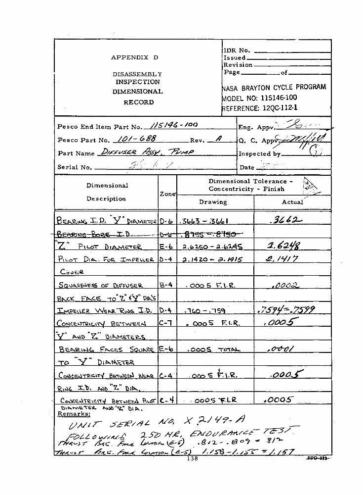
APPENDIX D
DISASSEMBLYINSPECTION
DIMENSIONAL
RECORD
IDR No. .IssuedRevision.Page .of.
vlASA BRAYTON CYCLE PROGRAMV10DEL NO: 115146-100REFERENCE: 12QC-112-1
Pesco End Item Part No. //£/*?£ - 'OO
Pesco Part No. /&/~ &88 Rev.
Part Name
Serial No. _
Eng. Appv._
Q. C.
Inspected by
Dimensional
DescriptionZone
Dimensional Tolerance -Concentricity - Finish
Drawing Actual
- D. V* .3L»t.3 - .'
Z " -p\i_crr E-fc - a
PvuoT 5-4 3.1420- , /y/
OP . OOoS T.\.g.
.759.75??C-l . Coo 5 F. l.R.
V* *v«iT> ^l"
• OooS
TO "
Remarks:
138

INSPECTION
DIMENSIONAL
RECORD
Pe sco End Item Part NFn, I 514£>~lOO
Pe s co Part No. \ l | - \ l l l Rf>v. A.
Part Name RoToR ^ KAoToR ( CaNVPV-^Te'
Serial Mn. /
Dimensional
Description
SUfVfT r\L-oT Y OlkMETER
QEi\R.\»jG jaofevJkjL. ^— Difs,.
De^Ri<.iG TTooeuku Jv DilV,
F"\avsU OM Z Ol^rAeTEC
P"ll4»SU OM X. DlklASTE.^
CoMC£OTE<CvrV KCTv.JEtvl
j /^oD . OlK^srreSS
CoKiceOTevc^y Be.TV*)f€*l*'"V *' "* r "
O O O £^£&t»AT5S5 OF S rV tkFT"
SV\DOLDH.^ TO V" DiKWSTtS
SaoKSvie&s OF SHKFT
SHoout>e«. -ro"7:"^^veTER.
Remarks: / > Af / 7~ S -^7
Zone'
fc-4
P.-4-
?>-1
B-4
B-lB-8
a-8
c-s
c-4
IDRIssuRevPag
NAS/MODREFE
No.ed.si one of
k BRAYTON CYCLE PROGRAMEL NO: 115146-100RENCE: 12QC-112-1
Eng.
Q. C
Inspi
A tf^r^£<-^<-^A CZ^qw^P*
^ ^N»rtoH Viy ( 7 )
;^;v-r:>/Dimensional Tolerance - /\Concentricity - Finish /NASRy
Drawing
. zacn- .zfcH
.-3U50 - - 3 U A 8
, IOOQ - ,19952/
N^
, 000 5 T: t.R
. oooS T. l.£.
. 0005 rr°T^-^-
. OOO 5 -rcnAA-
Actual
,^^^r' i Ji^O y •
-•^ fy^}Q ~~-~ *!«^7X5/'T
5v- ^s <r\^ —*y —
,d)^3^"
,^^-J"
/•^ '/^
.fttrS'
r^2z^«~r139

INSPECTIONDIMENSIONAL
RECORD
IDR No.
RevisionPage of
NASA BRAYTON CYCLE PROGRAM-f-.^ODEL NO: 115146-100REFERENCE: 12QO112-1
Pesco End TtPm Part No. \ \ S \ 4 k ~ l O O TTng r AppV'"- '•',..• '
Pesco Part No, Q\ "* \ £>O 32 Rev, Q rr Appv £r'*"&f'Vy£&^>
Part Name \A/ Nv*5V\t-R. . ~T\\£.O<ST" Tnapp^torl V.y V 7 /
Q -• • '. • • *•Serial No. 7 Hat* . '. •' - '
Dimensional
Description
\A/A.S\AeR W\OTV\
FMtsu o^VJissttee F«K.SFKorwE'aS OF \AJK.-Ste^ r\.cs«,
P^RN.v. -£.u\';^A OF \VNSV\tK FtocS
Remarks: l_J A/ / 7" ~5 '.•£7J
^a-'^ "^^
Zone'
c--s'b-^-
D-3
^>-3
?//5>^
Dimensional Tolerance -Concentricity - Finish
Drawing
. \TU -.17.5
<y.000046,4 TtfTXU
. OOO £ TOTK.V-
Actual
jaf?&
,40042?
.ov&y
^/^. Ax -2/ ^-^ -^.__
140

INSPECTIONDIMENSIONAL
RECORD
1 —
IDR No.Tssi i fd .
RevisionPage r,<
JASA BRAYTON CYCLE PROGRAM/IODEL NO: 115146-100DEFERENCE: 12QC-112-1
Pesco End Item Part Mo, l \ 5 l 4 ( o - l O O p^g Appv '
Pesco Part No. O\ -\5833 RPV. Q C. A ppT^vC^V^^^^^
Part.Name WA^SVAtB.. "TvVSoST TnspPct^H hy \U ''•" '• ' '
/5"~ - • ' * ^'Serial No. Hate. .-<-'"
Dimensional
Description
\A/NSV\e.N2. N/S/ID~V\
^xv^xS^ o^ W^SV\eR FKUS
ru^Tviess OP \A/KS\\E« VKctsPKEKVV.tV.V5vA OF Wi\£\\eS. r^CES
Remarks: {.>!A// 7 <t> , 72
^"'""^ ZJ
Zone
C-3
8-^V
?-3
B-3
Dimensional Tolerance -Concentricity - Finish
Drawing
. \8\ - . 180
y. oooo4fc4 TOTW.
.OOO 5 TCfTNU
Actual
</$o/&"
-OOG013
-*£><>»£-
?//5>^- /l/^. -V .'2-/' ^^"^ ^
141

IDR No. .IssuedRevision.Page
INSPECTION
DIMENSIONAL
RECORD
.of.
MASA BRAYTON CYCLE PROGRAM
dODEL NO: 115146-100
REFERENCE: 12QC-112-1
Pesco End Item Part No. //S/4& -
Pesco Part No. /&/- & 88.
, '7l>~t/>
No.
Eng.
Q. C. Appv. V85,J
Inspected by.
Dimensional
DescriptionZone'
Dimensional Tolerance -Concentricity --Finish
Drawing Actual
31. D. V*
©Pxusr Ed>_ - a
0-4 J . I4EO-
B-A .ooos r. \.g.
C-T . OooS F.t.R.
V* ^«4t> Z.
E-(o .OOOS TOTfrJU
-TOra.c.
000-5 T-l-Remarks:
PPD-9JJ
142

INSPECTIONDIMENSIONAL
IDR No.
Revision.Page .of.
NASA BRAYTON CYCLE- PROGRAM
MODEL NO: 115146-100
REFERENCE: 12QC-112-1
Pe sco End Item Part TVrnr 1 5144~|OO
Pesco Part No. \ 2-1 - \ 2 - l l
Part Name RoVoR t MoTog t
Serial No.
Eng.
Q. C. V85
Inspected by_
Dimensional
DescriptionZone
Dimensional Tolerance -Concentricity - Finish
Drawing Actual
C)DlK. rr
, "Sooo - . 1995
"Z"
B-8 . ooo5 T-i .R.
V
R-8X'
op oooS
V "
OP c-4 , ooo 5
TO ' tZ"
Remarks; /JA/1 /
143

INSPECTION
DIMENSIONAL
RECORD
CX/w 7~ 3/*» X— *l/ V 7- •/?.
Pesco End Item Part No. \ \ 5 \ 4 k - l O O
Pesco Part No. O\ — \B>o32. Rev.
Part .Name \A/ K.'oVXt-R . ~T\\£.OST
Serial No, f
Dimensional
Description
VA//VS \Aefi. W\DTV\
r~\vl isU ovi V^NSHeR Ffvcts
n-^orvje^s OF vJtv.'SVfc?, FKCH.S
P^UJBOSM OF \A/K£V\« FA^5
Remarks: _ _ .
^^—"'^
Zone1
C-7
D--V
D-3
IDRTssn
No.ed
RevisionPage of
NASA BRAYTON CYCLE PROGRAM;.•.^ODEL NO: 115146-100 """ ,^cFERENCE: 12QC-112-1 . ..,.; j
Q. C
Insp<
A v^^Zfe^7'
(^App" V. 85 ;
><-«-f>rl hy V?y'
Dimensional Tolerance -Concentricity - Finish
Drawing
. i-a.--.i-isy
.000046,4 TtfTM-
. OOO S TOT^V-
'""-**""" A«/ "
Actual
, /2-5> (T)^ — (^.0Q&03& ^
.0009JT
^j-7
v~-<~~r-~r-
144

INSPECTIONDIMENSIONAJ
RECORD
IDR No.
RevisionPage nf
JASA BRAYTON CYCLE PROGRAM
/10DEL NO: 115146-100. REFERENCE: 12QC-112-1
Pe SCO End Item Part Nf>, l \ 5 l 4 ( o - l O O TTna. Appv.t?^^^-*-^— «-v
Pesco Part No. O\ -\383i Rev. Q P. Appv V85J
Part Name W fVSVAtVC. ^ ~TV\1fJO'S\ Tnsp^rtpil >iy •' -^
Serial Nn /6 Hatp
Dimensional
Description
\A/NSV\eS WlDT\\
^xvivSvX o^4 \A/KSUe.R sO:S
FUKTUSSS OV7 NA/K'S'AE.^ ^KctS
PKSKV.LtV-\^xA OF V/A£V\£$. t-f^ES
Remarks:
* -.
Zone
C-3
B-4
?-^
B-3
Dimensional Tolerance -Concentricity - Finish
Drawing
. \ 8 \ - .180
y, OOOO46>4 TOTNU
.OOOS TOTNU
Actual
, /$#¥ S)x^___ /f^
tOOQ£&&
,c>QO(yi~.o v .'
x '- _/""•'
145

INSPECTIONDIMENSIONAL
RECORD
1DR No.I.ssuecl__RevisionPage of
MASA- BRAYTCN CYCLE FROGRAsfl
(/SODEL NO: 11514G-1GOREFERENCE: 12QC-112-1
Pesco End Item Part No. //S/J?6~S°° v.nv. Appv
Pesco Part No. /0/~G>£S RP V . /? Q C.t ^pp".
Part Name P/ff^^ /%ZP , '7 'xVfX' TnSp*rtoH hy
Serial No, X - ^V^'O Date
Dimensional
Description
8vr.fvS.vWiC> 31. P. V* VxMAe;^
B«AV<\UG Eov/.C _t:ir.V
*Z> P \i-crr fts/vMerciJ.
PILOT Dii^. roe. XrvM?E iA.c-;i
Coo.Cfi.
SG>iJf^.s.«idS 'OF D\fP->ss.'ft.
P.KCVT. FNX£ -ro"7."*V"0!^
H^pv:v'..'t;R WCK»-~V^£. T.t>.
Cciiict.vtTVAcvvv/ Pe^'vJviR «.\
V A.nt> 2." CuXv.e'.^E-.-S
B'v.f-^c.\viC-. Ffvct.-i S*0f*?-v
TO V" Dl^W>uTc.vX
CoviCevSTP-VClT-/ CfcT^ec^ WfcNfc
fewii ^.X>. AiiD "'Z-" t)ltX.
CoiV-tJiTP..?^-!*/ Ber-iE;c.A fttoTO'.f .vv«-.ii - 1 1- K^Ci •••^ (ji [^ ,
Remarks:
77/^f?? <&#£. /^^TZtusr- #*&. S^^//.-• • • ' • . • • • • • '-;/
Zone
D-4>
D-(s"
E-'t
0-4
B-4
D-^V
C-T
E-(o
C-4
C-^
CCCL/^-
'/lc<-*
Dimensional Tolerance -Concentricity - Finish
Drawing
.3Uk3 --z>y*\". 'A.I 5S" '"-'"" 3"ib'O- ~~
a.fcX^o- P.. -49
P. 14 20 - &.&IS
ooo5 T. \.C,
.1t.o - .15^„ Coo 5 r, (• R.
.oooS T^nfsi_
-.ooo?>' T.l.fc.-^
, OOO'ii T'*-f~
-r,&r-s (_£:—5s • "'
^V^'X ^^- ^) /./?
Actual
.J'^^1' i'-.'.V
i, i-^ #^rz^/f/4'
ro&&3' '"]
,7s- ?f-,&e>e>5^
. & o &3 , )
, o<s>oi
, ,(j? & o 5"~ ?
SL.-..^o'/ -.-.^"*Xj
•g^. /./flT=//*^e
PPD-3J3
146

INSPECTION
DIMENSIONAL
RECORD
IDE. No.T < ; ! ; i i r > f l
l\c V^ °:ion -. . »Page . nf
NASA BRAYTON CYCLE PROGRAMMODEL NO: 115146-100REFERENCE: 12QC- 112-1
Pe sco End- Item P;irt: Nn. 1 S M & j - l O O irnfr. Appv,
Ppsro Part No. \ ll ~ \ ?- U R P V , /V O f^ Apr".. / 'V:
Part Name RoToR ^ MoToR. CavAPu=:TC TnspprtPr l hy '. 7
S.H., NO Y~--£/*9- <T n*tf r/^7^
Dimensional
Description-
SvXf^TV P\uoT y Olf,wETtP
BtK«\'.sr> Tovop^jr-A- "£•* PIN.P)t^.R\OG- ToOf?Ot.,L' X" l")lk,
Fivu?, v\ DM "Z Dl^^Hnte
F"\i-ivSU OrJ K. DlKNVe-VtV-
CoMce>-iTPvC>W f? t-T-.' v;-.V;>! .
''y ' /<Ot>"'Z" OlKT«Vi-T?-^S
C O*J C. Ev^~P vC \Tv/ p —.TU.) :i.V.V\
"X" p^.-.r^Z" ^lP^i^.=T\.ps
S O O Ki?fj \.\~:.-'.< 0- S r\ t^^T
SV\Ti 0 Lt5 H.5 TO " V " Dl WAt— 5
SoONCv^EC-C, OF 5HKPT
StAooLSC-v. -ro ' *Z" DiMrvr.?..
Reinarks:
/ • • • • • , • - • • •
Zone'
S-4
t2 x
7">~ *~~
P.-1
6---1
B-l
B-8
B-8
C-a
C-4
Dimensional Tolerance -Concentricity - Finish
Drawing
. 2. Sol- .2504
. "3U^O - . 3U48, ^oOvO - , 2 9 9 ?
?/•
^/, ooo5 T. I .R. .
. ooo5 T: -R.
. oooS -ro-TNv-
. OOO S -TCTTK*^
•
Actual
. 2. ¥0? ' • 7)
>2£^°.-2-779't^^
000 -*i- '
\f &> d -o -T—
.
0oo£"
,e e # 5
;•-. . -' -. : ,-. • •
147

INSPECTIONDIMENSIONAL
RECORD
1DR No.Is suedRevisionPage , of
NASA BRAYTON CYCLE PROGRAM
MODEL NO: 115146-100REFERENCE: 12QC-112-1
Pesco End'Ttpm Part N". \ \ S \ 4 k - \ O O Rng. Appv
Pesco Part Nn. O\" \?>S32 Kf , v _ Q r., App,;
Part Name \A/ k'o^Afc-R ( T\\?_O S V Tnsper fpH hy A/
Serial No, /T ~ ^.' V? "" /J Hatp
Dimensional
Description
XA//VSVAE.R w \DT\-\
ITvvJ isv\ o\> VJr-r^'F.;?! F'ks.'c-.Ci
B-krwe^s o^ W^fc^ Vk^sP^R^.v.\-9.u\<5^A OF \A/l-6V\tR Ffv«S.5
Remarks:
/P^T-'Cs? Z-<-\ v^*
Zone'
C.-1
\>-+V5-3
\>-3
Dimensional Tolerance -Concentricity - Finish
Drawing
. i r k . - - . i - z *.-4/
,oooo4t>4- Ti.TrN.i-.
. OOO 5 To-r^u
-
Actual
./i<r*' r^^^ \u
.OOOOK?
f& o o 0<&f~'\y_
--
- • < " • — r— " "
148

INSPECTION
DIMENSIONAL
RECORD
Pesco End'Item Part No, \\ 5 I 4k - I DO
Pesco Part No. O\ -\3§33 Rev.
Part Name WX"5\Afc£. T V\£O<=,Y
Serial NO. /** /> .* ' if 7 ~~ -^
Dimensional
_ Description
\A/M=> \\E.>£ W/ \ I5TV\
^xvixSvX O^-i \AVsv\'H:R. VW-tS\
VV,fcTvlc-SS o1^ \VKCA^S? \-r^tS
PfSEK\.Lt.\-V?^A C? Wf-5\\f;R. ^rf^l5
-
Remarks:
Zone
C-3
R-4?;_v
B- 3
1DRIssuRevPag
MSA
,/IODt
<EFE
No.f>H.sione nf
BRAYTON CYCLE PROGRAM
[L NO: 115146-100
RENCE: 12QC-112-1
Q. C
Insp
A
"' APPV.
C*prt^rl V»y | V£P
r.
X'''
Dimensional Tolerance -Concentricity - Finish
1 Drawing
. \ 8 \ - .180
y-'.0300444 -TO-VKU
.oooS TC-XNU
Actual
,/^o^" Dv^' ^u
^oooortY (T-/^ N
- - -
/9-f^T^ R o o o o *«.- £-^^*~~^
149

INSPECTIONDIMENSIONAL
HE CORD
IDR No.
Revision^f
Pesco End Item Part No. /ISM'? - JQO Rng. Appv,
Pesco Part No, /O/'ff 'SY R PV . 8 Q, C. ' Appv,
Part Name L-0IS&/S. //'?'->]/, MoTO^. . Inspector] by • — '
Serial TMn. X-^-~ «^-^ *7 — & Date */y?Ssr
Dimensional
Description
BEAE tr>{(:> JZ.D.
BENR106 Bo*G.x'.D
^!l P \v_oT tli^s^^trvtS
Co^lCG»-ST"Vi\c;Ty OP ^£»s.e.v»J6
*r-»"X. D- SA/ITVA /I Dl^.^Afre^
Soo^R6ue« oc CoMtefbo*
F^c*? ^V-TK"^" DlN^CTt-e
Remarks:^AT-^ c^c^oc
Zone"
B-SR.q
C.-f»
6-5
. a.u
Dimensional Tolerance -Concentricity - Finish
Drawing
•. 30.13 -. "30 U
.SWo-SfcZS"
"S. HSO - S-IX45
.0005 T.l.R.
. OCO S To"Tfvv_
Actual
^^«. '(T)MA*Mtf'
Mft'
.— ;PPO-9M
150
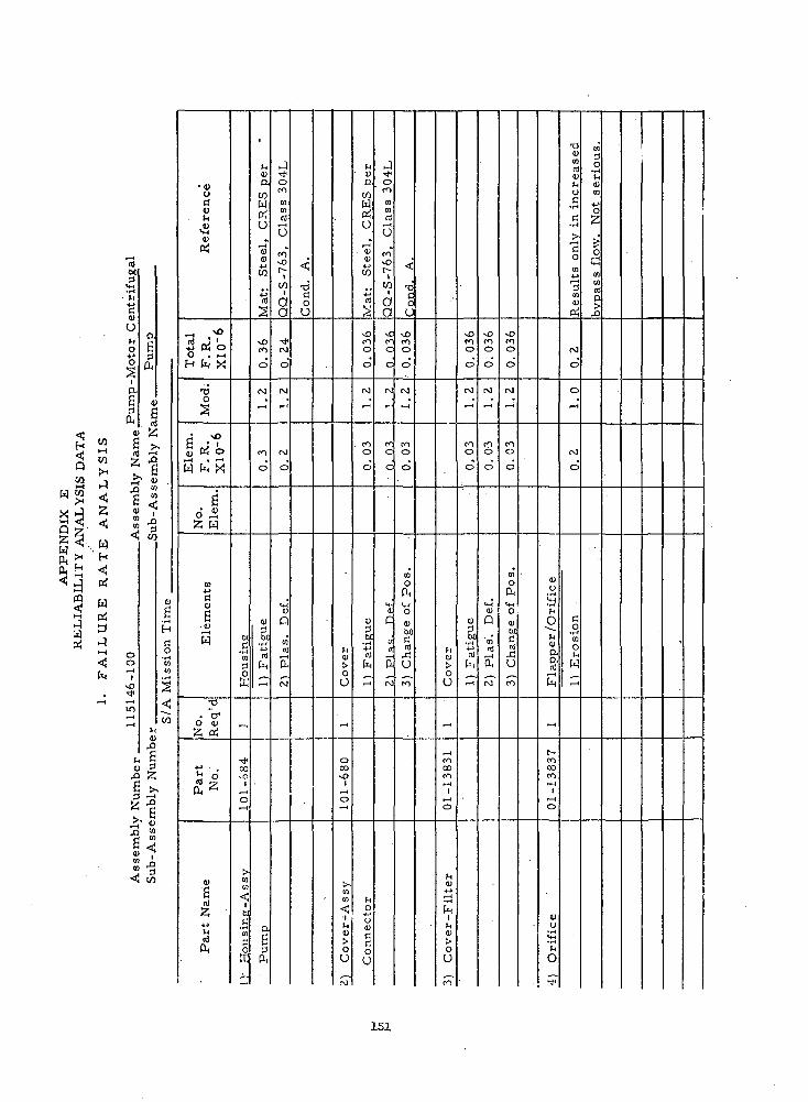
<H
PP
EN
DIX
E
TY
AN
AL
YS
IS D
A
* 3<3rj
w
\T
E
AN
AL
YS
I
^i
PiW
3,_)M
^h
'
M-J
CU
UM"O
O
a|ft
agft
(!)
gct)
g >.
Asse
mb
ly
Na
Sll
l-l-
Acc«
.l-r,K
l
oor— 1
If)
r-1
Ug•r-1
C
O•r-t
COto
<jTo
tuW
tu 3FQ 2jg >,?.6i- tuJQ
•tutjctu
&tuftj
^ NO
nj • l•+J DH OO . — iH b, X
•o0
p • 1
3 . 2W ft X
. gO p-t2 W
to
"dCUgW
•O
6 tu£ PH
+j ,
^ O^ft
tug
«2•M
Mct)
ft
susin
g
W
x l
00vO
1,_,o•— '
CO
Jf<
^hi
usin
j
offi
^
4
cu&wW
Oh
T—t<atuw
isS
vOCO
o
ro
-'
CO
o
Fatigue
^
o.gaft
j^o
toCOnJ
f-H
O
2i
W1
aa
^t*ro
o
rJ
r-4
CM
0
(U
ftto'cd
i-H
a,CV)
.
^•dCoo
41
oO
r— t
OCOvO
1,_!
0•—I
COCO<JJ
ooro
cuaWW
U0
r— <
tutuW
4-1
a)
<>
vOCOo
o
ror— 1
. COO
o
Fs.tig
ue
^
^HO
OvCftQ
O
J'•t
1
oCO
toCOcs
oCOvO
1W
aa
C-1c
c
ro
-
c
c
«*.iC
a
5ro
^
T3
OU
vOCOo
0
M
•—t
CO0
0
CO0ft
Ch
an
ge
o
CO
oO
_
COCOCO,_{
1!— <
o
cu
•T-4
ft1L,tu>OU
CO
SO
COo
o
ro
-'
M
o
0
0)
W)
la
-1
• >COo
0
ro.-H
CO
O
0
cu0
'to'rS
ft
ro
sOCO0
0
rJ
-<'
COo
0
tooft
Change
o
CO
cu
^-r-l
lap
pe
r/O
r
U,
r-cocoCO^~ti
r— (
O
cuU
ta
o
^
0COracu
oC
•H
C•rH
•"coCO
•0totu
PH
roo
0
^H
ro
o
Ero
sio
n
~«
to3O
'•^
CU
CO
0
^6
toto
p,0
•
151

co
W
W
n)00
cuo
ft
J? «,O W
Cfl
M
<
*J.-H
!h< w
.ssio
n T
ime
§
^CO
cu*•'C<ut4CD
W-!Otf
- .?"! fV <-»+-* m fo . ~*H fc X
•do•^
c ^g „; 'cu K o
W h X
fi0 ^2 W
CO•Mcl
Ele
mei
•o. ~a>
O CD
2 OJ
•4-1 e
- •§ft -21
IDg
-& —A
tnrtft
CD.a
H
PJ
4-a
"c
CO
MOft
m
OJ
d
o
~i
oCM
d
to0<ub/4-1rt
fc
<
^
4-1CD
4.
^O
*+*0)
Q
COrt
ftCD"h
4-1oIn
4Jc
• •HO1-1•d,— t0)
£
O
U3-M
•' H"
'ot-3
1
T3i— i(U
£vQ
U)•*-»tn0)
4->
f^
O-4_)
o0)
•4_)
cuTJ
Xrt<u
grj
.,_(
r— <
(U
ffi
Oo
d
0
r-«
0t— 1
o
Fatigue
r-«
CDtoQ
»*-!
CO,Q
T3Q)dGho
tM
cuaCD
J3
O
00O
t— 1
CO
d
o•*o
r-t
rtCU
W
Imp
erf
ect
CM
OJC•d+->a<U
ort
4-1(3
ilte
r E
lem
e
fc
^
CX)ro0000
1*— 40
'•scu
CUr~\
W"" 1
ho(3rtto
4->W
r--
i
JD13affi
^.r4
4J
IH
rt
^
CD>CCD
P
O
C-J
0
•—1
o
CM
r-1
3O
M-l
t— i
r4-»
(3CD
g•o0W
43•fJ
'0
in^fo
iCOCD4-1<\)
tf
CDf4
^!-H•r-t
rt[-1
CM
d
o
,-<"
CM
O
Fatigue
CM
O
II
rty
o•t~44-»rt
W
enboC
21
0
CM
O'•— iI
vOTfCOft*vj>
O^0
T3Ci
g^
-Pre
fo
W)c!3urt
OH
co"
0m
d
in
o
in
o
do•H
&tMocublr3rt
43U
r— *
vD
O
d
oo
d
•— t
o
Extr
ud
e
CM
0•
d
0
t-4
CM
O
>,tn!D
<4-1rtcu60rtgrtQ
CO
152

W
H•<Pi
KrtP-1
Re
fere
nc
e
-H .*>
O . -,H h X
•s
6 •*<U PH O
W k X
• ci2 W
U)
fl<uSw
TJ
o <u£H Pi
^ o"n "w
am
e
n)
Co
ver
~*_
r— 4CO
•—41
O
•
oOiTJ
W
?
"o
coef
fici
ent
>oZ<u
^0COoo
OJ
^CO0
0
1)
Fati
gu
e
M<a
t-H1)
P.
g
;xp
an
sio
n.
"itg
x
NO
oo
OJ
J
COo
°
, *
tuQ
tord
,—4
OJ
COoo
OJ
^(O0
0
too(^V4o<u01s
XU
Sc
rew
s
OJ
CO,—4
in<2;
aOi"1
f-tU
O
.
0
ot
red
un
dan
cy
<u"tdto
(X
i-H
O
IT,
O
o~4
o
3
oo
oU
•ord(0
i
Ooto
-dCOrd
grd
T3
to
1^
to<uog
Imp
ell
er
""
oCOooCOf— 1
'o
to<u
Imo
ell
-
COCT-0
0
^
^
OJoCJ
1)
Ero
sio
n
0
0
0
^
^CD
toto
2) O
ve
rstr
e
i
turt
PH4->
Imp
ing
em
en
^
0000
1
Q
toU)
M(D
Dif
fusi
00
OJt>
0
^Jcr-
OJC3
o
1) A
-bra
sio
n
CO
0
r-rNO
OJoo
toCO
2)
Ov
ers
tre
UUrtP
Sn
ac
ei
5
COO
o
o-I
COoo
I)£4-rt=
CO0
o
o
^COoo
tl '
0)
Q
COn)
(M
COCtoSO"~4-i
n)x;W
InototU
n)In
<Uto
a
"rtx:CO
oOJI—)
1
OJ
4-1
XI(O
3?
•oo
inc
orp
ora
t
to4J
tug0)
tu
OJpo
,_,
o
t-0
o
01
t— 1
3
O
—1
o
>4
O
Hrttuto0?
153

to
WH
niCO
sIa,Sft
p-
«srt
_>s3
X 6X D3 w
9],fl
- §2 &
r N
um
bl
--S
<i)o
<u
(!)rt
3 oi oO . -H
f-,' & X
TJ0
A
g -a) K o
W h X
g• fl)
0 ^^ W
01
C
s<u
3
T)
o' <u2 CH
« Q.
ft
<U
*52*jrtft
Th
rea
d
0
CJ
_J
rt<uIn
H
U?r-H
00
a-H
nj0)SI
13C
o
^1nj
(M
O
in
o
•*
o
060art
6
<uQ
1
w
2niJH
<U
3
wO
O
roO
o
'o
,-<'
roo
o
r-H
<i
Wa
sh
er,
ooO0
1
^
£^
}_<0)
CO
nj
^Co"r-H
Locknut
•~o•#oc- iPOCO
s
ud
•H
^1Oo-qi, — ira
CO
^^p-
1 — 1
o"
o
r-H
— <
0
, — 1
00oo
to3£.t-1
Wa
sh
er,
roro00ro
1
o
tn2H,£H
In<U
a
^5
<n0
o
o
^-
ro0
0
GO
-MUl
rt^3•f, t,
• I-t
ininmvO
CO
•s
Jl60
'rttH
CO
C-iH
0-,
^
o
0
r-H
O
— '
O
<udM
4-1rtU.
0rv)
i/ien0)
T3n)tl)ffi
•— iO
0
-1o
—>0
rt(UXCO
(M Co
ve
r
00vO
o
oosUltn<ji!-O
CC
o
roO
0
(M
-H'
roO
O
turH
S
.rH4-1
tih
oo
M
-1
roO
O
.
*3Q
enn!
ro
COo
0
rj
^
roO
O
•
oft
o0)cl
nJ
bro
154

CO
WH
W
rt60
tuU
o-4-JO
aS
O
3
oo
S
,0
CO
S .2
CO
(J
C!LJ<U
o-^P-<
+5 cd o0 . -Mt-* &X
tios
jrttW h X
• §O r-H
Z M
CO-MdCUa
•-H
T3
O <I>z rt
^
cugrt
•M
rt
/ockn
ut
^
n
CM
xO
•— io
Lo
ckn
ut-
Assy
. ,,-H
CM
OGa
TJf.3
T3cu
pcj,_,cu
rt
rtPi
CMO
O
r~*
O
o
*->
cu
COrt
^
CO
00ooxOCf~
"6<
Wa
sh
er -F
lat
^_CMCM
<JC
*oc3
CUrtr- 4
|~]
cd
td0
0
o
m
o
0
0°
cu
•r-l4J
rt
-1
roo
o
m
o\
rOO
O
•
CU
Q
CO
rtr- 10,
CM
CO
cre
ws
CO
CO
inp-
MS
35
2
cur*
Scre
w -M
achir
(\iC4
UCCO
T3
C
•6cu
fY
V•—re
hrtn
MO
O
•— i
o
,— 4
O
i— 4i-H
•-1
r-mCMi
•ortcuKinCU
CO
^~l•r-t
h
Ccu
o^4
£>
CUMcsf^co
fn
cre
ws
CO
^
rMin
NA
S13
artO
iowJ_i
^
^
c.frttC
T;acr__c
ct
rto
in• — i
o
m
o
o
o
<3— '
CO1
xO
00
rtcuK
cu
oo
CO
c r e
w s
CO
^
t-Hin
NA
S1
3S
cre
ws
-Ca
p
.mCM
o
rtT3C3
T3CU
Pn•— iCU
rt
nHi
inr-H
O
m
o
o
,—4
-<
00CM
O
T3rtcu£
cu
oo:o
.JJ
^
•*CO
1
r'
4-
xO
CM
t.Crt
T[
T4
P_
4
^2rtj-ft
p
r\C
c
—
c
o
CM
<
•-1
rash
er
^
00
xO
O
1 A
N9
60
Wa
sh
er-
Fla
t
, — .t —CM
U
rtT3
•aCU
, — icu
rt
rt0.
c
c
.r
roO
o
CM
cu
• H-Mrt
i
— '
o
0
in
_o.
o
CD
CM
vt-4CUQo
• ri
CO
rt
S(M~
155

to
wH
w
rton
aoO
a|ft
ag3
ft
OoI
vO
2 6 >•CO ^H
55 fi3CO
s<
XIs
CUoaCU
•2<u
•3 J?0 . ,-<H tn X
T3o
. 2
5J PJ oW ft X.
g0.32 W
CO
Q>
g<uW
•a. "a-
O CUZ p*(
4J
rd •?ft
• <ug-' -nl -
£
cd
^
cu
CJ
ft)In
(
CM
00ro
i
0
-1"-*-»cu
o
ffl^— •
CM
(Mr-
o
OJ
en
o
cu
rdhi— <
(
CO
00CO
1o
•>-4
c3O
2
CO
o
(V!
CM
O
v;cuQ
cart
^
: -~
-
•
. _t-£ -
- -
'
1
156

rtM
CD
O
o4-1O
a.g£,
wHH
W
fi >,rt -H.
I*J?* 0)
<! w
W
fa
si1 >.^ -H
x"a^v ""43 «
<!
ren
ce
«2
rf
*rt rJ4-t PJ O0 . ~H
H fa X
•ao•
• -ou PJ o
W fa X
. gO —<2 W
to'3IUgtu
r_|
W
•O
. "o*O IB
£ Xrt >2r
k
tuS
_rt
rt
MO
TO
R
>•
3*n04-1rt4-1W
-1
PJrJ
i
M"*
1)
Sta
tor
-Mo
tor
i—™XCCCs
1
sinCJ
-1
_,
mevi
~*
^<
>,
to<to0O
^H
^H
rJi
r-HrJ
2)
Ro
tor -M
oto
r
ire
we
lde
d.
i<u
to
rt
!M
in
•*"
_
^H
0
to
r-4
tntort
.C
"o
o
o4-1
Dam
age
up
<u(jc
t p
erf
orm
a
oIU
M-4a!
O
to<uord
_
^JogO
o
rtT3
Pesc
o t
est —
Mo
del
Z1.
95.
to0
-4
to0
ooIU
doO
r— 1
3) C
on
ne
cto
r
W)> C
n>(f]r-H
Hi
b
vj*
o
Hy
dro
dy
na
mi
bi*HJj
n!IUP^
rt
^Q
OCci")
1
0
4.
1 B
ea
rin
g A
toT3rtO
to(U
to
Reli
ab
ilit
y
00
-<
J•*0
intM
fiO
•r-iton)Mn
N
co
•
r-o•odrt
JO
mm
o
"o
00
o
oJ
ooo
"30
1JSu<a
^
•ori
(be
ari
ng
s A
faoo0
14JrtIU
•i-irt
"rto
*Hdrt
n(M
— 'm0
o
mrq
C0
01ni
X^
^
OOro
1
O
4.
2 B
ea
rin
g B
CO
o
o~i
00
o
•;Cfa
157

CO
;*j<^
wH
W
3
fa
cti00
ft
s
CUgri
<u ^g >.nj -H2 g4T S_Q w
g ^™ d<1 w
CU
Re
fere
nc
{H?H fa X
13O
2
i PJ oW fa X
go' J}£ w
CO
CU
gJH
w
13
. O1
O <U2: erf
^ oft
CU
gn)
4->
rd
P,£
O.
Ocu
14-1
"rt
OaCOcuofi
o
o
0
•ocu
" CUn
nso
r-S
]
CU
lO1
CUocK
gc"ECUP
ftovO
cin
o
CVJo
^
(M0
^H
^O4JoCU
oO
(VI
0t—
CMPJ
•sO1-)
CU
2"o
o*
[j_
ooCO
g'oP
a
cu
}-Q•t-JU4
C-CL
0o
.soP
1
158

zg
o
aDt
«,.
0oo
13g(AWaH
j*J9•J
fo
g
g
p£
J c
OF
FA
ILU
RE
TY
PE
CA
USE
usH OSS g
2 . 1H k aI *Ss
u
iP<
ua,**"uDi:DJ
1*4
to0
0
IM
m
Id
Fra
ctu
re o
f eh
aft
in f
ati
gu
e o
r sh
ftV
«lJS(0
0
1
J.£?Vag V
n. «
^ M. C- a
•o
0
2
a.
i
Ch
an
ge
of
posi
tion,
imp
ell
er
mis
ali
gn
men
t le
ad
ing t
o it
s ja
mm
ing
*8
*
1k,
JSh-
t*e
I
•g
Nu
t lo
ose
ns.
Im
pell
er
mis
ali
gn
men
din
g i
n i
mp
ell
er
jam
min
g.
^«.
*
**
z
TJ0
A C
I *
< .-s2 "
11•£ ti« Ze "o •sa1 i
U1/1 O.
0 JI "0 "v
S "° *• *•s- •- » •
,3 c « «- S 3 2Iw ; i/5 « W
-^ u u
Co
nta
min
ati
on
(ex
trem
e co
nd
itio
nco
nd
itio
nal.
Fra
ctu
re u
nd
er
fati
gu
e an
d p
last
id
efo
rmati
on
Fra
ctu
re u
nd
er
fati
gu
e an
d p
laB
tid
efo
rmati
on
— 1 ~H IS]
* ^
ce5rt
A
, i i— & T)
b. JT «
o
cV
u
iACJj*00c
sjaV,c
o **» "O•n cs s
B
Mag
neti
cav
oid
th
i.B
eari
ng se
izu
re d
ue
to h
alf
fre
-q
uen
cy w
hir
l condit
ions.
3•oC
«- —
i1<da
0
0C0f-££rtVO.
i £ts§ !3 M
1% a
•o"3cV•*C
•oV
V
I
V
E0u
>.20
Mot
or a
sB
eari
ng s
eizu
re d
ue t
o ex
cess
ive
heat
and
tac
k of
lub
rica
tion
^
irt
-"
10
1
1«
A
>,3E
" V
i ^It
tO
•c
1' V
1
Flu
id i
s i
pu
mp
ing
c.2
(sil
t/si
ze)
_
_;
3
—
A
s
1hrt
A
«
fc0
«
V
6•5
«T)V
•
.0 .
<9
E ««u
• *«03w .
Fra
ctu
re o
f in
let
an
d
ou
tlet
pip
ei
(co
nd
itio
nal-
co
mp
lete
b
reak
ag
e)
eit
he
r in
pip
e o
r at
the
weld
jo
int
o
*-"
-1O
I' i>3k*
0.
C'o.(0
Pas
t ex
pre
mot
eF
ract
ure
und
er f
atig
ue a
nd s
hear
(im
pell
er r
ubbi
ng)
.
osO
fi£
0•o'i14
X
•fct0V
0
Eoi*S»<•aV
« c
Coi
ls a
nin
aula
tloi
Gro
und-
Coi
l to
tta
tor
core
. EJ
CC• I
ve c
urre
nt d
raw
n le
adin
g to
o—
oc
o•^j
w
h0
oCoc«*.i
i"*Vo.3 "'
.— **•X «
5 !3 h*-. a
inve
rter
bu
rn o
ff.
•
159

VIS
ION
OR
AT
ION
AN
AL
YS
IS
DU
CT
S D
IIE
R C
OR
PE
CA
US
E
S s §O ^ Wu o S
b,
oo
i3
^eSKy
«
O5a2a
Mao8f«o
rPE
S
HO
UL
D
H
WH
Y F
AIL
UR
E
IOS
j "' aS ^ ctj
"• o
,UR
E T
YP
E
CA
US
E
•j
IKIN0
W a!t/l u3 n< 3<-> 3
S t^i8
w
H
S
H0,
H
S5Jah.
•£ "SJ, •« tov B
6 S1 "3
1- 1
£^J'-
« ?S -9 o
:tu
re (
con
dit
ion
al*
one
<le
ro
tor
bars
die
inte
grt
un
der
fat
igu
e an
d p
laat
ion
or
cra
ck
s.
2' 1• ^ E
I! 1
o. (O
1gi
o «
04 U
0 *S
9 th
"0055
Sta
inle
s
u
un
der
fat
igu
e an
d p
laat
Ion
or
cra
ck
s.F
ractu
red
efo
rmat
:
CM
19
&
0
6cu
j
|
5
wel
d jo
intB
. H
e!
u
VX
atio
n o
f w
eld
a.D
isin
teg
r
o
m
"o
•o0
**
0
•aV
Hel
ium
on
nec
tor-
her
met
ic a
eal
u"o
3
o
hOU
ou
0
0
3
1
I•o
V
3
0c
con
nec
tor-
cov
er w
eld
.
.
O
o
o
oU
•o(0
•o0
3 •'0
•O
O
e
• S
teel
iro
carb
on
or
tefl
<:e
d.
«a fa °C "Jj"3 ? .0
*®oo
uid
ov
ers
tre
aa
of
O-r
ing
in
ex
tru
sio
n,
: p
osit
ion etc
.
S o0 0uU fa u
(si n
k
i0,
iM0
o S.U 6
& I
s,?t» {•
||
ouEmh0
3ik
• -j
i Ec -
Pre
-fil
lab
solu
te
*o(S)
nta
min
atio
n
ou
0
£
0
U
50
Ck
o
1<tts«
%JS
BB
'b
per
form
ed d
u
0
on
tin
uit
y te
sta
an
ee t
est
ing
.P
has
e c
acce
pta
M
1 f
ail
ure
. O
pen
win
din
Ele
ctr
ica
0
o
is
leak
to
t.
E
1
2•3wt«
i
bre
ak a
l-w
eld j
oin
t o
fo
re r
oto
r b
ars
.
S E
J l
O
(M
O
I
tmv
V
"OG
"3ao
•ell
ev
ed
wit
h ail
iS
trai
n x
*a
'ractu
re d
ue
to v
lbra
tio
Win
ding
1et
c.
o
5U
J
•d0
—
0
U
1
X0M
"o^ •;"0 *•0
||
ur* •
un
der
fat
igu
e an
d p
laal
ion,
cra
ck
s,
or
dis
inte
f w
eld
join
t.
0 ** OM <5 „a £ g
1^fa t) 00
o
11
10
160

i D
ivis
ion
RP
O R
AT
ION
SE
AN
ALY
SIS
146-
1CO
hfi 3 s
|«s =§1§ri « oM«S .
PE
SC
OB
OR
G-V
FA
ILU
RE
BLY
rjtoto
ct0
O
0.
30.
gaS3
Hai ,
83a.
zZ
Sj
.;i
i
Iii
1
|1
• 1
Ua.s§3
Sb,Oto*
ITIA
L C
AU
SE
)
H
S
i>»•bC
•i
>Jah
g
|i|
J1,»*•!•
33
<•<H
6JSj
N
CA
US
E!F
.S
ff N
UM
BE
R
osg
u
zS£
4
*•1
j
t
J
3
H
* S
** ^» C£ 0u . u
•* - M • '•*
' 5-5 °•s "• -s^5 2 S S .e i- * i« c *•
l-o "5 D " c•3 -3 « a« -3 -o „•" C 5 .5 • C «S"2 v • «£ « h •
S || |g | j|*3 * ' *o * h O * *E
• " 5 S h t d 0 1 0 b S e *
: i a 1- IS 1 f-• j j 1 " " " 2 s * *11 1 1 11 al- ! 05
S
1 •s >• sa f f> •1 s •§E "3 *
^ * 12 S -8" ~ 's S
T e i s ^ e B 3« C A O | ^ O _ O J 5
"° "a ° « t - S ° o ^ **
-S !T 3 0 - 2 2 5 , u2 « = ° ? ^ » s 5J J « U U, O O U U. ^ H
o o o— . — (M 0 IM
fj 2 2 » V a> V 2'
s=•= . . 1" 0 ° 2 » • . ° h
^ ^ ^ c S. ^ 3 ^ £w ^ u u S a o Q t o
V
SSo
0 '«-i. a,1 S-« §• a
A Ot> V M
•u M *^
•'3 2 a
n 5 "J a Z
161

*o«— 4
4>bof*
PH
RE
PO
RT
P^HjjPQ
l-l
9H
ioHo3
u(4(4(XV
I
f-H
10)00<:at
Cen
trif
ug
;
*-o4J
O
1a
<u
1"osgt^
n\
ompo
n<
Cj
<aCO
• r-4
<U
«
4)4-tn)Q
1
mP<«goCO3
F-*
1
t— <
2
~4
. .
O
4-1l->
&
uto<0ft,
"4?uv a3 <u
•S o-1
°sS uC ^"^O 4Ja ug ^JO *«o w
jtT? •0 0 ™
£ X ffi
rto. i
Co
nsi
dera
t
*tf9co
0
cd
boco
Q
<u•O CO
'" O CQ ••§ <u« o
'rt
-*- • .
to ^*to a- Ato
^"o> >?
leak
age
j E
xte
rnal
o
0)&,toWrfOr— tHI0)
toIDto1)
"3"(3w
i
Mate
rial
<a
ractu
r
fa
hr— — ul,c'to3O
ffi
Ex
tern
;
o.-H
"ointoO
t— 4
1 E
ven
tual
a
tL C
on
dit
io
oCO
to(0
T— tO«
vOp-itoaa
atig
ue
fa
o.s3
syst
em.
*wa)Q
tad, — i
«4-n)11Cc
CO
uoO
cW
0
CO
leak
age;
Ex
tern
al
00o•
0•
tott)<u
to
<u
ractu
r
fa
(U4-»i-H
fa
Co
ve
r-
r— 1
rj
c04J
n)
co
nta
rnin
Gre
ate
r
<o3tu
•rH
1=4
I t
(U
. — i•(-i
v«-iO
**H0)
Q
to<6
S
Z
leak
age.
Ex
tern
al
000
•
0•
to
(U
to
0)
ractu
r
fa
1 1
o•y(jj- pjoO
Co
ver
-
N
N
ao•a
Ev
entu
al
i54-ri
fr
(J
| d
isch
arg
U_i
P
tort
r-H
leak
age.
Inte
rnal
ooo
•
0
•
ton)0)
to
(U
rac
tur
fa
h<u
*T^<uaS
CO
Ve
r-
on
N
i— t
.Htotoo
oE
fr
'-M
Q
inrt
(X
seiz
ure
.B
eari
ng
000
,_;
atoWtf0•— (<utoCOto<u•a
'<34-1to
Mate
rial:
(U
rac
tur
fa
10'o
Co
ve
r-
^(M
•Ci
bre
akd
o'
Ev
entu
al
,
•aC!oOJocotato
• aU•
covOf-
1toaa
tu3
"Sfa
^j4O
aR
^
.
v

CO
o
CM
<Obo
8SW
•2
gH-l
•Ocurd
(X4-1<dQ D
ate
Rev
ised
i-H
1
§CO
Sivlw 13bfi
NE
NT
Cen
triJ
2<mrf>
O
' f(X
CU
hn)
(X
cugo4JCO
3
U
00
^n^ TTi
rd ini—" — i
cu8- „•g 2|f 4->
C Hcu *«c! (X
g, oS <no <aO (X
Co
mp
on
ent
Ou
tpu
tE
ffec
t (C
on
seq
uen
ce)
•vO ,
° ° 2(X X ffi
coao
1•o
COaoO•a3-CO
O4-»Urd
_bpcocuQ
.ilu
re M
od
eP
rocess 1 1
CO
h
„„ :-
>• f10 Mco <orw
VM '*o oPi 2
•y
Wg
r— t
W
cui — i•rH
O
f)
Co
nta
min
atio
n:
Lo
w
CM
CM'
mcu
"3cu
4-»cn
COCOcu
"TJ
'!t4-1W
f— 1rt
Mat
eri
• •(H
on
tam
inati
o
U
--
cu^^
^B
ro
"3.
dCO
T)'5,— (
•3.Sgoti
mic
ron
CM
•OH
§
CU
Ht-4010
.nn)ClO
y
gIT)
Fra
ctu
rb
U
--:
TJCUIH
4-
a
c.reV<
Ch
—
"cccc
refe
— •'•
.
Co4->U<u
CO
0
o>Mre
rtu
vO
^
flcu
J3
•7;£
Lli
cone
CO
'DCU
+Jrt
_C'h
S
It
Mate
ri
cu01rtXacu
t—
_.
.1in01C
PC1
qCM
f)
pu
mp p
erf
orm
an
ce
. 1
jCOCOn
UCMCMOin
a.a:oyCOcu
a0
1
O
AocuM
1U
—
Fra
ctu
re:
Po
ssib
ilit
y
,
o.
.._.
of s
mal
l fr
ac
ture
d O
- 1
cu01n
£•—re
T)cu
"C
£n
—
rin
g p
iece
s en
teri
ng
1
1cuCO
CO
rt
n
cu
cua
•H
.-_."JK
3gCOCO
a
(X
0
•*'
*
Oa>
^4-4
o
r—ti— iaJ
•H
'fli— i
,0
^H
tt)^_»
COCO
tain
les
w
o
nu
m• p4
r— 11
•5
Mate
ri
CU•oo
W
—
CUi — iag
.— 1.
n-
ia.•co
>.n4^
a>
W
ver
stre
sfe
O
,_...
CO
C•OCn
I
a)W
n
c. sure
. 1
— —
o•ao
•o•5r- 1
CMco
M<u"3gCOn)4)I
W
•3
Mat
eri
bra
sio
n
<
<
—
..<t>
1 D
iffu
s
fM.
f
tab
le d
ue t
o e
nla
rge
- 1
cuT3O
W
—
1bo
"a
oCOCU
"o
"o
CU
g
bi
iOcuf
4-1
boC
°b mate
rial.
1
„_ :
—
163

00
"o
4)bOrd
ft
r .
PjsaH3S
RE
LIA
;
H1oft*g
1.
{
T3<urta4>
4-1nJP
p-H£1
gto10
<
rtSM
4->(34)U^«*
0+•*os(X
4)
iu
g0S84)
OP.g0J
TJ
Dat
e R
evis
e'
o
f4ft
4>
gOCOaU
ooi— i
i
r^in^
,o
rtfto -uCO4)
-ft
"4?
U
•s s0, 34-* rj<
Co
mp
on
ent
OE
ffec
t (C
on
s.
o o £'M — 1 Mft X ffi
mao•tH
134)•0•Hataoo
1COf4oun)
bp'CD<uP
TJ 10!F
ail
ure
Mci
i P
roces ,
!•
' '" "~~~"~
to h
o> n)rt ft
CO
. .t"3 o*
Hi•r-f
1 P
um
p in
op
eral
n>0
r->
•O
•M
1)
4-*
4)
l-H4)4)
CO
I— Iog0)
gO(-1
U
Fra
ctu
re:
!
-
co
CO
«
,—^
»•uca
4^
s
4
4
CD(00)
4-CO
1
4
E(1
4
•t-
| P
um
p i
no
pera
lS
hear
!
Cc
gc0
^
1 Im
pel
ler
mis
a
ro_r
ccac4iN
a£c
•o(i"cM4^
0uboC
"H
CH
ic
1 P
last
ic
del
Th
rea
d
^*
/ea
r
4>
ua
t.
(
"OC3tt)
mati
on
. !
"
i
oo^4HO
4)01C
4:U
'
rto
,
| Im
pel
ler
wea
r
r-H
^
ht
-lo
ckin
j
"M(0
t— 1rt1ugr-l•ai -»— i.5
r— tr-H
Lo
ckn
u
IT
^
.
Imp
ell
er
wear
coo
^
^4J>(U
mCO4)
1C
1
Ssf(
^4cu43tort
vO
^r
i0
Pla
stic
dei
mat
ion
|
\
--
164

CO
VM0
•*
CUt>0cd0,
sPS
'8sH-l
><H1-4.JHHV-4
PQ-<<2j•jns-H
£ •
51<H
Oo
1
(
13cuf4
aP-<uhfLmd)
tso
>.>-XIgSCOCO
<F— 1
(300
^MttCtl)Jw^l-lO
o§1&
&
V«.§rtu
g
om
ponent w
<
J
•dVto
••H>cu
fy*M4
tu•4JcdQ
14-*fc
*P<h<U
>_0
Custo
m
ii— ii
vO•*IT)
-1
Oz44H
SOuCOCUPi
"«"y
^ a3 «&. 3• o1
5 «O co
t! §ti o4) OC *-*0 .Ma, uS4Jt 3w\^ r—l
13 T~43 1 m
o o 2, ^^ MM •— 1 HH
DH X ffi
caao•i-i13hcu-d-Hcofl0O•d1toco(4
0•MUcd
fcC!60
• rtcocuQ
lure
Mode
Pro
ce
ss i
•Mcd
ta
>» f(0 ^ca <drt Pi
"§W
• «'
^^
—
c3CO
Scre
ws,
Nut
oin
— :
Wa
sh
ers
?
t-<a
r—(Uagtu>
xc
es
si
W
mi— t
o
cakcuhO
CO
pHCO
.4I— 1
s
cu-3u•H•Mcd
fcj
f— 1
<
cu4i!Uo
co
Sc
rew
s C
at)
t— tin
T>Cn
CO
'oC
•M
c
i.ncujj
y•«»CO
-ct
"c
1.cdcu
43cr
l-icu!>O
"Ot-id;
1DgI
•oCt:cu
43
O*—
c
CO
CO
O
1fo
rmation)
cu•d
— -
1C
cuh
J'3c
earins
«
mf— i
o
COJj
6MCJ
CO
PHCO
t—»-*i^
1 (F
atigue
f— t<
4->tuj«-yO
CO
Sc
rew
s C
ap,
•ro
in
irative
cuaoc
aEc
0• H•W
--CS
cdl-HQ.
*7cd<u
45co
j.
V
0u
head-
Moto
r
form
ation)
cuT)
TCU
4->h
O4:
CO
hCC•
^
PJ0
o
CO
[
Hu
copEHco
K->-
c--5
b+:cdh
,—t
i— 1
<
cuC•i-i
Scre
w-M
ach
rr
ir
i
•4
1iI
Ii
I
ear, p
lastic
43CO
•d
fillis
ter -h
ea
form
ation)
cu•d
—
CO
incccdcugft
10
pjO
o
pHto
t—1— <
2
cu.. . *TH
b*+jcd
fc^H
i— 1
<q
CO
gj<:o0
•*in
CJ•d•4->
CO
• «1— 1a
JH"cdCU
43CO
form
ation.
cu•d
— -
4-*ucu
U-l^4-1
tua
c'f.nCO
OZ
vO0
o
^ cu
ct^
COyCU14
4->CO
£C
cuh
•*->ocdi
h
Wa
sh
er-F
la1
IT
ir
OnCl
M
(X
" >
^
ventu
a
W
cubi
•i-i•ucd
^
cucf
(Sr re
w-m
acl
fe. O
4->O
gT:
<t
ed
uce
s
\-t
«4-CU•d
cr]cd
r- 4
CU
rrl
fillis
ter
hea<
crd
ct
c
Cr
£i-c
V-1-cuo
.
165

00
V,o
in
4>00
hfSj
pft
?Ht-«
3K!
V3
9Hj?1- .
OftS8V.f
f
<urtaV
ft<u+Jn)Q
1COCO
1
-^
00
•gcuU
o0s(Xa3
P^
O«.H3IS"o(••Mmag
ompo
nent
U
Dat
e R
evis
ed
o
£nj
^IO
•MCO
U
0ot— *1
„,
*H*-H
•
n)&, -OU<am
ft
U
Co
mp
on
ent
Ou
tpu
tE
ffec
t (C
on
seq
uen
-0 • o?O O ^,
ft X ffi
CO(3.2
24)
IS'(03oO•o• 3
m
O•wUrt
C!00
'co<uQ
4)
SH ^>
« yu o2 rt•H<!-<rt
to ^*
F
. .'$ o
(Xa3(XCO
•4-*CJ<u
<u
o
<uhS•MUrt£4
fc
®•Mrt-s(U
Scr
ews
-N
xO.m
m
1 p
erf
orm
an
ce
. N
ami
COO
1 o
late
wou
ld c
om
e Ic
<a•M
"o
3r— ii— i• r-l
aS3
m
0-
Va0
f-H
1
<ul-l4Jocd£4
tn
§
Sc
rew
s-C
^ir
| m
ou
nti
ng
. P
um
p
nJf-,
co
tdtuffi4-1-(1)
OoV)
.
1 in
op
erat
ive.
t>0_£}waso5
(Bra
ck
et
i
•
r-^in
COrtcuHrtw
rvjo,_:
T3rt0
1
i — (
«MUrt!H
ffl1
•M3z00.
in
Scre
w i
Mo
un
tin
g
ITCOrtvsrt
vD0,-,•
•drtO
r— 1
O
T~4
Was
her
CT-.in
CI(U
a
11aS
0
0'
CD
COrt0)
Bc/^
CO
• Hmnn
•
£I-H
Ij
Pr*
Sp
ace
tf-J
rr
o""*m'
-
166

CO
*o
<Dbort
(X
HP5
2
ME
NT
RE
LIA
BIL
ITY
RE
S
OO
«
i
(
•o<U
rtatu
(X0>4-1n)Q
^
atotc
rf—
nb
"EcU7"cc
D
IX
V
5un)-^us8o3
<uCOQ,
EoJ
1 1D
ate
Rev
ised
§
nlIXi^V
SI oS5
0or-H
1
vO
-1
mf— i*""*
•oi?t:n)
IXOUtotu
(X
u
Co
mp
on
ent
Ou
tpu
tE
ffec
t (C
on
seq
uen
41 •o o ^( X X
a(3
-213M4)
•rlm
Des
ign F
acto
rs a
nd
Co
n;
all
ure
Mode
Pro
cess 'j
fe
*"""•
>. *-»en Hu) nJret IX
.jj O
tft *•*
\
Late
ral
shaf
t m
ov
e
COoo
,
Car
bo
n b
eari
ng
m
ater
ial
Ab
rasi
on
•
aoaJHr3
«t .CO
3
H
o.
vO
n<U
N
"aO£
1
ag
•ctu
•cnjC
>
B
"
s"acto|t
a
ro0
O
Ste
el-L
ow
str
ess
lev
el
aE4-n)h
Cix
cr-
Bea
rin
g,
imp
ell
er
ri0)
we
ar.
o
"oCO
toO
(M
C)
.
Mat
eria
l: S
tain
less
- st
eel
o<u
• rH
Iti
t— 1
*jt~ t30TJ
td4-»cu3
CO
0(X
o.oo
Oa
n
a
W
Lo
w s
tress
lev
el.
ic
~" a
4-COn
"S
1
n£
n
Inc
rea
se i
n fl
ow (n
<
ro0
Mate
rial:
Sta
inle
ss s
teel
Ero
sio
n
t
COtonlO
«cuu
_Q
rifi
o,CT
a se
rio
us
effe
ct)
Ex
cess
ive
exte
rnal
OOa*-H
Ttua
Hel
ium
lea
k d
etec
tio
n t
ei
Fra
ctu
re :
CO
'ci
T
"a
o.o—<
an_s4-
cn)cuocn
na
tu
E4-
bre
akd
ow
n.
"rt
Imp
erfe
ct' s
e
oN
-J
Fra
ctu
re !
ac.n
PC
cp-
—
bo
h
^^tl
C".JJC
£
HI•aCOrt
IX
167

"•"o
«00
IX
Hrt
NE
NT
RE
LIA
BIL
ITY
R
EP
O
0X
*^>
D *' ^ *
(
_ •
11
t
1
ojrtft«
<a4->
Q
3EcuCOCO<aaol-ll-l
gcuJM^
3MO§e|
o.3
X
1)
u*rt-4U
g-^
M3
So(X
30J
1 1D
ate
Rev
ised
0*
•j->rt
PHh0•fio4^(0
U
oo
1
f—4in•— i
O*2finj
-o.
esco
P4
"«"u
4-» d3 <U
Co
mp
on
ent
Ou
tpE
ffec
t {C
onse
qu
•Q i to)"* t .H
D4 X E
CO
Q
rtf-icu
Des
ign
Facto
rs a
nd
Co
nsi
d
<uT3 to
- O -toNg (1) "«*5 o
CU O
S i xf— 1
3(^
-•*= "*-•-
wto Mto rt
pw
."3 otf ^H
1
~^
Ecu(OCO
*MOos
c
CJ
"TlC
c.(1
p
~CU
fe
Mate
rial:
4 P
ole
, 3 P
hase
A
u
ocu
1 — tw
ort
o.(M
|
|
f
C•4-
a
a
4-
aCoU
<u
r-H
rt
fe
Cot:
to
to4-
"oPoom*""*
100%
die
lectr
ic t
est
ing
wit
h
dcuaO
ocu
' CO
"*£
. **•CO
t— 4O>Oinr-4
Ocu
•T-4
Ef— (MO
CO
oh
mic
resi
stan
ce
test
ing
.
ojj
411JH)•
U
aCOcu
t
t<oM
1
wo
uld
lo
ad
th
e in
4->
ve
rte
r an
d b
urn
i
54.srt
•«^_,rt
o
cm
4.
J
l-lCUftoc
n\
(X000
_
cCU
•4-
°5
Mat
eria
l:
Car
bo
n -
Lig
ht p
c
do• H
COrt
<j
<&Jdrtcu
X
rtn
ibjd£
i — (
OT3
10
CU4J(IU
"^
XI
Fil
tere
d f
luid
to
coo
l an
d lu
i — i3ofa
<
4-1U(
Vt-
Cllc
nC
d
bea
rin
g.
aonftCO
t-,cu4-
cc
1*!
1
C.
(
ccu(4
nE
<ri.
wit
h u
ltim
ate
se
ij
*
Sam
e as
Beari
ne
v£o(V
Mat
eria
l: C
arb
on
cccrt
^
CQbi
•H
rtcu
pq
XIm
Sam
e as
Bea
rin
g A
__
o
- _
-
_ ^
168

1
>«' fHO , r t
a! i>
'ft60 £a aA Q
Hrto&
>>* 2»— i c
1— 1 (0
PQ ®5 ^
WE
NT
R
EI
Cen
trif
ug
al
g -^*^ O
O 5n SW ^-t
sft
4>
%
rt*o
az4-;d
om
po
ne]
U
Dat
e R
ev
ised
0*
4J
aftVa2to3U
oo
ivO
-P— t
""*• ,o^4-»
rt
Outauft
4>U4-. a
3 a)C
om
po
nen
t O
utp
Eff
ect
(Co
nse
qu
.vO .
o o 2h f— l Mft X K
(0
o-•-I*-•rt<o3toCi0O•0
9toflo°urtfa
•Hto0)Q
4)*O to
" O""10". '"*e 4)^^ Uo> o3 ft
'rtfa
rt ft
.
S ^
i
Pre
ssu
re a
nd
dis
in•*
•d"3
0
rt
"a;ffi
ij4_lCJ
rt
fa
t:o
MO
4->O
ti
O
t-H
O4->
aT
PoT0)bl
nt.
"'" '
T
0i
the
red
uct
ion
in
•."
i
•'ii
enPi
T
rd0)(Uc
CO
0
aa(1
Ct4
;
n
Hel
ium
le;
~~~
O
Co
nn
ec
o
ikH
n
.-.
C£c4-Oaj
re4-1OCa>410P
O
o
u
anft
Mate
rial:
Sen
sor
ovO
pe
rfo
rma
nc
e.
1^
1
>9
d
co
1'
1P
(
"cu
f(1
"~
0
c
c
4PO
4J
.O
So
lder
o
£
b1
4
1
<*—
^
ao<
•g
fiorrH4
r~mitoaa
c
Co
nn
ec
QO' 'O
rf4-c'cPfec
u-l
n
fa0
c'
t'c
. — • . —-.

APPENDIX F
ENGINEERING REPORT NO. 5289-B
DEVELOPMENT TEST PROGRAM PLANFOR
PESCO MODEL 115146-100COOLANT CIRCULATING PUMP
FOR A
BRAYTON CYCLE SPACE POWER SYSTEM
1. 0 Introduction
The test program plan described herein is prepared in compliancewith Task IV of NASA Contract NAS 3-10935 for the Lewis Research-Center.
2.0 Object
The object of this report is to present a developmental test programplan for Pesco Model 115146-100 coolant circulating pump for aBrayton cycle space power system.
3.0 Discussion
3. 1 Components
3. 1. 1 Motor Description
The motor is a . 60 hp, 4-pole, 3-phase, 400 cycle acmachine. The inverter input is 56 volts dc nominal with a quasi-squarewave output. The motor can be operated with a sine wave input. Motorspeed is approximately 11, 000 rpm at rated load. The motor is equippedwith thermocouples and a speed sensing device.
170

3.1.2 Pump Description
Pumping is provided by a radial flow impeller discharginginto a radial diffuser and through the motor cavity. In this manner,the entire pump flow is used to cool the motor windings. The pump isdesigned to deliver 3. 7 gpm flow at 60 psi minimum head. The availableinlet pressure, supplied by an accumulator in the system, is 20 psiaminimum. An integral two micron nominal filter in the pump inlet isdesigned to have a AP of 2. 5 psi maximum (clean) at the rated 3. 7 gpmflow. See Assembly Drawing 115146-100 in Appendix for pump designdetails.
3. 2 Test Equipment
The test loop for all tests will consist of the followingequipment: fluid reservoir, heat exchanger, discharge throttle valve,inlet and discharge thermocouples, inlet and discharge pressure gages,inlet pressurizing system, inlet vacuum system, filter bypass systemfor filling, ammeters and voltmeters, turbine flow meter, electroniccounter, system clean-up filter, removable sample patch system. Thepiping will include provisions for the cold plate. In addition, a coldtest loop will be added for low temperature tests. A test set-up schematicand equipment list is shown in the Appendix.
Equipment and instrumentation of the following accuracy shallbe used in conducting tests. The frequency of instrument calibrationis every three months.
171

Index Equipment Identification Accuracy Tolerance
1. Throttle Valve2. Cold Plate Throttle Valve3. Fill Filter4. System Clean-up Filter5. Removable Sample Patch6. Temperature Indicator7. Digital Counter8. Voltmeter9- Ammeter
10. Wattmeter11. Dielectric Tester12. Recording Oscillograph13. Flow Meter (Pump Flow)14. Flow Meter (Cold Plate Flow)
Not applicable - micro-needleNot applicable - micro-needle5 micron nominal5 micron nominal8 micron nominal±1% of scale1 count + time base±1% of F.S.± 1% of F.S.± 1% of F.S.
±2% of F. S.± 1/2% of Indie.± 1/2% of Indie.
The test schematic and the electrical schematic for the testloop are shown in Figures 1, 2, 4, and 5. Figure 3 identifies theinstrument and equipment callouts on the test schematics. (Contractprovided equipment is indicated with an asterisk. )
A contractor provided dc static power supply and temperaturerecorder was utilized at the 10, 000 hour point to facilitate unattendedunit operation.
3. 3 Cleanliness Requirements
The following specifications cover cleanliness of the components:
Components Specification
PumpMotorPump-Motor Assy.Cold Plate
FilterTest Equipment
EDI-107EDI-108EDI-108Marshall Space Flight Center Spec. 164, Type III,Class I with exceptionsMSFC Spec. 164, Type II, Class I with exceptionsApplicable Specifications
172

The test fluid, DC200-2CS Grade, cannot be purchasedconforming to any cleanliness requirements. The fluid used to fillthe test reservoir will be filtered.
Contamination level of fluid in test equipment shall not begreater than SAE, Class 2 (see Table below).
SAE, ASTM, AIA Tentative Contamination Level Standards
Size Range(Microns)
5-1010-2525-5050-100100 +
Class Level0
2,70067093161
1
4.-6001,340210283
2
9,7002,680380565
3
24,0005,36078011011
4
32,00010,7001,51022521
5
87,00021,4003,13043041
6
128, 00042,5006,5001,000
92(including Fibers)
Particles per 100 milliliter sample, as determined by SAE AircraftRecommended Practice 598 (ARP 598).
3.4 Test Conditions
Unless otherwise specified, the following conditions will applyto all tests of motor and/or motor-pump assembly:
a) Ambient Temperatureb) Fluid
c) Fluid Temperatured) Motor Power Input
e) Equivalent Inverter Inputf) Pump Inlet Pressureg) Room Ambient Humidity
& Atmospheric Pressure
60° - 100°FPer Interim Federal Spec. W-D-00107(D. C. 200 Grade 2 C. S. )80° ± 10°F39/47 volts at 400 Hz ± 4 HzQuasi-square wave 3-phase50 - 60 volts D. C.15 psia to 30 psia
Instrumentation voltage drop shall be compensated for by increasingthe dc input to the inverter.
When testing of a motor or motor-pump assembly is required usingsine wave power, the motor voltage shall be the same as that obtained if aninverter were used at the specified dc input voltage.
173

4. 0 Development Tests
4. 1 Motor Tests
The purpose of these tests will be to determine motorperformance, circuit constants, and separation losses withsine wave and quasi-square wave power. The specifictests to be performed are:
4. 1. 1 Sine Wave Power
a) No load saturation - motor wet and dryb) Locked rotor saturation - wet motorc) Speed torque performance curves - motor wet and
dry at 38. 8 volts, 43. 5 volts, and 46. 5 volts rms L/Ld) Two-phase sine power tests
1. Speed-torque performance at 38. 8 volts L-L rms2. Speed-torque performance at 46. 5 volts L-L rms3. Locked rotor saturation.
4.1.2 Quasi-Square Wave (Inverter)
a) No load saturation - motor wet and dryb) Locked rotor saturation - wet motorc) Speed torque performance curves - motor wet and dry
at 50 volts, 56 volts, and 60 volts dc.
4. 1. 3 Dielectric Check (Power Connector Only)
Apply 1500 volts (rms) 60 Hz for one minute between the fourmotor pins connected together and ground (motor housing). There shallbe no arcing or other evidence of insulation breakdown. The currentleakage shall not exceed 500 micro amperes.
4.1.4 Resistance and Continuity Check
Measure insulation resistance of each pin in the instrumentand power connectors to case with a 50 v dc megger. Resistance ofeach pin to case shall exceed 20 megohms. Measure the resistance ofeach phase winding and the speed pick-up coil. Check thermocouplecontinuity A-B and C-D.
174

4.2 Motor-Pump Tests
4,2, I Following assembly of the motor into the pump housing, repeatthe dielectric and continuity tests of para. 4. 1. 3 and para. 4. 1.4.
4.2. 1. 1 Test Mounting
4.2.2
The motor-pump shall be mounted on test fixture97-1212. External plumbing shall be per test schematic asin Figure 1, or equivalent.
4.2.1.2 Wiring
Unit wiring is to be in accordance with Figure 4.
Test Series 1
The purpose of these tests will be to substantiate analyticalpump characteristics necessary to provide the required head-flow curveand to determine motor performance using a sine wave power supply.Testing will consist of calibrations conducted at the following conditions:
1. Pump Inlet Pressure2. Pump Inlet Temperature3. Fluid4. Motor Voltage
5. Cold Plate Flow Rate
20 psia80°F ± 2°FDC 200, 2 C. S. GradeEquivalent of inverter output voltagewhen inverter input voltage is 50, 56,and 60 volts dc.0. 58 gpm at pump flow rate of 3. 7 gpm
175

The data listed below will be recorded at the following flowconditions: 0, 0.6, 1.0, 1.5, 2 .0 , 2.5, 3.0, 3.5, 3.7, 4.0and maximum flow in gpm
Inverter Input DC VoltsInverter Input DC AmperesInverter Output AC VoltsMotor Input AC VoltsMotor Input AC AmperesMotor Input AC WattsPump Inlet PressurePump FlowPump SpeedFilter APPump Inlet TemperaturePump Discharge TemperatureStator Winding TemperaturesCold Plate Inlet TemperatureCold Plate Discharge TemperatureCold Plate FlowClock TimeTotal Unit Running TimeAmbient TemperatureBarometric Pressure
All temperatures shall be recorded on a recording potentiometer.
4.2. 3 Test Series 2
Calibrations as described in Test Series I will be repeatedusing quasi-square wave input power (inverter) instead of sine wavepower.
Motor voltages will be the same as in Test Series I. Pertinentdata will be recorded.
4. 2. 4 Test Series 3
Calibrations will be run on a dynamometer using the barstockpump assembly at successively smaller impeller diameters until thepump head drops below 50 psi at 3. 7 gpm and 11, 300 rpm with a fluidtemperature of 80°F ± 2°F.
176

4.2. 5 Test Series 4
The purpose of this test will be to determine the effect ofvarious inlet pressures on pump performance. Inverter power will beused. NPSH calibrations at the same voltages and fluid conditions, asdescribed in Test Series I, will be conducted with pump inlet pressuresranging from 0 psig to 25 in. Hg vacuum. Net positive suction headrequirements will be determined at 0. 7, 2. 0, 3. 7 and maximum gallonsper minute flow.
4.2. 6 Test Series 5
The purpose of this test will be to determine the effect offluid viscosity and temperature on motor-pump performance. Calibra-tions, as described in Test Series 2, will be conducted at two temperatureconditions. One condition will be at a PMA inlet and ambient temperatureof -65"F. The other will be at an inverter cold plate outlet temperaturenear 150DF. The 150°F temperature is not to be exceeded and testingat this temperature shall be limited to 2-hour periods. Cold plate flowrate shall be 0. 58 gpm at a pump flow rate of 3. 7 gpm.
The test loop side and top covers shall be in place for the hotand cold ambient testing.
During the cold testing a starting current trace will be takenwith 50 v dc input to the inverter. Motor acceleration and torque willbe determined at cold start-up.
4.2. 7 Test Series 6
The motor-pump will be operated on quasi-square wave powerat a shut-off condition for three minutes. Winding temperatures will bedetermined and pertinent data recorded. Test conditions will be:
1)2)
Initial pump fluid temperature - 80° ± 2'Inverter voltage input - 60 v dc
177

4o 2. 8 Test Series 7
With the motor-pump filled with fluid the unit will besubjected to three reverse rotation starts on quasi-square wave power,not exceeding 60 seconds of total operation. The motor-pump will bedrained and the unit subjected to two dry starts not exceeding 10 secondstotal running time. The two starts will be conducted 30 minutes apart.As much data will be recorded as possible. These test conditions willbe:
1) Initial pump fluid temperature - Ambient2) Inverter voltage input - 50 v dc
5. 0 Design Assurance Test
5. 1 Dielectric and Continuity Check
Repeat the dielectric and continuity check of paragraphs4. 1. 3 and 4. 1.4.
5. 2 Pump-Motor Calibration
Perform a pump-motor calibration at the following conditions:
Inlet Pressure - 20 psiaInlet Temperature - 80°F ± 2°FInput Power - 56 v dc to inverterPump Flow - 0.6, 1.0, 2 ,0 , 3.0, 3.7, and
maximum flow in gpm
Record data listed in paragraph 4. 2. 2.
Repeat above tests at 50 v dc input to the inverter.
5. 3 Performance Test - 250 Hours
A 250-hour performance test will be conducted using thedevelopment pump-motor assembly, inverter, and cold plate.
178

The test will be conducted at the following conditions:
Pump Inlet Pressure - 20 psiaPump Temperature - 80°F ± 2°FFluid - DC 200 - 2 C. S. GradeInverter Voltage Input - 56 v dc
(Ref: 44. 4 v dc motor input
The pump shall be tested as follows:
Phase
III
in
Time(Hours)
25200
25
Flowgpm
0.63.7Maxim
During each phase the pump-motor assembly will be stoppedtwice every two hours for one minute each stop with one minuteoperation between the stops for a total of 250 stops. The testparameters listed in paragraph 4. 2.2 will be recorded prior to thefirst of the two stops every two hours.
At least one oscillograph trace of the start-up and coast downtransient shall be obtained during each phase.
5. 4 Pump Calibration
Repeat the pump calibration of paragraph 5. 2 at the 56 v dcinverter input.
5. 5 Resistance and Continuity Check
Repeat the resistance and continuity check of paragraph 4. 1.4.
5. 6 Disassembly and Inspection
The pump-motor assembly shall be disassembled and inspected.Critical dimensions shall be inspected and recorded, including the pumpshaft and bearings.
179

5, 7 Dielectric and Continuity Check
Clean and reassemble unit. Perform, the dielectric checkof paragraph 4. 1. 3 but at 1000 v ac and for 10 seconds maximum.Perform the resistance and continuity check of paragraph 4. 1.4,but at the 100 volt dc megger voltage.
6. 0 Endurance Test
A 20, 000 hour accumulative endurance test will be conducted on thedevelopment pump-mo tor assembly, inverter, and cold plate. Thetest will be conducted at the following conditions:
Pump Inlet Pressure - 20 psiaPump Inlet Temperature - 80°F ± 5°FFluid - DC200 - 2 C. S. GradeInverter Input Voltage - 56 v dc
(Ref: 44. 4 v dc motor input)
6. 1 Pump Calibration
Repeat the pump calibration of paragraph 5. 2 at the 56 v dcinverter input.
Clean unit and remove o-rings from end covers.
6. 2 Resistance and Continuity Check
Perform resistance and continuity check of paragraph 4. 1. 4,but at the 100 volt dc megger voltage.
6. 3 Seal Weld " • -
After cleaning, the end covers of the unit shall be seal weldedin accordance with Note 3 of Pesco Drawing No. 115146-100, Sheet I -Government furnished fittings shall be welded to the inlet and dischargetubing in accordance with Pesco Drawing No. 115146-100, Sheet 1.
180

6. 3. 1 Proof Pressure Test
Prior to the helium leak test the unit shall bepressurized to 150 psig for five minutes minimum withan inert gas through the pump inlet line.
6.3.2 Helium Leak Test
The pump-motor assembly shall be helium leaktested in accordance with paragraph 4. 3 of Pesco TestSpecification TR-700.
6.4 Resistance and Continuity Check
Perform the resistance and continuity test in accordance withparagraph 4. 1. 4, but at the 100 v dc megger voltage.
6.5 Pump Calibration
Perform the pump calibration of paragraph 5. 2 at the 56 v dcinverter input. Obtain an oscillograph trace of the start-up andcoast down transient.
6.6 Endurance Test - First 5000 Hours
A 5000-hour accumulative endurance test will be conducted onthe development pump-motor assembly, inverter, and cold plate. Theunit will be run continuous, where possible, 24 hours a day on a normalwork week basis. Unit will be operated at 3. 7 gpm pump flow, 0. 58 gpmcold plate flow, and nominal 56 v dc inverter input (Ref: 44. 4 v ac at themotor input).
Data listed in paragraph 4. 2. 2 will be recorded at least onceper shift. ,
6. 7 Pump Calibration at 5000 Hours
Perform pump calibration per paragraph 5. 2 at the 56 v dcinverter input after 5000 hours total running time. Obtain the oscillographof the start-up and coast down transient.
181

6. 8 Resistance and Continuity Check
Perform, resistance and continuity check per paragraph 4. 1.4but at the 100 v dc megger voltage.
6. 9 Disassemble and Inspect
Cut off seal welds on the PMA end covers, disassemble andinspect unit. Critical dimensions shall be recorded including pumpshaft and bearing dimensions.
7. 0 Reassembly and Re weld
7. 1 Resistance and Continuity Check
Clean and reassemble unit. Perform resistance and continuitycheck of paragraph 4. 1.4, but at the 100 v dc megger voltage.
7. 2 Pump Calibration
Repeat the pump calibration of paragraph 5. 2 at the 56 v dcinverter input.
Clean unit and remove o-rings from end covers.
7. 3 Resistance and Continuity Check
Perform the resistance and continuity check of paragraph 4. 1.4but at the 100 v dc megger voltage.
7.4 Seal Weld
After cleaning, the end covers of the unit shall be seal weldedin accordance with Note 3 of Pesco Drawing No. 115146-100, Sheet I.
7.4.1 Proof Pressure Test
Prior to the helium leak test the unit shall bepressurized to 150 psig for five minutes minimum with aninert gas through the pump inlet line.
182

7. 4. 2 Helium Leak Test
The pump-motor assembly shall be helium leaktested in accordance with paragraph 4. 3 of Pesco TestSpecification TR-700.
7. 5 Resistance and Continuity Check
Perform the resistance test in accordance with paragraph 4. 1.4,but at the 100 v dc megger voltage.
7. 6 Pump Calibration
Perform the pump calibration of paragraph 5. 2 at the 56 v dcinverter input voltage. Obtain an oscillograph trace of the start-upand coast down transient.
7. 7 Endurance Test - Last 15,000 hours
Conduct an additional 15, 000 hour accumulative endurance teston the development pump-motor assembly, inverter and cold plate. Theunit will be run continuous, where possible, 24 hours a day on a normalwork week basis. The unit will be operated at 3. 7 gpm pump flow,0. 58 gpm cold plate flow, and nominal 56 v dc. (Ref: 44. 4 v ac at themotor input).
Data listed in paragraph 4. 2. 2 will be recorded at least onceper shift.
7. 7. 1 Endurance Test at 2. 0 gpm
At an accumulated running time of 19, 600 hours, thepump discharge flow shall be changed to 2. 0 gpm and the unitrun for 100 hours.
7. 7. 2 Endurance Test at 0. 6 gpm
At an accumulated running time of 19, 700 hours,the pump discharge flow shall be changed to 0. 6 gpm and theunit run for 100 hours.
183

7.7.3 Endurance Test at Maximum Flow
At an accumulated running time of 19,800 hours, thepump discharge flow shall be changed to maximum flow and theunit run for 100 hours.
7. 7. 4 Endurance Test at 3. 7 gpm.
At an accumulated running time of 19,900 hours, thepump discharge flow shall be changed to 3. 7 gpm. Obtain anoscillograph trace of the startup and coast down transient.The pump-motor and inverter shall be run for 100 hours and asufficient number of start-stop cycles performed toaccumulate a total of 100 start-stop cycles for the 20,000 hourendurance test.
7. 8 Pump Calibration
Perform the pump calibration of paragraph 5. 2 at the 56 v acinverter input voltage.
7. 9 Resistance and Continuity Test
Perform the resistance and continuity check of paragraph 4. 1.4but at the 100 v dc megger voltage.
8. 0 Disassemble and Inspect
Cut off seal welds on the PMA end covers, disassemble and inspect unit.Critical dimensions shall be recorded.
184

185

15 AMP
A,
CYCLE ELECTRICAL SCHEMATICFIGURE 2
136

EQUIPMENT LIST
CODE TYPE ITEM OR FUNCTION
*T1*T2
T3T4
*T5*T6#T7#T8
HCl/Cl/Cl/CHCHeHeHe
Pump Fluid Inlet TemperaturePump Fluid Discharge TemperatureMotor Winding TemperatureMotor Winding TemperatureColdplate Inlet TemperatureColdplate Outlet TemperaturePump Ambient TemperatureReservoir Fluid Temperature
PIP2P3P4P5P6
*V1#V2*V3*V4#V5*V6*V7*V8*V9
#HE1
#HE2*F3*R1
SGTCI
BourdonBourdonBourdonBourdonBourdonBourdon
TubeTubeTubeTubeTubeTube
GlobeThrottleThrottleFlow ControlSolenoidSolenoid.SolenoidCheckSolenoid
Shell & lube
Shell & TubeSurface
Thermocouple
Reservoir PressurePump Inlet PressurePump Discharge PressurePump Filter Downstream PressureColdplate Inlet PressureColdplate Outlet Pressure
Manual Shutoff ValvesColdplate ThrottlePump Discharge ThrottleDiaphragm Operated 3-Way Diverting Valve3-Way - Air Service2-Way - Water Service2-Way - Steam ServiceFlow Directional Control2-Way - Liquid CO2 Service
Stainless Steel Heat Exchanger(Water and Hydraulic Oil)Brass Heat Exchanger (Steam & Water)4 Micron Absolute System FilterStainless Steel ReservoirLiquid Level Sight GlassHydraulic System Temperature Controller
*Indicates contract provided equipment
FIGURE 3
187

EQUIPMENT LIST
CODE TYPE . ITEM OR FUNCTION
TC 2 Thermocouple Ambient Temperature ControllerFM-1 Turbine Pump Output Flow MeasurementFM-2 Turbine Coldplate Hydraulic Flow Measurement
* MV - Quick Release Valve for ContaminationBomb Sample
#CP-1 Avco ColdplateVI - Voltmeter (DC)S - Shunt (As required by amperes)AMP - AmmeterCount- - Frequency Counter
*INV. - InverterA - Ammeter (per line)W - Wattmeter (per line)V2 - Voltmeter (AC)O - Oscilloscope (Wave Form)
*DC Power - Voltex Static DC Power Supply Mod. 82-253-1* Temp Recorder - Minneapolis-Honeywell Mod. RY15306836
* Indicates contract provided equipment.
FIGURE 3 (continued)
188

rNVE
ttS-isiise-Jl COWN
F rnt
(•X/}\ -/V-/
4- -OFF
" R T £
HR
TN
L
BU0r
K
-12-1 OS
r> rU v-
CV-Ivx
ON
R
'
w\ nPb
50-6OV
A1 ,_1 r
L
1
1
1
|
|
1 hf >
\ 4-
TEMR_ r\— (AK&CO R0t= r\
STTHSRN
A O T O R — PO/AP
nA w ,71 E
R ID CD o
N£
C c
Pvs^r^mopA/lWSTRv.N\£NTAT\ONf
COtvJMECTOR.
R r n f=- c^ w
4 -
SHIELD
C ^ c V —\ ^x^- »v
PLPCT"^rtfi/r*
ATOR rouM-p-oNOCOUr-'L£5 <^t^v=r>
PICKUP
PULSE SOURCE2. - SO VOC
TEST
FIGURE 4
189

190

Page Intentionally Left Blank

NATIONAL AERONAUTICS AND SPACE ADMINISTRATION
WASHINGTON. D.C. 2O546
OFFICIAL BUSINESS
PENALTY FOR PRIVATE USE S3OO FIRST CLASS MAIL
POSTAGE AND FEES PAIDIATIONAL AERONAUTICS AND
SPACE ADMINISTRATION431
POSTMASTER : If Undellverable (Section 158Postal Manual) Do Not Return
"The aeronautical and space activities of the United States shall beconducted so as to contribute . . . to the expansion of human knowl-edge of phenomena in the atmosphere and space. The Administrationshall provide for the widest practicable and appropriate disseminationof information concerning its activities and the results thereof."
—NATIONAL AERONAUTICS AND SPACE ACT OF 1958
NASA SCIENTIFIC AND TECHNICAL PUBLICATIONSTECHNICAL REPORTS: Scientific andtechnical information considered important,complete, and a lasting contribution to existingknowledge.
TECHNICAL NOTES: Information less broadin scope but nevertheless of importance as acontribution to existing knowledge.
TECHNICAL MEMORANDUMS:Information receiving limited distributionbecause of preliminary data, security classifica-tion, or other reasons. Also includes conferenceproceedings with either limited or unlimiteddistribution.
CONTRACTOR REPORTS: Scientific andtechnical information generated under a NASAcontract or grant and considered an importantcontribution to existing knowledge.
TECHNICAL TRANSLATIONS: Informationpublished in a foreign language consideredto merit NASA distribution in English.
SPECIAL PUBLICATIONS: Informationderived from or of value to NASA activities.Publications include final reports of majorprojects, monographs, data compilations,handbooks, sourcebooks, and.specialbibliographies.
TECHNOLOGY UTILIZATIONPUBLICATIONS: Information on technologyused by NASA that may be of particularinterest in commercial and other non-aerospaceapplications. Publications include Tech Briefs,Technology Utilization Reports andTechnology Surveys.
Details on the availability of these publications may be obtained from:
SCIENTIFIC AND TECHNICAL INFORMATION OFFICE
NATIONAL A E R O N A U T I C S A N D S P A C E A D M I N I S T R A T I O NWashington, D.C. 20546