![[Composite Cultures] - CORE](https://static.fdokumen.com/doc/165x107/6325e67de491bcb36c0a86c0/composite-cultures-core.jpg)
Analysis of Composite Pressure Vessels
10
Analysis of Composite Pressure Vessels Reza Mohammadzadeh Gheshlaghi 1 Mohammad Hassan Hojjati 2 Hamid Reza Mohammadi Daniali 3 1 Engineering Research Centre, Tabriz, Iran 2,3 Department of Mechanical Engineering, Mazandaran University, Babol, Iran Besat Str., Mirdamad, Zafaraniyeh, Tabriz, Iran 1 [email protected] ABSTRACT In this paper the mechanical behaviour of three kinds of composite pressure vessels are investigated. These vessels include the pressure vessel with spherical end cap, geodesic with constant thickness and geodesic with variable thickness end cap. In this research, netting theory is utilized to develop the model at preliminary design step. The profile of geodesic end cap was calculated and then modelled in ANSYS FEM software environment. This procedure also repeated for tow other vessels. To investigate the mechanical behaviour, three different analytical and numerical methods including of preliminary design with netting theory, analysis with classic theory of laminated shells and analysis with finite element method are employed. According to design criteria and the analysis result, the pressure vessel with geodesic and variable end cap shows better mechanical behaviour. Introduction Composite pressure vessels have found unique place in industrial, commercial, research and defense applications due to their higher efficiency and better resistance under hard working conditions. The composite gas cylinder is about 70% lighter than steel and about 30 to 50% lighter than aluminum lined tanks. Composite pressure vessels are good substitution for corresponding metallic pressure vessels in commercial applications. Higher cost and higher skills level for effective use of composite materials have confined widespread use of these materials in industry. Composite pressure vessels usually have a metallic (aluminum or titanium) liner that over wrapped with high strength glass or Kevlar fibers (Figure 1). Most composite pressure vessels are made using filament winding method. The most important advantage of filament winding is reduced cost. Figure 1.A typical composite pressure vessel
-
Upload
khangminh22 -
Category
Documents
-
view
1 -
download
0
Transcript of Analysis of Composite Pressure Vessels
Analysis of Composite Pressure Vessels
Reza Mohammadzadeh Gheshlaghi1Mohammad Hassan Hojjati2
Hamid Reza Mohammadi Daniali31Engineering Research Centre, Tabriz, Iran
2,3Department of Mechanical Engineering, Mazandaran University, Babol, Iran Besat Str., Mirdamad, Zafaraniyeh, Tabriz, Iran
ABSTRACT
In this paper the mechanical behaviour of three kinds of composite pressure vessels are investigated. These vessels include the pressure vessel with spherical end cap, geodesic with constant thickness and geodesic with variable thickness end cap. In this research, netting theory is utilized to develop the model at preliminary design step. The profile of geodesic end cap was calculated and then modelled in ANSYS FEM software environment. This procedure also repeated for tow other vessels. To investigate the mechanical behaviour, three different analytical and numerical methods including of preliminary design with netting theory, analysis with classic theory of laminated shells and analysis with finite element method are employed. According to design criteria and the analysis result, the pressure vessel with geodesic and variable end cap shows better mechanical behaviour.
Introduction
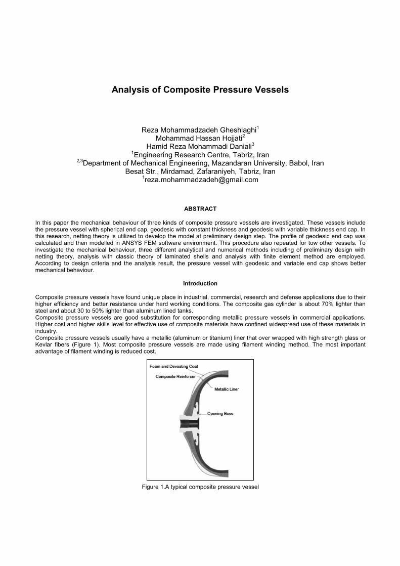
Composite pressure vessels have found unique place in industrial, commercial, research and defense applications due to their higher efficiency and better resistance under hard working conditions. The composite gas cylinder is about 70% lighter than steel and about 30 to 50% lighter than aluminum lined tanks. Composite pressure vessels are good substitution for corresponding metallic pressure vessels in commercial applications. Higher cost and higher skills level for effective use of composite materials have confined widespread use of these materials in industry. Composite pressure vessels usually have a metallic (aluminum or titanium) liner that over wrapped with high strength glass or Kevlar fibers (Figure 1). Most composite pressure vessels are made using filament winding method. The most important advantage of filament winding is reduced cost.
Figure 1.A typical composite pressure vessel
Motor casing and filament wounded pressure vessels have winding pattern that need to be solved using computer software. Geodesic domes contours were derived from conditions that filaments stress in any location of curvature surface is same and principal forces act in fiber direction. In this study, three various kind of dome were studied as a design problem: spherical end cap with constant thickness and winding angle, geodesic end cap with constant and variable thickness. According to unique capabilities of composite pressure vessels, especially significant weight saving and special application, various research and studies were done on this kind of pressure vessels. B. W. Tew has presented a design approach based on netting theory which enables engineers to develop preliminary structural designs for theses structures using composite materials. The integration of creep, cyclic loading and environmental degradation factors into initial design calculation is also discussed and illustrated [2]. Mohammad Z. Kabir has presented a numerical analysis of filament-reinforced internally pressurized cylindrical vessels with over-wrapped metallic liner. The method uses the load-bearing liner approach and leak-before-rupture as design criteria. The structure is modeled as an elastic, ideally plastic liner-reinforced with a quasi-isotropic composite [3]. Jae-Sung Park ET all have calculated filament winding patterns using a semi-geodesic fiber path equation for an arbitrary surface. Because the fiber path depends on the surface on which the fiber is wound, the winding angle varies in the longitudinal and thickness directions of a wound structure [4].
Netting Theory
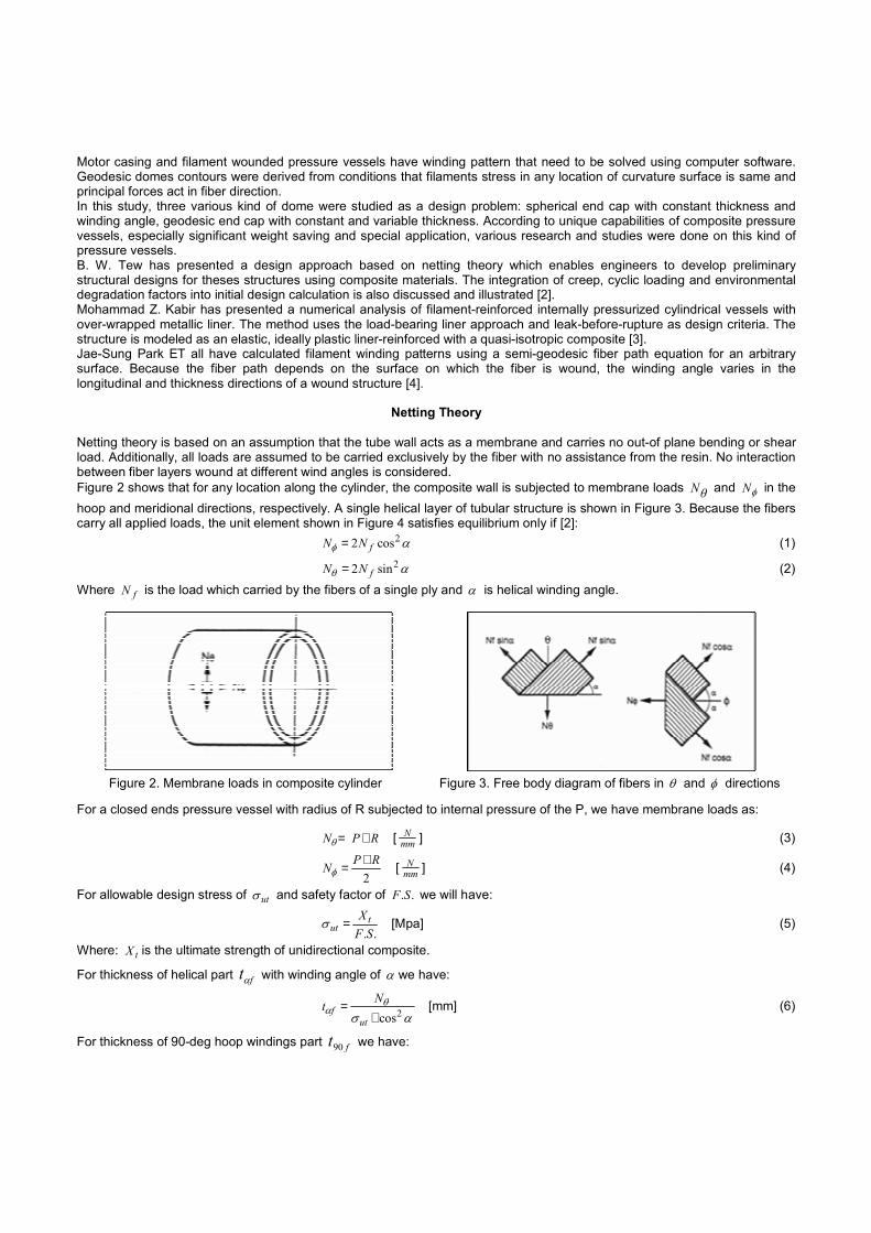
Netting theory is based on an assumption that the tube wall acts as a membrane and carries no out-of plane bending or shear load. Additionally, all loads are assumed to be carried exclusively by the fiber with no assistance from the resin. No interaction between fiber layers wound at different wind angles is considered. Figure 2 shows that for any location along the cylinder, the composite wall is subjected to membrane loads θΝ and φN in the hoop and meridional directions, respectively. A single helical layer of tubular structure is shown in Figure 3. Because the fibers carry all applied loads, the unit element shown in Figure 4 satisfies equilibrium only if [2]: αφ
2cos2 fNN = (1)
αθ2sin2 fNN = (2)
Where fN is the load which carried by the fibers of a single ply and α is helical winding angle.
Figure 2. Membrane loads in composite cylinder Figure 3. Free body diagram of fibers in θ and φ directions
For a closed ends pressure vessel with radius of R subjected to internal pressure of the P, we have membrane loads as:
RPN ×=θ [ mmN ] (3)
2RPN ×=φ [ mm
N ] (4)
For allowable design stress of utσ and safety factor of ..SF we will have:
..SF
Xtut =σ [Mpa] (5)
Where: tX is the ultimate strength of unidirectional composite.
For thickness of helical part ftα with winding angle of α we have:
ασ
θα 2cos×
=ut
fNt [mm] (6)
For thickness of 90-deg hoop windings part ft90 we have:
utf
NNt
σ
αφθ2
90tan×−
= [mm] (7)
Assuming fiber volume fraction approximately 0.72, total thickness will be:
72.0
90 ff ttt
+= α [mm] (8)
Number of helical hn and hoop cn wounded layers are determined as:
t
tn fh ×
=72.0α (9)
t
tn fc ×
=72.090 (10)
Determination of geodesic dome contours
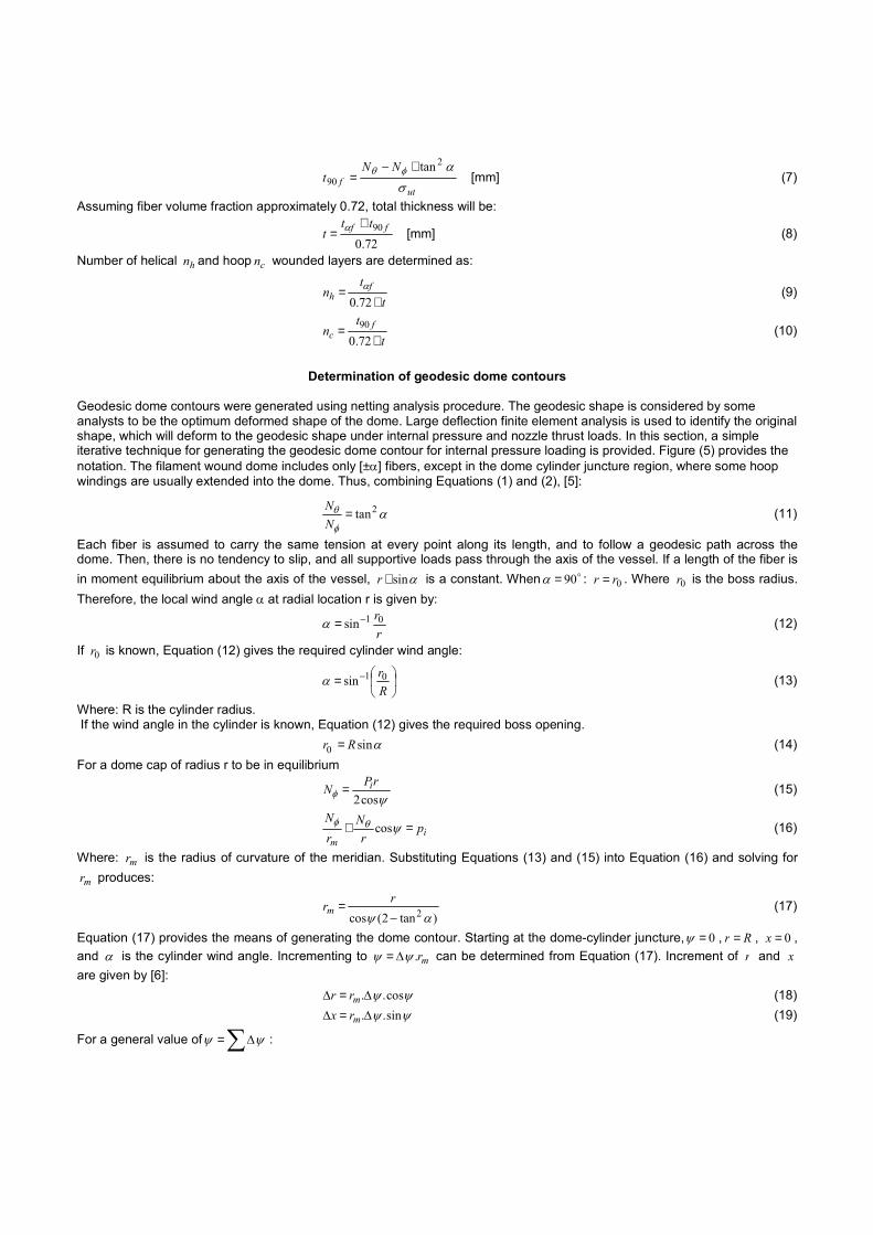
Geodesic dome contours were generated using netting analysis procedure. The geodesic shape is considered by some analysts to be the optimum deformed shape of the dome. Large deflection finite element analysis is used to identify the original shape, which will deform to the geodesic shape under internal pressure and nozzle thrust loads. In this section, a simple iterative technique for generating the geodesic dome contour for internal pressure loading is provided. Figure (5) provides the notation. The filament wound dome includes only [±α] fibers, except in the dome cylinder juncture region, where some hoop windings are usually extended into the dome. Thus, combining Equations (1) and (2), [5]:
αφ
θ 2tan=NN (11)
Each fiber is assumed to carry the same tension at every point along its length, and to follow a geodesic path across the dome. Then, there is no tendency to slip, and all supportive loads pass through the axis of the vessel. If a length of the fiber is in moment equilibrium about the axis of the vessel, αsin×r is a constant. When o90=α : 0rr = . Where 0r is the boss radius. Therefore, the local wind angle α at radial location r is given by:
rr01sin−=α (12)
If 0r is known, Equation (12) gives the required cylinder wind angle:
= −
Rr01sinα (13)
Where: R is the cylinder radius. If the wind angle in the cylinder is known, Equation (12) gives the required boss opening. αsin0 Rr = (14) For a dome cap of radius r to be in equilibrium
ψφ cos2rPN i= (15)
im
prN
rN
=+ ψθφ cos (16)
Where: mr is the radius of curvature of the meridian. Substituting Equations (13) and (15) into Equation (16) and solving for
mr produces:
)tan2(cos 2αψ −
= rrm (17)
Equation (17) provides the means of generating the dome contour. Starting at the dome-cylinder juncture, 0=ψ , Rr = , 0=x ,and α is the cylinder wind angle. Incrementing to mr.ψψ ∆= can be determined from Equation (17). Increment of r and xare given by [6]: ψψ cos..∆=∆ mrr (18) ψψ sin..∆=∆ mrx (19)
For a general value of ∑∆= ψψ :

∑∆−= rRr (20)
∑∆= xx (21)
At each step, the wind angle α is determined from equation (12). The solution proceeds, step-by-step until )57(2tan2 o== αα ,an inflection point at which mr in equation (17) is undefined. Using equation (12), the radial location of the inflection point is
022.1 rr = . In standard design procedures, a polar boss of outer radius ≥ 1.22 0r is inserted. The winding surface over the boss is commonly conical or spherical. Sometimes this region is locally reinforced. For geodesic dome with variable winding angle and thickness local thickness nt is given by following expression [3]:
αα
coscos o
rRtn = (22)
Where: oα is helical section winding angle, ot is total thickness of helical section and α is local winding angle of dome. Figure 4 shows geodesic dome contour notation.
Figure 4.Geodsic dome profile notation
Classic theory of laminated shell
Puck has used micromechanical equations to determine property of structural component and also the combination of lamina elastic modulus for determines laminate elastic modulus. In failure criteria puck paid more attention to lateral stress according to fiber directions, and planar shear stress [6]. An accurate approximation from elastic equilibriums was presented by Whitney. For thin shell like fiber reinforced pressure vessels, tanks and pipes in traditional applications shell’s theory show a good balance between accuracy and simplicity [7].
The finite element method The most usual method which is used for analyzing of complex structures is finite element analysis method. Using stiffness matrix of laminate shells and finite element theory we can provide programs for analysis of such structures. These programs can analysis orthotropic plates and using an assistant program, they convert laminates to an equal orthotropic ply and analysis with predefined programs. Input data in finite element programs for analysis of orthotropic plies are members of stiffness matrix or engineering coefficient ( xyzxy EEE ,,,υ ) that determine with assistant program and stiffness matrix determines using them [8].
Failure criterion of composite material Interaction of different materials caused various theories to be emerged for prediction the characteristic of composite materials. Maximum stress criterion: In this theory, stresses in principal directions must be less than corresponding strength. In other word, following conditions must be satisfied in tension and shear [8]: tX<1σ ; tY<2σ ; S<12τ (23) In addition, in compression following condition must be satisfied: cX>1σ ; cY>2σ (24) Tsai-Wu failure criterion: This theory used results of samples tension test according to ASTM standard method, then include accurate results. This theory specified as follows [8]: 12 2211
21266
22222112
2111 =+++++ σστσσσσ FFFFFF (25)
Where:
ct XXF 1
11 = ;ctYY
F 122 = ;
2661S
F = ;ct XX
F 111 −= ;
ct YYF 11
2 −= (26)
12F Can be determined from following expression:
( )21
221112 .21 FFF −= (27)
For comparison of various design methods, results for maximum stress and Tsai-Wu criteria are studied in this work.
Design Example A cylindrical pressure vessel with overall length of 800mm and diameter of 300mm, built using S glass fiber and epoxy resin with mechanical characteristic that is shown in table 1, under internal uniform pressure of 22Mpa is considered. Factor of safety for service pressure is 1.50. End cap opening diameter is 100mm and winding angle is determined o5.19=α according to equation 13. Ply thickness is 0.5mm. Cyclic load, static fatigue, mechanical and environmental degradations effects are abandoned. Preliminary design is done using netting theory. However this method may give us inaccurate results, it is a good star point for design of composite pressure vessels.
Meaning Value Mechanical Propertie Normal elastic modulus 60673.88[Mpa] E1Transverse elastic modulus 24821.136[Mpa] E2Shear modulus 11996.882[Mpa] G12Normal poison ratio 0.23
12υTransverse poison ratio 0.09
21υMaximum tensile strength 1289.32[Mpa] XtMaximum compressive strength 820.476[Mpa] XcTransverse tensile strength 45.988[Mpa] YtTransverse compressive strength 162.027[Mpa] YcMaximum shear strength 44.316[Mpa] S
Table 1. Material properties of used fiber glass epoxy composite
Then in a pressure vessel with radius of (R) membrane loads caused by internal pressure (P) are calculated using equations (1) and (2): 330015022 =×=×= RPNθ [ mm
N ] (28)
1650215022
2=×=×= RPNφ [ mm
N ] (29)
According to given safety factor of ( ..SF ) for allowable design stress of ( utσ ) we have:
546.8595.132.1289
..===
SFXt
utσ [Mpa] (30)
Helical divide thickness with winding angle of 19.5º is given by:
16.25.19cos546.859
1650cos 22 =
×=
×=
ασθ
αut
fNt [mm] (31)
Hoop divide thickness with winding angle of 90º is given by:
6.3546.859
5.19tan16503300tan 22
90 =×−=×−
=ut
f
NNt
σαφθ [mm] (32)
By consideration of fiber volume fraction of 72% total thickness (t) is:
872.0758.5
72.090 ==
+= ff ttt α [mm] (33)
Number of helical ( hn ) and hoop ( cn ) layers of pressure vessel are calculated by:
672.0
=×
=t
tn fh
α (34)
1072.090 =
×=
tt
n fc (35)
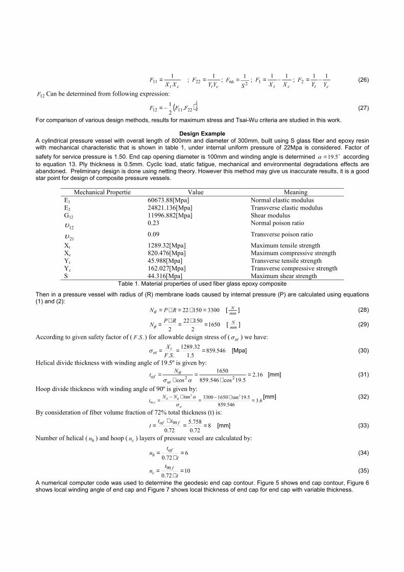
A numerical computer code was used to determine the geodesic end cap contour. Figure 5 shows end cap contour, Figure 6 shows local winding angle of end cap and Figure 7 shows local thickness of end cap for end cap with variable thickness.
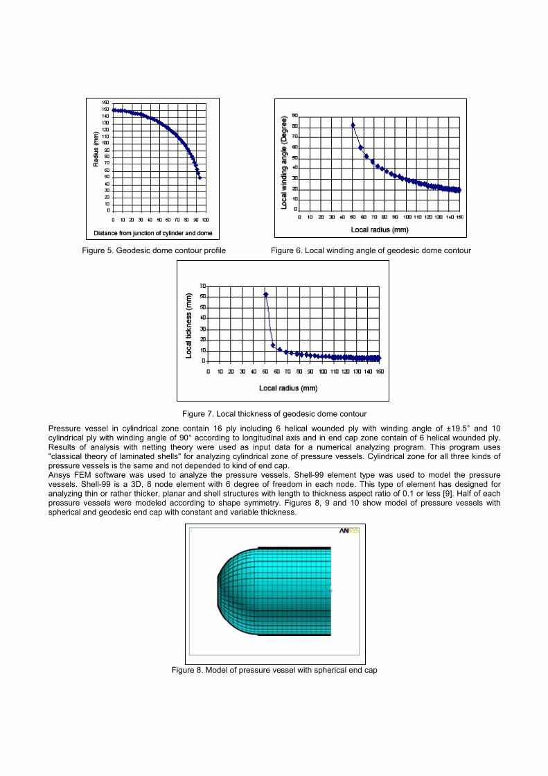
Figure 5. Geodesic dome contour profile Figure 6. Local winding angle of geodesic dome contour
Figure 7. Local thickness of geodesic dome contour
Pressure vessel in cylindrical zone contain 16 ply including 6 helical wounded ply with winding angle of ±19.5° and 10 cylindrical ply with winding angle of 90° according to longitudinal axis and in end cap zone contain of 6 helical wounded ply. Results of analysis with netting theory were used as input data for a numerical analyzing program. This program uses "classical theory of laminated shells" for analyzing cylindrical zone of pressure vessels. Cylindrical zone for all three kinds of pressure vessels is the same and not depended to kind of end cap. Ansys FEM software was used to analyze the pressure vessels. Shell-99 element type was used to model the pressure vessels. Shell-99 is a 3D, 8 node element with 6 degree of freedom in each node. This type of element has designed for analyzing thin or rather thicker, planar and shell structures with length to thickness aspect ratio of 0.1 or less [9]. Half of each pressure vessels were modeled according to shape symmetry. Figures 8, 9 and 10 show model of pressure vessels with spherical and geodesic end cap with constant and variable thickness.
Figure 8. Model of pressure vessel with spherical end cap

Figure 9. Geodesic dome with constant thickness Figure 10. Geodesic dome with variable thickness
Results and Discussion
The results of analyzing three kinds of pressure vessels using classical theory of laminated shells and finite element method are presented in Figs. 11 to 19. Results of classical theory of laminated shells are limited to cylindrical zone of vessel. Figures show obtained stresses and failure criteria values against distance from middle plan of pressure vessel and over its wall. Fig. 11 shows off axis hoop stress ( θσ ) along the wall of the pressure vessel. According to the graph, all three kinds of pressure vessels in cylindrical zone behave in a similar manner and determined stresses are in accordance with classical theory of laminated shells. Pressure vessel with spherical end cap shows suddenly growth in junction of cap and cylinder. It shows sensitivity of this area to thickness variation. In both of pressure vessel with geodesic end cap with constant and variable thickness this values is descendent.
Figure 11. Hoop stress along pressure vessel axis
As Fig. 12 shows for axial stress ( zσ ) like hoop stress, behavior of all three cases in cylindrical area are similar and a jump is seen in junction of cap and cylinder.
Figure 12. Axial stress along pressure vessel axis
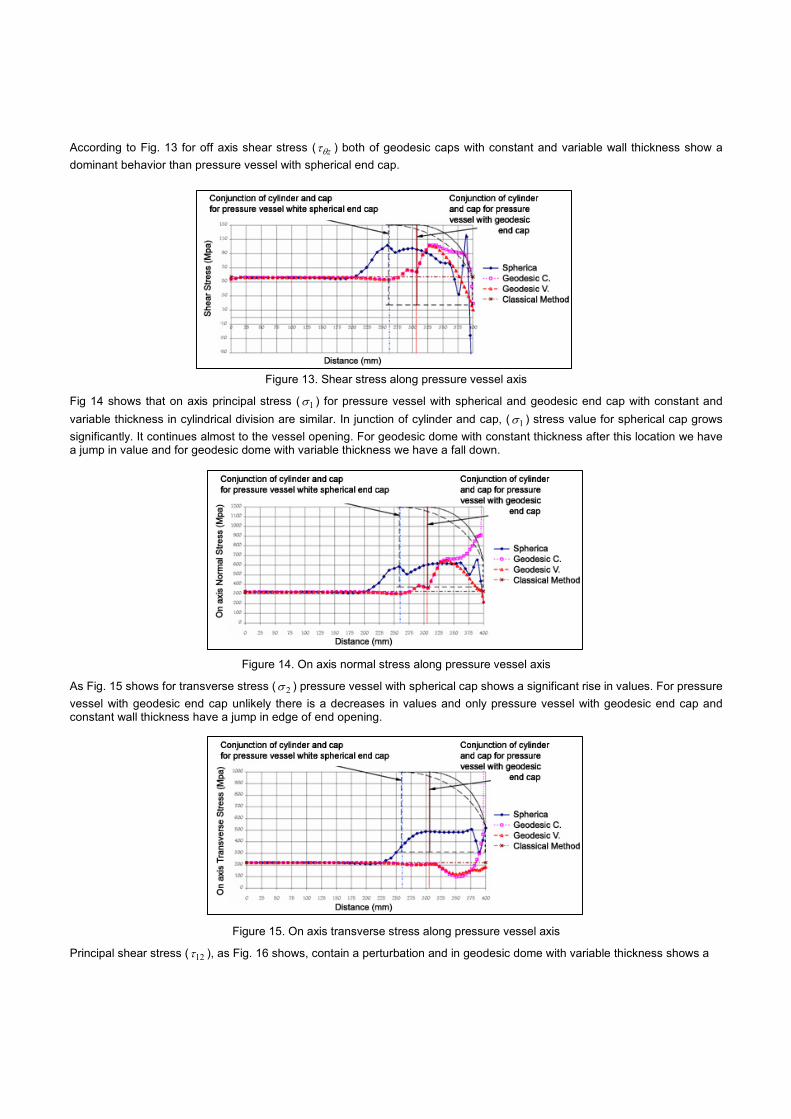
According to Fig. 13 for off axis shear stress ( zθτ ) both of geodesic caps with constant and variable wall thickness show a dominant behavior than pressure vessel with spherical end cap.
Figure 13. Shear stress along pressure vessel axis
Fig 14 shows that on axis principal stress ( 1σ ) for pressure vessel with spherical and geodesic end cap with constant and variable thickness in cylindrical division are similar. In junction of cylinder and cap, ( 1σ ) stress value for spherical cap grows significantly. It continues almost to the vessel opening. For geodesic dome with constant thickness after this location we have a jump in value and for geodesic dome with variable thickness we have a fall down.
Figure 14. On axis normal stress along pressure vessel axis
As Fig. 15 shows for transverse stress ( 2σ ) pressure vessel with spherical cap shows a significant rise in values. For pressure vessel with geodesic end cap unlikely there is a decreases in values and only pressure vessel with geodesic end cap and constant wall thickness have a jump in edge of end opening.
Figure 15. On axis transverse stress along pressure vessel axis
Principal shear stress ( 12τ ), as Fig. 16 shows, contain a perturbation and in geodesic dome with variable thickness shows a

Figure 16. On axis shear stress along pressure vessel axis
dominant behavior. Although 12τ have a smaller value in most of spherical dome than both of other end caps. Based on maximum stress and Tsai-Wu failure criteria a study hove done along the vessels axis. As Fig. 17 shows for maximum principal stress, for all three kind of vessels values are more than unit so we can expect failure in pressure vessels wall. In dome area for spherical one value rise but for others there is a decrease in values. Jump in opening edge for geodesic dome with constant thick ness is evidence of its sensitivity for probably failure. For Tsai-Wu failure criteria there is different condition.
Figure 17. Maximum stress failure criteria along pressure vessel axis
Determined values are more than previous failure criteria and failure limit but in geodesic domes we can see a dominant behavior according to Fig. 18. A maximum stress failure criterion shows different safety regions for various layers of pressure
Figure 18. Tsai-Wu failure criteria along pressure vessel axis
vessel so it is an underestimate criterion for design. In the case of shape deformation as Fig. 19 is illustrated pressure vessel with spherical end cap in dome area particularly in junction of cap and cylinder have a significant deformation in radial direction ( rδ ). Although unlikely for geodesic end caps, deformation is smaller.
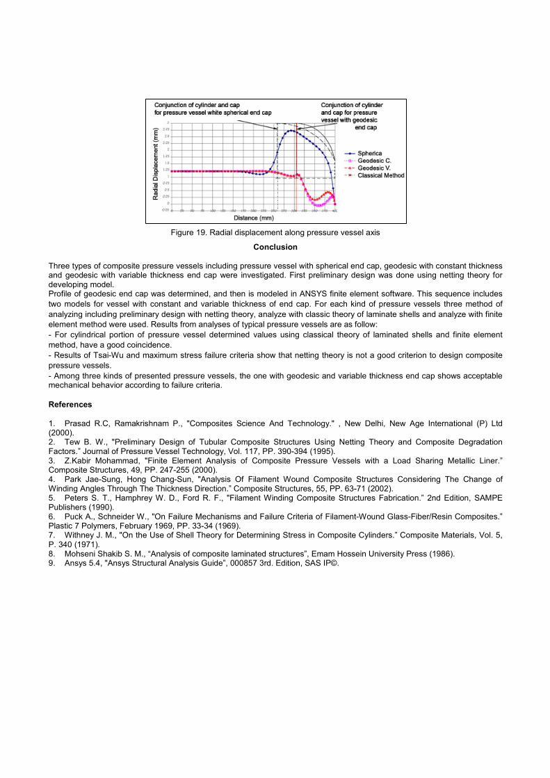
Figure 19. Radial displacement along pressure vessel axis
Conclusion
Three types of composite pressure vessels including pressure vessel with spherical end cap, geodesic with constant thickness and geodesic with variable thickness end cap were investigated. First preliminary design was done using netting theory for developing model. Profile of geodesic end cap was determined, and then is modeled in ANSYS finite element software. This sequence includes two models for vessel with constant and variable thickness of end cap. For each kind of pressure vessels three method of analyzing including preliminary design with netting theory, analyze with classic theory of laminate shells and analyze with finite element method were used. Results from analyses of typical pressure vessels are as follow: - For cylindrical portion of pressure vessel determined values using classical theory of laminated shells and finite element method, have a good coincidence. - Results of Tsai-Wu and maximum stress failure criteria show that netting theory is not a good criterion to design composite pressure vessels. - Among three kinds of presented pressure vessels, the one with geodesic and variable thickness end cap shows acceptable mechanical behavior according to failure criteria. References 1. Prasad R.C, Ramakrishnam P., "Composites Science And Technology." , New Delhi, New Age International (P) Ltd (2000). 2. Tew B. W., "Preliminary Design of Tubular Composite Structures Using Netting Theory and Composite Degradation Factors.” Journal of Pressure Vessel Technology, Vol. 117, PP. 390-394 (1995). 3. Z.Kabir Mohammad, "Finite Element Analysis of Composite Pressure Vessels with a Load Sharing Metallic Liner.” Composite Structures, 49, PP. 247-255 (2000). 4. Park Jae-Sung, Hong Chang-Sun, "Analysis Of Filament Wound Composite Structures Considering The Change of Winding Angles Through The Thickness Direction.” Composite Structures, 55, PP. 63-71 (2002). 5. Peters S. T., Hamphrey W. D., Ford R. F., "Filament Winding Composite Structures Fabrication.” 2nd Edition, SAMPE Publishers (1990). 6. Puck A., Schneider W., "On Failure Mechanisms and Failure Criteria of Filament-Wound Glass-Fiber/Resin Composites.” Plastic 7 Polymers, February 1969, PP. 33-34 (1969). 7. Withney J. M., "On the Use of Shell Theory for Determining Stress in Composite Cylinders.” Composite Materials, Vol. 5, P. 340 (1971). 8. Mohseni Shakib S. M., “Analysis of composite laminated structures”, Emam Hossein University Press (1986). 9. Ansys 5.4, "Ansys Structural Analysis Guide”, 000857 3rd. Edition, SAS IP©.