Analytical expressions for the disjoining pressure between particle-stabilized fluid–fluid...
11
Analytical expressions for the disjoining pressure between particle-stabilized fluid–fluid interfaces and composite materials† Carolina Vannozzi * Received 6th December 2011, Accepted 14th February 2012 DOI: 10.1039/c2sm07307b A method based on a hybrid Hamaker–Lifshitz approach is developed to derive numerical and analytical expressions of the disjoining pressure (i.e. van der Waals forces per unit area) of the thin film between two drops having micro/nanoparticles straddling their interfaces, as a function of the particle concentration, dimension and core material. This is useful to determine the ability of nanoparticles to stabilize immiscible polymer blends against coalescence, thus in the design of effective nanoparticle stabilizers. The system is modelled as two facing half spaces (i.e., two surfaces or walls with infinite depth) with 2D-lattices of spherical particles straddling the interfaces, interacting through a matrix. The method is also applied to the case of two compound half spaces with 3D-lattices of spherical inclusions to validate the method by comparison with well known effective medium expressions. This is also a model for drops with particles dispersed in their bulk or two interacting colloidal/nanocrystals. Our approach is promising for its ability to deal with complex geometries and with the presence of an intervening medium in a simple way, leading to analytical expressions that can be used both in experiments and in numerical simulations of coalescence; and it is especially applicable to polymeric systems having no strong dipole interactions. Multi-body interactions are only included by evaluating the Hamaker constants through the Lifshitz approach. 1. Introduction Despite the long established use of particles in emulsions and foams as stabilizers, only recently particles adsorbed at the interface of two immiscible polymers have been used to stabilize polymeric blends. 1–4 Indeed, new areas of research have been focused on the use of nanoparticles either with uniform surface properties 3,5–12 or coated with polymer ligands of mixed type, i.e. ligands of the dispersed and continuous phase type, the so-called ‘‘Janus nanoparticles’’. 5,10,13–17 This wide interest is due to the nanoparticle ability to give characteristic optical, electric and magnetic properties to the resulting composite material. 16,18,19 Additionally, nanoparticles can increase the blend dispersed phase volume fraction because of their small size. Current theories on coalescence suggest that particles can stabilize blends through the formation of a steric barrier or by producing Marangoni stresses due to their surface activity, slowing down the drainage of the matrix phase, as in the case of low molecular weight surfactants. 5,10 On the other hand, particles that have a core material different from the bulk materials will change the magnitude of the van der Waals (VDW) forces between two drops, influencing their coalescence stability. In fact, in the usual description of coalescence, VDW inter- actions determine the final drop fusion. In clean interface systems, they are usually incorporated in the normal stress boundary conditions as a disjoining pressure (P), which is commonly approximated as that between two parallel infinite half spaces (i.e., two surfaces or walls with infinite depth) per unit area: 20–23 P hs;hs ¼ A h 6pD 3 (1) where the superscripts stand for the two interacting bodies, i.e. hs, hs indicate two infinite half spaces, A h is the Hamaker constant, and D is the local distance between the two interfaces. A h can be measured or calculated through Lifshitz theory, i.e. via the dielectric functions of the bulk materials, as will be explained further. P is negative for attractive interactions and positive otherwise. Since it is well known that metals in void are characterized by A h roughly two orders of magnitude higher than dielectric materials, it is likely that metal nanoparticles stabilizing blends can accel- erate film drainage and favour droplet coalescence compared to dielectric particles or other stabilizers. This seems to be confirmed by Borrell and Leal’s experiments in the four-roll mill, 10 where two drops, compatibilized by polymer-coated Janus gold nano- particles, undergoing a head-on collision, showed a dramatic Chemical Engineering Department, University of California Santa Barbara, Santa Barbara, CA 93106, USA. E-mail: carolina.vannozzi@ gmail.com; Tel: +1 805893 3412 † Electronic supplementary information (ESI) available. See DOI: 10.1039/c2sm07307b 5214 | Soft Matter , 2012, 8, 5214–5224 This journal is ª The Royal Society of Chemistry 2012 Dynamic Article Links C < Soft Matter Cite this: Soft Matter , 2012, 8, 5214 www.rsc.org/softmatter PAPER
Transcript of Analytical expressions for the disjoining pressure between particle-stabilized fluid–fluid...

Dynamic Article LinksC<Soft Matter
Cite this: Soft Matter, 2012, 8, 5214
www.rsc.org/softmatter PAPER
Analytical expressions for the disjoining pressure between particle-stabilizedfluid–fluid interfaces and composite materials†
Carolina Vannozzi*
Received 6th December 2011, Accepted 14th February 2012
DOI: 10.1039/c2sm07307b
A method based on a hybrid Hamaker–Lifshitz approach is developed to derive numerical and
analytical expressions of the disjoining pressure (i.e. van der Waals forces per unit area) of the thin film
between two drops having micro/nanoparticles straddling their interfaces, as a function of the particle
concentration, dimension and core material. This is useful to determine the ability of nanoparticles to
stabilize immiscible polymer blends against coalescence, thus in the design of effective nanoparticle
stabilizers. The system is modelled as two facing half spaces (i.e., two surfaces or walls with infinite
depth) with 2D-lattices of spherical particles straddling the interfaces, interacting through a matrix. The
method is also applied to the case of two compound half spaces with 3D-lattices of spherical inclusions
to validate the method by comparison with well known effective medium expressions. This is also
a model for drops with particles dispersed in their bulk or two interacting colloidal/nanocrystals. Our
approach is promising for its ability to deal with complex geometries and with the presence of an
intervening medium in a simple way, leading to analytical expressions that can be used both in
experiments and in numerical simulations of coalescence; and it is especially applicable to polymeric
systems having no strong dipole interactions. Multi-body interactions are only included by evaluating
the Hamaker constants through the Lifshitz approach.
1. Introduction
Despite the long established use of particles in emulsions and
foams as stabilizers, only recently particles adsorbed at the
interface of two immiscible polymers have been used to stabilize
polymeric blends.1–4 Indeed, new areas of research have been
focused on the use of nanoparticles either with uniform surface
properties3,5–12 or coated with polymer ligands of mixed type, i.e.
ligands of the dispersed and continuous phase type, the so-called
‘‘Janus nanoparticles’’.5,10,13–17 This wide interest is due to the
nanoparticle ability to give characteristic optical, electric and
magnetic properties to the resulting composite material.16,18,19
Additionally, nanoparticles can increase the blend dispersed
phase volume fraction because of their small size.
Current theories on coalescence suggest that particles can
stabilize blends through the formation of a steric barrier or by
producing Marangoni stresses due to their surface activity,
slowing down the drainage of the matrix phase, as in the case of
low molecular weight surfactants.5,10 On the other hand, particles
that have a core material different from the bulk materials will
Chemical Engineering Department, University of California SantaBarbara, Santa Barbara, CA 93106, USA. E-mail: [email protected]; Tel: +1 805893 3412
† Electronic supplementary information (ESI) available. See DOI:10.1039/c2sm07307b
5214 | Soft Matter, 2012, 8, 5214–5224
change the magnitude of the van der Waals (VDW) forces
between two drops, influencing their coalescence stability.
In fact, in the usual description of coalescence, VDW inter-
actions determine the final drop fusion. In clean interface
systems, they are usually incorporated in the normal stress
boundary conditions as a disjoining pressure (P), which is
commonly approximated as that between two parallel infinite
half spaces (i.e., two surfaces or walls with infinite depth) per unit
area:20–23
Phs;hs ¼ � Ah
6pD3(1)
where the superscripts stand for the two interacting bodies, i.e.
hs, hs indicate two infinite half spaces, Ah is the Hamaker
constant, and D is the local distance between the two interfaces.
Ah can be measured or calculated through Lifshitz theory, i.e. via
the dielectric functions of the bulk materials, as will be explained
further. P is negative for attractive interactions and positive
otherwise.
Since it iswell known thatmetals in void are characterized byAh
roughly two orders of magnitude higher than dielectric materials,
it is likely that metal nanoparticles stabilizing blends can accel-
erate film drainage and favour droplet coalescence compared to
dielectric particles or other stabilizers. This seems to be confirmed
byBorrell andLeal’s experiments in the four-rollmill,10where two
drops, compatibilized by polymer-coated Janus gold nano-
particles, undergoing a head-on collision, showed a dramatic
This journal is ª The Royal Society of Chemistry 2012

reduction in the drainage time of about 70%compared to the same
system compatibilized by block-copolymers, while they still
considerably increased the drainage time by one order of magni-
tude compared to a clean interface system. Therefore, remark-
ably, this type of nanoparticles were less effective stabilizers than
surfactants, despite being more surface active. An opposite
behaviour was found using similar polymer coated Janus nano-
particles, having a polymeric core instead, in the blend
morphology study of M€uller and coworkers.5
Lacking a quantitative evaluation of VDW interactions in the
case of interfacial micro/nanoparticles, the objective of the
present paper is to derive a simple analytical expression to
account for the change inP due to the presence of these particles
in polymer blends to guide the design of effective stabilizers, as
a function of the particle size, concentration and type of core
material. This is achieved through a hybrid Hamaker–Lifshitz
approach,24,25 which hinges on the assumption of additivity of
the interaction potentials of the bodies that make up the system.
This assumption is an oversimplification of the complex induced-
dipole multi-body interactions present in real systems, but it is
often used to evaluate P. It usually provides the correct quali-
tative and quantitative behaviour of the interactions26 and it is
well suited in systems without strong dipole interactions, like the
polymeric systems of interest here. Moreover, it gives simple
analytical expressions that can be used in both computational
studies of coalescence26 and experimental ones.
In the present model, the two drops are approximated as half
spaces, separated by a matrix phase, with particles arranged in
2D-lattices straddling the interfaces (see Fig. 1a). This model is
valid in describing the coalescence of drops as long as the thin
lubrication film between two approaching drops is relatively
large compared to the particle dimension or interparticle spacing.
In flow induced coalescence theory, the film width is a fraction of
the drop radius R, i.e. O(Ca0.5R),27 where Ca is the capillary
number of the flow defined as Ca h RGmm/s, with G being the
shear rate, R the drop radius, mm the matrix viscosity and s the
interfacial tension of the system. This means that for Ca ¼O(10�4 to 10�2), typical of flow-induced coalescence experiments,
Fig. 1 Sketch of the model systems. (a) Section representing two infinite
compound half spaces of material 1, with spherical inclusions of material
2 straddling its interfaces, interacting across medium 3. The particles are
arranged in a 2D-simple cubic lattice, with lattice constant a, and the two
interfaces at distanceD apart. (b) The same system as in (a), with particles
dispersed in a 3D-SC lattice of spherical particles in the bulk of medium 1.
In both models medium 1 represents the bulk of two drops and medium 3
the thin film of matrix phase separating them.
This journal is ª The Royal Society of Chemistry 2012
and micron-sized drops, our model can be used for particle sizes
of the order of nanometres. We also studied the case of particles
dispersed in the drop phase, modelled as a 3D-lattice of spheres
(Fig. 1b). These situations can occur if ligand-stabilized particles
dispersed in the drops self-assemble in lattice structures, similarly
to what is observed for block-copolymer micelles28 or in the case
of two facing nanocrystals.
This paper is organized as follows: after a short discussion on
the issues arising from other approaches, considered in Section
1.1, Section 2 describes a brief review of the original Hamaker
summation method and its adaptation to the present cases. In
Section 3, results from the full pairwise summation and the
analytical formulae are compared for facing 2D-lattices of
spheres interacting across void. The method is also validated by
comparing the expression derived for 3D-lattices of spherical
inclusions dispersed in two infinite half spaces (i.e. nanocrystals)
with effective medium theory. Finally, the derived expressions
for particles straddling the interface are simulated and the error
introduced with our approximation is evaluated.
1.1. Issues with other approaches
Other approaches could be used to evaluate the effects of inter-
facial particles on P; however, each has some flaws that are
briefly discussed here.
As already stated, a hybrid Hamaker–Lifshitz approach is
employed here for its ability to give simple analytic expressions
despite the complex geometry of our discrete systems, regardless
of the particle size. Vice versa, the Lifshitz theory (LT) alone,
which is a quantum mechanical treatment of the interactions,
taking into account collective or multi-body effects, yields
analytical expressions only for a few simple geometries, for
instance two facing half spaces.29,30 Moreover, LT is a continuum
based theory, thus, it is not well suited to describe the discrete
nature of the interfacial region with particles partially immersed
in both materials (see Fig. 1a). An additional problem with LT is
that a theoretical description of the size dependent dielectric
function of nanoparticles, which has to be known in order to
apply LT to the present case, is still the target of active experi-
mental and theoretical research.31–38
Another possible approach to the present problem is the use of
the Effective Medium Theory (EMT) to calculate the effective
dielectric constant of the interfacial layer, considered as a sepa-
rate phase and then use it to calculate an effective Ah through
Lifshitz theory. However, EMT is a well established method to
treat 3D bulk periodic materials or random interfacial multi-
layers of polymer-coated nanoparticles at a liquid/air inter-
face,31,32 but here only one layer of particles is considered. Thus,
EMT cannot be used in its established formulation and has to be
adapted to include the appropriate boundary conditions for the
interfacial monolayer, complicating considerably the problem.
Moreover, EMT approaches are not applicable to distances of
the order of the lattice constant, because they ignore the spatial
arrangement of the system; on the contrary, this is possible with
the discrete approach here developed.
Another possibility to calculate an effective Ah of the interfa-
cial layer is via phenomenological mixing rules,39–41 where the
volume averaged dielectric function of each side of the interface
is obtained taking into account the particle and the surrounding
Soft Matter, 2012, 8, 5214–5224 | 5215

fluid. However, this method has only been experimentally tested
for straddling dielectric nanoparticles39–41 and it is not straight-
forward to apply it to metal particles, thus it is not pursued here.
2. Theory
2.1. Theoretical background: interaction of two bodies across
vacuum and a medium within the Hamaker approach
We now describe the basic features of the Hamaker and of the
Hamaker–Lifshitz approach, which form the theoretical basis of
our study. In his seminal work Hamaker42 describes a method to
calculate the total interaction energy between two macroscopic
bodies as a volume integral, taken over the interior volume of the
two bodies V1 and V2, of the distance dependence of the inter-
action energy of each atom in one body with each atom in the
other body:29
EðrÞ ¼ �ð
V1 ;V2
q1q2l12
jr1 � r2j6d r1d r2; (2)
where qi is the density of the atoms in the i-th body and l12 is the
London–van der Waals constant, which is a function of the
dielectric permittivity of the two media.31 The final expression of
the interaction energy between the two bodies is the product of
one part dependent only on material properties of the body with
another part dependent only on the distance between the two
interacting bodies, a function of their geometry. Eqn (2) leads to
the definition of Ah within the Hamaker approach as Ah ¼q1q2l12p
2.42 Thus, the interaction can be expressed as: E(D) ¼AhE
bb(D), where Ebb is the geometric dependence of the inter-
action energy between the two bodies andD is the distance of the
two interfaces.
Eqn (2) enables us to calculate the distance dependence of the
total interaction potential for several simple geometries, such as
two infinite half spaces, two spheres, a sphere and a half space, an
atom and a half space, etc.32,43 The retardation effect, which is
important for distances greater than 10 nm, can be considered in
(2) by incorporating correction factors to the atom pair poten-
tial,44 but it is neglected here for simplicity. From eqn (2), the
disjoining pressure is calculated as the negative gradient of the
total interaction energy with respect to D:
P ¼ � dE
dD: (3)
The presence of an intervening medium is easily incorporated
within the additivity assumption. In fact, the total interaction
energy of two bodies made of materials 1 and 2 interacting in
a medium of material 3 is given by:32,42,43,45,46
Etot ¼ E12 + E33 � E13 � E23 ¼ (A12 + A33 � A13 � A23)Ebb,(4)
where Eij and Aij are the interaction energy and the Hamaker
constant of the bodies i and j interacting across vacuum,
respectively. The interaction between two bodies, both of mate-
rial 1, is simply given by substituting subscript 2 with 1 in eqn (4).
This approach works for bodies of finite size as well as infinite
half spaces. When making use of the combining relations,23,24,47
namely A132 ¼ A12 + A33 � A13 � A23 and A131 ¼ A11 + A33 �2A13, the total interaction energy derived in eqn (4) can be
5216 | Soft Matter, 2012, 8, 5214–5224
written as Etot ¼ A132Ebb. Using this approach the interaction
energy of composite bodies interacting in a medium can be
derived. For example, in the Appendix is derived via the
Hamaker method the well known interaction energy of a five
layer system, often used in colloidal science to model particles
interacting with a coating layer.24
The accuracy of eqn (4) can be improved by evaluating A132
through the Lifshitz method, to partially account for multi-body
interactions, in the so-called Lifshitz–Hamaker approach.24,25
When the two bodies are metals (i.e. with an infinite static
dielectric constant) in a dielectric medium, Ah is generally eval-
uated by considering the complex dielectric function of the
metal.32 In our analysis, for the sake of both simplicity and lack
of data, we used the semi-empirical method described by
Bargeman and Vanvoors.46 This method is very often used in the
literature for estimating the interaction energy of metal nano-
particles in organic solvents.48 It enables us to evaluate the
Hamaker constant of two bodies interacting across a medium
from the experimentally measured Aij of the constituent pairs of
materials interacting across void.
The Hamaker method is valid as long as the particles do not
interact with each other and the surrounding material does not
preferentially orient itself due to the presence of the interacting
bodies.42 In the case of surface functionalized particles, the first
condition is reasonable, because the polymer coating prevents
the gold cores or the dielectric spheres from getting too close to
each other, this in turn keeps the area fraction low. The second
condition is also reasonable in polymer blends, where no strong
dipole moments are present.
2.2. Interaction energy per unit area of two half spaces with
3D-lattices of spheres as inclusions
The interaction energy per unit area of two composite half spaces
with 3D-lattices of spheres as inclusions (Fig. 1b) interacting in
void was determined by decomposing the total interaction
energy, Etot, in the sum of the interaction energies of sub-systems,
expressed in terms of analytical expressions well known or easily
determinable via eqn (2):
Etot ¼ Ehs;hs11 � 2E3D-l;hs
11 þ E3D-l;3D-l11|fflfflfflfflfflfflfflfflfflfflfflfflfflfflfflfflfflfflfflfflfflfflfflfflffl{zfflfflfflfflfflfflfflfflfflfflfflfflfflfflfflfflfflfflfflfflfflfflfflfflffl}
1
þ 2�E3D-l;hs
21 � E3D-l;3D-l21
�|fflfflfflfflfflfflfflfflfflfflfflfflfflfflfflfflfflfflffl{zfflfflfflfflfflfflfflfflfflfflfflfflfflfflfflfflfflfflffl}2
þE3D-l;3D-l22|fflfflfflfflffl{zfflfflfflfflffl}
3
; (5)
the superscripts refer to the geometry of the pair of bodies
involved in the interaction, i.e. 3D-l stands for 3D-lattice and hs
for half space, while the subscripts refer to the materials involved,
as represented in Fig. 1b.
Specifically, each bracket in eqn (5) represents the interaction
energy of each sub-system:
I. The three terms in the first bracket represent the interaction
energy of two infinite half spaces containing cavities. This is
obtained by subtracting, from the interaction energy of two half
spaces of material 1 Ehs,hs11 , twice the interaction energy of a 3D-
lattice of particles of material 1 interacting with a half space of
material 1, E3D-l,hs11 , and by adding the interaction energy of two
facing ghost 3D-lattices of particles of material 1, E3D-l,3D-l11 . The
This journal is ª The Royal Society of Chemistry 2012

last addition is necessary to avoid an underestimation of the total
interaction energy of two infinite half spaces with cavities;
II. The two terms in the second bracket correspond to the
interaction energy of a 3D-lattice of material 2 interacting with
a half space of material 1 containing cavities. This is obtained by
subtracting, from the interaction energy of a 3D-lattice of
material 2 interacting with a half space of material 1 E3D-l,hs21 , the
interaction energy of a 3D-lattice of material 2 interacting with
a ghost 3D-lattice of material 1, E3D-l,3D-l21 ;
III. The last term E3D-l,3D-l22 represents the interaction energy of
two facing 3D-lattices of particles of material 2.
Following the classical procedure outlined in Section 2.1 to
incorporate the presence of the intervening medium 3, using the
Lifshitz–Hamaker approach to express the energies in terms of
the Hamaker constants and the combining relations, the total
interaction energy is:
Etotmedium ¼ A131E
hs,hs(D) + A212E3D-l,3D-l(D + a)
+ 2(A231 � A131)E3D-l,hs(D + a/2), (6)
where E3D-l,3D-l is calculated by adding up the interaction energy
of each couple of 2D-layers present in the two facing bodies and
E3D-l,hs by adding up the interaction energy of each 2-D layer with
the opposite half space:
E3D-l;3D-l ¼XNi; j¼1
E l;lðDþ xði � jÞÞ; E3D-l;hs
¼XNi¼1
El;hsðDþ a=2þ xði � 1ÞÞ; (7)
where N is the number of layers in each body and x is the
interparticle distance, which depends on the lattice type, x ¼ a,
x ¼ affiffiffi2
p=3, x ¼ a=
ffiffiffi3
p, x ¼ a=
ffiffiffi2
p, respectively for SC or HCP,
BCC, and FCC lattices.
The interaction energy of a compound system interacting in
void is obtained from eqn (6) by making the substitution:A131/
A11, A212 / A22 and A231 / A21. The decomposition in sub-
systems in eqn (6) is also sketched in Fig. 2.
The expressions for the interaction energies used in this study
will be derived in Section 2.5. Using eqn (6) and (2), the disjoining
pressure of composite half spaces interacting across medium can
be derived:
Fig. 2 Model decomposition in different sub-systems of two composite
half spaces interacting across a medium. The simplified picture is
obtained by applying the combining relations. Top row, from left to
right: two half spaces of material 1 interacting across medium 3 and two
3D-lattices of particles of material 2 interacting in medium 1. Bottom
row, from left to right: 3D-lattices of material 2 interacting with a half
space of material 1 across medium 3 and 3D-lattice of material 1 inter-
acting with a half space of material 1 across medium 3.
This journal is ª The Royal Society of Chemistry 2012
PtotmedðDÞ ¼ � A131
6pD3
�XNj;i¼1
pA212
3rlirlj h ln
h2 � 4R2
p
h2
!þ4R2
p
�h2 � 2R2
p
�h�h2 � 4R2
p
�0@
1A
�XNi¼1
rliðA231 � A131Þ
3
Rp�
j � Rp
�2 þ Rp�j þ Rp
�2� 2Rp�
j � Rp
��j þ Rp
�!;(8)
where h ¼ D + a(i + j) and j ¼ D + a/2 + a(i � 1) for simple cubic
lattices and rli is the 2D number particle density of lattice i, i.e.
rli ¼ 2=a2ffiffiffi3
pfor a 2D-hexagonal-lattice or rli ¼ a�2 for a square-
lattice. In the following we assume that both interacting bodies
have the same particle density in each lattice, i.e. rli ¼ rl. As for
the interaction energy Etotmedium, the DP for two compound half
spaces interacting in void can be obtained from eqn (8) by
making the substitution A131 / A11and A231 / A21.
2.3. Comparison with EMT: pair additivity approach
validation
To test our method, eqn (8) was compared to eqn (1), in whichAh
was substituted with an effective Hamaker constant (Aeffh) eval-
uated using the effective dielectric functions of the composite
materials within LT. In fact, EMT is a well-established technique
for obtaining analytic and numerical effective-properties of
composite periodic materials.49,50 The ability of the proposed
method to match the EMT results, as a function of particle
concentration and the dielectric properties of the three media,
was evaluated. This could also give an indication of the relevance
of multi-body effects with respect to pairwise interactions in the
system under investigation. For a quantitative evaluation of eqn
(1) and (8), we chose two half spaces of polybutadiene (PBd)
interacting across polydimethylsiloxane (PDMS), described in
the experiments of drop coalescence with Janus polymer-coated
gold nanoparticles as stabilizers in ref. 10.
The effective electrical and optical properties of half spaceswith
spherical inclusions, necessary to calculate Aeffh, were evaluated
both for conducting particles and for dielectric particles. For the
sake of simplicity, only the static dielectric constant was consid-
ered, although for nanoparticles the Drude model offers a better
description of the dielectric function and its dependence on
particle size. We used the ‘‘exact’’ (i.e. including higher order
multi-poles) numerical data for the static dielectric constant of
a material with conducting spherical inclusions derived by
McPhedran andMcKenzie51,52 and the asymptotic expressions for
dielectric spherical inclusions derived by Sangani andAcrivos.53,54
Lastly, to evaluate eqn (8), knowledge of A12 ¼ APBd/Au and
A231 ¼ AAu/PDMS/PBd was necessary. Due to the lack of available
experimental data, they were determined by fitting the data
calculated using our method to the EMT approach.
2.4. Particles at interfaces
In the case of interfacial particles (Fig. 1a), the interface can be
modelled as a surface with zero thickness, where the properties of
Soft Matter, 2012, 8, 5214–5224 | 5217

the bulk phases 1 (the drop) and 3 (the matrix) undergo a step
change, having particles of material 2 arranged in a 2D-lattice of
inclusions straddling it. We can speculate that the Janus particle
immersion in the drop phase is determined by the volume frac-
tion of the two types of coating ligands. Thus, a particle with 50%
volume fraction in one type of ligand will have the core centre
positioned right at the interface. In our model we consider
different degrees of immersion (g) of the particles in phase 1 with
respect to the interface, i.e. the particle centre of mass is shifted
with respect to phase 1 of a distance gRp, thus for g ¼ 0 the
particle centre is at the interface, while for g¼ 1 it is immersed in
phase 1 and for g ¼ �1 in phase 3. In the case of bare particles,
whose position at the interface is given by contact angle
considerations, our method still applies.
The interaction energy of the composite system is derived
using the procedure outlined in Section 2.2, modified to take into
account the 2D-lattice of particles straddling the interface. As
sketched in Fig. 3, the total interaction energy of the system is
given by the sum of the interaction energies of sub-systems
interacting through medium 3, namely:
I. The interaction energy of the same system with holes in place
of the interfacial particles (see the first row of Fig. 3). This is given
by: twice the energy of one bi-material 2D-lattice [i.e. composed of
spheres made up half of material 1 (the drop phase) and half of
material 3 (the thin film of matrix phase)] interacting with a half
space of material 1 subtracted from the interaction energy of two
half spaces. We also need to add to the above the interaction
energy of two facing 2D-lattices of bi-material particles, for
reasons similar to those explained in Section 2.2 point I.
II. Twice the interaction energy of the bi-material 2D-lattice
interacting with the 2D-lattice of gold particles subtracted from
Fig. 3 Model decomposition of a system with interfacial particles. The
distance between the two interfaces is D. Top row, interaction energy of
the same systemwith holes in place of the interfacial particles, from left to
right: two interacting 2D-lattices of bi-material particles—twice a 2D-
lattice of bi-material particles interacting with a half space of material 1 in
a medium of material 3 + two half spaces of material 1 interacting across
material 3. Bottom row, from left to right: twice a 2D-lattice of material 2
particles interacting with a 2D-lattice of bi-material particles + twice
a 2D-lattice of particles of material 2 interacting with a half space of
material 1 across medium 3 + two interacting 2D-lattices of material 2.
5218 | Soft Matter, 2012, 8, 5214–5224
twice the energy of a 2D-lattice of gold particles interacting with
the facing half space;
III. The interaction energy of the two facing gold lattices.
The decomposition of the system in the single constituents is
summarized in the following equation:
Eint(D) ¼ �2El,lbi-material,2(D) + El,l
bi-material,bi-material(D)
+ A22El,l(D) � 2A131E
Tsl,hs(D) + 2A231El,hs(D) + A131E
hs,hs(D) (9)
where Tsl stands for a 2D-lattice of truncated spheres. In fact, as
can be noticed from Fig. 3, the bi-material particles interacting in
medium 3 with a half space (the first sketch in the second row) are
simply equivalent to a lattice of truncated spheres (in the picture
hemispheres are represented) of material 1 interacting in medium
3. Eqn (9) can also be derived rigorously by assuming that the
interface is a separate composite phase, as described in
Appendix, and applying eqn (4) to include the intervening
medium.
We were not able to determine simple analytical expressions to
evaluate the first and second term of eqn (9). Thus, we assume
that the bi-material particles are all made of either material 1 or
material 3. In this case, the interaction energy of the two bi-
material particle lattices lies between the interaction energies of
these two extreme cases; thus, the error associated with these two
approximations can be estimated. If we assume that the particles
are all made of material 1, the first three terms of eqn (9) are
simplified, via eqn (4), to the interaction of two facing 2D-lattices
of material 2 spheres interacting through material 1. Thus, we
obtain:
Eint(D) ¼ A212El,l(D) � 2A131E
Tsl,hs(D) + 2A231El,hs(D)
+ A131Ehs,hs(D). (10)
By substituting the analytic interaction energies (derived in the
next section) in eqn (10) and taking its negative gradient, we
derive the following disjoining pressure expression for interfacial
particles:
Pl;lðDÞ ¼ �A212r2lp
3
�Dþ 2gRp
�ln
�Dþ 2gRp
�2�4R2p�
Dþ 2gRp
�2!
þ4R2
p
��Dþ 2gRp
�2�2R2p
��Dþ 2gRp
���Dþ 2gRp
�2�4R2p
�!
� A231rl
3
Rp�
Dþ Rpðg� 1Þ�2 þ Rp�Dþ Rpðgþ 1Þ�2
� 2R2p�
Dþ Rpðg� 1Þ��Dþ Rpðgþ 1Þ�!
� A131rl
3
R3
pDð1þ gÞ2ðg� 2Þ þ Rpðg2 � 1ÞD3�Dþ Rpð1þ gÞ�2
!
� A131
6pD3:
(11)
Eqn (11) is the main result of our study. It can be used both in
numerical codes to evaluate the influence of interfacial particles
in inhibiting coalescence or for simple estimates in experiments.
As in the previous section Pl,l for the interfacial particle system
This journal is ª The Royal Society of Chemistry 2012

interacting in void is obtained from eqn (11), making the
substitution A231 / A21, A212 / A22 and A131 / A11.
Fig. 4 The reference system for the integration of the pair-potential of
the reference particle, positioned at z ¼ 0, with the 2D-lattice of spheres
belonging to the facing layer.
2.5. Derivation of El,hs, El,l, and ETsl,hs
In the following section, we derive the analytical expressions for
the interaction energies of the sub-systems, necessary to evaluate
the system total energy in eqn (7) and (10), unavailable in the
literature, namely: a 2D-lattice of spheres interacting with a half
space El,hs, two facing 2D-lattices of spheres El,l, and a 2D-lattice
of truncated spheres interacting with a half space ETsl,hs.
Numerical simulations were also employed to consider the
discrete nature of the problem and the effect of different spatial
arrangements. The numerical values were also compared with the
analytical formulae eqn (8) and (11) to evaluate their range of
validity.
The derived analytical expressions of the sub-system energies,
together with Es,s32,45 already available in the literature, are
summarized in Table 1.
2.5.1. Analytical method. The analytical expression of El,l is
here derived by integrating the well-known interaction potential
of two spheres Es,s,32,45 reported in Table 1. To do so, we start by
calculating the interaction energy of one sphere with a 2D lattice
of spheres, where the facing sphere is positioned at a centre-to-
centre distance z ¼ D (see Fig. 4), through the Hamaker pairwise
integration:24
Es;lðzÞ ¼ 2p
ðN0
E s;sðrÞrlx d x; (12)
where r ¼ ffiffiffiffiffiffiffiffiffiffiffiffiffiffiffix2 þ z2
pis the particle centre-to-centre distance. The
integral approach is limited to separation distances bigger than
the interparticle distance.55
The integration is finite since at large distances the asymptotic
form of Es,s(r) is like the interaction between two molecules,
fr�6.24 In the present case the retardation due to the finite speed
of light, usually present for distances above 10 nm,33 was
Table 1 Interaction potentials used in the paper. The energies are non-dime
E(z) D
Ehs;hs ¼ � 1
12pz2Intw
Es;s ¼ � 1
6
2R2
p
z2 � 4R2p
þ R2p
z2þ ln
z2 � 4R2
p
z2
!!T
El;l ¼ rlEs;l ¼ �p
6rl
2
4R2
p þ z2 � 2R2p
� �ln
z2 � 4R2
p
z2
!!To
El;hs ¼ rlEs;hs ¼ � rl
6
�Rp
z� Rp
þ Rp
zþ Rp
þ ln
�z� Rp
zþ Rp
Ab
ETsl;hs ¼ rlETs;hs
¼ � rl
12
�2Rp
zþ Rpð1þ gÞ þ�2Rpzgþ Rpð�1þ g2Þ
z2
þ 2ln
�z
zþ Rpð1þ gÞ
AthT
This journal is ª The Royal Society of Chemistry 2012
neglected for the sake of simplicity, but it could be incorporated
by modifying the Hamaker ‘‘constant’’ with a spatially varying
correction factor.26,31,44,45,56 Retardation will only make the
calculation cumbersome, but the integral (12) remains finite. The
final result is:
Es;l ¼ �p
6rl
4R2
p þ�z2 � 2R2
p
�ln
z2 � 4R2
p
z2
!!: (13)
The interaction energy of two facing 2D-lattices of particles
per unit area is simply: El,l ¼ rlEs,l. This is true when the two
layers have the same lattice constant and are symmetrical or
stagger, so that each particle in the layer has the same interaction
energy with the facing layer. The same is true for an array of
particles interacting with a half space, i.e. El,hs ¼ rlEs,hs, where
Es,hs is the interaction energy of a sphere with a half space,32
reported in Table 1.
ETsl,hs(D), i.e. the interaction of a 2D-lattice of truncated
spheres with a half space, is calculated through a volume inte-
gration of a molecule/half space interaction potential24 inside the
truncated sphere domain:
nsionalized by Ah; rl is the 2D particle density
escription
teraction of two half spaces per unit area: z is the distance between theo interfaces.
wo spheres: z is the centre-to-centre distance.
wo facing 2D-lattices of spheres: z is the centre-to-centre distance of twopposite spheres.
2D-lattice of spheres interacting with a half space: z is the distanceetween the centre of the sphere and the half space interface.
2D-lattice of truncated spheres interacting with an infinite half space: z ise distance between the centre of the sphere and the half space interface.he particles are immersed in phase 3 of a distance gRp.
Soft Matter, 2012, 8, 5214–5224 | 5219

Fig. 5 Dimensionless P between two facing 2D-lattices of spheres
arranged in a square lattice, for different a ¼ [2.4; 3; 4; 6; 12]Rp. The
dotted curves are for the stagger configuration, the solid curves are for
symmetric layers.
ETsl;hsðDÞ ¼ � rl
6
ðz¼2Rp
z¼R1
z�2Rp � z
�ðD� R1 þ zÞ3 dz; (14)
whereR1¼Rp(1� g) is the particle immersion in phase 3, e.g. for
hemispheres, R1 ¼ Rp. The resulting analytical formula is given
in Table 1.
Analytic expressions for two interacting 2D-lattices of hemi-
spheres or truncated spheres were not derived, because the
interaction potential depends on the relative position of the
spheres, making the integration analytically intractable. Similar
complications were experienced by Vold57 for the determination
of the analytical interaction potential of two anisotropic particles
via the Hamaker approach.
2.5.2. Pairwise summation. The discrete nature of the
problem was taken into account using a direct pairwise
summation of the interaction energy per unit area of two facing
2D-lattices of spheres positioned on a simple square lattice.
Using Matlab7, the total interaction energy of the system was
calculated for each D, and P was obtained by taking its
numerical gradient. All length-scales were non-dimensionalized
by Rp and the energies by Ah. In our model, for fixed particle
geometry, the lattice constant a (or a* ¼ a/Rp in dimensionless
terms) is a function of the ligand length and the degree of
interpenetration of the ligands of two adjacent particles.
The total interaction energy of the system per unit area was
obtained as the product of the particle area density in one
interface and the total interaction energy of a reference particle
with the opposite lattice. The latter was obtained by direct
pairwise summation of the interparticle potentials, i.e. Es,s, of the
reference particle with each particle in the 2D facing lattice
contained within the cut-off radius Rc; the remaining interaction
up to infinity was calculated by integrating eqn (12) with Rc as
the lower limit of integration and it was added to the result of the
direct pairwise summation. This method to calculate the total
interaction energy is similar to what is usually done in molecular
dynamic calculations of the total energy of a molecular system.49
Rc was chosen to contain 100 � 100 particles, so that the inte-
gration was an accurate approximation of the sum; 120 � 120
and 50� 50 systems were also tested, with no appreciable change
in the results. The deviation of the analytical formula (16) from
the numerical simulations was evaluated. Additionally, the effect
of the different relative position of the two facing grids (i.e. in
register vs. stagger lattices) was probed by changing the relative
position of the reference particle with respect to the facing lattice.
3. Results and discussion
3.1. Pl,l for two facing 2D-lattices and multilayers of SC
spheres–analytic expressions versus numeric simulations
In this section, Pl,l for two facing 2D-lattices of spheres inter-
acting in void is calculated by both the analytical formula, i.e. the
first bracket in eqn (11) with A232 / A22 and D ¼ z, and the
discrete numerical approach. Since the interaction energies are
non-dimensionalized by Ah, the effect of geometry is here tested
regardless of the type of the interacting media. Fig. 5 shows for
different a the numerical simulations of the dimensionless Pl,l
5220 | Soft Matter, 2012, 8, 5214–5224
between two facing 2D-lattices of SC spheres for the two extreme
cases of symmetric (head-on) and stagger configurations; in the
latter configuration, the lattice site is positioned in the centre of
the facing unit cell. For each lattice spacing, Pl,l in the stagger
configuration case is several orders of magnitude smaller than in
the in register configuration for z < a, while they are coincident
otherwise (see Fig. 5).
It can also be noted that, for a $ 4Rp, Pl,l in the stagger
configuration is finite as z / 0, because the two interfaces can
interpenetrate when the lattice spacing is greater than the particle
diameter. Moreover, Fig. 5 implies that the interaction energy
per unit area in the stagger configuration is higher than in the
head-on configuration for z < a. This implies that the head-on
configuration is more stable than the stagger one (unlike the case
of ionic particles or vertical dipoles, which show the opposite
behaviour24), in agreement with the study of ref. 36 on the self-
assembly of nano-colloids. Thus, the system in a stagger
configuration tends to restore the head-on symmetric configu-
ration, with a force on the xy plane, given by the negative surface
gradient of the total interaction energy that depends on the
relative position of the two lattices (see Fig. S1 of the ESI†, where
we show the vector plot of the force experienced on a particle,
occupying various positions in the unit cell relative to the facing
lattice).
The maximum lateral force on two gold lattices interacting
across PDMS is reported in Fig. 6 as a function of z for different
lattice spacing. The force magnitude is of the order of pN only
when z is of the order of nanometres. In this case, it might be
comparable to other surface forces acting parallel to the inter-
face, such as the viscous forces. For example, if we consider two
coalescing drops, the order of magnitude of the viscous forces
can be estimated from scaling arguments27 as:
s ¼ mm
up
D¼ mm
�Dp=af
�D2
mmD¼ D
ðsþ RPÞafR
(15)
where af z RCa0.5 is the film radius, mm is the film viscosity, i.e.
the matrix viscosity, up is the parabolic part of the velocity
evaluated at the centre of the thin film, and Dp is the pressure
drop between the film pressure (the sum of the disjoining pressure
and the capillary pressure � s/R) and the pressure outside the
This journal is ª The Royal Society of Chemistry 2012

Fig. 6 Maximum lateral force per gold particle for different a: a ¼ 3Rp
(solid curves); a ¼ 4Rp (dashed curves); a ¼ 12Rp (dotted curves), Rp ¼1.5 nm and AAu/PDMS/Au ¼ 2.99 � 10�19 J.
thin film, which is assumed to be zero. From eqn (15), the order
of magnitude of the viscous force acting on each particle can be
estimated as: Fvisc ¼ sR2p ¼ (s + RP)R2
pDR�2Ca�0.5.
Our analysis suggests that, since the head-on configuration
is the preferred configuration, coalescence stability might be
favoured. Indeed, the actual fusion of the two drops happens
when the facing fluid–fluid interfaces meet, but this might not
be possible due to steric hindrance of the two facing particles,
that keep the interfaces at a distance of 2Rp. Thus, in the
head-on configuration, flocculation might be favoured, unless
interfacial instabilities arise. On the other hand, if the drops
approach when the particles are in a stagger configuration,
there is the possibility that the two lattices interpenetrate. This
can lead to drop fusion, unless particle-induced bridging
occurs.1,58
Fig. 7 also showsPl,l for multilayer systems as a function of the
number of layers in each body. Note that the slope of Pl,l
increases considerably for the first three added layers. It is clear
that the analytical formula, eqn (8), matches numerical
Fig. 7 Dimensionless P between two 2D square lattices of spheres with
stagger and in-register configurations (solid curves) and a multilayer
system made of an SC lattice of spheres (dotted curves);N ¼ [2; 6; 10; 40]
is the number of layers. The dashed curve is the interaction of two infinite
half spaces per unit area. The analytical and numerical calculations agree
after a distance comparable with a.
This journal is ª The Royal Society of Chemistry 2012
simulations very well even for multilayers. Thus, the possibility
of using the analytical formula results in a great reduction in
computational costs.
Additionally, we found that the analytical expression of Pl,l
agrees very well with the mean interaction energy (see Fig. 7),
where the arithmetic mean is taken over all the possible positions
of the reference particle with respect to the facing lattice.
Moreover, they both match the numerical pairwise summation
data for z $ a.
3.2. Two interacting half spaces with SC lattices of spheres as
inclusions—comparison with EMT
The system studied here is composed of two composite half
spaces of PBd (n1 ¼ 1.5, 31 ¼ n12 ¼ 2.25), with 3D simple cubic
lattices of gold spheres as inclusions, interacting across void.
Fig. 8 shows P evaluated by eqn (8) with D ¼ z compared to P
evaluated by eqn (1), where the value of Ah was estimated using
the effective dielectric functions of the composites, as described
in Section 2.3. Similar calculations for the same system inter-
acting across PDMS (n3 ¼ 1.4, 33 ¼ n32 ¼ 1.96) and for systems
with dielectric particles interacting both in void and PDMS are
reported for completeness in Fig. S2–S6 of the ESI†. The
parameters needed to calculate the Hamaker constant of the
PBd/PDMS/PBd system are given in ref. 22.
In the case of dielectric particles, with dielectric constants
intermediate (3p2 ¼ 2.1) or greater (3p3 ¼ 6) than those of the
bulk phases, the pair additivity assumption works remarkably
well in void (Fig. S2 and S3 of the ESI†) and in a medium up
to a minimum lattice spacing amin ¼ 2.2Rp (see Fig. S4 and S5
of the ESI†), for distances bigger than O(10*Rp). Thus, the
present method, which takes into account the geometry of the
problem, agrees very well with the EMT approach, which, on
the contrary, considers a unit cell with effective properties
smeared out in the cell. In the case of metal particles in void
(Fig. 8), the two methods are almost superimposable up to
amin ¼ 2.4Rp, using AAu/PBd ¼ 4 � 10�19 J (determined as
Fig. 8 P (expressed in J)between twohalf spaces ofPBd interacting across
void, with Au particles as inclusions arranged in an SC lattice, a ¼ [6Rp;
4Rp; 3Rp; 2.4Rp], the solid curves are obtainedusing theEMTapproach, the
dashed dotted curves are obtained using the proposed approach; the same
system, with no inclusions (dotted curves); and two infinite half spaces of
gold interacting across void (dashed curves). AAu/PBd ¼ 4 � 10�19 J was
determined by fitting our method with EMT results.
Soft Matter, 2012, 8, 5214–5224 | 5221

Fig. 10 Effect of particles radius Rp ¼ [1.5 nm; 5 nm; 10 nm; 20 nm; 50
a fitting parameter due to the lack of data in the literature).
This is surprising considering that the additivity approach is
not a good approximation24 for a high dielectric mismatch. The
discrepancy for smaller a is obvious, i.e. the composite material
becomes a conductor with a static dielectric constant infinite in
value. Moreover, the same system interacting across PDMS,
using AAu/PDMS/PBd ¼ 9.69 � 10�20 J(determined as a fitting
parameter) coincides with the EMT method up to a ¼ 3Rp (see
Fig. S6 of the ESI†). Additionally, we note that in our model
and in effective medium theories it is not taken into account the
presence of a metal-to-insulator transition, found in nano-
particle thin films when the interparticle distance is 5 �A29,48,59
and that for distances smaller than 12 �A, quantum effects start
to appear.
The present model gave very positive results compared to the
EMT approach, despite the approximations used.
nm] (solid curves), for a* ¼ 4; clean interface system (PBd–PDMS–PBd)(dashed dotted curve).
3.3. P for particle stabilized thin filmsEqn (11) with g ¼ 0 and D ¼ z is employed to estimate Pl,l in
a system composed of two PBd drops with polymer coated
Janus gold nanoparticles (having PBd and PDMS ligands in
equal amount) at their interfaces interacting across a PDMS
matrix; this is the system also studied experimentally by
Borrell and Leal.10 The Hamaker constants necessary to
evaluate eqn (11) are: AAu/PDMS/PBd ¼ 9.69 � 10�20 J evaluated
by the method outlined in the previous section, AAu/PBd/Au ¼2.99 � 10�19 J calculated with Bargeman’s method46 and
APBd/PDMS/PBd ¼ 3 � 10�21 J from ref. 10. In Fig. 9 the effect of
particle concentration is presented at fixed Rp ¼ 1.5 nm. The
particle concentration is changed from a ¼ 6Rp to a ¼ 2.4Rp.
The VDW interactions are clearly enhanced by the presence of
this thin layer of interfacial gold nanoparticles. Despite this, for
z ¼ 50 nm there is an almost two order of magnitude difference
between the disjoining pressure of a system composed of half
spaces of gold interacting in PDMS and one with interfacial
Fig. 9 Effect of particle concentration. Two infinite half spaces of PBd
interacting across PDMS with Au particles (Rp ¼ 1.5 nm) at the inter-
faces, for a* ¼ [8; 6; 4; 3; 2.4] (solid curves); two half spaces of Au
interacting across PDMS (dashed curves); composite five-layer system
(see Appendix) composed of two PBd half spaces with two thin Au layers
(each 3 nm thick), interacting across PDMS (dotted curves); and two PBd
half spaces interacting across PDMS (dash dotted curves).
5222 | Soft Matter, 2012, 8, 5214–5224
particles with a ¼ 2.4Rp. This difference increases dramatically
with increasing D, making Pl,l closer to the one of a five layer
system.
The effect of particle size is reported in Fig. 10, where Rp is
changed from 1.5 nm to 50 nm at fixed a ¼ 4Rp. The effect of
particle size is dramatic in enhancing the VDW interactions in
the film. However, when considering bigger particles, the
question is to what extent is the continuum approach appli-
cable to describe coalescence? As mentioned in the Introduc-
tion, if the particle size is of the same order of D or af,
a discrete description of the interface might be necessary. Given
the complexity of the coalescence process, further studies,
incorporating eqn (11) in numerical codes to simulate coales-
cence, are needed in order to estimate the impact of metal
particle concentration and radii.
Applying our method to a specific system enabled us to
estimate the error introduced by the approximation used to
calculate eqn (11), as mentioned in Section 2.4. In the present
case, as shown in Fig. 11 and 12, the relative error (E2 � E1)/E2
of the two extreme cases, i.e. ghost particles composed all of
PBd (E1) and ghost particles composed all of PDMS (E2), is
very small (<10%) both when changing concentration and
particle radius.
Fig. 11 Relative error ¼ (E2 � E1)/E2 changing a*, with a* ¼ [8; 6; 4; 3;
2.4] and Rp ¼ 1.5 nm.
This journal is ª The Royal Society of Chemistry 2012

Fig. 12 Relative error¼ (E2 � E1)/E2 changing Rp, with Rp ¼ [1.5 nm; 5
nm; 10 nm; 20 nm; 50 nm] and a* ¼ 4.
Fig. 13 (a) Five-layer model and its decomposition to incorporate
medium 3 using the pair additivity assumption. 2 is the coating layer and
(b) when 2 is substituted by the interfacial layer of particles, which is
a composite system itself, the overall system is obtained.
4. Summary and conclusions
Numerical and analytical expressions were derived to evaluate
the magnitude of the disjoining pressure per unit area of two half
spaces interacting across a medium, with particles at their
interfaces (function of the particle radius, interparticle distance
and the particle degree of immersion in the dispersed phase) or
dispersed in the bulk in a periodic array. The model, based on the
pair additivity of the interaction potentials of the constituents,
better applies to polymeric systems with metallic or dielectric
particles, or systems not containing water or strong dipoles. The
analytical expressions can be easily incorporated in numerical
simulations of drop coalescence with interfacial particles, as long
as the lubrication thin film radius is greater than the particle
dimensions or lattice constant and where curvature effects can be
neglected.
Our method was compared to the EMT approach in the case of
bulk materials with periodic inclusions, where the EMT is well
established for both conducting and dielectric particles. In this
way, the validity of the pair-additivity approach was thus inves-
tigated, regardless of the lack of experimental data. A very good
agreement between the two approaches was found for dielectric
particles in void and in a medium, for lattice spacing as small as
2.2Rp, i.e. almost touching spheres. For composites with inclu-
sions of SC lattices of metal spheres, the metal/polymer/polymer
Hamaker constant was estimated as a fitting parameter, due to the
lack of experimental or theoretical values for the system of
interest. Its value, consistent with other metal/polymer systems,
was later used to evaluate P of films with interfacial metal
This journal is ª The Royal Society of Chemistry 2012
particles. The fitting procedure showed a good agreement with the
EMT results for lattice spacings up to a ¼ 2.4Rp.
The effect of different spatial arrangements was also investi-
gated using direct pairwise summation. In the case of two facing
2D-lattices of particles in register configuration, it was found that
|P| is several orders of magnitude higher than the stagger
configuration, for separation distances comparable to the lattice
spacing. The difference in energy between stagger and in register
configurations also causes a lateral force parallel to the interface
which tends to move the particles from a stagger position to
a symmetric position with respect to the facing lattice. When the
distance between the two interfaces is of the order of the inter-
particle distance, the lateral force is O(pN) and might compete
with hydrodynamic forces, which also act on the particles during
the drainage process.
When the two interfaces are at a distance comparable or bigger
than the lattice spacing, there is a very good agreement between
the analytical expression and the numerical values. This enables
the use of the analytic formula in simulations of interacting
monolayers for coalescence studies or of interacting multilayers,
which would otherwise be computationally intensive. Examples
of multilayer systems are self-assembly materials, like nano-
crystals, which can provide a simple experimental validation for
our method.
Our method, applied to two facing half spaces of PBd inter-
acting across PDMS with gold particles at their interfaces
(system studied in the coalescence experiments of Borrell and
Leal10), showed the dramatic effect of particle radius and
concentration on P. Although the soft corona stabilizing the
particles can decrease considerably this effect, by limiting the
particle concentration, it cannot be disregarded to describe
correctly and quantitatively coalescence. Additionally, the rela-
tive error in eqn (11), which should be checked for each system of
interest, was calculated to be very small in this case.
The proposed method is general and helpful for a quick
determination of the magnitude of VDW interactions. For
nanocomposite materials, it can be easily improved using a more
accurate description of the nanoparticle dielectric function, or
experimentally measuredAh, or through the use of more accurate
interaction potential models, for example, by including
retardation.
Appendix
Fig. 13a shows the composite system C, made up of an infinite
half space of material 1 with a coating layer of material 2 and
thickness T, interacting across medium 3. Recalling eqn (4), the
interaction energy is:
EtotC3C(D) ¼ Ehs,hs
CC (D) + 2Ehs,hs33 (D) � 2Ehs,hs
3C (D). (A1)
The total interaction was further broken down into the single
component interactions:
EtotC3C(D) ¼ Elayer,layer
22 (D) + 2Elayer,hs21 (D + T) + Ehs,hs
11 (D + 2T)
¼ � 2Ehs,hs31 (D + T) � 2Elayer,ha
23 (D) + Ehs,hs33 (D), (A2)
where the superscript ‘‘layer’’ stands for coating layer, (i.e.
Elayer,layer22 is the interaction energy between two coating layers of
Soft Matter, 2012, 8, 5214–5224 | 5223
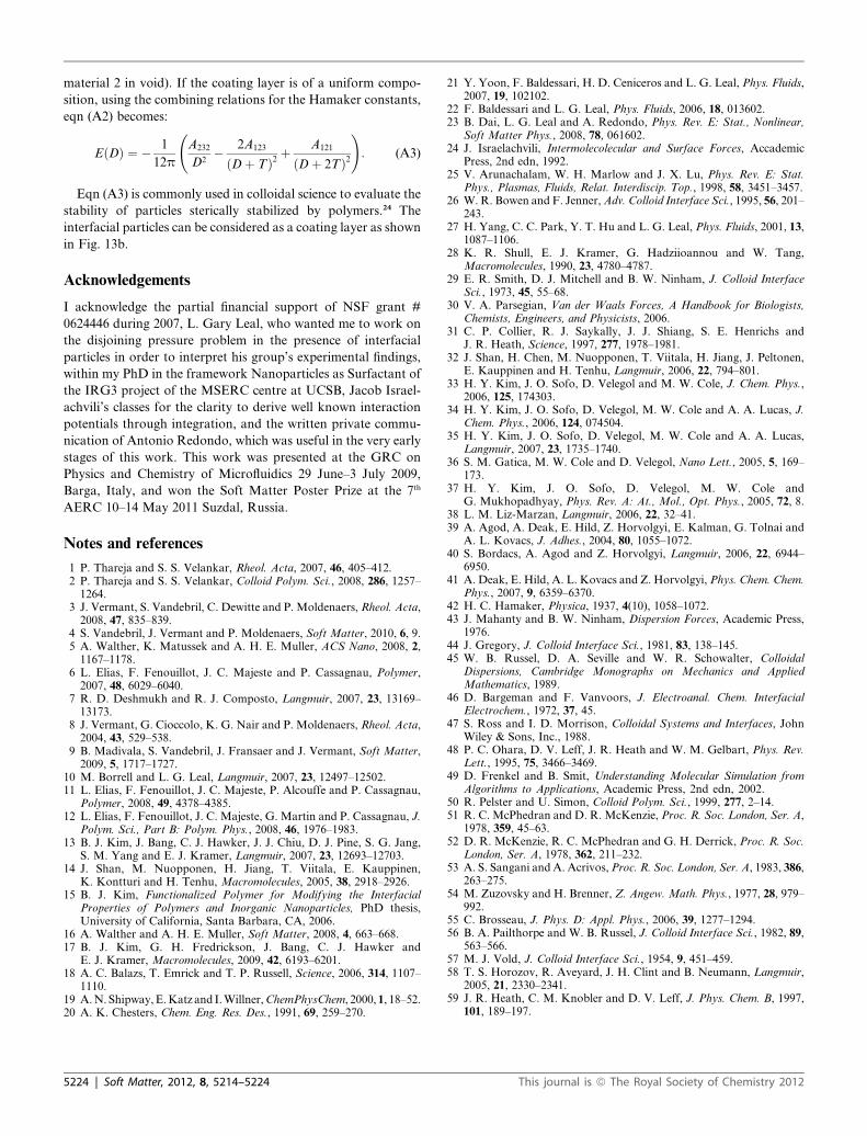
material 2 in void). If the coating layer is of a uniform compo-
sition, using the combining relations for the Hamaker constants,
eqn (A2) becomes:
EðDÞ ¼ � 1
12p
A232
D2� 2A123
ðDþ TÞ2 þA121
ðDþ 2TÞ2!: (A3)
Eqn (A3) is commonly used in colloidal science to evaluate the
stability of particles sterically stabilized by polymers.24 The
interfacial particles can be considered as a coating layer as shown
in Fig. 13b.
Acknowledgements
I acknowledge the partial financial support of NSF grant #
0624446 during 2007, L. Gary Leal, who wanted me to work on
the disjoining pressure problem in the presence of interfacial
particles in order to interpret his group’s experimental findings,
within my PhD in the framework Nanoparticles as Surfactant of
the IRG3 project of the MSERC centre at UCSB, Jacob Israel-
achvili’s classes for the clarity to derive well known interaction
potentials through integration, and the written private commu-
nication of Antonio Redondo, which was useful in the very early
stages of this work. This work was presented at the GRC on
Physics and Chemistry of Microfluidics 29 June–3 July 2009,
Barga, Italy, and won the Soft Matter Poster Prize at the 7th
AERC 10–14 May 2011 Suzdal, Russia.
Notes and references
1 P. Thareja and S. S. Velankar, Rheol. Acta, 2007, 46, 405–412.2 P. Thareja and S. S. Velankar, Colloid Polym. Sci., 2008, 286, 1257–1264.
3 J. Vermant, S. Vandebril, C. Dewitte and P. Moldenaers,Rheol. Acta,2008, 47, 835–839.
4 S. Vandebril, J. Vermant and P. Moldenaers, Soft Matter, 2010, 6, 9.5 A. Walther, K. Matussek and A. H. E. Muller, ACS Nano, 2008, 2,1167–1178.
6 L. Elias, F. Fenouillot, J. C. Majeste and P. Cassagnau, Polymer,2007, 48, 6029–6040.
7 R. D. Deshmukh and R. J. Composto, Langmuir, 2007, 23, 13169–13173.
8 J. Vermant, G. Cioccolo, K. G. Nair and P. Moldenaers, Rheol. Acta,2004, 43, 529–538.
9 B. Madivala, S. Vandebril, J. Fransaer and J. Vermant, Soft Matter,2009, 5, 1717–1727.
10 M. Borrell and L. G. Leal, Langmuir, 2007, 23, 12497–12502.11 L. Elias, F. Fenouillot, J. C. Majeste, P. Alcouffe and P. Cassagnau,
Polymer, 2008, 49, 4378–4385.12 L. Elias, F. Fenouillot, J. C. Majeste, G. Martin and P. Cassagnau, J.
Polym. Sci., Part B: Polym. Phys., 2008, 46, 1976–1983.13 B. J. Kim, J. Bang, C. J. Hawker, J. J. Chiu, D. J. Pine, S. G. Jang,
S. M. Yang and E. J. Kramer, Langmuir, 2007, 23, 12693–12703.14 J. Shan, M. Nuopponen, H. Jiang, T. Viitala, E. Kauppinen,
K. Kontturi and H. Tenhu, Macromolecules, 2005, 38, 2918–2926.15 B. J. Kim, Functionalized Polymer for Modifying the Interfacial
Properties of Polymers and Inorganic Nanoparticles, PhD thesis,University of California, Santa Barbara, CA, 2006.
16 A. Walther and A. H. E. Muller, Soft Matter, 2008, 4, 663–668.17 B. J. Kim, G. H. Fredrickson, J. Bang, C. J. Hawker and
E. J. Kramer, Macromolecules, 2009, 42, 6193–6201.18 A. C. Balazs, T. Emrick and T. P. Russell, Science, 2006, 314, 1107–
1110.19 A.N. Shipway,E.Katz and I.Willner,ChemPhysChem, 2000, 1, 18–52.20 A. K. Chesters, Chem. Eng. Res. Des., 1991, 69, 259–270.
5224 | Soft Matter, 2012, 8, 5214–5224
21 Y. Yoon, F. Baldessari, H. D. Ceniceros and L. G. Leal, Phys. Fluids,2007, 19, 102102.
22 F. Baldessari and L. G. Leal, Phys. Fluids, 2006, 18, 013602.23 B. Dai, L. G. Leal and A. Redondo, Phys. Rev. E: Stat., Nonlinear,
Soft Matter Phys., 2008, 78, 061602.24 J. Israelachvili, Intermolecolecular and Surface Forces, Accademic
Press, 2nd edn, 1992.25 V. Arunachalam, W. H. Marlow and J. X. Lu, Phys. Rev. E: Stat.
Phys., Plasmas, Fluids, Relat. Interdiscip. Top., 1998, 58, 3451–3457.26 W. R. Bowen and F. Jenner,Adv. Colloid Interface Sci., 1995, 56, 201–
243.27 H. Yang, C. C. Park, Y. T. Hu and L. G. Leal, Phys. Fluids, 2001, 13,
1087–1106.28 K. R. Shull, E. J. Kramer, G. Hadziioannou and W. Tang,
Macromolecules, 1990, 23, 4780–4787.29 E. R. Smith, D. J. Mitchell and B. W. Ninham, J. Colloid Interface
Sci., 1973, 45, 55–68.30 V. A. Parsegian, Van der Waals Forces, A Handbook for Biologists,
Chemists, Engineers, and Physicists, 2006.31 C. P. Collier, R. J. Saykally, J. J. Shiang, S. E. Henrichs and
J. R. Heath, Science, 1997, 277, 1978–1981.32 J. Shan, H. Chen, M. Nuopponen, T. Viitala, H. Jiang, J. Peltonen,
E. Kauppinen and H. Tenhu, Langmuir, 2006, 22, 794–801.33 H. Y. Kim, J. O. Sofo, D. Velegol and M. W. Cole, J. Chem. Phys.,
2006, 125, 174303.34 H. Y. Kim, J. O. Sofo, D. Velegol, M. W. Cole and A. A. Lucas, J.
Chem. Phys., 2006, 124, 074504.35 H. Y. Kim, J. O. Sofo, D. Velegol, M. W. Cole and A. A. Lucas,
Langmuir, 2007, 23, 1735–1740.36 S. M. Gatica, M. W. Cole and D. Velegol, Nano Lett., 2005, 5, 169–
173.37 H. Y. Kim, J. O. Sofo, D. Velegol, M. W. Cole and
G. Mukhopadhyay, Phys. Rev. A: At., Mol., Opt. Phys., 2005, 72, 8.38 L. M. Liz-Marzan, Langmuir, 2006, 22, 32–41.39 A. Agod, A. Deak, E. Hild, Z. Horvolgyi, E. Kalman, G. Tolnai and
A. L. Kovacs, J. Adhes., 2004, 80, 1055–1072.40 S. Bordacs, A. Agod and Z. Horvolgyi, Langmuir, 2006, 22, 6944–
6950.41 A. Deak, E. Hild, A. L. Kovacs and Z. Horvolgyi, Phys. Chem. Chem.
Phys., 2007, 9, 6359–6370.42 H. C. Hamaker, Physica, 1937, 4(10), 1058–1072.43 J. Mahanty and B. W. Ninham, Dispersion Forces, Academic Press,
1976.44 J. Gregory, J. Colloid Interface Sci., 1981, 83, 138–145.45 W. B. Russel, D. A. Seville and W. R. Schowalter, Colloidal
Dispersions, Cambridge Monographs on Mechanics and AppliedMathematics, 1989.
46 D. Bargeman and F. Vanvoors, J. Electroanal. Chem. InterfacialElectrochem., 1972, 37, 45.
47 S. Ross and I. D. Morrison, Colloidal Systems and Interfaces, JohnWiley & Sons, Inc., 1988.
48 P. C. Ohara, D. V. Leff, J. R. Heath and W. M. Gelbart, Phys. Rev.Lett., 1995, 75, 3466–3469.
49 D. Frenkel and B. Smit, Understanding Molecular Simulation fromAlgorithms to Applications, Academic Press, 2nd edn, 2002.
50 R. Pelster and U. Simon, Colloid Polym. Sci., 1999, 277, 2–14.51 R. C. McPhedran and D. R. McKenzie, Proc. R. Soc. London, Ser. A,
1978, 359, 45–63.52 D. R. McKenzie, R. C. McPhedran and G. H. Derrick, Proc. R. Soc.
London, Ser. A, 1978, 362, 211–232.53 A. S. Sangani and A. Acrivos,Proc. R. Soc. London, Ser. A, 1983, 386,
263–275.54 M. Zuzovsky and H. Brenner, Z. Angew. Math. Phys., 1977, 28, 979–
992.55 C. Brosseau, J. Phys. D: Appl. Phys., 2006, 39, 1277–1294.56 B. A. Pailthorpe and W. B. Russel, J. Colloid Interface Sci., 1982, 89,
563–566.57 M. J. Vold, J. Colloid Interface Sci., 1954, 9, 451–459.58 T. S. Horozov, R. Aveyard, J. H. Clint and B. Neumann, Langmuir,
2005, 21, 2330–2341.59 J. R. Heath, C. M. Knobler and D. V. Leff, J. Phys. Chem. B, 1997,
101, 189–197.
This journal is ª The Royal Society of Chemistry 2012